
water technology
Flow Sensor
de Bedienungsanleitung ................................................4
en Installation and Operation Guide ..............................8
fr Guide d’installation et d’utilisation ............................12
it Manuale d’installazione e d’uso ...............................16
nl Montage en bedieningshandleidning ........................20
es Guia al uso y a la instalación ....................................24
pt Manual de instruções e montagem ..........................28
ru
Руководство по монтажу и эксплуатации
..............32

2
water technology
(c) Aquis
Deutsch Inhalt
1. Allgemeine Information / Anwendungsbereich ..........................................4
2. Technische Daten ......................................................................................4
3. Hinweise ....................................................................................................4
4. Installation .................................................................................................5
5. Programmierung ........................................................................................6
6. Batteriewechsel ........................................................................................7
7. Service / Wartung ......................................................................................7
Français Sommaire
1. Information générales ...........................................................................12
2. Données techniques ................................................................................12
3. Instructions ..............................................................................................12
4. Installation ...............................................................................................13
5. Programmation ........................................................................................14
6. Remplacement de la pile ........................................................................15
7. Utilisation / Maintenance ........................................................................15
Português Conteúdo
1. Informações gerais / Âmbito de aplicação ..............................................28
2. Dados técnicos ........................................................................................28
3. Indicações ...............................................................................................28
4. Instalação ................................................................................................29
5. Programação ...........................................................................................30
6. Substituição da pilha ............................................................................31
7. Serviço / Manutenção ..............................................................................31
Русский Содержание
1. Общие сведения/сфера применения ...................................................32
2. Технические данные ..............................................................................32
3. Указания .................................................................................................32
4. Монтаж ...................................................................................................33
5. Программирование ................................................................................34
6. Замена батареи .................................................................................35
7. Сервисное обслуживание/техническое обслуживание ......................35
English Index
1. General Information ..................................................................................8
2. Technical Data ...........................................................................................8
3. Instructions ................................................................................................8
4. Installation .................................................................................................9
5. Programming ...........................................................................................10
6. Battery Replacement .............................................................................. 11
7. Service / Maintenance ............................................................................. 11
Español Indice
1. Información general/campo de aplicación ...............................................24
2. Datos técnicos .........................................................................................24
3. Indicaciones ............................................................................................24
4. Instalación ...............................................................................................25
5. Programación ..........................................................................................26
6. Cambio de la batería .............................................................................27
7. Servicio técnico/mantenimiento ...............................................................27
Italiano Indice
1. Informazioni generali / campo di applicazione .....................................16
2. Dati technici .............................................................................................16
3. Indicazioni ...............................................................................................16
4. Installazione ............................................................................................17
5. Programmazione .....................................................................................18
6. Cambio della batteria ............................................................................19
7. Assistenza / Manutenzione ....................................................................19
Nederlands Inhoud
1. Algemene informatie .............................................................................20
2. Technische Data ......................................................................................20
3. Handleiding .............................................................................................20
4. Plaatsing ..................................................................................................21
5. Programmatie ..........................................................................................22
6. Vervangen van de batterij .......................................................................23
7. Service / Onderhoud ...............................................................................23

3
water technology
2
5
3
4
9
1
Komponentenübersicht / Overview of components / Aperçu des composants /
Componenti / Overzicht van de componenten / Componentes /
Vista geral dos componentes / Обзор компонентов
Begriffsübersicht:
1 Programmier- und
Anzeigeeinheit
2 Display
3 „RESET“ Taste
4 „PROG“ Taste
5 Kabel 1.5 m
6 Schraube
7 Gehäuse
8 Knopfzelle 3VDC,
Type CR2032
9 Sensoreinheit mit G 3/8“
Überwurfmutter und G 3/8“
Aussengewinde
Definitions of terms:
1 programming and display unit
2 display
3 “RESET” button
4 “PROG” button
5 cable 1.5 m
6 screw
7 housing
8 coin cell 3VDC, type CR2032
9 sensor unit with G 3/8” F nut
and G 3/8” M thread
Aperçu des termes:
1 unité de programmation et
d’affichage
2 écran
3 bouton “RESET”
4 bouton “PROG”
5 tuyau 1.5 m
6 visse
7 boîtier
8 pile bouton 3VDC,
type CR2032
9 unité avec connexion écrou
G 3/8” F et filetage G 3/8” M
Panoramica dei componenti:
1 Unità di programmazione e
visualizzazione
2 Display
3 Pulsante „RESET“
4 Pulsante „PROG“
5 Cavo 1,5 m
6 Vite
7 Alloggiamento
8 Pila a bottone 3 VDC,
tipo CR2032
9 Unità sensore con G 3/8“
Dado per raccordi e filettature
esterne G 3/8“
Omschrijving van de termen:
1 programmatie en monitor
2 monitor
3 “RESET” toets
4 “PROG” toets
5 snoer 1.5 m
6 schroef
7 behuizing
8 batterij pastille 3VDC,
type CR2032
9 watermeter unit met G 3/8”
F IN en G 3/8” M UIT
schroefdraad
Resumen de los términos:
1 Unidad de indicación
y programación
2 Visualizador
3 Botón «RESET»
4 Botón «PROG»
5 Cable de alimentación de 1,5 m
6 Tornillo
7 Carcasa
8 Pila de botón de 3 V CC,
tipo CR2032
9 Unidad sensora con
tuerca de unión y rosca
exterior G 3/8“
Lista dos termos:
1 Unidade de programação
e visor
2 Visor
3 Tecla „RESET“
4 Tecla „PROG“
5 Cabo 1,5 m
6 Parafuso
7 Caixa
8 Pilha botão 3VDC,
Tipo CR2032
9 Unidade de sensor com G 3/8“
Porca cega e rosca exterior
G 3/8“
Обзор терминов:
1 Блок программирования и
индикации.
2 Дисплей.
3 Кнопка «RESET» (Сброс).
4 Кнопка «PROG»
(Программирование).
5 Сетевой шнур, длина 1,5 м.
6 Винт.
7 Корпус.
8 Элемент питания 3 В пост. тока,
тип CR2032.
9 Сенсорный блок с резьбой
G 3/8 дюйма, накидная гайка
и наружная резьба G 3/8
дюйма.
7
8
6

4
1. Allgemeine Information / Anwendungsbereich
Der CLARIS Flow Sensor wurde speziell für die Kontrolle von Wasserfilterkerzen entwickelt und dient der Messung
und Anzeige der Restfilterkapazität bis zum Austausch. Nach Eingabe der Ausgangskapazität des jeweiligen Filters
misst der CLARIS Flow Sensor die bezogene Filtratmenge und zeigt die noch zur Verfügung stehende Restkapazität
an. Bei Erreichung des Null-Wertes oder bei Überschreiten der max. zulässigen Einsatzdauer der Filterkerze von
12 Monaten, muss die Filterkerze ausgetauscht werden.
Über die Anzeige im externen Display kann der Anwender folgende Informationen abfragen:
• Restkapazität einer eingegebenen Filtratmenge
• Gesamtfiltratmenge
• Abruf Filtratmengen und Einsatzdauer der letzten 5 Filterkerzen
2. Technische Daten
Sensoreinheit
Anschlussgewinde [Zoll] Eingang 3/8“ IG / Ausgang 3/8“ AG
Eingangsdruck (min/max) [bar] 2 - 8
Durchussbereich [L/h] 10 - 100
Druckverlust (bis 100 l/h Durchuss) [bar] 0,2
Messgenauigkeit (horizontale Installation) [%] +/- 5
Wassertemperatur (min/max) [°C] +4 - +30
Umgebungstemperatur (min/max) [°C] +4 - +40
Abmessungen (BxHxT) [mm] 80 x 46 x 43
Einbaulage Horizontal empfohlen
Programmier- und Anzeigeeinheit
Spritzwasserdicht IP X4
Anzeige 5 Stellen
Zähler [L] abwärts von 99999 bis -9999
Abmessungen (BxHxT) [mm] 50 x 75 x 17
Kabel 1,5 Meter, 2 x 0,25 mm²
3. Hinweise
3.1 Allgemein
• Lesen Sie die Bedienungsanleitung vor der Inbetriebnahme des Flow Sensors aufmerksam und führen
Sie alle Schritte gemäß Anleitung durch.
• Die Durchflussrichtung muss der Kennzeichnung auf dem Gerät entsprechen.
• Die horizontale Einbaulage der Sensoreinheit ist empfohlen.
• Das Gerät darf keinen mechanischen Belastungen ausgesetzt werden.
• Es dürfen nur geeignete Dichtungs- und Verbindungselemente eingesetzt werden.
• Das System muss vor der Inbetriebnahme entlüftet werden.
3.2 Messtipps
• keine schnell pulsierende Förderung des Mediums zulassen
• kein Wasser-Luft-Gemisch zulassen
• Induktive Störungen sind zu vermeiden
• Die Impulszahl pro Liter ist nur für die Messung von Wasser kalibriert und kann je nach Medium
und Installation abweichen
3.3 Personal
Die Montage darf ausschließlich von geschultem und autorisiertem Personal unter Beachtung der ortsüblichen
Vorschriften durchgeführt werden.

5
3.4 Sicherheit
1. Beachten Sie alle Anweisungen und Anzeigen.
2. Verwenden Sie nur handelsübliche Batterien vom Typ CR2032.
3. Beachten Sie, dass die Abdeckung korrekt montiert ist. Ansonsten können Fremdkörper und Nässe eindringen.
4. In folgenden Fällen ist die Batterie zu entfernen:
• Wasser oder andere Flüssigkeiten sind in das Gerät eingedrungen.
• Die Anzeige des Gerätes funktioniert nicht mehr.
• Das Gerät bzw. das Gehäuse ist beschädigt.
• Die PROG. bzw. RESET Taste funktionieren nicht mehr.
Versuchen Sie auf keinen Fall das Gerät selbst zu reparieren, sondern verständigen Sie die entsprechende
Servicestelle.
3.5 Haftungsausschluss
Die Informationen in diesem Handbuch können ohne vorherige Ankündigung geändert werden. Trotz
sorgfältigster Ausarbeitung kann nicht ausgeschlossen werden, dass Fehler oder Unvollständigkeiten in diesem Hand-
buch enthalten sind. Es wird keinerlei Haftung für Fehler oder Datenverlust als Folge hieraus übernommen. Techni-
sche Änderungen vorbehalten.
Die Firma Aquis haftet nicht für etwaige Schäden einschließlich Folgeschäden, die aus falscher Installation oder
falschem Gebrauch des Produktes entstehen können.
Die Firma Aquis haftet nicht für Schäden, die durch die Verwendung fremder Komponenten entstehen.
3.6 Konformitätserklärung
Auf Anfrage erhältlich.
4. Installation
4.1 Erstinstallation des CLARIS-Filtersystems mit Sensoreinheit
Bei Erstinstallation muss zuerst der CLARIS-Filterkopf (siehe Betriebs- und Einbauleitung
„CLARIS Filterkerzensysteme“ Kapitel 6) montiert werden.
4.2 Nachrüstung der Sensoreinheit
Wenn bereits ein CLARIS-Filtersystem installiert ist, ist wie folgt vorzugehen:
1. Schlauch an der Ausgangsseite mit geeignetem Werkzeug vom Filterkopf entfernen.
2. Den Flow Sensor mit der Überwurfmutter am Filterkopfausgang verschrauben
(mitgelieferte Flachdichtung verwenden).
3. Schlauch an der Ausgangsseite des Flow Sensor verschrauben (Flachdichtung verwenden).
4.3 Programmier- und Anzeigeeinheit
4.3.1 Befestigung mittels doppelseitigem Klebeband
1. Befestigen Sie ein 40 x 40 mm doppelseitiges Klebeband an der Rückseite des Displays.
2. Kleben Sie die Anzeigeeinheit in der gewünschten Position fest.
4.3.2 Befestigung mittels Schraube
1. Flachkopfschraube mit max. Schaftdurchmesser von 4mm wird empfohlen.
BEACHTEN
Die Wasserzufuhr zum Filtersystem muss vor der Installation immer unterbrochen sein.
Auf die richtige Durchussrichtung (Pfeil auf Gehäuse) achten.
Geeignete Werkzeuge für die Montage verwenden (Gabelschlüssel 19 mm).
Die Einbaulage der Sensoreinheit sollte horizontal sein.
Das Gerät darf keinen mechanischen Belastungen ausgesetzt werden, insbesondere auf die Hebel-
wirkung von Schläuchen und Biegeradien achten. Leitungen gegebenenfalls abstützen!
Nur Dichtungs- und Verbindungselemente einsetzten, die für das System geeignet sind.
Das System vor Inbetriebnahme des Flow Sensors entlüften.

6
5. Programmierung
5.1 Eingabe der Filterkapazität in Liter
Entnehmen Sie der Bedienungsanleitung die angegebene Filterkapazität.
Schritte Taste Anzeige
1. 1x Drücken der Taste „PROG“ - „PROG“ blinkt
2. 1x Drücken der Taste „RESET“ - Aktive Ziffer blinkt
3.
Durch Drücken der „RESET“ Taste den gewünschten Wert eingeben -
Für die Zahl „2“, zweimal „RESET“ drücken
4.
1x Drücken der Taste „PROG“ um die gewünschte Ziffer zu bestätigen
und zur nächsten Ziffer zu wechseln
- Aktive Ziffer blinkt
5.
Durch Drücken der „RESET“ Taste den gewünschten Wert eingeben
- Für die Zahl „6“, sechsmal „RESET“ drücken
6.
Wiederholen Sie die Schritte 4. und 5., bis alle Ziffern
eingegeben sind
7.
1x Drücken der Taste „PROG“
- Die Filterkapazität ist nun programmiert - der eingestellte Wert
erscheint am Display
5.2 Rücksetzen der Filterkapazität (bei Filtertausch)
Schritte Taste Anzeige
1.
-Anzeige blinkt
Eingegebene Filterkapazität erreicht bzw. maximale Einsatzdauer von
12 Monaten überschritten
2.
Taste „RESET“ ca. 3 Sek. gedrückt halten
- Im Display erscheint „rESEt“
3.
Die Filterkapazität ist nun zurückgesetzt und der letzte eingegebene
Wert erscheint
5.3 Speicherabruf
Es besteht die Möglichkeit, das Filtratvolumen für die letzten 5 Filterkerzen abzurufen. Es wird immer die
durchgeflossene Menge Wasser in Liter und die Einsatzdauer (t) in Monaten angezeigt.
Schritte Taste Anzeige
1.
Taste „PROG“ ca. 5 Sek. lang gedrückt halten
- Die Ziffer „1“ erscheint
2.
Am Display erscheint die Litermenge und der Zeitraum der
letzten eingesetzten Filterkerze in Monaten
3.
1x Drücken der Taste „RESET“
- Es werden die Daten für die vorletzte Filterkerze angezeigt
4.
Schritt 3 wiederholen, um die Daten der weiteren Filterkerzen
abzurufen
5.
1x Drücken der Taste „PROG“
- Die aktuelle Filterkapazität wird angezeigt

7
5.4 Gesamtltratmenge
(ab erster Inbetriebnahme)
Schritte Taste Anzeige
1.
Taste „PROG“ ca. 5 Sek. lang gedrückt halten
- Die Ziffer „1“ erscheint
2.
Taste „PROG“ nochmals 5 Sek. lang gedrückt halten
- Gesamtliteranzahl ab Inbetriebnahme erscheint
3.
1x Drücken der Taste „PROG“
- Die aktuelle Filterkapazität wird angezeigt
6. Batteriewechsel
Schritte Taste Anzeige
1.
Auf dem Display blinkt „BATT“
- Batterie ist leer und muss ausgetauscht werden
1. Lösen der Schraube (S. 3, Pos. 6) am Gehäuse (S. 3, Pos. 7) mit einem Kreuzschlitzschraubendreher.
2. Den Gehäusedeckel abnehmen und die Batterie entnehmen.
3. Die neue Batterie (Typ CR2032) einsetzen und nach unten drücken (auf Polarität achten).
Deckel aufsetzen und mit der Schraube am Gehäuse befestigen.
HINWEIS: Die bis dahin gespeicherten Daten gehen beim Batteriewechsel nicht verloren.
7. Service / Wartung
Den CLARIS Flow Sensor täglich auf Dichtheit prüfen. Im Störfall wenden Sie sich bitte an Ihren Vertragspartner.

8
1. General Information
The CLARIS Flow Sensor has been developed to monitor the usage rate of the CLARIS water filter system and
to determine the optimum cartridge replacement interval. After setting the sensor to monitor the specific filter size,
the CLARIS Flow Sensor continually measures the filtrate volume to calculate and display the remaining filtration
capacity in litres. Once the available filtration capacity is exhausted (“zero”) or after 12 month operation, the filter
cartridge has to be replaced.
The programming and display unit provides the following information:
• residual filtration capacity of the cartridge
• total filtrate volume since CLARIS Flow Sensor installation
• filtrate volume and operation time of the last five installed filter cartridges
2. Technical Data
Sensor Unit
Connection [inches] In 3/8“ F nut / out 3/8“ M
Operating Pressure (min/max) [bar] 2 - 8
Flow rate [L/h] 10 - 100
Pressure loss (up to 100l/h ow rate) [bar] 0,2
Precision (horizontal installation) [%] +/- 5
Water Temperature (min/max) [°C] +4 to +30
Ambient Temperature (min/max) [°C] +4 to +40
Dimensions (BxHxT) [mm] 80 x 46 x 43
Installation position Horizontal recommended
Programming and Display Unit
Splash proof IP X4
Display 5 digits
Counter [L] Downwards 99999 to -9999
Dimensions (BxHxT) [mm] 50 x 17 x 73
Cable 1.5 metre, 2 x 0.25 mm²
3. Instructions
3.1 General
• Read the Installation and Operation Guide carefully before each installation and start of operation.
Follow all steps exactly as indicated in the instructions.
• Ensure that the flow direction corresponds to the arrows on the sensor unit.
• It is recommended to mount the sensor horizontally for greatest accuracy.
• Don’t expose the Flow Sensor to any mechanical stress.
• Ensure that all seals and connections are made using suitable components.
• Check that all air is vented from the system before the start of operation.
3.2 Measurement tips
• Avoid rapidly pulsating water flow
• Minimise water-air mixture
• Ensure the unit is sited away from strong magnetic fields
• Be aware that the unit is calibrated to measure water flow and hence measurements may vary
with other fluids
3.3 Staff
The installation and maintenance of the CLARIS Flow Sensor may only be carried out by trained and authorised
personnel.

9
3.4 Safety Information
1. Follow all instructions and guidelines.
2. Use only standard battery cells of the type CR2032.
3. Ensure that the battery cover is properly sealed to avoid debris and moisture penetration.
4. The battery should be removed in the following cases:
• Water or other liquids ingress into the appliance.
• If the Display does not function.
• If the housing of the Programming and Display Unit is damaged.
• If the PROG or RESET buttons do not function.
All repairs should only be carried out by an Authorised Service Agent.
3.5 Disclaimer
Information contained in this document is believed to be accurate at the time of publication, but does not constitute a
contractual offer. The right is reserved to alter specifications without prior notice. Illustrations and tabulated data are
for guidance only. Aquis does not assume liability for any damages, including subsequent damages, that may result
from incorrect installation or usage of the products. Aquis does not assume liability for damage caused by using parts
from other manufacturers.
3.6 Declaration of Conformity
Available on request.
4. Installation
4.1 First time installation of the CLARIS lter system with the sensor unit
For initial installation of CLARIS filter system with CLARIS Flow Sensor, first install the CLARIS filter head (see
Operation Guide “CLARIS filter systems” chapter 6).
4.2 Installation of the sensor unit to an existing CLARIS lter system
If a CLARIS filter system is already in place, follow the following steps:
1. Remove connection hose from the filter head liquid outlet using an appropriate tool.
2. Connect the sensor unit with the nut directly to the filter head (use the provided flat gasket).
3. Connect the hose to the outlet of the sensor unit (use the flat gasket).
4.3 Programming and Display Unit
4.3.1 Mounting with double-sided adhesive tape
1. Fasten an approx. 40 x 40 mm piece of double-sided adhesive tape to the back wall of the programming
and display unit.
2. Position the programming and display unit on the desired position.
4.3.2 Mounting using a screw
1. Flat head screw with max. 4 mm shaft diameter is recommended.
NOTE
Disconnect the CLARIS lter head from the water supply before start of installation.
Ensure correct alignment of sensor unit with direction of ow (arrow on the housing).
Use only appropriate tools for the installation (spanner 19 mm).
The sensor unit should be mounted horizontally.
Don‘t expose the Flow Sensor to any mechanical strain; particularly take care of any leverage effect
from kinked or bent hoses. If necessary brace the connections.
Use only suitable gaskets and connecting materials.
Before start of operation vent all air from the system.

10
5. Programming
5.1 Setting the lter capacity in litre
Please follow the capacity instruction for the appropriate CLARIS filter cartridge (see CLARIS filter Guide).
Step Button Display
1. Press the „PROG“ button once - „PROG“ flashes
2. Press the „RESET“ button once – active digit flashes
3.
By pressing the „RESET“ button, set the desired value
- For the digit “2”, press “RESET” two times
4.
Press the „PROG“ button once to confirm the desired digit and switch to
the next digit. - Active digit flashes
5.
By pressing the „RESET“ button, set the desired value
- For the digit „6“, press „RESET“ six times
6. Repeat Steps 4 and 5 until all digits have been set
7.
Press the „PROG“ button once
- Final filter capacity is set - the programmed value appears
5.2 Resetting the lter capacity (after replacement of lter cartridge)
Step Button Display
1.
- Display flashes
Programmed filter capacity exhausted or maximum operation time of 12
months exceeded
2.
Press and hold the „RESET“ button for approx. 3 sec.
- „rESEt“ appears on the display
3. The filter capacity is reset and the last programmed value appears
5.3 Memory Access
There is a possibility to individually retrieve the operating data (volume in litre and operation time in month) of the last
five filter cartridges installed.
Step Button Display
1.
Press and hold the „PROG“ button for approx. 5 sec.
- The digit „1“ appears
2.
The display indicates the volume in litres and the operation
time in months of the last cartridge in place
3.
Press the „RESET“ button once
- The operating data of the next to last filter cartridge are
displayed
4.
Repeat Step 3 to access to the memories of the prior installed
filter cartridges
5.
Press the „PROG“ button once
- The current filter capacity is displayed

11
5.4 Total ltrate volume
(from the start of first operation)
Step Button Display
1.
Press and hold the „PROG“ button for approx. 5 sec.
- The digit „1“ appears
2.
Once again press and hold the „PROG“ button for approx. 5
sec.
- The complete filtrate volume from the start of first operation
appears
3.
Press the „PROG“ button once
- The current filter capacity is displayed
6. Battery Replacement
Step Button Display
1.
On the display appears „BATT“
- The battery is empty and must be replaced
1. Loosen the screw (page 3, pos. 6) on the cover (page 3, pos. 7) with a Phillips head screwdriver.
2. Remove the cover and remove the old battery.
3. Insert the new battery (type CR2032) and press downwards (observe the polarity). Then place back the
cover to the housing and tighten the screw.
NOTE: All stored data remain after the battery replacement.
7. Service / Maintenance
Check the CLARIS Flow Sensor for leaks daily.
In the event of a fault, please contact your service contractor.

12
1. Information générales
Le débimètre CLARIS a été conçu spécialement pour contrôler l’utilisation du système de filtration CLARIS afin
de déterminer le moment optimal pour remplacer la cartouche. Après avoir programmé le système de contrôle en
fonction de la taille du filtre, le débimètre mesurera en continue le volume d’eau filtré pour calculer et afficher la
capacité restante en litres.
Lorsque la capacité a été atteinte ou que la durée d’utilisation maximale a été atteinte, l’écran indique qu’il faut
remplacer la cartouche.
L’unité de programmation et: d’affichage fournie les données suivantes:
• Capacité résiduelle du filtre
• Volume total filtré depuis l’installation du débimètre CLARIS
• Volume total filtré et temps de service des 5 derniers filtres installés.
2. Données techniques
Débimètre
Connexion [inches] 3/8“ F entrée / sortie 3/8“ M
Pression de service (min/max) [bar] 2 - 8
Débit [L/h] 10 - 100
Perte de pression (jusqu’à 100l/h ) [bar] 0,2
Précision (installation horizontale) [%] +/- 5
Température de l ’eau (min/max) [°C] +4 to +30
Température ambiante (min/max) [°C] +4 to +40
Dimensions (Lx H x l) [mm] 80 x 46 x 43
Position d’installation Horizontale recommandée
Unité de programmation et d’afchage
Étanche IP X4
Afchage 5 chiffres
Compteur [L] À rebours 99999 to -9999
Dimensions (LxHx l) [mm] 50 x 17 x 73
Tuyau 1.5 mètres 2 x 0.25 mm²
3. Instructions
3.1 Générales
• Lisez attentivement le guide d’installation et opérationel avant chaque installation et mise en service.
Suivez toutes les étapes indiquées sur les instructions.
• Assurez vous que le sens de l’écoulement de l’eau corresponde aux flèches sur le débimètre.
• Il est recommendé de fixer le débimètre à l’horizontale pour une meilleure précision des données.
• Ne pas exposer le débimètre à une pression mécanique.
• Assurez vous que toutes les fermetures et connexions sont faites avec des composants adaptés.
• Vérifiez que tout l’air est évacué du système avant de le mettre.
3.2 Recommendations
• Evitez les pulsions de débit fortes
• Minimiser le mélange eau et air
• Assurez vous que l’appareil est situé à l’écart des champs magnétiques forts
• Veuillez tenir compte que cet appareil a été calibré pour mesurer le débit de l’eau et par conséquent
pourrait varier avec d’autres fluides.
3.3 Personnel
L’installation et la maintenance du débimètre CLARIS doit être faite uniquement par un personnel formé et autorisé.

13
3.4 Informations relatives à la sécurité
1. Suivez toutes les instructions et recommendations
2. Utilisez uniquement des piles standards de type CR2032.
3. Assurez vous que le couvercle de la pile est correctement fermé pour éviter les poussières et l’humidité.
4. La pile doit être enlevée dans les cas suivants:
• De l’eau ou d’autres liquides s’infiltrent dans l’appareil
• Si l’écran d’affichage ne fonctionne pas
• Si le boîtier de l’unité de programmation et d’affichage est endommagé.
• Si les boutons PROG ou RESET ne fonctionnent pas
Toutes les réparations doivent être effectuées par un agent autorisé.
3.5 Réserves légales
Les informations contenues dans ce document sont reconnues être correctes au moment de la publication mais ne
constituent pas une offre contractuelle. Nous nous réservons le droit de modifier certaines données sans préavis.
Les illustrations et données tableau sont à titre indicatif uniquement. Aquis ne prend par la responsabilité des
dommages y compris les dommages liés à une installation ou utilisation incorrecte des produits. Aquis ne prend pas
la responsabilité de dommages causés par l’utilisation d’outils d’autres fabricants.
3.6 Déclaration de conformité
Disponible sur demande.
4. Installation
4.1 Première installation du système de ltration CLARIS avec le débimètre
Tout d’abord installez la tête de filtre CLARIS (voir guide opérationnel chapitre 6).
4.2 Installation du débimètre sur un système de ltration CLARIS déjà existant
Si le système CLARIS est déjà en place, suivez les étapes suivantes:
1 Retirez le flexible de connexion de la sortie sur la tête de filtre avec un outil adapté.
2. Branchez le débimètre avec l’écrou directement sur la tête de filtre (utilisez le joint plat fourni)
3. Branchez le flexible sur la sortie du débimètre
4.3 Programmation et unité d’afchage
4.3.1 Montage avec une bande adhésive double face
1. Appliquer un morceau de bande adhésive de +/- 40 x 40mm sur le mur où sera installé.
2. Installez l’appareil sur la position que vous souhaitez.
4.3.2 Montage avec une visse
1. Une visse plate maxi 4 mm de diamètre d’axe.
REMARQUE
Débranchez la tête de ltre CLARIS de l’arrivée d’eau avant de commencer l’installation.
Assurez vous du bon alignement entre le débimètre et le sens de l’écoulement de l’eau
(èche sur le boîtier).
Utilisez uniquement les outils adaptés pour l’installation (clé 19mm).
Le débimètre doit être monté à l’horizontale.
Ne pas sousmettre le débimètre à une tension mécanique, évitez que les tuyaux soient noués ou
déformés. Si besoin attachez les connexions.
Utilisez uniquement des joints et matériels de connexion adaptés.
Avant le début de l’installation, évacuez tout l’air du système.

14
5. Programmation
5.1 Indiquez la capacité du ltre en litres
Suivez l’indication de capacité du filtre CLARIS correspondant à sa taille (voir le guide filtre CLARIS).
Etapes Bouton Afchage
1. Appuyez une fois sur le bouton „PROG“ - „PROG“ clignote
2. Appuyez une fois sur le bouton „RESET“ – les chiffres clignotent
3.
En appuyant sur le bouton „RESET“, indiquez la valeur souhaité
- Pour le chiffre “2” appuyez deux fois sur le bouton“RESET”
4.
Appuyez une fois sur le bouton „PROG“ pour confirmer le chiffre souhaité et
passez au chiffre suivant. – les chiffres clignotent
5.
En appuyant sur le bouton RESET, indiquez la valeur souhaitée
- Pour le chiffre „6“, appuyez sur RESET six fois
6. Répetez les étapes 4 et 5 jusqu’à ce que tous les chiffres soient indiqués.
7.
Appuyez une fois sur le bouton „PROG“
- la capacité est réglée- la valeur programmée apparaît
5.2 Reprogrammer la capacité du ltre (après remplacement de la cartouche)
Etape Bouton Afchage
1.
- l’écran clignote
la capacité programmée du filtre a été atteinte ou le temps de service a
dépassé les 12 mois
2.
Appuyez en maintenant le bouton „RESET“ pendant 3 sec. environ
- RESET apparaît sur l’écran
3. la capacité est reprogrammée et les nouvelles valeurs apparaissent.
5.3 Accès à la mémoire
Il est possible de recouvrer les données relatives au service (volume en litre, temps de service en mois) des cinq
dernières installations.
Etape Bouton Afchage
1.
Appuyez sur le bouton „PROG“ pendant 5 sec. environ
- le chiffre „1“ apparaît
2.
L’écran indique le volume en litres et le temps de service en
mois de la dernière cartouche en place.
3.
Appuyez une fois sur le bouton RESET“
- les données de service des dernières cartouches sont
affichées
4.
Répetez l’étape 3 pour accéder à la mémorisation des
cartouches installées préalablement.
5.
Appuyez une fois sur le bouton „PROG“
- la capacité actuelle du filtre s’affiche

15
5.4 Volume total ltré
(depuis le début de la mise en service)
Etape Bouton Afchage
1.
Appuyez en maintenant le bouton „PROG“ pendant 5 sec
environ. - Le chiffre „1“ apparaît
2.
Répetez l’opération
- Le volume total filtré depuis sa mise en service apparaît.
3.
Appuyez une fois sur le bouton „PROG“
- La capacité actuelle s’affiche
6. Remplacement de la pile
Etape Bouton Afchage
1.
„BATT“ apparaît sur l’écran
- la pile est vide, elle doit être remplacée
1. Dévissez la visse (page 3, pos. 6) sur le dessus (page 3, pos. 7) avec un tournevisse.
2. Soulevez le boîtier et retirez l’ancienne pile.
3. Insérez la nouvelle pile (type CR2032) et appuyez en arrière. Ensuite placez le boîtier et resserez la visse.
REMARQUE:. Toutes les données sont maintenues après le remplacement de la pile.
7. Utilisation / Maintenance
Contrôlez le débimètre CLARIS quotidiennement contre les fuites.
En cas de difficulté, contactez votre agent de service.

16
1. Informazioni generali / campo di applicazione
Il CLARIS Flow Sensor è stato sviluppato appositamente per il controllo di cartucce filtranti per acqua e serve per la
misurazione e visualizzazione della capacità residua del filtro fino al cambio. Dopo l‘immissione dalla capacità iniziale
del rispettivo filtro, il CLARIS Flow Sensor misura la quantità di filtrato assunta e mostra la capacità residua ancora
a disposizione. Al raggiungimento del valore zero o al superamento della durata di impiego massima della cartuccia
filtrante di 12 mesi, questa deve essere sostituita.
Attraverso la visualizzazione nel display esterno l‘utente può consultare le seguenti informazioni:
• Capacità residua di una quantità di filtrato immessa
• Quantità di filtrato complessiva
• Acquisizione delle quantità di filtrato e della durata di impiego delle ultime 5 cartucce filtranti
2. Dati technici
Unità sensore
Filettatura di raccordo [pollici]
Ingresso, lettatura interna da 3/8“/ uscita,
lettatura esterna da 3/8“
Pressione di ingresso (min/max) [bar] 2 - 8
Campo di portata [l/h] 10 - 100
Perdita di pressione (no a 100 l/h di portata) [bar] 0,2
Accuratezza della misurazione (installazione
orizzontale)
[%] +/- 5
Temperatura dell'acqua (min/max) [°C] +4 - +30
Temperatura ambiente (min/max) [°C] +4 - +40
Dimensioni (LxAxP) [mm] 80 x 46 x 43
Posizione di montaggio È consigliato il montaggio in orizzontale
Unità di programmazione e visualizzazione
Impermeabile agli schizzi d'acqua IP X4
Visualizzazione 5 posizioni
Contatore [l] decrescente da 99999 a -9999
Dimensioni (LxAxP) [mm] 50 x 75 x 17
Cavo 1,5 metri, 2 x 0,25 mm²
3. Indicazioni
3.1 Informazioni generali
• Leggere attentamente le istruzioni per l‘uso prima della messa in funzione del Flow Sensor ed effettuare tutti i
passi secondo le istruzioni.
• La direzione del flusso deve corrispondere alla marcatura sull‘apparecchio.
• È consigliata la posizione di montaggio orizzontale dell‘unità sensore.
• L‘apparecchio non deve essere esposto a sollecitazioni meccaniche.
• Devono essere impiegati solo elementi di tenuta e di raccordo idonei.
• Prima della messa in funzione è necessario disareare il sistema.
3.2 Consigli per la misurazione
• Non consentire un trasporto rapido a impulsi del fluido
• Non consentire alcuna miscela acqua-aria
• Devono essere evitati disturbi induttivi
• Il numero di impulsi per litro è calibrato solo per la misurazione di acqua e può variare in funzione del fluido
e dell‘installazione
3.3 Personale
Il montaggio deve essere effettuato esclusivamente da personale addestrato e autorizzato tenendo conto delle norme
previste localmente.

17
3.4 Sicurezza
1. Rispettare tutte le istruzioni e indicazioni.
2. Utilizzare solo batterie commerciali del tipo CR2032.
3. Assicurare che il coperchio sia montato correttamente per evitare la penetrazione di corpi estranei e umidità.
4. Nei seguenti casi è necessario rimuovere la batteria:
• Acqua o altri liquidi sono penetrati nell‘apparecchio.
• L‘indicatore dell‘apparecchio non funziona più.
• L‘apparecchio o l‘alloggiamento sono danneggiati.
• I pulsanti PROG. o RESET non funzionano più.
Non tentate in nessun caso di riparare l‘apparecchio personalmente, ma informate il centro di assistenza apposito.
3.5 Esclusione di responsabilità
Le informazioni nel presente manuale possono essere modificate senza preavviso. Nonostante un‘elaborazione
molto accurata, non può essere escluso che il presente manuale contenga errori e incompletezze. Aquis declina
qualsiasi responsabilità per errori o perdite di dati che ne potrebbero conseguire. Con riserva di modifiche tecniche.
Aquis non risponde di eventuali danni, inclusi i danni secondari, che derivano da un‘installazione o da un uso errati
del prodotto.
Aquis non risponde di danni causati dall‘impiego di componenti estranei.
3.6 Dichiarazione di conformità
Disponibile su richiesta.
4. Installazione
4.1 Prima installazione del sistema ltrante CLARIS con unità sensore
In occasione della prima installazione deve essere montato prima la testa del filtro CLARIS (vedi le istruzioni di
esercizio e di installazione „Sistemi di cartucce filtranti CLARIS“ capitolo 6).
4.2 Aggiornamento dell‘unità sensore
Se è già installato un sistema filtrante CLARIS, è necessario procedere nel modo seguente:
1. Rimuovere il tubo flessibile sul lato di uscita dalla testa del filtro con un utensile adatto.
2. Avvitare il Flow Sensor con il dado per raccordi sull‘uscita della testa del filtro
(utilizzare la guarnizione piatta fornita in dotazione).
3. Avvitare il tubo flessibile sul lato di uscita del Flow Sensor (utilizzare la guarnizione piatta).
4.3 Unità di programmazione e visualizzazione
4.3.1 Fissaggio mediante un nastro biadesivo
1. Applicare un nastro biadesivo da 40 x 40 mm al lato posteriore del display.
2. Incollare l‘unità di visualizzazione nella posizione desiderata.
4.3.2 Fissaggio mediante vite
1. È consigliato l‘uso di una vite a testa piana con un diametro massimo del gambo di 4 mm.
NOTA
L‘alimentazione dell‘acqua al sistema ltrante deve sempre essere interrotta prima dell‘installazione.
Badare alla corretta direzione del usso (freccia sull‘alloggiamento).
Utilizzare utensili adatti per il montaggio (chiave ssa 19 mm).
La posizione di montaggio dell‘unità sensore dovrebbe essere orizzontale.
L‘apparecchio non deve essere soggetto a sollecitazioni meccaniche, in particolare è necessario fare
attenzione all‘effetto leva di tubi essibili e ai raggi di curvatura. Eventualmente sostenere le tubazioni!
Impiegare solo elementi di tenuta e di raccordo adatti per il sistema.
Disareare il sistema prima della messa in funzione del Flow Sensor.

18
5. Programmazione
5.1 Immissione della capacità del ltro in litri
Desumere nelle istruzioni per l‘uso la capacità del filtro indicata.
Fasi Pulsante Visualizzazione
1. 1x pressione del pulsante „PROG“ - „PROG“ lampeggia
2. 1x pressione del pulsante „RESET“ - La cifra attiva lampeggia
3.
Immettere il valore desiderato premendo il pulsante „RESET“ - Per il numero
„2“, premere due volte „RESET“
4.
1x pressione del pulsante „PROG“ per confermare la cifra desiderata e
passare alla cifra successiva
- La cifra attiva lampeggia
5.
Immettere il valore desiderato premendo il pulsante „RESET“
- Per il numero „6“, premere 6 volte „RESET“
6. Ripetere i passi 4 e 5 fino all‘immissione di tutte le cifre.
7.
1x pressione del pulsante „PROG“
- La capacità del filtro è ora programmata - il valore impostato appare sul
display
5.2 Reset della capacità del ltro (in caso di cambio del ltro)
Fasi Pulsante Visualizzazione
1.
- L‘indicatore lampeggia
Capacità del filtro immessa raggiunta oppure durata d‘impiego massima
di 12 mesi superata
2.
Tenere premuto il pulsante „RESET“ per circa 3 sec.
- Sul display appare „RESEt“
3. La capacità del filtro è ora resettata e appare l‘ultimo valore immesso
5.3 Prelievo dalla memoria
Esiste la possibilità di prelevare il volume di filtrato per le ultime 5 cartucce filtranti. Viene sempre visualizzata la
quantità d‘acqua passata in litri e la durata d‘impiego (t) in mesi.
Fasi Pulsante Visualizzazione
1.
Tenere premuto il pulsante „PROG“ per circa 5 sec.
- Appare la cifra „1“
2.
Sul display appare la quantità in litri e il periodo in mesi
dell‘ultima cartuccia filtrante inserita
3.
1x pressione del pulsante „RESET“
- Vengono visualizzati i dati per la penultima cartuccia filtrante
4.
Ripetere la fase 3 per richiamare i dati delle altre cartucce filtranti
5.
1x pressione del pulsante „PROG“
- Viene visualizzata la capacità attuale del filtro

19
5.4 Quantità complessiva di ltrato (dalla prima messa in funzione)
Fasi Pulsante Visualizzazione
1.
Tenere premuto il pulsante „PROG“ per circa 5 sec.
- Appare la cifra „1“
2.
Tenere nuovamente premuto il pulsante „PROG“ per
circa 5 sec.
- Appare la quantità complessiva di litri a partire dalla messa in
funzione
3.
1x pressione del pulsante „PROG“
- Viene visualizzata la capacità attuale del filtro
6. Cambio della batteria
Fasi Pulsante Visualizzazione
1.
Sul display lampeggia „BATT“
- La batteria è scarica e deve essere sostituita
1. Allentare la vite (pag. 3, pos. 6) sull‘alloggiamento (pag. 3, pos. 7) con un cacciavite con punta a croce.
2. Rimuovere il coperchio dell‘alloggiamento del filtro ed estrarre la batteria.
3. Inserire la nuova batteria (tipo CR2032) e spingerla verso il basso (badare alla corretta polarità).
Applicare il coperchio e fissare con la vite all‘alloggiamento.
NOTA: I dati salvati no a quel momento non vanno persi durante il cambio della batteria.
7. Assistenza / Manutenzione
Verificare giornalmente la tenuta del CLARIS Flow Sensor. In caso di guasto rivolgersi al proprio rivenditore
autorizzato.

20
1. Algemene informatie
De CLARIS Watermeter is ontwikkeld voor de opvolging van de CLARIS water filter systemen ter bepaling van de
uitwisseling interval. Na opstelling en programmatie van de watermeter in verhouding tot de gebruikte filterkaars zal
de CLARIS watermeter het volume gefilterd water opvolgen en op de monitor de overblijvende capaciteit aanduiden
in liters. Zodra de ingestelde capaciteit bereikt is (“zero”) of na 12 maand dienst, dient de filterkaars vervangen te
worden.
De programmatie en monitor bieden volgende informatie:
• Overblijvende filtratiecapaciteit van de filterkaars
• Totaal gefilterd volume water sinds de plaatsing van de CLARIS watermeter
• Volume en werkingstijd, individueel, van de laatste 5 geplaatste filterkaarsen
2. Technische Data
Sensor Unit
Aansluiting [inches] In 3/8“ F IN / OUT 3/8“ M
Werkingsdruk (min/max) [bar] 2 - 8
Debiet [L/h] 10 - 100
Drukverlies (tot 100l/h debiet) [bar] 0,2
Correctheid (horizontale opstelling) [%] +/- 5
Water Temperatuur (min/max) [°C] +4 to +30
Ambiente Temperature (min/max) [°C] +4 to +40
Afmetingen (BxHxT) [mm] 80 x 46 x 43
Positie van opstelling Horizontaal aangeraden
Programmatie en Monitor Unit
Splash proof IP X4
Display 5 digits
Teller [L] Aftellend 99999 tot -9999
Afmetingen (BxHxT) [mm] 50 x 17 x 73
Snoer 1.5 meter, 2 x 0.25 mm²
3. Handleiding
3.1 Algemeen
• Lees de installatie en operatie handleiding te gronde voor iedere plaatsing of opstart van een project.
Volg exact iedere stap vermeld in de handleiding.
• Verzekert er U van dat de aangegeven doorstroomrichting gerespecteerd is (aangegeven door de
pijl op de unit)
• Het is aangeraden om de watermeter horizontal op te stellen voor de beste en meest accurate meting.
• Gelieve de watermeter aan geen enkele mechanische stress te onderwerpen.
• Verzekert er U van dat alle aansluitingen en dichtingen gebruik maken van geschikte componenten
• Controleer dat alle lucht uit het systeem verwijdert is alvorens het geheel op te starten.
3.2 Werking tips
• Vermijd korte druk opstoten in het waterdebiet.
• Minimaliseer water – lucht vermenging
• Plaats de unit uit de buurt van sterke magnetische velden.
• Noteer dat de unit gekalibreerd werd voor het meten van een waterdebiet, metingen kunnen verschillen
bij het gebruik voor andere vloeistoffen
3.3 Personeel
De plaatsing en het onderhoud van de CLARIS Flow Sensor mag enkel gebeuren door opgeleid en bevoegd
personeel.

21
3.4 Veiligheidsinformatie
1. Volg alle instructies en richtlijnen.
2. Gebruik enkel standaard batterij pastilles type CR2032.
3. Verzekert U dat het deksel van batterij correct geplaatst is ter voorkoming van vervuiling en vocht insijpelen.
4. De batterij hoort verwijdert te worden in volgende gevallen:
• Insijpelen van water of andere vloeistoffen in de toepassing.
• Als de monitor niet werkt
• Als de behuizing van de programmatie of monitor unit beschadigd is.
• Als de PROG of RESET toetsen niet werken.
Alle herstellingen mogen enkel gebeuren door bevoegde diensten.
3.5 Belangrijk!
De inhoud van dit document kan gewijzigd worden zonder voorafgaandelijk melding. Ondanks grondige planning
en nazicht kunnen wij eventuele fouten of onvolledige informatie niet totaal uitsluiten. Wij aanvaarden geen
verantwoordelijkheid voor eventuele fouten of onvolledige data. Wij reserveren ons het recht om technische
aanpassingen uit te voeren. Jura neemt geen verantwoordelijkheid voor welke schade ook, inclusief daaruit
volgende schade, als deze het gevolg is van onzorgvuldige installatie of gebruik van de producten. Jura draagt geen
verantwoordelijkheid voor het gebruik van niet eigen materiaal voor de aansluiting van de systemen.
3.6 Verklaring van conformiteit
Beschikbaar op aanvraag.
4. Plaatsing
4.1 Eerste plaatsing van een lter systeem met een watermeter unit
Voor een nieuwe installatie van een filtersysteem met watermeter plaats U eerst de filterkop (zie handleiding
“CLARIS filter systems” rubriek 6).
4.2 Plaatsing van een watermeter unit op een bestaande opstelling
Als een CLARIS filter systeem al opgesteld is, onderneem volgende stappen:
1 Verwijder de aansluitingsslang (waterafvoer) van de filterkop, gebruik makend van de correcte materialen.
2. Verbind de watermeter unit direct op de filterkop (maak gebruik van een vlakke sleutel).
3. Verbind de aansluitslang op de uitgang van de watermeter (maak gebruik van een vlakke sleutel).
4.3 Programmatie en Monitor Unit
4.3.1 Opstelling met dubbelzijdige kleefband
1. Plaats een stuk dubbelzijdige kleefband van +/- 40 x 40 mm op de achterkant van de programmatie /
monitor unit.
2. Kleef de unit op de gewenste locatie.
4.3.2 Opstelling met schroef
1. Een vlakke kop schroef van 4 mm diameter is aangeraden.
NOTA!
Ontkoppel de CLARIS lterkop van de waterleiding alvorens tot de plaatsing van de watermeter over te
gaan.
Controleer de correcte doorstroming van het water (aangegeven door de pijl op de behuizing)
Gebruik enkel geschikte werktuigen voor de plaatsing (sleutel van 19 mm)
De watermeter unit hoort best horizontal opgesteld te worden.
De watermeter aan geen enkele mechanische stress te onderwerpen, hou rekening met een storende
werking van genepen of geplooide aansluitslangen.
Gebruik enkel aangepaste koppelstukken voor de aansluiting.
Voor het opstarten hoort alle lucht uit het systeem verwijdert te worden.

22
5. Programmatie
5.1 Instellen van de lter capaciteit in liters
Gelieve de instructies voor de capaciteit van de CLARIS filterkaars te volgen (zie handleiding CLARIS filter).
Stap Toets Monitor
1. Druk éénmaal op „PROG“ - „PROG“ gaat knipperen
2. Druk éénmaal op „RESET“ de actieve cijferpositie knippert
3.
Druk op de „RESET“ knop, stel in op de gewenste waarde (1ste cijfer)
- voor de 2de cijferpositie “2”, druk “RESET” twee maal
4.
Druk éénmaal op „PROG“ ter bevestiging en ga naar het volgende cijfer
- de geactiveerde Active cijferpositie knippert.
5.
Druk op de „RESET“ knop, stel in op de gewenste waarde
- Voor de 6de cijferpositie „6“, druk „RESET“ zes maal
6. Herhaal stap 4 en 5 tot alle cijferposities ingevuld zijn
7.
Druk éénmaal op „PROG“
- De totale filter capaciteit is ingesteld - de geprogrammeerde waarde komt
op de monitor
5.2 Resetten van de lter capaciteit (na het vervangen van een lterkaars)
Stap Toets Monitor
1.
- Monitor knippert
De ingestelde filtercapaciteit werd behaald of een maximum werkingstijd van
12 maand is bereikt.
2.
Druk de „RESET“ knop voor ongeveer 3 sec.
- „rESEt“ komt op de monitor
3.
De filtercapaciteit is terug op de origineel ingestelde waarde opgestart.
De geprogrammeerde waarde komt op de monitor.
5.3 Toegang tot het geheugen
Er is de mogelijkheid om individueel de werkingsdata van de laatste 5 filteruitwisselingen op te vragen.
Stap Toets Monitor
1.
Druk de „PROG“ toets voor ongeveer 5 sec.
- Het cijfer „1“ verschijnt
2.
De monitor toont het volume in liters en het aantal maanden
dienst van de laatste filterkaars in dienst.
3.
Druk éénmaal op de „RESET“ toets
- De werkingsdata van de volgende filterkaars wordt
aangegeven
4.
Herhaal stap 3 voor alle verdere data
(max. 5 laatste filterpatronen)
5.
Druk éénmaal op de „PROG“ toets
- De huidige filtercapaciteit komt op de monitor

23
5.4 Totaal volume gelterd water
(sinds de eerste opstart)
Stap Toets Monitor
1.
Druk de „PROG“ toets voor ongeveer. 5 sec.
- Het cijfer „1“ verschijnt
2.
Druk andermaal de „PROG“toets voor ongeveer. 5 sec
- Het totale aantal liters water sinds de eerste opstart wordt
aangegeven.
3.
Druk éénmaal op de „PROG“ toets
- De huidige filtercapaciteit komt op de monitor
6. Vervangen van de batterij
Stap Toets Monitor
1.
Op de monitor staat „BATT“ vermeld
- De batterij is aan vervanging toe
1. Verwijder de schroef van het deksel (page 3, pos. 6) (page 3, pos. 7) met een + schroevendraaier.
2. Verwijder het deksel en de batterij.
3. Plaats een nieuwe batterij (type CR2032) en druk ze stevig aan (controleer de polariteit).
Schroef het deksel terug stevig vast op de monitor.
NOTA: Alle opgeslagen data blijft behouden bij het vervangen van de batterij.
7. Service / Onderhoud
Controleer de CLARIS Flow Sensor dagelijks op eventuele lekken.
Bij defect, neem onmiddellijk contact met de onderhoudsdienst.

24
1. Información general/campo de aplicación
El sensor de flujo CLARIS ha sido especialmente desarrollado para controlar las bujías filtrantes de agua y sirve
para medir e indicar la capacidad de filtrado restante hasta la sustitución. Tras introducir la capacidad de salida del
filtro correspondiente, el sensor de flujo CLARIS mide la cantidad de filtrado específica e indica la capacidad restante
que todavía está disponible. La bujía filtrante debe sustituirse cuando se alcanza el valor cero o cuando se supera la
duración de uso máxima permitida de doce años.
Mediante la indicación en el visualizador externo, el usuario puede consultar las siguientes informaciones:
• Capacidad restante de una cantidad de filtrado introducida
• Cantidad de filtrado total
• Consulta de las cantidades de filtrado y de la duración del uso de las últimas 5 bujías filtrantes
2. Datos técnicos
Unidad sensora
Rosca de empalme [pulgadas] Entrada, IG 3/8“/salida, AG 3/8“
Presión de entrada (mín./máx.) [bar] 2 - 8
Rango de ujo [l/h] 10 - 100
Pérdida de presión (hasta ujo de 100 l/h) [bar] 0,2
Precisión de medición (instalación horizontal) [%] +/- 5
Temperatura del agua (mín./máx.) [°C] +4 - +30
Temperatura ambiente (mín./máx.) [°C] +4 - +40
Dimensiones (AxAxP) [mm] 80 x 46 x 43
Posición de montaje Horizontal (recomendable)
Unidad de indicación y programación
Protección frente a salpicaduras de agua IP X4
Indicación 5 dígitos
Contador [l] Decreciente de 99999 a -9999
Dimensiones (AxAxP) [mm] 50 x 75 x 17
Cable de alimentación 1,5 metros, 2 x 0,25 mm²
3. Indicaciones
3.1 General
• Lea atentamente el modo de empleo antes de la puesta en funcionamiento del sensor de flujo y realice todos los
pasos conforme a las instrucciones.
• La dirección del flujo debe corresponderse con la señalización de la máquina.
• Se recomienda montar la unidad sensora en posición horizontal.
• La máquina no debe someterse a cargas mecánicas.
• Únicamente deben emplearse elementos de unión y hermetización adecuados.
• El sistema debe purgarse antes de la puesta en funcionamiento.
3.2 Recomendaciones para la medición
• No permita la circulación del medio con pulsaciones rápidas.
• No permita la mezcla de agua y aire.
• Deben evitarse las anomalías inductivas.
• El número de impulsos por litro está calibrado únicamente para la medición de agua y puede diferir en
función del medio y de la instalación.
3.3 Personal
El montaje debe realizarlo únicamente personal debidamente autorizado y formado respetando en todo momento las
normativas locales vigentes.

25
3.4 Seguridad
1. Siga todas las instrucciones e indicaciones.
2. Emplee únicamente baterías corrientes del tipo CR2032.
3. Preste atención al correcto montaje de la tapa. De lo contrario, pueden entrar cuerpos extraños y humedad.
4. La batería debe retirarse en las siguientes situaciones:
• Han entrado agua u otros líquidos en la máquina.
• El indicador de la máquina no funciona.
• La máquina o la carcasa está dañada.
• El botón PROG. o RESET no funciona.
En ningún caso intente reparar usted mismo la máquina; debe dar parte al servicio técnico correspondiente.
3.5 Exención de responsabilidad
La información contenida en este manual puede modificarse sin previo aviso. A pesar de haber puesto el máximo
cuidado en la elaboración de este manual, no puede excluirse la presencia de errores o la ausencia de información.
No se asume ninguna clase de responsabilidad por los errores o la pérdida de datos resultantes. Reservado el
derecho a introducir modificaciones técnicas.
La empresa Aquis no se responsabiliza por los posibles daños, incluidos los daños resultantes, que puedan surgir
debido a una mala instalación o a un uso incorrecto del producto.
La empresa Aquis no se responsabiliza por los daños surgidos por la aplicación de componentes provenientes de
otros fabricantes.
3.6 Declaración de conformidad
Disponible bajo petición.
4. Instalación
4.1 Primera instalación del sistema de ltro CLARIS con unidad sensora
Durante la primera instalación debe montarse en primer lugar el cabezal del filtro CLARIS (véanse las instrucciones
de servicio y montaje «Sistemas de bujías filtrantes CLARIS», capítulo 6).
4.2 Montaje posterior de la unidad sensora
Si ya existe un sistema de filtro CLARIS instalado deberá procederse de la siguiente manera:
1. Retire del cabezal del filtro el tubo del lado de salida con la herramienta adecuada.
2. Atornille el sensor de flujo con la tuerca de unión en la salida del cabezal del filtro
(debe emplearse la junta plana suministrada).
3. Atornille el tubo en el lado de salida del sensor de flujo (debe emplearse la junta plana).
4.3 Unidad de indicación y programación
4.3.1 Fijación con cinta adhesiva de doble cara
1. Pegue una cinta adhesiva de doble cara de 40 x 40 mm en la parte posterior del visualizador.
2. Pegue la unidad de indicación en la posición deseada.
4.3.2 Fijación mediante tornillo
1. Se recomienda usar un tornillo avellanado con un diámetro del vástago de máximo 4 mm.
CONSIDERACIONES
La alimentación del agua al sistema de ltro debe haberse interrumpido siempre antes de la
instalación.
Respetar la dirección correcta del ujo (echa en la carcasa).
Utilice herramientas adecuadas para el montaje (llave de boca de 19 mm).
La unidad sensora debería montarse en posición horizontal.
La máquina no debe someterse a cargas mecánicas y debe prestarse especial atención a la
acción de palanca de los tubos y radios de exión. En caso necesario, asegurar los conductos.
Utilice únicamente elementos de unión y hermetización que sean adecuados para el sistema.
Antes de la puesta en funcionamiento del sensor de ujo, purgue el sistema.

26
5. Programación
5.1 Introducción de la capacidad de ltrado en litros
Consulte la capacidad de filtrado en el modo de empleo.
Pasos Botón Indicación
1. Pulsar una vez el botón «PROG». - «PROG» parpadea
2. Pulsar una vez el botón «RESET» - La cifra activa parpadea
3.
Introducir el valor deseado pulsando el botón «RESET» - Para el número
«2», pulsar «RESET» dos veces
4.
Pulsar una vez el botón «PROG» para confirmar la cifra deseada y cambiar
a la cifra siguiente
- La cifra activa parpadea
5.
Introducir el valor deseado pulsando el botón «RESET»
- Para el número «6», pulsar «RESET» seis veces
6. Repita los pasos 4 y 5 hasta que introducir todas las cifras
7.
Pulsar una vez el botón «PROG»
- Ya está programada la capacidad de filtrado - El valor ajustado aparece en
el visualizador
5.2 Restablecer la capacidad de ltrado (en caso de sustitución del ltro)
Pasos Botón Indicación
1.
- La indicación parpadea
Se ha alcanzado la capacidad de filtrado introducida o se ha superado la
duración de uso máxima de doce meses
2.
Mantener pulsado el botón «RESET» aproximadamente tres segundos
- En el visualizador aparece «RESEt»
3.
Se ha restablecido la capacidad de filtrado y aparece el último valor
introducido
5.3 Consulta de la memoria
Existe la posibilidad de consultar el volumen de filtrado de las últimas cinco bujías filtrantes. La cantidad de agua
circulante se indica siempre en litros y la duración de uso (t) en meses.
Pasos Botón Indicación
1.
Mantener pulsado el botón «PROG» aproximadamente cinco
segundos
- Aparece la cifra «1»
2.
En el visualizador aparecen la cantidad de litros y el lapso de
tiempo en meses de la última bujía filtrante empleada
3.
Pulsar una vez el botón «RESET»
- Se indican los datos de la penúltima bujía filtrante
4.
Repetir el paso 3 para consultar los datos de las demás bujías
filtrantes
5.
Pulsar una vez el botón «PROG»
- Se indica la capacidad de filtrado actual

27
5.4 Cantidad de ltrado total (a partir de la primera puesta en funcionamiento)
Pasos Botón Indicación
1.
Mantener pulsado el botón «PROG» aproximadamente cinco
segundos
- Aparece la cifra «1»
2.
Mantener pulsado otra vez el botón «PROG» cinco segundos
- Aparece el número total de litros a partir de la puesta en
funcionamiento
3.
Pulsar una vez el botón «PROG»
- Se indica la capacidad de filtrado actual
6. Cambio de la batería
Pasos Botón Indicación
1.
En el visualizador parpadea «BATT»
- La batería está descargada y debe cambiarse
1. Afloje el tornillo (p. 3, pos. 6) de la carcasa (p. 3, pos. 7) con un destornillador para tornillos de cabeza
ranurada en cruz.
2. Quite la tapa de la carcasa y saque la batería.
3. Coloque la batería nueva (tipo CR2032) y presiónela hacia abajo (respete la polaridad).
Coloque la tapa y fíjela a la carcasa con el tornillo.
NOTA: los datos guardados hasta ese momento no se pierden al cambiar la batería.
7. Servicio técnico/mantenimiento
Debe comprobarse diariamente la hermeticidad del sensor de flujo CLARIS. En caso de avería, rogamos se ponga
en contacto con su contratista.

28
1. Informações gerais / Âmbito de aplicação
O sensor de fluxo CLARIS foi especialmente desenvolvido para o controlo das velas dos filtros de água, destinando-
se à medição e indicação da capacidade restante do filtro até à sua substituição. Após a introdução da capacidade
de saída do filtro respetivo, o sensor de fluxo CLARIS mede a quantidade de filtrado e indica a capacidade restante
ainda disponível. Assim que é atingido o valor zero ou que é excedido o período de utilização admissível de 12
meses da vela filtrante, esta tem que ser substituída.
Através da indicação no visor externo, o utilizador poderá consultar as seguintes informações:
• Capacidade restante de uma quantidade de filtrado introduzida
• Quantidade total de filtrado
• Consulta das quantidades de filtrado e do período de utilização das últimas 5 velas filtrantes
2. Dados técnicos
Unidade de sensor
Rosca de ligação [polegadas] Entrada 3/8“ IG / Saída 3/8“ AG
Pressão de entrada (mín/máx) [bar] 2 - 8
Débito [L/h] 10 - 100
Perda de pressão (até um débito de 100 l/h) [bar] 0,2
Precisão de medida (instalação horizontal) [%] +/- 5
Temperatura da água (mín/máx) [°C] +4 - +30
Temperatura ambiente (mín/máx) [°C] +4 - +40
Dimensões (LxAxP) [mm] 80 x 46 x 43
Posição de montagem Recomendada a posição horizontal
Unidade de programação e visor
Proteção contra projeção de água IP X4
Indicação 5 dígitos
Contador [L] abaixo de 99999 até -9999
Dimensões (LxAxP) [mm] 50 x 75 x 17
Cabo 1,5 metros, 2 x 0,25 mm²
3. Indicações
3.1 Indicações de caráter geral
• Antes de colocar o sensor de fluxo em funcionamento, leia atentamente o manual de instruções e siga todos os
passos nele indicados.
• A direção do fluxo deve corresponder às marcas existentes no aparelho.
• É recomendável montar a unidade de sensor na posição horizontal.
• O aparelho não deverá estar exposto a quaisquer cargas mecânicas.
• Devem utilizar-se apenas juntas e elementos de ligação adequados.
• Antes da colocação em funcionamento, é necessário purgar o ar do sistema.
3.2 Conselhos para medição
• não permitir o transporte rápido e pulsante do fluido
• não permitir a mistura água-ar
• Devem evitar-se interferências indutivas
• O número de impulsos por litro está calibrado apenas para medição de água, podendo variar em função do
fluido e da instalação
3.3 Pessoal
A montagem será exclusivamente efetuada por técnicos autorizados, nos termos da regulamentação local em vigor.

29
3.4 Segurança
1. Observe todas as instruções e indicações.
2. Utilize apenas pilhas do tipo CR2032 à venda no mercado.
3. Certifique-se de que a tampa está corretamente montada. Caso contrário, poderão entrar corpos estranhos e
humidade.
4. A pilha deverá ser removida nos seguintes casos:
• Ter havido entrada de água ou de outros líquidos no aparelho.
• O visor do aparelho ter deixado de funcionar.
• O aparelho ou a caixa estarem danificados.
• A tecla PROG ou RESET ter deixado de funcionar.
Nunca tente reparar o aparelho. Em vez disso, comunique a avaria ao posto de serviço pós-venda competente.
3.5 Declaração de exoneração de responsabilidade
As informações contidas no presente manual podem ser alteradas sem aviso prévio. Apesar de uma elaboração
cuidada, não é possível excluir a ocorrência de erros ou lacunas no presente manual. Não assumimos qualquer
responsabilidade por falhas ou perda de dados daí decorrentes. Reservado o direito de proceder a alterações
técnicas.
A firma Aquis não se responsabiliza por eventuais danos, incluindo danos consequenciais decorrentes de uma
deficiente instalação ou utilização do produto.
A firma Aquis não se responsabiliza por danos provocados pela utilização de componentes de outros fabricantes.
3.6 Declaração de conformidade
Disponível a pedido.
4. Instalação
4.1 Primeira instalação do sistema de ltro CLARIS com unidade de sensor
Na primeira instalação, é necessário começar por montar a cabeça do filtro CLARIS (ver manual de instruções e
montagem „Sistemas de velas filtrantes CLARIS“ capítulo 6).
4.2 Retromontagem da unidade de sensor
Se já houver um sistema de filtro CLARIS instalado, proceder do seguinte modo:
1. Com uma ferramenta adequada, remover o tubo do lado da saída da cabeça do filtro.
2. Aparafusar o sensor de fluxo com a porca cega na saída da cabeça do filtro
(utilizar a junta chata fornecida).
3. Enroscar o tubo no lado da saída do sensor de fluxo (utilizar uma junta chata).
4.3 Unidade de programação e visor
4.3.1 Fixação por meio de ta adesiva de dupla face
1. Fixe uma fita adesiva de dupla face de 40 x 40 mm na parte de trás do visor.
2. Fixe o visor na posição pretendida.
4.3.2 Fixação por meio de parafuso
1. É recomendável utilizar um parafuso de cabeça chata com um diâmetro máx. de 4 mm.
ATENÇÃO
Antes da instalação, a entrada de água para o sistema de ltro tem de estar sempre fechada.
Ter sempre em atenção a direção correta do uxo (seta na caixa).
Utilizar ferramenta adequada para a montagem (chave de bocas de 19 mm)
A unidade de sensor deve ser montada em posição horizontal.
O aparelho não deverá estar exposto a quaisquer cargas mecânicas; ter em especial atenção o
efeito de alavanca dos tubos e os raios de curvatura. Se necessário, sustentar as tubagens!
Utilizar apenas juntas e elementos de ligação apropriados para o sistema.
Antes de colocar o sensor de uxo em funcionamento, purgar o ar do sistema.

30
5. Programação
5.1 Introdução da capacidade do ltro em litros
Consulte a capacidade do filtro no manual de instruções.
Passos Tecla Indicação
1. Premir 1x a tecla „PROG“ - „PROG“ começa a piscar
2. Premir 1x a tecla „RESET“ - o algarismo ativo começa a piscar
3.
Introduzir o valor pretendido premindo a tecla „RESET“ - para o número „2“,
premir duas vezes „RESET“
4.
Premir 1x a tecla „PROG“ para confirmar o algarismo pretendido e passar
ao seguinte
- O algarismo ativo começa a piscar
5.
Introduzir o valor pretendido premindo a tecla „RESET“
- Para o número „6“, premir seis vezes „RESET“
6. Repetir os passos 4 e 5 até introduzir todos os algarismos
7.
Premir 1x a tecla „PROG“
- Está concluída a programação da capacidade do filtro - o valor definido
aparece no visor
5.2 Reinicialização da capacidade do ltro (em caso de substituição do mesmo)
Passos Tecla Indicação
1.
- A indicação pisca
Atingida a capacidade do filtro introduzida ou excedido o período de
utilização de 12 meses
2.
Manter a tecla „RESET“ premida durante aprox. 3 segundos
- No visor aparece „RESET“
3.
A reinicialização da capacidade do filtro está concluída e aparece o último
valor introduzido
5.3 Consulta da memória
É possível consultar o volume de filtrado referente às últimas 5 velas filtrantes. É sempre indicada a quantidade de
fluxo de água em litros e o período de utilização (t) em meses.
Passos Tecla Indicação
1.
Manter a tecla „PROG“ premida durante aprox. 5 segundos
- Aparece o algarismo „1“
2.
Aparece no visor o número de litros e o período, em meses, da
última vela filtrante utilizada
3.
Premir 1x a tecla „RESET“
- São indicados os dados da penúltima vela filtrante
4.
Repetir o passo 3 para consultar os dados referentes às
restantes velas filtrantes
5.
Premir 1x a tecla „PROG“
- É indicada a capacidade atual do filtro

31
5.4 Quantidade total de ltrado (a partir da primeira colocação em funcionamento)
Passos Tecla Indicação
1.
Manter a tecla „PROG“ premida durante aprox. 5 segundos
- Aparece o algarismo „1“
2.
Manter novamente a tecla „PROG“ premida durante 5
segundos
- Aparece a quantidade total em litros a partir da colocação em
funcionamento
3.
Premir 1x a tecla „PROG“
- É indicada a capacidade atual do filtro
6. Substituição da pilha
Passos Tecla Indicação
1.
„BATT“ pisca no visor
- A pilha está vazia e tem de ser substituída
1. Com uma chave Phillips, soltar o parafuso (Pág. 3, pos. 6) existente na caixa (Pág. 3, Pos. 7)
2. Retirar a tampa da caixa e remover a pilha.
3. Introduzir a nova pilha (tipo CR2032) e pressioná-la para baixo (ter atenção à polaridade).
Colocar a tampa e fixá-la à caixa com o parafuso.
NOTA: Os dados memorizados até esse momento, não se perdem com a substituição da pilha.
7. Serviço / Manutenção
Verificar diariamente o sensor de fluxo CLARIS quanto à estanqueidade. Em caso de anomalia, dirija-se ao seu
concessionário.

32
1. Общие сведения/сфера применения
Датчик расхода CLARIS был разработан специально для контроля свечей для фильтрования воды и служит
для измерения и индикации остаточного срока службы фильтра до замены. После ввода исходного срока
службы соответствующего фильтра датчик расхода CLARIS измеряет количество фильтрата и показывает
остаточный срок службы. При достижении нулевого значения или превышении максимально допустимого
срока службы фильтровальной свечи (12 месяцев) фильтровальную свечу следует заменить.
С помощью внешнего дисплея пользователь может запросить следующую информацию:
• остаточный срок службы для указанного количества фильтрата;
• общее количество фильтрата;
• количество фильтрата и срок службы последних 5 фильтровальных свечей.
2. Технические данные
Сенсорный блок
Соединительная резьба [дюймы]
Вход 3/8 дюйма внутр. резьба/выход 3/8 дюйма
внешн. резьба
Входное давление (мин./макс.) [бар] 2 - 8
Диапазон потока [л/ч] 10 - 100
Падение давления (до потока 100 л/ч) [бар] 0,2
Точность измерения (горизонтальный
монтаж)
[%] +/- 5
Температура воды (мин./макс.) [°C] +4 - +30
Окружающая температура (мин./макс.) [°C] +4 - +40
Габариты (ШxВxГ) [мм] 80 x 46 x 43
Монтажное положение Рекомендуется горизонтальное
Блок программирования и индикации
Брызгонепроницаемый IP X4
Индикатор 5 позиций
Счетчик [л] Обратный от 99999 до -9999
Габариты (ШxВxГ) [мм] 50 x 75 x 17
Сетевой шнур 1,5 м, 2 x 0,25 мм²
3. Указания
3.1 Общие сведения
• Перед вводом датчика расхода в эксплуатацию внимательно прочтите руководство по эксплуатации и
выполните все шаги, описанные в нем.
• Направление потока должно соответствовать обозначению на устройстве.
• Сенсорный блок рекомендуется монтировать горизонтально.
• Устройство не должно подвергаться механическим нагрузкам.
• Можно использовать только подходящие уплотнительные и соединительные элементы.
• До ввода в эксплуатацию из системы следует удалить воздух.
3.2 Советы по измерению
• Не допускать быстрой пульсации при подаче среды.
• Не допускать смешивания воды с воздухом.
• Не допускать индуктивных помех.
• Число импульсов на литр задано только для измерения воды и может различаться в зависимости от
среды и монтажа.
3.3 Персонал
Монтаж может производиться только обученным и авторизованным персоналом с учетом предписаний,
действующих на месте эксплуатации.

33
3.4 Безопасность
1. Следуйте всем указаниям и индикациям.
2. Используйте только обычные батарейки типа CR2032.
3. Следите за тем, чтобы крышка была установлена правильно. В противном случае внутрь могут попасть
посторонние предметы и влага.
4. Батарею необходимо вынуть в следующих случаях:
• в устройство попала вода или другая жидкость;
• индикатор устройства не работает;
• устройство или корпус повреждены;
• кнопки «PROG.» или «RESET» не работают.
Ни в коем случае не пытайтесь починить устройство самостоятельно, обратитесь в соответствующий
центр сервисного обслуживания.
3.5 Освобождение от ответственности
Сведения в данном справочнике могут быть изменены без предварительного уведомления. Несмотря на
очень тщательную проверку, исключить наличие в этом справочнике ошибок или неполной информации
невозможно. Мы не несем никакой ответственности за ошибки и полноту данных. Права на технические
изменения сохраняются.
Компания Aquis не несет ответственности за любой ущерб, в том числе косвенный, который может быть
причинен в результате неправильного монтажа или ненадлежащего использования изделия.
Компания Aquis не несет ответственности за ущерб, возникший в результате использования компонентов
других производителей.
3.6 Декларация о соответствии
Доступна по запросу.
4. Монтаж
4.1 Первый монтаж фильтрующей системы CLARIS с сенсорным блоком
При первом монтаже сначала следует установить крышку фильтра CLARIS (см. руководство по эксплуатации и
монтажу «Фильтровальные свечи CLARIS», главу 6).
4.2 Дооснащение сенсорного блока
Если система фильтрации CLARIS уже установлена, необходимо сделать следующее:
1. С помощью подходящего инструмента отсоединить шланг от крышки фильтра со стороны выхода.
2. Прикрепить датчик расхода к выходу на крышке фильтра с помощью накидной гайки
(использовать поставленное плоское уплотнение).
3. Привинтить шланг к датчику расхода со стороны выхода (использовать плоское уплотнение).
4.3 Блок программирования и индикации
4.3.1 Крепление двусторонней клейкой лентой
1. Закрепите двустороннюю клейкую ленту 40 x 40 на задней стенке дисплея.
2. Приклейте блок индикации в нужном положении.
4.3.2 Крепление винтом
1. Рекомендуется использовать винт с плоской головкой с макс. диаметром стержня 4 мм.
СЛЕДУЕТ ПОМНИТЬ
Перед монтажом обязательно следует перекрыть подачу воды к системе фильтрации.
Проверить правильное направление потока (стрелка на корпусе).
Использовать подходящие инструменты для монтажа (вилочный ключ 19 мм).
Сенсорный блок следует монтировать в горизонтальном положении.
Устройство не должно подвергаться механическим нагрузкам, особое внимание следует
уделить эффектам рычага и радиусам изгиба шлангов. При необходимости установить
опоры под трубопроводы!
Использовать только те уплотнительные и соединительные элементы, которые
подходят к системе.
Перед вводом датчика расхода в эксплуатацию удалить воздух из системы.

34
5. Программирование
5.1 Ввод пропускной способности фильтра в литрах
Пропускная способность фильтра указана в руководстве по эксплуатации.
Шаги Кнопка Индикатор
1. 1 раз нажмите кнопку «PROG» – кнопка «PROG» мигает.
2. 1 раз нажмите кнопку «RESET» – активная цифра мигает.
3.
Посредством нажатия кнопки «RESET» введите нужное значение – для
ввода цифры «2» нажать «RESET» два раза.
4.
1 раз нажмите кнопку «PROG» для подтверждения ввода и перехода к
следующей цифре.
- Активная цифра мигает.
5.
Посредством нажатия кнопки «RESET» введите нужное значение.
- Для ввода цифры «6» нажмите «RESET» шесть раз.
6. Повторяйте шаги 4 и 5 до тех пор, пока не будут введены все цифры.
7.
1 раз нажмите кнопку «PROG».
- Пропускная способность фильтра задана – установленное значение
отображается на дисплее.
5.2 Сброс пропускной способности фильтра (при замене)
Шаги Кнопка Индикатор
1.
-Индикатор мигает.
Достигнута заданная пропускная способность или истек максимальный
срок службы (12 месяцев).
2.
Удерживайте кнопку «RESET» нажатой около 3 секунд.
- На дисплее появится «RESET».
3.
Пропускная способность сброшена на ноль, на дисплее появится
последнее введенное значение.
5.3 Просмотр памяти
На дисплей можно вызвать значение объема фильтрата для последних 5 фильтровальных свечей. При этом
всегда отображается объем прошедшей через фильтр воды в литрах и срок службы (t) в месяцах.
Шаги Кнопка Индикатор
1.
Удерживайте кнопку «PROG» нажатой около 5 секунд.
- Появится цифра «1».
2.
На дисплее появляется количество литров и время
эксплуатации последней установленной фильтровальной
свечи в месяцах.
3.
1 раз нажмите кнопку «RESET».
- На дисплее появятся данные предпоследней
фильтровальной свечи.
4.
Повторите шаг 3 для просмотра данных других свечей.
5.
1 раз нажмите кнопку «PROG».
- Отображается текущая пропускная способность фильтра.

35
5.4 Общее количество фильтрата (с первого запуска в эксплуатацию)
Шаги Кнопка Индикатор
1.
Удерживайте кнопку «PROG» нажатой около 5 секунд.
- Появится цифра «1».
2.
Еще раз нажмите кнопку «PROG» и удерживайте нажатой
около 5 секунд.
- Появится общее число литров с момента ввода в
эксплуатацию.
3.
1 раз нажмите кнопку «PROG».
- Отображается текущая пропускная способность фильтра.
6. Замена батареи
Шаги Кнопка Индикатор
1.
На дисплее мигает сообщение «BATT».
- Батарея разряжена; ее следует заменить.
1. Крестовой отверткой вывинтите винт (с. 3, поз. 6) из корпуса (с. 3, поз. 7).
2. Снимите крышку корпуса и выньте батарею.
3. Установите новую батарею (тип CR2032) и вдавите ее вниз (проверьте полярность).
Установите крышку и закрепите ее винтом на корпусе.
УКАЗАНИЕ: при замене батареи данные из памяти не будут утеряны.
7. Сервисное обслуживание/техническое обслуживание
Ежедневно проверяйте герметичность датчика расхода CLARIS. В случае сбоя в работе обратитесь к своему
партнеру по договору.

Aquis GmbH, Balgacherstrasse 17, CH-9445 Rebstein, Schwitzerland
Telefon: +41(0)71-7759500, Telefax: +41(0)71-7771641
-
 1
1
-
 2
2
-
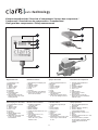 3
3
-
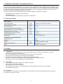 4
4
-
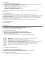 5
5
-
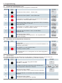 6
6
-
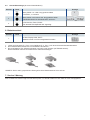 7
7
-
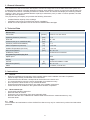 8
8
-
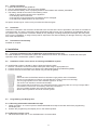 9
9
-
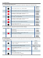 10
10
-
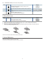 11
11
-
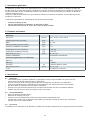 12
12
-
 13
13
-
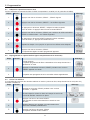 14
14
-
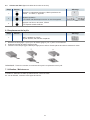 15
15
-
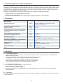 16
16
-
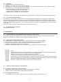 17
17
-
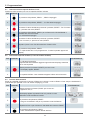 18
18
-
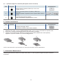 19
19
-
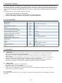 20
20
-
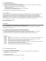 21
21
-
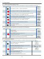 22
22
-
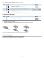 23
23
-
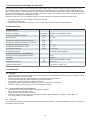 24
24
-
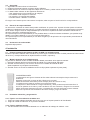 25
25
-
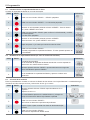 26
26
-
 27
27
-
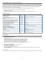 28
28
-
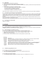 29
29
-
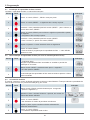 30
30
-
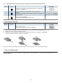 31
31
-
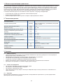 32
32
-
 33
33
-
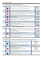 34
34
-
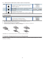 35
35
-
 36
36


in andere talen
Gerelateerde papieren
Andere documenten
-
Krups LATT'ESPRESS EA829 Series de handleiding
-
-
-
-
-
Tefal BR301041 de handleiding
-
-
Hager WXH21 Series Handleiding