
BC-HM VI.75.V5.5Q © Danfoss 06/96 1
Instructions
AMV 133
082R9063
082R9063
2
34 5
67
VMO
1 VF... AVQM AVPQM

2 VI.75.V5.5Q © Danfoss 06/96 BC-HM
11
8
10 9
12

BC-HM VI.75.V5.5Q © Danfoss 06/96 3
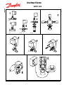
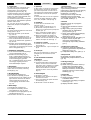
1. Application
AMV 133 is a three-point gearmotor with
built-in spring-return function. The motor
is applied in connection with heating
systems mounted where ordinary
pollution may occur.
The motor can be used together with the
following Danfoss seated valve types:
VMO, VF2, VFS, AVQM and AVPQM
(fig.1)
2. Installation
The motor is oriented as shown in fig. 2.
a) attach the motor to the valve
(figs. 3 and 4)
c) remove the motor cover as well as the
cover with the valve position
(fig. 5)
d) pull out the distance part mounted
between the coil and the electric
motor (fig. 6)
e) mount the locking clip onto the valve
spindle. The locking clip is taped to
the inside of the cover (fig. 7)
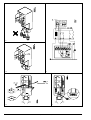
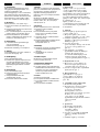
3. Wiring
a) The motor housing has knock-outs
for screwed cable entries (fig. 8)
b) Electric connection (fig. 9)
4. Protection
In case of overload, the motor is
protected by a 0,16 A fuse (fig. 10)
5. Manual emergency operation
a) Disconnect the voltage supply
b) Temporarily opening of the valve:
use a hexagon spanner to turn the
hexagon screw in the direction of the
arrow. The spring-return function of
the motor will close the valve when
the spanner is disengaged (fig. 11)
6. Dismantling
a) Disconnect the supply voltage
b) Remove all wires from the motor
terminal strip.
c) Remove the locking clip from the
valve spindle (fig. 12)
d) Separate the motor from the valve
ENGLISH
1. Anvendelse
AMV 133 er en 3-punkt motor med
indbygget spring-retur funktion og
anvendes i forbindelse med varmeanlæg
der er monteret hvor almindelig forure-
ning kan forkomme.
Motoren kan anvendes sammen med
følgende Danfoss sædeventiler:
VMO, VF2, VFS, AVQM og AVPQM
(fig. 1)
2. Montering
Motoren placeres som vist i fig. 2
a) Spænd motoren fast på ventilen
(fig. 3 og 4)
b) Fjern motordækslet og dækslet med
ventilskala pos. (fig. 5)
c) Træk afstandsstykket ud, som er
placeret mellem spolen og elmotoren
(fig. 6)
d) Monter låseclipsen på ventilens
spindel, låseclipsen er tapet fast på
indersiden af motordækslet (fig. 7)
3. El-tilslutning
a) I motorhuset er der gennemføringer
som er forberedt for kabelforskru-
ninger (fig. 8)
b) Elektrisk tilslutning, se eksempel 9
4. Sikring
I tilfælde af overbelastning sikres
motoren af en 0,16 A sikring (fig. 10)
5. Nødbetjening
a) Afbryd strømforsyningen
b) Ventilen kan åbnes midertidigt ved at
sekskantskruen drejes i pilens retning.
Når skruen slippes vil spring-retur
funktionen lukke ventilen
(fig. 11)
6. Demontering
a) Afbryd strømforsyningen
b) Fjern ledningerne fra motorens
klemrække
c) Fjern låseclipsen fra ventilspindelen
(fig. 12)
d) Demonter motoren fra ventilen
DANSK
1. Anmerkung
AMV 133 ist ein reversierbarer
Stellantrieb mit Sicherheitsfunktion, der
in Kombination mit den Ventilen VMO,
VF2 VF5, AVQM und AVPQM (Abb.1)
und einem elektronischen Dreipunkt-
regler zur witterungsgführten
Vorlauftemperaturregelung von Hei-
zungs- und Fernwärmeanlagen
eingesetzt wird. Bei Spannungsausfall
und Anlageübertemperatur (Über-
wachung durch einen Sicherheits-
thermostaten) schließt der Antrieb das
Ventil über die eingebaute Feder.
2. Montage
Abb. 2 zeigt die zulässige Einbaulage
des Stellantriebes.
Zur Montage mit dem Ventil wie folgt
vorgeben:
a) Motor auf das Ventil aufsetzen (Abb.3)
und mit einem 4 mm Imbus
festschrauben (Abb. 4).
b) Den Gehäusedeckel und den Deckel
mit der Hubskala abnehmen (Abb. 5).
c) Das Distanzstück, welches sich
zwischen Spule und Elektromotor
befindet, heraus-
ziehen (Abb. 6).
d) Mit der Sicherungsklemme die
Ventilkegelstange mit der Antriebs-
stange des Stellantriebes form-
schlüssig koppeln. Die Sicherungs-
klemme befindet sich auf der In-
nenseite des Gehäusedeckels
(Abb. 7).
3. Elektrischer Anschluß
Im Gehäuse des Stellantirebes befinden
sich Bohrungen, in die entsprechende
Kabelverschraubungen eingesetzt
werden können (Abb. 8).
Der elektrische Anschluß erfolgt nach
Abb. 9 (Darstellung mit TR
und
Sicherheitsthermostat!).
4. Sicherung
Der Motor ist mit einer 0,16A Sicherung
gegen Überlast geschützt (Abb. 10).
5. Manuelle Notbedienung
Spannungszuführung zum Stellantrieb
unterbrechen. Gehäusedeckel abneh-
men. Mit einem 5 mm Imbus kann das
Stellventil über den Stellantrieb geöffnet
werden (Abb. 11). Ventileinstellung an
der Hubskala ablesen.
Beim Loslassen des Imbus wird das
Ventil selbsttätig durch die im Stell-
antrieb eingebaute Feder geschlossen.
6. Demontage
Spannungszuführung zum Stellantrieb
unterbrechen und alle Leitungen am
Antrieb abklemmen. Ventilkegelstange
und Antriebsstange des Stellantriebes
durch Herausziehen der
Sicherungsklemme entkoppeln (Abb.
12). Mit einem 4 mm Imbus Motor am
Ventil lösen und abnehmen.
DEUTSCH

4 VI.75.V5.5Q © Danfoss 06/96 BC-HM
1. Aplicación
El AMV 133 es un motor de engranaje
de 3 puntos con función de retorno por
resorte incorporada. El motor se utiliza
en instalaciones de calefacción
montadas en lugares donde aparece un
nivel corriente de contaminación.
El motor puede ser utilizado junto con
las siguientes válvulas Danfoss: VMO,
VF 2, VFS, AVQM y AVPQM (fig. 1).
2. Instalación
El motor se coloca tal como se indica en
la fig. 2.
a) Acoplar el motor en la válvula (fig. 3 y
4).
b) Quitar la tapa del motor y también la
tapa de escala de ajuste de posición
de la válvula (fig. 5).
c) Tirar de la pieza espaciadora situada
entre la bobina y el motor eléctrico
(fig. 6).
d) Montar el muelle de sujeción en el
vástago de la válvula, el muelle de
sujección está adherido en el interior
de la tapa del motor (fig. 7).
3. Conexión eléctrica
a) En la caja de motor hay troquelados
preparados para entradas roscadas
de cable (fig. 8).
b) Conexión eléctrica, ver ejemplo en fig.
9.
4. Protección
En caso de sobrecarga el motor es
protegido por fusible de 0,16 A (fig. 10).
5. Operación manual de emergencia
a) Desconectar la corriente de
alimentación.
b) La válvula puede ser abierta
temporalmente haciendo girar la llave
hexagonal en dirección de la flecha.
La función de retorno por resorte
cerrará la válvula cuando la llave
hexagonal deje de ser accionada
(fig. 11).
6. Desmontaje
a) Desconectar la corriente de
alimentación.
b) Quitar los cables del bloque de
terminales del motor.
c) Quitar el muelle de sujeción del
vástago de la válvula (fig. 12).
d) Separar el motor de la válvula.
ESPAÑOL FRANÇAIS
1. Utilisation
AMV 133 est un moteur à trois points
avec fonction incorporée de retour par
ressort qui s’emploie pour les
installations de par ressort qui s'emploie
dans les installations de chauffage.
Le moteur peut s’utiliser avec les vannes
à siège Danfoss suivantes: VMO, VF2,
VFS, AVQM et AVPQM (fig. 1).
2. Montage
Le moteur se monte comme l’indique la
fig. 2.
a) Fixer solidement le moteur sur la
vanne (fig. 3 et 4).
b) Enlever le couvercle du moteur et le
couvercle portant la graduation de la
vanne (fig. 5).
c) Sortir la pièce entretoise qui se trouve
entre la bobine et le moteur électrique
(fig. 6).
d) Monter le circlip sur la tige de la
vanne. Le circlip est fixé avec un
papier collant à l’intérieur du
couvercle du moteur (fig. 7).
3. Branchement électrique
a) Dans le boîtier du moteur se trouvent
des orifices prévus pour l’introduction
des câbles (fig. 8).
b) Branchement électrique, voir
l’exemple de la fig. 9.
4. Fusible
En cas de surcharge, le moteur est
assuré par un fusible de 0,16 A (fig. 10).
5. Manoeuvre d’urgence
a) Couper le courant.
b) La vanne peut s’ouvrir
momentanément si l’on tourne la vis à
six pans dans le sens de la flèche.
Quand on lâche la vis, la fonction de
retour par ressort referme la vanne
(fig. 11).
6. Démontage
a) Couper le courant.
b) Enlever les fils des bornes du moteur.
c) Enlever le circlip de la tige de la
soupape (fig. 12).
d) Démonter le moteur de la vanne.
ITALIANO
1. Utilizzazione
AMV 133 è un motore a tre punti con
annessa funzione spring-return. Il motore
viene utilizzato con sistemi di
riscaldamento in luoghi dove può
verificarsi inquinamento non eccessivo.
Il motore può essere utilizzato insieme
con i seguenti tipi di valvole Danfoss:
VMO, VF2, AVQM e AVPQM (fig. 1).
2. Istallazione
Posizionare il motore come mostrato
nella fig. 2.
a) Fissare il motore alla valvola (fig. 3 e
4).
b) Togliere il coperchio del motore e
quello con le posizioni della valvola
(fig. 5).
c) Rimuovere l’intercapedine montata tra
la bobina e il motore elettrico (fig. 6).
d) Montare il fermaglio di chiusura sul
perno della valvola. Il fermaglio è
fissato con nastro adesivo all’interno
del coperchio (fig. 7).
3. Cablaggio
a) L’alloggiamento del motore ha entrate
predisposte per l’avvitamento di cavi
(fig. 8).
b) Allacciamento elettrico vedi fig. 9.
4. Protezione
In caso di sovraccarico il motore è
protetto da un fusibile di 0,16 A (fig. 10).
5. In caso di emergenza
a) Disinnescare la corrente.
b) La valvola può essere aperta
temporaneamente. Con una chiave
esagonale girare la vite esagonale in
direzione della freccia. Quando si
stacca la chiave, la funzione spring-
return del motore chiude la valvola
(fig. 11).
6. Smontaggio
a) Togliere corrente.
b) Staccare tutti i cavi dall’alloggiamento
del motore.
c) Rimuovere il fermaglio di chiusura dal
perno della valvola (fig. 12).
d) Separare il motore dalla valvola.

BC-HM VI.75.V5.5Q © Danfoss 06/96 5
NEDERLANDS
1. Toepassing
De AMV 133 is een servomotor voor
3-puntsbesturing met ingebouwde
veerteruggang. De motor wordt
toegepast in systemen (bijv. bij
stadsverwarming) waar om veiligheids-
redenen onder bepaalde omstandig-
heden een geforceerde sluitaktie door
veerteruggang is gewenst.
De motor kan samen met de volgende
types Danfoss zittingafsluiters gebruikt
worden: VMO 15-32.
VF 2 en VFS 15-50 (15-32 conform
DIN 32730) AVQM en AVDQM 15-32
(fig. 1).
2. Montage
De motor wordt aangebracht zoals staat
aangegeven in fig. 2.
a) Bevestig de motor op de afsluiter
(fig. 3 en 4).
b) Verwijder het motordeksel en het
deksel met de afsluiterschaal (fig. 5).
c) Trek het afstandsstuk dat tussen de
spoel en de elektromotor geplaatst is
(fig. 6) eruit.
d) Monteer de bevestigingsklem op de
afsluiterspindel. De bevestigingsklem
zit met tape op de binnenzijde van het
deksel vastgeplakt (fig. 7).
3. Elektrische aansluiting
a) In de motorkast zitten breekplaatjes
voor de kabelwartels (fig. 8).
b) Elektrische aansluiting, (fig. 9).
STB = veiligheidsthermostaat, bij
onderbreking wordt de afsluiter door
motorveerteruggang gesloten.
TR = regelthermostaat, functie heeft
voorrang op regeling door ECL
weersafhankelijke regelaar.
4. Beveiliging
In geval van overbelasting wordt de
motor door een 0,16 A(T) zekering
beveiligd (fig. 10).
5. Noodbediening
a) Onderbruk de netspanning.
b) De afsluiter kan tijdelijk geopend
worden door de in de richting van de
pijl te draaien. Wanneer de umbus-
slentel losgelaten wordt, zal de
veerteruggang de afsluiter sluiten
(fig. 11).
6. Demontage
a) Onderbruk de netspanning.
b) Verwijder de bedrading van de
aansluitklemmen van de motor.
c) Verwijder de bevestigingsklem op de
afsluiterspindel (fig. 12).
d) Demonteer de motor van de afsluiter.
PORTUGUÊS
1. Aplicação
O AMV 133 é um motor de engrenagem
de três pontos com função de retorno
por mola incorporada. O motor usa-se
em sistemas de aquecimento montados
em ambientes com níveis de poluição
normais.
O motor pode usar-se com as seguintes
válvulas de pistão da Danfoss: VMO,
VF 2, VFS, AVQM e AVPQM (fig. 1).
2. Instalação
O motor deve ser montado como
indicado na fig. 2.
a) Fixe o motor à válvula (fig. 3 e 4).
b) Desmonte a tampa do motor e a
tampa com a indicação da posição da
válvula (pos. 5).
c) Tire o separador montado entre a
bobina e o motor eléctrico (fig. 6).
d) Monte a braçadeira de aperto na
haste da válvula; a braçadeira está
afixada com fita auto-adesiva na parte
interior da tampa do motor (fig. 7).
3. Ligação à corrente
a) A caixa do motor está equipada com
bucins (fig. 8).
b) Ligação eléctrica - veja o exemplo na
fig. 9.
4. Protecção
Em caso de sobrecarga, o motor está
protegido por um fusível de 0,16 A
(fig. 10).
5. Funcionamento manual de
emergência
a) Desligue a corrente.
b) A válvula pode abrir-se temporaria-
mente; use uma chave sextavada
para fazer girar o parafuso no sentido
da flecha. A função de retorno pór
mola do motor fechará a válvula,
quando se tirar a chave do parafuso
(fig. 11).
6. Desmontagem
a) Desligue a corrente.
b) Desligue os fios eléctricos da placa
de bornes do motor.
c) Tire a braçadeira de aperto da haste
da válvula (fig. 12).
d) Desmonte o motor da válvula.
POLSKI
1. Zastosowanie
AMV 133 jest siownikiem do sterowania
3-poo¾eniowego zaworami
regulacyjnymi, wyposa¾onym w sp©¾yn©
powrotn¥. Montowa go mo¾na na
instalacjach o normalnym
zanieczyszczeniu wody sieciowej.
Siownik mo¾na stosowa wraz
z zaworami firmy Danfoss - VMO, VF2,
VFS, AVQM, IVQM (rys. 1).
2. Monta¿
Siownik montuje si© w pozycjach
zgodnie z rys. 2.
a) Zamontowa siownik do zaworu
(rys. 3 i 4).
b) Zdj¥ os³onê i pokrywê czo³ow¹
siownika wraz ze wskanikiem
pozycji zaworu (rys. 5).
c) Wyj¥ czêæ dystansow¹ znajduj¹c¹
siê miêdzy cewk¹ a silnikiem
elektrycznym (rys. 6).
d) Zamontowa ¥cznik zamykaj¹cy na
trzpieniu zaworu; ¥cznik jest
umocowany tam¹ klej¹c¹ na
wewnêtrznej czêci os³ony siownika
(rys. 7).
3. Pod³¹czenie elektryczne
a) W korpusie siownika znajduj¹ siê
gotowe wyprowadzenia do pod¥czeä
elektrycznych (rys. 8).
b) Pod³¹czenia elektryczne, patrz rys. 9.
4. Bezpiecznik
Na wypadek przeci¹¿eñ silnik jest
zabezpieczony bezpiecznikiem 0,16 A
(rys. 10).
5. Obs³uga awaryjna
a) Od³¹cz zasilanie.
b) Zawór mo¿na tymczasowo otworzyæ
przekrêcaj¹c szeciok¹tn¹ rubê
zgodnie z kierunkiem strza³ki. Gdy
ruba jest zwolniona, uruchamia si©
spr©¾yna powrotna i zawór zostaje
zamkniêty (rys. 11).
6. Demonta¿
a) Od³¹cz zasilanie.
b) Wyjmij przewody zasilaj¹ce
z zacisków silnika.
c) Usuñ ¥cznik zamykaj¹cy z trzpienia
zaworu (rys. 12).
d) Zdejmij siownik z zaworu.

6 VI.75.V5.5Q © Danfoss 06/96 BC-HM
SVENSKA
1. Användning
AMV 133 är en trepunktsmotor med
inbyggd fjäderåtergångsfunktion och
används i förbindelse med
värmeanläggningar, som är monterade,
där vanlig förorening kan förekomma.
Motorn kan användas tillsammans med
följande Danfoss sätesventiler: VMO,
VF2, VFS, AVQM och AVPQM (fig 1).
2. Montering
Motorn placeras, som visats i fig. 2.
a) Spänn fast motorn på ventilen (fig. 3
och 4).
b) Avlägsna motorlocket och locket med
ventilskalapos. (fig. 5).
c) Dra ut avståndsstycket, som placerats
mellan spolen och elmotorn (fig. 6).
d) Montera låsklämman på ventilens
spindel. Låsklämman är tejpat fast på
insidan av motorlocket (fig. 7).
3. Elanslutning
a) I motorhuset finns genomföringar,
som är beredda till
kabelförskruvningar (fig. 8).
b) Elektrisk anslutning, se exempel 9.
4. Säkring
Vid överbelastning är motorn säkrad av
en 0,16 A säkring (fig. 10).
5. Nödbetjäning
a) Bryt strömförsörjningen.
b) Ventilen kan öppnas temporärt med
att vrida sekskantskruven i pilens
riktning. När skruven släpps, stänger
fjäderåtergångsfunktionen ventilen
(fig. 11)
6. Demontering
a) Bryt strömförsörjningen.
b) Avlägsna ledningarna från motorns
anslutningsplint.
c) Avlägsna låsklämman från
ventilspindeln (fig 12).
d) Demontera motorn från ventilen.
SUOMEKSI
1. Käyttö
AMV 133 on kolmipiste-vaihdemoottori,
jossa on sisäänrakennettu jousipalautus
(spring-return) -toiminto. Moottoria
käytetään lämmitysjärjestelmissä
paikoissa, joissa voi esiintyä normaalia
likaisuutta.
Moottoria voi käyttää yhdessä
seuraavien Danfoss-istukkaventtiilien
kanssa: VMO, VF2, VFS, AVQM ja
AVPQM (kuva 1).
2. Asennus
Moottori sijoitetaan kuvan 2 mukaisesti.
a) Kiinnitä moottori venttiiliin
(kuva 3 ja 4).
b) Irrota moottorin kansi ja myöskin
kansi, johon on merkitty venttiilin
asento (kuva 5).
c) Vedä ulos kelan ja sähkömoottorin
väliosa (kuva 6).
d) Kiinnitä lukituspidike venttiilin karaan.
Pidike teipataan kiinni kannen
sisäpuolelle (kuva 7).
3. Käämitys
a) Moottorin rungossa on läpivientiaihiot
ruuvatuille kaapeliläpivienneille
(kuva 8).
b) Sähköliitäntä (ks. kuvan 9
esimerkkiä).
4. Sulakesuojaus
Moottorissa on ylikuormitussuojana
0,16 A:n sulake (kuva 10).
5. Manuaalinen hätäohjaus
a) Katkaise virransyöttö.
b) Venttiili voidaan avata väliaikaisesti
kääntämällä kuusiokoloruuvia nuolen
suuntaan. Kun ruuvi vapautetaan,
moottorin jousipalautustoiminto
sulkee venttiilin (kuva 11).
6. Irrotus
a) Katkaise virransyöttö.
b) Irrota johdot moottorin riviliittimestä.
c) Irrota lukituspidike venttiilin karasta
(kuva 12).
d) Irrota moottori venttiilistä.
GJ-HECCRB
1/ Ghbvtytybt
Ghbdhl AMV 133 ghtlcnfdkztn
cj,jq nh`[afpysq htlernjhysq
'ktrnhjldbufntkm cj dcnhjtyysv
ghe;byysv djpdhfnysv vt[fybpvjv/
Jy ghtlyfpyfxty lkz eghfdktybz
htuekbhe.obvb rkfgfyfvb abhvs
Lfyajcc nbgf VMO, VF2, VFS, AVQM
b AVPQM (hbc/ 1)/
Ghbdjl AMV 133 vj;tn
ecnfyfdkbdfnmcz yf rkfgfyf[ cbcntv
ntgkjcyf,;tybz d pfuhzpy`yys[
gjvtotybz[/
2/ Vjynf;
Vjynf; ghbdjlf ghjbpdjlbncz d
cjjndtncndbb c hbc/ 2/
f) Yfltymnt ghbdjl yf ujkjdre
rkfgfyf b pfrhtgbnt tuj (hbc/ 3 b 4)$
,) Cybvbnt rhsire ldbufntkz b
rhsire cj irfkjq gthtvtotybz
igbyltkz (hbc/ 5)/
d) Elfkbnt ghjrkflre?
hfcgjkj;tyye. vt;le j,vjnrjq b
hjnjhjv 'ktrnhjldbufntkz
(hbc/ 6)$
u) Cvjynbheqnt cnjgjhysq
ghe;byysq pf;bv yf igbyltkt
rkfgfyf/ D nhfycgjhnyjv
gjkj;tybb pf;bv ghbrhtgk`y
rktqrjq ktynjq r dyenhtyytq
cnjhjyt rhsirb ldbufntkz (hbc/7)$
3/ Gjlrk.xtybt r ctnb
f) Yf rjhgect 'ktrnhjldbufntkz
bvt.ncz veans lkz ghjgecrf
'ktrnhbxtcrb[ rf,tktq (hbc/ 8)$
,) C[tvf 'ktrnhbxtcrb[ cjtlbytybq
ghbdtltyf yf hbc/ 9/
4/ Ghtlj[hfybntkb
Lkz pfobns jn gthtuhepjr
'ktrnhjldbufntkm cyf,;`y
ghtlj[hfybntktv yf 0/16 F
(hbc/ 10)/
5/ Fdfhbqyjt hexyjt eghfdktybt
f) Jnrk.xbnt yfghz;tybt$
,) Rkfgfy vj;tn ,snm dhtvtyyj
jnrhsn gjdjhjnjv dnekrb
htlernjhf c gjvjom.
itcnbuhfyyjuj rk.xf d
yfghfdktybb? erfpfyyjv cnhtkrjq/
Tckb gjckt 'njuj dnekre
jngecnbnm? nj dcnhjtyysq
ghe;byysq djpdhfnysq vt[fybpv
pfrhjtn rkfgfy
(hbc/ 11)/
6/ Ltvjynf;
f) Jnrk.xbnt yfghz;tybt$
,) Jncjtlbybnt ghjdjlf jn
rktvvyjuj obnrf
'ktrnhjldbufntkz$
d) Elfkbnt cnjgjhysq ghe;byysq
pf;bv cj igbyltkz rkfgfyf
(hbc/ 12)$
u) Cybvbnt ghbdjl c rkfgfyf/
BC-HSS, CCB
-
 1
1
-
 2
2
-
 3
3
-
 4
4
-
 5
5
-
 6
6


in andere talen
- italiano: Danfoss AMV 133 Istruzioni per l'uso
- français: Danfoss AMV 133 Mode d'emploi
- Deutsch: Danfoss AMV 133 Bedienungsanleitung
- português: Danfoss AMV 133 Instruções de operação
- dansk: Danfoss AMV 133 Betjeningsvejledning
- svenska: Danfoss AMV 133 Bruksanvisningar
Gerelateerde papieren
-
Danfoss AMV 130, AMV 140, AMV 130 H, AMV 140 H Handleiding
-
-
-
-
-
-
-
-
Danfoss AME 11 Handleiding
-