
de Installationsanleitung
en Installation instructions
nl Installatiehandleiding
VR 100
0010025650
Publisher/manufacturer
Vaillant GmbH
Berghauser Str. 40 D-42859 Remscheid
Tel. +492191 18 0 Fax +492191 18 2810
[email protected] www.vaillant.de

?
+=
vaillant.co.uk/VR100
vaillant.nl/VR100
www.vai.vg/VR100
1
2
X31/X32
230V
24V
A B
C
3
1
3
2
B
C
A
D
4
0-3 m
5
10 s
7
A
C
B
6

C
D
E
F
A B
7
C D
A B
8
11
9
11
10
A
B
1
1.1
1.2
2
2.1
3
3.1
8
8.1
2.2
5
5.1
6
6.1
5.2
2.3
4
4.1
4.2
4.3
7
7.1
7.2
7.3
9
9.1
10
10.1
10.2
11
11.1
10.3
C
10.4
11.2
12
A
B
A
B
C
B
A
11
30 min
12


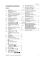
Inhalt
0020282111_02 VR 100 Installationsanleitung 1
Installationsanleitung
Inhalt
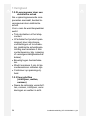
1 Sicherheit ..................................... 2
1.1 Bestimmungsgemäße
Verwendung................................... 2
1.2 Allgemeine Sicherheitshinweise .... 2
2 Hinweise zur Dokumentation...... 4
2.1 Mitgeltende Unterlagen
beachten ........................................ 4
2.2 Unterlagen aufbewahren ............... 4
2.3 Gültigkeit der Anleitung.................. 4
3 Verträglichkeit.............................. 4
3.1 Kompatibilität der
Kommunikationseinheit 1 .............. 4
4 Produktbeschreibung.................. 4
4.1 Aufbau der Kommunikations-
einheit ............................................ 4
4.2 Angaben auf dem Typenschild ...... 4
4.3 CE-Kennzeichnung........................ 4
5 Montage ........................................ 5
5.1 Lieferumfang prüfen 2 ................... 5
5.2 Montage- und
Installationsvoraussetzungen
prüfen............................................. 5
6 Installation.................................... 5
6.1 Qualifikation ................................... 5
7 Elektroinstallation........................ 5
7.1 Anschluss an Wärmeerzeuger
3 .................................................... 5
7.2 Anschluss an
Kommunikationseinheit
4 .................................................... 5
7.3 Anforderungen an den
Installationsort 6, 5 ....................... 5
8 Installation in der Wand .............. 6
8.1 Befestigen 7 .................................. 6
8.2 Überschüssiges Kabel 8 ............... 6
9 Inbetriebnahme ............................ 6
9.1 Kommunikationseinheit in
Betrieb nehmen 12, 9, 10, 11 ..... 6
10 Störungsbehebung...................... 6
10.1 Produkt neu starten und
Parameter zurücksetzen................ 6
10.2 Leuchtstärke der LEDs .................. 7
10.3 Änderung in der Konfiguration
des Heizungssystems
übernehmen................................... 7
10.4 Registrierungs- oder
Kommunikationsproblem mit
dem Server .................................... 7
11 Außerbetriebnahme..................... 7
11.1 Kommunikationseinheit
demontieren................................... 7
11.2 Recycling und Entsorgung............. 7
12 Kundendienst............................... 8
Anhang .................................................... 9
A Zustand (Hauptanzeige):
Bedeutung der Haupt-LED.......... 9
B Zustand (Signalstärke
des Mobilfunknetzes /
Kommunikation mit Server):
Bedeutung der Netz-LEDs ........ 10
C Technische Daten...................... 11

1 Sicherheit
2 Installationsanleitung VR 100 0020282111_02
1 Sicherheit
1.1 Bestimmungsgemäße
Verwendung
Bei unsachgemäßer oder nicht
bestimmungsgemäßer Verwen-
dung können Beeinträchtigun-
gen des Produkts und anderer
Sachwerte entstehen.
Die Kommunikationseinheit
dient zur Steuerung des Sys-
tems. Die Kommunikations-
einheit ist mit dem Mobilfunk-
netz kompatibel.
Eine SIM-Karte für die Kommu-
nikation über das Mobilfunknetz
ist bereits in der Kommunika-
tionseinheit vorinstalliert.
Die Kompatibilität der Kommu-
nikationseinheit mit sämtlichen
Komponenten muss vor der
Installation geprüft werden.
Die bestimmungsgemäße Ver-
wendung beinhaltet:
– das Beachten der beiliegen-
den Betriebs-, Installations-
und Wartungsanleitungen des
Produkts sowie aller weiteren
Komponenten der Anlage
– die Installation und Montage
entsprechend der Produkt-
und Systemzulassung
– die Einhaltung aller in den
Anleitungen aufgeführten In-
spektions- und Wartungsbe-
dingungen.
Die bestimmungsgemäße Ver-
wendung umfasst außerdem
die Installation gemäß IP-Code.
Eine andere Verwendung als
die in der vorliegenden Anlei-
tung beschriebene oder eine
Verwendung, die über die hier
beschriebene hinausgeht, gilt
als nicht bestimmungsgemäß.
Nicht bestimmungsgemäß ist
auch jede unmittelbare kom-
merzielle und industrielle Ver-
wendung.
Achtung!
Jede missbräuchliche Verwen-
dung ist untersagt.
1.2 Allgemeine
Sicherheitshinweise
1.2.1 Gefahr
durch unzureichende
Qualifikation
Folgende Arbeiten dürfen nur
Fachhandwerker durchführen,
die hinreichend dafür qualifiziert
sind:
– Montage
– Demontage
– Installation
– Inbetriebnahme
– Inspektion und Wartung
– Reparatur
– Außerbetriebnahme
▶ Gehen Sie gemäß dem aktu-
ellen Stand der Technik vor.

Sicherheit 1
0020282111_02 VR 100 Installationsanleitung 3
1.2.2 Lebensgefahr durch
Stromschlag
Wenn Sie spannungsführende
Komponenten berühren, dann
besteht Lebensgefahr durch
Stromschlag.
Bevor Sie am Wärmeerzeuger
arbeiten:
▶ Ziehen Sie den Netzstecker.
▶ Oder schalten Sie das Pro-
dukt spannungsfrei, indem
Sie alle Stromversorgun-
gen abschalten (elektrische
Trennvorrichtung mit min-
destens 3 mm Kontaktöff-
nung, z. B. Sicherung oder
Leitungsschutzschalter).
▶ Sichern Sie gegen Wieder-
einschalten.
▶ Warten Sie mindestens 3 min,
bis sich die Kondensatoren
entladen haben.
▶ Prüfen Sie auf Spannungs-
freiheit.
1.2.3 Vorschriften (Richtlinien,
Gesetze, Normen)
▶ Beachten Sie die nationalen
Vorschriften, Normen, Richt-
linien, Verordnungen und Ge-
setze.

2 Hinweise zur Dokumentation
4 Installationsanleitung VR 100 0020282111_02
2 Hinweise zur
Dokumentation
2.1 Mitgeltende Unterlagen
beachten
▶ Beachten Sie unbedingt alle Betriebs-
und Installationsanleitungen, die Kom-
ponenten der Anlage beiliegen.
2.2 Unterlagen aufbewahren
▶ Geben Sie diese Anleitung sowie alle
mitgeltenden Unterlagen an den An-
lagenbetreiber weiter.
2.3 Gültigkeit der Anleitung
Diese Anleitung gilt ausschließlich für:
Produkt - Artikelnummer
VR 100
0010025650
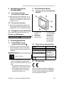
3 Verträglichkeit
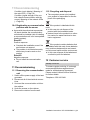
3.1 Kompatibilität der
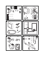
Kommunikationseinheit 1
1. Prüfen Sie, ob die Kommunikations-
einheit mit dem Wärmeerzeuger und
dem Raumthermostat in der Anlage
kompatibel ist.
Gültigkeit: Deutschland
www.vai.vg/VR100
▶ Scannen Sie den oben stehenden
Code, um die Liste der kompatiblen
Wärmeerzeuger und Raumthermo-
state aufzurufen.
◁ Die Produkte stehen auf der Liste.
Installieren Sie die Kommunika-
tionseinheit.
▽ Die Produkte stehen nicht auf der
Liste. Installieren Sie die Kommu-
nikationseinheit in diesem Fall
nicht.
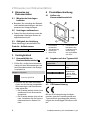
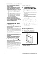
4 Produktbeschreibung
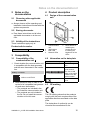
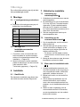
4.1 Aufbau der
Kommunikationseinheit
1 2
3
4
5
1 Kommunika-
tionseinheit
2 Wandhalterung
3 Haupt-LED
4 Netz-LEDs
5 Entstörtaste zum
Neustarten des
Produkts und für
die Erhöhung
der Leuchtstärke
der LEDs
4.2 Angaben auf dem Typenschild
Kennzeichnung auf dem
Typenschild
Bedeutung
VR 100 Produktbezeich-
nung
21073700201168840908005011N8
Bar-Code mit
Serialnummer,
7. bis 16. Ziffer
bilden die Artikel-
nummer
Anleitung lesen
4.3 CE-Kennzeichnung
Mit der CE-Kennzeichnung wird doku-
mentiert, dass die Produkte gemäß dem
Typenschild die grundlegenden Anforde-
rungen der einschlägigen Richtlinien erfül-
len.

Montage 5
0020282111_02 VR 100 Installationsanleitung 5
Die Konformitätserklärung kann beim Her-
steller eingesehen werden.
5 Montage
5.1 Lieferumfang prüfen 2
▶ Prüfen Sie den Lieferumfang auf Voll-
ständigkeit und Unversehrtheit.
Menge Bezeichnung
1 Kommunikationseinheit
1 Wandhalterung
1 Tüte mit Schrauben und Dübeln
1 Klemmschraube
1 Kabel
1 Kabelhalterung
5.2 Montage- und
Installationsvoraussetzungen
prüfen
1. Prüfen Sie, ob die Kommunikations-
einheit mit dem Wärmeerzeuger und
dem Raumthermostat in der Anlage
kompatibel ist. (→ Seite 4)
2. Beachten Sie bei der Wahl des In-
stallationsortes die Abmessungen der
Kommunikationseinheit.
Technische Daten (→ Seite 11)
6 Installation
6.1 Qualifikation
Die Elektroinstallation darf nur von einer
Elektrofachkraft durchgeführt werden.
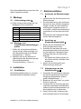
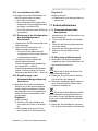
7 Elektroinstallation
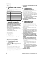
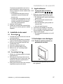
7.1 Anschluss an Wärmeerzeuger
3
1. Unterbrechen Sie die Stromzufuhr zum
Wärmeerzeuger.
2. Der Anschluss kann an der Anschluss-
klemme X31 bzw. X32 des Heizgeräts
erfolgen. Ziehen Sie die Installations-
anleitung des Heizgeräts zurate, um
zu ermitteln, welche Anschlussklemme
vorhanden ist und wo diese sich befin-
det.
3. Schließen Sie das mitgelieferte Kabel
an den Wärmeerzeuger an.
7.2 Anschluss an
Kommunikationseinheit 4
1. Rasten Sie den Wandhalter der
Kommunikationseinheit aus.
2. Schließen Sie das Kabel (1) an die
Kommunikationseinheit an und beach-
ten Sie dabei den Farbcode auf dem
Aufkleber (2) unter der Steckverbin-
dung (3).
– Die Farben der Drähte müssen mit
den Farben auf dem Aufkleber über-
einstimmen.
3. Stellen Sie die Stromzufuhr zum
Wärmeerzeuger wieder her.
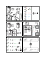
7.3 Anforderungen an den
Installationsort 6, 5
1. Vermeiden Sie Interferenzen zwischen
der Kommunikationseinheit und ihrer
Umgebung (Magnetfelder, Elektro-
geräte, Metallstrukturen …).
2. Bestimmen Sie eine Stelle, um mit der
Suche zu beginnen.
3. Versetzen Sie zur Ermittlung der best-
möglichen Signalstärke des Mobilfunk-
netzes die Kommunikationseinheit, um
den Installationsort zu bestimmen.
4. Warten Sie bei jeder Versetzung der
Kommunikationseinheit 10 Sekunden,

8 Installation in der Wand
6 Installationsanleitung VR 100 0020282111_02
um die Signalstärke des Mobilfunk-
netzes zu testen.
Zustand (Signalstärke des Mobilfunk-
netzes / Kommunikation mit Server):
Bedeutung der Netz-LEDs (→ Seite 10)
◁ Die leuchtenden LEDs zeigen die
Signalstärke des Mobilfunknetzes
an.
◁ Die LEDs erlöschen nach 30 Minu-
ten automatisch. Die Signalstärke
des Mobilfunknetzes wird danach
nicht mehr aktualisiert.
5. Markieren Sie die Bohrlöcher.
6. Platzieren Sie die Kommunikations-
einheit vorübergehend in der Nähe des
gewählten Installationsorts.
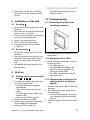
8 Installation in der Wand
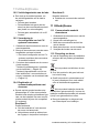
8.1 Befestigen 7
1. Unterbrechen Sie die Stromzufuhr zum
Wärmeerzeuger.
2. Befestigen Sie den Wandhalter an der
Wand, wie in der Abbildung dargestellt.
3. Rasten Sie die Kommunikationseinheit
am Wandhalter ein.
4. Schrauben Sie die Klemmschraube
ein.
5. Schneiden Sie das überschüssige Ka-
bel nicht ab.
6. Bewahren Sie gegebenenfalls über-
schüssiges Kabel auf. (→ Seite 6)
8.2 Überschüssiges Kabel 8
1. Wickeln Sie das überschüssige Kabel
im Wärmeerzeuger auf.
2. Befestigen Sie das überschüssige Ka-
bel mit dem mitgelieferten Clip und ver-
gewissern Sie sich, dass es nicht mit
heißen Komponenten in Berührung
kommen kann.
3. Stellen Sie die Stromzufuhr zum
Wärmeerzeuger wieder her.
9 Inbetriebnahme
9.1 Kommunikationseinheit in
Betrieb nehmen 12, 9, 10, 11
1. Stellen Sie gegebenenfalls die Strom-
zufuhr des Wärmeerzeugers wieder
her.
◁ Die Startsequenz wird automatisch
ausgelöst.
◁ Die Kommunikationseinheit wird
initialisiert.
◁ Alle LEDs leuchten grün (Haupt-
und Netz-LED).
▽ Nicht alle LEDs sind grün.
2. Überprüfen Sie den Zustand der LEDs.
3. Wenn Störungen auftreten, dann ge-
hen Sie gemäß der Tabellen im An-
hang vor.
4. Lassen Sie die LEDs erlöschen.
◁ Die LEDs erlöschen nach 30 Minu-
ten automatisch.
10 Störungsbehebung
10.1 Produkt neu starten und
Parameter zurücksetzen
1
▶ Halten Sie die Entstörtaste (1) zehn
Sekunden gedrückt.

Außerbetriebnahme 11
0020282111_02 VR 100 Installationsanleitung 7
10.2 Leuchtstärke der LEDs
▶ Drücken Sie kurz die Entstörtaste, um
die LEDs aufleuchten zu lassen.
◁ Die LEDs leuchten auf.
◁ Die leuchtenden LEDs zeigen den
Zustand der Kommunikationseinheit
an (Haupt- und Netz-LED).
◁ Die LEDs erlöschen nach 30 Minuten
automatisch.
10.3 Änderung in der Konfiguration
des Heizungssystems
übernehmen
1. Unterbrechen Sie die Stromzufuhr zum
Wärmeerzeuger.
2. Stellen Sie die Stromzufuhr zum
Wärmeerzeuger wieder her.
◁ Die neue Konfiguration des Hei-
zungssystems wird von der Kommu-
nikationseinheit erkannt.
3. Überprüfen Sie den Zustand der
Kommunikationseinheit.
Zustand (Hauptanzeige): Bedeutung
der Haupt-LED (→ Seite 9)
Zustand (Signalstärke des Mobilfunk-
netzes / Kommunikation mit Server):
Bedeutung der Netz-LEDs (→ Seite 10)
10.4 Registrierungs- oder
Kommunikationsproblem mit
dem Server
▶ Sprechen Sie mit dem autorisierten
Vertreter ab, ob die Kommunikations-
einheit installiert werden soll (Gefahr
der Installation einer Kommunikations-
einheit bei einem inkompatiblen Hei-
zungssystem).
Ergebnis 1:
Positive Antwort
▶ Schließen Sie die Installation ab,
auch wenn der Server nicht antwor-
tet.
▶ Das Problem wird aus der Ferne
ohne Eingriff am Produkt behoben.
Ergebnis 2:
Negative Antwort
▶ Installieren Sie die Kommunikations-
einheit nicht.
11 Außerbetriebnahme
11.1 Kommunikationseinheit
demontieren
1. Unterbrechen Sie die Stromzufuhr zum
Wärmeerzeuger.
2. Trennen Sie die sämtliche Verbindun-
gen.
3. Lösen Sie die Kommunikationseinheit
von ihrem Halter.
4. Lösen Sie die Schrauben des Halters.
5. Entfernen Sie den Halter von der
Wand.
11.2 Recycling und Entsorgung
▶ Überlassen Sie die Entsorgung der
Verpackung dem Fachhandwerker, der
das Produkt installiert hat.
Wenn das Produkt mit diesem Zei-
chen gekennzeichnet ist:
▶ Entsorgen Sie das Produkt in diesem
Fall nicht über den Hausmüll.
▶ Geben Sie stattdessen das Produkt an
einer Sammelstelle für Elektro- oder
Elektronik-Altgeräte ab.
Wenn das Produkt Batterien enthält,
die mit diesem Zeichen gekennzeichnet
sind, dann können die Batterien gesund-
heits- und umweltschädliche Substanzen
enthalten.
▶ Entsorgen Sie die Batterien in diesem
Fall an einer Sammelstelle für Batterien.

12 Kundendienst
8 Installationsanleitung VR 100 0020282111_02
12 Kundendienst
Gültigkeit: Deutschland
Auftragsannahme Vaillant Kundendienst:
02191 5767901

Anhang
0020282111_02 VR 100 Installationsanleitung 9
Anhang
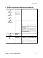
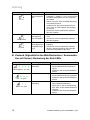
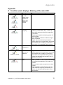
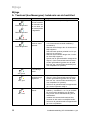
A Zustand (Hauptanzeige): Bedeutung der Haupt-LED
Aktueller Zustand Bedeutung Erläuterung / erforderliche Aktivität
Grün blinkend
Blau blinkend
Rot blinkend
Startsequenz
Die LEDs ändern
mehrmals ihre
Farbe, bis die
Startsequenz ab-
geschlossen ist.
– Warten Sie, bis die Startsequenz abgeschlos-
sen ist.
Grün blinkend
eBUS-Verbin-
dung wird her-
gestellt
– Warten Sie, bis sich der Zustand ändert, be-
vor Sie die Kommunikationseinheit installie-
ren (→ Kapitel 8).
– Wenn die LED länger als 10 Minuten weiter
blinkt.
Starten Sie einmal neu (schalten Sie das Hei-
zungssystem aus und wieder ein).
– Wenn die LED danach länger als 10 Minuten
weiter blinkt.
Sprechen Sie mit dem autorisierten Vertre-
ter ab, ob die Kommunikationseinheit instal-
liert werden soll (Gefahr der Installation einer
Kommunikationseinheit bei einem inkompati-
blen Heizungssystem).
An, grün
eBUS-Ver-
bindung ist
hergestellt
– Installieren Sie die Kommunikationseinheit.
An, gelb
Kommunikations-
einheit nicht re-
gistriert
– Sprechen Sie mit dem autorisierten Vertre-
ter ab, ob die Kommunikationseinheit instal-
liert werden soll (Gefahr der Installation einer
Kommunikationseinheit bei einem inkompati-
blen Heizungssystem).
– Informieren Sie den autorisierten Vertreter
darüber, dass die Registrierung erforderlich
ist.

Anhang
10 Installationsanleitung VR 100 0020282111_02
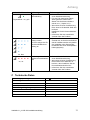
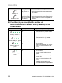
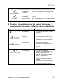
Aktueller Zustand Bedeutung Erläuterung / erforderliche Aktivität
an, rot
eBUS-Verbin-
dung fehlgeschla-
gen
– Wiederholen Sie alle Schritte der Elektro-
installation (→ Kapitel 7.1 und 7.2) und achten
Sie dabei insbesondere auf den Anschluss
des Kabels.
– Stellen Sie sicher, dass die Kabelverbindung
nicht unterbrochen ist.
– Installieren Sie die Kommunikationseinheit
nicht, wenn die LED weiterhin durchgängig
rot leuchtet.
– Informieren Sie den autorisierten Vertreter
über das Problem.
Rot blinkend
Wärmeerzeuger
und Regelung
nicht kompatibel
– Installieren Sie die Kommunikationseinheit
nicht.
– Informieren Sie den autorisierten Vertreter
über das Problem.
An, blau
Teilkompatibilität
der Anlage (keine
kompatible Rege-
lung)
– Installieren Sie die Kommunikationseinheit (→
Kapitel 8).
– Informieren Sie den autorisierten Vertreter
darüber, dass die Regelung des Heizungs-
systems inkompatibel ist oder fehlt.
B Zustand (Signalstärke des Mobilfunknetzes / Kommunika-
tion mit Server): Bedeutung der Netz-LEDs
Aktueller Zustand Bedeutung Erläuterung / erforderliche Aktivität
Hervorragend – an, grün
Hervorragende Mobilfunk-
verbindung
– Die Stelle ist für die Installation der
Kommunikationseinheit optimal ge-
eignet.
Installieren Sie die Kommunikations-
einheit.
Gut – an, grün
Gute Mobilfunkverbindung – Die Stelle ist für die Installation der
Kommunikationseinheit gut geeignet.
Installieren Sie die Kommunikations-
einheit.
Mittel – an, grün
Ausreichende Mobilfunk-
verbindung
– Suchen Sie eine Stelle mit einer bes-
seren Mobilfunkverbindung.
– Wenn dies zu keiner Verbesserung
führt, dann ist die aktuelle Stelle aus-
reichend.
Installieren Sie die Kommunikations-
einheit.

Anhang
0020282111_02 VR 100 Installationsanleitung 11
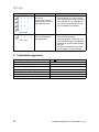
Aktueller Zustand Bedeutung Erläuterung / erforderliche Aktivität
Eingeschränkt – an, grün
Eingeschränkte Mobil-
funkverbindung
– Suchen Sie eine Stelle mit einer bes-
seren Mobilfunkverbindung.
– Für den Fall, dass keine andere
Stelle gefunden werden kann.
Starten Sie die Kommunikations-
einheit neu (→ Kapitel 10.1).
– Wenn dies zu keiner Verbesserung
führt, dann ist die aktuelle Stelle aus-
reichend.
Installieren Sie die Kommunikations-
einheit.
– Informieren Sie den autorisierten
Vertreter über das Problem.
An, blau
Der Server kann nicht
erreicht werden.
Die LEDs zeigen den Zu-
stand der Mobilfunkver-
bindung an.
– Sprechen Sie mit dem autorisierten
Vertreter ab, ob die Kommunikations-
einheit installiert werden soll (Gefahr
der Installation einer Kommunika-
tionseinheit bei einem inkompatiblen
Heizungssystem).
an, rot
Verbindungsabbruch zum
mobilen Kommunikations-
netz
– Suchen Sie eine Stelle mit einer bes-
seren Mobilfunkverbindung.
– Wenn dies zu keiner Verbesserung
führt und die LEDs weiterhin rot
leuchten, dann installieren Sie die
Kommunikationseinheit nicht.
– Informieren Sie den autorisierten
Vertreter über das Problem.
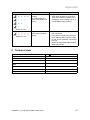
C Technische Daten
Bemessungsspannung
24 V ±10 %
Bemessungsstrom
< 200 mA
Schutzart
IP 20
Schutzklasse
III
Max. zulässige Umgebungstemperatur
0 … 50 ℃
Breite
84,5 mm
Tiefe
25,5 mm
Höhe
84,5 mm

Contents
12 Installation instructions VR 100 0020282111_02
Installation instructions
Contents
1 Safety .......................................... 13
1.1 Intended use ................................ 13
1.2 General safety information........... 13
2 Notes on the documentation .... 15
2.1 Observing other applicable
documents ................................... 15
2.2 Storing documents....................... 15
2.3 Validity of the instructions ............ 15
3 Compatibility .............................. 15
3.1 Compatibility of the
communication unit 1 .................. 15
4 Product description................... 15
4.1 Design of the communication
unit ............................................... 15
4.2 Information on the data plate....... 15
4.3 CE marking .................................. 15
5 Set-up.......................................... 16
5.1 Checking the scope of delivery
2 .................................................. 16
5.2 Checking the assembly and
installation prerequisites .............. 16
6 Installation.................................. 16
6.1 Qualification ................................. 16
7 Electrical installation................. 16
7.1 Connecting to the heat
generator 3 .................................. 16
7.2 Connecting to the
communication unit 4 .................. 16
7.3 Requirements for the
installation site 6, 5 ..................... 16
8 Installation on the wall .............. 17
8.1 Securing 7 ................................... 17
8.2 Excess cable 8 ............................ 17
9 Start-up ....................................... 17
9.1 Starting up the communication
unit 12, 9, 10, 11 ....................... 17
10 Troubleshooting ........................ 17
10.1 Restarting the product and
resetting parameters.................... 17
10.2 Brightness of the LEDs................ 17
10.3 Implementing a change to the
configuration of the heating
system ......................................... 17
10.4 Registration or communication
problem with the server ............... 18
11 Decommissioning...................... 18
11.1 Removing the communication
unit ............................................... 18
11.2 Recycling and disposal................ 18
12 Customer service....................... 18
Appendix ............................................... 19
A Condition (main display):
Meaning of the main LED.......... 19
B Condition (signal
strength of the mobile
network/communication with
the server): Meaning of the
network LEDs............................. 20
C Technical data............................ 21

Safety 1
0020282111_02 VR 100 Installation instructions 13
1 Safety
1.1 Intended use
In the event of inappropriate or
improper use, damage to the
product and other property may
arise.
The communication unit is used
to control the system. The com-
munication unit is compatible
with the mobile network.
A SIM card for communica-
tion via the mobile network has
already been pre-installed in the
communication unit.
Before the installation, you must
check that the communication
unit is compatible with all of the
components.
Intended use includes the fol-
lowing:
– observance of accompanying
operating, installation and
maintenance instructions for
the product and any other
system components
– installing and setting up the
product in accordance with
the product and system ap-
proval
– compliance with all inspection
and maintenance conditions
listed in the instructions.
Intended use also covers in-
stallation in accordance with the
IP code.
Any other use that is not spe-
cified in these instructions, or
use beyond that specified in this
document, shall be considered
improper use. Any direct com-
mercial or industrial use is also
deemed to be improper.
Caution.
Improper use of any kind is
prohibited.
1.2 General safety
information
1.2.1 Risk
caused by inadequate
qualifications
The following work must only
be carried out by competent
persons who are sufficiently
qualified to do so:
– Set-up
– Dismantling
– Installation
– Start-up
– Inspection and maintenance
– Repair
– Decommissioning
▶ Proceed in accordance with
current technology.
1.2.2 Risk of death from
electric shock
There is a risk of death from
electric shock if you touch live
components.

1 Safety
14 Installation instructions VR 100 0020282111_02
Before commencing work on
the heat generator:
▶ Unplug the mains plug.
▶ Or disconnect the product
from the power supply by
switching off all power sup-
plies (electrical partition with a
contact gap of at least 3 mm,
e.g. fuse or circuit breaker).
▶ Secure against being
switched back on again.
▶ Wait for at least 3 minutes
until the capacitors have dis-
charged.
▶ Check that there is no
voltage.
1.2.3 Regulations (directives,
laws, standards)
▶ Observe the national regula-
tions, standards, directives,
ordinances and laws.

Notes on the documentation 2
0020282111_02 VR 100 Installation instructions 15
2 Notes on the
documentation
2.1 Observing other applicable
documents
▶ Always observe all the operating and
installation instructions included with the
system components.
2.2 Storing documents
▶ Pass these instructions and all other
applicable documents on to the end
user.
2.3 Validity of the instructions
These instructions apply only to:
Product article number
VR 100
0010025650
3 Compatibility
3.1 Compatibility of the
communication unit 1
1. Check whether the communication unit
is compatible with the heat generator
and the room thermostat in the installa-
tion.
Validity: Great Britain
vaillant.co.uk/VR100
▶ Scan the above code in order to call
up the list of compatible heat generat-
ors and room thermostats.
◁ The products are included in the
list. Install the communication unit.
▽ The products are not included in
the list. Do not install the commu-
nication unit in this case.
4 Product description
4.1 Design of the communication
unit
1 2
3
4
5
1 Communication
unit
2 Wall bracket
3 Main LED
4 Network LEDs
5 Reset button for
restarting the
product and for
increasing the
brightness of the
LEDs
4.2 Information on the data plate
Label on the data plate Meaning
VR 100 Product designa-
tion
21073700201168840908005011N8
Barcode with
serial number,
The 7th to 16th
digits of the serial
number form the
article number
Read the instruc-
tions
4.3 CE marking
The CE marking shows that the products
comply with the basic requirements of the
applicable directives as stated on the data
plate.
The declaration of conformity can be
viewed at the manufacturer's site.

5 Set-up
16 Installation instructions VR 100 0020282111_02
5 Set-up
5.1 Checking the scope of delivery
2
▶ Check that the scope of delivery is com-
plete and intact.
Num-
ber
Designation
1 Communication unit
1 Wall bracket
1 Bag with bolts and wall plugs
1 Clamping screw
1 Cable
1 Cable bracket
5.2 Checking the assembly and
installation prerequisites
1. Check whether the communication unit
is compatible with the heat generator
and the room thermostat in the installa-
tion. (→ Page 15)
2. When choosing the installation site,
pay attention to the dimensions of the
communication unit.
Technical data (→ Page 21)
6 Installation
6.1 Qualification
Only qualified electricians may carry out
the electrical installation.
7 Electrical installation
7.1 Connecting to the heat
generator 3
1. Switch off the power supply of the heat
generator.
2. The connection can be made at con-
nection terminal X31 or X32 on the
boiler. Consult the boiler's installation
instructions in order to determine which
connection terminal is available and
where it is located.
3. Connect the enclosed cable to the heat
generator.
7.2 Connecting to the
communication unit 4
1. Unclip the unit mounting bracket from
the communication unit.
2. Connect the cable (1) to the commu-
nication unit and, in doing so, observe
the colour code on the sticker (2) below
the plug connection (3).
– The colours of the wires must match
the colours on the sticker.
3. Re-establish the power supply of the
heat generator.
7.3 Requirements for the
installation site 6, 5
1. Avoid interference between the com-
munication unit and its environment
(magnetic fields, electrical units, metal
structures, etc.).
2. Determine a location in order to start
the search.
3. To determine the best possible signal
strength for the mobile network, move
the communication unit in order to de-
termine the installation site.
4. Each time you move the communica-
tion unit, wait for 10 seconds in order
to test the signal strength of the mobile
network.
Condition (signal strength of the mo-
bile network/communication with the
server): Meaning of the network LEDs
(→ Page 20)
◁ The illuminated LEDs display the
signal strength of the mobile net-
work.
◁ The LEDs automatically switch off
after 30 minutes. The signal strength
of the mobile network is then no
longer updated.
5. Mark the drill holes.

Installation on the wall 8
0020282111_02 VR 100 Installation instructions 17
6. Temporarily position the communica-
tion unit close to the selected installa-
tion site.
8 Installation on the wall
8.1 Securing 7
1. Switch off the power supply of the heat
generator.
2. Secure the unit mounting bracket to the
wall as shown in the figure.
3. Click the communication unit into place
on the unit mounting bracket.
4. Screw in the clamping screw.
5. Do not cut off the excess cable.
6. If required, retain the excess cable.
(→ Page 17)
8.2 Excess cable 8
1. Wind up the excess cable in the heat
generator.
2. Use the enclosed clip to secure the ex-
cess cable and ensure that it cannot
come into contact with hot compon-
ents.
3. Re-establish the power supply to the
heat generator.
9 Start-up
9.1 Starting up the communication
unit 12, 9, 10, 11
1. If required, re-establish the power sup-
ply of the heat generator.
◁ The start sequence is triggered
automatically.
◁ The communication unit is initial-
ising.
◁ All LEDs light up green (main and
network LED).
▽ Not all of the LEDs are green.
2. Check the status of the LEDs.
3. If faults occur, proceed in accordance
with the tables in the appendix.
4. Allow the LEDs to switch off.
◁ The LEDs automatically switch off
after 30 minutes.
10 Troubleshooting
10.1 Restarting the product and
resetting parameters
1
▶ Press and hold the reset button (1) for
ten seconds.
10.2 Brightness of the LEDs
▶ Briefly press the reset button in order to
light up the LEDs.
◁ The LEDs light up.
◁ The illuminated LEDs display the
status of the communication unit
(main and network LED).
◁ The LEDs automatically switch off
after 30 minutes.
10.3 Implementing a change to the
configuration of the heating
system
1. Switch off the power supply of the heat
generator.
2. Re-establish the power supply of the
heat generator.
◁
The new heating system configura-
tion is detected by the communica-
tion unit.
3. Check the status of the communication
unit.

11 Decommissioning
18 Installation instructions VR 100 0020282111_02
Condition (main display): Meaning of
the main LED (→ Page 19)
Condition (signal strength of the mo-
bile network/communication with the
server): Meaning of the network LEDs
(→ Page 20)
10.4 Registration or communication
problem with the server
▶ Agree with the authorised representat-
ive about whether the communication
unit should be installed (risk of installing
a communication unit in an incompatible
heating system).
Result 1:
Positive response
▶ Complete the installation even if the
server does not respond.
▶ The problem is eliminated remotely
without any invasive work on the
product.
Result 2:
Negative response
▶ Do not install the communication
unit.
11 Decommissioning
11.1 Removing the communication
unit
1. Switch off the power supply of the heat
generator.
2. Disconnect all of the electrical connec-
tions.
3. Unmount the communication unit from
the retainer.
4. Undo the screws on the retainer.
5. Remove the retainer from the wall.
11.2 Recycling and disposal
▶ The competent person who installed
your product is responsible for the dis-
posal of the packaging.
If the product is labelled with this
mark:
▶ In this case, do not dispose of the
product with the household waste.
▶ Instead, hand in the product to a collec-
tion centre for waste electrical or elec-
tronic equipment.
If the product contains batteries that
are labelled with this mark, these batteries
may contain substances that are hazard-
ous to human health and the environment.
▶ In this case, dispose of the batteries at
a collection point for batteries.
12 Customer service
Validity: Great Britain
To ensure regular servicing, it is strongly
recommended that arrangements are
made for a Maintenance Agreement.
Please contact Vaillant Service Solutions
for further details:
Telephone: 0330 100 3461

Appendix
0020282111_02 VR 100 Installation instructions 19
Appendix
A Condition (main display): Meaning of the main LED
Current status Meaning Explanation/required activity
Flashing green
Flashing blue
Flashing red
Start sequence
The LEDs
change colour
several times
until the start
sequence is
complete.
– Wait until the start sequence is complete.
Flashing green
eBUS connection
is ongoing
– Wait until the status changes before you in-
stall the communication unit (→ section 8).
– If the LED continues to flash for longer than
10 minutes.
Restart again (switch the heating system off
and on again).
– If the LED then continues to flash for longer
than 10 minutes.
Agree with the authorised representative
about whether the communication unit should
be installed (risk of installing a communica-
tion unit in an incompatible heating system).
Steady on, green
eBUS connection
is established
– Install the communication unit.
Steady on, yellow
Communic-
ation unit not
registered
– Agree with the authorised representative
about whether the communication unit should
be installed (risk of installing a communica-
tion unit in an incompatible heating system).
– Inform the authorised representative that re-
gistration is required.
Steady on, red
eBUS connection
failed
– Repeat all of the steps of the electrical install-
ation (→ section 7.1 and 7.2) and, when doing
so, pay particular attention to the cable con-
nection.
– Ensure that the cable connection is not inter-
rupted.
– Do not install the communication unit if the
LED continues to light up permanently red.
– Inform the authorised representative about
the problem.

Appendix
20 Installation instructions VR 100 0020282111_02
Current status Meaning Explanation/required activity
Flashing red
Heat generator
and control not
compatible
– Do not install the communication unit.
– Inform the authorised representative about
the problem.
Steady on, blue
Partial compatib-
ility of the install-
ation (no compat-
ible control)
– Install the communication unit (→ section 8).
– Inform the authorised representative that the
heating system's control is incompatible or
missing.
B Condition (signal strength of the mobile net-
work/communication with the server): Meaning of the
network LEDs
Current status Meaning Explanation/required activity
Excellent – steady on,
green
Excellent mobile connec-
tion
– The location for installing the com-
munication unit is perfectly suitable.
Install the communication unit.
Good – steady on, green
Good mobile connection – The location for installing the com-
munication unit is very suitable.
Install the communication unit.
Medium – steady on,
green
Sufficient mobile connec-
tion
– Look for a location with a better mo-
bile connection.
– If this does not lead to any improve-
ment, the current location is suffi-
cient.
Install the communication unit.
Restricted – steady on,
green
Restricted mobile connec-
tion
– Look for a location with a better mo-
bile connection.
– In case no other location can be
found.
Restart the communication unit (→
section 10.1).
– If this does not lead to any improve-
ment, the current location is suffi-
cient.
Install the communication unit.
– Inform the authorised representative
about the problem.

Appendix
0020282111_02 VR 100 Installation instructions 21
Current status Meaning Explanation/required activity
Steady on, blue
The server cannot be
reached.
The LEDs display the
status of the mobile con-
nection.
– Agree with the authorised represent-
ative about whether the communic-
ation unit should be installed (risk of
installing a communication unit in an
incompatible heating system).
Steady on, red
Loss of connection to the
mobile communication
network
– Look for a location with a better mo-
bile connection.
– If this does not lead to any improve-
ment and the LEDs continue to light
up red, do not install the communica-
tion unit.
– Inform the authorised representative
about the problem.
C Technical data
Rated voltage
24 V ±10%
Rated current
< 200 mA
IP rating
IP 20
Protection class
III
Maximum permitted environmental temper-
ature
0 … 50 ℃
Width
84.5 mm
Depth
25.5 mm
Height
84.5 mm

Inhoudsopgave
22 Installatiehandleiding VR 100 0020282111_02
Installatiehandleiding
Inhoudsopgave
1 Veiligheid.................................... 23
1.1 Reglementair gebruik................... 23
1.2 Algemene veiligheidsinstruc-
ties ............................................... 23
2 Aanwijzingen bij de
documentatie ............................. 25
2.1 Aanvullend geldende
documenten in acht nemen ......... 25
2.2 Documenten bewaren.................. 25
2.3 Geldigheid van de handleiding .... 25
3 Verdraagzaamheid..................... 25
3.1 Compatibiliteit van de
communicatie-eenheid 1 ............. 25
4 Productbeschrijving .................. 25
4.1 Opbouw van de communicatie-
eenheid ........................................ 25
4.2 Gegevens op het typeplaatje....... 25
4.3 CE-markering............................... 25
5 Montage ...................................... 26
5.1 Leveringsomvang controleren
2 .................................................. 26
5.2 Montage- en
installatievoorwaarden
controleren................................... 26
6 Installatie .................................... 26
6.1 Kwalificatie................................... 26
7 Elektrische installatie................ 26
7.1 Aansluiting op warmteopwekker
3 .................................................. 26
7.2 Aansluiting op de
communicatie-eenheid 4 ............. 26
7.3 Eisen aan de installatielocatie
6, 5.............................................. 26
8 Installatie in de wand................. 27
8.1 Bevestigen 7 ............................... 27
8.2 Overtollige kabel 8 ...................... 27
9 Ingebruikname ........................... 27
9.1 Communicatie-eenheid in
gebruik nemen 12, 9, 10, 11 ..... 27
10 Verhelpen van storingen........... 27
10.1 Product opnieuw starten en
parameters resetten..................... 27
10.2 Verlichtingssterkte van de
leds .............................................. 28
10.3 Verandering in de configuratie
van het CV-systeem
overnemen................................... 28
10.4 Registratie- of
communicatieprobleem met de
server........................................... 28
11 Uitbedrijfname............................ 28
11.1 Communicatie-eenheid
demonteren.................................. 28
11.2 Recycling en afvoer ..................... 28
12 Serviceteam................................ 29
Bijlage.................................................... 30
A Toestand (hoofdweergave):
betekenis van de hoofd-led ...... 30
B Toestand (signaalsterkte van
het mobiele telefoonnet /
communicatie met server):
betekenis van de netwerk-
leds.............................................. 31
C Technische gegevens ............... 32

Veiligheid 1
0020282111_02 VR 100 Installatiehandleiding 23
1 Veiligheid
1.1 Reglementair gebruik
Bij ondeskundig of niet voorge-
schreven gebruik kunnen nade-
lige gevolgen voor het product
of andere voorwerpen ontstaan.
De communicatie-eenheid is
bedoeld voor de besturing van
uw systeem. De communicatie-
eenheid is compatibel met het
mobiele telefoonnet.
Een SIM-kaart voor de commu-
nicatie via het mobiele telefoon-
net is reeds in de communica-
tie-eenheid geïnstalleerd.
De compatibiliteit van de com-
municatie-eenheid met alle
componenten moet voor de in-
stallatie worden gecontroleerd.
Het reglementaire gebruik
houdt in:
– het naleven van de bijge-
voegde gebruiks-, installatie-
en onderhoudshandleidingen
van het product en van alle
andere componenten van de
installatie
– de installatie en montage con-
form de product- en systeem-
vergunning
– het naleven van alle in de
handleidingen vermelde in-
spectie- en onderhoudsvoor-
waarden.
Het gebruik volgens de voor-
schriften omvat bovendien de
installatie conform de IP-code.
Een ander gebruik dan het in
deze handleiding beschreven
gebruik of een gebruik dat van
het hier beschreven gebruik af-
wijkt, geldt als niet reglementair.
Als niet reglementair gebruik
geldt ook ieder direct commerci-
eel of industrieel gebruik.
Attentie!
Ieder misbruik is verboden.
1.2 Algemene
veiligheidsinstructies
1.2.1 Gevaar door
ontoereikende
kwalificatie
De volgende werkzaamheden
mogen alleen vakmannen met
voldoende kwalificaties uitvoe-
ren:
– Montage
– Demontage
– Installatie
– Ingebruikname
– Inspectie en onderhoud
– Reparatie
– Buitenbedrijfstelling
▶ Ga te werk conform de actu-
ele stand der techniek.

1 Veiligheid
24 Installatiehandleiding VR 100 0020282111_02
1.2.2 Levensgevaar door een
elektrische schok
Als u spanningsvoerende com-
ponenten aanraakt, bestaat le-
vensgevaar door elektrische
schok.
Voor u aan de warmteopwekker
werkt:
▶ Trek de stekker uit het stop-
contact.
▶ Of schakel het product span-
ningsvrij door alle stroom-
voorzieningen uit te schake-
len (elektrische scheidingsin-
richting met minstens 3 mm
contactopening, bijv. zekering
of vermogensveiligheidsscha-
kelaar).
▶ Beveilig tegen herinschake-
len.
▶ Wacht minstens 3 min tot de
condensatoren ontladen zijn.
▶ Controleer op spanningvrij-
heid.
1.2.3 Voorschriften
(richtlijnen, wetten,
normen)
▶ Neem de nationale voorschrif-
ten, normen, richtlijnen, veror-
deningen en wetten in acht.

Aanwijzingen bij de documentatie 2
0020282111_02 VR 100 Installatiehandleiding 25
2 Aanwijzingen bij de
documentatie
2.1 Aanvullend geldende
documenten in acht nemen
▶ Neem absoluut alle bedienings- en in-
stallatiehandleidingen die bij de compo-
nenten van de installatie worden mee-
geleverd in acht.
2.2 Documenten bewaren
▶ Gelieve deze handleiding alsook alle
aanvullend geldende documenten aan
de gebruiker van de installatie te geven.
2.3 Geldigheid van de handleiding
Deze handleiding geldt uitsluitend voor:
Product - artikelnummer
VR 100
0010025650
3 Verdraagzaamheid
3.1 Compatibiliteit van de
communicatie-eenheid 1
1. Controleer, of de communicatie-een-
heid compatibel is met de warmteop-
wekker en de kamerthermostaat in de
installatie.
Geldigheid: Nederland
vaillant.nl/VR100
▶ Scan de code hierboven, om de lijst
van de compatibele warmteopwek-
kers en kamerthermostaten op te roe-
pen.
◁ De producten staan op de lijst. In-
stalleer de communicatie-eenheid.
▽ De producten staan niet op de
lijst. Installeer de communicatie-
eenheid in dit geval niet.
4 Productbeschrijving
4.1 Opbouw van de communicatie-
eenheid
1 2
3
4
5
1 Communicatie-
eenheid
2 Wandhouder
3 Hoofd-LED
4 Netwerk-LED's
5 Ontstoringstoets
voor het opnieuw
opstarten van
het product en
voor het verho-
gen van de ver-
lichtingssterkte
van de LED's
4.2 Gegevens op het typeplaatje
Aanduiding op het type-
plaatje
Betekenis
VR 100 Productbenaming
21073700201168840908005011N8
Barcode met se-
rienummer,
Het 7e tot 16e
cijfer vormen het
artikelnummer
Handleiding le-
zen
4.3 CE-markering
Met de CE-markering wordt aangegeven
dat de producten volgens het typeplaatje
voldoen aan de fundamentele vereisten
van de geldende richtlijnen.

5 Montage
26 Installatiehandleiding VR 100 0020282111_02
De conformiteitsverklaring kan bij de fabri-
kant geraadpleegd worden.
5 Montage
5.1 Leveringsomvang controleren
2
▶ Controleer de leveringsomvang op vol-
ledigheid en beschadigingen.
Hoe-
veel-
heid
Omschrijving
1 Communicatie-eenheid
1 Wandhouder
1 Zakje met schroeven en pluggen
1 Klemschroef
1 Kabel
1 Kabelhouder
5.2 Montage- en
installatievoorwaarden
controleren
1. Controleer, of de communicatie-een-
heid compatibel is met de warmteop-
wekker en de kamerthermostaat in de
installatie. (→ Pagina 25)
2. Neem bij de keuze van de installatie-
plaats de afmetingen van de communi-
catie-eenheid in acht.
Technische gegevens (→ Pagina 32)
6 Installatie
6.1 Kwalificatie
De elektrische installatie mag alleen door
een elektromonteur worden uitgevoerd.
7 Elektrische installatie
7.1 Aansluiting op
warmteopwekker 3
1. Onderbreek de stroomtoevoer naar de
warmteopwekker.
2. De aansluiting kan via de aansluitklem
X31 resp. X32 het CV-toestel worden
uitgevoerd. Zie de installatiehandlei-
ding van het CV-toestel om te bepa-
len, welke aansluitklem aanwezig is en
waar deze zich bevindt..
3. Sluit de meegeleverde kabel op de
warmteopwekker aan.
7.2 Aansluiting op de
communicatie-eenheid 4
1. Lijn de wandhouder van de communi-
catie-eenheid uit.
2. Sluit de kabel (1) aan op de commu-
nicatie-eenheid en let daarbij op de
kleurcode op de sticker (2) onder de
stekkerverbinding (3).
– De kleuren van de draden moeten
overeenkomen met de kleuren op de
sticker.
3. Breng de stroomtoevoer naar de warm-
teopwekker opnieuw tot stand.
7.3 Eisen aan de installatielocatie
6, 5
1. Vermijd interferenties tussen de com-
municatie-eenheid en de omgeving er-
van (magnetische velden, elektrische
apparaten, metalen structuren …).
2. Bepaal een locatie, om het zoeken te
beginnen.
3. Om de beste signaalsterkte van het
mobiele telefoonnet vast te stellen,
moet u de communicatie-eenheid ver-
plaatsen, om de installatielocatie te be-
palen.
4. Wacht na elke verplaatsing van de
communicatie-eenheid 10 seconden,
om de signaalsterkte van het mobiele
telefoonnet te testen.

Installatie in de wand 8
0020282111_02 VR 100 Installatiehandleiding 27
Toestand (signaalsterkte van het mo-
biele telefoonnet / communicatie met
server): betekenis van de netwerk-leds
(→ Pagina 31)
◁ De brandende leds geven de sig-
naalsterkte van het mobiele tele-
foonnet aan.
◁ De leds gaan automatisch uit na 30
minuten. De signaalsterkte van het
mobiele telefoonnet wordt daarna
niet meer geactualiseerd.
5. Markeer de boorgaten.
6. Plaats de communicatie-eenheid tijde-
lijk in de buurt van de gekozen installa-
tieplaats.
8 Installatie in de wand
8.1 Bevestigen 7
1. Onderbreek de stroomtoevoer naar de
warmteopwekker.
2. Bevestig de wandhouder op de wand,
zoals op de afbeelding weergegeven.
3. Klik de communicatie-eenheid in de
wandhouder vast.
4. Schroef de klemschroef erin.
5. Snij de overtollige kabel niet af.
6. Bewaar een evt. overtollige kabel.
(→ Pagina 27)
8.2 Overtollige kabel 8
1. Wikkel de overtollige kabel in de warm-
teopwekker op.
2. Bevestig de overtollige kabel met de
meegeleverde clip en zorg ervoor, dat
deze niet met hete componenten in
aanraking kan komen.
3. Breng de stroomtoevoer naar de warm-
teopwekker opnieuw tot stand.
9 Ingebruikname
9.1 Communicatie-eenheid in
gebruik nemen 12, 9, 10, 11
1. Breng evt. de stroomtoevoer van de
warmteopwekker opnieuw tot stand.
◁ De startsequentie wordt automatisch
geactiveerd.
◁ De communicatie-eenheid wordt
geïnitialiseerd.
◁ Alle leds branden groen (hoofd- en
netwerk-led).
▽ Niet alle leds zijn groen.
2. Controleer de toestand van de leds.
3. Als er storingen optreden, ga dan con-
form de tabellen in de bijlage te werk.
4. Laat de leds uitgaan.
◁ De leds gaan automatisch uit na 30
minuten.
10 Verhelpen van storingen
10.1 Product opnieuw starten en
parameters resetten
1
▶ Houd de ontstoringstoets (1) tien secon-
den ingedrukt.

11 Uitbedrijfname
28 Installatiehandleiding VR 100 0020282111_02
10.2 Verlichtingssterkte van de leds
▶ Druk kort op de ontstoringstoets, om
de verlichtingssterkte van de leds te
verhogen.
◁ De leds gaan branden.
◁ De brandende leds geven de toe-
stand van de communicatie-eenheid
aan (hoofd- en netvoedingled).
◁ De leds gaan automatisch uit na 30
minuten.
10.3 Verandering in
de configuratie van het CV-
systeem overnemen
1. Onderbreek de stroomtoevoer naar de
warmteopwekker.
2. Breng de stroomtoevoer naar de warm-
teopwekker opnieuw tot stand.
◁ De nieuwe configuratie van het CV-
systeem wordt door de communica-
tie-eenheid herkend.
3. Controleer de toestand van de commu-
nicatie-eenheid.
Toestand (hoofdweergave): betekenis
van de hoofd-led (→ Pagina 30)
Toestand (signaalsterkte van het mo-
biele telefoonnet / communicatie met
server): betekenis van de netwerk-leds
(→ Pagina 31)
10.4 Registratie- of
communicatieprobleem met
de server
▶ Spreek met de geautoriseerde verte-
genwoordiger af, of de communicatie-
eenheid moet worden geïnstalleerd (ge-
vaar van de installatie van een commu-
nicatie-eenheid bij een niet compatibel
CV-systeem).
Resultaat 1:
Positief antwoord
▶ Sluit de installatie af, ook wanneer
de server niet antwoordt.
▶ Het probleem wordt op afstand zon-
der ingreep in het product verholpen.
Resultaat 2:
Negatief antwoord
▶ Installeer de communicatie-eenheid
niet.
11 Uitbedrijfname
11.1 Communicatie-eenheid
demonteren
1. Onderbreek de stroomtoevoer naar de
warmteopwekker.
2. Koppel alle verbindingen los.
3. Maak de communicatie-eenheid los
van de houder.
4. Maak de schroeven van de houder los.
5. Verwijder de houder van de wand.
11.2 Recycling en afvoer
▶ Laat de verpakking door de installateur
afvoeren die het product geïnstalleerd
heeft.
Als het product met dit teken is aan-
geduid:
▶ Gooi het product in dat geval niet met
het huisvuil weg.
▶ Geeft het product in plaats daarvan af
bij een inzamelpunt voor oude elektri-
sche of elektronische apparaten.
Als het product batterijen bevat die
met dit teken gekenmerkt zijn, kunnen de
batterijen substanties bevatten die schade-
lijk zijn voor gezondheid en milieu.
▶ Breng de batterijen in dat geval naar
een inzamelpunt voor batterijen.

Serviceteam 12
0020282111_02 VR 100 Installatiehandleiding 29
12 Serviceteam
Geldigheid: Nederland
Het Serviceteam dient ter ondersteuning
van de installateur en is tijdens kantoor-
uren te bereiken op nummer:
Serviceteam: 020 5659440

Bijlage
30 Installatiehandleiding VR 100 0020282111_02
Bijlage
A Toestand (hoofdweergave): betekenis van de hoofd-led
Actuele toestand Betekenis Uitleg/vereiste activiteit
Groen knipperend
Blauw knipperend
Rood knipperend
Startsequentie
De leds verande-
ren meerdere ke-
ren van kleur, tot
de startsequentie
is afgesloten.
– Wacht tot de startsequentie afgesloten is.
Groen knipperend
eBUS-verbinding
wordt tot stand
gebracht
– Wacht, tot de toestand verandert, voordat
u de communicatie-eenheid installeert (→
hoofdstuk 8).
– Wanneer de led langer dan 10 minuten door
blijft knipperen.
Start eenmaal opnieuw (schakel het CV-sys-
teem uit en weer aan).
– Wanneer de led daarna langer dan 10 minu-
ten door blijft knipperen.
Spreek met de geautoriseerde vertegenwoor-
diger af, of de communicatie-eenheid moet
worden geïnstalleerd (gevaar van de instal-
latie van een communicatie-eenheid bij een
niet compatibel CV-systeem).
Aan, groen
eBUS-verbinding
is tot stand ge-
bracht
– Installeer de communicatie-eenheid.
Aan, geel
Communicatie-
eenheid niet ge-
registreerd
– Spreek met de geautoriseerde vertegenwoor-
diger af, of de communicatie-eenheid moet
worden geïnstalleerd (gevaar van de instal-
latie van een communicatie-eenheid bij een
niet compatibel CV-systeem).
– Informeer de geautoriseerde vertegenwoordi-
ger, dat de registratie nodig is.
aan, rood
eBUS-verbinding
mislukt
– Herhaal alle stappen van de elektrische in-
stallatie (→ hoofdstuk 7.1 en 7.2) en let daar-
bij vooral op de aansluiting van de kabel.
– Zorg ervoor, dat de kabelverbinding niet is
onderbroken.
– Installeer de communicatie-eenheid niet,
wanneer de led continu rood blijft branden.
– Informeer de geautoriseerde vertegenwoordi-
ger over het probleem.

Bijlage
0020282111_02 VR 100 Installatiehandleiding 31
Actuele toestand Betekenis Uitleg/vereiste activiteit
Rood knipperend
Warmteopwekker
en regeling niet
compatibel
– Installeer de communicatie-eenheid niet.
– Informeer de geautoriseerde vertegenwoordi-
ger over het probleem.
Aan, blauw
Gedeeltelijke
compatibiliteit
van de installatie
(geen compatibel
regeling)
– Installeer de communicatie-eenheid (→ hoofd-
stuk 8).
– Informeer de geautoriseerde vertegenwoordi-
ging, dat de regeling van het CV-systeem niet
compatibel is of ontbreekt.
B Toestand (signaalsterkte van het mobiele telefoonnet /
communicatie met server): betekenis van de netwerk-leds
Actuele toestand Betekenis Uitleg/vereiste activiteit
Uitstekend – aan, groen
Uitstekende mobiele tele-
foonverbinding
– De positie is voor de installatie van
de communicatie-eenheid optimaal
geschikt.
Installeer de communicatie-eenheid.
Goed – aan, groen
Goede mobiele telefoon-
verbinding
– De positie is voor de installatie van
de communicatie-eenheid goed ge-
schikt.
Installeer de communicatie-eenheid.
Gemiddeld – aan, groen
Voldoende mobiele tele-
foonverbinding
– Zoek een positie met een betere mo-
biele telefoonverbinding.
– Wanneer dit geen verbetering ople-
vert, dan is de huidige positie vol-
doende.
Installeer de communicatie-eenheid.
Beperkt – aan, groen
Beperkte mobiele tele-
foonverbinding
– Zoek een positie met een betere mo-
biele telefoonverbinding.
– Voor het geval, dat geen andere po-
sitie kan worden gevonden.
Start de communicatie-eenheid op-
nieuw (→ hoofdstuk 10.1).
– Wanneer dit geen verbetering ople-
vert, dan is de huidige positie vol-
doende.
Installeer de communicatie-eenheid.
– Informeer de geautoriseerde verte-
genwoordiger over het probleem.

Bijlage
32 Installatiehandleiding VR 100 0020282111_02
Actuele toestand Betekenis Uitleg/vereiste activiteit
Aan, blauw
De server kan niet wor-
den bereikt.
De leds geven de toe-
stand van de mobiele te-
lefoonverbinding aan.
– Spreek met de geautoriseerde ver-
tegenwoordiger af, of de communi-
catie-eenheid moet worden geïnstal-
leerd (gevaar van de installatie van
een communicatie-eenheid bij een
niet compatibel CV-systeem).
aan, rood
Verbinding met het mo-
biele communicatienet-
werk afgebroken
– Zoek een positie met een betere mo-
biele telefoonverbinding.
– Wanneer dit geen verbetering ople-
vert en de leds blijven rood branden,
installeer de communicatie-eenheid
dan niet.
– Informeer de geautoriseerde verte-
genwoordiger over het probleem.
C Technische gegevens
Ontwerpspanning
24 V ±10 %
Nominale stroom
< 200 mA
Beschermingsklasse
IP 20
Veiligheidscategorie
III
Max. toegestane omgevingstemperatuur
0 … 50 ℃
Breedte
84,5 mm
Diepte
25,5 mm
Hoogte
84,5 mm


0020282111_02 12.03.2019
Supplier
Vaillant Deutschland GmbH & Co.KG
Berghauser Str. 40 D-42859 Remscheid
Telefon 02191 18 0 Telefax 02191 18 2810
Auftragsannahme Vaillant Kundendienst 02191 5767901
[email protected] www.vaillant.de
Vaillant Ltd.
Nottingham Road Belper 1 1 Derbyshire 1 1 DE56 1JT
Telephone 0330 100 3461
[email protected] www.vaillant.co.uk
Vaillant Group Netherlands B.V.
Postbus 23250 1100 DT Amsterdam
Telefoon 020 5659200 Telefax 020 6969366
Consumentenservice 020 5659420 Serviceteam 020 5659440
[email protected] www.vaillant.nl
© These instructions, or parts thereof, are protected by copyright and may be
reproduced or distributed only with the manufacturer's written consent.
0020282111_02
-
 1
1
-
 2
2
-
 3
3
-
 4
4
-
 5
5
-
 6
6
-
 7
7
-
 8
8
-
 9
9
-
 10
10
-
 11
11
-
 12
12
-
 13
13
-
 14
14
-
 15
15
-
 16
16
-
 17
17
-
 18
18
-
 19
19
-
 20
20
-
 21
21
-
 22
22
-
 23
23
-
 24
24
-
 25
25
-
 26
26
-
 27
27
-
 28
28
-
 29
29
-
 30
30
-
 31
31
-
 32
32
-
 33
33
-
 34
34
-
 35
35
-
 36
36
-
 37
37
-
 38
38
-
 39
39
-
 40
40


in andere talen
- English: Vaillant VR 100 Installation guide
- Deutsch: Vaillant VR 100 Installationsanleitung
Gerelateerde papieren
Andere documenten
-
Saunier Duval MiLink v3 (SR921) Installatie gids
-
-
Saunier Duval MiLink v2 Installatie gids
-
 Mr Handsfree VR100 3D Glasses de handleiding
-
Olympus OLYMPUS PENPAL PP-1 Handleiding
-
Bosch MC 400 Installation Instructions For Skilled Labour
-
STEINEL SensorLight RS PRO LED S1 Specificatie
-
-
Honeywell EKZ008200B Handleiding
-
Buderus EM100 Installation Instructions For Skilled Labour
