
YAMAHA ELECTRONICS CORPORATION, USA
6660 ORANGETHORPE AVE., BUENA PARK, CALIF. 90620, U.S.A.
YAMAHA CANADA MUSIC LTD.
135 MILNER AVE., SCARBOROUGH, ONTARIO M1S 3R1, CANADA
YAMAHA ELECTRONIK EUROPA G.m.b.H.
SIEMENSSTR. 22-34, 25462 RELLINGEN BEI HAMBURG, F.R. OF GERMANY
YAMAHA ELECTRONIQUE FRANCE S.A.
RUE AMBROISE CROIZAT BP70 CROISSY-BEAUBOURG 77312 MARNE-LA-VALLEE CEDEX02, FRANCE
YAMAHA ELECTRONICS (UK) LTD.
YAMAHA HOUSE, 200 RICKMANSWORTH ROAD WATFORD, HERTS WD18 7GQ, ENGLAND
YAMAHA SCANDINAVIA A.B.
J A WETTERGRENS GATA 1, BOX 30053, 400 43 VÄSTRA FRÖLUNDA, SWEDEN
YAMAHA MUSIC AUSTRALIA PTY, LTD.
17-33 MARKET ST., SOUTH MELBOURNE, 3205 VIC., AUSTRALIA
This document is printed on chlorine free (ECF) paper with soy ink.
©
2003 All rights reserved.
GB
PHONO
DVR
STANDBY
/ON
PURE DIRECT
2CH/MULTI CH
SPEAKERS
VIDEO AUX
REC OUT/ZONE 2
INPUT MODE
SOURCE/REMOTE
DVDDTV/LD
MD/TAPE
CD-R
TUNER
CD
VIDEO AUX
VCR 2
VCR 1
SAT
CABLE
A B
STRAIGHT
EFFECT
MULTI CH
INPUT
DSP
PROGRAM
BALANCE
TONE
CONTROL
VOLUME
INPUT SELECTOR
MULTI JOG
SILENT OPTIMIZER
MIC
PHONES
OPTICAL
R
AUDIO
L
VIDEO
S VIDEO
AV Amplifier
Amplificateur Audio-Vidéo
OWNER’S MANUAL
MODE D’EMPLOI
BEDIENUNGSANLEITUNG
Printed in Japan WB74160
DSPZ9gb1_cv.fm Page 1 Tuesday, October 21, 2003 1:12 PM

1 To assure the finest performance, please read this
manual carefully. Keep it in a safe place for future
reference.
2 Install this sound system in a well ventilated, cool,
dry, clean place — away from direct sunlight, heat
sources, vibration, dust, moisture, and/or cold.
Allow ventilation space of at least 30 cm on the top,
20 cm on the left and right, and 20 cm on the back
of this unit.
3 Locate this unit away from other electrical
appliances, motors, or transformers to avoid
humming sounds.
4 Do not expose this unit to sudden temperature
changes from cold to hot, and do not locate this
unit in a environment with high humidity (i.e. a
room with a humidifier) to prevent condensation
inside this unit, which may cause an electrical
shock, fire, damage to this unit, and/or personal
injury.
5 Avoid installing this unit where foreign object may
fall onto this unit and/or this unit may be exposed
to liquid dripping or splashing. On the top of this
unit, do not place:
– Other components, as they may cause damage
and/or discoloration on the surface of this unit.
– Burning objects (i.e. candles), as they may
cause fire, damage to this unit, and/or personal
injury.
– Containers with liquid in them, as they may fall
and liquid may cause electrical shock to the user
and/or damage to this unit.
6 Do not cover this unit with a newspaper, tablecloth,
curtain, etc. in order not to obstruct heat radiation.
If the temperature inside this unit rises, it may
cause fire, damage to this unit, and/or personal
injury.
7 Do not plug in this unit to a wall outlet until all
connections are complete.
8 Do not operate this unit upside-down. It may
overheat, possibly causing damage.
9 Do not use force on switches, knobs and/or cords.
10 When disconnecting the power cord from the wall
outlet, grasp the plug; do not pull the cord.
11 Do not clean this unit with chemical solvents; this
might damage the finish. Use a clean, dry cloth.
12 Only voltage specified on this unit must be used.
Using this unit with a higher voltage than specified
is dangerous and may cause fire, damage to this
unit, and/or personal injury. YAMAHA will not be
held responsible for any damage resulting from use
of this unit with a voltage other than specified.
13 To prevent damage by lightning, disconnect the
power cord from the wall outlet during an electrical
storm.
14 Do not attempt to modify or fix this unit. Contact
qualified YAMAHA service personnel when any
service is needed. The cabinet should never be
opened for any reasons.
15 When not planning to use this unit for long periods
of time (i.e. vacation), disconnect the AC power
plug from the wall outlet.
16 Be sure to read the “TROUBLESHOOTING” section
on common operating errors before concluding
that this unit is faulty.
17 Before moving this unit, press STANDBY/ON to set
this unit in the standby mode, and disconnect the
AC power plug from the wall outlet.
18 VOLTAGE SELECTOR (General model only)
The VOLTAGE SELECTOR on the rear panel of this
unit must be set for your local main voltage
BEFORE plugging into the AC main supply.
Voltages are 110/120/220/230-240 V AC, 50/60 Hz.
■ For U.K. customers
If the socket outlets in the home are not suitable for the
plug supplied with this appliance, it should be cut off and
an appropriate 3 pin plug fitted. For details, refer to the
instructions described below.
The plug severed from the mains lead must be destroyed, as a
plug with bared flexible cord is hazardous if engaged in a live
socket outlet.
■ Special Instructions for U.K. Model
CAUTION: READ THIS BEFORE OPERATING YOUR UNIT.
This unit is not disconnected from the AC power
source as long as it is connected to the wall outlet, even
if this unit itself is turned off. This state is called the
standby mode. In this state, this unit is designed to
consume a very small quantity of power.
WARNING
TO REDUCE THE RISK OF FIRE OR ELECTRIC
SHOCK, DO NOT EXPOSE THIS UNIT TO RAIN
OR MOISTURE.
Note
IMPORTANT
THE WIRES IN MAINS LEAD ARE COLOURED IN
ACCORDANCE WITH THE FOLLOWING CODE:
Blue: NEUTRAL
Brown: LIVE
As the colours of the wires in the mains lead of this
apparatus may not correspond with the coloured
markings identifying the terminals in your plug,
proceed as follows:
The wire which is coloured BLUE must be connected
to the terminal which is marked with the letter N or
coloured BLACK. The wire which is coloured
BROWN must be connected to the terminal which is
marked with the letter L or coloured RED.
Making sure that neither core is connected to the earth
terminal of the three pin plug.
00EN.00_DSPZ9_GB.book Page 2 Thursday, November 13, 2003 10:55 AM

1
English
PREPARATIONINTRODUCTION
BASIC
OPERATION
SOUND FIELD
PROGRAMS
ADVANCED
OPERATION
ADDITIONAL
INFORMATION
FEATURES .............................................................2
GETTING STARTED............................................3
Supplied accessories .................................................. 3
Installing batteries in the remote controls.................. 4
CONTROLS AND FUNCTIONS.......................... 5
Front panel ................................................................. 5
Remote control........................................................... 7
GUI remote control.................................................... 8
Using the remote controls.......................................... 9
Front panel display................................................... 10
Rear panel ................................................................ 11
SPEAKER SETUP................................................12
Speaker placement ................................................... 12
Speaker connections ................................................ 13
CONNECTIONS...................................................16
Connecting components........................................... 16
Connecting video components................................. 17
Connecting audio components................................. 24
Connecting the power supply cord .......................... 27
Speaker impedance setting....................................... 28
Turning on the power............................................... 28
USING THE GUI REMOTE CONTROL..........29
GUI remote control operations ................................ 29
AUTO SETUP.......................................................31
Introduction.............................................................. 31
Optimizer microphone setup.................................... 31
Starting the setup ..................................................... 32
Confirming the results ............................................. 34
PLAYBACK ..........................................................37
Basic operations....................................................... 37
Selecting sound field programs................................ 39
Listening to uncompromising pure audio................ 43
Selecting input modes.............................................. 44
RECORDING .......................................................46
SOUND FIELD PROGRAM
DESCRIPTIONS.............................................. 48
For movie/video sources.......................................... 48
For music sources .................................................... 51
ADVANCED OPERATIONS.............................. 53
Selecting the OSD mode.......................................... 53
Using the sleep timer ............................................... 53
Using the test tone.................................................... 54
SYSTEM OPTIONS............................................. 55
Changing parameter settings.................................... 57
Input Select .............................................................. 58
Manual setup: Sound ............................................... 61
Manual setup: Basic................................................. 64
Manual setup: Video................................................ 71
Manual setup: Option............................................... 75
Memory Guard......................................................... 78
REMOTE CONTROL FEATURES................... 80
Control area.............................................................. 80
Setting manufacturer codes...................................... 81
Programming codes from other remote controls ..... 82
Changing source names in the display window.......83
Using the macro feature........................................... 84
Clearing function sets .............................................. 86
Clearing individual functions................................... 87
Controlling components........................................... 88
ZONE 2.................................................................. 93
Zone 2 connections .................................................. 93
Remote controlling Zone 2 ...................................... 94
USING i.LINK...................................................... 96
What is i.LINK?....................................................... 96
Connecting i.LINK components.............................. 96
Assigning i.LINK components ................................ 97
Listening to playback from an i.LINK
component ........................................................... 97
Changing i.LINK Select parameters........................ 98
i.LINK display messages ....................................... 100
SOUND FIELD OPTIONS................................ 101
What is a sound field ............................................. 101
Stereo/Surround menu ........................................... 103
TROUBLESHOOTING..................................... 108
PARAMETRIC EQUALIZER
INFORMATION ............................................ 112
GLOSSARY ........................................................ 113
BLOCK DIAGRAMS ........................................ 117
SPECIFICATIONS............................................ 119
CONTENTS
INTRODUCTION
PREPARATION
BASIC OPERATION
SOUND FIELD PROGRAMS
ADVANCED OPERATION
ADDITIONAL INFORMATION
00EN.00_DSPZ9_GB.book Page 1 Thursday, November 13, 2003 10:55 AM

FEATURES
2
Built-in 9-channel power amplifier
◆ Minimum RMS output power
(0.015% THD, 20 Hz – 20 kHz, 8Ω)
Front: 170 W + 170 W
Center: 170 W
Surround: 170 W + 170 W
Surround back: 170 W + 170 W
Presence: 50 W + 50 W
Sound field features
◆ Proprietary YAMAHA technology for the creation of
sound fields
◆ THX Ultra 2
◆ Dolby Digital/Dolby Digital EX decoder
◆ Dolby Pro Logic/Dolby Pro Logic II/Dolby Pro Logic
IIx decoder
◆ DTS/DTS ES Matrix 6.1, Discrete 6.1/DTS 96/24
decoder
◆ DTS Neo:6 decoder
◆ Virtual CINEMA DSP
◆ SILENT CINEMA
™
Other features
◆ YPAO: YAMAHA Parametric Room Acoustic
Optimizer for automatic speaker setup
◆ 192-kHz/24-bit D/A converter
◆ On-screen display menus that allow you to optimize
this unit to suit your individual audio/video system
◆ 8-channel external decoder input for other future
formats (compatible with DSP)
◆ PURE DIRECT for pure fidelity sound with multi or
2-channel sources
◆ On-screen display function with dedicated GUI remote
control for performing all operations
◆ S Video signal input/output capability
◆ Component video input/output capability
◆ Video signal conversion (Composite video ↔
S Video ↔ Component video) capability for monitor
out
◆ Faroudja DCDi for progressive video output
◆ Faroudja True Life Enhancer for smooth video images
◆ TBC (Time Base Corrector) for jitterless video images
◆ i.LINK interface for direct digital transfer of digital
audio signals
◆ Optical and coaxial digital audio signal jacks
◆ Sleep timer
◆ Night listening mode
◆ Remote control with preset manufacturer codes and
“learning” macro capability
◆ Zone 2 custom installation facility
• y indicates a tip for your operation.
• Some operations can be performed by using either the buttons on the main unit or on the remote control. In cases where the button
names differ between the main unit and remote control, the button name on the remote control is given in parentheses.
• This manual is printed prior to production. Design and specifications are subject to change in part as a result of improvements, etc. In
case of differences between the manual and product, the product has priority.
Manufactured under license from Dolby Laboratories.
“Dolby”, “Pro Logic”, “Surround EX”, and the double-D symbol
are trademarks of Dolby Laboratories.
SILENT CINEMA is a trademark of YAMAHA
CORPORATION.
“DCDi” is a trademark of Faroudja, a division of Genesis
Microchip, Inc.
“DTS”, “DTS-ES Digital Surround”, “Neo:6” and “DTS 96/24”
are trademarks of Digital Theater Systems, Inc.
“THX” and the “THX” logo are registered trademarks of THX
Ltd. “Surround EX” is a jointly developed technology of THX
and Dolby Laboratories, Inc. and is a trademark of Dolby
Laboratories, Inc. All rights reserved. Used under authorization.
“i.LINK” and the “i.LINK” logo are trademarks of Sony
Corporation.
FEATURES
00EN.00_DSPZ9_GB.book Page 2 Thursday, November 13, 2003 10:55 AM

GETTING STARTED
3
English
INTRODUCTION
Please check that you received all of the following parts.
GETTING STARTED
Supplied accessories
TRANSMIT
RE-NAME
STANDBY
TUNER
MULTI CH IN
PURE DIRECT
TOP EXIT
INPUT MODE
SOUND
SYSTEM
CLEAR LEARN MACRO
OFF ON
MACRO
PHONO
CD
DVD
DVR
VCR 2
TITLE
MENU
CHAPTER
PAUSE
STOP
POWER
REC
STEREO
EX/ES
AMP
10KEY
JAZZ
MOVIE
THX
MUTE
VOLUME
STRAIGHT
TV INPUT
TV VOL
CH
PRESET
DISC
EFFECT
ON SCREEN
TESTSLEEP
PUSH
TV MUTE
MUSIC
ENTERTAIN
ROCK
HALL 1
HALL 2
CHURCH
NIGHT
/DTS
CHP/INDEX
A/B/C/D/E
SELECT
DISPLAY
SEARCH
SOURCE
PLAY
–+
ENTER
DTV/LD
VCR 1
CD-R
MD/TAPE
SAT
CABLE
POWER
V-AU X
1
5
9
6
0 +10
+100
78
23
4
SPEAKERS
A B
Remote control
Batteries (3)
(AA, LR6)
Power cord
Optimizer microphone
Speaker terminal wrench
Batteries (2)
(AAA, R03)
POWER
VOL
MUTE
TOP
EXIT
SYSTEM
STANDBY
+
–
ENTER
GUI
Remote control
*
The optimizer microphone is
sensitive to heat.
– Keep it away from direct
sunlight.
– Do not place it on top of this unit.
00EN.00_DSPZ9_GB.book Page 3 Thursday, November 13, 2003 10:55 AM

GETTING STARTED
4
Notes on batteries
• Change all of the batteries if you notice the following conditions: the operation range of the remote control decreases, the indicator
does not flash or its light becomes dim.
• Do not use old batteries together with new ones.
• Do not use different types of batteries (such as alkaline and manganese batteries) together. Read the packaging carefully as these
different types of batteries may have the same shape and color.
• If the batteries have leaked, dispose of them immediately. Avoid touching the leaked material or letting it come into contact with
clothing, etc. Clean the battery compartment thoroughly before installing new batteries.
■ Remote control
1 Open the battery compartment cover.
2 Insert three supplied batteries (AA, LR6)
according to the polarity markings (+ and –)
on the inside of the battery compartment.
3 After new batteries are correctly inserted,
press the RESET button in the battery
compartment using a ball point pen or
similar object.
(This does not clear the contents of the memory.)
4 Replace the cover by pressing until it snaps
into place.
■ GUI remote control
1 Press the part and slide the battery
compartment cover off.
2 Insert two supplied batteries (AAA, R03)
according to the polarity markings (+ and –)
on the inside of the battery compartment.
3 Slide the cover back until it snaps into place.
Installing batteries in the remote controls
If the remote control is without batteries for more than
3 minutes, or if exhausted batteries remain in the
remote control, the contents of the memory may be
cleared. If the memory is cleared, insert new batteries,
set up the manufacturer code(s) and program any
acquired functions that may have been cleared.
RESET button
1
3
2
00EN.00_DSPZ9_GB.book Page 4 Thursday, November 13, 2003 10:55 AM

CONTROLS AND FUNCTIONS
5
English
INTRODUCTION
1 STANDBY/ON
Turns on this unit or sets it to the standby mode. When you
turn on this unit, you will hear a click and there will be a
delay of a few seconds before this unit can reproduce
sound.
In standby mode, this unit consumes a small amount of power in
order to receive infrared-signals from the remote controls.
2 INPUT SELECTOR
Selects the input source you want to listen to or watch.
3 PURE DIRECT 2CH/MULTI CH
Turns on or off the 2-channel/multi-channel PURE
DIRECT mode (see page 43).
4 Remote control sensor
Receives signals from the remote controls.
5 Front panel display
Shows information about the operational status of this
unit.
6 INPUT MODE
Sets the priority for the type of input signal (AUTO,
i.LINK, DTS, DIGITAL, D.D.RF, ANALOG) received
when one component is connected to two or more input
jacks on this unit (see page 44).
7 MULTI CH INPUT
Selects the source connected to the MULTI CH INPUT
jacks. This source takes priority over the source selected
with INPUT SELECTOR (or the input selector buttons on
the remote control).
8 STRAIGHT/EFFECT
Switches the sound fields off or on. When STRAIGHT is
selected, input signals (2-channel or multi-channel) are
output directly from their respective speakers without
effect processing.
9 DSP PROGRAM
Press this button before rotating MULTI JOG to select
sound field programs.
CONTROLS AND FUNCTIONS
Front panel
PHONO
DVR
PURE DIRECT
2CH/MULTI CH
SPEAKERS
VIDEO AUX
REC OUT/ZONE 2
INPUT MODE
SOURCE/REMOTE
DVDDTV/LD
MD/TAPE
CD-R
TUNER
CD
VIDEO AUX
VCR 2
VCR 1
SAT
CABLE
AB
STRAIGHT
EFFECT
MULTI CH
INPUT
DSP
PROGRAM
BALANCE
TONE
CONTROL
VOLUME
INPUT SELECTOR
MULTI JOG
SILENT OPTIMIZER
MIC
PHONES
OPTICAL
R
AUDIO
L
VIDEO
S VIDEO
STANDBY
/ON
12 54C3789AB06
EFG HD
Note
00EN.00_DSPZ9_GB.book Page 5 Thursday, November 13, 2003 10:55 AM

CONTROLS AND FUNCTIONS
6
0 MULTI JOG
Rotate to select or adjust items when used with the DSP
PROGRAM, BALANCE or TONE CONTROL buttons.
A BALANCE
Adjusts the left/right balance of the front, presence,
surround and surround back speakers.
B TONE CONTROL
Press this button before rotating MULTI JOG to adjust the
bass/treble balance for the front left/right, center and
subwoofer channels (see page 38).
C VOLUME
Controls the output level of all audio channels.
This does not affect the REC OUT level.
D SPEAKERS A/B
Turns on or off the set of front speakers connected to the A
and/or B terminals on the rear panel each time the
corresponding button is pressed.
E PHONES jack
Outputs audio signals for private listening with
headphones. When you connect headphones, no signals
are output to the OUTPUT jacks or to the speakers.
F OPTIMIZER MIC jack
Use to connect and input audio signals from the supplied
microphone for the AUTO SETUP function (see page 31).
G REC OUT/ZONE 2
Selects the source you want to direct to the audio/video
recorder and ZONE 2 outputs independently of the source
you are listening to or watching in the main room. When
set to the SOURCE/REMOTE position, the input source is
directed to all outputs. The source in Zone 2 and the
source you record are always identical.
H VIDEO AUX jacks
Inputs audio and video signals from a portable external
source such as a game console. To reproduce source
signals from these jacks, select V-AUX as the input
source.
■ Opening and closing the front panel
door
When you want to use the controls behind the front panel
door, open the door by gently pressing on the lower part of
the panel. Keep the door closed when not using these
controls.
To open, press gently on the lower part of the panel.
00EN.00_DSPZ9_GB.book Page 6 Thursday, November 13, 2003 10:55 AM

CONTROLS AND FUNCTIONS
7
English
INTRODUCTION
This section describes the functions of each control on the
remote control. See “REMOTE CONTROL FEATURES”
on page 80 to operate other components with this remote
control.
1 Infrared window
Outputs infrared control signals. Aim this window at the
component you want to operate.
2 RE-NAME
Used for changing the input source name in the display
window (see page 83).
3 TRANSMIT indicator
Flashes while the remote control is sending signals.
4 STANDBY
Sets this unit in the standby mode.
5 SYSTEM POWER
Turns on this unit’s power.
6 PURE DIRECT
Turns on or off the 2-channel/multi-channel PURE
DIRECT mode (see page 43).
7 Display window
Shows the name of the selected source component that
you can control.
8 SOURCE SELECT k/n
Selects another component that you can control
independently of the input component selected with the
input selector buttons.
9 LIGHT
Press to momentarily light up the display window and
buttons on this remote control.
0 INPUT MODE
Sets the priority for the type of input signal (AUTO,
i.LINK, DTS, DIGITAL, D.D.RF, ANALOG) received
when one component is connected to two or more input
jacks on this unit (see page 44).
A 10KEY/AMP
Slide to 10KEY to select a numeric button or operate the
component selected using the input selector buttons.
Slide to AMP to operate this unit.
B EX/ES
Switches between 5.1- and 6.1/7.1-channel playback of
multi-channel software.
C ON SCREEN
Selects the GUI display mode for your video monitor.
D SLEEP
Sets the sleep timer.
E TEST
Outputs the test tone to adjust the speaker levels.
F CLEAR
Used for clearing functions acquired when using the learn
and rename features and setting manufacturer codes (see
page 86).
Remote control
TRANSMIT
RE-NAME
STANDBY
TUNER
MULTI CH IN
PURE DIRECT
TOP EXIT
INPUT MODE
SOUND
SYSTEM
CLEAR LEARN MACRO
OFF ON
MACRO
PHONO
CD
DVD
DVR
VCR 2
TITLE
MENU
CHAPTER
PAU SE
STOP
POWER
REC
STEREO
EX/ES
AMP
10KEY
JAZZ
MOVIE
THX
MUTE
VOLUME
STRAIGHT
TV INPUT
TV VOL
CH
PRESET
DISC
EFFECT
ON SCREEN
TESTSLEEP
PUSH
TV MUTE
MUSIC
ENTERTAIN
ROCK
HALL 1
HALL 2
CHURCH
NIGHT
/DTS
CHP/INDEX
A/B/C/D/E
SELECT
DISPLAY
SEARCH
SOURCE
PLAY
–+
ENTER
DTV/LD
VCR 1
CD-R
MD/TAPE
SAT
CABLE
POWER
V-AUX
1
5
9
6
0+10
+100
78
23
4
SPEAKERS
A B
F
G
H
I
O
Q
P
K
S
R
t
J
1
2
3
4
5
7
8
9
C
D
E
A
B
6
L
M
N
0
00EN.00_DSPZ9_GB.book Page 7 Thursday, November 13, 2003 10:55 AM

CONTROLS AND FUNCTIONS
8
G LEARN
Used for setting up the manufacturer code or for
programming the functions of other remote controls (see
pages 81 and 82).
H MACRO
Used to program a series of operations for control by a
single button (see page 84).
I MACRO ON/OFF
Turns the macro function on and off.
J Input selector buttons
Selects the input source and changes the control area.
K MULTI CH IN
Selects the source connected to the MULTI CH INPUT
jacks. This source takes priority over the source selected
with INPUT SELECTOR (or the input selector buttons on
the remote control).
L Operation buttons
Operate various parameters and commands shown in the
on-screen display.
M EXIT
Press to exit the on-screen display menus.
N TOP
Press to display the top level of the on-screen display
menus.
O Sound field program
Use to select sound field programs.
P MUTE
Mutes the sound. The MUTE indicator turns on when the
MUTE function is on. Press again to restore the audio
output to the previous volume level.
Q VOLUME +/–
Increases or decreases the volume level.
R STRAIGHT/EFFECT
Switches the sound fields off or on. When STRAIGHT is
selected, input signals (2-channel or multi-channel) are
output directly from their respective speakers without
effect processing.
S SPEAKERS A/B
Turn on or off the set of front speakers connected to the A
and/or B terminals on the rear panel each time the
corresponding button is pressed.
T Cover
Slide down to use the concealed buttons for various setup
and parameter operations.
This section describes the controls and functions of the
GUI remote control. See “USING THE GUI REMOTE
CONTROL” on page 29 for details.
1 SYSTEM POWER
Turns on this unit’s power.
2 Multi-control/ENTER
Tilt up/down or left/right to navigate through the various
parameters and commands shown in the on-screen display.
Press to choose the selected item in the on-screen display.
3 TOP
Press to display the top level of the on-screen display
menus.
4 EXIT
Press to exit the on-screen display menus.
5 STANDBY
Sets this unit in the standby mode.
6 VOLUME +/–
Increases or decreases the volume level.
7 MUTE
Mutes the sound. The MUTE indicator turns on when the
MUTE function is on. Press again to restore the audio
output to the previous volume level.
GUI remote control
POWER
VOL
MUTE
TOP
EXIT
SYSTEM
STANDBY
+
–
ENTER
6
5
1
2
3
4
7
00EN.00_DSPZ9_GB.book Page 8 Thursday, November 13, 2003 10:55 AM

CONTROLS AND FUNCTIONS
9
English
INTRODUCTION
The remote controls transmit directional infrared beams.
Be sure to aim the remote controls directly at the remote
control sensor on the main unit during operation.
■ Handling the remote controls
• Do not spill water or other liquids on the remote
controls.
• Do not drop the remote controls.
• Do not leave or store the remote controls in the
following types of conditions:
– high humidity such as near a bath
– high temperature such as near a heater or stove
– extremely low temperatures
– dusty locations
Using the remote controls
PHONO
DVR
PURE DIRECT
2CH/MULTI CH
SPEAKERS
VIDEO AUX
REC OUT/ZONE 2
INPUT MODE
SOURCE/REMOTE
DVDDTV/LD
MD/TAPE
CD-R
CD
TUNER
VIDEO AUX
VCR 2
VCR 1
SAT
CABLE
AB
STRAIGHT
EFFECT
MULTI CH
INPUT
DSP
PROGRAM
BALANCE
TONE
CONTROL
VOLUME
INPUT SELECTOR
MULTI JOG
SILENT OPTIMIZER
MIC
PHONES
OPTICAL
R
AUDIO
L
VIDEO
S VIDEO
STANDBY
/ON
30 30
POWER
VOL
MUTE
TOP EXIT
SYSTEM
STANDBY
+
–
ENTER
Approximately 6 m (20 ft)
00EN.00_DSPZ9_GB.book Page 9 Thursday, November 13, 2003 10:55 AM

CONTROLS AND FUNCTIONS
10
1 i.LINK indicator
Lights up when this unit is playing back i.LINK signals.
2 Decoder indicators
When any of this unit’s decoders function, the respective
indicator lights up.
3 HiFi DSP
Lights up when you select a HiFi DSP sound field
program.
4 VIRTUAL indicator
Lights up when Virtual CINEMA DSP is active (see
page 42).
5 CINEMA DSP indicator
Lights up when you select a CINEMA DSP sound field
program.
6 NIGHT indicator
Lights up when you select the night listening mode.
7 SILENT CINEMA indicator
Lights up when headphones are connected and a sound
field program selected (see page 38).
8 Headphones indicator
Lights up when headphones are connected.
9 SP A B indicators
Lights up according to the set of front speakers selected.
Both indicators light up when both sets of speakers are
selected, or when bi-wiring.
0 Input source indicators
A cursor lights to show the current input source.
A VOLUME level indicators
Indicates the volume level.
B MUTE indicator
Lights up when the MUTE function is on.
C LFE indicator
Lights up when the input signal contains the LFE signal.
D THX indicators
Lights up when a THX program is selected.
E PCM indicator
Lights up when this unit is reproducing PCM (pulse code
modulation) digital audio signals.
F Sound field indicators
Lights to indicate the active DSP sound fields.
G OPTIMIZER indicator
Lights up during the auto setup procedure and when the
auto setup speaker settings are used without any
modifications.
H ZONE 2 indicator
Lights up when Zone 2 power is on.
I SLEEP indicator
Lights up when the sleep timer is on.
J Multi-information display
Shows the current sound field program name and other
information when adjusting or changing settings.
K Input channel indicators
Indicates the channel component of the current digital
input signal.
Front panel display
MULTI CH
V–AUX DVR
VCR 1VCR 2 DTV/LDSAT CABLE DVD
MD/TAPE
CD–R
CD
TUNER
PHONO
96
24
MATRIX DISCRETE
HiFi DSP
NIGHT
SILENT
SLEEP
ZONE2
OPTIMIZER
DIGITAL
PL
PCMTHX
PL
EX
VIRTUAL
MUTE
RL
C
SL
SR
SB
VOLUME
LFE
A B
SP
C
I
315789 B40
D
6
K
A2
E
H
FJ
G
Presence DSP sound field
Listening position
Surround left
DSP sound field
Surround right
DSP sound field
Surround back DSP sound field
00EN.00_DSPZ9_GB.book Page 10 Thursday, November 13, 2003 10:55 AM

CONTROLS AND FUNCTIONS
11
English
INTRODUCTION
1 PHONO
See page 24 for connection information.
2 Speaker terminals
See page 14 for connection information.
3 AC INLET
Use this inlet to plug in the supplied power cable (see
page 27).
4 AC OUTLET(S)
Use to supply power to your other A/V components (see
page 27).
5 Audio component jacks
See pages 24 and 25 for connection information.
6 Pre out jacks
See page 26 for connection information.
7 MULTI CH INPUT jacks
See page 18 for connection information.
8 2CH IN jacks
See page 18 for connection information.
9 DIGITAL INPUT jacks
See pages 17, 19-21 and 23-25 for details.
0 DIGITAL OUTPUT jacks
See pages 23 and 25 for details.
A ZONE 2 COAXIAL OUT
See page 93 for details.
B Video component jacks
See pages 17 and 19-23 for connection information.
C i.LINK connectors
See pages 26 and 96 for connection information.
D ZONE 2 video jacks
See page 93 for details.
E REMOTE IN/OUT jacks
See page 93 for details.
F CONTROL OUT jacks
These are control expansion terminals for commercial use.
G RS-232C terminal
This is a control expansion terminal for commercial use.
Consult you dealer for details.
H ZONE 2 audio jacks
See page 93 for details.
I FRONT IN/CENTER IN
See page 26 for connection information.
< General models only >
VOLTAGE SELECTOR
See page 27 for details.
Rear panel
L L
R R
++
–
+
–
+
–
–
FRONT
A
FRONT
B
FRONT
B
FRONT
A
SURROUND
SUBWOOFER
FRONT
PURE DIRECT
CD DVD DTV/LD CBL SAT VCR 1
IN(PLAY)
MD/TAPE CD-R
OUT(REC) OUT(REC)
CENTERSURROUND
BACK
PRESENCE
/ZONE 2
SPEAKERS
AUDIO
SURROUND
BACK
(SINGLE)
SURROUND
SPEAKERSAC OUTLETS
AC IN
L
R
CENTER(SINGLE)
PHONO
SURROUND
BACK
SURROUND
GND
MULTI CH INPUT 2CH IN
PRESENCE
/ZONE 2
IN(PLAY) IN(PLAY) OUT(REC)
VCR 2
IN(PLAY) OUT(REC)
DVR
IN(PLAY) OUT(REC)
OUT
ZONE 2 FRONT CENTER
IN VCR 1 OUT
IN
VCR 2 OUT IN DVR OUT ZONE 2
SURROUND
BACK
PRESENCE SUBWOOFER
OUT (SINGLE)
L
R
COMPONENT VIDEO VIDEO
VIDEO
IN OUT IN +12V 15mA MAX
S.VIDEO
DVD1
–MONITOR OUT–2
DTV/LD
CBL SAT
Y
P
B
PR
DVD CBL SAT VCR1 DVRDTV/LD
1
–MONITOR OUT–2
DIGITAL INPUT
q RF—
DTV/LD DTV SATCD CD CD-R CD-R MD/TAPEDVD DVD DVR DVR
OPTICAL COAXIAL
ZONE 2CBLDVR
DIGITAL OUTPUT
1
REMOTE
CONTROL OUT
21 2
RS
–
232C
A B C D E F
1
2
4
3
5
6
7
8
9
0
BA
C
D
S400
(AUDIO)
SURROUND
S1/S2
(AC-3)
COAXIAL
LD
TUNER
2
1
3
5
2
6
4
0A CBFIGHD78 E9
(REAR)
(FRONT)
OUT
POWER AMP IN
00EN.00_DSPZ9_GB.book Page 11 Thursday, November 13, 2003 10:55 AM

SPEAKER SETUP
12
Since CINEMA DSP and THX are different surround
post-processing technologies, we recommend the
following speaker setup in order to enjoy the best surround
sound of each technology.
■ CINEMA DSP speaker layout
y
The speaker layout above shows the standard ITU-R speaker
setup. You can use it to enjoy CINEMA DSP, multi-channel
audio sources and THX.
Front speakers (FR and FL)
The front speakers are used for the main source sound.
Place these speakers an equal distance from the ideal
listening position. The distance of each speaker from each
side of the video monitor should be the same.
Center speaker (C)
The center speaker is for the center channel sounds
(dialog, vocals, etc.). Align the front face of the center
speaker with the front face of your video monitor. Place
the speaker centrally between the front speakers and as
close to the monitor as possible, such as directly over or
under it.
Surround speakers (SR and SL)
The surround speakers are used for effect and surround
sounds. Place these speakers behind your listening
position, facing slightly inwards, about 1.8 m (6 ft) above
the floor.
Surround back speakers (SBR and SBL)
The surround back speakers supplement the surround
speakers and provide for more realistic front-to-back
transitions. Place these speakers directly behind the
listening position and at the same height as the surround
speakers. They should be positioned at least 30 cm (12 in.)
apart. Ideally, they should be positioned at the same width
as the front speakers.
Subwoofer
The use of a subwoofer, such as the YAMAHA Active
Servo Processing Subwoofer System, is effective not only
for reinforcing bass frequencies from any or all channels,
but also for high fidelity reproduction of the LFE (low-
frequency effect) channel included in Dolby Digital and
DTS software. The position of the subwoofer is not so
critical, because low bass sounds are not highly
directional. But it is better to place the subwoofer near the
front speakers. Turn it slightly toward the center of the
room to reduce wall reflections.
Presence speakers (PR and PL)
Presence speakers supplement the sound from the front
speakers with extra ambient effects produced by CINEMA
DSP (see page 38). These effects include sounds that
filmmakers intend to locate a little farther back behind the
screen in order to create more theater-like ambience. Place
these speakers at the front of the room about 0.5 - 1 m
(1 - 3 ft) outside the front speakers, facing slightly
inwards, and about 1.8 m (6 ft) above the floor.
SPEAKER SETUP
Speaker placement
60˚
30˚
PL
PR
SBR
SBL
FL
FR
C
SL
SR
SR
80˚
SL
more than 30 cm (12 in.)
1.8 m (6 ft)
1.8 m (6 ft)
00EN.00_DSPZ9_GB.book Page 12 Thursday, November 13, 2003 10:55 AM

13
English
SPEAKER SETUP
PREPARATION
■ Di-pole speaker layout
Either di-pole or direct radiating speaker types can be used
for THX surround. If you choose di-pole speakers, please
place the surround and surround back speakers according
to the speaker layout below.
Be sure to connect the left channel (L), right channel (R),
“+” (red) and “–” (black) properly. If the connections are
faulty, no sound can be heard from the speakers, and if the
polarity of the speaker connections is incorrect, the sound
will be unnatural and lack bass.
• If you intend to use 6-ohm speakers, be sure to set this
unit’s speaker impedance setting to 6 ohms before
using (see page 28).
• Before connecting the speakers, make sure that this
unit’s power is off.
• Do not let the bare speaker wires touch each other or
any metal part of this unit. This could damage this unit
and/or the speakers.
• Use magnetically shielded speakers. If this type of
speaker still creates interference with the monitor,
place the speakers away from the monitor.
A speaker cord is actually a pair of insulated cables
running side by side. One cable is colored or shaped
differently, perhaps with a stripe, groove or ridges.
Connect the striped (grooved, etc.) cable to the “+” (red)
terminals on this unit and your speaker. Connect the plain
cable to the “–” (black) terminals.
1 Remove approximately 10 mm (3/8") of
insulation from each of the speaker cables.
2 Twist the exposed wires of the cable together
to prevent short circuits.
3 Unscrew the knob.
y
The supplied speaker terminal wrench is useful for screwing
or unscrewing knobs.
4 Insert one bare wire into the hole in the side
of each terminal.
5 Tighten the knob to secure the wire.
Banana plug connections
(With the exception of U.K. and Europe models)
First, tighten the knob and then insert the banana plug
connector into the end of the corresponding terminal.
Speaker connections
FL
SR
SL
FR
C
SBR
SBL
: Di-pole speaker
: Direction of di-pole speaker
CAUTION
10 mm (3/8")
1
2
Red: positive (+)
Black: negative (–)
5
4
3
Speaker
terminal
wrench
Banana plug
(With the exception of U.K. and Europe models)
00EN.00_DSPZ9_GB.book Page 13 Thursday, November 13, 2003 10:55 AM

14
SPEAKER SETUP
L L
R R
++
–
+
–
+
–
–
FRONT
A
FRONT
B
FRONT
B
FRONT
A
SURROUND CENTERSURROUND
BACK
PRESENCE
/ZONE 2
SPEAKERS
SURROUND
BACK
(SINGLE)
SURROUND
SPEAKERS
PRESENCE
/ZONE 2
SUBWOOFER
R
124 11
9 7
3
6 8
510
Right
subwoofer
system
Center
speaker
Front right
speaker (A)
Surround back
right speaker
Surround
right
speaker
1
2
3
4
5
6
10
11
9
8
7
Speaker layout
Presence
right
speaker
Presence
left
speaker
Surround back
left speaker
Front left
speaker (A)
Surround
left
speaker
Left
subwoofer
system
Front speakers (B)
00EN.00_DSPZ9_GB.book Page 14 Thursday, November 13, 2003 10:55 AM

15
English
SPEAKER SETUP
PREPARATION
■ FRONT terminals
Connect one or two speaker systems to these terminals. If
you use only one speaker system, connect it to either of
the FRONT A or B terminals.
The Canada model cannot output to two separate speaker systems
simultaneously.
Bi-wired connection
The unit also allows you to make bi-wired connections to
one speaker system. Use two pairs of speaker cables for
each speaker (one pair for the woofer and one pair for the
tweeter/mid-range). To use the bi-wired connections, press
SPEAKERS A and SPEAKERS B on the front panel so
that both SP A and B light up on the front panel display.
■ CENTER terminals
Connect a center speaker to these terminals.
■ SURROUND terminals
Connect a surround speaker system to these terminals.
■ SUBWOOFER jacks
Connect one or two subwoofer(s) with built-in amplifier,
such as the YAMAHA Active Servo Processing
Subwoofer System, to the jack(s).
■ SURROUND BACK terminals
Connect a surround back speaker system to these
terminals. If you only connect one surround back speaker,
connect it to the left (L) terminals.
■ PRESENCE/ZONE 2 terminals
Connect presence speakers to these terminals. You can
also use these terminals for connecting Zone 2 speakers
(see page 94).
The presence speakers output ambient effects created by the DSP
sound fields. They do not output sound when other sound fields
are selected.
Note
Bi-wired connection
This unit
Note
00EN.00_DSPZ9_GB.book Page 15 Thursday, November 13, 2003 10:55 AM

CONNECTIONS
16
Do not connect this unit or other components to the mains
power until all connections between components are
completed.
■ Signal directions and cable indications
■ Analog jacks
You can input analog signals from audio components by
connecting an audio pin cable to each of this unit’s analog
jacks. Connect red plugs to the right jacks and white plugs
to the left jacks.
■ Digital jacks
This unit has digital jacks for direct transmission of digital
signals through either coaxial or fiber optic cables. You
can use the digital jacks to input PCM, Dolby Digital and
DTS bitstreams. When you connect components to both
the COAXIAL and OPTICAL jacks, priority is given to
the input signals from the COAXIAL jack. COAXIAL
jacks are compatible with digital signals with sampling
frequencies up to 192 kHz, and OPTICAL jacks with
sampling frequencies up to 96 kHz.
This unit handles digital and analog signals independently. Thus,
audio signals input to the analog jacks are only output to the
analog OUT (REC) jacks. Likewise audio signals input to the
digital (OPTICAL or COAXIAL) jacks are only output to the
DIGITAL OUTPUT jacks.
■ i.LINK jacks
This unit can be connected with i.LINK equipped
components using 4-pin, S400 i.LINK cables. This
connection enables you to send and receive digital audio at
high speed and with high fidelity.
■ Video jacks
This unit has three types of video jacks. The signals input
through any type of VIDEO IN jack can be output through
any of the VIDEO (MONITOR OUT) jacks (automatic
video conversion).
VIDEO jack
For conventional composite video signals.
S VIDEO jack
For S video signals, separated into luminance (Y) and
color (C) video signals to achieve high-quality color
reproduction.
COMPONENT VIDEO jacks
For component signals, separated into luminance (Y)
and color difference (P
B, PR) to provide the best quality
in picture reproduction.
• When signals are input simultaneously through the
COMPONENT VIDEO, S VIDEO and VIDEO jacks, the input
priority is as follows: COMPONENT VIDEO, S VIDEO then
VIDEO.
• Video signal conversion is only possible for signals input
through the COMPONENT VIDEO jack when Resolution is set
to 480i/576i. Signals will not be converted when Resolution is
set to 480p/576p, 720p or 1080i (see page 72).
CONNECTIONS
Connecting components
Note
CAUTION
S
O
V
V
V
L
R
V
C
video signal direction
left analog cables
right analog cables
optical cables
coaxial cables
video cables
S video cables
For analog signals
For digital signals
For video signals
audio signal direction
Notes
VIDEO
S VIDEO
COMPONENT VIDEO
P
R
P
B
Y
00EN.00_DSPZ9_GB.book Page 16 Thursday, November 13, 2003 10:55 AM

17
English
CONNECTIONS
PREPARATION
■ Connections for DVD playback
Connecting video components
R R
++
–
–
FRONT
A
FRONT
B
SURROUND
SUBWOOFER
FRONT
PURE DIRECT
CD DVD DTV/LD
IN(PLAY)
MD/TAPE CD-R
OUT(REC) OUT(REC)
CENTERSURROUND
BACK
PRESENCE
/ZONE 2
SPEAKERS
AC I
L
R
CENTER(SINGLE)
PHONO
TUNER
SURROUND
BACK
SURROUND
GND
MULTI CH INPUT 2CH IN
IN(PLAY)
COMPONENT VIDEO
DVD1
–MONITOR OUT–2
DTV/LD
Y
P
B
PR
DVD CBL SAT VCR1 DVRDTV/LD
1
–MONITOR OUT–2
DIGITAL INPUT
q RF—
DTV/LD DTV SATCD CD CD-R CD-R MD/TDVD DVD DVRCBLDVR
A B C D E F
1
2
4
3
5
6
7
8
90 BA
S1/S2
(AC-3)
COAXIAL
LD
L
C
R
O
DVD player
Video
monitor
Optical out
Video out
Audio out
Video in
Coaxial out
00EN.00_DSPZ9_GB.book Page 17 Thursday, November 13, 2003 10:55 AM

18
CONNECTIONS
■ Connecting to the MULTI CH INPUT jacks
This unit is equipped with 8 additional input jacks (left and right FRONT, CENTER, left and right SURROUND, left and
right SURROUND BACK and SUBWOOFER) for discrete multi-channel input from a universal disc player, external
decoder, sound processor or pre-amplifier.
Connect the output jacks on your multi-disc player or external decoder to the MULTI CH INPUT jacks. Be sure to match
the left and right outputs to the left and right input jacks for the front and surround channels.
■ Connecting to the 2CH IN jacks
This unit is equipped with 2 additional input jacks for discrete 2-channel input from a universal disc player, passive input
selector or other high-speed audio component.
The signals input to these jacks can be chosen by pressing PURE DIRECT (see page 43). This feature provides the best
possible sound quality from this unit.
Connect the output jacks on your multi-disc player or external decoder to the 2CH IN jacks.
SUBWOOFER
FRONT
CENTER(SINGLE)
SURROUND
BACK
SURROUND
MULTI CH INPUT
L
R
L
R
L
R
Universal disc
player/External
decoder
For multi-channel input
Front out
Surround back out
Subwoofer out
Center out
Surround out
PURE DIRECT
2CH IN
L
R
Universal disc
player, etc.
For 2-channel input
2CH out
00EN.00_DSPZ9_GB.book Page 18 Thursday, November 13, 2003 10:55 AM

19
English
CONNECTIONS
PREPARATION
■ Connections for digital TV broadcasts or LD playback
*
A demodulator circuit is built into the Dolby Digital RF input so you can connect it directly to the Dolby Digital RF signal output on
your LD player. Make sure you set Coaxial Input to
1 LD-RF in the Assign system parameter (page 59).
R R
++
–
–
FRONT
A
FRONT
B
SURROUND
SUBWOOFER
FRONT
PURE DIRECT
CD DVD DTV/LD CBL SAT VCR 1
IN(PLAY)
MD/TAPE CD-R
OUT(REC) OUT(REC)
CENTERSURROUND
BACK
PRESENCE
/ZONE 2
SPEAKERS
AUDIO
AC OUTLETS
AC IN
L
R
CENTER(SINGLE)
PHONO
SURROUND
BACK
SURROUND
GND
MULTI CH INPUT 2CH IN
IN(PLAY) IN(PLAY) OUT(REC)
VC
R
IN(PLAY)
IN
VCR 1
OUT IN
VC
R
COMPONENT VIDEO VIDEO
DVD1
–MONITOR OUT–2
DTV/LD
CBL SAT
Y
P
B
PR
DVD CBL SAT VCR1 DVRDTV/LD
1
–MONITOR OUT–2
DIGITAL INPUT
q RF—
DTV/LD DTV SATCD CD CD-R CD-R MD/TAPEDVD DVD DVR DVR
OPTICAL COAXIAL
ZONE 2CBLDVR
DIGITAL OUTPUT
A B C D E F
1
2
4
3
5
6
7
8
90 BA
C
D
S1/S2
(AC-3)
COAXIAL
LD
TUNER
O
L
RC
*
DTV tuner/
LD player
Audio out
Video out
Optical out
Coaxial out
00EN.00_DSPZ9_GB.book Page 19 Thursday, November 13, 2003 10:55 AM

20
CONNECTIONS
■ Connections for cable TV broadcasts
R R
++
–
–
FRONT
A
FRONT
B
SURROUND
SUBWOOFER
FRONT
PURE DIRECT
CD DVD DTV/LD CBL SAT VCR 1
IN(PLAY)
MD/TAPE CD-R
OUT(REC) OUT(REC)
CENTERSURROUND
BACK
PRESENCE
/ZONE 2
SPEAKERS
AUDIO
AC OUTLETS
AC IN
L
R
CENTER(SINGLE)
PHONO
SURROUND
BACK
SURROUND
GND
MULTI CH INPUT 2CH IN
IN(PLAY) IN(PLAY) OUT(REC)
VC
R
IN(PLAY)
IN
VCR 1
OUT IN
VC
R
COMPONENT VIDEO VIDEO
DVD1
–MONITOR OUT–2
DTV/LD
CBL SAT
Y
P
B
PR
DVD CBL SAT VCR1 DVRDTV/LD
1
–MONITOR OUT–2
DIGITAL INPUT
q RF—
DTV/LD DTV SATCD CD CD-R CD-R MD/TAPEDVD DVD DVR DVR
OPTICAL COAXIAL
ZONE 2CBLDVR
DIGITAL OUTPUT
A B C D E F
1
2
4
3
5
6
7
8
90 BA
C
D
S1/S2
(AC-3)
COAXIAL
LD
TUNER
O
LR
Cable TV tuner
Audio out
Video out
Optical out
00EN.00_DSPZ9_GB.book Page 20 Thursday, November 13, 2003 10:55 AM

21
English
CONNECTIONS
PREPARATION
■ Connections for satellite broadcasts
R R
++
–
–
FRONT
A
FRONT
B
SURROUND
SUBWOOFER
FRONT
PURE DIRECT
CD DVD DTV/LD CBL SAT VCR 1
IN(PLAY)
MD/TAPE CD-R
OUT(REC) OUT(REC)
CENTERSURROUND
BACK
PRESENCE
/ZONE 2
SPEAKERS
AUDIO
AC OUTLETS
AC IN
L
R
CENTER(SINGLE)
PHONO
SURROUND
BACK
SURROUND
GND
MULTI CH INPUT 2CH IN
IN(PLAY) IN(PLAY) OUT(REC)
VC
R
IN(PLAY)
IN
VCR 1
OUT IN
VC
R
COMPONENT VIDEO VIDEO
DVD1
–MONITOR OUT–2
DTV/LD
CBL SAT
Y
P
B
PR
DVD CBL SAT VCR1 DVRDTV/LD
1
–MONITOR OUT–2
DIGITAL INPUT
q RF—
DTV/LD DTV SATCD CD CD-R CD-R MD/TAPEDVD DVD DVR DVR
OPTICAL COAXIAL
ZONE 2CBLDVR
DIGITAL OUTPUT
A B C D E F
1
2
4
3
5
6
7
8
90 BA
C
D
S1/S2
(AC-3)
COAXIAL
LD
TUNER
O
LR
Satellite tuner
Audio out
Video out
Optical out
00EN.00_DSPZ9_GB.book Page 21 Thursday, November 13, 2003 10:55 AM

22
CONNECTIONS
■ Connections for VCR playback and recording
■ Connections to VIDEO AUX jacks (on the front panel)
Use these jacks to connect any video source, such as a game console or video camera, to this unit.
R R
++
–
–
FRONT
A
FRONT
B
SURROUND
SUBWOOFER
FRONT
PURE DIRECT
CD DVD DTV/LD CBL SAT VCR 1
IN(PLAY)
MD/TAPE CD-R
OUT(REC) OUT(REC)
CENTERSURROUND
BACK
PRESENCE
/ZONE 2
SPEAKERS
AUDIO
AC OUTLETS
AC IN
L
R
CENTER(SINGLE)
PHONO
SURROUND
BACK
SURROUND
GND
MULTI CH INPUT 2CH IN
IN(PLAY) IN(PLAY) OUT(REC)
VC
R
IN(PLAY)
IN
VCR 1
OUT IN
VCR
2
COMPONENT VIDEO VIDEO
DVD1
–MONITOR OUT–2
DTV/LD
CBL SAT
Y
P
B
PR
DVD CBL SAT VCR1 DVRDTV/LD
1
–MONITOR OUT–2
DIGITAL INPUT
q RF—
DTV/LD DTV SATCD CD CD-R CD-R MD/TAPEDVD DVD DVR DVR
OPTICAL COAXIAL
ZONE 2CBLDVR
DIGITAL OUTPUT
A B C D E F
1
2
4
3
5
6
7
8
90 BA
C
D
S1/S2
(AC-3)
COAXIAL
LD
TUNER
LR
LR
VCR
Video out
Audio out
Video in
Audio in
VIDEO AUX
OPTICAL
R
AUDI O
L
VIDEO
S VIDEO
O
S
L
R
V
Game console
or video
camera
Video out
S video out
Audio out L
Audio out R
Optical out
00EN.00_DSPZ9_GB.book Page 22 Thursday, November 13, 2003 10:55 AM

23
English
CONNECTIONS
PREPARATION
■ Connections for DVD recorder playback and recording
L
R
+ +
–
–
FRONT
A
FRONT
B
FRONT
A
SURROUND
UBWOOFER
FRONT
PURE DIRECT
CD DVD DTV/LD CBL SAT VCR 1
IN(PLAY)
MD/TAPE CD-R
OUT(REC) OUT(REC)
CENTER
D
SPEAKERS
AUDIO
AC OUTLETS
AC IN
CENTER
M
ULTI CH INPUT 2CH IN
IN(PLAY) IN(PLAY) OUT(REC)
VCR 2
IN(PLAY) OUT(REC)
DVR
IN(PLAY) OUT(REC)
ZONE
2
IN
VCR 1
OUT IN
VCR 2
OUT IN
DVR
OUT
ZONE
2
COMPONENT VIDEO VIDEO
DVD1
–MONITOR OUT–2
DTV/LD
CBL SAT
CBL SAT VCR1 DVR
1
–MONITOR OUT–2
DIGITAL INPUT
DTV SATCD CD-R CD-R MD/TAPEDVD DVD DVR DVR
OPTICAL COAXIAL
ZONE 2CBLDVR
DIGITAL OUTPUT
C
D E F
4
3
5
6
7
8
90 BA
C
D
S400
(AUDIO)
S1/S2
TUNER
OUT
O
O
LR
C
LR
DVD recorder
Audio out
Video out
Optical out
Coaxial out
Video in
Audio in
Optical in
Video out
00EN.00_DSPZ9_GB.book Page 23 Thursday, November 13, 2003 10:55 AM

24
CONNECTIONS
■ Connections for audio playback
■ Connecting a turntable
PHONO jacks are for connecting a turntable with an MM
or high-output MC cartridge. If you have a turntable with
a low-output MC cartridge, use an in-line boosting
transformer or MC-head amplifier when connecting to
these jacks.
y
Connect your turntable to the GND terminal to reduce noise in
the signal. However you may hear less noise by not connecting to
the GND terminal with some record players.
Connecting audio components
R R
++
–
–
FRONT
A
FRONT
B
SURROUND
SUBWOOFER
FRONT
PURE DIRECT
CD DVD DTV/LD CBL SAT
IN(PLAY)
MD/TAPE CD-R
OUT(REC) OUT(REC)
CENTERSURROUND
BACK
PRESENCE
/ZONE 2
SPEAKERS
AUDIO
AC IN
L
R
CENTER(SINGLE)
PHONO
SURROUND
BACK
SURROUND
GND
MULTI CH INPUT 2CH IN
IN(PLAY)
COMPONENT VIDEO
DVD1
–MONITOR OUT–2
DTV/LD
CBL SAT
Y
P
B
PR
DVD CBL SAT VCR1 DVRDTV/LD
1
–MONITOR OUT–2
DIGITAL INPUT
q RF—
DTV/LD DTV SATCD CD CD-R CD-R MD/TAPEDVD DVD DVR DVR
OPTICAL
CBLDVR
DIGITAL OUTP
A B C D E F
1
2
4
3
5
6
7
8
90 BA
C
D
S1/S2
(AC-3)
COAXIAL
LD
TUNER
O
L
R
L
R
C
CD player
Turntable
Optical out
Coaxial out
Audio out
Audio out
GND
00EN.00_DSPZ9_GB.book Page 24 Thursday, November 13, 2003 10:55 AM

25
English
CONNECTIONS
PREPARATION
■ Connections for audio playback and recording
R R
++
–
–
FRONT
A
FRONT
B
SURROUND
SUBWOOFER
FRONT
PURE DIRECT
CD DVD DTV/LD CBL SAT
IN(PLAY)
MD/TAPE CD-R
OUT(REC) OUT(REC)
CENTERSURROUND
BACK
PRESENCE
/ZONE 2
SPEAKERS
AUDIO
AC IN
L
R
CENTER(SINGLE)
PHONO
SURROUND
BACK
SURROUND
GND
MULTI CH INPUT 2CH IN
IN(PLAY)
COMPONENT VIDEO
DVD1
–MONITOR OUT–2
DTV/LD
CBL SAT
Y
P
B
PR
DVD CBL SAT VCR1 DVRDTV/LD
1
–MONITOR OUT–2
DIGITAL INPUT
q RF—
DTV/LD DTV SATCD CD CD-R CD-R MD/TAPEDVD DVD DVR DVR
OPTICAL
CBLDVR
DIGITAL OUTP
A B C D E F
1
2
4
3
5
6
7
8
90 BA
C
D
S1/S2
(AC-3)
COAXIAL
LD
TUNER
L R
L R
L R
L R
O
O
O
MD/tape
CD recorder
Audio in
Audio out
Optical in
Optical in
Optical out
Audio in
Audio out
00EN.00_DSPZ9_GB.book Page 25 Thursday, November 13, 2003 10:55 AM

26
CONNECTIONS
■ Connecting external power amplifiers
If you want to increase the power output to the speakers,
or want to use another power amplifier, connect an
external amplifier to the pre out jacks.
• When RCA pin plugs are connected to the pre out jacks for
output to an external amplifier, it is not necessary to use the
corresponding SPEAKERS terminals. Set the volume of the
amplifier connected to this unit to the maximum.
• The signal output through the FRONT OUT, CENTER OUT
and SUBWOOFER jacks is affected by the TONE CONTROL
settings.
• Signals will only be output from the FRONT OUT jacks if
SPEAKERS B is set to “ZONE B” (see page 77) and
SPEAKERS A is turned off (see page 77).
1 FRONT OUT jacks
Front channel line output jacks.
2 CENTER OUT jack
Center channel line output jack.
3 SURROUND jacks
Surround channel line output jacks.
4 SURROUND BACK jacks
Surround back channel line output jacks.
5 PRESENCE jacks
Presence channel line output jacks.
6 SUBWOOFER jacks
Connect one or two subwoofer(s) with built-in amplifier,
such as the YAMAHA Active Servo Processing
Subwoofer System, to these jacks.
• Adjust the volume level of the subwoofer with the control on
the subwoofer. It is also possible to adjust the volume level
using this unit’s remote control (see page 69).
• Some signals may not be output from the SUBWOOFER jack
depending on the Speaker Set (see page 67) and LFE Level (see
page 63) settings.
■ Connecting external preamplifiers
If you want to input signals from another preamplifier,
connect the external preamplifier to the FRONT IN/
CENTER IN jacks.
1 FRONT IN jacks
Line input to this unit’s front channel amplifiers. When
connecting to these jacks, signals input to this unit’s
preamplifier will not be output from the unit’s front
amplifier.
2 CENTER IN jack
Line input to this unit’s center channel amplifier. When
connecting to this jack, signals input to this unit’s
preamplifier will not be output from the unit’s center
amplifier.
■ Connecting i.LINK components
If you have a component with an i.LINK connector, you
can enjoy digital audio from CD, DVD, Super Audio CD
or DVD-A discs.
Notes
Notes
OUT
FRONT CENTER
SURROUND
BACK
PRESENCE SUBWOOFER
OUT (SINGLE)
L
R
SURROUND
(REAR)
(FRONT)
POWER AMP IN
123456
FRONT CENTER
POWER AMP INPOWER AMP IN
12
S400
(AUDIO)
i.LINK component
00EN.00_DSPZ9_GB.book Page 26 Thursday, November 13, 2003 10:55 AM

27
English
CONNECTIONS
PREPARATION
■ Connecting the AC power cord
Plug the power cord into the AC inlet after all other
connections are complete, then plug the power cord into
an AC wall outlet.
Do not use an AC power cord other than the one provided.
Use of other power cords may result in fire or electrical
shock.
■ AC OUTLET(S) (SWITCHED)
U.K. and Australia models.............................. 1 OUTLET
Korea model ............................................................... None
Other models ..................................................2 OUTLETS
Use the outlet(s) to connect the power cords from your
other components to this unit. Power to the AC
OUTLET(S) is turned on and off using STANDBY/ON
(or SYSTEM POWER and STANDBY). The outlet(s)
supply power to any connected component whenever this
unit is turned on. The maximum power (total power
consumption of components) that can be connected to the
AC OUTLET(S) is:
Korea model .................................................................N/A
Other models ...........................................................120 W
■ VOLTAGE SELECTOR
(General model only)
The VOLTAGE SELECTOR on the rear panel of this unit
must be set to your local main voltage BEFORE plugging
into the AC main supply. Voltages are 110/120/220/230-
240 V AC and 50/60 Hz.
■ Memory back-up
The memory back-up circuit prevents the stored data from
being lost even if this unit is in the standby mode.
However, if the power cord is disconnected from the AC
wall outlet, or the power supply is cut for more than one
week, the stored data will be lost.
Connecting the power supply cord
DTV/LD CBL SAT VCR 1
AUDIO
AC OUTLETS
AC IN
IN(PLAY) OUT(REC)
VCR 2
IN(PLAY) OUT(REC) IN(PL
IN VCR 1 OUT IN VCR 2 OUT I
N
VIDEO
DTV/LD
CBL
SAT
D
-R MD/TAPE DVR
OPTICAL COAXIAL
ZONE 2
DIGITAL OUTPUT
B
C
D
S4
0
(AU
D
R
+
–
O
NT
A
DVD DTV/LD CBL SAT V
CP
E CD-R
UT(REC) OUT(REC)
AUDIO
A
AC IN
IN(PLAY) IN(PLAY)
IN V
C
VIDEO
DVD1
–MONITOR OUT–2
DTV/LD
CBL
SAT
SAT CD-R MD/TAPEDVR DVR
OPTICAL C
O
Z
O
CBL
DIGITAL OUTPUT
8
9
0
BA
C
D
S
1/S2
VO LTAGE
SELECTOR
VOLTAGE SELECTOR
(General model)
CAUTION
00EN.00_DSPZ9_GB.book Page 27 Thursday, November 13, 2003 10:55 AM

28
CONNECTIONS
If you are using 6-ohm speakers, set the impedance to 6
ohms as follows before turning on the power.
Be sure this unit is in the standby mode.
1 On the front panel, while holding down
SPEAKERS A, press STANDBY/ON.
“SP Imp. Set” appears on the front panel display for a
few seconds, then “Minimum 8ohms” appears.
2 Press SPEAKERS A or SPEAKERS B to
select the impedance of your speakers.
You can select either 6 ohms or 8 ohms.
3 Press STANDBY/ON to exit the setting.
This unit is set to the standby mode.
When all connections are complete, turn on this unit’s
power.
1 Press STANDBY/ON (SYSTEM POWER on the
remote controls) to turn on this unit’s power.
2 Turn on the video monitor connected to this
unit.
Speaker impedance setting
CAUTION
SPEAKERS
A
STANDBY
/ON
MinimumA 8ohms
A SPA Imp.A Set
Turning on the power
PHONO
DVR
PURE DIRECT
2CH/MULTI CH
SPEAKERS
VIDEO AUX
REC OUT/ZONE 2
INPUT MODE
SOURCE/REMOTE
DVDDTV/LD
MD/TAPE
CD-R
CD
TUNER
VIDEO AUX
VCR 2
VCR 1
SAT
CABLE
AB
STRAIGHT
EFFECT
MULTI CH
INPUT
DSP
PROGRAM
BALANCE
TONE
CONTROL
VOLUM E
INPUT SELECTOR
MULTI JOG
SILENT OPTIMIZER
MIC
PHONES
OPTICAL
R
AUDIO
L
VIDEO
S VIDEO
STANDBY
/ON
1
TRANSMIT
RE-NAME
STANDBY
TUNER
MULTI CH IN
PURE DIRECT
TOP EXIT
INPUT MODE
SOUND
SYSTEM
CLEAR LEARN MACRO
OFF ON
MACRO
PHONO
CD
DVD
DVR
VCR 2
TITLE
MENU
CHAPTER
PAUSE
STOP
POWER
REC
STEREO
AMP
10KEY
HALL
CHURCH
JAZZ
SELECT
DISPLAY
SEARCH
SOURCE
PLAY
–+
ENTER
DTV/LD
VCR 1
CD-R
MD/TAPE
SAT
CABLE
POWER
V-AU X
1
POWER
TOP
EXIT
SYSTEM
STANDBY
ENTER
1
STANDBY
/ON
SYSTEM
POWER
or
Front panel
Remote controls
00EN.00_DSPZ9_GB.book Page 28 Thursday, November 13, 2003 10:55 AM

USING THE GUI REMOTE CONTROL
29
English
PREPARATION
The GUI (graphical user interface) remote control
provides a simple and convenient way to control this unit
while viewing a GUI display on your video monitor. You
can use the following steps to:
• Configure i.LINK connections
• Select and configure sound field programs
• Select and configure input sources
• Manually configure your system settings
• Automatically set up your system
• Protect your system settings
• Display information about audio and video signals
1 Switch on this unit and your video monitor.
Make sure the GUI is displayed.
2 Press TOP.
The TOP display appears.
3 Press k/n repeatedly to select a category
(i.e., Manual Setup), then press h to enter
the selected category (i.e., Basic).
USING THE GUI REMOTE CONTROL
GUI remote control operations
POWER
TOP
EXIT
SYSTEM
STANDBY
ENTER
3-5
6
2
1
ENTER
ENTER
00EN.00_DSPZ9_GB.book Page 29 Thursday, November 13, 2003 10:55 AM

30
USING THE GUI REMOTE CONTROL
4 Use k/n/l / h to navigate through the
categories, menus and parameters.
5 To select the parameter you want to adjust
press ENTER.
6 Use k/n/l / h to adjust the parameters.
y
For details about each parameter see page 55.
7 When finished, press EXIT to exit.
All GUI remote control operations featured in this manual can
also be performed using the main remote control. When using the
main remote control to perform these operations, make sure that
10KEY/AMP on the remote controller is set to AMP.
Note
TOP
EXIT
ENTER
MULTI CH IN
PURE DIRECT
TOP EXIT
INPUT MODE
SOUND
TITLE
MENU
CHAPTER
PAUSE
STOP
POWER
REC
SELECT
DISPLAY
SEARCH
SOURCE
PLAY
–+
ENTER
00EN.00_DSPZ9_GB.book Page 30 Thursday, November 13, 2003 10:55 AM

AUTO SETUP
31
English
PREPARATION
This unit employs YAMAHA Parametric Room Acoustic
Optimizer (YPAO) technology which lets you avoid
troublesome listening-based speaker setup and achieves
highly accurate sound adjustments. The supplied
optimizer microphone collects and analyzes the sound
your speakers produce in your actual listening
environment.
• Please be advised that it is normal for loud test tones to be
output during the auto setup procedure.
• If auto setup stops and an error message(s) appear on the GUI
display, follow the troubleshooting on page 35.
YPAO performs the following checks and makes
appropriate adjustments to give you the best possible
sound from your system.
Wiring
Checks the polarity of each speaker.
Distance
Checks the distance of each speaker from the listening
position and adjusts the timing of each channel.
Size
Checks the speaker’s frequency response and sets the
appropriate low frequency crossover for each channel.
Equalizing
Adjusts frequency and levels of each channel’s parametric
equalizer to reduce coloration across the channels and
create a cohesive sound field. This is particularly
important if you use different brands or sizes of speakers
for some channels or have a room with unique sonic
characteristics.
YPAO equalizing calibration incorporates three
parameters (Frequency, Level and Q factor) for each of the
10 bands in its parametric equalizer (plus 5 subwoofer
bands) to provide highly precise automatic adjustment of
frequency characteristics.
Level
Checks and adjusts the sound level (volume) of each
speaker.
1 Connect the supplied optimizer microphone
to the OPTIMIZER MIC jack on the front
panel.
After you have completed the auto setup procedure, be sure to
disconnect the optimizer microphone. If it is left connected to this
unit, no sound will be output from the speakers.
2 Place the optimizer microphone on a flat
level surface with the omni-directional
microphone head upward, at your normal
listening position.
* If possible, use a tripod (etc.) to affix the optimizer
microphone at the same height as your ears would
be when you are seated in your listening position.
AUTO SETUP
Introduction
Notes
Optimizer microphone setup
Note
PHONO
DVR
SPEAKERS
VIDEO AUX
REC OUT/ZONE 2
INPUT MODE
SOURCE/REMOTE
DVDDTV/LD
MD/TAPE
CD-R
CD
TUNER
VIDEO AUX
VCR 2
VCR 1
SAT
CABLE
AB
STRAIGHT
EFFECT
MULTI CH
INPUT
DSP
PROGRAM
BALANC E
TONE
CONTROL
MULTI JOG
SILENT OPTIMIZER
MIC
PHONES
OPTICAL
R
AUDIO
L
VIDEO
S VIDEO
Optimizer microphone position
00EN.00_DSPZ9_GB.book Page 31 Thursday, November 13, 2003 10:55 AM

32
AUTO SETUP
For best results, make sure the room is as quiet as possible
during the auto setup procedure. If there is too much
ambient noise, the results may not be satisfactory.
y
If your subwoofer can adjust the output volume and crossover
frequency, set the volume to about half way (or slightly less), and
set the crossover frequency to the maximum.
1 Switch on the unit and video monitor, then
press TOP on the GUI remote control.
The TOP display appears.
2 Press k/n repeatedly to select Auto Setup,
then press h.
3 Press k/n repeatedly to select Setup Menu,
then press h.
4 Press k/n repeatedly to select Wiring,
Distance, Size, Equalizing or Level.
For Wiring, Distance, Size or Level, select:
Check To automatically check and adjust the selected
item.
Skip To skip the selected item and perform no
adjustments.
y
When using THX speakers, select Skip and make sure that
Small or Small x2 is selected in Speaker Set (page 67) and
that 80Hz (THX) is selected in Cross Over (page 69).
Starting the setup
TOP
EXIT
ENTER
GUI remote control
ENTER
ENTER
00EN.00_DSPZ9_GB.book Page 32 Thursday, November 13, 2003 10:55 AM

33
English
AUTO SETUP
PREPARATION
For Equalizing, select:
Skip To skip the selected item and perform no
adjustments.
Flat To average the frequency response of all
speakers. Recommended if all of your speakers
are of similar quality.
Front To adjust the frequency response of each speaker
in accordance with the sound of your front
speakers. Recommended if your front speakers
are of much higher quality than your other
speakers.
Low To average the frequency response of all
speakers, giving priority to the accuracy of bass
frequencies.
Mid To average the frequency response of all
speakers, giving priority to the accuracy of mid-
range frequencies.
High To average the frequency response of all
speakers, giving priority to the accuracy of high
frequencies.
5 Once you have selected the desired setting,
press l to move back to Setup Menu.
6 Press n to select Setup Type, then select:
Auto To automatically perform the entire
auto setup procedure.
Step To pause for confirmation between
each check in the auto setup procedure.
7 Press n to select Start, then press ENTER.
Loud test tones are output from each speaker and
“Measuring” appears during the auto setup
procedure.
• To pause the auto setup procedure, press one of the cursor
buttons (
k/n/l / h) or ENTER. In the pause mode,
press k to RETRY the procedure,
l to cancel auto setup,
o
r n to skip to the next item without completing the
current procedure.
• If “E10:Internal Err” appears during testing, restart the
procedure from step 3.
• If “E12:No Speaker” appears on the GUI display after the
Wiring check, all 9 speakers and 2 subwoofers are not
connected. If you did connect all of the speakers and
subwoofers, first check the physical connections, then
press ENTER, and then k (RETRY) to retry the Wiring
check.
00EN.00_DSPZ9_GB.book Page 33 Thursday, November 13, 2003 10:55 AM

34
AUTO SETUP
You can confirm the results of each analysis.
If you set Setup Type to Auto.
The results are displayed after all items have been
analysed.
•Press n and select Setup to set the measured values.
•Press k and select Retry to retry the auto setup procedure.
•Press h and select Detail to view information about
measurement results and error or warning messages. For
more details about error and warning messages, see
“Troubleshooting for the auto setup procedure” on
page 35.
•Press l and select Exit to cancel the auto setup procedure.
If you set Setup Type to Step.
The results are displayed individually after each analysis.
• Press n and select Next to start measurement of the next
menu item.
• Press k and select Retry to measure the current item again.
• Press h and select Detail to view information about
measurement results and error or warning messages. For
more details about error and warning messages, see
“Troubleshooting for the auto setup procedure” on
page 35.
• Press l and select Exit to cancel the auto setup procedure.
After all menu items have been measured, “Measurement
Over” appears on the screen and the results for each item
are displayed.
• Press n and select Setup to set the measured values.
• Press k and select Retry to retry the auto setup procedure.
• Press h and select Detail to view information about
measurement results and error or warning messages. For
more details about error and warning messages, see
“Troubleshooting for the auto setup procedure” on
page 35.
• Press l and select Exit to cancel the auto setup procedure.
y
If you want to make more detailed settings, change the system
parameters using the Manual Setup menu. If you want to return to
the Auto Setup settings after making settings in the Manual Setup
menu, navigate to the Information screen in the Auto Setup menu,
press k/n repeatedly to select the parameter you want to adjust,
then press ENTER.
• If you change speakers, speaker positions, or the layout of your
listening environment, perform auto setup again to re-calibrate
your system.
• In the Distance results, the distance displayed may be longer
than the actual distance depending on the characteristics of your
subwoofer. This may also be the case when using an external
amplifier.
• In the Equalizing results, different values may be set for the
same band to provide finer adjustments.
Confirming the results
Notes
00EN.00_DSPZ9_GB.book Page 34 Thursday, November 13, 2003 10:55 AM

35
English
AUTO SETUP
PREPARATION
■ Troubleshooting for the auto setup procedure
Before auto setup
During auto setup
Press l / h to display detailed information for individual errors. Select Retry to try the auto setup procedure again.
Error message Cause Remedy
Connect MIC! Optimizer microphone is not connected. • Connect the supplied optimizer microphone to the
OPTIMIZER MIC jack on the front panel.
Unplug Phones! Headphones are connected. • Unplug the headphones.
No Setup Menu! No setup menu items have been selected. • Select at least one setup menu item.
Memory Guard! This setting is protected. • Remove the protection setting for auto setup (see
page 78).
Error message Cause Remedy
E01:No Front SP Front L/R channel signal(s) is (are) not
detected.
• Select the front speakers with SPEAKERS A or B.
• Check the front L/R speaker connections.
E02:No Surr. SP A surround channel signal is not detected. • Check the surround speaker connections.
E03:No Pres. SP A presence channel signal is not detected. • Check the presence speaker connections.
E04:SBR ->SBL Only the surround back right channel signal is
detected.
• Connect the surround back speaker to the LEFT
SURROUND BACK SPEAKERS terminal if you
only have one surround back speaker.
E05:Noisy Background noise is too loud. • Try auto setup in a quiet environment.
• Turn off noisy electric equipment like air
conditioners, or move it away from this unit.
E06:Check Surr. Surround back speaker(s) is (are) connected,
though surround L/R speakers are not.
• Connect surround speakers when using (a) surround
back speaker(s).
E07:No MIC The optimizer microphone was unplugged
during the auto setup procedure.
• Connect the supplied optimizer microphone to the
OPTIMIZER MIC jack on the front panel.
E08:No Signal The optimizer microphone does not detect test
tones.
• Check the microphone setting.
• Check the speaker connections and placement.
E09:User Cancel The auto setup procedure was cancelled
because a setting that affects auto setup was
changed during the procedure.
• Perform the auto setup procedure again.
E10:Internal Err No DSP response. • Restart this unit, then try the auto setup procedure
again.
E11:Complex Err Multiple errors occurred. • Check the speaker connections and placement.
E12:No Speaker
All 9 speakers and 2 subwoofers are not
connected.
• Check the speaker connections and placement.
00EN.00_DSPZ9_GB.book Page 35 Thursday, November 13, 2003 10:55 AM

36
AUTO SETUP
After auto setup
The following warning messages are displayed after analysis is complete to inform you of possible problems. We
recommend that you check the contents of each message, then select Retry to try the auto setup procedure again.
Warning message Cause Remedy
W1:Out of Phase Speaker polarity is incorrect. This message may
appear depending on the speakers even when
they are connected correctly.
• Check the speaker connections.
W2:Over24m/80ft The distance between the speaker and the
listening position is over 24 m (80 ft).
• Bring the speaker closer to the listening position.
W3:Level Error The difference in volume level between the
speakers is excessive. (No level correction is
made.)
• Readjust the speaker installation.
• Check the speaker connections.
• Use speakers of similar quality.
• Adjust the output volume of the subwoofer.
00EN.00_DSPZ9_GB.book Page 36 Thursday, November 13, 2003 10:55 AM

PLAYBACK
37
English
BASIC
OPERATION
1 Press STANDBY/ON (SYSTEM POWER on the
remote control) to turn on the power.
2 Turn on the video monitor connected to this
unit.
3 Press SPEAKERS A or B to select the
speakers you want to use.
Each press turns the respective speakers on and off.
y
When bi-wiring, select both A and B.
4 Select the input source.
Rotate INPUT SELECTOR (or press one of the input
selector buttons on the remote control) to select the
input you desire.
The current input source name and input mode appear
in the front panel display and video monitor for a few
seconds.
5 Start playback or select a broadcast station
on the source component.
Refer to the operating instructions for the component.
6 Adjust the volume to the desired output level.
PLAYBACK
Basic operations
PHONO
DVR
PURE DIRECT
2CH/MULTI CH
SPEAKERS
VIDEO AUX
REC OUT/ZONE 2
INPUT MODE
SOURCE/REMOTE
DVDDTV/LD
MD/TAPE
CD-R
CD
TUNER
VIDEO AUX
VCR 2
VCR 1
SAT
CABLE
AB
STRAIGHT
EFFECT
MULTI CH
INPUT
DSP
PROGRAM
BALANCE
TONE
CONTROL
VOLUM E
INPUT SELECTOR
MULTI JOG
SILENT OPTIMIZER
MIC
PHONES
OPTICAL
R
AUDIO
L
VIDEO
S VIDEO
STANDBY
/ON
7
4
6
1
3
TRANSMIT
RE-NAME
STANDBY
TUNER
MULTI CH IN
PURE DIRECT
TOP EXIT
INPUT MODE
SOUND
SYSTEM
CLEAR LEARN MACRO
OFF ON
MACRO
PHONO
CD
DVD
DVR
VCR 2
TITLE
MENU
CHAPTER
PAU SE
STOP
POWER
REC
STEREO
AMP
10KEY
HALL
CHURCH
JAZZ
SELECT
DISPLAY
SEARCH
SOURCE
PLAY
–+
ENTER
DTV/LD
VCR 1
CD-R
MD/TAPE
SAT
CABLE
POWER
V-AU X
MUTE
VOLUME
STRAIGHT
TV INPUT
TV VOL
CH
PRESET
DISC
EFFECT
ON SCREEN
TESTSLEEP
PUSH
TV MUTE
CHP/INDEX
A/B/C/D/E
SPEAKERS
AB
1
4
3
6
STANDBY
/ON
SYSTEM
POWER
Front panel Remote control
or
SPEAKERS
A B
SPEAKERS
AB
or
Front panel Remote control
TUNER
PHONO
CD
DVD
DVR
VCR 2
DTV/LD
VCR 1
CD-R
MD/TAPE
SAT
CABLE
V-A UX
INPUT SELECTOR
Front panel Remote control
or
INPUT DVD
MULTI CH
V–AUX DVR
VCR 1VCR 2 DTV/LDSAT CABLE DVD
MD/TAPE
CD–R CDTUNER
PHONO
RL
C
SL
SR
VOLUME
LFE
A
SP
AUTO:DTS
Selected input source
Input mode
VOLUME
VOLUME
or
Remote control
Front panel
00EN.00_DSPZ9_GB.book Page 37 Thursday, November 13, 2003 10:55 AM

38
PLAYBACK
7 Select a sound field program if desired.
Press DSP PROGRAM then rotate MULTI JOG (or
on the remote control, set 10KEY/AMP to AMP, then
press one of the sound field program buttons
repeatedly) to select a sound field program. (See
page 48 for details about sound field programs.)
When this unit detects Dolby Digital signals, the following
display appears for a few seconds. This shows how the signal
level is being corrected to become –27 dB (THX
recommendation).
To listen with headphones (SILENT CINEMA)
The SILENT CINEMA mode allows you to enjoy multi-
channel music or movie sound, including Dolby Digital
and DTS surround, through ordinary headphones.
SILENT CINEMA activates automatically whenever you
connect headphones to the PHONES jack while listening
to CINEMA DSP or HiFi DSP sound field programs. The
“SILENT CINEMA” indicator lights up on the front panel
display. (If the sound field programs are off, you listen
with normal stereo reproduction.)
To adjust the tone
You can adjust the bass/treble
balance for the front left/right,
center and subwoofer channels.
Press TONE CONTROL
repeatedly on the front panel to
select Treble or Bass.
Select Treble, then rotate MULTI JOG to the right or left
to increase or decrease the high-frequency response.
Select Bass, then rotate MULTI JOG to the right or left to
increase or decrease the low-frequency response.
To cancel the tone control, press TONE CONTROL
repeatedly to select OFF.
• If you increase or decrease the high-frequency or low-frequency
sound to an extreme level, the tonal quality of the surround
speakers may not match that of the front left/right and center
speakers.
• TONE CONTROL is not effective when:
– The THX (page 48) or DIRECT STEREO (page 43) program
is selected.
– PURE DIRECT is selected.
• If headphones are connected to this unit, the Tone Control
setting adjusts the bass/treble balance of your headphones
(page 62).
To mute the sound
Press MUTE on the remote control.
“MUTE” blinks in the front panel display.
To resume the audio output, press MUTE
again (or press VOLUME +/–). “MUTE” disappears from
the display.
y
• You can adjust the muting level (see page 64).
• You can also perform this operation using the GUI remote
control (see page 29).
Note
MULTI JOG
DSP
PROGRAM
STEREO
6.1/5.1
AMP
10KEY
JAZZ
MOVIE
THX
MUSIC
ENTERTAIN
ROCK
HALL#1
HALL#2
CHURCH
NIGHT
/DTS
CHP/INDEX
1
5
9
6
0 +10
+100
78
234
Remote control
Front panel
or
DialNorm;;+4dB
Notes
TONE
CONTROL
MULTI JOG
MUTE
00EN.00_DSPZ9_GB.book Page 38 Thursday, November 13, 2003 10:55 AM

39
English
PLAYBACK
BASIC
OPERATION
■ Selecting MULTI CH INPUT
Press MULTI CH INPUT so that “Input MULTI CH”
appears in the front panel display and “MULTI CH ON/
OFF” appears on the video monitor.
If you want to select another input source with INPUT
SELECTOR (or one of the input selector buttons on the remote
control) when “Input MULTI CH” is shown on the front panel
display or “MULTI CH ON” is shown on the video monitor, press
MULTI CH INPUT to turn off this setting.
■ Playing video sources in the
background
You can combine a video image from a video source with
a sound from an audio source. For example, you can enjoy
listening to classical music while having beautiful scenery
from the video source on the video monitor.
Use the input selector buttons to select a video source,
then select an audio source.
If you want to enjoy audio from the MULTI CH INPUT jacks
together with a video source, use the on-screen display menu (see
“BGV (Background video)” on page 60).
■ Front panel operation
Press DSP PROGRAM, then rotate MULTI JOG to
select the desired program.
The name of the selected program appears on the front
panel display and on the video monitor.
Note
Note
MULTI CH
INPUT
MULTI CH IN
Front panel Remote control
or
TUNER
PHONO
CD
DVD
DVR
VCR 2
DTV/LD
VCR 1
CD-R
MD/TAPE
SAT
CABLE
V-A UX
Audio sources
Video sources
Selecting sound field programs
PHONO
DVR
PURE DIRECT
2CH/MULTI CH
SPEAKERS
VIDEO AUX
REC OUT/ZONE 2
INPUT MODE
SOURCE/REMOTE
DVDDTV/LD
MD/TAPE
CD-R
CD
TUNER
VIDEO AUX
VCR 2
VCR 1
SAT
CABLE
AB
STRAIGHT
EFFECT
MULTI CH
INPUT
DSP
PROGRAM
BALANCE
TONE
CONTROL
VOLUME
INPUT SELECTOR
MULTI JOG
SILENT OPTIMIZER
MIC
PHONES
OPTICAL
R
AUDIO
L
VIDEO
S VIDEO
STANDBY
/ON
PROGRAM
JAZZ CLUB
MULTI CH
V–AUX DVR
VCR 1VCR 2 DTV/LDSAT CABLE DVD
MD/TAPE
CD–R
CD
TUNER
PHONO
HiFi DSP
RL
C
SL
SR
VOLUME
LFE
A
SP
Village Gate
Program name
MULTI JOG
DSP
PROGRAM
00EN.00_DSPZ9_GB.book Page 39 Thursday, November 13, 2003 10:55 AM

40
PLAYBACK
■ Remote control operation
Set 10KEY/AMP to AMP, then press one of the
sound field program buttons repeatedly to select
the desired program.
The name of the selected program appears on the front
panel display and on the video monitor.
y
• You can also perform these operations using the GUI remote
control (see page 29).
• Choose a sound field program based on your listening
preference, and not on the name of the program.
• When you select an input source, this unit automatically selects
the last sound field program used with that source.
• Sound field programs cannot be selected when PURE DIRECT
is selected.
• 128 kHz, 176.4 kHz and 192 kHz sampling frequencies are
sampled down to half their original sampling frequency before
sound field programs are applied.
• DSD signals are converted to PCM (88.2 kHz) before sound
field programs are applied.
■ Enjoying multi-channel software
If you connected a surround back speaker, use this feature
to enjoy 6.1/7.1-channel playback for multi-channel
sources using the Dolby Pro Logic IIx, Dolby Digital
Surround EX or DTS ES decoders.
Press EX/ES on the remote control to switch
between 5.1- and 6.1/7.1- channel playback.
To select a decoder, press l / h repeatedly
when PLIIx Movie (etc.) is displayed.
AUTO
When a signal (flag) that can be recognized by the unit is
input, the unit selects the optimum decoder for playing
back the signal in 6.1/7.1 channels.
If the unit cannot recognize the flag or no flag is present in
the input signal, it cannot automatically be played in 6.1/
7.1 channels.
Decoders (select with l / h)
You can select from the following modes depending on the
format of the software you are playing.
PLIIx Movie
For playing back Dolby Digital, DTS or analog
multi-channel signals in 7.1 channels using the Pro
Logic IIx movie decoder.
PLIIx Music
For playing back Dolby Digital, DTS or analog
multi-channel signals in 6.1/7.1 channels using the
Pro Logic IIx music decoder.
EX/ES
For playing back Dolby Digital or analog multi-
channel signals in 6.1/7.1 channels using the Dolby
Digital Surround EX decoder.
DTS signals are played back in 6.1/7.1 channels
using the DTS ES decoder.
EX
For playing back Dolby Digital or DTS signals in
6.1/7.1 channels using the Dolby Digital Surround
EX decoder.
OFF
Decoders are not used to create 6.1/7.1 channels.
y
When Surround Back is set to “Large x1” or “Small x1” (see
page 68), the surround back channel is output from the left
SURROUND BACK speaker terminals.
Notes
STEREO
EX/ES
AMP
10KEY
JAZZ
MOVIE
THX
MUTE
VOLUME
STRAIGHT
TV INPUT
TV VOL
CH
PRESET
DISC
EFFECT
ON SCREEN
TESTSLEEP
TV MUTE
MUSIC
ENTERTAIN
ROCK
HALL#1
HALL#2
CHURCH
NIGHT
/DTS
CHP/INDEX
A/B/C/D/E
1
5
9
6
0+10
+100
78
234
SPEAKERS
AB
PUSH
Sound field
program
buttons
10KEY/AMP
JAZZ CLUB
MULTI CH
V–AUX DVR
VCR 1VCR 2 DTV/LDSAT CABLE DVD
MD/TAPE
CD–R
CD
TUNER
PHONO
HiFi DSP
RL
C
SL
SR
VOLUME
LFE
A
SP
Village Gate
Program name
STEREO
6.1/5.1
AMP
10KEY
JAZZ
MOVIE
THX
MUSIC
ENTERTAIN
ROCK
HALL#1
HALL#2
CHURCH
NIGHT
/DTS
CHP/INDEX
1
5
9
6
0 +10
+100
78
234
EX/ES
CHP/INDEX
00EN.00_DSPZ9_GB.book Page 40 Thursday, November 13, 2003 10:55 AM

41
English
PLAYBACK
BASIC
OPERATION
• 6.1/7.1-channel playback is not possible even if EX/ES is
pressed in the following cases:
– When Surround or Surround Back is set to “None” (see
page 68).
– When the source being played does not contain surround L/R
channel signals.
– When a Dolby Digital KARAOKE source is being played.
– When “2ch Stereo”, “9ch Stereo” or “Direct” is selected.
• When this unit’s power is turned off, the mode is reset to Auto.
• When the DTS ES discrete decoder is applied to DTS 96/24
signals, you cannot use the DTS 96/24 decoding feature.
• The Pro Logic IIx decoder is not available when Surround Back
in the Basic menu is set to “None” (see page 68).
• “PLIIx Movie” cannot be selected when Surround Back in the
Basic menu is set to “Large x1” or “Small x1” (see page 68).
• For 6.1/7.1-channel playback of multi-channel signals input
through MULTI CH INPUT, select MULTI CH in the Input
Select menu, then set Input Channels to 5.1ch (6.1/7.1-channel
processing using the PLIIx decoder) or 7.1ch (plays back
external 7.1-channel signals as they are).
■ Enjoying 2-channel software
Signals input from 2-channel sources can also be played
back on multiple channels using the Dolby Pro Logic,
Dolby Pro Logic II, Dolby Pro Logic IIx, or DTS Neo:6
decoders.
Press q/DTS on the remote control to switch
between Surround Standard or Surround
Enhanced decoding modes.
You can select the decoder used for each decoding mode
with the Decode Type parameter in the Stereo/Surround
menu (page 107).
For playback using Surround Standard
You can use the Decode Type parameter to select from the
following decoders.
• Pro Logic
• Pro Logic II Movie
• Pro Logic II Music
• Pro Logic II Game
• Neo:6 Cinema
• Neo:6 Music
• Pro Logic IIx Movie
• Pro Logic IIx Music
• Pro Logic IIx Game
For playback using Surround Enhanced
You can use the Decode Type parameter to select from the
following decoders.
• Pro Logic
• Pro Logic II
•Neo:6
• Pro Logic IIx
The Pro Logic IIx decoder is not available when Surround Back
in the Basic menu is set to “None” (see page 68).
Notes
Note
+10
q/DTS
00EN.00_DSPZ9_GB.book Page 41 Thursday, November 13, 2003 10:55 AM

42
PLAYBACK
■ Listening at night
This mode reproduces dialog clearly while reducing the
volume of loud sound effects for easier listening at low
volumes or at night.
Press NIGHT on the remote control.
The NIGHT indicator in the front panel
display lights up.
Press NIGHT again to cancel. The NIGHT
indicator goes off.
y
• You can use the night listening mode with any sound field
program except Direct Stereo (even though the NIGHT
indicator lights up during Direct Stereo mode).
• Night listening mode may vary in effectiveness depending on
the input source and surround sound settings you use.
■ Virtual CINEMA DSP
Virtual CINEMA DSP allows you to enjoy the CINEMA
DSP programs without surround speakers. It creates
virtual speakers to reproduce the natural sound field.
If you do not connect surround speakers, Virtual CINEMA
DSP activates automatically whenever you select a
CINEMA DSP sound field program.
When headphones are connected, Virtual CINEMA DSP will not
activate, even when Surround is set to “None” (see page 68).
■ Listening to unprocessed sound
Press STRAIGHT/EFFECT to select STRAIGHT.
2-channel stereo sources are output from the front left and
right speakers only. Multi-channel sources are decoded
straight into the appropriate channels without any
additional effect processing.
Press STRAIGHT/EFFECT again so that “STRAIGHT”
disappears from the display when you want to turn the
sound effect back on.
y
You can also perform this operation using the GUI remote control
(see page 29).
■ Downmixing to 2 channels
You can enjoy 2-channel stereo playback even from multi-
channel sources.
Press DSP PROGRAM, then rotate MULTI JOG (or
set 10KEY/AMP to AMP then press STEREO
repeatedly on the remote control) to select
“STEREO 2ch Stereo”.
y
• You can also perform this operation using the GUI remote
control (see page 29).
• You can use a subwoofer with this program when SWFR or
Both is selected in Bass Out (see page 67).
Note
NIGHT
+100
STRAIGHT
EFFECT
STRAIGHT
EFFECT
Front panel Remote control
or
2ch Stereo
STEREO
STEREO
6.1/5.1
AMP
10KEY
JAZZ
MOVIE
THX
MUSIC
ENTERTAIN
ROCK
HALL#1
HALL#2
CHURCH
NIGHT
/DTS
CHP/INDEX
1
5
9
6
0 +10
+100
78
234
Front panel
or
MULTI JOG
DSP
PROGRAM
Remote control
00EN.00_DSPZ9_GB.book Page 42 Thursday, November 13, 2003 10:55 AM

43
English
PLAYBACK
BASIC
OPERATION
PURE DIRECT allows you to enjoy the highest possible
fidelity from audio sources connected to the 2CH IN
PURE DIRECT or MULTI CH IN jacks. This function
bypasses all of this unit's decoders and digital circuitry to
provide uncompromised audio fidelity. It also turns off the
front panel display and the power to this unit's video
circuitry to eliminate noise.
y
INPUT SELECTOR cannot be used to select other sources when
PURE DIRECT is selected.
Press PURE DIRECT, to activate pure direct
mode.
• PURE DIRECT lights green when the MULTI CH IN jacks are
selected.
• PURE DIRECT lights blue when the 2CH IN PURE DIRECT
jacks are selected.
• To switch between the multi-channel and 2-channel inputs,
press MULTI CH IN.
Press PURE DIRECT again to cancel.
y
• TONE CONTROL (page 38) and system option settings
(page 55) are not effective.
• The front panel display automatically dims when the PURE
DIRECT mode is activated.
■ Listening to high fidelity sources
(Analog/DSD/PCM)
To enjoy high quality sound, select the STEREO Direct ---
sound field program. The program works with analog,
PCM and DSD sources.
Press DSP PROGRAM, then rotate MULTI JOG (or
set 10KEY/AMP to AMP and press STEREO
repeatedly on the remote control) to select
“STEREO Direct ---”.
• “STEREO Direct Analog” appears for 2-channel analog
sources.
• “STEREO Direct PCM” appears for PCM digital audio sources.
• “STEREO Direct DSD” appears for Super Audio CD sources.
y
You can also perform this operation using the GUI remote control
(see page 29).
• To avoid unexpected noise, do not play DTS-encoded CDs in
this mode.
• No sound is played back when the input mode is set to DTS or
D.D.RF.
• When multi-channel signals (Dolby Digital and DTS) are input,
this unit automatically selects an analog signal input.
• TONE CONTROL (page 38) and system option settings
(page 55) are not effective.
• The front panel display automatically dims when this sound
field program is selected.
Listening to uncompromising pure
audio
Notes
PURE DIRECT
2CH/MULTI CH
PURE DIRECT
TITLE
Front panel Remote control
or
Notes
STEREO
6.1/5.1
AMP
10KEY
JAZZ
MOVIE
THX
MUSIC
ENTERTAIN
ROCK
HALL#1
HALL#2
CHURCH
NIGHT
/DTS
CHP/INDEX
1
5
9
6
0 +10
+100
78
234
Front panel
MULTI JOG
DSP
PROGRAM
Remote control
or
00EN.00_DSPZ9_GB.book Page 43 Thursday, November 13, 2003 10:55 AM

44
PLAYBACK
This unit comes with a variety of input jacks. Do the
following to select the type of input signals you want to
use.
1 Select the input source.
2 Press INPUT MODE (or INPUT MODE when
10KEY/AMP is set to AMP) to select an input
mode.
In most cases, use Auto.
Auto Automatically selects input signals in the
following order:
1) i.LINK
2) Dolby Digital RF
3) Digital signals*
4) Analog signals
i.LINK Selects only i.LINK signals. If no i.LINK
signals are input, no sound is output.
D.D.RF Selects only Dolby Digital RF signals. If no
Dolby Digital RF signals are input, no
sound is output.
DTS Selects only digital signals encoded in DTS.
If no DTS signals are input, no sound is
output.
Digital Selects digital signals input from the
OPTICAL or COAXIAL jacks. Use if
i.LINK or Dolby Digital RF signals are also
being input.
Analog Selects only analog signals. If no analog
signals are input, no sound is output.
* If this unit detects a Dolby Digital or DTS signal, the
decoder automatically switches to the appropriate sound
field program.
y
• You can adjust the default input mode this unit selects when the
power is turned on (see page 76).
• If MULTI CH IN is selected, you cannot change the input
source using INPUT SELECTOR. Press MULTI CH IN on the
remote control or MULTI CH INPUT on the front panel to
remove the selection.
• You can also perform this operation using the GUI remote
control (see page 29).
• When playing back CD or LD sources encoded in DTS, set the
input mode to DTS.
• If the digital output data of the player has been processed in any
way, you may not be able to perform DTS decoding even if you
make a digital connection between this unit and the player.
• When “STEREO Direct ---” is selected, playback is not
possible in the following cases:
– For Dolby Digital playback in DDRF mode
– For DTS playback in DTS mode
– For all other compressed signal streams
Selecting input modes
INPUT SELECTOR
TUNER
PHONO
CD
DVD
DVR
VCR 2
DTV/LD
VCR 1
CD-R
MD/TAPE
SAT
CABLE
V-A UX
or
Front panel Remote control
Input DVD
MULTI CH
V–AUX DVR
VCR 1VCR 2 DTV/LDSAT CABLE DVD
MD/TAPE
CD–R
CD
TUNER
PHONO
RL
C
SL
SR
VOLUME
LFE
A
SP
Auto:DTS
Front panel Remote control
or
Input mode
INPUT MODE
MULTI CH IN
PURE DIRECT
TOP EXIT
INPUT MODE
SOUND
TITLE
MENU
CHAPTER
PAUSE
STOP
POWER
REC
STEREO
AMP
10KEY
HALL 1
HALL 2
CHURCH
SELECT
DISPLAY
SEARCH
SOURCE
PLAY
–+
ENTER
1234
Notes
00EN.00_DSPZ9_GB.book Page 44 Thursday, November 13, 2003 10:55 AM

45
English
PLAYBACK
BASIC
OPERATION
■ Displaying information about the input
source
You can display signal information for the audio or video
signal currently being input.
Remote control operation
1 Press TOP on the GUI remote control.
2 Press n repeatedly to select Signal Info.
The signal information appears on the GUI display.
y
Press h to switch between the Audio Info and Video Info
screens.
Audio signal information
Format
Signal format display. When the unit cannot detect a
digital signal, it automatically switches to analog input.
Sampling
Sampling frequency. When the unit is unable to detect the
sampling frequency, “Unknown” appears.
Channel
Number of source channels in the input signal. For
example, a multi-channel sound track with 3 front
channels, 2 surround channels and LFE, is displayed as
“3/2/0.1”.
Bitrate
Bit rate. When the unit is unable to detect the bit rate,
“Unknown” appears.
Dialogue
Dialog normalization information for Dolby Digital
signals.
Flag 1/Flag 2
A signal format capable of identifying special operation
commands contained in audio input signals.
Video signal information
Resolution
Resolution for video input/output signals. When the unit is
unable to detect the resolution, “–” appears.
• Both the input and output resolution are displayed
simultaneously.
Aspect
Aspect ratio for video input/output signals. When the unit
is unable to detect the aspect ratio, “–” appears.
• Both the input and output aspect ratios are displayed
simultaneously.
Copy Protect
Presence of copyright-protected video input signals. When
the unit is unable to determine whether any copyright-
protected signals are present, “– – –” appears.
y
You can also perform this operation using the GUI remote control
(see page 29).
00EN.00_DSPZ9_GB.book Page 45 Thursday, November 13, 2003 10:55 AM

RUNNING H/F 1
46
You can use the REC OUT/ZONE 2 control to record one
source while watching and/or listening to another source.
Recording adjustments and other operations are
performed from the recording components. Refer to the
operating instructions for these components.
.
1 Turn on this unit’s power and all connected
components.
2 Select the source component you want to
record from by using REC OUT/ZONE 2.
• To record the current input source you are watching
or listening to, set REC OUT/ZONE 2 to
SOURCE/REMOTE.
• To record a source other than the one you are
watching or listening to, set REC OUT/ZONE 2 to
the source you want to record.
After making this setting, you can change the source
you are listening to and/or watching without affecting
the recording by rotating INPUT (or pressing one of
the input selector buttons on the remote control).
The source you record and the source in Zone 2 are always
identical.
3 Start playback (or select a broadcast station)
on the source component.
4 Start recording on the recording component.
y
To record audio and video from different sources, set REC OUT/
ZONE 2 to SOURCE/REMOTE, select a video source first, then
select an audio source (see page 39).
• Do a test recording before you start an actual recording.
• When this unit is set in the standby mode, you cannot record
between other components connected to this unit.
• The setting of TONE CONTROL, VOLUME, “Speaker Level”
(page 69) and programs does not affect the recorded material.
• A source connected to this unit’s MULTI CH INPUT jacks
cannot be recorded.
• S video and composite video signals pass independently
through this unit’s video circuits. Therefore, when recording or
dubbing video signals, if your video source component is
connected to provide only an S video (or composite video)
signal, you can record only an S video (or composite video)
signal to your VCR.
• A given input source is not output on the same REC OUT
channel. (For example, the signal input from VCR 1 IN is not
output on VCR 1 OUT.)
• Check the copyright laws in your country to record from
records, CDs, radio, etc. Recording of copyrighted material may
infringe copyright laws.
• Dolby Digital RF signals are not output from the DIGITAL
OUTPUT jacks.
• Signals input through an i.LINK connection are only output to
the DIGITAL OUTPUT jacks when REC OUT/ZONE 2 is set
to SOURCE/REMOTE (priority is given to input signals from
the OPTICAL and COAXIAL jacks).
• Audio signals from CD or DVD video discs input through an
i.LINK connection are only output if they come un-encrypted
from the playback device. In other words, copy-protected
signals input through an i.LINK connection will not be output
to the REC OUT jacks.
RECORDING
Note
PHONO
DVR
PURE DIRECT
2CH/MULTI CH
SPEAKERS
VIDEO AUX
REC OUT/ZONE 2
INPUT MODE
SOURCE/REMOTE
DVDDTV/LD
MD/TAPE
CD-R
CD
TUNER
VIDEO AUX
VCR 2
VCR 1
SAT
CABLE
A B
STRAIGHT
EFFECT
MULTI CH
INPUT
DSP
PROGRAM
BALANCE
TONE
CONTROL
VOLUM E
INPUT SELECTOR
MULTI JOG
SILENT OPTIMIZER
MIC
PHONES
OPTICAL
R
AUDIO
L
VIDEO
S VIDEO
STANDBY
/ON
21
PHONO
DVR
REC OUT/ZONE 2
SOURCE/REMOTE
DVDDTV/LD
MD/TAPE
CD-R
CD
TUNER
VIDEO AUX
VCR 2
VCR 1
SAT
CABLE
PHONO
DVR
REC OUT/ZONE 2
SOURCE/REMOTE
DVDDTV/LD
MD/TAPE
CD-R
VIDEO AUX
VCR 2
VCR 1
SAT
CABLE
CD
TUNER
Notes
If you play back a video source that uses scrambled or
encoded signals to prevent it from being dubbed, the
picture itself may be disturbed due to those signals.
00EN.00_DSPZ9_GB.book Page 46 Thursday, November 13, 2003 10:55 AM

47
English
PLAYBACK
BASIC
OPERATION
■ Special considerations when recording
DTS software
The DTS signal is a digital bitstream. Attempting to
digitally record the DTS bitstream will result in noise
being recorded. Therefore, if you want to use this unit to
record sources that have DTS signals recorded on them,
the following considerations and adjustments need to be
made.
For LDs, DVDs and CDs encoded with DTS, when your
player is compatible with the DTS format, follow its
operation instructions to make a setting so that the analog
signal is output from the player.
00EN.00_DSPZ9_GB.book Page 47 Thursday, November 13, 2003 10:55 AM

SOUND FIELD PROGRAM DESCRIPTIONS
48
This unit is equipped with a variety of precise digital decoders that allow you to enjoy multi-channel playback from
almost any sound source (stereo or multi-channel). This unit is also equipped with a YAMAHA digital sound field
processing (DSP) chip containing several sound field programs which you can use to enhance your playback experience.
Most of these sound field programs are precise digital recreations of actual acoustic environments found in famous
concert halls, music venues, and movie theaters.
y
The YAMAHA CINEMA DSP modes are compatible with all Dolby Digital, DTS, and Dolby Surround sources. Set the input mode to
Auto (see page 44) to enable this unit to automatically switch to the appropriate digital decoder according to the signal being input.
You can select from the following sound fields when playing movie or video sources. The sound fields marked “MULTI”
can be used with multi-channel sources, like DVD, digital TV, etc. Those marked “
2-CH” can be used with 2-channel
(stereo) sources like TV programs, video tapes, etc.
SOUND FIELD PROGRAM DESCRIPTIONS
For movie/video sources
Program Features Sources
STEREO:
2ch Stereo
Downmixes multi-channel sources to 2 (left and right) channels or plays back 2-channel sources
as is.
MULTI
2-CH
MUSIC VIDEO:
Pop/Rock
This program produces an enthusiastic atmosphere and lets you feel as if you are at an actual jazz
or rock concert.
MUSIC VIDEO:
DJ
The sound field makes the voice of a disc jokey sound clearer.
MUSIC VIDEO:
Classical/Opera
This program provides excellent vocal depth and overall clarity by restraining excessive
reverberation.
The surround sound field is relatively moderate but it reproduces beautiful sound using data
collected from a concert hall.
MUSIC VIDEO:
Pavillion
This program reproduces vocals clearly, letting you feel the spaciousness of a pavilion.
Reverberation, which is somewhat delayed, reproduces the live acoustics unique to a pavilion,
and helps to make concert scenes more exciting.
MOVIE THEATER:
Spectacle
CINEMA DSP processing. This program creates the extremely wide sound field of a 70-mm
movie theater. It precisely reproduces the source sound in detail, making both the video and the
sound field incredibly real. This is ideal for any kind of video source encoded with Dolby
Surround, Dolby Digital or DTS (especially large-scale movie productions).
MOVIE THEATER:
Sci-Fi
CINEMA DSP processing. This program clearly reproduces dialog and sound effects in the latest
sound form for science fiction films, thus creating a broad and expansive cinematic space amid
silence. You can enjoy science fiction films in a virtual-space sound field that includes Dolby
Surround, Dolby Digital and DTS-encoded software employing the most advanced techniques.
MOVIE THEATER:
Adventure
CINEMA DSP processing. This program is ideal for precisely reproducing the sound design of
the newest 70-mm and multichannel soundtrack films. The sound field is made to be similar to
that of the newest movie theaters, so the reverberations of the sound field itself are restrained as
much as possible.
MOVIE THEATER:
General
CINEMA DSP processing. This program is for reproducing sounds from 70-mm and
multichannel soundtrack films, and is characterized by soft and extensive sound field. The
presence sound field. The presence sound field is relatively narrow. It spatially spreads all around
and toward the screen, restraining the echo effect of conversations without losing clarity.
THX: Cinema
THX processing for any multi-channel source. 2-channel sources are decoded by the PRO
LOGIC, PRO LOGIC II, PRO LOGIC IIx or DTS Neo: 6 decoder before THX processing. Yo u
can select the decoder using the sound field parameter described on page 107.
00EN.00_DSPZ9_GB.book Page 48 Thursday, November 13, 2003 10:55 AM

49
English
SOUND FIELD PROGRAM DESCRIPTIONS
SOUND FIELD
PROGRAMS
THX:
Ultra2 Cinema
THX processing for non EX/ES encoded 5.1 channel sources. This program outputs sound from
the surround back L/R speakers using ASA (advanced speaker array) processing. This mode is
only available when you have set up a 7.1 speaker system (i.e. two surround back speakers), and
the input signal has surround left and surround right contents.
MULTI
THX:
Surround EX
THX processing for Dolby Digital and Dolby Digital EX sources. This program is available only
when surround back L/R speakers are connected to this unit and when the input source contains
surround back channel signals.
THX:
qD+PLIIx Movie
THX and Dolby Pro Logic IIx Movie processing for Dolby Digital sources.
THX:
DTS+PLIIx Movie
THX and Dolby Pro Logic IIx Movie processing for DTS sources.
THX:
MltIn+PLIIxMovie
THX and Dolby Pro Logic IIx Movie processing for signals input through the MULTI CH INPUT
jacks.
ES Matrix 6.1
THX processing for DTS ES sources.
SUR. STANDARD:
Dolby Digital
Standard 5.1 channel processing for Dolby Digital sources. The ENHANCED version of this
program provides additional CINEMA DSP processing.
SUR. STANDARD:
Dolby Digital EX
Standard 6.1 channel processing for Dolby Digital EX sources.
The ENHANCED version of this
program provides additional CINEMA DSP processing.
SUR. STANDARD:
qD+PLIIx Movie
Standard Dolby Digital and Dolby Pro Logic IIx Movie processing.
SUR. STANDARD:
qD+PLIIx Music
Standard Dolby Digital and Dolby Pro Logic IIx Music processing.
SUR. STANDARD:
DTS
Standard 5.1 channel processing for DTS and 96-kHz/24-bit DTS sources. The ENHANCED
version of this program provides additional CINEMA DSP processing.
SUR. STANDARD:
DTS ES Mtrx 6.1
Standard 6.1 channel processing for DTS Matrix 6.1 sources. The ENHANCED version of this
program provides additional CINEMA DSP processing.
SUR. STANDARD:
DTS ES Dscrt 6.1
Standard 6.1 channel processing for DTS Discrete 6.1 sources. The ENHANCED version of this
program provides additional CINEMA DSP processing.
SUR. STANDARD:
DTS 96/24
Standard DTS 96/24-bit processing.
SUR. STANDARD:
DTS 96/24 ES
Standard DTS 96/24 ES processing.
SUR. STANDARD:
DTS+Dolby EX
Standard DTS and Dolby Digital EX processing.
SUR. STANDARD:
DTS+PLIIx Movie
Standard DTS and Dolby Pro Logic IIx Movie processing.
SUR. STANDARD:
DTS+PLIIx Music
Standard DTS and Dolby Pro Logic IIx Music processing.
Program Features Sources
00EN.00_DSPZ9_GB.book Page 49 Thursday, November 13, 2003 10:55 AM

50
SOUND FIELD PROGRAM DESCRIPTIONS
SUR. STANDARD:
Multi In
Indicates that signals are being input through the MULTI CH INPUT jacks.
MULTI
SUR. STANDARD:
MultiIn+DolbyD
Dolby Digital processing for signals input through the MULTI CH INPUT jacks.
SUR. STANDARD:
MltIn+PLIIxMovie
Dolby Pro Logic IIx Movie processing for signals input through the MULTI CH INPUT jacks.
SUR. STANDARD:
MltIn+PLIIxMusic
Dolby Pro Logic IIx Music processing for signals input through the MULTI CH INPUT jacks.
SUR. STANDARD:
DSD
Indicates that DSD signals are being input via i.LINK.
SUR. STANDARD:
Multi PCM
Indicates that multi-channel PCM signals are being input via i.LINK.
SUR. STANDARD:
Pro Logic
Standard processing for Dolby Surround sources.
The ENHANCED version of this program
provides additional CINEMA DSP processing.
2-CH
SUR. STANDARD:
PLII Movie
Standard Dolby Pro Logic II processing for movie software.
SUR. STANDARD:
PLII Game
Standard Dolby Pro Logic II processing for game software.
SUR. ENHANCED:
Pro Logic II
CINEMA DSP Enhanced processing for sources decoded by the PRO LOGIC II decoder.
SUR. STANDARD:
PLIIx Movie
Standard Dolby Pro Logic IIx processing for movie software.
SUR. STANDARD:
PLIIx Game
Standard Dolby Pro Logic IIx processing for game software.
SUR. ENHANCED:
Pro Logic IIx
CINEMA DSP Enhanced processing for sources decoded by the PRO LOGIC IIx decoder.
SUR. STANDARD:
Neo:6 Cinema
Standard DTS processing for movie software.
SUR. ENHANCED:
Neo:6
CINEMA DSP Enhanced processing for sources decoded by the DTS Neo:6 decoder.
Program Features Sources
00EN.00_DSPZ9_GB.book Page 50 Thursday, November 13, 2003 10:55 AM

51
English
SOUND FIELD PROGRAM DESCRIPTIONS
SOUND FIELD
PROGRAMS
You can select from the following sound fields when playing music sources.
For music sources
Program Features Sources
SUR. STANDARD:
PLII Music
Dolby Pro Logic II processing for music software.
2-CH
SUR. STANDARD:
PLIIx Music
Dolby Pro Logic IIx processing for music software.
SUR. STANDARD:
Neo:6 Music
DTS processing for music software.
STEREO:
Direct
Use to output sources without any processing.
MULTI
2-CH
STEREO:
9ch Stereo
Use to output sources from all speakers. This provides a larger sound field and is ideal for
background music at parties, etc.
CONCERT HALL1:
Munich A
HiFi DSP processing. This is a large fan-shaped concert hall in Munich which has
approximately 2500 seats. Almost the whole interior is made of wood. There is relatively little
reflection from the walls, and sound spreads finely and beautifully.
CONCERT HALL1:
Munich B
HiFi DSP processing. This hall is frequently used for recording orchestral music, and is a shoe-
box type concert hall with around 1300 seats. The hall is constructed from marble, resulting in
relatively flat resonance. Further, the high ceiling causes sound to reverberate for longer than
usual.
CONCERT HALL1:
Frankfurt
HiFi DSP processing. This is a large shoe-box type concert hall with around 2400 seats located
in Frankfurt. This hall has a very solid, powerful sound. The listener’s virtual seat is in the
center-right section on the first floor.
CONCERT HALL1:
Stuttgart
HiFi DSP processing. This is a large asymmetrical concert hall with around 2000 seats located
in downtown Stuttgart. Sound reflected off the concrete wall located to the left of listeners has a
powerful presence.
CONCERT HALL1:
Vienna
HiFi DSP processing. A classic shoe-box type concert hall with approximately 1700 seats.
Pillars and ornate carvings create extremely complex reflections which produce a very full, rich
sound.
CONCERT HALL1:
Amsterdam
HiFi DSP processing. This is a large 2200 seat shoe-box type concert hall in Amsterdam. It has
a circular stage with seats located behind the stage.
CONCERT HALL2:
U.S.A Hall A
HiFi DSP processing. This is a large 2600 seat concert hall in the United States which features a
fairly traditional European design. The interior is relatively simple, in the American style. The
middle and high frequencies are richly and beautifully reinforced.
CONCERT HALL2:
U.S.A Hall B
HiFi DSP processing. This spacious arch-shaped hall has a dome ceiling and can seat 2600. The
ample resonance apparent in the sound is a feature brought about by longer than average period
of reverberation. In addition to this, the reflector suspended above the stage allows listeners to
experience rich sound from the direction of the stage.
CONCERT HALL2:
LIVE CONCERT
HiFi DSP processing. A large round concert hall with a rich surround effect. Pronounced
reflections from all directions emphasize the extension of sounds. The sound field has a great
deal of presence, and your virtual seat is near the center, close to the stage.
00EN.00_DSPZ9_GB.book Page 51 Thursday, November 13, 2003 10:55 AM

52
SOUND FIELD PROGRAM DESCRIPTIONS
CHURCH:
Tokyo
HiFi DSP processing. The acoustic environment of an ordinary church with moderate
reverberations. The reverberation lasts 2.5 seconds. This is ideal for reproducing church organ
and choral music.
MULTI
2-CH
CHURCH:
Freiburg
HiFi DSP processing. This program recreates the acoustic environment of a big church located
in south Germany. The reverberation delay is very long while the early reflections are smaller
than with other sound field programs.
CHURCH:
Royaumont
HiFi DSP processing. This program features the sound field created by the refectory (dining
hall) of a beautiful medieval Gothic monastery located in Royaumont on the outskirts of Paris.
JAZZ CLUB:
Village Gate
HiFi DSP processing. This is the sound field at a jazz club in New York. It is in a basement and
has a relatively spacious floor area. The listener’s virtual seat is at the center left of the hall.
JAZZ CLUB:
Village Vanguard
HiFi DSP processing. A traditional jazz club in New York, located on 7th Avenue. This room
has a low ceiling, and the “stage” is located in a corner. This program creates an intimate “close-
to-the music” feel.
JAZZ CLUB:
The Bottom Line
HiFi DSP processing. This is the sound field at stage front in “The Bottom Line”, a famous New
York jazz club. The floor can seat 300 people to the left and right in a sound field offering a real
and vibrant sound.
ROCK CONCERT:
The Roxy Theatre
HiFi DSP processing. The ideal program for lively, dynamic rock music. The data for this
program was recorded at LA’s “hottest” rock club. The listener’s virtual seat is at the center-left
of the hall.
ROCK CONCERT:
Warehouse Loft
HiFi DSP processing. This program simulates a space enclosed by concrete. An energetic sound
field is created with relatively clear reflections from the walls.
ROCK CONCERT:
Arena
HiFi DSP processing. This program gives you long delays between direct sounds and effect
sounds, with the extraordinarily spacious feel of a large arena.
ENTERTAINMENT:
Disco
HiFi DSP processing. This program recreates the acoustic environment of a lively disco in the
heart of a big city. The sound is dense and highly concentrated. It is also characterized by high-
energy, “immediate” sound.
ENTERTAINMENT:
Party
HiFi DSP processing. This is a sound field suitable for back-ground music at parties where you
can hear the sound directly from the rear as well, thus realizing music enjoyment over a wide
area.
THX: Music
THX processing for all 5.1 encoded music sources. This program outputs sound from the
surround back L/R speakers using ASA (advanced speaker array) processing. This mode is only
available when you have set up a 7.1 speaker system (i.e. two surround back speakers), and the
input signal has surround left and surround right contents.
MULTI
Program Features Sources
00EN.00_DSPZ9_GB.book Page 52 Thursday, November 13, 2003 10:55 AM

ADVANCED OPERATIONS
53
English
ADVANCED
OPERATION
You can also display simple text information about this
unit’s operation status on your video monitor.
1 Turn on the video monitor connected to this
unit.
2 Press ON SCREEN repeatedly to turn the
OSD mode on or off.
ON
Briefly shows the contents of the front panel display at the
bottom of the screen each time you operate this unit.
OFF
The contents of the front panel display are not shown.
• When 16:9 Zoom is selected for Aspect, the OSD is not
displayed even if it is set to ON.
• The OSD signal is not output to the REC OUT jack, and will
not be recorded.
Use this feature to automatically set this unit in the
standby mode after a certain amount of time. The sleep
timer is useful when you are going to sleep while this unit
is playing or recording a source. The sleep timer also
automatically turns off any external components
connected to the AC OUTLET(S).
■ Setting the sleep timer
1 Select a source and start playback on the
source component.
2 Press SLEEP repeatedly to
set the amount of time.
Each time you press SLEEP, the front
panel display changes as shown
below. The SLEEP indicator flashes
while switching the amount of time for the sleep
timer.
The “SLEEP” indicator lights up on the front panel
display after the sleep timer has been set.
■ Canceling the sleep timer
Press SLEEP repeatedly until “Sleep Off” appears on the
front panel display.
After a few seconds, “Sleep Off” disappears, and the
“Sleep” indicator goes off.
y
The sleep timer setting can also be canceled by pressing
STANDBY on the remote controls (or STANDBY/ON on the
front panel) to set this unit in the standby mode.
ADVANCED OPERATIONS
Selecting the OSD mode
Notes
Using the sleep timer
ON SCREEN
TESTSLEEP
PUSH
SPEAKERS
AB
STEREO
6.1/5.1
AMP
10KEY
JAZZ
MOVIE
THX
MUTE
VOLUME
STRAIGHT
TV INPUT
TV VOL
CH
PRESET
DISC
EFFECT
ON SCREEN
TESTSLEEP
PUSH
TV MUTE
MUSIC
ENTERTAIN
ROCK
HALL#1
HALL#2
CHURCH
NIGHT
/DTS
CHP/INDEX
A/B/C/D/E
1
5
9
6
0 +10
+100
78
234
SPEAKERS
AB
2
SLEEP
Sleep 120min. Sleep 90min.
Sleep 60min.Sleep 30min.Sleep Off
Sleep 120min.
MULTI CH
V–AUX DVR
VCR 1VCR 2 DTV/LDSAT CABLE DVD
MD/TAPE
CD–R CDTUNER
PHONO
HiFi DSP
RL
C
SL
SR
VOLUME
LFE
A
SP
JAZZ CLUB
MULTI CH
V–AUX DVR
VCR 1VCR 2 DTV/LDSAT CABLE DVD
MD/TAPE
CD–R CD
TUNER
PHONO
HiFi DSP
SLEEP
RL
C
SL
SR
VOLUME
LFE
A
SP
Village Gate
Lights up
SLEEP
00EN.00_DSPZ9_GB.book Page 53 Thursday, November 13, 2003 10:55 AM

54
ADVANCED OPERATIONS
You can use the test tone feature to manually balance your
speaker levels. Please note that this operation will override
the level adjustments made in the auto setup procedure
(page 31) and “Speaker Level” (page 69). Use the test tone
to set speaker levels so that the volume from each speaker
is identical when heard from your listening position.
1 Press TEST.
The unit outputs a test tone.
2 Press k/n repeatedly to select the speaker
you want to adjust.
TEST L<->R Front left and right speakers
TEST L<->C Center speaker
TEST L<->SL Surround left speaker
TEST SL<->SR Surround right speaker
TEST SL<->SB Surround back speaker
*
TEST SL<->SBL Surround back left speaker
TEST SBL<->SBR Surround back right speaker
TEST L<->PL Presence left speaker
TEST PL<->PR Presence right speaker
TEST L<->SWL Left subwoofer
TEST SWL<->SWR Right subwoofer
TEST ALL All speakers
*
Select if you are using only one surround back
speaker.
• If a speaker is not connected, the corresponding adjustment(s)
will not be displayed.
• If you are using only one surround back speaker, balance its
level against that of the surround left speaker.
• When the Subwoofer Set “Config.” parameter is set to
Monaural (see page 66), balance the levels of both SWL and
SWR speakers against that of the front left speaker.
3 Press l / h to adjust the speaker volumes.
4 Press TEST once more when you have
completed your adjustment.
The test tone stops.
y
• Use a handheld SPL meter, hold at arms length and point
upwards so that the meter is in the listening position. With the
meter set to the 70 dB scale and to C SLOW, calibrate each
speaker to 75 dB.
• Before outputting the test tone, we recommend that you set the
output volume to 0 dB.
• Press ENTER while outputting the test tone to switch the test
tone to the currently selected set of speakers. Hold down
ENTER for 2 seconds or more to fix the test tone to output only
from the current speaker. The upper right area of the screen
changes as follows:
You cannot enter the test mode if headphones are connected to the
PHONES jack. Remove the headphones from the PHONES jack.
Using the test tone
TRANSMIT
RE-NAME
STANDBY
TUNER
MULTI CH IN
PURE DIRECT
TOP EXIT
INPUT MODE
SOUND
SYSTEM
CLEAR LEARN MACRO
OFF ON
MACRO
PHONO
CD
DVD
DVR
VCR 2
TITLE
MENU
CHAPTER
PAUSE
STOP
POWER
REC
STEREO
AMP
10KEY
JAZZ
MUSIC
TV THTR
ROCK
HALL 1
HALL 2
CHURCH
SELECT
DISPLAY
SEARCH
SOURCE
PLAY
–+
ENTER
DTV/LD
VCR 1
CD-R
MD/TAPE
SAT
CABLE
POWER
V-AU X
1234
6.1/5.1
MOVIE
THX
MUTE
VOLUME
STRAIGHT
TV INPUT
TV VOL
CH
PRESET
DISC
EFFECT
ON SCREEN
TESTSLEEP
PUSH
TV MUTE
NIGHT
/DTS
CHP/INDEX
A/B/C/D/E
9
0+10
+100
SPEAKERS
AB
2,3
1,4
TEST
Notes
Note
If you press ENTER for 2
seconds or more...
...the output speaker is fixed.
00EN.00_DSPZ9_GB.book Page 54 Thursday, November 13, 2003 10:55 AM

SYSTEM OPTIONS
55
English
ADVANCED
OPERATION
You can use the following parameters to adjust a variety of system settings and customize the way this unit operates.
Change the initial settings (indicated in bold under each parameter) to reflect the needs of your listening environment.
■ Stereo/Surround (Stereo/Surround)
Use to manually adjust the sound of your speakers.
■ Input Select (Input select)
Use to reassign digital input/outputs, select the input signal, rename the inputs, or adjust the output volume of each jack.
■ Manual Setup (Manual setup)
Use to manually adjust speaker and system settings.
Sound (Sound)
Use to manually adjust the sound parameters.
Basic (Basic)
Use to quickly setup basic system parameters.
SYSTEM OPTIONS
Item Features Page
Mode Selects the input signal.
58
Volume Trim Adjusts the output volume of each jack.
59
Assign Assigns jacks according to the component to be used.
59
Rename Changes the name of the input.
59
Analog Level Selects the analog input level.
60
BGV Selects the video source to be output when MULTI CH is selected.
60
Input Channels Selects the number of audio channels input through the MULTI CH INPUT jacks.
60
Item Features Page
Cinema EQ Adjusts the source sound to your liking.
61
Graphic EQ Adjusts the tonal quality of each speaker.
61
Tone Control Adjusts the tonal balance of the speakers and headphones.
62
LFE Level Adjusts the output level of the LFE channel for Dolby Digital or DTS signals.
63
Dynamic Range Adjusts the dynamic range for Dolby Digital or DTS signals.
63
Audio Option Customizes overall audio settings for this unit.
63
Item Features Page
THX Set Selects the subwoofer and surround back speaker settings suitable for THX.
65
Subwoofer Set Selects settings for your subwoofer(s).
66
Speaker Set
Selects the output mode suitable for each speaker, the speakers for low-frequency signal output,
and the cross over frequency.
67
Speaker Level Adjusts the output level of each speaker.
69
Speaker Distance Adjusts the delay time of each speaker.
70
00EN.00_DSPZ9_GB.book Page 55 Thursday, November 13, 2003 10:55 AM

56
SYSTEM OPTIONS
Video (Video)
Use to manually adjust the video parameters.
Option (Option)
Use to adjust the optional system settings.
■ Auto Setup (Auto setup)
Use to specify which speaker parameters auto setup will adjust, and to activate the auto setup procedure (see page 31).
■ Memory Guard (Memory Guard)
Use to lock the on-screen display menu parameter settings.
■ Signal Info. (Signal Info.)
Use to check audio and video signal information (see pages 45).
■ i.LINK Select (i.LINK Select)
Use to customize the i.LINK Select connection or display information (see page 98).
Item Features Page
Processor Turns on/off the digital video processor.
71
Picture Mode Selects and adjusts the video picture mode suitable for the video picture.
72
Resolution Selects the video resolution.
72
Aspect Selects the aspect ratio.
73
Cross Color Removes noise from image brightness.
74
TV Format Selects the video format.
74
S Video Selects the output of video devices.
75
Item Features Page
Surr.Initialize Initializes the parameters of all or a group of sound field programs.
76
Input Mode Selects the initial input mode of the source.
76
Display Adjusts the on-screen and front panel displays.
77
Multi Zone Customizes the Zone 2 and Zone B settings.
77
Item Features Page
i.LINK Setup Locks i.LINK Select settings.
78
Surr.Parameter
Locks Stereo/Surround settings.
78
Input Setup
Locks Input Select settings.
78
Manual Setup
Locks Manual Setup settings.
79
Auto Setup
Locks Auto Setup settings.
79
00EN.00_DSPZ9_GB.book Page 56 Thursday, November 13, 2003 10:55 AM

57
English
SYSTEM OPTIONS
ADVANCED
OPERATION
Use the GUI remote control to access and adjust each
parameter.
y
You can also perform this operation using the remote control (see
page 29).
1 Press TOP on the GUI remote control.
2 Press k/n repeatedly to select a menu, then
press h to enter the selected menu.
3 Press k/n repeatedly to select the parameter
you want to adjust.
4 Press ENTER or h, then press k/n
repeatedly to change the setting of the item
you want to adjust.
5 Press EXIT.
y
If you want to continue adjusting parameter settings, press
ENTER to return to the previously selected menu item.
Changing parameter settings
TOP
EXIT
ENTER
2-4
4
5
1
80Hz
(
THX
)
80Hz
(
THX
)
TOP
EXIT
ENTER
00EN.00_DSPZ9_GB.book Page 57 Thursday, November 13, 2003 10:55 AM

58
SYSTEM OPTIONS
• The available parameters may be displayed on more than one
page of the on-screen display. To scroll through pages, press
k/n.
• You cannot change parameter values when Memory Guard is
set to “Guard”. If you want to change the parameter values, set
Memory Guard to “Free” (see page 78).
Use this feature to reassign digital input/outputs, select the
input signal, rename the inputs, or adjust the level of the
signal input to each jack.
1 Press TOP on the GUI remote control.
2 Select Input Select, then press h.
3 Select the desired input (CD, DVD, etc.), then
press h to access and adjust.
■ Mode (Mode)
Use this feature to select the input signal.
Input Select > input source (DVD, etc.) > Mode
Choices: Auto, D.D.RF, DTS, Digital, i.LINK, Analog
y
• This menu is only available for input sources that have been
assigned digital jacks.
• Before you can select i.LINK, you must first connect this unit to
an i.LINK component and assign it to an input.
• Before you can select D.D.RF, you must first select DTV/LD as
the input source and then specify 1 LD-RF for the Coaxial
Input (see page 59).
Notes
Memory back-up
The memory back-up circuit prevents the stored data
from being lost even if this unit is set in the standby
mode, the power cord is disconnected from the AC
outlet, or the power supply is temporarily cut due to
power failure. However, if the power is cut for more
than one week, the parameter values will return to the
factory settings. If this happens, edit the parameter
value again.
Input Select
00EN.00_DSPZ9_GB.book Page 58 Thursday, November 13, 2003 10:55 AM

59
English
SYSTEM OPTIONS
ADVANCED
OPERATION
■ Volume Trim (Volume trim)
Use this feature to adjust the level of the signal input to
each jack. This is useful if you want to balance the level of
each input source to avoid sudden changes in volume
when switching between input sources.
Input Select > input source (DVD, etc.) > Volume Trim
Control range: –6.0 to +6.0
■ Assign (Assign)
You can assign the digital audio input/output and
component video jacks to other components if this unit’s
initial settings do not correspond to your needs. Change
the following parameters to reassign the jacks and
effectively connect more components.
Once the jacks are reassigned, you can select the
corresponding component using INPUT SELECTOR on
the front panel or the input selector buttons on the remote
control.
Input Select > input source (DVD, etc.) > Assign >
Example 1:
To assign the COAXIAL 1 (DTV/LD) jack to the DVD
input.
1) Select Input Select, then select DVD.
2) Select Assign > Coaxial Input, then select 1 DTV/LD.
Example 2:
To clear a jack assignment.
1) Select Input Select, then select the input source (DVD,
etc.).
2) Select Assign, then select the jack assignment (Coaxial
Input, Optical Input, Optical Output or Component
Video).
3) Select None, then press ENTER to clear the
assignment.
• You cannot select a specific item more than once for the same
type of jack.
• When you connect a component to both the COAXIAL and
OPTICAL jacks, priority is given to the input signals from the
COAXIAL jack.
• If you want to use the COAXIAL 1 (DTV/LD)
jack to input
Dolby Digital RF signals, assign the DTV/LD input source to
the Coaxial Input (1 DTV/LD), then press h to select
1 LD-RF.
■ Rename (Rename)
Use this feature to change the name of the inputs on the
GUI and front panel display. (DVD is used as the source
component in the following example.)
Input Select > input source (DVD, etc.) > Rename
1 Press an input selector button to select the
input you want to change the name of.
2 Press l / h to place the _ (under-bar) under
the space or character you want to edit.
3 Press ENTER to select a character type
(CAPITAL/SMALL/FIGURE/MARK).
4 Press k/n to select the character you want to
use and l / h to move to the next one.
• You can use up to 8 characters for each input.
•Press n to change the character in the following
order, or press k to go in the reverse order:
A to Z, 0 to 9, a to z, #, *, +, etc.
• Repeat steps 1 to 3 to rename each input.
5 Select the OK button and press ENTER when
complete.
Notes
00EN.00_DSPZ9_GB.book Page 59 Thursday, November 13, 2003 10:55 AM

60
SYSTEM OPTIONS
■ Analog Level (Analog level)
Use this feature to select the analog input signal.
Input Select > input source (DVD, etc.) > Analog Level
Choices: STD, HIGH
• Normally, select STD.
• Select HIGH if the analog input level is higher than
normal or the sound seems distorted.
■ BGV (Background video)
Use this feature to select which video signal will be output
when MULTI CH is selected.
Input Select > MULTI CH > BGV
Choices: DVD, DTV/LD, CABLE, SAT, VCR1, VCR2,
DVR, V-AUX, Last, OFF
• Select Last if you want this unit to use the last video
input source that was selected.
• Select OFF if you do not want a video image to be
output.
Even when Last is selected, the last video input source selected
will not be used after PURE DIRECT is selected or this unit is set
to standby mode.
■ Input Channels (Input channels)
Use this feature to specify the number of audio channels
input through the MULTI CH INPUT jacks.
Input Select > MULTI CH > Input Channels
Choices: 2ch, 5.1ch, 7.1ch
• Select 2ch if you want to input stereo audio signals
using only the FRONT L/R jacks.
• Select 5.1ch if you want to input 5.1-channel audio
signals through the FRONT L/R, CENTER,
SURROUND L/R and SUBWOOFER jacks.
• Select 7.1ch if you want to input 7.1-channel audio
signals through all jacks.
Note
00EN.00_DSPZ9_GB.book Page 60 Thursday, November 13, 2003 10:55 AM

61
English
SYSTEM OPTIONS
ADVANCED
OPERATION
Use this menu to adjust the sound parameters.
1 Press TOP on the GUI remote control.
2 Select Manual Setup, then press h.
3 Select Sound, then press h.
4 Select the desired parameters, then press h
to access and adjust.
■ Cinema EQ (Cinema equalizer)
Use this feature to adjust PEQ and high frequency levels
for any speaker.
Manual Setup > Sound > Cinema EQ
Choices: Off, On, PEQ*, HIGH*
*
When PEQ or HIGH is selected, you can set a frequency
between 1.0 and 12.7 kHz and a level between –9 and +3 dB.
• Front & Center adjusts levels for the front left, front
right, and center speakers.
• Surround adjusts levels for the surround left and
surround right speakers.
• Surround Back adjusts levels for the surround back
left and surround back right speakers.
• Presence adjusts levels for the front presence left and
right speakers.
■ Graphic EQ (Graphic equalizer)
Use this feature to select the parametric (Auto Setup PEQ)
or graphic equalizer (Manual GEQ).
To access these parameters, select:
Manual Setup > Sound > Graphic EQ >
Manual setup: Sound
00EN.00_DSPZ9_GB.book Page 61 Thursday, November 13, 2003 10:55 AM

62
SYSTEM OPTIONS
EQ Select (Equalizer select)
Choices: Auto Setup PEQ, Manual GEQ, EQ Defeat
• Select Auto Setup PEQ to use the equalizer adjusted in
auto setup.
• Select Manual GEQ to adjust the built-in 9-band
graphic equalizer so that the tonal quality of the
presence L/R, center, surround L/R and surround back
L/R speakers matches that of the front left and right
speakers.
• Select EQ Defeat to cancel equalizing.
Choices: –6 to +6 (dB)
You can adjust 9 frequency bands: 63Hz, 125Hz, 250Hz,
500Hz, 1kHz, 2kHz, 4kHz, 8kHz, 16kHz
• Front L adjusts the tonal quality of the front left
speaker.
• Front R adjusts the tonal quality of the front right
speaker.
• Center adjusts the tonal quality of the center speaker.
• Surround L adjusts the tonal quality of the surround
left speaker.
• Surround R adjusts the tonal quality of the surround
right speaker.
• Surround Back L adjusts the tonal quality of the
surround back left speaker.
• Surround Back R adjusts the tonal quality of the
surround back right speaker.
• Presence L adjusts the tonal quality of the presence
left speaker.
• Presence R adjusts the tonal quality of the presence
right speaker.
Cinema EQ and Graphic EQ adjustments do not affect the output
to your headphones.
■ Tone Control (Tone control)
Use to adjust the amount of bass and treble output to your
speakers and headphones.
Manual Setup > Sound > Tone Control >
Control (Tone control)
Choices: Defeat, Speaker, Headphone
• Select Defeat if you do not want to make any
adjustments.
• Select Speaker to adjust the bass/treble balance of your
speakers.
• Select Headphone to adjust the bass/treble balance of
your headphones.
Bass (Bass control)
Use this feature to adjust low-frequencies output to your
speakers or headphones.
Choices: –6 to +6 (dB), Initial: 0 dB
You can adjust three frequency bands: 125Hz, 350Hz,
500Hz.
Note
00EN.00_DSPZ9_GB.book Page 62 Thursday, November 13, 2003 10:55 AM

63
English
SYSTEM OPTIONS
ADVANCED
OPERATION
Treble (Treble control)
Use this feature to adjust high-frequencies output to your
speakers or headphones.
Choices: –6 to +6 (dB), Initial: 0 dB
You can adjust three frequency bands: 2.5kHz, 3.5kHz,
8.0kHz.
TONE CONTROL is not effective when:
– The THX (page 49) or DIRECT STEREO (page 43) program
is selected.
– PURE DIRECT is selected.
■ LFE Level (Low-frequency effect level)
Use to adjust the output level of the LFE (low-frequency
effect) channel according to the capacity of your
subwoofer or headphones. The LFE channel carries low-
frequency special effects which are only added to certain
scenes. This setting is effective only when this unit
decodes Dolby Digital or DTS signals.
To access these parameters, select:
Manual Setup > Sound > LFE Level >
Choices: –20 to 0 (dB)
Speaker (Speaker)
Select to adjust the speaker LFE level.
Headphone (Headphone)
Select to adjust the headphone LFE level.
Depending on the settings of LFE Level, some signals may not be
output from the SUBWOOFER jack.
■ Dynamic Range (Dynamic range)
Use to select the amount of dynamic range compression to
be applied to your speakers and headphones. This setting
is effective only when the unit is decoding Dolby Digital
and DTS signals.
To access these parameters, select:
Manual Setup > Sound > Dynamic Range >
Choices: MAX (maximum), STD (standard),
MIN (minimum)
Speaker (Speaker)
Select to adjust the speaker compression.
Headphone (Headphone)
Select to adjust the headphone compression.
• Select MAX for feature films.
• Select STD for general use.
• Select MIN for listening to sources at low volume
levels.
■ Audio Option (Audio option)
Use to customize this unit’s overall audio settings.
To access these parameters, select:
Manual Setup > Sound > Audio Option >
Audio Delay (Audio delay)
Use to delay the sound output and synchronize it with the
video image. This may be necessary when using certain
LCD monitors or projectors.
Choices: 0 to 200 (ms)
Note
Note
00EN.00_DSPZ9_GB.book Page 63 Thursday, November 13, 2003 10:55 AM

64
SYSTEM OPTIONS
Muting Type (Muting type)
Use to adjust how much the mute function reduces the
output volume.
Choices: Full, –20dB
• Select Full to completely halt all output of sound.
• Select –20dB to reduce the current volume by 20 dB.
Use this menu to set up basic system parameters.
1 Press TOP on the GUI remote control.
2 Select Manual Setup, then press h.
3 Select Basic, then press h.
4 Select the desired parameters, then press h
to access and adjust.
y
• Most of the parameters described in the basic menu are set
automatically when you run auto setup. You can use the basic
menu to make further adjustments, but we recommend running
auto setup first.
• You can reset these parameters by performing the auto setup
procedure (see page 32).
Manual setup: Basic
00EN.00_DSPZ9_GB.book Page 64 Thursday, November 13, 2003 10:55 AM

65
English
SYSTEM OPTIONS
ADVANCED
OPERATION
■ THX Set (THX settings)
Use to manually adjust the THX settings.
Manual Setup > Basic > THX Set >
THX Ultra2 SWFR (THX Ultra2 subwoofer)
Use this feature to select the THX Ultra2-compatible
subwoofer.
Choices: No*, Yes
• Select No if you do not want to use the subwoofer.
• Select Yes if you want to use the subwoofer.
* When No is selected, Bndry Gain Comp (boundary gain
compensation) is set to Off.
Bndry Gain Comp (Boundary gain
compensation)
Use this feature to improve boomy bass when the listening
position is close to the rear wall.
Choices: Off, On
• Select Off if you do not want to use the Bndry Gain
Comp function.
• Select On to use the Bndry Gain Comp function.
SB Speaker Dist. (Surround back speaker
distance)
Use this feature to optimize the surround sound field when
you have to place the surround back speakers apart.
Choices:
U.S.A. and Canada models: under 1ft, 1 – 4ft, over 4ft
Other models: under 0.3m, 0.3 – 1.2m, over 1.2m
• Select under 0.3m or under 1ft if the distance between
the two surround back speakers is less than 0.3 m (1
foot).
• Select 0.3 – 1.2m or 1 – 4ft if the distance between the
two surround back speakers is between 0.3 and 1.2 m
(1 and 4 feet).
• Select over 1.2m or over 4ft if the distance between the
two surround back speakers is more than 1.2 m (4 feet).
Bndry Gain Comp
THX Ultra2 SWFR
SB Speaker Dist.
Bndry Gain Comp
THX Ultra2 SWFR
SB Speaker Dist.
SB Speaker Dist.
THX Ultra2 SWFR
Bndry Gain Comp
00EN.00_DSPZ9_GB.book Page 65 Thursday, November 13, 2003 10:55 AM

66
SYSTEM OPTIONS
■ Subwoofer Set (Subwoofer set)
Use to manually adjust any setting for your subwoofer.
Manual Setup > Basic > Subwoofer Set >
Config. (Subwoofer configuration)
Use this feature to configure the position of the
subwoofers.
Choices: Front & Rear, Stereo, Monaural, None
• Select Front & Rear if your two subwoofers are in the
front and rear sound fields.
• Select Stereo if your two subwoofers are in the front
right and left sound fields.
• Select Monaural if your subwoofer(s) are in a single
sound field.
• Select None if you do not have any subwoofers.
Phase (Phase)
If bass sounds are lacking or unclear, use this feature to
adjust the frequency phase characteristics of your
subwoofer(s). Try reversing the phase for both the left and
right subwoofer speakers together using L&R Reverse,
and if the sound is still not satisfactory, try adjusting the
phase for these speakers individually.
Choices: Normal, L Reverse, R Reverse, L&R Reverse
• Select Normal if you do not want to reverse the phase
for your subwoofer(s).
• Select L Reverse to reverse the phase for the left
subwoofer.
• Select R Reverse to reverse the phase for the right
subwoofer.
• Select L&R Reverse to reverse the phase for both the
left and right subwoofer speakers.
00EN.00_DSPZ9_GB.book Page 66 Thursday, November 13, 2003 10:55 AM

67
English
SYSTEM OPTIONS
ADVANCED
OPERATION
Bass Out (Bass out)
LFE signals carry low-frequency effects when this unit
decodes Dolby Digital or DTS signals. These low-
frequency signals can be directed to both front left and
right speakers, and to the subwoofer (which can be used
for both stereo reproduction and sound field programs).
Choices: Both, SWFR, Front
You may not be able to select certain items depending on your
subwoofer configuration (Config.) settings.
• Select Both to direct LFE signals to the subwoofer.
Front L/R low-frequency signals are directed to both
the subwoofer and front channels, and all other low-
frequency signals are directed in accordance with other
speaker settings.
• Select SWFR if you connected a subwoofer. The unit
directs all LFE and low-frequency signals in
accordance with other speaker settings.
• Select Front if you have not connected a subwoofer.
The unit directs all low-frequency and LFE signals to
the front speakers (even if you have previously set
Front to Small in Speaker Set).
■ Speaker Set (Speaker set)
Use to manually adjust any speaker setting.
Manual Setup > Basic > Speaker Set >
Set any THX speakers to Small.
Front (Front speakers)
Choices: Large, Small
• Select Large if you have large front speakers. The unit
directs the entire range of the front left and right
channel signals to the front left and right speakers.
• Select Small if you have small front speakers. The unit
directs the low-frequency signals of the front channel
to the speakers selected with “Bass Out”.
Center (Center speaker)
Choices: Large, Small, None
• Select Large if you have a large center speaker. The
unit directs the entire range of the center channel signal
to the center speaker.
• Select Small if you have a small center speaker. The
unit directs the low-frequency signals of the center
channel to the speakers selected with “Bass Out”.
• Select None if you do not have a center speaker. The
unit directs all of the center channel signal to the front
left and right speakers.
Note
Note
00EN.00_DSPZ9_GB.book Page 67 Thursday, November 13, 2003 10:55 AM

68
SYSTEM OPTIONS
Surround (Surround left/right speakers)
Choices: Large, Small, None
• Select Large if you have large surround left and right
speakers or if a rear subwoofer is connected to the
surround speakers. The entire range of the surround
channel signal is directed to the surround left and right
speakers.
• Select Small if you have small surround left and right
speakers. The low-frequency signals of the surround
channel are directed to the speakers selected with
“Bass Out”.
• Select None if you do not have surround speakers. This
sets the unit to the Virtual CINEMA DSP mode (see
page 42) and automatically sets the surround back
speaker setting (Surround Back) to None.
Surround Back
(Surround back left/right speakers)
Choices: Large x1, Small x1, Small x2,
Large x2, None
• Select Large x1 if you have a large surround back
speaker. The unit directs the entire range of the
surround back channel signal to the surround back left
speaker.
• Select Small x1 if you have a small surround back
speaker. The low-frequency signals of the surround
back channel are directed to the speakers selected with
“Bass Out”, and the rest of the frequency signals are
directed to the surround back left speaker.
• Select Small x2 if you have two small surround back
speakers. The low-frequency signals of the surround
back channels are directed to the speakers selected with
“Bass Out”.
• Select Large x2 if you have two large surround back
speakers. The unit directs the entire range of the
surround back channel signal to the surround back
speakers.
• Select None if you do not have a surround back
speaker. The unit directs all of the surround back
channel signal to the surround left and right speakers.
If you select Large x1 or Small x1, connect a speaker to the
SURROUND BACK (SINGLE) speaker terminals.
Note
00EN.00_DSPZ9_GB.book Page 68 Thursday, November 13, 2003 10:55 AM

69
English
SYSTEM OPTIONS
ADVANCED
OPERATION
Presence (Presence speakers)
Choices: None, Yes
• Select None if you do not have presence speakers. This
unit directs all presence channel signals to the front left
and right speakers.
• Select Yes if you have presence speakers.
When Zone2 Amplifier is set to Internal (see page 78), Presence
is automatically set to None.
Cross Over (Cross over)
Use this feature to select a cross-over (cut-off) frequency
for all low-frequency signals. All frequencies below the
selected frequency are sent to the subwoofer.
Choices: 40Hz, 60Hz, 80Hz (THX), 90Hz, 100Hz,
110Hz, 120Hz, 160Hz, 200Hz
• Select 80Hz (THX) when using a THX system.
■ Speaker Level (Speaker level)
Use these settings to manually balance the speaker levels
between the front left speakers and each speaker selected
in Speaker Set (see page 67).
Manual Setup > Basic > Speaker Level
Choices: –10.0 dB to +10.0 dB
• Front L adjusts the balance of the front left speaker.
• Front R adjusts the balance of the front right speaker.
• Center adjusts the balance of the center speaker.
• Surround L adjusts the balance of the surround left
speaker.
• Surround R adjusts the balance of the surround right
speaker.
• Surround Back L adjusts the balance of the surround
back left speaker.
• Surround Back R adjusts the balance of the
surround back right speaker.
• Presence L adjusts the balance of the front left and
presence left speakers.
• Presence R adjusts the balance of the front left and
presence right speakers.
• Subwoofer L adjusts the balance of the left
subwoofer.
• Subwoofer R adjusts the balance of the right
subwoofer when two subwoofers are connected.
y
To calibrate correctly to THX reference levels, use the internal
pink noise generator (see page 54).
• You cannot adjust the level of channels set to None in Speaker
Set.
• If you are only using one surround back speaker, connect it to
the SURROUND BACK (SINGLE) jack, and adjust the balance
in Surround Back L.
Note
80Hz
(
THX
)
Notes
00EN.00_DSPZ9_GB.book Page 69 Thursday, November 13, 2003 10:55 AM

70
SYSTEM OPTIONS
■ Speaker Distance (Speaker distance)
Use this feature to manually input the distance of each
speaker and adjust the delay applied to the respective
channel. Ideally, each speaker should be the same distance
from the main listening position. However, this is not
possible in most home situations. Thus, a certain amount
of delay must be applied to the sound from each speaker
so that all sound will arrive at the listening position at the
same time.
To access these parameters, select:
Manual Setup > Basic > Speaker Distance >
Unit (Unit)
Choices: meters (m), feet (ft)
Initial setting:
U.S.A. and Canada models: feet (ft)
Other models: meters (m)
• Select meters to input speaker distances in meters.
• Select feet to input speaker distances in feet.
Choices: 0.3 to 24.00 m (1 to 80 ft)
Initial setting for all speakers:
U.S.A. and Canada models: 10.0 feet
Other models: 3.0 meters
• Front L adjusts the distance of the front left speaker.
• Front R adjusts the distance of the front right speaker.
• Center adjusts the distance of the center speaker.
• Surround L adjusts the distance of the surround left
speaker.
• Surround R adjusts the distance of the surround right
speaker.
• Surround Back L adjusts the distance of the
surround back left speaker.
• Surround Back R adjusts the distance of the
surround back right speaker.
• Presence L adjusts the distance of the presence left
speaker.
• Presence R adjusts the distance of the presence right
speaker.
• Subwoofer L adjusts the distance of the front or left
subwoofer.
• Subwoofer R adjusts the distance of the rear or right
subwoofer when two subwoofers are connected.
If you reset the default setting for Unit, the above values are also
reset.
Note
00EN.00_DSPZ9_GB.book Page 70 Thursday, November 13, 2003 10:55 AM

71
English
SYSTEM OPTIONS
ADVANCED
OPERATION
Use this menu to adjust the video parameters.
y
If output to the monitor fails while you are performing the
parameter setup procedure, the setting of this unit’s video
parameters could be incompatible with your video monitor. Press
and hold down EXIT on the remote control for 5 seconds or
longer to initialize the Video parameters.
Initial settings:
• TV format (TV format):
– U.S.A., Canada, Korea and General models: NTSC
– Other models: PAL
• Resolution (resolution): 480i/576i
• Only TV Format and S Video are avaiable for
progressive or high definition signals (signals with a
resolution of 480p/576p or greater).
• Image processing may not be available for non-
standard signals such as those output by some game
machines.
1 Press TOP on the GUI remote control.
2 Select Manual Setup, then press h.
3 Select Video, then press h.
4 Select the desired parameters, then press h
to access and adjust.
■ Processor (Processor)
Use this feature to turn on/off the digital video processors.
Manual Setup > Video > Processor
Choices: Off, On
• Select Off to turn off the digital video processors.
*
• Select On to turn on the digital video processors.
* The signal is output without effect processing. (This
setting does not affect the GUI display.)
• For optimal video performance, THX recommends setting
Processor to Off.
• When playing back video that contains teletext or other
additional signals, the additional signals may not be played
back if you select On. If this happens, select Off.
• When you press TOP on the GUI remote control, the video
processing system is enabled and the GUI screen displayed
even if Off is selected.
Manual setup: Video
Notes
00EN.00_DSPZ9_GB.book Page 71 Thursday, November 13, 2003 10:55 AM

72
SYSTEM OPTIONS
■ Picture Mode (Picture mode)
Use this feature to select the video picture mode and
adjust each mode to suit the video picture.
Manual Setup > Video > Picture Mode >
Choices: Cinema, Standard, Dynamic
• Select Cinema for movies.
• Select Standard for general video sources.
• Select Dynamic for encoded fully animated video
sources, such as video games.
Choices: Enhancer (0 to +24), 3D NR (0 to +10),
Brightness (–24 to +24), Contrast (–24 to +24), Saturation
(–24 to +24), Reset
1) Press k/n to select the item you want to adjust, then
press ENTER.
The setting adjustment screen is displayed.
2) Use l / h to adjust the settings, then press ENTER
• Select Enhancer to adjust the sharpness.
• Select 3D NR to reduce the picture noise.
• Select Brightness to adjust the brightness.
• Select Contrast to adjust the contrast.
• Select Saturation to adjust the depth of color.
• Select Reset, then press h to cancel the picture
adjustment.
With some monitors, making extreme adjustments to several
items may result in video distortion. In such cases, select Reset to
cancel the picture adjustments and use the video adjustment
features provided on your monitor.
■ Resolution (Resolution)
Use this feature to select the video resolution. This is the
resolution of the output image when Processor is set to
On.
Manual Setup > Video > Resolution
Choices: 480p/576p, 480i/576i, 720p, 1080i
• Select 480p/576p to set the resolution to 480p/576p.
• Select 480i/576i to set the resolution to 480i/576i.
• Select 720p to set the resolution to 720p.*
• Select 1080i to set the resolution to 1080i.*
* Even if 720p or 1080i is selected, signals protected by
copyright laws are output at 480p/576p.
This setting is only possible for signals output to the
COMPONENT VIDEO jacks.
Note
Note
00EN.00_DSPZ9_GB.book Page 72 Thursday, November 13, 2003 10:55 AM

73
English
SYSTEM OPTIONS
ADVANCED
OPERATION
■ Aspect (Aspect)
Use this feature to select the aspect ratio for the output
image converted using the video processing circuit.
Manual Setup > Video > Aspect
Choices: Through, Auto, 16:9 Normal, 16:9 Zoom
• Through: Does not change the aspect ratio of the
input video signal in any way.
• Auto: Automatically detects the aspect ratio of the
input video signal and chooses the most appropriate
setting automatically.
• 16:9 Normal: Adds black bars to the left and right
sides of the input video signal before outputting it to
the TV. Use to watch 4:3 software on a 16:9 TV.
• 16:9 Zoom: Cuts off the top and bottom of the input
video signal before outputting it to the TV. Use to
watch 4:3 letter boxed software on a 16:9 TV.
See Aspect conversion examples on the next page for
details.
00EN.00_DSPZ9_GB.book Page 73 Thursday, November 13, 2003 10:55 AM

74
SYSTEM OPTIONS
■ Aspect conversion examples
The images with bold outlines indicate the most suitable setting for each input signal/TV combination.
If you want to watch 16:9 software on a 4:3 TV, you need to change the aspect ratio on your TV.
■ Cross Color (Cross color)
Use this feature to remove noise from the brightness of
displayed images.
Manual Setup > Video > Cross Color
Choices: Not Suppress, Suppress
• Select Not Suppress if you do not want to adjust the
brightness of displayed images.
• Select Suppress to remove noise from the brightness of
displayed images.
■ TV Format (TV format)
Use this feature to select the video format for your TV.
Manual Setup > Video > TV Format
Choices: PAL, NTSC
Initial setting:
U.S.A., Canada, Korea and General models: NTSC
Europe, U.K., Australia and China: PAL
If no image signal is being input for the selected TV
format, select the format for the signal currently being
output. Because COMPONENT OUT relies on resolution
settings, if Resolution is set to 480i/576i, the signal is
output for NTSC at 480i and for PAL at 576i.
Input signal aspect
ratio
TV type
Setting
Through 16:9 Normal 16:9 Zoom
4:3 4:3
16:9
4:3
(Letter box)
4:3
16:9
16:9
4:3
16:9
Note
00EN.00_DSPZ9_GB.book Page 74 Thursday, November 13, 2003 10:55 AM

75
English
SYSTEM OPTIONS
ADVANCED
OPERATION
■ S Video (S Video)
Use this feature to match the video output to the input on
your monitor. S1 allows you to automatically resize wide
screen software compressed at 4:3 so that it is displayed at
16:9. S2 allows you to automatically resize letter box
software so that it is displayed in wide screen mode in
addition to the S1 functionality.
Manual Setup > Video > S Video
Choices: S, S1, S2
• Select S when connecting this unit to the S input
terminal on your monitor.
• Select S1 when connecting this unit to the S or S1
video input terminals on your monitor.
• Select S2 when connecting this unit to the S2 video
input terminals on your monitor.
[
This menu adjusts the optional system settings.
1 Press TOP on the GUI remote control.
2 Select Manual Setup, then press h.
3 Select Option then press h.
4 Select the desired parameters, then press h
to access and adjust.
5 When finished adjusting parameters, press
ENTER.
Manual setup: Option
00EN.00_DSPZ9_GB.book Page 75 Thursday, November 13, 2003 10:55 AM

76
SYSTEM OPTIONS
■ Surr.Initialize (Surround initialize)
Use this feature to initialize the parameters for each sound
field program within sound field program groups. When
you initialize a sound field program group, all of the
parameter values within that group revert to their initial
settings.
Adjusted sound field parameter settings are displayed in
blue.
Manual Setup > Option > Surr.Initialize
Choices: All, 1-11
• Select All to initialize settings for all sound field
program parameters.
• Select 1-11 to initialize individual sound
field
programs. Use the numeric keys on the remote control
to select the sound field program you want to initialize,
then press ENTER.
• Select EXIT, then press ENTER to exit this menu.
Sound field program groups cannot be initialized when the
Memory Guard Surr.Parameter is set to “Guard” (see page 78).
■ Input Mode (Input mode)
Use this feature to designate the input mode for sources
connected to the DIGITAL INPUT jacks when you turn on
this unit.
Manual Setup > Option > Input Mode
Choices: Auto, Last
• Select Auto if you want this unit to automatically
detect input signal types and select the appropriate
input mode.
• Select Last if you want this unit to automatically select
the last input mode used for the connected source.
Selecting Last does not recall the last setting for the EX/ES
button.
Note
Note
00EN.00_DSPZ9_GB.book Page 76 Thursday, November 13, 2003 10:55 AM

77
English
SYSTEM OPTIONS
ADVANCED
OPERATION
■ Display (Display)
Use this feature to adjust the on-screen and front panel
displays.
Manual Setup > Option > Display >
Wall Paper (Wallpaper)
Use this feature to select the background when no image is
input from an external source. If you do not want to
display the background, select None.
Choices: None, 1(DSP-Z9), 2(Horn), 3(Piano), 4(Gray)
When Processor is set to Off in the Manual Setup menu, no
background is displayed even if no image is input.
Position (Position)
Use to adjust the vertical and horizontal position of the
GUI display.
Choices: +5 (downward/left) to –5 (upward/right)
•Press k to raise the position of the GUI display.
•Press n to lower the position of the GUI display.
•Press h to shift the position of the GUI display to the
right.
•Press l to shift the position of the GUI display to the
left.
On Screen (Text OSD on/off)
Use this feature to turn on/off the text information on-
screen display.
Choices: Off, On
• Select Off to turn off the text information OSD.
• Select On to turn on the text information OSD.
When Aspect is set to 16:9 Zoom (see page 73), the OSD is not
displayed even if On Screen is set to On.
Dimmer (Dimmer)
Use to adjust the brightness of the front panel display.
Choices: –4 to 0
■ Multi Zone (Multi zone)
Use this feature to customize the Zone 2 and Zone B
settings.
Manual Setup > Option > Multi Zone >
Speaker B (Speaker B)
Use this feature to select the location of the front speakers
connected to the SPEAKERS B terminals.
Choices: Zone1, ZoneB
• Select Zone1 to turn on/off SPEAKERS A and B when
the speakers connected to the SPEAKERS B terminals
are set in the main room.
• Select ZoneB if the speakers connected to the
SPEAKERS B terminals are set in another room. If
SPEAKERS A is turned off and SPEAKERS B is
turned on, all the speakers including the subwoofer in
the main room are muted and the unit outputs sound
from SPEAKERS B only.
• If you connect headphones to the PHONES jack on this unit, the
sound is output from both the headphones and SPEAKERS B.
• When a DSP program is selected, the unit automatically enters
the Virtual CINEMA DSP mode.
Note
Note
Notes
00EN.00_DSPZ9_GB.book Page 77 Thursday, November 13, 2003 10:55 AM

78
SYSTEM OPTIONS
Zone2 Amplifier (Zone 2 Amplifier)
Use to select how the ZONE 2 speakers are amplified.
Choices: Internal, External, None
• Select External if you connect your Zone 2 speakers
through an external amplifier connected to this unit’s
ZONE 2 OUTPUT jacks.
• Select Internal to use this unit’s internal amplifier if
you connect your Zone 2 speakers directly to this unit’s
PRESENCE/ZONE 2 speaker terminals.
• Select None if you do not want to use the Zone2
feature.
When Internal is selected, the presence speaker setting
automatically switches to None.
Zone2 Volume (Zone 2 volume)
Use to select how the volume control will operate with
regard to the ZONE 2 OUTPUT jacks. When Zone2
Amplifier is set to Internal, this feature is automatically set
to Variable.
Choices: Fixed, Variable
• Select Fixed to fix the ZONE 2 OUTPUT volume level
to a standard line level.
• Select Variable to adjust the ZONE 2 OUTPUT volume
simultaneously using VOL +/– on the remote control.
Zone2 Tuner Sel. (Zone 2 tuner select)
(U.S.A., Canada and Australia models only)
Use this feature to enable/disable the tuner function in
Zone 2.
Choices: Enable, Disable
• Select Enable to use the tuner function in Zone 2.
• Select Disable if you do not want to use the tuner
function in Zone 2.
Use this feature to prevent accidental changes to
individual parameter settings.
1 Press TOP on the GUI remote control.
2 Select Memory Guard, then press h.
3 Select the desired parameters, then press h
to access and adjust.
■ i.LINK Setup (i.LINK setup)
Choices: Free, Guard
• Select Guard to prevent changes to the i.LINK
parameters. Even when Guard is set, you can
assign newly connected devices to the jacks on this
unit if Plug & Play is set to ON (see page 99).
• Select Free to enable changes to the i.LINK
parameters.
■ Surr.Parameter (Surround parameter)
Choices: Free, Guard
• Select Guard to prevent changes to the surround
parameters.
• Select Free to enable changes to the surround
parameters.
■ Input Setup (Input setup)
Choices: Free, Guard
• Select Guard to prevent changes to the input setup
parameters.
• Select Free to enable changes to the input setup
parameters.
Note
Memory Guard
00EN.00_DSPZ9_GB.book Page 78 Thursday, November 13, 2003 10:55 AM

79
English
SYSTEM OPTIONS
ADVANCED
OPERATION
■ Manual Setup (Manual setup)
Choices: Free, Guard
• Select Guard to prevent changes to the manual
setup parameters. When Guard is set, you can
select the Picture Mode (Cinema, Standard or
Dynamic), but cannot adjust the settings of each
mode.
• Select Free to enable changes to the manual setup
parameters.
■ Auto Setup (Auto setup)
Choices: Free, Guard
• Select Guard to prevent changes to the auto setup
parameters. Even when Guard is set, you can
change the Distance unit.
• Select Free to enable changes to the auto setup
parameters.
In general, front panel and remote control operations are not
affected by “Guard” functions. However, you cannot do the
following:
• Adjust the tone control
• Switch the input mode
• Switch the text information display on/off using ON SCREEN
on the remote control
Note
00EN.00_DSPZ9_GB.book Page 79 Thursday, November 13, 2003 10:55 AM

REMOTE CONTROL FEATURES
80
In addition to controlling this unit, the remote control can also operate other A/V components made by YAMAHA and
other manufacturers. To control other components, you must set up the remote control with the appropriate manufacturer
code(s).
This remote control also has two other sophisticated features: learn and macro. The learn feature (LEARN) allows the
remote to acquire functions from other remote controls equipped with an infrared remote control transmitter. The macro
feature (MACRO) allows you to program a series of operations in sequence for single-button operation, or use the
factory-set macros to operate other YAMAHA components.
■ Controlling this unit
The shaded area below can control this unit no matter
which component control area is selected.
■ Controlling other components
The shaded areas below can be used to control other
components. Each button has a different function
depending on the selected component. Select the
component you want to control by pressing an input
selector button or SOURCE SELECT k/n. The name of
the selected component appears in the display window.
REMOTE CONTROL FEATURES
Control area
TRANSMIT
RE-NAME
STANDBY
TUNER
MULTI CH IN
PURE DIRECT
TOP EXIT
INPUT MODE
SOUND
SYSTEM
CLEAR LEARN MACRO
OFF ON
MACRO
PHONO
CD
DVD
DVR
VCR 2
TITLE
MENU
CHAPTER
PAU S E
STOP
POWER
REC
STEREO
EX/ES
AMP
10KEY
JAZZ
MOVIE
THX
MUTE
VOLUME
STRAIGHT
TV INPUT
TV VOL
CH
PRESET
DISC
EFFECT
ON SCREEN
TESTSLEEP
PUSH
TV MUTE
MUSIC
ENTERTAIN
ROCK
HALL 1
HALL 2
CHURCH
NIGHT
/DTS
CHP/INDEX
A/B/C/D/E
SELECT
DISPLAY
SEARCH
SOURCE
PLAY
–+
ENTER
DTV/LD
VCR 1
CD-R
MD/TAPE
SAT
CABLE
POWER
V-A UX
1
5
9
6
0 +10
+100
78
23
4
SPEAKERS
AB
Set to AMP
TRANSMIT
RE-NAME
STANDBY
TUNER
MULTI CH IN
PURE DIRECT
TOP E XIT
INPUT MODE
SOUND
SYSTEM
CLEAR LEARN MACRO
OFF ON
MACRO
PHONO
CD
DVD
DVR
VCR 2
TITLE
MENU
CHAPTER
PAU S E
STOP
POWER
REC
STEREO
EX/ES
AMP
10KEY
ROCK
MOVIE
THX
MUTE
VOLUME
STRAIGHT
TV INPUT
TV VOL
CH
PRESET
DISC
EFFECT
PUSH
TV MUTE
MUSIC
TV THTR
ENTERTAIN
HALL
CHURCH
JAZZ
NIGHT
/DTS
CHP/INDEX
A/B/C/D/E
SELECT
DISPLAY
SEARCH
SOURCE
PLAY
–+
ENTER
DTV/LD
VCR 1
CD-R
MD/TAPE
SAT
CABLE
POWER
V-A UX
1
5
9
6
0 +10
+100
78
23
4
PURE DIRECT
TOP E XIT
INPUT MODE
SOUND
TITLE
MENU
CHAPTER
PAU S E
STOP
POWER
REC
STEREO
EX/ES
JAZZ
MOVIE
THX
TV INPUT
TV VOL
CH
PRESET
DISC
TV MUTE
MUSIC
ENTERTAIN
ROCK
HALL 1
HALL 2
CHURCH
NIGHT
/DTS
CHP/INDEX
A/B/C/D/E
DISPLAY
SEARCH
PLAY
–+
ENTER
1
5
9
6
0+10
+100
78
23
4
Input selector buttons for
switching the component
control area
Component control area
You can control up to 13 different components by setting the
appropriate manufacturer codes (see page 88).
Set to 10KEY
00EN.00_DSPZ9_GB.book Page 80 Thursday, November 13, 2003 10:55 AM

81
English
REMOTE CONTROL FEATURES
ADVANCED
OPERATION
You can control other components by setting the
appropriate manufacturer codes. Codes can be set for each
input area.
The following table shows the input area (default
component), component category (Library) and
manufacturer code for each area.
You may not be able to operate your YAMAHA component even
if a YAMAHA manufacturer code is initially set as listed above.
In this case, try to set another YAMAHA manufacturer code(s).
1 Press an input selector button to select the
source component you want to set up.
2 Press and hold LEARN for about 3 seconds
using a ballpoint pen or similar object.
“SETUP” and the selected component name appear
alternately in the display window.
Be sure to press down LEARN for at least 3 seconds,
otherwise the learning process will start.
y
Complete each of the following steps within 30 seconds.
Otherwise, the learning mode is automatically canceled. In
this case, press LEARN again.
If you want to change a library (component
category), press l / h to set a different
component type.
Library choices: L:DVD, L:LD, L:CD, L:CDR,
L:MD, L:TAP, L:TUN, L:AMP*, L:TV, L:CAB,
L:DBS, L:SAT, L:VCR
* The amplifier Library (L:AMP) code is preset to “YPC”
to operate this unit. However, you can switch between the
following four codes if necessary.
YPC To operate this unit (without ZONE 2 features).
ZONE To operate this unit (with ZONE 2 features).
DSP To operate YAMAHA DSP amplifiers that cannot
be operated with the YPC code.
NO To operate the amplifiers of other manufacturers
using this unit’s remote control.
3 Press k/n to select the name of your
component’s manufacturer.
You will find the names of most worldwide audio-
video manufacturers in alphabetical order in the
display window.
4 Press one of the buttons shaded below to
see if you can control your component. If you
can, the manufacturer code you set is
correct.
y
• If more than one code is listed for the manufacturer of
your component, try each of them until you find the
correct one.
• If you want to continue setting up a code for another
component, press ENTER and repeat steps 1, 3 and 4.
Setting manufacturer codes
Input area Component category
(Library)
Manufacturer
code
V-AUX VCR –
TUNER TUNER YAMAHA 1
PHONO TV –
CABLE CABLE –
SAT SAT –
MD/TAPE MD YAMAHA 1
CD-R CD-R YAMAHA
CD CD YAMAHA 1
DTV/LD TV –
VCR 1 VCR –
VCR 2 VCR –
DVR DVD –
DVD DVD YAMAHA 1
Note
TUNER
PHONO
CD
DVD
DVR
VCR 2
DTV/LD
VCR 1
CD-R
MD/TAPE
SAT
CABLE
V-A UX
LEARN
ENTER
MULTI CH IN
PURE DIRECT
TOP EXIT
INPUT MODE
SOUND
TITLE
MENU
CHAPTER
PAUSE
STOP
POWER
REC
SELECT
DISPLAY
SEARCH
SOURCE
PLAY
–+
ENTER
00EN.00_DSPZ9_GB.book Page 81 Thursday, November 13, 2003 10:55 AM

82
REMOTE CONTROL FEATURES
5 Press LEARN again to exit from the setup
mode.
• The supplied remote control does not contain all possible
manufacturer codes for commercially available AV components
(including YAMAHA AV components). If operation is not
possible with any of the manufacturer codes, program the new
remote control function with the Learn feature (see below) or
use the remote control supplied with the component.
• If you have already programmed a remote control function for a
button, the function by learning programming takes priority
over the setup manufacturer code function.
• “ERROR” appears in the display window if you press a button
not indicated in the respective step, or when you press more
than one button at the same time.
If you want to program functions not included in the basic
operations covered by the manufacturer code, or an
appropriate manufacturer code is not available, do the
following. You can program any of the buttons available in
the component control area (see page 80). The buttons can
be programmed independently for each component.
This remote control transmits infrared rays. If the other remote
control also uses infrared rays, this remote control can learn most
of its functions. However, you may not be able to program some
special signals or extremely long transmissions. (Refer to the
operating instructions for the remote control of your component.)
1 Set 10KEY/AMP to 10KEY.
y
It is also possible to program in this unit’s control area with
10KEY/AMP set to AMP. However, if you do this, you will
not be able to control this unit and select sound field
programs.
2 Press an input selector button to select a
source component.
3 Place this remote control about 5 to 10 cm
away from the remote control for your
component on a flat surface so that their
infrared transmitters are aimed at each other.
4 Press LEARN using a ballpoint pen or similar
object.
Do not press and hold LEARN. If you hold down
LEARN for more than 3 seconds, the remote control
enters the manufacturer code setting mode.
y
Complete each of the following steps within 30 seconds.
Otherwise, the learning mode is automatically canceled. In
this case, press LEARN again.
5 Press the button for which you want to
program the new function.
“LEARN” is displayed.
Notes
Programming codes from other
remote controls
Note
LEARN
AMP
10KEY
TUNER
PHONO
CD
DVD
DVR
VCR 2
DTV/LD
VCR 1
CD-R
MD/TAPE
SAT
CABLE
V-A UX
TRANSMIT
RE-NAME
STANDBY
TUNER
MULTI CH IN
PURE DIRECT
TOP EXIT
INPUT MODE
SYSTEM
CLEAR LEARN MACRO
OFF ON
MACRO
PHONO
CD
DVD
DVR
VCR 2
TITLE
SOURCE
ENTER
DTV/LD
VCR 1
CD-R
MD/TAPE
SAT
CABLE
POWER
V-AU X
5 to 10 cm (2 to 4 in.)
Flashes alternately
LEARN
TRANSMIT
RE-NAME
STANDBY
TUNER
MULTI CH IN
PURE DIRECT
TOP EXIT
INPUT MODE
SYSTEM
CLEAR LEARN MACRO
OFF ON
MACRO
PHONO
CD
DVD
DVR
VCR 2
TITLE
SOURCE
ENTER
DTV/LD
VCR 1
CD-R
MD/TAPE
SAT
CABLE
POWER
V-AU X
00EN.00_DSPZ9_GB.book Page 82 Thursday, November 13, 2003 10:55 AM

83
English
REMOTE CONTROL FEATURES
ADVANCED
OPERATION
6 Press and hold the button you want to
program on the remote control for your
component until “OK” appears in the display
window.
• “NG” appears in the display window if programming was
unsuccessful. In this case, start over from step 5.
• This remote control can learn approximately 120 functions.
However depending on the signals learned, “FULL” may
appear in the display before you have programmed 120
functions. In this case, clear unnecessary programmed functions
to make room for further learning.
7 Repeat steps 5 and 6 to program additional
functions.
8 Press LEARN again to exit from the learning
mode.
• Learning may not be possible in the following cases:
– When the batteries in the remote control for this unit or other
components are weak.
– When the distance between the two remote controls is too
great or too small.
– When the remote control infrared windows are not aimed at
an appropriate angle.
– When the remote control is exposed to direct sunlight.
– When the function to be programmed is continuous or
uncommon.
• “ERROR” appears in the display window if you press more than
one button at the same time.
You can change the name that appears in the display
window on the remote control if you want to use a
different name to the one that is factory preset. This is
useful when you have set the input selector to control
another component.
1 Press an input selector button to select the
source component you want to rename.
The selected component name appears in the display
window.
2 Press RE-NAME using a
ballpoint pen or similar
object.
3 Press k/n to select and enter a character.
Pressing n changes the character as follows:
A to Z, a to z, 0 to 9, space, -(hyphen), and /(slash).
(Pressing k changes the characters in reverse order.)
4 Press l / h to move the cursor to the next
position.
y
If you want to continue setting up names for other
components, press ENTER and repeat steps 1, 3 and 4.
5 Press RE-NAME again to exit from the
renaming mode.
Notes
Notes
TRANSMIT
RE-NAME
STANDBY
TUNER
MULTI CH IN
PURE DIRECT
TOP EXIT
INPUT MODE
SYSTEM
CLEAR LEARN MACRO
OFF ON
MACRO
PHONO
CD
DVD
DVR
VCR 2
TITLE
SOURCE
ENTER
DTV/LD
VCR 1
CD-R
MD/TAPE
SAT
CABLE
POWER
V-AU X
LEARN
Changing source names in the
display window
TUNER
PHONO
CD
DVD
DVR
VCR 2
DTV/LD
VCR 1
CD-R
MD/TAPE
SAT
CABLE
V-A UX
RE-NAME
ENTER
ENTER
RE-NAME
00EN.00_DSPZ9_GB.book Page 83 Thursday, November 13, 2003 10:55 AM

84
REMOTE CONTROL FEATURES
The macro feature makes it possible to perform a series of operations with the press of a single button. For example,
when you want to play a CD, normally you would turn on the components, select the CD input, and press the play button
to start playback. The macro feature lets you perform all of these operations simply by pressing the CD macro button.
The buttons listed as macro buttons below are factory set with macro programs. You can also program your own macros
(see page 85).
*1
You can turn on some components (including YAMAHA components) connected to this unit by connecting them to the AC
OUTLET(S) on the rear panel of this unit. (Power control may not be synchronized with this unit depending on the component. For
details, refer to the operation instructions for the connected component.)
*2
Playback can be started for any YAMAHA remote control-compatible MD recorder, CD player, CD recorder, DVD player, or LD
player. When using macros to operate other components, you will need to program the PLAY button on the control area of that
component (see pages 82 and 83) or set a manufacturer code (see page 81).
*3
When TUNER is selected as the input source, YAMAHA tuners will play the last station received before the unit was set to the
standby mode.
Using the macro feature
Macro buttons First Second Third
(*1)
—
—
—
—
—
—
(MD/TAPE area) (*2)
(CD-R area) (*2)
(CD area) (*2)
—
(VCR 1 area) (*2)
(VCR 2 area) (*2)
(DVR area) (*2)
(DVD area) (*2)
—
—
CD
SYSTEM
POWER
CD
(CD area)
PLAY
Press a macro button To automatically transmit these signals in order
SYSTEM
POWER
SYSTEM
POWER
POWER
(DTV/
LD area)
V-AUX V-AUX
TUNER
TUNER
(*3)
PHONO PHONO
CABLE CABLE
SAT SAT
MD/TAPE
MD/TAPE
PLAY
CD-R CD-R
PLAY
CD CD
PLAY
DTV/LD DTV/LD
VCR 1
VCR 1
PLAY
VCR2 VCR2
PLAY
DVR DVR
PLAY
DVD
DVD
PLAY
STANDBY STANDBY
00EN.00_DSPZ9_GB.book Page 84 Thursday, November 13, 2003 10:55 AM

85
English
REMOTE CONTROL FEATURES
ADVANCED
OPERATION
■ Macro operations
1 Set MACRO ON/OFF to ON.
2 Press a macro button.
• When you have finished using the macro feature, set MACRO
ON/OFF to OFF.
• While the remote is carrying out a macro program, it will not
accept any other button’s function until the macro operation is
complete (the TRANSMIT indicator stops flashing).
• Continue to aim the remote control at the component the macro
is operating until the macro operation is complete.
■ Programming macro operations
You can program your own macros and use the macro
feature to transmit several remote control commands in
sequence at the press of a button. Be sure to set up
manufacturer codes or perform learning operations before
programming the macro. We do not recommend
programming continuous operations such as volume
control in a macro.
• The default macro is not cleared when a new macro is
programmed for a button. The default macro can be used again
when the programmed macro is cleared.
• It is not possible to add a new signal (macro step) to the default
macro. Programming a macro changes all macro contents.
1 Press MACRO using a ballpoint pen or
similar object.
“MCR ?” appears in the display window.
y
Complete each of the following steps within 30 seconds.
Otherwise, the learning mode is automatically canceled. In
this case, press MACRO again.
2 Press the macro button you want to use to
operate the macro.
The macro button name and the selected component
name appear alternately in the display window.
• “AGAIN” appears in the display window if you press a button other
than a macro button.
• To change the selected source component, press SOURCE SELECT
k/n. Pressing the input selector buttons will program a macro step,
whereas SOURCE SELECT k/n only changes the selected
component and corresponding component control area.
3 Press the buttons for the functions you want
to include in the macro operation in
sequence.
You can set up to 10 steps (10 functions). After you
have set 10 steps, “FULL” appears and the remote
control automatically exits from the macro mode.
“NG” appears in the display window if programming was
unsuccessful. In this case, start over from step 2.
Notes
Notes
TRANSMIT
RE-NAME
STANDBY
TUNER
MULTI CH IN
PURE DIRECT
SYSTEM
CLEAR LEARN MACRO
OFF ON
MACRO
PHONO
CD
DVD
DVR
VCR 2
TITLE
DTV/LD
VCR 1
CD-R
MD/TAPE
SAT
CABLE
POWER
V-A UX
MACRO
MACRO ON/OFF
Macro buttons
MACRO
Notes
Note
TUNER
PHONO
CD
DVD
DVR
VCR 2
DTV/LD
VCR 1
CD-R
MD/TAPE
SAT
CABLE
V-A UX
Flashes alternately
STANDBY
TUNER
MULTI CH IN
PURE DIRECT
TOP EXIT
INPUT MODE
SOUND
SYSTEM
PHONO
CD
DVD
DVR
VCR 2
TITLE
MENU
CHAPTER
PAUSE
STOP
POWER
REC
SELECT
DISPLAY
SEARCH
SOURCE
PLAY
–+
ENTER
DTV/LD
VCR 1
CD-R
MD/TAPE
SAT
CABLE
POWER
V-A UX
1
2
MCR 1: DVD a
MCR 2: DVD h
Indicates the
number of macro
steps entered
Flashes alternately so you can
set the next step
00EN.00_DSPZ9_GB.book Page 85 Thursday, November 13, 2003 10:55 AM

86
REMOTE CONTROL FEATURES
4 Press MACRO again when the operation
sequence you want to program is complete.
You can clear all changes made in each function set, such
as learned functions, macros, renamed component
(source) names and setup manufacturer codes.
1 Press CLEAR by using a ballpoint pen or
similar object.
y
Complete each of the following steps within 30 seconds.
Otherwise, the learning mode is automatically canceled. In
this case, press CLEAR again.
2 Press k/n to select the clear mode.
L:DVD
(L: name of a component)
Clears all learned functions for the respective
component control area. Press an input selector
button to select the component.
L:AMP Clears all learned functions for this unit’s control
area.
L:ALL Clears all learned functions.
M:ALL Clears all programmed macros.
RNAME Clears all renamed component (source) names.
FCTRY Clears all remote functions and returns the remote
to the factory settings.
3 Press and hold CLEAR again for about 3
seconds.
“C:OK” appears in the display window.
“C:NG” appears in the display window if the operation was
unsuccessful. In this case, start over from step 2.
4 Press CLEAR to exit the clear mode.
Once you have cleared a learned function or macro
for a button, the button reverts to the factory setting.
“ERROR” appears in the display window under the following
circumstances:
– When a button other than a cursor or ENTER is pressed.
– When more than one button is pressed simultaneously.
– When MACRO ON/OFF or 10KEY/AMP is switched to
another position.
Memory back-up
If the remote control is without batteries for more than
3 minutes, or if exhausted batteries remain in the
remote control, the contents of the memory may be
cleared. If the memory is cleared, insert new batteries,
set up the manufacturer code(s) and program any
acquired functions that may have been cleared.
Clearing function sets
CLEAR
Note
Note
CLEAR
CLEAR
00EN.00_DSPZ9_GB.book Page 86 Thursday, November 13, 2003 10:55 AM

87
English
REMOTE CONTROL FEATURES
ADVANCED
OPERATION
■ Clearing a learned function
You can clear the functions learned in programmed
buttons for each area.
1 Press an input selector button to select the
source component that contains the function
you want to clear.
The selected component name appears in the display
window.
2 Press LEARN using a ballpoint pen or similar
object.
“LEARN” and the selected component name appear
alternately in the display window.
y
Complete each of the following steps within 30 seconds.
Otherwise the learning mode is automatically canceled. In
this case, press LEARN again.
3 Press and hold CLEAR using a ballpoint pen
or similar object, then press the button you
want to clear for about 3 seconds.
“C:OK” appears in the display window.
When you clear a learned function, the button reverts
to the factory setting (or manufacturer setting if you
have set manufacturer codes).
4 Repeat step 3 if you want to clear other
learned functions.
5 Press LEARN to exit the clear mode.
■ Clearing macro functions
1 Press MACRO using a ballpoint pen or
similar object.
y
Complete each of the following steps within 30 seconds.
Otherwise the learning mode is automatically canceled. In
this case, press MACRO again.
2 Press and hold CLEAR using a ballpoint pen
or similar object, then press the macro
button you want to clear for about 3 seconds.
“C:OK” appears in the display window.
When you clear a macro, the button reverts to the
factory setting (or manufacturer setting if you have
set manufacturer codes).
3 Repeat step 2 if you want to clear other
macro functions.
4 Press MACRO to exit the clear mode.
Clearing individual functions
TUNER
PHONO
CD
DVD
DVR
VCR 2
DTV/LD
VCR 1
CD-R
MD/TAPE
SAT
CABLE
V-A UX
LEARN
Flashes alternately
TRANSMIT
RE-NAME
STANDBY
TUNER
MULTI CH IN
SYSTEM
CLEAR LEARN MACRO
OFF ON
MACRO
PHONO
CD
DVD
DVR
VCR 2
DTV/LD
VCR 1
CD-R
MD/TAPE
SAT
CABLE
POWER
V-A UX
MACRO
TRANSMIT
RE-NAME
STANDBY
TUNER
MULTI CH IN
SYSTEM
CLEAR LEARN MACRO
OFF ON
MACRO
PHONO
CD
DVD
DVR
VCR 2
DTV/LD
VCR 1
CD-R
MD/TAPE
SAT
CABLE
POWER
V-A UX
MACRO
00EN.00_DSPZ9_GB.book Page 87 Thursday, November 13, 2003 10:55 AM

88
REMOTE CONTROL FEATURES
Once you set the appropriate manufacturer codes, you can use this remote to control your other components. Note that
some buttons may not correctly operate the selected component. You can use the input selector buttons to select the
component you want to operate and automatically switch the remote control to the appropriate control mode for that
component.
y
• To control a component without changing this unit’s input mode, use SOURCE SELECT k/n to select the component.
• TV VOL +/–, TV INPUT, and TV MUTE operate your TV without switching the input if the manufacturer code for your TV is set in
the DTV/LD area. If a component other than TV is set in this area, you can control your TV by setting it in the PHONO area. If your
TV is set in both the DTV/LD and PHONO areas, priority is given to the signal in the DTV/LD area.
■ Operating a DVD player (DVD and DVR areas)
■ Operating a VCR or (VCR 1, VCR 2 and V-AUX areas)
Controlling components
TITLE
SEARCH
POWER
Return
STOP
Title/Index
TV operation
MENU
DISPLAY
Menu cursor/ENTER
PLAY
PAUSE
Numeric buttons
Clear
DISC +/– (disc skip)
Audio
Skip search
MULTI CH IN
PURE DIRECT
TOP EXIT
INPUT MODE
SOUND
DVD
DVR
VCR 2
TITLE
MENU
CHAPTER
PAUSE
STOP
POWER
REC
STEREO
EX/ES
AMP
10KEY
JAZZ
MOVIE
THX
MUTE
VOLUME
STRAIGHT
TV INPUT
TV VOL
CH
PRESET
DISC
EFFECT
TV MUTE
MUSIC
ENTERTAIN
ROCK
HALL 1
HALL 2
CHURCH
NIGHT
/DTS
CHP/INDEX
A/B/C/D/E
SELECT
DISPLAY
SEARCH
SOURCE
PLAY
–+
ENTER
DTV/LD
VCR 1
1
5
9
6
0 +10
+100
78
23
4
STANDBY
TUNER
MULTI CH IN
PURE DIRECT
TOP EXIT
INPUT MODE
SOUND
SYSTEM
PHONO
CD
DVD
DVR
VCR 2
TITLE
MENU
CHAPTER
PAUSE
STOP
POWER
REC
STEREO
EX/ES
AMP
10KEY
JAZZ
MOVIE
THX
MUTE
VOLUME
STRAIGHT
TV INPUT
TV VOL
CH
PRESET
DISC
EFFECT
TV MUTE
MUSIC
ENTERTAIN
ROCK
HALL 1
HALL 2
CHURCH
NIGHT
/DTS
CHP/INDEX
A/B/C/D/E
SELECT
DISPLAY
SEARCH
SOURCE
PLAY
–+
ENTER
DTV/LD
VCR 1
CD-R
MD/TAPE
SAT
CABLE
POWER
V-AUX
1
5
9
6
0 +10
+100
78
23
4
SEARCH
POWER
Record
(Press twice to start recording)
STOP
TV/Video input
TV operation
PLAY
PAUSE
Numeric buttons
CH +/– (channel)
00EN.00_DSPZ9_GB.book Page 88 Thursday, November 13, 2003 10:55 AM

89
English
REMOTE CONTROL FEATURES
ADVANCED
OPERATION
■ Operating a digital TV (DTV/LD area) or cable/satellite TV (CABLE or SAT areas)
*1
SEARCH, REC, STOP, PAUSE and PLAY operate your VCR without switching the input to VCR 1 if the manufacturer code for
your VCR is set in the VCR 1 area.
*2
TV VOL +/–, TV INPUT and TV MUTE operate your TV without switching the input if the manufacturer code for your TV is set in
the DTV/LD area.
■ Operating an LD player
You need to set the manufacturer code for your LD player following the setting procedure described on page 81 because
DTV/LD is factory-set to operate TVs.
STANDBY
TUNER
MULTI CH IN
PURE DIRECT
TOP EXIT
INPUT MODE
SOUND
SYSTEM
PHONO
CD
DVD
DVR
VCR 2
TITLE
MENU
CHAPTER
PAUSE
STOP
POWER
REC
STEREO
EX/ES
AMP
10KEY
JAZZ
MOVIE
THX
MUTE
VOLUME
STRAIGHT
TV INPUT
TV VOL
CH
PRESET
DISC
EFFECT
TV MUTE
MUSIC
ENTERTAIN
ROCK
HALL 1
HALL 2
CHURCH
NIGHT
/DTS
CHP/INDEX
A/B/C/D/E
SELECT
DISPLAY
SEARCH
SOURCE
PLAY
–+
ENTER
DTV/LD
VCR 1
CD-R
MD/TAPE
SAT
CABLE
POWER
V-AUX
1
5
9
6
0 +10
+100
78
23
4
DISPLAY
POWER
Enter
TV VOL +/–
TV MUTE
*
1
Numeric buttons
MENU,
Menu cursor/Select
(CABLE and SAT only)
Recall
(CABLE and SAT only)
(CABLE and SAT only)
TV INPUT
*
2
CH +/– (channel)
MULTI CH IN
PURE DIRECT
TOP EXIT
INPUT MODE
SOUND
DVD
DVR
VCR 2
TITLE
MENU
CHAPTER
PAUSE
STOP
POWER
REC
STEREO
EX/ES
AMP
10KEY
JAZZ
MOVIE
THX
MUTE
VOLUME
STRAIGHT
TV INPUT
TV VOL
CH
PRESET
DISC
EFFECT
TV MUTE
MUSIC
ENTERTAIN
ROCK
HALL 1
HALL 2
CHURCH
NIGHT
/DTS
CHP/INDEX
A/B/C/D/E
SELECT
DISPLAY
SEARCH
SOURCE
PLAY
–+
ENTER
DTV/LD
VCR 1
1
5
9
6
0 +10
+100
78
23
4
DISPLAY
SEARCH
POWER
Chapter/Time
TV operation
SOUND
CHAPTER –/+ (chapter search)
PLAY
PAUSE
Numeric buttons
Clear
STOP
00EN.00_DSPZ9_GB.book Page 89 Thursday, November 13, 2003 10:55 AM

90
REMOTE CONTROL FEATURES
■ Operating a CD player (CD area)
■ Operating a CD recorder (CD-R area) or MD recorder (MD/TAPE area)
STANDBY
TUNER
MULTI CH IN
PURE DIRECT
TOP EXIT
INPUT MODE
SOUND
SYSTEM
PHONO
CD
DVD
DVR
VCR 2
TITLE
MENU
CHAPTER
PAUSE
STOP
POWER
REC
STEREO
EX/ES
AMP
10KEY
JAZZ
MOVIE
THX
MUTE
VOLUME
STRAIGHT
TV INPUT
TV VOL
CH
PRESET
DISC
EFFECT
TV MUTE
MUSIC
ENTERTAIN
ROCK
HALL 1
HALL 2
CHURCH
NIGHT
/DTS
CHP/INDEX
A/B/C/D/E
SELECT
DISPLAY
SEARCH
SOURCE
PLAY
–+
ENTER
DTV/LD
VCR 1
CD-R
MD/TAPE
SAT
CABLE
POWER
V-AUX
1
5
9
6
0 +10
+100
78
23
4
DISPLAY
SEARCH
POWER
STOP
INDEX
TV operation
Skip search
DISC –/+ (disc skip)
PLAY
PAUSE
Numeric buttons
Clear
STANDBY
TUNER
MULTI CH IN
PURE DIRECT
TOP EXIT
INPUT MODE
SOUND
SYSTEM
PHONO
CD
DVD
DVR
VCR 2
TITLE
MENU
CHAPTER
PAUSE
STOP
POWER
REC
STEREO
EX/ES
AMP
10KEY
JAZZ
MOVIE
THX
MUTE
VOLUME
STRAIGHT
TV INPUT
TV VOL
CH
PRESET
DISC
EFFECT
TV MUTE
MUSIC
ENTERTAIN
ROCK
HALL 1
HALL 2
CHURCH
NIGHT
/DTS
CHP/INDEX
A/B/C/D/E
SELECT
DISPLAY
SEARCH
SOURCE
PLAY
–+
ENTER
DTV/LD
VCR 1
CD-R
MD/TAPE
SAT
CABLE
POWER
V-AUX
1
5
9
6
0 +10
+100
78
23
4
DISPLAY
SEARCH
POWER
Record
(MD only)
INDEX
(CD-R only)
TV operation
Skip search
PLAY
Numeric buttons
Clear
(CD-R only)
STOP
PAUSE
00EN.00_DSPZ9_GB.book Page 90 Thursday, November 13, 2003 10:55 AM

91
English
REMOTE CONTROL FEATURES
ADVANCED
OPERATION
■ Operating a tape deck (MD/TAPE area)
You need to set the manufacturer code for your tape deck following the setting procedure described on page 81 because
MD/TAPE is factory-set to operate MD decks.
■ Operating a tuner (TUNER area)
STANDBY
TUNER
MULTI CH IN
PURE DIRECT
TOP EXIT
INPUT MODE
SOUND
SYSTEM
PHONO
CD
DVD
DVR
VCR 2
TITLE
MENU
CHAPTER
PAUSE
STOP
POWER
REC
STEREO
EX/ES
AMP
10KEY
JAZZ
MOVIE
THX
MUTE
VOLUME
STRAIGHT
TV INPUT
TV VOL
CH
PRESET
DISC
EFFECT
TV MUTE
MUSIC
ENTERTAIN
ROCK
HALL 1
HALL 2
CHURCH
NIGHT
/DTS
CHP/INDEX
A/B/C/D/E
SELECT
DISPLAY
SEARCH
SOURCE
PLAY
–+
ENTER
DTV/LD
VCR 1
CD-R
MD/TAPE
SAT
CABLE
POWER
V-AUX
1
5
9
6
0 +10
+100
78
23
4
SEARCH backward/forward
Record
STOP
INDEX
A/B
Direction A/B
PLAY
PAUSE
Numeric buttons
TV operation
STANDBY
TUNER
MULTI CH IN
PURE DIRECT
TOP EXIT
INPUT MODE
SOUND
SYSTEM
PHONO
CD
DVD
DVR
VCR 2
TITLE
MENU
CHAPTER
PAUSE
STOP
POWER
REC
STEREO
EX/ES
AMP
10KEY
JAZZ
MOVIE
THX
MUTE
VOLUME
STRAIGHT
TV INPUT
TV VOL
CH
PRESET
DISC
EFFECT
TV MUTE
MUSIC
ENTERTAIN
ROCK
HALL 1
HALL 2
CHURCH
NIGHT
/DTS
CHP/INDEX
A/B/C/D/E
SELECT
DISPLAY
SEARCH
SOURCE
PLAY
–+
ENTER
DTV/LD
VCR 1
CD-R
MD/TAPE
SAT
CABLE
POWER
V-AUX
1
5
9
6
0 +10
+100
78
23
4
POWER
Preset group A
Preset group B
Preset group A/B/C/D/E
Preset group C
Preset numbers 1 - 8
Preset group E
Preset group D
PRESET +/–
00EN.00_DSPZ9_GB.book Page 91 Thursday, November 13, 2003 10:55 AM

92
REMOTE CONTROL FEATURES
■ Operating optional components (OPTN area)
OPTN is an additional component control area that can be programmed with remote control functions independently
from any input source.
• You cannot set a manufacturer code for this area. See page 82 to program buttons operated within this component control area.
• The OPTN area cannot be used when ZONE is selected in the amplifier Library (page 81).
Notes
STANDBY
TUNER
MULTI CH IN
PURE DIRECT
TOP EXIT
INPUT MODE
SOUND
SYSTEM
PHONO
CD
DVD
DVR
VCR 2
TITLE
MENU
CHAPTER
PAUSE
STOP
POWER
REC
STEREO
EX/ES
AMP
10KEY
JAZZ
MOVIE
THX
MUTE
VOLUME
STRAIGHT
TV INPUT
TV VOL
CH
PRESET
DISC
EFFECT
TV MUTE
MUSIC
ENTERTAIN
ROCK
HALL 1
HALL 2
CHURCH
NIGHT
/DTS
CHP/INDEX
A/B/C/D/E
SELECT
DISPLAY
SEARCH
SOURCE
PLAY
–+
ENTER
DTV/LD
VCR 1
CD-R
MD/TAPE
SAT
CABLE
POWER
V-AUX
1
5
9
6
0 +10
+100
78
23
4
00EN.00_DSPZ9_GB.book Page 92 Thursday, November 13, 2003 10:55 AM

ZONE 2
93
English
ADVANCED
OPERATION
This unit allows you to configure a multi-room audio-video system. The Zone 2 feature enables you to set this unit to
reproduce separate input sources in the main room and second room (Zone 2) using the supplied remote control from the
second room.
You need the following additional equipment to use this unit’s multi-room functions:
• An amplifier and speakers for the second room.
• A video monitor for the second room.
y
• Since there are a number of ways you can connect and use this
unit in a multi-room installation, we recommend that you
consult your nearest authorized YAMAHA dealer or service
center for the Zone 2 connections that best meet your
requirements.
• Some YAMAHA models are able to connect directly to this
unit’s REMOTE CONTROL OUT jack. If you own these types
of products, you may not need to use an infrared emitter. Up to
6 YAMAHA components can be connected as shown here.
■ System configuration and connection example
Using external amplifiers
To use an external amplifier in Zone 2, select External in ZONE2 AMP.
• When not using the main room, turn down the volume of this unit in the main room. Adjust the Zone 2 volume using the amplifier in
the second room.
• To avoid unexpected noise, DO NOT USE the Zone 2 feature with CDs encoded in DTS.
• Dolby Digital RF signals and signals input through an i.LINK connection are not output from ZONE 2 COAXIAL OUT. Further, the
Zone 2 volume setting does not apply to signals output from ZONE 2 COAXIAL OUT (i.e., input signals are output at the same
volume they are input).
ZONE 2
Zone 2 connections
OUT
IN
OUT
IN
REMOTE
CONTROL OUT
This unit
Notes
This unit
Infrared emitter
DVD player
(or other component)
Amplifier Video
monitor
Remote control
Infrared signal
receiver
Second roomMain room
ZONE 2 AUDIO OUT or
ZONE 2 COAXIAL OUT
ZONE 2 VIDEO OUT
REMOTE CONTROL OUT
DVD INPUT
ZONE 2 REMOTE IN
00EN.00_DSPZ9_GB.book Page 93 Thursday, November 13, 2003 10:55 AM

94
ZONE 2
Using this unit’s internal amplifier
To use this unit’s internal amplifier, select ON in ZONE2 AMP.
The supplied remote control can be used to control Zone
2. You can even select the input source and control
components located in the main room directly from the
second room regardless of the listening condition in the
main room.
■ To enable Zone mode on the remote
control
This allows you to switch the remote control mode from
one room to another, and use STANDBY, SYSTEM
POWER, MUTE, and VOLUME +/– to control the
selected room.
1 Set REC OUT/ZONE 2 on the front panel to
SOURCE/REMOTE.
2 Repeat steps 1 and 2 of the procedure in
“Setting manufacturer codes” on page 81.
3 Press l / h to select “L:AMP”.
4 Press k/n to select “Zone”.
5 Press LEARN to complete the Zone setup.
The remote control is able to operate this unit from
Zone 2.
■ To control Zone 2
1 Press SOURCE SELECT k repeatedly to
display “Zone 2” in the display window.
2 Press SYSTEM POWER to turn on the power
for Zone 2.
R
+
–
PRESENCE
/ZONE 2
L
+
–
PRESENCE
/ZONE 2
Second room
This unit
Remote controlling Zone 2
PHONO
DVR
REC OUT/ZONE 2
SOURCE/REMOTE
DVDDTV/LD
MD/TAPE
CD-R
CD
TUNER
VIDEO AUX
VCR 2
VCR 1
SAT
CABLE
ENTER
ENTER
LEARN
SELECT
SOURCE
00EN.00_DSPZ9_GB.book Page 94 Thursday, November 13, 2003 10:55 AM

95
English
ZONE 2
ADVANCED
OPERATION
3 Press an input selector button to select the
input source you want to listen to in the
second room.
The display window shows “2: name of selected
input”.
Signals input to V-AUX and PHONO jacks cannot be sent to
Zone 2.
4 You can control this unit from Zone 2 using
the input selector, STANDBY, SYSTEM
POWER, MUTE and VOLUME +/– buttons.
* VOLUME +/– can only be used when Variable is selected
in Zone 2 Volume (see page 78). Further, you cannot
adjust the volume of signals output from ZONE 2
COAXIAL OUT.
5 Press SOURCE SELECT k/n to exit from the
Zone 2 mode.
• The source in Zone 2 and the source available for recording are
always the same.
• “Zone 2” appears in the display window only when k is
pressed, and SYSTEM only when n is pressed.
■ Turning this unit to either on or standby
SYSTEM POWER and STANDBY work differently
depending on the selected mode that appears on the
display window.
• When the Normal or Zone2 mode is selected, you can
turn the main unit or Zone 2 to on/standby individually.
• When the System mode is selected, or when YPC is
selected as the amplifier library (L:AMP) code, you
can turn the main unit and Zone 2 to on/standby
simultaneously.
*
“MAIN” appears for a few seconds when SYSTEM POWER
or STANDBY is pressed.
■ Special considerations for DTS software
The DTS signal is a digital bitstream. If you attempt to
send the DTS signal to the second room you will only hear
digital noise (that may damage your speakers). Thus, the
following considerations and adjustments need to be made
when playing DTS encoded discs.
For LDs or DVDs encoded with DTS
Only 2 channel analog audio signals may be sent to the
second/third room.
• for LDs: Set your LD player’s left and right outputs to
the analog soundtrack.
• for DVDs: Use the disc menu to set the DVD player’s
mixed 2-channel left and right audio outputs to the
PCM or Dolby Digital soundtrack.
For CDs encoded in DTS
To avoid unexpected noise, DO NOT USE the Zone 2
feature with CDs encoded in DTS.
Note
Notes
TUNER
PHONO
CD
DVD
DVR
VCR 2
DTV/LD
VCR 1
CD-R
MD/TAPE
SAT
CABLE
V-A UX
*
TRANSMIT
RE-NAME
STANDBY
TUNER
MULTI CH IN
PURE DIRECT
TOP EXIT
INPUT MODE
SOUND
SYSTEM
CLEAR LEARN MACRO
OFF ON
MACRO
PHONO
CD
DVD
DVR
VCR 2
TITLE
MENU
CHAPTER
PAU SE
STOP
POWER
REC
STEREO
AMP
10KEY
HALL
CHURCH
JAZZ
SELECT
DISPLAY
SEARCH
SOURCE
PLAY
–+
ENTER
DTV/LD
VCR 1
CD-R
MD/TAPE
SAT
CABLE
POWER
V-AU X
STEREO
6.1/5.1
AMP
10KEY
JAZZ
MOVIE
THX
MUTE
VOLUME
STRAIGHT
TV INPUT
TV VOL
CH
PRESET
DISC
EFFECT
TV MUTE
MUSIC
ENTERTAIN
ROCK
HALL 1
HALL 2
CHURCH
NIGHT
/DTS
CHP/INDEX
A/B/C/D/E
1
5
9
6
0+10
+100
78
23
4
PUSH
LCD display SYSTEM POWER/
STANDBY
Normal mode*
Name of component Turns the main unit
to on/standby
Zone 2 mode
“Zone 2” or “2:name
of component”
Turns Zone 2 to on/
standby
SYSTEM mode
“SYSTM”
Turns everything (the
main unit and Zone
2) to on/standby
00EN.00_DSPZ9_GB.book Page 95 Thursday, November 13, 2003 10:55 AM

USING I.LINK
96
This unit is fitted with two i.LINK (AUDIO) connectors.
By connecting components that support i.LINK (AUDIO)
connections, in addition to digital transmission of 2-ch
linear PCM signals and audio signals that have been
compressed in multi-channel format, you can also send
and receive uncompressed multi-channel audio signals,
such as DVD audio and Super Audio CD signals for which
digital transmission was not previously possible.
i.LINK is a high-speed and bi-directional digital interface
in compliance with the IEEE1394 international standard.
• This unit supports i.LINK (AUDIO) for digital
transmission of conventional 2-channel PCM signals
and compressed multi-channel audio signals, as well as
DVD audio (multi-channel PCM) and Super Audio CD
(DSD) multi-channel audio signals using a single
IEEE1394 cable connected from an i-LINK (AUDIO)-
compatible component.
• The i.LINK transmission format supports the A&M
Protocol (Audio and Music Data Transmission
Protocol).
• i.LINK supports transmission speeds up to S400.
• Because i.LINK supports DTCP (Digital Transmission
Content Protection), digital audio signals can be
transmitted without any degradation in signal quality.
You can connect i.LINK-compatible devices to this unit
using either the daisy chain or tree connections.
■ Daisy chain connections
Use to link components together in a single chain. You can
link up to 17 different components (including this unit)
with this method.
■ Tree connections
Use to link components in a branched configuration when
3 or more i.LINK connectors are available. You can link
up to 63 different components (including this unit) with
this method.
y
• When making connections, use a 4-pin IEEE1394 cable that
supports the S400 transmission speed. We also recommend
using a cable less than 3.0 m (12 ft) in length.
• This unit supports hot plugging, a function that allows you to
disconnect or connect the IEEE1394 cable while the power is
turned on.
• The system will not work if components are connected in a loop
(where the output signal is returned to the original component).
When connecting multiple i.LINK components, be sure not to
connect them in a loop. If a loop connection is detected, the
message “Loop Connection” is displayed on this unit’s front
panel display. If this happens, disconnect the IEEE1394 cable,
and use a recommended connection method.
• Do not disconnect or connect the IEEE1394 cable from this unit
or other i.LINK components while data is being transferred.
Doing so may disrupt playback or cause noise.
• When connecting the IEEE1394 cable to this unit’s i.LINK
connectors, be sure to confirm the orientation of the connector
before connecting the cable. Using excessive force to connect
the cable to the connector in the wrong orientation will damage
the connector.
USING i.LINK
What is i.LINK?
This unit’s i.LINK interface was based on the
following design standards:
• IEEE Std 1394a-2000 (Standard for a High
Performance Serial Bus)
• Audio and Music Data Transmission Protocol 2.0
This unit’s i.LINK interface supports the following
AM824 sequence adaptation layers: IEC60958
bitstream, DVD-Audio and Super Audio CD.
Connecting i.LINK components
Notes
i.LINK
component
i.LINK
component
i.LINK
component
i.LINK
component
i.LINK
component
i.LINK
component
i.LINK
component
00EN.00_DSPZ9_GB.book Page 96 Thursday, November 13, 2003 10:55 AM

97
English
USING i.LINK
ADVANCED
OPERATION
When an i.LINK component is connected, this unit
automatically recognizes the connection and registers the
connected component. Registered i.LINK components,
such as CD or DVD players, can be assigned to a specific
input. Assigning an i.LINK component to a specific input
allows you to select the video input signals from that
component together with the audio signals received via the
i.LINK connection for simultaneous playback.
• If you connect an i.LINK component that does not support
i.LINK (AUDIO), or an i.LINK component that does not
support audio signal transmission, the connected component
will be registered with this unit, but cannot be assigned to a
specific input.
• i.LINK components without a vendor or model name, such as
IEEE1394 repeater/hub, are not registered.
1 Turn on the power for this unit and the
connected i.LINK component.
The i.LINK component is automatically recognized.
“Link Check” flashes on the front panel display
during this procedure.
After the i.LINK component is recognized, the name (model
number) and name of the assigned input are displayed.
2 Rotate INPUT SELECTOR to select the input
to which you want to assign the i.LINK
component.
3 After selecting, press PURE DIRECT to
complete the assignment.
If two or more i.LINK components are connected
simultaneously, repeat steps 2 and 3 to assign input
for the other i.LINK components.
y
• If you do not want to assign a specific input, select
“MULTI CH” in step 2, then press PURE DIRECT. If you do
this, the i.LINK component is assigned to MULTI CH INPUT.
Even after you assign the i.LINK component to a specific input,
you can still use MULTI CH INPUT to select i.LINK (AUDIO)
components using INPUT SELECTOR.
• After recognition in step 1 is complete, the i.LINK component
is automatically assigned to MULTI CH INPUT if no operation
is performed within 10 seconds.
• You can change the input assignment using the i.LINK Select
menu (see page 99).
Perform the following steps to listen to playback from a
registered i.LINK component.
If the i.LINK component has been assigned to a
specific input
1 Rotate INPUT SELECTOR to select the input
assigned to the i.LINK component.
2 Press INPUT MODE repeatedly to set “Auto”
or “i.LINK” as the input mode.
3 Start playback on the connected i.LINK
component.
Refer to the operating instructions supplied with the
component.
Assigning i.LINK components
Notes
PHONO
DVR
PURE DIRECT
2CH/MULTI CH
SPEAKERS
VIDEO AUX
REC OUT/ZONE 2
INPUT MODE
SOURCE/REMOTE
DVDDTV/LD
MD/TAPE
CD-R
CD
TUNER
VIDEO AUX
VCR 2
VCR 1
SAT
CABLE
AB
STRAIGHT
EFFECT
MULTI CH
INPUT
DSP
PROGRAM
BALANCE
TONE
CONTROL
VOLUME
INPUT SELECTOR
MULTI JOG
SILENT OPTIMIZER
MIC
PHONES
OPTICAL
R
AUDIO
L
VIDEO
S VIDEO
STANDBY
/ON
132
i.LINK Info.
MULTI CH
V–AUX DVR
VCR 1VCR 2 DTV/LDSAT CABLE DVD
MD/TAPE
CD–R
CD
TUNER
PHONO
RL
C
SL
SR
VOLUME
LFE
Link Check
DVD-AAAAA
MULTI CH
V–AUX DVR
VCR 1VCR 2 DTV/LDSAT CABLE DVD
MD/TAPE
CD–R
CD
TUNER
PHONO
RL
C
SL
SR
VOLUME
LFE
-> DVD
i.LINK Assign ?
MULTI CH
V–AUX DVR
VCR 1VCR 2 DTV/LDSAT CABLE DVD
MD/TAPE
CD–R
CD
TUNER
PHONO
RL
C
SL
SR
VOLUME
LFE
->InputSelector
Listening to playback from an
i.LINK component
Input DVD
MULTI CH
V–AUX DVR
VCR 1VCR 2 DTV/LDSAT CABLE DVD
MD/TAPE
CD–R
CD
TUNER
PHONO
RL
C
SL
SR
VOLUME
LFE
Auto:---
Input DVD
MULTI CH
V–AUX DVR
VCR 1VCR 2 DTV/LDSAT CABLE DVD
MD/TAPE
CD–R
CD
TUNER
PHONO
RL
C
SL
SR
VOLUME
LFE
i.LINK:---
or
00EN.00_DSPZ9_GB.book Page 97 Thursday, November 13, 2003 10:55 AM

98
USING i.LINK
If MULTI CH INPUT is assigned for the i.LINK
component
1 Press MULTI CH INPUT.
2 Press INPUT MODE repeatedly to set “Auto”
or “i.LINK” as the input mode.
3 Start playback on the connected i.LINK
component.
Refer to the operating instructions supplied with the
component.
y
If multiple i.LINK components are connected to this unit, rotate
INPUT SELECTOR to select the desired i.LINK component after
step 2.
Using the Auto Play function
If your i.LINK component supports automatic playback
operations, you can use the auto play function. With auto
play, you can select from the following two playback
modes.
Auto play
When you select the i.LINK component using this unit’s
INPUT SELECTOR, playback from the selected i.LINK
component begins automatically.
Auto operation
When you start playback on the i.LINK component, this
unit automatically switches the input to select the i.LINK
component.
• To set the playback mode, use “Auto Play” in the i.LINK Select
menu (see page 99).
• Auto Play is not displayed when Input Mode is set to “Digital”
or “Analog”.
■ i.LINK indicator
Use this menu to display information about registered
i.LINK components, delete any unused registered
components, or customize the operation and playback
settings to be used when this unit is connected to an
i.LINK component.
1 Press TOP on the GUI remote control.
2 Select i.LINK Select, then press h.
3 Press k/n repeatedly to select the parameter
you want to adjust.
4 Press ENTER or h, then press k/n
repeatedly to change the setting of the item
you want to adjust.
5 Press EXIT.
Notes
Input DVD
MULTI CH
V–AUX DVR
VCR 1VCR 2 DTV/LDSAT CABLE DVD
MD/TAPE
CD–R
CD
TUNER
PHONO
RL
C
SL
SR
VOLUME
LFE
i.LINK:---
Input DVD
MULTI CH
V–AUX DVR
VCR 1VCR 2 DTV/LDSAT CABLE DVD
MD/TAPE
CD–R
CD
TUNER
PHONO
RL
C
SL
SR
VOLUME
LFE
Auto:---
or
Lights This unit plays back signals
input via i.LINK.
Flashes An i.LINK component is
connected, but this unit
plays back signals input via
sources other than i.LINK.
Goes out No i.LINK component is
connected.
Changing i.LINK Select
parameters
POWER
TOP
EXIT
SYSTEM
STANDBY
ENTER
1
2-4
5
00EN.00_DSPZ9_GB.book Page 98 Thursday, November 13, 2003 10:55 AM

99
English
USING i.LINK
ADVANCED
OPERATION
■ Information (Information)
Use this feature to display the following information:
operation status of registered i.LINK devices, registered
i.LINK devices that have been deleted, and i.LINK signals
that are currently being received.
i.LINK Select > Information >
Choices: Details, Delete, Protect, i.LINK Status
• Select Details to display the following information
about the selected i.LINK component.
– Vendor: Displays the name of the manufacturer for
your i.LINK component.
– Model: Displays the model number for your
i.LINK component.
– Active (connected) or Non Active (not
connected): Displays depending on whether your
i.LINK component is connected.
– Audio (for audio signals) or Non Audio (for non-
audio signals): Displays depending on whether your
i.LINK component supports audio signal playback.
– Assign: Displays the name of the input assigned to
the selected i.LINK component.
• Select Delete to delete the selected i.LINK component
from the registered components list. To delete, press
ENTER.
y
To delete all of the i.LINK components from the registered
components list, set “All Delete” to
Yes in the i.LINK Status
screen and press
ENTER.
• Select Protect to prevent the selected component from
accidentally being deleted.
• Select i.LINK Status to display the number of i.LINK
components registered, the number of i.LINK components
currently connected to this unit, and the number of i.LINK
components that can be deleted. If an error occurs while using
an i.LINK component connected to this unit using an IEEE1394
cable, the contents of the error are displayed here.
• You cannot delete an i.LINK component while it is connected to
this unit.
■ Select (Select)
Use this feature to select which registered i.LINK
component’s audio signal will be selected for playback.
i.LINK Select > Select
Select the name of the desired component and press
ENTER to switch the input. When you select the desired
component, its manufacturer and model information
appear along with its input assignment at the right of the
screen.
■ Plug & Play (Plug and play)
Use this feature to select whether you want the unit to
automatically switch to the input assign mode when a new
i.LINK component is connected.
i.LINK Select > Plug & Play
Choices: ON, OFF
• Select ON to display the input assign inquiry message
and enter the input assign mode when a new i.LINK
component is connected.
• Select OFF if you want MULTI CH INPUT to be
assigned as the input without entering the input assign
function when a new i.LINK component is connected.
■ Input Assign (Input assign)
Use this feature if you want to change the input
assignment of a registered i.LINK component. You can
select to assign the i.LINK component to any of the
various inputs (PHONO to V-AUX) or MULTI CH
INPUT.
i.LINK Select > Input Assign >
Choices: PHONO, TUNER, CD, CD-R, MD/TAPE, DVD,
DTV/LD, CABLE, SAT, VCR 1, VCR 2, DVR, V-AUX,
MULTI CH IN
1 Press k/n repeatedly to select the i.LINK
component you want to assign, then press
h.
2 Press k/n repeatedly to select the input for
the i.LINK component, then press ENTER.
■ Auto Play (Auto Play)
Use this feature to turn on/off automatic playback when an
i.LINK component is selected using INPUT SELECTOR,
or select whether you want the input to switch
automatically when an input stream from a connected
i.LINK component is detected.
i.LINK Select > Auto Play
Choices: Z9
→ Player, Z9 ← Player, Z9 ↔ Player,
Z9 × Player
•Select Z9
→ Player if you want playback to start
automatically on the i.LINK component selected using
INPUT SELECTOR.
•Select Z9 ← Player if you want this unit to
automatically switch its input to the i.LINK component
which has started playing back.
•Select Z9 ↔ Player if you want both playback to start
automatically on the i.LINK component selected using
INPUT SELECTOR, and you want this unit to
automatically switch its input to the i.LINK component
which has started playing back.
•Select Z9
× Player to disable automatic playback for
the i.LINK components. This setting also prevents this
unit from automatically switching its input to the
i.LINK component.
Notes
00EN.00_DSPZ9_GB.book Page 99 Thursday, November 13, 2003 10:55 AM

100
USING i.LINK
Status display messages
The following messages may appear on the front panel display depending on the status of this unit.
Error messages
The following messages appear on the front panel display if a connection or registration error is detected.
i.LINK display messages
Message Contents
Link Check Appears while the i.LINK component connection is being checked.
No Name Appears if the model name of the connected i.LINK component cannot be acquired.
No Vendor Name Appears if the vendor name of the connected i.LINK component cannot be acquired.
Message Cause Remedy
Bus Full The 1394 bus transmission band is full, and no
more data can be transmitted.
This problem may be resolved by disconnecting any
unused i.LINK components.
If an i.LINK component with a slow transmission speed
(S100 or S200) is connected between this unit and the
i.LINK (AUDIO) component which you want to play
back, the bus may become full. Changing the
connection order of the i.LINK components so that this
unit and the i.LINK (AUDIO) component are directly
connected may resolve this problem.
Cannot Link The connected i.LINK component is not
recognized because the connection is
incomplete.
Check that all i.LINK components are connected
properly using an IEEE1394 cable.
Loop Connect This unit and the i.LINK component are
connected in a loop (where the output signal is
returned to the original component).
Disconnect the IEEE1394 cable, then reconnect it in
either a daisy chain or tree configuration.
Node Over More than 63 i.LINK components (including
this unit) are connected.
Reduce the number of connected components.
Hop Over More than 15 i.LINK components are
connected in a daisy chain configuration.
Reduce the number of i.LINK components connected
between the two end components to 15 or less.
Reconnect the i.LINK components using the tree-type
connections.
00EN.00_DSPZ9_GB.book Page 100 Thursday, November 13, 2003 10:55 AM

SOUND FIELD OPTIONS
101
English
ADDITIONAL
INFORMATION
What really creates the rich, full tones of a live instrument are the multiple reflections from the walls of the room. In
addition to making the sound “live”, these reflections enable us to tell where the player is situated, and the size and shape
of the room in which we are sitting.
■ Elements of a sound field
In any environment, in addition to the direct sound coming straight to our ears from the player’s instrument, there are two
distinct types of sound reflections that combine to make up the sound field:
Early reflections
Reflected sounds reach our ears extremely rapidly (50 ms – 100 ms after the direct sound), after reflecting from one
surface only — for example, from the ceiling or a wall. Early reflections actually add clarity to the direct sound.
Reverberations
These are caused by reflections from more than one surface — walls, ceiling, the back of the room — so numerous that
they merge together to form a continuous sonic “afterglow”. They are non-directional, and lessen the clarity of the direct
sound.
Direct sound, early reflections and subsequent reverberation taken together help us to determine the subjective size and
shape of the room, and it is this information that the digital sound field processor reproduces in order to create sound
fields.
If you could create the appropriate early reflections and subsequent reverberations in your listening room, you would be
able to create your own listening environment. The acoustics in your room could be changed to those of a concert hall, a
dance floor, or virtually any size room at all. This ability to create sound fields at will is exactly what YAMAHA has done
with the digital sound field processor.
■ Sound field parameters (Stereo/Surround)
Use to select and adjust sound field parameters.
SOUND FIELD OPTIONS
What is a sound field
Item Features Page
DSP Level Adjusts the level of all the DSP effect sounds.
103
Init. Delay Adjusts the apparent distance from the source sound.
103
Room Size Adjusts the apparent size of the sound field.
103
Liveness Adjusts the reflectivity of the virtual walls in the hall.
104
Dialogue Lift Adjusts the height of the front and center channel sounds.
104
Rev. Time Adjusts the apparent size of the acoustic environment.
104
Rev. Delay
Adjusts the time difference between the beginning of the direct sound and the beginning
of the reverberation sound.
105
Rev. Level Adjusts the volume of the reverberation sound.
105
Sur. Delay Adjusts the delay between the front (left, right and center) signals and the surround signals.
105
Initialize Initializes the parameters of the sound field program.
105
Sur.Init.Delay Adjusts the delay between the direct sound and the first reflection in the surround sound field.
105
Sur.Room Size Adjusts the apparent size of the surround sound field.
105
Sur.Liveness Adjusts the apparent reflectivity of the virtual walls in the surround sound field.
105
SB Init.Delay Adjusts the delay between the direct sound and the first reflection in the surround back sound field.
105
00EN.00_DSPZ9_GB.book Page 101 Thursday, November 13, 2003 10:55 AM

102
SOUND FIELD OPTIONS
SB Room Size Adjusts the apparent size of the surround back sound field.
105
SB Liveness Adjusts the apparent reflectivity of the virtual wall in the surround back sound field.
105
Panorama Extends the front stereo image to include the surround speakers for wraparound effect.
106
Center Width Adjusts the center image from all three front speakers to varying degrees.
106
Dimension Adjusts the sound field either towards the front or towards the rear.
106
Center Image Adjusts the center image from all three front speakers to varying degrees.
106
Center Level Adjusts the volume level of center channel in 9-channel stereo mode.
106
Surround L Level Adjusts the volume level of surround left channel in 9-channel stereo mode.
106
Surround R Level Adjusts the volume level of surround right channel in 9-channel stereo mode.
106
Sur.Back L Level Adjusts the volume level of surround back left channel in 9-channel stereo mode.
106
Sur.Back R Level Adjusts the volume level of surround back right channel in 9-channel stereo mode.
106
Sur.Back Level Adjusts the volume level of surround back channel in 9-channel stereo mode.
106
Presence L Level Adjusts the volume level of presence left channel in 9-channel stereo mode.
106
Presence R Level Adjusts the volume level of presence right channel in 9-channel stereo mode.
106
Decode Type
Selects the decoder used to decode 2-channel sources into multi-channel using THX Cinema,
Surround Enhanced, Surround Standard or Movie Theater programs.
107
Item Features Page
00EN.00_DSPZ9_GB.book Page 102 Thursday, November 13, 2003 10:55 AM

103
English
SOUND FIELD OPTIONS
ADDITIONAL
INFORMATION
You can adjust the values of certain digital sound field
parameters so that the sound fields are recreated
accurately in your listening room. The following
parameters are not always found in every program.
1 Press TOP on the GUI remote.
2 Select Stereo/Surround, then press h.
3 Select the desired sound field program, then
press h to access and adjust.
■ DSP Level (DSP level)
This parameter adjusts the level of all DSP effect sounds
within a narrow range. Depending on the acoustics of your
listening room, you may want to increase or decrease the
DSP effect level relative to the level of direct sound.
Control range: –6 dB – +3 dB
■ Init. Delay (Initial delay)
This parameter changes the apparent distance from the
source sound by adjusting the delay between the direct
sound and the first reflection heard by the listener. The
smaller the value, the closer the sound source seems to the
listener. The larger the value, the farther it seems. For a
small room, set to a small value. For a large room, set to a
large value.
Control range: 1
– 99 msec
■ Room Size (Room size)
This parameter adjusts the apparent size of the sound field.
The larger the value, the larger the sound field becomes.
As sound is repeatedly reflected around a room, the larger
that room is, the longer the time between the original
reflected sound and the subsequent reflections. By
controlling the time between the reflected sounds, you can
change the apparent size of the virtual venue. Changing
this parameter from one to two doubles the apparent
length of the room.
Control range: 0.1 – 2.0
Stereo/Surround menu
Source sound
Early
reflections
Level
Level
INIT. DLY
INIT. DLY
Time
Time
Sound source
Reflection face
Small value = 1 ms
Large value = 99 ms
Source sound
Level
Time
Level
Time
Early
reflections
Sound source
Large value = 2.0
Small value = 0.1
00EN.00_DSPZ9_GB.book Page 103 Thursday, November 13, 2003 10:55 AM

104
SOUND FIELD OPTIONS
■ Liveness (Liveness)
This parameter adjusts the reflectivity of the virtual walls
in the hall by changing the rate at which the early
reflections decay. The early reflections of a sound source
decay much faster in a room with acoustically absorbent
wall surfaces than in one which has highly reflective
surfaces. A room with acoustically absorbent surfaces is
referred to as “dead”, while a room with highly reflective
surfaces is referred to as “live”. The Liveness parameter
lets you adjust the early reflection decay rate, and thus the
“liveness” of the room.
Control range: 0 – 10
■ Dialogue Lift (Dialog lift)
This parameter adjusts the height of the front and center
channel sounds by assigning some of the front and center
channel elements to the presence speakers. The larger the
parameter, the higher the position of the front and center
channel sound.
Choices: 0, 1, 2, 3, 4, 5
■ Rev. Time (Reverberation time)
This parameter adjusts the amount of time it takes for the
dense, subsequent reverberation sound to decay by 60 dB
(at 1 kHz). This changes the apparent size of the acoustic
environment over an extremely wide range. Set a longer
reverberation time for “dead” sources and listening room
environments, and a shorter time for “live” sources and
listening room environments.
Control range: 1.0 – 5.0 sec
Source sound
Level
Live
Time
Level
Dead
Time
Large
reflected sound
Large value = 10
Small reflected
sound
Small value = 0
60 dB 60 dB
Reverberation
Source sound
REV.TIME
REV.TIME
Early reflections
Sound source
Large value = 5.0 sSmall value = 1.0 s
Long
reverberation
Short
reverberation
00EN.00_DSPZ9_GB.book Page 104 Thursday, November 13, 2003 10:55 AM

105
English
SOUND FIELD OPTIONS
ADDITIONAL
INFORMATION
■ Rev. Delay (Reverberation delay)
This parameter adjusts the time difference between the
beginning of the direct sound and the beginning of the
reverberation sound. The larger the value, the later the
reverberation sound begins. A later reverberation sound
makes you feel like you are in a larger acoustic
environment.
Control range: 0 – 250 msec
■ Rev. Level (Reverberation level)
This parameter adjusts the volume of reverberation sound.
The larger the value, the stronger the reverberations
become.
Control range: 0 – 100%
■ Sur. Delay (Surround delay)
This parameter adjusts the delay for surround signals and
surround sound fields.
Control range: 0 – 15 msec
■ Initialize (Initialize)
This parameter initializes each sound field program.
Choices: YES, NO
■ Sur.Init.Delay (Surround initial delay)
This parameter adjusts the delay between the direct sound
and the first reflection in the surround sound field.
Control range: 1 – 49 msec
■ Sur.Room Size (Surround room size)
This parameter adjusts the apparent size of the surround
sound field.
Control range: 0.1 – 2.0
■ Sur.Liveness (Surround liveness)
This parameter adjusts the apparent reflectivity of the
virtual walls in the surround sound field.
Control range: 0 – 10
■ SB Init.Delay
(Surround back initial delay)
This parameter adjusts the delay between direct sound and
the first reflection in the surround back sound field.
Control range: 1 – 49 msec
■ SB Room Size
(Surround back room size)
This parameter adjusts the apparent size of the surround
back sound field.
Control range: 0.1 – 2.0
■ SB Liveness (Surround back Liveness)
This parameter adjusts the apparent reflectivity of the
virtual wall in the surround back sound field.
Control range: 0 – 10
(dB)
60 dB
Level
Source sound
Reverberation
REV.TIME
REV.DELAY
Time
Source sound
Level
REV. LEVEL
Time
00EN.00_DSPZ9_GB.book Page 105 Thursday, November 13, 2003 10:55 AM

106
SOUND FIELD OPTIONS
For PRO LOGIC II Music
■ Panorama (Panorama)
This parameter extends the front stereo image to include
the surround speakers for wraparound effect.
Choices: OFF/ON, initial setting is OFF.
■ Center Width (Center width)
This parameter adjusts the center image from all three
front speakers to varying degrees. A larger value adjusts
the center image towards the front left and right speakers.
Control range: 0 (center channel sound is output only from
the center speaker) to 7 (center channel sound is output
only from the front left and right speakers), initial setting
is 3.
■ Dimension (Dimension)
This parameter gradually adjusts the sound field either
towards the front or rear.
Control range: –3 (towards the rear) to +3 (towards the
front), initial setting is STD (standard).
For DTS Neo:6 Music
■ Center Image (Center image)
This parameter adjusts the center image from all three
front speakers to varying degrees.
Control range: 0 – 1.0, initial setting is 0.3.
For 9ch Stereo
■ Center Level (Center level)
This parameter adjusts the volume level for the center
channel in 9-channel stereo mode.
Control range: 0 – 100%
■ Surround L Level (Surround left level)
This parameter adjusts the volume level for the surround
left channel in 9-channel stereo mode.
Control range: 0 – 100%
■ Surround R Level (Surround right level)
This parameter adjusts the volume level for the surround
right channel in 9-channel stereo mode.
Control range: 0 – 100%
■ Sur.Back L Level
(Surround back left level)
This parameter adjusts the volume level for the surround
back left channel in 9-channel stereo mode.
Control range: 0 – 100%
■ Sur.Back R Level
(Surround back right level)
This parameter adjusts the volume level for the surround
back right channel in 9-channel stereo mode.
Control range: 0 – 100%
■ Sur.Back Level (Surround back level)
This parameter adjusts the volume level for the surround
back channel in 9-channel stereo mode.
Control range: 0 – 100%
■ Presence L Level (Presence left level)
This parameter adjusts the volume level for the presence
left channel in 9-channel stereo mode.
Control range: 0 – 100%
■ Presence R Level (Presence right level)
This parameter adjusts the volume level for the presence
right channel in 9-channel stereo mode.
Control range: 0 – 100%
00EN.00_DSPZ9_GB.book Page 106 Thursday, November 13, 2003 10:55 AM

107
English
SOUND FIELD OPTIONS
ADDITIONAL
INFORMATION
■ Decode Type (Decoder type)
For THX Cinema
Function: Selects the decoder used to playback 2-
channel sources using THX Cinema.
Choices: Pro Logic / Pro Logic II / Pro Logic IIx /
Neo:6
For Surround Enhanced
Function: Selects the decoder used to playback 2-
channel sources using Surround
Enhanced.
Choices: Pro Logic / Pro Logic II / Neo:6 /
Pro Logic IIx
For Surround Standard
Function: Selects the decoder used to playback 2-
channel sources using Surround
Standard.
Choices: Pro Logic / PLII Movie / PLII Music /
PLII Game / PLIIx Movie / PLIIx Music
/ PLIIx Game / Neo:6 Cinema / Neo:6
Music
For Movie Theater Programs
Function: Selects the decoder used to playback 2-
channel sources using Movie Theater.
Choices: Pro Logic / Pro Logic II / Neo:6 /
Pro Logic IIx
00EN.00_DSPZ9_GB.book Page 107 Thursday, November 13, 2003 10:55 AM

TROUBLESHOOTING
108
Refer to the chart below when this unit does not function properly. If the problem you are experiencing is not listed
below, or if the remedy explanation does not help, set this unit to the standby mode, disconnect the power cord, and
contact your nearest authorized YAMAHA dealer or service center.
■ General
TROUBLESHOOTING
Problem Cause Remedy
Refer to
page
This unit fails to turn
on when STANDBY/
ON (or SYSTEM
POWER) is pressed,
or enters the standby
mode soon after the
power has been
turned on.
The power cord is not connected or the
plug is not inserted properly.
Connect the power cord firmly.
—
The impedance setting is incorrect. Set the impedance to match your speakers.
28
The protection circuitry has been
activated.
Make sure all speaker wire connections on this unit
and all speakers are secure, and that the connection
wires are not touching anything other than their
respective connections.
13—15
This unit has been exposed to a strong
external electric shock (such as lightning
or strong static electricity).
Set this unit in the standby mode, disconnect the
power cord, plug it back in after 30 seconds, then use
it as normal.
—
No sound The input or output cable connections are
incorrect.
Connect the cables properly. If the problem persists,
the cables may be defective.
17—26
The optimizer microphone is connected. Disconnect the optimizer microphone.
31
The input mode setting is incorrect. Select a different input mode.
44
No appropriate input source has been
selected.
Select an appropriate input source using INPUT
SELECTOR, MULTI CH INPUT or the input selector
buttons.
37
Speaker connections are not secure. Secure the connections.
13
The front speakers have not been selected
properly.
Select the front speakers you want to use with
SPEAKERS A and/or B.
37
The volume is turned down. Turn up the volume.
—
The sound is muted. Press MUTE or any operation button on this unit to
cancel mute and adjust the volume.
38
The signals this unit cannot reproduce are
being received from a source component
e.g.: a CD-ROM.
Play a source whose signals this unit can reproduce.
—
00EN.00_DSPZ9_GB.book Page 108 Thursday, November 13, 2003 10:55 AM

109
English
TROUBLESHOOTING
ADDITIONAL
INFORMATION
Problem Cause Remedy
Refer to
page
The sound suddenly
goes off.
The protection circuitry has been activated
due to a short circuit, etc.
Check that the correct impedance is set.
28
Check that the speaker wires are not touching each
other and then turn this unit back on.
—
The sleep timer has turned the unit off. Turn on the power, and playback the source again.
—
The sound is muted. Press MUTE or any operation button on this unit to
cancel mute and adjust the volume.
38
The speaker on one
side only can be
heard.
The cable connections are incorrect. Connect the cables properly. If the problem persists,
the cables may be defective.
13
The balance settings are incorrect. Adjust the Speaker Level settings.
69
No sound from the
effect speakers.
The sound field programs are turned off. Press STRAIGHT/EFFECT to turn them on.
42
A Dolby Surround, Dolby Digital or DTS
decoding DSP program is being used with
material not encoded with Dolby
Surround, Dolby Digital or DTS.
Select another sound field program.
39
A sampling digital signal of 96 kHz or
higher is being input to this unit.
No sound from the
center speaker.
The output level of the center speaker is
set to minimum.
Raise the level of the center speaker.
69
“Center” is set to None in Speaker Set. Select the appropriate mode for your center speaker.
67
One of the Hi-Fi DSP programs (except
for 9ch Stereo) has been selected.
Select another sound field program.
39
No sound from the
surround speakers.
The output level of the surround speakers
is set to minimum.
Raise the output level of the surround speakers.
69
“Surround” is set to None in Speaker Set. Select the appropriate speaker mode for the surround
L/R speakers.
68
A monaural source is being played with
STRAIGHT/EFFECT set to STRAIGHT.
Press STRAIGHT/EFFECT to turn on the sound
fields. Then select another sound field program.
—
No sound from the
surround back
speakers.
“Surround” is set to None in Speaker Set. If the speaker mode for the surround L/R speakers is
set to None, the speaker mode for the surround back
speaker is automatically set to None. Select the
appropriate speaker mode for the surround L/R
speaker mode.
68
“Surround Back” is set to None in Speaker
Set.
Select Large or Small.
68
No sound from the
subwoofer.
“Bass Out” is set to Front in Subwoofer
Set when a Dolby Digital or DTS signal is
being played.
Select SWFR or Both.
67
“Bass Out” is set to SWFR or Front in
Subwoofer Set when a 2-channel source is
being played.
Select Both.
67
The source does not contain low bass
signals.
00EN.00_DSPZ9_GB.book Page 109 Thursday, November 13, 2003 10:55 AM

110
TROUBLESHOOTING
Problem Cause Remedy
Refer to
page
Dolby Digital or DTS
sources cannot be
played. (The Dolby
Digital or DTS
indicator on the front
panel display does
not light up.)
The connected component is not set to
output Dolby Digital or DTS digital
signals.
Make an appropriate setting following the operating
instructions for your component.
—
The input mode is set to Analog. Change the input mode setting to Auto or DTS.
44
A “humming” sound
can be heard.
The cable connections are incorrect. Firmly connect the audio plugs. If the problem
persists, the cables may be defective.
—
The turntable is not connected to the GND
terminal.
Connect the grounding cord of your turntable to this
unit’s GND terminal.
24
The volume level is
low while playing a
record.
The record is being played on a turntable
with an MC cartridge.
The turntable should be connected to this unit through
an MC-head amplifier.
24
The volume level
cannot be increased,
or sound is distorted.
The component connected to this unit’s
OUT (REC) jacks is turned off.
Turn on the power to the component.
—
The sound effect
cannot be recorded.
It is not possible to record sound effects
with a recording component.
A source cannot be
recorded by a digital
recording component
connected to this
unit’s DIGITAL
OUTPUT jack.
The source component is not connected to
this unit’s DIGITAL INPUT jacks.
Connect the source component to the DIGITAL
INPUT jacks.
17—25
Some components cannot record the
Dolby Digital or DTS sources.
A source cannot be
recorded by an
analog component
connected to this
unit’s AUDIO OUT
jacks.
The source component is not connected to
this unit’s analog AUDIO input jacks.
Connect the source component to the analog AUDIO
input jacks.
17—25
The sound field
parameters and some
other settings on this
unit cannot be
changed.
Memory Guard is set to Guard. Select Free to enable changes to the sound field
parameters.
78
This unit does not
operate properly.
The internal microcomputer has been
frozen by an external electric shock (such
as lightning or excessive static electricity)
or by a power supply with low voltage.
Disconnect the AC power cord from the outlet and
then plug it in again after about 30 seconds.
—
“CHECK SP WIRES”
appears on the front
panel display.
The speaker cables have short-circuited. Make sure all speaker cables are connected correctly.
13
00EN.00_DSPZ9_GB.book Page 110 Thursday, November 13, 2003 10:55 AM

111
English
TROUBLESHOOTING
ADDITIONAL
INFORMATION
■ Remote control
Problem Cause Remedy
Refer to
page
There is noise
interference from
digital or high-
frequency equipment,
or this unit.
This unit is too close to digital or high-
frequency equipment.
Move this unit further away from such equipment.
—
The picture is
disturbed.
The video source uses scrambled or
encoded signals to prevent dubbing.
Playing back video software that has an anti-copy
signal or video signals with a lot of noise may
produce unstable images.
—
This unit suddenly
switches to the
standby mode.
The internal temperature has become too
high and the overheat protection circuitry
activated.
Wait until this unit cools down and then turn it back
on.
—
Monitor output fails. The wrong TV format is set. Press and hold down EXIT on the remote control for
5 seconds or longer to initialize Video settings.
71
Problem Cause Remedy
Refer to
page
The remote control
does not work or
function properly.
The remote control is being used at the
wrong distance or angle.
The remote control will function within a maximum
range of 6 m (20 ft) at no more than 30 degrees off-
axis from the front panel.
9
Direct sunlight or lighting (from an
inverter type fluorescent lamp, etc.) is
striking this unit’s remote control sensor.
Reposition this unit.
—
The batteries are weak. Replace all batteries.
4
The manufacturer code was not set
correctly.
Set the manufacturer code correctly.
81
Try setting another code for the same manufacturer.
81
Even if the manufacturer code is correctly
set, there are some models that do not
respond to the remote control.
Program the necessary functions independently for
the programmable buttons using the learn feature.
82
The remote control
does not “learn” new
functions.
The batteries of this remote control and/or
the remote control for your component are
too weak.
Replace the batteries.
4
The distance between the two remote
controls is too long or too short.
Place the remote controls at the proper distance.
82
Signal coding or modulation of the remote
control for your component is not
compatible with this remote control.
Learning is not possible.
—
Memory capacity is full. Delete unnecessary functions to make room for new
functions.
86, 87
00EN.00_DSPZ9_GB.book Page 111 Thursday, November 13, 2003 10:55 AM

PARAMETRIC EQUALIZER INFORMATION
112
This unit employs YAMAHA Parametric Room Acoustic
Optimizer (YPAO) technology to optimize the frequency
characteristics of its parametric equalizer to match your
listening environment. YPAO uses a combination of the
following three parameters (Frequency, Level and Q
factor) to provide highly precise adjustment of the
frequency characteristics.
■ Frequency
This parameter is adjustable in one-third octave
increments between 63 Hz and 16 kHz.
■ Level
This parameter is adjustable in increments of 0.5 dB
between –20 and +6 dB.
■ Q factor
The width of the specified frequency band is referred to as
the Q factor. This parameter is adjustable between the
values 0.5 and 10.
YPAO adjusts frequency characteristics to suit your
listening requirements using a combination of the above
three parameters (Frequency, Level and Q factor) for each
equalizer band in this unit’s parametric equalizer. This unit
has 10 equalizer bands for each channel (plus 5 subwoofer
bands).
The use of multiple equalizer bands enables more precise
adjustments of frequency characteristics (as in Figure 2).
This is not possible using only a single equalizer band (as
in Figure 1).
Figure 1
Figure 2
PARAMETRIC EQUALIZER INFORMATION
Level
Frequency
Original frequency
characteristic
Band 1
Frequency
characteristic after
correction
Level
Frequency
Band 1
Band 2
Frequency
characteristic after
correction
00EN.00_DSPZ9_GB.book Page 112 Thursday, November 13, 2003 10:55 AM

GLOSSARY
113
English
ADDITIONAL
INFORMATION
■ Dolby Surround
Dolby Surround uses a 4 channel analog recording system
to reproduce realistic and dynamic sound effects: 2 front
left and right channels (stereo), a center channel for dialog
(monaural), and a surround channel for special sound
effects (monaural). The surround channel reproduces
sound within a narrow frequency range.
Dolby Surround is widely used with nearly all video tapes
and laser discs, and in many TV and cable broadcasts as
well. The Dolby Pro Logic decoder built into this unit
employs a digital signal processing system that
automatically stabilizes the volume on each channel to
enhance moving sound effects and directionality.
■ Dolby Digital
Dolby Digital is a digital surround sound system that gives
you completely independent multi-channel audio. With 3
front channels (left, center, and right), and 2 surround
stereo channels, Dolby Digital provides 5 full-range audio
channels. With an additional channel especially for bass
effects, called LFE (low frequency effect), the system has
a total of 5.1 channels (LFE is counted as 0.1 channel). By
using 2-channel stereo for the surround speakers, more
accurate moving sound effects and surround sound
environment are possible than with Dolby Surround. The
wide dynamic range (from maximum to minimum
volume) reproduced by the 5 full-range channels and the
precise sound orientation generated using digital sound
processing provide listeners with previously unheard of
excitement and realism.
With this unit, any sound environment from monaural up
to a 5.1-channel configuration can be freely selected for
your enjoyment.
Dolby Digital EX creates 6 full-bandwidth output
channels from 5.1-channel sources. This is done using a
matrix decoder that derives 3 surround channels from the
2 in the original recording. For the best results, Dolby
Digital EX should be used with movie sound tracks
recorded with Dolby Digital Surround EX. With this
additional channel, you can experience more dynamic and
realistic moving sound especially with scenes with
“flyover” and “fly-around” effects.
■ Dolby Pro Logic II
Dolby Pro Logic II is an improved technique used to
decode vast numbers of existing Dolby Surround software.
This new technology enables a discrete 5-channel
playback with 2 front left and right channels, 1 center
channel, and 2 surround left and right channels (instead of
only 1 surround channel for conventional Pro Logic
technology). The Music and Game modes are also
available for 2-channel sources in addition to the movie
mode.
■ Dolby Pro Logic IIx
Dolby Pro Logic IIx is a new technology enabling discrete
7.1-channel playback from 2-channel or multi-channel
sources. There is a Music mode for music, a Movie mode
for movies and a Game mode for games.
■ DTS (Digital Theater Systems)
Digital Surround
DTS digital surround was developed to replace the analog
soundtracks of movies with a 6-channel digital sound
track, and is now rapidly gaining popularity in movie
theaters around the world. Digital Theater Systems Inc.
has developed a home theater system so that you can enjoy
the depth of sound and natural spatial representation of
DTS digital surround in your home. This system produces
practically distortion-free 6-channel sound (technically,
left, right and center channels, 2 surround channels, plus
an LFE 0.1 channel as a subwoofer, for a total of 5.1
channels). The unit incorporates DTS-ES decoder that
enables 6.1- channel reproduction by adding the surround
back channel to existing 5.1-channel format.
■ DTS 96/24
DTS 96/24 offers an unprecedented level of audio quality
for multi-channel sound on DVD-Video, and is fully
backward-compatible with all DTS decoders. “96” refers
to a 96 kHz sampling rate (compared to the typical 48 kHz
sampling rate). “24” refers to 24-bit word length. DTS 96/
24 offers sound quality transparent to the original 96/24
master, and 96/24 5.1-channel sound with full-quality full-
motion video for music programs and motion picture
soundtracks on DVD-video.
GLOSSARY
00EN.00_DSPZ9_GB.book Page 113 Thursday, November 13, 2003 10:55 AM

114
GLOSSARY
■ Neo:6
Neo:6 decodes the conventional 2-channel sources for 6
channel playback by the specific decoder. It enables
playback with the full-range channels with higher
separation just like digital discrete signal playback. Two
modes are available; “Music mode” for playing music
sources and “Cinema mode” for movies.
■ LFE 0.1 channel
This channel is for the reproduction of low bass signals.
The frequency range for this channel is 20 Hz to 120 Hz.
This channel is counted as 0.1 because it only enforces a
low frequency range compared to the full-range
reproduced by the other 5/6 channels in a Dolby Digital or
DTS 5.1/6.1 channel systems.
■ CINEMA DSP
Since the Dolby Surround and DTS systems were
originally designed for use in movie theaters, their effect
is best felt in a theater having many speakers and designed
for acoustic effects. Since home conditions, such as room
size, wall material, number of speakers, and so on, can
differ so widely, it’s inevitable that there are differences in
the sound heard as well. Based on a wealth of actually
measured data, YAMAHA CINEMA DSP uses
YAMAHA original sound field technology to combine
Dolby Pro Logic, Dolby Digital and DTS systems to
provide the visual and audio experience of movie theater
in the listening room of your own home.
■ SILENT CINEMA DSP
YAMAHA has developed a natural, realistic sound effect
DSP algorithm for headphones.
Parameters for headphones have been set for each sound
field so that accurate representations of all the sound field
programs can be enjoyed on headphones.
■ Virtual CINEMA DSP
YAMAHA has developed a Virtual CINEMA DSP
algorithm that allows you to enjoy DSP sound field
surround effects even without any surround speakers by
using virtual surround speakers.
It is even possible to enjoy Virtual CINEMA DSP using a
minimal two-speaker system that does not include a center
speaker.
■ Composite Video signal
With the composite video signal system, the video signal
is composed of three basic elements of a video picture;
color, brightness and synchronization data. A composite
video jack on a video component transmits these three
elements combined.
■ S VIDEO signal
With the S VIDEO signal system, the video signal
normally transmitted using a pin cable is separated and
transmitted as the Y signal for the luminance and the C
signal for the chrominance through the S VIDEO cable.
Using the S VIDEO jack eliminates video signal
transmission loss and allows recording and playback of
even more beautiful images.
■ Component video signal
With the component video signal system, the video signal
is separated into the Y signal for the luminance and the P
B
and PR signals for the chrominance. Color can be
reproduced more faithfully with this system because each
of these signals is independent. The component signal is
also called the “color difference signal” because the
luminance signal is subtracted from the color signal.
A monitor with component input jacks is required in order
to use the component signal for output.
■ PCM (Linear PCM)
Linear PCM is a signal format under which an analog
audio signal is digitized, recorded and transmitted without
using any compression. This is used as a method of
recording CDs and DVD audio. The PCM system uses a
technique for sampling the size of the analog signal per
very small unit of time. Standing for “pulse code
modulation”, the analog signal is encoded as pulses and
then modulated for recording.
■ Sampling frequency and number of
quantized bits
When digitizing an analog audio signal, the number of
times the signal is sampled per second is called the
sampling frequency, while the degree of fineness when
converting the sound level into a numeric value is called
the number of quantized bits.
The range of rates that can be played back is determined
based on the sampling rate, while the dynamic range
representing the sound level difference is determined by
the number of quantized bits. In principle, the higher the
sampling frequency, the wider the range of frequencies
that can be played back, and the higher the number of
quantized bits, the more finely the sound level can be
reproduced.
00EN.00_DSPZ9_GB.book Page 114 Thursday, November 13, 2003 10:55 AM

115
English
GLOSSARY
ADDITIONAL
INFORMATION
■ THX Cinema processing
THX is an exclusive set of standards and technologies
established by the world-renowned film production
company, Lucasfilm Ltd. THX grew from George Lucas’
personal desire to make your experience of the film
soundtrack, in both movie theatres and in your home
theatre, as faithful as possible to what the director
intended.
Movie soundtracks are mixed in special movie theatres
called dubbing stages and are designed to be played back
in movie theatres with similar equipment and conditions.
This same soundtrack is then transferred directly onto
Laserdisc, VHS tape, DVD, etc., and is not changed for
playback in a small home theatre environment.
THX engineers developed patented technologies to
accurately translate the sound from the movie theatre
environment into the home, correcting the tonal and
spatial errors that occur. On this product, when the THX
indicator is on, THX features are automatically added in
Cinema modes (e.g. THX Cinema, THX Surround EX).
■ Re-Equalization
The tonal balance of a film soundtrack will be excessively
bright and harsh when played back over audio equipment
in the home because film soundtracks were designed to be
played back in large movie theatres using very different
professional equipment. Re-Equalization restores the
correct tonal balance for watching a movie soundtrack in a
small home environment.
■ Timbre Matching
The human ear changes our perception of a sound
depending on the direction from which the sound is
coming. In a movie theatre, there is an array of surround
speakers so that the surround information is all around
you. In a home theatre, you use only two speakers located
to the side of your head. The Timbre Matching feature
filters the information going to the surround speakers so
that they more closely match the tonal characteristics of
the sound coming from the front speakers. This ensures
seamless panning between the front and surround
speakers.
■ Adaptive Decorrelation
In a movie theatre, a large number of surround speakers
help create an enveloping surround sound experience, but
in a home theatre there are usually only two speakers. This
can make the surround speakers sound like headphones
that lack spaciousness and envelopment. The surround
sounds will also collapse into the closest speaker as you
move away from the middle seating position. Adaptive
Decorrelation slightly changes one surround channel's
time and phase relationship with respect to the other
surround channel. This expands the listening position and
creates – with only two speakers – the same spacious
surround experience as in a movie theatre.
■ A.S.A. (Advanced Speaker Array)
ASA is a proprietary THX technology which processes
the sound fed to 2 surround and 2 surround back speakers
to provide the optimal surround sound experience. When
you set up your home theater system using all eight
speaker outputs (Left, Center, Right, Surround Right,
Surround Back Right, Surround Back Left, Surround Left
and Subwoofer), placing the two Surround Back speakers
close together facing the front of the room as shown in the
diagram will provide the largest sweet spot. If for practical
reasons you have to place the Surround Back speakers
apart, you will need to go to the THX Audio Set-up screen
and choose the setting that most closely corresponds to the
speaker distance, which will re-optimize the surround
sound field. ASA is used in two new surround modes;
THX Ultra2 Cinema and THX Music Mode.
■ THX ULTRA2 CINEMA MODE
THX Ultra2 Cinema mode plays 5.1 movies using all 8
speakers giving you the best possible movie watching
experience. In this mode, ASA processing blends the side
surround speakers and back surround speakers providing
the optimal mix of ambient and directional surround
sounds. This mode permits the playback of a non
Surround EX/ES encoded 5.1 movie to be played back
over a 7.1 system. DTS-ES (Matrix and 6.1 Discrete) and
Dolby Digital Surround EX encoded soundtracks will be
automatically detected, if the appropriate flag has been
encoded. Some Dolby Digital Surround EX soundtracks
are missing the digital flag that allows automatic
switching. If you know that the movie that you are
watching is encoded in Surround EX, you can manually
select the THX Surround EX playback mode, otherwise
THX Ultra2 Cinema mode will apply ASA processing to
provide optimum replay.
00EN.00_DSPZ9_GB.book Page 115 Thursday, November 13, 2003 10:55 AM

116
GLOSSARY
■ THX MUSIC MODE
For the replay of multi-channel music the THX Music
Mode should be selected. In this mode THX ASA
processing is applied to the surround channels of all 5.1
encoded music sources such as DTS, and Dolby Digital to
provide a wide stable rear soundstage. This mode is to be
used with multi-channel music sources such as DTS 5.1
music and Dolby Digital 5.1 music.
■ B.G.C. (Boundary Gain Compensation)
If your chosen listening room layout (for practical or
aesthetic reasons) results in most of the listeners being
close to the rear wall, the resulting bass level can be
sufficiently reinforced by the boundary that the overall
sound quality becomes ‘boomy’. THX Ultra2 receivers
contain the BGC (Boundary Gain Compensation) feature
to provide an improved bass balance. BGC can be selected
by choosing ‘On’ from the ‘BGC’ section of the ‘THX
Set’ setup menu.
■ THX Ultra2
Before any home theatre component can be THX Ultra2
certified, it must pass a rigorous series of quality and
performance tests. Only then can a product feature the
THX Ultra2 logo, which is your guarantee that the Home
Theatre products you purchase will give you superb
performance for many years to come. The THX Ultra2
specification provides uncompromised eight-channel
playback of any multi-channel program, whether movie
soundtracks or music over the widest possible seating
area. In addition, all Ultra2 controllers and receivers
incorporate video switching capable of handling all wide-
bandwidth sources, including HDTV and progressive scan
DVD, without degrading the picture.
■ THX Surround EX
THX Surround EX - Dolby Digital Surround EX is a joint
development of Dolby Laboratories and the THX Ltd.
In a movie theater, film soundtracks that have been
encoded with Dolby Digital Surround EX technology are
able to reproduce an extra channel which has been added
during the mixing of the program. This channel, called
Surround Back, places sounds behind the listener in
addition to the currently available front left, front center,
front right, surround right, surround left and subwoofer
channels. This additional channel provides the opportunity
for more detailed imaging behind the listener and brings
more depth, spacious ambience and sound localization
than ever before.
Movies that were created using the Dolby Digital
Surround EX technology, when released into the home
consumer market may exhibit wording to that effect on the
packaging. A list of movies created using this technology
can be found on the Dolby web site at www.dolby.com. A
list of available DVD software titles encoded with this
technology can be found at www.thx.com.
Only receiver and controller products bearing the THX
Surround EX logo, when in the THX Surround EX mode,
faithfully reproduce this new technology in the home.
This product may also engage the THX Surround EX
mode during the playback of 5.1 channel material that is
not Dolby Digital Surround EX encoded. In such case the
information delivered to the Surround Back channel is
program dependent and may or may not be very pleasing
depending on the particular soundtrack and the tastes of
the individual listener.
■ ITU-R
ITU-R is the radio communication sector of the ITU
(International Telecommunication Union). ITU-R
recommends a standard speaker placement which is used
in many critical listening rooms, especially for mastering
purposes.
00EN.00_DSPZ9_GB.book Page 116 Thursday, November 13, 2003 10:55 AM

BLOCK DIAGRAMS
117
English
ADDITIONAL
INFORMATION
■ Block diagram
\
* Tuner section for U.S.A., Canada and Australia models only.
BLOCK DIAGRAMS
COAX/RF
RF-
Demodulator
COAX
x3
OPT
RX
x8
OPT
TX
OPT
TX
OPT
TX
COAX
MULTI
ch
INPUT
i.LINK
IEEE1394
2ch
Direct IN
FM/AM
PHONO
PHONO EQ
TUNER
*
L/R
L/R
L/R
SEL
SEL
SEL
PURE
DIRECT
MULTI
PURE
DIRECT
2ch
L/R
L/R
L/R
L/R
CENTER
SPEAKER
CONFIG.
HEAD PHONES
FRONT L/R
CENTER
SURROUND
L/R
SURROUND
BACK L/R
PRESENCE
L/R
(Zone2)
SURROUND L/R
SURROUND BACK
L/R
SUB WOOFER L/R
PRESENCE L/R
SOURCE
REC
CD etc
REC
OUT
REC/
Source
SEL
Zone2
OUT
Zone2
Volume
i.LINK
INTER
-FACE
Rec OUT
Selector
INPUT
Selector
SOURCE
PCM 2ch DIRECT
REC
DIR
RXOUT
DATA
L/R
or
STREAM(Multi)
SEL
DECODER
DSP
DD
DD-EX
DTS
DTS-ES
DTS 96/24
PCM DIRECT
DSD(Direct Stream Digital) STRAIGHT
YSS930 No4
Pro Logic
Pro LogicII
Pro LogicIIx
Neo:6
YSS930 No3
YSS930 No2
YSS930 No1
YSS930 No8
YSS930 No7
YSS930 No6
YSS930 No5
SEL
PCM1792
DSD
compliant
PCM1792
DSD
compliant
PCM1792
DSD
compliant
PCM1792
DSD
compliant
PCM1792
PCM1792
DSD
compliant
SEL
SEL
SEL
SEL
YPAO
L
L-
L+
R-
R+
SL-
SL+
SR-
SR+
SBL-
SBL+
SBR-
SBR+
SWR
SWL
PR
PL
C-
C+
L/R
SL/SR
SBL/
SBR
SWL/
SWR
C
R
SL
SR
C
SBL
SBR
PR/PL
SWR
SWL
REC OUT
ZONE2
OUT
FRONT L/R
C/SW
RL/RR
SBL/SBR
PCM(Multi)
DSD
(Direct Stream
Digital)
S/PDIF
UNBAL/BAL
2ch/
Multi
CS5361
ADC
L/R
C/SW
SL/SR
SBL/
SBR
PCM(Multi)
CS5361
ADC
CS5361
ADC
CS5361
ADC
SEL.
INPUT
Selector
REC OUT
Selector
:BALANCE SIGNAL
Analog Multi
VOLUME YAC520
PRE OUT
SPEAKER OUT
ANALOG i.LINK(1394) ANALOG MULTI
DIGITAL
MAIN IN
D/A
POWER AMP
DSP
A/D
00EN.00_DSPZ9_GB.book Page 117 Thursday, November 13, 2003 10:55 AM

118
BLOCK DIAGRAMS
■ Video matrix
■ Power supply
DVD etc
DVD etc
DVD etc
INPUT
Selector
SOURCE
SOURCE
S1/S2
REC
REC
SOURCE
REC OUT
Selector
REC/Source
SEL
SEL
SEL
SEL
SEL
VIDEO DECODER
REC OUT
Zone2
OUT
COMPOSITE
DVD etc
INPUT
Selector
REC OUT
Selector
REC/Source
SEL
OSD
COMPONENT VIDEO DECODER
IP/CONVERTER
ENHANCER
VIDEO
ENCODER
REC OUT
Zone2
OUT
S-VIDEO
DVD etc DVD etc
DVD etc
INPUT
Selector
COMPONENT
COMPOSITE
MONITOR OUT
S-VIDEOCOMPONENT
D-TARMINAL
[J]
D/AA/D
+5V
+5V
-5V
+5V
+5V
-5V
+12V
-12V
+12V
-12V
+B
-B
TOROIDAL
TRANSFORMER
POWER CONTROL(Pure Direct)
FL DRIVERFor VIDEO/DIGITALFor POWER AMPFor AUDIO FL
00EN.00_DSPZ9_GB.book Page 118 Thursday, November 13, 2003 10:55 AM

SPECIFICATIONS
119
English
ADDITIONAL
INFORMATION
AUDIO SECTION
• Minimum RMS Output Power
20 Hz to 20 kHz, 0.015% THD, 8 Ω
Front, Center, Surround, Surround back........................... 170 W
1 kHz, 0.05% THD
Presence .............................................................................. 50 W
• Maximum Power (EIAJ) [China, Korea and General models]
1 kHz, 10% THD, 8 Ω
Front, Center, Surround .....................................................250 W
Surround back....................................................................200 W
Presence ...............................................................................70 W
• DIN Standard Output Power [Europe and U.K. models]
1 kHz, 0.7% THD, 4 Ω
Front, Center, Surround, Surround back............................300 W
Presence ...............................................................................90 W
• IEC Power [Europe and U.K. models]
1 kHz, 0.015% THD, 8 Ω , Front .........................................175 W
• Dynamic Power (IHF)
8/6/4/2 Ω ........................................................ 210/260/340/580 W
• Damping Factor (IHF)
20 Hz to 20 kHz, –8 Ω , Front L/R, Center ................. 200 or more
• Frequency Response
CD to Front L/R...................................... 10 Hz to 100 kHz, –3 dB
• Total Harmonic Distortion
20 Hz to 20 kHz, 85 W, 8 Ω , Front L/R ........................... 0.005%
• Signal to Noise Ratio (IHF-A Network)
Phono MM (5 mV) to Front L/R ...........................................86 dB
CD (200 mV, shorted) to Front L/R, Effect Off.....................97 dB
• Residual Noise (IHF-A Network)
Front L/R ................................................................ 150 µV or less
• Channel Separation (1 kHz/10 kHz)
CD (5.1 kΩ terminated) to Front L/R........................ 70 dB/60 dB
• Tone Control (Front, Center)
BASS Boost/Cut 50 Hz.............................................. +6 dB/–6 dB
TREBLE Boost/Cut 20 kHz ...................................... +6 dB/–6 dB
• Phones Output........................................................... 200 mV/100 Ω
• Input Sensitivity
PHONO................................................................... 2.5 mV/47 kΩ
CD, etc, MULTI CH .............................................. 200 mV/47 kΩ
Front, Center .................................................................. 1 V/47 kΩ
• Output Level
REC OUT ............................................................. 200 mV/0.5 kΩ
PRE OUT................................................................... 1.0 V/0.5 kΩ
SUBWOOFER, Split ................................................. 2.0 V/0.5 kΩ
SUBWOOFER, Mono ............................................... 4.0 V/0.5 kΩ
VIDEO SECTION
•TV Format
[U.S.A., Canada and Korea models] ............................ NTSC/PAL
[Other models] ............................................................. PAL/NTSC
• Video Conversion............................................................... 480i/576i
• Composite Video Signal Level...................................... 1 Vp-p/75 Ω
• S-Video Signal Level .............. Y:1 Vp-p 75 Ω , C:0.286 Vp-p/75 Ω
• Component Video Signal Level
Y..................................................................................1 Vp-p/75 Ω
PB/CB, PR/CR .......................................................... 0.7 Vp-p/75 Ω
• Video Maximum Input Level ................................ 1.5 Vp-p or more
• Signal to Noise Ratio (Processor Off)......................... 70 dB or more
• Frequency Response (MONITOR OUT)
Composite, S-Video .................................. 5 Hz to 10 MHz, –3 dB
Component .............................................. 5 Hz to 100 MHz, –3 dB
GENERAL
• Power Supply
[U.S.A. and Canada models]............................... AC 120 V/60 Hz
[Australia model] ................................................ AC 240 V/50 Hz
[Europe and U.K. models] .................................. AC 230 V/50 Hz
[China model]...................................................... AC 220 V/50 Hz
[Korea model] ..................................................... AC 220 V/60 Hz
[General model] ............ AC 110/120/220/230 to 240 V, 50/60 Hz
• Power Consumption
[U.S.A. and Canada models].............................. 1000 W/1220 VA
[Other models] .................................................................. 1000 W
• Standby Power Consumption ....................................... 1.0 W or less
•AC Outlets
[U.S.A. and Canada models]......................... 1 (Switched, 120 W/
1.0 A maximum)
[Australia and U.K. models] ........ 1 (Switched, 120 W maximum)
[Europe, China and
General models] ............... 2 (Switched, Total 120 W maximum)
• Dimension (W x H x D) ................................... 435 x 211 x 471 mm
(17-1/8” x 8-5/16” x 18-1/2”)
• Weight ...................................................................... 30.0 kg (66 lbs)
SPECIFICATIONS
00EN.00_DSPZ9_GB.book Page 119 Thursday, November 13, 2003 10:55 AM

YAMAHA ELECTRONICS CORPORATION, USA
6660 ORANGETHORPE AVE., BUENA PARK, CALIF. 90620, U.S.A.
YAMAHA CANADA MUSIC LTD.
135 MILNER AVE., SCARBOROUGH, ONTARIO M1S 3R1, CANADA
YAMAHA ELECTRONIK EUROPA G.m.b.H.
SIEMENSSTR. 22-34, 25462 RELLINGEN BEI HAMBURG, F.R. OF GERMANY
YAMAHA ELECTRONIQUE FRANCE S.A.
RUE AMBROISE CROIZAT BP70 CROISSY-BEAUBOURG 77312 MARNE-LA-VALLEE CEDEX02, FRANCE
YAMAHA ELECTRONICS (UK) LTD.
YAMAHA HOUSE, 200 RICKMANSWORTH ROAD WATFORD, HERTS WD18 7GQ, ENGLAND
YAMAHA SCANDINAVIA A.B.
J A WETTERGRENS GATA 1, BOX 30053, 400 43 VÄSTRA FRÖLUNDA, SWEDEN
YAMAHA MUSIC AUSTRALIA PTY, LTD.
17-33 MARKET ST., SOUTH MELBOURNE, 3205 VIC., AUSTRALIA
This document is printed on chlorine free (ECF) paper with soy ink.
©
2003 All rights reserved.
GB
PHONO
DVR
STANDBY
/ON
PURE DIRECT
2CH/MULTI CH
SPEAKERS
VIDEO AUX
REC OUT/ZONE 2
INPUT MODE
SOURCE/REMOTE
DVDDTV/LD
MD/TAPE
CD-R
TUNER
CD
VIDEO AUX
VCR 2
VCR 1
SAT
CABLE
A B
STRAIGHT
EFFECT
MULTI CH
INPUT
DSP
PROGRAM
BALANCE
TONE
CONTROL
VOLUME
INPUT SELECTOR
MULTI JOG
SILENT OPTIMIZER
MIC
PHONES
OPTICAL
R
AUDIO
L
VIDEO
S VIDEO
AV Amplifier
Amplificateur Audio-Vidéo
OWNER’S MANUAL
MODE D’EMPLOI
BEDIENUNGSANLEITUNG
Printed in Japan WB74160
DSPZ9gb1_cv.fm Page 1 Tuesday, October 21, 2003 1:12 PM
Documenttranscriptie
DSPZ9gb1_cv.fm Page 1 Tuesday, October 21, 2003 1:12 PM GB PURE DIRECT VOLUME REC OUT/ZONE 2 MULTI JOG SOURCE/REMOTE 2CH/MULTI CH DTV/LD CABLE SPEAKERS A B BALANCE DVD SAT INPUT SELECTOR MD/TAPE CD-R INPUT MODE MULTI CH INPUT STRAIGHT DSP PROGRAM CD VCR 1 VCR 2 TUNER TONE CONTROL EFFECT PHONO DVR VIDEO AUX STANDBY /ON SILENT PHONES VIDEO AUX OPTIMIZER MIC S VIDEO VIDEO L AUDIO R OPTICAL AV Amplifier Amplificateur Audio-Vidéo This document is printed on chlorine free (ECF) paper with soy ink. © 2003 YAMAHA ELECTRONICS CORPORATION, USA 6660 ORANGETHORPE AVE., BUENA PARK, CALIF. 90620, U.S.A. YAMAHA CANADA MUSIC LTD. 135 MILNER AVE., SCARBOROUGH, ONTARIO M1S 3R1, CANADA YAMAHA ELECTRONIK EUROPA G.m.b.H. SIEMENSSTR. 22-34, 25462 RELLINGEN BEI HAMBURG, F.R. OF GERMANY YAMAHA ELECTRONIQUE FRANCE S.A. RUE AMBROISE CROIZAT BP70 CROISSY-BEAUBOURG 77312 MARNE-LA-VALLEE CEDEX02, FRANCE YAMAHA ELECTRONICS (UK) LTD. YAMAHA HOUSE, 200 RICKMANSWORTH ROAD WATFORD, HERTS WD18 7GQ, ENGLAND YAMAHA SCANDINAVIA A.B. J A WETTERGRENS GATA 1, BOX 30053, 400 43 VÄSTRA FRÖLUNDA, SWEDEN YAMAHA MUSIC AUSTRALIA PTY, LTD. 17-33 MARKET ST., SOUTH MELBOURNE, 3205 VIC., AUSTRALIA All rights reserved. Printed in Japan WB74160 OWNER’S MANUAL MODE D’EMPLOI BEDIENUNGSANLEITUNG 00EN.00_DSPZ9_GB.book Page 2 Thursday, November 13, 2003 10:55 AM CAUTION: READ THIS BEFORE OPERATING YOUR UNIT. 1 To assure the finest performance, please read this manual carefully. Keep it in a safe place for future reference. 15 When not planning to use this unit for long periods of time (i.e. vacation), disconnect the AC power plug from the wall outlet. 2 Install this sound system in a well ventilated, cool, dry, clean place — away from direct sunlight, heat sources, vibration, dust, moisture, and/or cold. Allow ventilation space of at least 30 cm on the top, 20 cm on the left and right, and 20 cm on the back of this unit. 16 Be sure to read the “TROUBLESHOOTING” section on common operating errors before concluding that this unit is faulty. 3 Locate this unit away from other electrical appliances, motors, or transformers to avoid humming sounds. 4 Do not expose this unit to sudden temperature changes from cold to hot, and do not locate this unit in a environment with high humidity (i.e. a room with a humidifier) to prevent condensation inside this unit, which may cause an electrical shock, fire, damage to this unit, and/or personal injury. 18 VOLTAGE SELECTOR (General model only) The VOLTAGE SELECTOR on the rear panel of this unit must be set for your local main voltage BEFORE plugging into the AC main supply. Voltages are 110/120/220/230-240 V AC, 50/60 Hz. 5 6 Avoid installing this unit where foreign object may fall onto this unit and/or this unit may be exposed to liquid dripping or splashing. On the top of this unit, do not place: – Other components, as they may cause damage and/or discoloration on the surface of this unit. – Burning objects (i.e. candles), as they may cause fire, damage to this unit, and/or personal injury. – Containers with liquid in them, as they may fall and liquid may cause electrical shock to the user and/or damage to this unit. Do not cover this unit with a newspaper, tablecloth, curtain, etc. in order not to obstruct heat radiation. If the temperature inside this unit rises, it may cause fire, damage to this unit, and/or personal injury. 7 Do not plug in this unit to a wall outlet until all connections are complete. 8 Do not operate this unit upside-down. It may overheat, possibly causing damage. 9 Do not use force on switches, knobs and/or cords. 10 When disconnecting the power cord from the wall outlet, grasp the plug; do not pull the cord. 17 Before moving this unit, press STANDBY/ON to set this unit in the standby mode, and disconnect the AC power plug from the wall outlet. This unit is not disconnected from the AC power source as long as it is connected to the wall outlet, even if this unit itself is turned off. This state is called the standby mode. In this state, this unit is designed to consume a very small quantity of power. WARNING TO REDUCE THE RISK OF FIRE OR ELECTRIC SHOCK, DO NOT EXPOSE THIS UNIT TO RAIN OR MOISTURE. ■ For U.K. customers If the socket outlets in the home are not suitable for the plug supplied with this appliance, it should be cut off and an appropriate 3 pin plug fitted. For details, refer to the instructions described below. Note The plug severed from the mains lead must be destroyed, as a plug with bared flexible cord is hazardous if engaged in a live socket outlet. ■ Special Instructions for U.K. Model IMPORTANT THE WIRES IN MAINS LEAD ARE COLOURED IN ACCORDANCE WITH THE FOLLOWING CODE: 11 Do not clean this unit with chemical solvents; this might damage the finish. Use a clean, dry cloth. Blue: NEUTRAL Brown: LIVE 12 Only voltage specified on this unit must be used. Using this unit with a higher voltage than specified is dangerous and may cause fire, damage to this unit, and/or personal injury. YAMAHA will not be held responsible for any damage resulting from use of this unit with a voltage other than specified. As the colours of the wires in the mains lead of this apparatus may not correspond with the coloured markings identifying the terminals in your plug, proceed as follows: The wire which is coloured BLUE must be connected to the terminal which is marked with the letter N or coloured BLACK. The wire which is coloured BROWN must be connected to the terminal which is marked with the letter L or coloured RED. Making sure that neither core is connected to the earth terminal of the three pin plug. 13 To prevent damage by lightning, disconnect the power cord from the wall outlet during an electrical storm. 14 Do not attempt to modify or fix this unit. Contact qualified YAMAHA service personnel when any service is needed. The cabinet should never be opened for any reasons. 00EN.00_DSPZ9_GB.book Page 1 Thursday, November 13, 2003 10:55 AM CONTENTS SOUND FIELD PROGRAMS FEATURES ............................................................. 2 GETTING STARTED............................................ 3 SOUND FIELD PROGRAM DESCRIPTIONS .............................................. 48 Supplied accessories .................................................. 3 Installing batteries in the remote controls.................. 4 For movie/video sources.......................................... 48 For music sources .................................................... 51 CONTROLS AND FUNCTIONS.......................... 5 ADVANCED OPERATION ADVANCED OPERATIONS.............................. 53 Selecting the OSD mode.......................................... 53 Using the sleep timer ............................................... 53 Using the test tone.................................................... 54 SYSTEM OPTIONS............................................. 55 PREPARATION SPEAKER SETUP................................................ 12 CONNECTIONS................................................... 16 Connecting components........................................... 16 Connecting video components................................. 17 Connecting audio components................................. 24 Connecting the power supply cord .......................... 27 Speaker impedance setting....................................... 28 Turning on the power............................................... 28 USING THE GUI REMOTE CONTROL.......... 29 Introduction.............................................................. 31 Optimizer microphone setup.................................... 31 Starting the setup ..................................................... 32 Confirming the results ............................................. 34 BASIC OPERATION Basic operations....................................................... 37 Selecting sound field programs................................ 39 Listening to uncompromising pure audio ................ 43 Selecting input modes.............................................. 44 ZONE 2.................................................................. 93 Zone 2 connections .................................................. 93 Remote controlling Zone 2 ...................................... 94 USING i.LINK ...................................................... 96 What is i.LINK?....................................................... 96 Connecting i.LINK components .............................. 96 Assigning i.LINK components ................................ 97 Listening to playback from an i.LINK component ........................................................... 97 Changing i.LINK Select parameters........................ 98 i.LINK display messages ....................................... 100 RECORDING ....................................................... 46 ADVANCED OPERATION PLAYBACK .......................................................... 37 Control area.............................................................. 80 Setting manufacturer codes...................................... 81 Programming codes from other remote controls ..... 82 Changing source names in the display window....... 83 Using the macro feature........................................... 84 Clearing function sets .............................................. 86 Clearing individual functions................................... 87 Controlling components........................................... 88 SOUND FIELD PROGRAMS GUI remote control operations ................................ 29 AUTO SETUP ....................................................... 31 REMOTE CONTROL FEATURES................... 80 BASIC OPERATION Speaker placement ................................................... 12 Speaker connections ................................................ 13 Changing parameter settings.................................... 57 Input Select .............................................................. 58 Manual setup: Sound ............................................... 61 Manual setup: Basic................................................. 64 Manual setup: Video................................................ 71 Manual setup: Option............................................... 75 Memory Guard......................................................... 78 PREPARATION Front panel ................................................................. 5 Remote control........................................................... 7 GUI remote control.................................................... 8 Using the remote controls .......................................... 9 Front panel display................................................... 10 Rear panel ................................................................ 11 INTRODUCTION INTRODUCTION ADDITIONAL INFORMATION SOUND FIELD OPTIONS................................ 101 TROUBLESHOOTING..................................... 108 PARAMETRIC EQUALIZER INFORMATION ............................................ 112 GLOSSARY ........................................................ 113 BLOCK DIAGRAMS ........................................ 117 SPECIFICATIONS ............................................ 119 ADDITIONAL INFORMATION What is a sound field ............................................. 101 Stereo/Surround menu ........................................... 103 English 1 00EN.00_DSPZ9_GB.book Page 2 Thursday, November 13, 2003 10:55 AM FEATURES FEATURES Built-in 9-channel power amplifier Other features ◆ Minimum RMS output power (0.015% THD, 20 Hz – 20 kHz, 8Ω) Front: 170 W + 170 W Center: 170 W Surround: 170 W + 170 W Surround back: 170 W + 170 W Presence: 50 W + 50 W ◆ YPAO: YAMAHA Parametric Room Acoustic Optimizer for automatic speaker setup ◆ 192-kHz/24-bit D/A converter ◆ On-screen display menus that allow you to optimize this unit to suit your individual audio/video system ◆ 8-channel external decoder input for other future formats (compatible with DSP) ◆ PURE DIRECT for pure fidelity sound with multi or 2-channel sources ◆ On-screen display function with dedicated GUI remote control for performing all operations ◆ S Video signal input/output capability ◆ Component video input/output capability ◆ Video signal conversion (Composite video ↔ S Video ↔ Component video) capability for monitor out ◆ Faroudja DCDi for progressive video output ◆ Faroudja True Life Enhancer for smooth video images ◆ TBC (Time Base Corrector) for jitterless video images ◆ i.LINK interface for direct digital transfer of digital audio signals ◆ Optical and coaxial digital audio signal jacks ◆ Sleep timer ◆ Night listening mode ◆ Remote control with preset manufacturer codes and “learning” macro capability ◆ Zone 2 custom installation facility Sound field features ◆ Proprietary YAMAHA technology for the creation of sound fields ◆ THX Ultra 2 ◆ Dolby Digital/Dolby Digital EX decoder ◆ Dolby Pro Logic/Dolby Pro Logic II/Dolby Pro Logic IIx decoder ◆ DTS/DTS ES Matrix 6.1, Discrete 6.1/DTS 96/24 decoder ◆ DTS Neo:6 decoder ◆ Virtual CINEMA DSP ◆ SILENT CINEMA™ • y indicates a tip for your operation. • Some operations can be performed by using either the buttons on the main unit or on the remote control. In cases where the button names differ between the main unit and remote control, the button name on the remote control is given in parentheses. • This manual is printed prior to production. Design and specifications are subject to change in part as a result of improvements, etc. In case of differences between the manual and product, the product has priority. Manufactured under license from Dolby Laboratories. “Dolby”, “Pro Logic”, “Surround EX”, and the double-D symbol are trademarks of Dolby Laboratories. “DTS”, “DTS-ES Digital Surround”, “Neo:6” and “DTS 96/24” are trademarks of Digital Theater Systems, Inc. SILENT CINEMA is a trademark of YAMAHA CORPORATION. “THX” and the “THX” logo are registered trademarks of THX Ltd. “Surround EX” is a jointly developed technology of THX and Dolby Laboratories, Inc. and is a trademark of Dolby Laboratories, Inc. All rights reserved. Used under authorization. “DCDi” is a trademark of Faroudja, a division of Genesis Microchip, Inc. 2 “i.LINK” and the “i.LINK” logo Corporation. are trademarks of Sony 00EN.00_DSPZ9_GB.book Page 3 Thursday, November 13, 2003 10:55 AM GETTING STARTED GETTING STARTED INTRODUCTION Supplied accessories Please check that you received all of the following parts. Remote control TRANSMIT RE-NAME CLEAR LEARN MACRO GUI Remote control MACRO OFF ON SYSTEM STANDBY V-AUX TUNER PHONO CABLE SAT MD/TAPE CD-R CD DTV/LD VCR 1 VCR 2 DVR DVD MULTI CH IN PURE DIRECT STANDBY POWER SYSTEM POWER TITLE Batteries (3) (AA, LR6) Batteries (2) (AAA, R03) ENTER ENTER SOURCE INPUT MODE TOP DISPLAY MENU SELECT POWER EXIT SOUND – SEARCH REC STOP CHAPTER PAUSE + TOP EXIT PLAY + 10KEY AMP EX/ES STEREO HALL 1 HALL 2 2 3 4 ROCK MUSIC ENTERTAIN 5 6 THX 9 0 7 /DTS +10 VOL CHURCH 1 JAZZ MOVIE – 8 MUTE NIGHT +100 CHP/INDEX A/B/C/D/E PRESET TV INPUT TV VOL MUTE CH VOLUME STRAIGHT TV MUTE DISC EFFECT A SPEAKERS ON SCREEN SLEEP TEST B PUSH Optimizer microphone Speaker terminal wrench Power cord * The optimizer microphone is sensitive to heat. – Keep it away from direct sunlight. – Do not place it on top of this unit. English 3 00EN.00_DSPZ9_GB.book Page 4 Thursday, November 13, 2003 10:55 AM GETTING STARTED Installing batteries in the remote controls Notes on batteries • Change all of the batteries if you notice the following conditions: the operation range of the remote control decreases, the indicator does not flash or its light becomes dim. • Do not use old batteries together with new ones. • Do not use different types of batteries (such as alkaline and manganese batteries) together. Read the packaging carefully as these different types of batteries may have the same shape and color. • If the batteries have leaked, dispose of them immediately. Avoid touching the leaked material or letting it come into contact with clothing, etc. Clean the battery compartment thoroughly before installing new batteries. ■ Remote control ■ GUI remote control 2 RESET button 1 3 1 Open the battery compartment cover. 2 Insert three supplied batteries (AA, LR6) according to the polarity markings (+ and –) on the inside of the battery compartment. 3 After new batteries are correctly inserted, press the RESET button in the battery compartment using a ball point pen or similar object. (This does not clear the contents of the memory.) 4 Replace the cover by pressing until it snaps into place. If the remote control is without batteries for more than 3 minutes, or if exhausted batteries remain in the remote control, the contents of the memory may be cleared. If the memory is cleared, insert new batteries, set up the manufacturer code(s) and program any acquired functions that may have been cleared. 4 1 Press the part and slide the battery compartment cover off. 2 Insert two supplied batteries (AAA, R03) according to the polarity markings (+ and –) on the inside of the battery compartment. 3 Slide the cover back until it snaps into place. 00EN.00_DSPZ9_GB.book Page 5 Thursday, November 13, 2003 10:55 AM CONTROLS AND FUNCTIONS CONTROLS AND FUNCTIONS INTRODUCTION Front panel 1 2 3 4 5 PURE DIRECT 6 7 8 9 0 DTV/LD CABLE SPEAKERS A B MULTI JOG DVD MD/TAPE SAT INPUT SELECTOR CD-R VCR 1 INPUT MODE MULTI CH INPUT STRAIGHT BALANCE DSP PROGRAM CD TUNER VCR 2 C VOLUME REC OUT/ZONE 2 SOURCE/REMOTE 2CH/MULTI CH A B TONE CONTROL EFFECT PHONO DVR VIDEO AUX STANDBY /ON SILENT PHONES D VIDEO AUX OPTIMIZER MIC S VIDEO E F G 1 STANDBY/ON Turns on this unit or sets it to the standby mode. When you turn on this unit, you will hear a click and there will be a delay of a few seconds before this unit can reproduce sound. Note In standby mode, this unit consumes a small amount of power in order to receive infrared-signals from the remote controls. 2 INPUT SELECTOR Selects the input source you want to listen to or watch. 3 PURE DIRECT 2CH/MULTI CH Turns on or off the 2-channel/multi-channel PURE DIRECT mode (see page 43). 4 Remote control sensor Receives signals from the remote controls. L AUDIO R OPTICAL H 6 INPUT MODE Sets the priority for the type of input signal (AUTO, i.LINK, DTS, DIGITAL, D.D.RF, ANALOG) received when one component is connected to two or more input jacks on this unit (see page 44). 7 MULTI CH INPUT Selects the source connected to the MULTI CH INPUT jacks. This source takes priority over the source selected with INPUT SELECTOR (or the input selector buttons on the remote control). 8 STRAIGHT/EFFECT Switches the sound fields off or on. When STRAIGHT is selected, input signals (2-channel or multi-channel) are output directly from their respective speakers without effect processing. 9 DSP PROGRAM Press this button before rotating MULTI JOG to select sound field programs. English 5 Front panel display Shows information about the operational status of this unit. VIDEO 5 00EN.00_DSPZ9_GB.book Page 6 Thursday, November 13, 2003 10:55 AM CONTROLS AND FUNCTIONS 0 MULTI JOG Rotate to select or adjust items when used with the DSP PROGRAM, BALANCE or TONE CONTROL buttons. A BALANCE Adjusts the left/right balance of the front, presence, surround and surround back speakers. B TONE CONTROL Press this button before rotating MULTI JOG to adjust the bass/treble balance for the front left/right, center and subwoofer channels (see page 38). H VIDEO AUX jacks Inputs audio and video signals from a portable external source such as a game console. To reproduce source signals from these jacks, select V-AUX as the input source. ■ Opening and closing the front panel door When you want to use the controls behind the front panel door, open the door by gently pressing on the lower part of the panel. Keep the door closed when not using these controls. C VOLUME Controls the output level of all audio channels. This does not affect the REC OUT level. D SPEAKERS A/B Turns on or off the set of front speakers connected to the A and/or B terminals on the rear panel each time the corresponding button is pressed. E PHONES jack Outputs audio signals for private listening with headphones. When you connect headphones, no signals are output to the OUTPUT jacks or to the speakers. F OPTIMIZER MIC jack Use to connect and input audio signals from the supplied microphone for the AUTO SETUP function (see page 31). G REC OUT/ZONE 2 Selects the source you want to direct to the audio/video recorder and ZONE 2 outputs independently of the source you are listening to or watching in the main room. When set to the SOURCE/REMOTE position, the input source is directed to all outputs. The source in Zone 2 and the source you record are always identical. 6 To open, press gently on the lower part of the panel. 00EN.00_DSPZ9_GB.book Page 7 Thursday, November 13, 2003 10:55 AM CONTROLS AND FUNCTIONS Remote control 1 2 3 4 5 TRANSMIT RE-NAME CLEAR LEARN A B STANDBY V-AUX TUNER PHONO CABLE SAT MD/TAPE CD-R CD DTV/LD VCR 1 VCR 2 DVR DVD ENTER INPUT MODE TOP DISPLAY MENU SELECT POWER 10KEY AMP EX/ES SOUND – CHAPTER + REC STOP PAUSE PLAY STEREO HALL 1 HALL 2 CHURCH 1 2 3 4 JAZZ ROCK MUSIC ENTERTAIN 5 6 MOVIE THX 9 0 7 /DTS +10 8 NIGHT O P PRESET MUTE CH VOLUME STRAIGHT TV MUTE L M N +100 CHP/INDEX TV VOL E EXIT SEARCH A/B/C/D/E D K TITLE SOURCE J 4 STANDBY Sets this unit in the standby mode. 5 SYSTEM POWER Turns on this unit’s power. 6 PURE DIRECT Turns on or off the 2-channel/multi-channel PURE DIRECT mode (see page 43). 7 Display window Shows the name of the selected source component that you can control. MULTI CH IN PURE DIRECT TV INPUT C ON SYSTEM 7 0 MACRO OFF POWER 6 8 9 MACRO F G H I 3 TRANSMIT indicator Flashes while the remote control is sending signals. INTRODUCTION This section describes the functions of each control on the remote control. See “REMOTE CONTROL FEATURES” on page 80 to operate other components with this remote control. DISC EFFECT A SPEAKERS Q R 8 SOURCE SELECT k/n Selects another component that you can control independently of the input component selected with the input selector buttons. 9 LIGHT Press to momentarily light up the display window and buttons on this remote control. 0 INPUT MODE Sets the priority for the type of input signal (AUTO, i.LINK, DTS, DIGITAL, D.D.RF, ANALOG) received when one component is connected to two or more input jacks on this unit (see page 44). A 10KEY/AMP Slide to 10KEY to select a numeric button or operate the component selected using the input selector buttons. Slide to AMP to operate this unit. ON SCREEN SLEEP TEST B S PUSH t B EX/ES Switches between 5.1- and 6.1/7.1-channel playback of multi-channel software. C ON SCREEN Selects the GUI display mode for your video monitor. D SLEEP Sets the sleep timer. E TEST Outputs the test tone to adjust the speaker levels. 1 Infrared window Outputs infrared control signals. Aim this window at the component you want to operate. F CLEAR Used for clearing functions acquired when using the learn and rename features and setting manufacturer codes (see page 86). English 2 RE-NAME Used for changing the input source name in the display window (see page 83). 7 00EN.00_DSPZ9_GB.book Page 8 Thursday, November 13, 2003 10:55 AM CONTROLS AND FUNCTIONS G LEARN Used for setting up the manufacturer code or for programming the functions of other remote controls (see pages 81 and 82). H MACRO Used to program a series of operations for control by a single button (see page 84). I MACRO ON/OFF Turns the macro function on and off. GUI remote control This section describes the controls and functions of the GUI remote control. See “USING THE GUI REMOTE CONTROL” on page 29 for details. SYSTEM STANDBY POWER 1 5 J Input selector buttons Selects the input source and changes the control area. K MULTI CH IN Selects the source connected to the MULTI CH INPUT jacks. This source takes priority over the source selected with INPUT SELECTOR (or the input selector buttons on the remote control). 2 3 4 ENTER TOP L Operation buttons Operate various parameters and commands shown in the on-screen display. EXIT + VOL 6 – M EXIT Press to exit the on-screen display menus. MUTE 7 N TOP Press to display the top level of the on-screen display menus. O Sound field program Use to select sound field programs. P MUTE Mutes the sound. The MUTE indicator turns on when the MUTE function is on. Press again to restore the audio output to the previous volume level. 1 SYSTEM POWER Turns on this unit’s power. Q VOLUME +/– Increases or decreases the volume level. 2 Multi-control/ENTER Tilt up/down or left/right to navigate through the various parameters and commands shown in the on-screen display. Press to choose the selected item in the on-screen display. R STRAIGHT/EFFECT Switches the sound fields off or on. When STRAIGHT is selected, input signals (2-channel or multi-channel) are output directly from their respective speakers without effect processing. 3 TOP Press to display the top level of the on-screen display menus. S SPEAKERS A/B Turn on or off the set of front speakers connected to the A and/or B terminals on the rear panel each time the corresponding button is pressed. 5 STANDBY Sets this unit in the standby mode. T Cover Slide down to use the concealed buttons for various setup and parameter operations. 8 4 EXIT Press to exit the on-screen display menus. 6 VOLUME +/– Increases or decreases the volume level. 7 MUTE Mutes the sound. The MUTE indicator turns on when the MUTE function is on. Press again to restore the audio output to the previous volume level. 00EN.00_DSPZ9_GB.book Page 9 Thursday, November 13, 2003 10:55 AM CONTROLS AND FUNCTIONS Using the remote controls VOLUME REC OUT/ZONE 2 MULTI JOG SOURCE/REMOTE DTV/LD CABLE SPEAKERS A B DVD MD/TAPE CD-R SAT INPUT MODE MULTI CH INPUT STRAIGHT TUNER VCR 2 BALANCE DSP PROGRAM CD VCR 1 INTRODUCTION PURE DIRECT 2CH/MULTI CH INPUT SELECTOR TONE CONTROL EFFECT PHONO DVR VIDEO AUX STANDBY /ON SILENT VIDEO AUX OPTIMIZER MIC PHONES 30 S VIDEO 30 VIDEO L AUDIO R OPTICAL Approximately 6 m (20 ft) SYSTEM STANDBY POWER ENTER TOP EXIT + VOL – MUTE The remote controls transmit directional infrared beams. Be sure to aim the remote controls directly at the remote control sensor on the main unit during operation. ■ Handling the remote controls • Do not spill water or other liquids on the remote controls. • Do not drop the remote controls. • Do not leave or store the remote controls in the following types of conditions: – high humidity such as near a bath – high temperature such as near a heater or stove – extremely low temperatures – dusty locations English 9 00EN.00_DSPZ9_GB.book Page 10 Thursday, November 13, 2003 10:55 AM CONTROLS AND FUNCTIONS Front panel display 1 2 3 4 MULTI CH V–AUX 5 DVR 67 VCR 2 8 VCR 1 9 SAT CABLE 0 DTV/LD DVD B A MD/TAPE CD–R TUNER 96 24 D E VIRTUAL MUTE VOLUME NIGHT EX SILENT SP AB LFE L SL OPTIMIZER SLEEP ZONE2 F PHONO CD MATRIX DISCRETE HiFi DSP DIGITAL PL PL THX PCM C I G C SB R SR K J H 1 i.LINK indicator Lights up when this unit is playing back i.LINK signals. D THX indicators Lights up when a THX program is selected. 2 Decoder indicators When any of this unit’s decoders function, the respective indicator lights up. E PCM indicator Lights up when this unit is reproducing PCM (pulse code modulation) digital audio signals. 3 HiFi DSP Lights up when you select a HiFi DSP sound field program. F Sound field indicators Lights to indicate the active DSP sound fields. 4 VIRTUAL indicator Lights up when Virtual CINEMA DSP is active (see page 42). 5 CINEMA DSP indicator Lights up when you select a CINEMA DSP sound field program. 6 NIGHT indicator Lights up when you select the night listening mode. 7 SILENT CINEMA indicator Lights up when headphones are connected and a sound field program selected (see page 38). 8 Headphones indicator Lights up when headphones are connected. 9 SP A B indicators Lights up according to the set of front speakers selected. Both indicators light up when both sets of speakers are selected, or when bi-wiring. 0 Input source indicators A cursor lights to show the current input source. A VOLUME level indicators Indicates the volume level. B MUTE indicator Lights up when the MUTE function is on. C LFE indicator Lights up when the input signal contains the LFE signal. 10 Presence DSP sound field Listening position Surround left DSP sound field Surround right DSP sound field Surround back DSP sound field G OPTIMIZER indicator Lights up during the auto setup procedure and when the auto setup speaker settings are used without any modifications. H ZONE 2 indicator Lights up when Zone 2 power is on. I SLEEP indicator Lights up when the sleep timer is on. J Multi-information display Shows the current sound field program name and other information when adjusting or changing settings. K Input channel indicators Indicates the channel component of the current digital input signal. 00EN.00_DSPZ9_GB.book Page 11 Thursday, November 13, 2003 10:55 AM CONTROLS AND FUNCTIONS Rear panel 3 4 5 2 6 AC IN + + R – SURROUND BACK SURROUND CENTER FRONT FRONT B A SPEAKERS (SINGLE) L PHONO SURROUND BACK SUBWOOFER SURROUND FRONT TUNER CD IN(PLAY) OUT(REC) MD/TAPE IN(PLAY) OUT(REC) CD-R DVD DTV/LD CBL – AC OUTLETS AUDIO PURE DIRECT MULTI CH INPUT L – CENTER GND + L – PRESENCE /ZONE 2 R + R FRONT FRONT A B SURROUND BACK SURROUND (SINGLE) SPEAKERS OUT SAT IN(PLAY) OUT(REC) VCR 1 IN(PLAY) OUT(REC) VCR 2 IN(PLAY) OUT(REC) DVR OUT ZONE 2 OUT FRONT POWER AMP IN CENTER PRESENCE /ZONE 2 (FRONT) (SINGLE) SURROUND SURROUND BACK INTRODUCTION 2 1 L PRESENCE R (REAR) SUBWOOFER 2CH IN COMPONENT VIDEO VIDEO Y VIDEO PB 1–MONITOR OUT–2 S1/S2 PR A B DVD DTV/LD C CBL D SAT E VCR1 F DVR DVD DTV/LD CBL DTV/LD CD DVD DVR SAT IN VCR 1 OUT IN VCR 2 OUT CD CD-R DVD DTV CBL SAT DVR CD-R MD/TAPE DVR ZONE 2 REMOTE 1 2 3 4 5 6 7 8 9 0 A B C D 9 0 1 CONTROL OUT 2 1 2 RS–232C (AUDIO) OPTICAL 8 S.VIDEO S400 (AC-3) 7 ZONE 2 DIGITAL OUTPUT LD q RF— COAXIAL IN DVR OUT 1–MONITOR OUT–2 DIGITAL INPUT COAXIAL A IN B C D OUT E IN +12V 15mA MAX F G HI 1 PHONO See page 24 for connection information. B Video component jacks See pages 17 and 19-23 for connection information. 2 Speaker terminals See page 14 for connection information. C i.LINK connectors See pages 26 and 96 for connection information. 3 AC INLET Use this inlet to plug in the supplied power cable (see page 27). D ZONE 2 video jacks See page 93 for details. 4 AC OUTLET(S) Use to supply power to your other A/V components (see page 27). 5 Audio component jacks See pages 24 and 25 for connection information. 6 Pre out jacks See page 26 for connection information. 7 MULTI CH INPUT jacks See page 18 for connection information. 8 2CH IN jacks See page 18 for connection information. 9 DIGITAL INPUT jacks See pages 17, 19-21 and 23-25 for details. E REMOTE IN/OUT jacks See page 93 for details. F CONTROL OUT jacks These are control expansion terminals for commercial use. G RS-232C terminal This is a control expansion terminal for commercial use. Consult you dealer for details. H ZONE 2 audio jacks See page 93 for details. I FRONT IN/CENTER IN See page 26 for connection information. < General models only > VOLTAGE SELECTOR See page 27 for details. English 0 DIGITAL OUTPUT jacks See pages 23 and 25 for details. A ZONE 2 COAXIAL OUT See page 93 for details. 11 00EN.00_DSPZ9_GB.book Page 12 Thursday, November 13, 2003 10:55 AM SPEAKER SETUP SPEAKER SETUP Center speaker (C) Speaker placement Since CINEMA DSP and THX are different surround post-processing technologies, we recommend the following speaker setup in order to enjoy the best surround sound of each technology. ■ CINEMA DSP speaker layout PL Surround speakers (SR and SL) PR C FR FL SL SR 60˚ 80˚ SBL SR SBR The surround back speakers supplement the surround speakers and provide for more realistic front-to-back transitions. Place these speakers directly behind the listening position and at the same height as the surround speakers. They should be positioned at least 30 cm (12 in.) apart. Ideally, they should be positioned at the same width as the front speakers. Subwoofer more than 30 cm (12 in.) y The speaker layout above shows the standard ITU-R speaker setup. You can use it to enjoy CINEMA DSP, multi-channel audio sources and THX. 1.8 m (6 ft) 1.8 m (6 ft) Front speakers (FR and FL) The front speakers are used for the main source sound. Place these speakers an equal distance from the ideal listening position. The distance of each speaker from each side of the video monitor should be the same. 12 The surround speakers are used for effect and surround sounds. Place these speakers behind your listening position, facing slightly inwards, about 1.8 m (6 ft) above the floor. Surround back speakers (SBR and SBL) 30˚ SL The center speaker is for the center channel sounds (dialog, vocals, etc.). Align the front face of the center speaker with the front face of your video monitor. Place the speaker centrally between the front speakers and as close to the monitor as possible, such as directly over or under it. The use of a subwoofer, such as the YAMAHA Active Servo Processing Subwoofer System, is effective not only for reinforcing bass frequencies from any or all channels, but also for high fidelity reproduction of the LFE (lowfrequency effect) channel included in Dolby Digital and DTS software. The position of the subwoofer is not so critical, because low bass sounds are not highly directional. But it is better to place the subwoofer near the front speakers. Turn it slightly toward the center of the room to reduce wall reflections. Presence speakers (PR and PL) Presence speakers supplement the sound from the front speakers with extra ambient effects produced by CINEMA DSP (see page 38). These effects include sounds that filmmakers intend to locate a little farther back behind the screen in order to create more theater-like ambience. Place these speakers at the front of the room about 0.5 - 1 m (1 - 3 ft) outside the front speakers, facing slightly inwards, and about 1.8 m (6 ft) above the floor. 00EN.00_DSPZ9_GB.book Page 13 Thursday, November 13, 2003 10:55 AM SPEAKER SETUP ■ Di-pole speaker layout Either di-pole or direct radiating speaker types can be used for THX surround. If you choose di-pole speakers, please place the surround and surround back speakers according to the speaker layout below. FL C A speaker cord is actually a pair of insulated cables running side by side. One cable is colored or shaped differently, perhaps with a stripe, groove or ridges. Connect the striped (grooved, etc.) cable to the “+” (red) terminals on this unit and your speaker. Connect the plain cable to the “–” (black) terminals. FR 10 mm (3/8") 1 SR SBL 1 Remove approximately 10 mm (3/8") of insulation from each of the speaker cables. 2 Twist the exposed wires of the cable together to prevent short circuits. 3 Unscrew the knob. SBR : Di-pole speaker y : Direction of di-pole speaker The supplied speaker terminal wrench is useful for screwing or unscrewing knobs. 4 Insert one bare wire into the hole in the side of each terminal. 5 Tighten the knob to secure the wire. Speaker connections Be sure to connect the left channel (L), right channel (R), “+” (red) and “–” (black) properly. If the connections are faulty, no sound can be heard from the speakers, and if the polarity of the speaker connections is incorrect, the sound will be unnatural and lack bass. • • • • CAUTION If you intend to use 6-ohm speakers, be sure to set this unit’s speaker impedance setting to 6 ohms before using (see page 28). Before connecting the speakers, make sure that this unit’s power is off. Do not let the bare speaker wires touch each other or any metal part of this unit. This could damage this unit and/or the speakers. Use magnetically shielded speakers. If this type of speaker still creates interference with the monitor, place the speakers away from the monitor. PREPARATION SL 2 5 4 3 Red: positive (+) Black: negative (–) Speaker terminal wrench Banana plug connections (With the exception of U.K. and Europe models) First, tighten the knob and then insert the banana plug connector into the end of the corresponding terminal. Banana plug English (With the exception of U.K. and Europe models) 13 00EN.00_DSPZ9_GB.book Page 14 Thursday, November 13, 2003 10:55 AM SPEAKER SETUP Presence right speaker Front right speaker (A) Center speaker 10 5 Presence left speaker Front left speaker (A) 3 4 11 Left subwoofer system 2 Right subwoofer system 1 Front speakers (B) + + R + R – L SURROUND BACK SURROUND CENTER SPEAKERS L – – PRESENCE /ZONE 2 + – FRONT FRONT FRONT FRONT B A A B SURROUND SPEAKERS SURROUND BACK (SINGLE) PRESENCE /ZONE 2 R SUBWOOFER 6 Surround back right speaker 8 9 Surround right speaker Surround left speaker 10 11 5 3 4 1 2 9 Speaker layout 14 8 7 6 7 Surround back left speaker 00EN.00_DSPZ9_GB.book Page 15 Thursday, November 13, 2003 10:55 AM SPEAKER SETUP ■ FRONT terminals ■ PRESENCE/ZONE 2 terminals Connect one or two speaker systems to these terminals. If you use only one speaker system, connect it to either of the FRONT A or B terminals. Connect presence speakers to these terminals. You can also use these terminals for connecting Zone 2 speakers (see page 94). Note Note The Canada model cannot output to two separate speaker systems simultaneously. The presence speakers output ambient effects created by the DSP sound fields. They do not output sound when other sound fields are selected. PREPARATION Bi-wired connection The unit also allows you to make bi-wired connections to one speaker system. Use two pairs of speaker cables for each speaker (one pair for the woofer and one pair for the tweeter/mid-range). To use the bi-wired connections, press SPEAKERS A and SPEAKERS B on the front panel so that both SP A and B light up on the front panel display. Bi-wired connection This unit ■ CENTER terminals Connect a center speaker to these terminals. ■ SURROUND terminals Connect a surround speaker system to these terminals. ■ SUBWOOFER jacks Connect one or two subwoofer(s) with built-in amplifier, such as the YAMAHA Active Servo Processing Subwoofer System, to the jack(s). ■ SURROUND BACK terminals Connect a surround back speaker system to these terminals. If you only connect one surround back speaker, connect it to the left (L) terminals. English 15 00EN.00_DSPZ9_GB.book Page 16 Thursday, November 13, 2003 10:55 AM CONNECTIONS CONNECTIONS ■ i.LINK jacks Connecting components CAUTION Do not connect this unit or other components to the mains power until all connections between components are completed. ■ Signal directions and cable indications audio signal direction This unit can be connected with i.LINK equipped components using 4-pin, S400 i.LINK cables. This connection enables you to send and receive digital audio at high speed and with high fidelity. ■ Video jacks This unit has three types of video jacks. The signals input through any type of VIDEO IN jack can be output through any of the VIDEO (MONITOR OUT) jacks (automatic video conversion). COMPONENT VIDEO video signal direction Y For analog signals PB left analog cables L right analog cables R For digital signals optical cables O coaxial cables C For video signals video cables V S video cables S V V ■ Analog jacks V You can input analog signals from audio components by connecting an audio pin cable to each of this unit’s analog jacks. Connect red plugs to the right jacks and white plugs to the left jacks. ■ Digital jacks This unit has digital jacks for direct transmission of digital signals through either coaxial or fiber optic cables. You can use the digital jacks to input PCM, Dolby Digital and DTS bitstreams. When you connect components to both the COAXIAL and OPTICAL jacks, priority is given to the input signals from the COAXIAL jack. COAXIAL jacks are compatible with digital signals with sampling frequencies up to 192 kHz, and OPTICAL jacks with sampling frequencies up to 96 kHz. Note This unit handles digital and analog signals independently. Thus, audio signals input to the analog jacks are only output to the analog OUT (REC) jacks. Likewise audio signals input to the digital (OPTICAL or COAXIAL) jacks are only output to the DIGITAL OUTPUT jacks. 16 S VIDEO VIDEO PR VIDEO jack For conventional composite video signals. S VIDEO jack For S video signals, separated into luminance (Y) and color (C) video signals to achieve high-quality color reproduction. COMPONENT VIDEO jacks For component signals, separated into luminance (Y) and color difference (PB, PR) to provide the best quality in picture reproduction. Notes • When signals are input simultaneously through the COMPONENT VIDEO, S VIDEO and VIDEO jacks, the input priority is as follows: COMPONENT VIDEO, S VIDEO then VIDEO. • Video signal conversion is only possible for signals input through the COMPONENT VIDEO jack when Resolution is set to 480i/576i. Signals will not be converted when Resolution is set to 480p/576p, 720p or 1080i (see page 72). 00EN.00_DSPZ9_GB.book Page 17 Thursday, November 13, 2003 10:55 AM CONNECTIONS Connecting video components ■ Connections for DVD playback AC I + + R R Video in – Video monitor – SURROUND BACK SURROUND CENTER SPEAKERS (SINGLE) L FRONT FRONT B A PREPARATION PRESENCE /ZONE 2 CENTER R L R PHONO SURROUND BACK SUBWOOFER SURROUND FRONT PURE DIRECT TUNER GND MULTI CH INPUT CD IN(PLAY) OUT(REC) MD/TAPE IN(PLAY) OUT(REC) CD-R DVD DTV/LD 2CH IN Audio out COMPONENT VIDEO Y DVD player Video out PB 1–MONITOR OUT–2 S1/S2 PR A DVD B DTV/LD C CBL D SAT E VCR1 F DVR DVD Optical out DTV/LD Coaxial out 1–MONITOR OUT–2 DIGITAL INPUT DTV/LD CD DVD DVR 1 2 3 4 CD CD-R DVD DTV CBL SAT DVR CD-R MD/T LD q RF— (AC-3) 5 6 7 8 9 0 A B O COAXIAL C English 17 00EN.00_DSPZ9_GB.book Page 18 Thursday, November 13, 2003 10:55 AM CONNECTIONS ■ Connecting to the MULTI CH INPUT jacks This unit is equipped with 8 additional input jacks (left and right FRONT, CENTER, left and right SURROUND, left and right SURROUND BACK and SUBWOOFER) for discrete multi-channel input from a universal disc player, external decoder, sound processor or pre-amplifier. Connect the output jacks on your multi-disc player or external decoder to the MULTI CH INPUT jacks. Be sure to match the left and right outputs to the left and right input jacks for the front and surround channels. For multi-channel input R Surround out L (SINGLE) Center out CENTER R Front out L SURROUND BACK SURROUND SUBWOOFER Universal disc player/External decoder FRONT Subwoofer out MULTI CH INPUT R Surround back out L ■ Connecting to the 2CH IN jacks This unit is equipped with 2 additional input jacks for discrete 2-channel input from a universal disc player, passive input selector or other high-speed audio component. The signals input to these jacks can be chosen by pressing PURE DIRECT (see page 43). This feature provides the best possible sound quality from this unit. Connect the output jacks on your multi-disc player or external decoder to the 2CH IN jacks. For 2-channel input R L PURE DIRECT 2CH IN 18 2CH out Universal disc player, etc. 00EN.00_DSPZ9_GB.book Page 19 Thursday, November 13, 2003 10:55 AM CONNECTIONS ■ Connections for digital TV broadcasts or LD playback AC IN + + R R – – PRESENCE /ZONE 2 SURROUND BACK SURROUND CENTER FRONT FRONT B A SPEAKERS (SINGLE) L PHONO SURROUND BACK SUBWOOFER SURROUND FRONT PURE DIRECT CD TUNER GND MULTI CH INPUT IN(PLAY) OUT(REC) MD/TAPE IN(PLAY) OUT(REC) CD-R DVD DTV/LD CBL SAT IN(PLAY) OUT(REC) VCR 1 IN(PLAY) VCR 2CH IN COMPONENT VIDEO PREPARATION R AC OUTLETS AUDIO CENTER VIDEO Y PB 1–MONITOR OUT–2 S1/S2 PR A DVD B DTV/LD C CBL D SAT E VCR1 F DVR DVD DTV/LD CBL CD DVD DVR 1 2 3 4 IN VCR 1 OUT IN VCR 1–MONITOR OUT–2 DIGITAL OUTPUT DIGITAL INPUT DTV/LD SAT CD CD-R DVD DTV CBL SAT DVR CD-R MD/TAPE DVR ZONE 2 LD q RF— (AC-3) COAXIAL 5 6 8 7 9 0 A B C D OPTICAL C * Coaxial out O R COAXIAL L Optical out DTV tuner/ LD player Video out Audio out * A demodulator circuit is built into the Dolby Digital RF input so you can connect it directly to the Dolby Digital RF signal output on your LD player. Make sure you set Coaxial Input to 1 LD-RF in the Assign system parameter (page 59). English 19 00EN.00_DSPZ9_GB.book Page 20 Thursday, November 13, 2003 10:55 AM CONNECTIONS ■ Connections for cable TV broadcasts AC IN + + R R – – PRESENCE /ZONE 2 SURROUND BACK SURROUND CENTER SPEAKERS (SINGLE) L R PHONO FRONT FRONT B A SURROUND BACK SUBWOOFER SURROUND FRONT PURE DIRECT CD TUNER GND MULTI CH INPUT AC OUTLETS AUDIO CENTER IN(PLAY) OUT(REC) MD/TAPE IN(PLAY) OUT(REC) CD-R DVD DTV/LD CBL SAT IN(PLAY) OUT(REC) VCR 1 IN(PLAY) VCR 2CH IN COMPONENT VIDEO VIDEO Y PB 1–MONITOR OUT–2 S1/S2 PR A DVD B DTV/LD C CBL D SAT E VCR1 F DVR DVD DTV/LD CBL CD DVD DVR 1 2 3 4 IN VCR 1 OUT 1–MONITOR OUT–2 DIGITAL OUTPUT DIGITAL INPUT DTV/LD SAT CD CD-R DVD DTV CBL SAT DVR CD-R MD/TAPE DVR ZONE 2 LD q RF— (AC-3) COAXIAL 5 6 7 9 8 0 A C D OPTICAL O R Optical out Cable TV tuner Video out 20 B Audio out COAXIAL L IN VCR 00EN.00_DSPZ9_GB.book Page 21 Thursday, November 13, 2003 10:55 AM CONNECTIONS ■ Connections for satellite broadcasts AC IN + + R R – – PRESENCE /ZONE 2 SURROUND BACK SURROUND CENTER SPEAKERS R PHONO FRONT B A SURROUND BACK SUBWOOFER SURROUND FRONT PURE DIRECT CD TUNER GND MULTI CH INPUT AC OUTLETS AUDIO CENTER IN(PLAY) OUT(REC) MD/TAPE IN(PLAY) OUT(REC) CD-R DVD DTV/LD CBL SAT IN(PLAY) OUT(REC) VCR 1 IN(PLAY) VCR 2CH IN COMPONENT VIDEO PREPARATION (SINGLE) L FRONT VIDEO Y PB 1–MONITOR OUT–2 S1/S2 PR A DVD B DTV/LD C CBL D SAT E VCR1 F DVR DVD DTV/LD CBL CD DVD DVR 1 2 3 4 IN VCR 1 OUT IN VCR 1–MONITOR OUT–2 DIGITAL OUTPUT DIGITAL INPUT DTV/LD SAT CD CD-R DVD DTV CBL SAT DVR CD-R MD/TAPE DVR ZONE 2 LD q RF— (AC-3) COAXIAL 5 6 7 8 9 0 A B C D OPTICAL O COAXIAL R L Optical out Satellite tuner Video out Audio out English 21 00EN.00_DSPZ9_GB.book Page 22 Thursday, November 13, 2003 10:55 AM CONNECTIONS ■ Connections for VCR playback and recording AC IN + + R R – – PRESENCE /ZONE 2 SURROUND BACK SURROUND CENTER FRONT FRONT B A SPEAKERS (SINGLE) L R PHONO SURROUND BACK SUBWOOFER SURROUND FRONT IN(PLAY) OUT(REC) MD/TAPE PURE DIRECT TUNER GND MULTI CH INPUT AC OUTLETS AUDIO CENTER CD IN(PLAY) OUT(REC) CD-R DVD DTV/LD CBL SAT IN(PLAY) OUT(REC) VCR 1 IN(PLAY) VCR 2CH IN COMPONENT VIDEO VIDEO Y PB 1–MONITOR OUT–2 S1/S2 PR A DVD B DTV/LD C CBL D E SAT VCR1 F DVR DVD DTV/LD CBL CD DVD DVR 1 2 3 4 IN VCR 1 OUT IN VCR 2 1–MONITOR OUT–2 DIGITAL OUTPUT DIGITAL INPUT DTV/LD SAT CD CD-R DVD DTV CBL SAT DVR CD-R MD/TAPE DVR ZONE 2 LD q RF— (AC-3) COAXIAL 5 6 7 8 9 0 A B C D OPTICAL R L L Video out VCR Video in Audio in Audio out ■ Connections to VIDEO AUX jacks (on the front panel) Use these jacks to connect any video source, such as a game console or video camera, to this unit. VIDEO AUX S VIDEO VIDEO L S V L AUDIO R OPTICAL R O Optical out Audio out R Audio out L Video out S video out 22 COAXIAL Game console or video camera R 00EN.00_DSPZ9_GB.book Page 23 Thursday, November 13, 2003 10:55 AM CONNECTIONS ■ Connections for DVD recorder playback and recording AC IN + + R L – – D SURROUND CENTER SPEAKERS FRONT FRONT B A FRONT AUDIO UBWOOFER FRONT IN(PLAY) OUT(REC) MD/TAPE PURE DIRECT TUNER MULTI CH INPUT CD IN(PLAY) OUT(REC) CD-R DVD DTV/LD CBL SAT COMPONENT VIDEO CBL D 1–MONITOR OUT–2 SAT E VCR1 F DVR DVD DTV/LD CBL IN(PLAY) OUT(REC) DVR OUT ZONE 2 DVR SAT IN VCR 1 OUT IN VCR 2 OUT IN DVR OUT ZONE 2 1–MONITOR OUT–2 DIGITAL OUTPUT DIGITAL INPUT DVD IN(PLAY) OUT(REC) VCR 2 VIDEO S1/S2 C IN(PLAY) OUT(REC) VCR 1 2CH IN PREPARATION CENTER A AC OUTLETS CD CD-R DVD DTV CBL SAT DVR CD-R MD/TAPE DVR ZONE 2 S400 3 4 5 6 7 8 9 0 A B C D OPTICAL R O L (AUDIO) COAXIAL L O R Optical in Optical out Audio out DVD recorder Video out Video out Video in Coaxial out Audio in C English 23 00EN.00_DSPZ9_GB.book Page 24 Thursday, November 13, 2003 10:55 AM CONNECTIONS Connecting audio components ■ Connections for audio playback R CD player GND L R Audio out L Turntable Audio out Coaxial out Optical out C O AC IN + + R R – – PRESENCE /ZONE 2 SURROUND BACK SURROUND CENTER SPEAKERS (SINGLE) L R PHONO FRONT FRONT B A AUDIO CENTER SURROUND BACK SUBWOOFER SURROUND FRONT IN(PLAY) OUT(REC) MD/TAPE PURE DIRECT TUNER GND MULTI CH INPUT CD IN(PLAY) OUT(REC) CD-R DVD DTV/LD CBL SAT 1–MONITOR OUT–2 DVD DTV/LD CBL SAT 2CH IN COMPONENT VIDEO Y PB S1/S2 PR A DVD B C DTV/LD CBL D SAT E VCR1 F DVR 1–MONITOR OUT–2 DIGITAL OUTP DIGITAL INPUT DTV/LD CD DVD DVR 1 2 3 4 CD CD-R DVD DTV CBL SAT DVR CD-R MD/TAPE DVR LD q RF— (AC-3) COAXIAL 5 6 7 8 9 0 A B C D OPTICAL ■ Connecting a turntable y PHONO jacks are for connecting a turntable with an MM or high-output MC cartridge. If you have a turntable with a low-output MC cartridge, use an in-line boosting transformer or MC-head amplifier when connecting to these jacks. Connect your turntable to the GND terminal to reduce noise in the signal. However you may hear less noise by not connecting to the GND terminal with some record players. 24 00EN.00_DSPZ9_GB.book Page 25 Thursday, November 13, 2003 10:55 AM CONNECTIONS ■ Connections for audio playback and recording Optical in MD/tape Audio out Audio in L L R O R PREPARATION AC IN + + R R – – PRESENCE /ZONE 2 SURROUND BACK SURROUND CENTER SPEAKERS (SINGLE) L R PHONO FRONT FRONT B A AUDIO CENTER SURROUND BACK SUBWOOFER SURROUND FRONT PURE DIRECT TUNER GND MULTI CH INPUT CD IN(PLAY) OUT(REC) MD/TAPE IN(PLAY) OUT(REC) CD-R DVD DTV/LD CBL SAT 1–MONITOR OUT–2 DVD DTV/LD CBL SAT 2CH IN COMPONENT VIDEO Y PB S1/S2 PR A DVD B DTV/LD C CBL D SAT E VCR1 F DVR 1–MONITOR OUT–2 DIGITAL OUTP DIGITAL INPUT DTV/LD CD DVD DVR 1 2 3 4 CD CD-R DVD DTV CBL SAT DVR CD-R MD/TAPE DVR LD q RF— (AC-3) COAXIAL 5 6 7 9 8 0 A B C D OPTICAL O L Audio out R L R Audio in O Optical in CD recorder Optical out English 25 00EN.00_DSPZ9_GB.book Page 26 Thursday, November 13, 2003 10:55 AM CONNECTIONS ■ Connecting external power amplifiers ■ Connecting external preamplifiers If you want to increase the power output to the speakers, or want to use another power amplifier, connect an external amplifier to the pre out jacks. If you want to input signals from another preamplifier, connect the external preamplifier to the FRONT IN/ CENTER IN jacks. Notes • When RCA pin plugs are connected to the pre out jacks for output to an external amplifier, it is not necessary to use the corresponding SPEAKERS terminals. Set the volume of the amplifier connected to this unit to the maximum. • The signal output through the FRONT OUT, CENTER OUT and SUBWOOFER jacks is affected by the TONE CONTROL settings. • Signals will only be output from the FRONT OUT jacks if SPEAKERS B is set to “ZONE B” (see page 77) and SPEAKERS A is turned off (see page 77). OUT POWER AMP IN OUT FRONT 1 (FRONT) (SINGLE) CENTER 2 SURROUND 3 L SURROUND BACK PRESENCE R (REAR) SUBWOOFER 4 5 6 1 FRONT OUT jacks Front channel line output jacks. 2 CENTER OUT jack Center channel line output jack. 3 SURROUND jacks Surround channel line output jacks. POWER AMP IN FRONT CENTER 1 2 1 FRONT IN jacks Line input to this unit’s front channel amplifiers. When connecting to these jacks, signals input to this unit’s preamplifier will not be output from the unit’s front amplifier. 2 CENTER IN jack Line input to this unit’s center channel amplifier. When connecting to this jack, signals input to this unit’s preamplifier will not be output from the unit’s center amplifier. ■ Connecting i.LINK components If you have a component with an i.LINK connector, you can enjoy digital audio from CD, DVD, Super Audio CD or DVD-A discs. S400 (AUDIO) 4 SURROUND BACK jacks Surround back channel line output jacks. 5 PRESENCE jacks Presence channel line output jacks. 6 SUBWOOFER jacks Connect one or two subwoofer(s) with built-in amplifier, such as the YAMAHA Active Servo Processing Subwoofer System, to these jacks. Notes • Adjust the volume level of the subwoofer with the control on the subwoofer. It is also possible to adjust the volume level using this unit’s remote control (see page 69). • Some signals may not be output from the SUBWOOFER jack depending on the Speaker Set (see page 67) and LFE Level (see page 63) settings. 26 i.LINK component 00EN.00_DSPZ9_GB.book Page 27 Thursday, November 13, 2003 10:55 AM CONNECTIONS Connecting the power supply cord ■ Connecting the AC power cord Plug the power cord into the AC inlet after all other connections are complete, then plug the power cord into an AC wall outlet. AC IN CAUTION CBL IN(PLAY) OUT(REC) VCR 1 SAT IN(PLAY) OUT(REC) VCR 2 IN(PL VIDEO SAT CBL DTV/LD IN VCR 1 OUT IN VCR 2 OUT IN DIGITAL OUTPUT D-R MD/TAPE DVR ZONE 2 S40 B D C (AUD OPTICAL COAXIAL VOLTAGE SELECTOR U.K. and Australia models .............................. 1 OUTLET Korea model ............................................................... None Other models ..................................................2 OUTLETS Use the outlet(s) to connect the power cords from your other components to this unit. Power to the AC OUTLET(S) is turned on and off using STANDBY/ON (or SYSTEM POWER and STANDBY). The outlet(s) supply power to any connected component whenever this unit is turned on. The maximum power (total power consumption of components) that can be connected to the AC OUTLET(S) is: Korea model .................................................................N/A Other models ...........................................................120 W ■ VOLTAGE SELECTOR (General model only) The VOLTAGE SELECTOR on the rear panel of this unit must be set to your local main voltage BEFORE plugging into the AC main supply. Voltages are 110/120/220/230240 V AC and 50/60 Hz. VOLTAGE SELECTOR AC IN + R ■ Memory back-up – ONT A A AUDIO UT(REC) PE ■ AC OUTLET(S) (SWITCHED) PREPARATION DTV/LD Do not use an AC power cord other than the one provided. Use of other power cords may result in fire or electrical shock. AC OUTLETS AUDIO IN(PLAY) OUT(REC) CD-R DVD DTV/LD CBL SAT IN(PLAY) VC The memory back-up circuit prevents the stored data from being lost even if this unit is in the standby mode. However, if the power cord is disconnected from the AC wall outlet, or the power supply is cut for more than one week, the stored data will be lost. VIDEO 1–MONITOR OUT–2 S1/S2 DVD DTV/LD CBL SAT IN VC DIGITAL OUTPUT SAT CBL 8 9 DVR 0 CD-R A B MD/TAPE C DVR ZO D OPTICAL CO (General model) English 27 00EN.00_DSPZ9_GB.book Page 28 Thursday, November 13, 2003 10:55 AM CONNECTIONS Speaker impedance setting Turning on the power When all connections are complete, turn on this unit’s power. CAUTION If you are using 6-ohm speakers, set the impedance to 6 ohms as follows before turning on the power. 1 Be sure this unit is in the standby mode. 1 On the front panel, while holding down SPEAKERS A, press STANDBY/ON. “SP Imp. Set” appears on the front panel display for a few seconds, then “Minimum 8ohms” appears. PURE DIRECT VOLUME REC OUT/ZONE 2 MULTI JOG SOURCE/REMOTE DTV/LD CABLE SPEAKERS 2CH/MULTI CH A B DVD MD/TAPE CD-R SAT INPUT SELECTOR INPUT MODE MULTI CH INPUT STRAIGHT BALANCE DSP PROGRAM CD VCR 1 TUNER VCR 2 TONE CONTROL EFFECT PHONO DVR VIDEO AUX STANDBY /ON SILENT VIDEO AUX OPTIMIZER MIC S VIDEO PHONES VIDEO L AUDIO R OPTICAL SPEAKERS A STANDBY /ON ASPAImp.ASet MinimumA8ohms TRANSMIT 1 RE-NAME CLEAR LEARN MACRO MACRO OFF ON SYSTEM 1 SYSTEM POWER STANDBY V-AUX TUNER PHONO CABLE SAT MD/TAPE CD-R CD DTV/LD VCR 1 VCR 2 DVR STANDBY POWER DVD MULTI CH IN PURE DIRECT TITLE ENTER 2 3 SOURCE Press SPEAKERS A or SPEAKERS B to select the impedance of your speakers. You can select either 6 ohms or 8 ohms. Press STANDBY/ON to exit the setting. This unit is set to the standby mode. SELECT POWER ENTER INPUT MODE TOP DISPLAY MENU EXIT SOUND – SEARCH CHAPTER + REC STOP PAUSE PLAY STEREO HALL CHURCH JAZZ TOP 10KEY AMP 1 EXIT Press STANDBY/ON (SYSTEM POWER on the remote controls) to turn on this unit’s power. SYSTEM POWER STANDBY /ON Front panel 2 28 or Remote controls Turn on the video monitor connected to this unit. 00EN.00_DSPZ9_GB.book Page 29 Thursday, November 13, 2003 10:55 AM USING THE GUI REMOTE CONTROL USING THE GUI REMOTE CONTROL GUI remote control operations Press k/n repeatedly to select a category (i.e., Manual Setup), then press h to enter the selected category (i.e., Basic). ENTER ENTER PREPARATION The GUI (graphical user interface) remote control provides a simple and convenient way to control this unit while viewing a GUI display on your video monitor. You can use the following steps to: • Configure i.LINK connections • Select and configure sound field programs • Select and configure input sources • Manually configure your system settings • Automatically set up your system • Protect your system settings • Display information about audio and video signals 3 SYSTEM 1 STANDBY POWER ENTER 2 TOP EXIT 3-5 6 1 Switch on this unit and your video monitor. Make sure the GUI is displayed. 2 Press TOP. The TOP display appears. English 29 00EN.00_DSPZ9_GB.book Page 30 Thursday, November 13, 2003 10:55 AM USING THE GUI REMOTE CONTROL 4 Use k/n/l / h to navigate through the categories, menus and parameters. 5 To select the parameter you want to adjust press ENTER. 6 Use k/n/l / h to adjust the parameters. y For details about each parameter see page 55. 7 When finished, press EXIT to exit. ENTER TOP EXIT Note All GUI remote control operations featured in this manual can also be performed using the main remote control. When using the main remote control to perform these operations, make sure that 10KEY/AMP on the remote controller is set to AMP. MULTI CH IN PURE DIRECT TITLE ENTER SOURCE SELECT POWER 30 INPUT MODE TOP DISPLAY MENU SEARCH REC STOP EXIT SOUND – CHAPTER PAUSE + PLAY 00EN.00_DSPZ9_GB.book Page 31 Thursday, November 13, 2003 10:55 AM AUTO SETUP AUTO SETUP Introduction 1 Connect the supplied optimizer microphone to the OPTIMIZER MIC jack on the front panel. REC OUT/ZONE 2 MULTI JOG SOURCE/REMOTE DTV/LD CABLE SPEAKERS A B BALANCE DVD SAT MD/TAPE CD-R VCR 1 INPUT MODE MULTI CH INPUT STRAIGHT DSP PROGRAM CD TUNER VCR 2 PREPARATION This unit employs YAMAHA Parametric Room Acoustic Optimizer (YPAO) technology which lets you avoid troublesome listening-based speaker setup and achieves highly accurate sound adjustments. The supplied optimizer microphone collects and analyzes the sound your speakers produce in your actual listening environment. Optimizer microphone setup TONE CONTROL EFFECT PHONO DVR VIDEO AUX SILENT Notes PHONES VIDEO AUX OPTIMIZER MIC S VIDEO VIDEO L AUDIO R OPTICAL • Please be advised that it is normal for loud test tones to be output during the auto setup procedure. • If auto setup stops and an error message(s) appear on the GUI display, follow the troubleshooting on page 35. YPAO performs the following checks and makes appropriate adjustments to give you the best possible sound from your system. Wiring Checks the polarity of each speaker. Distance Checks the distance of each speaker from the listening position and adjusts the timing of each channel. Size Checks the speaker’s frequency response and sets the appropriate low frequency crossover for each channel. Note After you have completed the auto setup procedure, be sure to disconnect the optimizer microphone. If it is left connected to this unit, no sound will be output from the speakers. 2 Place the optimizer microphone on a flat level surface with the omni-directional microphone head upward, at your normal listening position. * If possible, use a tripod (etc.) to affix the optimizer microphone at the same height as your ears would be when you are seated in your listening position. Equalizing Adjusts frequency and levels of each channel’s parametric equalizer to reduce coloration across the channels and create a cohesive sound field. This is particularly important if you use different brands or sizes of speakers for some channels or have a room with unique sonic characteristics. YPAO equalizing calibration incorporates three parameters (Frequency, Level and Q factor) for each of the 10 bands in its parametric equalizer (plus 5 subwoofer bands) to provide highly precise automatic adjustment of frequency characteristics. Optimizer microphone position Level Checks and adjusts the sound level (volume) of each speaker. English 31 00EN.00_DSPZ9_GB.book Page 32 Thursday, November 13, 2003 10:55 AM AUTO SETUP Starting the setup 3 Press k/n repeatedly to select Setup Menu, then press h. 4 Press k/n repeatedly to select Wiring, Distance, Size, Equalizing or Level. For best results, make sure the room is as quiet as possible during the auto setup procedure. If there is too much ambient noise, the results may not be satisfactory. y If your subwoofer can adjust the output volume and crossover frequency, set the volume to about half way (or slightly less), and set the crossover frequency to the maximum. 1 Switch on the unit and video monitor, then press TOP on the GUI remote control. The TOP display appears. ENTER TOP EXIT GUI remote control 2 Press k/n repeatedly to select Auto Setup, then press h. For Wiring, Distance, Size or Level, select: Check ENTER ENTER Skip To automatically check and adjust the selected item. To skip the selected item and perform no adjustments. y When using THX speakers, select Skip and make sure that Small or Small x2 is selected in Speaker Set (page 67) and that 80Hz (THX) is selected in Cross Over (page 69). 32 00EN.00_DSPZ9_GB.book Page 33 Thursday, November 13, 2003 10:55 AM AUTO SETUP For Equalizing, select: Skip Flat Front Low High 5 Once you have selected the desired setting, press l to move back to Setup Menu. 6 Press n to select Setup Type, then select: Auto Step 7 Press n to select Start, then press ENTER. Loud test tones are output from each speaker and “Measuring” appears during the auto setup procedure. • To pause the auto setup procedure, press one of the cursor buttons (k/n/l / h) or ENTER. In the pause mode, press k to RETRY the procedure, l to cancel auto setup, or n to skip to the next item without completing the current procedure. • If “E10:Internal Err” appears during testing, restart the procedure from step 3. • If “E12:No Speaker” appears on the GUI display after the Wiring check, all 9 speakers and 2 subwoofers are not connected. If you did connect all of the speakers and subwoofers, first check the physical connections, then press ENTER, and then k (RETRY) to retry the Wiring check. PREPARATION Mid To skip the selected item and perform no adjustments. To average the frequency response of all speakers. Recommended if all of your speakers are of similar quality. To adjust the frequency response of each speaker in accordance with the sound of your front speakers. Recommended if your front speakers are of much higher quality than your other speakers. To average the frequency response of all speakers, giving priority to the accuracy of bass frequencies. To average the frequency response of all speakers, giving priority to the accuracy of midrange frequencies. To average the frequency response of all speakers, giving priority to the accuracy of high frequencies. To automatically perform the entire auto setup procedure. To pause for confirmation between each check in the auto setup procedure. English 33 00EN.00_DSPZ9_GB.book Page 34 Thursday, November 13, 2003 10:55 AM AUTO SETUP Confirming the results If you set Setup Type to Step. The results are displayed individually after each analysis. You can confirm the results of each analysis. If you set Setup Type to Auto. The results are displayed after all items have been analysed. • Press n and select Setup to set the measured values. • Press k and select Retry to retry the auto setup procedure. • Press h and select Detail to view information about measurement results and error or warning messages. For more details about error and warning messages, see “Troubleshooting for the auto setup procedure” on page 35. • Press l and select Exit to cancel the auto setup procedure. • Press n and select Next to start measurement of the next menu item. • Press k and select Retry to measure the current item again. • Press h and select Detail to view information about measurement results and error or warning messages. For more details about error and warning messages, see “Troubleshooting for the auto setup procedure” on page 35. • Press l and select Exit to cancel the auto setup procedure. After all menu items have been measured, “Measurement Over” appears on the screen and the results for each item are displayed. • Press n and select Setup to set the measured values. • Press k and select Retry to retry the auto setup procedure. • Press h and select Detail to view information about measurement results and error or warning messages. For more details about error and warning messages, see “Troubleshooting for the auto setup procedure” on page 35. • Press l and select Exit to cancel the auto setup procedure. y If you want to make more detailed settings, change the system parameters using the Manual Setup menu. If you want to return to the Auto Setup settings after making settings in the Manual Setup menu, navigate to the Information screen in the Auto Setup menu, press k/n repeatedly to select the parameter you want to adjust, then press ENTER. Notes • If you change speakers, speaker positions, or the layout of your listening environment, perform auto setup again to re-calibrate your system. • In the Distance results, the distance displayed may be longer than the actual distance depending on the characteristics of your subwoofer. This may also be the case when using an external amplifier. • In the Equalizing results, different values may be set for the same band to provide finer adjustments. 34 00EN.00_DSPZ9_GB.book Page 35 Thursday, November 13, 2003 10:55 AM AUTO SETUP ■ Troubleshooting for the auto setup procedure Before auto setup Error message Cause Remedy Connect MIC! Optimizer microphone is not connected. • Connect the supplied optimizer microphone to the OPTIMIZER MIC jack on the front panel. Unplug Phones! Headphones are connected. • Unplug the headphones. No Setup Menu! No setup menu items have been selected. • Select at least one setup menu item. Memory Guard! This setting is protected. • Remove the protection setting for auto setup (see page 78). PREPARATION During auto setup Press l / h to display detailed information for individual errors. Select Retry to try the auto setup procedure again. Error message Cause Remedy E01:No Front SP Front L/R channel signal(s) is (are) not detected. • Select the front speakers with SPEAKERS A or B. • Check the front L/R speaker connections. E02:No Surr. SP A surround channel signal is not detected. • Check the surround speaker connections. E03:No Pres. SP A presence channel signal is not detected. • Check the presence speaker connections. E04:SBR ->SBL Only the surround back right channel signal is detected. • Connect the surround back speaker to the LEFT SURROUND BACK SPEAKERS terminal if you only have one surround back speaker. E05:Noisy Background noise is too loud. • Try auto setup in a quiet environment. • Turn off noisy electric equipment like air conditioners, or move it away from this unit. E06:Check Surr. Surround back speaker(s) is (are) connected, though surround L/R speakers are not. • Connect surround speakers when using (a) surround back speaker(s). E07:No MIC The optimizer microphone was unplugged during the auto setup procedure. • Connect the supplied optimizer microphone to the OPTIMIZER MIC jack on the front panel. E08:No Signal The optimizer microphone does not detect test tones. • Check the microphone setting. • Check the speaker connections and placement. E09:User Cancel The auto setup procedure was cancelled because a setting that affects auto setup was changed during the procedure. • Perform the auto setup procedure again. E10:Internal Err No DSP response. • Restart this unit, then try the auto setup procedure again. E11:Complex Err Multiple errors occurred. • Check the speaker connections and placement. E12:No Speaker All 9 speakers and 2 subwoofers are not connected. • Check the speaker connections and placement. English 35 00EN.00_DSPZ9_GB.book Page 36 Thursday, November 13, 2003 10:55 AM AUTO SETUP After auto setup The following warning messages are displayed after analysis is complete to inform you of possible problems. We recommend that you check the contents of each message, then select Retry to try the auto setup procedure again. Warning message Cause Remedy W1:Out of Phase Speaker polarity is incorrect. This message may appear depending on the speakers even when they are connected correctly. • Check the speaker connections. W2:Over24m/80ft The distance between the speaker and the listening position is over 24 m (80 ft). • Bring the speaker closer to the listening position. W3:Level Error The difference in volume level between the speakers is excessive. (No level correction is made.) • • • • 36 Readjust the speaker installation. Check the speaker connections. Use speakers of similar quality. Adjust the output volume of the subwoofer. 00EN.00_DSPZ9_GB.book Page 37 Thursday, November 13, 2003 10:55 AM PLAYBACK PLAYBACK 4 Basic operations 1 4 7 3 6 Select the input source. Rotate INPUT SELECTOR (or press one of the input selector buttons on the remote control) to select the input you desire. V-AUX TUNER CABLE SAT MD/TAPE CD-R CD DTV/LD VCR 1 VCR 2 DVR DVD INPUT SELECTOR or PURE DIRECT VOLUME REC OUT/ZONE 2 MULTI JOG SOURCE/REMOTE DTV/LD CABLE SPEAKERS 2CH/MULTI CH A B DVD MD/TAPE CD-R SAT INPUT SELECTOR INPUT MODE MULTI CH INPUT TUNER VCR 2 BALANCE DSP PROGRAM STRAIGHT CD VCR 1 PHONO TONE CONTROL EFFECT PHONO DVR VIDEO AUX STANDBY /ON SILENT Front panel VIDEO AUX OPTIMIZER MIC VIDEO S VIDEO PHONES L AUDIO R Remote control OPTICAL The current input source name and input mode appear in the front panel display and video monitor for a few seconds. A/B/C/D/E RE-NAME CLEAR LEARN MACRO MACRO OFF PRESET TV INPUT ON TV VOL MUTE CH VOLUME STRAIGHT TV MUTE 1 SYSTEM STANDBY V-AUX TUNER CABLE SAT MD/TAPE CD-R CD DTV/LD VCR 1 VCR 2 DVR DVD POWER PHONO DISC EFFECT A SPEAKERS MULTI CH 4 V–AUX DVR VCR 2 ON SCREEN SLEEP TEST B MULTI CH IN PURE DIRECT 6 TITLE PUSH 3 SP A ENTER SOURCE SELECT POWER 10KEY AMP 1 INPUT MODE TOP DISPLAY MENU VCR 1 SAT CABLE DTV/LD DVD MD/TAPE CD–R TUNER CD PHONO VOLUME INPUT DVD AUTO:DTS LFE L SL C R SR EXIT SOUND – SEARCH CHAPTER + REC STOP PAUSE PLAY STEREO HALL CHURCH JAZZ Input mode Press STANDBY/ON (SYSTEM POWER on the remote control) to turn on the power. 5 Start playback or select a broadcast station on the source component. Refer to the operating instructions for the component. 6 Adjust the volume to the desired output level. SYSTEM POWER STANDBY /ON BASIC OPERATION Selected input source CHP/INDEX TRANSMIT or VOLUME Front panel Remote control 2 Turn on the video monitor connected to this unit. 3 Press SPEAKERS A or B to select the speakers you want to use. Each press turns the respective speakers on and off. or Front panel VOLUME Remote control SPEAKERS A B or Front panel A SPEAKERS B Remote control y When bi-wiring, select both A and B. English 37 00EN.00_DSPZ9_GB.book Page 38 Thursday, November 13, 2003 10:55 AM PLAYBACK 7 Select a sound field program if desired. Press DSP PROGRAM then rotate MULTI JOG (or on the remote control, set 10KEY/AMP to AMP, then press one of the sound field program buttons repeatedly) to select a sound field program. (See page 48 for details about sound field programs.) MULTI JOG 10KEY AMP DSP PROGRAM or 6.1/5.1 STEREO HALL#1 HALL#2 CHURCH 1 2 3 4 JAZZ ROCK MUSIC ENTERTAIN 5 6 7 MOVIE THX 9 0 /DTS +10 8 NIGHT +100 CHP/INDEX Front panel Remote control To adjust the tone You can adjust the bass/treble MULTI JOG balance for the front left/right, center and subwoofer channels. Press TONE CONTROL repeatedly on the front panel to select Treble or Bass. Select Treble, then rotate MULTI JOG to the right or left to increase or decrease the high-frequency response. Select Bass, then rotate MULTI JOG to the right or left to increase or decrease the low-frequency response. To cancel the tone control, press TONE CONTROL repeatedly to select OFF. TONE CONTROL Note Notes When this unit detects Dolby Digital signals, the following display appears for a few seconds. This shows how the signal level is being corrected to become –27 dB (THX recommendation). • If you increase or decrease the high-frequency or low-frequency sound to an extreme level, the tonal quality of the surround speakers may not match that of the front left/right and center speakers. • TONE CONTROL is not effective when: – The THX (page 48) or DIRECT STEREO (page 43) program is selected. – PURE DIRECT is selected. • If headphones are connected to this unit, the Tone Control setting adjusts the bass/treble balance of your headphones (page 62). DialNorm;;+4dB To listen with headphones (SILENT CINEMA) The SILENT CINEMA mode allows you to enjoy multichannel music or movie sound, including Dolby Digital and DTS surround, through ordinary headphones. SILENT CINEMA activates automatically whenever you connect headphones to the PHONES jack while listening to CINEMA DSP or HiFi DSP sound field programs. The “SILENT CINEMA” indicator lights up on the front panel display. (If the sound field programs are off, you listen with normal stereo reproduction.) To mute the sound Press MUTE on the remote control. “MUTE” blinks in the front panel display. MUTE To resume the audio output, press MUTE again (or press VOLUME +/–). “MUTE” disappears from the display. y • You can adjust the muting level (see page 64). • You can also perform this operation using the GUI remote control (see page 29). 38 00EN.00_DSPZ9_GB.book Page 39 Thursday, November 13, 2003 10:55 AM PLAYBACK ■ Selecting MULTI CH INPUT Press MULTI CH INPUT so that “Input MULTI CH” appears in the front panel display and “MULTI CH ON/ OFF” appears on the video monitor. MULTI CH INPUT Selecting sound field programs ■ Front panel operation MULTI CH IN or PURE DIRECT VOLUME REC OUT/ZONE 2 MULTI JOG SOURCE/REMOTE Front panel Remote control DTV/LD CABLE SPEAKERS 2CH/MULTI CH A B DVD MD/TAPE INPUT MODE CD-R SAT INPUT SELECTOR MULTI CH INPUT TUNER VCR 2 BALANCE DSP PROGRAM STRAIGHT CD VCR 1 TONE CONTROL EFFECT PHONO DVR VIDEO AUX STANDBY /ON SILENT VIDEO AUX OPTIMIZER MIC S VIDEO PHONES VIDEO L AUDIO OPTICAL R PROGRAM Note If you want to select another input source with INPUT SELECTOR (or one of the input selector buttons on the remote control) when “Input MULTI CH” is shown on the front panel display or “MULTI CH ON” is shown on the video monitor, press MULTI CH INPUT to turn off this setting. Press DSP PROGRAM, then rotate MULTI JOG to select the desired program. The name of the selected program appears on the front panel display and on the video monitor. BASIC OPERATION MULTI JOG ■ Playing video sources in the background DSP PROGRAM You can combine a video image from a video source with a sound from an audio source. For example, you can enjoy listening to classical music while having beautiful scenery from the video source on the video monitor. MULTI CH V–AUX DVR VCR 2 HiFi DSP Use the input selector buttons to select a video source, then select an audio source. Video sources V-AUX TUNER PHONO CABLE SAT MD/TAPE CD-R CD DTV/LD VCR 1 VCR 2 DVR DVD Audio sources SP A VCR 1 SAT CABLE DTV/LD DVD MD/TAPE CD–R TUNER JAZZ CLUB Village Gate CD PHONO VOLUME LFE L SL C R SR Program name Note If you want to enjoy audio from the MULTI CH INPUT jacks together with a video source, use the on-screen display menu (see “BGV (Background video)” on page 60). English 39 00EN.00_DSPZ9_GB.book Page 40 Thursday, November 13, 2003 10:55 AM PLAYBACK ■ Remote control operation 10KEY AMP 10KEY/AMP STEREO HALL#1 2 3 4 ROCK MUSIC ENTERTAIN 7 6 MOVIE THX 9 Sound field program buttons 8 /DTS 0 NIGHT +10 +100 CHP/INDEX A/B/C/D/E PRESET TV INPUT TV VOL MUTE CH If you connected a surround back speaker, use this feature to enjoy 6.1/7.1-channel playback for multi-channel sources using the Dolby Pro Logic IIx, Dolby Digital Surround EX or DTS ES decoders. CHURCH 1 JAZZ 5 EX/ES HALL#2 ■ Enjoying multi-channel software VOLUME STRAIGHT TV MUTE EFFECT DISC PUSH Press EX/ES on the remote control to switch between 5.1- and 6.1/7.1- channel playback. ON SCREEN SLEEP TEST A SPEAKERS B EX/ES Set 10KEY/AMP to AMP, then press one of the sound field program buttons repeatedly to select the desired program. The name of the selected program appears on the front panel display and on the video monitor. 10KEY AMP 6.1/5.1 STEREO HALL#1 HALL#2 CHURCH 1 2 3 4 JAZZ ROCK MUSIC ENTERTAIN 5 6 MOVIE THX 9 0 SAT CABLE 7 /DTS +10 8 NIGHT +100 CHP/INDEX MULTI CH V–AUX DVR VCR 2 HiFi DSP SP A VCR 1 DTV/LD DVD MD/TAPE CD–R TUNER JAZZ CLUB Village Gate CD PHONO CHP/INDEX To select a decoder, press l / h repeatedly when PLIIx Movie (etc.) is displayed. AUTO When a signal (flag) that can be recognized by the unit is input, the unit selects the optimum decoder for playing back the signal in 6.1/7.1 channels. If the unit cannot recognize the flag or no flag is present in the input signal, it cannot automatically be played in 6.1/ 7.1 channels. VOLUME LFE L SL C R SR Decoders (select with l / h) You can select from the following modes depending on the format of the software you are playing. Program name PLIIx Movie For playing back Dolby Digital, DTS or analog multi-channel signals in 7.1 channels using the Pro Logic IIx movie decoder. y • You can also perform these operations using the GUI remote control (see page 29). • Choose a sound field program based on your listening preference, and not on the name of the program. PLIIx Music For playing back Dolby Digital, DTS or analog multi-channel signals in 6.1/7.1 channels using the Pro Logic IIx music decoder. Notes • When you select an input source, this unit automatically selects the last sound field program used with that source. • Sound field programs cannot be selected when PURE DIRECT is selected. • 128 kHz, 176.4 kHz and 192 kHz sampling frequencies are sampled down to half their original sampling frequency before sound field programs are applied. • DSD signals are converted to PCM (88.2 kHz) before sound field programs are applied. EX/ES For playing back Dolby Digital or analog multichannel signals in 6.1/7.1 channels using the Dolby Digital Surround EX decoder. DTS signals are played back in 6.1/7.1 channels using the DTS ES decoder. EX For playing back Dolby Digital or DTS signals in 6.1/7.1 channels using the Dolby Digital Surround EX decoder. OFF Decoders are not used to create 6.1/7.1 channels. y When Surround Back is set to “Large x1” or “Small x1” (see page 68), the surround back channel is output from the left SURROUND BACK speaker terminals. 40 00EN.00_DSPZ9_GB.book Page 41 Thursday, November 13, 2003 10:55 AM PLAYBACK Notes • 6.1/7.1-channel playback is not possible even if EX/ES is pressed in the following cases: – When Surround or Surround Back is set to “None” (see page 68). – When the source being played does not contain surround L/R channel signals. – When a Dolby Digital KARAOKE source is being played. – When “2ch Stereo”, “9ch Stereo” or “Direct” is selected. • When this unit’s power is turned off, the mode is reset to Auto. • When the DTS ES discrete decoder is applied to DTS 96/24 signals, you cannot use the DTS 96/24 decoding feature. • The Pro Logic IIx decoder is not available when Surround Back in the Basic menu is set to “None” (see page 68). • “PLIIx Movie” cannot be selected when Surround Back in the Basic menu is set to “Large x1” or “Small x1” (see page 68). • For 6.1/7.1-channel playback of multi-channel signals input through MULTI CH INPUT, select MULTI CH in the Input Select menu, then set Input Channels to 5.1ch (6.1/7.1-channel processing using the PLIIx decoder) or 7.1ch (plays back external 7.1-channel signals as they are). ■ Enjoying 2-channel software Signals input from 2-channel sources can also be played back on multiple channels using the Dolby Pro Logic, Dolby Pro Logic II, Dolby Pro Logic IIx, or DTS Neo:6 decoders. Press q/DTS on the remote control to switch between Surround Standard or Surround Enhanced decoding modes. You can select the decoder used for each decoding mode with the Decode Type parameter in the Stereo/Surround menu (page 107). q/DTS +10 BASIC OPERATION For playback using Surround Standard You can use the Decode Type parameter to select from the following decoders. • Pro Logic • Pro Logic II Movie • Pro Logic II Music • Pro Logic II Game • Neo:6 Cinema • Neo:6 Music • Pro Logic IIx Movie • Pro Logic IIx Music • Pro Logic IIx Game For playback using Surround Enhanced You can use the Decode Type parameter to select from the following decoders. • Pro Logic • Pro Logic II • Neo:6 • Pro Logic IIx Note The Pro Logic IIx decoder is not available when Surround Back in the Basic menu is set to “None” (see page 68). English 41 00EN.00_DSPZ9_GB.book Page 42 Thursday, November 13, 2003 10:55 AM PLAYBACK ■ Listening at night ■ Downmixing to 2 channels This mode reproduces dialog clearly while reducing the volume of loud sound effects for easier listening at low volumes or at night. You can enjoy 2-channel stereo playback even from multichannel sources. Press NIGHT on the remote control. The NIGHT indicator in the front panel display lights up. Press NIGHT again to cancel. The NIGHT indicator goes off. NIGHT +100 Press DSP PROGRAM, then rotate MULTI JOG (or set 10KEY/AMP to AMP then press STEREO repeatedly on the remote control) to select “STEREO 2ch Stereo”. MULTI JOG y STEREO 6.1/5.1 Note When headphones are connected, Virtual CINEMA DSP will not activate, even when Surround is set to “None” (see page 68). ■ Listening to unprocessed sound Press STRAIGHT/EFFECT to select STRAIGHT. 2-channel stereo sources are output from the front left and right speakers only. Multi-channel sources are decoded straight into the appropriate channels without any additional effect processing. STRAIGHT STRAIGHT or EFFECT EFFECT Front panel Remote control Press STRAIGHT/EFFECT again so that “STRAIGHT” disappears from the display when you want to turn the sound effect back on. y You can also perform this operation using the GUI remote control (see page 29). HALL#2 CHURCH 2 3 4 ROCK MUSIC ENTERTAIN 5 6 7 MOVIE THX 9 0 /DTS +10 8 NIGHT +100 CHP/INDEX Front panel Remote control STEREO 2ch Stereo ■ Virtual CINEMA DSP Virtual CINEMA DSP allows you to enjoy the CINEMA DSP programs without surround speakers. It creates virtual speakers to reproduce the natural sound field. If you do not connect surround speakers, Virtual CINEMA DSP activates automatically whenever you select a CINEMA DSP sound field program. HALL#1 1 JAZZ or • You can use the night listening mode with any sound field program except Direct Stereo (even though the NIGHT indicator lights up during Direct Stereo mode). • Night listening mode may vary in effectiveness depending on the input source and surround sound settings you use. 42 10KEY AMP DSP PROGRAM y • You can also perform this operation using the GUI remote control (see page 29). • You can use a subwoofer with this program when SWFR or Both is selected in Bass Out (see page 67). 00EN.00_DSPZ9_GB.book Page 43 Thursday, November 13, 2003 10:55 AM PLAYBACK Listening to uncompromising pure audio PURE DIRECT allows you to enjoy the highest possible fidelity from audio sources connected to the 2CH IN PURE DIRECT or MULTI CH IN jacks. This function bypasses all of this unit's decoders and digital circuitry to provide uncompromised audio fidelity. It also turns off the front panel display and the power to this unit's video circuitry to eliminate noise. ■ Listening to high fidelity sources (Analog/DSD/PCM) To enjoy high quality sound, select the STEREO Direct --sound field program. The program works with analog, PCM and DSD sources. Press DSP PROGRAM, then rotate MULTI JOG (or set 10KEY/AMP to AMP and press STEREO repeatedly on the remote control) to select “STEREO Direct ---”. MULTI JOG y 10KEY AMP DSP PROGRAM INPUT SELECTOR cannot be used to select other sources when PURE DIRECT is selected. or 6.1/5.1 STEREO HALL#1 HALL#2 CHURCH 1 2 3 4 JAZZ ROCK MUSIC ENTERTAIN 5 6 7 MOVIE THX 9 0 /DTS +10 8 NIGHT +100 CHP/INDEX Press PURE DIRECT, to activate pure direct mode. PURE DIRECT PURE DIRECT or TITLE 2CH/MULTI CH Remote control • PURE DIRECT lights green when the MULTI CH IN jacks are selected. • PURE DIRECT lights blue when the 2CH IN PURE DIRECT jacks are selected. • To switch between the multi-channel and 2-channel inputs, press MULTI CH IN. Press PURE DIRECT again to cancel. y Notes • TONE CONTROL (page 38) and system option settings (page 55) are not effective. • The front panel display automatically dims when the PURE DIRECT mode is activated. Remote control • “STEREO Direct Analog” appears for 2-channel analog sources. • “STEREO Direct PCM” appears for PCM digital audio sources. • “STEREO Direct DSD” appears for Super Audio CD sources. y You can also perform this operation using the GUI remote control (see page 29). Notes BASIC OPERATION Front panel Front panel • To avoid unexpected noise, do not play DTS-encoded CDs in this mode. • No sound is played back when the input mode is set to DTS or D.D.RF. • When multi-channel signals (Dolby Digital and DTS) are input, this unit automatically selects an analog signal input. • TONE CONTROL (page 38) and system option settings (page 55) are not effective. • The front panel display automatically dims when this sound field program is selected. English 43 00EN.00_DSPZ9_GB.book Page 44 Thursday, November 13, 2003 10:55 AM PLAYBACK Auto Selecting input modes This unit comes with a variety of input jacks. Do the following to select the type of input signals you want to use. 1 Select the input source. i.LINK INPUT SELECTOR or V-AUX TUNER CABLE SAT MD/TAPE CD-R CD DTV/LD VCR 1 VCR 2 DVR DVD Front panel 2 PHONO D.D.RF DTS Remote control Press INPUT MODE (or INPUT MODE when 10KEY/AMP is set to AMP) to select an input mode. In most cases, use Auto. MULTI CH IN PURE DIRECT Digital Analog TITLE ENTER SOURCE INPUT MODE or INPUT MODE TOP DISPLAY MENU SELECT Front panel MULTI CH V–AUX DVR + STOP PAUSE PLAY STEREO HALL 1 HALL 2 CHURCH 1 2 3 4 Remote control VCR 2 SP A VCR 1 SAT CABLE DTV/LD DVD MD/TAPE Input DVD Auto:DTS Input mode 44 CHAPTER REC POWER 10KEY AMP * If this unit detects a Dolby Digital or DTS signal, the decoder automatically switches to the appropriate sound field program. EXIT SOUND – SEARCH CD–R TUNER CD PHONO VOLUME LFE L SL C Automatically selects input signals in the following order: 1) i.LINK 2) Dolby Digital RF 3) Digital signals* 4) Analog signals Selects only i.LINK signals. If no i.LINK signals are input, no sound is output. Selects only Dolby Digital RF signals. If no Dolby Digital RF signals are input, no sound is output. Selects only digital signals encoded in DTS. If no DTS signals are input, no sound is output. Selects digital signals input from the OPTICAL or COAXIAL jacks. Use if i.LINK or Dolby Digital RF signals are also being input. Selects only analog signals. If no analog signals are input, no sound is output. R SR y • You can adjust the default input mode this unit selects when the power is turned on (see page 76). • If MULTI CH IN is selected, you cannot change the input source using INPUT SELECTOR. Press MULTI CH IN on the remote control or MULTI CH INPUT on the front panel to remove the selection. • You can also perform this operation using the GUI remote control (see page 29). Notes • When playing back CD or LD sources encoded in DTS, set the input mode to DTS. • If the digital output data of the player has been processed in any way, you may not be able to perform DTS decoding even if you make a digital connection between this unit and the player. • When “STEREO Direct ---” is selected, playback is not possible in the following cases: – For Dolby Digital playback in DDRF mode – For DTS playback in DTS mode – For all other compressed signal streams 00EN.00_DSPZ9_GB.book Page 45 Thursday, November 13, 2003 10:55 AM PLAYBACK ■ Displaying information about the input source Video signal information You can display signal information for the audio or video signal currently being input. Remote control operation 1 Press TOP on the GUI remote control. 2 Press n repeatedly to select Signal Info. The signal information appears on the GUI display. y Press h to switch between the Audio Info and Video Info screens. Audio signal information Resolution Resolution for video input/output signals. When the unit is unable to detect the resolution, “–” appears. • Both the input and output resolution are displayed simultaneously. Format Signal format display. When the unit cannot detect a digital signal, it automatically switches to analog input. Sampling Sampling frequency. When the unit is unable to detect the sampling frequency, “Unknown” appears. Copy Protect Presence of copyright-protected video input signals. When the unit is unable to determine whether any copyrightprotected signals are present, “– – –” appears. BASIC OPERATION Aspect Aspect ratio for video input/output signals. When the unit is unable to detect the aspect ratio, “–” appears. • Both the input and output aspect ratios are displayed simultaneously. y You can also perform this operation using the GUI remote control (see page 29). Channel Number of source channels in the input signal. For example, a multi-channel sound track with 3 front channels, 2 surround channels and LFE, is displayed as “3/2/0.1”. Bitrate Bit rate. When the unit is unable to detect the bit rate, “Unknown” appears. Dialogue Dialog normalization information for Dolby Digital signals. Flag 1/Flag 2 A signal format capable of identifying special operation commands contained in audio input signals. English 45 00EN.00_DSPZ9_GB.book Page 46 Thursday, November 13, 2003 10:55 AM RUNNING H/F 1 RECORDING You can use the REC OUT/ZONE 2 control to record one source while watching and/or listening to another source. 3 Start playback (or select a broadcast station) on the source component. Recording adjustments and other operations are performed from the recording components. Refer to the operating instructions for these components. 4 Start recording on the recording component. . y To record audio and video from different sources, set REC OUT/ ZONE 2 to SOURCE/REMOTE, select a video source first, then select an audio source (see page 39). Notes PURE DIRECT VOLUME REC OUT/ZONE 2 MULTI JOG SOURCE/REMOTE 2CH/MULTI CH DTV/LD CABLE SPEAKERS A B DVD MD/TAPE CD-R SAT INPUT SELECTOR INPUT MODE MULTI CH INPUT TUNER VCR 2 BALANCE DSP PROGRAM STRAIGHT CD VCR 1 TONE CONTROL EFFECT PHONO DVR VIDEO AUX STANDBY /ON SILENT VIDEO AUX OPTIMIZER MIC S VIDEO PHONES 1 VIDEO AUDIO L OPTICAL R 2 1 Turn on this unit’s power and all connected components. 2 Select the source component you want to record from by using REC OUT/ZONE 2. • To record the current input source you are watching or listening to, set REC OUT/ZONE 2 to SOURCE/REMOTE. REC OUT/ZONE 2 SOURCE/REMOTE DTV/LD CABLE DVD MD/TAPE CD-R SAT CD VCR 1 TUNER VCR 2 PHONO DVR VIDEO AUX • To record a source other than the one you are watching or listening to, set REC OUT/ZONE 2 to the source you want to record. REC OUT/ZONE 2 SOURCE/REMOTE DTV/LD CABLE SAT VCR 1 VCR 2 DVR DVD MD/TAPE CD-R CD TUNER PHONO VIDEO AUX After making this setting, you can change the source you are listening to and/or watching without affecting the recording by rotating INPUT (or pressing one of the input selector buttons on the remote control). Note The source you record and the source in Zone 2 are always identical. 46 • Do a test recording before you start an actual recording. • When this unit is set in the standby mode, you cannot record between other components connected to this unit. • The setting of TONE CONTROL, VOLUME, “Speaker Level” (page 69) and programs does not affect the recorded material. • A source connected to this unit’s MULTI CH INPUT jacks cannot be recorded. • S video and composite video signals pass independently through this unit’s video circuits. Therefore, when recording or dubbing video signals, if your video source component is connected to provide only an S video (or composite video) signal, you can record only an S video (or composite video) signal to your VCR. • A given input source is not output on the same REC OUT channel. (For example, the signal input from VCR 1 IN is not output on VCR 1 OUT.) • Check the copyright laws in your country to record from records, CDs, radio, etc. Recording of copyrighted material may infringe copyright laws. • Dolby Digital RF signals are not output from the DIGITAL OUTPUT jacks. • Signals input through an i.LINK connection are only output to the DIGITAL OUTPUT jacks when REC OUT/ZONE 2 is set to SOURCE/REMOTE (priority is given to input signals from the OPTICAL and COAXIAL jacks). • Audio signals from CD or DVD video discs input through an i.LINK connection are only output if they come un-encrypted from the playback device. In other words, copy-protected signals input through an i.LINK connection will not be output to the REC OUT jacks. If you play back a video source that uses scrambled or encoded signals to prevent it from being dubbed, the picture itself may be disturbed due to those signals. 00EN.00_DSPZ9_GB.book Page 47 Thursday, November 13, 2003 10:55 AM PLAYBACK ■ Special considerations when recording DTS software The DTS signal is a digital bitstream. Attempting to digitally record the DTS bitstream will result in noise being recorded. Therefore, if you want to use this unit to record sources that have DTS signals recorded on them, the following considerations and adjustments need to be made. For LDs, DVDs and CDs encoded with DTS, when your player is compatible with the DTS format, follow its operation instructions to make a setting so that the analog signal is output from the player. BASIC OPERATION English 47 00EN.00_DSPZ9_GB.book Page 48 Thursday, November 13, 2003 10:55 AM SOUND FIELD PROGRAM DESCRIPTIONS SOUND FIELD PROGRAM DESCRIPTIONS This unit is equipped with a variety of precise digital decoders that allow you to enjoy multi-channel playback from almost any sound source (stereo or multi-channel). This unit is also equipped with a YAMAHA digital sound field processing (DSP) chip containing several sound field programs which you can use to enhance your playback experience. Most of these sound field programs are precise digital recreations of actual acoustic environments found in famous concert halls, music venues, and movie theaters. y The YAMAHA CINEMA DSP modes are compatible with all Dolby Digital, DTS, and Dolby Surround sources. Set the input mode to Auto (see page 44) to enable this unit to automatically switch to the appropriate digital decoder according to the signal being input. For movie/video sources You can select from the following sound fields when playing movie or video sources. The sound fields marked “MULTI” can be used with multi-channel sources, like DVD, digital TV, etc. Those marked “2-CH” can be used with 2-channel (stereo) sources like TV programs, video tapes, etc. Program Features STEREO: 2ch Stereo Downmixes multi-channel sources to 2 (left and right) channels or plays back 2-channel sources as is. MUSIC VIDEO: Pop/Rock This program produces an enthusiastic atmosphere and lets you feel as if you are at an actual jazz or rock concert. MUSIC VIDEO: DJ The sound field makes the voice of a disc jokey sound clearer. MUSIC VIDEO: Classical/Opera This program provides excellent vocal depth and overall clarity by restraining excessive reverberation. The surround sound field is relatively moderate but it reproduces beautiful sound using data collected from a concert hall. MUSIC VIDEO: Pavillion This program reproduces vocals clearly, letting you feel the spaciousness of a pavilion. Reverberation, which is somewhat delayed, reproduces the live acoustics unique to a pavilion, and helps to make concert scenes more exciting. MOVIE THEATER: Spectacle CINEMA DSP processing. This program creates the extremely wide sound field of a 70-mm movie theater. It precisely reproduces the source sound in detail, making both the video and the sound field incredibly real. This is ideal for any kind of video source encoded with Dolby Surround, Dolby Digital or DTS (especially large-scale movie productions). MOVIE THEATER: Sci-Fi CINEMA DSP processing. This program clearly reproduces dialog and sound effects in the latest sound form for science fiction films, thus creating a broad and expansive cinematic space amid silence. You can enjoy science fiction films in a virtual-space sound field that includes Dolby Surround, Dolby Digital and DTS-encoded software employing the most advanced techniques. MOVIE THEATER: Adventure CINEMA DSP processing. This program is ideal for precisely reproducing the sound design of the newest 70-mm and multichannel soundtrack films. The sound field is made to be similar to that of the newest movie theaters, so the reverberations of the sound field itself are restrained as much as possible. MOVIE THEATER: General CINEMA DSP processing. This program is for reproducing sounds from 70-mm and multichannel soundtrack films, and is characterized by soft and extensive sound field. The presence sound field. The presence sound field is relatively narrow. It spatially spreads all around and toward the screen, restraining the echo effect of conversations without losing clarity. THX: Cinema THX processing for any multi-channel source. 2-channel sources are decoded by the PRO LOGIC, PRO LOGIC II, PRO LOGIC IIx or DTS Neo: 6 decoder before THX processing. You can select the decoder using the sound field parameter described on page 107. 48 Sources MULTI 2-CH 00EN.00_DSPZ9_GB.book Page 49 Thursday, November 13, 2003 10:55 AM SOUND FIELD PROGRAM DESCRIPTIONS Program Features THX: Ultra2 Cinema THX processing for non EX/ES encoded 5.1 channel sources. This program outputs sound from the surround back L/R speakers using ASA (advanced speaker array) processing. This mode is only available when you have set up a 7.1 speaker system (i.e. two surround back speakers), and the input signal has surround left and surround right contents. THX: Surround EX THX processing for Dolby Digital and Dolby Digital EX sources. This program is available only when surround back L/R speakers are connected to this unit and when the input source contains surround back channel signals. THX: qD+PLIIx Movie THX and Dolby Pro Logic IIx Movie processing for Dolby Digital sources. THX: DTS+PLIIx Movie THX and Dolby Pro Logic IIx Movie processing for DTS sources. Sources THX and Dolby Pro Logic IIx Movie processing for signals input through the MULTI CH INPUT THX: MltIn+PLIIxMovie jacks. ES Matrix 6.1 THX processing for DTS ES sources. SUR. STANDARD: Dolby Digital Standard 5.1 channel processing for Dolby Digital sources. The ENHANCED version of this program provides additional CINEMA DSP processing. Standard 6.1 channel processing for Dolby Digital EX sources. The ENHANCED version of this SUR. STANDARD: Dolby Digital EX program provides additional CINEMA DSP processing. SUR. STANDARD: qD+PLIIx Movie Standard Dolby Digital and Dolby Pro Logic IIx Movie processing. SUR. STANDARD: qD+PLIIx Music Standard Dolby Digital and Dolby Pro Logic IIx Music processing. SUR. STANDARD: DTS Standard 5.1 channel processing for DTS and 96-kHz/24-bit DTS sources. The ENHANCED version of this program provides additional CINEMA DSP processing. SUR. STANDARD: DTS ES Mtrx 6.1 Standard 6.1 channel processing for DTS Matrix 6.1 sources. The ENHANCED version of this program provides additional CINEMA DSP processing. MULTI SOUND FIELD PROGRAMS Standard 6.1 channel processing for DTS Discrete 6.1 sources. The ENHANCED version of this SUR. STANDARD: DTS ES Dscrt 6.1 program provides additional CINEMA DSP processing. SUR. STANDARD: DTS 96/24 Standard DTS 96/24-bit processing. SUR. STANDARD: DTS 96/24 ES Standard DTS 96/24 ES processing. SUR. STANDARD: DTS+Dolby EX Standard DTS and Dolby Digital EX processing. SUR. STANDARD: DTS+PLIIx Movie Standard DTS and Dolby Pro Logic IIx Movie processing. SUR. STANDARD: DTS+PLIIx Music Standard DTS and Dolby Pro Logic IIx Music processing. English 49 00EN.00_DSPZ9_GB.book Page 50 Thursday, November 13, 2003 10:55 AM SOUND FIELD PROGRAM DESCRIPTIONS Program Features SUR. STANDARD: Multi In Indicates that signals are being input through the MULTI CH INPUT jacks. SUR. STANDARD: MultiIn+DolbyD Dolby Digital processing for signals input through the MULTI CH INPUT jacks. Sources Dolby Pro Logic IIx Movie processing for signals input through the MULTI CH INPUT jacks. SUR. STANDARD: MltIn+PLIIxMovie Dolby Pro Logic IIx Music processing for signals input through the MULTI CH INPUT jacks. SUR. STANDARD: MltIn+PLIIxMusic SUR. STANDARD: DSD Indicates that DSD signals are being input via i.LINK. SUR. STANDARD: Multi PCM Indicates that multi-channel PCM signals are being input via i.LINK. SUR. STANDARD: Pro Logic Standard processing for Dolby Surround sources. The ENHANCED version of this program provides additional CINEMA DSP processing. SUR. STANDARD: PLII Movie Standard Dolby Pro Logic II processing for movie software. SUR. STANDARD: PLII Game Standard Dolby Pro Logic II processing for game software. SUR. ENHANCED: Pro Logic II CINEMA DSP Enhanced processing for sources decoded by the PRO LOGIC II decoder. SUR. STANDARD: PLIIx Movie Standard Dolby Pro Logic IIx processing for movie software. SUR. STANDARD: PLIIx Game Standard Dolby Pro Logic IIx processing for game software. SUR. ENHANCED: Pro Logic IIx CINEMA DSP Enhanced processing for sources decoded by the PRO LOGIC IIx decoder. SUR. STANDARD: Neo:6 Cinema Standard DTS processing for movie software. SUR. ENHANCED: Neo:6 CINEMA DSP Enhanced processing for sources decoded by the DTS Neo:6 decoder. 50 MULTI 2-CH 00EN.00_DSPZ9_GB.book Page 51 Thursday, November 13, 2003 10:55 AM SOUND FIELD PROGRAM DESCRIPTIONS For music sources You can select from the following sound fields when playing music sources. Program Features Dolby Pro Logic II processing for music software. SUR. STANDARD: PLIIx Music Dolby Pro Logic IIx processing for music software. SUR. STANDARD: Neo:6 Music DTS processing for music software. STEREO: Direct Use to output sources without any processing. STEREO: 9ch Stereo Use to output sources from all speakers. This provides a larger sound field and is ideal for background music at parties, etc. CONCERT HALL1: Munich A HiFi DSP processing. This is a large fan-shaped concert hall in Munich which has approximately 2500 seats. Almost the whole interior is made of wood. There is relatively little reflection from the walls, and sound spreads finely and beautifully. CONCERT HALL1: Munich B HiFi DSP processing. This hall is frequently used for recording orchestral music, and is a shoebox type concert hall with around 1300 seats. The hall is constructed from marble, resulting in relatively flat resonance. Further, the high ceiling causes sound to reverberate for longer than usual. CONCERT HALL1: Frankfurt HiFi DSP processing. This is a large shoe-box type concert hall with around 2400 seats located in Frankfurt. This hall has a very solid, powerful sound. The listener’s virtual seat is in the center-right section on the first floor. CONCERT HALL1: Stuttgart HiFi DSP processing. This is a large asymmetrical concert hall with around 2000 seats located in downtown Stuttgart. Sound reflected off the concrete wall located to the left of listeners has a powerful presence. CONCERT HALL1: Vienna HiFi DSP processing. A classic shoe-box type concert hall with approximately 1700 seats. Pillars and ornate carvings create extremely complex reflections which produce a very full, rich sound. CONCERT HALL1: Amsterdam HiFi DSP processing. This is a large 2200 seat shoe-box type concert hall in Amsterdam. It has a circular stage with seats located behind the stage. CONCERT HALL2: U.S.A Hall A HiFi DSP processing. This is a large 2600 seat concert hall in the United States which features a fairly traditional European design. The interior is relatively simple, in the American style. The middle and high frequencies are richly and beautifully reinforced. CONCERT HALL2: U.S.A Hall B HiFi DSP processing. This spacious arch-shaped hall has a dome ceiling and can seat 2600. The ample resonance apparent in the sound is a feature brought about by longer than average period of reverberation. In addition to this, the reflector suspended above the stage allows listeners to experience rich sound from the direction of the stage. CONCERT HALL2: LIVE CONCERT HiFi DSP processing. A large round concert hall with a rich surround effect. Pronounced reflections from all directions emphasize the extension of sounds. The sound field has a great deal of presence, and your virtual seat is near the center, close to the stage. 2-CH MULTI 2-CH SOUND FIELD PROGRAMS SUR. STANDARD: PLII Music Sources English 51 00EN.00_DSPZ9_GB.book Page 52 Thursday, November 13, 2003 10:55 AM SOUND FIELD PROGRAM DESCRIPTIONS Program Features CHURCH: Tokyo HiFi DSP processing. The acoustic environment of an ordinary church with moderate reverberations. The reverberation lasts 2.5 seconds. This is ideal for reproducing church organ and choral music. CHURCH: Freiburg HiFi DSP processing. This program recreates the acoustic environment of a big church located in south Germany. The reverberation delay is very long while the early reflections are smaller than with other sound field programs. CHURCH: Royaumont HiFi DSP processing. This program features the sound field created by the refectory (dining hall) of a beautiful medieval Gothic monastery located in Royaumont on the outskirts of Paris. JAZZ CLUB: Village Gate HiFi DSP processing. This is the sound field at a jazz club in New York. It is in a basement and has a relatively spacious floor area. The listener’s virtual seat is at the center left of the hall. JAZZ CLUB: Village Vanguard HiFi DSP processing. A traditional jazz club in New York, located on 7th Avenue. This room has a low ceiling, and the “stage” is located in a corner. This program creates an intimate “closeto-the music” feel. JAZZ CLUB: The Bottom Line HiFi DSP processing. This is the sound field at stage front in “The Bottom Line”, a famous New York jazz club. The floor can seat 300 people to the left and right in a sound field offering a real and vibrant sound. ROCK CONCERT: The Roxy Theatre HiFi DSP processing. The ideal program for lively, dynamic rock music. The data for this program was recorded at LA’s “hottest” rock club. The listener’s virtual seat is at the center-left of the hall. ROCK CONCERT: Warehouse Loft HiFi DSP processing. This program simulates a space enclosed by concrete. An energetic sound field is created with relatively clear reflections from the walls. ROCK CONCERT: Arena HiFi DSP processing. This program gives you long delays between direct sounds and effect sounds, with the extraordinarily spacious feel of a large arena. ENTERTAINMENT: Disco HiFi DSP processing. This program recreates the acoustic environment of a lively disco in the heart of a big city. The sound is dense and highly concentrated. It is also characterized by highenergy, “immediate” sound. ENTERTAINMENT: Party HiFi DSP processing. This is a sound field suitable for back-ground music at parties where you can hear the sound directly from the rear as well, thus realizing music enjoyment over a wide area. THX: Music THX processing for all 5.1 encoded music sources. This program outputs sound from the surround back L/R speakers using ASA (advanced speaker array) processing. This mode is only available when you have set up a 7.1 speaker system (i.e. two surround back speakers), and the input signal has surround left and surround right contents. 52 Sources MULTI 2-CH MULTI 00EN.00_DSPZ9_GB.book Page 53 Thursday, November 13, 2003 10:55 AM ADVANCED OPERATIONS ADVANCED OPERATIONS Selecting the OSD mode 2 You can also display simple text information about this unit’s operation status on your video monitor. 1 Turn on the video monitor connected to this unit. 2 Press ON SCREEN repeatedly to turn the OSD mode on or off. Press SLEEP repeatedly to SLEEP set the amount of time. Each time you press SLEEP, the front panel display changes as shown below. The SLEEP indicator flashes while switching the amount of time for the sleep timer. Sleep 120min. Sleep Off Sleep 90min. Sleep 30min. Sleep 60min. ON SCREEN MULTI CH SLEEP A TEST V–AUX DVR VCR 2 HiFi DSP B SPEAKERS VCR 1 SAT CABLE DTV/LD Sleep DVD MD/TAPE CD–R TUNER CD 120min. PHONO VOLUME SP A LFE L SL C R SR PUSH The “SLEEP” indicator lights up on the front panel display after the sleep timer has been set. ON Briefly shows the contents of the front panel display at the bottom of the screen each time you operate this unit. MULTI CH V–AUX DVR VCR 2 VCR 1 HiFi DSP SP A OFF The contents of the front panel display are not shown. SLEEP SAT CABLE DTV/LD DVD MD/TAPE CD–R TUNER JAZZ CLUB Village Gate CD PHONO VOLUME LFE L SL C R SR Lights up Notes • When 16:9 Zoom is selected for Aspect, the OSD is not displayed even if it is set to ON. • The OSD signal is not output to the REC OUT jack, and will not be recorded. Using the sleep timer Press SLEEP repeatedly until “Sleep Off” appears on the front panel display. After a few seconds, “Sleep Off” disappears, and the “Sleep” indicator goes off. SLEEP y The sleep timer setting can also be canceled by pressing STANDBY on the remote controls (or STANDBY/ON on the front panel) to set this unit in the standby mode. ADVANCED OPERATION Use this feature to automatically set this unit in the standby mode after a certain amount of time. The sleep timer is useful when you are going to sleep while this unit is playing or recording a source. The sleep timer also automatically turns off any external components connected to the AC OUTLET(S). ■ Canceling the sleep timer ■ Setting the sleep timer 10KEY AMP 6.1/5.1 STEREO HALL#1 HALL#2 CHURCH 1 2 3 4 JAZZ ROCK MUSIC ENTERTAIN 5 6 7 MOVIE THX 9 0 /DTS +10 8 NIGHT +100 CHP/INDEX A/B/C/D/E PRESET TV INPUT TV VOL MUTE CH VOLUME STRAIGHT TV MUTE DISC EFFECT A SPEAKERS ON SCREEN 2 SLEEP TEST B PUSH English 1 Select a source and start playback on the source component. 53 00EN.00_DSPZ9_GB.book Page 54 Thursday, November 13, 2003 10:55 AM ADVANCED OPERATIONS Using the test tone Notes You can use the test tone feature to manually balance your speaker levels. Please note that this operation will override the level adjustments made in the auto setup procedure (page 31) and “Speaker Level” (page 69). Use the test tone to set speaker levels so that the volume from each speaker is identical when heard from your listening position. 6.1/5.1 MOVIE THX 9 0 /DTS +10 NIGHT +100 CHP/INDEX TRANSMIT RE-NAME CLEAR LEARN MACRO MACRO OFF ON A/B/C/D/E SYSTEM POWER STANDBY V-AUX TUNER TV VOL SAT MD/TAPE CD-R CD VCR 1 VCR 2 DVR DVD SLEEP TITLE ENTER INPUT MODE TOP DISPLAY MENU SELECT 10KEY AMP 1 EXIT SOUND – SEARCH Press TEST once more when you have completed your adjustment. The test tone stops. STRAIGHT DISC EFFECT A SPEAKERS MULTI CH IN PURE DIRECT POWER 4 VOLUME ON SCREEN SOURCE Press l / h to adjust the speaker volumes. MUTE CH TV MUTE CABLE DTV/LD 3 PRESET TV INPUT PHONO • If a speaker is not connected, the corresponding adjustment(s) will not be displayed. • If you are using only one surround back speaker, balance its level against that of the surround left speaker. • When the Subwoofer Set “Config.” parameter is set to Monaural (see page 66), balance the levels of both SWL and SWR speakers against that of the front left speaker. CHAPTER 2,3 TEST PUSH B 1,4 + REC STOP PAUSE PLAY STEREO HALL 1 HALL 2 CHURCH 1 2 3 4 JAZZ ROCK MUSIC TV THTR Press TEST. The unit outputs a test tone. y TEST • Use a handheld SPL meter, hold at arms length and point upwards so that the meter is in the listening position. With the meter set to the 70 dB scale and to C SLOW, calibrate each speaker to 75 dB. • Before outputting the test tone, we recommend that you set the output volume to 0 dB. • Press ENTER while outputting the test tone to switch the test tone to the currently selected set of speakers. Hold down ENTER for 2 seconds or more to fix the test tone to output only from the current speaker. The upper right area of the screen changes as follows: If you press ENTER for 2 seconds or more... ...the output speaker is fixed. 2 54 Press k/n repeatedly to select the speaker you want to adjust. TEST L<->R Front left and right speakers TEST L<->C Center speaker TEST L<->SL Surround left speaker TEST SL<->SR Surround right speaker TEST SL<->SB Surround back speaker* TEST SL<->SBL Surround back left speaker TEST SBL<->SBR Surround back right speaker TEST L<->PL Presence left speaker TEST PL<->PR Presence right speaker TEST L<->SWL Left subwoofer TEST SWL<->SWR Right subwoofer TEST ALL All speakers * Select if you are using only one surround back speaker. Note You cannot enter the test mode if headphones are connected to the PHONES jack. Remove the headphones from the PHONES jack. 00EN.00_DSPZ9_GB.book Page 55 Thursday, November 13, 2003 10:55 AM SYSTEM OPTIONS SYSTEM OPTIONS You can use the following parameters to adjust a variety of system settings and customize the way this unit operates. Change the initial settings (indicated in bold under each parameter) to reflect the needs of your listening environment. ■ Stereo/Surround (Stereo/Surround) Use to manually adjust the sound of your speakers. ■ Input Select (Input select) Use to reassign digital input/outputs, select the input signal, rename the inputs, or adjust the output volume of each jack. Item Features Page Mode Selects the input signal. 58 Volume Trim Adjusts the output volume of each jack. 59 Assign Assigns jacks according to the component to be used. 59 Rename Changes the name of the input. 59 Analog Level Selects the analog input level. 60 BGV Selects the video source to be output when MULTI CH is selected. 60 Input Channels Selects the number of audio channels input through the MULTI CH INPUT jacks. 60 ■ Manual Setup (Manual setup) Use to manually adjust speaker and system settings. Sound (Sound) Use to manually adjust the sound parameters. Item Features Page Adjusts the source sound to your liking. 61 Graphic EQ Adjusts the tonal quality of each speaker. 61 Tone Control Adjusts the tonal balance of the speakers and headphones. 62 LFE Level Adjusts the output level of the LFE channel for Dolby Digital or DTS signals. 63 Dynamic Range Adjusts the dynamic range for Dolby Digital or DTS signals. 63 Audio Option Customizes overall audio settings for this unit. 63 ADVANCED OPERATION Cinema EQ Basic (Basic) Use to quickly setup basic system parameters. Item Features Page THX Set Selects the subwoofer and surround back speaker settings suitable for THX. 65 Subwoofer Set Selects settings for your subwoofer(s). 66 Speaker Set Selects the output mode suitable for each speaker, the speakers for low-frequency signal output, and the cross over frequency. 67 Speaker Level Adjusts the output level of each speaker. 69 Speaker Distance Adjusts the delay time of each speaker. 70 English 55 00EN.00_DSPZ9_GB.book Page 56 Thursday, November 13, 2003 10:55 AM SYSTEM OPTIONS Video (Video) Use to manually adjust the video parameters. Item Features Page Processor Turns on/off the digital video processor. 71 Picture Mode Selects and adjusts the video picture mode suitable for the video picture. 72 Resolution Selects the video resolution. 72 Aspect Selects the aspect ratio. 73 Cross Color Removes noise from image brightness. 74 TV Format Selects the video format. 74 S Video Selects the output of video devices. 75 Option (Option) Use to adjust the optional system settings. Item Features Page Surr.Initialize Initializes the parameters of all or a group of sound field programs. 76 Input Mode Selects the initial input mode of the source. 76 Display Adjusts the on-screen and front panel displays. 77 Multi Zone Customizes the Zone 2 and Zone B settings. 77 ■ Auto Setup (Auto setup) Use to specify which speaker parameters auto setup will adjust, and to activate the auto setup procedure (see page 31). ■ Memory Guard (Memory Guard) Use to lock the on-screen display menu parameter settings. Item Features Page i.LINK Setup Locks i.LINK Select settings. 78 Surr.Parameter Locks Stereo/Surround settings. 78 Input Setup Locks Input Select settings. 78 Manual Setup Locks Manual Setup settings. 79 Auto Setup Locks Auto Setup settings. 79 ■ Signal Info. (Signal Info.) Use to check audio and video signal information (see pages 45). ■ i.LINK Select (i.LINK Select) Use to customize the i.LINK Select connection or display information (see page 98). 56 00EN.00_DSPZ9_GB.book Page 57 Thursday, November 13, 2003 10:55 AM SYSTEM OPTIONS Changing parameter settings 3 Use the GUI remote control to access and adjust each parameter. 4 2-4 ENTER 1 TOP Press k/n repeatedly to select the parameter you want to adjust. EXIT 5 80Hz (THX) y You can also perform this operation using the remote control (see page 29). 1 Press TOP on the GUI remote control. 2 Press k/n repeatedly to select a menu, then press h to enter the selected menu. 4 Press ENTER or h, then press k/n repeatedly to change the setting of the item you want to adjust. 80Hz (THX) 5 Press EXIT. ADVANCED OPERATION ENTER TOP EXIT y If you want to continue adjusting parameter settings, press ENTER to return to the previously selected menu item. English 57 00EN.00_DSPZ9_GB.book Page 58 Thursday, November 13, 2003 10:55 AM SYSTEM OPTIONS Notes • The available parameters may be displayed on more than one page of the on-screen display. To scroll through pages, press k/n. • You cannot change parameter values when Memory Guard is set to “Guard”. If you want to change the parameter values, set Memory Guard to “Free” (see page 78). Memory back-up The memory back-up circuit prevents the stored data from being lost even if this unit is set in the standby mode, the power cord is disconnected from the AC outlet, or the power supply is temporarily cut due to power failure. However, if the power is cut for more than one week, the parameter values will return to the factory settings. If this happens, edit the parameter value again. Input Select Use this feature to reassign digital input/outputs, select the input signal, rename the inputs, or adjust the level of the signal input to each jack. 1 Press TOP on the GUI remote control. 2 Select Input Select, then press h. 3 Select the desired input (CD, DVD, etc.), then press h to access and adjust. ■ Mode (Mode) Use this feature to select the input signal. Input Select > input source (DVD, etc.) > Mode Choices: Auto, D.D.RF, DTS, Digital, i.LINK, Analog y • This menu is only available for input sources that have been assigned digital jacks. • Before you can select i.LINK, you must first connect this unit to an i.LINK component and assign it to an input. • Before you can select D.D.RF, you must first select DTV/LD as the input source and then specify 1 LD-RF for the Coaxial Input (see page 59). 58 00EN.00_DSPZ9_GB.book Page 59 Thursday, November 13, 2003 10:55 AM SYSTEM OPTIONS ■ Volume Trim (Volume trim) ■ Rename (Rename) Use this feature to adjust the level of the signal input to each jack. This is useful if you want to balance the level of each input source to avoid sudden changes in volume when switching between input sources. Input Select > input source (DVD, etc.) > Volume Trim Control range: –6.0 to +6.0 Use this feature to change the name of the inputs on the GUI and front panel display. (DVD is used as the source component in the following example.) Input Select > input source (DVD, etc.) > Rename 1 Press an input selector button to select the input you want to change the name of. 2 Press l / h to place the _ (under-bar) under the space or character you want to edit. 3 Press ENTER to select a character type (CAPITAL/SMALL/FIGURE/MARK). 4 Press k/n to select the character you want to use and l / h to move to the next one. • You can use up to 8 characters for each input. • Press n to change the character in the following order, or press k to go in the reverse order: A to Z, 0 to 9, a to z, #, *, +, etc. • Repeat steps 1 to 3 to rename each input. 5 Select the OK button and press ENTER when complete. ■ Assign (Assign) You can assign the digital audio input/output and component video jacks to other components if this unit’s initial settings do not correspond to your needs. Change the following parameters to reassign the jacks and effectively connect more components. Once the jacks are reassigned, you can select the corresponding component using INPUT SELECTOR on the front panel or the input selector buttons on the remote control. Input Select > input source (DVD, etc.) > Assign > Example 1: To assign the COAXIAL 1 (DTV/LD) jack to the DVD input. 1) Select Input Select, then select DVD. 2) Select Assign > Coaxial Input, then select 1 DTV/LD. Example 2: To clear a jack assignment. 1) Select Input Select, then select the input source (DVD, etc.). 2) Select Assign, then select the jack assignment (Coaxial Input, Optical Input, Optical Output or Component Video). 3) Select None, then press ENTER to clear the assignment. ADVANCED OPERATION Notes English • You cannot select a specific item more than once for the same type of jack. • When you connect a component to both the COAXIAL and OPTICAL jacks, priority is given to the input signals from the COAXIAL jack. • If you want to use the COAXIAL 1 (DTV/LD) jack to input Dolby Digital RF signals, assign the DTV/LD input source to the Coaxial Input (1 DTV/LD), then press h to select 1 LD-RF. 59 00EN.00_DSPZ9_GB.book Page 60 Thursday, November 13, 2003 10:55 AM SYSTEM OPTIONS ■ Analog Level (Analog level) ■ Input Channels (Input channels) Use this feature to select the analog input signal. Input Select > input source (DVD, etc.) > Analog Level Choices: STD, HIGH Use this feature to specify the number of audio channels input through the MULTI CH INPUT jacks. Input Select > MULTI CH > Input Channels Choices: 2ch, 5.1ch, 7.1ch • Normally, select STD. • Select HIGH if the analog input level is higher than normal or the sound seems distorted. ■ BGV (Background video) Use this feature to select which video signal will be output when MULTI CH is selected. Input Select > MULTI CH > BGV Choices: DVD, DTV/LD, CABLE, SAT, VCR1, VCR2, DVR, V-AUX, Last, OFF • Select Last if you want this unit to use the last video input source that was selected. • Select OFF if you do not want a video image to be output. Note Even when Last is selected, the last video input source selected will not be used after PURE DIRECT is selected or this unit is set to standby mode. 60 • Select 2ch if you want to input stereo audio signals using only the FRONT L/R jacks. • Select 5.1ch if you want to input 5.1-channel audio signals through the FRONT L/R, CENTER, SURROUND L/R and SUBWOOFER jacks. • Select 7.1ch if you want to input 7.1-channel audio signals through all jacks. 00EN.00_DSPZ9_GB.book Page 61 Thursday, November 13, 2003 10:55 AM SYSTEM OPTIONS Manual setup: Sound Use this menu to adjust the sound parameters. 1 Press TOP on the GUI remote control. 2 Select Manual Setup, then press h. 3 Select Sound, then press h. 4 Select the desired parameters, then press h to access and adjust. ■ Cinema EQ (Cinema equalizer) Use this feature to adjust PEQ and high frequency levels for any speaker. Manual Setup > Sound > Cinema EQ Choices: Off, On, PEQ*, HIGH* * When PEQ or HIGH is selected, you can set a frequency between 1.0 and 12.7 kHz and a level between –9 and +3 dB. • Front & Center adjusts levels for the front left, front right, and center speakers. • Surround adjusts levels for the surround left and surround right speakers. • Surround Back adjusts levels for the surround back left and surround back right speakers. • Presence adjusts levels for the front presence left and right speakers. ■ Graphic EQ (Graphic equalizer) Use this feature to select the parametric (Auto Setup PEQ) or graphic equalizer (Manual GEQ). To access these parameters, select: Manual Setup > Sound > Graphic EQ > ADVANCED OPERATION English 61 00EN.00_DSPZ9_GB.book Page 62 Thursday, November 13, 2003 10:55 AM SYSTEM OPTIONS EQ Select (Equalizer select) Choices: Auto Setup PEQ, Manual GEQ, EQ Defeat ■ Tone Control (Tone control) Use to adjust the amount of bass and treble output to your speakers and headphones. Manual Setup > Sound > Tone Control > Control (Tone control) Choices: Defeat, Speaker, Headphone • Select Auto Setup PEQ to use the equalizer adjusted in auto setup. • Select Manual GEQ to adjust the built-in 9-band graphic equalizer so that the tonal quality of the presence L/R, center, surround L/R and surround back L/R speakers matches that of the front left and right speakers. • Select EQ Defeat to cancel equalizing. Choices: –6 to +6 (dB) You can adjust 9 frequency bands: 63Hz, 125Hz, 250Hz, 500Hz, 1kHz, 2kHz, 4kHz, 8kHz, 16kHz • Front L adjusts the tonal quality of the front left speaker. • Front R adjusts the tonal quality of the front right speaker. • Center adjusts the tonal quality of the center speaker. • Surround L adjusts the tonal quality of the surround left speaker. • Surround R adjusts the tonal quality of the surround right speaker. • Surround Back L adjusts the tonal quality of the surround back left speaker. • Surround Back R adjusts the tonal quality of the surround back right speaker. • Presence L adjusts the tonal quality of the presence left speaker. • Presence R adjusts the tonal quality of the presence right speaker. Note Cinema EQ and Graphic EQ adjustments do not affect the output to your headphones. 62 • Select Defeat if you do not want to make any adjustments. • Select Speaker to adjust the bass/treble balance of your speakers. • Select Headphone to adjust the bass/treble balance of your headphones. Bass (Bass control) Use this feature to adjust low-frequencies output to your speakers or headphones. Choices: –6 to +6 (dB), Initial: 0 dB You can adjust three frequency bands: 125Hz, 350Hz, 500Hz. 00EN.00_DSPZ9_GB.book Page 63 Thursday, November 13, 2003 10:55 AM SYSTEM OPTIONS Treble (Treble control) Use this feature to adjust high-frequencies output to your speakers or headphones. Choices: –6 to +6 (dB), Initial: 0 dB You can adjust three frequency bands: 2.5kHz, 3.5kHz, 8.0kHz. ■ Dynamic Range (Dynamic range) Use to select the amount of dynamic range compression to be applied to your speakers and headphones. This setting is effective only when the unit is decoding Dolby Digital and DTS signals. To access these parameters, select: Manual Setup > Sound > Dynamic Range > Choices: MAX (maximum), STD (standard), MIN (minimum) Note TONE CONTROL is not effective when: – The THX (page 49) or DIRECT STEREO (page 43) program is selected. – PURE DIRECT is selected. ■ LFE Level (Low-frequency effect level) Use to adjust the output level of the LFE (low-frequency effect) channel according to the capacity of your subwoofer or headphones. The LFE channel carries lowfrequency special effects which are only added to certain scenes. This setting is effective only when this unit decodes Dolby Digital or DTS signals. To access these parameters, select: Manual Setup > Sound > LFE Level > Choices: –20 to 0 (dB) Speaker (Speaker) Select to adjust the speaker compression. Headphone (Headphone) Select to adjust the headphone compression. • Select MAX for feature films. • Select STD for general use. • Select MIN for listening to sources at low volume levels. ■ Audio Option (Audio option) Use to customize this unit’s overall audio settings. To access these parameters, select: Manual Setup > Sound > Audio Option > ADVANCED OPERATION Audio Delay (Audio delay) Use to delay the sound output and synchronize it with the video image. This may be necessary when using certain LCD monitors or projectors. Choices: 0 to 200 (ms) Speaker (Speaker) Select to adjust the speaker LFE level. Headphone (Headphone) Select to adjust the headphone LFE level. English Note Depending on the settings of LFE Level, some signals may not be output from the SUBWOOFER jack. 63 00EN.00_DSPZ9_GB.book Page 64 Thursday, November 13, 2003 10:55 AM SYSTEM OPTIONS Muting Type (Muting type) Use to adjust how much the mute function reduces the output volume. Choices: Full, –20dB Manual setup: Basic Use this menu to set up basic system parameters. 1 Press TOP on the GUI remote control. 2 Select Manual Setup, then press h. 3 Select Basic, then press h. 4 Select the desired parameters, then press h to access and adjust. • Select Full to completely halt all output of sound. • Select –20dB to reduce the current volume by 20 dB. y • Most of the parameters described in the basic menu are set automatically when you run auto setup. You can use the basic menu to make further adjustments, but we recommend running auto setup first. • You can reset these parameters by performing the auto setup procedure (see page 32). 64 00EN.00_DSPZ9_GB.book Page 65 Thursday, November 13, 2003 10:55 AM SYSTEM OPTIONS ■ THX Set (THX settings) Use to manually adjust the THX settings. Manual Setup > Basic > THX Set > THX Ultra2 SWFR (THX Ultra2 subwoofer) Use this feature to select the THX Ultra2-compatible subwoofer. Choices: No*, Yes SB Speaker Dist. (Surround back speaker distance) Use this feature to optimize the surround sound field when you have to place the surround back speakers apart. Choices: U.S.A. and Canada models: under 1ft, 1 – 4ft, over 4ft Other models: under 0.3m, 0.3 – 1.2m, over 1.2m THX Ultra2 SWFR Bndry Gain Comp SB Speaker Dist. THX Ultra2 SWFR Bndry Gain Comp SB Speaker Dist. • Select No if you do not want to use the subwoofer. • Select Yes if you want to use the subwoofer. * When No is selected, Bndry Gain Comp (boundary gain compensation) is set to Off. Bndry Gain Comp (Boundary gain compensation) Use this feature to improve boomy bass when the listening position is close to the rear wall. Choices: Off, On • Select under 0.3m or under 1ft if the distance between the two surround back speakers is less than 0.3 m (1 foot). • Select 0.3 – 1.2m or 1 – 4ft if the distance between the two surround back speakers is between 0.3 and 1.2 m (1 and 4 feet). • Select over 1.2m or over 4ft if the distance between the two surround back speakers is more than 1.2 m (4 feet). THX Ultra2 SWFR Bndry Gain Comp ADVANCED OPERATION SB Speaker Dist. • Select Off if you do not want to use the Bndry Gain Comp function. • Select On to use the Bndry Gain Comp function. English 65 00EN.00_DSPZ9_GB.book Page 66 Thursday, November 13, 2003 10:55 AM SYSTEM OPTIONS ■ Subwoofer Set (Subwoofer set) Use to manually adjust any setting for your subwoofer. Manual Setup > Basic > Subwoofer Set > Config. (Subwoofer configuration) Use this feature to configure the position of the subwoofers. Choices: Front & Rear, Stereo, Monaural, None • Select Front & Rear if your two subwoofers are in the front and rear sound fields. • Select Stereo if your two subwoofers are in the front right and left sound fields. • Select Monaural if your subwoofer(s) are in a single sound field. • Select None if you do not have any subwoofers. 66 Phase (Phase) If bass sounds are lacking or unclear, use this feature to adjust the frequency phase characteristics of your subwoofer(s). Try reversing the phase for both the left and right subwoofer speakers together using L&R Reverse, and if the sound is still not satisfactory, try adjusting the phase for these speakers individually. Choices: Normal, L Reverse, R Reverse, L&R Reverse • Select Normal if you do not want to reverse the phase for your subwoofer(s). • Select L Reverse to reverse the phase for the left subwoofer. • Select R Reverse to reverse the phase for the right subwoofer. • Select L&R Reverse to reverse the phase for both the left and right subwoofer speakers. 00EN.00_DSPZ9_GB.book Page 67 Thursday, November 13, 2003 10:55 AM SYSTEM OPTIONS Bass Out (Bass out) LFE signals carry low-frequency effects when this unit decodes Dolby Digital or DTS signals. These lowfrequency signals can be directed to both front left and right speakers, and to the subwoofer (which can be used for both stereo reproduction and sound field programs). Choices: Both, SWFR, Front Note ■ Speaker Set (Speaker set) Use to manually adjust any speaker setting. Manual Setup > Basic > Speaker Set > Note Set any THX speakers to Small. Front (Front speakers) Choices: Large, Small You may not be able to select certain items depending on your subwoofer configuration (Config.) settings. • Select Both to direct LFE signals to the subwoofer. Front L/R low-frequency signals are directed to both the subwoofer and front channels, and all other lowfrequency signals are directed in accordance with other speaker settings. • Select SWFR if you connected a subwoofer. The unit directs all LFE and low-frequency signals in accordance with other speaker settings. • Select Front if you have not connected a subwoofer. The unit directs all low-frequency and LFE signals to the front speakers (even if you have previously set Front to Small in Speaker Set). • Select Large if you have large front speakers. The unit directs the entire range of the front left and right channel signals to the front left and right speakers. • Select Small if you have small front speakers. The unit directs the low-frequency signals of the front channel to the speakers selected with “Bass Out”. Center (Center speaker) Choices: Large, Small, None ADVANCED OPERATION • Select Large if you have a large center speaker. The unit directs the entire range of the center channel signal to the center speaker. • Select Small if you have a small center speaker. The unit directs the low-frequency signals of the center channel to the speakers selected with “Bass Out”. • Select None if you do not have a center speaker. The unit directs all of the center channel signal to the front left and right speakers. English 67 00EN.00_DSPZ9_GB.book Page 68 Thursday, November 13, 2003 10:55 AM SYSTEM OPTIONS Surround (Surround left/right speakers) Choices: Large, Small, None • Select Large if you have large surround left and right speakers or if a rear subwoofer is connected to the surround speakers. The entire range of the surround channel signal is directed to the surround left and right speakers. • Select Small if you have small surround left and right speakers. The low-frequency signals of the surround channel are directed to the speakers selected with “Bass Out”. • Select None if you do not have surround speakers. This sets the unit to the Virtual CINEMA DSP mode (see page 42) and automatically sets the surround back speaker setting (Surround Back) to None. Surround Back (Surround back left/right speakers) Choices: Large x1, Small x1, Small x2, Large x2, None • Select Large x1 if you have a large surround back speaker. The unit directs the entire range of the surround back channel signal to the surround back left speaker. • Select Small x1 if you have a small surround back speaker. The low-frequency signals of the surround back channel are directed to the speakers selected with “Bass Out”, and the rest of the frequency signals are directed to the surround back left speaker. • Select Small x2 if you have two small surround back speakers. The low-frequency signals of the surround back channels are directed to the speakers selected with “Bass Out”. • Select Large x2 if you have two large surround back speakers. The unit directs the entire range of the surround back channel signal to the surround back speakers. • Select None if you do not have a surround back speaker. The unit directs all of the surround back channel signal to the surround left and right speakers. Note If you select Large x1 or Small x1, connect a speaker to the SURROUND BACK (SINGLE) speaker terminals. 68 00EN.00_DSPZ9_GB.book Page 69 Thursday, November 13, 2003 10:55 AM SYSTEM OPTIONS Presence (Presence speakers) Choices: None, Yes • Select None if you do not have presence speakers. This unit directs all presence channel signals to the front left and right speakers. • Select Yes if you have presence speakers. Note When Zone2 Amplifier is set to Internal (see page 78), Presence is automatically set to None. Cross Over (Cross over) Use this feature to select a cross-over (cut-off) frequency for all low-frequency signals. All frequencies below the selected frequency are sent to the subwoofer. Choices: 40Hz, 60Hz, 80Hz (THX), 90Hz, 100Hz, 110Hz, 120Hz, 160Hz, 200Hz 80Hz (THX) ■ Speaker Level (Speaker level) Use these settings to manually balance the speaker levels between the front left speakers and each speaker selected in Speaker Set (see page 67). Manual Setup > Basic > Speaker Level y To calibrate correctly to THX reference levels, use the internal pink noise generator (see page 54). • Select 80Hz (THX) when using a THX system. Notes ADVANCED OPERATION Choices: –10.0 dB to +10.0 dB • Front L adjusts the balance of the front left speaker. • Front R adjusts the balance of the front right speaker. • Center adjusts the balance of the center speaker. • Surround L adjusts the balance of the surround left speaker. • Surround R adjusts the balance of the surround right speaker. • Surround Back L adjusts the balance of the surround back left speaker. • Surround Back R adjusts the balance of the surround back right speaker. • Presence L adjusts the balance of the front left and presence left speakers. • Presence R adjusts the balance of the front left and presence right speakers. • Subwoofer L adjusts the balance of the left subwoofer. • Subwoofer R adjusts the balance of the right subwoofer when two subwoofers are connected. • You cannot adjust the level of channels set to None in Speaker Set. • If you are only using one surround back speaker, connect it to the SURROUND BACK (SINGLE) jack, and adjust the balance in Surround Back L. English 69 00EN.00_DSPZ9_GB.book Page 70 Thursday, November 13, 2003 10:55 AM SYSTEM OPTIONS ■ Speaker Distance (Speaker distance) Use this feature to manually input the distance of each speaker and adjust the delay applied to the respective channel. Ideally, each speaker should be the same distance from the main listening position. However, this is not possible in most home situations. Thus, a certain amount of delay must be applied to the sound from each speaker so that all sound will arrive at the listening position at the same time. To access these parameters, select: Manual Setup > Basic > Speaker Distance > Choices: 0.3 to 24.00 m (1 to 80 ft) Initial setting for all speakers: U.S.A. and Canada models: 10.0 feet Other models: 3.0 meters • Front L adjusts the distance of the front left speaker. • Front R adjusts the distance of the front right speaker. • Center adjusts the distance of the center speaker. • Surround L adjusts the distance of the surround left speaker. • Surround R adjusts the distance of the surround right speaker. • Surround Back L adjusts the distance of the surround back left speaker. • Surround Back R adjusts the distance of the surround back right speaker. • Presence L adjusts the distance of the presence left speaker. • Presence R adjusts the distance of the presence right speaker. • Subwoofer L adjusts the distance of the front or left subwoofer. • Subwoofer R adjusts the distance of the rear or right subwoofer when two subwoofers are connected. Note Unit (Unit) Choices: meters (m), feet (ft) Initial setting: U.S.A. and Canada models: feet (ft) Other models: meters (m) • Select meters to input speaker distances in meters. • Select feet to input speaker distances in feet. 70 If you reset the default setting for Unit, the above values are also reset. 00EN.00_DSPZ9_GB.book Page 71 Thursday, November 13, 2003 10:55 AM SYSTEM OPTIONS Manual setup: Video Use this menu to adjust the video parameters. ■ Processor (Processor) Use this feature to turn on/off the digital video processors. Manual Setup > Video > Processor Choices: Off, On y If output to the monitor fails while you are performing the parameter setup procedure, the setting of this unit’s video parameters could be incompatible with your video monitor. Press and hold down EXIT on the remote control for 5 seconds or longer to initialize the Video parameters. Initial settings: • TV format (TV format): – U.S.A., Canada, Korea and General models: NTSC – Other models: PAL • Resolution (resolution): 480i/576i • Only TV Format and S Video are avaiable for progressive or high definition signals (signals with a resolution of 480p/576p or greater). • Image processing may not be available for nonstandard signals such as those output by some game machines. 1 Press TOP on the GUI remote control. Select Manual Setup, then press h. 3 Select Video, then press h. 4 Select the desired parameters, then press h to access and adjust. * The signal is output without effect processing. (This setting does not affect the GUI display.) Notes • For optimal video performance, THX recommends setting Processor to Off. • When playing back video that contains teletext or other additional signals, the additional signals may not be played back if you select On. If this happens, select Off. • When you press TOP on the GUI remote control, the video processing system is enabled and the GUI screen displayed even if Off is selected. ADVANCED OPERATION 2 • Select Off to turn off the digital video processors.* • Select On to turn on the digital video processors. English 71 00EN.00_DSPZ9_GB.book Page 72 Thursday, November 13, 2003 10:55 AM SYSTEM OPTIONS ■ Picture Mode (Picture mode) ■ Resolution (Resolution) Use this feature to select the video picture mode and adjust each mode to suit the video picture. Manual Setup > Video > Picture Mode > Choices: Cinema, Standard, Dynamic Use this feature to select the video resolution. This is the resolution of the output image when Processor is set to On. Manual Setup > Video > Resolution Choices: 480p/576p, 480i/576i, 720p, 1080i • Select Cinema for movies. • Select Standard for general video sources. • Select Dynamic for encoded fully animated video sources, such as video games. Choices: Enhancer (0 to +24), 3D NR (0 to +10), Brightness (–24 to +24), Contrast (–24 to +24), Saturation (–24 to +24), Reset 1) Press k/n to select the item you want to adjust, then press ENTER. The setting adjustment screen is displayed. 2) Use l / h to adjust the settings, then press ENTER • • • • • • Select Enhancer to adjust the sharpness. Select 3D NR to reduce the picture noise. Select Brightness to adjust the brightness. Select Contrast to adjust the contrast. Select Saturation to adjust the depth of color. Select Reset, then press h to cancel the picture adjustment. Note With some monitors, making extreme adjustments to several items may result in video distortion. In such cases, select Reset to cancel the picture adjustments and use the video adjustment features provided on your monitor. 72 • • • • Select 480p/576p to set the resolution to 480p/576p. Select 480i/576i to set the resolution to 480i/576i. Select 720p to set the resolution to 720p.* Select 1080i to set the resolution to 1080i.* * Even if 720p or 1080i is selected, signals protected by copyright laws are output at 480p/576p. Note This setting is only possible for signals output to the COMPONENT VIDEO jacks. 00EN.00_DSPZ9_GB.book Page 73 Thursday, November 13, 2003 10:55 AM SYSTEM OPTIONS ■ Aspect (Aspect) Use this feature to select the aspect ratio for the output image converted using the video processing circuit. Manual Setup > Video > Aspect Choices: Through, Auto, 16:9 Normal, 16:9 Zoom • Through: Does not change the aspect ratio of the input video signal in any way. • Auto: Automatically detects the aspect ratio of the input video signal and chooses the most appropriate setting automatically. • 16:9 Normal: Adds black bars to the left and right sides of the input video signal before outputting it to the TV. Use to watch 4:3 software on a 16:9 TV. • 16:9 Zoom: Cuts off the top and bottom of the input video signal before outputting it to the TV. Use to watch 4:3 letter boxed software on a 16:9 TV. See Aspect conversion examples on the next page for details. ADVANCED OPERATION English 73 00EN.00_DSPZ9_GB.book Page 74 Thursday, November 13, 2003 10:55 AM SYSTEM OPTIONS ■ Aspect conversion examples The images with bold outlines indicate the most suitable setting for each input signal/TV combination. Input signal aspect ratio 4:3 Setting TV type Through 16:9 Normal 16:9 Zoom 4:3 16:9 4:3 (Letter box) 4:3 16:9 16:9 4:3 16:9 Note If you want to watch 16:9 software on a 4:3 TV, you need to change the aspect ratio on your TV. ■ Cross Color (Cross color) ■ TV Format (TV format) Use this feature to remove noise from the brightness of displayed images. Manual Setup > Video > Cross Color Choices: Not Suppress, Suppress Use this feature to select the video format for your TV. Manual Setup > Video > TV Format Choices: PAL, NTSC Initial setting: U.S.A., Canada, Korea and General models: NTSC Europe, U.K., Australia and China: PAL • Select Not Suppress if you do not want to adjust the brightness of displayed images. • Select Suppress to remove noise from the brightness of displayed images. 74 If no image signal is being input for the selected TV format, select the format for the signal currently being output. Because COMPONENT OUT relies on resolution settings, if Resolution is set to 480i/576i, the signal is output for NTSC at 480i and for PAL at 576i. 00EN.00_DSPZ9_GB.book Page 75 Thursday, November 13, 2003 10:55 AM SYSTEM OPTIONS ■ S Video (S Video) Use this feature to match the video output to the input on your monitor. S1 allows you to automatically resize wide screen software compressed at 4:3 so that it is displayed at 16:9. S2 allows you to automatically resize letter box software so that it is displayed in wide screen mode in addition to the S1 functionality. Manual Setup > Video > S Video Choices: S, S1, S2 • Select S when connecting this unit to the S input terminal on your monitor. • Select S1 when connecting this unit to the S or S1 video input terminals on your monitor. • Select S2 when connecting this unit to the S2 video input terminals on your monitor. [ Manual setup: Option This menu adjusts the optional system settings. 1 Press TOP on the GUI remote control. 2 Select Manual Setup, then press h. 3 Select Option then press h. 4 Select the desired parameters, then press h to access and adjust. 5 When finished adjusting parameters, press ENTER. ADVANCED OPERATION English 75 00EN.00_DSPZ9_GB.book Page 76 Thursday, November 13, 2003 10:55 AM SYSTEM OPTIONS ■ Surr.Initialize (Surround initialize) ■ Input Mode (Input mode) Use this feature to initialize the parameters for each sound field program within sound field program groups. When you initialize a sound field program group, all of the parameter values within that group revert to their initial settings. Adjusted sound field parameter settings are displayed in blue. Manual Setup > Option > Surr.Initialize Choices: All, 1-11 Use this feature to designate the input mode for sources connected to the DIGITAL INPUT jacks when you turn on this unit. Manual Setup > Option > Input Mode • Select All to initialize settings for all sound field program parameters. • Select 1-11 to initialize individual sound field programs. Use the numeric keys on the remote control to select the sound field program you want to initialize, then press ENTER. • Select EXIT, then press ENTER to exit this menu. Note Sound field program groups cannot be initialized when the Memory Guard Surr.Parameter is set to “Guard” (see page 78). 76 Choices: Auto, Last • Select Auto if you want this unit to automatically detect input signal types and select the appropriate input mode. • Select Last if you want this unit to automatically select the last input mode used for the connected source. Note Selecting Last does not recall the last setting for the EX/ES button. 00EN.00_DSPZ9_GB.book Page 77 Thursday, November 13, 2003 10:55 AM SYSTEM OPTIONS ■ Display (Display) ■ Multi Zone (Multi zone) Use this feature to adjust the on-screen and front panel displays. Manual Setup > Option > Display > Use this feature to customize the Zone 2 and Zone B settings. Manual Setup > Option > Multi Zone > Wall Paper (Wallpaper) Use this feature to select the background when no image is input from an external source. If you do not want to display the background, select None. Choices: None, 1(DSP-Z9), 2(Horn), 3(Piano), 4(Gray) Speaker B (Speaker B) Use this feature to select the location of the front speakers connected to the SPEAKERS B terminals. Choices: Zone1, ZoneB • Select Zone1 to turn on/off SPEAKERS A and B when the speakers connected to the SPEAKERS B terminals are set in the main room. • Select ZoneB if the speakers connected to the SPEAKERS B terminals are set in another room. If SPEAKERS A is turned off and SPEAKERS B is turned on, all the speakers including the subwoofer in the main room are muted and the unit outputs sound from SPEAKERS B only. Note When Processor is set to Off in the Manual Setup menu, no background is displayed even if no image is input. Position (Position) Use to adjust the vertical and horizontal position of the GUI display. Choices: +5 (downward/left) to –5 (upward/right) • Press k to raise the position of the GUI display. • Press n to lower the position of the GUI display. • Press h to shift the position of the GUI display to the right. • Press l to shift the position of the GUI display to the left. Notes • If you connect headphones to the PHONES jack on this unit, the sound is output from both the headphones and SPEAKERS B. • When a DSP program is selected, the unit automatically enters the Virtual CINEMA DSP mode. ADVANCED OPERATION On Screen (Text OSD on/off) Use this feature to turn on/off the text information onscreen display. Choices: Off, On • Select Off to turn off the text information OSD. • Select On to turn on the text information OSD. Note When Aspect is set to 16:9 Zoom (see page 73), the OSD is not displayed even if On Screen is set to On. Dimmer (Dimmer) Use to adjust the brightness of the front panel display. Choices: –4 to 0 English 77 00EN.00_DSPZ9_GB.book Page 78 Thursday, November 13, 2003 10:55 AM SYSTEM OPTIONS Zone2 Amplifier (Zone 2 Amplifier) Use to select how the ZONE 2 speakers are amplified. Choices: Internal, External, None • Select External if you connect your Zone 2 speakers through an external amplifier connected to this unit’s ZONE 2 OUTPUT jacks. • Select Internal to use this unit’s internal amplifier if you connect your Zone 2 speakers directly to this unit’s PRESENCE/ZONE 2 speaker terminals. • Select None if you do not want to use the Zone2 feature. Memory Guard Use this feature to prevent accidental changes to individual parameter settings. 1 Press TOP on the GUI remote control. 2 Select Memory Guard, then press h. 3 Select the desired parameters, then press h to access and adjust. Note When Internal is selected, the presence speaker setting automatically switches to None. Zone2 Volume (Zone 2 volume) Use to select how the volume control will operate with regard to the ZONE 2 OUTPUT jacks. When Zone2 Amplifier is set to Internal, this feature is automatically set to Variable. Choices: Fixed, Variable • Select Fixed to fix the ZONE 2 OUTPUT volume level to a standard line level. • Select Variable to adjust the ZONE 2 OUTPUT volume simultaneously using VOL +/– on the remote control. Zone2 Tuner Sel. (Zone 2 tuner select) (U.S.A., Canada and Australia models only) Use this feature to enable/disable the tuner function in Zone 2. Choices: Enable, Disable • Select Enable to use the tuner function in Zone 2. • Select Disable if you do not want to use the tuner function in Zone 2. ■ i.LINK Setup (i.LINK setup) Choices: Free, Guard • Select Guard to prevent changes to the i.LINK parameters. Even when Guard is set, you can assign newly connected devices to the jacks on this unit if Plug & Play is set to ON (see page 99). • Select Free to enable changes to the i.LINK parameters. ■ Surr.Parameter (Surround parameter) Choices: Free, Guard • Select Guard to prevent changes to the surround parameters. • Select Free to enable changes to the surround parameters. ■ Input Setup (Input setup) Choices: Free, Guard • Select Guard to prevent changes to the input setup parameters. • Select Free to enable changes to the input setup parameters. 78 00EN.00_DSPZ9_GB.book Page 79 Thursday, November 13, 2003 10:55 AM SYSTEM OPTIONS ■ Manual Setup (Manual setup) Choices: Free, Guard • Select Guard to prevent changes to the manual setup parameters. When Guard is set, you can select the Picture Mode (Cinema, Standard or Dynamic), but cannot adjust the settings of each mode. • Select Free to enable changes to the manual setup parameters. ■ Auto Setup (Auto setup) Choices: Free, Guard • Select Guard to prevent changes to the auto setup parameters. Even when Guard is set, you can change the Distance unit. • Select Free to enable changes to the auto setup parameters. Note In general, front panel and remote control operations are not affected by “Guard” functions. However, you cannot do the following: • Adjust the tone control • Switch the input mode • Switch the text information display on/off using ON SCREEN on the remote control ADVANCED OPERATION English 79 00EN.00_DSPZ9_GB.book Page 80 Thursday, November 13, 2003 10:55 AM REMOTE CONTROL FEATURES REMOTE CONTROL FEATURES In addition to controlling this unit, the remote control can also operate other A/V components made by YAMAHA and other manufacturers. To control other components, you must set up the remote control with the appropriate manufacturer code(s). This remote control also has two other sophisticated features: learn and macro. The learn feature (LEARN) allows the remote to acquire functions from other remote controls equipped with an infrared remote control transmitter. The macro feature (MACRO) allows you to program a series of operations in sequence for single-button operation, or use the factory-set macros to operate other YAMAHA components. Control area ■ Controlling this unit ■ Controlling other components The shaded area below can control this unit no matter which component control area is selected. The shaded areas below can be used to control other components. Each button has a different function depending on the selected component. Select the component you want to control by pressing an input selector button or SOURCE SELECT k/n. The name of the selected component appears in the display window. TRANSMIT RE-NAME CLEAR LEARN MACRO MACRO OFF ON SYSTEM STANDBY V-AUX TUNER CABLE SAT MD/TAPE CD-R CD DTV/LD VCR 1 VCR 2 DVR DVD POWER PHONO MULTI CH IN PURE DIRECT TITLE TRANSMIT ENTER SOURCE INPUT MODE TOP EXIT DISPLAY MENU SOUND SELECT POWER Set to AMP 10KEY AMP – SEARCH REC STEREO STOP HALL 1 CHAPTER PAUSE HALL 2 RE-NAME CLEAR LEARN MACRO MACRO OFF ON SYSTEM STANDBY V-AUX TUNER CABLE SAT MD/TAPE CD-R CD DTV/LD VCR 1 VCR 2 DVR DVD POWER PHONO + PLAY CHURCH 1 2 3 4 JAZZ ROCK MUSIC ENTERTAIN 5 6 7 8 MOVIE THX 9 0 Input selector buttons for switching the component control area MULTI CH IN PURE DIRECT TITLE PURE DIRECT ENTER EX/ES /DTS +10 TITLE NIGHT SOURCE +100 CHP/INDEX A/B/C/D/E INPUT MODE TOP DISPLAY MENU SELECT PRESET EXIT SOUND CHAPTER + TOP INPUT MODE TV VOL MUTE CH POWER DISC EFFECT Set to 10KEY 10KEY AMP ON SCREEN EX/ES TEST STOP PAUSE PLAY SEARCH EXIT – CHAPTER + STRAIGHT TV MUTE SLEEP REC VOLUME SOUND MENU DISPLAY TV INPUT ENTER – SEARCH A SPEAKERS B STEREO REC CHURCH POWER HALL 1 2 ROCK ENTERTAIN 5 6 MOVIE THX 9 0 CHP/INDEX EX/ES A/B/C/D/E PRESET STOP JAZZ TV THTR HALL 1 1 2 7 /DTS +10 5 PLAY 4 3 MUSIC STEREO JAZZ PAUSE 8 HALL 2 CHURCH 3 4 MUSIC ENTERTAIN NIGHT ROCK +100 6 MOVIE THX 9 0 7 /DTS +10 8 NIGHT +100 CHP/INDEX PUSH TV INPUT TV VOL MUTE CH A/B/C/D/E PRESET VOLUME STRAIGHT TV MUTE TV INPUT TV VOL DISC EFFECT CH TV MUTE PUSH DISC Component control area You can control up to 13 different components by setting the appropriate manufacturer codes (see page 88). 80 00EN.00_DSPZ9_GB.book Page 81 Thursday, November 13, 2003 10:55 AM REMOTE CONTROL FEATURES If you want to change a library (component category), press l / h to set a different component type. Setting manufacturer codes You can control other components by setting the appropriate manufacturer codes. Codes can be set for each input area. Library choices: L:DVD, L:LD, L:CD, L:CDR, L:MD, L:TAP, L:TUN, L:AMP*, L:TV, L:CAB, L:DBS, L:SAT, L:VCR The following table shows the input area (default component), component category (Library) and manufacturer code for each area. Input area Component category (Library) * The amplifier Library (L:AMP) code is preset to “YPC” to operate this unit. However, you can switch between the following four codes if necessary. YPC To operate this unit (without ZONE 2 features). ZONE To operate this unit (with ZONE 2 features). DSP To operate YAMAHA DSP amplifiers that cannot Manufacturer code V-AUX VCR – TUNER TUNER YAMAHA 1 PHONO TV – CABLE CABLE – SAT SAT – MD/TAPE MD YAMAHA 1 CD-R CD-R YAMAHA CD CD YAMAHA 1 DTV/LD TV – VCR 1 VCR – VCR 2 VCR – DVR DVD – DVD DVD YAMAHA 1 NO 3 be operated with the YPC code. To operate the amplifiers of other manufacturers using this unit’s remote control. Press k/n to select the name of your component’s manufacturer. You will find the names of most worldwide audiovideo manufacturers in alphabetical order in the display window. ENTER Note You may not be able to operate your YAMAHA component even if a YAMAHA manufacturer code is initially set as listed above. In this case, try to set another YAMAHA manufacturer code(s). 1 Press an input selector button to select the source component you want to set up. 4 Press one of the buttons shaded below to see if you can control your component. If you can, the manufacturer code you set is correct. MULTI CH IN PURE DIRECT TUNER PHONO SAT MD/TAPE CD-R CD DTV/LD VCR 1 VCR 2 DVR DVD TITLE ENTER SOURCE SELECT POWER 2 Press and hold LEARN for about 3 seconds using a ballpoint pen or similar object. “SETUP” and the selected component name appear alternately in the display window. ADVANCED OPERATION V-AUX CABLE INPUT MODE TOP DISPLAY MENU SEARCH REC STOP EXIT SOUND – CHAPTER PAUSE + PLAY y • If more than one code is listed for the manufacturer of your component, try each of them until you find the correct one. • If you want to continue setting up a code for another component, press ENTER and repeat steps 1, 3 and 4. LEARN Be sure to press down LEARN for at least 3 seconds, otherwise the learning process will start. English y Complete each of the following steps within 30 seconds. Otherwise, the learning mode is automatically canceled. In this case, press LEARN again. 81 00EN.00_DSPZ9_GB.book Page 82 Thursday, November 13, 2003 10:55 AM REMOTE CONTROL FEATURES 5 Press LEARN again to exit from the setup mode. 3 LEARN Place this remote control about 5 to 10 cm away from the remote control for your component on a flat surface so that their infrared transmitters are aimed at each other. LEARN MACRO ON MACRO OFF PHONO CLEAR TUNER RE-NAME V-AUX TRANSMIT STANDBY CD SYSTEM POWER CD-R MACRO PHONO OFF CLEAR LEARN ON MACRO CD TUNER RE-NAME STANDBY V-AUX TRANSMIT CD-R SYSTEM MD/TAPE POWER SAT DVD CABLE DVD MD/TAPE DVR SAT VCR 2 MULTI CH IN VCR 1 DVR CD DTV/LD PHONO VCR 2 PURE DIRECT CD-R VCR 1 MD/TAPE EXIT TUNER SAT DTV/LD ENTER V-AUX CABLE CABLE Press the button for which you want to program the new function. “LEARN” is displayed. TOP Press an input selector button to select a source component. DVD 5 TITLE 82 MULTI CH IN Complete each of the following steps within 30 seconds. Otherwise, the learning mode is automatically canceled. In this case, press LEARN again. INPUT MODE It is also possible to program in this unit’s control area with 10KEY/AMP set to AMP. However, if you do this, you will not be able to control this unit and select sound field programs. DVR y SOURCE 10KEY AMP VCR 2 EXIT Flashes alternately y 2 TITLE ENTER Press LEARN using a ballpoint pen or similar object. Do not press and hold LEARN. If you hold down LEARN for more than 3 seconds, the remote control enters the manufacturer code setting mode. LEARN Note Set 10KEY/AMP to 10KEY. PURE DIRECT TOP 4 If you want to program functions not included in the basic operations covered by the manufacturer code, or an appropriate manufacturer code is not available, do the following. You can program any of the buttons available in the component control area (see page 80). The buttons can be programmed independently for each component. 1 VCR 1 INPUT MODE 5 to 10 cm (2 to 4 in.) Programming codes from other remote controls This remote control transmits infrared rays. If the other remote control also uses infrared rays, this remote control can learn most of its functions. However, you may not be able to program some special signals or extremely long transmissions. (Refer to the operating instructions for the remote control of your component.) DTV/LD SOURCE Notes • The supplied remote control does not contain all possible manufacturer codes for commercially available AV components (including YAMAHA AV components). If operation is not possible with any of the manufacturer codes, program the new remote control function with the Learn feature (see below) or use the remote control supplied with the component. • If you have already programmed a remote control function for a button, the function by learning programming takes priority over the setup manufacturer code function. • “ERROR” appears in the display window if you press a button not indicated in the respective step, or when you press more than one button at the same time. 00EN.00_DSPZ9_GB.book Page 83 Thursday, November 13, 2003 10:55 AM REMOTE CONTROL FEATURES 6 Press and hold the button you want to program on the remote control for your component until “OK” appears in the display window. Changing source names in the display window V-AUX CD-R TUNER MACRO CD PHONO OFF TRANSMIT STANDBY MD/TAPE SYSTEM POWER SAT RE-NAME CLEAR LEARN ON MACRO DVD CABLE MULTI CH IN EXIT DVR ENTER VCR 2 PURE DIRECT TOP TITLE VCR 1 INPUT MODE DTV/LD SOURCE You can change the name that appears in the display window on the remote control if you want to use a different name to the one that is factory preset. This is useful when you have set the input selector to control another component. 1 Press an input selector button to select the source component you want to rename. The selected component name appears in the display window. Notes • “NG” appears in the display window if programming was unsuccessful. In this case, start over from step 5. • This remote control can learn approximately 120 functions. However depending on the signals learned, “FULL” may appear in the display before you have programmed 120 functions. In this case, clear unnecessary programmed functions to make room for further learning. 7 Repeat steps 5 and 6 to program additional functions. 8 Press LEARN again to exit from the learning mode. 2 3 V-AUX TUNER CABLE SAT MD/TAPE CD-R CD DTV/LD VCR 1 VCR 2 DVR DVD PHONO Press RE-NAME using a ballpoint pen or similar object. RE-NAME Press k/n to select and enter a character. Pressing n changes the character as follows: A to Z, a to z, 0 to 9, space, -(hyphen), and /(slash). (Pressing k changes the characters in reverse order.) LEARN ENTER Notes 4 Press l / h to move the cursor to the next position. ADVANCED OPERATION • Learning may not be possible in the following cases: – When the batteries in the remote control for this unit or other components are weak. – When the distance between the two remote controls is too great or too small. – When the remote control infrared windows are not aimed at an appropriate angle. – When the remote control is exposed to direct sunlight. – When the function to be programmed is continuous or uncommon. • “ERROR” appears in the display window if you press more than one button at the same time. ENTER y If you want to continue setting up names for other components, press ENTER and repeat steps 1, 3 and 4. 5 Press RE-NAME again to exit from the renaming mode. RE-NAME English 83 00EN.00_DSPZ9_GB.book Page 84 Thursday, November 13, 2003 10:55 AM REMOTE CONTROL FEATURES Using the macro feature The macro feature makes it possible to perform a series of operations with the press of a single button. For example, when you want to play a CD, normally you would turn on the components, select the CD input, and press the play button to start playback. The macro feature lets you perform all of these operations simply by pressing the CD macro button. The buttons listed as macro buttons below are factory set with macro programs. You can also program your own macros (see page 85). Press a macro button To automatically transmit these signals in order CD SYSTEM POWER Macro buttons First SYSTEM CD (CD area) Second POWER POWER V-AUX V-AUX TUNER TUNER PHONO PHONO CABLE CABLE SAT SAT MD/TAPE PLAY Third (DTV/ LD area) — — (*3) — — — — MD/TAPE PLAY CD-R PLAY CD CD PLAY DTV/LD DTV/LD VCR 1 VCR 1 PLAY VCR2 VCR2 PLAY DVR DVR PLAY DVD DVD PLAY SYSTEM POWER CD-R (*1) STANDBY *1 STANDBY — (MD/TAPE area) (*2) (CD-R area) (*2) (CD area) (*2) — (VCR 1 area) (*2) (VCR 2 area) (*2) (DVR area) (*2) (DVD area) (*2) — You can turn on some components (including YAMAHA components) connected to this unit by connecting them to the AC OUTLET(S) on the rear panel of this unit. (Power control may not be synchronized with this unit depending on the component. For details, refer to the operation instructions for the connected component.) *2 Playback can be started for any YAMAHA remote control-compatible MD recorder, CD player, CD recorder, DVD player, or LD player. When using macros to operate other components, you will need to program the PLAY button on the control area of that component (see pages 82 and 83) or set a manufacturer code (see page 81). *3 When TUNER is selected as the input source, YAMAHA tuners will play the last station received before the unit was set to the standby mode. 84 00EN.00_DSPZ9_GB.book Page 85 Thursday, November 13, 2003 10:55 AM REMOTE CONTROL FEATURES ■ Macro operations 2 MACRO TRANSMIT RE-NAME CLEAR LEARN MACRO MACRO OFF ON MACRO ON/OFF SYSTEM STANDBY V-AUX TUNER CABLE SAT MD/TAPE CD-R CD DTV/LD VCR 1 VCR 2 DVR DVD POWER PHONO Press the macro button you want to use to operate the macro. The macro button name and the selected component name appear alternately in the display window. Macro buttons PURE DIRECT MULTI CH IN V-AUX TUNER CABLE SAT MD/TAPE CD-R CD DTV/LD VCR 1 VCR 2 DVR DVD PHONO TITLE 1 Set MACRO ON/OFF to ON. 2 Press a macro button. Flashes alternately Notes Notes • When you have finished using the macro feature, set MACRO ON/OFF to OFF. • While the remote is carrying out a macro program, it will not accept any other button’s function until the macro operation is complete (the TRANSMIT indicator stops flashing). • Continue to aim the remote control at the component the macro is operating until the macro operation is complete. • “AGAIN” appears in the display window if you press a button other than a macro button. • To change the selected source component, press SOURCE SELECT k/n. Pressing the input selector buttons will program a macro step, whereas SOURCE SELECT k/n only changes the selected component and corresponding component control area. ■ Programming macro operations You can program your own macros and use the macro feature to transmit several remote control commands in sequence at the press of a button. Be sure to set up manufacturer codes or perform learning operations before programming the macro. We do not recommend programming continuous operations such as volume control in a macro. 3 Press the buttons for the functions you want to include in the macro operation in sequence. You can set up to 10 steps (10 functions). After you have set 10 steps, “FULL” appears and the remote control automatically exits from the macro mode. SYSTEM POWER STANDBY V-AUX TUNER CABLE SAT MD/TAPE CD-R CD DTV/LD VCR 1 VCR 2 DVR DVD Notes PHONO MULTI CH IN PURE DIRECT TITLE • The default macro is not cleared when a new macro is programmed for a button. The default macro can be used again when the programmed macro is cleared. • It is not possible to add a new signal (macro step) to the default macro. Programming a macro changes all macro contents. SELECT POWER INPUT MODE TOP DISPLAY MENU SEARCH REC STOP EXIT SOUND – CHAPTER PAUSE + 1 PLAY 2 MCR 1: DVD a MCR 2: DVD h Press MACRO using a ballpoint pen or similar object. “MCR ?” appears in the display window. ADVANCED OPERATION 1 ENTER SOURCE Indicates the number of macro steps entered MACRO y Complete each of the following steps within 30 seconds. Otherwise, the learning mode is automatically canceled. In this case, press MACRO again. Flashes alternately so you can set the next step Note “NG” appears in the display window if programming was unsuccessful. In this case, start over from step 2. English 85 00EN.00_DSPZ9_GB.book Page 86 Thursday, November 13, 2003 10:55 AM REMOTE CONTROL FEATURES 4 Press MACRO again when the operation sequence you want to program is complete. Memory back-up If the remote control is without batteries for more than 3 minutes, or if exhausted batteries remain in the remote control, the contents of the memory may be cleared. If the memory is cleared, insert new batteries, set up the manufacturer code(s) and program any acquired functions that may have been cleared. Clearing function sets You can clear all changes made in each function set, such as learned functions, macros, renamed component (source) names and setup manufacturer codes. 1 y Complete each of the following steps within 30 seconds. Otherwise, the learning mode is automatically canceled. In this case, press CLEAR again. Press k/n to select the clear mode. L:DVD (L: name of a component) L:AMP L:ALL M:ALL RNAME FCTRY 86 Press and hold CLEAR again for about 3 seconds. “C:OK” appears in the display window. CLEAR Note “C:NG” appears in the display window if the operation was unsuccessful. In this case, start over from step 2. 4 Press CLEAR to exit the clear mode. Once you have cleared a learned function or macro for a button, the button reverts to the factory setting. CLEAR Press CLEAR by using a ballpoint pen or similar object. CLEAR 2 3 Clears all learned functions for the respective component control area. Press an input selector button to select the component. Clears all learned functions for this unit’s control area. Clears all learned functions. Clears all programmed macros. Clears all renamed component (source) names. Clears all remote functions and returns the remote to the factory settings. Note “ERROR” appears in the display window under the following circumstances: – When a button other than a cursor or ENTER is pressed. – When more than one button is pressed simultaneously. – When MACRO ON/OFF or 10KEY/AMP is switched to another position. 00EN.00_DSPZ9_GB.book Page 87 Thursday, November 13, 2003 10:55 AM REMOTE CONTROL FEATURES Clearing individual functions ■ Clearing a learned function You can clear the functions learned in programmed buttons for each area. 1 Press an input selector button to select the source component that contains the function you want to clear. The selected component name appears in the display window. 4 Repeat step 3 if you want to clear other learned functions. 5 Press LEARN to exit the clear mode. ■ Clearing macro functions 1 Press MACRO using a ballpoint pen or similar object. MACRO V-AUX TUNER PHONO CABLE SAT MD/TAPE CD-R CD DTV/LD VCR 1 VCR 2 DVR DVD y 2 Press LEARN using a ballpoint pen or similar object. “LEARN” and the selected component name appear alternately in the display window. Complete each of the following steps within 30 seconds. Otherwise the learning mode is automatically canceled. In this case, press MACRO again. 2 Press and hold CLEAR using a ballpoint pen or similar object, then press the macro button you want to clear for about 3 seconds. “C:OK” appears in the display window. LEARN TRANSMIT Flashes alternately y Complete each of the following steps within 30 seconds. Otherwise the learning mode is automatically canceled. In this case, press LEARN again. 3 TRANSMIT RE-NAME CLEAR LEARN MACRO CLEAR LEARN MACRO MACRO OFF ON STANDBY V-AUX TUNER CABLE SAT MD/TAPE CD-R CD DTV/LD VCR 1 VCR 2 DVR DVD PHONO MULTI CH IN When you clear a macro, the button reverts to the factory setting (or manufacturer setting if you have set manufacturer codes). 3 Repeat step 2 if you want to clear other macro functions. 4 Press MACRO to exit the clear mode. ADVANCED OPERATION Press and hold CLEAR using a ballpoint pen or similar object, then press the button you want to clear for about 3 seconds. “C:OK” appears in the display window. RE-NAME SYSTEM POWER MACRO OFF ON SYSTEM POWER STANDBY V-AUX TUNER PHONO CABLE SAT MD/TAPE CD-R CD DTV/LD VCR 1 VCR 2 DVR MACRO DVD MULTI CH IN When you clear a learned function, the button reverts to the factory setting (or manufacturer setting if you have set manufacturer codes). English 87 00EN.00_DSPZ9_GB.book Page 88 Thursday, November 13, 2003 10:55 AM REMOTE CONTROL FEATURES Controlling components Once you set the appropriate manufacturer codes, you can use this remote to control your other components. Note that some buttons may not correctly operate the selected component. You can use the input selector buttons to select the component you want to operate and automatically switch the remote control to the appropriate control mode for that component. y • To control a component without changing this unit’s input mode, use SOURCE SELECT k/n to select the component. • TV VOL +/–, TV INPUT, and TV MUTE operate your TV without switching the input if the manufacturer code for your TV is set in the DTV/LD area. If a component other than TV is set in this area, you can control your TV by setting it in the PHONO area. If your TV is set in both the DTV/LD and PHONO areas, priority is given to the signal in the DTV/LD area. ■ Operating a DVD player (DVD and DVR areas) DTV/LD DVR VCR 2 VCR 1 TITLE DVD MULTI CH IN PURE DIRECT TITLE Menu cursor/ENTER ENTER MENU DISPLAY SOURCE INPUT MODE TOP DISPLAY MENU SELECT EXIT SOUND – SEARCH CHAPTER + SEARCH POWER Return POWER REC STOP PAUSE PLAY STEREO HALL 1 HALL 2 CHURCH 1 2 3 4 JAZZ ROCK MUSIC ENTERTAIN 5 6 7 8 MOVIE THX 9 0 Audio Skip search PLAY PAUSE 10KEY AMP STOP EX/ES Title/Index /DTS +10 Numeric buttons NIGHT +100 Clear CHP/INDEX TV operation A/B/C/D/E PRESET TV INPUT MUTE TV VOL CH VOLUME DISC +/– (disc skip) STRAIGHT TV MUTE EFFECT DISC ■ Operating a VCR or (VCR 1, VCR 2 and V-AUX areas) SYSTEM POWER STANDBY V-AUX TUNER PHONO CABLE SAT MD/TAPE CD-R CD DTV/LD VCR 1 VCR 2 DVR DVD MULTI CH IN PURE DIRECT TITLE ENTER SOURCE INPUT MODE TOP DISPLAY MENU SELECT SEARCH POWER Record (Press twice to start recording) STOP POWER 10KEY AMP EX/ES TV/Video input EXIT SOUND – SEARCH CHAPTER REC STOP PAUSE STEREO HALL 1 HALL 2 + PLAY CHURCH 1 2 3 4 JAZZ ROCK MUSIC ENTERTAIN 5 6 7 8 MOVIE THX 9 0 /DTS +10 PLAY PAUSE Numeric buttons NIGHT +100 CHP/INDEX TV operation A/B/C/D/E PRESET TV INPUT TV VOL MUTE CH DISC 88 VOLUME STRAIGHT TV MUTE EFFECT CH +/– (channel) 00EN.00_DSPZ9_GB.book Page 89 Thursday, November 13, 2003 10:55 AM REMOTE CONTROL FEATURES ■ Operating a digital TV (DTV/LD area) or cable/satellite TV (CABLE or SAT areas) SYSTEM POWER STANDBY V-AUX TUNER PHONO CABLE SAT MD/TAPE CD-R CD DTV/LD VCR 1 VCR 2 DVR DVD MULTI CH IN PURE DIRECT TITLE ENTER SOURCE DISPLAY INPUT MODE TOP DISPLAY MENU SELECT POWER POWER EX/ES SOUND – SEARCH 10KEY AMP Enter TV INPUT EXIT + CHAPTER REC STOP PAUSE PLAY STEREO HALL 1 HALL 2 CHURCH 1 2 3 4 JAZZ ROCK MUSIC ENTERTAIN 5 6 7 8 MOVIE THX 9 0 /DTS +10 Recall (CABLE and SAT only) TV INPUT MUTE TV VOL Numeric buttons +100 PRESET *2 (CABLE and SAT only) TV VOL +/– *1 NIGHT CHP/INDEX A/B/C/D/E MENU, Menu cursor/Select (CABLE and SAT only) CH VOLUME CH +/– (channel) STRAIGHT TV MUTE EFFECT DISC TV MUTE *1 SEARCH, REC, STOP, PAUSE and PLAY operate your VCR without switching the input to VCR 1 if the manufacturer code for your VCR is set in the VCR 1 area. *2 TV VOL +/–, TV INPUT and TV MUTE operate your TV without switching the input if the manufacturer code for your TV is set in the DTV/LD area. ■ Operating an LD player You need to set the manufacturer code for your LD player following the setting procedure described on page 81 because DTV/LD is factory-set to operate TVs. DTV/LD DVR VCR 2 VCR 1 DVD MULTI CH IN PURE DIRECT TITLE ENTER SOURCE TOP EXIT DISPLAY MENU SOUND SELECT – SEARCH CHAPTER SOUND ADVANCED OPERATION DISPLAY SEARCH INPUT MODE + CHAPTER –/+ (chapter search) POWER REC STOP PAUSE PLAY STEREO HALL 1 HALL 2 CHURCH POWER PLAY PAUSE 10KEY AMP STOP EX/ES Chapter/Time 1 2 3 4 JAZZ ROCK MUSIC ENTERTAIN 5 6 7 8 MOVIE THX 9 0 /DTS +10 Numeric buttons NIGHT +100 Clear CHP/INDEX TV operation A/B/C/D/E PRESET TV INPUT TV VOL MUTE CH VOLUME STRAIGHT TV MUTE DISC EFFECT English 89 00EN.00_DSPZ9_GB.book Page 90 Thursday, November 13, 2003 10:55 AM REMOTE CONTROL FEATURES ■ Operating a CD player (CD area) SYSTEM POWER STANDBY V-AUX TUNER PHONO CABLE SAT MD/TAPE CD-R CD DTV/LD VCR 1 VCR 2 DVR DVD MULTI CH IN PURE DIRECT TITLE ENTER SOURCE DISPLAY INPUT MODE TOP EXIT DISPLAY MENU SOUND SELECT – SEARCH CHAPTER + SEARCH POWER REC STOP PAUSE Skip search PLAY POWER STOP PLAY PAUSE 10KEY AMP EX/ES INDEX STEREO HALL 1 HALL 2 CHURCH 1 2 3 4 JAZZ ROCK MUSIC ENTERTAIN 5 6 7 8 MOVIE THX 9 0 /DTS +10 Numeric buttons NIGHT +100 Clear CHP/INDEX TV operation A/B/C/D/E PRESET TV INPUT MUTE TV VOL CH VOLUME DISC –/+ (disc skip) STRAIGHT TV MUTE EFFECT DISC ■ Operating a CD recorder (CD-R area) or MD recorder (MD/TAPE area) SYSTEM POWER STANDBY V-AUX TUNER PHONO CABLE SAT MD/TAPE CD-R CD DTV/LD VCR 1 VCR 2 DVR DVD MULTI CH IN PURE DIRECT TITLE ENTER SOURCE DISPLAY INPUT MODE TOP EXIT DISPLAY MENU SOUND SELECT – SEARCH SEARCH POWER POWER Record (MD only) 10KEY AMP STOP EX/ES INDEX (CD-R only) TV operation + STOP PAUSE PLAY STEREO HALL 1 HALL 2 CHURCH 1 2 3 4 JAZZ ROCK MUSIC ENTERTAIN 5 6 7 MOVIE THX 9 0 /DTS A/B/C/D/E +10 +100 MUTE CH VOLUME STRAIGHT TV MUTE DISC EFFECT Numeric buttons 8 PRESET TV INPUT Skip search PLAY PAUSE NIGHT CHP/INDEX TV VOL 90 CHAPTER REC Clear (CD-R only) 00EN.00_DSPZ9_GB.book Page 91 Thursday, November 13, 2003 10:55 AM REMOTE CONTROL FEATURES ■ Operating a tape deck (MD/TAPE area) You need to set the manufacturer code for your tape deck following the setting procedure described on page 81 because MD/TAPE is factory-set to operate MD decks. SYSTEM POWER STANDBY V-AUX TUNER PHONO CABLE SAT MD/TAPE CD-R CD DTV/LD VCR 1 VCR 2 DVR DVD MULTI CH IN PURE DIRECT TITLE ENTER SOURCE INPUT MODE TOP DISPLAY MENU SELECT EXIT SOUND – SEARCH SEARCH backward/forward CHAPTER A/B + Direction A/B POWER REC STOP PAUSE PLAY PLAY PAUSE Record 10KEY AMP STOP EX/ES INDEX STEREO HALL 1 HALL 2 CHURCH 1 2 3 4 JAZZ ROCK MUSIC ENTERTAIN 5 6 7 8 MOVIE THX 9 0 /DTS +10 Numeric buttons NIGHT +100 CHP/INDEX TV operation A/B/C/D/E PRESET TV INPUT MUTE TV VOL CH VOLUME STRAIGHT TV MUTE EFFECT DISC ■ Operating a tuner (TUNER area) SYSTEM POWER STANDBY V-AUX TUNER PHONO CABLE SAT MD/TAPE CD-R CD DTV/LD VCR 1 VCR 2 DVR DVD MULTI CH IN PURE DIRECT TITLE ENTER SOURCE INPUT MODE TOP DISPLAY MENU SELECT POWER 10KEY AMP EX/ES Preset group A Preset group B + REC STOP PAUSE PLAY STEREO HALL 1 HALL 2 CHURCH 1 2 3 4 JAZZ ROCK MUSIC ENTERTAIN 5 6 7 8 MOVIE THX 9 0 /DTS +10 Preset group C +100 Preset group E Preset group D PRESET TV INPUT TV VOL Preset numbers 1 - 8 NIGHT CHP/INDEX A/B/C/D/E MUTE CH VOLUME PRESET +/– STRAIGHT TV MUTE Preset group A/B/C/D/E CHAPTER ADVANCED OPERATION POWER EXIT SOUND – SEARCH DISC EFFECT English 91 00EN.00_DSPZ9_GB.book Page 92 Thursday, November 13, 2003 10:55 AM REMOTE CONTROL FEATURES ■ Operating optional components (OPTN area) OPTN is an additional component control area that can be programmed with remote control functions independently from any input source. Notes • You cannot set a manufacturer code for this area. See page 82 to program buttons operated within this component control area. • The OPTN area cannot be used when ZONE is selected in the amplifier Library (page 81). SYSTEM POWER STANDBY V-AUX TUNER PHONO CABLE SAT MD/TAPE CD-R CD DTV/LD VCR 1 VCR 2 DVR DVD MULTI CH IN PURE DIRECT TITLE ENTER SOURCE INPUT MODE TOP DISPLAY MENU SELECT POWER 10KEY AMP EX/ES EXIT SOUND – SEARCH CHAPTER + REC STOP PAUSE PLAY STEREO HALL 1 HALL 2 CHURCH 1 2 3 4 JAZZ ROCK MUSIC ENTERTAIN 5 6 7 MOVIE THX 9 0 /DTS +10 8 NIGHT +100 CHP/INDEX A/B/C/D/E PRESET TV INPUT TV VOL MUTE CH DISC 92 VOLUME STRAIGHT TV MUTE EFFECT 00EN.00_DSPZ9_GB.book Page 93 Thursday, November 13, 2003 10:55 AM ZONE 2 ZONE 2 This unit allows you to configure a multi-room audio-video system. The Zone 2 feature enables you to set this unit to reproduce separate input sources in the main room and second room (Zone 2) using the supplied remote control from the second room. Zone 2 connections You need the following additional equipment to use this unit’s multi-room functions: • An amplifier and speakers for the second room. • A video monitor for the second room. y OUT IN OUT IN REMOTE CONTROL OUT This unit • Since there are a number of ways you can connect and use this unit in a multi-room installation, we recommend that you consult your nearest authorized YAMAHA dealer or service center for the Zone 2 connections that best meet your requirements. • Some YAMAHA models are able to connect directly to this unit’s REMOTE CONTROL OUT jack. If you own these types of products, you may not need to use an infrared emitter. Up to 6 YAMAHA components can be connected as shown here. ■ System configuration and connection example Using external amplifiers To use an external amplifier in Zone 2, select External in ZONE2 AMP. ZONE 2 VIDEO OUT ZONE 2 AUDIO OUT or ZONE 2 COAXIAL OUT Amplifier DVD player (or other component) This unit Video monitor Remote control DVD INPUT ADVANCED OPERATION Infrared signal receiver Infrared emitter Main room REMOTE CONTROL OUT Second room ZONE 2 REMOTE IN Notes • When not using the main room, turn down the volume of this unit in the main room. Adjust the Zone 2 volume using the amplifier in the second room. • To avoid unexpected noise, DO NOT USE the Zone 2 feature with CDs encoded in DTS. • Dolby Digital RF signals and signals input through an i.LINK connection are not output from ZONE 2 COAXIAL OUT. Further, the Zone 2 volume setting does not apply to signals output from ZONE 2 COAXIAL OUT (i.e., input signals are output at the same volume they are input). English 93 00EN.00_DSPZ9_GB.book Page 94 Thursday, November 13, 2003 10:55 AM ZONE 2 Using this unit’s internal amplifier To use this unit’s internal amplifier, select ON in ZONE2 AMP. + + L R – – PRESENCE /ZONE 2 PRESENCE /ZONE 2 Second room This unit Remote controlling Zone 2 The supplied remote control can be used to control Zone 2. You can even select the input source and control components located in the main room directly from the second room regardless of the listening condition in the main room. ■ To enable Zone mode on the remote control This allows you to switch the remote control mode from one room to another, and use STANDBY, SYSTEM POWER, MUTE, and VOLUME +/– to control the selected room. 1 Set REC OUT/ZONE 2 on the front panel to SOURCE/REMOTE. 4 ENTER 5 ■ To control Zone 2 1 SOURCE/REMOTE SAT VCR 1 VCR 2 DVR Press LEARN to complete the Zone setup. The remote control is able to operate this unit from Zone 2. LEARN REC OUT/ZONE 2 DTV/LD CABLE Press k/n to select “Zone”. Press SOURCE SELECT k repeatedly to display “Zone 2” in the display window. SOURCE DVD MD/TAPE CD-R CD SELECT TUNER PHONO VIDEO AUX 2 Repeat steps 1 and 2 of the procedure in “Setting manufacturer codes” on page 81. 3 Press l / h to select “L:AMP”. 2 ENTER 94 Press SYSTEM POWER to turn on the power for Zone 2. 00EN.00_DSPZ9_GB.book Page 95 Thursday, November 13, 2003 10:55 AM ZONE 2 3 Press an input selector button to select the input source you want to listen to in the second room. The display window shows “2: name of selected input”. V-AUX TUNER CABLE SAT MD/TAPE CD-R CD DTV/LD VCR 1 VCR 2 DVR DVD PHONO ■ Turning this unit to either on or standby SYSTEM POWER and STANDBY work differently depending on the selected mode that appears on the display window. • When the Normal or Zone2 mode is selected, you can turn the main unit or Zone 2 to on/standby individually. • When the System mode is selected, or when YPC is selected as the amplifier library (L:AMP) code, you can turn the main unit and Zone 2 to on/standby simultaneously. Note LCD display SYSTEM POWER/ STANDBY Signals input to V-AUX and PHONO jacks cannot be sent to Zone 2. Normal mode* Name of component Turns the main unit to on/standby 4 Zone 2 mode “Zone 2” or “2:name of component” Turns Zone 2 to on/ standby SYSTEM mode “SYSTM” Turns everything (the main unit and Zone 2) to on/standby You can control this unit from Zone 2 using the input selector, STANDBY, SYSTEM POWER, MUTE and VOLUME +/– buttons. 10KEY AMP TRANSMIT RE-NAME CLEAR LEARN MACRO MACRO OFF STANDBY V-AUX TUNER STEREO HALL 1 CABLE SAT MD/TAPE CD-R CD DTV/LD VCR 1 VCR 2 DVR DVD 3 4 MUSIC ENTERTAIN 6 THX 9 0 7 A/B/C/D/E TV VOL MULTI CH IN /DTS +10 MUTE CH VOLUME STRAIGHT TV MUTE DISC POWER 10KEY AMP INPUT MODE TOP EXIT DISPLAY MENU SOUND – EFFECT * PUSH ENTER SEARCH * +100 PRESET TITLE SELECT 8 NIGHT CHP/INDEX TV INPUT SOURCE CHURCH 2 ROCK 5 MOVIE PHONO 6.1/5.1 PURE DIRECT HALL 2 1 JAZZ ON SYSTEM POWER CHAPTER + REC STOP PAUSE PLAY STEREO HALL CHURCH JAZZ * VOLUME +/– can only be used when Variable is selected in Zone 2 Volume (see page 78). Further, you cannot adjust the volume of signals output from ZONE 2 COAXIAL OUT. 5 Press SOURCE SELECT k/n to exit from the Zone 2 mode. Notes ■ Special considerations for DTS software The DTS signal is a digital bitstream. If you attempt to send the DTS signal to the second room you will only hear digital noise (that may damage your speakers). Thus, the following considerations and adjustments need to be made when playing DTS encoded discs. For LDs or DVDs encoded with DTS Only 2 channel analog audio signals may be sent to the second/third room. • for LDs: Set your LD player’s left and right outputs to the analog soundtrack. • for DVDs: Use the disc menu to set the DVD player’s mixed 2-channel left and right audio outputs to the PCM or Dolby Digital soundtrack. ADVANCED OPERATION • The source in Zone 2 and the source available for recording are always the same. • “Zone 2” appears in the display window only when k is pressed, and SYSTEM only when n is pressed. “MAIN” appears for a few seconds when SYSTEM POWER or STANDBY is pressed. For CDs encoded in DTS To avoid unexpected noise, DO NOT USE the Zone 2 feature with CDs encoded in DTS. English 95 00EN.00_DSPZ9_GB.book Page 96 Thursday, November 13, 2003 10:55 AM USING I.LINK USING i.LINK This unit is fitted with two i.LINK (AUDIO) connectors. By connecting components that support i.LINK (AUDIO) connections, in addition to digital transmission of 2-ch linear PCM signals and audio signals that have been compressed in multi-channel format, you can also send and receive uncompressed multi-channel audio signals, such as DVD audio and Super Audio CD signals for which digital transmission was not previously possible. What is i.LINK? i.LINK is a high-speed and bi-directional digital interface in compliance with the IEEE1394 international standard. • This unit supports i.LINK (AUDIO) for digital transmission of conventional 2-channel PCM signals and compressed multi-channel audio signals, as well as DVD audio (multi-channel PCM) and Super Audio CD (DSD) multi-channel audio signals using a single IEEE1394 cable connected from an i-LINK (AUDIO)compatible component. • The i.LINK transmission format supports the A&M Protocol (Audio and Music Data Transmission Protocol). • i.LINK supports transmission speeds up to S400. • Because i.LINK supports DTCP (Digital Transmission Content Protection), digital audio signals can be transmitted without any degradation in signal quality. This unit’s i.LINK interface was based on the following design standards: • IEEE Std 1394a-2000 (Standard for a High Performance Serial Bus) • Audio and Music Data Transmission Protocol 2.0 This unit’s i.LINK interface supports the following AM824 sequence adaptation layers: IEC60958 bitstream, DVD-Audio and Super Audio CD. 96 Connecting i.LINK components You can connect i.LINK-compatible devices to this unit using either the daisy chain or tree connections. ■ Daisy chain connections Use to link components together in a single chain. You can link up to 17 different components (including this unit) with this method. i.LINK component i.LINK component i.LINK component ■ Tree connections Use to link components in a branched configuration when 3 or more i.LINK connectors are available. You can link up to 63 different components (including this unit) with this method. i.LINK component i.LINK component i.LINK component i.LINK component y • When making connections, use a 4-pin IEEE1394 cable that supports the S400 transmission speed. We also recommend using a cable less than 3.0 m (12 ft) in length. • This unit supports hot plugging, a function that allows you to disconnect or connect the IEEE1394 cable while the power is turned on. Notes • The system will not work if components are connected in a loop (where the output signal is returned to the original component). When connecting multiple i.LINK components, be sure not to connect them in a loop. If a loop connection is detected, the message “Loop Connection” is displayed on this unit’s front panel display. If this happens, disconnect the IEEE1394 cable, and use a recommended connection method. • Do not disconnect or connect the IEEE1394 cable from this unit or other i.LINK components while data is being transferred. Doing so may disrupt playback or cause noise. • When connecting the IEEE1394 cable to this unit’s i.LINK connectors, be sure to confirm the orientation of the connector before connecting the cable. Using excessive force to connect the cable to the connector in the wrong orientation will damage the connector. 00EN.00_DSPZ9_GB.book Page 97 Thursday, November 13, 2003 10:55 AM USING i.LINK Assigning i.LINK components When an i.LINK component is connected, this unit automatically recognizes the connection and registers the connected component. Registered i.LINK components, such as CD or DVD players, can be assigned to a specific input. Assigning an i.LINK component to a specific input allows you to select the video input signals from that component together with the audio signals received via the i.LINK connection for simultaneous playback. Notes • If you connect an i.LINK component that does not support i.LINK (AUDIO), or an i.LINK component that does not support audio signal transmission, the connected component will be registered with this unit, but cannot be assigned to a specific input. • i.LINK components without a vendor or model name, such as IEEE1394 repeater/hub, are not registered. PURE DIRECT MULTI JOG SOURCE/REMOTE 2CH/MULTI CH A B DVD MD/TAPE SAT INPUT SELECTOR CD-R VCR 1 INPUT MODE MULTI CH INPUT STRAIGHT BALANCE DSP PROGRAM CD TUNER VCR 2 TONE CONTROL EFFECT Rotate INPUT SELECTOR to select the input to which you want to assign the i.LINK component. 3 After selecting, press PURE DIRECT to complete the assignment. If two or more i.LINK components are connected simultaneously, repeat steps 2 and 3 to assign input for the other i.LINK components. y • If you do not want to assign a specific input, select “MULTI CH” in step 2, then press PURE DIRECT. If you do this, the i.LINK component is assigned to MULTI CH INPUT. Even after you assign the i.LINK component to a specific input, you can still use MULTI CH INPUT to select i.LINK (AUDIO) components using INPUT SELECTOR. • After recognition in step 1 is complete, the i.LINK component is automatically assigned to MULTI CH INPUT if no operation is performed within 10 seconds. • You can change the input assignment using the i.LINK Select menu (see page 99). Listening to playback from an i.LINK component VOLUME REC OUT/ZONE 2 DTV/LD CABLE SPEAKERS 2 PHONO DVR VIDEO AUX STANDBY /ON SILENT VIDEO AUX OPTIMIZER MIC S VIDEO PHONES VIDEO L AUDIO Perform the following steps to listen to playback from a registered i.LINK component. OPTICAL R If the i.LINK component has been assigned to a specific input 1 1 2 3 MULTI CH V–AUX DVR VCR 2 VCR 1 SAT CABLE DTV/LD DVD MD/TAPE CD–R TUNER CD Rotate INPUT SELECTOR to select the input assigned to the i.LINK component. 2 Press INPUT MODE repeatedly to set “Auto” or “i.LINK” as the input mode. MULTI CH DVR VCR 2 VCR 1 SAT CABLE DTV/LD DVD MD/TAPE CD–R V–AUX DVR VCR 2 VCR 1 SAT CABLE DTV/LD DVD VCR 1 SAT CABLE DTV/LD DVD MD/TAPE CD–R TUNER PHONO CD PHONO VOLUME LFE L SL C R SR LFE L SL TUNER CD C R SR or MULTI CH V–AUX DVR VCR 2 VCR 1 SAT CABLE DTV/LD DVD MD/TAPE CD–R Input DVD i.LINK:--- TUNER CD PHONO VOLUME LFE L SL C R SR PHONO VOLUME DVD-AAAAA -> DVD MULTI CH VCR 2 Input DVD Auto:--- After the i.LINK component is recognized, the name (model number) and name of the assigned input are displayed. V–AUX DVR VOLUME i.LINK Info. Link Check MULTI CH V–AUX ADVANCED OPERATION Turn on the power for this unit and the connected i.LINK component. The i.LINK component is automatically recognized. “Link Check” flashes on the front panel display during this procedure. 1 LFE L SL MD/TAPE CD–R TUNER CD R SR 3 Start playback on the connected i.LINK component. Refer to the operating instructions supplied with the component. PHONO English i.LINK Assign ? ->InputSelector C VOLUME LFE L SL C R SR 97 00EN.00_DSPZ9_GB.book Page 98 Thursday, November 13, 2003 10:55 AM USING i.LINK ■ i.LINK indicator If MULTI CH INPUT is assigned for the i.LINK component 1 Press MULTI CH INPUT. 2 Press INPUT MODE repeatedly to set “Auto” or “i.LINK” as the input mode. MULTI CH V–AUX DVR VCR 2 VCR 1 SAT CABLE DTV/LD DVD MD/TAPE CD–R TUNER CD Lights This unit plays back signals input via i.LINK. Flashes An i.LINK component is connected, but this unit plays back signals input via sources other than i.LINK. Goes out No i.LINK component is connected. PHONO VOLUME Input DVD Auto:--- LFE L SL C R SR or MULTI CH V–AUX DVR VCR 2 VCR 1 SAT CABLE DTV/LD DVD MD/TAPE CD–R Input DVD i.LINK:--- 3 TUNER CD PHONO VOLUME LFE L SL C R SR Start playback on the connected i.LINK component. Refer to the operating instructions supplied with the component. Changing i.LINK Select parameters Use this menu to display information about registered i.LINK components, delete any unused registered components, or customize the operation and playback settings to be used when this unit is connected to an i.LINK component. SYSTEM If multiple i.LINK components are connected to this unit, rotate INPUT SELECTOR to select the desired i.LINK component after step 2. Using the Auto Play function If your i.LINK component supports automatic playback operations, you can use the auto play function. With auto play, you can select from the following two playback modes. Auto play When you select the i.LINK component using this unit’s INPUT SELECTOR, playback from the selected i.LINK component begins automatically. STANDBY POWER y ENTER 1 TOP EXIT 2-4 5 1 Press TOP on the GUI remote control. 2 Select i.LINK Select, then press h. 3 Press k/n repeatedly to select the parameter you want to adjust. 4 Press ENTER or h, then press k/n repeatedly to change the setting of the item you want to adjust. 5 Press EXIT. Auto operation When you start playback on the i.LINK component, this unit automatically switches the input to select the i.LINK component. Notes • To set the playback mode, use “Auto Play” in the i.LINK Select menu (see page 99). • Auto Play is not displayed when Input Mode is set to “Digital” or “Analog”. 98 00EN.00_DSPZ9_GB.book Page 99 Thursday, November 13, 2003 10:55 AM USING i.LINK ■ Information (Information) ■ Plug & Play (Plug and play) Use this feature to display the following information: operation status of registered i.LINK devices, registered i.LINK devices that have been deleted, and i.LINK signals that are currently being received. i.LINK Select > Information > Choices: Details, Delete, Protect, i.LINK Status • Select Details to display the following information about the selected i.LINK component. Use this feature to select whether you want the unit to automatically switch to the input assign mode when a new i.LINK component is connected. i.LINK Select > Plug & Play Choices: ON, OFF • Select ON to display the input assign inquiry message and enter the input assign mode when a new i.LINK component is connected. • Select OFF if you want MULTI CH INPUT to be assigned as the input without entering the input assign function when a new i.LINK component is connected. – Vendor: Displays the name of the manufacturer for your i.LINK component. – Model: Displays the model number for your i.LINK component. – Active (connected) or Non Active (not connected): Displays depending on whether your i.LINK component is connected. – Audio (for audio signals) or Non Audio (for nonaudio signals): Displays depending on whether your i.LINK component supports audio signal playback. – Assign: Displays the name of the input assigned to the selected i.LINK component. • Select Delete to delete the selected i.LINK component from the registered components list. To delete, press ENTER. ■ 1 Press k/n repeatedly to select the i.LINK component you want to assign, then press h. 2 Press k/n repeatedly to select the input for the i.LINK component, then press ENTER. y To delete all of the i.LINK components from the registered components list, set “All Delete” to Yes in the i.LINK Status screen and press ENTER. Notes ■ Select (Select) Use this feature to select which registered i.LINK component’s audio signal will be selected for playback. i.LINK Select > Select Select the name of the desired component and press ENTER to switch the input. When you select the desired component, its manufacturer and model information appear along with its input assignment at the right of the screen. ■ Auto Play (Auto Play) 99 English Use this feature to turn on/off automatic playback when an i.LINK component is selected using INPUT SELECTOR, or select whether you want the input to switch automatically when an input stream from a connected i.LINK component is detected. i.LINK Select > Auto Play Choices: Z9 → Player, Z9 ← Player, Z9 ↔ Player, Z9 × Player • Select Z9 → Player if you want playback to start automatically on the i.LINK component selected using INPUT SELECTOR. • Select Z9 ← Player if you want this unit to automatically switch its input to the i.LINK component which has started playing back. • Select Z9 ↔ Player if you want both playback to start automatically on the i.LINK component selected using INPUT SELECTOR, and you want this unit to automatically switch its input to the i.LINK component which has started playing back. • Select Z9 × Player to disable automatic playback for the i.LINK components. This setting also prevents this unit from automatically switching its input to the i.LINK component. ADVANCED OPERATION • Select Protect to prevent the selected component from accidentally being deleted. • Select i.LINK Status to display the number of i.LINK components registered, the number of i.LINK components currently connected to this unit, and the number of i.LINK components that can be deleted. If an error occurs while using an i.LINK component connected to this unit using an IEEE1394 cable, the contents of the error are displayed here. • You cannot delete an i.LINK component while it is connected to this unit. Input Assign (Input assign) Use this feature if you want to change the input assignment of a registered i.LINK component. You can select to assign the i.LINK component to any of the various inputs (PHONO to V-AUX) or MULTI CH INPUT. i.LINK Select > Input Assign > Choices: PHONO, TUNER, CD, CD-R, MD/TAPE, DVD, DTV/LD, CABLE, SAT, VCR 1, VCR 2, DVR, V-AUX, MULTI CH IN 00EN.00_DSPZ9_GB.book Page 100 Thursday, November 13, 2003 10:55 AM USING i.LINK i.LINK display messages Status display messages The following messages may appear on the front panel display depending on the status of this unit. Message Contents Link Check Appears while the i.LINK component connection is being checked. No Name Appears if the model name of the connected i.LINK component cannot be acquired. No Vendor Name Appears if the vendor name of the connected i.LINK component cannot be acquired. Error messages The following messages appear on the front panel display if a connection or registration error is detected. Message Bus Full Cause The 1394 bus transmission band is full, and no more data can be transmitted. Remedy This problem may be resolved by disconnecting any unused i.LINK components. If an i.LINK component with a slow transmission speed (S100 or S200) is connected between this unit and the i.LINK (AUDIO) component which you want to play back, the bus may become full. Changing the connection order of the i.LINK components so that this unit and the i.LINK (AUDIO) component are directly connected may resolve this problem. Cannot Link The connected i.LINK component is not recognized because the connection is incomplete. Check that all i.LINK components are connected properly using an IEEE1394 cable. Loop Connect This unit and the i.LINK component are connected in a loop (where the output signal is returned to the original component). Disconnect the IEEE1394 cable, then reconnect it in either a daisy chain or tree configuration. Node Over More than 63 i.LINK components (including this unit) are connected. Reduce the number of connected components. Hop Over More than 15 i.LINK components are connected in a daisy chain configuration. Reduce the number of i.LINK components connected between the two end components to 15 or less. Reconnect the i.LINK components using the tree-type connections. 100 00EN.00_DSPZ9_GB.book Page 101 Thursday, November 13, 2003 10:55 AM SOUND FIELD OPTIONS SOUND FIELD OPTIONS What is a sound field What really creates the rich, full tones of a live instrument are the multiple reflections from the walls of the room. In addition to making the sound “live”, these reflections enable us to tell where the player is situated, and the size and shape of the room in which we are sitting. ■ Elements of a sound field In any environment, in addition to the direct sound coming straight to our ears from the player’s instrument, there are two distinct types of sound reflections that combine to make up the sound field: Early reflections Reflected sounds reach our ears extremely rapidly (50 ms – 100 ms after the direct sound), after reflecting from one surface only — for example, from the ceiling or a wall. Early reflections actually add clarity to the direct sound. Reverberations These are caused by reflections from more than one surface — walls, ceiling, the back of the room — so numerous that they merge together to form a continuous sonic “afterglow”. They are non-directional, and lessen the clarity of the direct sound. Direct sound, early reflections and subsequent reverberation taken together help us to determine the subjective size and shape of the room, and it is this information that the digital sound field processor reproduces in order to create sound fields. If you could create the appropriate early reflections and subsequent reverberations in your listening room, you would be able to create your own listening environment. The acoustics in your room could be changed to those of a concert hall, a dance floor, or virtually any size room at all. This ability to create sound fields at will is exactly what YAMAHA has done with the digital sound field processor. ■ Sound field parameters (Stereo/Surround) Use to select and adjust sound field parameters. Item Features Page Adjusts the level of all the DSP effect sounds. 103 Init. Delay Adjusts the apparent distance from the source sound. 103 Room Size Adjusts the apparent size of the sound field. 103 Liveness Adjusts the reflectivity of the virtual walls in the hall. 104 Dialogue Lift Adjusts the height of the front and center channel sounds. 104 Rev. Time Adjusts the apparent size of the acoustic environment. 104 Rev. Delay Adjusts the time difference between the beginning of the direct sound and the beginning of the reverberation sound. 105 Rev. Level Adjusts the volume of the reverberation sound. 105 Sur. Delay Adjusts the delay between the front (left, right and center) signals and the surround signals. 105 Initialize Initializes the parameters of the sound field program. 105 Sur.Init.Delay Adjusts the delay between the direct sound and the first reflection in the surround sound field. 105 Sur.Room Size Adjusts the apparent size of the surround sound field. 105 Sur.Liveness Adjusts the apparent reflectivity of the virtual walls in the surround sound field. 105 SB Init.Delay Adjusts the delay between the direct sound and the first reflection in the surround back sound field. 105 ADDITIONAL INFORMATION DSP Level English 101 00EN.00_DSPZ9_GB.book Page 102 Thursday, November 13, 2003 10:55 AM SOUND FIELD OPTIONS Item Features Page SB Room Size Adjusts the apparent size of the surround back sound field. 105 SB Liveness Adjusts the apparent reflectivity of the virtual wall in the surround back sound field. 105 Panorama Extends the front stereo image to include the surround speakers for wraparound effect. 106 Center Width Adjusts the center image from all three front speakers to varying degrees. 106 Dimension Adjusts the sound field either towards the front or towards the rear. 106 Center Image Adjusts the center image from all three front speakers to varying degrees. 106 Center Level Adjusts the volume level of center channel in 9-channel stereo mode. 106 Surround L Level Adjusts the volume level of surround left channel in 9-channel stereo mode. 106 Surround R Level Adjusts the volume level of surround right channel in 9-channel stereo mode. 106 Sur.Back L Level Adjusts the volume level of surround back left channel in 9-channel stereo mode. 106 Sur.Back R Level Adjusts the volume level of surround back right channel in 9-channel stereo mode. 106 Sur.Back Level Adjusts the volume level of surround back channel in 9-channel stereo mode. 106 Presence L Level Adjusts the volume level of presence left channel in 9-channel stereo mode. 106 Presence R Level Adjusts the volume level of presence right channel in 9-channel stereo mode. 106 Decode Type Selects the decoder used to decode 2-channel sources into multi-channel using THX Cinema, Surround Enhanced, Surround Standard or Movie Theater programs. 107 102 00EN.00_DSPZ9_GB.book Page 103 Thursday, November 13, 2003 10:55 AM SOUND FIELD OPTIONS Stereo/Surround menu You can adjust the values of certain digital sound field parameters so that the sound fields are recreated accurately in your listening room. The following parameters are not always found in every program. 1 Press TOP on the GUI remote. 2 Select Stereo/Surround, then press h. ■ Init. Delay (Initial delay) This parameter changes the apparent distance from the source sound by adjusting the delay between the direct sound and the first reflection heard by the listener. The smaller the value, the closer the sound source seems to the listener. The larger the value, the farther it seems. For a small room, set to a small value. For a large room, set to a large value. Control range: 1 – 99 msec Source sound Level Level Early reflections Time Time INIT. DLY INIT. DLY Sound source Reflection face 3 Large value = 99 ms Small value = 1 ms Select the desired sound field program, then press h to access and adjust. ■ Room Size (Room size) This parameter adjusts the apparent size of the sound field. The larger the value, the larger the sound field becomes. As sound is repeatedly reflected around a room, the larger that room is, the longer the time between the original reflected sound and the subsequent reflections. By controlling the time between the reflected sounds, you can change the apparent size of the virtual venue. Changing this parameter from one to two doubles the apparent length of the room. Control range: 0.1 – 2.0 DSP Level (DSP level) Source sound Level This parameter adjusts the level of all DSP effect sounds within a narrow range. Depending on the acoustics of your listening room, you may want to increase or decrease the DSP effect level relative to the level of direct sound. Control range: –6 dB – +3 dB Level ■ Time ADDITIONAL INFORMATION Time Early reflections Sound source English Small value = 0.1 Large value = 2.0 103 00EN.00_DSPZ9_GB.book Page 104 Thursday, November 13, 2003 10:55 AM SOUND FIELD OPTIONS ■ Liveness (Liveness) ■ Rev. Time (Reverberation time) This parameter adjusts the reflectivity of the virtual walls in the hall by changing the rate at which the early reflections decay. The early reflections of a sound source decay much faster in a room with acoustically absorbent wall surfaces than in one which has highly reflective surfaces. A room with acoustically absorbent surfaces is referred to as “dead”, while a room with highly reflective surfaces is referred to as “live”. The Liveness parameter lets you adjust the early reflection decay rate, and thus the “liveness” of the room. Control range: 0 – 10 This parameter adjusts the amount of time it takes for the dense, subsequent reverberation sound to decay by 60 dB (at 1 kHz). This changes the apparent size of the acoustic environment over an extremely wide range. Set a longer reverberation time for “dead” sources and listening room environments, and a shorter time for “live” sources and listening room environments. Control range: 1.0 – 5.0 sec Reverberation Source sound Early reflections Source sound 60 dB 60 dB Dead REV.TIME Time Large reflected sound Small value = 0 Large value = 10 ■ Dialogue Lift (Dialog lift) This parameter adjusts the height of the front and center channel sounds by assigning some of the front and center channel elements to the presence speakers. The larger the parameter, the higher the position of the front and center channel sound. Choices: 0, 1, 2, 3, 4, 5 104 REV.TIME Time Short reverberation Small reflected sound Sound source Level Level Live Small value = 1.0 s Long reverberation Large value = 5.0 s 00EN.00_DSPZ9_GB.book Page 105 Thursday, November 13, 2003 10:55 AM SOUND FIELD OPTIONS ■ Rev. Delay (Reverberation delay) ■ Sur. Delay (Surround delay) This parameter adjusts the time difference between the beginning of the direct sound and the beginning of the reverberation sound. The larger the value, the later the reverberation sound begins. A later reverberation sound makes you feel like you are in a larger acoustic environment. Control range: 0 – 250 msec This parameter adjusts the delay for surround signals and surround sound fields. Control range: 0 – 15 msec ■ Initialize (Initialize) This parameter initializes each sound field program. Choices: YES, NO Level ■ Sur.Init.Delay (Surround initial delay) This parameter adjusts the delay between the direct sound and the first reflection in the surround sound field. Control range: 1 – 49 msec Source sound (dB) ■ Sur.Room Size (Surround room size) 60 dB Reverberation Time This parameter adjusts the apparent size of the surround sound field. Control range: 0.1 – 2.0 ■ Sur.Liveness (Surround liveness) REV.DELAY This parameter adjusts the apparent reflectivity of the virtual walls in the surround sound field. Control range: 0 – 10 REV.TIME ■ Rev. Level (Reverberation level) This parameter adjusts the volume of reverberation sound. The larger the value, the stronger the reverberations become. Control range: 0 – 100% ■ SB Init.Delay (Surround back initial delay) This parameter adjusts the delay between direct sound and the first reflection in the surround back sound field. Control range: 1 – 49 msec ■ SB Room Size (Surround back room size) Source sound Level This parameter adjusts the apparent size of the surround back sound field. Control range: 0.1 – 2.0 ■ SB Liveness (Surround back Liveness) REV. LEVEL This parameter adjusts the apparent reflectivity of the virtual wall in the surround back sound field. Control range: 0 – 10 Time ADDITIONAL INFORMATION English 105 00EN.00_DSPZ9_GB.book Page 106 Thursday, November 13, 2003 10:55 AM SOUND FIELD OPTIONS For PRO LOGIC II Music For 9ch Stereo ■ Panorama (Panorama) ■ Center Level (Center level) This parameter extends the front stereo image to include the surround speakers for wraparound effect. Choices: OFF/ON, initial setting is OFF. This parameter adjusts the volume level for the center channel in 9-channel stereo mode. Control range: 0 – 100% ■ Center Width (Center width) ■ Surround L Level (Surround left level) This parameter adjusts the center image from all three front speakers to varying degrees. A larger value adjusts the center image towards the front left and right speakers. Control range: 0 (center channel sound is output only from the center speaker) to 7 (center channel sound is output only from the front left and right speakers), initial setting is 3. This parameter adjusts the volume level for the surround left channel in 9-channel stereo mode. Control range: 0 – 100% ■ Dimension (Dimension) This parameter gradually adjusts the sound field either towards the front or rear. Control range: –3 (towards the rear) to +3 (towards the front), initial setting is STD (standard). For DTS Neo:6 Music ■ Surround R Level (Surround right level) This parameter adjusts the volume level for the surround right channel in 9-channel stereo mode. Control range: 0 – 100% ■ Sur.Back L Level (Surround back left level) This parameter adjusts the volume level for the surround back left channel in 9-channel stereo mode. Control range: 0 – 100% ■ Center Image (Center image) ■ Sur.Back R Level (Surround back right level) This parameter adjusts the center image from all three front speakers to varying degrees. Control range: 0 – 1.0, initial setting is 0.3. This parameter adjusts the volume level for the surround back right channel in 9-channel stereo mode. Control range: 0 – 100% ■ Sur.Back Level (Surround back level) This parameter adjusts the volume level for the surround back channel in 9-channel stereo mode. Control range: 0 – 100% ■ Presence L Level (Presence left level) This parameter adjusts the volume level for the presence left channel in 9-channel stereo mode. Control range: 0 – 100% ■ Presence R Level (Presence right level) This parameter adjusts the volume level for the presence right channel in 9-channel stereo mode. Control range: 0 – 100% 106 00EN.00_DSPZ9_GB.book Page 107 Thursday, November 13, 2003 10:55 AM SOUND FIELD OPTIONS ■ Decode Type (Decoder type) For THX Cinema Function: Choices: Selects the decoder used to playback 2channel sources using THX Cinema. Pro Logic / Pro Logic II / Pro Logic IIx / Neo:6 For Surround Enhanced Function: Choices: Selects the decoder used to playback 2channel sources using Surround Enhanced. Pro Logic / Pro Logic II / Neo:6 / Pro Logic IIx For Surround Standard Function: Choices: Selects the decoder used to playback 2channel sources using Surround Standard. Pro Logic / PLII Movie / PLII Music / PLII Game / PLIIx Movie / PLIIx Music / PLIIx Game / Neo:6 Cinema / Neo:6 Music For Movie Theater Programs Function: Choices: Selects the decoder used to playback 2channel sources using Movie Theater. Pro Logic / Pro Logic II / Neo:6 / Pro Logic IIx ADDITIONAL INFORMATION English 107 00EN.00_DSPZ9_GB.book Page 108 Thursday, November 13, 2003 10:55 AM TROUBLESHOOTING TROUBLESHOOTING Refer to the chart below when this unit does not function properly. If the problem you are experiencing is not listed below, or if the remedy explanation does not help, set this unit to the standby mode, disconnect the power cord, and contact your nearest authorized YAMAHA dealer or service center. ■ General Problem This unit fails to turn on when STANDBY/ ON (or SYSTEM POWER) is pressed, or enters the standby mode soon after the power has been turned on. No sound 108 Cause Remedy Refer to page The power cord is not connected or the plug is not inserted properly. Connect the power cord firmly. — The impedance setting is incorrect. Set the impedance to match your speakers. 28 The protection circuitry has been activated. Make sure all speaker wire connections on this unit and all speakers are secure, and that the connection wires are not touching anything other than their respective connections. This unit has been exposed to a strong external electric shock (such as lightning or strong static electricity). Set this unit in the standby mode, disconnect the power cord, plug it back in after 30 seconds, then use it as normal. — The input or output cable connections are incorrect. Connect the cables properly. If the problem persists, the cables may be defective. 17—26 The optimizer microphone is connected. Disconnect the optimizer microphone. 31 The input mode setting is incorrect. Select a different input mode. 44 No appropriate input source has been selected. Select an appropriate input source using INPUT SELECTOR, MULTI CH INPUT or the input selector buttons. 37 Speaker connections are not secure. Secure the connections. 13 The front speakers have not been selected properly. Select the front speakers you want to use with SPEAKERS A and/or B. 37 The volume is turned down. Turn up the volume. — The sound is muted. Press MUTE or any operation button on this unit to cancel mute and adjust the volume. 38 The signals this unit cannot reproduce are being received from a source component e.g.: a CD-ROM. Play a source whose signals this unit can reproduce. — 13—15 00EN.00_DSPZ9_GB.book Page 109 Thursday, November 13, 2003 10:55 AM TROUBLESHOOTING Problem The sound suddenly goes off. Cause Remedy Refer to page Check that the correct impedance is set. 28 Check that the speaker wires are not touching each other and then turn this unit back on. — The sleep timer has turned the unit off. Turn on the power, and playback the source again. — The sound is muted. Press MUTE or any operation button on this unit to cancel mute and adjust the volume. 38 The speaker on one side only can be heard. The cable connections are incorrect. Connect the cables properly. If the problem persists, the cables may be defective. 13 The balance settings are incorrect. Adjust the Speaker Level settings. 69 No sound from the effect speakers. The sound field programs are turned off. Press STRAIGHT/EFFECT to turn them on. 42 A Dolby Surround, Dolby Digital or DTS decoding DSP program is being used with material not encoded with Dolby Surround, Dolby Digital or DTS. Select another sound field program. 39 The output level of the center speaker is set to minimum. Raise the level of the center speaker. 69 “Center” is set to None in Speaker Set. Select the appropriate mode for your center speaker. 67 One of the Hi-Fi DSP programs (except for 9ch Stereo) has been selected. Select another sound field program. 39 The output level of the surround speakers is set to minimum. Raise the output level of the surround speakers. 69 “Surround” is set to None in Speaker Set. Select the appropriate speaker mode for the surround L/R speakers. 68 A monaural source is being played with STRAIGHT/EFFECT set to STRAIGHT. Press STRAIGHT/EFFECT to turn on the sound fields. Then select another sound field program. — “Surround” is set to None in Speaker Set. If the speaker mode for the surround L/R speakers is set to None, the speaker mode for the surround back speaker is automatically set to None. Select the appropriate speaker mode for the surround L/R speaker mode. 68 “Surround Back” is set to None in Speaker Set. Select Large or Small. 68 “Bass Out” is set to Front in Subwoofer Set when a Dolby Digital or DTS signal is being played. Select SWFR or Both. 67 “Bass Out” is set to SWFR or Front in Subwoofer Set when a 2-channel source is being played. Select Both. 67 The protection circuitry has been activated due to a short circuit, etc. A sampling digital signal of 96 kHz or higher is being input to this unit. No sound from the center speaker. No sound from the surround speakers. No sound from the surround back speakers. No sound from the subwoofer. ADDITIONAL INFORMATION The source does not contain low bass signals. English 109 00EN.00_DSPZ9_GB.book Page 110 Thursday, November 13, 2003 10:55 AM TROUBLESHOOTING Problem Cause Remedy Refer to page Dolby Digital or DTS sources cannot be played. (The Dolby Digital or DTS indicator on the front panel display does not light up.) The connected component is not set to output Dolby Digital or DTS digital signals. Make an appropriate setting following the operating instructions for your component. — The input mode is set to Analog. Change the input mode setting to Auto or DTS. 44 A “humming” sound can be heard. The cable connections are incorrect. Firmly connect the audio plugs. If the problem persists, the cables may be defective. — The turntable is not connected to the GND terminal. Connect the grounding cord of your turntable to this unit’s GND terminal. 24 The volume level is low while playing a record. The record is being played on a turntable with an MC cartridge. The turntable should be connected to this unit through an MC-head amplifier. 24 The volume level cannot be increased, or sound is distorted. The component connected to this unit’s OUT (REC) jacks is turned off. Turn on the power to the component. — The sound effect cannot be recorded. It is not possible to record sound effects with a recording component. A source cannot be recorded by a digital recording component connected to this unit’s DIGITAL OUTPUT jack. The source component is not connected to this unit’s DIGITAL INPUT jacks. A source cannot be recorded by an analog component connected to this unit’s AUDIO OUT jacks. Connect the source component to the DIGITAL INPUT jacks. 17—25 The source component is not connected to this unit’s analog AUDIO input jacks. Connect the source component to the analog AUDIO input jacks. 17—25 The sound field parameters and some other settings on this unit cannot be changed. Memory Guard is set to Guard. Select Free to enable changes to the sound field parameters. 78 This unit does not operate properly. The internal microcomputer has been frozen by an external electric shock (such as lightning or excessive static electricity) or by a power supply with low voltage. Disconnect the AC power cord from the outlet and then plug it in again after about 30 seconds. — “CHECK SP WIRES” appears on the front panel display. The speaker cables have short-circuited. Make sure all speaker cables are connected correctly. 13 110 Some components cannot record the Dolby Digital or DTS sources. 00EN.00_DSPZ9_GB.book Page 111 Thursday, November 13, 2003 10:55 AM TROUBLESHOOTING Problem Cause Remedy Refer to page There is noise interference from digital or highfrequency equipment, or this unit. This unit is too close to digital or highfrequency equipment. Move this unit further away from such equipment. — The picture is disturbed. The video source uses scrambled or encoded signals to prevent dubbing. Playing back video software that has an anti-copy signal or video signals with a lot of noise may produce unstable images. — This unit suddenly switches to the standby mode. The internal temperature has become too high and the overheat protection circuitry activated. Wait until this unit cools down and then turn it back on. — Monitor output fails. The wrong TV format is set. Press and hold down EXIT on the remote control for 5 seconds or longer to initialize Video settings. 71 ■ Remote control Problem The remote control does not work or function properly. The remote control does not “learn” new functions. Cause Remedy Refer to page The remote control is being used at the wrong distance or angle. The remote control will function within a maximum range of 6 m (20 ft) at no more than 30 degrees offaxis from the front panel. 9 Direct sunlight or lighting (from an inverter type fluorescent lamp, etc.) is striking this unit’s remote control sensor. Reposition this unit. — The batteries are weak. Replace all batteries. 4 The manufacturer code was not set correctly. Set the manufacturer code correctly. 81 Try setting another code for the same manufacturer. 81 Even if the manufacturer code is correctly set, there are some models that do not respond to the remote control. Program the necessary functions independently for the programmable buttons using the learn feature. 82 The batteries of this remote control and/or the remote control for your component are too weak. Replace the batteries. 4 The distance between the two remote controls is too long or too short. Place the remote controls at the proper distance. 82 Signal coding or modulation of the remote control for your component is not compatible with this remote control. Learning is not possible. — Memory capacity is full. Delete unnecessary functions to make room for new functions. 86, 87 ADDITIONAL INFORMATION English 111 00EN.00_DSPZ9_GB.book Page 112 Thursday, November 13, 2003 10:55 AM PARAMETRIC EQUALIZER INFORMATION PARAMETRIC EQUALIZER INFORMATION This unit employs YAMAHA Parametric Room Acoustic Optimizer (YPAO) technology to optimize the frequency characteristics of its parametric equalizer to match your listening environment. YPAO uses a combination of the following three parameters (Frequency, Level and Q factor) to provide highly precise adjustment of the frequency characteristics. ■ Q factor The width of the specified frequency band is referred to as the Q factor. This parameter is adjustable between the values 0.5 and 10. ■ Frequency This parameter is adjustable in one-third octave increments between 63 Hz and 16 kHz. ■ Level This parameter is adjustable in increments of 0.5 dB between –20 and +6 dB. YPAO adjusts frequency characteristics to suit your listening requirements using a combination of the above three parameters (Frequency, Level and Q factor) for each equalizer band in this unit’s parametric equalizer. This unit has 10 equalizer bands for each channel (plus 5 subwoofer bands). The use of multiple equalizer bands enables more precise adjustments of frequency characteristics (as in Figure 2). This is not possible using only a single equalizer band (as in Figure 1). Figure 1 Frequency characteristic after correction Level Band 1 Frequency Original frequency characteristic Figure 2 Level Frequency characteristic after correction Band 1 Frequency Band 2 112 00EN.00_DSPZ9_GB.book Page 113 Thursday, November 13, 2003 10:55 AM GLOSSARY GLOSSARY ■ Dolby Surround ■ Dolby Pro Logic II Dolby Surround uses a 4 channel analog recording system to reproduce realistic and dynamic sound effects: 2 front left and right channels (stereo), a center channel for dialog (monaural), and a surround channel for special sound effects (monaural). The surround channel reproduces sound within a narrow frequency range. Dolby Surround is widely used with nearly all video tapes and laser discs, and in many TV and cable broadcasts as well. The Dolby Pro Logic decoder built into this unit employs a digital signal processing system that automatically stabilizes the volume on each channel to enhance moving sound effects and directionality. Dolby Pro Logic II is an improved technique used to decode vast numbers of existing Dolby Surround software. This new technology enables a discrete 5-channel playback with 2 front left and right channels, 1 center channel, and 2 surround left and right channels (instead of only 1 surround channel for conventional Pro Logic technology). The Music and Game modes are also available for 2-channel sources in addition to the movie mode. ■ Dolby Digital Dolby Digital is a digital surround sound system that gives you completely independent multi-channel audio. With 3 front channels (left, center, and right), and 2 surround stereo channels, Dolby Digital provides 5 full-range audio channels. With an additional channel especially for bass effects, called LFE (low frequency effect), the system has a total of 5.1 channels (LFE is counted as 0.1 channel). By using 2-channel stereo for the surround speakers, more accurate moving sound effects and surround sound environment are possible than with Dolby Surround. The wide dynamic range (from maximum to minimum volume) reproduced by the 5 full-range channels and the precise sound orientation generated using digital sound processing provide listeners with previously unheard of excitement and realism. With this unit, any sound environment from monaural up to a 5.1-channel configuration can be freely selected for your enjoyment. Dolby Digital EX creates 6 full-bandwidth output channels from 5.1-channel sources. This is done using a matrix decoder that derives 3 surround channels from the 2 in the original recording. For the best results, Dolby Digital EX should be used with movie sound tracks recorded with Dolby Digital Surround EX. With this additional channel, you can experience more dynamic and realistic moving sound especially with scenes with “flyover” and “fly-around” effects. ■ Dolby Pro Logic IIx Dolby Pro Logic IIx is a new technology enabling discrete 7.1-channel playback from 2-channel or multi-channel sources. There is a Music mode for music, a Movie mode for movies and a Game mode for games. ■ DTS (Digital Theater Systems) Digital Surround DTS digital surround was developed to replace the analog soundtracks of movies with a 6-channel digital sound track, and is now rapidly gaining popularity in movie theaters around the world. Digital Theater Systems Inc. has developed a home theater system so that you can enjoy the depth of sound and natural spatial representation of DTS digital surround in your home. This system produces practically distortion-free 6-channel sound (technically, left, right and center channels, 2 surround channels, plus an LFE 0.1 channel as a subwoofer, for a total of 5.1 channels). The unit incorporates DTS-ES decoder that enables 6.1- channel reproduction by adding the surround back channel to existing 5.1-channel format. ■ DTS 96/24 ADDITIONAL INFORMATION DTS 96/24 offers an unprecedented level of audio quality for multi-channel sound on DVD-Video, and is fully backward-compatible with all DTS decoders. “96” refers to a 96 kHz sampling rate (compared to the typical 48 kHz sampling rate). “24” refers to 24-bit word length. DTS 96/ 24 offers sound quality transparent to the original 96/24 master, and 96/24 5.1-channel sound with full-quality fullmotion video for music programs and motion picture soundtracks on DVD-video. English 113 00EN.00_DSPZ9_GB.book Page 114 Thursday, November 13, 2003 10:55 AM GLOSSARY ■ Neo:6 ■ S VIDEO signal Neo:6 decodes the conventional 2-channel sources for 6 channel playback by the specific decoder. It enables playback with the full-range channels with higher separation just like digital discrete signal playback. Two modes are available; “Music mode” for playing music sources and “Cinema mode” for movies. With the S VIDEO signal system, the video signal normally transmitted using a pin cable is separated and transmitted as the Y signal for the luminance and the C signal for the chrominance through the S VIDEO cable. Using the S VIDEO jack eliminates video signal transmission loss and allows recording and playback of even more beautiful images. ■ LFE 0.1 channel This channel is for the reproduction of low bass signals. The frequency range for this channel is 20 Hz to 120 Hz. This channel is counted as 0.1 because it only enforces a low frequency range compared to the full-range reproduced by the other 5/6 channels in a Dolby Digital or DTS 5.1/6.1 channel systems. ■ CINEMA DSP Since the Dolby Surround and DTS systems were originally designed for use in movie theaters, their effect is best felt in a theater having many speakers and designed for acoustic effects. Since home conditions, such as room size, wall material, number of speakers, and so on, can differ so widely, it’s inevitable that there are differences in the sound heard as well. Based on a wealth of actually measured data, YAMAHA CINEMA DSP uses YAMAHA original sound field technology to combine Dolby Pro Logic, Dolby Digital and DTS systems to provide the visual and audio experience of movie theater in the listening room of your own home. ■ SILENT CINEMA DSP YAMAHA has developed a natural, realistic sound effect DSP algorithm for headphones. Parameters for headphones have been set for each sound field so that accurate representations of all the sound field programs can be enjoyed on headphones. ■ Virtual CINEMA DSP YAMAHA has developed a Virtual CINEMA DSP algorithm that allows you to enjoy DSP sound field surround effects even without any surround speakers by using virtual surround speakers. It is even possible to enjoy Virtual CINEMA DSP using a minimal two-speaker system that does not include a center speaker. ■ Composite Video signal With the composite video signal system, the video signal is composed of three basic elements of a video picture; color, brightness and synchronization data. A composite video jack on a video component transmits these three elements combined. 114 ■ Component video signal With the component video signal system, the video signal is separated into the Y signal for the luminance and the PB and PR signals for the chrominance. Color can be reproduced more faithfully with this system because each of these signals is independent. The component signal is also called the “color difference signal” because the luminance signal is subtracted from the color signal. A monitor with component input jacks is required in order to use the component signal for output. ■ PCM (Linear PCM) Linear PCM is a signal format under which an analog audio signal is digitized, recorded and transmitted without using any compression. This is used as a method of recording CDs and DVD audio. The PCM system uses a technique for sampling the size of the analog signal per very small unit of time. Standing for “pulse code modulation”, the analog signal is encoded as pulses and then modulated for recording. ■ Sampling frequency and number of quantized bits When digitizing an analog audio signal, the number of times the signal is sampled per second is called the sampling frequency, while the degree of fineness when converting the sound level into a numeric value is called the number of quantized bits. The range of rates that can be played back is determined based on the sampling rate, while the dynamic range representing the sound level difference is determined by the number of quantized bits. In principle, the higher the sampling frequency, the wider the range of frequencies that can be played back, and the higher the number of quantized bits, the more finely the sound level can be reproduced. 00EN.00_DSPZ9_GB.book Page 115 Thursday, November 13, 2003 10:55 AM GLOSSARY ■ THX Cinema processing ■ Adaptive Decorrelation THX is an exclusive set of standards and technologies established by the world-renowned film production company, Lucasfilm Ltd. THX grew from George Lucas’ personal desire to make your experience of the film soundtrack, in both movie theatres and in your home theatre, as faithful as possible to what the director intended. Movie soundtracks are mixed in special movie theatres called dubbing stages and are designed to be played back in movie theatres with similar equipment and conditions. This same soundtrack is then transferred directly onto Laserdisc, VHS tape, DVD, etc., and is not changed for playback in a small home theatre environment. THX engineers developed patented technologies to accurately translate the sound from the movie theatre environment into the home, correcting the tonal and spatial errors that occur. On this product, when the THX indicator is on, THX features are automatically added in Cinema modes (e.g. THX Cinema, THX Surround EX). In a movie theatre, a large number of surround speakers help create an enveloping surround sound experience, but in a home theatre there are usually only two speakers. This can make the surround speakers sound like headphones that lack spaciousness and envelopment. The surround sounds will also collapse into the closest speaker as you move away from the middle seating position. Adaptive Decorrelation slightly changes one surround channel's time and phase relationship with respect to the other surround channel. This expands the listening position and creates – with only two speakers – the same spacious surround experience as in a movie theatre. ■ Re-Equalization The tonal balance of a film soundtrack will be excessively bright and harsh when played back over audio equipment in the home because film soundtracks were designed to be played back in large movie theatres using very different professional equipment. Re-Equalization restores the correct tonal balance for watching a movie soundtrack in a small home environment. ■ Timbre Matching The human ear changes our perception of a sound depending on the direction from which the sound is coming. In a movie theatre, there is an array of surround speakers so that the surround information is all around you. In a home theatre, you use only two speakers located to the side of your head. The Timbre Matching feature filters the information going to the surround speakers so that they more closely match the tonal characteristics of the sound coming from the front speakers. This ensures seamless panning between the front and surround speakers. ■ A.S.A. (Advanced Speaker Array) ASA is a proprietary THX technology which processes the sound fed to 2 surround and 2 surround back speakers to provide the optimal surround sound experience. When you set up your home theater system using all eight speaker outputs (Left, Center, Right, Surround Right, Surround Back Right, Surround Back Left, Surround Left and Subwoofer), placing the two Surround Back speakers close together facing the front of the room as shown in the diagram will provide the largest sweet spot. If for practical reasons you have to place the Surround Back speakers apart, you will need to go to the THX Audio Set-up screen and choose the setting that most closely corresponds to the speaker distance, which will re-optimize the surround sound field. ASA is used in two new surround modes; THX Ultra2 Cinema and THX Music Mode. ■ THX ULTRA2 CINEMA MODE ADDITIONAL INFORMATION THX Ultra2 Cinema mode plays 5.1 movies using all 8 speakers giving you the best possible movie watching experience. In this mode, ASA processing blends the side surround speakers and back surround speakers providing the optimal mix of ambient and directional surround sounds. This mode permits the playback of a non Surround EX/ES encoded 5.1 movie to be played back over a 7.1 system. DTS-ES (Matrix and 6.1 Discrete) and Dolby Digital Surround EX encoded soundtracks will be automatically detected, if the appropriate flag has been encoded. Some Dolby Digital Surround EX soundtracks are missing the digital flag that allows automatic switching. If you know that the movie that you are watching is encoded in Surround EX, you can manually select the THX Surround EX playback mode, otherwise THX Ultra2 Cinema mode will apply ASA processing to provide optimum replay. English 115 00EN.00_DSPZ9_GB.book Page 116 Thursday, November 13, 2003 10:55 AM GLOSSARY ■ THX MUSIC MODE ■ THX Surround EX For the replay of multi-channel music the THX Music Mode should be selected. In this mode THX ASA processing is applied to the surround channels of all 5.1 encoded music sources such as DTS, and Dolby Digital to provide a wide stable rear soundstage. This mode is to be used with multi-channel music sources such as DTS 5.1 music and Dolby Digital 5.1 music. THX Surround EX - Dolby Digital Surround EX is a joint development of Dolby Laboratories and the THX Ltd. In a movie theater, film soundtracks that have been encoded with Dolby Digital Surround EX technology are able to reproduce an extra channel which has been added during the mixing of the program. This channel, called Surround Back, places sounds behind the listener in addition to the currently available front left, front center, front right, surround right, surround left and subwoofer channels. This additional channel provides the opportunity for more detailed imaging behind the listener and brings more depth, spacious ambience and sound localization than ever before. Movies that were created using the Dolby Digital Surround EX technology, when released into the home consumer market may exhibit wording to that effect on the packaging. A list of movies created using this technology can be found on the Dolby web site at www.dolby.com. A list of available DVD software titles encoded with this technology can be found at www.thx.com. Only receiver and controller products bearing the THX Surround EX logo, when in the THX Surround EX mode, faithfully reproduce this new technology in the home. This product may also engage the THX Surround EX mode during the playback of 5.1 channel material that is not Dolby Digital Surround EX encoded. In such case the information delivered to the Surround Back channel is program dependent and may or may not be very pleasing depending on the particular soundtrack and the tastes of the individual listener. ■ B.G.C. (Boundary Gain Compensation) If your chosen listening room layout (for practical or aesthetic reasons) results in most of the listeners being close to the rear wall, the resulting bass level can be sufficiently reinforced by the boundary that the overall sound quality becomes ‘boomy’. THX Ultra2 receivers contain the BGC (Boundary Gain Compensation) feature to provide an improved bass balance. BGC can be selected by choosing ‘On’ from the ‘BGC’ section of the ‘THX Set’ setup menu. ■ THX Ultra2 Before any home theatre component can be THX Ultra2 certified, it must pass a rigorous series of quality and performance tests. Only then can a product feature the THX Ultra2 logo, which is your guarantee that the Home Theatre products you purchase will give you superb performance for many years to come. The THX Ultra2 specification provides uncompromised eight-channel playback of any multi-channel program, whether movie soundtracks or music over the widest possible seating area. In addition, all Ultra2 controllers and receivers incorporate video switching capable of handling all widebandwidth sources, including HDTV and progressive scan DVD, without degrading the picture. 116 ■ ITU-R ITU-R is the radio communication sector of the ITU (International Telecommunication Union). ITU-R recommends a standard speaker placement which is used in many critical listening rooms, especially for mastering purposes. 00EN.00_DSPZ9_GB.book Page 117 Thursday, November 13, 2003 10:55 AM BLOCK DIAGRAMS BLOCK DIAGRAMS ■ Block diagram \ RFDemodulator COAX/RF PCM 2ch DIRECT SOURCE COAX x3 INPUT Selector DIGITAL DIR OPT RX L/R Rec OUT Selector REC OUT COAX ZONE2 OUT L/R or STREAM(Multi) UNBAL/BAL 2ch/ Multi FRONT L/R CS5361 ADC SEL. MULTI ch INPUT C/SW CS5361 ADC C/SW RL/RR CS5361 ADC SL/SR SBL/SBR CS5361 ADC SBL/ SBR SL+ SLSR+ SR- C PCM1792 DSD compliant C+ C- SBL PCM1792 DSD compliant SBL+ SBLSBR+ SBR- SR SEL DD DD-EX SBL/ SBR SEL SBR DTS DTS-ES DTS 96/24 Pro Logic Pro LogicII Pro LogicIIx Neo:6 PCM1792 DSD compliant SEL SL YPAO DECODER L/R L+ LR+ R- R C RXOUT DATA PCM1792 DSD compliant SEL SL/SR DSP OPT TX OPT TX OPT TX SEL ANALOG MULTI L REC x8 PCM1792 PR/PL YSS930 No4 YSS930 No3 YSS930 No2 YSS930 No1 SWL/ YSS930 No8 SWR YSS930 No7 YSS930 No6 YSS930 No5 SWR SEL SWL PCM1792 DSD compliant PL PR SWL SWR D/A DSP PCM(Multi) PCM DIRECT DSD(Direct Stream Digital) STRAIGHT L/R 2ch Direct IN TUNER * L/R PURE L/R PHONO L/R MULTI PHONO EQ REC OUT REC Selector CENTER CENTER L/R SOURCE Analog Multi INPUT Selector CD etc ANALOG FRONT L/R SPEAKER CONFIG. 2ch L/R DIRECT SEL REC OUT L/R SURROUND L/R REC/ Source SEL SEL SURROUND BACK L/R SURROUND L/R SPEAKER OUT FM/AM HEAD PHONES PURE DIRECT MAIN IN IEEE1394 i.LINK INTER PCM(Multi) -FACE DSD (Direct Stream Digital) PRE OUT i.LINK VOLUME YAC520 i.LINK(1394) A/D S/PDIF :BALANCE SIGNAL SURROUND BACK L/R Zone2 Volume SUB WOOFER L/R PRESENCE L/R (Zone2) PRESENCE L/R SEL Zone2 OUT ADDITIONAL INFORMATION POWER AMP * Tuner section for U.S.A., Canada and Australia models only. English 117 00EN.00_DSPZ9_GB.book Page 118 Thursday, November 13, 2003 10:55 AM BLOCK DIAGRAMS ■ Video matrix SEL MONITOR OUT REC/Source SEL REC OUT DVD etc SEL Zone2 OUT S1/S2 REC OUT REC/Source SEL Zone2 OUT COMPONENT A/D DVD etc INPUT Selector SEL S-VIDEO OSD DVD etc VIDEO ENCODER REC S-VIDEO REC OUT Selector SOURCE IP/CONVERTER ENHANCER INPUT Selector COMPONENT VIDEO DECODER DVD etc D/A DVD etc SOURCE SEL DVD etc +5V +5V For VIDEO/DIGITAL +5V +5V FL DRIVER ■ Power supply -5V -5V POWER CONTROL(Pure Direct) For POWER AMP +B TOROIDAL TRANSFORMER FL -B +12V For AUDIO +12V -12V 118 COMPOSITE REC -12V COMPONENT D-TARMINAL [J] COMPOSITE REC OUT Selector SOURCE VIDEO DECODER INPUT Selector DVD etc 00EN.00_DSPZ9_GB.book Page 119 Thursday, November 13, 2003 10:55 AM SPECIFICATIONS SPECIFICATIONS AUDIO SECTION VIDEO SECTION • Minimum RMS Output Power 20 Hz to 20 kHz, 0.015% THD, 8 Ω Front, Center, Surround, Surround back........................... 170 W 1 kHz, 0.05% THD Presence .............................................................................. 50 W • TV Format [U.S.A., Canada and Korea models] ............................ NTSC/PAL [Other models] ............................................................. PAL/NTSC • Maximum Power (EIAJ) [China, Korea and General models] 1 kHz, 10% THD, 8 Ω Front, Center, Surround .....................................................250 W Surround back.................................................................... 200 W Presence ...............................................................................70 W • DIN Standard Output Power [Europe and U.K. models] 1 kHz, 0.7% THD, 4 Ω Front, Center, Surround, Surround back............................ 300 W Presence ...............................................................................90 W • IEC Power [Europe and U.K. models] 1 kHz, 0.015% THD, 8 Ω , Front ......................................... 175 W • Dynamic Power (IHF) 8/6/4/2 Ω ........................................................ 210/260/340/580 W • Damping Factor (IHF) 20 Hz to 20 kHz, –8 Ω , Front L/R, Center ................. 200 or more • Frequency Response CD to Front L/R...................................... 10 Hz to 100 kHz, –3 dB • Total Harmonic Distortion 20 Hz to 20 kHz, 85 W, 8 Ω , Front L/R ........................... 0.005% • Signal to Noise Ratio (IHF-A Network) Phono MM (5 mV) to Front L/R ........................................... 86 dB CD (200 mV, shorted) to Front L/R, Effect Off..................... 97 dB • Residual Noise (IHF-A Network) Front L/R ................................................................ 150 µV or less • Channel Separation (1 kHz/10 kHz) CD (5.1 kΩ terminated) to Front L/R........................ 70 dB/60 dB • Tone Control (Front, Center) BASS Boost/Cut 50 Hz.............................................. +6 dB/–6 dB TREBLE Boost/Cut 20 kHz ...................................... +6 dB/–6 dB • Phones Output........................................................... 200 mV/100 Ω • Input Sensitivity PHONO................................................................... 2.5 mV/47 kΩ CD, etc, MULTI CH .............................................. 200 mV/47 kΩ Front, Center .................................................................. 1 V/47 kΩ • Video Conversion ............................................................... 480i/576i • Composite Video Signal Level...................................... 1 Vp-p/75 Ω • S-Video Signal Level .............. Y:1 Vp-p 75 Ω , C:0.286 Vp-p/75 Ω • Component Video Signal Level Y..................................................................................1 Vp-p/75 Ω PB/CB, PR/CR .......................................................... 0.7 Vp-p/75 Ω • Video Maximum Input Level ................................ 1.5 Vp-p or more • Signal to Noise Ratio (Processor Off)......................... 70 dB or more • Frequency Response (MONITOR OUT) Composite, S-Video .................................. 5 Hz to 10 MHz, –3 dB Component .............................................. 5 Hz to 100 MHz, –3 dB GENERAL • Power Supply [U.S.A. and Canada models]............................... AC 120 V/60 Hz [Australia model] ................................................ AC 240 V/50 Hz [Europe and U.K. models] .................................. AC 230 V/50 Hz [China model]...................................................... AC 220 V/50 Hz [Korea model] ..................................................... AC 220 V/60 Hz [General model] ............ AC 110/120/220/230 to 240 V, 50/60 Hz • Power Consumption [U.S.A. and Canada models].............................. 1000 W/1220 VA [Other models] .................................................................. 1000 W • Standby Power Consumption ....................................... 1.0 W or less • AC Outlets [U.S.A. and Canada models]......................... 1 (Switched, 120 W/ 1.0 A maximum) [Australia and U.K. models] ........ 1 (Switched, 120 W maximum) [Europe, China and General models] ............... 2 (Switched, Total 120 W maximum) • Dimension (W x H x D) ................................... 435 x 211 x 471 mm (17-1/8” x 8-5/16” x 18-1/2”) • Weight ...................................................................... 30.0 kg (66 lbs) ADDITIONAL INFORMATION • Output Level REC OUT ............................................................. 200 mV/0.5 kΩ PRE OUT................................................................... 1.0 V/0.5 kΩ SUBWOOFER, Split ................................................. 2.0 V/0.5 kΩ SUBWOOFER, Mono ............................................... 4.0 V/0.5 kΩ English 119 DSPZ9gb1_cv.fm Page 1 Tuesday, October 21, 2003 1:12 PM GB PURE DIRECT VOLUME REC OUT/ZONE 2 MULTI JOG SOURCE/REMOTE 2CH/MULTI CH DTV/LD CABLE SPEAKERS A B BALANCE DVD SAT INPUT SELECTOR MD/TAPE CD-R INPUT MODE MULTI CH INPUT STRAIGHT DSP PROGRAM CD VCR 1 VCR 2 TUNER TONE CONTROL EFFECT PHONO DVR VIDEO AUX STANDBY /ON SILENT PHONES VIDEO AUX OPTIMIZER MIC S VIDEO VIDEO L AUDIO R OPTICAL AV Amplifier Amplificateur Audio-Vidéo This document is printed on chlorine free (ECF) paper with soy ink. © 2003 YAMAHA ELECTRONICS CORPORATION, USA 6660 ORANGETHORPE AVE., BUENA PARK, CALIF. 90620, U.S.A. YAMAHA CANADA MUSIC LTD. 135 MILNER AVE., SCARBOROUGH, ONTARIO M1S 3R1, CANADA YAMAHA ELECTRONIK EUROPA G.m.b.H. SIEMENSSTR. 22-34, 25462 RELLINGEN BEI HAMBURG, F.R. OF GERMANY YAMAHA ELECTRONIQUE FRANCE S.A. RUE AMBROISE CROIZAT BP70 CROISSY-BEAUBOURG 77312 MARNE-LA-VALLEE CEDEX02, FRANCE YAMAHA ELECTRONICS (UK) LTD. YAMAHA HOUSE, 200 RICKMANSWORTH ROAD WATFORD, HERTS WD18 7GQ, ENGLAND YAMAHA SCANDINAVIA A.B. J A WETTERGRENS GATA 1, BOX 30053, 400 43 VÄSTRA FRÖLUNDA, SWEDEN YAMAHA MUSIC AUSTRALIA PTY, LTD. 17-33 MARKET ST., SOUTH MELBOURNE, 3205 VIC., AUSTRALIA All rights reserved. Printed in Japan WB74160 OWNER’S MANUAL MODE D’EMPLOI BEDIENUNGSANLEITUNG-
 1
1
-
 2
2
-
 3
3
-
 4
4
-
 5
5
-
 6
6
-
 7
7
-
 8
8
-
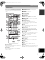 9
9
-
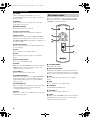 10
10
-
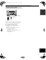 11
11
-
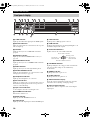 12
12
-
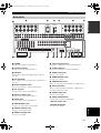 13
13
-
 14
14
-
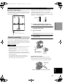 15
15
-
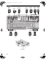 16
16
-
 17
17
-
 18
18
-
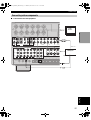 19
19
-
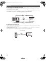 20
20
-
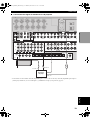 21
21
-
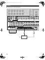 22
22
-
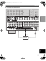 23
23
-
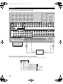 24
24
-
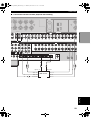 25
25
-
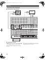 26
26
-
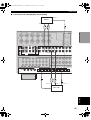 27
27
-
 28
28
-
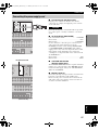 29
29
-
 30
30
-
 31
31
-
 32
32
-
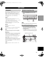 33
33
-
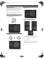 34
34
-
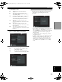 35
35
-
 36
36
-
 37
37
-
 38
38
-
 39
39
-
 40
40
-
 41
41
-
 42
42
-
 43
43
-
 44
44
-
 45
45
-
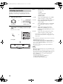 46
46
-
 47
47
-
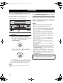 48
48
-
 49
49
-
 50
50
-
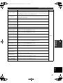 51
51
-
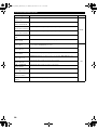 52
52
-
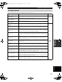 53
53
-
 54
54
-
 55
55
-
 56
56
-
 57
57
-
 58
58
-
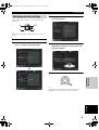 59
59
-
 60
60
-
 61
61
-
 62
62
-
 63
63
-
 64
64
-
 65
65
-
 66
66
-
 67
67
-
 68
68
-
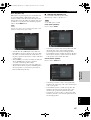 69
69
-
 70
70
-
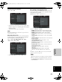 71
71
-
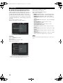 72
72
-
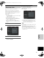 73
73
-
 74
74
-
 75
75
-
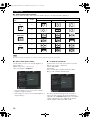 76
76
-
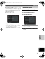 77
77
-
 78
78
-
 79
79
-
 80
80
-
 81
81
-
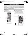 82
82
-
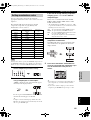 83
83
-
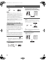 84
84
-
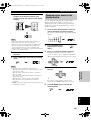 85
85
-
 86
86
-
 87
87
-
 88
88
-
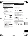 89
89
-
 90
90
-
 91
91
-
 92
92
-
 93
93
-
 94
94
-
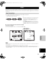 95
95
-
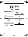 96
96
-
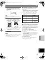 97
97
-
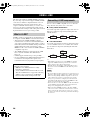 98
98
-
 99
99
-
 100
100
-
 101
101
-
 102
102
-
 103
103
-
 104
104
-
 105
105
-
 106
106
-
 107
107
-
 108
108
-
 109
109
-
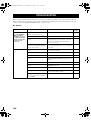 110
110
-
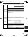 111
111
-
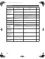 112
112
-
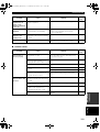 113
113
-
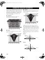 114
114
-
 115
115
-
 116
116
-
 117
117
-
 118
118
-
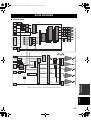 119
119
-
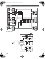 120
120
-
 121
121
-
 122
122


in andere talen
- English: Yamaha DSP-Z9 User manual
- italiano: Yamaha DSP-Z9 Manuale utente
- русский: Yamaha DSP-Z9 Руководство пользователя
- français: Yamaha DSP-Z9 Manuel utilisateur
- español: Yamaha DSP-Z9 Manual de usuario
- Deutsch: Yamaha DSP-Z9 Benutzerhandbuch
- português: Yamaha DSP-Z9 Manual do usuário
- dansk: Yamaha DSP-Z9 Brugermanual
- suomi: Yamaha DSP-Z9 Ohjekirja
- čeština: Yamaha DSP-Z9 Uživatelský manuál
- svenska: Yamaha DSP-Z9 Användarmanual
- Türkçe: Yamaha DSP-Z9 Kullanım kılavuzu
- polski: Yamaha DSP-Z9 Instrukcja obsługi
- română: Yamaha DSP-Z9 Manual de utilizare
Gerelateerde papieren
-
Yamaha RX-V2400RDS de handleiding
-
Yamaha DSP-E580 de handleiding
-
-
-
-
-
-
-
-
