APRILIA RSV4 FACTORY-R - 10-2010 Data papier
- Categorie
- Motorfietsen
- Type
- Data papier

APRILIA WOULD LIKE TO THANK YOU
for choosing one of its products. We have drawn up this booklet to provide a comprehensive overview of your vehicle's quality features. Please read it
carefully before riding the vehicle for the first time. It contains information, tips and precautions for using your vehicle. It also describes features, details
and devices to assure you that you have made the right choice. We believe that if you follow our suggestions, you will soon get to know your new vehicle
well and will use it for a long time at full satisfaction. This booklet is an integral part of the vehicle, and should the vehicle be sold, it must be transferred
to the new owner.
APRILIA WIL U BEDANKEN
omdat u één van haar producten heeft gekozen. Wij hebben deze handleiding opgesteld opdat u de kwaliteiten ervan ten volle kan waarderen. Wij
raden aan om deze handleiding geheel door te lezen, voordat u met het voertuig gaat rijden. Het bevat informatie, raadgevingen en waarschuwingen
in verband met het gebruik van uw voertuig; daarnaast zal u eigenschappen, bijzonderheden en handigheidjes ontdekken die u ervan zullen overtuigen
dat u een juiste keuze heeft gemaakt. Wij zijn er zeker van dat indien u hier rekening mee zal houden, u makkelijk zal wennen aan uw nieuw voertuig,
waar u lang naar volle tevredenheid gebruik van zal kunnen maken. Deze uitgave is een integrerend deel van het voertuig, en bij verkoop van dit laatste
moet het worden overhandigd aan de nieuwe eigenaar.
RSV4 Factory - R
Ed. 10 2010

The instructions in this booklet have been compiled primarily to offer a simple and clear guide to using the vehicle; it also describes routine maintenance
procedures and regular checks that should be carried out on the vehicle at an Aprilia Dealer or Authorised Workshop. This booklet also contains
instructions for simple repairs. Any operations not specifically described in this booklet require the use of special tools and/or particular technical
knowledge; for these operations, please take your vehicle to an Aprilia Dealer or Authorised Workshop.
De instructies in deze handleiding zijn voorbereid om vooral een eenvoudige en duidelijke leidraad te zijn voor het gebruik; men vindt eveneens de
handelingen van het klein onderhoud en van de periodieke controles die bij een Dealer of Erkende Aprilia Garage moeten uitgevoerd worden. De
handleiding bevat tevens instructies voor een aantal eenvoudige herstellingen. De herstellingen die niet uitgebreid in deze uitgave zijn beschreven,
vereisen dat men over speciale gereedschappen en/of specifieke technische kennis beschikt; voor het uitvoeren van deze herstellingen raadt men aan
om zich te wenden tot een Dealer of Erkende Aprilia Garage.
2

Personal safety
Failure to completely observe these instructions will
result in serious risk of personal injury.
Persoonlijke veiligheid
Indien deze voorschriften niet of niet volledig worden
opgevolgd, kan dit ernstig letsel aan personen tot ge-
volg hebben.
Safeguarding the environment
Sections marked with this symbol indicate the correct
use of the vehicle to prevent damaging the environ-
ment.
Bescherming van
Geeft het juiste gedrag aan dat u aan moet houden
zodat het gebruik van het voertuig geen schade aan-
richt aan de natuur.
Vehicle intactness
The incomplete or non-observance of these regula-
tions leads to the risk of serious damage to the vehicle
and sometimes even the invalidity of the guarantee.
Staat van het voertuig
Indien deze voorschriften niet of niet volledig worden
opgevolgd kan dit ernstige schade aan het voertuig,
en eventueel het vervallen van deze garantie tot ge-
volg hebben.
The symbols illustrated above are very important.
They are used to highlight parts of the booklet that
should be read with particular care. The different sym-
bols are used to make each topic in the manual simple
and quick to locate. Before starting the engine, read
this booklet carefully, particularly the "SAFE RIDING"
section. Your safety as well as other's does not only
depend on the quickness of your reflexes and agility,
but also on how well you know your vehicle, the state
of maintenance of the vehicle itself and your knowl-
edge of the rules for SAFE RIDING. For your safety,
get to know your vehicle well so as to safely ride and
master it given any riding condition. IMPORTANT
This booklet is an integral part of the vehicle, and must
be handed to the new owner in the event of sale.
Bovengenoemde signalen zijn erg belangrijk. Ze heb-
ben namelijk tot doel om de delen van het boekje aan
te geven die u aandachtig door moet lezen. Zoals u
ziet, bestaat ieder teken uit een ander grafisch sym-
bool, zodat de bijbehorende onderwerpen meteen
duidelijk kunnen worden gevonden in de verschillen-
de delen. Vooraleer men de motor start, leest men
aandachtig deze handleiding, en vooral de paragraaf
"VEILIG RIJDEN". Uw veiligheid en die van anderen
hangt niet enkel af van uw reflexen en vlugheid, maar
ook van de kennis en de efficiëntie van het voertuig,
en van de kennis van de fundamentele regels voor het
VEILIG RIJDEN. We raden daarom aan om vertrouwd
te raken met het voertuig, zodat u zich in alle situaties
veilig en beheersd kan bewegen. BELANGRIJK Deze
handleiding moet beschouwd worden als integrerend
deel van het voertuig, en moet worden overhandigd
bij de verkoop ervan.
3
Pagina wordt geladen...

INDEX
INDEX
GENERAL RULES.......................................................................... 9
Foreword.................................................................................. 10
Carbon monoxide..................................................................... 10
Fuel.......................................................................................... 11
Hot components....................................................................... 12
Coolant..................................................................................... 12
Used engine oil and gearbox oil............................................... 13
Brake and clutch fluid............................................................... 14
Battery hydrogen gas and electrolyte....................................... 15
Stand........................................................................................ 16
Reporting of defects that affect safety...................................... 17
System a-PRC (Aprilia Performance Ride Control)..................... 17
VEHICLE......................................................................................... 19
Arrangement of the main components......................................... 21
Dashboard................................................................................... 24
Analog instrument panel.............................................................. 24
Light unit...................................................................................... 26
Digital lcd display......................................................................... 26
Alarms...................................................................................... 30
Mapping selection.................................................................... 33
Control buttons......................................................................... 36
Advanced functions.................................................................. 39
Ignition switch........................................................................... 52
Locking the steering wheel....................................................... 53
a-PRC setting buttons.................................................................. 54
Horn button.................................................................................. 54
Switch direction indicators........................................................... 55
High/low beam selector............................................................... 56
Passing button............................................................................. 56
Start-up button............................................................................. 57
Engine stop switch....................................................................... 57
ALGEMENE NORMEN..................................................................... 9
Vooronderstelling....................................................................... 10
Koolmonoxide............................................................................. 10
Brandstof.................................................................................... 11
Warme onderdelen..................................................................... 12
Koelvloeistof............................................................................... 12
Gebruikte motorolie en koppelingsolie....................................... 13
Rem- en koppelingsvloeistof...................................................... 14
Elektrolyt en waterstofgas van de accu...................................... 15
Standaard................................................................................... 16
Communicatie van de defecten die invloed hebben op de vei-
ligheid......................................................................................... 17
Antiblokkeersysteem a-PRC (Aprilia Performance Ride Control)
....................................................................................................... 17
VOERTUING..................................................................................... 19
Plaats van de hoofdcomponenten................................................. 21
Legenda......................................................................................... 24
Analoog instrumentenpaneel......................................................... 24
Groep controlelampjes................................................................... 26
Digitaal display............................................................................... 26
Alarmen...................................................................................... 30
Selectie lokalisaties.................................................................... 33
Commandoknoppen................................................................... 36
Geavanceerde functies.............................................................. 39
Startschakelaar.......................................................................... 52
Stuurslot vergrendelen............................................................... 53
Knoppen regeling a-PRC............................................................... 54
Drukknop claxon............................................................................ 54
Schakelaar richtingaanwijzers....................................................... 55
Lichtschakelaar.............................................................................. 56
Knop die knippert voor groot licht.................................................. 56
5

System a-PRC (Aprilia Performance Ride Control)..................... 58
Immobilizer system operation.................................................. 70
Fairings........................................................................................ 72
Opening the saddle.................................................................. 73
Glove/tool kit compartment...................................................... 75
Identification................................................................................. 76
USE................................................................................................. 79
Checks......................................................................................... 80
Refuelling..................................................................................... 83
Rear shock absorbers adjustment............................................... 85
Rear shock absorbers setting.................................................. 90
Front fork adjustment................................................................... 94
Front fork setting...................................................................... 97
Steering shock absorber adjustment........................................... 104
Justering af greb til forbremse..................................................... 106
Clutch lever adjustment............................................................... 107
Running in.................................................................................... 107
Starting up the engine.................................................................. 109
Moving off / riding........................................................................ 114
Stopping the engine..................................................................... 122
Parking......................................................................................... 123
Catalytic silencer.......................................................................... 124
Stand........................................................................................... 127
Suggestion to prevent theft.......................................................... 127
Basic safety rules......................................................................... 129
MAINTENANCE.............................................................................. 137
Foreword...................................................................................... 138
Engine oil level check............................................................... 138
Engine oil top-up...................................................................... 140
Tyres............................................................................................ 141
Cooling fluid level......................................................................... 144
Coolant check.......................................................................... 146
Coolant top-up.......................................................................... 146
Checking the brake oil level......................................................... 147
Braking system fluid top up...................................................... 148
Battery removal........................................................................ 152
Use of a new battery................................................................ 153
Checking the electrolyte level.................................................. 155
Charging the battery................................................................. 155
Startknop........................................................................................ 57
Stopschakelaar motor.................................................................... 57
Antiblokkeersysteem a-PRC (Aprilia Performance Ride Control)
....................................................................................................... 58
De werking van het immobilizersysteem.................................... 70
Stroomlijnpanelen.......................................................................... 72
Zadel openen............................................................................. 73
Documentenvakje/gereedschapskit........................................... 75
Identificatie..................................................................................... 76
GEBRUIK.......................................................................................... 79
Controles........................................................................................ 80
Tanken........................................................................................... 83
Regulering achterdempers............................................................. 85
Instelling achterste schokdempers............................................. 90
Regulering voorvorken................................................................... 94
Instelling voorvork...................................................................... 97
Regeling stuurdemper.................................................................... 104
Regulering voorremhendel............................................................. 106
Regulering schakelhendel.............................................................. 107
Inrijden........................................................................................... 107
Starten des motors......................................................................... 109
Start / besturing.............................................................................. 114
Stoppen van de motor.................................................................... 122
Parkeren........................................................................................ 123
Katalysator..................................................................................... 124
Standaard...................................................................................... 127
Tips tegen diefstal.......................................................................... 127
Basis veiligheidsnormen................................................................ 129
ONDERHOUD................................................................................... 137
Premisse........................................................................................ 138
Controle van het peil van de motorolie....................................... 138
Het bijvullen van motorolie......................................................... 140
Banden........................................................................................... 141
Peil koelvloeistof............................................................................ 144
Controle van de koelvloeistof..................................................... 146
Bijvulling van de koelvloeistof..................................................... 146
Controle van het oliepeil van de remmen...................................... 147
Bijvullen van de remvloeistof...................................................... 148
Verwijdering van de accu........................................................... 152
6

Long periods of inactivity............................................................. 156
Fuses........................................................................................... 158
Lamps.......................................................................................... 161
Headlight adjustment............................................................... 163
Front direction indicators............................................................. 166
Rear optical unit........................................................................... 166
Rear turn indicators..................................................................... 167
Number plate light........................................................................ 167
Brake light.................................................................................... 168
Rear-view mirrors........................................................................ 168
Front and rear disc brake............................................................. 169
Periods of inactivity...................................................................... 171
Cleaning the vehicle.................................................................... 173
Transport..................................................................................... 178
Chain backlash check.............................................................. 179
Chain backlash adjustment...................................................... 180
Checking wear of chain, front and rear sprockets.................... 181
Chain lubrication and cleaning................................................. 182
TECHNICAL DATA......................................................................... 185
Kit equipment............................................................................... 196
PROGRAMMED MAINTENANCE.................................................. 199
Scheduled maintenance table..................................................... 200
Inwerkingstelling van een nieuwe accu...................................... 153
Controle van het elektrolytpeil.................................................... 155
Opladen van de accu................................................................. 155
Länger stillegen.............................................................................. 156
Zekeringen..................................................................................... 158
Lampjes......................................................................................... 161
Afstellen van de koplamp........................................................... 163
Richtingaanwijzers voor................................................................. 166
Lampenset achter.......................................................................... 166
Richtingaanwijzers achter.............................................................. 167
Kentekenverlichting........................................................................ 167
Remlicht......................................................................................... 168
Achteruitkijkspiegels...................................................................... 168
Schijfrem voor en achter................................................................ 169
Stilstand van het voertuig............................................................... 171
Reinigen van het voertuig.............................................................. 173
Vervoer.......................................................................................... 178
Controle van de speling van de ketting...................................... 179
Regeling van de speling van de ketting...................................... 180
Controle van het gebruik van de ketting, het tandrad en kroon
................................................................................................... 181
Smering en reiniging van de ketting........................................... 182
TECHNISCHE GEGEVENS.............................................................. 185
Bijgeleverd gereedschap............................................................... 196
GEPLAND ONDERHOUD................................................................ 199
Tabel gepland onderhoud.............................................................. 200
7
Pagina wordt geladen...

RSV4 Factory - R
Chap. 01
General rules
Hst. 01
Algemene
normen
9

Foreword
NOTE
CARRY OUT THE MAINTENANCE OP-
ERATIONS AT HALF THE INTERVALS
SPECIFIED IF THE VEHICLE IS USED
IN WET OR DUSTY AREAS, OFF
ROAD OR FOR SPORTING APPLICA-
TIONS.
Vooronderstelling
N.B.
WANNEER HET VOERTUIG WORDT
GEBRUIKT IN REGENACHTIGE OF
STOFFIGE ZONES, OP SLECHTE WE-
GEN, OF WANNEER MEN SPORTIEF
RIJDT, MOETEN DE ONDERHOUDS-
HANDELINGEN AAN DE HELFT VAN
HET AANGEDUIDE TIJDSINTERVAL
UITGEVOERD WORDEN.
Carbon monoxide
If you need to keep the engine running in
order to perform a procedure, please en-
sure that you do so in an open or very well
ventilated area. Never let the engine run
in an enclosed area. If you do work in an
enclosed area, make sure to use a
smoke-extraction system.
CAUTION
EXHAUST EMISSIONS CONTAIN
CARBON MONOXIDE, A POISONOUS
GAS WHICH CAN CAUSE LOSS OF
CONSCIOUSNESS AND EVEN
DEATH.
Koolmonoxide
Wanneer het nodig is om de motor te
doen werken om een handeling uit te
voeren, controleert men of dit in een open
ruimte of in een goed geventileerd lokaal
gebeurt. Laat de motor nooit werken in
een gesloten ruimte. Wanneer men in
een gesloten ruimte werkt, gebruikt men
een evacuatiesysteem voor de uitlaat-
gassen.
LET OP
DE UITLAATGASSEN BEVATTEN
KOOLMONOXIDE, EEN GIFTIG GAS
DAT BEWUSTELOOSHEID EN OOK
DE DOOD KAN VEROORZAKEN.
10
1 General rules / 1 Algemene normen
Pagina wordt geladen...

NEN HET UITSTROMEN VAN BRAND-
STOF VEROORZAKEN.
Hot components
The engine and the exhaust system com-
ponents get very hot and remain in this
condition for a certain time interval after
the engine has been switched off. Before
handling these components, make sure
that you are wearing insulating gloves or
wait until the engine and the exhaust sys-
tem have cooled down.
Warme onderdelen
De motor en de onderdelen van de uit-
laatinstallatie worden zeer warm en blij-
ven lang warm, ook nadat de motor wordt
uitgezet. Vooraleer men deze onderde-
len hanteert, draagt men isolerende
handschoenen, of wacht men tot de mo-
tor en de uitlaatinstallatie zijn afgekoeld.
Coolant
The coolant contains ethylene glycol
which, under certain conditions, can be-
come flammable. When ethylene glycol
burns, it produces an invisible flame
which can nevertheless cause burns.
CAUTION
TAKE CARE NOT TO POUR COOLANT
ONTO HOT ENGINE OR EXHAUST
SYSTEM COMPONENTS; THE FLUID
MAY CATCH FIRE AND BURN WITH
INVISIBLE FLAMES. WHEN CARRY-
ING OUT MAINTENANCE OPERA-
TIONS, IT IS ADVISABLE TO WEAR
LATEX GLOVES. EVEN THOUGH IT IS
Koelvloeistof
De koelvloeistof bevat ethyleenglycol,
wat in sommige omstandigheden ont-
vlambaar is. Wanneer het brandt, produ-
ceert ethylglycol onzichtbare vlammen,
die toch brandwonden veroorzaken.
LET OP
LET OP OM GEEN KOELVLOEISTOF
TE MORSEN OP DE HETE DELEN VAN
DE MOTOR EN DE UITLAATINSTAL-
LATIE; DEZE ZOU BRAND KUNNEN
VATTEN MET ONZICHTBARE VLAM-
MEN. BIJ ONDERHOUDSHANDELIN-
GEN RAADT MEN AAN OM LATEX
HANDSCHOENEN TE GEBRUIKEN.
12
1 General rules / 1 Algemene normen
Pagina wordt geladen...
Pagina wordt geladen...
Pagina wordt geladen...
Pagina wordt geladen...

Reporting of defects that
affect safety
Unless otherwise specified in this Use
and Maintenance Booklet, do not remove
any mechanical or electrical component.
CAUTION
SOME OF THE VEHICLE'S CONNEC-
TORS ARE INTERCHANGEABLE AND
IF MOUNTED INCORRECTLY CAN
JEOPARDISE REGULAR FUNCTION-
ING OF THE VEHICLE AND/OR DAM-
AGE PARTS OF IT IRREPARABLY.
Communicatie van de
defecten die invloed hebben
op de veiligheid
Behalve waar gespecificeerd wordt in dit
Gebruiks- en onderhoudsboekje, mag
geen enkel mechanisch of elektrisch on-
derdeel gedemonteerd worden.
LET OP
SOMMIGE CONNECTOREN VAN HET
VOERTUIG KUNNEN ONDERLING
VERWISSELBAAR ZIJN, EN ALS ZE
VERKEERD GEMONTEERD WORDEN
KUNNEN ZE DE NORMALE WERKING
VAN HET VOERTUIG SCHADEN EN/
OF ONHERSTELBARE SCHADE AAN
DE DELEN ZELF VEROORZAKEN.
System a-PRC (Aprilia
Performance Ride Control)
a-PRC system (Aprilia Performance
Ride Control)
The a-PRC system consists of the follow-
ing control systems:
ALC (Aprilia Launch Control)
A system designed to help the rider opti-
mise acceleration during standing starts.
Antiblokkeersysteem a-PRC
(Aprilia Performance Ride
Control)
a-PRC (Aprilia Performance Ride Con-
trol) systeem
Het a-PRC systeem bestaat uit de vol-
gende controlesystemen:
ALC (Aprilia Launch Control)
17
1 General rules / 1 Algemene normen

ATC (Aprilia Traction Control)
A system designed to help the rider con-
trol wheelspin.
AWC (Aprilia Wheelie Control)
A system designed to help the rider con-
trol wheeling by reducing torque to gently
lower the front wheel to the ground.
AQS (Aprilia Quick Shift)
This system enables upshifts without us-
ing the clutch and without changing the
throttle position.
Dit systeem is bedacht om de bestuurder
te helpen de acceleratie vanuit stilstand
te optimaliseren.
ATC (Aprilia Traction Control)
Dit systeem is bedacht om de bestuurder
te helpen het slippen van de wielen onder
controle te houden.
AWC (Aprilia Wheelie Control)
Dit systeem is bedacht om de bestuurder
te helpen het fenomeen van het steigeren
te beperken door het koppel te verlagen
om het voorwiel zo zacht op de grond te
laten komen.
AQS (Aprilia Quick Shift)
Dit systeem maakt de versnelling moge-
lijk zonder dat u de koppeling gebruikt en
zonder dat u de stand van de gashendel
wijzigt.
key:
a-PRC: motorcycle with a-PRC system
(Aprilia Performance Ride Control).
Legende:
a-PRC: motorfiets voorzien van het a-
PRC (Aprilia Performance Ride Control)
systeem.
18
1 General rules / 1 Algemene normen

RSV4 Factory - R
Chap. 02
Vehicle
Hst. 02
Voertuing
19
Pagina wordt geladen...

02_02
Arrangement of the main
components (02_02)
key:
1. Left side fairing
2. Horn
3. Left headlamp
4. Windshield
5. Left hand rear view mirror and
turn indicator
6. Steering damper
7. Clutch lever
8. Left hand switch
9. Fuel tank cap
Plaats van de
hoofdcomponenten (02_02)
Legende:
1. Linker zijbekleding
2. Akoestische melder
3. Linker voorlicht
4. Kapje
5. Linker achteruitkijkspiegel en
richtingaanwijzer
6. Stuurdemper
7. Koppelingshendel
8. Linker schakelaar
9. Dop van de brandstoftank
21
2 Vehicle / 2 Voertuing

10. Fuel tank
11. Left side fairing
12. Battery
13. Auxiliary fuses
14. Main fuses
15. Taillight
16. License plate light
17. Rear left turn indicator
18. Saddle / glovebox / toolkit com-
partment lock
19. Left hand rider footrest
20. Side stand
21. Gear lever
22. AQS (Aprilia Quick Shift)
23. Left hand fairing lug
24. Engine oil radiator
25. Coolant radiator
26. CLF ECU (Tone Wheel Reading
ECU)
27. Tail fairing
28. Right side fairing
29. Rear shock absorber
30. Sensor box (inertia sensor plat-
form)
31. Air filter
32. ECU
33. Right hand switch
34. Starter button
35. Front brake fluid reservoir
36. Instrument/indicator light panel
37. Right hand rear view mirror and
turn indicator
38. Front right headlamp
39. Right side fairing
40. Expansion tank cap
41. Front tone wheel
42. Coolant expansion tank
43. Oil filter
10. Brandstoftank
11. Linker zijplaatje
12. Accu
13. Secundaire zekeringen
14. Hoofdzekeringen
15. Achterlicht
16. Nummerplaatlicht
17. Linker richtingaanwijzer achter-
aan
18. Slot van het zadel / documen-
tenvakje / gereedschapskit
19. Linker voetsteun bestuurder
20. Laterale standaard
21. Versnellingshendel
22. AQS (Aprilia Quick Shift)
23. Beslag linkerzijbekleding
24. Olieradiator motor
25. Koelvloeistofradiator
26. CLF-schakelkast (schakelkast
fonische lezingen)
27. Achterspatbord
28. Rechter zijplaatje
29. Achterste schokdemper
30. Sensor box (inertieplatform)
31. Luchtfilter
32. ECU Unit
33. Rechter schakelaar
34. Startknop
35. Vloeistoftank van de voorrem
36. Groep instrumenten/indicatoren
37. Rechter achteruitkijkspiegel en
richtingaanwijzer
38. Rechter koplamp
39. Rechter zijbekleding
40. Dop van het expansievat
41. Voorste geluidswiel
42. Expansievat koelvloeistof
43. Oliefilter
22
2 Vehicle / 2 Voertuing

44. Engine oil plug
45. Right hand fairing lug
46. Engine oil level
47. Gear lever
48. Right hand rider footrest
49. Rear tone wheel
50. Rear brake pump and fluid res-
ervoir
51. Rear right turn indicator
44. Dop van de motorolie
45. Beslag rechterzijbekleding
46. Peil van de motorolie
47. Versnellingshendel
48. Rechter voetsteun bestuurder
49. Achterste geluidswiel
50. Pomp en remvloeistof tank ach-
teraan
51. Rechter richtingaanwijzer ach-
teraan
02_03
23
2 Vehicle / 2 Voertuing

Dashboard (02_03)
key:
1. Horn button
2. Turn indicator control
3. MODE Control
4. Clutch control lever
5. High beam flashing switch
6. Ignition switch /steering lock
7. Instruments and gauges
8. Throttle grip
9. Engine stop button
10. Starter button
11. Front brake lever
12. "+" button
13. "-" button
Legenda (02_03)
Legende:
1. Drukknop van de akoestische
melder
2. Commando van de richtingaan-
wijzers
3. Commando MODE
4. Bedieningshendel van de kop-
peling
5. Drukknop voor het knipperen
van het groot licht
6. Schakelaar van de ontsteking /
stuurslot
7. Instrumenten en indicatoren
8. Gashandvat
9. Drukknop voor het stilleggen
van de motor
10. Startknop
11. Hendel van de voorrem
12. Knop "+"
13. Knop "-"
02_04
Analog instrument panel
(02_04)
key:
1. Rpm indicator
2. Multifunctional digital display
3. Warning lights
Analoog instrumentenpaneel
(02_04)
Legende:
1. Toerenteller
2. Digitaal multifunctioneel display
3. CONTROLELAMPEN
24
2 Vehicle / 2 Voertuing

The instrument panel has an immobilizer
system which prevents start-up in case
the system does not identify a key which
has been stored before.
The vehicle is supplied with two keys al-
ready programmed. The instrument pan-
el accepts a maximum of four keys at the
same time: contact an Official Aprilia
Dealer to enable these keys or to disable
a key that has been lost. When the vehi-
cle is delivered and approximately ten
seconds after the key is set to ON, the
instrument panel requests a personal
five-digit code to be entered. This request
is no longer displayed once the personal
code is entered. For code entering pro-
cedure, see the CODE MODIFICATION
section
It is important to remember the per-
sonal code because:
•
the vehicle can be started if
the immobilizer system is
faulty
•
the instrument panel need not
be replaced should the igni-
tion switch be changed
•
new keys can be programmed
Het dashboard heeft een immobilizersys-
teem dat de start belet wanneer het sys-
teem de sleutel niet herkent die eerder
werd opgeslagen.
Bij het voertuig worden twee reeds opge-
slagen sleutels geleverd. Het dashboard
aanvaardt tegelijkertijd maximum vier
sleutels: voor hun activering of voor het
desactiveren van een verloren sleutel,
moet men zich wenden tot een Officiële
Aprilia Dealer. Wanneer het voertuig
wordt overhandigd, zal ongeveer 10 se-
conden lang na het draaien van de sleutel
in positie ON het dashboard vragen om
een persoonlijke code van vijf cijfers in te
voeren. Deze vraag zal niet meer worden
weergegeven nadat de persoonlijke code
werd ingevoerd. Voor de procedure van
het invoeren van de code moet de para-
graaf WIJZIGING VAN DE CODE ge-
raadpleegd worden
Het is belangrijk om de persoonlijke
code te herinneren, omdat deze dient
voor het volgende:
•
het starten van het voertuig
wanneer de werking van het
immobilizersysteem defect is
•
het vermijdt de vervanging
van het dashboard wanneer
de ontstekingsschakelaar
moet vervangen worden
•
het opslaan van nieuwe sleu-
tels
25
2 Vehicle / 2 Voertuing

02_05
Light unit (02_05)
Key (a-PRC):
1. General warning light, red
2. Gear in neutral warning light,
green
3. a-PRC (Aprilia Performance
Ride Control) indicator light, or-
ange
4. Low fuel warning light, orange
5. Right turn indicator warning
light, green
6. ABS warning light (not enabled)
7. Gear shift warning light, red
8. Left turn indicator warning light,
green
9. High beam indicator light, blue.
Groep controlelampjes
(02_05)
Legenda (a-PRC):
1. Controlelamp algemene War-
ning, rood
2. Controlelamp van de versnelling
in vrij, groen
3. Controlelamp a-PRC (Aprilia
Performance Ride Control),
oranje
4. Oranje controlelamp van de
brandstofreserve
5. Controlelamp van de rechter
richtingaanwijzer, groen
6. Controlelamp ABS (niet actief)
7. Controlelamp schakelen, rood
8. Controlelamp van de linker rich-
tingaanwijzer, groen
9. Controlelamp groot licht, blauw
02_06
Digital lcd display (02_06,
02_07, 02_08, 02_09, 02_10,
02_11, 02_12)
•
By turning the ignition key to
'KEY ON', the following indica-
tors on the instrument panel are
lit for two seconds:
- The 'RSV4' logo
- All warning lights
Digitaal display (02_06, 02_07,
02_08, 02_09, 02_10, 02_11,
02_12)
•
Door de ontstekingssleutel in
positie 'KEY ON' te draaien,
wordt op het dashboard het vol-
gende twee seconden lang
weergegeven:
- Het logo 'RSV4'
- Alle controlelampen
26
2 Vehicle / 2 Voertuing

02_07
•
The rpm indicator pointer moves
and then goes back to its origi-
nal position.
•
De wijzer van de toerenteller
verplaatst zich en keert daarna
terug naar de beginpositie.
NOTE
EVERY TIME THE SELECTOR IS HELD
DOWN TO THE RIGHT OR LEFT, YOU
CAN GO FROM ONE CONFIGURA-
TION TO ANOTHER.
N.B.
BIJ ELKE LANGE DRUK OP DE SCHA-
KELAAR NAAR LINKS OF RECHTS
KAN OVERGEGAAN WORDEN VAN
DE ENE CONFIGURATIE NAAR DE
ANDERE.
02_08
ROAD - TRIP 1/TRIP 2 MODES (a-PRC)
1) Water temperature (displayed either in
°C or °F);
2) Gear selected;
3) Clock (in 24H format or in 12H format
with no AM/PM indication) or chronome-
ter (selectable from menu).
4) Map selected;
5) ALC (Aprilia Launch Control);
6) ATC (Aprilia Traction Control); The lev-
el is displayed in negative against a black
MODALITEIT ROAD - TRIP 1/TRIP 2 (a-
PRC)
1) Meting van de watertemperatuur (in C
° of in F°);
2) Versnelling ingeschakeld;
3) Klok (weergave in modaliteit H24 en
modaliteit H12 zonder aanduiding AM /
PM) of chronometer (selecteerbaar in het
menu).
4) Gekozen kaart;
5) ALC (Aprilia Launch Control);
27
2 Vehicle / 2 Voertuing

background when AWC (Aprilia Wheelie
Control) is active.
7) Speed (speedometer);
8) Information, if available, relative to
maps stored in ECU;
9) Service interval spanner symbol, if ap-
plicable.
10) Trip computer log or alarms stored.
6) ATC (Aprilia Traction Control); De
AWC (Aprilia Wheelie Control) is geacti-
veerd als het weergegeven nummer van
het niveau negatief is.
7) Snelheid (snelheidsmeter);
8) De eventuele indicatie van de lokali-
satie die in de regeleenheid aanwezig is;
9) Eventuele sleutel onderhoudsbeurt.
10) Dagboek van de reiscomputer of
eventuele alarmen.
02_09
RACE MODE (a-PRC)
1) Chronometer or Launch control;
2) Gear selected;
3) Information, if available, relative to
maps stored in ECU;
4) Map selected;
5) ATC (Aprilia Traction Control); The lev-
el is displayed in negative against a black
background when AWC (Aprilia Wheelie
Control) is active.
6) Speed (speedometer);
7) Water temperature (displayed either in
°C or °F);
MODALITEIT RACE (a-PRC)
1) Chronometer of Launch control;
2) Versnelling ingeschakeld;
3) De eventuele indicatie van de lokali-
satie die in de regeleenheid aanwezig is;
4) Gekozen kaart;
5) ATC (Aprilia Traction Control); De
AWC (Aprilia Wheelie Control) is geacti-
veerd als het weergegeven nummer van
het niveau negatief is.
6) Snelheid (snelheidsmeter);
7) Meting van de watertemperatuur (in C
° of in F°).
28
2 Vehicle / 2 Voertuing

02_10
Two kilometres after the low fuel warning
light turns on, the kilometres travelled
with low fuel are shown on the digital dis-
play.
2 km na de inschakeling van de contro-
lelamp van de brandstofreserve ver-
schijnt op het digitaal display de aandui-
ding van het aantal afgelegde km in
reserve.
Pressing the centre button of the MODE
control while the low fuel warning light is
active temporarily deactivates the warn-
ing light for 60 seconds.
At "KEY-ON" the indication of reserve
can have a delay of 60 seconds.
Wanneer de controlelamp van de brand-
stofreserve oplicht, gaat deze door op het
bediening MODE te drukken uit en na 60
seconden weer aan.
Bij "KEY-ON" kan de aanduiding van de
reserve 60 seconden later aangeduid
worden.
02_11
The instrument panel can display instan-
taneous fuel consumption
The instrument panel can display aver-
age fuel consumption since the last jour-
ney log reset
Upon entering reserve, the distance in
Km (or mi) travelled since entering re-
serve state is displayed instead of the trip
counter
Het dashboard kan momentele verbruik
weergeven.
Het dashboard kan het gemiddelde ver-
bruik vanaf de laatste reset van het reis-
verslag weergeven.
Bij aanvang van het reserveverbruik, ver-
schijnt in plaats van de hodometer het
aantal km (mi) dat vanaf het begin van de
reserve is afgelegd.
29
2 Vehicle / 2 Voertuing

02_12
When a maintenance interval threshold is
exceeded, an icon with a spanner is
shown. This indicator may be reset once
the scheduled service has been comple-
ted by an authorised Aprilia Dealership
or service centre.
The "spanner" icon flashes for five sec-
onds when the key is turned to "KEY ON"
when there is less than 300 Km (186 mi)
remaining before the next scheduled
maintenance interval.
With the key set to "KEY OFF" the gen-
eral alarm warning light flashes to indi-
cate activation of the locking system. To
minimise battery consumption the light
stops flashing after 48 hours.
Wanneer de limieten van de onderhouds-
intervallenworden overschreden, ver-
schijnt een icoon met het symbool van de
Engelse sleutel. Wanneer de geprogram-
meerde onderhoudshandelingen bij de
Dealers en Erkende Aprilia Garages
worden uitgevoerd, kan deze aanduiding
geëlimineerd worden.
Wanneer de sleutel in de positie "KEY
ON" wordt gedraaid en er ontbreken min-
der dan 300 km (186 mi) tot het uitvoeren
van het geprogrammeerd onderhoud,
knippert de icoon "Engelse sleutel" vijf
seconden lang.
Met de sleutel in positie "KEY OFF" knip-
pert de controlelamp van het algemeen
alarm om de activering van het immobili-
zersysteem te melden. Om het verbruik
van de accu te verminderen houdt het
knipperen op na 48 uren.
02_13
Alarms (02_13, 02_14, 02_15,
02_16, 02_17)
In case of failure, a different icon is dis-
played according to the cause at the bot-
tom of the display.
Take your vehicle as soon as possible to
an Official Aprilia Dealer.
SERVICE ALARM
In case of failure found in the instrument
panel or in the electronic control unit, the
instrument panel signals the failure by
Alarmen (02_13, 02_14, 02_15,
02_16, 02_17)
Wanneer een onregelmatigheid gedetec-
teerd wordt, wordt op het onderste deel
van het display een icoon weergegeven
die verschilt afhankelijk van de oorzaak.
Men moet zich onmiddellijk tot een Offi-
ciële aprilia Dealer wenden.
ALARM SERVICE
Wanneer een onregelmatigheid gedetec-
teerd wordt door het dashboard of de
30
2 Vehicle / 2 Voertuing

displaying the SERVICE icon and the red
general warning light comes on.
elektronische centrale, meldt het dash-
board de onregelmatigheid door de icoon
SERVICE weer te geven en door het op-
lichten van de rode controlelamp van het
algemeen alarm
02_14
If there is an immobilizer failure at igni-
tion, the instrument panel requests you to
enter a user code. If the code is entered
correctly, the instrument panel signals
the failure by displaying the SERVICE
icon and the red general warning light
comes on.
URGENT SERVICE ALARM
A serious failure is signalled by a fast
flashing (two flashes per second) of the
general warning light and by the UR-
GENT and SERVICE words alternately
being shown on the digital display. Take
your vehicle as soon as possible to an
Official Aprilia Dealer. In these cases,
the control unit activates a safety proce-
dure that limits the vehicle performance
so that the rider is able to reach an Official
Aprilia Dealer at low speed. According to
the type of failure, performance can be
limited in two ways: a) by reducing the
maximum torque produced; b) by keep-
ing the engine at idle speed but slightly
accelerated (during this operation, the
throttle control is disabled).
Wanneer bij de ontsteking een onregel-
matigheid van de immobilizer wordt ge-
detecteerd, vraagt het dashboard om de
code van de gebruiker in te voeren Wan-
neer de code correct wordt ingevoerd,
meldt het dashboard de onregelmatig-
heid door het symbool SERVICE weer te
geven en door het oplichten van de rode
controlelamp van het algemeen alarm.
ALARM URGENT SERVICE
Een ernstige onregelmatigheid wordt ge-
meld door het snel knipperen (twee knip-
peringen per seconde) van de controle-
lamp van het algemeen alarm, en door de
afwisselende weergave van de opschrif-
ten URGENT en SERVICE op het digitaal
display. Men moet zich onmiddellijk tot
een Officiële aprilia Dealer wenden. In
deze gevallen activeert de centrale een
veiligheidsprocedure door de prestaties
van het voertuig te beperken, zodat met
beperkte snelheid de Officiële aprilia
Dealer kan bereikt worden. Naargelang
het type van onregelmatigheid kunnen de
prestaties op twee manieren beperkt
worden: a) door het maximum geleverde
koppel te verminderen; b) door de motor
aan een toerental te houden dat iets ho-
ger is dan het minimum (tijdens deze
31
2 Vehicle / 2 Voertuing

werking wordt het gascommando ge-
deactiveerd).
02_15
Oil failure
In case of failing oil pressure or oil pres-
sure sensor failure, the bulb and the red
general warning light turn on the instru-
ment panel.
Onregelmatigheid olie
In geval van een onregelmatigheid van
de oliedruk of de sensor van de oliedruk,
meldt het dashboard de onregelmatig-
heid met een ampul en het oplichten van
de rode controlelamp van het algemeen
alarm.
Engine overheating alarm
The engine overheating alarm is activa-
ted when the temperature reaches 115 °
C (239 °F). It is signalled when the gen-
eral red warning light turns on.
Alarm oververhitting van de motor
Het alarm van de overtemperatuur van
de motor wordt geactiveerd wanneer de
temperatuur 115 °C (239 °F) bereikt. Dit
wordt gemeld door het oplichten van de
rode alarmcontrolelamp.
02_16
Electronic control unit disconnected
alarm
In case no connection is detected, the
disconnection icon is displayed on the in-
strument panel and the red general warn-
ing light turns on to signal this condition.
Alarm elektronische centrale niet ver-
bonden
Wanneer de afwezigheid van de verbin-
ding wordt gedetecteerd, meldt het dash-
board de onregelmatigheid door het sym-
bool van het niet verbonden zijn weer te
geven en door het oplichten van de rode
controlelamp van het algemeen alarm.
32
2 Vehicle / 2 Voertuing

02_17
Turn indicator malfunction
When the instrument panel detects a fail-
ing turn indicator, the turn indicator warn-
ing light flashes twice as fast and the
problem is signalled on the digital display.
Storing Richtingaanwijzer
Wanneer het dashboard het stukgaan
van de richtingaanwijzers detecteert,
knippert de controlelamp van de richting-
aanwijzers eens zo snel, en verschijnt de
aanduiding op het digitaal display.
02_18
Mapping selection (02_18,
02_19)
The engine control unit has three differ-
ent user-selectable electronic throttle
management maps, which are indicated
as follows at the top left of the instrument
panel digital display (1) :
•
T is the TRACK mapping
•
S is the SPORT mapping
•
R is the ROAD mapping
The "T" engine management map is the
most responsive of all and is conceived
for track use.
CAUTION
ONLY EXPERT RIDERS, RIDING ON
ROADS WITH GOOD GRIP ARE AD-
VISED TO USE THIS MODE. IT IS NOT
RECOMMENDED FOR WET SURFA-
CES AND/OR ROADS WITH LOW
GRIP.
Selectie lokalisaties (02_18,
02_19)
De centrale voor de besturing van de mo-
tor bevat 3 verschillende "lokalisaties"
voor de besturing van de elektronische
gashendel, die als volgt links bovenaan
op het digitale display op het dashboard
(1) worden weergegeven:
•
T voor de lokalisatie TRACK
•
S voor de lokalisatie SPORT
•
R voor de lokalisatie ROAD
De lokalisatie "T" reageert het snelst is
bestemd om op het circuit te worden ge-
bruikt.
LET OP
HET GEBRUIK VAN DEZE MODALI-
TEIT WORDT AANGERADEN VOOR
ERVAREN MOTORRIJDERS EN OP
WEGEN MET EEN GOEDE WEGLIG-
GING. HET GEBRUIK OP NATTE WE-
33
2 Vehicle / 2 Voertuing

GEN EN/OF MET EEN SLECHTE WEG-
LIGGING WORDT AFGERADEN.
02_19
The "S" engine management map is tail-
ored for performance-oriented use. In
this mode the vehicle's performance in
first and second gear is reduced.
De lokalisatie "S" werd bedacht voor een
sportief gebruik. In deze modaliteit zijn de
prestaties van het voertuig in de eerste
en tweede versnelling beperkt.
The "R" engine management map is de-
signed for normal road use. The system
reduces the maximum torque supplied by
the engine and smoothly delivers it so as
to prevent loss of grip. In this mode, the
vehicle performance is limited, and there-
fore, the maximum speed cannot be
reached.
CAUTION
THIS IS NOT AN ANTI-SKID DEVICE.
BE EXTREMELY CAUTIOUS WHEN
RIDING ON ROADS WITH LOW GRIP.
De lokalisatie "R" werd bedacht voor een
gebruik op de weg. Het systeem vermin-
dert het maximale koppel dat geleverd
wordt door de motor maar geeft het op
een zachte manier, zodat een betere grip
verkregen wordt. In deze modaliteit wor-
den de prestaties van de motor beperkt,
en kan de maximum snelheid dus niet
bereikt worden.
LET OP
HET IS GEEN ANTI-SLIPMECHANIS-
ME, EN ER WORDT DUS AANGERA-
DEN OM ZEER GOED OP TE LETTEN
OP WEGEN MET EEN SLECHTE WEG-
LIGGING.
The rider may cycle through the different
engine maps by pressing the starter but-
De overgang naar de verschillende loka-
lisaties gebeurt door middel van de in-
34
2 Vehicle / 2 Voertuing

ton, which may be used to select maps
once 5 seconds have elapsed after en-
gine start.
CAUTION
THE RIDER MAY USE THE STARTER
BUTTON TO SELECT MAPS EVEN
WITH THE VEHICLE IN MOTION, PRO-
VIDED THAT THE ENGINE IS RUN-
NING AND THE THROTTLE IS RE-
LEASED.
werkingstelling van de startknop die 5
sec na de start van de motor de functie
van Selectieknop voor de lokalisaties
aanneemt
LET OP
DE SELECTIEPROCEDURE VAN DE
LOKALISATIES IS EVENEENS ACTIEF
MET DE MOTOR IN WERKING, MAAR
ENKEL MET GESTARTE MOTOR EN
WANNEER GEEN GAS GEGEVEN
WORDT.
To change engine maps, proceed as fol-
lows.
•
Press the starter button once.
The symbol of engine map cur-
rently in use is displayed in neg-
ative against a black back-
ground.
•
Press the button twice within 1.5
seconds; the next engine map is
displayed in negative against a
black background. To select this
engine map, press the starter
button within 1.5 seconds. Oth-
erwise, the next engine map in
the sequence will be displayed
in negative against a black
background. When the desired
map is shown, press the starter
button and the desired map will
be displayed normally. In any
case, do not "open" the throttle
during this operation. If the throt-
tle is opened, the activation
Om de lokalisatie te wijzigen, moet als
volgt gehandeld worden:
•
het symbool van de actueel toe-
gepaste lokalisatie wordt "nega-
tief" op het display weergege-
ven als u voor de eerste keer op
de startknop drukt
•
druk twee maal binnen 1,5 se-
conde op de knop; de volgende
lokalisatie zal "negatief" aange-
duid worden op het display.
Druk binnen 1,5 seconden op de
startknop als u deze lokalisatie
wenst te kiezen. In het omge-
keerde geval zal de volgende
lokalisatie van de sequentie ne-
gatief worden weergegeven.
Wanneer de gewenste lokalisa-
tie wordt weergegeven, moet op
de startknop gedrukt worden en
zal de gewenste lokalisatie "po-
sitief" worden weergegeven. Tij-
dens deze handeling mag de
35
2 Vehicle / 2 Voertuing

process for the new engine map
by the ECU is interrupted (the
map symbol is displayed nor-
mally and flashing) until the
throttle is closed again, allowing
the ECU to complete the proce-
dure.
CAUTION
IF THE THROTTLE IS OPENED WHILE
A NEW MAP IS DISPLAYED IN NEGA-
TIVE AGAINST A BLACK BACK-
GROUND (INDICATING THAT IT IS
STILL BEING ACTIVATED BY THE
ECU), THE NEW MAP SELECTED
WILL START TO FLASH (DISPLAYED
NORMALLY) BUT WILL NOT BE EF-
FECTIVELY APPLIED UNTIL THE
THROTTLE IS RELEASED AGAIN.
gashendel in geen enkel geval
"geopend" worden. Als u de
gashendel opent wordt de aan-
vaarding door de elektronische
besturingsunit ECU van de nieu-
we lokalisatie onderbroken (de
lokalisatie knippert "in positief")
tot u de gashendel sluit, zodat
de ECU de handeling kan vol-
tooien.
LET OP
DE NIEUW GEKOZEN LOKALISATIE
BEGINT OP POSITIEF OP HET DIS-
PLAY TE KNIPPEREN ALS U HET
GASCOMMANDO BEDIENT TERWIJL
OP HET DISPLAY DE NIEUWE LOKA-
LISATIE NEGATIEF WORDT WEER-
GEGEVEN EN ZICH DUS NOG IN DE
FASE VAN DE AANVAARDING DOOR
DE CENTRALE BEVINDT. DE NIEUWE
LOKALISATIE WORDT PAS TOEGE-
PAST ALS U HET GASCOMMANDO
LOSLAAT.
02_20
Control buttons (02_20)
Trip journal 1 and 2
There are two trip journals available.
Press and hold down the MODE control
to the left to select the TRIP JOURNAL 1;
icon "1" on the DIGITAL DISPLAY turns
on.
Commandoknoppen (02_20)
Boordjournaal 1 en 2
Er zijn twee boordjournaals aanwezig.
Met een lange druk op het Bediening MO-
DE naar links, wordt het BOORDJOUR-
NAAL 1 geselecteerd, en licht de icoon
"1" op het DIGITAAL DISPLAY op.
36
2 Vehicle / 2 Voertuing

Press and hold down the MODE control
to the right to select the TRIP JOURNAL
2; icon "2" on the DIGITAL DISPLAY
turns on.
In each journal, each time the MODE
control is briefly pressed to the right or
left, the following information is displayed
in sequence:
1) ODOMETER;
2) TRIP ODOMETER;
3) JOURNEY TIME;
4) MAXIMUM SPEED;
5) AVERAGE SPEED;
6) AVERAGE FUEL CONSUMPTION;
7) INSTANTANEOUS FUEL CON-
SUMPTION;
8) MENU (only with vehicle at a standstill)
With the following options: TRIP ODOM-
ETER, TRAVELLING TIME, MAXIMUM
SPEED, MEAN SPEED, AVERAGE
FUEL CONSUMPTION, press and hold
down the central key to reset all the indi-
cations stored in the active TRIP JOUR-
NAL.
Met een lange druk op het bediening MO-
DE naar rechts, wordt het BOORDJOUR-
NAAL 2 geselecteerd, en licht de icoon
"2" op het DIGITAAL DISPLAY op.
In elk journaal wordt bij elke korte druk
van het bediening MODE naar rechts of
naar links achtereenvolgens de volgende
informatie weergegeven:
1) HODOMETER;
2) GEDEELTELIJKE HODOMETER;
3) TIJDSDUUR;
4) MAXIMUM SNELHEID;
5) GEMIDDELDE SNELHEID;
6) GEMIDDELD BRANDSTOFVER-
BRUIK;
7) ONMIDDELLIJK BRANDSTOFVER-
BRUIK;
8) MENU (enkel wanneer het voertuig
stilstaat).
Bij de volgende trefwoorden: HODOME-
TER PARTIEEL, TIJDSDUUR, MAXI-
MUM SNELHEID, GEMIDDELDE SNEL-
HEID, GEMIDDELD BRANDSTOFVER-
BRUIK wist een korte druk op de centrale
toets alle aanduidingen die opgeslagen
werden in het actieve BOORDJOUR-
NAAL.
CHRONOMETER
CHRONOMETER
37
2 Vehicle / 2 Voertuing

To use the chronometer, select the
CHRONOMETER function from the
MENU of the instrument panel advanced
functions.
The chronometer appears at the top of
the digital display, replacing the clock.
With the vehicle in motion the chronom-
eter functioning is controlled by means of
the MODE control central button.
Press the central button briefly to start the
chronometer. Timekeeping starts when
the button is pressed. If the button is
pressed again within 15 seconds after
starting timekeeping, the chronometer is
reset. After that time, and if the button is
pressed again, the data is stored and the
next timekeeping begins.
Timekeeping is cancelled by pressing
and holding down the central button, or
when speed goes back to zero; the dis-
play shows the last timekeeping. Time-
keeping starts again following the steps
described above.
Once 40 timekeeping sessions have
been acquired, acquisition stops and the
message "FULL" is shown on the digital
display. A new series of timekeeping can
be started again only after deleting pre-
vious times stored by means of the
MENU of the instrument panel advanced
functions.
Om de chronometer te gebruiken, moet
de functie CHRONOMETER geselec-
teerd worden in het MENU van de ge-
avanceerde functies van het dashboard.
De chronometer verschijnt bovenaan op
het digitaal display, en vervangt de klok.
Wanneer het voertuig in beweging is,
wordt de werking van de chronometer ge-
controleerd door de centrale toets van
het bediening MODE.
De start van de chronometer wordt uitge-
voerd met een korte druk op de centrale
toets. De eerste druk doet de tijdmeting
starten. Wanneer men nog drukt tijdens
de eerste 15 seconden na het begin van
de tijdmeting, herbegint de chronometer
vanaf nul. Na deze periode zal bij een
volgende druk het gegeven opgeslagen
worden, en zal de volgende meting star-
ten.
Met een lange druk op de centrale toets
of wanneer de snelheid terugkeert naar
nul, wordt de meting geannuleerd, en op
het display verschijnt de laatste meting.
De sessie start weer zoals hierboven
werd beschreven.
De verwerving wordt beëindigd en op het
digitale display wordt het bericht "FULL"
weergegeven als 40 tellingen verworven
zijn. Een nieuwe sessie tijdmetingen kan
enkel hernomen worden wanneer de eer-
der uitgevoerde metingen gewist worden
met het MENU van de geavanceerde
functies van het dashboard.
38
2 Vehicle / 2 Voertuing

02_21
02_22
Advanced functions (02_21,
02_22, 02_23, 02_24, 02_25,
02_26, 02_27, 02_28, 02_29,
02_30)
MENU (a-PRC)
The configuration menu is accessible
with the vehicle at a standstill by pressing
and holding the MODE button, and con-
tains the following functions:
- EXIT
- SETTINGS
- A-PRC SETTINGS
- CHRONOMETER
- CALIBRATION
- DIAGNOSIS
- LANGUAGES
Geavanceerde functies
(02_21, 02_22, 02_23, 02_24,
02_25, 02_26, 02_27, 02_28,
02_29, 02_30)
MENU (a-PRC)
Het configuratiemenu dat u stilstaand
kunt betreden met een lange druk op de
bediening MODE op de menu weergave
bevat de volgende begrippen:
- EXIT
- INSTELLINGEN
- INSTELLINGEN a-PRC
- CHRONOMETER
- KALIBRATIE
- DIAGNOSTIEK
- TALEN
SETTINGS
The SETTINGS menu consists of the fol-
lowing options:
- EXIT
- TIME ADJUSTMENT
- GEAR SHIFT
- BACKLIGHTING
- CODE CHANGE
INSTELLINGEN
Het menu van de INSTELLINGEN be-
staat uit de volgende trefwoorden:
- EXIT
- REGELING VAN HET UUR
- SCHAKELEN
- ACHTERGRONDVERLICHTING
- WIJZIGING VAN DE CODE
39
2 Vehicle / 2 Voertuing

- CODE RESET
- °C / °F
- 12/24 h
The functions of the settings menu are
indicated in the following sections.
Once the operation is finished, the instru-
ment panel goes back to the main menu.
- HERSTELLING VAN DE CODE
- °C/°F
- 12/24 h
De functies van het menu van de instel-
lingen worden aangeduid in de volgende
paragrafen.
Na het beëindigen van de handeling
keert het display terug naar het hoofdme-
nu.
TIME ADJUSTMENT
The clock can be set as follows. The main
screen shows the "Hour Adjustment"
control.
In this mode, the minute indicator is no
longer displayed leaving only the hour in-
dicator. Each time the MODE command
is pressed to the right, the hour value in-
creases; likewise, each time the MODE
command is pressed to the left, the hour
value decreases. Press the MODE com-
mand central part to store the set value
and to shift to minute adjustment.
The hour indicator is no longer displayed
when this function is activated; only the
minute indicator is shown. Each time the
MODE command is pressed to the right,
the minute value increases; likewise,
each time the MODE command is press-
ed to the left the minute value decreases.
REGELING VAN HET UUR
In deze modaliteit kan de klok ingesteld
worden. Het hoofdzakelijke beeldscherm
zal het bediening "Regeling uur" weerge-
ven.
Wanneer deze modaliteit wordt bereikt,
verdwijnt de aanduiding van de minuten
en blijft enkel diegene van de uren zicht-
baar. Bij elke druk naar rechts van het
bediening MODE verhoogt de waarde
van de uren, en symmetrisch bij elke druk
naar links van het bediening MODE ver-
laagt de waarde van de uren. Een druk
op het centrale deel van het bediening
MODE slaat de ingestelde waarde op, en
er wordt overgegaan naar de regeling
van de minuten.
Wanneer deze modaliteit wordt bereikt,
verdwijnt de aanduiding van de uren en
blijft enkel die van de minuten. Bij elke
druk naar rechts van het bediening MO-
DE verhoogt de waarde van de minuten,
en symmetrisch bij elke druk naar links
40
2 Vehicle / 2 Voertuing

Press the MODE command central part
to store the set value and to exit the clock
adjustment function.
van het bediening MODE verlaagt de
waarde van de minuten.
Een druk op het centrale deel van het be-
diening MODE slaat de ingestelde waar-
de op, en wordt de modaliteit van de
regeling van de klok verlaten.
02_23
GEAR SHIFT THRESHOLD
The gear shift threshold can be set in this
mode. The main screen page shows the
message "GEAR SHIFT THRESHOLD".
Each time the MODE command is press-
ed to the right, the threshold value in-
creases by 100 RPM; vice versa, each
time the MODE command is pressed to
the left, the threshold value decreases by
100 RPM.
After reaching either the highest or lowest
limit, the next time the command is press-
ed will produce no effect.
The procedure ends when the MODE
command is pressed at the central posi-
tion, which stores the set value, the point-
er goes back to zero and the instrument
panel goes back to the configuration
menu.
When the battery is first activated, the in-
strument panel is set to the run-in rev
value. Afterwards, the last set value is
displayed:
•
RUN-IN REVOLUTIONS: 8500
rpm
•
MAXIMUM REVOLUTIONS:
15000 rpm
SCHAKELLIMIET
In deze functie stelt men de waarde van
de schakellimiet in. Het hoofdscherm ver-
schijnt met de melding "SCHAKELLI-
MIET".
Bij elke druk naar rechts van het bedie-
ning MODE verhoogt de limietwaarde
met 100 RPM, en omgekeerd bij elke
druk naar links van het bediening MODE
verlaagt de limietwaarde met 100 RPM.
Bij het bereiken van de limiet, onderste of
bovenste, heeft elke volgende druk op de
schakelaar geen enkel effect.
De handeling eindigt met een druk op het
bediening MODE in de centrale positie,
waardoor de ingestelde waarde wordt
opgeslagen, de wijzer keert terug naar
nul, en het dashboard gaat terug naar de
pagina van het menu van de configuratie.
Bij de eerste aansluiting van de accu
wordt het dashboard ingesteld op de
waarde van de toeren van de proefperi-
ode, en bij de volgende aansluitingen
wordt het ingesteld op de laatst ingestel-
de waarde:
•
TOERENTAL VAN DE PROEF-
PERIODE: 8500 toeren/min
(rpm)
41
2 Vehicle / 2 Voertuing

If the set threshold value is exceeded, the
gear change warning light on the instru-
ment panel starts to flash. It turns off
when the value goes back below the
threshold limit.
•
MAXIMUM TOERENTAL:
15000 toeren/min (rpm)
Bij het overschrijden van de vastgestelde
waarde knippert de controlelamp van de
melding van het schakelen op het dash-
board, tot onder de limiet wordt terugge-
keerd.
02_24
02_25
BACKLIGHTING BRIGHTNESS
This function adjusts the backlighting
brightness to three levels. Each time the
MODE command is pressed to the right
or left, the following icons are shown:
•
LOW
•
MEAN
•
HIGH
Once the operation is finished, when the
MODE command is pressed at central
position, the instrument panel shows the
SETTINGS menu.
When the battery is detached, the display
is configured with the maximum level of
brightness.
INTENSITEIT VAN DE ACHTER-
GRONDVERLICHTING
Met deze functie kan de intensiteit van de
achtergrondverlichting ingesteld worden
op drie niveaus. Bij elke druk naar rechts
of links van het bediening MODE, kan de
gebruiker de volgende iconen lezen:
•
LOW
•
MEAN
•
HIGH
Op het einde van de handeling keert het
dashboard met een druk op het bedie-
ning MODE in centrale positie terug naar
het menu INSTELLINGEN.
Wanneer de accu wordt losgekoppeld,
wordt het display aan de maximum hel-
derheid geconfigureerd.
42
2 Vehicle / 2 Voertuing

02_26
CODE CHANGE
This function is used to modify an old
code. Once you have entered this func-
tion, the following message is displayed:
"ENTER OLD CODE"
After recognising the old code, the new
code is requested and the display shows
the following message:
"ENTER NEW CODE"
Once the operation is finished, the dis-
play shows the DIAGNOSIS menu. If the
code has been used, this operation is not
allowed.
Once the operation is finished, the instru-
ment panel shows the SETTINGS menu.
If it is the first time a code is stored, only
the new code is requested.
CODE WIJZIGEN
Deze functie wordt gebruikt wanneer
men over de oude code beschikt, en wan-
neer men deze wil wijzigen. In deze func-
tie verschijnt de melding:
"VOER DE OUDE CODE IN"
Na de herkenning van de oude code
wordt er gevraagd om de nieuwe code in
te voeren, en het display toont de volgen-
de melding:
"VOER DE NIEUWE CODE IN"
Op het einde van de handeling keert het
display terug naar het menu DIAGNOS-
TIEK. Wanneer men deze met de code
heeft bereikt, wordt deze handeling niet
toegelaten.
Op het einde van de handeling keert het
dashboard terug naar het menu INSTEL-
LINGEN.
43
2 Vehicle / 2 Voertuing

Wanneer voor de eerste keer wordt op-
geslagen, wordt enkel het invoeren van
de nieuwe code gevraagd.
CODE RESET
This function is used to set a new code
when the old one is not available; in this
case, at least two keys will have to be in-
serted in the ignition lock. After the first
key has been inserted, the second one is
requested with the following message:
"INSERT KEY II"
In between keys, the instrument panel re-
mains lit; if the key is not inserted within
20 seconds, the operation finishes. After
recognising the second key, the insertion
of the new code is required with the mes-
sage:
"ENTER NEW CODE"
Once the operation is finished, the dis-
play shows the DIAGNOSIS menu. If the
code has been used, this operation is not
allowed.
Once the operation is finished, the instru-
ment panel shows the SETTINGS menu.
CODE RESETTEN
Deze functie wordt gebruikt wanneer
men niet over de oude code beschikt en
wanneer men deze wil wijzigen, in dit ge-
val moet men minstens twee sleutels in
het startblok plaatsen. De eerste is reeds
geplaatst, en daarna wordt het plaatsen
van de tweede gevraagd met de melding:
"PLAATS DE TWEEDE SLEUTEL"
Tijdens de overgang van de ene naar de
andere sleutel blijft het dashboard opge-
licht, en wanneer de sleutel niet binnen
de 20 seconden wordt geplaatst wordt de
handeling beëindigd. Na de herkenning
van de tweede sleutel wordt de invoer
van de nieuwe code gevraagd met de
melding:
"VOER DE NIEUWE CODE IN"
Op het einde van de handeling keert het
display terug naar het menu DIAGNOS-
TIEK. Wanneer men deze met de code
heeft bereikt, wordt deze handeling niet
toegelaten.
Op het einde van de handeling keert het
dashboard terug naar het menu INSTEL-
LINGEN.
44
2 Vehicle / 2 Voertuing

°C/°F
Select the °C / °F option from the SET-
TINGS menu for this function.
This function selects the unit of measure-
ment for the coolant temperature: °C or °
F.
12H / 24H
Select the 12H / 24H option from the
SETTINGS menu for this function.
This menu selects the clock display mode
as 12h or 24h.
°C / °F
Om deze modaliteit te bereiken, moet in
het menu INSTELLINGEN °C / °F gese-
lecteerd worden.
Dit menu selecteert de meeteenheid van
de koelwatertemperatuur: °C of °F.
12H / 24H
Om deze modaliteit te bereiken, moet in
het menu INSTELLINGEN 12H / 24H ge-
selecteerd worden.
Dit menu selecteert de weergave 12H of
24H van de klok.
a-PRC SETTINGS
NOTE
THIS MODE CAN ONLY BE AC-
CESSED IF THE ATC (Aprilia Traction
Control) SYSTEM IS ACTIVE.
INSTELLINGEN a-PRC
N.B.
U KUNT DEZE MODALITEIT UITSLUI-
TEND BETREDEN ALS HET ATC (Apri-
lia Traction Control) SYSTEEM GEAC-
TIVEERD IS.
45
2 Vehicle / 2 Voertuing

02_27
This mode allows the rider to set/activate
AWC (Aprilia Wheelie Control) level and
set ALC (Aprilia Launch Control) levels,
with the vehicle at a standstill.
After selecting the function A-PRC SET-
TINGS, press the MODE selector briefly
to access the AWC and ALC level set-
tings screen.
The AWC level is selected automatically
and displayed in negative against a black
background. Press the "+" and "-" buttons
briefly to increase or decrease the level
setting from "1" (minimum system inter-
vention) to "3" (maximum system inter-
vention).
To deactivate the system, set the mini-
mum level "1" then press and hold "-".
Press and hold "+" to activate again.
In deze modaliteit kunt u bij stilstaand
voertuig de AWC (Aprilia Wheelie Con-
trol) niveaus instellen/activeren en de
ALC (Aprilia Launch Control) niveaus in-
stellen.
U betreedt de weergave met de instellin-
gen van de AWC en ALC niveaus door
kort op de MODE schakelaar te drukken
als u voor INSTELLINGEN A-PRC geko-
zen heeft.
Het negatief weergegeven AWC niveau
wordt automatisch gekozen en kan met
een korte druk op de toetsen "+" en "-"
gewijzigd worden van een waarde
"1" (minimum ingreep) tot "3"(maximum
ingreep).
Houd de toets "-" lang ingedrukt om het
systeem op niveau "1" te deactiveren.
Houd de toets "+" lang ingedrukt om het
systeem te heractiveren.
02_28
To set the ALC level from the adjustment
screen (accessible from A-PRC SET-
TINGS), push the MODE selector briefly
to the left so that the ALC level is dis-
played in negative against a black back-
ground.
Press the "+" and "-" buttons briefly to in-
crease or decrease the ALC level setting
from "1" (minimum system intervention)
to "3" (maximum system intervention).
Verplaats de MODE schakelaar een
beetje naar links zodat de ALC negatief
wordt om het ALC niveau op het scherm
met instellingen (het scherm dat u be-
treedt vanaf de a-PRC INSTELLINGEN)
te kunnen instellen.
Het ALC niveau kan gewijzigd worden
met een korte druk op de toetsen "+" en
"-" van "1" (minimum ingreep) tot
"3" (maximum ingreep).
46
2 Vehicle / 2 Voertuing
Pagina wordt geladen...

- KLOK / CHRONOMETER
- WISSEN METINGEN
CLOCK/CHRONOMETER
This function allows you to select which
function to have at the top of the display:
clock or chronometer.
KLOK / CHRONOMETER
Hiermee kan de functie geselecteerd
worden die bovenaan het display moet
weergegeven worden: klok of chronome-
ter.
02_29
View times
This option shows the stored chronome-
ter times. Press the MODE selector for a
couple of seconds to the right or left to
scroll the time screens; hold it down to
display the CHRONOMETER menu. If
the battery is removed, the stored times
are lost.
Visualiseer de metingen
Deze functie toont de verworven chrono-
metertijden. Met korte drukken op de
keuzeschakelaar MODE naar rechts en
links worden de pagina's van de metin-
gen overlopen, en met een lange druk
verschijnt op het display het menu
CHRONOMETER. Wanneer de accu
wordt losgekoppeld, verliest men de op-
geslagen tijden.
Delete times
This option deletes the stored chronom-
eter times. A deletion confirmation is re-
quested. Once the operation is finished,
the display goes back to the chronometer
menu.
Wis de metingen
Deze modaliteit elimineert de verworven
chronometertijden. De bevestiging voor
het wissen wordt gevraagd. Na het be-
eindigen van de handeling keert het dis-
play terug naar het menu CHRONOME-
TER.
48
2 Vehicle / 2 Voertuing

02_30
CALIBRATION
Select the CALIBRATION function from
the configuration menu to access the
CALIBRATION function.
When the CALIBRATION function is se-
lected (with vehicle at a standstill), a
screen is shown with the following mes-
sage at the bottom of the display:
CALIBRATING
To calibrate the a-PRC (Aprilia Perform-
ance Ride Control) system, ride for ap-
proximately 10 seconds in a straight line
on a flat section of road in second gear
and at a speed of 40 +/- 3 Km/h (24.85 +/-
1.86 mph), until the message CALIBRAT-
ING is no longer shown on the display.
NOTE
ONCE THE MESSAGE 'CALIBRATING'
CEASES TO BE DISPLAYED, STOP
THE VEHICLE, TURN THE IGNITION
SWITCH OFF AND LEAVE OFF FOR
AT LEAST 30 SECONDS TO COM-
PLETE THE CALIBRATION PROCE-
DURE.
THIS ALLOWS THE CALIBRATION TO
BE STORED IN THE MEMORY.
NOTE
THE CALIBRATION PROCEDURE IS
USED TO OPTIMISE a-PRC FUNC-
TIONALITY IN THE EVENT OF CHANG-
ING TYRE TYPE OR FINAL DRIVE
KALIBRERING
Om de functie KALIBRATIE te bereiken,
moet u in het configuratiemenu het begrip
CHRONOMETER kiezen.
Een scherm met de volgende beschrij-
ving aan de onderkant van het display
wordt weergegeven als u voor de functie
KALIBRATIE (bij stilstaand voertuig) ge-
kozen heef:
CALIBRATING
Rijd ongeveer 10 seconden lang in de
tweede versnelling met een snelheid van
40 +/- 3 km/h (24.85 +/- 1.86 mph) op een
vlakke en rechte weg tot op het display
het bericht KALIBRATIE verdwijnt om het
a-PRC systeem (Aprilia Performance Ri-
de Control) te kalibreren.
N.B.
BRENG HET VOERTUIG TOT STIL-
STAND EN SCHAKEL HET DASH-
BOARD MINSTENS 30 SECONDEN
LANG UIT OM DE PROCEDURE TE
VOLTOOIEN ALS HET BERICHT CALI-
BRATING VAN HET DASHBOARD
VERDWENEN IS.
OP DEZE MANIER WORDT DE KALI-
BRATIE IN HET GEHEUGEN VAN DE
REGELEENHEID OPGESLAGEN.
N.B.
DE KALIBRATIE IS NOODZAKELIJK
OM DE FUNCTIONERING VAN DE a-
PRC ALS HET SOORT BANDEN EN DE
49
2 Vehicle / 2 Voertuing

RATIO (PINION-SPROCKET COMBI-
NATION).
IF THE VEHICLE IS FITTED WITH
TYRES OTHER THAN THOSE INDICA-
TED IN THIS USE AND MAINTENANCE
MANUAL, THE LEVEL SETTINGS OF
THE SYSTEM MAY NEED TO BE
MODIFIED IN ORDER TO OBTAIN THE
SAME BEHAVIOUR AS BEFORE.
NOTE
TURN THE IGNITION SWITCH OFF TO
ABORT THE CALIBRATION PROCE-
DURE.
DURING CALIBRATION, ATC IS AU-
TOMATICALLY DEACTIVATED (IF
PREVIOUSLY ACTIVATED).
DEFINITIEVE TRANSMISSIEVERHOU-
DING (RONDSEL-TANDENKROON)
GEWIJZIGD WORDT.
HET KAN NODIG BLIJKEN OM DE NI-
VEAUS VOOR DE INSTELLING VAN
HET SYSTEEM TE WIJZIGEN OM HET-
ZELFDE GEDRAG VAN HET ATC SYS-
TEEM TE KUNNEN WAARBORGEN
ALS U BANDEN GEBRUIKT MET SPE-
CIFICATIES DIE NIET VOLDOEN AAN
DEGENE DIE IN DEZE HANDLEIDING
VOOR GEBRUIK EN ONDERHOUD
VERMELD ZIJN.
N.B.
SCHAKEL HET DASHBOARD UIT ALS
U DE KALIBRATIE WENST TE ANNU-
LEREN.
DE ATC WORDT TIJDENS DE KALI-
BRATIE AUTOMATISCH GEDEACTI-
VEERD (ALS HET SYSTEEM EERDER
GEACTIVEERD WAS).
DIAGNOSIS
Open the configuration menu to display
the DIAGNOSIS option.
This menu interfaces with the systems
present on the vehicle and diagnoses
them. To enable this menu, enter an ac-
cess code available only from official
Aprilia dealers.
DIAGNOSTIEK
Wanneer het configuratiemenu wordt be-
reikt, is het mogelijk om het trefwoord
DIAGNOSTIEK weer te geven.
Dit menu wordt geïnterfaced met de sys-
temen die aanwezig zijn op de motor, en
voert hierop de diagnose uit. Om het te
activeren moet de toegangscode inge-
50
2 Vehicle / 2 Voertuing

voerd worden, die enkel in het bezit is van
de erkende dealers van Aprilia.
LANGUAGES
Open the configuration menu to access
the LANGUAGES function. Select the
LANGUAGES option to choose the inter-
face language.
The options are:
- ITALIANO
- ENGLISH
- FRANÇAIS
- DEUTSCH
- ESPAÑOL
Once the operation is finished, the dis-
play goes back to the LANGUAGES
menu.
TALEN
Vanaf het configuratiemenu kan de func-
tie van de TALEN bereikt worden. Wan-
neer het trefwoord TALEN wordt gese-
lecteerd, kan de taal van de interface
gekozen worden
De opties zijn:
- ITALIANO
- ENGLISH
- FRANÇAIS
- DEUTSCH
- ESPAÑOL
Op het einde van de handeling keert het
display terug naar het menu TALEN
51
2 Vehicle / 2 Voertuing

02_31
Ignition switch (02_31)
The ignition switch (1) is located on the
headstock upper plate.
The vehicle is supplied with two keys
(one is the spare key).
The lights go off when the ignition switch
is set to «OFF».
NOTE
THE KEY ACTIVATES THE IGNITION
SWITCH AND OPERATES THE
STEERING LOCK.
NOTE
THE HIGH AND LOW BEAM LIGHTS
TURN ON AUTOMATICALLY UPON
ENGINE START-UP.
Startschakelaar (02_31)
De ontstekingsschakelaar (1) bevindt
zich op de bovenste plaat van de kop van
de stuurinrichting.
Bij het voertuig worden twee sleutels bij-
geleverd (één reservesleutel).
Het uitgaan van de lichten gebeurt wan-
neer de ontstekingsschakelaar op
«OFF» wordt geplaatst.
N.B.
DE SLEUTEL ACTIVEERT DE ONT-
STEKINGSSCHAKELAAR/HET
STUURSLOT.
N.B.
DE DIMLICHTEN / GROTE LICHTEN
GAAN AUTOMATISCH AAN NA DE
START VAN DE MOTOR.
LOCK: The steering is locked. It is not
possible to start the engine or switch on
the lights. The key can be extracted
OFF: The engine and lights cannot be set
to work. The key can be extracted.
ON: The engine can be started. The key
cannot be removed
PARKING: The steering is blocked. The
engine cannot be started. The lights of
the front and rear headlamps are activa-
ted. The ignition key can be extracted.
LOCK: Het stuur is geblokkeerd. Het is
niet mogelijk om de motor te starten en
om de lichten te activeren. Het is mogelijk
om de sleutel te verwijderen.
OFF: De motor en de lichten kunnen niet
in werking worden gesteld. Het is moge-
lijk om de sleutel te verwijderen.
ON: De motor kan gestart worden. Het is
niet mogelijk om de sleutel te verwijde-
ren.
PARKING: De stuurinrichting is geblok-
keerd. De motor kan niet gestart worden.
52
2 Vehicle / 2 Voertuing

Once the key has been extracted, the im-
mobilizer system is active (if present).
Het positielicht van het voorlicht en de
positielichten van het achterlicht worden
geactiveerd. Het is mogelijk om de sleutel
te verwijderen. Nadat de sleutel wordt
verwijderd, is het immobilizersysteem ac-
tief (indien aanwezig).
02_32
Locking the steering wheel
(02_32)
To lock the steering:
• Turn the handlebar completely to the
left.
• Turn the key to «OFF».
• Push in the key and turn it anticlockwise
(to the left), steer the handlebar slowly
until the key is set to «LOCK».
• Remove the key.
CAUTION
TO AVOID LOSING CONTROL OF THE
VEHICLE, NEVER TURN THE KEY TO
"LOCK" WHILE RIDING.
Stuurslot vergrendelen
(02_32)
Om het stuur te blokkeren:
• Draai het stuur volledig naar links.
• Draai de sleutel in positie «OFF».
• Druk op de sleutel en draai hem in te-
genwijzerzin (naar links) rond, stuur lang-
zaam tot de sleutel op «LOCK» wordt
geplaatst.
• Verwijder de sleutel.
LET OP
DRAAI DE SLEUTEL NOOIT IN POSI-
TIE «LOCK» TIJDENS HET RIJDEN,
ZODAT MEN DE CONTROLE OVER
HET VOERTUIG NIET VERLIEST.
53
2 Vehicle / 2 Voertuing

02_33
02_34
a-PRC setting buttons (02_33,
02_34)
These allow the rider to adjust the set-
tings of the different functions of the a-
PRC system.
Knoppen regeling a-PRC
(02_33, 02_34)
Maken het mogelijk om de diverse func-
ties van het a-PRC in te stellen.
02_35
Horn button (02_35)
Press it to activate the horn.
Drukknop claxon (02_35)
De akoestische melder wordt in werking
gesteld door op de drukknop te drukken.
54
2 Vehicle / 2 Voertuing

02_36
Switch direction indicators
(02_36)
Move the switch to the left, to indicate a
left turn; move the switch to the right to
indicate a right turn. Pressing the switch
deactivates the turn indicator.
CAUTION
IF THE WARNING LIGHT WITH AR-
ROWS FLASHES QUICKLY, IT MEANS
THAT ONE OR BOTH TURN INDICA-
TORS LIGHT BULBS ARE BURNT
OUT.
Schakelaar richtingaanwijzers
(02_36)
Verplaats de schakelaar naar links, om
aan te duiden dat men naar links draait;
verplaats de schakelaar naar rechts, om
aan te duiden dat men naar rechts draait.
Druk op de schakelaar om de richting-
aanwijzer te deactiveren.
LET OP
WANNEER DE CONTROLELAMP VAN
DE PIJLEN SNEL KNIPPERT, ZIJN
EEN OF BEIDE LAMPJES VAN DE
RICHTINGAANWIJZERS VERBRAND.
The turn indicators have a self-cancelling
function that implements the following
logic.
With the vehicle at a standstill (speed =
zero), the turn indicators continue flash-
ing indefinitely.
With the vehicle in motion, the turn indi-
cators self-cancel when one the two fol-
lowing conditions is met:
•
After a time (t) = 40 sec.
•
After riding 500 m (0.31 mi).
If the vehicle speed reaches zero during
this period, the time and distance counts
are reset and start again from zero when
the vehicle starts moving once again.
Het automatisch terugspringen van de
richtingaanwijzers is met de volgende lo-
gica uitgevoerd.
Als het voertuig stil staat, en de snelheid
dus gelijk is aan nul, blijven de richting-
aanwijzers oneindig knipperen.
Als het voertuig in beweging is, springen
de richtingaanwijzers automatisch terug
wanneer één van de volgende twee toe-
standen bereikt wordt:
•
Na een tijd t = 40 sec.
•
Nadat 500 m (0.31 mi) is afge-
legd
Als tijdens dit tijdsverloop de snelheid tot
nul daalt, worden de meting van tijd en
afstand gewist, en begint de meting op-
55
2 Vehicle / 2 Voertuing

Switching on the opposite side turn indi-
cators without pressing the switch in the
intermediate reset position causes both
the time and distance counters to reset
and recommence from zero.
nieuw wanneer het voertuig weer in be-
weging wordt gezet.
De overgang van de richtingaanwijzing
van de ene naar de andere kant zonder
een tussentijdse nulstellingsimpuls, zorgt
voor het wissen van de meting en het op-
nieuw starten van het meten van zowel
tijd als afstand.
02_37
High/low beam selector
(02_37)
Press the light switch to turn on the low
beam light; press it again to turn on the
high beam light.
Lichtschakelaar (02_37)
Wanneer op de schakelaar van de lichten
wordt gedrukt, wordt het dimlicht geacti-
veerd; wanneer er nogmaals wordt op
gedrukt, wordt het groot licht geactiveerd.
02_38
Passing button (02_38)
Uses the high beam flash in case of dan-
ger or emergency.
Releasing the switch deactivates the high
beam flash.
Knop die knippert voor groot
licht (02_38)
Hiermee kan men het knipperen van het
groot licht gebruiken, in geval van gevaar
of nood.
Wanneer men de drukknop loslaat, wordt
het knipperen van het groot licht gedeac-
tiveerd.
56
2 Vehicle / 2 Voertuing

02_39
Start-up button (02_39)
With the key inserted in the ignition and
turned to ON, when the button is pushed
the starter motor will start the engine
AFTER A FEW SECONDS FROM THE
ENGINE START-UP, THE START-UP
BUTTON ASSUMES THE MAPPING
CHANGE FUNCTION.
Startknop (02_39)
Wanneer, met de sleutel in de ontsteking
en op ON gedraaid, op de knop wordt ge-
drukt, zal de startmotor de motor in werk-
ing stellen
DE STARTKNOP NEEMT ENKELE SE-
CONDEN NA DE START VAN DE MO-
TOR DE FUNCTIE VAN SELECTIEK-
NOP VAN DE LOKALISATIE AAN.
02_40
Engine stop switch (02_40)
It acts as an engine cut-off or emergency
stop switch.
Press this switch to stop the engine.
Stopschakelaar motor (02_40)
Dit is een veiligheidsschakelaar of een
noodstopschakelaar.
Druk op de schakelaar om de motor stil
te leggen.
57
2 Vehicle / 2 Voertuing

System a-PRC (Aprilia
Performance Ride Control)
a-PRC system (Aprilia Performance
Ride Control)
Aprilia Performance Ride Control is an
engine torque control system that helps
improve performance and enhance safe-
ty for the rider.
a-PRC consists of four systems:
ATC: Aprilia Traction Control;
AWC: Aprilia Wheelie Control;
ALC: Aprilia Launch Control;
AQS: Aprilia Quick Shift.
Antiblokkeersysteem a-PRC
(Aprilia Performance Ride
Control)
a-PRC (Aprilia Performance Ride Con-
trol) systeem
Aprilia Performance Ride Control is een
systeem dat het koppel van de motor
controleert en zo de performance en de
veiligheid voor de bestuurder verbetert.
a-PRC bevat 4 systemen:
ATC: Aprilia Traction Control;
AWC: Aprilia Wheelie Control;
ALC: Aprilia Launch Control;
AQS: Aprilia Quick Shift.
WARNING AND INDICATOR LIGHTS,
KEY
- Indicator light off: with system activa-
ted with vehicle in motion or system acti-
vated after exceeding 5 Km/h (3.1 mph)
after key-on;
- Indicator light continuously lit: with
system intentionally deactivated by rider
or in the event of a malfunction causing
deactivation;
- Indicator light flashing slowly: with
system active after key-on before ex-
ceeding 5 Km/h (3.1 mph) or in the case
of certain malfunctions causing ATC level
LEGENDA CONTROLELAMPEN
- Controlelamp uit: als het systeem tij-
dens het rijden geactiveerd is of als het
systeem geactiveerd wordt nadat de
snelheid van 5 km/h (3.1 mph) wordt
overschreden na de inschakeling van het
dashboard;
- Controlelamp aan: het systeem vrijwil-
lig uitgeschakeld door de bestuurder of
bij een defect die tot uitschakeling leidt;
- Controlelamp knippert (langzaam
knipperend): als het systeem ingescha-
keld is na het inschakelen van het dash-
board voordat de snelheid van 5 km/h
(3.1 mph) wordt overschreden of in het
58
2 Vehicle / 2 Voertuing

to be locked ("+" and "-" buttons disa-
bled);
- Indicator light flashing quickly: when
one of the a-PRC functions (ATC, AWC
and ALC) is actively invoking traction
control.
geval van bepaalde defecten die leiden
tot bevriezing (dan worden de knoppen
"+" en "-" uitgeschakeld) van het ATC-ni-
veau;
- Controlelamp knippert (snel knippe-
rend): als een van de functies van het
systeem a-PRC (ATC, AWC e ALC) op
de tractiecontrole ingrijpt.
Aprilia Traction Control
Traction control: a system designed to
help the rider control wheelspin.
Aprilia Traction Control
Tractiecontrole: het is een systeem om
de bestuurder te helpen het slippen van
de wielen onder controle te houden.
ATC is a device that controls the rear
wheel sliding during acceleration, limiting
if necessary, in order to increase the ve-
hicle stability.
The ATC system enhances control over
the vehicle, taking into consideration nev-
er to exceed the physical limits of vehicle
grip on the road. The rider is fully respon-
sible for riding at a suitable speed based
on weather and road conditions, always
leaving an appropriate safety margin.
Under no circumstances can the ATC
system compensate for the rider's mis-
judgement or improper use of throttle
grip.
De ATC is een systeem dat het slippen
van het achterwiel tijdens het versnellen
controleert en eventueel beperkt om de
stabiliteit van het voertuig te bevorderen.
Het ATC systeem verbetert de controle
van het voertuig en zorgt ervoor dat de
fysieke limieten van de wegligging van
het voertuig niet overschreden worden.
De bestuurder moet met een gepaste
snelheid rijden, moet rekening houden
met de weersinvloeden en de toestand
van het wegdek en moet voor een nood-
zakelijke veiligheidsmarge zorgen.
Het ATC systeem is niet in staat om in de
verschillende situaties beoordelingsfou-
ten en een onjuist gebruik van de ver-
snelling te compenseren.
59
2 Vehicle / 2 Voertuing

THE TRACTION CONTROL SYSTEM
DOES NOT PREVENT FALLS WHILE
CORNERING.
ABRUPT ACCELERATION WITH THE
VEHICLE INCLINED OR HANDLEBAR
TURNED, CREATES A LACK OF STA-
BILITY DIFFICULT TO HANDLE.
DO NOT SPEED RECKLESSLY. THE
VEHICLE GRIP ON THE ROAD IS SUB-
JECT TO LAWS OF PHYSICS WHICH
EVEN THE ATC SYSTEM CAN NOT
ELIMINATE.
DE TRACTIECONTROLE BEHOEDT
NIET VOOR HET VALLEN IN BOCH-
TEN.
EEN BRUUSKE VERSNELLING MET
HELLEND VOERTUIG OF ALS HET
STUUR GEDRAAID IS VEROOR-
ZAAKT EEN INSTABILITEIT DIE MOEI-
LIJK TE BEHEERSEN IS.
VOORKOM ONVOORZICHTIG RIJ-
DEN. DE WEGLIGGING VAN HET
VOERTUIG IS ONDERWORPEN AAN
BEPAALDE NATUURKUNDIGE WET-
TEN DIE DE ATC NIET KAN ELIMINE-
REN.
The ATC system also responds optimally
and limits wheelspin during cornering.
This is made possible by the inertia sen-
sor platform, which provides the ECU
with precise information concerning the
inclination of the motorcycle.
ATC SYSTEM DEACTIVATED MAN-
UALLY
At key-on and after the initial instrument
panel check cycle, if the system is deac-
tivated, the a-PRC indicator light remains
lit constantly until the rider activates the
system again.
Het ATC systeem grijpt optimaal in tij-
dens het rijden in bochten en controleert
het slippen dus ook tijdens deze rijfase.
Dit is mogelijk dankzij de aanwezigheid
van het inertie platform dat de regeleen-
heid voorziet van nauwkeurige indicaties
betreffende de inclinatie van de motor-
fiets.
ATC SYSTEEM HANDMATIG GE-
DEACTIVEERD
De a-PRC controlelamp blijft branden tot
u het systeem activeert als bij het starten
van het voertuig na de controle van het
dashboard het systeem gedeactiveerd is.
60
2 Vehicle / 2 Voertuing

ATC SYSTEM ACTIVE
At key-on and after the initial instrument
panel check cycle, if the system was ac-
tive at the last key-off, the a-PRC indica-
tor light flashes until the vehicle exceeds
5 Km/h (3.1 mph), after which it extin-
guishes.
ATC SYSTEEM GEACTIVEERD
De a-PRC controlelamp knippert na de
controle van het dashboard als het sys-
teem sinds het vorige gebruik geacti-
veerd gebleven is. De lamp blijft knippe-
ren tot de snelheid van 5 km/h (3.1 mph)
overschreden wordt. Boven deze snel-
heid wordt de lamp uitgeschakeld.
If the a-PRC indicator light remains con-
stantly lit, this means that a fault has been
detected and the ATC system has been
automatically deactivated.
In this case carry out the following oper-
ations:
- stop the vehicle;
- key OFF-ON;
- reactivate the system manually
- ride over 5 km/h (3.1 mph): the a-PRC
indicator light should extinguish;
- ATC system working correctly.
If the 'ATC system deactivated' indication
persists:
NOTE
SHOULD THIS OCCUR, CONTACT AN
Official APRILIA Dealer.
Als de a-PRC controlelamp vast brandt is
er sprake van een storing. In dit geval
wordt de ATC automatisch gedeacti-
veerd.
In dat geval moeten de volgende hande-
lingen uitgevoerd worden:
- stop het voertuig;
- sleutel OFF-ON;
- het systeem handmatig heractiveren
- rij harder dan 5 km/h (3.1 mph): de con-
trolelamp a-PRC moet uitgaan;
- de ATC functioneert.
Als de melding van de gedeactiveerde
ABS aanhoudt:
N.B.
IN DIT GEVAL WENDT MEN ZICH TOT
EEN Officiële Aprilia Dealer.
61
2 Vehicle / 2 Voertuing
Pagina wordt geladen...

Characteristic
Distance between tone wheel and
front sensor
0.3 - 2.00 mm (0.012 - 0.079 in)
Distance between tone wheel and rear
sensor
0.3 - 2.00 mm (0.012 - 0.079 in)
Technische kenmerken
Afstand tussen het fonische wiel en de
voorste sensor
0,3 - 2,00 mm (0.012 - 0.079 in)
Afstand tussen het fonische wiel en de
achterste sensor
0,3 - 2,00 mm (0.012 - 0.079 in)
To activate the system, press and hold
the "+" setting button, the value "1" is
shown on the display.
When the ATC system is activated with
the vehicle at a standstill, the a-PRC in-
dicator light flashes until the vehicle rea-
ches a speed of 5 Km/h (3.1 mph).
Press the "+" and "-" buttons briefly to in-
crease or decrease the ATC level setting
from "1" (minimum system intervention)
to "8" (maximum system intervention).
NOTE
THIS IS ALSO POSSIBLE WITH THE
MOTORCYCLE IN MOTION.
NOTE
EACH TIME THE SET VALUE IS MODI-
FIED, THE NUMERICAL SYMBOL
FLASHES FOR APPROXIMATELY 2
SECONDS BEFORE THE NEW SET-
TING IS CONFIRMED.
Houd de "+" steltoets langdurig ingedrukt
om het systeem te activeren. Op het dis-
play wordt de waarde "1" weergegeven.
De a-PRC controlelamp knippert als het
ATC systeem geactiveerd wordt bij stil-
staand voertuig. De lamp blijft knipperen
tot de snelheid van 5 km/h (3.1 mph)
overschreden wordt.
Het ATC niveau kan gewijzigd worden
met een korte druk op de toetsen "+" en
"-" van "1" (minimum ingreep) tot
"8" (maximum ingreep).
N.B.
DEZE HANDELING KAN OOK WOR-
DEN UITGEVOERD ALS DE MOTOR-
FIETS RIJDT.
N.B.
HET NUMMER KNIPPERT ONGEVEER
2 SECONDEN LANG ALS U DE WAAR-
DE INSTELT ALVORENS DE INSTEL-
LING WORDT BEVESTIGD.
63
2 Vehicle / 2 Voertuing
Pagina wordt geladen...
Pagina wordt geladen...
Pagina wordt geladen...

Aprilia Launch Control
Launch control: a system designed to
help the rider optimise acceleration dur-
ing standing starts.
CAUTION
ALC MUST BE USED WITH EXTREME
PRUDENCE AS THERE IS NO FUNC-
TION TO PREVENT THE MOTORCY-
CLE FROM FLIPPING IN ANY OF THE
THREE POSSIBLE LEVELS.
THIS SYSTEM IS FOR EXPERT USERS
ONLY AND IS INTENDED EXCLUSIVE-
LY FOR TRACK USE
RELEASE THE CLUTCH PROGRES-
SIVELY TO PREVENT EXCESS SLIP-
PAGE, WHICH COULD DAMAGE THE
MECHANICALS OF THE VEHICLE.
Aprilia Launch Control
Gecontroleerde lancering: het is een
systeem dat bedacht is om de bestuurder
te helpen de acceleratie vanuit stilstand
te optimaliseren.
LET OP
HET ALC SYSTEEM DIENT HEEL
VOORZICHTIG GEBRUIKT TE WOR-
DEN AANGEZIEN HET GEEN SYS-
TEEM IS TEGEN OVER DE KOP
SLAAN IN ELK VAN DE DRIE MOGE-
LIJKE AANDRAAINIVEAUS.
HET SYSTEEM IS BESTEMD VOOR
ERVAREN GEBRUIKERS EN MAG
UITSLUITEND VOOR HET CIRCUIT
GEBRUIKT WORDEN
LAAT DE KOPPELING DUS GELEIDE-
LIJK LOS ZODAT OVERMATIG SLIP-
PEN WORDT VERMEDEN WAAR-
DOOR DE ONDERDELEN VAN DE
MOTOR MOGELIJK BESCHADIGD
KUNNEN RAKEN.
ALC launch control is a specific function-
ing scenario for the traction control sys-
tem which takes into consideration the
fact that initial speed is zero. Once the
LAUNCH control function is activated
and the throttle is opened completely, the
engine speed increases to and is main-
tained at approximately 10,000 rpm, irre-
spective of the level set. The LAUNCH
function is automatically deactivated in
ALC, gecontroleerde lancering. Dit is een
specifieke gebruiksconditie van de trac-
tiecontrole waarbij de beginsnelheid nul
is. Als de LAUNCH geactiveerd is, zal de
motor 10.000 toeren-min (rpm) maken
als de gashendel helemaal geopend
wordt. Het gebruik van de LAUNCH con-
ditie is mogelijk in het geval van een van
de volgende situaties:
67
2 Vehicle / 2 Voertuing

the event of any of the three following sit-
uations:
•
A gear higher than second is se-
lected;
•
Vehicle speed exceeds 160 Km/
h (99.42 mph);
To activate ALC in the level selected pre-
viously from the menu, with the vehicle
stationary, simultaneously press and
hold "+" and "-" for at least 3 seconds,
until the message "LAUNCH" (in ROAD
display mode) or "L" (in RACE display
mode) is shown on the digital display.
When ALC is activated, the ATC and
AWC systems are automatically deacti-
vated and remain so until the ALC func-
tion is exited ALC (message cleared from
digital display). Once the ALC function is
exited, the ATC and AWC systems re-
sume operation with the settings selected
previously.
CAUTION
DURING THE INITIAL STAGE OF ALC
FUNCTION (DURING CLUTCH RE-
LEASE), THE SYSTEM HELPS THE
RIDER KEEP THE FRONT WHEEL AS
CLOSE TO THE GROUND AS POSSI-
BLE.
DURING THE SECOND STAGE OF
ALC FUNCTION (WITH THE CLUTCH
LEVER COMPLETELY RELEASED),
THE OBJECTIVE OF THE SYSTEM IS
TO HELP THE RIDER MAXIMISE VEHI-
CLE ACCELERATION IN RELATION
•
U schakelt een versnelling in die
hoger is dan de tweede versnel-
ling;
•
Een vastgestelde snelheid bo-
ven 160 km/u (99.42 mi/h) wordt
overschreden.
Om het eerder in het menu geselecteer-
de ALC/systeem te activeren dient er ge-
lijktijdig, bij snelheid nul, de knoppen "+"
en "-" langer dan 3 seconden ingedrukt te
worden, totdat op de digitale display he
woord "LAUNCH" (in visualisatiemodus
ROAD) of "L" (in de visualisatiemodus
RACE).
Eenmaal geactiveerd wordt het ALC-,
ATC- en AWC-systeem automatisch ge-
deactiveerd tot het moment dat de ALC-
functie uitgeschakeld wordt (het woord
op de digitale display verdwijnt), op dit
punt gaan de ATC en AWC terug naar de
eerder ingestelde instellingen.
LET OP
IN DE EERSTE FASE VAN WERKING
AN HET ALC-SYSTEEM (OP HET MO-
MENT DAT DE KOPPELINGSHENDEL
WORDT LOSGELATEN). HET DOEL IS
DE BESTUURDER TE HELPEN HET
VOORWIEL ZO DICHT MOGELIJK BIJ
DE GROND TE HOUDEN.
IN DE TWEEDE FASE VAN DE WERK-
ING VAN HET ALC-SYSTEEM, (DE
KOPPELINGSHENDEL WORDT HELE-
MAAL LOSGELATEN), IS HET DOEL
DE BESTUURDER TE HELPEN DE AC-
CELERATIE MAXIMALISEREN VAN
68
2 Vehicle / 2 Voertuing

TO THE ALC LEVEL SELECTED. DUR-
ING THE SECOND STAGE OF OPER-
ATION, THE SYSTEM ALLOWS THE
FRONT WHEEL TO LIFT FROM THE
GROUND TO MAXIMISE ACCELERA-
TION.
DE MOTOR VOLGENS HET GESELEC-
TEERDE ALC-NIVEAU. IN DEZE
TWEEDE FASE VAN HET MAXIMALI-
SEREN VAN DE ACCELERATIE
STAAT HET SYSTEEM HET OPTILLEN
VAN HET VOORWIEL TOE.
AWC and/or ALC can only be activated if
the ATC system is on. This means that
neither the wheelie control function nor
launch control can be selected unless the
traction control is on. The three systems
can therefore be set independently of one
another and can function simultaneously.
Uitsluitend als de ATC geactiveerd is
kunt u de AWC en/of de ALC activeren.
U kunt de wheeling controle of de lance-
ringsprocedure dus niet activeren als u
de tractiecontrole niet heeft ingescha-
keld. De 3 systemen kunnen afzonderlijk
van elkaar ingesteld worden en kunnen
tegelijkertijd ingrijpen.
Aprilia Quick Shift
A system that enables upshifts without
using the clutch and without changing the
throttle position.
This system uses the gear shift signal
from the gear lever to perform quicker
gear changes with a smaller drop in en-
gine speed than with a conventional gear
shift.
The system is only active above an en-
gine speed of approximately 4000 rpm.
Aprilia Quick Shift
Dit systeem maakt het mogelijk om naar
een hogere versnelling over de schake-
len zonder dat u de koppeling gebruikt en
zonder dat u de stand van de gashendel
wijzigt.
Het systeem gebruikt het signaal van de
schakelsensor op de versnellingshendel
om sneller over te schakelen terwijl het
toerental minder afneemt dan wanneer u
traditioneel schakelt.
Het systeem is uitsluitend actief boven
een bepaald toerental van de motor: on-
geveer 4000 toeren/min (rpm).
69
2 Vehicle / 2 Voertuing

CAUTION
THE CLUTCH MUST BE USED FOR
UPSHIFTS AT ENGINE SPEEDS BE-
LOW 4000 RPM.
CAUTION
THE SYSTEM IS ACTIVE ONLY DUR-
ING UPSHIFTS, WITH THE THROTTLE
OPEN.
THE SYSTEM IS NOT ACTIVE DURING
DOWNSHIFTS.
LET OP
MAAK GEBRUIK VAN DE KOPPELING
OM NAAR EEN HOGERE VERSNEL-
LING OVER TE SCHAKELEN ALS HET
TOERENTAL VAN DE MOTOR LAGER
IS DAN 4000 toeren/min (rpm).
LET OP
HET SYSTEEM IS ALLEEN ACTIEF BIJ
HET INSCHAKELEN VAN DE VER-
SNELLING BIJ EEN GEOPENDE GAS-
HENDEL.
HET SYSTEEM IS NIET ACTIEF ALS U
EEN HELLING OP RIJDT.
02_41
Immobilizer system operation
(02_41)
For enhanced theft protection, the vehi-
cle is equipped with an electronic immo-
bilizer system that is activated automati-
cally when the ignition key is removed.
Keep the second key in a safe place since
it is not possible to make a copy if it gets
lost.
This would imply replacing numerous
parts of the vehicle (besides the locks).
Each key in the grip has an electronic de-
vice - transponder - which modulates the
radio frequency signal emitted by a spe-
De werking van het
immobilizersysteem (02_41)
Om de bescherming tegen diefstal te ver-
hogen, is het voertuig uitgerust met een
elektronisch blokkeersysteem van de
motor, dat automatisch wordt geacti-
veerd wanneer de ontstekingssleutel
wordt verwijderd.
Bewaar de tweede sleutel op een veilige
plaats, omdat wanneer ook de tweede
sleutel wordt verloren, het niet meer mo-
gelijk is om een kopie te maken.
Dit houdt in dat vele onderdelen van het
voertuig moeten vervangen worden
(naast de sloten).
70
2 Vehicle / 2 Voertuing

cial aerial inside the switch when the ve-
hicle is started.
The modulated signal is the "password"
by which the appropriate central unit rec-
ognises the key and only after this oc-
curs, it allows the engine start-up.
CAUTION
THE IMMOBILIZER SYSTEM CAN
MEMORISE UP TO FOUR KEYS.
DATA STORAGE OPERATION CAN
ONLY BE PERFORMED AT AN Aprilia
official DEALER.
DATA STORAGE PROCEDURE CAN-
CELS THE EXISTING CODES. THERE-
FORE, IF A CUSTOMER WANTS TO
PROGRAM SOME NEW KEYS, S/HE
SHOULD GO TO THE DEALER TAK-
ING ALL THE KEYS S/HE WANTS TO
ENABLE.
Elke sleutel heeft in de handgreep een
elektronisch mechanisme - transponder -
die het verzonden radiofrequentiesignaal
moduleert bij de start, langs een in de
schakelaar ingebouwde speciale anten-
ne.
Het gemoduleerd signaal vormt het
"wachtwoord" waarmee de speciale cen-
trale de sleutel herkent, en enkel aan
deze voorwaarde de start van de motor
toestaat.
LET OP
HET IMMOBILIZERSYSTEEM KAN
VIER SLEUTELS OPSLAAN.
DE HANDELING VAN HET OPSLAAN
KAN ENKEL BIJ EEN Erkende Aprilia
Dealer UITGEVOERD WORDEN.
DE PROCEDURE VAN HET OPSLAAN
WIST DE EERDER INGESTELDE CO-
DES, DUS WANNEER DE KLANT
NIEUWE SLEUTELS WIL OPSLAAN,
MOET HIJ ZICH WENDEN TOT EEN
DEALER MET ALLE SLEUTELS DIE
MOETEN GEACTIVEERD WORDEN.
71
2 Vehicle / 2 Voertuing

02_42
Fairings (02_42)
SIDE FAIRINGS
The operations to be carried out are de-
scribed for the right fairing but are appli-
cable for both fairings.
•
Undo and remove the four
screws (1).
•
Detach the three inserts on the
inner side of the fairing (2).
•
Ease off the lateral fairing very
carefully, taking particular care
with the fixing point (3) with the
air duct and with the tabs (4) fas-
tening the fairing to the lug.
•
To reassemble, repeat the
above procedure in reverse or-
der, taking particular care not to
damage the components in-
volved.
NOTE
HANDLE PAINTED AND PLASTIC
COMPONENTS WITH CARE; BE
CAREFUL NOT TO SCRATCH OR
DAMAGE THEM.
Stroomlijnpanelen (02_42)
ZIJBEKLEDINGEN
De uit te voeren handelingen worden be-
schreven voor de rechter bekleding,
maar gelden voor beide bekledingen.
•
Draai de vier bouten (1) los en
verwijder ze.
•
De drie inzetstukken op de bin-
nenbekleding (2) losmaken.
•
De zijbekleding zeer voorzich-
ting losmaken, en hierbij goed
letten op het inzetstuk (3) met
het luchttransport en op de be-
vestigingsvinnen (4) met het be-
slag.
•
Voor de hermontage het hierbo-
ven beschrevene in omgekeer-
de volgorde uitvoeren, en goed
op de betreffende onderdelen
letten.
N.B.
HANTEER ZORGVULDIG DE PLASTIC
EN GELAKTE DELEN; KRAS OF BE-
SCHADIG ZE NIET.
72
2 Vehicle / 2 Voertuing

02_43
Opening the saddle (02_43,
02_44, 02_45, 02_46, 02_47)
REMOVING THE TAIL FAIRING / PAS-
SENGER SADDLE
•
Turn the key clockwise.
Zadel openen (02_43, 02_44,
02_45, 02_46, 02_47)
VERWIJDERING ACHTERSPAT-
BORD / PASSAGIERSZADEL
•
Draai de sleutel met de klok
mee.
02_44
•
Lift and remove the tail fairing /
passenger saddle.
•
Het achterspatbord / passa-
gierszadel omhoog trekken en
afhalen.
02_45
RIDER SADDLE REMOVAL
•
Using the Allen key located un-
der the tail fairing / passenger
saddle, unscrew and remove
the two screws fastening the
saddle and remove the saddle
from the vehicle.
VERWIJDERING VAN HET ZADEL
VAN DE BESTUURDER
•
Gebruik de zeshoekige sleutel
die zich onder het achterspat-
bord / passagierszadel bevindt,
de twee bevestigingsbouten van
het zadel losschroeven en uit-
nemen en het zadel van het
voertuig afhalen.
73
2 Vehicle / 2 Voertuing

02_46
02_47
Refitting
•
Carry out the procedure descri-
bed above in reverse order.
•
After refitting and fastening the
saddle, place the Allen key in
the relative seat under the tail
fairing / passenger saddle.
•
Take particular care when refit-
ting the tail fairing / passenger
saddle; insert the rear tabs un-
der the tail fairing and press
down at the front until the lock
audibly clicks closed.
CAUTION
BEFORE LOWERING AND LOCKING
THE SADDLE, CHECK THAT THE IG-
NITION KEY HAS NOT BEEN LEFT
THE IGNITION KEY IN THE GLOVE-
BOX /TOOL KIT.
CAUTION
BEFORE RIDING, MAKE SURE THAT
THE SADDLE IS CORRECTLY FAS-
Hermontage
•
Het hierboven beschrevene in
omgekeerde volgorde herhalen.
•
Na het zadel weer gemonteerd
en vastgezet te hebben, de zes-
hoekige sleutel in de hiervoor
bestemde houder van het ach-
terspatbord / passagierszadel
doen.
•
Goed letten op de positionering
van het achterspatbord /passa-
gierszadel; de achtervinnen on-
der het spatbord plaatsen en de
voorkant naar beneden drukken
zodat het slot dichtklapt.
LET OP
VOORALEER MEN HET ZADEL OM-
LAAG BRENGT EN BLOKKEERT,
CONTROLEERT MEN OF MEN DE
SLEUTEL NIET VERGETEN IS IN DE
DOCUMENTENRUIMTE / GEREED-
SCHAPSKIT.
74
2 Vehicle / 2 Voertuing
Pagina wordt geladen...

02_49
Identification (02_49)
Write down the chassis and engine num-
ber in the specific space in this booklet.
The chassis number is handy when pur-
chasing spare parts.
CAUTION
THE MODIFICATION OF THE IDENTI-
FICATION CODES IS A SERIOUS PUN-
ISHABLE CRIME. HOWEVER, THE
LIMITED WARRANTY FOR NEW VEHI-
CLES WILL BE VOID IF THE VEHICLE
IDENTIFICATION NUMBER (VIN) HAS
BEEN MODIFIED OR NOT PROMPTLY
DETERMINED.
Identificatie (02_49)
Het is een goede gewoonte om het fra-
menummer en het motornummer op de
speciale plaats in dit boekje te schrijven.
Het framenummer kan gebruikt worden
voor het aanschaffen van reserveonder-
delen.
LET OP
HET WIJZIGEN VAN DE IDENTIFICA-
TIECODES IS EEN MISDRIJF DAT BE-
STRAFT KAN WORDEN MET ERNSTI-
GE BESCHULDIGINGEN. BOVENDIEN
ZAL DE BEPERKTE GARANTIE VOOR
NIEUWE VOERTUIGEN GEANNU-
LEERD WORDEN ALS HET SERIE-
NUMMER VAN DE IDENTIFICATIE
VAN HET VOERTUIG (VIN) GEWIJ-
ZIGD WERD OF NIET ONMIDDELLIJK
KAN BEPAALD WORDEN.
CHASSIS NUMBER
The chassis number is stamped on the
right hand side of the headstock.
Chassis No. ....................
FRAMENUMMER
Het framenummer is gedrukt op de kop
van het stuur, rechter kant.
Frame nr....................
ENGINE NUMBER
The engine number is printed on the base
of the engine crankcase, left hand side.
MOTORNUMMER
Het motornummer is gedrukt op het on-
derstel van de motorcarter, op de linker
kant.
76
2 Vehicle / 2 Voertuing
Pagina wordt geladen...
Pagina wordt geladen...

RSV4 Factory - R
Chap. 03
Use
Hst. 03
Gebruik
79

Checks (03_01)
CAUTION
BEFORE RIDING, ALWAYS PERFORM
A PRELIMINARY CHECK OF THE VE-
HICLE TO ENSURE CORRECT AND
SAFE OPERATION. FAILURE TO DO
SO MAY LEAD TO SERIOUS PERSON-
AL INJURY OR DAMAGE TO THE VE-
HICLE. DO NOT HESITATE TO CON-
TACT AN OFFICIAL Aprilia DEALER IF
YOU DO NOT UNDERSTAND HOW
SOME CONTROLS WORK OR IF A
MALFUNCTION IS DETECTED OR
SUSPECTED. CHECKING TAKES
VERY LITTLE TIME BUT CONSIDERA-
BLY INCREASES SAFETY.
Controles (03_01)
LET OP
VÓÓR HET VERTREK VOERT MEN
VOOR EEN CORRECTE EN VEILIGE
WERKING STEEDS EEN VOORAF-
GAANDE CONTROLE VAN HET
VOERTUIG UIT. HET NIET UITVOE-
REN VAN DEZE HANDELINGEN KAN
ERNSTIGE LETSELS AAN UZELF OF
SCHADE AAN HET VOERTUIG VER-
OORZAKEN. AARZEL NIET OM ZICH
TE WENDEN TOT EEN Officiële Aprilia
Dealer, WANNEER MEN DE WERKING
VAN BEPAALDE COMMANDO'S NIET
BEGRIJPT OF WANNEER MEN ONRE-
GELMATIGHEDEN IN DE WERKING
MERKT OF VERMOEDT. DE NODIGE
TIJD VOOR EEN CONTROLE IS UI-
TERST BEPERKT, EN DE VEILIGHEID
KOMT OP DE EERSTE PLAATS.
03_01
This vehicle has been programmed to in-
dicate in real time any operation failure
stored in the electronic control unit mem-
ory.
Every time the ignition switch is turned to
"KEY ON", the alarm LED warning light
turns on for about three seconds on the
instrument panel.
Dit voertuig is voorzien voor het onmid-
dellijk ontdekken van eventuele onregel-
matigheden in verband met de werking,
die opgeslagen worden door de elektro-
nische centrale.
Telkens als de ontstekingsschakelaar op
"ON" wordt geplaatst, licht de controle-
lamp van de alarm LED op het dashboard
ongeveer drie seconden lang op.
80
3 Use / 3 Gebruik

PRE-RIDE CHECKS
Front and rear disc brake Check for proper operation. Check
brake lever empty travel and brake
fluid level. Check for leaks. Check
brake pads for wear. If necessary
top-up with brake fluid.
Throttle grip Check that the throttle functions
smoothly and can be fully opened
and closed in all steering positions.
Adjust and/or lubricate if
necessary.
Engine oil Check and/or top-up as required.
Wheels/ tyres Check that tyres are in good
conditions. Check inflation
pressure, tyre wear and potential
damage.
Remove any possible strange
body that might be stuck in the
tread design.
Brake levers Check they function smoothly.
Lubricate the joints and adjust the
travel if necessary.
Clutch lever Check correct operation and empty
travel. Check the condition of the
cable on the handlebar and on the
engine. The cable must be
replaced if it shows any signs of
VOORAFGAANDE CONTROLES
Voorste en achterste schijfrem Controleer de werking, de loze slag
van de commandohendels, het peil
van de vloeistof en eventuele
lekken. Controleer de slijtage van
de remblokken. Indien nodig vult
men remvloeistof bij.
Gashendel Controleer of hij zacht werkt en of
men hem volledig kan openen en
sluiten, in alle posities van het
stuur. Registreer en/of smeer
indien nodig.
Motorolie Controleer en/of vul bij indien
nodig.
Wielen/banden Controleer de conditie van de
rijvlakken van de banden, de
spanning, de slijtage en eventuele
schade.
Verwijder eventueel aanwezige
vreemde voorwerpen uit het profiel
van het rijvlak.
Remhendels Controleer of ze zacht werken.
Smeer de bewegingsplaatsen en
regel de slag indien nodig.
Koppelingshendel Controleer de correcte werking en
de lege slag. Controleer de staat
van de kabel op het stuur en op de
81
3 Use / 3 Gebruik

fraying. Lubricate the joints if
necessary.
Steering Check that rotation is free and
smooth to the end of the stroke on
both sides, with no clearance or
slack.
Side stand Check that it slides smoothly and
that it snaps back to its rest position
upon spring tension. Lubricate
couplings and joints if necessary.
Check that the side stand safety
switch operates correctly.
Clamping elements Check that the clamping elements
are not loose.
Adjust or tighten them as required.
Fuel tank Check the coolant level and refill if
necessary.
Check the circuit for leaks or
obstructions.
Check that the tank cap closes
correctly.
Engine stop switch (ON - OFF) Check function.
Lights, warning lights, horn, rear
stop light switch and electrical
devices
Check function of horn and lights.
Replace bulbs or repair any faults
noted.
motor. Vervang de kabel als hij
beschadigd is. Smeer indien nodig
de bewegingsplaatsen.
Stuur Controleer of de rotatie vrij is tot
aan de eindslag op beide kanten,
homogeen en vloeiend is, en of
geen spelingen of lossingen
aanwezig zijn.
Laterale standaard Controleer of hij goed schuift, en of
de spanning van de veren hem in
de normale positie terugbrengt.
Smeer indien nodig de
koppelingen en de
bewegingsplaatsen.
Controleer de correcte werking van
de veiligheidsschakelaar van de
laterale standaard.
Bevestigingselementen Controleer of de
bevestigingselementen niet gelost
zijn.
Stel ze af of sluit ze eventueel.
Brandstoftank Controleer het peil, en tank indien
nodig.
Controleer eventuele lekken of
afsluitingen van het circuit.
Controleer de correcte sluiting van
de brandstofdop.
Schakelaar voor het stilleggen van
de motor (ON - OFF)
Controleer de correcte werking.
82
3 Use / 3 Gebruik

Lichten, controlelampen,
akoestische melder, schakelaars
van het achterste stoplicht en
elektrische mechanismen
Controleer de correcte werking van
de akoestische en visuele
mechanismen. Vervang de
lampjes of grijp in bij defecten.
03_02
Refuelling (03_02)
To refuel:
•
Lift the cover (1).
•
Introduce the key (2) in the fuel
tank cap lock (3).
•
Turn the key clockwise, pull and
open the fuel tank lid.
Characteristic
Fuel tank (reserve included)
17 l (3.74 UK gal)
Fuel tank reserve
3.6 l (0.79 UK gal)
Tanken (03_02)
Voor het tanken handelt men als volgt:
•
Hef het dekseltje (1) op.
•
Plaats de sleutel (2) in het slot
van de brandstofdop (3).
•
Draai de sleutel in wijzerszin,
trek aan het brandstofdeurtje,
en open het.
Technische kenmerken
Brandstoftank (inclusief de reserve)
17 l (3.74 UK gal)
Reserve van de brandstoftank
3,6 l (0.79 UK gal)
•
Refuel.
CAUTION
DO NOT ADD ADDITIVES OR ANY
OTHER SUBSTANCES TO THE FUEL.
•
Voer het tanken uit.
LET OP
VOEG GEEN ADDITIEVEN OF ANDE-
RE STOFFEN AAN DE BRANDSTOF
TOE.
83
3 Use / 3 Gebruik

WHEN USING A FUNNEL OR ANY
OTHER ELEMENT, MAKE SURE IT IS
PERFECTLY CLEAN.
DO NOT FILL THE TANK UP TO THE
RIM; FUEL MAXIMUM LEVEL MUST
ALWAYS BE BELOW THE LOWER
EDGE OF THE FILLER NECK (SEE
FIGURE).
WANNEER EEN TRECHTER OF IETS
ANDERS WORDT GEBRUIKT, MOET
DEZE PERFECT SCHOON WORDEN.
VUL DE TANK NIET VOLLEDIG; HET
MAXIMUM BRANDSTOFPEIL MOET
ONDER DE ONDERSTE RAND VAN DE
BUISVERBINDING BLIJVEN (RAAD-
PLEEG DE FIGUUR).
after refuelling:
•
The fuel cap may only be refitted
with the key (2) inserted.
•
Once the key (2) is inserted,
press the cap to close it again.
•
Remove the key (2).
•
Close the cover (1).
MAKE SURE THE CAP IS TIGHTLY
CLOSED.
nadat men heeft getankt:
•
De dop kan alleen gesloten wor-
den wanneer de sleutel (2) in-
gebracht is.
•
Sluit de dop weer door er op te
drukken, wanneer de sleutel (2)
aanwezig is.
•
Verwijder de sleutel (2).
•
H et dekseltje (1) weer sluiten.
CONTROLEER OF DE DOP CORRECT
GESLOTEN IS.
84
3 Use / 3 Gebruik

03_03
Rear shock absorbers
adjustment (03_03, 03_04)
The rear suspension consists of a spring-
shock absorber unit linked to the frame
via uniball joints and to the swingarm via
a linkage system.
To adjust the rear shock absorbers, the
following adjustments can be performed:
Rebound damping, adjusting with the
knurled hand grip (1); compression
damping by adjusting the thumbscrew
with the knob (2); Spring preload by ad-
justing the ring nut (3) blocked in its seat
by the lock ring nut (4).
NOTE
THE VEHICLE HAS A HEIGHT AD-
JUSTABLE SUSPENSION. FOR USE
ON THE TRACK PLEASE OBSERVE
THE VALUES RECOMMENDED FOR
USE ON THE ROAD.
CAUTION
CARRY OUT MAINTENANCE OPERA-
TIONS AT HALF THE INTERVALS
SHOWN IF THE VEHICLE IS USED IN
WET OR DUSTY AREAS, OFF ROAD
OR FOR SPORTING APPLICATIONS.
REAR SHOCK ABSORBER STAND-
ARD SETTING IS ADJUSTED TO MEET
SPORTING RIDING.
HOWEVER, THIS SET CAN BE ADJUS-
TED TO SPECIFIC NEEDS ACCORD-
ING TO VEHICLE USE.
Regulering achterdempers
(03_03, 03_04)
De achterste ophanging bestaat uit een
groep veerschokdemper, die verbonden
is door middel van een uni-ball aan het
frame en door middel van hefsystemen
aan de achtervork.
Voor de regeling van de achterste schok-
dempers kan het volgende uitgevoerd
worden: Rem in extensie met behulp van
de regeling van de gekartelde knop (1);
rem in compressie met behulp van de re-
geling van de gekartelde bout met knop
(2); Voorbelasting van de veer met be-
hulp van de regeling van de moer (3) die
in de zit geblokkeerd wordt door middel
van de moerblokkering (4).
N.B.
HET VOERTUIG IS UITGERUST MET
EEN OPHANGING DIE REGELBAAR IS
IN DE HOOGTE. VOOR GEBRUIK OP
HET CIRCUIT MOETEN DE WAARDEN
GERESPECTEERD WORDEN DIE
AANBEVOLEN WORDEN VOOR GE-
BRUIK OP DE OPENBARE WEG.
LET OP
WANNEER HET VOERTUIG WORDT
GEBRUIKT IN REGENACHTIGE OF
STOFFIGE ZONES, OP SLECHTE WE-
GEN, OF WANNEER MEN SPORTIEF
RIJDT, MOETEN DE ONDERHOUDS-
HANDELINGEN AAN DE HELFT VAN
HET AANGEDUIDE TIJDSINTERVAL
UITGEVOERD WORDEN.
85
3 Use / 3 Gebruik
Pagina wordt geladen...

THE STROKE ON BOTH SIDES SO AS
NOT DAMAGE THEM.
STE INSTELLING (VOLLEDIGE ROTA-
TIE VAN HET REGISTER IN WIJZER-
ZIN).
FORCEER DE ROTATIE VAN HET RE-
GELREGISTER NIET (1 - 2), NAAST DE
EINDELOOP IN TWEE RICHTINGEN,
VOOR HET VERMIJDEN VAN MOGE-
LIJKE BESCHADIGINGEN.
•
Using the specific spanner, un-
screw the locking ring nut (4).
•
Operate on the adjusting ring
nut (3) to adjust the spring pre-
loading (B).
•
Once the adjustment is done,
screw the ring nut (4).
•
Turn the (1) screw to adjust the
shock absorber hydraulic re-
bound damping.
•
Turn the knob (2) to adjust the
shock absorber hydraulic com-
pression damping.
To change the vehicle setting:
•
Loosen the lock nut (5) slightly.
•
Turn the adjuster screw (6) to
adjust the shock absorber cen-
tre to centre distance (A).
•
After adjusting, tighten the lock
nut (5).
FOR THE RSV4 R VERSION ONLY:
•
Gebruik de speciale sleutel, en
draai gematigd de blokkeer-
moer (4) los.
•
Handel op de regelmoer (3) om
de voorbelasting van de veer (B)
te regelen.
•
Na de blokkering moet de moer
(4) gesloten worden.
•
Handel op de bout (1) voor het
regelen van de hydraulische
remming in extensie van de
schokdemper.
•
Druk op de knop (2) voor het re-
gelen van de hydraulische rem-
ming in compressie.
Om de inrichting van het voertuig te
veranderen:
•
De tegenmoer (5) een beetje
losdraaien.
•
Met het register (6) de hartaf-
stand van de schokdemper (A)
regelen.
•
Na regeling de tegenmoer (5)
vastdraaien.
87
3 Use / 3 Gebruik
Pagina wordt geladen...
Pagina wordt geladen...
Pagina wordt geladen...
Pagina wordt geladen...
Pagina wordt geladen...

Compression adjustment, knob (2) open (**) 1.5 click from fully closed
(*)
Regeling in compressie, bout (2) vanuit de stand gesloten (*),
openen (**) 1,5 slag
REAR SHOCK ABSORBER - RSV4 R - RACING
ADJUSTMENT RANGE (TRACK USE ONLY)
Shock absorber centre-to-centre
distance (A)
311.5 +/- 1.5 mm (12.26 +/- 0.059
in)
(preloaded) Spring (B) length 144 mm + 3 turns (5.67 in)
Rebound adjustment, ring nut (1) open (**) 8 +/- 1 clicks from fully
closed (*)
Compression adjustment, knob (2) open (**) 0.5 click from fully closed
(*)
ACHTERSTE SCHOKDEMPER - RSV4 R - RANGE
REGELING RACING (ENKEL GEBRUIK OP CIRCUIT)
Hartafstand van de schokdemper
(A)
311.5 +/- 1,5 mm (12.26 +/- 0.059
in)
Lengte van de veer (voorbelast)
(B)
144 mm + 3 slagen (5.67 in)
Regeling in extensie, moer (1) vanuit de stand helemaal gesloten
(*), openen (**) 8 +/- 1 klikken
Regeling in compressie, bout (2) vanaf alles gesloten (*), openen
(**) voor 0,5 draai
(*) = clockwise
(**) = anticlockwise
(*) = rechtsom
(**) = linksom
93
3 Use / 3 Gebruik

03_07
Front fork adjustment (03_07)
•
Operating the front brake lever,
press the handlebar repeatedly
to send the fork fully down. The
stroke should be soft and there
should be no oil marks on the
stems.
•
Check the tightening of all the
elements and the correct oper-
ation of the front and rear sus-
pension joints.
CAUTION
PLEASE CONTACT AN Official Aprilia
Dealer TO HAVE THE FRONT FORK
OIL CHANGED AND ITS OIL SEALS
REPLACED.
Regulering voorvorken
(03_07)
•
Met de hendel van de voorrem
geactiveerd, drukt men herhaal-
delijk op het stuur, door de vork
te laten zakken. De loop moet
zacht zijn, en er mogen geen
oliesporen op de stangen zijn.
•
Controleer de sluiting van alle
onderdelen en de werking van
alle bewegingsplaatsen van de
voorste en achterste ophanging.
LET OP
VOOR DE VERVANGING VAN DE OLIE
VAN DE VOORVORK EN DE OLIE-
KEERRINGEN, WENDT MEN ZICH TOT
EEN Officiële Aprilia Dealer
The front suspension consists of a hy-
draulic fork connected to the headstock
by means of two plates.
To adjust the settings for this vehicle,
each fork is equipped with an upper ad-
justment screw (1) to set the rebound
damping; an upper nut (3) to adjust the
spring preloading and a lower adjustment
screw (2) to modify the compression
damping.
TO PREVENT DAMAGE, DO NOT
FORCE THE ADJUSTER (1-2) ROTA-
De voorste ophanging bestaat uit een hy-
draulische vork, verbonden door middel
van twee platen aan de stuurinrichtings-
kop
Om de instellingen van dit voertuig te re-
gelen, is elke vork voorzien van een re-
gelbout (1) bovenaan om de rem in
extensie te regelen; een moer (3) boven-
aan voor de regeling van de voorbelas-
ting van de veer en een regelbout (2)
onderaan om de rem in compressie te re-
gelen.
94
3 Use / 3 Gebruik

TION BEYOND THE RESPECTIVE END
OF TRAVEL IN EITHER DIRECTION.
SET BOTH STEMS WITH THE SAME
SPRING PRELOAD AND DAMPING
TOLERANCES: RIDING THE VEHICLE
WITH A DIFFERENT ADJUSTMENT
FOR THE TWO STEMS REDUCES ITS
STABILITY. IF YOU INCREASE
SPRING PRELOAD, YOU ALSO NEED
TO INCREASE REBOUND DAMPING
TO PREVENT SUDDEN JERKS WHILE
RIDING.
FORCEER DE ROTATIE VAN HET RE-
GELREGISTER (1-2) NIET VERDER
DAN DE EINDSLAG IN DE TWEE RICH-
TINGEN, OM MOGELIJKE BESCHADI-
GINGEN TE VERMIJDEN. STEL BEIDE
STANGEN IN MET DEZELFDE IJKING
VAN DE VOORBELASTING VAN DE
VEER EN DE HYDRAULISCHE REM-
MING: WANNEER MEN MET HET
VOERTUIG RIJDT MET EEN VER-
SCHILLENDE INSTELLING VAN DE
STANGEN, VERMINDERT DIT DE STA-
BILITEIT VAN HET VOERTUIG. WAN-
NEER MEN DE VOORBELASTING
VAN DE VEER VERHOOGT, MOET
MEN OOK DE HYDRAULISCHE REM-
MING IN EXTENSIE VERHOGEN, OM
PLOTSELINGE STUITERINGEN TIJ-
DENS HET RIJDEN TE VERMIJDEN.
Standard front fork setting is adjusted to
suit most high and low speed riding con-
ditions, whether the vehicle is partially or
fully loaded.
However, the setting can be modified for
specific needs according to vehicle use.
RACING TRACK SETTINGS MUST BE
DONE ONLY FOR OFFICIAL COMPET-
ITIONS OR SPORTS EVENTS WHICH
De standaardinstelling van de voorvork is
zodanig geregeld om te voldoen aan de
meeste rijcondities aan lage snelheid, en
met weinig én met volle lading van het
voertuig.
Het is alleszins mogelijk om een aange-
paste regeling uit te voeren in functie van
het gebruik van het voertuig.
95
3 Use / 3 Gebruik
Pagina wordt geladen...
Pagina wordt geladen...

FRONT FORK - RSV4 FACTORY - STANDARD
ADJUSTMENT (FOR ROAD USE ONLY)
Rebound damping adjustment,
screw (1)
Unscrew (**) 12 clicks from fully
closed (*)
Compression damping
adjustment, screw (2)
Unscrew (**) 14 clicks from fully
closed (*)
Spring preloading, nut (3) screw (*) 8 turns from fully open (**)
Stems (A) (***) protrusion from top
plate (excluding cover)
2 notches/ 8 mm (2 notches/0.31
in)
VOORVORK - RSV4 FACTORY - STANDAARD
REGELING (VOOR GEBRUIK OP DE OPENBARE WEG)
Hydraulische regeling in extensie,
bout (1)
vanaf alles gesloten (*), losdraaien
(**) 12 klikken
Hydraulische regeling in
compressie, bout (2)
vanaf alles gesloten (*), losdraaien
(**) 14 klikken
Voorbelasting van de veer, moer
(3)
vanaf alles open (*), vastdraaien
(**) voor 8 draaien
Uitsteking van de stangen (A) (***)
vanaf de bovenste plaat (exclusief
de dop)
2 strepen / 8 mm (2 strepen / 0.31
in)
FRONT FORK - RSV4 FACTORY - RACING ADJUSTMENT
RANGE (TRACK USE ONLY)
Rebound damping adjustment,
screw (1)
Unscrew (**) 8 - 10 clicks (*) from
fully closed
Compression damping
adjustment, screw (2)
Unscrew (**) 6 - 8 clicks (*) from
fully closed
Spring preloading, nut (3) Screw (*) 7 - 8 turns from fully open
(**)
Stems (A) (***) protrusion from top
plate (excluding cover)
2 notches/8 mm (2 notches/0.31 in)
- 3 notches/12 mm (3 notches/0.47
in)
VOORVORK - RSV4 FACTORY - RANGE REGELING
RACING (ENKEL GEBRUIK OP CIRCUIT)
Hydraulische regeling in extensie,
bout (1)
Vanaf helemaal gesloten (*),
losdraaien (**) 8 - 10 klikken
Hydraulische regeling in
compressie, bout (2)
Vanaf helemaal gesloten (*),
losdraaien (**) 6 - 8 klikken
Voorbelasting van de veer, moer
(3)
Vanaf helemaal open (*),
vastdraaien (**) voor 7 - 8 draaien
Uitsteking van de stangen (A) (***)
vanaf de bovenste plaat (exclusief
de dop)
2 strepen / 8 mm (2 strepen / 0.31
in) - 3 strepen / 12 mm (3 strepen /
0.47 in)
98
3 Use / 3 Gebruik

(*) - Clockwise
(**) - Anticlockwise
(***) - this type of adjustment may only be
made by an aprilia Official Dealer.
(*) - Met de klok mee
(**) - Tegen de klok in
(***) = voor dit type regeling uitsluitend
contact opnemen met een Erkende
Aprilia Dealer.
03_11
03_12
Front fork setting (03_10,
03_11, 03_12, 03_13)
RSV4 R (Sachs fork)
TO COUNT THE CLICKS AND/OR
TURNS OF SET SCREWS (1 - 2 - 3) AL-
WAYS START FROM THE MOST RIGID
SETTING (SET SCREW FULLY
CLOCKWISE).
Instelling voorvork (03_10,
03_11, 03_12, 03_13)
RSV4 R (Sachs vork)
VOOR HET TELLEN VAN HET AAN-
TAL KLIKKEN EN/OF DRAAIEN VAN
HET REGELREGISTER (1 - 2 - 3), VER-
TREKT MEN STEEDS VAN DE HARD-
STE INSTELLING (VOLLEDIGE ROTA-
TIE VAN DE STELSCHROEF RECHTS-
OM).
99
3 Use / 3 Gebruik
Pagina wordt geladen...

FRONT FORK - RSV4 R - RACING ADJUSTMENT RANGE
(SACHS - TRACK USE ONLY)
Rebound damping adjustment,
screw (1)
Unscrew (**) 7-8 clicks (*) from fully
closed
Compression damping
adjustment, screw (2)
Unscrew (**) 5-4 clicks (*) from fully
closed
Spring preloading, nut (3) screw (*) 5 turns from fully open (**)
Stems (A) (***) protrusion from top
plate (excluding cover)
1 notches/ 4 mm (1 notches/0.16
in)
VOORVORK - RSV4 R - RANGE INSTELLING RACING
(SACHS) (ENKEL GEBRUIK OP CIRCUIT)
Hydraulische regeling in extensie,
bout (1)
Vanuit de stand helemaal gesloten
(*), losdraaien (**) 8-7 klikken
Hydraulische regeling in
compressie, bout (2)
Vanuit de stand helemaal gesloten
(*), losdraaien (**) 5-4 klikken
Voorbelasting van de veer, moer
(3)
vanaf alles open (*), vastdraaien
(**) voor 5 draaien
Uitsteking van de stangen (A) (***)
vanaf de bovenste plaat (exclusief
de dop)
1 streep / 4 mm (1 streep / 0.16 in)
(*) - Clockwise
(**) - Anticlockwise
(***) - this type of adjustment may only be
made by an aprilia Official Dealer.
(*) - Met de klok mee
(**) - Tegen de klok in
(***) = voor dit type regeling uitsluitend
contact opnemen met een Erkende
Aprilia Dealer.
03_14
Front fork setting (03_13,
03_14, 03_15, 03_16)
RSV4 R (Showa fork)
TO COUNT THE CLICKS AND/OR
TURNS OF SET SCREWS (1 - 2 - 3) AL-
WAYS START FROM THE MOST RIGID
Instelling voorvork (03_13,
03_14, 03_15, 03_16)
RSV4 R (Showa vork)
VOOR HET TELLEN VAN HET AAN-
TAL KLIKKEN EN/OF DRAAIEN VAN
HET REGELREGISTER (1 - 2 - 3), VER-
TREKT MEN STEEDS VAN DE HARD-
101
3 Use / 3 Gebruik

03_15
03_16
SETTING (SET SCREW FULLY
CLOCKWISE).
STE INSTELLING (VOLLEDIGE ROTA-
TIE VAN DE STELSCHROEF RECHTS-
OM).
FRONT FORK - RSV4 R - STANDARD SETTING (SHOWA -
FOR ROAD USE ONLY)
Rebound damping adjustment,
screw (1)
Unscrew (**) 1.5 turns from fully
closed (*)
Compression damping
adjustment, screw (2)
Unscrew (**) 1 turn from fully
closed (*)
Spring preloading, nut (3) Unscrew (**) 5 notches from fully
closed (*)
VOORVORK - RSV4 R - STANDAARD INSTELLING
(SHOWA) (VOOR GEBRUIK OP DE OPENBARE WEG)
Hydraulische regeling in extensie,
bout (1)
Vanaf helemaal gesloten (*),
losdraaien (**) voor 1,5 draai
Hydraulische regeling in
compressie, bout (2)
Vanaf helemaal gesloten (*),
losdraaien (**) voor 1 draai
Voorbelasting van de veer, moer
(3)
Vanaf helemaal gesloten (*),
losdraaien (**) voor 5 strepen
102
3 Use / 3 Gebruik

Stems (A) (***) protrusion from top
plate (excluding cover)
3 notches/ 12 mm (3 notches/0.47
in)
Uitsteking van de stangen (A) (***)
vanaf de bovenste plaat (exclusief
de dop)
3 strepen / 12 mm (3 strepen / 0.47
in)
FRONT FORK - RSV4 R - RACING ADJUSTMENT RANGE
(SHOWA - TRACK USE ONLY)
Rebound damping adjustment,
screw (1)
Unscrew (**) 3/4 - 1 turn (*) from
fully closed
Compression damping
adjustment, screw (2)
Unscrew (**) 0.5 turn from fully
closed (*)
Spring preloading, nut (3) Unscrew (**) 4 - 5 notches from
fully closed (*)
Stems (A) (***) protrusion from top
plate (excluding cover)
3 notches/ 12 mm (3 notches/0.47
in)
VOORVORK - RSV4 R - RANGE INSTELLING RACING
(SHOWA) (ENKEL GEBRUIK OP CIRCUIT)
Hydraulische regeling in extensie,
bout (1)
Vanaf helemaal gesloten (*),
losdraaien (**) voor 3/4 - 1 draai
Hydraulische regeling in
compressie, bout (2)
Vanaf helemaal gesloten (*),
losdraaien (**) voor 0,5 draai
Voorbelasting van de veer, moer
(3)
Vanaf helemaal gesloten (*),
losdraaien (**) voor 4 - 5 strepen
Uitsteking van de stangen (A) (***)
vanaf de bovenste plaat (exclusief
de dop)
3 strepen / 12 mm (3 strepen / 0.47
in)
(*) - Clockwise
(**) - Anticlockwise
(***) - this type of adjustment may only be
made by an aprilia Official Dealer.
(*) - Met de klok mee
(**) - Tegen de klok in
(***) = voor dit type regeling uitsluitend
contact opnemen met een Erkende
Aprilia Dealer.
103
3 Use / 3 Gebruik

03_17
Steering shock absorber
adjustment (03_17, 03_18)
FOR THE RSV4 FACTORY VERSION
ONLY:
the steering damper may be adjusted by
turning the knob (1).
•
Turn the knob (1) clockwise to
stiffen the steering.
•
Turn the knob anticlockwise to
loosen the steering.
SPORT SETTINGS MAY BE USED ON-
LY FOR OFFICIAL COMPETITIONS TO
BE CARRIED OUT ON TRACKS,
AWAY FROM NORMAL ROAD TRAF-
FIC AND WITH THE AUTHORISATION
OF THE RELEVANT AUTHORITIES.
ADJUSTMENTS MAY ONLY BE MADE
WITH THE VEHICLE STATIONARY.
AFTER ALTERING THE SETTINGS,
ALWAYS CHECK THAT THE HANDLE-
BAR TURNS FREELY IN BOTH DIREC-
TIONS.
Regeling stuurdemper (03_17,
03_18)
ENKEL VOOR VERSIE RSV4 FACTO-
RY:
De schokdemper van het stuur kan gere-
geld worden door aan de knop (1) te
draaien.
•
Door met de klok mee aan de
knop (1) te draaien, wordt het
stuur stijver.
•
Door de knop tegen de klok in te
draaien, wordt het stuur soepe-
ler.
DE REGELINGEN VOOR SPORTIEF
GEBRUIK MOGEN UITSLUITEND UIT-
GEVOERD WORDEN VOOR GEORGA-
NISEERDE WEDSTRIJDEN OF SPOR-
TIEVE EVENEMENTEN, DIE ALLES-
ZINS IN EEN GESLOTEN CIRCUIT
MOETEN GEREDEN WORDEN, NIET
IN HET VERKEER, EN MET TOESTEM-
MING VAN DE RECHTSBEVOEGDE
AUTORITEITEN.
VOER DE REGELINGEN ENKEL UIT
WANNEER HET VOERTUIG STIL-
STAAT. NADAT DE REGELINGEN GE-
WIJZIGD WERDEN, MOET STEEDS
GECONTROLEERD WORDEN OF HET
104
3 Use / 3 Gebruik
Pagina wordt geladen...

03_18
FOR THE RSV4 R VERSION ONLY:
The RSV4 R version is equipped with a
non-adjustable steering damper. No ad-
justment can be made.
ENKEL VOOR VERSIE RSV4 R:
De versie RSV4 R is voorzien van een
schokdemper van het stuur die niet kan
geregeld worden. Er kan dus geen enke-
le regeling uitgevoerd worden.
03_19
Justering af greb til forbremse
(03_19)
The distance between the end of the lev-
er (1) and the hand grip (2) may be ad-
justed with the set screw (3).
•
Push the control lever (1) for-
ward and turn the set screw (3)
until the lever (1) is at the de-
sired distance.
•
Turn the adjuster screw anti-
clockwise to bring the lever (1)
closer to the hand grip (2).
Regulering voorremhendel
(03_19)
Het is mogelijk om de afstand te regelen
tussen het uiteinde van de hendel (1) en
het handvat (2), door aan het register (3)
te draaien.
•
Duw de commandohendel (1)
vooruit en draai aan het register
(3) tot de hendel (1) op de ge-
wenste afstand wordt geplaatst.
•
Door het register tegen de klok
in te draaien, komt de hendel (1)
dichter bij het handvat (2).
106
3 Use / 3 Gebruik

03_20
03_21
Clutch lever adjustment
(03_20, 03_21)
The clutch lever clearance (1) may be
adjusted with the adjuster screw (3).
•
Turn the adjuster screw (3) for-
ward to increase clutch lever
clearance (1) and check lever
function while using the hand
grip (2) as you would when rid-
ing the vehicle.
•
Check that clearance is be-
tween 1 and 3 mm (0.039 e 0.12
in).
CAUTION
WHENEVER MODIFYING THE
CLUTCH LEVER ANGLE, ALWAYS
ENSURE THAT THERE IS NO INTER-
FERENCE AT ALL BETWEEN THE
LEVER AND THE "-" BUTTON WHEN
THE LEVER IS PULLED COMPLETE-
LY. FAILURE TO DO SO MAY RESULT
IN a-PRC MALFUNCTIONS.
Regulering schakelhendel
(03_20, 03_21)
De speling van de hendel van de koppe-
ling (1) kan middels het register (3) afge-
steld worden.
•
Het register (3) in de bewe-
gingsrichting draaien om de
speling van de hendel (1) te ver-
groten, en de werking op het rij-
den controleren door het hand-
vat (2) te gebruiken zoals in
rijstand.
•
Controleer of de speling zich
tussen 1 en 3 mm (0.039 en 0.12
in) bevindt.
LET OP
WANNEER DE STANDAARD HOEK
VAN DE KOPPELINGSHENDEL MOET
GEWIJZIGD WORDEN, MOET GECON-
TROLEERD WORDEN WANNEER DE
HENDEL COMPLEET IS INGETROK-
KEN OF GEEN INTERFERENTIE AAN-
WEZIG IS MET DE TOETS "-". ZONIET
KUNNEN STORINGEN AAN HET a-
PRC SYSTEEM VEROORZAAKT
WORDEN.
Running in
Engine run-in is essential to ensure en-
gine long life and correct operation.
Twisty roads and gradients are ideal to
run in engine, brakes and suspensions
Inrijden
Het inrijden van de motor is fundamen-
teel voor het garanderen van de duur en
de correcte werking. Rij indien mogelijk
op wegen met veel bochten en/of hellin-
107
3 Use / 3 Gebruik

effectively. Vary your riding speed during
the run-in. This ensures that components
operate under both "loaded" and "unloa-
ded" conditions, allowing the engine
components to cool.
CAUTION
THE FULL PERFORMANCE OF THE
VEHICLE IS ONLY AVAILABLE AFTER
THE SERVICE AT THE END OF THE
RUN-IN PERIOD.
gen, waar de motor, de ophangingen en
de remmen worden onderworpen aan
een meer efficiëntere proefperiode. Wij-
zig de rijsnelheid tijdens de proefperiode.
Op deze manier kan men het werk van de
onderdelen "belasten" en vervolgens
"ontlasten", door de delen van de motor
af te koelen.
LET OP
ENKEL NADAT MEN DE SERVICE-
BEURT NA DE PROEFPERIODE
HEEFT UITGEVOERD, VERKRIJGT
MEN DE BESTE PRESTATIES VAN
HET VOERTUIG.
Follow the guidelines detailed below:
•
Do not twist the throttle grip
abruptly and completely when
the engine is working at a low
revs, either during or after run-
in.
•
During the first 100 Km (62
miles) use the brakes gently,
avoiding sudden or prolonged
braking. That is to permit the ad-
equate adjustment of the pad
friction material to the brake
discs.
•
It is recommended, during the
first 1000 km (621 mi), not to ex-
ceed 7500 rpm and 9500 rpm up
2000 km (1243 mi).
Men moet zich houden aan de volgen-
de indicaties:
•
Versnel niet bruusk en volledig
wanneer de motor aan een laag
regime werkt, tijdens en na de
proefperiode.
•
Tijdens de eerste 100 km (62
mijl) handelt men voorzichtig op
de remmen, en vermijdt men om
bruusk en lang te remmen. Dit
om een correcte stabilisatie van
het wrijvingsmateriaal van de
pastilles op de remschijven te
verkrijgen.
•
Er wordt aanbevolen om tijdens
de eerste 1000 km (621 mi) de
7500 toeren/min niet te over-
schrijden, en om tot 2000 km
(1243 mi) de 9500 toeren/min
niet te overschrijden.
108
3 Use / 3 Gebruik

AFTER THE SPECIFIED MILEAGE,
TAKE YOUR VEHICLE TO AN Official
Aprilia Dealer FOR THE CHECKS IN-
DICATED IN THE "PERIODICAL MAIN-
TENANCE" TABLE IN THE SCHED-
ULED MAINTENANCE SECTION TO
AVOID INJURING YOURSELF, OTH-
ERS AND /OR DAMAGING THE VEHI-
CLE.
BIJ DE VOORZIENE KILOMETER-
STAND LAAT MEN BIJ EEN Officiële
aprilia Dealer DE CONTROLES UIT-
VOEREN DIE VOORZIEN ZIJN IN DE
TABEL VAN HET "PERIODIEK ON-
DERHOUD" VAN HET DEEL GEPRO-
GRAMMEERD ONDERHOUD, OM LET-
SELS AAN ZICHZELF EN ANDEREN
EN/OF SCHADE AAN HET VOERTUIG
TE VOORKOMEN.
Starting up the engine (03_22,
03_23, 03_24, 03_25, 03_26)
This vehicle is extremely powerful and
must be used carefully and driven with
caution and respect for its power and
potential.
Do not carry objects in the top fairing
(between the handlebar and the instru-
ment panel) so that the handlebar can
turn freely and the instrument panel is
visible at all times.
EXHAUST FUMES CONTAIN CARBON
MONOXIDE, AN EXTREMELY HARM-
FUL SUBSTANCE IF INHALED.
Starten des motors (03_22,
03_23, 03_24, 03_25, 03_26)
Dit voertuig is zeer krachtig en moet
dus voorzichtig en zorgvuldig ge-
bruikt worden. Respecteer het vermo-
gen en de potentiële capaciteit van het
voertuig.
Plaats geen voorwerpen in het kapje
(tussen het stuur en het dashboard)
zodat de rotatie van het stuur en het
zicht op het dashboard niet gehinderd
worden.
DE UITLAATGASSEN BEVATTEN
KOOLMONOXIDE, EEN UITERST
SCHADELIJKE STOF WANNEER ZE
WORDT INGEADEMD.
109
3 Use / 3 Gebruik
Pagina wordt geladen...

03_22
03_23
03_24
•
Get on the motorcycle, assum-
ing the correct driving posture.
•
Make sure that the side stand
has been fully retracted.
•
Operate the front or rear brake
(or both).
•
Operate the clutch lever (8) and
make sure that the transmission
(9) is in neutral. If the transmis-
sion is in neutral, the green col-
oured light "N" (10) will turn on.
•
Turn the engine stop switch (2)
to "RUN". Turn the ignition key
(4) to "ON".
•
Press the starter button (3) once
only.
At this stage:
•
The starting screen page will be
shown on the multifunction dis-
play for 2 seconds.
•
All warning lights (5) and the
backlighting will turn on for 2
seconds on the instrument pan-
el.
•
The rpm indicator (6) will go to
the end of the scale for 3 sec-
onds, then it will return to the
minimum value.
•
With the engine operating nor-
mally, the number of rpms at
which the engine is operating
will be displayed instantaneous-
ly.
•
Ga correct op het voertuig zit-
ten.
•
Controleer of de laterale stan-
daard volledig ingeklapt is.
•
Knijp de voorrem of de achter-
rem in (of beide).
•
Knijp de koppelingshendel (8) in
en controleer of de versnelling
(9) zich in de vrije positie be-
vindt. Als de versnellingsbak
zich in de vrije positie bevindt,
licht het groene licht "N" (10) op.
•
Draai de schakelaar voor het
stilleggen van de motor (2) op
"RUN". Draai de ontstekings-
sleutel (4) op "ON".
•
Druk één keer op de startknop
(3).
Op dit moment gebeurt het volgende:
•
Het beeldscherm van de start
zal 2 seconden weergegeven
worden op het multifunctionele
display.
•
Op het dashboard lichten alle
controlelampen (5) en de retro-
verlichting 2 seconden op.
•
De toerenteller (6) zal het
schaalminimum 3 seconden be-
reiken, en zal daarna terugkeren
naar de minimum waarde.
•
Wanneer de motor normaal in
werking is, wordt het operatio-
nele toerental (t/min) van de mo-
tor onmiddellijk aangeduid.
111
3 Use / 3 Gebruik
Pagina wordt geladen...
Pagina wordt geladen...
Pagina wordt geladen...

03_27
To start:
•
Turn on the engine.
•
Adjust the inclination of the rear-
view mirrors to ensure proper
visibility.
CAUTION
WITH THE VEHICLE AT A STAND-
STILL, PRACTICE USING THE REAR-
VIEW MIRRORS. THE MIRRORS ARE
CONVEX, SO OBJECTS MAY SEEM
FARTHER AWAY THAN THEY REAL-
LY ARE. THESE MIRRORS OFFER A
WIDE-ANGLE VIEW AND ONLY EXPE-
RIENCE HELPS YOU JUDGE THE DIS-
TANCE SEPARATING YOU AND THE
VEHICLE BEHIND.
Voor de start:
•
Start de motor.
•
Regel de achteruitkijkspiegels
zodat een goede zichtbaarheid
wordt verkregen
LET OP
WANNEER HET VOERTUIG STIL-
STAAT, PROBEERT MEN REEDS OM
AAN DE ACHTERUITKIJKSPIEGEL-
TJES GEWOON TE RAKEN. HET RE-
FLECTERENDE OPPERVLAK IS
ROND, DAAROM LIJKEN DE VOOR-
WERPEN VERDER DAN DAT ZE WER-
KELIJK ZIJN. DEZE SPIEGELTJES
BIEDEN EEN GROOTHOEKIG BEELD,
EN ENKEL ERVARING MAAKT HET IN-
SCHATTEN MOGELIJK VAN DE AF-
STAND VAN DE VOERTUIGEN DIE
VOLGEN.
03_28
•
With throttle grip (2) closed
(Pos. A) and engine at idle, op-
erate the clutch lever (3).
•
Push the gearbox lever (4)
downward to select the first
gear.
•
Release the clutch lever (activa-
ted during start-up).
CAUTION
WHEN TURNING OFF THE VEHICLE,
DO NOT RELEASE THE CLUTCH TOO
•
Met het gashandvat (2) gesloten
(Pos. A) en de motor aan het
minimum toerental, moet de
koppelingshendel (3) ingekne-
pen worden.
•
Druk de versnellingshendel (4)
naar beneden om de eerste ver-
snelling in te schakelen.
•
Laat de koppelingshendel los
(geactiveerd bij de start).
115
3 Use / 3 Gebruik

QUICKLY OR SUDDENLY, AS THIS
COULD CAUSE THE ENGINE TO STOP
OR THE VEHICLE TO REAR UP ON
THE BACK WHEEL. DO NOT ACCEL-
ERATE SUDDENLY WHEN RELEAS-
ING THE CLUTCH FOR THE SAME
REASON.
LET OP
WANNEER HET VOERTUIG WORDT
UITGESCHAKELD, MAG DE KOPPE-
LING NIET TE SNEL OF PLOTSELING
LOSGELATEN WORDEN OMDAT DE
MOTOR ZOU KUNNEN STILGELEGD
WORDEN OF HET VOERTUIG ZOU
KUNNEN STEIGEREN. GEEF VOOR
DEZELFDE REDENEN NIET PLOTSE-
LING GAS WANNEER DE KOPPELING
WORDT LOSGELATEN.
03_29
•
Slowly release the clutch lever
(3) and at the same time accel-
erate by slightly twisting the
throttle grip (2) (Pos. B).
The vehicle starts moving forward.
•
For the first kilometres travelled,
limit the speed in order to warm
up the engine.
NOTE
THE VEHICLE IS EQUIPPED WITH AN
RPM LIMITER THAT IS PART OF THE
"RIDE-BY-WIRE" INJECTION SYS-
TEM.
•
Laat de hendel van de koppeling
(3) langzaam los en geef tege-
lijkertijd gas door aan het gas-
handvat (2) te draaien (Pos.B).
Het voertuig zal beginnen rijden.
•
De eerste kilometers beperkt
men de snelheid om de motor
op te warmen.
N.B.
HET VOERTUIG IS VOORZIEN VAN
EEN BEGRENZER VAN HET TOEREN-
TAL DIE DEEL UITMAAKT VAN HET
INJECTIESYSTEEM "RIDE-BY-WIRE".
•
Accelerate gradually by twisting
the throttle grip (2) (Pos. B)
without exceeding the recom-
mended rpm.
•
Verhoog geleidelijk aan de snel-
heid door gradueel aan het gas-
handvat te draaien (2) (Pos.B),
zonder het aanbevolen toeren-
tal te overschrijden.
116
3 Use / 3 Gebruik
Pagina wordt geladen...

ER WORDT AANBEVOLEN OM VAN
EEN HOGERE NAAR EEN LAGERE
VERSNELLING TE SCHAKELEN:
•
When riding downhill and when
braking, in order to increase the
braking power by using engine
compression.
•
When going uphill, when the en-
gaged gear does not suit the
speed (high gear, moderate
speed) and the number of en-
gine revs falls.
CAUTION
DOWNSHIFT ONE GEAR AT A TIME;
WHEN SHIFTING TO A LOWER GEAR,
DOWNSHIFTING MORE THAN ONE
GEAR AT A TIME COULD OVERREV
THE ENGINE; THAT IS, THE MAXIMUM
RPM VALUE PERMITTED FOR THE
ENGINE COULD BE EXCEEDED.
NOTE
THE VEHICLE HAS AN ANTI-SLIPPER
CLUTCH THAT IS ABLE TO PREVENT
THE WHEEL LOCKING WHEN DOWN-
SHIFTING, ANY POSSIBLE PULSINGS
ON THE LEVER ARE A SIGN THAT
THE SYSTEM IS WORKING PROPER-
LY.
•
Wanneer men op een afdaling
rijdt en bij het remmen, gebruikt
men de compressie van de mo-
tor om de remactie te verhogen.
•
Wanneer men een helling oprijdt
en de geschakelde versnelling
is niet geschikt voor de snelheid
(hoge versnelling, gematigde
snelheid), het toerental van de
motor verlaagt.
LET OP
SCHAKEL TERUG MET ÉÉN VER-
SNELLING PER KEER; WANNEER
TWEE VERSNELLINGEN WORDT TE-
RUGGESCHAKELD, KAN EEN TE
HOOG TOERENTAL VAN DE MOTOR
BEREIKT WORDEN ZODAT DE MAXI-
MUM TOEGESTANE WAARDE VAN
HET TOERENTAL VAN DE MOTOR
WORDT OVERSCHREDEN.
N.B.
HET VOERTUIG IS VOORZIEN VAN
EEN KOPPELING MET SCHOKBE-
SCHERMING ZODAT HET WIEL NIET
WORDT GEBLOKKEERD BIJ HET TE-
RUGSCHAKELEN; HET EVENTUEEL
SCHOKKEN VAN DE HENDEL HEEFT
TE MAKEN MET DE GOEDE WERKING
VAN HET SYSTEEM.
118
3 Use / 3 Gebruik

03_30
•
Release the hand grip (2)
(Pos.A).
•
If necessary, pull the brake lev-
ers gently and reduce speed.
•
Operate the clutch lever (3) and
lower the gearshift lever (4) to
engage a lower gear.
•
Release the brake levers when
it is operated.
•
Release the clutch lever (3) and
accelerate moderately.
CAUTION
STOP THE VEHICLE MAINLY USING
THE FRONT BRAKE. USE THE REAR
BRAKE TO BALANCE THE BRAKING
ONLY AND IN ANY CASE TOGETHER
WITH THE FRONT BRAKE.
IF THE COOLANT TEMPERATURE
SHOWN ON THE MULTIFUNCTIONAL
DIGITAL DISPLAY IS HIGHER THAN
115°C (239°F), STOP THE VEHICLE
AND LET THE ENGINE RUN AT 3000
rpm FOR ABOUT TWO MINUTES SO
THAT THE COOLANT FLOWS REGU-
LARLY IN THE SYSTEM; THEN SET
THE ENGINE STOP SWITCH TO "OFF"
AND CHECK THE COOLANT LEVEL.
IF THE TEMPERATURE INDICATION
CONTINUES FLASHING AFTER
CHECKING THE COOLANT LEVEL,
CONTACT AN Official Aprilia Dealer.
•
Laat het gashandvat (2)
(Pos.A) los.
•
Indien nodig activeert men ge-
matigd de remhendels en min-
dert men de snelheid van het
voertuig.
•
Activeer de hendel van de kop-
peling (3) en breng de comman-
dohendel voor het schakelen (4)
omlaag, om naar de lagere ver-
snelling te schakelen.
•
Laat de remhendels los indien
geactiveerd.
•
Laat de hendel van de koppeling
(3) los en geef gematigd gas.
LET OP
STOP HET VOERTUIG DOOR VOOR-
AL DE VOORREM TE GEBRUIKEN.
GEBRUIK DE ACHTERREM ENKEL
OM HET REMMEN TE BALANCEREN,
EN STEEDS SAMEN MET DE VOOR-
REM.
WANNEER OP HET MULTIFUNCTIO-
NEEL DIGITAAL DISPLAY EEN TEM-
PERATUUR VAN DE KOELVLOEI-
STOF VERSCHIJNT DIE HOGER IS
DAN 115°C (239°F), STOPT MEN HET
VOERTUIG EN LAAT MEN DE MOTOR
DRAAIEN AAN 3000 toeren/min (rpm)
VOOR ONGEVEER TWEE MINUTEN,
ZODAT DE KOELVLOEISTOF REGEL-
MATIG KAN CIRCULEREN IN DE IN-
STALLATIE; PLAATS DE SCHAKE-
119
3 Use / 3 Gebruik
Pagina wordt geladen...
Pagina wordt geladen...

GEEFT, MOET MET EEN MATIGE
SNELHEID WORDEN GEREDEN EN
MAG NIET PLOTSELING GEREMD
WORDEN OF MOGEN GEEN SNELLE
MANOEUVRES UITGEVOERD WOR-
DEN ZODAT DE TRACTIE NIET
WORDT VERLOREN EN U EVENTU-
EEL ZOU KUNNEN VALLEN OF EEN
ONGEVAL ZOU KUNNEN VEROORZA-
KEN.
03_31
Stopping the engine (03_31)
•
Release the throttle grip (1)
(Pos. A), brake gradually and at
the same time "downshift" gears
to slow down.
Once the speed is reduced, before
stopping the vehicle:
•
Operate the clutch lever (2) so
that engine does not shut off.
When the vehicle is at a standstill:
•
Set the gearshift lever in neutral
(green "N" indicator light lit).
•
Release the clutch lever.
•
While at a temporary halt, keep
at least one of the vehicle
brakes held.
Stoppen van de motor (03_31)
•
Laat het gashandvat los (1)
(Pos.A), activeer geleidelijk de
remmen en "schakel" tegelijker-
tijd terug om snelheid te minde-
ren.
Wanneer men snelheid geminderd
heeft, voert men het volgende uit voor-
dat het voertuig volledig komt stil te
staan:
•
Activeer de hendel van de kop-
peling (2) zodat de motor niet
stilvalt.
Met het voertuig stil:
•
Plaats de hendel van de ver-
snelling in vrij (groene controle-
lamp "N" aan).
•
De koppelingshendel loslaten.
•
Tijdens een momentele pauze
houdt men minstens één rem in-
getrokken.
122
3 Use / 3 Gebruik
Pagina wordt geladen...

CAUTION
VEHICLE FALL OR EXCESSIVE INCLI-
NATION CAN CAUSE FUEL OUT-
FLOW.
FUEL USED TO DRIVE EXPLOSION
ENGINES IS HIGHLY FLAMMABLE
AND CAN BECOME EXPLOSIVE UN-
DER SPECIFIC CONDITIONS.
DO NOT REST THE RIDER OR PAS-
SENGER WEIGHT ON THE SIDE
STAND.
LET OP
HET VALLEN OF DE EXCESSIEVE IN-
CLINATIE VAN HET VOERTUIG KUN-
NEN HET UITSTROMEN VAN BRAND-
STOF VEROORZAKEN.
DE BRANDSTOF DIE WORDT GE-
BRUIKT VOOR DE AANDRIJVING VAN
DE ONTPLOFFINGSMOTOR IS UI-
TERST BRANDBAAR, EN KAN EX-
PLOSIEF WORDEN IN BEPAALDE
OMSTANDIGHEDEN.
BELAST DE LATERALE STANDAARD
NIET MET UW GEWICHT OF DAT VAN
DE PASSAGIER.
Catalytic silencer
The vehicle has a silencer with a "plati-
num - palladium - rhodium three-way"
metal catalytic converter.
This device oxidises the CO (carbon
monoxide) producing carbon dioxide,
and the UHC (unburned hydrocarbons)
producing water vapour and reduces
NOX (nitrogen oxide) producing oxygen
and nitrogen present in the exhaust
fumes.
Katalysator
Het voertuig is uitgerust met een knal-
demper met metalen katalysator van het
type "trivalent met platina - palladium -
rodium".
Dit mechanisme moet zorgen voor de
oxidatie van CO (koolmonoxide) zodat
het wordt omgezet in kooldioxide, van HC
(onverbrande koolwaterstoffen) zodat ze
worden omgezet in waterdamp en voor
de beperking van NOX (stikstofoxides)
door ze om te zetten in zuurstof en stik-
stof die aanwezig zijn in de uitlaatgassen.
124
3 Use / 3 Gebruik

DO NOT PARK THE VEHICLE NEAR
DRY BRUSHWOOD OR IN PLACES
EASILY ACCESSIBLE BY CHILDREN
BECAUSE THE CATALYTIC CON-
VERTER REACHES HIGH TEMPERA-
TURES DURING VEHICLE OPERA-
TION; FOR THIS REASON, PAY
UTMOST ATTENTION AND DO NOT
TOUCH IT UNTIL IT HAS COMPLETE-
LY COOLED DOWN.
DO NOT USE LEADED PETROL AS IT
CAUSES IRREPARABLE DAMAGE TO
THE CATALYTIC CONVERTER.
VERMIJD OM HET VOERTUIG TE PAR-
KEREN IN DE BUURT VAN DROGE
STRUIKGEWASSEN OF VAN PLAAT-
SEN DIE BEREIKBAAR ZIJN DOOR
KINDEREN, OMDAT DE KATALYTI-
SCHE UITLAAT TIJDENS HET GE-
BRUIK ZEER HOGE TEMPERATUREN
BEREIKT; LET DUS ZEER GOED OP
EN VERMIJD EENDER WELK CON-
TACT, VÓÓR ZE HELEMAAL AFGE-
KOELD IS.
GEBRUIK GEEN BENZINE MET LOOD,
OMDAT ZO DE KATALYSATOR
WORDT VERNIETIGD.
Vehicle owners are warned that the law
may prohibit the following:
•
the removal of any device or el-
ement belonging to a new vehi-
cle or any other action by any-
one leading to render it non-
operating, if not for mainte-
nance, repair or replacement
reasons, in order to control
noise emission before the sale
or delivery of the vehicle to the
ultimate buyer or while it is used;
•
using the vehicle after that de-
vice or element has been re-
moved or rendered non-operat-
ing.
Men waarschuwt de eigenaar van het
voertuig dat de wet het volgende kan ver-
bieden:
•
de verwijdering en elke hande-
ling om eender welk toestel of
samenstellend element in een
nieuw voertuig niet-operationeel
te maken, door eender wie, be-
halve voor het onderhoud, de
herstelling of de vervanging, om
de lawaai-emissie te controle-
ren vóór de verkoop of levering
van het voertuig aan de koper of
wanneer het gebruikt wordt;
•
het gebruik van het voertuig na-
dat dit mechanisme of samen-
stellend element werd verwij-
125
3 Use / 3 Gebruik

Check the muffler/exhaust silencer and
the silencer pipes, make sure there are
no signs of rust or holes and that the ex-
haust system works properly.
If you not an increase in exhaust noise,
take your vehicle to an Official Aprilia
Dealer at once.
THIS MOTORCYCLE HAS A VALVE IN
THE EXHAUST SYSTEM THAT IS
CONTROLLED BY THE ELECTRONIC
CONTROL UNIT. WHEN THE MOTOR-
CYCLE IS STOPPED AND IS IN NEU-
TRAL, THIS VALVE CLOSES TO LIMIT
THE NOISE PRODUCED BY THE EX-
HAUST SILENCER.
IT IS STRICTLY FORBIDDEN TO TAM-
PER WITH THE EXHAUST SYSTEM
AND/OR THIS VALVE.
derd of niet-operationeel werd
gemaakt.
Controleer de uitlaat/knaldemper van de
uitlaat en de buizen van de knaldemper,
en controleer of er geen roest of boringen
zijn en of het uitlaatsysteem correct
werkt.
Wanneer het lawaai van het uitlaatsys-
teem verhoogt, contacteert men onmid-
dellijk een Officiële aprilia Dealer.
DIT VOERTUIG IS VOORZIEN VAN
EEN KLEP IN DE UITLAATINSTALLA-
TIE DIE GECONTROLEERD WORDT
DOOR DE ELEKTRONISCHE CEN-
TRALE. WANNEER HET VOERTUIG
WORDT STILGELEGD EN ZICH IN
ZIJN VRIJ BEVINDT, WORDT DEZE
KLEP GESLOTEN ZODAT DE UIT-
LAAT NIET TE VEEL LAWAAI MAAKT.
HET IS VERBODEN OM AAN DE UIT-
LAATINSTALLATIE EN/OF AAN DEZE
KLEP TE KNOEIEN.
126
3 Use / 3 Gebruik

03_32
Stand (03_32)
If the side stand must be lowered for any
reason (for example after moving the ve-
hicle), proceed as described below:
•
Select an appropriate parking
area.
•
Grasp the left handgrip (1) and
place your right hand on the rear
upper part of the vehicle (2).
•
Lower the side stand with your
right foot, and extend it com-
pletely (3).
•
Tilt the motorcycle until the
stand touch the ground.
•
Turn the handlebar fully left-
wards.
MAKE SURE THAT THE GROUND ON
WHICH THE MOTORCYCLE IS
PARKED IS STABLE, EVEN AND FREE
OF OBSTACLES.
Standaard (03_32)
Als de laterale standaard voor eender
welke reden uitgeklapt moet worden (bij-
voorbeeld nadat het voertuig werd ver-
plaatst), moet als volgt gehandeld wor-
den:
•
Kies een geschikte parkeer-
plaats.
•
Neem het linker handgreep (1)
vast en hou de rechter hand op
het achterste bovenste deel van
het voertuig (2).
•
Duw op de laterale standaard
met de rechter voet naar bene-
den, en klap hem volledig uit (3).
•
Hel het voertuig tot de stan-
daard de grond raakt.
•
Draai het stuur volledig naar
links.
CONTROLEER OF HET TERREIN VAN
DE PARKEERPLAATS STABIEL EN
REGELMATIG IS EN GEEN OBSTA-
KELS BEVAT.
Suggestion to prevent theft
CAUTION
WHEN USING A DISC LOCKING DE-
VICE, PAY UTMOST ATTENTION TO
REMOVE IT BEFORE RIDING. FAIL-
Tips tegen diefstal
LET OP
WANNEER MEN EEN SCHIJFBLOK-
KERINGSMECHANISME GEBRUIKT,
LET MEN ZEER GOED OP OM HET TE
127
3 Use / 3 Gebruik

URE TO OBSERVE THIS WARNING
MAY CAUSE SERIOUS DAMAGE TO
THE BRAKING SYSTEM AND ACCI-
DENTS WITH CONSEQUENT PHYSI-
CAL INJURIES OR EVEN DEATH.
VERWIJDEREN VOORALEER MEN
MET HET VOERTUIG GAAT RIJDEN.
HET NIET RESPECTEREN VAN DEZE
WAARSCHUWING KAN ERNSTIGE
SCHADE VEROORZAKEN AAN DE
REMINSTALLATIE EN ONGELUKKEN
VEROORZAKEN, MET LETSELS EN
ZELFS DE DOOD ALS GEVOLG.
NEVER leave the ignition key in the lock
and always use the steering lock. Park
the vehicle in a safe place such as a ga-
rage or a place with guards. Whenever
possible, use an additional anti-theft de-
vice. Make sure all vehicle documents
are in order and the road tax paid. Write
down your personal details and tele-
phone number on this page to help iden-
tifying the owner in case of vehicle
retrieval after a theft.
LAST NAME: ..................................
NAME: .........................................
ADDRESS: .................................
TELEPHONE No: ..........................
WARNING
IN MANY CASES, STOLEN VEHICLES
CAN BE IDENTIFIED BY DATA IN THE
USE / MAINTENANCE BOOKLET
Laat de ontstekingssleutel NOOIT achter
op het voertuig, en gebruik steeds het
stuurslot. Parkeer het voertuig op een
veilige plaats, indien mogelijk in een ga-
rage of een bewaakte plaats. Gebruik in-
dien mogelijk een extra antidiefstalme-
chanisme. Controleer of de documenten
en de verkeersbelasting in orde zijn.
Schrijf uw gegevens en telefoonnummer
op deze pagina, om de identificatie van
de eigenaar te vergemakkelijken in geval
van het terugvinden van het voertuig na
diefstal.
NAAM: ....................................
VOORNAAM: ..........................
ADRES: ....................................
TELEFOONNUMMER: ................
WAARSCHUWING
IN VEEL GEVALLEN WORDEN GE-
STOLEN VOERTUIGEN GEÏDENTIFI-
CEERD DOOR MIDDEL VAN DE GE-
128
3 Use / 3 Gebruik

GEVENS IN HET GEBRUIKS- EN
ONDERHOUDSBOEKJE.
03_33
03_34
Basic safety rules (03_33,
03_34, 03_35, 03_36, 03_37)
Follow the instructions given below atten-
tively to avoid injuring persons, damaging
property or the vehicle in the event of the
rider or the passenger falling off the ve-
hicle and/or the vehicle falling or over-
turning.
When getting on and off the vehicle,
make sure nothing is restricting your
movements; do not hold any objects in
your hands (helmet, gloves or goggles
not put on).
Always get on and off the vehicle on the
left side and with the side stand lowered.
Basis veiligheidsnormen
(03_33, 03_34, 03_35, 03_36,
03_37)
Schenk maximaal aandacht aan de vol-
gende veiligheidsaanduidingen, omdat
ze opgesteld zijn om letsels aan perso-
nen, schade aan voorwerpen of het voer-
tuig te vermijden, veroorzaakt door de
bestuurder of de passagier die vallen, en/
of van het vallen of omslaan van het voer-
tuig zelf.
Het op- en afstappen van het voertuig
moet gebeuren met een totale bewe-
gingsvrijheid en met handen die niet wor-
den gehinderd (voorwerpen, niet gedra-
gen helm of handschoenen of bril).
Men moet steeds opstappen en afstap-
pen aan de linker kant van het voertuig,
en enkel wanneer de laterale standaard
uitgeklapt is.
129
3 Use / 3 Gebruik

03_35
03_36
03_37
The stand has been designed to support
the weight of the vehicle and a minimum
load, without the added weight of rider
and passenger.
The purpose of the side stand is to pre-
vent the vehicle from falling or overturn-
ing while rider and passenger get on the
vehicle and get ready to ride; the stand
should not be used to support the weight
of rider and passenger.
While getting on and off, the vehicle may
become unstable due to its weight and it
may fall or overturn.
CAUTION
THE RIDER MUST GET ON THE VEHI-
CLE FIRST AND GET OFF LAST TO BE
ABLE TO CONTROL AND BALANCE
THE VEHICLE WHILE THE PASSEN-
GER IS GETTING ON OR OFF THE VE-
HICLE.
De standaard is ontworpen om het ge-
wicht van het voertuig met een minimum
last te steunen, zonder bestuurder en
passagier.
Het opstappen in de rijpositie wanneer
het voertuig op de laterale standaard
staat, is enkel toegestaan om de moge-
lijkheid te voorkomen dat het valt, en de
laterale standaard is niet voorzien om het
gewicht van de bestuurder en de passa-
gier te dragen.
Tijdens het op- of afstappen kan het ge-
wicht van het voertuig evenwichtsverlies
veroorzaken, met als gevolg de mogelijk-
heid op het vallen en het omslaan.
LET OP
DE BESTUURDER MOET STEEDS
EERST OP HET VOERTUIG STAPPEN
EN ALS LAATSTE AFSTAPPEN, EN
HIJ ZORGT VOOR HET EVENWICHT
EN DE STABILITEIT TIJDENS HET OP-
EN AFSTAPPEN VAN DE PASSAGIER
130
3 Use / 3 Gebruik
Pagina wordt geladen...

DEN EN OVERTREFFEN (ACHTER-
STUK EN BAGAGE), ZONDER DAT
HET VOERTUIG UIT EVENWICHT
WORDT GEBRACHT.
GETTING ON THE VEHICLE
•
Grip the handlebar correctly and
get on the vehicle without rest-
ing your weight on the side
stand
CAUTION
IF YOU CAN NOT REACH THE
GROUND WITH BOTH FEET WHEN
SEATED, PLACE YOUR RIGHT FOOT
ON THE GROUND (IF YOU LOSE BAL-
ANCE, THE SIDE STAND WILL PRE-
VENT A FALL ON THE LEFT SIDE)
AND BE READY TO PUT YOUR LEFT
FOOT ON THE GROUND.
OPSTAPPEN
•
Grijp het stuur correct vast en
stap op het voertuig zonder uw
gewicht op de laterale stan-
daard te laten rusten.
LET OP
WANNEER MEN NIET MET BEIDE
VOETEN DE GROND RAAKT, STEUNT
MEN OP DE RECHTER VOET (IN GE-
VAL VAN EVENWICHTSVERLIES IS
DE LINKER KANT "BESCHERMD"
DOOR DE LATERALE STANDAARD),
EN HOUDT MEN DE LINKER VOET
KLAAR OM TE STEUNEN.
•
Place both feet on the ground,
straighten and balance the ve-
hicle keeping it upright in riding
position.
CAUTION
THE RIDER MUST NOT EXTRACT OR
ATTEMPT TO EXTRACT THE PAS-
SENGER FOOTRESTS WHILE SEAT-
ED, BECAUSE THIS MIGHT COMPRO-
•
Laat beide voeten op de grond
steunen, plaats het voertuig
recht vooruit, en houd het in
evenwicht.
LET OP
DE BESTUURDER IN DE RIJPOSITIE
MAG OF MAG NIET PROBEREN OM
DE VOETENSTEUN VAN DE PASSA-
GIER UIT TE KLAPPEN, DIT ZOU HET
EVENWICHT EN DE STABILITEIT VAN
HET VOERTUIG KUNNEN SCHADEN.
132
3 Use / 3 Gebruik

MISE VEHICLE STABILITY AND
BALANCE.
•
Have the passenger fold out the
two passenger footrests.
•
Give instructions as necessary
to help the passenger mount the
vehicle.
•
Lift and retract the side stand
completely with the left foot.
GETTING OFF THE VEHICLE
•
Select an appropriate parking
spot.
•
Stop the vehicle.
•
Stop the engine.
MAKE SURE THAT THE GROUND ON
WHICH THE MOTORCYCLE IS
PARKED IS STABLE, EVEN AND FREE
OF OBSTACLES.
•
De twee voetensteunen van de
passagier door de passagier la-
ten afnemen.
•
De passagie aanwijzingen ge-
ven hoe het voertuig te bestij-
gen.
•
Met de linkervoet de laterale
standaard helemaal laten in-
klappen.
AFSTAPPEN
•
De parkeerzone kiezen.
•
Het voertuig stilleggen.
•
Leg de motor stil.
CONTROLEER OF HET TERREIN VAN
DE PARKEERPLAATS STABIEL EN
REGELMATIG IS EN GEEN OBSTA-
KELS BEVAT.
•
With the left shoe heel, lower
and extend the side stand com-
pletely.
CAUTION
IF YOU CAN NOT REACH THE
GROUND WITH BOTH FEET WHEN
SEATED, PLACE YOUR RIGHT FOOT
ON THE GROUND (IF YOU LOSE BAL-
•
Met de linker hiel duwt men te-
gen de laterale standaard, en
klapt men deze volledig uit.
LET OP
WANNEER MEN NIET MET BEIDE
VOETEN DE GROND RAAKT, STEUNT
MEN OP DE RECHTER VOET (IN GE-
VAL VAN EVENWICHTSVERLIES IS
133
3 Use / 3 Gebruik

ANCE, THE SIDE STAND WILL PRE-
VENT A FALL ON THE LEFT SIDE)
AND BE READY TO PUT YOUR LEFT
FOOT ON THE GROUND.
DE LINKER KANT "BESCHERMD"
DOOR DE LATERALE STANDAARD),
EN HOUDT MEN DE LINKER VOET
KLAAR OM TE STEUNEN.
•
Place both feet on the ground
and keep the vehicle balanced
in the upright position.
•
Give instructions as necessary
to help the passenger dismount
the vehicle.
RISK OF FALLING AND OVERTURN-
ING.
MAKE SURE THE PASSENGER HAS
GOT OFF THE VEHICLE.
DO NOT REST YOUR WEIGHT ON THE
SIDE STAND.
•
Beide voeten op de grond zet-
ten, en het voertuig in de rijstand
in evenwicht houden.
•
De passagier aanwijzingen ge-
ven hoe van het voertuig te stap-
pen.
GEVAAR OP VALLEN OF OMSLAAN.
CONTROLEER OF DE PASSAGIER
VAN HET VOERTUIG IS GESTAPT.
LAAT HET EIGEN GEWICHT NIET OP
DE LATERALE STANDAARD RUS-
TEN.
•
Tilt the motorcycle until the
stand touch the ground.
•
Grasp the handlebar firmly and
get off the vehicle.
•
Turn the handlebar fully left-
wards.
•
Return the passenger footrests
to position.
•
Hel het voertuig tot de stan-
daard de grond raakt.
•
Grijp het stuur correct vast, en
stap van het voertuig.
•
Draai het stuur volledig naar
links.
•
Plaats de voetensteun van de
passagier in positie.
134
3 Use / 3 Gebruik
Pagina wordt geladen...
Pagina wordt geladen...

RSV4 Factory - R
Chap. 04
Maintenance
Hst. 04
Onderhoud
137
Pagina wordt geladen...

CAUTION
DO NOT IDLE THE ENGINE WITH THE
VEHICLE AT A STANDSTILL TO
WARM THE ENGINE AND BRING THE
OIL TO OPERATING TEMPERATURE.
PREFERABLY CHECK THE OIL AF-
TER A JOURNEY OF AFTER TRAVEL-
LING APPROXIMATELY 15 Km (10
miles) IN EXTRAURBAN CONDITIONS
(ENOUGH TO WARM UP THE ENGINE
OIL TO OPERATING TEMPERATURE).
DE CONTROLE VAN HET PEIL VAN
DE MOTOROLIE MOET UITGEVOERD
WORDEN BIJ WARME MOTOR.
LET OP
OM DE MOTOR OP TE WARMEN EN
DE MOTOROLIE OP WERKTEMPERA-
TUUR TE BRENGEN, LAAT MEN DE
MOTOR NIET WERKEN AAN HET MI-
NIMUM TOERENTAL WANNEER HET
VOERTUIG STIL STAAT.
DE CORRECTE PROCEDURE VOOR-
ZIET HET UITVOEREN VAN DE CON-
TROLE NA EEN REIS, OF NADAT MEN
ONGEVEER 15 km (10 mijl) HEEFT AF-
GELEGD BUITEN DE STAD (VOL-
DOENDE OM DE MOTOROLIE OP
TEMPERATUUR TE BRENGEN).
•
Shut off the engine and wait for
a few seconds.
•
Keep the vehicle upright with
both wheels on the ground.
•
Ensure that the vehicle is on a
level surface.
•
Check via the inspection glass
in the crankcase, on the right-
hand side of the vehicle, that the
oil level is near the upper mark-
ing.
- Upper marking = Max. level
•
De motor afzetten en een paar
seconden wachten.
•
Houd het voertuig in verticale
positie met de twee wielen op de
grond.
•
Controleren of de ondergrond
plat is.
•
Controleer langs het daarvoor
bestemde inspectievenstertje
op de carter, op de rechter zijde
van het voertuig, of het oliepeil
zich nabij de bovenste streep
bevindt.
139
4 Maintenance / 4 Onderhoud

- Lower marking = Min. level
CAUTION
NEVER ALLOW THE OIL LEVEL TO
DROP BELOW THE MINIMUM LEVEL
OR FILL ABOVE THE MAXIMUM LEV-
EL; IF YOU DO NOT COMPLY WITH
THE MINIMUM AND MAXIMUM OIL
LEVELS THE ENGINE COULD BE SE-
RIOUSLY DAMAGED
- Bovenste streep = Maximum peil
- Onderste streep = Minimum peil
LET OP
HET OLIEPEIL MAG NOOIT ONDER
HET MINIMUM PEIL DALEN EN MAG
NOOIT HET MAXIMUM PEIL OVER-
SCHRIJDEN; ALS DE MINIMUM EN
MAXIMUM OLIEPEILEN NIET GERES-
PECTEERD WORDEN, KAN DE MO-
TOR ERNSTIG BESCHADIGD WOR-
DEN
04_02
Engine oil top-up (04_02)
If necessary, top up the engine oil level
as follows:
•
Unscrew and remove the cap.
CAUTION
USE RECOMMENDED OIL ONLY. RE-
FER TO THE RECOMMENDED PROD-
UCTS TABLE.
Het bijvullen van motorolie
(04_02)
Indien nodig moet het oliepeil van motor
op de volgende manier hersteld worden:
•
Draai de dop los en verwijder
hem.
LET OP
ALLEEN DE IN DE PRODUCTENTA-
BEL AANGERADEN MOTOROLIE GE-
BRUIKEN.
•
Add the quantity of oil necessary
to reach the correct level.
CAUTION
DO NOT ADD ADDITIVES OR ANY
OTHER SUBSTANCES TO THE OIL.
WHEN USING A FUNNEL OR ANY
•
Bijvullen met de benodigde hoe-
veelheid motorolie om het juiste
niveau te bereiken.
LET OP
VOEG GEEN ADDITIEVEN OF ANDE-
RE STOFFEN TOE AAN DE OLIE.
140
4 Maintenance / 4 Onderhoud
Pagina wordt geladen...
Pagina wordt geladen...
Pagina wordt geladen...

plicable legislation in the country where
the vehicle is used.
minder dan voorgeschreven door de van
kracht zijnde wetgeving van het land
waar het voertuig wordt gebruikt.
Cooling fluid level
Do not use the vehicle if the coolant is
below the minimum level.
CAUTION
COOLANT IS TOXIC IF INGESTED;
CONTACT WITH YOUR EYES OR SKIN
MAY CAUSE IRRITATION. IF THE FLU-
ID GETS IN CONTACT WITH THE
EYES OR SKIN, RINSE REPEATEDLY
WITH PLENTY OF WATER AND SEEK
MEDICAL ADVICE. IF SWALLOWED,
INDUCE VOMITING, RINSE MOUTH
AND THROAT WITH PLENTY OF WA-
TER AND SEEK MEDICAL ADVICE IM-
MEDIATELY.
Peil koelvloeistof
Gebruik het voertuig niet wanneer het
peil van de koelvloeistof zich onder het
minimum peil bevindt.
LET OP
DE KOELVLOEISTOF IS SCHADELIJK
WANNEER HIJ WORDT INGESLIKT;
HET CONTACT MET DE HUID EN DE
OGEN KAN IRRITATIES VEROORZA-
KEN. WANNEER DE VLOEISTOF IN
CONTACT ZOU KOMEN MET DE HUID
EN DE OGEN, SPOELT MEN LANG
MET VEEL WATER, EN RAADPLEEGT
MEN EEN ARTS. WANNEER HET
WORDT INGESLIKT, MOET MEN
OVERGEVEN, DE MOND EN DE KEEL
SPOELEN MET VEEL WATER, EN ON-
MIDDELLIJK EEN ARTS RAADPLE-
GEN.
Coolant solution is 50% water and 50%
antifreeze fluid.
De oplossing van de koelvloeistof be-
staat uit 50% water en 50% antivries.
144
4 Maintenance / 4 Onderhoud

This is the ideal mixture for most operat-
ing temperatures and provides good cor-
rosion protection.
It is advisable to use the same mixture
even in hot weather as this minimises
loss due to evaporation and the need of
frequent top-ups.
Less water evaporation means fewer
mineral salts depositing in the radiators,
which helps preserve the efficiency of the
cooling system.
Dit mengsel is ideaal voor de meeste
werkingstemperaturen, en garandeert
een goede bescherming tegen corrosie.
Het is een goede gewoonte om hetzelfde
mengsel ook tijdens het warme seizoen
te gebruiken, omdat op deze manier ver-
lies door verdamping en het frequent bij-
vullen wordt vermeden.
Op deze manier verminderen de bezink-
sels van mineraalzouten, die in de radia-
tor door het verdampte water werden
gelaten, en verandert de efficiëntie van
de koelinstallatie niet.
If the external temperature drops below 0
°C (32 °F), check the cooling system fre-
quently and add more antifreeze fluid if
needed (up to 60% max.).
Use distilled water in the coolant mixture
to avoid damaging the engine.
CAUTION
DO NOT UNSCREW THE RADIATOR
CAP WHEN THE ENGINE IS HOT,
SINCE COOLANT IS UNDER PRES-
SURE AND VERY HOT. CONTACT
WITH SKIN OR CLOTHES MAY CAUSE
SEVERE BURNS AND/OR INJURIES.
In geval de buitentemperatuur minder
dan 0 °C (32 °F) bedraagt, moet men het
koelcircuit frequent controleren en voegt
men indien noodzakelijk een hogere con-
centratie antivries toe (tot een maximum
van 60%).
Voor de koeloplossing gebruikt men ge-
destilleerd water, om de motor niet te
beschadigen.
LET OP
DRAAI DE DOP NIET VAN DE RADIA-
TOR WANNEER DE MOTOR WARM
STAAT, OMDAT DE KOELVLOEISTOF
EEN HOGE TEMPERATUUR HEEFT
EN ONDER DRUK STAAT. BIJ CON-
TACT MET DE HUID OF DE KLEDING
145
4 Maintenance / 4 Onderhoud

KAN HET ERNSTIGE LETSELS/SCHA-
DE VEROORZAKEN.
04_03
Coolant check (04_03)
•
Shut off the engine and wait until
it cools off.
•
Keep the vehicle upright on a
level surface with both wheels
on the ground.
•
Looking through the relative slit
on the inner right hand fairing,
check that the liquid level in the
expansion tank is between the
"FULL" and "LOW" markings.
WARNING
STOP THE ENGINE AND WAIT FOR IT
TO COOL DOWN BEFORE CHECKING
OR TOPPING UP COOLANT LEVEL.
Controle van de koelvloeistof
(04_03)
•
Leg de motor stil en wacht tot hij
afgekoeld is.
•
Hou het voertuig rechtop met de
twee wielen op een vlakke on-
dergrond.
•
Controleer of, gezien vanaf de
linkerkant van het voertuig, mid-
dels de hiervoor bestemde
spleet op de rechter binnenbe-
kleding, het vloeistofniveau in
het expansievat zich tussen de
aangegeven niveaus
"FULL" (maximum) en "LOW"
minimum bevindt.
WAARSCHUWING
VOER DE HANDELINGEN VAN DE
CONTROLE EN HET BIJVULLEN VAN
DE KOELVLOEISTOF UIT WANNEER
DE MOTOR UITGESCHAKELD IS EN
KOUD STAAT.
Coolant top-up
•
Remove the right side fairing.
•
Remove the expansion tank
cap.
Bijvulling van de koelvloeistof
•
Verwijder de rechter zijbekle-
ding.
•
De dop van het expansievat ver-
wijderen.
146
4 Maintenance / 4 Onderhoud

•
Top-up with recommended liq-
uid to the "FULL" marking on the
expansion tank, visible from the
left hand side through the slit in
the inner right hand fairing.
•
Met de aanbevolen vloeistof vul-
len totdat de streep "FULL" van
het expansievat bereikt wordt,
zichtbaar op de linkerkant door
de spleet op de rechter binnen-
bekleding.
Checking the brake oil level
Brake fluid check
•
Rest the vehicle on its stand.
•
For the front brake, turn the han-
dlebar fully to the right.
•
For the rear brake, keep the ve-
hicle upright so that the fluid in
the reservoir is at the same level
with the plug.
•
Make sure that the fluid level in
the reservoir is above the "MIN"
reference mark:
MIN = minimum level
MAX = maximum level
If the fluid does not reach at least the
"MIN" reference mark:
•
Check brake pads and disc for
wear.
•
If the pads and/or the disc do not
need replacing, top-up the fluid.
Controle van het oliepeil van
de remmen
Controle van de remvloeistof
•
Plaats het voertuig op de stan-
daard.
•
Voor de voorrem moet het stuur
volledig naar rechts gedraaid
worden.
•
Voor de achterrem moet het
voertuig in verticale positie ge-
houden worden zodat de vloei-
stof in de tank parallel met de
dop is.
•
Controleer of de vloeistof in de
tank de "MIN" referentie over-
schrijdt:
MIN = minimum peil.
MAX = maximum peil
Wanneer de vloeistof minstens de "MIN"
referentie niet bereikt:
•
Controleer de slijtage van de
rempastilles en van de schijf.
•
Wanneer de pastilles en/of de
schijf niet moeten vervangen
147
4 Maintenance / 4 Onderhoud
Pagina wordt geladen...

NEL OR ANY OTHER ELEMENT IS
USED, MAKE SURE THAT IT IS PER-
FECTLY CLEAN.
BRAKE FLUID IS HIGHLY CORRO-
SIVE - AVOID CONTACT WITH THE
SKIN, EYES AND BIKE PARTS.
WHEN TOPPING UP, PROTECT THE
AREAS NEAR THE TANK WITH AB-
SORBENT MATERIAL.
Recommended products
AGIP BRAKE 4
Brake fluid
As an alternative to the recommended
fluid, other fluids that meet or exceed the
required specifications may be used.
SAE J1703, NHTSA 116 DOT 4, ISO
4925 Synthetic fluid
RALLEL MET DE RAND VAN DE TANK
TE HOUDEN (IN HORIZONTALE POSI-
TIE). VOEG GEEN ADDITIEVEN OF
ANDERE STOFFEN TOE AAN DE
VLOEISTOF. WANNEER MEN EEN
TRECHTER OF IETS ANDERS GE-
BRUIKT, MOET DEZE PERFECT REIN
ZIJN.
DE REMVLOEISTOF IS ZEER CORRO-
SIEF, VERMIJDT DUS CONTACT MET
DE HUID EN DE OGEN EN MET DELEN
VAN HET VOERTUIG ZELF.
WANNEER WORDT BIJGEVULD MOE-
TEN DE ZONES RONDOM DE TANK
BESCHERMD WORDEN MET ABSOR-
BEREND MATERIAAL.
Aanbeloven producten
AGIP BRAKE 4
remvloeistof
In plaats van de aanbevolen vloeistof kan
men vloeistoffen gebruiken met confor-
me of hogere prestaties dan de specifie-
ken. Synthetische vloeistof SAE J1703,
NHTSA 116 DOT 4, ISO 4925
149
4 Maintenance / 4 Onderhoud

04_04
Front braking system
•
Use a short crosshead screw-
driver to undo the screws (1) of
the front braking system (2) fluid
reservoir.
•
Lift and remove the cover (3) to-
gether with the screws (1) and
the gasket (4).
•
Top up the reservoir (2) with rec-
ommended brake fluid to above
the "MIN" level marking.
CAUTION
TOP-UP TO MAXIMUM LEVEL MARK
ONLY WHEN BRAKE PADS ARE NEW.
FILLING UP TO THE MAXIMUM LEVEL
WITH WORN PADS IS NOT ADVISED,
AS THIS WILL CAUSE FLUID SPILL-
AGE WHEN REPLACING THE BRAKE
PADS.
CHECK BRAKING EFFICIENCY.
IF THE FREE STROKE OF THE BRAKE
PEDAL OR THE BRAKE LEVER IS
TOO LONG, OR IN THE CASE OF
LEAKS, IT MAY BE NECESSARY TO
BLEED AIR FROM THE SYSTEM.
SHOULD THIS OCCUR, CONTACT AN
Official Aprilia Dealer.
Installatie van de voorrem
•
Gebruik een korte kruiskop-
schroevendraaier om de bouten
(1) van de vloeistoftank van de
voorste reminstallatie (2) los te
draaien.
•
Hef het deksel op (3) compleet
met bouten (1) en pakking (4),
en verwijder het.
•
De tank (2) bijvullen met de aan-
bevolen remvloeistof, totdat het
minimumniveau, aangegeven
met "MIN" overschreden wordt.
LET OP
MEN MAG ENKEL BIJVULLEN TOT
AAN HET MAXIMUM PEIL WANNEER
ER NIEUWE PASTILLES AANWEZIG
ZIJN. MEN RAADT AAN OM NIET BIJ
TE VULLEN TOT AAN HET MAX PEIL
WANNEER DE PASTILLES VERSLE-
TEN ZIJN, OMDAT DE VLOEISTOF
ZAL UITSTROMEN WANNEER DE
REMPASTILLES ZULLEN VERVAN-
GEN WORDEN.
CONTROLEER DE REMEFFICIËNTIE.
ALS DE VRIJE LOOP VAN HET REM-
PEDAAL OF VAN DE REMHENDEL TE
LANG IS, OF IN GEVAL VAN LEKKEN,
MOET DE LUCHT UIT HET SYSTEEM
GEVOERD WORDEN.
150
4 Maintenance / 4 Onderhoud
Pagina wordt geladen...

IN DIT GEVAL MOET EEN Officiële
Aprilia Dealer GECONTACTEERD
WORDEN.
04_06
04_07
Battery removal (04_06,
04_07)
•
Make sure that the ignition
switch is set to "OFF".
•
Remove the rider saddle.
•
Unscrew and remove the two
screws (1) using the spanner
supplied in the tool kit.
•
Remove the secondary fuse box
(2).
•
Remove the battery retainer (3).
•
Undo and remove the screw (4)
of the negative terminal (-).
•
Move the negative lead (5)
aside.
•
Move the rubber cap that pro-
tects the positive clamp (+).
•
Undo and remove the screw (6)
of the positive terminal (+).
•
Move the positive lead (7) aside.
PAY MAXIMUM ATTENTION AND
PREVENT ALL CONTACT BETWEEN
THE BATTERY POLES AND ANY MET-
Verwijdering van de accu
(04_06, 04_07)
•
Controleer of de ontstekings-
schakelaar zich in positie ''OFF''
bevindt.
•
Verwijder het zadel van de be-
stuurder.
•
Draai de twee bouten (1) los met
behulp van de sleutel die zich in
de gereedschapskit bevindt, en
verwijder ze.
•
De doos met secundaire zeke-
ringen (2) uitnemen.
•
De accublokkering (3) verwijde-
ren.
•
Draai de bout (4) los en verwij-
der ze van de negatieve klem
(-).
•
Verplaats de negatieve kabel (5)
zijdelings.
•
Verplaats het rubberen be-
schermingskapje van de positie-
ve klem (+).
•
Draai de bout (6) los en verwij-
der ze van de positieve klem (+).
•
Verplaats de positieve kabel (7)
zijdelings.
152
4 Maintenance / 4 Onderhoud

AL OBJECT TO PREVENT THE RISK
OF SHORT-CIRCUITS.
LET OP DAT DE POLEN VAN DE ACCU
NIET IN CONTACT KOMEN MET ELK-
AAR EN MET EENDER WELK META-
LEN VOORWERP ZODAT GEEN
KORTSLUITING WORDT VEROOR-
ZAAKT.
•
Hold the battery (8) firmly and lift
it out of its compartment.
•
Put the battery away on a level
surface, in a cool and dry place.
•
Refit the rider saddle.
•
Grijp de accu (8) stevig vast, en
verwijder ze uit haar plaats door
ze op te heffen.
•
Plaats de accu op een vlakke
ondergrond, in een koele en
droge plaats.
•
Herplaats het zadel van de be-
stuurder.
Use of a new battery (04_08,
04_09)
CHECK THAT THE BATTERY LEADS
AND TERMINALS ARE:
- IN GOOD CONDITION (NOT CORRO-
DED OR COVERED BY DEPOSITS);
- COVERED BY NEUTRAL GREASE
OR PETROLEUM JELLY.
Inwerkingstelling van een
nieuwe accu (04_08, 04_09)
CONTROLEER OF DE TERMINALS
VAN DE KABELS EN DE KLEMMEN
VAN DE ACCU:
- IN GOEDE CONDITIES VERKEREN
(EN GEEN CORROSIE VERTONEN OF
BEDEKT ZIJN MET AFZETTINGEN);
- BEDEKT ZIJN MET NEUTRAAL VET
OF VASELINE.
153
4 Maintenance / 4 Onderhoud

CAUTION
UPON REFITTING, CONNECT THE
LEAD TO THE POSITIVE TERMINAL
(+) FIRST AND AFTERWARDS THE
LEAD TO THE NEGATIVE TERMINAL
(-).
LET OP
BIJ DE HERMONTAGE VERBINDT
MEN EERST DE KABEL OP DE POSI-
TIEVE KLEM (+) EN DAARNA OP DE
NEGATIEVE KLEM (-).
04_08
04_09
•
Remove the saddle if refitted.
•
Place the battery (8) in its hous-
ing.
•
Fasten the positive cable (7) to
the positive terminal (+), tighten-
ing the screw (6).
The positive cable (7) must be positioned
to the side of the battery (8).
•
Place the protective rubber cap
on the positive clamp (+).
•
Fasten the negative cable (5) to
the negative terminal (+), tight-
ening the screw (4).
The negative cable (5) must be posi-
tioned to the side of the battery (8).
•
Fit the battery retainer (3).
•
Fit the secondary fuse box (2).
•
Tighten the two screws (1) using
the spanner supplied in the tool
kit.
•
Fit and fasten the rider's saddle
as described in the paragraph
"opening the saddle".
•
Als het zadel weer op zijn plaats
is gezet, dit verwijderen.
•
Plaats de accu (8) op zijn plaats.
•
De positieve kabel (7) plaatsen
en vastmaken aan de positieve
klem (+) door de bout (6) vast te
draaien.
De positieve kabel (7) moet naast de ac-
cu (8) worden geplaatst.
•
Plaats het rubberen bescher-
mingskapje op de positieve
klem (+).
•
De negatieve kabel (5) plaatsen
en vastmaken aan de negatieve
klem (-) door de bout (4) vast te
draaien.
De negatieve kabel (5) moet naast de ac-
cu (8) worden geplaatst.
•
De accublokkering (3) plaatsen.
•
De doos met secundaire zeke-
ringen (2) plaatsen.
•
Draai de twee bouten (1) vast
met behulp van de sleutel die
zich in de gereedschapskit be-
vindt.
154
4 Maintenance / 4 Onderhoud

•
Het bestuurderszadel plaatsen
en vastmaken zoals beschreven
in de paragraaf "opening zadel".
Checking the electrolyte level
WARNING
THE MOTORCYCLE IS SUPPLIED
WITH A BATTERY THAT DOES NOT
REQUIRE MAINTENANCE OTHER
THAN OCCASIONALLY CHECKING
THE CHARGING LEVEL.
Controle van het elektrolytpeil
WAARSCHUWING
HET VOERTUIG IS VOORZIEN VAN
EEN ACCU DIE GEEN ONDERHOUD
BEHOEFT, BEHALVE EEN OCCASIO-
NELE CONTROLE VAN HET PEIL.
Charging the battery
•
Remove the battery.
•
Get an adequate battery charg-
er.
•
Set the battery charger for the
recharge type indicated.
•
Connect the battery to the bat-
tery charger.
CAUTION
WHEN RECHARGING OR USING THE
BATTERY, BE CAREFUL TO HAVE
THE ROOM ADEQUATELY AIRED. DO
NOT BREATH GASES RELEASED
WHEN THE BATTERY IS RECHARG-
ING.
Opladen van de accu
•
Verwijder de accu.
•
Voorzie een geschikte accula-
der.
•
Voorzie de acculader voor het
aangegeven type van lading.
•
Verbindt de accu aan de accu-
lader.
LET OP
TIJDENS HET LADEN OF HET GE-
BRUIK, VOORZIET MEN HET LOKAAL
VAN EEN GESCHIKTE VENTILATIE
EN VERMIJDT MEN HET INADEMEN
VAN DE GASSEN DIE VRIJKOMEN
155
4 Maintenance / 4 Onderhoud
Pagina wordt geladen...

TRIP INFORMATION AND CHRONOM-
ETER TIMES.
LET OP
WANNEER MEN DE ZEKERING VAN
30A VERWIJDERT, WORDEN DE
FUNCTIES OP NUL GESTELD: DIGI-
TALE KLOK, REISINFORMATIE EN
CHRONOMETINGEN.
If the vehicle is inactive longer than fifteen
days, it is necessary to recharge the bat-
tery to avoid sulphation.
•
Remove the battery.
In winter or when the vehicle is out of use
for prolonged periods, check charge level
frequently (about once a month) to pre-
vent deterioration.
•
Recharge it fully with an ordina-
ry charge.
If the battery is still on the vehicle, dis-
connect the cables from the terminals.
Wanneer het voertuig langer dan vijftien
dagen inactief blijft, moet men de accu
opladen om sulfatering te vermijden.
•
Verwijder de accu.
Tijdens de winter of wanneer het voertuig
stilstaat, controleert men periodiek de la-
ding (ongeveer eens per maand) om het
verval ervan te vermijden.
•
Laad ze volledig op door gebruik
te maken van een normale la-
ding.
Wanneer de accu op het voertuig blijft,
maakt men de kabels los van de klem-
men.
157
4 Maintenance / 4 Onderhoud

04_10
Fuses (04_10, 04_11, 04_12,
04_13)
Check fuses in case of failure or irregular
functioning of an electrical component or
engine starting failure.
Check the auxiliary 15A fuses first, then
the main 30A fuse.
CAUTION
DO NOT REPAIR FAULTY FUSES.
NEVER USE A FUSE THAT IS DIFFER-
ENT THAN WHAT IS SPECIFIED TO
PREVENT DAMAGES TO THE ELEC-
TRICAL SYSTEM OR SHORT CIR-
CUITS, WITH THE RISK OF FIRE.
CAUTION
A FUSE THAT BLOWS FREQUENTLY
MAY INDICATE A SHORT CIRCUIT OR
OVERLOAD. IF THIS OCCURS, CON-
SULT AN APRILIA Official Dealer.
Zekeringen (04_10, 04_11,
04_12, 04_13)
Wanneer men het niet of onregelmatig
werken van een elektrisch onderdeel of
het niet starten van de motor opmerkt,
moet men de zekeringen controleren.
Controleer eerst de secundaire zekerin-
gen van 15A, en vervolgens de hoofdze-
kering van 30A.
LET OP
HERSTEL GEEN DEFECTE ZEKERIN-
GEN.
GEBRUIK NOOIT EEN ANDERE VER-
MOGENSZEKERING DAN DIEGENE
DIE GESPECIFICEERD WORDT OM
SCHADE AAN DE ELEKTRISCHE IN-
STALLATIE OF EEN KORTSLUITING
MET RISICO OP BRAND TE VERMIJ-
DEN.
LET OP
WANNEER EEN ZEKERING FRE-
QUENT WORDT BESCHADIGD, IS ER
WAARSCHIJNLIJK EEN KORTSLUI-
TING OF EEN OVERBELASTING. IN
DIT GEVAL RAADPLEEGT MEN EEN
Officiële Aprilia Dealer.
158
4 Maintenance / 4 Onderhoud

04_11
04_12
04_13
To check:
•
Set the ignition switch to "OFF"
to avoid an accidental short cir-
cuit.
•
Remove the rider saddle.
•
Open the cover of the auxiliary
fuse box (1).
•
Take out one fuse at a time and
check whether the filament (2) is
broken.
•
Before replacing the fuse, find
and solve, whenever possible,
the problem that caused it to
blow.
•
If the fuse is damaged, replace
it with one of the same current
rating.
•
Remove the rider saddle.
•
To check the main fuses, carry
out the same operations descri-
bed above for auxiliary fuses.
NOTE
IF THE SPARE FUSE IS USED, RE-
PLACE IT WITH ONE OF THE SAME
TYPE IN THE CORRESPONDING FIT-
TING.
CAUTION
REMOVING THE 30A FUSE RESETS
THESE FUNCTIONS: DIGITAL CLOCK,
TRIP INFORMATION AND CHRONOM-
ETER TIMES.
Voor de controle:
•
Plaats de ontstekingsschake-
laar op "OFF" om een toevallige
kortsluiting te vermijden.
•
Verwijder het zadel van de be-
stuurder.
•
Open het dekseltje van de doos
(1) van de secundaire zekerin-
gen.
•
Verwijder de zekeringen één
voor één, en controleer of de
draad (2) onderbroken is.
•
Vooraleer men de zekering ver-
vangt, zoekt men indien moge-
lijk de oorzaak van het pro-
bleem.
•
Vervang de zekering indien be-
schadigd, met een andere met
dezelfde elektrische stroom-
sterkte.
•
Verwijder het zadel van de be-
stuurder.
•
Voer ook voor de hoofdzekerin-
gen de handelingen uit die eer-
der werden beschreven voor de
secundaire zekeringen.
N.B.
WANNEER MEN EEN RESERVEZEKE-
RING GEBRUIKT, PLAATST MEN EEN
GELIJKE IN DE SPECIALE ZITTING.
LET OP
WANNEER MEN DE ZEKERING VAN
30A VERWIJDERT, WORDEN DE
FUNCTIES OP NUL GESTELD: DIGI-
159
4 Maintenance / 4 Onderhoud

TALE KLOK, REISINFORMATIE EN
CHRONOMETINGEN.
AUXILIARY FUSES DISTRIBUTION
A) 5A fuse Lights relay, stop light, daylight
running lights, variable geometry
intake ducts (factory)
B) 5A fuse Instrument panel, turn indicators,
speed, instrument panel diagnosis,
tone wheel ECU (a-PRC)
C) 15A fuse Control unit
D) 7.5A fuse Control unit
E) 15A fuse High beam/low beam, horn.
F) 15A fuse Coils, injectors, fuel pump, oxygen
sensor and secondary air valve
G) 15A fuse Fans.
SCHIKKING VAN DE SECUNDAIRE ZEKERINGEN
A) zekering van 5A Relais lampen, stadslicht,
regeleenheid aanzuiging met
variabele geometrie (factory)
B) Zekering van 5A Dashboard, richtingaanwijzers,
snelheid, diagnostiek dashboard,
regeleenheid fonische aflezing (a-
PRC)
C) zekering van 15A Centrale
D) zekering van 7,5A Centrale
E) zekering van 15A Groot licht/dimlichten, claxon
F) zekering van 15A Bobines, injectoren, benzinepomp,
lambdasonde, secundaire lucht
G) zekering 15A Ventilatoren.
CAUTION
THREE OF THE FUSES ARE SPARES
(H).
LET OP
DRIE ZEKERINGEN ZIJN RESERVE-
ZEKERINGEN (H).
160
4 Maintenance / 4 Onderhoud

MAIN FUSES DISTRIBUTION
L) 30A fuse Battery recharge and vehicle
current consumers, injection
current consumers (red and red/
white cables).
SCHIKKING VAN DE HOOFDZEKERINGEN
L) zekering 30A Oplading van de accu en ladingen
van het voertuig, injectieladingen
(rode en rood/witte kabels).
CAUTION
THERE IS ONE SPARE FUSE (I).
LET OP
ÉÉN ZEKERING IS EEN RESERVEZE-
KERING (I).
04_14
Lamps (04_14, 04_15, 04_16)
For a clearer explanation, the picture
shows the windshield detached from the
vehicle. It is not necessary to remove the
windshield to replace the high- and low-
beam light bulbs.
In the headlamp there are:
•
one high-beam light bulb (1)
•
two low-beam light bulbs (2);
•
two tail light bulbs (3).
Two turn indicator light bulbs (4) are
housed within the rear view mirrors.
The high-beam and low-beam light bulbs
are the same.
For replacement:
•
Rest the vehicle on its stand.
HIGH- AND LOW-BEAM LIGHT BULBS
Lampjes (04_14, 04_15, 04_16)
Voor een duidelijker zicht werd het kapje
van het voertuig verwijderd. Voor de ver-
vanging van de lampen van de grote lich-
ten en de dimlichten, moet het kapje zelf
niet verwijderd worden.
In het voorlicht vindt men:
•
een lampje van het groot licht
(1);
•
twee lampjes van het dimlicht
(2);
•
twee lampjes van het positielicht
(3
Aan de binnenkant van de achteruitkijk-
spiegels bevinden zich twee richtingaan-
wijzerlampjes (4).
Het lampje van het groot licht en dat van
het dimlicht zijn dezelfde.
161
4 Maintenance / 4 Onderhoud

04_15
04_16
Should high- and low-beam light bulbs
need to be replaced at the same time,
mark the connectors and upon refitting
check that they are correctly positioned.
•
Disconnect the connector (5 or
6).
•
Turn the bulb retainer ring nut
anticlockwise and remove the
bulb.
•
Replace the damaged bulb with
a new bulb of the same type.
•
Reinstall the bulb in its fitting
and turn it clockwise until it is
tight.
•
Connect the connector (6 or 5)
correctly.
POSITION LIGHT BULB
•
Pull out the position light bulb
holder (7) from its seat.
•
Slide off and replace the bulb
with another of the same type.
CAUTION
BEFORE REPLACING A BULB, TURN
THE IGNITION SWITCH TO «KEY OFF»
AND WAIT A FEW MINUTES FOR THE
BULB TO COOL OFF.
WEAR CLEAN GLOVES OR USE A
CLEAN DRY CLOTH TO REPLACE
THE BULB.
DO NOT LEAVE PRINTS ON THE
BULB AS THIS MAY CAUSE IT TO
Voor de vervanging:
•
Plaats het voertuig op de stan-
daard.
LAMPJES VAN HET GROOT LICHT EN
HET DIMLICHT
Wanneer de lampjes van het groot licht
en het dimlicht gelijktijdig moeten vervan-
gen worden, merkt men de connectors en
controleert men bij de hermontage de
correcte plaatsing.
•
Maak de connector los (5 of 6).
•
Draai de stopmoer in tegenwij-
zerszin, en verwijder de lamp-
romp.
•
Het lampje vervangen door een
ander van hetzelfde type.
•
Hermonteer de lampromp in de
speciale zit en draai ze in wij-
zerszin tot ze blokkeert.
•
Installeer de connector (5 of 6)
correct.
LAMPJE VAN HET POSITIELICHT
•
Grijp de lamphouder van de po-
sitielichten vast (7), trek er aan,
en verwijder hem uit de zit.
•
Verwijder en vervang het lampje
met een ander van hetzelfde ty-
pe.
LET OP
VOORALEER MEN EEN LAMPJE VER-
VANGT, PLAATST MEN DE ONTSTE-
162
4 Maintenance / 4 Onderhoud
Pagina wordt geladen...

LICHTBUNDEL SPECIFIEKE PROCE-
DURES AANGENOMEN WORDEN.
04_18
EU: To quickly and easily check the align-
ment of the front light, place the vehicle
on a level surface 10 m (32.8 ft) away
from a vertical wall. Turn on the dipped
beam light, sit on the vehicle and check
that the light beam projected onto the wall
is a little below the level of the headlight
(about 9/10 of the total height).
In order to carry out vertical adjust-
ment of the light beam:
•
Rest the vehicle on its stand.
•
Working from the left rear side of
the windshield, adjust the centre
screw (3) with a short cross
headed screwdriver. SCREW it
(clockwise) to raise the light
beams; UNDO it (anticlockwise)
to lower the light beam.
•
This screw adjusts the inclina-
tion of the entire front headlight
assembly.
NOTE
CHECK THAT THE LIGHT BEAM VER-
TICAL DIRECTION IS CORRECT.
EU: Voor een snelle controle van de cor-
recte richting van de lichtbundel vooraan
plaatst men het voertuig op 10 m (32.8 ft)
afstand van een verticale wand en con-
troleert men of het terrein vlak is. Ont-
steek het dimlicht, ga op het voertuig
zitten en controleer of de lichtbundel die
op de wand wordt geprojecteerd zich iets
onder de horizontale lijn van de koplamp
bevindt (ongeveer 9/10 van de totale
hoogte).
Voor het uitvoeren van de verticale re-
geling van de lichtbundel:
•
Plaats het voertuig op de stan-
daard.
•
Vanaf de achterkant links van
het kapje met een korte kruis-
kopschroevendraaier de mid-
delste bout bewerken (3). Door
haar VAST TE DRAAIEN (in wij-
zerzin) wordt de lichtbundel ver-
hoogd; Door haar LOS TE
DRAAIEN (in tegenwijzerszin)
wordt de lichtbundel verlaagd.
•
Met deze bout wordt de helling
van de gehele optische groep
aan de voorkant afgesteld.
164
4 Maintenance / 4 Onderhoud

N.B.
CONTROLEER DE CORRECTE VERTI-
CALE RICHTING VAN DE LICHTBUN-
DEL.
In order to carry out horizontal adjust-
ment of the light beam:
•
Rest the vehicle on its stand.
•
Working from the rear left hand
side of the top fairing, adjust
both screws simultaneously with
a short cross headed screwdriv-
er:
- tightening the right hand screw while si-
multaneously loosening the left hand
screw moves the light beam to the left.
- tightening the left hand screw while si-
multaneously loosening the right hand
screw moves the light beam to the right.
NOTE
CHECK THAT THE LIGHT BEAM HOR-
IZONTAL DIRECTION IS CORRECT.
Voor het uitvoeren van de horizontale
regeling van de lichtbundel:
•
Plaats het voertuig op de stan-
daard.
•
Vanaf de linker achterkant van
het capje, met een korte kruis-
kopschroevendraaier tegelijker-
tijd de beide bouten bewerken:
- door de rechterbout vast te schroeven
en tegelijkertijd de linkerbout los te
schroeven, verplaatst de lichtbundel zich
naar links.
- door de linkerbout vast te schroeven en
tegelijkertijd de rechterbout los te schroe-
ven, verplaatst de lichtbundel zich naar
rechts.
N.B.
CONTROLEER DE CORRECTE HORI-
ZONTALE RICHTING VAN DE LICHT-
BUNDEL.
165
4 Maintenance / 4 Onderhoud

04_19
Front direction indicators
(04_19, 04_20)
•
Unscrew and remove the screw.
Richtingaanwijzers voor
(04_19, 04_20)
•
Draai de bout los en verwijder
deze.
04_20
•
Turn the bulb anticlockwise and
remove.
•
Replace with a new bulb of the
same type.
•
Draai de lamp in tegenwijzers-
zin, en verwijder ze.
•
Het lampje met zelfde type
lampje vervangen.
Rear optical unit
This vehicle has a LED taillight; have it
replaced at an Official Aprilia Dealer.
Lampenset achter
De motor is uitgerust met een LED ach-
terlicht, dus voor de vervanging wordt
aangeraden om zich te wenden tot een
Officiële aprilia Dealer.
166
4 Maintenance / 4 Onderhoud

04_21
Rear turn indicators (04_21)
•
Rest the vehicle on its stand.
•
Loosen and remove screw (1).
•
Remove glass (2).
•
Press bulb (3) slightly and turn it
anticlockwise.
•
Pull the bulb (3) out of its fitting.
•
Insert a bulb of the same type
adequately.
Richtingaanwijzers achter
(04_21)
•
Plaats het voertuig op de stan-
daard.
•
Draai de bout los (1) en verwij-
der ze.
•
Verwijder de lens (2).
•
Druk gematigd op het lampje
(3), en draai het in tegenwijzer-
zin.
•
Verwijder het lampje (3) uit de
zitting.
•
Plaats op correcte wijze een
nieuw lampje van hetzelfde ty-
pe.
04_22
Number plate light (04_22)
•
Rest the vehicle on its stand.
•
Unscrew and remove the screw.
•
Take out the license plate light
bulb holder.
•
Slide off and replace the bulb
with another of the same type.
Kentekenverlichting (04_22)
•
Plaats het voertuig op de stan-
daard.
•
Draai de bout los en verwijder
deze.
•
Verwijder de lamphouder van
het nummerplaatlicht.
•
Verwijder en vervang het lampje
met een ander van hetzelfde ty-
pe.
167
4 Maintenance / 4 Onderhoud

Brake light
This vehicle has a LED taillight; have it
replaced at an Official Aprilia Dealer.
Remlicht
De motor is uitgerust met een LED ach-
terlicht, dus voor de vervanging wordt
aangeraden om zich te wenden tot een
Officiële aprilia Dealer.
04_23
04_24
Rear-view mirrors (04_23,
04_24, 04_25)
•
The rear view mirrors may be
folded inward on their respective
mountings.
Achteruitkijkspiegels (04_23,
04_24, 04_25)
•
De achteruitkijkspiegels kunnen
ten opzichte van de steun inge-
klapt worden, door ze vanaf de
rijstand naar binnen te draaien.
168
4 Maintenance / 4 Onderhoud
Pagina wordt geladen...

04_27
To perform a quick pad wear check:
•
Rest the vehicle on its stand.
•
Carry out a visual inspection of
brake disc and pads as follows:
- inspect the front brake callipers from
above and behind (1);
- inspect the rear brake calliper (2) from
below and behind;
CAUTION
EXCESSIVE WEAR OF THE FRICTION
MATERIAL MAKES THE PAD METAL
SUPPORT GET INTO CONTACT WITH
THE DISC, WHICH RESULTS IN A
METALLIC NOISE AND SPARKS IN
THE CALLIPER; THEREFORE, BRAK-
ING EFFICIENCY AND DISC SAFETY
AND INTEGRITY ARE AT RISK.
Voor het uitvoeren van een snelle con-
trole van de slijtage van de pastilles:
•
Plaats het voertuig op de stan-
daard.
•
Voer een visuele controle uit
tussen de schijf en de pastilles,
door te handelen als volgt:
- van boven achteraan voor de voorste
remtangen (1);
- van onder achteraan voor de achterste
remtang (2).
LET OP
EEN VERDER VERBRUIK VAN HET
WRIJVINGSMATERIAAL KAN HET
CONTACT VEROORZAKEN MET DE
METALEN STEUN VAN DE PASTIL-
LES MET DE SCHIJF, MET ALS GE-
VOLG LAWAAI VAN METAAL EN DE
TANG DIE VONKEN MAAKT; DE
DOELTREFFENDHEID VAN HET REM-
MEN, DE VEILIGHEID EN DE INTEGRI-
TEIT VAN DE SCHIJF WORDEN OP
DEZE MANIER GESCHAAD.
170
4 Maintenance / 4 Onderhoud

04_28
If the friction material thickness (even of
one front (3) or rear (4) pad) is reduced
to a value of about 1.5 mm (0.06 in) (or
even if one of the wear indicators is not
very visible), contact an Official Aprilia
Dealer to have the calliper pads replaced.
USE ORIGINAL PADS ONLY.
IF NON ORIGINAL PADS ARE USED
THE PERFORMANCE OF THE BRAK-
ING SYSTEM COULD BE COMPRO-
MISED AND/OR DAMAGED.
Wanneer de dikte van het wrijvingsmate-
riaal (ook slechts van de pastille vooraan
(3) of achteraan (4)) verminderd is tot een
waarde van ongeveer 1,5 mm (0.06
inch) (of wanneer ook slechts één van de
slijtage-indicators zichtbaar is), laat men
alle pastilles van de remtangen vervan-
gen, door zich te wenden tot een Officiële
aprilia Dealer.
GEBRUIK ENKEL ORIGINELE PAS-
TILLES.
ALS ANDERE PASTILLES GEBRUIKT
WORDEN, KUNNEN DE PRESTATIES
GESCHAAD WORDEN EN/OF KAN DE
REMINSTALLATIE BESCHADIGD
WORDEN.
04_29
Periods of inactivity (04_29)
Take some measures to avoid the side
effects of not using the scooter. Besides,
it is necessary to carry out general repairs
and checks before garaging the motorcy-
cle as one can forget to do so afterwards.
Proceed as follows:
•
Remove the battery.
•
Wash and dry the vehicle.
•
Polish the painted surfaces.
•
Inflate the tyres.
Stilstand van het voertuig
(04_29)
Men moet enkele voorzorgsmaatregelen
treffen om de effecten van het niet ge-
bruiken van het voertuig tegen te gaan.
Bovendien moet men de herstellingen en
de algemene controle vóór het opbergen
uitvoeren, anders kan men vergeten om
dit vervolgens uit te voeren.
Handel als volgt:
•
Verwijder de accu.
•
Was en droog het voertuig.
171
4 Maintenance / 4 Onderhoud

•
Set the vehicle in a room with no
heating or humidity, with mini-
mum temperature variations
and not exposed to sun rays.
•
Wrap and tie a plastic bag
around the exhaust pipe open-
ing to keep moisture out.
NOTE
PLACE A SUITABLE SUPPORT UN-
DER THE VEHICLE TO KEEP BOTH
WHEELS OFF THE GROUND.
•
Breng was aan op de gelakte
oppervlakken.
•
Blaas de banden op.
•
Plaats het voertuig in een niet
verwarmd lokaal, zonder voch-
tigheid, beschermd tegen zon-
nestralen, en waar temperatuur-
verschillen miniem zijn.
•
Plaats een plastic zakje op de
uitlaat en bindt dit vast, zodat er
geen vochtigheid in kan komen.
N.B.
PLAATS HET VOERTUIG ZODANIG
DAT BEIDE BANDEN VAN DE GROND
ZIJN, DOOR GEBRUIK TE MAKEN
VAN EEN DAARVOOR BESTEMDE
STEUN.
•
Put the vehicle on the front
stand (optional) and on the back
stand (optional).
•
Cover the vehicle (do not use
plastic or waterproof materials).
•
Plaats het voertuig op de daar-
voor bestemde standaard voor-
aan (optional) en achteraan (op-
tional).
•
Bedek het voertuig, maar ge-
bruik geen plastic of ondoor-
dringbaar materiaal.
After storage
NOTE
TAKE THE PLASTIC BAGS OFF THE
EXHAUST PIPE OPENING.
NA HET OPBERGEN
N.B.
VERWIJDER DE PLASTIC ZAKJES
VAN DE UITEINDEN VAN DE UITLAAT.
172
4 Maintenance / 4 Onderhoud

•
Uncover and clean the vehicle.
•
Check the battery for correct
charge and install it.
•
Refill the fuel tank.
•
Carry out the pre-ride checks.
CAUTION
TEST RIDE THE VEHICLE AT MODER-
ATE SPEED FOR A FEW KILOMETRES
IN AN AREA AWAY FROM TRAFFIC.
•
Verwijder de bedekking en rei-
nig het voertuig.
•
Controleer de staat van lading
van de accu, en installeer ze.
•
Tank brandstof.
•
Voer de voorbereidende contro-
les uit.
LET OP
VOER EEN TESTRONDE VAN ENKE-
LE KILOMETERS UIT AAN EEN GE-
MATIGDE SNELHEID IN EEN VER-
KEERSVRIJE ZONE.
Cleaning the vehicle (04_30,
04_31, 04_32)
Clean the motorcycle frequently if ex-
posed to adverse conditions, such as:
•
Air pollution (cities and industrial
areas).
•
Salinity and humidity in the at-
mosphere (seashore areas, hot
and wet weather).
•
Special environmental/season-
al conditions (use of salt, anti-
icing chemical products on the
roads in winter).
•
Always clean off any smog and
pollution residue, tar stains, in-
sects, bird droppings, etc. from
the bodywork.
Reinigen van het voertuig
(04_30, 04_31, 04_32)
Reinig het voertuig regelmatig wan-
neer het wordt gebruikt in de volgende
zones of condities:
•
Atmosferische vervuiling (stad
en industriële zones).
•
Zoutgehalte en vochtigheid uit
de atmosfeer (zeegebieden,
warm en vochtig klimaat).
•
Speciale milieu/seizoenscondi-
ties (het gebruik van zout, che-
mische ijswerende producten
op wegen in de winterperiode).
•
Vermijd vooral dat er op de car-
rosserie afzettingen achterblij-
ven, resten van industriële en
173
4 Maintenance / 4 Onderhoud

•
Avoid parking the vehicle under
trees. During some seasons,
resins, fruits or leaves contain-
ing aggressive chemical sub-
stances that may damage the
paintwork may fall from trees.
•
Clean the instrument panel with
a soft, damp cloth.
CAUTION
BEFORE WASHING THE VEHICLE,
COVER THE ENGINE AIR INTAKES
AND THE EXHAUST PIPES.
CAUTION
AFTER CLEANING YOUR MOTORCY-
CLE, BRAKING EFFICIENCY MAY BE
TEMPORARILY AFFECTED DUE TO
THE PRESENCE OF WATER ON THE
FRICTION SURFACES OF THE BRAK-
ING CIRCUIT. CALCULATE A LON-
GER BRAKING DISTANCE IN ORDER
TO AVOID ACCIDENTS. BRAKE RE-
PEATEDLY TO RESTORE NORMAL
OPERATION. CARRY OUT THE PRE-
LIMINARY CHECKS.
vervuilende stoffen, teervlek-
ken, dode insecten, uitwerpse-
len van vogels, enz.
•
Parkeer het voertuig niet onder
bomen. In sommige seizoenen
kan er uit de bomen hars, fruit of
bladeren vallen die chemische
stoffen bevatten die schadelijk
zijn voor de lak.
•
Reinig het dashboard met een
zachte en vochtige doek.
LET OP
VOORALEER MEN HET VOERTUIG
WAST, DICHT MEN DE INLATEN VAN
DE AANZUIGLUCHT VAN DE MOTOR
EN DE UITLAATOPENINGEN VAN DE
UITLAAT.
LET OP
NADAT MEN HET VOERTUIG HEEFT
GEWASSEN, KAN DE REMDOEL-
TREFFENDHEID TIJDELIJK MINDER
ZIJN DOOR DE AANWEZIGHEID VAN
WATER OP DE WRIJVINGSOPPER-
VLAKKEN VAN DE REMINSTALLATIE.
VOORZIE EEN LANGE REMAFSTAND
OM ONGELUKKEN TE VERMIJDEN.
ACTIVEER HERHAALDELIJK DE
REMMEN, OM DE NORMALE REM-
CONDITIES TE HERSTELLEN. VOER
174
4 Maintenance / 4 Onderhoud

DE VOORBEREIDENDE CONTROLES
UIT.
04_30
04_31
To clean off dirt and mud deposited from
painted surfaces, soften caked dirt with a
low-pressure water jet. Sponge off using
a car body sponge soaked in a car body
shampoo and water solution (2 - 4% parts
of shampoo in water). Then rinse with
plenty of water, and dry with a chamois
leather. To clean the engine outer parts,
use degreasing detergent, brushes and
old cloths. Anodised or painted alumini-
um parts such as forks, wheel rims,
frame, footrests etc. should be washed
using water and mild soap. Using aggres-
sive detergents may damage the surface
treatment of these components.
TO CLEAN THE HEADLIGHTS USE A
SPONGE SOAKED IN WATER AND
MILD DETERGENT, RUBBING THE
SURFACE GENTLY AND RINSING
FREQUENTLY WITH PLENTY OF WA-
TER. REMEMBER TO CLEAN THE VE-
HICLE CAREFULLY BEFORE APPLY-
ING SILICON WAX POLISH. DO NOT
POLISH MATT-PAINTED SURFACES
WITH POLISHING PASTE. THE VEHI-
CLE SHOULD NEVER BE WASHED IN
DIRECT SUNLIGHT, ESPECIALLY
DURING SUMMER, OR WITH THE
BODYWORK STILL HOT AS THE CAR
Om het vuil en de modder te verwijderen
die zich hebben afgezet op de gelakte
oppervlakken, moet men een waterstraal
onder lage druk gebruiken, de vuile delen
zorgvuldig nat maken, en de modder en
het vuil verwijderen met een zachte
spons voor carrosserie die doordrenkt is
in veel water en shampoo (2 ÷ 4% delen
shampoo in water). Spoel vervolgens
overvloedig met water en droog af met
een zeem. Om de externe delen van de
motor te reinigen, gebruikt men een ont-
vettend reinigingsmiddel, kwasten en
doeken. De delen in elektrolytisch geoxi-
deerd of gelakt aluminium, zoals de vor-
ken, de velgen, het frame, de voetsteu-
nen enz., moeten gewassen worden met
neutrale zeep en water. Het gebruik van
te agressieve reinigingsmiddelen kan de
oppervlaktebehandeling van deze onder-
delen aantasten.
VOOR DE REINIGING VAN DE LICH-
TEN GEBRUIKT MEN EEN SPONS DIE
WERD ONDERGEDOMPELD IN WA-
TER EN EEN NEUTRAAL REINIGINGS-
MIDDEL, WRIJFT MEN ZACHTJES OP
DE OPPERVLAKKEN EN SPOELT
MEN FREQUENT MET VEEL WATER.
MEN HERINNERT DAT HET OPPOET-
175
4 Maintenance / 4 Onderhoud
Pagina wordt geladen...
Pagina wordt geladen...

04_33
Transport (04_33, 04_34)
Before transporting the vehicle, empty
the fuel tank well and make sure it is per-
fectly dry.
During transport, the vehicle must be well
anchored and upright, and first gear must
be engaged to avoid fuel and oil leaks.
IN CASE OF FAILURE, DO NOT HAVE
THE VEHICLE TOWED. ASK FOR
ROAD ASSISTANCE SERVICE.
Vervoer (04_33, 04_34)
Vooraleer men het voertuig vervoert,
moet men de brandstoftank zorgvuldig
ledigen, en controleren of deze goed
droog is.
Tijdens de verplaatsing moet het voertuig
in verticale positie blijven, goed veran-
kerd zijn en in de eerste versnelling ge-
plaatst worden, om eventuele lekken van
brandstof en olie te vermijden.
IN GEVAL VAN EEN DEFECT MAG
MEN HET VOERTUIG NIET SLEPEN,
MAAR MOET MEN EEN HULPDIENST
CONTACTEREN.
04_34
•
Fold the rear view mirrors in-
ward so that they are less ex-
posed to external damage.
•
De achteruitkijkspiegels ten op-
zichte van de rijstand naar bin-
nen draaien, zodat ze minder
worden blootgesteld aan exter-
ne beschadigingen.
178
4 Maintenance / 4 Onderhoud

04_35
Chain backlash check (04_35)
To check the clearance:
•
Shut off the engine.
•
Rest the vehicle on its stand.
•
Engage neutral gear.
•
Check that vertical oscillation at
a point between the pinion and
the sprocket on the lower
branch of the chain is around 30
mm (1.18 in).
•
Move the vehicle forward so as
to check the chain vertical oscil-
lation in other positions too.
clearance should remain con-
stant at all wheel rotation pha-
ses.
Adjust clearance if it is uniform but higher
or lower than 30 mm (1.18 in).
CAUTION
IF CLEARANCE IS GREATER IN SOME
POSITIONS, THIS MEANS THAT
SOME ELEMENTS OF THE CHAIN
ARE CRUSHED OR SEIZED. IN THIS
CASE, THE TRANSMISSION CHAIN
MUST BE REPLACED.
TO AVOID RISK OF SEIZURE, LUBRI-
CATE THE CHAIN ON A REGULAR
BASIS.
Controle van de speling van de
ketting (04_35)
Voor de controle van de speling:
•
Leg de motor stil.
•
Plaats het voertuig op de stan-
daard.
•
Plaats de hendel van de ver-
snellingsbak in vrij.
•
Controleer of de verticale
schommeling, in een punt tus-
sen het rondsel en de kroon in
de onderste vertakking van de
ketting, minstens 30 mm (1.18
in) bedraagt.
•
Verplaats het voertuig vooruit,
zodat de verticale schommeling
van de ketting ook in andere po-
sities kan gecontroleerd wor-
den; de speling moet tijdens alle
fasen van de rotatie van het wiel
constant blijven.
Wanneer de speling uniform is, maar
meer of minder dan 30 mm (1.18 in) be-
draagt, voert men de regeling uit.
LET OP
ALS DE SPELING IN BEPAALDE PO-
SITIES GROTER IS, ZIJN ENKELE
ELEMENTEN VAN DE KETTING VER-
PLETTERD OF AFGESLAAN. IN DIT
GEVAL MOET DE TRANSMISSIEKET-
TING VERVANGEN WORDEN.
OM TE VOORKOMEN DAT DE SCHA-
KELS KUNNEN AFSLAAN, SMEERT
MEN REGELMATIG DE KETTING.
179
4 Maintenance / 4 Onderhoud

04_36
04_37
Chain backlash adjustment
(04_36, 04_37)
If you need to adjust chain tension after
the check:
•
Place the vehicle on its rear
service stand (optional).
•
Loosen the nut (1) completely.
•
Loosen both lock nuts (4).
•
Use the adjuster screws (5) to
set the chain clearance, ensur-
ing that the references (2-3)
match on both sides of the vehi-
cle.
•
Tighten both lock nuts (4).
•
Tighten the nut (1).
•
Check chain clearance.
NOTE
WHEEL CENTRING IS CARRIED OUT
USING THE IDENTIFIABLE FIXED
REFERENCES (2-3) INSIDE THE
CHAIN TENSIONER PAD MOUNTS ON
THE SWINGARM ARMS, IN FRONT OF
THE WHEEL AXLE.
Locking torques (N*m)
Rear wheel nut
120 Nm (88.5 lbf ft)
Regeling van de speling van
de ketting (04_36, 04_37)
Wanneer het na de controle nodig is om
de spanning van de ketting te regelen,
handelt men als volgt:
•
Het voertuig op de hiervoor be-
stemde achter steunstandaard
(optional) plaatsen.
•
Los de blokkeermoer (1) volle-
dig.
•
Los de twee tegenmoeren (4).
•
Handel op de registers (5) en re-
gel de speling van de ketting,
door langs beide kanten van het
voertuig te controleren of dezelf-
de referenties (2 - 3) overeen-
komen.
•
Sluit de twee tegenmoeren (4).
•
Sluit de moer (1).
•
Controleer de speling van de
ketting.
N.B.
VOOR HET CENTREREN VAN HET
WIEL ZIJN ER VASTE REFERENTIES
(2-3) VOORZIEN, DIE MEN IN DE ZIT-
TEN VAN DE SLEDEN VAN DE KET-
TINGSPANNER OP DE ARMEN VAN
DE VORK VINDT, VÓÓR DE WIELPIN.
Aandraaikoppels (N*m)
Moer achterwiel
120 Nm (88,5 lbf ft)
180
4 Maintenance / 4 Onderhoud

Checking wear of chain, front
and rear sprockets
Also check the following parts and make
sure that the chain, pinion and sprocket
do not have:
•
Damaged rollers.
•
Loosened pins.
•
Dry, rusty, flattened or jammed
chain links.
•
Excessive wear.
•
Missing sealing rings.
•
Excessively worn or damaged
pinion or sprocket teeth.
CAUTION
IF THE CHAIN ROLLERS ARE DAM-
AGED, THE PINS ARE LOOSENED
AND/OR THE SEAL RINGS ARE MISS-
ING OR DAMAGED, THE WHOLE
CHAIN APPARATUS (PINION,
SPROCKET AND CHAIN) SHOULD BE
REPLACED.
Controle van het gebruik van
de ketting, het tandrad en
kroon
Controleer bovendien de volgende delen,
en controleer of de ketting, het rondsel en
de kroon geen:
•
Beschadigde rollen hebben.
•
Geloste pinnen hebben.
•
Droge, verroeste, samenge-
drukte of afgeslagen schakels
hebben.
•
Excessieve slijtage vertonen.
•
Ontbrekende dichtingsringen
hebben.
•
Excessief versleten of bescha-
digde rondsel- of kroontanden
hebben.
LET OP
WANNEER DE ROLLEN VAN DE KET-
TING BESCHADIGD, DE PINNEN GE-
LOST EN/OF DE DICHTINGSRINGEN
BESCHADIGD OF AFWEZIG ZIJN,
MOET MEN DE VOLLEDIGE GROEP
VAN DE KETTING VERVANGEN
(RONDSEL, KROON EN KETTING).
CAUTION
LUBRICATE THE CHAIN ON A REGU-
LAR BASIS, PARTICULARLY IF YOU
FIND DRY OR RUSTY PARTS. FLAT-
TENED OR JAMMED CHAIN LINKS
SHOULD BE LUBRICATED AND
GOOD OPERATING CONDITIONS RE-
LET OP
SMEER DE KETTING REGELMATIG,
VOORAL WANNEER MEN DROGE OF
VERROESTE DELEN OPMERKT. DE
SAMENGEDRUKTE OF AFGESLA-
GEN SCHAKELS MOETEN GE-
SMEERD WORDEN EN OPNIEUW IN
181
4 Maintenance / 4 Onderhoud

STORED. IF REPAIR IS NOT POSSI-
BLE, CONTACT AN Official Aprilia
Dealer TO HAVE IT REPLACED.
WERKCONDITIES GEBRACHT WOR-
DEN. WANNEER DIT NIET MOGELIJK
ZOU ZIJN, WENDT MEN ZICH TOT
EEN Officiële aprilia Dealer, DIE ZAL
ZORGEN VOOR DE VERVANGING.
Chain lubrication and cleaning
Never wash the chain with high pressure
air/water jets or steam jets or highly flam-
mable solvents.
•
Wash the chain with fuel oil or
kerosene. Maintenance opera-
tions should be more frequent if
there are signs of quick rust.
Lubricate the chain whenever necessary.
•
After washing and drying the
chain, lubricate it with spray
grease for sealed chains.
THE TRANSMISSION CHAIN HAS
RUBBER O-RING GASKETS BE-
TWEEN THE SIDE PLATES OF THE
CHAIN ITSELF THAT ARE USED TO
HOLD THE GREASE. UTMOST AT-
TENTION IS REQUIRED WHEN AD-
JUSTING, LUBRICATING, WASHING
OR REPLACING THE CHAIN.
CHAIN LUBRICANTS AVAILABLE ON
THE MARKET CAN CONTAIN SUB-
Smering en reiniging van de
ketting
Was de ketting absoluut niet met water-
stralen, dampstralen, waterstralen onder
hoge druk, en met oplosmiddelen met ho-
ge ontvlambaarheidsgraad.
•
Was de ketting met nafta of ke-
rosine. Wanneer de ketting vlug
verroest, moet men de onder-
houdshandelingen eerder uit-
voeren.
smeer de ketting elke keer dit nodig is.
•
Nadat de ketting gewassen en
gedroogd is, smeert men ze met
vetspray voor verzegelde ket-
tingen.
DE TRANSMISSIEKETTING HEEFT
RUBBEREN O-RINGPAKKINGEN
TUSSEN DE LATERALE PLATEN VAN
DE KETTING ZELF, DIE DIENEN OM
HET VET TEGEN TE HOUDEN. LET
ZEER GOED OP TIJDENS DE HANDE-
LINGEN VAN DE REGELING, DE SME-
182
4 Maintenance / 4 Onderhoud
Pagina wordt geladen...

184
4 Maintenance / 4 Onderhoud
Pagina wordt geladen...

DIMENSIONS
Max. length 2040 mm (80.31 in)
Max. width (at handlebar) 735 mm (28.94 in)
Max. height (to windshield) 1120 mm (44.09 in)
Saddle height 847 mm (33.35 in)
Wheelbase 1420 mm (55.90 in)
Minimum ground clearance 130 mm (5.12 in)
Dry weight - RSV4 Factory 189 kg (417 lb)
Dry weight - RSV4 R 194 kg (428 lb)
Kerb weight - RSV4 Factory 200 kg (441 lb)
Kerb weight - RSV4 R 205 kg (452 lb)
Full loaded weight (rider only) -
RSV4 Factory
275 kg (606 lb)
Full loaded weight (rider only) -
RSV4 R
280 kg (617 lb)
AFMETINGEN
Max lengte 2040 mm (80.31 in)
Max. breedte (bij de besturing) 735 mm (28.94 in)
Max hoogte (tot de kap) 1120 mm (44.09 in)
Hoogte tot het zadel 847 mm (33.35 in)
hartafstand 1420 mm (55.90 in)
Minimum vrije hoogte vanaf de
grond
130 mm (5.12 in)
Leeg gewicht - RSV4 Factory 189 kg (417 lb)
Leeg gewicht - RSV4 R 194 kg (428 lb)
Gewicht per versnellingsorde -
RSV4 Factory
200 kg (441 lb)
Gewicht per versnellingsorde -
RSV4 R
205 kg (452 lb)
Gewicht bij maximale belasting
(enkel bestuurder) - RSV4 Factory
275 kg (606 lb)
Gewicht bij maximale belasting
(enkel bestuurder) - RSV4 R
280 kg (617 lb)
ENGINE
Model V4
MOTOR
Model V4
186
5 Technical data / 5 Technische gegevens

Type 65° longitudinal V-4, 4-stroke, 4
valves per cylinder, double
overhead camshafts.
Engine capacity 999 cm³ (60.96 cu.in)
Bore / stroke 78 mm / 52.26 mm (3.07 in / 2.06
in)
Compression ratio 13 : 1
Idle speed 1400 ± 100 rpm
Engine revs at maximum speed 14000 ± 100 rpm
Clutch Multiplate wet clutch with
mechanical control lever on left
side of the handlebar Anti-
juddering and slipper clutch
systems
Ignition starter
TIMING SYSTEM Morse chain on intake camshaft,
cam to cam gear, bucket tappets
and valve clearance adjustments
with calibrated pads
Acceptable values with control
clearance between cam and valve
intake: 0.10 - 0.15 mm (0.0039 -
0.0059 in)
exhaust: 0.20 - 0.25 mm (0.0079 -
0.0098 in)
Lubrication system Wet sump with oil radiator
Type 4 cilinders 4-takt in V 65° in de
lengte met 4 kleppen per cilinder,
dubbele as met nokken in de kop.
Cilinderinhoud 999 cc (60.96 cu in)
Boring/slag 78 mm / 52,26 mm (3.07 in / 2.06
in)
Compressieverhouding 13: 1
Toerental van de motor bij het
minimumtoerental
1400 ± 100 toeren/min (rpm)
Toerental van de motor bij het
maximum toerental
14000 ± 100 toeren/min (rpm)
Koppeling Multischijf in oliebad met
mechanische bediening op de
linkerkant van het stuur. Anti-
juddering en slagwerend systeem
Start Elektrisch
Distributie Morseketting op aanzuigas,
raderwerk cam to cam, klepstoters
en regeling van de klepspeling met
gekalibreerde remblokken.
De waarden hebben een
controlespeling tussen de kam en
de klep
aanzuiging: 0,10 - 0,15 mm
(0.0039 - 0.0059 in)
uitlaat: 0,20 - 0,25 mm (0.0079 -
0.0098 in)
Smeersysteem Vochtige carter met olieradiator
187
5 Technical data / 5 Technische gegevens

Oil pump Dual trochoidal pump (lubrication +
cooling)
Oil filter With external cartridge filter
Cooling Fluid
Cooling system 3-way thermostatic valve, cooling
radiator with electric fan and
expansion tank
Coolant pump Centrifugal bearingless aspirating
pump with integrated ceramic
gasket
Air filter In cotton
Alternatively:
Air filter Paper
Oliepomp Dubbele trochoidale pomp
(smering + koeling)
Oliefilter Met extern filterelement
Koeling Met vloeistof
Koelinstallatie 3-wegs thermostatische klep,
koelradiator met elektroschroef en
expansievat.
Koelpomp Afzuigcentrifuge zonder
kussentjes en integrale
keramische houder
Luchtfilter In katoen
Als alternatief:
Luchtfilter Papier
CAPACITY
Fuel tank (reserve included) 17 l (3.74 UK gal)
Fuel tank reserve 3.6 l (0.79 UK gal)
Engine oil oil and filter change 4 l (0.88 UK
gal)
Coolant 2.4 l (0.53 UK gal)
CAPACITEIT
Brandstoftank (inclusief de
reserve)
17 l (3.74 UK gal)
Reserve van de brandstoftank 3,6 l (0.79 UK gal)
Motorolie olieverversing en oliefilter 4 l (0.88
Uk gal)
Koelvloeistof 2,4 l (0.53 UK gal)
188
5 Technical data / 5 Technische gegevens

Seats 1 + 1
Two seat configuration: if vehicle is
fitted with footrests and saddle for
passenger
Maximum weight capacity 201 kg (443 lb)
Plaatsen 1 + 1
Dubbele configuratie: als het
voertuig uitgerust is met een
steunen en passagierszadel
Maximaal vervoerbaar gewicht 201 kg (443 lb)
GEAR RATIOS
Primary drive ratio 44 / 73 (with gears)
1st gear ratio 16 / 38 (secondary)
2nd gear ratio 18 / 35 (secondary)
3rd gear ratio 17 / 28 (secondary)
4th gear ratio 22 / 32 (secondary)
5th gear ratio 26 / 34 (secondary)
6th gear ratio 27 / 33 (secondary)
Final drive gear ratio 16 / 42
TRANSMISSIEVERHOUDINGEN
Primaire transmissieverhouding 73 / 44 (met raderwerken)
Transmissieverhouding 1°
versnelling
16 / 38 (secundair)
Transmissieverhouding 2°
versnelling
18 / 35 (secundair)
Transmissieverhouding 3°
versnelling
17 / 28 (secundair)
Transmissieverhouding 4°
versnelling
22 / 32 (secundair)
Transmissieverhouding 5°
versnelling
26 / 34 (secundair)
Transmissieverhouding 6°
versnelling
27 / 33 (secundair)
Eindtransmissieverhouding 16 / 42
189
5 Technical data / 5 Technische gegevens

DRIVE CHAIN
Type 525
With sealed master link
Model Regina 110 links
TRANSMISSIEKETTING
Type 525
Met verzegelde koppelingsschakel
Model Regina 110 schakels
TRACTION CONTROL
a-PRC system (Aprilia Performance Ride
Control), which includes traction
control, wheelie control, launch
control and clutchless gear shift
functions.
TRACTIECONTROLE
a-PRC systeem (Aprilia Performance Ride Control)
systeem met de tractiecontrole,
wheeling controle, launch control
en schakelen zonder het gebruik
van de koppeling.
FUEL SYSTEM
Fuel Premium unleaded petrol,
minimum octane rating 95 (NORM)
and 85 (NOMM)
VOEDING
Brandstof Loodvrije superbenzine, met een
minimum octaangehalte van 95
(N.O.R.M.) en 85 (N.O.M.M.).
190
5 Technical data / 5 Technische gegevens

FUEL SYSTEM
Throttle body diameter 48 mm (1.89 in)
Type - RSV4 Factory Electronic injection with 2 injectors
per cylinder, 4 throttle bodies
motorised (Ride by wire). Intake
cones at variable height. 2 dynamic
air intakes. Selectable multimap.
Type - RSV4 R Electronic injection with 2 injectors
per cylinder, 4 throttle bodies
motorised (Ride by wire). 2
dynamic air intakes. Selectable
multimap.
VOEDINGSSYSTEEM
Diameter smoorklephuis 48 mm (1.89 in)
Type - RSV4 Factory Elektronische injectie met 2
injectoren per cilinder, 4
gemotoriseerde smoorklephuizen
(Ride by wire). Aanzuigkegeltjes
met variabele hoogte. 2
dynamische luchtinlaten.
Selecteerbare Multimap.
Type - RSV4 R Elektronische injectie met 2
injectoren per cilinder, 4
gemotoriseerde smoorklephuizen
(Ride by wire). 2 dynamische
luchtinlaten. Selecteerbare
Multimap.
CHASSIS
Type - RSV4 Factory Adjustable aluminium, dual beam
chassis with pressed and cast
sheet elements.
Type - RSV4 R Aluminium, dual beam chassis with
pressed and cast sheet elements.
Steering rake 26.5° (measurements with
reference to bare frame). Rake
value for the Factory version fitted
with standard bushings is 26.8°
FRAME
Type - RSV4 Factory Regelbaar aluminium frame met
dubbele balk met gegoten
elementen en gedrukt in staalplaat.
Type - RSV4 R Aluminium frame met dubbele balk
met gegoten elementen en gedrukt
in staalplaat.
Hellingshoek van het stuur 26,5° (de afmetingen verwijzen
naar het "naakte" frame). In het
geval van de Factory versie met
191
5 Technical data / 5 Technische gegevens

Trail - RSV4 Factory 110 mm (4.33 in)
(with adjustable inserts, headstock
as a standard feature)
Trail - RSV4 R 107 mm (4.21 in)
standaard gemonteerde bussen is
de inclinatie 26,8°
Voorloop - RSV4 Factory 110 mm (4.33 in)
(met regelbare inzetstukken, kop
standaard)
Voorloop - RSV4 R 107 mm (4.21 in)
SUSPENSION
Front fork - RSV4 Factory Ohlins upside down units with
adjustable hydraulic damping and
43 mm (1.69 in) diam. stanchions
with Tin surface coating)
Front fork - RSV4 R Adjustable upside down hydraulic
fork with 43 mm (1.69 in)
stanchions.
Front wheel travel 120 mm (4.72 in)
Rear shock absorber - RSV4
Factory
ÖHLINS piggyback shock
absorber with progressive APS
system and adjustable spring
preload, wheelbase and hydraulic
compression and rebound
damping
Rear shock absorber - RSV4 R Sachs piggyback shock absorber
with progressive APS system and
adjustable spring preload,
OPHANGINGEN
Voorvork - RSV4 Factory Ohlins van omgekeerde stangen,
hydraulisch regelbaar, stangen
diam 43 mm (1.69 in) (met Tin
oppervlaktebehandeling)
Voorvork - RSV4 R Met omgekeerde stangen,
instelbaar met hydraulische
werking, stangen diam. 43 mm
(1.69 in).
Verplaatsing van het voorwiel 120 mm (4.72 in)
Achterste schokdemper - RSV4
Factory
Met progressieve krukstang met
APS-systeem. Schokdemper
Ohlins met piggy-back, regelbare
voorbelasting van de veer, lengte
asafstand en hydraulische rem in
compressie en extensie.
Achterste schokdemper - RSV4 R Met progressieve krukstang met
APS-systeem. Schokdemper
192
5 Technical data / 5 Technische gegevens

wheelbase and hydraulic
compression and rebound
damping
Rear wheel travel 130 mm (5.12 in)
Sachs met piggy-back, regelbare
voorbelasting van de veer, lengte
asafstand en hydraulische rem in
compressie en extensie.
Verplaatsing van het achterwiel 130 mm (5.12 in)
BRAKES
Front Dual 320 mm (12.59 inches) diam.
floating disc, enbloc calipers with
radial fixing and four pistons 34 mm
diam. (1.34 inches) and 4 pads -
radial pump and brake pipe in
metal braid.
Rear disc type -220 mm diam. (8.66
inches), 2-piston calipers - 32 mm
diam. (1.25 inches) - pump with
built-in tank and metal braid pipe.
REMMEN
Vooraan Met dubbele drijvende schijf - Ø
320 mm (12.59 in), monoblok
tangen met radiale bevestiging met
vier zuigertjes - Ø 34 mm (1.34 in)
en 4 pastilles - radiale pomp en
rembuis in metalen vlecht.
Achteraan Met schijf - Ø 220 mm (8.66 in),
tang met dubbele zuiger - Ø 32 mm
(1.25 in) - pomp met geïntegreerd
reservoir en buis in metalen vlecht.
WHEEL RIMS
Front wheel rim 3.50 x 17" RSV4 R - forged for the
RSV4 Factory version
Rear wheel rim 6.00 x 17" RSV4 R - forged for the
RSV4 Factory version
WIELVELGEN
Velg van het voorwiel 3,50 x 17" RSV4 R - met vork voor
de versie RSV4 Factory
Velg van het achterwiel 6,00 x 17" RSV4 R - met vork voor
de versie RSV4 Factory
193
5 Technical data / 5 Technische gegevens

TYRES
Tyre model Pirelli DIABLO Super Corsa SP
Metzeler RACETEC K3
Michelin Power One
Dunlop SPORTMAX GP Racer
(Mixture "M" Front)
Dunlop SPORTMAX GP Racer
(Mixture "E" Rear)
Front tyre 120/70 ZR17 (58W)
Inflation pressure 1 passenger: 2.3 bar (230 kPa)
(33.36 PSI)
2 passengers: 2.5 bar (250 kPa)
(36.26 PSI)
Rear tyre 200/55 ZR17 (78W) (*)
190/55 ZR17 (75W)
190/50 ZR17 (73W)
(*) With these dimensions use
only Pirelli Diablo Supercorsa
SP tyres.
Inflation pressure 1 passenger: 2.5 bar (250 kPa)
(36.26 PSI)
2 passengers: 2.8 bar (280 kPa)
(40.61 PSI)
BANDEN
Model van de banden Pirelli DIABLO Super Corsa SP
Metzeler RACETEC K3
Michelin Power One
Dunlop SPORTMAX GP Racer
(Mengsel "M" Vooraan)
Dunlop SPORTMAX GP Racer
(Mengsel "E" Achteraan)
Voorband 120/70 ZR17 (58W)
Bandenspanning 1 passagier: 2,3 bar (230 Kpa)
(33.36 PSI)
2 passagiers: 2,5 bar (250 Kpa)
(36.26 PSI)
Achterband 200/55 ZR17 (78W) (*)
190/55 ZR17 (75W)
190/50 ZR17 (73W)
(*) Gebruik voor deze
specificatie uitsluitend Pirelli
Diablo Supercorsa SP banden.
Bandenspanning 1 passagier: 2,5 bar (250 Kpa)
(36.26 PSI)
2 passagiers: 2,8 bar (280 Kpa)
(40.61 PSI)
194
5 Technical data / 5 Technische gegevens

ELECTRICAL SYSTEM
Spark plugs NGK-R CR9EB
NGK-R CR10E (for competition
use)
Electrode gap 0.7 - 0.8 mm (0.027 - 0.031 in)
Battery YUASA YT12A-BS, 12 V 9.5 Ah or
YUASA YTZ10S, 12 V 8.6 Ah
Coils Stick coil
Recharging system Flywheel with rare earth magnets
Alternator 450 W
Main fuses 30 A
Auxiliary fuses 5A - 7.5A - 15A
ELEKTRISCHE INSTALLATIE
Bougies NGK-R CR9EB
NGK-R CR10E (voor sportief
gebruik)
Afstand van de elektroden 0,7 - 0,8 mm (0.027 - 0.031 in)
Accu YUASA YT12A-BS, 12 V 9,5 Ah of
YUASA YTZ10S, 12 V 8,6 Ah
bobines Stick coil
Systeem voor opnieuw opladen Vliegwiel met permanente
magneten op zeldzame
aardmaterialen
Generator 450 W
Hoofdzekeringen 30 A
Secundaire zekeringen 5A - 7,5A - 15A
BULBS
Low-/ high beam light 12V - 55W H11
Front daylight running light 12V - 5W
Turn indicators 12V - 10W (White light)
Rear daylight running light / stop
light
LED
LAMPJES
Groot licht / dimlicht 12 V - 55W H11
Voorste positielicht 12V - 5W
Richtingaanwijzers 12V - 10W (Wit licht)
Achterste positielicht / stoplicht LED
195
5 Technical data / 5 Technische gegevens

License plate light 12V - 5W Nummerplaatlicht 12V - 5W
WARNING LIGHTS
High beam light LED
Right turn indicator LED
Left turn indicator LED
General warning LED
Gear in neutral LED
Side stand down LED
Fuel reserve LED
ABS NOT ENABLED
CONTROLELAMPEN
Groot licht LED
Rechter richtingaanwijzer LED
Linker richtingaanwijzer LED
Algemene Warning LED
Versnellingsbak in vrij LED
Laterale standaard uitgeklapt LED
Brandstofreserve LED
ABS NIET ACTIEF
05_01
Kit equipment (05_01, 05_02)
•
An Allen key is located under the
passenger saddle / tail fairing,
used to remove the saddle fas-
tener screws in order to remove
the saddle and allow access to
the toolkit compartment.
•
To remove the passenger sad-
dle / tail fairing, see the section
Vehicle / Saddle opening
Bijgeleverd gereedschap
(05_01, 05_02)
•
Onder het passagierszadel /
spatbord bevindt zich een zes-
hoekige sleutel waarmee de be-
vestigingsbouten van het zadel
verwijderd kunnen worden om
zo toegang te krijgen tot de ge-
reedschapsruimte.
•
Om het zadeltje van de passa-
gier / eindstuk te verwijderen,
wordt verwezen naar het deel
196
5 Technical data / 5 Technische gegevens

Voertuig / Opening van het za-
del.
05_02
The tools supplied are:
1. A toolkit pouch
2. Cross headed screwdriver with
non reversible handle
3. 17 mm (0.67 in) open ended
spanner
4. 8 - 10 mm (0.31 - 0.39 in) open
ended spanner
5. Bent 3 mm (0.12 in) Allen key
6. Bent 5 mm (0.67 in) Allen key
7. Wrench for preload adjustment
ring nut
8. Wrench extension
9. Fuse removal pincers
De bijgevoegde gereedschappen zijn:
1. Gereedschapstas
2. Kruiskopschroevendraaier met
niet omkeerbaat handvat
3. Vorksleutel 17 mm (0.67 in);
4. Vorksleutel 8 - 10 mm (0.31 -
0.39 in)
5. Zeshoekssleutel mannelijk ge-
bogen 3 mm (0.12 in)
6. Zeshoekssleutel mannelijk ge-
bogen 5 mm (0.67 in)
7. Moersleutel voor regeling voor-
belasting
8. Verlengstuk voor sleutel
9. Tangetje voor het verwijderen
van zekeringen
197
5 Technical data / 5 Technische gegevens
Pagina wordt geladen...

RSV4 Factory - R
Chap. 06
Programmed
maintenance
Hst. 06
Gepland
onderhoud
199

Scheduled maintenance table
Adequate maintenance is fundamental to
ensure long-lasting, optimum operation
and performance of your vehicle.
To this end, Aprilia offers a set of checks
and maintenance services (at the own-
er's expense), that are summarised in the
table shown on the following page. Any
minor faults must be reported without de-
lay to an Authorised Aprilia Dealer or
Sub-Dealer without waiting until the next
scheduled service to solve it.
All scheduled maintenance services
must be carried out at the specified inter-
vals and mileage, as soon as the prede-
termined mileage is reached. Carrying
out scheduled services on time is essen-
tial for your warranty validity. For further
information regarding Warranty proce-
dures and ''Scheduled Maintenance'',
please refer to the ''Warranty Booklet''.
NOTE
CARRY OUT MAINTENANCE OPERA-
TIONS AT HALF THE INTERVALS
SPECIFIED IF THE VEHICLE IS USED
IN PARTICULAR RAINY OR DUSTY
CONDITIONS, OFF ROAD OR FOR
TRACK USE.
Tabel gepland onderhoud
Een aangepast onderhoud is van door-
slaggevend belang voor een langere le-
vensduur van het voertuig in optimale
werkcondities met optimale prestaties.
Daarom heeft Aprilia een serie van con-
troles en onderhoudshandelingen tegen
betaling voorzien, die men vindt in het
samenvattend kader op de volgende pa-
gina. Het is een goede gewoonte om
eventuele kleine onregelmatigheden bij
de werking onmiddellijk mee te delen aan
een Officiële Aprilia Dealer of Verko-
per zonder te wachten, om ze te verhel-
pen, tot het uitvoeren van de volgende
servicebeurt.
Het is absoluut noodzakelijk om de ser-
vicebeurten uit te voeren aan de voorge-
schreven kilometerintervals en tijden,
wanneer de voorziene kilometerstand
wordt bereikt Een stipte uitvoering van de
servicebeurten is noodzakelijk voor het
correcte gebruik van de garantie. Voor
alle andere informatie in verband met de
toepassingswijzen van de Garantie en de
uitvoering van het "Geprogrammeerd
Onderhoud", raadpleegt men het "Garan-
tieboekje".
N.B.
WANNEER HET VOERTUIG WORDT
GEBRUIKT IN REGENACHTIGE OF
STOFFIGE ZONES, OP SLECHTE WE-
GEN, OF WANNEER MEN SPORTIEF
RIJDT, MOETEN DE ONDERHOUDS-
200
6 Programmed maintenance / 6 Gepland onderhoud

HANDELINGEN AAN DE HELFT VAN
HET AANGEDUIDE TIJDSINTERVAL
UITGEVOERD WORDEN.
I: INSPECT AND CLEAN, ADJUST, LU-
BRICATE OR REPLACE IF NECESSA-
RY
C: CLEAN, R: REPLACE, A: ADJUST, L:
LUBRICATE
(1) Check at each engine start
(2) Check and clean and adjust or re-
place, if necessary, before every journey.
(3) Check and clean and adjust or re-
place, if necessary, every 1000 Km (621
mi)
(4) Replace every 2 years
(5) Replace every 4 years
(6) Every 5000 Km (3107 mi) if the vehicle
is used for racing
(7) Every 10000 Km (6213 mi) if the ve-
hicle is used for racing
I: CONTROLEREN EN REINIGEN, RE-
GELEN, SMEREN OF VERVANGEN IN-
DIEN NODIG
C: REINIGEN, R: VERVANGEN, A: RE-
GELEN, L: SMEREN
(1) Bij elke keer starten controleren
(2) Controleren en reinigen, regelen of
vervangen indien nodig vóór elke reis
(3) Elke 1000 km (621 mi) controleren en
reinigen, regelen of vervangen.
(4) Elke 2 jaar vervangen
(5) Elke 4 jaar vervangen
(6) Elke 5000 km (3107 mijl) in geval van
sportief gebruik
(7) Elke 10000 km (6213 mijl) in geval van
sportief gebruik
ROUTINE MAINTENANCE TABLE
Km x 1000 1 10 20 30 40
Rear shock absorber (6) I I
Set up (6) I I I I I
201
6 Programmed maintenance / 6 Gepland onderhoud
Pagina wordt geladen...
Pagina wordt geladen...

Km x 1000 1 10 20 30 40
Uitbalancering cilinders I I I I
Bougie (6) I R I R
Transmissieketting (3) I - L I - L I - L I - L I - L
Kabel koppeling L L L L L
Transmissie- en commandokabels (6) I I I I I
Kroon - rondsel (6) I I I I
Kussentjes - stangenstelsels achterste ophanging I I
Kussentjes en speling van het stuur (6) I I I I
Kussentjes wielen (6) I I I I
Diagnose van centrale I I I I
Remschijven (6) I I I I I
Luchtfilter (6) I R I R
Filter van de motorolie (6) R R R R R
Motoroliefilter (op zuiger) C
Vork I I
Algemene werking van het voertuig (6) I I I I I
Kleppenspeling (7) A A
Koelinstallatie (6) I I I I
Remsystemen (6) I I I I I
Installatie lichten I I I I I
Schakelaar standaard I I I I
Veiligheidsschakelaars I I I I I
204
6 Programmed maintenance / 6 Gepland onderhoud

Km x 1000 1 10 20 30 40
Stop schakelaars I I I I
Remvloeistof (4) I I I I I
Koelvloeistof (4) I I I I I
Olie voor de vork (7) R R
Motorolie (6) R R R R R
Regeling van de lichten I I I I
Oliekeerring voor de vork (6) I R I R
Flexibele koppeling I I
Banden - druk/slijtage (2) I I I I I
Wielen (6) I I I I I
Sluiting bouten (6) I I I I I
Sluiting bouten bedekking koppeling, vliegwiel en
oliecarter
I I I I I
Waarschuwingslampje dashboardstoringen (1)
Brandstofleidingen (5) I I I I
Slijtage koppeling (7) I I
Slijtage remblokken (2) I I I I I
205
6 Programmed maintenance / 6 Gepland onderhoud
Pagina wordt geladen...

Product Description Specifications
AGIP ARNICA SA 32 (Sachs) Fork oil (R) SAE 0W - ISO VG 32
TABEL VAN DE AANBEVOLEN PRODUCTEN
Product
Beschrijving Kenmerken
AGIP RACING 4T, SAE 5W-40 Motorolie Gebruik merkolie met prestaties conform aan
of hoger dan de specificaties JASO MA, MA2 -
API SJ (5W-40); API SG - ACEA A3 (5W-40)
AGIP MP GREASE Vet voor kussentjes, koppelingen,
knooppunten en hefsystemen
In plaats van het aanbevolen product, gebruikt
men merkvet voor draaiende kussentjes, met
bruikbaar temperatuurbereik -30°C...+140°C
(-22°F...+284°F), druppelpunt 150°C...230°C
(302°F...446°F), hoge roestwerende
bescherming, goede weerstand tegen water
en oxidatie.
AGIP PERMANENT SPEZIAL Koelvloeistof Biologisch afbreekbare koelvloeistof,
gebruiksklaar, met "long life" technologie en
kenmerken (rood). Verzekert een bescherming
tegen vriestemperaturen tot -40°. Beantwoordt
aan de norm CUNA 956-16.
AGIP BRAKE 4 remvloeistof In plaats van de aanbevolen vloeistof kan men
vloeistoffen gebruiken met conforme of hogere
prestaties dan de specifieken. Synthetische
vloeistof SAE J1703, NHTSA 116 DOT 4, ISO
4925
OHLINS 5W Olie voor de vork (Factory) -
AGIP FORK 7.5W (Showa) Vorkolie (R) SAE 7.5W
207
6 Programmed maintenance / 6 Gepland onderhoud
Pagina wordt geladen...
Pagina wordt geladen...
Pagina wordt geladen...

TREFWOORDENREGISTER
A
ACCU: 15, 152, 153, 155
Achteruitkijkspiegels: 168
Alarmen: 30
B
Banden: 141
Brandstof: 11
C
Claxon: 54
D
Display: 26
I
Identificatie: 76
K
Katalysator: 124
Ketting: 179–182
Knoppen regeling a-PRC: 54
Koelvloeistof: 12, 144, 146
Koplamp: 163
M
Motorolie: 13, 138, 140
O
Onderhoud: 137, 199, 200
R
Remvloeistof: 148
Richtingaanwijzers: 55, 166,
167
S
Schijfrem: 169
Schokdempers: 90, 92
Selectie lokalisaties: 33
Standaard: 16, 127
Start: 114
Stopschakelaar: 57
Stuurdemper: 104
Stuurslot: 53
T
Technische gegevens: 185
V
Veiligheidsnormen: 129
Z
Zadel: 73
Zekeringen: 158
211

THE VALUE OF SERVICE
As a result of continuous technical updates and specific mechanic training programs for Aprilia products, only Aprilia Official Network mechanics know this vehicle fully and have the special tools
necessary to carry out maintenance and repair operations correctly.
The reliability of the vehicle also depends on its mechanical state. Checking the vehicle before riding it, its regular maintenance and the use of Original Aprilia Spare Parts only are essential factors!
For information about the nearest Official Dealer and/or Service Centre, consult the Yellow Pages or search directly on the inset map in our Official Website:
www.aprilia.com
Only by requesting Aprilia Original Spare Parts can you be sure of purchasing products that were developed and tested during the actual vehicle design stage. All Aprilia Original Spare Parts undergo
quality control procedures to guarantee reliability and durability.
The descriptions and illustrations given in this publication are not binding; While the basic characteristics as described and illustrated in this booklet remain unchanged, Aprilia reserves the right, at any
time and without being required to update this publication beforehand, to make any changes to components, parts or accessories, which it considers necessary to improve the product or which are
required for manufacturing or construction reasons.
Not all versions/models shown in this publication are available in all countries. The availability of individual versions/models should be confirmed with the official Aprilia sales network.
© Copyright 2010 - Aprilia. All rights reserved. Reproduction of this publication in whole or in part is prohibited. Aprilia - After sales service.
The Aprilia trademark is the property of Piaggio & C. S.p.A.
DE WAARDE VAN DE ASSISTENTIE
Dankzij de voortdurende technische actualiseringen en de specifieke trainingsprogramma´s van de Aprilia producten, kennen enkel de onderhoudsmonteurs van het Officiële Netwerk van Aprilia
grondig dit voertuig, en beschikken ze over de nodige speciale uitrusting voor een correcte uitvoering van de handelingen van het onderhoud en de herstellingen.
De betrouwbaarheid van het voertuig hangt ook af van de mechanische condities van het voertuig. De controle vóór het rijden, het regelmatig onderhoud en het exclusief gebruik van de Originele
Reserveonderdelen van Aprilia zijn essentiële factoren!
Voor informatie in verband met de dichtstbijzijnde Officiële dealer en/of Assistentiedienst, raadpleegt men de Gouden Gids of zoekt men rechtstreeks op de geografische kaart op onze Officiële
Website:
www.aprilia.com
Enkel wanneer men Originele Aprilia Reserveonderdelen aanvraagt, zal men een product krijgen dat reeds bestudeerd en getest werd tijdens de ontwerpfase van het voertuig. De Originele Aprilia
Reserveonderdelen worden systematisch onderworpen aan kwaliteitscontroleprocedures om de volledige betrouwbaarheid en de duur ervan te garanderen.
De beschrijvingen en de illustraties in deze uitgave zijn niet bindend; Aprilia houdt zich derhalve het recht voor om, met behoud van de essentiële eigenschappen van het model dat hierin is beschreven
en geïllustreerd, op elk moment wijzigingen aan te brengen aan de organen, de onderdelen of de levering van accessoires naar gelang zij dit nodig acht om het product te verbeteren, of om te voldoen
aan vereisten van constructieve of commerciële aard, zonder verplicht te zijn om tijdig deze uitgave bij te werken.
Niet alle versies in deze uitgave zijn in alle landen beschikbaar. De beschikbaarheid van de afzonderlijke versies moet gecontroleerd worden via het officiële verkoopsnetwerk van Aprilia.

© Copyright 2010 - Aprilia. Alle rechten voorbehouden. Het reproduceren van de inhoud, ook van delen hiervan, is verboden. Aprilia - Dienst na verkoop.
Het merk aprilia is eigendom van Piaggio & C. S.p.A.
Documenttranscriptie
APRILIA WOULD LIKE TO THANK YOU for choosing one of its products. We have drawn up this booklet to provide a comprehensive overview of your vehicle's quality features. Please read it carefully before riding the vehicle for the first time. It contains information, tips and precautions for using your vehicle. It also describes features, details and devices to assure you that you have made the right choice. We believe that if you follow our suggestions, you will soon get to know your new vehicle well and will use it for a long time at full satisfaction. This booklet is an integral part of the vehicle, and should the vehicle be sold, it must be transferred to the new owner. APRILIA WIL U BEDANKEN omdat u één van haar producten heeft gekozen. Wij hebben deze handleiding opgesteld opdat u de kwaliteiten ervan ten volle kan waarderen. Wij raden aan om deze handleiding geheel door te lezen, voordat u met het voertuig gaat rijden. Het bevat informatie, raadgevingen en waarschuwingen in verband met het gebruik van uw voertuig; daarnaast zal u eigenschappen, bijzonderheden en handigheidjes ontdekken die u ervan zullen overtuigen dat u een juiste keuze heeft gemaakt. Wij zijn er zeker van dat indien u hier rekening mee zal houden, u makkelijk zal wennen aan uw nieuw voertuig, waar u lang naar volle tevredenheid gebruik van zal kunnen maken. Deze uitgave is een integrerend deel van het voertuig, en bij verkoop van dit laatste moet het worden overhandigd aan de nieuwe eigenaar. RSV4 Factory - R Ed. 10 2010 The instructions in this booklet have been compiled primarily to offer a simple and clear guide to using the vehicle; it also describes routine maintenance procedures and regular checks that should be carried out on the vehicle at an Aprilia Dealer or Authorised Workshop. This booklet also contains instructions for simple repairs. Any operations not specifically described in this booklet require the use of special tools and/or particular technical knowledge; for these operations, please take your vehicle to an Aprilia Dealer or Authorised Workshop. De instructies in deze handleiding zijn voorbereid om vooral een eenvoudige en duidelijke leidraad te zijn voor het gebruik; men vindt eveneens de handelingen van het klein onderhoud en van de periodieke controles die bij een Dealer of Erkende Aprilia Garage moeten uitgevoerd worden. De handleiding bevat tevens instructies voor een aantal eenvoudige herstellingen. De herstellingen die niet uitgebreid in deze uitgave zijn beschreven, vereisen dat men over speciale gereedschappen en/of specifieke technische kennis beschikt; voor het uitvoeren van deze herstellingen raadt men aan om zich te wenden tot een Dealer of Erkende Aprilia Garage. 2 Personal safety Persoonlijke veiligheid Failure to completely observe these instructions will result in serious risk of personal injury. Indien deze voorschriften niet of niet volledig worden opgevolgd, kan dit ernstig letsel aan personen tot gevolg hebben. Safeguarding the environment Bescherming van Sections marked with this symbol indicate the correct use of the vehicle to prevent damaging the environment. Geeft het juiste gedrag aan dat u aan moet houden zodat het gebruik van het voertuig geen schade aanricht aan de natuur. Vehicle intactness Staat van het voertuig The incomplete or non-observance of these regulations leads to the risk of serious damage to the vehicle and sometimes even the invalidity of the guarantee. Indien deze voorschriften niet of niet volledig worden opgevolgd kan dit ernstige schade aan het voertuig, en eventueel het vervallen van deze garantie tot gevolg hebben. The symbols illustrated above are very important. They are used to highlight parts of the booklet that should be read with particular care. The different symbols are used to make each topic in the manual simple and quick to locate. Before starting the engine, read this booklet carefully, particularly the "SAFE RIDING" section. Your safety as well as other's does not only depend on the quickness of your reflexes and agility, but also on how well you know your vehicle, the state of maintenance of the vehicle itself and your knowledge of the rules for SAFE RIDING. For your safety, get to know your vehicle well so as to safely ride and master it given any riding condition. IMPORTANT This booklet is an integral part of the vehicle, and must be handed to the new owner in the event of sale. Bovengenoemde signalen zijn erg belangrijk. Ze hebben namelijk tot doel om de delen van het boekje aan te geven die u aandachtig door moet lezen. Zoals u ziet, bestaat ieder teken uit een ander grafisch symbool, zodat de bijbehorende onderwerpen meteen duidelijk kunnen worden gevonden in de verschillende delen. Vooraleer men de motor start, leest men aandachtig deze handleiding, en vooral de paragraaf "VEILIG RIJDEN". Uw veiligheid en die van anderen hangt niet enkel af van uw reflexen en vlugheid, maar ook van de kennis en de efficiëntie van het voertuig, en van de kennis van de fundamentele regels voor het VEILIG RIJDEN. We raden daarom aan om vertrouwd te raken met het voertuig, zodat u zich in alle situaties veilig en beheersd kan bewegen. BELANGRIJK Deze handleiding moet beschouwd worden als integrerend deel van het voertuig, en moet worden overhandigd bij de verkoop ervan. 3 INDEX INDEX GENERAL RULES.......................................................................... Foreword.................................................................................. Carbon monoxide..................................................................... Fuel.......................................................................................... Hot components....................................................................... Coolant..................................................................................... Used engine oil and gearbox oil............................................... Brake and clutch fluid............................................................... Battery hydrogen gas and electrolyte....................................... Stand........................................................................................ Reporting of defects that affect safety...................................... System a-PRC (Aprilia Performance Ride Control)..................... VEHICLE......................................................................................... Arrangement of the main components......................................... Dashboard................................................................................... Analog instrument panel.............................................................. Light unit...................................................................................... Digital lcd display......................................................................... Alarms...................................................................................... Mapping selection.................................................................... Control buttons......................................................................... Advanced functions.................................................................. Ignition switch........................................................................... Locking the steering wheel....................................................... a-PRC setting buttons.................................................................. Horn button.................................................................................. Switch direction indicators........................................................... High/low beam selector............................................................... Passing button............................................................................. Start-up button............................................................................. Engine stop switch....................................................................... 9 10 10 11 12 12 13 14 15 16 17 17 19 21 24 24 26 26 30 33 36 39 52 53 54 54 55 56 56 57 57 ALGEMENE NORMEN..................................................................... Vooronderstelling....................................................................... Koolmonoxide............................................................................. Brandstof.................................................................................... Warme onderdelen..................................................................... Koelvloeistof............................................................................... Gebruikte motorolie en koppelingsolie....................................... Rem- en koppelingsvloeistof...................................................... Elektrolyt en waterstofgas van de accu...................................... Standaard................................................................................... Communicatie van de defecten die invloed hebben op de veiligheid......................................................................................... Antiblokkeersysteem a-PRC (Aprilia Performance Ride Control) ....................................................................................................... VOERTUING..................................................................................... Plaats van de hoofdcomponenten................................................. Legenda......................................................................................... Analoog instrumentenpaneel......................................................... Groep controlelampjes................................................................... Digitaal display............................................................................... Alarmen...................................................................................... Selectie lokalisaties.................................................................... Commandoknoppen................................................................... Geavanceerde functies.............................................................. Startschakelaar.......................................................................... Stuurslot vergrendelen............................................................... Knoppen regeling a-PRC............................................................... Drukknop claxon............................................................................ Schakelaar richtingaanwijzers....................................................... Lichtschakelaar.............................................................................. Knop die knippert voor groot licht.................................................. 5 9 10 10 11 12 12 13 14 15 16 17 17 19 21 24 24 26 26 30 33 36 39 52 53 54 54 55 56 56 System a-PRC (Aprilia Performance Ride Control)..................... 58 Immobilizer system operation.................................................. 70 Fairings........................................................................................ 72 Opening the saddle.................................................................. 73 Glove/tool kit compartment...................................................... 75 Identification................................................................................. 76 USE................................................................................................. 79 Checks......................................................................................... 80 Refuelling..................................................................................... 83 Rear shock absorbers adjustment............................................... 85 Rear shock absorbers setting.................................................. 90 Front fork adjustment................................................................... 94 Front fork setting...................................................................... 97 Steering shock absorber adjustment........................................... 104 Justering af greb til forbremse..................................................... 106 Clutch lever adjustment............................................................... 107 Running in.................................................................................... 107 Starting up the engine.................................................................. 109 Moving off / riding........................................................................ 114 Stopping the engine..................................................................... 122 Parking......................................................................................... 123 Catalytic silencer.......................................................................... 124 Stand........................................................................................... 127 Suggestion to prevent theft.......................................................... 127 Basic safety rules......................................................................... 129 MAINTENANCE.............................................................................. 137 Foreword...................................................................................... 138 Engine oil level check............................................................... 138 Engine oil top-up...................................................................... 140 Tyres............................................................................................ 141 Cooling fluid level......................................................................... 144 Coolant check.......................................................................... 146 Coolant top-up.......................................................................... 146 Checking the brake oil level......................................................... 147 Braking system fluid top up...................................................... 148 Battery removal........................................................................ 152 Use of a new battery................................................................ 153 Checking the electrolyte level.................................................. 155 Charging the battery................................................................. 155 Startknop........................................................................................ 57 Stopschakelaar motor.................................................................... 57 Antiblokkeersysteem a-PRC (Aprilia Performance Ride Control) ....................................................................................................... 58 De werking van het immobilizersysteem.................................... 70 Stroomlijnpanelen.......................................................................... 72 Zadel openen............................................................................. 73 Documentenvakje/gereedschapskit........................................... 75 Identificatie..................................................................................... 76 GEBRUIK.......................................................................................... 79 Controles........................................................................................ 80 Tanken........................................................................................... 83 Regulering achterdempers............................................................. 85 Instelling achterste schokdempers............................................. 90 Regulering voorvorken................................................................... 94 Instelling voorvork...................................................................... 97 Regeling stuurdemper.................................................................... 104 Regulering voorremhendel............................................................. 106 Regulering schakelhendel.............................................................. 107 Inrijden........................................................................................... 107 Starten des motors......................................................................... 109 Start / besturing.............................................................................. 114 Stoppen van de motor.................................................................... 122 Parkeren........................................................................................ 123 Katalysator..................................................................................... 124 Standaard...................................................................................... 127 Tips tegen diefstal.......................................................................... 127 Basis veiligheidsnormen................................................................ 129 ONDERHOUD................................................................................... 137 Premisse........................................................................................ 138 Controle van het peil van de motorolie....................................... 138 Het bijvullen van motorolie......................................................... 140 Banden........................................................................................... 141 Peil koelvloeistof............................................................................ 144 Controle van de koelvloeistof..................................................... 146 Bijvulling van de koelvloeistof..................................................... 146 Controle van het oliepeil van de remmen...................................... 147 Bijvullen van de remvloeistof...................................................... 148 Verwijdering van de accu........................................................... 152 6 Long periods of inactivity............................................................. 156 Fuses........................................................................................... 158 Lamps.......................................................................................... 161 Headlight adjustment............................................................... 163 Front direction indicators............................................................. 166 Rear optical unit........................................................................... 166 Rear turn indicators..................................................................... 167 Number plate light........................................................................ 167 Brake light.................................................................................... 168 Rear-view mirrors........................................................................ 168 Front and rear disc brake............................................................. 169 Periods of inactivity...................................................................... 171 Cleaning the vehicle.................................................................... 173 Transport..................................................................................... 178 Chain backlash check.............................................................. 179 Chain backlash adjustment...................................................... 180 Checking wear of chain, front and rear sprockets.................... 181 Chain lubrication and cleaning................................................. 182 TECHNICAL DATA......................................................................... 185 Kit equipment............................................................................... 196 PROGRAMMED MAINTENANCE.................................................. 199 Scheduled maintenance table..................................................... 200 Inwerkingstelling van een nieuwe accu...................................... 153 Controle van het elektrolytpeil.................................................... 155 Opladen van de accu................................................................. 155 Länger stillegen.............................................................................. 156 Zekeringen..................................................................................... 158 Lampjes......................................................................................... 161 Afstellen van de koplamp........................................................... 163 Richtingaanwijzers voor................................................................. 166 Lampenset achter.......................................................................... 166 Richtingaanwijzers achter.............................................................. 167 Kentekenverlichting........................................................................ 167 Remlicht......................................................................................... 168 Achteruitkijkspiegels...................................................................... 168 Schijfrem voor en achter................................................................ 169 Stilstand van het voertuig............................................................... 171 Reinigen van het voertuig.............................................................. 173 Vervoer.......................................................................................... 178 Controle van de speling van de ketting...................................... 179 Regeling van de speling van de ketting...................................... 180 Controle van het gebruik van de ketting, het tandrad en kroon ................................................................................................... 181 Smering en reiniging van de ketting........................................... 182 TECHNISCHE GEGEVENS.............................................................. 185 Bijgeleverd gereedschap............................................................... 196 GEPLAND ONDERHOUD................................................................ 199 Tabel gepland onderhoud.............................................................. 200 7 RSV4 Factory - R Chap. 01 General rules Hst. 01 Algemene normen 9 1 General rules / 1 Algemene normen Foreword Vooronderstelling NOTE N.B. CARRY OUT THE MAINTENANCE OPERATIONS AT HALF THE INTERVALS SPECIFIED IF THE VEHICLE IS USED IN WET OR DUSTY AREAS, OFF ROAD OR FOR SPORTING APPLICATIONS. WANNEER HET VOERTUIG WORDT GEBRUIKT IN REGENACHTIGE OF STOFFIGE ZONES, OP SLECHTE WEGEN, OF WANNEER MEN SPORTIEF RIJDT, MOETEN DE ONDERHOUDSHANDELINGEN AAN DE HELFT VAN HET AANGEDUIDE TIJDSINTERVAL UITGEVOERD WORDEN. Carbon monoxide Koolmonoxide If you need to keep the engine running in order to perform a procedure, please ensure that you do so in an open or very well ventilated area. Never let the engine run in an enclosed area. If you do work in an enclosed area, make sure to use a smoke-extraction system. Wanneer het nodig is om de motor te doen werken om een handeling uit te voeren, controleert men of dit in een open ruimte of in een goed geventileerd lokaal gebeurt. Laat de motor nooit werken in een gesloten ruimte. Wanneer men in een gesloten ruimte werkt, gebruikt men een evacuatiesysteem voor de uitlaatgassen. CAUTION LET OP EXHAUST EMISSIONS CONTAIN CARBON MONOXIDE, A POISONOUS GAS WHICH CAN CAUSE LOSS OF CONSCIOUSNESS AND EVEN DEATH. 10 DE UITLAATGASSEN BEVATTEN KOOLMONOXIDE, EEN GIFTIG GAS DAT BEWUSTELOOSHEID EN OOK DE DOOD KAN VEROORZAKEN. 1 General rules / 1 Algemene normen NEN HET UITSTROMEN VAN BRANDSTOF VEROORZAKEN. Hot components Warme onderdelen The engine and the exhaust system components get very hot and remain in this condition for a certain time interval after the engine has been switched off. Before handling these components, make sure that you are wearing insulating gloves or wait until the engine and the exhaust system have cooled down. De motor en de onderdelen van de uitlaatinstallatie worden zeer warm en blijven lang warm, ook nadat de motor wordt uitgezet. Vooraleer men deze onderdelen hanteert, draagt men isolerende handschoenen, of wacht men tot de motor en de uitlaatinstallatie zijn afgekoeld. Coolant Koelvloeistof The coolant contains ethylene glycol which, under certain conditions, can become flammable. When ethylene glycol burns, it produces an invisible flame which can nevertheless cause burns. De koelvloeistof bevat ethyleenglycol, wat in sommige omstandigheden ontvlambaar is. Wanneer het brandt, produceert ethylglycol onzichtbare vlammen, die toch brandwonden veroorzaken. CAUTION LET OP TAKE CARE NOT TO POUR COOLANT ONTO HOT ENGINE OR EXHAUST SYSTEM COMPONENTS; THE FLUID MAY CATCH FIRE AND BURN WITH INVISIBLE FLAMES. WHEN CARRYING OUT MAINTENANCE OPERATIONS, IT IS ADVISABLE TO WEAR LATEX GLOVES. EVEN THOUGH IT IS LET OP OM GEEN KOELVLOEISTOF TE MORSEN OP DE HETE DELEN VAN DE MOTOR EN DE UITLAATINSTALLATIE; DEZE ZOU BRAND KUNNEN VATTEN MET ONZICHTBARE VLAMMEN. BIJ ONDERHOUDSHANDELINGEN RAADT MEN AAN OM LATEX HANDSCHOENEN TE GEBRUIKEN. 12 Unless otherwise specified in this Use and Maintenance Booklet, do not remove any mechanical or electrical component. CAUTION SOME OF THE VEHICLE'S CONNECTORS ARE INTERCHANGEABLE AND IF MOUNTED INCORRECTLY CAN JEOPARDISE REGULAR FUNCTIONING OF THE VEHICLE AND/OR DAMAGE PARTS OF IT IRREPARABLY. System a-PRC (Aprilia Performance Ride Control) a-PRC system (Aprilia Performance Ride Control) The a-PRC system consists of the following control systems: ALC (Aprilia Launch Control) A system designed to help the rider optimise acceleration during standing starts. 17 Communicatie van de defecten die invloed hebben op de veiligheid Behalve waar gespecificeerd wordt in dit Gebruiks- en onderhoudsboekje, mag geen enkel mechanisch of elektrisch onderdeel gedemonteerd worden. LET OP SOMMIGE CONNECTOREN VAN HET VOERTUIG KUNNEN ONDERLING VERWISSELBAAR ZIJN, EN ALS ZE VERKEERD GEMONTEERD WORDEN KUNNEN ZE DE NORMALE WERKING VAN HET VOERTUIG SCHADEN EN/ OF ONHERSTELBARE SCHADE AAN DE DELEN ZELF VEROORZAKEN. Antiblokkeersysteem a-PRC (Aprilia Performance Ride Control) a-PRC (Aprilia Performance Ride Control) systeem Het a-PRC systeem bestaat uit de volgende controlesystemen: ALC (Aprilia Launch Control) 1 General rules / 1 Algemene normen Reporting of defects that affect safety ATC (Aprilia Traction Control) A system designed to help the rider control wheelspin. AWC (Aprilia Wheelie Control) A system designed to help the rider control wheeling by reducing torque to gently lower the front wheel to the ground. AQS (Aprilia Quick Shift) This system enables upshifts without using the clutch and without changing the throttle position. Dit systeem is bedacht om de bestuurder te helpen de acceleratie vanuit stilstand te optimaliseren. ATC (Aprilia Traction Control) Dit systeem is bedacht om de bestuurder te helpen het slippen van de wielen onder controle te houden. AWC (Aprilia Wheelie Control) Dit systeem is bedacht om de bestuurder te helpen het fenomeen van het steigeren te beperken door het koppel te verlagen om het voorwiel zo zacht op de grond te laten komen. AQS (Aprilia Quick Shift) 1 General rules / 1 Algemene normen Dit systeem maakt de versnelling mogelijk zonder dat u de koppeling gebruikt en zonder dat u de stand van de gashendel wijzigt. key: Legende: a-PRC: motorcycle with a-PRC system (Aprilia Performance Ride Control). a-PRC: motorfiets voorzien van het aPRC (Aprilia Performance Ride Control) systeem. 18 RSV4 Factory - R Chap. 02 Vehicle Hst. 02 Voertuing 19 2 Vehicle / 2 Voertuing 02_02 Arrangement of the main components (02_02) Plaats van de hoofdcomponenten (02_02) key: Legende: 1. 2. 3. 4. 5. 6. 7. 8. 9. Left side fairing Horn Left headlamp Windshield Left hand rear view mirror and turn indicator Steering damper Clutch lever Left hand switch Fuel tank cap 21 1. 2. 3. 4. 5. 6. 7. 8. 9. Linker zijbekleding Akoestische melder Linker voorlicht Kapje Linker achteruitkijkspiegel en richtingaanwijzer Stuurdemper Koppelingshendel Linker schakelaar Dop van de brandstoftank 10. 11. 12. 13. 14. 15. 16. 17. 18. 19. 20. 21. 22. 23. 24. 25. 26. 2 Vehicle / 2 Voertuing 27. 28. 29. 30. 31. 32. 33. 34. 35. 36. 37. 38. 39. 40. 41. 42. 43. Fuel tank Left side fairing Battery Auxiliary fuses Main fuses Taillight License plate light Rear left turn indicator Saddle / glovebox / toolkit compartment lock Left hand rider footrest Side stand Gear lever AQS (Aprilia Quick Shift) Left hand fairing lug Engine oil radiator Coolant radiator CLF ECU (Tone Wheel Reading ECU) Tail fairing Right side fairing Rear shock absorber Sensor box (inertia sensor platform) Air filter ECU Right hand switch Starter button Front brake fluid reservoir Instrument/indicator light panel Right hand rear view mirror and turn indicator Front right headlamp Right side fairing Expansion tank cap Front tone wheel Coolant expansion tank Oil filter 22 10. 11. 12. 13. 14. 15. 16. 17. 18. 19. 20. 21. 22. 23. 24. 25. 26. 27. 28. 29. 30. 31. 32. 33. 34. 35. 36. 37. 38. 39. 40. 41. 42. 43. Brandstoftank Linker zijplaatje Accu Secundaire zekeringen Hoofdzekeringen Achterlicht Nummerplaatlicht Linker richtingaanwijzer achteraan Slot van het zadel / documentenvakje / gereedschapskit Linker voetsteun bestuurder Laterale standaard Versnellingshendel AQS (Aprilia Quick Shift) Beslag linkerzijbekleding Olieradiator motor Koelvloeistofradiator CLF-schakelkast (schakelkast fonische lezingen) Achterspatbord Rechter zijplaatje Achterste schokdemper Sensor box (inertieplatform) Luchtfilter ECU Unit Rechter schakelaar Startknop Vloeistoftank van de voorrem Groep instrumenten/indicatoren Rechter achteruitkijkspiegel en richtingaanwijzer Rechter koplamp Rechter zijbekleding Dop van het expansievat Voorste geluidswiel Expansievat koelvloeistof Oliefilter Engine oil plug Right hand fairing lug Engine oil level Gear lever Right hand rider footrest Rear tone wheel Rear brake pump and fluid reservoir 51. Rear right turn indicator 44. 45. 46. 47. 48. 49. 50. Dop van de motorolie Beslag rechterzijbekleding Peil van de motorolie Versnellingshendel Rechter voetsteun bestuurder Achterste geluidswiel Pomp en remvloeistof tank achteraan 51. Rechter richtingaanwijzer achteraan 2 Vehicle / 2 Voertuing 44. 45. 46. 47. 48. 49. 50. 02_03 23 Dashboard (02_03) Legenda (02_03) key: Legende: 2 Vehicle / 2 Voertuing 1. 2. 3. 4. 5. 6. 7. 8. 9. 10. 11. 12. 13. Horn button Turn indicator control MODE Control Clutch control lever High beam flashing switch Ignition switch /steering lock Instruments and gauges Throttle grip Engine stop button Starter button Front brake lever "+" button "-" button 1. Drukknop van de akoestische melder 2. Commando van de richtingaanwijzers 3. Commando MODE 4. Bedieningshendel van de koppeling 5. Drukknop voor het knipperen van het groot licht 6. Schakelaar van de ontsteking / stuurslot 7. Instrumenten en indicatoren 8. Gashandvat 9. Drukknop voor het stilleggen van de motor 10. Startknop 11. Hendel van de voorrem 12. Knop "+" 13. Knop "-" Analog instrument panel (02_04) Analoog instrumentenpaneel (02_04) key: Legende: 1. Rpm indicator 2. Multifunctional digital display 3. Warning lights 02_04 24 1. Toerenteller 2. Digitaal multifunctioneel display 3. CONTROLELAMPEN Het dashboard heeft een immobilizersysteem dat de start belet wanneer het systeem de sleutel niet herkent die eerder werd opgeslagen. The vehicle is supplied with two keys already programmed. The instrument panel accepts a maximum of four keys at the same time: contact an Official Aprilia Dealer to enable these keys or to disable a key that has been lost. When the vehicle is delivered and approximately ten seconds after the key is set to ON, the instrument panel requests a personal five-digit code to be entered. This request is no longer displayed once the personal code is entered. For code entering procedure, see the CODE MODIFICATION section Bij het voertuig worden twee reeds opgeslagen sleutels geleverd. Het dashboard aanvaardt tegelijkertijd maximum vier sleutels: voor hun activering of voor het desactiveren van een verloren sleutel, moet men zich wenden tot een Officiële Aprilia Dealer. Wanneer het voertuig wordt overhandigd, zal ongeveer 10 seconden lang na het draaien van de sleutel in positie ON het dashboard vragen om een persoonlijke code van vijf cijfers in te voeren. Deze vraag zal niet meer worden weergegeven nadat de persoonlijke code werd ingevoerd. Voor de procedure van het invoeren van de code moet de paragraaf WIJZIGING VAN DE CODE geraadpleegd worden It is important to remember the personal code because: • • • the vehicle can be started if the immobilizer system is faulty the instrument panel need not be replaced should the ignition switch be changed new keys can be programmed Het is belangrijk om de persoonlijke code te herinneren, omdat deze dient voor het volgende: • • • 25 het starten van het voertuig wanneer de werking van het immobilizersysteem defect is het vermijdt de vervanging van het dashboard wanneer de ontstekingsschakelaar moet vervangen worden het opslaan van nieuwe sleutels 2 Vehicle / 2 Voertuing The instrument panel has an immobilizer system which prevents start-up in case the system does not identify a key which has been stored before. Light unit (02_05) Key (a-PRC): 02_05 1. General warning light, red 2. Gear in neutral warning light, green 3. a-PRC (Aprilia Performance Ride Control) indicator light, orange 4. Low fuel warning light, orange 5. Right turn indicator warning light, green 6. ABS warning light (not enabled) 7. Gear shift warning light, red 8. Left turn indicator warning light, green 9. High beam indicator light, blue. 2 Vehicle / 2 Voertuing Digital lcd display (02_06, 02_07, 02_08, 02_09, 02_10, 02_11, 02_12) • By turning the ignition key to 'KEY ON', the following indicators on the instrument panel are lit for two seconds: - The 'RSV4' logo 02_06 - All warning lights Groep controlelampjes (02_05) Legenda (a-PRC): 1. Controlelamp algemene Warning, rood 2. Controlelamp van de versnelling in vrij, groen 3. Controlelamp a-PRC (Aprilia Performance Ride Control), oranje 4. Oranje controlelamp van de brandstofreserve 5. Controlelamp van de rechter richtingaanwijzer, groen 6. Controlelamp ABS (niet actief) 7. Controlelamp schakelen, rood 8. Controlelamp van de linker richtingaanwijzer, groen 9. Controlelamp groot licht, blauw Digitaal display (02_06, 02_07, 02_08, 02_09, 02_10, 02_11, 02_12) • Door de ontstekingssleutel in positie 'KEY ON' te draaien, wordt op het dashboard het volgende twee seconden lang weergegeven: - Het logo 'RSV4' - Alle controlelampen 26 The rpm indicator pointer moves and then goes back to its original position. • De wijzer van de toerenteller verplaatst zich en keert daarna terug naar de beginpositie. 02_07 NOTE N.B. EVERY TIME THE SELECTOR IS HELD DOWN TO THE RIGHT OR LEFT, YOU CAN GO FROM ONE CONFIGURATION TO ANOTHER. BIJ ELKE LANGE DRUK OP DE SCHAKELAAR NAAR LINKS OF RECHTS KAN OVERGEGAAN WORDEN VAN DE ENE CONFIGURATIE NAAR DE ANDERE. ROAD - TRIP 1/TRIP 2 MODES (a-PRC) MODALITEIT ROAD - TRIP 1/TRIP 2 (aPRC) 1) Water temperature (displayed either in °C or °F); 2) Gear selected; 3) Clock (in 24H format or in 12H format with no AM/PM indication) or chronometer (selectable from menu). 02_08 1) Meting van de watertemperatuur (in C ° of in F°); 2) Versnelling ingeschakeld; 4) Map selected; 3) Klok (weergave in modaliteit H24 en modaliteit H12 zonder aanduiding AM / PM) of chronometer (selecteerbaar in het menu). 5) ALC (Aprilia Launch Control); 4) Gekozen kaart; 6) ATC (Aprilia Traction Control); The level is displayed in negative against a black 5) ALC (Aprilia Launch Control); 27 2 Vehicle / 2 Voertuing • background when AWC (Aprilia Wheelie Control) is active. 7) Speed (speedometer); 8) Information, if available, relative to maps stored in ECU; 9) Service interval spanner symbol, if applicable. 10) Trip computer log or alarms stored. 6) ATC (Aprilia Traction Control); De AWC (Aprilia Wheelie Control) is geactiveerd als het weergegeven nummer van het niveau negatief is. 7) Snelheid (snelheidsmeter); 8) De eventuele indicatie van de lokalisatie die in de regeleenheid aanwezig is; 9) Eventuele sleutel onderhoudsbeurt. 10) Dagboek van de reiscomputer of eventuele alarmen. 2 Vehicle / 2 Voertuing 02_09 RACE MODE (a-PRC) MODALITEIT RACE (a-PRC) 1) Chronometer or Launch control; 1) Chronometer of Launch control; 2) Gear selected; 2) Versnelling ingeschakeld; 3) Information, if available, relative to maps stored in ECU; 3) De eventuele indicatie van de lokalisatie die in de regeleenheid aanwezig is; 4) Map selected; 4) Gekozen kaart; 5) ATC (Aprilia Traction Control); The level is displayed in negative against a black background when AWC (Aprilia Wheelie Control) is active. 5) ATC (Aprilia Traction Control); De AWC (Aprilia Wheelie Control) is geactiveerd als het weergegeven nummer van het niveau negatief is. 6) Speed (speedometer); 6) Snelheid (snelheidsmeter); 7) Water temperature (displayed either in °C or °F); 7) Meting van de watertemperatuur (in C ° of in F°). 28 2 km na de inschakeling van de controlelamp van de brandstofreserve verschijnt op het digitaal display de aanduiding van het aantal afgelegde km in reserve. Pressing the centre button of the MODE control while the low fuel warning light is active temporarily deactivates the warning light for 60 seconds. Wanneer de controlelamp van de brandstofreserve oplicht, gaat deze door op het bediening MODE te drukken uit en na 60 seconden weer aan. At "KEY-ON" the indication of reserve can have a delay of 60 seconds. Bij "KEY-ON" kan de aanduiding van de reserve 60 seconden later aangeduid worden. The instrument panel can display instantaneous fuel consumption Het dashboard kan momentele verbruik weergeven. The instrument panel can display average fuel consumption since the last journey log reset Het dashboard kan het gemiddelde verbruik vanaf de laatste reset van het reisverslag weergeven. Upon entering reserve, the distance in Km (or mi) travelled since entering reserve state is displayed instead of the trip counter Bij aanvang van het reserveverbruik, verschijnt in plaats van de hodometer het aantal km (mi) dat vanaf het begin van de reserve is afgelegd. 02_10 02_11 29 2 Vehicle / 2 Voertuing Two kilometres after the low fuel warning light turns on, the kilometres travelled with low fuel are shown on the digital display. When a maintenance interval threshold is exceeded, an icon with a spanner is shown. This indicator may be reset once the scheduled service has been completed by an authorised Aprilia Dealership or service centre. 02_12 The "spanner" icon flashes for five seconds when the key is turned to "KEY ON" when there is less than 300 Km (186 mi) remaining before the next scheduled maintenance interval. 2 Vehicle / 2 Voertuing With the key set to "KEY OFF" the general alarm warning light flashes to indicate activation of the locking system. To minimise battery consumption the light stops flashing after 48 hours. Wanneer de sleutel in de positie "KEY ON" wordt gedraaid en er ontbreken minder dan 300 km (186 mi) tot het uitvoeren van het geprogrammeerd onderhoud, knippert de icoon "Engelse sleutel" vijf seconden lang. Met de sleutel in positie "KEY OFF" knippert de controlelamp van het algemeen alarm om de activering van het immobilizersysteem te melden. Om het verbruik van de accu te verminderen houdt het knipperen op na 48 uren. Alarms (02_13, 02_14, 02_15, 02_16, 02_17) Alarmen (02_13, 02_14, 02_15, 02_16, 02_17) In case of failure, a different icon is displayed according to the cause at the bottom of the display. Wanneer een onregelmatigheid gedetecteerd wordt, wordt op het onderste deel van het display een icoon weergegeven die verschilt afhankelijk van de oorzaak. Take your vehicle as soon as possible to an Official Aprilia Dealer. SERVICE ALARM 02_13 Wanneer de limieten van de onderhoudsintervallenworden overschreden, verschijnt een icoon met het symbool van de Engelse sleutel. Wanneer de geprogrammeerde onderhoudshandelingen bij de Dealers en Erkende Aprilia Garages worden uitgevoerd, kan deze aanduiding geëlimineerd worden. In case of failure found in the instrument panel or in the electronic control unit, the instrument panel signals the failure by 30 Men moet zich onmiddellijk tot een Officiële aprilia Dealer wenden. ALARM SERVICE Wanneer een onregelmatigheid gedetecteerd wordt door het dashboard of de elektronische centrale, meldt het dashboard de onregelmatigheid door de icoon SERVICE weer te geven en door het oplichten van de rode controlelamp van het algemeen alarm If there is an immobilizer failure at ignition, the instrument panel requests you to enter a user code. If the code is entered correctly, the instrument panel signals the failure by displaying the SERVICE icon and the red general warning light comes on. Wanneer bij de ontsteking een onregelmatigheid van de immobilizer wordt gedetecteerd, vraagt het dashboard om de code van de gebruiker in te voeren Wanneer de code correct wordt ingevoerd, meldt het dashboard de onregelmatigheid door het symbool SERVICE weer te geven en door het oplichten van de rode controlelamp van het algemeen alarm. URGENT SERVICE ALARM 02_14 A serious failure is signalled by a fast flashing (two flashes per second) of the general warning light and by the URGENT and SERVICE words alternately being shown on the digital display. Take your vehicle as soon as possible to an Official Aprilia Dealer. In these cases, the control unit activates a safety procedure that limits the vehicle performance so that the rider is able to reach an Official Aprilia Dealer at low speed. According to the type of failure, performance can be limited in two ways: a) by reducing the maximum torque produced; b) by keeping the engine at idle speed but slightly accelerated (during this operation, the throttle control is disabled). 31 ALARM URGENT SERVICE Een ernstige onregelmatigheid wordt gemeld door het snel knipperen (twee knipperingen per seconde) van de controlelamp van het algemeen alarm, en door de afwisselende weergave van de opschriften URGENT en SERVICE op het digitaal display. Men moet zich onmiddellijk tot een Officiële aprilia Dealer wenden. In deze gevallen activeert de centrale een veiligheidsprocedure door de prestaties van het voertuig te beperken, zodat met beperkte snelheid de Officiële aprilia Dealer kan bereikt worden. Naargelang het type van onregelmatigheid kunnen de prestaties op twee manieren beperkt worden: a) door het maximum geleverde koppel te verminderen; b) door de motor aan een toerental te houden dat iets hoger is dan het minimum (tijdens deze 2 Vehicle / 2 Voertuing displaying the SERVICE icon and the red general warning light comes on. werking wordt het gascommando gedeactiveerd). Oil failure Onregelmatigheid olie In case of failing oil pressure or oil pressure sensor failure, the bulb and the red general warning light turn on the instrument panel. In geval van een onregelmatigheid van de oliedruk of de sensor van de oliedruk, meldt het dashboard de onregelmatigheid met een ampul en het oplichten van de rode controlelamp van het algemeen alarm. Engine overheating alarm Alarm oververhitting van de motor The engine overheating alarm is activated when the temperature reaches 115 ° C (239 °F). It is signalled when the general red warning light turns on. Het alarm van de overtemperatuur van de motor wordt geactiveerd wanneer de temperatuur 115 °C (239 °F) bereikt. Dit wordt gemeld door het oplichten van de rode alarmcontrolelamp. Electronic control unit disconnected alarm Alarm elektronische centrale niet verbonden In case no connection is detected, the disconnection icon is displayed on the instrument panel and the red general warning light turns on to signal this condition. Wanneer de afwezigheid van de verbinding wordt gedetecteerd, meldt het dashboard de onregelmatigheid door het symbool van het niet verbonden zijn weer te geven en door het oplichten van de rode controlelamp van het algemeen alarm. 2 Vehicle / 2 Voertuing 02_15 02_16 32 Storing Richtingaanwijzer When the instrument panel detects a failing turn indicator, the turn indicator warning light flashes twice as fast and the problem is signalled on the digital display. Wanneer het dashboard het stukgaan van de richtingaanwijzers detecteert, knippert de controlelamp van de richtingaanwijzers eens zo snel, en verschijnt de aanduiding op het digitaal display. Mapping selection (02_18, 02_19) Selectie lokalisaties (02_18, 02_19) The engine control unit has three different user-selectable electronic throttle management maps, which are indicated as follows at the top left of the instrument panel digital display (1) : De centrale voor de besturing van de motor bevat 3 verschillende "lokalisaties" voor de besturing van de elektronische gashendel, die als volgt links bovenaan op het digitale display op het dashboard (1) worden weergegeven: 02_17 02_18 • • • T is the TRACK mapping S is the SPORT mapping R is the ROAD mapping The "T" engine management map is the most responsive of all and is conceived for track use. CAUTION ONLY EXPERT RIDERS, RIDING ON ROADS WITH GOOD GRIP ARE ADVISED TO USE THIS MODE. IT IS NOT RECOMMENDED FOR WET SURFACES AND/OR ROADS WITH LOW GRIP. 33 • • • T voor de lokalisatie TRACK S voor de lokalisatie SPORT R voor de lokalisatie ROAD De lokalisatie "T" reageert het snelst is bestemd om op het circuit te worden gebruikt. LET OP HET GEBRUIK VAN DEZE MODALITEIT WORDT AANGERADEN VOOR ERVAREN MOTORRIJDERS EN OP WEGEN MET EEN GOEDE WEGLIGGING. HET GEBRUIK OP NATTE WE- 2 Vehicle / 2 Voertuing Turn indicator malfunction GEN EN/OF MET EEN SLECHTE WEGLIGGING WORDT AFGERADEN. The "S" engine management map is tailored for performance-oriented use. In this mode the vehicle's performance in first and second gear is reduced. De lokalisatie "S" werd bedacht voor een sportief gebruik. In deze modaliteit zijn de prestaties van het voertuig in de eerste en tweede versnelling beperkt. The "R" engine management map is designed for normal road use. The system reduces the maximum torque supplied by the engine and smoothly delivers it so as to prevent loss of grip. In this mode, the vehicle performance is limited, and therefore, the maximum speed cannot be reached. De lokalisatie "R" werd bedacht voor een gebruik op de weg. Het systeem vermindert het maximale koppel dat geleverd wordt door de motor maar geeft het op een zachte manier, zodat een betere grip verkregen wordt. In deze modaliteit worden de prestaties van de motor beperkt, en kan de maximum snelheid dus niet bereikt worden. 02_19 2 Vehicle / 2 Voertuing CAUTION THIS IS NOT AN ANTI-SKID DEVICE. BE EXTREMELY CAUTIOUS WHEN RIDING ON ROADS WITH LOW GRIP. The rider may cycle through the different engine maps by pressing the starter but34 LET OP HET IS GEEN ANTI-SLIPMECHANISME, EN ER WORDT DUS AANGERADEN OM ZEER GOED OP TE LETTEN OP WEGEN MET EEN SLECHTE WEGLIGGING. De overgang naar de verschillende lokalisaties gebeurt door middel van de in- CAUTION THE RIDER MAY USE THE STARTER BUTTON TO SELECT MAPS EVEN WITH THE VEHICLE IN MOTION, PROVIDED THAT THE ENGINE IS RUNNING AND THE THROTTLE IS RELEASED. To change engine maps, proceed as follows. • • Press the starter button once. The symbol of engine map currently in use is displayed in negative against a black background. Press the button twice within 1.5 seconds; the next engine map is displayed in negative against a black background. To select this engine map, press the starter button within 1.5 seconds. Otherwise, the next engine map in the sequence will be displayed in negative against a black background. When the desired map is shown, press the starter button and the desired map will be displayed normally. In any case, do not "open" the throttle during this operation. If the throttle is opened, the activation 35 werkingstelling van de startknop die 5 sec na de start van de motor de functie van Selectieknop voor de lokalisaties aanneemt LET OP DE SELECTIEPROCEDURE VAN DE LOKALISATIES IS EVENEENS ACTIEF MET DE MOTOR IN WERKING, MAAR ENKEL MET GESTARTE MOTOR EN WANNEER GEEN GAS GEGEVEN WORDT. Om de lokalisatie te wijzigen, moet als volgt gehandeld worden: • • het symbool van de actueel toegepaste lokalisatie wordt "negatief" op het display weergegeven als u voor de eerste keer op de startknop drukt druk twee maal binnen 1,5 seconde op de knop; de volgende lokalisatie zal "negatief" aangeduid worden op het display. Druk binnen 1,5 seconden op de startknop als u deze lokalisatie wenst te kiezen. In het omgekeerde geval zal de volgende lokalisatie van de sequentie negatief worden weergegeven. Wanneer de gewenste lokalisatie wordt weergegeven, moet op de startknop gedrukt worden en zal de gewenste lokalisatie "positief" worden weergegeven. Tijdens deze handeling mag de 2 Vehicle / 2 Voertuing ton, which may be used to select maps once 5 seconds have elapsed after engine start. process for the new engine map by the ECU is interrupted (the map symbol is displayed normally and flashing) until the throttle is closed again, allowing the ECU to complete the procedure. CAUTION 2 Vehicle / 2 Voertuing IF THE THROTTLE IS OPENED WHILE A NEW MAP IS DISPLAYED IN NEGATIVE AGAINST A BLACK BACKGROUND (INDICATING THAT IT IS STILL BEING ACTIVATED BY THE ECU), THE NEW MAP SELECTED WILL START TO FLASH (DISPLAYED NORMALLY) BUT WILL NOT BE EFFECTIVELY APPLIED UNTIL THE THROTTLE IS RELEASED AGAIN. gashendel in geen enkel geval "geopend" worden. Als u de gashendel opent wordt de aanvaarding door de elektronische besturingsunit ECU van de nieuwe lokalisatie onderbroken (de lokalisatie knippert "in positief") tot u de gashendel sluit, zodat de ECU de handeling kan voltooien. LET OP DE NIEUW GEKOZEN LOKALISATIE BEGINT OP POSITIEF OP HET DISPLAY TE KNIPPEREN ALS U HET GASCOMMANDO BEDIENT TERWIJL OP HET DISPLAY DE NIEUWE LOKALISATIE NEGATIEF WORDT WEERGEGEVEN EN ZICH DUS NOG IN DE FASE VAN DE AANVAARDING DOOR DE CENTRALE BEVINDT. DE NIEUWE LOKALISATIE WORDT PAS TOEGEPAST ALS U HET GASCOMMANDO LOSLAAT. Control buttons (02_20) Commandoknoppen (02_20) Trip journal 1 and 2 Boordjournaal 1 en 2 There are two trip journals available. Er zijn twee boordjournaals aanwezig. Press and hold down the MODE control to the left to select the TRIP JOURNAL 1; icon "1" on the DIGITAL DISPLAY turns on. Met een lange druk op het Bediening MODE naar links, wordt het BOORDJOURNAAL 1 geselecteerd, en licht de icoon "1" op het DIGITAAL DISPLAY op. 02_20 36 Met een lange druk op het bediening MODE naar rechts, wordt het BOORDJOURNAAL 2 geselecteerd, en licht de icoon "2" op het DIGITAAL DISPLAY op. In each journal, each time the MODE control is briefly pressed to the right or left, the following information is displayed in sequence: In elk journaal wordt bij elke korte druk van het bediening MODE naar rechts of naar links achtereenvolgens de volgende informatie weergegeven: 1) ODOMETER; 1) HODOMETER; 2) TRIP ODOMETER; 2) GEDEELTELIJKE HODOMETER; 3) JOURNEY TIME; 3) TIJDSDUUR; 4) MAXIMUM SPEED; 4) MAXIMUM SNELHEID; 5) AVERAGE SPEED; 5) GEMIDDELDE SNELHEID; 6) AVERAGE FUEL CONSUMPTION; 6) GEMIDDELD BRUIK; 7) INSTANTANEOUS SUMPTION; FUEL CON- 8) MENU (only with vehicle at a standstill) With the following options: TRIP ODOMETER, TRAVELLING TIME, MAXIMUM SPEED, MEAN SPEED, AVERAGE FUEL CONSUMPTION, press and hold down the central key to reset all the indications stored in the active TRIP JOURNAL. CHRONOMETER 7) ONMIDDELLIJK BRANDSTOFVERBRUIK; 8) MENU (enkel wanneer het voertuig stilstaat). Bij de volgende trefwoorden: HODOMETER PARTIEEL, TIJDSDUUR, MAXIMUM SNELHEID, GEMIDDELDE SNELHEID, GEMIDDELD BRANDSTOFVERBRUIK wist een korte druk op de centrale toets alle aanduidingen die opgeslagen werden in het actieve BOORDJOURNAAL. CHRONOMETER 37 BRANDSTOFVER- 2 Vehicle / 2 Voertuing Press and hold down the MODE control to the right to select the TRIP JOURNAL 2; icon "2" on the DIGITAL DISPLAY turns on. To use the chronometer, select the CHRONOMETER function from the MENU of the instrument panel advanced functions. Om de chronometer te gebruiken, moet de functie CHRONOMETER geselecteerd worden in het MENU van de geavanceerde functies van het dashboard. The chronometer appears at the top of the digital display, replacing the clock. De chronometer verschijnt bovenaan op het digitaal display, en vervangt de klok. With the vehicle in motion the chronometer functioning is controlled by means of the MODE control central button. Wanneer het voertuig in beweging is, wordt de werking van de chronometer gecontroleerd door de centrale toets van het bediening MODE. Press the central button briefly to start the chronometer. Timekeeping starts when the button is pressed. If the button is pressed again within 15 seconds after starting timekeeping, the chronometer is reset. After that time, and if the button is pressed again, the data is stored and the next timekeeping begins. 2 Vehicle / 2 Voertuing Timekeeping is cancelled by pressing and holding down the central button, or when speed goes back to zero; the display shows the last timekeeping. Timekeeping starts again following the steps described above. Once 40 timekeeping sessions have been acquired, acquisition stops and the message "FULL" is shown on the digital display. A new series of timekeeping can be started again only after deleting previous times stored by means of the MENU of the instrument panel advanced functions. 38 De start van de chronometer wordt uitgevoerd met een korte druk op de centrale toets. De eerste druk doet de tijdmeting starten. Wanneer men nog drukt tijdens de eerste 15 seconden na het begin van de tijdmeting, herbegint de chronometer vanaf nul. Na deze periode zal bij een volgende druk het gegeven opgeslagen worden, en zal de volgende meting starten. Met een lange druk op de centrale toets of wanneer de snelheid terugkeert naar nul, wordt de meting geannuleerd, en op het display verschijnt de laatste meting. De sessie start weer zoals hierboven werd beschreven. De verwerving wordt beëindigd en op het digitale display wordt het bericht "FULL" weergegeven als 40 tellingen verworven zijn. Een nieuwe sessie tijdmetingen kan enkel hernomen worden wanneer de eerder uitgevoerde metingen gewist worden met het MENU van de geavanceerde functies van het dashboard. Geavanceerde functies (02_21, 02_22, 02_23, 02_24, 02_25, 02_26, 02_27, 02_28, 02_29, 02_30) MENU (a-PRC) MENU (a-PRC) The configuration menu is accessible with the vehicle at a standstill by pressing and holding the MODE button, and contains the following functions: Het configuratiemenu dat u stilstaand kunt betreden met een lange druk op de bediening MODE op de menu weergave bevat de volgende begrippen: - EXIT - EXIT - SETTINGS - INSTELLINGEN - A-PRC SETTINGS - INSTELLINGEN a-PRC - CHRONOMETER - CHRONOMETER - CALIBRATION - KALIBRATIE - DIAGNOSIS - DIAGNOSTIEK - LANGUAGES - TALEN SETTINGS INSTELLINGEN The SETTINGS menu consists of the following options: Het menu van de INSTELLINGEN bestaat uit de volgende trefwoorden: - EXIT - EXIT - TIME ADJUSTMENT - REGELING VAN HET UUR - GEAR SHIFT - SCHAKELEN - BACKLIGHTING - ACHTERGRONDVERLICHTING - CODE CHANGE - WIJZIGING VAN DE CODE 02_22 39 2 Vehicle / 2 Voertuing 02_21 Advanced functions (02_21, 02_22, 02_23, 02_24, 02_25, 02_26, 02_27, 02_28, 02_29, 02_30) - CODE RESET - HERSTELLING VAN DE CODE - °C / °F - °C/°F - 12/24 h - 12/24 h The functions of the settings menu are indicated in the following sections. De functies van het menu van de instellingen worden aangeduid in de volgende paragrafen. Once the operation is finished, the instrument panel goes back to the main menu. TIME ADJUSTMENT REGELING VAN HET UUR The clock can be set as follows. The main screen shows the "Hour Adjustment" control. In deze modaliteit kan de klok ingesteld worden. Het hoofdzakelijke beeldscherm zal het bediening "Regeling uur" weergeven. In this mode, the minute indicator is no longer displayed leaving only the hour indicator. Each time the MODE command is pressed to the right, the hour value increases; likewise, each time the MODE command is pressed to the left, the hour value decreases. Press the MODE command central part to store the set value and to shift to minute adjustment. 2 Vehicle / 2 Voertuing Na het beëindigen van de handeling keert het display terug naar het hoofdmenu. The hour indicator is no longer displayed when this function is activated; only the minute indicator is shown. Each time the MODE command is pressed to the right, the minute value increases; likewise, each time the MODE command is pressed to the left the minute value decreases. 40 Wanneer deze modaliteit wordt bereikt, verdwijnt de aanduiding van de minuten en blijft enkel diegene van de uren zichtbaar. Bij elke druk naar rechts van het bediening MODE verhoogt de waarde van de uren, en symmetrisch bij elke druk naar links van het bediening MODE verlaagt de waarde van de uren. Een druk op het centrale deel van het bediening MODE slaat de ingestelde waarde op, en er wordt overgegaan naar de regeling van de minuten. Wanneer deze modaliteit wordt bereikt, verdwijnt de aanduiding van de uren en blijft enkel die van de minuten. Bij elke druk naar rechts van het bediening MODE verhoogt de waarde van de minuten, en symmetrisch bij elke druk naar links van het bediening MODE verlaagt de waarde van de minuten. GEAR SHIFT THRESHOLD SCHAKELLIMIET The gear shift threshold can be set in this mode. The main screen page shows the message "GEAR SHIFT THRESHOLD". In deze functie stelt men de waarde van de schakellimiet in. Het hoofdscherm verschijnt met de melding "SCHAKELLIMIET". Bij elke druk naar rechts van het bediening MODE verhoogt de limietwaarde met 100 RPM, en omgekeerd bij elke druk naar links van het bediening MODE verlaagt de limietwaarde met 100 RPM. Bij het bereiken van de limiet, onderste of bovenste, heeft elke volgende druk op de schakelaar geen enkel effect. De handeling eindigt met een druk op het bediening MODE in de centrale positie, waardoor de ingestelde waarde wordt opgeslagen, de wijzer keert terug naar nul, en het dashboard gaat terug naar de pagina van het menu van de configuratie. Bij de eerste aansluiting van de accu wordt het dashboard ingesteld op de waarde van de toeren van de proefperiode, en bij de volgende aansluitingen wordt het ingesteld op de laatst ingestelde waarde: Each time the MODE command is pressed to the right, the threshold value increases by 100 RPM; vice versa, each time the MODE command is pressed to the left, the threshold value decreases by 100 RPM. After reaching either the highest or lowest limit, the next time the command is pressed will produce no effect. The procedure ends when the MODE command is pressed at the central position, which stores the set value, the pointer goes back to zero and the instrument panel goes back to the configuration menu. When the battery is first activated, the instrument panel is set to the run-in rev value. Afterwards, the last set value is displayed: • • RUN-IN REVOLUTIONS: 8500 rpm MAXIMUM REVOLUTIONS: 15000 rpm 41 Een druk op het centrale deel van het bediening MODE slaat de ingestelde waarde op, en wordt de modaliteit van de regeling van de klok verlaten. • TOERENTAL VAN DE PROEFPERIODE: 8500 toeren/min (rpm) 2 Vehicle / 2 Voertuing 02_23 Press the MODE command central part to store the set value and to exit the clock adjustment function. If the set threshold value is exceeded, the gear change warning light on the instrument panel starts to flash. It turns off when the value goes back below the threshold limit. BACKLIGHTING BRIGHTNESS This function adjusts the backlighting brightness to three levels. Each time the MODE command is pressed to the right or left, the following icons are shown: • • • 02_24 LOW MEAN HIGH Once the operation is finished, when the MODE command is pressed at central position, the instrument panel shows the SETTINGS menu. 2 Vehicle / 2 Voertuing When the battery is detached, the display is configured with the maximum level of brightness. 02_25 42 • MAXIMUM TOERENTAL: 15000 toeren/min (rpm) Bij het overschrijden van de vastgestelde waarde knippert de controlelamp van de melding van het schakelen op het dashboard, tot onder de limiet wordt teruggekeerd. INTENSITEIT VAN DE GRONDVERLICHTING ACHTER- Met deze functie kan de intensiteit van de achtergrondverlichting ingesteld worden op drie niveaus. Bij elke druk naar rechts of links van het bediening MODE, kan de gebruiker de volgende iconen lezen: • • • LOW MEAN HIGH Op het einde van de handeling keert het dashboard met een druk op het bediening MODE in centrale positie terug naar het menu INSTELLINGEN. Wanneer de accu wordt losgekoppeld, wordt het display aan de maximum helderheid geconfigureerd. 2 Vehicle / 2 Voertuing 02_26 CODE CHANGE CODE WIJZIGEN This function is used to modify an old code. Once you have entered this function, the following message is displayed: Deze functie wordt gebruikt wanneer men over de oude code beschikt, en wanneer men deze wil wijzigen. In deze functie verschijnt de melding: "ENTER OLD CODE" After recognising the old code, the new code is requested and the display shows the following message: "ENTER NEW CODE" Once the operation is finished, the display shows the DIAGNOSIS menu. If the code has been used, this operation is not allowed. Once the operation is finished, the instrument panel shows the SETTINGS menu. If it is the first time a code is stored, only the new code is requested. 43 "VOER DE OUDE CODE IN" Na de herkenning van de oude code wordt er gevraagd om de nieuwe code in te voeren, en het display toont de volgende melding: "VOER DE NIEUWE CODE IN" Op het einde van de handeling keert het display terug naar het menu DIAGNOSTIEK. Wanneer men deze met de code heeft bereikt, wordt deze handeling niet toegelaten. Op het einde van de handeling keert het dashboard terug naar het menu INSTELLINGEN. Wanneer voor de eerste keer wordt opgeslagen, wordt enkel het invoeren van de nieuwe code gevraagd. CODE RESET CODE RESETTEN This function is used to set a new code when the old one is not available; in this case, at least two keys will have to be inserted in the ignition lock. After the first key has been inserted, the second one is requested with the following message: Deze functie wordt gebruikt wanneer men niet over de oude code beschikt en wanneer men deze wil wijzigen, in dit geval moet men minstens twee sleutels in het startblok plaatsen. De eerste is reeds geplaatst, en daarna wordt het plaatsen van de tweede gevraagd met de melding: "INSERT KEY II" In between keys, the instrument panel remains lit; if the key is not inserted within 20 seconds, the operation finishes. After recognising the second key, the insertion of the new code is required with the message: "ENTER NEW CODE" 2 Vehicle / 2 Voertuing Once the operation is finished, the display shows the DIAGNOSIS menu. If the code has been used, this operation is not allowed. Once the operation is finished, the instrument panel shows the SETTINGS menu. "PLAATS DE TWEEDE SLEUTEL" Tijdens de overgang van de ene naar de andere sleutel blijft het dashboard opgelicht, en wanneer de sleutel niet binnen de 20 seconden wordt geplaatst wordt de handeling beëindigd. Na de herkenning van de tweede sleutel wordt de invoer van de nieuwe code gevraagd met de melding: "VOER DE NIEUWE CODE IN" Op het einde van de handeling keert het display terug naar het menu DIAGNOSTIEK. Wanneer men deze met de code heeft bereikt, wordt deze handeling niet toegelaten. Op het einde van de handeling keert het dashboard terug naar het menu INSTELLINGEN. 44 °C / °F Select the °C / °F option from the SETTINGS menu for this function. Om deze modaliteit te bereiken, moet in het menu INSTELLINGEN °C / °F geselecteerd worden. This function selects the unit of measurement for the coolant temperature: °C or ° F. Dit menu selecteert de meeteenheid van de koelwatertemperatuur: °C of °F. 12H / 24H 12H / 24H Select the 12H / 24H option from the SETTINGS menu for this function. Om deze modaliteit te bereiken, moet in het menu INSTELLINGEN 12H / 24H geselecteerd worden. This menu selects the clock display mode as 12h or 24h. Dit menu selecteert de weergave 12H of 24H van de klok. a-PRC SETTINGS INSTELLINGEN a-PRC NOTE N.B. THIS MODE CAN ONLY BE ACCESSED IF THE ATC (Aprilia Traction Control) SYSTEM IS ACTIVE. U KUNT DEZE MODALITEIT UITSLUITEND BETREDEN ALS HET ATC (Aprilia Traction Control) SYSTEEM GEACTIVEERD IS. 45 2 Vehicle / 2 Voertuing °C/°F This mode allows the rider to set/activate AWC (Aprilia Wheelie Control) level and set ALC (Aprilia Launch Control) levels, with the vehicle at a standstill. After selecting the function A-PRC SETTINGS, press the MODE selector briefly to access the AWC and ALC level settings screen. 02_27 The AWC level is selected automatically and displayed in negative against a black background. Press the "+" and "-" buttons briefly to increase or decrease the level setting from "1" (minimum system intervention) to "3" (maximum system intervention). To deactivate the system, set the minimum level "1" then press and hold "-". Press and hold "+" to activate again. In deze modaliteit kunt u bij stilstaand voertuig de AWC (Aprilia Wheelie Control) niveaus instellen/activeren en de ALC (Aprilia Launch Control) niveaus instellen. U betreedt de weergave met de instellingen van de AWC en ALC niveaus door kort op de MODE schakelaar te drukken als u voor INSTELLINGEN A-PRC gekozen heeft. Het negatief weergegeven AWC niveau wordt automatisch gekozen en kan met een korte druk op de toetsen "+" en "-" gewijzigd worden van een waarde "1" (minimum ingreep) tot "3"(maximum ingreep). Houd de toets "-" lang ingedrukt om het systeem op niveau "1" te deactiveren. 2 Vehicle / 2 Voertuing Houd de toets "+" lang ingedrukt om het systeem te heractiveren. 02_28 To set the ALC level from the adjustment screen (accessible from A-PRC SETTINGS), push the MODE selector briefly to the left so that the ALC level is displayed in negative against a black background. Verplaats de MODE schakelaar een beetje naar links zodat de ALC negatief wordt om het ALC niveau op het scherm met instellingen (het scherm dat u betreedt vanaf de a-PRC INSTELLINGEN) te kunnen instellen. Press the "+" and "-" buttons briefly to increase or decrease the ALC level setting from "1" (minimum system intervention) to "3" (maximum system intervention). Het ALC niveau kan gewijzigd worden met een korte druk op de toetsen "+" en "-" van "1" (minimum ingreep) tot "3" (maximum ingreep). 46 - KLOK / CHRONOMETER - WISSEN METINGEN CLOCK/CHRONOMETER This function allows you to select which function to have at the top of the display: clock or chronometer. KLOK / CHRONOMETER Hiermee kan de functie geselecteerd worden die bovenaan het display moet weergegeven worden: klok of chronometer. View times Visualiseer de metingen This option shows the stored chronometer times. Press the MODE selector for a couple of seconds to the right or left to scroll the time screens; hold it down to display the CHRONOMETER menu. If the battery is removed, the stored times are lost. Deze functie toont de verworven chronometertijden. Met korte drukken op de keuzeschakelaar MODE naar rechts en links worden de pagina's van de metingen overlopen, en met een lange druk verschijnt op het display het menu CHRONOMETER. Wanneer de accu wordt losgekoppeld, verliest men de opgeslagen tijden. Delete times Wis de metingen This option deletes the stored chronometer times. A deletion confirmation is requested. Once the operation is finished, the display goes back to the chronometer menu. Deze modaliteit elimineert de verworven chronometertijden. De bevestiging voor het wissen wordt gevraagd. Na het beeindigen van de handeling keert het display terug naar het menu CHRONOMETER. 2 Vehicle / 2 Voertuing 02_29 48 KALIBRERING Select the CALIBRATION function from the configuration menu to access the CALIBRATION function. Om de functie KALIBRATIE te bereiken, moet u in het configuratiemenu het begrip CHRONOMETER kiezen. When the CALIBRATION function is selected (with vehicle at a standstill), a screen is shown with the following message at the bottom of the display: Een scherm met de volgende beschrijving aan de onderkant van het display wordt weergegeven als u voor de functie KALIBRATIE (bij stilstaand voertuig) gekozen heef: CALIBRATING To calibrate the a-PRC (Aprilia Performance Ride Control) system, ride for approximately 10 seconds in a straight line on a flat section of road in second gear and at a speed of 40 +/- 3 Km/h (24.85 +/1.86 mph), until the message CALIBRATING is no longer shown on the display. NOTE ONCE THE MESSAGE 'CALIBRATING' CEASES TO BE DISPLAYED, STOP THE VEHICLE, TURN THE IGNITION SWITCH OFF AND LEAVE OFF FOR AT LEAST 30 SECONDS TO COMPLETE THE CALIBRATION PROCEDURE. THIS ALLOWS THE CALIBRATION TO BE STORED IN THE MEMORY. NOTE THE CALIBRATION PROCEDURE IS USED TO OPTIMISE a-PRC FUNCTIONALITY IN THE EVENT OF CHANGING TYRE TYPE OR FINAL DRIVE 49 CALIBRATING Rijd ongeveer 10 seconden lang in de tweede versnelling met een snelheid van 40 +/- 3 km/h (24.85 +/- 1.86 mph) op een vlakke en rechte weg tot op het display het bericht KALIBRATIE verdwijnt om het a-PRC systeem (Aprilia Performance Ride Control) te kalibreren. N.B. BRENG HET VOERTUIG TOT STILSTAND EN SCHAKEL HET DASHBOARD MINSTENS 30 SECONDEN LANG UIT OM DE PROCEDURE TE VOLTOOIEN ALS HET BERICHT CALIBRATING VAN HET DASHBOARD VERDWENEN IS. OP DEZE MANIER WORDT DE KALIBRATIE IN HET GEHEUGEN VAN DE REGELEENHEID OPGESLAGEN. N.B. DE KALIBRATIE IS NOODZAKELIJK OM DE FUNCTIONERING VAN DE aPRC ALS HET SOORT BANDEN EN DE 2 Vehicle / 2 Voertuing 02_30 CALIBRATION RATIO (PINION-SPROCKET COMBINATION). IF THE VEHICLE IS FITTED WITH TYRES OTHER THAN THOSE INDICATED IN THIS USE AND MAINTENANCE MANUAL, THE LEVEL SETTINGS OF THE SYSTEM MAY NEED TO BE MODIFIED IN ORDER TO OBTAIN THE SAME BEHAVIOUR AS BEFORE. NOTE TURN THE IGNITION SWITCH OFF TO ABORT THE CALIBRATION PROCEDURE. DURING CALIBRATION, ATC IS AUTOMATICALLY DEACTIVATED (IF PREVIOUSLY ACTIVATED). DEFINITIEVE TRANSMISSIEVERHOUDING (RONDSEL-TANDENKROON) GEWIJZIGD WORDT. HET KAN NODIG BLIJKEN OM DE NIVEAUS VOOR DE INSTELLING VAN HET SYSTEEM TE WIJZIGEN OM HETZELFDE GEDRAG VAN HET ATC SYSTEEM TE KUNNEN WAARBORGEN ALS U BANDEN GEBRUIKT MET SPECIFICATIES DIE NIET VOLDOEN AAN DEGENE DIE IN DEZE HANDLEIDING VOOR GEBRUIK EN ONDERHOUD VERMELD ZIJN. N.B. SCHAKEL HET DASHBOARD UIT ALS U DE KALIBRATIE WENST TE ANNULEREN. 2 Vehicle / 2 Voertuing DE ATC WORDT TIJDENS DE KALIBRATIE AUTOMATISCH GEDEACTIVEERD (ALS HET SYSTEEM EERDER GEACTIVEERD WAS). DIAGNOSIS DIAGNOSTIEK Open the configuration menu to display the DIAGNOSIS option. Wanneer het configuratiemenu wordt bereikt, is het mogelijk om het trefwoord DIAGNOSTIEK weer te geven. This menu interfaces with the systems present on the vehicle and diagnoses them. To enable this menu, enter an access code available only from official Aprilia dealers. 50 Dit menu wordt geïnterfaced met de systemen die aanwezig zijn op de motor, en voert hierop de diagnose uit. Om het te activeren moet de toegangscode inge- LANGUAGES TALEN Open the configuration menu to access the LANGUAGES function. Select the LANGUAGES option to choose the interface language. Vanaf het configuratiemenu kan de functie van de TALEN bereikt worden. Wanneer het trefwoord TALEN wordt geselecteerd, kan de taal van de interface gekozen worden The options are: De opties zijn: - ITALIANO - ITALIANO - ENGLISH - ENGLISH - FRANÇAIS - FRANÇAIS - DEUTSCH - DEUTSCH - ESPAÑOL Once the operation is finished, the display goes back to the LANGUAGES menu. 51 - ESPAÑOL Op het einde van de handeling keert het display terug naar het menu TALEN 2 Vehicle / 2 Voertuing voerd worden, die enkel in het bezit is van de erkende dealers van Aprilia. Ignition switch (02_31) Startschakelaar (02_31) The ignition switch (1) is located on the headstock upper plate. De ontstekingsschakelaar (1) bevindt zich op de bovenste plaat van de kop van de stuurinrichting. The vehicle is supplied with two keys (one is the spare key). The lights go off when the ignition switch is set to «OFF». NOTE 02_31 THE KEY ACTIVATES THE IGNITION SWITCH AND OPERATES THE STEERING LOCK. 2 Vehicle / 2 Voertuing NOTE Bij het voertuig worden twee sleutels bijgeleverd (één reservesleutel). Het uitgaan van de lichten gebeurt wanneer de ontstekingsschakelaar op «OFF» wordt geplaatst. N.B. DE SLEUTEL ACTIVEERT DE ONTSTEKINGSSCHAKELAAR/HET STUURSLOT. THE HIGH AND LOW BEAM LIGHTS TURN ON AUTOMATICALLY UPON ENGINE START-UP. N.B. LOCK: The steering is locked. It is not possible to start the engine or switch on the lights. The key can be extracted LOCK: Het stuur is geblokkeerd. Het is niet mogelijk om de motor te starten en om de lichten te activeren. Het is mogelijk om de sleutel te verwijderen. OFF: The engine and lights cannot be set to work. The key can be extracted. ON: The engine can be started. The key cannot be removed PARKING: The steering is blocked. The engine cannot be started. The lights of the front and rear headlamps are activated. The ignition key can be extracted. 52 DE DIMLICHTEN / GROTE LICHTEN GAAN AUTOMATISCH AAN NA DE START VAN DE MOTOR. OFF: De motor en de lichten kunnen niet in werking worden gesteld. Het is mogelijk om de sleutel te verwijderen. ON: De motor kan gestart worden. Het is niet mogelijk om de sleutel te verwijderen. PARKING: De stuurinrichting is geblokkeerd. De motor kan niet gestart worden. Het positielicht van het voorlicht en de positielichten van het achterlicht worden geactiveerd. Het is mogelijk om de sleutel te verwijderen. Nadat de sleutel wordt verwijderd, is het immobilizersysteem actief (indien aanwezig). Locking the steering wheel (02_32) Stuurslot vergrendelen (02_32) To lock the steering: Om het stuur te blokkeren: • Turn the handlebar completely to the left. • Draai het stuur volledig naar links. • Turn the key to «OFF». 02_32 • Draai de sleutel in positie «OFF». • Push in the key and turn it anticlockwise (to the left), steer the handlebar slowly until the key is set to «LOCK». • Druk op de sleutel en draai hem in tegenwijzerzin (naar links) rond, stuur langzaam tot de sleutel op «LOCK» wordt geplaatst. • Remove the key. • Verwijder de sleutel. CAUTION LET OP TO AVOID LOSING CONTROL OF THE VEHICLE, NEVER TURN THE KEY TO "LOCK" WHILE RIDING. DRAAI DE SLEUTEL NOOIT IN POSITIE «LOCK» TIJDENS HET RIJDEN, ZODAT MEN DE CONTROLE OVER HET VOERTUIG NIET VERLIEST. 53 2 Vehicle / 2 Voertuing Once the key has been extracted, the immobilizer system is active (if present). a-PRC setting buttons (02_33, 02_34) Knoppen regeling a-PRC (02_33, 02_34) These allow the rider to adjust the settings of the different functions of the aPRC system. Maken het mogelijk om de diverse functies van het a-PRC in te stellen. Horn button (02_35) Drukknop claxon (02_35) Press it to activate the horn. De akoestische melder wordt in werking gesteld door op de drukknop te drukken. 02_33 2 Vehicle / 2 Voertuing 02_34 02_35 54 Schakelaar richtingaanwijzers (02_36) Move the switch to the left, to indicate a left turn; move the switch to the right to indicate a right turn. Pressing the switch deactivates the turn indicator. Verplaats de schakelaar naar links, om aan te duiden dat men naar links draait; verplaats de schakelaar naar rechts, om aan te duiden dat men naar rechts draait. Druk op de schakelaar om de richtingaanwijzer te deactiveren. CAUTION 02_36 IF THE WARNING LIGHT WITH ARROWS FLASHES QUICKLY, IT MEANS THAT ONE OR BOTH TURN INDICATORS LIGHT BULBS ARE BURNT OUT. LET OP The turn indicators have a self-cancelling function that implements the following logic. Het automatisch terugspringen van de richtingaanwijzers is met de volgende logica uitgevoerd. With the vehicle at a standstill (speed = zero), the turn indicators continue flashing indefinitely. Als het voertuig stil staat, en de snelheid dus gelijk is aan nul, blijven de richtingaanwijzers oneindig knipperen. With the vehicle in motion, the turn indicators self-cancel when one the two following conditions is met: Als het voertuig in beweging is, springen de richtingaanwijzers automatisch terug wanneer één van de volgende twee toestanden bereikt wordt: • • After a time (t) = 40 sec. After riding 500 m (0.31 mi). If the vehicle speed reaches zero during this period, the time and distance counts are reset and start again from zero when the vehicle starts moving once again. 55 WANNEER DE CONTROLELAMP VAN DE PIJLEN SNEL KNIPPERT, ZIJN EEN OF BEIDE LAMPJES VAN DE RICHTINGAANWIJZERS VERBRAND. • • Na een tijd t = 40 sec. Nadat 500 m (0.31 mi) is afgelegd Als tijdens dit tijdsverloop de snelheid tot nul daalt, worden de meting van tijd en afstand gewist, en begint de meting op- 2 Vehicle / 2 Voertuing Switch direction indicators (02_36) Switching on the opposite side turn indicators without pressing the switch in the intermediate reset position causes both the time and distance counters to reset and recommence from zero. nieuw wanneer het voertuig weer in beweging wordt gezet. High/low beam selector (02_37) Lichtschakelaar (02_37) Press the light switch to turn on the low beam light; press it again to turn on the high beam light. De overgang van de richtingaanwijzing van de ene naar de andere kant zonder een tussentijdse nulstellingsimpuls, zorgt voor het wissen van de meting en het opnieuw starten van het meten van zowel tijd als afstand. Wanneer op de schakelaar van de lichten wordt gedrukt, wordt het dimlicht geactiveerd; wanneer er nogmaals wordt op gedrukt, wordt het groot licht geactiveerd. 02_37 2 Vehicle / 2 Voertuing Passing button (02_38) Uses the high beam flash in case of danger or emergency. Releasing the switch deactivates the high beam flash. Knop die knippert voor groot licht (02_38) Hiermee kan men het knipperen van het groot licht gebruiken, in geval van gevaar of nood. Wanneer men de drukknop loslaat, wordt het knipperen van het groot licht gedeactiveerd. 02_38 56 Startknop (02_39) With the key inserted in the ignition and turned to ON, when the button is pushed the starter motor will start the engine Wanneer, met de sleutel in de ontsteking en op ON gedraaid, op de knop wordt gedrukt, zal de startmotor de motor in werking stellen AFTER A FEW SECONDS FROM THE ENGINE START-UP, THE START-UP BUTTON ASSUMES THE MAPPING CHANGE FUNCTION. DE STARTKNOP NEEMT ENKELE SECONDEN NA DE START VAN DE MOTOR DE FUNCTIE VAN SELECTIEKNOP VAN DE LOKALISATIE AAN. Engine stop switch (02_40) Stopschakelaar motor (02_40) It acts as an engine cut-off or emergency stop switch. Dit is een veiligheidsschakelaar of een noodstopschakelaar. Press this switch to stop the engine. Druk op de schakelaar om de motor stil te leggen. 02_40 57 2 Vehicle / 2 Voertuing 02_39 Start-up button (02_39) System a-PRC (Aprilia Performance Ride Control) a-PRC system (Aprilia Performance Ride Control) Aprilia Performance Ride Control is an engine torque control system that helps improve performance and enhance safety for the rider. Antiblokkeersysteem a-PRC (Aprilia Performance Ride Control) a-PRC (Aprilia Performance Ride Control) systeem a-PRC consists of four systems: Aprilia Performance Ride Control is een systeem dat het koppel van de motor controleert en zo de performance en de veiligheid voor de bestuurder verbetert. ATC: Aprilia Traction Control; a-PRC bevat 4 systemen: AWC: Aprilia Wheelie Control; ATC: Aprilia Traction Control; ALC: Aprilia Launch Control; AWC: Aprilia Wheelie Control; AQS: Aprilia Quick Shift. ALC: Aprilia Launch Control; AQS: Aprilia Quick Shift. WARNING AND INDICATOR LIGHTS, KEY 2 Vehicle / 2 Voertuing - Indicator light off: with system activated with vehicle in motion or system activated after exceeding 5 Km/h (3.1 mph) after key-on; - Indicator light continuously lit: with system intentionally deactivated by rider or in the event of a malfunction causing deactivation; - Indicator light flashing slowly: with system active after key-on before exceeding 5 Km/h (3.1 mph) or in the case of certain malfunctions causing ATC level 58 LEGENDA CONTROLELAMPEN - Controlelamp uit: als het systeem tijdens het rijden geactiveerd is of als het systeem geactiveerd wordt nadat de snelheid van 5 km/h (3.1 mph) wordt overschreden na de inschakeling van het dashboard; - Controlelamp aan: het systeem vrijwillig uitgeschakeld door de bestuurder of bij een defect die tot uitschakeling leidt; - Controlelamp knippert (langzaam knipperend): als het systeem ingeschakeld is na het inschakelen van het dashboard voordat de snelheid van 5 km/h (3.1 mph) wordt overschreden of in het - Indicator light flashing quickly: when one of the a-PRC functions (ATC, AWC and ALC) is actively invoking traction control. geval van bepaalde defecten die leiden tot bevriezing (dan worden de knoppen "+" en "-" uitgeschakeld) van het ATC-niveau; - Controlelamp knippert (snel knipperend): als een van de functies van het systeem a-PRC (ATC, AWC e ALC) op de tractiecontrole ingrijpt. Aprilia Traction Control Aprilia Traction Control Traction control: a system designed to help the rider control wheelspin. Tractiecontrole: het is een systeem om de bestuurder te helpen het slippen van de wielen onder controle te houden. ATC is a device that controls the rear wheel sliding during acceleration, limiting if necessary, in order to increase the vehicle stability. De ATC is een systeem dat het slippen van het achterwiel tijdens het versnellen controleert en eventueel beperkt om de stabiliteit van het voertuig te bevorderen. The ATC system enhances control over the vehicle, taking into consideration never to exceed the physical limits of vehicle grip on the road. The rider is fully responsible for riding at a suitable speed based on weather and road conditions, always leaving an appropriate safety margin. Het ATC systeem verbetert de controle van het voertuig en zorgt ervoor dat de fysieke limieten van de wegligging van het voertuig niet overschreden worden. De bestuurder moet met een gepaste snelheid rijden, moet rekening houden met de weersinvloeden en de toestand van het wegdek en moet voor een noodzakelijke veiligheidsmarge zorgen. Under no circumstances can the ATC system compensate for the rider's misjudgement or improper use of throttle grip. 59 Het ATC systeem is niet in staat om in de verschillende situaties beoordelingsfouten en een onjuist gebruik van de versnelling te compenseren. 2 Vehicle / 2 Voertuing to be locked ("+" and "-" buttons disabled); THE TRACTION CONTROL SYSTEM DOES NOT PREVENT FALLS WHILE CORNERING. DE TRACTIECONTROLE BEHOEDT NIET VOOR HET VALLEN IN BOCHTEN. ABRUPT ACCELERATION WITH THE VEHICLE INCLINED OR HANDLEBAR TURNED, CREATES A LACK OF STABILITY DIFFICULT TO HANDLE. EEN BRUUSKE VERSNELLING MET HELLEND VOERTUIG OF ALS HET STUUR GEDRAAID IS VEROORZAAKT EEN INSTABILITEIT DIE MOEILIJK TE BEHEERSEN IS. DO NOT SPEED RECKLESSLY. THE VEHICLE GRIP ON THE ROAD IS SUBJECT TO LAWS OF PHYSICS WHICH EVEN THE ATC SYSTEM CAN NOT ELIMINATE. The ATC system also responds optimally and limits wheelspin during cornering. 2 Vehicle / 2 Voertuing This is made possible by the inertia sensor platform, which provides the ECU with precise information concerning the inclination of the motorcycle. ATC SYSTEM DEACTIVATED MANUALLY At key-on and after the initial instrument panel check cycle, if the system is deactivated, the a-PRC indicator light remains lit constantly until the rider activates the system again. 60 VOORKOM ONVOORZICHTIG RIJDEN. DE WEGLIGGING VAN HET VOERTUIG IS ONDERWORPEN AAN BEPAALDE NATUURKUNDIGE WETTEN DIE DE ATC NIET KAN ELIMINEREN. Het ATC systeem grijpt optimaal in tijdens het rijden in bochten en controleert het slippen dus ook tijdens deze rijfase. Dit is mogelijk dankzij de aanwezigheid van het inertie platform dat de regeleenheid voorziet van nauwkeurige indicaties betreffende de inclinatie van de motorfiets. ATC SYSTEEM DEACTIVEERD HANDMATIG GE- De a-PRC controlelamp blijft branden tot u het systeem activeert als bij het starten van het voertuig na de controle van het dashboard het systeem gedeactiveerd is. ATC SYSTEEM GEACTIVEERD At key-on and after the initial instrument panel check cycle, if the system was active at the last key-off, the a-PRC indicator light flashes until the vehicle exceeds 5 Km/h (3.1 mph), after which it extinguishes. De a-PRC controlelamp knippert na de controle van het dashboard als het systeem sinds het vorige gebruik geactiveerd gebleven is. De lamp blijft knipperen tot de snelheid van 5 km/h (3.1 mph) overschreden wordt. Boven deze snelheid wordt de lamp uitgeschakeld. If the a-PRC indicator light remains constantly lit, this means that a fault has been detected and the ATC system has been automatically deactivated. Als de a-PRC controlelamp vast brandt is er sprake van een storing. In dit geval wordt de ATC automatisch gedeactiveerd. In this case carry out the following operations: In dat geval moeten de volgende handelingen uitgevoerd worden: - stop the vehicle; - stop het voertuig; - key OFF-ON; - sleutel OFF-ON; - reactivate the system manually - het systeem handmatig heractiveren - ride over 5 km/h (3.1 mph): the a-PRC indicator light should extinguish; - rij harder dan 5 km/h (3.1 mph): de controlelamp a-PRC moet uitgaan; - ATC system working correctly. - de ATC functioneert. If the 'ATC system deactivated' indication persists: Als de melding van de gedeactiveerde ABS aanhoudt: NOTE N.B. SHOULD THIS OCCUR, CONTACT AN Official APRILIA Dealer. IN DIT GEVAL WENDT MEN ZICH TOT EEN Officiële Aprilia Dealer. 61 2 Vehicle / 2 Voertuing ATC SYSTEM ACTIVE Technische kenmerken Distance between tone wheel and front sensor Afstand tussen het fonische wiel en de voorste sensor 0.3 - 2.00 mm (0.012 - 0.079 in) 0,3 - 2,00 mm (0.012 - 0.079 in) Distance between tone wheel and rear sensor Afstand tussen het fonische wiel en de achterste sensor 0.3 - 2.00 mm (0.012 - 0.079 in) 0,3 - 2,00 mm (0.012 - 0.079 in) To activate the system, press and hold the "+" setting button, the value "1" is shown on the display. Houd de "+" steltoets langdurig ingedrukt om het systeem te activeren. Op het display wordt de waarde "1" weergegeven. When the ATC system is activated with the vehicle at a standstill, the a-PRC indicator light flashes until the vehicle reaches a speed of 5 Km/h (3.1 mph). De a-PRC controlelamp knippert als het ATC systeem geactiveerd wordt bij stilstaand voertuig. De lamp blijft knipperen tot de snelheid van 5 km/h (3.1 mph) overschreden wordt. Press the "+" and "-" buttons briefly to increase or decrease the ATC level setting from "1" (minimum system intervention) to "8" (maximum system intervention). NOTE THIS IS ALSO POSSIBLE WITH THE MOTORCYCLE IN MOTION. NOTE EACH TIME THE SET VALUE IS MODIFIED, THE NUMERICAL SYMBOL FLASHES FOR APPROXIMATELY 2 SECONDS BEFORE THE NEW SETTING IS CONFIRMED. 63 Het ATC niveau kan gewijzigd worden met een korte druk op de toetsen "+" en "-" van "1" (minimum ingreep) tot "8" (maximum ingreep). N.B. DEZE HANDELING KAN OOK WORDEN UITGEVOERD ALS DE MOTORFIETS RIJDT. N.B. HET NUMMER KNIPPERT ONGEVEER 2 SECONDEN LANG ALS U DE WAARDE INSTELT ALVORENS DE INSTELLING WORDT BEVESTIGD. 2 Vehicle / 2 Voertuing Characteristic Aprilia Launch Control Launch control: a system designed to help the rider optimise acceleration during standing starts. Gecontroleerde lancering: het is een systeem dat bedacht is om de bestuurder te helpen de acceleratie vanuit stilstand te optimaliseren. CAUTION ALC MUST BE USED WITH EXTREME PRUDENCE AS THERE IS NO FUNCTION TO PREVENT THE MOTORCYCLE FROM FLIPPING IN ANY OF THE THREE POSSIBLE LEVELS. THIS SYSTEM IS FOR EXPERT USERS ONLY AND IS INTENDED EXCLUSIVELY FOR TRACK USE RELEASE THE CLUTCH PROGRESSIVELY TO PREVENT EXCESS SLIPPAGE, WHICH COULD DAMAGE THE MECHANICALS OF THE VEHICLE. ALC launch control is a specific functioning scenario for the traction control system which takes into consideration the fact that initial speed is zero. Once the LAUNCH control function is activated and the throttle is opened completely, the engine speed increases to and is maintained at approximately 10,000 rpm, irrespective of the level set. The LAUNCH function is automatically deactivated in 67 LET OP HET ALC SYSTEEM DIENT HEEL VOORZICHTIG GEBRUIKT TE WORDEN AANGEZIEN HET GEEN SYSTEEM IS TEGEN OVER DE KOP SLAAN IN ELK VAN DE DRIE MOGELIJKE AANDRAAINIVEAUS. HET SYSTEEM IS BESTEMD VOOR ERVAREN GEBRUIKERS EN MAG UITSLUITEND VOOR HET CIRCUIT GEBRUIKT WORDEN LAAT DE KOPPELING DUS GELEIDELIJK LOS ZODAT OVERMATIG SLIPPEN WORDT VERMEDEN WAARDOOR DE ONDERDELEN VAN DE MOTOR MOGELIJK BESCHADIGD KUNNEN RAKEN. ALC, gecontroleerde lancering. Dit is een specifieke gebruiksconditie van de tractiecontrole waarbij de beginsnelheid nul is. Als de LAUNCH geactiveerd is, zal de motor 10.000 toeren-min (rpm) maken als de gashendel helemaal geopend wordt. Het gebruik van de LAUNCH conditie is mogelijk in het geval van een van de volgende situaties: 2 Vehicle / 2 Voertuing Aprilia Launch Control the event of any of the three following situations: • • A gear higher than second is selected; Vehicle speed exceeds 160 Km/ h (99.42 mph); • U schakelt een versnelling in die hoger is dan de tweede versnelling; Een vastgestelde snelheid boven 160 km/u (99.42 mi/h) wordt overschreden. To activate ALC in the level selected previously from the menu, with the vehicle stationary, simultaneously press and hold "+" and "-" for at least 3 seconds, until the message "LAUNCH" (in ROAD display mode) or "L" (in RACE display mode) is shown on the digital display. Om het eerder in het menu geselecteerde ALC/systeem te activeren dient er gelijktijdig, bij snelheid nul, de knoppen "+" en "-" langer dan 3 seconden ingedrukt te worden, totdat op de digitale display he woord "LAUNCH" (in visualisatiemodus ROAD) of "L" (in de visualisatiemodus RACE). When ALC is activated, the ATC and AWC systems are automatically deactivated and remain so until the ALC function is exited ALC (message cleared from digital display). Once the ALC function is exited, the ATC and AWC systems resume operation with the settings selected previously. Eenmaal geactiveerd wordt het ALC-, ATC- en AWC-systeem automatisch gedeactiveerd tot het moment dat de ALCfunctie uitgeschakeld wordt (het woord op de digitale display verdwijnt), op dit punt gaan de ATC en AWC terug naar de eerder ingestelde instellingen. LET OP CAUTION 2 Vehicle / 2 Voertuing • DURING THE INITIAL STAGE OF ALC FUNCTION (DURING CLUTCH RELEASE), THE SYSTEM HELPS THE RIDER KEEP THE FRONT WHEEL AS CLOSE TO THE GROUND AS POSSIBLE. IN DE EERSTE FASE VAN WERKING AN HET ALC-SYSTEEM (OP HET MOMENT DAT DE KOPPELINGSHENDEL WORDT LOSGELATEN). HET DOEL IS DE BESTUURDER TE HELPEN HET VOORWIEL ZO DICHT MOGELIJK BIJ DE GROND TE HOUDEN. DURING THE SECOND STAGE OF ALC FUNCTION (WITH THE CLUTCH LEVER COMPLETELY RELEASED), THE OBJECTIVE OF THE SYSTEM IS TO HELP THE RIDER MAXIMISE VEHICLE ACCELERATION IN RELATION IN DE TWEEDE FASE VAN DE WERKING VAN HET ALC-SYSTEEM, (DE KOPPELINGSHENDEL WORDT HELEMAAL LOSGELATEN), IS HET DOEL DE BESTUURDER TE HELPEN DE ACCELERATIE MAXIMALISEREN VAN 68 DE MOTOR VOLGENS HET GESELECTEERDE ALC-NIVEAU. IN DEZE TWEEDE FASE VAN HET MAXIMALISEREN VAN DE ACCELERATIE STAAT HET SYSTEEM HET OPTILLEN VAN HET VOORWIEL TOE. AWC and/or ALC can only be activated if the ATC system is on. This means that neither the wheelie control function nor launch control can be selected unless the traction control is on. The three systems can therefore be set independently of one another and can function simultaneously. Uitsluitend als de ATC geactiveerd is kunt u de AWC en/of de ALC activeren. U kunt de wheeling controle of de lanceringsprocedure dus niet activeren als u de tractiecontrole niet heeft ingeschakeld. De 3 systemen kunnen afzonderlijk van elkaar ingesteld worden en kunnen tegelijkertijd ingrijpen. Aprilia Quick Shift Aprilia Quick Shift A system that enables upshifts without using the clutch and without changing the throttle position. Dit systeem maakt het mogelijk om naar een hogere versnelling over de schakelen zonder dat u de koppeling gebruikt en zonder dat u de stand van de gashendel wijzigt. This system uses the gear shift signal from the gear lever to perform quicker gear changes with a smaller drop in engine speed than with a conventional gear shift. The system is only active above an engine speed of approximately 4000 rpm. Het systeem gebruikt het signaal van de schakelsensor op de versnellingshendel om sneller over te schakelen terwijl het toerental minder afneemt dan wanneer u traditioneel schakelt. Het systeem is uitsluitend actief boven een bepaald toerental van de motor: ongeveer 4000 toeren/min (rpm). 69 2 Vehicle / 2 Voertuing TO THE ALC LEVEL SELECTED. DURING THE SECOND STAGE OF OPERATION, THE SYSTEM ALLOWS THE FRONT WHEEL TO LIFT FROM THE GROUND TO MAXIMISE ACCELERATION. CAUTION LET OP THE CLUTCH MUST BE USED FOR UPSHIFTS AT ENGINE SPEEDS BELOW 4000 RPM. MAAK GEBRUIK VAN DE KOPPELING OM NAAR EEN HOGERE VERSNELLING OVER TE SCHAKELEN ALS HET TOERENTAL VAN DE MOTOR LAGER IS DAN 4000 toeren/min (rpm). CAUTION THE SYSTEM IS ACTIVE ONLY DURING UPSHIFTS, WITH THE THROTTLE OPEN. THE SYSTEM IS NOT ACTIVE DURING DOWNSHIFTS. LET OP HET SYSTEEM IS ALLEEN ACTIEF BIJ HET INSCHAKELEN VAN DE VERSNELLING BIJ EEN GEOPENDE GASHENDEL. 2 Vehicle / 2 Voertuing HET SYSTEEM IS NIET ACTIEF ALS U EEN HELLING OP RIJDT. Immobilizer system operation (02_41) De werking van het immobilizersysteem (02_41) For enhanced theft protection, the vehicle is equipped with an electronic immobilizer system that is activated automatically when the ignition key is removed. Om de bescherming tegen diefstal te verhogen, is het voertuig uitgerust met een elektronisch blokkeersysteem van de motor, dat automatisch wordt geactiveerd wanneer de ontstekingssleutel wordt verwijderd. Keep the second key in a safe place since it is not possible to make a copy if it gets lost. 02_41 This would imply replacing numerous parts of the vehicle (besides the locks). Bewaar de tweede sleutel op een veilige plaats, omdat wanneer ook de tweede sleutel wordt verloren, het niet meer mogelijk is om een kopie te maken. Each key in the grip has an electronic device - transponder - which modulates the radio frequency signal emitted by a spe- Dit houdt in dat vele onderdelen van het voertuig moeten vervangen worden (naast de sloten). 70 The modulated signal is the "password" by which the appropriate central unit recognises the key and only after this occurs, it allows the engine start-up. CAUTION THE IMMOBILIZER SYSTEM CAN MEMORISE UP TO FOUR KEYS. DATA STORAGE OPERATION CAN ONLY BE PERFORMED AT AN Aprilia official DEALER. DATA STORAGE PROCEDURE CANCELS THE EXISTING CODES. THEREFORE, IF A CUSTOMER WANTS TO PROGRAM SOME NEW KEYS, S/HE SHOULD GO TO THE DEALER TAKING ALL THE KEYS S/HE WANTS TO ENABLE. 71 Elke sleutel heeft in de handgreep een elektronisch mechanisme - transponder die het verzonden radiofrequentiesignaal moduleert bij de start, langs een in de schakelaar ingebouwde speciale antenne. Het gemoduleerd signaal vormt het "wachtwoord" waarmee de speciale centrale de sleutel herkent, en enkel aan deze voorwaarde de start van de motor toestaat. LET OP HET IMMOBILIZERSYSTEEM VIER SLEUTELS OPSLAAN. KAN DE HANDELING VAN HET OPSLAAN KAN ENKEL BIJ EEN Erkende Aprilia Dealer UITGEVOERD WORDEN. DE PROCEDURE VAN HET OPSLAAN WIST DE EERDER INGESTELDE CODES, DUS WANNEER DE KLANT NIEUWE SLEUTELS WIL OPSLAAN, MOET HIJ ZICH WENDEN TOT EEN DEALER MET ALLE SLEUTELS DIE MOETEN GEACTIVEERD WORDEN. 2 Vehicle / 2 Voertuing cial aerial inside the switch when the vehicle is started. Fairings (02_42) Stroomlijnpanelen (02_42) SIDE FAIRINGS ZIJBEKLEDINGEN The operations to be carried out are described for the right fairing but are applicable for both fairings. De uit te voeren handelingen worden beschreven voor de rechter bekleding, maar gelden voor beide bekledingen. • • 02_42 • • Undo and remove the four screws (1). Detach the three inserts on the inner side of the fairing (2). Ease off the lateral fairing very carefully, taking particular care with the fixing point (3) with the air duct and with the tabs (4) fastening the fairing to the lug. To reassemble, repeat the above procedure in reverse order, taking particular care not to damage the components involved. • • • • NOTE 2 Vehicle / 2 Voertuing HANDLE PAINTED AND PLASTIC COMPONENTS WITH CARE; BE CAREFUL NOT TO SCRATCH OR DAMAGE THEM. 72 Draai de vier bouten (1) los en verwijder ze. De drie inzetstukken op de binnenbekleding (2) losmaken. De zijbekleding zeer voorzichting losmaken, en hierbij goed letten op het inzetstuk (3) met het luchttransport en op de bevestigingsvinnen (4) met het beslag. Voor de hermontage het hierboven beschrevene in omgekeerde volgorde uitvoeren, en goed op de betreffende onderdelen letten. N.B. HANTEER ZORGVULDIG DE PLASTIC EN GELAKTE DELEN; KRAS OF BESCHADIG ZE NIET. Zadel openen (02_43, 02_44, 02_45, 02_46, 02_47) REMOVING THE TAIL FAIRING / PASSENGER SADDLE VERWIJDERING ACHTERSPATBORD / PASSAGIERSZADEL • Turn the key clockwise. • Draai de sleutel met de klok mee. • Lift and remove the tail fairing / passenger saddle. • Het achterspatbord / passagierszadel omhoog trekken en afhalen. 02_43 02_44 RIDER SADDLE REMOVAL • Using the Allen key located under the tail fairing / passenger saddle, unscrew and remove the two screws fastening the saddle and remove the saddle from the vehicle. 02_45 73 VERWIJDERING VAN HET ZADEL VAN DE BESTUURDER • Gebruik de zeshoekige sleutel die zich onder het achterspatbord / passagierszadel bevindt, de twee bevestigingsbouten van het zadel losschroeven en uitnemen en het zadel van het voertuig afhalen. 2 Vehicle / 2 Voertuing Opening the saddle (02_43, 02_44, 02_45, 02_46, 02_47) 02_46 Refitting • • • 02_47 Hermontage Carry out the procedure described above in reverse order. After refitting and fastening the saddle, place the Allen key in the relative seat under the tail fairing / passenger saddle. Take particular care when refitting the tail fairing / passenger saddle; insert the rear tabs under the tail fairing and press down at the front until the lock audibly clicks closed. 2 Vehicle / 2 Voertuing CAUTION BEFORE LOWERING AND LOCKING THE SADDLE, CHECK THAT THE IGNITION KEY HAS NOT BEEN LEFT THE IGNITION KEY IN THE GLOVEBOX /TOOL KIT. CAUTION BEFORE RIDING, MAKE SURE THAT THE SADDLE IS CORRECTLY FAS74 • • • Het hierboven beschrevene in omgekeerde volgorde herhalen. Na het zadel weer gemonteerd en vastgezet te hebben, de zeshoekige sleutel in de hiervoor bestemde houder van het achterspatbord / passagierszadel doen. Goed letten op de positionering van het achterspatbord /passagierszadel; de achtervinnen onder het spatbord plaatsen en de voorkant naar beneden drukken zodat het slot dichtklapt. LET OP VOORALEER MEN HET ZADEL OMLAAG BRENGT EN BLOKKEERT, CONTROLEERT MEN OF MEN DE SLEUTEL NIET VERGETEN IS IN DE DOCUMENTENRUIMTE / GEREEDSCHAPSKIT. Identification (02_49) Identificatie (02_49) Write down the chassis and engine number in the specific space in this booklet. The chassis number is handy when purchasing spare parts. Het is een goede gewoonte om het framenummer en het motornummer op de speciale plaats in dit boekje te schrijven. Het framenummer kan gebruikt worden voor het aanschaffen van reserveonderdelen. CAUTION LET OP 2 Vehicle / 2 Voertuing 02_49 THE MODIFICATION OF THE IDENTIFICATION CODES IS A SERIOUS PUNISHABLE CRIME. HOWEVER, THE LIMITED WARRANTY FOR NEW VEHICLES WILL BE VOID IF THE VEHICLE IDENTIFICATION NUMBER (VIN) HAS BEEN MODIFIED OR NOT PROMPTLY DETERMINED. HET WIJZIGEN VAN DE IDENTIFICATIECODES IS EEN MISDRIJF DAT BESTRAFT KAN WORDEN MET ERNSTIGE BESCHULDIGINGEN. BOVENDIEN ZAL DE BEPERKTE GARANTIE VOOR NIEUWE VOERTUIGEN GEANNULEERD WORDEN ALS HET SERIENUMMER VAN DE IDENTIFICATIE VAN HET VOERTUIG (VIN) GEWIJZIGD WERD OF NIET ONMIDDELLIJK KAN BEPAALD WORDEN. CHASSIS NUMBER The chassis number is stamped on the right hand side of the headstock. FRAMENUMMER Het framenummer is gedrukt op de kop van het stuur, rechter kant. Chassis No. .................... Frame nr.................... ENGINE NUMBER MOTORNUMMER The engine number is printed on the base of the engine crankcase, left hand side. Het motornummer is gedrukt op het onderstel van de motorcarter, op de linker kant. 76 RSV4 Factory - R Chap. 03 Use Hst. 03 Gebruik 79 3 Use / 3 Gebruik Checks (03_01) Controles (03_01) CAUTION LET OP BEFORE RIDING, ALWAYS PERFORM A PRELIMINARY CHECK OF THE VEHICLE TO ENSURE CORRECT AND SAFE OPERATION. FAILURE TO DO SO MAY LEAD TO SERIOUS PERSONAL INJURY OR DAMAGE TO THE VEHICLE. DO NOT HESITATE TO CONTACT AN OFFICIAL Aprilia DEALER IF YOU DO NOT UNDERSTAND HOW SOME CONTROLS WORK OR IF A MALFUNCTION IS DETECTED OR SUSPECTED. CHECKING TAKES VERY LITTLE TIME BUT CONSIDERABLY INCREASES SAFETY. VÓÓR HET VERTREK VOERT MEN VOOR EEN CORRECTE EN VEILIGE WERKING STEEDS EEN VOORAFGAANDE CONTROLE VAN HET VOERTUIG UIT. HET NIET UITVOEREN VAN DEZE HANDELINGEN KAN ERNSTIGE LETSELS AAN UZELF OF SCHADE AAN HET VOERTUIG VEROORZAKEN. AARZEL NIET OM ZICH TE WENDEN TOT EEN Officiële Aprilia Dealer, WANNEER MEN DE WERKING VAN BEPAALDE COMMANDO'S NIET BEGRIJPT OF WANNEER MEN ONREGELMATIGHEDEN IN DE WERKING MERKT OF VERMOEDT. DE NODIGE TIJD VOOR EEN CONTROLE IS UITERST BEPERKT, EN DE VEILIGHEID KOMT OP DE EERSTE PLAATS. This vehicle has been programmed to indicate in real time any operation failure stored in the electronic control unit memory. Dit voertuig is voorzien voor het onmiddellijk ontdekken van eventuele onregelmatigheden in verband met de werking, die opgeslagen worden door de elektronische centrale. Every time the ignition switch is turned to "KEY ON", the alarm LED warning light turns on for about three seconds on the instrument panel. 03_01 80 Telkens als de ontstekingsschakelaar op "ON" wordt geplaatst, licht de controlelamp van de alarm LED op het dashboard ongeveer drie seconden lang op. Front and rear disc brake Check for proper operation. Check brake lever empty travel and brake fluid level. Check for leaks. Check brake pads for wear. If necessary top-up with brake fluid. Throttle grip Check that the throttle functions smoothly and can be fully opened and closed in all steering positions. Adjust and/or lubricate if necessary. Engine oil Check and/or top-up as required. Wheels/ tyres Check that tyres are in good conditions. Check inflation pressure, tyre wear and potential damage. VOORAFGAANDE CONTROLES Voorste en achterste schijfrem Controleer de werking, de loze slag van de commandohendels, het peil van de vloeistof en eventuele lekken. Controleer de slijtage van de remblokken. Indien nodig vult men remvloeistof bij. Gashendel Controleer of hij zacht werkt en of men hem volledig kan openen en sluiten, in alle posities van het stuur. Registreer en/of smeer indien nodig. Motorolie Controleer en/of vul bij indien nodig. Wielen/banden Controleer de conditie van de rijvlakken van de banden, de spanning, de slijtage en eventuele schade. Remove any possible strange body that might be stuck in the tread design. Brake levers Check they function smoothly. Lubricate the joints and adjust the travel if necessary. Clutch lever Verwijder eventueel aanwezige vreemde voorwerpen uit het profiel van het rijvlak. Check correct operation and empty travel. Check the condition of the cable on the handlebar and on the engine. The cable must be replaced if it shows any signs of Remhendels Controleer of ze zacht werken. Smeer de bewegingsplaatsen en regel de slag indien nodig. Koppelingshendel 81 Controleer de correcte werking en de lege slag. Controleer de staat van de kabel op het stuur en op de 3 Use / 3 Gebruik PRE-RIDE CHECKS fraying. Lubricate the joints if necessary. Steering Side stand motor. Vervang de kabel als hij beschadigd is. Smeer indien nodig de bewegingsplaatsen. Check that rotation is free and smooth to the end of the stroke on both sides, with no clearance or slack. Check that it slides smoothly and that it snaps back to its rest position upon spring tension. Lubricate couplings and joints if necessary. Stuur Controleer of de rotatie vrij is tot aan de eindslag op beide kanten, homogeen en vloeiend is, en of geen spelingen of lossingen aanwezig zijn. Laterale standaard Controleer of hij goed schuift, en of de spanning van de veren hem in de normale positie terugbrengt. Smeer indien nodig de koppelingen en de bewegingsplaatsen. Check that the side stand safety switch operates correctly. Clamping elements Check that the clamping elements are not loose. Controleer de correcte werking van de veiligheidsschakelaar van de laterale standaard. Adjust or tighten them as required. Fuel tank Check the coolant level and refill if necessary. Bevestigingselementen Check the circuit for leaks or obstructions. Stel ze af of sluit ze eventueel. Check that the tank cap closes correctly. 3 Use / 3 Gebruik Controleer of de bevestigingselementen niet gelost zijn. Brandstoftank Controleer het peil, en tank indien nodig. Engine stop switch (ON - OFF) Check function. Controleer eventuele lekken of afsluitingen van het circuit. Lights, warning lights, horn, rear stop light switch and electrical devices Check function of horn and lights. Replace bulbs or repair any faults noted. Controleer de correcte sluiting van de brandstofdop. Schakelaar voor het stilleggen van Controleer de correcte werking. de motor (ON - OFF) 82 Refuelling (03_02) Tanken (03_02) To refuel: Voor het tanken handelt men als volgt: • • • Lift the cover (1). Introduce the key (2) in the fuel tank cap lock (3). Turn the key clockwise, pull and open the fuel tank lid. • • • Characteristic 03_02 Controleer de correcte werking van de akoestische en visuele mechanismen. Vervang de lampjes of grijp in bij defecten. Fuel tank (reserve included) Hef het dekseltje (1) op. Plaats de sleutel (2) in het slot van de brandstofdop (3). Draai de sleutel in wijzerszin, trek aan het brandstofdeurtje, en open het. Technische kenmerken Brandstoftank (inclusief de reserve) 17 l (3.74 UK gal) 17 l (3.74 UK gal) Fuel tank reserve Reserve van de brandstoftank 3.6 l (0.79 UK gal) 3,6 l (0.79 UK gal) • • Refuel. Voer het tanken uit. CAUTION LET OP DO NOT ADD ADDITIVES OR ANY OTHER SUBSTANCES TO THE FUEL. VOEG GEEN ADDITIEVEN OF ANDERE STOFFEN AAN DE BRANDSTOF TOE. 83 3 Use / 3 Gebruik Lichten, controlelampen, akoestische melder, schakelaars van het achterste stoplicht en elektrische mechanismen WHEN USING A FUNNEL OR ANY OTHER ELEMENT, MAKE SURE IT IS PERFECTLY CLEAN. WANNEER EEN TRECHTER OF IETS ANDERS WORDT GEBRUIKT, MOET DEZE PERFECT SCHOON WORDEN. DO NOT FILL THE TANK UP TO THE RIM; FUEL MAXIMUM LEVEL MUST ALWAYS BE BELOW THE LOWER EDGE OF THE FILLER NECK (SEE FIGURE). VUL DE TANK NIET VOLLEDIG; HET MAXIMUM BRANDSTOFPEIL MOET ONDER DE ONDERSTE RAND VAN DE BUISVERBINDING BLIJVEN (RAADPLEEG DE FIGUUR). after refuelling: nadat men heeft getankt: • • • • The fuel cap may only be refitted with the key (2) inserted. Once the key (2) is inserted, press the cap to close it again. Remove the key (2). Close the cover (1). • • • • De dop kan alleen gesloten worden wanneer de sleutel (2) ingebracht is. Sluit de dop weer door er op te drukken, wanneer de sleutel (2) aanwezig is. Verwijder de sleutel (2). H et dekseltje (1) weer sluiten. MAKE SURE THE CAP IS TIGHTLY CLOSED. 3 Use / 3 Gebruik CONTROLEER OF DE DOP CORRECT GESLOTEN IS. 84 Regulering achterdempers (03_03, 03_04) The rear suspension consists of a springshock absorber unit linked to the frame via uniball joints and to the swingarm via a linkage system. De achterste ophanging bestaat uit een groep veerschokdemper, die verbonden is door middel van een uni-ball aan het frame en door middel van hefsystemen aan de achtervork. To adjust the rear shock absorbers, the following adjustments can be performed: Rebound damping, adjusting with the knurled hand grip (1); compression damping by adjusting the thumbscrew with the knob (2); Spring preload by adjusting the ring nut (3) blocked in its seat by the lock ring nut (4). NOTE 03_03 THE VEHICLE HAS A HEIGHT ADJUSTABLE SUSPENSION. FOR USE ON THE TRACK PLEASE OBSERVE THE VALUES RECOMMENDED FOR USE ON THE ROAD. CAUTION CARRY OUT MAINTENANCE OPERATIONS AT HALF THE INTERVALS SHOWN IF THE VEHICLE IS USED IN WET OR DUSTY AREAS, OFF ROAD OR FOR SPORTING APPLICATIONS. REAR SHOCK ABSORBER STANDARD SETTING IS ADJUSTED TO MEET SPORTING RIDING. HOWEVER, THIS SET CAN BE ADJUSTED TO SPECIFIC NEEDS ACCORDING TO VEHICLE USE. 85 Voor de regeling van de achterste schokdempers kan het volgende uitgevoerd worden: Rem in extensie met behulp van de regeling van de gekartelde knop (1); rem in compressie met behulp van de regeling van de gekartelde bout met knop (2); Voorbelasting van de veer met behulp van de regeling van de moer (3) die in de zit geblokkeerd wordt door middel van de moerblokkering (4). N.B. HET VOERTUIG IS UITGERUST MET EEN OPHANGING DIE REGELBAAR IS IN DE HOOGTE. VOOR GEBRUIK OP HET CIRCUIT MOETEN DE WAARDEN GERESPECTEERD WORDEN DIE AANBEVOLEN WORDEN VOOR GEBRUIK OP DE OPENBARE WEG. LET OP WANNEER HET VOERTUIG WORDT GEBRUIKT IN REGENACHTIGE OF STOFFIGE ZONES, OP SLECHTE WEGEN, OF WANNEER MEN SPORTIEF RIJDT, MOETEN DE ONDERHOUDSHANDELINGEN AAN DE HELFT VAN HET AANGEDUIDE TIJDSINTERVAL UITGEVOERD WORDEN. 3 Use / 3 Gebruik Rear shock absorbers adjustment (03_03, 03_04) STE INSTELLING (VOLLEDIGE ROTATIE VAN HET REGISTER IN WIJZERZIN). FORCEER DE ROTATIE VAN HET REGELREGISTER NIET (1 - 2), NAAST DE EINDELOOP IN TWEE RICHTINGEN, VOOR HET VERMIJDEN VAN MOGELIJKE BESCHADIGINGEN. • • • • • Using the specific spanner, unscrew the locking ring nut (4). Operate on the adjusting ring nut (3) to adjust the spring preloading (B). Once the adjustment is done, screw the ring nut (4). Turn the (1) screw to adjust the shock absorber hydraulic rebound damping. Turn the knob (2) to adjust the shock absorber hydraulic compression damping. • • • • • To change the vehicle setting: • • • Loosen the lock nut (5) slightly. Turn the adjuster screw (6) to adjust the shock absorber centre to centre distance (A). After adjusting, tighten the lock nut (5). Om de inrichting van het voertuig te veranderen: • • • FOR THE RSV4 R VERSION ONLY: 87 Gebruik de speciale sleutel, en draai gematigd de blokkeermoer (4) los. Handel op de regelmoer (3) om de voorbelasting van de veer (B) te regelen. Na de blokkering moet de moer (4) gesloten worden. Handel op de bout (1) voor het regelen van de hydraulische remming in extensie van de schokdemper. Druk op de knop (2) voor het regelen van de hydraulische remming in compressie. De tegenmoer (5) een beetje losdraaien. Met het register (6) de hartafstand van de schokdemper (A) regelen. Na regeling de tegenmoer (5) vastdraaien. 3 Use / 3 Gebruik THE STROKE ON BOTH SIDES SO AS NOT DAMAGE THEM. Regeling in compressie, bout (2) REAR SHOCK ABSORBER - RSV4 R - RACING ADJUSTMENT RANGE (TRACK USE ONLY) vanuit de stand gesloten (*), openen (**) 1,5 slag ACHTERSTE SCHOKDEMPER - RSV4 R - RANGE REGELING RACING (ENKEL GEBRUIK OP CIRCUIT) Shock absorber centre-to-centre distance (A) 311.5 +/- 1.5 mm (12.26 +/- 0.059 in) Hartafstand van de schokdemper (A) 311.5 +/- 1,5 mm (12.26 +/- 0.059 in) (preloaded) Spring (B) length 144 mm + 3 turns (5.67 in) 144 mm + 3 slagen (5.67 in) Rebound adjustment, ring nut (1) open (**) 8 +/- 1 clicks from fully closed (*) Lengte van de veer (voorbelast) (B) Regeling in extensie, moer (1) vanuit de stand helemaal gesloten (*), openen (**) 8 +/- 1 klikken Regeling in compressie, bout (2) vanaf alles gesloten (*), openen (**) voor 0,5 draai Compression adjustment, knob (2) open (**) 0.5 click from fully closed (*) (*) = clockwise (*) = rechtsom (**) = anticlockwise (**) = linksom 93 3 Use / 3 Gebruik Compression adjustment, knob (2) open (**) 1.5 click from fully closed (*) Front fork adjustment (03_07) • • 03_07 Operating the front brake lever, press the handlebar repeatedly to send the fork fully down. The stroke should be soft and there should be no oil marks on the stems. Check the tightening of all the elements and the correct operation of the front and rear suspension joints. CAUTION PLEASE CONTACT AN Official Aprilia Dealer TO HAVE THE FRONT FORK OIL CHANGED AND ITS OIL SEALS REPLACED. 3 Use / 3 Gebruik The front suspension consists of a hydraulic fork connected to the headstock by means of two plates. To adjust the settings for this vehicle, each fork is equipped with an upper adjustment screw (1) to set the rebound damping; an upper nut (3) to adjust the spring preloading and a lower adjustment screw (2) to modify the compression damping. TO PREVENT DAMAGE, DO NOT FORCE THE ADJUSTER (1-2) ROTA- 94 Regulering voorvorken (03_07) • • Met de hendel van de voorrem geactiveerd, drukt men herhaaldelijk op het stuur, door de vork te laten zakken. De loop moet zacht zijn, en er mogen geen oliesporen op de stangen zijn. Controleer de sluiting van alle onderdelen en de werking van alle bewegingsplaatsen van de voorste en achterste ophanging. LET OP VOOR DE VERVANGING VAN DE OLIE VAN DE VOORVORK EN DE OLIEKEERRINGEN, WENDT MEN ZICH TOT EEN Officiële Aprilia Dealer De voorste ophanging bestaat uit een hydraulische vork, verbonden door middel van twee platen aan de stuurinrichtingskop Om de instellingen van dit voertuig te regelen, is elke vork voorzien van een regelbout (1) bovenaan om de rem in extensie te regelen; een moer (3) bovenaan voor de regeling van de voorbelasting van de veer en een regelbout (2) onderaan om de rem in compressie te regelen. Standard front fork setting is adjusted to suit most high and low speed riding conditions, whether the vehicle is partially or fully loaded. However, the setting can be modified for specific needs according to vehicle use. RACING TRACK SETTINGS MUST BE DONE ONLY FOR OFFICIAL COMPETITIONS OR SPORTS EVENTS WHICH 95 FORCEER DE ROTATIE VAN HET REGELREGISTER (1-2) NIET VERDER DAN DE EINDSLAG IN DE TWEE RICHTINGEN, OM MOGELIJKE BESCHADIGINGEN TE VERMIJDEN. STEL BEIDE STANGEN IN MET DEZELFDE IJKING VAN DE VOORBELASTING VAN DE VEER EN DE HYDRAULISCHE REMMING: WANNEER MEN MET HET VOERTUIG RIJDT MET EEN VERSCHILLENDE INSTELLING VAN DE STANGEN, VERMINDERT DIT DE STABILITEIT VAN HET VOERTUIG. WANNEER MEN DE VOORBELASTING VAN DE VEER VERHOOGT, MOET MEN OOK DE HYDRAULISCHE REMMING IN EXTENSIE VERHOGEN, OM PLOTSELINGE STUITERINGEN TIJDENS HET RIJDEN TE VERMIJDEN. De standaardinstelling van de voorvork is zodanig geregeld om te voldoen aan de meeste rijcondities aan lage snelheid, en met weinig én met volle lading van het voertuig. Het is alleszins mogelijk om een aangepaste regeling uit te voeren in functie van het gebruik van het voertuig. 3 Use / 3 Gebruik TION BEYOND THE RESPECTIVE END OF TRAVEL IN EITHER DIRECTION. SET BOTH STEMS WITH THE SAME SPRING PRELOAD AND DAMPING TOLERANCES: RIDING THE VEHICLE WITH A DIFFERENT ADJUSTMENT FOR THE TWO STEMS REDUCES ITS STABILITY. IF YOU INCREASE SPRING PRELOAD, YOU ALSO NEED TO INCREASE REBOUND DAMPING TO PREVENT SUDDEN JERKS WHILE RIDING. FRONT FORK - RSV4 FACTORY - STANDARD ADJUSTMENT (FOR ROAD USE ONLY) VOORVORK - RSV4 FACTORY - STANDAARD REGELING (VOOR GEBRUIK OP DE OPENBARE WEG) Rebound damping adjustment, screw (1) Unscrew (**) 12 clicks from fully closed (*) Hydraulische regeling in extensie, vanaf alles gesloten (*), losdraaien bout (1) (**) 12 klikken Compression damping adjustment, screw (2) Unscrew (**) 14 clicks from fully closed (*) Hydraulische regeling in compressie, bout (2) vanaf alles gesloten (*), losdraaien (**) 14 klikken Spring preloading, nut (3) screw (*) 8 turns from fully open (**) Voorbelasting van de veer, moer (3) vanaf alles open (*), vastdraaien (**) voor 8 draaien Stems (A) (***) protrusion from top 2 notches/ 8 mm (2 notches/0.31 plate (excluding cover) in) Uitsteking van de stangen (A) (***) 2 strepen / 8 mm (2 strepen / 0.31 vanaf de bovenste plaat (exclusief in) de dop) 3 Use / 3 Gebruik FRONT FORK - RSV4 FACTORY - RACING ADJUSTMENT RANGE (TRACK USE ONLY) VOORVORK - RSV4 FACTORY - RANGE REGELING RACING (ENKEL GEBRUIK OP CIRCUIT) Rebound damping adjustment, screw (1) Unscrew (**) 8 - 10 clicks (*) from fully closed Hydraulische regeling in extensie, Vanaf helemaal gesloten (*), bout (1) losdraaien (**) 8 - 10 klikken Compression damping adjustment, screw (2) Unscrew (**) 6 - 8 clicks (*) from fully closed Hydraulische regeling in compressie, bout (2) Vanaf helemaal gesloten (*), losdraaien (**) 6 - 8 klikken Spring preloading, nut (3) Screw (*) 7 - 8 turns from fully open (**) Voorbelasting van de veer, moer (3) Vanaf helemaal open (*), vastdraaien (**) voor 7 - 8 draaien Stems (A) (***) protrusion from top 2 notches/8 mm (2 notches/0.31 in) plate (excluding cover) - 3 notches/12 mm (3 notches/0.47 in) Uitsteking van de stangen (A) (***) 2 strepen / 8 mm (2 strepen / 0.31 vanaf de bovenste plaat (exclusief in) - 3 strepen / 12 mm (3 strepen / de dop) 0.47 in) 98 (*) - Met de klok mee (**) - Anticlockwise (**) - Tegen de klok in (***) - this type of adjustment may only be made by an aprilia Official Dealer. (***) = voor dit type regeling uitsluitend contact opnemen met een Erkende Aprilia Dealer. Front fork setting (03_10, 03_11, 03_12, 03_13) Instelling voorvork (03_10, 03_11, 03_12, 03_13) RSV4 R (Sachs fork) RSV4 R (Sachs vork) TO COUNT THE CLICKS AND/OR TURNS OF SET SCREWS (1 - 2 - 3) ALWAYS START FROM THE MOST RIGID SETTING (SET SCREW FULLY CLOCKWISE). VOOR HET TELLEN VAN HET AANTAL KLIKKEN EN/OF DRAAIEN VAN HET REGELREGISTER (1 - 2 - 3), VERTREKT MEN STEEDS VAN DE HARDSTE INSTELLING (VOLLEDIGE ROTATIE VAN DE STELSCHROEF RECHTSOM). 03_12 99 3 Use / 3 Gebruik 03_11 (*) - Clockwise VOORVORK - RSV4 R - RANGE INSTELLING RACING (SACHS) (ENKEL GEBRUIK OP CIRCUIT) Rebound damping adjustment, screw (1) Unscrew (**) 7-8 clicks (*) from fully closed Hydraulische regeling in extensie, Vanuit de stand helemaal gesloten bout (1) (*), losdraaien (**) 8-7 klikken Compression damping adjustment, screw (2) Unscrew (**) 5-4 clicks (*) from fully closed Hydraulische regeling in compressie, bout (2) Vanuit de stand helemaal gesloten (*), losdraaien (**) 5-4 klikken Spring preloading, nut (3) screw (*) 5 turns from fully open (**) Voorbelasting van de veer, moer (3) vanaf alles open (*), vastdraaien (**) voor 5 draaien Stems (A) (***) protrusion from top 1 notches/ 4 mm (1 notches/0.16 plate (excluding cover) in) Uitsteking van de stangen (A) (***) 1 streep / 4 mm (1 streep / 0.16 in) vanaf de bovenste plaat (exclusief de dop) (*) - Clockwise (*) - Met de klok mee (**) - Anticlockwise (**) - Tegen de klok in (***) - this type of adjustment may only be made by an aprilia Official Dealer. (***) = voor dit type regeling uitsluitend contact opnemen met een Erkende Aprilia Dealer. Front fork setting (03_13, 03_14, 03_15, 03_16) Instelling voorvork (03_13, 03_14, 03_15, 03_16) RSV4 R (Showa fork) RSV4 R (Showa vork) TO COUNT THE CLICKS AND/OR TURNS OF SET SCREWS (1 - 2 - 3) ALWAYS START FROM THE MOST RIGID VOOR HET TELLEN VAN HET AANTAL KLIKKEN EN/OF DRAAIEN VAN HET REGELREGISTER (1 - 2 - 3), VERTREKT MEN STEEDS VAN DE HARD- 03_14 101 3 Use / 3 Gebruik FRONT FORK - RSV4 R - RACING ADJUSTMENT RANGE (SACHS - TRACK USE ONLY) SETTING (SET CLOCKWISE). SCREW FULLY STE INSTELLING (VOLLEDIGE ROTATIE VAN DE STELSCHROEF RECHTSOM). 03_15 03_16 3 Use / 3 Gebruik FRONT FORK - RSV4 R - STANDARD SETTING (SHOWA FOR ROAD USE ONLY) VOORVORK - RSV4 R - STANDAARD INSTELLING (SHOWA) (VOOR GEBRUIK OP DE OPENBARE WEG) Rebound damping adjustment, screw (1) Unscrew (**) 1.5 turns from fully closed (*) Hydraulische regeling in extensie, Vanaf helemaal gesloten (*), bout (1) losdraaien (**) voor 1,5 draai Compression damping adjustment, screw (2) Unscrew (**) 1 turn from fully closed (*) Hydraulische regeling in compressie, bout (2) Vanaf helemaal gesloten (*), losdraaien (**) voor 1 draai Spring preloading, nut (3) Unscrew (**) 5 notches from fully closed (*) Voorbelasting van de veer, moer (3) Vanaf helemaal gesloten (*), losdraaien (**) voor 5 strepen 102 Uitsteking van de stangen (A) (***) 3 strepen / 12 mm (3 strepen / 0.47 vanaf de bovenste plaat (exclusief in) de dop) FRONT FORK - RSV4 R - RACING ADJUSTMENT RANGE (SHOWA - TRACK USE ONLY) VOORVORK - RSV4 R - RANGE INSTELLING RACING (SHOWA) (ENKEL GEBRUIK OP CIRCUIT) Rebound damping adjustment, screw (1) Unscrew (**) 3/4 - 1 turn (*) from fully closed Hydraulische regeling in extensie, Vanaf helemaal gesloten (*), bout (1) losdraaien (**) voor 3/4 - 1 draai Compression damping adjustment, screw (2) Unscrew (**) 0.5 turn from fully closed (*) Hydraulische regeling in compressie, bout (2) Vanaf helemaal gesloten (*), losdraaien (**) voor 0,5 draai Spring preloading, nut (3) Unscrew (**) 4 - 5 notches from fully closed (*) Voorbelasting van de veer, moer (3) Vanaf helemaal gesloten (*), losdraaien (**) voor 4 - 5 strepen Stems (A) (***) protrusion from top 3 notches/ 12 mm (3 notches/0.47 plate (excluding cover) in) Uitsteking van de stangen (A) (***) 3 strepen / 12 mm (3 strepen / 0.47 vanaf de bovenste plaat (exclusief in) de dop) (*) - Clockwise (*) - Met de klok mee (**) - Anticlockwise (**) - Tegen de klok in (***) - this type of adjustment may only be made by an aprilia Official Dealer. (***) = voor dit type regeling uitsluitend contact opnemen met een Erkende Aprilia Dealer. 103 3 Use / 3 Gebruik Stems (A) (***) protrusion from top 3 notches/ 12 mm (3 notches/0.47 plate (excluding cover) in) Steering shock absorber adjustment (03_17, 03_18) Regeling stuurdemper (03_17, 03_18) FOR THE RSV4 FACTORY VERSION ONLY: ENKEL VOOR VERSIE RSV4 FACTORY: the steering damper may be adjusted by turning the knob (1). De schokdemper van het stuur kan geregeld worden door aan de knop (1) te draaien. • 03_17 • Turn the knob (1) clockwise to stiffen the steering. Turn the knob anticlockwise to loosen the steering. 3 Use / 3 Gebruik SPORT SETTINGS MAY BE USED ONLY FOR OFFICIAL COMPETITIONS TO BE CARRIED OUT ON TRACKS, AWAY FROM NORMAL ROAD TRAFFIC AND WITH THE AUTHORISATION OF THE RELEVANT AUTHORITIES. ADJUSTMENTS MAY ONLY BE MADE WITH THE VEHICLE STATIONARY. AFTER ALTERING THE SETTINGS, ALWAYS CHECK THAT THE HANDLEBAR TURNS FREELY IN BOTH DIRECTIONS. • • Door met de klok mee aan de knop (1) te draaien, wordt het stuur stijver. Door de knop tegen de klok in te draaien, wordt het stuur soepeler. DE REGELINGEN VOOR SPORTIEF GEBRUIK MOGEN UITSLUITEND UITGEVOERD WORDEN VOOR GEORGANISEERDE WEDSTRIJDEN OF SPORTIEVE EVENEMENTEN, DIE ALLESZINS IN EEN GESLOTEN CIRCUIT MOETEN GEREDEN WORDEN, NIET IN HET VERKEER, EN MET TOESTEMMING VAN DE RECHTSBEVOEGDE AUTORITEITEN. VOER DE REGELINGEN ENKEL UIT WANNEER HET VOERTUIG STILSTAAT. NADAT DE REGELINGEN GEWIJZIGD WERDEN, MOET STEEDS GECONTROLEERD WORDEN OF HET 104 FOR THE RSV4 R VERSION ONLY: ENKEL VOOR VERSIE RSV4 R: The RSV4 R version is equipped with a non-adjustable steering damper. No adjustment can be made. De versie RSV4 R is voorzien van een schokdemper van het stuur die niet kan geregeld worden. Er kan dus geen enkele regeling uitgevoerd worden. Justering af greb til forbremse (03_19) Regulering voorremhendel (03_19) The distance between the end of the lever (1) and the hand grip (2) may be adjusted with the set screw (3). Het is mogelijk om de afstand te regelen tussen het uiteinde van de hendel (1) en het handvat (2), door aan het register (3) te draaien. 03_18 • • 3 Use / 3 Gebruik 03_19 Push the control lever (1) forward and turn the set screw (3) until the lever (1) is at the desired distance. Turn the adjuster screw anticlockwise to bring the lever (1) closer to the hand grip (2). 106 • • Duw de commandohendel (1) vooruit en draai aan het register (3) tot de hendel (1) op de gewenste afstand wordt geplaatst. Door het register tegen de klok in te draaien, komt de hendel (1) dichter bij het handvat (2). Regulering schakelhendel (03_20, 03_21) The clutch lever clearance (1) may be adjusted with the adjuster screw (3). De speling van de hendel van de koppeling (1) kan middels het register (3) afgesteld worden. • 03_20 • Turn the adjuster screw (3) forward to increase clutch lever clearance (1) and check lever function while using the hand grip (2) as you would when riding the vehicle. Check that clearance is between 1 and 3 mm (0.039 e 0.12 in). CAUTION 03_21 • • Het register (3) in de bewegingsrichting draaien om de speling van de hendel (1) te vergroten, en de werking op het rijden controleren door het handvat (2) te gebruiken zoals in rijstand. Controleer of de speling zich tussen 1 en 3 mm (0.039 en 0.12 in) bevindt. WHENEVER MODIFYING THE CLUTCH LEVER ANGLE, ALWAYS ENSURE THAT THERE IS NO INTERFERENCE AT ALL BETWEEN THE LEVER AND THE "-" BUTTON WHEN THE LEVER IS PULLED COMPLETELY. FAILURE TO DO SO MAY RESULT IN a-PRC MALFUNCTIONS. LET OP Running in Inrijden Engine run-in is essential to ensure engine long life and correct operation. Twisty roads and gradients are ideal to run in engine, brakes and suspensions Het inrijden van de motor is fundamenteel voor het garanderen van de duur en de correcte werking. Rij indien mogelijk op wegen met veel bochten en/of hellin- 107 WANNEER DE STANDAARD HOEK VAN DE KOPPELINGSHENDEL MOET GEWIJZIGD WORDEN, MOET GECONTROLEERD WORDEN WANNEER DE HENDEL COMPLEET IS INGETROKKEN OF GEEN INTERFERENTIE AANWEZIG IS MET DE TOETS "-". ZONIET KUNNEN STORINGEN AAN HET aPRC SYSTEEM VEROORZAAKT WORDEN. 3 Use / 3 Gebruik Clutch lever adjustment (03_20, 03_21) effectively. Vary your riding speed during the run-in. This ensures that components operate under both "loaded" and "unloaded" conditions, allowing the engine components to cool. CAUTION THE FULL PERFORMANCE OF THE VEHICLE IS ONLY AVAILABLE AFTER THE SERVICE AT THE END OF THE RUN-IN PERIOD. Follow the guidelines detailed below: • 3 Use / 3 Gebruik • • Do not twist the throttle grip abruptly and completely when the engine is working at a low revs, either during or after runin. During the first 100 Km (62 miles) use the brakes gently, avoiding sudden or prolonged braking. That is to permit the adequate adjustment of the pad friction material to the brake discs. It is recommended, during the first 1000 km (621 mi), not to exceed 7500 rpm and 9500 rpm up 2000 km (1243 mi). 108 gen, waar de motor, de ophangingen en de remmen worden onderworpen aan een meer efficiëntere proefperiode. Wijzig de rijsnelheid tijdens de proefperiode. Op deze manier kan men het werk van de onderdelen "belasten" en vervolgens "ontlasten", door de delen van de motor af te koelen. LET OP ENKEL NADAT MEN DE SERVICEBEURT NA DE PROEFPERIODE HEEFT UITGEVOERD, VERKRIJGT MEN DE BESTE PRESTATIES VAN HET VOERTUIG. Men moet zich houden aan de volgende indicaties: • • • Versnel niet bruusk en volledig wanneer de motor aan een laag regime werkt, tijdens en na de proefperiode. Tijdens de eerste 100 km (62 mijl) handelt men voorzichtig op de remmen, en vermijdt men om bruusk en lang te remmen. Dit om een correcte stabilisatie van het wrijvingsmateriaal van de pastilles op de remschijven te verkrijgen. Er wordt aanbevolen om tijdens de eerste 1000 km (621 mi) de 7500 toeren/min niet te overschrijden, en om tot 2000 km (1243 mi) de 9500 toeren/min niet te overschrijden. BIJ DE VOORZIENE KILOMETERSTAND LAAT MEN BIJ EEN Officiële aprilia Dealer DE CONTROLES UITVOEREN DIE VOORZIEN ZIJN IN DE TABEL VAN HET "PERIODIEK ONDERHOUD" VAN HET DEEL GEPROGRAMMEERD ONDERHOUD, OM LETSELS AAN ZICHZELF EN ANDEREN EN/OF SCHADE AAN HET VOERTUIG TE VOORKOMEN. Starting up the engine (03_22, 03_23, 03_24, 03_25, 03_26) Starten des motors (03_22, 03_23, 03_24, 03_25, 03_26) This vehicle is extremely powerful and must be used carefully and driven with caution and respect for its power and potential. Dit voertuig is zeer krachtig en moet dus voorzichtig en zorgvuldig gebruikt worden. Respecteer het vermogen en de potentiële capaciteit van het voertuig. Do not carry objects in the top fairing (between the handlebar and the instrument panel) so that the handlebar can turn freely and the instrument panel is visible at all times. EXHAUST FUMES CONTAIN CARBON MONOXIDE, AN EXTREMELY HARMFUL SUBSTANCE IF INHALED. 109 Plaats geen voorwerpen in het kapje (tussen het stuur en het dashboard) zodat de rotatie van het stuur en het zicht op het dashboard niet gehinderd worden. DE UITLAATGASSEN BEVATTEN KOOLMONOXIDE, EEN UITERST SCHADELIJKE STOF WANNEER ZE WORDT INGEADEMD. 3 Use / 3 Gebruik AFTER THE SPECIFIED MILEAGE, TAKE YOUR VEHICLE TO AN Official Aprilia Dealer FOR THE CHECKS INDICATED IN THE "PERIODICAL MAINTENANCE" TABLE IN THE SCHEDULED MAINTENANCE SECTION TO AVOID INJURING YOURSELF, OTHERS AND /OR DAMAGING THE VEHICLE. • • • 03_22 • • Get on the motorcycle, assuming the correct driving posture. Make sure that the side stand has been fully retracted. Operate the front or rear brake (or both). Operate the clutch lever (8) and make sure that the transmission (9) is in neutral. If the transmission is in neutral, the green coloured light "N" (10) will turn on. Turn the engine stop switch (2) to "RUN". Turn the ignition key (4) to "ON". Press the starter button (3) once only. At this stage: • • 03_23 • • The starting screen page will be shown on the multifunction display for 2 seconds. All warning lights (5) and the backlighting will turn on for 2 seconds on the instrument panel. The rpm indicator (6) will go to the end of the scale for 3 seconds, then it will return to the minimum value. With the engine operating normally, the number of rpms at which the engine is operating will be displayed instantaneously. 03_24 111 • • • • • • Ga correct op het voertuig zitten. Controleer of de laterale standaard volledig ingeklapt is. Knijp de voorrem of de achterrem in (of beide). Knijp de koppelingshendel (8) in en controleer of de versnelling (9) zich in de vrije positie bevindt. Als de versnellingsbak zich in de vrije positie bevindt, licht het groene licht "N" (10) op. Draai de schakelaar voor het stilleggen van de motor (2) op "RUN". Draai de ontstekingssleutel (4) op "ON". Druk één keer op de startknop (3). Op dit moment gebeurt het volgende: • • • • Het beeldscherm van de start zal 2 seconden weergegeven worden op het multifunctionele display. Op het dashboard lichten alle controlelampen (5) en de retroverlichting 2 seconden op. De toerenteller (6) zal het schaalminimum 3 seconden bereiken, en zal daarna terugkeren naar de minimum waarde. Wanneer de motor normaal in werking is, wordt het operationele toerental (t/min) van de motor onmiddellijk aangeduid. 3 Use / 3 Gebruik • • • Voor de start: Turn on the engine. Adjust the inclination of the rearview mirrors to ensure proper visibility. • • Start de motor. Regel de achteruitkijkspiegels zodat een goede zichtbaarheid wordt verkregen CAUTION LET OP WITH THE VEHICLE AT A STANDSTILL, PRACTICE USING THE REARVIEW MIRRORS. THE MIRRORS ARE CONVEX, SO OBJECTS MAY SEEM FARTHER AWAY THAN THEY REALLY ARE. THESE MIRRORS OFFER A WIDE-ANGLE VIEW AND ONLY EXPERIENCE HELPS YOU JUDGE THE DISTANCE SEPARATING YOU AND THE VEHICLE BEHIND. WANNEER HET VOERTUIG STILSTAAT, PROBEERT MEN REEDS OM AAN DE ACHTERUITKIJKSPIEGELTJES GEWOON TE RAKEN. HET REFLECTERENDE OPPERVLAK IS ROND, DAAROM LIJKEN DE VOORWERPEN VERDER DAN DAT ZE WERKELIJK ZIJN. DEZE SPIEGELTJES BIEDEN EEN GROOTHOEKIG BEELD, EN ENKEL ERVARING MAAKT HET INSCHATTEN MOGELIJK VAN DE AFSTAND VAN DE VOERTUIGEN DIE VOLGEN. 03_27 • • • With throttle grip (2) closed (Pos. A) and engine at idle, operate the clutch lever (3). Push the gearbox lever (4) downward to select the first gear. Release the clutch lever (activated during start-up). • • CAUTION 03_28 • WHEN TURNING OFF THE VEHICLE, DO NOT RELEASE THE CLUTCH TOO 115 Met het gashandvat (2) gesloten (Pos. A) en de motor aan het minimum toerental, moet de koppelingshendel (3) ingeknepen worden. Druk de versnellingshendel (4) naar beneden om de eerste versnelling in te schakelen. Laat de koppelingshendel los (geactiveerd bij de start). 3 Use / 3 Gebruik To start: QUICKLY OR SUDDENLY, AS THIS COULD CAUSE THE ENGINE TO STOP OR THE VEHICLE TO REAR UP ON THE BACK WHEEL. DO NOT ACCELERATE SUDDENLY WHEN RELEASING THE CLUTCH FOR THE SAME REASON. • Slowly release the clutch lever (3) and at the same time accelerate by slightly twisting the throttle grip (2) (Pos. B). The vehicle starts moving forward. • 3 Use / 3 Gebruik 03_29 For the first kilometres travelled, limit the speed in order to warm up the engine. LET OP WANNEER HET VOERTUIG WORDT UITGESCHAKELD, MAG DE KOPPELING NIET TE SNEL OF PLOTSELING LOSGELATEN WORDEN OMDAT DE MOTOR ZOU KUNNEN STILGELEGD WORDEN OF HET VOERTUIG ZOU KUNNEN STEIGEREN. GEEF VOOR DEZELFDE REDENEN NIET PLOTSELING GAS WANNEER DE KOPPELING WORDT LOSGELATEN. • Laat de hendel van de koppeling (3) langzaam los en geef tegelijkertijd gas door aan het gashandvat (2) te draaien (Pos.B). Het voertuig zal beginnen rijden. • De eerste kilometers beperkt men de snelheid om de motor op te warmen. NOTE N.B. THE VEHICLE IS EQUIPPED WITH AN RPM LIMITER THAT IS PART OF THE "RIDE-BY-WIRE" INJECTION SYSTEM. HET VOERTUIG IS VOORZIEN VAN EEN BEGRENZER VAN HET TOERENTAL DIE DEEL UITMAAKT VAN HET INJECTIESYSTEEM "RIDE-BY-WIRE". • Accelerate gradually by twisting the throttle grip (2) (Pos. B) without exceeding the recommended rpm. 116 • Verhoog geleidelijk aan de snelheid door gradueel aan het gashandvat te draaien (2) (Pos.B), zonder het aanbevolen toerental te overschrijden. ER WORDT AANBEVOLEN OM VAN EEN HOGERE NAAR EEN LAGERE VERSNELLING TE SCHAKELEN: • • When riding downhill and when braking, in order to increase the braking power by using engine compression. When going uphill, when the engaged gear does not suit the speed (high gear, moderate speed) and the number of engine revs falls. • • CAUTION DOWNSHIFT ONE GEAR AT A TIME; WHEN SHIFTING TO A LOWER GEAR, DOWNSHIFTING MORE THAN ONE GEAR AT A TIME COULD OVERREV THE ENGINE; THAT IS, THE MAXIMUM RPM VALUE PERMITTED FOR THE ENGINE COULD BE EXCEEDED. 3 Use / 3 Gebruik NOTE THE VEHICLE HAS AN ANTI-SLIPPER CLUTCH THAT IS ABLE TO PREVENT THE WHEEL LOCKING WHEN DOWNSHIFTING, ANY POSSIBLE PULSINGS ON THE LEVER ARE A SIGN THAT THE SYSTEM IS WORKING PROPERLY. 118 Wanneer men op een afdaling rijdt en bij het remmen, gebruikt men de compressie van de motor om de remactie te verhogen. Wanneer men een helling oprijdt en de geschakelde versnelling is niet geschikt voor de snelheid (hoge versnelling, gematigde snelheid), het toerental van de motor verlaagt. LET OP SCHAKEL TERUG MET ÉÉN VERSNELLING PER KEER; WANNEER TWEE VERSNELLINGEN WORDT TERUGGESCHAKELD, KAN EEN TE HOOG TOERENTAL VAN DE MOTOR BEREIKT WORDEN ZODAT DE MAXIMUM TOEGESTANE WAARDE VAN HET TOERENTAL VAN DE MOTOR WORDT OVERSCHREDEN. N.B. HET VOERTUIG IS VOORZIEN VAN EEN KOPPELING MET SCHOKBESCHERMING ZODAT HET WIEL NIET WORDT GEBLOKKEERD BIJ HET TERUGSCHAKELEN; HET EVENTUEEL SCHOKKEN VAN DE HENDEL HEEFT TE MAKEN MET DE GOEDE WERKING VAN HET SYSTEEM. • • • • 03_30 Release the hand grip (2) (Pos.A). If necessary, pull the brake levers gently and reduce speed. Operate the clutch lever (3) and lower the gearshift lever (4) to engage a lower gear. Release the brake levers when it is operated. Release the clutch lever (3) and accelerate moderately. CAUTION STOP THE VEHICLE MAINLY USING THE FRONT BRAKE. USE THE REAR BRAKE TO BALANCE THE BRAKING ONLY AND IN ANY CASE TOGETHER WITH THE FRONT BRAKE. IF THE COOLANT TEMPERATURE SHOWN ON THE MULTIFUNCTIONAL DIGITAL DISPLAY IS HIGHER THAN 115°C (239°F), STOP THE VEHICLE AND LET THE ENGINE RUN AT 3000 rpm FOR ABOUT TWO MINUTES SO THAT THE COOLANT FLOWS REGULARLY IN THE SYSTEM; THEN SET THE ENGINE STOP SWITCH TO "OFF" AND CHECK THE COOLANT LEVEL. IF THE TEMPERATURE INDICATION CONTINUES FLASHING AFTER CHECKING THE COOLANT LEVEL, CONTACT AN Official Aprilia Dealer. 119 • • • • • Laat het gashandvat (2) (Pos.A) los. Indien nodig activeert men gematigd de remhendels en mindert men de snelheid van het voertuig. Activeer de hendel van de koppeling (3) en breng de commandohendel voor het schakelen (4) omlaag, om naar de lagere versnelling te schakelen. Laat de remhendels los indien geactiveerd. Laat de hendel van de koppeling (3) los en geef gematigd gas. LET OP STOP HET VOERTUIG DOOR VOORAL DE VOORREM TE GEBRUIKEN. GEBRUIK DE ACHTERREM ENKEL OM HET REMMEN TE BALANCEREN, EN STEEDS SAMEN MET DE VOORREM. WANNEER OP HET MULTIFUNCTIONEEL DIGITAAL DISPLAY EEN TEMPERATUUR VAN DE KOELVLOEISTOF VERSCHIJNT DIE HOGER IS DAN 115°C (239°F), STOPT MEN HET VOERTUIG EN LAAT MEN DE MOTOR DRAAIEN AAN 3000 toeren/min (rpm) VOOR ONGEVEER TWEE MINUTEN, ZODAT DE KOELVLOEISTOF REGELMATIG KAN CIRCULEREN IN DE INSTALLATIE; PLAATS DE SCHAKE- 3 Use / 3 Gebruik • GEEFT, MOET MET EEN MATIGE SNELHEID WORDEN GEREDEN EN MAG NIET PLOTSELING GEREMD WORDEN OF MOGEN GEEN SNELLE MANOEUVRES UITGEVOERD WORDEN ZODAT DE TRACTIE NIET WORDT VERLOREN EN U EVENTUEEL ZOU KUNNEN VALLEN OF EEN ONGEVAL ZOU KUNNEN VEROORZAKEN. Stopping the engine (03_31) • Release the throttle grip (1) (Pos. A), brake gradually and at the same time "downshift" gears to slow down. Once the speed is reduced, before stopping the vehicle: • 03_31 When the vehicle is at a standstill: • 3 Use / 3 Gebruik Operate the clutch lever (2) so that engine does not shut off. • • Set the gearshift lever in neutral (green "N" indicator light lit). Release the clutch lever. While at a temporary halt, keep at least one of the vehicle brakes held. Stoppen van de motor (03_31) • Wanneer men snelheid geminderd heeft, voert men het volgende uit voordat het voertuig volledig komt stil te staan: • Activeer de hendel van de koppeling (2) zodat de motor niet stilvalt. Met het voertuig stil: • • • 122 Laat het gashandvat los (1) (Pos.A), activeer geleidelijk de remmen en "schakel" tegelijkertijd terug om snelheid te minderen. Plaats de hendel van de versnelling in vrij (groene controlelamp "N" aan). De koppelingshendel loslaten. Tijdens een momentele pauze houdt men minstens één rem ingetrokken. CAUTION LET OP VEHICLE FALL OR EXCESSIVE INCLINATION CAN CAUSE FUEL OUTFLOW. HET VALLEN OF DE EXCESSIEVE INCLINATIE VAN HET VOERTUIG KUNNEN HET UITSTROMEN VAN BRANDSTOF VEROORZAKEN. FUEL USED TO DRIVE EXPLOSION ENGINES IS HIGHLY FLAMMABLE AND CAN BECOME EXPLOSIVE UNDER SPECIFIC CONDITIONS. DE BRANDSTOF DIE WORDT GEBRUIKT VOOR DE AANDRIJVING VAN DE ONTPLOFFINGSMOTOR IS UITERST BRANDBAAR, EN KAN EXPLOSIEF WORDEN IN BEPAALDE OMSTANDIGHEDEN. DO NOT REST THE RIDER OR PASSENGER WEIGHT ON THE SIDE STAND. 3 Use / 3 Gebruik BELAST DE LATERALE STANDAARD NIET MET UW GEWICHT OF DAT VAN DE PASSAGIER. Catalytic silencer Katalysator The vehicle has a silencer with a "platinum - palladium - rhodium three-way" metal catalytic converter. Het voertuig is uitgerust met een knaldemper met metalen katalysator van het type "trivalent met platina - palladium rodium". This device oxidises the CO (carbon monoxide) producing carbon dioxide, and the UHC (unburned hydrocarbons) producing water vapour and reduces NOX (nitrogen oxide) producing oxygen and nitrogen present in the exhaust fumes. 124 Dit mechanisme moet zorgen voor de oxidatie van CO (koolmonoxide) zodat het wordt omgezet in kooldioxide, van HC (onverbrande koolwaterstoffen) zodat ze worden omgezet in waterdamp en voor de beperking van NOX (stikstofoxides) door ze om te zetten in zuurstof en stikstof die aanwezig zijn in de uitlaatgassen. DO NOT USE LEADED PETROL AS IT CAUSES IRREPARABLE DAMAGE TO THE CATALYTIC CONVERTER. Vehicle owners are warned that the law may prohibit the following: • the removal of any device or element belonging to a new vehicle or any other action by anyone leading to render it nonoperating, if not for maintenance, repair or replacement reasons, in order to control noise emission before the sale or delivery of the vehicle to the ultimate buyer or while it is used; • using the vehicle after that device or element has been removed or rendered non-operating. 125 VERMIJD OM HET VOERTUIG TE PARKEREN IN DE BUURT VAN DROGE STRUIKGEWASSEN OF VAN PLAATSEN DIE BEREIKBAAR ZIJN DOOR KINDEREN, OMDAT DE KATALYTISCHE UITLAAT TIJDENS HET GEBRUIK ZEER HOGE TEMPERATUREN BEREIKT; LET DUS ZEER GOED OP EN VERMIJD EENDER WELK CONTACT, VÓÓR ZE HELEMAAL AFGEKOELD IS. GEBRUIK GEEN BENZINE MET LOOD, OMDAT ZO DE KATALYSATOR WORDT VERNIETIGD. Men waarschuwt de eigenaar van het voertuig dat de wet het volgende kan verbieden: • de verwijdering en elke handeling om eender welk toestel of samenstellend element in een nieuw voertuig niet-operationeel te maken, door eender wie, behalve voor het onderhoud, de herstelling of de vervanging, om de lawaai-emissie te controleren vóór de verkoop of levering van het voertuig aan de koper of wanneer het gebruikt wordt; • het gebruik van het voertuig nadat dit mechanisme of samenstellend element werd verwij- 3 Use / 3 Gebruik DO NOT PARK THE VEHICLE NEAR DRY BRUSHWOOD OR IN PLACES EASILY ACCESSIBLE BY CHILDREN BECAUSE THE CATALYTIC CONVERTER REACHES HIGH TEMPERATURES DURING VEHICLE OPERATION; FOR THIS REASON, PAY UTMOST ATTENTION AND DO NOT TOUCH IT UNTIL IT HAS COMPLETELY COOLED DOWN. Check the muffler/exhaust silencer and the silencer pipes, make sure there are no signs of rust or holes and that the exhaust system works properly. If you not an increase in exhaust noise, take your vehicle to an Official Aprilia Dealer at once. derd of niet-operationeel werd gemaakt. Controleer de uitlaat/knaldemper van de uitlaat en de buizen van de knaldemper, en controleer of er geen roest of boringen zijn en of het uitlaatsysteem correct werkt. Wanneer het lawaai van het uitlaatsysteem verhoogt, contacteert men onmiddellijk een Officiële aprilia Dealer. THIS MOTORCYCLE HAS A VALVE IN THE EXHAUST SYSTEM THAT IS CONTROLLED BY THE ELECTRONIC CONTROL UNIT. WHEN THE MOTORCYCLE IS STOPPED AND IS IN NEUTRAL, THIS VALVE CLOSES TO LIMIT THE NOISE PRODUCED BY THE EXHAUST SILENCER. IT IS STRICTLY FORBIDDEN TO TAMPER WITH THE EXHAUST SYSTEM AND/OR THIS VALVE. DIT VOERTUIG IS VOORZIEN VAN EEN KLEP IN DE UITLAATINSTALLATIE DIE GECONTROLEERD WORDT DOOR DE ELEKTRONISCHE CENTRALE. WANNEER HET VOERTUIG WORDT STILGELEGD EN ZICH IN ZIJN VRIJ BEVINDT, WORDT DEZE KLEP GESLOTEN ZODAT DE UITLAAT NIET TE VEEL LAWAAI MAAKT. 3 Use / 3 Gebruik HET IS VERBODEN OM AAN DE UITLAATINSTALLATIE EN/OF AAN DEZE KLEP TE KNOEIEN. 126 Standaard (03_32) If the side stand must be lowered for any reason (for example after moving the vehicle), proceed as described below: Als de laterale standaard voor eender welke reden uitgeklapt moet worden (bijvoorbeeld nadat het voertuig werd verplaatst), moet als volgt gehandeld worden: • • 03_32 • • • Select an appropriate parking area. Grasp the left handgrip (1) and place your right hand on the rear upper part of the vehicle (2). Lower the side stand with your right foot, and extend it completely (3). Tilt the motorcycle until the stand touch the ground. Turn the handlebar fully leftwards. • • • • • MAKE SURE THAT THE GROUND ON WHICH THE MOTORCYCLE IS PARKED IS STABLE, EVEN AND FREE OF OBSTACLES. Kies een geschikte parkeerplaats. Neem het linker handgreep (1) vast en hou de rechter hand op het achterste bovenste deel van het voertuig (2). Duw op de laterale standaard met de rechter voet naar beneden, en klap hem volledig uit (3). Hel het voertuig tot de standaard de grond raakt. Draai het stuur volledig naar links. CONTROLEER OF HET TERREIN VAN DE PARKEERPLAATS STABIEL EN REGELMATIG IS EN GEEN OBSTAKELS BEVAT. Suggestion to prevent theft Tips tegen diefstal CAUTION LET OP WHEN USING A DISC LOCKING DEVICE, PAY UTMOST ATTENTION TO REMOVE IT BEFORE RIDING. FAIL- WANNEER MEN EEN SCHIJFBLOKKERINGSMECHANISME GEBRUIKT, LET MEN ZEER GOED OP OM HET TE 127 3 Use / 3 Gebruik Stand (03_32) 3 Use / 3 Gebruik URE TO OBSERVE THIS WARNING MAY CAUSE SERIOUS DAMAGE TO THE BRAKING SYSTEM AND ACCIDENTS WITH CONSEQUENT PHYSICAL INJURIES OR EVEN DEATH. VERWIJDEREN VOORALEER MEN MET HET VOERTUIG GAAT RIJDEN. HET NIET RESPECTEREN VAN DEZE WAARSCHUWING KAN ERNSTIGE SCHADE VEROORZAKEN AAN DE REMINSTALLATIE EN ONGELUKKEN VEROORZAKEN, MET LETSELS EN ZELFS DE DOOD ALS GEVOLG. NEVER leave the ignition key in the lock and always use the steering lock. Park the vehicle in a safe place such as a garage or a place with guards. Whenever possible, use an additional anti-theft device. Make sure all vehicle documents are in order and the road tax paid. Write down your personal details and telephone number on this page to help identifying the owner in case of vehicle retrieval after a theft. LAST NAME: .................................. Laat de ontstekingssleutel NOOIT achter op het voertuig, en gebruik steeds het stuurslot. Parkeer het voertuig op een veilige plaats, indien mogelijk in een garage of een bewaakte plaats. Gebruik indien mogelijk een extra antidiefstalmechanisme. Controleer of de documenten en de verkeersbelasting in orde zijn. Schrijf uw gegevens en telefoonnummer op deze pagina, om de identificatie van de eigenaar te vergemakkelijken in geval van het terugvinden van het voertuig na diefstal. NAME: ......................................... NAAM: .................................... ADDRESS: ................................. VOORNAAM: .......................... TELEPHONE No: .......................... ADRES: .................................... WARNING TELEFOONNUMMER: ................ IN MANY CASES, STOLEN VEHICLES CAN BE IDENTIFIED BY DATA IN THE USE / MAINTENANCE BOOKLET WAARSCHUWING 128 IN VEEL GEVALLEN WORDEN GESTOLEN VOERTUIGEN GEÏDENTIFICEERD DOOR MIDDEL VAN DE GE- Basic safety rules (03_33, 03_34, 03_35, 03_36, 03_37) Follow the instructions given below attentively to avoid injuring persons, damaging property or the vehicle in the event of the rider or the passenger falling off the vehicle and/or the vehicle falling or overturning. 03_33 When getting on and off the vehicle, make sure nothing is restricting your movements; do not hold any objects in your hands (helmet, gloves or goggles not put on). Always get on and off the vehicle on the left side and with the side stand lowered. Basis veiligheidsnormen (03_33, 03_34, 03_35, 03_36, 03_37) Schenk maximaal aandacht aan de volgende veiligheidsaanduidingen, omdat ze opgesteld zijn om letsels aan personen, schade aan voorwerpen of het voertuig te vermijden, veroorzaakt door de bestuurder of de passagier die vallen, en/ of van het vallen of omslaan van het voertuig zelf. Het op- en afstappen van het voertuig moet gebeuren met een totale bewegingsvrijheid en met handen die niet worden gehinderd (voorwerpen, niet gedragen helm of handschoenen of bril). Men moet steeds opstappen en afstappen aan de linker kant van het voertuig, en enkel wanneer de laterale standaard uitgeklapt is. 03_34 129 3 Use / 3 Gebruik GEVENS IN HET GEBRUIKS- EN ONDERHOUDSBOEKJE. 03_35 The stand has been designed to support the weight of the vehicle and a minimum load, without the added weight of rider and passenger. De standaard is ontworpen om het gewicht van het voertuig met een minimum last te steunen, zonder bestuurder en passagier. The purpose of the side stand is to prevent the vehicle from falling or overturning while rider and passenger get on the vehicle and get ready to ride; the stand should not be used to support the weight of rider and passenger. Het opstappen in de rijpositie wanneer het voertuig op de laterale standaard staat, is enkel toegestaan om de mogelijkheid te voorkomen dat het valt, en de laterale standaard is niet voorzien om het gewicht van de bestuurder en de passagier te dragen. While getting on and off, the vehicle may become unstable due to its weight and it may fall or overturn. CAUTION THE RIDER MUST GET ON THE VEHICLE FIRST AND GET OFF LAST TO BE ABLE TO CONTROL AND BALANCE THE VEHICLE WHILE THE PASSENGER IS GETTING ON OR OFF THE VEHICLE. 3 Use / 3 Gebruik 03_36 03_37 130 Tijdens het op- of afstappen kan het gewicht van het voertuig evenwichtsverlies veroorzaken, met als gevolg de mogelijkheid op het vallen en het omslaan. LET OP DE BESTUURDER MOET STEEDS EERST OP HET VOERTUIG STAPPEN EN ALS LAATSTE AFSTAPPEN, EN HIJ ZORGT VOOR HET EVENWICHT EN DE STABILITEIT TIJDENS HET OPEN AFSTAPPEN VAN DE PASSAGIER DEN EN OVERTREFFEN (ACHTERSTUK EN BAGAGE), ZONDER DAT HET VOERTUIG UIT EVENWICHT WORDT GEBRACHT. GETTING ON THE VEHICLE • • Grijp het stuur correct vast en stap op het voertuig zonder uw gewicht op de laterale standaard te laten rusten. CAUTION LET OP IF YOU CAN NOT REACH THE GROUND WITH BOTH FEET WHEN SEATED, PLACE YOUR RIGHT FOOT ON THE GROUND (IF YOU LOSE BALANCE, THE SIDE STAND WILL PREVENT A FALL ON THE LEFT SIDE) AND BE READY TO PUT YOUR LEFT FOOT ON THE GROUND. WANNEER MEN NIET MET BEIDE VOETEN DE GROND RAAKT, STEUNT MEN OP DE RECHTER VOET (IN GEVAL VAN EVENWICHTSVERLIES IS DE LINKER KANT "BESCHERMD" DOOR DE LATERALE STANDAARD), EN HOUDT MEN DE LINKER VOET KLAAR OM TE STEUNEN. • 3 Use / 3 Gebruik Grip the handlebar correctly and get on the vehicle without resting your weight on the side stand OPSTAPPEN Place both feet on the ground, straighten and balance the vehicle keeping it upright in riding position. • Laat beide voeten op de grond steunen, plaats het voertuig recht vooruit, en houd het in evenwicht. CAUTION LET OP THE RIDER MUST NOT EXTRACT OR ATTEMPT TO EXTRACT THE PASSENGER FOOTRESTS WHILE SEATED, BECAUSE THIS MIGHT COMPRO- DE BESTUURDER IN DE RIJPOSITIE MAG OF MAG NIET PROBEREN OM DE VOETENSTEUN VAN DE PASSAGIER UIT TE KLAPPEN, DIT ZOU HET EVENWICHT EN DE STABILITEIT VAN HET VOERTUIG KUNNEN SCHADEN. 132 • • • STABILITY AND Have the passenger fold out the two passenger footrests. Give instructions as necessary to help the passenger mount the vehicle. Lift and retract the side stand completely with the left foot. • • • GETTING OFF THE VEHICLE • • • Select an appropriate parking spot. Stop the vehicle. Stop the engine. MAKE SURE THAT THE GROUND ON WHICH THE MOTORCYCLE IS PARKED IS STABLE, EVEN AND FREE OF OBSTACLES. • With the left shoe heel, lower and extend the side stand completely. De twee voetensteunen van de passagier door de passagier laten afnemen. De passagie aanwijzingen geven hoe het voertuig te bestijgen. Met de linkervoet de laterale standaard helemaal laten inklappen. AFSTAPPEN • • • De parkeerzone kiezen. Het voertuig stilleggen. Leg de motor stil. CONTROLEER OF HET TERREIN VAN DE PARKEERPLAATS STABIEL EN REGELMATIG IS EN GEEN OBSTAKELS BEVAT. • Met de linker hiel duwt men tegen de laterale standaard, en klapt men deze volledig uit. CAUTION LET OP IF YOU CAN NOT REACH THE GROUND WITH BOTH FEET WHEN SEATED, PLACE YOUR RIGHT FOOT ON THE GROUND (IF YOU LOSE BAL- WANNEER MEN NIET MET BEIDE VOETEN DE GROND RAAKT, STEUNT MEN OP DE RECHTER VOET (IN GEVAL VAN EVENWICHTSVERLIES IS 133 3 Use / 3 Gebruik MISE VEHICLE BALANCE. ANCE, THE SIDE STAND WILL PREVENT A FALL ON THE LEFT SIDE) AND BE READY TO PUT YOUR LEFT FOOT ON THE GROUND. • • Place both feet on the ground and keep the vehicle balanced in the upright position. Give instructions as necessary to help the passenger dismount the vehicle. RISK OF FALLING AND OVERTURNING. MAKE SURE THE PASSENGER HAS GOT OFF THE VEHICLE. DO NOT REST YOUR WEIGHT ON THE SIDE STAND. • 3 Use / 3 Gebruik • • • Tilt the motorcycle until the stand touch the ground. Grasp the handlebar firmly and get off the vehicle. Turn the handlebar fully leftwards. Return the passenger footrests to position. 134 DE LINKER KANT "BESCHERMD" DOOR DE LATERALE STANDAARD), EN HOUDT MEN DE LINKER VOET KLAAR OM TE STEUNEN. • • Beide voeten op de grond zetten, en het voertuig in de rijstand in evenwicht houden. De passagier aanwijzingen geven hoe van het voertuig te stappen. GEVAAR OP VALLEN OF OMSLAAN. CONTROLEER OF DE PASSAGIER VAN HET VOERTUIG IS GESTAPT. LAAT HET EIGEN GEWICHT NIET OP DE LATERALE STANDAARD RUSTEN. • • • • Hel het voertuig tot de standaard de grond raakt. Grijp het stuur correct vast, en stap van het voertuig. Draai het stuur volledig naar links. Plaats de voetensteun van de passagier in positie. RSV4 Factory - R Chap. 04 Maintenance Hst. 04 Onderhoud 137 DO NOT IDLE THE ENGINE WITH THE VEHICLE AT A STANDSTILL TO WARM THE ENGINE AND BRING THE OIL TO OPERATING TEMPERATURE. PREFERABLY CHECK THE OIL AFTER A JOURNEY OF AFTER TRAVELLING APPROXIMATELY 15 Km (10 miles) IN EXTRAURBAN CONDITIONS (ENOUGH TO WARM UP THE ENGINE OIL TO OPERATING TEMPERATURE). DE CONTROLE VAN HET PEIL VAN DE MOTOROLIE MOET UITGEVOERD WORDEN BIJ WARME MOTOR. LET OP OM DE MOTOR OP TE WARMEN EN DE MOTOROLIE OP WERKTEMPERATUUR TE BRENGEN, LAAT MEN DE MOTOR NIET WERKEN AAN HET MINIMUM TOERENTAL WANNEER HET VOERTUIG STIL STAAT. DE CORRECTE PROCEDURE VOORZIET HET UITVOEREN VAN DE CONTROLE NA EEN REIS, OF NADAT MEN ONGEVEER 15 km (10 mijl) HEEFT AFGELEGD BUITEN DE STAD (VOLDOENDE OM DE MOTOROLIE OP TEMPERATUUR TE BRENGEN). • • • • Shut off the engine and wait for a few seconds. Keep the vehicle upright with both wheels on the ground. Ensure that the vehicle is on a level surface. Check via the inspection glass in the crankcase, on the righthand side of the vehicle, that the oil level is near the upper marking. - Upper marking = Max. level 139 • • • • De motor afzetten en een paar seconden wachten. Houd het voertuig in verticale positie met de twee wielen op de grond. Controleren of de ondergrond plat is. Controleer langs het daarvoor bestemde inspectievenstertje op de carter, op de rechter zijde van het voertuig, of het oliepeil zich nabij de bovenste streep bevindt. 4 Maintenance / 4 Onderhoud CAUTION - Lower marking = Min. level - Bovenste streep = Maximum peil CAUTION - Onderste streep = Minimum peil NEVER ALLOW THE OIL LEVEL TO DROP BELOW THE MINIMUM LEVEL OR FILL ABOVE THE MAXIMUM LEVEL; IF YOU DO NOT COMPLY WITH THE MINIMUM AND MAXIMUM OIL LEVELS THE ENGINE COULD BE SERIOUSLY DAMAGED LET OP Engine oil top-up (04_02) Het bijvullen van motorolie (04_02) If necessary, top up the engine oil level as follows: • Unscrew and remove the cap. 4 Maintenance / 4 Onderhoud Indien nodig moet het oliepeil van motor op de volgende manier hersteld worden: • CAUTION USE RECOMMENDED OIL ONLY. REFER TO THE RECOMMENDED PRODUCTS TABLE. 04_02 • HET OLIEPEIL MAG NOOIT ONDER HET MINIMUM PEIL DALEN EN MAG NOOIT HET MAXIMUM PEIL OVERSCHRIJDEN; ALS DE MINIMUM EN MAXIMUM OLIEPEILEN NIET GERESPECTEERD WORDEN, KAN DE MOTOR ERNSTIG BESCHADIGD WORDEN Add the quantity of oil necessary to reach the correct level. CAUTION DO NOT ADD ADDITIVES OR ANY OTHER SUBSTANCES TO THE OIL. WHEN USING A FUNNEL OR ANY 140 Draai de dop los en verwijder hem. LET OP ALLEEN DE IN DE PRODUCTENTABEL AANGERADEN MOTOROLIE GEBRUIKEN. • Bijvullen met de benodigde hoeveelheid motorolie om het juiste niveau te bereiken. LET OP VOEG GEEN ADDITIEVEN OF ANDERE STOFFEN TOE AAN DE OLIE. plicable legislation in the country where the vehicle is used. minder dan voorgeschreven door de van kracht zijnde wetgeving van het land waar het voertuig wordt gebruikt. Cooling fluid level Peil koelvloeistof Do not use the vehicle if the coolant is below the minimum level. Gebruik het voertuig niet wanneer het peil van de koelvloeistof zich onder het minimum peil bevindt. CAUTION 4 Maintenance / 4 Onderhoud LET OP COOLANT IS TOXIC IF INGESTED; CONTACT WITH YOUR EYES OR SKIN MAY CAUSE IRRITATION. IF THE FLUID GETS IN CONTACT WITH THE EYES OR SKIN, RINSE REPEATEDLY WITH PLENTY OF WATER AND SEEK MEDICAL ADVICE. IF SWALLOWED, INDUCE VOMITING, RINSE MOUTH AND THROAT WITH PLENTY OF WATER AND SEEK MEDICAL ADVICE IMMEDIATELY. Coolant solution is 50% water and 50% antifreeze fluid. 144 DE KOELVLOEISTOF IS SCHADELIJK WANNEER HIJ WORDT INGESLIKT; HET CONTACT MET DE HUID EN DE OGEN KAN IRRITATIES VEROORZAKEN. WANNEER DE VLOEISTOF IN CONTACT ZOU KOMEN MET DE HUID EN DE OGEN, SPOELT MEN LANG MET VEEL WATER, EN RAADPLEEGT MEN EEN ARTS. WANNEER HET WORDT INGESLIKT, MOET MEN OVERGEVEN, DE MOND EN DE KEEL SPOELEN MET VEEL WATER, EN ONMIDDELLIJK EEN ARTS RAADPLEGEN. De oplossing van de koelvloeistof bestaat uit 50% water en 50% antivries. Dit mengsel is ideaal voor de meeste werkingstemperaturen, en garandeert een goede bescherming tegen corrosie. It is advisable to use the same mixture even in hot weather as this minimises loss due to evaporation and the need of frequent top-ups. Het is een goede gewoonte om hetzelfde mengsel ook tijdens het warme seizoen te gebruiken, omdat op deze manier verlies door verdamping en het frequent bijvullen wordt vermeden. Less water evaporation means fewer mineral salts depositing in the radiators, which helps preserve the efficiency of the cooling system. If the external temperature drops below 0 °C (32 °F), check the cooling system frequently and add more antifreeze fluid if needed (up to 60% max.). Use distilled water in the coolant mixture to avoid damaging the engine. Op deze manier verminderen de bezinksels van mineraalzouten, die in de radiator door het verdampte water werden gelaten, en verandert de efficiëntie van de koelinstallatie niet. In geval de buitentemperatuur minder dan 0 °C (32 °F) bedraagt, moet men het koelcircuit frequent controleren en voegt men indien noodzakelijk een hogere concentratie antivries toe (tot een maximum van 60%). Voor de koeloplossing gebruikt men gedestilleerd water, om de motor niet te beschadigen. CAUTION LET OP DO NOT UNSCREW THE RADIATOR CAP WHEN THE ENGINE IS HOT, SINCE COOLANT IS UNDER PRESSURE AND VERY HOT. CONTACT WITH SKIN OR CLOTHES MAY CAUSE SEVERE BURNS AND/OR INJURIES. 145 DRAAI DE DOP NIET VAN DE RADIATOR WANNEER DE MOTOR WARM STAAT, OMDAT DE KOELVLOEISTOF EEN HOGE TEMPERATUUR HEEFT EN ONDER DRUK STAAT. BIJ CONTACT MET DE HUID OF DE KLEDING 4 Maintenance / 4 Onderhoud This is the ideal mixture for most operating temperatures and provides good corrosion protection. KAN HET ERNSTIGE LETSELS/SCHADE VEROORZAKEN. Coolant check (04_03) • • • 04_03 Shut off the engine and wait until it cools off. Keep the vehicle upright on a level surface with both wheels on the ground. Looking through the relative slit on the inner right hand fairing, check that the liquid level in the expansion tank is between the "FULL" and "LOW" markings. Controle van de koelvloeistof (04_03) • • • WARNING STOP THE ENGINE AND WAIT FOR IT TO COOL DOWN BEFORE CHECKING OR TOPPING UP COOLANT LEVEL. Leg de motor stil en wacht tot hij afgekoeld is. Hou het voertuig rechtop met de twee wielen op een vlakke ondergrond. Controleer of, gezien vanaf de linkerkant van het voertuig, middels de hiervoor bestemde spleet op de rechter binnenbekleding, het vloeistofniveau in het expansievat zich tussen de aangegeven niveaus "FULL" (maximum) en "LOW" minimum bevindt. 4 Maintenance / 4 Onderhoud WAARSCHUWING VOER DE HANDELINGEN VAN DE CONTROLE EN HET BIJVULLEN VAN DE KOELVLOEISTOF UIT WANNEER DE MOTOR UITGESCHAKELD IS EN KOUD STAAT. Coolant top-up • • Remove the right side fairing. Remove the expansion tank cap. 146 Bijvulling van de koelvloeistof • • Verwijder de rechter zijbekleding. De dop van het expansievat verwijderen. Top-up with recommended liquid to the "FULL" marking on the expansion tank, visible from the left hand side through the slit in the inner right hand fairing. Checking the brake oil level Brake fluid check • • • • Rest the vehicle on its stand. For the front brake, turn the handlebar fully to the right. For the rear brake, keep the vehicle upright so that the fluid in the reservoir is at the same level with the plug. Make sure that the fluid level in the reservoir is above the "MIN" reference mark: MIN = minimum level MAX = maximum level If the fluid does not reach at least the "MIN" reference mark: • • Check brake pads and disc for wear. If the pads and/or the disc do not need replacing, top-up the fluid. • Controle van het oliepeil van de remmen Controle van de remvloeistof • • • • Plaats het voertuig op de standaard. Voor de voorrem moet het stuur volledig naar rechts gedraaid worden. Voor de achterrem moet het voertuig in verticale positie gehouden worden zodat de vloeistof in de tank parallel met de dop is. Controleer of de vloeistof in de tank de "MIN" referentie overschrijdt: MIN = minimum peil. MAX = maximum peil Wanneer de vloeistof minstens de "MIN" referentie niet bereikt: • • 147 Met de aanbevolen vloeistof vullen totdat de streep "FULL" van het expansievat bereikt wordt, zichtbaar op de linkerkant door de spleet op de rechter binnenbekleding. Controleer de slijtage van de rempastilles en van de schijf. Wanneer de pastilles en/of de schijf niet moeten vervangen 4 Maintenance / 4 Onderhoud • BRAKE FLUID IS HIGHLY CORROSIVE - AVOID CONTACT WITH THE SKIN, EYES AND BIKE PARTS. WHEN TOPPING UP, PROTECT THE AREAS NEAR THE TANK WITH ABSORBENT MATERIAL. Recommended products AGIP BRAKE 4 Brake fluid As an alternative to the recommended fluid, other fluids that meet or exceed the required specifications may be used. SAE J1703, NHTSA 116 DOT 4, ISO 4925 Synthetic fluid RALLEL MET DE RAND VAN DE TANK TE HOUDEN (IN HORIZONTALE POSITIE). VOEG GEEN ADDITIEVEN OF ANDERE STOFFEN TOE AAN DE VLOEISTOF. WANNEER MEN EEN TRECHTER OF IETS ANDERS GEBRUIKT, MOET DEZE PERFECT REIN ZIJN. DE REMVLOEISTOF IS ZEER CORROSIEF, VERMIJDT DUS CONTACT MET DE HUID EN DE OGEN EN MET DELEN VAN HET VOERTUIG ZELF. WANNEER WORDT BIJGEVULD MOETEN DE ZONES RONDOM DE TANK BESCHERMD WORDEN MET ABSORBEREND MATERIAAL. Aanbeloven producten AGIP BRAKE 4 remvloeistof In plaats van de aanbevolen vloeistof kan men vloeistoffen gebruiken met conforme of hogere prestaties dan de specifieken. Synthetische vloeistof SAE J1703, NHTSA 116 DOT 4, ISO 4925 149 4 Maintenance / 4 Onderhoud NEL OR ANY OTHER ELEMENT IS USED, MAKE SURE THAT IT IS PERFECTLY CLEAN. Front braking system • • • 04_04 Use a short crosshead screwdriver to undo the screws (1) of the front braking system (2) fluid reservoir. Lift and remove the cover (3) together with the screws (1) and the gasket (4). Top up the reservoir (2) with recommended brake fluid to above the "MIN" level marking. CAUTION Installatie van de voorrem • • • Gebruik een korte kruiskopschroevendraaier om de bouten (1) van de vloeistoftank van de voorste reminstallatie (2) los te draaien. Hef het deksel op (3) compleet met bouten (1) en pakking (4), en verwijder het. De tank (2) bijvullen met de aanbevolen remvloeistof, totdat het minimumniveau, aangegeven met "MIN" overschreden wordt. LET OP 4 Maintenance / 4 Onderhoud TOP-UP TO MAXIMUM LEVEL MARK ONLY WHEN BRAKE PADS ARE NEW. FILLING UP TO THE MAXIMUM LEVEL WITH WORN PADS IS NOT ADVISED, AS THIS WILL CAUSE FLUID SPILLAGE WHEN REPLACING THE BRAKE PADS. CHECK BRAKING EFFICIENCY. IF THE FREE STROKE OF THE BRAKE PEDAL OR THE BRAKE LEVER IS TOO LONG, OR IN THE CASE OF LEAKS, IT MAY BE NECESSARY TO BLEED AIR FROM THE SYSTEM. SHOULD THIS OCCUR, CONTACT AN Official Aprilia Dealer. 150 MEN MAG ENKEL BIJVULLEN TOT AAN HET MAXIMUM PEIL WANNEER ER NIEUWE PASTILLES AANWEZIG ZIJN. MEN RAADT AAN OM NIET BIJ TE VULLEN TOT AAN HET MAX PEIL WANNEER DE PASTILLES VERSLETEN ZIJN, OMDAT DE VLOEISTOF ZAL UITSTROMEN WANNEER DE REMPASTILLES ZULLEN VERVANGEN WORDEN. CONTROLEER DE REMEFFICIËNTIE. ALS DE VRIJE LOOP VAN HET REMPEDAAL OF VAN DE REMHENDEL TE LANG IS, OF IN GEVAL VAN LEKKEN, MOET DE LUCHT UIT HET SYSTEEM GEVOERD WORDEN. IN DIT GEVAL MOET EEN Officiële Aprilia Dealer GECONTACTEERD WORDEN. Battery removal (04_06, 04_07) • • • • 04_06 • • 4 Maintenance / 4 Onderhoud • • • • Make sure that the ignition switch is set to "OFF". Remove the rider saddle. Unscrew and remove the two screws (1) using the spanner supplied in the tool kit. Remove the secondary fuse box (2). Remove the battery retainer (3). Undo and remove the screw (4) of the negative terminal (-). Move the negative lead (5) aside. Move the rubber cap that protects the positive clamp (+). Undo and remove the screw (6) of the positive terminal (+). Move the positive lead (7) aside. Verwijdering van de accu (04_06, 04_07) • • • • • • • • 04_07 PAY MAXIMUM ATTENTION AND PREVENT ALL CONTACT BETWEEN THE BATTERY POLES AND ANY MET- 152 • • Controleer of de ontstekingsschakelaar zich in positie ''OFF'' bevindt. Verwijder het zadel van de bestuurder. Draai de twee bouten (1) los met behulp van de sleutel die zich in de gereedschapskit bevindt, en verwijder ze. De doos met secundaire zekeringen (2) uitnemen. De accublokkering (3) verwijderen. Draai de bout (4) los en verwijder ze van de negatieve klem (-). Verplaats de negatieve kabel (5) zijdelings. Verplaats het rubberen beschermingskapje van de positieve klem (+). Draai de bout (6) los en verwijder ze van de positieve klem (+). Verplaats de positieve kabel (7) zijdelings. LET OP DAT DE POLEN VAN DE ACCU NIET IN CONTACT KOMEN MET ELKAAR EN MET EENDER WELK METALEN VOORWERP ZODAT GEEN KORTSLUITING WORDT VEROORZAAKT. • • • Hold the battery (8) firmly and lift it out of its compartment. Put the battery away on a level surface, in a cool and dry place. Refit the rider saddle. • • • Grijp de accu (8) stevig vast, en verwijder ze uit haar plaats door ze op te heffen. Plaats de accu op een vlakke ondergrond, in een koele en droge plaats. Herplaats het zadel van de bestuurder. Use of a new battery (04_08, 04_09) Inwerkingstelling van een nieuwe accu (04_08, 04_09) CHECK THAT THE BATTERY LEADS AND TERMINALS ARE: CONTROLEER OF DE TERMINALS VAN DE KABELS EN DE KLEMMEN VAN DE ACCU: - IN GOOD CONDITION (NOT CORRODED OR COVERED BY DEPOSITS); - COVERED BY NEUTRAL GREASE OR PETROLEUM JELLY. 153 - IN GOEDE CONDITIES VERKEREN (EN GEEN CORROSIE VERTONEN OF BEDEKT ZIJN MET AFZETTINGEN); - BEDEKT ZIJN MET NEUTRAAL VET OF VASELINE. 4 Maintenance / 4 Onderhoud AL OBJECT TO PREVENT THE RISK OF SHORT-CIRCUITS. CAUTION LET OP UPON REFITTING, CONNECT THE LEAD TO THE POSITIVE TERMINAL (+) FIRST AND AFTERWARDS THE LEAD TO THE NEGATIVE TERMINAL (-). BIJ DE HERMONTAGE VERBINDT MEN EERST DE KABEL OP DE POSITIEVE KLEM (+) EN DAARNA OP DE NEGATIEVE KLEM (-). • • • Remove the saddle if refitted. Place the battery (8) in its housing. Fasten the positive cable (7) to the positive terminal (+), tightening the screw (6). The positive cable (7) must be positioned to the side of the battery (8). • 4 Maintenance / 4 Onderhoud 04_08 • Place the protective rubber cap on the positive clamp (+). Fasten the negative cable (5) to the negative terminal (+), tightening the screw (4). • • • De positieve kabel (7) moet naast de accu (8) worden geplaatst. • • The negative cable (5) must be positioned to the side of the battery (8). • • • • 04_09 Fit the battery retainer (3). Fit the secondary fuse box (2). Tighten the two screws (1) using the spanner supplied in the tool kit. Fit and fasten the rider's saddle as described in the paragraph "opening the saddle". 154 Als het zadel weer op zijn plaats is gezet, dit verwijderen. Plaats de accu (8) op zijn plaats. De positieve kabel (7) plaatsen en vastmaken aan de positieve klem (+) door de bout (6) vast te draaien. Plaats het rubberen beschermingskapje op de positieve klem (+). De negatieve kabel (5) plaatsen en vastmaken aan de negatieve klem (-) door de bout (4) vast te draaien. De negatieve kabel (5) moet naast de accu (8) worden geplaatst. • • • De accublokkering (3) plaatsen. De doos met secundaire zekeringen (2) plaatsen. Draai de twee bouten (1) vast met behulp van de sleutel die zich in de gereedschapskit bevindt. Het bestuurderszadel plaatsen en vastmaken zoals beschreven in de paragraaf "opening zadel". Checking the electrolyte level Controle van het elektrolytpeil WARNING WAARSCHUWING THE MOTORCYCLE IS SUPPLIED WITH A BATTERY THAT DOES NOT REQUIRE MAINTENANCE OTHER THAN OCCASIONALLY CHECKING THE CHARGING LEVEL. HET VOERTUIG IS VOORZIEN VAN EEN ACCU DIE GEEN ONDERHOUD BEHOEFT, BEHALVE EEN OCCASIONELE CONTROLE VAN HET PEIL. Charging the battery Opladen van de accu • • • • Remove the battery. Get an adequate battery charger. Set the battery charger for the recharge type indicated. Connect the battery to the battery charger. • • • • Verwijder de accu. Voorzie een geschikte acculader. Voorzie de acculader voor het aangegeven type van lading. Verbindt de accu aan de acculader. CAUTION LET OP WHEN RECHARGING OR USING THE BATTERY, BE CAREFUL TO HAVE THE ROOM ADEQUATELY AIRED. DO NOT BREATH GASES RELEASED WHEN THE BATTERY IS RECHARGING. TIJDENS HET LADEN OF HET GEBRUIK, VOORZIET MEN HET LOKAAL VAN EEN GESCHIKTE VENTILATIE EN VERMIJDT MEN HET INADEMEN VAN DE GASSEN DIE VRIJKOMEN 155 4 Maintenance / 4 Onderhoud • If the vehicle is inactive longer than fifteen days, it is necessary to recharge the battery to avoid sulphation. • Remove the battery. In winter or when the vehicle is out of use for prolonged periods, check charge level frequently (about once a month) to prevent deterioration. • Recharge it fully with an ordinary charge. If the battery is still on the vehicle, disconnect the cables from the terminals. 157 LET OP WANNEER MEN DE ZEKERING VAN 30A VERWIJDERT, WORDEN DE FUNCTIES OP NUL GESTELD: DIGITALE KLOK, REISINFORMATIE EN CHRONOMETINGEN. Wanneer het voertuig langer dan vijftien dagen inactief blijft, moet men de accu opladen om sulfatering te vermijden. • Verwijder de accu. Tijdens de winter of wanneer het voertuig stilstaat, controleert men periodiek de lading (ongeveer eens per maand) om het verval ervan te vermijden. • Laad ze volledig op door gebruik te maken van een normale lading. Wanneer de accu op het voertuig blijft, maakt men de kabels los van de klemmen. 4 Maintenance / 4 Onderhoud TRIP INFORMATION AND CHRONOMETER TIMES. Fuses (04_10, 04_11, 04_12, 04_13) Zekeringen (04_10, 04_11, 04_12, 04_13) Check fuses in case of failure or irregular functioning of an electrical component or engine starting failure. Wanneer men het niet of onregelmatig werken van een elektrisch onderdeel of het niet starten van de motor opmerkt, moet men de zekeringen controleren. Check the auxiliary 15A fuses first, then the main 30A fuse. CAUTION 04_10 Controleer eerst de secundaire zekeringen van 15A, en vervolgens de hoofdzekering van 30A. LET OP DO NOT REPAIR FAULTY FUSES. NEVER USE A FUSE THAT IS DIFFERENT THAN WHAT IS SPECIFIED TO PREVENT DAMAGES TO THE ELECTRICAL SYSTEM OR SHORT CIRCUITS, WITH THE RISK OF FIRE. 4 Maintenance / 4 Onderhoud CAUTION A FUSE THAT BLOWS FREQUENTLY MAY INDICATE A SHORT CIRCUIT OR OVERLOAD. IF THIS OCCURS, CONSULT AN APRILIA Official Dealer. HERSTEL GEEN DEFECTE ZEKERINGEN. GEBRUIK NOOIT EEN ANDERE VERMOGENSZEKERING DAN DIEGENE DIE GESPECIFICEERD WORDT OM SCHADE AAN DE ELEKTRISCHE INSTALLATIE OF EEN KORTSLUITING MET RISICO OP BRAND TE VERMIJDEN. LET OP WANNEER EEN ZEKERING FREQUENT WORDT BESCHADIGD, IS ER WAARSCHIJNLIJK EEN KORTSLUITING OF EEN OVERBELASTING. IN DIT GEVAL RAADPLEEGT MEN EEN Officiële Aprilia Dealer. 158 • • • • 04_11 • • • • 04_12 Set the ignition switch to "OFF" to avoid an accidental short circuit. Remove the rider saddle. Open the cover of the auxiliary fuse box (1). Take out one fuse at a time and check whether the filament (2) is broken. Before replacing the fuse, find and solve, whenever possible, the problem that caused it to blow. If the fuse is damaged, replace it with one of the same current rating. Remove the rider saddle. To check the main fuses, carry out the same operations described above for auxiliary fuses. NOTE • • • • • • • • IF THE SPARE FUSE IS USED, REPLACE IT WITH ONE OF THE SAME TYPE IN THE CORRESPONDING FITTING. CAUTION REMOVING THE 30A FUSE RESETS THESE FUNCTIONS: DIGITAL CLOCK, TRIP INFORMATION AND CHRONOMETER TIMES. Plaats de ontstekingsschakelaar op "OFF" om een toevallige kortsluiting te vermijden. Verwijder het zadel van de bestuurder. Open het dekseltje van de doos (1) van de secundaire zekeringen. Verwijder de zekeringen één voor één, en controleer of de draad (2) onderbroken is. Vooraleer men de zekering vervangt, zoekt men indien mogelijk de oorzaak van het probleem. Vervang de zekering indien beschadigd, met een andere met dezelfde elektrische stroomsterkte. Verwijder het zadel van de bestuurder. Voer ook voor de hoofdzekeringen de handelingen uit die eerder werden beschreven voor de secundaire zekeringen. N.B. WANNEER MEN EEN RESERVEZEKERING GEBRUIKT, PLAATST MEN EEN GELIJKE IN DE SPECIALE ZITTING. LET OP WANNEER MEN DE ZEKERING VAN 30A VERWIJDERT, WORDEN DE FUNCTIES OP NUL GESTELD: DIGI- 04_13 159 4 Maintenance / 4 Onderhoud Voor de controle: To check: TALE KLOK, REISINFORMATIE EN CHRONOMETINGEN. SCHIKKING VAN DE SECUNDAIRE ZEKERINGEN 4 Maintenance / 4 Onderhoud AUXILIARY FUSES DISTRIBUTION A) 5A fuse Lights relay, stop light, daylight running lights, variable geometry intake ducts (factory) A) zekering van 5A Relais lampen, stadslicht, regeleenheid aanzuiging met variabele geometrie (factory) B) 5A fuse Instrument panel, turn indicators, speed, instrument panel diagnosis, tone wheel ECU (a-PRC) B) Zekering van 5A Dashboard, richtingaanwijzers, snelheid, diagnostiek dashboard, regeleenheid fonische aflezing (aPRC) C) 15A fuse Control unit D) 7.5A fuse Control unit C) zekering van 15A Centrale D) zekering van 7,5A Centrale E) 15A fuse High beam/low beam, horn. E) zekering van 15A Groot licht/dimlichten, claxon F) 15A fuse Coils, injectors, fuel pump, oxygen sensor and secondary air valve F) zekering van 15A Bobines, injectoren, benzinepomp, lambdasonde, secundaire lucht G) zekering 15A Ventilatoren. G) 15A fuse Fans. CAUTION LET OP THREE OF THE FUSES ARE SPARES (H). DRIE ZEKERINGEN ZIJN RESERVEZEKERINGEN (H). 160 L) 30A fuse SCHIKKING VAN DE HOOFDZEKERINGEN Battery recharge and vehicle current consumers, injection current consumers (red and red/ white cables). 04_14 L) zekering 30A Oplading van de accu en ladingen van het voertuig, injectieladingen (rode en rood/witte kabels). CAUTION LET OP THERE IS ONE SPARE FUSE (I). ÉÉN ZEKERING IS EEN RESERVEZEKERING (I). Lamps (04_14, 04_15, 04_16) Lampjes (04_14, 04_15, 04_16) For a clearer explanation, the picture shows the windshield detached from the vehicle. It is not necessary to remove the windshield to replace the high- and lowbeam light bulbs. Voor een duidelijker zicht werd het kapje van het voertuig verwijderd. Voor de vervanging van de lampen van de grote lichten en de dimlichten, moet het kapje zelf niet verwijderd worden. In the headlamp there are: In het voorlicht vindt men: • • • one high-beam light bulb (1) two low-beam light bulbs (2); two tail light bulbs (3). Two turn indicator light bulbs (4) are housed within the rear view mirrors. The high-beam and low-beam light bulbs are the same. For replacement: • Rest the vehicle on its stand. HIGH- AND LOW-BEAM LIGHT BULBS 161 • • • een lampje van het groot licht (1); twee lampjes van het dimlicht (2); twee lampjes van het positielicht (3 Aan de binnenkant van de achteruitkijkspiegels bevinden zich twee richtingaanwijzerlampjes (4). Het lampje van het groot licht en dat van het dimlicht zijn dezelfde. 4 Maintenance / 4 Onderhoud MAIN FUSES DISTRIBUTION Should high- and low-beam light bulbs need to be replaced at the same time, mark the connectors and upon refitting check that they are correctly positioned. • • • 04_15 • • Disconnect the connector (5 or 6). Turn the bulb retainer ring nut anticlockwise and remove the bulb. Replace the damaged bulb with a new bulb of the same type. Reinstall the bulb in its fitting and turn it clockwise until it is tight. Connect the connector (6 or 5) correctly. POSITION LIGHT BULB • • 4 Maintenance / 4 Onderhoud 04_16 Pull out the position light bulb holder (7) from its seat. Slide off and replace the bulb with another of the same type. CAUTION Voor de vervanging: • Plaats het voertuig op de standaard. LAMPJES VAN HET GROOT LICHT EN HET DIMLICHT Wanneer de lampjes van het groot licht en het dimlicht gelijktijdig moeten vervangen worden, merkt men de connectors en controleert men bij de hermontage de correcte plaatsing. • • • • • Maak de connector los (5 of 6). Draai de stopmoer in tegenwijzerszin, en verwijder de lampromp. Het lampje vervangen door een ander van hetzelfde type. Hermonteer de lampromp in de speciale zit en draai ze in wijzerszin tot ze blokkeert. Installeer de connector (5 of 6) correct. LAMPJE VAN HET POSITIELICHT • BEFORE REPLACING A BULB, TURN THE IGNITION SWITCH TO «KEY OFF» AND WAIT A FEW MINUTES FOR THE BULB TO COOL OFF. WEAR CLEAN GLOVES OR USE A CLEAN DRY CLOTH TO REPLACE THE BULB. DO NOT LEAVE PRINTS ON THE BULB AS THIS MAY CAUSE IT TO 162 • Grijp de lamphouder van de positielichten vast (7), trek er aan, en verwijder hem uit de zit. Verwijder en vervang het lampje met een ander van hetzelfde type. LET OP VOORALEER MEN EEN LAMPJE VERVANGT, PLAATST MEN DE ONTSTE- LICHTBUNDEL SPECIFIEKE PROCEDURES AANGENOMEN WORDEN. EU: To quickly and easily check the alignment of the front light, place the vehicle on a level surface 10 m (32.8 ft) away from a vertical wall. Turn on the dipped beam light, sit on the vehicle and check that the light beam projected onto the wall is a little below the level of the headlight (about 9/10 of the total height). In order to carry out vertical adjustment of the light beam: 04_18 • • 4 Maintenance / 4 Onderhoud • Rest the vehicle on its stand. Working from the left rear side of the windshield, adjust the centre screw (3) with a short cross headed screwdriver. SCREW it (clockwise) to raise the light beams; UNDO it (anticlockwise) to lower the light beam. This screw adjusts the inclination of the entire front headlight assembly. EU: Voor een snelle controle van de correcte richting van de lichtbundel vooraan plaatst men het voertuig op 10 m (32.8 ft) afstand van een verticale wand en controleert men of het terrein vlak is. Ontsteek het dimlicht, ga op het voertuig zitten en controleer of de lichtbundel die op de wand wordt geprojecteerd zich iets onder de horizontale lijn van de koplamp bevindt (ongeveer 9/10 van de totale hoogte). Voor het uitvoeren van de verticale regeling van de lichtbundel: • • NOTE CHECK THAT THE LIGHT BEAM VERTICAL DIRECTION IS CORRECT. 164 • Plaats het voertuig op de standaard. Vanaf de achterkant links van het kapje met een korte kruiskopschroevendraaier de middelste bout bewerken (3). Door haar VAST TE DRAAIEN (in wijzerzin) wordt de lichtbundel verhoogd; Door haar LOS TE DRAAIEN (in tegenwijzerszin) wordt de lichtbundel verlaagd. Met deze bout wordt de helling van de gehele optische groep aan de voorkant afgesteld. CONTROLEER DE CORRECTE VERTICALE RICHTING VAN DE LICHTBUNDEL. In order to carry out horizontal adjustment of the light beam: • • Rest the vehicle on its stand. Working from the rear left hand side of the top fairing, adjust both screws simultaneously with a short cross headed screwdriver: - tightening the right hand screw while simultaneously loosening the left hand screw moves the light beam to the left. - tightening the left hand screw while simultaneously loosening the right hand screw moves the light beam to the right. NOTE CHECK THAT THE LIGHT BEAM HORIZONTAL DIRECTION IS CORRECT. Voor het uitvoeren van de horizontale regeling van de lichtbundel: • • Plaats het voertuig op de standaard. Vanaf de linker achterkant van het capje, met een korte kruiskopschroevendraaier tegelijkertijd de beide bouten bewerken: - door de rechterbout vast te schroeven en tegelijkertijd de linkerbout los te schroeven, verplaatst de lichtbundel zich naar links. - door de linkerbout vast te schroeven en tegelijkertijd de rechterbout los te schroeven, verplaatst de lichtbundel zich naar rechts. N.B. CONTROLEER DE CORRECTE HORIZONTALE RICHTING VAN DE LICHTBUNDEL. 165 4 Maintenance / 4 Onderhoud N.B. Front direction indicators (04_19, 04_20) Richtingaanwijzers voor (04_19, 04_20) • Unscrew and remove the screw. • Draai de bout los en verwijder deze. • Turn the bulb anticlockwise and remove. Replace with a new bulb of the same type. • Draai de lamp in tegenwijzerszin, en verwijder ze. Het lampje met zelfde type lampje vervangen. 04_19 • • 4 Maintenance / 4 Onderhoud 04_20 Rear optical unit Lampenset achter This vehicle has a LED taillight; have it replaced at an Official Aprilia Dealer. De motor is uitgerust met een LED achterlicht, dus voor de vervanging wordt aangeraden om zich te wenden tot een Officiële aprilia Dealer. 166 • • • • • • Rest the vehicle on its stand. Loosen and remove screw (1). Remove glass (2). Press bulb (3) slightly and turn it anticlockwise. Pull the bulb (3) out of its fitting. Insert a bulb of the same type adequately. 04_21 Richtingaanwijzers achter (04_21) • • • • • • Number plate light (04_22) • • • • Rest the vehicle on its stand. Unscrew and remove the screw. Take out the license plate light bulb holder. Slide off and replace the bulb with another of the same type. 04_22 167 Plaats het voertuig op de standaard. Draai de bout los (1) en verwijder ze. Verwijder de lens (2). Druk gematigd op het lampje (3), en draai het in tegenwijzerzin. Verwijder het lampje (3) uit de zitting. Plaats op correcte wijze een nieuw lampje van hetzelfde type. Kentekenverlichting (04_22) • • • • Plaats het voertuig op de standaard. Draai de bout los en verwijder deze. Verwijder de lamphouder van het nummerplaatlicht. Verwijder en vervang het lampje met een ander van hetzelfde type. 4 Maintenance / 4 Onderhoud Rear turn indicators (04_21) Brake light Remlicht This vehicle has a LED taillight; have it replaced at an Official Aprilia Dealer. De motor is uitgerust met een LED achterlicht, dus voor de vervanging wordt aangeraden om zich te wenden tot een Officiële aprilia Dealer. Rear-view mirrors (04_23, 04_24, 04_25) Achteruitkijkspiegels (04_23, 04_24, 04_25) • The rear view mirrors may be folded inward on their respective mountings. 4 Maintenance / 4 Onderhoud 04_23 04_24 168 • De achteruitkijkspiegels kunnen ten opzichte van de steun ingeklapt worden, door ze vanaf de rijstand naar binnen te draaien. To perform a quick pad wear check: • • Rest the vehicle on its stand. Carry out a visual inspection of brake disc and pads as follows: - inspect the front brake callipers from above and behind (1); 04_27 Voor het uitvoeren van een snelle controle van de slijtage van de pastilles: • • Plaats het voertuig op de standaard. Voer een visuele controle uit tussen de schijf en de pastilles, door te handelen als volgt: - inspect the rear brake calliper (2) from below and behind; - van boven achteraan voor de voorste remtangen (1); CAUTION - van onder achteraan voor de achterste remtang (2). 4 Maintenance / 4 Onderhoud EXCESSIVE WEAR OF THE FRICTION MATERIAL MAKES THE PAD METAL SUPPORT GET INTO CONTACT WITH THE DISC, WHICH RESULTS IN A METALLIC NOISE AND SPARKS IN THE CALLIPER; THEREFORE, BRAKING EFFICIENCY AND DISC SAFETY AND INTEGRITY ARE AT RISK. 170 LET OP EEN VERDER VERBRUIK VAN HET WRIJVINGSMATERIAAL KAN HET CONTACT VEROORZAKEN MET DE METALEN STEUN VAN DE PASTILLES MET DE SCHIJF, MET ALS GEVOLG LAWAAI VAN METAAL EN DE TANG DIE VONKEN MAAKT; DE DOELTREFFENDHEID VAN HET REMMEN, DE VEILIGHEID EN DE INTEGRITEIT VAN DE SCHIJF WORDEN OP DEZE MANIER GESCHAAD. 04_28 Wanneer de dikte van het wrijvingsmateriaal (ook slechts van de pastille vooraan (3) of achteraan (4)) verminderd is tot een waarde van ongeveer 1,5 mm (0.06 inch) (of wanneer ook slechts één van de slijtage-indicators zichtbaar is), laat men alle pastilles van de remtangen vervangen, door zich te wenden tot een Officiële aprilia Dealer. USE ORIGINAL PADS ONLY. IF NON ORIGINAL PADS ARE USED THE PERFORMANCE OF THE BRAKING SYSTEM COULD BE COMPROMISED AND/OR DAMAGED. GEBRUIK ENKEL ORIGINELE PASTILLES. ALS ANDERE PASTILLES GEBRUIKT WORDEN, KUNNEN DE PRESTATIES GESCHAAD WORDEN EN/OF KAN DE REMINSTALLATIE BESCHADIGD WORDEN. Periods of inactivity (04_29) Take some measures to avoid the side effects of not using the scooter. Besides, it is necessary to carry out general repairs and checks before garaging the motorcycle as one can forget to do so afterwards. Proceed as follows: 04_29 • • • • Remove the battery. Wash and dry the vehicle. Polish the painted surfaces. Inflate the tyres. 171 Stilstand van het voertuig (04_29) Men moet enkele voorzorgsmaatregelen treffen om de effecten van het niet gebruiken van het voertuig tegen te gaan. Bovendien moet men de herstellingen en de algemene controle vóór het opbergen uitvoeren, anders kan men vergeten om dit vervolgens uit te voeren. Handel als volgt: • • Verwijder de accu. Was en droog het voertuig. 4 Maintenance / 4 Onderhoud If the friction material thickness (even of one front (3) or rear (4) pad) is reduced to a value of about 1.5 mm (0.06 in) (or even if one of the wear indicators is not very visible), contact an Official Aprilia Dealer to have the calliper pads replaced. • • Set the vehicle in a room with no heating or humidity, with minimum temperature variations and not exposed to sun rays. Wrap and tie a plastic bag around the exhaust pipe opening to keep moisture out. NOTE • • • • PLACE A SUITABLE SUPPORT UNDER THE VEHICLE TO KEEP BOTH WHEELS OFF THE GROUND. Breng was aan op de gelakte oppervlakken. Blaas de banden op. Plaats het voertuig in een niet verwarmd lokaal, zonder vochtigheid, beschermd tegen zonnestralen, en waar temperatuurverschillen miniem zijn. Plaats een plastic zakje op de uitlaat en bindt dit vast, zodat er geen vochtigheid in kan komen. N.B. PLAATS HET VOERTUIG ZODANIG DAT BEIDE BANDEN VAN DE GROND ZIJN, DOOR GEBRUIK TE MAKEN VAN EEN DAARVOOR BESTEMDE STEUN. • 4 Maintenance / 4 Onderhoud • Put the vehicle on the front stand (optional) and on the back stand (optional). Cover the vehicle (do not use plastic or waterproof materials). • • Plaats het voertuig op de daarvoor bestemde standaard vooraan (optional) en achteraan (optional). Bedek het voertuig, maar gebruik geen plastic of ondoordringbaar materiaal. After storage NA HET OPBERGEN NOTE N.B. TAKE THE PLASTIC BAGS OFF THE EXHAUST PIPE OPENING. VERWIJDER DE PLASTIC ZAKJES VAN DE UITEINDEN VAN DE UITLAAT. 172 • • Uncover and clean the vehicle. Check the battery for correct charge and install it. Refill the fuel tank. Carry out the pre-ride checks. CAUTION • • • • Verwijder de bedekking en reinig het voertuig. Controleer de staat van lading van de accu, en installeer ze. Tank brandstof. Voer de voorbereidende controles uit. LET OP TEST RIDE THE VEHICLE AT MODERATE SPEED FOR A FEW KILOMETRES IN AN AREA AWAY FROM TRAFFIC. VOER EEN TESTRONDE VAN ENKELE KILOMETERS UIT AAN EEN GEMATIGDE SNELHEID IN EEN VERKEERSVRIJE ZONE. Cleaning the vehicle (04_30, 04_31, 04_32) Reinigen van het voertuig (04_30, 04_31, 04_32) Clean the motorcycle frequently if exposed to adverse conditions, such as: • Air pollution (cities and industrial areas). • Salinity and humidity in the atmosphere (seashore areas, hot and wet weather). • Special environmental/seasonal conditions (use of salt, antiicing chemical products on the roads in winter). • Always clean off any smog and pollution residue, tar stains, insects, bird droppings, etc. from the bodywork. Reinig het voertuig regelmatig wanneer het wordt gebruikt in de volgende zones of condities: • Atmosferische vervuiling (stad en industriële zones). • Zoutgehalte en vochtigheid uit de atmosfeer (zeegebieden, warm en vochtig klimaat). • Speciale milieu/seizoenscondities (het gebruik van zout, chemische ijswerende producten op wegen in de winterperiode). • Vermijd vooral dat er op de carrosserie afzettingen achterblijven, resten van industriële en 173 4 Maintenance / 4 Onderhoud • • • • Avoid parking the vehicle under trees. During some seasons, resins, fruits or leaves containing aggressive chemical substances that may damage the paintwork may fall from trees. Clean the instrument panel with a soft, damp cloth. CAUTION • • vervuilende stoffen, teervlekken, dode insecten, uitwerpselen van vogels, enz. Parkeer het voertuig niet onder bomen. In sommige seizoenen kan er uit de bomen hars, fruit of bladeren vallen die chemische stoffen bevatten die schadelijk zijn voor de lak. Reinig het dashboard met een zachte en vochtige doek. LET OP BEFORE WASHING THE VEHICLE, COVER THE ENGINE AIR INTAKES AND THE EXHAUST PIPES. VOORALEER MEN HET VOERTUIG WAST, DICHT MEN DE INLATEN VAN DE AANZUIGLUCHT VAN DE MOTOR EN DE UITLAATOPENINGEN VAN DE UITLAAT. 4 Maintenance / 4 Onderhoud CAUTION AFTER CLEANING YOUR MOTORCYCLE, BRAKING EFFICIENCY MAY BE TEMPORARILY AFFECTED DUE TO THE PRESENCE OF WATER ON THE FRICTION SURFACES OF THE BRAKING CIRCUIT. CALCULATE A LONGER BRAKING DISTANCE IN ORDER TO AVOID ACCIDENTS. BRAKE REPEATEDLY TO RESTORE NORMAL OPERATION. CARRY OUT THE PRELIMINARY CHECKS. 174 LET OP NADAT MEN HET VOERTUIG HEEFT GEWASSEN, KAN DE REMDOELTREFFENDHEID TIJDELIJK MINDER ZIJN DOOR DE AANWEZIGHEID VAN WATER OP DE WRIJVINGSOPPERVLAKKEN VAN DE REMINSTALLATIE. VOORZIE EEN LANGE REMAFSTAND OM ONGELUKKEN TE VERMIJDEN. ACTIVEER HERHAALDELIJK DE REMMEN, OM DE NORMALE REMCONDITIES TE HERSTELLEN. VOER 04_30 04_31 To clean off dirt and mud deposited from painted surfaces, soften caked dirt with a low-pressure water jet. Sponge off using a car body sponge soaked in a car body shampoo and water solution (2 - 4% parts of shampoo in water). Then rinse with plenty of water, and dry with a chamois leather. To clean the engine outer parts, use degreasing detergent, brushes and old cloths. Anodised or painted aluminium parts such as forks, wheel rims, frame, footrests etc. should be washed using water and mild soap. Using aggressive detergents may damage the surface treatment of these components. TO CLEAN THE HEADLIGHTS USE A SPONGE SOAKED IN WATER AND MILD DETERGENT, RUBBING THE SURFACE GENTLY AND RINSING FREQUENTLY WITH PLENTY OF WATER. REMEMBER TO CLEAN THE VEHICLE CAREFULLY BEFORE APPLYING SILICON WAX POLISH. DO NOT POLISH MATT-PAINTED SURFACES WITH POLISHING PASTE. THE VEHICLE SHOULD NEVER BE WASHED IN DIRECT SUNLIGHT, ESPECIALLY DURING SUMMER, OR WITH THE BODYWORK STILL HOT AS THE CAR 175 Om het vuil en de modder te verwijderen die zich hebben afgezet op de gelakte oppervlakken, moet men een waterstraal onder lage druk gebruiken, de vuile delen zorgvuldig nat maken, en de modder en het vuil verwijderen met een zachte spons voor carrosserie die doordrenkt is in veel water en shampoo (2 ÷ 4% delen shampoo in water). Spoel vervolgens overvloedig met water en droog af met een zeem. Om de externe delen van de motor te reinigen, gebruikt men een ontvettend reinigingsmiddel, kwasten en doeken. De delen in elektrolytisch geoxideerd of gelakt aluminium, zoals de vorken, de velgen, het frame, de voetsteunen enz., moeten gewassen worden met neutrale zeep en water. Het gebruik van te agressieve reinigingsmiddelen kan de oppervlaktebehandeling van deze onderdelen aantasten. VOOR DE REINIGING VAN DE LICHTEN GEBRUIKT MEN EEN SPONS DIE WERD ONDERGEDOMPELD IN WATER EN EEN NEUTRAAL REINIGINGSMIDDEL, WRIJFT MEN ZACHTJES OP DE OPPERVLAKKEN EN SPOELT MEN FREQUENT MET VEEL WATER. MEN HERINNERT DAT HET OPPOET- 4 Maintenance / 4 Onderhoud DE VOORBEREIDENDE CONTROLES UIT. Transport (04_33, 04_34) Vervoer (04_33, 04_34) Before transporting the vehicle, empty the fuel tank well and make sure it is perfectly dry. Vooraleer men het voertuig vervoert, moet men de brandstoftank zorgvuldig ledigen, en controleren of deze goed droog is. During transport, the vehicle must be well anchored and upright, and first gear must be engaged to avoid fuel and oil leaks. 04_33 IN CASE OF FAILURE, DO NOT HAVE THE VEHICLE TOWED. ASK FOR ROAD ASSISTANCE SERVICE. Tijdens de verplaatsing moet het voertuig in verticale positie blijven, goed verankerd zijn en in de eerste versnelling geplaatst worden, om eventuele lekken van brandstof en olie te vermijden. IN GEVAL VAN EEN DEFECT MAG MEN HET VOERTUIG NIET SLEPEN, MAAR MOET MEN EEN HULPDIENST CONTACTEREN. 4 Maintenance / 4 Onderhoud • Fold the rear view mirrors inward so that they are less exposed to external damage. 04_34 178 • De achteruitkijkspiegels ten opzichte van de rijstand naar binnen draaien, zodat ze minder worden blootgesteld aan externe beschadigingen. To check the clearance: • • • • 04_35 • Shut off the engine. Rest the vehicle on its stand. Engage neutral gear. Check that vertical oscillation at a point between the pinion and the sprocket on the lower branch of the chain is around 30 mm (1.18 in). Move the vehicle forward so as to check the chain vertical oscillation in other positions too. clearance should remain constant at all wheel rotation phases. Adjust clearance if it is uniform but higher or lower than 30 mm (1.18 in). CAUTION IF CLEARANCE IS GREATER IN SOME POSITIONS, THIS MEANS THAT SOME ELEMENTS OF THE CHAIN ARE CRUSHED OR SEIZED. IN THIS CASE, THE TRANSMISSION CHAIN MUST BE REPLACED. TO AVOID RISK OF SEIZURE, LUBRICATE THE CHAIN ON A REGULAR BASIS. Controle van de speling van de ketting (04_35) Voor de controle van de speling: • • • • • Leg de motor stil. Plaats het voertuig op de standaard. Plaats de hendel van de versnellingsbak in vrij. Controleer of de verticale schommeling, in een punt tussen het rondsel en de kroon in de onderste vertakking van de ketting, minstens 30 mm (1.18 in) bedraagt. Verplaats het voertuig vooruit, zodat de verticale schommeling van de ketting ook in andere posities kan gecontroleerd worden; de speling moet tijdens alle fasen van de rotatie van het wiel constant blijven. Wanneer de speling uniform is, maar meer of minder dan 30 mm (1.18 in) bedraagt, voert men de regeling uit. LET OP ALS DE SPELING IN BEPAALDE POSITIES GROTER IS, ZIJN ENKELE ELEMENTEN VAN DE KETTING VERPLETTERD OF AFGESLAAN. IN DIT GEVAL MOET DE TRANSMISSIEKETTING VERVANGEN WORDEN. OM TE VOORKOMEN DAT DE SCHAKELS KUNNEN AFSLAAN, SMEERT MEN REGELMATIG DE KETTING. 179 4 Maintenance / 4 Onderhoud Chain backlash check (04_35) Chain backlash adjustment (04_36, 04_37) Regeling van de speling van de ketting (04_36, 04_37) If you need to adjust chain tension after the check: Wanneer het na de controle nodig is om de spanning van de ketting te regelen, handelt men als volgt: • • • • 04_36 • • • Place the vehicle on its rear service stand (optional). Loosen the nut (1) completely. Loosen both lock nuts (4). Use the adjuster screws (5) to set the chain clearance, ensuring that the references (2-3) match on both sides of the vehicle. Tighten both lock nuts (4). Tighten the nut (1). Check chain clearance. NOTE 4 Maintenance / 4 Onderhoud 04_37 WHEEL CENTRING IS CARRIED OUT USING THE IDENTIFIABLE FIXED REFERENCES (2-3) INSIDE THE CHAIN TENSIONER PAD MOUNTS ON THE SWINGARM ARMS, IN FRONT OF THE WHEEL AXLE. Locking torques (N*m) Rear wheel nut 120 Nm (88.5 lbf ft) • • • • • • • Het voertuig op de hiervoor bestemde achter steunstandaard (optional) plaatsen. Los de blokkeermoer (1) volledig. Los de twee tegenmoeren (4). Handel op de registers (5) en regel de speling van de ketting, door langs beide kanten van het voertuig te controleren of dezelfde referenties (2 - 3) overeenkomen. Sluit de twee tegenmoeren (4). Sluit de moer (1). Controleer de speling van de ketting. N.B. VOOR HET CENTREREN VAN HET WIEL ZIJN ER VASTE REFERENTIES (2-3) VOORZIEN, DIE MEN IN DE ZITTEN VAN DE SLEDEN VAN DE KETTINGSPANNER OP DE ARMEN VAN DE VORK VINDT, VÓÓR DE WIELPIN. Aandraaikoppels (N*m) Moer achterwiel 120 Nm (88,5 lbf ft) 180 Also check the following parts and make sure that the chain, pinion and sprocket do not have: • • • • • • Damaged rollers. Loosened pins. Dry, rusty, flattened or jammed chain links. Excessive wear. Missing sealing rings. Excessively worn or damaged pinion or sprocket teeth. CAUTION Controle van het gebruik van de ketting, het tandrad en kroon Controleer bovendien de volgende delen, en controleer of de ketting, het rondsel en de kroon geen: • • • • • • Beschadigde rollen hebben. Geloste pinnen hebben. Droge, verroeste, samengedrukte of afgeslagen schakels hebben. Excessieve slijtage vertonen. Ontbrekende dichtingsringen hebben. Excessief versleten of beschadigde rondsel- of kroontanden hebben. IF THE CHAIN ROLLERS ARE DAMAGED, THE PINS ARE LOOSENED AND/OR THE SEAL RINGS ARE MISSING OR DAMAGED, THE WHOLE CHAIN APPARATUS (PINION, SPROCKET AND CHAIN) SHOULD BE REPLACED. LET OP CAUTION LET OP LUBRICATE THE CHAIN ON A REGULAR BASIS, PARTICULARLY IF YOU FIND DRY OR RUSTY PARTS. FLATTENED OR JAMMED CHAIN LINKS SHOULD BE LUBRICATED AND GOOD OPERATING CONDITIONS RE- SMEER DE KETTING REGELMATIG, VOORAL WANNEER MEN DROGE OF VERROESTE DELEN OPMERKT. DE SAMENGEDRUKTE OF AFGESLAGEN SCHAKELS MOETEN GESMEERD WORDEN EN OPNIEUW IN 181 WANNEER DE ROLLEN VAN DE KETTING BESCHADIGD, DE PINNEN GELOST EN/OF DE DICHTINGSRINGEN BESCHADIGD OF AFWEZIG ZIJN, MOET MEN DE VOLLEDIGE GROEP VAN DE KETTING VERVANGEN (RONDSEL, KROON EN KETTING). 4 Maintenance / 4 Onderhoud Checking wear of chain, front and rear sprockets STORED. IF REPAIR IS NOT POSSIBLE, CONTACT AN Official Aprilia Dealer TO HAVE IT REPLACED. WERKCONDITIES GEBRACHT WORDEN. WANNEER DIT NIET MOGELIJK ZOU ZIJN, WENDT MEN ZICH TOT EEN Officiële aprilia Dealer, DIE ZAL ZORGEN VOOR DE VERVANGING. Chain lubrication and cleaning Smering en reiniging van de ketting Never wash the chain with high pressure air/water jets or steam jets or highly flammable solvents. • Wash the chain with fuel oil or kerosene. Maintenance operations should be more frequent if there are signs of quick rust. Was de ketting absoluut niet met waterstralen, dampstralen, waterstralen onder hoge druk, en met oplosmiddelen met hoge ontvlambaarheidsgraad. • Lubricate the chain whenever necessary. • After washing and drying the chain, lubricate it with spray grease for sealed chains. smeer de ketting elke keer dit nodig is. 4 Maintenance / 4 Onderhoud • THE TRANSMISSION CHAIN HAS RUBBER O-RING GASKETS BETWEEN THE SIDE PLATES OF THE CHAIN ITSELF THAT ARE USED TO HOLD THE GREASE. UTMOST ATTENTION IS REQUIRED WHEN ADJUSTING, LUBRICATING, WASHING OR REPLACING THE CHAIN. CHAIN LUBRICANTS AVAILABLE ON THE MARKET CAN CONTAIN SUB- 182 Was de ketting met nafta of kerosine. Wanneer de ketting vlug verroest, moet men de onderhoudshandelingen eerder uitvoeren. Nadat de ketting gewassen en gedroogd is, smeert men ze met vetspray voor verzegelde kettingen. DE TRANSMISSIEKETTING HEEFT RUBBEREN O-RINGPAKKINGEN TUSSEN DE LATERALE PLATEN VAN DE KETTING ZELF, DIE DIENEN OM HET VET TEGEN TE HOUDEN. LET ZEER GOED OP TIJDENS DE HANDELINGEN VAN DE REGELING, DE SME- 184 4 Maintenance / 4 Onderhoud AFMETINGEN 5 Technical data / 5 Technische gegevens DIMENSIONS Max. length 2040 mm (80.31 in) Max lengte 2040 mm (80.31 in) Max. width (at handlebar) 735 mm (28.94 in) Max. breedte (bij de besturing) 735 mm (28.94 in) Max. height (to windshield) 1120 mm (44.09 in) Max hoogte (tot de kap) 1120 mm (44.09 in) Saddle height 847 mm (33.35 in) Hoogte tot het zadel 847 mm (33.35 in) Wheelbase 1420 mm (55.90 in) hartafstand 1420 mm (55.90 in) Minimum ground clearance 130 mm (5.12 in) 130 mm (5.12 in) Dry weight - RSV4 Factory 189 kg (417 lb) Minimum vrije hoogte vanaf de grond Dry weight - RSV4 R 194 kg (428 lb) Leeg gewicht - RSV4 Factory 189 kg (417 lb) Kerb weight - RSV4 Factory 200 kg (441 lb) Leeg gewicht - RSV4 R 194 kg (428 lb) Kerb weight - RSV4 R 205 kg (452 lb) Gewicht per versnellingsorde RSV4 Factory 200 kg (441 lb) Full loaded weight (rider only) RSV4 Factory 275 kg (606 lb) Gewicht per versnellingsorde RSV4 R 205 kg (452 lb) Full loaded weight (rider only) RSV4 R 280 kg (617 lb) Gewicht bij maximale belasting 275 kg (606 lb) (enkel bestuurder) - RSV4 Factory Gewicht bij maximale belasting (enkel bestuurder) - RSV4 R ENGINE Model V4 280 kg (617 lb) MOTOR Model 186 V4 65° longitudinal V-4, 4-stroke, 4 valves per cylinder, double overhead camshafts. Type 4 cilinders 4-takt in V 65° in de lengte met 4 kleppen per cilinder, dubbele as met nokken in de kop. Engine capacity 999 cm³ (60.96 cu.in) Cilinderinhoud 999 cc (60.96 cu in) Bore / stroke 78 mm / 52.26 mm (3.07 in / 2.06 in) Boring/slag 78 mm / 52,26 mm (3.07 in / 2.06 in) Compression ratio 13 : 1 Compressieverhouding 13: 1 Idle speed 1400 ± 100 rpm Toerental van de motor bij het minimumtoerental 1400 ± 100 toeren/min (rpm) Engine revs at maximum speed 14000 ± 100 rpm Toerental van de motor bij het maximum toerental 14000 ± 100 toeren/min (rpm) Clutch Multiplate wet clutch with mechanical control lever on left side of the handlebar Antijuddering and slipper clutch systems Koppeling Multischijf in oliebad met mechanische bediening op de linkerkant van het stuur. Antijuddering en slagwerend systeem Ignition starter Start Elektrisch TIMING SYSTEM Morse chain on intake camshaft, cam to cam gear, bucket tappets and valve clearance adjustments with calibrated pads Distributie Morseketting op aanzuigas, raderwerk cam to cam, klepstoters en regeling van de klepspeling met gekalibreerde remblokken. De waarden hebben een controlespeling tussen de kam en de klep aanzuiging: 0,10 (0.0039 - 0.0059 in) Smeersysteem Vochtige carter met olieradiator Acceptable values with control intake: 0.10 - 0.15 mm (0.0039 clearance between cam and valve 0.0059 in) exhaust: 0.20 - 0.25 mm (0.0079 0.0098 in) Lubrication system Wet sump with oil radiator 187 0,15 mm uitlaat: 0,20 - 0,25 mm (0.0079 0.0098 in) 5 Technical data / 5 Technische gegevens Type 5 Technical data / 5 Technische gegevens Oil pump Dual trochoidal pump (lubrication + cooling) Oliepomp Dubbele trochoidale (smering + koeling) Oil filter With external cartridge filter Oliefilter Met extern filterelement Cooling Fluid Koeling Met vloeistof Cooling system 3-way thermostatic valve, cooling radiator with electric fan and expansion tank Koelinstallatie 3-wegs thermostatische klep, koelradiator met elektroschroef en expansievat. Coolant pump Centrifugal bearingless aspirating pump with integrated ceramic gasket Koelpomp Afzuigcentrifuge kussentjes en keramische houder Air filter In cotton Luchtfilter In katoen Alternatively: Air filter pomp zonder integrale Als alternatief: Paper Luchtfilter CAPACITY Papier CAPACITEIT Fuel tank (reserve included) 17 l (3.74 UK gal) Brandstoftank (inclusief de reserve) 17 l (3.74 UK gal) Fuel tank reserve 3.6 l (0.79 UK gal) Reserve van de brandstoftank 3,6 l (0.79 UK gal) Engine oil oil and filter change 4 l (0.88 UK gal) Motorolie olieverversing en oliefilter 4 l (0.88 Uk gal) Coolant 2.4 l (0.53 UK gal) Koelvloeistof 2,4 l (0.53 UK gal) 188 1+1 Plaatsen 1+1 Two seat configuration: if vehicle is fitted with footrests and saddle for passenger Maximum weight capacity 201 kg (443 lb) Dubbele configuratie: als het voertuig uitgerust is met een steunen en passagierszadel Maximaal vervoerbaar gewicht 201 kg (443 lb) TRANSMISSIEVERHOUDINGEN GEAR RATIOS Primary drive ratio 44 / 73 (with gears) Primaire transmissieverhouding 73 / 44 (met raderwerken) 1st gear ratio 16 / 38 (secondary) Transmissieverhouding 1° versnelling 16 / 38 (secundair) 2nd gear ratio 18 / 35 (secondary) Transmissieverhouding 2° versnelling 18 / 35 (secundair) 3rd gear ratio 17 / 28 (secondary) 17 / 28 (secundair) 4th gear ratio 22 / 32 (secondary) Transmissieverhouding 3° versnelling 26 / 34 (secondary) Transmissieverhouding 4° versnelling 22 / 32 (secundair) 5th gear ratio 27 / 33 (secondary) Transmissieverhouding 5° versnelling 26 / 34 (secundair) 6th gear ratio Final drive gear ratio 16 / 42 Transmissieverhouding 6° versnelling 27 / 33 (secundair) Eindtransmissieverhouding 16 / 42 189 5 Technical data / 5 Technische gegevens Seats DRIVE CHAIN Type TRANSMISSIEKETTING 525 Type With sealed master link Model Met verzegelde koppelingsschakel Regina 110 links Model TRACTION CONTROL 5 Technical data / 5 Technische gegevens a-PRC system Regina 110 schakels TRACTIECONTROLE (Aprilia Performance Ride Control), which includes traction control, wheelie control, launch control and clutchless gear shift functions. a-PRC systeem FUEL SYSTEM Fuel 525 (Aprilia Performance Ride Control) systeem met de tractiecontrole, wheeling controle, launch control en schakelen zonder het gebruik van de koppeling. VOEDING Premium unleaded petrol, minimum octane rating 95 (NORM) and 85 (NOMM) Brandstof 190 Loodvrije superbenzine, met een minimum octaangehalte van 95 (N.O.R.M.) en 85 (N.O.M.M.). Throttle body diameter 48 mm (1.89 in) Diameter smoorklephuis 48 mm (1.89 in) Type - RSV4 Factory Electronic injection with 2 injectors per cylinder, 4 throttle bodies motorised (Ride by wire). Intake cones at variable height. 2 dynamic air intakes. Selectable multimap. Type - RSV4 Factory Type - RSV4 R Electronic injection with 2 injectors per cylinder, 4 throttle bodies motorised (Ride by wire). 2 dynamic air intakes. Selectable multimap. Elektronische injectie met 2 injectoren per cilinder, 4 gemotoriseerde smoorklephuizen (Ride by wire). Aanzuigkegeltjes met variabele hoogte. 2 dynamische luchtinlaten. Selecteerbare Multimap. Type - RSV4 R Elektronische injectie met 2 injectoren per cilinder, 4 gemotoriseerde smoorklephuizen (Ride by wire). 2 dynamische luchtinlaten. Selecteerbare Multimap. CHASSIS FRAME Type - RSV4 Factory Adjustable aluminium, dual beam chassis with pressed and cast sheet elements. Type - RSV4 Factory Regelbaar aluminium frame met dubbele balk met gegoten elementen en gedrukt in staalplaat. Type - RSV4 R Aluminium, dual beam chassis with pressed and cast sheet elements. Type - RSV4 R Aluminium frame met dubbele balk met gegoten elementen en gedrukt in staalplaat. Steering rake 26.5° (measurements with reference to bare frame). Rake value for the Factory version fitted with standard bushings is 26.8° Hellingshoek van het stuur 26,5° (de afmetingen verwijzen naar het "naakte" frame). In het geval van de Factory versie met 191 5 Technical data / 5 Technische gegevens VOEDINGSSYSTEEM FUEL SYSTEM Trail - RSV4 Factory standaard gemonteerde bussen is de inclinatie 26,8° 110 mm (4.33 in) (with adjustable inserts, headstock as a standard feature) Trail - RSV4 R Voorloop - RSV4 Factory 110 mm (4.33 in) (met regelbare inzetstukken, kop standaard) 107 mm (4.21 in) Voorloop - RSV4 R 5 Technical data / 5 Technische gegevens SUSPENSION 107 mm (4.21 in) OPHANGINGEN Front fork - RSV4 Factory Ohlins upside down units with adjustable hydraulic damping and 43 mm (1.69 in) diam. stanchions with Tin surface coating) Voorvork - RSV4 Factory Ohlins van omgekeerde stangen, hydraulisch regelbaar, stangen diam 43 mm (1.69 in) (met Tin oppervlaktebehandeling) Front fork - RSV4 R Adjustable upside down hydraulic fork with 43 mm (1.69 in) stanchions. Voorvork - RSV4 R Met omgekeerde stangen, instelbaar met hydraulische werking, stangen diam. 43 mm (1.69 in). Front wheel travel 120 mm (4.72 in) Verplaatsing van het voorwiel 120 mm (4.72 in) Rear shock absorber - RSV4 Factory ÖHLINS piggyback shock absorber with progressive APS system and adjustable spring preload, wheelbase and hydraulic compression and rebound damping Achterste schokdemper - RSV4 Factory Met progressieve krukstang met APS-systeem. Schokdemper Ohlins met piggy-back, regelbare voorbelasting van de veer, lengte asafstand en hydraulische rem in compressie en extensie. Rear shock absorber - RSV4 R Sachs piggyback shock absorber with progressive APS system and adjustable spring preload, Achterste schokdemper - RSV4 R Met progressieve krukstang met APS-systeem. Schokdemper 192 Rear wheel travel and and hydraulic rebound Sachs met piggy-back, regelbare voorbelasting van de veer, lengte asafstand en hydraulische rem in compressie en extensie. 130 mm (5.12 in) Verplaatsing van het achterwiel BRAKES 130 mm (5.12 in) REMMEN Front Dual 320 mm (12.59 inches) diam. floating disc, enbloc calipers with radial fixing and four pistons 34 mm diam. (1.34 inches) and 4 pads radial pump and brake pipe in metal braid. Vooraan Met dubbele drijvende schijf - Ø 320 mm (12.59 in), monoblok tangen met radiale bevestiging met vier zuigertjes - Ø 34 mm (1.34 in) en 4 pastilles - radiale pomp en rembuis in metalen vlecht. Rear disc type -220 mm diam. (8.66 inches), 2-piston calipers - 32 mm diam. (1.25 inches) - pump with built-in tank and metal braid pipe. Achteraan Met schijf - Ø 220 mm (8.66 in), tang met dubbele zuiger - Ø 32 mm (1.25 in) - pomp met geïntegreerd reservoir en buis in metalen vlecht. WHEEL RIMS WIELVELGEN Front wheel rim 3.50 x 17" RSV4 R - forged for the RSV4 Factory version Velg van het voorwiel 3,50 x 17" RSV4 R - met vork voor de versie RSV4 Factory Rear wheel rim 6.00 x 17" RSV4 R - forged for the RSV4 Factory version Velg van het achterwiel 6,00 x 17" RSV4 R - met vork voor de versie RSV4 Factory 193 5 Technical data / 5 Technische gegevens wheelbase compression damping TYRES 5 Technical data / 5 Technische gegevens Tyre model BANDEN Pirelli DIABLO Super Corsa SP Model van de banden Pirelli DIABLO Super Corsa SP Metzeler RACETEC K3 Metzeler RACETEC K3 Michelin Power One Michelin Power One Dunlop SPORTMAX GP Racer (Mixture "M" Front) Dunlop SPORTMAX GP Racer (Mengsel "M" Vooraan) Dunlop SPORTMAX GP Racer (Mixture "E" Rear) Dunlop SPORTMAX GP Racer (Mengsel "E" Achteraan) Front tyre 120/70 ZR17 (58W) Voorband 120/70 ZR17 (58W) Inflation pressure 1 passenger: 2.3 bar (230 kPa) (33.36 PSI) Bandenspanning 1 passagier: 2,3 bar (230 Kpa) (33.36 PSI) 2 passengers: 2.5 bar (250 kPa) (36.26 PSI) Rear tyre Inflation pressure 200/55 ZR17 (78W) (*) 2 passagiers: 2,5 bar (250 Kpa) (36.26 PSI) Achterband 200/55 ZR17 (78W) (*) 190/55 ZR17 (75W) 190/55 ZR17 (75W) 190/50 ZR17 (73W) 190/50 ZR17 (73W) (*) With these dimensions use only Pirelli Diablo Supercorsa SP tyres. (*) Gebruik voor deze specificatie uitsluitend Pirelli Diablo Supercorsa SP banden. 1 passenger: 2.5 bar (250 kPa) (36.26 PSI) Bandenspanning 2 passengers: 2.8 bar (280 kPa) (40.61 PSI) 194 1 passagier: 2,5 bar (250 Kpa) (36.26 PSI) 2 passagiers: 2,8 bar (280 Kpa) (40.61 PSI) Spark plugs NGK-R CR9EB ELEKTRISCHE INSTALLATIE Bougies NGK-R CR9EB NGK-R CR10E (for competition use) NGK-R CR10E gebruik) (voor sportief Electrode gap 0.7 - 0.8 mm (0.027 - 0.031 in) Afstand van de elektroden 0,7 - 0,8 mm (0.027 - 0.031 in) Battery YUASA YT12A-BS, 12 V 9.5 Ah or YUASA YTZ10S, 12 V 8.6 Ah Accu YUASA YT12A-BS, 12 V 9,5 Ah of YUASA YTZ10S, 12 V 8,6 Ah Coils Stick coil bobines Stick coil Recharging system Flywheel with rare earth magnets Systeem voor opnieuw opladen Alternator 450 W Vliegwiel met magneten op aardmaterialen Main fuses 30 A Generator 450 W Auxiliary fuses 5A - 7.5A - 15A Hoofdzekeringen 30 A Secundaire zekeringen 5A - 7,5A - 15A BULBS LAMPJES Low-/ high beam light 12V - 55W H11 Groot licht / dimlicht 12 V - 55W H11 Front daylight running light 12V - 5W Voorste positielicht 12V - 5W Turn indicators 12V - 10W (White light) Richtingaanwijzers 12V - 10W (Wit licht) Rear daylight running light / stop light LED Achterste positielicht / stoplicht LED 195 permanente zeldzame 5 Technical data / 5 Technische gegevens ELECTRICAL SYSTEM License plate light 12V - 5W Nummerplaatlicht 12V - 5W 5 Technical data / 5 Technische gegevens WARNING LIGHTS CONTROLELAMPEN High beam light LED Groot licht LED Right turn indicator LED Rechter richtingaanwijzer LED Left turn indicator LED Linker richtingaanwijzer LED General warning LED Algemene Warning LED Gear in neutral LED Versnellingsbak in vrij LED Side stand down LED Laterale standaard uitgeklapt LED Fuel reserve LED Brandstofreserve LED ABS NOT ENABLED ABS NIET ACTIEF Kit equipment (05_01, 05_02) • • An Allen key is located under the passenger saddle / tail fairing, used to remove the saddle fastener screws in order to remove the saddle and allow access to the toolkit compartment. To remove the passenger saddle / tail fairing, see the section Vehicle / Saddle opening 05_01 196 Bijgeleverd gereedschap (05_01, 05_02) • • Onder het passagierszadel / spatbord bevindt zich een zeshoekige sleutel waarmee de bevestigingsbouten van het zadel verwijderd kunnen worden om zo toegang te krijgen tot de gereedschapsruimte. Om het zadeltje van de passagier / eindstuk te verwijderen, wordt verwezen naar het deel The tools supplied are: 1. A toolkit pouch 2. Cross headed screwdriver with non reversible handle 3. 17 mm (0.67 in) open ended spanner 4. 8 - 10 mm (0.31 - 0.39 in) open ended spanner 5. Bent 3 mm (0.12 in) Allen key 6. Bent 5 mm (0.67 in) Allen key 7. Wrench for preload adjustment ring nut 8. Wrench extension 9. Fuse removal pincers 05_02 197 De bijgevoegde gereedschappen zijn: 1. Gereedschapstas 2. Kruiskopschroevendraaier met niet omkeerbaat handvat 3. Vorksleutel 17 mm (0.67 in); 4. Vorksleutel 8 - 10 mm (0.31 0.39 in) 5. Zeshoekssleutel mannelijk gebogen 3 mm (0.12 in) 6. Zeshoekssleutel mannelijk gebogen 5 mm (0.67 in) 7. Moersleutel voor regeling voorbelasting 8. Verlengstuk voor sleutel 9. Tangetje voor het verwijderen van zekeringen 5 Technical data / 5 Technische gegevens Voertuig / Opening van het zadel. RSV4 Factory - R Chap. 06 Programmed maintenance Hst. 06 Gepland onderhoud 199 Scheduled maintenance table Tabel gepland onderhoud Adequate maintenance is fundamental to ensure long-lasting, optimum operation and performance of your vehicle. Een aangepast onderhoud is van doorslaggevend belang voor een langere levensduur van het voertuig in optimale werkcondities met optimale prestaties. 6 Programmed maintenance / 6 Gepland onderhoud To this end, Aprilia offers a set of checks and maintenance services (at the owner's expense), that are summarised in the table shown on the following page. Any minor faults must be reported without delay to an Authorised Aprilia Dealer or Sub-Dealer without waiting until the next scheduled service to solve it. All scheduled maintenance services must be carried out at the specified intervals and mileage, as soon as the predetermined mileage is reached. Carrying out scheduled services on time is essential for your warranty validity. For further information regarding Warranty procedures and ''Scheduled Maintenance'', please refer to the ''Warranty Booklet''. NOTE CARRY OUT MAINTENANCE OPERATIONS AT HALF THE INTERVALS SPECIFIED IF THE VEHICLE IS USED IN PARTICULAR RAINY OR DUSTY CONDITIONS, OFF ROAD OR FOR TRACK USE. Daarom heeft Aprilia een serie van controles en onderhoudshandelingen tegen betaling voorzien, die men vindt in het samenvattend kader op de volgende pagina. Het is een goede gewoonte om eventuele kleine onregelmatigheden bij de werking onmiddellijk mee te delen aan een Officiële Aprilia Dealer of Verkoper zonder te wachten, om ze te verhelpen, tot het uitvoeren van de volgende servicebeurt. Het is absoluut noodzakelijk om de servicebeurten uit te voeren aan de voorgeschreven kilometerintervals en tijden, wanneer de voorziene kilometerstand wordt bereikt Een stipte uitvoering van de servicebeurten is noodzakelijk voor het correcte gebruik van de garantie. Voor alle andere informatie in verband met de toepassingswijzen van de Garantie en de uitvoering van het "Geprogrammeerd Onderhoud", raadpleegt men het "Garantieboekje". N.B. WANNEER HET VOERTUIG WORDT GEBRUIKT IN REGENACHTIGE OF STOFFIGE ZONES, OP SLECHTE WEGEN, OF WANNEER MEN SPORTIEF RIJDT, MOETEN DE ONDERHOUDS- 200 I: INSPECT AND CLEAN, ADJUST, LUBRICATE OR REPLACE IF NECESSARY I: CONTROLEREN EN REINIGEN, REGELEN, SMEREN OF VERVANGEN INDIEN NODIG C: CLEAN, R: REPLACE, A: ADJUST, L: LUBRICATE C: REINIGEN, R: VERVANGEN, A: REGELEN, L: SMEREN (1) Check at each engine start (1) Bij elke keer starten controleren (2) Check and clean and adjust or replace, if necessary, before every journey. (2) Controleren en reinigen, regelen of vervangen indien nodig vóór elke reis (3) Check and clean and adjust or replace, if necessary, every 1000 Km (621 mi) (3) Elke 1000 km (621 mi) controleren en reinigen, regelen of vervangen. (4) Replace every 2 years (4) Elke 2 jaar vervangen (5) Elke 4 jaar vervangen (5) Replace every 4 years (6) Every 5000 Km (3107 mi) if the vehicle is used for racing (7) Every 10000 Km (6213 mi) if the vehicle is used for racing (6) Elke 5000 km (3107 mijl) in geval van sportief gebruik (7) Elke 10000 km (6213 mijl) in geval van sportief gebruik ROUTINE MAINTENANCE TABLE Km x 1000 1 10 Rear shock absorber (6) Set up (6) 20 30 I I I 201 I 40 I I I 6 Programmed maintenance / 6 Gepland onderhoud HANDELINGEN AAN DE HELFT VAN HET AANGEDUIDE TIJDSINTERVAL UITGEVOERD WORDEN. Km x 1000 1 10 20 30 40 Uitbalancering cilinders I I I I Bougie (6) I R I R Transmissieketting (3) I-L I-L I-L I-L I-L Kabel koppeling L L L L L Transmissie- en commandokabels (6) I I I I I I I I I Kroon - rondsel (6) 6 Programmed maintenance / 6 Gepland onderhoud Kussentjes - stangenstelsels achterste ophanging I I Kussentjes en speling van het stuur (6) I I I I Kussentjes wielen (6) I I I I Diagnose van centrale I I I I I I I I I R I R R R R R Remschijven (6) I Luchtfilter (6) Filter van de motorolie (6) R Motoroliefilter (op zuiger) C Vork Algemene werking van het voertuig (6) I I I Kleppenspeling (7) I I I A Koelinstallatie (6) I A I I I I Remsystemen (6) I I I I I Installatie lichten I I I I I I I I I I I I I Schakelaar standaard Veiligheidsschakelaars I 204 1 Stop schakelaars 10 20 30 40 I I I I Remvloeistof (4) I I I I I Koelvloeistof (4) I I I I I Olie voor de vork (7) Motorolie (6) R R R R R R R Regeling van de lichten I I I I Oliekeerring voor de vork (6) I R I R Flexibele koppeling I I Banden - druk/slijtage (2) I I I I I Wielen (6) I I I I I Sluiting bouten (6) I I I I I Sluiting bouten bedekking koppeling, vliegwiel en oliecarter I I I I I I I I I Waarschuwingslampje dashboardstoringen (1) Brandstofleidingen (5) Slijtage koppeling (7) Slijtage remblokken (2) I I I 205 I I I I 6 Programmed maintenance / 6 Gepland onderhoud Km x 1000 AGIP ARNICA SA 32 Description (Sachs) Fork oil (R) Specifications SAE 0W - ISO VG 32 TABEL VAN DE AANBEVOLEN PRODUCTEN Beschrijving Product Kenmerken AGIP RACING 4T, SAE 5W-40 Motorolie Gebruik merkolie met prestaties conform aan of hoger dan de specificaties JASO MA, MA2 API SJ (5W-40); API SG - ACEA A3 (5W-40) AGIP MP GREASE Vet voor kussentjes, koppelingen, knooppunten en hefsystemen In plaats van het aanbevolen product, gebruikt men merkvet voor draaiende kussentjes, met bruikbaar temperatuurbereik -30°C...+140°C (-22°F...+284°F), druppelpunt 150°C...230°C (302°F...446°F), hoge roestwerende bescherming, goede weerstand tegen water en oxidatie. AGIP PERMANENT SPEZIAL Koelvloeistof Biologisch afbreekbare koelvloeistof, gebruiksklaar, met "long life" technologie en kenmerken (rood). Verzekert een bescherming tegen vriestemperaturen tot -40°. Beantwoordt aan de norm CUNA 956-16. AGIP BRAKE 4 remvloeistof In plaats van de aanbevolen vloeistof kan men vloeistoffen gebruiken met conforme of hogere prestaties dan de specifieken. Synthetische vloeistof SAE J1703, NHTSA 116 DOT 4, ISO 4925 OHLINS 5W Olie voor de vork (Factory) - AGIP FORK 7.5W (Showa) Vorkolie (R) SAE 7.5W 207 6 Programmed maintenance / 6 Gepland onderhoud Product TREFWOORDENREGISTER A K S ACCU: 15, 152, 153, 155 Achteruitkijkspiegels: 168 Alarmen: 30 Katalysator: 124 Ketting: 179–182 Knoppen regeling a-PRC: 54 Koelvloeistof: 12, 144, 146 Koplamp: 163 Schijfrem: 169 Schokdempers: 90, 92 Selectie lokalisaties: 33 Standaard: 16, 127 Start: 114 Stopschakelaar: 57 Stuurdemper: 104 Stuurslot: 53 B Banden: 141 Brandstof: 11 M Motorolie: 13, 138, 140 C Claxon: 54 T O Technische gegevens: 185 Onderhoud: 137, 199, 200 D V Display: 26 R Veiligheidsnormen: 129 I Remvloeistof: 148 Richtingaanwijzers: 55, 166, 167 Z Zadel: 73 Zekeringen: 158 Identificatie: 76 211 THE VALUE OF SERVICE As a result of continuous technical updates and specific mechanic training programs for Aprilia products, only Aprilia Official Network mechanics know this vehicle fully and have the special tools necessary to carry out maintenance and repair operations correctly. The reliability of the vehicle also depends on its mechanical state. Checking the vehicle before riding it, its regular maintenance and the use of Original Aprilia Spare Parts only are essential factors! For information about the nearest Official Dealer and/or Service Centre, consult the Yellow Pages or search directly on the inset map in our Official Website: www.aprilia.com Only by requesting Aprilia Original Spare Parts can you be sure of purchasing products that were developed and tested during the actual vehicle design stage. All Aprilia Original Spare Parts undergo quality control procedures to guarantee reliability and durability. The descriptions and illustrations given in this publication are not binding; While the basic characteristics as described and illustrated in this booklet remain unchanged, Aprilia reserves the right, at any time and without being required to update this publication beforehand, to make any changes to components, parts or accessories, which it considers necessary to improve the product or which are required for manufacturing or construction reasons. Not all versions/models shown in this publication are available in all countries. The availability of individual versions/models should be confirmed with the official Aprilia sales network. © Copyright 2010 - Aprilia. All rights reserved. Reproduction of this publication in whole or in part is prohibited. Aprilia - After sales service. The Aprilia trademark is the property of Piaggio & C. S.p.A. DE WAARDE VAN DE ASSISTENTIE Dankzij de voortdurende technische actualiseringen en de specifieke trainingsprogramma´s van de Aprilia producten, kennen enkel de onderhoudsmonteurs van het Officiële Netwerk van Aprilia grondig dit voertuig, en beschikken ze over de nodige speciale uitrusting voor een correcte uitvoering van de handelingen van het onderhoud en de herstellingen. De betrouwbaarheid van het voertuig hangt ook af van de mechanische condities van het voertuig. De controle vóór het rijden, het regelmatig onderhoud en het exclusief gebruik van de Originele Reserveonderdelen van Aprilia zijn essentiële factoren! Voor informatie in verband met de dichtstbijzijnde Officiële dealer en/of Assistentiedienst, raadpleegt men de Gouden Gids of zoekt men rechtstreeks op de geografische kaart op onze Officiële Website: www.aprilia.com Enkel wanneer men Originele Aprilia Reserveonderdelen aanvraagt, zal men een product krijgen dat reeds bestudeerd en getest werd tijdens de ontwerpfase van het voertuig. De Originele Aprilia Reserveonderdelen worden systematisch onderworpen aan kwaliteitscontroleprocedures om de volledige betrouwbaarheid en de duur ervan te garanderen. De beschrijvingen en de illustraties in deze uitgave zijn niet bindend; Aprilia houdt zich derhalve het recht voor om, met behoud van de essentiële eigenschappen van het model dat hierin is beschreven en geïllustreerd, op elk moment wijzigingen aan te brengen aan de organen, de onderdelen of de levering van accessoires naar gelang zij dit nodig acht om het product te verbeteren, of om te voldoen aan vereisten van constructieve of commerciële aard, zonder verplicht te zijn om tijdig deze uitgave bij te werken. Niet alle versies in deze uitgave zijn in alle landen beschikbaar. De beschikbaarheid van de afzonderlijke versies moet gecontroleerd worden via het officiële verkoopsnetwerk van Aprilia. © Copyright 2010 - Aprilia. Alle rechten voorbehouden. Het reproduceren van de inhoud, ook van delen hiervan, is verboden. Aprilia - Dienst na verkoop. Het merk aprilia is eigendom van Piaggio & C. S.p.A.-
 1
1
-
 2
2
-
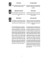 3
3
-
 4
4
-
 5
5
-
 6
6
-
 7
7
-
 8
8
-
 9
9
-
 10
10
-
 11
11
-
 12
12
-
 13
13
-
 14
14
-
 15
15
-
 16
16
-
 17
17
-
 18
18
-
 19
19
-
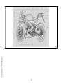 20
20
-
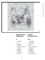 21
21
-
 22
22
-
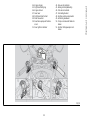 23
23
-
 24
24
-
 25
25
-
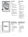 26
26
-
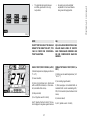 27
27
-
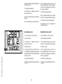 28
28
-
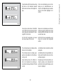 29
29
-
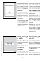 30
30
-
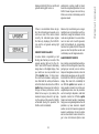 31
31
-
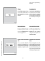 32
32
-
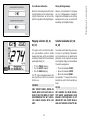 33
33
-
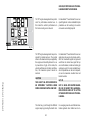 34
34
-
 35
35
-
 36
36
-
 37
37
-
 38
38
-
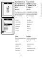 39
39
-
 40
40
-
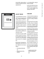 41
41
-
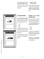 42
42
-
 43
43
-
 44
44
-
 45
45
-
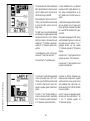 46
46
-
 47
47
-
 48
48
-
 49
49
-
 50
50
-
 51
51
-
 52
52
-
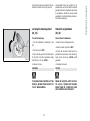 53
53
-
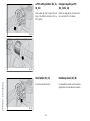 54
54
-
 55
55
-
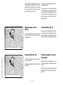 56
56
-
 57
57
-
 58
58
-
 59
59
-
 60
60
-
 61
61
-
 62
62
-
 63
63
-
 64
64
-
 65
65
-
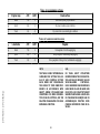 66
66
-
 67
67
-
 68
68
-
 69
69
-
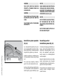 70
70
-
 71
71
-
 72
72
-
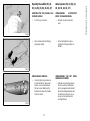 73
73
-
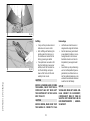 74
74
-
 75
75
-
 76
76
-
 77
77
-
 78
78
-
 79
79
-
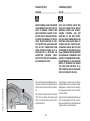 80
80
-
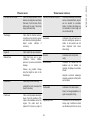 81
81
-
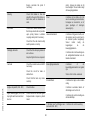 82
82
-
 83
83
-
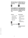 84
84
-
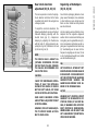 85
85
-
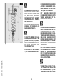 86
86
-
 87
87
-
 88
88
-
 89
89
-
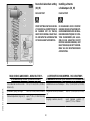 90
90
-
 91
91
-
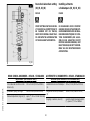 92
92
-
 93
93
-
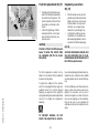 94
94
-
 95
95
-
 96
96
-
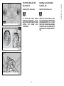 97
97
-
 98
98
-
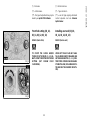 99
99
-
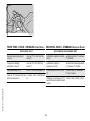 100
100
-
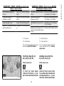 101
101
-
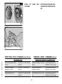 102
102
-
 103
103
-
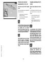 104
104
-
 105
105
-
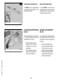 106
106
-
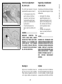 107
107
-
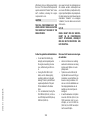 108
108
-
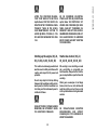 109
109
-
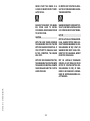 110
110
-
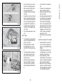 111
111
-
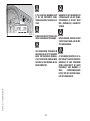 112
112
-
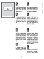 113
113
-
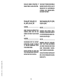 114
114
-
 115
115
-
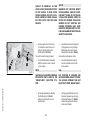 116
116
-
 117
117
-
 118
118
-
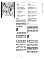 119
119
-
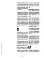 120
120
-
 121
121
-
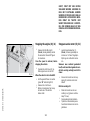 122
122
-
 123
123
-
 124
124
-
 125
125
-
 126
126
-
 127
127
-
 128
128
-
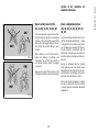 129
129
-
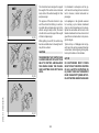 130
130
-
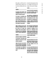 131
131
-
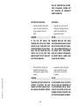 132
132
-
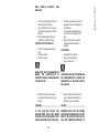 133
133
-
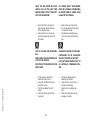 134
134
-
 135
135
-
 136
136
-
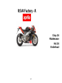 137
137
-
 138
138
-
 139
139
-
 140
140
-
 141
141
-
 142
142
-
 143
143
-
 144
144
-
 145
145
-
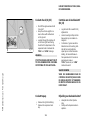 146
146
-
 147
147
-
 148
148
-
 149
149
-
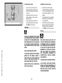 150
150
-
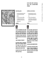 151
151
-
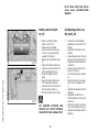 152
152
-
 153
153
-
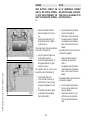 154
154
-
 155
155
-
 156
156
-
 157
157
-
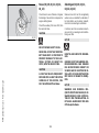 158
158
-
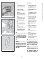 159
159
-
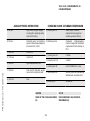 160
160
-
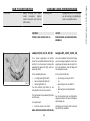 161
161
-
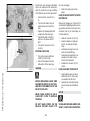 162
162
-
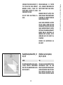 163
163
-
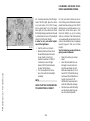 164
164
-
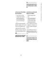 165
165
-
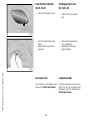 166
166
-
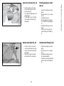 167
167
-
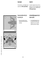 168
168
-
 169
169
-
 170
170
-
 171
171
-
 172
172
-
 173
173
-
 174
174
-
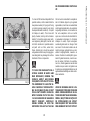 175
175
-
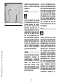 176
176
-
 177
177
-
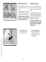 178
178
-
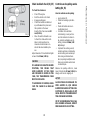 179
179
-
 180
180
-
 181
181
-
 182
182
-
 183
183
-
 184
184
-
 185
185
-
 186
186
-
 187
187
-
 188
188
-
 189
189
-
 190
190
-
 191
191
-
 192
192
-
 193
193
-
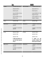 194
194
-
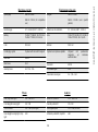 195
195
-
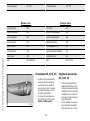 196
196
-
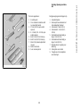 197
197
-
 198
198
-
 199
199
-
 200
200
-
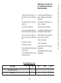 201
201
-
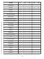 202
202
-
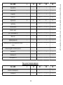 203
203
-
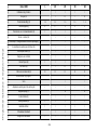 204
204
-
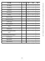 205
205
-
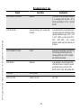 206
206
-
 207
207
-
 208
208
-
 209
209
-
 210
210
-
 211
211
-
 212
212
-
 213
213


APRILIA RSV4 FACTORY-R - 10-2010 Data papier
- Categorie
- Motorfietsen
- Type
- Data papier
in andere talen
Gerelateerde papieren
-
APRILIA DORSODURO 750 - de handleiding
-
-
-
-
APRILIA SX 50 - ANNEXE 639 Handleiding
-
-
-
APRILIA NA Mana 850 Handleiding
-
-