Makita BTW151 Handleiding
- Categorie
- Elektrisch gereedschap
- Type
- Handleiding

GB
Cordless Impact Wrench Instruction Manual
F
Boulonneuse sans fil Manuel d’instructions
D
Akku-Schlagschrauber Betriebsanleitung
I
Avvitatrice ad impulso a batteria Istruzioni per l’uso
NL
Snoerloze slagmoersleutel Gebruiksaanwijzing
E
Llave de impacto a batería Manual de instrucciones
P
Chave de impacto a bateria Manual de instruções
DK
Elektronisk akku slagnøgle Brugsanvisning
S
Sladdlös mutterdragare Bruksanvisning
N
Batteridrevet slagskrunøkkel Bruksanvisning
SF
Akku-iskuväännin Käyttöohje
GR
Ασύρµατ κρυστικ κλειδί
δηγίες ρήσεως
BTW151

2
2
1
3
4
5
7
4
6
8
9 9
11
13
12
10
14
16
15
12
34
56

3
0
M12
M10
M8
1.0 2.0 3.0 4.0
5.0
6.0
(M12)
(M10)
(M8)
N • m
(kgf • cm)
80
60
40
20
(204)
(408)
(816)
100
(1020)
120
(1224)
140
(1428)
(612)
*2
*1
17
18
50
(25)
100
(50)
150
(75)
196
(98)
250
(99)
300
(99)
20
19
80
60
40
20
0
M16
*2
M14
M12
1.0 2.0 3.0
(204)
(408)
(816)
50
(25)
100
(50)
150
(75)
100
(1020)
120
(1224)
140
(1428)
N • m
(kgf • cm)
(612)
(M14)
(M16)
(M12)
17
18
20
19
21
22
23
78
9
10
GB
Standard bolt
F
Boulon standard
D
Standardschrauben
I
Bullone standard
NL
Standaard bout
E
Tornillo estándar
P
Porca normal
DK
Standardbolt
S
Standardbult
N
Standardbolt
SF
Nornaali pultti
GR
Καννικ µπυλνι
GB
High tensile bolt
F
Boulon à haute résistance
D
HV-Schrauben
I
Bullone altamente tensile
NL
Bout met grote treksterkte
E
Tornillo de alta resistencia
P
Porca de grande elasticidade
DK
Kvalitetsstålbolt
S
Bult med hög hållfasthet
N
Høy strekkbolt
SF
Suurvetolujuuspultti
GR
Μπυλνι υψηλής εκτατικτητς

4
ENGLISH
Explanation of general view
1 Red part
2Button
3 Battery cartridge
4 Socket
5 Anvil
6Pin
7O-ring
8 Switch trigger
9 Reversing switch lever
10 A side
11 B side
12 Clockwise
13 Counterclockwise
14 Example: Setting dial 52
15 First digit
16 Second digit
17 Fastening time
18 Seconds
19 Number of impacts
20 (Dial setting)
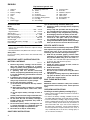
21 Limit mark
22 Brush holder cap
23 Screwdriver
SPECIFICATIONS
Model BTW151
Capacities
Standard bolt ......................................... 10 m – 16 mm
High tensile bolt ....................................... 8 m – 12 mm
Square drive .......................................................12.7 mm
No load speed (min
–1
) ......................................0 – 2,300
Impacts per minute .......................................... 0 – 3,000
Max. fastening torque ........................................ 150 N•m
Overall length ......................................................200 mm
Net weight (with battery cartridge) ........................ 1.9 kg
Rated voltage ................................................ D.C. 14.4 V
• Due to our continuing program of research and devel-
opment, the specifications herein are subject to change
without notice.
• Note: Specifications may differ from country to country.
Safety Hints
For your own safety, please refer to the enclosed safety
instructions.
IMPORTANT SAFETY INSTRUCTIONS FOR
BATTERY CARTRIDGE
ENC005-1
1. Before using battery cartridge, read all instruc-
tions and cautionary markings on (1) battery
charger, (2) battery, and (3) product using battery.
2. Do not disassemble battery cartridge.
3. If operating time has become excessively
shorter, stop operating immediately. It may result
in a risk of overheating, possible burns and even
an explosion.
4. If electrolyte gets into your eyes, rinse them out
with clear water and seek medical attention right
away. It may result in loss of your eyesight.
5. Do not short the battery cartridge:
(1) Do not touch the terminals with any conduc-
tive material.
(2) Avoid storing battery cartridge in a container
with other metal objects such as nails, coins,
etc.
(3) Do not expose battery cartridge to water or
rain.
A battery short can cause a large current flow, over-
heating, possible burns and even a breakdown.
6. Do not store the tool and battery cartridge in
locations where the temperature may reach or
exceed 50°C (122°F).
7. Do not incinerate the battery cartridge even if it
is severely damaged or is completely worn out.
The battery cartridge can explode in a fire.
8. Be careful not to drop or strike battery.
SAVE THESE INSTRUCTIONS.
Tips for maintaining maximum battery life
1. Charge the battery cartridge before completely
discharged.
Always stop tool operation and charge the bat-
tery cartridge when you notice less tool power.
2. Never recharge a fully charged battery cartridge.
Overcharging shortens the battery service life.
3. Charge the battery cartridge with room tempera-
ture at 10°C – 40°C (50°F – 104°F). Let a hot bat-
tery cartridge cool down before charging it.
4. Charge the Nickel Metal Hydride battery cartridge
when you do not use it for more than six months.
SPECIFIC SAFETY RULES
GEB009-2
DO NOT let comfort or familiarity with product (gained
from repeated use) replace strict adherence to impact
wrench safety rules. If you use this tool unsafely or
incorrectly, you can suffer serious personal injury.
1. Hold tool by insulated gripping surfaces when
performing an operation where the cutting tool
may contact hidden wiring or its own cord. Con-
tact with a “live” wire will make exposed metal parts
of the tool “live” and shock the operator.
2. Wear ear protectors.
3. Check the socket carefully for wear, cracks or
damage before installation.
4. Hold the tool firmly.
5. Always be sure you have a firm footing.
Be sure no one is below when using the tool in
high locations.
6. The proper fastening torque may differ depend-
ing upon the kind or size of the bolt. Check the
torque with a torque wrench.
SAVE THESE INSTRUCTIONS.
WARNING:
MISUSE or failure to follow the safety rules stated in
this instruction manual may cause serious personal
injury.
OPERATING INSTRUCTIONS
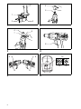
Installing or removing battery cartridge (Fig. 1)
• Always switch off the tool before insertion or removal of
the battery cartridge.
• To remove the battery cartridge, withdraw it from the
tool while sliding the button on the side of the cartridge.
• To insert the battery cartridge, align the tongue on the
battery cartridge with the groove in the housing and slip
it into place. Always insert it all the way until it locks in
place with a little click. If you can see the red part on
the upper side of the button, it is not locked completely.
Insert it fully until the red part cannot be seen. If not, it
may accidentally fall out of the tool, causing injury to
you or someone around you.

5
• Do not use force when inserting the battery cartridge. If
the cartridge does not slide in easily, it is not being
inserted correctly.
Selecting correct socket
Always use the correct size socket for bolts and nuts. An
incorrect size socket will result in inaccurate and incon-
sistent fastening torque and/or damage to the bolt or nut.
Installing or removing socket (Fig. 2 & 3)
CAUTION:
Always be sure that the tool is switched off and the bat-
tery cartridge is removed before installing or removing
the socket.
1. For socket without O-ring and pin
To install the socket, push it onto the anvil of the tool
until it locks into place.
To remove the socket, simply pull it off.
2. For socket with O-ring and pin
Move the O-ring out of the groove in the socket and
remove the pin from the socket. Fit the socket onto
the anvil of the tool so that the hole in the socket is
aligned with the hole in the anvil. Insert the pin
through the hole in the socket and anvil. Then return
the O-ring to the original position in the socket
groove to retain the pin. To remove the socket, follow
the installation procedures in reverse.
Switch action (Fig. 4)
CAUTION:
Before inserting the battery cartridge into the tool, always
check to see that the switch trigger actuates properly and
returns to the “OFF” position when released.
To start the tool, simply pull the trigger. Tool speed is
increased by increasing pressure on the trigger. Release
the trigger to stop.
Reversing switch action (Fig. 5)
CAUTION:
• Always check the direction of rotation before operation.
• Use the reversing switch only after the tool comes to a
complete stop. Changing the direction of rotation
before the tool stops may damage the tool.
• When not operating the tool, always set the reversing
switch lever to the neutral position.
This tool has a reversing switch to change the direction of
rotation. Depress the reversing switch lever from the A
side for clockwise rotation or from the B side for counter-
clockwise rotation. When the reversing switch lever is in
the neutral position, the switch trigger cannot be pulled.
Auto-stop setting for number of impacts (Fig. 6)
This tool has a convenient auto-stop mechanism that
allows you to preset the desired number of impacts in
terms of the application. The tool then stops automati-
cally after reaching the preset number of impacts.
1. To set the dial on the back of the tool, first slide out
the battery cartridge by sliding the button on the side
of the cartridge.
2. Two dials can be seen on the battery holder side.
Use a slotted screwdriver to set the dial to a desired
2-digit setting.
3. You cannot set the auto-stop setting for fastening
with more than 200 impacts (over 4 sec.)
Note:
Do not force the dial when turning. You might break it.
Dial setting and function (Fig. 6)
Bolt fastening
Temporary bolt fastening and loosening
By using the B or C on the left dial in combination with one of the digits (from 0 to 9) on the right-hand dial, you can do
temporary bolt fastening or bolt loosening.
Dial setting Clockwise Counterclockwise Application
01 – 98
Tool stops after the twice
the set number of impacts
is reached. See the next
section for the appropriate
fastening torque.
Pull the trigger to start the
tool; release it to stop.
Bolt fastening while control-
ling the number of impacts.
99
Pull the trigger to start the tool; release it to stop. Bolt fastening without con-
trolling the number of
impacts; or when fastening
with more than 200 impacts
(over 4 sec.)
00
No rotation even with trig-
ger pulled.
Pull the trigger to start the
tool; release it to stop.
—
Dial setting Clockwise Counterclockwise Application
B [*]
Select dial 0- 9 for B [*]
After catching the first
impact, tool stops [*] x 0.1
seconds later.
Pull the trigger to start the
tool; release it to stop.
For temporary bolt fasten-
ing.
C [*]
Select dial 0 – 9 for C [*]
Pull the trigger to start the
tool; release it to stop.
After stopping to impact,
tool stops [*] x 0.1 seconds
later.
To loosen bolts.

6
Operation
CAUTION:
Always insert the battery cartridge all the way until it
locks in place. If you can see the red part on the upper
side of the button, it is not locked completely. Insert it fully
until the red part cannot be seen. If not, it may acciden-
tally fall out of the tool, causing injury to you or someone
arround you.
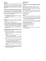
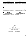
The proper fastening torque may differ depending upon
the kind or size of the bolt, the material of the workpiece
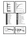
to be fastened, etc. The relation between fastening
torque and fastening time is shown in Fig. 7 for standard
bolt or Fig. 8 for high tensile bolt. Hold the tool firmly and
place the socket over the bolt or nut. Turn the tool on and
fasten for the proper fastening time.
[*1] Presetting number of impacts is impossible for more
than 200 impacts (4 seconds).
[*2] Fastening time includes when you pull the trigger
completely.
NOTE:
• When fastening screw M8 or smaller, carefully adjust
pressure on the switch trigger so that the screw is not
damaged.
• Hold the tool pointed straight at the bolt.
• If you fasten the bolt for a time longer than shown in the
figure, the bolt or the socket may be overstressed,
damaged, etc. Before starting your job, always perform
a test operation to determine the proper fastening time
for your bolt. Especially for the bolt other than M8, per-
form the above test operation to prevent the trouble on
socket or bolt, etc.
The fastening torque is affected by a wide variety of fac-
tors including the following. After fastening, always check
the torque with a torque wrench.
1. When the battery cartridge is discharged almost
completely, voltage will drop and the fastening
torque will be reduced.
2. Socket
• Failure to use the correct size socket will cause a
reduction in the fastening torque.
• A worn socket (wear on the hex end or square
end) will cause a reduction in the fastening torque.
3. Bolt
• Even though the torque coefficient and the class of
bolt are the same, the proper fastening torque will
differ according to the diameter of the bolt.
• Even though the diameters of bolts are the same,
the proper fastening torque will differ according to
the torque coefficient, the class of bolt and the bolt
length.
4. The manner of holding the tool or the material of
driving position to be fastened will affect the torque.
5. Operating the tool at low speed will cause a reduc-
tion in the fastening torque.
MAINTENANCE
CAUTION:
Always be sure that the tool is switched off and the bat-
tery cartridge is removed before carrying out any work on
the tool.
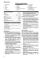
Replacement of carbon brushes (Fig. 9 & 10)
Replace carbon brushes when they are worn down to the
limit mark. Both identical carbon brushes should be
replaced at the same time.
To maintain product safety and reliability, repairs, mainte-
nance or adjustment should be carried out by a Makita
Authorized Service Center.
ACCESSORIES
CAUTION:
• These accessories or attachments are recommended
for use with your Makita tool specified in this manual.
The use of any other accessories or attachments might
present a risk of injury to persons. Only use accessory
or attachment for its stated purpose.
If you need any assistance for more details regarding
these accessories, ask your local Makita service center.
• Socket (with pin and O-ring)
• Extension bar (with pin and O-ring)
• Universal joint (with pin and O-ring)
• Bit adapter (with pin and O-ring)
• Phillips bit
• Shoulder strap
• Various type of Makita genuine batteries and chargers
• Plastic carrying case

18
NEDERLANDS
Verklaring van algemene gegevens
1 Rood gedeelte
2 Knop
3 Accu
4Sok
5 Draaistuk
6 Pen
7O-ring
8 Trekschakelaar
9 Omkeerschakelaar
10 A zijde
11 B zijde
12 Rechtsom
13 Linksom
14 Voorbeeld: Schijf ingesteld
op 52
15 Eerste cijfer
16 Tweede cijfer
17 Aantrektijd
18 Seconden
19 Aantal slagen
20 (Instelling van de schijven)
21 Limietstreep
22 Borstelhouderdop
23 Schroevendraaier
TECHNISCHE GEGEVENS
Model BTW151
Capaciteiten
Standaardbout .................................... 10 mm – 16 mm
Trekvaste bout ......................................8 mm – 12 mm
Vierkant ............................................................. 12,7 mm
Toerental onbelast (min
–1
) ................................ 0 – 2 300
Aantal slagen per minuut .................................. 0 – 3 000
Maximaal aantrekkoppel ................................... 150 N•m
Totale lengte ....................................................... 200 mm
Netto gewicht (accu inbegrepen) ........................... 1,9 kg
Nominale spanning ....................................... D.C. 14,4 V
• In verband met ononderbroken research en ontwikke-
ling behouden wij ons het recht voor bovenstaande
technische gegevens te wijzigen zonder voorafgaande
kennisgeving.
• Opmerking: De technische gegevens kunnen van land
tot land verschillen.
Veiligheidswenken
Volg veiligheidshalve de bijgevoegde veiligheidsvoor-
schriften nauwkeurig op.
BELANGRIJKE
VEILIGHEIDSVOORSCHRIFTEN VOOR ACCU
1. Lees alle voorschriften en waarschuwingen op
(1) de acculader, (2) de accu, en (3) het product
waarvoor de accu wordt gebruikt, aandachtig
door alvorens de acculader in gebruik te nemen.
2. Neem de accu niet uit elkaar.
3. Als de gebruikstijd van een opgeladen accu aan-
zienlijk korter is geworden, moet u het gebruik
ervan onmiddellijk stopzetten. Voortgezet
gebruik kan oververhitting, brandwonden en
zelfs een ontploffing veroorzaken.
4. Als er elektrolyt in uw ogen is terechtgekomen,
spoel dan uw ogen met schoon water en roep
onmiddellijk de hulp van een dokter in. Elektrolyt
in de ogen kan blindheid veroorzaken.
5. Voorkom kortsluiting van de accu:
(1) Raak de accuklemmen nooit aan met een
geleidend materiaal.
(2) Bewaar de accu niet in een bak waarin
andere metalen voorwerpen zoals spijkers,
munten e.d. worden bewaard.
(3) Stel de accu niet bloot aan water of regen.
Kortsluiting van de accu kan oorzaak zijn van
een grote stroomafgifte, oververhitting, brand-
wonden, en zelfs defecten.
6. Bewaar het gereedschap en de accu niet op
plaatsen waar de temperatuur kan oplopen tot
50°C of hoger.
7. Werp de accu nooit in het vuur, ook niet wanneer
hij zwaar beschadigd of volledig versleten is. De
accu kan namelijk ontploffen in het vuur.
8. Wees voorzichtig dat u de accu niet laat vallen
en hem niet blootstelt aan schokken of stoten.
BEWAAR DEZE VOORSCHRIFTEN.
Tips voor een maximale levensduur van de accu
1. Laad de accu op voordat hij volledig ontladen is.
Stop het gebruik van het gereedschap en laad de
accu op telkens wanneer u vaststelt dat het ver-
mogen van het gereedschap is afgenomen.
2. Laad een volledig opgeladen accu nooit opnieuw
op. Als u de accu te veel oplaadt, zal hij minder
lang meegaan.
3. Laad de accu op bij een kamertemperatuur tus-
sen 10°C en 40°C. Laat een warme accu afkoelen
alvorens hem op te laden.
4. Laad de nikkel-metaalhydride accu op telkens
wanneer u hem langer dan zes maanden niet
hebt gebruikt.
AANVULLENDE
VEILIGHEIDSVOORSCHRIFTEN
Neem de veiligheidsvoorschriften voor het gereed-
schap altijd strict in acht en laat u NIET misleiden
door een vals gevoel van gemak of vertrouwdheid
met het product (verworven na herhaald gebruik).
Onveilig of verkeerd gebruik van dit gereedschap
kan leiden tot ernstige persoonlijke verwondingen.
1. Houd het gereedschap bij de geïsoleerde hand-
greepvlakken vast wanneer u werkt op plaatsen
waar de sok van het gereedschap op verborgen
elektrische bedrading of zijn eigen netsnoer kan
stoten. Door contact met onder spanning staande
draden, zullen de niet-geïsoleerde metalen delen
van het gereedschap onder spanning komen te
staan zodat de gebruiker een elektrische schok kan
krijgen.
2. Draag oorbeschermers.
3. Controleer de sok nauwkeurig op slijtage,
scheuren of beschadiging alvorens deze op het
gereedschap te monteren.
4. Houd het gereedschap stevig vast.
5. Zorg ervoor dat u altijd stevige steun voor de
voeten hebt.
Controleer of er niemand beneden u aanwezig is
wanneer u het gereedschap op een hoge plaats
gaat gebruiken.
6. Het juiste aantrekkoppel kan verschillen afhan-
kelijk van de soort of grootte van de bout. Con-
troleer het aantrekkoppel met een
momentsleutel.

19
BEWAAR DEZE VOORSCHRIFTEN.
WAARSCHUWING:
VERKEERD GEBRUIK of het niet naleven van de vei-
ligheidsvoorschriften in deze gebruiksaanwijzing
kan leiden tot ernstige verwondingen.
BEDIENINGSVOORSCHRIFTEN
Installeren of verwijderen van de accu (Fig. 1)
• Schakel het gereedschap altijd uit alvorens de accu te
installeren of te verwijderen.
• Om de accu te verwijderen, haalt u deze uit het gereed-
schap terwijl u de knop op de zijkant van de accu verschuift.
• Om de accu te installeren, doet u de tong op de accu
overeenkomen met de groef in de behuizing en dan
schuift u de accu erin. Schuif de accu zo ver mogelijk
erin totdat deze op zijn plaats vastklikt. Wanneer het
rode gedeelte op de bovenkant van de knop nog zicht-
baar is, zit de accu niet volledig erin. Schuif hem volledig
erin totdat het rode gedeelte niet meer zichtbaar is. Als
u dit niet doet, kan de accu per ongeluk eruit vallen en
uzelf of andere personen in uw omgeving verwonden.
• Als de accu moeilijk in de houder gaat, moet u niet pro-
beren hem met geweld erin te duwen. Indien de accu
er niet gemakkelijk ingaat, betekent dit dat u hem niet
op de juiste wijze erin steekt.
Selecteren van de juiste sok
Gebruik altijd een sok van de juiste maat voor het vast-
draaien van bouten en moeren. Het gebruik van een sok
van de onjuiste maat zal een onnauwkeurig of onregel-
matig aantrekkoppel en/of beschadiging van de bout of
moer tot gevolg hebben.
Installeren of verwijderen van de sok (Fig. 2 en 3)
LET OP:
Controleer altijd of het gereedschap is uitgeschakeld en
de accu is verwijderd alvorens de sok te installeren of te
verwijderen.
1. Voor een sok zonder O-ring en pen
Installeer de sok door deze op het draaistuk van het
gereedschap te duwen totdat de sok op zijn plaats
vergrendelt.
Om de sok te verwijderen, trekt u deze gewoon eraf.
2. Voor een sok met O-ring en pen
Verwijder de O-ring uit de groef in de sok en verwij-
der de pen uit de sok. Schuif de sok over het draai-
stuk van het gereedschap zodat het gat in de sok op
één lijn komt met het gat in het draaistuk. Steek de
pen door het gat in de sok en in het draaistuk. Breng
de O-ring weer op zijn oorspronkelijke plaats in de
groef aan, zodat de pen op zijn plaats wordt gehou-
den. Om de sok te verwijderen, voert u deze proce-
dure in omgekeerde volgorde uit.
Werking van de trekschakelaar (Fig. 4)
LET OP:
Alvorens de accu in het gereedschap te plaatsen, moet u
altijd controleren of de trekschakelaar juist werkt en bij
loslaten naar de “OFF” positie terugkeert.
Om het gereedschap te starten, drukt u gewoon de trek-
schakelaar in. Oefen meer druk uit op de trekschakelaar
om het toerental te vermeerderen. Om het gereedschap
te stoppen, de trekschakelaar loslaten.
Werking van de omkeerschakelaar (Fig. 5)
LET OP:
• Controleer altijd de draairichting alvorens het gereed-
schap te gebruiken.
• Verander de stand van de omkeerschakelaar alleen
nadat het gereedschap volledig tot stilstand is geko-
men. Indien u de draairichting verandert terwijl de boor
nog draait, kan het gereedschap beschadigd raken.
• Zet de omkeerschakelaar altijd in de neutrale stand
wanneer u het gereedschap niet gebruikt.
Dit gereedschap heeft een omkeerschakelaar voor het
veranderen van de draairichting. Druk de omkeerschake-
laar in vanaf zijde A voor rechtse draairichting, of vanaf
zijde B voor linkse draairichting. Wanneer deze omkeer-
schakelaar in de neutrale stand staat, kan de trekschake-
laar niet worden ingedrukt.
Automatische stop na vooraf ingesteld aantal
slagen (Fig. 6)
Dit gereedschap heeft een handig automatisch stopme-
chanisme waarmee u het gewenste aantal slagen voor
de te gebruiken toepassing vooraf kunt instellen. Het
gereedschap stopt automatisch nadat het vooraf inge-
stelde aantal slagen is bereikt.
1. Om de schijf op de achterzijde van het gereedschap
in te stellen, haalt u eerst de accu eruit door de knop
op de zijkant van de accu te verschuiven.
2. Er zijn twee schijven op de zijkant van de accuhou-
der. Gebruik een sleufschroevendraaier om de schij-
ven in te stellen op de gewenste 2-cijfers instelling.
3. U kunt niet instellen voor automatische stop na meer
dan 200 slagen (langer dan 4 sec.).
Opmerking:
Forceer de schijf niet wanneer u deze draait. De schijf
zou kunnen breken.

20
Instelling van de schijven en functies (Fig. 6)
Vastdraaien van bouten
Tijdelijk vastdraaien en losdraaien van bouten
Door B of C op de linker schijf te gebruiken in combinatie met een van de cijfers (0 tot 9) op de rechter schijf kunt u
bouten tijdelijk vastdraaien of bouten losdraaien.
Bediening
LET OP:
Steek de accu altijd zo ver mogelijk erin totdat hij goed
op zijn plaats vastzit. Als het rode gedeelte op de boven-
kant van de knop nog zichtbaar is, zit de accu niet volle-
dig erin. Steek hem volledig erin totdat het rode gedeelte
niet meer zichtbaar is. Als de accu niet goed erin zit, kan
hij per ongeluk uit het gereedschap vallen en kunt u of
kunnen anderen in uw omgeving verwonding oplopen.
Het juiste aantrekkoppel hangt van het soort of de
grootte van de bout, het materiaal van het te bevestigen
werkstuk, enz. De verhouding tussen het aantrekkoppel
en de aantrektijd is aangegeven in Fig. 7 voor een stan-
daardbout en in Fig. 8 voor een bout met grote trek-
sterkte. Houd het gereedschap stevig vast en plaats de
sok over de bout of moer. Schakel het gereedschap in en
draai vast binnen de juiste aantrektijd.
[*1] U kunt niet vooraf instellen voor automatische stop
na meer dan 200 slagen (langer dan 4 seconden).
[*2] De aandraaitijd geldt voor wanneer de trekschake-
laar volledig wordt ingedrukt.
OPMERKINGEN:
• Wanneer u schroef M8 of een kleinere schroef vast-
draait, moet u de druk op de trekschakelaar voorzichtig
aanpassen zodat de schroef niet wordt beschadigd.
• Houd het gereedschap altijd recht op de bout.
• Als u de bout gedurende langere tijd dan de opgegeven
tijd aantrekt, kan de bout of de sok breken of bescha-
digd raken. Alvorens het eigenlijke werk te doen, moet
u daarom altijd een proefje doen met een gelijke bout
om de juiste aantrektijd te bepalen. Doe dit in elk geval
voor andere bouten dan M8 om beschadiging van de
sok of bout, enz. te voorkomen.
Het aantrekkoppel wordt beïnvloed door een aantal ver-
schillende factoren, waaronder de volgende. Controleer
na het vastdraaien altijd het aantrekkoppel met een
momentsleutel.
1. Wanneer de accu bijna leeg is, neemt het voltage af
en vermindert het aantrekkoppel.
2. Sok
• Het gebruik van een sok van de onjuiste maat zal
resulteren in een te laag aantrekkoppel.
• Een versleten sok (slijtage op het zeskante of vier-
kante uiteinde) zal resulteren in een te laag aan-
trekkoppel.
3. Bout
• Zelfs wanneer de koppelverhouding en de klasse
van de bout overeenkomen, kan door verschillen in
de diameter van de bouten het juiste aantrekkop-
pel per bout toch afwijken.
• Ook al zijn de diameters van twee bouten gelijk,
dan kunnen er nog verschillen in het juiste aan-
trekkoppel van de twee bouten optreden ten
gevolge van verschillen in de koppelverhouding en
de klasse en lengte van de bouten.
4. Het aantrekkoppel wordt beïnvloed door de manier
van vasthouden van het gereedschap of door het
materiaal waarin de bout wordt vastgedraaid.
5. Het aantrekkoppel vermindert wanneer het gereed-
schap bij lage snelheid wordt gebruikt.
Instelling van de schijven Rechtsom Linksom Toepassing
01 – 98
Het gereedschap stopt
nadat tweemaal het inge-
stelde aantal slagen is
bereikt. Zie het volgende
gedeelte voor het geschikte
aandraaimoment.
Druk de trekschakelaar in
om het gereedschap te
starten; laat los om te stop-
pen.
Vastdraaien van bouten
terwijl u het aantal slagen
controleert.
99
Druk de trekschakelaar in om het gereedschap te star-
ten; laat los om te stoppen.
Vastdraaien van bouten
zonder dat u het aantal sla-
gen controleert; of vast-
draaien met meer dan 200
slagen (langer dan 4 sec.).
00
Het gereedschap draait
niet ook al drukt u de trek-
schakelaar in.
Druk de trekschakelaar in
om het gereedschap te star-
ten; laat los om te stoppen.
—
Instelling van de schijven Rechtsom Linksom Toepassing
B [*]
Kies een van de cijfers
0 – 9 voor B [*].
Het gereedschap stopt [*] x
0,1 seconde na de eerste
slag.
Druk de trekschakelaar in
om het gereedschap te
starten; laat los om te stop-
pen.
Tijdelijk vastdraaien van
bouten.
C[*]
Kies een van de cijfers
0 – 9 voor C [*].
Druk de trekschakelaar in
om het gereedschap te
starten; laat los om te stop-
pen.
Het gereedschap stopt [*] x
0,1 seconde na de slag.
Losdraaien van bouten.

21
ONDERHOUD
LET OP:
Controleer altijd of het gereedschap is uitgeschakeld en
de accu is losgekoppeld vooraleer onderhoud uit te voe-
ren aan het gereedschap.
Vervangen van koolborstels (Fig. 9 en 10)
Vervang de borstels wanneer ze tot aan de aangegeven
limiet zijn afgesleten. Beide koolborstels dienen tegelij-
kertijd te worden vervangen.
Opdat het gereedschap veilig en betrouwbaar blijft, die-
nen alle reparaties, onderhoud of afstellingen te worden
uitgevoerd bij een erkend Makita service centrum.
ACCESSOIRES
LET OP:
• Deze accessoires of hulpstukken worden aanbevolen
voor gebruik met het Makita gereedschap dat in deze
gebruiksaanwijzing is beschreven. Bij gebruik van
andere accessoires of hulpstukken bestaat er gevaar
voor persoonlijke verwonding. Gebruik de accessoires
of hulpstukken uitsluitend voor hun bestemde doel.
Raadpleeg het dichtstbijzijnde Makita Servicecentrum
voor verder advies of bijzonderheden omtrent deze
accessoires.
• Sok (met pen en O-ring)
• Verlengstaaf (met pen en O-ring)
• Aantrekkoppel (met pen en O-ring)
• Bitadapter (met pen en O-ring)
• Phillips schroefbit
• Schouderriem
• Diverse types originele Makita accu’s en acculaders
• Plastic draagtas

45
ENH102-4
EC-DECLARATION OF CONFORMITY
We declare under our sole responsibility that this product
is in compliance with the following standards of standard-
ized documents,
EN60745, EN55014
in accordance with Council Directives, 89/336/EEC and
98/37/EC.
DÉCLARATION DE CONFORMITÉ CE
Nous déclarons sous notre entière responsabilité que ce
produit est conforme aux normes des documents stan-
dardisés suivants,
EN60745, EN55014
conformément aux Directives du Conseil, 89/336/CEE et
98/37/EG.
CE-KONFORMITÄTSERKLÄRUNG
Hiermit erklärt wir unter unserer alleinigen Verantwor-
tung, daß dieses Produkt gemäß den Ratsdirektiven
89/336/EWG und 98/37/EG mit den folgenden Normen
von Normendokumenten übereinstimmen:
EN60745, EN55014.
DICHIARAZIONE DI CONFORMITÀ
CON LE NORME DELLA COMUNITÀ EUROPEA
Dichiariamo sotto la nostra sola responsabilità che
questo prodotto è conforme agli standard di documenti
standardizzati seguenti:
EN60745, EN55014
secondo le direttive del Consiglio 89/336/CEE e
98/37/CE.
EG-VERKLARING VAN CONFORMITEIT
Wij verklaren hierbij uitsluitend op eigen verant-
woordelijkheid dat dit produkt voldoet aan de volgende
normen van genormaliseerde documenten,
EN60745, EN55014
in overeenstemming met de richtlijnen van de Raad
89/336/EEC en 98/37/EC.
DECLARACIÓN DE CONFORMIDAD DE LA CE
Declaramos bajo nuestra sola responsabilidad que este
producto cumple con las siguientes normas de docu-
mentos normalizados,
EN60745, EN55014
de acuerdo con las directivas comunitarias, 89/336/EEC
y 98/37/CE.
Yasuhiko Kanzaki
CE 2005
Director Amministratore
Directeur Directeur
Direktor Director
MAKITA INTERNATIONAL EUROPE LTD.
Michigan Drive, Tongwell, Milton Keynes,
Bucks MK15 8JD, ENGLAND
Responsible manufacturer: Produttore responsabile:
Fabricant responsable
:
Verantwoordelijke fabrikant:
Verantwortlicher Hersteller: Fabricante responsable:
Makita Corporation Anjo Aichi Japan
ENGLISH
FRANÇAISE
DEUTSCH
ITALIANO
NEDERLANDS
ESPAÑOL

46
ENH102-4
DECLARAÇÃO DE CONFORMIDADE DA CE
Declaramos sob inteira responsabilidade que este
produto obedece às seguintes normas de documentos
normalizados,
EN60745, EN55014
de acordo com as directivas 89/336/CEE e 98/37/CE do
Conselho.
EU-DEKLARATION OM KONFORMITET
Vi erklærer hermed på eget ansvar, at dette produkt er i
overensstemmelse med de følgende standarder i de
normsættende dokumenter,
EN60745, EN55014
i overensstemmelse med Rådets Direktiver 89/336/EEC
og 98/37/EC.
EG-DEKLARATION OM ÖVERENSSTÄMMELSE
Under eget ansvar deklarerar vi härmed att denna
produkt överensstämmer med följande standardiseringar
för standardiserade dokument,
EN60745, EN55014
i enlighet med EG-direktiven 89/336/EEC och 98/37/EC.
EUs SAMSVARS-ERKLÆRING
Vi erklærer på eget ansvar at dette produktet er i over-
ensstemmelse med følgende standard i de standardis-
erte dokumenter:
EN60745, EN55014,
i samsvar med Råds-direktivene, 89/336/EEC og
98/37/EC.
VAKUUTUS EC-VASTAAVUUDESTA
Yksinomaisesti vastuullisina ilmoitamme, että tämä tuote
on seuraavien standardoitujen dokumenttien standardien
mukainen,
EN60745, EN55014
neuvoston direktiivien 89/336/EEC ja 98/37/EC mukai-
sesti.
∆ΗΛΩΣΗ ΣΥΜΜΡΦΩΣΗΣ ΕΚ
∆ηλώνυµε υπ την µναδική µας ευθύνη τι αυτ
τ πριν ρίσκεται σε Συµφωνία µε τα ακλυθα
πρτυπα τυππιηµένων εγγράφων,
EN60745, EN55014
σύµφωνα µε τις δηγίες τυ Συµυλίυ,
89/336/EEC και 98/37/ΚE.
Yasuhiko Kanzaki
CE 2005
Director Direktor
Direktør Johtaja
Direktör ∆ιευθυντής
MAKITA INTERNATIONAL EUROPE LTD.
Michigan Drive, Tongwell, Milton Keynes,
Bucks MK15 8JD, ENGLAND
Fabricante responsável: Ansvarlig produsent:
Ansvarlig fabrikant: Vastaava valmistaja:
Ansvarig tillverkare: Υπεύθυνς κατασκευαστής:
Makita Corporation Anjo Aichi Japan
PORTUGUÊS
DANSK
SVENSKA
NORSK
SUOMI
ΕΛΛΗΝΙΚΑ

47
ENG006-2-V4
For European countries only
Noise and Vibration
The typical A-weighted noise levels are
sound pressure level: 90 dB (A)
sound power level: 101 dB (A)
Uncertainty is 3 dB (A).
– Wear ear protection. –
The typical weighted root mean square acceleration
value is 7 m/s
2
.
These values have been obtained according to
EN60745.
Pour les pays d’Europe uniquement
Bruit et vibrations
Les niveaux de bruit ponderes types A sont:
niveau de pression sonore: 90 dB (A)
niveau de puissance du son: 101 dB (A)
L’incertitude de mesure est de 3 dB (A).
– Porter des protecteurs anti-bruit. –
L’accélération pondérée est de 7 m/s
2
.
Ces valeurs ont été obtenues selon EN60745.
Nur für europäische Länder
Geräusch- und Vibrationsentwicklung
Die typischen A-bewerteten Geräuschpegel betragen:
Schalldruckpegel: 90 dB (A)
Schalleistungspegel: 101 dB (A)
Die Abweichung beträgt 3 dB (A).
– Gehörschutz tragen. –
Der gewichtete Effektivwert der Beschleunigung beträgt
7m/s
2
.
Diese Werte wurden gemäß EN60745 erhalten.
Modello per l’Europa soltanto
Rumore e vibrazione
I livelli del rumore pesati secondo la curva A sono:
Livello pressione sonora: 90dB (A)
Livello potenza sonora: 101 dB (A)
L’incertezza è di 3 dB (A).
– Indossare i paraorecchi. –
Il valore quadratico medio di accellerazione è di 7 m/s
2
.
Questi valori sono stati ottenuti in conformità EN60745.
Alleen voor Europese landen
Geluidsniveau en trilling
De typische A-gewogen geluidsniveau’s zijn
geluidsdrukniveau: 90 dB (A)
geluidsenergie-niveau: 101 dB (A)
Onzekerheid is 3 dB (A).
– Draag oorbeschermers. –
De typische gewogen effectieve versnellingswaarde is
7m/s
2
.
Deze waarden werden verkregen in overeenstemming
met EN60745.
Para países europeos solamente
Ruido y vibración
Los niveles típicos de ruido ponderados A son
presión sonora:90 dB (A)
nivel de potencia sonora: 101 dB (A)
Incerteza 3 dB (A).
– Póngase protectores en los oídos. –
El valor ponderado de la aceleración es de 7 m/s
2
.
Estos valores han sido obtenidos de acuerdo con
EN60745.
ENGLISH
FRANÇAISE
DEUTSCH
ITALIANO
NEDERLANDS
ESPAÑOL

Makita Corporation
Anjo, Aichi, Japan
884384C999
ENG006-2-V4
Só para países Europeus
Ruído e vibração
Os níveis normais de ruído A são
nível de pressão de som: 90 dB (A)
nível do sum: 101 dB (A)
A incerteza é de 3 dB (A).
– Utilize protectores para os ouvidos –
O valor médio da aceleração é 7 m/s
2
.
Estes valores foram obtidos de acordo com EN60745.
Kun for lande i Europa
Lyd og vibration
De typiske A-vægtede lydniveauer er
lydtryksniveau: 90 dB (A)
lydeffektniveau: 101 dB (A)
Der er en usikkerhed på 3 dB (A).
– Bær høreværn. –
Den vægtede effektive accelerationsværdi er 7 m/s
2
.
Disse værdier er beregnet i overensstemmelse med
EN60745.
Endast för Europa
Buller och vibration
De typiska A-vägda bullernivåerna är
ljudtrycksnivå: 90 dB (A)
ljudeffektnivå: 101 dB (A)
Osäkerheten är 3 dB (A).
– Använd hörselskydd –
Det typiskt vägda effektivvärdet för acceleration är
7m/s
2
.
Dessa värden har erhållits i enlighet med EN60745.
Gjelder bare land i Europa
Støy og vibrasjon
De vanlige A-belastede støynivå er
lydtrykksnivå: 90 dB (A)
lydstyrkenivå: 101 dB (A)
Usikkerheten er på 3 dB (A).
– Benytt hørselvern. –
Den vanlig belastede effektiv-verdi for akselerasjon er
7m/s
2
.
Disse verdiene er beregnet eller målt i samsvar med
EN60745.
Vain Euroopan maat
Melutaso ja tärinä
Tyypilliset A-painotetut melutasot ovat
äänenpainetaso: 90 dB (A)
äänen tehotaso: 101 dB (A)
Epävarmuus on 3 dB (A).
– Käytä kuulosuojaimia. –
Tyypillinen kiihtyvyyden painotettu tehollisarvo on
7m/s
2
.
Nämä arvot on mitattu normin EN60745 mukaisesti.
Μν για ώρες της Ευρώπης
Θρυς και κραδασµς
ι τυπικές A-µετρύµενες εντάσεις ήυ είναι
πίεση ήυ: 90 dB (A)
δύναµη τυ ήυ: 101 dB (A)
Η Α$ε$αι%τητα είναι 3 dB (A).
– Φράτε ωτασπίδες. –
Η τυπική α+ία της µετρύµενης ρί,ας τυ µέσυ
τετραγώνυ της επιτάυνσης είναι 7 m/s
2
.
Αυτές ι τιµές έυν σηµειωθεί σύµφωνα µε τ
EN60745.
PORTUGUÊS
DANSK
SVENSKA
NORSK
SUOMI
ΕΛΛΗΝΙΚΑ
-
 1
1
-
 2
2
-
 3
3
-
 4
4
-
 5
5
-
 6
6
-
 7
7
-
 8
8
-
 9
9
-
 10
10
-
 11
11
-
 12
12
-
 13
13
-
 14
14


Makita BTW151 Handleiding
- Categorie
- Elektrisch gereedschap
- Type
- Handleiding
in andere talen
- English: Makita BTW151 User manual