HomeMatic IP 157662 LED Controller Handleiding
- Type
- Handleiding

Installations- und Bedienungsanleitung
Installation and operating manual
Notice d‘installation et d‘emploi
Manual de instalación y uso
Istruzioni per l‘installazione e l‘uso
Installatie- en bedieningshandleiding
LED Controller - RGBW S. 2
LED Controller – RGBW p. 24
LED Contrôleur – RGBW p. 37
LED Controlador – RGBW p. 51
Controller per LED – RGBW p. 65
LED Controller – RGBW p. 79
HmIP-RGBW
DE
EN
FR
ES
IT
NL

Lieferumfang
Anzahl Bezeichnung
1 Homematic IP LED Controller – RGBW
1 Bedienungsanleitung
Dokumentation © 2022 eQ-3 AG, Deutschland
Alle Rechte vorbehalten. Ohne schriftliche Zustimmung des Herausgebers darf diese
Anleitung auch nicht auszugsweise in irgendeiner Form reproduziert werden oder unter
Verwendung elektronischer, mechanischer oder chemischer Verfahren vervielfältigt oder
verarbeitet werden.
Es ist möglich, dass die vorliegende Anleitung noch drucktechnische Mängel oder
Druckfehler aufweist. Die Angaben in dieser Anleitung werden jedoch regelmäßig über-
prüft und Korrekturen in der nächsten Ausgabe vorgenommen. Für Fehler technischer
oder drucktechnischer Art und ihre Folgen übernehmen wir keine Haftung.
Alle Warenzeichen und Schutzrechte werden anerkannt.
Printed in Hong Kong
Änderungen im Sinne des technischen Fortschritts können ohne Vorankündigung vor-
genommen werden.
157662 (web)
Version 1.0 (12/2022)

1
BB
A
CD

2
3
E

4
F
5

6
7
Stripe 4
Stripe 3
Stripe 2
Stripe 1
_
+
4
3
2
1
+12V /
+24V

8
9
RGB Stripe
_
+
+12V /
+24V
B
G
R
+
RGBW
Stripe
B
G
W
R
+
_
+
+12V /
+24V

10
11
TW2 Stripe
TW1 Stripe
_
+
+12V /
+24V
+
+
CW2
WW2
CW1
WW1
Homematic IP
HAP

12
13
HomematicHomematic IP
*
CCU
4 s

14
4 s

11
Inhaltsverzeichnis
1 Hinweise zur Anleitung ...........................................................................12
2 Gefahrenhinweise .................................................................................... 12
3 Funktion und Geräteübersicht ..............................................................14
4 Allgemeine Systeminformationen ........................................................15
5 Inbetriebnahme ........................................................................................15
5.1 Installationshinweise ..........................................................................15
5.2 Montage und Installation ................................................................. 16
5.3 Anlernen ...............................................................................................17
5.4 Grundeinstellungen ........................................................................... 18
5.4.1 Farbdarstellung durch den HSV Farbraum ......................... 19
5.4.2 HCL (Human Centric Lightning) ........................................... 19
5.4.3 Dim2Warm ................................................................................ 19
6 Fehlerbehebung ...................................................................................... 20
6.1 Fehlercodes und Blinkfolgen ..........................................................20
6.2 Befehl nicht bestätigt ........................................................................ 20
6.3 Duty Cycle ...........................................................................................21
7 Wiederherstellung der Werkseinstellungen .......................................21
8 Wartung und Reinigung ..........................................................................22
9 Allgemeine Hinweise zum Funkbetrieb ..............................................22
10 Technische Daten ....................................................................................22

12
Hinweise zur Anleitung
1 Hinweise zur Anleitung
Lesen Sie diese Anleitung sorgfältig, bevor Sie Ihr Homematic IP Gerät in
Betrieb nehmen. Bewahren Sie die Anleitung zum späteren Nachschla-
gen auf!
Wenn Sie das Gerät anderen Personen zur Nutzung überlassen, überge-
ben Sie auch diese Anleitung.
Benutzte Symbole:
Achtung!
Hier wird auf eine Gefahr hingewiesen.
Hinweis. Dieser Abschnitt enthält zusätzliche wichtige Informatio-
nen.
2 Gefahrenhinweise
Önen Sie das Gerät nicht. Es enthält keine durch den Anwender zu
wartenden Teile. Lassen Sie das Gerät im Fehlerfall von einer Fach-
kraft prüfen.
Aus Sicherheits- und Zulassungsgründen (CE) ist das eigenmächtige
Umbauen und/oder Verändern des Geräts nicht gestattet.
Verwenden Sie das Gerät nicht, wenn es von außen erkennbare
Schäden, z. B. am Gehäuse, an Bedienelementen oder an den An-
schlussbuchsen ausweist. Lassen Sie das Gerät im Zweifelsfall von
einer Fachkraft prüfen.
Betreiben Sie das Gerät nur in trockener sowie staubfreier Umge-
bung, setzen Sie es keinem Einfluss von Feuchtigkeit, Vibrationen,
ständiger Sonnen- oder anderer Wärmeeinstrahlung, übermäßiger
Kälte und keinen mechanischen Belastungen aus.

13
Gefahrenhinweise
Das Gerät ist kein Spielzeug! Erlauben Sie Kindern nicht damit zu
spielen. Lassen Sie das Verpackungsmaterial nicht achtlos liegen.
Plastikfolien/ -tüten, Styroporteile etc. können für Kinder zu einem
gefährlichen Spielzeug werden.
Bei Sach- oder Personenschäden, die durch unsachgemäße Hand-
habung oder Nichtbeachten der Gefahrenhinweise verursacht wer-
den, übernehmen wir keine Haftung. In solchen Fällen erlischt jeder
Gewährleistungsanspruch! Für Folgeschäden übernehmen wir kei-
ne Haftung!
Beachten Sie beim Anschluss an die Geräteklemmen die hierfür
zulässigen Leitungen und Leitungsquerschnitte.
Eine Überlastung kann zur Zerstörung des Geräts, zu einem Brand
oder zu einem elektrischen Schlag führen.
Beachten Sie vor Anschluss eines Verbrauchers
die technischen
Daten, insbesondere die maximal zulässige Schaltleistung der
Lastkreise und Art des anzuschließenden Verbrauchers. Belasten Sie
den
Controller nur bis zur angegebenen Leistungsgrenze.
Das Gerät ist nur für den Einsatz in Wohnbereichen, Geschäfts- und
Gewerbebereichen sowie in Kleinbetrieben bestimmt.
Jeder andere Einsatz, als der in dieser Bedienungsanleitung be-
schriebene, ist nicht bestimmungsgemäß und führt zu Gewährleis-
tungs- und Haftungsausschluss.

14
Funktion und Geräteübersicht
3 Funktion und Geräteübersicht
Der Homematic IP LED Controller – RGBW ermöglicht die einfache Steu-
erung von RGBW-LED-Beleuchtungen direkt per Funk über das Home-
matic IP System. Farbe, Helligkeit und Sättigung können unabhängig von-
einander angesteuert werden.
Der LED Controller bietet die Möglichkeit entweder einen RGB(W)-Stripe,
zwei Tunable White Stripes oder vier Einzelkanäle anzusteuern. Beim Be-
trieb von Tunable White Stripes können diese im Dim2Warm-Modus oder
dynamischen Tageslicht-(HCL) Modus betrieben werden.
Durch das robuste Gehäuse eignet sich der LED Controller optimal für die
unsichtbare Montage in Zwischenwand oder -decke.
Außerdem erhöht die leichte Fernbedienbarkeit per App zusätzlich den
Komfort. So lassen sich beispielsweise individuelle Einschalthelligkeiten
oder auch automatische Abschaltungen nach einer konfigurierbaren Ein-
schaltdauer einstellen.
Alle technischen Dokumente und Updates finden Sie stets aktuell unter
www.homematic-ip.com.
Geräteübersicht (Abbildung 1):
(A) Systemtaste (Anlerntaste und Geräte-LED)
(B) Befestigungslaschen
(C) Anschlussklemme 2-polig Eingang
(D) Anschlussklemme 4-polig Ausgang
(E) Abdeckkappe
(F) Abdeckkappe

15
Allgemeine Systeminformationen
4 Allgemeine Systeminformationen
Dieses Gerät ist Teil des Homematic IP Smart-Home-Systems und kom-
muniziert über das HomematicIP Funkprotokoll. Alle Geräte des Systems
können komfortabel und individuell per Smartphone über die Home-
maticIP App konfiguriert werden. Alternativ haben Sie die Möglichkeit,
HomematicIP Geräte über die Zentrale CCU3 oder in Verbindung mit
vielen Partnerlösungen zu betreiben. Welcher Funktionsumfang sich
innerhalb des Systems im Zusammenspiel mit weiteren Komponenten
ergibt, entnehmen Sie bitte dem Homematic IP Anwenderhandbuch.
Alle technischen Dokumente und Updates finden Sie stets aktuell unter
www.homematic-ip.com.
5 Inbetriebnahme
5.1 Installationshinweise
Bitte notieren Sie sich vor der Installation die auf dem Gerät ange-
brachte Gerätenummer (SGTIN) und den Verwendungszweck, da-
mit Sie das Gerät im Nachhinein leichter zuordnen können. Alterna-
tiv steht die Gerätenummer auch auf dem beiliegenden
QR-Code-Aufkleber.
Mit einer unsachgemäßen Installation riskieren Sie schwere Sach-
schäden, z. B. durch Brand. Es droht für Sie die persönliche Haftung
bei Personen- und Sachschäden.
Beachten Sie bei der Installation die Gefahrenhinweise gemäß „2 Ge-
fahrenhinweise“ auf Seite 12.
Beachten Sie die auf dem Gerät angegebene Abisolierlänge der anzu-
schließenden Leiter.

16
Inbetriebnahme
Zugelassene Leitungsquerschnitte zum Anschluss der Versorgungsspan-
nung von 12-24 VDC sind:
Starre Leitung [mm2]
0,5-2,5
Zugelassene Leitungsquerschnitte zum Anschluss der LED-Stripes sind:
Starre Leitung [mm2]
0,2-1,5
5.2 Montage und Installation
Bitte lesen Sie diesen Abschnitt erst vollständig, bevor Sie mit der
Installation beginnen.
Stellen Sie sicher, dass an der gewünschten Montagestelle keine Lei-
tungen verlaufen!
Gerät darf nur für ortsfeste Installationen verwendet werden. Das
Gerät ist sicher innerhalb einer festen Installation zu fixieren.
Für die Montage des LED Controllers in Zwischendecke oder Wand ge-
hen Sie wie folgt vor:
• Positionieren Sie den LED Controller an der gewünschten
Montagestelle.
• Kennzeichnen Sie die Bohrpunkte anhand der Önungen der Be-
festigungslaschen (B).
• Wählen Sie die passenden Schrauben und Dübel aus.
• Bohren Sie die Löcher entsprechend der Schraubengröße und
setzen Sie die Dübel ein.
• Sie können den LED Controller jetzt über die Befestigungsla-
schen mithilfe der Schrauben montieren (Abbildung 2).

17
Inbetriebnahme
Für die Installation des LED Controllers in Zwischenwand- oder Decke
gehen Sie wie folgt vor:
• Lösen Sie die Schraube an der Abdeckkappe (E) mit Hilfe eines
Schraubenziehers (Abbildung 3).
• Önen Sie die Abdeckkappe (Abbildung 5).
• Schließen Sie das Netzteil an die Anschlussklemme (C) (Eingang
2-polig) gemäß der Anschlusszeichnungen (Abbildungen 6 bis
10) an.
Beim speisenden Netzteil muss es sich um ein Betriebsgerät mit
Schutzkleinspannung (SELV) für LED-Module gemäß EN 61347-1,
Anhang L handeln. Das Netzteil muss kurzschlussfest (bedingt oder
unbedingt) oder fehlersicher (fail-safe) sein.
• Lösen Sie die Schraube an der gegenüberliegenden Abdeckkap-
pe (F) (Abbildung 4).
• Önen Sie die Abdeckkappe (Abbildung 5).
• Schließen Sie die Verbraucher entsprechend einer der Anschluss-
zeichungen (Abbildungen 7 bis 10) an die Anschlussklemme (D)
(Ausgang 4-polig) an.
• Verschließen Sie die Abdeckkappen des LED Controllers wieder.
• Schalten Sie das versorgende Netzteil ein, um den Anlernmodus
des Geräts zu aktivieren.
5.3 Anlernen
Bitte lesen Sie diesen Abschnitt erst vollständig, bevor Sie mit dem
Anlernen beginnen.
Richten Sie zunächst Ihren Homematic IP Access Point über die
Homematic IP App ein, um weitere Homematic IP Geräte im System
nutzen zu können. Ausführliche Informationen dazu finden Sie in
der Bedienungsanleitung des Access Points.
Sie können das Gerät an den Access Point oder an die Zentrale CCU3
anlernen. Weitere Informationen dazu entnehmen Sie bitte dem
Homematic IP Anwenderhandbuch (zu finden im Downloadbereich
unter www.homematic-ip.com).

18
Inbetriebnahme
Damit das Gerät in Ihr System integriert und per kostenloser Homema-
ticIP App gesteuert werden kann, muss es an den Homematic IP Access
Point angelernt werden.
Zum Anlernen des Geräts gehen Sie wie folgt vor:
• Önen Sie die Homematic IP App auf Ihrem Smartphone.
• Wählen Sie den Menüpunkt „Gerät anlernen“ aus.
• Nach dem Einschalten des spannungsversorgenden Netzteils ist
der Anlernmodus des Aktors für 3 Minuten aktiv (Abbildung 11).
Sie können den Anlernmodus manuell für weitere 3 Minuten starten,
indem Sie die Systemtaste (A) kurz drücken (Abbildung 11).
• Das Gerät erscheint automatisch in der Homematic IP App.
• Zur Bestätigung geben Sie in der App die letzten vier Ziern der
Gerätenummer (SGTIN) ein oder scannen Sie den QR-Code. Die
Gerätenummer finden Sie auf dem Aufkleber im Lieferumfang
oder direkt am Gerät.
• Warten Sie, bis der Anlernvorgang abgeschlossen ist.
• Zur Bestätigung eines erfolgreichen Anlernvorgangs leuchtet die
LED (A) grün. Das Gerät ist nun einsatzbereit.
• Leuchtet die LED rot, versuchen Sie es erneut.
• Wählen Sie die gewünschte Lösung für Ihr Gerät aus.
• Vergeben Sie in der App einen Namen für das Gerät und ordnen
Sie es einem Raum zu.
5.4 Grundeinstellungen
In den Geräteeinstellungen der Bedienoberflächen (HmIP App und
WebUI) wird der Betriebmodus des LED Controllers eingestellt. Dieser ist
entsprechend des Einsatzzweckes einzustellen. Es stehen die nachfol-
genden Optionen zur Verfügung:
• 4 x LED Stripes (Abbildung 7)
• 1 x RGB (Abbildung 8)
• 1 x RGBW (Abbildung 9)
• 2 x Tunable White (Abbildung 10)

19
Fehlerbehebung
6 Fehlerbehebung
6.1 Fehlercodes und Blinkfolgen
Blinkcode Bedeutung Lösung
Kurzes oranges
Blinken
Funkübertragung/
Sendeversuch/Da-
tenübertragung
Warten Sie, bis die Übertra-
gung beendet ist.
1x langes grünes
Leuchten
Vorgang bestätigt Sie können mit der Bedie-
nung fortfahren.
Kurzes oranges
Blinken (alle 10 s)
Anlernmodus aktiv Geben Sie die letzten
vier Ziern der Geräte-
Seriennummer zur
Bestätigung ein (s. „5.3
Anlernen“ auf Seite 17).
6x langes rotes
Blinken
Gerät defekt Achten Sie auf die
Anzeige in Ihrer App oder
wenden Sie sich an Ihren
Fachhändler.
1x oranges und 1x
grünes Leuchten
Testanzeige
Nachdem die Testanzeige
erloschen ist, können Sie
fortfahren.
1x langes rotes
Leuchten
Vorgang fehlge-
schlagen oder Duty
Cycle-Limit erreicht
Versuchen Sie es erneut
(s. „6.2 Befehl nicht bestä-
tigt“ auf Seite 19 oder
„6.3 Duty Cycle“ auf Seite
20).
6.2 Befehl nicht bestätigt
Bestätigt mindestens ein Empfänger einen Befehl nicht, leuchtet zum
Abschluss der fehlerhaften Übertragung die LED (A) rot auf. Grund für
die fehlerhafte Übertragung kann eine Funkstörung sein (s. „9 Allgemeine
Hinweise zum Funkbetrieb“ auf Seite 21). Die fehlerhafte Übertragung
kann folgende Ursachen haben:
• Empfänger nicht erreichbar,
• Empfänger kann Befehl nicht ausführen (Lastausfall, mechani-
sche Blockade etc.) oder
• Empfänger defekt.

20
Wiederherstellung der Werkseinstellungen
6.3 Duty Cycle
Der Duty Cycle beschreibt eine gesetzlich geregelte Begrenzung der
Sendezeit von Geräten im 868 MHz-Bereich. Das Ziel dieser Regelung
ist es, die Funktion aller im 868 MHz-Bereich arbeitenden Geräte zu ge-
währleisten.
In dem von uns genutzten Frequenzbereich 868 MHz beträgt die maxi-
male Sendezeit eines jeden Geräts 1 % einer Stunde (also 36 Sekunden in
einer Stunde). Die Geräte dürfen bei Erreichen des 1 %-Limits nicht mehr
senden, bis diese zeitliche Begrenzung vorüber ist. Gemäß dieser Richt-
linie, werden Homematic IP Geräte zu 100 % normenkonform entwickelt
und produziert.
Im normalen Betrieb wird der Duty Cycle in der Regel nicht erreicht. Dies
kann jedoch in Einzelfällen bei der Inbetriebnahme oder Erstinstallation
eines Systems durch vermehrte und funkintensive Anlernprozesse der
Fall sein. Eine Überschreitung des Duty Cycle-Limits wird durch ein lan-
ges rotes Leuchten der LED (A) angezeigt und kann sich durch temporär
fehlende Funktion des Geräts äußern. Nach kurzer Zeit (max. 1 Stunde) ist
die Funktion des Geräts wiederhergestellt.
7 Wiederherstellung der Werkseinstellungen
Die Werkseinstellungen des Geräts können wiederhergestellt wer-
den. Dabei gehen alle Einstellungen verloren.
Um die Werkseinstellungen des Geräts wiederherzustellen, gehen Sie wie
folgt vor:
• Drücken Sie für 4 s auf die Systemtaste (A), bis die LED (A) schnell
orange zu blinken beginnt (Abbildung 13).
• Lassen Sie die Systemtaste wieder los.
• Drücken Sie die Systemtaste erneut für 4 s, bis die LED grün auf-
leuchtet (Abbildung 14).
• Lassen Sie die Systemtaste wieder los, um das Wiederherstellen der
Werkseinstellungen abzuschließen.
Das Gerät führt einen Neustart durch.

21
Wartung und Reinigung
8 Wartung und Reinigung
Das Gerät ist wartungsfrei. Überlassen Sie eine Wartung oder Reparatur
einer Fachkraft.
Reinigen Sie das Gerät mit einem weichen, sauberen, trockenen und fussel-
freien Tuch. Verwenden Sie keine lösemittelhaltigen Reinigungsmittel, das
Kunststogehäuse und die Beschriftung können dadurch angegrien werden.
9 Allgemeine Hinweise zum Funkbetrieb
Die Funkübertragung wird auf einem nicht exklusiven Übertragungsweg
realisiert, weshalb Störungen nicht ausgeschlossen werden können. Wei-
tere Störeinflüsse können hervorgerufen werden durch Schaltvorgänge,
Elektromotoren oder defekte Elektrogeräte.
Die Reichweite in Gebäuden kann stark von der im Freifeld abwei-
chen. Außer der Sendeleistung und den Empfangseigenschaften der
Empfänger spielen Umwelteinflüsse wie Luftfeuchtigkeit neben
baulichen Gegebenheiten vor Ort eine wichtige Rolle.
Hiermit erklärt die eQ-3 AG, Maiburger Str. 29, 26789 Leer, Deutsch-
land, dass der Funkanlagentyp Homematic IP HmIP-RGBW der Richt-
linie 2014/53/EU entspricht. Der vollständige Text der EU-Konfor-
mitätserklärung ist unter der folgenden Internetadresse verfügbar:
www.homematic-ip.com

22
Technische Daten
10 Technische Daten
Geräte-Kurzbezeichnung:
HmIP-RGBW
Versorgungsspannung: 12-24 VDC
Stromaufnahme: 8,5 A (max. 2,1 A pro Kanal)
Leistungsaufnahme
Ruhebetrieb: 60 mW @ 24 V
PWM-Grundfrequenz: 1 kHz
Leitungsart und -querschnitt:
(Starre Leitung)
Eingangsklemmen 0,5-2 mm²
Ausgangsklemmen 0,2-1,5 mm²
Leitungslänge (Eingangs-
und Ausgangsklemmen) < 3 m
Außendurchmesser
Eingangsleitungen 7 mm
Ausgangsleitungen 5 mm
Schutzart: IP20
Umgebungstemperatur: 5 bis 40 °C
Abmessungen (B x H x T): 170 x 40 x 26 mm
Gewicht: 79 g
Funk-Frequenzband: 868,0-868,60 MHz
869,4-869,65 MHz
Max. Funk-Sendeleistung 10 dBm
Empfängerkategorie: SRD category 2
Typ. Funk-Freifeldreichweite: 260 m
Duty Cycle: < 1 % pro h/< 10 % pro h
Schutzklasse: III
Verschmutzungsgrad: 2
Technische Änderungen vorbehalten.

23
Technische Daten
Lastart Kanal 1-4
Ohmsche Last 2,1 A
LED ohne Vorschaltgerät 2,1 A/50,4 VA
Entsorgungshinweis
Gerät nicht im Hausmüll entsorgen! Elektronische Geräte sind ent-
sprechend der Richtlinie über Elektro- und Elektronik-Altgeräte über
die örtlichen Sammelstellen für Elektronik-Altgeräte zu entsorgen.
Konformitätshinweis
Das CE-Zeichen ist ein Freiverkehrszeichen, das sich ausschließlich
an die Behörden wendet und keine Zusicherung von Eigenschaften
beinhaltet.
Bei technischen Fragen zum Gerät wenden Sie sich bitte an Ihren
Fachhändler.

24
Package contents
Quantity Description
1 Homematic IP LED Controller – RGBW
1 Operating manual
Documentation © 2022 eQ-3 AG, Germany
All rights reserved. Translation from the original version in German. This manual may
not be reproduced in any format, either in whole or in part, nor may it be duplicated or
edited by electronic, mechanical or chemical means, without the written consent of the
publisher.
Typographical and printing errors cannot be excluded. However, the information con-
tained in this manual is reviewed on a regular basis and any necessary corrections will
be implemented in the next edition. We accept no liability for technical or typographical
errors or the consequences thereof.
All trademarks and industrial property rights are acknowledged.
Printed in Hong Kong
Changes may be made without prior notice as a result of technical advances.
157662 (web)
Version 1.0 (12/2022)

25
Table of contents
1 Information about this manual ............................................................ 26
2 Hazard information ................................................................................ 26
3 Function and device overview ..............................................................27
4 General system information ................................................................. 29
5 Start-up ..................................................................................................... 29
5.1 Installation instructions ....................................................................29
5.2 Mounting and installation ................................................................30
5.3 Pairing ...................................................................................................31
5.4 Basic settings ...................................................................................... 32
6 Troubleshooting .......................................................................................32
6.1 Error codes and flashing sequences ............................................. 32
6.2 Command not confirmed ................................................................ 33
6.3 Duty cycle .......................................................................................... 33
7 Restoring factory settings ..................................................................... 34
8 Maintenance and cleaning .................................................................... 34
9 General information about radio operation ...................................... 34
10 Technical specifications .........................................................................35

26
Information about this manual
1 Information about this manual
Please read this manual carefully before beginning operation with your
Homematic IP device. Keep the manual so you can refer to it at a later
date if you need to.
If you hand over the device to other persons for use, please hand over
this manual as well.
Symbols used:
Important!
This indicates a hazard.
Please note: This section contains important additional information.
2 Hazard information
Do not open the device. It does not contain any parts that need to
be maintained by the user. If you have any doubts, have the device
checked by an expert.
For safety and licensing reasons (CE), unauthorized changes and/or
modifications of the device is not permitted.
Do not use the device if there are signs of damage to the housing,
control elements or connecting sockets, for example. If you have
any doubts, have the device checked by an expert.
The device may only be operated in dry and dust-free environment
and must be protected from the eects of moisture, vibrations, solar
or other methods of heat radiation, excessive cold and mechanical
loads.
The device is not a toy: do not allow children to play with it. Do not
leave packaging material lying around. Plastic films/bags, pieces of
polystyrene, etc. can be dangerous in the hands of a child.

27
Function and device overview
We accept no liability for damage to property or personal injury
caused by improper use or the failure to observe the hazard warn-
ings. In such cases, all warranty claims are void. We accept no liabil-
ity for any consequential damage.
When connecting to the device terminals, take the permissible
cables and cable cross sections into account.
Exceeding this capacity could lead to the destruction of the device,
fires or electric shocks.
Please take the technical data
(in particular the maximum permissible
switching capacity of the load circuits and the type of load to be
connected) into account before connecting a load. Do not exceed
the
capacity specified for the controller.
The device may only be operated within a domestic environment, in
business and trade areas and in small enterprises.
Using the device for any purpose other than that described in this
operating manual does not fall within the scope of intended use and
will invalidate any warranty or liability.
3 Function and device overview
The Homematic IP LED Controller – RGBW enables simple control of
RGBW LED lighting directly and wirelessly via the Homematic IP system.
Colour, brightness and saturation can be controlled independently of
each other.
The LED controller oers the option of controlling either one RGB(W)
strip, two tunable white strips or up to four simple strips. Tunable white
strips can be operated in Dim2Warm mode or dynamic daylight (HCL)
mode.
Its robust housing makes the LED controller ideal for invisible mounting
in partition walls or false ceilings.
In addition, easy remote control via app further increases ease of use. For

28
General system information
example, you can set customised initial brightness levels or automatic
switch-os after a configurable switch-on time.
All current technical documents and updates are provided at
www.homematic-ip.com.
Device overview (figure 1):
(A) System button (pairing button and device LED)
(B) Mounting lugs
(C) Terminal with 2-pin input
(D) Terminal with 4-pin output
(E) Cap
(F) Cap
4 General system information
This device is part of the Homematic IP smart home system and works
with the Homematic IP protocol. All devices in the Homematic IP system
can be configured easily and individually with the CCU3 user interface or
flexibly with the smartphone app in connection with the Homematic IP
cloud. The functions provided by the system in combination with oth-
er components are described in the Homematic IP Wired User Guide,
available for download. All current technical documents and updates are
provided at www.homematic-ip.com.
5 Start-up
5.1 Installation instructions
Before installation, please note the device number (SGTIN) labelled
on the device as well as the exact application purpose in order to
facilitate later allocation. You can also find the device number on the
QR code sticker supplied.
Incorrect installation also means that you risk serious damage to
property, e.g. due to fire. You risk personal liability for personal inju-
ry and property damage.

29
Start-up
Please observe the hazard information in section “2 Hazard informa-
tion” auf Seite 26 during installation.
Please note the insulation stripping length of the conductor to be
connected, indicated on the device.
Permitted cable cross-sections for connection to a supply voltage of
12–24 VDC are:
Rigid cable [mm2]
0.5–2.5
Permitted cable cross sections for connecting to the LED strips are:
Rigid cable [mm2]
0.2–1.5
5.2 Mounting and installation
Please read this entire section before starting to install the device.
Make sure there are no electricity cables or similar at the desired
mounting location!
The device must only be used for fixed installations. The device must
be securely attached within a fixed installation.
Proceed as follows to mount the LED controller in a false ceiling or par-
tition wall:
• Position the LED controller at the desired location.
• Mark the drilling points using the openings of the mounting lugs
(B).
• Select the appropriate screws and dowels.
• Drill the holes according to the screw size and insert the dowels.
• You can now mount the LED controller over the mounting brack-
ets using the screws (fig. 2).

30
Start-up
Proceed as follows to mount the LED controller in a partition wall or false
ceiling:
• Loosen the screw on the cap (E) using a screwdriver (fig. 3).
• Open the cap (fig. 5).
• Connect the power supply unit to the terminal (C) (2-pin input)
according to the connection diagrams (fig. 6 to 10).
The power supply unit must be a converter with safety extra-low
voltage (SELV) for LED modules in accordance with EN 61347-1, An-
nex L. The power supply unit must be short-circuit proof (condition-
al or unconditional) or fail-safe.
• Loosen the screw on the opposite cap (F) (fig. 4).
• Open the cap (fig. 5).
• Connect the loads to the terminal (D) (4-pin output) according to
the connection diagrams (fig. 7 to 10).
• Close the LED controller caps again.
• Switch on the power supply to activate the device's pairing mode.
5.3 Pairing
Please read this entire section before starting the pairing procedure.
First set up your Homematic IP Access Point via the Homematic IP
app to enable operation of other Homematic IP devices within your
system. For further information, please refer to the Access Point op-
erating manual.
You can pair the device with either the access point or the Homemat-
ic Central Control Unit CCU3. For detailed information, please refer
to the Homematic IP User Guide, available for download in the
download area of www.homematic-ip.com.
To integrate the device into your system and to enable control via the free
Homematic IP app, you must first add the device to your Homematic IP
Access Point.

31
Start-up
To add the device, please proceed as follows:
• Open the Homematic IP app on your smartphone.
• Select the menu item “Add device”.
• When the power supply is switched on, the actuator’s pairing
mode is active for 3 minutes (fig. 11).
You can manually launch the pairing mode for another 3 minutes by
briefly pressing the system button (A) (fig. 11).
• Your device will automatically appear in the Homematic IP app.
• To confirm, enter the last four digits of the device number (SG-
TIN) in your app, or scan the QR code. The device number can be
found on the sticker supplied or attached to the device.
• Wait until pairing is completed.
• If pairing was successful, the LED (A) lights up green. The device
is now ready for use.
• If the LED lights up red, please try again.
• Select the desired solution for your device.
• In the app, give the device a name and allocate it to a room.
5.4 Basic settings
The operating mode of the LED controller is set in the device settings of
the user interfaces (HmIP app and WebUI). This must be set according to
the intended use. The following options are available:
• 4 x Single LED strips (fig. 7)
• 1 x RGB (fig. 8)
• 1 x RGBW (fig. 9)
• 2 x Tunable White (fig. 10)

32
Troubleshooting
6 Troubleshooting
6.1 Error codes and flashing sequences
Flashing code Meaning Solution
Short orange flash-
es
Radio transmission/
attempting to trans-
mit/data transmis-
sion
Wait until the transmission
is completed.
1x long green flash Transmission con-
firmed
You can continue opera-
tion.
Short orange flash-
es (every 10 s)
Pairing mode active Enter the last four numbers
of the device’s serial
number to confirm (see “5.3
Pairing” auf Seite 30).
6x long red flashes Device defective Please see your app for
error message or contact
your retailer.
1x orange and 1x
green flash
Test display
You can continue once the
test display has stopped.
1x long red flash Transmission failed
or duty cycle limit
reached
Please try again (see sec.
“6.2 Command not con-
firmed” auf Seite 32 or
“6.3 Duty cycle” auf Seite
33).
6.2 Command not confirmed
If at least one receiver does not confirm a command, the device LED
(A) lights up red at the end of the failed transmission process. The failed
transmission may be caused by radio interference (see “9 General infor-
mation about radio operation” auf Seite 34). This may be caused by
the following:
• Receiver cannot be reached.
• Receiver is unable to execute the command (load failure, me-
chanical blockade, etc.).
• Receiver is faulty.

33
Restoring factory settings
6.3 Duty cycle
The duty cycle is a legally regulated limit of the transmission time of de-
vices in the 868 MHz range. The aim of this regulation is to safeguard the
operation of all devices working in the 868 MHz range.
In the 868 MHz frequency range we use, the maximum transmission time
of any device is 1% of an hour (i.e. 36 seconds in an hour). Devices must
cease transmission when they reach the 1% limit until this time restriction
ends. Homematic IP devices are designed and produced with 100% con-
formity to this regulation.
During normal operation, the duty cycle is not usually reached. How-
ever, repeated and radio-intensive pairing processes mean that it may
be reached in isolated instances during start-up or initial installation of a
system. If the duty cycle limit is exceeded, this is indicated by the LED (A)
emitting a long red flash, and the device may temporarily not function.
The device will start working correctly again after a short period (max. 1
hour).
7 Restoring factory settings
The device’s factory settings can be restored. If you do this, you will
lose all your settings.
To restore the factory settings of the device, please proceed as follows:
• Press and hold down the system button (A) for 4 seconds, until
the LED (A) starts quickly flashing orange (fig. 13).
• Release the system button.
• Press and hold down the system button for 4 seconds again, until
the LED lights up green (fig. 14).
• Release the system button again to conclude the procedure.
The device will perform a restart.

34
Maintenance and cleaning
8 Maintenance and cleaning
The product does not require any maintenance. Leave any mainte-
nance or repair to a specialist.
Clean the device using a soft, clean, dry and lint-free cloth. Do not use any
detergents containing solvents, as they could corrode the plastic housing
and label.
9 General information about radio operation
Radio transmission is performed on a non-exclusive transmission path,
which means that there is a possibility of interference occurring. Inter-
ference can also be caused by switching operations, electrical motors or
defective electrical devices.
The transmission range within buildings can dier significantly from
that available in open space. Besides the transmitting power and the
reception characteristics of the receiver, environmental factors such
as humidity in the vicinity play an important role, as do on-site struc-
tural/screening conditions.
Hereby, eQ-3 AG, Maiburger Str. 29, 26789 Leer/Germany declares that
the radio equipment type Homematic IP HmIP-RGBW is in com-
pliance with Directive 2014/53/EU. The full text of the EU decla-
ration of conformity is available at the following internet address:
www.homematic-ip.com.
10 Technical specifications
Device short description:
HmIP-RGBW
Supply voltage: 12-24 VDC
Current consumption: 8.5 A (max. 2.1 A per channel)
Power consumption
Standby: 60 mW @ 24 V
PWM base frequency: 1 kHz

35
Technical specifications
Cable type and cross section:
(Rigid cable)
Input terminals 0.5–2 mm²
Output terminals 0.2–1.5 mm²
Cable length (input
and output terminals) < 3 m
External diameter
Input cables 7 mm
Output cables 5 mm
Protection rating: IP20
Ambient temperature: 5 to 40 °C
Dimensions (W x H x D): 170 x 40 x 26 mm
Weight: 79 g
Radio frequency band: 868.0-868.60 MHz
869.4-869.65 MHz
Max. radio transmission power 10 dBm
Receiver category: SRD category 2
Typical range in open space: 260 m
Duty cycle: < 1 % per h/< 10 % per h
Protection class: III
Pollution degree: 2
Subject to modifications.
Load type Channel 1-4
Resistive load 2.1 A
LED without ballast 2.1 A/50.4 VA

36
Technical specifications
Instructions for disposal
Do not dispose of the device with normal domestic waste! Electron-
ic equipment must be disposed of at local collection points for waste
electronic equipment in compliance with the Waste Electrical and
Electronic Equipment Directive.
Information about conformity
The CE mark is a free trademark that is intended exclusively for the
authorities and does not imply any assurance of properties.
For technical support, please contact your retailer.

37
Contenu de la livraison
Nombre Désignation
1 Homematic IP Contrôleur LED – RGBW
1 Mode d’emploi
Documentation © 2022 eQ-3 AG, Allemagne
Tous droits réservés. Le présent manuel ne peut être reproduit, en totalité ou sous forme
d’extraits, de manière quelconque sans l’accord écrit de l’éditeur, ni copié ou modifié par
des procédés électroniques, mécaniques ou chimiques.
Il est possible que le présent manuel contienne des défauts typographiques ou des
erreurs d’impression. Les indications du présent manuel sont régulièrement vérifiées et
les corrections eectuées dans les éditions suivantes. Notre responsabilité ne saurait
être engagée en cas d’erreur technique ou typographique et pour les conséquences en
découlant.
Tous les sigles et droits protégés sont reconnus.
Imprimé à HongKong
Des modifications en vue d’améliorations techniques peuvent être eectuées sans aver-
tissement préalable.
157662 (Web)
Version 1.0 (12/2022)

38
Table des matières
1 Remarques sur la notice ........................................................................ 39
2 Mises en garde ......................................................................................... 39
3 Fonction et aperçu de l’appareil .......................................................... 40
4 Informations générales sur le système .............................................. 42
5 Mise en service ........................................................................................ 42
5.1 Instructions d’installation ................................................................. 42
5.2 Montage et installation .....................................................................43
5.3 Apprentissage .....................................................................................44
5.4 Réglages de base ............................................................................... 45
6 Élimination des défauts ......................................................................... 46
6.1 Codes d'erreurs et séquences de clignotement ......................... 46
6.2 Commande non confirmée ............................................................46
6.3 Duty Cycle .......................................................................................... 47
7 Restauration des réglages d’usine ........................................................47
8 Entretien et nettoyage ........................................................................... 48
9 Remarques générales sur le fonctionnement radio ........................ 48
10 Caractéristiques techniques ................................................................. 49

39
Remarques sur la notice
1 Remarques sur la notice
Lisez attentivement la présente notice avant de mettre votre appareil Ho-
mematic IP en service. Conservez la notice pour pouvoir vous y référer
ultérieurement!
Si vous laissez d’autres personnes utiliser l’appareil, n’oubliez pas de leur
remettre également cette notice d’utilisation.
Symboles utilisés:
Attention!
Ce symbole indique un danger.
Remarque : Cette section contient d’autres informations impor-
tantes.
2 Mises en garde
N’ouvrez pas l’appareil. Aucune pièce requérant un entretien de la
part de l’utilisateur ne se trouve à l’intérieur. En cas de panne, faites
vérifier l’appareil par du personnel spécialisé.
Pour des raisons de sécurité et d’autorisation(CE), les transforma-
tions et/ou modifications arbitraires du produit ne sont pas autori-
sées.
N’utilisez pas l’appareil s’il présente des dommages extérieurs vi-
sibles, par exemple sur le boîtier, les éléments de commande ou les
prises de raccordement. En cas de doute, faites vérifier l’appareil par
du personnel spécialisé.
Utilisez l’appareil uniquement dans un environnement sec et non
poussiéreux. Ne l’exposez pas à l’humidité, à des vibrations, aux
rayons du soleil ou à d’autres rayonnements thermiques perma-
nents, à un froid excessif ainsi qu’à des charges mécaniques.

40
Fonction et aperçu de l’appareil
Cet appareil n’est pas un jouet ! Tenez-le hors de portée des enfants.
Ne laissez pas traîner le matériel d’emballage. Les sachets/films en
plastique, éléments en polystyrène, etc. peuvent constituer des
jouets dangereux pour les enfants.
Notre responsabilité ne saurait être engagée en cas de dommages
matériels ou de dommages corporels dus au maniement inappro-
prié ou au non-respect des mises en garde. Dans de tels cas, tout
droit à la garantie est annulé ! Nous ne pouvons être tenus respon-
sables des dommages indirects occasionnés !
Respectez les câbles et les sections de câble admissibles lors du
branchement aux bornes de l’appareil.
Une surcharge peut détruire l’appareil, provoquer un incendie ou
une électrocution.
Avant de brancher un consommateur, respectez
les caractéristiques
techniques, y compris la puissance de commutation maximale des
circuits de charge et le type de consommateur à brancher. Ne
sollicitez le
contrôleur que jusqu’à la limite de puissance indiquée.
L’appareil est conçu pour être utilisé uniquement dans les environ-
nements résidentiels, commerciaux et de l’industrie légère.
Toute application autre que celle décrite dans le présent mode
d’emploi n’est pas conforme et entraîne l’exclusion de la garantie et
de la responsabilité.
3 Fonction et aperçu de l’appareil
Le Homematic IP Contrôleur LED – RGBW permet de commander aisé-
ment les éclairages LED RVBB directement par radio via le système Ho-
mematic IP. La couleur, la luminosité et la saturation peuvent être réglées
individuellement.
Le contrôleur LED permet de commander soit un bandeau RVB(B), deux

41
Fonction et aperçu de l’appareil
bandeaux Tunable White ou jusqu’à quatre bandeaux LED simples (mo-
dulation de la largeur d’impulsions). Lors de l’usage de bandeaux Tunable
White, ces bandeaux peuvent être utilisés en mode «Dim2Warm» ou
«Lumière du jour dynamique (HCL)».
Grâce à son boîtier robuste le contrôleur LED est idéal pour le montage
invisible dans la paroi intermédiaire ou le faux plafond.
En outre, la possibilité de commande à distance facile depuis l’application
accroît, en plus, le confort. Il est ainsi, par exemple, possible de régler des
luminosités d’allumage personnalisées ou également des extinctions au-
tomatiques dès qu’une durée de mise en marche configurable est écou-
lée.
Vous trouverez tous les documents techniques actuels et les dernières
mises à jour sur www.homematic-ip.com.
Aperçu de l’appareil (Figure 1):
(A) Touche système (touche d’apprentissage et LED de l’appareil)
(B) Pattes de fixation
(C) Borne de raccordement 2 pôles entrée
(D) Borne de raccordement 4 pôles sortie
(E) Cache
(F) Cache

42
Informations générales sur le système
4 Informations générales sur le système
Cet appareil fait partie du système Smart Home Homematic IP et com-
munique par le biais du protocole Homematic IP. Vous pouvez configurer
très simplement chaque appareil du système en passant par l’interface
utilisateur de la centrale CCU3 ou tout simplement par votre smartphone,
via l’application Homematic IP et le cloud Homematic IP. Vous trouverez
dans le manuel du système Homematic IP Wired l’étendue des fonctions
du système en association avec d’autres éléments. Vous trouverez tous
les documents techniques actuels et les dernières mises à jour sur
www.homematic-ip.com.
5 Mise en service
5.1 Instructions d’installation
Avant l’installation, veuillez noter le numéro de l’appareil (SGTIN)
inscrit sur l’appareil et l’usage prévu afin que vous puissiez ultérieu-
rement attribuer plus facilement l’appareil. Le numéro de l’appareil
se trouve également sur l’étiquette ci-jointe portant le codeQR.
Une installation non conforme peut également entraîner des dom-
mages matériels lourds (par ex. par un incendie). Votre responsabili-
té risque d’être engagée en cas de dommages corporels et maté-
riels.
Lors de l’installation, respectez les mises en garde indiquées à la sec-
tion v. «2 Mises en garde« à la page 39.
Respectez la longueur de dénudage indiquée sur l’appareil pour les
conducteurs à raccorder.
Sections de câble autorisées pour le raccordement de la tension d’ali-
mentation de 12-24 VCC :
Câble rigide [mm2]
de 0,5 à 2,5

43
Mise en service
Sections de câble autorisées pour le raccordement des bandeaux LED:
Câble rigide [mm2]
de 0,2 à 1,5
5.2 Montage et installation
Merci de lire attentivement cette section avant de procéder à l’ins-
tallation.
Assurez-vous qu’aucun câble ne passe à l’emplacement de mon-
tage souhaité !
L’appareil ne peut être utilisé que comme une installation fixe. L’ap-
pareil doit être posé dans une installation fixe.
Procédez comme suitpour le montage du contrôleurLED dans un faux
plafond ou dans le mur :
• Positionnez le contrôleur LED à l’emplacement de montage
souhaité.
• Marquez les points de perçage en utilisant les ouvertures des
pattes de fixation (B).
• Choisissez les vis et les chevilles adéquates.
• Percez les trous en fonction de la taille des vis et insérez les che-
villes.
• Vous pouvez maintenant monter le contrôleur LED en utilisant
les pattes de fixation et les vis (Figure 2).
Procédez comme suitpour le montage du contrôleur LED dans une paroi
intermédiaire ou un faux plafond :
• Desserrez la vis du cache (E) en utilisant un tournevis (Figure 3).
• Ouvrez le cache (Figure 5).
• Branchez le bloc d’alimentation sur la borne de raccordement
(C) (entrée à 2 pôles) conformément aux schémas de connexion
(Figures 6 à 10) .

44
Mise en service
Le bloc d'alimentation doit être un modèle avec SELV avec protec-
tion basse tension pour modules LED selon EN 61347-1, Annexe L.
Le bloc d’alimentation doit être pourvu d’une protection contre les
court-circuits (sous condition ou sans condition) ou intrinsèque
(fail-safe).
• Desserrez la vis du cache opposé (F) (Figure 4).
• Ouvrez le cache (Figure 5).
• Branchez les consommateurs conformément à l’un des schémas
de connexion (Figures 7 à 10) sur la borne de raccordement (D)
(sortie à 4pôles).
• Refermez les cache du contrôleurLED.
• Mettez le bloc d’alimentation sous tension pour activer le mode
apprentissage de l’appareil.
5.3 Apprentissage
Merci de lire attentivement et complètement cette section avant de
procéder à l’apprentissage.
Commencez par configurer le HomematicIP Access Point à l’aide
de l’application Homematic IP afin de pouvoir utiliser d’autres appa-
reils HomematicIP avec votre système. Vous trouverez des informa-
tions détaillées à ce sujet dans la notice d’emploi du point d’accès
«Access Point».
Vous pouvez programmer l’appareil sur l’Access Point ou sur la cen-
trale CCU3. Vous trouverez de plus amples informations sur le sujet
dans le manuel d’utilisation HomematicIP (disponible dans l’espace
de téléchargement du site Internet www.homematic-ip.com).
Pour que l’appareil puisse être intégré à votre système et commandé via
l’application HomematicIP gratuite, vous devez d’abord procéder à son
apprentissage sur leHomematicIP AccessPoint.
Procédez de la manière suivante pour l’apprentissage de l’appareil :

45
Mise en service
• Ouvrez l’applicationHomematicIP sur votre smartphone.
• Sélectionnez le point de menu « Procéder à l’apprentissage de
l'appareil ».
• Après avoir mis sous tension le bloc d'alimentation secteur, le
mode d’apprentissage est actif pendant 3minutes (Figure 11).
Vous pouvez relancer manuellement le mode d'apprentissage pour
3 autres minutes en appuyant brièvement sur la touche système (A)
(Figure 11).
• L’appareil apparaît automatiquement dans l’application Home-
maticIP.
• Pour confirmer, saisissez les quatre derniers chires de l’appa-
reil(SGTIN) dans l’application ou scannez lecodeQR. Le numéro
de l’appareil se trouve sur l’autocollant contenu dans la livraison
ou directement sur l’appareil.
• Attendez que la procédure d’apprentissage soit terminée.
• La LED (A) s’allume en vert pour confirmer que l’apprentissage a
été correctement eectué. L’appareil peut désormais être utilisé.
• Si la LED s’allume est rouge, recommencez le processus.
• Choisissez la solution souhaitée pour votre appareil.
• Donnez un nom à l’appareil dans l’application et attribuez-le à
une pièce.
5.4 Réglages de base
Le mode de fonctionnement du contrôleurLED est réglé dans les ré-
glages de l’appareil des interfaces utilisateur (appli HmIP et WebUI). Il faut
le régler en fonction du type d’utilisation. Vous avez le choix entre les
options suivantes :
• 4 x Stripe (Figure 7)
• 1 x RVB (Figure 8)
• 1 x RVBB (Figure 9)
• 2 x Tuneable White (Figure 10)

46
Élimination des défauts
6 Élimination des défauts
6.1 Codes d'erreurs et séquences de clignotement
Code de clignote-
ment Signification Solution
Bref clignotement
orange
Transmission radio/
essai d’émission/
transmission des
données
Attendez que la transmis-
sion soit terminée.
1 long éclairage vert Opération confir-
mée
Vous pouvez poursuivre
avec la commande.
Clignotement court
en orange (toutes
les 10 secondes)
Mode d’apprentis-
sage actif
Saisissez les quatre derniers
chires du numéro de
série de l’appareil pour la
confirmation (voir v. «5.3
Apprentissage« à la page
44).
6 longs clignote-
ments rouges
Appareil défectueux Tenez compte de
l’achage dans votre
application ou contactez
votre revendeur.
1 éclairage orange
et 1 éclairage vert
Achage de test
Après que l’achage de
test est éteint, vous pouvez
poursuivre.
1 activation longue
en rouge
Opération échouée
ou limite Duty Cycle
atteinte
Réessayez (voir v. «6.2
Commande non confir-
mée« à la page 46 ou v.
«6.3 Duty Cycle« à la page
47).
6.2 Commande non confirmée
Si au moins un récepteur ne confirme pas une commande, la LED (A) s’al-
lume de couleur rouge à la fin de la transmission défectueuse. La raison
de la transmission défectueuse peut être un dysfonctionnement (voir v.
«9 Remarques générales sur le fonctionnement radio« à la page 48).
Une transmission défectueuse peut avoir les causes suivantes :
• Récepteur non joignable,
• le récepteur ne peut pas exécuter une commande (chute de

47
Restauration des réglages d’usine
charge, blocage mécanique, etc.) ou
• récepteur défectueux.
6.3 Duty Cycle
Le Duty Cycle décrit une limitation régulée légalement du temps d’émis-
sion des appareils dans la plage de868MHz. L’objectif de ce règlement
est de garantir la fonction de tous les appareils qui travaillent dans la
plagede868MHz.
Dans la plage de fréquences que nous utilisons (868 MHz), le temps
d’émission maximum de chaque appareil s’élève à1% d’une heure (donc
36 secondes dans une heure). Les appareils ne peuvent plus émettre
lorsque la limite de1% est atteinte jusqu’à ce que cette limite temporelle
soit dépassée. Conformément à cette directive, les appareilsHomema-
ticIP sont développés et fabriqués à 100% conformément à la norme.
Dans un fonctionnement normal, le DutyCycle n’est, en règle générale,
pas atteint. Ceci peut cependant être le cas lors de la mise en service ou
de la première installation d’un système par des processus de program-
mation multipliés et intensifs. Un dépassement de la limite Duty Cycle
s'ache par un long éclairage rouge de la LED (A) et peut s'exprimer par
une fonction temporairement manquante de l'appareil. Après un court
laps de temps(1heure maxi.), le fonctionnement de l’appareil est rétabli.
7 Restauration des réglages d’usine
Les réglages d’usine de l’appareil peuvent être rétablis. Dans ce
cadre, tous les réglages antérieurs sont perdus.
Afin de rétablir les réglages d’usine de l’appareil, procédez comme suit:
• Appuyez pendant4s sur la touche système (A) jusqu’à ce que la
LED (A) commence à clignoter rapidement en orange (Figure 13).
• Relâchez la touche système.
• Appuyez une nouvelle fois sur la touche système pendant 4 s
jusqu'à ce que la LED s’allume en vert (Figure 14).

48
Entretien et nettoyage
• Relâchez la touche système pour terminer le rétablissement des ré-
glages d’usine.
L’appareil eectue un redémarrage.
8 Entretien et nettoyage
L’appareil ne requiert aucun entretien. La maintenance et les répara-
tions doivent être eectuées par un spécialiste.
Nettoyez l’appareil avec un chion doux, propre, sec et non pelucheux.
N’utilisez pas de nettoyant contenant un solvant, le boîtier en plastique et
les écritures peuvent être attaqués.
9 Remarques générales sur le fonctionnement
radio
La transmission radio est réalisée par une voie non exclusive, ce qui peut
provoquer des interférences. D’autres perturbations peuvent être provo-
quées par des opérations de commutation, des électromoteurs ou des
appareils électriques défectueux.
La portée dans des bâtiments peut diverger fortement de celle dans
un champ libre. En dehors des performances d’émission et des ca-
ractéristiques de réception des récepteurs, les influences environ-
nementales comme l’hygrométrie et les données structurelles du
site jouent un rôle important.
Par la présente, eQ-3 AG, basée à Maiburger Str. 29, 26789 Leer, en
Allemagne, déclare que l’équipement radioélectrique Homematic IP
HmIP-RGBW est conforme à la directive 2014/53/EU. L’intégralité de la
déclaration européenne de conformité est disponible à l’adresse sui-
vante: www.homematic-ip.com.

49
Caractéristiques techniques
10 Caractéristiques techniques
Désignation abrégée de l’appareil:
HmIP-RGBW
Tension d’alimentation: 12-24 VCC
Courant absorbé: 8,5 A (max. 2,1 A par canal)
Puissance absorbée
Mode repos: 60 mW @ 24 V
Fréquence PWM de base : 1 kHz
Type et section de câble :
(câble rigide)
Bornes d’entrée de 0,5 à 2 mm²
Bornes de sortie de 0,2 à 1,5 mm²
Longueur du câble (bornes
d’entrée et de sortie) < 3 m
Diamètre extérieur
Câbles d’entrée 7 mm
Câbles de sortie 5 mm
Type de protection: IP20
Température ambiante: de 5 à 40 °C
Dimensions (l x H x P): 170 x 40 x 26 mm
Poids: 79 g
Bande de fréquences radio: 868,0-868,60 MHz
869,4-869,65 MHz
Puissance d’émission radio max. 10 dBm
Catégorie du récepteur: SRD catégorie2
Portée radio en champ libre typ.: 260 m
Duty Cycle: < 1 % par h / < 10 % par h
Classe de protection: III
Degré de contamination: 2
Sous réserve de modifications techniques.

50
Caractéristiques techniques
Type de charge Canaux 1 à 4
Charge ohmique 2,1 A
LED sans ballast 2,1 A/50,4 VA
Consignes pour l’élimination
L’appareil ne doit pas être jeté avec les ordures ménagères ! Les ap-
pareils électroniques sont à éliminer conformément à la directive
relative aux appareils électriques et électroniques usagés via les
points de collecte locaux d’appareils usagés.
Informations de conformité
Le sigleCE est un sigle de libre circulation destiné uniquement aux
administrations ; il ne constitue pas une garantie de caractéristiques.
Pour toute question technique concernant les appareils, veuillez
vous adresser à votre revendeur.

51
Volumen de suministro
Cantidad Componente
1 Homematic IP Controlador de LED – RGBW
1 Instrucciones de uso
Documentación © 2022 eQ-3 AG, Alemania
Todos los derechos reservados. Queda prohibida la reproducción total o parcial de estas
instrucciones en todas las formas posibles o utilizando procedimientos electrónicos,
mecánicos o químicos, así como su divulgación, sin el consentimiento por escrito del
editor.
Es posible que las presentes instrucciones contengan aún erratas o errores de impre-
sión. Sin embargo, se efectúa una revisión periódica de los datos contenidos en estas
instrucciones y se incluyen las correcciones en la siguiente edición. No se asume ningu-
na responsabilidad por los errores de tipo técnico o tipográfico y sus consecuencias.
Se reconocen todas las marcas registradas y derechos protegidos.
Printed in Hong Kong
Pueden efectuarse modificaciones debidas al progreso tecnológico sin previo aviso.
157662 (web)
Versión 1.0 (12/2022)

52
Índice
1 Advertencias sobre estas instrucciones ..............................................53
2 Advertencias de peligro ..........................................................................53
3 Funciones y esquema del dispositivo ................................................. 54
4 Información general del sistema ......................................................... 56
5 Puesta en servicio ................................................................................... 56
5.1 Instrucciones de instalación ............................................................ 56
5.2 Montaje e instalación ........................................................................ 57
5.3 Conexión ............................................................................................. 58
5.4 Ajuste básico .......................................................................................59
6 Reparación de fallos ............................................................................... 60
6.1 Códigos de errores y secuencias intermitentes ..........................60
6.2 Comando sin confirmar ...................................................................60
6.3 Duty Cycle .......................................................................................... 61
7 Restablecimiento de la configuración de fábrica .............................61
8 Mantenimiento y limpieza ..................................................................... 62
9 Indicaciones generales sobre el modo inalámbrico ....................... 62
10 Datos técnicos ......................................................................................... 62

53
Advertencias sobre estas instrucciones
1 Advertencias sobre estas instrucciones
Lea atentamente estas instrucciones antes de poner en servicio su dispo-
sitivo Homematic IP. ¡Conserve estas instrucciones para consultas pos-
teriores!
Si cede este dispositivo para que lo utilicen otras personas, entregue
también estas instrucciones junto con el dispositivo.
Símbolos empleados:
¡Atención!
Esta palabra señala un peligro.
Aviso. Este apartado contiene información complementaria impor-
tante.
2 Advertencias de peligro
No abra el dispositivo. No contiene ninguna pieza que requiera
mantenimiento por parte del usuario. En caso de fallo, solicite la
revisión por parte de un técnico.
Por razones de seguridad y de homologación (CE) no está permitido
realizar ninguna transformación o cambio en el dispositivo por
cuenta propia.
No utilice el dispositivo cuando presente daños visibles desde el ex-
terior (p. ej. en la caja, los elementos de mando o la toma de red). En
caso de duda, solicite la revisión por parte de un técnico.
Utilice este dispositivo únicamente en entornos secos y sin polvo.
No lo exponga a los efectos de humedad, vibraciones, radiación so-
lar excesiva u otra radiación térmica permanente, frío excesivo o
cargas mecánicas.

54
Funciones y esquema del dispositivo
¡Este dispositivo no es un juguete! No permita que los niños jueguen
con él. No deje tirado el material de embalaje de forma descuidada.
Las láminas o bolsas de plástico, las piezas de corcho blanco, etc.
pueden convertirse en un juguete peligroso para los niños.
Se declina toda responsabilidad por las lesiones o los daños mate-
riales causados por un uso indebido o incumplimiento de las adver-
tencias de peligro. ¡En esos casos se anula el derecho a garantía! ¡No
se asume ninguna responsabilidad por daños indirectos!
Deben utilizarse los cables y secciones de cable permitidos para
conectar a los bornes del dispositivo.
Una sobrecarga puede dañar gravemente el dispositivo, provocar un
incendio o una descarga eléctrica.
Antes de conectar un consumidor
consulte los datos técnicos, sobre
todo la potencia de ruptura máxima admisible de los circuitos de
carga y el tipo de consumidor a conectar. No se debe cargar el
controlador
por encima de su límite de capacidad
.
El dispositivo está diseñado para el uso exclusivamente en viviendas,
entornos comerciales e industriales o en pequeñas empresas.
Todo uso distinto del indicado en estas instrucciones se considera
incorrecto y conlleva la anulación de la garantía y la responsabilidad.
3 Funciones y esquema del dispositivo
Homematic IP Controlador de LED – RGBW facilita el control de la ilu-
minación LED RGBW directamente por radio a través del sistema Ho-
mematic IP. Permite un control por separado del color, la intensidad y la
saturación.
El controlador de LED ofrece la posibilidad de activar una tira RGB(W),
dos tiras Tunable White o cuatro sencillas tiras LED. Las tiras Tunable Whi-
te pueden funcionar en el modo Dim2Warm o bien en el modo de luz

55
Funciones y esquema del dispositivo
natural dinámica (HCL).
Gracias a la robusta carcasa, el controlador de LED es ideal para el mon-
taje oculto en la pared o falso techo.
Además, el fácil manejo a distancia vía app ofrece aún más confort. Así,
por ejemplo, es posible personalizar la intensidad de la luz al encenderse
o también el apagado automático tras un tiempo de encendido definido.
Todos los documentos técnicos y actualizaciones están a su disposición
en www.homematic-ip.com.
Esquema del dispositivo (figura 1):
(A)) Botón del sistema (botón de conexión y LED del dispositivo)
(B) Bridas de fijación
(C) Borne de conexión de 2 polos para entrada
(D) Borne de conexión de 4 polos para salida
(E) Tapa
(F) Tapa

56
Información general del sistema
4 Información general del sistema
Este dispositivo es parte del sistema smart home Homematic IP y se co-
munica por el protocolo de radio Homematic IP. Se puede configurar
todos los dispositivos del sistema confortablemente e indivualmente a
travès la aplicación Homematic IP. Alternativamente, se puede operar los
dispositivos Homematic IP por la central CCU3 o en conneción con mu-
chos soluciones de nuestros socios. Para más información sobre el los
funciones del sistema en combinación con otros componentes, consulte
el manual de usuario. Visite www.homematic-ip.com para consultar to-
dos los documentos técnicos y actualizaciones.
5 Puesta en servicio
5.1 Instrucciones de instalación
Antes de realizar la instalación, por favor, anote el número de apara-
to aplicado sobre el mismo (SGTIN) y la finalidad asignada para faci-
litar su identificación más tarde. El número de aparato también figu-
ra en el adhesivo del código QR adjunto.
Una instalación incorrecta puede ocasionar costosos daños mate-
riales, por ejemplo, por un incendio. En usted recae la responsabili-
dad personal en caso de daños personales y materiales.
Al realizar la instalación observe las advertencias de peligro señaladas
en el capítulo „2 Advertencias de peligro“ en página 53.
Respete la longitud de aislamiento del cable a conectar indicada en
el dispositivo.
Las secciones de cable permitidas para conectar la tensión de alimenta-
ción de 12-24 VDC son:
Cable rígido [mm2]
0,5-2,5

57
Puesta en servicio
Las secciones de cable permitidas para conectar las tiras LED son:
Cable rígido [mm2]
0,2-1,5
5.2 Montaje e instalación
Por favor, lea íntegramente este capítulo antes de realizar la instala-
ción.
¡Compruebe que no haya ninguna otra línea de suministro en el lu-
gar de la instalación!
El equipo solo puede ser utilizado en instalaciones fijas. El dispositi-
vo tiene que estar montado de forma segura dentro de una instala-
ción fija.
Procedimiento para efectuar el montaje del controlador de LED en falsos
techos o paredes:
• Coloque el controlador de LED en el lugar de montaje deseado.
• Marque los puntos a perforar con ayuda de los orificios de las
bridas de fijación (B).
• Seleccione los tornillos y los tacos apropiados.
• Taladre los orificios según el tamaño de los tornillos y coloque
los tacos.
• Ahora ya puede fijar el controlador de LED por las bridas de fija-
ción con los tornillos (figura 2).
Procedimiento para instalar el controlador de LED en falsos techos o pa-
redes:
• Afloje el tornillo de la tapa (E) con ayuda de un pequeño destor-
nillador (figura 3).
• Abra la tapa (figura 5).
• Conecte el bloque de alimentación al borne de conexión (C) (en-
trada de 2 polos) siguiendo el esquema (figuras 6 a 10).

58
Puesta en servicio
La fuente de alimentación tiene que ser un mecanismo de control
con muy baja tensión de protección (SELV) para módulos LED, de
conformidad con la norma EN 61347-1, anexo L. La fuente de ali-
mentación tiene que ser resistente al cortocircuito (condicionado o
no condicionado) o a prueba de fallos (fail-safe).
• Afloje el tornillo de la tapa opuesta (F) (figura 4).
• Abra la tapa (figura 5).
• Conecte el consumidor siguiendo el esquema (figuras 7 a 10) al
borne de conexión (D) (salida de 4 polos).
• Cierre de nuevo la tapa del controlador de LED.
• Conecte de nuevo cable de alimentación para activar el modo de
conexión del dispositivo.
5.3 Conexión
Por favor, lea íntegramente este capítulo antes de realizar la cone-
xión.
En primer lugar tiene que configurar su Homematic IP Access Point
desde la app Homematic IP para poder utilizar otros dispositivos
Homematic IP en su sistema. Encontrará más información al res-
pecto en las instrucciones de uso del Access Point.
También puede conectar el dispositivo a Access Point o a la central
CCU3. Para más información al respecto, por favor, consulte el ma-
nual de usuario de HomematicIP (lo encontrará en la sección de
descargas de www.homematic-ip.com).
Para integrar el dispositivo en su sistema y realizar el control desde la app
gratuita Homematic IP es necesario conectarlo al Homematic IP Access
Point.
Modo de proceder para conectar el dispositivo:
• Abra la app Homematic IP en su móvil.
• Seleccione el punto del menú »Conectar dispositivo«.

59
Puesta en servicio
• Al conectar la alimentación se activa el modo de conexión del
actuador durante 3 minutos (figura 11).
También se puede activar el modo de conexión durante 3 minutos
manualmente con una pulsación corta del botón del sistema (A) (fi-
gura 11).
• El dispositivo se muestra automáticamente en la app Homematic
IP.
• Para confirmarlo tiene que introducir en la aplicación las cuatro
últimas cifras del número de aparato (SGTIN) o escanear el có-
digo QR. El número de dispositivo se encuentra en el adhesivo
incluido en el volumen de suministro o bien directamente sobre
el aparato.
• Espere hasta que haya finalizado el proceso de conexión.
• Como confirmación de que el proceso de conexión se ha ejecu-
tado correctamente se enciende el LED (A) verde. Ahora el dispo-
sitivo ya está preparado para funcionar.
• Si se enciende el LED rojo, inténtelo de nuevo.
• Seleccione la solución deseada para su dispositivo.
• Introduzca un nombre para el dispositivo en la app y asígnele una
sala.
5.4 Ajuste básico
Con los ajustes de la interfaz de mando (App HmIP y WebUI) se configura
el modo de servicio del controlador de LED. Este depende de la finalidad
de uso. Existen las siguientes opciones:
• 4 x LED stripe (figura 7)
• 1 x RGB (figura 8)
• 1 x RGBW (figura 9)
• 2 x Tunable White (figura 10)

60
Reparación de fallos
6 Reparación de fallos
6.1 Códigos de errores y secuencias intermitentes
Secuencia intermi-
tente Significado Solución
Luz naranja intermi-
tente corta
Transmisión ina-
lámbrica, intento de
transmisión o trans-
misión de datos
Espere hasta que finalice la
transmisión.
1 vez luz verde larga Confirmación de
una operación
Puede continuar con el
manejo.
Luz naranja intermi-
tente corta (cada 10
seg.)
Modo de conexión
activo
Introduzca las últimas
cuatro cifras del número
de serie del dispositivo
como confirmación (v. „5.3
Conexión“ en página 58).
Luz roja intermiten-
te larga (6 veces)
Dispositivo defec-
tuoso
Consulte los mensajes de la
aplicación o contacte con
su proveedor.
1 vez luz naranja y 1
vez verde
Indicación de prue-
ba
Cuando se apague la
indicación de prueba puede
continuar.
1 luz roja larga Error de ejecución
o límite Duty Cycle
alcanzado
Inténtelo de nuevo (v. „5.1
Instrucciones de instala-
ción“ en página 56 o
„6.3 Duty Cycle“ en página
61).
6.2 Comando sin confirmar
Si alguno de los receptores no confirma un comando se enciende el LED
(A) rojo al final de la transmisión errónea. El motivo de una transmisión
errónea puede ser un fallo de funcionamiento (v. „9 Indicaciones gene-
rales sobre el modo inalámbrico“ en página 62). Posibles causas de
errores en la transmisión:
• receptor no disponible

61
Restablecimiento de la configuración de fábrica
• el receptor no puede ejecutar el comando (fallo de tensión, blo-
queo mecánico, etc.)
• receptor defectuoso
6.3 Duty Cycle
Duty Cycle describe una limitación del tiempo de transmisión regulada
por ley para dispositivos en la banda de 868 MHz. El objeto de esta regu-
lación es garantizar el funcionamiento de todos los aparatos que trabajan
en la banda de 868 MHz.
En la banda de frecuencia de 868 MHz utilizada por nosotros, el tiempo
de transmisión máximo de un dispositivo es del 1% de una hora (es de-
cir, 36 segundos en una hora). Cuando se alcanza ese límite del 1%, los
dispositivos no pueden seguir transmitiendo hasta que finaliza esa limi-
tación temporal. Los dispositivos Homematic IP cumplen esa directiva al
100% en su desarrollo y fabricación.
Utilizados de un modo normal en general no se alcanza el Duty Cycle. Sí
puede ocurrir en casos aislados, por ejemplo durante la puesta en servicio
o la primera instalación de un sistema, debido a los múltiples procesos de
conexión con mayor intensidad de transmisión. Cuando se supera el lí-
mite de Duty Cycle, se enciende el LED (A) rojo una vez de forma prolon-
gada y puede fallar el funcionamiento del dispositivo de forma temporal.
El funcionamiento se restablece al cabo de un tiempo (máximo 1 hora).
7 Restablecimiento de la configuración de fábrica
Se puede restablecer la configuración de fábrica del dispositivo. Al
hacerlo se pierden todos los ajustes.
Modo de proceder para restablecer la configuración de fábrica del dis-
positivo:
• Pulse el botón del sistema (A) durante 4 segundos hasta que el
LED (A) empiece a parpadear rápidamente con luz naranja (figura
13).
• Suelte de nuevo el botón del sistema.
• Pulse de nuevo el botón del sistema durante 4 seg. hasta que se
encienda el LED verde (figura 14).

62
Mantenimiento y limpieza
• Suelte de nuevo el botón del sistema para finalizar el restableci-
miento de la configuración de fábrica.
El dispositivo ejecuta un reinicio.
8 Mantenimiento y limpieza
El dispositivo no requiere mantenimiento. En caso de fallo, encargue
su reparación a un técnico.
Limpie el dispositivo con un paño suave, limpio, seco y que no deje pelusa.
No utilice productos de limpieza que contengan disolventes. Estas sustan-
cias pueden estropear la carcasa de plástico y la rotulación.
9 Indicaciones generales sobre el modo
inalámbrico
La transmisión inalámbrica se realiza por una vía de transmisión no ex-
clusiva, por lo que pueden producirse fallos. También pueden ser fuentes
de errores las conmutaciones, motores eléctricos o equipos eléctricos
defectuosos.
El alcance en edificios puede diferir mucho del alcance en campo
libre. Aparte de la capacidad de transmisión y de las propiedades de
recepción de los receptores, también desempeñan un papel impor-
tante los efectos ambientales, como la humedad o los elementos
constructivos del lugar.
eQ-3 AG, Maiburger Str. 29, 26789 Leer, Alemania, declara que la ins-
talación inalámbrica, Homematic IP HmIP-RGBW, cumple la Di-
rectiva 2014/53/UE. El texto de la declaración de conformidad CE
está disponible al completo en la siguiente dirección de Internet:
www.homematic-ip.com

63
Datos técnicos
10 Datos técnicos
Nombre abreviado del dispositivo:
HmIP-RGBW
Tensión de alimentación: 12-24 VDC
Consumo de corriente: 8,5 A (máx. 2,1 A por canal)
Potencia absorbida
Modo de reposo: 60 mW @ 24 V
Frecuencia de base para PWM: 1 kHz
Tipo de cable y sección:
(Conducto rígido)
Bornes de entrada 0,5-2 mm²
Bornes de salida 0,2-1,5 mm²
Longitud del conducto (bornes de entrada
y salida) < 3 m
Diámetro exterior
Cables de entrada 7 mm
Cables de salida 5 mm
Tipo de protección: IP20
Temperatura ambiente: de 5 a 40 °C
Dimensiones (A x H x P): 170 x 40 x 26 mm
Peso: 79 g
Banda de radiofrecuencia: 868,0-868,60 MHz
869,4-869,65 MHz
Potencia de radioemisión máx. 10 dBm
Categoría de receptor: SRD category 2
Alcance típ. en campo abierto: 260 m
Duty Cycle: < 1 % por h/< 10 % por h
Clase de protección: III
Grado de suciedad: 2
Salvo modificaciones técnicas.

64
Datos técnicos
Clase de carga Canal 1-4
Carga óhmica 2,1 A
LED sin balasto 2,1 A/50,4 VA
Indicaciones sobre la eliminación
¡No desechar el dispositivo en la basura doméstica! La eliminación
de los equipos electrónicos debe efectuarse siguiendo la directiva
de equipos eléctricos y electrónicos usados, en los puntos de reco-
gida locales para ese tipo de aparatos.
Información relativa a la conformidad
El distintivo CE es un símbolo de mercado libre dirigido exclusiva-
mente a las autoridades y que no implica ninguna garantía de deter-
minadas características.
Para consultas técnicas sobre el dispositivo contacte con su pro-
veedor.

65
Fornitura
Quantità Definizione
1 Homematic IP Controller per LED – RGBW
1 Istruzioni per l'uso
Documentazione © 2022 eQ-3 AG, Germania
Tutti i diritti riservati. Senza l’approvazione scritta del produttore è vietata la riproduzione
di questo manuale o di sue parti in qualsiasi forma o la sua duplicazione o modifica con
l’utilizzo di processi elettronici, meccanici o chimici.
Questo manuale potrebbe presentare difetti dovuti alla tecnica di stampa o errori di
stampa. Tuttavia le informazioni qui contenute vengono costantemente verificate ed
eventualmente corrette nell'edizione successiva. Si declina qualsiasi responsabilità per
errori di tipo tecnico o di stampa e per le loro conseguenze.
Si riconoscono tutti i marchi depositati e i diritti di proprietà.
Stampato ad Hong Kong.
Non si escludono modifiche apportate senza preavviso conformemente agli sviluppi
tecnici.
157662 (web)
Versione 1.0 (12/2022)

66
Indice
1 Indicazioni su queste istruzioni .............................................................67
2 Indicazioni di pericolo ............................................................................67
3 Funzioni e vista d'insieme dell'apparecchio ...................................... 68
4 Informazioni generali sul sistema ........................................................ 70
5 Messa in funzione ................................................................................... 70
5.1 Avvertenze per l'installazione ..........................................................70
5.2 Montaggio e installazione ................................................................. 71
5.3 Accoppiamento ................................................................................. 72
5.4 Impostazioni di base ......................................................................... 73
6 Risoluzione dei guasti .............................................................................73
6.1 Codici di errore e sequenze di spie lampeggianti ...................... 74
6.2 Comando non confermato ............................................................. 74
6.3 Duty Cycle .......................................................................................... 75
7 Ripristino delle impostazioni di fabbrica .............................................75
8 Manutenzione e pulizia ..........................................................................76
9 Informazioni generali sul funzionamento via radio ..........................76
10 Dati tecnici ................................................................................................76

67
Indicazioni su queste istruzioni
1 Indicazioni su queste istruzioni
Leggere attentamente queste istruzioni prima di mettere in funzione
questo dispositivo Homematic IP. Conservare questo manuale per poter-
lo consultare anche in futuro!
Se si ada l’utilizzo dell’apparecchio ad altre persone consegnare anche
queste istruzioni per l’uso.
Simboli utilizzati:
Attenzione!
Nei punti con questo simbolo viene segnalato un pericolo.
Nota. Questo paragrafo contiene altre informazioni importanti.
2 Indicazioni di pericolo
Non aprire mai l'apparecchio. Questo apparecchio non contiene
parti che possano essere riparate dall’utente. In caso di guasto far
controllare l’apparecchio da un tecnico specializzato.
Per ragioni di sicurezza o di omologazione (CE) non sono ammesse
modifiche costruttive o di altro genere del prodotto.
Non utilizzare l'apparecchio se presenta danni esteriori evidenti, ad
es. sulla scatola esterna, sui comandi oppure sulle prese di collega-
mento. In caso di dubbi far controllare l’apparecchio da un tecnico
specializzato.
Utilizzare l’unità solo in un ambiente asciutto e privo di polvere, non
esporla a umidità, vibrazioni, luce solare costante o altro calore,
freddo eccessivo o stress meccanico.

68
Funzioni e vista d'insieme dell'apparecchio
Questo apparecchio non è un giocattolo! Non consentire ai bambi-
ni di giocare con l’apparecchio. Non lasciare incustodito il materiale
dell’imballaggio. Le pellicole o i sacchetti di plastica, le parti di poli-
stirolo, ecc. possono diventare un giocattolo pericoloso.
L’azienda declina qualsiasi responsabilità per danni a cose o persone
causati da un utilizzo improprio o dalla mancata osservanza delle
indicazioni di pericolo. In casi simili decade il diritto alla garanzia! Si
declina qualsiasi responsabilità per danni indiretti!
Quando si esegue l'allaccio ai morsetti dell'apparecchio tenere
presenti i cavi ammessi e la loro sezione.
Un sovraccarico può causarne la distruzione, provocare un incendio
o generare scosse elettriche.
Prima di collegare un’utenza,
osservare i dati tecnici, in particolare la
capacità di commutazione massima consentita dei circuiti di carico
e il tipo di utenza da collegare. Caricare il controller
solo fino al limite
di potenza specificato.
Questo dispositivo è destinato esclusivamente all’uso in ambienti
residenziali, commerciali e dell’industria leggera.
Qualsiasi impiego diverso da quello descritto nelle presenti istruzio-
ni per l’uso non è conforme alle disposizioni e comporta l’esclusione
di responsabilità e la perdita dei diritti di garanzia.
3 Funzioni e vista d'insieme dell'apparecchio
Il controller LED Homematic IP - RGBW consente di controllare in modo
semplice l’illuminazione LED RGBW direttamente via radio attraverso il
sistema Homematic IP. Il controllo di tonalità, luminosità e saturazione
può essere eseguito singolarmente.
Il controller LED ore la possibilità di controllare una striscia RGB(W), due
strisce bianche sintonizzabili o quattro strisce LED semplici. Le strisce

69
Funzioni e vista d'insieme dell'apparecchio
Tunable White possono essere utilizzate in modalità Dim2Warm oppure
in modalità dinamica Luce diurna (HCL).
La robusta custodia rende il controller LED ideale per il montaggio invisi-
bile in pareti divisorie o sotti.
In più, la possibilità di inviare facilmente comandi a distanza tramite app
assicura un maggiore comfort. Così è possibile, per esempio, regolare
singolarmente i valori della luminosità all’accensione o anche gli spegni-
menti automatici dopo un tempo di attivazione configurabile.
Tutta la documentazione tecnica e gli aggiornamenti sono sempre dispo-
nibili su www.homematic-ip.com.
Panoramica dispositivo(immagine 1):
(A) Tasto di sistema (tasto di inizializzazione e LED dell’apparecchio)
(B) Linguette di fissaggio
(C) Morsetto di collegamento ingresso a 2 poli
(D) Morsetto di collegamento uscita a 4 poli
(E) Calotta di copertura
(F) Calotta di copertura

70
Informazioni generali sul sistema
4 Informazioni generali sul sistema
Questo apparecchio fa parte del sistema Homematic IP Smart-Home e
comunica tramite il protocollo radio Homematic IP. Tutti gli apparecchi
del sistema possono essere configurati comodamente e singolarmen-
te dallo smartphone tramite l’app Homematic IP. In alternativa gli appa-
recchi Homematic IP possono essere gestiti tramite la centralina CCU3
oppure tramite un collegamento con numerosi sistemi di fornitori terzi.
Per conoscere la gamma di funzioni che si può utilizzare all’interno del
sistema Homematic IP abbinato ad altri componenti, consultare il Ma-
nuale dell’utente di Homematic IP. Tutta la documentazione tecnica e gli
aggiornamenti sono sempre disponibili su www.homematic-ip.com.
5 Messa in funzione
5.1 Avvertenze per l'installazione
Prima dell’installazione prendere nota del numero (SGTIN) riportato
sull’apparecchio e della funzione prevista, in modo da riuscire più
facilmente ad assegnare l’apparecchio successivamente. Altrimenti
il numero dell’apparecchio è indicato anche sull’adesivo con il codi-
ce QR fornito in dotazione.
Con un’installazione eseguita in modo non appropriato si rischiano
gravi danni materiali, ad es. dovuti a un incendio. In caso di danni a
persone o cose si rischia l’attribuzione di responsabilità personale.
Durante l’installazione rispettare le indicazioni di pericolo come da
sezione “2 Indicazioni di pericolo“ a pag. 67.
Tenere presente la lunghezza di spelatura indicata sul dispositivo per
i conduttori da collegare.

71
Messa in funzione
Le sezioni dei cavi approvate per il collegamento della tensione di ali-
mentazione di 12-24 VDC sono:
cavo rigido [mm2]
0,5-2,5
Le sezioni dei cavi approvate per il collegamento delle strisce LED sono:
cavo rigido [mm2]
0,2-1,5
5.2 Montaggio e installazione
Leggere interamente questo paragrafo prima di iniziare ad installare
l’apparecchio.
Assicurarsi che nella posizione di montaggio desiderata non passino
cavi!
L’unità può essere utilizzata solo per installazioni fisse. Questo appa-
recchio deve essere fissato saldamente all’interno di un’installazione
fissa.
Per installare il controller LED in un controsotto o in una parete, proce-
dere come segue:
• Posizionare il controller LED nella posizione di montaggio
desiderata.
• Segnare i punti da forare secondo le aperture delle linguette di
fissaggio (B).
• Scegliere viti e tasselli adatti.
• Eseguire i fori secondo le dimensioni delle viti e inserire i tasselli.
• Ora è possibile montare il controller LED utilizzando le stae di
montaggio e le viti (immagine 2).
Per installare il controller LED in una controparete o in un sotto, proce-
dere come segue:

72
Messa in funzione
• Allentare la vite del coperchio (E) con l’aiuto di un cacciavite (im-
magine 3).
• Aprire il coperchio (immagine 5).
• Collegare l’alimentatore al terminale di collegamento (C) (entrata
a 2 poli) secondo i disegni di collegamento (immagini da 6 a 10).
Per l’alimentazione di rete utilizzare un alimentatore con bassissima
tensione di sicurezza (SELV) per moduli a LED secondo la norma EN
61347-1, Allegato L. L’alimentatore deve essere dotato di protezione
da cortocircuito (integrata o garantita dalla struttura) oppure a sicu-
rezza intrinseca (fail-safe).
• Allentare la vite sul coperchio opposto (F) (immagine 4).
• Aprire il coperchio (immagine 5).
• Collegare i carichi al terminale secondo uno degli schemi di col-
legamento (immagini da 7 a 10) (D) (uscita a 4 poli).
• Richiudere i coperchi del controller LED.
• Accendere l’alimentatore per attivare la modalità di apprendi-
mento dell’unità.
5.3 Accoppiamento
Leggere interamente questo paragrafo prima di cominciare l’inizia-
lizzazione.
Per prima cosa, configurare il punto di accesso IP Homematic tra-
mite l’app Homematic IP per poter utilizzare altri dispositivi IP Ho-
mematic nel sistema. Informazioni dettagliate sono riportate nelle
istruzioni per l'uso dell'Access Point.
Questo dispositivo può essere inizializzato dall’Access Point o dalla
centralina CCU3. Ulteriori informazioni a riguardo sono fornite nel
Manuale dell’utente di Homematic IP (disponibile nella sezione
Download all’indirizzo www.homematic-ip.com).

73
Messa in funzione
Anché il dispositivo possa essere integrato nel sistema e controllato
tramite l’app gratuita Homematic IP, deve essere appreso dal punto di
accesso Homematic IP.
Per l'accoppiamento del dispositivo procedere nel modo seguente:
• Aprire l'app Homematic IP sullo smartphone.
• Selezionare la voce del menu “Accoppiamento dell’apparec-
chio”.
• Dopo l’accensione dell’alimentatore, la modalità di apprendi-
mento dell’attuatore è attiva per 3 minuti (immagine 11).
È possibile avviare manualmente la modalità di autoapprendimento
per altri 3 minuti premendo brevemente il pulsante di sistema (A)
(immagine 11).
• L'apparecchio compare automaticamente nell'app Homematic
IP.
• Per confermare, digitare nell'app le ultime quattro cifre del nume-
ro dell'apparecchio (SGTIN) oppure eseguire una scansione del
codice QR. Il numero dell'apparecchio è riportato nell'etichetta
adesiva inclusa nella fornitura o direttamente sull'apparecchio.
• Attendere che la procedura di accoppiamento sia conclusa.
• Per confermare l'avvenuta inizializzazione si accende la luce ver-
de del LED (A) . L'apparecchio è pronto per l’uso.
• Se si accende la luce del LED rossa, riprovare la procedura.
• Selezionare la soluzione desiderata per il proprio dispositivo.
• Nell’app assegnare un nome all'apparecchio e associarlo a un
ambiente.
5.4 Impostazioni di base
La modalità operativa del controller LED viene impostata nelle imposta-
zioni del dispositivo delle interfacce utente (HmIP App e WebUI). Que-
sto deve essere impostato in base all’uso previsto. Sono disponibili le se-
guenti opzioni:
• 4 x LED stripe (immagine 7)
• 1 x RGB (immagine 8)

74
Risoluzione dei guasti
• 1 x RGBW (immagine 9)
• 2 x tunable white (immagine 10)
6 Risoluzione dei guasti
6.1 Codici di errore e sequenze di spie lampeggianti
Codice di segnala-
zione Significato Soluzione
Luce arancione
lampeggiante per
breve tempo
Trasmissione radio/
tentativo d'invio/tra-
smissione dati
Attendere che la trasmis-
sione sia conclusa.
Luce verde accesa a
lungo 1 volta
Procedura confer-
mata
Si può procedere all’uso.
Luce arancione
lampeggiante per
breve tempo (ogni
10 s)
Modalità di accop-
piamento attiva
Digitare le ultime quattro
cifre del numero di
serie dell'apparecchio
per confermare (v. “5.3
Accoppiamento“ a pag.
72).
Luce rossa lampeg-
giante a lungo 6
volte
Dispositivo difettoso Prestare attenzione alle
indicazioni nell’app o
rivolgersi a un rivenditore
specializzato.
Luce arancione 1
volta e luce verde 1
volta
Visualizzazione di
prova
Una volta che la
visualizzazione di prova è
spenta si può proseguire.
Luce rossa accesa a
lungo 1 volta
Procedura non riu-
scita o raggiunto il
limite del duty cycle
Riprovare (v. “6.2 Coman-
do non confermato“ a pag.
74 o “6.3 Duty Cycle“ a
pag. 75).
6.2 Comando non confermato
Se un comando non viene confermato da almeno un ricevitore, al ter-
mine della trasmissione difettosa si accende la luce rossa del LED (A) . Il
motivo della trasmissione difettosa potrebbe essere un disturbo radio (v.
“9 Informazioni generali sul funzionamento via radio“ a pag. 76). La
trasmissione difettosa può essere dovuta a:

75
Ripristino delle impostazioni di fabbrica
• ricevitore non raggiungibile,
• ricevitore che non può eseguire un comando (interruzione di ca-
rico, blocco meccanico, ecc.) oppure
• ricevitore difettoso.
6.3 Duty Cycle
Il Duty Cycle indica un limite disciplinato dalla legge e applicato al tem-
po di trasmissione degli apparecchi nella gamma 868 MHz. Lo scopo di
questa disciplina è garantire il funzionamento di tutti gli apparecchi nella
gamma 868 MHz.
Nella gamma di frequenza 868 MHz da noi utilizzata, il tempo massimo
di trasmissione di ogni apparecchio è pari all'1% di un'ora (quindi 36 se-
condi in un'ora). Quando raggiungono il limite dell’1% gli apparecchi non
possono più trasmettere finché non sarà scaduto questo limite di tempo.
Conformemente a questa direttiva gli apparecchi Homematic IP vengono
sviluppati e prodotti nell’assoluto rispetto delle norme.
Nel normale funzionamento di solito non si raggiunge il duty cycle. Tut-
tavia, questo potrebbe accadere in casi singoli alla messa in esercizio o
alla prima installazione di un sistema a causa di processi di inizializzazio-
ne ripetuti o ad alta intensità radio. Il superamento del limite di duty cycle
viene segnalato dalla spia rossa a LED (A) che resta accesa a lungo e può
manifestarsi con l’assenza temporanea di funzionamento dell'apparec-
chio. Trascorso un tempo breve (max. 1 ora) si ripristina il funzionamento
dell’apparecchio.
7 Ripristino delle impostazioni di fabbrica
L’utente può ripristinare le impostazioni di fabbrica dell'apparecchio.
In questo caso tutte le impostazioni andranno perdute.
Per ripristinare le impostazioni di fabbrica dell’apparecchio procedere nel
modo seguente:
• Premere per 4 secondi il pulsante di sistema (A) fino a quando il
LED (A) inizia a lampeggiare velocemente in arancione (immagi-
ne 13).
• Rilasciare quindi il tasto.

76
Manutenzione e pulizia
• Premere nuovamente il pulsante di sistema per 4 secondi fino a
quando il LED si accende di verde (immagine 14).
• Rilasciare di nuovo il tasto di sistema per concludere il ripristino del-
le impostazioni di fabbrica.
L'apparecchio esegue un riavvio.
8 Manutenzione e pulizia
Questo apparecchio non richiede manutenzione. Se è necessario un
intervento di manutenzione o riparazione rivolgersi a un tecnico spe-
cializzato.
Pulire l'apparecchio con un panno morbido, pulito, asciutto e privo di peluc-
chi. Non utilizzare detergenti a base di solventi poiché potrebbero danneg-
giare la scatola esterna di plastica e le iscrizioni sull'apparecchio.
9 Informazioni generali sul funzionamento via
radio
La trasmissione via radio avviene su un canale di trasmissione non esclu-
sivo; non si possono pertanto escludere segnali di disturbo. Altre interfe-
renze possono essere causate da processi di commutazione, da motori
elettrici o da apparecchi elettrici difettosi.
La portata del segnale all'interno degli edifici può essere molto di-
versa da quella all'aria aperta. Oltre alla potenza di trasmissione e
alle proprietà di ricezione del ricevitore, anche alcuni fattori climati-
ci come l'umidità dell’aria o le condizioni della struttura sul posto
sono importanti per il segnale.
Con la presente la eQ-3 AG, Maiburger Str. 29, 26789 Leer, Germania,
dichiara che l’apparecchio radio Homematic IP modello HmIP-RGBW
è conforme alla Direttiva 2014/53/UE. Il testo integrale della dichiarazione
di conformità UE è disponibile al seguente indirizzo internet:
www.homematic-ip.com

77
Dati tecnici
10 Dati tecnici
Sigla dell'apparecchio:
HmIP-RGBW
Tensione di alimentazione: 12-24 VDC
Corrente assorbita: 8,5 A (max. 2,1 A per canale)
Potenza assorbita
funzionamento a riposo: 60 mW @ 24 V
Frequenza base PWM: 1 kHz
Tipo di cavo e sezione cavo:
(linea rigida)
Morsetti d’ingresso 0,5-2 mm²
Morsetti d’uscita 0,2-1,5 mm²
Lunghezza linea (morsetti d’ingresso
e d’uscita) < 3 m
Diametro esterno
Linee d’ingresso 7 mm
Linee d’uscita 5 mm
Grado di protezione: IP20
Temperatura ambiente: tra 5 e 40 °C
Dimensioni (L x A x P): 170 x 40 x 26 mm
Peso: 79 g
Banda di frequenza radio: 868,0-868,60 MHz
869,4-869,65 MHz
Max. potenza di trasmissione radio 10dBm
Categoria ricevitore: dispositivo a corto raggio (SRD) cat. 2
Portata radio tipica in campo libero: 260 m
Duty Cycle: < 1 % pro h/< 10 % pro h
Classe di protezione: III
Grado di contaminazione: 2
Con riserva di modifiche tecniche.

78
Dati tecnici
Tipo di carico Canale 1 -4
carico ohmico 2,1 A
LED senza stabilizzatore 2,1 A/50,4 VA
Avvertenze per lo smaltimento
Non smaltire l'apparecchio nei rifiuti domestici! Gli apparecchi elet-
tronici devono essere smaltiti conformemente alla direttiva sui rifiu-
ti di apparecchi elettrici ed elettronici ed essere consegnati presso
un apposito centro di raccolta.
Dichiarazione di conformità
Il marchio CE è un contrassegno del mercato libero che si rivolge
esclusivamente agli enti uciali e che non rappresenta una garanzia
delle caratteristiche del prodotto.
Per domande di tipo tecnico sull’apparecchio rivolgersi al proprio
rivenditore specializzato.

79
Leveringsomvang
Aantal Naam
1 Homematic IP LED Controller – RGBW
1 Handleiding
Documentatie © 2022 eQ-3 AG, Duitsland
Alle rechten voorbehouden. Zonder schriftelijke toestemming van de uitgever mogen
deze handleiding of fragmenten ervan op geen enkele manier worden gereproduceerd
of met behulp van elektronische, mechanische of chemische middelen worden verveel-
voudigd of verwerkt.
Het is mogelijk dat deze handleiding nog druktechnische gebreken of drukfouten ver-
toont. De gegevens in deze handleiding worden echter regelmatig gecontroleerd en
indien nodig in de volgende uitgave gecorrigeerd. Voor fouten van technische of druk-
technische aard inclusief de gevolgen ervan stellen wij ons niet aansprakelijk.
Alle handelsmerken en octrooirechten worden erkend.
Printed in Hong Kong
Wijzigingen die de technische vooruitgang dienen, zijn zonder voorafgaande aankondi-
ging mogelijk.
157662 (web)
Versie 1.0 (122022)

80
Inhoudsopgave
1 Instructies bij deze handleiding ............................................................81
2 Gevarenaanduidingen ............................................................................. 81
3 Werking en overzicht van het apparaat ............................................. 82
4 Algemene systeeminformatie .............................................................. 84
5 Inbedrijfstelling ........................................................................................ 84
5.1 Installatie-instructies .........................................................................84
5.2 Montage en installatie.......................................................................85
5.3 Inleren ..................................................................................................86
5.4 Basisinstellingen ................................................................................. 87
6 Storingen oplossen ................................................................................. 88
6.1 Foutcodes en knipperreeksen ........................................................88
6.2 Commando niet bevestigd .............................................................. 88
6.3 Duty cycle ..........................................................................................89
7 Herstellen van de fabrieksinstellingen ................................................ 89
8 Onderhoud en reiniging ........................................................................ 90
9 Algemene instructies voor het draadloze bedrijf ............................. 90
10 Technische gegevens ............................................................................. 90

81
Instructies bij deze handleiding
1 Instructies bij deze handleiding
Lees deze handleiding zorgvuldig door voordat u uw Homematic IP ap-
paraat in gebruik neemt. Bewaar de handleiding, om ze ook later nog te
kunnen raadplegen!
Als u het apparaat door andere personen laat gebruiken, geef dan ook
deze handleiding mee.
Gebruikte symbolen:
Opgelet!
Hier wordt op een risico attent gemaakt.
Opmerking. Dit hoofdstuk bevat aanvullende belangrijke informatie.
2 Gevarenaanduidingen
Open het apparaat niet. Het bevat geen onderdelen die door de ge-
bruiker moeten worden onderhouden. Laat het apparaat in geval
van een storing door een specialist controleren.
Om redenen van veiligheid en markering (CE) is het eigenmachtig
verbouwen en/of veranderen van het apparaat niet toegestaan.
Gebruik het apparaat niet, indien het uiterlijk zichtbare schade, bijv.
aan de kast, aan bedieningselementen of aan de aansluitbussen,
vertoont. Laat het apparaat in geval van twijfel door een specialist
controleren.
Gebruik het apparaat uitsluitend in een droge en stofvrije omgeving,
stel het niet bloot aan vocht, trillingen, langdurig zonlicht of andere
warmtebronnen, extreme koude of mechanische belastingen.

82
Werking en overzicht van het apparaat
Het apparaat is geen speelgoed! Laat kinderen er niet mee spelen.
Laat verpakkingsmateriaal niet rondslingeren. Plastic folies en zak-
ken, vormstukken van styropor enz. kunnen door kinderen als ge-
vaarlijk speelgoed worden gebruikt.
Voor zaak- of personenschade die door een onjuist gebruik of
niet-naleving van de gevarenaanduidingen veroorzaakt is, stellen wij
ons niet aansprakelijk. In dergelijke gevallen vervalt ieder garantie-
recht! Voor gevolgschade stellen wij ons niet aansprakelijk!
Neem bij het aansluiten op de apparaatklemmen in acht, welke
kabels en kabeldoorsnedes hiervoor zijn toegestaan.
Een overbelasting kan tot de vernieling van het apparaat, brand of
elektrische schokken leiden.
Controleer voor het aansluiten van een verbruiker
de technische
gegevens en met name het maximaal toegestane schakelvermogen
van de laststroomkringen en het type van de aan te sluiten verbruiker.
Belast de
controller uitsluitend tot de opgegeven vermogensgrens.
Het apparaat is alleen bedoeld voor gebruik in woonruimten, han-
dels- en industriële ruimten en in kleine bedrijven.
Elk ander gebruik dan wat in deze handleiding beschreven wordt, is
oneigenlijk en leidt tot de uitsluiting van garantie en aansprakelijk-
heid.
3 Werking en overzicht van het apparaat
De Homematic IP LED Controller – RGBW zorgt voor de eenvoudige
draadloze besturing van RGBW-ledverlichtingen direct via het Homema-
tic IP Systeem. Kleur, helderheid en diepte kunnen onafhankelijk van el-
kaar worden aangestuurd.
De LED Controller biedt de mogelijk voor de aansturing van ofwel
één RGB(W)-Stripe, twee Tunable White Stripes of tot vier eenvoudige

83
Werking en overzicht van het apparaat
LED-stripes. Bij het gebruik van Tunable White Stripes kunnen deze in de
Dim2Warm-modus of in de dynamische daglichtmodus (HCL) worden
bediend.
Dankzij de robuuste behuizing is de LED Controller optimaal geschikt
voor de onzichtbare montage in de tussenwand of een verlaagd plafond.
De eenvoudige bediening op afstand per app biedt extra comfort. Zo
kunnen bijvoorbeeld individuele inschakelmogelijkheden of automati-
sche uitschakelingen volgens een configureerbare inschakelduur worden
ingesteld.
Alle technische documenten en updates vindt u in de actuele versie op
www.homematic-ip.com.
Overzicht van het apparaat (afbeelding 1):
(A) Systeemtoets (inleertoets en apparaatled)
(B) Bevestigingslippen
C Aansluitklem 2-polig ingang
D Aansluitklem 4-polig uitgang
(E) Afdekkap
(F) Afdekkap

84
Algemene systeeminformatie
4 Algemene systeeminformatie
Dit apparaat is een onderdeel van het Homematic IP Smart Home Sys-
teem en communiceert via het Homematic IP zendprotocol. Alle ap-
paraten van het systeem kunnen comfortabel en individueel via een
smartphone met de Homematic IP App worden geconfigureerd. U
hebt ook de mogelijkheid om de Homematic IP apparaten via de cen-
trale CCU3 of in combinatie met vele partneroplossingen te gebruiken.
Welke functies binnen het systeem in combinatie met andere compo-
nenten mogelijk zijn, vindt u in het Homematic IP gebruikershandboek.
Alle technische documenten en updates vindt u in de actuele versie op
www.homematic-ip.com.
5 Inbedrijfstelling
5.1 Installatie-instructies
Noteer a.u.b. vóór de installatie het op het apparaat aangebrachte
apparaatnummer (SGTIN) en de toepassing, zodat u het apparaat
achteraf eenvoudiger kunt toewijzen. Het apparaatnummer staat als
alternatief ook op de bijgeleverde QR-sticker.
Met een onjuiste installatie riskeert u ernstige materiële schade, bijv.
door brand. Het risico bestaat dat u persoonlijk aansprakelijk wordt
gesteld voor personen- en zaakschade.
Neem bij de installatie de gevarenaanduidingen overeenkomstig ‘2
Gevarenaanduidingen’ op pagina 81 in acht.
Neem de op het apparaat aangegeven striplengte voor de aan te slui-
ten kabels in acht.
De toegestane leidingdoorsnedes voor de aansluiting van de voedings-
spanning van 12-24 VDC zijn:
Starre kabel [mm2]
0,5-2,5

85
Inbedrijfstelling
De toegestane leidingdoorsnedes voor de aansluiting op de LED-stripes:
Starre kabel [mm2]
0,2-1,5
5.2 Montage en installatie
Lees dit hoofdstuk volledig door, voordat u met de installatie begint.
Waarborg dat op de gewenste montageplaats geen leidingen verlo-
pen!
Het apparaat mag alleen voor vaste installaties worden gebruikt. Het
apparaat dient veilig in een vaste installatie te worden bevestigd.
Ga als volgt te werk voor de montage van de LED Controller in een ver-
laagd plafond of een wand:
• Positioneer de LED Controller op de gewenste montageplaats.
• Markeer de boorpunten met behulp van de openingen in de be-
vestigingslippen (B).
• Selecteer de bijpassende schroeven en pluggen.
• Boor de gaten overeenkomstig de schroefmaat en plaats de
pluggen.
• U kunt de LED Controller nu via de bevestigingslippen monteren
met behulp van de schroeven (afbeelding 2).
Ga als volgt te werk voor de montage van de LED Controller in een ver-
laagd plafond of een wand:
• Draai de schroef aan de afdekkap (E) los met behulp van een
schroevendraaier (afbeelding 3).
• Open de afdekkap (afbeelding 5).
• Sluit het voedingsapparaat volgens het aansluitschema aan op de
aansluitklem (C) (ingang 2-polig) (afbeeldingen 6 t/m 10) .

86
Inbedrijfstelling
Het voedingsapparaat moet een apparaat met extra lage spanning
(SELV) voor ledmodules conform EN 61347-1 zijn. Het voedingsap-
paraat moet kortsluitvast (voorwaardelijk of onvoorwaardelijk) of
faalveilig (failsafe) zijn.
• Draai de schroef aan de tegenoverliggende afdekkap (F) (afbeel-
ding 4) los.
• Open de afdekkap (afbeelding 5).
• Sluit de verbruiker aan op de aansluitklem (D) (uitgang 4-polig)
overeenkomstig een van de aansluitschema's (afbeeldingen 7
t/m 10).
• Sluit de afdekkappen van de LED Controller weer.
• Schakel het voedingsapparaat in om de inleermodus van het ap-
paraat te activeren.
5.3 Inleren
Lees dit hoofdstuk volledig door, voordat u met het inleren begint.
Configureer eerst uw Homematic IP Access Point via de Homematic
IP App om nog andere Homematic IP apparaten in het systeem te
kunnen gebruiken. Uitgebreide informatie hierover vindt u in de
handleiding van het accesspoint.
U kunt het apparaat op het accesspoint of op de centrale CCU3 in-
leren. Voor meer informatie hierover verwijzen wij naar het Home-
matic IP gebruikershandboek (u vindt dit onder www.homematic-ip.
com).
Om te waarborgen dat het apparaat in uw systeem geïntegreerd en per
kosteloze Homematic IP App bestuurd kan worden, moet het op de
Homematic IP Access Point worden aangeleerd.
Ga als volgt te werk om het apparaat aan te leren:
• Open de Homematic IP app op uw smartphone.
• Selecteer het menu-item ‘‘Apparaat inleren’.

87
Inbedrijfstelling
• Na het inschakelen van het voedingsapparaat is de inleermodus
van de actor gedurende 3 minuten actief (afbeelding 11).
U kunt de inleermodus handmatig voor nog eens 3 minuten starten
door kort op de systeemtoets (A) te drukken (afbeelding 11).
• Het apparaat verschijnt automatisch in de Homematic IP app.
• Ter bevestiging dient u in de app de laatste vier cijfers van het ap-
paraatnummer (SGTIN) in te voeren of de QR-code te scannen.
Het apparaatnummer vindt u op de bijgeleverde sticker of op het
apparaat zelf.
• Wacht tot het inleerproces voltooid is.
• Ter bevestiging van een succesvol aanleerproces brandt de led
(A) groen. Het apparaat is nu gebruiksklaar.
• Indien de led rood brandt, dient u het opnieuw te proberen.
• Kies de gewenste oplossing voor uw apparaat.
• Geef het apparaat in de app een naam en wijs het toe aan een
ruimte.
5.4 Basisinstellingen
In de apparaatinstellingen van de gebruikersinterface (HmIP-App en We-
bUI) wordt de bedrijfsmodus van de LED Controller ingesteld. Deze dient
overeenkomstig de gewenste toepassing te worden ingesteld. De onder-
staande opties staan ter beschikking:
• 4 x LED stripe (afbeelding 7)
• 1 x RGB (afbeelding 8)
• 1 x RGBW (afbeelding 9)
• 2 x Tunable White (afbeelding 10)

88
Storingen oplossen
6 Storingen oplossen
6.1 Foutcodes en knipperreeksen
Knippercode Betekenis Oplossing
Kort oranje knippe-
ren
Draadloze over-
dracht, zendpoging,
gegevensoverdracht
Wacht tot de overdracht
beëindigd is.
1x lang groen op-
lichten
Proces bevestigd U kunt met de bediening
doorgaan.
Kort oranje knippe-
ren (om de 10 sec.)
Inleermodus actief Voer ter bevestiging de
laatste vier cijfers van het
apparaat-serienummer in
(zie ‘5.3 Inleren’ op pagina
86).
6x lang rood knip-
peren
Apparaat defect Controleer de weergave in
uw app of neem contact op
met uw dealer.
1x oranje en 1x
groen oplichten
Testindicatie
Wanneer de testindicatie
weer uit is, kunnen u
doorgaan.
1x lang rood oplich-
ten
Proces mislukt of
duty-cycle-limiet
bereikt
Probeer het opnieuw (zie
‘6.2 Commando niet be-
vestigd’ op pagina 88 of
‘6.3 Duty cycle’ op pagina
89).
6.2 Commando niet bevestigd
Indien ten minste één ontvanger een commando niet bevestigt, licht de
led bij het afsluiten van de mislukte overdracht (A) rood op. De reden voor
deze mislukte overdracht kan een communicatiestoring zijn (zie ‘9 Alge-
mene instructies voor het draadloze bedrijf’ op pagina 90). De mislukte
overdracht kan de volgende oorzaken hebben:
• de ontvanger is niet bereikbaar,
• de ontvanger kan het commando niet uitvoeren (lastuitval, me-
chanische blokkering enz.) of
• de ontvanger is defect.

89
Herstellen van de fabrieksinstellingen
6.3 Duty cycle
De duty cycle beschrijft een wettelijk geregelde begrenzing van de zend-
tijd van apparaten in het 868MHz-bereik. Het doel van deze regeling is
om de werking van alle in het 868MHz-bereik werkende apparaten te
garanderen.
In het door ons gebruikte frequentiebereik van 868 MHz bedraagt de
maximale zendtijd van een apparaat 1% van een uur (dus 36 seconden
per uur). De apparaten mogen bij het bereiken van de 1%-limiet niet meer
zenden, tot deze tijdelijke begrenzing weer voorbij is. In overeenstem-
ming met deze richtlijn worden Homematic IP apparaten 100% conform
de norm ontwikkeld en geproduceerd.
In het normale bedrijf wordt de duty cycle doorgaans niet bereikt. In af-
zonderlijke situaties kan dit bij de inbedrijfstelling of eerste installatie van
een systeem wel het geval zijn, wanneer meerdere en zendintensieve
inleerprocessen actief zijn. Een overschrijding van de duty cycle-limiet
wordt aangegeven door een lang rood oplichten van de led (A) en kan
zich uiten in een tijdelijke onderbreking van de werking van het apparaat.
Na korte tijd (max. 1 uur) werkt het apparaat weer normaal.
7 Herstellen van de fabrieksinstellingen
De fabrieksinstellingen van het apparaat kunnen worden hersteld.
Hierbij gaan alle instellingen verloren.
Om de fabrieksinstellingen van het apparaat te herstellen, gaat u als volgt
te werk:
• Druk gedurende 4 sec. op de systeemtoets (A) totdat de led (A)
snel oranje begint te knipperen (afbeelding 13).
• Laat de systeemtoets weer los.
• Houd de systeemtoets opnieuw 4 sec. ingedrukt tot de led groen
oplicht (afbeelding 14).
• Laat de systeemtoets weer los om het herstel van de fabrieksinstel-
lingen te voltooien.
Het apparaat voert een herstart uit.

90
Onderhoud en reiniging
8 Onderhoud en reiniging
Het apparaat is onderhoudsvrij. Laat het onderhoud of reparaties over
aan een vakman.
Reinig het apparaat met een zachte, schone, droge en pluisvrije doek. Ge-
bruik geen oplosmiddelhoudende reinigingsmiddelen. Deze kunnen de
kunststof kast en opschriften aantasten.
9 Algemene instructies voor het draadloze bedrijf
De draadloze communicatie wordt via een niet-exclusief communica-
tiekanaal gerealiseerd, zodat storingen niet kunnen worden uitgesloten.
Andere storende invloeden kunnen afkomstig zijn van schakelprocessen,
elektromotoren of defecte elektrische apparaten.
Het bereik in gebouwen kan sterk afwijken van het bereik in het vrije
veld. Behalve het zendvermogen en de ontvangsteigenschappen
van de ontvangers spelen ook omgevingsinvloeden zoals lucht-
vochtigheid en de bouwkundige situatie ter plekke een belangrijke
rol.
Hierbij verklaart eQ-3 AG, Maiburger Str. 29, 26789 Leer, Duitsland, dat
het draadloze apparaattype Homematic IP HmIP-RGBW in overeenstem-
ming is met de richtlijn 2014/53/EU. De volledige tekst van de EUconfor-
miteitsverklaring is beschikbaar onder het volgende internetadres:
www.homematic-ip.com.
10 Technische gegevens
Apparaatcode:
HmIP-RGBW
Voedingsspanning: 12-24 VDC
Stroomopname: 8,5 A (max. 2,1 A per kanaal)
Opgenomen vermogen
Stand-by: 60 mW @ 24 V
PWM-basisfrequentie: 1 kHz

91
Technische gegevens
Kabeltype en -doorsnede:
(starre kabel)
Ingangsklemmen 0,5-2 mm²
Uitgangsklemmen 0,2-1,5 mm²
Leidinglengte (ingangs-
en uitgangsklemmen) < 3 m
Buitendiameter
Ingangskabels 7 mm
Uitgangskabels 5 mm
Beschermingsgraad: IP20
Omgevingstemperatuur: 5 tot 40 °C
Afmetingen (b x h x d): 170 x 40 x 26 mm
Gewicht: 79 g
Zendfrequentieband: 868,0-868,60 MHz
869,4-869,65 MHz
Max. zendvermogen 10 dBm
Ontvangersklasse: SRD class 2
Typisch bereik in het vrije veld: 260 m
Duty cycle: < 1% per h / < 10% per h
Beschermklasse: III
Verontreinigingsgraad: 2
Technische wijzigingen voorbehouden.
Lasttype Kanaal 1-4
Ohmse last 2,1 A
Led zonder voorschakelapparaat 2,1 A/50,4 VA

92
Technische gegevens
Verwijdering
Het apparaat hoort niet in de vuilnisbak! Elektronische apparaten
moeten overeenkomstig de richtlijn voor afgedankte elektrische en
elektronische apparaten worden ingeleverd bij de inzamelpunten
voor afgedankte apparaten.
Informatie met betrekking tot de conformiteit
De CE-markering is een label voor het vrije verkeer van goederen
binnen de Europese Unie en is uitsluitend bedoeld voor de desbe-
treende autoriteiten. Het is geen garantie voor bepaalde eigen-
schappen.
Met technische vragen m.b.t. het apparaat kunt u terecht bij uw dea-
ler.

Bevollmächtigter des Herstellers:
Manufacturer’s authorised representative:
eQ-3 AG
Maiburger Straße 29
26789 Leer / GERMANY
www.eQ-3.de
Kostenloser Download der Homematic IP App!
Free download of the Homematic IP app!
-
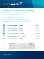 1
1
-
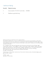 2
2
-
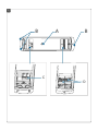 3
3
-
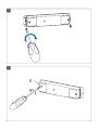 4
4
-
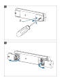 5
5
-
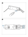 6
6
-
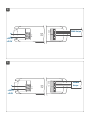 7
7
-
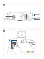 8
8
-
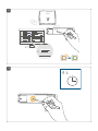 9
9
-
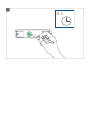 10
10
-
 11
11
-
 12
12
-
 13
13
-
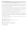 14
14
-
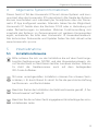 15
15
-
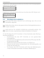 16
16
-
 17
17
-
 18
18
-
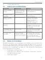 19
19
-
 20
20
-
 21
21
-
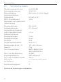 22
22
-
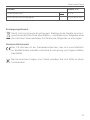 23
23
-
 24
24
-
 25
25
-
 26
26
-
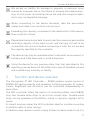 27
27
-
 28
28
-
 29
29
-
 30
30
-
 31
31
-
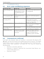 32
32
-
 33
33
-
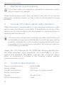 34
34
-
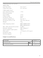 35
35
-
 36
36
-
 37
37
-
 38
38
-
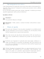 39
39
-
 40
40
-
 41
41
-
 42
42
-
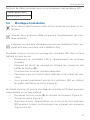 43
43
-
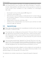 44
44
-
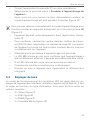 45
45
-
 46
46
-
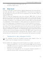 47
47
-
 48
48
-
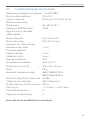 49
49
-
 50
50
-
 51
51
-
 52
52
-
 53
53
-
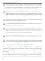 54
54
-
 55
55
-
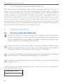 56
56
-
 57
57
-
 58
58
-
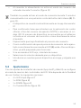 59
59
-
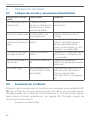 60
60
-
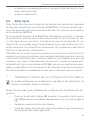 61
61
-
 62
62
-
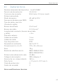 63
63
-
 64
64
-
 65
65
-
 66
66
-
 67
67
-
 68
68
-
 69
69
-
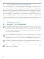 70
70
-
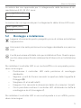 71
71
-
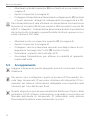 72
72
-
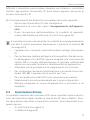 73
73
-
 74
74
-
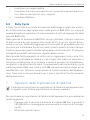 75
75
-
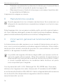 76
76
-
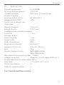 77
77
-
 78
78
-
 79
79
-
 80
80
-
 81
81
-
 82
82
-
 83
83
-
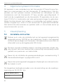 84
84
-
 85
85
-
 86
86
-
 87
87
-
 88
88
-
 89
89
-
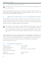 90
90
-
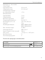 91
91
-
 92
92
-
 93
93


HomeMatic IP 157662 LED Controller Handleiding
- Type
- Handleiding
in andere talen
Gerelateerde artikelen
Andere documenten
-
HomeMatic HmIP-PSM-2 Handleiding
-
HomeMatic HmIP-WTH-B-2 Handleiding
-
HomeMatic hmip-etrv-b-2 Handleiding
-
Xavax 111951 de handleiding
-
Briteq BEAM MATRIX5x5-RGBW de handleiding
-
 Ibiza Light LLS500RGBW de handleiding
-
-
-
Chauvet Professional Colorado Referentie gids
-
Chauvet Colorado Referentie gids
