
ADB-1140
ADB-1240
ADB-40
BETRIEBSANLEITUNG
OPERATING INSTRUCTIONS
MODE D’EMPLOI
GEBRUIKSAANWIJZING
easy2wire AD_AP_I-Manual_210x240_Fin1.indd 1 28.10.14 17:02

easy2wire ADB | DEUTSCH
DE
2
13
12
14
Abb. A
DIAGRAM A
ILLUSTRATION A
AFBEELDING A
A
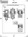
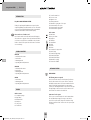
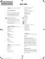
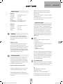
AUSSENSTATION• OUTDOOR STATION • BOÎTIER EXTÉRIEUR • BUITENSTATION
6 6
5
5
9
3
4
2
1
77
5 5
10
11
8
easy2wire AD_AP_I-Manual_210x240_Fin1.indd 2 28.10.14 17:02

DE
DEUTSCH | easy2wire ADB
3
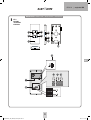
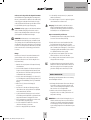
INNENSTATION •INDOOR STATION • BOÎTIER INTÉRIEUR • BINNENSTATION
5
4
1
2
3
8
7
6
10
Abb. B
DIAGRAM B
ILLUSTRATION B
AFBEELDING B
B
11 12 13
15
9
14
easy2wire AD_AP_I-Manual_210x240_Fin1.indd 3 28.10.14 17:02

easy2wire ADB | DEUTSCH
DE
4
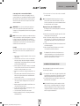
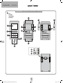
A.7 Schrauben für Terminalabdeckung
A.8 Frontcoverschrauben
A.9 Helligkeitssensor
A.10 Lautstärke-Potentiometer
A.11 Dip-Schalter für Öffnungszeit des Türöffners
A.12 Anschlussterminal Türöffner
A.13 Anschlussterminal Spannungsversorgung
A.14 Anschlussterminal Signalleitung
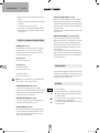
Innenstation
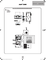
B.1 Stummtaste
B.2 Türöffnertaste
B.3 Mikrofon
B.4 Sprechtaste
B.5 Interntaste
B.6 Melodie
B.7 Lautstärke +
B.8 Lautstärke -
B.9 Potentiometer für Klingellautstärke
B.10 Gehäuserückseite
B.11 Terminal Betriebsspannung
B.12 Terminal BUS-Eingang
B.13 Terminal BUS-Ausgang
B.14 DIP-Schalter für Codierung
B.15 Anschluss für VTX-Bell
AUSSENSTATION
INSTALLATION
Folgende Leitungen werden benötigt:
2 Leitungen von der Außenstation zu der/den Innenstation/en sowie
2 Leitungen von der Außenstation zum Türöffner. Die Leitung kann
wahlweise sternförmig oder von Station zu Station verlegt werden. Für
die Verbindung von Station zu Station befinden sich in der Innenstation
zwei Anschlussklemmen für die BUS-Leitung (Eingang und Ausgang),
bei Sternverdrahtung wird die BUS-Leitung nur an Eingang angeschlos-
sen Die Betriebsspannung wird entweder an einer Innenstation oder
an der Außenstation angeschlossen. Sie sollten sie aber nicht doppelt
zu führen.
Anschluss eines Türöffners
Der Türöffner wird direkt durch zwei Leitungen mit der Außenstation
verbunden. Es ist keine zusätzliche Stromversorgung nötig, um den
Türöffner anzusteuern. Der Türöffner muss für 12 Volt Gleichspannung
ausgelegt sein und darf nicht mehr als 1A Strom benötigen. Bei einigen
Türöffnern ist auf korrekte Polung zu achten.
EINLEITUNG
Easy2Wire TÜRSPRECH-SYSTEM
Vielen Dank für den Kauf des Easy2Wire Türsprech-Systems. Sie
haben eine hochwertige Anlage mit Edelstahl-Abdeckung gekauft.
Die Edelstahl-Abdeckungen werden aufwändig per Hand gefertigt
und besitzen dadurch individuelle Merkmale, die als ein Zeichen von
Qualität anzusehen sind.
Pflegehinweis Edelstahl
Bitte säubern Sie Edelstahl-Oberflächen nicht mit handelsüblichen
Reinigungsmitteln, da diese zu scharf sind. Bitte nur mit Edelstahlrei-
nigungs- bzw. Pflegespray säubern. Sollten Sie dieses nicht zur Hand
haben, einfach nur klares Wasser verwenden.
Wird dieser Pflegetipp nicht beachtet, kann es zu Verfärbungen bzw. im
schlimmsten Fall zu Rostschäden kommen.
VERPACKUNGSINHALT
ADB-1140
1x Einfamilien-Außenstation
1x Innenstation
1x Befestigungsmaterial
1x Betriebs- und Montageanleitung
ADB-1240
1x Zweifamilien-Außenstation
2x Innenstation
1x Befestigungsmaterial
1x Betriebs- und Montageanleitung
ADB-40
1x Zusatz-Innenstation
1x Befestigungsmaterial
1x Betriebs- und Montageanleitung
LEGENDE
Außenstation
A.1 Lautsprecheröffnungen
A.2 Klingeltaster
A.3 Leuchtfeld
A.4 Mikrofon
A.5 Gehäuseschrauben
A.6 Terminalabdeckung
easy2wire AD_AP_I-Manual_210x240_Fin1.indd 4 28.10.14 17:02

DE
DEUTSCH | easy2wire ADB
5
10. Passen Sie das Namensschild Ihren Wünschen entsprechend an
(siehe ‚Anpassen von Namensschild und Leuchtfeld’).
11. Führen Sie anschließend die Schritte 1 bis 5 in umgekehrter Rei-
henfolge durch, um die Außenstation wieder zusammenzusetzen.
Hinweis: Falls das Leuchtfeld und die Namensschilder nicht von
alleine in Position bleiben, wenn das Edelstahlfrontcover aufgesetzt
werden soll, können Sie Leuchtfeld und Namenschilder mit einem
Streifen Klebeband sichern.
Anpassen von Namensschild und Leuchtfeld
Das Namensschild besteht aus zwei transparenten Kunststoffteilen,
welche durch 2 Schrauben miteinander verbunden sind.
12. Entfernen Sie beide Schrauben und nehmen Sie das Namensschild
auseinander. Zwischen den beiden Kunststoffteilen liegt die Folie
für die Beschriftung.
13. Beschriften Sie die Folie mit einem wischfesten Filzstift oder dru-
cken Sie sich ein Namensschild mit den Abmessungen 71 x 15 mm
per PC und Drucker aus (Es kann normales Papier benutzt werden,
besser geeignet ist bedruckbare Folie, welche Sie im Schreibwaren-
geschäft erhalten können).
14. Legen Sie das beschriftete Namensschild (Folie) zwischen beide
Kunststoffteile und verschrauben Sie diese wieder miteinander.
15. Achten Sie darauf, dass das untere Kunststoffteil richtig herum mit
dem oberen Kunststoffteil zusammengesetzt wird.
Das Leuchtfeld besteht ebenfalls aus zwei Kunststoffteilen, eines fest
mit der Außenstation verbunden, das andere wird lose darauf gelegt
und durch das Frontcover in Position gehalten. Die Abmessungen für das
Beschriftungsfeld sind 72 x 62 mm.
MONTAGE DER INNENSTATION
Die Montagehöhe der Innenstationen können Sie Ihren Gegebenheiten
entsprechend frei wählen.
1. Das Gehäuse der Innenstation ist nur zusammen gesteckt und wird
durch Nasen und Nuten zusammengehalten. Um das Gehäu-
seunterteil vom Vorderteil zu trennen, kann das Unterteil einfach
abgezogen werden.
2. Benutzen Sie das Gehäuseunterteil als Hilfe zum Anzeichnen
der Bohrlöcher. Achten Sie dabei darauf, das Unterteil gerade
auszurichten.
Anschluss des Funk-Erweiterungsmoduls VTX-BELL
Mit dem VTX-BELL kann das Klingelsignal per Funk an Empfänger der
BELL-Serie (z.Z. BELL 200 RX, BELL 210 USB und BELL 220 RX) weiter-
geleitet werden. Das Funkmodul wird auf den 3-poligen Stecker (B.15)
innerhalb der Innenstation gesteckt. Sie benötigen die kurze 3-polige
Verlängerung die dem VTX-BELL beiliegt.
WICHTIG: Das Netzteil bitte erst mit dem Stromnetz verbinden, wenn
die Anlage vollständig montiert ist. Ansonsten können während der
Installation Kurzschlüsse auftreten, die die Geräte im schlimmsten Fall
zerstören.
HINWEIS: Die Außenstation ist gemäß IP 44 spritzwassergeschützt. Bei
starkem Regen, insbesondere wenn zusätzlich ein starker Wind weht,
kann trotzdem Wasser ins Gehäuse eindringen. Daher empfehlen wir
die Montage nur im geschützten Außenbereich. Ist eine Montage im
geschützten Außenbereich nicht möglich, sollte ein Wetterschutz über der
Außenstation montiert werden.
Montage
Am Montageort der Außenstation sollte die Wand eben sein und beim
Verschrauben der Außenstation darauf geachtet werden, dass diese sich
nicht verzieht. Dies gilt ebenso für die Innenstation/en.
1. Schrauben Sie die beiden Schrauben (A.8), welche das Frontcover
fixieren, aus der Außenstation heraus.
2. Heben Sie das Edelstahlfrontcover ab. Dazu fassen Sie es seitlich
mit den Fingern und drücken gleichzeitig mit beiden Daumen das
Namensschild nach hinten heraus. Eventuell klemmt dabei das
große Leuchtfeld und es muss etwas nach hinten gedrückt werden.
3. Jetzt sind die Gehäuseschrauben (A.5) und die Schrauben (A.7)
für die Terminalabdeckung (A.6) freigelegt. Schrauben Sie zuerst
die Schrauben der Terminalabdeckung heraus und legen Sie die
Terminalabdeckung beiseite.
4. Schrauben Sie die 6 Gehäuseschrauben (A.5) heraus und legen Sie
sie zur Seite.
5. Trennen Sie jetzt vorsichtig das Gehäuseunterteil vom Gehäuseo-
berteil. Die beiden 6-poligen Stecker, die die Hauptplatine mit den
Anschlussterminals verbinden, können jetzt abgezogen werden.
6. Legen Sie das Gehäuseoberteil zur Seite und nehmen Sie das
Gehäuseunterteil, um die entsprechenden Befestigungslöcher am
Bestimmungsort der Außenstation anzuzeichnen.
7. Bohren Sie die Befestigungslocher mit einem geeigneten 6mm-
Bohrer und stecken Sie in jedes Loch einen der mitgelieferten Dübel.
8. Führen Sie die Anschlussleitung durch die Leitungsdurchführung und
verschrauben Sie das Gehäuseunterteil mit der Wand.
9. Schließen Sie die von Ihnen verlegte Leitung an den
Anschlussterminals an.
easy2wire AD_AP_I-Manual_210x240_Fin1.indd 5 28.10.14 17:02

easy2wire ADB | DEUTSCH
DE
6
HINWEIS: Das Gehäuseunterteil kann auch auf einer Hohlwanddose
befestigt werden. Dazu befinden Sich um das Leitungs-Einführungs-
loch entsprechende Befestigungslöcher. Sollte sich hierdurch keine
ausreichende Fixierung ergeben, bohren Sie weitere Befestigungslö-
cher und verschrauben Sie damit die Innenstation zusätzlich.
3. Bohren Sie die Befestigungslöcher mit einem 6mm-Bohrer und
stecken Sie in jedes Loch einen Dübel.
4. Stecken Sie die Leitungen durch das dafür vorgesehene Einfüh-
rungsloch im Gehäuseunterteil.
5. Schrauben Sie das Gehäuseunterteil an der Wand fest.
6. Schließen Sie die Leitungen entsprechend des Verdrahtungsplanes
an und setzen Sie das Gehäusevorderteil auf das Gehäuseunterteil.
Achten Sie dabei darauf, dass es richtig einrastet.
EINSTELUNGEN an INNEN- und AUSSENSTATION
CODIERUNG (Innenstation)
An den Innenstationen befinden sich Dip-Schalter (B.14) zur Codierung.
Jede Innenstation muss auf den richtigen Code eingestellt werden.
Wenn eine Partei mehrere Innenstationen hat, ist die Codierung bei
allen der Partei zugehörigen Innenstationen gleich einzustellen.
1-Familien-Version
Dip-Schalter 1 „ON“ alle anderen „OFF“
2-Familenversion
Innenstation(en) für Familie 1
Dip-Schalter 1 „ON“ alle anderen „OFF“
Innenstation(en) für Familie 2
Dip-Schalter 2 „ON“ alle anderen „OFF“
HINWEIS: Werden zwei oder mehr Innenstationen angeschlossen, ist
Dip-schalter 6 bei der letzten Innenstation auf „ON“ zu stellen.
SPRECHLAUTSTÄRKE (Außenstation)
Mit dem Potentiometer (A.10) wird die Sprachlautstärke der Außensta-
tion eingestellt. Für volle Lautstärke drehen Sie das Potentiometer im
Uhrzeigersinn vorsichtig bis zum Anschlag und dann ein klein wenig
zurück. Durch Drehen gegen den Uhrzeigersinn wird die Lautstärke
verringert.
SRECHLAUTSTÄRKE (Innenstation)
An der Innenstation können Sie die Gesprächslautstärke mit den beiden
seitlichen Tastern B.7 und B.8 in mehreren Stufen einstellen.
KLINGELLAUTSTÄRKE (Innenstation)
Mit dem Potentiometer (B.9) wird die Klingellautstärke der Innenstation
eingestellt. Für volle Lautstärke drehen Sie das Potentiometer im Uhr-
zeigersinn vorsichtig bis zum Anschlag und dann ein klein wenig zurück.
Durch Drehen gegen den Uhrzeigersinn wird die Lautstärke verringert.
KLINGELTON ÄNDERN (Innenstation)
Über die Taste B.6 kann der Klingelton geändert werden. Drücken Sie
die Sprechtaste (B.4) um die Innenstation zu aktivieren. Danach drücken
Sie auf die Melodietaste (B.6), eine Melodie wird abgespielt. Drücken
Sie die Melodietaste so oft, bis der gewünschte Klingelton abgespielt
wird. Zur Bestätigung drücken Sie auf die Sprechtaste. Danach ist der
eingestellte Ton gespeichert.
Wird die Anlage stromlos geschaltet, wird die Melodie wieder auf die
Werkseinstellung zurückgesetzt.
KLINGELMELODIE DEAKTIVIEREN (z.B. bei Nachtruhe)
Die Klingelmelodie kann deaktiviert werden, um z.B. bei Nachtruhe nicht
gestört zu werden. Drücken Sie dazu einmal kurz auf die Stummtaste
(B.1.) der Inneneinheit. Die LED der Stummtaste leuchtet zur Erinnerung
bei deaktivierter Melodie rot. Um die Melodie wieder zu aktivieren,
drücken Sie erneut kurz auf die Stummtaste, die rote LED erlischt und
die Melodie ist wieder aktiviert.
Das optische Signal (Leuchtrahmen der Sprech- und Türöffner-Taste)
bleibt auch bei deaktivierter Klingelmelodie aktiv und zeigt weiterhin
ein Klingeln an. Des weiteren blinkt die rote LED wenn bei aktivierter
Stummschaltung geklingelt wurde.
INBETRIEBNAHME
Nachdem alle Komponenten angeschlossen und codiert wurden, verbin-
den Sie das Netzteil mit dem 230V-Netz. Danach klingeln Sie einmal,
um das System zu initialisieren. Diese Initialisierung muss jedes Mal
durchgeführt werden, wenn die Anlage zwischenzeitlich stromlos war.
BEDIENUNG
1. Drücken Sie auf die Klingeltaste.
2. An der/den entsprechenden Innenstation/en ertönt
der eingestellte Klingelton
3. Nehmen Sie das Gespräch an der Innenstation durch kurzen Druck
auf die Sprech-Taste (MUND) an.
4. Ist ein Türöffner angeschlossen, können Sie durch kurzen Druck auf
die Türöffner-Taste (SCHLÜSSEL) den Türöffner aktivieren.
5. Durch erneutes kurzes Drücken der Sprech-Taste (MUND) wird die
Anlage wieder in den Standby-Betrieb geschaltet.
easy2wire AD_AP_I-Manual_210x240_Fin1.indd 6 28.10.14 17:02

DE
DEUTSCH | easy2wire ADB
7
Wenden Sie sich an eine Fachkraft, wenn Sie Zweifel über die Arbeits-
weise, die Sicherheit oder den Anschluss des Geräts haben.
Gehen Sie vorsichtig mit dem Produkt um - durch Stöße, Schläge oder
dem Fall aus bereits geringer Höhe wird es beschädigt.
2 JAHRE BESCHRÄNKTE GARANTIE
Es wird für die Dauer von 2 Jahren ab Kaufdatum gewährleistet, dass
dieses Produkt frei von Defekten in den Materialien und in der Ausfüh-
rung ist. Dies trifft nur zu, wenn das Gerät in üblicher Weise benutzt
wird und regelmäßig instand gehalten wird. Die Verpflichtungen dieser
Garantie werden auf die Reparatur oder den Wiedereinbau irgendeines
Teils des Gerätes begrenzt und gelten nur unter der Bedingung, dass
keine unbefugten Veränderungen oder versuchte Reparaturen vorge-
nommen wurden. Ihre gesetzlichen Rechte als Kunde werden in keiner
Weise durch diese Garantie beeinträchtigt.
Bitte beachten Sie!
Es besteht kein Anspruch auf Garantie in u. a. folgenden Fällen:
• Bedienungsfehler
• Störungen durch andere Funkanlagen (z.B. Handybetrieb)
• Fremdeingriffe/-wirkungen
• Mechanische Beschädigungen
• Feuchtigkeitsschäden
• Kein Garantie-Nachweis (Kaufbeleg)
Bei Schäden, die durch Nichtbeachten dieser Bedienungsanleitung
verursacht werden, erlischt der Garantieanspruch. Für Folgeschäden
übernehmen wir keine Haftung! Bei Sach- oder Personenschäden, die
durch unsachgemäße Handhabung oder Nichtbeachten der Sicherheits-
hinweise verursacht werden, übernehmen wir keine Haftung. In solchen
Fällen erlischt jeder Garantieanspruch!
Haftungsbeschränkung:
Der Hersteller ist nicht für den Verlust oder die Beschädigung irgendwel-
cher Art einschließlich der beiläufigen oder Folgeschäden haftbar, die
direkt oder indirekt aus der Störung dieses Produktes resultieren.
DE
Diese Bedienungsanleitung ist eine Publikation der
m-e GmbH modern-electronics,
An den Kolonaten 37, 26160 Bad Zwischenahn
Diese Bedienungsanleitung entspricht dem technischen Stand bei
Drucklegung. Änderung in Technik und Ausstattung vorbehalten.
TECHNISCHE DATEN
Außenstation
Betriebsspannung: 15 Volt DC / min. 1A
Stromaufnahme: 130 ± 50 mA
Temperaturbereich: -20 bis + 50°C
Abmessungen: 124x 200 x 20 mm
Türöffner-Anschluss: 12 Volt DC / 1A max.
Spitzwassergeschützt gemäß IP 44
Innenstation
Betriebsspannung: 15 Volt DC / min. 1A
Stromaufnahme: 130 ± 50 mA
Temperaturbereich: 0 bis + 50°C
Abmessungen: 164 x 91 x 23 mm
HINWEISE
Unter Einwirkung von starken statischen, elektrischen oder hochfre-
quenten Feldern (Entladungen, Mobiltelefonen, Funkanlagen, Handys,
Mikrowellen) kann es zu Funktionsbeeinträchtigungen der Geräte (des
Gerätes) kommen.
Reinigung und Pflege
Netzbetriebene Geräte vor dem Reinigen vom Netz trennen (Stecker
ziehen). Die Oberfläche des Gehäuses kann mit einem mit Seifenlauge
angefeuchtetem weichen Tuch gereinigt werden. Verwenden Sie keine
Scheuermittel oder Chemikalien. Staubablagerungen an Lüftungs-
schlitzen nur mit einem Pinsel lösen und gegebenenfalls mit einem
Staubsauger absaugen. Die Saugdüse nicht direkt an das Gerät halten.
SICHERHEITSHINWEISE
Bei Beschädigung von Gehäusen, Steckern, Netzkabel oder bei Schäden
an der Isolation, Geräte sofort außer Betrieb nehmen und Netzleitungen
abziehen. STROMSCHLAG - LEBENSGEFAHR. (Netzstecker aus der Steckdo-
se ziehen!) Schäden sofort durch Fachmann beheben lassen!
Keine eigenen Reparaturversuche durchführen!
Aus Sicherheits- und Zulassungsgründen (CE) ist das eigenmächtige
Umbauen und/oder Verändern des Produkts nicht gestattet.
Lassen Sie das Verpackungsmaterial nicht achtlos liegen, Plastikfolien/-
tüten, Styroporteile etc. könnten für Kinder zu einem gefährlichen
Spielzeug werden.
easy2wire AD_AP_I-Manual_210x240_Fin1.indd 7 28.10.14 17:02

GB
easy2wire ADB | ENGLISH
88
13
12
14
Abb. A
DIAGRAM A
ILLUSTRATION A
AFBEELDING A
A
AUSSENSTATION• OUTDOOR STATION • BOÎTIER EXTÉRIEUR • BUITENSTATION
6 6
5
5
9
3
4
2
1
77
5 5
10
11
8
easy2wire AD_AP_I-Manual_210x240_Fin1.indd 8 28.10.14 17:02

GB
ENGLISH | easy2wire ADB
99
INNENSTATION •INDOOR STATION • BOÎTIER INTÉRIEUR • BINNENSTATION
5
4
1
2
3
8
7
6
10
Abb. B
DIAGRAM B
ILLUSTRATION B
AFBEELDING B
B
11 12 13
15
9
14
easy2wire AD_AP_I-Manual_210x240_Fin1.indd 9 28.10.14 17:02

GB
easy2wire ADB | ENGLISH
1010
INTRODUCTION
Easy2Wire DOOR INTERCOM SYSTEM
Thank you for purchasing the Easy2Wire intercom system. You have
acquired a high-quality system with a stainless steel cover. The stainless
steel covers are made carefully by hand and therefore have individual
characteristics that should be considered a mark of quality.
Notes on the care of stainless steel
Never clean the stainless steel surfaces with commercial cleaning pro-
ducts as these are too aggressive. Please only clean them with stainless
steel cleaner or care spray. If this is not available use only clear water.
Failure to observe this care tip can lead to discoloration or in the worst
case to rust damage.
PACKAGE CONTENTS
ADB-1140
1x One-family outdoor station
1x Indoor station
1x Mounting materials
1x Operating and assembly instructions
ADB-1240
1x Two-family outdoor station
2x Indoor station
1x Mounting materials
1x Operating and assembly instructions
ADB-40
1x Indoor station
1x Mounting materials
1x Operating and assembly instructions
LEGEND
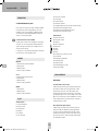
Outdoor station
A.1 Loudspeaker openings
A.2 Ringer button
A.3 Illuminated field
A.4 Microphone
A.5 Casing screws
A.6 Terminal cover
A.7 Screws for terminal cover
A.8 Front cover screws
A.9 Brightness sensor
A.10 Volume potentiometer
A.11 DIP switch for opening time of door opener
A.12 Contact terminal for door opener
A.13 Contact terminal for power supply
A.14 Contact terminal for signal line
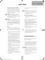
Indoor station
B.1 Mute button
B.2 Door opener button
B.3 Microphone
B.4 Talk button
B.5 Internal button
B.6 Melody
B.7 Volume +
B.8 Volume -
B.9 Potentiometer for ringer volume
B.10 Back of casing
B.11 Terminal for supply voltage
B.12 Terminal for BUS input
B.13 Terminal for BUS output
B.14 DIP switch for encoding
B.15 Connection for VTX-Bell
OUTDOOR STATION
INSTALLATION
The following wires are required:
2 wires from the outdoor station to the indoor station(s) and 2 wires
from the outdoor station to the door opener. The lines can either be
laid radially or station-to-station. There are two terminals in the indoor
station for the BUS line (input and output) for a station-to-station
connection, for radial wiring the BUS line is only connected to the input.
The supply voltage is either connected to one indoor station or to the
outdoor station. There should not be a double feed.
Connection of a door opener
The door opener is connected directly to the outdoor station with two
lines. No additional power supply is necessary to control the door
opener. The door opener must be designed for 12-volt direct voltage
and may not require more than 1 A current. Some door openers require
correct poling.
easy2wire AD_AP_I-Manual_210x240_Fin1.indd 10 28.10.14 17:02

GB
ENGLISH | easy2wire ADB
1111
Connecting the radio extension module VTX-BELL
The VTX-BELL can be used to transfer the bell signal by radio to the
recipient of the BELL series (currently BELL 200 RX, BELL 210 USB and
BELL 220 RX). The radio module is attached to the 3-pole plug (B.15)
inside the indoor station. You need the short 3-pole extension that is
included in the VTX-BELL.
IMPORTANT: Please only connect the mains power supply to the
power once the system has been fully mounted. Otherwise short-
circuiting can occur during installation, which can destroy the apparatus
in the worst case.
NOTE: The outdoor station is splash proof in accordance with IP 44. In
heavy rain, particularly in conjunction with high winds, it is still possible
for water to penetrate the casing. We therefore recommend only
mounting the station in a protected outdoor area. If it is not possible to
mount the station in a protected indoor area then weather protection
should be fitted over the outdoor station.
Assembly
The outdoor station should be mounted on a level wall and it must not
distort when screws are inserted. This is equally valid for the indoor
station(s).
1. Remove both the screws (A.8) that attach the front cover out of the
outdoor station.
2. Lift off the stainless steel front cover. In order to do this, hold the
sides with your fingers and push the nameplate out backwards
using both thumbs. The large illuminated field may stick and may
need to be pushed backwards a little.
3. Now the casing screws (A.5) and the screws (A.7) for the terminal
cover (A.6) have been revealed. First remove the screws from the
terminal cover and lay the terminal cover to one side.
4. Remove the six screws from the casing (A.5) and lay them to one
side.
5. Now carefully separate the back half of the casing from the front
half. The two 6-pole plugs that connect the main board with the
terminal can now be removed.
6. Lay the front half of the casing to one side and take the back half
of the casing to draw the mounting holes at the location for the
outdoor station.
7. Drill the mounting holes with a suitable 6 mm drill and insert one
of the included dowels into each hole.
8. Feed the connection wire through the feed-through and screw the
back half of the casing onto the wall.
9. Connect the wire that you have laid onto the terminal.
10. Adjust the nameplate as desired (see ‘adjusting the name plate
and illuminated field’).
11. Then carry out steps 1 to 5 in reverse order in order to re-assemble
the outdoor station.
Note: If the illuminated field and the name plates do not stay in
position of their own accord when the stainless steel front cover
needs to be replaced then you can secure the illuminated field and
the name plates with a strip of sticky tape.
Adjusting the name plate and illuminated field
The nameplate consists of two transparent plastic sections that are
joined with 2 screws.
12. Remove both screws and take the nameplate apart. The foil for the
lettering is between the two plastic parts.
13. Write on the foil with a smudge-proof felt pen or print a nameplate
with the dimensions 71 x 15 mm using a PC and printer (you can
use normal paper but printable foil from stationery shop is better
suited).
14. Lay the printed nameplate (foil) between the two plastic parts and
screw them back together.
15. Make sure that the back half of the plastic case is assembled
correctly with the front half of the plastic case.
The illuminated field is also made up of two plastic parts, one
of which is firmly attached to the outdoor station and the other
is attached loosely and held in position by the front cover. The
dimensions for the name field are 72 x 62 mm.
ASSEMBLY OF THE INDOOR STATION
The assembly height of the indoor station can be freely selected in
accordance with your situation.
1. The casing on the indoor station is only clipped together and is held
together with projections and notches. The back part can be pulled
away easily to separate the back casing from the front section.
2. Use the back half of the casing to help mark the drill holes. Ensure
that the back half is in a straight line.
NOTE: The back half of the casing can also be attached to a hollow-
wall box. There are corresponding mounting holes for this purpose
around the installation hole for the wire. If this does not provide
enough hold then drill more mounting holes and screw the indoor
station on using these additional holes.
easy2wire AD_AP_I-Manual_210x240_Fin1.indd 11 28.10.14 17:02

GB
easy2wire ADB | ENGLISH
1212
INNENSTATION
INDOOR STATION
BOÎTIER INTÉRIEUR
BINNENSTATION
3. Drill the mounting holes with a 6 mm drill and insert a dowel into
each hole.
4. Push the wires through the corresponding feedhole in the back half
of the casing.
5. Screw the lower half of the casing onto the wall.
6. Connect the wires in accordance with the wiring plan and place the
front half of the casing onto the lower section. Make sure it clicks
correctly into place.
SETTINGS on the INDOOR and OUTDOOR STATIONS
ENCODING (indoor station)
There are DIP switches (B.14) on the indoor station for encoding. Each
indoor station needs to be set to the correct code. If one party has
several indoor stations then the encoding must be the same for all
indoor stations belonging to the party.
One-family version
DIP switch 1 „ON“, all others „OFF“
Two-family version
Indoor station(s) for family 1
DIP switch 1 „ON“, all others „OFF“
Indoor station(s) for family 2
DIP switch 2 „ON“, all others „OFF“
NOTE: If two or more indoor stations are connected then DIP switch 6
must be switched to “ON” on the last indoor station.
CONVERSATION VOLUME (outdoor station)
The conversation volume on the outdoor station is set using the
potentiometer (A.10). For full volume turn the potentiometer carefully in
a clockwise direction to its limit and then turn it back a little. Turn it in
an anti-clockwise direction to reduce the volume.
CONVERSATION VOLUME (indoor station)
You can set the conversation volume on the indoor station in several
stages using the two buttons B.7 and B.8 on the side.
RINGER VOLUME (indoor station)
The ringer volume on the indoor station is set using the potentiometer
(B.9). For full volume turn the potentiometer carefully in a clockwise
direction to its limit and then turn it back a little. Turn it in an anti-
clockwise direction to reduce the volume.
CHANGING THE RING TONE (indoor station)
The ring tone can be changed using button B.6. Press the talk button
(B.4) to activate the indoor station. Then press on the melody button
(B.6) and a melody will play. Keep pressing the melody button until the
desired ring tone plays. To confirm the melody press the talk button. The
set melody is then saved.
If the system is disconnected from the mains the melody will be set back
to the factory setting.
DEACTIVATE RINGER MELODY (e.g. during the night)
It is possible to deactivate the ringer melody, e.g. in order not to be
disturbed at night. To do this, press the mute button (B.1) on the indoor
unit down once, briefly. The LED on the mute button lights up red to
remind you that the melody is deactivated. To re-activate the melody
press the mute button briefly again. The red LED will go out and the
melody is reactivated.
The optical signal (the illuminated frame on the talk and door opener
button) remains active even when the ringer melody is deactivated and
continues to light up when the bell is rung. The red LED also flashes if
the bell is rung while muted.
INITIAL OPERATION
Connect the mains power supply unit to the 230 V network once all the
components are connected and encoded. Then ring the bell once in order
to initialise the system. This initialisation needs to be carried out each
time the system is disconnected from the mains.
OPERATION
1. Press the ringer button.
2. The set melody will sound at the corresponding indoor station(s).
3. Accept the conversation at the indoor station by briefly pressing on
the talk button (MOUTH).
4. If a door opener is connected you can activate the door opener by
pressing briefly on the door opener button (KEY).
5. Press the talk button again briefly (MOUTH) in order to switch the
system back to standby.
easy2wire AD_AP_I-Manual_210x240_Fin1.indd 12 28.10.14 17:02

GB
ENGLISH | easy2wire ADB
131313
TECHNICAL DATA
Outdoor station
Supply voltage: 15 volt DC / min. 1 A
Power consumption: 130 ± 50 mA
Temperature range: -20 to +50°C
Dimensions: 200 x 124 x 20 mm
Door opener connection: 12 volt DC / 1 A max.
Splash-proof in accordance with IP 44
Indoor station
Supply voltage: 15 volt DC / min. 1 A
Power consumption: 130 ± 50 mA
Temperature range: 0 to +50°C
Dimensions: 164 x 91 x 23 mm
NOTES
The functionality of the unit can be affected by the influence of strong
static, electrical or high frequency fields (discharging, mobile phones,
radios, microwaves).
Cleaning and maintenance
Always disconnect mains powered units from the mains supply before
cleaning (disconnect the plug). The unit housing can be cleaned using
a soapy soft cloth. Do not use any abrasive materials or chemicals.
Remove dust build-up from ventilation slits using a brush and clean up
using a vacuum cleaner. Do not hold the vacuum cleaner nozzle directly
against the unit.
SAFETY INSTRUCTION
In the event of damage to the housing, connectors, power cables or
isolation shielding, switch off the device immediately and disconnect
from the mains power. ELECTRIC SHOCK – DANGER OF LOSS OF LIFE.
(Unplug the mains connector from the socket!). Damage should be
repaired immediately by a specialist!
Never carry out repairs yourself!
For reasons of safety and licensing (CE), unauthorised conversion and /
or modification of the product is prohibited.
Do not leave packaging material lying about since plastic foils and
pockets and polystyrene parts etc. could be lethal toys for children.
The interior unit is suitable only for dry interior rooms (not bathrooms
and other moist places). Do not allow the devices to get moist or wet.
Please consult a specialist should you have doubts regarding the
method of operation, the safety, or the connections of the device.
Handle the product with care – it is sensitive to bumps, knocks or falls
even from low heights.
2 YEAR LIMITED GUARANTEE
For two years after the date of purchase, the defect-free condition of
the product model and its materials is guaranteed. This guarantee is
only valid when the device is used as intended and is subject to regular
maintenance checks. The scope of this guarantee is limited to the
repair or reinstallation of any part of the device, and is only valid if no
unauthorised modifications or attempted repairs have been undertaken.
Customer statutory rights are not affected by this guarantee.
Please note!
No claim can be made under guarantee in the following circumstances:
• Operational malfunction
• Empty batteries or faulty accumulator
• Fault through other radio installation (i.e. mobile operation)
• Unauthorised modifications / actions
• Mechanical damage
• Moisture damage
• No proof of guarantee (purchase receipt)
Claims under warranty will be invalidated in the event of damage
caused by non-compliance with the operating instructions. We do not
accept any responsibility for consequential damage! No liability will be
accepted for material damage or personal injury caused by inappropri-
ate operation or failure to observe the safety instructions. In such cases,
the guarantee will be rendered void.
Liability limitation
The manufacturer is not liable for loss or damage of any kind including
incidental or consequential damage which is the direct or indirect result
of a fault to this product.
GB
These operating instruction are published by
m-e GmbH modern-electronics,
An den Kolonaten 37, 26160 Bad Zwischenahn/Germany
The operating instructions reflect the current technical specifications at
time of print. We reserve the right to change the technical or physical
specifications.
easy2wire AD_AP_I-Manual_210x240_Fin1.indd 13 28.10.14 17:02

FR
easy2wire ADB | FRANÇAIS
14
13
12
14
Abb. A
DIAGRAM A
ILLUSTRATION A
AFBEELDING A
A
AUSSENSTATION• OUTDOOR STATION • BOÎTIER EXTÉRIEUR • BUITENSTATION
6 6
5
5
9
3
4
2
1
77
5 5
10
11
8
easy2wire AD_AP_I-Manual_210x240_Fin1.indd 14 28.10.14 17:02

FR
FRANÇAIS | easy2wire ADB
15
INNENSTATION •INDOOR STATION • BOÎTIER INTÉRIEUR • BINNENSTATION
5
4
1
2
3
8
7
6
10
Abb. B
DIAGRAM B
ILLUSTRATION B
AFBEELDING B
B
11 12 13
15
9
14
easy2wire AD_AP_I-Manual_210x240_Fin1.indd 15 28.10.14 17:02

FR
easy2wire ADB | FRANÇAIS
16
INTRODUCTION
SYSTÈME D’INTERPHONE Easy2Wire
Nous vous remercions d’avoir choisi le système d’interphone Easy2Wire.
Vous avez acheté un système de haute qualité avec cache en acier
inoxydable. Les caches en acier inoxydable sont fabriqués à la main
et possèdent ainsi des caractéristiques individuelles qui doivent être
considérées comme un signe de qualité.
Conseil d’entretien de l’acier inoxydable
Ne jamais nettoyer les surfaces d’acier inoxydable avec des détergents
du commerce, car ceux-ci sont trop agressifs. Utiliser uniquement des
sprays de nettoyage et d’entretien de l’acier inoxydable. Si vous n’en
avez pas, nettoyer à l’eau claire.
Le non-respect de ce conseil d’entretien peut entraîner des décolorations
voire dans le pire des cas des dommages de rouille.
CONTENU
ADB-1140
1x Station extérieure pour maison individuelle
1x Station intérieure
1x Matériel de fixation
1x Notice de montage et d’utilisation
ADB-1240
1x Station extérieure pour maison jumelée
2x Station intérieure
1x Matériel de fixation
1x Notice de montage et d’utilisation
ADB-40
1x Station intérieure
1x Matériel de fixation
1x Notice de montage et d’utilisation
Légende
Station extérieure
A.1 Orifices du haut-parleur
A.2 Bouton de sonnerie
A.3 Champ lumineux
A.4 Microphone
A.5 Vis du boîtier
A.6 Cache du terminal
A.7 Vis pour cache du terminal
A.8 Vis de la façade
A.9 Capteur de luminosité
A.10 Potentiomètre du volume
A.11 Commutateur Dip pour le temps d’ouverture de la gâche électrique
A.12 Terminal de raccordement gâche électrique
A.13 Terminal de raccordement alimentation de tension
A.14 Terminal de raccordement ligne de signal
Station intérieure
B.1 Bouton mode silencieux
B.2 Bouton gâche électrique
B.3 Microphone
B.4 Bouton communication
B.5 Bouton interne
B.6 Mélodie
B.7 Volume +
B.8 Volume -
B.9 Potentiomètre pour le volume de la sonnerie
B.10 Fond du boîtier
B.11 Terminal tension d’alimentation
B.12 Terminal entrée BUS
B.13 Terminal sortie BUS
B.14 Commutateur DIP pour le codage
B.15 Raccord pour VTX-Bell
STATION EXTÉRIEURE
INSTALLATION
Les câbles suivants sont nécessaires :
2 câbles de la station extérieure à la/aux station(s) intérieure(s) ainsi
que 2 câbles de la station extérieure à la gâche électrique. Le câble
peut être cheminé soit en étoile, soit de station à station. Pour le
raccordement de station à station, il y a deux bornes de raccordement
pour la ligne BUS (entrée et sortie), en cas de câblage en étoile, le câble
BUS n’est raccordé qu’à l’entrée. La tension d’alimentation est raccordée
à une des stations intérieures ou à la station extérieure. En revanche, il
ne faut pas la cheminer en double.
Raccordement d’une gâche électrique
La gâche électrique est directement reliée à la station extérieure au
moyen de deux câbles. Une alimentation électrique supplémentaire
n’est pas nécessaire pour commander la gâche électrique. La gâche
électrique doit être prévue pour 12 volts de tension continue et ne doit
pas nécessiter plus de 1 A de courant. Il faut veiller à la bonne polarité
sur certaines gâches électriques.
easy2wire AD_AP_I-Manual_210x240_Fin1.indd 16 28.10.14 17:02

FR
FRANÇAIS | easy2wire ADB
17
11. Suivre ensuite les étapes 1 à 5 en ordre inverse pour réassembler la
station extérieure.
Remarque : Si le champ lumineux et le porte-nom ne restent pas en
position une fois la façade en acier inoxydable remise en place,
il est possible de maintenir le champ lumineux et le porte-nom à
l’aide de ruban adhésif.
Ajuster le porte-nom et le champ lumineux
Le porte-nom est constitué de deux pièces en plastique transparent
qui sont reliées par 2 vis.
12. Retirer les deux vis du porte-nom et l’ouvrir. Entre les deux pièces en
plastique se trouve un film pour marquer le nom.
13. Marquer le nom sur le film à l’aide d’un feutre indélébile ou
imprimer une étiquette aux dimensions 71 x 15 mm par ordinateur
et imprimante (il est possible d’utiliser du papier normal, le film
imprimable disponible en papeterie convient mieux).
14. Placer l’étiquette marquée (film) entre les deux pièces en plastique
et remettre les vis.
15. Veiller à ce que la pièce plastique inférieure repose dans le bon sens
sur la pièce plastique supérieure.
Le champ lumineux est également constitué de deux pièces en
plastique. L’une est fixée à la station extérieure, l’autre y repose
sans fixation et est maintenue par la façade. Les dimensions du
champ de marquage sont de 72 x 62 mm.
MONTAGE DE LA STATION INTÉRIEURE
La hauteur de montage de la station intérieure peut être librement
déterminée selon les conditions données.
1. Le boîtier de la station intérieure est seulement enclenché et main-
tenu avec des ergots et des encoches. Pour retirer la partie inférieure
du boîtier de la partie avant, il suffit de l’enlever simplement.
2. Utiliser la partie inférieure du boîtier pour repérer les perçages.
Veiller à ce que la partie inférieure soit bien de niveau.
REMARQUE : La partie inférieure du boîtier peut être fixée sur une
boîte pour paroi creuse. Les trous de fixation nécessaires se trouvent
autour de la traversée des câbles. Si cette fixation ne devait pas
suffire, il faut percer d’autres trous de fixation et mettre des vis
supplémentaires sur la station intérieure.
3. Percer les trous de fixation avec une mèche de 6 mm et placer une
cheville dans chaque trou.
Raccordement du module d’extension radio VTX-BELL
Le VTX-BELL permet de transférer le signal de la sonnerie par radio au
récepteur de la série BELL (actuellement BELL 200 RX, BELL 210 USB
et BELL 220 RX). Le module radio est connecté sur la prise tripolaire
(B.15) dans la station intérieure. Vous aurez besoin de la courte rallonge
tripolaire fournie avec le module VTX-BELL.
IMPORTANT : Seulement brancher le bloc d’alimentation sur le
secteur lorsque le système est intégralement monté. Sinon des courts-
circuits peuvent apparaître pendant l’installation qui dans le pire des cas
peuvent entraîner la destruction de l’appareil.
REMARQUE : La station extérieure est protégée contre les eaux de
projection selon IP 44. En cas de forte pluie, notamment associée à du
vent puissant, il est tout de même possible que de l’eau pénètre dans le
boîtier. Nous recommandons par conséquent d’installer l’appareil à un
endroit à l’abri. S’il n’est pas possible de l’installer dehors à un endroit
abrité, il convient d’installer une protection contre les intempéries au-
dessus de la station extérieure.
Montage
Le mur doit être plan à l’emplacement de montage de la station exté-
rieure et il faut veiller à ce que la station extérieure ne se déforme pas
lors du vissage. Cela vaut également pour la/les station(s) intérieure(s).
1. Dévisser les deux vis (A.8) de la station extérieure qui maintiennent
la façade.
2. Soulever la façade en acier inoxydable. Pour cela, il faut la tenir sur
le côté avec les doigts et appuyer en même temps avec les deux
pouces sur le porte-nom pour le faire sortir par l’arrière. Le champ
lumineux risque de coincer, il suffit de le pousser vers l’arrière.
3. Maintenant les vis du boîtier (A.5) et les vis (A.7) du cache du
terminal (A.6) sont accessibles. Dévisser d’abord les vis du cache du
terminal et mettre le cache du terminal de côté.
4. Dévisser ensuite les 6 vis du boîtier (A.5) et les mettre de côté.
5. Séparer maintenant délicatement la partie inférieure du boîtier de la
partie supérieure. Les deux connecteurs à six pôles qui relient la pla-
tine principale aux terminaux de raccordement, peuvent maintenant
être débranchés.
6. Mettre la partie supérieure du boîtier de côté et utiliser la partie
inférieure pour repérer les trous de fixation de la station extérieure à
l’emplacement voulu.
7. Percer les trous de fixation à l’aide d’une mèche de 6 mm adaptée
et placer les chevilles fournies dans tous les perçages.
8. Passer le câble de connexion par la traversée et visser la partie
inférieure du boîtier sur le mur.
9. Raccorder le câble cheminé aux terminaux de raccordement.
10. Ajuster le porte-nom selon vos besoins (voir « Ajuster le porte-nom et
le champ lumineux »).
easy2wire AD_AP_I-Manual_210x240_Fin1.indd 17 28.10.14 17:02

FR
easy2wire ADB | FRANÇAIS
18
CHANGEMENT DE LA SONNERIE (station intérieure)
Le bouton B.6 permet de changer de sonnerie. Appuyer sur le bouton de
communication (B.4) pour activer la station intérieure. Puis appuyer sur
le bouton des mélodies (B.6), une mélodie retentit. Appuyer autant de
fois sur le bouton des mélodies jusqu’à atteindre la sonnerie souhaitée.
Pour confirmer appuyer sur le bouton de communication. La sonnerie
configurée est alors enregistrée.
Si le système est mis hors tension, la sonnerie est réinitialisée à la
configuration par défaut.
DÉSACTIVER LA SONNERIE (p. ex. la nuit)
La sonnerie peut être désactivée, pour éviter p. ex. d’être dérangé la
nuit. Pour cela, appuyer une fois brièvement sur le bouton du mode
silencieux (B.1) de la station intérieure. La LED du bouton du mode
silencieux s’allume en rouge pour rappeler que la sonnerie est désac-
tivée. Pour réactiver la sonnerie, il faut appuyer à nouveau brièvement
sur le bouton du mode silencieux, la LED rouge s’éteint et la sonnerie
est à nouveau activée.
Le signal visuel (cadre lumineux du bouton de communication et de
la gâche électrique) reste activé, même si la sonnerie est désactivée,
et indique si quelqu’un sonne dehors. De plus, la LED rouge clignote,
lorsque quelqu’un sonne dehors alors que la sonnerie est désactivée.
MISE EN SERVICE
Une fois tous les composants branchés et codés, il faut raccorder le bloc
d’alimentation au secteur de 230 V. Puis, il faut sonner une fois pour
initialiser le système. Cette initialisation doit être réalisée chaque fois
que le système a été hors tension.
UTILISATION
1. Appuyer sur le bouton de sonnerie.
2. La sonnerie configurée retentit au niveau de la/des station(s)
intérieure(s) correspondante(s).
3. Accepter la communication sur la station intérieure en appuyant
brièvement sur le bouton de communication (BOUCHE).
4. Si une gâche électrique est raccordée, celle-ci peut être actionnée
en appuyant brièvement sur le bouton de la gâche électrique (CLÉ).
5. En appuyant à nouveau brièvement sur le bouton de communica-
tion (BOUCHE), le système est remis en mode de veille.
4. Passer les câbles dans la traversée prévue à cet effet dans la partie
inférieure.
5. Visser la partie inférieure du boîtier sur le mur.
6. Raccorder les câbles conformément au plan de câblage et placer la
partie avant du boîtier sur la partie inférieure. Veiller à ce qu’elle
s’enclenche correctement.
RÉGLAGES de la STATION INTÉRIEURE et EXTÉRIEURE
CODAGE (station intérieure)
Les stations intérieures sont munies de commutateurs Dip (B.14) pour
le codage. Chaque station intérieure doit être réglée sur le bon code.
Si une partie possède plusieurs stations intérieures, le codage de
toutes les stations intérieures appartenant à la même partie doit être
identique.
Version 1 famille
Commutateur Dip 1 « ON », tous les autres « OFF »
Version 2 familles
Station(s) intérieure(s) pour la famille 1
Commutateur Dip 1 « ON », tous les autres « OFF »
Station(s) intérieure(s) pour la famille 2
Commutateur Dip 2 « ON », tous les autres « OFF »
REMARQUE : Si deux ou plusieurs stations intérieures sont
branchées, le commutateur Dip 6 sur la dernière station intérieure doit
être mis sur « ON ».
VOLUME VOCAL (station extérieure)
Le potentiomètre (A.10) permet de régler le volume vocal de la station
extérieure. Pour le régler au maximum, tourner le potentiomètre
doucement dans le sens des aiguilles d’une montre jusqu’en butée,
puis revenir un peu. En tournant dans le sens contraire des aiguilles
d’une montre, le volume se réduit.
VOLUME VOCAL (station intérieure)
Le volume vocal de la station intérieure peut être réglé à plusieurs
niveaux à l’aide des deux poussoirs latéraux B.7 et B.8.
VOLUME DE LA SONNERIE (station intérieure)
Le potentiomètre (B.9) permet de régler le volume de la sonnerie à la
station intérieure. Pour le régler au maximum, tourner le potentiomètre
doucement dans le sens des aiguilles d’une montre jusqu’en butée,
puis revenir un peu. En tournant dans le sens contraire des aiguilles
d’une montre, le volume se réduit.
easy2wire AD_AP_I-Manual_210x240_Fin1.indd 18 28.10.14 17:02

FR
FRANÇAIS | easy2wire ADB
19
En cas de doute concernant le raccordement, le fonctionnement ou la
sécurité de l’appareil, veuillez contacter un spécialiste.
Ce produit doit être manipulé avec précaution. Les coups, les chocs ou
une chute, même d’une faible hauteur, peuvent l’endommage
GARANTIE LIMITEE A 2 ANS
Il est garanti pendant 2 ans à partir de la date d’achat que ce produit
ne présente aucun défaut au niveau du matériau et du modèle. Cette
garantie est uniquement valide lorsque l’appareil est utilisé de manière
conforme, et entretenu régulièrement. La présente garantie se limite à
la réparation ou au réassemblage d’une pièce quelconque de l’appareil
dans la mesure où aucune modification ou réparations non autorisées
n’ont été effectuées. Vos droits légaux en tant que client ne sont en
aucun cas influencés par cette garantie.
Veuillez noter que toute réclamation dans le cadre de la garantie est
exclue dans les cas suivants, entre autres :
• Erreur de commande
• Piles vides ou accus défectueux
• Perturbations dues à d’autres appareils radio (par ex. utilisation
d’un téléphone portable)
• Interventions/influences extérieures
• Dégâts mécaniques
• Dégâts provoqués par l’humidité
• Aucune preuve de garantie (bon d’achat)
La garantie s’annule en cas de non-observation du présent mode
d’emploi. Nous déclinons toute responsabilité pour tout dommage
indirect ! Nous déclinons également toute responsabilité en cas de
dommages survenus sur l’appareil ou des personnes suite à une mani-
pulation non-conforme ou la non-observation des consignes de sécurité.
La garantie s’annule automatiquement dans ces cas-là !
Responsabilité limitée :
Le fabricant décline toute responsabilité en cas de perte ou de
dommages quelconques, y compris les dommages consécutifs ou
accessoires qui résultent directement ou indirectement de la défaillance
de ce produit.
F
Cette notice est une publication de la société m-e GmbH modern-electro-
nics, An den Kolonaten 37, 26160 Bad Zwischenahn/Allemagne.
Cette notice est conforme à la règlementation en vigueur lors de
l´impression. Sous réserve de modifications techniques et
dèquipement.
DONNÉES TECHNIQUES
Station extérieure
Tension d’alimentation : 15 volts c.c. / min. 1 A
Consommation : 130 ± 50 mA
Plage de température : -20 à +50°C
Dimensions : 200 x 124 x 20 mm
Raccord gâche électrique : 12 volts c.c. / 1 A max.
Protection contre les eaux de projection selon IP 44
Station intérieure
Tension d’alimentation : 15 volts c.c. / min. 1 A
Consommation : 130 ± 50 mA
Plage de température : 0 à +50°C
Dimensions : 164 x 91 x 23 mm
CONSIGNES
L‘influence de forts chants statiques, électriques ou haute fréquence (dé-
charges, téléphones mobiles, installations radio, portables, micro-ondes)
peut entraîner des dysfonctionnements des appareils (de l‘appareil).
Nettoyage et entretien
Débrancher du secteur les appareils alimentés sur secteur avant le
nettoyage (retirer la fiche). La surface du boîtier peut être nettoyée à
l‘aide d‘un chiffon humidifié avec une lotion savonneuse. Ne pas utiliser
de produits abrasifs ou chimiques. Ne retirer la poussière accumulée sur
les lattes des grilles d‘aération qu‘avec un pinceau ou aspirer avec un
aspirateur. Ne pas tenir l‘embout aspirant juste sur l‘appareil.
CONSIGNES DE SECURITE
En cas de détérioration de boîtiers, de prises, de câbles ou d‘isolation,
arrêter immédiatement les appareils et débrancher les câbles. DANGER
DE MORT PAR ELECTROCUTION. (Débrancher la fiche de la prise
d‘alimentation secteur !) Faire immédiatement réparer les détériorations
par un technicien qualifié !
Ne pas tenter de réparer vous-même les détériorations!
Pour des raisons de sécurité et d’homologation, toute transformation ou
modification arbitraire du produit est interdite.
Ne laissez pas traîner le matériel d’emballage. Les feuilles ou poches
plastiques, les éléments polystyrène, etc. peuvent se transformer en
jouets dangereux pour les enfants.
L’usage de module intérieur doit s‘effectuer dans des milieux secs
uniquement (évitez tout usage dans espaces humides comme la salle
de bain par exemple). Évitez tout contact du dispositif avec l’humidité
ou avec l’eau.
easy2wire AD_AP_I-Manual_210x240_Fin1.indd 19 28.10.14 17:02

13
12
14
Abb. A
DIAGRAM A
ILLUSTRATION A
AFBEELDING A
A
AUSSENSTATION• OUTDOOR STATION • BOÎTIER EXTÉRIEUR • BUITENSTATION
6 6
5
5
9
3
4
2
1
77
5 5
10
11
8
NL
easy2wire ADB | NEDERLANDS
NL
20
easy2wire AD_AP_I-Manual_210x240_Fin1.indd 20 28.10.14 17:02

NLNL
INNENSTATION •INDOOR STATION • BOÎTIER INTÉRIEUR • BINNENSTATION
5
4
1
2
3
8
7
6
10
Abb. B
DIAGRAM B
ILLUSTRATION B
AFBEELDING B
B
11 12 13
15
9
14
NEDERLANDS | easy2wire VDB
21
easy2wire AD_AP_I-Manual_210x240_Fin1.indd 21 28.10.14 17:02

NL
easy2wire ADB | NEDERLANDS
NL
22
EINLEITUNG
Easy2Wire DEURINTERCOM-SYSTEEM
Hartelijk dank dat u ons Easy2Wire video-deurintercomsysteem hebt
gekocht. U hebt een installatie van hoge kwaliteit met een afdekking
van edelstaal aangeschaft. De afdekkingen van edelstaal worden
arbeidsintensief, met de hand gemaakt en beschikken daardoor over
individuele kenmerken waaraan u de kwaliteit kunt herkennen.
Onderhoudsinstructie voor edelstaal
Oppervlakken van edelstaal bij voorkeur niet met de in de handel
verkrijgbare reinigingsmiddelen schoon maken, deze zijn te scherp.
Graag alleen met edelstaalreiniger of onderhoudsspray reinigen. Hebt u
dat niet bij de hand, neem dan schoon water.
Als deze onderhoudstip wordt genegeerd, kunnen er verkleuringen en in
het ergste geval roestschade ontstaan.
INHOUD VAN DE VERPAKKING
ADB-1140
1x eengezinswoning-buitenstation
1x binnenstation
1x montagemateriaal
1x gebruiks- en montageaanwijzing
ADB-1240
1x dubbele woning-buitenstation
2x binnenstation
1x montagemateriaal
1x gebruiks- en montageaanwijzing
ADB-40
1x binnenstation
1x montagemateriaal
1x gebruiks- en montageaanwijzing
LEGENDA
Buitenstation
A.1 Luidsprekeropeningen
A.2 Knop Bel
A.3 Verlicht venster
A.4 Microfoon
A.5 Schroeven voor de behuizing
A.6 Afdekking van de terminal
A.7 Schroeven voor de afdekking van de terminal
A.8 Schroeven voor de frontafdekking
A.9 Lichtsterktesensor
A.10 Potentiometer voor het geluidsvolume
A.11 dip-switch voor de tijdsduur van de deuropener
A.12 Aansluitterminal deuropener
A.13 Aansluitterminal voeding
A.14 Aansluitterminal signaalkabel
Binnenstation
B.1 Knop Geluidloos
B.2 Knop Deuropener
B.3 Microfoon
B.4 Knop Spreken
B.5 Knop Intern
B.6 Melodie
B.7 Volume +
B.8 Volume -
B.9 Potentiometer voor het volume van het belgeluid
B.10 Achterwand behuizing
B.11 Terminal bedrijfsspanning
B.12 Terminal BUS-ingang
B.13 Terminal BUS-uitgang
B.14 dip-switches voor de codering
B.15 Aansluiting voor VTX-BELL
BUITENSTATION
INSTALLATIE
U hebt de hierna genoemde kabels nodig:
Twee (2) kabels van het buitenstation naar het binnenstation alsook
twee (2) kabels van het buitenstation naar de deuropener. De kabels
kunnen naar keuze stervormig of van station naar station worden
aangelegd. Voor het aansluiten van station naar station zijn in het
binnenstation twee aansluitklemmen voor de BUS-kabel (ingang en
uitgang), bij stervormige kabelaansluiting wordt de BUS-kabel alleen
op de ingang aangesloten. De voeding wordt of aan een binnenstation,
of aan een buitenstation, aangesloten. Sluit de voeding in geen geval
dubbel aan.
Aansluiten van een deuropener
De deuropener wordt met twee kabels rechtstreeks op het buitenstation
aangesloten. Voor het regelen van de deuropener is geen bijkomende
voeding vereist. De deuropener moet geschikt zijn voor 12 V gelijkstroom
en mag niet meer stroom nodig hebben dan 1A. Let bij de deuropener
op de juiste richting van de polen.
easy2wire AD_AP_I-Manual_210x240_Fin1.indd 22 28.10.14 17:02

NLNL
NEDERLANDS | easy2wire VDB
23
Aansluiten van de radiografische uitbreidingsmodule VTX-BELL.
Met de VTX-BELL kan het belsignaal radiografisch aan ontvangers uit de
BELL-serie (op dit moment BELL 200 RX, BELL 210 USB en BELL 220 RX)
worden doorgegeven. De radiografische module wordt op de 3-polige
stekker (B.15) binnenin het binnenstation gestoken. Daarvoor hebt u de
korte, bij de VTX-BELL geleverde, 3-polige verlenging nodig.
BELANGRIJK: De adapter graag pas op het elektriciteitsnet aansluiten
nadat u de installatie volledig hebt gemonteerd. Anders zouden er
tijdens de montage kortsluitingen kunnen voorkomen die in het ergste
geval de apparatuur onherstelbaar kunnen beschadigen.
AANWIJZING: Het buitenstation is in overeenstemming met IP 44
tegen spatwater beschermd. Bij heftige regen, vooral wanneer de wind
ook nog krachtig is, kan er desondanks water binnendringen in de behu-
izing. We adviseren daarom om het station buiten op een beschutte plek
te monteren. Is het niet mogelijk om het station buiten op een beschutte
plek te monteren dan dient u een bescherming tegen weersinvloeden
te monteren.
Montage
Bovendien moet de muur op de locatie waar het buitenstation wordt
gemonteerd vlak zijn en moet u er bij het vastschroeven van het
buitenstation op letten dat u het niet scheef trekt. Dit geldt ook voor
het/de binnenstation(s).
1. Draai beide schroeven (A.8) waarmee het frontpaneel is bevestigd
uit het buitenstation.
2. Neem het edelstalen frontpaneel eraf. Pak het aan weerszijden met
de vingers vast en druk tegelijkertijd met beide duimen het naam-
bordje naar achteren en eruit. Het kan zijn dat het grote lichtvenster
iets klemt. Druk het dan iets naar achteren.
3. Nu zijn de schroeven van de behuizing (A.5) en de schroeven (A.7)
voor de afdekking van de terminal (A.6) blootgelegd. Draai eerst de
schroeven van de terminalafdekking eruit en leg de terminalafdek-
king weg.
4. Draai nu de zes (6) schroeven uit de behuizing (A.5)
en leg deze weg.
5. Neem nu boven- en onderstuk van de behuizing voorzichtig uit
elkaar. U kunt nu de twee 6-polige stekkers die de hoofdprintplaat
met de terminals verbinden, eraf trekken.
6. Leg het bovenstuk van de behuizing weg en neem het onderstuk
van de behuizing om met behulp daarvan op de plaats van bestem-
ming van het buitenstation de montagegaten af te tekenen.
7. Boor de montagegaten met een passende boor van 6 mm en steek
in elk gat één van de erbij geleverde pluggen.
8. Steek de toevoerkabel door de kabeldoorvoer en schroef het
onderdeel van de behuizing op de muur vast.
9. Sluit de door u aangelegde kabel op de terminal aan.
10. Pas het naambordje aan naar uw wensen (zie: „Aanpassen van
naambordje en lichtvenster“).
11. Voer daarna de stappen 1 tot en met 5 in omgekeerde volgorde uit
om het buitenstation weer in elkaar te zetten.
Aanwijzing: Zouden het naambordje en het lichtvenster niet uit
zichzelf op hun plaats blijven zitten, wanneer u het edelstalen
frontpaneel weer wilt aanbrengen, dan kunt u het lichtvenster en
het naambordje met een strook plakband vastzetten.
Aanpassen van naambordje en lichtvenster
Het naambordje bestaat uit twee doorzichtige, kunststof onderdelen
die met twee schroeven aan elkaar zijn bevestigd.
12. Verwijder beide schroeven en neem het naambordje uit elkaar.
Tussen beide kunststof onderdelen ligt de folie voor de tekst.
13. Beschrijf de folie met een veegvaste viltstift of druk via de PC en de
printer een naambordje met de afmetingen 71 x 15 mm af (u kunt
normaal papier gebruiken maar bedrukbare folie die u in winkel
voor schrijfartikelen kunt kopen is beter geschikt).
14. Leg het van tekst voorziene naambordje (folie) tussen de twee
kunststof onderdelen en schroef deze weer aan elkaar.
15. Let er daarbij op dat het onderste kunststof onderdeel in de juiste
richting aan het bovenste wordt gezet.
Het lichtvenster bestaat eveneens uit twee kunststof onderdelen,
waarvan het ene vastzit aan de buiteneenheid. Het andere wordt
daar los bovenop gelegd en door het frontpaneel op zijn plaats
gehouden. De afmetingen van het tekstveld zijn 72 x 62 mm.
MONTAGE BINNENSTATION
De montagehoogte van het binnenstation kunt u in overeenstemming
met uw omstandigheden zelf kiezen.
1. De behuizing van het binnenstation is alleen maar in elkaar gesto-
ken en wordt door nokken en sleuven bijeen gehouden. Om het
onderste deel van de behuizing van het frontgedeelte te scheiden
kunt u het onderste deel er eenvoudig aftrekken.
2. Gebruik het onderste deel van de behuizing als mal om de
boorgaten af te tekenen. Let er daarbij op dat het onderste deel
waterpas aan de muur hangt.
AANWIJZING: Het onderste deel van de behuizing kan ook op een
inbouwdoos worden bevestigd. Hiervoor zijn rond de kabeldoorvo-
eropening de overeenkomstige montageopeningen aangebracht.
Zou de bevestiging op deze wijze niet voldoende zijn dan kunt u
nog twee montageopeningen boren en het binnenstation nog extra
vastschroeven.
easy2wire AD_AP_I-Manual_210x240_Fin1.indd 23 28.10.14 17:02

NL
easy2wire ADB | NEDERLANDS
NL
24
3. Boor de montagegaten met een passende boor van 6 mm en steek
in elk gat één van de erbij geleverde pluggen.
4. Steek de kabels door de daarvoor aanwezige doorvoeropening in het
behuizingsdeel.
5. Schroef het onderste deel van de behuizing aan de muur vast.
6. Sluit de kabels in overeenstemming met het aansluitschema aan en
zet het frontdeel op het onderste deel van de behuizing. Let erop
dat het frontdeel goed op zijn plaats valt.
INSTELLINGEN op het BINNEN- en BUITENSTATION
CODERING (binnenstation)
Op het binnenstation bevinden zich dip-switches (B.14) om de installatie
van een code te voorzien. Ieder binnenstation moet op de juiste code
worden ingesteld. Heeft een partij meerdere binnenstations dan moet
de codering bij alle, bij die partij behorende binnenstations, hetzelfde
worden ingesteld.
Versie voor een eengezinswoning
dip-switch 1 op „ON“ alle andere op „OFF“
Versie voor een dubbele woning
Binnenstation(s) voor woning 1
dip-switch 1 op „ON“ alle andere op „OFF“
Binnenstation(s) voor woning 2
dip-switch 2 op „ON“ alle andere op „OFF“
AANWIJZING: Wanneer twee of meer binnenstations worden
aangesloten, moet dip-switch 6 bij het laatste binnenstation op „ON“
worden gezet.
SPRAAKVOLUME (buitenstation)
Met de potentiometer (A.10) wordt het volume voor de spraak op het
buitenstation ingesteld. Voor het volle volume draait u de potentiometer
in klokrichting voorzichtig tot aan de aanslag en dan iets terug. Door
tegen klokrichting te draaien verlaagt u het volume.
SPRAAKVOLUME (binnenstation)
Op het binnenstation kunt u het geluidsvolume van de spraak met de
beide knoppen aan de zijkant B.7 en B.8 in meerdere stappen instellen.
BELVOLUME (binnenstation)
Met de potentiometer (B.9) wordt het volume van de bel op het
binnenstation ingesteld. Voor het volle volume draait u de potentiometer
in klokrichting voorzichtig tot aan de aanslag en dan iets terug. Door
tegen klokrichting te draaien verlaagt u het volume.
BELGELUID WIJZIGEN (binnenstation)
Met behulp van knop B.6 kan het belgeluid worden gewijzigd. Druk
op de knop Spreken (B.4) om het binnenstation te activeren. Daarna
drukt u op de knop Melodie (B.6). Er wordt een melodie afgespeeld.
Druk net zo vaak op de knop Melodie tot het gewenste belgeluid wordt
afgespeeld. Druk om te bevestigen op de knop Spreken. Het ingestelde
belgeluid is nu opgeslagen.
Wanneer de voeding van de installatie wordt uitgeschakeld, komt de
melodie weer op de fabrieksinstelling te staan.
BELMELODIE DEACTIVEREN (bijv. ‚s nachts)
De belmelodie kan worden gedeactiveerd zodat u bijv. tijdens de
nachtrust niet wordt gestoord. Druk hiervoor één keer kort op de
knop Geluidloos (B.1) op het binnenstation. De led onder de knop
Geluidloos is rood verlicht om u eraan te herinneren dat de melodie is
gedeactiveerd. Om de melodie weer te activeren, drukt u nog een keer
kort op de knop Geluidloos, de rode led gaat uit en de melodie is weer
geactiveerd.
Het optische signaal (verlichte kaders om de knoppen Spreken en Deu-
ropener) blijft ook wanneer de belmelodie is gedeactiveerd geactiveerd
en geeft nog steeds aan dat er wordt gebeld. Ook begint de rode led te
knipperen wanneer er wordt gebeld als de melodie op Geluidloos
is gezet.
IN GEBRUIK NEMEN.
Nadat alle componenten zijn aangesloten en van een code zijn voorzien,
sluit u de adapter aan op het elektriciteitsnet van 230 V. Bel daarna een
keer om het systeem te initialiseren. De installatie moet telkens opnieuw
worden geïnitialiseerd als de stroom naar de installatie tussentijds
onderbroken is geweest.
BEDIENING
1. Druk op de beldrukknop.
2. Het/De betreffende binnenstation(s) brengen het ingestelde
belgeluid ten gehore.
3. Neem het gesprek op het binnenstation aan, door kort op de
gespreksknop (MOND) te drukken.
4. Wanneer een deuropener op het systeem is aangesloten, kunt u
door op de knop Deuropener (SLEUTEL) te drukken de deuropener
activeren.
5. Door nog een keer kort op de gespreksknop (MOND) te drukken
keert de installatie terug in de stand-by-modus.
easy2wire AD_AP_I-Manual_210x240_Fin1.indd 24 28.10.14 17:02

NLNL
NEDERLANDS | easy2wire VDB
25
TECHNISCHE GEGEVENS
Buitenstation:
Bedrijfsspanning: 15 Volt DC (gelijkstroom) / min. 1A
Stroomverbruik: 130 ± 50 mA
Temperatuurbereik: -20 tot + 50°C
Afmetingen: 200 x 124 x 20 mm
Aansluiting deuropener: 12 Volt DC (gelijkstroom) / min. 1A
Tegen spatwater beschermd in overeenstemming met IP 44
Binnenstation
Bedrijfsspanning: 15 Volt DC (gelijkstroom) / min. 1A
Stroomverbruik: 130 ± 50 mA
Temperatuurbereik: 0 tot + 50°C
Afmetingen: 164 x 91 x 23 mm
AANWIJZING
Onder invloed van sterke statische, elektrische of hoogfrequente
velden (ontladingen, mobiele telefoons, radiozendinstallaties, GSM’s,
microgolven) kan de werking van de toestellen (het toestel) nadelig
worden beïnvloed.
Reiniging en verzorging
Toestellen aangesloten op de elektriciteit, vóór het reinigen van het
stroomnet loskoppelen (stekker uit het stopcontact trekken). Het
oppervlak van de behuizing kan worden gereinigd met een zachte doek
bevochtigd in zeepsop. U mag geen schuurmiddelen of chemische pro-
ducten gebruiken. Afzetting van stof op verluchtingsgleuven, enkel met
een borsteltje wegvegen en eventueel met een stofzuiger wegzuigen. De
zuigpijp niet rechtstreeks tegen het toestel houden.
VEILIGHEIDSRICHTLIJNEN
Bij beschadiging van behuizingen, stekkers, voedingskabels of aan
de isolatie, dient het toestel onmiddellijk buiten gebruik te worden
gesteld en de voedingsleidingen afgesloten te worden. STROOMSCHOK
– LEVENSGEVAAR. (Stroomstekker uit het stopcontact trekken!) Schade
onmiddellijk door een vakman laten herstellen!
U mag zelf niet trachten de reparatie uit te voeren!
Om veiligheids- en vergunningsredenen (CE) is het niet toegestaan om
op eigen houtje het product om te bouwen en/of te veranderen.
Laat het verpakkingsmateriaal niet achteloos rondslingeren, plastic
folie/ zakken, polystyreendelen enz. kunnen in kinderhanden gevaarlijk
speelgoed worden.
De binnenunit is alleen geschikt voor droge binnenruimtes (geen
badkamers of andere vochtige ruimtes). Vermijd dat de apparaten
vochtig of nat worden.
Wend u tot een vakman als u twijfelt over de werkwijze, de veiligheid of
de aansluiting van het toestel.
Ga voorzichtig om met het product - door stoten, slagen of een val van al
geringe hoogte wordt het beschadigd.
2 JAAR BEPERKTE GARANTIE
Voor de duur van 2 jaar wordt de garantie gegeven, dat dit product vrij
is van defecten in het materiaal en in de uitvoering. Dat is alleen van
toepassing als het toestel op normale wijze gebruikt wordt en regelmatig
wordt onderhouden. De verplichtingen van deze garantie zijn beperkt
tot de reparatie of de nieuwe montage van een of ander onderdeel
van het toestel en gelden uitsluitend onder de voorwaarde dat er geen
onbevoegde wijzigingen of pogingen tot reparatie werden uitgevoerd.
Uw wettelijke rechten als klant worden op geen enkele wijze door deze
garantie beïnvloed.
Opgelet!
Er is geen recht op garantie in ondermeer de volgende gevallen:
• bedieningsfouten
• lege batterijen of defecte accu‘s
• storingen door andere toestellen op radiostralen (bv. gsm-gebruik)
• ingrepen/inwerkingen van buitenaf
• mechanische beschadigingen
• vochtschade
• geen garantiebewijs (aankoopbewijs)
Bij schade die veroorzaakt wordt doordat deze gebruiksaanwijzing niet
werd opgevolgd, vervalt alle aanspraak op garantie. Voor vervolgschade
zijn wij niet aansprakelijk! Bij materiële of lichamelijke schade die vero-
orzaakt werd door oncorrect gebruik of doordat de veiligheidsrichtlijnen
niet werden opgevolgd, zijn wij niet aansprakelijk. In deze gevallen
vervalt elke aanspraak op garantie!
Aansprakelijkheidsbeperking:
De fabrikant is niet aansprakelijk voor het verlies of de beschadiging van
om het even welke soort, met inbegrip van bijkomende of vervolgschade,
die direct of indirect het resultaat zijn van een fout in het product.
NL
Deze gebruiksaanwijzing is een publicatie van
m-e GmbH modern-electronics,
An den Kolonaten 37, 26160 Bad Zwischenahn/Duitsland
Deze gebruiksaanwijzing voldoet aan de technische eisen bij het ter
perse gaan. Wijzigingen in techniek en uitrusting voorbehouden.
easy2wire AD_AP_I-Manual_210x240_Fin1.indd 25 28.10.14 17:02

easy2wire AD_AP_I-Manual_210x240_Fin1.indd 26 28.10.14 17:02

easy2wire AD_AP_I-Manual_210x240_Fin1.indd 27 28.10.14 17:02

“Hiermit erklärt die me GmbH modern-electronics, dass sich
dieses Gerät in Übereinstimmung mit den grundlegenden
Anforderungen und den übrigen einschlägigen Bestimmungen
befi ndet.” KONFORMITÄTSERKLÄRUNG kann unter folgender
Adresse gefunden werden:
http://www.m-e.de/download/ce/easy2wire-adb-ce.pdf
28-10 | 2014
WWW.M-E.DE
easy2wire AD_AP_I-Manual_210x240_Fin1.indd 28 28.10.14 17:02
-
 1
1
-
 2
2
-
 3
3
-
 4
4
-
 5
5
-
 6
6
-
 7
7
-
 8
8
-
 9
9
-
 10
10
-
 11
11
-
 12
12
-
 13
13
-
 14
14
-
 15
15
-
 16
16
-
 17
17
-
 18
18
-
 19
19
-
 20
20
-
 21
21
-
 22
22
-
 23
23
-
 24
24
-
 25
25
-
 26
26
-
 27
27
-
 28
28


Me ADB-1140-B-WARE Handleiding
- Type
- Handleiding
- Deze handleiding is ook geschikt voor
in andere talen
- English: Me ADB-1140-B-WARE Operating instructions
- français: Me ADB-1140-B-WARE Mode d'emploi
- Deutsch: Me ADB-1140-B-WARE Bedienungsanleitung