Yamaha A3000 de handleiding
- Categorie
- Muzikale uitrusting
- Type
- de handleiding

Owner's Manual

92-469- ➀
Model _____________________________________
Serial No. __________________________________
Purchase Date ______________________________
ENVIRONMENTAL ISSUES: Yamaha strives to pro-
duce products that are both user safe and environmentally
friendly. We sincerely believe that our products and the
production methods used to produce them, meet these
goals. In keeping with both the letter and the spirit of the
law, we want you to be aware of the following:
Battery Notice: This product MAY contain a small non-
rechargable battery which (if applicable) is soldered in
place. The average life span of this type of battery is ap-
proximately five years. When replacement becomes nec-
essary, contact a qualified service representative to per-
form the replacement.
Warning: Do not attempt to recharge, disassemble, or
incinerate this type of battery. Keep all batteries away
from children. Dispose of used batteries promptly and as
regulated by applicable laws. Note: In some areas, the
servicer is required by law to return the defective parts.
However, you do have the option of having the servicer
dispose of these parts for you.
Disposal Notice: Should this product become damaged
beyond repair, or for some reason its useful life is consid-
ered to be at an end, please observe all local, state, and
federal regulations that relate to the disposal of products
that contain lead, batteries, plastics, etc.
NOTICE: Service charges incurred due to lack of knowl-
edge relating to how a function or effect works (when the
unit is operating as designed) are not covered by the
manufacturer’s warranty, and are therefore the owners
responsibility. Please study this manual carefully and con-
sult your dealer before requesting service.
NAME PLATE LOCATION: The graphic below indi-
cates the location of the name plate. The model number,
serial number, power requirements, etc., are located on
this plate. You should record the model number, serial
number, and the date of purchase in the spaces provided
below and retain this manual as a permanent record of
your purchase.
CAUTION
RISK OF ELECTRIC SHOCK
DO NOT OPEN
CAUTION: TO REDUCE THE RISK OF ELECTRIC SHOCK.
DO NOT REMOVE COVER (OR BACK).
NO USER-SERVICEABLE PARTS INSIDE.
REFER SERVICING TO QUALIFIED SERVICE PERSONNEL.
PRODUCT SAFETY MARKINGS: Yamaha electronic
products may have either labels similar to the graphics
shown below or molded/stamped facsimiles of these
graphics on the enclosure. The explanation of these graph-
ics appears on this page. Please observe all cautions indi-
cated on this page and those indicated in the safety in-
struction section.
The exclamation point within the equi-
lateral triangle is intended to alert the
user to the presence of important oper-
ating and maintenance (servicing) in-
structions in the literature accompany-
ing the product.
The lightning flash with arrowhead
symbol, within the equilateral triangle,
is intended to alert the user to the pres-
ence of uninsulated “dangerous volt-
age” within the product’s enclosure that
may be of sufficient magnitude to con-
stitute a risk of electrical shock.
IMPORTANT NOTICE: All Yamaha electronic prod-
ucts are tested and approved by an independent safety
testing laboratory in order that you may be sure that when
it is properly installed and used in its normal and custom-
ary manner, all foreseeable risks have been eliminated.
DO NOT modify this unit or commission others to do so
unless specifically authorized by Yamaha. Product per-
formance and/or safety standards may be diminished.
Claims filed under the expressed warranty may be denied
if the unit is/has been modified. Implied warranties may
also be affected.
SPECIFICATIONS SUBJECT TO CHANGE: The
information contained in this manual is believed to be
correct at the time of printing. However, Yamaha reserves
the right to change or modify any of the specifications
without notice or obligation to update existing units.
SPECIAL MESSAGE SECTION
Rear Panel

• Before moving the instrument, remove all connected cables.
• When cleaning the instrument, use a soft, dry cloth. Do not use paint thinners,
solvents, cleaning fluids, or chemical-impregnated wiping cloths. Also, do not
place vinyl or plastic objects on the instrument, since this might discolor the panel.
• Do not rest your weight on, or place heavy objects on the instrument, and do
not use excessive force on the buttons, switches or connectors.
• Do not place objects in front of the instrument's air vent, since this may
prevent adequate ventilation of the internal components, and possibly result
in the instrument overheating. To ensure adequate ventilation and cooling,
leave at least 10cm of open space behind the A3000 rear panel, and at least
4cm of open space above the top cover.
• Do not operate the instrument for a long period of time at a high or uncom-
fortable volume level, since this can cause permanent hearing loss. If you
experience any hearing loss or ringing in the ears, consult a physician.
■SAVING USER DATA
• To protect against data loss caused by malfunction or operating error, be sure
to save your data regularly to floppy disk, hard disk or other storage medium.
Yamaha cannot be held responsible for damage caused by improper use or modi-
fications to the instrument, or data that is lost or destroyed.
Always turn the power off when the instrument is not in use.
PRECAUTIONS
PLEASE READ CAREFULLY BEFORE PROCEEDING
* Please keep these precautions in a safe place for future reference.
• This instrument contains no user-serviceable parts. Do not attempt to disas-
semble or modify the internal components in any way.
• Do not expose the instrument to rain, use it near water or in damp or wet
conditions, or place containers on it containing liquids which might spill
into any openings.
• If the power cord or plug becomes frayed or damaged, or if there is a sudden
loss of sound during use of the instrument, or if any unusual smells or
smoke should appear to be caused by it, immediately turn off the power
switch, disconnect the electric plug from the outlet, and have the instrument
inspected by qualified Yamaha service personnel.
• Only use the voltage specified as correct for the instrument. The required
voltage is printed on the name plate of the instrument.
• Always connect the three-pin attachment plug to a properly grounded power
source. (For more information about the main power supply, see “Connect-
ing the Power.)
• Before cleaning the instrument, always remove the electric plug from the
outlet. Never insert or remove an electric plug with wet hands.
• Check the electric plug periodically and remove any dirt or dust which may
have accumulated on it.
CAUTION
Always follow the basic precautions listed below to avoid the possibility of physical injury to you or others, or damage to the
instrument or other property. These precautions include, but are not limited to, the following:
• Do not place the power cord near heat sources such as heaters or radiators,
and do not excessively bend or otherwise damage the cord, place heavy
objects on it, or place it in a position where anyone could walk on, trip over,
or roll anything over it.
• When removing the electric plug from an outlet, always hold the plug itself
and not the cord. Pulling by the cord can damage it.
• Do not connect the instrument to an electrical outlet using a multiple-con-
nector. Doing so can result in lower sound quality, or possibly cause over-
heating in the outlet.
• Remove the electric plug from the outlet when the instrument is not to be
used for extended periods of time, or during electrical storms.
• Before connecting the instrument to other electronic components, turn off
the power for all components. Before turning the power on or off for all
components, set all volume levels to minimum.
• Do not expose the instrument to excessive dust or vibrations, or extreme cold or
heat (such as in direct sunlight, near a heater, or in a car during the day) to prevent
the possibility of panel disfiguration or damage to the internal components.
• Do not use the instrument near other electrical products such as televisions,
radios, or speakers, since this might cause interference which can affect
proper operation of the other products.
• Do not place the instrument in an unstable position where it might acciden-
tally fall over.
■Handling and Installation of Options
CAUTION
• Before handling an option board, hard disk, or SIMM, you should briefly touch
the A3000 metal casing (or other such metallic area) with your bare hand so as
to drain off any static charge from your body. Note that even a slight amount of
electrostatic discharge may cause damage to these components.
• It is recommended that you wear gloves to protect your hands from metallic
projections on the A3000, hard disk, SIMMs, option boards, and other com-
ponents. Touching leads or connectors with bare hands may cause finger
cuts, and may also result in poor electrical contact or electrostatic damage.
• Take care to avoid dropping screws into the A3000 unit. If a screw does
fall in, be sure to remove it before you reassemble and power up the unit.
Starting the unit with a loose screw inside may lead to improper opera-
tion or equipment failure. (If you are unable to retrieve a dropped screw,
consult your Yamaha dealer for advice.)
WARNING
• Before beginning installation, switch off the power to the A3000 and
connected peripherals, and unplug them from the power outlet. Then
remove all cables connecting the A3000 to other devices. (Leaving the
power cord connected while working can result in electric shock. Leav-
ing other cables connected can interfere with work.)
• Do not disassemble, modify, or apply excessive force to board areas and
connectors on option boards, hard disk, and SIMMs. Bending or tam-
pering with boards and connectors may lead to electric shock, fire, or
equipment failures.
* Consult your Yamaha dealer if you have any questions regarding installation procedures for options boards, hard disks, SIMMs, or other optional devices.
* If SIMM memory, hard disk, or other optional component fails to work properly, consult the item's dealer for advice.
WARNING
Always follow the basic precautions listed below to avoid the possibility of serious injury or even death from electrical shock,
short-circuiting, damages, fire or other hazards. These precautions include, but are not limited to, the following:

Features
2
Features
Versatile Professional Sampler
The A3000 professional sampler is an ideal break-beat
machine and phrase sampler for a wide variety of re-
cording and performance applications.
Excellent Effects System
The A3000’s triple-block effect system lets you set up
as many as three independent effects. Select from a wide
range of built-in effects — including original effects
custom-designed to heighten the performance quali-
ties of phrase and break-beat play. You can also apply
effects to incoming signals as you record them, and to
analog input that you feed through the A3000 for
realtime output.
Easy to Use
The A3000 presents its editing and control capabilities
in an easy-to-use three-level arrangement. All opera-
tions are handled using front-panel mode buttons, func-
tion keys, and knobs. You can access and edit any set-
ting by selecting the mode, then selecting the func-
tion, and then turning the knobs directly under the
screen. It is also possible to use knobs and function
keys to control realtime playback.
Performance-Enhancing Options
Installation of the optional I/O expansion board (AIEB1
board) adds digital I/O capability plus six additional as-
signable-output pairs to your A3000. The A3000 also
accepts up to 128MB of expansion memory.
List of Accessories
Your A3000 package includes the following accessories. Make sure that all of these accessories are included.
• CD-ROM
• Power cord
• MIDI cable
• Five floppy disks
• Owner’s Manual
• Power supply cable for hard disk (red/white 4-wire cable)
• SCSI cable for hard disk
* If any of the above items is missing, please contact your Yamaha dealer for assistance.
Unauthorized copying of copyrighted software for purposes other than purchaser’s personal use is prohibited.

Features
3
PROFESSIONAL SAMPLER
Owner’s Manual
Thank you for your purchase of the Yamaha A3000 Professional Sampler. The A3000
incorporates a leading-edge AWM2 tone generator, and is an ideal for use with synthesiz-
ers, MIDI keyboards, and other MIDI devices in a wide variety of musical applications.
This owner’s manual will help you get the most from your A3000’s many advanced fea-
tures. Please read through the essential parts of the manual carefully before beginning
work with your sampler, and refer back to the manual for additional information as
necessary. Please be sure to store the manual in a safe and handy location.

Contents
4
Using the Manual .............................................................................. 6
Panel and Connector Arrangement .................................................. 8
A3000 Options ................................................................................. 14
Handling the Floppy Disk Drive(FDD) and Floppy Disk ............... 16
Chapter 1 Setting Up
Setting Up........................................................................................ 20
Connecting the Power .................................................................... 21
Connecting the A3000 Outputs ...................................................... 22
Connecting the Audio Inputs ......................................................... 25
MIDI Connections ........................................................................... 27
Power ON/OFF ................................................................................ 30
Sound Check ................................................................................... 32
Chapter 2 Trying It Out
Introduction .................................................................................... 36
Starting Out .................................................................................... 38
Next Step ......................................................................................... 45
Sample Editing................................................................................ 52
Program Editing ............................................................................. 57
Sequence Play ................................................................................. 62
Saving and Reloading Your Data .................................................... 64
Accompanying Disks ....................................................................... 68
Chapter 3 Basics
Samples and Programs ................................................................... 70
Sample Output Destinations and Effects ....................................... 78
Data Configuration and Handling .................................................. 80
Modes and Functions ...................................................................... 84
Basic Operation ............................................................................... 86
Other Keys and Operations ............................................................. 91
Chapter 4 PLAY Mode
Play Mode ........................................................................................ 94
Program & Sample Selection Screen ............................................. 95
PROGRAM/SAMPLE Selection Screen ................................................... 95
COMMAND Pages ............................................................................ 98
SAVE ........................................................................................................ 98
INIT (Program Initialization) ............................................................... 101
COPY ..................................................................................................... 102
PGMDUMP (Program Dump) .............................................................. 103
SETINIT (Set Program’s Initial Conditions)........................................ 104
NEWBANK (Create a Sample Bank) ..................................................... 105
DELETE ................................................................................................ 106
DUPL (Duplicate) .................................................................................. 107
SMPDUMP (Sample Dump) .................................................................. 108
PROGRAM Function ..................................................................... 110
PROGRAM - PgmSel (Select Program) ................................................ 110
SAMPLE Function ........................................................................ 112
SAMPLE - SmpSel (Select Sample)...................................................... 112
SAMPLE - SmpBnk (Select Sample from Sample Bank) .................... 114
SAMPLE - ToBank (Assign Sample to Bank) ....................................... 115
SAMPLE - SmpSort (Sort Samples) ..................................................... 117
EASY EDIT Function .................................................................... 118
EASY EDIT - EasyEd ............................................................................. 119
EFFECT Function ......................................................................... 121
EFFECT - EfType (Select the Effect Types) .......................................... 121
EFFECT - Efct1,...,Efct3 (Edit the Effects) .......................................... 124
EFFECT - In&Out (Input/output levels and pan) ................................ 126
EFFECT - EdType (Effect Edit Type) .................................................... 127
SETUP Function ........................................................................... 128
SETUP - PgmMstr (Program’s Master Settings) .................................. 128
SETUP - Portmnt (Portamento) ........................................................... 130
SETUP - ADSetup (A/D-In Setup) ........................................................ 132
SETUP - ADOut (Output Setup for A/D-Input Signal) ........................ 134
CONTROL Function...................................................................... 136
CONTROL - PgmCtl1 (Program Controller Setup 1) .......................... 136
CONTROL - PgmCtl2 (Program Controller Setup 2) .......................... 139
CONTROL - Reset (Controller Reset) ................................................... 141
Chapter 5 EDIT Mode
EDIT Mode .................................................................................... 144
COMMAND Pages .......................................................................... 147
SAVE ...................................................................................................... 147
REVERT ................................................................................................. 149
NORM (Normalize) ............................................................................... 150
RESMPL - TmStrch (Resampling - Time Stretch) .............................. 151
RESMPL - PtchCnv (Resampling - Pitch Conversion) ........................ 153
FADE ..................................................................................................... 155
REVERS (Reverse) ................................................................................ 157
LOOPXFD (Loop Crossfade) ................................................................. 158
SETINIT (Register Initial Parameter Values)....................................... 160
TRIM/LOOP Function ................................................................... 161
TRIM/LOOP - Config (Configure)......................................................... 161
TRIM/LOOP - Wave (Edit Waveform) ................................................... 164
TRIM/LOOP - Loop (Edit Loop Addresses) ........................................... 166
TRIM/LOOP - WvMode (Set Wave Mode) ............................................. 168
MAP/OUT Function ....................................................................... 170
MAP/OUT - KeyRnge (Key Range) ........................................................ 170
MAP/OUT - VelRnge (Velocity Range) .................................................. 172
MAP/OUT - Lvl&Mode ........................................................................... 174
MAP/OUT - Output ................................................................................ 176
MAP/OUT - Pitch ................................................................................... 178
MAP/OUT - Expand ............................................................................... 179
MAP/OUT - LvlScale (Level Scaling) .................................................... 180
FILTER Function .......................................................................... 182
FILTER - Filter ...................................................................................... 182
FILTER - FltSens (Filter Sensitivity) ................................................... 184
FILTER - FltScale (Filter Scaling) ........................................................ 185
FILTER - EQ (Equalization) ................................................................. 187
EG Function .................................................................................. 188
EG - AEG (Amplitude Envelope Generator)......................................... 188
EG - AEGMode (AEG Mode Settings) ................................................... 190
EG - FEGRate (Filter-EG Rates) ........................................................... 192
EG - FEGLevel (Filter-EG Levels) ........................................................ 194
EG - FEGMode (FEG Mode Settings) ................................................... 196
EG - PEGRate (Pitch-EG Rates) ........................................................... 198
EG - PEGLevel (Pitch-EG Levels) ........................................................ 200
Contents

Contents
5
EG - PEGMode (PEG Mode Settings) ................................................... 201
LFO Function ................................................................................ 203
LFO - Common ..................................................................................... 203
LFO - FltrMod (Filter Modulation) ...................................................... 205
LFO - PtchMod (Pitch Modulation)...................................................... 206
LFO - AmpMod (Amplitude Modulation) ............................................. 207
MIDI/CTRL Function .................................................................... 208
MIDI/CTRL - RCh&Alt (Receive Channel and Alternate ..................... 208
MIDI/CTRL - SmpCtl1 (Sample Controller Setup 1) ........................... 210
MIDI/CTRL - SmpCtl2 (Sample Controller Setup 2) ........................... 213
MIDI/CTRL - Vel&PB (Velocity and Pitchbend) ................................... 215
Chapter 6 RECORDING Mode
RECORDING Mode ....................................................................... 220
COMMAND Page ........................................................................... 221
SAVE ...................................................................................................... 221
RECORD Function ........................................................................ 223
RECORD - Record ................................................................................. 223
SETUP Function ........................................................................... 227
SETUP - RecData .................................................................................. 227
SETUP - Target...................................................................................... 230
SETUP - KeyRnge ................................................................................. 232
SETUP - Trigger .................................................................................... 234
SETUP - Process.................................................................................... 235
METER Function .......................................................................... 236
METER - Meter ..................................................................................... 236
METER - TrgLvl .................................................................................... 237
EFFECT Function ......................................................................... 238
EFFECT - EfType (Select the Effect Types) ........................................ 238
EFFECT - RecEf1,...,RecEf3 (Edit the Effects) .................................... 239
EFFECT - In&Out (Input/output levels and pan)................................ 240
EFFECT - EdType (Effect Edit Type) .................................................... 240
EXT CTRL Function ..................................................................... 241
EXT CTRL - CD-ROM ........................................................................... 241
EXT CTRL - CD-DA ............................................................................... 242
MONITOR Function ...................................................................... 243
MONITOR - Monitor ............................................................................. 243
MONITOR - Click .................................................................................. 245
Chapter 7 DISK Mode
DISK Mode .................................................................................... 248
COMMAND Pages .......................................................................... 249
LOAD ..................................................................................................... 249
DELETE ................................................................................................ 250
COPY ..................................................................................................... 251
FORMAT ................................................................................................ 252
PHYS_FMT (Physical Format) ............................................................. 254
PART_FMT (Format a Partition) .......................................................... 256
FD_FMT (Format a Floppy Disk) ......................................................... 258
PROGRAM Function ..................................................................... 259
PROGRAM - PgmLoad (Load Program(s)) ........................................... 259
SAMPLE Function ........................................................................ 261
SAMPLE - SmpLoad (Load Sample(s)) ................................................ 261
SEQUENCE Function ................................................................... 264
SEQUENCE - SeqLoad (Load Sequence(s)) ......................................... 264
VOLUME Function ........................................................................ 266
VOLUME - Volume ................................................................................ 266
DISK Function .............................................................................. 268
DISK - Disk ........................................................................................... 268
DISK - Config (Configure) .................................................................... 270
DISK - SelfID ........................................................................................ 271
IMPORT Function ......................................................................... 272
IMPORT - ImpSmp (Import a sample)................................................. 272
IMPORT - ImpVce (Import a voice) ...................................................... 274
IMPORT - ImpOthr (Import Other Data Type) .................................... 276
Chapter 8 UTILITY Mode
UTILITY Mode ............................................................................... 280
COMMAND Pages .......................................................................... 281
SAVE ...................................................................................................... 281
DELETE ................................................................................................ 283
SAVESYS (Save System Settings)......................................................... 284
LOADSYS (Load System Settings) ....................................................... 285
ALLDUMP (Data Dump) ....................................................................... 286
TOTAL EQ Function ..................................................................... 287
Total EQ - Gain...................................................................................... 288
Total EQ - Freq ...................................................................................... 289
Total EQ - Width ................................................................................... 290
PANEL PLAY Function.................................................................. 291
PANEL PLAY - KnobCtl (Knob Control) .............................................. 291
PANEL PLAY - KnobSet ........................................................................ 292
PANEL PLAY - FKeySet (Set Function Keys) ....................................... 294
SEQUENCE Function ................................................................... 296
SEQUENCE - SeqSel (Select Sequence) .............................................. 296
SEQUENCE - Play&Rec (Playback and Recording) ............................. 297
MASTER Function ........................................................................ 298
MASTER - Tuning ................................................................................. 298
MASTER - StOut (Stereo Output Assignment) .................................... 299
SYSTEM Function ........................................................................ 300
SYSTEM - Keys ..................................................................................... 300
SYSTEM - Display ................................................................................. 302
SYSTEM - Page ..................................................................................... 303
SYSTEM - FreeMem .............................................................................. 304
MIDI Function .............................................................................. 305
MIDI - Receive ....................................................................................... 305
MIDI - Adjust ......................................................................................... 307
MIDI - RcvFlt (Receiving Filter) ........................................................... 309
MIDI - Bulk (Bulk Dump) ..................................................................... 310
Appendix
Installing SIMMs ........................................................................... 312
Installing the AIEB1 I/O Expansion Board .................................. 316
Setting the SCSI Board Terminator Switch ................................. 320
Installing an Internal Hard Disk .................................................. 323
Connecting external SCSI devices................................................ 328
Specifications ................................................................................ 332
Effect type list ............................................................................... 335
Effect parameter list ..................................................................... 337
Control change number list ......................................................... 347
Troubleshooting ............................................................................ 348
Error messages.............................................................................. 351
MIDI data format........................................................................... 352
Index
Index .............................................................................................. 364

Using the Manual
6
Using the Manual
Manual Organization
This manual comprises eight chapters and an Appendix. Chapters 1 and 3 contain es-
sential information and should be read carefully. You may also wish to run through the
brief tutorial given in Chapter 2 before beginning serious work with the A3000.
Chapters 4 through 8 provide detailed information about each of the five operating
modes. Refer to this information as needed while working with the A3000.
■ Chapter 1 Setting Up
This chapter explains the A3000’s controls and connectors, and shows how to connect
up speakers and MIDI devices. Please read through this chapter before you start to work
with the A3000.
■ Chapter 2 Trying It Out
This chapter guides you through a trial run with the A3000. Going through these proce-
dures will help you get a good feel for basic A3000 operations.
■ Chapter 3 Basics
The chapter introduces basic concepts, terminology, and operating procedures. Read
this chapter to learn about samples, sample banks, programs, and sequences; modes
and functions; screen displays; and other important features.
■ Chapter 4 PLAY Mode
This chapter explains all PLAY-mode functions. You use PLAY mode to edit and play
programs.
■ Chapter 5 EDIT Mode
This chapter explains all EDIT-mode functions. You use EDIT mode to edit your samples
and sample banks.
■ Chapter 6 RECORDING Mode
This chapter explains all RECORDING-mode functions. You use RECORDING mode to
record samples and sequences.
■ Chapter 7 DISK Mode
This chapter explains all DISK-mode functions. You use DISK mode to manage your
floppy and hard disks.
■ Chapter 8 UTILITY Mode
This chapter explains all UTILITY-mode functions. You use UTILITY mode to set the
system’s environment.
■ Appendix
Provides option installation instructions, troubleshooting advice, error-message descrip-
tions, A3000 specifications, and MIDI information.

Using the Manual
7
Finding the Information You Need
You can use any of the following methods to locate information within this manual.
Use the
Contents
.
Check the Contents on pages 4 to 6.
Use the Index.
Refer to the Index on pages 363 to 367.
Refer to
Panel and Connector Arrangement
.
Go to the “Panel and Connector Arrangement” section (pages 8 to 14) and locate the
knob, key, or other component that you require information about. Then refer to the
indicated page.
Leaf through the manual.
Page through sections related to the feature you need information about. Note that
each page has a header indicating the page’s contents, and a footer indicating the chap-
ter name.
Icons
This manual uses the following icons to call attention to specific types of information.
Important: An important note or precaution intended to help you avoid
loss of data or other major inconvenience. Always read these notices care-
fully.
FYI (For Your Information): Reference information indirectly related to
the content of the main text. May contain practical advice or general sup-
plementary information.
Procedure: Step-by-step instructions for carrying out a particular opera-
tion. A ▼ mark within a procedure indicates the result produced by carry-
ing out the immediately preceding instruction.
☞ xx Page reference. Directs you to another page for related information.
Screen illustrations and other drawings within this manual are for explanatory pur-
poses only, and may in some cases differ from actual displays and configurations.

Panel and Connector Arrangement
8
MASTER VOL REC VOL
PHONES L INPUT R
1 2 3 4 5
(5)(2)
(1)
(3)
(4)
(7)(6)
Panel and Connector Arrangement
Front Panel (Left Side)
(1) MASTER VOL (Master Volume)
Adjusts the output level at the STEREO OUT connectors only. This knob does not affect
the output level at the ASSIGNABLE OUT connectors, or at the various connectors
provided on the optional I/O expansion board (AIEB1 board).

Panel and Connector Arrangement
9
(2) REC VOL (Recording Volume)
Adjusts the input level from the front panel’s INPUT L and INPUT R jacks. Use the knob
to adjust the level when recording a sample, or when passing an input signal directly
through the A3000 outputs for realtime output (“A/D In” feature).
This knob does not affect the input level to the DIGITAL IN and OPTICAL IN connectors
on the optional I/O expansion board (AIEB1 board).
(3) PHONES jack
Connects to a set of stereo headphones. The PHONES jack always produces the same
signal as the STEREO OUT jacks. Note that headphone impedance should be between
16 and 150 ohms.
(4) INPUT L, INPUT R jacks
Use these jacks to input an analog signal for recording, or for realtime output (“A/D In”
feature). Use the INPUT L jack if you are supplying a monaural signal.
(5) Display
The display indicates the status and settings for the currently selected function, and
presents messages and confirmation prompts. When you are working at a parameter-
setting page, the top line of the display indicates the parameter names, while the bot-
tom line shows the current values. The names and values appear directly over the knobs
that you use to make the settings.
(6) Knob “push” lamps
The lamp above the knob lights up to indicate that the knob can be pushed to execute
some action. If the lamp is off, pushing the knob has no effect.
(7) Knobs
You use the knobs to set the various parameter values, to switch display pages, and
execute operations. In most cases you turn the knob to set a value, and push the knob to
execute an operation — for example, to start or stop recording. Knobs are numbered 1
to 5.

Panel and Connector Arrangement
10
Front Panel (Right Side)
(1) Mode buttons
The A3000 provides five operating modes. You select the mode by pressing the corre-
sponding mode button. The button lamp comes on to indicate that the mode is selected.
Each mode is further divided into six functions. After selecting the mode, you can switch
among its functions by pressing the appropriate function keys.
(The A3000 also uses the button lamps to let you know that it is receiving MIDI data.
Each lamp corresponds to a different MIDI data type, and will continue to blink while
the A3000 is receiving MIDI data of that type. (☞92))
(2) Function keys
Use these keys to switch among the six functions within the currently selected mode.
(3) COMMAND key
You press the COMMAND key to access additional commands relevant to the mode and
function that you are currently working in. (☞91)
PLAPLAYY
EDITEDIT
RECREC
DISKDISK
UTILITYUTILITY
PROGRAMPROGRAM
TRIM/LOOPTRIM/LOOP
RECORDRECORD
PROGRAMPROGRAM
TTOTOTALAL EQ EQ
SAMPLESAMPLE
MAP/OUTMAP/OUT
SETUPSETUP
SAMPLESAMPLE
PPANELANEL PLA PLAYY
EASYEASY EDIT EDIT
FILFILTERTER
METERMETER
SEQUENCESEQUENCE
SEQUENCESEQUENCE
EFFECTEFFECT
EGEG
EFFECTEFFECT
VOLUMEVOLUME
MASTERMASTER
SETUPSETUP
LFOLFO
EXITEXIT CTRL CTRL
DISKDISK
SYSTEMSYSTEM
CONTROLCONTROL
MIDI/CTRLMIDI/CTRL
MONITMONITOROR
IMPORIMPORTT
MIDIMIDI
COMMAND ASSIGNABLE AUDITION
POWERPOWER
ON/ON/ OFFOFF
(1)
(2)
(7)
(6)(5)(4)(3)

Panel and Connector Arrangement
11
(4) ASSIGNABLE key
You can assign this key any of four different functions. You can set it to operate as a
damp key (so that it switches all sound off), as a controller reset button, or as a toggle
for the knob-controller feature (knobs act as controllers) or the function-key playback
feature (function keys act as MIDI keys). (☞91)
(5) AUDITION key
Press the key to play out the currently selected sample. You use this feature to check the
sound of the sample while editing.
(6) Floppy-disk drive
Accepts a 3.5-inch floppy disk. You can use floppy disks to save and reload your data
(programs, samples, sequences, and system settings).
Note that there is an access lamp at the lower left of the drive. The lamp lights up while
the disk is being accessed. Please do not eject the floppy-disk while this lamp is on.
To eject a disk, press the EJECT button at the lower right of the drive.
(7) POWER switch
Press once to switch the power on. Press again to turn the power off.
Important
The A3000 stores all new data into main memory only, and will lose all of this data when
you switch off the power. You must therefore be sure to save all important data to disk
before turning the A3000 off.

Panel and Connector Arrangement
12
Rear Panel
(1) AC inlet
Connects to the AC power cord supplied with the A3000. (Please do not use any other
power cord with this unit.)
(2) MIDI connectors
These connectors link the A3000 to external MIDI devices. The MIDI IN connector re-
ceives MIDI signals, while the MIDI OUT connector transmits MIDI data generated by
the A3000. The MIDI THRU connector relays the MIDI signals received at the MIDI IN
connector.
(3) ASSIGNABLE OUT jacks
Analog output jacks. These jacks operate independently of the STEREO OUT jacks. You
can use these jacks to output the sound of one or more selected samples, or to output
the signal supplied through the front panel’s analog input connectors (☞134, 176). You
may also set them so that they output the same signal as the STEREO OUT jacks (☞299).
(4) STEREO OUT jacks
These are the main analog output jacks.
(5) SCSI connector
This is a half-pitch 50-pin connector. You use it to connect up a SCSI hard drive, CD-
ROM drive, or other SCSI device.
(1) (2)
(3) (4)
(5)

Panel and Connector Arrangement
13
Rear Panel (with optional AIEB1 board installed)
(1) (2) (3)
(1) OPTICAL IN, OUT connectors
Use these connectors to input or output digital signals over optical-fiber cable. You can
use the OPTICAL IN to record a digital signal of frequency 48kHz, 44.1kHz, or 32kHz.
The OPTICAL OUT connector outputs a digital signal of frequency 44.1kHz.
(2) DIGITAL IN, OUT connectors
Use these connectors to input or output digital signals over coaxial (RCA-pin) cable. The
digital signal format is CD/DAT (S/P DIF).
You can use the DIGITAL IN connector to record a digital signal of frequency 48kHz,
44.1kHz, or 32kHz. The DIGITAL OUT connector outputs a digital signal of frequency
44.1kHz.
(3) ASSIGNABLE OUT jacks (AS1 to AS6)
Additional analog output jacks. Each pair (1&2, 3&4, 5&6) operates independently of all
other outputs on the A3000. You can use these jacks to output the sound of one or more
selected samples, or to output the signal supplied through the front panel’s analog in-
put connectors (☞134, 176). You may also set them so that they output the same signal
as the STEREO OUT jacks (☞299).

A3000 Options
14
A3000 Options
You can enhance the capability of your A3000 by installing options. The A3000 supports
two options: (1) additional memory, and (2) the AIEB1 board (I/O expansion board).
Expansion Memory (SIMMs)
The A3000 stores all active data in main memory. To play a sample back, you must first
load it into main memory. And whenever you record a sample, you must record it into
main memory.
Samples consume a great deal of memory. The A3000 comes standard with 2 megabytes
(2MB) of memory — but this is only sufficient to store about 23 seconds of high-quality
monaural sound (at 44.1kHz sampling frequency), or approximately 11.5 seconds of
stereo sound.
You can increase this capacity by installing additional memory. The A3000 accepts ex-
pansion memory in the form of SIMMs (single in-line memory modules). Using SIMMs,
you can install up to 128MB of memory onto the A3000. SIMMs can be purchased from
almost any computer-supply dealer.
Adding memory will allow you to record longer samples, and to work with more sam-
ples at the same time. For information about how to install SIMMs, refer to the Appen-
dix. (☞312)
Important
• You need to use 72-pin SIMMs with access time of 70ns or less. The SIMM module
size may be 4MB, 8MB, 16MB, or 32MB. The A3000 is designed for use with 32-bit
SIMMs, but can also accept installation of 36-bit (parity-type) SIMMs.
• SIMMs must be installed in pairs: you can install either two SIMMs or four SIMMs.
Both modules in a pair must have the same memory capacity.
• The A3000 ships with 2MB of sampling memory installed, and is capable of accessing
up to 128MB. If you add one pair of 32MB SIMMs, for example, you increase the
available sampling memory to a total of (2 + 32×2 =) 66MB. If you install four 32MB
SIMMs, however, the sampling memory size becomes 128MB (and the original 2MB
are effectively disabled).
• For more information about SIMM purchase, refer to your A3000 dealer.

A3000 Options
15
The I/O Expansion Board (AIEB1 Board)
In its standard configuration, the A3000 supports analog I/O only. Although it stores all
internal data in digital form, it does not provide direct digital I/O connectors.
You can add digital I/O capacity by installing an AIEB1 board. The board offers two
different digital connector types: optical connectors, and coaxial connectors. As an added
benefit, the board also includes three stereo ASSIGNABLE OUTPUT pairs (six analog
jacks), which operate independently of the standard STEREO OUT and ASSIGNABLE
OUT jacks.
For information about how to install this board, refer to the Appendix. (☞312)

Handling the Floppy Disk Drive(FDD) and Floppy Disk
16
Handling the Floppy Disk Drive(FDD) and Floppy Disk
Precautions
Be sure to handle floppy disks and treat the disk drive with care. Follow the important
precautions below.
Disk Type
The A3000 disk drive accepts 2HD-type and 2DD-type 3.5" floppy disks.
Inserting/Ejecting Floppy Disks
To insert a floppy disk into the disk drive:
Hold the disk so that the label of the disk is facing upward and the sliding shutter is
facing forward, towards the disk slot. Carefully insert the disk into the slot, slowly push-
ing it all the way in until it clicks into place and the eject button pops out.
To eject a floppy disk:
Before ejecting the disk, be sure to confirm that the FDD is stopped (check if the LED
below the floppy disk slot is off).
Press the eject button slowly as far as it will go; the disk will automatically pop out.
When the disk is fully ejected, carefully remove it by hand.
Never attempt to remove the disk or turn the power off during reading or writing. Do-
ing so can damage the disk and possibly the disk drive.
If the eject button is pressed too quickly, or if it is not pressed in as far as it will go, the
disk may not eject properly. The eject button may become stuck in a half-pressed posi-
tion with the disk extending from the drive slot by only a few millimeters. If this hap-
pens, do not attempt to pull out the partially ejected disk, since using force in this
situation can damage the disk drive mechanism or the floppy disk. To remove a partially
ejected disk, try pressing the eject button once again, or push the disk back into the slot
and then repeat the eject procedure.
Be sure to remove the floppy disk from the disk drive before turning off the power. A
floppy disk left in the drive for extended periods can easily pick up dust and dirt that can
cause data read and write errors.

Handling the Floppy Disk Drive(FDD) and Floppy Disk
17
Cleaning the Disk Drive Read/Write Head
• Clean the read/write head regularly. This instrument employs a precision magnetic
read/write head which, after an extended period of use, will pick up a layer of mag-
netic particles from the disks used that will eventually cause read and write errors.
• To maintain the disk drive in optimum working order Yamaha recommends that you
use a commercially-available dry-type head cleaning disk to clean the head about
once a month. Ask your Yamaha dealer about the availability of proper head-cleaning
disks.
Never insert anything but floppy disks into the disk drive. Other objects may cause
damage to the disk drive or floppy disks.
About the Floppy Disks
To handle floppy disks with care:
Do not place heavy objects on a disk or bend or apply pressure to the disk in any way.
Always keep floppy disks in their protective cases when they are not in use.
Do not expose the disk to direct sunlight, extremely high or low temperatures, or exces-
sive humidity, dust or liquids.
Do not open the sliding shutter and touch the exposed surface of the floppy disk inside.
Do not expose the disk to magnetic fields, such as those produced by televisions, speak-
ers, motors, etc., since magnetic fields can partially or completely erase data on the
disk, rendering it unreadable.
Never use a floppy disk with a deformed shutter or housing.
Do not attach anything other than the provided labels to a floppy disk. Also make sure
that labels are attached in the proper location.
To protect your data (Write-protect Tab):
To prevent accidental erasure of important data, slide the disk’s write-protect tab to the
“protect” position (tab open).
Data backup
For maximum data security Yamaha recommends that you keep two copies of impor-
tant data on separate floppy disks. This gives you a backup if one disk is lost or damaged.

18

1
1
Chapter 1
Setting Up

Setting Up
20
Chapter 1 Setting Up
Setting Up
This chapter explains how to set up your equipment and run a simple sound check.
Setup Sequence
This chapter takes you through each of the steps necessary to connect up your system.
Connecting the Power
Explains how to connect up the A3000’s power cord. (☞21)
Connecting the A3000 Outputs
Shows how to connect the A3000’s stereo and assignable outputs to external audio de-
vices. (☞22)
Connecting the Audio Inputs
Shows how to connect microphones and other input devices to the A3000. (☞25)
MIDI Connections
Introduces basic MIDI concepts, and shows how to connect up MIDI devices. (☞27)
Power ON/OFF
Explains the proper sequence for turning connected devices on and off. (☞30)
Sound Check
Takes you through a simple sound check, to confirm that your equipment is connected
correctly. (☞32)
Important
If you have purchased SIMM expansion memory, the AIEB1 expansion board, or an in-
ternal hard disk for your A3000, or if you need to connect up an external SCSI disk,
please be sure to install this equipment before going through the procedures given in
this manual. For installation and connection information, please refer to the following
pages.
• SIMM modules ☞312
• AIEB1 board ☞316
• Internal SCSI hard drive ☞326
• External SCSI drive ☞331

Connecting the Power
21
Chapter 1 Setting Up
Chapter 1
Connecting the Power
This page shows you how to connect up the power cord that comes with the A3000.
Important
• Be sure that the A3000’s power switch is OFF before you attach the cord. (The switch
is OFF when it is all the way out.)
• The A3000 is designed for use with a grounded line (three-prong outlet).
Connecting the Cord
Connect the supplied power cord to the AC inlet on the rear panel. Then plug the other
end of the cord into a 3-prong wall outlet.
AC INLET
Rear Panel
Power Cord
Wall Outlet

Connecting the A3000 Outputs
22
Chapter 1 Setting Up
Connecting the A3000 Outputs
This section explains how to connect the A3000 audio outputs to external devices.
Important
• Be sure that power to the A3000 and to peripheral devices is OFF before making these
connections. Connecting devices while power is ON may result in damage to amps or
speakers.
• Digital I/O connections are available only if the optional AIEB1 board is installed.
Connecting the Analog Outputs
The A3000 comes standard with the following stereo output jacks.
STEREO OUT Main analog output.
ASSIGNABLE OUT You can set the jacks to operate independently of the STEREO
OUT jacks, so that they output selected samples or programs
only. The feature is useful, for example, when you want to send
the main signal to one audio device while sending a specific
sample to a different device. But it is also possible to set these
jacks so that they output the same signal as the STEREO OUT
jacks. (☞299)
If you have installed the optional I/O expansion board (AIEB1 board), your A3000 will
include three additional ASSIGNABLE OUT pairs (ASSIGNABLE OUT jacks 1 to 6).
For monaural output:
STEREO OUT
R L/MONO
ASSIGNABLE OUT
RL
A3000 Rear Panel Amp, mixer, etc.
INPUT

Connecting the A3000 Outputs
23
Chapter 1 Setting Up
Chapter 1
For stereo output:
STEREO OUT
R L/MONO
ASSIGNABLE OUT
RL
A3000 Rear Panel Amp, mixer, etc.
L
INPUT
R
For assignable output:
STEREO OUT
R L/MONO
ASSIGNABLE OUT
RL
A3000 Rear Panel Amp, mixer, etc.
L
INPUT 1
R L
INPUT 2
R
Assignable output using AIEB1 expansion board:
STEREO OUT
ASSIGNABLE OUT
R L/MONO
123456
ASSIGNABLE OUT
RL
A3000
Rear Panel
Amp, mixer, etc.
L
INPUT 1
R L
INPUT 2
INPUT 3 INPUT 4 INPUT 5
R
LRLRLR
(It is not necessary, of course, to connect up all of the outputs on the expansion board.
Connect only the outputs you need to use.)

Connecting the A3000 Outputs
24
Chapter 1 Setting Up
Connecting the Digital Outputs
You can add digital I/O capacity to the A3000 by installing the optional I/O expansion
board (AIEB1 board). The board enables direct digital output of A3000 playback and
digital through-put.
For purposes of compatibility, the AIEB1 board includes two different output types:
OPTICAL OUT (optical fiber) and DIGITAL OUT (coaxial cable). Note that both of these
outputs always produce identical signals.
The digital outputs function as assignable outputs. You can set them to output selected
samples or programs, or you can set them to produce the same output as the STEREO
OUT jacks (by setting the To AsgnOut parameter to DIG&OPT; ☞299).
Important
The OPTICAL connectors are protected by plastic covers. You must remove the cover
before connecting the cable. Please remember to replace the cover when you disconnect
the cable.
OPTICAL output connection
Digital device
OPTICAL INPUT
OUT
DIGITALOPTICAL
INOUTIN
A3000 Rear Panel
Coaxial output connection
Digital device
DIGITAL INPUT
OUT
DIGITALOPTICAL
INOUTIN
A3000 Rear Panel

Connecting the Audio Inputs
25
Chapter 1 Setting Up
Chapter 1
Connecting the Audio Inputs
This section explains how to connect the A3000 to a microphone, cassette recorder, or
other sound source.
Important
• Be sure that power to the A3000 and to peripheral devices is OFF before making these
connections. Connecting devices while power is ON may result in damage to amps or
speakers.
• Digital I/O connections are available only if the optional AIEB1 board is installed.
• To select the input to be used for recording, use the Input parameter on the RecData
page (☞227).
Connecting to Analog Input
The following illustrations show how to connect to an analog input source, such as a
microphone, analog tape recorder, or analog synthesizer.
For monaural input
INPUT
LR
A3000 Front PanelTape recorder, synth, etc.
OUTPUT
INPUT
LR
A3000 Front PanelMicrophone, etc.

Connecting the Audio Inputs
26
Chapter 1 Setting Up
For stereo input
INPUT
LR
A3000 Front PanelTape recorder, synth, etc.
INPUT
LR
A3000 Front PanelMicrophone, etc.
OUTPUT
LR
Connecting to Digital Input
Installation of the optional I/O expansion board (AIEB1 board) lets you record digital
signals directly from a digital input source — such as a CD player or DAT recorder.
For purposes of compatibility, the AIEB1 board includes two different input types: OP-
TICAL (optical fiber) and DIGITAL (coaxial cable).
OPTICAL input connection
OUT
DIGITALOPTICAL
INOUTIN
A3000 Rear PanelDigital device
OPTICAL OUTPUT
Coaxial input connection
OUT
DIGITALOPTICAL
INOUTIN
A3000 Rear PanelDigital device
DIGITAL OUTPUT

MIDI Connections
27
Chapter 1 Setting Up
Chapter 1
MIDI Connections
This section explains how to connect the A3000 to MIDI devices.
Important
Be sure that power to the A3000 and to peripheral devices is OFF before making MIDI
connections. Connecting devices while power is ON may result in MIDI processing er-
rors or unexpected and continuous sound output.
About MIDI
The following overview introduces some basic MIDI concepts. Readers familiar with
MIDI may wish to skip to “MIDI Connection Configurations,” on the next page.
What is MIDI?
MIDI (for “Musical Instrument Digital Interface”) is a standard, internationally-recog-
nized interface for music-related digital communication among electronic instruments,
computers, sequencers, and related devices.
MIDI connectors and cables
MIDI devices provide MIDI connectors marked IN, OUT, and THRU. The IN connector
receives data from external devices, the OUT connector outputs locally produced data,
and the THRU connector relays data received at the IN connector. MIDI connections are
made by running standard MIDI cables between connectors on different devices. Each
MIDI cable connects the OUT or THRU connector of one device to the IN connector of
another device.
Channels
A single MIDI cable carries up to 16 channels of performance data. If you have a MIDI
setup consisting of three keyboards outputting performance data to a fourth device, for
example, each keyboard would be transmitting data over a different channel. Each channel
is identified by its channel number (1 to 16).

MIDI Connections
28
Chapter 1 Setting Up
Data types
Each channel can carry a variety of data types. Data types include the following.
Note data: Keys (on keyboard), and key striking force
Control change: Controller movement (modulation wheel, foot controller, etc.)
Program change: Change in voice or program
Aftertouch: Pressure applied to key after initial strike
Pitchbend: Movement of the pitchbend wheel
Bulk data: Voice and device settings and related data
MIDI Connection Configurations
You can use MIDI connections to control the A3000 from an external keyboard, sequencer,
or computer, or to transfer A3000 data to an external MIDI device.
Connecting to keyboard or MIDI controller:
MIDI
IN OUT THRU
Keyboard (or controller)
MIDI
IN OUT THRU
A3000 Rear Panel
Connecting to keyboard/controller and external tone generator:
MIDI
IN OUT THRU
Keyboard (or controller)
MIDI
IN OUT THRU
A3000 Rear Panel
MIDI
IN OUT THRU
Tone generator (synthesizer, etc.)

MIDI Connections
29
Chapter 1 Setting Up
Chapter 1
Connecting to computer or sequencer:
Computer
MIDI
IN OUT THRU
MIDI interface
(or tone generator with
built-in interface)
A3000 Rear Panel
MIDI
IN OUT THRU
Sequencer
MIDI
IN OUT THRU
A3000 Rear Panel
MIDI
IN OUT THRU
FYI
A wide variety of MIDI connection configurations are available. Design your setup to
suit your device and performance requirements.

Power ON/OFF
30
Chapter 1 Setting Up
Power ON/OFF
This section explains the correct procedures for powering up and powering down your equip-
ment.
Power ON
Important
Speakers or amplifiers should be switched on last to protect against unexpected sound
surges that may damage your equipment.
Procedure
1.
Switch on power to external MIDI and SCSI devices.
• When powering up MIDI devices, it is generally good practice (although not strictly
necessary) to switch on the transmitting-side device first.
• If you are switching on a SCSI disk or CD-ROM drive, allow the drive a few seconds to
get up to speed before proceeding to Step 2.
2.
Switch on the power to the A3000. (Press the POWER switch on the front
panel.)
3.
Switch on power to speakers and other audio devices.
Power OFF
Important
• Like other samplers, the A3000 stores all new data into main memory only, and will
lose all of this data when you switch off the power. You must therefore save all impor-
tant data to disk before turning the A3000 off.
• Speakers or amplifiers should be switched off first to protect against unexpected sound
surges that may damage your equipment.

Power ON/OFF
31
Chapter 1 Setting Up
Chapter 1
Procedure
1.
Switch off the amplifiers or speakers.
2.
Switch off the power to the A3000. (Press the POWER switch on the front
panel.)
3.
Switch off external MIDI and SCSI devices.

Sound Check
32
Chapter 1 Setting Up
Sound Check
The next procedure takes you though a simple sound check that you can use to confirm proper
connection of external audio and MIDI devices. The procedure assumes that you are using a MIDI
keyboard to control A3000 playback.
Procedure
1.
Switch on power to all devices as described above.
2.
Turn the MASTER VOL knob on the front panel to approximately middle position.
3.
Adjust the volume of the speakers or amplifiers.
4.
Set the Transmit Channel of your controlling MIDI keyboard to “1”.
The A3000’s “Basic Receive Channel” is set to “1” at time of shipping. This means that
the A3000 is set to receive data over MIDI Channel 1.
5.
Confirm that the PLAY-mode lamp is lit.
If necessary, press the PLAY button so that the lamp comes on.
6.
Press the second function key (counting from the left).
PLAY
EDIT
REC
DISK
UTILITY
PROGRAM
TRIM / LOOP
RECORD
PROGRAM
TOTAL EQ
SAMPLE
MAP / OUT
SETUP
SAMPLE
PANEL PLAY
EASY EDIT
FILTER
METER
SEQUENCE
SEQUENCE
EFFECT
EG
EFFECT
VOLUME
MASTER
SETUP
LFO
EXT CTRL
DISK
SYSTEM
CONTROL
MIDI / CTRL
MONITOR
IMPORT
MIDI
PLAY
EDIT
REC
DISK
UTILITY
PROGRAM
TRIM / LOOP
RECORD
PROGRAM
TOTAL EQ
SAMPLE
MAP / OUT
SETUP
SAMPLE
PANEL PLAY
EASY EDIT
FILTER
METER
SEQUENCE
SEQUENCE
EFFECT
EG
EFFECT
VOLUME
MASTER
SETUP
LFO
EXT CTRL
DISK
SYSTEM
CONTROL
MIDI / CTRL
MONITOR
IMPORT
MIDI

Sound Check
33
Chapter 1 Setting Up
Chapter 1
▼The SmpSel (sample select) page should now appear. (The name SmpSel is displayed
at the lower left of the screen.)
If the screen is showing a different page, turn Knob 1 until SmpSel appears.
7.
Turn Knob 4 one click to the right, so that the ToPgm setting changes to on.
At power-on, the A3000 automatically generates several basic samples. In this example,
we will play the sine wave sample.
8.
Play some keys on your MIDI keyboard.
The A3000 should produce a “sine wave” sound when you play the keys. If you hear this
sound, the check is successful and you can proceed to Step 9.
• If you do not hear any sound, try pressing the [AUDITION] key on the front panel. If
this produces sound, then there is a problem with your MIDI connection or settings.
If the [AUDITION] key also fails to generate sound, then the problem is with your
speaker or amplifier connection. In either case, you should now switch off the power
to all devices, check the connections and settings, and then try again. (Be sure to
switch devices on and off in the correct order, as described in the previous two Proce-
dures.)
9.
Turn the volume at your speakers (or amplifiers) to minimum level.
10.
Turn the MASTER VOL dial all the way to the left (minimum setting).
11.
Switch off power to all devices, in the correct order (speakers first, then the
A3000, and then MIDI and SCSI devices).

34
Chapter 1 Setting Up

2
2
Chapter 2
Trying It Out

Introduction
36
Chapter 2 Trying It Out
Introduction
This chapter takes you through a mini-tutorial that will help you become familiar with basic
operating methods and give you some initial hands-on experience with your A3000. The practice
provided here should help you gain rapid mastery of A3000 operating procedures.
Tutorial Flow
The chapter progresses through a coordinated sequence of operations, as outlined be-
low.
Starting Out
Recording
Playback
Deleting and Redoing
Next Step
More Recording
Changing the Sample Names
Setting the Original Key and the Key Range
Sample Editing
Using Loops
Using a Filter
Using an Envelope Generator
Using the LFO
Program Editing
Using Effects
Editing a Different Program
Sequence Play
Recording the Sequence
Playing the Sequence
Saving and Reloading Your Data
Formatting a Floppy Disk
Saving Your Data
Loading Data from Disk

Introduction
37
Chapter 2 Trying It Out
Chapter 2
Accompanying Disks
Floppy Disks
CD-ROM
Things You Will Need
You will need following equipment to carry out the trials described in this chapter.
Please refer to Chapter 1 for information about how to connect the devices. (☞21 to 29)
• A3000
• Powered speakers, or headphones, To listen to sound generated by the A3000.
or other audio device
• Microphone (stereo or monaural) To record samples into the A3000.
• MIDI keyboard or controller To input performance data into the A3000.
• Floppy disk (Yamaha MF2HD, To save samples and programs created at the A3000.
or other 2HD disk preferably new)
Important
• Set the “MIDI Transmit Channel” on your MIDI device to “1”.
• Descriptions in this chapter assume that you have not changed A3000 settings from
their factory default values. Operation may not match the descriptions if settings
have been changed.

Starting Out
38
Chapter 2 Trying It Out
Starting Out
This section guides you through the easiest procedure for recording and replaying a sample.
Recording
We begin with a short vocal recording — a 2-second, continuous ahhhh sound— that
you will record through a microphone. In subsequent sections you will record other
vocal samples, and then learn how to edit the samples and put them together.
Procedure
1.
Switch on power to the A3000 and connected devices. Be sure to switch on
your devices in the correct sequence.
For information about the appropriate power-on sequence, refer to Chapter 1. (☞30)
▼The screen should now look like this.
2.
Select REC mode, SETUP function.
Press the RECORDING mode button (REC button), and then press the second function
key.
▼The RecData page appears.(The name “RecData” appears at the lower left of the screen.)
If the above page does not appear, try turning Knob 1 as necessary to produce it.
Memo
• Each operation is identified by its mode and function. You begin the operation by pressing the
appropriate mode button (along the left), followed by the function key (along the top), so that the
corresponding screen (or page) appears. Note that you do not need to press the mode button if the
mode is already selected — the mode remains effective until you change it.
• Most screens include a descriptive screen name at the lower left corner.
PLAY
EDIT
REC
DISK
UTILITY
PROGRAM
TRIM / LOOP
RECORD
PROGRAM
TOTAL EQ
SAMPLE
MAP / OUT
SETUP
SAMPLE
PANEL PLAY
EASY EDIT
FILTER
METER
SEQUENCE
SEQUENCE
EFFECT
EG
EFFECT
VOLUME
MASTER
SETUP
LFO
EXT CTRL
DISK
SYSTEM
CONTROL
MIDI / CTRL
MONITOR
IMPORT
MIDI

Starting Out
39
Chapter 2 Trying It Out
Chapter 2
3.
Turn Knob 2 to select the input.
The Input setting selects the input to be recorded. The A3000 records only the signal
carried through the connector(s) that you select here.
• If you are recording from a monaural microphone connected to the “L” input on the
front panel, select AD L.
• If you are recording from a stereo microphone connected to both the “L” and “R”
inputs, select AD L/R.
Memo
• After selecting the appropriate function screen (page), you adjust the various settings by rotating
the appropriate knobs. Each knob controls a different setting. Above each knob you will see the
name of the setting it controls (on the top line of the screen), and the currently selected value (on
the second line). Turning the knob changes the value shown in the second line.
• If you have installed the optional AIEB1 I/O expansion board, you will also be able to select
DIGITAL or OPTICAL as your input source.
4.
Turn Knob 3 to set the sample type (SmpType) to Mono.
This setting selects the type of sample to be recorded: either monaural or stereo. In this
example, we will create a monaural sample. (Note that the Mono setting forces a mon-
aural recording, even if you are supplying your input through a stereo microphone.)
5.
Turn Knob 1 to the right one click to advance to the Target page.
You use this page to set the recording method and sample name, and to select whether
the recorded sample is to be associated with the current program.
▼The screen now looks like this.

Starting Out
40
Chapter 2 Trying It Out
Memo
Notice that the SETUP function we are working with consists of a number of different pages. In
general, most functions comprise multiple pages. You can always switch among these pages by
turning Knob 1. (As an alternative, you can also switch pages by pressing the currently lit function
key.)
6.
Be sure that the ToPgm (“To Program”) setting, above Knob 5, is on.
Memo
• Note that samples are intended to serve as constituents of a more complex sound, or program.
The only way to play a sample, in fact, is to place it into a program. By setting the ToPgm value to
on, you are telling the A3000 to place the newly recorded sample into the currently selected
program, so that you will be able to play it back immediately after recording.
For more information about the relation between samples and programs, refer to Chapter 3. (☞70)
• Notice that the A3000 automatically assigns the default name _NewSample to the sample that
you are about to record. Although you can change this name either before or after recording, in
this example we will leave the name as it is.
7.
Turn Knob 1 to the right two more clicks to move to the Trigger page.
▼Your screen should look like this.
8.
Turn Knob 2 to set StartBy to ManOnly (manual only).
▼ The screen now looks like this.
Memo
The StartBy setting selects the trigger that will start the recording. The ManOnly setting means that
the A3000 will not begin recording until you push the >START knob. If you set the value to SrcIn, the
A3000 will begin recording immediately when the input level reaches some preset trigger level.
(☞234)

Starting Out
41
Chapter 2 Trying It Out
Chapter 2
9.
Press the third function key.
▼The Meter screen appears.
10.
Chant a continuous ahhhh sound into microphone while adjusting the REC
VOL knob (on the left side of the front panel) and watching the movement of
the meter bar. Adjust so that the bar approaches but stays within the outlined
limits.
Memo
• If the input volume is too high, the bar reaches the end of the limit area and a [C] mark appears at
the right of the bar to indicate that clipping has occurred. Lower the volume so that the [C] no
longer appears.
• Be sure to speak loudly enough (and hold the mike close enough) to generate a sufficient level on
the meter.
11.
Press the first (leftmost) function key.
▼The Record screen appears.
12.
Press Knob 5 (>Go).
Memo
Note that only certain knobs have “push” capability for each screen. The red lamp (push lamp)
directly above each knob indicates whether a push operation is currently assigned. If the lamp is ON,
pushing the knob will generate the action indicated on the screen. If the lamp is OFF, pushing the
knob has no effect.
13.
Face the microphone and get ready to record. When you are ready, press Knob
4 (>START) and start recording an ahhhh sound. Record for about 2 seconds,
then press Knob 5 (>FINISH) to end the recording.
Try to make a steady, continuous sound, while keeping pitch and volume fairly constant.
Later we will see how to build this sound into a loop.
▼The screen shown at Step 11 above reappears when recording is finished.

Starting Out
42
Chapter 2 Trying It Out
Playback
We will now proceed to play the sample that we have just recorded.
Procedure
1.
Select PLAY mode, and then select the PROGRAM function.
▼The screen looks like this.
Although it is possible to play samples when working at other pages, in most cases you
want to use this page to start the replay.
2.
Strike a key on your MIDI keyboard.
Striking the key should cause your sample to play back. If you did not hear anything,
check the speaker and MIDI connections. You may also need to adjust the MASTER VOL
on the A3000 (the far left dial on the front panel), or the output level on your speakers.
Memo
Notice that you play a program, rather than a specific sample. In this case, you are playing program
Pgm001, which is set up to play the sample that you just recorded (_NewSample).
• If you are not happy with the recording results, turn to the next page for information
about how to delete the sample so that you can record it again. If you are pleased with
the result, you are ready to proceed to the “Next Step” section, starting on page 45.
• If you wish to stop for a while and switch off the power, note that your recorded
sample will be lost unless you first save it to disk. You can save the sample by insert-
ing a formatted floppy disk into the drive, then proceeding as described on pages 64 to
66. When you are ready to resume operation, please reload the data from the disk
(☞67) and then proceed to the “Next Step” section (☞45).
PLAY
EDIT
REC
DISK
UTILITY
PROGRAM
TRIM / LOOP
RECORD
PROGRAM
TOTAL EQ
SAMPLE
MAP / OUT
SETUP
SAMPLE
PANEL PLAY
EASY EDIT
FILTER
METER
SEQUENCE
SEQUENCE
EFFECT
EG
EFFECT
VOLUME
MASTER
SETUP
LFO
EXT CTRL
DISK
SYSTEM
CONTROL
MIDI / CTRL
MONITOR
IMPORT
MIDI

Starting Out
43
Chapter 2 Trying It Out
Chapter 2
Deleting and Redoing
If the recording results are not satisfactory, please use the following procedure to delete
the recorded sample. Then record the sample again as described in the previous section.
Procedure
1.
Select PLAY mode, and then select the SAMPLE function (second function
button).
▼The screen looks like this.
2.
Press the COMMAND key.
Memo
The COMMAND key calls up a command screen that you use to execute a specific command. The
command that appears depends on the current mode and function.
3.
Turn Knob 1 to select the >DELETE page.
4.
Be sure that Type (Knob 2) is set to Smp.
If necessary, turn Knob 2 to change the setting to Smp.
5.
Turn Knob 4 to select the name of the sample to be deleted.
In this case, you want to set the value to _NewSample.
PLAY
EDIT
REC
DISK
UTILITY
PROGRAM
TRIM / LOOP
RECORD
PROGRAM
TOTAL EQ
SAMPLE
MAP / OUT
SETUP
SAMPLE
PANEL PLAY
EASY EDIT
FILTER
METER
SEQUENCE
SEQUENCE
EFFECT
EG
EFFECT
VOLUME
MASTER
SETUP
LFO
EXT CTRL
DISK
SYSTEM
CONTROL
MIDI / CTRL
MONITOR
IMPORT
MIDI

Starting Out
44
Chapter 2 Trying It Out
6.
Press Knob 1 (>DELETE).
▼The following confirmation prompt appears.
7.
Press Knob 5 (>YES) to execute the deletion.
The new sample is now deleted. You can record it again as described above.
Memo
In practice, it is not necessary to manually delete the sample as described here in order to replace it
with a new one. You may instead record a new sample directly over the current sample, as explained
later in this manual (☞230).

Next Step
45
Chapter 2 Trying It Out
Chapter 2
Next Step
In this section we record two more samples, a continuous eeeee sound and a continuous ohhhh
sound. We will then assign a name, an original key, and a key range to each of these samples.
Finally, we will try out the split keyboard feature.
More Recording
We begin by recording an eeeee and an ohhhh sample.
Procedure
1.
Select REC mode, SETUP function.
Press the RECORD mode button (REC button), and then press the second function key.
2.
Turn Knob 1 to select the Target page.
▼The screen should now look like this.
3.
Turn Knob 2 to set Sample to New+.
Memo
Select New+ when you want to record two or more new samples in succession.
4.
Press the first (leftmost) function key.
▼The Record screen appears.
PLAY
EDIT
REC
DISK
UTILITY
PROGRAM
TRIM / LOOP
RECORD
PROGRAM
TOTAL EQ
SAMPLE
MAP / OUT
SETUP
SAMPLE
PANEL PLAY
EASY EDIT
FILTER
METER
SEQUENCE
SEQUENCE
EFFECT
EG
EFFECT
VOLUME
MASTER
SETUP
LFO
EXT CTRL
DISK
SYSTEM
CONTROL
MIDI / CTRL
MONITOR
IMPORT
MIDI

Next Step
46
Chapter 2 Trying It Out
5.
Press Knob 5 (>Go).
6.
Face the microphone and get ready to record. When you are ready, press Knob
4 (>START) and start recording an eeeee sound. Record for about 2 seconds,
and then press Knob 5 (>FINISH) to end the recording.
▼The eeeee sound is now recorded.
7.
Face the microphone and get ready to record again. Press Knob 4 (>START)
and start recording an ohhhh sound. Continue for about 2 seconds, and then
press Knob 5 (>FINISH).
▼The screen shown at step 4 reappears when recording is finished.
8.
Play a note on your MIDI keyboard.
Pressing the note should cause all three of your samples to play out together.
• If you are unhappy with your two new samples, you can delete them both by pushing
Knob 2 (>ALLDEL), and then pressing Knob 5 (>YES) to confirm. Then record them
again as described above.
• If you want to redo only one of the two new samples, delete the bad sample using the
procedure given on page 43 above (“Deleting and Redoing”). Note that you will need
to select the sample by its names. Sample names are described immediately below.
Memo
Each time you record a sample under an already existing sample name, the A3000 appends a se-
quential number to the end of the name. Since you have used the default name for all samples, the
A3000 set the name for your first sample (ahhhh) to_NewSample, the name for your second re-
corded sample (eeeee) to _NewSample 1, and the name for your third recorded sample (ohhhh) to
_NewSample 2.

Next Step
47
Chapter 2 Trying It Out
Chapter 2
Changing the Sample Names
The A3000 has set non-descriptive default names for your new samples: _NewSample,
_NewSample 1, and _NewSample 2. We will now change the names to Voice AH,
Voice EE, and Voice OH, respectively.
Procedure
1.
Select PLAY mode, SAMPLE function.
2.
Turn Knob 1 to select the SmpSel (Sample Select) page.
▼The screen should now look like this.
3.
Turn Knob 2 or Knob 3 to select _NewSample as the sample.
4.
Press Knob 2 or Knob 3.
5.
Turn Knob 3 to select <DELETE>.
PLAY
EDIT
REC
DISK
UTILITY
PROGRAM
TRIM / LOOP
RECORD
PROGRAM
TOTAL EQ
SAMPLE
MAP / OUT
SETUP
SAMPLE
PANEL PLAY
EASY EDIT
FILTER
METER
SEQUENCE
SEQUENCE
EFFECT
EG
EFFECT
VOLUME
MASTER
SETUP
LFO
EXT CTRL
DISK
SYSTEM
CONTROL
MIDI / CTRL
MONITOR
IMPORT
MIDI

Next Step
48
Chapter 2 Trying It Out
6.
Press Knob 3 as many times as necessary to delete all of the characters in the
name.
▼The name field should now be empty.
7.
Turn Knob 2 to select V.
8.
Press Knob 2 (<ENTER>) to enter the new character and move the cursor one
space to the right.
9.
Repeat steps 7 to 8 in order to enter the rest of the name. Please set the name
to Voice AH.
Note that you will need to enter a space character between the “e” and the “A”. You can
do this by pressing Knob 1 once (without turning Knob 2) after inputting the “e”.
10.
Press Knob 5 (>OK).
▼This completes the name change. The original screen now reappears.
11.
Turn Knob 2 or Knob 3 to select _NewSample 1.
12.
Press Knob 2 or Knob 3.

Next Step
49
Chapter 2 Trying It Out
Chapter 2
13.
Turn Knob 3 to select <PASTE>.
14.
Press Knob 3 (<PASTE>).
▼The name that you just entered (Voice AH) is “pasted” into the name field.
Memo
Use the paste function to simplify the work of entering names. This feature lets you reinput a previ-
ous character string with a single press on the knob.
15.
Turn Knob 1 to move the cursor to the next to last letter of the displayed name
(A).
16.
Turn Knob 2 to change the A into an E. Then turn Knob 1 to advance to the
last letter (H), and turn Knob 2 again to change this into another E.
17.
Press Knob 5 (>OK).
▼ This completes the name change. The original screen reappears.
18.
Now repeat Steps 11 to 17 to change the name for your third sample from
_NewSample 2 to Voice OH.

Next Step
50
Chapter 2 Trying It Out
Setting the Original Key and the Key Range
Notice that striking a key on your MIDI keyboard will replay all three of your samples at
the same time. For our first “sample edit” session, we will now set the samples so that
keyboard keys from C2 to B2 produce Voice AH, while keys C3 to B3 produce Voice EE,
and keys C4 to B4 produce Voice OH.
Procedure
1.
Select EDIT Mode, and then select the MAP/OUT function.
2.
Turn Knob 1 to select the KeyRnge page.
▼The screen should now look like this.
3.
Press Knob 1.
▼The following screen appears.
Memo
You use this screen to select the program or sample that you want to edit. Always go to this screen to
select the appropriate item before you begin editing.
4.
Turn Knob 2 or 3 to select the Voice AH sample for editing.
▼Be sure that Voice AH is selected.
5.
Press Knob 1 again.
▼The initial KeyRnge screen reappears.
PLAY
EDIT
REC
DISK
UTILITY
PROGRAM
TRIM / LOOP
RECORD
PROGRAM
TOTAL EQ
SAMPLE
MAP / OUT
SETUP
SAMPLE
PANEL PLAY
EASY EDIT
FILTER
METER
SEQUENCE
SEQUENCE
EFFECT
EG
EFFECT
VOLUME
MASTER
SETUP
LFO
EXT CTRL
DISK
SYSTEM
CONTROL
MIDI / CTRL
MONITOR
IMPORT
MIDI

Next Step
51
Chapter 2 Trying It Out
Chapter 2
6.
Turn Knob 2 to set the OrigKey (original key) value to C2. Then turn Knob 3
to set Low to C2, and turn Knob 4 to set High to B2.
▼As you can see, the “original key” is now set to C2, while the key range is C2 to B2.
7.
Press Knob 1, and then turn Knob 2 or Knob 3 to select Voice EE for editing.
Then press Knob 1 again.
8.
Turn Knob 2 to set OrigKey to C3. Then turn Knob 3 to set Low to C3, and
turn Knob 4 to set High to B3.
• Note that in actual recording work you would want to set the original key to the
sample’s true pitch. In this practice session, however, we will set an imprecise value
for the sake of convenience.
▼The “original key” is now set to C3. The key range is C3 to B3.
9.
Press Knob 1, and then turn Knob 2 or Knob 3 to select Voice OH for editing.
Then press Knob 1 again.
10.
Set OrigKey to C4; set Low to C4; and set High to B4.
▼The “original key” is now set to C4. The key range is C4 to B4.
11.
Now try playing at the MIDI keyboard.
▼Notice that each key in the C2 - B2 octave produces the ahhhh sound. Keys C3 to B3
produce the eeeee sample, while keys C4 to B4 play the ohhhh sample.
Memo
Notice how this procedure lets you map the different samples in a program to specific areas of the
keyboard.
In the next section we will proceed to try out more sophisticated editing of your three
samples.
If you wish to stop here for a while and switch off the power, please save your edited data
to floppy disk (☞64 to 66). When you are ready to resume operation, please reload the
data from the disk (☞67) and then proceed to the next page.

Sample Editing
52
Chapter 2 Trying It Out
Sample Editing
In this section we will try out further editing on your ahhhh, eeeee, and ohhhh samples.
Using Loops
We will now set up a loop for the ahhhh sample. The sample will then play out continu-
ously when you hold down an appropriate key at the MIDI keyboard.
Procedure
1.
Select EDIT mode, and then select the TRIM/LOOP function.
2.
Press Knob 1, and then turn Knob 2 or Knob 3 to select the Voice AH sample
for editing. Then press Knob 1 again.
3.
Turn Knob 1 to select the WvMode (wave mode) screen.
▼The screen should now look like this.
4.
Turn Knob 2 to set LpMode (loop mode) to –␣ –␣ –␣ → O.
5.
Press and hold the AUDITION key.
You use the AUDITION key to play out the currently selected sample. Notice how the
sound loops: ahhhh, ahhhh, ahhhh. In the next few steps we will adjust the loop start
and end points to produce a smoother loop (ahhh-hhh-hhh).
PLAY
EDIT
REC
DISK
UTILITY
PROGRAM
TRIM / LOOP
RECORD
PROGRAM
TOTAL EQ
SAMPLE
MAP / OUT
SETUP
SAMPLE
PANEL PLAY
EASY EDIT
FILTER
METER
SEQUENCE
SEQUENCE
EFFECT
EG
EFFECT
VOLUME
MASTER
SETUP
LFO
EXT CTRL
DISK
SYSTEM
CONTROL
MIDI / CTRL
MONITOR
IMPORT
MIDI

Sample Editing
53
Chapter 2 Trying It Out
Chapter 2
Memo
Notice that you can use the AUDITION key in place of the MIDI keyboard to play out the sound of
your samples.
6.
Turn Knob 1 to select the Config (Configure) screen. Then turn Knob 3 to set
Zero to on.
The zero feature (also known as automatic zeroing) eliminates the cracking sound that
may occur when playback jumps from the loop endpoint to the loop start point.
▼The screen now looks like this.
7.
Turn Knob 1 to select the Loop screen. Then turn Knob 4 to set Step to ×1000
and turn Knob 2 as necessary to set LpStart (loop start point) to approximately
30000.
8.
Turn Knob 3 as necessary to set LpEnd (loop endpoint) to approximately 45000.
9.
Hold down the AUDITION key to check the editing results.
Adjust the start and endpoint values as necessary to further improve the sound of the
loop.
10.
Now play a key between C2 and B2 at your keyboard.
The key should produce the sound of the edited ahhh-hhh-hhh sample. The sound should
continue until the key is released.

Sample Editing
54
Chapter 2 Trying It Out
Using a Filter
We will now set up a filter for the eeeee sample. The filter settings should produce a
significant change in the sample’s sound.
Procedure
1.
Select EDIT mode, and then select the FILTER function.
2.
Press Knob 1, and then turn Knob 2 or Knob 3 to select the Voice EE sample
for editing. Then press Knob 1 again.
3.
Turn Knob 1 to select the Filter screen. Then turn Knob 2 to set Type to HiPass1.
Turn Knob 3 to set Cutoff to 100.
▼The screen should now look like this.
4.
Now play a key between C3 and B3 at your keyboard.
▼Notice how the filter has eliminated the low-frequency components of the eeeee sound.
Memo
The A3000 offers a variety of filter types. You can select from among two high-pass filters (HiPass1,
HiPass2), two low-pass filters (LowPass1, LowPass2), a band-pass filter (BandPass), and a band-
eliminate filter (BandElim).
PLAY
EDIT
REC
DISK
UTILITY
PROGRAM
TRIM / LOOP
RECORD
PROGRAM
TOTAL EQ
SAMPLE
MAP / OUT
SETUP
SAMPLE
PANEL PLAY
EASY EDIT
FILTER
METER
SEQUENCE
SEQUENCE
EFFECT
EG
EFFECT
VOLUME
MASTER
SETUP
LFO
EXT CTRL
DISK
SYSTEM
CONTROL
MIDI / CTRL
MONITOR
IMPORT
MIDI

Sample Editing
55
Chapter 2 Trying It Out
Chapter 2
Using an Envelope Generator
We will now adjust the amplitude EG to lengthen the release rate of the ohhhh sample.
The “release” determines how long the sample sound lingers after you stop playing the
key at the keyboard.
Procedure
1.
Select EDIT mode, and then select the EG (envelope generator) function.
2.
Press Knob 1, and then turn Knob 2 or Knob 3 to select the Voice OH sample
for editing. Then press Knob 1 again.
3.
Turn Knob 1 to select the AEG (amplitude envelope generator) screen. Then
turn Knob 5 to set the RelRate value to 40.
▼The screen should now look like this.
4.
Now play a key between C4 and B4 at your keyboard.
Notice how the sound fades out slowly when you release the key.
Memo
• The AEG determines how the sample’s amplitude (sound level) develops over time. In addition to
the release-rate value, you can also set an attack rate and a sustain level. The attack rate value
determines how rapidly the sound rises when the key is first hit, while the sustain level deter-
mines how the sound continues while the key is held down.
• The A3000 also provides a filter EG (“FEG”) and pitch EG (“PEG”). You use these features to
select how filtering and pitch develop over time while the key is held down.
PLAY
EDIT
REC
DISK
UTILITY
PROGRAM
TRIM / LOOP
RECORD
PROGRAM
TOTAL EQ
SAMPLE
MAP / OUT
SETUP
SAMPLE
PANEL PLAY
EASY EDIT
FILTER
METER
SEQUENCE
SEQUENCE
EFFECT
EG
EFFECT
VOLUME
MASTER
SETUP
LFO
EXT CTRL
DISK
SYSTEM
CONTROL
MIDI / CTRL
MONITOR
IMPORT
MIDI

Sample Editing
56
Chapter 2 Trying It Out
Using the LFO
We will now set the LFO (low-frequency oscillator) to create a vibrato in the ahhhh
sample.
Procedure
1.
Select EDIT mode, LFO function.
2.
Press Knob 1, and then turn Knob 2 or Knob 3 to select the Voice AH sample
for editing. Then press Knob 1 again.
3.
Turn Knob 1 to select the PtchMod (pitch modulation) screen. Then turn
Knob 2 to set the Depth to 30.
▼The screen now looks like this.
4.
Turn Knob 1 to select the Common screen. Turn Knob 2 to set Wave to
Triangl. Turn Knob 3 to set Speed to 15; turn Knob 4 to set Delay to 90.
5.
Now play and hold a key between C2 and B2 at your keyboard.
Notice how a gentle vibrato (pitch waver) begins after the sound has been held for a few
moments.
In the next section we will begin to do some program editing.
If you wish to stop here for a while and switch off the power, please save your edited data
to floppy disk (☞64 to 66). When you are ready to resume operation, please reload the
data from the disk (☞67) and then proceed to the next page.
PLAY
EDIT
REC
DISK
UTILITY
PROGRAM
TRIM / LOOP
RECORD
PROGRAM
TOTAL EQ
SAMPLE
MAP / OUT
SETUP
SAMPLE
PANEL PLAY
EASY EDIT
FILTER
METER
SEQUENCE
SEQUENCE
EFFECT
EG
EFFECT
VOLUME
MASTER
SETUP
LFO
EXT CTRL
DISK
SYSTEM
CONTROL
MIDI / CTRL
MONITOR
IMPORT
MIDI

ProgramEditing
57
Chapter 2 Trying It Out
Chapter 2
Program Editing
This section introduces you to some basic program-editing procedures.
Using Effects
We will first set up an effect for the currently selected program (Pgm 001). In particular,
we will apply a “flanging pan” effect to the eeeee sample.
Procedure
1.
Select EDIT mode, and then select the MAP/OUT function.
2.
Press Knob 1, and then turn Knob 2 or Knob 3 to select the Voice EE sample
for editing. Then press Knob 1 again.
3.
Turn Knob 1 to select the Output page. Then turn Knob 2 to set MainOut to
Effect1.
▼The screen should now look like this.
Memo
The A3000 allows you to assign up to three effects (Effect1, Effect2, and Effect3) to each program.
You can then apply any one of these effects to each of the samples used by the program. The MainOut
setting determines which of the effects is applied to the sample. In this case, we will apply Effect1.
PLAY
EDIT
REC
DISK
UTILITY
PROGRAM
TRIM / LOOP
RECORD
PROGRAM
TOTAL EQ
SAMPLE
MAP / OUT
SETUP
SAMPLE
PANEL PLAY
EASY EDIT
FILTER
METER
SEQUENCE
SEQUENCE
EFFECT
EG
EFFECT
VOLUME
MASTER
SETUP
LFO
EXT CTRL
DISK
SYSTEM
CONTROL
MIDI / CTRL
MONITOR
IMPORT
MIDI

ProgramEditing
58
Chapter 2 Trying It Out
4.
Select PLAY mode, EFFECT function.
5.
Turn Knob 1 to select the EfType (effect type) screen. Then turn Knob 2 to set
Effect1 to FlngPan (flanging pan).
6.
Now play a key between C3 and B3 at your keyboard.
Notice how the flange effect pans back and forth from right to left.
Editing a Different Program
Now we will see how to set up and edit another program. We will leave our current
program (Pgm 001) as is, and begin work on a second program (Pgm 002).
Procedure
1.
Select PLAY mode, PROGRAM function.
PLAY
EDIT
REC
DISK
UTILITY
PROGRAM
TRIM / LOOP
RECORD
PROGRAM
TOTAL EQ
SAMPLE
MAP / OUT
SETUP
SAMPLE
PANEL PLAY
EASY EDIT
FILTER
METER
SEQUENCE
SEQUENCE
EFFECT
EG
EFFECT
VOLUME
MASTER
SETUP
LFO
EXT CTRL
DISK
SYSTEM
CONTROL
MIDI / CTRL
MONITOR
IMPORT
MIDI
PLAY
EDIT
REC
DISK
UTILITY
PROGRAM
TRIM / LOOP
RECORD
PROGRAM
TOTAL EQ
SAMPLE
MAP / OUT
SETUP
SAMPLE
PANEL PLAY
EASY EDIT
FILTER
METER
SEQUENCE
SEQUENCE
EFFECT
EG
EFFECT
VOLUME
MASTER
SETUP
LFO
EXT CTRL
DISK
SYSTEM
CONTROL
MIDI / CTRL
MONITOR
IMPORT
MIDI

ProgramEditing
59
Chapter 2 Trying It Out
Chapter 2
2.
Turn Knob 2 or Knob 3 to set Program to 002:“Pgm 002”.
▼The screen should now look like this.
3.
Try playing at the keyboard to see what happens.
Nothing happens. Program 002 is still empty, since we have not yet assigned any sam-
ples to it. So we will now proceed to assign the three samples we have already created to
this new program.
4.
Press the second (SAMPLE) function key.
If necessary, turn Knob 1 until SmpSel appears at the lower left of the screen.
5.
Turn Knob 2 or Knob 3 to select the Voice AH sample.
6.
Turn Knob 4 to set ToPgm to on.
This setting selects Voice AH for use in this program.
7.
Now turn Knob 2 or 3 to select the Voice EE sample, then turn Knob 4 to set
ToPgm to on. Then turn Knob 2 or 3 again to select the Voice OH sample, and
again turn Knob 4 to set ToPgm to on.
All three samples are now selected for use with this program.
8.
Try playing at the keyboard again.
As with Program 001, keys from C2 to B2 produce the ahhhh sample, keys from C3 to
B3 play the eeeee sample, and keys from C4 to B4 play the ohhhh sample.

ProgramEditing
60
Chapter 2 Trying It Out
Memo
• Notice that there was no need to go through this procedure for Program 001, which was ready to
play immediately after the samples were recorded. This is because you set the ToPgm setting to
on before you began to record (see page 40). This setting causes the recorded sample to map
directly to the currently selected program.
• Notice also that the keyboard ranges for all three samples are the same for both programs. This is
because the range settings are stored with the samples, not with the program. The Voice AH
sample is currently set for range C2 to B2, while Voice EE is set for C3 to B3, and Voice OH is set
for C4 to B4.
Next, let’s try dropping the pitch of Voice AH by one octave, and then raising the pitch
of Voice OH by the same amount.
One way to do this would be to lower or raise each sample’s internal pitch settings. But
this would also change the sound of Program 001, since the pitch settings are stored
with the sample and affect all programs in which the sample is used.
To limit our change to Program 002 only, we will instead use the Easy Edit feature to
adjust the pitch.
9.
Press the third (EASY EDIT) function key.
10.
Press Knob 1, then turn Knob 2 or Knob 3 to select Voice AH for easy editing.
Then press Knob 1 again.
11.
Turn Knob 2 or Knob 3 to select the Tune Coarse edit parameter.

ProgramEditing
61
Chapter 2 Trying It Out
Chapter 2
12.
Turn Knob 4 or Knob 5 to set the value to -12.
13.
Press Knob 1, then turn Knob 2 or Knob 3 to select Voice OH for easy editing.
Then press Knob 1 again.
14.
Turn Knob 4 or Knob 5 to set the coarse tune value to +12.
15.
Try playing at the keyboard.
▼Notice that the pitch of the ahhhh is now lower by one octave, while the ohhhh is
higher by an octave.
In the next section we will try recording and playing a “sequence.”
If you wish to stop here for a while and switch off the power, please save your edited data
to floppy disk (☞64 to 66). When you are ready to resume operation, please reload the
data from the disk (☞67) and then proceed to the next page.

Sequence Play
62
Chapter 2 Trying It Out
Sequence Play
In this section you will learn how to record and play a sequence.
Recording the Sequence
Here we will record a sequence that makes use of Program 001. Note that a sequence is
a stream of MIDI performance data that you record from your keyboard into the A3000
for later playback.
Procedure
1.
Select PLAY mode, PROGRAM function.
2.
Turn Knob 2 or Knob 3 to set Program to 001:“Pgm 001”.
▼The screen looks like this.
3.
Select UTILITY mode, SEQUENCE function.
▼The screen should now look like this.
If the above screen does not appear, turn Knob 1 until SeqSel appears at the lower left.
PLAY
EDIT
REC
DISK
UTILITY
PROGRAM
TRIM / LOOP
RECORD
PROGRAM
TOTAL EQ
SAMPLE
MAP / OUT
SETUP
SAMPLE
PANEL PLAY
EASY EDIT
FILTER
METER
SEQUENCE
SEQUENCE
EFFECT
EG
EFFECT
VOLUME
MASTER
SETUP
LFO
EXT CTRL
DISK
SYSTEM
CONTROL
MIDI / CTRL
MONITOR
IMPORT
MIDI
PLAY
EDIT
REC
DISK
UTILITY
PROGRAM
TRIM / LOOP
RECORD
PROGRAM
TOTAL EQ
SAMPLE
MAP / OUT
SETUP
SAMPLE
PANEL PLAY
EASY EDIT
FILTER
METER
SEQUENCE
SEQUENCE
EFFECT
EG
EFFECT
VOLUME
MASTER
SETUP
LFO
EXT CTRL
DISK
SYSTEM
CONTROL
MIDI / CTRL
MONITOR
IMPORT
MIDI

Sequence Play
63
Chapter 2 Trying It Out
Chapter 2
4.
Press Knob 5 (>NEW).
▼The A3000 creates a new, blank sequence.
5.
Turn Knob 1 to select the Play&Rec screen.
6.
Get ready to play a sequence at your MIDI keyboard. When you are ready, press
Knob 4 (>REC) and then begin playing immediately. Play for about 10 sec-
onds, then press Knob 5 (>STOP).
Playing the Sequence
Now let’s play back the sequence that you just recorded.
Procedure
1.
Press Knob 5 (>PLAY).
▼The A3000 starts replay of the recorded sequence.
2.
Press Knob 5 (>STOP).
▼The replay stops.

Saving and Reloading Your Data
64
Chapter 2 Trying It Out
Saving and Reloading Your Data
Like other samplers, the A3000 stores all new data into main memory only, and will lose all of this
data when you switch off the power. You must therefore be sure to save all important data to disk
before turning the A3000 off. Note that “new data” here refers to all newly recorded samples and
sequences, and to all editing changes that you make to your samples and programs.
In this example, we will save the data to a 2HD-type floppy disk.
Formatting a Floppy Disk
Floppy disks must be formatted before they can be used. The format operation sets the
disk up so that it can be used for data storage and retrieval. You can format a new disk
using the procedure described below, or you can use preformatted disks.
Note that the A3000 supports the following two format types only.
• MFF2DD (2DD disk type): MS-DOS 9-sector format 720KB
• MF2HD (2HD disk type): MS-DOS 18-sector format 1.44MB
Important
The format operation erases any data already on the disk.
Procedure
1.
Select DISK mode, DISK function.
If necessary, turn Knob 1 to select the Disk page.
▼The screen now looks like this.
PLAY
EDIT
REC
DISK
UTILITY
PROGRAM
TRIM / LOOP
RECORD
PROGRAM
TOTAL EQ
SAMPLE
MAP / OUT
SETUP
SAMPLE
PANEL PLAY
EASY EDIT
FILTER
METER
SEQUENCE
SEQUENCE
EFFECT
EG
EFFECT
VOLUME
MASTER
SETUP
LFO
EXT CTRL
DISK
SYSTEM
CONTROL
MIDI / CTRL
MONITOR
IMPORT
MIDI

Saving and Reloading Your Data
65
Chapter 2 Trying It Out
Chapter 2
2.
Press the COMMAND key.
3.
Insert the floppy disk you want to format into the disk drive.
In this example, it is assumed that you are using a new (unformatted) HD-type disk.
4.
Turn Knob 1 to select the FD_FMT screen.
5.
Make sure that Type is set to 2HD. (If 2HD is not already selected, turn Knob
2 to select it.)
The name to be given to the formatted disk appears above Knobs 4 and 5. The default
name is “New FD”. Although you are free to change the name, we will leave the default
name unchanged for this example.
6.
Press Knob 1 (>FD_FMT).
▼The following confirmation prompt appears.
7.
Press Knob 5 (>YES).
▼The A3000 starts to format the disk. Please wait until the original screen returns,
indicating that the format is finished.
Saving Your Data
The next procedure shows how to save all of your new data to floppy disk.
Important
This procedure writes all current memory content into the floppy disk, overwriting any
data already existing on the disk.

Saving and Reloading Your Data
66
Chapter 2 Trying It Out
Procedure
1.
Select PLAY mode.
Function selection is not significant (you can execute this operation regardless of the
selected function), but in this case let’s select PROGRAM.
2.
Press the COMMAND key.
3.
Turn Knob 1 to select the >SAVE screen.
▼The screen should now look like this.
4.
Be sure that Type is set to All(wipe). If necessary, turn Knob 2 to change the
setting to this value.
5.
Be sure that To is set to Dsk:“New FD”. If necessary, turn Knob 3 or Knob 4
to change the setting to this value.
6.
Press Knob 1 (>SAVE).
▼The following confirmation prompt appears.
7.
Press Knob 5 (>YES).
▼The A3000 starts to save the data. Please wait until the original screen returns, indi-
cating that the save is finished.
PLAY
EDIT
REC
DISK
UTILITY
PROGRAM
TRIM / LOOP
RECORD
PROGRAM
TOTAL EQ
SAMPLE
MAP / OUT
SETUP
SAMPLE
PANEL PLAY
EASY EDIT
FILTER
METER
SEQUENCE
SEQUENCE
EFFECT
EG
EFFECT
VOLUME
MASTER
SETUP
LFO
EXT CTRL
DISK
SYSTEM
CONTROL
MIDI / CTRL
MONITOR
IMPORT
MIDI

Saving and Reloading Your Data
67
Chapter 2 Trying It Out
Chapter 2
Loading Data from Disk
The section shows you to reload the saved disk data back into the A3000.
Procedure
1.
Select DISK mode, DISK function.
If necessary, turn Knob 1 to select the Disk page.
▼The screen now looks like this.
2.
Be sure that Disk is set to New FD. If necessary, turn Knob 2 or Knob 3 to
change the setting to this value.
3.
Press the fourth (VOLUME) function key.
▼The Volume screen appears.
4.
Press Knob 4 (>LOAD).
▼The following confirmation prompt appears.
5.
Press Knob 5 (>YES).
▼The A3000 starts to load the data. The original screen reappears when loading is
finished.
PLAY
EDIT
REC
DISK
UTILITY
PROGRAM
TRIM / LOOP
RECORD
PROGRAM
TOTAL EQ
SAMPLE
MAP / OUT
SETUP
SAMPLE
PANEL PLAY
EASY EDIT
FILTER
METER
SEQUENCE
SEQUENCE
EFFECT
EG
EFFECT
VOLUME
MASTER
SETUP
LFO
EXT CTRL
DISK
SYSTEM
CONTROL
MIDI / CTRL
MONITOR
IMPORT
MIDI

Accompanying Disks
68
Chapter 2 Trying It Out
Accompanying Disks
The A3000 package includes five floppy disks and one CD-ROM.
Floppy Disks
Disk 1 Demonstration 1: “DJ TSUYOSHI”
Disk 2 Demonstration 2: “Something Wonderful”
Disk 3 Demonstration 3: “TAKASHI MORIO (D ground)”
Disk 4 Demonstration 4
Disk 5 Drum Variations
The four demonstration disks include both voice and sequence data. The “Drum Varia-
tions” disk contains a variety of voices.
To use a floppy disk, begin by inserting it into the drive. Then press the DISK mode
button and then the DISK function key (fifth function key), and then turn Knob 2 to
select the disk. Then press the VOLUME function key (fourth function key), and push
Knob 4 (>LOAD) to load the disk content into the A3000.
If you have loaded one of the demonstration disks, you can proceed to play the sequence
by pressing the UTILITY mode button, then pressing the SEQUENCE function key (third
function key), then turning Knob 1 to select the Play&Rec page, and then pushing Knob
5 (>PLAY) to begin the playback.
CD-ROM
Track 1 of the CD-ROM contains A3000-format data (non-audio data) that can be loaded
directly into the A3000. To load this data, you will need to insert the disk into a SCSI
CD-ROM drive connected to the A3000’s SCSI connector.
The other CD tracks contain standard CD audio data. You can record this data from a
standard CD player through standard audio connections. Do not attempt to record Track
1 in this way, however.
For information about the disk content, refer to the CD’s jacket.

3
3
Chapter 3
Basics

Samples and Programs
70
Chapter 3 Basics
Samples and Programs
Samples and programs are the building blocks that you use to create and organize sounds on
your A3000. This chapter introduces you to these two essential concepts.
Basics
A sample is a sound unit that serves as a component of a larger, more comprehensive
sound, or program. A program is an organization of samples and related settings into a
playable sound. Programs, in other words, are built from samples.
An object is an independent data structure that exists in memory and can be manipu-
lated by you, the user. Despite their differences, samples and programs both meet this
definition, and may both be referred to as objects.
When playing sounds from the A3000, you play the programs rather than the individual
samples. As an example, assume that you have created three samples in A3000 memory:
a “piano” sample, a “bass” sample, and a “sax” sample. You could then create a program
to play any or all of these samples. The relationship is illustrated by the diagrams below.
Memory
Program
No sound
"Piano" sample "Bass" sample "Sax" sample
Deselect
Select
Deselect
Select
Deselect
Select
In the above case, the program has deselected all three samples, and will therefore pro-
duce no sound. Although you are free to select this program, it will not generate any
sound so long as all samples are deselected.
If you set the program so that it uses the piano sample only, as shown below, then the
program will be able to produce piano sound only.
Memory
Program
Piano only
"Piano" sample "Bass" sample "Sax" sample
Deselect
Select
Deselect
Select
Deselect
Select

Samples and Programs
71
Chapter 3 Basics
Chapter 3
If you set the program to use all three samples, then you will then be able to use it to
produce all three sounds.
Memory
Program
Piano,
Bass,
Sax
"Piano" sample "Bass" sample "Sax" sample
Deselect
Select
Deselect
Select
Deselect
Select
The basic approach, then, is to place all required samples into memory, and then set
each program to use the samples that you want it to play.
We can now proceed to look in more detail at the structure of samples and programs on
the A3000.
Samples
A sample consists of basic sound data (also called waveform data, or wave data), to-
gether with parameter data (sample parameters).
Sample Data
Wave data Digital data representing an acoustic sound wave. You generally
create this data by recording sound at the A3000, using input
from a microphone or some external audio device. Note that the
process of recording acoustic sound in digital form is known as
sampling.
Sample parameters Settings that determine how the wave data is reproduced. Pa-
rameters on the A3000 include the following: start and end ad-
dresses (define which area of the wave is played out), loop type
(how the wave loops), original key, key range (keyboard range
that causes sample to play), filter, envelope generators, LFO,
and MIDI receive channel.

Samples and Programs
72
Chapter 3 Basics
Important
• On most conventional samplers, a “sample” consists of waveform data only. The A3000
is a more sophisticated device that associates a variety of editable parameters with
each waveform.
• An A3000 sample may be either stereo or monaural. A stereo sample contains two
waveform patterns — one for the right channel, and another for the left.
• The amount of available memory determines the length and number of samples that
can be used at any one time.
• The A3000 offers a special object type, referred to as a sample bank. The sample bank
consists of a group of samples, but can be handled in the same way as a single sample.
Details are provided later in this chapter.
Programs
A program is a playable collection of samples and other data. The program is the object
that you use when you want to play sounds from the A3000.
The A3000 provides 128 programs, each identified by its own program number. Pro-
gram numbers run from 001 to 128.
Note that all 128 programs are always resident in memory, even though many of these
programs may be empty of data. In fact, when you first switch on the A3000 all 128
programs will be completely empty and essentially useless. Even an empty program is
considered to exist, however, since it is always possible for you, or for an external MIDI
device, to select it.
Program Data
Programs consist of the following data types.
Program parameters General playback settings: effect selection, sound output level,
and others.
ToPgm switches The sample select/deselect switches described above. These
switches determine which samples the program uses.(Note that
ToPgm stands for to program.)
Easy-edit parameters
Edit settings that temporarily adjust or override the sample pa-
rameters of the selected samples (the samples selected by the
program’s ToPgm switches). Note that the easy-edit parameters
do not overwrite the sample parameters, but simply “overrule”
them during the time that the program remains in use.
The following diagram again illustrates the relation between samples, programs, and
data types.

Samples and Programs
73
Chapter 3 Basics
Chapter 3
Memory
Program 001
Sample A
Wave data
ToPgm switch
Easy-edit parameters
Program Parameters
Sample parameters
Sample B
Wave data
ToPgm switch
Easy-edit parameters
Sample parameters
Sample C
Wave data
ToPgm switch
Easy-edit parameters
Sample parameters
Program 002
ToPgm switch
Easy-edit parameters
Program Parameters
ToPgm switch
Easy-edit parameters
ToPgm switch
Easy-edit parameters
Program 128
ToPgm switch
Easy-edit parameters
Program Parameters
ToPgm switch
Easy-edit parameters
ToPgm switch
Easy-edit parameters
Program Setup Example 1
We can now set up some programs by plugging in values for the various data types
indicated above.
Sample A: Piano, with key range set to “C-2 to G8.”
Sample B: Bass. Key range set to “C2 to C4.”
Sample C: Sax. Key range set to “C4 to B5.”
Program 001: ToPgm ON for Sample A, OFF for Samples B and C. Selected
effect = reverb. Easy-edit parameters all “off.”
Program 002: ToPgm OFF for Sample A, ON for Samples B and C. Selected
effect = delay. Easy-edit parameters all “off.”

Samples and Programs
74
Chapter 3 Basics
Memory
Program 001
Sample A
Piano waveform
On
Off
Effect = Reverb
Key range: C-2 to G8
Sample B
Bass waveform
Off
Off
Key range: C2 to C4
Sample C
Sax waveform
Off
Off
Key range: C4 to B5
Program 002
Off
Off
Effect = Delay
On
Off
On
Off
Selection of Program 1 causes the A3000 to play a piano sound (Sample A) each time
any key on the keyboard is hit. (Note that the key range is set from C-2 to G8, covering
the entire keyboard.) A reverb effect is applied to the sound.
Program 2 causes the A3000 to produce a bass sound (Sample B) over keyboard range
C2 to C4, and a sax sound (Sample C) over keyboard range C4 to B5. Both sounds are
played through a delay effect.
Notice that in the case of Program 2, key C4 plays out both samples at the same time.
Assume, then, that you want to remove this overlap. One way to do this would be to
change Sample B’s key range to “C2 to B3.” The problem with this approach is that it
changes the sample’s own parameters, and will therefore affect all programs in which
the sample is used.
Another way to resolve the problem, then, is to use the “easy edit” feature to adjust the
range for Program 2 only, while leaving the sample’s own parameter data unchanged.
The following illustration shows the idea.
Memory
Program 001
Sample A
Piano waveform
On
Off
Effect = Reverb
Key range: C-2 to G8
Sample B
Bass waveform
Off
Off
Key range: C2 to C4
Sample C
Sax waveform
Off
Off
Key range: C4 to B5
Program 002
Off
Off
Effect = Delay
On
Change key range to: C2 to B3
On
Off

Samples and Programs
75
Chapter 3 Basics
Chapter 3
The above adjustment removes the overlap. Program 2 will now play the bass sample
over keyboard range C2 to B3, and the sax sample over range C4 to B5.
Program Setup Example 2
In this example, we assign a different MIDI Receive Channel to each sample.
Sample A: Piano. MIDI Receive Channel is “1.”
Sample B: Bass. MIDI Receive Channel is “2.”
Sample C: Sax. MIDI Receive Channel is “3.”
Program 001: ToPgm ON for all three samples. Easy-edit parameters all “off.”
Memory
Program 001
Sample A
Piano waveform
On
Off
Effect = Reverb
MIDI R. Ch. = 1
Sample B
Bass waveform
On
Off
MIDI R. Ch. = 2
Sample C
Sax waveform
On
Off
MIDI R. Ch. = 3
When Program 1 is in use, MIDI performance data transmitted through MIDI Channel
1 produces the piano sample, while Channel 2 data plays the bass and Channel 3 data
drives the sax. This result is a multitimbral performance, with different channels pro-
ducing different voices.
Note again that the above setup requires that you set the appropriate channel value into
each sample’s local parameters. Suppose that you want to use this channel arrangement
with Program 1 only, while leaving all samples set to play on MIDI Channel 1 with all
other programs. The following illustration shows how you would set this up.
Memory
Program 001
Sample A
Piano waveform
On
Off
Effect = Reverb
MIDI R. Ch. = 1
Sample B
Bass waveform
On
Change MIDI R. Ch.to "2".
MIDI R. Ch. = 1
Sample C
Sax waveform
On
Change MIDI R. Ch. to "3".
MIDI R. Ch. = 1

Samples and Programs
76
Chapter 3 Basics
Sample Banks
It is generally not possible to use a single sample to reproduce an instrument sound
accurately over a large range of keys. Instead, the way to get faithful reproduction is to
record several samples from the original instrument, each at a different pitch, and then
assign each of these samples to a corresponding area of the keyboard. This approach is
referred to as multisampling.
Once you have produced these samples, you will want to keep them together and treat
them as a group. The A3000 therefore lets you handle the entire group of samples as a
single unit, called a sample bank.
As an example, assume that you want to use three samples to record a piano: Sample A
to generate sounds from C1 to B2, Sample B for the range C3 to B4, and Sample C for
the range C5 to B6. If you do this without using a sample bank, the setup will look like
this.
Memory
Program 001
Sample A
Low piano waveform
On
Off
Effect = Reverb
Key range: C1 to B2
Sample B
Mid piano waveform
On
Off
Key range: C3 to B4
Sample C
High piano waveform
On
Off
Key range: C5 to B6
The difficulty with this approach is that each time you wish to use the piano sound in a
different program, you must remember to set the program’s ToPgm switches ON for all
three of these samples. And when you need to save the samples to disk or reload them,
you must always remember to save or load all three of them together.
By setting up a sample bank, however, you can avoid these problems. The sample bank
lets you treat all three samples as a single unit. In practice, you can treat them as if they
were a single sample. The following illustration shows the idea.

Samples and Programs
77
Chapter 3 Basics
Chapter 3
Memory
Program 001
"Sample D" (Sample bank)
Low piano waveform
On
Off
Effect = Reverb
Key range: C1 to B2
Mid piano waveform
Key range: C3 to B4
High piano waveform
Key range: C5 to B6
FYI
• Sample banks also have other uses. For example, you can create a sample bank consisting of
samples from you favorite drum set (bass drum, snare, tom, hi-hat, cymbals, and so on), with each
sample mapped to a different note within an octave. You can use a single ToPgm switch to set the
entire drum set on or off for any given program.
• In most cases the A3000 automatically converts multisample data that you import from another
sampler into the sample-bank structure described here. This feature does not work with all sam-
pler models, however.
Summary
Let’s briefly review the basic characteristics of samples and programs.
Sample
• Consists of waveform data (sound wave) and sample parameters (basic playback con-
ditions).
• May be either stereo or monaural.
• Multiple samples can be grouped into a single sample bank. You can then treat the
sample bank as a single “virtual” sample.
• When playing sound from the A3000, you do not select and play at the sample level.
Instead, you create programs that utilize the samples, and then play the programs.
Program
• You use programs to play back your samples.
• The A3000 provides 128 programs (001 to 128).
• To use a sample within a program, you set the program’s ToPgm switch ON for that
sample.
• You can use the Easy Edit feature to adjust playback conditions at the program level.
These adjustments do not affect the sample data itself, and are effective only while
the program is selected.

Sample Output Destinations and Effects
78
Chapter 3 Basics
Sample Output Destinations and Effects
Each sample includes output parameters that select the sample’s output destination and effects
usage. The A3000 provides a double-output system (main output and assignable output) and a
triple effect system (three independent effect circuits).
Double Output System
You can output each sample to two different output systems: a main output and an
assignable output. Each system offers five different settings, as follows.
Main Output
off No main output.
Stereo Bypass the effects.
Effect1 Output to Effect 1.
Effect2 Output to Effect 2.
Effect3 Output to Effect 3.
Assignable Output
off No assignable output.
ASL&R Output to assignable output jacks L and R.
AS1&2 Output to assignable output jacks 1 and 2. (Requires optional
AIEB1 board.)
AS3&4 Output to assignable output jacks 3 and 4. (Requires AIEB1
board.)
AS5&6 Output to assignable output jacks 5 and 6. (Requires AIEB1
board.)
DIG&OPT Output to OPTICAL and DIGITAL jacks only. (Requires AIEB1
board.)

Sample Output Destinations and Effects
79
Chapter 3 Basics
Chapter 3
Program
Sample
ASSIGNABLE OUT (L, R)
ASSIGNABLE OUT (1, 2)*
ASSIGNABLE OUT (3, 4)*
ASSIGNABLE OUT (5, 6)*
*These jacks are available only
if the optional AIEBI expansion
board is installed.
STEREO OUT, PHONES
Main Output
off
Effect3
Stereo
Effect1
Effect2
Assignable
Output
Sound generation
Mix
off
AS5&6
DIG&OPT
ASL&R
AS1&2
AS3&4
DIGITAL OUT,* OPTICAL OUT*
Effect1
Effect2
Effect3
FYI
• You can set the output so that the signal to the STEREO OUT jacks also passes to the
DIGITAL OUT and OPTICAL OUT jacks or to any ASSIGNABLE OUT pair. You make
this setting using the StOut (“Stereo Out”) parameter, located in the UTILITY mode’s
MASTER function. (☞299)
• You can use a program’s Easy Edit feature to change the output destination for any
sample within the program. The change is effective at the program level only, and
does not alter the output settings within the sample itself.
Triple Effect System
The A3000 allows each program to use up to three effects. The three effects are imple-
mented as independent, parallel circuits. It is also possible, however, to “rewire” any or
all of these circuits into a serial configuration (☞121).
Important
As the above illustration suggests, the sample’s “main output” setting selects the effect
circuit to which the sample’s output passes. Notice that the sample does not select the
actual effect itself (reverb, delay, and so on). The effects themselves are assigned sepa-
rately by each program.

Data Configuration and Handling
80
Chapter 3 Basics
Data Configuration and Handling
The A3000 main memory loses all data at power off. It is therefore essential that you save all
important data to disk before you switch off the power. Of course, you must also reload the data
you wish to use each time you switch the power back on.
This section describes the relationship between data in main memory and data stored on disk.
Main Memory storage
In addition to sample data and program data, the A3000 main memory also stores sys-
tem parameters and sequence data.
System Parameters Master tuning, total equalization, and other system-wide settings.
These settings apply in common to all programs .
Sequence Data Performance data received and recorded from an external MIDI
device. (Sequence data exists in memory only if you load it from
disk or generate it from an external device.)
The following illustration shows the structure of all data in main memory.
Memory
Program 001
Sample A
Wave data
ToPgm switch
Easy-edit parameters
Program Parameters
Sample parameters
Sample B
Wave data
ToPgm switch
Easy-edit parameters
Sample parameters
Sample C
Wave data
ToPgm switch
Easy-edit parameters
Sample parameters
Program 002
ToPgm switch
Easy-edit parameters
Program Parameters
ToPgm switch
Easy-edit parameters
ToPgm switch
Easy-edit parameters
Program 128
ToPgm switch
Easy-edit parameters
Program Parameters
ToPgm switch
Easy-edit parameters
ToPgm switch
Easy-edit parameters
System Parameters
Sequence Data

Data Configuration and Handling
81
Chapter 3 Basics
Chapter 3
Disks and Volumes
The A3000 includes a built-in floppy disk drive. You may also connect the A3000 to an
external SCSI drive, or install an internal SCSI drive (provided that you also install the
optional ASIB1 expansion board).
Disks
You can store data to floppy disk, or (if an ASIB1 is installed) to hard disk, MO disk, or
any other type of SCSI disk medium. Note that new disks must be formatted before they
can be used. (☞252 to 258)
If you are using a SCSI disk, you are free to divide the disk space into multiple parti-
tions. If you elect to do this, you can then treat each partition as if it were a separate
disk.
Volumes
The A3000 stores all main-memory data into a volume on the target disk (or disk parti-
tion). The volume stores an entire set of main-memory data.
A floppy disk can store a single volume only. The A3000 automatically creates this vol-
ume (named “FD VOLUME”) when you format the disk.
If you are using a SCSI disk, then you are free to create multiple volumes, so that you
can store a different set of data onto each. The following illustration shows the relation-
ship between disks and volumes.
Floppy Disk
Volume
("FD VOLUME")
Hard Disk
Volume
Volume
Volume
Volume
Volume
Disk 1
(Partition 1)
Disk 2
(Partition 2)
Volume
Volume
Volume Volume
Volume
Volume
Volume
Volume
Volume
Volume
Volume
Disk 3
(Partition 3)
Partitioned Hard Disk
Volume

Data Configuration and Handling
82
Chapter 3 Basics
The point to remember here is that each disk volume corresponds exactly to a full set of
main-memory data. As the next illustration shows, the A3000 saves all main-memory
data into a single volume. When you reload the volume, you restore the main memory
to its exact state at the time of the data save.
Memory
Program 001
Sample A
Wave data
ToPgm switch
Easy-edit parameters
Program Parameters
Sample parameters
Sample B
Wave data
ToPgm switch
Easy-edit parameters
Sample parameters
Sample C
Wave data
ToPgm switch
Easy-edit parameters
Sample parameters
Program 002
ToPgm switch
Easy-edit parameters
Program Parameters
ToPgm switch
Easy-edit parameters
ToPgm switch
Easy-edit parameters
Program 128
ToPgm switch
Easy-edit parameters
Program Parameters
ToPgm switch
Easy-edit parameters
ToPgm switch
Easy-edit parameters
System Parameters
Sequence Data
Volume
Program 001
Sample A
Wave data
ToPgm switch
Easy-edit parameters
Program Parameters
Sample parameters
Sample B
Wave data
ToPgm switch
Easy-edit parameters
Sample parameters
Sample C
Wave data
ToPgm switch
Easy-edit parameters
Sample parameters
Program 002
ToPgm switch
Easy-edit parameters
Program Parameters
ToPgm switch
Easy-edit parameters
ToPgm switch
Easy-edit parameters
Program 128
ToPgm switch
Easy-edit parameters
Program Parameters
ToPgm switch
Easy-edit parameters
ToPgm switch
Easy-edit parameters
System Parameters
Sequence Data

Data Configuration and Handling
83
Chapter 3 Basics
Chapter 3
Saving and Loading
For the sake of convenience, you will generally want to save and reload an entire vol-
ume. The use of a “volume save” makes it easy to save the entire main-memory content
before switching the A3000 off, so that you can then restore the identical environment
the next time you switch the power back on. You can resume work exactly where you
left off, with all of your samples and programs intact.
The use of multiple volumes allows you to prepare multiple environments, so that you
can then switch from one to the other during live performance or when working on
different projects. If you are using floppy disks only, then you can store only one volume
per disk (so that you will need to change disks in order to load a different environment).
If you are using a SCSI drive, however, then you can save multiple volumes to the same
physical disk.
It is also possible, of course, to save and reload one or more selected objects (samples,
programs, or sequences). This approach is useful when you want to bring objects from
one environment into another environment — for example, when you want to load all
objects from one volume and then add selected objects from some other volume.
Saving and Loading Procedures
For instructions about how to execute various types of saves and loads, please refer to
the pages indicated below.
Save Type
Page
All main-memory content 98, ...
Newly edited data only 98, ...
All programs only 98, 110, ...
Single program only 98, 110, ...
All samples only 98, ...
Single sample only 113, 147, ...
Single sequence 281
Load Type
Page
Entire volume 266
All programs 259
Single program 249, 259
All samples 261
Single sample 261
All sequences 264
Single sequence 264

Modes and Functions
84
Chapter 3 Basics
Modes and Functions
The A3000 provides five operating modes: PLAY, EDIT, RECORDING, DISK, and UTILITY. Each
mode is subdivided into six functions.
Modes
PLAY mode
Use this mode to select, play, and edit your programs. The mode lets you access and edit
all program parameters, set up programs for playback, and carry out playback.
EDIT mode
Use this mode to edit your samples. The mode lets you access and edit all program
parameters.
RECORDING mode
Use this mode to record new samples into memory.
Disk mode
This mode handles disk operations. Use it to format and set up new disks, manage your
disk data, save from main memory to disk, and load from disk back to main memory.
UTILITY mode
Use this mode to set system-wide parameters, and to record and play sequences.

Modes and Functions
85
Chapter 3 Basics
Chapter 3
Memory
Program 001
Sample A
Wave data
ToPgm switch
Easy-edit parameters
Program Parameters
Sample parameters
Sample B
Wave data
ToPgm switch
Easy-edit parameters
Sample parameters
Sample C
Wave data
ToPgm switch
Easy-edit parameters
Sample parameters
Program 002
ToPgm switch
Easy-edit parameters
Program Parameters
ToPgm switch
Easy-edit parameters
ToPgm switch
Easy-edit parameters
Program 128
ToPgm switch
Easy-edit parameters
Program Parameters
ToPgm switch
Easy-edit parameters
ToPgm switch
Easy-edit parameters
System Parameters
Sequence Data
Functions
Each mode offers six different functions. The functions for each mode are as follows.
■ PLAY functions
PROGRAM, SAMPLE, EASY EDIT, EFFECT, SETUP, CONTROL
■ EDIT functions
TRIM/LOOP, MAP/OUT, FILTER, EG, LFO, MIDI/CTRL
■ RECORDING functions
RECORD, SETUP, METER, EFFECT, EXT CTRL, MONITOR
■ DISK functions
PROGRAM, SAMPLE, SEQUENCE, VOLUME, DISK, IMPORT
■ UTILITY functions
TOTAL EQ, PANEL PLAY, SEQUENCE, MASTER, SYSTEM, MIDI
PLAY mode: Edit any
program.
UTILITY mode:
Set system-wide parameters;
record and replay sequences.
EDIT mode: Edit any sample.
DISK mode: Manage disk data; save to
disk; load from disk.
RECORDING mode: Record new samples.

Basic Operation
86
Chapter 3 Basics
Basic Operation
This section describes basic A3000 operations.
Selecting the Mode and Function
You select the mode by pressing the corresponding mode button. You can then select
the function by pressing the appropriate function key. The five mode buttons are aligned
vertically along the selection area, while the six function keys are aligned along the top.
If you want to change the filter settings for one of your samples, for example, you first
press the EDIT button (to select EDIT mode), and then press the third function key (to
select the EDIT mode’s FILTER function).
The following Filter screen will then appear.
Selecting the Screen
When you select a function as described above, the A3000 displays a corresponding
screen that you can use to change various settings or execute an operation. Most func-
tions, however, contain too many selections for a single screen — and therefore
offer you multiple screens, each with a different group of settings or operations. Since
you can only view one screen at a time, you must switch among the screens as necessary
in order to access all of the settings or operations that you need.
You can switch from one screen to another (within the same function) in either of two
ways: (1) by turning Knob 1, or (2) by pressing the same function key. These two meth-
ods are explained in further detail below.
The marking at the lower left of the screen indicates your position in the screen se-
quence. A ▼ mark means that you are at the function’s “first” screen. A ▲ mark means
that you are at the final screen (you cannot advance to any additional screens). A mark
means that you are somewhere in the middle of the sequence (you can move both for-
ward and backward to different screens).
PLAY
EDIT
REC
DISK
UTILITY
PROGRAM
TRIM / LOOP
RECORD
PROGRAM
TOTAL EQ
SAMPLE
MAP / OUT
SETUP
SAMPLE
PANEL PLAY
EASY EDIT
FILTER
METER
SEQUENCE
SEQUENCE
EFFECT
EG
EFFECT
VOLUME
MASTER
SETUP
LFO
EXT CTRL
DISK
SYSTEM
CONTROL
MIDI / CTRL
MONITOR
IMPORT
MIDI
▲
▼

Basic Operation
87
Chapter 3 Basics
Chapter 3
Changing the Page with Knob 1
As mentioned above, you can switch from one page to another (within the same func-
tion) by turning Knob 1. Turn the knob one click to the right to advance to the next
page, or one click to the left to move back one page.
Assume that you have just selected the EDIT mode’s FILTER function and are looking at
the first page (Filter page). Turning the knob to the right will now take through the
function’s second, third, and fourth pages: Filter → FltSens → FltScale → EQ. You could
then move backward through these pages by turning the knob to the left.
Changing the Page with the Function Key
You can also change the page by pressing the function key. Note that you must press the
same function key — the key currently indicated by the illuminated lamp. Each press of
this key moves you ahead one page. Pressing the key when you are at the last page cycles
you back to the first page. In the case of the FILTER function, the sequence would be:
Filter → FltSens → FltScale → EQ → Filter → FltSens..., and so on.
Changing the Settings
You use Knobs 2 to 5 to change the settings on each page. In most cases, the parameter
names appear on the top line of the screen, with the current values appearing on the
second line. Turning the knob changes the value displayed directly above the knob posi-
tion.
Again, assume that you are working at the Filter page of the EDIT mode’s FILTER func-
tion. Your screen looks something like this:
You can change the filter type by turning Knob 2. Turn the knob as necessary to select
the appropriate Type value. The choices are: Bypass, LowPass1, LowPass2, HiPass1,
HiPass2, BandPass, and BandElim.
In the same way, you can use Knob 3 to set the cutoff frequency, Knob 4 to set the filter
gain, and Knob 5 to set the “Q/Width” value.
FYI
In some cases two adjacent knobs are assigned to the same parameter. In these cases
you can use either knob to set the value.

Basic Operation
88
Chapter 3 Basics
Executing an Operation
Some pages allow you to execute operations. The second line of the screen displays the
names of any available operations. Operation names always appear in uppercase charac-
ters with a leading > symbol. For example: >SAVE, >LOAD, and >NEW. To execute the
operation, you press the knob directly under the operation name.
Note that only certain knobs have “push” capability for each screen. The red lamp (push
lamp) directly above the knob lights up if the knob’s “push” feature is currently avail-
able. Pushing a knob while the lamp is off has no effect.
As an example, the “program select” page in the PLAY-mode PROGRAM function looks
like this.
In this case, you can press Knob 4 to proceed to save the selected program to disk.
Entering Names
In many cases you will want to set or change the names of programs or samples. The
following screen, for example, can be used to change the name of a sample.
In general, you enter or change a name one letter at a time — first move the cursor to
the desired position, then change or delete the character at that position, and so on. A
number of variations and shortcuts are also available. The general entry operations are
as follows.
Moving the Cursor
The name (character string) that you are working on appears in brackets on the first
line of the screen. The current character position is marked by the cursor, which ap-
pears as an underscore under one of the characters in the name. You use Knob 1 to
change the cursor position: turn right to move the cursor the right, or left to move the
cursor to the left.
Entering a Character
You use Knob 2 to enter a character at the cursor position. Rotate the knob until the
desired alphanumeric appears. Note that the A3000 supports both uppercase and
lowercase letters.

Basic Operation
89
Chapter 3 Basics
Chapter 3
Advancing the Cursor
Another way to advance the cursor is to push Knob 2. Each push moves the cursor one
position to the right. This means that you can change the entire name using just Knob
2: turn the knob to change the current character, then push it to move to the next
character.
Entering a Space Character
You can enter a space character by pressing Knob 1. A space appears at the cursor posi-
tion, and the cursor automatically advances to the next position. (It is also possible to
select the space character by turning Knob 2, but this will take you more time.)
Interposing a Space Character
You can interpose space characters at the current cursor position by turning Knob␣ 3 to
select <SPACE>, then pressing Knob 3 to enter the space. All characters from the cur-
sor position onward jump ahead one position to make room for the new space.
Deleting a Character
First turn Knob 3 to select <DELETE>. You can then press Knob 3 to delete the character
at the current cursor position. Characters located to the right of the cursor move back
one space to fill in the gap.
Replacing with Most Recent Name (“Pasting”)
This A3000 stores the most recently entered name into a special “paste” buffer. When
you are ready to enter another name, you can insert the buffer content by turning Knob
3 to select <PASTE>, and then pressing Knob 3 to execute. This operation deletes the
current name and replaces it with the paste string. Note that current cursor position
has no effect on this operation.
This feature makes it easy to enter a number of similar names. You might name your
first sample “Piano 1”, for example. When you are ready to name the next sample, you
could simply paste in the name “Piano 1” and then change the last character to “2”. This
is faster than entering the entire name one character at a time.
Canceling Your Input
You can cancel the name change and return to the previous screen by pressing Knob 4
(>EXIT). You can also cancel the entry by simply moving to a different screen without
first pressing Knob 5 (>OK).
Registering the Name Change
The new name does not become effective until you press Knob 5 (>OK). Pressing this
knob registers the new name, updates the contents of the paste buffer, and returns you
to the previous screen.

Basic Operation
90
Chapter 3 Basics
Setting Values from a Remote MIDI Device
You will notice that an “MD” mark precedes some of the parameter names along the top
line of the screen. This mark means that it is possible to set the parameter value from a
remote MIDI device. To enable remote setting, you must first press the corresponding
knob, so that the push indicator begins to blink.
For example, the “MD” mark appears before the OrigKey, Low, and High parameter
names on the KeyRnge screen (EDIT mode, MAP/OUT function), as shown below.
To set the High value from your MIDI keyboard, you first press Knob 4 so that the
indicator lamp above the knob begins blinking. The blinking indication means that the
A3000 is ready to set the value in accordance with the input received at the MIDI IN
connector. You can now make the setting by striking the appropriate key at the key-
board.
To register the new setting, press the knob again so that the lamp comes on solid (or
else press a different knob to select another “MD” parameter).

Other Keys and Operations
91
Chapter 3 Basics
Chapter 3
Other Keys and Operations
This section explains the use of the remaining panel keys, and briefly introduces the A3000’s
“A/D Input” and “MIDI Indicator” features.
Special Keys
COMMAND Key
This key gives you access to additional commands relevant to the mode and function
that you are currently using. If you are working in PLAY mode, for example, the COM-
MAND key gives you access to command screens that you can use to save programs and
samples to disk, format a disk, copy objects from one location to another, and so on. If
you are working at the EDIT mode’s TRIM/LOOP function, then the COMMAND key
gives you access to special waveform management commands (such as NORMALIZE
and REVERSE).
For more information, refer to mode descriptions starting from Chapter 4.
ASSIGNABLE Key
You can set this key to perform any one of several different operations. The purpose of
the key is to give you easy access to an operation that you intend to perform frequently.
You select the key’s operation using the UTILITY mode’s SYSTEM function. (☞300)
For example, you might set up this key so that it forces off (damps) all sound output. Or
you might set it so that it initializes all controllers. Or you may want to use it to switch
Knobs 2 through 4 into realtime controllers, or to enable the function keys to operate as
playback controls.
AUDITION Key
This key plays out the currently selected sample. You use this key, then, when you need
to check the sound of a sample, or when you want to hear results while you are editing
a sample. Please note that this playback is completely independent of the currently
selected program, and is not affected by program parameters. This type of direct sample
playback is available only with the AUDITION key.
If you press this key when working with a sample bank, the A3000 plays out each sample
in the bank, one after the other.

Other Keys and Operations
92
Chapter 3 Basics
A/D Input
This special feature lets you pass an analog signal through the A3000 at the same time
as you are playing out your programs. You would typically use this feature when you
wish to combine a vocal performance with A3000 program play.
You must supply the analog signal to the A/D input(s) on the front panel. You may elect
to pass this signal through any of the available effects on its way through the A3000.
You can set this feature up using the PLAY mode SETUP function. (☞132)
MIDI Indicator
The A3000 lets you know that it is currently receiving MIDI data by blinking one of the
lamps on its five mode buttons. The blinking lamp indicates the type of data that com-
ing in, as follows.
Received Data Type Blinking Lamp
Note On/Off : PLAY lamp
Control Change : EDIT lamp
Pitchbend : RECORDING lamp
Aftertouch : DISK lamp
Program Change : UTILITY lamp
But note that these indications do not operate with respect to data types that are filtered
out by the MIDI Receiving Filter (☞309).

4
4
Chapter 4
PLAY Mode

Play Mode
94
Chapter 4 PLAY Mode
Play Mode
You use PLAY mode to edit, arrange, and play A3000 programs.
PLAY-Mode Functions
PLAY mode consists of the six functions described below.
PROGRAM
You use the PROGRAM function to select programs for replay or editing, to save edited
programs to disk, and to carry out normal playback. (☞110)
SAMPLE
This function lets you select samples for each program, save samples to disk, build sam-
ple banks, and perform various other sample-level operations. (☞112)
EASY EDIT
Use this function to make program-level adjustments to each sample’s playback set-
tings. You make these settings separately for each program, and they remain effective
only while the program is selected. These changes do not affect the sample’s own (local)
data. (☞118)
EFFECT
This function selects and sets up the effects for each program. (☞121)
SETUP
Use this function to set the output level, transposition, portamento, and A/D-input fea-
ture. These settings apply in common to all programs. (☞128)
CONTROL
This function sets up program controllers and handles controller resets.

Program & Sample Selection Screen
95
Chapter 4 PLAY Mode
Chapter 4
Program & Sample Selection Screen
The A3000 includes a special selection screen that you can access at almost any time by pushing
Knob 1. You can then use the screen to select a sample or program for playback or editing, and to
set a number of other features as described below. This screen is unlike other screens in that you
can select it regardless of the current mode or function.
Important
You cannot access this screen while the COMMAND key is engaged (while the key’s
indicator lamp is on), since Knob 1 is assigned a different operation in this cases. Be
sure to release the COMMAND key before trying to select a sample or program.
FYI
This special screen is provided as a convenience, since program and sample selection is
such a frequent operation. The parameters that you set here are the same as (are linked
to) the parameters offered by the following regular screens.
• PLAY mode, PROGRAM function: Program selection, program name. (☞110)
• PLAY mode, SAMPLE function: Sample selection, sample name. (☞112)
PROGRAM/SAMPLE Selection Screen
Use this screen to select a program or sample for playback or editing, or to switch “sample solo” or “MIDI to
sample” features ON or OFF.
PROGRAM
TRIM / LOOP
RECORD
PROGRAM
TOTAL EQ
PLAY
EDIT
REC
DISK
UTILITY
SAMPLE
MAP / OUT
SETUP
SAMPLE
PANEL PLAY
EASY EDIT
FILTER
METER
SEQUENCE
SEQUENCE
EFFECT
EG
EFFECT
VOLUME
MASTER
SETUP
LFO
EXT CTRL
DISK
SYSTEM
CONTROL
MIDI / CTRL
MONITOR
IMPORT
MIDI
Push Knob 1.
Knob 1 Knob 2 Knob 3 Knob 4 Knob 5
Turn action ✔✔✔✔✔
Push action ✔ ----
You use this screen to select a program or sample for playback or editing; to change the
name of a sample or program; to enable or disable the “sample solo” feature, and to
enable or disable the “MIDI to sample” feature. All of these operations are described on
the next page.

Program & Sample Selection Screen
96
Chapter 4 PLAY Mode
Knob 1 Program Back
• Turn the knob to select a program.
• Push the knob to return to the previous screen.
Knobs 2, 3
Sample
Turn the knob to select a sample. The name of the selected sample appears on the sec-
ond line of the screen.
• If you select a stereo sample, an [S] mark appears in front of the name.
• If you select a sample bank, a [B] appears in front of the name.
Knob 4 SmpSolo = off, on
This setting enables or disables the “sample solo” feature. Setting this feature ON lets
you use MIDI input to play the selected sample (or sample bank) by itself. You use this
feature when you are editing a sample (or sample bank) and need to hear how it sounds
in isolation from other samples.
As an example, assume that you are working with a program that uses two samples,
Sample A and Sample B, and that both of these samples are set to play over the entire
key range (C-2 to G8). If the “sample solo” feature is OFF, playing a key at the keyboard
will produce sounds from both samples.
Assume, further, that you are now editing Sample A, and that you want to produce the
sound of this sample without intrusion from Sample B. If you set the “sample solo”
feature ON, your MIDI input will produce sound from Sample A only.
• Note that this feature is available only with samples used by the program selected by
Knob 1. If you select a sample that is not used by this program, the screen displays a
“- - -” to indicate that the feature is not available.
• Note also that this feature is not available with individual samples within a sample
bank. If you select such a sample, the screen displays a “- - -”. But it is possible,
however, to select the entire sample bank for solo play.

Program & Sample Selection Screen
97
Chapter 4 PLAY Mode
Chapter 4
Knob 5 MIDI → Smp = off, on
This setting enables or disables the “MIDI-to-sample” feature. Setting this feature ON
lets you use MIDI input to change from one sample to another (within a given pro-
gram). This feature is useful when you need to make similar editing changes to each of
the samples in a given program.
As an example, assume that you are working with a program that uses three samples:
Sample A (key range C-2 to B3), Sample B (key range C4 to B4), and Sample C (key
range C5 to G8). Assume also that the MIDI → Smp feature is set on, and that you are
editing Sample A. If you now strike a key between C4 and B4 at your keyboard, the in-
edit sample automatically switches to Sample B. If you next strike a key between C5 and
G8, the in-edit sample changes to Sample C. In each case the edit screen itself remains
unchanged (although the displayed values change to reflect the newly selected sample).
• If you have mapped more than one sample to a single key, that key will always select
one of these samples — but it is not possible for you to designate which of these is
selected.
• If you strike a key that plays a sample that exists within a sample bank, the A3000
selects the entire sample bank, rather than the individual sample. An exception, how-
ever, is noted directly below.
• If you are currently editing a sample that exists within a sample bank, you can use
this feature only to switch to other samples within the same bank. In this case, the
A3000 does not recognize keys associated with outside samples or with other sample
banks.

COMMAND Pages
98
Chapter 4 PLAY Mode
COMMAND Pages
This section describes the command screens (command pages) that you can access by pressing
the COMMAND key while working in PLAY mode.
SAVE
Use this page to save object(s) to disk.
PROGRAM
TRIM / LOOP
RECORD
PROGRAM
TOTAL EQ
PLAY
EDIT
REC
DISK
UTILITY
SAMPLE
MAP / OUT
SETUP
SAMPLE
PANEL PLAY
EASY EDIT
FILTER
METER
SEQUENCE
SEQUENCE
EFFECT
EG
EFFECT
VOLUME
MASTER
SETUP
LFO
EXT CTRL
DISK
SYSTEM
CONTROL
MIDI / CTRL
MONITOR
IMPORT
MIDI
Press the COMMAND key, then turn Knob 1 to select >SAVE.
Knob 1 Knob 2 Knob 3 Knob 4 Knob 5
Turn action ✔✔✔✔✔
Push action ✔ ----
Use this page to save the selected memory-resident object(s) to disk. You can elect to
save all programs, all samples, the selected program only (together with all samples
used by the program), or a selected sample only.
Knob 1 Change Page >SAVE
• Turn the knob to change to a different command page.
• Push the knob when you are ready to execute the save. The A3000 returns a confir-
mation prompt. Push Knob 5 (>YES) to proceed with the save, or Knob 4 (>NO) to
cancel.
• If a name conflict occurs (if the selected object in main memory has the same name
as a corresponding object on the target volume), the A3000 prompts for instructions
about how to resolve the conflict. (☞100)
Knob 2 Type of Save = All(wipe), AllPgm(wp), Edited, AllSmp, Pgm
Turn the knob to select the object(s) to be saved to disk. Selections are as follows.
All(wipe) Saves all memory content to disk. This operation saves all ob-
jects currently in memory (all usable programs, all samples, and
all sequences) to the destination volume on disk. The operation
erases all data already existing in the destination disk volume.
[Note: a program is usable if it uses at least one sample or if its
“AD In” setting is on.]

COMMAND Pages
99
Chapter 4 PLAY Mode
Chapter 4
AllPgm(wp) Saves all usable programs, together with all samples used by
these programs, to the destination volume on disk. Does not save
any sequences. Saves only those samples that are used with at
least one program (does not save unused samples).
This operation erases all data already existing in the destination
disk volume.
Edited Saves all new data to disk (all new and all edited objects that
have not yet been saved to disk in their current form). Does not
save objects that have not been changed since the most recent
disk load.
AllSmp Saves all samples into the destination volume.
Pgm Saves the currently selected program only, together with all sam-
ples used by that program.
Note that you can save the program into any “program number”
(001 to 128) on the destination side. Note also that the operation
deletes any program data already existing in the target program
number on the disk side (in the destination volume).
Knob 3 Destination Type = Dsk, Vol, Pgm
Use this knob together with Knob 4 or 5 to select the destination for the save.
Dsk Use this to view or change the destination-disk setting. When
you select Dsk, the identity of the currently selected disk appears
above Knobs 4 and 5. If necessary, you can then turn either of
those knobs to change the destination disk.
Vol Use this to view or change the volume setting. When you select
Vol, the name of the currently selected volume appears above
Knobs 4 and 5. If necessary, you can then turn either of those
knobs to change the destination volume.
Pgm If you are saving a single program, you use this setting to view
or change the destination program number (001 to 128). When
you select Pgm, the currently selected destination number ap-
pears above Knobs 4 and 5. If necessary, you can then turn ei-
ther of those knobs to change the number.
Note that the Pgm setting is available only when you are saving
a single program (only when the Type value above Knob 2 is set
to Pgm).
As an example, suppose that you want to save the currently selected program into Pro-
gram Number 005 on Volume “B” in Disk “A”. First select the disk: Turn Knob 3 to
select Dsk, then turn Knob 4 or 5 to select A. Next, select the volume: Turn Knob 3 again
to select Vol, then turn Knob 4 or 5 to select B. Finally, turn Knob 3 to select Pgm, and
turn Knob 4 or 5 to select 005.
Knobs 4, 5
Destination
Use either knob to select the destination disk, volume, or program number.

COMMAND Pages
100
Chapter 4 PLAY Mode
Name Conflicts
During a save operation, the A3000 may encounter a sample or sequence that has the
same name as a sample or sequence already existing within the destination volume.
The first time the A3000 encounters this type of name duplication during a save, it
displays the command page shown below. You must then determine how to resolve the
name conflict, as follows.
Knob 1 Select whether to repeat this page display for each duplication
If you are saving more than one sample, you can use this knob to select whether to
handle all sample-name duplications in the same way, or whether to have the A3000
prompt you for instructions each time it encounters another conflict.
• If you select One, the A3000 will display the above-shown command page each time
it encounters another sample-name duplication. You can decide how to proceed for
each such sample.
• If you select All, the A3000 will apply your instructions to all same-name samples that
it encounters during the current save operation.
Note that the One/All selection has no meaning if you are saving a single sample only,
or if you are saving a sequence. (It is not possible to save more than one sequence in a
single operation.)
Knob 2 >RENAME
Push Knob 2 if you want to rename the object (sample or sequence) in memory before
executing the save. This option lets you keep both the original disk object and the newly
saved object. If you select this option, the A3000 appends an asterisk (*) to the memory-
resident name before executing the save.
Knob 3 >SKIP
Push this knob if you do not want to save the conflicting object to disk. In this case, the
original disk-side object will remain unchanged.
Knob 4 >REPLAC
Push this knob if you want to overwrite the existing disk object with the object that you
are saving. If you select this option, the A3000 will delete the original disk object and
replace it with the object from main memory.
Knob 5 >ABORT
Push this knob to terminate the save operation without executing any further saves.
Note that it is not possible to undo any saves that you have already completed.

COMMAND Pages
101
Chapter 4 PLAY Mode
Chapter 4
INIT (Program Initialization)
Use this command page to initialize one or all programs.
PROGRAM
TRIM / LOOP
RECORD
PROGRAM
TOTAL EQ
PLAY
EDIT
REC
DISK
UTILITY
SAMPLE
MAP / OUT
SETUP
SAMPLE
PANEL PLAY
EASY EDIT
FILTER
METER
SEQUENCE
SEQUENCE
EFFECT
EG
EFFECT
VOLUME
MASTER
SETUP
LFO
EXT CTRL
DISK
SYSTEM
CONTROL
MIDI / CTRL
MONITOR
IMPORT
MIDI
Press the COMMAND key, then turn Knob 1 to select >INIT.
Knob 1 Knob 2 Knob 3 Knob 4 Knob 5
Turn action ✔✔✔✔ -
Push action ✔ ----
Use this screen to initialize one or all memory-resident programs.
FYI
Initialization removes all sample assignments (sets all ToPgm switches to OFF), clears
all Easy Edit settings, and returns the EFFECT, SETUP, and CONTROL settings to the
initial values selected at the SETINIT page (☞104). (If you have not set any SETINIT
values, then EFFECT, SETUP, and CONTROL settings revert to their factory defaults)
Knob 1 Change Page >INIT
• Turn the knob to change to a different command page.
• Push the knob to execute program initialization. The A3000 then returns a confirma-
tion screen. Push Knob 5 (>YES) to complete the initialization, or Knob 4 (>NO) to
cancel.
Knob 2 Type of Initialization = Pgm, AllPgm
Turn the knob to select whether to initialize all programs or only one program.
Pgm Initialize only the program selected by Knob 3 or 4.
AllPgm Initialize all programs.
Knobs 3, 4
Program = 001,...,128
If you are initializing a single program only, turn either knob to select the program.
Note that this item does not appear if you are initializing all programs (if Type is set to
AllPgm).

COMMAND Pages
102
Chapter 4 PLAY Mode
COPY
Copies all program data from selected program into destination program, resulting in two copies of the same
program.
PROGRAM
TRIM / LOOP
RECORD
PROGRAM
TOTAL EQ
PLAY
EDIT
REC
DISK
UTILITY
SAMPLE
MAP / OUT
SETUP
SAMPLE
PANEL PLAY
EASY EDIT
FILTER
METER
SEQUENCE
SEQUENCE
EFFECT
EG
EFFECT
VOLUME
MASTER
SETUP
LFO
EXT CTRL
DISK
SYSTEM
CONTROL
MIDI / CTRL
MONITOR
IMPORT
MIDI
Press the COMMAND key, then turn Knob 1 to select >COPY.
Knob 1 Knob 2 Knob 3 Knob 4 Knob 5
Turn action ✔✔✔✔✔
Push action ✔ ----
Use this page to copy (replicate) a program. The A3000 copies all data from the selected
memory-resident program into the destination memory-resident program. Following
the copy, the two programs will have identical data but different program numbers.
Knob 1 Change Page >COPY
• Turn the knob to change to a different command page.
• Push the knob to execute the copy. The A3000 returns a confirmation screen. Push
Knob 5 (>YES) to complete the copy, or Knob 4 (>NO) to cancel.
Knobs 2, 3
Program = 001,...,128
Turn either knob to select the program that you want to copy.
Knobs 4, 5
To = 001,...,128
Turn either knob to select the destination program number.

COMMAND Pages
103
Chapter 4 PLAY Mode
Chapter 4
PGMDUMP (Program Dump)
Transmits a bulk dump of the selected program.
PROGRAM
TRIM / LOOP
RECORD
PROGRAM
TOTAL EQ
PLAY
EDIT
REC
DISK
UTILITY
SAMPLE
MAP / OUT
SETUP
SAMPLE
PANEL PLAY
EASY EDIT
FILTER
METER
SEQUENCE
SEQUENCE
EFFECT
EG
EFFECT
VOLUME
MASTER
SETUP
LFO
EXT CTRL
DISK
SYSTEM
CONTROL
MIDI / CTRL
MONITOR
IMPORT
MIDI
Press the COMMAND key, then turn Knob 1 to select >PGMDUMP.
Knob 1 Knob 2 Knob 3 Knob 4 Knob 5
Turn action ✔✔✔✔ -
Push action ✔ ----
Use this page to dump the selected memory-resident program to an external MIDI de-
vice. The dump operation transmits all of the program’s data to the external device.
Important
Before you can transmit or receive a program dump, you must set matching device-
number values at the A3000 and the external device. (☞310)
Knob 1 Change Page >PGMDUMP
• Turn the knob to change to a different command page.
• Push the knob to execute the program dump. The A3000 returns a confirmation
screen. Push Knob 5 (>YES) to proceed, or Knob 4 (>NO) to cancel.
Knobs 2, 3
Program = 001,...,128
Turn either knob to select the program that you want to dump.
Knob 4 withRelated = off, on
Use this setting to select whether to include the program’s samples in the dump.
• If you select off, the A3000 transmits program data only.
• If you select on, the A3000 transmits the program data together with all data from all
samples used by the program. (Sample data is transmitted in A3000 proprietary for-
mat.)

COMMAND Pages
104
Chapter 4 PLAY Mode
SETINIT (Set Program’s Initial Conditions)
Sets default values for the selected program’s effect, setup, and control settings.
PROGRAM
TRIM / LOOP
RECORD
PROGRAM
TOTAL EQ
PLAY
EDIT
REC
DISK
UTILITY
SAMPLE
MAP / OUT
SETUP
SAMPLE
PANEL PLAY
EASY EDIT
FILTER
METER
SEQUENCE
SEQUENCE
EFFECT
EG
EFFECT
VOLUME
MASTER
SETUP
LFO
EXT CTRL
DISK
SYSTEM
CONTROL
MIDI / CTRL
MONITOR
IMPORT
MIDI
Press the COMMAND key, then turn Knob 1 to select >SETINIT.
Knob 1 Knob 2 Knob 3 Knob 4 Knob 5
Turn action ✔✔✔✔ -
Push action ✔ ----
Use this page to register the selected program’s current EFFECT, SETUP, and/or CON-
TROL settings as that program’s default (initial) settings. The settings that you register
here will automatically take effect whenever power is turned on, and whenever you
reinitialize the program with the INIT command. (☞101)
The “EFFECT, SETUP, and CONTROL settings” are the settings that you make using
PLAY mode’s EFFECT, SETUP, and CONTROL functions.
As an example, assume that you want to set the program so that it uses “reverb” as its
default Effect 1. To do this, you would (a) select the program, (b) go to PLAY | EFFECT
and set Effect1 to “reverb”, and then (c) come to the SETINIT command page, set [EF-
FECT] (Knob 2) to on, and then push Knob 1 to execute.
Important
• The settings that you make here are stored in nonvolatile memory, and are not lost at
power-off.
• The A3000 accepts initial settings only for the program’s EFFECT, SETUP, and CON-
TROL parameters. You cannot set your own default values for program’s PROGRAM,
SAMPLE, and EASY EDIT settings.
Knob 1 Change Page >SETINIT
• Turn the knob to change to a different command page.
• Push the knob to initialize the selected settings. The A3000 returns a confirmation
screen. Push Knob 5 (>YES) to proceed, or Knob 4 (>NO) to cancel.
Knob 2 [EFFECT] = off, on
Set this on if you want to register the program’s current EFFECT settings as the pro-
gram’s default effect values.
Knob 3 [SETUP] = off, on
Set this on if you want to register the program’s current SETUP settings as the pro-
gram’s default setup values.
Knob 4 [CONTROL] = off, on
Set this on if you want to register the program’s current CONTROL settings as the
program’s default control values.

COMMAND Pages
105
Chapter 4 PLAY Mode
Chapter 4
NEWBANK (Create a Sample Bank)
Creates a sample bank.
PROGRAM
TRIM / LOOP
RECORD
PROGRAM
TOTAL EQ
PLAY
EDIT
REC
DISK
UTILITY
SAMPLE
MAP / OUT
SETUP
SAMPLE
PANEL PLAY
EASY EDIT
FILTER
METER
SEQUENCE
SEQUENCE
EFFECT
EG
EFFECT
VOLUME
MASTER
SETUP
LFO
EXT CTRL
DISK
SYSTEM
CONTROL
MIDI / CTRL
MONITOR
IMPORT
MIDI
Press the COMMAND key, then turn Knob 1 to select >NEWBANK.
Knob 1 Knob 2 Knob 3 Knob 4 Knob 5
Turn action ✔ ----
Push action ✔ --✔✔
Use this page to create a new, empty sample bank in main memory.
Important
This function generates an empty sample bank. To assign samples to the bank, you use
the PLAY | SAMPLE ToBank parameter.
Knob 1 Change Page >NEWBANK
• Turn the knob to change to a different command page.
• Push the knob to execute. The A3000 returns a confirmation screen. Push Knob 5
(>YES) to create the bank, or Knob 4 (>NO) to cancel.
Knobs 4, 5
Edit the Name
If you wish to change the name, push either knob to proceed to the name editing screen.
For information about how to edit name strings, see “Entering Names” (☞88).

COMMAND Pages
106
Chapter 4 PLAY Mode
DELETE
Deletes one or more samples (or sample banks) from memory,
PROGRAM
TRIM / LOOP
RECORD
PROGRAM
TOTAL EQ
PLAY
EDIT
REC
DISK
UTILITY
SAMPLE
MAP / OUT
SETUP
SAMPLE
PANEL PLAY
EASY EDIT
FILTER
METER
SEQUENCE
SEQUENCE
EFFECT
EG
EFFECT
VOLUME
MASTER
SETUP
LFO
EXT CTRL
DISK
SYSTEM
CONTROL
MIDI / CTRL
MONITOR
IMPORT
MIDI
Press the COMMAND key, then turn Knob 1 to select >DELETE.
Knob 1 Knob 2 Knob 3 Knob 4 Knob 5
Turn action ✔✔ - ✔✔
Push action ✔ ----
Use this page to delete one or more samples from main memory. You can choose to
delete (a) a single sample only, (b) all unused samples only, or (c) all samples.
Important
Deleting a sample will change the sound of any programs or sample banks in which the
sample is used. Before deleting, check to make sure that the sample is not used by
programs and sample banks that you wish to maintain.
Knob 1 Change Page >DELETE
• Turn the knob to change to a different command page.
• Push the knob to delete the sample(s). The A3000 returns a confirmation screen.
Press Knob 5 (>YES) to complete the deletion, or Knob 4 (>NO) to cancel.
• If you select a sample bank for deletion, the A3000 screen will ask whether you want
to also delete all of the samples within that bank. Push Knob 5 (>YES) to delete all
samples together with the bank, or push Knob 4 (>NO) to delete the sample bank
only, while leaving the samples in memory.
Knob 2 Type of Deletion = Smp, AllSmp, FreeSmp
Turn the knob to select whether to delete one sample (or sample bank) only, all samples
and sample banks, or unused samples only.
Smp Delete the single sample or sample bank selected by Knob 4 or
5.
AllSmp Delete all samples and sample banks.
FreeSmp Delete unused samples and sample banks only (all samples and
sample banks that are not associated with any programs).
Knobs 4, 5
Sample =
Name of sample or sample bank
If you are deleting a single sample (or sample bank) only, turn either knob to select the
sample (bank) to be deleted. Note that this item appears only if Type is set to Smp.

COMMAND Pages
107
Chapter 4 PLAY Mode
Chapter 4
DUPL (Duplicate)
Creates another copy of a memory-resident sample or sample bank.
PROGRAM
TRIM / LOOP
RECORD
PROGRAM
TOTAL EQ
PLAY
EDIT
REC
DISK
UTILITY
SAMPLE
MAP / OUT
SETUP
SAMPLE
PANEL PLAY
EASY EDIT
FILTER
METER
SEQUENCE
SEQUENCE
EFFECT
EG
EFFECT
VOLUME
MASTER
SETUP
LFO
EXT CTRL
DISK
SYSTEM
CONTROL
MIDI / CTRL
MONITOR
IMPORT
MIDI
Press the COMMAND key, then turn Knob 1 to select >DUPL.
Knob 1 Knob 2 Knob 3 Knob 4 Knob 5
Turn action ✔ - ✔ --
Push action ✔ --✔✔
• Use this page to create another copy of a selected sample (or sample bank) under a
different name. Immediately following the copy, the new version will have the same
sound as the original version: it will have the same parameter settings, and will make
use of the same waveform data. You can then edit the parameter data to customize
the sound of the new sample.
The main benefit of this procedure is that both versions will access (share) the same
waveform memory. (The waveform data itself is not duplicated.) This means that you
can make as many copies as you like without using up any additional wave memory.
• If you duplicate a sample bank, the A3000 duplicates both the bank and all of the
samples within the bank. (The name for each new sample becomes: original name +
“*”.)
Knob 1 Change Page >DUPL
• Turn the knob to change to a different command page.
• Push the knob to execute the duplication. The A3000 returns a confirmation screen.
Push Knob 5 (>YES) to complete the duplication, or Knob 4 (>NO) to cancel.
Knob 3 Sample = 001,...,128
Turn the knob to select the sample (or bank) that you want to copy.
Knobs 4, 5
Edit the Name
The A3000 automatically generates a name for the new sample (or sample bank) by
adding an asterisk to the original name. If the name of the original sample (or bank) is
“ABC”, for example, then the name for the duplicated version becomes “ABC*”.
If you wish to change this name, push either knob to proceed to the name editing screen.
For information about how to edit name strings, see “Entering Names” (☞88).

COMMAND Pages
108
Chapter 4 PLAY Mode
SMPDUMP (Sample Dump)
Transmits a bulk dump of the selected sample.
PROGRAM
TRIM / LOOP
RECORD
PROGRAM
TOTAL EQ
PLAY
EDIT
REC
DISK
UTILITY
SAMPLE
MAP / OUT
SETUP
SAMPLE
PANEL PLAY
EASY EDIT
FILTER
METER
SEQUENCE
SEQUENCE
EFFECT
EG
EFFECT
VOLUME
MASTER
SETUP
LFO
EXT CTRL
DISK
SYSTEM
CONTROL
MIDI / CTRL
MONITOR
IMPORT
MIDI
Press the COMMAND key, then turn Knob 1 to select >SMPDUMP.
Knob 1 Knob 2 Knob 3 Knob 4 Knob 5
Turn action ✔✔✔ - ✔
Push action ✔ ----
Use this page to dump a memory-resident sample or sample bank to an external MIDI
device. The dump operation transmits all of the sample’s data (or parameter data only;
see below) to the external device.
Important
Before you can transmit or receive a sample dump, you must set matching device-number
values at the A3000 and the external device. (☞310)
Knob 1 Change Page >SMPDUMP
• Turn the knob to change to a different command page.
• Push the knob to execute the sample dump. The A3000 returns a confirmation screen.
Push Knob 5 (>YES) to proceed, or Knob 4 (>NO) to cancel.
Knobs 2, 3
Sample = sample name
• Turn either knob to select the sample or sample bank that you want to dump.
• If you select a sample bank: a [B] appears before the sample-bank name, and the
operation name above Knob 5 changes from Format to withRelated.
Knob 5 • Format = norm, param, SDS#1,...,#1025
• withRelated = off,on
The selection here varies according to whether you are dumping a sample or a sample
bank.
• If you are dumping a sample, use the Format setting to select the dump format. Avail-
able formats are as follows.
norm Transmit all data (wave and parameter) in A3000 format.
param Transmit parameter data only, in A3000 format.

COMMAND Pages
109
Chapter 4 PLAY Mode
Chapter 4
SDS#1,...,#1025 Transmit all data (wave and parameter data) in “sample-dump
standard format.” The numerical value gives the SDS sample
number transmitted along with the dumped data.
• If you are dumping a sample bank, use the withRelated setting to select whether or
not to include the component samples in the dump. Set the value to on if you want to
include the sample data, or off if you want to send the bank data only. (If you set the
value to on, the A3000 dumps the component samples in A3000 proprietary format.)

110
Chapter 4 PLAY Mode
PROGRAM Function
PROGRAM Function
This section describes the PLAY-mode PROGRAM function. You use this function to
select programs for replay or editing, to save edited programs to disk, and to carry out
normal playback.
PROGRAM - PgmSel (Select Program)
Selects program for playback or editing, or saves data to disk
PROGRAM
TRIM / LOOP
RECORD
PROGRAM
TOTAL EQ
PLAY
EDIT
REC
DISK
UTILITY
SAMPLE
MAP / OUT
SETUP
SAMPLE
PANEL PLAY
EASY EDIT
FILTER
METER
SEQUENCE
SEQUENCE
EFFECT
EG
EFFECT
VOLUME
MASTER
SETUP
LFO
EXT CTRL
DISK
SYSTEM
CONTROL
MIDI / CTRL
MONITOR
IMPORT
MIDI
Knob 1 Knob 2 Knob 3 Knob 4 Knob 5
Turn action - ✔ ---
Push action ✔ - ✔✔✔
Use this page to select a program for playback or editing, or to save a selected program
or all programs to disk.
Knob 1 Select P/S
Push the knob to move to the Program/Sample Selection screen. (☞95)
Knob 2 Program = 001,...,128
Turn the knob to select a program for playback, editing, or save.
Knob 3 Edit the Name
If you wish to set or change the program’s name, push this knob to proceed to the name
editing screen. For information about how to edit name strings, see “Entering Names”
(☞88).

111
Chapter 4 PLAY Mode
Chapter 4
PROGRAM Function
Knob 4 >SAVE
Push this knob to save the selected program, together with all of its associated samples,
to disk. The A3000 then returns a confirmation screen. Push Knob 5 (>YES) to execute
the save, or Knob 4 (>NO) to cancel.
Note that this operation always saves the program to the currently selected disk volume
(☞266), and always to the same program number. (For example, if you are saving Pro-
gram 005 from main memory, the A3000 will save the data into Program 005 on disk.)
If you wish to save to a different volume or program number, do not use this screen. Use
the SAVE command page instead (press the COMMAND key and go to the >SAVE com-
mand page). (☞98)
Knob 5 >ALL
Push this knob to save all usable programs, together will all associated samples. (A
program is usable if it uses at least one sample or if its “A/D-input” setting is on.) The
A3000 then returns a confirmation screen. Push Knob 5 (>YES) to execute the save, or
Knob 4 (>NO) to cancel.
This operation always saves data to the currently selected disk volume (☞266). Note
that the save operation will delete any data already existing in the destination volume.
If you wish to save the data to a volume other than the currently selected volume, do not
use this screen. Use the SAVE command page instead (press the COMMAND key and go
to the >SAVE command page). (☞98)

112
Chapter 4 PLAY Mode
SAMPLE Function
SAMPLE Function
This section describes the PLAY-mode SAMPLE function. You can use this function to
assign samples to programs, to save samples to disk, and to build sample banks.
SAMPLE - SmpSel (Select Sample)
Selects sample (or sample bank) for playback or editing, or saves data to disk.
PROGRAM
TRIM / LOOP
RECORD
PROGRAM
TOTAL EQ
PLAY
EDIT
REC
DISK
UTILITY
SAMPLE
MAP / OUT
SETUP
SAMPLE
PANEL PLAY
EASY EDIT
FILTER
METER
SEQUENCE
SEQUENCE
EFFECT
EG
EFFECT
VOLUME
MASTER
SETUP
LFO
EXT CTRL
DISK
SYSTEM
CONTROL
MIDI / CTRL
MONITOR
IMPORT
MIDI
Turn Knob 1 to select SmpSel.
Knob 1 Knob 2 Knob 3 Knob 4 Knob 5
Turn action ✔✔✔✔ -
Push action ✔✔✔ - ✔
Use this page to assign samples to the current program, to select samples for editing, or
to save the selected sample to disk.
Knob 1 Change Page Select P/S
• Turn the knob to change to a different page within the SAMPLE function. Available
pages are: SmpSel (this page), SmpBank, ToBank, and SmpSort.
• Push the knob to move to the Program/Sample Selection screen. (☞95)
Knobs 2, 3
Sample = sample name Edit the Name
• Turn either knob to select a sample (or sample bank) for program assignment or disk
save. Once you have selected the sample, you can use Knob 4 to assign it to (or de-
assign it from) the current program, and you can use Knob 5 to save it to disk.
If you select a sample bank, a [B] mark appears in front of the name. If you select a
stereo sample, an [S] mark appears in front of the name.
If you select a new or edited sample that has not yet been saved to disk in its current
form, an [E] (“edited”) mark appears to the right of the name.
• If you wish to set or change the sample name, push either knob to proceed to the
name-editing screen. For information about how to edit name strings, see “Entering
Names” (☞88).

113
Chapter 4 PLAY Mode
Chapter 4
SAMPLE Function
Knob 4 ToPgm = off, on
• Use the ToPgm (assign-to-program) switch to assign or de-assign the selected sample
to the currently selected program. Set the switch on if you want the program to
produce the sound of the sample, or off if you do not.
• You cannot set the switch for samples that belong to a sample bank (since you must
assign or de-assign the entire bank). If Knob 2 or 3 selects a sample that belongs to a
bank, therefore, the ToPgm setting is blanked out (a “- - -” appears in the setting area).
• Selecting too many overlapped samples (samples with identical or overlapping key
ranges) may cause a delay in playback. In general, you should set your program up
such that no key (on the keyboard) produces sound from more than four monaural
samples (or 2 stereo samples).
Knob 5 >SAVE
• Push this knob to save the selected sample or sample bank. The A3000 then returns a
confirmation screen. Push Knob 5 (>YES) to execute the save, or Knob 4 (>NO) to
cancel.
• If you select a sample bank, the A3000 will also save all samples within the bank.
• Note that this operation always saves to the currently selected disk volume (☞266).
If you wish to save to a different volume, do not use this screen. Use the SAVE com-
mand page instead (press the COMMAND key and go to the >SAVE command page).
(☞100).

114
Chapter 4 PLAY Mode
SAMPLE Function
SAMPLE - SmpBnk (Select Sample from Sample Bank)
Selects a sample from a sample bank.
PROGRAM
TRIM / LOOP
RECORD
PROGRAM
TOTAL EQ
PLAY
EDIT
REC
DISK
UTILITY
SAMPLE
MAP / OUT
SETUP
SAMPLE
PANEL PLAY
EASY EDIT
FILTER
METER
SEQUENCE
SEQUENCE
EFFECT
EG
EFFECT
VOLUME
MASTER
SETUP
LFO
EXT CTRL
DISK
SYSTEM
CONTROL
MIDI / CTRL
MONITOR
IMPORT
MIDI
Turn Knob 1 to select SmpSel.
Knob 1 Knob 2 Knob 3 Knob 4 Knob 5
Turn action ✔✔✔✔ -
Push action ✔ - ✔✔✔
Use this page to remove a sample from a sample bank, or to edit the selected sample’s
name.
Knob 1 Change Page Select P/S
• Turn the knob to change to a different page within the SAMPLE function. Available
pages are: SmpSel, SmpBank, (this page), ToBank, and SmpSort.
• Push the knob to move to the Program/Sample Selection screen. (☞95)
Knob 2 Sample bank = bank name
• Turn this knob to select the sample bank containing the sample that you want to
remove or edit.
• If you select a new or edited sample bank that has not yet been saved to disk in its
current form, an [E] (“edited”) mark appears in front of the name.
Knobs 3, 4
Sample = sample name Edit the Name
• Turn either knob to select a sample from the sample bank selected by Knob 2.
• If you wish to set or change the name of the selected sample, push either knob to
proceed to the name-editing screen. For information about how to edit name strings,
see “Entering Names” (☞88).
Knob 5 >REMOVE
Push this knob to remove the sample from the sample bank. You will then be able to use
it as a freestanding sample.

115
Chapter 4 PLAY Mode
Chapter 4
SAMPLE Function
SAMPLE - ToBank (Assign Sample to Bank)
Places a sample into a sample bank.
PROGRAM
TRIM / LOOP
RECORD
PROGRAM
TOTAL EQ
PLAY
EDIT
REC
DISK
UTILITY
SAMPLE
MAP / OUT
SETUP
SAMPLE
PANEL PLAY
EASY EDIT
FILTER
METER
SEQUENCE
SEQUENCE
EFFECT
EG
EFFECT
VOLUME
MASTER
SETUP
LFO
EXT CTRL
DISK
SYSTEM
CONTROL
MIDI / CTRL
MONITOR
IMPORT
MIDI
Turn Knob 1 to select ToBank.
Knob 1 Knob 2 Knob 3 Knob 4 Knob 5
Turn action ✔✔✔✔ -
Push actio ✔ - ✔✔✔
Use this page to set samples into sample banks.
FYI
• You cannot use this page to create a new sample bank. To create a sample bank, use
the NEWBANK command page instead (press the COMMAND key and go to the
>NEWBANK command page). (☞105).
• To remove a sample from a sample bank, use the REMOVE page. (☞114)
Knob 1 Change Page Select P/S
• Turn the knob to change to a different page within the SAMPLE function. Available
pages are: SmpSel, SmpBank, ToBank (this page), and SmpSort.
• Push the knob to move to the Program/Sample Selection screen. (☞95)
Knob 2 Sample bank = bank name
• Turn this knob to select the destination sample bank.
• If you select a new or edited sample bank that has not yet been saved to disk in its
current form, an [E] (“edited”) mark appears in front of the name.
Knobs 3, 4
Sample = sample name Edit the Name
• Turn either knob to select the sample that you want to add to the sample bank.
• If you wish to set or change the name of the selected sample, push either knob to
proceed to the name-editing screen. For information about how to edit name strings,
see “Entering Names” (☞88).

116
Chapter 4 PLAY Mode
SAMPLE Function
Knob 5 >ADD
• Push this knob to add the selected sample to the selected sample bank.
• It is not possible to add a sample that is already assigned to a different sample bank or
to a program. If you select a sample that is already assigned, therefore, the A3000 will
display a Duplicate & Add? prompt screen — giving you a chance to generate a new
copy of the sample for inclusion into the selected bank.
The Duplicate & Add? screen also shows the default name for the new sample, which
is equivalent to original name + “*”. If you wish to change the name, press Knob 2 or
3 to proceed to the name-editing screen.
When you are ready to proceed, press Knob 5 (>YES) to generate the duplicate sam-
ple and add it to the selected sample bank.
Note that the A3000 does not create another copy of the waveform data when “dupli-
cating” the sample. Instead, both samples access the same waveform memory area.
This means that the duplication does not consume any additional waveform memory.

117
Chapter 4 PLAY Mode
Chapter 4
SAMPLE Function
SAMPLE - SmpSort (Sort Samples)
Sorts the order in which sample names appear on the screen.
PROGRAM
TRIM / LOOP
RECORD
PROGRAM
TOTAL EQ
PLAY
EDIT
REC
DISK
UTILITY
SAMPLE
MAP / OUT
SETUP
SAMPLE
PANEL PLAY
EASY EDIT
FILTER
METER
SEQUENCE
SEQUENCE
EFFECT
EG
EFFECT
VOLUME
MASTER
SETUP
LFO
EXT CTRL
DISK
SYSTEM
CONTROL
MIDI / CTRL
MONITOR
IMPORT
MIDI
Turn Knob 1 to select SmpSort.
Knob 1 Knob 2 Knob 3 Knob 4 Knob 5
Turn action ✔✔✔✔ -
Push action ✔ ----
Use this page to select the sequence in which sample and sample-bank names appear on
the screen. You can select either alphabetical or reverse alphabetical order. You can also
opt to display all program-assigned samples ahead of all unassigned samples. Finally,
you can choose whether to display or hide the names of the samples that are assigned to
sample banks.
Knob 1 Change Page Select P/S
• Turn the knob to change to a different page within the SAMPLE function. Available
pages are: SmpSel, SmpBank, ToBank, and SmpSort (this page).
• Push the knob to move to the Program/Sample Selection screen. (☞95)
Knob 2 Name = off, forward, backward
This knob selects the sort type. You can select either forward (alphabetical order) or
backward (reverse alphabetical order), or you can set sorting off.
Knob 3 PgmOn = top, mixed
Use this knob to select whether to show all program-assigned samples first (ahead of all
unassigned samples).
top Show all program-associated samples first (in name order se-
lected by Knob 2), then show unassociated samples.
mixed Show all samples in the selected order, regardless of whether or
not they are used in programs.
Knob 4 InBank = hide, show
Use this knob to select whether to display the names of samples that belong to banks.
hide Show names of sample banks and of all samples that are not
associated with sample banks. Do not show names of the indi-
vidual samples that are included in sample banks.
show Show names of all sample and sample banks.

118
Chapter 4 PLAY Mode
EASY EDIT Function
EASY EDIT Function
This section describes the PLAY-mode EASY EDIT function. You use easy-editing to
adjust the sound of the samples used by the selected program.
Important
• These adjustments are applied by the program, and do not alter the settings stored
within the sample itself. Some of these adjustments operate as offsets to the sample’s
own parameters, while others temporarily override the sample’s own parameters.
• EASY EDIT settings for a particular sample are lost when you remove the sample
from the program (when you set the program’s ToPgm switch OFF for that sample).
The settings are not restored if you then set the ToPgm switch back on.
• You cannot apply Easy Editing to samples that are not used by the current program,
or to samples that exist within sample banks. If you select such a sample, the lower
line of the screen will be blanked out (“- - -”) to indicate that editing is unavailable.
• If you apply easy editing to a sample bank, the settings apply to the entire bank. You
can apply edit settings to individual samples within the bank.
FYI
This feature lets you adjust the way a sample operates and sounds within a program
while leaving the sample’s original settings unchanged. This is particularly useful when
you wish to use the same sample in different ways with different programs.

119
Chapter 4 PLAY Mode
Chapter 4
EASY EDIT Function
EASY EDIT - EasyEd
Adjust the sound of samples used within the program.
PROGRAM
TRIM / LOOP
RECORD
PROGRAM
TOTAL EQ
PLAY
EDIT
REC
DISK
UTILITY
SAMPLE
MAP / OUT
SETUP
SAMPLE
PANEL PLAY
EASY EDIT
FILTER
METER
SEQUENCE
SEQUENCE
EFFECT
EG
EFFECT
VOLUME
MASTER
SETUP
LFO
EXT CTRL
DISK
SYSTEM
CONTROL
MIDI / CTRL
MONITOR
IMPORT
MIDI
Knob 1 Knob 2 Knob 3 Knob 4 Knob 5
Turn action - ✔✔✔✔
Push action ✔ ----
You use this feature to adjust the way the sample operates and sounds within the cur-
rently selected program.
Knob 1 Select P/S
Push the knob to move to the Program/Sample Selection screen. (☞95)
Knobs 2, 3
Edit Param = Level, Pan, ... ,MIDI Control
Turn either knob to select the parameter that you want to adjust. You can then use
Knob 4 or 5 to adjust the value. Repeat this sequence for all parameters that you need to
adjust: first select the parameter with Knob 2 or 3, and then adjust the value using Knob
4 or 5.
The available parameters are listed below. Refer to the indicated page for more informa-
tion.
Parameter Purpose Page
Level Output level 174
Pan Stereo positioning 174
Tune Coarse Coarse pitch adjustment (semitone increments) 178
Tune Fine Fine pitch adjustment (1.171875-cent increments) 178
AEG AttackRate Amplitude EG’s attack rate 188
AEG ReleaseRate Amplitude EG’s release rate 188
Filter Cutoff Filter’s cutoff frequency 182
Filter Q/Width Filter’s Q/Width setting 182
Key Limit Low Lowest key of key range* 170
Key Limit High Highest key of key range* 170
Key RangeShift Keyboard range shift
Key X-fade Key crossfade on/off 170
Vel Limit Low Minimum playback velocity† 172
Vel Limit High Maximum playback velocity† 172
Vel X-fade Velocity crossfade on/off 172

120
Chapter 4 PLAY Mode
EASY EDIT Function
Poly/Mono Poly/Mono switch 174
Poramento Portamento on/off 174
AlternateGrp “Alternate group” select 208
Main Output Main Output select 176
Main Out level Output level to main output 176
Assign Output Assignable-output select 176
Assign Out Lvl Output level to assignable output 176
MIDI ReceiveCH MIDI Receive Channel 208
MIDI Control MIDI Control enable/disable‡ 210
* You can use these settings only to reduce the sample’s internally-set key range. Set-
tings that would increase the internally-set key range are ineffective. (See next page.)
† You can use these settings only to reduce the sample’s internally-set velocity range.
Settings that would increase this velocity range are ineffective. (See next page.)
‡ Selects whether the sample’s own control settings are effective or ineffective.
Knobs 4, 5
Value = parameter value
Turn either of these knobs to set the value for the selected parameter. Available values
differ for each parameter.
• Values preceded by a + or - sign are applied as offsets to the sample’s own setting. The
applied value (sample setting plus offset) is indicated in parentheses to the right of
the offset value.
• If you set the value to =Sample, the program will use the sample’s own setting.
• The Key Limit and Velocity Limit settings can be used only to reduce the sample’s
locally set keyboard range and velocity range. You cannot set the Limit Low value
below the sample’s own low-limit setting; you cannot set the Limit High value above
the sample’s high-limit setting. For example, if the sample’s locally set key range is
“C2 to B3”, then you may adjust the range to “C2 to B2,” but not to “C2 to B4.”

121
Chapter 4 PLAY Mode
Chapter 4
EFFECT Function
EFFECT Function
This section describes the PLAY-mode EFFECT function. You use this function to set up
the program’s effects.
Important
• The sample’s “main output” destination determines the effect that the sample re-
ceives. In particular, the A3000 does not apply any effect to samples whose main
output is set to off or to Stereo. To apply an effect to a sample, make sure that the
sample’s main output is set to Effect1, Effect2, or Effect3. (☞176)
• Note that you can also adjust the “main output” setting using the Easy Edit function.
(☞119).
EFFECT - EfType (Select the Effect Types)
Selects effect types and effect-block interconnection for the program.
PROGRAM
TRIM / LOOP
RECORD
PROGRAM
TOTAL EQ
PLAY
EDIT
REC
DISK
UTILITY
SAMPLE
MAP / OUT
SETUP
SAMPLE
PANEL PLAY
EASY EDIT
FILTER
METER
SEQUENCE
SEQUENCE
EFFECT
EG
EFFECT
VOLUME
MASTER
SETUP
LFO
EXT CTRL
DISK
SYSTEM
CONTROL
MIDI / CTRL
MONITOR
IMPORT
MIDI
Turn Knob 1 to select EfType.
Knob 1 Knob 2 Knob 3 Knob 4 Knob 5
Turn action ✔✔✔✔✔
Push action ✔✔✔✔ -
Use this page to assign a specific effect to each of the effect blocks (Effect 1, Effect 2, and
Effect 3), and to set the interconnection (if any) among these blocks.
Knob 1 Change Page Select P/S
• Turn the knob to change to a different page within the EFFECT function. Available
pages are: EfType (this page), Efct1, Efct2, Efct3, In&Out, and EdType.
• Push the knob to move to the Program/Sample Selection screen. (☞95)
Knob 2 Effect1 = Through, Scratch,...,Canyon Bypass
• Turn the knob to select the effect type to be applied as Effect 1. For information about
available selections, refer to the “Effect type list” in the appendix. (☞335).
• Push the knob to toggle Effect 1 on or off. Press once to switch the effect off (so that
a “- - -” appears above the knob); press again to switch the effect back on.

122
Chapter 4 PLAY Mode
EFFECT Function
Knob 3 Effect2 = Through, Scratch,...,Canyon Bypass
• Turn the knob to select the effect type to be applied as Effect 2. For information about
available selections, refer to the “Effect type list” in the appendix. (☞335).
• Push the knob to toggle Effect 2 on or off. Press once to switch the effect off (so that
a “- - -” appears above the knob); press again to switch the effect back on.
Knob 4 Effect3 = Through, Scratch,...,Canyon Bypass
• Turn the knob to select the effect type to be applied as Effect 3. For information about
available selections, refer to the “Effect type list” in the appendix. (☞335).
• Push the knob to toggle Effect 3 on or off. Press once to switch the effect off (so that
a — appears above the knob); press again to switch the effect back on.
Knob 5 Connect = 1/2/3, 1 → 2/3, 1 → 2 → 3
Turn this knob to select the interconnection between the three effects blocks. Available
settings are as follows.
1/2/3 No interconnection — all effects blocks operate independently.
Samples whose main output destination is to Effect1 move
through the Effect-1 block only (receive Effect 1 only) and then
pass the A3000’s stereo outputs. Similarly, samples with main
output destination set to Effect2 or Effect3 move through the
corresponding block only and then pass to the stereo outputs.
1 → 2/3 Feeds the Effect-1 block through the Effect-2 block. Specifi-
cally, output from the Effect-1 block passes through the Effect-2
block and then to the stereo outputs.
Operation is therefore as follows. Samples with destination set
to Effect1 receive both Effect 1 and Effect 2, and then pass to the
stereo outputs. Samples with destination set to Effect2 receive
Effect 2 only (and pass to stereo outputs). Samples with destina-
tion set to Effect3 receive Effect 3 only (and pass to stereo out-
puts).
1 → 2 → 3 Feeds the Effect-1 block to the Effect-2 block, and the Effect-2
block to the Effect-3 block. Samples with destination set to Ef-
fect1 receive all three effects. Samples with destination set to
Effect2 receive Effect 2 and Effect 3 only. Samples with destina-
tion set to Effect3 receive Effect 3 only. Again, all output from
the Effect-3 block passes to the stereo outputs.

123
Chapter 4 PLAY Mode
Chapter 4
EFFECT Function
1/2/3
Samples set to Main Output=Effect1 Effect-1 To stereo out
To stereo out
To stereo out
Effect-2
Effect-3
Samples set to Main Output=Effect2
Samples set to Main Output=Effect3
1→2/3
Samples set to Main Output=Effect1 Effect-1
To stereo out
To stereo out
Effect-2
Effect-3
Samples set to Main Output=Effect2
Samples set to Main Output=Effect3
1→2→3
Samples set to Main Output=Effect1 Effect-1
To stereo out
Effect-2
Effect-3
Samples set to Main Output=Effect2
Samples set to Main Output=Effect3

124
Chapter 4 PLAY Mode
EFFECT Function
EFFECT - Efct1,...,Efct3 (Edit the Effects)
Use this page to edit the effects selected for the current program. The page’s appearance
and operation varies according to whether “EffectEditType” value is set to “full” or “favorite”
(☞127).
■ If “EffectEditType” is set to “full”, the page appears as follows.
Sets parameters for the selected effect (Effect 1, 2, or 3).
PROGRAM
TRIM / LOOP
RECORD
PROGRAM
TOTAL EQ
PLAY
EDIT
REC
DISK
UTILITY
SAMPLE
MAP / OUT
SETUP
SAMPLE
PANEL PLAY
EASY EDIT
FILTER
METER
SEQUENCE
SEQUENCE
EFFECT
EG
EFFECT
VOLUME
MASTER
SETUP
LFO
EXT CTRL
DISK
SYSTEM
CONTROL
MIDI / CTRL
MONITOR
IMPORT
MIDI
Turn Knob 1 to select Efct1, Efct2, or Efct3.
Knob 1 Knob 2 Knob 3 Knob 4 Knob 5
Turn action ✔✔✔ - ✔
Push action ✔ ----
Use this page to set parameter values for the selected effect (Effect 1, 2, or 3). You can
access and set all of the effect’s parameters.
Knob 1 Change Page Select P/S
• Turn the knob to change to a different page within the EFFECT function. Available
pages are: EfType, Efct1, Efct2, Efct3, In&Out, and EdType.
• Push the knob to move to the Program/Sample Selection screen. (☞95)
Knobs 2, 3
Parameter = parameter name
Turn either knob to select the parameter whose value you want to view or set. You can
then set the value using Knob 5. You can repeat the sequence to set each of the available
parameters: first select the parameter with Knob 2 or 3, and then set the value with
Knob 5.
Note that the available parameters differ for each effect type. For a listing of parameters
and their meanings, refer to the “Effect parameter list” in the Appendix. (☞337)
Knob 5 Value = value
Turn the knob to set the value for the parameter selected by Knob 2 or 3.

125
Chapter 4 PLAY Mode
Chapter 4
EFFECT Function
■ If “EffectEditType” is set to “favorite”, the page looks like this.
Sets parameters for the selected effect (Effect 1, 2, or 3).
PROGRAM
TRIM / LOOP
RECORD
PROGRAM
TOTAL EQ
PLAY
EDIT
REC
DISK
UTILITY
SAMPLE
MAP / OUT
SETUP
SAMPLE
PANEL PLAY
EASY EDIT
FILTER
METER
SEQUENCE
SEQUENCE
EFFECT
EG
EFFECT
VOLUME
MASTER
SETUP
LFO
EXT CTRL
DISK
SYSTEM
CONTROL
MIDI / CTRL
MONITOR
IMPORT
MIDI
Turn Knob 1 to select Efct1, Efct2, or Efct3.
Knob 1 Knob 2 Knob 3 Knob 4 Knob 5
Turn action ✔✔✔✔✔
Push action ✔✔✔✔✔
Use this page to set parameter values for the selected effect (Effect 1, 2, or 3). The screen
displays the four “favorite” parameters for this effect. You can set the values with Knobs
2 to 5, or change the “favorite” selection by pressing any of the Knobs 2 to 5.
Knob 1 Change Page Select P/S
• Turn the knob to change to a different page within the EFFECT function. Available
pages are: EfType, Efct1, Efct2, Efct3, In&Out, and EdType.
• Push the knob to move to the Program/Sample Selection screen. (☞95)
Knobs 2 to 5
Value = parameter name Select Parameter
Each knob sets the value for one parameter. The parameter name appears on the top
line of the screen, and the current value on the second line. Turn the knob to change the
value.
Although each effect offers a large number of parameters, this screen only shows four
“favorites.” As the factory default, the screen shows the four most important (most in-
fluential) parameters.
You can change the “favorite” grouping by pressing any knob between 2 and 5, produc-
ing a screen such as shown above. You can then turn Knobs 2 through 5 to select new
favorites. When you are ready to return to the value-setting screen, press one of the
knobs (Knobs 2 to 5) again.

126
Chapter 4 PLAY Mode
EFFECT Function
EFFECT - In&Out (Input/output levels and pan)
Sets input level, output level, and pan for each effect (Effects 1, 2, and 3).
PROGRAM
TRIM / LOOP
RECORD
PROGRAM
TOTAL EQ
PLAY
EDIT
REC
DISK
UTILITY
SAMPLE
MAP / OUT
SETUP
SAMPLE
PANEL PLAY
EASY EDIT
FILTER
METER
SEQUENCE
SEQUENCE
EFFECT
EG
EFFECT
VOLUME
MASTER
SETUP
LFO
EXT CTRL
DISK
SYSTEM
CONTROL
MIDI / CTRL
MONITOR
IMPORT
MIDI
Turn Knob 1 to select In&Out.
Knob 1 Knob 2 Knob 3 Knob 4 Knob 5
Turn action ✔✔✔✔✔
Push action ✔ ----
Use this page to set the input level, output level, and pan for each of the three effect
blocks (Effect 1, Effect 2, and Effect 3).
Knob 1 Change Page Select P/S
• Turn the knob to change to a different page within the EFFECT function. Available
pages are: EfType, Efct1, Efct2, Efct3, In&Out (this page) and EdType.
• Push the knob to move to the Program/Sample Selection screen. (☞95)
Knob 2 Effect# = 1, 2, 3
Turn the knob to select the effect block (Effect 1, 2, or 3) whose values you want to set.
You can then set the various values using Knobs 3, 4, and 5. You can repeat the sequence
to set each of the three effects: first select the effect block with Knob 2, then set the
values with Knobs 3, 4, and 5.
Knob 3 InLevel = 0,...,127
Turn the knob to set the input level for the selected effect block.
Knob 4 OutLevel = 0,...,127
Turn the knob to set the output level for the selected effect block.
Knob 5 Pan = -63,...,+63
Turn the knob to set the pan (stereo positioning) for the effect block’s output. Positive
values set pan to the right; negative values set pan to the left.
If the effect output is stereo, higher absolute pan settings will narrow the stereo feeling
while noticeably shifting the sound position.

127
Chapter 4 PLAY Mode
Chapter 4
EFFECT Function
EFFECT - EdType (Effect Edit Type)
Selects the effect-edit method: either “full” or “favorite.”
PROGRAM
TRIM / LOOP
RECORD
PROGRAM
TOTAL EQ
PLAY
EDIT
REC
DISK
UTILITY
SAMPLE
MAP / OUT
SETUP
SAMPLE
PANEL PLAY
EASY EDIT
FILTER
METER
SEQUENCE
SEQUENCE
EFFECT
EG
EFFECT
VOLUME
MASTER
SETUP
LFO
EXT CTRL
DISK
SYSTEM
CONTROL
MIDI / CTRL
MONITOR
IMPORT
MIDI
Turn Knob 1 to select EdType.
Knob 1 Knob 2 Knob 3 Knob 4 Knob 5
Turn action ✔ - ✔ --
Push action ✔ ----
Use this page to select the method for editing at the Efct1, Efct2, and Efct3 pages (☞125).
Note that this page does not let you edit parameter values themselves. You must use the
Efct1, Efct2, and Efct3 pages to access and change the values.
Knob 1 Change Page Select P/S
• Turn the knob to change to a different page within the EFFECT function. Available
pages are: EfType, Efct1, Efct2, Efct3, In&Out, and EdType (this page).
• Push the knob to move to the Program/Sample Selection screen. (☞95)
Knob 3 EffectEditType = full, favorite
Turn the knob to select the editing method used at the Efct1, Efct2, and Efct3 pages.
Methods are as follows.
full At the edit page, you select each parameter by turning Knob 1 to
cycle through the parameter list. This method gives you rela-
tively easy access to all parameters, but may increase the time it
takes for you to locate the parameters you want to set. The “full”
edit page appears as follows.
favorite The edit page gives you immediate access to four “favorite” pa-
rameters. This makes it very easy to edit these four parameters,
while making it slightly more complicated to access the many
other parameters. Under factory defaults, the edit page shows
the four most important (influential) parameters, although you
are free to change the “favorite” selection while working at that
page. The “favorite” edit page looks like this.

128
Chapter 4 PLAY Mode
SETUP Function
SETUP Function
The PLAY-mode SETUP function lets you set each program’s general output level, trans-
position, portamento, and A/D-input.
SETUP - PgmMstr (Program’s Master Settings)
Sets the program’s output level, transposition, and LFO “sample & hold” speed.
PROGRAM
TRIM / LOOP
RECORD
PROGRAM
TOTAL EQ
PLAY
EDIT
REC
DISK
UTILITY
SAMPLE
MAP / OUT
SETUP
SAMPLE
PANEL PLAY
EASY EDIT
FILTER
METER
SEQUENCE
SEQUENCE
EFFECT
EG
EFFECT
VOLUME
MASTER
SETUP
LFO
EXT CTRL
DISK
SYSTEM
CONTROL
MIDI / CTRL
MONITOR
IMPORT
MIDI
Turn Knob 1 to select PgmMstr.
Knob 1 Knob 2 Knob 3 Knob 4 Knob 5
Turn action ✔✔✔✔ -
Push action ✔ ----
Use this page to set the program’s overall output level, its transposition, and its sample/
hold speed.
Knob 1 Change Page Select P/S
• Turn the knob to change to a different page within the SETUP function. Available
pages are: PgmMstr (this page), Portmnt, ADSetup, and ADOut.
• Push the knob to move to the Program/Sample Selection screen. (☞95)
Knob 2 Level = 0,...,127
Turn the knob to set the program’s overall output level.
Knob 3 Transpose = -127,...,+127
Use this setting to transpose the program up or down, in semitone increments. The
transposition operates by raising or lowering all samples used by the program.
Note that each sample’s keyboard range also transposes by an equivalent amount. If a
sample’s keyboard range is set to C3 through B3, for example, then transposing the
program by -12 will shift the range for the sample to C2 through B2, so that striking key
C2 will produce the sound originally associated with key C3.

129
Chapter 4 PLAY Mode
Chapter 4
SETUP Function
Knob 4 S/HSpeed = 0,...,127
Turn the knob to set the sample & hold speed for the LFO (low-frequency oscillator).
This setting determines how the LFO operates on samples whose LFO Wave parameter
is set to S/H. Specifically, the setting determines the “sample and hold” rate used for
random LFO modulation. (Note that the term “sample” in “sample & hold” refers to
sampling rate, and is unrelated to A3000 sound samples.)
This setting has meaning only if the program uses at least one sample for which
Wave=S/H. If the program uses two or more such samples, then the speed you set here
applies to all of these samples.

130
Chapter 4 PLAY Mode
SETUP Function
SETUP - Portmnt (Portamento)
Sets the program’s portamento.
PROGRAM
TRIM / LOOP
RECORD
PROGRAM
TOTAL EQ
PLAY
EDIT
REC
DISK
UTILITY
SAMPLE
MAP / OUT
SETUP
SAMPLE
PANEL PLAY
EASY EDIT
FILTER
METER
SEQUENCE
SEQUENCE
EFFECT
EG
EFFECT
VOLUME
MASTER
SETUP
LFO
EXT CTRL
DISK
SYSTEM
CONTROL
MIDI / CTRL
MONITOR
IMPORT
MIDI
Turn Knob 1 to select Portmnt.
Knob 1 Knob 2 Knob 3 Knob 4 Knob 5
Turn action ✔✔✔✔ -
Push action ✔ ----
Use this page to set the portamento mode and portamento rate or time for the selected
program. Portamento refers to the “sliding” of one pitch into the next during replay.
The settings here determine how each played note slides into the next played note.
Important
These settings apply only to samples for which portamento is switched on. They have no
effect on samples whose Porta parameter is set to off. (☞174)
Knob 1 Change Page Select P/S
• Turn the knob to change to a different page within the SETUP function. Available
pages are: PgmMstr, Portmnt (this page), ADSetup, and ADOut.
• Push the knob to move to the Program/Sample Selection screen. (☞95)
Knobs 2, 3
Mode(mono) = rate(fingered), rate(fulltime),
time(fingered), time(fulltime)
• Turn either knob to select the mode.
• The “rate” settings select a fixed-rate slide, while the “time” settings select a fixed-
time slide.
• If you select a “fingered” portamento, the A3000 applies a slide between two consecu-
tive notes only if the first note is still being held when the second note is played. If
you select a “fulltime” portamento, the A3000 applies a slide between all consecu-
tively played notes, even if the first note is released before the next note is played.
• Note that the “fingered” setting is effective only on samples that are set for one-note-
at-a-time replay (samples whose Mono/Poly switch is set to mono; ☞174). Samples
set to poly always receive “fulltime” portamento.
rate(fingered) Slides one note into the next only if the first note (key) is still
held when the next note is struck. Slide is at a constant rate; the
time required to slide from the first note’s pitch to the next note’s
pitch increases as the difference between the pitches increases.
rate(fulltime) Pitch between consecutive notes always slides, even if the first
note is released before the second note is struck. Again, pitch
slide occurs at a constant rate.

131
Chapter 4 PLAY Mode
Chapter 4
SETUP Function
time(fingered) Slides one note into the next only if the first note (key) is still
held when the next note is struck. The slide time is always the
same; the slide rate increases as the difference between the pitches
increases.
time(fulltime) Pitch between consecutive notes always slides, even if the first
note is released before the second note is struck. Again, the
slide time is always the same.
Knob 4 Rate/Time = 0,...,127
This value sets the pitch slide rate or slide time. The setting determines the slide rate (if
the mode is set to “rate”) or the slide time (if the mode is set to “time”).

132
Chapter 4 PLAY Mode
SETUP Function
SETUP - ADSetup (A/D-In Setup)
Sets the A/D-in feature on or off, and sets the A/D-input source and pan.
PROGRAM
TRIM / LOOP
RECORD
PROGRAM
TOTAL EQ
PLAY
EDIT
REC
DISK
UTILITY
SAMPLE
MAP / OUT
SETUP
SAMPLE
PANEL PLAY
EASY EDIT
FILTER
METER
SEQUENCE
SEQUENCE
EFFECT
EG
EFFECT
VOLUME
MASTER
SETUP
LFO
EXT CTRL
DISK
SYSTEM
CONTROL
MIDI / CTRL
MONITOR
IMPORT
MIDI
Turn Knob 1 to select ADSetup.
Knob 1 Knob 2 Knob 3 Knob 4 Knob 5
Turn action ✔✔✔✔ -
Push action ✔ ----
The A/D-input feature lets you feed an acoustic signal from an external device (typically
a microphone) through the A3000. You can set the signal to receive any one of the
program’s three effects, or you can relay the signal through the A3000 without change.
You use this page to set the program’s A/D-Input feature on or off, and to set the A/D
input source and pan.
Important
It is not possible to use the digital connectors on the optional I/O expansion board
(AIEB1 board) as the A/D input source.
Knob 1 Change Page Select P/S
• Turn the knob to change to a different page within the SETUP function. Available
pages are: PgmMstr, Portmnt, ADSetup (this page), and ADOut.
• Push the knob to move to the Program/Sample Selection screen. (☞95)
Knob 2 A/D In = off, on
Turn this knob to switch the A/D-input feature on or off.
Knob 3 Source = L/R, L+R, L
Selects the input for the acoustic signal.
L/R Use input stereo signal; handle the signal as stereo.
L+R Use input stereo signal, but handle as monaural (mix the incom-
ing L-channel and R-channel signals).
L Use monaural input received on the left channel. (Select this
setting when using a monaural microphone. Be sure to connect
the microphone to the “L” connector on the A3000.)

133
Chapter 4 PLAY Mode
Chapter 4
SETUP Function
Knob 4 Pan = -63,...,+63
This value sets the pan (stereo positioning) for the output from the A/D-input signal.
Positive values set pan to the right; negative values set pan to the left.
If Source is set to L/R, higher absolute pan settings will narrow the stereo feeling while
noticeably shifting the sound position.

134
Chapter 4 PLAY Mode
SETUP Function
SETUP - ADOut (Output Setup for A/D-Input Signal)
Selects the output destinations for the A/D-in signal, and sets the output levels.
PROGRAM
TRIM / LOOP
RECORD
PROGRAM
TOTAL EQ
PLAY
EDIT
REC
DISK
UTILITY
SAMPLE
MAP / OUT
SETUP
SAMPLE
PANEL PLAY
EASY EDIT
FILTER
METER
SEQUENCE
SEQUENCE
EFFECT
EG
EFFECT
VOLUME
MASTER
SETUP
LFO
EXT CTRL
DISK
SYSTEM
CONTROL
MIDI / CTRL
MONITOR
IMPORT
MIDI
Turn Knob 1 to select ADOut.
Knob 1 Knob 2 Knob 3 Knob 4 Knob 5
Turn action ✔✔✔✔✔
Push action ✔ ----
This page sets the main and assignable output destinations and levels for the A/D-in
signal.
Knob 1 Change Page Select P/S
• Turn the knob to change to a different page within the SETUP function. Available
pages are: PgmMstr, Portmnt, ADSetup, and ADOut (this page).
• Push the knob to move to the Program/Sample Selection screen. (☞95)
Knob 2 MainOut = off, Stereo, Effect1, Effect2, Effect3
Selects the main output destination for the A/D-input signal. Available settings are as
follows.
off The signal does not flow to any main output. Use this setting
when you want to output the signal through assignable outputs
only (see below).
Stereo Output the signal directly to the stereo outputs, bypassing all
effects.
Effect1,...,Effect3 Pass the signal through the selected effect block (Effect 1, Effect
2, or Effect 3), and output the result to the stereo outputs.
Knob 3 Level = 0,...,127
Sets the output level at the main output.

135
Chapter 4 PLAY Mode
Chapter 4
SETUP Function
Knob 4 AsgnPut off, ASL&R, AS1&2, AS3&4, AS5&6, DIG&OPT
• Selects the assignable-output destination for the A/D-input signal.
• Set this value to off if you do not want to output the signal to any assignable output.
Set the value to ASL&R if you want to output the signal to the A3000’s standard
assignable-output pair. The other settings are meaningful only if you have installed
the optional I/O expansion board (AIEB1 board); if the board is not installed, these
settings are equivalent to off.
• If you have installed the AIEB1 board, you may also select from among the other
assignable-output pairs indicated above. If you select DIG&OUT, the A3000 will out-
put the identical signal to both the DIGITAL and the OPTICAL output jacks.
Knob 5 AsLevel = 0,...,127
Sets the output level at the assignable outputs.

136
Chapter 4 PLAY Mode
CONTROL Function
CONTROL Function
The PLAY-mode CONTROL function sets up the program’s controller handling.
CONTROL - PgmCtl1 (Program Controller Setup 1)
Sets the program’s controller usage.
PROGRAM
TRIM / LOOP
RECORD
PROGRAM
TOTAL EQ
PLAY
EDIT
REC
DISK
UTILITY
SAMPLE
MAP / OUT
SETUP
SAMPLE
PANEL PLAY
EASY EDIT
FILTER
METER
SEQUENCE
SEQUENCE
EFFECT
EG
EFFECT
VOLUME
MASTER
SETUP
LFO
EXT CTRL
DISK
SYSTEM
CONTROL
MIDI / CTRL
MONITOR
IMPORT
MIDI
Turn Knob 1 to select PgmCtl1.
Knob 1 Knob 2 Knob 3 Knob 4 Knob 5
Turn action ✔✔✔✔✔
Push action ✔ - ✔ --
You use this page together with page PgmCtl2 to set up the controller matrix that
determines how selected MIDI controllers operate on the program’s playback. The ma-
trix selects up to four controllers, and assigns to each of these a specific function and
operating range. A conceptual illustration of the matrix is shown below.
The controller settings that you make here operate in response to control-change mes-
sages received over the Basic Receive Channel. (☞305)
Matrix#
1
2
3
4
Device Function Type Range
Matrix No.
Selects the controlled
parameter.
Sets the maximum
control range.
Selects a controller. Determines how the A3000 converts
the received controller values.
You use the PgmCtl1 page to set the Device and Function values only. Use page PgmCtl2
(☞139) to set the Type and Range values.

137
Chapter 4 PLAY Mode
Chapter 4
CONTROL Function
Knob 1 Change Page Select P/S
• Turn the knob to change to a different page within the CONTROL function. Available
pages are: PgmCtl1 (this page), PgmCtl2, and Reset.
• Push the knob to move to the Program/Sample Selection screen. (☞95)
Knob 2 Matrix# = 1,...,4
Selects the matrix entry for editing. You can use the matrix to set up four controllers.
Each matrix entry sets up a different controller.
Knob 3 Device = 000,...,120, AT, PB MIDI IN
Use this setting to select the external physical controller that you want to set for opera-
tion with the A3000. The setting selects one of the controllers on your external MIDI
device. You can then use Knob 4 (and also the PgmCtl2 page) to determine how this
controller affects the playback of this program.
You select the controller by its controller number (sometimes called control-change
number). Each controller number identifies a specific controller, as set forth in the
MIDI standard.
In addition, you may also select PB (pitchbend) and AT (aftertouch) controls. The MIDI
standard defines these controls differently from the others, so they do not have their
own controller numbers.
Most MIDI devices are equipped with the following physical controllers.
Controller Controller Number
Modulation wheel 001
Breath controller 002
Foot controller 004
Volume controller 007
Expression pedal 011
You are free to select any of the above controllers, or any other of the controllers (con-
trol numbers) available on your equipment. You should generally avoid controller num-
bers 000 and 032, however, as many MIDI devices use these numbers for bank selection
purposes.
You can input your controller-number selection directly from your MIDI keyboard. First
press Knob 2 so that the indicator lamp (directly above the knob) begins blinking, and
then operate the appropriate controller at the keyboard. The controller’s controller
number will then appear on the screen directly above the knob. Push the knob again (or
move to another page) to terminate this MIDI-entry mode and register the new setting.

138
Chapter 4 PLAY Mode
CONTROL Function
Knobs 4, 5
Function = - - - - - ,..., EF3-16
Use this setting to select the parameter to be controlled by the controller selected by
Knob 2. Choices are listed below. For more information, refer to the indicated pages.
Function Parameter See Page...
Portament R/T Portamento time or rate 130
S/H Speed LFO “sample & hold” speed 128
AD Pan Pan for A/D-input 132
AD Level Main-output level for A/D input 134
Program level Program output level 128
EF1:Level Output level for Effect 1 126
EF1:Pan Pan for Effect 1 126
EF1-x [x=1,...,16] Parameter x for Effect 1 124
EF2:Level Output level for Effect 2 126
EF2:Pan Pan for Effect 2 126
EF2-x [x=1,...,16] Parameter x for Effect 2 124
EF3:Level Output level for Effect 3 126
EF3:Pan Pan for Effect 3 126
EF3-x [x=1,...,16] Parameter x for Effect 3 124
Note that certain effect parameters cannot be controlled (a “- - -” appears in the Function
column if you attempt to select such a parameter. Note also that certain controls may
generate noise when used with certain effect parameters.

139
Chapter 4 PLAY Mode
Chapter 4
CONTROL Function
CONTROL - PgmCtl2 (Program Controller Setup 2)
Sets the program’s controller usage.
PROGRAM
TRIM / LOOP
RECORD
PROGRAM
TOTAL EQ
PLAY
EDIT
REC
DISK
UTILITY
SAMPLE
MAP / OUT
SETUP
SAMPLE
PANEL PLAY
EASY EDIT
FILTER
METER
SEQUENCE
SEQUENCE
EFFECT
EG
EFFECT
VOLUME
MASTER
SETUP
LFO
EXT CTRL
DISK
SYSTEM
CONTROL
MIDI / CTRL
MONITOR
IMPORT
MIDI
Turn Knob 1 to select PgmCtl2.
Knob 1 Knob 2 Knob 3 Knob 4 Knob 5
Turn action ✔✔✔✔ -
Push action ✔ ----
You use this page together with page PgmCtl1 to set up the program’s controller matrix.
The matrix determines how selected MIDI controllers operate on the program’s play-
back.
You use PgmCtl1 to set each matrix entry’s Device and Function. You use this page
(PgmCtl2) so set each entry’s Type and Range.
Refer to the explanation of PgmCtl1 (☞135) for a conceptual illustration of the matrix.
Knob 1 Change Page Select P/S
• Turn the knob to change to a different page within the CONTROL function. Available
pages are: PgmCtl1, PgmCtl2 (this page), and Reset.
• Push the knob to move to the Program/Sample Selection screen. (☞95)
Knob 2 Matrix# = 1,...,4
Selects the matrix entry for editing. You can use the matrix to set up four controllers.
Each matrix entry sets up a different controller.
Knob 3 Type = +offset, -/+offset
The setting determines how the A3000 converts and applies the control-change value
received from the controller.
When you move a controller at a MIDI device, the controller transmits a control-change
value indicating the magnitude of the movement. The transmitted values always range
from 0 to 127.
Upon receiving the value, the A3000 converts it as specified here, and then applies it to
the parameter selected by the Function entry (☞138). The conversion determines how
strongly (and in which direction) the parameter changes in response to the controller’s
movement.
Note that the conversion also depends on the “range” value, which you set using Knob
4 (see below).

140
Chapter 4 PLAY Mode
CONTROL Function
+offset The A3000 converts the received value (0 to 127) to a corre-
sponding value in the range {0 to range}, and adds the result to
the target parameter. Notice that the resulting offset is therefore
always positive (or always negative, depending on the Range
sign; see below). In other words, the controller can offset the
target parameter in one direction only.
-/+offset The A3000 converts the received value (0 to 127) to a corre-
sponding value in the range {-range to 0 to +range}, and adds
the result to the target parameter. Notice that in this case the
controller applies 0 offset when at its center position; displace-
ment in one direction generates a negative offset, while displace-
ment in the other generates a positive offset.
Knob 4 Range = -63,...,+63
Sets the maximum offset that the controller can apply to the target parameter. This also
determines how sensitive the parameter is to changes in the controller position.
• A value of 0 disables the controller completely.
• A value of +63 or -63 allows the controller to have full effect.
• A negative setting reverses the controller’s normal direction. For example, moving a
volume dial clockwise will increase the volume if the setting is positive, but will
decrease the volume if the setting is negative.

141
Chapter 4 PLAY Mode
Chapter 4
CONTROL Function
CONTROL - Reset (Controller Reset)
Selects whether controllers initialize when you switch into this program.
PROGRAM
TRIM / LOOP
RECORD
PROGRAM
TOTAL EQ
PLAY
EDIT
REC
DISK
UTILITY
SAMPLE
MAP / OUT
SETUP
SAMPLE
PANEL PLAY
EASY EDIT
FILTER
METER
SEQUENCE
SEQUENCE
EFFECT
EG
EFFECT
VOLUME
MASTER
SETUP
LFO
EXT CTRL
DISK
SYSTEM
CONTROL
MIDI / CTRL
MONITOR
IMPORT
MIDI
Turn Knob 1 to select Reset.
Knob 1 Knob 2 Knob 3 Knob 4 Knob 5
Turn action ✔✔✔--
Push action ✔ ----
This page selects how controllers are set when you switch into this program from an-
other program. You can choose to retain the previous control-change values, or else to
temporarily reset these values to 0. You can set the operation separately for each MIDI
channel.
For more information, refer to the supplementary explanation on the next page.
Knob 1 Change Page Select P/S
• Turn the knob to change to a different page within the CONTROL function. Available
pages are: PgmCtl1, PgmCtl2 and Reset (this page).
• Push the knob to move to the Program/Sample Selection screen. (☞95)
Knob 2 MIDICh = 1,...,16
Selects the MIDI Receive Channel. After selecting the channel, you can use Knob 3 to
select whether controllers are reset for the samples that play on that channel (see next
page).You can then repeat this sequence as necessary: Use Knob 2 to select another
channel, then use Knob 3 to enable or disable controller reset for that channel.
Knob 3 CtlReset = off, on
Selects whether the controller control-change values currently set for the previous pro-
gram reinitialize to 0 when you switch into this program. You can set the operation
separately for each MIDI Receive Channel.
off Maintain previous values.
on Return values to 0.

142
Chapter 4 PLAY Mode
CONTROL Function
Supplementary Explanation
Assume that you have set up the following two programs.
Program 001: This program makes use of Sample A. Sample A, in turn, is set
up so that operation of the modulation wheel (Controller 001)
causes changes in the sample’s pitch. Sample A is set to play out
in response to MIDI performance data received over MIDI Re-
ceive Channel 1.
Program 002: This program uses Sample B, which is set so that the modula-
tion wheel controls the sample’s filter modulation. Again, the
sample is set to receive its playback instructions from MIDI
Receive Channel 1.
Now assume that you are playing Program 001, and you have turned the modulation
wheel all the way up to produce a large pitch change in Sample A. Finally, assume that
you now switch to Program 002, using either the A3000 panel or a program-change
message from your MIDI keyboard. The behavior of Sample B when you first switch into
Program 002 depends on whether or not the controller value is reset.
If CtlReset = “off” for Program 002, Channel 1:
The modulation wheel’s control-change value remains in effect; the sample begins play-
back with a strong filter modulation. (Note: the modulation-wheel value affects the
filter, not the pitch.) To reduce the filter modulation, you must move the modulation
wheel back down.
If CtlReset = “on” for Program 002, Channel 1:
The modulation wheel’s applied control-change value becomes 0; the sample begins
playback with no filter modulation. If you move the modulation wheel even slightly,
however, the control-change value immediately changes to match the wheel’s true posi-
tion.

5
5
Chapter 5
EDIT Mode

EDIT Mode
144
Chapter 5 EDIT Mode
EDIT Mode
You use EDIT mode to edit your samples and sample banks.
EDIT-Mode Functions
EDIT mode comprises the six functions described below.
TRIM/LOOP
Use this function to select the playback area on the waveform (the playback “start” and
“end” points), to trim off extraneous waveform data, and to set up the playback direction
(forward or backward) and loop characteristics (loop range and type). (☞161)
MAP/OUT
Use this function to edit the sample’s key range, original-key value, output level, tuning,
and various other playback settings. (☞170)
FILTER
This function sets the sample’s filter type, filter characteristics, and equalization. (☞182)
EG
Use this function to set up the sample’s three envelope generators: amplitude EG, filter
EG, and pitch EG. The EG settings determine how the sound of each note develops over
time. (☞188)
LFO
This function sets up the sample’s low-frequency oscillator (LFO). You use the LFO to
apply an audible modulation to the output level, filtering, and pitch.(☞203)
MIDI/CTRL
This function selects the MIDI channel that drives the sample, and determines how the
sample responds to controller action. You can also use this function to select the sam-
ple’s “alternate group.” (☞208)
FYI
• You can listen to the sound of the sample you are editing by pressing the AUDITION
key. This makes it easy to monitor the results of your changes as you make them.
(☞91)
• If you are editing a sample that is used by the currently selected program, the pro-
gram’s number appears in brackets at the top left of the screen; for example: [Pgm001].
If you edit a sample that does not belong to the program (or a sample that exists as a
component of a sample bank), then the brackets change to parentheses: (Pgm001).

EDIT Mode
145
Chapter 5 EDIT Mode
Chapter 5
Samples and Sample Banks
You use EDIT mode to edit both samples and sample banks. Operation varies slightly
according to whether you are editing (1) a freestanding sample, (2) a sample bank, or (3)
a sample within a sample bank.
Freestanding sample
In most cases you will probably be editing freestanding samples — individual samples
that are not assigned to sample banks. You can access and edit all available sample
parameters directly.
Sample banks
A sample bank is a group of related samples that you handle as a single unit for purposes
of program assignment, disk saves, and disk loads. When editing a sample bank, you
should be aware of the difference between (a) parameter values set by each sample within
the bank, and (b) parameter values set by the sample bank itself. For example, you need
to understand the meaning of two special sample-bank settings: “----”, and “(----)”.
A “----” parameter setting means that each sample in the bank uses its own locally-set
value for this parameter. When you begin editing the sample bank, many parameters
will show this setting. If you like, you can select a specific value for the parameter by
rotating the corresponding knob. If you do this, the A3000 will apply the value you
select to all of the samples in the bank, temporarily overriding their local settings. If you
wish to cancel the bank-level setting and return the samples to their original values,
turn the knob to reselect the “----”.
A “(----)” setting means that it is not possible to override the samples’ local settings for
this parameter. Turning the knob will have no effect.
Keep in mind that sample-bank editing never changes the parameter values stored within
the samples themselves. To change these values, you must edit the samples individually.
Samples within a sample bank
Editing content is the same as for freestanding samples — you have direct access to
each of the sample’s parameters.
Selecting the Sample (or Bank)
Before you can edit a sample or sample bank, you must first select it. A variety of selec-
tion methods are available, as described below.
If the sample (bank) is already in a program...
If the sample (bank) you want to edit already belongs to a program, you can select it as
follows: (1) Select PLAY | PROGRAM (PLAY mode, PROGRAM function); (2) go to the
PgmSel page and turn Knob 2 or 3 to select the program; (3) select PLAY | SAMPLE; (4)
go to the SmpSel page and turn Knob 2 or 3 to select the sample (bank). Then press the
EDIT mode button to enter editing mode.

EDIT Mode
146
Chapter 5 EDIT Mode
To create a program at same the time...
If you want to edit a sample (bank) and assign it to a new program, you can do it this
way: (1) Select PLAY | PROGRAM; (2) go to the PgmSel page and turn Knob 2 or 3 to
select a new (unused) program; (3) select PLAY | SAMPLE; (4) go to the SmpSel page,
turn Knob 2 or 3 to select the sample (bank), and then turn Knob 4 to set the ToPgm
switch to on. Then press the EDIT mode button to enter editing mode. If necessary, you
can later switch to PLAY mode and apply further editing at the program level.
To edit a sample (bank) without assigning it to a program...
Use the procedure described directly above — since you want to temporarily assign the
sample to a program so that you can use a MIDI keyboard to monitor the sound of your
editing results. Then when you have finished editing the sample (bank), go back to the
PLAY | SAMPLE SmpSel page and set the ToPgm switch to off
to remove the sample
(bank) from the program.
To select a sample from a sample bank, for independent editing...
If you need to edit a sample from a sample bank, proceed as follows: (1) Select PLAY |
SAMPLE and go to the SmpBank page, (2) turn Knob 2 to select the sample bank, and
(3) turn Knob 3 or 4 to select the sample. Then press the EDIT mode button to enter
editing mode.
Important
Remember to save your edited sample and sample banks to disk (☞147). All unsaved
data is lost when you switch off the A3000.
FYI
It is usually possible to switch directly from one sample to another while working in
EDIT mode. To switch to a different sample, push Knob 1 on the edit screen you are
working at. If switching is supported, the A3000 will now display the Program/Sample
selection screen. Turn Knob 2 or 3 to select the next sample you want to edit. Then press
Knob 1 again to return to the previous edit screen, with the new sample now selected.

COMMAND Pages
147
Chapter 5 EDIT Mode
Chapter 5
COMMAND Pages
This section describes the command screens (command pages) that you can access by pressing
the COMMAND key while working in EDIT mode.
SAVE
Saves object(s) from memory to disk.
PROGRAM
TRIM / LOOP
RECORD
PROGRAM
TOTAL EQ
PLAY
EDIT
REC
DISK
UTILITY
SAMPLE
MAP / OUT
SETUP
SAMPLE
PANEL PLAY
EASY EDIT
FILTER
METER
SEQUENCE
SEQUENCE
EFFECT
EG
EFFECT
VOLUME
MASTER
SETUP
LFO
EXT CTRL
DISK
SYSTEM
CONTROL
MIDI / CTRL
MONITOR
IMPORT
MIDI
Press the COMMAND key, then turn Knob 1 to select >SAVE.
Knob 1 Knob 2 Knob 3 Knob 4 Knob 5
Turn action ✔✔✔✔✔
Push action ✔ ----
Use this page to save the selected memory-resident object(s) to disk. You can elect to
save all programs, all samples and sample banks, the selected program only (together
with all samples used by the program), or a selected sample only.
Knob 1 Change Page >SAVE
• Turn the knob to change to a different command page.
• Push the knob when you are ready to execute the save. The A3000 returns a confir-
mation prompt. Push Knob 5 (>YES) to proceed with the save, or Knob 4 (>NO) to
cancel.
• If a name conflict occurs (if the selected object in main memory has the same name
as a corresponding object on the target volume), the A3000 prompts for instructions
about how to resolve the conflict. (☞100)
Knob 2 Type of Save = All(wipe), AllPgm(wp), Edited, AllSmp, Smp(Bank)
Turn the knob to select the object(s) to be saved to disk. Selections are as follows.
All(wipe) Saves all memory content to disk. This operation saves all ob-
jects currently in memory (all usable programs, all samples, and
all sequences) to the destination volume on disk. The operation
erases all data already existing in the destination disk volume.
[Note: a program is usable if it uses at least one sample or if its
“A/D-in” setting is on.]

COMMAND Pages
148
Chapter 5 EDIT Mode
AllPgm(wp) Saves all usable programs, together with all samples used by
these programs, to the destination volume on disk. Does not save
any sequences. Saves only those samples that are used with at
least one program (does not save unused samples).
This operation erases all data already existing in the destination
disk volume.
Edited Saves all new data to the destination volume (all new and all
edited objects that have not yet been saved to disk in their cur-
rent form). Does not save objects that have not been changed
since the most recent disk load.
AllSmp Saves all samples into the destination volume.
Smp(Bank) Saves the currently selected sample (or sample bank) to the des-
tination volume. If a sample bank is selected, the A3000 also
saves all of the samples used in the bank.
Knob 3
Destination Type
= Dsk, Vol
Use this knob together with Knob 4 or 5 to select the destination for the save.
Dsk Use this to view or change the destination-disk setting. When
you select Dsk, the identity of the currently selected disk appears
above Knobs 4 and 5. If necessary, you can then turn either of
those knobs to change the destination disk.
Vol Use this to view or change the volume setting. When you select
Vol, the name of the currently selected volume appears above
Knobs 4 and 5. If necessary, you can then turn either of those
knobs to change the destination volume.
Knobs 4, 5
Destination
Use either knob to select the destination disk or volume.

COMMAND Pages
149
Chapter 5 EDIT Mode
Chapter 5
REVERT
Overwrites memory-resident sample with the disk version of the sample.
PROGRAM
TRIM / LOOP
RECORD
PROGRAM
TOTAL EQ
PLAY
EDIT
REC
DISK
UTILITY
SAMPLE
MAP / OUT
SETUP
SAMPLE
PANEL PLAY
EASY EDIT
FILTER
METER
SEQUENCE
SEQUENCE
EFFECT
EG
EFFECT
VOLUME
MASTER
SETUP
LFO
EXT CTRL
DISK
SYSTEM
CONTROL
MIDI / CTRL
MONITOR
IMPORT
MIDI
Press the COMMAND key, then turn Knob 1 to select >REVERT.
Knob 1 Knob 2 Knob 3 Knob 4 Knob 5
Turn action ✔ ----
Push action ✔ ----
This operation reloads the selected sample or sample bank from disk into memory,
canceling any new editing changes that you have made. This operation is available only
if you have already saved the object to disk.
You use this operation to cancel “errors” that you make when editing or re-recording a
sample. Assume, for example, that you record a sample, immediately save the results to
disk (as you should), and then start to edit. If you now make a significant error during
editing, you can use the REVERT command to restore the sample to its initial state. You
can then begin editing all over again.
Important
• This operation is available only if you have already saved your data to disk. Remem-
ber to save important data to disk before you make significant editing changes.
• This operation is not available with imported samples.
Knob 1 Change Page >REVERT
• Turn the knob to change to a different command page.
• Push the knob to execute the reversion. The A3000 returns a confirmation screen.
Push Knob 5 (>YES) to proceed, or Knob 4 (>NO) to cancel.

COMMAND Pages
150
Chapter 5 EDIT Mode
NORM (Normalize)
Adjusts waveform to optimal level.
PROGRAM
TRIM / LOOP
RECORD
PROGRAM
TOTAL EQ
PLAY
EDIT
REC
DISK
UTILITY
SAMPLE
MAP / OUT
SETUP
SAMPLE
PANEL PLAY
EASY EDIT
FILTER
METER
SEQUENCE
SEQUENCE
EFFECT
EG
EFFECT
VOLUME
MASTER
SETUP
LFO
EXT CTRL
DISK
SYSTEM
CONTROL
MIDI / CTRL
MONITOR
IMPORT
MIDI
Press the COMMAND key, then turn Knob 1 to select >NORM.
Knob 1 Knob 2 Knob 3 Knob 4 Knob 5
Turn action ✔ ----
Push action ✔ ----
This command adjusts the waveform to its optimal level. Adjustment is made by propor-
tionately raising all levels such that the highest level comes to just below the clip point,
as illustrated below. (The “clip point” is the maximum level appropriate for digital process-
ing.)
Normalize
Important
This command does not operate on sample banks.
Knob 1 Change Page >NORM
• Turn the knob to change to a different command page.
• Push the knob to execute the normalization. The A3000 returns a confirmation screen.
Push Knob 5 (>YES) to proceed, or Knob 4 (>NO) to cancel.

COMMAND Pages
151
Chapter 5 EDIT Mode
Chapter 5
RESMPL - TmStrch (Resampling - Time Stretch)
Lengthens or shortens the selected sample without changing its pitch.
PROGRAM
TRIM / LOOP
RECORD
PROGRAM
TOTAL EQ
PLAY
EDIT
REC
DISK
UTILITY
SAMPLE
MAP / OUT
SETUP
SAMPLE
PANEL PLAY
EASY EDIT
FILTER
METER
SEQUENCE
SEQUENCE
EFFECT
EG
EFFECT
VOLUME
MASTER
SETUP
LFO
EXT CTRL
DISK
SYSTEM
CONTROL
MIDI / CTRL
MONITOR
IMPORT
MIDI
Knob 1 Knob 2 Knob 3 Knob 4 Knob 5
Turn action ✔✔✔✔✔
Push action ✔✔ ---
The Resampling command page gives you access to two different commands: Time Stretch
(described here), and Pitch Conversion (☞153). Select either of these operations by
turning Knob 2.
You use the Time Stretch command to lengthen or shorten the playback time of the
selected sample. The adjustment does not affect the sample’s pitch.
Important
• This command does not operate on sample banks.
• The command lengthens or shortens the entire waveform. (Operation is not restricted
to the area between the start and end addresses.)
• Time conversion may produce unexpected results with some samples. It is recom-
mended that you limit adjustment to 10% in either direction, except in cases where
you are trying to achieve an unusual effect.
• Following time conversion, the “start address” and “loop start address” reset to the
wave-start address (=0), and the “end address” and “loop end address” reset to the
wave-end address.
Knob 1 Change Page >RESMPL
• Turn the knob to change to a different command page.
• Push the knob to execute the time conversion. The A3000 returns a confirmation
screen. Push Knob 5 (>YES) to proceed, or Knob 4 (>NO) to cancel.
Knob 2 Func =TmStrch, PtchCnv >Test
• Turn the knob to select the command you want to execute: Time Stretch or Pitch
Conversion.
• Push the knob to hear how the converted sample will sound. This feature lets you
confirm that results will be appropriate before you execute the actual conversion.
Press the COMMAND key, turn Knob 1 to select >RESMPL,
then turn Knob 2 to select TmStrch.

COMMAND Pages
152
Chapter 5 EDIT Mode
Knobs 3, 4
Length
= x % [Allowable range varies according to sample.]
Turn either knob to set the time adjustment. Values above 100% lengthen the sample,
while values below 100% compress it.
Knob 5 Accuracy =sound4,...,sound1, normal,rhythm1,..., rhythm4
Time-stretch conversion does not produce perfect results, and involves a tradeoff be-
tween sound and rhythm quality. This setting allows you to give priority to either sound
or rhythm quality when making the conversion.
Select sound4 to give maximum weight to sound quality, rhythm4 to give maximum
weight to rhythm quality, or normal for equal weight. Other values are intermediate
settings.

COMMAND Pages
153
Chapter 5 EDIT Mode
Chapter 5
RESMPL - PtchCnv (Resampling - Pitch Conversion)
Changes the sample’s pitch while leaving its playback length unchanged.
PROGRAM
TRIM / LOOP
RECORD
PROGRAM
TOTAL EQ
PLAY
EDIT
REC
DISK
UTILITY
SAMPLE
MAP / OUT
SETUP
SAMPLE
PANEL PLAY
EASY EDIT
FILTER
METER
SEQUENCE
SEQUENCE
EFFECT
EG
EFFECT
VOLUME
MASTER
SETUP
LFO
EXT CTRL
DISK
SYSTEM
CONTROL
MIDI / CTRL
MONITOR
IMPORT
MIDI
Knob 1 Knob 2 Knob 3 Knob 4 Knob 5
Turn action ✔✔✔✔✔
Push action ✔✔ ---
The Resampling command page gives you access to different commands: Pitch Conver-
sion (described here), and Time Stretch (☞151). Select either of these operations by
turning Knob 2.
You use the Pitch Conversion command to change the pitch of the selected sample
while leaving its playback length unchanged. Knob 3 sets the coarse pitch adjustment
(in semitones), while Knob 4 sets the fine adjustment.
Important
• This command does not operate on sample banks.
• The command operates on the entire waveform. (Operation is not restricted to the
area between the start and end addresses.)
• Following the conversion, the “start address” and “loop start address” reset to the
wave-start address (=0), and the “end address” and “loop end address” reset to the
wave-end address.
Knob 1 Change Page >RESMPL
• Turn the knob to change to a different command page.
• Push the knob to execute the pitch conversion. The A3000 returns a confirmation
screen. Push Knob 5 (>YES) to proceed, or Knob 4 (>NO) to cancel.
Knob 2 Func =TmStrch, PtchCnv >Test
• Turn the knob to select the command you want to execute: Time Stretch or Pitch
Conversion.
• Push the knob to hear how the converted sample will sound. This feature lets you
confirm that results will be appropriate before you execute the actual conversion.
Knob 3 Coarse = -12,...,+12
Use this knob to raise or lower the pitch in semitone increments.
Press the COMMAND key, turn Knob 1 to select >RESMPL,
then turn Knob 2 to select PtchCnv.

COMMAND Pages
154
Chapter 5 EDIT Mode
Knob 4 Fine = -50,...,+50
Use this knob to raise or lower the pitch in increments of 1.171875 cents. (Note: 100
cents = 1 semitone.)
Knob 5 Accuracy =sound4,...,sound1, normal,rhythm1,..., rhythm4
Time-fixed pitch adjustment does not produce perfect results, and involves a tradeoff
between sound and rhythm quality. This setting allows you to give priority to either
sound or rhythm quality when making the conversion.
Select sound4 to give maximum weight to sound quality, rhythm4 to give maximum
weight to rhythm quality, or normal for equal weight. Other values are intermediate
settings.

COMMAND Pages
155
Chapter 5 EDIT Mode
Chapter 5
FADE
Sets a fade-in or fade-out for the sample.
PROGRAM
TRIM / LOOP
RECORD
PROGRAM
TOTAL EQ
PLAY
EDIT
REC
DISK
UTILITY
SAMPLE
MAP / OUT
SETUP
SAMPLE
PANEL PLAY
EASY EDIT
FILTER
METER
SEQUENCE
SEQUENCE
EFFECT
EG
EFFECT
VOLUME
MASTER
SETUP
LFO
EXT CTRL
DISK
SYSTEM
CONTROL
MIDI / CTRL
MONITOR
IMPORT
MIDI
Press the COMMAND key, then turn Knob 1 to select >FADE.
Knob 1 Knob 2 Knob 3 Knob 4 Knob 5
Turn action ✔✔✔✔✔
Push action ✔ ----
This command selects whether the sample “fades in” or “fades out,” and sets the length
and type of the fade. Note that fade-in always starts at the start address, while fade-out
always ends at the end address. (For information on how to edit the start and end ad-
dresses, see page 164.) The following drawing illustrates the concept.
Fade In
Start address
Length
Fadeout
End address
Length
Important
This command does not operate on sample banks.
Knob 1 Change Page >FADE
• Turn the knob to change to a different command page.
• Push the knob to execute processing. The A3000 returns a confirmation screen. Push
Knob 5 (>YES) to proceed, or Knob 4 (>NO) to cancel.
Knob 2 In/Out = in, out
Turn the knob to select whether the sample uses fade-in or fade-out.

COMMAND Pages
156
Chapter 5 EDIT Mode
Knob 3 Curve = -exponent, linear, +exponent
This setting selects the curve type for the fade. Three types are available, as illustrated
below.
Level
-exponent
Fade-In Curves
Time
Level
linear
Time
Level
+exponent
Time
Level
-exponent
Fade-Out Curves
Time
Level
linear
Time
Level
+exponent
Time
Knob 4 Length 0,...,(
end address
-
start address
)
Turn the knob to set the length for the fade, in “address” units. The minimum length is
0 (no fade). The maximum length is equal to the entire playback length of the waveform
(the length from the start address to the end address).
Note again that fade-in always begins from the start address, while fade-out always ends
at the end address.

COMMAND Pages
157
Chapter 5 EDIT Mode
Chapter 5
REVERS (Reverse)
Reverses the sample.
PROGRAM
TRIM / LOOP
RECORD
PROGRAM
TOTAL EQ
PLAY
EDIT
REC
DISK
UTILITY
SAMPLE
MAP / OUT
SETUP
SAMPLE
PANEL PLAY
EASY EDIT
FILTER
METER
SEQUENCE
SEQUENCE
EFFECT
EG
EFFECT
VOLUME
MASTER
SETUP
LFO
EXT CTRL
DISK
SYSTEM
CONTROL
MIDI / CTRL
MONITOR
IMPORT
MIDI
Press the COMMAND key, then turn Knob 1 to select >REVERS.
Knob 1 Knob 2 Knob 3 Knob 4 Knob 5
Turn action ✔ ----
Push action ✔ ----
This command reverses the waveform with respect to time, so that the sound is re-
versed.
Revers
Important
• This command does not operate on sample banks.
• The command reverses the entire waveform. Operation is not restricted to the area
between the start and end addresses.
Knob 1 Change Page >REVERS
• Turn the knob to change to a different command page.
• Push the knob to execute the reversal. The A3000 returns a confirmation screen.
Push Knob 5 (>YES) to proceed, or Knob 4 (>NO) to cancel.

COMMAND Pages
158
Chapter 5 EDIT Mode
LOOPXFD (Loop Crossfade)
Sets up the loop crossfade for the sample.
PROGRAM
TRIM / LOOP
RECORD
PROGRAM
TOTAL EQ
PLAY
EDIT
REC
DISK
UTILITY
SAMPLE
MAP / OUT
SETUP
SAMPLE
PANEL PLAY
EASY EDIT
FILTER
METER
SEQUENCE
SEQUENCE
EFFECT
EG
EFFECT
VOLUME
MASTER
SETUP
LFO
EXT CTRL
DISK
SYSTEM
CONTROL
MIDI / CTRL
MONITOR
IMPORT
MIDI
Press the COMMAND key, then turn Knob 1 to select >LOOPXFD.
Knob 1 Knob 2 Knob 3 Knob 4 Knob 5
Turn action ✔✔✔--
Push action ✔ ----
This command sets up a loop crossfade (overlapping fade-in and fade-out) so as to pro-
duce a smoother loop
Important
This command does not operate on sample banks.
Knob 1 Change Page >LOOPXFD
• Turn the knob to change to a different command page.
• Push the knob to register the crossfade. The A3000 returns a confirmation screen.
Push Knob 5 (>YES) to proceed, or Knob 4 (>NO) to cancel.
Knob 2: Width = 0%,...,100%
Sets the length of the crossfade area, as a percentage of the total loop length.
Knob 3 Area = sustain, release
Selects the area over which crossfade is applied, and determines the segments that are
used to generate the crossfade. (See the illustrations on the next page.)
sustain Generates the crossfade by merging the end part of the loop with
the area just preceding the loop start. This method produces
smoother sustained looping, and the crossfade recurs with each
iteration.
release Generates the crossfade by merging the initial part of the loop
with the initial segment following the loop area. This method
produces a smoother loop release, and the crossfade occurs only
once (as the loop is exited). This method is useful only with the
“– → – →” loop type (☞169).

COMMAND Pages
159
Chapter 5 EDIT Mode
Chapter 5
Processing if Area = sustain:
Width (where C - D = 100%)
Start Address
Step 1: Copy waveform piece from end of segment A-B into a buffer. Extract piece of equal length from the end of
C-D, and copy into another buffer. The length of these pieces is determined by the Width setting.
ABCDEF
Loop Start Address Loop End Address
Step 2: Apply fade-in processing to the A-B piece, and fade-out processing to the C-D piece.
Step 3: Combine the two resulting waveforms, and write the result into the extraction area at the end of C-D.
End Address
Processing if Area = release:
Width (where C - D = 100%)
Start Address
Step 1: Copy waveform piece from start of segment C-D into a buffer. Extract equal piece from the start of E-F,
and copy into another buffer. The lengths of these pieces is determined by the Width setting.
ABCDEF
Loop Start Address Loop End Address
Step 2: Apply fade-in processing to the C-D piece, and fade-out processing to the E-F piece.
Step 3: Combine the two resulting waveforms, and write the result into the extraction area at the start of E-F.
End Address

COMMAND Pages
160
Chapter 5 EDIT Mode
SETINIT (Register Initial Parameter Values)
Registers current parameter values as “initial” values.
PROGRAM
TRIM / LOOP
RECORD
PROGRAM
TOTAL EQ
PLAY
EDIT
REC
DISK
UTILITY
SAMPLE
MAP / OUT
SETUP
SAMPLE
PANEL PLAY
EASY EDIT
FILTER
METER
SEQUENCE
SEQUENCE
EFFECT
EG
EFFECT
VOLUME
MASTER
SETUP
LFO
EXT CTRL
DISK
SYSTEM
CONTROL
MIDI / CTRL
MONITOR
IMPORT
MIDI
Press the COMMAND key, then turn Knob 1 to select >SETINIT.
Knob 1 Knob 2 Knob 3 Knob 4 Knob 5
Turn action ✔ ----
Push action ✔ ----
This command registers the selected sample’s parameter settings (filter settings, LFO
settings, EG settings, and so on) as the default values to be used for new samples. If the
current sample is set to use a HiPass1 filter, for example, then any subsequent sample
that you record will also be initially set to use a HiPass1 filter.
Important
This command does not operate on sample banks.
FYI
The initial settings are stored in nonvolatile memory, and are not lost at power-off.
Knob 1 Change Page >SETINIT
• Turn the knob to change to a different command page.
• Push the knob to register the new initial values. The A3000 returns a confirmation
screen. Push Knob 5 (>YES) to proceed, or Knob 4 (>NO) to cancel.

161
Chapter 5 EDIT Mode
Chapter 5
TRIM/LOOP Function
TRIM/LOOP Function
This section describes the EDIT mode’s TRIM/LOOP function. You use this function to
change the playback area on the waveform (the playback “start” and “end” points), to
trim off extraneous waveform data, to set the playback direction (forward or backward)
and loop characteristics (loop range and type), and to make various other related set-
tings.
FYI
Keep in mind that the COMMAND key gives you rapid access to a number of helpful
commands while you are working with this function. For example, you can use the
COMMAND key when you want to save your edit results to disk, or when you want to
cancel your new changes and restore the previously saved data. (☞147)
TRIM/LOOP - Config (Configure)
Selects TRIM/LOOP editing options.
PROGRAM
TRIM / LOOP
RECORD
PROGRAM
TOTAL EQ
PLAY
EDIT
REC
DISK
UTILITY
SAMPLE
MAP / OUT
SETUP
SAMPLE
PANEL PLAY
EASY EDIT
FILTER
METER
SEQUENCE
SEQUENCE
EFFECT
EG
EFFECT
VOLUME
MASTER
SETUP
LFO
EXT CTRL
DISK
SYSTEM
CONTROL
MIDI / CTRL
MONITOR
IMPORT
MIDI
Turn Knob 1 to select Config.
Knob 1 Knob 2 Knob 3 Knob 4 Knob 5
Turn action ✔✔✔✔✔
Push action ✔ ----
Use this page to select TRIM/LOOP edit options. You can choose to lock the waveform
playback and loop lengths, or you can enable automatic zeroing or automatic snap (see
below). You can also select the type of value used to indicate the sample’s end and loop-
end addresses.
Important
The Length, Zero, and Snap options are mutually exclusive: enabling any one of these
automatically disables the other two.
Knob 1 Change Page Select P/S
• Turn the knob to change to a different page within the TRIM/LOOP function. Avail-
able pages are: Config (this page), Wave, Loop, and WvMode.
• Push the knob to move to the Program/Sample Selection screen. (☞95)

162
Chapter 5 EDIT Mode
TRIM/LOOP Function
Knob 2 Length = unlock, lock
This option lets you lock in the waveform’s play length (the distance between the wave
start and wave end addresses) and loop length (the distance between the loop-start and
loop-end addresses).
You enable this option by setting it to lock. If you do this, any change you make to any of
these addresses will generate an equal change in the corresponding address — so that
you can shift the playback or loop position along the waveform while maintaining con-
stant playback length and loop length.
You will want to use this feature, for example, when you need to keep the playback or
loop length at some fixed value for timing purposes.
Start Address
Waveform Play Length
(This length is locked. Changing either address causes
an equal change in the opposing address.)
Loop Start Address Loop End Address
End Address
Loop Length
(This length is also locked.)
Knob 3 Zero = off, on
This “automatic zeroing” option is another convenient feature for address editing. If
you enable this option, any address change you make will be forced to the nearest zero-
point — the address will jump from zero point to zero point as you turn the editing
knob. If you disable this option, then you can change addresses continuously over the
entire waveform.
You can move the address to
any location on the waveform
If Zero = off:
Address always jumps to nearest
zero-point on the waveform.
If Zero = on:
Setting an address on a non-zero point may cause the sample to “click” during playback.
Forcing the address to a zero-point will ensure that you avoid this unwanted click.

163
Chapter 5 EDIT Mode
Chapter 5
TRIM/LOOP Function
Knob 4 Snap = off, on
The “automatic snap” option is useful when you are editing loop start and loop end
addresses. If you enable this option, then you will only be able to change a loop address
to those points on the waveform that have the same level as the opposing loop address;
the address you are editing will jump from one such point to the next as you turn the
knob. If you disable this option, then you can change either address continuously over
the waveform.
Setting the two loop addresses to different levels on the waveform may cause a “click”
sound at the loop point during playback. Forcing the loop start and loop end addresses
to the same level will ensure that you avoid this problem.
The following illustration shows how this feature operates during editing of the loop
end address.
You can move the loop end address
to any location on the waveform
Loop Start Address
If Snap = off:
The loop end address always jumps to the nearest
point having the same level as the loop start address.
Loop Start Address
If Snap = on:
Knob 5 EndType = address, length, time, beat, graph
Selects the type of indication used to show the end address and the loop end address on
the edit screen. (Note that the start address and loop start address are always shown by
their absolute address values.)
address End and loop end addresses are indicated by their absolute ad-
dress values on the waveform. (This is the standard setting.)
length Each end address is shown by its distance from the correspond-
ing start address, in address increments.
beat Each end address is shown by its distance in beats from the cor-
responding start address.
graph Numerical indication is the same as for “address” setting above,
but the screen also displays a waveform graphic with positional
indicators.

164
Chapter 5 EDIT Mode
TRIM/LOOP Function
TRIM/LOOP - Wave (Edit Waveform)
Sets start and end addresses, and “trims” the waveform.
PROGRAM
TRIM / LOOP
RECORD
PROGRAM
TOTAL EQ
PLAY
EDIT
REC
DISK
UTILITY
SAMPLE
MAP / OUT
SETUP
SAMPLE
PANEL PLAY
EASY EDIT
FILTER
METER
SEQUENCE
SEQUENCE
EFFECT
EG
EFFECT
VOLUME
MASTER
SETUP
LFO
EXT CTRL
DISK
SYSTEM
CONTROL
MIDI / CTRL
MONITOR
IMPORT
MIDI
Turn Knob 1 to select Wave.
Knob 1 Knob 2 Knob 3 Knob 4 Knob 5
Turn action ✔✔✔✔ -
Push action ✔✔✔✔✔
Use this page to select the playback start and end points on the waveform. You can also
use it to delete the unused area at each end of the waveform so as to free up additional
memory.
FYI
You can use the EndType setting on the Configure page to select the method for display-
ing the end address. (☞161)
Knob 1 Change Page Select P/S
• Turn the knob to change to a different page within the TRIM/LOOP function. Avail-
able pages are: Config, Wave (this page), Loop, and WvMode.
• Push the knob to move to the Program/Sample Selection screen. (☞95)
Knob 2 Start = 0, ...,
end address
Realtime Set
• Sets the playback “start” address on the waveform. (Note that the waveform itself
always starts at address 0.) The concept is illustrated below.
• Note that the actual playback start location is also determined by the settings that
you make at the Wave Mode page (☞168).
Start Address
Playback Area of Waveform
End Address
• If you push this knob while playing the sample with the AUDITION key or an external
keyboard, the start address automatically resets to the current playback location.

165
Chapter 5 EDIT Mode
Chapter 5
TRIM/LOOP Function
Knob 3 End
=
start address
,...,
final address
Realtime Set
• Sets the playback “end” address on the waveform.
• The actual playback endpoint also depends on the loop-mode setting that you make
at the Wave Mode page. (☞168)
• The EndType setting on the Configure page selects the units used to indicate the end
address on the screen (☞161). If you set EndType to beat, the end address is indicated
by its distance, in beats, from the start address. The beat calculation is determined by
the Tempo setting that you make with Knob 4; see directly below.
If EndType (in the Config page) ≠ beat:
Knob 4 Step = ×1,...,×10000
• This knob selects the increment used for address adjustments made with Knobs 2
and 3. Specifically, the value that you set here determines the amount that the ad-
dress value changes when you turn Knob 2 or Knob 3 by a single click.
• The setting is identical to the Step setting on the Loop page (☞167). You can change
the value from either page.
• If the EndType parameter on the Config page (☞163) is set to beat, then this knob
operates differently, as described below.
If EndType (in the Config page) = beat:
Knob 4 Tempo = 80.00,...,159.99 Calculate Tempo
• This knob sets the tempo used to calculate the number of beats between the start
address and end address.
• The setting is identical to the Tempo setting on the Loop page (☞167). You can change
the value from either page.
• If you push the knob, the A3000 automatically calculates and displays the tempo
value for you, based on the assumption that the number of beats between the current
start and end addresses is 4 beats (or an even multiple or dividend of 4 beats.).
• If the EndType parameter on the Config page (☞163) is set to a value other than beat,
then this knob operates differently, as described above.
Knob 5 >Extract
Push this knob to “trim” the waveform, deleting all waveform data ahead of the start
address and all waveform data located after the end address. This operation reduces the
size of the sample and frees up additional waveform memory.
Start Address End Address Start Address
Extract
End Address
When you push the knob, the A3000 returns a confirmation screen. Push Knob 5 (>YES)
to proceed, or Knob 4 (>NO) to cancel. Note that the deleted waveform area cannot be
recovered (unless you have already saved the data to disk.)

166
Chapter 5 EDIT Mode
TRIM/LOOP Function
TRIM/LOOP - Loop (Edit Loop Addresses)
Sets loop start and loop end addresses.
PROGRAM
TRIM / LOOP
RECORD
PROGRAM
TOTAL EQ
PLAY
EDIT
REC
DISK
UTILITY
SAMPLE
MAP / OUT
SETUP
SAMPLE
PANEL PLAY
EASY EDIT
FILTER
METER
SEQUENCE
SEQUENCE
EFFECT
EG
EFFECT
VOLUME
MASTER
SETUP
LFO
EXT CTRL
DISK
SYSTEM
CONTROL
MIDI / CTRL
MONITOR
IMPORT
MIDI
Turn Knob 1 to select Loop.
Knob 1 Knob 2 Knob 3 Knob 4 Knob 5
Turn action ✔✔✔✔✔
Push action ✔✔✔✔✔
Use this page to select the start and end points for the playback loop.
FYI
• To set the loop mode (loop direction and type), use the WvMode page. (☞168)
• You can use the EndType setting on the Configure page to select the method for
displaying the end address. (☞161)
Knob 1 Change Page Select P/S
• Turn the knob to change to a different page within the TRIM/LOOP function. Avail-
able pages are: Config, Wave, Loop (this page), and WvMode.
• Push the knob to move to the Program/Sample Selection screen. (☞95)
Knob 2 LpStart
=
loop start address
,...,
end address
Realtime Set
• Sets the start point of the loop on the waveform. The concept is illustrated below.
• Note that actual loop handling depends on the loop-mode setting. (☞168)
Start Address
Playback Area of Waveform
Loop Start Address Loop End Address
End Address
Looping Area

167
Chapter 5 EDIT Mode
Chapter 5
TRIM/LOOP Function
If you push this knob while playing the sample with the AUDITION key or an external
keyboard, the loop start address automatically resets to the current playback location.
Knob 3 LpEnd
=
loop start address
,...,
final address
Realtime Set
• Sets the end point (loop-back point) of the loop.
• Note that actual loop handling depends on the loop-mode setting. (☞168).
• The EndType setting on the Configure page selects the units used to indicate the
address on the screen (☞161). If you set EndType to beat, the loop end address is
indicated by its distance, in beats, from the loop start address. The beat calculation is
determined by the Tempo setting that you make with Knob 4; see directly below.
If EndType (in the Config page) ≠ beat:
Knob 4 Step = ×1,...,×10000
• This knob selects the increment used for address adjustments made with Knobs 2
and 3. Specifically, the value that you set here determines the amount that the ad-
dress value changes when you turn Knob 2 or Knob 3 by a single click.
• The setting is identical to the Step setting on the Wave page (☞165). You can change
the value from either page.
• If the EndType parameter on the Config page (☞163) is set to beat, then this knob
operates differently, as described below.
If EndType (in the Config page) = beat:
Knob 4 Tempo = 80.00,...,159.99 Calculate Tempo
• This knob sets the tempo used to calculate the number of beats between the start
address and end address.
• The setting is identical to the Tempo setting on the Wave page (☞165). You can
change the value from either page.
• If you push the knob, the A3000 automatically calculates and displays the tempo
value for you, based on the assumption that the number of beats between the current
start and end addresses is 4 beats (or an even multiple or dividend of 4 beats).
• If the EndType parameter on the Config page (☞163) is set to a value other than beat,
then this knob operates differently, as described above.
Knob 5 LpMonitr = -500ms,...,0ms Monitor Loop
Push this knob to monitor the sound of the loop. This feature lets you hear how the
sound of the loop changes as you edit the loop addresses.
The LpMonitr setting lets you start the monitored loop playback slightly ahead of the
loop start point. If you set the value to -500ms and then press the knob, for example, the
A3000 begins replay from a point 1/2 second before the loop start. (This lead-in is played
only once, and does not recur after the loop is entered.)

168
Chapter 5 EDIT Mode
TRIM/LOOP Function
TRIM/LOOP - WvMode (Set Wave Mode)
Sets the loop mode and the start-address velocity sensitivity.
PROGRAM
TRIM / LOOP
RECORD
PROGRAM
TOTAL EQ
PLAY
EDIT
REC
DISK
UTILITY
SAMPLE
MAP / OUT
SETUP
SAMPLE
PANEL PLAY
EASY EDIT
FILTER
METER
SEQUENCE
SEQUENCE
EFFECT
EG
EFFECT
VOLUME
MASTER
SETUP
LFO
EXT CTRL
DISK
SYSTEM
CONTROL
MIDI / CTRL
MONITOR
IMPORT
MIDI
Turn Knob 1 to select WvMode.
Knob 1 Knob 2 Knob 3 Knob 4 Knob 5
Turn action ✔✔✔--
Push action ✔ ----
• Use this page to select the loop mode and the start-address velocity sensitivity.
• The right side of the screen indicates the selected sample’s sampling rate.
Knob 1 Change Page Select P/S
• Turn the knob to change to a different page within the TRIM/LOOP function. Avail-
able pages are: Config, Wave, Loop, and WvMode (this page).
• Push the knob to move to the Program/Sample Selection screen. (☞95)
Knob 2 LpMode = Select from 6 types.
• Sets the loop mode. (Note the you can also use this setting to cause the sample to
play back in reverse.)
• The six loop modes are illustrated and described on the next page.
Knob 3 Vel → Start = -63,...,+63
This value sets the start-address velocity sensitivity: the degree by which the start point
varies in response to the velocity (force) of the played note. This feature gives you added
control over the attack part of the playback.
A value of 0 leaves the start address constant for all velocities. Positive values cause the
start-point to move forward (the address to get higher) at higher velocities, and to move
backward at lower velocities. Negative settings have the opposite effect.

169
Chapter 5 EDIT Mode
Chapter 5
TRIM/LOOP Function
Re~ ↑ Mi~Fa~ ↓
Start Address
Loop
Start
Address
Loop
End
Address
End Address
If key is held:
↓ Re~ Mi~ Fa~
Key hit and release:
↓ Re~ Mi~ ↑Fa~
• “↓” denotes Note On.
• “↑” denotes Note Off.
• Small letters indicate “release” tone
as note dies out following Note-Off.
The length of the release depends
on the sample’s release-rate setting.
Do~ Re~ Mi~ Fa~ So
Address Settings
Loop Mode = “ ” (Forward, No Loop):
If key is held: ↓ Re~ Mi~ Fa~
Key hit and release:
(Sound is same regardless of key release.)
If key is held:
(Sound is reversed.)
Key hit and release:
(Sound is reversed.)
(Sound is same regardless of key release.)
↓ Re~ ↑ Mi~ Fa~
Loop Mode = “Shot ” (One-Shot)
Loop Mode = “ Shot” (Reverse One-Shot)
Re~ Mi~ Fa~ ↓
Key hit and release:
Loop Mode = “ ” (Reverse, No Loop):
Re~ Mi~ ↑ Fa~ ↓
If key is held:
Re~ Mi~ Fa~ ↓
If key is held: ↓ Re~ Mi~ Mi~ Mi~ Mi~...
Key hit and release:
↓ Re~ Mi~ Mi~ ↑Mi~ Mi~...
Loop Mode = “ ” (Forward Loop, No Exit):
If key is held: ↓ Re~ Mi~ Mi~ Mi~ Mi~...
Key hit and release:
↓
Re~ Mi~ Mi~ Mi~ Mi~ ↑ Fa~...
Loop Mode = “ ” (Forward Loop, Exit at Note-Off)

170
Chapter 5 EDIT Mode
MAP/OUT Function
MAP/OUT Function
You use the MAP/OUT function to set the sample’s “original key,” key range, output
destinations, output level, tuning, and related settings.
FYI
• Keep in mind that the COMMAND key gives you rapid access to a number of helpful
commands while you are working with this function. For example, you can use the
COMMAND key when you want to save your edit results to disk, or when you want to
cancel your new changes and restore the previously saved data. (☞147)
• You can use the Note setting in the UTILITY | SYSTEM Display page (☞302) to select
whether key values for the BP1 and BP2 settings are shown by name (“C-2” to “G8”)
or by the corresponding MIDI note number (0 to 127). Descriptions below assume
that you are using name display.
MAP/OUT - KeyRnge (Key Range)
Sets the sample’s “original key,” key range, and key crossfade.
PROGRAM
TRIM / LOOP
RECORD
PROGRAM
TOTAL EQ
PLAY
EDIT
REC
DISK
UTILITY
SAMPLE
MAP / OUT
SETUP
SAMPLE
PANEL PLAY
EASY EDIT
FILTER
METER
SEQUENCE
SEQUENCE
EFFECT
EG
EFFECT
VOLUME
MASTER
SETUP
LFO
EXT CTRL
DISK
SYSTEM
CONTROL
MIDI / CTRL
MONITOR
IMPORT
MIDI
Turn Knob 1 to select KeyRnge.
Knob 1 Knob 2 Knob 3 Knob 4 Knob 5
Turn action ✔✔✔✔✔
Push action ✔✔✔✔-
Use this page to set the sample’s “original key,” key range, and key crossfade.
Knob 1 Change Page Select P/S
• Turn the knob to change to a different page within the MAP/OUT function. Available
pages are: KeyRnge (this page), VelRnge, Lvl&Mode, Output, Pitch, Expand, and LvlScale.
• Push the knob to move to the Program/Sample Selection screen. (☞95)
Knob 2 OrigKey = C-2,...,G8 MIDI IN
• Turn the knob to set the sample’s “original key” — the key that best represents the
sample’s inherent pitch.
• Push the knob if you want to set the value using an external MIDI device. The knob
indicator begins blinking, indicating that the A3000 is ready to receive MIDI input.
Transmit the appropriate note value, then lock the setting in by pressing the knob
again (or else press a different MIDI IN knob, or change to a different screen).

171
Chapter 5 EDIT Mode
Chapter 5
MAP/OUT Function
Knob 3 Low = C-2,...,
High key
MIDI IN
• Turn the knob to set the low end for the sample’s key range.
• Push the knob if you want to set the value using MIDI input. Be sure that the knob
indicator is blinking, then transmit the note from your MIDI device. Then press the
same knob again, or else press a different MIDI IN knob or change to a different
screen.
Knob 4 High =
Low key
,...,G8 MIDI IN
• Turn the knob to set the high end for the sample’s key range.
• Push the knob if you want to set the value using MIDI input. (See above.)
Knob 5 KeyXfd = off, on
• Set this parameter on to enable key crossfade, or off to disable.
• If you set the value to off, the sample plays out over the selected key range only. Keys
that are adjacent to but outside of the key range do not produce any sound from this
sample.
• If you set the value to on, keys adjacent to the key range also produce the sample,
with the sample’s output level decreasing gradually with increasing distance from
the range border. The drawing below illustrates the concept.
• The use of key crossfade allows you to blend adjacent samples into one another, so as
to avoid dramatic voice changes at the range borders. This is particularly useful when
working with samples that map the same type of sound to different ranges on the
keyboard (multisampling).
Low High
Sound Level
If Key Crossfade = OFF:
Pitch
Low High
Sound Level
If Key Crossfade = ON:
Pitch

172
Chapter 5 EDIT Mode
MAP/OUT Function
MAP/OUT - VelRnge (Velocity Range)
Sets the velocity range, velocity sensitivity, and velocity crossfade.
PROGRAM
TRIM / LOOP
RECORD
PROGRAM
TOTAL EQ
PLAY
EDIT
REC
DISK
UTILITY
SAMPLE
MAP / OUT
SETUP
SAMPLE
PANEL PLAY
EASY EDIT
FILTER
METER
SEQUENCE
SEQUENCE
EFFECT
EG
EFFECT
VOLUME
MASTER
SETUP
LFO
EXT CTRL
DISK
SYSTEM
CONTROL
MIDI / CTRL
MONITOR
IMPORT
MIDI
Turn Knob 1 to select VelRnge.
Knob 1 Knob 2 Knob 3 Knob 4 Knob 5
Turn action ✔✔✔✔✔
Push action ✔✔✔ --
Use this page to set the sample’s velocity range, velocity sensitivity, and velocity crossfade.
Knob 1 Change Page Select P/S
• Turn the knob to change to a different page within the MAP/OUT function. Available
pages are: KeyRnge, VelRnge (this page), Lvl&Mode, Output, Pitch, Expand, and LvlScale.
• Push the knob to move to the Program/Sample Selection screen. (☞95)
Knob 2 Low = 0,...,
High velocity
MIDI IN
• Turn the knob to set the minimum velocity required to produce sound from this
sample. (But refer also to the explanation for Knob 4, below.)
• Push the knob if you want to set the value using an external MIDI device. The knob
indicator begins blinking, indicating that the A3000 is ready to receive MIDI input.
Now transmit any note, taking care to use the appropriate velocity (key-strike force).
Once you have made the correct setting, lock it in by pressing the knob again (or else
press a different MIDI IN knob, or change to a different screen).
Knob 3 High =
Low velocity
,...,127 MIDI IN
• Turn the knob to set the maximum velocity that can be used to produce sound from
this sample. (But refer also to the explanation for Knob 4, below.)
• Push the knob if you want to set the value using an external MIDI device. (See expla-
nation above.)

173
Chapter 5 EDIT Mode
Chapter 5
MAP/OUT Function
Knob 4 VelXfd = off, on
• Set this parameter on to enable velocity crossfade, or off to disable.
• If you set the value to off, the sample plays out over the selected velocity range only.
Velocities outside of the range do not produce any sound from the sample.
• If you set the value to on, velocity values close to but outside of the specified range
will also produce the sample, with the sample’s output level decreasing with increas-
ing distance from the range limit.
• The use of velocity crossfade allows you to blend samples that are set for playback at
different velocity ranges, so that sound does not change drastically in response to
slight velocity changes near the range limit.
Low High
Sound Level
If Velocity Crossfade = OFF:
Velocity
Low High
Sound Level
If Velocity Crossfade = ON:
Velocity
Knob 5 VelSense → Start = -63,...,+63
• This value sets the sample’s velocity sensitivity. The velocity sensitivity determines
how the sample’s output level varies in response to changes in velocity.
A value of 0 produces constant output level for all velocities within the velocity range.
Positive values causes output level to increase with increasing velocity, while nega-
tive settings have the opposite effect.
• You can use the UTILITY | MIDI Adjust page to set the adjustment that the A3000
applies to received velocity values before transmitting them to the internal tone gen-
erator. (☞307)

174
Chapter 5 EDIT Mode
MAP/OUT Function
MAP/OUT - Lvl&Mode
Sets the sample’s level, pan, portamento, and poly/mono switch.
PROGRAM
TRIM / LOOP
RECORD
PROGRAM
TOTAL EQ
PLAY
EDIT
REC
DISK
UTILITY
SAMPLE
MAP / OUT
SETUP
SAMPLE
PANEL PLAY
EASY EDIT
FILTER
METER
SEQUENCE
SEQUENCE
EFFECT
EG
EFFECT
VOLUME
MASTER
SETUP
LFO
EXT CTRL
DISK
SYSTEM
CONTROL
MIDI / CTRL
MONITOR
IMPORT
MIDI
Turn Knob 1 to select Lvl&Mode.
Knob 1 Knob 2 Knob 3 Knob 4 Knob 5
Turn action ✔✔✔✔✔
Push action ✔ ----
Use this page to set the sample’s level, pan, portamento, and poly/mono switch.
Knob 1 Change Page Select P/S
• Turn the knob to change to a different page within the MAP/OUT function. Available
pages are: KeyRnge, VelRnge, Lvl&Mode (this page), Output, Pitch, Expand, and LvlScale.
• Push the knob to move to the Program/Sample Selection screen. (☞95)
Knob 2 Level = 0,...,127
Turn the knob to set the sample’s output level.
Knob 3 Pan = -63,...,+63
Turn the knob to set the sample’s pan (stereo position). Positive values set the pan to the
right; negative values move the pan to the left.
If you are working with a stereo sample, higher pan magnitudes will narrow the stereo
range while noticeably shifting the sound position. See the illustration below.

175
Chapter 5 EDIT Mode
Chapter 5
MAP/OUT Function
If sample is monaural:
Pan = -63
RL
C
Pan = 0
RL
C
Pan = +63
RL
C
If sample is stereo:
Pan = -63
RL
C
Pan = 0
RL
C
Pan = +63
RL
C
Pan = -32
RL
C
Pan = +32
RL
C
Knob 4 Poly/Mono = Poly, Mono
Select Mono if you want to limit playback of this sample to one note at a time. Select
Poly to enable simultaneous playback of multiple notes.
Knob 5 Porta = off, on
• This is a portamento enable switch. Set it on to enable if you want the sample to use
portamento, or off if you do not.
• Portamento refers to the “sliding” of one pitch into the next during replay. Note that
portamento operation itself must be set at the program level (☞130).

176
Chapter 5 EDIT Mode
MAP/OUT Function
MAP/OUT - Output
Sets the sample’s output destinations and output levels.
PROGRAM
TRIM / LOOP
RECORD
PROGRAM
TOTAL EQ
PLAY
EDIT
REC
DISK
UTILITY
SAMPLE
MAP / OUT
SETUP
SAMPLE
PANEL PLAY
EASY EDIT
FILTER
METER
SEQUENCE
SEQUENCE
EFFECT
EG
EFFECT
VOLUME
MASTER
SETUP
LFO
EXT CTRL
DISK
SYSTEM
CONTROL
MIDI / CTRL
MONITOR
IMPORT
MIDI
Turn Knob 1 to select Output.
Knob 1 Knob 2 Knob 3 Knob 4 Knob 5
Turn action ✔✔✔✔✔
Push action ✔ ----
Use this page to set the sample’s main and assignable output destinations, and the out-
put level to each.
Knob 1 Change Page Select P/S
• Turn the knob to change to a different page within the MAP/OUT function. Available
pages are: KeyRnge, VelRnge, Lvl&Mode, Output (this page), Pitch, Expand, and LvlScale.
• Push the knob to move to the Program/Sample Selection screen. (☞95)
Knob 2 MainOut = off, Stereo, Effect1, Effect2, Effect3
Selects the sample’s main output destination. Available settings are as follows.
off The signal does not flow to any main output. Use this setting
when you want to output the sample through assignable outputs
only (see below).
Stereo Output the sample signal directly to the stereo outputs, bypass-
ing all effects.
Effect1,...,Effect3 Pass the sample’s signal through the selected effect block (Ef-
fect 1, Effect 2, or Effect 3), then output the result to the stereo
outputs.
Knob 3 Level = 0,...,127
Sets the output level to the main output.

177
Chapter 5 EDIT Mode
Chapter 5
MAP/OUT Function
Knob 4 AsgnPut = off, ASL&R, (AS1&2, AS3&4, AS5&6, DIG&OPT)
• Selects the assignable-output destination for sample’s output signal
• Set this value to off if you do not want to output the signal to any assignable output.
Set the value to ASL&R if you want to output the signal to the A3000’s standard
assignable-output pair. The other settings are meaningful only if you have installed
the optional I/O expansion board (AIEB1 board); if the board is not installed, these
settings are equivalent to off.
• If you have installed the AIEB1 board, you may also select from among the other
assignable-output pairs indicated above. If you select DIG&OUT, the A3000 outputs
the identical signal to both the DIGITAL and the OPTICAL output connectors.
Knob 5 AsLevel = 0,...,127
Sets the output level to the assignable outputs.

178
Chapter 5 EDIT Mode
MAP/OUT Function
MAP/OUT - Pitch
Sets the sample’s pitch characteristics.
PROGRAM
TRIM / LOOP
RECORD
PROGRAM
TOTAL EQ
PLAY
EDIT
REC
DISK
UTILITY
SAMPLE
MAP / OUT
SETUP
SAMPLE
PANEL PLAY
EASY EDIT
FILTER
METER
SEQUENCE
SEQUENCE
EFFECT
EG
EFFECT
VOLUME
MASTER
SETUP
LFO
EXT CTRL
DISK
SYSTEM
CONTROL
MIDI / CTRL
MONITOR
IMPORT
MIDI
Turn Knob 1 to select Pitch.
Knob 1 Knob 2 Knob 3 Knob 4 Knob 5
Turn action ✔✔✔✔✔
Push action ✔ ----
Use this page to set the sample’s tuning and pitch characteristics.
Knob 1 Change Page Select P/S
• Turn the knob to change to a different page within the MAP/OUT function. Available
pages are: KeyRnge, VelRnge, Lvl&Mode, Output, Pitch (this page), Expand, and LvlScale.
• Push the knob to move to the Program/Sample Selection screen. (☞95)
Knob 2 Coarse = -127,...,+127
Turn the knob to adjust the sample’s pitch, in semitone increments.
Knob 3 Fine = -63,...,+63
Turn the knob to fine-tune the sample’s pitch. Each click adjusts the pitch by 1.171875
cent. (Note: 100 cents = 1 semitone)
Knob 4 Fixed = off, on
Set this parameter on if you want the sample to play out at the same pitch over its entire
key range.
Knob 5 Random = 0,...,63
Use this setting to impart a slight, random pitch variation to the sample’s pitch.
Set to 0 to eliminate all random variation. Increase the value to produce a greater range
of variation.
Note that this variation is applied to each note at the start of its playback. This setting
does not affect how pitch develops once the note has started playing.

179
Chapter 5 EDIT Mode
Chapter 5
MAP/OUT Function
MAP/OUT - Expand
Sets the sound’s expansion characteristics.
PROGRAM
TRIM / LOOP
RECORD
PROGRAM
TOTAL EQ
PLAY
EDIT
REC
DISK
UTILITY
SAMPLE
MAP / OUT
SETUP
SAMPLE
PANEL PLAY
EASY EDIT
FILTER
METER
SEQUENCE
SEQUENCE
EFFECT
EG
EFFECT
VOLUME
MASTER
SETUP
LFO
EXT CTRL
DISK
SYSTEM
CONTROL
MIDI / CTRL
MONITOR
IMPORT
MIDI
Turn Knob 1 to select Expand.
Knob 1 Knob 2 Knob 3 Knob 4 Knob 5
Turn action ✔✔✔✔ -
Push action ✔ ----
Use this page to create a more expansive sound for the sample. This feature makes it
possible to broaden the sound of monaural samples, and to generate wider acoustics for
your stereo samples.
FYI
The expansion settings introduce slight differentials between left-channel and right-
channel playback. These settings impart subtle stereo characteristics to monaural sam-
ples.
Knob 1 Change Page Select P/S
• Turn the knob to change to a different page within the MAP/OUT function. Available
pages are: KeyRnge, VelRnge, Lvl&Mode, Output, Pitch , Expand(this page), and LvlScale.
• Push the knob to move to the Program/Sample Selection screen. (☞95)
Knob 2 Detune = -7,...,+7
This feature sets up a tuning differential (discord) between left and right channels. Posi-
tive values apply the differential in one direction, while negative values apply it in the
other. A setting of 0 switches detuning off.
Knob 3 Dephase = -63,...,+63
This feature sets up a differential in the playback start address for each channel —
resulting in a subtle phase discord. Positive values apply the differential in one direc-
tion, while negative values apply it in the other. A setting of 0 switches dephasing off.
Knob 4 Width = -63,...,+63
This parameter sets the sound’s width. A setting of +63 produces normal positioning
for stereo samples.

180
Chapter 5 EDIT Mode
MAP/OUT Function
MAP/OUT - LvlScale (Level Scaling)
Sets the relation between output level and keyboard location.
PROGRAM
TRIM / LOOP
RECORD
PROGRAM
TOTAL EQ
PLAY
EDIT
REC
DISK
UTILITY
SAMPLE
MAP / OUT
SETUP
SAMPLE
PANEL PLAY
EASY EDIT
FILTER
METER
SEQUENCE
SEQUENCE
EFFECT
EG
EFFECT
VOLUME
MASTER
SETUP
LFO
EXT CTRL
DISK
SYSTEM
CONTROL
MIDI / CTRL
MONITOR
IMPORT
MIDI
Turn Knob 1 to select LvlScale.
Knob 1 Knob 2 Knob 3 Knob 4 Knob 5
Turn action ✔✔✔✔ -
Push action ✔ - ✔✔ -
This page determines how the sample’s output level varies across the keyboard.
The following illustration shows the relationship. All notes from BP1 down produce
sound at Level 1, while all notes from BP2 up produce sound at Level 2. The sound level
changes at a constant rate over the keyboard range BP1 to BP2.
BP1
BP2
Level
Level2
Level1
Pitch (Note)
FYI
• Certain samples seem to get louder as pitch increases, while certain others seem to
become softer with rising pitch. The level-scaling feature described here lets you
correct for these variations, allowing you to produce an apparently uniform playback
level over the entire keyboard.
• You can use the Note setting in the UTILITY | SYSTEM Display page (☞302) to select
whether key values for the BP1 and BP2 settings are shown by name (“C-2” to “G8”)
or by the corresponding MIDI note number (0 to 127). Descriptions below assume
that you are using name display.

181
Chapter 5 EDIT Mode
Chapter 5
MAP/OUT Function
Knob 1 Change Page Select P/S
• Turn the knob to change to a different page within the MAP/OUT function. Available
pages are: KeyRnge, VelRnge, Lvl&Mode, Output, Pitch, Expand, and LvlScale (this
page).
• Push the knob to move to the Program/Sample Selection screen. (☞95)
Knob 2 Level1 = 0,...,127
Sets the Level1 output level. (See illustration on preceding page.)
Knob 3 BP1
= C-2,...,(
BP2 - 1 semitone
)
MIDI IN
• Selects Breakpoint 1.
• Push the knob if you want to set the value using an external MIDI device. The knob
indicator begins blinking, indicating that the A3000 is ready to receive MIDI input.
Transmit the appropriate note value, then lock the setting in by pressing the knob
again (or else press a different MIDI IN knob, or change to a different screen).
Knob 4 BP2
= (
C-2 + 1 semitone
),...,G8
MIDI IN
• Selects Breakpoint 2.
• Push the knob if you want to set the value using an external MIDI device. (See expla-
nation directly above.)
Knob 5 Level2 = 0,...,127
Sets the Level2 output level.

182
Chapter 5 EDIT Mode
FILTER Function
FILTER Function
You use this function to set the sample’s filter type, filter characteristics, and equaliza-
tion. You can also set the way that filter strength varies with respect to velocity and
keyboard location.
FYI
• You can use filter-EG settings and LFO settings to create variations in filter cutoff
frequency over time. (☞192, 202)
• The COMMAND key gives you rapid access to a number of helpful commands while
you are working with this function. For example, you can use the COMMAND key
when you want to save your edit results to disk, or when you want to cancel your new
changes and restore the previously saved data. (☞147)
FILTER - Filter
Selects the filter type, and sets the cutoff frequency and the Q/width value.
PROGRAM
TRIM / LOOP
RECORD
PROGRAM
TOTAL EQ
PLAY
EDIT
REC
DISK
UTILITY
SAMPLE
MAP / OUT
SETUP
SAMPLE
PANEL PLAY
EASY EDIT
FILTER
METER
SEQUENCE
SEQUENCE
EFFECT
EG
EFFECT
VOLUME
MASTER
SETUP
LFO
EXT CTRL
DISK
SYSTEM
CONTROL
MIDI / CTRL
MONITOR
IMPORT
MIDI
Turn Knob 1 to select Filter.
Knob 1 Knob 2 Knob 3 Knob 4 Knob 5
Turn action ✔✔✔✔✔
Push action ✔ ----
This page sets the filter type, cutoff frequency, and Q/width value.
Knob 1 Change Page Select P/S
• Turn the knob to change to a different page within the FILTER function. Available
pages are: Filter (this page), FltSens, FltScale, and EQ.
• Push the knob to move to the Program/Sample Selection screen. (☞95)
Knob 2 Type = Bypass,...,BandElim
Select any one of the following filter types.
Bypass No filter.
LowPass1 Low-pass filter #1. (A low-pass filter blocks out all frequencies
above the cutoff frequency.)

183
Chapter 5 EDIT Mode
Chapter 5
FILTER Function
LowPass2 Low-pass filter #2. Offers much higher Q (resonance) than low-
pass filter #1.
HiPass1 High-pass filter #1. (A high-pass filter blocks out all frequen-
cies below the cutoff frequency.)
HiPass2 High-pass filter #2. Offers much higher Q (resonance) than high-
pass filter #1.
BandPass Band-pass filter. (Allows only frequencies near the cutoff fre-
quency to pass; blocks out all higher and lower frequencies.)
BandElim Band-eliminate filter. (Blocks out the frequency range around
the cutoff frequency, while allowing higher and lower frequen-
cies to pass.)
These frequencies
are cut.
These frequencies
are cut.
Cutoff
These frequencies
pass.
Level
Frequency
Low Pass High Pass
Cutoff
These frequencies
are cut.
Q emphasis
These frequencies
pass.
Level
Frequency
Cutoff
These frequencies
are cut.
These frequencies are cut.
These frequencies pass.
Level
Band Pass
Frequency
Cutoff
These frequencies
pass.
These frequencies
pass.
Level
Band-Eliminate
Frequency
Q emphasis
Knob 3 Cutoff = 0,...,127
Use this knob to set the filter’s cutoff frequency.
Knob 4 FltGain = -31,...,+31
• Use this knob to set the filter’s output level.
• Note that high settings may produce distortion when used with certain sample sounds
or when many samples are played together.
Knob 5 Q/Width = 0,...,31
This knob sets the Q value (resonance) or width setting, depending on the filter type.
• If you select a low-pass or high-pass filter, this setting selects the Q value. The Q value
determines the amount of emphasis applied to frequencies that are very close the
cutoff point. (See drawing above.) Higher settings produce stronger emphasis. Note
that high settings for a LowPass2 or HiPass2 filter may produce distortion with cer-
tain samples.
• If you select the band-pass filter, this setting determines the width of the band that is
allowed to pass. Increasing the setting will widen the band, allowing more frequen-
cies to pass.
• If you select the band-eliminate filter, this setting determines the width of the fre-
quency ranges that are allowed to pass. Increasing the setting will allow more fre-
quencies to pass (will reduce the elimination zone). Note that the elimination band
itself becomes narrower as you increase the value.

184
Chapter 5 EDIT Mode
FILTER Function
FILTER - FltSens (Filter Sensitivity)
Selects the filter’s velocity sensitivity.
PROGRAM
TRIM / LOOP
RECORD
PROGRAM
TOTAL EQ
PLAY
EDIT
REC
DISK
UTILITY
SAMPLE
MAP / OUT
SETUP
SAMPLE
PANEL PLAY
EASY EDIT
FILTER
METER
SEQUENCE
SEQUENCE
EFFECT
EG
EFFECT
VOLUME
MASTER
SETUP
LFO
EXT CTRL
DISK
SYSTEM
CONTROL
MIDI / CTRL
MONITOR
IMPORT
MIDI
Turn Knob 1 to select FltSens.
Knob 1 Knob 2 Knob 3 Knob 4 Knob 5
Turn action ✔✔✔✔✔
Push action ✔ ----
This page determines how velocity affects the filter’s cutoff frequency and Q/Width value.
Knob 1 Change Page Select P/S
• Turn the knob to change to a different page within the FILTER function. Available
pages are: Filter, FltSens (this page), FltScale, and EQ.
• Push the knob to move to the Program/Sample Selection screen. (☞95)
Knobs 2, 3
Vel → Cutoff = -63,...,+63
Determines how the cutoff frequency changes in response to velocity. If you set the
value to 0, the cutoff frequency remains the same at all velocities. Positive values cause
the cutoff frequency to move up as velocity increases, while negative values cause the
frequency to move down as velocity increases.
Knobs 4, 5
Vel → Q/Width = -63,...,+63
Determines how the Q/width value changes in response to velocity. If you set the value
to 0, the Q/width value remains the same at all velocities. Positive values cause the value
to increase as velocity increases, while negative values cause the value to decrease as
velocity increases.

185
Chapter 5 EDIT Mode
Chapter 5
FILTER Function
FILTER - FltScale (Filter Scaling)
Sets the relation between cutoff frequency and keyboard location.
PROGRAM
TRIM / LOOP
RECORD
PROGRAM
TOTAL EQ
PLAY
EDIT
REC
DISK
UTILITY
SAMPLE
MAP / OUT
SETUP
SAMPLE
PANEL PLAY
EASY EDIT
FILTER
METER
SEQUENCE
SEQUENCE
EFFECT
EG
EFFECT
VOLUME
MASTER
SETUP
LFO
EXT CTRL
DISK
SYSTEM
CONTROL
MIDI / CTRL
MONITOR
IMPORT
MIDI
Turn Knob 1 to select FltScale.
Knob 1 Knob 2 Knob 3 Knob 4 Knob 5
Turn action ✔✔✔✔ -
Push action ✔ - ✔✔ -
This page determines how the cutoff frequency varies across the keyboard.
The following illustration shows the relationship. All notes from BP1 down are filtered
using cutoff frequency “Cutoff1,” while all notes from BP2 up are filtered by “Cutoff2.”
The applied cutoff frequency changes at a constant rate over the keyboard range BP1 to
BP2.
BP1
BP2
Frequency
+
—
Cutoff2
Cutoff1
Pitch (Note)
Cutoff frequency
set by Cutoff
parameter on
Filter page.
Applied cutoff frequency.
Important
It is not possible to set the actual cutoff frequency beyond a certain range. Regardless of
settings you make at this page, the cutoff frequency will not shift beyond these limits.
FYI
You can use the Note setting on the UTILITY | SYSTEM Display page (☞302) to select
whether key values for the BP1 and BP2 settings are shown by name (“C-2” to “G8”) or
by the corresponding MIDI note number (0 to 127). Descriptions below assume that you
are using name display.

186
Chapter 5 EDIT Mode
FILTER Function
Knob 1 Change Page Select P/S
• Turn the knob to change to a different page within the FILTER function. Available
pages are: Filter, FltSens, FltScale (this page), and EQ.
• Push the knob to move to the Program/Sample Selection screen. (☞95)
Knob 2 Cutoff1 = -127,...,127
Sets the Cutoff1 cutoff frequency.(See illustration on preceding page.)
Knob 3 BP1
= C-2,...,(
BP2 - 1 semitone
)
MIDI IN
• Selects Breakpoint 1.
• Push the knob if you want to set the value using an external MIDI device. The knob
indicator begins blinking, indicating that the A3000 is ready to receive MIDI input.
Transmit the appropriate note value, then lock the setting in by pressing the knob
again (or else press a different MIDI IN knob, or change to a different screen).
Knob 4 BP2
= (
C-2 + 1 semitone
),...,G8
MIDI IN
• Selects Breakpoint 2.
• Push the knob if you want to set the value using an external MIDI device. (See expla-
nation directly above.)
Knob 5 Cutoff2 = -127,...,127
Sets the Cutoff2 cutoff frequency.

187
Chapter 5 EDIT Mode
Chapter 5
FILTER Function
FILTER - EQ (Equalization)
Sets the sample’s equalization.
PROGRAM
TRIM / LOOP
RECORD
PROGRAM
TOTAL EQ
PLAY
EDIT
REC
DISK
UTILITY
SAMPLE
MAP / OUT
SETUP
SAMPLE
PANEL PLAY
EASY EDIT
FILTER
METER
SEQUENCE
SEQUENCE
EFFECT
EG
EFFECT
VOLUME
MASTER
SETUP
LFO
EXT CTRL
DISK
SYSTEM
CONTROL
MIDI / CTRL
MONITOR
IMPORT
MIDI
Turn Knob 1 to select EQ.
Knob 1 Knob 2 Knob 3 Knob 4 Knob 5
Turn action ✔✔✔✔ -
Push action ✔ ----
This page sets up the sample’s 1-band equalizer.
Knob 1 Change Page Select P/S
• Turn the knob to change to a different page within the FILTER function. Available
pages are: Filter, FltSens, FltScale, and EQ (this page).
• Push the knob to move to the Program/Sample Selection screen. (☞95)
Knob 2 Freq = 32Hz,...,16.0kHz
Turn the knob to set the equalizer’s frequency point.
Knob 3 Gain = -12dB,...,+12dB
This value sets the gain at the equalizer’s frequency point.
Knob 4 Width = 1.0,...,2.0
This value determines the width of the emphasis or attenuation band. Note that smaller
values increase the width, while larger values decrease the width.

188
Chapter 5 EDIT Mode
EG Function
EG Function
The EG function sets up the sample’s envelope generators (EGs). The envelope genera-
tors determine how sound develops over time, both while the note is held and after it is
released. The A3000 offers three different EGs: an amplitude EG, a filter EG, and a pitch
EG.
FYI
The COMMAND key gives you rapid access to a number of helpful commands while you
are working with this function. For example, you can use the COMMAND key when you
want to save your edit results to disk, or when you want to cancel your new changes and
restore the previously saved data. (☞147)
EG - AEG (Amplitude Envelope Generator)
Sets up the amplitude envelope generator.
PROGRAM
TRIM / LOOP
RECORD
PROGRAM
TOTAL EQ
PLAY
EDIT
REC
DISK
UTILITY
SAMPLE
MAP / OUT
SETUP
SAMPLE
PANEL PLAY
EASY EDIT
FILTER
METER
SEQUENCE
SEQUENCE
EFFECT
EG
EFFECT
VOLUME
MASTER
SETUP
LFO
EXT CTRL
DISK
SYSTEM
CONTROL
MIDI / CTRL
MONITOR
IMPORT
MIDI
Turn Knob 1 to select AEG.
Knob 1 Knob 2 Knob 3 Knob 4 Knob 5
Turn action ✔✔✔✔✔
Push action ✔ ----
This page sets up the AEG (amplitude envelope generator). The AEG determines how
the sound level (amplitude) develops over time. Development begins at Note On, and
terminates when the sound dies out. The envelope is defined by four settings, as illus-
trated below.
Note On
Level
Maximum Level
Attack Rate Decay Rate Release Rate
Time
Sustain Level
Note Off

189
Chapter 5 EDIT Mode
Chapter 5
EG Function
Knob 1 Change Page Select P/S
• Turn the knob to change to a different page within the EG function. Available pages
are: AEG (this page), AEGMode, FEGRate, FEGLevel, FEGMode, PEGRate, PEGLevel,
and PEGMode.
• Push the knob to move to the Program/Sample Selection screen. (☞95)
Knob 2 AtkRate = 0,...,127
This value sets the attack rate. The meaning of the setting varies according to the set-
ting of the AttackMode parameter on the AEGMode page (☞191).
• If AttackMode is set to “rate”, then the AtkRate value sets the rate at which amplitude
rises from 0 (at time of Note-On) to its maximum level. Higher values produce a
faster attack.
• If AttackMode is set to “time”, amplitude begins at maximum level immediately upon
Note-On, and holds steady for a certain time before beginning to decline. In this case,
the AtkRate value determines how long the maximum level is held. (See illustration
on page 191.) Note that higher values produces shorter holding time (faster progres-
sion).
Knob 3 DcyRate = 0,...,127
This value sets the decay rate: the rate at which the sound drops from its maximum
amplitude to its “sustain” level. Higher values produce faster decay.
Note that this setting is meaningless (there is no decay period) if the SusLvl value (Knob
4) is set to 127.
Knob 4 SusLvl = 0,...,127
This value sets the sustain level. The sustain level is the steady level that begins when
decay is completed, and continues until Note Off occurs.
Knob 5 RelRate = 0,...,127
This value sets the release rate: the rate at which the amplitude drops from the sustain
level to zero following Note Off. Higher values produce faster release. A setting of 127
causes sound to stop immediately when Note Off occurs.

190
Chapter 5 EDIT Mode
EG Function
EG - AEGMode (AEG Mode Settings)
Sets up the AEG’s scaling, velocity sensitivity, and attack type.
PROGRAM
TRIM / LOOP
RECORD
PROGRAM
TOTAL EQ
PLAY
EDIT
REC
DISK
UTILITY
SAMPLE
MAP / OUT
SETUP
SAMPLE
PANEL PLAY
EASY EDIT
FILTER
METER
SEQUENCE
SEQUENCE
EFFECT
EG
EFFECT
VOLUME
MASTER
SETUP
LFO
EXT CTRL
DISK
SYSTEM
CONTROL
MIDI / CTRL
MONITOR
IMPORT
MIDI
Turn Knob 1 to select AEGMode.
Knob 1 Knob 2 Knob 3 Knob 4 Knob 5
Turn action ✔✔✔✔ -
Push action ✔ ----
Use this page to determine how AEG rates vary with velocity and keyboard location, and
to select the AEG attack type (rising or flat).
Knob 1 Change Page Select P/S
• Turn the knob to change to a different page within the EG function. Available pages
are: AEG, AEGMode (this page), FEGRate, FEGLevel, FEGMode, PEGRate, PEGLevel,
and PEGMode.
• Push the knob to move to the Program/Sample Selection screen. (☞95)
Knob 2 RateScl = -7,...,+7
This setting determines how the AEG rates (attack, decay, and release rates) vary ac-
cording to keyboard location (pitch) of the played note. Set the value to 0 to keep rates
the same for all keyboard notes. Positive settings cause rates to increase as you move up
the keyboard, while negative settings cause rates to decrease as you move up the key-
board.
Knob 3 Vel → Rate = -63,...,+63
This value sets the AEG’s velocity sensitivity: the amount by which the AEG rates (at-
tack, decay, and release rates) vary in response to the velocity (force) of the played note.
Set the value to 0 to keep rates the same for all velocities. Positive settings cause rates to
increase as velocity increases, while negative settings cause rates to decrease as velocity
increases.

191
Chapter 5 EDIT Mode
Chapter 5
EG Function
Knob 4 AttackMode = rate, hold
This value sets the AEG attack mode — the way that amplitude behaves immediately
following Note On.
rate Level starts at 0 (when Note On occurs) and rises to maximum,
then begins to drop.
hold Level starts immediately at it maximum point and holds steady
for a certain interval before beginning to drop.
Note that the AtkRate setting on the AEG page (☞188) sets the timing for the attack.
Higher AtkRate settings produce a faster attack — so that the level rises more quickly (if
the mode is set to rate) or holds steady for a shorter time before dropping (if the mode is
set to hold).
Note On
If AttackMode = rate:
Level
Maximum Level
Attack Rate
Time
Note Off Note On
If AttackMode = hold:
Level
Maximum Level
Attack Rate
Time
Note Off

192
Chapter 5 EDIT Mode
EG Function
EG - FEGRate (Filter-EG Rates)
Sets the rates for the filter EG.
PROGRAM
TRIM / LOOP
RECORD
PROGRAM
TOTAL EQ
PLAY
EDIT
REC
DISK
UTILITY
SAMPLE
MAP / OUT
SETUP
SAMPLE
PANEL PLAY
EASY EDIT
FILTER
METER
SEQUENCE
SEQUENCE
EFFECT
EG
EFFECT
VOLUME
MASTER
SETUP
LFO
EXT CTRL
DISK
SYSTEM
CONTROL
MIDI / CTRL
MONITOR
IMPORT
MIDI
Turn Knob 1 to select FEGRate.
Knob 1 Knob 2 Knob 3 Knob 4 Knob 5
Turn action ✔ - ✔✔✔
Push action ✔ ----
Use this page together with the FEGLevel page (☞194) to set up the sample’s FEG (filter
envelope generator). The FEG determines how the filter’s cutoff frequency shifts over
time as each note plays out.
Note On
Frequency (+)
Frequency (-)
Initial Level
Attack Rate Decay Rate Release Rate
Time
Attack Level
Release Level
Sustain Level
Specified Cutoff
Frequency*
Note Off
Use the FEGRate page (this page) to set the rates (attack, decay, and release rates). Use
the FEGLevel page to set the levels (initial, attack, sustain, and release levels).
* “Specified Cutoff Frequency” is the value set by the Cutoff parameter on the Filter
page (☞182).

193
Chapter 5 EDIT Mode
Chapter 5
EG Function
Important
Filter-EG settings are not effective if the Type parameter on the Filter page (☞182) is set
to Bypass.
Knob 1 Change Page Select P/S
• Turn the knob to change to a different page within the EG function. Available pages
are: AEG, AEGMode, FEGRate(this page), FEGLevel, FEGMode, PEGRate, PEGLevel,
and PEGMode.
• Push the knob to move to the Program/Sample Selection screen. (☞95)
Knob 3 Attack = 0,...,127
This value sets the rate at which the cutoff frequency moves from its initial level (at
Note On) to the attack level. Higher values produce faster rates.
Knob 4 Decay = 0,...,127
This value sets the rate at which the cutoff frequency moves from the attack level to the
sustain level. Higher values produce faster rates.
Knob 5 Release = 0,...,127
This value sets the rate at which the cutoff frequency moves from the sustain level to the
release level following Note Off. Higher values produce faster rates.
Note that the effectiveness of this setting declines at higher AEG release rates (☞189),
since the sound dies out before the shift in cutoff frequency can be heard.

194
Chapter 5 EDIT Mode
EG Function
EG - FEGLevel (Filter-EG Levels)
Sets the levels for the filter EG.
PROGRAM
TRIM / LOOP
RECORD
PROGRAM
TOTAL EQ
PLAY
EDIT
REC
DISK
UTILITY
SAMPLE
MAP / OUT
SETUP
SAMPLE
PANEL PLAY
EASY EDIT
FILTER
METER
SEQUENCE
SEQUENCE
EFFECT
EG
EFFECT
VOLUME
MASTER
SETUP
LFO
EXT CTRL
DISK
SYSTEM
CONTROL
MIDI / CTRL
MONITOR
IMPORT
MIDI
Turn Knob 1 to select FEGLevel.
Knob 1 Knob 2 Knob 3 Knob 4 Knob 5
Turn action ✔✔✔✔✔
Push action ✔ ----
Use this page together with the FEGRate page (☞192) to set up the sample’s FEG (filter
envelope generator). The FEG determines how the filter’s cutoff frequency shifts over
time as each note plays out.
The FEGLevel page (this page) sets the FEG’s levels (initial, attack, sustain, and release).
The FEGRate page sets the FEG’s various rates (attack, decay, and release rates).
Important
• It is not possible to set the actual cutoff frequency beyond a certain range. Regardless
of settings you make at this page, the cutoff frequency will not shift beyond these
limits.
• Filter-EG settings are not effective if the Type parameter on the Filter page (☞182) is
set to Bypass.
Knob 1 Change Page Select P/S
• Turn the knob to change to a different page within the EG function. Available pages
are: AEG, AEGMode, FEGRate, FEGLevel (this page), FEGMode, PEGRate, PEGLevel,
and PEGMode.
• Push the knob to move to the Program/Sample selection screen. (☞95)
Knob 2 Init = -127,...,+127
This value sets the initial level (the cutoff-frequency offset applied at time of Note On).

195
Chapter 5 EDIT Mode
Chapter 5
EG Function
Knob 3 Attack = -127,...,+127
This value sets the attack level. (See illustration, page 192.)
Knob 4 Sustain = -127,...,+127
This value sets the sustain level. (See illustration, page 192.)
Knob 5 Release = -127,...,+127
This value sets the release level. (See illustration, page 192.)

196
Chapter 5 EDIT Mode
EG Function
EG - FEGMode (FEG Mode Settings)
Sets up the FEG’s scaling and velocity sensitivities.
PROGRAM
TRIM / LOOP
RECORD
PROGRAM
TOTAL EQ
PLAY
EDIT
REC
DISK
UTILITY
SAMPLE
MAP / OUT
SETUP
SAMPLE
PANEL PLAY
EASY EDIT
FILTER
METER
SEQUENCE
SEQUENCE
EFFECT
EG
EFFECT
VOLUME
MASTER
SETUP
LFO
EXT CTRL
DISK
SYSTEM
CONTROL
MIDI / CTRL
MONITOR
IMPORT
MIDI
Turn Knob 1 to select FEGMode.
Knob 1 Knob 2 Knob 3 Knob 4 Knob 5
Turn action ✔✔✔✔✔
Push action ✔ ----
Use this page to determine how FEG rates vary with keyboard location and velocity, and
how FEG levels vary with velocity.
Knob 1 Change Page Select P/S
• Turn the knob to change to a different page within the EG function. Available pages
are: AEG, AEGMode, FEGRate, FEGLevel, FEGMode (this page), PEGRate, PEGLevel,
and PEGMode.
• Push the knob to move to the Program/Sample Selection screen. (☞95)
Knob 2 RateScl = -7,...,+7
This setting determines how the FEG rates (attack, decay, and release rates) vary ac-
cording to keyboard location (pitch) of the played note.
Set the value to 0 to keep rates the same for all keyboard notes. Positive settings cause
rates to increase as you move up the keyboard, while negative settings cause rates to
decrease as you move up the keyboard.
Knob 3 Vel → Rate = -63,...,+63
This value sets the velocity sensitivity of the FEG rates: the amount by which the FEG
rates (attack, decay, and release rates) vary in response to the velocity (force) of the
played note.
Set the value to 0 to keep rates the same for all velocities. Positive settings cause rates to
increase as velocity increases, while negative settings cause rates to decrease as velocity
increases.

197
Chapter 5 EDIT Mode
Chapter 5
EG Function
Knob 4 →AtkLvl = -63,...,+63
This parameter sets the first velocity-sensitivity value for the FEG’s initial level and
attack level. The value operates together with the value set by Knob 5 to determine the
amount by which these levels vary in response to the velocity of the played note.
Positive settings cause levels to increase as velocity increases, while negative settings
cause levels to decrease as velocity increases.
Knob 5 →Level = -63,...,+63
This parameter sets the general velocity sensitivity for all FEG levels (initial, attack,
sustain, and release). Positive settings cause levels to increase as velocity increases,
while negative settings cause levels to decrease as velocity increases.

198
Chapter 5 EDIT Mode
EG Function
EG - PEGRate (Pitch-EG Rates)
Sets the rates for the pitch EG.
PROGRAM
TRIM / LOOP
RECORD
PROGRAM
TOTAL EQ
PLAY
EDIT
REC
DISK
UTILITY
SAMPLE
MAP / OUT
SETUP
SAMPLE
PANEL PLAY
EASY EDIT
FILTER
METER
SEQUENCE
SEQUENCE
EFFECT
EG
EFFECT
VOLUME
MASTER
SETUP
LFO
EXT CTRL
DISK
SYSTEM
CONTROL
MIDI / CTRL
MONITOR
IMPORT
MIDI
Turn Knob 1 to select PEGRate.
Knob 1 Knob 2 Knob 3 Knob 4 Knob 5
Turn action ✔ - ✔✔✔
Push action ✔ ----
Use this page together with the PEGLevel page (☞200) to set up the sample’s PEG (pitch
envelope generator). The PEG determines how the pitch varies over time as each note
plays out.
Note On
Pitch (high)
Pitch (low)
Initial Level
Attack Rate Decay Rate Release Rate
Time
Attack Level
Release Level
Sustain Level
Basic Pitch
Note Off
Use the PEGRate page (this page) to set the rates (attack, decay, and release rates). Use
the PEGLevel page to set the levels (initial, attack, sustain, and release levels).
Knob 1 Change Page Select P/S
• Turn the knob to change to a different page within the EG function. Available pages
are: AEG, AEGMode, FEGRate, FEGLevel, FEGMode, PEGRate (this page), PEGLevel,
and PEGMode.
• Push the knob to move to the Program/Sample Selection screen. (☞95)

199
Chapter 5 EDIT Mode
Chapter 5
EG Function
Knob 3 Attack = 0,...,127
This value sets the rate at which the pitch moves from its initial level (at Note On) to the
attack level. Higher values produce faster rates.
Knob 4 Decay = 0,...,127
This value sets the rate at which the pitch moves from the attack level to the sustain
level. Higher values produce faster rates.
Knob 5 Release = 0,...,127
This value sets the rate at which the pitch moves from the sustain level to the release
level following Note Off. Higher values produce faster rates.
Note that the effectiveness of this setting declines at higher AEG release rates (☞189),
since the sound dies out before the shift in pitch can be heard.

200
Chapter 5 EDIT Mode
EG Function
EG - PEGLevel (Pitch-EG Levels)
Sets the levels for the pitch EG.
PROGRAM
TRIM / LOOP
RECORD
PROGRAM
TOTAL EQ
PLAY
EDIT
REC
DISK
UTILITY
SAMPLE
MAP / OUT
SETUP
SAMPLE
PANEL PLAY
EASY EDIT
FILTER
METER
SEQUENCE
SEQUENCE
EFFECT
EG
EFFECT
VOLUME
MASTER
SETUP
LFO
EXT CTRL
DISK
SYSTEM
CONTROL
MIDI / CTRL
MONITOR
IMPORT
MIDI
Turn Knob 1 to select PEGLevel.
Knob 1 Knob 2 Knob 3 Knob 4 Knob 5
Turn action ✔✔✔✔✔
Push action ✔ ----
Use this page together with the PEGRate page (☞198) to set up the sample’s PEG (pitch
envelope generator). The PEG determines how the pitch varies over time as each note
plays out.
The PEGLevel page (this page) sets the PEG’s levels (initial, attack, sustain, and release).
The PEGRate page sets the PEG’s various rates (attack, decay, and release rates).
Knob 1 Change Page Select P/S
• Turn the knob to change to a different page within the EG function. Available pages
are: AEG, AEGMode, FEGRate, FEGLevel, FEGMode, PEGRate, PEGLevel (this page),
and PEGMode.
• Push the knob to move to the Program/Sample Selection screen. (☞95)
Knob 2 Init = -127,...,+127
This value sets the initial level (the pitch offset applied at time of Note On).
Knob 3 Attack = -127,...,+127
This value sets the attack level. (See illustration, page 198.)
Knob 4 Sustain = -127,...,+127
This value sets the sustain level. (See illustration, page 198.)
Knob 5 Release = -127,...,+127
This value sets the release level. (See illustration, page 198.)

201
Chapter 5 EDIT Mode
Chapter 5
EG Function
EG - PEGMode (PEG Mode Settings)
Sets up the PEG’s scaling, velocity sensitivity, and range.
PROGRAM
TRIM / LOOP
RECORD
PROGRAM
TOTAL EQ
PLAY
EDIT
REC
DISK
UTILITY
SAMPLE
MAP / OUT
SETUP
SAMPLE
PANEL PLAY
EASY EDIT
FILTER
METER
SEQUENCE
SEQUENCE
EFFECT
EG
EFFECT
VOLUME
MASTER
SETUP
LFO
EXT CTRL
DISK
SYSTEM
CONTROL
MIDI / CTRL
MONITOR
IMPORT
MIDI
Turn Knob 1 to select PEGMode.
Knob 1 Knob 2 Knob 3 Knob 4 Knob 5
Turn action ✔✔✔✔ -
Push action ✔ ----
Use this page to determine how PEG rates vary with velocity and keyboard location, and
how the PEG levels vary with velocity. Also use it to set the range for the PEG levels.
Knob 1 Change Page Select P/S
• Turn the knob to change to a different page within the EG function. Available pages
are: AEG, AEGMode, FEGRate, FEGLevel, FEGMode, PEGRate, PEGLevel, and
PEGMode (this page).
• Push the knob to move to the Program/Sample Selection screen. (☞95)
Knob 2 RateScl = -7,...,+7
This setting determines how the PEG rates (attack, decay, and release rates) vary ac-
cording to keyboard location (pitch) of the played note. Set the value to 0 to keep rates
the same for all keyboard notes. Positive settings cause rates to increase as you move up
the keyboard, while negative settings cause rates to decrease as you move up the key-
board.
Knob 3 Vel → Rate = -63,...,+63
This value sets the velocity sensitivity for the PEG rates: the amount by these PEG rates
(attack, decay, and release rates) vary in response to the velocity (force) of the played
note.
Set the value to 0 to keep rates the same for all velocities. Positive settings cause rates to
increase as velocity increases, while negative settings cause rates to decrease as velocity
increases.

202
Chapter 5 EDIT Mode
EG Function
Knob 4 →Level = -63,...,+63
This value sets the velocity sensitivity for the PEG levels: the amount by these levels
(initial, attack, sustain, and release rates) vary in response to the velocity of the played
note.
Set the value to 0 to keep the levels the same for all velocities. Positive settings cause the
levels to increase as velocity increases, while negative settings cause the levels to de-
crease as velocity increases.
Knob 5 Range = -63,...,+63
This value sets the range for PEG pitch variation, in semitones.
This setting works in conjunction with the level settings at the PEGLevel page (☞200)
to determine how far the PEG levels are from the sample’s basic pitch (☞198). If you set
the PEGLevel settings to maximum (+127 or -127), then the distance between each level
and the basic pitch will be equal to the number of semitones that you set here.

203
Chapter 5 EDIT Mode
Chapter 5
LFO Function
LFO Function
You use the LFO function to set up the sample’s LFO (low-frequency oscillator). The
LFO applies a low-frequency modulation to the output volume, filter cutoff frequency,
and pitch.
FYI
The COMMAND key gives you rapid access to a number of helpful commands while you
are working with this function. For example, you can use the COMMAND key when you
want to save your edit results to disk, or when you want to cancel your new changes and
restore the previously saved data. (☞147)
LFO - Common
Sets the basic LFO parameters.
PROGRAM
TRIM / LOOP
RECORD
PROGRAM
TOTAL EQ
PLAY
EDIT
REC
DISK
UTILITY
SAMPLE
MAP / OUT
SETUP
SAMPLE
PANEL PLAY
EASY EDIT
FILTER
METER
SEQUENCE
SEQUENCE
EFFECT
EG
EFFECT
VOLUME
MASTER
SETUP
LFO
EXT CTRL
DISK
SYSTEM
CONTROL
MIDI / CTRL
MONITOR
IMPORT
MIDI
Turn Knob 1 to select Common.
Knob 1 Knob 2 Knob 3 Knob 4 Knob 5
Turn action ✔✔✔✔✔
Push action ✔ ----
Use this page to set the basic LFO parameters — wave type, oscillation speed, delay, and
phase synchronization.
Knob 1 Change Page Select P/S
• Turn the knob to change to a different page within the LFO function. Available pages
are: Common (this page), FltrMod, PtchMod, and AmpMod.
• Push the knob to move to the Program/Sample Selection screen. (☞95)

204
Chapter 5 EDIT Mode
LFO Function
Knob 2 Wave = Saw, Triangl, Square, S/H
This parameter selects the LFO waveform. The waveform, in turn, determines the type
of modulation (oscillation) applied to the sample’s filter, pitch, and amplitude.
Modulation
Saw (Sawtooth wave)
Time
Modulation
Triangl (Triangle wave)
Time
Modulation
Square
Time
Modulation
S/H (“Sample & hold”: random pattern)
Time
Knob 3 Speed = 0,...,127
• This value sets the modulation speed for the saw, triangle, or square waveform. Higher
values produce faster modulation.
• Modulation speed for the S/H waveform must be set at the program side (☞128). If
you have selected the S/H waveform, the screen displays the current program-side
setting. You cannot change the setting from this page.
Knob 4 Delay = 0,...,127
This parameter sets the interval between Note On and the onset of LFO modulation.
Higher values produce longer delay together with a more gradual buildup of the modu-
lation level.
Knob 5 Sync = off, on
This setting selects whether LFO oscillation always begins from the same phase (at the
same point in the LFO waveform).
If you set the value to on, LFO oscillation will restart from phase 0 (the leftmost point in
the above illustrations) with each new note that you play.

205
Chapter 5 EDIT Mode
Chapter 5
LFO Function
LFO - FltrMod (Filter Modulation)
Sets LFO filter modulation.
PROGRAM
TRIM / LOOP
RECORD
PROGRAM
TOTAL EQ
PLAY
EDIT
REC
DISK
UTILITY
SAMPLE
MAP / OUT
SETUP
SAMPLE
PANEL PLAY
EASY EDIT
FILTER
METER
SEQUENCE
SEQUENCE
EFFECT
EG
EFFECT
VOLUME
MASTER
SETUP
LFO
EXT CTRL
DISK
SYSTEM
CONTROL
MIDI / CTRL
MONITOR
IMPORT
MIDI
Turn Knob 1 to select FltrMod.
Knob 1 Knob 2 Knob 3 Knob 4 Knob 5
Turn action ✔✔✔--
Push action ✔ ----
This page determines how the LFO waveform acts upon (modulates) the filter cutoff
frequency.
Important
These settings are meaningless if the Type parameter on the Filter page (☞182) is set to
Bypass.
Knob 1 Change Page Select P/S
• Turn the knob to change to a different page within the LFO function. Available pages
are: Common, FltrMod (this page), PtchMod, and AmpMod.
• Push the knob to move to the Program/Sample Selection screen. (☞95)
Knob 2 Depth = 0,...,127
This value sets the degree by which the filter’s cutoff frequency is modulated by the LFO
waveform. Higher values produce stronger modulation.
Knob 3 PhaseInvert = off, on
Set this value to on if you want to invert the waveform used to modulate the filter.
If the setting is on, the A3000 modulates the cutoff frequency using the inverse of the
selected LFO waveform. (The inverse is obtained by rotating the actual LFO waveform
180 degrees with respect to the time axis. The actual LFO waveforms are shown on page
204.)

206
Chapter 5 EDIT Mode
LFO Function
LFO - PtchMod (Pitch Modulation)
Sets LFO pitch modulation.
PROGRAM
TRIM / LOOP
RECORD
PROGRAM
TOTAL EQ
PLAY
EDIT
REC
DISK
UTILITY
SAMPLE
MAP / OUT
SETUP
SAMPLE
PANEL PLAY
EASY EDIT
FILTER
METER
SEQUENCE
SEQUENCE
EFFECT
EG
EFFECT
VOLUME
MASTER
SETUP
LFO
EXT CTRL
DISK
SYSTEM
CONTROL
MIDI / CTRL
MONITOR
IMPORT
MIDI
Turn Knob 1 to select PtchMod.
Knob 1 Knob 2 Knob 3 Knob 4 Knob 5
Turn action ✔✔✔ --
Push action ✔ ----
This page determines how the LFO waveform modulates the sample’s pitch.
Knob 1 Change Page Select P/S
• Turn the knob to change to a different page within the LFO function. Available pages
are: Common, FltrMod, PtchMod (this page), and AmpMod.
• Push the knob to move to the Program/Sample Selection screen. (☞95)
Knob 2 Depth = 0,...,127
This value sets the degree by which the pitch is modulated by the LFO waveform. Higher
values produce stronger modulation.
Knob 3 PhaseInvert = off, on
Set this value to on if you want to invert the waveform used to modulate the pitch.
If the setting is on, the A3000 modulates the pitch using the inverse of the selected LFO
waveform. (The inverse is obtained by rotating the actual LFO waveform 180 degrees
with respect to the time axis. The actual LFO waveforms are shown on page 204.)

207
Chapter 5 EDIT Mode
Chapter 5
LFO Function
LFO - AmpMod (Amplitude Modulation)
Sets LFO amplitude modulation.
PROGRAM
TRIM / LOOP
RECORD
PROGRAM
TOTAL EQ
PLAY
EDIT
REC
DISK
UTILITY
SAMPLE
MAP / OUT
SETUP
SAMPLE
PANEL PLAY
EASY EDIT
FILTER
METER
SEQUENCE
SEQUENCE
EFFECT
EG
EFFECT
VOLUME
MASTER
SETUP
LFO
EXT CTRL
DISK
SYSTEM
CONTROL
MIDI / CTRL
MONITOR
IMPORT
MIDI
Turn Knob 1 to select AmpMod.
Knob 1 Knob 2 Knob 3 Knob 4 Knob 5
Turn action ✔✔ ---
Push action ✔ ----
This page determines how the LFO waveform modulates the sample’s amplitude.
Knob 1 Change Page Select P/S
• Turn the knob to change to a different page within the LFO function. Available pages
are: Common, FltrMod, PtchMod, and AmpMod (this page).
• Push the knob to move to the Program/Sample Selection screen. (☞95)
Knob 2 Depth = 0,...,127
This value sets the degree by which the amplitude is modulated by the LFO waveform.
Higher values produce stronger modulation.

208
Chapter 5 EDIT Mode
MIDI/CTRL Function
MIDI/CTRL Function
You use the MIDI/CTRL function to set the sample’s MIDI Receive Channel, to designate
its “alternate group,” and to set up its controller handling.
FYI
The COMMAND key gives you rapid access to a number of helpful commands while you
are working with this function. For example, you can use the COMMAND key when you
want to save your edit results to disk, or when you want to cancel your new changes and
restore the previously saved data. (☞147)
MIDI/CTRL - RCh&Alt (Receive Channel and Alternate
Sets the sample’s MIDI Receive Channel and “alternate group.”
PROGRAM
TRIM / LOOP
RECORD
PROGRAM
TOTAL EQ
PLAY
EDIT
REC
DISK
UTILITY
SAMPLE
MAP / OUT
SETUP
SAMPLE
PANEL PLAY
EASY EDIT
FILTER
METER
SEQUENCE
SEQUENCE
EFFECT
EG
EFFECT
VOLUME
MASTER
SETUP
LFO
EXT CTRL
DISK
SYSTEM
CONTROL
MIDI / CTRL
MONITOR
IMPORT
MIDI
Turn Knob 1 to select RCh&Alt.
Knob 1 Knob 2 Knob 3 Knob 4 Knob 5
Turn action ✔✔ - ✔ -
Push action ✔✔ ---
You use this page to set the sample’s MIDI Receive Channel, and to assign the sample to
an “alternate group.”
Important
If you set the sample into an alternate group (if you set the AlternateGroup parameter to
any value other than “off”), you will not be able to play more than one note at a time
from the sample, since each new note from the sample automatically switches off any
preceding note from the sample.
Knob 1 Change Page Select P/S
• Turn the knob to change to a different page within the MIDI/CTRL function. Avail-
able pages are: RCh&Alt (this page), SmpCtl1, SmpCtl2, and Vel&PB.
• Push the knob to move to the Program/Sample Selection screen. (☞95)

209
Chapter 5 EDIT Mode
Chapter 5
MIDI/CTRL Function
Knob 2 ReceiveCh = 1,...,16, Bch MIDI IN
• Turn the knob to select the MIDI channel that drives the sample’s playback. Set the
value to 1 to 16 to select the corresponding channel. Select Bch if you want to use the
channel selected by the BasicCh parameter in the UTILITY | MIDI Receive page
(☞305).
• Push the knob if you want to set the channel from an external MIDI device. The knob
indicator begins blinking, indicating that the A3000 is ready to receive MIDI input.
Now transmit any note to the A3000 over the appropriate channel; the A3000 detects
the channel and displays the value over the knob. Lock in the setting in by pressing
the knob again or by changing to a different page.
Knob 4 AlternateGroup = off, 1,...,16
Turn the knob to select the “alternate group” for the sample. The A3000 supports 16
alternate groups. Set the value off if you do not want to place the sample into any of
these groups. (If you set the value to anything other than off, you will not be able to play
more than one note from this sample at any given time.)
Explanation: You use alternate groups to prevent simultaneous play of samples that do
not go well together. Only one note from the group can be in play at any given time;
playing any note from any sample in the group automatically switches off any other
note already playing from that group.
As an example, in general you would not want to play a “high-hat close” sound while a
“high-hat open” sound is still audible. To prevent accidental overlap of these two sounds,
you would place your “high-hat-open” sample and your “high-hat-close” sample into
the same alternate group. If you then play the “close” sample while the “open” sample is
still sounding, the A3000 immediately switches off the “open” sample and starts playing
the “close” sample.

210
Chapter 5 EDIT Mode
MIDI/CTRL Function
MIDI/CTRL - SmpCtl1 (Sample Controller Setup 1)
Sets up the sample’s controller usage.
PROGRAM
TRIM / LOOP
RECORD
PROGRAM
TOTAL EQ
PLAY
EDIT
REC
DISK
UTILITY
SAMPLE
MAP / OUT
SETUP
SAMPLE
PANEL PLAY
EASY EDIT
FILTER
METER
SEQUENCE
SEQUENCE
EFFECT
EG
EFFECT
VOLUME
MASTER
SETUP
LFO
EXT CTRL
DISK
SYSTEM
CONTROL
MIDI / CTRL
MONITOR
IMPORT
MIDI
Turn Knob 1 to select SmpCtl1.
Knob 1 Knob 2 Knob 3 Knob 4 Knob 5
Turn action ✔✔✔✔✔
Push action ✔ - ✔ --
You use this page together with page SmpCtl2 to set up the controller matrix that
determines how selected MIDI controllers operate on the sample’s playback. The matrix
selects up to six controllers, and assigns to each of these a specific function and operat-
ing range. A conceptual illustration of the matrix is shown below.
Matrix#
1
2
3
4
5
6
Device Function Type Range
Matrix No
Selects the controlled parameter.
Sets the maximum control range.
Selects a controller.
Determines how the A3000 converts
the received controller values.
You use the SmpCtl1 page to set the Device and Function values only. Use page SmpCtl2
(☞213) to set the Type and Range values.
Knob 1 Change Page Select P/S
• Turn the knob to change to a different page within the MIDI/CTRL function. Avail-
able pages are: RCh&Alt, SmpCtl1 (this page), SmpCtl2, and Vel&PB.
• Push the knob to move to the Program/Sample Selection screen. (☞95)

211
Chapter 5 EDIT Mode
Chapter 5
MIDI/CTRL Function
Knob 2 Matrix# = 1,...,6
Selects the matrix entry for editing. You can use the matrix to set up six controllers.
Each matrix entry sets up a different controller.
Knob 3 Device = 000,...,120, AT, PB MIDI IN
Use this setting to select the external physical controller that you want to set for opera-
tion with the sample. The setting selects one of the controllers on your external MIDI
device. You can then use Knob 4 (and also the SmpCtl2 page) to determine how this
controller affects the playback of this sample.
You select the controller by its controller number (sometimes called control-change
number). Each controller number identifies a specific controller, as set forth in the
MIDI standard.
In addition, you may also select PB (pitchbend) and AT (aftertouch) controls. The MIDI
standard defines these controls differently from the others, so they do not have their
own controller numbers.
Most MIDI devices are equipped with the following physical controllers.
Controller Controller Number
Modulation wheel 001
Breath controller 002
Foot controller 004
Volume controller 007
Expression pedal 011
You are free to select any of the above controllers, or any other of the controllers (con-
trol numbers) available on your equipment. But note the following points.
• It is recommended that you do not use controller numbers 000 and 032, as many
MIDI devices use these numbers for bank selection purposes.
• The volume controller (007) always controls volume. You may select a different func-
tion for this controller, but it will continue to control volume at the same time.
• If you set PB (the pitchbend wheel) to a function other than “-----”, the pitchbend
wheel will control the selected function only (and will lose its normal pitch-bending
effect).
You can input your controller-number selection directly from your MIDI keyboard. First
press Knob 2 so that the indicator lamp (directly above the knob) begins blinking, and
then operate the appropriate controller at the keyboard. The controller’s controller
number will then appear on the screen directly above the knob. Push the knob again (or
move to another page) to terminate this MIDI-entry mode and register the new setting.

212
Chapter 5 EDIT Mode
MIDI/CTRL Function
Knobs 4, 5
Function = - - - - -,..., Start Address
Use this setting to select the parameter to be controlled by the controller selected by
Knob 2. Choices are listed below. For more information, refer to the indicated pages.
Function Parameter See Page...
- - - None
PitchModDepth LFO pitch modulation depth 206
AmpModDepth LFO amplitude modulation depth 207
CutoffModDepth LFO filter modulation depth 205
Cutoff Bias Filter’s cutoff frequency 182
FilterQ/Width Filter’s Q/Width 182
Pan Bias Pan* 174
Pitch Bias Pitch
Level Output level† 174
LFO Speed LFO speed 203
LFO Delay LFO delay 203
AEG Attack AEG attack rate 188
AEG Release AEG release rate 188
PEG Attack PEG attack rate 198
PEG Release PEG release rate 198
FEG Attack FEG attack rate 192
FEG Release FEG release rate 192
PitchBend Pitch-bend
Start Address Wave play start address 164
* Pan can also be controlled by Controller 010.
† Level can also be controlled by Controller 007.

213
Chapter 5 EDIT Mode
Chapter 5
MIDI/CTRL Function
MIDI/CTRL - SmpCtl2 (Sample Controller Setup 2)
Sets up the sample’s controller usage.
PROGRAM
TRIM / LOOP
RECORD
PROGRAM
TOTAL EQ
PLAY
EDIT
REC
DISK
UTILITY
SAMPLE
MAP / OUT
SETUP
SAMPLE
PANEL PLAY
EASY EDIT
FILTER
METER
SEQUENCE
SEQUENCE
EFFECT
EG
EFFECT
VOLUME
MASTER
SETUP
LFO
EXT CTRL
DISK
SYSTEM
CONTROL
MIDI / CTRL
MONITOR
IMPORT
MIDI
Turn Knob 1 to select SmpCtl2.
Knob 1 Knob 2 Knob 3 Knob 4 Knob 5
Turn action ✔✔✔✔ -
Push action ✔ ----
You use this page together with page SmpCtl1 to set up the sample’s controller matrix.
The matrix determines how selected MIDI controllers operate on the sample’s playback.
You use SmpCtl1 to set each matrix entry’s Device and Function. You use this page
(SmpCtl2) so set each entry’s Type and Range.
Refer to the explanation of SmpCtl1 (☞210) for a conceptual illustration of the matrix.
Knob 1 Change Page Select P/S
• Turn the knob to change to a different page within the MIDI/CTRL function. Avail-
able pages are: RCh&Alt, SmpCtl1, SmpCtl2 (this page), and Vel&PB.
• Push the knob to move to the Program/Sample Selection screen. (☞95)
Knob 2 Matrix# = 1,...,6
Selects the matrix entry for editing. You can use the matrix to set up six controllers.
Each matrix entry sets up a different controller.
Knob 3 Type = +offset, -/+offset
The setting determines how the A3000 converts and applies the control-change value
received from the controller.
When you move a controller at a MIDI device, the controller transmits a control-change
value indicating the magnitude of the movement. The transmitted values always range
from 0 to 127.
Upon receiving the value, the A3000 converts it as specified here, and then applies it to
the parameter selected by the Function entry (☞212). The conversion determines how
strongly (and in which direction) the parameter changes in response to the controller’s
movement.
Note that the conversion also depends on the “range” value, which you set using Knob
4 (see below).
+offset The A3000 converts the received value (0 to 127) to a corre-
sponding value in the range {0 to range}, and adds the result to
the target parameter. Notice that the resulting offset is therefore
always positive (or always negative, depending on the Range
sign; see below). In other words, the controller can offset the
target parameter in one direction only.

214
Chapter 5 EDIT Mode
MIDI/CTRL Function
-/+offset The A3000 converts the received value (0 to 127) to a corre-
sponding value in the range {-range to 0 to +range}, and adds
the result to the target parameter. Notice that in this case the
controller applies 0 offset when at its center position; displace-
ment in one direction generates a negative offset, while displace-
ment in the other generates a positive offset.
Knob 4 Range = -63,...,+63
Sets the maximum offset that the controller can apply to the target parameter. This also
determines how sensitive the parameter is to changes in the controller position.
• A value of 0 disables the controller completely.
• A value of +63 or -63 allows the controller to have full effect.
• A negative setting reverses the controller’s normal direction. For example, moving a
volume dial clockwise will increase the volume if the setting is positive, but will
decrease the volume if the setting is negative.

215
Chapter 5 EDIT Mode
Chapter 5
MIDI/CTRL Function
MIDI/CTRL - Vel&PB (Velocity and Pitchbend)
Sets the sample’s handling of velocity and pitchbend input.
PROGRAM
TRIM / LOOP
RECORD
PROGRAM
TOTAL EQ
PLAY
EDIT
REC
DISK
UTILITY
SAMPLE
MAP / OUT
SETUP
SAMPLE
PANEL PLAY
EASY EDIT
FILTER
METER
SEQUENCE
SEQUENCE
EFFECT
EG
EFFECT
VOLUME
MASTER
SETUP
LFO
EXT CTRL
DISK
SYSTEM
CONTROL
MIDI / CTRL
MONITOR
IMPORT
MIDI
Turn Knob 1 to select Vel&PB.
Knob 1 Knob 2 Knob 3 Knob 4 Knob 5
Turn action ✔✔✔✔ -
Push action ✔✔ ---
You use this page to set the sample’s minimum velocity, velocity offset, and pitchbend
handling.
FYI
Upon receiving a Note-On message, the A3000 first checks that the velocity value is
within the range specified by the EDIT | MAP/OUT VelRnge page (☞173). If the velocity
is outside of this range, the A3000 does not play the note. If the velocity is inside the
range, the A3000 adjusts the velocity according to the minimum and offset values that
you set here, and then applies additional adjustment in accordance with the VelocityCurve
setting on the UTILITY | MIDI Adjust page.
Knob 1 Change Page Select P/S
• Turn the knob to change to a different page within the MIDI/CTRL function. Avail-
able pages are: RCh&Alt, SmpCtl1, SmpCtl2, and Vel&PB (this page).
• Push the knob to move to the Program/Sample Selection screen. (☞95)
Knob 2 VelLow = 0,...,127 MIDI IN
• Turn the knob to select the minimum velocity for note replay. Whenever the A3000
receives a Note-On message with a lower velocity, it will automatically raise the ve-
locity to the value given here.
• If you wish to set the value from an external MIDI keyboard: Push the knob so that
the knob indicator begins blinking, then play any note using the appropriate velocity
(force). The velocity value will appear on the screen directly above the knob. Lock the
setting in by pressing the knob again or by moving to a different page.

216
Chapter 5 EDIT Mode
MIDI/CTRL Function
Knob 3 VelOfst = -127,...,+127
Use this value to apply an offset to all received velocities — so as to raise or lower all
velocities by the same amount. If you set the offset to -25, for example, then a Note-On
message with a velocity of 90 will be replayed at a velocity of 65.
Knob 4 PB Type = Normal,...,Up&Dwn12
This setting determines how strongly the pitchbend wheel controls the sample’s pitch.
More specifically, it determines how upward and downward wheel movements operate
on the sample.
The following diagram shows the meaning of each setting. The “PB Range” value indi-
cated in the diagram is set by Knob 5 (see next page).
Pitchbend Value Playback Pitch
64
32
0
86
127 Basic Pitch + PB Range
Normal
Basic Pitch
Basic Pitch - PB Range
Pitchbend Value Playback Pitch
64
32
0
86
127 Basic Pitch + PB Range
Slow
Basic Pitch
Almost stopped (Extremely low, muddy sound.
such as produced by manually slowing a
record-player turntable to almost a full stop.)
Almost stopped (Extremely low, muddy sound,
such as produced by manually slowing a
record-player turntable to almost a full stop.)
Pitchbend Value Playback Pitch
64
32
0
86
127 Basic Pitch + PB Range
Slow&Rev
Basic Pitch
Reverse play at basic pitch.
(Sample replay ends at wave-play
start address.)
Reverse play at basic pitch.
(Sample replay ends at wave-play
start address.)
Pitchbend Value Playback Pitch
64
32
0
86
127 Basic Pitch + PB Range
Stop
Almost stopped (Extremely low, muddy sound,
such as produced by manually slowing a
record-player turntable to almost a full stop.)
Pitchbend Value Playback Pitch
64
32
0
86
127 Basic Pitch + PB Range
Stop&Rev
Pitchbend Value Playback Pitch
64
32
0
86
127 Basic Pitch +
x
semitones
(or: Basic Pitch +
z
semitones)
Basic Pitch -
y
semitones
(or: Basic Pitch +
z
semitones)
Up
x
Down
y
Basic Pitch
Almost stopped (Extremely low, muddy sound,
such as produced by manually slowing a
record-player turntable to almost a full stop.)

217
Chapter 5 EDIT Mode
Chapter 5
MIDI/CTRL Function
Knob 5 PB Range = 0,...,24
This setting works together with the PB Type value (Knob 4) to determine the pitchbend
range for the pitchbend wheel. Refer to the diagram on the previous page. (Note that
this setting is not meaningful if PB Type is set to Up
x
Dwn
y
or Up&Dwn
z
).

218
Chapter 5 EDIT Mode
MIDI/CTRL Function

6
6
Chapter 6
RECORDING Mode

RECORDING Mode
220
Chapter 6 RECORDING Mode
RECORDING Mode
You use RECORDING mode to set up for and carry out recording of new samples.
RECORDING Functions
RECORDING mode comprises the six functions described below.
RECORD
Use this function to record a new sample. (☞223).
SETUP
Use this function to set up for a new recording. You can set a wide variety of setup
parameters: input source, input level, sample’s original key and key range, recording
start trigger, recording end trigger, automatic normalization, and others.␣ (☞227)
METER
Use the METER function to check the input level, and to set the recording trigger levels.
(☞236)
EFFECT
This function sets the effects applied to the signal as it is recorded. (☞238)
EXT CTRL (External Control)
This function lets you control playback from an audio CD mounted in a SCSI drive. Use
this function when you are recording from a CD. (☞241)
MONITOR
This function sets up the monitoring feature, so that you can monitor the input signal
as you record it. You can also use the function to set up a metronome.␣ (☞220)

COMMAND Pages
221
Chapter 6 RECORDING Mode
Chapter 6
COMMAND Page
This section describes the command screens (command pages) that you can access by pressing
the COMMAND key while working in RECORDING mode.
SAVE
Saves object(s) from memory to disk.
PROGRAM
TRIM / LOOP
RECORD
PROGRAM
TOTAL EQ
PLAY
EDIT
REC
DISK
UTILITY
SAMPLE
MAP / OUT
SETUP
SAMPLE
PANEL PLAY
EASY EDIT
FILTER
METER
SEQUENCE
SEQUENCE
EFFECT
EG
EFFECT
VOLUME
MASTER
SETUP
LFO
EXT CTRL
DISK
SYSTEM
CONTROL
MIDI / CTRL
MONITOR
IMPORT
MIDI
Press the COMMAND key, then turn Knob 1 to select >SAVE.
Knob 1 Knob 2 Knob 3 Knob 4 Knob 5
Turn action - ✔✔✔✔
Push action ✔ ----
Use this page to save the selected memory-resident object(s) to disk. You can elect to
save all programs, all samples and sample banks, the selected program only (together
with all samples used by that program), or a selected sample only.
Knob 1 >SAVE
• Push the knob when you are ready to execute the save. The A3000 returns a confir-
mation prompt. Push Knob 5 (>YES) to proceed with the save, or Knob 4 (>NO) to
cancel.
• If a name conflict occurs (if the selected object in main memory has the same name
as a corresponding object on the target volume), the A3000 prompts for instructions
about how to resolve the conflict. (☞100)
Knob 2 Type of Save = All(wipe), AllPgm(wp), Edited, AllSmp, Smp(Bank)
Turn the knob to select the object(s) to be saved to disk. Selections are as follows.
All(wipe) Saves all memory content to disk. This operation saves all ob-
jects currently in memory (all usable programs, all samples, and
all sequences) to the destination volume on disk. The operation
erases all data already existing in the destination disk volume.
[Note: a program is usable if it uses at least one sample or if its
“A/D In” setting is on.]

COMMAND Pages
222
Chapter 6 RECORDING Mode
AllPgm(wp) Saves all usable programs, together with all samples used by
these programs, to the destination volume on disk. Does not save
any sequences. Saves only those samples that are used with at
least one program (does not save unused samples).
This operation erases all data already existing in the destination
disk volume.
Edited Saves all new data to the destination volume (all new and all
edited objects that have not yet been saved to disk in their cur-
rent form). Does not save objects that have not been changed
since the most recent disk load.
AllSmp Saves all samples into the destination volume.
Smp(Bank) Saves the currently selected sample (or sample bank) to the des-
tination volume. If a sample bank is selected, the A3000 also
saves all of the samples used in the bank.
Knob 3 Destination Type = Dsk, Vol
Use this knob together with Knob 4 or 5 to select the destination for the save.
Dsk Use this to view or change the destination-disk setting. When
you select Dsk, the identity of the currently selected disk appears
above Knobs 4 and 5. If necessary, you can then turn either of
those knobs to change the destination disk.
Vol Use this to view or change the volume setting. When you select
Vol, the name of the currently selected volume appears above
Knobs 4 and 5. If necessary, you can then turn either of those
knobs to change the destination volume
Knobs 4, 5
Destination
Use either of these knobs to select the destination disk or volume

223
Chapter 6 RECORDING Mode
Chapter 6
RECORD Function
RECORD Function
You use the RECORD function to record a new sample.
Important
Before beginning to record, you must first use the other RECORDING-mode functions
to set up the recording environment.
RECORD - Record
Records a sample.
PROGRAM
TRIM / LOOP
RECORD
PROGRAM
TOTAL EQ
PLAY
EDIT
REC
DISK
UTILITY
SAMPLE
MAP / OUT
SETUP
SAMPLE
PANEL PLAY
EASY EDIT
FILTER
METER
SEQUENCE
SEQUENCE
EFFECT
EG
EFFECT
VOLUME
MASTER
SETUP
LFO
EXT CTRL
DISK
SYSTEM
CONTROL
MIDI / CTRL
MONITOR
IMPORT
MIDI
Knob 1 Knob 2 Knob 3 Knob 4 Knob 5
Turn action -----
Push action ✔✔ - ✔✔
Use this function to record one or more samples.
• The function begins by displaying the “initial recording page” shown above — the
first of several pages that appear during recording. (If you have set the Sample value
in the Target page (☞230) to Replace, then >RETRY will appear in place of >GO
above Knob 5.)
• The value shown above Knob 2 indicates the maximum length (in seconds) currently
available for your recording.
Knob 1 Select P/S
Push the knob to move to the Program/Sample Selection screen. (☞95)
Knob 2 >ALLDEL
If you are in the process of recording a series of samples, you can use this command to
delete all samples that you have just finished recording. This command is available only
if you are using serial recording (only if the Sample value in the Target page (☞230) is
set to New+), and only if you have already completed at least one recording in the
series.

224
Chapter 6 RECORDING Mode
RECORD Function
Knob 4 >OPTIMIZE
The A3000 can record onto contiguous memory space only. Loading, deleting, and trim-
ming of samples can result in gaps between adjacent samples in memory, reducing the
amount of memory available for recording. You can use the >OPTIMIZE command to
realign the samples, removing all gaps and leaving a single stretch of free memory —
allowing for a longer recording.
The following illustration gives an example. Before optimization, the maximum record-
ing length is only 10 seconds (the length of the largest free space). By optimizing, how-
ever, you increase the available length to 20 seconds.
Memory
Maximum recording length = 10 seconds.
Before optimizing:
Sample A Sample B Sample C
5-sec. length 5-sec. length10-sec. length
Memory
Maximum recording length = 20 seconds.
After optimizing:
Sample A Sample B Sample C
20-sec. length
Notice that the amount of contiguous memory that you can obtain by optimizing is
indicated on the first line of the screen, directly above “>OPTIMIZE”. There is no need to
optimize if this value is equivalent to the time value indicated above Knob 2.
Push the knob to execute the optimization. The A3000 returns a confirmation screen.
Push Knob 5 (>YES) to proceed, or Knob 4 (>NO) to cancel.
Knob 5 >GO
Push the knob when you are ready to start recording. The A3000 will then display the
“recording standby” page illustrated below.
• You can now start actual recording by pushing Knob 4 (>START).
• If you have set up a start trigger (by setting the StartBy parameter in the Trigger page
to SrcIn), the A3000 will start recording automatically when the input level rises
above the trigger level (unless you start recording earlier by pushing Knob 4). (☞234)
• If you are recording from an audio CD (if you have used the EXT CTRL function to set
up playback from a CD-ROM drive), the CD will begin playback when standby screen
appears. (☞242)
While recording is in progress, the A3000 displays one of the recording screens de-
scribed below.

225
Chapter 6 RECORDING Mode
Chapter 6
RECORD Function
■ If Sample = Replace or New
If you have set the Sample parameter on the Target page (☞230) to Replace or New,
then the following screen appears while recording is in progress.
• To end the recording at its current point, push Knob 5 (>FINISH). The A3000 regis-
ters the new sample and returns you to the initial recording screen.
• To abort the recording, push Knob 4 (>ABORT). The A3000 deletes the recorded
waveform and related data, and returns you to the initial screen.
• If you have set up a stop trigger (if you have set StopBy at the Trigger page to SrcOut),
then recording stops automatically when the input level falls below the trigger level
(unless you push Knob 4 or Knob 5 first).
• If you are recording from an audio CD (external CD-ROM drive), CD playback also
stops when you push Knob 4 or Knob 5.
■ If Sample = New+
If you have set the Sample parameter on the Target page (☞230) to New+, then the
A3000 displays the following page while recording is in progress.
• To end (and register) the current recording and proceed to the next recording, push
Knob 2 (>STOP). The A3000 returns to the recording standby page (☞224) and stands
by to start the new recording.
Note: If you have set up a stop trigger (if you have set StopBy at the Trigger page to
SrcOut), then recording will stop automatically when the input level falls below the
trigger level, unless you stop it sooner by pushing a knob.
• To abort the current recording and proceed to the next recording, push Knob 3 (>SKIP).
The A3000 deletes the data that was just recorded, returns to the standby page, and
stands by for the next recording.
• To end (and register) the current recording and terminate the serial recording se-
quence, push Knob 4 (>FINISH). The A3000 returns you to the initial recording screen.

226
Chapter 6 RECORDING Mode
RECORD Function
• When you push Knob 2 (>STOP) or Knob 3 (>SKIP) to end the current recording and
proceed to the next, the screen display depends on whether you have selected a stop
trigger.
If you have not selected a stop trigger: The A3000 immediately returns to the standby
page and stands by to begin the next recording.
If you have selected a stop trigger (if you have set StopBy to SrcOut): The A3000
stops the recording, but continues to wait for the input level to fall below the trigger
before proceeding. In this case, the following screen appears.
If you push Knob 4 (>START), the A3000 will immediately start recording the next
sample. If you do nothing, the A3000 will wait for the level to fall below the trigger,
and will then return to the standby page.
• If you push Knob 2 (>STOP) or Knob 3 (>SKIP) while recording from an audio CD
(external CD-ROM drive), the A3000 automatically advances the CD position to the
next index number. If the playback position is currently at the last index number in
the track (or if the CD does not provide index data), the position advances to the next
track.

227
Chapter 6 RECORDING Mode
Chapter 6
SETUP Function
SETUP Function
You use the SETUP function to set up for a recording — to select the input source, to set
the recording start and stop methods, and to set a wide variety of other setup param-
eters.
SETUP - RecData
Sets basic recording parameters.
PROGRAM
TRIM / LOOP
RECORD
PROGRAM
TOTAL EQ
PLAY
EDIT
REC
DISK
UTILITY
SAMPLE
MAP / OUT
SETUP
SAMPLE
PANEL PLAY
EASY EDIT
FILTER
METER
SEQUENCE
SEQUENCE
EFFECT
EG
EFFECT
VOLUME
MASTER
SETUP
LFO
EXT CTRL
DISK
SYSTEM
CONTROL
MIDI / CTRL
MONITOR
IMPORT
MIDI
Turn Knob 1 to select RecData.
Knob 1 Knob 2 Knob 3 Knob 4 Knob 5
Turn action ✔✔✔✔✔
Push action ✔ ----
You use this page to designate the input source, to select the sample type (monaural or
stereo), and to set the sampling frequency and the pretrigger time.
Knob 1 Change Page Select P/S
• Turn the knob to change to a different page within the SETUP function. Available
pages are: RecData (this page), Target, KeyRnge, Trigger, and Process.
• Push the knob to move to the Program/Sample Selection screen. (☞95)
Knob 2 Input = AD L, AD L/R, STOut, DIGITAL, OPTICAL
This setting selects the input source for the recording. Note that the DIGITAL and
OPTICAL settings are effective only if you have installed the optional I/O expansion
board (AIEB1 board).
AD L Record analog signal from the front panel’s INPUT-L jack.
AD L/R Record analog signal from both front-panel input jacks (INPUT-
L and INPUT-R).
STOut Record the signal that the A3000 is producing and transmitting
to its own stereo outputs. (A process called resampling: the A3000
re-records its own signal. You use this setting to record playback
that you control from a MIDI keyboard or other such device.)

228
Chapter 6 RECORDING Mode
SETUP Function
DIGITAL Record the digital signal supplied to the DIGITAL IN connector
on the AIEB1 expansion board.
OPTICAL Record the digital signal supplied to the OPTICAL IN connec-
tor on the AIEB1 expansion board.
• You cannot apply recording effects to STOut, DIGITAL, or OPTICAL signals. If you
select any of these inputs, the RecEfSW switch (in the EFFECT function’s EfType
page; ☞238) is forced to off.
• If you select DIGITAL or OPTICAL, the SmpType setting is forced to Stereo.
• If you select STOut, then MIDI control-change messages (as well as pitchbend and
aftertouch messages) are all disabled during recording. In addition, maximum po-
lyphony (the maximum number of monaural samples that can play at one time) is
limited to 4 (so that you cannot record sound from more than 4 monaural or 2 stereo
samples at any given moment).
Knob 3 SmpType = Mono, Stereo
This setting selects whether the new sample is stereo or monaural. Note that the Stereo
setting is forced if Input is set to DIGITAL or OPTICAL.
Mono Record as a monaural sample.
• If Input = AD L, the A3000 records the INPUT-L signal with-
out change.
• If Input = AD L/R or STOut, the A3000 mixes the left and right
signals to produce the monaural sample.
Stereo Record as a stereo sample.
• If Input = AD L, the A3000 records the INPUT-L signal into
both waveforms (left and right waveforms) of the new sam-
ple. (The two waveforms are therefore identical.)
• If Input = AD L/R or STOut, the A3000 records the L and R
signals into the respective waveforms of the stereo sample.
Knob 4 Freq (varies according to Input setting)
This setting selects the sampling frequency the A3000 uses to record the input. Higher
frequencies produce better sound — and in most cases you will want to use the highest
frequency (44.1kHz) to secure the highest sound quality. But note that higher frequen-
cies also consume more memory.
Available settings depend on the input source, as follows.
• If Input is set to AD L, AD L/R, or STOut, then you can select any of the following:
44.1k (44.1kHz), 22k or 22kLoFi (22.05kHz), 11k or 11kLoFi (11.025kHz), or 5k or
5kLoFi (5.5125kHz). [When converting to 22k, 11k, or 5k, the A3000 applies a filter to
eliminate “return” noise produced by the conversion. The “LoFi” settings switch the
filter off, resulting in a rougher sound.]
• If Input is set to DIGITAL or OPTICAL, then you can set the frequency to ext, ext/2,
ext/4, or ext/8 (external clock x 1, 1/2, 1/4, or 1/8, respectively).
Please also note the following additional points.
• If you select a frequency other than 44.1, the quality that you hear when monitoring
the signal may not match the quality of the actual recording.

229
Chapter 6 RECORDING Mode
Chapter 6
SETUP Function
• For DIGITAL and OPTICAL inputs, the A3000 supports the following three clock
frequencies only: 48kHz, 44.1kHz, and 32kHz. The A3000 can not accept input fre-
quencies other than these. Note also that the A3000 does not filter out return noise
when reducing the frequency to ext/2, ext/4, or ext/8. Also note that if you reduce
the frequency, the quality that you hear when monitoring the signal may not match
the recording quality.
• Note that you can not use the DIGITAL OUT connector (on the AIEB1 expansion
board) to monitor the input signal. Note also that A3000’s DIGITAL OUT frequency is
fixed at 44.1kHz.
Knob 5 Pretrig = 0ms,...,500ms
Use this feature to add a “pretrigger” period to the recording, so that actual recording
starts at a specified interval ahead of the start trigger. While in standby, the A3000 re-
tains memory of recent input. When the A3000 receives the start trigger, it moves the
start point back so as to include the pretrigger interval into the recording.
As an example, assume you want to record a sudden explosive sound from a tape cas-
sette, and that you are using a manual trigger to do this (you push the >START knob
when you hear the sound start). Since the sound comes up so suddenly, you will always
push the knob too late. If you set the pretrigger to a 500ms, however, then you can wait
1/2 second after the sound has started before pushing the >START knob.
The pretrigger is especially helpful when you are using a signal-level trigger (when
StartBy = SrcIn; ☞234), since it allows you to capture the attack portion of the target
sound. If you set the level to 30 and the pretrigger to 0ms, you will miss any attack
qualities as the level builds from 1 to 29. If you set the pretrigger to 300ms, however,
you will be able to capture 0.3 second of attack.
Original Sound
Level
Start trigger is here
Time
Sample produced when pretrigger = 0ms.
Level
Time
Sample produced when pretrigger = 300ms.
Level
Time
300ms (0.3sec.)

230
Chapter 6 RECORDING Mode
SETUP Function
SETUP - Target
Selects the recording method, sets the sample name, and assigns the sample to a program.
PROGRAM
TRIM / LOOP
RECORD
PROGRAM
TOTAL EQ
PLAY
EDIT
REC
DISK
UTILITY
SAMPLE
MAP / OUT
SETUP
SAMPLE
PANEL PLAY
EASY EDIT
FILTER
METER
SEQUENCE
SEQUENCE
EFFECT
EG
EFFECT
VOLUME
MASTER
SETUP
LFO
EXT CTRL
DISK
SYSTEM
CONTROL
MIDI / CTRL
MONITOR
IMPORT
MIDI
Turn Knob 1 to select Target.
Knob 1 Knob 2 Knob 3 Knob 4 Knob 5
Turn action ✔✔ --✔
Push action ✔ - ✔✔ -
Use this page to select the recording method (replacement, new, or serial), set the sam-
ple name, and assign the sample to a program.
Knob 1 Change Page Select P/S
• Turn the knob to change to a different page within the SETUP function. Available
pages are: RecData, Target (this page), KeyRnge, Trigger, and Process.
• Push the knob to move to the Program/Sample Selection screen. (☞95)
Knob 2 Sample = Replace, New, New+
This setting selects the recording method.
Replace Record the new sound directly into the currently selected sam-
ple, overwriting (completely replacing) its waveform data. But
retain all of the existing sample’s parameter settings (key range,
original key, etc.).
New Record a new sample.
New+ Record a series of new samples.
• Note that Replace is not available if you have selected a sample bank rather than a
sample.

231
Chapter 6 RECORDING Mode
Chapter 6
SETUP Function
Knobs 3, 4
Name
• To change the name for the sample to be recorded, push this knob to proceed to the
name editing screen. For information about how to edit name strings, see “Entering
Names” (☞ 88). If you do not set a name, the A3000 uses the default name (if this is
a New or New+ recording) or the existing name (if this is a Replace recording).
• If the name you choose matches the name of an existing sample, or if you are making
a serial recording (New+ recording), the A3000 appends a sequential number to the
new name(s).
Knob 5 ToPgm off, on, C1→, C2→, C3→, C4→, C5→
• Use this feature to select whether to immediately assign the recorded sample(s) to
the currently selected program. If you decide to assign the sample, the A3000 will set
the program’s ToPgm switch for this sample to “on” as soon as recording of the sam-
ple is finished.
• This setting is not available if the you are making a Replace-type recording. In this
case, the screen displays a “- - -” above the knob.
• If you are making a single new recording (if Sample = New), then you can set this
value to on or off only.
If you select on, the A3000 immediately assigns the newly recorded sample to the
currently selected program — so that you can hear the sample by playing the
program.
If you select off, the new sample remains unassigned. You will not be able to play
the sample until you assign it to some program.
• If you are making a series of new recording (if Sample = New+), then you can set
this value to off, on, C1→, C2→, C3→, C4→, or C5→.
If you select on, the A3000 assigns all of the new samples to the currently selected
program — so that you can hear all of the samples by playing the program.
If you select off, the new samples remain unassigned. You will not be able to play
the samples until you assign them to some program.
If you select C1→, the A3000 maps the first recorded sample to key C1 of the
currently selected program, the second sample to key C#1, the third sample to
D1, and so on up the keyboard. Note that this key mapping automatically cancels
any key-range settings that you have made in the SETUP function’s KeyRnge page
(☞232). As soon as you have finished recording, you can play the samples one at
a time by playing a scale (starting at C1) at your keyboard.
The C2→ to C5→ settings work the same way as the C1→ setting, except that
the C2→ setting maps the samples starting from C2 on the keyboard (C2, C2#,
D2...), the C3→ setting maps the samples starting from C3, and so on.
▲▲
▲
▲▲▲

232
Chapter 6 RECORDING Mode
SETUP Function
SETUP - KeyRnge
Sets the key range and “original key” for the new sample(s).
PROGRAM
TRIM / LOOP
RECORD
PROGRAM
TOTAL EQ
PLAY
EDIT
REC
DISK
UTILITY
SAMPLE
MAP / OUT
SETUP
SAMPLE
PANEL PLAY
EASY EDIT
FILTER
METER
SEQUENCE
SEQUENCE
EFFECT
EG
EFFECT
VOLUME
MASTER
SETUP
LFO
EXT CTRL
DISK
SYSTEM
CONTROL
MIDI / CTRL
MONITOR
IMPORT
MIDI
Turn Knob 1 to select KeyRnge.
Knob 1 Knob 2 Knob 3 Knob 4 Knob 5
Turn action ✔✔✔✔ -
Push action ✔✔✔✔ -
You use this page to set the key range and “original key” settings for the sample(s) that
you are about to record.
Note that you cannot set these values if the Target page (☞230) is set up in either of the
following ways.
• If the Sample parameter is set to Replace. In this case, the existing sample’s settings
are automatically retained.
• If the Sample parameter is set to New+ and the ToPgm parameter is set to
C1→,...,C5→.
FYI
You can use the Note setting in the UTILITY | SYSTEM Display page (☞302) to select
whether key values are shown by name (“C-2” to “G8”) or by the corresponding MIDI
note number (0 to 127). Descriptions below assume that you are using name display.
Knob 1 Change Page Select P/S
• Turn the knob to change to a different page within the SETUP function. Available
pages are: RecData, Target, KeyRnge (this page), Trigger, and Process.
• Push the knob to move to the Program/Sample Selection screen. (☞95)
Knob 2 OrigKey = C-2,...,G8 MIDI IN
• Turn the knob to set the sample’s “original key” — the key that best represents the
sample’s inherent pitch.
• Push the knob if you want to set the value using MIDI input. Be sure that the knob
indicator is blinking, then transmit the note from your MIDI device. Then lock the
value in by pushing the same knob again or by changing to a different screen.

233
Chapter 6 RECORDING Mode
Chapter 6
SETUP Function
Knob 3 Low = C-2,...,
High key
MIDI IN
• Turn the knob to set the low end for the sample’s key range.
• Push the knob if you want to set the value using MIDI input. Be sure that the knob
indicator is blinking, then transmit the note from your MIDI device. Then push the
same knob again, or else push a different MIDI IN knob or change to a different
screen.
Knob 4 High =
Low key
,...,G8 MIDI IN
• Turn the knob to set the high end for the sample’s key range.
• Push the knob if you want to set the value using MIDI input. (See above.)

234
Chapter 6 RECORDING Mode
SETUP Function
SETUP - Trigger
Selects the trigger types used to start and stop recording.
PROGRAM
TRIM / LOOP
RECORD
PROGRAM
TOTAL EQ
PLAY
EDIT
REC
DISK
UTILITY
SAMPLE
MAP / OUT
SETUP
SAMPLE
PANEL PLAY
EASY EDIT
FILTER
METER
SEQUENCE
SEQUENCE
EFFECT
EG
EFFECT
VOLUME
MASTER
SETUP
LFO
EXT CTRL
DISK
SYSTEM
CONTROL
MIDI / CTRL
MONITOR
IMPORT
MIDI
Turn Knob 1 to select Trigger.
Knob 1 Knob 2 Knob 3 Knob 4 Knob 5
Turn action ✔✔✔ --
Push action ✔ ----
You use this page to set the type of triggers used to start and stop actual recording.
Knob 1 Change Page Select P/S
• Turn the knob to change to a different page within the SETUP function. Available
pages are: RecData, Target, KeyRnge, Trigger (this page), and Process.
• Push the knob to move to the Program/Sample Selection screen. (☞95)
Knob 2 StartBy = ManOnly, SrcIn
Turn the knob to set the type of trigger used to start recording. The setting determines
how the A3000 switches from standby into actual recording.
ManOnly Manual trigger only. The A3000 does not begin recording until
you push Knob 4 (>START) at the recording standby page (☞224)
SrcIn The A3000 automatically begins recording when the input level
rises above the SrcIn level specified in the METER function’s
TrgLvl page (☞237). But you are free to start recording earlier
than this by pushing Knob 4 (>START) at the standby page.
Knob 3 StopBy = ManOnly, SrcOut
Turn the knob to set the type of trigger used to stop recording.
ManOnly Manual trigger only. The A3000 stops recording only when you
push Knob 5 (>FINISH) or Knob 2 (>STOP), or when you run
out of free memory.
SrcOut The A3000 automatically stops recording when the input level
falls below the SrcOut level specified in the METER function’s
TrgLvl page (☞237). But you are free to stop recording earlier
than this by pushing Knob 5 (>FINISH) or Knob 2 (>STOP).

235
Chapter 6 RECORDING Mode
Chapter 6
SETUP Function
SETUP - Process
Selects whether to apply automatic normalization.
PROGRAM
TRIM / LOOP
RECORD
PROGRAM
TOTAL EQ
PLAY
EDIT
REC
DISK
UTILITY
SAMPLE
MAP / OUT
SETUP
SAMPLE
PANEL PLAY
EASY EDIT
FILTER
METER
SEQUENCE
SEQUENCE
EFFECT
EG
EFFECT
VOLUME
MASTER
SETUP
LFO
EXT CTRL
DISK
SYSTEM
CONTROL
MIDI / CTRL
MONITOR
IMPORT
MIDI
Turn Knob 1 to select Target.
Knob 1 Knob 2 Knob 3 Knob 4 Knob 5
Turn action ✔✔ ---
Push action ✔ ----
Use this page to select whether the A3000 normalizes samples immediately after record-
ing them.
Knob 1 Change Page Select P/S
• Turn the knob to change to a different page within the SETUP function. Available
pages are: RecData, Target, KeyRnge, Trigger, and Process (this page).
• Push the knob to move to the Program/Sample Selection screen. (☞95)
Knob 2 AutoNormalize = on, off
• Set this on if you want the A3000 to normalize each new sample immediately after
recording it.
• If you select on, the A3000 automatically adjusts the recorded waveform by propor-
tionately raising all levels such that the highest level comes to just below the clip
point, as illustrated below. (The “clip point” is the maximum level appropriate for
digital processing.)
• Note that you can normalize a sample at any time using the EDIT mode’s NORM
command. (☞150)
Recorded sample
Normalize

236
Chapter 6 RECORDING Mode
METER Function
METER Function
You use the METER function to check the input level, and to set the trigger levels used
to start and stop recording.
METER - Meter
PROGRAM
TRIM / LOOP
RECORD
PROGRAM
TOTAL EQ
PLAY
EDIT
REC
DISK
UTILITY
SAMPLE
MAP / OUT
SETUP
SAMPLE
PANEL PLAY
EASY EDIT
FILTER
METER
SEQUENCE
SEQUENCE
EFFECT
EG
EFFECT
VOLUME
MASTER
SETUP
LFO
EXT CTRL
DISK
SYSTEM
CONTROL
MIDI / CTRL
MONITOR
IMPORT
MIDI
Turn Knob 1 to select Meter.
Knob 1 Knob 2 Knob 3 Knob 4 Knob 5
Turn action ✔ ---✔
Push action ✔ ----
• Use the displayed level meter to check the input level before beginning recording. If
you are recording the A3000’s own output signal (if Input = STOut on the SETUP
function’s RecData page [☞227]), then you can use Knob 5 to adjust the level.
• You can use the monitor feature to listen to the sound of the signal while this page
remains on the display. Use the MONITOR function (☞243) to switch monitoring on
or off, and to select the output destination for the monitor signal.
• If you are recording an analog signal, adjust the front panel’s REC VOL knob so that
maximum input level reaches (but does not exceed) the [C] mark that appears to the
right of the meter. The [C] mark indicates the “clip” level. Note that it is not possible
to adjust the input level if you are recording a digital signal.
• If you have selected DIGITAL or OPTICAL as your input source (☞227) but the A3000
is unable to receive the signal (because the cable is not connected, or because the
A3000 does not recognize the incoming frequency), the A3000 displays the following
message to indicate that it requires valid input: “DIG or OPT signal input is required.”
Knob 1 Change Page Select P/S
• Turn the knob to switch between the function’s Meter and TrgLvl pages.
• Push the knob to move to the Program/Sample Selection screen. (☞95)
Knob 2 RecLevel = -12,...,+12
Sets the recording level used when recording the A3000’s own output signal (resampling).
This adjustment is available only if Input is set to STOut. (☞227)

237
Chapter 6 RECORDING Mode
Chapter 6
METER Function
METER - TrgLvl
Sets the recording trigger levels.
PROGRAM
TRIM / LOOP
RECORD
PROGRAM
TOTAL EQ
PLAY
EDIT
REC
DISK
UTILITY
SAMPLE
MAP / OUT
SETUP
SAMPLE
PANEL PLAY
EASY EDIT
FILTER
METER
SEQUENCE
SEQUENCE
EFFECT
EG
EFFECT
VOLUME
MASTER
SETUP
LFO
EXT CTRL
DISK
SYSTEM
CONTROL
MIDI / CTRL
MONITOR
IMPORT
MIDI
Turn Knob 1 to select TrgLvl.
Knob 1 Knob 2 Knob 3 Knob 4 Knob 5
Turn action ✔ --✔✔
Push action ✔ ----
• Use this page to set the input levels required to start and stop recording. These set-
tings are effective only if you have selected SrcIn and/or SrcOut triggering at the
SETUP Trigger page (☞234).
• Use the SrcIn value to set the level for the recording start trigger. Use SrcOut to set
the level for the stop trigger.
• You can use the monitor feature to listen to the sound of the signal while this page is
on the display. Use the MONITOR function (☞243) to switch monitoring on or off,
and to select the output destination for the monitor signal.
Knob 1 Change Page Select P/S
• Turn the knob to switch between the function’s Meter and TrgLvl pages.
• Push the knob to move to the Program/Sample Selection screen. (☞95)
Knob 4 SrcIn = 0,...,63
• This value sets the input level that triggers the start of recording. The setting is
meaningful only if you have set the Trigger page’s StartBy parameter to SrcIn.
• The display’s upper-level triangle mark (▲) points to the position of the SrcIn level on
the graphic level meter.
Knob 5 SrcOut = 0,...,63
• This value sets the input level that triggers the end of recording. The setting is mean-
ingful only if you have set the Trigger page’s StopBy parameter to SrcOut.
• The display’s lower-level triangle mark (▲) points to the position of the SrcOut level
on the graphic level meter.

238
Chapter 6 RECORDING Mode
EFFECT Function
EFFECT Function
The EFFECT function sets the recording effect(s). If the recording-effect switch is ena-
bled, the A3000 passes the incoming signal through the selected effect(s) before record-
ing it into memory.
Most of the settings provided here are identical to those that you use to set up the
program effects. The explanations below describe only those parameters that are differ-
ent. For detailed information, refer to the explanations for the PLAY | EFFECT function.
(☞121)
EFFECT - EfType (Select the Effect Types)
Selects effect types and sets effect use on or off.
PROGRAM
TRIM / LOOP
RECORD
PROGRAM
TOTAL EQ
PLAY
EDIT
REC
DISK
UTILITY
SAMPLE
MAP / OUT
SETUP
SAMPLE
PANEL PLAY
EASY EDIT
FILTER
METER
SEQUENCE
SEQUENCE
EFFECT
EG
EFFECT
VOLUME
MASTER
SETUP
LFO
EXT CTRL
DISK
SYSTEM
CONTROL
MIDI / CTRL
MONITOR
IMPORT
MIDI
Turn Knob 1 to select EfType.
Knob 1 Knob 2 Knob 3 Knob 4 Knob 5
Turn action ✔✔✔✔✔
Push action ✔✔✔✔ -
• With the exception of the Knob 5 setting, this page is identical to the corresponding
PLAY| EFFECT page (☞121). Knob 5, however, sets the recording-effect switch rather
than the effect-block interconnection.
• Note that the A3000 always uses a “1→2→3→” connection type when applying re-
cording effects. The incoming signal passes through Effect 1 first, then through Ef-
fect 2, and then through Effect 3.
• For information about the available effect types, refer to the “Effect type list” in the
Appendix. (☞335)
Knob 5 RecEfSW = off, 1→2→3→
• This setting determines whether the A3000 passes the incoming signal through the
effect blocks before recording it. If you set the value to off, the signal does not receive
any effect. If you set the value to 1→2→3→, the signal passes sequentially through
all three blocks.
• Note that this setting is forced to off if the Input setting (☞227) is set to STOut,
DIGITAL, or OPTICAL.

239
Chapter 6 RECORDING Mode
Chapter 6
EFFECT Function
EFFECT - RecEf1,...,RecEf3 (Edit the Effects)
Use this page to edit the recording effects. The page’s appearance and operation varies
according to whether the RecEfEditType value is set to full or favorite (☞240).
■ If “RecEfEditType” is set to “full”, the page appears as follows.
Sets parameters for the selected effect (Effect 1, 2, or 3).
PROGRAM
TRIM / LOOP
RECORD
PROGRAM
TOTAL EQ
PLAY
EDIT
REC
DISK
UTILITY
SAMPLE
MAP / OUT
SETUP
SAMPLE
PANEL PLAY
EASY EDIT
FILTER
METER
SEQUENCE
SEQUENCE
EFFECT
EG
EFFECT
VOLUME
MASTER
SETUP
LFO
EXT CTRL
DISK
SYSTEM
CONTROL
MIDI / CTRL
MONITOR
IMPORT
MIDI
Turn Knob 1 to select RecEf1, RecEf2, or RecEf3.
Knob 1 Knob 2 Knob 3 Knob 4 Knob 5
Turn action ✔✔✔✔✔
Push action ✔ ----
• This page is identical to the corresponding page in the PLAY | EFFECT function.
(☞124)
• Available parameters differ for each effect type. For a listing of parameters and their
meanings, refer to the “Effect parameter list” in the Appendix. (☞337)
■ If “RecEfEditType” is set to “favorite”, the page looks like this.
Sets parameters for the selected effect (Effect 1, 2, or 3).
PROGRAM
TRIM / LOOP
RECORD
PROGRAM
TOTAL EQ
PLAY
EDIT
REC
DISK
UTILITY
SAMPLE
MAP / OUT
SETUP
SAMPLE
PANEL PLAY
EASY EDIT
FILTER
METER
SEQUENCE
SEQUENCE
EFFECT
EG
EFFECT
VOLUME
MASTER
SETUP
LFO
EXT CTRL
DISK
SYSTEM
CONTROL
MIDI / CTRL
MONITOR
IMPORT
MIDI
Turn Knob 1 to select RecEf1, RecEf2, or RecEf3.
Knob 1 Knob 2 Knob 3 Knob 4 Knob 5
Turn action ✔✔✔✔✔
Push action ✔✔✔✔✔
• This page is identical to the corresponding page in the PLAY | EFFECT function.
(☞125)
• Available parameters differ for each effect type. For a listing of parameters and their
meanings, refer to the “Effect parameter list” in the Appendix. (☞337)

240
Chapter 6 RECORDING Mode
EFFECT Function
EFFECT - In&Out (Input/output levels and pan)
Sets input level, output level, and pan for each effect (Effects 1, 2, and 3).
PROGRAM
TRIM / LOOP
RECORD
PROGRAM
TOTAL EQ
PLAY
EDIT
REC
DISK
UTILITY
SAMPLE
MAP / OUT
SETUP
SAMPLE
PANEL PLAY
EASY EDIT
FILTER
METER
SEQUENCE
SEQUENCE
EFFECT
EG
EFFECT
VOLUME
MASTER
SETUP
LFO
EXT CTRL
DISK
SYSTEM
CONTROL
MIDI / CTRL
MONITOR
IMPORT
MIDI
Turn Knob 1 to select In&Out.
Knob 1 Knob 2 Knob 3 Knob 4 Knob 5
Turn action ✔✔✔✔✔
Push action ✔ ----
This page is identical to the corresponding page in the PLAY | EFFECT function. (☞126)
EFFECT - EdType (Effect Edit Type)
Selects the effect-edit method: either “full” or “favorite.”
PROGRAM
TRIM / LOOP
RECORD
PROGRAM
TOTAL EQ
PLAY
EDIT
REC
DISK
UTILITY
SAMPLE
MAP / OUT
SETUP
SAMPLE
PANEL PLAY
EASY EDIT
FILTER
METER
SEQUENCE
SEQUENCE
EFFECT
EG
EFFECT
VOLUME
MASTER
SETUP
LFO
EXT CTRL
DISK
SYSTEM
CONTROL
MIDI / CTRL
MONITOR
IMPORT
MIDI
Turn Knob 1 to select EdType.
Knob 1 Knob 2 Knob 3 Knob 4 Knob 5
Turn action ✔ - ✔ --
Push action ✔ ----
This page is identical to the corresponding page in the PLAY | EFFECT function. (☞127)

241
Chapter 6 RECORDING Mode
Chapter 6
EXT CTRL Function
EXT CTRL Function
You use this function to control playback of an audio CD from an external CD-ROM
drive (SCSI drive). This feature lets you record samples from CD playback.
Important
To record CD playback, you must first connect the Analog Out (or Audio Out) connector
from the CD-ROM drive to the analog input(s) on the A3000’s front panel. You must also
select use of analog input by setting the Input parameter (on the RecData page; ☞227)
to AD L/R or AD L.
EXT CTRL - CD-ROM
Selects the CD-ROM drive (by its SCSI ID).
PROGRAM
TRIM / LOOP
RECORD
PROGRAM
TOTAL EQ
PLAY
EDIT
REC
DISK
UTILITY
SAMPLE
MAP / OUT
SETUP
SAMPLE
PANEL PLAY
EASY EDIT
FILTER
METER
SEQUENCE
SEQUENCE
EFFECT
EG
EFFECT
VOLUME
MASTER
SETUP
LFO
EXT CTRL
DISK
SYSTEM
CONTROL
MIDI / CTRL
MONITOR
IMPORT
MIDI
Turn Knob 1 to select CD-ROM.
Knob 1 Knob 2 Knob 3 Knob 4 Knob 5
Turn action ✔✔ ---
Push action ✔ ----
Use this page to designate the CD-ROM drive that you want to control. You designate
the drive by selecting its SCSI ID.
Knob 1 Change Page Select P/S
• Turn the knob to switch between the function’s CD-ROM and CD-DA pages.
• Push the knob to move to the Program/Sample Selection screen. (☞95)
Knob 2 SCSI ID = 0,...,7
Turn the knob to select the SCSI ID of the CD-ROM drive that you want to record from.
The right side of the screen indicates the name (and manufacturer) of the device con-
nected to the currently selected SCSI ID. Turn the knob until you see the name (manu-
facturer) of the CD-ROM drive that you want to use.

242
Chapter 6 RECORDING Mode
EXT CTRL Function
EXT CTRL - CD-DA
Controls CD playback.
PROGRAM
TRIM / LOOP
RECORD
PROGRAM
TOTAL EQ
PLAY
EDIT
REC
DISK
UTILITY
SAMPLE
MAP / OUT
SETUP
SAMPLE
PANEL PLAY
EASY EDIT
FILTER
METER
SEQUENCE
SEQUENCE
EFFECT
EG
EFFECT
VOLUME
MASTER
SETUP
LFO
EXT CTRL
DISK
SYSTEM
CONTROL
MIDI / CTRL
MONITOR
IMPORT
MIDI
Turn Knob 1 to select CD-DA.
Knob 1 Knob 2 Knob 3 Knob 4 Knob 5
Turn action ✔✔✔ --
Push action ✔ ---✔
Use this page to set up playback from the audio CD mounted in the selected CD-ROM
SCSI drive.
Knob 1 Change Page Select P/S
• Turn the knob to switch between the function’s CD-ROM and CD-DA pages.
• Push the knob to move to the Program/Sample Selection screen. (☞95)
Knob 2 Track = 1,...
Selects the track at which playback starts.
Knob 3 Index = 1,...
Selects the index location (within the selected track) at which playback starts..
Knob 5 >PLAY
• Push this knob to start CD playback. Playback begins at the track and index location
selected by Knobs 2 and 3.
• The following screen appears while playback is in progress. You can push Knob 5
(>STOP) to stop the playback, or push Knob 4 (>PAUSE) to pause the playback.
• If you push Knob 4 (>PAUSE) at the above screen, the A3000 pauses the play and
displays the following screen. You can then resume play by pushing Knob 4 (>CON-
TINUE), or end it by pushing Knob 5 (>STOP).

243
Chapter 6 RECORDING Mode
Chapter 6
MONITOR Function
MONITOR Function
This function sets up the monitoring feature, so that you can monitor the input signal
as you record it. You can also use this function to generate a metronome click that you
can use to help time your recording.
MONITOR - Monitor
Sets up the input monitor.
PROGRAM
TRIM / LOOP
RECORD
PROGRAM
TOTAL EQ
PLAY
EDIT
REC
DISK
UTILITY
SAMPLE
MAP / OUT
SETUP
SAMPLE
PANEL PLAY
EASY EDIT
FILTER
METER
SEQUENCE
SEQUENCE
EFFECT
EG
EFFECT
VOLUME
MASTER
SETUP
LFO
EXT CTRL
DISK
SYSTEM
CONTROL
MIDI / CTRL
MONITOR
IMPORT
MIDI
Turn Knob 1 to select Monitor.
Knob 1 Knob 2 Knob 3 Knob 4 Knob 5
Turn action ✔✔✔--
Push action ✔ ---✔
Use this page to switch monitoring on or off, to select the monitor output, and to set the
monitor level.
Knob 1 Change Page Select P/S
• Turn the knob to switch between the function’s Monitor and Click pages.
• Push the knob to move to the Program/Sample Selection screen. (☞95)
Knob 2 Output = Stereo, ASL&R, AS1&2, AS3&4, AS5&6, DIG&OPT
• Turn the knob to select the output location for the monitor signal.
• Note that the AS1&2, AS3&4, AS5&6, and DIG&OPT settings are effective only if
you have installed the optional AIEB1 expansion board.
• This setting is forced to Stereo if the A3000 is taking its input from the DIGITAL or
OPTICAL connector (if the Input setting in the RecData page (☞227) is set to DIGITAL
or OPTICAL).
Knob 3 Level = 0,...,127
• Turn the knob to set the monitor’s output level. (This setting does not affect the level
of the input signal.)
• Note that you cannot adjust this setting if using OPTICAL or DIGITAL input.

244
Chapter 6 RECORDING Mode
MONITOR Function
Knob 5 Monitor = off, on
• Turn the knob to switch monitoring on or off. If you set the value to off, the A3000
will not relay the input signal to the selected monitor output.
• If you set the value to on, you will be able to monitor the signal while working at any
of the pages within RECORDING mode.

245
Chapter 6 RECORDING Mode
Chapter 6
MONITOR Function
MONITOR - Click
Creates a “click” sample.
PROGRAM
TRIM / LOOP
RECORD
PROGRAM
TOTAL EQ
PLAY
EDIT
REC
DISK
UTILITY
SAMPLE
MAP / OUT
SETUP
SAMPLE
PANEL PLAY
EASY EDIT
FILTER
METER
SEQUENCE
SEQUENCE
EFFECT
EG
EFFECT
VOLUME
MASTER
SETUP
LFO
EXT CTRL
DISK
SYSTEM
CONTROL
MIDI / CTRL
MONITOR
IMPORT
MIDI
Turn Knob 1 to select Click.
Knob 1 Knob 2 Knob 3 Knob 4 Knob 5
Turn action ✔✔✔✔✔
Push action ✔ ----
• Use this page to set up a metronome sound that you can use to help time the record-
ing of drum and percussion phrases.
• When you set Click to on (Knob 5), the A3000 generates a special sample (named
“Click”) in main memory. (The A3000 will not create the sample, however, if a sample
with this name already exists.) It then uses the sample to produce the metronome
sound while you are working in RECORDING mode.
• You can select the output destination for the click by editing the “Click” sample.
Knob 1 Change Page Select P/S
• Turn the knob to switch between the function’s Monitor and Click pages.
• Push the knob to move to the Program/Sample Selection screen. (☞95)
Knob 2 Tempo = 80:00,...,159.99
Sets the tempo for the click.
Knob 3 Level = 0,...,127
Sets the output level for the click.
Knob 4 Beat = 1,...,15
Sets the number of beats.
Knob 5 Click = off, on
• Set this on if you want to output the click sound. If the setting is on, the A3000
continues to generate the click while you are working in RECORDING mode.
• If the setting is on, the A3000 will include click information into the samples that
you record. The information is set into the sample’s parameter data, and does not
affect the waveform itself. You can later use the click data as an aid when editing the
sample’s waveform addresses. (☞164, 166)

246
Chapter 6 RECORDING Mode
MONITOR Function
• Be careful if using the click while recording from a microphone, since it is possible
for the microphone to pick up the click sound and record it into the waveform.

7
7
Chapter 7
DISK Mode

DISK Mode
248
Chapter 7 DISK Mode
DISK Mode
You use DISK mode to load data from disk, and to manage your disks, volumes, and SCSI setup.
DISK Functions
DISK mode comprises the six functions described below.
PROGRAM
Use this function to load one or all programs from disk into main memory.␣ (☞259)
SAMPLE
Use this function to load one or all samples from disk into main memory.␣ (☞261)
SEQUENCE
Use this function to load one or all sequences from disk into main memory.␣ (☞264)
VOLUME
Use this to create and select disk volumes, and to load all data from a volume.␣ (☞266)
DISK
Use this to select a disk, to format disks, and to manage your disk partitions.␣ (☞272)
IMPORT
This function lets you load samples and sound data created by or for other sampler
models. (☞272)
Important
Remember that when you format a disk, you lose all data currently existing in the disk.
Be careful to avoid accidental data loss.

DISK Mode
249
Chapter 7 DISK Mode
Chapter 7
COMMAND Pages
This section describes the command screens (command pages) that you can access by pressing
the COMMAND key while working in DISK mode.
LOAD
Loads the selected disk-resident program into any program number in memory.
PROGRAM
TRIM / LOOP
RECORD
PROGRAM
TOTAL EQ
PLAY
EDIT
REC
DISK
UTILITY
SAMPLE
MAP / OUT
SETUP
SAMPLE
PANEL PLAY
EASY EDIT
FILTER
METER
SEQUENCE
SEQUENCE
EFFECT
EG
EFFECT
VOLUME
MASTER
SETUP
LFO
EXT CTRL
DISK
SYSTEM
CONTROL
MIDI / CTRL
MONITOR
IMPORT
MIDI
Press the COMMAND key.
Knob 1 Knob 2 Knob 3 Knob 4 Knob 5
Turn action --✔✔ -
Push action ✔ ----
Use this command when you want to load the selected disk-resident program into main
memory under a different program number. You can load the program into any pro-
gram number (001 to 128) on the memory side. The number at the disk side remains
unchanged.
Knob 1 >LOAD
Push the knob when you are ready to execute the load. The A3000 returns a confirma-
tion screen. Push Knob 5 (>YES) to proceed with the load, or Knob 4 (>NO) to cancel.
Knobs 3, 4
Program = 001,...,128
Turn either knob to select the destination program number (memory-side program
number). The bottom line of the screen displays the destination number.

COMMAND Pages
250
Chapter 7 DISK Mode
DELETE
Deletes a sample, sequence, or volume from disk.
PROGRAM
TRIM / LOOP
RECORD
PROGRAM
TOTAL EQ
PLAY
EDIT
REC
DISK
UTILITY
SAMPLE
MAP / OUT
SETUP
SAMPLE
PANEL PLAY
EASY EDIT
FILTER
METER
SEQUENCE
SEQUENCE
EFFECT
EG
EFFECT
VOLUME
MASTER
SETUP
LFO
EXT CTRL
DISK
SYSTEM
CONTROL
MIDI / CTRL
MONITOR
IMPORT
MIDI
Press the COMMAND key, then turn Knob 1 to select >DELETE.
Knob 1 Knob 2 Knob 3 Knob 4 Knob 5
Turn action ✔ --✔✔
Push action ✔ ----
Use this command to delete a sample or sequence within the currently selected volume,
or to delete the entire volume. (The command’s operation depends on the function you
are working in: SAMPLE, SEQUENCE, or VOLUME.)
Important
• If you are deleting a volume, keep in mind that the deletion will cause loss of all
objects stored within that volume.
• Note that it is not possible to delete the volume on a floppy disk.
Knob 1 Change Page >DELETE
• Turn the knob to change to a different command page. (Only available if you are
working in the VOLUME function.)
• Push the knob when you are ready to delete the sample, sequence, or volume indi-
cated above Knob 4 and 5. The A3000 returns a confirmation screen. Push Knob 5
(>YES) to proceed with the deletion, or Knob 4 (>NO) to cancel.
Knobs 4, 5
Sample | Sequence | Volume = name
• Turn either knob to select the sample, sequence, or volume that you want to delete.
(Operation depends on the function you are currently working in: SAMPLE, SE-
QUENCE, or VOLUME.)
• Note that if you select a sample bank for deletion, the A3000 will delete the bank itself
but will not delete the samples contained in the bank.

COMMAND Pages
251
Chapter 7 DISK Mode
Chapter 7
COPY
Copies the contents of the selected volume into another volume.
PROGRAM
TRIM / LOOP
RECORD
PROGRAM
TOTAL EQ
PLAY
EDIT
REC
DISK
UTILITY
SAMPLE
MAP / OUT
SETUP
SAMPLE
PANEL PLAY
EASY EDIT
FILTER
METER
SEQUENCE
SEQUENCE
EFFECT
EG
EFFECT
VOLUME
MASTER
SETUP
LFO
EXT CTRL
DISK
SYSTEM
CONTROL
MIDI / CTRL
MONITOR
IMPORT
MIDI
Press the COMMAND key, then turn Knob 1 to select >COPY.
Knob 1 Knob 2 Knob 3 Knob 4 Knob 5
Turn action ✔ - ✔✔✔
Push action ✔ ----
• This command copies all data from one volume into another. The copy operation
deletes (replaces) all data already existing in the destination volume.
• You use this command page to select the destination volume only. You must select
the source volume before you call this page.
• Note that it is not possible to copy volumes to or from floppy disk.
Knob 1 Change Page >COPY
• Turn the knob to change to a different command page.
• Push the knob when you are ready to execute the copy. The A3000 returns a confir-
mation screen. Push Knob 5 (>YES) to proceed with the copy, or Knob 4 (>NO) to
cancel.
Knob 3 Destination Type = Dsk, Vol
Use this knob together with Knob 4 or 5 to select the destination volume for the copy.
Dsk Use this to view or change the destination-disk setting. When
you select Dsk, the identity of the currently selected disk appears
above Knobs 4 and 5. If necessary, you can then turn either of
those knobs to change the destination disk.
Vol Use this to change the volume setting. When you select Vol, the
name of the currently selected volume appears above Knobs 4
and 5. If necessary, you can then turn either of those knobs to
change the destination volume.
Knobs 4, 5
Destination
Use either knob to select the destination disk or volume.

COMMAND Pages
252
Chapter 7 DISK Mode
FORMAT
Formats the selected SCSI disk. (Fast format)
PROGRAM
TRIM / LOOP
RECORD
PROGRAM
TOTAL EQ
PLAY
EDIT
REC
DISK
UTILITY
SAMPLE
MAP / OUT
SETUP
SAMPLE
PANEL PLAY
EASY EDIT
FILTER
METER
SEQUENCE
SEQUENCE
EFFECT
EG
EFFECT
VOLUME
MASTER
SETUP
LFO
EXT CTRL
DISK
SYSTEM
CONTROL
MIDI / CTRL
MONITOR
IMPORT
MIDI
Press the COMMAND key, then turn Knob 1 to select >FORMAT.
Knob 1 Knob 2 Knob 3 Knob 4 Knob 5
Turn action ✔✔✔ --
Push action ✔ --✔✔
Use this command to fast-format and partition a SCSI disk.
Important
• Formatting a disk causes loss of all data on the disk.
• You can divide the disk into as many as 8 partitions when formatting it, but you
cannot set specific partition sizes. The A3000 automatically generates equally sized
partitions.
• The A3000 cannot use partitions larger than 512 megabytes. Be sure to set enough
partitions to keep partition size to 512MB or less.
• This operation applies fast formatting (logical formatting) only. If you need to format
a disk that was previously used with another device, please use the PHYS_FMT (physical
format) command instead (☞254).
FYI
• You cannot use this command to format floppy disks. To format a floppy disk, use the
FD_FMT command page. (☞258)
• If you need to format a specific partition only, use the PART_FMT command␣ (☞256).
• The A3000 uses a proprietary disk format for SCSI disks. The format is compatible
with the Yamaha A7000, but is not recognized by computers or other such devices.

COMMAND Pages
253
Chapter 7 DISK Mode
Chapter 7
Knob 1 Change Page >FORMAT
• Turn the knob to change to a different command page.
• Push the knob when you are ready to execute the format. The A3000 returns a confir-
mation screen. Push Knob 5 (>YES) to proceed with the format, or Knob 4 (>NO) to
cancel.
Knob 2 ID = 0,...,7
Use this knob to select the disk that you want to format, by its SCSI ID. Be careful to
select the correct ID; do not select the wrong disk, or an unused ID, or the ID of the
A3000 itself.
Knob 3 NumOfPart = 1,...,8
• Use this knob to set the number of partitions that you want to create on the disk. If
you set the value to 1, the A3000 sets the entire disk up as a single partition.
• Remember that the A3000 cannot use partitions larger than 512KB. Consider the
total size of your disk, and set enough partitions so that partition size does exceed
512KB.
Knobs 4, 5
Name
The bottom line of the screen shows the name of the disk or of the first partition (if you
have created multiple partitions). If you wish to change the name, push Knob 4 or Knob
5 to proceed to the name editing screen. For information about how to edit name strings,
see “Entering Names” (☞88).
If you have created multiple partitions, the first partition takes the name shown here,
while subsequent partitions take the same name followed by a sequential number (lo-
cated at the far right side of the name field). If you have created a 3-partition disk under
the name “HardDisk”, for example, then the first partition is named “HardDisk”, the
second is named “HardDisk 1”, and the third is named “HardDisk␣␣␣␣␣␣␣2.”

COMMAND Pages
254
Chapter 7 DISK Mode
PHYS_FMT (Physical Format)
Formats the selected SCSI disk. (Physical format)
PROGRAM
TRIM / LOOP
RECORD
PROGRAM
TOTAL EQ
PLAY
EDIT
REC
DISK
UTILITY
SAMPLE
MAP / OUT
SETUP
SAMPLE
PANEL PLAY
EASY EDIT
FILTER
METER
SEQUENCE
SEQUENCE
EFFECT
EG
EFFECT
VOLUME
MASTER
SETUP
LFO
EXT CTRL
DISK
SYSTEM
CONTROL
MIDI / CTRL
MONITOR
IMPORT
MIDI
Press the COMMAND key, then turn Knob 1 to select >PHYS_FMT.
Knob 1 Knob 2 Knob 3 Knob 4 Knob 5
Turn action ✔✔✔ --
Push action ✔ --✔✔
Use this command to physically format and partition a SCSI disk.
Important
• Formatting a disk causes loss of all data on the disk.
• You can divide the disk into as many as 8 partitions when formatting it, but you
cannot set specific partition sizes. The A3000 automatically generates equally sized
partitions.
• The A3000 cannot use partitions larger than 512 megabytes. Be sure to set enough
partitions to keep partition size to 512MB or less.
• This operation physically formats the disk (low-level format). The operation takes
longer than the fast-format that you can execute from the FORMAT command page
(☞252).
FYI
• You cannot use this command to format floppy disks. To format a floppy disk, use the
FD_FMT command page. (☞258)
• The A3000 uses a proprietary disk format for SCSI disks. The format is compatible
with the Yamaha A7000, but is not recognized by computers or other such devices.

COMMAND Pages
255
Chapter 7 DISK Mode
Chapter 7
Knob 1 Change Page >PHYS_FMT
• Turn the knob to change to a different command page.
• Push the knob when you are ready to execute the format. The A3000 returns a confir-
mation screen. Push Knob 5 (>YES) to proceed with the format, or Knob 4 (>NO) to
cancel.
Knob 2 ID = 0,...,7
Use this knob to select the disk that you want to format, by its SCSI ID. Be careful to
select the correct ID; do not select the wrong disk, or an unused ID, or the ID of the
A3000 itself.
Knob 3 NumOfPart = 1,...,8
• Use this knob to set the number of partitions that you want to create on the disk. If
you set the value to 1, the A3000 sets the entire disk up as a single partition.
• Remember that the A3000 cannot use partitions larger than 512KB. Consider the
total size of your disk, and set enough partitions so that partition size does exceed
512KB.
Knobs 4, 5
Name
The bottom line of the screen shows the name of the disk or of the first partition (if you
have created multiple partitions). If you wish to change the name, push Knob 4 or Knob
5 to proceed to the name editing screen. For information about how to edit name strings,
see “Entering Names” (☞88).
If you have created multiple partitions, the first partition takes the name shown here,
while subsequent partitions take the same name followed by a sequential number (lo-
cated at the far right side of the name field). If you have created a 3-partition disk under
the name “HardDisk”, for example, then the first partition is named “HardDisk”, the
second is named “HardDisk␣␣␣␣␣␣␣1”, and the third is named “HardDisk␣␣␣␣␣␣␣2.”

COMMAND Pages
256
Chapter 7 DISK Mode
PART_FMT (Format a Partition)
Formats the selected partition. (Fast format).
PROGRAM
TRIM / LOOP
RECORD
PROGRAM
TOTAL EQ
PLAY
EDIT
REC
DISK
UTILITY
SAMPLE
MAP / OUT
SETUP
SAMPLE
PANEL PLAY
EASY EDIT
FILTER
METER
SEQUENCE
SEQUENCE
EFFECT
EG
EFFECT
VOLUME
MASTER
SETUP
LFO
EXT CTRL
DISK
SYSTEM
CONTROL
MIDI / CTRL
MONITOR
IMPORT
MIDI
Press the COMMAND key, then turn Knob 1 to select >PART_FMT.
Knob 1 Knob 2 Knob 3 Knob 4 Knob 5
Turn action ✔✔✔ --
Push action ✔ --✔✔
Use this command to fast-format a specified partition on the SCSI disk.
Important
Formatting a partition causes loss of all data existing in that partition.
FYI
• You cannot use this command to format floppy disks. To format a floppy disk, use the
FD_FMT command page. (☞258).
• The A3000 uses a proprietary disk format for SCSI disks. This format is not recog-
nized by computers and other foreign devices.
Knob 1 Change Page >PART_FMT
• Turn the knob to change to a different command page.
• Push the knob when you are ready to execute the format. The A3000 returns a confir-
mation screen. Push Knob 5 (>YES) to proceed with the format, or Knob 4 (>NO) to
cancel.
Knob 2 ID = 0,...,7
Use this knob to select the SCSI ID of the disk containing the partition that you want to
format. Be careful to select the correct ID; do not select the wrong disk, or an unused
ID, or the ID of the A3000 itself.
Knob 3 Partition = 1,...,8
Turn the knob to select the partition that you want to format, by its partition number.
Note that the A3000 does not show partition numbers for non-existent partitions.

COMMAND Pages
257
Chapter 7 DISK Mode
Chapter 7
Knobs 4, 5
Name
If you wish to change the name of the partition, push Knob 4 or Knob 5 to proceed to
the name editing screen. For information about how to edit name strings, see “Entering
Names” (☞88).

COMMAND Pages
258
Chapter 7 DISK Mode
FD_FMT (Format a Floppy Disk)
Formats a floppy disk.
PROGRAM
TRIM / LOOP
RECORD
PROGRAM
TOTAL EQ
PLAY
EDIT
REC
DISK
UTILITY
SAMPLE
MAP / OUT
SETUP
SAMPLE
PANEL PLAY
EASY EDIT
FILTER
METER
SEQUENCE
SEQUENCE
EFFECT
EG
EFFECT
VOLUME
MASTER
SETUP
LFO
EXT CTRL
DISK
SYSTEM
CONTROL
MIDI / CTRL
MONITOR
IMPORT
MIDI
Press the COMMAND key, then turn Knob 1 to select >FD_FMT.
Knob 1 Knob 2 Knob 3 Knob 4 Knob 5
Turn action ✔✔ ---
Push action ✔ --✔✔
Use this command to format a floppy disk.
Important
• Formatting a disk causes loss of all data existing in that disk.
• You cannot format a floppy disk if the disk’s “write protect” tab is enabled (if the
“window” on the disk casing is open).
FYI
The A3000’s uses MS-DOS–compatible floppy-disk format.
Knob 1 Change Page >FD_FMT
• Turn the knob to change to a different command page.
• Push the knob when you are ready to execute the format. The A3000 returns a confir-
mation screen. Push Knob 5 (>YES) to proceed with the format, or Knob 4 (>NO) to
cancel.
Knob 2 Type = 2HD, 2DD
• Use this knob to specify the disk type.
• Be sure that the setting matches the type of the disk you are using. Do not use 2HD
format on a 2DD disk, or 2DD format on a 2HD disk.
K
nobs 4, 5
Name
If you wish to change the name for the floppy disk, push Knob 4 or Knob 5 to proceed to
the name editing screen. For information about how to edit name strings, see “Entering
Names” (☞88).

259
Chapter 7 DISK Mode
Chapter 7
PROGRAM Function
PROGRAM Function
You use the PROGRAM function to load one or all programs from a floppy disk or SCSI
disk volume into the A3000 main memory. Before using this function, you must select
the source disk or volume using the DISK or VOLUME function.
• If loading from a floppy disk, you must first insert the floppy disk into the A3000
floppy drive, and then select the disk at the DISK function. (☞268)
• If loading from a SCSI disk, you must first select the disk (partition) and volume
containing the program(s) you want to load. (☞268, 266)
For details about the relationship between disks, partitions, and volumes, refer to the
section entitled “Disks and Volumes” in Chapter 3. (☞81)
FYI
Before you can load programs, you must first save them to disk. You can save your
programs to disk using the PLAY | PROGRAM function. (☞110)
PROGRAM - PgmLoad (Load Program(s))
Loads one or all programs from disk.
PROGRAM
TRIM / LOOP
RECORD
PROGRAM
TOTAL EQ
PLAY
EDIT
REC
DISK
UTILITY
SAMPLE
MAP / OUT
SETUP
SAMPLE
PANEL PLAY
EASY EDIT
FILTER
METER
SEQUENCE
SEQUENCE
EFFECT
EG
EFFECT
VOLUME
MASTER
SETUP
LFO
EXT CTRL
DISK
SYSTEM
CONTROL
MIDI / CTRL
MONITOR
IMPORT
MIDI
Knob 1 Knob 2 Knob 3 Knob 4 Knob 5
Turn action - ✔ ---
Push action ✔ --✔✔
Use this page to select and load one or all programs, together with all samples used by
these programs.
FYI
If you want to load a program from disk into a different program number in memory
(for example, Program 001 from disk into Program 003 in memory), you should first
select the disk-side program at this page, and then press the COMMAND key and use
Knob 3 or 4 to select the program number for the destination program. (☞249)

260
Chapter 7 DISK Mode
PROGRAM Function
Knob 1 Select P/S
Push the knob to move to the Program/Sample Selection screen. (☞95)
Knob 2 Program = 001,...,128
If you want to load a single program from disk, turn this knob to select the program (by
its program number).
Knob 4 >LOAD
Push this knob to load the program selected by Knob 2 into the identical program number
in main memory, while at the same time loading all of the samples used by that pro-
gram. The load operation deletes any data already stored in the destination program
number — although it does not delete any samples that were used by the overwritten
program.
When you push the knob, the A3000 returns a confirmation screen. Push Knob 5 (>YES)
to execute the load, or Knob 4 (>NO) to cancel.
Knob 5 >ALL
Push this knob to load all programs from the selected disk volume, together with all
samples used by these programs. The A3000 returns a confirmation screen asking whether
you want to proceed. Push Knob 5 (>YES) to execute the load, or Knob 4 (>NO) to
cancel.

261
Chapter 7 DISK Mode
Chapter 7
SAMPLE Function
SAMPLE Function
You use the SAMPLE function to load one or all samples from a floppy disk or SCSI disk
volume into the A3000 main memory. Before using this function, you must select the
source disk or volume using the DISK or VOLUME function.
• If loading from a floppy disk, you must first insert the floppy disk into the A3000
floppy drive, and then select the disk at the DISK function. (☞268)
• If loading from a SCSI disk, you must first select the disk (partition) and volume
containing the program(s) you want to load. (☞268, 266)
For details about the relationship between disks, partitions, and volumes, refer to the
section entitled “Disks and Volumes” in Chapter 3. (☞81)
Please note that is possible to audition a sample directly from SCSI disk, so that you can
check the sound before deciding whether or not to load it. To hear the sample, first
select it with Knob 2 or 3 at the SmpLoad page (see below), and then press the AUDI-
TION key. (This feature does not work with floppy disks, and some SCSI disks may not
support it.)
FYI
Before you can load samples, you must first save them to disk. You can save your sam-
ples to disk using the PLAY | SAMPLE function. (☞112)
SAMPLE - SmpLoad (Load Sample(s))
Loads one or all samples from disk.
PROGRAM
TRIM / LOOP
RECORD
PROGRAM
TOTAL EQ
PLAY
EDIT
REC
DISK
UTILITY
SAMPLE
MAP / OUT
SETUP
SAMPLE
PANEL PLAY
EASY EDIT
FILTER
METER
SEQUENCE
SEQUENCE
EFFECT
EG
EFFECT
VOLUME
MASTER
SETUP
LFO
EXT CTRL
DISK
SYSTEM
CONTROL
MIDI / CTRL
MONITOR
IMPORT
MIDI
Knob 1 Knob 2 Knob 3 Knob 4 Knob 5
Turn action - ✔✔--
Push action ✔ --✔✔
Use this page to load one or all samples from disk.

262
Chapter 7 DISK Mode
SAMPLE Function
Knob 1 Select P/S
Push the knob to move to the Program/Sample Selection screen. (☞95)
Knobs 2, 3
Sample = sample name
If you want to load a single sample from disk, turn either knob to select the disk-side
sample.
If you select a sample bank, a [B] appears in front of the name. (Stereo samples are not
identified by an [S] mark, however.)
Knob 4 >LOAD
• Push this knob to load the sample selected by Knob 2 or 3. The screen returns a
confirmation screen. Push Knob 5 (>YES) to execute the load, or Knob 4 (>NO) to
cancel.
• If the selected disk-side sample has the same name as a sample currently in memory,
the A3000 will prompt for instructions about how to resolve the conflict. (☞263)
Knob 5 >ALL
• Push this knob to load all samples from the selected disk volume. The A3000 returns
a confirmation screen. Push Knob 5 (>YES) to proceed, or Knob 4 (>NO) to cancel.
• If any of the disk-side samples has the same name as a sample in memory, the A3000
will prompt for instructions about how to resolve the conflict. (☞263)

263
Chapter 7 DISK Mode
Chapter 7
SAMPLE Function
Name Conflicts
During a load operation, the A3000 may encounter a disk-side sample (or sequence)
that has the same name as a sample (or sequence) already existing within main memory.
The first time the A3000 encounters this type of name duplication during a load, it
displays the command page shown below. You must then determine how to resolve the
name conflict, as follows.
Knob 1 Select whether to repeat this page display for each duplication
If you are loading more than one object (sample or sequence), you can use this knob to
select whether to handle all name duplications in the same way, or whether to have the
A3000 prompt you for instructions each time it encounters another conflict.
• If you select One, the A3000 will display the above-shown command page each time
it encounters another name duplication. You can decide how to proceed for each
such object.
• If you select All, the A3000 will apply your instructions to all name duplications that
it encounters during the current load operation.
Note that the One/All selection has no meaning if you are loading a single object only.
Knob 2 >RENAME
Push Knob 2 if you want to rename the object currently in memory before loading the
conflicting object from disk. If you select this option, the A3000 appends an asterisk (*)
to the existing name in memory, and then loads the disk-side object under the original
name.
Knob 3 >SKIP
Push this knob if you do not want to load the conflicting object from disk. In this case,
the original memory-resident object remains unchanged.
Knob 4 >REPLAC
Push this knob if you want to overwrite the existing memory object with the object that
you are loading. If you select this option, the A3000 deletes the original memory object
and replaces it with the object from disk.
Knob 5 >ABORT
Push this knob to terminate the load operation without executing any further loads.
Note that it is not possible to undo any loads that you have already completed.

264
Chapter 7 DISK Mode
SEQUENCE Function
SEQUENCE Function
You use the SEQUENCE function to load one or all sequences from a floppy disk or SCSI
disk volume into the A3000 main memory. Before using this function, you must select
the source disk or volume using the DISK or VOLUME function.
• If loading from a floppy disk, you must first insert the floppy disk into the A3000
floppy drive, and then select the disk at the DISK function. (☞268)
• If loading from a SCSI disk, you must first select the disk (partition) and volume
containing the sequence(s) you want to load. (☞268, 266)
For details about the relationship between disks, partitions, and volumes, refer to the
section entitled “Disks and Volumes” in Chapter 3. (☞81)
FYI
Before you can load sequences, you must first save them to disk. You can save your
sequence(s) to disk using the UTILITY | SEQUENCE function. (☞281)
SEQUENCE - SeqLoad (Load Sequence(s))
Loads one or all sequences from disk.
PROGRAM
TRIM / LOOP
RECORD
PROGRAM
TOTAL EQ
PLAY
EDIT
REC
DISK
UTILITY
SAMPLE
MAP / OUT
SETUP
SAMPLE
PANEL PLAY
EASY EDIT
FILTER
METER
SEQUENCE
SEQUENCE
EFFECT
EG
EFFECT
VOLUME
MASTER
SETUP
LFO
EXT CTRL
DISK
SYSTEM
CONTROL
MIDI / CTRL
MONITOR
IMPORT
MIDI
Knob 1 Knob 2 Knob 3 Knob 4 Knob 5
Turn action - ✔✔--
Push action ✔ --✔✔
Use this page to load one or all sequences from disk.
Knob 1 Select P/S
Push the knob to move to the Program/Sample Selection screen. (☞95)
Knobs 2, 3
Sequence = sequence name
If you want to load a single sequence from disk, turn this knob to select the disk-side
sequence.

265
Chapter 7 DISK Mode
Chapter 7
SEQUENCE Function
Knob 4 >LOAD
• Push this knob to load the sequence selected by Knob 2 or 3. The screen then returns
a confirmation screen. Push Knob 5 (>YES) to execute the load, or Knob 4 (>NO) to
cancel.
• If the selected disk-side sequence has the same name as a sequence currently in
memory, the A3000 will prompt for instructions about how to resolve the conflict.
(☞263)
Knob 5 >ALL
• Push this knob to load all sequences from the selected disk (volume). The A3000 will
return a confirmation screen asking you whether you want to proceed. Push Knob 5
(>YES) to proceed, or Knob 4 (>NO) to cancel.
• If any of the disk-side sequences has the same name as a sequence in memory, the
A3000 will prompt for instructions about how to resolve the conflict. (☞263)

266
Chapter 7 DISK Mode
VOLUME Function
VOLUME Function
You use the VOLUME function to select and manage disk volumes. Note that this func-
tion only allows access to the volumes on the currently selected disk (partition). To
change the disk selection, use the DISK function. (☞268)
For details about the relationship between disks, partitions, and volumes, refer to the
section entitled “Disks and Volumes” in Chapter 3. (☞81)
VOLUME - Volume
Selects, loads, and creates volumes.
PROGRAM
TRIM / LOOP
RECORD
PROGRAM
TOTAL EQ
PLAY
EDIT
REC
DISK
UTILITY
SAMPLE
MAP / OUT
SETUP
SAMPLE
PANEL PLAY
EASY EDIT
FILTER
METER
SEQUENCE
SEQUENCE
EFFECT
EG
EFFECT
VOLUME
MASTER
SETUP
LFO
EXT CTRL
DISK
SYSTEM
CONTROL
MIDI / CTRL
MONITOR
IMPORT
MIDI
Knob 1 Knob 2 Knob 3 Knob 4 Knob 5
Turn action - ✔✔--
Push action ✔✔✔✔✔
Use this page to select a volume for saves and loads, to change the volume name, to
create a new volume, or to load all data from the selected volume to main memory.
Important
Floppy disks always hold a single volume only. The A3000 automatically creates this
volume at time of formatting, and gives it the name FD VOLUME. This name cannot be
changed.

267
Chapter 7 DISK Mode
Chapter 7
VOLUME Function
Knob 1 Select P/S
Push the knob to move to the Program/Sample Selection screen. (☞95)
Knobs 2, 3
Volume = volume name Edit the Name
• Turn either knob to select the volume containing the objects (samples, programs, or
sequences) that you want to load into the main memory. Whenever you execute a
load, the A3000 always takes the data from the volume you select here. In most cases
you will also use this volume as the destination for your data saves (although you are
free to select a different volume when making the save).
Note that you can only select volumes that are located on the currently selected disk
(partition). To change to a different disk, use the DISK function. (☞268)
• Push either knob if you want to change the name of the selected volume. The A3000
then displays the name-editing screen. For information about how to edit name strings,
see “Entering Names” (☞88). Note that it is not possible to change the name of
volumes on floppy disks.
Knob 4 >LOAD
Push this knob if you want to load all objects (programs, samples, and sequences) from
the selected volume into the A3000 main memory. The A3000 returns a confirmation
screen. Press Knob 5 (>YES) to execute the load, or Knob 4 (>NO) to cancel.
Knob 5 >NEW
• Push the knob to add a new, empty volume to the selected disk (partition). The A3000
automatically names the volume New Volume. (If a volume with this name already
exists, the A3000 appends a sequential number to the new name.) You can then change
the name by pressing Knob 2 or 3.
• Note that you cannot add a volume to a floppy disk.

268
Chapter 7 DISK Mode
DISK Function
DISK Function
You use the DISK function to select and manage disks (partitions). The A3000 uses the
disk that you select as the source for data loads. This selection also determines the
volumes that you can select at the VOLUME function (☞266).
You can also use this function to change the SCSI ID of the A3000, and to enable or
disable use of connected SCSI disks and CD-ROM drives.
Finally, you use this function’s command pages to format your disks (both hard disks
and floppies), and to create and manage disk partitions. You access the command pages
by selecting the DISK function, then pressing the COMMAND key (☞252 to 258).
For details about the relationship between disks, partitions, and volumes, refer to the
section entitled “Disks and Volumes” in Chapter 3. (☞81)
DISK - Disk
Selects a disk (partition).
PROGRAM
TRIM / LOOP
RECORD
PROGRAM
TOTAL EQ
PLAY
EDIT
REC
DISK
UTILITY
SAMPLE
MAP / OUT
SETUP
SAMPLE
PANEL PLAY
EASY EDIT
FILTER
METER
SEQUENCE
SEQUENCE
EFFECT
EG
EFFECT
VOLUME
MASTER
SETUP
LFO
EXT CTRL
DISK
SYSTEM
CONTROL
MIDI / CTRL
MONITOR
IMPORT
MIDI
Turn Knob 1 to select Disk.
Knob 1 Knob 2 Knob 3 Knob 4 Knob 5
Turn action ✔✔✔ --
Push action ✔✔✔ --
• Use this page to select the disk (partition) used for data loads, and to change the disk
(partition) name.
• The right side of the screen indicates the amount of free space on the currently se-
lected disk (partition).
FYI
If you find that you are unable to access a connected SCSI disk or CD-ROM, go to the
Configure page (☞270) to check the device’s SCSI ID and to make sure the device is
enabled (“mounted”).

269
Chapter 7 DISK Mode
Chapter 7
DISK Function
Knob 1 Change Page Select P/S
• Turn the knob to change to a different page within the DISK function. Available
pages are: Disk (this page), Config, and SelfID.
• Push the knob to move to the Program/Sample Selection screen. (☞95)
Knobs 2, 3
Disk = disk (partition) name Edit the Name
• Turn either knob to select the disk (partition) containing the objects (samples, pro-
grams, or sequences) that you want to load into main memory. Whenever you ex-
ecute a load, the A3000 always take the data from the disk (partition) that you select
here. In most cases you will also use this disk (partition) as the destination for your
data saves (although you are free to select a different disk when making the save.)
• If you select a floppy disk, the disk type (2HD or 2DD) is indicated on the lower right
of the screen.
• If you select a SCSI disk (or any other interconnected SCSI device), the device’s ID
appears on the lower right side of the screen.
• Push either knob if you want to change the name of the selected disk (partition). The
A3000 then displays the name-editing screen. For information about how to edit
name strings, see “Entering Names” (☞88).

270
Chapter 7 DISK Mode
DISK Function
DISK - Config (Configure)
Enables or disables use of SCSI devices.
PROGRAM
TRIM / LOOP
RECORD
PROGRAM
TOTAL EQ
PLAY
EDIT
REC
DISK
UTILITY
SAMPLE
MAP / OUT
SETUP
SAMPLE
PANEL PLAY
EASY EDIT
FILTER
METER
SEQUENCE
SEQUENCE
EFFECT
EG
EFFECT
VOLUME
MASTER
SETUP
LFO
EXT CTRL
DISK
SYSTEM
CONTROL
MIDI / CTRL
MONITOR
IMPORT
MIDI
Turn Knob 1 to select Config.
Knob 1 Knob 2 Knob 3 Knob 4 Knob 5
Turn action ✔✔ --✔
Push action ✔ ----
Use this page to check the SCSI IDs of the devices connected to the A3000, and to enable
or disable the use of each of these devices.
FYI
After changing a SCSI ID or connecting a new SCSI device to your system, you should
always come to this page to check the connection status. For information about how to
connect up SCSI devices, please refer to “Connecting external SCSI devices.” (☞328)
Knob 1 Change Page Select P/S
• Turn the knob to change to a different page within the DISK function. Available
pages are: Disk, Config (this page),and SelfID.
• Push the knob to move to the Program/Sample Selection screen. (☞95)
Knob 2 SCSI ID = 0,...,7
• Turn the knob to select a SCSI ID. If a device with this ID is currently connected, the
screen indicates the device’s name, its manufacturer, and its current “mount” status
(see below). Note that the A3000 itself, and any internal hard disk that you have
installed, are also SCSI devices, and will be identified on the screen when you select
the corresponding ID.
• If you select the ID of the A3000, the screen displays “YAMAHA : A3000”.
• If you select an unused ID, the screen displays “- - - - - - - -:- - - - - - - -”.
Knob 5 Mount = off, on
• Use this setting to “mount” or “unmount” (internally connect or disconnect) the
selected SCSI device.
on Mounts the device, so that you can use it with the A3000.
off Unmounts the device. The A3000 will not be able to use this
device while this setting remains off.
• This setting is not available if you have selected the ID of the A3000 itself.

271
Chapter 7 DISK Mode
Chapter 7
DISK Function
DISK - SelfID
Sets the SCSI ID of the A3000.
PROGRAM
TRIM / LOOP
RECORD
PROGRAM
TOTAL EQ
PLAY
EDIT
REC
DISK
UTILITY
SAMPLE
MAP / OUT
SETUP
SAMPLE
PANEL PLAY
EASY EDIT
FILTER
METER
SEQUENCE
SEQUENCE
EFFECT
EG
EFFECT
VOLUME
MASTER
SETUP
LFO
EXT CTRL
DISK
SYSTEM
CONTROL
MIDI / CTRL
MONITOR
IMPORT
MIDI
Turn Knob 1 to select SelfID.
Knob 1 Knob 2 Knob 3 Knob 4 Knob 5
Turn action ✔✔ ---
Push action ✔ ----
Use this page to set the SCSI ID of the A3000.
Important
• There is generally no need to change the ID from its factory setting (ID 7). You will
need to make this change only if you are connecting up another SCSI device that has
a fixed (unchangeable) ID of 7.
• Be sure that the ID that you set here does not match the ID of any other device in
your system — since all devices must have different IDs. To check for currently used
IDs, use the Config page (☞270).
• The ID that you set here does not become effective until you switch the power off and
then back on.
Knob 1 Change Page Select P/S
• Turn the knob to change to a different page within the DISK function. Available
pages are: Disk, Config, and SelfID (this page).
• Push the knob to move to the Program/Sample Selection screen. (☞95)
Knob 2 A3000 ID = 0,...,7
Turn the knob to set the new ID. (The new setting does not become effective until you
switch power off and then back on.)

272
Chapter 7 DISK Mode
IMPORT Function
IMPORT Function
You use this function to load samples and other objects created by devices other than
the A3000. The A3000 is able to import A7000 samples, computer-generated samples,
and samples available in stores on floppy disk or CD-ROM. It can also import “voices”
and “programs” (into A3000 sample banks), and TX16W samples, standard MIDI files,
and AIFF and WAV-type sample files (into A3000 sequences).
You import the data from a floppy disk, hard disk, CD-ROM, or other SCSI storage
device.
• If importing from a floppy disk, you must first insert the floppy disk into the A3000
floppy drive, and then select the disk at the DISK function. (☞268)
• If importing from a CD-ROM or other SCSI drive, you must first select the disk (par-
tition) and volume containing the data. (☞268, 266)
IMPORT - ImpSmp (Import a sample)
Imports a sample.
PROGRAM
TRIM / LOOP
RECORD
PROGRAM
TOTAL EQ
PLAY
EDIT
REC
DISK
UTILITY
SAMPLE
MAP / OUT
SETUP
SAMPLE
PANEL PLAY
EASY EDIT
FILTER
METER
SEQUENCE
SEQUENCE
EFFECT
EG
EFFECT
VOLUME
MASTER
SETUP
LFO
EXT CTRL
DISK
SYSTEM
CONTROL
MIDI / CTRL
MONITOR
IMPORT
MIDI
Turn Knob 1 to select ImpSmp.
Knob 1 Knob 2 Knob 3 Knob 4 Knob 5
Turn action ✔✔ --✔
Push action ✔ ---✔
Use this page to import an A7000 sample, or an over-the-counter sample provided on
floppy disk or CD-ROM.
FYI
Changes in pitch, loop playback, or sound quality may occur with some samples. Note
also that the A3000 is unable to import certain of the older sample formats.

273
Chapter 7 DISK Mode
Chapter 7
IMPORT Function
Knob 1 Change Page Select P/S
• Turn the knob to change to a different page within the IMPORT function. Available
pages are: ImpSmp (this page), ImpVce, and ImpOthr.
• Push the knob to move to the Program/Sample Selection screen. (☞95)
Knobs 2, 3
Sample Name = sample name
• Turn either knob to select the sample that you want to import.
• If you select an A7000 “alias” sample for import, an [A] appears to the right of the
sample name.
Knob 5 >IMPORT
Push the knob to import the sample selected by Knob 2 or 3. The A3000 returns a
confirmation screen. Press Knob 5 (>YES) to complete the import, or Knob 4 (>NO) to
cancel.

274
Chapter 7 DISK Mode
IMPORT Function
IMPORT - ImpVce (Import a voice)
Imports a foreign voice or program.
PROGRAM
TRIM / LOOP
RECORD
PROGRAM
TOTAL EQ
PLAY
EDIT
REC
DISK
UTILITY
SAMPLE
MAP / OUT
SETUP
SAMPLE
PANEL PLAY
EASY EDIT
FILTER
METER
SEQUENCE
SEQUENCE
EFFECT
EG
EFFECT
VOLUME
MASTER
SETUP
LFO
EXT CTRL
DISK
SYSTEM
CONTROL
MIDI / CTRL
MONITOR
IMPORT
MIDI
Turn Knob 1 to select ImpVce.
Knob 1 Knob 2 Knob 3 Knob 4 Knob 5
Turn action ✔✔✔ --
Push action ✔ ---✔
Use this page to import a voice created at a Yamaha A7000, or a “program” created at
another machine type or purchased over-the-counter on floppy disk or CD-ROM. The
A3000 imports the object into a sample bank.
FYI
Some of the parameters in the original object may not be preserved by the A3000. In
some cases, the A3000 may be unable to load some of the component samples from the
original object. Changes in pitch or other sound characteristics may occur.
Knob 1 Change Page Select P/S
• Turn the knob to change to a different page within the IMPORT function. Available
pages are: ImpSmp, ImpVce (this page), and ImpOthr.
• Push the knob to move to the Program/Sample Selection screen. (☞95)
Knobs 2, 3
Voice, Program Name = voice name or program name
• Turn either knob to select the foreign voice or program that you want to import.
• The letter to the right of the name identifies the type of foreign object that you have
selected. Note that all of these objects become sample banks at the A3000 side.
Indications are as follows.
V A7000 normal voice
D A7000 drum voice
P “Program”

275
Chapter 7 DISK Mode
Chapter 7
IMPORT Function
Knob 5 >IMPORT
Push the knob to import the object selected by Knob 2 or 3. The A3000 returns a confir-
mation screen. Press Knob 5 (>YES) to complete the import, or Knob 4 (>NO) to can-
cel.

276
Chapter 7 DISK Mode
IMPORT Function
IMPORT - ImpOthr (Import Other Data Type)
Imports SMF, AIFF, or WAV file into an A3000 sequence.
PROGRAM
TRIM / LOOP
RECORD
PROGRAM
TOTAL EQ
PLAY
EDIT
REC
DISK
UTILITY
SAMPLE
MAP / OUT
SETUP
SAMPLE
PANEL PLAY
EASY EDIT
FILTER
METER
SEQUENCE
SEQUENCE
EFFECT
EG
EFFECT
VOLUME
MASTER
SETUP
LFO
EXT CTRL
DISK
SYSTEM
CONTROL
MIDI / CTRL
MONITOR
IMPORT
MIDI
Turn Knob 1 to select ImpOthr.
Knob 1 Knob 2 Knob 3 Knob 4 Knob 5
Turn action ✔✔✔ --
Push action ✔ ---✔
Use this page to import a TX16W sample, a computer-generated AIFF or WAV sample
file, or a standard MIDI file (SMF) purchased in a store or generated by a sequencer or
computer.
Important
• The A3000 recognizes the file type by its file extension. The A3000 will not be able to
handle the file if the extension is incorrect.
File extensions are as follows.
.W
xx
TX16W sample file (xx: arbitrary)
.AIF AIFF sample file
.WAV WAV-type sample file
• To import a file generated at a computer, begin by saving the file from the computer
onto an MS-DOS–format floppy disk. You can then insert the disk into the A3000.
Use either of the following MS-DOS format types.
If 2DD disk: 7-sector format (720 KB)
If 2HD disk: 18-sector format (1.44MB)
• The A3000 supports SMF File Type 0.
FYI
Changes in pitch, loop playback, or sound quality may occur with some samples. Note
also that the A3000 may be unable to recognize certain AIFF and WAV files.

277
Chapter 7 DISK Mode
Chapter 7
IMPORT Function
Knob 1 Change Page Select P/S
• Turn the knob to change to a different page within the IMPORT function. Available
pages are: ImpSmp, ImpVce, and ImpOthr (this page).
• Push the knob to move to the Program/Sample Selection screen. (☞95)
Knobs 2, 3
File Name = filename
Turn either knob to select the file that you want to import.
Knob 5 >IMPORT
Push the knob to import the file selected by Knob 2 or 3. The A3000 returns a confirma-
tion screen. Press Knob 5 (>YES) to complete the import, or Knob 4 (>NO) to cancel.

278
Chapter 7 DISK Mode

8
8
Chapter 8
UTILITY Mode

UTILITY Mode
280
Chapter 8 UTILITY Mode
UTILITY Mode
You use UTILITY mode to set up the system’s environment, and to record and play sequences.
UTILITY Functions
UTILITY mode offers the six functions described below.
TOTAL EQ
This function sets up the 4-band equalizer for the stereo output.␣ (☞287)
PANEL PLAY
This function lets you set up knobs so that they operate as MIDI controllers, and func-
tion keys so that they operate as MIDI keyboard keys.␣ (☞291)
SEQUENCE
Use this function to record and replay MIDI sequences. (☞296)
MASTER
Use this function to adjust the system’s output pitch, to adjust the level to the stereo
outputs, and to set an assignable-output destination for the stereo output signal.␣ (☞298)
SYSTEM
This function sets the operating mode for the ASSIGNABLE and AUDITION keys, selects
whether notes are displayed by name or MIDI number, and determines the first function
that becomes active when you switch to a new mode, and the first page that becomes
active when you switch to a new function. (☞300)
MIDI
This function sets the various MIDI parameters (Basic Receive Channel, “omni” enable,
velocity curve, and others).␣ (☞305)
Important
Changes that you make in UTILITY mode never cause any changes to the local settings
stored in your programs and samples. But some UTILITY settings do affect the way that
programs and samples behave, and may effectively disable (or add an offset to) the local
settings.

COMMAND Pages
281
Chapter 8 UTILITY Mode
Chapter 8
COMMAND Pages
This section describes the command screens (command pages) that you can access by pressing
the COMMAND key while working in UTILITY mode.
SAVE
Saves object(s) from memory to disk.
PROGRAM
TRIM / LOOP
RECORD
PROGRAM
TOTAL EQ
PLAY
EDIT
REC
DISK
UTILITY
SAMPLE
MAP / OUT
SETUP
SAMPLE
PANEL PLAY
EASY EDIT
FILTER
METER
SEQUENCE
SEQUENCE
EFFECT
EG
EFFECT
VOLUME
MASTER
SETUP
LFO
EXT CTRL
DISK
SYSTEM
CONTROL
MIDI / CTRL
MONITOR
IMPORT
MIDI
Press the COMMAND key, then turn Knob 1 to select >SAVE.
Knob 1 Knob 2 Knob 3 Knob 4 Knob 5
Turn action ✔✔✔✔✔
Push action ✔ ----
Use this page to save the selected memory-resident object(s) to disk.
Knob 1 Change Page >SAVE
• Turn the knob to change to a different command page.
• Push the knob when you are ready to execute the save. The A3000 returns a confir-
mation prompt. Push Knob 5 (>YES) to proceed with the save, or Knob 4 (>NO) to
cancel.
• If a name conflict occurs (if the selected object in main memory has the same name
as a corresponding object on the target volume), the A3000 prompts for instructions
about how to resolve the conflict. (☞100)
Knob 2 Type of Save = All(wipe), AllPgm(wp), Edited, AllSmp, Seq
Turn the knob to select the object(s) to be saved to disk. Selections are as follows.
All(wipe) Saves all memory content to disk. This operation saves all ob-
jects currently in memory (all usable programs, all samples, and
all sequences) to the destination volume on disk. The operation
erases all data already existing in the destination disk volume.
[Note: a program is usable if it uses at least one sample or if its
“AD In” setting is on.]

COMMAND Pages
282
Chapter 8 UTILITY Mode
AllPgm(wp) Saves all usable programs, together with all samples used by
these programs, to the destination volume on disk. Does not save
any sequences. Saves only those samples that are used with at
least one program (does not save unused samples).
This operation erases all data already existing in the destination
disk volume.
Edited Saves all new data to the destination volume (all new and all
edited objects that have not yet been saved to disk in their cur-
rent form). Does not save objects that have not been changed
since the most recent disk load.
AllSmp Saves all samples into the destination volume.
Seq Saves the currently selected sequence to the destination volume.
Knob 3 Destination Type = Dsk, Vol
Use this knob together with Knob 4 or 5 to select the destination for the save.
Dsk Use this to view or change the destination-disk setting. When
you select Dsk, the identity of the currently selected disk appears
above Knobs 4 and 5. If necessary, you can then turn either of
those knobs to change the destination disk.
Vol Use this to view or change the volume setting. When you select
Vol, the name of the currently selected volume appears above
Knobs 4 and 5. If necessary, you can then turn either of those
knobs to change the destination volume.
Knobs 4, 5
Destination
Use either knob to select the destination disk or volume.

COMMAND Pages
283
Chapter 8 UTILITY Mode
Chapter 8
DELETE
Deletes one or all sequences from main memory.
PROGRAM
TRIM / LOOP
RECORD
PROGRAM
TOTAL EQ
PLAY
EDIT
REC
DISK
UTILITY
SAMPLE
MAP / OUT
SETUP
SAMPLE
PANEL PLAY
EASY EDIT
FILTER
METER
SEQUENCE
SEQUENCE
EFFECT
EG
EFFECT
VOLUME
MASTER
SETUP
LFO
EXT CTRL
DISK
SYSTEM
CONTROL
MIDI / CTRL
MONITOR
IMPORT
MIDI
Press the COMMAND key, then turn Knob 1 to select >DELETE.
Knob 1 Knob 2 Knob 3 Knob 4 Knob 5
Turn action ✔✔ - ✔✔
Push action ✔ ----
Use this command to delete one or all sequences from main memory.
Knob 1 Change Page >DELETE
• Turn the knob to change to a different command page.
• Push the knob when you are ready to delete the sequence(s). The A3000 returns a
confirmation screen. Push Knob 5 (>YES) to proceed with the deletion, or Knob 4
(>NO) to cancel.
Knob 2 Type = Seq, AllSeq
Turn the knob to select whether to delete one or all sequences.
Seq Delete the single sequence selected by Knob 4 or 5.
AllSeq Delete all sequences.
Knobs 4, 5
Sequence = sequence name
If you are deleting a single sequence only, turn either knob to select the sequence.

COMMAND Pages
284
Chapter 8 UTILITY Mode
SAVESYS (Save System Settings)
Saves system settings to disk.
PROGRAM
TRIM / LOOP
RECORD
PROGRAM
TOTAL EQ
PLAY
EDIT
REC
DISK
UTILITY
SAMPLE
MAP / OUT
SETUP
SAMPLE
PANEL PLAY
EASY EDIT
FILTER
METER
SEQUENCE
SEQUENCE
EFFECT
EG
EFFECT
VOLUME
MASTER
SETUP
LFO
EXT CTRL
DISK
SYSTEM
CONTROL
MIDI / CTRL
MONITOR
IMPORT
MIDI
Press the COMMAND key, then turn Knob 1 to select >SAVESYS.
Knob 1 Knob 2 Knob 3 Knob 4 Knob 5
Turn action ✔✔✔ --
Push action ✔ ----
Use this command when you want to save the current system environment (all system
settings) to disk. For a complete listing of the system parameters, refer to Table 2, “Sys-
tem Parameters,” in the “MIDI data format” section of the Appendix. (☞352)
Important
Each disk partition can store one environment only. Note that the environment is stored
at the disk level (rather than the volume level), and is not identified by name.
Knob 1 Change Page >SAVESYS
• Turn the knob to change to a different command page.
• Push the knob to execute the save. The A3000 returns a confirmation screen. Push
Knob 5 (>YES) to proceed, or Knob 4 (>NO) to cancel.
Knobs 2, 3
Disk = disk (partition) name
Turn either knob to select the destination disk (disk partition).

COMMAND Pages
285
Chapter 8 UTILITY Mode
Chapter 8
LOADSYS (Load System Settings)
Loads system environment from disk.
PROGRAM
TRIM / LOOP
RECORD
PROGRAM
TOTAL EQ
PLAY
EDIT
REC
DISK
UTILITY
SAMPLE
MAP / OUT
SETUP
SAMPLE
PANEL PLAY
EASY EDIT
FILTER
METER
SEQUENCE
SEQUENCE
EFFECT
EG
EFFECT
VOLUME
MASTER
SETUP
LFO
EXT CTRL
DISK
SYSTEM
CONTROL
MIDI / CTRL
MONITOR
IMPORT
MIDI
Press the COMMAND key, then turn Knob 1 to select >LOADSYS.
Knob 1 Knob 2 Knob 3 Knob 4 Knob 5
Turn action ✔✔✔--
Push action ✔ ----
Use this command to reload a system environment that you saved using the >SAVESYS
command (☞284). This operation replaces the current environment (all system set-
tings) with the saved environment.
For a complete listing of the system parameters, refer to Table 2, “System Parameters,”
in the “MIDI data format” section of the Appendix. (☞352).
Knob 1 Change Page >LOADSYS
• Turn the knob to change to a different command page.
• Push the knob to execute the load. The A3000 returns a confirmation screen. Push
Knob 5 (>YES) to proceed, or Knob 4 (>NO) to cancel.
Knobs 2, 3
Disk = disk (partition) name
Turn either knob to select the disk (partition) containing the environment that you
want to load.

COMMAND Pages
286
Chapter 8 UTILITY Mode
ALLDUMP (Data Dump)
Dumps all data, or system data only.
PROGRAM
TRIM / LOOP
RECORD
PROGRAM
TOTAL EQ
PLAY
EDIT
REC
DISK
UTILITY
SAMPLE
MAP / OUT
SETUP
SAMPLE
PANEL PLAY
EASY EDIT
FILTER
METER
SEQUENCE
SEQUENCE
EFFECT
EG
EFFECT
VOLUME
MASTER
SETUP
LFO
EXT CTRL
DISK
SYSTEM
CONTROL
MIDI / CTRL
MONITOR
IMPORT
MIDI
Press the COMMAND key.
Knob 1 Knob 2 Knob 3 Knob 4 Knob 5
Turn action --✔--
Push action ✔ ----
Use this command to execute a MIDI bulk dump. The dump operation transmits A3000
memory-resident data to the connected MIDI device.
You can choose whether to dump all memory content, or system settings only.
Important
Before executing this operation, you must connect up the destination MIDI device, and
you must set appropriate “device number” values at each side. (☞310)
Knob 1 Change Page >ALLDUMP
Push the knob to start the dump. The A3000 returns a confirmation screen. Push Knob
5 (>YES) to proceed, or Knob 4 (>NO) to cancel.
Knob 3 Type = all, system
Select whether to transmit all data, or system data only.
all Transmit all memory content (all programs, all samples, all se-
quences, and all system data).
system Transmit system settings only.

287
Chapter 8 UTILITY Mode
Chapter 8
TOTAL EQ Function
TOTAL EQ Function
This function sets up the 4-band equalizer applied to the stereo-output signal.
You set up the equalizer by setting its gain, frequency, and width parameters. The fol-
lowing illustration shows how these parameters operate on the output frequency.
Level
Low
Width
LowBoost
Gain
Low
Freq
Middle
Freq
High
Freq
Middle
Width
High
Width
Frequency
LowBoost
Freq
Low
Gain
High
Gain
Middle
Gain
Important
The 4-band equalizer does not operate on assignable output. If you choose to branch the
stereo-output signal to a designated assignable-output pair, however (To AsgnOut pa-
rameter;☞299), then equalization will apply to the output at both locations.
FYI
The equalization you set here applies to all sound directed to the stereo output. If you
have set the A3000 up temporarily in a studio or sound stage, the equalizer offers a
convenient way to make final adjustments to match the acoustics of your environment.

288
Chapter 8 UTILITY Mode
TOTAL EQ Function
TOTAL EQ - Gain
Sets the gain values for the equalizer.
PROGRAM
TRIM / LOOP
RECORD
PROGRAM
TOTAL EQ
PLAY
EDIT
REC
DISK
UTILITY
SAMPLE
MAP / OUT
SETUP
SAMPLE
PANEL PLAY
EASY EDIT
FILTER
METER
SEQUENCE
SEQUENCE
EFFECT
EG
EFFECT
VOLUME
MASTER
SETUP
LFO
EXT CTRL
DISK
SYSTEM
CONTROL
MIDI / CTRL
MONITOR
IMPORT
MIDI
Turn Knob 1 to select Gain.
Knob 1 Knob 2 Knob 3 Knob 4 Knob 5
Turn action ✔✔✔✔✔
Push action ✔ ----
Use this page to set the equalizer’s gain values.
Knob 1 Change Page Select P/S
• Turn the knob to change to a different page within the TOTAL EQ function. Available
pages are: Gain (this page), Freq, and Width.
• Push the knob to move to the Program/Sample Selection screen. (☞95)
Knob 2 LowBoost = -12dB,...,+12dB
Sets the low-frequency boost.
Knob 3 Low = -12dB,...,+12dB
Sets the gain for the low-frequency band.
Knob 4 Middle = -12dB,...,+12dB
Sets the gain for the mid-frequency band.
Knob 5 High = -12dB,...,+12dB
Sets the gain for the high-frequency band.

289
Chapter 8 UTILITY Mode
Chapter 8
TOTAL EQ Function
TOTAL EQ - Freq
Sets the equalizer frequency points.
PROGRAM
TRIM / LOOP
RECORD
PROGRAM
TOTAL EQ
PLAY
EDIT
REC
DISK
UTILITY
SAMPLE
MAP / OUT
SETUP
SAMPLE
PANEL PLAY
EASY EDIT
FILTER
METER
SEQUENCE
SEQUENCE
EFFECT
EG
EFFECT
VOLUME
MASTER
SETUP
LFO
EXT CTRL
DISK
SYSTEM
CONTROL
MIDI / CTRL
MONITOR
IMPORT
MIDI
Turn Knob 1 to select Freq.
Knob 1 Knob 2 Knob 3 Knob 4 Knob 5
Turn action ✔✔✔✔✔
Push action ✔ ----
Use this page to set the equalizer’s four frequency points.
Knob 1 Change Page Select P/S
• Turn the knob to change to a different page within the TOTAL EQ function. Available
pages are: Gain, Freq (this page), and Width.
• Push the knob to move to the Program/Sample Selection screen. (☞95)
Knob 2 LowBoost = 32Hz,...,2.0kHz
Sets the low-boost frequency point.
Knob 3 Low = 32Hz,...,2.0kHz
Sets the frequency point for the low-frequency band.
Knob 4 Middle = 32Hz,...,16.0kHz
Sets the frequency point for the mid-frequency band.
Knob 5 High = -500Hz,...,16.0kHz
Sets the frequency point for the high-frequency band.

290
Chapter 8 UTILITY Mode
TOTAL EQ Function
TOTAL EQ - Width
Sets the equalizer band widths.
PROGRAM
TRIM / LOOP
RECORD
PROGRAM
TOTAL EQ
PLAY
EDIT
REC
DISK
UTILITY
SAMPLE
MAP / OUT
SETUP
SAMPLE
PANEL PLAY
EASY EDIT
FILTER
METER
SEQUENCE
SEQUENCE
EFFECT
EG
EFFECT
VOLUME
MASTER
SETUP
LFO
EXT CTRL
DISK
SYSTEM
CONTROL
MIDI / CTRL
MONITOR
IMPORT
MIDI
Turn Knob 1 to select Width.
Knob 1 Knob 2 Knob 3 Knob 4 Knob 5
Turn action ✔ - ✔✔✔
Push action ✔ ----
Use this page to set the equalizer’s low, middle, and high band widths.
Knob 1 Change Page Select P/S
• Turn the knob to change to a different page within the TOTAL EQ function. Available
pages are: Gain, Freq, and Width (this page).
• Push the knob to move to the Program/Sample Selection screen. (☞95)
Knob 3 Low = 1.0,...,12.0
• Sets the band width for low-frequency equalization.
• Note that lower values produce greater width.
Knob 4 Middle = 1.0,...,12.0
• Sets the band width for mid-frequency equalization.
• Lower values produce greater width.
Knob 5 High = 1.0,...,12.0
• Sets the band width for high-frequency equalization.
• Lower values produce greater width.

291
Chapter 8 UTILITY Mode
Chapter 8
PANEL PLAY Function
PANEL PLAY Function
This function lets you set up and use the A3000 knobs as “MIDI controllers,” and to set
up the function keys so that they operate as keys on a MIDI keyboard.
PANEL PLAY - KnobCtl (Knob Control)
Knobs operate as controllers.
PROGRAM
TRIM / LOOP
RECORD
PROGRAM
TOTAL EQ
PLAY
EDIT
REC
DISK
UTILITY
SAMPLE
MAP / OUT
SETUP
SAMPLE
PANEL PLAY
EASY EDIT
FILTER
METER
SEQUENCE
SEQUENCE
EFFECT
EG
EFFECT
VOLUME
MASTER
SETUP
LFO
EXT CTRL
DISK
SYSTEM
CONTROL
MIDI / CTRL
MONITOR
IMPORT
MIDI
Turn Knob 1 to select KnobCtl.
Knob 1 Knob 2 Knob 3 Knob 4 Knob 5
Turn action ✔✔✔✔✔
Push action ✔ ----
While this page is on display, Knobs 2 to 5 function as MIDI controllers. The push indi-
cators blink to identify the active controller knobs.
You use the KnobSet page to select the control function (controller number) and Trans-
mit channel for each of the knobs you want to use. (☞292)
FYI
You can also use the ASSIGNABLE key to activate knob-control mode. To do this, you
must first set the key’s function to “Knob Control.” (Go to the Keys page in the UTILITY
| SYSTEM function (☞300)). Once you have set this up, you can enter knob-control
mode while working at almost any screen by depressing the ASSIGNABLE key.
Knob 1 Change Page Select P/S
• Turn the knob to change to a different page within the PANEL PLAY function. Avail-
able pages are: KnobCtl (this page), KnobSet, and FKeySet.
• Push the knob to move to the Program/Sample Selection screen. (☞95)
Knobs 2 to 5
Knob2,...,Knob5 = 000,...,127
• Turn the knob to transmit control-change data to the A3000 playback system.
• The lower line on the display indicates the knob’s Transmit channel and the current
control-change value. A display of “- -:- - -” indicates that the knob’s control function
is set to “off” (☞292).

292
Chapter 8 UTILITY Mode
PANEL PLAY Function
PANEL PLAY - KnobSet
Sets up knobs as controllers.
PROGRAM
TRIM / LOOP
RECORD
PROGRAM
TOTAL EQ
PLAY
EDIT
REC
DISK
UTILITY
SAMPLE
MAP / OUT
SETUP
SAMPLE
PANEL PLAY
EASY EDIT
FILTER
METER
SEQUENCE
SEQUENCE
EFFECT
EG
EFFECT
VOLUME
MASTER
SETUP
LFO
EXT CTRL
DISK
SYSTEM
CONTROL
MIDI / CTRL
MONITOR
IMPORT
MIDI
Turn Knob 1 to select >KnobSet.
Knob 1 Knob 2 Knob 3 Knob 4 Knob 5
Turn action ✔✔✔✔✔
Push action ✔ ---✔
• Use this page to assign a controller number and Transmit channel to each of the
knobs you want to use as controller.
• To actually use the knobs as controllers, you must go to the KnobCtl page (or else use
the ASSIGNABLE key). (☞291)
Knob 1 Change Page Select P/S
• Turn the knob to change to a different page within the PANEL PLAY function. Avail-
able pages are: KnobCtl, KnobSet (this page), and FKeySet.
• Push the knob to move to the Program/Sample Selection screen. (☞95)
Knob 2 Knob# = 2,...,5
Select the knob you want to set up, by its knob number. You can then set the knob up
using Knobs 3 to 5, as described immediately below. You may then repeat this sequence
for each knob that you want to set up: first select the knob number with Knob 2, then
set the values using Knobs 3 to 5.
Knob 3 Ctrl = off, on, Step1, Step2, Step3
• This value sets the selected knob’s control sensitivity-the amount by which the con-
trol value changes per increment of knob rotation. Set to on for minimum sensitiv-
ity, or to Step 1, Step 2, or Step 3 for greater sensitivity (where Step 3 gives the
highest sensitivity).
• Set the value to off if you want to disable use of the selected knob as a controller.
Knob 4 T-ch = 1,...,16, Bch MIDI IN
• This value sets the “Transmit” channel for the selected knob’s controller action. The
setting determines the channel over which the knob-generated control-change data
is transmitted.
• Set the value to Bch if you want to use the channel selected by the BasicCh param-
eter in the UTILITY | MIDI Receive page (☞305).
• Push the knob if you want to set the channel from an external MIDI device. The knob
indicator begins blinking, indicating that the A3000 is ready to receive MIDI input.
Now transmit any channel message from the MIDI device; the A3000 detects the
channel and displays the value over the knob. Lock in the setting in by pushing the
knob again or by switching to a different screen.

293
Chapter 8 UTILITY Mode
Chapter 8
PANEL PLAY Function
Knob 5 Device = 000,...,120 MIDI IN
• This value assigns the knob’s controller function (controller number).
• Push the knob if you want to set the number from an external MIDI device. The knob
indicator begins blinking, indicating that the A3000 is ready to receive MIDI input.
Now operate the appropriate controller at the MIDI device; the A3000 detects the
controller number and displays the value over the knob. Lock in the setting in by
pushing the knob again or by switching to a different screen.
• Keep in mind that the MIDI standard defines specific uses for certain controller num-
bers.

294
Chapter 8 UTILITY Mode
PANEL PLAY Function
PANEL PLAY - FKeySet (Set Function Keys)
Assigns MIDI notes to function keys.
PROGRAM
TRIM / LOOP
RECORD
PROGRAM
TOTAL EQ
PLAY
EDIT
REC
DISK
UTILITY
SAMPLE
MAP / OUT
SETUP
SAMPLE
PANEL PLAY
EASY EDIT
FILTER
METER
SEQUENCE
SEQUENCE
EFFECT
EG
EFFECT
VOLUME
MASTER
SETUP
LFO
EXT CTRL
DISK
SYSTEM
CONTROL
MIDI / CTRL
MONITOR
IMPORT
MIDI
Turn Knob 1 to select FKeySet.
Knob 1 Knob 2 Knob 3 Knob 4 Knob 5
Turn action ✔✔✔✔✔
Push action ✔ - ✔✔✔
• The A3000 lets you set up the six function keys as MIDI keys (keyboard keys), so that
you can use them to produce sound from the selected program (more specifically, to
send Note-On messages to the program). You set up each function key by designating
its transmission channel, note number, and velocity.
• In order to actually use the function keys to produce sound, you must first set the
ASSIGNABLE key so that it works with this feature. (Go to the UTILITY | SYSTEM
Keys page and set the ASSIGNABLE parameter to FKey Play on/off.) Once you have
done this, you can toggle function-key playback on and off by pressing the ASSIGN-
ABLE key — press once to enable playback (the ASSIGNABLE lamp comes on); press
again to return the keys to their normal operation (the lamp goes off).
• Note that you cannot use function-key playback while working in RECORDING mode,
or while using certain other A3000 screens.
Knob 1 Change Page Select P/S
• Turn the knob to change to a different page within the PANEL PLAY function. Avail-
able pages are: KnobCtl, KnobSet, and FKeySet (this page).
• Push the knob to move to the Program/Sample Selection screen. (☞95)
Knob 2 FKey# = 1,...,6
Select the function key that you to set up, by its function-key number (where numbers
run from left to right; “1” identifies to the leftmost key). You can then use Knobs 2 to 5
to set the values for the selected function key. You then repeat this sequence for each
function key that you want to set up: first select the function key with Knob 2, then set
the values using Knobs 3 to 5.

295
Chapter 8 UTILITY Mode
Chapter 8
PANEL PLAY Function
Knob 3 T-ch = 1,...,16, Bch MIDI IN
• Use this knob to set the “Transmit” channel for the selected function key. The setting
determines the MIDI channel over which the Note-On message is transmitted.
• Set the value to Bch if you want to use the channel selected by the BasicCh param-
eter in the UTILITY | MIDI Receive page (☞305).
• Push the knob if you want to set the channel from an external MIDI device. The knob
indicator begins blinking, indicating that the A3000 is ready to receive MIDI input.
Now transmit any note to the A3000 over the appropriate channel; the A3000 detects
the channel and displays the value over the knob. Lock in the setting in by pushing
the knob again or changing to a different screen.
Knob 4 Note = C-2,...,G8 MIDI IN
• Use this knob to set the note to be played by the selected function key. The setting
determines the note value that the key transmits when sending a Note-On message.
• To set the value from an external MIDI device: Push the knob (so that the indicator
begins blinking), then transmit the appropriate Note-On value. (See explanation di-
rectly above.)
• You can use the Note setting in the UTILITY | SYSTEM Display page (☞302) to select
whether note values are shown by name (“C-2” to “G8”) or by the corresponding
MIDI note number (“0” to “127”).
Knob 5 Velocity = 1,...,127 MIDI IN
• Use this knob to set the velocity for selected function key. The setting determines the
velocity value that the key transmits when sending a Note-On message.
• To set the value from an external MIDI device: Push the knob (so that the indicator
begins blinking), then transmit any note using the appropriate velocity. (See expla-
nation directly above.)
• You can use the Note setting in the UTILITY | SYSTEM Display page (☞302) to select
whether note values are shown by name (“C-2” to “G8”) or by the corresponding
MIDI note number (“0” to “127”).

296
Chapter 8 UTILITY Mode
SEQUENCE Function
SEQUENCE Function
A sequence is a recorded series of MIDI performance data (MIDI instructions). The A3000
records a sequence by memorizing the MIDI data that you send from a MIDI keyboard
or other such MIDI device. When you play the sequence back, the A3000 reproduces the
same series of instructions.
The A3000’s sequencing feature is ideal for capturing performance ideas involving break
beats and phrase samples. Note, however, that the A3000 is not designed to offer the
capabilities of a professional sequencer, and does not support MIDI clock synchroniza-
tion, sequence editing, or other such functions.
SEQUENCE - SeqSel (Select Sequence)
Selects a sequence for playback or recording.
PROGRAM
TRIM / LOOP
RECORD
PROGRAM
TOTAL EQ
PLAY
EDIT
REC
DISK
UTILITY
SAMPLE
MAP / OUT
SETUP
SAMPLE
PANEL PLAY
EASY EDIT
FILTER
METER
SEQUENCE
SEQUENCE
EFFECT
EG
EFFECT
VOLUME
MASTER
SETUP
LFO
EXT CTRL
DISK
SYSTEM
CONTROL
MIDI / CTRL
MONITOR
IMPORT
MIDI
Turn Knob 1 to select SeqSel.
Knob 1 Knob 2 Knob 3 Knob 4 Knob 5
Turn action ✔✔✔ --
Push action ✔✔✔ - ✔
Use this page to select a sequence for playback or recording.
Knob 1 Change Page Select P/S
• Turn the knob to switch between the function’s SeqSel and Play&Rec pages.
• Push the knob to move to the Program/Sample Selection screen. (☞95)
Knobs 2, 3
Sequence = sequence name Edit the Name
• Turn either knob to select the sequence that you want to play or over-record. The
name of the selected sequence appears above the knobs.
• You can change the name of the sequence by pushing either knob to proceed to the
name editing screen. For information about how to edit name strings, see “Entering
Names” (☞ 88).
Knob 5 >NEW
Push the knob to create a new sequence. The A3000 automatically names the sequence
“New Seq
x
” (where
x
is a sequential number that increments as necessary to avoid
name duplication).

297
Chapter 8 UTILITY Mode
Chapter 8
SEQUENCE Function
SEQUENCE - Play&Rec (Playback and Recording)
Plays or records a sequence.
PROGRAM
TRIM / LOOP
RECORD
PROGRAM
TOTAL EQ
PLAY
EDIT
REC
DISK
UTILITY
SAMPLE
MAP / OUT
SETUP
SAMPLE
PANEL PLAY
EASY EDIT
FILTER
METER
SEQUENCE
SEQUENCE
EFFECT
EG
EFFECT
VOLUME
MASTER
SETUP
LFO
EXT CTRL
DISK
SYSTEM
CONTROL
MIDI / CTRL
MONITOR
IMPORT
MIDI
Turn Knob 1 to select Play&Rec.
Knob 1 Knob 2 Knob 3 Knob 4 Knob 5
Turn action ✔✔ ---
Push action ✔ --✔✔
Use this page to play or record (or over-record) the sequence that you select at the
SeqSel page (☞296).
Knob 1 Change Page Select P/S
• Turn the knob to switch between the function’s SeqSel and Play&Rec pages.
• Push the knob to move to the Program/Sample Selection screen. (☞95)
Knob 2 Speed(%) = -50,...,+50
• This value sets the playback speed, relative to the recorded speed.
• The setting is by percentage. A value of +0 reproduces the original speed; a setting of
+50 increases the speed by a factor of 1.5, while a setting of -50 cuts the speed in
half.
• If you are playing back an imported SMF (standard MIDI file), the available range
may be less than shown here.
Knob 4 >REC
• Push the knob to begin recording.
• Once recording has started, you can pause it by pushing Knob 4 (>PAUSE), and then
resume from the point you left of by pushing Knob 4 (>CONTINUE) once again. You
can terminate the recording at any time by pushing Knob 5 (>STOP).
Knob 5 >PLAY
• Push the knob to begin playback.
• Once playback has started, you can pause it by pushing Knob 4 (>PAUSE), and then
resume from the point you left of by pushing Knob 4 (>CONTINUE) again. You can
terminate playback at any time by pushing Knob 5 (>STOP).

298
Chapter 8 UTILITY Mode
MASTER Function
MASTER Function
Use this function to adjust the system’s output pitch, to adjust the level to the stereo
outputs, and to set an assignable-output destination for the stereo output signal.
MASTER - Tuning
Sets the system-wide tuning.
PROGRAM
TRIM / LOOP
RECORD
PROGRAM
TOTAL EQ
PLAY
EDIT
REC
DISK
UTILITY
SAMPLE
MAP / OUT
SETUP
SAMPLE
PANEL PLAY
EASY EDIT
FILTER
METER
SEQUENCE
SEQUENCE
EFFECT
EG
EFFECT
VOLUME
MASTER
SETUP
LFO
EXT CTRL
DISK
SYSTEM
CONTROL
MIDI / CTRL
MONITOR
IMPORT
MIDI
Turn Knob 1 to select Tuning.
Knob 1 Knob 2 Knob 3 Knob 4 Knob 5
Turn action ✔✔✔ --
Push action ✔ ----
Use this page to adjust the tuning (shift the pitch) of all system output.
The lower right of the screen indicates the degree of pitch shift, with respect to note A3.
The value to the left of the arrow indicates the normal frequency for A3 (which is 440Hz),
while the value to the right indicates the “tuned” frequency.
Knob 1 Change Page Select P/S
• Turn the knob to switch between the function’s Tuning and StOut pages.
• Push the knob to move to the Program/Sample Selection screen. (☞95)
Knob 2 Coarse = -127,...,+127
Turn the knob to adjust the tuning, in semitone increments.
Knob 3 Fine = -63,...,+63
Turn the knob to adjust the tuning in increments of 1.171875 cent.
(Note: 100␣ cents = 1 semitone)

299
Chapter 8 UTILITY Mode
Chapter 8
MASTER Function
MASTER - StOut (Stereo Output Assignment)
Selects an assignable-output destination for the stereo-output signal. Also, sets the “level offset” for the stereo output.
PROGRAM
TRIM / LOOP
RECORD
PROGRAM
TOTAL EQ
PLAY
EDIT
REC
DISK
UTILITY
SAMPLE
MAP / OUT
SETUP
SAMPLE
PANEL PLAY
EASY EDIT
FILTER
METER
SEQUENCE
SEQUENCE
EFFECT
EG
EFFECT
VOLUME
MASTER
SETUP
LFO
EXT CTRL
DISK
SYSTEM
CONTROL
MIDI / CTRL
MONITOR
IMPORT
MIDI
Turn Knob 1 to select StOut.
Knob 1 Knob 2 Knob 3 Knob 4 Knob 5
Turn action ✔✔✔✔✔
Push action ✔ ----
Use this page to adjust the level to the stereo outputs. You can also select an assignable-
output destination for the stereo output signal — so that the stereo-output jacks and
the selected assignable-output connectors produce exactly the same signal.
Important
The setting that you make at this page takes precedence over the assignable-output
settings within samples and programs. If you select AS2&3 at this page, for example,
then AS2&3 will always produce the same signal as the stereo outputs.
Knob 1 Change Page Select P/S
• Turn the knob to switch between the function’s Tuning and StOut pages.
• Push the knob to move to the Program/Sample Selection screen. (☞95)
Knobs 2, 3
To AsgnOut = off, ASL&R, AS1&2, AS3&4, AS5&6, DIG&OPT
• Set this value to off if you do not want to pass the stereo-output signal to any assign-
able output. Set the value to ASL&R if you want to pass the signal to the A3000’s
standard assignable-output pair. The other settings are meaningful only if you have
installed the optional I/O expansion board (AIEB1 board); if the board is not installed,
these settings are equivalent to off.
• If you have installed the AIEB1 board, you may also select from among the other
assignable-output pairs indicated above. If you select DIG&OPT, the A3000 transmits
the same signal to both the DIGITAL and the OPTICAL output jacks.
Knobs 4, 5
Level Offset = -0dB,...,+24dB
• Use this setting to raise the level to the stereo outputs.
• Note that higher settings may produce distortion with certain types of sound, or
when many notes are played at the same time.

300
Chapter 8 UTILITY Mode
SYSTEM Function
SYSTEM Function
Use this function to set up the system’s operating environment and screen-display op-
tions, and to check the amount of free memory.
SYSTEM - Keys
Sets the operation of the ASSIGNABLE and AUDITION keys.
PROGRAM
TRIM / LOOP
RECORD
PROGRAM
TOTAL EQ
PLAY
EDIT
REC
DISK
UTILITY
SAMPLE
MAP / OUT
SETUP
SAMPLE
PANEL PLAY
EASY EDIT
FILTER
METER
SEQUENCE
SEQUENCE
EFFECT
EG
EFFECT
VOLUME
MASTER
SETUP
LFO
EXT CTRL
DISK
SYSTEM
CONTROL
MIDI / CTRL
MONITOR
IMPORT
MIDI
Turn Knob 1 to select Keys.
Knob 1 Knob 2 Knob 3 Knob 4 Knob 5
Turn action ✔✔✔ - ✔
Push action ✔ ----
This page sets the operation of the ASSIGNABLE and AUDITION keys.
Knob 1 Change Page Select P/S
• Turn the knob to change to a different page within the SYSTEM function. Available
pages are: Keys (this page), Display, Page, and FreeMem.
• Push the knob to move to the Program/Sample Selection screen. (☞95)
Knobs 2, 3
ASSIGNABLE = Damp,...,Fkey Play on/off
Turn either knob to select the operation of the ASSIGNABLE key.
Damp Switches off (damps) all sound output.
Controller Reset Resets all control-change values.
Knob Control on/off Switches the knob operation mode. While the ASSIGNABLE
key is engaged (indicator lamp is on), Knobs 2 to 5 operate as
controllers, in accordance with the settings in the KnobSet page
of the PANEL PLAY function (☞292).
Fkey Play on/off Switches the function-key operation mode. While the ASSIGN-
ABLE key is engaged (indicator lamp is on), the function keys
operate as keyboard keys -- transmitting Note On messages in
accordance with the settings in the FKeySet page of the PANEL
PLAY function (☞294).

301
Chapter 8 UTILITY Mode
Chapter 8
SYSTEM Function
Knob 5 AUDITION = normal, toggle
Selects whether the AUDITION key produces sound only while held down, or whether it
continues to produce sound until pressed a second time.
normal The key produces sound only while you hold it down. Sound
stops immediately when you release the key.
toggle Pressing the key once starts the playback. Pressing the key again
stops the sound (if it is still playing) and disengages the key.

302
Chapter 8 UTILITY Mode
SYSTEM Function
SYSTEM - Display
Selects note display type.
PROGRAM
TRIM / LOOP
RECORD
PROGRAM
TOTAL EQ
PLAY
EDIT
REC
DISK
UTILITY
SAMPLE
MAP / OUT
SETUP
SAMPLE
PANEL PLAY
EASY EDIT
FILTER
METER
SEQUENCE
SEQUENCE
EFFECT
EG
EFFECT
VOLUME
MASTER
SETUP
LFO
EXT CTRL
DISK
SYSTEM
CONTROL
MIDI / CTRL
MONITOR
IMPORT
MIDI
Turn Knob 1 to select Display.
Knob 1 Knob 2 Knob 3 Knob 4 Knob 5
Turn action ✔✔ ---
Push action ✔ ----
This page selects whether the screen indicates note values by name or by MIDI note
number.
Knob 1 Change Page Select P/S
• Turn the knob to change to a different page within the SYSTEM function. Available
pages are: Keys, Display (this page), Page, and FreeMem.
• Push the knob to move to the Program/Sample Selection screen. (☞95)
Knob 2 Note = name, number
This value selects the note display type.
name The A3000 displays note values by name. For example: C3, F4,
F#-1.
number The A3000 displays note values by MIDI note number. For ex-
ample: 60, 77, 18.

303
Chapter 8 UTILITY Mode
Chapter 8
SYSTEM Function
SYSTEM - Page
Determines initial function selection, page selection.
PROGRAM
TRIM / LOOP
RECORD
PROGRAM
TOTAL EQ
PLAY
EDIT
REC
DISK
UTILITY
SAMPLE
MAP / OUT
SETUP
SAMPLE
PANEL PLAY
EASY EDIT
FILTER
METER
SEQUENCE
SEQUENCE
EFFECT
EG
EFFECT
VOLUME
MASTER
SETUP
LFO
EXT CTRL
DISK
SYSTEM
CONTROL
MIDI / CTRL
MONITOR
IMPORT
MIDI
Turn Knob 1 to select Page.
Knob 1 Knob 2 Knob 3 Knob 4 Knob 5
Turn action ✔✔✔✔✔
Push action ✔ ----
This page selects whether the A3000 moves to the “first” or “most recent” function
when you switch the mode; and whether it moves to the “first” or “most recent” page
when you switch the function.
Knob 1 Change Page Select P/S
• Turn the knob to change to a different page within the SYSTEM function. Available
pages are: Keys, Display, Page (this page), and FreeMem.
• Push the knob to move to the Program/Sample Selection screen. (☞95)
Knobs 2, 3
atModeChange = 1stFunction, LastFunction
This setting selects whether the A3000 activates the “first” function or the “last” (most
recent) function when you switch to a different mode.
1stFunction When you switch to a different mode, the A3000 automatically
moves into the function identified by the first (leftmost) func-
tion key.
LastFunction When you switch to a different mode, the A3000 automatically
re-enters the function that was active when you last exited that
mode.
Knobs 4, 5
atFuncChange = 1stPage, LastPage
This setting selects whether the A3000 activates the “first” page or the “last” (most
recent) page when you switch to a different function within the current mode.
1stPage When you change functions (by pressing a function key), the
A3000 automatically displays the initial page for that function.
LastPage When you change functions (by pressing a function key), the
A3000 automatically displays the page that was shown when
you last exited that function.

304
Chapter 8 UTILITY Mode
SYSTEM Function
SYSTEM - FreeMem
Shows amount of free memory.
PROGRAM
TRIM / LOOP
RECORD
PROGRAM
TOTAL EQ
PLAY
EDIT
REC
DISK
UTILITY
SAMPLE
MAP / OUT
SETUP
SAMPLE
PANEL PLAY
EASY EDIT
FILTER
METER
SEQUENCE
SEQUENCE
EFFECT
EG
EFFECT
VOLUME
MASTER
SETUP
LFO
EXT CTRL
DISK
SYSTEM
CONTROL
MIDI / CTRL
MONITOR
IMPORT
MIDI
Turn Knob 1 to select FreeMem.
Knob 1 Knob 2 Knob 3 Knob 4 Knob 5
Turn action ✔ ----
Push action ✔ ----
This page displays the amount of memory currently available for use (currently un-
used). The screen shows separate values for waveform memory (Wave) and parameter
memory (Param).
Note that the A3000 uses its waveform memory to store waveform data for all samples.
It uses its parameter memory to store the parameters for programs, samples, and se-
quences.
Knob 1 Change Page Select P/S
• Turn the knob to change to a different page within the SYSTEM function. Available
pages are: Keys, Display, Page, and FreeMem (this page).
• Push the knob to move to the Program/Sample Selection screen. (☞95)

305
Chapter 8 UTILITY Mode
Chapter 8
MIDI Function
MIDI Function
Use this function to set the various MIDI parameters.
MIDI - Receive
Sets the MIDI reception parameters.
PROGRAM
TRIM / LOOP
RECORD
PROGRAM
TOTAL EQ
PLAY
EDIT
REC
DISK
UTILITY
SAMPLE
MAP / OUT
SETUP
SAMPLE
PANEL PLAY
EASY EDIT
FILTER
METER
SEQUENCE
SEQUENCE
EFFECT
EG
EFFECT
VOLUME
MASTER
SETUP
LFO
EXT CTRL
DISK
SYSTEM
CONTROL
MIDI / CTRL
MONITOR
IMPORT
MIDI
Turn Knob 1 to select Receive.
Knob 1 Knob 2 Knob 3 Knob 4 Knob 5
Turn action ✔✔✔✔ -
Push action ✔✔ ---
This page sets the A3000’s MIDI reception parameters.
Knob 1 Change Page Select P/S
• Turn the knob to change to a different page within the MIDI function. Available pages
are: Receive (this page), Adjust, RcvFlt, and Bulk.
• Push the knob to move to the Program/Sample Selection screen. (☞95)
Knob 2 BasicCh = 1,...,16 MIDI IN
• This value sets the A3000’s “Basic Receive” channel.
• If Omni=on (see explanation for Knob 4 below), then the BasicCh setting is mean-
ingless — since the A3000 accepts messages over all channels. If Omni=off, then the
BasicCh sets the channel used to receive control-change and program-change mes-
sages, and the default channel for playback (Note-On and Note-Off) messages.
• Playback messages (Note messages) on this channel control playback of all samples
whose ReceiveCh setting is set to Bch. (☞209)
• Control-change messages on this channel control playback of programs, in accord-
ance with each program’s controller setup. (☞135)
• Program-change messages on this channel cause the A3000 to change programs (pro-
vided that PgmChange is set on; see explanation for Knob 4 below).
• If you wish to set the channel from an external MIDI device, push the knob so that
the knob indicator begins blinking. Then transmit any channel message from the
MIDI device; the A3000 will detect the channel and display the value over the knob.
Lock in the setting in pushing the knob again or by changing to a different page.

306
Chapter 8 UTILITY Mode
MIDI Function
Knob 3 Omni = off, on
Set this value on to enable reception over all channels.
Note that setting the value to on disables the Basic Channel setting that you make with
Knob 2, since the A3000 will accept note messages, program-change messages (if
PgmChange=on; see below), and control-change messages over all channels.
Knob 4 PgmChange = off, on
The setting determines whether the A3000 accepts program-change messages.
on The A3000 accepts program change messages. Specifically, the
A3000 will change programs in response to program-change
messages received over the Basic Receive Channel (if Omni=off),
or over any channel (if Omni=on).
off The A3000 will never switch programs in response to program-
change messages.

307
Chapter 8 UTILITY Mode
Chapter 8
MIDI Function
MIDI - Adjust
Sets MIDI transposition and velocity curve.
PROGRAM
TRIM / LOOP
RECORD
PROGRAM
TOTAL EQ
PLAY
EDIT
REC
DISK
UTILITY
SAMPLE
MAP / OUT
SETUP
SAMPLE
PANEL PLAY
EASY EDIT
FILTER
METER
SEQUENCE
SEQUENCE
EFFECT
EG
EFFECT
VOLUME
MASTER
SETUP
LFO
EXT CTRL
DISK
SYSTEM
CONTROL
MIDI / CTRL
MONITOR
IMPORT
MIDI
Turn Knob 1 to select Adjust.
Knob 1 Knob 2 Knob 3 Knob 4 Knob 5
Turn action ✔✔✔✔✔
Push action ✔ ----
This page sets MIDI transposition, and determines how the A3000 adjusts received Note-
On messages before transmitting them to the internal tone generator.
Knob 1 Change Page Select P/S
• Turn either knob to change to a different page within the MIDI function. Available
pages are: Receive, Adjust (this page), RcvFlt, and Bulk.
• Push the knob to move to the Program/Sample Selection screen. (☞95)
Knobs 2, 3
Transpose = -127,...,+127
Turn either knob to set the transposition applied to received note values, in semitones.
Set to +0 if you do not want to apply any transposition.
Example: If you set the value to +1, the A3000 will transpose all received note values
upward by one semitone. If the MIDI device transmits a Note-On for A4, the
A3000 will change the value to A#4 before passing it into the internal tone
generator.
Knobs 4, 5
VelocityCurve = normal, soft-1, soft-2, hard-1, hard-2,
vel=127, vel=117,...,vel=7
This setting selects the conversion curve that the A3000 uses to adjust received velocity
values before sending them to the tone generator. (See illustration on next page.)
normal Linear relationship
soft-1, soft-2 The applied velocity rises more rapidly in the low-velocity range,
with the rate becoming flatter at higher range. Use one of these
settings if you tend to strike the keyboard lightly when playing.
The soft-2 setting is more pronounced than the soft-1 setting.
hard-1, hard-2 The applied velocity increases relatively slowly in the low-ve-
locity range, with the rate becoming sharper as velocity gets
higher. Use one of these settings if you have a relatively strong
key attack. The hard-2 setting is more pronounced than the
hard-1 setting.
vel=127,...,vel=7 Uses a single velocity for all notes, regardless of received veloc-
ity value. You can set the applied velocity to any velocity value
ending in 7 (127, 117,...,17, 7).

308
Chapter 8 UTILITY Mode
MIDI Function
Velocity sent to
tone generator
normal
Received velocity
Velocity sent to
tone generator
soft-1
Received velocity
Velocity sent to
tone generator
soft-2
Received velocity
Velocity sent to
tone generator
hard-1
Received velocity
Velocity sent to
tone generator
hard-2
Received velocity
Velocity sent to
tone generator
vel=127,...,vel=7
Received velocity

309
Chapter 8 UTILITY Mode
Chapter 8
MIDI Function
MIDI - RcvFlt (Receiving Filter)
Sets up filtering of MIDI data.
PROGRAM
TRIM / LOOP
RECORD
PROGRAM
TOTAL EQ
PLAY
EDIT
REC
DISK
UTILITY
SAMPLE
MAP / OUT
SETUP
SAMPLE
PANEL PLAY
EASY EDIT
FILTER
METER
SEQUENCE
SEQUENCE
EFFECT
EG
EFFECT
VOLUME
MASTER
SETUP
LFO
EXT CTRL
DISK
SYSTEM
CONTROL
MIDI / CTRL
MONITOR
IMPORT
MIDI
Turn Knob 1 to select RcvFlt.
Knob 1 Knob 2 Knob 3 Knob 4 Knob 5
Turn action ✔✔✔✔ -
Push action ✔ ----
This page selects the types of MIDI messages accepted by the A3000. The A3000 accepts
messages of a given type only if the corresponding parameter is set to enable. If the
setting is disable, the A3000 filters out (ignores) messages of this type.
Note that the settings that you make here remain effective when you are recording a
sequence. If you disable control-change messages, for example, then the sequence will
not register any control-change messages that are received during recording.
Knob 1 Change Page Select P/S
• Turn the knob to change to a different page within the MIDI function. Available pages
are: Receive, Adjust, RcvFlt (this page), and Bulk.
• Push the knob to move to the Program/Sample Selection screen. (☞95)
Knob 2 CtrlCng = enable, disable
Set this to enable if you want to allow control-change data to pass to the tone generator.
Set to disable if you want the A3000 to ignore (filter out) all control-change data.
Knob 3 AftrTch = enable, disable
Set this to enable if you want to allow aftertouch data to pass to the tone generator. Set
to disable if you want the A3000 to ignore (filter out) all aftertouch data.
Knob 4 PtchBnd = enable, disable
Set this to enable if you want to allow pitchbend data to pass to the tone generator. Set
to disable if you want the A3000 to ignore (filter out) all pitchbend data.

310
Chapter 8 UTILITY Mode
MIDI Function
MIDI - Bulk (Bulk Dump)
Sets parameters for MIDI bulk dumps.
PROGRAM
TRIM / LOOP
RECORD
PROGRAM
TOTAL EQ
PLAY
EDIT
REC
DISK
UTILITY
SAMPLE
MAP / OUT
SETUP
SAMPLE
PANEL PLAY
EASY EDIT
FILTER
METER
SEQUENCE
SEQUENCE
EFFECT
EG
EFFECT
VOLUME
MASTER
SETUP
LFO
EXT CTRL
DISK
SYSTEM
CONTROL
MIDI / CTRL
MONITOR
IMPORT
MIDI
Turn Knob 1 to select Bulk.
Knob 1 Knob 2 Knob 3 Knob 4 Knob 5
Turn action ✔✔✔ --
Push action ✔ ----
This page sets parameters related to MIDI bulk dumps.
Knob 1 Change Page Select P/S
• Turn the knob to change to a different page within the MIDI function. Available pages
are: Receive, Adjust, RcvFlt, and Bulk (this page).
• Push the knob to move to the Program/Sample Selection screen. (☞95)
Knob 2 Protect = off, on
This setting selects whether the A3000 accepts bulk-dump transmissions from con-
nected MIDI devices. If you set the protection off, the A3000 will accept and process
dumped data as soon as it is received. If you set the protection on, the A3000 ignores all
received bulk data.
Knob 3 Device# = off, 1,...,16, all
This value sets the A3000’s device number for purposes of bulk dumps.
The A3000 can transfer a bulk dump to/from another device only if the two devices have
consistent device-number settings.
off The A3000 does not send or receive bulk dumps.
1,...,16 The A3000 can receive bulk dumps directed to this device number
only. It transmits all bulk dumps to this device number,
all The A3000 accepts all bulk dumps, regardless of device number.
It transmits bulk dumps to Device #1 only.

A
A
Appendix

Installing SIMMs
312
Appendix
Installing SIMMs
You can increase the A3000’s sampling memory by installing commercially available
SIMMs (single in-line memory modules). This section explains how to carry out the
installation.
Important
• Before performing the installation, please read precautions “Handling and Installa-
tion of Options,” found at the beginning of this manual.
• You need to use 72-pin SIMMs with access time of 70ns or less. The SIMM module
size may be 4MB, 8MB, 16MB, or 32MB. The A3000 is designed for use with 32-bit
SIMMs, but can also accept installation of 36-bit (parity-type) SIMMs.
• When purchasing SIMMs, make sure that the SIMM design does not utilize more
than 18 memory chips per module. (SIMMs comprised of more than 18 chips do not
operate correctly on the A3000.)
• SIMMs must be installed in pairs: you can install either two SIMMs or four SIMMs.
Both modules in a pair must have the same memory capacity.
• The A3000 ships with 2MB of sampling memory installed, and is capable of accessing
up to 128MB. If you add one pair of 32MB SIMMs, for example, you increase the
available sampling memory to a total of (2 + 32 × 2 =) 66MB. If you install four 32MB
SIMMs, however, the sampling memory size becomes 128MB (and the original 2MB
are effectively disabled).
Procedure
1.
Be sure that you have the following at hand before starting the installation.
• A3000 main unit
• SIMMs (One or two pairs: 2 or 4 modules)
• Phillips screwdriver
Magnetic-tipped screwdriver is recommended.
• Workbench
Please carry out all work on a stable workbench or table. Spreading a cloth over the
work surface will help prevent scratching.
• Gloves: Be sure to wear gloves so that your hands are not scratched by the metal
cover or other metal parts.

Installing SIMMs
313
Appendix
Appendix
Bottom Top
Rear panel
2.
Switch off the A3000 power, and unplug the power cord from the wall outlet.
3.
Remove the screws holding the A3000 top cover in place.
Set the A3000 upside down on the workbench and unscrew the 6 screws along the sides
of the bottom (see drawing). Then turn the A3000 right side up again and unscrew the 3
screws along the top. Then unscrew the 5 screws holding the cover to the rear panel.
4.
Hold the two sides of the cover and slide the cover straight back (over the rear
panel) and off.

Installing SIMMs
314
Appendix
(1)
5.
Install the SIMMs into the memory sockets.
First identify the sockets you will install the SIMMs into. There are four sockets, divided
into two banks. The two sockets for bank 1 are labeled 1, and the two sockets for bank 2
are labeled 2. Bank 1 must be filled first, and then if necessary you can proceed to fill
bank 2. (The labels 1 and 2 are located at the left side of the slot when viewed from the
front panel.)
NOTE: Although the above illustration does not show the SCSI board mounted in the A3000, please note
that
there is no need
to remove the SCSI board when installing SIMMs.
If you are using different SIMM sizes in the two banks, the larger size must be
installed into the Bank 1 sockets to ensure that the A3000 handles the memory
correctly. For example, if you are adding one pair of 32MB SIMMs and one pair of
8MB SIMMs, you must install the 32MB SIMMs into Bank 1. If you already have
SIMMs installed in Bank 1 and are now adding a larger pair, you will need to move
the original pair into Bank 2 and insert the new pair into Bank 1.
When inserting SIMMs, always begin with the free socket furthest from the A3000 front
side. (SIMMs will not fit into the sockets if you reverse this order.)
Hold the SIMM with its cutout part facing to the left (as viewed from the front panel),
and set it into the socket at an angle as shown in Figure 1. Then push in direction shown
in Figure 2 so that it becomes upright and the hook snaps into place.
1
2

Installing SIMMs
315
Appendix
Appendix
Repeat this step for each SIMM that you wish to install.
* If you need to remove a SIMM from a socket, hold open the two hooks on the socket
(one at each end) and push on the SIMM so that it moves to the opposite angle from
that shown in Figure (2) (toward yourself in the diagram), and then pull the SIMM
out.
This completes the installation. There is no need to remove the expansion board when
installing other devices.
6.
Return the top cover to its original position, and fasten into place with the
screws removed at Step 3 above.
• When remounting the cover, be careful to keep clear of internal cabling, and do not
allow cables to be pinched or pulled.
• When refastening the three screws on the top, press inward on the top center part of
the front panel.
7.
Plug in the power cord.
• The UTILITY - SYSTEM FreeMem page allows you to verify that the installed SIMM
modules were detected correctly. (☞304)
(2)

Installing the AIEB1 I/O Expansion Board
316
Appendix
Installing the AIEB1 I/O Expansion Board
The optional AIEB1 Input/Output expansion board adds digital I/O (both optical and
coaxial formats) and six assignable outputs to the A3000. For information about the
board’s connectors and general board setup, refer to information elsewhere in this manual
(☞22 to 26).
Important
Before performing the installation, please read precautions “Handling and Installation
of Options,” found at the beginning of this manual.
Procedure
1.
Be sure that you have the following at hand before starting the installation.
• A3000 main unit
• AIEB1 I/O expansion board
Confirm that there are 3 cables extending from the board.
• Phillips screwdriver
Magnetic-tipped screwdriver is recommended.
• Workbench
Please carry out all work on a stable workbench or table. Spreading a cloth over the
work surface will help prevent scratching.
• Gloves: Be sure to wear gloves so that your hands are not scratched by the metal
cover or other metal parts.
2.
Switch off the A3000 power, and unplug the power cord from the wall outlet.
3.
Remove the screws holding the A3000 top cover in place.
Set the A3000 upside down on the workbench and unscrew the 6 screws along the sides
of the bottom (see drawing). Then turn the A3000 right side up again and unscrew the 3
screws along the top. Then unscrew the 5 screws holding the cover to the rear panel.

Installing the AIEB1 I/O Expansion Board
317
Appendix
Appendix
4.
Hold the two sides of the cover and slide the cover straight back (over the rear
panel) and off.
5.
Now go to the rear panel and remove the 3 screws holding the expansion-
board coverplate in place. Take the coverplate out.
Keep the 3 silver-colored screws at hand, since you will need them to fasten the expan-
sion board. (Note that these screws are not the same type as those removed at Step 3.)
You will not need the coverplate again unless you decide to remove the expansion board.
NOTE: Although the above illustration does not show the SCSI board mounted in the A3000, please note
that t
here is no need
to remove the SCSI board when installing SIMMs.
Bottom Top
Rear panel

Installing the AIEB1 I/O Expansion Board
318
Appendix
6.
Connect the wide flat cable.
Connect the wide flat cable from the expansion board into the corresponding connector
in the A3000 (the long black connector located just behind the three MIDI terminals).
Note that the connectors are notched to ensure that you connect in the right direction.
Make sure that you run the cable through the hook-shaped bundle tie located within
the A3000 (as shown in the drawing). Adjust the shape of the tie so that the cable is
secure.
7.
Insert the AIEB1 expansion board.
Support the board as shown in the drawing, and fasten it in to the rear panel by screw-
ing in the three screws that you removed at Step 5 above.
8.
Connect the two red/white cables.
First connect the 3-wire cable into the connector indicated in the drawing. (Note that
these connectors can attach in one direction only. Make sure that the direction is cor-
rect and do not try to force the connection.)

Installing the AIEB1 I/O Expansion Board
319
Appendix
Appendix
Now connect the remaining cable (the 4-wire cable) into the connector indicated in the
photo. If you do not have a hard disk installed, you can connect to either of the free
connectors.
* If for some reason you later need to remove either of these red/white cable connec-
tions, be sure to press on the connector’s tab when pulling the connector out. Pulling
without pressing may cause the connector to break.
The expansion board is now fully installed. There is no need to remove the expansion
board when installing other devices.
9.
Secure the red/white cables and the wide flat cable to the bundle tie.
Run the flat cable, the 3-wire cable, and the 4-wire cable through the bundle tie (see
drawing). Adjust the tie so that the cables are secure.
10.
Return the top cover to its original position, and fasten into place with the
screws removed at Step 3 above.
• When remounting the cover, be careful to keep clear of internal cabling, and do not
allow cables to be pinched or pulled.
• When refastening the three screws on the top, press inward on the top center part of
the front panel.
11.
Plug in the power cord.

Setting the SCSI Board Terminator Switch
320
Appendix
Setting the SCSI Board Terminator Switch
About SCSI
SCSI (pronounced “scuzzy”) stands for Small Computer System Interface, and is a data
transmission interface standard used by personal computers and other devices.
Hard disk drives (internal or external), MO disk drives, or CD-ROM drives which sup-
port this standard can be connected to the A3000 for use. Up to 7 SCSI devices can be
connected. (If an internal hard disk is installed, up to 6 external SCSI devices can be
connected.)
External SCSI devices usually have two SCSI connectors. These two connectors allow
you to connect multiple SCSI devices in a “daisy-chain.” The placement sequence of a
device within the daisy-chain does not matter.
The last device in the daisy chain must have a device known as a “terminator” connected
to it. (Alternatively, the terminator switch of the last device must be turned on.) A ter-
minator is also required for the first device of the daisy chain, but this is provided by the
terminator switch (or terminator jumper switch) of the internal hard disk or the SCSI
interface board itself.
When an internal hard disk is installed
indicates the terminator (or a terminator switch
that is turned on). Devices which are not indicated by
this symbol must not have a terminator attached to them.
(Alternatively, their terminator switch must be turned off.)
A3000
External SCSI
device
Internal HD
T
T
When an internal hard disk is not installed
A3000
External SCSI
device
T
T
T
External SCSI
device
External SCSI
device
External SCSI
device
External SCSI
device
SCSI interface
board
SCSI interface
board
Important
• Including the A3000, each SCSI device is distinguished by a number from 0—7, called
the SCSI ID. If two or more devices have the same SCSI ID number, the SCSI devices
will not function correctly. When shipped from the factory, the A3000 is set to SCSI
ID 6. Be aware that the SCSI ID number of a device has no relation to its position in
the daisy-chain.
• If an external SCSI device is not connected, it is not necessary to attach a terminator
to the external SCSI connector of the SCSI interface board.

Setting the SCSI Board Terminator Switch
321
Appendix
Appendix
Procedure
1.
Be sure that you have the following at hand before starting the installation.
• A3000 main unit
• Phillips screwdriver
Magnetic-tipped screwdriver is recommended.
• Workbench
Please carry out all work on a stable workbench or table. Spreading a cloth over the
work surface will help prevent scratching.
• Gloves: Be sure to wear gloves so that your hands are not scratched by the metal
cover or other metal parts.
2.
Switch off the A3000 power, and unplug the power cord from the wall outlet.
3.
Remove the screws holding the A3000 top cover in place.
Set the A3000 upside down on the workbench and unscrew the 6 screws along the sides
of the bottom (see drawing). Then turn the A3000 right side up again and unscrew the 3
screws along the top. Then unscrew the 5 screws holding the cover to the rear panel.
4.
Hold the two sides of the cover and slide the cover straight back (over the rear
panel) and off.
Bottom Top
Rear panel

Setting the SCSI Board Terminator Switch
322
Appendix
5.
Set the SCSI terminator switch.
Set the TERM switch on the SCSI board to match your configuration, as follows.
If you are connecting an internal hard disk
Set the SCSI terminator switch of the SCSI interface board to OFF. (When shipped from
the factory this is ON.)
* In this case you must also set the SCSI terminator of the internal disk itself to ON.
(☞324) And if you are connecting one or more external SCSI devices, you must also
be sure to switch ON the terminator of the final device in the chain. (Alternatively,
turn its terminator switch ON.) (☞328)
If you are not connecting an internal hard disk
Set the SCSI terminator switch of the SCSI interface board to ON. (When shipped from
the factory this is ON.)
* If you are connecting one or more external SCSI devices, you must also be sure to
switch ON the terminator of the final device in the chain. (Alternatively, turn its
terminator switch ON.) (☞328)
6.
Return the top cover to its original position, and fasten into place with the
screws removed at Step 3 above.
• Be careful to keep clear of internal cabling when remounting the cover.
• When refastening the three screws on the top, press inward on the top center part of
the front panel.
7.
Plug in the power cord.

Installing an Internal Hard Disk
323
Appendix
Appendix
Installing an Internal Hard Disk
This section explains how to install a standard SCSI hard disk drive (bare drive) into the
A3000.
Important
• Before performing the installation, please read precautions “Handling and Installa-
tion of Options,” found at the beginning of this manual.
• Consult your Yamaha dealer for information about hard disk models that have been
confirmed as operating correctly with the A3000.
Procedure
1.
Be sure that you have the following at hand before starting the installation.
• A3000 main unit
• Internal SCSI hard disk
• Hard disk installation screws
Available from your hard disk dealer.
• Red/white cable (4-wire cable) supplied with the A3000. (power supply cable for the
hard disk)
• SCSI cable for the hard disk supplied with the A3000.
• Phillips screwdriver
Magnetic-tipped screwdriver is recommended.
• Screwdriver for the hard-disk installation screws.
Note that some hard-disk models do not use Phillips-head screws.
• Workbench
Please carry out all work on a stable workbench or table. Spreading a cloth over the
work surface will help prevent scratching.
• Gloves: Be sure to wear gloves so that your hands are not scratched by the metal
cover or other metal parts.

Installing an Internal Hard Disk
324
Appendix
2.
Check the hard disk settings.
Be sure that the hard disk’s terminator is set to ON. For information about how to make
this setting, refer to the instructions provided with the disk.
It is recommended that you set the hard disk’s SCSI ID to 4, although you are free to set
the ID to any value other than 6 (the factory-set ID for the A3000). For information
about how to make this setting, refer to the instructions provided with the disk.
3.
Switch off the A3000 power, and unplug the power cord from the wall outlet.
4.
Remove the screws holding the A3000 top cover in place.
Set the A3000 upside down on the workbench and unscrew the 6 screws along the sides
of the bottom (see drawing). Then turn the A3000 right side up again and unscrew the 3
screws along the top. Then unscrew the 5 screws holding the cover to the rear panel.
5.
Hold the two sides of the cover and slide the cover straight back (over the rear
panel) and off.
Bottom Top
Rear panel

Installing an Internal Hard Disk
325
Appendix
Appendix
6.
Connect the SCSI cable for the hard disk to the connector of the SCSI interface board as
shown in the illustration. When connecting the cable, support the SCSI board from the
bottom and avoid excessive force on the board. Also, set the SCSI board’s terminator
switch to OFF at this time.
7.
Connect the SCSI interface board to the hard disk.
Connect the free end of the flat SCSI cable (connected to the SCSI interface board) to
the connector on the hard disk. The connectors are notched to ensure that you connect
in the right direction.
8.
Using the red/white cable (hard disk power supply cable), connect the hard
disk to the A3000.
Begin by connecting one end of the 4-wire red/white cable (hard disk power supply
cable) to the connector on the hard disk.

Installing an Internal Hard Disk
326
Appendix
Now connect the other end of the cable into the connector indicated in the drawing. If
you do not have an AEIB1 I/O expansion board installed, you can connect to either of
the free connectors. Note that the connection can be made in one direction only; make
sure that the direction is correct and do not try to force the connector in.
* If for some reason you later need to disconnect this cable, be sure to press on the
connector’s tab when pulling the connector out. Pulling without pressing may cause
the connector to break.
9.
Install the hard disk.
Temporarily rest the disk unit on the workbench to the right of the A3000 (viewing from
the front panel). Now carefully stand the A3000 up onto its right panel (see drawing),
while taking due care to keep the hard disk from falling out.

Installing an Internal Hard Disk
327
Appendix
Appendix
Now support the hard disk in the correct position with one hand (on the inside of the
unit) while using the other hand to insert the screws and fasten into place. Note that the
screws must be inserted from the outside of the unit, through the base (see drawing)
The hard disk is now fully installed. There is no need to remove the disk when installing
other devices.
10.
Gently lower the A3000 back down into its normal position. Then replace the
top cover and fasten it in place with the screws removed at Step 4 above.
• When remounting the cover, be careful to keep clear of internal cabling, and do not
allow cables to be pinched or pulled.
• When refastening the three screws on the top, press inward on the top center part of
the front panel.
11.
Plug in the power cord.
Important
After installing the hard disk, connect your audio and MIDI devices, and turn on the
A3000. Then mount the hard disk (☞270), format it (☞254), and partition it into vol-
umes (☞266).

Connecting external SCSI devices
328
Appendix
Connecting external SCSI devices
This section explains how to connect external devices such as external hard disk drives, MO
drives, or CD-ROM drives.
Important
• Before connecting SCSI devices, be sure to turn off the power of the A3000 and all
connected equipment. If the power is on while connections are being made, the A3000
or SCSI devices can be damaged.
• SCSI devices are distinguished by a SCSI ID number of 0—7. If two or more devices
have the same SCSI ID number, the SCSI devices will not function correctly.
• Don’t forget to attach a terminator to the last SCSI device in the daisy-chain.
• Use as short a SCSI cable as possible. Using long cables can cause unreliable opera-
tion. (In general, the total cable length including the cables inside the A3000 should
be less than 6 meters (approximately 18 feet).)
• Use good-quality SCSI cables. Poor-quality cables can cause unreliable operation.
• Hard disks and MO disks will be formatted by the A3000. If you wish to use a hard disk
or MO disk that was being used by a computer, you will need to perform the format
operation after connecting and powering-on the disk.
• Some SCSI devices have only one SCSI connector. If you are using such a device,
connect it at the end of the daisy-chain.
Procedure
1.
Use SCSI cables to daisy-chain the external SCSI devices.
There are several types of SCSI connector. Use SCSI cables appropriate for your devices.
2.
Connect the power cable of the external SCSI device to an AC outlet.

Connecting external SCSI devices
329
Appendix
Appendix
3.
Set the SCSI ID (0—7) of the external SCSI device.
Select a SCSI ID that will not conflict with the other SCSI devices (including the A3000).
When the A3000 is shipped from the factory, the SCSI ID is set to 6. When installing the
internal hard disk, we suggest that you set the internal hard disk to a SCSI ID of 4.
4.
Attach the terminator to the SCSI connector (the vacant one of the two SCSI
connectors) of the last device in the daisy-chain.
Alternatively, turn on the terminator switch of that device.
5.
Make sure that the terminator switch is turned OFF for all other devices in the
daisy-chain (i.e., all devices other than the last device).
Important
After installing a new hard disk or MO drive (or one which has been used by another
computer device), connect your audio and MIDI devices, and turn on the external SCSI
devices and the A3000. (If using an MO drive, insert the MO disk.) Then mount the disk
(☞270), format it (☞254), and partition it into volumes (☞266).
FYI
Many articles and books concerning SCSI are available. However most of them discuss
only the concepts or the specification, and do not tell you what to do if the system does
not work when connected as described. The following paragraphs will provide more
information about SCSI that will help you correct problems which may occur when
SCSI devices are connected. Please read this material if you experience problems. Please
be aware that when connecting SCSI devices, problems with termination and cabling
can cause valuable data to be damaged. We regret that Yamaha can take no responsibil-
ity regarding any data which is lost.
■ Principles of termination
Termination is the greatest source of potential problems in a SCSI system. Termination
refers to an impedance-matched resistance which is connected to the bus to terminate
the end of the data path. The “terminator” is the resistance required to provide termina-
tion.

Connecting external SCSI devices
330
Appendix
SCSI connects a 220-ohm resistance between Vcc and the data lines, and 330-ohms
between the ground and data lines. Termination is achieved when this collective resist-
ance is connected to line 18 of the SCSI bus. Normally, the Vcc signal is output from
line 38 of the SCSI bus to supply the power. If the drive itself has a terminator, the drive
will supply power to the terminator. In this case, it is not necessary to supply Vcc power
to line 38. In general, it is necessary to provide termination at the beginning and the
end of the SCSI bus. This is because termination allows high-speed data transfer unaf-
fected by noise, and keeps the bus signals clean.
■ Realities of terminator installation
Although we have said that a terminator is required at the beginning and end of the
SCSI bus, this is a general principle and not a requirement. For example if the bus is
extremely short (45 cm or less), there are cases in which it is best for there to be a
terminator only on one or the other end. This is something which you should be aware
of when using recent ultra-miniature drives. However if other drives are connected in
addition to these drives, the situation will again be different.
Also, if the SCSI devices are separated by more than 3 meters, it is said that using a
terminator at the 3 meter point is preferable. In this case, three or more terminators
will exist within the SCSI bus.
In this way, the theory and practice of SCSI connections can differ widely. Simply changing
a drive in a system that had been working correctly can cause operation to become
unreliable, or adding a drive to an unreliable system can cause it to start working cor-
rectly. In practice, a certain amount of trial and error is necessary.
■ Reasons for SCSI errors
A SCSI bus operates stably only if all the connected SCSI devices are operating cor-
rectly. If any of the devices are producing noise, the other devices will also produce
errors, and in the worst case, the boot block of a drive can be destroyed. (All data in that
drive will be lost.)
Also, there are cases in which a system on which data appears to have saved may not
have actually saved the data, resulting in data loss.
The following paragraphs will discuss the reasons for such errors, and will provide a
sequence for your troubleshooting.
• Check the SCSI ID
Make sure that there is no conflict between the SCSI ID of each SCSI device includ-
ing the A3000. When shipped from the factory, the A3000’s SCSI ID is set to 6. We
suggest that the internal hard disk normally be set to 4. Be sure to turn off the power
before changing the SCSI ID setting.
• Check the terminator
As discussed above, check the location where the terminator is attached.

Connecting external SCSI devices
331
Appendix
Appendix
• Check the SCSI cables
Low-quality SCSI cables will almost always create problems. Always use double-
shielded cables. It is also important that the shield be grounded inside the connector.
Long SCSI cables frequently cause problems, so use as short a SCSI cable as possible.
Bending or twisting a SCSI cable in a confined space can cause conductors to break
or pins to be broken, so be careful to avoid this.
• Faulty cabling inside an external SCSI device
Inside an external SCSI drive, a V-shaped connector is normally used to connect the
two SCSI connectors and the drive. However some drives use an I-shaped connector.
Drives connected with an I-shaped connector sometimes produce noise which causes
errors.
• External SCSI devices with 25-pin connectors
Some SCSI devices use 25-pin connectors. These can also be the case of errors. Also,
most SCSI cables on which both connectors are 25-pin do not fulfill the SCSI stand-
ard, and this can also cause problems.

Specifications
332
Appendix
Specifications
Tone generation method
AWM2 tone generator
Polyphony
64 notes, 16 multis, layering
Key assignment
Last-note priority, dynamic voice allocation, mono-mode supported
A/D conversion
16 bit delta-sigma type 64-times oversampling
D/A conversion
18 bit 4-times oversampling
Digital I/O (only when AIEB1 I/O expansion board is installed)
Input/output DIGITAL connectors S/P-DIF (coaxial)
OPTICAL connectors S/P-DIF (optical)
Input frequency 48 kHz, 44.1 kHz, 32 kHz
Output frequency 44.1 kHz
Sampling frequency
Analog input 44.1, 22.05, 11.025 kHz, 5.5125 kHz (mono and stereo)
Digital input (only when AIEB1 I/O expansion board is installed)
48 kHz, 44.1 kHz, 32 kHz external synchronized recording (stereo only)
1/2, 1/4 and 1/8 undersampling is supported
Internal sample memory capacity
Standard 2 Mbytes (installed on-board)
Maximum 128 Mbytes
(When four 32 Mbyte 72 pin SIMM modules are installed. The
on-board 2 Mbytes are unused only if memory has been expanded
to the maximum.)

Specifications
333
Appendix
Appendix
Sampling time
Maximum sample length
32 Mbytes monaural
64 Mbytes stereo
Maximum sampling time (mono or stereo)
6 minutes 20 seconds (44.1 kHz)
12 minutes 40 seconds (22.05 kHz)
25 minutes 21 seconds (11.025 kHz)
50 minutes 43 seconds (5.5125 kHz)
Front panel
POWER switch
REC INPUT L,R jacks (phone × 2)
REC VOLUME (L& R shared)
MASTER VOLUME (L&R shared, STEREO OUT & PHONES shared)
PHONES OUTPUT jack
Knobs (1—5)
Mode buttons (PLAY, EDIT, REC, DISK, UTILITY)
Function buttons (six buttons)
Command button
Assignable button
Audition button
LCD (40 character × 2 line, LED backlight)
3.5" 2HD/2DD dual mode floppy disk drive
Rear panel
SCSI connector
STEREO OUT L/MONO, R (phone jack × 2)
ASSIGNABLE OUT L, R (phone jack × 2)
MIDI (IN, OUT, THRU)
Power supply connector (AC inlet)
Fan
Dimensions
Two-space rackmount unit
W 483 mm × D 403 mm × H 90 mm (19” × 15-5/6” × 3-1/2”)
Weight
6.9 kg (15lbs 3oz)

Specifications
334
Appendix
Included items
Power cable × 1
MIDI cable × 1
Power supply cable for hard disk (red/white 4-wire cable) × 1
SCSI cable for hard disk × 1
CD-ROM × 1
FD set (five disks) × 1
Owner’s manual × 1
Options (made by Yamaha)
AIEB1 I/O expansion board
Internal expansion devices (made by other manufacturers)
Expansion memory (use a pair of identical-size SIMM modules of the following types)
Access time 70 ns or less
Bit width 32 (no parity) or 36 (with parity), Must comply with
JEDEC standard
Expansion memory 72 pin SIMM (4 Mbyte)
Expansion memory 72 pin SIMM (8 Mbyte)
Expansion memory 72 pin SIMM (16 Mbyte)
Expansion memory 72 pin SIMM (32 Mbyte)
Internal hard disk drive (3.5 inch) performance requirements
Rotational speed 3600 rpm or more
Average seek time 35 ms (maximum) or less
Average rotational latency 8.3 ms or less
Recording density 29,300 bpi (18,275 TPI) or more
Transfer speed 400 kBPS or more
SCSI SCSI-1 compatible
Power supply +5V maximum 500 mA
+12V operating maximum 500 mA
startup maximum 1.4 A
Specifications and descriptions in this owner’s manual are for information purposes only. Yamaha Corp. reserves the
right to change or modify products or specifications at any time without prior notice. Since specifications, equip-
ment or options may not be the same in every locale, please check with your Yamaha dealer.

Effect type list
335
Appendix
Appendix
Effect type list
This section explains each of the types of effect that are built into the A3000. For the parameters
of each effect, refer to the following section “Effect parameter list.”
No. Effecttype Effect
1 Scratch (DIGITAL SCRATCH) Adds a scratch sound to the input signal.
2 AutoSyn (AUTO SYNTH) Processes the input signal into a synthesizer-type sound.
3 TechMod (TECH MODULATION) Adds a unique feeling of modulation similar to ring modulation.
4 NoisDly (NOISY MOD DELAY) Adds a modulated delay sound.
5 FlngPan (FLANGING PAN) Flanger and auto-pan are synchronized.
6 FlowPan (FLOW PAN) Auto-pan is placed in series, moving the sound image in complex ways.
7 NoisAmb (NOISE AMBIENT) Adds noise to the input signal, and uses a delay to broaden the sound.
8 LoReso (LOW RESOLUTION) Simulates a lowered resolution for the input signal. The phase of the
Rch can be inverted.
9 Noisy (NOISY) Adds a feeling of noise to the input signal.
10 AtkLoFi (ATTACK LOFI) Creates a somewhat LoFi feeling, and emphasizes the attack of the
sound. Also has the feel of a flanger.
11 Radio (RADIO) Simulates a radio.
12 TurnTbl (DIGITAL TURNTABLE) Simulates the noise of an analog record.
13 Jump (JUMP) Cuts apart the input signal and applies extreme modulation to the
playback order or speed.
14 BeatChg (BEAT CHANGE) Modifies the waveform length of the sound in realtime. Use in con-
junction with a controller.
15 VceCncl (VOICE CANCELAR) Attenuates the vocal part of a CD or other source.
16 3BandEQ (3BAND EQ) An EQ which allows equalization of low, mid and high bands.
17 Exciter (AURAL EXCITER) Adds new harmonics to the input signal to make the sound stand out.
Aural Exciter
®
is a registered trademark of Aphex Systems, Ltd., and is manufactured under license.
18 AWah+DS (AUTO WAH+DIST) The output of an Auto Wah can be distorted by Distortion.
19 AWah+OD (AUTO WAH+ODRV) The output of an Auto Wah can be distorted by Overdrive.
20 TWah+DS (TOUCH WAH+DIST) The output of a Touch Wah can be distorted by Distortion.
21 TWah+OD (TOUCH WAH+ODRV) The output of a Touch Wah can be distorted by Overdrive.
22 Dist (DISTORTION) Adds distortion with an edge. Since a Noise Gate is included, this is
also suitable for A/D input.
23 OverDrv (OVERDRIVE) Adds mild distortion. Since a Noise Gate is included, this is also suit-
able for A/D input.
24 AmpSim (AMP SIMULATOR) Simulates a guitar amp. Since a Noise Gate is included, this is also
suitable for A/D input.

Effect type list
336
Appendix
No. Effecttype Effect
25 Comp (COMPRESSOR) Holds down the output level when a specified input level is exceeded.
A sense of attack can also be added to the sound.
26 Comp+DS (COMP+DIST) Since a Compressor is included in the first stage, steady distortion
can be produced regardless of changes in input level.
27 NoiseGt (NOISE GATE) Gates the input when the input signal falls below a specified level.
This is effective when you wish to decrease the noise at the A/D input.
28 Chorus (CHORUS) Standard chorus effect.
29 Celeste (CELESTE) Uses a three-phase LFO to add more modulation and width to the
sound.
30 Flanger (FLANGER) Creates a sound reminiscent of a jet airplane.
31 Sympho (SYMPHONIC) Adds more stages to the modulation of Celeste.
32 Phaser1 (PHASER 1) Cyclically modulates the phase to add modulation to the sound.
33 Phaser2 (PHASER 2) Cyclically modulates the phase to add modulation to the sound.
34 Pitch1 (PITCH CHANGE 1) Changes the pitch of the input signal.
35 Pitch2 (PITCH CHANGE 2) Changes the pitch of the input signal.
36 Detune (ENSEMBLE DETUNE) Chorus effect without modulation, created by adding a slightly pitch-
shifted sound.
37 Rotary (ROTARY SPEAKER) Simulates a rotary speaker.
38 Rot2Way (2WAY ROTARY SPEAKER) Simulates a rotary speaker.
39 Tremolo (TREMOLO) Cyclically modulates the volume.
40 AutoPan (AUTO PAN) Cyclically moves the sound between left and right, front and back.
41 Ambienc (AMBIENCE) Blurs the stereo positioning of the sound to add spatial width.
42 3Delay (DELAY L,C,R) Produces three delayed sounds: L, R and C (center).
43 2Delay (DELAY L,R) Produces two delayed sounds: L and R. Two feedback delays are
provided.
44 Echo (ECHO) Two delayed sounds (L and R), and independent feedback delays for
L and R.
45 X-Delay (CROSS DELAY) The feedback of the two delayed sounds is crossed.
46 Dly+Pan (DELAY+AUTO PAN) Delayed sound is cyclically moved between left and right.
47 Hall (HALL) Reverb simulating the acoustics of a hall.
48 Room (ROOM) Reverb simulating the acoustics of a room.
49 Stage (STAGE) Reverb suitable for a solo instrument.
50 Plate (PLATE) Reverb simulating a plate reverb unit.
51 WhiteRm (WHITE ROOM) Unique short reverb with a bit of initial delay.
52 Tunnel (TUNNEL) Simulates a cylindrical space expanding to left and right.
53 Basemnt (BASEMENT) Reverb with unique reverberation following a slight initial delay.
54 Canyon (CANYON) Creates the sound of an imaginary space in which the sound expands
limitlessly.

Effect parameter list
337
Appendix
Appendix
Effect parameter list
This section explains the meaning of each parameter in each effect.
The tables give the parameter number, the range of settings (or selections), and the explanation.
1: Scratch (DIGITAL SCRATCH)
1 Input Level 0~127 Scratch depth
2 Initial Delay 0.1~460.0ms Delay time
3 Scratch Speed 1~127 Scratch modulation frequency
4 Scratch Depth 0~127 Scratch modulation depth
5 Auto Pan Speed 0.00Hz~39.7Hz Autopan frequency
6 Auto Pan Depth 0~127 Autopan depth
7 EQ Mid Frequency 100Hz~10.0kHz Frequency at which the EQ will boost/cut the mid range
8 EQ Mid Gain -12~+12dB Gain by which the EQ will boost/cut the mid range
9 EQ Mid Width 1.0~12.0 Width of the mid range area boosted/cut by the EQ
10 HPF Frequency Thru~8.0kHz Frequency at which the high pass filter will cut the low range
11 Dry/Wet Balance D63>W ~ D=W ~ D<W63 Balance between dry sound and effect sound
2: AutoSyn (AUTO SYNTH)
1 Mod Speed 0~127 Modulation speed
2 Mod Wave Type typeA, typeB, typeC, typeD Modulation type
3 Mod Depth 0~127 Modulation depth
4 Mod Depth Ofst R -64~+63 R ch offset relative to modulation depth
5 LPF Frequency 1.0kHz~Thru Frequency at which the low pass filter will cut the high range
6 HPF Frequency Thru~8.0kHz Frequency at which the high pass filter will cut the low range
7 Dry Mix Level 0~127 Add dry sound before the delay input
8 Delay Time 0.1~370.0ms Delay time
9 Delay Time Ofst R -884~0 Delay time offset for the R ch offset
10 Feedback Level -63~+63 Feedback amount
11 FB Level Ofst R -63~+63 Feedback offset for the R ch
12 Delay Level 0~127 Delay level
13 AM Speed 0~127 Modulation frequency
14 AM Wave tri, sine, saw up, saw down Select modulation waveform
15 AM Depth 0~127 Amplitude modulation depth
16 AM Inverse R “normal, inverse” Left/right phase reversal of the amplitude modulation signal
3: TechMod (TECH MODULATION)
1 Mod Speed 0~127 Modulation speed
2 Mod Depth 0~127 Modulation depth
3 Pre Mod HPF Freq Thru~8.0kHz Frequency at which the high pass filter will cut the low range
4 Mod Gain -12~+12dB Gain of the modulation signal
5 Mod LPF Frequency 1.0kHz~Thru Frequency at which the low pass filter will cut the high range
6 Mod LPF Resonance 1.0~12.0 Resonance of the low pass filter
7 Mod Mix Balance D63>W ~ D=W ~ D<W63 Balance between the effect sound and the dry sound before the delay input
8 Delay Time 0.1~740.0ms Delay time
9 Delay Time Ofst R -884~0 Delay time offset for the R ch
10 Feedback Level -64~+63 Feedback amount
11 FB Level Ofst R -64~+63 Feedback offset for the R ch
12 Feedback Hi Damp 0.1~1.0 Adjust the high range attenuation (lower values will cause the high range to decay
faster)
13 FB Hi Damp Ofst R -0.9~+0.9 High Damp offset for the R ch
14 Dry/Wet Balance D63>W ~ D=W ~ D<W63 Balance between the dry sound and effect sound

Effect parameter list
338
Appendix
4: NoisDly (NOISY MOD DELAY)
1 Dry/Wet Balance D63>W ~ D=W ~ D<W63 Balance between the dry sound and the effect sound
2 Mod Speed 0~127 Delay modulation frequency
3 Mod Wave Type typeA, typeB, typeC, typeD Modulation type
4 Mod Depth 0~127 Modulation depth
5 Delay Time 0.1~650.0ms Delay time
6 Feedback Level -63~+63 Feedback amount
7 Mod Mix Balance 1~127 Balance between delay sound and delay bypass sound
8 Hi Gain -12~+12dB Gain by which the EQ will boost/cut the high range
9 HPF Frequency Thru~8.0kHz Frequency at which the high pass filter will cut the low range
5: FlngPan (PLANGING PAN)
1 Dry/Wet Balance D63>W ~ D=W ~ D<W63 Balance between the dry sound and the effect sound
2 Flange&Pan Speed 0.00Hz~39.7Hz Delay modulation frequency
3 Flanger Depth 0~127 Delay modulation depth
4 Flanger Delay 0.1~180.0ms Delay time
5 Flanger Feedback -63~+63 Feedback amount
6 FlangPan Delay 0.1~180.0ms Delay time
7 FlangPan Feedback -63~+63 Feedback amount
8 HPF Frequency Thru~8.0kHz Frequency at which the high pass filter will cut the low range
9 LPF Frequency 1.0kHz~Thru Frequency at which the low pass filter will cut the high range
10 Delay Time 0.1~270.0ms Delay time
11 Delay Feedback -63~+63 Feedback amount
12 Delay Level 0~127 Delay level
13 AM Speed 0.00Hz~39.7Hz Frequency of amplitude modulation
14 AM Wave tri, sine, saw up, saw down Select amplitude modulation waveform
15 AM Depth 0~127 Amplitude modulation depth
16 AM Inverse R normal, inverse Invert left/right phase of amplitude modulation signal
6: FlowPan (FLOW PAN)
1 Dry/Wet Balance D63>W ~ D=W ~ D<W63 Balance between delay sound and effect sound
2 Delay Time 0.1~650.0ms Delay time
3 Delay Time Ofst R -884~0 Offset of R ch delay time
4 Feedback Level -63~+63 Feedback amount
5 FB Level Ofst R -63~+63 Offset of R ch feedback
6 Feedback Hi Damp 0.1~1.0 Adjust the high range attenuation (lower values will cause the high range to decay
faster)
7 FB Hi Damp Ofst R -0.9~+0.9 Offset of R ch high damp
8 Delay Mod Speed 0.00Hz~39.7Hz Delay modulation frequency
9 Delay Mod Depth 0~127 Delay modulation depth
10 Delay Dry/Wet 1~127 Balance between delay sound and effect sound
11 PreDelayPan Speed 0.00Hz~39.7Hz Frequency of the pre-delay autopan
12 PreDelayPan Wave tri, sine Waveform of the pre-delay autopan
13 PreDelayPan Depth 0~127 Depth of the pre-delay autopan
14 Auto Pan Speed 0.00Hz~39.7Hz Autopan frequency
15 Auto Pan Wave tri, sine Autopan waveform selection
16 Auto Pan Depth 0~127 Autopan depth
7: NoisAmb (NOISE AMBIENT)
1 Dry/Wet Balance D63>W ~ D=W ~ D<W63 Balance between dry sound and effect sound
2 Mod Speed 0~127 Modulation speed
3 Mod Depth 0~127 Modulation depth
4 Noise Level 0~127 Level of noise component
5 LPF Frequency 1.0kHz~Thru Frequency at which the low pass filter will cut the high range
6 Dry Mix Level 0~127 Pre-delay dry level
7 Delay Time 0.1~370.0ms Delay time
8 Delay Time Ofst R -884~0 Delay time offset for the R ch
9 Feedback Level -63~+63 Feedback amount
10 Delay Level 0~127 Delay level
11 AM Speed 0.00Hz~39.7Hz Modulation frequency
12 AM Wave tri, sine, saw up, saw down Modulation waveform selection
13 AM Depth 0~127 Depth of amplitude modulation
14 AM Inverse R normal, inverse Invert left/right phase of amplitude modulation signal

Effect parameter list
339
Appendix
Appendix
8: LoReso (LOW RESOLUTION)
1 Mod Depth 0~127 Modulation depth
2 Mod Delay Offset 1~127 Modulation delay offset
3 Mod Feedback -64~+63 Feedback amount
4 Resolution 1, 1/2~1/128 Resolution
5 Mod Mix Balance 0~127 Balance between modulation sound and modulation bypass sound
6 Phase Inverse R off, wet, wet+dry Left/right phase reversal
7 Dry/Wet Balance D63>W ~ D=W ~ D<W63 Balance between dry sound and effect sound
9: Noisy (NOISY)
1 Drive 0~127 Degree of distortion
2 Mod Depth 1~10 Modulation depth
3 Mod Speed 0~127 Modulation speed
4 Mod Feedback -63~+63 Feedback amount
5 AM Speed 0.00Hz~39.7Hz Amplitude modulation frequency
6 AM Depth 0~127 Amplitude modulation depth
7 Mod Mix Balance 1~127 Balance between noise modulated sound and bypass sound
8 LPF Frequency 1.0kHz~Thru Frequency at which the low pass filter will cut the high range
9 LPF Resonance 1.0~12.0 Resonance of the low pass filter
10 EQ Frequency 100Hz~10.0kHz Frequency at which the EQ will boost/cut the mid range
11 EQ Gain -12~+12dB Gain by which the EQ will boost/cut the mid range
12 EQ Width 1.0~12.0 Width of the mid range area which the EQ will boost/cut
13 Dry/Wet Balance D63>W ~ D=W ~ D<W63 Balance between the dry sound and effect sound
10: AtkLoFi (ATTACK LOFI)
1 Sensitive 0~127 Sensitivity
2 Resolution 1, 1/2~1/32 Resolution
3 Peak Frequency 100Hz~10.0kHz Frequency at which a peak will be created in the mid range
4 LPF Frequency 1.1kHz~Thru Frequency at which the low pass filter will cut the high range
5 Flanger Speed 0.00Hz~39.7Hz Frequency of delay modulation
6 Flanger LFO Wave tri, sine, saw up, saw down Modulation waveform selection
7 Flanger Depth 0~127 Modulation depth
8 Fln Depth Ofst R -64~+63 R ch offset for depth
9 Flanger Delay 0.1~650ms Delay time
10 Fln Delay Ofst R -884~0 R ch offset for delay time
11 Flanger Feedback -63~+63 Feedback amount
12 Flanger FB Ofst R -63~+63 R ch offset for feedback
13 Flanger FB HiDamp 0.1~1.0 Adjust the high range attenuation (low values will cause the high range to decay
faster)
14 FB HiDamp Ofst R -0.9~+0.9 R ch offset for high damp
15 Fln Mix Balance 1~127 Balance between flanger sound and bypass sound
16 Dry/Wet Balance D63>W ~ D=W ~ D<W63 Balance between dry sound and effect sound
11: Radio (RADIO)
1 Noise Level 0~127 Degree of noise modulation
2 Tone 0~127 Tone of noise modulation
3 Mod LPF Frequency 1.0kHz~Thru Frequency at which the low pass filter will cut the high range
4 Mod HPF Resonance 1.0~12.0 Resonance of high pass filter
5 HPF Frequency Thru~8.0kHz Frequency at which the high pass filter will cut the low range
6 LPF Frequency 1.0kHz~Thru Frequency at which the low pass filter will cut the high range
7 Dry/Wet Balance D63>W ~ D=W ~ D<W63 Balance between dry sound and effect sound
12: TurnTbl (DIGITAL TURNTABLE)
1 Click Density 0~5 Frequency with which the click sounds will occur
2 Click Level 0~127 Level of the click sounds
3 Noise Tone 0~6 Tone of noise
4 Noise Mod Speed 0.00Hz~39.7Hz Amplitude modulation frequency of the noise
5 Noise Mod Depth 0~127 Amplitude modulation depth of the noise
6 Dry Send to Noise 0~127 Mixture of dry signal into the noise
7 Noise LPF Freq 1.0kHz~Thru Frequency at which the low pass filter will cut the high range
8 Noise LPF Q 1.0~12.0 Low pass filter resonance
9 Noise Level 0~127 Noise level
10 Dry LPF Frequency 1.0kHz~Thru Frequency at which the low pass filter will cut the high range
11 Dry Level 0~127 Level of the dry sound

Effect parameter list
340
Appendix
13: Jump (JUMP)
1 Depth 0~127 Modulation depth
2 Speed 0~127 Modulation speed
3 Direction L<>R, L>>R Modulation type
4 Type typeA, typeB, typeC Modulation type
5 Jump Wave Type typeA, typeB, typeC, typeD Modulation type
6 Resolution 1, 1/2~1/256 Resolution
7 LPF Frequency 1.0k~Thru Frequency at which the low pass filter will cut the high range
8 HPF Frequency Thru~8.0kHz Frequency at which the high pass filter will cut the low range
9 Dry/Wet Balance D63>W ~ D=W ~ D<W63 Balance between the dry sound and effect sound
14: BeatChg (BEAT CHANGE)
1 BeatChange(Ctrl) -63~+63 Special parameter which allows a controller to modify the beat change
2 Beat Range 0~12 Width of variation for sample playback speed
3 PitchChange(Ctrl) -63~+63 Special parameter which allows a controller to modify the pitch change
4 Pitch Range 0~12 Width of variation for Pitch Change
5 Accuracy Type sound4~normal~rhythm4 Balance between emphasis on sound quality and emphasis on sense of beat
6 EQ Frequency 100Hz~10.0kHz Frequency at which the EQ will boost/cut the mid range
7 EQ Gain -12~+12dB Gain by which the EQ will boost/cut the mid range
8 EQ Width 1.0~12.0 Width of the area in which the EQ will boost/cut the mid range
9 Dry/Wet Balance D63>W ~ D=W ~ D<W63 Balance between the dry sound and effect sound
• You can use this effect to set up a controller so that the controller will vary the playback speed while leaving the pitch unchanged. To set this up, first
select the program, then go the program’s EfType page (☞121) and set one of the program effects (Effect 1, 2, or 3) to BeatChg. Then go to the program’s
PgmCtl page (☞136), select the desired controller (Device), and set its Function to EF
x
-1 (where x is the Effect number: 1, 2, or 3). Then go to the effects
editing page (☞124) and set this effect’s Beat Range parameter to an appropriate value. Leave the BeatChange (Ctrl) and PitchChange (Ctrl) values set to
0, so that the effect operates only in response to the controller input.
• Note that this effect may not operate as expected if you apply it to the input signal or if you select it for more than one of the A3000’s three effect blocks.
15: VceCncl (VOICE CANCELLER)
1 Low Adjust 0~26 Adjust the frequency of the lower limit of the mid range that will be attenuated.
2 High Adjust 0~26 Adjust the frequency of the upper limit of the mid range that will be attenuated.
16: 3BandEQ 3 BAND EQ)
1 EQ Low Frequency 50Hz~2.0kHz Frequency at which the EQ will boost/cut the low range
2 EQ Low Gain -12~+12dB Amount of gain by which the EQ will boost/cut the low range
3 EQ Mid Frequency 100Hz~10.0kHz Frequency at which the EQ will boost/cut the low range
4 EQ Mid Gain -12~+12dB Amount of gain by which the EQ will boost/cut the mid range
5 EQ Mid Width 1.0~12.0 Width of the area in which the EQ will boost/cut the mid range
6 EQ High Gain -12~+12dB Amount of gain by which the EQ will boost/cut the high range
7 EQ High Frequency 500Hz~16.0kHz Frequency at which the EQ will boost/cut the high range
8 Input Mode mono/stereo Mono/stereo input mode selection
17: Exciter (AURAL EXCITER) Aural Exciter is a registered trademark of Aphex Systems, Ltd., and is manufactured under license.
1 HPF Cutoff Freq 500Hz~16.0kHz Frequency at which the high pass filter will cut the low range of the effect sound
2 Drive 0~127 Degree with which the exciter effect will be applied
3 Mix Level 0~127 Level at which the effect sound will be mixed into the dry sound
18: AWah+Drum Set (AUTO WAH + DIST), 19: AWah+OD (AUTO WAH+ODRV)
1 LFO Frequency 0.00Hz~39.7Hz Frequency at which the wah filter will be controlled
2 LFO Depth 0~127 Depth at which the wah filter will be controlled
3 Cutoff Freq Offset 0~127 Offset value for the wah filter control frequency
4 Resonance 1.0~12.0 Bandwidth of the wah filter
5 Drive 0~127 (Distortion) Degree of distortion
6 PostDrive EQ Low -12~+12dB (Distortion) Gain by which the EQ will boost/cut the low range
7 PostDrive EQ Mid -12~+12dB (Distortion) Gain by which the EQ will boost/cut the mid range
8 PostDrive LPF Freq 1.0kHz~thru (Distortion) Frequency at which the filter will cut the high range
9 Drive Output Level 0~127 (Distortion) Output level
10 EQ Low Frequency 32Hz~2.0kHz Frequency at which the EQ will boost/cut the low range
11 EQ Low Gain -12~+12dB Amount of gain by which the EQ will boost/cut the low range
12 EQ High Frequency 500Hz~16.0kHz Frequency at which the EQ will boost/cut the high range
13 EQ High Gain -12~+12dB Amount of gain by which the EQ will boost/cut the high range
14 Dry/Wet Balance D63>W ~ D=W ~ D<W63 Balance between the dry sound and effect sound

Effect parameter list
341
Appendix
Appendix
20: TWah+Drum Set (TOUCH WAH+DIST), 21: TWah+OD (TOUCH WAH+ODRV)
1 Sensitive 0~127 Sensitivity at which the wah filter will change in response to the input level
2 Cutoff Freq Offset 0~127 Offset value for the wah filter control frequency
3 Resonance 1.0~12.0 Bandwidth of the wah filter
4 Drive 0~127 (Distortion) Degree of distortion
5 PostDrive EQ Low -12~+12dB (Distortion) Gain by which the EQ will boost/cut the low range
6 PostDrive EQ Mid -12~+12dB (Distortion) Frequency at which the filter will cut the high range
7 PostDrive LPF Freq 1.0kHz~thru (Distortion) Frequency at which the filter will cut the high range
8 Drive Output Level 0~127 (Distortion) Output leve
9 EQ Low Frequency 32Hz~2.0kHz Frequency at which the EQ will boost/cut the low range
10 EQ Low Gain -12~+12dB Amount of gain by which the EQ will boost/cut the low range
11 EQ High Frequency 500Hz~16.0kHz Frequency at which the EQ will boost/cut the high range
12 EQ High Gain -12~+12dB Amount of gain by which the EQ will boost/cut the high range
13 Dry/Wet Balance D63>W ~ D=W ~ D<W63 Balance between the dry sound and effect sound
22: Dist (DISTORTION), 23: OverDrv (OVERDRIVE)
1 Drive 0~127 Degree of distortion
2 EQ Low Frequency 32Hz~2.0kHz Frequency at which the EQ will boost/cut the low range
3 EQ Low Gain -12~+12dB Gain with which the EQ will boost/cut the low range
4 LPF Cutoff 1.0kHz~Thru Frequency at which the filter will cut the high range
5 Output Level 0~127 Output level
6 Edge 0~127 Curve of distortion characteristics (sharp (127): distortion begins suddenly;
mild (0): distortion begins gradually)
7 EQ Mid Frequency 100Hz~10.0kHz Frequency at which the EQ will boost/cut the mid range
8 EQ Mid Gain -12~+12dB Gain with which the EQ will boost/cut the mid range
9 EQ Mid Width 1.0~12.0 Width of the area in which the EQ will boost/cut the mid range
10 Dry/Wet Balance D63>W ~ D=W ~ D<W63 Balance between the dry sound and the effect sound
24: AmpSim (AMP SIMULATOR)
1 Dry/Wet Balance D63>W ~ D=W ~ D<W63 Balance between dry sound and effect sound
2 Drive 0~127 Degree of distortion
3 AMP Type Off, Stack, Combo, Tube Select the type of amp to be simulated
4 LPF Cutoff 315Hz~Thru Frequency at which the low pass filter will cut the high range
5 Edge 0~127 Curve of distortion characteristics (sharp (127): distortion begins suddenly;
mild (0): distortion begins gradually)
6 Output Level 0~127 Output level
25: Comp (COMPRESSOR)
1 Threshold -48~-6dB Input level at which compression begins to be applied
2 Attack 1~40ms Time until when the compressor begins to take effect
3 Release 10~680ms Time until the compressor effect disappears
4 Ratio 1.0~20.0 Compression ratio of the compressor
5 Output Level 0~127 Output level
26: Comp+Drum Set (COMP+DIST)
1 Drive 0~127 Degree of distortion
2 LPF Cutoff Freq 1.0k~Thru Frequency at which the filter will cut the high range
3 Output Level 0~127 Output level
4 Edge 0~127 Curve of distortion characteristics (sharp (127): distortion begins suddenly;
mild (0): distortion begins gradually)
5 Attack 1ms~40ms (Compressor) Time until when the compressor begins to take effect
6 Release 10ms~680ms (Compressor) Time until the compressor effect disappears
7 Threshold -48dB~-6dB (Compressor) Input level at which compression begins to be applied
8 Ratio 1.0~20.0 (Compression) Compression ratio of the compressor
9 EQ Low Frequency 32Hz~2.0kHz Frequency at which the EQ will boost/cut the low range
10 EQ Low Gain -12~+12dB Gain with which the EQ will boost/cut the low range
11 EQ Mid Frequency 100Hz~10.0kHz Frequency at which the EQ will boost/cut the mid range
12 EQ Mid Gain -12~+12dB Gain with which the EQ will boost/cut the mid range
13 EQ Mid Width 1.0~12.0 Width of the mid range area which the EQ will boost/cut
14 Dry/Wet Balance D63>W ~ D=W ~ D<W63 Balance of the dry sound and effect sound

Effect parameter list
342
Appendix
27: NoiseGt (NOISE GATE)
1 Threshold -72~-30dB Input level at which the gate begins to open
2 Attack 1~40ms Time until when the gate begins to open
3 Release 10~680ms Time until the gate closes
4 Output Level 0~127 Output level
28: Chorus (CHORUS), 29: Celeste (CELESTE)
1 Dry/Wet Balance D63>W ~ D=W ~ D<W63 Balance of the dry sound and effect sound
2 LFO Frequency 0.00Hz~39.7Hz Delay modulation frequency
3 LFO Depth 0~127 Delay modulation depth
4 Feedback Level -63~+63 Level at which the delay output is returned to the input (negative values invert the phase)
5 Delay Offset 0~12.7ms Offset value for delay modulation
6 EQ Low Frequency 32Hz~2.0kHz Frequency at which the EQ will boost/cut the low range
7 EQ Low Gain -12~+12dB Gain with which the EQ will boost/cut the low range
8 EQ Mid Frequency 100Hz~10.0kHz Frequency at which the EQ will boost/cut the mid range
9 EQ Mid Gain -12~+12dB Gain with which the EQ will boost/cut the mid range
10 EQ Mid Width 1.0~12.0 Width of the mid range area which the EQ will boost/cut
11 EQ High Frequency 500Hz~16.0kHz Frequency at which the EQ will boost/cut the high range
12 EQ High Gain -12~+12dB Gain with which the EQ will boost/cut the high range
13 Input Mode mono/stereo Mono/stereo selection for the input
30: Flanger (FLANGER)
1 Dry/Wet Balance D63>W ~ D=W ~ D<W63 Balance of the dry sound and effect sound
2 LFO Frequency 0.00Hz~39.7Hz Frequency of delay modulation
3 LFO Depth 0~127 Depth of delay modulation
4 Feedback Level -63~+63 Level at which delay output is returned to the input
5 Delay Offset 0~12.7ms Offset value for delay modulation
6 LFOPhaseDifference -180~+180deg L/R phase difference of modulation waveform (no difference at 0 deg (=64))
7 EQ Low Frequency 32Hz~2.0kHz Frequency at which the EQ will boost/cut the low range
8 EQ Low Gain -12~+12dB Gain with which the EQ will boost/cut the low range
9 EQ Mid Frequency 100Hz~10.0kHz Frequency at which the EQ will boost/cut the mid range
10 EQ Mid Gain -12~+12dB Gain with which the EQ will boost/cut the mid range
11 EQ Mid Width 1.0~12.0 Width of the mid range area which the EQ will boost/cut
12 EQ High Frequency 500Hz~16.0kHz Frequency at which the EQ will boost/cut the high range
13 EQ High Gain -12~+12dB Gain with which the EQ will boost/cut the high range
31: Sympho (SYMPHONIC)
1 Dry/Wet Balance D63>W ~ D=W ~ D<W63 Balance of the dry sound and effect sound
2 LFO Frequency 0.00Hz~39.7Hz Frequency of delay modulation
3 LFO Depth 0~127 Depth of delay modulation
4 Delay Offset 0~50.0ms Delay modulation offset value
5 EQ Low Frequency 32Hz~2.0kHz Frequency at which the EQ will boost/cut the low range
6 EQ Low Gain -12~+12dB Gain with which the EQ will boost/cut the low range
7 EQ Mid Frequency 100Hz~10.0kHz Frequency at which the EQ will boost/cut the mid range
8 EQ Mid Gain -12~+12dB Gain with which the EQ will boost/cut the mid range
9 EQ Mid Width 1.0~12.0 Width of the mid range area which the EQ will boost/cut
10 EQ High Frequency 500Hz~16.0kHz Frequency at which the EQ will boost/cut the high range
11 EQ High Gain -12~+12dB Gain with which the EQ will boost/cut the high range
32: Phaser1 (PHASER 1)
1 Dry/Wet Balance D63>W ~ D=W ~ D<W63 Balance of the dry sound and effect sound
2 LFO Frequency 0.00Hz~39.7Hz Frequency of phase modulation
3 LFO Depth 0~127 Depth of phase modulation
4 Phase Shift Offset 0~127 Phase shift offset value
5 Feedback Level -63~+63 Level at which phaser output will be returned to the input (negative values invert the phase)
6 Stage 4~12 Number of phaser shifter stages
7 Diffusion mono, stereo Diffusion
8 EQ Low Frequency 32Hz~2.0kHz Frequency at which the EQ will boost/cut the low range
9 EQ Low Gain -12~+12dB Gain with which the EQ will boost/cut the low range
10 EQ High Frequency 500Hz~16.0kHz Frequency at which the EQ will boost/cut the high range
11 EQ High Gain -12~+12dB Gain with which the EQ will boost/cut the high range

Effect parameter list
343
Appendix
Appendix
33: Phaser2 (PHASER 2)
1 Dry/Wet Balance D63>W ~ D=W ~ D<W63 Balance of the dry sound and effect sound
2 LFO Frequency 0.00Hz~39.7Hz Frequency of phase modulation
3 LFO Depth 0~127 Depth of phase modulation
4 Phase Shift Offset 0~127 Phase shift offset value
5 Feedback Level -63~+63 Level at which phaser output will be returned to the input (negative values invert the phase)
6 Stage 3, 4, 5, 6 Number of phaser shifter stages
7 LFOPhaseDifference -180deg~+180deg L/R phase difference in the modulation waveform (no difference at 0 deg (=64))
8 EQ Low Frequency 32Hz~2.0kHz Frequency at which the EQ will boost/cut the low range
9 EQ Low Gain -12~+12dB Gain with which the EQ will boost/cut the low range
10 EQ High Frequency 500Hz~16.0kHz Frequency at which the EQ will boost/cut the high range
11 EQ High Gain -12~+12dB Gain with which the EQ will boost/cut the high range
34: Pitch1 (PITCH CHANGE 1)
1 Dry/Wet Balance D63>W ~ D=W ~ D<W63 Balance of the dry sound and effect sound
2 Pitch -24~+24 Pitch change in semitone steps
3 Initial Delay 0.1~200ms Delay length
4 Fine1 -50Hz~+50Hz Fine pitch setting for first unit
5 Fine2 -50Hz~+50Hz Fine pitch setting for second unit
6 Feedback Level -63~+63 Amount of feedback
7 Pan1 L63~R63 Panning of first unit
8 Output Level1 0~127 Output level of first unit
9 Pan2 L63~R63 Panning of second unit
10 Output Level2 0~127 Output level of second unit
35: Pitch2 (PITCH CHANGE 2)
1 Dry/Wet Balance D63>W ~ D=W ~ D<W63 Balance of the dry sound and effect sound
2 Pitch -24~+24 Pitch change in semitone steps
3 Initial Delay 0.1~200ms Delay length
4 Fine1 -50~+50cent Fine pitch setting for first unit
5 Fine2 -50~+50cent Fine pitch setting for second unit
6 Feedback Gain -63~+63 Amount of feedback
7 Pan1 L63~R63 Panning of first unit
8 Output Level1 0~127 Output level of first unit
9 Pan2 L63~R63 Panning of second unit
10 Output Level2 0~127 Output level of second unit
36: Detune (ENSEMBLE DETUNE)
1 Dry/Wet Balance D63>W ~ D=W ~ D<W63 Balance of the dry sound and effect sound
2 Detune -50~+50cent Amount by which the pitch will be detuned
3 Initial Delay Lch 0~50.0ms Length of left channel delay
4 Initial Delay Rch 0~50.0ms Length of right channel delay
5 EQ Low Frequency 32Hz~2.0kHz Frequency at which the EQ will boost/cut the low range
6 EQ Low Gain -12~+12dB Gain with which the EQ will boost/cut the low range
7 EQ High Frequency 500Hz~16.0kHz Frequency at which the EQ will boost/cut the high range
8 EQ High Gain -12~+12dB Gain with which the EQ will boost/cut the high range
37: Rotary (ROTARY SPEAKER)
1 LFO Frequency 0.00Hz~39.7Hz Rotation frequency of the speaker
2 LFO Depth 0~127 Depth of modulation produced by speaker rotation
3 EQ Low Frequency 32Hz~2.0kHz Frequency at which the EQ will boost/cut the low range
4 EQ Low Gain -12~+12dB Gain with which the EQ will boost/cut the low range
5 EQ Mid Frequency 100Hz~10.0kHz Frequency at which the EQ will boost/cut the mid range
6 EQ Mid Gain -12~+12dB Gain with which the EQ will boost/cut the mid range
7 EQ Mid Width 1.0~12.0 Width of the mid range area which the EQ will boost/cut
8 EQ High Frequency 500Hz~16.0kHz Frequency at which the EQ will boost/cut the high range
9 EQ High Gain -12~+12dB Gain with which the EQ will boost/cut the high range
10 Dry/Wet Balance D63>W ~ D=W ~ D<W63 Balance of the dry sound and effect sound

Effect parameter list
344
Appendix
38: Ro2Way (2WAY ROTARY SPEAKER)
1 Rotor Speed 0.0Hz~39.7Hz Rotation frequency of the speaker
2 Drive Low 0~127 Depth of modulation produced by high-range speaker rotation
3 Drive High 0~127 Depth of modulation produced by low-range speaker rotation
4 Low/High Balance L63>H ~ L=H ~ L<H63 Volume balance between high-range speaker and low-range speaker
5 Crossover Frequency 100Hz~10.0kHz Crossover frequency between high-range speaker and low-range speaker
6 Mic L-R Angle 0deg~180deg L/R angle of mics which pick up the output
7 EQ Low Frequency 32Hz~2.0kHz Frequency at which the EQ will boost/cut the low range
8 EQ Low Gain -12~+12dB Gain with which the EQ will boost/cut the low range
9 EQ High Frequency 500Hz~16.0kHz Frequency at which the EQ will boost/cut the high range
10 EQ High Gain -12~+12dB Gain with which the EQ will boost/cut the high range
39: Tremolo (TREMOLO)
1 LFO Frequency 0.00Hz~39.7Hz Modulation frequency
2 AM Depth 0~127 Amplitude modulation depth
3 PM Depth 0~127 Delay modulation depth
4 LFOPhaseDifference -180~+180deg L/R phase difference of the modulation waveform (no difference at 0 deg (=64))
5 EQ Low Frequency 32Hz~2.0kHz Frequency at which the EQ will boost/cut the low range
6 EQ Low Gain -12~+12dB Gain with which the EQ will boost/cut the low range
7 EQ Mid Frequency 100Hz~10.0kHz Frequency at which the EQ will boost/cut the mid range
8 EQ Mid Gain -12~+12dB Gain with which the EQ will boost/cut the mid range
9 EQ Mid Width 1.0~12.0 Width of the mid range area which the EQ will boost/cut
10 EQ High Frequency 500Hz~16.0kHz Frequency at which the EQ will boost/cut the high range
11 EQ High Gain -12~+12dB Gain with which the EQ will boost/cut the high range
12 Input Mode mono, stereo Mono/stereo selection for the input
40: AutoPan (AUTO PAN)
1 LFO Frequency 0.00Hz~39.7Hz Auto pan frequency
2 L/R Depth 0~127 Left/right depth of panning
3 F/R Depth 0~127 Front/rear depth of panning
4 Pan Direction L<>R, L>>R, L<<R, Lturn, Rturn, L/R Auto pan type (L<->R is sine wave, L/R is square wave)
5 EQ Low Frequency 32Hz~2.0kHz Frequency at which the EQ will boost/cut the low range
6 EQ Low Gain -12~+12dB Gain with which the EQ will boost/cut the low range
7 EQ Mid Frequency 100Hz~10.0kHz Frequency at which the EQ will boost/cut the mid range
8 EQ Mid Gain -12~+12dB Gain with which the EQ will boost/cut the mid range
9 EQ Mid Width 1.0~12.0 Width of the mid range area which the EQ will boost/cut
10 EQ High Frequency 500Hz~16.0kHz Frequency at which the EQ will boost/cut the high range
11 EQ High Gain -12~+12dB Gain with which the EQ will boost/cut the high range
41: Ambienc (AMBIENCE)
1 Dry/Wet Balance D63>W ~ D=W ~ D<W63 Balance of the dry sound and effect sound
2 Delay Time 0~50.0ms Delay length
3 Wet Output Phase normal/invers Invert the phase of the effect sound between L/R
4 EQ Low Frequency 32Hz~2.0kHz Frequency at which the EQ will boost/cut the low range
5 EQ Low Gain -12~+12dB Gain with which the EQ will boost/cut the low range
6 EQ High Frequency 500Hz~16.0kHz Frequency at which the EQ will boost/cut the high range
7 EQ High Gain -12~+12dB Gain with which the EQ will boost/cut the high range
42: 3Delay (DELAY L,C,R)
1 Dry/Wet Balance D63>W ~ D=W ~ D<W63 Balance of the dry sound and effect sound
2 Delay Time L 0.1~1480ms Length of left channel delay
3 Delay Time R 0.1~1480ms Length of right channel delay
4 Delay Time C 0.1~1480ms Length of center channel delay
5 Feedback Time 0.1~1480ms Length of feedback delay
6 Feedback Level -63~+63 Feedback amount
7 Delay Level C 0~127 Volume of center channel
8 Feedback High Damp 0.1~1.0 High range attenuation (lower values cause the high range to decay faster)
9 EQ Low Frequency 32Hz~2.0kHz Frequency at which the EQ will boost/cut the low range
10 EQ Low Gain -12~+12dB Gain with which the EQ will boost/cut the low range
11 EQ High Frequency 500Hz~16.0kHz Frequency at which the EQ will boost/cut the high range
12 EQ High Gain -12~+12dB Gain with which the EQ will boost/cut the high range

Effect parameter list
345
Appendix
Appendix
43: 2Delay (DELAY L,R)
1 Dry/Wet Balance D63>W ~ D=W ~ D<W63 Balance of the dry sound and effect sound
2 Delay Time L 0.1~1480ms Length of left channel delay
3 Delay Time R 0.1~1480ms Length of right channel delay
4 Feedback Time 1 0.1~1480ms Length of feedback delay 1
5 Feedback Time 2 0.1~1480ms Length of feedback delay 2
6 Feedback Level -63~+63 Amount of feedback
7 Feedback High Damp 0.1~1.0 High range attenuation (lower values cause the high range to decay faster)
8 EQ Low Frequency 32Hz~2.0kHz Frequency at which the EQ will boost/cut the low range
9 EQ Low Gain -12~+12dB Gain with which the EQ will boost/cut the low range
10 EQ High Frequency 500Hz~16.0kHz Frequency at which the EQ will boost/cut the high range
11 EQ High Gain -12~+12dB Gain with which the EQ will boost/cut the high range
44: Echo (ECHO)
1 Dry/Wet Balance D63>W ~ D=W ~ D<W63 Balance of the dry sound and effect sound
2 Delay Time L1 0.1~740ms Length of first delay of left channel
3 Feedback Level L -63~+63 Amount of feedback for left channel
4 Delay Time R1 0.1~740ms Length of first delay of right channel
5 Feedback Level R -63~+63 Amount of feedback for right channel
6 Feedback High Damp 0.1~1.0 High range attenuation (lower values cause the high range to decay faster)
7 Delay Time L2 0.1~740ms Length of second delay of left channel
8 Delay Time R2 0.1~740ms Length of second delay of right channel
9 Delay Level 2 0~127 Volume of second delay
10 EQ Low Frequency 32Hz~2.0kHz Frequency at which the EQ will boost/cut the low range
11 EQ Low Gain -12~+12dB Gain with which the EQ will boost/cut the low range
12 EQ High Frequency 500Hz~16.0kHz Frequency at which the EQ will boost/cut the high range
13 EQ High Gain -12~+12dB Gain with which the EQ will boost/cut the high range
45: X-Delay (CROSS DELAY)
1 Dry/Wet Balance D63>W ~ D=W ~ D<W63 Balance of the dry sound and effect sound
2 Delay Time L>R 0.1~740ms Delay time from left (input) to right (output)
3 Delay Time R>L 0.1~740ms Delay time from right (input) to left (output)
4 Feedback Level -63~+63 Amount of feedback
5 Input Select “L, R, L&R” Input select
6 Feedback High Damp 0.1~1.0 High range attenuation (lower values cause the high range to decay faster)
7 EQ Low Frequency 32Hz~2.0kHz Frequency at which the EQ will boost/cut the low range
8 EQ Low Gain -12~+12dB Gain with which the EQ will boost/cut the low range
9 EQ High Frequency 500Hz~16.0kHz Frequency at which the EQ will boost/cut the high range
10 EQ High Gain -12~+12dB Gain with which the EQ will boost/cut the high range
46: Dly+Pan (DELAY+AUTO PAN)
1 Dry/Wet Balance D63>W ~ D=W ~ D<W63 Balance of the dry sound and effect sound
2 Delay Time 0.1~740ms Delay time
3 Feedback Level -63~+63 Amount of feedback
4 Feedback High Damp 0.1~1.0 High range attenuation (lower values cause the high range to decay faster)
5 Auto Pan Speed 0.00Hz~39.7Hz Auto pan frequency
6 Auto Pan Depth 0~127 Panning depth
7 EQ Frequency 90Hz~10.0kHz Frequency at which the EQ will boost/cut the mid range
8 EQ Gain -12~+12dB Gain with which the EQ will boost/cut the mid range
9 EQ Width 1.0~12.0 Width of the mid range area which the EQ will boost/cut
47: Hall (HALL), 48: Room (ROOM), 49: Stage (STAGE), 50: Plate (PLATE)
1 Dry/Wet Balance D63>W ~ D=W ~ D<W63 Balance of the dry sound and effect sound
2 Reverb Time 0.3~30.0s Reverb length
3 Diffusion 0~10 Spread of the reverb
4 Initial Delay 0.1~99.3ms Delay time until the early reflections
5 HPF Cutoff Freq Thru~8.0kHz Frequency at which the high pass filter will cut the low range
6 LPF Cutoff Freq 1.0kHz~Thru Frequency at which the low pass filter will cut the high range
7 Reverb Delay 0.1~99.3ms Delay time from the early reflections until the reverberation
8 Density 0~4 Density of the reverberation
9 Er/Rev Balance E63>R ~ E=R ~ E<R63 Level balance of the early reflections and the reverberation
10 Feedback High Damp 0.1~1.0 High range attenuation (lower values cause the high range to decay faster)
11 Feedback Level -63~+63 Amount of feedback for the initial delay

Effect parameter list
346
Appendix
51: WhiteRm (WHITE ROOM), 52: Tunnel (TUNNEL), 53: Basemnt (BASEMENT), 54: Canyon (CANYON)
1 Dry/Wet Balance D63>W ~ D=W ~ D<W63 Balance of the dry sound and effect sound
2 Reverb Time 0.3~30.0s Reverb length
3 Diffusion 0~10 Spread of the reverb
4 Initial Delay 0.1~99.3ms Delay time until the early reflections
5 HPF Cutoff Freq Thru~8.0kHz Frequency at which the high pass filter will cut the low range
6 LPF Cutoff Freq 1.0kHz~Thru Frequency at which the low pass filter will cut the high range
7 Width 0.5~10.2m Width of the simulated room
8 Height 0.5~20.2m Height of the simulated room
9 Depth 0.5~30.2m Depth of the simulated room
10 Wall Vary 0~30 Wall surface of the simulated room (higher values produce more random reflections)
11 Reverb Delay 0.1~99.3ms Delay time from the early reflections until the reverberation
12 Density 0~4 Density of the reverberation
13 Er/Rev Balance E63>R ~ E=R ~ E<R63 Level balance of the early reflections and the reverberation
14 Feedback High Damp 0.1~1.0 High range attenuation (lower values cause the high range to decay faster)
15 Feedback Level -63~+63 Amount of feedback for the initial delay

Control change number list
347
Appendix
Appendix
Control change number list
A list of the control change numbers used by many MIDI devices (synthesizers, MIDI controllers,
MIDI tone generators etc.) is given below. You may find it useful to refer to this when making
controller settings for programs or samples.
In the table, the “Controller or function” column lists only the application that is most widely
used in Yamaha products and other MIDI devices, and does not indicate that the effect that the
controller will have on the sound of the A3000.
Control change number Controller or function
000 Bank select MSB
001 Modulation wheel
002 Breath controller
003 Unused
004 Foot controller
005 Portamento time
006 Data entry MSB
007 Volume control
008—009 Unused
010 Panpot
011 Expression
012—031 Unused
032 Bank select LSB
033—037 Unused
038 Data entry LSB
039—063 Unused
064 Hold 1
065 Portamento switch
066 Unused
067 Soft pedal
068—120 Unused

Troubleshooting
348
Appendix
Troubleshooting
If you experience problems such as “no sound” or “incorrect pitch,” refer to this section and
make sure that the A3000 and your other equipment has the correct settings.
No sound
• Is the power of the A3000 and your external equipment turned on?
• Are MIDI cables and audio cables connected correctly between the A3000 and the
external equipment? (☞22—29)
• Is the MASTER VOL knob raised? (☞8)
When there is a problem with the program settings
• Is the program setting ToPgm turned ON for the desired sample in memory? (☞112)
• In the EASY EDIT settings, have you modified the sample keyboard range or velocity
range, or the MIDI receive channel? (☞118)
• Are the effect settings InLevel or OutLevel set to 0? (☞126)
• Is Level set to 0? (☞128)
• If an external controller has been set to control program level, is that controller in
the 0 position? (☞136)
When there is a problem with the sample settings
• Are the key range settings Low and High set correctly? (☞170)
• Are the velocity range settings Low and High set correctly? (☞172)
• Is Level set to 0? (☞174)
• Is a setting other than OFF selected for MainOut or AsgnOut? (☞176)
• For some samples, strongly applying a filter may mean that the sound cannot be
heard at all. (☞182)
• Is the AEG AtkRate set to an extremely low value? (☞188)
• Is the MIDI receive channel of the sample set correctly? (☞208)
• If an external controller has been set to control sample level, is that controller in the
0 position? (☞210)

Troubleshooting
349
Appendix
Appendix
Pitch is incorrect
• Has the pitch bend wheel of an external MIDI device been moved?
When there is a problem with the program settings
• Is Transpose set to a value other than 0? (☞128)
• If you are using a sample for which portamento is turned on, is the portamento Rate
set extremely low (or is the Time extremely high)? (☞130)
When there is a problem with the sample settings
• Is OrigKey set correctly? (☞170)
• Are Coarse and Fine set correctly? (☞178)
• Is Fixed turned ON? (☞178)
• Is Random set to a setting other than 0? (☞178)
• Is the PEG set? (☞198)
• If an external controller has been set to control the Pitch Bias of a sample, is that
controller raised (or lowered) ? (☞210)
When there is a problem with the utility settings
• Are the master tuning parameters Coarse and Fine set correctly? (☞298)
• Is the MIDI parameter Transpose set to other than 0? (☞307)
Cannot record
• If you are recording an analog signal, is the REC VOL knob turned up? (☞8)
• Is there free memory? To create contiguous free space, execute the Optimize opera-
tion. (☞223)
• Is the Input selected correctly? (☞227)
Cannot save data
• Is the write protect tab of the floppy disk in the Protect position?
• Is the floppy disk or hard disk formatted correctly? (☞252—258)
• Is the hard disk mounted correctly? (☞270)
• If you are using a hard disk, is a volume selected? (☞266)

Troubleshooting
350
Appendix
Other problems
Cannot use the A/D input function
• Is the program’s A/D In setting turned ON? (☞132)
• Is the A/D input MainOut or AsgnOut set to other than OFF? (☞134)
• Is the A/D input Level or AsLevel set to 0? (☞132)
Cannot make fine adjustments to the sample addresses
• Are Zero (auto zero) or Snap (auto snap) turned ON? (☞161)
Cannot play chords
• Is the sample parameter or easy edit parameter Poly/Mono set to Mono? (☞119, 174)
• Does the sample parameter or easy edit parameter Alternate Group have a setting
other than OFF? (☞119, 208)
Volume or tone differs depending on the pitch
• Is level scaling specified for the sample? (☞180)
• Is filter scaling specified for the sample? (☞185)
Tone, pitch or volume changes cyclically
• Is the sample’s LFO parameter FltrMod set to a Depth or 1 or more? (☞205)
• Is the sample’s LFO parameter PtchMod set to a Depth or 1 or more? (☞206)
• Is the sample’s LFO parameter AmpMod set to a Depth or 1 or more? (☞207)
• If an external controller has been set to control the Ptch Mod Depth, Amp Mod Depth
or Cutoff Mod Depth of a sample, is that controller raised (or lowered) ? (☞210)
Of the incoming MIDI messages, only specific MIDI messages are not received
• In the utility setting MIDI Receive Filter, are any of the settings CtrlChg, AftrTch or
PtchBnd set to “disable”? (☞309)

Error messages
351
Appendix
Appendix
Error messages
Here is a list of the error messages that will appear when an incorrect operation is performed or
when a setting is incorrect.
Audio CD is required. .......................... An audio CD is not loaded into the external CD-ROM drive.
Bulk data error..................................... Processing of a bulk dump failed.
Bulk protect switch is ON. ................... Bulk data was transmitted to the A3000 when Bulk Protect was turned on.
Cannot copy Volume to FD. ................ Cannot copy a volume unit to a floppy disk.
Cannot find associated file(s).............. The sound data file referred to by the sound data does not exist.
Cannot find file. ................................... The specified file does not exist.
Cannot find disk. ................................. Not ready for disk operation.
Cannot find SCSI disk. ........................ SCSI disk could not be found.
Cannot revert this sample. .................. A newly created sample or an imported sample cannot be Reverted.
Cannot write to CD-ROM. ................... You attempted to write to CD-ROM.
DIG or OPT signal input is required. ... A digital audio signal is not being input to DIGITAL IN or OPTICAL IN.
Disk drive is not ready. ........................ The disk is not ready for saving or loading.
Disk is not formatted. .......................... The disk is not formatted for the A3000.
Disk is write protected. ........................ The disk is write protected, and writing could not be performed.
Disk read/write error. ........................... An error occurred while reading or writing to/from disk.
File is being accessed......................... You attempted to access a file which was undergoing some type of processing.
Foreign disk format. ............................ Since the disk is not in A3000 format, the operation could not be performed.
MIDI buffer is full. ................................ The A3000’s processing was not able to keep up with MIDI input.
MIDI is busy......................................... You attempted to execute a bulk dump from the front panel while a bulk dump
or parameter change etc. was being processed.
MIDI receive error................................ A MIDI receive error occurred.
Name already exists............................ A file or object of the specified name already exists.
Non-existent track or index. ................ The audio CD loaded into the external CD-ROM drive does not have the
specified track number or index number.
Not enough free disk area................... The specified operation could not be performed due to insufficient free space
on the disk.
Parameter memory full........................ The specified operation could not be performed due to insufficient free space
in the parameter memory.
Please set device number................... Transmission or reception of bulk data was attempted with the device number
turned off.
Sample processing failed. ................... When executing a waveform processing command, the specified command
could not be executed due to insufficient free space in the work area of wave
memory, or for some other reason.
SIMM configuration error..................... The A3000 was not able to start up, due to the fact that expansion SIMM’s are
not installed in pairs, or because the usage order of the expansion slots is
incorrect etc.
Too many takes. .................................. The sample could not be created, either because the maximum number of 64
was exceeded when consecutively recording with New+, or because an
identically-named sample already exists.
Unknown disk or file format................. Either the contents of the file have been damaged, or it is the wrong format.
Unsupported filename. ........................ The filename could not be detected by the A3000.
Verification error. ................................. A verification error occurred while writing to disk.
Wave memory error............................. An error occurred in wave memory.
Wave memory full. .............................. The specified command could not be executed due to insufficient free space in
wave memory.

MIDI data format
352
Appendix
MIDI data format
1. MIDI reception/transmission conditions block diagram
< MIDI reception conditions > 1/3
Bch —— Basic Receive ch.
SW —— disable SW.
$FE Active Sensing
$8n Note Off
$9n Note On/Off
Control Change
<SW> $Bn,$00 various Control Changes
enable/disable ↓↓
↓↓
$Bn,$78 ↓
MIDI
Program Change
<SW> $Cn,$00 Program Change
enable/disable ↓↓
↓↓
$Cn,$7F ↓
After Touch
(SW) $Dn After Touch
enable/disable
Pitch Bend
(SW) $En Pitch Bend
enable/disable
< MIDI reception conditions > 2/3
SW —— BULK protect SW.
n —— Device Number
MIDI $F0,$43,$10,$58,$7F,$00,$00,$F7
Test Entry
$F0,$43,$1n,$58,$00 Paramter Change
(object select)
$F0,$43,$1n,$58,$01 Paramter Change
(object edit)
$F0,$43,$1n,$58,$02 Paramter Change
(system parameter)
$F0,$43,$1n,$58,$03 Paramter Change
(switch remote)
$F0,$43,$3n,$58,$01 Paramter Value Request
(object)
$F0,$43,$3n,$58,$02 Paramter Value Request
(system parameter)
$F0,$43,$2n,$7A Dump Request
Bulk Protect
<SW> $F0,$43,$0n,$7A System Parameter Bulk
enable/disable (LM__0278SY)
$F0,$43,$0n,$7A Program Bulk
(LM__0278PG)
$F0,$43,$0n,$7A Sample Bank Bulk
(LM__0278SB)
$F0,$43,$0n,$7A Sample Bulk
(LM__0278SP)
$F0,$43,$0n,$7A Wave Data Bulk
(LM__0278WD)
$F0,$43,$0n,$7A Sequence Bulk
(LM__0278SQ)
< MIDI reception conditions > 3/3
SW —— BULK protect SW.
nn —— Device Number
Bulk Protect
MIDI (SW) $F0,$7E,$nn,$01 Dump Header
enable/
disable
$F0,$7E,$nn,$02 Data Packet
$F0,$7E,$nn,$03 Dump Request
$F0,$7E,$nn,$7C Wait
$F0,$7E,$nn,$7D Cancel
$F0,$7E,$nn,$7E NAK
$F0,$7E,$nn,$7F ACK
$F0,$7E,$nn,$05,$01 Loop Point Transmission
$F0,$7E,$nn,$05,$02 Loop Points Request
$F0,$7E,$nn,$06,$01 Identity Request
$F0,$7E,$nn,$06,$02 Identity Reply
< MIDI transmission conditions >
Note Off
Note On/Off
Control Change
Program Change
After Touch
Pitch Bend
Dump Header <Device Number> MIDI
1-16; in the case of All, 1
Dump Packet
ACK
NAK
Cancel
Wait
Loop Point Transmission
Identity Reply
System Parameter Bulk
Program Bulk
Sample Bank Bulk
Sample Bulk
Wave Data Bulk
Sequence Bulk
Object List Bulk
Parameter Change

MIDI data format
353
Appendix
Appendix
2. Channel messages
Channel messages are received as follows.
When the Omni Sw is on, the channel has no significance for Note On/Off, Control Change, Pitch Bend
and After Touch.
When the Program Change SW is on, Program Changes take effect on the Basic Receive Channel. When
it is off, Program Changes have no effect.
Transmission is performed when the internal MIDI sequencer is playing, and when the KNOB Control
function and FKey Play function are being used.
When the MIDI sequencer is playing, the MIDI events that are played back are transmitted to the internal
tone generator, and also simultaneously transmitted via MIDI OUT.
When the FKey Play function is used, Note On/Off messages will be transmitted on the specified channel
with the specified note number and velocity. The velocity used when transmitting a Note Off message is
fixed. Note Off messages will have a velocity of 0 if the form $8n is used, and if the form $9n is used the
velocity will be determined case by case.
2.1. Reception
2.1.1. Note off
Note range = C-2...G8
Velocity range = ignored
2.1.2. Note on/off
Note range = C-2...G8
Velocity range = 0...127
2.1.3. Polyphonic aftertouch
Not received.
2.1.4. Control changes
The following parameters can be controlled.
Parameters which function for each program.
cntrl# parameter data rng
5 Portament time 0...127
0-120 Portament R/T 0...127 *
0-120 S/H Speed 0...127 *
0-120 AD Pan 0...127 *
0-120 AD Level 0...127 *
0-120 Program Level 0...127 *
0-120 EF1 Level 0...127 *
0-120 EF1 Pan 0...127 *
0-120 EF1 Parameter 1...16 0...127 *
0-120 EF2 Level 0...127 *
0-120 EF2 Pan 0...127 *
0-120 EF2 Parameter 1...16 0...127 *
0-120 EF3 Level 0...127 *
0-120 EF3 Pan 0...127 *
0-120 EF3 Parameter 1...16 0...127 *
Parameters marked by “*” depend on the Control Matrix settings.
Parameters which function for each MIDI channel of a program
cntrl# parameter data rng
7 Volume(Level) 0...127
10 Pan 0...127
64 Sustain 0...127
65 Portament ON/OFF 0...127
66 Sostenute 0...127
Parameters which function for samples or sample banks
cntrl# parameter data rng
0-120 Pitch Mod Depth 0...127 *
0-120 Amp Mod Depth 0...127 *
0-120 Cutoff Mod Depth 0...127 *
0-120 Cutoff Bias 0...127 *
0-120 Filter Q/Width 0...127 *
0-120 Pan Bias 0...127 *
0-120 Pitch Bias 0...127 *
0-120 Volume(Level) 0...127 *
0-120 LFO Speed 0...127 *
0-120 LFO Delay 0...127 *
0-120 AEG Attack 0...127 *
0-120 AEG Release 0...127 *
0-120 PEG Atack 0...127 *
0-120 PEG Release 0...127 *
0-120 FEG Attack 0...127 *
0-120 FEG Release 0...127 *
0-120 Pitch Bend 0...127 *
0-120 Start Address 0...127 *
Parameters marked by “*” depend on the Control Matrix settings.
2.1.5. Mode messages
Messages which function always
cntrl# parameter data rng
120 All sound off 0...127
121 Reset all controllers 0...127
123 All notes off 0...127
Messages which function for samples or sample banks
cntrl# parameter data rng
126 mono mode 0...127
127 poly mode 0...127
2.1.6. Program changes
When a program change is received, the A3000 will select the correspondingly-numbered program as the
one for playing and editing. However if the Program Change SW is off, nothing will happen. Also, pro-
gram changes will be processed only on the channel specified by the Basic Receive SW.
2.1.7. Pitch bend
The 7 bits of the MSB are used.
2.1.8 Channel aftertouch
Received.
3. Realtime messages
3.1. Reception
3.1.1. Active sensing
Once active sensing is received, monitoring will begin, and if no MIDI input appears for an interval longer
than approximately 400 msec, the MIDI receive buffer will be cleared, and the tone generator will be
damped.

MIDI data format
354
Appendix
4. UNIVERSAL SYSTEM EXCLUSIVE
4.1. SAMPLE DUMP STANDARD
Transmission is performed when you execute the Sample Editor command “Bulk” with the Standard
format, or when a Sample Dump Request is received.
The A3000 will automatically detect whether the MIDI connections are an open loop or a closed loop, and
will automatically switch to use or not use hand shaking.
Messages will be valid when their channel number matches the device number.
The sample number is in the range of 0—1024 (displayed as 1—1025), and samples will automatically be
assigned to sample objects. For transmission, these numbers or the specified number will be used. For
reception, sample numbers in the range of 0—16383 will be recognized, and the sample will be kept as
“MIDI nnnnn” where sample number nnnnn is added to the name.
4.1.1. Dump Request
0 11110000 F0
1 01111110 7E
2 0nnnnnnn nnnnnnn = Channel Number
3 00110100 03
4 0sssssss sssssss = Sample number(LSB first)
5 0sssssss sssssss =
6 11110111 F7
When this message is received, the A3000 will search for the correspondingly-numbered sample, and if
that sample exists, a dump header will be transmitted. If the corresponding sample does not exist,
processing will be terminated.
This message is not transmitted.
4.1.2. ACK
0 11110000 F0
1 01111110 7E
2 0nnnnnnn nnnnnnn = Channel Number
3 00110100 7F
4 0ppppppp ppppppp = Packet number
5 11110111 F7
This message indicates that the receiving device correctly received a packet. “Packet number” indicates
the number of the packet which was received correctly.
This message is transmitted and received.
4.1.3. NAK
0 11110000 F0
1 01111110 7E
2 0nnnnnnn nnnnnnn = Channel Number
3 00110100 7E
4 0ppppppp ppppppp = Packet number
5 11110111 F7
This message indicates that the receiving device received a packet incorrectly. “Packet number” indicates
the number of the packet which was received incorrectly.
This message is transmitted and received.
4.1.4. Cancel
0 11110000 F0
1 01111110 7D
2 0nnnnnnn nnnnnnn = Channel Number
3 00110100 7D
4 0ppppppp ppppppp = Packet number
5 11110111 F7
This message indicates that a dump is to be terminated. “Packet number” indicates the packet which was
terminated.
This message is transmitted and received.
4.1.5. Wait
0 11110000 F0
1 01111110 7C
2 0nnnnnnn nnnnnnn = Channel Number
3 00110100 7C
4 0ppppppp ppppppp = Packet number
5 11110111 F7
This message indicates a pause during a dump.
This message is transmitted and received.
4.1.6. Dump Header
0 11110000 F0
1 01111110 7E
2 0nnnnnnn nnnnnnn = Channel Number
3 00110100 01
4 0sssssss sssssss = Sample number(LSB first)
5 0sssssss sssssss =
6 0eeeeeee eeeeeee = Sample format
7 0fffffff fffffff = Sample period(LSB first)
8 0fffffff fffffff =
9 0fffffff fffffff =
10 0ggggggg ggggggg = Sample length(LSB first)
11 0ggggggg ggggggg =
12 0ggggggg ggggggg =
13 0hhhhhhh hhhhhhh = Sustain loop start point(LSB first)
14 0hhhhhhh hhhhhhh =
15 0hhhhhhh hhhhhhh =
16 0iiiiiii iiiiiii = Sustain loop end point(LSB first)
17 0iiiiiii iiiiiii =
18 0iiiiiii iiiiiii =
19 0jjjjjjj ppppppp = Loop type
20 11110111 F7
This is the header portion of a dump.
Name Range Contents
Sample format 8~28 Number of bits in one sample word
Sample period 0~2097151 Sample rate (nSec units)
Sample lenrth 0~2097151 Amount of data (word units)
Sustain Loop start point 0~2097151 Loop start address (word units)
Sustain Loop end point 0~2097151 Loop end address (word units)
Loop type $00/$01/$7F Loop type
$00=forward only,
$01=backward/forward,
$7F=Loop off
This message is transmitted and received.
4.1.7. Data Packet
0 11110000 F0
1 01111110 7E
2 0nnnnnnn nnnnnnn = Channel Number
3 00110100 02
4 0ppppppp ppppppp = Packet number
5 0ddddddd ddddddd
↓↓Sample data(120byte)
124 0ddddddd ddddddd
125 0lllllll lllllll = Checksum
126 11110111 F7
This is the data portion of a dump.
This message is transmitted and received.
4.2. MULTIPLE LOOP POINT MESSAGES
4.2.1. Loop Point Transmission
0 11110000 F0
1 01111110 7E
2 0nnnnnnn nnnnnnn = Channel Number
3 00110100 05
4 00110100 01
5 0sssssss sssssss = Sample number(LSB first)
6 0sssssss sssssss =
7 0bbbbbbb bbbbbbb = Loop number(LSB first)
8 0bbbbbbb bbbbbbb =
9 0ccccccc sssssss = Loop type
10 0ttttttt ttttttt = Loop start address(LSB first)
11 0ttttttt ttttttt =
12 0ttttttt ttttttt =
13 0eeeeeee eeeeeee = Loop end address(LSB first)
14 0eeeeeee eeeeeee =
15 0eeeeeee eeeeeee =
16 11110111 F7
This is loop point data.

MIDI data format
355
Appendix
Appendix
Name Range Contents
Loop number 0—16383 Loop number
16383 ($7F, $7F) means to delete all loops
Loop type $00/$01/$7F Loop type
$00= forward only
$01= backward/forward
$7F= loop off
Loop start address 0—2097151 Loop start address (word units)
Loop end address 0—2097151 Loop end address (word units)
If the sample contains a release loop, this message is transmitted after the sample dump.
Alternatively, this message is transmitted in reply to a Loop Point Request message.
4.2.2. Loop Point Request
0 11110000 F0
1 01111110 7E
2 0nnnnnnn nnnnnnn = Channel Number
3 00110100 05
4 00110100 02
5 0sssssss sssssss = Sample number (LSB first)
6 0sssssss sssssss =
7 0bbbbbbb bbbbbbb = Loop number(LSB first)
8 0bbbbbbb bbbbbbb =
9 11110111 F7
This message requests loop points.
Name Range Contents
Loop number 0—16383 Loop number
16383 ($7F, $7F) requests all loops
This message is only received.
4.3. INQUIRY MESSAGE
4.3.1. Identity Request
0 11110000 F0
1 01111110 7E
2 0nnnnnnn nnnnnnn = Channel Number
3 00110100 06
4 00110100 01
5 11110111 F7
This message requests device-specific information.
4.3.2. Identity Reply
0 11110000 F0
1 01111110 7E
2 0nnnnnnn nnnnnnn = Channel Number
3 00110100 06
4 00110100 02
5 01000011 43 = Manufacturers System Exclusive ID code
6 0fffffff fffffff = Device family code(LSB first)
7 0fffffff fffffff =
8 0ddddddd ddddddd = Device family number code(LSB first)
9 0ddddddd ddddddd =
10 0vvvvvvv vvvvvvv = Software revision level. Format device specific
11 0vvvvvvv vvvvvvv = (LSB first)
12 0vvvvvvv vvvvvvv =
13 0vvvvvvv vvvvvvv =
14 11110111 F7
This message is returned in response to an Identity Request message asking for device-specific informa-
tion.
Name Range Contents
Device family code 0041 LM
Device family number code 0116 #0278
Software revision level 0100-nnnn A3000 software version
This message is only transmitted in response to an Identity Request message.
5. YAMAHA SYSTEM EXCLUSIVE
5.1. Bulk dump
This message is transmitted when an editing operation “Bulk” is executed, when the MIDI UTILITY
“Bulk” operation is executed, or when a dump request is received.
This message can be received if bulk protect is off.
Data format
0 11110000 F0
1 01000011 43
2 0000nnnn nnnn = Device Number
3 00001010 7A
4 0bbbbbbb
number of bytes
5 0bbbbbbb
6 01001100 4C(ASCII”L”)
7 01001101 4D(ASCII”M”)
8 00100000 20(ASCII” “)
9 00100000 20(ASCII” “)
10 00110000 30(ASCII”0")
11 00110001 32(ASCII”2")
12 00110000 37(ASCII”7")
13 00110000 38(ASCII”8")
14 0mmmmmmm mmmmmmm = data format name ending (ASCII)
15 0mmmmmmm mmmmmmm = data format name ending (ASCII)
16 0ccccccc
↓↓ object name(ASCII)
31 0ccccccc
32 0ddddddd ddddddd = data
↓↓ ↓
0sssssss sssssss = check_sum
11110111 F7
The data format name ending in bytes 14 and 15 specifies the type of bulk data, as follows.
mm Data type
SY System parameter bulk dump
PG Program bulk dump
SB Sample bank bulk dump
SP Sample bulk dump
WD Wave data bulk dump
SQ Sequence bulk dump
OL Object list bulk dump
Note) mm is ASCII code
“Object name” is the name attached to the bulk dump. However for system parameters and object lists,
this will always be eight bytes of 20 (ASCII “ “).
If a bulk dump is 4096 bytes or more including the header, data will be divided into packets of 4096, and
all data will be transmitted in the above format.
Data bytes are divided in the order of upper nibble and lower nibble. For details on the data contents, refer
to table 1.

MIDI data format
356
Appendix
5.2. Dump request
Bulk dump transmission is performed when a dump request is received.
0 11110000 F0
1 01000011 43
2 0000nnnn nnnn = Device Number
3 00001010 7A
4 01001100 4C(ASCII”L”)
5 01001101 4D(ASCII”M”)
6 00100000 20(ASCII” “)
7 00100000 20(ASCII” “)
8 00110000 30(ASCII”0")
9 00110001 32(ASCII”2")
10 00110000 37(ASCII”7")
11 00110000 38(ASCII”8")
12 0mmmmmmm mmmmmmm = data format name ending
13 0mmmmmmm mmmmmmm = data format name ending
14 0ccccccc
↓↓ object name
29 0ccccccc
30 11110111 F7
The data format name ending in bytes 12 and 13 specifies the type of transmitted data, as follows.
mm Data type
SY System parameter bulk dump
PG Program bulk dump
SB Sample bank bulk dump
SP Sample bulk dump
WD Wave data bulk dump
SQ Sequence bulk dump
OL Object list bulk dump
Note) mm is ASCII code
“Object name” is the name attached to the bulk dump. The data specified by the data format name and
object name will be transmitted as bulk data.
However in the case of system parameters and object lists, the object name has no significance, and the
bulk data is transmitted only by the data format name.
5.3. Parameter change
This message is transmitted when a parameter value request is received.
When specifying an object, first use a parameter change to specify the name of the desired object, and
then specify the individual parameter change for the desired parameter item.
5.3.1. Parameter change (object select)
0 11110000 F0
1 01000011 43
2 0001nnnn nnnn = Device Number
3 01011000 58 g=22,h=0
4 00000000 00
5 0ccccccc
↓↓ object name(16byte)
20 0ccccccc
22 0ttttttt object type
21 11110111 F7
This message specifies the object.
The object type is shown in the following table.
mm Data type
20 Program bulk dump
17 Sample bank bulk dump
16 Sample bulk dump
2 Wave data bulk dump
19 Sequence bulk dump
5.3.2. Parameter change (object edit)
0 11110000 F0
1 01000011 43
2 0001nnnn nnnn = Device Number
3 01011000 58 g=22,h=0
4 00000001 01
5 0ppppppp
↓↓ parameter(6byte)
10 0ppppppp
11 0ddddddd
↓↓ data
0ddddddd
11110111 F7
This message is a parameter change for the specified object.
For the parameters, refer to table 1.
Data bytes are divided in the order of upper nibble and lower nibble. For details on the data size and
content, refer to table 1.
5.3.3 Parameter change (system parameter)
0 11110000 F0
1 01000011 43
2 0001nnnn nnnn = Device Number
3 01011000 58 g=22,h=0
4 00000001 02
5 0ppppppp
↓↓ parameter(6byte)
10 0ppppppp
11 0ddddddd
↓↓ data
0ddddddd
11110111 F7
This message is a parameter change for system parameters.
For the parameters, refer to table 2.
Data bytes are divided in the order of upper nibble and lower nibble. For details on the data size and
content, refer to table 2.
5.3.4. Parameter change (switch remote)
0 11110000 F0
1 01000011 43
2 0001nnnn nnnn = Device Number
3 01011000 58 g=22,h=0
4 00000001 03
5 0ppppppp switch number
6 00000000 00
↓↓ ↓
10 00000000 00
11 0ddddddd data
27 11110111 F7
This message performs remote control of switches.
For the switch numbers, refer to table 3.
With the exception of switch numbers 123—127, data of $00-$3F turns the switch off, and data of $40-
$7F turns the switch on.
For switch numbers 123—127 (knob encoders), a value of 64 less than the data specifies the number of
pulses which correspond to rotation (10 pulses per rotation). Positive numbers are rotation toward the
right, and negative numbers are rotation toward the left.
This message is received only.

MIDI data format
357
Appendix
Appendix
5.3.5. Parameter request (object)
0 11110000 F0
1 01000011 43
2 0011nnnn nnnn = Device Number
3 01011000 58 g=22,h=0
4 00000000 01
5 0ppppppp
↓↓ parameter(6byte)
10 0ppppppp
11 11110111F7
This message requests transmission of the parameter of the specified object as a parameter change.
Refer to table 1 for the parameters.
This message is received only.
5.3.6. Parameter request (system parameter)
0 11110000 F0
1 01000011 43
2 0011nnnn nnnn = Device Number
3 01011000 58 g=22,h=0
4 00000000 02
5 0ppppppp
↓↓ parameter(6byte)
10 0ppppppp
11 11110111 F7
This message requests transmission of a system parameter as a parameter change.
Refer to table 2 for the parameters.
This message is received only.
6. Table 1: Sound parameters
< Bulk dump data format for each object >
p offset decimal
s data size UC unsigned 8 bit
SC signed 8 bit (2’s complement)
US unsigned 16 bit
SS signed 16 bit (2’s complement)
UL unsigned 32 bit
SL signed 32 bit (2’s complement)
[ ] refer to the appropriate parameter block
*n ‘n’ successive occurrences of the above format data
v value decimal
c displayable ASCII code other than \
b bitmap (refer to the ‘name’ field for bit units)
max maximum number expressible by data size
■ Program bulk dump 232+56* (number of samples) bytes
p s v name
0000 [Common] 64byte
0064 UC*8 c program name
0072 UC b b0:AD in on, b2-1:AD in source,
b4-3:effect connect
0073 UC - reserved
0074 US b b0:MIDI channel1 controller reset...
b15:MIDI channel16 controller reset
0076 US - reserved
0078 SC ±63 AD in pan
0079 UC 0-4 AD in main output
0080 UC 0-127 AD in level
0081 UC 0-4 AD in assignable output
0082 UC 0-127 AD in assignable level
0083 UC 0-127 program level
0084 SC ±63 fine tune
0085 SC ±127 coarse tune
0086 SC ±127 transpose
0087 UC - reserved
0088 UC 0-3 portamento type
0089 UC 0-127 portamento rate
0090 UC 0-127 portamento time
0091 UC 0-127 S/H speed
0092 US - reserved
0094 US 0-999 number of samples (??)
0096 [Effect Parameter]*3 120byte(effect1-3)
0216 [Control Matrix]*4 16byte(matrix1-4)
0232 [Easy Edit Parameter]*n 56byte*(number of samples)byte
(Note 1) Number of sample and sample banks for which ToPgm is turned on.
■ Sample bank bulk dump 276+20* (number of samples) bytes
p s v name
0000 [Common] 64byte
0064 [Sample Parameter] 188byte
0252 UL*4 - reserved
0268 UC 0-127 number of samples
0269 UC*7 - reserved
0276 [Sample Bank Member]*n 20*(number of samples)byte
■ Sample bulk dump 300 bytes
p s v name
0000 [Common] 64byte
0064 UC*16 c wave name L
0080 UC*16 c wave name R
0096 UL*2 - reserved
0104 UL*2 - reserved
0112 [Sample Parameter] 188byte
■ Wave data bulk dump
p s v name
0000 [Common] 64byte
0064 SS - reserved
0066 US - reserved
0068 US - reserved
0070 US - reserved
0072 US*nnnn wave data (nnnn=size)
■ Sequence bulk dump
p s v name
0000 [Common] 64byte
0064 US 50-250 original tempo
0066 US - reserved
0068 US - reserved
0070 US - reserved
0072 UC*nnnn sequence data (nnnn=size)
■ Object request bulk dump
p s v name
0000 UC obj type (Note 1)
0001 UC*16 c name
:
From “obj type” to “name” is repeated for each object existing in memory.
:
(Note 1) sample:16, sample bank:17, sequence:19, program:20
■ Parameter block
p s v name
0000 UC obj type (Note 1)
0001 UC - reserved
0002 UC*16 c name
0018 UC*2 - reserved
0020 UL size (Note 2)
0024 UC*16 - reserved
0040 UC*16 - reserved
0056 UC - reserved
0057 UC*3 - reserved
0060 UL - reserved
(Note 1) sample:16, sample bank:17, sequence:19, program:20
(Note 2) For a Wave Data bulk dump, this is the wave data word size. For a Sequence bulk dump, this is the sequence data byte size. Otherwise this is 0.

MIDI data format
358
Appendix
[Control Matrix] 4byte
p s v name
0000 UC 0-122 control device
0001 UC 0-59 control function
0002 UC 0-1 control type
0003 SC ±63 control range
[Sample Parameter] 188byte
p s v name
0000 [Control Matrix]*6 24byte(matrix1-6)
0024 UL b b0:linked to program001...b31:program032
0028 UL b b0:linked to program033...b31:program064
0032 UL b b0:linked to program065...b31:program096
0036 UL b b0:linked to program097...b31:program128
0040 UC b b0:sample bank member, b1:mono sample,
b2:expanded (Note 1)
0041 UC b b0:portamento, b1:mono mode,
b2:note x-fade, b3:velocity x-fade,
b4:fixed pitch
0042 UC 0-16 MIDI receive channel
0043 UC 0-13 pitch bend type
0044 UC 0-24 pitch bend range
0045 SC ±63 coarse tune
0046 UC 0-127 original key L
0047 UC 0-127 original key R
0048 US 1-65535 sampling frequency L
0050 US 1-65535 sampling frequency R
0052 SC ±63 file tune L
0053 SC ±63 file tune R
0054 SS*2 - reserved
0058 UC 0-127 key range high
0059 UC 0-127 key range low
0060 UC - reserved
0061 UC 0-5 loop mode
0062 US 8000-15999 tempo
0064 UL 0-16777215 wave start address L
0068 UL 0-16777215 wave start address R
0072 UL 0-16777215 wave length L
0076 UL 0-16777215 wave length R
0080 UL 0-16777215 loop start address L
0084 UL 0-16777215 loop start address R
0088 UL 0-16777215 loop length L
0092 UL 0-16777215 loop length R
0096 SC ±63 start address velocity sensitivity
0097 UC 0-6 filter type
0098 UC 0-127 filter cutoff frequency
0099 UC 0-127 filter Q/width
0100 UC 0-127 cutoff key scaling break point 1
0101 UC 0-127 cutoff key scaling break point 2
0102 SC ±127 cutoff key scaling level 1
0103 SC ±127 cutoff key scaling level 2
0104 SC ±63 cutoff velocity sensitivity
0105 SC ±63 Q/width velocity sensitivity
0106 SC ±7 detune
0107 SC ±63 dephase
0108 SC ±63 expand width
0109 UC 0-63 random pitch
0110 UC 0-127 level
0111 SC ±63 pan
0112 UC 0-127 velocity low limit
0113 UC ±127 velocity offset
0114 UC 0-127 velocity range high
0115 UC 0-127 velocity range low
0116 UC 0-127 level key scaling break point 1
0117 UC 0-127 level key scaling break point 2
0118 UC 0-127 level key scaling level 1
0119 UC 0-127 level key scaling level 2
0120 SC ±63 key velocity sensitivity
0121 UC 0-16 alternate group number
0122 UC 4-58 EQ frequency
0123 SC 52-76 EQ gain
0124 UC 10-120 EQ width
0125 SC - reserved
0126 UC 0-127 FEG attack rate
0127 UC 0-127 FEG decay rate
0128 UC 0-127 FEG release rate
0129 SC ±127 FEG init level
0130 SC ±127 FEG attack level
0131 SC ±127 FEG sustain level
0132 SC ±127 FEG release level
0133 SC ±7 FEG rate key scaling
0134 SC ±63 FEG rate velocity sensitivity
0135 SC ±63 FEG attack level velocity sensitivity
0136 SC ±63 FEG level velocity sensitivity
0137 UC 0-127 PEG attack rate
0138 UC 0-127 PEG decay rate
0139 UC 0-127 PEG release rate
0140 SC ±127 PEG init level
0141 SC ±127 PEG attack level
0142 SC ±127 PEG sustain level
0143 SC ±127 PEG release level
0144 SC ±7 PEG rate key scaling
0145 SC ±63 PEG rate velocity sensitivity
0146 SC ±63 PEG level velocity sensitivity
0147 UC ±63 PEG range
0148 UC 0-127 AEG attack rate
0149 UC 0-127 AEG decay rate
0150 UC 0-127 AEG release rate
0151 UC*2 - reserved
0153 UC 0-127 AEG sustain level
0154 UC - reserved
0155 UC 0-1 AEG attack mode
0156 SC ±7 AEG rate key scaling
0157 SC ±63 AEG rate velocity sensitivity
0158 UC 0-4 LFO wave
0159 UC 0-127 LFO speed
0160 UC 0-127 LFO delay time
0161 UC b b0:sync, b1:Filter mod phase invert,
b2:pitch mod phase invert
0162 UC 0-127 cutoff mod depth
0163 UC 0-127 pitch mod depth
0164 UC 0-127 amplitude mod depth
0165 UC 0-4 main output
0166 UC 0-127 main output level
0167 UC 0-4 assignable output
0168 UC 0-127 assignable output level
0169 UC - reserved
0170 US*5 - reserved
0180 UL 0-16777215 wave end address
0184 UL 0-16777215 loop end address
(Note 1) If Detune or Dephase is other than +/-1, this is 1 for a mono sample.
[Sample Bank Member] 20byte
p s v name
0000 UC*16 c sample name
0016 UL - reserved
[Easy Edit Parameter]Å@56byte
p s v name
0000 UC*16 c sample(bank) name
0016 UL - reserved
0020 UC obj type (Note 1)
0021 SC -1,0-16 MIDI receive channel (Note 2)
0022 SC ±127 level offset
0023 SC - reserved
0024 SC ±63 pan offset
0025 SC - reserved
0026 SC ±63 fine tune offset
0027 SC - reserved
0028 SC ±127 coarse tune offset
0029 SC - reserved
0030 UC 0-127 key limit high
0031 UC 0-127 key limit low
0032 SC ±127 key range shift
0033 UC 0-127 velocity limit high
0034 UC 0-127 velocity limit low
0035 UC b b0:portamento, b2:mono mode, b4:note x-fade,
b6:velocity x-fade (Note 3)
0036 SC -1,0-16 alternate group number (Note 2)
0037 SC ±127 AEG attack rate offset
0038 SC - reserved
0039 SC ±127 AEG release rate offset
0040 SC - reserved
0041 SC ±127 filter cutoff offset
0042 SC - reserved

MIDI data format
359
Appendix
Appendix
0043 SC ±127 filter Q/width offset
0044 SC - reserved
0045 SC -1,0-4 main output (Note 2)
0046 SC ±127 main output level offset
0047 SC - reserved
0048 SC 0-5 assignable output
0049 SC ±127 assignable output level offset
0050 SC - reserved
0051 UC 0-1 MIDI control on/off
0052 UC - reserved
0053 UC*3 - reserved
(Note 1) sample:16, sample bank:17
(Note 2) -1:"=sample"
(Note 3) 1:”=sample” for each bn and bn+1
[Effect Parameter] 40byte
p s v name
0000 UC 0-1 bypass
0001 UC 0-127 input level
0002 UC 0-127 output level
0003 SC ±63 pan
0004 UC*3 - reserved
0007 UC 0-54 effect type
0008 US*16 effect parameters
< Parameter change table for sound parameters >
p1...6 parameter number Decimal
s data size UC unsigned 8 bit
SC signed 8 bit (2’s complement)
US unsigned 16 bit
SS signed 16 bit (2’s complement)
UL unsigned 32 bit
SL signed 32 bit (2’s complement)
[ ] refer to the appropriate parameter block
*n ‘n’ successive occurrences of the above format data
v value decimal
c displayable ASCII code other than \
b bitmap
refer to the ‘name’ field for bit units
max maximum number expressible by data size
■ Program parameters
P1 P2 P3 P4 P5 P6 s v name
0 [Common]
10----UC*8 c program name
1 1 0-15 ---UC0,1 controller reset
1 2 0-15 ----- reserved
13----UC0,1 AD in on
14----UC0-2 AD in source
15----SC±63 AD in pan
16----UC0-4 AD in main output
17----UC0-127 AD in level
18----UC0-4 AD in assignable output
19----UC0-127 AD in assignable level
110----UC0-127 program level
111----SC±63 fine tune
112----SC±127 coarse tune
113----SC±127 transpose
114------ reserved
115------ reserved
116----UC0-3 portamento type
117----UC0-127 portamento rate
118----UC0-127 portamento time
119----UC0-127 S/H speed
120----US0-999 number of samples
1 21 0-2 0 - - UC 0,1 effect bypass
1 21 0-2 1 - - UC 0-127 effect input level
1 21 0-2 2 - - UC 0-127 effect output level
1 21 0-2 3 - - SC ±63 effect pan
1 21 0-2 4 - - UC 0-54 effect type
1 21 0-2 5 0-15 0 - - effect parameter
1 21 0-2 5 0-15 1 - - reserved
1 22 0-3 0 - - UC 0-122 control device 1-4
1 22 0-3 1 - - UC 0-59 control function 1-4
1 22 0-3 2 - - UC 0-1 control type 1-4
1 22 0-3 3 - - SC ±63 control range 1-4
123----UC0-2 effect connection
2 0-9 0-99 0 - - UC*16 c sample(bank) name
2 0-9 0-99 1 ---- reserved
easy edit
2 0-9 0-99 2 - - SC -1,0-16 MIDI receive channel (Note 1)
2 0-9 0-99 3 0 - SC ±127 level offset
2 0-9 0-99 4 0 - SC ±63 pan offset
2 0-9 0-99 5 0 - SC ±63 fine tune offset
2 0-9 0-99 6 0 - SC ±127 coarse tune offset
2 0-9 0-99 7 - - UC 0-127 key limit high
2 0-9 0-99 8 - - UC 0-127 key limit low
2 0-9 0-99 9 - - UC ±127 key range shift
2 0-9 0-99 10 - - UC 0-127 velocity limit high
2 0-9 0-99 11 - - UC 0-127 velocity limit low
2 0-9 0-99 12 - - SC -1,0,1 portamento on (Note 1)
2 0-9 0-99 13 - - SC -1,0,1 mono mode (Note 1)
2 0-9 0-99 14 - - SC -1,0,1 key x-fade on (Note 1)
2 0-9 0-99 15 - - SC -1,0,1 velocity x-fade on (Note 1)
2 0-9 0-99 16 - - SC -1,0-16 alternate group number (Note 1)
2 0-9 0-99 17 0 - SC ±127 AEG attack rate offset
2 0-9 0-99 18 0 - SC ±127 AEG release rate offset
2 0-9 0-99 19 0 - SC ±127 filter cutoff offset
2 0-9 0-99 20 0 - SC ±127 filter Q/width offset
2 0-9 0-99 21 - - SC -1,0-4 main output (Note 1)
2 0-9 0-99 22 0 - SC ±127 main output level offset
2 0-9 0-99 23 - - SC -1,0-5 assignable output (Note 1)
2 0-9 0-99 24 0 - SC ±127 assignable output level offset
2 0-9 0-99 25 - - UC 0,1 MIDI control on
2 0-9 0-99 26 ---- reserved
(Note 1) -1: “=sample”
■ Sample bank parameters
P1 P2 P3 P4 P5 P6 s v name
0 [Common]
10 ------ reserved
11 ----UC0-127 number of samples
12----0-126 UC*16 sample name
13------ reserved
2 [Sample Parameter]
■ Sample parameters
P1 P2 P3 P4 P5 P6 s v name
0 [Common]
100-1----- reserved
110-1----- reserved
120-1----- reserved
2 [Sample Parameter]
■ Parameter block
[Common]
P1 P2 P3 P4 P5 P6 s v name
00----UC0-8 obj type (Note 1)
01----UC- reserved
02----UC*16 c name
03------ reserved
04------ reserved
(Note 1) sample:16, sample bank:17, program:20

MIDI data format
360
Appendix
[Sample Parameter]
P1 P2 P3 P4 P5 P6 s v name
2 0 0-127 ---UC0,1 linked to program1-128
21----UC0,1 1:sample bank member
22----UC0-2 0:stereo,1:mono,
2:expanded (Note 1)
23----UC0-16 MIDI receive channel
24----UC0-13 pitch bend type
25----UC0-24 pitch bend range
260-1---UC0-127 original key L,R
270-1---US1-65535 sampling frequency L,R
280-1---SC±63 file tune L,R
29----SC±63 coarse tune
210----UC0-127 key range high
211----UC0-127 key range low
212----UC0-5 loop mode
213----UL0-16777215 wave start address
2140---UL0-16777215 wave length
215----UL0-16777215 wave end address
216----UL0-16777215 loop start address
2170---UL0-16777215 loop length
218----UL0-16777215 loop end address
219----SC±63 start address velocity
sensitivity
220----US8000-15999 sample tempo
221----UC0-6 filter type
222----UC0-127 filter cutoff frequency
223----UC0-127 filter Q/width
2240-1---SC0-127 cutoff key scaling break point 1,2
2250-1---SC0±127 cutoff key scaling level 1,2
226----SC±63 cutoff velocity sensitivity
227----SC±63 Q/width velocity sensitivity
228----UC0,1 fixed pitch on/off
229----SC±7 detune
230----SC±63 dephase
231----SC±63 expand width
232----UC0-63 random pitch
233----UC0-127 sample level
234----SC±63 pan
235----UC0-127 velocity low limit
236----SC±127 velocity offset
237----UC0-127 velocity range high
238----UC0-127 velocity range low
2390-1---UC0-127 level key scaling break point 1,2
2400-1---UC0-127 level key scaling level 1,2
241----SC±63 key velocity sensitivity
242----UC0,1 portamento on
243----UC0,1 mono mode
244----UC0,1 key x-fade on
245----UC0,1 velocity x-fade on
246------ reserved
247------ reserved
248----UC0-16 alternate group number
249----UC0-127 EQ frequency
250----SC±63 EQ gain
251----UC0-127 EQ width
252------ reserved
2530-2---UC0-127 FEG rate attack,decay,release
2540-3---SC±127 FEG level init, attack, sustain,
release
255----SC±7 FEG rate key scaling
256----SC±63 FEG rate velocity sensitivity
257----SC±63 FEG attack level velocity
sensitivity
258----SC±63 FEG level velocity sensitivity
2590-2---UC0-127 PEG rate attack,decay,release
2600-3---SC±127 PEG level init,attack,sustain,
release
261----SC±7 PEG rate key scaling
262----SC±63 PEG rate velocity sensitivity
263----SC±63 PEG level velocity sensitivity
264----SC±63 PEG range
2650-2---UC0-127 AEG rate attack,decay,release
2660-1----- reserved
2662---UC0-127 AEG sustain level
2663----- reserved
267----SC±7 AEG rate key scaling
268----SC±63 AEG rate velocity sensitivity
269----UC0,1 AEG attack mode
270----UC0-4 LFO wave
271----UC0-127 LFO speed
272----UC0-127 LFO delay time
273----UC0,1 LFO sync on
274----UC0,1 LFO pitch mod phase invert
275----UC0,1 LFO cutoff mod phase invert
276----UC0-127 cutoff mod depth
277----UC0-127 pitch mod depth
278----UC0-127 amplitude mod depth
279----UC0-4 main output
280----UC0-127 main output level
281----UC0-4 assignable output
282----UC0-127 assignable output level
2 83 0-5 0 - - UC 0-122 control device 1-6
2 83 0-5 1 - - UC 0-18 control function 1-6
2 83 0-5 2 - - UC 0-1 control type 1-6
2 83 0-5 3 - - SC ±63 control range 1-6
(Note 1) Mono sample when 2:detune or dephase is other than ±0
7. Table 2: System parameters
■ System parameter bulk dump 840 bytes
p offset Decimal
s data size UC unsigned 8 bit
SC signed 8 bit (2’s complement)
US unsigned 16 bit
SS signed 16 bit (2’s complement)
UL unsigned 32 bit
SL signed 32 bit (2’s complement)
[ ] refer to the appropriate parameter block
*n ‘n’ successive occurrences of the above format data
v value decimal
c displayable ASCII code other than \
b bitmap
refer to the ‘name’ field for bit units
max maximum number expressible by data size
p s v name
0000 UC*16 - reserved
0016 SC ±63 master fine tune
0017 SC ±127 master coarse tune
0018 SC ±127 master transpose
0019 UC 0-17 velocity curve
0020 UC 0-15 MIDI basic receive channel
0021 UC 0-5 stereo to assignable out
0022 UC b b0:omni, b1:program change enable
0023 UC 0-16 knob2 control MIDI transmit channel
0024 UC 0-16 knob3 control MIDI transmit channel
0025 UC 0-16 knob4 control MIDI transmit channel
0026 UC 0-16 knob5 control MIDI transmit channel
0027 UC 0-120 knob2 control device
0028 UC 0-120 knob3 control device
0029 UC 0-120 knob4 control device
0030 UC 0-120 knob5 control device
0030 UC 0-16 fkey1 play MIDI transmit channel
0032 UC 0-16 fkey2 play MIDI transmit channel
0033 UC 0-16 fkey3 play MIDI transmit channel
0034 UC 0-16 fkey4 play MIDI transmit channel
0035 UC 0-16 fkey5 play MIDI transmit channel
0036 UC 0-16 fkey6 play MIDI transmit channel
0037 UC 0-127 fkey1 play note number
0038 UC 0-127 fkey2 play note number
0039 UC 0-127 fkey3 play note number
0040 UC 0-127 fkey4 play note number
0041 UC 0-127 fkey5 play note number
0042 UC 0-127 fkey6 play note number
0043 UC 1-127 fkey1 play velocity
0044 UC 1-127 fkey2 play velocity
0045 UC 1-127 fkey3 play velocity
0046 UC 1-127 fkey4 play velocity
0047 UC 1-127 fkey5 play velocity
0048 UC 1-127 fkey6 play velocity
0049 UC - reserved
0050 UC 4-40 low boost frequency
0051 UC 52-76 low boost gain
0052 UC - reserved
0053 UC 4-40 low frequency
0054 UC 52-76 low gain
0055 UC 10-120 low width

MIDI data format
361
Appendix
Appendix
0056 UC 4-58 mid frequency
0057 UC 52-76 mid gain
0058 UC 10-120 mid width
0059 UC 28-58 high frequency
0060 UC 52-76 high gain
0061 UC 10-120 high width
0062 UC*2 - reserved
0064 UC 0-7 self SCSI ID
0065 UC b mounted SCSI ID
0080 US - reserved
0082 US b b15-12:effect type1 favorite parameter1
b11-8:effect type1 favorite parameter2
b7-4:effect type1 favorite parameter3
b3-0:effect type1 favorite parameter4
0084 US*53 b effect type2...54 favorite parameters
0190 US*9 - reserved
0208 UC - reserved
0209 UC 0-1 effect edit type
0210 UC 0-1 knob2 control on
0211 UC 0-1 knob3 control on
0212 UC 0-1 knob4 control on
0213 UC 0-1 knob5 control on
0214 UC 0-4 assignable key function
0215 UC 0-1 audition key function
0216 UC 0-1 page mode at mode change
0217 UC 0-1 page mode at function change
0218 UC 0-1 note display type
0219 UC - reserved
0220 UC 0-1 sample name sort type
0221 UC 0-1 program on sample sort type
0222 UC 0-1 sample in sample bank sort type
0223 UC 0-4 wave end address display type
0224 UC - reserved
0225 UC*47 - reserved
0272 [Effect Parameter]*3 120byte(rec effect1-3)
0392 UC 0-2 record target sample
0393 UC 0-1 record sample type
0394 UC 0-4 record input
0395 UC 0-3 record frequency (Note 1)
0396 UC 0-5 pre-trigger time
0397 UC 0-1 start trigger type
0398 UC 0-1 stop trigger type
0399 UC 0-63 source in level
0400 UC 0-63 source out level
0401 SC 0-4 record target to-program type
0402 UC 0-127 record target key range low
0403 UC 0-127 record target key range high
0404 SC 0-127 record target original key
0405 UC 0-1 auto normalize
0406 SC -1,0-7 external control SCSI ID (Note 2)
0407 UC 1-256 external control start track
0408 UC 1-256 external control start index
0409 UC 0-5 monitor output
0410 UC 0-127 monitor level
0411 UC 0-127 click level
0412 US 8000-15999 click tempo
0414 UC 1-15 click beat
0415 UC*11 - reserved
0426 UC*6 - reserved
0432 UC*8 - reserved
0440 UC*2 - reserved
0442 UC 0-1 bulk protect
0443 UC 0-1 after touch disable
0444 UC 0-1 control change disable
0445 UC 0-1 pitch bend disable
0446 UC - reserved
0447 UC 0-17 MIDI device number
0448 UC*8 - reserved
initial value
0456 [Sample Parameter] 188byte
0644 [Effect Parameter]*3 120byte(effect1-3)
0764 [Control Matrix]*4 16byte(program control matrix1-4)
0780 UC*8 - reserved
0788 UC b b0:AD in on, b2-1:AD in source,
b4-3:effect connect
0789 UC - reserved
0790 US b b0:MIDI channel1 controller reset...
b15:MIDI channel16 controller reset
0792 US - reserved
0794 SC ±63 AD in pan
0795 UC 0-4 AD in main output
0796 UC 0-127 AD in level
0797 UC 0-4 AD in assignable output
0798 UC 0-127 AD in assignable level
0799 UC 0-127 program level
0800 SC ±63 fine tune
0801 SC ±127 coarse tune
0802 SC ±127 transpose
0803 UC - reserved
0804 UC 0-3 portamento type
0805 UC 0-127 portamento rate
0806 UC 0-127 portamento time
0807 UC 0-127 S/H speed
0808 US - reserved
0810 UC*30 - reserved
(Note 1) 0:x1, 1:x1/2, 2:x1/4, 3:x1/8 for 44.1 kHz when analog in is used, or for the frequency of the input signal when digital in is used.
(Note 2) -1:off
■ System parameter change table
P1 P2 P3 P4 s v name
110 - SC ±63 master fine tune
111 - SC ±127 master coarse tune
112 - SC ±127 master transpose
1 1 3 - UC 0-17 velocity curve
1 1 4 - UC 0-15 MIDI basic receive channel
1 1 5 - UC 0,1 MIDI basic channel omni on
1 1 6 - UC 0,1 MIDI program change enable
1 1 7 0-3 UC 0-16 knob2-5 control MIDI transmit
channel
1 1 8 0-3 UC 0-120 knob2-5 control device
1 1 9 0-5 UC 0-16 fkey1-6 play MIDI transmit
channel
1 1 10 0-5 UC 0-127 fkey1-6 play note number
1 1 11 0-5 UC 0-127 fkey1-6 play velocity
1 1 12 - SC 52-76 total EQ Low boost gain
1 1 13 - UC 4-40 total EQ Low boost frequency
1 1 14 - SC 52-76 total EQ Low gain
1 1 15 - UC 4-40 total EQ Low frequency
1 1 16 - UC 10-120 total EQ Low width
1 1 17 - SC 52-76 total EQ Mid gain
1 1 18 - UC 4-58 total EQ Mid frequency
1 1 19 - UC 10-120 total EQ Mid width
1 1 20 - SC 52-76 total EQ High gain
1 1 21 - UC 28-58 total EQ High frequency
1 1 22 - UC 10-120 total EQ High width
1 1 23 - UC 0-5 stereo to assignable out
1 1 24 - - - reserved
1 1 25 - - - reserved
1 1 26 - - - reserved
8. Table 3: Switch remote switch number
ppppppp Panel name
0 FKEY1
1 FKEY2
2 FKEY3
3 FKEY4
4 FKEY5
5 FKEY6
6 [COMMAND]
7 [ASSIGNABLE]
8 [AUDITION]
9 [PLAY]
10 [EDIT]
11 [REC]
12 [DISK]
13 [UTILITY]
14 KNO
15 KNOB2 SW
16 KNOB3 SW
17 KNOB4 SW
18 KNOB5 SW
123 KNOB1 ENCODER
124 KNOB2 ENCODER
125 KNOB3 ENCODER
126 KNOB4 ENCODER
127 KNOB5 ENCODER

YAMAHA [ Professional Sampler ] Date:04-FEB-1997
Model A3000 MIDI Implementation Chart Version : 1.0
+----------------------------------------------------------------------+
: : Transmitted : Recognized : Remarks :
: Function ... ::::
:-------------------+----------------+----------------+----------------:
:Basic Default :1-16 :1-16 :memorized :
:Channel Changed :1-16 :1-16 : :
:-------------------+----------------+----------------+----------------:
: Default : x : 1,2,3,4 : memorized :
:Mode Messages : x : POLY,MONO(M=1) : :
: altered : ************** : x : :
:-------------------+----------------+----------------+----------------:
:Note :0-127 :0-127 : :
:Number : True voice: **************:0-127 : :
:-------------------+----------------+----------------+----------------:
:Velocity Note ON : o v=1-127 : o v=1-127 : :
: Note OFF : x : x : :
:-------------------+----------------+----------------+----------------:
:After Key's : x : x : :
:Touch Ch's : o : o : :
:-------------------+----------------+----------------+----------------:
:Pitch Bender : o : o *1:7 bit resolution:
:-------------------+----------------+----------------+----------------:
: 5 : o : o *1:portamento time :
: 7 : o : o *1:volume :
: 10 : o : o *1:pan :
: Control 64 : o : o *1:sustain :
: 65 : o : o *1:portamento :
: 66 : o : o *1:sostenute :
: Change 0 - 120 : o : o *1:(assignable) :
: ::::
: ::::
: ::::
: ::::
: ::::
:All Sound Off(120) : x : o : :
:ResetAllCntrl(121) : x : o : :
:-------------------+----------------+----------------+----------------:
:Prog : x : o 0-127 *1: :
:Change : True # : *********** : o 0-127 : :
:-------------------+----------------+----------------+----------------:
:System Exclusive : o : o *2: object etc. :
:-------------------+----------------+----------------+----------------:
: : Song Pos. : x : x : :
:common : Song Sel. : x : x : :
: : Tune : x : x : :
:-------------------+----------------+----------------+----------------:
:System :Clock : x : x : :
:Real Time :Commands: x : x : :
:-------------------+----------------+----------------+----------------:
:Aux :Local ON/OFF : x : x : :
: :All Notes OFF: x : o : :
:Mes- :Active Sense : x : o : :
:sages:Reset : x : x : :
:-------------------+----------------+----------------+----------------:
:Note *1 receive if each receive filter = enable. :
: *2 receive if device No is not off. :
: :
: :
+-------------------+----------------+----------------+----------------+
Mode 1 : OMNI ON, POLY Mode 2 : OMNI ON, MONO o : Yes
Mode 3 : OMNI OFF, POLY Mode 4 : OMNI OFF, MONO x : No

I
I
Index

Index
364
Index
Index
A
A/D Input feature ............................................................................ 92
A/D-Input setup ............................................................................. 132
AC Inlet............................................................................................ 12
Accuracy setting ................................................................... 152, 154
ADD command.............................................................................. 116
Adjust page .................................................................................... 307
ADOut page ................................................................................... 134
ADSetup page ................................................................................ 132
AEG page ...................................................................................... 188
AEGMode page ............................................................................ 190
Aftertouch ....................................................................................... 28
AIEB1 board ............................................................................ 16, 316
ALLDUMP command ..................................................................... 286
Alternate Group ............................................................................ 209
Amplitude EG ................................................................................ 188
Amplitude modulation .................................................................. 207
AmpMod page .............................................................................. 207
ASSIGNABLE key .................................................................... 11, 300
ASSIGNABLE OUT connectors ................................................. 12, 13
Attack mode .................................................................................. 191
AUDITION key ................................................................... 11, 91, 301
AutoNormalize setting ................................................................. 235
B
Band-Eliminate filter .................................................................... 183
Band-Pass filter ............................................................................. 183
Bulk data ......................................................................................... 28
Bulk dump ..................................................................................... 310
C
CD-DA page ................................................................................... 242
CD-ROM page ............................................................................... 241
“Click” sample setup ..................................................................... 245
COMMAND key................................................................................ 10
Common page (LFO setup) .......................................................... 203
Config page, DISK function ......................................................... 270
Config page, TRIM/LOOP function .............................................. 161
Connect setting............................................................................. 122
CONTROL function ....................................................................... 136
Control-change data ....................................................................... 28
Controller reset ............................................................................. 141
Controller setup, for programs..................................................... 136
Controller setup, for samples ....................................................... 210
Copy commands................................................................... 102, 251
CtlReset (Controller Reset) setting ............................................... 141
Cutoff frequency............................................................................ 183
D
DELETE commands ........................................................ 106, 250, 283
DIGITAL connectors ....................................................................... 13
DISK function ............................................................................... 268
DISK mode .................................................................................... 248
Display ............................................................................................... 9
Display page .................................................................................. 302
DUPL command ............................................................................. 107
E
EASY EDIT function ..................................................................... 118
Easy Edit parameters ...................................................................... 72
EDIT Mode .................................................................................... 144
EdType page .................................................................................. 127
EFFECT function, EDIT mode ..................................................... 238
EFFECT function, PLAY mode ..................................................... 121
Effect type list ............................................................................... 335
Effect parameter list ..................................................................... 337
Effect-block connection ................................................................ 122
Effects .............................................................................................. 79
EG function ................................................................................... 188
End address ................................................................................... 165
EndType setting............................................................................. 163
EQ page ......................................................................................... 187
Error messages.............................................................................. 351
Expand page .................................................................................. 179
Expansion I/O Board (AIEB1) ......................................................... 16
Expansion memory ......................................................................... 15
EXT CTRL function....................................................................... 241
External control ............................................................................ 241
EXTRACT command ...................................................................... 165
F
FADE page ..................................................................................... 155
Fast format .................................................................................... 252
FD-FMT page .................................................................................. 258
FEGLevel page ............................................................................... 194
FEGMode page ............................................................................. 196
FEGRate page ................................................................................ 192
Filter EG ........................................................................................ 192

Index
365
Index
Index
FILTER function ........................................................................... 182
Filter modulation .......................................................................... 205
Filter scaling ................................................................................. 185
Filter sensitivity ............................................................................ 184
Fixed-pitch setting ........................................................................ 178
FKeySet page ................................................................................. 294
Floppy disks ..................................................................................... 17
Floppy-disk drive ............................................................................. 11
FltrMod page.................................................................................. 205
FltScale page.................................................................................. 185
FltSens page ................................................................................... 184
FORMAT command....................................................................... 252
Formatting a single partition ....................................................... 256
Formatting, floppy disk ................................................................ 258
Formatting, hard disk ................................................................... 252
Free-Memory check ...................................................................... 304
Front panel ........................................................................................ 8
Function keys .................................................................................. 10
Functions ........................................................................................ 85
H
Headphone connection ..................................................................... 9
Hi-Pass filter.................................................................................. 183
I
IMPORT function .......................................................................... 272
ImpOthr page ................................................................................. 276
ImpSmp page ................................................................................. 272
ImpVce page .................................................................................. 274
In&Out page ................................................................................... 126
INIT command .............................................................................. 101
INPUT jack ........................................................................................ 9
Internal hard disk ......................................................................... 323
K
Key crossfade ................................................................................. 171
KeyRnge page ........................................................................ 170, 232
Keys page....................................................................................... 300
KeyXfd page ................................................................................... 171
Knob “push” lamps ........................................................................... 9
Knob control ................................................................................. 291
KnobCtl page ................................................................................. 291
Knobs................................................................................................. 9
KnobSet page ................................................................................ 292
L
Length lock ................................................................................... 162
LFO ................................................................................................ 203
LOAD command ........................................................................... 249
LOADSYS command ..................................................................... 285
Loop crossfade ............................................................................... 158
Loop end address........................................................................... 167
Loop mode ..................................................................................... 168
Loop page ...................................................................................... 166
Loop start addres........................................................................... 166
LOOPXFD command ..................................................................... 158
Low-Pass filter ............................................................................... 182
LpMode page................................................................................. 168
Lvl&Mode page .............................................................................. 174
LvlScale page ................................................................................. 180
M
Main output ..................................................................................... 78
ManOnly setting........................................................................... 234
MAP/OUT function ........................................................................ 170
MASTER function ......................................................................... 298
MASTER VOL knob ........................................................................... 8
METER function ........................................................................... 236
MIDI Basic Channel ...................................................................... 305
MIDI connection ............................................................................. 27
MIDI connectors ............................................................................. 12
MIDI data format........................................................................... 352
MIDI function................................................................................ 305
MIDI indicators ............................................................................... 92
MIDI-to-sample setting ................................................................... 96
MIDI/CTRL function ..................................................................... 208
Mode buttons .................................................................................. 10
Modes............................................................................................... 84
MONITOR function ....................................................................... 243
Mount setting ................................................................................ 270
N
NEWBANK command ................................................................. 105
NORM command ......................................................................... 150
Normalizing .................................................................................. 150
Note data ......................................................................................... 28
O
Omni setting ................................................................................. 306
OPTICAL connectors ...................................................................... 13
OPTIMIZE command ..................................................................... 224
OrigKey setting............................................................................. 170
Output destination .......................................................................... 78
Output page ................................................................................... 176

Index
366
Index
P
Page page ...................................................................................... 303
Pan settings ........................................................................... 133, 174
Panel and Connector Arrangement .................................................. 8
PANEL PLAY function................................................................... 291
PART_FMT command .................................................................... 256
PB Range setting........................................................................... 217
PB Type setting ............................................................................. 216
PEGLevel page ............................................................................... 200
PEGMode page ............................................................................. 201
PEGRate page ................................................................................ 198
PgmChange setting ...................................................................... 306
PgmCtl page................................................................................... 136
PGMDUMP command .................................................................. 103
PgmLoad page ............................................................................... 259
PgmMstr page ................................................................................ 128
PgmSel page .................................................................................. 110
PHONES jack .................................................................................... 9
Physical disk format ...................................................................... 254
PHYS_FMT command ................................................................... 254
Pitch conversion ............................................................................ 153
Pitch EG ........................................................................................ 198
Pitch modulation .......................................................................... 206
Pitch page ....................................................................................... 178
Pitchbend ........................................................................................ 28
Pitchbend handling ............................................................... 216, 217
PLAY mode ...................................................................................... 94
Play&Rec page ............................................................................... 297
Poly/Mono setting ....................................................................... 175
Porta setting .................................................................................. 175
Portamento ........................................................................... 130, 175
Portmnt page .................................................................................. 130
Power cord ...................................................................................... 21
Power on/off sequence .................................................................... 30
POWER switch ................................................................................ 11
Pretrigger setup ............................................................................ 229
Process page .................................................................................. 235
Program dump .............................................................................. 103
PROGRAM function, DISK mode ................................................ 259
PROGRAM function, PLAY mode ................................................ 110
Program initialization .................................................................. 101
Program load ................................................................................. 259
Program parameters ....................................................................... 72
Program-change data...................................................................... 28
Program/Sample Selection page .................................................... 95
Programs ......................................................................................... 72
PtchCnv setup ................................................................................ 153
PtchMod setup .............................................................................. 206
Q
Q/Width setting .......................................................................... 183
R
Random pitch setting.................................................................... 178
RCh&Alt page................................................................................. 208
RcvFlt page ..................................................................................... 309
Rear panel........................................................................................ 12
REC VOL knob .................................................................................. 9
RecData page ................................................................................ 227
Receive page.................................................................................. 305
ReceiveCh setting ......................................................................... 209
RecLevel setting............................................................................. 236
RECORD page ............................................................................... 223
Recording level.............................................................................. 236
RECORDING mode ....................................................................... 220
Reset page ...................................................................................... 141
RESMPL command ........................................................................ 151
REVERS command ......................................................................... 157
REVERT command ......................................................................... 149
S
Sample banks .......................................................................... 76, 114
Sample dump ................................................................................ 108
Sample duplication ....................................................................... 107
SAMPLE function, DISK mode..................................................... 261
SAMPLE function, PLAY mode..................................................... 112
Sample loading.............................................................................. 261
Sample parameters ......................................................................... 71
Sample solo ..................................................................................... 96
Sample sort ................................................................................... 117
Samples ........................................................................................... 71
SAVE command ....................................................... 98, 147, 221, 281
SAVESYS command ...................................................................... 280
SCSI connector ............................................................................... 14
SCSI error ..................................................................................... 330
SCSI ID select................................................................................ 270
SelfID page ..................................................................................... 271
SeqLoad page ................................................................................ 264
SeqSel page ................................................................................... 296
SEQUENCE function, DISK mode ............................................... 264
SEQUENCE function, UTIL. mode ............................................... 296
Sequences ................................................................................ 80, 296
SETINIT command ............................................................... 104, 160
SETUP function, PLAY mode ........................................................ 128
SETUP function, REC. mode ........................................................ 227
SIMM expansion memory ....................................................... 15, 312

Index
367
Index
Index
SmpBnk page ................................................................................. 114
SmpCtl page .................................................................................. 210
SMPDUMP command ................................................................... 108
SmpLoad page ............................................................................... 261
SmpSel page .................................................................................. 112
SmpSolo setting .............................................................................. 96
SmpSort page ................................................................................ 117
SmpType setting ........................................................................... 228
Snap setting .................................................................................. 163
Specifications ................................................................................ 332
SrcIn setting .................................................................................. 234
Start address.................................................................................. 164
StartBy setting ............................................................................... 234
STEREO OUT assignment ............................................................ 299
STEREO OUT jacks ......................................................................... 12
StopBy setting ............................................................................... 234
StOut page ..................................................................................... 299
SYSTEM function.......................................................................... 300
System load ................................................................................... 285
System parameters.......................................................................... 80
System save ................................................................................... 284
T
Target page .................................................................................... 230
Tempo setting........................................................................ 165, 167
Termination ................................................................................... 329
Time stretch .................................................................................. 151
TmStrch setup ................................................................................ 151
“To-program” switch ....................................................................... 72
ToBank page .................................................................................. 115
ToPgm setting ................................................................................ 113
TOTAL EQ function ...................................................................... 287
Transpose settings ................................................................. 128, 307
TrgLvl page ..................................................................................... 237
Trigger page ................................................................................... 234
TRIM/LOOP function .................................................................... 161
Tuning page .................................................................................... 298
U
UTILITY mode ............................................................................... 280
V
Vel&PB page ................................................................................... 215
Velocity crossfade .......................................................................... 173
Velocity range................................................................................ 172
Velocity sensitivity ........................................................................ 173
Velocity-crossfade setting ............................................................. 173
VelocityCurve setting .................................................................... 307
VelRnge page ................................................................................. 172
VelSense setting ............................................................................ 173
VOLUME function ......................................................................... 266
W
Wave mode .................................................................................... 168
Wave page, TRIM/LOOP function ............................................... 164
Wave setting, LFO function ........................................................ 204
Waveform data................................................................................. 71
WvMode page .............................................................................. 168
Z
Zero setting ................................................................................... 162

MEMO

MEMO

FCC INFORMATION (U.S.A.)
1. IMPORTANT NOTICE: DO NOT MODIFY THIS UNIT!
This product, when installed as indicated in the instructions con-
tained in this manual, meets FCC requirements. Modifications not
expressly approved by Yamaha may void your authority, granted
by the FCC, to use the product.
2. IMPORTANT: When connecting this product to accessories and/
or another product use only high quality shielded cables. Cable/s
supplied with this product MUST be used. Follow all installation
instructions. Failure to follow instructions could void your FCC
authorization to use this product in the USA.
3. NOTE: This product has been tested and found to comply with
the requirements listed in FCC Regulations, Part 15 for Class “B”
digital devices. Compliance with these requirements provides a
reasonable level of assurance that your use of this product in a
residential environment will not result in harmful interference with
other electronic devices. This equipment generates/uses radio
frequencies and, if not installed and used according to the instruc-
tions found in the users manual, may cause interference harmful
to the operation of other electronic devices. Compliance with FCC
regulations does not guarantee that interference will not occur in
all installations. If this product is found to be the source of inter-
ference, which can be determined by turning the unit “OFF” and
“ON”, please try to eliminate the problem by using one of the
following measures:
Relocate either this product or the device that is being affected by
the interference.
Utilize power outlets that are on different branch (circuit breaker
or fuse) circuits or install AC line filter/s.
In the case of radio or TV interference, relocate/reorient the an-
tenna. If the antenna lead-in is 300 ohm ribbon lead, change the
lead-in to co-axial type cable.
If these corrective measures do not produce satisfactory results,
please contact the local retailer authorized to distribute this type
of product. If you can not locate the appropriate retailer, please
contact Yamaha Corporation of America, Electronic Service Divi-
sion, 6600 Orangethorpe Ave, Buena Park, CA90620
The above statements apply ONLY to those products distributed
by Yamaha Corporation of America or its subsidiaries.
* This applies only to products distributed by YAMAHA CORPORATION OF AMERICA.
IMPORTANT NOTICE FOR THE UNITED KINGDOM
Connecting the Plug and Cord
WARNING: THIS APPARATUS MUST BE EARTHED
IMPORTANT. The wires in this mains lead are coloured in accor-
dance with the following code:
GREEN-AND-YELLOW : EARTH
BLUE : NEUTRAL
BROWN : LIVE
As the colours of the wires in the mains lead of this apparatus may not
correspond with the coloured markings identifying the terminals in your
plug proceed as follows:
The wire which is coloured GREEN-and-YELLOW must be connected
to the terminal in the plug which is marked by the letter E or by the
safety earth symbol or colored GREEN or GREEN-and-YELLOW.
The wire which is coloured BLUE must be connected to the terminal
which is marked with the letter N or coloured BLACK.
The wire which is coloured BROWN must be connected to the terminal
which is marked with the letter L or coloured RED.
• This applies only to products distributed by Yamaha-Kemble Music (U.K.) Ltd.

92-469-3
WARNING- When using any electrical or electronic prod-
uct, basic precautions should always be followed. These precau-
tions include, but are not limited to, the following:
1. Read all Safety Instructions, Installation Instructions,
Special Message Section items, and any Assembly Instructions
found in this manual BEFORE making any connections, includ-
ing connection to the main supply.
2. Do not attempt to service this product beyond that de-
scribed in the user-maintenance instructions. All other servicing
should be referred to qualified service personnel.
3. Main Power Supply Verification: Yamaha products are
manufactured specifically for the supply voltage in the area
where they are to be sold. If you should move, or if any doubt
exists about the supply voltage in your area, please contact your
dealer for supply voltage verification and (if applicable) instruc-
tions. The required supply voltage is printed on the name plate.
For name plate location, please refer to the graphic found in the
Special Message Section of this manual.
4. DANGER-Grounding Instructions: This product must be
grounded and therefore has been equipped with a three pin at-
tachment plug. If this product should malfunction, the ground
pin provides a path of low resistance for electrical current, re-
ducing the risk of electrical shock. If your wall socket will not
accommodate this type plug, contact an electrician to have the
outlet replaced in accordance with local electrical codes. Do
NOT modify the plug or change the plug to a different type!
5. WARNING: Do not place this product or any other
objects on the power cord or place it in a position where anyone
could walk on, trip over, or roll anything over power or connect-
ing cords of any kind. The use of an extension cord is not rec-
ommended! If you must use an extension cord, the minimum
wire size for a 25' cord (or less) is 18 AWG. NOTE: The smaller
the AWG number, the larger the current handling capacity. For
longer extension cords, consult a local electrician.
6. Ventilation: Electronic products, unless specifically
designed for enclosed installations, should be placed in locations
that do not interfere with proper ventilation. If instructions for
enclosed installations are not provided, it must be assumed that
unobstructed ventilation is required.
7. Temperature considerations: Electronic products should
be installed in locations that do not seriously contribute to their
operating temperature. Placement of this product close to heat
sources such as; radiators, heat registers etc., should be avoided.
8. This product was NOT designed for use in wet/damp loca-
tions and should not be used near water or exposed to rain. Exam-
ples of wet /damp locations are; near a swimming pool, spa, tub,
sink, or wet basement.
9. This product should be used only with the components
supplied or; a cart ,rack, or stand that is recommended by the
manufacturer. If a cart, rack, or stand is used, please observe all
safety markings and instructions that accompany the accessory
product.
10. The power supply cord (plug) should be disconnected from
the outlet when electronic products are to be left unused for ex-
tended periods of time. Cords should also be disconnected when
there is a high probability of lightening and/or electrical storm
activity.
11. Care should be taken that objects do not fall and liquids are
not spilled into the enclosure through any openings that may exist.
12. Electrical/electronic products should be serviced by a
qualified service person when:
a. The power supply cord has been damaged; or
b. Objects have fallen, been inserted, or liquids have been
spilled into the enclosure through openings; or
c. The product has been exposed to rain; or
d. The product does not operate, exhibits a marked change
in performance; or
e. The product has been dropped, or the enclosure of the
product has been damaged.
13. This product, either alone or in combination with an ampli-
fier and headphones or speaker/s, may be capable of producing
sound levels that could cause permanent hearing loss. DO NOT
operate for a long period of time at a high volume level or at a
level that is uncomfortable. If you experience any hearing loss or
ringing in the ears, you should consult an audiologist.
IMPORTANT: The louder the sound, the shorter the time period
before damage occurs.
14. Some Yamaha products may have benches and/or acces-
sory mounting fixtures that are either supplied as a part of the
product or as optional accessories. Some of these items are de-
signed to be dealer assembled or installed. Please make sure that
benches are stable and any optional fixtures (where applicable) are
well secured BEFORE using. Benches supplied by Yamaha are
designed for seating only. No other uses are recommended.
INFORMATION RELATING TO PERSONAL INJURY, ELECTRICAL SHOCK,
AND FIRE HAZARD POSSIBILITIES HAS BEEN INCLUDED IN THIS LIST.
IMPORTANT SAFETY INSTRUCTIONS
PLEASE KEEP THIS MANUAL

Die Einzelheiten zu Produkten sind bei Ihrer unten aufgeführten Nie-
derlassung und bei Yamaha Vertragshändlern in den jeweiligen
Bestimmungsländern erhältlich.
Para detalles sobre productos, contacte su tienda Yamaha más cercana
o el distribuidor autorizado que se lista debajo.
For details of products, please contact your nearest Yamaha or the
authorized distributor listed below.
Pour plus de détails sur les produits, veuillez-vous adresser à Yamaha
ou au distributeur le plus proche de vous figurant dans la liste suivante.
ITALY
Yamaha Musica Italia S.P.A.,
Combo Division
Viale Italia 88, 20020 Lainate (Milano), Italy
Tel: 02-935-771
SPAIN
Yamaha-Hazen Electronica Musical, S.A.
Jorge Juan 30, 28001, Madrid, Spain
Tel: 91-577-7270
PORTUGAL
Valentim de Carvalho CI SA
Estrada de Porto Salvo, Paço de Arcos 2780 Oeiras,
Portugal
Tel: 01-443-3398/4030/1823
GREECE
Philippe Nakas S.A.
Navarinou Street 13, P.Code 10680, Athens, Greece
Tel: 01-364-7111
SWEDEN
Yamaha Scandinavia AB
J. A. Wettergrens Gata 1
Box 30053
S-400 43 Göteborg, Sweden
Tel: 031 89 34 00
DENMARK
YS Copenhagen Liaison Office
Generatorvej 8B
DK-2730 Herlev, Denmark
Tel: 44 92 49 00
FINLAND
Warner Music Finland OY/Fazer Music
Aleksanterinkatu 11, P.O. Box 260
SF-00101 Helsinki, Finland
Tel: 0435 011
NORWAY
Narud Yamaha AS
Grini Næringspark 17
N-1345 Østerås, Norway
Tel: 67 14 47 90
ICELAND
Skifan HF
Skeifan 17 P.O. Box 8120
IS-128 Reykjavik, Iceland
Tel: 525 5000
OTHER EUROPEAN COUNTRIES
Yamaha Europa GmbH.
Siemensstraße 22-34, 25462 Rellingen, F.R. of
Germany
Tel: 04101-3030
ASIA
HONG KONG
Tom Lee Music Co., Ltd.
11/F., Silvercord Tower 1, 30 Canton Road,
Tsimshatsui, Kowloon, Hong Kong
Tel: 730-1098
INDONESIA
PT. Yamaha Music Indonesia (Distributor)
PT. Nusantik
Gedung Yamaha Music Center, Jalan Jend. Gatot
Subroto Kav. 4, Jakarta 12930, Indonesia
Tel: 21-520-2577
KOREA
Cosmos Corporation
#131-31, Neung-Dong, Sungdong-Ku, Seoul
Korea
Tel: 02-466-0021~5
MALAYSIA
Yamaha Music Malaysia, Sdn., Bhd.
16-28, Jalan SS 2/72, Petaling Jaya, Selangor,
Malaysia
Tel: 3-717-8977
PHILIPPINES
Yupangco Music Corporation
339 Gil J. Puyat Avenue, P.O. Box 885 MCPO,
Makati, Metro Manila, Philippines
Tel: 819-7551
SINGAPORE
Yamaha Music Asia Pte., Ltd.
Blk 17A Toa Payoh #01-190 Lorong 7
Singapore 1231
Tel: 354-0133
TAIWAN
Kung Hsue She Trading Co., Ltd.
No. 322, Section 1, FuHsing S. Road,
Taipei 106, Taiwan. R.O.C.
Tel: 02-709-1266
THAILAND
Siam Music Yamaha Co., Ltd.
865 Phornprapha Building, Rama I Road,
Patumwan, Bangkok 10330, Thailand
Tel: 2-215-3443
THE PEOPLE’S REPUBLIC OF CHINA
AND OTHER ASIAN COUNTRIES
Yamaha Corporation,
International Marketing Division
Nakazawa-cho 10-1, Hamamatsu, Japan 430
Tel: 053-460-2317
AFRICA
Yamaha Corporation,
International Marketing Division
Nakazawa-cho 10-1, Hamamatsu, Japan 430
Tel: 053-460-2312
NORTH AMERICA
CANADA
Yamaha Canada Music Ltd.
135 Milner Avenue, Scarborough, Ontario,
M1S 3R1, Canada
Tel: 416-298-1311
U.S.A.
Yamaha Corporation of America
6600 Orangethorpe Ave., Buena Park, Calif. 90620,
U.S.A.
Tel: 714-522-9011
OCEANIA
AUSTRALIA
Yamaha Music Australia Pty. Ltd.
17-33 Market Street, South Melbourne, Vic. 3205,
Australia
Tel: 3-699-2388
NEW ZEALAND
Music Houses of N.Z. Ltd.
146/148 Captain Springs Road, Te Papapa,
Auckland, New Zealand
Tel: 9-634-0099
COUNTRIES AND TRUST
TERRITORIES IN PACIFIC OCEAN
Yamaha Corporation,
International Marketing Division
Nakazawa-cho 10-1, Hamamatsu, Japan 430
Tel: 053-460-2317
MIDDLE & SOUTH AMERICA
MEXICO
Yamaha De Mexico S.A. De C.V.,
Departamento de ventas
Javier Rojo Gomez No.1149, Col. Gpe Del
Moral, Deleg. Iztapalapa, 09300 Mexico, D.F.
Tel: 686-00-33
BRASIL
Yamaha Musical Do Brasil LTDA.
Ave. Reboucas 2636, São Paulo, Brasil
Tel: 011-853-1377
PANAMA
Yamaha De Panama S.A.
Edificio Interseco, Calle Elvira Mendez no.10,
Piso 3, Oficina #105, Ciudad de Panama, Panama
Tel: 507-69-5311
OTHER LATIN AMERICAN COUNTRIES
AND CARIBBEAN COUNTRIES
Yamaha Music Latin America Corp.
6101 Blue Lagoon Drive, Miami, Florida 33126,
U.S.A.
Tel: 305-261-4111
MIDDLE EAST
TURKEY/CYPRUS
Yamaha Europa GmbH.
Siemensstraße 22-34, 25462 Rellingen,
F.R. of Germany
Tel: 04101-3030
OTHER COUNTRIES
Yamaha Corporation,
International Marketing Division
Nakazawa-cho 10-1, Hamamatsu, Japan 430
Tel: 053-460-2312
EUROPE
THE UNITED KINGDOM
Yamaha-Kemble Music (U.K.) Ltd.
Sherbourne Drive, Tilbrook, Milton Keynes,
MK7 8BL, England
Tel: 01908-366700
IRELAND
Danfay Ltd.
61D, Sallynoggin Road, Dun Laoghaire, Co. Dublin
Tel: 01-2859177
GERMANY/SWITZERLAND
Yamaha Europa GmbH.
Siemensstraße 22-34, 25462 Rellingen,
F.R. of Germany
Tel: 04101-3030
AUSTRIA
Yamaha Music Austria
Schleiergasse 20, A-1100 Wien Austria
Tel: 0222-60203900
THE NETHERLANDS
Yamaha Music Nederland
Kanaalweg 18G, 3526KL, Utrecht, The Netherlands
Tel: 030-2828411
BELGIUM
Yamaha Music Belgium
Keiberg Imperiastraat 8, 1930 Zaventem, Belgium
Tel: 02-7258220
FRANCE
Yamaha Musique France,
Division Professionnelle
BP 70-77312 Marne-la-Valée Cedex 2, France
Tel: 01-64-61-4000
HEAD OFFICE Yamaha Corporation, Electronic Musical Instrument Division
Nakazawa-cho 10-1, Hamamatsu, Japan 430
Tel: 053-460-2445
SY11


705CRIT8.2 -02B0 Printed in JapanVZ04450
M.D.G., EMI Division © Yamaha Corporation 1997
Documenttranscriptie
Owner's Manual SPECIAL MESSAGE SECTION PRODUCT SAFETY MARKINGS: Yamaha electronic products may have either labels similar to the graphics shown below or molded/stamped facsimiles of these graphics on the enclosure. The explanation of these graphics appears on this page. Please observe all cautions indicated on this page and those indicated in the safety instruction section. CAUTION RISK OF ELECTRIC SHOCK DO NOT OPEN CAUTION: TO REDUCE THE RISK OF ELECTRIC SHOCK. DO NOT REMOVE COVER (OR BACK). NO USER-SERVICEABLE PARTS INSIDE. REFER SERVICING TO QUALIFIED SERVICE PERSONNEL. The exclamation point within the equilateral triangle is intended to alert the user to the presence of important operating and maintenance (servicing) instructions in the literature accompanying the product. The lightning flash with arrowhead symbol, within the equilateral triangle, is intended to alert the user to the presence of uninsulated “dangerous voltage” within the product’s enclosure that may be of sufficient magnitude to constitute a risk of electrical shock. IMPORTANT NOTICE: All Yamaha electronic products are tested and approved by an independent safety testing laboratory in order that you may be sure that when it is properly installed and used in its normal and customary manner, all foreseeable risks have been eliminated. DO NOT modify this unit or commission others to do so unless specifically authorized by Yamaha. Product performance and/or safety standards may be diminished. Claims filed under the expressed warranty may be denied if the unit is/has been modified. Implied warranties may also be affected. SPECIFICATIONS SUBJECT TO CHANGE: The information contained in this manual is believed to be correct at the time of printing. However, Yamaha reserves the right to change or modify any of the specifications without notice or obligation to update existing units. ENVIRONMENTAL ISSUES: Yamaha strives to produce products that are both user safe and environmentally friendly. We sincerely believe that our products and the production methods used to produce them, meet these goals. In keeping with both the letter and the spirit of the law, we want you to be aware of the following: Battery Notice: This product MAY contain a small nonrechargable battery which (if applicable) is soldered in place. The average life span of this type of battery is approximately five years. When replacement becomes necessary, contact a qualified service representative to perform the replacement. Warning: Do not attempt to recharge, disassemble, or incinerate this type of battery. Keep all batteries away from children. Dispose of used batteries promptly and as regulated by applicable laws. Note: In some areas, the servicer is required by law to return the defective parts. However, you do have the option of having the servicer dispose of these parts for you. Disposal Notice: Should this product become damaged beyond repair, or for some reason its useful life is considered to be at an end, please observe all local, state, and federal regulations that relate to the disposal of products that contain lead, batteries, plastics, etc. NOTICE: Service charges incurred due to lack of knowledge relating to how a function or effect works (when the unit is operating as designed) are not covered by the manufacturer’s warranty, and are therefore the owners responsibility. Please study this manual carefully and consult your dealer before requesting service. NAME PLATE LOCATION: The graphic below indicates the location of the name plate. The model number, serial number, power requirements, etc., are located on this plate. You should record the model number, serial number, and the date of purchase in the spaces provided below and retain this manual as a permanent record of your purchase. Rear Panel Model _____________________________________ Serial No. __________________________________ Purchase Date ______________________________ 92-469- ➀ PRECAUTIONS PLEASE READ CAREFULLY BEFORE PROCEEDING * Please keep these precautions in a safe place for future reference. WARNING Always follow the basic precautions listed below to avoid the possibility of serious injury or even death from electrical shock, short-circuiting, damages, fire or other hazards. These precautions include, but are not limited to, the following: • This instrument contains no user-serviceable parts. Do not attempt to disassemble or modify the internal components in any way. • Do not expose the instrument to rain, use it near water or in damp or wet conditions, or place containers on it containing liquids which might spill into any openings. • If the power cord or plug becomes frayed or damaged, or if there is a sudden loss of sound during use of the instrument, or if any unusual smells or smoke should appear to be caused by it, immediately turn off the power switch, disconnect the electric plug from the outlet, and have the instrument inspected by qualified Yamaha service personnel. • Only use the voltage specified as correct for the instrument. The required voltage is printed on the name plate of the instrument. • Always connect the three-pin attachment plug to a properly grounded power source. (For more information about the main power supply, see “Connecting the Power.) • Before cleaning the instrument, always remove the electric plug from the outlet. Never insert or remove an electric plug with wet hands. • Check the electric plug periodically and remove any dirt or dust which may have accumulated on it. CAUTION Always follow the basic precautions listed below to avoid the possibility of physical injury to you or others, or damage to the instrument or other property. These precautions include, but are not limited to, the following: • Do not place the power cord near heat sources such as heaters or radiators, and do not excessively bend or otherwise damage the cord, place heavy objects on it, or place it in a position where anyone could walk on, trip over, or roll anything over it. • When removing the electric plug from an outlet, always hold the plug itself and not the cord. Pulling by the cord can damage it. • Do not connect the instrument to an electrical outlet using a multiple-connector. Doing so can result in lower sound quality, or possibly cause overheating in the outlet. • Remove the electric plug from the outlet when the instrument is not to be used for extended periods of time, or during electrical storms. • Before connecting the instrument to other electronic components, turn off the power for all components. Before turning the power on or off for all components, set all volume levels to minimum. • Do not expose the instrument to excessive dust or vibrations, or extreme cold or heat (such as in direct sunlight, near a heater, or in a car during the day) to prevent the possibility of panel disfiguration or damage to the internal components. • Do not use the instrument near other electrical products such as televisions, radios, or speakers, since this might cause interference which can affect proper operation of the other products. • Do not place the instrument in an unstable position where it might accidentally fall over. • Before moving the instrument, remove all connected cables. • When cleaning the instrument, use a soft, dry cloth. Do not use paint thinners, solvents, cleaning fluids, or chemical-impregnated wiping cloths. Also, do not place vinyl or plastic objects on the instrument, since this might discolor the panel. • Do not rest your weight on, or place heavy objects on the instrument, and do not use excessive force on the buttons, switches or connectors. • Do not place objects in front of the instrument's air vent, since this may prevent adequate ventilation of the internal components, and possibly result in the instrument overheating. To ensure adequate ventilation and cooling, leave at least 10cm of open space behind the A3000 rear panel, and at least 4cm of open space above the top cover. • Do not operate the instrument for a long period of time at a high or uncomfortable volume level, since this can cause permanent hearing loss. If you experience any hearing loss or ringing in the ears, consult a physician. ■SAVING USER DATA • To protect against data loss caused by malfunction or operating error, be sure to save your data regularly to floppy disk, hard disk or other storage medium. Yamaha cannot be held responsible for damage caused by improper use or modifications to the instrument, or data that is lost or destroyed. Always turn the power off when the instrument is not in use. ■Handling and Installation of Options WARNING • Before beginning installation, switch off the power to the A3000 and connected peripherals, and unplug them from the power outlet. Then remove all cables connecting the A3000 to other devices. (Leaving the power cord connected while working can result in electric shock. Leaving other cables connected can interfere with work.) • Do not disassemble, modify, or apply excessive force to board areas and connectors on option boards, hard disk, and SIMMs. Bending or tampering with boards and connectors may lead to electric shock, fire, or equipment failures. CAUTION • Before handling an option board, hard disk, or SIMM, you should briefly touch the A3000 metal casing (or other such metallic area) with your bare hand so as to drain off any static charge from your body. Note that even a slight amount of electrostatic discharge may cause damage to these components. • It is recommended that you wear gloves to protect your hands from metallic projections on the A3000, hard disk, SIMMs, option boards, and other components. Touching leads or connectors with bare hands may cause finger cuts, and may also result in poor electrical contact or electrostatic damage. • Take care to avoid dropping screws into the A3000 unit. If a screw does fall in, be sure to remove it before you reassemble and power up the unit. Starting the unit with a loose screw inside may lead to improper operation or equipment failure. (If you are unable to retrieve a dropped screw, consult your Yamaha dealer for advice.) * Consult your Yamaha dealer if you have any questions regarding installation procedures for options boards, hard disks, SIMMs, or other optional devices. * If SIMM memory, hard disk, or other optional component fails to work properly, consult the item's dealer for advice. Features Features Versatile Professional Sampler The A3000 professional sampler is an ideal break-beat machine and phrase sampler for a wide variety of recording and performance applications. Excellent Effects System The A3000’s triple-block effect system lets you set up as many as three independent effects. Select from a wide range of built-in effects — including original effects custom-designed to heighten the performance qualities of phrase and break-beat play. You can also apply effects to incoming signals as you record them, and to analog input that you feed through the A3000 for realtime output. Easy to Use The A3000 presents its editing and control capabilities in an easy-to-use three-level arrangement. All operations are handled using front-panel mode buttons, function keys, and knobs. You can access and edit any setting by selecting the mode, then selecting the function, and then turning the knobs directly under the screen. It is also possible to use knobs and function keys to control realtime playback. Performance-Enhancing Options Installation of the optional I/O expansion board (AIEB1 board) adds digital I/O capability plus six additional assignable-output pairs to your A3000. The A3000 also accepts up to 128MB of expansion memory. List of Accessories Your A3000 package includes the following accessories. Make sure that all of these accessories are included. • CD-ROM • Power cord • MIDI cable • Five floppy disks • Owner’s Manual • Power supply cable for hard disk (red/white 4-wire cable) • SCSI cable for hard disk * If any of the above items is missing, please contact your Yamaha dealer for assistance. Unauthorized copying of copyrighted software for purposes other than purchaser’s personal use is prohibited. 2 Features PROFESSIONAL SAMPLER Owner’s Manual Thank you for your purchase of the Yamaha A3000 Professional Sampler. The A3000 incorporates a leading-edge AWM2 tone generator, and is an ideal for use with synthesizers, MIDI keyboards, and other MIDI devices in a wide variety of musical applications. This owner’s manual will help you get the most from your A3000’s many advanced features. Please read through the essential parts of the manual carefully before beginning work with your sampler, and refer back to the manual for additional information as necessary. Please be sure to store the manual in a safe and handy location. 3 Contents Contents Using the Manual .............................................................................. 6 Panel and Connector Arrangement .................................................. 8 A3000 Options ................................................................................. 14 Handling the Floppy Disk Drive(FDD) and Floppy Disk ............... 16 Chapter 1 Setting Up Setting Up ........................................................................................ Connecting the Power .................................................................... Connecting the A3000 Outputs ...................................................... Connecting the Audio Inputs ......................................................... MIDI Connections ........................................................................... Power ON/OFF ................................................................................ Sound Check ................................................................................... 20 21 22 25 27 30 32 Chapter 2 Trying It Out Introduction .................................................................................... Starting Out .................................................................................... Next Step ......................................................................................... Sample Editing ................................................................................ Program Editing ............................................................................. Sequence Play ................................................................................. Saving and Reloading Your Data .................................................... Accompanying Disks ....................................................................... 36 38 45 52 57 62 64 68 Chapter 3 Basics Samples and Programs ................................................................... Sample Output Destinations and Effects ....................................... Data Configuration and Handling .................................................. Modes and Functions ...................................................................... Basic Operation ............................................................................... Other Keys and Operations ............................................................. 70 78 80 84 86 91 Chapter 4 PLAY Mode Play Mode ........................................................................................ 94 Program & Sample Selection Screen ............................................. 95 PROGRAM/SAMPLE Selection Screen ................................................... 95 COMMAND Pages ............................................................................ 98 SAVE ........................................................................................................ 98 INIT (Program Initialization) ............................................................... 101 COPY ..................................................................................................... 102 PGMDUMP (Program Dump) .............................................................. 103 SETINIT (Set Program’s Initial Conditions) ........................................ 104 NEWBANK (Create a Sample Bank) ..................................................... 105 DELETE ................................................................................................ 106 DUPL (Duplicate) .................................................................................. 107 SMPDUMP (Sample Dump) .................................................................. 108 PROGRAM Function ..................................................................... 110 PROGRAM - PgmSel (Select Program) ................................................ 110 SAMPLE Function ........................................................................ 112 SAMPLE - SmpSel (Select Sample) ...................................................... 112 SAMPLE - SmpBnk (Select Sample from Sample Bank) .................... 114 SAMPLE - ToBank (Assign Sample to Bank) ....................................... 115 4 SAMPLE - SmpSort (Sort Samples) ..................................................... 117 EASY EDIT Function .................................................................... 118 EASY EDIT - EasyEd ............................................................................. 119 EFFECT Function ......................................................................... 121 EFFECT - EfType (Select the Effect Types) .......................................... 121 EFFECT - Efct1,...,Efct3 (Edit the Effects) .......................................... 124 EFFECT - In&Out (Input/output levels and pan) ................................ 126 EFFECT - EdType (Effect Edit Type) .................................................... 127 SETUP Function ........................................................................... 128 SETUP - PgmMstr (Program’s Master Settings) .................................. 128 SETUP - Portmnt (Portamento) ........................................................... 130 SETUP - ADSetup (A/D-In Setup) ........................................................ 132 SETUP - ADOut (Output Setup for A/D-Input Signal) ........................ 134 CONTROL Function ...................................................................... 136 CONTROL - PgmCtl1 (Program Controller Setup 1) .......................... 136 CONTROL - PgmCtl2 (Program Controller Setup 2) .......................... 139 CONTROL - Reset (Controller Reset) ................................................... 141 Chapter 5 EDIT Mode EDIT Mode .................................................................................... 144 COMMAND Pages .......................................................................... 147 SAVE ...................................................................................................... 147 REVERT ................................................................................................. 149 NORM (Normalize) ............................................................................... 150 RESMPL - TmStrch (Resampling - Time Stretch) .............................. 151 RESMPL - PtchCnv (Resampling - Pitch Conversion) ........................ 153 FADE ..................................................................................................... 155 REVERS (Reverse) ................................................................................ 157 LOOPXFD (Loop Crossfade) ................................................................. 158 SETINIT (Register Initial Parameter Values) ....................................... 160 TRIM/LOOP Function ................................................................... 161 TRIM/LOOP - Config (Configure) ......................................................... TRIM/LOOP - Wave (Edit Waveform) ................................................... TRIM/LOOP - Loop (Edit Loop Addresses) ........................................... TRIM/LOOP - WvMode (Set Wave Mode) ............................................. 161 164 166 168 MAP/OUT Function ....................................................................... 170 MAP/OUT - KeyRnge (Key Range) ........................................................ 170 MAP/OUT - VelRnge (Velocity Range) .................................................. 172 MAP/OUT - Lvl&Mode ........................................................................... 174 MAP/OUT - Output ................................................................................ 176 MAP/OUT - Pitch ................................................................................... 178 MAP/OUT - Expand ............................................................................... 179 MAP/OUT - LvlScale (Level Scaling) .................................................... 180 FILTER Function .......................................................................... 182 FILTER - Filter ...................................................................................... 182 FILTER - FltSens (Filter Sensitivity) ................................................... 184 FILTER - FltScale (Filter Scaling) ........................................................ 185 FILTER - EQ (Equalization) ................................................................. 187 EG Function .................................................................................. 188 EG - AEG (Amplitude Envelope Generator) ......................................... 188 EG - AEGMode (AEG Mode Settings) ................................................... 190 EG - FEGRate (Filter-EG Rates) ........................................................... 192 EG - FEGLevel (Filter-EG Levels) ........................................................ 194 EG - FEGMode (FEG Mode Settings) ................................................... 196 EG - PEGRate (Pitch-EG Rates) ........................................................... 198 EG - PEGLevel (Pitch-EG Levels) ........................................................ 200 Contents EG - PEGMode (PEG Mode Settings) ................................................... 201 LFO Function ................................................................................ 203 LFO - Common ..................................................................................... 203 LFO - FltrMod (Filter Modulation) ...................................................... 205 LFO - PtchMod (Pitch Modulation)...................................................... 206 LFO - AmpMod (Amplitude Modulation) ............................................. 207 MIDI/CTRL Function .................................................................... 208 MIDI/CTRL - RCh&Alt (Receive Channel and Alternate ..................... 208 MIDI/CTRL - SmpCtl1 (Sample Controller Setup 1) ........................... 210 MIDI/CTRL - SmpCtl2 (Sample Controller Setup 2) ........................... 213 MIDI/CTRL - Vel&PB (Velocity and Pitchbend) ................................... 215 DISK - Config (Configure) .................................................................... 270 DISK - SelfID ........................................................................................ 271 IMPORT Function ......................................................................... 272 IMPORT - ImpSmp (Import a sample) ................................................. 272 IMPORT - ImpVce (Import a voice) ...................................................... 274 IMPORT - ImpOthr (Import Other Data Type) .................................... 276 Chapter 8 UTILITY Mode UTILITY Mode ............................................................................... 280 COMMAND Pages .......................................................................... 281 RECORDING Mode ....................................................................... 220 COMMAND Page ........................................................................... 221 SAVE ...................................................................................................... 281 DELETE ................................................................................................ 283 SAVESYS (Save System Settings)......................................................... 284 LOADSYS (Load System Settings) ....................................................... 285 ALLDUMP (Data Dump) ....................................................................... 286 SAVE ...................................................................................................... 221 TOTAL EQ Function ..................................................................... 287 RECORD Function ........................................................................ 223 Total EQ - Gain ...................................................................................... 288 Total EQ - Freq ...................................................................................... 289 Total EQ - Width ................................................................................... 290 Chapter 6 RECORDING Mode RECORD - Record ................................................................................. 223 SETUP Function ........................................................................... 227 SETUP - RecData .................................................................................. 227 SETUP - Target ...................................................................................... 230 SETUP - KeyRnge ................................................................................. 232 SETUP - Trigger .................................................................................... 234 SETUP - Process .................................................................................... 235 PANEL PLAY Function .................................................................. 291 METER Function .......................................................................... 236 SEQUENCE - SeqSel (Select Sequence) .............................................. 296 SEQUENCE - Play&Rec (Playback and Recording) ............................. 297 METER - Meter ..................................................................................... 236 METER - TrgLvl .................................................................................... 237 EFFECT Function ......................................................................... 238 EFFECT - EfType (Select the Effect Types) ........................................ 238 EFFECT - RecEf1,...,RecEf3 (Edit the Effects) .................................... 239 EFFECT - In&Out (Input/output levels and pan) ................................ 240 EFFECT - EdType (Effect Edit Type) .................................................... 240 EXT CTRL Function ..................................................................... 241 EXT CTRL - CD-ROM ........................................................................... 241 EXT CTRL - CD-DA ............................................................................... 242 MONITOR Function ...................................................................... 243 MONITOR - Monitor ............................................................................. 243 MONITOR - Click .................................................................................. 245 Chapter 7 DISK Mode DISK Mode .................................................................................... 248 COMMAND Pages .......................................................................... 249 LOAD ..................................................................................................... 249 DELETE ................................................................................................ 250 COPY ..................................................................................................... 251 FORMAT ................................................................................................ 252 PHYS_FMT (Physical Format) ............................................................. 254 PART_FMT (Format a Partition) .......................................................... 256 FD_FMT (Format a Floppy Disk) ......................................................... 258 PROGRAM Function ..................................................................... 259 PROGRAM - PgmLoad (Load Program(s)) ........................................... 259 SAMPLE Function ........................................................................ 261 SAMPLE - SmpLoad (Load Sample(s)) ................................................ 261 SEQUENCE Function ................................................................... 264 SEQUENCE - SeqLoad (Load Sequence(s)) ......................................... 264 VOLUME Function ........................................................................ 266 VOLUME - Volume ................................................................................ 266 PANEL PLAY - KnobCtl (Knob Control) .............................................. 291 PANEL PLAY - KnobSet ........................................................................ 292 PANEL PLAY - FKeySet (Set Function Keys) ....................................... 294 SEQUENCE Function ................................................................... 296 MASTER Function ........................................................................ 298 MASTER - Tuning ................................................................................. 298 MASTER - StOut (Stereo Output Assignment) .................................... 299 SYSTEM Function ........................................................................ 300 SYSTEM - Keys ..................................................................................... 300 SYSTEM - Display ................................................................................. 302 SYSTEM - Page ..................................................................................... 303 SYSTEM - FreeMem .............................................................................. 304 MIDI Function .............................................................................. 305 MIDI - Receive ....................................................................................... MIDI - Adjust ......................................................................................... MIDI - RcvFlt (Receiving Filter) ........................................................... MIDI - Bulk (Bulk Dump) ..................................................................... 305 307 309 310 Appendix Installing SIMMs ........................................................................... Installing the AIEB1 I/O Expansion Board .................................. Setting the SCSI Board Terminator Switch ................................. Installing an Internal Hard Disk .................................................. Connecting external SCSI devices ................................................ Specifications ................................................................................ Effect type list ............................................................................... Effect parameter list ..................................................................... Control change number list ......................................................... Troubleshooting ............................................................................ Error messages .............................................................................. MIDI data format ........................................................................... 312 316 320 323 328 332 335 337 347 348 351 352 Index Index .............................................................................................. 364 DISK Function .............................................................................. 268 DISK - Disk ........................................................................................... 268 5 Using the Manual Using the Manual Manual Organization This manual comprises eight chapters and an Appendix. Chapters 1 and 3 contain essential information and should be read carefully. You may also wish to run through the brief tutorial given in Chapter 2 before beginning serious work with the A3000. Chapters 4 through 8 provide detailed information about each of the five operating modes. Refer to this information as needed while working with the A3000. ■ Chapter 1 Setting Up This chapter explains the A3000’s controls and connectors, and shows how to connect up speakers and MIDI devices. Please read through this chapter before you start to work with the A3000. ■ Chapter 2 Trying It Out This chapter guides you through a trial run with the A3000. Going through these procedures will help you get a good feel for basic A3000 operations. ■ Chapter 3 Basics The chapter introduces basic concepts, terminology, and operating procedures. Read this chapter to learn about samples, sample banks, programs, and sequences; modes and functions; screen displays; and other important features. ■ Chapter 4 PLAY Mode This chapter explains all PLAY-mode functions. You use PLAY mode to edit and play programs. ■ Chapter 5 EDIT Mode This chapter explains all EDIT-mode functions. You use EDIT mode to edit your samples and sample banks. ■ Chapter 6 RECORDING Mode This chapter explains all RECORDING-mode functions. You use RECORDING mode to record samples and sequences. ■ Chapter 7 DISK Mode This chapter explains all DISK-mode functions. You use DISK mode to manage your floppy and hard disks. ■ Chapter 8 UTILITY Mode This chapter explains all UTILITY-mode functions. You use UTILITY mode to set the system’s environment. ■ Appendix Provides option installation instructions, troubleshooting advice, error-message descriptions, A3000 specifications, and MIDI information. 6 Using the Manual Finding the Information You Need You can use any of the following methods to locate information within this manual. Use the Contents. Check the Contents on pages 4 to 6. Use the Index. Refer to the Index on pages 363 to 367. Refer to Panel and Connector Arrangement. Go to the “Panel and Connector Arrangement” section (pages 8 to 14) and locate the knob, key, or other component that you require information about. Then refer to the indicated page. Leaf through the manual. Page through sections related to the feature you need information about. Note that each page has a header indicating the page’s contents, and a footer indicating the chapter name. Icons This manual uses the following icons to call attention to specific types of information. Important: An important note or precaution intended to help you avoid loss of data or other major inconvenience. Always read these notices carefully. FYI (For Your Information): Reference information indirectly related to the content of the main text. May contain practical advice or general supplementary information. Procedure: Step-by-step instructions for carrying out a particular operation. A ▼ mark within a procedure indicates the result produced by carrying out the immediately preceding instruction. ☞ xx Page reference. Directs you to another page for related information. Screen illustrations and other drawings within this manual are for explanatory purposes only, and may in some cases differ from actual displays and configurations. 7 Panel and Connector Arrangement Panel and Connector Arrangement Front Panel (Left Side) (2) MASTER VOL REC VOL PHONES L (5) (1) INPUT R 1 (3) (4) 2 (6) 3 4 5 (7) (1) MASTER VOL (Master Volume) Adjusts the output level at the STEREO OUT connectors only. This knob does not affect the output level at the ASSIGNABLE OUT connectors, or at the various connectors provided on the optional I/O expansion board (AIEB1 board). 8 Panel and Connector Arrangement (2) REC VOL (Recording Volume) Adjusts the input level from the front panel’s INPUT L and INPUT R jacks. Use the knob to adjust the level when recording a sample, or when passing an input signal directly through the A3000 outputs for realtime output (“A/D In” feature). This knob does not affect the input level to the DIGITAL IN and OPTICAL IN connectors on the optional I/O expansion board (AIEB1 board). (3) PHONES jack Connects to a set of stereo headphones. The PHONES jack always produces the same signal as the STEREO OUT jacks. Note that headphone impedance should be between 16 and 150 ohms. (4) INPUT L, INPUT R jacks Use these jacks to input an analog signal for recording, or for realtime output (“A/D In” feature). Use the INPUT L jack if you are supplying a monaural signal. (5) Display The display indicates the status and settings for the currently selected function, and presents messages and confirmation prompts. When you are working at a parametersetting page, the top line of the display indicates the parameter names, while the bottom line shows the current values. The names and values appear directly over the knobs that you use to make the settings. (6) Knob “push” lamps The lamp above the knob lights up to indicate that the knob can be pushed to execute some action. If the lamp is off, pushing the knob has no effect. (7) Knobs You use the knobs to set the various parameter values, to switch display pages, and execute operations. In most cases you turn the knob to set a value, and push the knob to execute an operation — for example, to start or stop recording. Knobs are numbered 1 to 5. 9 Panel and Connector Arrangement Front Panel (Right Side) (1) (2) POWER PLAY PLA Y EDIT REC PROGRAM SAMPLE EASY EDIT EFFECT SETUP CONTROL TRIM/LOOP MAP/OUT FILTER FIL TER EG LFO MIDI/CTRL RECORD SETUP METER EFFECT EXIT CTRL MONITOR MONIT OR PROGRAM SAMPLE SEQUENCE VOLUME DISK IMPORT IMPOR T TOT OTAL AL EQ PANEL PLA PLAY Y SEQUENCE MASTER SYSTEM MIDI (7) ON/ OFF DISK UTILITY COMMAND ASSIGNABLE (3) (4) AUDITION (5) (6) (1) Mode buttons The A3000 provides five operating modes. You select the mode by pressing the corresponding mode button. The button lamp comes on to indicate that the mode is selected. Each mode is further divided into six functions. After selecting the mode, you can switch among its functions by pressing the appropriate function keys. (The A3000 also uses the button lamps to let you know that it is receiving MIDI data. Each lamp corresponds to a different MIDI data type, and will continue to blink while the A3000 is receiving MIDI data of that type. (☞92)) (2) Function keys Use these keys to switch among the six functions within the currently selected mode. (3) COMMAND key You press the COMMAND key to access additional commands relevant to the mode and function that you are currently working in. (☞91) 10 Panel and Connector Arrangement (4) ASSIGNABLE key You can assign this key any of four different functions. You can set it to operate as a damp key (so that it switches all sound off), as a controller reset button, or as a toggle for the knob-controller feature (knobs act as controllers) or the function-key playback feature (function keys act as MIDI keys). (☞91) (5) AUDITION key Press the key to play out the currently selected sample. You use this feature to check the sound of the sample while editing. (6) Floppy-disk drive Accepts a 3.5-inch floppy disk. You can use floppy disks to save and reload your data (programs, samples, sequences, and system settings). Note that there is an access lamp at the lower left of the drive. The lamp lights up while the disk is being accessed. Please do not eject the floppy-disk while this lamp is on. To eject a disk, press the EJECT button at the lower right of the drive. (7) POWER switch Press once to switch the power on. Press again to turn the power off. Important The A3000 stores all new data into main memory only, and will lose all of this data when you switch off the power. You must therefore be sure to save all important data to disk before turning the A3000 off. 11 Panel and Connector Arrangement Rear Panel (5) (1) (2) (3) (4) (1) AC inlet Connects to the AC power cord supplied with the A3000. (Please do not use any other power cord with this unit.) (2) MIDI connectors These connectors link the A3000 to external MIDI devices. The MIDI IN connector receives MIDI signals, while the MIDI OUT connector transmits MIDI data generated by the A3000. The MIDI THRU connector relays the MIDI signals received at the MIDI IN connector. (3) ASSIGNABLE OUT jacks Analog output jacks. These jacks operate independently of the STEREO OUT jacks. You can use these jacks to output the sound of one or more selected samples, or to output the signal supplied through the front panel’s analog input connectors (☞134, 176). You may also set them so that they output the same signal as the STEREO OUT jacks (☞299). (4) STEREO OUT jacks These are the main analog output jacks. (5) SCSI connector This is a half-pitch 50-pin connector. You use it to connect up a SCSI hard drive, CDROM drive, or other SCSI device. 12 Panel and Connector Arrangement Rear Panel (with optional AIEB1 board installed) (1) (2) (3) (1) OPTICAL IN, OUT connectors Use these connectors to input or output digital signals over optical-fiber cable. You can use the OPTICAL IN to record a digital signal of frequency 48kHz, 44.1kHz, or 32kHz. The OPTICAL OUT connector outputs a digital signal of frequency 44.1kHz. (2) DIGITAL IN, OUT connectors Use these connectors to input or output digital signals over coaxial (RCA-pin) cable. The digital signal format is CD/DAT (S/P DIF). You can use the DIGITAL IN connector to record a digital signal of frequency 48kHz, 44.1kHz, or 32kHz. The DIGITAL OUT connector outputs a digital signal of frequency 44.1kHz. (3) ASSIGNABLE OUT jacks (AS1 to AS6) Additional analog output jacks. Each pair (1&2, 3&4, 5&6) operates independently of all other outputs on the A3000. You can use these jacks to output the sound of one or more selected samples, or to output the signal supplied through the front panel’s analog input connectors (☞134, 176). You may also set them so that they output the same signal as the STEREO OUT jacks (☞299). 13 A3000 Options A3000 Options You can enhance the capability of your A3000 by installing options. The A3000 supports two options: (1) additional memory, and (2) the AIEB1 board (I/O expansion board). Expansion Memory (SIMMs) The A3000 stores all active data in main memory. To play a sample back, you must first load it into main memory. And whenever you record a sample, you must record it into main memory. Samples consume a great deal of memory. The A3000 comes standard with 2 megabytes (2MB) of memory — but this is only sufficient to store about 23 seconds of high-quality monaural sound (at 44.1kHz sampling frequency), or approximately 11.5 seconds of stereo sound. You can increase this capacity by installing additional memory. The A3000 accepts expansion memory in the form of SIMMs (single in-line memory modules). Using SIMMs, you can install up to 128MB of memory onto the A3000. SIMMs can be purchased from almost any computer-supply dealer. Adding memory will allow you to record longer samples, and to work with more samples at the same time. For information about how to install SIMMs, refer to the Appendix. (☞312) Important • You need to use 72-pin SIMMs with access time of 70ns or less. The SIMM module size may be 4MB, 8MB, 16MB, or 32MB. The A3000 is designed for use with 32-bit SIMMs, but can also accept installation of 36-bit (parity-type) SIMMs. • SIMMs must be installed in pairs: you can install either two SIMMs or four SIMMs. Both modules in a pair must have the same memory capacity. • The A3000 ships with 2MB of sampling memory installed, and is capable of accessing up to 128MB. If you add one pair of 32MB SIMMs, for example, you increase the available sampling memory to a total of (2 + 32×2 =) 66MB. If you install four 32MB SIMMs, however, the sampling memory size becomes 128MB (and the original 2MB are effectively disabled). • For more information about SIMM purchase, refer to your A3000 dealer. 14 A3000 Options The I/O Expansion Board (AIEB1 Board) In its standard configuration, the A3000 supports analog I/O only. Although it stores all internal data in digital form, it does not provide direct digital I/O connectors. You can add digital I/O capacity by installing an AIEB1 board. The board offers two different digital connector types: optical connectors, and coaxial connectors. As an added benefit, the board also includes three stereo ASSIGNABLE OUTPUT pairs (six analog jacks), which operate independently of the standard STEREO OUT and ASSIGNABLE OUT jacks. For information about how to install this board, refer to the Appendix. (☞312) 15 Handling the Floppy Disk Drive(FDD) and Floppy Disk Handling the Floppy Disk Drive(FDD) and Floppy Disk Precautions Be sure to handle floppy disks and treat the disk drive with care. Follow the important precautions below. Disk Type The A3000 disk drive accepts 2HD-type and 2DD-type 3.5" floppy disks. Inserting/Ejecting Floppy Disks To insert a floppy disk into the disk drive: Hold the disk so that the label of the disk is facing upward and the sliding shutter is facing forward, towards the disk slot. Carefully insert the disk into the slot, slowly pushing it all the way in until it clicks into place and the eject button pops out. To eject a floppy disk: Before ejecting the disk, be sure to confirm that the FDD is stopped (check if the LED below the floppy disk slot is off). Press the eject button slowly as far as it will go; the disk will automatically pop out. When the disk is fully ejected, carefully remove it by hand. Never attempt to remove the disk or turn the power off during reading or writing. Doing so can damage the disk and possibly the disk drive. If the eject button is pressed too quickly, or if it is not pressed in as far as it will go, the disk may not eject properly. The eject button may become stuck in a half-pressed position with the disk extending from the drive slot by only a few millimeters. If this happens, do not attempt to pull out the partially ejected disk, since using force in this situation can damage the disk drive mechanism or the floppy disk. To remove a partially ejected disk, try pressing the eject button once again, or push the disk back into the slot and then repeat the eject procedure. Be sure to remove the floppy disk from the disk drive before turning off the power. A floppy disk left in the drive for extended periods can easily pick up dust and dirt that can cause data read and write errors. 16 Handling the Floppy Disk Drive(FDD) and Floppy Disk Cleaning the Disk Drive Read/Write Head • Clean the read/write head regularly. This instrument employs a precision magnetic read/write head which, after an extended period of use, will pick up a layer of magnetic particles from the disks used that will eventually cause read and write errors. • To maintain the disk drive in optimum working order Yamaha recommends that you use a commercially-available dry-type head cleaning disk to clean the head about once a month. Ask your Yamaha dealer about the availability of proper head-cleaning disks. Never insert anything but floppy disks into the disk drive. Other objects may cause damage to the disk drive or floppy disks. About the Floppy Disks To handle floppy disks with care: Do not place heavy objects on a disk or bend or apply pressure to the disk in any way. Always keep floppy disks in their protective cases when they are not in use. Do not expose the disk to direct sunlight, extremely high or low temperatures, or excessive humidity, dust or liquids. Do not open the sliding shutter and touch the exposed surface of the floppy disk inside. Do not expose the disk to magnetic fields, such as those produced by televisions, speakers, motors, etc., since magnetic fields can partially or completely erase data on the disk, rendering it unreadable. Never use a floppy disk with a deformed shutter or housing. Do not attach anything other than the provided labels to a floppy disk. Also make sure that labels are attached in the proper location. To protect your data (Write-protect Tab): To prevent accidental erasure of important data, slide the disk’s write-protect tab to the “protect” position (tab open). Data backup For maximum data security Yamaha recommends that you keep two copies of important data on separate floppy disks. This gives you a backup if one disk is lost or damaged. 17 18 1 Chapter 1 Setting Up Setting Up Setting Up This chapter explains how to set up your equipment and run a simple sound check. Setup Sequence This chapter takes you through each of the steps necessary to connect up your system. Connecting the Power Explains how to connect up the A3000’s power cord. (☞21) Connecting the A3000 Outputs Shows how to connect the A3000’s stereo and assignable outputs to external audio devices. (☞22) Connecting the Audio Inputs Shows how to connect microphones and other input devices to the A3000. (☞25) MIDI Connections Introduces basic MIDI concepts, and shows how to connect up MIDI devices. (☞27) Power ON/OFF Explains the proper sequence for turning connected devices on and off. (☞30) Sound Check Takes you through a simple sound check, to confirm that your equipment is connected correctly. (☞32) Important If you have purchased SIMM expansion memory, the AIEB1 expansion board, or an internal hard disk for your A3000, or if you need to connect up an external SCSI disk, please be sure to install this equipment before going through the procedures given in this manual. For installation and connection information, please refer to the following pages. • SIMM modules ☞312 • AIEB1 board ☞316 • Internal SCSI hard drive ☞326 • External SCSI drive ☞331 20 Chapter 1 Setting Up Connecting the Power Chapter 1 Connecting the Power This page shows you how to connect up the power cord that comes with the A3000. Important • Be sure that the A3000’s power switch is OFF before you attach the cord. (The switch is OFF when it is all the way out.) • The A3000 is designed for use with a grounded line (three-prong outlet). Connecting the Cord Connect the supplied power cord to the AC inlet on the rear panel. Then plug the other end of the cord into a 3-prong wall outlet. Wall Outlet Rear Panel AC INLET Power Cord Chapter 1 Setting Up 21 Connecting the A3000 Outputs Connecting the A3000 Outputs This section explains how to connect the A3000 audio outputs to external devices. Important • Be sure that power to the A3000 and to peripheral devices is OFF before making these connections. Connecting devices while power is ON may result in damage to amps or speakers. • Digital I/O connections are available only if the optional AIEB1 board is installed. Connecting the Analog Outputs The A3000 comes standard with the following stereo output jacks. STEREO OUT ASSIGNABLE OUT Main analog output. You can set the jacks to operate independently of the STEREO OUT jacks, so that they output selected samples or programs only. The feature is useful, for example, when you want to send the main signal to one audio device while sending a specific sample to a different device. But it is also possible to set these jacks so that they output the same signal as the STEREO OUT jacks. (☞299) If you have installed the optional I/O expansion board (AIEB1 board), your A3000 will include three additional ASSIGNABLE OUT pairs (ASSIGNABLE OUT jacks 1 to 6). For monaural output: A3000 Rear Panel ASSIGNABLE OUT R L 22 Chapter 1 Setting Up Amp, mixer, etc. STEREO OUT R L/MONO INPUT Connecting the A3000 Outputs A3000 Rear Panel ASSIGNABLE OUT R L Chapter 1 For stereo output: Amp, mixer, etc. INPUT L R STEREO OUT R L/MONO For assignable output: A3000 Rear Panel ASSIGNABLE OUT R L Amp, mixer, etc. STEREO OUT R L/MONO INPUT 1 L R INPUT 2 L R L R INPUT 3 L R INPUT 4 INPUT 1 L R INPUT 2 L R Assignable output using AIEB1 expansion board: A3000 Rear Panel 6 5 4 3 2 ASSIGNABLE OUT 1 L R INPUT 5 Amp, mixer, etc. ASSIGNABLE OUT R L STEREO OUT R L/MONO (It is not necessary, of course, to connect up all of the outputs on the expansion board. Connect only the outputs you need to use.) Chapter 1 Setting Up 23 Connecting the A3000 Outputs Connecting the Digital Outputs You can add digital I/O capacity to the A3000 by installing the optional I/O expansion board (AIEB1 board). The board enables direct digital output of A3000 playback and digital through-put. For purposes of compatibility, the AIEB1 board includes two different output types: OPTICAL OUT (optical fiber) and DIGITAL OUT (coaxial cable). Note that both of these outputs always produce identical signals. The digital outputs function as assignable outputs. You can set them to output selected samples or programs, or you can set them to produce the same output as the STEREO OUT jacks (by setting the To AsgnOut parameter to DIG&OPT; ☞299). Important The OPTICAL connectors are protected by plastic covers. You must remove the cover before connecting the cable. Please remember to replace the cover when you disconnect the cable. OPTICAL output connection IN OUT OPTICAL IN OUT DIGITAL A3000 Rear Panel OPTICAL INPUT Digital device Coaxial output connection IN OUT OPTICAL A3000 Rear Panel 24 Chapter 1 Setting Up IN OUT DIGITAL DIGITAL INPUT Digital device Connecting the Audio Inputs This section explains how to connect the A3000 to a microphone, cassette recorder, or other sound source. Chapter 1 Connecting the Audio Inputs Important • Be sure that power to the A3000 and to peripheral devices is OFF before making these connections. Connecting devices while power is ON may result in damage to amps or speakers. • Digital I/O connections are available only if the optional AIEB1 board is installed. • To select the input to be used for recording, use the Input parameter on the RecData page (☞227). Connecting to Analog Input The following illustrations show how to connect to an analog input source, such as a microphone, analog tape recorder, or analog synthesizer. For monaural input Microphone, etc. A3000 Front Panel INPUT L R Tape recorder, synth, etc. OUTPUT A3000 Front Panel INPUT L R Chapter 1 Setting Up 25 Connecting the Audio Inputs For stereo input Microphone, etc. A3000 Front Panel INPUT L R Tape recorder, synth, etc. OUTPUT L R A3000 Front Panel INPUT L R Connecting to Digital Input Installation of the optional I/O expansion board (AIEB1 board) lets you record digital signals directly from a digital input source — such as a CD player or DAT recorder. For purposes of compatibility, the AIEB1 board includes two different input types: OPTICAL (optical fiber) and DIGITAL (coaxial cable). OPTICAL input connection OPTICAL OUTPUT Digital device IN OUT OPTICAL IN OUT DIGITAL A3000 Rear Panel Coaxial input connection DIGITAL OUTPUT Digital device 26 Chapter 1 Setting Up IN OUT OPTICAL A3000 Rear Panel IN OUT DIGITAL MIDI Connections Chapter 1 MIDI Connections This section explains how to connect the A3000 to MIDI devices. Important Be sure that power to the A3000 and to peripheral devices is OFF before making MIDI connections. Connecting devices while power is ON may result in MIDI processing errors or unexpected and continuous sound output. About MIDI The following overview introduces some basic MIDI concepts. Readers familiar with MIDI may wish to skip to “MIDI Connection Configurations,” on the next page. What is MIDI? MIDI (for “Musical Instrument Digital Interface”) is a standard, internationally-recognized interface for music-related digital communication among electronic instruments, computers, sequencers, and related devices. MIDI connectors and cables MIDI devices provide MIDI connectors marked IN, OUT, and THRU. The IN connector receives data from external devices, the OUT connector outputs locally produced data, and the THRU connector relays data received at the IN connector. MIDI connections are made by running standard MIDI cables between connectors on different devices. Each MIDI cable connects the OUT or THRU connector of one device to the IN connector of another device. Channels A single MIDI cable carries up to 16 channels of performance data. If you have a MIDI setup consisting of three keyboards outputting performance data to a fourth device, for example, each keyboard would be transmitting data over a different channel. Each channel is identified by its channel number (1 to 16). Chapter 1 Setting Up 27 MIDI Connections Data types Each channel can carry a variety of data types. Data types include the following. Note data: Control change: Program change: Aftertouch: Pitchbend: Bulk data: Keys (on keyboard), and key striking force Controller movement (modulation wheel, foot controller, etc.) Change in voice or program Pressure applied to key after initial strike Movement of the pitchbend wheel Voice and device settings and related data MIDI Connection Configurations You can use MIDI connections to control the A3000 from an external keyboard, sequencer, or computer, or to transfer A3000 data to an external MIDI device. Connecting to keyboard or MIDI controller: Keyboard (or controller) IN MIDI OUT THRU A3000 Rear Panel IN MIDI OUT THRU Connecting to keyboard/controller and external tone generator: Keyboard (or controller) IN 28 Chapter 1 Setting Up MIDI OUT THRU A3000 Rear Panel IN MIDI OUT THRU Tone generator (synthesizer, etc.) IN MIDI OUT THRU MIDI Connections MIDI interface (or tone generator with built-in interface) Computer IN Sequencer IN MIDI OUT THRU MIDI OUT THRU Chapter 1 Connecting to computer or sequencer: A3000 Rear Panel IN MIDI OUT THRU A3000 Rear Panel IN MIDI OUT THRU FYI A wide variety of MIDI connection configurations are available. Design your setup to suit your device and performance requirements. Chapter 1 Setting Up 29 Power ON/OFF Power ON/OFF This section explains the correct procedures for powering up and powering down your equipment. Power ON Important Speakers or amplifiers should be switched on last to protect against unexpected sound surges that may damage your equipment. Procedure 1. Switch on power to external MIDI and SCSI devices. 2. Switch on the power to the A3000. (Press the POWER switch on the front panel.) 3. Switch on power to speakers and other audio devices. • When powering up MIDI devices, it is generally good practice (although not strictly necessary) to switch on the transmitting-side device first. • If you are switching on a SCSI disk or CD-ROM drive, allow the drive a few seconds to get up to speed before proceeding to Step 2. Power OFF Important • Like other samplers, the A3000 stores all new data into main memory only, and will lose all of this data when you switch off the power. You must therefore save all important data to disk before turning the A3000 off. • Speakers or amplifiers should be switched off first to protect against unexpected sound surges that may damage your equipment. 30 Chapter 1 Setting Up Power ON/OFF Chapter 1 Procedure 1. Switch off the amplifiers or speakers. 2. Switch off the power to the A3000. (Press the POWER switch on the front panel.) 3. Switch off external MIDI and SCSI devices. Chapter 1 Setting Up 31 Sound Check Sound Check The next procedure takes you though a simple sound check that you can use to confirm proper connection of external audio and MIDI devices. The procedure assumes that you are using a MIDI keyboard to control A3000 playback. Procedure 1. Switch on power to all devices as described above. 2. Turn the MASTER VOL knob on the front panel to approximately middle position. 3. Adjust the volume of the speakers or amplifiers. 4. Set the Transmit Channel of your controlling MIDI keyboard to “1”. 5. Confirm that the PLAY-mode lamp is lit. The A3000’s “Basic Receive Channel” is set to “1” at time of shipping. This means that the A3000 is set to receive data over MIDI Channel 1. If necessary, press the PLAY button so that the lamp comes on. PLAY EDIT REC DISK PROGRAM SAMPLE EASY EDIT EFFECT SETUP CONTROL TRIM / LOOP MAP / OUT FILTER EG LFO MIDI / CTRL RECORD SETUP METER EFFECT EXT CTRL MONITOR PROGRAM SAMPLE SEQUENCE VOLUME DISK IMPORT PANEL PLAY SEQUENCE MASTER SYSTEM MIDI TOTAL EQ UTILITY 6. Press the second function key (counting from the left). PLAY EDIT REC DISK UTILITY 32 Chapter 1 Setting Up PROGRAM SAMPLE EASY EDIT EFFECT SETUP CONTROL TRIM / LOOP MAP / OUT FILTER EG LFO MIDI / CTRL RECORD SETUP METER EFFECT EXT CTRL MONITOR PROGRAM SAMPLE SEQUENCE VOLUME DISK IMPORT PANEL PLAY SEQUENCE MASTER SYSTEM MIDI TOTAL EQ ▼ The SmpSel (sample select) page should now appear. (The name SmpSel is displayed at the lower left of the screen.) Chapter 1 Sound Check If the screen is showing a different page, turn Knob 1 until SmpSel appears. 7. Turn Knob 4 one click to the right, so that the ToPgm setting changes to on. 8. Play some keys on your MIDI keyboard. 9. Turn the volume at your speakers (or amplifiers) to minimum level. At power-on, the A3000 automatically generates several basic samples. In this example, we will play the sine wave sample. The A3000 should produce a “sine wave” sound when you play the keys. If you hear this sound, the check is successful and you can proceed to Step 9. • If you do not hear any sound, try pressing the [AUDITION] key on the front panel. If this produces sound, then there is a problem with your MIDI connection or settings. If the [AUDITION] key also fails to generate sound, then the problem is with your speaker or amplifier connection. In either case, you should now switch off the power to all devices, check the connections and settings, and then try again. (Be sure to switch devices on and off in the correct order, as described in the previous two Procedures.) 10. Turn the MASTER VOL dial all the way to the left (minimum setting). 11. Switch off power to all devices, in the correct order (speakers first, then the A3000, and then MIDI and SCSI devices). Chapter 1 Setting Up 33 34 Chapter 1 Setting Up 2 Chapter 2 Trying It Out Introduction Introduction This chapter takes you through a mini-tutorial that will help you become familiar with basic operating methods and give you some initial hands-on experience with your A3000. The practice provided here should help you gain rapid mastery of A3000 operating procedures. Tutorial Flow The chapter progresses through a coordinated sequence of operations, as outlined below. Starting Out Recording Playback Deleting and Redoing Next Step More Recording Changing the Sample Names Setting the Original Key and the Key Range Sample Editing Using Loops Using a Filter Using an Envelope Generator Using the LFO Program Editing Using Effects Editing a Different Program Sequence Play Recording the Sequence Playing the Sequence Saving and Reloading Your Data Formatting a Floppy Disk Saving Your Data Loading Data from Disk 36 Chapter 2 Trying It Out Introduction Accompanying Disks Floppy Disks Things You Will Need You will need following equipment to carry out the trials described in this chapter. Please refer to Chapter 1 for information about how to connect the devices. (☞21 to 29) • A3000 • Powered speakers, or headphones, or other audio device • Microphone (stereo or monaural) • MIDI keyboard or controller • Floppy disk (Yamaha MF2HD, or other 2HD disk preferably new) Chapter 2 CD-ROM To listen to sound generated by the A3000. To record samples into the A3000. To input performance data into the A3000. To save samples and programs created at the A3000. Important • Set the “MIDI Transmit Channel” on your MIDI device to “1”. • Descriptions in this chapter assume that you have not changed A3000 settings from their factory default values. Operation may not match the descriptions if settings have been changed. Chapter 2 Trying It Out 37 Starting Out Starting Out This section guides you through the easiest procedure for recording and replaying a sample. Recording We begin with a short vocal recording — a 2-second, continuous ahhhh sound— that you will record through a microphone. In subsequent sections you will record other vocal samples, and then learn how to edit the samples and put them together. Procedure 1. Switch on power to the A3000 and connected devices. Be sure to switch on your devices in the correct sequence. For information about the appropriate power-on sequence, refer to Chapter 1. (☞30) ▼ The screen should now look like this. 2. Select REC mode, SETUP function. Press the RECORDING mode button (REC button), and then press the second function key. PLAY EDIT REC DISK PROGRAM SAMPLE EASY EDIT EFFECT SETUP CONTROL TRIM / LOOP MAP / OUT FILTER EG LFO MIDI / CTRL RECORD SETUP METER EFFECT EXT CTRL MONITOR PROGRAM SAMPLE SEQUENCE VOLUME DISK IMPORT PANEL PLAY SEQUENCE MASTER SYSTEM MIDI TOTAL EQ UTILITY ▼ The RecData page appears.(The name “RecData” appears at the lower left of the screen.) If the above page does not appear, try turning Knob 1 as necessary to produce it. Memo • Each operation is identified by its mode and function. You begin the operation by pressing the appropriate mode button (along the left), followed by the function key (along the top), so that the corresponding screen (or page) appears. Note that you do not need to press the mode button if the mode is already selected — the mode remains effective until you change it. • Most screens include a descriptive screen name at the lower left corner. 38 Chapter 2 Trying It Out Starting Out Turn Knob 2 to select the input. The Input setting selects the input to be recorded. The A3000 records only the signal carried through the connector(s) that you select here. • If you are recording from a monaural microphone connected to the “L” input on the front panel, select AD L. • If you are recording from a stereo microphone connected to both the “L” and “R” inputs, select AD L/R. Chapter 2 3. Memo • After selecting the appropriate function screen (page), you adjust the various settings by rotating the appropriate knobs. Each knob controls a different setting. Above each knob you will see the name of the setting it controls (on the top line of the screen), and the currently selected value (on the second line). Turning the knob changes the value shown in the second line. • If you have installed the optional AIEB1 I/O expansion board, you will also be able to select DIGITAL or OPTICAL as your input source. 4. Turn Knob 3 to set the sample type (SmpType) to Mono. 5. Turn Knob 1 to the right one click to advance to the Target page. This setting selects the type of sample to be recorded: either monaural or stereo. In this example, we will create a monaural sample. (Note that the Mono setting forces a monaural recording, even if you are supplying your input through a stereo microphone.) You use this page to set the recording method and sample name, and to select whether the recorded sample is to be associated with the current program. ▼ The screen now looks like this. Chapter 2 Trying It Out 39 Starting Out Memo Notice that the SETUP function we are working with consists of a number of different pages. In general, most functions comprise multiple pages. You can always switch among these pages by turning Knob 1. (As an alternative, you can also switch pages by pressing the currently lit function key.) 6. Be sure that the ToPgm (“To Program”) setting, above Knob 5, is on. Memo • Note that samples are intended to serve as constituents of a more complex sound, or program. The only way to play a sample, in fact, is to place it into a program. By setting the ToPgm value to on, you are telling the A3000 to place the newly recorded sample into the currently selected program, so that you will be able to play it back immediately after recording. For more information about the relation between samples and programs, refer to Chapter 3. (☞70) • Notice that the A3000 automatically assigns the default name _NewSample to the sample that you are about to record. Although you can change this name either before or after recording, in this example we will leave the name as it is. 7. Turn Knob 1 to the right two more clicks to move to the Trigger page. 8. Turn Knob 2 to set StartBy to ManOnly (manual only). ▼ Your screen should look like this. ▼ The screen now looks like this. Memo The StartBy setting selects the trigger that will start the recording. The ManOnly setting means that the A3000 will not begin recording until you push the >START knob. If you set the value to SrcIn, the A3000 will begin recording immediately when the input level reaches some preset trigger level. (☞234) 40 Chapter 2 Trying It Out Starting Out 10. Press the third function key. ▼ The Meter screen appears. Chant a continuous ahhhh sound into microphone while adjusting the REC VOL knob (on the left side of the front panel) and watching the movement of the meter bar. Adjust so that the bar approaches but stays within the outlined limits. Chapter 2 9. Memo • If the input volume is too high, the bar reaches the end of the limit area and a [C] mark appears at the right of the bar to indicate that clipping has occurred. Lower the volume so that the [C] no longer appears. • Be sure to speak loudly enough (and hold the mike close enough) to generate a sufficient level on the meter. 11. Press the first (leftmost) function key. 12. Press Knob 5 (>Go). ▼ The Record screen appears. Memo Note that only certain knobs have “push” capability for each screen. The red lamp (push lamp) directly above each knob indicates whether a push operation is currently assigned. If the lamp is ON, pushing the knob will generate the action indicated on the screen. If the lamp is OFF, pushing the knob has no effect. 13. Face the microphone and get ready to record. When you are ready, press Knob 4 (>START) and start recording an ahhhh sound. Record for about 2 seconds, then press Knob 5 (>FINISH) to end the recording. Try to make a steady, continuous sound, while keeping pitch and volume fairly constant. Later we will see how to build this sound into a loop. ▼ The screen shown at Step 11 above reappears when recording is finished. Chapter 2 Trying It Out 41 Starting Out Playback We will now proceed to play the sample that we have just recorded. Procedure 1. Select PLAY mode, and then select the PROGRAM function. PLAY EDIT REC DISK PROGRAM SAMPLE EASY EDIT EFFECT SETUP CONTROL TRIM / LOOP MAP / OUT FILTER EG LFO MIDI / CTRL RECORD SETUP METER EFFECT EXT CTRL MONITOR PROGRAM SAMPLE SEQUENCE VOLUME DISK IMPORT PANEL PLAY SEQUENCE MASTER SYSTEM MIDI TOTAL EQ UTILITY ▼ The screen looks like this. Although it is possible to play samples when working at other pages, in most cases you want to use this page to start the replay. 2. Strike a key on your MIDI keyboard. Striking the key should cause your sample to play back. If you did not hear anything, check the speaker and MIDI connections. You may also need to adjust the MASTER VOL on the A3000 (the far left dial on the front panel), or the output level on your speakers. Memo Notice that you play a program, rather than a specific sample. In this case, you are playing program Pgm001, which is set up to play the sample that you just recorded (_NewSample). • If you are not happy with the recording results, turn to the next page for information about how to delete the sample so that you can record it again. If you are pleased with the result, you are ready to proceed to the “Next Step” section, starting on page 45. • If you wish to stop for a while and switch off the power, note that your recorded sample will be lost unless you first save it to disk. You can save the sample by inserting a formatted floppy disk into the drive, then proceeding as described on pages 64 to 66. When you are ready to resume operation, please reload the data from the disk (☞67) and then proceed to the “Next Step” section (☞45). 42 Chapter 2 Trying It Out Starting Out Deleting and Redoing Procedure 1. Select PLAY mode, and then select the SAMPLE function (second function button). Chapter 2 If the recording results are not satisfactory, please use the following procedure to delete the recorded sample. Then record the sample again as described in the previous section. PLAY EDIT REC DISK PROGRAM SAMPLE EASY EDIT EFFECT SETUP CONTROL TRIM / LOOP MAP / OUT FILTER EG LFO MIDI / CTRL RECORD SETUP METER EFFECT EXT CTRL MONITOR PROGRAM SAMPLE SEQUENCE VOLUME DISK IMPORT PANEL PLAY SEQUENCE MASTER SYSTEM MIDI TOTAL EQ UTILITY ▼ The screen looks like this. 2. Press the COMMAND key. Memo The COMMAND key calls up a command screen that you use to execute a specific command. The command that appears depends on the current mode and function. 3. Turn Knob 1 to select the >DELETE page. 4. Be sure that Type (Knob 2) is set to Smp. 5. Turn Knob 4 to select the name of the sample to be deleted. If necessary, turn Knob 2 to change the setting to Smp. In this case, you want to set the value to _NewSample. Chapter 2 Trying It Out 43 Starting Out 6. Press Knob 1 (>DELETE). 7. Press Knob 5 (>YES) to execute the deletion. ▼ The following confirmation prompt appears. The new sample is now deleted. You can record it again as described above. Memo In practice, it is not necessary to manually delete the sample as described here in order to replace it with a new one. You may instead record a new sample directly over the current sample, as explained later in this manual (☞230). 44 Chapter 2 Trying It Out Next Step In this section we record two more samples, a continuous eeeee sound and a continuous ohhhh sound. We will then assign a name, an original key, and a key range to each of these samples. Finally, we will try out the split keyboard feature. More Recording Chapter 2 Next Step We begin by recording an eeeee and an ohhhh sample. Procedure 1. Select REC mode, SETUP function. Press the RECORD mode button (REC button), and then press the second function key. PLAY EDIT REC DISK PROGRAM SAMPLE EASY EDIT EFFECT SETUP CONTROL TRIM / LOOP MAP / OUT FILTER EG LFO MIDI / CTRL RECORD SETUP METER EFFECT EXT CTRL MONITOR PROGRAM SAMPLE SEQUENCE VOLUME DISK IMPORT PANEL PLAY SEQUENCE MASTER SYSTEM MIDI TOTAL EQ UTILITY 2. Turn Knob 1 to select the Target page. 3. Turn Knob 2 to set Sample to New+. ▼ The screen should now look like this. Memo Select New+ when you want to record two or more new samples in succession. 4. Press the first (leftmost) function key. ▼ The Record screen appears. Chapter 2 Trying It Out 45 Next Step 5. Press Knob 5 (>Go). 6. Face the microphone and get ready to record. When you are ready, press Knob 4 (>START) and start recording an eeeee sound. Record for about 2 seconds, and then press Knob 5 (>FINISH) to end the recording. ▼ The eeeee sound is now recorded. 7. Face the microphone and get ready to record again. Press Knob 4 (>START) and start recording an ohhhh sound. Continue for about 2 seconds, and then press Knob 5 (>FINISH). ▼ The screen shown at step 4 reappears when recording is finished. 8. Play a note on your MIDI keyboard. Pressing the note should cause all three of your samples to play out together. • If you are unhappy with your two new samples, you can delete them both by pushing Knob 2 (>ALLDEL), and then pressing Knob 5 (>YES) to confirm. Then record them again as described above. • If you want to redo only one of the two new samples, delete the bad sample using the procedure given on page 43 above (“Deleting and Redoing”). Note that you will need to select the sample by its names. Sample names are described immediately below. Memo Each time you record a sample under an already existing sample name, the A3000 appends a sequential number to the end of the name. Since you have used the default name for all samples, the A3000 set the name for your first sample (ahhhh) to_NewSample, the name for your second recorded sample (eeeee) to _NewSample 1, and the name for your third recorded sample (ohhhh) to _NewSample 2. 46 Chapter 2 Trying It Out Next Step Changing the Sample Names Chapter 2 The A3000 has set non-descriptive default names for your new samples: _NewSample, _NewSample 1, and _NewSample 2. We will now change the names to Voice AH, Voice EE, and Voice OH, respectively. Procedure 1. Select PLAY mode, SAMPLE function. PLAY EDIT REC DISK PROGRAM SAMPLE EASY EDIT EFFECT SETUP CONTROL TRIM / LOOP MAP / OUT FILTER EG LFO MIDI / CTRL RECORD SETUP METER EFFECT EXT CTRL MONITOR PROGRAM SAMPLE SEQUENCE VOLUME DISK IMPORT PANEL PLAY SEQUENCE MASTER SYSTEM MIDI TOTAL EQ UTILITY 2. Turn Knob 1 to select the SmpSel (Sample Select) page. 3. Turn Knob 2 or Knob 3 to select _NewSample as the sample. 4. Press Knob 2 or Knob 3. 5. Turn Knob 3 to select <DELETE>. ▼ The screen should now look like this. Chapter 2 Trying It Out 47 Next Step 6. Press Knob 3 as many times as necessary to delete all of the characters in the name. ▼ The name field should now be empty. 7. Turn Knob 2 to select V. 8. Press Knob 2 (<ENTER>) to enter the new character and move the cursor one space to the right. 9. Repeat steps 7 to 8 in order to enter the rest of the name. Please set the name to Voice AH. Note that you will need to enter a space character between the “e” and the “A”. You can do this by pressing Knob 1 once (without turning Knob 2) after inputting the “e”. 48 Chapter 2 10. Press Knob 5 (>OK). 11. Turn Knob 2 or Knob 3 to select _NewSample 1. 12. Press Knob 2 or Knob 3. Trying It Out ▼ This completes the name change. The original screen now reappears. 13. Turn Knob 3 to select <PASTE>. 14. Press Knob 3 (<PASTE>). ▼ The name that you just entered (Voice AH) is “pasted” into the name field. Chapter 2 Next Step Memo Use the paste function to simplify the work of entering names. This feature lets you reinput a previous character string with a single press on the knob. 15. Turn Knob 1 to move the cursor to the next to last letter of the displayed name (A). 16. Turn Knob 2 to change the A into an E. Then turn Knob 1 to advance to the last letter (H), and turn Knob 2 again to change this into another E. 17. Press Knob 5 (>OK). 18. Now repeat Steps 11 to 17 to change the name for your third sample from _NewSample 2 to Voice OH. ▼ This completes the name change. The original screen reappears. Chapter 2 Trying It Out 49 Next Step Setting the Original Key and the Key Range Notice that striking a key on your MIDI keyboard will replay all three of your samples at the same time. For our first “sample edit” session, we will now set the samples so that keyboard keys from C2 to B2 produce Voice AH, while keys C3 to B3 produce Voice EE, and keys C4 to B4 produce Voice OH. Procedure 1. Select EDIT Mode, and then select the MAP/OUT function. PLAY EDIT REC DISK PROGRAM SAMPLE EASY EDIT EFFECT SETUP CONTROL TRIM / LOOP MAP / OUT FILTER EG LFO MIDI / CTRL RECORD SETUP METER EFFECT EXT CTRL MONITOR PROGRAM SAMPLE SEQUENCE VOLUME DISK IMPORT PANEL PLAY SEQUENCE MASTER SYSTEM MIDI TOTAL EQ UTILITY 2. Turn Knob 1 to select the KeyRnge page. 3. Press Knob 1. ▼ The screen should now look like this. ▼ The following screen appears. Memo You use this screen to select the program or sample that you want to edit. Always go to this screen to select the appropriate item before you begin editing. 50 Chapter 2 4. Turn Knob 2 or 3 to select the Voice AH sample for editing. 5. Press Knob 1 again. Trying It Out ▼ Be sure that Voice AH is selected. ▼ The initial KeyRnge screen reappears. Next Step 6. Turn Knob 2 to set the OrigKey (original key) value to C2. Then turn Knob 3 to set Low to C2, and turn Knob 4 to set High to B2. 7. Press Knob 1, and then turn Knob 2 or Knob 3 to select Voice EE for editing. Then press Knob 1 again. 8. Turn Knob 2 to set OrigKey to C3. Then turn Knob 3 to set Low to C3, and turn Knob 4 to set High to B3. Chapter 2 ▼ As you can see, the “original key” is now set to C2, while the key range is C2 to B2. • Note that in actual recording work you would want to set the original key to the sample’s true pitch. In this practice session, however, we will set an imprecise value for the sake of convenience. ▼ The “original key” is now set to C3. The key range is C3 to B3. 9. Press Knob 1, and then turn Knob 2 or Knob 3 to select Voice OH for editing. Then press Knob 1 again. 10. Set OrigKey to C4; set Low to C4; and set High to B4. 11. Now try playing at the MIDI keyboard. ▼ The “original key” is now set to C4. The key range is C4 to B4. ▼ Notice that each key in the C2 - B2 octave produces the ahhhh sound. Keys C3 to B3 produce the eeeee sample, while keys C4 to B4 play the ohhhh sample. Memo Notice how this procedure lets you map the different samples in a program to specific areas of the keyboard. In the next section we will proceed to try out more sophisticated editing of your three samples. If you wish to stop here for a while and switch off the power, please save your edited data to floppy disk (☞64 to 66). When you are ready to resume operation, please reload the data from the disk (☞67) and then proceed to the next page. Chapter 2 Trying It Out 51 Sample Editing Sample Editing In this section we will try out further editing on your ahhhh, eeeee, and ohhhh samples. Using Loops We will now set up a loop for the ahhhh sample. The sample will then play out continuously when you hold down an appropriate key at the MIDI keyboard. Procedure 1. Select EDIT mode, and then select the TRIM/LOOP function. PLAY EDIT REC DISK PROGRAM SAMPLE EASY EDIT EFFECT SETUP CONTROL TRIM / LOOP MAP / OUT FILTER EG LFO MIDI / CTRL RECORD SETUP METER EFFECT EXT CTRL MONITOR PROGRAM SAMPLE SEQUENCE VOLUME DISK IMPORT PANEL PLAY SEQUENCE MASTER SYSTEM MIDI TOTAL EQ UTILITY 52 Chapter 2 2. Press Knob 1, and then turn Knob 2 or Knob 3 to select the Voice AH sample for editing. Then press Knob 1 again. 3. Turn Knob 1 to select the WvMode (wave mode) screen. 4. Turn Knob 2 to set LpMode (loop mode) to –␣ –␣ –␣ → O. 5. Press and hold the AUDITION key. Trying It Out ▼ The screen should now look like this. You use the AUDITION key to play out the currently selected sample. Notice how the sound loops: ahhhh, ahhhh, ahhhh. In the next few steps we will adjust the loop start and end points to produce a smoother loop (ahhh-hhh-hhh). Sample Editing Memo 6. Turn Knob 1 to select the Config (Configure) screen. Then turn Knob 3 to set Zero to on. The zero feature (also known as automatic zeroing) eliminates the cracking sound that may occur when playback jumps from the loop endpoint to the loop start point. ▼ The screen now looks like this. 7. Turn Knob 1 to select the Loop screen. Then turn Knob 4 to set Step to ×1000 and turn Knob 2 as necessary to set LpStart (loop start point) to approximately 30000. 8. Turn Knob 3 as necessary to set LpEnd (loop endpoint) to approximately 45000. 9. Hold down the AUDITION key to check the editing results. 10. Chapter 2 Notice that you can use the AUDITION key in place of the MIDI keyboard to play out the sound of your samples. Adjust the start and endpoint values as necessary to further improve the sound of the loop. Now play a key between C2 and B2 at your keyboard. The key should produce the sound of the edited ahhh-hhh-hhh sample. The sound should continue until the key is released. Chapter 2 Trying It Out 53 Sample Editing Using a Filter We will now set up a filter for the eeeee sample. The filter settings should produce a significant change in the sample’s sound. Procedure 1. Select EDIT mode, and then select the FILTER function. PLAY EDIT REC DISK PROGRAM SAMPLE EASY EDIT EFFECT SETUP CONTROL TRIM / LOOP MAP / OUT FILTER EG LFO MIDI / CTRL RECORD SETUP METER EFFECT EXT CTRL MONITOR PROGRAM SAMPLE SEQUENCE VOLUME DISK IMPORT PANEL PLAY SEQUENCE MASTER SYSTEM MIDI TOTAL EQ UTILITY 2. Press Knob 1, and then turn Knob 2 or Knob 3 to select the Voice EE sample for editing. Then press Knob 1 again. 3. Turn Knob 1 to select the Filter screen. Then turn Knob 2 to set Type to HiPass1. Turn Knob 3 to set Cutoff to 100. ▼ The screen should now look like this. 4. Now play a key between C3 and B3 at your keyboard. ▼ Notice how the filter has eliminated the low-frequency components of the eeeee sound. Memo The A3000 offers a variety of filter types. You can select from among two high-pass filters (HiPass1, HiPass2), two low-pass filters (LowPass1, LowPass2), a band-pass filter (BandPass), and a bandeliminate filter (BandElim). 54 Chapter 2 Trying It Out Sample Editing Using an Envelope Generator Procedure 1. Select EDIT mode, and then select the EG (envelope generator) function. Chapter 2 We will now adjust the amplitude EG to lengthen the release rate of the ohhhh sample. The “release” determines how long the sample sound lingers after you stop playing the key at the keyboard. PLAY EDIT REC DISK PROGRAM SAMPLE EASY EDIT EFFECT SETUP CONTROL TRIM / LOOP MAP / OUT FILTER EG LFO MIDI / CTRL RECORD SETUP METER EFFECT EXT CTRL MONITOR PROGRAM SAMPLE SEQUENCE VOLUME DISK IMPORT PANEL PLAY SEQUENCE MASTER SYSTEM MIDI TOTAL EQ UTILITY 2. Press Knob 1, and then turn Knob 2 or Knob 3 to select the Voice OH sample for editing. Then press Knob 1 again. 3. Turn Knob 1 to select the AEG (amplitude envelope generator) screen. Then turn Knob 5 to set the RelRate value to 40. ▼ The screen should now look like this. 4. Now play a key between C4 and B4 at your keyboard. Notice how the sound fades out slowly when you release the key. Memo • The AEG determines how the sample’s amplitude (sound level) develops over time. In addition to the release-rate value, you can also set an attack rate and a sustain level. The attack rate value determines how rapidly the sound rises when the key is first hit, while the sustain level determines how the sound continues while the key is held down. • The A3000 also provides a filter EG (“FEG”) and pitch EG (“PEG”). You use these features to select how filtering and pitch develop over time while the key is held down. Chapter 2 Trying It Out 55 Sample Editing Using the LFO We will now set the LFO (low-frequency oscillator) to create a vibrato in the ahhhh sample. Procedure 1. Select EDIT mode, LFO function. PLAY EDIT REC DISK PROGRAM SAMPLE EASY EDIT EFFECT SETUP CONTROL TRIM / LOOP MAP / OUT FILTER EG LFO MIDI / CTRL RECORD SETUP METER EFFECT EXT CTRL MONITOR PROGRAM SAMPLE SEQUENCE VOLUME DISK IMPORT PANEL PLAY SEQUENCE MASTER SYSTEM MIDI TOTAL EQ UTILITY 2. Press Knob 1, and then turn Knob 2 or Knob 3 to select the Voice AH sample for editing. Then press Knob 1 again. 3. Turn Knob 1 to select the PtchMod (pitch modulation) screen. Then turn Knob 2 to set the Depth to 30. ▼ The screen now looks like this. 4. Turn Knob 1 to select the Common screen. Turn Knob 2 to set Wave to Triangl. Turn Knob 3 to set Speed to 15; turn Knob 4 to set Delay to 90. 5. Now play and hold a key between C2 and B2 at your keyboard. Notice how a gentle vibrato (pitch waver) begins after the sound has been held for a few moments. In the next section we will begin to do some program editing. If you wish to stop here for a while and switch off the power, please save your edited data to floppy disk (☞64 to 66). When you are ready to resume operation, please reload the data from the disk (☞67) and then proceed to the next page. 56 Chapter 2 Trying It Out ProgramEditing Program Editing Using Effects We will first set up an effect for the currently selected program (Pgm 001). In particular, we will apply a “flanging pan” effect to the eeeee sample. Chapter 2 This section introduces you to some basic program-editing procedures. Procedure 1. Select EDIT mode, and then select the MAP/OUT function. PLAY EDIT REC DISK PROGRAM SAMPLE EASY EDIT EFFECT SETUP CONTROL TRIM / LOOP MAP / OUT FILTER EG LFO MIDI / CTRL RECORD SETUP METER EFFECT EXT CTRL MONITOR PROGRAM SAMPLE SEQUENCE VOLUME DISK IMPORT PANEL PLAY SEQUENCE MASTER SYSTEM MIDI TOTAL EQ UTILITY 2. Press Knob 1, and then turn Knob 2 or Knob 3 to select the Voice EE sample for editing. Then press Knob 1 again. 3. Turn Knob 1 to select the Output page. Then turn Knob 2 to set MainOut to Effect1. ▼ The screen should now look like this. Memo The A3000 allows you to assign up to three effects (Effect1, Effect2, and Effect3) to each program. You can then apply any one of these effects to each of the samples used by the program. The MainOut setting determines which of the effects is applied to the sample. In this case, we will apply Effect1. Chapter 2 Trying It Out 57 ProgramEditing 4. Select PLAY mode, EFFECT function. PLAY EDIT REC DISK PROGRAM SAMPLE EASY EDIT EFFECT SETUP CONTROL TRIM / LOOP MAP / OUT FILTER EG LFO MIDI / CTRL RECORD SETUP METER EFFECT EXT CTRL MONITOR PROGRAM SAMPLE SEQUENCE VOLUME DISK IMPORT PANEL PLAY SEQUENCE MASTER SYSTEM MIDI TOTAL EQ UTILITY 5. Turn Knob 1 to select the EfType (effect type) screen. Then turn Knob 2 to set Effect1 to FlngPan (flanging pan). 6. Now play a key between C3 and B3 at your keyboard. Notice how the flange effect pans back and forth from right to left. Editing a Different Program Now we will see how to set up and edit another program. We will leave our current program (Pgm 001) as is, and begin work on a second program (Pgm 002). Procedure 1. Select PLAY mode, PROGRAM function. PLAY EDIT REC DISK UTILITY 58 Chapter 2 Trying It Out PROGRAM SAMPLE EASY EDIT EFFECT SETUP CONTROL TRIM / LOOP MAP / OUT FILTER EG LFO MIDI / CTRL RECORD SETUP METER EFFECT EXT CTRL MONITOR PROGRAM SAMPLE SEQUENCE VOLUME DISK IMPORT PANEL PLAY SEQUENCE MASTER SYSTEM MIDI TOTAL EQ ProgramEditing 2. Turn Knob 2 or Knob 3 to set Program to 002:“Pgm 002”. 3. Try playing at the keyboard to see what happens. 4. Press the second (SAMPLE) function key. Nothing happens. Program 002 is still empty, since we have not yet assigned any samples to it. So we will now proceed to assign the three samples we have already created to this new program. Chapter 2 ▼ The screen should now look like this. If necessary, turn Knob 1 until SmpSel appears at the lower left of the screen. 5. Turn Knob 2 or Knob 3 to select the Voice AH sample. 6. Turn Knob 4 to set ToPgm to on. 7. Now turn Knob 2 or 3 to select the Voice EE sample, then turn Knob 4 to set ToPgm to on. Then turn Knob 2 or 3 again to select the Voice OH sample, and again turn Knob 4 to set ToPgm to on. This setting selects Voice AH for use in this program. All three samples are now selected for use with this program. 8. Try playing at the keyboard again. As with Program 001, keys from C2 to B2 produce the ahhhh sample, keys from C3 to B3 play the eeeee sample, and keys from C4 to B4 play the ohhhh sample. Chapter 2 Trying It Out 59 ProgramEditing Memo • Notice that there was no need to go through this procedure for Program 001, which was ready to play immediately after the samples were recorded. This is because you set the ToPgm setting to on before you began to record (see page 40). This setting causes the recorded sample to map directly to the currently selected program. • Notice also that the keyboard ranges for all three samples are the same for both programs. This is because the range settings are stored with the samples, not with the program. The Voice AH sample is currently set for range C2 to B2, while Voice EE is set for C3 to B3, and Voice OH is set for C4 to B4. Next, let’s try dropping the pitch of Voice AH by one octave, and then raising the pitch of Voice OH by the same amount. One way to do this would be to lower or raise each sample’s internal pitch settings. But this would also change the sound of Program 001, since the pitch settings are stored with the sample and affect all programs in which the sample is used. To limit our change to Program 002 only, we will instead use the Easy Edit feature to adjust the pitch. 9. 60 Chapter 2 Press the third (EASY EDIT) function key. 10. Press Knob 1, then turn Knob 2 or Knob 3 to select Voice AH for easy editing. Then press Knob 1 again. 11. Turn Knob 2 or Knob 3 to select the Tune Coarse edit parameter. Trying It Out 12. Turn Knob 4 or Knob 5 to set the value to -12. 13. Press Knob 1, then turn Knob 2 or Knob 3 to select Voice OH for easy editing. Then press Knob 1 again. 14. Turn Knob 4 or Knob 5 to set the coarse tune value to +12. 15. Try playing at the keyboard. Chapter 2 ProgramEditing ▼ Notice that the pitch of the ahhhh is now lower by one octave, while the ohhhh is higher by an octave. In the next section we will try recording and playing a “sequence.” If you wish to stop here for a while and switch off the power, please save your edited data to floppy disk (☞64 to 66). When you are ready to resume operation, please reload the data from the disk (☞67) and then proceed to the next page. Chapter 2 Trying It Out 61 Sequence Play Sequence Play In this section you will learn how to record and play a sequence. Recording the Sequence Here we will record a sequence that makes use of Program 001. Note that a sequence is a stream of MIDI performance data that you record from your keyboard into the A3000 for later playback. Procedure 1. Select PLAY mode, PROGRAM function. PLAY EDIT REC DISK PROGRAM SAMPLE EASY EDIT EFFECT SETUP CONTROL TRIM / LOOP MAP / OUT FILTER EG LFO MIDI / CTRL RECORD SETUP METER EFFECT EXT CTRL MONITOR PROGRAM SAMPLE SEQUENCE VOLUME DISK IMPORT PANEL PLAY SEQUENCE MASTER SYSTEM MIDI TOTAL EQ UTILITY 2. Turn Knob 2 or Knob 3 to set Program to 001:“Pgm 001”. 3. Select UTILITY mode, SEQUENCE function. ▼ The screen looks like this. PLAY EDIT REC DISK PROGRAM SAMPLE EASY EDIT EFFECT SETUP CONTROL TRIM / LOOP MAP / OUT FILTER EG LFO MIDI / CTRL RECORD SETUP METER EFFECT EXT CTRL MONITOR PROGRAM SAMPLE SEQUENCE VOLUME DISK IMPORT PANEL PLAY SEQUENCE MASTER SYSTEM MIDI TOTAL EQ UTILITY ▼ The screen should now look like this. If the above screen does not appear, turn Knob 1 until SeqSel appears at the lower left. 62 Chapter 2 Trying It Out Sequence Play 4. Press Knob 5 (>NEW). 5. Turn Knob 1 to select the Play&Rec screen. 6. Get ready to play a sequence at your MIDI keyboard. When you are ready, press Knob 4 (>REC) and then begin playing immediately. Play for about 10 seconds, then press Knob 5 (>STOP). Chapter 2 ▼ The A3000 creates a new, blank sequence. Playing the Sequence Now let’s play back the sequence that you just recorded. Procedure 1. Press Knob 5 (>PLAY). 2. Press Knob 5 (>STOP). ▼ The A3000 starts replay of the recorded sequence. ▼ The replay stops. Chapter 2 Trying It Out 63 Saving and Reloading Your Data Saving and Reloading Your Data Like other samplers, the A3000 stores all new data into main memory only, and will lose all of this data when you switch off the power. You must therefore be sure to save all important data to disk before turning the A3000 off. Note that “new data” here refers to all newly recorded samples and sequences, and to all editing changes that you make to your samples and programs. In this example, we will save the data to a 2HD-type floppy disk. Formatting a Floppy Disk Floppy disks must be formatted before they can be used. The format operation sets the disk up so that it can be used for data storage and retrieval. You can format a new disk using the procedure described below, or you can use preformatted disks. Note that the A3000 supports the following two format types only. • MFF2DD (2DD disk type): MS-DOS 9-sector format 720KB • MF2HD (2HD disk type): MS-DOS 18-sector format 1.44MB Important The format operation erases any data already on the disk. Procedure 1. Select DISK mode, DISK function. If necessary, turn Knob 1 to select the Disk page. PLAY EDIT REC DISK PROGRAM SAMPLE EASY EDIT EFFECT SETUP CONTROL TRIM / LOOP MAP / OUT FILTER EG LFO MIDI / CTRL RECORD SETUP METER EFFECT EXT CTRL MONITOR PROGRAM SAMPLE SEQUENCE VOLUME DISK IMPORT PANEL PLAY SEQUENCE MASTER SYSTEM MIDI TOTAL EQ UTILITY ▼ The screen now looks like this. 64 Chapter 2 Trying It Out 2. Press the COMMAND key. 3. Insert the floppy disk you want to format into the disk drive. 4. Turn Knob 1 to select the FD_FMT screen. 5. Make sure that Type is set to 2HD. (If 2HD is not already selected, turn Knob 2 to select it.) In this example, it is assumed that you are using a new (unformatted) HD-type disk. Chapter 2 Saving and Reloading Your Data The name to be given to the formatted disk appears above Knobs 4 and 5. The default name is “New FD”. Although you are free to change the name, we will leave the default name unchanged for this example. 6. Press Knob 1 (>FD_FMT). 7. Press Knob 5 (>YES). ▼ The following confirmation prompt appears. ▼ The A3000 starts to format the disk. Please wait until the original screen returns, indicating that the format is finished. Saving Your Data The next procedure shows how to save all of your new data to floppy disk. Important This procedure writes all current memory content into the floppy disk, overwriting any data already existing on the disk. Chapter 2 Trying It Out 65 Saving and Reloading Your Data Procedure 1. Select PLAY mode. Function selection is not significant (you can execute this operation regardless of the selected function), but in this case let’s select PROGRAM. PLAY EDIT REC DISK PROGRAM SAMPLE EASY EDIT EFFECT SETUP CONTROL TRIM / LOOP MAP / OUT FILTER EG LFO MIDI / CTRL RECORD SETUP METER EFFECT EXT CTRL MONITOR PROGRAM SAMPLE SEQUENCE VOLUME DISK IMPORT PANEL PLAY SEQUENCE MASTER SYSTEM MIDI TOTAL EQ UTILITY 66 Chapter 2 2. Press the COMMAND key. 3. Turn Knob 1 to select the >SAVE screen. 4. Be sure that Type is set to All(wipe). If necessary, turn Knob 2 to change the setting to this value. 5. Be sure that To is set to Dsk:“New FD”. If necessary, turn Knob 3 or Knob 4 to change the setting to this value. 6. Press Knob 1 (>SAVE). 7. Press Knob 5 (>YES). Trying It Out ▼ The screen should now look like this. ▼ The following confirmation prompt appears. ▼ The A3000 starts to save the data. Please wait until the original screen returns, indicating that the save is finished. Saving and Reloading Your Data Loading Data from Disk The section shows you to reload the saved disk data back into the A3000. 1. Chapter 2 Procedure Select DISK mode, DISK function. If necessary, turn Knob 1 to select the Disk page. PLAY EDIT REC DISK PROGRAM SAMPLE EASY EDIT EFFECT SETUP CONTROL TRIM / LOOP MAP / OUT FILTER EG LFO MIDI / CTRL RECORD SETUP METER EFFECT EXT CTRL MONITOR PROGRAM SAMPLE SEQUENCE VOLUME DISK IMPORT PANEL PLAY SEQUENCE MASTER SYSTEM MIDI TOTAL EQ UTILITY ▼ The screen now looks like this. 2. Be sure that Disk is set to New FD. If necessary, turn Knob 2 or Knob 3 to change the setting to this value. 3. Press the fourth (VOLUME) function key. 4. Press Knob 4 (>LOAD). 5. Press Knob 5 (>YES). ▼ The Volume screen appears. ▼ The following confirmation prompt appears. ▼ The A3000 starts to load the data. The original screen reappears when loading is finished. Chapter 2 Trying It Out 67 Accompanying Disks Accompanying Disks The A3000 package includes five floppy disks and one CD-ROM. Floppy Disks Disk 1 Disk 2 Disk 3 Disk 4 Disk 5 Demonstration 1: “DJ TSUYOSHI” Demonstration 2: “Something Wonderful” Demonstration 3: “TAKASHI MORIO (D ground)” Demonstration 4 Drum Variations The four demonstration disks include both voice and sequence data. The “Drum Variations” disk contains a variety of voices. To use a floppy disk, begin by inserting it into the drive. Then press the DISK mode button and then the DISK function key (fifth function key), and then turn Knob 2 to select the disk. Then press the VOLUME function key (fourth function key), and push Knob 4 (>LOAD) to load the disk content into the A3000. If you have loaded one of the demonstration disks, you can proceed to play the sequence by pressing the UTILITY mode button, then pressing the SEQUENCE function key (third function key), then turning Knob 1 to select the Play&Rec page, and then pushing Knob 5 (>PLAY) to begin the playback. CD-ROM Track 1 of the CD-ROM contains A3000-format data (non-audio data) that can be loaded directly into the A3000. To load this data, you will need to insert the disk into a SCSI CD-ROM drive connected to the A3000’s SCSI connector. The other CD tracks contain standard CD audio data. You can record this data from a standard CD player through standard audio connections. Do not attempt to record Track 1 in this way, however. For information about the disk content, refer to the CD’s jacket. 68 Chapter 2 Trying It Out 3 Chapter 3 Basics Samples and Programs Samples and Programs Samples and programs are the building blocks that you use to create and organize sounds on your A3000. This chapter introduces you to these two essential concepts. Basics A sample is a sound unit that serves as a component of a larger, more comprehensive sound, or program. A program is an organization of samples and related settings into a playable sound. Programs, in other words, are built from samples. An object is an independent data structure that exists in memory and can be manipulated by you, the user. Despite their differences, samples and programs both meet this definition, and may both be referred to as objects. When playing sounds from the A3000, you play the programs rather than the individual samples. As an example, assume that you have created three samples in A3000 memory: a “piano” sample, a “bass” sample, and a “sax” sample. You could then create a program to play any or all of these samples. The relationship is illustrated by the diagrams below. Memory Program "Piano" sample "Bass" sample "Sax" sample Deselect Deselect Deselect Select Select Select No sound In the above case, the program has deselected all three samples, and will therefore produce no sound. Although you are free to select this program, it will not generate any sound so long as all samples are deselected. If you set the program so that it uses the piano sample only, as shown below, then the program will be able to produce piano sound only. Memory Program "Piano" sample "Bass" sample "Sax" sample Deselect Deselect Deselect Select Select Select Piano only 70 Chapter 3 Basics Samples and Programs If you set the program to use all three samples, then you will then be able to use it to produce all three sounds. "Piano" sample Program "Bass" sample "Sax" sample Deselect Deselect Deselect Select Select Select Piano, Bass, Sax The basic approach, then, is to place all required samples into memory, and then set each program to use the samples that you want it to play. We can now proceed to look in more detail at the structure of samples and programs on the A3000. Chapter 3 Memory Samples A sample consists of basic sound data (also called waveform data, or wave data), together with parameter data (sample parameters). Sample Data Wave data Sample parameters Digital data representing an acoustic sound wave. You generally create this data by recording sound at the A3000, using input from a microphone or some external audio device. Note that the process of recording acoustic sound in digital form is known as sampling. Settings that determine how the wave data is reproduced. Parameters on the A3000 include the following: start and end addresses (define which area of the wave is played out), loop type (how the wave loops), original key, key range (keyboard range that causes sample to play), filter, envelope generators, LFO, and MIDI receive channel. Chapter 3 Basics 71 Samples and Programs Important • On most conventional samplers, a “sample” consists of waveform data only. The A3000 is a more sophisticated device that associates a variety of editable parameters with each waveform. • An A3000 sample may be either stereo or monaural. A stereo sample contains two waveform patterns — one for the right channel, and another for the left. • The amount of available memory determines the length and number of samples that can be used at any one time. • The A3000 offers a special object type, referred to as a sample bank. The sample bank consists of a group of samples, but can be handled in the same way as a single sample. Details are provided later in this chapter. Programs A program is a playable collection of samples and other data. The program is the object that you use when you want to play sounds from the A3000. The A3000 provides 128 programs, each identified by its own program number. Program numbers run from 001 to 128. Note that all 128 programs are always resident in memory, even though many of these programs may be empty of data. In fact, when you first switch on the A3000 all 128 programs will be completely empty and essentially useless. Even an empty program is considered to exist, however, since it is always possible for you, or for an external MIDI device, to select it. Program Data Programs consist of the following data types. Program parameters ToPgm switches General playback settings: effect selection, sound output level, and others. The sample select/deselect switches described above. These switches determine which samples the program uses.(Note that ToPgm stands for to program.) Easy-edit parameters Edit settings that temporarily adjust or override the sample parameters of the selected samples (the samples selected by the program’s ToPgm switches). Note that the easy-edit parameters do not overwrite the sample parameters, but simply “overrule” them during the time that the program remains in use. The following diagram again illustrates the relation between samples, programs, and data types. 72 Chapter 3 Basics Memory Program 001 Program Parameters Program 002 Program Parameters Program 128 Program Parameters Sample A Sample B Sample C Wave data Wave data Wave data Sample parameters Sample parameters Sample parameters ToPgm switch ToPgm switch ToPgm switch Easy-edit parameters Easy-edit parameters Easy-edit parameters ToPgm switch ToPgm switch ToPgm switch Easy-edit parameters Easy-edit parameters Easy-edit parameters ToPgm switch ToPgm switch ToPgm switch Easy-edit parameters Easy-edit parameters Easy-edit parameters Chapter 3 Samples and Programs Program Setup Example 1 We can now set up some programs by plugging in values for the various data types indicated above. Sample A: Sample B: Sample C: Program 001: Program 002: Piano, with key range set to “C-2 to G8.” Bass. Key range set to “C2 to C4.” Sax. Key range set to “C4 to B5.” ToPgm ON for Sample A, OFF for Samples B and C. Selected effect = reverb. Easy-edit parameters all “off.” ToPgm OFF for Sample A, ON for Samples B and C. Selected effect = delay. Easy-edit parameters all “off.” Chapter 3 Basics 73 Samples and Programs Memory Program 001 Effect = Reverb Program 002 Effect = Delay Sample A Sample B Sample C Piano waveform Bass waveform Sax waveform Key range: C-2 to G8 Key range: C2 to C4 Key range: C4 to B5 On Off Off Off Off Off Off On On Off Off Off Selection of Program 1 causes the A3000 to play a piano sound (Sample A) each time any key on the keyboard is hit. (Note that the key range is set from C-2 to G8, covering the entire keyboard.) A reverb effect is applied to the sound. Program 2 causes the A3000 to produce a bass sound (Sample B) over keyboard range C2 to C4, and a sax sound (Sample C) over keyboard range C4 to B5. Both sounds are played through a delay effect. Notice that in the case of Program 2, key C4 plays out both samples at the same time. Assume, then, that you want to remove this overlap. One way to do this would be to change Sample B’s key range to “C2 to B3.” The problem with this approach is that it changes the sample’s own parameters, and will therefore affect all programs in which the sample is used. Another way to resolve the problem, then, is to use the “easy edit” feature to adjust the range for Program 2 only, while leaving the sample’s own parameter data unchanged. The following illustration shows the idea. Memory Program 001 Effect = Reverb Program 002 Effect = Delay 74 Chapter 3 Basics Sample A Sample B Sample C Piano waveform Bass waveform Sax waveform Key range: C-2 to G8 Key range: C2 to C4 Key range: C4 to B5 On Off Off Off Off Off Off On On Off Change key range to: C2 to B3 Off Samples and Programs The above adjustment removes the overlap. Program 2 will now play the bass sample over keyboard range C2 to B3, and the sax sample over range C4 to B5. Program Setup Example 2 Sample A: Sample B: Sample C: Program 001: Memory Program 001 Effect = Reverb Piano. MIDI Receive Channel is “1.” Bass. MIDI Receive Channel is “2.” Sax. MIDI Receive Channel is “3.” ToPgm ON for all three samples. Easy-edit parameters all “off.” Sample A Sample B Sample C Piano waveform Bass waveform Sax waveform MIDI R. Ch. = 1 MIDI R. Ch. = 2 MIDI R. Ch. = 3 On On On Off Off Off Chapter 3 In this example, we assign a different MIDI Receive Channel to each sample. When Program 1 is in use, MIDI performance data transmitted through MIDI Channel 1 produces the piano sample, while Channel 2 data plays the bass and Channel 3 data drives the sax. This result is a multitimbral performance, with different channels producing different voices. Note again that the above setup requires that you set the appropriate channel value into each sample’s local parameters. Suppose that you want to use this channel arrangement with Program 1 only, while leaving all samples set to play on MIDI Channel 1 with all other programs. The following illustration shows how you would set this up. Memory Program 001 Effect = Reverb Sample A Sample B Sample C Piano waveform Bass waveform Sax waveform MIDI R. Ch. = 1 MIDI R. Ch. = 1 MIDI R. Ch. = 1 On On On Off Change MIDI R. Ch.to "2". Change MIDI R. Ch. to "3". Chapter 3 Basics 75 Samples and Programs Sample Banks It is generally not possible to use a single sample to reproduce an instrument sound accurately over a large range of keys. Instead, the way to get faithful reproduction is to record several samples from the original instrument, each at a different pitch, and then assign each of these samples to a corresponding area of the keyboard. This approach is referred to as multisampling. Once you have produced these samples, you will want to keep them together and treat them as a group. The A3000 therefore lets you handle the entire group of samples as a single unit, called a sample bank. As an example, assume that you want to use three samples to record a piano: Sample A to generate sounds from C1 to B2, Sample B for the range C3 to B4, and Sample C for the range C5 to B6. If you do this without using a sample bank, the setup will look like this. Memory Program 001 Effect = Reverb Sample A Sample B Sample C Low piano waveform Mid piano waveform High piano waveform Key range: C1 to B2 Key range: C3 to B4 Key range: C5 to B6 On On On Off Off Off The difficulty with this approach is that each time you wish to use the piano sound in a different program, you must remember to set the program’s ToPgm switches ON for all three of these samples. And when you need to save the samples to disk or reload them, you must always remember to save or load all three of them together. By setting up a sample bank, however, you can avoid these problems. The sample bank lets you treat all three samples as a single unit. In practice, you can treat them as if they were a single sample. The following illustration shows the idea. 76 Chapter 3 Basics Samples and Programs Memory Program 001 Mid piano waveform High piano waveform Key range: C1 to B2 Key range: C3 to B4 Key range: C5 to B6 On Off Chapter 3 Effect = Reverb "Sample D" (Sample bank) Low piano waveform FYI • Sample banks also have other uses. For example, you can create a sample bank consisting of samples from you favorite drum set (bass drum, snare, tom, hi-hat, cymbals, and so on), with each sample mapped to a different note within an octave. You can use a single ToPgm switch to set the entire drum set on or off for any given program. • In most cases the A3000 automatically converts multisample data that you import from another sampler into the sample-bank structure described here. This feature does not work with all sampler models, however. Summary Let’s briefly review the basic characteristics of samples and programs. Sample • Consists of waveform data (sound wave) and sample parameters (basic playback conditions). • May be either stereo or monaural. • Multiple samples can be grouped into a single sample bank. You can then treat the sample bank as a single “virtual” sample. • When playing sound from the A3000, you do not select and play at the sample level. Instead, you create programs that utilize the samples, and then play the programs. Program • You use programs to play back your samples. • The A3000 provides 128 programs (001 to 128). • To use a sample within a program, you set the program’s ToPgm switch ON for that sample. • You can use the Easy Edit feature to adjust playback conditions at the program level. These adjustments do not affect the sample data itself, and are effective only while the program is selected. Chapter 3 Basics 77 Sample Output Destinations and Effects Sample Output Destinations and Effects Each sample includes output parameters that select the sample’s output destination and effects usage. The A3000 provides a double-output system (main output and assignable output) and a triple effect system (three independent effect circuits). Double Output System You can output each sample to two different output systems: a main output and an assignable output. Each system offers five different settings, as follows. Main Output off Stereo Effect1 Effect2 Effect3 No main output. Bypass the effects. Output to Effect 1. Output to Effect 2. Output to Effect 3. Assignable Output off ASL&R AS1&2 AS3&4 AS5&6 DIG&OPT 78 Chapter 3 Basics No assignable output. Output to assignable output jacks L and R. Output to assignable output jacks 1 and 2. (Requires optional AIEB1 board.) Output to assignable output jacks 3 and 4. (Requires AIEB1 board.) Output to assignable output jacks 5 and 6. (Requires AIEB1 board.) Output to OPTICAL and DIGITAL jacks only. (Requires AIEB1 board.) Sample Output Destinations and Effects Program Sample off Stereo Effect2 Effect3 Effect1 STEREO OUT, PHONES Effect2 Effect3 Chapter 3 Effect1 Mix Main Output Sound generation off ASL&R ASSIGNABLE OUT (L, R) AS1&2 ASSIGNABLE OUT (1, 2)* AS3&4 ASSIGNABLE OUT (3, 4)* AS5&6 ASSIGNABLE OUT (5, 6)* Assignable Output DIG&OPT DIGITAL OUT,* OPTICAL OUT* *These jacks are available only if the optional AIEBI expansion board is installed. FYI • You can set the output so that the signal to the STEREO OUT jacks also passes to the DIGITAL OUT and OPTICAL OUT jacks or to any ASSIGNABLE OUT pair. You make this setting using the StOut (“Stereo Out”) parameter, located in the UTILITY mode’s MASTER function. (☞299) • You can use a program’s Easy Edit feature to change the output destination for any sample within the program. The change is effective at the program level only, and does not alter the output settings within the sample itself. Triple Effect System The A3000 allows each program to use up to three effects. The three effects are implemented as independent, parallel circuits. It is also possible, however, to “rewire” any or all of these circuits into a serial configuration (☞121). Important As the above illustration suggests, the sample’s “main output” setting selects the effect circuit to which the sample’s output passes. Notice that the sample does not select the actual effect itself (reverb, delay, and so on). The effects themselves are assigned separately by each program. Chapter 3 Basics 79 Data Configuration and Handling Data Configuration and Handling The A3000 main memory loses all data at power off. It is therefore essential that you save all important data to disk before you switch off the power. Of course, you must also reload the data you wish to use each time you switch the power back on. This section describes the relationship between data in main memory and data stored on disk. Main Memory storage In addition to sample data and program data, the A3000 main memory also stores system parameters and sequence data. System Parameters Master tuning, total equalization, and other system-wide settings. These settings apply in common to all programs . Sequence Data Performance data received and recorded from an external MIDI device. (Sequence data exists in memory only if you load it from disk or generate it from an external device.) The following illustration shows the structure of all data in main memory. Memory Sample A Sample B Sample C System Parameters Wave data Wave data Wave data Sequence Data Sample parameters Sample parameters Sample parameters ToPgm switch ToPgm switch ToPgm switch Easy-edit parameters Easy-edit parameters Easy-edit parameters ToPgm switch ToPgm switch ToPgm switch Easy-edit parameters Easy-edit parameters Easy-edit parameters ToPgm switch ToPgm switch ToPgm switch Easy-edit parameters Easy-edit parameters Easy-edit parameters Program 001 Program Parameters Program 002 Program Parameters Program 128 Program Parameters 80 Chapter 3 Basics Data Configuration and Handling Disks and Volumes The A3000 includes a built-in floppy disk drive. You may also connect the A3000 to an external SCSI drive, or install an internal SCSI drive (provided that you also install the optional ASIB1 expansion board). You can store data to floppy disk, or (if an ASIB1 is installed) to hard disk, MO disk, or any other type of SCSI disk medium. Note that new disks must be formatted before they can be used. (☞252 to 258) If you are using a SCSI disk, you are free to divide the disk space into multiple partitions. If you elect to do this, you can then treat each partition as if it were a separate disk. Chapter 3 Disks Volumes The A3000 stores all main-memory data into a volume on the target disk (or disk partition). The volume stores an entire set of main-memory data. A floppy disk can store a single volume only. The A3000 automatically creates this volume (named “FD VOLUME”) when you format the disk. If you are using a SCSI disk, then you are free to create multiple volumes, so that you can store a different set of data onto each. The following illustration shows the relationship between disks and volumes. Floppy Disk Volume ("FD VOLUME") Partitioned Hard Disk Hard Disk Volume Disk 1 (Partition 1) Disk 2 (Partition 2) Disk 3 (Partition 3) Volume Volume Volume Volume Volume Volume Volume Volume Volume Volume Volume Volume Volume Volume Volume Volume Chapter 3 Basics 81 Data Configuration and Handling The point to remember here is that each disk volume corresponds exactly to a full set of main-memory data. As the next illustration shows, the A3000 saves all main-memory data into a single volume. When you reload the volume, you restore the main memory to its exact state at the time of the data save. Memory Wave data Wave data Wave data Sample parameters Sample parameters Sample parameters ToPgm switch ToPgm switch ToPgm switch Easy-edit parameters Easy-edit parameters Easy-edit parameters ToPgm switch ToPgm switch ToPgm switch Easy-edit parameters Easy-edit parameters Easy-edit parameters ToPgm switch ToPgm switch ToPgm switch Easy-edit parameters Easy-edit parameters Easy-edit parameters Program 002 Program Parameters Program 128 Program Parameters Volume Sample A Sample B Sample C System Parameters Wave data Wave data Wave data Sequence Data Sample parameters Sample parameters Sample parameters ToPgm switch ToPgm switch ToPgm switch Easy-edit parameters Easy-edit parameters Easy-edit parameters ToPgm switch ToPgm switch ToPgm switch Easy-edit parameters Easy-edit parameters Easy-edit parameters ToPgm switch ToPgm switch ToPgm switch Easy-edit parameters Easy-edit parameters Easy-edit parameters Program 001 Program Parameters Program 002 Program Parameters Program 128 Program Parameters Basics Sample C Sequence Data Program Parameters Chapter 3 Sample B System Parameters Program 001 82 Sample A Data Configuration and Handling For the sake of convenience, you will generally want to save and reload an entire volume. The use of a “volume save” makes it easy to save the entire main-memory content before switching the A3000 off, so that you can then restore the identical environment the next time you switch the power back on. You can resume work exactly where you left off, with all of your samples and programs intact. The use of multiple volumes allows you to prepare multiple environments, so that you can then switch from one to the other during live performance or when working on different projects. If you are using floppy disks only, then you can store only one volume per disk (so that you will need to change disks in order to load a different environment). If you are using a SCSI drive, however, then you can save multiple volumes to the same physical disk. It is also possible, of course, to save and reload one or more selected objects (samples, programs, or sequences). This approach is useful when you want to bring objects from one environment into another environment — for example, when you want to load all objects from one volume and then add selected objects from some other volume. Chapter 3 Saving and Loading Saving and Loading Procedures For instructions about how to execute various types of saves and loads, please refer to the pages indicated below. Save Type All main-memory content Newly edited data only All programs only Single program only All samples only Single sample only Single sequence Page 98, ... 98, ... 98, 110, ... 98, 110, ... 98, ... 113, 147, ... 281 Load Type Entire volume All programs Single program All samples Single sample All sequences Single sequence Page 266 259 249, 259 261 261 264 264 Chapter 3 Basics 83 Modes and Functions Modes and Functions The A3000 provides five operating modes: PLAY, EDIT, RECORDING, DISK, and UTILITY. Each mode is subdivided into six functions. Modes PLAY mode Use this mode to select, play, and edit your programs. The mode lets you access and edit all program parameters, set up programs for playback, and carry out playback. EDIT mode Use this mode to edit your samples. The mode lets you access and edit all program parameters. RECORDING mode Use this mode to record new samples into memory. Disk mode This mode handles disk operations. Use it to format and set up new disks, manage your disk data, save from main memory to disk, and load from disk back to main memory. UTILITY mode Use this mode to set system-wide parameters, and to record and play sequences. 84 Chapter 3 Basics Modes and Functions EDIT mode: Edit any sample. UTILITY mode: Set system-wide parameters; record and replay sequences. Memory Sample A Sample B Sample C System Parameters Wave data Wave data Wave data Sequence Data Sample parameters Sample parameters Sample parameters ToPgm switch ToPgm switch ToPgm switch Easy-edit parameters Easy-edit parameters Easy-edit parameters ToPgm switch ToPgm switch ToPgm switch Easy-edit parameters Easy-edit parameters Easy-edit parameters ToPgm switch ToPgm switch ToPgm switch Easy-edit parameters Easy-edit parameters Easy-edit parameters Program 001 PLAY mode: Edit any program. Program Parameters Program 002 Program Parameters Program 128 Program Parameters Chapter 3 RECORDING mode: Record new samples. DISK mode: Manage disk data; save to disk; load from disk. Functions Each mode offers six different functions. The functions for each mode are as follows. ■ PLAY functions PROGRAM, SAMPLE, EASY EDIT, EFFECT, SETUP, CONTROL ■ EDIT functions TRIM/LOOP, MAP/OUT, FILTER, EG, LFO, MIDI/CTRL ■ RECORDING functions RECORD, SETUP, METER, EFFECT, EXT CTRL, MONITOR ■ DISK functions PROGRAM, SAMPLE, SEQUENCE, VOLUME, DISK, IMPORT ■ UTILITY functions TOTAL EQ, PANEL PLAY, SEQUENCE, MASTER, SYSTEM, MIDI Chapter 3 Basics 85 Basic Operation Basic Operation This section describes basic A3000 operations. Selecting the Mode and Function You select the mode by pressing the corresponding mode button. You can then select the function by pressing the appropriate function key. The five mode buttons are aligned vertically along the selection area, while the six function keys are aligned along the top. If you want to change the filter settings for one of your samples, for example, you first press the EDIT button (to select EDIT mode), and then press the third function key (to select the EDIT mode’s FILTER function). PLAY EDIT REC DISK PROGRAM SAMPLE EASY EDIT EFFECT SETUP CONTROL TRIM / LOOP MAP / OUT FILTER EG LFO MIDI / CTRL RECORD SETUP METER EFFECT EXT CTRL MONITOR PROGRAM SAMPLE SEQUENCE VOLUME DISK IMPORT PANEL PLAY SEQUENCE MASTER SYSTEM MIDI TOTAL EQ UTILITY The following Filter screen will then appear. Selecting the Screen When you select a function as described above, the A3000 displays a corresponding screen that you can use to change various settings or execute an operation. Most functions, however, contain too many selections for a single screen — and therefore offer you multiple screens, each with a different group of settings or operations. Since you can only view one screen at a time, you must switch among the screens as necessary in order to access all of the settings or operations that you need. You can switch from one screen to another (within the same function) in either of two ways: (1) by turning Knob 1, or (2) by pressing the same function key. These two methods are explained in further detail below. The marking at the lower left of the screen indicates your position in the screen sequence. A ▼ mark means that you are at the function’s “first” screen. A ▲ mark means that you are at the final screen (you cannot advance to any additional screens). A ▲▼ mark means that you are somewhere in the middle of the sequence (you can move both forward and backward to different screens). 86 Chapter 3 Basics Basic Operation Changing the Page with Knob 1 Assume that you have just selected the EDIT mode’s FILTER function and are looking at the first page (Filter page). Turning the knob to the right will now take through the function’s second, third, and fourth pages: Filter → FltSens → FltScale → EQ. You could then move backward through these pages by turning the knob to the left. Chapter 3 As mentioned above, you can switch from one page to another (within the same function) by turning Knob 1. Turn the knob one click to the right to advance to the next page, or one click to the left to move back one page. Changing the Page with the Function Key You can also change the page by pressing the function key. Note that you must press the same function key — the key currently indicated by the illuminated lamp. Each press of this key moves you ahead one page. Pressing the key when you are at the last page cycles you back to the first page. In the case of the FILTER function, the sequence would be: Filter → FltSens → FltScale → EQ → Filter → FltSens..., and so on. Changing the Settings You use Knobs 2 to 5 to change the settings on each page. In most cases, the parameter names appear on the top line of the screen, with the current values appearing on the second line. Turning the knob changes the value displayed directly above the knob position. Again, assume that you are working at the Filter page of the EDIT mode’s FILTER function. Your screen looks something like this: You can change the filter type by turning Knob 2. Turn the knob as necessary to select the appropriate Type value. The choices are: Bypass, LowPass1, LowPass2, HiPass1, HiPass2, BandPass, and BandElim. In the same way, you can use Knob 3 to set the cutoff frequency, Knob 4 to set the filter gain, and Knob 5 to set the “Q/Width” value. FYI In some cases two adjacent knobs are assigned to the same parameter. In these cases you can use either knob to set the value. Chapter 3 Basics 87 Basic Operation Executing an Operation Some pages allow you to execute operations. The second line of the screen displays the names of any available operations. Operation names always appear in uppercase characters with a leading > symbol. For example: >SAVE, >LOAD, and >NEW. To execute the operation, you press the knob directly under the operation name. Note that only certain knobs have “push” capability for each screen. The red lamp (push lamp) directly above the knob lights up if the knob’s “push” feature is currently available. Pushing a knob while the lamp is off has no effect. As an example, the “program select” page in the PLAY-mode PROGRAM function looks like this. In this case, you can press Knob 4 to proceed to save the selected program to disk. Entering Names In many cases you will want to set or change the names of programs or samples. The following screen, for example, can be used to change the name of a sample. In general, you enter or change a name one letter at a time — first move the cursor to the desired position, then change or delete the character at that position, and so on. A number of variations and shortcuts are also available. The general entry operations are as follows. Moving the Cursor The name (character string) that you are working on appears in brackets on the first line of the screen. The current character position is marked by the cursor, which appears as an underscore under one of the characters in the name. You use Knob 1 to change the cursor position: turn right to move the cursor the right, or left to move the cursor to the left. Entering a Character You use Knob 2 to enter a character at the cursor position. Rotate the knob until the desired alphanumeric appears. Note that the A3000 supports both uppercase and lowercase letters. 88 Chapter 3 Basics Basic Operation Advancing the Cursor Another way to advance the cursor is to push Knob 2. Each push moves the cursor one position to the right. This means that you can change the entire name using just Knob 2: turn the knob to change the current character, then push it to move to the next character. You can enter a space character by pressing Knob 1. A space appears at the cursor position, and the cursor automatically advances to the next position. (It is also possible to select the space character by turning Knob 2, but this will take you more time.) Interposing a Space Character You can interpose space characters at the current cursor position by turning Knob␣ 3 to select <SPACE>, then pressing Knob 3 to enter the space. All characters from the cursor position onward jump ahead one position to make room for the new space. Chapter 3 Entering a Space Character Deleting a Character First turn Knob 3 to select <DELETE>. You can then press Knob 3 to delete the character at the current cursor position. Characters located to the right of the cursor move back one space to fill in the gap. Replacing with Most Recent Name (“Pasting”) This A3000 stores the most recently entered name into a special “paste” buffer. When you are ready to enter another name, you can insert the buffer content by turning Knob 3 to select <PASTE>, and then pressing Knob 3 to execute. This operation deletes the current name and replaces it with the paste string. Note that current cursor position has no effect on this operation. This feature makes it easy to enter a number of similar names. You might name your first sample “Piano 1”, for example. When you are ready to name the next sample, you could simply paste in the name “Piano 1” and then change the last character to “2”. This is faster than entering the entire name one character at a time. Canceling Your Input You can cancel the name change and return to the previous screen by pressing Knob 4 (>EXIT). You can also cancel the entry by simply moving to a different screen without first pressing Knob 5 (>OK). Registering the Name Change The new name does not become effective until you press Knob 5 (>OK). Pressing this knob registers the new name, updates the contents of the paste buffer, and returns you to the previous screen. Chapter 3 Basics 89 Basic Operation Setting Values from a Remote MIDI Device You will notice that an “MD” mark precedes some of the parameter names along the top line of the screen. This mark means that it is possible to set the parameter value from a remote MIDI device. To enable remote setting, you must first press the corresponding knob, so that the push indicator begins to blink. For example, the “MD” mark appears before the OrigKey, Low, and High parameter names on the KeyRnge screen (EDIT mode, MAP/OUT function), as shown below. To set the High value from your MIDI keyboard, you first press Knob 4 so that the indicator lamp above the knob begins blinking. The blinking indication means that the A3000 is ready to set the value in accordance with the input received at the MIDI IN connector. You can now make the setting by striking the appropriate key at the keyboard. To register the new setting, press the knob again so that the lamp comes on solid (or else press a different knob to select another “MD” parameter). 90 Chapter 3 Basics Other Keys and Operations Other Keys and Operations This section explains the use of the remaining panel keys, and briefly introduces the A3000’s “A/D Input” and “MIDI Indicator” features. COMMAND Key This key gives you access to additional commands relevant to the mode and function that you are currently using. If you are working in PLAY mode, for example, the COMMAND key gives you access to command screens that you can use to save programs and samples to disk, format a disk, copy objects from one location to another, and so on. If you are working at the EDIT mode’s TRIM/LOOP function, then the COMMAND key gives you access to special waveform management commands (such as NORMALIZE and REVERSE). For more information, refer to mode descriptions starting from Chapter 4. Chapter 3 Special Keys ASSIGNABLE Key You can set this key to perform any one of several different operations. The purpose of the key is to give you easy access to an operation that you intend to perform frequently. You select the key’s operation using the UTILITY mode’s SYSTEM function. (☞300) For example, you might set up this key so that it forces off (damps) all sound output. Or you might set it so that it initializes all controllers. Or you may want to use it to switch Knobs 2 through 4 into realtime controllers, or to enable the function keys to operate as playback controls. AUDITION Key This key plays out the currently selected sample. You use this key, then, when you need to check the sound of a sample, or when you want to hear results while you are editing a sample. Please note that this playback is completely independent of the currently selected program, and is not affected by program parameters. This type of direct sample playback is available only with the AUDITION key. If you press this key when working with a sample bank, the A3000 plays out each sample in the bank, one after the other. Chapter 3 Basics 91 Other Keys and Operations A/D Input This special feature lets you pass an analog signal through the A3000 at the same time as you are playing out your programs. You would typically use this feature when you wish to combine a vocal performance with A3000 program play. You must supply the analog signal to the A/D input(s) on the front panel. You may elect to pass this signal through any of the available effects on its way through the A3000. You can set this feature up using the PLAY mode SETUP function. (☞132) MIDI Indicator The A3000 lets you know that it is currently receiving MIDI data by blinking one of the lamps on its five mode buttons. The blinking lamp indicates the type of data that coming in, as follows. Received Data Type Blinking Lamp Note On/Off : PLAY lamp Control Change : EDIT lamp Pitchbend : RECORDING lamp Aftertouch : DISK lamp Program Change : UTILITY lamp But note that these indications do not operate with respect to data types that are filtered out by the MIDI Receiving Filter (☞309). 92 Chapter 3 Basics 4 Chapter 4 PLAY Mode Play Mode Play Mode You use PLAY mode to edit, arrange, and play A3000 programs. PLAY-Mode Functions PLAY mode consists of the six functions described below. PROGRAM You use the PROGRAM function to select programs for replay or editing, to save edited programs to disk, and to carry out normal playback. (☞110) SAMPLE This function lets you select samples for each program, save samples to disk, build sample banks, and perform various other sample-level operations. (☞112) EASY EDIT Use this function to make program-level adjustments to each sample’s playback settings. You make these settings separately for each program, and they remain effective only while the program is selected. These changes do not affect the sample’s own (local) data. (☞118) EFFECT This function selects and sets up the effects for each program. (☞121) SETUP Use this function to set the output level, transposition, portamento, and A/D-input feature. These settings apply in common to all programs. (☞128) CONTROL This function sets up program controllers and handles controller resets. 94 Chapter 4 PLAY Mode Program & Sample Selection Screen Program & Sample Selection Screen The A3000 includes a special selection screen that you can access at almost any time by pushing Knob 1. You can then use the screen to select a sample or program for playback or editing, and to set a number of other features as described below. This screen is unlike other screens in that you can select it regardless of the current mode or function. Important FYI This special screen is provided as a convenience, since program and sample selection is such a frequent operation. The parameters that you set here are the same as (are linked to) the parameters offered by the following regular screens. • PLAY mode, PROGRAM function: Program selection, program name. (☞110) • PLAY mode, SAMPLE function: Sample selection, sample name. (☞112) Chapter 4 You cannot access this screen while the COMMAND key is engaged (while the key’s indicator lamp is on), since Knob 1 is assigned a different operation in this cases. Be sure to release the COMMAND key before trying to select a sample or program. PROGRAM/SAMPLE Selection Screen Use this screen to select a program or sample for playback or editing, or to switch “sample solo” or “MIDI to sample” features ON or OFF. PLAY PROGRAM SAMPLE EASY EDIT EFFECT SETUP CONTROL EDIT TRIM / LOOP MAP / OUT FILTER EG LFO MIDI / CTRL REC RECORD SETUP METER EFFECT EXT CTRL MONITOR DISK PROGRAM SAMPLE SEQUENCE VOLUME DISK IMPORT UTILITY TOTAL EQ PANEL PLAY SEQUENCE MASTER SYSTEM MIDI Turn action Push action Knob 1 ✔ ✔ Knob 2 ✔ - Push Knob 1. Knob 3 ✔ - Knob 4 ✔ - Knob 5 ✔ - You use this screen to select a program or sample for playback or editing; to change the name of a sample or program; to enable or disable the “sample solo” feature, and to enable or disable the “MIDI to sample” feature. All of these operations are described on the next page. Chapter 4 PLAY Mode 95 Program & Sample Selection Screen Knob 1 Program Back • Turn the knob to select a program. • Push the knob to return to the previous screen. Knobs 2, 3 Sample Turn the knob to select a sample. The name of the selected sample appears on the second line of the screen. • If you select a stereo sample, an [S] mark appears in front of the name. • If you select a sample bank, a [B] appears in front of the name. Knob 4 SmpSolo = off, on This setting enables or disables the “sample solo” feature. Setting this feature ON lets you use MIDI input to play the selected sample (or sample bank) by itself. You use this feature when you are editing a sample (or sample bank) and need to hear how it sounds in isolation from other samples. As an example, assume that you are working with a program that uses two samples, Sample A and Sample B, and that both of these samples are set to play over the entire key range (C-2 to G8). If the “sample solo” feature is OFF, playing a key at the keyboard will produce sounds from both samples. Assume, further, that you are now editing Sample A, and that you want to produce the sound of this sample without intrusion from Sample B. If you set the “sample solo” feature ON, your MIDI input will produce sound from Sample A only. • Note that this feature is available only with samples used by the program selected by Knob 1. If you select a sample that is not used by this program, the screen displays a “- - -” to indicate that the feature is not available. • Note also that this feature is not available with individual samples within a sample bank. If you select such a sample, the screen displays a “- - -”. But it is possible, however, to select the entire sample bank for solo play. 96 Chapter 4 PLAY Mode Program & Sample Selection Screen MIDI → Smp = off, on This setting enables or disables the “MIDI-to-sample” feature. Setting this feature ON lets you use MIDI input to change from one sample to another (within a given program). This feature is useful when you need to make similar editing changes to each of the samples in a given program. As an example, assume that you are working with a program that uses three samples: Sample A (key range C-2 to B3), Sample B (key range C4 to B4), and Sample C (key range C5 to G8). Assume also that the MIDI → Smp feature is set on, and that you are editing Sample A. If you now strike a key between C4 and B4 at your keyboard, the inedit sample automatically switches to Sample B. If you next strike a key between C5 and G8, the in-edit sample changes to Sample C. In each case the edit screen itself remains unchanged (although the displayed values change to reflect the newly selected sample). • If you have mapped more than one sample to a single key, that key will always select one of these samples — but it is not possible for you to designate which of these is selected. • If you strike a key that plays a sample that exists within a sample bank, the A3000 selects the entire sample bank, rather than the individual sample. An exception, however, is noted directly below. • If you are currently editing a sample that exists within a sample bank, you can use this feature only to switch to other samples within the same bank. In this case, the A3000 does not recognize keys associated with outside samples or with other sample banks. Chapter 4 PLAY Mode Chapter 4 Knob 5 97 COMMAND Pages COMMAND Pages This section describes the command screens (command pages) that you can access by pressing the COMMAND key while working in PLAY mode. SAVE Use this page to save object(s) to disk. PLAY PROGRAM SAMPLE EASY EDIT EFFECT SETUP CONTROL EDIT TRIM / LOOP MAP / OUT FILTER EG LFO MIDI / CTRL REC RECORD SETUP METER EFFECT EXT CTRL MONITOR DISK PROGRAM SAMPLE SEQUENCE VOLUME DISK IMPORT UTILITY TOTAL EQ PANEL PLAY SEQUENCE MASTER SYSTEM MIDI Turn action Push action Knob 1 ✔ ✔ Knob 2 ✔ - Press the COMMAND key, then turn Knob 1 to select >SAVE. Knob 3 ✔ - Knob 4 ✔ - Knob 5 ✔ - Use this page to save the selected memory-resident object(s) to disk. You can elect to save all programs, all samples, the selected program only (together with all samples used by the program), or a selected sample only. Knob 1 Change Page >SAVE • Turn the knob to change to a different command page. • Push the knob when you are ready to execute the save. The A3000 returns a confirmation prompt. Push Knob 5 (>YES) to proceed with the save, or Knob 4 (>NO) to cancel. • If a name conflict occurs (if the selected object in main memory has the same name as a corresponding object on the target volume), the A3000 prompts for instructions about how to resolve the conflict. (☞100) Knob 2 Type of Save = All(wipe), AllPgm(wp), Edited, AllSmp, Pgm Turn the knob to select the object(s) to be saved to disk. Selections are as follows. All(wipe) Saves all memory content to disk. This operation saves all objects currently in memory (all usable programs, all samples, and all sequences) to the destination volume on disk. The operation erases all data already existing in the destination disk volume. [Note: a program is usable if it uses at least one sample or if its “AD In” setting is on.] 98 Chapter 4 PLAY Mode AllPgm(wp) Edited AllSmp Pgm Knob 3 Saves all usable programs, together with all samples used by these programs, to the destination volume on disk. Does not save any sequences. Saves only those samples that are used with at least one program (does not save unused samples). This operation erases all data already existing in the destination disk volume. Saves all new data to disk (all new and all edited objects that have not yet been saved to disk in their current form). Does not save objects that have not been changed since the most recent disk load. Saves all samples into the destination volume. Saves the currently selected program only, together with all samples used by that program. Note that you can save the program into any “program number” (001 to 128) on the destination side. Note also that the operation deletes any program data already existing in the target program number on the disk side (in the destination volume). Destination Type = Dsk, Vol, Pgm Chapter 4 COMMAND Pages Use this knob together with Knob 4 or 5 to select the destination for the save. Dsk Use this to view or change the destination-disk setting. When you select Dsk, the identity of the currently selected disk appears above Knobs 4 and 5. If necessary, you can then turn either of those knobs to change the destination disk. Vol Use this to view or change the volume setting. When you select Vol, the name of the currently selected volume appears above Knobs 4 and 5. If necessary, you can then turn either of those knobs to change the destination volume. Pgm If you are saving a single program, you use this setting to view or change the destination program number (001 to 128). When you select Pgm, the currently selected destination number appears above Knobs 4 and 5. If necessary, you can then turn either of those knobs to change the number. Note that the Pgm setting is available only when you are saving a single program (only when the Type value above Knob 2 is set to Pgm). As an example, suppose that you want to save the currently selected program into Program Number 005 on Volume “B” in Disk “A”. First select the disk: Turn Knob 3 to select Dsk, then turn Knob 4 or 5 to select A. Next, select the volume: Turn Knob 3 again to select Vol, then turn Knob 4 or 5 to select B. Finally, turn Knob 3 to select Pgm, and turn Knob 4 or 5 to select 005. Knobs 4, 5 Destination Use either knob to select the destination disk, volume, or program number. Chapter 4 PLAY Mode 99 COMMAND Pages Name Conflicts During a save operation, the A3000 may encounter a sample or sequence that has the same name as a sample or sequence already existing within the destination volume. The first time the A3000 encounters this type of name duplication during a save, it displays the command page shown below. You must then determine how to resolve the name conflict, as follows. Knob 1 Select whether to repeat this page display for each duplication If you are saving more than one sample, you can use this knob to select whether to handle all sample-name duplications in the same way, or whether to have the A3000 prompt you for instructions each time it encounters another conflict. • If you select One, the A3000 will display the above-shown command page each time it encounters another sample-name duplication. You can decide how to proceed for each such sample. • If you select All, the A3000 will apply your instructions to all same-name samples that it encounters during the current save operation. Note that the One/All selection has no meaning if you are saving a single sample only, or if you are saving a sequence. (It is not possible to save more than one sequence in a single operation.) Knob 2 >RENAME Push Knob 2 if you want to rename the object (sample or sequence) in memory before executing the save. This option lets you keep both the original disk object and the newly saved object. If you select this option, the A3000 appends an asterisk (*) to the memoryresident name before executing the save. Knob 3 >SKIP Push this knob if you do not want to save the conflicting object to disk. In this case, the original disk-side object will remain unchanged. Knob 4 >REPLAC Push this knob if you want to overwrite the existing disk object with the object that you are saving. If you select this option, the A3000 will delete the original disk object and replace it with the object from main memory. Knob 5 >ABORT Push this knob to terminate the save operation without executing any further saves. Note that it is not possible to undo any saves that you have already completed. 100 Chapter 4 PLAY Mode COMMAND Pages INIT (Program Initialization) Use this command page to initialize one or all programs. PROGRAM SAMPLE EASY EDIT EFFECT SETUP CONTROL EDIT TRIM / LOOP MAP / OUT FILTER EG LFO MIDI / CTRL REC RECORD SETUP METER EFFECT EXT CTRL MONITOR DISK PROGRAM SAMPLE SEQUENCE VOLUME DISK IMPORT UTILITY TOTAL EQ PANEL PLAY SEQUENCE MASTER SYSTEM MIDI Turn action Push action Knob 1 ✔ ✔ Knob 2 ✔ - Press the COMMAND key, then turn Knob 1 to select >INIT. Knob 3 ✔ - Knob 4 ✔ - Knob 5 - Use this screen to initialize one or all memory-resident programs. Chapter 4 PLAY FYI Initialization removes all sample assignments (sets all ToPgm switches to OFF), clears all Easy Edit settings, and returns the EFFECT, SETUP, and CONTROL settings to the initial values selected at the SETINIT page (☞104). (If you have not set any SETINIT values, then EFFECT, SETUP, and CONTROL settings revert to their factory defaults) Knob 1 >INIT Change Page • Turn the knob to change to a different command page. • Push the knob to execute program initialization. The A3000 then returns a confirmation screen. Push Knob 5 (>YES) to complete the initialization, or Knob 4 (>NO) to cancel. Knob 2 Type of Initialization = Pgm, AllPgm Turn the knob to select whether to initialize all programs or only one program. Pgm Initialize only the program selected by Knob 3 or 4. AllPgm Initialize all programs. Knobs 3, 4 Program = 001,...,128 If you are initializing a single program only, turn either knob to select the program. Note that this item does not appear if you are initializing all programs (if Type is set to AllPgm). Chapter 4 PLAY Mode 101 COMMAND Pages COPY Copies all program data from selected program into destination program, resulting in two copies of the same program. PLAY PROGRAM SAMPLE EASY EDIT EFFECT SETUP CONTROL EDIT TRIM / LOOP MAP / OUT FILTER EG LFO MIDI / CTRL REC RECORD SETUP METER EFFECT EXT CTRL MONITOR DISK PROGRAM SAMPLE SEQUENCE VOLUME DISK IMPORT UTILITY TOTAL EQ PANEL PLAY SEQUENCE MASTER SYSTEM MIDI Knob 1 ✔ ✔ Turn action Push action Knob 2 ✔ - Press the COMMAND key, then turn Knob 1 to select >COPY. Knob 3 ✔ - Knob 4 ✔ - Knob 5 ✔ - Use this page to copy (replicate) a program. The A3000 copies all data from the selected memory-resident program into the destination memory-resident program. Following the copy, the two programs will have identical data but different program numbers. Knob 1 >COPY Change Page • Turn the knob to change to a different command page. • Push the knob to execute the copy. The A3000 returns a confirmation screen. Push Knob 5 (>YES) to complete the copy, or Knob 4 (>NO) to cancel. Knobs 2, 3 Program = 001,...,128 Turn either knob to select the program that you want to copy. Knobs 4, 5 To = 001,...,128 Turn either knob to select the destination program number. 102 Chapter 4 PLAY Mode COMMAND Pages PGMDUMP (Program Dump) Transmits a bulk dump of the selected program. PROGRAM SAMPLE EASY EDIT EFFECT SETUP CONTROL EDIT TRIM / LOOP MAP / OUT FILTER EG LFO MIDI / CTRL REC RECORD SETUP METER EFFECT EXT CTRL MONITOR DISK PROGRAM SAMPLE SEQUENCE VOLUME DISK IMPORT UTILITY TOTAL EQ PANEL PLAY SEQUENCE MASTER SYSTEM MIDI Turn action Push action Knob 1 ✔ ✔ Knob 2 ✔ - Press the COMMAND key, then turn Knob 1 to select >PGMDUMP. Knob 3 ✔ - Knob 4 ✔ - Knob 5 - Use this page to dump the selected memory-resident program to an external MIDI device. The dump operation transmits all of the program’s data to the external device. Chapter 4 PLAY Important Before you can transmit or receive a program dump, you must set matching devicenumber values at the A3000 and the external device. (☞310) Knob 1 >PGMDUMP Change Page • Turn the knob to change to a different command page. • Push the knob to execute the program dump. The A3000 returns a confirmation screen. Push Knob 5 (>YES) to proceed, or Knob 4 (>NO) to cancel. Knobs 2, 3 Program = 001,...,128 Turn either knob to select the program that you want to dump. Knob 4 withRelated = off, on Use this setting to select whether to include the program’s samples in the dump. • If you select off, the A3000 transmits program data only. • If you select on, the A3000 transmits the program data together with all data from all samples used by the program. (Sample data is transmitted in A3000 proprietary format.) Chapter 4 PLAY Mode 103 COMMAND Pages SETINIT (Set Program’s Initial Conditions) Sets default values for the selected program’s effect, setup, and control settings. PLAY PROGRAM SAMPLE EASY EDIT EFFECT SETUP CONTROL EDIT TRIM / LOOP MAP / OUT FILTER EG LFO MIDI / CTRL REC RECORD SETUP METER EFFECT EXT CTRL MONITOR DISK PROGRAM SAMPLE SEQUENCE VOLUME DISK IMPORT UTILITY TOTAL EQ PANEL PLAY SEQUENCE MASTER SYSTEM MIDI Turn action Push action Knob 1 ✔ ✔ Knob 2 ✔ - Press the COMMAND key, then turn Knob 1 to select >SETINIT. Knob 3 ✔ - Knob 4 ✔ - Knob 5 - Use this page to register the selected program’s current EFFECT, SETUP, and/or CONTROL settings as that program’s default (initial) settings. The settings that you register here will automatically take effect whenever power is turned on, and whenever you reinitialize the program with the INIT command. (☞101) The “EFFECT, SETUP, and CONTROL settings” are the settings that you make using PLAY mode’s EFFECT, SETUP, and CONTROL functions. As an example, assume that you want to set the program so that it uses “reverb” as its default Effect 1. To do this, you would (a) select the program, (b) go to PLAY | EFFECT and set Effect1 to “reverb”, and then (c) come to the SETINIT command page, set [EFFECT] (Knob 2) to on, and then push Knob 1 to execute. Important • The settings that you make here are stored in nonvolatile memory, and are not lost at power-off. • The A3000 accepts initial settings only for the program’s EFFECT, SETUP, and CONTROL parameters. You cannot set your own default values for program’s PROGRAM, SAMPLE, and EASY EDIT settings. Knob 1 >SETINIT Change Page • Turn the knob to change to a different command page. • Push the knob to initialize the selected settings. The A3000 returns a confirmation screen. Push Knob 5 (>YES) to proceed, or Knob 4 (>NO) to cancel. Knob 2 [EFFECT] = off, on Set this on if you want to register the program’s current EFFECT settings as the program’s default effect values. Knob 3 [SETUP] = off, on Set this on if you want to register the program’s current SETUP settings as the program’s default setup values. Knob 4 [CONTROL] = off, on Set this on if you want to register the program’s current CONTROL settings as the program’s default control values. 104 Chapter 4 PLAY Mode COMMAND Pages NEWBANK (Create a Sample Bank) Creates a sample bank. PROGRAM SAMPLE EASY EDIT EFFECT SETUP CONTROL EDIT TRIM / LOOP MAP / OUT FILTER EG LFO MIDI / CTRL REC RECORD SETUP METER EFFECT EXT CTRL MONITOR DISK PROGRAM SAMPLE SEQUENCE VOLUME DISK IMPORT UTILITY TOTAL EQ PANEL PLAY SEQUENCE MASTER SYSTEM MIDI Turn action Push action Knob 1 ✔ ✔ Knob 2 - Press the COMMAND key, then turn Knob 1 to select >NEWBANK. Knob 3 - Knob 4 ✔ Knob 5 ✔ Use this page to create a new, empty sample bank in main memory. Chapter 4 PLAY Important This function generates an empty sample bank. To assign samples to the bank, you use the PLAY | SAMPLE ToBank parameter. Knob 1 Change Page >NEWBANK • Turn the knob to change to a different command page. • Push the knob to execute. The A3000 returns a confirmation screen. Push Knob 5 (>YES) to create the bank, or Knob 4 (>NO) to cancel. Knobs 4, 5 Edit the Name If you wish to change the name, push either knob to proceed to the name editing screen. For information about how to edit name strings, see “Entering Names” (☞88). Chapter 4 PLAY Mode 105 COMMAND Pages DELETE Deletes one or more samples (or sample banks) from memory, PLAY PROGRAM SAMPLE EASY EDIT EFFECT SETUP CONTROL EDIT TRIM / LOOP MAP / OUT FILTER EG LFO MIDI / CTRL REC RECORD SETUP METER EFFECT EXT CTRL MONITOR DISK PROGRAM SAMPLE SEQUENCE VOLUME DISK IMPORT UTILITY TOTAL EQ PANEL PLAY SEQUENCE MASTER SYSTEM MIDI Turn action Push action Knob 1 ✔ ✔ Knob 2 ✔ - Press the COMMAND key, then turn Knob 1 to select >DELETE. Knob 3 - Knob 4 ✔ - Knob 5 ✔ - Use this page to delete one or more samples from main memory. You can choose to delete (a) a single sample only, (b) all unused samples only, or (c) all samples. Important Deleting a sample will change the sound of any programs or sample banks in which the sample is used. Before deleting, check to make sure that the sample is not used by programs and sample banks that you wish to maintain. Knob 1 >DELETE Change Page • Turn the knob to change to a different command page. • Push the knob to delete the sample(s). The A3000 returns a confirmation screen. Press Knob 5 (>YES) to complete the deletion, or Knob 4 (>NO) to cancel. • If you select a sample bank for deletion, the A3000 screen will ask whether you want to also delete all of the samples within that bank. Push Knob 5 (>YES) to delete all samples together with the bank, or push Knob 4 (>NO) to delete the sample bank only, while leaving the samples in memory. Knob 2 Type of Deletion = Smp, AllSmp, FreeSmp Turn the knob to select whether to delete one sample (or sample bank) only, all samples and sample banks, or unused samples only. Smp Delete the single sample or sample bank selected by Knob 4 or 5. AllSmp Delete all samples and sample banks. FreeSmp Delete unused samples and sample banks only (all samples and sample banks that are not associated with any programs). Knobs 4, 5 Sample = Name of sample or sample bank If you are deleting a single sample (or sample bank) only, turn either knob to select the sample (bank) to be deleted. Note that this item appears only if Type is set to Smp. 106 Chapter 4 PLAY Mode COMMAND Pages DUPL (Duplicate) Creates another copy of a memory-resident sample or sample bank. PROGRAM SAMPLE EASY EDIT EFFECT SETUP CONTROL EDIT TRIM / LOOP MAP / OUT FILTER EG LFO MIDI / CTRL REC RECORD SETUP METER EFFECT EXT CTRL MONITOR DISK PROGRAM SAMPLE SEQUENCE VOLUME DISK IMPORT UTILITY TOTAL EQ PANEL PLAY SEQUENCE MASTER SYSTEM MIDI Turn action Push action Knob 1 ✔ ✔ Knob 2 - Press the COMMAND key, then turn Knob 1 to select >DUPL. Knob 3 ✔ - Knob 4 ✔ Knob 5 ✔ • Use this page to create another copy of a selected sample (or sample bank) under a different name. Immediately following the copy, the new version will have the same sound as the original version: it will have the same parameter settings, and will make use of the same waveform data. You can then edit the parameter data to customize the sound of the new sample. The main benefit of this procedure is that both versions will access (share) the same waveform memory. (The waveform data itself is not duplicated.) This means that you can make as many copies as you like without using up any additional wave memory. • If you duplicate a sample bank, the A3000 duplicates both the bank and all of the samples within the bank. (The name for each new sample becomes: original name + “*”.) Knob 1 Chapter 4 PLAY >DUPL Change Page • Turn the knob to change to a different command page. • Push the knob to execute the duplication. The A3000 returns a confirmation screen. Push Knob 5 (>YES) to complete the duplication, or Knob 4 (>NO) to cancel. Knob 3 Sample = 001,...,128 Turn the knob to select the sample (or bank) that you want to copy. Knobs 4, 5 Edit the Name The A3000 automatically generates a name for the new sample (or sample bank) by adding an asterisk to the original name. If the name of the original sample (or bank) is “ABC”, for example, then the name for the duplicated version becomes “ABC*”. If you wish to change this name, push either knob to proceed to the name editing screen. For information about how to edit name strings, see “Entering Names” (☞88). Chapter 4 PLAY Mode 107 COMMAND Pages SMPDUMP (Sample Dump) Transmits a bulk dump of the selected sample. PLAY PROGRAM SAMPLE EASY EDIT EFFECT SETUP CONTROL EDIT TRIM / LOOP MAP / OUT FILTER EG LFO MIDI / CTRL REC RECORD SETUP METER EFFECT EXT CTRL MONITOR DISK PROGRAM SAMPLE SEQUENCE VOLUME DISK IMPORT UTILITY TOTAL EQ PANEL PLAY SEQUENCE MASTER SYSTEM MIDI Turn action Push action Knob 1 ✔ ✔ Knob 2 ✔ - Press the COMMAND key, then turn Knob 1 to select >SMPDUMP. Knob 3 ✔ - Knob 4 - Knob 5 ✔ - Use this page to dump a memory-resident sample or sample bank to an external MIDI device. The dump operation transmits all of the sample’s data (or parameter data only; see below) to the external device. Important Before you can transmit or receive a sample dump, you must set matching device-number values at the A3000 and the external device. (☞310) Knob 1 >SMPDUMP Change Page • Turn the knob to change to a different command page. • Push the knob to execute the sample dump. The A3000 returns a confirmation screen. Push Knob 5 (>YES) to proceed, or Knob 4 (>NO) to cancel. Knobs 2, 3 Sample = sample name • Turn either knob to select the sample or sample bank that you want to dump. • If you select a sample bank: a [B] appears before the sample-bank name, and the operation name above Knob 5 changes from Format to withRelated. Knob 5 • Format • withRelated = norm, param, SDS#1,...,#1025 = off,on The selection here varies according to whether you are dumping a sample or a sample bank. • If you are dumping a sample, use the Format setting to select the dump format. Available formats are as follows. norm Transmit all data (wave and parameter) in A3000 format. param Transmit parameter data only, in A3000 format. 108 Chapter 4 PLAY Mode COMMAND Pages SDS#1,...,#1025 Chapter 4 Transmit all data (wave and parameter data) in “sample-dump standard format.” The numerical value gives the SDS sample number transmitted along with the dumped data. • If you are dumping a sample bank, use the withRelated setting to select whether or not to include the component samples in the dump. Set the value to on if you want to include the sample data, or off if you want to send the bank data only. (If you set the value to on, the A3000 dumps the component samples in A3000 proprietary format.) Chapter 4 PLAY Mode 109 PROGRAM Function PROGRAM Function This section describes the PLAY-mode PROGRAM function. You use this function to select programs for replay or editing, to save edited programs to disk, and to carry out normal playback. PROGRAM - PgmSel (Select Program) Selects program for playback or editing, or saves data to disk PLAY PROGRAM SAMPLE EASY EDIT EFFECT SETUP CONTROL EDIT TRIM / LOOP MAP / OUT FILTER EG LFO MIDI / CTRL REC RECORD SETUP METER EFFECT EXT CTRL MONITOR DISK PROGRAM SAMPLE SEQUENCE VOLUME DISK IMPORT UTILITY TOTAL EQ PANEL PLAY SEQUENCE MASTER SYSTEM MIDI Turn action Push action Knob 1 ✔ Knob 2 ✔ - Knob 3 ✔ Knob 4 ✔ Knob 5 ✔ Use this page to select a program for playback or editing, or to save a selected program or all programs to disk. Knob 1 Select P/S Push the knob to move to the Program/Sample Selection screen. (☞95) Knob 2 Program = 001,...,128 Turn the knob to select a program for playback, editing, or save. Knob 3 Edit the Name If you wish to set or change the program’s name, push this knob to proceed to the name editing screen. For information about how to edit name strings, see “Entering Names” (☞88). 110 Chapter 4 PLAY Mode PROGRAM Function Knob 4 >SAVE Push this knob to save the selected program, together with all of its associated samples, to disk. The A3000 then returns a confirmation screen. Push Knob 5 (>YES) to execute the save, or Knob 4 (>NO) to cancel. Note that this operation always saves the program to the currently selected disk volume (☞266), and always to the same program number. (For example, if you are saving Program 005 from main memory, the A3000 will save the data into Program 005 on disk.) If you wish to save to a different volume or program number, do not use this screen. Use the SAVE command page instead (press the COMMAND key and go to the >SAVE command page). (☞98) >ALL Push this knob to save all usable programs, together will all associated samples. (A program is usable if it uses at least one sample or if its “A/D-input” setting is on.) The A3000 then returns a confirmation screen. Push Knob 5 (>YES) to execute the save, or Knob 4 (>NO) to cancel. This operation always saves data to the currently selected disk volume (☞266). Note that the save operation will delete any data already existing in the destination volume. If you wish to save the data to a volume other than the currently selected volume, do not use this screen. Use the SAVE command page instead (press the COMMAND key and go to the >SAVE command page). (☞98) Chapter 4 PLAY Mode Chapter 4 Knob 5 111 SAMPLE Function SAMPLE Function This section describes the PLAY-mode SAMPLE function. You can use this function to assign samples to programs, to save samples to disk, and to build sample banks. SAMPLE - SmpSel (Select Sample) Selects sample (or sample bank) for playback or editing, or saves data to disk. PLAY PROGRAM SAMPLE EASY EDIT EFFECT SETUP CONTROL EDIT TRIM / LOOP MAP / OUT FILTER EG LFO MIDI / CTRL REC RECORD SETUP METER EFFECT EXT CTRL MONITOR DISK PROGRAM SAMPLE SEQUENCE VOLUME DISK IMPORT UTILITY TOTAL EQ PANEL PLAY SEQUENCE MASTER SYSTEM MIDI Turn action Push action Knob 1 ✔ ✔ Knob 2 ✔ ✔ Turn Knob 1 to select SmpSel. Knob 3 ✔ ✔ Knob 4 ✔ - Knob 5 ✔ Use this page to assign samples to the current program, to select samples for editing, or to save the selected sample to disk. Knob 1 Change Page Select P/S • Turn the knob to change to a different page within the SAMPLE function. Available pages are: SmpSel (this page), SmpBank, ToBank, and SmpSort. • Push the knob to move to the Program/Sample Selection screen. (☞95) Knobs 2, 3 Sample = sample name Edit the Name • Turn either knob to select a sample (or sample bank) for program assignment or disk save. Once you have selected the sample, you can use Knob 4 to assign it to (or deassign it from) the current program, and you can use Knob 5 to save it to disk. If you select a sample bank, a [B] mark appears in front of the name. If you select a stereo sample, an [S] mark appears in front of the name. If you select a new or edited sample that has not yet been saved to disk in its current form, an [E] (“edited”) mark appears to the right of the name. • If you wish to set or change the sample name, push either knob to proceed to the name-editing screen. For information about how to edit name strings, see “Entering Names” (☞88). 112 Chapter 4 PLAY Mode SAMPLE Function Knob 4 ToPgm = off, on • Use the ToPgm (assign-to-program) switch to assign or de-assign the selected sample to the currently selected program. Set the switch on if you want the program to produce the sound of the sample, or off if you do not. • You cannot set the switch for samples that belong to a sample bank (since you must assign or de-assign the entire bank). If Knob 2 or 3 selects a sample that belongs to a bank, therefore, the ToPgm setting is blanked out (a “- - -” appears in the setting area). • Selecting too many overlapped samples (samples with identical or overlapping key ranges) may cause a delay in playback. In general, you should set your program up such that no key (on the keyboard) produces sound from more than four monaural samples (or 2 stereo samples). >SAVE • Push this knob to save the selected sample or sample bank. The A3000 then returns a confirmation screen. Push Knob 5 (>YES) to execute the save, or Knob 4 (>NO) to cancel. • If you select a sample bank, the A3000 will also save all samples within the bank. • Note that this operation always saves to the currently selected disk volume (☞266). If you wish to save to a different volume, do not use this screen. Use the SAVE command page instead (press the COMMAND key and go to the >SAVE command page). (☞100). Chapter 4 PLAY Mode Chapter 4 Knob 5 113 SAMPLE Function SAMPLE - SmpBnk (Select Sample from Sample Bank) Selects a sample from a sample bank. PLAY PROGRAM SAMPLE EASY EDIT EFFECT SETUP CONTROL EDIT TRIM / LOOP MAP / OUT FILTER EG LFO MIDI / CTRL REC RECORD SETUP METER EFFECT EXT CTRL MONITOR DISK PROGRAM SAMPLE SEQUENCE VOLUME DISK IMPORT UTILITY TOTAL EQ PANEL PLAY SEQUENCE MASTER SYSTEM MIDI Turn action Push action Knob 1 ✔ ✔ Knob 2 ✔ - Turn Knob 1 to select SmpSel. Knob 3 ✔ ✔ Knob 4 ✔ ✔ Knob 5 ✔ Use this page to remove a sample from a sample bank, or to edit the selected sample’s name. Knob 1 Change Page Select P/S • Turn the knob to change to a different page within the SAMPLE function. Available pages are: SmpSel, SmpBank, (this page), ToBank, and SmpSort. • Push the knob to move to the Program/Sample Selection screen. (☞95) Knob 2 Sample bank = bank name • Turn this knob to select the sample bank containing the sample that you want to remove or edit. • If you select a new or edited sample bank that has not yet been saved to disk in its current form, an [E] (“edited”) mark appears in front of the name. Knobs 3, 4 Sample = sample name Edit the Name • Turn either knob to select a sample from the sample bank selected by Knob 2. • If you wish to set or change the name of the selected sample, push either knob to proceed to the name-editing screen. For information about how to edit name strings, see “Entering Names” (☞88). Knob 5 >REMOVE Push this knob to remove the sample from the sample bank. You will then be able to use it as a freestanding sample. 114 Chapter 4 PLAY Mode SAMPLE Function SAMPLE - ToBank (Assign Sample to Bank) Places a sample into a sample bank. PROGRAM SAMPLE EASY EDIT EFFECT SETUP CONTROL EDIT TRIM / LOOP MAP / OUT FILTER EG LFO MIDI / CTRL REC RECORD SETUP METER EFFECT EXT CTRL MONITOR DISK PROGRAM SAMPLE SEQUENCE VOLUME DISK IMPORT UTILITY TOTAL EQ PANEL PLAY SEQUENCE MASTER SYSTEM MIDI Turn action Push actio Knob 1 ✔ ✔ Knob 2 ✔ - Turn Knob 1 to select ToBank. Knob 3 ✔ ✔ Knob 4 ✔ ✔ Knob 5 ✔ Use this page to set samples into sample banks. Chapter 4 PLAY FYI • You cannot use this page to create a new sample bank. To create a sample bank, use the NEWBANK command page instead (press the COMMAND key and go to the >NEWBANK command page). (☞105). • To remove a sample from a sample bank, use the REMOVE page. (☞114) Knob 1 Change Page Select P/S • Turn the knob to change to a different page within the SAMPLE function. Available pages are: SmpSel, SmpBank, ToBank (this page), and SmpSort. • Push the knob to move to the Program/Sample Selection screen. (☞95) Knob 2 Sample bank = bank name • Turn this knob to select the destination sample bank. • If you select a new or edited sample bank that has not yet been saved to disk in its current form, an [E] (“edited”) mark appears in front of the name. Knobs 3, 4 Sample = sample name Edit the Name • Turn either knob to select the sample that you want to add to the sample bank. • If you wish to set or change the name of the selected sample, push either knob to proceed to the name-editing screen. For information about how to edit name strings, see “Entering Names” (☞88). Chapter 4 PLAY Mode 115 SAMPLE Function Knob 5 >ADD • Push this knob to add the selected sample to the selected sample bank. • It is not possible to add a sample that is already assigned to a different sample bank or to a program. If you select a sample that is already assigned, therefore, the A3000 will display a Duplicate & Add? prompt screen — giving you a chance to generate a new copy of the sample for inclusion into the selected bank. The Duplicate & Add? screen also shows the default name for the new sample, which is equivalent to original name + “*”. If you wish to change the name, press Knob 2 or 3 to proceed to the name-editing screen. When you are ready to proceed, press Knob 5 (>YES) to generate the duplicate sample and add it to the selected sample bank. Note that the A3000 does not create another copy of the waveform data when “duplicating” the sample. Instead, both samples access the same waveform memory area. This means that the duplication does not consume any additional waveform memory. 116 Chapter 4 PLAY Mode SAMPLE Function SAMPLE - SmpSort (Sort Samples) Sorts the order in which sample names appear on the screen. PROGRAM SAMPLE EASY EDIT EFFECT SETUP CONTROL EDIT TRIM / LOOP MAP / OUT FILTER EG LFO MIDI / CTRL REC RECORD SETUP METER EFFECT EXT CTRL MONITOR DISK PROGRAM SAMPLE SEQUENCE VOLUME DISK IMPORT UTILITY TOTAL EQ PANEL PLAY SEQUENCE MASTER SYSTEM MIDI Turn action Push action Knob 1 ✔ ✔ Turn Knob 1 to select SmpSort. Knob 2 ✔ - Knob 3 ✔ - Knob 4 ✔ - Knob 5 - Use this page to select the sequence in which sample and sample-bank names appear on the screen. You can select either alphabetical or reverse alphabetical order. You can also opt to display all program-assigned samples ahead of all unassigned samples. Finally, you can choose whether to display or hide the names of the samples that are assigned to sample banks. Knob 1 Change Page Chapter 4 PLAY Select P/S • Turn the knob to change to a different page within the SAMPLE function. Available pages are: SmpSel, SmpBank, ToBank, and SmpSort (this page). • Push the knob to move to the Program/Sample Selection screen. (☞95) Knob 2 Name = off, forward, backward This knob selects the sort type. You can select either forward (alphabetical order) or backward (reverse alphabetical order), or you can set sorting off. Knob 3 PgmOn = top, mixed Use this knob to select whether to show all program-assigned samples first (ahead of all unassigned samples). top Show all program-associated samples first (in name order selected by Knob 2), then show unassociated samples. mixed Show all samples in the selected order, regardless of whether or not they are used in programs. Knob 4 InBank = hide, show Use this knob to select whether to display the names of samples that belong to banks. hide Show names of sample banks and of all samples that are not associated with sample banks. Do not show names of the individual samples that are included in sample banks. show Show names of all sample and sample banks. Chapter 4 PLAY Mode 117 EASY EDIT Function EASY EDIT Function This section describes the PLAY-mode EASY EDIT function. You use easy-editing to adjust the sound of the samples used by the selected program. Important • These adjustments are applied by the program, and do not alter the settings stored within the sample itself. Some of these adjustments operate as offsets to the sample’s own parameters, while others temporarily override the sample’s own parameters. • EASY EDIT settings for a particular sample are lost when you remove the sample from the program (when you set the program’s ToPgm switch OFF for that sample). The settings are not restored if you then set the ToPgm switch back on. • You cannot apply Easy Editing to samples that are not used by the current program, or to samples that exist within sample banks. If you select such a sample, the lower line of the screen will be blanked out (“- - -”) to indicate that editing is unavailable. • If you apply easy editing to a sample bank, the settings apply to the entire bank. You can apply edit settings to individual samples within the bank. FYI This feature lets you adjust the way a sample operates and sounds within a program while leaving the sample’s original settings unchanged. This is particularly useful when you wish to use the same sample in different ways with different programs. 118 Chapter 4 PLAY Mode EASY EDIT Function EASY EDIT - EasyEd PLAY PROGRAM SAMPLE EASY EDIT EFFECT SETUP CONTROL EDIT TRIM / LOOP MAP / OUT FILTER EG LFO MIDI / CTRL REC RECORD SETUP METER EFFECT EXT CTRL MONITOR DISK PROGRAM SAMPLE SEQUENCE VOLUME DISK IMPORT UTILITY TOTAL EQ PANEL PLAY SEQUENCE MASTER SYSTEM MIDI Turn action Push action Knob 1 ✔ Knob 2 ✔ - Knob 3 ✔ - Knob 4 ✔ - Knob 5 ✔ - You use this feature to adjust the way the sample operates and sounds within the currently selected program. Knob 1 Chapter 4 Adjust the sound of samples used within the program. Select P/S Push the knob to move to the Program/Sample Selection screen. (☞95) Knobs 2, 3 Edit Param = Level, Pan, ... ,MIDI Control Turn either knob to select the parameter that you want to adjust. You can then use Knob 4 or 5 to adjust the value. Repeat this sequence for all parameters that you need to adjust: first select the parameter with Knob 2 or 3, and then adjust the value using Knob 4 or 5. The available parameters are listed below. Refer to the indicated page for more information. Parameter Purpose Page Level Output level 174 Pan Stereo positioning 174 Tune Coarse Coarse pitch adjustment (semitone increments) 178 Tune Fine Fine pitch adjustment (1.171875-cent increments) 178 AEG AttackRate Amplitude EG’s attack rate 188 AEG ReleaseRate Amplitude EG’s release rate 188 Filter Cutoff Filter’s cutoff frequency 182 Filter Q/Width Filter’s Q/Width setting 182 Key Limit Low Lowest key of key range* 170 Key Limit High Highest key of key range* 170 Key RangeShift Keyboard range shift Key X-fade Key crossfade on/off 170 Vel Limit Low Minimum playback velocity† 172 Vel Limit High Maximum playback velocity† 172 Vel X-fade Velocity crossfade on/off 172 Chapter 4 PLAY Mode 119 EASY EDIT Function Poly/Mono Poly/Mono switch 174 Poramento Portamento on/off 174 AlternateGrp “Alternate group” select 208 Main Output Main Output select 176 Main Out level Output level to main output 176 Assign Output Assignable-output select 176 Assign Out Lvl Output level to assignable output 176 MIDI ReceiveCH MIDI Receive Channel 208 MIDI Control MIDI Control enable/disable‡ 210 * You can use these settings only to reduce the sample’s internally-set key range. Settings that would increase the internally-set key range are ineffective. (See next page.) † You can use these settings only to reduce the sample’s internally-set velocity range. Settings that would increase this velocity range are ineffective. (See next page.) ‡ Selects whether the sample’s own control settings are effective or ineffective. Knobs 4, 5 Value = parameter value Turn either of these knobs to set the value for the selected parameter. Available values differ for each parameter. • Values preceded by a + or - sign are applied as offsets to the sample’s own setting. The applied value (sample setting plus offset) is indicated in parentheses to the right of the offset value. • If you set the value to =Sample, the program will use the sample’s own setting. • The Key Limit and Velocity Limit settings can be used only to reduce the sample’s locally set keyboard range and velocity range. You cannot set the Limit Low value below the sample’s own low-limit setting; you cannot set the Limit High value above the sample’s high-limit setting. For example, if the sample’s locally set key range is “C2 to B3”, then you may adjust the range to “C2 to B2,” but not to “C2 to B4.” 120 Chapter 4 PLAY Mode EFFECT Function EFFECT Function This section describes the PLAY-mode EFFECT function. You use this function to set up the program’s effects. Important Chapter 4 • The sample’s “main output” destination determines the effect that the sample receives. In particular, the A3000 does not apply any effect to samples whose main output is set to off or to Stereo. To apply an effect to a sample, make sure that the sample’s main output is set to Effect1, Effect2, or Effect3. (☞176) • Note that you can also adjust the “main output” setting using the Easy Edit function. (☞119). EFFECT - EfType (Select the Effect Types) Selects effect types and effect-block interconnection for the program. PLAY PROGRAM SAMPLE EASY EDIT EFFECT SETUP CONTROL EDIT TRIM / LOOP MAP / OUT FILTER EG LFO MIDI / CTRL REC RECORD SETUP METER EFFECT EXT CTRL MONITOR DISK PROGRAM SAMPLE SEQUENCE VOLUME DISK IMPORT UTILITY TOTAL EQ PANEL PLAY SEQUENCE MASTER SYSTEM MIDI Turn action Push action Knob 1 ✔ ✔ Knob 2 ✔ ✔ Turn Knob 1 to select EfType. Knob 3 ✔ ✔ Knob 4 ✔ ✔ Knob 5 ✔ - Use this page to assign a specific effect to each of the effect blocks (Effect 1, Effect 2, and Effect 3), and to set the interconnection (if any) among these blocks. Knob 1 Change Page Select P/S • Turn the knob to change to a different page within the EFFECT function. Available pages are: EfType (this page), Efct1, Efct2, Efct3, In&Out, and EdType. • Push the knob to move to the Program/Sample Selection screen. (☞95) Knob 2 Effect1 = Through, Scratch,...,Canyon Bypass • Turn the knob to select the effect type to be applied as Effect 1. For information about available selections, refer to the “Effect type list” in the appendix. (☞335). • Push the knob to toggle Effect 1 on or off. Press once to switch the effect off (so that a “- - -” appears above the knob); press again to switch the effect back on. Chapter 4 PLAY Mode 121 EFFECT Function Knob 3 Effect2 = Through, Scratch,...,Canyon Bypass • Turn the knob to select the effect type to be applied as Effect 2. For information about available selections, refer to the “Effect type list” in the appendix. (☞335). • Push the knob to toggle Effect 2 on or off. Press once to switch the effect off (so that a “- - -” appears above the knob); press again to switch the effect back on. Knob 4 Effect3 = Through, Scratch,...,Canyon Bypass • Turn the knob to select the effect type to be applied as Effect 3. For information about available selections, refer to the “Effect type list” in the appendix. (☞335). • Push the knob to toggle Effect 3 on or off. Press once to switch the effect off (so that a — appears above the knob); press again to switch the effect back on. Knob 5 Connect = 1/2/3, 1 → 2/3, 1 → 2 → 3 Turn this knob to select the interconnection between the three effects blocks. Available settings are as follows. 1/2/3 No interconnection — all effects blocks operate independently. Samples whose main output destination is to Effect1 move through the Effect-1 block only (receive Effect 1 only) and then pass the A3000’s stereo outputs. Similarly, samples with main output destination set to Effect2 or Effect3 move through the corresponding block only and then pass to the stereo outputs. 1 → 2/3 Feeds the Effect-1 block through the Effect-2 block. Specifically, output from the Effect-1 block passes through the Effect-2 block and then to the stereo outputs. Operation is therefore as follows. Samples with destination set to Effect1 receive both Effect 1 and Effect 2, and then pass to the stereo outputs. Samples with destination set to Effect2 receive Effect 2 only (and pass to stereo outputs). Samples with destination set to Effect3 receive Effect 3 only (and pass to stereo outputs). 1→2→3 Feeds the Effect-1 block to the Effect-2 block, and the Effect-2 block to the Effect-3 block. Samples with destination set to Effect1 receive all three effects. Samples with destination set to Effect2 receive Effect 2 and Effect 3 only. Samples with destination set to Effect3 receive Effect 3 only. Again, all output from the Effect-3 block passes to the stereo outputs. 122 Chapter 4 PLAY Mode EFFECT Function 1/2/3 Samples set to Main Output=Effect1 Effect-1 To stereo out Samples set to Main Output=Effect2 Effect-2 To stereo out Samples set to Main Output=Effect3 Effect-3 To stereo out 1→2/3 Samples set to Main Output=Effect1 Effect-1 Samples set to Main Output=Effect2 Effect-2 To stereo out Samples set to Main Output=Effect3 Effect-3 To stereo out Samples set to Main Output=Effect1 Effect-1 Samples set to Main Output=Effect2 Effect-2 Samples set to Main Output=Effect3 Effect-3 Chapter 4 1→2→3 To stereo out Chapter 4 PLAY Mode 123 EFFECT Function EFFECT - Efct1,...,Efct3 (Edit the Effects) Use this page to edit the effects selected for the current program. The page’s appearance and operation varies according to whether “EffectEditType” value is set to “full” or “favorite” (☞127). ■ If “EffectEditType” is set to “full”, the page appears as follows. Sets parameters for the selected effect (Effect 1, 2, or 3). PLAY PROGRAM SAMPLE EASY EDIT EFFECT SETUP CONTROL EDIT TRIM / LOOP MAP / OUT FILTER EG LFO MIDI / CTRL REC RECORD SETUP METER EFFECT EXT CTRL MONITOR DISK PROGRAM SAMPLE SEQUENCE VOLUME DISK IMPORT UTILITY TOTAL EQ PANEL PLAY SEQUENCE MASTER SYSTEM MIDI Turn action Push action Knob 1 ✔ ✔ Knob 2 ✔ - Turn Knob 1 to select Efct1, Efct2, or Efct3. Knob 3 ✔ - Knob 4 - Knob 5 ✔ - Use this page to set parameter values for the selected effect (Effect 1, 2, or 3). You can access and set all of the effect’s parameters. Knob 1 Change Page Select P/S • Turn the knob to change to a different page within the EFFECT function. Available pages are: EfType, Efct1, Efct2, Efct3, In&Out, and EdType. • Push the knob to move to the Program/Sample Selection screen. (☞95) Knobs 2, 3 Parameter = parameter name Turn either knob to select the parameter whose value you want to view or set. You can then set the value using Knob 5. You can repeat the sequence to set each of the available parameters: first select the parameter with Knob 2 or 3, and then set the value with Knob 5. Note that the available parameters differ for each effect type. For a listing of parameters and their meanings, refer to the “Effect parameter list” in the Appendix. (☞337) Knob 5 Value = value Turn the knob to set the value for the parameter selected by Knob 2 or 3. 124 Chapter 4 PLAY Mode EFFECT Function ■ If “EffectEditType” is set to “favorite”, the page looks like this. Sets parameters for the selected effect (Effect 1, 2, or 3). PROGRAM SAMPLE EASY EDIT EFFECT SETUP CONTROL EDIT TRIM / LOOP MAP / OUT FILTER EG LFO MIDI / CTRL REC RECORD SETUP METER EFFECT EXT CTRL MONITOR DISK PROGRAM SAMPLE SEQUENCE VOLUME DISK IMPORT UTILITY TOTAL EQ PANEL PLAY SEQUENCE MASTER SYSTEM MIDI Turn action Push action Knob 1 ✔ ✔ Knob 2 ✔ ✔ Turn Knob 1 to select Efct1, Efct2, or Efct3. Knob 3 ✔ ✔ Knob 4 ✔ ✔ Knob 5 ✔ ✔ Use this page to set parameter values for the selected effect (Effect 1, 2, or 3). The screen displays the four “favorite” parameters for this effect. You can set the values with Knobs 2 to 5, or change the “favorite” selection by pressing any of the Knobs 2 to 5. Knob 1 Change Page Chapter 4 PLAY Select P/S • Turn the knob to change to a different page within the EFFECT function. Available pages are: EfType, Efct1, Efct2, Efct3, In&Out, and EdType. • Push the knob to move to the Program/Sample Selection screen. (☞95) Knobs 2 to 5 Value = parameter name Select Parameter Each knob sets the value for one parameter. The parameter name appears on the top line of the screen, and the current value on the second line. Turn the knob to change the value. Although each effect offers a large number of parameters, this screen only shows four “favorites.” As the factory default, the screen shows the four most important (most influential) parameters. You can change the “favorite” grouping by pressing any knob between 2 and 5, producing a screen such as shown above. You can then turn Knobs 2 through 5 to select new favorites. When you are ready to return to the value-setting screen, press one of the knobs (Knobs 2 to 5) again. Chapter 4 PLAY Mode 125 EFFECT Function EFFECT - In&Out (Input/output levels and pan) Sets input level, output level, and pan for each effect (Effects 1, 2, and 3). PLAY PROGRAM SAMPLE EASY EDIT EFFECT SETUP CONTROL EDIT TRIM / LOOP MAP / OUT FILTER EG LFO MIDI / CTRL REC RECORD SETUP METER EFFECT EXT CTRL MONITOR DISK PROGRAM SAMPLE SEQUENCE VOLUME DISK IMPORT UTILITY TOTAL EQ PANEL PLAY SEQUENCE MASTER SYSTEM MIDI Turn action Push action Knob 1 ✔ ✔ Turn Knob 1 to select In&Out. Knob 2 ✔ - Knob 3 ✔ - Knob 4 ✔ - Knob 5 ✔ - Use this page to set the input level, output level, and pan for each of the three effect blocks (Effect 1, Effect 2, and Effect 3). Knob 1 Change Page Select P/S • Turn the knob to change to a different page within the EFFECT function. Available pages are: EfType, Efct1, Efct2, Efct3, In&Out (this page) and EdType. • Push the knob to move to the Program/Sample Selection screen. (☞95) Knob 2 Effect# = 1, 2, 3 Turn the knob to select the effect block (Effect 1, 2, or 3) whose values you want to set. You can then set the various values using Knobs 3, 4, and 5. You can repeat the sequence to set each of the three effects: first select the effect block with Knob 2, then set the values with Knobs 3, 4, and 5. Knob 3 InLevel = 0,...,127 Turn the knob to set the input level for the selected effect block. Knob 4 OutLevel = 0,...,127 Turn the knob to set the output level for the selected effect block. Knob 5 Pan = -63,...,+63 Turn the knob to set the pan (stereo positioning) for the effect block’s output. Positive values set pan to the right; negative values set pan to the left. If the effect output is stereo, higher absolute pan settings will narrow the stereo feeling while noticeably shifting the sound position. 126 Chapter 4 PLAY Mode EFFECT Function EFFECT - EdType (Effect Edit Type) Selects the effect-edit method: either “full” or “favorite.” PROGRAM SAMPLE EASY EDIT EFFECT SETUP CONTROL EDIT TRIM / LOOP MAP / OUT FILTER EG LFO MIDI / CTRL REC RECORD SETUP METER EFFECT EXT CTRL MONITOR DISK PROGRAM SAMPLE SEQUENCE VOLUME DISK IMPORT UTILITY TOTAL EQ PANEL PLAY SEQUENCE MASTER SYSTEM MIDI Turn action Push action Knob 1 ✔ ✔ Turn Knob 1 to select EdType. Knob 2 - Knob 3 ✔ - Knob 4 - Knob 5 - Use this page to select the method for editing at the Efct1, Efct2, and Efct3 pages (☞125). Note that this page does not let you edit parameter values themselves. You must use the Efct1, Efct2, and Efct3 pages to access and change the values. Knob 1 Change Page Chapter 4 PLAY Select P/S • Turn the knob to change to a different page within the EFFECT function. Available pages are: EfType, Efct1, Efct2, Efct3, In&Out, and EdType (this page). • Push the knob to move to the Program/Sample Selection screen. (☞95) Knob 3 EffectEditType = full, favorite Turn the knob to select the editing method used at the Efct1, Efct2, and Efct3 pages. Methods are as follows. full At the edit page, you select each parameter by turning Knob 1 to cycle through the parameter list. This method gives you relatively easy access to all parameters, but may increase the time it takes for you to locate the parameters you want to set. The “full” edit page appears as follows. favorite The edit page gives you immediate access to four “favorite” parameters. This makes it very easy to edit these four parameters, while making it slightly more complicated to access the many other parameters. Under factory defaults, the edit page shows the four most important (influential) parameters, although you are free to change the “favorite” selection while working at that page. The “favorite” edit page looks like this. Chapter 4 PLAY Mode 127 SETUP Function SETUP Function The PLAY-mode SETUP function lets you set each program’s general output level, transposition, portamento, and A/D-input. SETUP - PgmMstr (Program’s Master Settings) Sets the program’s output level, transposition, and LFO “sample & hold” speed. PLAY PROGRAM SAMPLE EASY EDIT EFFECT SETUP CONTROL EDIT TRIM / LOOP MAP / OUT FILTER EG LFO MIDI / CTRL REC RECORD SETUP METER EFFECT EXT CTRL MONITOR DISK PROGRAM SAMPLE SEQUENCE VOLUME DISK IMPORT UTILITY TOTAL EQ PANEL PLAY SEQUENCE MASTER SYSTEM MIDI Turn action Push action Knob 1 ✔ ✔ Knob 2 ✔ - Turn Knob 1 to select PgmMstr. Knob 3 ✔ - Knob 4 ✔ - Knob 5 - Use this page to set the program’s overall output level, its transposition, and its sample/ hold speed. Knob 1 Change Page Select P/S • Turn the knob to change to a different page within the SETUP function. Available pages are: PgmMstr (this page), Portmnt, ADSetup, and ADOut. • Push the knob to move to the Program/Sample Selection screen. (☞95) Knob 2 Level = 0,...,127 Turn the knob to set the program’s overall output level. Knob 3 Transpose = -127,...,+127 Use this setting to transpose the program up or down, in semitone increments. The transposition operates by raising or lowering all samples used by the program. Note that each sample’s keyboard range also transposes by an equivalent amount. If a sample’s keyboard range is set to C3 through B3, for example, then transposing the program by -12 will shift the range for the sample to C2 through B2, so that striking key C2 will produce the sound originally associated with key C3. 128 Chapter 4 PLAY Mode SETUP Function S/HSpeed = 0,...,127 Turn the knob to set the sample & hold speed for the LFO (low-frequency oscillator). This setting determines how the LFO operates on samples whose LFO Wave parameter is set to S/H. Specifically, the setting determines the “sample and hold” rate used for random LFO modulation. (Note that the term “sample” in “sample & hold” refers to sampling rate, and is unrelated to A3000 sound samples.) This setting has meaning only if the program uses at least one sample for which Wave=S/H. If the program uses two or more such samples, then the speed you set here applies to all of these samples. Chapter 4 Knob 4 Chapter 4 PLAY Mode 129 SETUP Function SETUP - Portmnt (Portamento) Sets the program’s portamento. PLAY PROGRAM SAMPLE EASY EDIT EFFECT SETUP CONTROL EDIT TRIM / LOOP MAP / OUT FILTER EG LFO MIDI / CTRL REC RECORD SETUP METER EFFECT EXT CTRL MONITOR DISK PROGRAM SAMPLE SEQUENCE VOLUME DISK IMPORT UTILITY TOTAL EQ PANEL PLAY SEQUENCE MASTER SYSTEM MIDI Turn action Push action Knob 1 ✔ ✔ Knob 2 ✔ - Turn Knob 1 to select Portmnt. Knob 3 ✔ - Knob 4 ✔ - Knob 5 - Use this page to set the portamento mode and portamento rate or time for the selected program. Portamento refers to the “sliding” of one pitch into the next during replay. The settings here determine how each played note slides into the next played note. Important These settings apply only to samples for which portamento is switched on. They have no effect on samples whose Porta parameter is set to off. (☞174) Knob 1 Change Page Select P/S • Turn the knob to change to a different page within the SETUP function. Available pages are: PgmMstr, Portmnt (this page), ADSetup, and ADOut. • Push the knob to move to the Program/Sample Selection screen. (☞95) Knobs 2, 3 Mode(mono) = rate(fingered), rate(fulltime), time(fingered), time(fulltime) • Turn either knob to select the mode. • The “rate” settings select a fixed-rate slide, while the “time” settings select a fixedtime slide. • If you select a “fingered” portamento, the A3000 applies a slide between two consecutive notes only if the first note is still being held when the second note is played. If you select a “fulltime” portamento, the A3000 applies a slide between all consecutively played notes, even if the first note is released before the next note is played. • Note that the “fingered” setting is effective only on samples that are set for one-noteat-a-time replay (samples whose Mono/Poly switch is set to mono; ☞174). Samples set to poly always receive “fulltime” portamento. rate(fingered) Slides one note into the next only if the first note (key) is still held when the next note is struck. Slide is at a constant rate; the time required to slide from the first note’s pitch to the next note’s pitch increases as the difference between the pitches increases. rate(fulltime) Pitch between consecutive notes always slides, even if the first note is released before the second note is struck. Again, pitch slide occurs at a constant rate. 130 Chapter 4 PLAY Mode SETUP Function time(fingered) time(fulltime) Rate/Time = 0,...,127 This value sets the pitch slide rate or slide time. The setting determines the slide rate (if the mode is set to “rate”) or the slide time (if the mode is set to “time”). Chapter 4 Knob 4 Slides one note into the next only if the first note (key) is still held when the next note is struck. The slide time is always the same; the slide rate increases as the difference between the pitches increases. Pitch between consecutive notes always slides, even if the first note is released before the second note is struck. Again, the slide time is always the same. Chapter 4 PLAY Mode 131 SETUP Function SETUP - ADSetup (A/D-In Setup) Sets the A/D-in feature on or off, and sets the A/D-input source and pan. PLAY PROGRAM SAMPLE EASY EDIT EFFECT SETUP CONTROL EDIT TRIM / LOOP MAP / OUT FILTER EG LFO MIDI / CTRL REC RECORD SETUP METER EFFECT EXT CTRL MONITOR DISK PROGRAM SAMPLE SEQUENCE VOLUME DISK IMPORT UTILITY TOTAL EQ PANEL PLAY SEQUENCE MASTER SYSTEM MIDI Turn action Push action Knob 1 ✔ ✔ Turn Knob 1 to select ADSetup. Knob 2 ✔ - Knob 3 ✔ - Knob 4 ✔ - Knob 5 - The A/D-input feature lets you feed an acoustic signal from an external device (typically a microphone) through the A3000. You can set the signal to receive any one of the program’s three effects, or you can relay the signal through the A3000 without change. You use this page to set the program’s A/D-Input feature on or off, and to set the A/D input source and pan. Important It is not possible to use the digital connectors on the optional I/O expansion board (AIEB1 board) as the A/D input source. Knob 1 Change Page Select P/S • Turn the knob to change to a different page within the SETUP function. Available pages are: PgmMstr, Portmnt, ADSetup (this page), and ADOut. • Push the knob to move to the Program/Sample Selection screen. (☞95) Knob 2 A/D In = off, on Turn this knob to switch the A/D-input feature on or off. Knob 3 Source = L/R, L+R, L Selects the input for the acoustic signal. L/R Use input stereo signal; handle the signal as stereo. L+R Use input stereo signal, but handle as monaural (mix the incoming L-channel and R-channel signals). L Use monaural input received on the left channel. (Select this setting when using a monaural microphone. Be sure to connect the microphone to the “L” connector on the A3000.) 132 Chapter 4 PLAY Mode SETUP Function Pan = -63,...,+63 This value sets the pan (stereo positioning) for the output from the A/D-input signal. Positive values set pan to the right; negative values set pan to the left. If Source is set to L/R, higher absolute pan settings will narrow the stereo feeling while noticeably shifting the sound position. Chapter 4 Knob 4 Chapter 4 PLAY Mode 133 SETUP Function SETUP - ADOut (Output Setup for A/D-Input Signal) Selects the output destinations for the A/D-in signal, and sets the output levels. PLAY PROGRAM SAMPLE EASY EDIT EFFECT SETUP CONTROL EDIT TRIM / LOOP MAP / OUT FILTER EG LFO MIDI / CTRL REC RECORD SETUP METER EFFECT EXT CTRL MONITOR DISK PROGRAM SAMPLE SEQUENCE VOLUME DISK IMPORT UTILITY TOTAL EQ PANEL PLAY SEQUENCE MASTER SYSTEM MIDI Turn action Push action Knob 1 ✔ ✔ Knob 2 ✔ - Turn Knob 1 to select ADOut. Knob 3 ✔ - Knob 4 ✔ - Knob 5 ✔ - This page sets the main and assignable output destinations and levels for the A/D-in signal. Knob 1 Change Page Select P/S • Turn the knob to change to a different page within the SETUP function. Available pages are: PgmMstr, Portmnt, ADSetup, and ADOut (this page). • Push the knob to move to the Program/Sample Selection screen. (☞95) Knob 2 MainOut = off, Stereo, Effect1, Effect2, Effect3 Selects the main output destination for the A/D-input signal. Available settings are as follows. off The signal does not flow to any main output. Use this setting when you want to output the signal through assignable outputs only (see below). Stereo Output the signal directly to the stereo outputs, bypassing all effects. Effect1,...,Effect3 Pass the signal through the selected effect block (Effect 1, Effect 2, or Effect 3), and output the result to the stereo outputs. Knob 3 Level = 0,...,127 Sets the output level at the main output. 134 Chapter 4 PLAY Mode SETUP Function Knob 4 AsgnPut off, ASL&R, AS1&2, AS3&4, AS5&6, DIG&OPT • Selects the assignable-output destination for the A/D-input signal. • Set this value to off if you do not want to output the signal to any assignable output. Set the value to ASL&R if you want to output the signal to the A3000’s standard assignable-output pair. The other settings are meaningful only if you have installed the optional I/O expansion board (AIEB1 board); if the board is not installed, these settings are equivalent to off. • If you have installed the AIEB1 board, you may also select from among the other assignable-output pairs indicated above. If you select DIG&OUT, the A3000 will output the identical signal to both the DIGITAL and the OPTICAL output jacks. AsLevel = 0,...,127 Sets the output level at the assignable outputs. Chapter 4 Knob 5 Chapter 4 PLAY Mode 135 CONTROL Function CONTROL Function The PLAY-mode CONTROL function sets up the program’s controller handling. CONTROL - PgmCtl1 (Program Controller Setup 1) Sets the program’s controller usage. PLAY PROGRAM SAMPLE EASY EDIT EFFECT SETUP CONTROL EDIT TRIM / LOOP MAP / OUT FILTER EG LFO MIDI / CTRL REC RECORD SETUP METER EFFECT EXT CTRL MONITOR DISK PROGRAM SAMPLE SEQUENCE VOLUME DISK IMPORT UTILITY TOTAL EQ PANEL PLAY SEQUENCE MASTER SYSTEM MIDI Turn action Push action Knob 1 ✔ ✔ Turn Knob 1 to select PgmCtl1. Knob 2 ✔ - Knob 3 ✔ ✔ Knob 4 ✔ - Knob 5 ✔ - You use this page together with page PgmCtl2 to set up the controller matrix that determines how selected MIDI controllers operate on the program’s playback. The matrix selects up to four controllers, and assigns to each of these a specific function and operating range. A conceptual illustration of the matrix is shown below. The controller settings that you make here operate in response to control-change messages received over the Basic Receive Channel. (☞305) Selects a controller. Selects the controlled parameter. Matrix No. Matrix# Determines how the A3000 converts the received controller values. Device Function Sets the maximum control range. Type Range 1 2 3 4 You use the PgmCtl1 page to set the Device and Function values only. Use page PgmCtl2 (☞139) to set the Type and Range values. 136 Chapter 4 PLAY Mode CONTROL Function Knob 1 Change Page Select P/S • Turn the knob to change to a different page within the CONTROL function. Available pages are: PgmCtl1 (this page), PgmCtl2, and Reset. • Push the knob to move to the Program/Sample Selection screen. (☞95) Knob 2 Matrix# = 1,...,4 Selects the matrix entry for editing. You can use the matrix to set up four controllers. Each matrix entry sets up a different controller. Device = 000,...,120, AT, PB MIDI IN Use this setting to select the external physical controller that you want to set for operation with the A3000. The setting selects one of the controllers on your external MIDI device. You can then use Knob 4 (and also the PgmCtl2 page) to determine how this controller affects the playback of this program. You select the controller by its controller number (sometimes called control-change number). Each controller number identifies a specific controller, as set forth in the MIDI standard. In addition, you may also select PB (pitchbend) and AT (aftertouch) controls. The MIDI standard defines these controls differently from the others, so they do not have their own controller numbers. Most MIDI devices are equipped with the following physical controllers. Controller Chapter 4 Knob 3 Controller Number Modulation wheel 001 Breath controller 002 Foot controller 004 Volume controller 007 Expression pedal 011 You are free to select any of the above controllers, or any other of the controllers (control numbers) available on your equipment. You should generally avoid controller numbers 000 and 032, however, as many MIDI devices use these numbers for bank selection purposes. You can input your controller-number selection directly from your MIDI keyboard. First press Knob 2 so that the indicator lamp (directly above the knob) begins blinking, and then operate the appropriate controller at the keyboard. The controller’s controller number will then appear on the screen directly above the knob. Push the knob again (or move to another page) to terminate this MIDI-entry mode and register the new setting. Chapter 4 PLAY Mode 137 CONTROL Function Knobs 4, 5 Function = - - - - - ,..., EF3-16 Use this setting to select the parameter to be controlled by the controller selected by Knob 2. Choices are listed below. For more information, refer to the indicated pages. Function Parameter Portament R/T Portamento time or rate 130 S/H Speed LFO “sample & hold” speed 128 AD Pan Pan for A/D-input 132 AD Level Main-output level for A/D input 134 Program level Program output level 128 EF1:Level Output level for Effect 1 126 EF1:Pan Pan for Effect 1 126 EF1-x [x=1,...,16] Parameter x for Effect 1 124 EF2:Level Output level for Effect 2 126 EF2:Pan Pan for Effect 2 126 EF2-x [x=1,...,16] Parameter x for Effect 2 124 EF3:Level Output level for Effect 3 126 EF3:Pan Pan for Effect 3 126 EF3-x [x=1,...,16] Parameter x for Effect 3 124 See Page... Note that certain effect parameters cannot be controlled (a “- - -” appears in the Function column if you attempt to select such a parameter. Note also that certain controls may generate noise when used with certain effect parameters. 138 Chapter 4 PLAY Mode CONTROL Function CONTROL - PgmCtl2 (Program Controller Setup 2) Sets the program’s controller usage. PROGRAM SAMPLE EASY EDIT EFFECT SETUP CONTROL EDIT TRIM / LOOP MAP / OUT FILTER EG LFO MIDI / CTRL REC RECORD SETUP METER EFFECT EXT CTRL MONITOR DISK PROGRAM SAMPLE SEQUENCE VOLUME DISK IMPORT UTILITY TOTAL EQ PANEL PLAY SEQUENCE MASTER SYSTEM MIDI Turn action Push action Knob 1 ✔ ✔ Knob 2 ✔ - Turn Knob 1 to select PgmCtl2. Knob 3 ✔ - Knob 4 ✔ - Knob 5 - You use this page together with page PgmCtl1 to set up the program’s controller matrix. The matrix determines how selected MIDI controllers operate on the program’s playback. You use PgmCtl1 to set each matrix entry’s Device and Function. You use this page (PgmCtl2) so set each entry’s Type and Range. Refer to the explanation of PgmCtl1 (☞135) for a conceptual illustration of the matrix. Knob 1 Change Page Chapter 4 PLAY Select P/S • Turn the knob to change to a different page within the CONTROL function. Available pages are: PgmCtl1, PgmCtl2 (this page), and Reset. • Push the knob to move to the Program/Sample Selection screen. (☞95) Knob 2 Matrix# = 1,...,4 Selects the matrix entry for editing. You can use the matrix to set up four controllers. Each matrix entry sets up a different controller. Knob 3 Type = +offset, -/+offset The setting determines how the A3000 converts and applies the control-change value received from the controller. When you move a controller at a MIDI device, the controller transmits a control-change value indicating the magnitude of the movement. The transmitted values always range from 0 to 127. Upon receiving the value, the A3000 converts it as specified here, and then applies it to the parameter selected by the Function entry (☞138). The conversion determines how strongly (and in which direction) the parameter changes in response to the controller’s movement. Note that the conversion also depends on the “range” value, which you set using Knob 4 (see below). Chapter 4 PLAY Mode 139 CONTROL Function +offset -/+offset Knob 4 Range The A3000 converts the received value (0 to 127) to a corresponding value in the range {0 to range}, and adds the result to the target parameter. Notice that the resulting offset is therefore always positive (or always negative, depending on the Range sign; see below). In other words, the controller can offset the target parameter in one direction only. The A3000 converts the received value (0 to 127) to a corresponding value in the range {-range to 0 to +range}, and adds the result to the target parameter. Notice that in this case the controller applies 0 offset when at its center position; displacement in one direction generates a negative offset, while displacement in the other generates a positive offset. = -63,...,+63 Sets the maximum offset that the controller can apply to the target parameter. This also determines how sensitive the parameter is to changes in the controller position. • A value of 0 disables the controller completely. • A value of +63 or -63 allows the controller to have full effect. • A negative setting reverses the controller’s normal direction. For example, moving a volume dial clockwise will increase the volume if the setting is positive, but will decrease the volume if the setting is negative. 140 Chapter 4 PLAY Mode CONTROL Function CONTROL - Reset (Controller Reset) Selects whether controllers initialize when you switch into this program. PROGRAM SAMPLE EASY EDIT EFFECT SETUP CONTROL EDIT TRIM / LOOP MAP / OUT FILTER EG LFO MIDI / CTRL REC RECORD SETUP METER EFFECT EXT CTRL MONITOR DISK PROGRAM SAMPLE SEQUENCE VOLUME DISK IMPORT UTILITY TOTAL EQ PANEL PLAY SEQUENCE MASTER SYSTEM MIDI Turn action Push action Knob 1 ✔ ✔ Knob 2 ✔ - Turn Knob 1 to select Reset. Knob 3 ✔ - Knob 4 - Knob 5 - This page selects how controllers are set when you switch into this program from another program. You can choose to retain the previous control-change values, or else to temporarily reset these values to 0. You can set the operation separately for each MIDI channel. For more information, refer to the supplementary explanation on the next page. Knob 1 Change Page Chapter 4 PLAY Select P/S • Turn the knob to change to a different page within the CONTROL function. Available pages are: PgmCtl1, PgmCtl2 and Reset (this page). • Push the knob to move to the Program/Sample Selection screen. (☞95) Knob 2 MIDICh = 1,...,16 Selects the MIDI Receive Channel. After selecting the channel, you can use Knob 3 to select whether controllers are reset for the samples that play on that channel (see next page).You can then repeat this sequence as necessary: Use Knob 2 to select another channel, then use Knob 3 to enable or disable controller reset for that channel. Knob 3 CtlReset = off, on Selects whether the controller control-change values currently set for the previous program reinitialize to 0 when you switch into this program. You can set the operation separately for each MIDI Receive Channel. off Maintain previous values. on Return values to 0. Chapter 4 PLAY Mode 141 CONTROL Function Supplementary Explanation Assume that you have set up the following two programs. Program 001: This program makes use of Sample A. Sample A, in turn, is set up so that operation of the modulation wheel (Controller 001) causes changes in the sample’s pitch. Sample A is set to play out in response to MIDI performance data received over MIDI Receive Channel 1. Program 002: This program uses Sample B, which is set so that the modulation wheel controls the sample’s filter modulation. Again, the sample is set to receive its playback instructions from MIDI Receive Channel 1. Now assume that you are playing Program 001, and you have turned the modulation wheel all the way up to produce a large pitch change in Sample A. Finally, assume that you now switch to Program 002, using either the A3000 panel or a program-change message from your MIDI keyboard. The behavior of Sample B when you first switch into Program 002 depends on whether or not the controller value is reset. If CtlReset = “off” for Program 002, Channel 1: The modulation wheel’s control-change value remains in effect; the sample begins playback with a strong filter modulation. (Note: the modulation-wheel value affects the filter, not the pitch.) To reduce the filter modulation, you must move the modulation wheel back down. If CtlReset = “on” for Program 002, Channel 1: The modulation wheel’s applied control-change value becomes 0; the sample begins playback with no filter modulation. If you move the modulation wheel even slightly, however, the control-change value immediately changes to match the wheel’s true position. 142 Chapter 4 PLAY Mode 5 Chapter 5 EDIT Mode EDIT Mode EDIT Mode You use EDIT mode to edit your samples and sample banks. EDIT-Mode Functions EDIT mode comprises the six functions described below. TRIM/LOOP Use this function to select the playback area on the waveform (the playback “start” and “end” points), to trim off extraneous waveform data, and to set up the playback direction (forward or backward) and loop characteristics (loop range and type). (☞161) MAP/OUT Use this function to edit the sample’s key range, original-key value, output level, tuning, and various other playback settings. (☞170) FILTER This function sets the sample’s filter type, filter characteristics, and equalization. (☞182) EG Use this function to set up the sample’s three envelope generators: amplitude EG, filter EG, and pitch EG. The EG settings determine how the sound of each note develops over time. (☞188) LFO This function sets up the sample’s low-frequency oscillator (LFO). You use the LFO to apply an audible modulation to the output level, filtering, and pitch.(☞203) MIDI/CTRL This function selects the MIDI channel that drives the sample, and determines how the sample responds to controller action. You can also use this function to select the sample’s “alternate group.” (☞208) FYI • You can listen to the sound of the sample you are editing by pressing the AUDITION key. This makes it easy to monitor the results of your changes as you make them. (☞91) • If you are editing a sample that is used by the currently selected program, the program’s number appears in brackets at the top left of the screen; for example: [Pgm001]. If you edit a sample that does not belong to the program (or a sample that exists as a component of a sample bank), then the brackets change to parentheses: (Pgm001). 144 Chapter 5 EDIT Mode EDIT Mode Samples and Sample Banks You use EDIT mode to edit both samples and sample banks. Operation varies slightly according to whether you are editing (1) a freestanding sample, (2) a sample bank, or (3) a sample within a sample bank. Freestanding sample In most cases you will probably be editing freestanding samples — individual samples that are not assigned to sample banks. You can access and edit all available sample parameters directly. A sample bank is a group of related samples that you handle as a single unit for purposes of program assignment, disk saves, and disk loads. When editing a sample bank, you should be aware of the difference between (a) parameter values set by each sample within the bank, and (b) parameter values set by the sample bank itself. For example, you need to understand the meaning of two special sample-bank settings: “----”, and “(----)”. A “----” parameter setting means that each sample in the bank uses its own locally-set value for this parameter. When you begin editing the sample bank, many parameters will show this setting. If you like, you can select a specific value for the parameter by rotating the corresponding knob. If you do this, the A3000 will apply the value you select to all of the samples in the bank, temporarily overriding their local settings. If you wish to cancel the bank-level setting and return the samples to their original values, turn the knob to reselect the “----”. A “(----)” setting means that it is not possible to override the samples’ local settings for this parameter. Turning the knob will have no effect. Keep in mind that sample-bank editing never changes the parameter values stored within the samples themselves. To change these values, you must edit the samples individually. Chapter 5 Sample banks Samples within a sample bank Editing content is the same as for freestanding samples — you have direct access to each of the sample’s parameters. Selecting the Sample (or Bank) Before you can edit a sample or sample bank, you must first select it. A variety of selection methods are available, as described below. If the sample (bank) is already in a program... If the sample (bank) you want to edit already belongs to a program, you can select it as follows: (1) Select PLAY | PROGRAM (PLAY mode, PROGRAM function); (2) go to the PgmSel page and turn Knob 2 or 3 to select the program; (3) select PLAY | SAMPLE; (4) go to the SmpSel page and turn Knob 2 or 3 to select the sample (bank). Then press the EDIT mode button to enter editing mode. Chapter 5 EDIT Mode 145 EDIT Mode To create a program at same the time... If you want to edit a sample (bank) and assign it to a new program, you can do it this way: (1) Select PLAY | PROGRAM; (2) go to the PgmSel page and turn Knob 2 or 3 to select a new (unused) program; (3) select PLAY | SAMPLE; (4) go to the SmpSel page, turn Knob 2 or 3 to select the sample (bank), and then turn Knob 4 to set the ToPgm switch to on. Then press the EDIT mode button to enter editing mode. If necessary, you can later switch to PLAY mode and apply further editing at the program level. To edit a sample (bank) without assigning it to a program... Use the procedure described directly above — since you want to temporarily assign the sample to a program so that you can use a MIDI keyboard to monitor the sound of your editing results. Then when you have finished editing the sample (bank), go back to the PLAY | SAMPLE SmpSel page and set the ToPgm switch to off to remove the sample (bank) from the program. To select a sample from a sample bank, for independent editing... If you need to edit a sample from a sample bank, proceed as follows: (1) Select PLAY | SAMPLE and go to the SmpBank page, (2) turn Knob 2 to select the sample bank, and (3) turn Knob 3 or 4 to select the sample. Then press the EDIT mode button to enter editing mode. Important Remember to save your edited sample and sample banks to disk (☞147). All unsaved data is lost when you switch off the A3000. FYI It is usually possible to switch directly from one sample to another while working in EDIT mode. To switch to a different sample, push Knob 1 on the edit screen you are working at. If switching is supported, the A3000 will now display the Program/Sample selection screen. Turn Knob 2 or 3 to select the next sample you want to edit. Then press Knob 1 again to return to the previous edit screen, with the new sample now selected. 146 Chapter 5 EDIT Mode COMMAND Pages COMMAND Pages This section describes the command screens (command pages) that you can access by pressing the COMMAND key while working in EDIT mode. SAVE Saves object(s) from memory to disk. PROGRAM SAMPLE EASY EDIT EFFECT SETUP CONTROL EDIT TRIM / LOOP MAP / OUT FILTER EG LFO MIDI / CTRL REC RECORD SETUP METER EFFECT EXT CTRL MONITOR DISK PROGRAM SAMPLE SEQUENCE VOLUME DISK IMPORT UTILITY TOTAL EQ PANEL PLAY SEQUENCE MASTER SYSTEM MIDI Turn action Push action Knob 1 ✔ ✔ Knob 2 ✔ - Press the COMMAND key, then turn Knob 1 to select >SAVE. Knob 3 ✔ - Knob 4 ✔ - Knob 5 ✔ - Chapter 5 PLAY Use this page to save the selected memory-resident object(s) to disk. You can elect to save all programs, all samples and sample banks, the selected program only (together with all samples used by the program), or a selected sample only. Knob 1 Change Page >SAVE • Turn the knob to change to a different command page. • Push the knob when you are ready to execute the save. The A3000 returns a confirmation prompt. Push Knob 5 (>YES) to proceed with the save, or Knob 4 (>NO) to cancel. • If a name conflict occurs (if the selected object in main memory has the same name as a corresponding object on the target volume), the A3000 prompts for instructions about how to resolve the conflict. (☞100) Knob 2 Type of Save = All(wipe), AllPgm(wp), Edited, AllSmp, Smp(Bank) Turn the knob to select the object(s) to be saved to disk. Selections are as follows. All(wipe) Saves all memory content to disk. This operation saves all objects currently in memory (all usable programs, all samples, and all sequences) to the destination volume on disk. The operation erases all data already existing in the destination disk volume. [Note: a program is usable if it uses at least one sample or if its “A/D-in” setting is on.] Chapter 5 EDIT Mode 147 COMMAND Pages AllPgm(wp) Edited AllSmp Smp(Bank) Knob 3 Saves all usable programs, together with all samples used by these programs, to the destination volume on disk. Does not save any sequences. Saves only those samples that are used with at least one program (does not save unused samples). This operation erases all data already existing in the destination disk volume. Saves all new data to the destination volume (all new and all edited objects that have not yet been saved to disk in their current form). Does not save objects that have not been changed since the most recent disk load. Saves all samples into the destination volume. Saves the currently selected sample (or sample bank) to the destination volume. If a sample bank is selected, the A3000 also saves all of the samples used in the bank. Destination Type= Dsk, Vol Use this knob together with Knob 4 or 5 to select the destination for the save. Dsk Use this to view or change the destination-disk setting. When you select Dsk, the identity of the currently selected disk appears above Knobs 4 and 5. If necessary, you can then turn either of those knobs to change the destination disk. Vol Use this to view or change the volume setting. When you select Vol, the name of the currently selected volume appears above Knobs 4 and 5. If necessary, you can then turn either of those knobs to change the destination volume. Knobs 4, 5 Destination Use either knob to select the destination disk or volume. 148 Chapter 5 EDIT Mode COMMAND Pages REVERT Overwrites memory-resident sample with the disk version of the sample. PROGRAM SAMPLE EASY EDIT EFFECT SETUP CONTROL EDIT TRIM / LOOP MAP / OUT FILTER EG LFO MIDI / CTRL REC RECORD SETUP METER EFFECT EXT CTRL MONITOR DISK PROGRAM SAMPLE SEQUENCE VOLUME DISK IMPORT UTILITY TOTAL EQ PANEL PLAY SEQUENCE MASTER SYSTEM MIDI Turn action Push action Knob 1 ✔ ✔ Knob 2 - Press the COMMAND key, then turn Knob 1 to select >REVERT. Knob 3 - Knob 4 - Knob 5 - This operation reloads the selected sample or sample bank from disk into memory, canceling any new editing changes that you have made. This operation is available only if you have already saved the object to disk. You use this operation to cancel “errors” that you make when editing or re-recording a sample. Assume, for example, that you record a sample, immediately save the results to disk (as you should), and then start to edit. If you now make a significant error during editing, you can use the REVERT command to restore the sample to its initial state. You can then begin editing all over again. Chapter 5 PLAY Important • This operation is available only if you have already saved your data to disk. Remember to save important data to disk before you make significant editing changes. • This operation is not available with imported samples. Knob 1 Change Page >REVERT • Turn the knob to change to a different command page. • Push the knob to execute the reversion. The A3000 returns a confirmation screen. Push Knob 5 (>YES) to proceed, or Knob 4 (>NO) to cancel. Chapter 5 EDIT Mode 149 COMMAND Pages NORM (Normalize) Adjusts waveform to optimal level. PLAY PROGRAM SAMPLE EASY EDIT EFFECT SETUP CONTROL EDIT TRIM / LOOP MAP / OUT FILTER EG LFO MIDI / CTRL REC RECORD SETUP METER EFFECT EXT CTRL MONITOR DISK PROGRAM SAMPLE SEQUENCE VOLUME DISK IMPORT UTILITY TOTAL EQ PANEL PLAY SEQUENCE MASTER SYSTEM MIDI Turn action Push action Knob 1 ✔ ✔ Knob 2 - Press the COMMAND key, then turn Knob 1 to select >NORM. Knob 3 - Knob 4 - Knob 5 - This command adjusts the waveform to its optimal level. Adjustment is made by proportionately raising all levels such that the highest level comes to just below the clip point, as illustrated below. (The “clip point” is the maximum level appropriate for digital processing.) Normalize Important This command does not operate on sample banks. Knob 1 Change Page >NORM • Turn the knob to change to a different command page. • Push the knob to execute the normalization. The A3000 returns a confirmation screen. Push Knob 5 (>YES) to proceed, or Knob 4 (>NO) to cancel. 150 Chapter 5 EDIT Mode COMMAND Pages RESMPL - TmStrch (Resampling - Time Stretch) Lengthens or shortens the selected sample without changing its pitch. PROGRAM SAMPLE EASY EDIT EFFECT SETUP CONTROL EDIT TRIM / LOOP MAP / OUT FILTER EG LFO MIDI / CTRL REC RECORD SETUP METER EFFECT EXT CTRL MONITOR DISK PROGRAM SAMPLE SEQUENCE VOLUME DISK IMPORT UTILITY TOTAL EQ PANEL PLAY SEQUENCE MASTER SYSTEM MIDI Turn action Push action Knob 1 ✔ ✔ Knob 2 ✔ ✔ Press the COMMAND key, turn Knob 1 to select >RESMPL, then turn Knob 2 to select TmStrch. Knob 3 ✔ - Knob 4 ✔ - Knob 5 ✔ - The Resampling command page gives you access to two different commands: Time Stretch (described here), and Pitch Conversion (☞153). Select either of these operations by turning Knob 2. You use the Time Stretch command to lengthen or shorten the playback time of the selected sample. The adjustment does not affect the sample’s pitch. Important Chapter 5 PLAY • This command does not operate on sample banks. • The command lengthens or shortens the entire waveform. (Operation is not restricted to the area between the start and end addresses.) • Time conversion may produce unexpected results with some samples. It is recommended that you limit adjustment to 10% in either direction, except in cases where you are trying to achieve an unusual effect. • Following time conversion, the “start address” and “loop start address” reset to the wave-start address (=0), and the “end address” and “loop end address” reset to the wave-end address. Knob 1 >RESMPL Change Page • Turn the knob to change to a different command page. • Push the knob to execute the time conversion. The A3000 returns a confirmation screen. Push Knob 5 (>YES) to proceed, or Knob 4 (>NO) to cancel. Knob 2 Func =TmStrch, PtchCnv >Test • Turn the knob to select the command you want to execute: Time Stretch or Pitch Conversion. • Push the knob to hear how the converted sample will sound. This feature lets you confirm that results will be appropriate before you execute the actual conversion. Chapter 5 EDIT Mode 151 COMMAND Pages Knobs 3, 4 Length = x % [Allowable range varies according to sample.] Turn either knob to set the time adjustment. Values above 100% lengthen the sample, while values below 100% compress it. Knob 5 Accuracy =sound4,...,sound1, normal,rhythm1,..., rhythm4 Time-stretch conversion does not produce perfect results, and involves a tradeoff between sound and rhythm quality. This setting allows you to give priority to either sound or rhythm quality when making the conversion. Select sound4 to give maximum weight to sound quality, rhythm4 to give maximum weight to rhythm quality, or normal for equal weight. Other values are intermediate settings. 152 Chapter 5 EDIT Mode COMMAND Pages RESMPL - PtchCnv (Resampling - Pitch Conversion) Changes the sample’s pitch while leaving its playback length unchanged. PROGRAM SAMPLE EASY EDIT EFFECT SETUP CONTROL EDIT TRIM / LOOP MAP / OUT FILTER EG LFO MIDI / CTRL REC RECORD SETUP METER EFFECT EXT CTRL MONITOR DISK PROGRAM SAMPLE SEQUENCE VOLUME DISK IMPORT UTILITY TOTAL EQ PANEL PLAY SEQUENCE MASTER SYSTEM MIDI Turn action Push action Knob 1 ✔ ✔ Press the COMMAND key, turn Knob 1 to select >RESMPL, then turn Knob 2 to select PtchCnv. Knob 2 ✔ ✔ Knob 3 ✔ - Knob 4 ✔ - Knob 5 ✔ - The Resampling command page gives you access to different commands: Pitch Conversion (described here), and Time Stretch (☞151). Select either of these operations by turning Knob 2. You use the Pitch Conversion command to change the pitch of the selected sample while leaving its playback length unchanged. Knob 3 sets the coarse pitch adjustment (in semitones), while Knob 4 sets the fine adjustment. Chapter 5 PLAY Important • This command does not operate on sample banks. • The command operates on the entire waveform. (Operation is not restricted to the area between the start and end addresses.) • Following the conversion, the “start address” and “loop start address” reset to the wave-start address (=0), and the “end address” and “loop end address” reset to the wave-end address. Knob 1 >RESMPL Change Page • Turn the knob to change to a different command page. • Push the knob to execute the pitch conversion. The A3000 returns a confirmation screen. Push Knob 5 (>YES) to proceed, or Knob 4 (>NO) to cancel. Knob 2 Func =TmStrch, PtchCnv >Test • Turn the knob to select the command you want to execute: Time Stretch or Pitch Conversion. • Push the knob to hear how the converted sample will sound. This feature lets you confirm that results will be appropriate before you execute the actual conversion. Knob 3 Coarse = -12,...,+12 Use this knob to raise or lower the pitch in semitone increments. Chapter 5 EDIT Mode 153 COMMAND Pages Knob 4 Fine = -50,...,+50 Use this knob to raise or lower the pitch in increments of 1.171875 cents. (Note: 100 cents = 1 semitone.) Knob 5 Accuracy =sound4,...,sound1, normal,rhythm1,..., rhythm4 Time-fixed pitch adjustment does not produce perfect results, and involves a tradeoff between sound and rhythm quality. This setting allows you to give priority to either sound or rhythm quality when making the conversion. Select sound4 to give maximum weight to sound quality, rhythm4 to give maximum weight to rhythm quality, or normal for equal weight. Other values are intermediate settings. 154 Chapter 5 EDIT Mode COMMAND Pages FADE Sets a fade-in or fade-out for the sample. PROGRAM SAMPLE EASY EDIT EFFECT SETUP CONTROL EDIT TRIM / LOOP MAP / OUT FILTER EG LFO MIDI / CTRL REC RECORD SETUP METER EFFECT EXT CTRL MONITOR DISK PROGRAM SAMPLE SEQUENCE VOLUME DISK IMPORT UTILITY TOTAL EQ PANEL PLAY SEQUENCE MASTER SYSTEM MIDI Turn action Push action Knob 1 ✔ ✔ Knob 2 ✔ - Press the COMMAND key, then turn Knob 1 to select >FADE. Knob 3 ✔ - Knob 4 ✔ - Knob 5 ✔ - This command selects whether the sample “fades in” or “fades out,” and sets the length and type of the fade. Note that fade-in always starts at the start address, while fade-out always ends at the end address. (For information on how to edit the start and end addresses, see page 164.) The following drawing illustrates the concept. Fade In Chapter 5 PLAY Length Start address Fadeout Length End address Important This command does not operate on sample banks. Knob 1 >FADE Change Page • Turn the knob to change to a different command page. • Push the knob to execute processing. The A3000 returns a confirmation screen. Push Knob 5 (>YES) to proceed, or Knob 4 (>NO) to cancel. Knob 2 In/Out = in, out Turn the knob to select whether the sample uses fade-in or fade-out. Chapter 5 EDIT Mode 155 COMMAND Pages Knob 3 Curve = -exponent, linear, +exponent This setting selects the curve type for the fade. Three types are available, as illustrated below. Fade-In Curves -exponent linear Level +exponent Level Time Fade-Out Curves -exponent Time +exponent Level Time Length Time linear Level Knob 4 Level Level Time Time 0,...,( end address - start address) Turn the knob to set the length for the fade, in “address” units. The minimum length is 0 (no fade). The maximum length is equal to the entire playback length of the waveform (the length from the start address to the end address). Note again that fade-in always begins from the start address, while fade-out always ends at the end address. 156 Chapter 5 EDIT Mode COMMAND Pages REVERS (Reverse) Reverses the sample. PLAY PROGRAM SAMPLE EASY EDIT EFFECT SETUP CONTROL EDIT TRIM / LOOP MAP / OUT FILTER EG LFO MIDI / CTRL REC RECORD SETUP METER EFFECT EXT CTRL MONITOR DISK PROGRAM SAMPLE SEQUENCE VOLUME DISK IMPORT UTILITY TOTAL EQ PANEL PLAY SEQUENCE MASTER SYSTEM MIDI Turn action Push action Knob 1 ✔ ✔ Knob 2 - Press the COMMAND key, then turn Knob 1 to select >REVERS. Knob 3 - Knob 4 - Knob 5 - Chapter 5 This command reverses the waveform with respect to time, so that the sound is reversed. Revers Important • This command does not operate on sample banks. • The command reverses the entire waveform. Operation is not restricted to the area between the start and end addresses. Knob 1 Change Page >REVERS • Turn the knob to change to a different command page. • Push the knob to execute the reversal. The A3000 returns a confirmation screen. Push Knob 5 (>YES) to proceed, or Knob 4 (>NO) to cancel. Chapter 5 EDIT Mode 157 COMMAND Pages LOOPXFD (Loop Crossfade) Sets up the loop crossfade for the sample. PLAY PROGRAM SAMPLE EASY EDIT EFFECT SETUP CONTROL EDIT TRIM / LOOP MAP / OUT FILTER EG LFO MIDI / CTRL REC RECORD SETUP METER EFFECT EXT CTRL MONITOR DISK PROGRAM SAMPLE SEQUENCE VOLUME DISK IMPORT UTILITY TOTAL EQ PANEL PLAY SEQUENCE MASTER SYSTEM MIDI Turn action Push action Knob 1 ✔ ✔ Knob 2 ✔ - Press the COMMAND key, then turn Knob 1 to select >LOOPXFD. Knob 3 ✔ - Knob 4 - Knob 5 - This command sets up a loop crossfade (overlapping fade-in and fade-out) so as to produce a smoother loop Important This command does not operate on sample banks. Knob 1 >LOOPXFD Change Page • Turn the knob to change to a different command page. • Push the knob to register the crossfade. The A3000 returns a confirmation screen. Push Knob 5 (>YES) to proceed, or Knob 4 (>NO) to cancel. Knob 2: Width = 0%,...,100% Sets the length of the crossfade area, as a percentage of the total loop length. Knob 3 Area = sustain, release Selects the area over which crossfade is applied, and determines the segments that are used to generate the crossfade. (See the illustrations on the next page.) sustain Generates the crossfade by merging the end part of the loop with the area just preceding the loop start. This method produces smoother sustained looping, and the crossfade recurs with each iteration. release Generates the crossfade by merging the initial part of the loop with the initial segment following the loop area. This method produces a smoother loop release, and the crossfade occurs only once (as the loop is exited). This method is useful only with the “– → – →” loop type (☞169). 158 Chapter 5 EDIT Mode COMMAND Pages Processing if Area = sustain: Start Address A Loop Start Address B C Loop End Address D End Address E F Width (where C - D = 100%) Step 1: Copy waveform piece from end of segment A-B into a buffer. Extract piece of equal length from the end of C-D, and copy into another buffer. The length of these pieces is determined by the Width setting. Step 2: Apply fade-in processing to the A-B piece, and fade-out processing to the C-D piece. Step 3: Combine the two resulting waveforms, and write the result into the extraction area at the end of C-D. Processing if Area = release: A Loop Start Address B C Loop End Address D End Address E F Width (where C - D = 100%) Step 1: Copy waveform piece from start of segment C-D into a buffer. Extract equal piece from the start of E-F, and copy into another buffer. The lengths of these pieces is determined by the Width setting. Chapter 5 Start Address Step 2: Apply fade-in processing to the C-D piece, and fade-out processing to the E-F piece. Step 3: Combine the two resulting waveforms, and write the result into the extraction area at the start of E-F. Chapter 5 EDIT Mode 159 COMMAND Pages SETINIT (Register Initial Parameter Values) Registers current parameter values as “initial” values. PLAY PROGRAM SAMPLE EASY EDIT EFFECT SETUP CONTROL EDIT TRIM / LOOP MAP / OUT FILTER EG LFO MIDI / CTRL REC RECORD SETUP METER EFFECT EXT CTRL MONITOR DISK PROGRAM SAMPLE SEQUENCE VOLUME DISK IMPORT UTILITY TOTAL EQ PANEL PLAY SEQUENCE MASTER SYSTEM MIDI Turn action Push action Knob 1 ✔ ✔ Knob 2 - Press the COMMAND key, then turn Knob 1 to select >SETINIT. Knob 3 - Knob 4 - Knob 5 - This command registers the selected sample’s parameter settings (filter settings, LFO settings, EG settings, and so on) as the default values to be used for new samples. If the current sample is set to use a HiPass1 filter, for example, then any subsequent sample that you record will also be initially set to use a HiPass1 filter. Important This command does not operate on sample banks. FYI The initial settings are stored in nonvolatile memory, and are not lost at power-off. Knob 1 Change Page >SETINIT • Turn the knob to change to a different command page. • Push the knob to register the new initial values. The A3000 returns a confirmation screen. Push Knob 5 (>YES) to proceed, or Knob 4 (>NO) to cancel. 160 Chapter 5 EDIT Mode TRIM/LOOP Function TRIM/LOOP Function This section describes the EDIT mode’s TRIM/LOOP function. You use this function to change the playback area on the waveform (the playback “start” and “end” points), to trim off extraneous waveform data, to set the playback direction (forward or backward) and loop characteristics (loop range and type), and to make various other related settings. FYI Keep in mind that the COMMAND key gives you rapid access to a number of helpful commands while you are working with this function. For example, you can use the COMMAND key when you want to save your edit results to disk, or when you want to cancel your new changes and restore the previously saved data. (☞147) TRIM/LOOP - Config (Configure) PLAY PROGRAM SAMPLE EASY EDIT EFFECT SETUP CONTROL EDIT TRIM / LOOP MAP / OUT FILTER EG LFO MIDI / CTRL REC RECORD SETUP METER EFFECT EXT CTRL MONITOR DISK PROGRAM SAMPLE SEQUENCE VOLUME DISK IMPORT UTILITY TOTAL EQ PANEL PLAY SEQUENCE MASTER SYSTEM MIDI Turn action Push action Knob 1 ✔ ✔ Knob 2 ✔ - Chapter 5 Selects TRIM/LOOP editing options. Turn Knob 1 to select Config. Knob 3 ✔ - Knob 4 ✔ -- Knob 5 ✔ Use this page to select TRIM/LOOP edit options. You can choose to lock the waveform playback and loop lengths, or you can enable automatic zeroing or automatic snap (see below). You can also select the type of value used to indicate the sample’s end and loopend addresses. Important The Length, Zero, and Snap options are mutually exclusive: enabling any one of these automatically disables the other two. Knob 1 Change Page Select P/S • Turn the knob to change to a different page within the TRIM/LOOP function. Available pages are: Config (this page), Wave, Loop, and WvMode. • Push the knob to move to the Program/Sample Selection screen. (☞95) Chapter 5 EDIT Mode 161 TRIM/LOOP Function Knob 2 Length = unlock, lock This option lets you lock in the waveform’s play length (the distance between the wave start and wave end addresses) and loop length (the distance between the loop-start and loop-end addresses). You enable this option by setting it to lock. If you do this, any change you make to any of these addresses will generate an equal change in the corresponding address — so that you can shift the playback or loop position along the waveform while maintaining constant playback length and loop length. You will want to use this feature, for example, when you need to keep the playback or loop length at some fixed value for timing purposes. Start Address End Address Waveform Play Length (This length is locked. Changing either address causes an equal change in the opposing address.) Loop Length (This length is also locked.) Loop Start Address Knob 3 Zero Loop End Address = off, on This “automatic zeroing” option is another convenient feature for address editing. If you enable this option, any address change you make will be forced to the nearest zeropoint — the address will jump from zero point to zero point as you turn the editing knob. If you disable this option, then you can change addresses continuously over the entire waveform. If Zero = off: You can move the address to any location on the waveform If Zero = on: Address always jumps to nearest zero-point on the waveform. Setting an address on a non-zero point may cause the sample to “click” during playback. Forcing the address to a zero-point will ensure that you avoid this unwanted click. 162 Chapter 5 EDIT Mode TRIM/LOOP Function Knob 4 Snap = off, on The “automatic snap” option is useful when you are editing loop start and loop end addresses. If you enable this option, then you will only be able to change a loop address to those points on the waveform that have the same level as the opposing loop address; the address you are editing will jump from one such point to the next as you turn the knob. If you disable this option, then you can change either address continuously over the waveform. Setting the two loop addresses to different levels on the waveform may cause a “click” sound at the loop point during playback. Forcing the loop start and loop end addresses to the same level will ensure that you avoid this problem. The following illustration shows how this feature operates during editing of the loop end address. If Snap = on: Loop Start Address Loop Start Address You can move the loop end address The loop end address always jumps to the nearest to any location on the waveform point having the same level as the loop start address. Knob 5 EndType Chapter 5 If Snap = off: = address, length, time, beat, graph Selects the type of indication used to show the end address and the loop end address on the edit screen. (Note that the start address and loop start address are always shown by their absolute address values.) address End and loop end addresses are indicated by their absolute address values on the waveform. (This is the standard setting.) length Each end address is shown by its distance from the corresponding start address, in address increments. beat Each end address is shown by its distance in beats from the corresponding start address. graph Numerical indication is the same as for “address” setting above, but the screen also displays a waveform graphic with positional indicators. Chapter 5 EDIT Mode 163 TRIM/LOOP Function TRIM/LOOP - Wave (Edit Waveform) Sets start and end addresses, and “trims” the waveform. PLAY PROGRAM SAMPLE EASY EDIT EFFECT SETUP CONTROL EDIT TRIM / LOOP MAP / OUT FILTER EG LFO MIDI / CTRL REC RECORD SETUP METER EFFECT EXT CTRL MONITOR DISK PROGRAM SAMPLE SEQUENCE VOLUME DISK IMPORT UTILITY TOTAL EQ PANEL PLAY SEQUENCE MASTER SYSTEM MIDI Turn action Push action Knob 1 ✔ ✔ Knob 2 ✔ ✔ Turn Knob 1 to select Wave. Knob 3 ✔ ✔ Knob 4 ✔ ✔✔ Knob 5 - Use this page to select the playback start and end points on the waveform. You can also use it to delete the unused area at each end of the waveform so as to free up additional memory. FYI You can use the EndType setting on the Configure page to select the method for displaying the end address. (☞161) Knob 1 Change Page Select P/S • Turn the knob to change to a different page within the TRIM/LOOP function. Available pages are: Config, Wave (this page), Loop, and WvMode. • Push the knob to move to the Program/Sample Selection screen. (☞95) Knob 2 Start = 0, ..., end address Realtime Set • Sets the playback “start” address on the waveform. (Note that the waveform itself always starts at address 0.) The concept is illustrated below. • Note that the actual playback start location is also determined by the settings that you make at the Wave Mode page (☞168). Start Address End Address Playback Area of Waveform • If you push this knob while playing the sample with the AUDITION key or an external keyboard, the start address automatically resets to the current playback location. 164 Chapter 5 EDIT Mode TRIM/LOOP Function Knob 3 End = start address,..., final address Realtime Set • Sets the playback “end” address on the waveform. • The actual playback endpoint also depends on the loop-mode setting that you make at the Wave Mode page. (☞168) • The EndType setting on the Configure page selects the units used to indicate the end address on the screen (☞161). If you set EndType to beat, the end address is indicated by its distance, in beats, from the start address. The beat calculation is determined by the Tempo setting that you make with Knob 4; see directly below. If EndType (in the Config page) ≠ beat: Step = ×1,...,×10000 • This knob selects the increment used for address adjustments made with Knobs 2 and 3. Specifically, the value that you set here determines the amount that the address value changes when you turn Knob 2 or Knob 3 by a single click. • The setting is identical to the Step setting on the Loop page (☞167). You can change the value from either page. • If the EndType parameter on the Config page (☞163) is set to beat, then this knob operates differently, as described below. If EndType (in the Config page) = beat: Knob 4 Tempo = 80.00,...,159.99 Calculate Tempo Chapter 5 Knob 4 • This knob sets the tempo used to calculate the number of beats between the start address and end address. • The setting is identical to the Tempo setting on the Loop page (☞167). You can change the value from either page. • If you push the knob, the A3000 automatically calculates and displays the tempo value for you, based on the assumption that the number of beats between the current start and end addresses is 4 beats (or an even multiple or dividend of 4 beats.). • If the EndType parameter on the Config page (☞163) is set to a value other than beat, then this knob operates differently, as described above. >Extract Knob 5 Push this knob to “trim” the waveform, deleting all waveform data ahead of the start address and all waveform data located after the end address. This operation reduces the size of the sample and frees up additional waveform memory. Start Address End Address Start Address End Address Extract When you push the knob, the A3000 returns a confirmation screen. Push Knob 5 (>YES) to proceed, or Knob 4 (>NO) to cancel. Note that the deleted waveform area cannot be recovered (unless you have already saved the data to disk.) Chapter 5 EDIT Mode 165 TRIM/LOOP Function TRIM/LOOP - Loop (Edit Loop Addresses) Sets loop start and loop end addresses. PLAY PROGRAM SAMPLE EASY EDIT EFFECT SETUP CONTROL EDIT TRIM / LOOP MAP / OUT FILTER EG LFO MIDI / CTRL REC RECORD SETUP METER EFFECT EXT CTRL MONITOR DISK PROGRAM SAMPLE SEQUENCE VOLUME DISK IMPORT UTILITY TOTAL EQ PANEL PLAY SEQUENCE MASTER SYSTEM MIDI Turn action Push action Knob 1 ✔ ✔ Turn Knob 1 to select Loop. Knob 2 ✔ ✔ Knob 3 ✔ ✔ Knob 4 ✔ ✔ Knob 5 ✔ ✔ Use this page to select the start and end points for the playback loop. FYI • To set the loop mode (loop direction and type), use the WvMode page. (☞168) • You can use the EndType setting on the Configure page to select the method for displaying the end address. (☞161) Knob 1 Change Page Select P/S • Turn the knob to change to a different page within the TRIM/LOOP function. Available pages are: Config, Wave, Loop (this page), and WvMode. • Push the knob to move to the Program/Sample Selection screen. (☞95) Knob 2 LpStart = loop start address,...,end address Realtime Set • Sets the start point of the loop on the waveform. The concept is illustrated below. • Note that actual loop handling depends on the loop-mode setting. (☞168) Start Address End Address Playback Area of Waveform Looping Area Loop Start Address 166 Chapter 5 EDIT Mode Loop End Address TRIM/LOOP Function If you push this knob while playing the sample with the AUDITION key or an external keyboard, the loop start address automatically resets to the current playback location. Knob 3 LpEnd = loop start address,..., final address Realtime Set • Sets the end point (loop-back point) of the loop. • Note that actual loop handling depends on the loop-mode setting. (☞168). • The EndType setting on the Configure page selects the units used to indicate the address on the screen (☞161). If you set EndType to beat, the loop end address is indicated by its distance, in beats, from the loop start address. The beat calculation is determined by the Tempo setting that you make with Knob 4; see directly below. If EndType (in the Config page) ≠ beat: Step = ×1,...,×10000 • This knob selects the increment used for address adjustments made with Knobs 2 and 3. Specifically, the value that you set here determines the amount that the address value changes when you turn Knob 2 or Knob 3 by a single click. • The setting is identical to the Step setting on the Wave page (☞165). You can change the value from either page. • If the EndType parameter on the Config page (☞163) is set to beat, then this knob operates differently, as described below. If EndType (in the Config page) = beat: Knob 4 Tempo = 80.00,...,159.99 Chapter 5 Knob 4 Calculate Tempo • This knob sets the tempo used to calculate the number of beats between the start address and end address. • The setting is identical to the Tempo setting on the Wave page (☞165). You can change the value from either page. • If you push the knob, the A3000 automatically calculates and displays the tempo value for you, based on the assumption that the number of beats between the current start and end addresses is 4 beats (or an even multiple or dividend of 4 beats). • If the EndType parameter on the Config page (☞163) is set to a value other than beat, then this knob operates differently, as described above. Knob 5 LpMonitr = -500ms,...,0ms Monitor Loop Push this knob to monitor the sound of the loop. This feature lets you hear how the sound of the loop changes as you edit the loop addresses. The LpMonitr setting lets you start the monitored loop playback slightly ahead of the loop start point. If you set the value to -500ms and then press the knob, for example, the A3000 begins replay from a point 1/2 second before the loop start. (This lead-in is played only once, and does not recur after the loop is entered.) Chapter 5 EDIT Mode 167 TRIM/LOOP Function TRIM/LOOP - WvMode (Set Wave Mode) Sets the loop mode and the start-address velocity sensitivity. PLAY PROGRAM SAMPLE EASY EDIT EFFECT SETUP CONTROL EDIT TRIM / LOOP MAP / OUT FILTER EG LFO MIDI / CTRL REC RECORD SETUP METER EFFECT EXT CTRL MONITOR DISK PROGRAM SAMPLE SEQUENCE VOLUME DISK IMPORT UTILITY TOTAL EQ PANEL PLAY SEQUENCE MASTER SYSTEM MIDI Turn action Push action Knob 1 ✔ ✔ Turn Knob 1 to select WvMode. Knob 2 ✔ - Knob 3 ✔ - Knob 4 - Knob 5 - • Use this page to select the loop mode and the start-address velocity sensitivity. • The right side of the screen indicates the selected sample’s sampling rate. Knob 1 Change Page Select P/S • Turn the knob to change to a different page within the TRIM/LOOP function. Available pages are: Config, Wave, Loop, and WvMode (this page). • Push the knob to move to the Program/Sample Selection screen. (☞95) Knob 2 LpMode = Select from 6 types. • Sets the loop mode. (Note the you can also use this setting to cause the sample to play back in reverse.) • The six loop modes are illustrated and described on the next page. Knob 3 Vel → Start = -63,...,+63 This value sets the start-address velocity sensitivity: the degree by which the start point varies in response to the velocity (force) of the played note. This feature gives you added control over the attack part of the playback. A value of 0 leaves the start address constant for all velocities. Positive values cause the start-point to move forward (the address to get higher) at higher velocities, and to move backward at lower velocities. Negative settings have the opposite effect. 168 Chapter 5 EDIT Mode TRIM/LOOP Function Address Settings Loop Start Address Start Address Re~ Loop Mode = “ Mi~ End Address Fa~ • “↓” denotes Note On. • “↑” denotes Note Off. • Small letters indicate “release” tone as note dies out following Note-Off. The length of the release depends on the sample’s release-rate setting. So ” (Forward, No Loop): Loop Mode = “ If key is held: ↓ Re~ Mi~ Fa~ Key hit and release: ↓ Re~ Mi~ ↑Fa~ ” (Forward Loop, No Exit): Loop Mode = “ If key is held: ↓ Re~ Mi~ Mi~ Mi~ Mi~... Key hit and release: ↓ Re~ Mi~ Mi~ ↑Mi~ Mi~... ” (Forward Loop, Exit at Note-Off) Loop Mode = “ If key is held: ↓ Re~ Mi~ Mi~ Mi~ Mi~... Key hit and release: ↓ Re~ Mi~ Mi~ Mi~ Mi~ ↑ ... Fa~ Chapter 5 Do~ Loop End Address ” (Reverse, No Loop): Loop Mode = “Shot ” (One-Shot) If key is held: ↓ ~aF ~iM ~eR Key hit and release: ↓ ~aF~iM ↑ ~eR (Sound is reversed.) If key is held: ↓ Re~ Mi~ Fa~ Key hit and release: ↓ Re~ ↑ Mi~ Fa~ (Sound is same regardless of key release.) Loop Mode = “ Shot” (Reverse One-Shot) If key is held: ↓ ~aF ~iM ~eR Key hit and release: ↓ ~aF ↑ ~iM ~eR (Sound is reversed.) (Sound is same regardless of key release.) Chapter 5 EDIT Mode 169 MAP/OUT Function MAP/OUT Function You use the MAP/OUT function to set the sample’s “original key,” key range, output destinations, output level, tuning, and related settings. FYI • Keep in mind that the COMMAND key gives you rapid access to a number of helpful commands while you are working with this function. For example, you can use the COMMAND key when you want to save your edit results to disk, or when you want to cancel your new changes and restore the previously saved data. (☞147) • You can use the Note setting in the UTILITY | SYSTEM Display page (☞302) to select whether key values for the BP1 and BP2 settings are shown by name (“C-2” to “G8”) or by the corresponding MIDI note number (0 to 127). Descriptions below assume that you are using name display. MAP/OUT - KeyRnge (Key Range) Sets the sample’s “original key,” key range, and key crossfade. PLAY PROGRAM SAMPLE EASY EDIT EFFECT SETUP CONTROL EDIT TRIM / LOOP MAP / OUT FILTER EG LFO MIDI / CTRL REC RECORD SETUP METER EFFECT EXT CTRL MONITOR DISK PROGRAM SAMPLE SEQUENCE VOLUME DISK IMPORT UTILITY TOTAL EQ PANEL PLAY SEQUENCE MASTER SYSTEM MIDI Turn action Push action Knob 1 ✔ ✔ Turn Knob 1 to select KeyRnge. Knob 2 ✔ ✔ Knob 3 ✔ ✔ Knob 4 ✔ ✔- Knob 5 ✔ Use this page to set the sample’s “original key,” key range, and key crossfade. Knob 1 Change Page Select P/S • Turn the knob to change to a different page within the MAP/OUT function. Available pages are: KeyRnge (this page), VelRnge, Lvl&Mode, Output, Pitch, Expand, and LvlScale. • Push the knob to move to the Program/Sample Selection screen. (☞95) Knob 2 OrigKey = C-2,...,G8 MIDI IN • Turn the knob to set the sample’s “original key” — the key that best represents the sample’s inherent pitch. • Push the knob if you want to set the value using an external MIDI device. The knob indicator begins blinking, indicating that the A3000 is ready to receive MIDI input. Transmit the appropriate note value, then lock the setting in by pressing the knob again (or else press a different MIDI IN knob, or change to a different screen). 170 Chapter 5 EDIT Mode MAP/OUT Function Knob 3 Low = C-2,...,High key MIDI IN • Turn the knob to set the low end for the sample’s key range. • Push the knob if you want to set the value using MIDI input. Be sure that the knob indicator is blinking, then transmit the note from your MIDI device. Then press the same knob again, or else press a different MIDI IN knob or change to a different screen. Knob 4 High = Low key,...,G8 MIDI IN • Turn the knob to set the high end for the sample’s key range. • Push the knob if you want to set the value using MIDI input. (See above.) KeyXfd = off, on • Set this parameter on to enable key crossfade, or off to disable. • If you set the value to off, the sample plays out over the selected key range only. Keys that are adjacent to but outside of the key range do not produce any sound from this sample. • If you set the value to on, keys adjacent to the key range also produce the sample, with the sample’s output level decreasing gradually with increasing distance from the range border. The drawing below illustrates the concept. • The use of key crossfade allows you to blend adjacent samples into one another, so as to avoid dramatic voice changes at the range borders. This is particularly useful when working with samples that map the same type of sound to different ranges on the keyboard (multisampling). Chapter 5 Knob 5 If Key Crossfade = OFF: Sound Level Pitch Low High If Key Crossfade = ON: Sound Level Pitch Low High Chapter 5 EDIT Mode 171 MAP/OUT Function MAP/OUT - VelRnge (Velocity Range) Sets the velocity range, velocity sensitivity, and velocity crossfade. PLAY PROGRAM SAMPLE EASY EDIT EFFECT SETUP CONTROL EDIT TRIM / LOOP MAP / OUT FILTER EG LFO MIDI / CTRL REC RECORD SETUP METER EFFECT EXT CTRL MONITOR DISK PROGRAM SAMPLE SEQUENCE VOLUME DISK IMPORT UTILITY TOTAL EQ PANEL PLAY SEQUENCE MASTER SYSTEM MIDI Turn action Push action Knob 1 ✔ ✔ Knob 2 ✔ ✔ Turn Knob 1 to select VelRnge. Knob 3 ✔ ✔ Knob 4 ✔ -- Knob 5 ✔ Use this page to set the sample’s velocity range, velocity sensitivity, and velocity crossfade. Knob 1 Change Page Select P/S • Turn the knob to change to a different page within the MAP/OUT function. Available pages are: KeyRnge, VelRnge (this page), Lvl&Mode, Output, Pitch, Expand, and LvlScale. • Push the knob to move to the Program/Sample Selection screen. (☞95) Knob 2 Low = 0,...,High velocity MIDI IN • Turn the knob to set the minimum velocity required to produce sound from this sample. (But refer also to the explanation for Knob 4, below.) • Push the knob if you want to set the value using an external MIDI device. The knob indicator begins blinking, indicating that the A3000 is ready to receive MIDI input. Now transmit any note, taking care to use the appropriate velocity (key-strike force). Once you have made the correct setting, lock it in by pressing the knob again (or else press a different MIDI IN knob, or change to a different screen). Knob 3 High = Low velocity,...,127 MIDI IN • Turn the knob to set the maximum velocity that can be used to produce sound from this sample. (But refer also to the explanation for Knob 4, below.) • Push the knob if you want to set the value using an external MIDI device. (See explanation above.) 172 Chapter 5 EDIT Mode MAP/OUT Function Knob 4 VelXfd = off, on • Set this parameter on to enable velocity crossfade, or off to disable. • If you set the value to off, the sample plays out over the selected velocity range only. Velocities outside of the range do not produce any sound from the sample. • If you set the value to on, velocity values close to but outside of the specified range will also produce the sample, with the sample’s output level decreasing with increasing distance from the range limit. • The use of velocity crossfade allows you to blend samples that are set for playback at different velocity ranges, so that sound does not change drastically in response to slight velocity changes near the range limit. If Velocity Crossfade = OFF: Sound Level Velocity High Chapter 5 Low If Velocity Crossfade = ON: Sound Level Velocity Low Knob 5 High VelSense → Start = -63,...,+63 • This value sets the sample’s velocity sensitivity. The velocity sensitivity determines how the sample’s output level varies in response to changes in velocity. A value of 0 produces constant output level for all velocities within the velocity range. Positive values causes output level to increase with increasing velocity, while negative settings have the opposite effect. • You can use the UTILITY | MIDI Adjust page to set the adjustment that the A3000 applies to received velocity values before transmitting them to the internal tone generator. (☞307) Chapter 5 EDIT Mode 173 MAP/OUT Function MAP/OUT - Lvl&Mode Sets the sample’s level, pan, portamento, and poly/mono switch. PLAY PROGRAM SAMPLE EASY EDIT EFFECT SETUP CONTROL EDIT TRIM / LOOP MAP / OUT FILTER EG LFO MIDI / CTRL REC RECORD SETUP METER EFFECT EXT CTRL MONITOR DISK PROGRAM SAMPLE SEQUENCE VOLUME DISK IMPORT UTILITY TOTAL EQ PANEL PLAY SEQUENCE MASTER SYSTEM MIDI Turn action Push action Knob 1 ✔ ✔ Turn Knob 1 to select Lvl&Mode. Knob 2 ✔ - Knob 3 ✔ - Knob 4 ✔ -- Knob 5 ✔ Use this page to set the sample’s level, pan, portamento, and poly/mono switch. Knob 1 Change Page Select P/S • Turn the knob to change to a different page within the MAP/OUT function. Available pages are: KeyRnge, VelRnge, Lvl&Mode (this page), Output, Pitch, Expand, and LvlScale. • Push the knob to move to the Program/Sample Selection screen. (☞95) Knob 2 Level = 0,...,127 Turn the knob to set the sample’s output level. Knob 3 Pan = -63,...,+63 Turn the knob to set the sample’s pan (stereo position). Positive values set the pan to the right; negative values move the pan to the left. If you are working with a stereo sample, higher pan magnitudes will narrow the stereo range while noticeably shifting the sound position. See the illustration below. 174 Chapter 5 EDIT Mode MAP/OUT Function If sample is monaural: Pan = -63 Pan = 0 L R Pan = +63 L R C L R C C If sample is stereo: Pan = -63 Pan = 0 L R L R C R C Pan = +32 R C L R C Chapter 5 L Poly/Mono L C Pan = -32 Knob 4 Pan = +63 = Poly, Mono Select Mono if you want to limit playback of this sample to one note at a time. Select Poly to enable simultaneous playback of multiple notes. Knob 5 Porta = off, on • This is a portamento enable switch. Set it on to enable if you want the sample to use portamento, or off if you do not. • Portamento refers to the “sliding” of one pitch into the next during replay. Note that portamento operation itself must be set at the program level (☞130). Chapter 5 EDIT Mode 175 MAP/OUT Function MAP/OUT - Output Sets the sample’s output destinations and output levels. PLAY PROGRAM SAMPLE EASY EDIT EFFECT SETUP CONTROL EDIT TRIM / LOOP MAP / OUT FILTER EG LFO MIDI / CTRL REC RECORD SETUP METER EFFECT EXT CTRL MONITOR DISK PROGRAM SAMPLE SEQUENCE VOLUME DISK IMPORT UTILITY TOTAL EQ PANEL PLAY SEQUENCE MASTER SYSTEM MIDI Turn action Push action Knob 1 ✔ ✔ Knob 2 ✔ - Turn Knob 1 to select Output. Knob 3 ✔ - Knob 4 ✔ -- Knob 5 ✔ Use this page to set the sample’s main and assignable output destinations, and the output level to each. Knob 1 Change Page Select P/S • Turn the knob to change to a different page within the MAP/OUT function. Available pages are: KeyRnge, VelRnge, Lvl&Mode, Output (this page), Pitch, Expand, and LvlScale. • Push the knob to move to the Program/Sample Selection screen. (☞95) Knob 2 MainOut = off, Stereo, Effect1, Effect2, Effect3 Selects the sample’s main output destination. Available settings are as follows. off The signal does not flow to any main output. Use this setting when you want to output the sample through assignable outputs only (see below). Stereo Output the sample signal directly to the stereo outputs, bypassing all effects. Effect1,...,Effect3 Pass the sample’s signal through the selected effect block (Effect 1, Effect 2, or Effect 3), then output the result to the stereo outputs. Knob 3 Level = 0,...,127 Sets the output level to the main output. 176 Chapter 5 EDIT Mode MAP/OUT Function Knob 4 AsgnPut = off, ASL&R, (AS1&2, AS3&4, AS5&6, DIG&OPT) • Selects the assignable-output destination for sample’s output signal • Set this value to off if you do not want to output the signal to any assignable output. Set the value to ASL&R if you want to output the signal to the A3000’s standard assignable-output pair. The other settings are meaningful only if you have installed the optional I/O expansion board (AIEB1 board); if the board is not installed, these settings are equivalent to off. • If you have installed the AIEB1 board, you may also select from among the other assignable-output pairs indicated above. If you select DIG&OUT, the A3000 outputs the identical signal to both the DIGITAL and the OPTICAL output connectors. AsLevel = 0,...,127 Sets the output level to the assignable outputs. Chapter 5 Knob 5 Chapter 5 EDIT Mode 177 MAP/OUT Function MAP/OUT - Pitch Sets the sample’s pitch characteristics. PLAY PROGRAM SAMPLE EASY EDIT EFFECT SETUP CONTROL EDIT TRIM / LOOP MAP / OUT FILTER EG LFO MIDI / CTRL REC RECORD SETUP METER EFFECT EXT CTRL MONITOR DISK PROGRAM SAMPLE SEQUENCE VOLUME DISK IMPORT UTILITY TOTAL EQ PANEL PLAY SEQUENCE MASTER SYSTEM MIDI Turn action Push action Knob 1 ✔ ✔ Turn Knob 1 to select Pitch. Knob 2 ✔ - Knob 3 ✔ - Knob 4 ✔ -- Knob 5 ✔ Use this page to set the sample’s tuning and pitch characteristics. Knob 1 Change Page Select P/S • Turn the knob to change to a different page within the MAP/OUT function. Available pages are: KeyRnge, VelRnge, Lvl&Mode, Output, Pitch (this page), Expand, and LvlScale. • Push the knob to move to the Program/Sample Selection screen. (☞95) Knob 2 Coarse = -127,...,+127 Turn the knob to adjust the sample’s pitch, in semitone increments. Knob 3 Fine = -63,...,+63 Turn the knob to fine-tune the sample’s pitch. Each click adjusts the pitch by 1.171875 cent. (Note: 100 cents = 1 semitone) Knob 4 Fixed = off, on Set this parameter on if you want the sample to play out at the same pitch over its entire key range. Knob 5 Random = 0,...,63 Use this setting to impart a slight, random pitch variation to the sample’s pitch. Set to 0 to eliminate all random variation. Increase the value to produce a greater range of variation. Note that this variation is applied to each note at the start of its playback. This setting does not affect how pitch develops once the note has started playing. 178 Chapter 5 EDIT Mode MAP/OUT Function MAP/OUT - Expand Sets the sound’s expansion characteristics. PROGRAM SAMPLE EASY EDIT EFFECT SETUP CONTROL EDIT TRIM / LOOP MAP / OUT FILTER EG LFO MIDI / CTRL REC RECORD SETUP METER EFFECT EXT CTRL MONITOR DISK PROGRAM SAMPLE SEQUENCE VOLUME DISK IMPORT UTILITY TOTAL EQ PANEL PLAY SEQUENCE MASTER SYSTEM MIDI Turn action Push action Knob 1 ✔ ✔ Turn Knob 1 to select Expand. Knob 2 ✔ - Knob 3 ✔ - Knob 4 ✔ -- Knob 5 - Use this page to create a more expansive sound for the sample. This feature makes it possible to broaden the sound of monaural samples, and to generate wider acoustics for your stereo samples. FYI The expansion settings introduce slight differentials between left-channel and rightchannel playback. These settings impart subtle stereo characteristics to monaural samples. Knob 1 Change Page Chapter 5 PLAY Select P/S • Turn the knob to change to a different page within the MAP/OUT function. Available pages are: KeyRnge, VelRnge, Lvl&Mode, Output, Pitch , Expand(this page), and LvlScale. • Push the knob to move to the Program/Sample Selection screen. (☞95) Knob 2 Detune = -7,...,+7 This feature sets up a tuning differential (discord) between left and right channels. Positive values apply the differential in one direction, while negative values apply it in the other. A setting of 0 switches detuning off. Knob 3 Dephase = -63,...,+63 This feature sets up a differential in the playback start address for each channel — resulting in a subtle phase discord. Positive values apply the differential in one direction, while negative values apply it in the other. A setting of 0 switches dephasing off. Knob 4 Width = -63,...,+63 This parameter sets the sound’s width. A setting of +63 produces normal positioning for stereo samples. Chapter 5 EDIT Mode 179 MAP/OUT Function MAP/OUT - LvlScale (Level Scaling) Sets the relation between output level and keyboard location. PLAY PROGRAM SAMPLE EASY EDIT EFFECT SETUP CONTROL EDIT TRIM / LOOP MAP / OUT FILTER EG LFO MIDI / CTRL REC RECORD SETUP METER EFFECT EXT CTRL MONITOR DISK PROGRAM SAMPLE SEQUENCE VOLUME DISK IMPORT UTILITY TOTAL EQ PANEL PLAY SEQUENCE MASTER SYSTEM MIDI Turn action Push action Knob 1 ✔ ✔ Knob 2 ✔ - Turn Knob 1 to select LvlScale. Knob 3 ✔ ✔ Knob 4 ✔ ✔ Knob 5 - This page determines how the sample’s output level varies across the keyboard. The following illustration shows the relationship. All notes from BP1 down produce sound at Level 1, while all notes from BP2 up produce sound at Level 2. The sound level changes at a constant rate over the keyboard range BP1 to BP2. Level Level2 Level1 Pitch (Note) BP1 BP2 FYI • Certain samples seem to get louder as pitch increases, while certain others seem to become softer with rising pitch. The level-scaling feature described here lets you correct for these variations, allowing you to produce an apparently uniform playback level over the entire keyboard. • You can use the Note setting in the UTILITY | SYSTEM Display page (☞302) to select whether key values for the BP1 and BP2 settings are shown by name (“C-2” to “G8”) or by the corresponding MIDI note number (0 to 127). Descriptions below assume that you are using name display. 180 Chapter 5 EDIT Mode MAP/OUT Function Knob 1 Change Page Select P/S • Turn the knob to change to a different page within the MAP/OUT function. Available pages are: KeyRnge, VelRnge, Lvl&Mode, Output, Pitch, Expand, and LvlScale (this page). • Push the knob to move to the Program/Sample Selection screen. (☞95) Knob 2 Level1 = 0,...,127 Sets the Level1 output level. (See illustration on preceding page.) Knob 3 BP1 = C-2,...,(BP2 - 1 semitone) MIDI IN • Selects Breakpoint 1. • Push the knob if you want to set the value using an external MIDI device. The knob indicator begins blinking, indicating that the A3000 is ready to receive MIDI input. Transmit the appropriate note value, then lock the setting in by pressing the knob again (or else press a different MIDI IN knob, or change to a different screen). BP2 = (C-2 + 1 semitone),...,G8 MIDI IN • Selects Breakpoint 2. • Push the knob if you want to set the value using an external MIDI device. (See explanation directly above.) Knob 5 Level2 = 0,...,127 Sets the Level2 output level. Chapter 5 EDIT Mode Chapter 5 Knob 4 181 FILTER Function FILTER Function You use this function to set the sample’s filter type, filter characteristics, and equalization. You can also set the way that filter strength varies with respect to velocity and keyboard location. FYI • You can use filter-EG settings and LFO settings to create variations in filter cutoff frequency over time. (☞192, 202) • The COMMAND key gives you rapid access to a number of helpful commands while you are working with this function. For example, you can use the COMMAND key when you want to save your edit results to disk, or when you want to cancel your new changes and restore the previously saved data. (☞147) FILTER - Filter Selects the filter type, and sets the cutoff frequency and the Q/width value. PLAY PROGRAM SAMPLE EASY EDIT EFFECT SETUP CONTROL EDIT TRIM / LOOP MAP / OUT FILTER EG LFO MIDI / CTRL REC RECORD SETUP METER EFFECT EXT CTRL MONITOR DISK PROGRAM SAMPLE SEQUENCE VOLUME DISK IMPORT UTILITY TOTAL EQ PANEL PLAY SEQUENCE MASTER SYSTEM MIDI Turn action Push action Knob 1 ✔ ✔ Knob 2 ✔ - Turn Knob 1 to select Filter. Knob 3 ✔ - Knob 4 ✔ - Knob 5 ✔ - This page sets the filter type, cutoff frequency, and Q/width value. Knob 1 Change Page Select P/S • Turn the knob to change to a different page within the FILTER function. Available pages are: Filter (this page), FltSens, FltScale, and EQ. • Push the knob to move to the Program/Sample Selection screen. (☞95) Knob 2 Type = Bypass,...,BandElim Select any one of the following filter types. Bypass No filter. LowPass1 Low-pass filter #1. (A low-pass filter blocks out all frequencies above the cutoff frequency.) 182 Chapter 5 EDIT Mode FILTER Function LowPass2 Low-pass filter #2. Offers much higher Q (resonance) than lowpass filter #1. High-pass filter #1. (A high-pass filter blocks out all frequencies below the cutoff frequency.) High-pass filter #2. Offers much higher Q (resonance) than highpass filter #1. Band-pass filter. (Allows only frequencies near the cutoff frequency to pass; blocks out all higher and lower frequencies.) Band-eliminate filter. (Blocks out the frequency range around the cutoff frequency, while allowing higher and lower frequencies to pass.) HiPass1 HiPass2 BandPass BandElim Low Pass High Pass Q emphasis Q emphasis Level These frequencies pass. These frequencies are cut. Cutoff Frequency Band Pass Level Cutoff Cutoff Frequency These frequencies are cut. Level These frequencies are cut. Cutoff Knob 3 These frequencies pass. Band-Eliminate These frequencies pass. These frequencies are cut. These frequencies are cut. Frequency These frequencies pass. Chapter 5 Level These frequencies pass. Cutoff Frequency = 0,...,127 Use this knob to set the filter’s cutoff frequency. Knob 4 FltGain = -31,...,+31 • Use this knob to set the filter’s output level. • Note that high settings may produce distortion when used with certain sample sounds or when many samples are played together. Knob 5 Q/Width = 0,...,31 This knob sets the Q value (resonance) or width setting, depending on the filter type. • If you select a low-pass or high-pass filter, this setting selects the Q value. The Q value determines the amount of emphasis applied to frequencies that are very close the cutoff point. (See drawing above.) Higher settings produce stronger emphasis. Note that high settings for a LowPass2 or HiPass2 filter may produce distortion with certain samples. • If you select the band-pass filter, this setting determines the width of the band that is allowed to pass. Increasing the setting will widen the band, allowing more frequencies to pass. • If you select the band-eliminate filter, this setting determines the width of the frequency ranges that are allowed to pass. Increasing the setting will allow more frequencies to pass (will reduce the elimination zone). Note that the elimination band itself becomes narrower as you increase the value. Chapter 5 EDIT Mode 183 FILTER Function FILTER - FltSens (Filter Sensitivity) Selects the filter’s velocity sensitivity. PLAY PROGRAM SAMPLE EASY EDIT EFFECT SETUP CONTROL EDIT TRIM / LOOP MAP / OUT FILTER EG LFO MIDI / CTRL REC RECORD SETUP METER EFFECT EXT CTRL MONITOR DISK PROGRAM SAMPLE SEQUENCE VOLUME DISK IMPORT UTILITY TOTAL EQ PANEL PLAY SEQUENCE MASTER SYSTEM MIDI Turn action Push action Knob 1 ✔ ✔ Turn Knob 1 to select FltSens. Knob 2 ✔ - Knob 3 ✔ - Knob 4 ✔ - Knob 5 ✔ - This page determines how velocity affects the filter’s cutoff frequency and Q/Width value. Knob 1 Change Page Select P/S • Turn the knob to change to a different page within the FILTER function. Available pages are: Filter, FltSens (this page), FltScale, and EQ. • Push the knob to move to the Program/Sample Selection screen. (☞95) Knobs 2, 3 Vel → Cutoff = -63,...,+63 Determines how the cutoff frequency changes in response to velocity. If you set the value to 0, the cutoff frequency remains the same at all velocities. Positive values cause the cutoff frequency to move up as velocity increases, while negative values cause the frequency to move down as velocity increases. Knobs 4, 5 Vel → Q/Width = -63,...,+63 Determines how the Q/width value changes in response to velocity. If you set the value to 0, the Q/width value remains the same at all velocities. Positive values cause the value to increase as velocity increases, while negative values cause the value to decrease as velocity increases. 184 Chapter 5 EDIT Mode FILTER Function FILTER - FltScale (Filter Scaling) Sets the relation between cutoff frequency and keyboard location. PROGRAM SAMPLE EASY EDIT EFFECT SETUP CONTROL EDIT TRIM / LOOP MAP / OUT FILTER EG LFO MIDI / CTRL REC RECORD SETUP METER EFFECT EXT CTRL MONITOR DISK PROGRAM SAMPLE SEQUENCE VOLUME DISK IMPORT UTILITY TOTAL EQ PANEL PLAY SEQUENCE MASTER SYSTEM MIDI Turn action Push action Knob 1 ✔ ✔ Turn Knob 1 to select FltScale. Knob 2 ✔ - Knob 3 ✔ ✔ Knob 4 ✔ ✔ Knob 5 - This page determines how the cutoff frequency varies across the keyboard. The following illustration shows the relationship. All notes from BP1 down are filtered using cutoff frequency “Cutoff1,” while all notes from BP2 up are filtered by “Cutoff2.” The applied cutoff frequency changes at a constant rate over the keyboard range BP1 to BP2. Chapter 5 PLAY Frequency + Applied cutoff frequency. Cutoff2 Cutoff frequency set by Cutoff parameter on Filter page. Cutoff1 — Pitch (Note) BP1 BP2 Important It is not possible to set the actual cutoff frequency beyond a certain range. Regardless of settings you make at this page, the cutoff frequency will not shift beyond these limits. FYI You can use the Note setting on the UTILITY | SYSTEM Display page (☞302) to select whether key values for the BP1 and BP2 settings are shown by name (“C-2” to “G8”) or by the corresponding MIDI note number (0 to 127). Descriptions below assume that you are using name display. Chapter 5 EDIT Mode 185 FILTER Function Knob 1 Change Page Select P/S • Turn the knob to change to a different page within the FILTER function. Available pages are: Filter, FltSens, FltScale (this page), and EQ. • Push the knob to move to the Program/Sample Selection screen. (☞95) Knob 2 Cutoff1 = -127,...,127 Sets the Cutoff1 cutoff frequency.(See illustration on preceding page.) Knob 3 BP1 = C-2,...,(BP2 - 1 semitone) MIDI IN • Selects Breakpoint 1. • Push the knob if you want to set the value using an external MIDI device. The knob indicator begins blinking, indicating that the A3000 is ready to receive MIDI input. Transmit the appropriate note value, then lock the setting in by pressing the knob again (or else press a different MIDI IN knob, or change to a different screen). Knob 4 BP2 = (C-2 + 1 semitone),...,G8 MIDI IN • Selects Breakpoint 2. • Push the knob if you want to set the value using an external MIDI device. (See explanation directly above.) Knob 5 Cutoff2 = -127,...,127 Sets the Cutoff2 cutoff frequency. 186 Chapter 5 EDIT Mode FILTER Function FILTER - EQ (Equalization) Sets the sample’s equalization. PLAY PROGRAM SAMPLE EASY EDIT EFFECT SETUP CONTROL EDIT TRIM / LOOP MAP / OUT FILTER EG LFO MIDI / CTRL REC RECORD SETUP METER EFFECT EXT CTRL MONITOR DISK PROGRAM SAMPLE SEQUENCE VOLUME DISK IMPORT UTILITY TOTAL EQ PANEL PLAY SEQUENCE MASTER SYSTEM MIDI Turn action Push action Knob 1 ✔ ✔ Turn Knob 1 to select EQ. Knob 2 ✔ - Knob 3 ✔ - Knob 4 ✔ - Knob 5 - Knob 1 Change Page Select P/S • Turn the knob to change to a different page within the FILTER function. Available pages are: Filter, FltSens, FltScale, and EQ (this page). • Push the knob to move to the Program/Sample Selection screen. (☞95) Knob 2 Freq Chapter 5 This page sets up the sample’s 1-band equalizer. = 32Hz,...,16.0kHz Turn the knob to set the equalizer’s frequency point. Knob 3 Gain = -12dB,...,+12dB This value sets the gain at the equalizer’s frequency point. Knob 4 Width = 1.0,...,2.0 This value determines the width of the emphasis or attenuation band. Note that smaller values increase the width, while larger values decrease the width. Chapter 5 EDIT Mode 187 EG Function EG Function The EG function sets up the sample’s envelope generators (EGs). The envelope generators determine how sound develops over time, both while the note is held and after it is released. The A3000 offers three different EGs: an amplitude EG, a filter EG, and a pitch EG. FYI The COMMAND key gives you rapid access to a number of helpful commands while you are working with this function. For example, you can use the COMMAND key when you want to save your edit results to disk, or when you want to cancel your new changes and restore the previously saved data. (☞147) EG - AEG (Amplitude Envelope Generator) Sets up the amplitude envelope generator. PLAY PROGRAM SAMPLE EASY EDIT EFFECT SETUP CONTROL EDIT TRIM / LOOP MAP / OUT FILTER EG LFO MIDI / CTRL REC RECORD SETUP METER EFFECT EXT CTRL MONITOR DISK PROGRAM SAMPLE SEQUENCE VOLUME DISK IMPORT UTILITY TOTAL EQ PANEL PLAY SEQUENCE MASTER SYSTEM MIDI Turn action Push action Knob 1 ✔ ✔ Knob 2 ✔ - Turn Knob 1 to select AEG. Knob 3 ✔ - Knob 4 ✔ - Knob 5 ✔ - This page sets up the AEG (amplitude envelope generator). The AEG determines how the sound level (amplitude) develops over time. Development begins at Note On, and terminates when the sound dies out. The envelope is defined by four settings, as illustrated below. Level Maximum Level Sustain Level Time Attack Rate Note On 188 Chapter 5 EDIT Mode Decay Rate Release Rate Note Off EG Function Knob 1 Change Page Select P/S • Turn the knob to change to a different page within the EG function. Available pages are: AEG (this page), AEGMode, FEGRate, FEGLevel, FEGMode, PEGRate, PEGLevel, and PEGMode. • Push the knob to move to the Program/Sample Selection screen. (☞95) Knob 2 AtkRate = 0,...,127 Knob 3 DcyRate = 0,...,127 This value sets the decay rate: the rate at which the sound drops from its maximum amplitude to its “sustain” level. Higher values produce faster decay. Note that this setting is meaningless (there is no decay period) if the SusLvl value (Knob 4) is set to 127. Knob 4 SusLvl Chapter 5 This value sets the attack rate. The meaning of the setting varies according to the setting of the AttackMode parameter on the AEGMode page (☞191). • If AttackMode is set to “rate”, then the AtkRate value sets the rate at which amplitude rises from 0 (at time of Note-On) to its maximum level. Higher values produce a faster attack. • If AttackMode is set to “time”, amplitude begins at maximum level immediately upon Note-On, and holds steady for a certain time before beginning to decline. In this case, the AtkRate value determines how long the maximum level is held. (See illustration on page 191.) Note that higher values produces shorter holding time (faster progression). = 0,...,127 This value sets the sustain level. The sustain level is the steady level that begins when decay is completed, and continues until Note Off occurs. Knob 5 RelRate = 0,...,127 This value sets the release rate: the rate at which the amplitude drops from the sustain level to zero following Note Off. Higher values produce faster release. A setting of 127 causes sound to stop immediately when Note Off occurs. Chapter 5 EDIT Mode 189 EG Function EG - AEGMode (AEG Mode Settings) Sets up the AEG’s scaling, velocity sensitivity, and attack type. PLAY PROGRAM SAMPLE EASY EDIT EFFECT SETUP CONTROL EDIT TRIM / LOOP MAP / OUT FILTER EG LFO MIDI / CTRL REC RECORD SETUP METER EFFECT EXT CTRL MONITOR DISK PROGRAM SAMPLE SEQUENCE VOLUME DISK IMPORT UTILITY TOTAL EQ PANEL PLAY SEQUENCE MASTER SYSTEM MIDI Turn action Push action Knob 1 ✔ ✔ Turn Knob 1 to select AEGMode. Knob 2 ✔ - Knob 3 ✔ - Knob 4 ✔ - Knob 5 - Use this page to determine how AEG rates vary with velocity and keyboard location, and to select the AEG attack type (rising or flat). Knob 1 Change Page Select P/S • Turn the knob to change to a different page within the EG function. Available pages are: AEG, AEGMode (this page), FEGRate, FEGLevel, FEGMode, PEGRate, PEGLevel, and PEGMode. • Push the knob to move to the Program/Sample Selection screen. (☞95) Knob 2 RateScl = -7,...,+7 This setting determines how the AEG rates (attack, decay, and release rates) vary according to keyboard location (pitch) of the played note. Set the value to 0 to keep rates the same for all keyboard notes. Positive settings cause rates to increase as you move up the keyboard, while negative settings cause rates to decrease as you move up the keyboard. Knob 3 Vel → Rate = -63,...,+63 This value sets the AEG’s velocity sensitivity: the amount by which the AEG rates (attack, decay, and release rates) vary in response to the velocity (force) of the played note. Set the value to 0 to keep rates the same for all velocities. Positive settings cause rates to increase as velocity increases, while negative settings cause rates to decrease as velocity increases. 190 Chapter 5 EDIT Mode EG Function AttackMode = rate, hold This value sets the AEG attack mode — the way that amplitude behaves immediately following Note On. rate Level starts at 0 (when Note On occurs) and rises to maximum, then begins to drop. hold Level starts immediately at it maximum point and holds steady for a certain interval before beginning to drop. Note that the AtkRate setting on the AEG page (☞188) sets the timing for the attack. Higher AtkRate settings produce a faster attack — so that the level rises more quickly (if the mode is set to rate) or holds steady for a shorter time before dropping (if the mode is set to hold). If AttackMode = rate: If AttackMode = hold: Level Level Maximum Level Maximum Level Time Attack Rate Note On Time Attack Rate Note Off Note On Chapter 5 Knob 4 Note Off Chapter 5 EDIT Mode 191 EG Function EG - FEGRate (Filter-EG Rates) Sets the rates for the filter EG. PLAY PROGRAM SAMPLE EASY EDIT EFFECT SETUP CONTROL EDIT TRIM / LOOP MAP / OUT FILTER EG LFO MIDI / CTRL REC RECORD SETUP METER EFFECT EXT CTRL MONITOR DISK PROGRAM SAMPLE SEQUENCE VOLUME DISK IMPORT UTILITY TOTAL EQ PANEL PLAY SEQUENCE MASTER SYSTEM MIDI Turn action Push action Knob 1 ✔ ✔ Knob 2 - Turn Knob 1 to select FEGRate. Knob 3 ✔ - Knob 4 ✔ - Knob 5 ✔ - Use this page together with the FEGLevel page (☞194) to set up the sample’s FEG (filter envelope generator). The FEG determines how the filter’s cutoff frequency shifts over time as each note plays out. Frequency (+) Initial Level Sustain Level Specified Cutoff Frequency* Time Attack Level Release Level Frequency (-) Attack Rate Note On Decay Rate Release Rate Note Off Use the FEGRate page (this page) to set the rates (attack, decay, and release rates). Use the FEGLevel page to set the levels (initial, attack, sustain, and release levels). * “Specified Cutoff Frequency” is the value set by the Cutoff parameter on the Filter page (☞182). 192 Chapter 5 EDIT Mode EG Function Important Filter-EG settings are not effective if the Type parameter on the Filter page (☞182) is set to Bypass. Knob 1 Change Page Select P/S • Turn the knob to change to a different page within the EG function. Available pages are: AEG, AEGMode, FEGRate(this page), FEGLevel, FEGMode, PEGRate, PEGLevel, and PEGMode. • Push the knob to move to the Program/Sample Selection screen. (☞95) Knob 3 Attack = 0,...,127 This value sets the rate at which the cutoff frequency moves from its initial level (at Note On) to the attack level. Higher values produce faster rates. Knob 4 Decay = 0,...,127 This value sets the rate at which the cutoff frequency moves from the attack level to the sustain level. Higher values produce faster rates. Release = 0,...,127 This value sets the rate at which the cutoff frequency moves from the sustain level to the release level following Note Off. Higher values produce faster rates. Note that the effectiveness of this setting declines at higher AEG release rates (☞189), since the sound dies out before the shift in cutoff frequency can be heard. Chapter 5 EDIT Mode Chapter 5 Knob 5 193 EG Function EG - FEGLevel (Filter-EG Levels) Sets the levels for the filter EG. PLAY PROGRAM SAMPLE EASY EDIT EFFECT SETUP CONTROL EDIT TRIM / LOOP MAP / OUT FILTER EG LFO MIDI / CTRL REC RECORD SETUP METER EFFECT EXT CTRL MONITOR DISK PROGRAM SAMPLE SEQUENCE VOLUME DISK IMPORT UTILITY TOTAL EQ PANEL PLAY SEQUENCE MASTER SYSTEM MIDI Knob 1 ✔ ✔ Turn action Push action Knob 2 ✔ - Turn Knob 1 to select FEGLevel. Knob 3 ✔ - Knob 4 ✔ - Knob 5 ✔ - Use this page together with the FEGRate page (☞192) to set up the sample’s FEG (filter envelope generator). The FEG determines how the filter’s cutoff frequency shifts over time as each note plays out. The FEGLevel page (this page) sets the FEG’s levels (initial, attack, sustain, and release). The FEGRate page sets the FEG’s various rates (attack, decay, and release rates). Important • It is not possible to set the actual cutoff frequency beyond a certain range. Regardless of settings you make at this page, the cutoff frequency will not shift beyond these limits. • Filter-EG settings are not effective if the Type parameter on the Filter page (☞182) is set to Bypass. Knob 1 Change Page Select P/S • Turn the knob to change to a different page within the EG function. Available pages are: AEG, AEGMode, FEGRate, FEGLevel (this page), FEGMode, PEGRate, PEGLevel, and PEGMode. • Push the knob to move to the Program/Sample selection screen. (☞95) Knob 2 Init = -127,...,+127 This value sets the initial level (the cutoff-frequency offset applied at time of Note On). 194 Chapter 5 EDIT Mode EG Function Knob 3 Attack = -127,...,+127 This value sets the attack level. (See illustration, page 192.) Knob 4 Sustain = -127,...,+127 This value sets the sustain level. (See illustration, page 192.) Release = -127,...,+127 This value sets the release level. (See illustration, page 192.) Chapter 5 Knob 5 Chapter 5 EDIT Mode 195 EG Function EG - FEGMode (FEG Mode Settings) Sets up the FEG’s scaling and velocity sensitivities. PLAY PROGRAM SAMPLE EASY EDIT EFFECT SETUP CONTROL EDIT TRIM / LOOP MAP / OUT FILTER EG LFO MIDI / CTRL REC RECORD SETUP METER EFFECT EXT CTRL MONITOR DISK PROGRAM SAMPLE SEQUENCE VOLUME DISK IMPORT UTILITY TOTAL EQ PANEL PLAY SEQUENCE MASTER SYSTEM MIDI Turn action Push action Knob 1 ✔ ✔ Turn Knob 1 to select FEGMode. Knob 2 ✔ - Knob 3 ✔ - Knob 4 ✔ - Knob 5 ✔ - Use this page to determine how FEG rates vary with keyboard location and velocity, and how FEG levels vary with velocity. Knob 1 Change Page Select P/S • Turn the knob to change to a different page within the EG function. Available pages are: AEG, AEGMode, FEGRate, FEGLevel, FEGMode (this page), PEGRate, PEGLevel, and PEGMode. • Push the knob to move to the Program/Sample Selection screen. (☞95) Knob 2 RateScl = -7,...,+7 This setting determines how the FEG rates (attack, decay, and release rates) vary according to keyboard location (pitch) of the played note. Set the value to 0 to keep rates the same for all keyboard notes. Positive settings cause rates to increase as you move up the keyboard, while negative settings cause rates to decrease as you move up the keyboard. Knob 3 Vel → Rate = -63,...,+63 This value sets the velocity sensitivity of the FEG rates: the amount by which the FEG rates (attack, decay, and release rates) vary in response to the velocity (force) of the played note. Set the value to 0 to keep rates the same for all velocities. Positive settings cause rates to increase as velocity increases, while negative settings cause rates to decrease as velocity increases. 196 Chapter 5 EDIT Mode EG Function Knob 4 →AtkLvl = -63,...,+63 This parameter sets the first velocity-sensitivity value for the FEG’s initial level and attack level. The value operates together with the value set by Knob 5 to determine the amount by which these levels vary in response to the velocity of the played note. Positive settings cause levels to increase as velocity increases, while negative settings cause levels to decrease as velocity increases. →Level = -63,...,+63 This parameter sets the general velocity sensitivity for all FEG levels (initial, attack, sustain, and release). Positive settings cause levels to increase as velocity increases, while negative settings cause levels to decrease as velocity increases. Chapter 5 Knob 5 Chapter 5 EDIT Mode 197 EG Function EG - PEGRate (Pitch-EG Rates) Sets the rates for the pitch EG. PLAY PROGRAM SAMPLE EASY EDIT EFFECT SETUP CONTROL EDIT TRIM / LOOP MAP / OUT FILTER EG LFO MIDI / CTRL REC RECORD SETUP METER EFFECT EXT CTRL MONITOR DISK PROGRAM SAMPLE SEQUENCE VOLUME DISK IMPORT UTILITY TOTAL EQ PANEL PLAY SEQUENCE MASTER SYSTEM MIDI Turn action Push action Knob 1 ✔ ✔ Knob 2 - Turn Knob 1 to select PEGRate. Knob 3 ✔ - Knob 4 ✔ - Knob 5 ✔ - Use this page together with the PEGLevel page (☞200) to set up the sample’s PEG (pitch envelope generator). The PEG determines how the pitch varies over time as each note plays out. Pitch (high) Initial Level Sustain Level Basic Pitch Time Attack Level Release Level Pitch (low) Attack Rate Note On Decay Rate Release Rate Note Off Use the PEGRate page (this page) to set the rates (attack, decay, and release rates). Use the PEGLevel page to set the levels (initial, attack, sustain, and release levels). Knob 1 Change Page Select P/S • Turn the knob to change to a different page within the EG function. Available pages are: AEG, AEGMode, FEGRate, FEGLevel, FEGMode, PEGRate (this page), PEGLevel, and PEGMode. • Push the knob to move to the Program/Sample Selection screen. (☞95) 198 Chapter 5 EDIT Mode EG Function Knob 3 Attack = 0,...,127 This value sets the rate at which the pitch moves from its initial level (at Note On) to the attack level. Higher values produce faster rates. Knob 4 Decay = 0,...,127 This value sets the rate at which the pitch moves from the attack level to the sustain level. Higher values produce faster rates. Release = 0,...,127 This value sets the rate at which the pitch moves from the sustain level to the release level following Note Off. Higher values produce faster rates. Note that the effectiveness of this setting declines at higher AEG release rates (☞189), since the sound dies out before the shift in pitch can be heard. Chapter 5 Knob 5 Chapter 5 EDIT Mode 199 EG Function EG - PEGLevel (Pitch-EG Levels) Sets the levels for the pitch EG. PLAY PROGRAM SAMPLE EASY EDIT EFFECT SETUP CONTROL EDIT TRIM / LOOP MAP / OUT FILTER EG LFO MIDI / CTRL REC RECORD SETUP METER EFFECT EXT CTRL MONITOR DISK PROGRAM SAMPLE SEQUENCE VOLUME DISK IMPORT UTILITY TOTAL EQ PANEL PLAY SEQUENCE MASTER SYSTEM MIDI Knob 1 ✔ ✔ Turn action Push action Knob 2 ✔ - Turn Knob 1 to select PEGLevel. Knob 3 ✔ - Knob 4 ✔ - Knob 5 ✔ - Use this page together with the PEGRate page (☞198) to set up the sample’s PEG (pitch envelope generator). The PEG determines how the pitch varies over time as each note plays out. The PEGLevel page (this page) sets the PEG’s levels (initial, attack, sustain, and release). The PEGRate page sets the PEG’s various rates (attack, decay, and release rates). Knob 1 Change Page Select P/S • Turn the knob to change to a different page within the EG function. Available pages are: AEG, AEGMode, FEGRate, FEGLevel, FEGMode, PEGRate, PEGLevel (this page), and PEGMode. • Push the knob to move to the Program/Sample Selection screen. (☞95) Knob 2 Init = -127,...,+127 This value sets the initial level (the pitch offset applied at time of Note On). Knob 3 Attack = -127,...,+127 This value sets the attack level. (See illustration, page 198.) Knob 4 Sustain = -127,...,+127 This value sets the sustain level. (See illustration, page 198.) Knob 5 Release = -127,...,+127 This value sets the release level. (See illustration, page 198.) 200 Chapter 5 EDIT Mode EG Function EG - PEGMode (PEG Mode Settings) Sets up the PEG’s scaling, velocity sensitivity, and range. PLAY PROGRAM SAMPLE EASY EDIT EFFECT SETUP CONTROL EDIT TRIM / LOOP MAP / OUT FILTER EG LFO MIDI / CTRL REC RECORD SETUP METER EFFECT EXT CTRL MONITOR DISK PROGRAM SAMPLE SEQUENCE VOLUME DISK IMPORT UTILITY TOTAL EQ PANEL PLAY SEQUENCE MASTER SYSTEM MIDI Turn action Push action Knob 1 ✔ ✔ Turn Knob 1 to select PEGMode. Knob 2 ✔ - Knob 3 ✔ - Knob 4 ✔ - Knob 5 - Knob 1 Change Page Select P/S • Turn the knob to change to a different page within the EG function. Available pages are: AEG, AEGMode, FEGRate, FEGLevel, FEGMode, PEGRate, PEGLevel, and PEGMode (this page). • Push the knob to move to the Program/Sample Selection screen. (☞95) Knob 2 RateScl Chapter 5 Use this page to determine how PEG rates vary with velocity and keyboard location, and how the PEG levels vary with velocity. Also use it to set the range for the PEG levels. = -7,...,+7 This setting determines how the PEG rates (attack, decay, and release rates) vary according to keyboard location (pitch) of the played note. Set the value to 0 to keep rates the same for all keyboard notes. Positive settings cause rates to increase as you move up the keyboard, while negative settings cause rates to decrease as you move up the keyboard. Knob 3 Vel → Rate = -63,...,+63 This value sets the velocity sensitivity for the PEG rates: the amount by these PEG rates (attack, decay, and release rates) vary in response to the velocity (force) of the played note. Set the value to 0 to keep rates the same for all velocities. Positive settings cause rates to increase as velocity increases, while negative settings cause rates to decrease as velocity increases. Chapter 5 EDIT Mode 201 EG Function Knob 4 →Level = -63,...,+63 This value sets the velocity sensitivity for the PEG levels: the amount by these levels (initial, attack, sustain, and release rates) vary in response to the velocity of the played note. Set the value to 0 to keep the levels the same for all velocities. Positive settings cause the levels to increase as velocity increases, while negative settings cause the levels to decrease as velocity increases. Knob 5 Range = -63,...,+63 This value sets the range for PEG pitch variation, in semitones. This setting works in conjunction with the level settings at the PEGLevel page (☞200) to determine how far the PEG levels are from the sample’s basic pitch (☞198). If you set the PEGLevel settings to maximum (+127 or -127), then the distance between each level and the basic pitch will be equal to the number of semitones that you set here. 202 Chapter 5 EDIT Mode LFO Function LFO Function You use the LFO function to set up the sample’s LFO (low-frequency oscillator). The LFO applies a low-frequency modulation to the output volume, filter cutoff frequency, and pitch. FYI The COMMAND key gives you rapid access to a number of helpful commands while you are working with this function. For example, you can use the COMMAND key when you want to save your edit results to disk, or when you want to cancel your new changes and restore the previously saved data. (☞147) LFO - Common PLAY PROGRAM SAMPLE EASY EDIT EFFECT SETUP CONTROL EDIT TRIM / LOOP MAP / OUT FILTER EG LFO MIDI / CTRL REC RECORD SETUP METER EFFECT EXT CTRL MONITOR DISK PROGRAM SAMPLE SEQUENCE VOLUME DISK IMPORT UTILITY TOTAL EQ PANEL PLAY SEQUENCE MASTER SYSTEM MIDI Turn action Push action Knob 1 ✔ ✔ Knob 2 ✔ - Chapter 5 Sets the basic LFO parameters. Turn Knob 1 to select Common. Knob 3 ✔ - Knob 4 ✔ - Knob 5 ✔ - Use this page to set the basic LFO parameters — wave type, oscillation speed, delay, and phase synchronization. Knob 1 Change Page Select P/S • Turn the knob to change to a different page within the LFO function. Available pages are: Common (this page), FltrMod, PtchMod, and AmpMod. • Push the knob to move to the Program/Sample Selection screen. (☞95) Chapter 5 EDIT Mode 203 LFO Function Knob 2 Wave = Saw, Triangl, Square, S/H This parameter selects the LFO waveform. The waveform, in turn, determines the type of modulation (oscillation) applied to the sample’s filter, pitch, and amplitude. Saw (Sawtooth wave) Triangl (Triangle wave) Modulation Modulation Time Square S/H (“Sample & hold”: random pattern) Modulation Modulation Time Knob 3 Speed Time Time = 0,...,127 • This value sets the modulation speed for the saw, triangle, or square waveform. Higher values produce faster modulation. • Modulation speed for the S/H waveform must be set at the program side (☞128). If you have selected the S/H waveform, the screen displays the current program-side setting. You cannot change the setting from this page. Knob 4 Delay = 0,...,127 This parameter sets the interval between Note On and the onset of LFO modulation. Higher values produce longer delay together with a more gradual buildup of the modulation level. Knob 5 Sync = off, on This setting selects whether LFO oscillation always begins from the same phase (at the same point in the LFO waveform). If you set the value to on, LFO oscillation will restart from phase 0 (the leftmost point in the above illustrations) with each new note that you play. 204 Chapter 5 EDIT Mode LFO Function LFO - FltrMod (Filter Modulation) Sets LFO filter modulation. PLAY PROGRAM SAMPLE EASY EDIT EFFECT SETUP CONTROL EDIT TRIM / LOOP MAP / OUT FILTER EG LFO MIDI / CTRL REC RECORD SETUP METER EFFECT EXT CTRL MONITOR DISK PROGRAM SAMPLE SEQUENCE VOLUME DISK IMPORT UTILITY TOTAL EQ PANEL PLAY SEQUENCE MASTER SYSTEM MIDI Turn action Push action Knob 1 ✔ ✔ Knob 2 ✔ - Turn Knob 1 to select FltrMod. Knob 3 ✔ - Knob 4 - Knob 5 - Important These settings are meaningless if the Type parameter on the Filter page (☞182) is set to Bypass. Knob 1 Change Page Chapter 5 This page determines how the LFO waveform acts upon (modulates) the filter cutoff frequency. Select P/S • Turn the knob to change to a different page within the LFO function. Available pages are: Common, FltrMod (this page), PtchMod, and AmpMod. • Push the knob to move to the Program/Sample Selection screen. (☞95) Knob 2 Depth = 0,...,127 This value sets the degree by which the filter’s cutoff frequency is modulated by the LFO waveform. Higher values produce stronger modulation. Knob 3 PhaseInvert = off, on Set this value to on if you want to invert the waveform used to modulate the filter. If the setting is on, the A3000 modulates the cutoff frequency using the inverse of the selected LFO waveform. (The inverse is obtained by rotating the actual LFO waveform 180 degrees with respect to the time axis. The actual LFO waveforms are shown on page 204.) Chapter 5 EDIT Mode 205 LFO Function LFO - PtchMod (Pitch Modulation) Sets LFO pitch modulation. PLAY PROGRAM SAMPLE EASY EDIT EFFECT SETUP CONTROL EDIT TRIM / LOOP MAP / OUT FILTER EG LFO MIDI / CTRL REC RECORD SETUP METER EFFECT EXT CTRL MONITOR DISK PROGRAM SAMPLE SEQUENCE VOLUME DISK IMPORT UTILITY TOTAL EQ PANEL PLAY SEQUENCE MASTER SYSTEM MIDI Turn action Push action Knob 1 ✔ ✔ Knob 2 ✔ - Turn Knob 1 to select PtchMod. Knob 3 ✔ - Knob 4 - Knob 5 - This page determines how the LFO waveform modulates the sample’s pitch. Knob 1 Change Page Select P/S • Turn the knob to change to a different page within the LFO function. Available pages are: Common, FltrMod, PtchMod (this page), and AmpMod. • Push the knob to move to the Program/Sample Selection screen. (☞95) Knob 2 Depth = 0,...,127 This value sets the degree by which the pitch is modulated by the LFO waveform. Higher values produce stronger modulation. Knob 3 PhaseInvert = off, on Set this value to on if you want to invert the waveform used to modulate the pitch. If the setting is on, the A3000 modulates the pitch using the inverse of the selected LFO waveform. (The inverse is obtained by rotating the actual LFO waveform 180 degrees with respect to the time axis. The actual LFO waveforms are shown on page 204.) 206 Chapter 5 EDIT Mode LFO Function LFO - AmpMod (Amplitude Modulation) Sets LFO amplitude modulation. PLAY PROGRAM SAMPLE EASY EDIT EFFECT SETUP CONTROL EDIT TRIM / LOOP MAP / OUT FILTER EG LFO MIDI / CTRL REC RECORD SETUP METER EFFECT EXT CTRL MONITOR DISK PROGRAM SAMPLE SEQUENCE VOLUME DISK IMPORT UTILITY TOTAL EQ PANEL PLAY SEQUENCE MASTER SYSTEM MIDI Turn action Push action Knob 1 ✔ ✔ Knob 2 ✔ - Turn Knob 1 to select AmpMod. Knob 3 - Knob 4 - Knob 5 - Knob 1 Change Page Select P/S • Turn the knob to change to a different page within the LFO function. Available pages are: Common, FltrMod, PtchMod, and AmpMod (this page). • Push the knob to move to the Program/Sample Selection screen. (☞95) Knob 2 Depth Chapter 5 This page determines how the LFO waveform modulates the sample’s amplitude. = 0,...,127 This value sets the degree by which the amplitude is modulated by the LFO waveform. Higher values produce stronger modulation. Chapter 5 EDIT Mode 207 MIDI/CTRL Function MIDI/CTRL Function You use the MIDI/CTRL function to set the sample’s MIDI Receive Channel, to designate its “alternate group,” and to set up its controller handling. FYI The COMMAND key gives you rapid access to a number of helpful commands while you are working with this function. For example, you can use the COMMAND key when you want to save your edit results to disk, or when you want to cancel your new changes and restore the previously saved data. (☞147) MIDI/CTRL - RCh&Alt (Receive Channel and Alternate Sets the sample’s MIDI Receive Channel and “alternate group.” PLAY PROGRAM SAMPLE EASY EDIT EFFECT SETUP CONTROL EDIT TRIM / LOOP MAP / OUT FILTER EG LFO MIDI / CTRL REC RECORD SETUP METER EFFECT EXT CTRL MONITOR DISK PROGRAM SAMPLE SEQUENCE VOLUME DISK IMPORT UTILITY TOTAL EQ PANEL PLAY SEQUENCE MASTER SYSTEM MIDI Turn action Push action Knob 1 ✔ ✔ Knob 2 ✔ ✔ Turn Knob 1 to select RCh&Alt. Knob 3 - Knob 4 ✔ - Knob 5 - You use this page to set the sample’s MIDI Receive Channel, and to assign the sample to an “alternate group.” Important If you set the sample into an alternate group (if you set the AlternateGroup parameter to any value other than “off”), you will not be able to play more than one note at a time from the sample, since each new note from the sample automatically switches off any preceding note from the sample. Knob 1 Change Page Select P/S • Turn the knob to change to a different page within the MIDI/CTRL function. Available pages are: RCh&Alt (this page), SmpCtl1, SmpCtl2, and Vel&PB. • Push the knob to move to the Program/Sample Selection screen. (☞95) 208 Chapter 5 EDIT Mode MIDI/CTRL Function Knob 2 ReceiveCh = 1,...,16, Bch MIDI IN • Turn the knob to select the MIDI channel that drives the sample’s playback. Set the value to 1 to 16 to select the corresponding channel. Select Bch if you want to use the channel selected by the BasicCh parameter in the UTILITY | MIDI Receive page (☞305). • Push the knob if you want to set the channel from an external MIDI device. The knob indicator begins blinking, indicating that the A3000 is ready to receive MIDI input. Now transmit any note to the A3000 over the appropriate channel; the A3000 detects the channel and displays the value over the knob. Lock in the setting in by pressing the knob again or by changing to a different page. AlternateGroup = off, 1,...,16 Turn the knob to select the “alternate group” for the sample. The A3000 supports 16 alternate groups. Set the value off if you do not want to place the sample into any of these groups. (If you set the value to anything other than off, you will not be able to play more than one note from this sample at any given time.) Explanation: You use alternate groups to prevent simultaneous play of samples that do not go well together. Only one note from the group can be in play at any given time; playing any note from any sample in the group automatically switches off any other note already playing from that group. As an example, in general you would not want to play a “high-hat close” sound while a “high-hat open” sound is still audible. To prevent accidental overlap of these two sounds, you would place your “high-hat-open” sample and your “high-hat-close” sample into the same alternate group. If you then play the “close” sample while the “open” sample is still sounding, the A3000 immediately switches off the “open” sample and starts playing the “close” sample. Chapter 5 EDIT Mode Chapter 5 Knob 4 209 MIDI/CTRL Function MIDI/CTRL - SmpCtl1 (Sample Controller Setup 1) Sets up the sample’s controller usage. PLAY PROGRAM SAMPLE EASY EDIT EFFECT SETUP CONTROL EDIT TRIM / LOOP MAP / OUT FILTER EG LFO MIDI / CTRL REC RECORD SETUP METER EFFECT EXT CTRL MONITOR DISK PROGRAM SAMPLE SEQUENCE VOLUME DISK IMPORT UTILITY TOTAL EQ PANEL PLAY SEQUENCE MASTER SYSTEM MIDI Turn action Push action Knob 1 ✔ ✔ Knob 2 ✔ - Turn Knob 1 to select SmpCtl1. Knob 3 ✔ ✔ Knob 4 ✔ - Knob 5 ✔ - You use this page together with page SmpCtl2 to set up the controller matrix that determines how selected MIDI controllers operate on the sample’s playback. The matrix selects up to six controllers, and assigns to each of these a specific function and operating range. A conceptual illustration of the matrix is shown below. Selects a controller. Matrix No Matrix# Determines how the A3000 converts the received controller values. Selects the controlled parameter. Device Function Sets the maximum control range. Type Range 1 2 3 4 5 6 You use the SmpCtl1 page to set the Device and Function values only. Use page SmpCtl2 (☞213) to set the Type and Range values. Knob 1 Change Page Select P/S • Turn the knob to change to a different page within the MIDI/CTRL function. Available pages are: RCh&Alt, SmpCtl1 (this page), SmpCtl2, and Vel&PB. • Push the knob to move to the Program/Sample Selection screen. (☞95) 210 Chapter 5 EDIT Mode MIDI/CTRL Function Knob 2 Matrix# = 1,...,6 Selects the matrix entry for editing. You can use the matrix to set up six controllers. Each matrix entry sets up a different controller. Device = 000,...,120, AT, PB MIDI IN Use this setting to select the external physical controller that you want to set for operation with the sample. The setting selects one of the controllers on your external MIDI device. You can then use Knob 4 (and also the SmpCtl2 page) to determine how this controller affects the playback of this sample. You select the controller by its controller number (sometimes called control-change number). Each controller number identifies a specific controller, as set forth in the MIDI standard. In addition, you may also select PB (pitchbend) and AT (aftertouch) controls. The MIDI standard defines these controls differently from the others, so they do not have their own controller numbers. Most MIDI devices are equipped with the following physical controllers. Controller Controller Number Modulation wheel 001 Breath controller 002 Foot controller 004 Volume controller 007 Expression pedal 011 Chapter 5 Knob 3 You are free to select any of the above controllers, or any other of the controllers (control numbers) available on your equipment. But note the following points. • It is recommended that you do not use controller numbers 000 and 032, as many MIDI devices use these numbers for bank selection purposes. • The volume controller (007) always controls volume. You may select a different function for this controller, but it will continue to control volume at the same time. • If you set PB (the pitchbend wheel) to a function other than “-----”, the pitchbend wheel will control the selected function only (and will lose its normal pitch-bending effect). You can input your controller-number selection directly from your MIDI keyboard. First press Knob 2 so that the indicator lamp (directly above the knob) begins blinking, and then operate the appropriate controller at the keyboard. The controller’s controller number will then appear on the screen directly above the knob. Push the knob again (or move to another page) to terminate this MIDI-entry mode and register the new setting. Chapter 5 EDIT Mode 211 MIDI/CTRL Function Knobs 4, 5 Function = - - - - -,..., Start Address Use this setting to select the parameter to be controlled by the controller selected by Knob 2. Choices are listed below. For more information, refer to the indicated pages. Function Parameter --- None PitchModDepth LFO pitch modulation depth 206 AmpModDepth LFO amplitude modulation depth 207 CutoffModDepth LFO filter modulation depth 205 Cutoff Bias Filter’s cutoff frequency 182 FilterQ/Width Filter’s Q/Width 182 Pan Bias Pan* 174 Pitch Bias Pitch Level Output level† 174 LFO Speed LFO speed 203 LFO Delay LFO delay 203 AEG Attack AEG attack rate 188 AEG Release AEG release rate 188 PEG Attack PEG attack rate 198 PEG Release PEG release rate 198 FEG Attack FEG attack rate 192 FEG Release FEG release rate 192 PitchBend Pitch-bend Start Address Wave play start address * Pan can also be controlled by Controller 010. † Level can also be controlled by Controller 007. 212 Chapter 5 EDIT Mode See Page... 164 MIDI/CTRL Function MIDI/CTRL - SmpCtl2 (Sample Controller Setup 2) Sets up the sample’s controller usage. PROGRAM SAMPLE EASY EDIT EFFECT SETUP CONTROL EDIT TRIM / LOOP MAP / OUT FILTER EG LFO MIDI / CTRL REC RECORD SETUP METER EFFECT EXT CTRL MONITOR DISK PROGRAM SAMPLE SEQUENCE VOLUME DISK IMPORT UTILITY TOTAL EQ PANEL PLAY SEQUENCE MASTER SYSTEM MIDI Turn action Push action Knob 1 ✔ ✔ Knob 2 ✔ - Turn Knob 1 to select SmpCtl2. Knob 3 ✔ - Knob 4 ✔ - Knob 5 - You use this page together with page SmpCtl1 to set up the sample’s controller matrix. The matrix determines how selected MIDI controllers operate on the sample’s playback. You use SmpCtl1 to set each matrix entry’s Device and Function. You use this page (SmpCtl2) so set each entry’s Type and Range. Refer to the explanation of SmpCtl1 (☞210) for a conceptual illustration of the matrix. Knob 1 Change Page Select P/S Chapter 5 PLAY • Turn the knob to change to a different page within the MIDI/CTRL function. Available pages are: RCh&Alt, SmpCtl1, SmpCtl2 (this page), and Vel&PB. • Push the knob to move to the Program/Sample Selection screen. (☞95) Knob 2 Matrix# = 1,...,6 Selects the matrix entry for editing. You can use the matrix to set up six controllers. Each matrix entry sets up a different controller. Knob 3 Type = +offset, -/+offset The setting determines how the A3000 converts and applies the control-change value received from the controller. When you move a controller at a MIDI device, the controller transmits a control-change value indicating the magnitude of the movement. The transmitted values always range from 0 to 127. Upon receiving the value, the A3000 converts it as specified here, and then applies it to the parameter selected by the Function entry (☞212). The conversion determines how strongly (and in which direction) the parameter changes in response to the controller’s movement. Note that the conversion also depends on the “range” value, which you set using Knob 4 (see below). +offset The A3000 converts the received value (0 to 127) to a corresponding value in the range {0 to range}, and adds the result to the target parameter. Notice that the resulting offset is therefore always positive (or always negative, depending on the Range sign; see below). In other words, the controller can offset the target parameter in one direction only. Chapter 5 EDIT Mode 213 MIDI/CTRL Function -/+offset Knob 4 Range The A3000 converts the received value (0 to 127) to a corresponding value in the range {-range to 0 to +range}, and adds the result to the target parameter. Notice that in this case the controller applies 0 offset when at its center position; displacement in one direction generates a negative offset, while displacement in the other generates a positive offset. = -63,...,+63 Sets the maximum offset that the controller can apply to the target parameter. This also determines how sensitive the parameter is to changes in the controller position. • A value of 0 disables the controller completely. • A value of +63 or -63 allows the controller to have full effect. • A negative setting reverses the controller’s normal direction. For example, moving a volume dial clockwise will increase the volume if the setting is positive, but will decrease the volume if the setting is negative. 214 Chapter 5 EDIT Mode MIDI/CTRL Function MIDI/CTRL - Vel&PB (Velocity and Pitchbend) Sets the sample’s handling of velocity and pitchbend input. PLAY PROGRAM SAMPLE EASY EDIT EFFECT SETUP CONTROL EDIT TRIM / LOOP MAP / OUT FILTER EG LFO MIDI / CTRL REC RECORD SETUP METER EFFECT EXT CTRL MONITOR DISK PROGRAM SAMPLE SEQUENCE VOLUME DISK IMPORT UTILITY TOTAL EQ PANEL PLAY SEQUENCE MASTER SYSTEM MIDI Turn action Push action Knob 1 ✔ ✔ Knob 2 ✔ ✔ Turn Knob 1 to select Vel&PB. Knob 3 ✔ - Knob 4 ✔ - Knob 5 - FYI Upon receiving a Note-On message, the A3000 first checks that the velocity value is within the range specified by the EDIT | MAP/OUT VelRnge page (☞173). If the velocity is outside of this range, the A3000 does not play the note. If the velocity is inside the range, the A3000 adjusts the velocity according to the minimum and offset values that you set here, and then applies additional adjustment in accordance with the VelocityCurve setting on the UTILITY | MIDI Adjust page. Knob 1 Change Page Chapter 5 You use this page to set the sample’s minimum velocity, velocity offset, and pitchbend handling. Select P/S • Turn the knob to change to a different page within the MIDI/CTRL function. Available pages are: RCh&Alt, SmpCtl1, SmpCtl2, and Vel&PB (this page). • Push the knob to move to the Program/Sample Selection screen. (☞95) Knob 2 VelLow = 0,...,127 MIDI IN • Turn the knob to select the minimum velocity for note replay. Whenever the A3000 receives a Note-On message with a lower velocity, it will automatically raise the velocity to the value given here. • If you wish to set the value from an external MIDI keyboard: Push the knob so that the knob indicator begins blinking, then play any note using the appropriate velocity (force). The velocity value will appear on the screen directly above the knob. Lock the setting in by pressing the knob again or by moving to a different page. Chapter 5 EDIT Mode 215 MIDI/CTRL Function Knob 3 VelOfst = -127,...,+127 Use this value to apply an offset to all received velocities — so as to raise or lower all velocities by the same amount. If you set the offset to -25, for example, then a Note-On message with a velocity of 90 will be replayed at a velocity of 65. Knob 4 PB Type = Normal,...,Up&Dwn12 This setting determines how strongly the pitchbend wheel controls the sample’s pitch. More specifically, it determines how upward and downward wheel movements operate on the sample. The following diagram shows the meaning of each setting. The “PB Range” value indicated in the diagram is set by Knob 5 (see next page). Normal Pitchbend Value 127 Slow Playback Pitch Pitchbend Value Basic Pitch + PB Range 127 86 64 86 Basic Pitch 64 32 0 127 Basic Pitch - PB Range Basic Pitch + PB Range 64 32 Almost stopped (Extremely low, muddy sound, such as produced by manually slowing a record-player turntable to almost a full stop.) 32 Reverse play at basic pitch. (Sample replay ends at wave-play start address.) 64 Basic Pitch + PB Range Almost stopped (Extremely low, muddy sound, such as produced by manually slowing a record-player turntable to almost a full stop.) 0 Pitchbend Value 127 Playback Pitch Basic Pitch + x semitones (or: Basic Pitch + z semitones) 86 Almost stopped (Extremely low, muddy sound, such as produced by manually slowing a record-player turntable to almost a full stop.) 32 0 Playback Pitch Basic Pitch + PB Range UpxDowny Playback Pitch 86 EDIT Mode 127 Basic Pitch 127 Chapter 5 Pitchbend Value 64 Pitchbend Value Almost stopped (Extremely low, muddy sound. such as produced by manually slowing a record-player turntable to almost a full stop.) 86 Stop&Rev 216 0 Stop Playback Pitch 86 0 Basic Pitch 32 Slow&Rev Pitchbend Value Playback Pitch Basic Pitch + PB Range 64 Basic Pitch 32 Reverse play at basic pitch. (Sample replay ends at wave-play start address.) 0 Basic Pitch - y semitones (or: Basic Pitch + z semitones) MIDI/CTRL Function PB Range = 0,...,24 This setting works together with the PB Type value (Knob 4) to determine the pitchbend range for the pitchbend wheel. Refer to the diagram on the previous page. (Note that this setting is not meaningful if PB Type is set to UpxDwny or Up&Dwnz). Chapter 5 Knob 5 Chapter 5 EDIT Mode 217 MIDI/CTRL Function 218 Chapter 5 EDIT Mode 6 Chapter 6 RECORDING Mode RECORDING Mode RECORDING Mode You use RECORDING mode to set up for and carry out recording of new samples. RECORDING Functions RECORDING mode comprises the six functions described below. RECORD Use this function to record a new sample. (☞223). SETUP Use this function to set up for a new recording. You can set a wide variety of setup parameters: input source, input level, sample’s original key and key range, recording start trigger, recording end trigger, automatic normalization, and others.␣ (☞227) METER Use the METER function to check the input level, and to set the recording trigger levels. (☞236) EFFECT This function sets the effects applied to the signal as it is recorded. (☞238) EXT CTRL (External Control) This function lets you control playback from an audio CD mounted in a SCSI drive. Use this function when you are recording from a CD. (☞241) MONITOR This function sets up the monitoring feature, so that you can monitor the input signal as you record it. You can also use the function to set up a metronome.␣ (☞220) 220 Chapter 6 RECORDING Mode COMMAND Pages COMMAND Page This section describes the command screens (command pages) that you can access by pressing the COMMAND key while working in RECORDING mode. SAVE Saves object(s) from memory to disk. PROGRAM SAMPLE EASY EDIT EFFECT SETUP CONTROL EDIT TRIM / LOOP MAP / OUT FILTER EG LFO MIDI / CTRL REC RECORD SETUP METER EFFECT EXT CTRL MONITOR DISK PROGRAM SAMPLE SEQUENCE VOLUME DISK IMPORT UTILITY TOTAL EQ PANEL PLAY SEQUENCE MASTER SYSTEM MIDI Turn action Push action Knob 1 ✔ Knob 2 ✔ - Press the COMMAND key, then turn Knob 1 to select >SAVE. Knob 3 ✔ - Knob 4 ✔ - Knob 5 ✔ - Use this page to save the selected memory-resident object(s) to disk. You can elect to save all programs, all samples and sample banks, the selected program only (together with all samples used by that program), or a selected sample only. Chapter 6 PLAY >SAVE Knob 1 • Push the knob when you are ready to execute the save. The A3000 returns a confirmation prompt. Push Knob 5 (>YES) to proceed with the save, or Knob 4 (>NO) to cancel. • If a name conflict occurs (if the selected object in main memory has the same name as a corresponding object on the target volume), the A3000 prompts for instructions about how to resolve the conflict. (☞100) Knob 2 Type of Save = All(wipe), AllPgm(wp), Edited, AllSmp, Smp(Bank) Turn the knob to select the object(s) to be saved to disk. Selections are as follows. All(wipe) Saves all memory content to disk. This operation saves all objects currently in memory (all usable programs, all samples, and all sequences) to the destination volume on disk. The operation erases all data already existing in the destination disk volume. [Note: a program is usable if it uses at least one sample or if its “A/D In” setting is on.] Chapter 6 RECORDING Mode 221 COMMAND Pages AllPgm(wp) Edited AllSmp Smp(Bank) Knob 3 Saves all usable programs, together with all samples used by these programs, to the destination volume on disk. Does not save any sequences. Saves only those samples that are used with at least one program (does not save unused samples). This operation erases all data already existing in the destination disk volume. Saves all new data to the destination volume (all new and all edited objects that have not yet been saved to disk in their current form). Does not save objects that have not been changed since the most recent disk load. Saves all samples into the destination volume. Saves the currently selected sample (or sample bank) to the destination volume. If a sample bank is selected, the A3000 also saves all of the samples used in the bank. Destination Type = Dsk, Vol Use this knob together with Knob 4 or 5 to select the destination for the save. Dsk Use this to view or change the destination-disk setting. When you select Dsk, the identity of the currently selected disk appears above Knobs 4 and 5. If necessary, you can then turn either of those knobs to change the destination disk. Vol Use this to view or change the volume setting. When you select Vol, the name of the currently selected volume appears above Knobs 4 and 5. If necessary, you can then turn either of those knobs to change the destination volume Knobs 4, 5 Destination Use either of these knobs to select the destination disk or volume 222 Chapter 6 RECORDING Mode RECORD Function RECORD Function You use the RECORD function to record a new sample. Important Before beginning to record, you must first use the other RECORDING-mode functions to set up the recording environment. RECORD - Record PLAY PROGRAM SAMPLE EASY EDIT EFFECT SETUP CONTROL EDIT TRIM / LOOP MAP / OUT FILTER EG LFO MIDI / CTRL REC RECORD SETUP METER EFFECT EXT CTRL MONITOR DISK PROGRAM SAMPLE SEQUENCE VOLUME DISK IMPORT UTILITY TOTAL EQ PANEL PLAY SEQUENCE MASTER SYSTEM MIDI Turn action Push action Knob 1 ✔ Knob 2 ✔ Knob 3 - Knob 4 ✔ Knob 5 ✔ Use this function to record one or more samples. • The function begins by displaying the “initial recording page” shown above — the first of several pages that appear during recording. (If you have set the Sample value in the Target page (☞230) to Replace, then >RETRY will appear in place of >GO above Knob 5.) • The value shown above Knob 2 indicates the maximum length (in seconds) currently available for your recording. Knob 1 Chapter 6 Records a sample. Select P/S Push the knob to move to the Program/Sample Selection screen. (☞95) Knob 2 >ALLDEL If you are in the process of recording a series of samples, you can use this command to delete all samples that you have just finished recording. This command is available only if you are using serial recording (only if the Sample value in the Target page (☞230) is set to New+), and only if you have already completed at least one recording in the series. Chapter 6 RECORDING Mode 223 RECORD Function >OPTIMIZE Knob 4 The A3000 can record onto contiguous memory space only. Loading, deleting, and trimming of samples can result in gaps between adjacent samples in memory, reducing the amount of memory available for recording. You can use the >OPTIMIZE command to realign the samples, removing all gaps and leaving a single stretch of free memory — allowing for a longer recording. The following illustration gives an example. Before optimization, the maximum recording length is only 10 seconds (the length of the largest free space). By optimizing, however, you increase the available length to 20 seconds. Before optimizing: Memory Sample A Sample B 5-sec. length Sample C 10-sec. length Maximum recording length = 10 seconds. 5-sec. length After optimizing: Memory Sample A Sample B Maximum recording length = 20 seconds. Sample C 20-sec. length Notice that the amount of contiguous memory that you can obtain by optimizing is indicated on the first line of the screen, directly above “>OPTIMIZE”. There is no need to optimize if this value is equivalent to the time value indicated above Knob 2. Push the knob to execute the optimization. The A3000 returns a confirmation screen. Push Knob 5 (>YES) to proceed, or Knob 4 (>NO) to cancel. >GO Knob 5 Push the knob when you are ready to start recording. The A3000 will then display the “recording standby” page illustrated below. • You can now start actual recording by pushing Knob 4 (>START). • If you have set up a start trigger (by setting the StartBy parameter in the Trigger page to SrcIn), the A3000 will start recording automatically when the input level rises above the trigger level (unless you start recording earlier by pushing Knob 4). (☞234) • If you are recording from an audio CD (if you have used the EXT CTRL function to set up playback from a CD-ROM drive), the CD will begin playback when standby screen appears. (☞242) While recording is in progress, the A3000 displays one of the recording screens described below. 224 Chapter 6 RECORDING Mode RECORD Function ■ If Sample = Replace or New If you have set the Sample parameter on the Target page (☞230) to Replace or New, then the following screen appears while recording is in progress. • To end the recording at its current point, push Knob 5 (>FINISH). The A3000 registers the new sample and returns you to the initial recording screen. • To abort the recording, push Knob 4 (>ABORT). The A3000 deletes the recorded waveform and related data, and returns you to the initial screen. • If you have set up a stop trigger (if you have set StopBy at the Trigger page to SrcOut), then recording stops automatically when the input level falls below the trigger level (unless you push Knob 4 or Knob 5 first). • If you are recording from an audio CD (external CD-ROM drive), CD playback also stops when you push Knob 4 or Knob 5. • To end (and register) the current recording and proceed to the next recording, push Knob 2 (>STOP). The A3000 returns to the recording standby page (☞224) and stands by to start the new recording. Note: If you have set up a stop trigger (if you have set StopBy at the Trigger page to SrcOut), then recording will stop automatically when the input level falls below the trigger level, unless you stop it sooner by pushing a knob. • To abort the current recording and proceed to the next recording, push Knob 3 (>SKIP). The A3000 deletes the data that was just recorded, returns to the standby page, and stands by for the next recording. • To end (and register) the current recording and terminate the serial recording sequence, push Knob 4 (>FINISH). The A3000 returns you to the initial recording screen. Chapter 6 RECORDING Mode Chapter 6 ■ If Sample = New+ If you have set the Sample parameter on the Target page (☞230) to New+, then the A3000 displays the following page while recording is in progress. 225 RECORD Function • When you push Knob 2 (>STOP) or Knob 3 (>SKIP) to end the current recording and proceed to the next, the screen display depends on whether you have selected a stop trigger. If you have not selected a stop trigger: The A3000 immediately returns to the standby page and stands by to begin the next recording. If you have selected a stop trigger (if you have set StopBy to SrcOut): The A3000 stops the recording, but continues to wait for the input level to fall below the trigger before proceeding. In this case, the following screen appears. If you push Knob 4 (>START), the A3000 will immediately start recording the next sample. If you do nothing, the A3000 will wait for the level to fall below the trigger, and will then return to the standby page. • If you push Knob 2 (>STOP) or Knob 3 (>SKIP) while recording from an audio CD (external CD-ROM drive), the A3000 automatically advances the CD position to the next index number. If the playback position is currently at the last index number in the track (or if the CD does not provide index data), the position advances to the next track. 226 Chapter 6 RECORDING Mode SETUP Function SETUP Function You use the SETUP function to set up for a recording — to select the input source, to set the recording start and stop methods, and to set a wide variety of other setup parameters. SETUP - RecData Sets basic recording parameters. PROGRAM SAMPLE EASY EDIT EFFECT SETUP CONTROL EDIT TRIM / LOOP MAP / OUT FILTER EG LFO MIDI / CTRL REC RECORD SETUP METER EFFECT EXT CTRL MONITOR DISK PROGRAM SAMPLE SEQUENCE VOLUME DISK IMPORT UTILITY TOTAL EQ PANEL PLAY SEQUENCE MASTER SYSTEM MIDI Turn action Push action Knob 1 ✔ ✔ Knob 2 ✔ - Turn Knob 1 to select RecData. Knob 3 ✔ - Knob 4 ✔ - Knob 5 ✔ - You use this page to designate the input source, to select the sample type (monaural or stereo), and to set the sampling frequency and the pretrigger time. Knob 1 Change Page Select P/S Chapter 6 PLAY • Turn the knob to change to a different page within the SETUP function. Available pages are: RecData (this page), Target, KeyRnge, Trigger, and Process. • Push the knob to move to the Program/Sample Selection screen. (☞95) Knob 2 Input = AD L, AD L/R, STOut, DIGITAL, OPTICAL This setting selects the input source for the recording. Note that the DIGITAL and OPTICAL settings are effective only if you have installed the optional I/O expansion board (AIEB1 board). AD L Record analog signal from the front panel’s INPUT-L jack. AD L/R Record analog signal from both front-panel input jacks (INPUTL and INPUT-R). STOut Record the signal that the A3000 is producing and transmitting to its own stereo outputs. (A process called resampling: the A3000 re-records its own signal. You use this setting to record playback that you control from a MIDI keyboard or other such device.) Chapter 6 RECORDING Mode 227 SETUP Function DIGITAL Record the digital signal supplied to the DIGITAL IN connector on the AIEB1 expansion board. OPTICAL Record the digital signal supplied to the OPTICAL IN connector on the AIEB1 expansion board. • You cannot apply recording effects to STOut, DIGITAL, or OPTICAL signals. If you select any of these inputs, the RecEfSW switch (in the EFFECT function’s EfType page; ☞238) is forced to off. • If you select DIGITAL or OPTICAL, the SmpType setting is forced to Stereo. • If you select STOut, then MIDI control-change messages (as well as pitchbend and aftertouch messages) are all disabled during recording. In addition, maximum polyphony (the maximum number of monaural samples that can play at one time) is limited to 4 (so that you cannot record sound from more than 4 monaural or 2 stereo samples at any given moment). Knob 3 SmpType = Mono, Stereo This setting selects whether the new sample is stereo or monaural. Note that the Stereo setting is forced if Input is set to DIGITAL or OPTICAL. Mono Stereo Knob 4 Freq Record as a monaural sample. • If Input = AD L, the A3000 records the INPUT-L signal without change. • If Input = AD L/R or STOut, the A3000 mixes the left and right signals to produce the monaural sample. Record as a stereo sample. • If Input = AD L, the A3000 records the INPUT-L signal into both waveforms (left and right waveforms) of the new sample. (The two waveforms are therefore identical.) • If Input = AD L/R or STOut, the A3000 records the L and R signals into the respective waveforms of the stereo sample. (varies according to Input setting) This setting selects the sampling frequency the A3000 uses to record the input. Higher frequencies produce better sound — and in most cases you will want to use the highest frequency (44.1kHz) to secure the highest sound quality. But note that higher frequencies also consume more memory. Available settings depend on the input source, as follows. • If Input is set to AD L, AD L/R, or STOut, then you can select any of the following: 44.1k (44.1kHz), 22k or 22kLoFi (22.05kHz), 11k or 11kLoFi (11.025kHz), or 5k or 5kLoFi (5.5125kHz). [When converting to 22k, 11k, or 5k, the A3000 applies a filter to eliminate “return” noise produced by the conversion. The “LoFi” settings switch the filter off, resulting in a rougher sound.] • If Input is set to DIGITAL or OPTICAL, then you can set the frequency to ext, ext/2, ext/4, or ext/8 (external clock x 1, 1/2, 1/4, or 1/8, respectively). Please also note the following additional points. • If you select a frequency other than 44.1, the quality that you hear when monitoring the signal may not match the quality of the actual recording. 228 Chapter 6 RECORDING Mode SETUP Function • For DIGITAL and OPTICAL inputs, the A3000 supports the following three clock frequencies only: 48kHz, 44.1kHz, and 32kHz. The A3000 can not accept input frequencies other than these. Note also that the A3000 does not filter out return noise when reducing the frequency to ext/2, ext/4, or ext/8. Also note that if you reduce the frequency, the quality that you hear when monitoring the signal may not match the recording quality. • Note that you can not use the DIGITAL OUT connector (on the AIEB1 expansion board) to monitor the input signal. Note also that A3000’s DIGITAL OUT frequency is fixed at 44.1kHz. Pretrig = 0ms,...,500ms Use this feature to add a “pretrigger” period to the recording, so that actual recording starts at a specified interval ahead of the start trigger. While in standby, the A3000 retains memory of recent input. When the A3000 receives the start trigger, it moves the start point back so as to include the pretrigger interval into the recording. As an example, assume you want to record a sudden explosive sound from a tape cassette, and that you are using a manual trigger to do this (you push the >START knob when you hear the sound start). Since the sound comes up so suddenly, you will always push the knob too late. If you set the pretrigger to a 500ms, however, then you can wait 1/2 second after the sound has started before pushing the >START knob. The pretrigger is especially helpful when you are using a signal-level trigger (when StartBy = SrcIn; ☞234), since it allows you to capture the attack portion of the target sound. If you set the level to 30 and the pretrigger to 0ms, you will miss any attack qualities as the level builds from 1 to 29. If you set the pretrigger to 300ms, however, you will be able to capture 0.3 second of attack. Original Sound Sample produced when pretrigger = 0ms. Level Chapter 6 Knob 5 Level Time Time Start trigger is here Sample produced when pretrigger = 300ms. Level 300ms (0.3sec.) Chapter 6 Time RECORDING Mode 229 SETUP Function SETUP - Target Selects the recording method, sets the sample name, and assigns the sample to a program. PLAY PROGRAM SAMPLE EASY EDIT EFFECT SETUP CONTROL EDIT TRIM / LOOP MAP / OUT FILTER EG LFO MIDI / CTRL REC RECORD SETUP METER EFFECT EXT CTRL MONITOR DISK PROGRAM SAMPLE SEQUENCE VOLUME DISK IMPORT UTILITY TOTAL EQ PANEL PLAY SEQUENCE MASTER SYSTEM MIDI Turn action Push action Knob 1 ✔ ✔ Knob 2 ✔ - Turn Knob 1 to select Target. Knob 3 ✔ Knob 4 ✔ Knob 5 ✔ - Use this page to select the recording method (replacement, new, or serial), set the sample name, and assign the sample to a program. Knob 1 Change Page Select P/S • Turn the knob to change to a different page within the SETUP function. Available pages are: RecData, Target (this page), KeyRnge, Trigger, and Process. • Push the knob to move to the Program/Sample Selection screen. (☞95) Knob 2 Sample = Replace, New, New+ This setting selects the recording method. Replace Record the new sound directly into the currently selected sample, overwriting (completely replacing) its waveform data. But retain all of the existing sample’s parameter settings (key range, original key, etc.). New Record a new sample. New+ Record a series of new samples. • Note that Replace is not available if you have selected a sample bank rather than a sample. 230 Chapter 6 RECORDING Mode SETUP Function Knobs 3, 4 Name • To change the name for the sample to be recorded, push this knob to proceed to the name editing screen. For information about how to edit name strings, see “Entering Names” (☞ 88). If you do not set a name, the A3000 uses the default name (if this is a New or New+ recording) or the existing name (if this is a Replace recording). • If the name you choose matches the name of an existing sample, or if you are making a serial recording (New+ recording), the A3000 appends a sequential number to the new name(s). ToPgm off, on, C1→, C2→, C3→, C4→, C5→ ▲ • Use this feature to select whether to immediately assign the recorded sample(s) to the currently selected program. If you decide to assign the sample, the A3000 will set the program’s ToPgm switch for this sample to “on” as soon as recording of the sample is finished. • This setting is not available if the you are making a Replace-type recording. In this case, the screen displays a “- - -” above the knob. • If you are making a single new recording (if Sample = New), then you can set this value to on or off only. If you select on, the A3000 immediately assigns the newly recorded sample to the currently selected program — so that you can hear the sample by playing the program. If you select off, the new sample remains unassigned. You will not be able to play the sample until you assign it to some program. • If you are making a series of new recording (if Sample = New+), then you can set this value to off, on, C1→, C2→, C3→, C4→, or C5→. If you select on, the A3000 assigns all of the new samples to the currently selected program — so that you can hear all of the samples by playing the program. If you select off, the new samples remain unassigned. You will not be able to play the samples until you assign them to some program. If you select C1→, the A3000 maps the first recorded sample to key C1 of the currently selected program, the second sample to key C#1, the third sample to D1, and so on up the keyboard. Note that this key mapping automatically cancels any key-range settings that you have made in the SETUP function’s KeyRnge page (☞232). As soon as you have finished recording, you can play the samples one at a time by playing a scale (starting at C1) at your keyboard. The C2→ to C5→ settings work the same way as the C1→ setting, except that the C2→ setting maps the samples starting from C2 on the keyboard (C2, C2#, D2...), the C3→ setting maps the samples starting from C3, and so on. ▲ ▲ Chapter 6 Knob 5 ▲ ▲ ▲ Chapter 6 RECORDING Mode 231 SETUP Function SETUP - KeyRnge Sets the key range and “original key” for the new sample(s). PLAY PROGRAM SAMPLE EASY EDIT EFFECT SETUP CONTROL EDIT TRIM / LOOP MAP / OUT FILTER EG LFO MIDI / CTRL REC RECORD SETUP METER EFFECT EXT CTRL MONITOR DISK PROGRAM SAMPLE SEQUENCE VOLUME DISK IMPORT UTILITY TOTAL EQ PANEL PLAY SEQUENCE MASTER SYSTEM MIDI Turn action Push action Knob 1 ✔ ✔ Turn Knob 1 to select KeyRnge. Knob 2 ✔ ✔ Knob 3 ✔ ✔ Knob 4 ✔ ✔ Knob 5 - You use this page to set the key range and “original key” settings for the sample(s) that you are about to record. Note that you cannot set these values if the Target page (☞230) is set up in either of the following ways. • If the Sample parameter is set to Replace. In this case, the existing sample’s settings are automatically retained. • If the Sample parameter is set to New+ and the ToPgm parameter is set to C1→,...,C5→. FYI You can use the Note setting in the UTILITY | SYSTEM Display page (☞302) to select whether key values are shown by name (“C-2” to “G8”) or by the corresponding MIDI note number (0 to 127). Descriptions below assume that you are using name display. Knob 1 Change Page Select P/S • Turn the knob to change to a different page within the SETUP function. Available pages are: RecData, Target, KeyRnge (this page), Trigger, and Process. • Push the knob to move to the Program/Sample Selection screen. (☞95) Knob 2 OrigKey = C-2,...,G8 MIDI IN • Turn the knob to set the sample’s “original key” — the key that best represents the sample’s inherent pitch. • Push the knob if you want to set the value using MIDI input. Be sure that the knob indicator is blinking, then transmit the note from your MIDI device. Then lock the value in by pushing the same knob again or by changing to a different screen. 232 Chapter 6 RECORDING Mode SETUP Function Knob 3 Low = C-2,...,High key MIDI IN • Turn the knob to set the low end for the sample’s key range. • Push the knob if you want to set the value using MIDI input. Be sure that the knob indicator is blinking, then transmit the note from your MIDI device. Then push the same knob again, or else push a different MIDI IN knob or change to a different screen. High = Low key,...,G8 MIDI IN • Turn the knob to set the high end for the sample’s key range. • Push the knob if you want to set the value using MIDI input. (See above.) Chapter 6 Knob 4 Chapter 6 RECORDING Mode 233 SETUP Function SETUP - Trigger Selects the trigger types used to start and stop recording. PLAY PROGRAM SAMPLE EASY EDIT EFFECT SETUP CONTROL EDIT TRIM / LOOP MAP / OUT FILTER EG LFO MIDI / CTRL REC RECORD SETUP METER EFFECT EXT CTRL MONITOR DISK PROGRAM SAMPLE SEQUENCE VOLUME DISK IMPORT UTILITY TOTAL EQ PANEL PLAY SEQUENCE MASTER SYSTEM MIDI Turn action Push action Knob 1 ✔ ✔ Knob 2 ✔ - Turn Knob 1 to select Trigger. Knob 3 ✔ - Knob 4 - Knob 5 - You use this page to set the type of triggers used to start and stop actual recording. Knob 1 Change Page Select P/S • Turn the knob to change to a different page within the SETUP function. Available pages are: RecData, Target, KeyRnge, Trigger (this page), and Process. • Push the knob to move to the Program/Sample Selection screen. (☞95) Knob 2 StartBy = ManOnly, SrcIn Turn the knob to set the type of trigger used to start recording. The setting determines how the A3000 switches from standby into actual recording. ManOnly Manual trigger only. The A3000 does not begin recording until you push Knob 4 (>START) at the recording standby page (☞224) SrcIn The A3000 automatically begins recording when the input level rises above the SrcIn level specified in the METER function’s TrgLvl page (☞237). But you are free to start recording earlier than this by pushing Knob 4 (>START) at the standby page. Knob 3 StopBy = ManOnly, SrcOut Turn the knob to set the type of trigger used to stop recording. ManOnly Manual trigger only. The A3000 stops recording only when you push Knob 5 (>FINISH) or Knob 2 (>STOP), or when you run out of free memory. SrcOut The A3000 automatically stops recording when the input level falls below the SrcOut level specified in the METER function’s TrgLvl page (☞237). But you are free to stop recording earlier than this by pushing Knob 5 (>FINISH) or Knob 2 (>STOP). 234 Chapter 6 RECORDING Mode SETUP Function SETUP - Process Selects whether to apply automatic normalization. PLAY PROGRAM SAMPLE EASY EDIT EFFECT SETUP CONTROL EDIT TRIM / LOOP MAP / OUT FILTER EG LFO MIDI / CTRL REC RECORD SETUP METER EFFECT EXT CTRL MONITOR DISK PROGRAM SAMPLE SEQUENCE VOLUME DISK IMPORT UTILITY TOTAL EQ PANEL PLAY SEQUENCE MASTER SYSTEM MIDI Turn action Push action Knob 1 ✔ ✔ Knob 2 ✔ - Turn Knob 1 to select Target. Knob 3 - Knob 4 - Knob 5 - Use this page to select whether the A3000 normalizes samples immediately after recording them. Knob 1 Change Page Select P/S Knob 2 AutoNormalize = on, off • Set this on if you want the A3000 to normalize each new sample immediately after recording it. • If you select on, the A3000 automatically adjusts the recorded waveform by proportionately raising all levels such that the highest level comes to just below the clip point, as illustrated below. (The “clip point” is the maximum level appropriate for digital processing.) • Note that you can normalize a sample at any time using the EDIT mode’s NORM command. (☞150) Chapter 6 • Turn the knob to change to a different page within the SETUP function. Available pages are: RecData, Target, KeyRnge, Trigger, and Process (this page). • Push the knob to move to the Program/Sample Selection screen. (☞95) Normalize Recorded sample Chapter 6 RECORDING Mode 235 METER Function METER Function You use the METER function to check the input level, and to set the trigger levels used to start and stop recording. METER - Meter PLAY PROGRAM SAMPLE EASY EDIT EFFECT SETUP CONTROL EDIT TRIM / LOOP MAP / OUT FILTER EG LFO MIDI / CTRL REC RECORD SETUP METER EFFECT EXT CTRL MONITOR DISK PROGRAM SAMPLE SEQUENCE VOLUME DISK IMPORT UTILITY TOTAL EQ PANEL PLAY SEQUENCE MASTER SYSTEM MIDI Turn action Push action Knob 1 ✔ ✔ Turn Knob 1 to select Meter. Knob 2 - Knob 3 - Knob 4 - Knob 5 ✔ - • Use the displayed level meter to check the input level before beginning recording. If you are recording the A3000’s own output signal (if Input = STOut on the SETUP function’s RecData page [☞227]), then you can use Knob 5 to adjust the level. • You can use the monitor feature to listen to the sound of the signal while this page remains on the display. Use the MONITOR function (☞243) to switch monitoring on or off, and to select the output destination for the monitor signal. • If you are recording an analog signal, adjust the front panel’s REC VOL knob so that maximum input level reaches (but does not exceed) the [C] mark that appears to the right of the meter. The [C] mark indicates the “clip” level. Note that it is not possible to adjust the input level if you are recording a digital signal. • If you have selected DIGITAL or OPTICAL as your input source (☞227) but the A3000 is unable to receive the signal (because the cable is not connected, or because the A3000 does not recognize the incoming frequency), the A3000 displays the following message to indicate that it requires valid input: “DIG or OPT signal input is required.” Knob 1 Change Page Select P/S • Turn the knob to switch between the function’s Meter and TrgLvl pages. • Push the knob to move to the Program/Sample Selection screen. (☞95) Knob 2 RecLevel = -12,...,+12 Sets the recording level used when recording the A3000’s own output signal (resampling). This adjustment is available only if Input is set to STOut. (☞227) 236 Chapter 6 RECORDING Mode METER Function METER - TrgLvl Sets the recording trigger levels. PROGRAM SAMPLE EASY EDIT EFFECT SETUP CONTROL EDIT TRIM / LOOP MAP / OUT FILTER EG LFO MIDI / CTRL REC RECORD SETUP METER EFFECT EXT CTRL MONITOR DISK PROGRAM SAMPLE SEQUENCE VOLUME DISK IMPORT UTILITY TOTAL EQ PANEL PLAY SEQUENCE MASTER SYSTEM MIDI Turn action Push action Knob 1 ✔ ✔ Knob 2 - Turn Knob 1 to select TrgLvl. Knob 3 - Knob 4 ✔ - Knob 5 ✔ - • Use this page to set the input levels required to start and stop recording. These settings are effective only if you have selected SrcIn and/or SrcOut triggering at the SETUP Trigger page (☞234). • Use the SrcIn value to set the level for the recording start trigger. Use SrcOut to set the level for the stop trigger. • You can use the monitor feature to listen to the sound of the signal while this page is on the display. Use the MONITOR function (☞243) to switch monitoring on or off, and to select the output destination for the monitor signal. Knob 1 Change Page Select P/S • Turn the knob to switch between the function’s Meter and TrgLvl pages. • Push the knob to move to the Program/Sample Selection screen. (☞95) Knob 4 SrcIn Chapter 6 PLAY = 0,...,63 • This value sets the input level that triggers the start of recording. The setting is meaningful only if you have set the Trigger page’s StartBy parameter to SrcIn. • The display’s upper-level triangle mark (▲) points to the position of the SrcIn level on the graphic level meter. Knob 5 SrcOut = 0,...,63 • This value sets the input level that triggers the end of recording. The setting is meaningful only if you have set the Trigger page’s StopBy parameter to SrcOut. • The display’s lower-level triangle mark (▲) points to the position of the SrcOut level on the graphic level meter. Chapter 6 RECORDING Mode 237 EFFECT Function EFFECT Function The EFFECT function sets the recording effect(s). If the recording-effect switch is enabled, the A3000 passes the incoming signal through the selected effect(s) before recording it into memory. Most of the settings provided here are identical to those that you use to set up the program effects. The explanations below describe only those parameters that are different. For detailed information, refer to the explanations for the PLAY | EFFECT function. (☞121) EFFECT - EfType (Select the Effect Types) Selects effect types and sets effect use on or off. PLAY PROGRAM SAMPLE EASY EDIT EFFECT SETUP CONTROL EDIT TRIM / LOOP MAP / OUT FILTER EG LFO MIDI / CTRL REC RECORD SETUP METER EFFECT EXT CTRL MONITOR DISK PROGRAM SAMPLE SEQUENCE VOLUME DISK IMPORT UTILITY TOTAL EQ PANEL PLAY SEQUENCE MASTER SYSTEM MIDI Turn action Push action Knob 1 ✔ ✔ Knob 2 ✔ ✔ Turn Knob 1 to select EfType. Knob 3 ✔ ✔ Knob 4 ✔ ✔ Knob 5 ✔ - • With the exception of the Knob 5 setting, this page is identical to the corresponding PLAY| EFFECT page (☞121). Knob 5, however, sets the recording-effect switch rather than the effect-block interconnection. • Note that the A3000 always uses a “1→2→3→” connection type when applying recording effects. The incoming signal passes through Effect 1 first, then through Effect 2, and then through Effect 3. • For information about the available effect types, refer to the “Effect type list” in the Appendix. (☞335) Knob 5 RecEfSW = off, 1→2→3→ • This setting determines whether the A3000 passes the incoming signal through the effect blocks before recording it. If you set the value to off, the signal does not receive any effect. If you set the value to 1→2→3→, the signal passes sequentially through all three blocks. • Note that this setting is forced to off if the Input setting (☞227) is set to STOut, DIGITAL, or OPTICAL. 238 Chapter 6 RECORDING Mode EFFECT Function EFFECT - RecEf1,...,RecEf3 (Edit the Effects) Use this page to edit the recording effects. The page’s appearance and operation varies according to whether the RecEfEditType value is set to full or favorite (☞240). ■ If “RecEfEditType” is set to “full”, the page appears as follows. Sets parameters for the selected effect (Effect 1, 2, or 3). PROGRAM SAMPLE EASY EDIT EFFECT SETUP CONTROL EDIT TRIM / LOOP MAP / OUT FILTER EG LFO MIDI / CTRL REC RECORD SETUP METER EFFECT EXT CTRL MONITOR DISK PROGRAM SAMPLE SEQUENCE VOLUME DISK IMPORT UTILITY TOTAL EQ PANEL PLAY SEQUENCE MASTER SYSTEM MIDI Knob 1 ✔ ✔ Turn action Push action Turn Knob 1 to select RecEf1, RecEf2, or RecEf3. Knob 2 ✔ - Knob 3 ✔ - Knob 4 ✔ - Knob 5 ✔ - • This page is identical to the corresponding page in the PLAY | EFFECT function. (☞124) • Available parameters differ for each effect type. For a listing of parameters and their meanings, refer to the “Effect parameter list” in the Appendix. (☞337) ■ If “RecEfEditType” is set to “favorite”, the page looks like this. Chapter 6 PLAY Sets parameters for the selected effect (Effect 1, 2, or 3). PLAY PROGRAM SAMPLE EASY EDIT EFFECT SETUP CONTROL EDIT TRIM / LOOP MAP / OUT FILTER EG LFO MIDI / CTRL REC RECORD SETUP METER EFFECT EXT CTRL MONITOR DISK PROGRAM SAMPLE SEQUENCE VOLUME DISK IMPORT UTILITY TOTAL EQ PANEL PLAY SEQUENCE MASTER SYSTEM MIDI Turn action Push action Knob 1 ✔ ✔ Knob 2 ✔ ✔ Turn Knob 1 to select RecEf1, RecEf2, or RecEf3. Knob 3 ✔ ✔ Knob 4 ✔ ✔ Knob 5 ✔ ✔ • This page is identical to the corresponding page in the PLAY | EFFECT function. (☞125) • Available parameters differ for each effect type. For a listing of parameters and their meanings, refer to the “Effect parameter list” in the Appendix. (☞337) Chapter 6 RECORDING Mode 239 EFFECT Function EFFECT - In&Out (Input/output levels and pan) Sets input level, output level, and pan for each effect (Effects 1, 2, and 3). PLAY PROGRAM SAMPLE EASY EDIT EFFECT SETUP CONTROL EDIT TRIM / LOOP MAP / OUT FILTER EG LFO MIDI / CTRL REC RECORD SETUP METER EFFECT EXT CTRL MONITOR DISK PROGRAM SAMPLE SEQUENCE VOLUME DISK IMPORT UTILITY TOTAL EQ PANEL PLAY SEQUENCE MASTER SYSTEM MIDI Knob 1 ✔ ✔ Turn action Push action Knob 2 ✔ - Turn Knob 1 to select In&Out. Knob 3 ✔ - Knob 4 ✔ - Knob 5 ✔ - This page is identical to the corresponding page in the PLAY | EFFECT function. (☞126) EFFECT - EdType (Effect Edit Type) Selects the effect-edit method: either “full” or “favorite.” PLAY PROGRAM SAMPLE EASY EDIT EFFECT SETUP CONTROL EDIT TRIM / LOOP MAP / OUT FILTER EG LFO MIDI / CTRL REC RECORD SETUP METER EFFECT EXT CTRL MONITOR DISK PROGRAM SAMPLE SEQUENCE VOLUME DISK IMPORT UTILITY TOTAL EQ PANEL PLAY SEQUENCE MASTER SYSTEM MIDI Turn action Push action Knob 1 ✔ ✔ Knob 2 - Turn Knob 1 to select EdType. Knob 3 ✔ - Knob 4 - Knob 5 - This page is identical to the corresponding page in the PLAY | EFFECT function. (☞127) 240 Chapter 6 RECORDING Mode EXT CTRL Function EXT CTRL Function You use this function to control playback of an audio CD from an external CD-ROM drive (SCSI drive). This feature lets you record samples from CD playback. Important To record CD playback, you must first connect the Analog Out (or Audio Out) connector from the CD-ROM drive to the analog input(s) on the A3000’s front panel. You must also select use of analog input by setting the Input parameter (on the RecData page; ☞227) to AD L/R or AD L. EXT CTRL - CD-ROM Selects the CD-ROM drive (by its SCSI ID). PROGRAM SAMPLE EASY EDIT EFFECT SETUP CONTROL EDIT TRIM / LOOP MAP / OUT FILTER EG LFO MIDI / CTRL REC RECORD SETUP METER EFFECT EXT CTRL MONITOR DISK PROGRAM SAMPLE SEQUENCE VOLUME DISK IMPORT UTILITY TOTAL EQ PANEL PLAY SEQUENCE MASTER SYSTEM MIDI Turn action Push action Knob 1 ✔ ✔ Knob 2 ✔ - Turn Knob 1 to select CD-ROM. Knob 3 - Knob 4 - Knob 5 - Chapter 6 PLAY Use this page to designate the CD-ROM drive that you want to control. You designate the drive by selecting its SCSI ID. Knob 1 Change Page Select P/S • Turn the knob to switch between the function’s CD-ROM and CD-DA pages. • Push the knob to move to the Program/Sample Selection screen. (☞95) Knob 2 SCSI ID = 0,...,7 Turn the knob to select the SCSI ID of the CD-ROM drive that you want to record from. The right side of the screen indicates the name (and manufacturer) of the device connected to the currently selected SCSI ID. Turn the knob until you see the name (manufacturer) of the CD-ROM drive that you want to use. Chapter 6 RECORDING Mode 241 EXT CTRL Function EXT CTRL - CD-DA Controls CD playback. PLAY PROGRAM SAMPLE EASY EDIT EFFECT SETUP CONTROL EDIT TRIM / LOOP MAP / OUT FILTER EG LFO MIDI / CTRL REC RECORD SETUP METER EFFECT EXT CTRL MONITOR DISK PROGRAM SAMPLE SEQUENCE VOLUME DISK IMPORT UTILITY TOTAL EQ PANEL PLAY SEQUENCE MASTER SYSTEM MIDI Turn action Push action Knob 1 ✔ ✔ Knob 2 ✔ - Turn Knob 1 to select CD-DA. Knob 3 ✔ - Knob 4 - Knob 5 ✔ Use this page to set up playback from the audio CD mounted in the selected CD-ROM SCSI drive. Knob 1 Change Page Select P/S • Turn the knob to switch between the function’s CD-ROM and CD-DA pages. • Push the knob to move to the Program/Sample Selection screen. (☞95) Knob 2 Track = 1,... Selects the track at which playback starts. Knob 3 Index = 1,... Selects the index location (within the selected track) at which playback starts.. >PLAY Knob 5 • Push this knob to start CD playback. Playback begins at the track and index location selected by Knobs 2 and 3. • The following screen appears while playback is in progress. You can push Knob 5 (>STOP) to stop the playback, or push Knob 4 (>PAUSE) to pause the playback. • If you push Knob 4 (>PAUSE) at the above screen, the A3000 pauses the play and displays the following screen. You can then resume play by pushing Knob 4 (>CONTINUE), or end it by pushing Knob 5 (>STOP). 242 Chapter 6 RECORDING Mode MONITOR Function MONITOR Function This function sets up the monitoring feature, so that you can monitor the input signal as you record it. You can also use this function to generate a metronome click that you can use to help time your recording. MONITOR - Monitor Sets up the input monitor. PROGRAM SAMPLE EASY EDIT EFFECT SETUP CONTROL EDIT TRIM / LOOP MAP / OUT FILTER EG LFO MIDI / CTRL REC RECORD SETUP METER EFFECT EXT CTRL MONITOR DISK PROGRAM SAMPLE SEQUENCE VOLUME DISK IMPORT UTILITY TOTAL EQ PANEL PLAY SEQUENCE MASTER SYSTEM MIDI Turn action Push action Knob 1 ✔ ✔ Knob 2 ✔ - Turn Knob 1 to select Monitor. Knob 3 ✔ - Knob 4 - Knob 5 ✔ Use this page to switch monitoring on or off, to select the monitor output, and to set the monitor level. Knob 1 Change Page Select P/S Chapter 6 PLAY • Turn the knob to switch between the function’s Monitor and Click pages. • Push the knob to move to the Program/Sample Selection screen. (☞95) Knob 2 Output = Stereo, ASL&R, AS1&2, AS3&4, AS5&6, DIG&OPT • Turn the knob to select the output location for the monitor signal. • Note that the AS1&2, AS3&4, AS5&6, and DIG&OPT settings are effective only if you have installed the optional AIEB1 expansion board. • This setting is forced to Stereo if the A3000 is taking its input from the DIGITAL or OPTICAL connector (if the Input setting in the RecData page (☞227) is set to DIGITAL or OPTICAL). Knob 3 Level = 0,...,127 • Turn the knob to set the monitor’s output level. (This setting does not affect the level of the input signal.) • Note that you cannot adjust this setting if using OPTICAL or DIGITAL input. Chapter 6 RECORDING Mode 243 MONITOR Function Knob 5 Monitor = off, on • Turn the knob to switch monitoring on or off. If you set the value to off, the A3000 will not relay the input signal to the selected monitor output. • If you set the value to on, you will be able to monitor the signal while working at any of the pages within RECORDING mode. 244 Chapter 6 RECORDING Mode MONITOR Function MONITOR - Click Creates a “click” sample. PROGRAM SAMPLE EASY EDIT EFFECT SETUP CONTROL EDIT TRIM / LOOP MAP / OUT FILTER EG LFO MIDI / CTRL REC RECORD SETUP METER EFFECT EXT CTRL MONITOR DISK PROGRAM SAMPLE SEQUENCE VOLUME DISK IMPORT UTILITY TOTAL EQ PANEL PLAY SEQUENCE MASTER SYSTEM MIDI Turn action Push action Knob 1 ✔ ✔ Knob 2 ✔ - Turn Knob 1 to select Click. Knob 3 ✔ - Knob 4 ✔ - Knob 5 ✔ - • Use this page to set up a metronome sound that you can use to help time the recording of drum and percussion phrases. • When you set Click to on (Knob 5), the A3000 generates a special sample (named “Click”) in main memory. (The A3000 will not create the sample, however, if a sample with this name already exists.) It then uses the sample to produce the metronome sound while you are working in RECORDING mode. • You can select the output destination for the click by editing the “Click” sample. Knob 1 Change Page Select P/S • Turn the knob to switch between the function’s Monitor and Click pages. • Push the knob to move to the Program/Sample Selection screen. (☞95) Knob 2 Tempo Chapter 6 PLAY = 80:00,...,159.99 Sets the tempo for the click. Knob 3 Level = 0,...,127 Sets the output level for the click. Knob 4 Beat = 1,...,15 Sets the number of beats. Knob 5 Click = off, on • Set this on if you want to output the click sound. If the setting is on, the A3000 continues to generate the click while you are working in RECORDING mode. • If the setting is on, the A3000 will include click information into the samples that you record. The information is set into the sample’s parameter data, and does not affect the waveform itself. You can later use the click data as an aid when editing the sample’s waveform addresses. (☞164, 166) Chapter 6 RECORDING Mode 245 MONITOR Function • Be careful if using the click while recording from a microphone, since it is possible for the microphone to pick up the click sound and record it into the waveform. 246 Chapter 6 RECORDING Mode 7 Chapter 7 DISK Mode DISK Mode DISK Mode You use DISK mode to load data from disk, and to manage your disks, volumes, and SCSI setup. DISK Functions DISK mode comprises the six functions described below. PROGRAM Use this function to load one or all programs from disk into main memory.␣ (☞259) SAMPLE Use this function to load one or all samples from disk into main memory.␣ (☞261) SEQUENCE Use this function to load one or all sequences from disk into main memory.␣ (☞264) VOLUME Use this to create and select disk volumes, and to load all data from a volume.␣ (☞266) DISK Use this to select a disk, to format disks, and to manage your disk partitions.␣ (☞272) IMPORT This function lets you load samples and sound data created by or for other sampler models. (☞272) Important Remember that when you format a disk, you lose all data currently existing in the disk. Be careful to avoid accidental data loss. 248 Chapter 7 DISK Mode DISK Mode COMMAND Pages This section describes the command screens (command pages) that you can access by pressing the COMMAND key while working in DISK mode. LOAD Loads the selected disk-resident program into any program number in memory. PLAY PROGRAM SAMPLE EASY EDIT EFFECT SETUP CONTROL EDIT TRIM / LOOP MAP / OUT FILTER EG LFO MIDI / CTRL REC RECORD SETUP METER EFFECT EXT CTRL MONITOR DISK PROGRAM SAMPLE SEQUENCE VOLUME DISK IMPORT UTILITY TOTAL EQ PANEL PLAY SEQUENCE MASTER SYSTEM MIDI Turn action Push action Knob 1 ✔ Knob 2 - Press the COMMAND key. Knob 3 ✔ - Knob 4 ✔ - Knob 5 - >LOAD Knob 1 Push the knob when you are ready to execute the load. The A3000 returns a confirmation screen. Push Knob 5 (>YES) to proceed with the load, or Knob 4 (>NO) to cancel. Knobs 3, 4 Program Chapter 7 Use this command when you want to load the selected disk-resident program into main memory under a different program number. You can load the program into any program number (001 to 128) on the memory side. The number at the disk side remains unchanged. = 001,...,128 Turn either knob to select the destination program number (memory-side program number). The bottom line of the screen displays the destination number. Chapter 7 DISK Mode 249 COMMAND Pages DELETE Deletes a sample, sequence, or volume from disk. PLAY PROGRAM SAMPLE EASY EDIT EFFECT SETUP CONTROL EDIT TRIM / LOOP MAP / OUT FILTER EG LFO MIDI / CTRL REC RECORD SETUP METER EFFECT EXT CTRL MONITOR DISK PROGRAM SAMPLE SEQUENCE VOLUME DISK IMPORT UTILITY TOTAL EQ PANEL PLAY SEQUENCE MASTER SYSTEM MIDI Turn action Push action Knob 1 ✔ ✔ Knob 2 - Press the COMMAND key, then turn Knob 1 to select >DELETE. Knob 3 - Knob 4 ✔ - Knob 5 ✔ - Use this command to delete a sample or sequence within the currently selected volume, or to delete the entire volume. (The command’s operation depends on the function you are working in: SAMPLE, SEQUENCE, or VOLUME.) Important • If you are deleting a volume, keep in mind that the deletion will cause loss of all objects stored within that volume. • Note that it is not possible to delete the volume on a floppy disk. Knob 1 Change Page >DELETE • Turn the knob to change to a different command page. (Only available if you are working in the VOLUME function.) • Push the knob when you are ready to delete the sample, sequence, or volume indicated above Knob 4 and 5. The A3000 returns a confirmation screen. Push Knob 5 (>YES) to proceed with the deletion, or Knob 4 (>NO) to cancel. Knobs 4, 5 Sample | Sequence | Volume = name • Turn either knob to select the sample, sequence, or volume that you want to delete. (Operation depends on the function you are currently working in: SAMPLE, SEQUENCE, or VOLUME.) • Note that if you select a sample bank for deletion, the A3000 will delete the bank itself but will not delete the samples contained in the bank. 250 Chapter 7 DISK Mode COMMAND Pages COPY Copies the contents of the selected volume into another volume. PLAY PROGRAM SAMPLE EASY EDIT EFFECT SETUP CONTROL EDIT TRIM / LOOP MAP / OUT FILTER EG LFO MIDI / CTRL REC RECORD SETUP METER EFFECT EXT CTRL MONITOR DISK PROGRAM SAMPLE SEQUENCE VOLUME DISK IMPORT UTILITY TOTAL EQ PANEL PLAY SEQUENCE MASTER SYSTEM MIDI Turn action Push action Knob 1 ✔ ✔ Press the COMMAND key, then turn Knob 1 to select >COPY. Knob 2 - Knob 3 ✔ - Knob 4 ✔ - Knob 5 ✔ - • This command copies all data from one volume into another. The copy operation deletes (replaces) all data already existing in the destination volume. • You use this command page to select the destination volume only. You must select the source volume before you call this page. • Note that it is not possible to copy volumes to or from floppy disk. Knob 1 Change Page >COPY Knob 3 Destination Type = Dsk, Vol Use this knob together with Knob 4 or 5 to select the destination volume for the copy. Dsk Use this to view or change the destination-disk setting. When you select Dsk, the identity of the currently selected disk appears above Knobs 4 and 5. If necessary, you can then turn either of those knobs to change the destination disk. Vol Use this to change the volume setting. When you select Vol, the name of the currently selected volume appears above Knobs 4 and 5. If necessary, you can then turn either of those knobs to change the destination volume. Knobs 4, 5 Chapter 7 • Turn the knob to change to a different command page. • Push the knob when you are ready to execute the copy. The A3000 returns a confirmation screen. Push Knob 5 (>YES) to proceed with the copy, or Knob 4 (>NO) to cancel. Destination Use either knob to select the destination disk or volume. Chapter 7 DISK Mode 251 COMMAND Pages FORMAT Formats the selected SCSI disk. (Fast format) PLAY PROGRAM SAMPLE EASY EDIT EFFECT SETUP CONTROL EDIT TRIM / LOOP MAP / OUT FILTER EG LFO MIDI / CTRL REC RECORD SETUP METER EFFECT EXT CTRL MONITOR DISK PROGRAM SAMPLE SEQUENCE VOLUME DISK IMPORT UTILITY TOTAL EQ PANEL PLAY SEQUENCE MASTER SYSTEM MIDI Turn action Push action Knob 1 ✔ ✔ Knob 2 ✔ - Press the COMMAND key, then turn Knob 1 to select >FORMAT. Knob 3 ✔ - Knob 4 ✔ Knob 5 ✔ Use this command to fast-format and partition a SCSI disk. Important • Formatting a disk causes loss of all data on the disk. • You can divide the disk into as many as 8 partitions when formatting it, but you cannot set specific partition sizes. The A3000 automatically generates equally sized partitions. • The A3000 cannot use partitions larger than 512 megabytes. Be sure to set enough partitions to keep partition size to 512MB or less. • This operation applies fast formatting (logical formatting) only. If you need to format a disk that was previously used with another device, please use the PHYS_FMT (physical format) command instead (☞254). FYI • You cannot use this command to format floppy disks. To format a floppy disk, use the FD_FMT command page. (☞258) • If you need to format a specific partition only, use the PART_FMT command␣ (☞256). • The A3000 uses a proprietary disk format for SCSI disks. The format is compatible with the Yamaha A7000, but is not recognized by computers or other such devices. 252 Chapter 7 DISK Mode COMMAND Pages Knob 1 >FORMAT Change Page • Turn the knob to change to a different command page. • Push the knob when you are ready to execute the format. The A3000 returns a confirmation screen. Push Knob 5 (>YES) to proceed with the format, or Knob 4 (>NO) to cancel. Knob 2 ID = 0,...,7 Use this knob to select the disk that you want to format, by its SCSI ID. Be careful to select the correct ID; do not select the wrong disk, or an unused ID, or the ID of the A3000 itself. Knob 3 NumOfPart = 1,...,8 • Use this knob to set the number of partitions that you want to create on the disk. If you set the value to 1, the A3000 sets the entire disk up as a single partition. • Remember that the A3000 cannot use partitions larger than 512KB. Consider the total size of your disk, and set enough partitions so that partition size does exceed 512KB. Name The bottom line of the screen shows the name of the disk or of the first partition (if you have created multiple partitions). If you wish to change the name, push Knob 4 or Knob 5 to proceed to the name editing screen. For information about how to edit name strings, see “Entering Names” (☞88). If you have created multiple partitions, the first partition takes the name shown here, while subsequent partitions take the same name followed by a sequential number (located at the far right side of the name field). If you have created a 3-partition disk under the name “HardDisk”, for example, then the first partition is named “HardDisk”, the second is named “HardDisk 1”, and the third is named “HardDisk␣ ␣ ␣ ␣ ␣ ␣ ␣ 2.” Chapter 7 Knobs 4, 5 Chapter 7 DISK Mode 253 COMMAND Pages PHYS_FMT (Physical Format) Formats the selected SCSI disk. (Physical format) PLAY PROGRAM SAMPLE EASY EDIT EFFECT SETUP CONTROL EDIT TRIM / LOOP MAP / OUT FILTER EG LFO MIDI / CTRL REC RECORD SETUP METER EFFECT EXT CTRL MONITOR DISK PROGRAM SAMPLE SEQUENCE VOLUME DISK IMPORT UTILITY TOTAL EQ PANEL PLAY SEQUENCE MASTER SYSTEM MIDI Turn action Push action Knob 1 ✔ ✔ Knob 2 ✔ - Press the COMMAND key, then turn Knob 1 to select >PHYS_FMT. Knob 3 ✔ - Knob 4 ✔ Knob 5 ✔ Use this command to physically format and partition a SCSI disk. Important • Formatting a disk causes loss of all data on the disk. • You can divide the disk into as many as 8 partitions when formatting it, but you cannot set specific partition sizes. The A3000 automatically generates equally sized partitions. • The A3000 cannot use partitions larger than 512 megabytes. Be sure to set enough partitions to keep partition size to 512MB or less. • This operation physically formats the disk (low-level format). The operation takes longer than the fast-format that you can execute from the FORMAT command page (☞252). FYI • You cannot use this command to format floppy disks. To format a floppy disk, use the FD_FMT command page. (☞258) • The A3000 uses a proprietary disk format for SCSI disks. The format is compatible with the Yamaha A7000, but is not recognized by computers or other such devices. 254 Chapter 7 DISK Mode COMMAND Pages Knob 1 >PHYS_FMT Change Page • Turn the knob to change to a different command page. • Push the knob when you are ready to execute the format. The A3000 returns a confirmation screen. Push Knob 5 (>YES) to proceed with the format, or Knob 4 (>NO) to cancel. Knob 2 ID = 0,...,7 Use this knob to select the disk that you want to format, by its SCSI ID. Be careful to select the correct ID; do not select the wrong disk, or an unused ID, or the ID of the A3000 itself. Knob 3 NumOfPart = 1,...,8 • Use this knob to set the number of partitions that you want to create on the disk. If you set the value to 1, the A3000 sets the entire disk up as a single partition. • Remember that the A3000 cannot use partitions larger than 512KB. Consider the total size of your disk, and set enough partitions so that partition size does exceed 512KB. Name The bottom line of the screen shows the name of the disk or of the first partition (if you have created multiple partitions). If you wish to change the name, push Knob 4 or Knob 5 to proceed to the name editing screen. For information about how to edit name strings, see “Entering Names” (☞88). If you have created multiple partitions, the first partition takes the name shown here, while subsequent partitions take the same name followed by a sequential number (located at the far right side of the name field). If you have created a 3-partition disk under the name “HardDisk”, for example, then the first partition is named “HardDisk”, the second is named “HardDisk␣ ␣ ␣ ␣ ␣ ␣ ␣ 1”, and the third is named “HardDisk␣ ␣ ␣ ␣ ␣ ␣ ␣ 2.” Chapter 7 Knobs 4, 5 Chapter 7 DISK Mode 255 COMMAND Pages PART_FMT (Format a Partition) Formats the selected partition. (Fast format). PLAY PROGRAM SAMPLE EASY EDIT EFFECT SETUP CONTROL EDIT TRIM / LOOP MAP / OUT FILTER EG LFO MIDI / CTRL REC RECORD SETUP METER EFFECT EXT CTRL MONITOR DISK PROGRAM SAMPLE SEQUENCE VOLUME DISK IMPORT UTILITY TOTAL EQ PANEL PLAY SEQUENCE MASTER SYSTEM MIDI Knob 1 ✔ ✔ Turn action Push action Knob 2 ✔ - Press the COMMAND key, then turn Knob 1 to select >PART_FMT. Knob 3 ✔ - Knob 4 ✔ Knob 5 ✔ Use this command to fast-format a specified partition on the SCSI disk. Important Formatting a partition causes loss of all data existing in that partition. FYI • You cannot use this command to format floppy disks. To format a floppy disk, use the FD_FMT command page. (☞258). • The A3000 uses a proprietary disk format for SCSI disks. This format is not recognized by computers and other foreign devices. Knob 1 >PART_FMT Change Page • Turn the knob to change to a different command page. • Push the knob when you are ready to execute the format. The A3000 returns a confirmation screen. Push Knob 5 (>YES) to proceed with the format, or Knob 4 (>NO) to cancel. Knob 2 ID = 0,...,7 Use this knob to select the SCSI ID of the disk containing the partition that you want to format. Be careful to select the correct ID; do not select the wrong disk, or an unused ID, or the ID of the A3000 itself. Knob 3 Partition = 1,...,8 Turn the knob to select the partition that you want to format, by its partition number. Note that the A3000 does not show partition numbers for non-existent partitions. 256 Chapter 7 DISK Mode COMMAND Pages Name If you wish to change the name of the partition, push Knob 4 or Knob 5 to proceed to the name editing screen. For information about how to edit name strings, see “Entering Names” (☞88). Chapter 7 Knobs 4, 5 Chapter 7 DISK Mode 257 COMMAND Pages FD_FMT (Format a Floppy Disk) Formats a floppy disk. PLAY PROGRAM SAMPLE EASY EDIT EFFECT SETUP CONTROL EDIT TRIM / LOOP MAP / OUT FILTER EG LFO MIDI / CTRL REC RECORD SETUP METER EFFECT EXT CTRL MONITOR DISK PROGRAM SAMPLE SEQUENCE VOLUME DISK IMPORT UTILITY TOTAL EQ PANEL PLAY SEQUENCE MASTER SYSTEM MIDI Turn action Push action Knob 1 ✔ ✔ Press the COMMAND key, then turn Knob 1 to select >FD_FMT. Knob 2 ✔ - Knob 3 - Knob 4 ✔ Knob 5 ✔ Use this command to format a floppy disk. Important • Formatting a disk causes loss of all data existing in that disk. • You cannot format a floppy disk if the disk’s “write protect” tab is enabled (if the “window” on the disk casing is open). FYI The A3000’s uses MS-DOS–compatible floppy-disk format. Knob 1 >FD_FMT Change Page • Turn the knob to change to a different command page. • Push the knob when you are ready to execute the format. The A3000 returns a confirmation screen. Push Knob 5 (>YES) to proceed with the format, or Knob 4 (>NO) to cancel. Knob 2 Type = 2HD, 2DD • Use this knob to specify the disk type. • Be sure that the setting matches the type of the disk you are using. Do not use 2HD format on a 2DD disk, or 2DD format on a 2HD disk. Knobs 4, 5 Name If you wish to change the name for the floppy disk, push Knob 4 or Knob 5 to proceed to the name editing screen. For information about how to edit name strings, see “Entering Names” (☞88). 258 Chapter 7 DISK Mode PROGRAM Function PROGRAM Function You use the PROGRAM function to load one or all programs from a floppy disk or SCSI disk volume into the A3000 main memory. Before using this function, you must select the source disk or volume using the DISK or VOLUME function. • If loading from a floppy disk, you must first insert the floppy disk into the A3000 floppy drive, and then select the disk at the DISK function. (☞268) • If loading from a SCSI disk, you must first select the disk (partition) and volume containing the program(s) you want to load. (☞268, 266) For details about the relationship between disks, partitions, and volumes, refer to the section entitled “Disks and Volumes” in Chapter 3. (☞81) FYI Before you can load programs, you must first save them to disk. You can save your programs to disk using the PLAY | PROGRAM function. (☞110) PROGRAM - PgmLoad (Load Program(s)) PLAY PROGRAM SAMPLE EASY EDIT EFFECT SETUP CONTROL EDIT TRIM / LOOP MAP / OUT FILTER EG LFO MIDI / CTRL REC RECORD SETUP METER EFFECT EXT CTRL MONITOR DISK PROGRAM SAMPLE SEQUENCE VOLUME DISK IMPORT UTILITY TOTAL EQ PANEL PLAY SEQUENCE MASTER SYSTEM MIDI Turn action Push action Knob 1 ✔ Knob 2 ✔ - Knob 3 - Knob 4 ✔ Knob 5 ✔ Chapter 7 Loads one or all programs from disk. Use this page to select and load one or all programs, together with all samples used by these programs. FYI If you want to load a program from disk into a different program number in memory (for example, Program 001 from disk into Program 003 in memory), you should first select the disk-side program at this page, and then press the COMMAND key and use Knob 3 or 4 to select the program number for the destination program. (☞249) Chapter 7 DISK Mode 259 PROGRAM Function Knob 1 Select P/S Push the knob to move to the Program/Sample Selection screen. (☞95) Knob 2 Program = 001,...,128 If you want to load a single program from disk, turn this knob to select the program (by its program number). Knob 4 >LOAD Push this knob to load the program selected by Knob 2 into the identical program number in main memory, while at the same time loading all of the samples used by that program. The load operation deletes any data already stored in the destination program number — although it does not delete any samples that were used by the overwritten program. When you push the knob, the A3000 returns a confirmation screen. Push Knob 5 (>YES) to execute the load, or Knob 4 (>NO) to cancel. Knob 5 >ALL Push this knob to load all programs from the selected disk volume, together with all samples used by these programs. The A3000 returns a confirmation screen asking whether you want to proceed. Push Knob 5 (>YES) to execute the load, or Knob 4 (>NO) to cancel. 260 Chapter 7 DISK Mode SAMPLE Function SAMPLE Function You use the SAMPLE function to load one or all samples from a floppy disk or SCSI disk volume into the A3000 main memory. Before using this function, you must select the source disk or volume using the DISK or VOLUME function. • If loading from a floppy disk, you must first insert the floppy disk into the A3000 floppy drive, and then select the disk at the DISK function. (☞268) • If loading from a SCSI disk, you must first select the disk (partition) and volume containing the program(s) you want to load. (☞268, 266) For details about the relationship between disks, partitions, and volumes, refer to the section entitled “Disks and Volumes” in Chapter 3. (☞81) Please note that is possible to audition a sample directly from SCSI disk, so that you can check the sound before deciding whether or not to load it. To hear the sample, first select it with Knob 2 or 3 at the SmpLoad page (see below), and then press the AUDITION key. (This feature does not work with floppy disks, and some SCSI disks may not support it.) FYI Before you can load samples, you must first save them to disk. You can save your samples to disk using the PLAY | SAMPLE function. (☞112) SAMPLE - SmpLoad (Load Sample(s)) PLAY PROGRAM SAMPLE EASY EDIT EFFECT SETUP CONTROL EDIT TRIM / LOOP MAP / OUT FILTER EG LFO MIDI / CTRL REC RECORD SETUP METER EFFECT EXT CTRL MONITOR DISK PROGRAM SAMPLE SEQUENCE VOLUME DISK IMPORT UTILITY TOTAL EQ PANEL PLAY SEQUENCE MASTER SYSTEM MIDI Turn action Push action Knob 1 ✔ Knob 2 ✔ - Chapter 7 Loads one or all samples from disk. Knob 3 ✔ - Knob 4 ✔ Knob 5 ✔ Use this page to load one or all samples from disk. Chapter 7 DISK Mode 261 SAMPLE Function Knob 1 Select P/S Push the knob to move to the Program/Sample Selection screen. (☞95) Knobs 2, 3 Sample = sample name If you want to load a single sample from disk, turn either knob to select the disk-side sample. If you select a sample bank, a [B] appears in front of the name. (Stereo samples are not identified by an [S] mark, however.) Knob 4 >LOAD • Push this knob to load the sample selected by Knob 2 or 3. The screen returns a confirmation screen. Push Knob 5 (>YES) to execute the load, or Knob 4 (>NO) to cancel. • If the selected disk-side sample has the same name as a sample currently in memory, the A3000 will prompt for instructions about how to resolve the conflict. (☞263) Knob 5 >ALL • Push this knob to load all samples from the selected disk volume. The A3000 returns a confirmation screen. Push Knob 5 (>YES) to proceed, or Knob 4 (>NO) to cancel. • If any of the disk-side samples has the same name as a sample in memory, the A3000 will prompt for instructions about how to resolve the conflict. (☞263) 262 Chapter 7 DISK Mode SAMPLE Function Name Conflicts During a load operation, the A3000 may encounter a disk-side sample (or sequence) that has the same name as a sample (or sequence) already existing within main memory. The first time the A3000 encounters this type of name duplication during a load, it displays the command page shown below. You must then determine how to resolve the name conflict, as follows. Knob 1 Select whether to repeat this page display for each duplication If you are loading more than one object (sample or sequence), you can use this knob to select whether to handle all name duplications in the same way, or whether to have the A3000 prompt you for instructions each time it encounters another conflict. • If you select One, the A3000 will display the above-shown command page each time it encounters another name duplication. You can decide how to proceed for each such object. • If you select All, the A3000 will apply your instructions to all name duplications that it encounters during the current load operation. Note that the One/All selection has no meaning if you are loading a single object only. Knob 2 >RENAME Knob 3 >SKIP Push this knob if you do not want to load the conflicting object from disk. In this case, the original memory-resident object remains unchanged. Knob 4 >REPLAC Chapter 7 Push Knob 2 if you want to rename the object currently in memory before loading the conflicting object from disk. If you select this option, the A3000 appends an asterisk (*) to the existing name in memory, and then loads the disk-side object under the original name. Push this knob if you want to overwrite the existing memory object with the object that you are loading. If you select this option, the A3000 deletes the original memory object and replaces it with the object from disk. Knob 5 >ABORT Push this knob to terminate the load operation without executing any further loads. Note that it is not possible to undo any loads that you have already completed. Chapter 7 DISK Mode 263 SEQUENCE Function SEQUENCE Function You use the SEQUENCE function to load one or all sequences from a floppy disk or SCSI disk volume into the A3000 main memory. Before using this function, you must select the source disk or volume using the DISK or VOLUME function. • If loading from a floppy disk, you must first insert the floppy disk into the A3000 floppy drive, and then select the disk at the DISK function. (☞268) • If loading from a SCSI disk, you must first select the disk (partition) and volume containing the sequence(s) you want to load. (☞268, 266) For details about the relationship between disks, partitions, and volumes, refer to the section entitled “Disks and Volumes” in Chapter 3. (☞81) FYI Before you can load sequences, you must first save them to disk. You can save your sequence(s) to disk using the UTILITY | SEQUENCE function. (☞281) SEQUENCE - SeqLoad (Load Sequence(s)) Loads one or all sequences from disk. PLAY PROGRAM SAMPLE EASY EDIT EFFECT SETUP CONTROL EDIT TRIM / LOOP MAP / OUT FILTER EG LFO MIDI / CTRL REC RECORD SETUP METER EFFECT EXT CTRL MONITOR DISK PROGRAM SAMPLE SEQUENCE VOLUME DISK IMPORT UTILITY TOTAL EQ PANEL PLAY SEQUENCE MASTER SYSTEM MIDI Turn action Push action Knob 1 ✔ Knob 2 ✔ - Knob 3 ✔ - Knob 4 ✔ Knob 5 ✔ Use this page to load one or all sequences from disk. Knob 1 Select P/S Push the knob to move to the Program/Sample Selection screen. (☞95) Knobs 2, 3 Sequence = sequence name If you want to load a single sequence from disk, turn this knob to select the disk-side sequence. 264 Chapter 7 DISK Mode SEQUENCE Function Knob 4 >LOAD • Push this knob to load the sequence selected by Knob 2 or 3. The screen then returns a confirmation screen. Push Knob 5 (>YES) to execute the load, or Knob 4 (>NO) to cancel. • If the selected disk-side sequence has the same name as a sequence currently in memory, the A3000 will prompt for instructions about how to resolve the conflict. (☞263) >ALL • Push this knob to load all sequences from the selected disk (volume). The A3000 will return a confirmation screen asking you whether you want to proceed. Push Knob 5 (>YES) to proceed, or Knob 4 (>NO) to cancel. • If any of the disk-side sequences has the same name as a sequence in memory, the A3000 will prompt for instructions about how to resolve the conflict. (☞263) Chapter 7 Knob 5 Chapter 7 DISK Mode 265 VOLUME Function VOLUME Function You use the VOLUME function to select and manage disk volumes. Note that this function only allows access to the volumes on the currently selected disk (partition). To change the disk selection, use the DISK function. (☞268) For details about the relationship between disks, partitions, and volumes, refer to the section entitled “Disks and Volumes” in Chapter 3. (☞81) VOLUME - Volume Selects, loads, and creates volumes. PLAY PROGRAM SAMPLE EASY EDIT EFFECT SETUP CONTROL EDIT TRIM / LOOP MAP / OUT FILTER EG LFO MIDI / CTRL REC RECORD SETUP METER EFFECT EXT CTRL MONITOR DISK PROGRAM SAMPLE SEQUENCE VOLUME DISK IMPORT UTILITY TOTAL EQ PANEL PLAY SEQUENCE MASTER SYSTEM MIDI Turn action Push action Knob 1 ✔ Knob 2 ✔ ✔ Knob 3 ✔ ✔ Knob 4 ✔ Knob 5 ✔ Use this page to select a volume for saves and loads, to change the volume name, to create a new volume, or to load all data from the selected volume to main memory. Important Floppy disks always hold a single volume only. The A3000 automatically creates this volume at time of formatting, and gives it the name FD VOLUME. This name cannot be changed. 266 Chapter 7 DISK Mode VOLUME Function Knob 1 Select P/S Push the knob to move to the Program/Sample Selection screen. (☞95) Knobs 2, 3 Volume = volume name Edit the Name • Turn either knob to select the volume containing the objects (samples, programs, or sequences) that you want to load into the main memory. Whenever you execute a load, the A3000 always takes the data from the volume you select here. In most cases you will also use this volume as the destination for your data saves (although you are free to select a different volume when making the save). Note that you can only select volumes that are located on the currently selected disk (partition). To change to a different disk, use the DISK function. (☞268) • Push either knob if you want to change the name of the selected volume. The A3000 then displays the name-editing screen. For information about how to edit name strings, see “Entering Names” (☞88). Note that it is not possible to change the name of volumes on floppy disks. Knob 4 >LOAD Push this knob if you want to load all objects (programs, samples, and sequences) from the selected volume into the A3000 main memory. The A3000 returns a confirmation screen. Press Knob 5 (>YES) to execute the load, or Knob 4 (>NO) to cancel. >NEW • Push the knob to add a new, empty volume to the selected disk (partition). The A3000 automatically names the volume New Volume. (If a volume with this name already exists, the A3000 appends a sequential number to the new name.) You can then change the name by pressing Knob 2 or 3. • Note that you cannot add a volume to a floppy disk. Chapter 7 Knob 5 Chapter 7 DISK Mode 267 DISK Function DISK Function You use the DISK function to select and manage disks (partitions). The A3000 uses the disk that you select as the source for data loads. This selection also determines the volumes that you can select at the VOLUME function (☞266). You can also use this function to change the SCSI ID of the A3000, and to enable or disable use of connected SCSI disks and CD-ROM drives. Finally, you use this function’s command pages to format your disks (both hard disks and floppies), and to create and manage disk partitions. You access the command pages by selecting the DISK function, then pressing the COMMAND key (☞252 to 258). For details about the relationship between disks, partitions, and volumes, refer to the section entitled “Disks and Volumes” in Chapter 3. (☞81) DISK - Disk Selects a disk (partition). PLAY PROGRAM SAMPLE EASY EDIT EFFECT SETUP CONTROL EDIT TRIM / LOOP MAP / OUT FILTER EG LFO MIDI / CTRL REC RECORD SETUP METER EFFECT EXT CTRL MONITOR DISK PROGRAM SAMPLE SEQUENCE VOLUME DISK IMPORT UTILITY TOTAL EQ PANEL PLAY SEQUENCE MASTER SYSTEM MIDI Turn action Push action Knob 1 ✔ ✔ Knob 2 ✔ ✔ Turn Knob 1 to select Disk. Knob 3 ✔ ✔ Knob 4 - Knob 5 - • Use this page to select the disk (partition) used for data loads, and to change the disk (partition) name. • The right side of the screen indicates the amount of free space on the currently selected disk (partition). FYI If you find that you are unable to access a connected SCSI disk or CD-ROM, go to the Configure page (☞270) to check the device’s SCSI ID and to make sure the device is enabled (“mounted”). 268 Chapter 7 DISK Mode DISK Function Knob 1 Change Page Select P/S • Turn the knob to change to a different page within the DISK function. Available pages are: Disk (this page), Config, and SelfID. • Push the knob to move to the Program/Sample Selection screen. (☞95) Disk = disk (partition) name Edit the Name • Turn either knob to select the disk (partition) containing the objects (samples, programs, or sequences) that you want to load into main memory. Whenever you execute a load, the A3000 always take the data from the disk (partition) that you select here. In most cases you will also use this disk (partition) as the destination for your data saves (although you are free to select a different disk when making the save.) • If you select a floppy disk, the disk type (2HD or 2DD) is indicated on the lower right of the screen. • If you select a SCSI disk (or any other interconnected SCSI device), the device’s ID appears on the lower right side of the screen. • Push either knob if you want to change the name of the selected disk (partition). The A3000 then displays the name-editing screen. For information about how to edit name strings, see “Entering Names” (☞88). Chapter 7 Knobs 2, 3 Chapter 7 DISK Mode 269 DISK Function DISK - Config (Configure) Enables or disables use of SCSI devices. PLAY PROGRAM SAMPLE EASY EDIT EFFECT SETUP CONTROL EDIT TRIM / LOOP MAP / OUT FILTER EG LFO MIDI / CTRL REC RECORD SETUP METER EFFECT EXT CTRL MONITOR DISK PROGRAM SAMPLE SEQUENCE VOLUME DISK IMPORT UTILITY TOTAL EQ PANEL PLAY SEQUENCE MASTER SYSTEM MIDI Turn action Push action Knob 1 ✔ ✔ Knob 2 ✔ - Turn Knob 1 to select Config. Knob 3 - Knob 4 - Knob 5 ✔ - Use this page to check the SCSI IDs of the devices connected to the A3000, and to enable or disable the use of each of these devices. FYI After changing a SCSI ID or connecting a new SCSI device to your system, you should always come to this page to check the connection status. For information about how to connect up SCSI devices, please refer to “Connecting external SCSI devices.” (☞328) Knob 1 Change Page Select P/S • Turn the knob to change to a different page within the DISK function. Available pages are: Disk, Config (this page),and SelfID. • Push the knob to move to the Program/Sample Selection screen. (☞95) Knob 2 SCSI ID = 0,...,7 • Turn the knob to select a SCSI ID. If a device with this ID is currently connected, the screen indicates the device’s name, its manufacturer, and its current “mount” status (see below). Note that the A3000 itself, and any internal hard disk that you have installed, are also SCSI devices, and will be identified on the screen when you select the corresponding ID. • If you select the ID of the A3000, the screen displays “YAMAHA : A3000”. • If you select an unused ID, the screen displays “- - - - - - - -:- - - - - - - -”. Knob 5 Mount = off, on • Use this setting to “mount” or “unmount” (internally connect or disconnect) the selected SCSI device. on Mounts the device, so that you can use it with the A3000. off Unmounts the device. The A3000 will not be able to use this device while this setting remains off. • This setting is not available if you have selected the ID of the A3000 itself. 270 Chapter 7 DISK Mode DISK Function DISK - SelfID Sets the SCSI ID of the A3000. PLAY PROGRAM SAMPLE EASY EDIT EFFECT SETUP CONTROL EDIT TRIM / LOOP MAP / OUT FILTER EG LFO MIDI / CTRL REC RECORD SETUP METER EFFECT EXT CTRL MONITOR DISK PROGRAM SAMPLE SEQUENCE VOLUME DISK IMPORT UTILITY TOTAL EQ PANEL PLAY SEQUENCE MASTER SYSTEM MIDI Turn action Push action Knob 1 ✔ ✔ Knob 2 ✔ - Turn Knob 1 to select SelfID. Knob 3 - Knob 4 - Knob 5 - Use this page to set the SCSI ID of the A3000. Important Knob 1 Change Page Select P/S • Turn the knob to change to a different page within the DISK function. Available pages are: Disk, Config, and SelfID (this page). • Push the knob to move to the Program/Sample Selection screen. (☞95) Knob 2 A3000 ID Chapter 7 • There is generally no need to change the ID from its factory setting (ID 7). You will need to make this change only if you are connecting up another SCSI device that has a fixed (unchangeable) ID of 7. • Be sure that the ID that you set here does not match the ID of any other device in your system — since all devices must have different IDs. To check for currently used IDs, use the Config page (☞270). • The ID that you set here does not become effective until you switch the power off and then back on. = 0,...,7 Turn the knob to set the new ID. (The new setting does not become effective until you switch power off and then back on.) Chapter 7 DISK Mode 271 IMPORT Function IMPORT Function You use this function to load samples and other objects created by devices other than the A3000. The A3000 is able to import A7000 samples, computer-generated samples, and samples available in stores on floppy disk or CD-ROM. It can also import “voices” and “programs” (into A3000 sample banks), and TX16W samples, standard MIDI files, and AIFF and WAV-type sample files (into A3000 sequences). You import the data from a floppy disk, hard disk, CD-ROM, or other SCSI storage device. • If importing from a floppy disk, you must first insert the floppy disk into the A3000 floppy drive, and then select the disk at the DISK function. (☞268) • If importing from a CD-ROM or other SCSI drive, you must first select the disk (partition) and volume containing the data. (☞268, 266) IMPORT - ImpSmp (Import a sample) Imports a sample. PLAY PROGRAM SAMPLE EASY EDIT EFFECT SETUP CONTROL EDIT TRIM / LOOP MAP / OUT FILTER EG LFO MIDI / CTRL REC RECORD SETUP METER EFFECT EXT CTRL MONITOR DISK PROGRAM SAMPLE SEQUENCE VOLUME DISK IMPORT UTILITY TOTAL EQ PANEL PLAY SEQUENCE MASTER SYSTEM MIDI Turn action Push action Knob 1 ✔ ✔ Knob 2 ✔ - Turn Knob 1 to select ImpSmp. Knob 3 - Knob 4 - Knob 5 ✔ ✔ Use this page to import an A7000 sample, or an over-the-counter sample provided on floppy disk or CD-ROM. FYI Changes in pitch, loop playback, or sound quality may occur with some samples. Note also that the A3000 is unable to import certain of the older sample formats. 272 Chapter 7 DISK Mode IMPORT Function Knob 1 Change Page Select P/S • Turn the knob to change to a different page within the IMPORT function. Available pages are: ImpSmp (this page), ImpVce, and ImpOthr. • Push the knob to move to the Program/Sample Selection screen. (☞95) Knobs 2, 3 Sample Name = sample name • Turn either knob to select the sample that you want to import. • If you select an A7000 “alias” sample for import, an [A] appears to the right of the sample name. >IMPORT Push the knob to import the sample selected by Knob 2 or 3. The A3000 returns a confirmation screen. Press Knob 5 (>YES) to complete the import, or Knob 4 (>NO) to cancel. Chapter 7 Knob 5 Chapter 7 DISK Mode 273 IMPORT Function IMPORT - ImpVce (Import a voice) Imports a foreign voice or program. PLAY PROGRAM SAMPLE EASY EDIT EFFECT SETUP CONTROL EDIT TRIM / LOOP MAP / OUT FILTER EG LFO MIDI / CTRL REC RECORD SETUP METER EFFECT EXT CTRL MONITOR DISK PROGRAM SAMPLE SEQUENCE VOLUME DISK IMPORT UTILITY TOTAL EQ PANEL PLAY SEQUENCE MASTER SYSTEM MIDI Turn action Push action Knob 1 ✔ ✔ Knob 2 ✔ - Turn Knob 1 to select ImpVce. Knob 3 ✔ - Knob 4 - Knob 5 ✔ Use this page to import a voice created at a Yamaha A7000, or a “program” created at another machine type or purchased over-the-counter on floppy disk or CD-ROM. The A3000 imports the object into a sample bank. FYI Some of the parameters in the original object may not be preserved by the A3000. In some cases, the A3000 may be unable to load some of the component samples from the original object. Changes in pitch or other sound characteristics may occur. Knob 1 Change Page Select P/S • Turn the knob to change to a different page within the IMPORT function. Available pages are: ImpSmp, ImpVce (this page), and ImpOthr. • Push the knob to move to the Program/Sample Selection screen. (☞95) Knobs 2, 3 Voice, Program Name = voice name or program name • Turn either knob to select the foreign voice or program that you want to import. • The letter to the right of the name identifies the type of foreign object that you have selected. Note that all of these objects become sample banks at the A3000 side. Indications are as follows. V A7000 normal voice D A7000 drum voice P “Program” 274 Chapter 7 DISK Mode IMPORT Function >IMPORT Push the knob to import the object selected by Knob 2 or 3. The A3000 returns a confirmation screen. Press Knob 5 (>YES) to complete the import, or Knob 4 (>NO) to cancel. Chapter 7 Knob 5 Chapter 7 DISK Mode 275 IMPORT Function IMPORT - ImpOthr (Import Other Data Type) Imports SMF, AIFF, or WAV file into an A3000 sequence. PLAY PROGRAM SAMPLE EASY EDIT EFFECT SETUP CONTROL EDIT TRIM / LOOP MAP / OUT FILTER EG LFO MIDI / CTRL REC RECORD SETUP METER EFFECT EXT CTRL MONITOR DISK PROGRAM SAMPLE SEQUENCE VOLUME DISK IMPORT UTILITY TOTAL EQ PANEL PLAY SEQUENCE MASTER SYSTEM MIDI Turn action Push action Knob 1 ✔ ✔ Knob 2 ✔ - Turn Knob 1 to select ImpOthr. Knob 3 ✔ - Knob 4 - Knob 5 ✔ Use this page to import a TX16W sample, a computer-generated AIFF or WAV sample file, or a standard MIDI file (SMF) purchased in a store or generated by a sequencer or computer. Important • The A3000 recognizes the file type by its file extension. The A3000 will not be able to handle the file if the extension is incorrect. File extensions are as follows. .Wxx TX16W sample file (xx: arbitrary) .AIF AIFF sample file .WAV WAV-type sample file • To import a file generated at a computer, begin by saving the file from the computer onto an MS-DOS–format floppy disk. You can then insert the disk into the A3000. Use either of the following MS-DOS format types. If 2DD disk: 7-sector format (720 KB) If 2HD disk: 18-sector format (1.44MB) • The A3000 supports SMF File Type 0. FYI Changes in pitch, loop playback, or sound quality may occur with some samples. Note also that the A3000 may be unable to recognize certain AIFF and WAV files. 276 Chapter 7 DISK Mode IMPORT Function Knob 1 Change Page Select P/S • Turn the knob to change to a different page within the IMPORT function. Available pages are: ImpSmp, ImpVce, and ImpOthr (this page). • Push the knob to move to the Program/Sample Selection screen. (☞95) Knobs 2, 3 File Name = filename Turn either knob to select the file that you want to import. >IMPORT Push the knob to import the file selected by Knob 2 or 3. The A3000 returns a confirmation screen. Press Knob 5 (>YES) to complete the import, or Knob 4 (>NO) to cancel. Chapter 7 Knob 5 Chapter 7 DISK Mode 277 278 Chapter 7 DISK Mode 8 Chapter 8 UTILITY Mode UTILITY Mode UTILITY Mode You use UTILITY mode to set up the system’s environment, and to record and play sequences. UTILITY Functions UTILITY mode offers the six functions described below. TOTAL EQ This function sets up the 4-band equalizer for the stereo output.␣ (☞287) PANEL PLAY This function lets you set up knobs so that they operate as MIDI controllers, and function keys so that they operate as MIDI keyboard keys.␣ (☞291) SEQUENCE Use this function to record and replay MIDI sequences. (☞296) MASTER Use this function to adjust the system’s output pitch, to adjust the level to the stereo outputs, and to set an assignable-output destination for the stereo output signal.␣ (☞298) SYSTEM This function sets the operating mode for the ASSIGNABLE and AUDITION keys, selects whether notes are displayed by name or MIDI number, and determines the first function that becomes active when you switch to a new mode, and the first page that becomes active when you switch to a new function. (☞300) MIDI This function sets the various MIDI parameters (Basic Receive Channel, “omni” enable, velocity curve, and others).␣ (☞305) Important Changes that you make in UTILITY mode never cause any changes to the local settings stored in your programs and samples. But some UTILITY settings do affect the way that programs and samples behave, and may effectively disable (or add an offset to) the local settings. 280 Chapter 8 UTILITY Mode COMMAND Pages COMMAND Pages This section describes the command screens (command pages) that you can access by pressing the COMMAND key while working in UTILITY mode. SAVE Saves object(s) from memory to disk. PLAY PROGRAM SAMPLE EASY EDIT EFFECT SETUP CONTROL EDIT TRIM / LOOP MAP / OUT FILTER EG LFO MIDI / CTRL REC RECORD SETUP METER EFFECT EXT CTRL MONITOR DISK PROGRAM SAMPLE SEQUENCE VOLUME DISK IMPORT UTILITY TOTAL EQ PANEL PLAY SEQUENCE MASTER SYSTEM MIDI Turn action Push action Knob 1 ✔ ✔ Knob 2 ✔ - Press the COMMAND key, then turn Knob 1 to select >SAVE. Knob 3 ✔ - Knob 4 ✔ - Knob 5 ✔ - Use this page to save the selected memory-resident object(s) to disk. Change Page >SAVE • Turn the knob to change to a different command page. • Push the knob when you are ready to execute the save. The A3000 returns a confirmation prompt. Push Knob 5 (>YES) to proceed with the save, or Knob 4 (>NO) to cancel. • If a name conflict occurs (if the selected object in main memory has the same name as a corresponding object on the target volume), the A3000 prompts for instructions about how to resolve the conflict. (☞100) Knob 2 Type of Save = All(wipe), AllPgm(wp), Edited, AllSmp, Seq Turn the knob to select the object(s) to be saved to disk. Selections are as follows. All(wipe) Saves all memory content to disk. This operation saves all objects currently in memory (all usable programs, all samples, and all sequences) to the destination volume on disk. The operation erases all data already existing in the destination disk volume. [Note: a program is usable if it uses at least one sample or if its “AD In” setting is on.] Chapter 8 UTILITY Mode Chapter 8 Knob 1 281 COMMAND Pages AllPgm(wp) Edited AllSmp Seq Knob 3 Saves all usable programs, together with all samples used by these programs, to the destination volume on disk. Does not save any sequences. Saves only those samples that are used with at least one program (does not save unused samples). This operation erases all data already existing in the destination disk volume. Saves all new data to the destination volume (all new and all edited objects that have not yet been saved to disk in their current form). Does not save objects that have not been changed since the most recent disk load. Saves all samples into the destination volume. Saves the currently selected sequence to the destination volume. Destination Type = Dsk, Vol Use this knob together with Knob 4 or 5 to select the destination for the save. Dsk Use this to view or change the destination-disk setting. When you select Dsk, the identity of the currently selected disk appears above Knobs 4 and 5. If necessary, you can then turn either of those knobs to change the destination disk. Vol Use this to view or change the volume setting. When you select Vol, the name of the currently selected volume appears above Knobs 4 and 5. If necessary, you can then turn either of those knobs to change the destination volume. Knobs 4, 5 Destination Use either knob to select the destination disk or volume. 282 Chapter 8 UTILITY Mode COMMAND Pages DELETE Deletes one or all sequences from main memory. PLAY PROGRAM SAMPLE EASY EDIT EFFECT SETUP CONTROL EDIT TRIM / LOOP MAP / OUT FILTER EG LFO MIDI / CTRL REC RECORD SETUP METER EFFECT EXT CTRL MONITOR DISK PROGRAM SAMPLE SEQUENCE VOLUME DISK IMPORT UTILITY TOTAL EQ PANEL PLAY SEQUENCE MASTER SYSTEM MIDI Turn action Push action Knob 1 ✔ ✔ Press the COMMAND key, then turn Knob 1 to select >DELETE. Knob 2 ✔ - Knob 3 - Knob 4 ✔ - Knob 5 ✔ - Use this command to delete one or all sequences from main memory. Knob 1 >DELETE Change Page • Turn the knob to change to a different command page. • Push the knob when you are ready to delete the sequence(s). The A3000 returns a confirmation screen. Push Knob 5 (>YES) to proceed with the deletion, or Knob 4 (>NO) to cancel. Knob 2 Type = Seq, AllSeq Turn the knob to select whether to delete one or all sequences. Seq Delete the single sequence selected by Knob 4 or 5. AllSeq Delete all sequences. Sequence = sequence name If you are deleting a single sequence only, turn either knob to select the sequence. Chapter 8 Knobs 4, 5 Chapter 8 UTILITY Mode 283 COMMAND Pages SAVESYS (Save System Settings) Saves system settings to disk. PLAY PROGRAM SAMPLE EASY EDIT EFFECT SETUP CONTROL EDIT TRIM / LOOP MAP / OUT FILTER EG LFO MIDI / CTRL REC RECORD SETUP METER EFFECT EXT CTRL MONITOR DISK PROGRAM SAMPLE SEQUENCE VOLUME DISK IMPORT UTILITY TOTAL EQ PANEL PLAY SEQUENCE MASTER SYSTEM MIDI Knob 1 ✔ ✔ Turn action Push action Knob 2 ✔ - Press the COMMAND key, then turn Knob 1 to select >SAVESYS. Knob 3 ✔ - Knob 4 - Knob 5 - Use this command when you want to save the current system environment (all system settings) to disk. For a complete listing of the system parameters, refer to Table 2, “System Parameters,” in the “MIDI data format” section of the Appendix. (☞352) Important Each disk partition can store one environment only. Note that the environment is stored at the disk level (rather than the volume level), and is not identified by name. Knob 1 >SAVESYS Change Page • Turn the knob to change to a different command page. • Push the knob to execute the save. The A3000 returns a confirmation screen. Push Knob 5 (>YES) to proceed, or Knob 4 (>NO) to cancel. Knobs 2, 3 Disk = disk (partition) name Turn either knob to select the destination disk (disk partition). 284 Chapter 8 UTILITY Mode COMMAND Pages LOADSYS (Load System Settings) Loads system environment from disk. PLAY PROGRAM SAMPLE EASY EDIT EFFECT SETUP CONTROL EDIT TRIM / LOOP MAP / OUT FILTER EG LFO MIDI / CTRL REC RECORD SETUP METER EFFECT EXT CTRL MONITOR DISK PROGRAM SAMPLE SEQUENCE VOLUME DISK IMPORT UTILITY TOTAL EQ PANEL PLAY SEQUENCE MASTER SYSTEM MIDI Turn action Push action Knob 1 ✔ ✔ Knob 2 ✔ - Press the COMMAND key, then turn Knob 1 to select >LOADSYS. Knob 3 ✔ - Knob 4 - Knob 5 - Use this command to reload a system environment that you saved using the >SAVESYS command (☞284). This operation replaces the current environment (all system settings) with the saved environment. For a complete listing of the system parameters, refer to Table 2, “System Parameters,” in the “MIDI data format” section of the Appendix. (☞352). Knob 1 >LOADSYS Change Page • Turn the knob to change to a different command page. • Push the knob to execute the load. The A3000 returns a confirmation screen. Push Knob 5 (>YES) to proceed, or Knob 4 (>NO) to cancel. Disk = disk (partition) name Turn either knob to select the disk (partition) containing the environment that you want to load. Chapter 8 Knobs 2, 3 Chapter 8 UTILITY Mode 285 COMMAND Pages ALLDUMP (Data Dump) Dumps all data, or system data only. PLAY PROGRAM SAMPLE EASY EDIT EFFECT SETUP CONTROL EDIT TRIM / LOOP MAP / OUT FILTER EG LFO MIDI / CTRL REC RECORD SETUP METER EFFECT EXT CTRL MONITOR DISK PROGRAM SAMPLE SEQUENCE VOLUME DISK IMPORT UTILITY TOTAL EQ PANEL PLAY SEQUENCE MASTER SYSTEM MIDI Knob 1 ✔ Turn action Push action Press the COMMAND key. Knob 2 - Knob 3 ✔ - Knob 4 - Knob 5 - Use this command to execute a MIDI bulk dump. The dump operation transmits A3000 memory-resident data to the connected MIDI device. You can choose whether to dump all memory content, or system settings only. Important Before executing this operation, you must connect up the destination MIDI device, and you must set appropriate “device number” values at each side. (☞310) Knob 1 >ALLDUMP Change Page Push the knob to start the dump. The A3000 returns a confirmation screen. Push Knob 5 (>YES) to proceed, or Knob 4 (>NO) to cancel. Knob 3 Type = all, system Select whether to transmit all data, or system data only. all Transmit all memory content (all programs, all samples, all sequences, and all system data). system Transmit system settings only. 286 Chapter 8 UTILITY Mode TOTAL EQ Function TOTAL EQ Function This function sets up the 4-band equalizer applied to the stereo-output signal. You set up the equalizer by setting its gain, frequency, and width parameters. The following illustration shows how these parameters operate on the output frequency. Low Width Middle Width High Width Level LowBoost Gain Low Gain High Gain Middle Gain Frequency LowBoost Freq Low Freq Middle Freq High Freq Important The 4-band equalizer does not operate on assignable output. If you choose to branch the stereo-output signal to a designated assignable-output pair, however (To AsgnOut parameter;☞299), then equalization will apply to the output at both locations. FYI Chapter 8 The equalization you set here applies to all sound directed to the stereo output. If you have set the A3000 up temporarily in a studio or sound stage, the equalizer offers a convenient way to make final adjustments to match the acoustics of your environment. Chapter 8 UTILITY Mode 287 TOTAL EQ Function TOTAL EQ - Gain Sets the gain values for the equalizer. PLAY PROGRAM SAMPLE EASY EDIT EFFECT SETUP CONTROL EDIT TRIM / LOOP MAP / OUT FILTER EG LFO MIDI / CTRL REC RECORD SETUP METER EFFECT EXT CTRL MONITOR DISK PROGRAM SAMPLE SEQUENCE VOLUME DISK IMPORT UTILITY TOTAL EQ PANEL PLAY SEQUENCE MASTER SYSTEM MIDI Knob 1 ✔ ✔ Turn action Push action Knob 2 ✔ - Turn Knob 1 to select Gain. Knob 3 ✔ - Knob 4 ✔ - Knob 5 ✔ - Use this page to set the equalizer’s gain values. Knob 1 Change Page Select P/S • Turn the knob to change to a different page within the TOTAL EQ function. Available pages are: Gain (this page), Freq, and Width. • Push the knob to move to the Program/Sample Selection screen. (☞95) Knob 2 LowBoost = -12dB,...,+12dB Sets the low-frequency boost. Knob 3 Low = -12dB,...,+12dB Sets the gain for the low-frequency band. Knob 4 Middle = -12dB,...,+12dB Sets the gain for the mid-frequency band. Knob 5 High = -12dB,...,+12dB Sets the gain for the high-frequency band. 288 Chapter 8 UTILITY Mode TOTAL EQ Function TOTAL EQ - Freq Sets the equalizer frequency points. PLAY PROGRAM SAMPLE EASY EDIT EFFECT SETUP CONTROL EDIT TRIM / LOOP MAP / OUT FILTER EG LFO MIDI / CTRL REC RECORD SETUP METER EFFECT EXT CTRL MONITOR DISK PROGRAM SAMPLE SEQUENCE VOLUME DISK IMPORT UTILITY TOTAL EQ PANEL PLAY SEQUENCE MASTER SYSTEM MIDI Turn action Push action Knob 1 ✔ ✔ Turn Knob 1 to select Freq. Knob 2 ✔ - Knob 3 ✔ - Knob 4 ✔ - Knob 5 ✔ - Use this page to set the equalizer’s four frequency points. Knob 1 Change Page Select P/S • Turn the knob to change to a different page within the TOTAL EQ function. Available pages are: Gain, Freq (this page), and Width. • Push the knob to move to the Program/Sample Selection screen. (☞95) Knob 2 LowBoost = 32Hz,...,2.0kHz Sets the low-boost frequency point. Knob 3 Low = 32Hz,...,2.0kHz Sets the frequency point for the low-frequency band. Knob 4 Middle = 32Hz,...,16.0kHz Sets the frequency point for the mid-frequency band. High = -500Hz,...,16.0kHz Chapter 8 Knob 5 Sets the frequency point for the high-frequency band. Chapter 8 UTILITY Mode 289 TOTAL EQ Function TOTAL EQ - Width Sets the equalizer band widths. PLAY PROGRAM SAMPLE EASY EDIT EFFECT SETUP CONTROL EDIT TRIM / LOOP MAP / OUT FILTER EG LFO MIDI / CTRL REC RECORD SETUP METER EFFECT EXT CTRL MONITOR DISK PROGRAM SAMPLE SEQUENCE VOLUME DISK IMPORT UTILITY TOTAL EQ PANEL PLAY SEQUENCE MASTER SYSTEM MIDI Knob 1 ✔ ✔ Turn action Push action Knob 2 - Turn Knob 1 to select Width. Knob 3 ✔ - Knob 4 ✔ - Knob 5 ✔ - Use this page to set the equalizer’s low, middle, and high band widths. Knob 1 Change Page Select P/S • Turn the knob to change to a different page within the TOTAL EQ function. Available pages are: Gain, Freq, and Width (this page). • Push the knob to move to the Program/Sample Selection screen. (☞95) Knob 3 Low = 1.0,...,12.0 • Sets the band width for low-frequency equalization. • Note that lower values produce greater width. Knob 4 Middle = 1.0,...,12.0 • Sets the band width for mid-frequency equalization. • Lower values produce greater width. Knob 5 High = 1.0,...,12.0 • Sets the band width for high-frequency equalization. • Lower values produce greater width. 290 Chapter 8 UTILITY Mode PANEL PLAY Function PANEL PLAY Function This function lets you set up and use the A3000 knobs as “MIDI controllers,” and to set up the function keys so that they operate as keys on a MIDI keyboard. PANEL PLAY - KnobCtl (Knob Control) Knobs operate as controllers. PLAY PROGRAM SAMPLE EASY EDIT EFFECT SETUP CONTROL EDIT TRIM / LOOP MAP / OUT FILTER EG LFO MIDI / CTRL REC RECORD SETUP METER EFFECT EXT CTRL MONITOR DISK PROGRAM SAMPLE SEQUENCE VOLUME DISK IMPORT UTILITY TOTAL EQ PANEL PLAY SEQUENCE MASTER SYSTEM MIDI Turn action Push action Knob 1 ✔ ✔ Knob 2 ✔ - Turn Knob 1 to select KnobCtl. Knob 3 ✔ - Knob 4 ✔ - Knob 5 ✔ - While this page is on display, Knobs 2 to 5 function as MIDI controllers. The push indicators blink to identify the active controller knobs. You use the KnobSet page to select the control function (controller number) and Transmit channel for each of the knobs you want to use. (☞292) You can also use the ASSIGNABLE key to activate knob-control mode. To do this, you must first set the key’s function to “Knob Control.” (Go to the Keys page in the UTILITY | SYSTEM function (☞300)). Once you have set this up, you can enter knob-control mode while working at almost any screen by depressing the ASSIGNABLE key. Knob 1 Change Page Select P/S • Turn the knob to change to a different page within the PANEL PLAY function. Available pages are: KnobCtl (this page), KnobSet, and FKeySet. • Push the knob to move to the Program/Sample Selection screen. (☞95) Knobs 2 to 5 Chapter 8 FYI Knob2,...,Knob5 = 000,...,127 • Turn the knob to transmit control-change data to the A3000 playback system. • The lower line on the display indicates the knob’s Transmit channel and the current control-change value. A display of “- -:- - -” indicates that the knob’s control function is set to “off” (☞292). Chapter 8 UTILITY Mode 291 PANEL PLAY Function PANEL PLAY - KnobSet Sets up knobs as controllers. PLAY PROGRAM SAMPLE EASY EDIT EFFECT SETUP CONTROL EDIT TRIM / LOOP MAP / OUT FILTER EG LFO MIDI / CTRL REC RECORD SETUP METER EFFECT EXT CTRL MONITOR DISK PROGRAM SAMPLE SEQUENCE VOLUME DISK IMPORT UTILITY TOTAL EQ PANEL PLAY SEQUENCE MASTER SYSTEM MIDI Knob 1 ✔ ✔ Turn action Push action Knob 2 ✔ - Turn Knob 1 to select >KnobSet. Knob 3 ✔ - Knob 4 ✔ - Knob 5 ✔ ✔ • Use this page to assign a controller number and Transmit channel to each of the knobs you want to use as controller. • To actually use the knobs as controllers, you must go to the KnobCtl page (or else use the ASSIGNABLE key). (☞291) Knob 1 Change Page Select P/S • Turn the knob to change to a different page within the PANEL PLAY function. Available pages are: KnobCtl, KnobSet (this page), and FKeySet. • Push the knob to move to the Program/Sample Selection screen. (☞95) Knob 2 Knob# = 2,...,5 Select the knob you want to set up, by its knob number. You can then set the knob up using Knobs 3 to 5, as described immediately below. You may then repeat this sequence for each knob that you want to set up: first select the knob number with Knob 2, then set the values using Knobs 3 to 5. Knob 3 Ctrl = off, on, Step1, Step2, Step3 • This value sets the selected knob’s control sensitivity-the amount by which the control value changes per increment of knob rotation. Set to on for minimum sensitivity, or to Step 1, Step 2, or Step 3 for greater sensitivity (where Step 3 gives the highest sensitivity). • Set the value to off if you want to disable use of the selected knob as a controller. Knob 4 T-ch = 1,...,16, Bch MIDI IN • This value sets the “Transmit” channel for the selected knob’s controller action. The setting determines the channel over which the knob-generated control-change data is transmitted. • Set the value to Bch if you want to use the channel selected by the BasicCh parameter in the UTILITY | MIDI Receive page (☞305). • Push the knob if you want to set the channel from an external MIDI device. The knob indicator begins blinking, indicating that the A3000 is ready to receive MIDI input. Now transmit any channel message from the MIDI device; the A3000 detects the channel and displays the value over the knob. Lock in the setting in by pushing the knob again or by switching to a different screen. 292 Chapter 8 UTILITY Mode PANEL PLAY Function Device = 000,...,120 MIDI IN • This value assigns the knob’s controller function (controller number). • Push the knob if you want to set the number from an external MIDI device. The knob indicator begins blinking, indicating that the A3000 is ready to receive MIDI input. Now operate the appropriate controller at the MIDI device; the A3000 detects the controller number and displays the value over the knob. Lock in the setting in by pushing the knob again or by switching to a different screen. • Keep in mind that the MIDI standard defines specific uses for certain controller numbers. Chapter 8 Knob 5 Chapter 8 UTILITY Mode 293 PANEL PLAY Function PANEL PLAY - FKeySet (Set Function Keys) Assigns MIDI notes to function keys. PLAY PROGRAM SAMPLE EASY EDIT EFFECT SETUP CONTROL EDIT TRIM / LOOP MAP / OUT FILTER EG LFO MIDI / CTRL REC RECORD SETUP METER EFFECT EXT CTRL MONITOR DISK PROGRAM SAMPLE SEQUENCE VOLUME DISK IMPORT UTILITY TOTAL EQ PANEL PLAY SEQUENCE MASTER SYSTEM MIDI Knob 1 ✔ ✔ Turn action Push action Knob 2 ✔ - Turn Knob 1 to select FKeySet. Knob 3 ✔ ✔ Knob 4 ✔ ✔ Knob 5 ✔ ✔ • The A3000 lets you set up the six function keys as MIDI keys (keyboard keys), so that you can use them to produce sound from the selected program (more specifically, to send Note-On messages to the program). You set up each function key by designating its transmission channel, note number, and velocity. • In order to actually use the function keys to produce sound, you must first set the ASSIGNABLE key so that it works with this feature. (Go to the UTILITY | SYSTEM Keys page and set the ASSIGNABLE parameter to FKey Play on/off.) Once you have done this, you can toggle function-key playback on and off by pressing the ASSIGNABLE key — press once to enable playback (the ASSIGNABLE lamp comes on); press again to return the keys to their normal operation (the lamp goes off). • Note that you cannot use function-key playback while working in RECORDING mode, or while using certain other A3000 screens. Knob 1 Change Page Select P/S • Turn the knob to change to a different page within the PANEL PLAY function. Available pages are: KnobCtl, KnobSet, and FKeySet (this page). • Push the knob to move to the Program/Sample Selection screen. (☞95) Knob 2 FKey# = 1,...,6 Select the function key that you to set up, by its function-key number (where numbers run from left to right; “1” identifies to the leftmost key). You can then use Knobs 2 to 5 to set the values for the selected function key. You then repeat this sequence for each function key that you want to set up: first select the function key with Knob 2, then set the values using Knobs 3 to 5. 294 Chapter 8 UTILITY Mode PANEL PLAY Function Knob 3 T-ch = 1,...,16, Bch MIDI IN • Use this knob to set the “Transmit” channel for the selected function key. The setting determines the MIDI channel over which the Note-On message is transmitted. • Set the value to Bch if you want to use the channel selected by the BasicCh parameter in the UTILITY | MIDI Receive page (☞305). • Push the knob if you want to set the channel from an external MIDI device. The knob indicator begins blinking, indicating that the A3000 is ready to receive MIDI input. Now transmit any note to the A3000 over the appropriate channel; the A3000 detects the channel and displays the value over the knob. Lock in the setting in by pushing the knob again or changing to a different screen. Knob 4 Note = C-2,...,G8 MIDI IN • Use this knob to set the note to be played by the selected function key. The setting determines the note value that the key transmits when sending a Note-On message. • To set the value from an external MIDI device: Push the knob (so that the indicator begins blinking), then transmit the appropriate Note-On value. (See explanation directly above.) • You can use the Note setting in the UTILITY | SYSTEM Display page (☞302) to select whether note values are shown by name (“C-2” to “G8”) or by the corresponding MIDI note number (“0” to “127”). Velocity = 1,...,127 MIDI IN • Use this knob to set the velocity for selected function key. The setting determines the velocity value that the key transmits when sending a Note-On message. • To set the value from an external MIDI device: Push the knob (so that the indicator begins blinking), then transmit any note using the appropriate velocity. (See explanation directly above.) • You can use the Note setting in the UTILITY | SYSTEM Display page (☞302) to select whether note values are shown by name (“C-2” to “G8”) or by the corresponding MIDI note number (“0” to “127”). Chapter 8 Knob 5 Chapter 8 UTILITY Mode 295 SEQUENCE Function SEQUENCE Function A sequence is a recorded series of MIDI performance data (MIDI instructions). The A3000 records a sequence by memorizing the MIDI data that you send from a MIDI keyboard or other such MIDI device. When you play the sequence back, the A3000 reproduces the same series of instructions. The A3000’s sequencing feature is ideal for capturing performance ideas involving break beats and phrase samples. Note, however, that the A3000 is not designed to offer the capabilities of a professional sequencer, and does not support MIDI clock synchronization, sequence editing, or other such functions. SEQUENCE - SeqSel (Select Sequence) Selects a sequence for playback or recording. PLAY PROGRAM SAMPLE EASY EDIT EFFECT SETUP CONTROL EDIT TRIM / LOOP MAP / OUT FILTER EG LFO MIDI / CTRL REC RECORD SETUP METER EFFECT EXT CTRL MONITOR DISK PROGRAM SAMPLE SEQUENCE VOLUME DISK IMPORT UTILITY TOTAL EQ PANEL PLAY SEQUENCE MASTER SYSTEM MIDI Knob 1 ✔ ✔ Turn action Push action Knob 2 ✔ ✔ Turn Knob 1 to select SeqSel. Knob 3 ✔ ✔ Knob 4 - Knob 5 ✔ Use this page to select a sequence for playback or recording. Knob 1 Change Page Select P/S • Turn the knob to switch between the function’s SeqSel and Play&Rec pages. • Push the knob to move to the Program/Sample Selection screen. (☞95) Knobs 2, 3 Sequence = sequence name Edit the Name • Turn either knob to select the sequence that you want to play or over-record. The name of the selected sequence appears above the knobs. • You can change the name of the sequence by pushing either knob to proceed to the name editing screen. For information about how to edit name strings, see “Entering Names” (☞ 88). >NEW Knob 5 Push the knob to create a new sequence. The A3000 automatically names the sequence “New Seq x” (where x is a sequential number that increments as necessary to avoid name duplication). 296 Chapter 8 UTILITY Mode SEQUENCE Function SEQUENCE - Play&Rec (Playback and Recording) Plays or records a sequence. PLAY PROGRAM SAMPLE EASY EDIT EFFECT SETUP CONTROL EDIT TRIM / LOOP MAP / OUT FILTER EG LFO MIDI / CTRL REC RECORD SETUP METER EFFECT EXT CTRL MONITOR DISK PROGRAM SAMPLE SEQUENCE VOLUME DISK IMPORT UTILITY TOTAL EQ PANEL PLAY SEQUENCE MASTER SYSTEM MIDI Turn action Push action Knob 1 ✔ ✔ Turn Knob 1 to select Play&Rec. Knob 2 ✔ - Knob 3 - Knob 4 ✔ Knob 5 ✔ Use this page to play or record (or over-record) the sequence that you select at the SeqSel page (☞296). Knob 1 Change Page Select P/S • Turn the knob to switch between the function’s SeqSel and Play&Rec pages. • Push the knob to move to the Program/Sample Selection screen. (☞95) Knob 2 Speed(%) = -50,...,+50 • This value sets the playback speed, relative to the recorded speed. • The setting is by percentage. A value of +0 reproduces the original speed; a setting of +50 increases the speed by a factor of 1.5, while a setting of -50 cuts the speed in half. • If you are playing back an imported SMF (standard MIDI file), the available range may be less than shown here. >REC • Push the knob to begin recording. • Once recording has started, you can pause it by pushing Knob 4 (>PAUSE), and then resume from the point you left of by pushing Knob 4 (>CONTINUE) once again. You can terminate the recording at any time by pushing Knob 5 (>STOP). Knob 5 Chapter 8 Knob 4 >PLAY • Push the knob to begin playback. • Once playback has started, you can pause it by pushing Knob 4 (>PAUSE), and then resume from the point you left of by pushing Knob 4 (>CONTINUE) again. You can terminate playback at any time by pushing Knob 5 (>STOP). Chapter 8 UTILITY Mode 297 MASTER Function MASTER Function Use this function to adjust the system’s output pitch, to adjust the level to the stereo outputs, and to set an assignable-output destination for the stereo output signal. MASTER - Tuning Sets the system-wide tuning. PLAY PROGRAM SAMPLE EASY EDIT EFFECT SETUP CONTROL EDIT TRIM / LOOP MAP / OUT FILTER EG LFO MIDI / CTRL REC RECORD SETUP METER EFFECT EXT CTRL MONITOR DISK PROGRAM SAMPLE SEQUENCE VOLUME DISK IMPORT UTILITY TOTAL EQ PANEL PLAY SEQUENCE MASTER SYSTEM MIDI Knob 1 ✔ ✔ Turn action Push action Turn Knob 1 to select Tuning. Knob 2 ✔ - Knob 3 ✔ - Knob 4 - Knob 5 - Use this page to adjust the tuning (shift the pitch) of all system output. The lower right of the screen indicates the degree of pitch shift, with respect to note A3. The value to the left of the arrow indicates the normal frequency for A3 (which is 440Hz), while the value to the right indicates the “tuned” frequency. Knob 1 Change Page Select P/S • Turn the knob to switch between the function’s Tuning and StOut pages. • Push the knob to move to the Program/Sample Selection screen. (☞95) Knob 2 Coarse = -127,...,+127 Turn the knob to adjust the tuning, in semitone increments. Knob 3 Fine = -63,...,+63 Turn the knob to adjust the tuning in increments of 1.171875 cent. (Note: 100␣ cents = 1 semitone) 298 Chapter 8 UTILITY Mode MASTER Function MASTER - StOut (Stereo Output Assignment) Selects an assignable-output destination for the stereo-output signal. Also, sets the “level offset” for the stereo output. PLAY PROGRAM SAMPLE EASY EDIT EFFECT SETUP CONTROL EDIT TRIM / LOOP MAP / OUT FILTER EG LFO MIDI / CTRL REC RECORD SETUP METER EFFECT EXT CTRL MONITOR DISK PROGRAM SAMPLE SEQUENCE VOLUME DISK IMPORT UTILITY TOTAL EQ PANEL PLAY SEQUENCE MASTER SYSTEM MIDI Turn action Push action Knob 1 ✔ ✔ Knob 2 ✔ - Turn Knob 1 to select StOut. Knob 3 ✔ - Knob 4 ✔ - Knob 5 ✔ - Use this page to adjust the level to the stereo outputs. You can also select an assignableoutput destination for the stereo output signal — so that the stereo-output jacks and the selected assignable-output connectors produce exactly the same signal. Important The setting that you make at this page takes precedence over the assignable-output settings within samples and programs. If you select AS2&3 at this page, for example, then AS2&3 will always produce the same signal as the stereo outputs. Knob 1 Change Page Select P/S • Turn the knob to switch between the function’s Tuning and StOut pages. • Push the knob to move to the Program/Sample Selection screen. (☞95) To AsgnOut = off, ASL&R, AS1&2, AS3&4, AS5&6, DIG&OPT • Set this value to off if you do not want to pass the stereo-output signal to any assignable output. Set the value to ASL&R if you want to pass the signal to the A3000’s standard assignable-output pair. The other settings are meaningful only if you have installed the optional I/O expansion board (AIEB1 board); if the board is not installed, these settings are equivalent to off. • If you have installed the AIEB1 board, you may also select from among the other assignable-output pairs indicated above. If you select DIG&OPT, the A3000 transmits the same signal to both the DIGITAL and the OPTICAL output jacks. Knobs 4, 5 Level Offset Chapter 8 Knobs 2, 3 = -0dB,...,+24dB • Use this setting to raise the level to the stereo outputs. • Note that higher settings may produce distortion with certain types of sound, or when many notes are played at the same time. Chapter 8 UTILITY Mode 299 SYSTEM Function SYSTEM Function Use this function to set up the system’s operating environment and screen-display options, and to check the amount of free memory. SYSTEM - Keys Sets the operation of the ASSIGNABLE and AUDITION keys. PLAY PROGRAM SAMPLE EASY EDIT EFFECT SETUP CONTROL EDIT TRIM / LOOP MAP / OUT FILTER EG LFO MIDI / CTRL REC RECORD SETUP METER EFFECT EXT CTRL MONITOR DISK PROGRAM SAMPLE SEQUENCE VOLUME DISK IMPORT UTILITY TOTAL EQ PANEL PLAY SEQUENCE MASTER SYSTEM MIDI Knob 1 ✔ ✔ Turn action Push action Knob 2 ✔ - Turn Knob 1 to select Keys. Knob 3 ✔ - Knob 4 - Knob 5 ✔ - This page sets the operation of the ASSIGNABLE and AUDITION keys. Knob 1 Change Page Select P/S • Turn the knob to change to a different page within the SYSTEM function. Available pages are: Keys (this page), Display, Page, and FreeMem. • Push the knob to move to the Program/Sample Selection screen. (☞95) Knobs 2, 3 ASSIGNABLE = Damp,...,Fkey Play on/off Turn either knob to select the operation of the ASSIGNABLE key. Damp Switches off (damps) all sound output. Controller Reset Resets all control-change values. Knob Control on/off Switches the knob operation mode. While the ASSIGNABLE key is engaged (indicator lamp is on), Knobs 2 to 5 operate as controllers, in accordance with the settings in the KnobSet page of the PANEL PLAY function (☞292). Fkey Play on/off Switches the function-key operation mode. While the ASSIGNABLE key is engaged (indicator lamp is on), the function keys operate as keyboard keys -- transmitting Note On messages in accordance with the settings in the FKeySet page of the PANEL PLAY function (☞294). 300 Chapter 8 UTILITY Mode SYSTEM Function AUDITION = normal, toggle Selects whether the AUDITION key produces sound only while held down, or whether it continues to produce sound until pressed a second time. normal The key produces sound only while you hold it down. Sound stops immediately when you release the key. toggle Pressing the key once starts the playback. Pressing the key again stops the sound (if it is still playing) and disengages the key. Chapter 8 Knob 5 Chapter 8 UTILITY Mode 301 SYSTEM Function SYSTEM - Display Selects note display type. PLAY PROGRAM SAMPLE EASY EDIT EFFECT SETUP CONTROL EDIT TRIM / LOOP MAP / OUT FILTER EG LFO MIDI / CTRL REC RECORD SETUP METER EFFECT EXT CTRL MONITOR DISK PROGRAM SAMPLE SEQUENCE VOLUME DISK IMPORT UTILITY TOTAL EQ PANEL PLAY SEQUENCE MASTER SYSTEM MIDI Knob 1 ✔ ✔ Turn action Push action Knob 2 ✔ - Turn Knob 1 to select Display. Knob 3 - Knob 4 - Knob 5 - This page selects whether the screen indicates note values by name or by MIDI note number. Knob 1 Change Page Select P/S • Turn the knob to change to a different page within the SYSTEM function. Available pages are: Keys, Display (this page), Page, and FreeMem. • Push the knob to move to the Program/Sample Selection screen. (☞95) Knob 2 Note = name, number This value selects the note display type. name The A3000 displays note values by name. For example: C3, F4, F#-1. number The A3000 displays note values by MIDI note number. For example: 60, 77, 18. 302 Chapter 8 UTILITY Mode SYSTEM Function SYSTEM - Page Determines initial function selection, page selection. PLAY PROGRAM SAMPLE EASY EDIT EFFECT SETUP CONTROL EDIT TRIM / LOOP MAP / OUT FILTER EG LFO MIDI / CTRL REC RECORD SETUP METER EFFECT EXT CTRL MONITOR DISK PROGRAM SAMPLE SEQUENCE VOLUME DISK IMPORT UTILITY TOTAL EQ PANEL PLAY SEQUENCE MASTER SYSTEM MIDI Turn action Push action Knob 1 ✔ ✔ Knob 2 ✔ - Turn Knob 1 to select Page. Knob 3 ✔ - Knob 4 ✔ - Knob 5 ✔ - This page selects whether the A3000 moves to the “first” or “most recent” function when you switch the mode; and whether it moves to the “first” or “most recent” page when you switch the function. Knob 1 Change Page Select P/S • Turn the knob to change to a different page within the SYSTEM function. Available pages are: Keys, Display, Page (this page), and FreeMem. • Push the knob to move to the Program/Sample Selection screen. (☞95) atModeChange = 1stFunction, LastFunction This setting selects whether the A3000 activates the “first” function or the “last” (most recent) function when you switch to a different mode. 1stFunction When you switch to a different mode, the A3000 automatically moves into the function identified by the first (leftmost) function key. LastFunction When you switch to a different mode, the A3000 automatically re-enters the function that was active when you last exited that mode. Knobs 4, 5 atFuncChange = 1stPage, LastPage Chapter 8 Knobs 2, 3 This setting selects whether the A3000 activates the “first” page or the “last” (most recent) page when you switch to a different function within the current mode. 1stPage When you change functions (by pressing a function key), the A3000 automatically displays the initial page for that function. LastPage When you change functions (by pressing a function key), the A3000 automatically displays the page that was shown when you last exited that function. Chapter 8 UTILITY Mode 303 SYSTEM Function SYSTEM - FreeMem Shows amount of free memory. PLAY PROGRAM SAMPLE EASY EDIT EFFECT SETUP CONTROL EDIT TRIM / LOOP MAP / OUT FILTER EG LFO MIDI / CTRL REC RECORD SETUP METER EFFECT EXT CTRL MONITOR DISK PROGRAM SAMPLE SEQUENCE VOLUME DISK IMPORT UTILITY TOTAL EQ PANEL PLAY SEQUENCE MASTER SYSTEM MIDI Knob 1 ✔ ✔ Turn action Push action Knob 2 - Turn Knob 1 to select FreeMem. Knob 3 - Knob 4 - Knob 5 - This page displays the amount of memory currently available for use (currently unused). The screen shows separate values for waveform memory (Wave) and parameter memory (Param). Note that the A3000 uses its waveform memory to store waveform data for all samples. It uses its parameter memory to store the parameters for programs, samples, and sequences. Knob 1 Change Page Select P/S • Turn the knob to change to a different page within the SYSTEM function. Available pages are: Keys, Display, Page, and FreeMem (this page). • Push the knob to move to the Program/Sample Selection screen. (☞95) 304 Chapter 8 UTILITY Mode MIDI Function MIDI Function Use this function to set the various MIDI parameters. MIDI - Receive Sets the MIDI reception parameters. PLAY PROGRAM SAMPLE EASY EDIT EFFECT SETUP CONTROL EDIT TRIM / LOOP MAP / OUT FILTER EG LFO MIDI / CTRL REC RECORD SETUP METER EFFECT EXT CTRL MONITOR DISK PROGRAM SAMPLE SEQUENCE VOLUME DISK IMPORT UTILITY TOTAL EQ PANEL PLAY SEQUENCE MASTER SYSTEM MIDI Turn action Push action Knob 1 ✔ ✔ Knob 2 ✔ ✔ Turn Knob 1 to select Receive. Knob 3 ✔ - Knob 4 ✔ - Knob 5 - This page sets the A3000’s MIDI reception parameters. Knob 1 Change Page Select P/S • Turn the knob to change to a different page within the MIDI function. Available pages are: Receive (this page), Adjust, RcvFlt, and Bulk. • Push the knob to move to the Program/Sample Selection screen. (☞95) BasicCh = 1,...,16 MIDI IN • This value sets the A3000’s “Basic Receive” channel. • If Omni=on (see explanation for Knob 4 below), then the BasicCh setting is meaningless — since the A3000 accepts messages over all channels. If Omni=off, then the BasicCh sets the channel used to receive control-change and program-change messages, and the default channel for playback (Note-On and Note-Off) messages. • Playback messages (Note messages) on this channel control playback of all samples whose ReceiveCh setting is set to Bch. (☞209) • Control-change messages on this channel control playback of programs, in accordance with each program’s controller setup. (☞135) • Program-change messages on this channel cause the A3000 to change programs (provided that PgmChange is set on; see explanation for Knob 4 below). • If you wish to set the channel from an external MIDI device, push the knob so that the knob indicator begins blinking. Then transmit any channel message from the MIDI device; the A3000 will detect the channel and display the value over the knob. Lock in the setting in pushing the knob again or by changing to a different page. Chapter 8 UTILITY Mode Chapter 8 Knob 2 305 MIDI Function Knob 3 Omni = off, on Set this value on to enable reception over all channels. Note that setting the value to on disables the Basic Channel setting that you make with Knob 2, since the A3000 will accept note messages, program-change messages (if PgmChange=on; see below), and control-change messages over all channels. Knob 4 PgmChange = off, on The setting determines whether the A3000 accepts program-change messages. on The A3000 accepts program change messages. Specifically, the A3000 will change programs in response to program-change messages received over the Basic Receive Channel (if Omni=off), or over any channel (if Omni=on). off The A3000 will never switch programs in response to programchange messages. 306 Chapter 8 UTILITY Mode MIDI Function MIDI - Adjust Sets MIDI transposition and velocity curve. PLAY PROGRAM SAMPLE EASY EDIT EFFECT SETUP CONTROL EDIT TRIM / LOOP MAP / OUT FILTER EG LFO MIDI / CTRL REC RECORD SETUP METER EFFECT EXT CTRL MONITOR DISK PROGRAM SAMPLE SEQUENCE VOLUME DISK IMPORT UTILITY TOTAL EQ PANEL PLAY SEQUENCE MASTER SYSTEM MIDI Turn action Push action Knob 1 ✔ ✔ Knob 2 ✔ - Turn Knob 1 to select Adjust. Knob 3 ✔ - Knob 4 ✔ - Knob 5 ✔ - This page sets MIDI transposition, and determines how the A3000 adjusts received NoteOn messages before transmitting them to the internal tone generator. Knob 1 Change Page Select P/S • Turn either knob to change to a different page within the MIDI function. Available pages are: Receive, Adjust (this page), RcvFlt, and Bulk. • Push the knob to move to the Program/Sample Selection screen. (☞95) Knobs 2, 3 Transpose = -127,...,+127 Knobs 4, 5 VelocityCurve = normal, soft-1, soft-2, hard-1, hard-2, vel=127, vel=117,...,vel=7 This setting selects the conversion curve that the A3000 uses to adjust received velocity values before sending them to the tone generator. (See illustration on next page.) normal Linear relationship soft-1, soft-2 The applied velocity rises more rapidly in the low-velocity range, with the rate becoming flatter at higher range. Use one of these settings if you tend to strike the keyboard lightly when playing. The soft-2 setting is more pronounced than the soft-1 setting. hard-1, hard-2 The applied velocity increases relatively slowly in the low-velocity range, with the rate becoming sharper as velocity gets higher. Use one of these settings if you have a relatively strong key attack. The hard-2 setting is more pronounced than the hard-1 setting. vel=127,...,vel=7 Uses a single velocity for all notes, regardless of received velocity value. You can set the applied velocity to any velocity value ending in 7 (127, 117,...,17, 7). Chapter 8 UTILITY Mode Chapter 8 Turn either knob to set the transposition applied to received note values, in semitones. Set to +0 if you do not want to apply any transposition. Example: If you set the value to +1, the A3000 will transpose all received note values upward by one semitone. If the MIDI device transmits a Note-On for A4, the A3000 will change the value to A#4 before passing it into the internal tone generator. 307 MIDI Function normal soft-1 Velocity sent to tone generator Velocity sent to tone generator Received velocity hard-1 UTILITY Mode Received velocity Received velocity vel=127,...,vel=7 Velocity sent to tone generator Received velocity Chapter 8 Velocity sent to tone generator hard-2 Velocity sent to tone generator 308 soft-2 Velocity sent to tone generator Received velocity Received velocity MIDI Function MIDI - RcvFlt (Receiving Filter) Sets up filtering of MIDI data. PLAY PROGRAM SAMPLE EASY EDIT EFFECT SETUP CONTROL EDIT TRIM / LOOP MAP / OUT FILTER EG LFO MIDI / CTRL REC RECORD SETUP METER EFFECT EXT CTRL MONITOR DISK PROGRAM SAMPLE SEQUENCE VOLUME DISK IMPORT UTILITY TOTAL EQ PANEL PLAY SEQUENCE MASTER SYSTEM MIDI Turn action Push action Knob 1 ✔ ✔ Knob 2 ✔ - Turn Knob 1 to select RcvFlt. Knob 3 ✔ - Knob 4 ✔ - Knob 5 - This page selects the types of MIDI messages accepted by the A3000. The A3000 accepts messages of a given type only if the corresponding parameter is set to enable. If the setting is disable, the A3000 filters out (ignores) messages of this type. Note that the settings that you make here remain effective when you are recording a sequence. If you disable control-change messages, for example, then the sequence will not register any control-change messages that are received during recording. Knob 1 Change Page Select P/S • Turn the knob to change to a different page within the MIDI function. Available pages are: Receive, Adjust, RcvFlt (this page), and Bulk. • Push the knob to move to the Program/Sample Selection screen. (☞95) Knob 2 CtrlCng = enable, disable Knob 3 AftrTch = enable, disable Set this to enable if you want to allow aftertouch data to pass to the tone generator. Set to disable if you want the A3000 to ignore (filter out) all aftertouch data. Knob 4 PtchBnd = enable, disable Chapter 8 Set this to enable if you want to allow control-change data to pass to the tone generator. Set to disable if you want the A3000 to ignore (filter out) all control-change data. Set this to enable if you want to allow pitchbend data to pass to the tone generator. Set to disable if you want the A3000 to ignore (filter out) all pitchbend data. Chapter 8 UTILITY Mode 309 MIDI Function MIDI - Bulk (Bulk Dump) Sets parameters for MIDI bulk dumps. PLAY PROGRAM SAMPLE EASY EDIT EFFECT SETUP CONTROL EDIT TRIM / LOOP MAP / OUT FILTER EG LFO MIDI / CTRL REC RECORD SETUP METER EFFECT EXT CTRL MONITOR DISK PROGRAM SAMPLE SEQUENCE VOLUME DISK IMPORT UTILITY TOTAL EQ PANEL PLAY SEQUENCE MASTER SYSTEM MIDI Knob 1 ✔ ✔ Turn action Push action Knob 2 ✔ - Turn Knob 1 to select Bulk. Knob 3 ✔ - Knob 4 - Knob 5 - This page sets parameters related to MIDI bulk dumps. Knob 1 Change Page Select P/S • Turn the knob to change to a different page within the MIDI function. Available pages are: Receive, Adjust, RcvFlt, and Bulk (this page). • Push the knob to move to the Program/Sample Selection screen. (☞95) Knob 2 Protect = off, on This setting selects whether the A3000 accepts bulk-dump transmissions from connected MIDI devices. If you set the protection off, the A3000 will accept and process dumped data as soon as it is received. If you set the protection on, the A3000 ignores all received bulk data. Knob 3 Device# = off, 1,...,16, all This value sets the A3000’s device number for purposes of bulk dumps. The A3000 can transfer a bulk dump to/from another device only if the two devices have consistent device-number settings. off The A3000 does not send or receive bulk dumps. 1,...,16 The A3000 can receive bulk dumps directed to this device number only. It transmits all bulk dumps to this device number, all The A3000 accepts all bulk dumps, regardless of device number. It transmits bulk dumps to Device #1 only. 310 Chapter 8 UTILITY Mode A Appendix Installing SIMMs Installing SIMMs You can increase the A3000’s sampling memory by installing commercially available SIMMs (single in-line memory modules). This section explains how to carry out the installation. Important • Before performing the installation, please read precautions “Handling and Installation of Options,” found at the beginning of this manual. • You need to use 72-pin SIMMs with access time of 70ns or less. The SIMM module size may be 4MB, 8MB, 16MB, or 32MB. The A3000 is designed for use with 32-bit SIMMs, but can also accept installation of 36-bit (parity-type) SIMMs. • When purchasing SIMMs, make sure that the SIMM design does not utilize more than 18 memory chips per module. (SIMMs comprised of more than 18 chips do not operate correctly on the A3000.) • SIMMs must be installed in pairs: you can install either two SIMMs or four SIMMs. Both modules in a pair must have the same memory capacity. • The A3000 ships with 2MB of sampling memory installed, and is capable of accessing up to 128MB. If you add one pair of 32MB SIMMs, for example, you increase the available sampling memory to a total of (2 + 32 × 2 =) 66MB. If you install four 32MB SIMMs, however, the sampling memory size becomes 128MB (and the original 2MB are effectively disabled). Procedure 1. 312 Appendix Be sure that you have the following at hand before starting the installation. • A3000 main unit • SIMMs (One or two pairs: 2 or 4 modules) • Phillips screwdriver Magnetic-tipped screwdriver is recommended. • Workbench Please carry out all work on a stable workbench or table. Spreading a cloth over the work surface will help prevent scratching. • Gloves: Be sure to wear gloves so that your hands are not scratched by the metal cover or other metal parts. Installing SIMMs 2. Switch off the A3000 power, and unplug the power cord from the wall outlet. 3. Remove the screws holding the A3000 top cover in place. Set the A3000 upside down on the workbench and unscrew the 6 screws along the sides of the bottom (see drawing). Then turn the A3000 right side up again and unscrew the 3 screws along the top. Then unscrew the 5 screws holding the cover to the rear panel. Bottom Top Rear panel Hold the two sides of the cover and slide the cover straight back (over the rear panel) and off. Appendix 4. Appendix 313 Installing SIMMs 5. Install the SIMMs into the memory sockets. First identify the sockets you will install the SIMMs into. There are four sockets, divided into two banks. The two sockets for bank 1 are labeled 1, and the two sockets for bank 2 are labeled 2. Bank 1 must be filled first, and then if necessary you can proceed to fill bank 2. (The labels 1 and 2 are located at the left side of the slot when viewed from the front panel.) 1 2 NOTE: Although the above illustration does not show the SCSI board mounted in the A3000, please note that there is no need to remove the SCSI board when installing SIMMs. If you are using different SIMM sizes in the two banks, the larger size must be installed into the Bank 1 sockets to ensure that the A3000 handles the memory correctly. For example, if you are adding one pair of 32MB SIMMs and one pair of 8MB SIMMs, you must install the 32MB SIMMs into Bank 1. If you already have SIMMs installed in Bank 1 and are now adding a larger pair, you will need to move the original pair into Bank 2 and insert the new pair into Bank 1. When inserting SIMMs, always begin with the free socket furthest from the A3000 front side. (SIMMs will not fit into the sockets if you reverse this order.) Hold the SIMM with its cutout part facing to the left (as viewed from the front panel), and set it into the socket at an angle as shown in Figure 1. Then push in direction shown in Figure 2 so that it becomes upright and the hook snaps into place. (1) 314 Appendix Installing SIMMs (2) Repeat this step for each SIMM that you wish to install. * If you need to remove a SIMM from a socket, hold open the two hooks on the socket (one at each end) and push on the SIMM so that it moves to the opposite angle from that shown in Figure (2) (toward yourself in the diagram), and then pull the SIMM out. This completes the installation. There is no need to remove the expansion board when installing other devices. 6. Return the top cover to its original position, and fasten into place with the screws removed at Step 3 above. • When remounting the cover, be careful to keep clear of internal cabling, and do not allow cables to be pinched or pulled. • When refastening the three screws on the top, press inward on the top center part of the front panel. Plug in the power cord. • The UTILITY - SYSTEM FreeMem page allows you to verify that the installed SIMM modules were detected correctly. (☞304) Appendix 7. Appendix 315 Installing the AIEB1 I/O Expansion Board Installing the AIEB1 I/O Expansion Board The optional AIEB1 Input/Output expansion board adds digital I/O (both optical and coaxial formats) and six assignable outputs to the A3000. For information about the board’s connectors and general board setup, refer to information elsewhere in this manual (☞22 to 26). Important Before performing the installation, please read precautions “Handling and Installation of Options,” found at the beginning of this manual. Procedure 316 Appendix 1. Be sure that you have the following at hand before starting the installation. 2. Switch off the A3000 power, and unplug the power cord from the wall outlet. 3. Remove the screws holding the A3000 top cover in place. • A3000 main unit • AIEB1 I/O expansion board Confirm that there are 3 cables extending from the board. • Phillips screwdriver Magnetic-tipped screwdriver is recommended. • Workbench Please carry out all work on a stable workbench or table. Spreading a cloth over the work surface will help prevent scratching. • Gloves: Be sure to wear gloves so that your hands are not scratched by the metal cover or other metal parts. Set the A3000 upside down on the workbench and unscrew the 6 screws along the sides of the bottom (see drawing). Then turn the A3000 right side up again and unscrew the 3 screws along the top. Then unscrew the 5 screws holding the cover to the rear panel. Installing the AIEB1 I/O Expansion Board Bottom Top Rear panel 4. Hold the two sides of the cover and slide the cover straight back (over the rear panel) and off. 5. Now go to the rear panel and remove the 3 screws holding the expansionboard coverplate in place. Take the coverplate out. Appendix Keep the 3 silver-colored screws at hand, since you will need them to fasten the expansion board. (Note that these screws are not the same type as those removed at Step 3.) You will not need the coverplate again unless you decide to remove the expansion board. NOTE: Although the above illustration does not show the SCSI board mounted in the A3000, please note that there is no need to remove the SCSI board when installing SIMMs. Appendix 317 Installing the AIEB1 I/O Expansion Board 318 Appendix 6. Connect the wide flat cable. 7. Insert the AIEB1 expansion board. 8. Connect the two red/white cables. Connect the wide flat cable from the expansion board into the corresponding connector in the A3000 (the long black connector located just behind the three MIDI terminals). Note that the connectors are notched to ensure that you connect in the right direction. Make sure that you run the cable through the hook-shaped bundle tie located within the A3000 (as shown in the drawing). Adjust the shape of the tie so that the cable is secure. Support the board as shown in the drawing, and fasten it in to the rear panel by screwing in the three screws that you removed at Step 5 above. First connect the 3-wire cable into the connector indicated in the drawing. (Note that these connectors can attach in one direction only. Make sure that the direction is correct and do not try to force the connection.) Installing the AIEB1 I/O Expansion Board Now connect the remaining cable (the 4-wire cable) into the connector indicated in the photo. If you do not have a hard disk installed, you can connect to either of the free connectors. * If for some reason you later need to remove either of these red/white cable connections, be sure to press on the connector’s tab when pulling the connector out. Pulling without pressing may cause the connector to break. The expansion board is now fully installed. There is no need to remove the expansion board when installing other devices. 10. Secure the red/white cables and the wide flat cable to the bundle tie. Run the flat cable, the 3-wire cable, and the 4-wire cable through the bundle tie (see drawing). Adjust the tie so that the cables are secure. Return the top cover to its original position, and fasten into place with the screws removed at Step 3 above. • When remounting the cover, be careful to keep clear of internal cabling, and do not allow cables to be pinched or pulled. • When refastening the three screws on the top, press inward on the top center part of the front panel. 11. Appendix 9. Plug in the power cord. Appendix 319 Setting the SCSI Board Terminator Switch Setting the SCSI Board Terminator Switch About SCSI SCSI (pronounced “scuzzy”) stands for Small Computer System Interface, and is a data transmission interface standard used by personal computers and other devices. Hard disk drives (internal or external), MO disk drives, or CD-ROM drives which support this standard can be connected to the A3000 for use. Up to 7 SCSI devices can be connected. (If an internal hard disk is installed, up to 6 external SCSI devices can be connected.) External SCSI devices usually have two SCSI connectors. These two connectors allow you to connect multiple SCSI devices in a “daisy-chain.” The placement sequence of a device within the daisy-chain does not matter. The last device in the daisy chain must have a device known as a “terminator” connected to it. (Alternatively, the terminator switch of the last device must be turned on.) A terminator is also required for the first device of the daisy chain, but this is provided by the terminator switch (or terminator jumper switch) of the internal hard disk or the SCSI interface board itself. When an internal hard disk is installed A3000 Internal HD T indicates the terminator (or a terminator switch that is turned on). Devices which are not indicated by this symbol must not have a terminator attached to them. (Alternatively, their terminator switch must be turned off.) T SCSI interface board External SCSI device External SCSI device External SCSI device T When an internal hard disk is not installed A3000 SCSI interface board T External SCSI device External SCSI device External SCSI device T Important • Including the A3000, each SCSI device is distinguished by a number from 0—7, called the SCSI ID. If two or more devices have the same SCSI ID number, the SCSI devices will not function correctly. When shipped from the factory, the A3000 is set to SCSI ID 6. Be aware that the SCSI ID number of a device has no relation to its position in the daisy-chain. • If an external SCSI device is not connected, it is not necessary to attach a terminator to the external SCSI connector of the SCSI interface board. 320 Appendix Setting the SCSI Board Terminator Switch Procedure 1. Be sure that you have the following at hand before starting the installation. 2. Switch off the A3000 power, and unplug the power cord from the wall outlet. 3. Remove the screws holding the A3000 top cover in place. • A3000 main unit • Phillips screwdriver Magnetic-tipped screwdriver is recommended. • Workbench Please carry out all work on a stable workbench or table. Spreading a cloth over the work surface will help prevent scratching. • Gloves: Be sure to wear gloves so that your hands are not scratched by the metal cover or other metal parts. Set the A3000 upside down on the workbench and unscrew the 6 screws along the sides of the bottom (see drawing). Then turn the A3000 right side up again and unscrew the 3 screws along the top. Then unscrew the 5 screws holding the cover to the rear panel. Bottom Top Rear panel Hold the two sides of the cover and slide the cover straight back (over the rear panel) and off. Appendix 4. Appendix 321 Setting the SCSI Board Terminator Switch 5. Set the SCSI terminator switch. Set the TERM switch on the SCSI board to match your configuration, as follows. If you are connecting an internal hard disk Set the SCSI terminator switch of the SCSI interface board to OFF. (When shipped from the factory this is ON.) * In this case you must also set the SCSI terminator of the internal disk itself to ON. (☞324) And if you are connecting one or more external SCSI devices, you must also be sure to switch ON the terminator of the final device in the chain. (Alternatively, turn its terminator switch ON.) (☞328) If you are not connecting an internal hard disk Set the SCSI terminator switch of the SCSI interface board to ON. (When shipped from the factory this is ON.) * If you are connecting one or more external SCSI devices, you must also be sure to switch ON the terminator of the final device in the chain. (Alternatively, turn its terminator switch ON.) (☞328) 6. Return the top cover to its original position, and fasten into place with the screws removed at Step 3 above. • Be careful to keep clear of internal cabling when remounting the cover. • When refastening the three screws on the top, press inward on the top center part of the front panel. 7. 322 Appendix Plug in the power cord. Installing an Internal Hard Disk Installing an Internal Hard Disk This section explains how to install a standard SCSI hard disk drive (bare drive) into the A3000. Important • Before performing the installation, please read precautions “Handling and Installation of Options,” found at the beginning of this manual. • Consult your Yamaha dealer for information about hard disk models that have been confirmed as operating correctly with the A3000. Procedure Be sure that you have the following at hand before starting the installation. • A3000 main unit • Internal SCSI hard disk • Hard disk installation screws Available from your hard disk dealer. • Red/white cable (4-wire cable) supplied with the A3000. (power supply cable for the hard disk) • SCSI cable for the hard disk supplied with the A3000. • Phillips screwdriver Magnetic-tipped screwdriver is recommended. • Screwdriver for the hard-disk installation screws. Note that some hard-disk models do not use Phillips-head screws. • Workbench Please carry out all work on a stable workbench or table. Spreading a cloth over the work surface will help prevent scratching. • Gloves: Be sure to wear gloves so that your hands are not scratched by the metal cover or other metal parts. Appendix Appendix 1. 323 Installing an Internal Hard Disk 2. Check the hard disk settings. 3. Switch off the A3000 power, and unplug the power cord from the wall outlet. 4. Remove the screws holding the A3000 top cover in place. Be sure that the hard disk’s terminator is set to ON. For information about how to make this setting, refer to the instructions provided with the disk. It is recommended that you set the hard disk’s SCSI ID to 4, although you are free to set the ID to any value other than 6 (the factory-set ID for the A3000). For information about how to make this setting, refer to the instructions provided with the disk. Set the A3000 upside down on the workbench and unscrew the 6 screws along the sides of the bottom (see drawing). Then turn the A3000 right side up again and unscrew the 3 screws along the top. Then unscrew the 5 screws holding the cover to the rear panel. Bottom Top Rear panel 5. 324 Appendix Hold the two sides of the cover and slide the cover straight back (over the rear panel) and off. Installing an Internal Hard Disk 6. Connect the SCSI cable for the hard disk to the connector of the SCSI interface board as shown in the illustration. When connecting the cable, support the SCSI board from the bottom and avoid excessive force on the board. Also, set the SCSI board’s terminator switch to OFF at this time. 7. Connect the SCSI interface board to the hard disk. 8. Using the red/white cable (hard disk power supply cable), connect the hard disk to the A3000. Begin by connecting one end of the 4-wire red/white cable (hard disk power supply cable) to the connector on the hard disk. Appendix Appendix Connect the free end of the flat SCSI cable (connected to the SCSI interface board) to the connector on the hard disk. The connectors are notched to ensure that you connect in the right direction. 325 Installing an Internal Hard Disk Now connect the other end of the cable into the connector indicated in the drawing. If you do not have an AEIB1 I/O expansion board installed, you can connect to either of the free connectors. Note that the connection can be made in one direction only; make sure that the direction is correct and do not try to force the connector in. * If for some reason you later need to disconnect this cable, be sure to press on the connector’s tab when pulling the connector out. Pulling without pressing may cause the connector to break. 9. 326 Appendix Install the hard disk. Temporarily rest the disk unit on the workbench to the right of the A3000 (viewing from the front panel). Now carefully stand the A3000 up onto its right panel (see drawing), while taking due care to keep the hard disk from falling out. Installing an Internal Hard Disk Now support the hard disk in the correct position with one hand (on the inside of the unit) while using the other hand to insert the screws and fasten into place. Note that the screws must be inserted from the outside of the unit, through the base (see drawing) The hard disk is now fully installed. There is no need to remove the disk when installing other devices. 10. Gently lower the A3000 back down into its normal position. Then replace the top cover and fasten it in place with the screws removed at Step 4 above. • When remounting the cover, be careful to keep clear of internal cabling, and do not allow cables to be pinched or pulled. • When refastening the three screws on the top, press inward on the top center part of the front panel. Plug in the power cord. Important After installing the hard disk, connect your audio and MIDI devices, and turn on the A3000. Then mount the hard disk (☞270), format it (☞254), and partition it into volumes (☞266). Appendix Appendix 11. 327 Connecting external SCSI devices Connecting external SCSI devices This section explains how to connect external devices such as external hard disk drives, MO drives, or CD-ROM drives. Important • Before connecting SCSI devices, be sure to turn off the power of the A3000 and all connected equipment. If the power is on while connections are being made, the A3000 or SCSI devices can be damaged. • SCSI devices are distinguished by a SCSI ID number of 0—7. If two or more devices have the same SCSI ID number, the SCSI devices will not function correctly. • Don’t forget to attach a terminator to the last SCSI device in the daisy-chain. • Use as short a SCSI cable as possible. Using long cables can cause unreliable operation. (In general, the total cable length including the cables inside the A3000 should be less than 6 meters (approximately 18 feet).) • Use good-quality SCSI cables. Poor-quality cables can cause unreliable operation. • Hard disks and MO disks will be formatted by the A3000. If you wish to use a hard disk or MO disk that was being used by a computer, you will need to perform the format operation after connecting and powering-on the disk. • Some SCSI devices have only one SCSI connector. If you are using such a device, connect it at the end of the daisy-chain. Procedure 328 Appendix 1. Use SCSI cables to daisy-chain the external SCSI devices. 2. Connect the power cable of the external SCSI device to an AC outlet. There are several types of SCSI connector. Use SCSI cables appropriate for your devices. Connecting external SCSI devices 3. Set the SCSI ID (0—7) of the external SCSI device. 4. Attach the terminator to the SCSI connector (the vacant one of the two SCSI connectors) of the last device in the daisy-chain. Select a SCSI ID that will not conflict with the other SCSI devices (including the A3000). When the A3000 is shipped from the factory, the SCSI ID is set to 6. When installing the internal hard disk, we suggest that you set the internal hard disk to a SCSI ID of 4. Alternatively, turn on the terminator switch of that device. Make sure that the terminator switch is turned OFF for all other devices in the daisy-chain (i.e., all devices other than the last device). 5. Important After installing a new hard disk or MO drive (or one which has been used by another computer device), connect your audio and MIDI devices, and turn on the external SCSI devices and the A3000. (If using an MO drive, insert the MO disk.) Then mount the disk (☞270), format it (☞254), and partition it into volumes (☞266). FYI Appendix Many articles and books concerning SCSI are available. However most of them discuss only the concepts or the specification, and do not tell you what to do if the system does not work when connected as described. The following paragraphs will provide more information about SCSI that will help you correct problems which may occur when SCSI devices are connected. Please read this material if you experience problems. Please be aware that when connecting SCSI devices, problems with termination and cabling can cause valuable data to be damaged. We regret that Yamaha can take no responsibility regarding any data which is lost. ■ Principles of termination Termination is the greatest source of potential problems in a SCSI system. Termination refers to an impedance-matched resistance which is connected to the bus to terminate the end of the data path. The “terminator” is the resistance required to provide termination. Appendix 329 Connecting external SCSI devices SCSI connects a 220-ohm resistance between Vcc and the data lines, and 330-ohms between the ground and data lines. Termination is achieved when this collective resistance is connected to line 18 of the SCSI bus. Normally, the Vcc signal is output from line 38 of the SCSI bus to supply the power. If the drive itself has a terminator, the drive will supply power to the terminator. In this case, it is not necessary to supply Vcc power to line 38. In general, it is necessary to provide termination at the beginning and the end of the SCSI bus. This is because termination allows high-speed data transfer unaffected by noise, and keeps the bus signals clean. ■ Realities of terminator installation Although we have said that a terminator is required at the beginning and end of the SCSI bus, this is a general principle and not a requirement. For example if the bus is extremely short (45 cm or less), there are cases in which it is best for there to be a terminator only on one or the other end. This is something which you should be aware of when using recent ultra-miniature drives. However if other drives are connected in addition to these drives, the situation will again be different. Also, if the SCSI devices are separated by more than 3 meters, it is said that using a terminator at the 3 meter point is preferable. In this case, three or more terminators will exist within the SCSI bus. In this way, the theory and practice of SCSI connections can differ widely. Simply changing a drive in a system that had been working correctly can cause operation to become unreliable, or adding a drive to an unreliable system can cause it to start working correctly. In practice, a certain amount of trial and error is necessary. ■ Reasons for SCSI errors A SCSI bus operates stably only if all the connected SCSI devices are operating correctly. If any of the devices are producing noise, the other devices will also produce errors, and in the worst case, the boot block of a drive can be destroyed. (All data in that drive will be lost.) Also, there are cases in which a system on which data appears to have saved may not have actually saved the data, resulting in data loss. The following paragraphs will discuss the reasons for such errors, and will provide a sequence for your troubleshooting. • Check the SCSI ID Make sure that there is no conflict between the SCSI ID of each SCSI device including the A3000. When shipped from the factory, the A3000’s SCSI ID is set to 6. We suggest that the internal hard disk normally be set to 4. Be sure to turn off the power before changing the SCSI ID setting. • Check the terminator As discussed above, check the location where the terminator is attached. 330 Appendix Connecting external SCSI devices Appendix • Check the SCSI cables Low-quality SCSI cables will almost always create problems. Always use doubleshielded cables. It is also important that the shield be grounded inside the connector. Long SCSI cables frequently cause problems, so use as short a SCSI cable as possible. Bending or twisting a SCSI cable in a confined space can cause conductors to break or pins to be broken, so be careful to avoid this. • Faulty cabling inside an external SCSI device Inside an external SCSI drive, a V-shaped connector is normally used to connect the two SCSI connectors and the drive. However some drives use an I-shaped connector. Drives connected with an I-shaped connector sometimes produce noise which causes errors. • External SCSI devices with 25-pin connectors Some SCSI devices use 25-pin connectors. These can also be the case of errors. Also, most SCSI cables on which both connectors are 25-pin do not fulfill the SCSI standard, and this can also cause problems. Appendix 331 Specifications Specifications Tone generation method AWM2 tone generator Polyphony 64 notes, 16 multis, layering Key assignment Last-note priority, dynamic voice allocation, mono-mode supported A/D conversion 16 bit delta-sigma type 64-times oversampling D/A conversion 18 bit 4-times oversampling Digital I/O (only when AIEB1 I/O expansion board is installed) Input/output Input frequency Output frequency DIGITAL connectors S/P-DIF (coaxial) OPTICAL connectors S/P-DIF (optical) 48 kHz, 44.1 kHz, 32 kHz 44.1 kHz Sampling frequency Analog input 44.1, 22.05, 11.025 kHz, 5.5125 kHz (mono and stereo) Digital input (only when AIEB1 I/O expansion board is installed) 48 kHz, 44.1 kHz, 32 kHz external synchronized recording (stereo only) 1/2, 1/4 and 1/8 undersampling is supported Internal sample memory capacity Standard Maximum 332 Appendix 2 Mbytes (installed on-board) 128 Mbytes (When four 32 Mbyte 72 pin SIMM modules are installed. The on-board 2 Mbytes are unused only if memory has been expanded to the maximum.) Specifications Sampling time Maximum sample length 32 Mbytes monaural 64 Mbytes stereo Maximum sampling time (mono or stereo) 6 minutes 20 seconds (44.1 kHz) 12 minutes 40 seconds (22.05 kHz) 25 minutes 21 seconds (11.025 kHz) 50 minutes 43 seconds (5.5125 kHz) Front panel POWER switch REC INPUT L,R jacks (phone × 2) REC VOLUME (L& R shared) MASTER VOLUME (L&R shared, STEREO OUT & PHONES shared) PHONES OUTPUT jack Knobs (1—5) Mode buttons (PLAY, EDIT, REC, DISK, UTILITY) Function buttons (six buttons) Command button Assignable button Audition button LCD (40 character × 2 line, LED backlight) 3.5" 2HD/2DD dual mode floppy disk drive Rear panel (phone jack × 2) (phone jack × 2) (IN, OUT, THRU) (AC inlet) Appendix SCSI connector STEREO OUT L/MONO, R ASSIGNABLE OUT L, R MIDI Power supply connector Fan Dimensions Two-space rackmount unit W 483 mm × D 403 mm × H 90 mm (19” × 15-5/6” × 3-1/2”) Weight 6.9 kg (15lbs 3oz) Appendix 333 Specifications Included items Power cable MIDI cable Power supply cable for hard disk (red/white 4-wire cable) SCSI cable for hard disk CD-ROM FD set (five disks) Owner’s manual ×1 ×1 ×1 ×1 ×1 ×1 ×1 Options (made by Yamaha) AIEB1 I/O expansion board Internal expansion devices (made by other manufacturers) Expansion memory (use a pair of identical-size SIMM modules of the following types) Access time 70 ns or less Bit width 32 (no parity) or 36 (with parity), Must comply with JEDEC standard Expansion memory 72 pin SIMM (4 Mbyte) Expansion memory 72 pin SIMM (8 Mbyte) Expansion memory 72 pin SIMM (16 Mbyte) Expansion memory 72 pin SIMM (32 Mbyte) Internal hard disk drive (3.5 inch) performance requirements Rotational speed 3600 rpm or more Average seek time 35 ms (maximum) or less Average rotational latency 8.3 ms or less Recording density 29,300 bpi (18,275 TPI) or more Transfer speed 400 kBPS or more SCSI SCSI-1 compatible Power supply +5V maximum 500 mA +12V operating maximum 500 mA startup maximum 1.4 A Specifications and descriptions in this owner’s manual are for information purposes only. Yamaha Corp. reserves the right to change or modify products or specifications at any time without prior notice. Since specifications, equipment or options may not be the same in every locale, please check with your Yamaha dealer. 334 Appendix Effect type list Effect type list This section explains each of the types of effect that are built into the A3000. For the parameters of each effect, refer to the following section “Effect parameter list.” No. Effecttype Effect 1 Scratch (DIGITAL SCRATCH) Adds a scratch sound to the input signal. 2 AutoSyn (AUTO SYNTH) Processes the input signal into a synthesizer-type sound. 3 TechMod (TECH MODULATION) Adds a unique feeling of modulation similar to ring modulation. 4 NoisDly (NOISY MOD DELAY) Adds a modulated delay sound. 5 FlngPan (FLANGING PAN) Flanger and auto-pan are synchronized. 6 FlowPan (FLOW PAN) Auto-pan is placed in series, moving the sound image in complex ways. 7 NoisAmb (NOISE AMBIENT) Adds noise to the input signal, and uses a delay to broaden the sound. 8 LoReso (LOW RESOLUTION) Simulates a lowered resolution for the input signal. The phase of the Rch can be inverted. 9 Noisy (NOISY) Adds a feeling of noise to the input signal. 10 AtkLoFi (ATTACK LOFI) Creates a somewhat LoFi feeling, and emphasizes the attack of the 11 Radio (RADIO) Simulates a radio. 12 TurnTbl (DIGITAL TURNTABLE) Simulates the noise of an analog record. 13 Jump (JUMP) Cuts apart the input signal and applies extreme modulation to the 14 BeatChg (BEAT CHANGE) sound. Also has the feel of a flanger. playback order or speed. Modifies the waveform length of the sound in realtime. Use in conjunction with a controller. 15 VceCncl (VOICE CANCELAR) Attenuates the vocal part of a CD or other source. 16 3BandEQ (3BAND EQ) An EQ which allows equalization of low, mid and high bands. 17 Exciter (AURAL EXCITER) Adds new harmonics to the input signal to make the sound stand out. 18 AWah+DS (AUTO WAH+DIST) The output of an Auto Wah can be distorted by Distortion. 19 AWah+OD (AUTO WAH+ODRV) The output of an Auto Wah can be distorted by Overdrive. 20 TWah+DS (TOUCH WAH+DIST) The output of a Touch Wah can be distorted by Distortion. 21 TWah+OD (TOUCH WAH+ODRV) The output of a Touch Wah can be distorted by Overdrive. 22 Dist (DISTORTION) Adds distortion with an edge. Since a Noise Gate is included, this is also suitable for A/D input. 23 OverDrv (OVERDRIVE) Appendix Aural Exciter ® is a registered trademark of Aphex Systems, Ltd., and is manufactured under license. Adds mild distortion. Since a Noise Gate is included, this is also suitable for A/D input. 24 AmpSim (AMP SIMULATOR) Simulates a guitar amp. Since a Noise Gate is included, this is also suitable for A/D input. Appendix 335 Effect type list No. Effecttype Effect 25 Comp (COMPRESSOR) Holds down the output level when a specified input level is exceeded. 26 Comp+DS (COMP+DIST) A sense of attack can also be added to the sound. Since a Compressor is included in the first stage, steady distortion can be produced regardless of changes in input level. 27 NoiseGt (NOISE GATE) Gates the input when the input signal falls below a specified level. 28 Chorus (CHORUS) Standard chorus effect. 29 Celeste (CELESTE) Uses a three-phase LFO to add more modulation and width to the This is effective when you wish to decrease the noise at the A/D input. sound. 30 Flanger (FLANGER) Creates a sound reminiscent of a jet airplane. 31 Sympho (SYMPHONIC) Adds more stages to the modulation of Celeste. 32 Phaser1 (PHASER 1) Cyclically modulates the phase to add modulation to the sound. 33 Phaser2 (PHASER 2) Cyclically modulates the phase to add modulation to the sound. 34 Pitch1 (PITCH CHANGE 1) Changes the pitch of the input signal. 35 Pitch2 (PITCH CHANGE 2) Changes the pitch of the input signal. 36 Detune (ENSEMBLE DETUNE) Chorus effect without modulation, created by adding a slightly pitchshifted sound. 37 Rotary (ROTARY SPEAKER) Simulates a rotary speaker. 38 Rot2Way (2WAY ROTARY SPEAKER) Simulates a rotary speaker. 39 Tremolo (TREMOLO) Cyclically modulates the volume. 40 AutoPan (AUTO PAN) Cyclically moves the sound between left and right, front and back. 41 Ambienc (AMBIENCE) Blurs the stereo positioning of the sound to add spatial width. 42 3Delay (DELAY L,C,R) Produces three delayed sounds: L, R and C (center). 43 2Delay (DELAY L,R) Produces two delayed sounds: L and R. Two feedback delays are provided. 44 Echo (ECHO) Two delayed sounds (L and R), and independent feedback delays for L and R. 45 X-Delay (CROSS DELAY) The feedback of the two delayed sounds is crossed. 46 Dly+Pan (DELAY+AUTO PAN) Delayed sound is cyclically moved between left and right. 47 Hall (HALL) Reverb simulating the acoustics of a hall. 48 Room (ROOM) Reverb simulating the acoustics of a room. 49 Stage (STAGE) Reverb suitable for a solo instrument. 50 Plate (PLATE) Reverb simulating a plate reverb unit. 51 WhiteRm (WHITE ROOM) Unique short reverb with a bit of initial delay. 52 Tunnel (TUNNEL) Simulates a cylindrical space expanding to left and right. 53 Basemnt (BASEMENT) Reverb with unique reverberation following a slight initial delay. 54 Canyon (CANYON) Creates the sound of an imaginary space in which the sound expands limitlessly. 336 Appendix Effect parameter list Effect parameter list This section explains the meaning of each parameter in each effect. The tables give the parameter number, the range of settings (or selections), and the explanation. 1: Scratch (DIGITAL SCRATCH) 1 2 3 4 5 6 7 8 9 10 11 Input Level Initial Delay Scratch Speed Scratch Depth Auto Pan Speed Auto Pan Depth EQ Mid Frequency EQ Mid Gain EQ Mid Width HPF Frequency Dry/Wet Balance 0~127 0.1~460.0ms 1~127 0~127 0.00Hz~39.7Hz 0~127 100Hz~10.0kHz -12~+12dB 1.0~12.0 Thru~8.0kHz D63>W ~ D=W ~ D<W63 Scratch depth Delay time Scratch modulation frequency Scratch modulation depth Autopan frequency Autopan depth Frequency at which the EQ will boost/cut the mid range Gain by which the EQ will boost/cut the mid range Width of the mid range area boosted/cut by the EQ Frequency at which the high pass filter will cut the low range Balance between dry sound and effect sound 2: AutoSyn (AUTO SYNTH) 1 2 3 4 5 6 7 8 9 10 11 12 13 14 15 16 Mod Speed Mod Wave Type Mod Depth Mod Depth Ofst R LPF Frequency HPF Frequency Dry Mix Level Delay Time Delay Time Ofst R Feedback Level FB Level Ofst R Delay Level AM Speed AM Wave AM Depth AM Inverse R 0~127 typeA, typeB, typeC, typeD 0~127 -64~+63 1.0kHz~Thru Thru~8.0kHz 0~127 0.1~370.0ms -884~0 -63~+63 -63~+63 0~127 0~127 tri, sine, saw up, saw down 0~127 “normal, inverse” Modulation speed Modulation type Modulation depth R ch offset relative to modulation depth Frequency at which the low pass filter will cut the high range Frequency at which the high pass filter will cut the low range Add dry sound before the delay input Delay time Delay time offset for the R ch offset Feedback amount Feedback offset for the R ch Delay level Modulation frequency Select modulation waveform Amplitude modulation depth Left/right phase reversal of the amplitude modulation signal 1 2 3 4 5 6 7 8 9 10 11 12 Mod Speed Mod Depth Pre Mod HPF Freq Mod Gain Mod LPF Frequency Mod LPF Resonance Mod Mix Balance Delay Time Delay Time Ofst R Feedback Level FB Level Ofst R Feedback Hi Damp 13 FB Hi Damp Ofst R 14 Dry/Wet Balance 0~127 0~127 Thru~8.0kHz -12~+12dB 1.0kHz~Thru 1.0~12.0 D63>W ~ D=W ~ D<W63 0.1~740.0ms -884~0 -64~+63 -64~+63 0.1~1.0 -0.9~+0.9 D63>W ~ D=W ~ D<W63 Modulation speed Modulation depth Frequency at which the high pass filter will cut the low range Gain of the modulation signal Frequency at which the low pass filter will cut the high range Resonance of the low pass filter Balance between the effect sound and the dry sound before the delay input Delay time Delay time offset for the R ch Feedback amount Feedback offset for the R ch Adjust the high range attenuation (lower values will cause the high range to decay faster) High Damp offset for the R ch Balance between the dry sound and effect sound Appendix Appendix 3: TechMod (TECH MODULATION) 337 Effect parameter list 4: NoisDly (NOISY MOD DELAY) 1 2 3 4 5 6 7 8 9 Dry/Wet Balance Mod Speed Mod Wave Type Mod Depth Delay Time Feedback Level Mod Mix Balance Hi Gain HPF Frequency D63>W ~ D=W ~ D<W63 0~127 typeA, typeB, typeC, typeD 0~127 0.1~650.0ms -63~+63 1~127 -12~+12dB Thru~8.0kHz Balance between the dry sound and the effect sound Delay modulation frequency Modulation type Modulation depth Delay time Feedback amount Balance between delay sound and delay bypass sound Gain by which the EQ will boost/cut the high range Frequency at which the high pass filter will cut the low range 5: FlngPan (PLANGING PAN) 1 2 3 4 5 6 7 8 9 10 11 12 13 14 15 16 Dry/Wet Balance Flange&Pan Speed Flanger Depth Flanger Delay Flanger Feedback FlangPan Delay FlangPan Feedback HPF Frequency LPF Frequency Delay Time Delay Feedback Delay Level AM Speed AM Wave AM Depth AM Inverse R D63>W ~ D=W ~ D<W63 0.00Hz~39.7Hz 0~127 0.1~180.0ms -63~+63 0.1~180.0ms -63~+63 Thru~8.0kHz 1.0kHz~Thru 0.1~270.0ms -63~+63 0~127 0.00Hz~39.7Hz tri, sine, saw up, saw down 0~127 normal, inverse Balance between the dry sound and the effect sound Delay modulation frequency Delay modulation depth Delay time Feedback amount Delay time Feedback amount Frequency at which the high pass filter will cut the low range Frequency at which the low pass filter will cut the high range Delay time Feedback amount Delay level Frequency of amplitude modulation Select amplitude modulation waveform Amplitude modulation depth Invert left/right phase of amplitude modulation signal 6: FlowPan (FLOW PAN) 1 2 3 4 5 6 Dry/Wet Balance Delay Time Delay Time Ofst R Feedback Level FB Level Ofst R Feedback Hi Damp D63>W ~ D=W ~ D<W63 0.1~650.0ms -884~0 -63~+63 -63~+63 0.1~1.0 7 8 9 10 11 12 13 14 15 16 FB Hi Damp Ofst R Delay Mod Speed Delay Mod Depth Delay Dry/Wet PreDelayPan Speed PreDelayPan Wave PreDelayPan Depth Auto Pan Speed Auto Pan Wave Auto Pan Depth -0.9~+0.9 0.00Hz~39.7Hz 0~127 1~127 0.00Hz~39.7Hz tri, sine 0~127 0.00Hz~39.7Hz tri, sine 0~127 Balance between delay sound and effect sound Delay time Offset of R ch delay time Feedback amount Offset of R ch feedback Adjust the high range attenuation (lower values will cause the high range to decay faster) Offset of R ch high damp Delay modulation frequency Delay modulation depth Balance between delay sound and effect sound Frequency of the pre-delay autopan Waveform of the pre-delay autopan Depth of the pre-delay autopan Autopan frequency Autopan waveform selection Autopan depth 7: NoisAmb (NOISE AMBIENT) 1 2 3 4 5 6 7 8 9 10 11 12 13 14 338 Dry/Wet Balance Mod Speed Mod Depth Noise Level LPF Frequency Dry Mix Level Delay Time Delay Time Ofst R Feedback Level Delay Level AM Speed AM Wave AM Depth AM Inverse R Appendix D63>W ~ D=W ~ D<W63 0~127 0~127 0~127 1.0kHz~Thru 0~127 0.1~370.0ms -884~0 -63~+63 0~127 0.00Hz~39.7Hz tri, sine, saw up, saw down 0~127 normal, inverse Balance between dry sound and effect sound Modulation speed Modulation depth Level of noise component Frequency at which the low pass filter will cut the high range Pre-delay dry level Delay time Delay time offset for the R ch Feedback amount Delay level Modulation frequency Modulation waveform selection Depth of amplitude modulation Invert left/right phase of amplitude modulation signal Effect parameter list 8: LoReso (LOW RESOLUTION) 1 2 3 4 5 6 7 Mod Depth Mod Delay Offset Mod Feedback Resolution Mod Mix Balance Phase Inverse R Dry/Wet Balance 0~127 1~127 -64~+63 1, 1/2~1/128 0~127 off, wet, wet+dry D63>W ~ D=W ~ D<W63 Modulation depth Modulation delay offset Feedback amount Resolution Balance between modulation sound and modulation bypass sound Left/right phase reversal Balance between dry sound and effect sound 0~127 1~10 0~127 -63~+63 0.00Hz~39.7Hz 0~127 1~127 1.0kHz~Thru 1.0~12.0 100Hz~10.0kHz -12~+12dB 1.0~12.0 D63>W ~ D=W ~ D<W63 Degree of distortion Modulation depth Modulation speed Feedback amount Amplitude modulation frequency Amplitude modulation depth Balance between noise modulated sound and bypass sound Frequency at which the low pass filter will cut the high range Resonance of the low pass filter Frequency at which the EQ will boost/cut the mid range Gain by which the EQ will boost/cut the mid range Width of the mid range area which the EQ will boost/cut Balance between the dry sound and effect sound 9: Noisy (NOISY) 1 2 3 4 5 6 7 8 9 10 11 12 13 Drive Mod Depth Mod Speed Mod Feedback AM Speed AM Depth Mod Mix Balance LPF Frequency LPF Resonance EQ Frequency EQ Gain EQ Width Dry/Wet Balance 10: AtkLoFi (ATTACK LOFI) 1 2 3 4 5 6 7 8 9 10 11 12 13 Sensitive Resolution Peak Frequency LPF Frequency Flanger Speed Flanger LFO Wave Flanger Depth Fln Depth Ofst R Flanger Delay Fln Delay Ofst R Flanger Feedback Flanger FB Ofst R Flanger FB HiDamp 14 FB HiDamp Ofst R 15 Fln Mix Balance 16 Dry/Wet Balance 0~127 1, 1/2~1/32 100Hz~10.0kHz 1.1kHz~Thru 0.00Hz~39.7Hz tri, sine, saw up, saw down 0~127 -64~+63 0.1~650ms -884~0 -63~+63 -63~+63 0.1~1.0 -0.9~+0.9 1~127 D63>W ~ D=W ~ D<W63 Sensitivity Resolution Frequency at which a peak will be created in the mid range Frequency at which the low pass filter will cut the high range Frequency of delay modulation Modulation waveform selection Modulation depth R ch offset for depth Delay time R ch offset for delay time Feedback amount R ch offset for feedback Adjust the high range attenuation (low values will cause the high range to decay faster) R ch offset for high damp Balance between flanger sound and bypass sound Balance between dry sound and effect sound 0~127 0~127 1.0kHz~Thru 1.0~12.0 Thru~8.0kHz 1.0kHz~Thru D63>W ~ D=W ~ D<W63 Degree of noise modulation Tone of noise modulation Frequency at which the low pass filter will cut the high range Resonance of high pass filter Frequency at which the high pass filter will cut the low range Frequency at which the low pass filter will cut the high range Balance between dry sound and effect sound 1 2 3 4 5 6 7 Noise Level Tone Mod LPF Frequency Mod HPF Resonance HPF Frequency LPF Frequency Dry/Wet Balance Appendix 11: Radio (RADIO) 12: TurnTbl (DIGITAL TURNTABLE) 1 2 3 4 5 6 7 8 9 10 11 Click Density Click Level Noise Tone Noise Mod Speed Noise Mod Depth Dry Send to Noise Noise LPF Freq Noise LPF Q Noise Level Dry LPF Frequency Dry Level 0~5 0~127 0~6 0.00Hz~39.7Hz 0~127 0~127 1.0kHz~Thru 1.0~12.0 0~127 1.0kHz~Thru 0~127 Frequency with which the click sounds will occur Level of the click sounds Tone of noise Amplitude modulation frequency of the noise Amplitude modulation depth of the noise Mixture of dry signal into the noise Frequency at which the low pass filter will cut the high range Low pass filter resonance Noise level Frequency at which the low pass filter will cut the high range Level of the dry sound Appendix 339 Effect parameter list 13: Jump (JUMP) 1 2 3 4 5 6 7 8 9 Depth Speed Direction Type Jump Wave Type Resolution LPF Frequency HPF Frequency Dry/Wet Balance 0~127 0~127 L<>R, L>>R typeA, typeB, typeC typeA, typeB, typeC, typeD 1, 1/2~1/256 1.0k~Thru Thru~8.0kHz D63>W ~ D=W ~ D<W63 Modulation depth Modulation speed Modulation type Modulation type Modulation type Resolution Frequency at which the low pass filter will cut the high range Frequency at which the high pass filter will cut the low range Balance between the dry sound and effect sound 14: BeatChg (BEAT CHANGE) 1 2 3 4 5 6 7 8 9 BeatChange(Ctrl) Beat Range PitchChange(Ctrl) Pitch Range Accuracy Type EQ Frequency EQ Gain EQ Width Dry/Wet Balance -63~+63 0~12 -63~+63 0~12 sound4~normal~rhythm4 100Hz~10.0kHz -12~+12dB 1.0~12.0 D63>W ~ D=W ~ D<W63 Special parameter which allows a controller to modify the beat change Width of variation for sample playback speed Special parameter which allows a controller to modify the pitch change Width of variation for Pitch Change Balance between emphasis on sound quality and emphasis on sense of beat Frequency at which the EQ will boost/cut the mid range Gain by which the EQ will boost/cut the mid range Width of the area in which the EQ will boost/cut the mid range Balance between the dry sound and effect sound • You can use this effect to set up a controller so that the controller will vary the playback speed while leaving the pitch unchanged. To set this up, first select the program, then go the program’s EfType page (☞121) and set one of the program effects (Effect 1, 2, or 3) to BeatChg. Then go to the program’s PgmCtl page (☞136), select the desired controller (Device), and set its Function to EFx -1 (where x is the Effect number: 1, 2, or 3). Then go to the effects editing page (☞124) and set this effect’s Beat Range parameter to an appropriate value. Leave the BeatChange (Ctrl) and PitchChange (Ctrl) values set to 0, so that the effect operates only in response to the controller input. • Note that this effect may not operate as expected if you apply it to the input signal or if you select it for more than one of the A3000’s three effect blocks. 15: VceCncl (VOICE CANCELLER) 1 2 Low Adjust High Adjust 0~26 0~26 Adjust the frequency of the lower limit of the mid range that will be attenuated. Adjust the frequency of the upper limit of the mid range that will be attenuated. 16: 3BandEQ 3 BAND EQ) 1 2 3 4 5 6 7 8 EQ Low Frequency EQ Low Gain EQ Mid Frequency EQ Mid Gain EQ Mid Width EQ High Gain EQ High Frequency Input Mode 50Hz~2.0kHz -12~+12dB 100Hz~10.0kHz -12~+12dB 1.0~12.0 -12~+12dB 500Hz~16.0kHz mono/stereo 17: Exciter (AURAL EXCITER) 1 2 3 HPF Cutoff Freq Drive Mix Level Frequency at which the EQ will boost/cut the low range Amount of gain by which the EQ will boost/cut the low range Frequency at which the EQ will boost/cut the low range Amount of gain by which the EQ will boost/cut the mid range Width of the area in which the EQ will boost/cut the mid range Amount of gain by which the EQ will boost/cut the high range Frequency at which the EQ will boost/cut the high range Mono/stereo input mode selection Aural Exciter is a registered trademark of Aphex Systems, Ltd., and is manufactured under license. 500Hz~16.0kHz 0~127 0~127 Frequency at which the high pass filter will cut the low range of the effect sound Degree with which the exciter effect will be applied Level at which the effect sound will be mixed into the dry sound 18: AWah+Drum Set (AUTO WAH + DIST), 19: AWah+OD (AUTO WAH+ODRV) 1 2 3 4 5 6 7 8 9 10 11 12 13 14 340 LFO Frequency LFO Depth Cutoff Freq Offset Resonance Drive PostDrive EQ Low PostDrive EQ Mid PostDrive LPF Freq Drive Output Level EQ Low Frequency EQ Low Gain EQ High Frequency EQ High Gain Dry/Wet Balance Appendix 0.00Hz~39.7Hz 0~127 0~127 1.0~12.0 0~127 -12~+12dB -12~+12dB 1.0kHz~thru 0~127 32Hz~2.0kHz -12~+12dB 500Hz~16.0kHz -12~+12dB D63>W ~ D=W ~ D<W63 Frequency at which the wah filter will be controlled Depth at which the wah filter will be controlled Offset value for the wah filter control frequency Bandwidth of the wah filter (Distortion) Degree of distortion (Distortion) Gain by which the EQ will boost/cut the low range (Distortion) Gain by which the EQ will boost/cut the mid range (Distortion) Frequency at which the filter will cut the high range (Distortion) Output level Frequency at which the EQ will boost/cut the low range Amount of gain by which the EQ will boost/cut the low range Frequency at which the EQ will boost/cut the high range Amount of gain by which the EQ will boost/cut the high range Balance between the dry sound and effect sound Effect parameter list 20: TWah+Drum Set (TOUCH WAH+DIST), 21: TWah+OD (TOUCH WAH+ODRV) 1 2 3 4 5 6 7 8 9 10 11 12 13 Sensitive Cutoff Freq Offset Resonance Drive PostDrive EQ Low PostDrive EQ Mid PostDrive LPF Freq Drive Output Level EQ Low Frequency EQ Low Gain EQ High Frequency EQ High Gain Dry/Wet Balance 0~127 0~127 1.0~12.0 0~127 -12~+12dB -12~+12dB 1.0kHz~thru 0~127 32Hz~2.0kHz -12~+12dB 500Hz~16.0kHz -12~+12dB D63>W ~ D=W ~ D<W63 Sensitivity at which the wah filter will change in response to the input level Offset value for the wah filter control frequency Bandwidth of the wah filter (Distortion) Degree of distortion (Distortion) Gain by which the EQ will boost/cut the low range (Distortion) Frequency at which the filter will cut the high range (Distortion) Frequency at which the filter will cut the high range (Distortion) Output leve Frequency at which the EQ will boost/cut the low range Amount of gain by which the EQ will boost/cut the low range Frequency at which the EQ will boost/cut the high range Amount of gain by which the EQ will boost/cut the high range Balance between the dry sound and effect sound 22: Dist (DISTORTION), 23: OverDrv (OVERDRIVE) 1 2 3 4 5 6 Drive EQ Low Frequency EQ Low Gain LPF Cutoff Output Level Edge 0~127 32Hz~2.0kHz -12~+12dB 1.0kHz~Thru 0~127 0~127 7 8 9 10 EQ Mid Frequency EQ Mid Gain EQ Mid Width Dry/Wet Balance 100Hz~10.0kHz -12~+12dB 1.0~12.0 D63>W ~ D=W ~ D<W63 Degree of distortion Frequency at which the EQ will boost/cut the low range Gain with which the EQ will boost/cut the low range Frequency at which the filter will cut the high range Output level Curve of distortion characteristics (sharp (127): distortion begins suddenly; mild (0): distortion begins gradually) Frequency at which the EQ will boost/cut the mid range Gain with which the EQ will boost/cut the mid range Width of the area in which the EQ will boost/cut the mid range Balance between the dry sound and the effect sound 24: AmpSim (AMP SIMULATOR) 1 2 3 4 5 Dry/Wet Balance Drive AMP Type LPF Cutoff Edge D63>W ~ D=W ~ D<W63 0~127 Off, Stack, Combo, Tube 315Hz~Thru 0~127 6 Output Level 0~127 Balance between dry sound and effect sound Degree of distortion Select the type of amp to be simulated Frequency at which the low pass filter will cut the high range Curve of distortion characteristics (sharp (127): distortion begins suddenly; mild (0): distortion begins gradually) Output level 25: Comp (COMPRESSOR) 1 2 3 4 5 Threshold Attack Release Ratio Output Level -48~-6dB 1~40ms 10~680ms 1.0~20.0 0~127 Input level at which compression begins to be applied Time until when the compressor begins to take effect Time until the compressor effect disappears Compression ratio of the compressor Output level 1 2 3 4 Drive LPF Cutoff Freq Output Level Edge 0~127 1.0k~Thru 0~127 0~127 5 6 7 8 9 10 11 12 13 14 Attack Release Threshold Ratio EQ Low Frequency EQ Low Gain EQ Mid Frequency EQ Mid Gain EQ Mid Width Dry/Wet Balance 1ms~40ms 10ms~680ms -48dB~-6dB 1.0~20.0 32Hz~2.0kHz -12~+12dB 100Hz~10.0kHz -12~+12dB 1.0~12.0 D63>W ~ D=W ~ D<W63 Degree of distortion Frequency at which the filter will cut the high range Output level Curve of distortion characteristics (sharp (127): distortion begins suddenly; mild (0): distortion begins gradually) (Compressor) Time until when the compressor begins to take effect (Compressor) Time until the compressor effect disappears (Compressor) Input level at which compression begins to be applied (Compression) Compression ratio of the compressor Frequency at which the EQ will boost/cut the low range Gain with which the EQ will boost/cut the low range Frequency at which the EQ will boost/cut the mid range Gain with which the EQ will boost/cut the mid range Width of the mid range area which the EQ will boost/cut Balance of the dry sound and effect sound Appendix Appendix 26: Comp+Drum Set (COMP+DIST) 341 Effect parameter list 27: NoiseGt (NOISE GATE) 1 2 3 4 Threshold Attack Release Output Level -72~-30dB 1~40ms 10~680ms 0~127 Input level at which the gate begins to open Time until when the gate begins to open Time until the gate closes Output level 28: Chorus (CHORUS), 29: Celeste (CELESTE) 1 2 3 4 5 6 7 8 9 10 11 12 13 Dry/Wet Balance LFO Frequency LFO Depth Feedback Level Delay Offset EQ Low Frequency EQ Low Gain EQ Mid Frequency EQ Mid Gain EQ Mid Width EQ High Frequency EQ High Gain Input Mode D63>W ~ D=W ~ D<W63 0.00Hz~39.7Hz 0~127 -63~+63 0~12.7ms 32Hz~2.0kHz -12~+12dB 100Hz~10.0kHz -12~+12dB 1.0~12.0 500Hz~16.0kHz -12~+12dB mono/stereo Balance of the dry sound and effect sound Delay modulation frequency Delay modulation depth Level at which the delay output is returned to the input (negative values invert the phase) Offset value for delay modulation Frequency at which the EQ will boost/cut the low range Gain with which the EQ will boost/cut the low range Frequency at which the EQ will boost/cut the mid range Gain with which the EQ will boost/cut the mid range Width of the mid range area which the EQ will boost/cut Frequency at which the EQ will boost/cut the high range Gain with which the EQ will boost/cut the high range Mono/stereo selection for the input 30: Flanger (FLANGER) 1 2 3 4 5 6 7 8 9 10 11 12 13 Dry/Wet Balance LFO Frequency LFO Depth Feedback Level Delay Offset LFOPhaseDifference EQ Low Frequency EQ Low Gain EQ Mid Frequency EQ Mid Gain EQ Mid Width EQ High Frequency EQ High Gain D63>W ~ D=W ~ D<W63 0.00Hz~39.7Hz 0~127 -63~+63 0~12.7ms -180~+180deg 32Hz~2.0kHz -12~+12dB 100Hz~10.0kHz -12~+12dB 1.0~12.0 500Hz~16.0kHz -12~+12dB Balance of the dry sound and effect sound Frequency of delay modulation Depth of delay modulation Level at which delay output is returned to the input Offset value for delay modulation L/R phase difference of modulation waveform (no difference at 0 deg (=64)) Frequency at which the EQ will boost/cut the low range Gain with which the EQ will boost/cut the low range Frequency at which the EQ will boost/cut the mid range Gain with which the EQ will boost/cut the mid range Width of the mid range area which the EQ will boost/cut Frequency at which the EQ will boost/cut the high range Gain with which the EQ will boost/cut the high range 31: Sympho (SYMPHONIC) 1 2 3 4 5 6 7 8 9 10 11 Dry/Wet Balance LFO Frequency LFO Depth Delay Offset EQ Low Frequency EQ Low Gain EQ Mid Frequency EQ Mid Gain EQ Mid Width EQ High Frequency EQ High Gain D63>W ~ D=W ~ D<W63 0.00Hz~39.7Hz 0~127 0~50.0ms 32Hz~2.0kHz -12~+12dB 100Hz~10.0kHz -12~+12dB 1.0~12.0 500Hz~16.0kHz -12~+12dB Balance of the dry sound and effect sound Frequency of delay modulation Depth of delay modulation Delay modulation offset value Frequency at which the EQ will boost/cut the low range Gain with which the EQ will boost/cut the low range Frequency at which the EQ will boost/cut the mid range Gain with which the EQ will boost/cut the mid range Width of the mid range area which the EQ will boost/cut Frequency at which the EQ will boost/cut the high range Gain with which the EQ will boost/cut the high range 32: Phaser1 (PHASER 1) 1 2 3 4 5 6 7 8 9 10 11 342 Dry/Wet Balance LFO Frequency LFO Depth Phase Shift Offset Feedback Level Stage Diffusion EQ Low Frequency EQ Low Gain EQ High Frequency EQ High Gain Appendix D63>W ~ D=W ~ D<W63 0.00Hz~39.7Hz 0~127 0~127 -63~+63 4~12 mono, stereo 32Hz~2.0kHz -12~+12dB 500Hz~16.0kHz -12~+12dB Balance of the dry sound and effect sound Frequency of phase modulation Depth of phase modulation Phase shift offset value Level at which phaser output will be returned to the input (negative values invert the phase) Number of phaser shifter stages Diffusion Frequency at which the EQ will boost/cut the low range Gain with which the EQ will boost/cut the low range Frequency at which the EQ will boost/cut the high range Gain with which the EQ will boost/cut the high range Effect parameter list 33: Phaser2 (PHASER 2) 1 2 3 4 5 6 7 8 9 10 11 Dry/Wet Balance LFO Frequency LFO Depth Phase Shift Offset Feedback Level Stage LFOPhaseDifference EQ Low Frequency EQ Low Gain EQ High Frequency EQ High Gain D63>W ~ D=W ~ D<W63 0.00Hz~39.7Hz 0~127 0~127 -63~+63 3, 4, 5, 6 -180deg~+180deg 32Hz~2.0kHz -12~+12dB 500Hz~16.0kHz -12~+12dB Balance of the dry sound and effect sound Frequency of phase modulation Depth of phase modulation Phase shift offset value Level at which phaser output will be returned to the input (negative values invert the phase) Number of phaser shifter stages L/R phase difference in the modulation waveform (no difference at 0 deg (=64)) Frequency at which the EQ will boost/cut the low range Gain with which the EQ will boost/cut the low range Frequency at which the EQ will boost/cut the high range Gain with which the EQ will boost/cut the high range 34: Pitch1 (PITCH CHANGE 1) 1 2 3 4 5 6 7 8 9 10 Dry/Wet Balance Pitch Initial Delay Fine1 Fine2 Feedback Level Pan1 Output Level1 Pan2 Output Level2 D63>W ~ D=W ~ D<W63 -24~+24 0.1~200ms -50Hz~+50Hz -50Hz~+50Hz -63~+63 L63~R63 0~127 L63~R63 0~127 Balance of the dry sound and effect sound Pitch change in semitone steps Delay length Fine pitch setting for first unit Fine pitch setting for second unit Amount of feedback Panning of first unit Output level of first unit Panning of second unit Output level of second unit 35: Pitch2 (PITCH CHANGE 2) 1 2 3 4 5 6 7 8 9 10 Dry/Wet Balance Pitch Initial Delay Fine1 Fine2 Feedback Gain Pan1 Output Level1 Pan2 Output Level2 D63>W ~ D=W ~ D<W63 -24~+24 0.1~200ms -50~+50cent -50~+50cent -63~+63 L63~R63 0~127 L63~R63 0~127 Balance of the dry sound and effect sound Pitch change in semitone steps Delay length Fine pitch setting for first unit Fine pitch setting for second unit Amount of feedback Panning of first unit Output level of first unit Panning of second unit Output level of second unit 36: Detune (ENSEMBLE DETUNE) Dry/Wet Balance Detune Initial Delay Lch Initial Delay Rch EQ Low Frequency EQ Low Gain EQ High Frequency EQ High Gain D63>W ~ D=W ~ D<W63 -50~+50cent 0~50.0ms 0~50.0ms 32Hz~2.0kHz -12~+12dB 500Hz~16.0kHz -12~+12dB Balance of the dry sound and effect sound Amount by which the pitch will be detuned Length of left channel delay Length of right channel delay Frequency at which the EQ will boost/cut the low range Gain with which the EQ will boost/cut the low range Frequency at which the EQ will boost/cut the high range Gain with which the EQ will boost/cut the high range Appendix 1 2 3 4 5 6 7 8 37: Rotary (ROTARY SPEAKER) 1 2 3 4 5 6 7 8 9 10 LFO Frequency LFO Depth EQ Low Frequency EQ Low Gain EQ Mid Frequency EQ Mid Gain EQ Mid Width EQ High Frequency EQ High Gain Dry/Wet Balance 0.00Hz~39.7Hz 0~127 32Hz~2.0kHz -12~+12dB 100Hz~10.0kHz -12~+12dB 1.0~12.0 500Hz~16.0kHz -12~+12dB D63>W ~ D=W ~ D<W63 Rotation frequency of the speaker Depth of modulation produced by speaker rotation Frequency at which the EQ will boost/cut the low range Gain with which the EQ will boost/cut the low range Frequency at which the EQ will boost/cut the mid range Gain with which the EQ will boost/cut the mid range Width of the mid range area which the EQ will boost/cut Frequency at which the EQ will boost/cut the high range Gain with which the EQ will boost/cut the high range Balance of the dry sound and effect sound Appendix 343 Effect parameter list 38: Ro2Way (2WAY ROTARY SPEAKER) 1 2 3 4 5 6 7 8 9 10 Rotor Speed Drive Low Drive High Low/High Balance Crossover Frequency Mic L-R Angle EQ Low Frequency EQ Low Gain EQ High Frequency EQ High Gain 0.0Hz~39.7Hz 0~127 0~127 L63>H ~ L=H ~ L<H63 100Hz~10.0kHz 0deg~180deg 32Hz~2.0kHz -12~+12dB 500Hz~16.0kHz -12~+12dB Rotation frequency of the speaker Depth of modulation produced by high-range speaker rotation Depth of modulation produced by low-range speaker rotation Volume balance between high-range speaker and low-range speaker Crossover frequency between high-range speaker and low-range speaker L/R angle of mics which pick up the output Frequency at which the EQ will boost/cut the low range Gain with which the EQ will boost/cut the low range Frequency at which the EQ will boost/cut the high range Gain with which the EQ will boost/cut the high range 39: Tremolo (TREMOLO) 1 2 3 4 5 6 7 8 9 10 11 12 LFO Frequency AM Depth PM Depth LFOPhaseDifference EQ Low Frequency EQ Low Gain EQ Mid Frequency EQ Mid Gain EQ Mid Width EQ High Frequency EQ High Gain Input Mode 0.00Hz~39.7Hz 0~127 0~127 -180~+180deg 32Hz~2.0kHz -12~+12dB 100Hz~10.0kHz -12~+12dB 1.0~12.0 500Hz~16.0kHz -12~+12dB mono, stereo Modulation frequency Amplitude modulation depth Delay modulation depth L/R phase difference of the modulation waveform (no difference at 0 deg (=64)) Frequency at which the EQ will boost/cut the low range Gain with which the EQ will boost/cut the low range Frequency at which the EQ will boost/cut the mid range Gain with which the EQ will boost/cut the mid range Width of the mid range area which the EQ will boost/cut Frequency at which the EQ will boost/cut the high range Gain with which the EQ will boost/cut the high range Mono/stereo selection for the input 40: AutoPan (AUTO PAN) 1 2 3 4 5 6 7 8 9 10 11 LFO Frequency L/R Depth F/R Depth Pan Direction EQ Low Frequency EQ Low Gain EQ Mid Frequency EQ Mid Gain EQ Mid Width EQ High Frequency EQ High Gain 0.00Hz~39.7Hz 0~127 0~127 L<>R, L>>R, L<<R, Lturn, Rturn, L/R 32Hz~2.0kHz -12~+12dB 100Hz~10.0kHz -12~+12dB 1.0~12.0 500Hz~16.0kHz -12~+12dB Auto pan frequency Left/right depth of panning Front/rear depth of panning Auto pan type (L<->R is sine wave, L/R is square wave) Frequency at which the EQ will boost/cut the low range Gain with which the EQ will boost/cut the low range Frequency at which the EQ will boost/cut the mid range Gain with which the EQ will boost/cut the mid range Width of the mid range area which the EQ will boost/cut Frequency at which the EQ will boost/cut the high range Gain with which the EQ will boost/cut the high range 41: Ambienc (AMBIENCE) 1 2 3 4 5 6 7 Dry/Wet Balance Delay Time Wet Output Phase EQ Low Frequency EQ Low Gain EQ High Frequency EQ High Gain D63>W ~ D=W ~ D<W63 0~50.0ms normal/invers 32Hz~2.0kHz -12~+12dB 500Hz~16.0kHz -12~+12dB Balance of the dry sound and effect sound Delay length Invert the phase of the effect sound between L/R Frequency at which the EQ will boost/cut the low range Gain with which the EQ will boost/cut the low range Frequency at which the EQ will boost/cut the high range Gain with which the EQ will boost/cut the high range 42: 3Delay (DELAY L,C,R) 1 2 3 4 5 6 7 8 9 10 11 12 344 Dry/Wet Balance Delay Time L Delay Time R Delay Time C Feedback Time Feedback Level Delay Level C Feedback High Damp EQ Low Frequency EQ Low Gain EQ High Frequency EQ High Gain Appendix D63>W ~ D=W ~ D<W63 0.1~1480ms 0.1~1480ms 0.1~1480ms 0.1~1480ms -63~+63 0~127 0.1~1.0 32Hz~2.0kHz -12~+12dB 500Hz~16.0kHz -12~+12dB Balance of the dry sound and effect sound Length of left channel delay Length of right channel delay Length of center channel delay Length of feedback delay Feedback amount Volume of center channel High range attenuation (lower values cause the high range to decay faster) Frequency at which the EQ will boost/cut the low range Gain with which the EQ will boost/cut the low range Frequency at which the EQ will boost/cut the high range Gain with which the EQ will boost/cut the high range Effect parameter list 43: 2Delay (DELAY L,R) 1 2 3 4 5 6 7 8 9 10 11 Dry/Wet Balance Delay Time L Delay Time R Feedback Time 1 Feedback Time 2 Feedback Level Feedback High Damp EQ Low Frequency EQ Low Gain EQ High Frequency EQ High Gain D63>W ~ D=W ~ D<W63 0.1~1480ms 0.1~1480ms 0.1~1480ms 0.1~1480ms -63~+63 0.1~1.0 32Hz~2.0kHz -12~+12dB 500Hz~16.0kHz -12~+12dB Balance of the dry sound and effect sound Length of left channel delay Length of right channel delay Length of feedback delay 1 Length of feedback delay 2 Amount of feedback High range attenuation (lower values cause the high range to decay faster) Frequency at which the EQ will boost/cut the low range Gain with which the EQ will boost/cut the low range Frequency at which the EQ will boost/cut the high range Gain with which the EQ will boost/cut the high range D63>W ~ D=W ~ D<W63 0.1~740ms -63~+63 0.1~740ms -63~+63 0.1~1.0 0.1~740ms 0.1~740ms 0~127 32Hz~2.0kHz -12~+12dB 500Hz~16.0kHz -12~+12dB Balance of the dry sound and effect sound Length of first delay of left channel Amount of feedback for left channel Length of first delay of right channel Amount of feedback for right channel High range attenuation (lower values cause the high range to decay faster) Length of second delay of left channel Length of second delay of right channel Volume of second delay Frequency at which the EQ will boost/cut the low range Gain with which the EQ will boost/cut the low range Frequency at which the EQ will boost/cut the high range Gain with which the EQ will boost/cut the high range 44: Echo (ECHO) 1 2 3 4 5 6 7 8 9 10 11 12 13 Dry/Wet Balance Delay Time L1 Feedback Level L Delay Time R1 Feedback Level R Feedback High Damp Delay Time L2 Delay Time R2 Delay Level 2 EQ Low Frequency EQ Low Gain EQ High Frequency EQ High Gain 45: X-Delay (CROSS DELAY) 1 2 3 4 5 6 7 8 9 10 Dry/Wet Balance Delay Time L>R Delay Time R>L Feedback Level Input Select Feedback High Damp EQ Low Frequency EQ Low Gain EQ High Frequency EQ High Gain D63>W ~ D=W ~ D<W63 0.1~740ms 0.1~740ms -63~+63 “L, R, L&R” 0.1~1.0 32Hz~2.0kHz -12~+12dB 500Hz~16.0kHz -12~+12dB Balance of the dry sound and effect sound Delay time from left (input) to right (output) Delay time from right (input) to left (output) Amount of feedback Input select High range attenuation (lower values cause the high range to decay faster) Frequency at which the EQ will boost/cut the low range Gain with which the EQ will boost/cut the low range Frequency at which the EQ will boost/cut the high range Gain with which the EQ will boost/cut the high range 1 2 3 4 5 6 7 8 9 Dry/Wet Balance Delay Time Feedback Level Feedback High Damp Auto Pan Speed Auto Pan Depth EQ Frequency EQ Gain EQ Width D63>W ~ D=W ~ D<W63 0.1~740ms -63~+63 0.1~1.0 0.00Hz~39.7Hz 0~127 90Hz~10.0kHz -12~+12dB 1.0~12.0 Balance of the dry sound and effect sound Delay time Amount of feedback High range attenuation (lower values cause the high range to decay faster) Auto pan frequency Panning depth Frequency at which the EQ will boost/cut the mid range Gain with which the EQ will boost/cut the mid range Width of the mid range area which the EQ will boost/cut Appendix 46: Dly+Pan (DELAY+AUTO PAN) 47: Hall (HALL), 48: Room (ROOM), 49: Stage (STAGE), 50: Plate (PLATE) 1 2 3 4 5 6 7 8 9 10 11 Dry/Wet Balance Reverb Time Diffusion Initial Delay HPF Cutoff Freq LPF Cutoff Freq Reverb Delay Density Er/Rev Balance Feedback High Damp Feedback Level D63>W ~ D=W ~ D<W63 0.3~30.0s 0~10 0.1~99.3ms Thru~8.0kHz 1.0kHz~Thru 0.1~99.3ms 0~4 E63>R ~ E=R ~ E<R63 0.1~1.0 -63~+63 Balance of the dry sound and effect sound Reverb length Spread of the reverb Delay time until the early reflections Frequency at which the high pass filter will cut the low range Frequency at which the low pass filter will cut the high range Delay time from the early reflections until the reverberation Density of the reverberation Level balance of the early reflections and the reverberation High range attenuation (lower values cause the high range to decay faster) Amount of feedback for the initial delay Appendix 345 Effect parameter list 51: WhiteRm (WHITE ROOM), 52: Tunnel (TUNNEL), 53: Basemnt (BASEMENT), 54: Canyon (CANYON) 1 2 3 4 5 6 7 8 9 10 11 12 13 14 15 346 Dry/Wet Balance Reverb Time Diffusion Initial Delay HPF Cutoff Freq LPF Cutoff Freq Width Height Depth Wall Vary Reverb Delay Density Er/Rev Balance Feedback High Damp Feedback Level Appendix D63>W ~ D=W ~ D<W63 0.3~30.0s 0~10 0.1~99.3ms Thru~8.0kHz 1.0kHz~Thru 0.5~10.2m 0.5~20.2m 0.5~30.2m 0~30 0.1~99.3ms 0~4 E63>R ~ E=R ~ E<R63 0.1~1.0 -63~+63 Balance of the dry sound and effect sound Reverb length Spread of the reverb Delay time until the early reflections Frequency at which the high pass filter will cut the low range Frequency at which the low pass filter will cut the high range Width of the simulated room Height of the simulated room Depth of the simulated room Wall surface of the simulated room (higher values produce more random reflections) Delay time from the early reflections until the reverberation Density of the reverberation Level balance of the early reflections and the reverberation High range attenuation (lower values cause the high range to decay faster) Amount of feedback for the initial delay Control change number list Control change number list A list of the control change numbers used by many MIDI devices (synthesizers, MIDI controllers, MIDI tone generators etc.) is given below. You may find it useful to refer to this when making controller settings for programs or samples. Control change number Controller or function 000 Bank select MSB 001 Modulation wheel 002 Breath controller 003 Unused 004 Foot controller 005 Portamento time 006 Data entry MSB 007 Volume control 008—009 Unused 010 Panpot 011 Expression 012—031 Unused 032 Bank select LSB 033—037 Unused 038 Data entry LSB 039—063 Unused 064 Hold 1 065 Portamento switch 066 Unused 067 Soft pedal 068—120 Unused Appendix In the table, the “Controller or function” column lists only the application that is most widely used in Yamaha products and other MIDI devices, and does not indicate that the effect that the controller will have on the sound of the A3000. Appendix 347 Troubleshooting Troubleshooting If you experience problems such as “no sound” or “incorrect pitch,” refer to this section and make sure that the A3000 and your other equipment has the correct settings. No sound • Is the power of the A3000 and your external equipment turned on? • Are MIDI cables and audio cables connected correctly between the A3000 and the external equipment? (☞22—29) • Is the MASTER VOL knob raised? (☞8) When there is a problem with the program settings • Is the program setting ToPgm turned ON for the desired sample in memory? (☞112) • In the EASY EDIT settings, have you modified the sample keyboard range or velocity range, or the MIDI receive channel? (☞118) • Are the effect settings InLevel or OutLevel set to 0? (☞126) • Is Level set to 0? (☞128) • If an external controller has been set to control program level, is that controller in the 0 position? (☞136) When there is a problem with the sample settings • • • • • Are the key range settings Low and High set correctly? (☞170) Are the velocity range settings Low and High set correctly? (☞172) Is Level set to 0? (☞174) Is a setting other than OFF selected for MainOut or AsgnOut? (☞176) For some samples, strongly applying a filter may mean that the sound cannot be heard at all. (☞182) • Is the AEG AtkRate set to an extremely low value? (☞188) • Is the MIDI receive channel of the sample set correctly? (☞208) • If an external controller has been set to control sample level, is that controller in the 0 position? (☞210) 348 Appendix Troubleshooting Pitch is incorrect • Has the pitch bend wheel of an external MIDI device been moved? When there is a problem with the program settings • Is Transpose set to a value other than 0? (☞128) • If you are using a sample for which portamento is turned on, is the portamento Rate set extremely low (or is the Time extremely high)? (☞130) When there is a problem with the sample settings • • • • • • Is OrigKey set correctly? (☞170) Are Coarse and Fine set correctly? (☞178) Is Fixed turned ON? (☞178) Is Random set to a setting other than 0? (☞178) Is the PEG set? (☞198) If an external controller has been set to control the Pitch Bias of a sample, is that controller raised (or lowered) ? (☞210) When there is a problem with the utility settings • Are the master tuning parameters Coarse and Fine set correctly? (☞298) • Is the MIDI parameter Transpose set to other than 0? (☞307) Cannot record • If you are recording an analog signal, is the REC VOL knob turned up? (☞8) • Is there free memory? To create contiguous free space, execute the Optimize operation. (☞223) • Is the Input selected correctly? (☞227) Cannot save data Is the write protect tab of the floppy disk in the Protect position? Is the floppy disk or hard disk formatted correctly? (☞252—258) Is the hard disk mounted correctly? (☞270) If you are using a hard disk, is a volume selected? (☞266) Appendix • • • • Appendix 349 Troubleshooting Other problems Cannot use the A/D input function • Is the program’s A/D In setting turned ON? (☞132) • Is the A/D input MainOut or AsgnOut set to other than OFF? (☞134) • Is the A/D input Level or AsLevel set to 0? (☞132) Cannot make fine adjustments to the sample addresses • Are Zero (auto zero) or Snap (auto snap) turned ON? (☞161) Cannot play chords • Is the sample parameter or easy edit parameter Poly/Mono set to Mono? (☞119, 174) • Does the sample parameter or easy edit parameter Alternate Group have a setting other than OFF? (☞119, 208) Volume or tone differs depending on the pitch • Is level scaling specified for the sample? (☞180) • Is filter scaling specified for the sample? (☞185) Tone, pitch or volume changes cyclically • • • • Is the sample’s LFO parameter FltrMod set to a Depth or 1 or more? (☞205) Is the sample’s LFO parameter PtchMod set to a Depth or 1 or more? (☞206) Is the sample’s LFO parameter AmpMod set to a Depth or 1 or more? (☞207) If an external controller has been set to control the Ptch Mod Depth, Amp Mod Depth or Cutoff Mod Depth of a sample, is that controller raised (or lowered) ? (☞210) Of the incoming MIDI messages, only specific MIDI messages are not received • In the utility setting MIDI Receive Filter, are any of the settings CtrlChg, AftrTch or PtchBnd set to “disable”? (☞309) 350 Appendix Error messages Error messages Audio CD is required. .......................... Bulk data error. .................................... Bulk protect switch is ON. ................... Cannot copy Volume to FD. ................ Cannot find associated file(s). ............. Cannot find file. ................................... Cannot find disk. ................................. Cannot find SCSI disk. ........................ Cannot revert this sample. .................. Cannot write to CD-ROM. ................... DIG or OPT signal input is required. ... Disk drive is not ready. ........................ Disk is not formatted. .......................... Disk is write protected. ........................ Disk read/write error. ........................... File is being accessed. ........................ Foreign disk format. ............................ MIDI buffer is full. ................................ MIDI is busy. ........................................ MIDI receive error. ............................... Name already exists. ........................... Non-existent track or index. ................ Not enough free disk area. .................. Parameter memory full. ....................... Please set device number. .................. Sample processing failed. ................... SIMM configuration error. .................... Too many takes. .................................. Unknown disk or file format. ................ Unsupported filename. ........................ Verification error. ................................. Wave memory error. ............................ Wave memory full. .............................. An audio CD is not loaded into the external CD-ROM drive. Processing of a bulk dump failed. Bulk data was transmitted to the A3000 when Bulk Protect was turned on. Cannot copy a volume unit to a floppy disk. The sound data file referred to by the sound data does not exist. The specified file does not exist. Not ready for disk operation. SCSI disk could not be found. A newly created sample or an imported sample cannot be Reverted. You attempted to write to CD-ROM. A digital audio signal is not being input to DIGITAL IN or OPTICAL IN. The disk is not ready for saving or loading. The disk is not formatted for the A3000. The disk is write protected, and writing could not be performed. An error occurred while reading or writing to/from disk. You attempted to access a file which was undergoing some type of processing. Since the disk is not in A3000 format, the operation could not be performed. The A3000’s processing was not able to keep up with MIDI input. You attempted to execute a bulk dump from the front panel while a bulk dump or parameter change etc. was being processed. A MIDI receive error occurred. A file or object of the specified name already exists. The audio CD loaded into the external CD-ROM drive does not have the specified track number or index number. The specified operation could not be performed due to insufficient free space on the disk. The specified operation could not be performed due to insufficient free space in the parameter memory. Transmission or reception of bulk data was attempted with the device number turned off. When executing a waveform processing command, the specified command could not be executed due to insufficient free space in the work area of wave memory, or for some other reason. The A3000 was not able to start up, due to the fact that expansion SIMM’s are not installed in pairs, or because the usage order of the expansion slots is incorrect etc. The sample could not be created, either because the maximum number of 64 was exceeded when consecutively recording with New+, or because an identically-named sample already exists. Either the contents of the file have been damaged, or it is the wrong format. The filename could not be detected by the A3000. A verification error occurred while writing to disk. An error occurred in wave memory. The specified command could not be executed due to insufficient free space in wave memory. Appendix Appendix Here is a list of the error messages that will appear when an incorrect operation is performed or when a setting is incorrect. 351 MIDI data format MIDI data format 1. MIDI reception/transmission conditions block diagram < MIDI reception conditions > 3/3 SW —— BULK protect SW. nn —— Device Number < MIDI reception conditions > 1/3 Bch —— Basic Receive ch. SW —— disable SW. MIDI $F0,$7E,$nn,$01 Dump Header $8n Note Off $F0,$7E,$nn,$02 Data Packet $9n Note On/Off $F0,$7E,$nn,$03 Dump Request $FE Active Sensing Control Change <SW> enable/disable Bulk Protect (SW) enable/ disable $Bn,$00 various Control Changes ↓ ↓ ↓ ↓ $Bn,$78 ↓ $F0,$7E,$nn,$7C Wait $F0,$7E,$nn,$7D Cancel $F0,$7E,$nn,$7E NAK $F0,$7E,$nn,$7F ACK $F0,$7E,$nn,$05,$01 Loop Point Transmission $F0,$7E,$nn,$05,$02 Loop Points Request $F0,$7E,$nn,$06,$01 Identity Request $F0,$7E,$nn,$06,$02 Identity Reply MIDI Program Change <SW> enable/disable $Cn,$00 Program Change ↓ ↓ ↓ ↓ $Cn,$7F ↓ After Touch (SW) enable/disable $Dn After Touch Pitch Bend (SW) enable/disable $En Pitch Bend < MIDI transmission conditions > Note Off Note On/Off < MIDI reception conditions > 2/3 Control Change SW —— BULK protect SW. n —— Device Number Program Change MIDI Bulk Protect <SW> enable/disable 352 Appendix $F0,$43,$10,$58,$7F,$00,$00,$F7 Test Entry After Touch $F0,$43,$1n,$58,$00 Paramter Change (object select) Pitch Bend $F0,$43,$1n,$58,$01 Paramter Change (object edit) $F0,$43,$1n,$58,$02 Paramter Change (system parameter) Dump Header Dump Packet ACK $F0,$43,$1n,$58,$03 Paramter Change (switch remote) $F0,$43,$3n,$58,$01 Paramter Value Request (object) $F0,$43,$3n,$58,$02 Paramter Value Request (system parameter) Loop Point Transmission $F0,$43,$2n,$7A Dump Request Identity Reply $F0,$43,$0n,$7A (LM__0278SY) System Parameter Bulk $F0,$43,$0n,$7A (LM__0278PG) Program Bulk $F0,$43,$0n,$7A (LM__0278SB) Sample Bank Bulk $F0,$43,$0n,$7A (LM__0278SP) Sample Bulk $F0,$43,$0n,$7A (LM__0278WD) Wave Data Bulk $F0,$43,$0n,$7A (LM__0278SQ) Sequence Bulk NAK Cancel Wait System Parameter Bulk Program Bulk Sample Bank Bulk Sample Bulk Wave Data Bulk Sequence Bulk Object List Bulk Parameter Change <Device Number> 1-16; in the case of All, 1 MIDI MIDI data format Parameters which function for samples or sample banks 2. Channel messages cntrl# Channel messages are received as follows. When the Omni Sw is on, the channel has no significance for Note On/Off, Control Change, Pitch Bend and After Touch. When the Program Change SW is on, Program Changes take effect on the Basic Receive Channel. When it is off, Program Changes have no effect. Transmission is performed when the internal MIDI sequencer is playing, and when the KNOB Control function and FKey Play function are being used. When the MIDI sequencer is playing, the MIDI events that are played back are transmitted to the internal tone generator, and also simultaneously transmitted via MIDI OUT. When the FKey Play function is used, Note On/Off messages will be transmitted on the specified channel with the specified note number and velocity. The velocity used when transmitting a Note Off message is fixed. Note Off messages will have a velocity of 0 if the form $8n is used, and if the form $9n is used the velocity will be determined case by case. 2.1. Reception 0-120 0-120 0-120 0-120 0-120 0-120 0-120 0-120 0-120 0-120 0-120 0-120 0-120 0-120 0-120 0-120 0-120 0-120 parameter Pitch Mod Depth Amp Mod Depth Cutoff Mod Depth Cutoff Bias Filter Q/Width Pan Bias Pitch Bias Volume(Level) LFO Speed LFO Delay AEG Attack AEG Release PEG Atack PEG Release FEG Attack FEG Release Pitch Bend Start Address data rng 0...127 0...127 0...127 0...127 0...127 0...127 0...127 0...127 0...127 0...127 0...127 0...127 0...127 0...127 0...127 0...127 0...127 0...127 * * * * * * * * * * * * * * * * * * Parameters marked by “*” depend on the Control Matrix settings. 2.1.1. Note off Note range Velocity range = C-2...G8 = ignored 2.1.2. Note on/off Note range Velocity range = C-2...G8 = 0...127 2.1.5. Mode messages Messages which function always cntrl# 120 121 123 2.1.3. Polyphonic aftertouch parameter All sound off Reset all controllers All notes off data rng 0...127 0...127 0...127 Not received. Messages which function for samples or sample banks 2.1.4. Control changes cntrl# parameter data rng The following parameters can be controlled. 126 127 mono mode poly mode 0...127 0...127 Parameters which function for each program. cntrl# parameter data rng 2.1.6. Program changes 5 0-120 Portament time Portament R/T 0...127 0...127 * 0-120 0-120 0-120 0-120 0-120 0-120 0-120 0-120 0-120 0-120 0-120 0-120 0-120 S/H Speed AD Pan AD Level Program Level EF1 Level EF1 Pan EF1 Parameter 1...16 EF2 Level EF2 Pan EF2 Parameter 1...16 EF3 Level EF3 Pan EF3 Parameter 1...16 0...127 0...127 0...127 0...127 0...127 0...127 0...127 0...127 0...127 0...127 0...127 0...127 0...127 * * * * * * * * * * * * * When a program change is received, the A3000 will select the correspondingly-numbered program as the one for playing and editing. However if the Program Change SW is off, nothing will happen. Also, program changes will be processed only on the channel specified by the Basic Receive SW. 2.1.7. Pitch bend The 7 bits of the MSB are used. 2.1.8 Channel aftertouch Received. 3. Realtime messages 3.1. Reception Parameters marked by “*” depend on the Control Matrix settings. cntrl# 7 10 64 65 66 parameter Volume(Level) Pan Sustain Portament ON/OFF Sostenute data rng Once active sensing is received, monitoring will begin, and if no MIDI input appears for an interval longer than approximately 400 msec, the MIDI receive buffer will be cleared, and the tone generator will be damped. 0...127 0...127 0...127 0...127 0...127 Appendix Appendix 3.1.1. Active sensing Parameters which function for each MIDI channel of a program 353 MIDI data format 4. UNIVERSAL SYSTEM EXCLUSIVE 4.1. SAMPLE DUMP STANDARD Transmission is performed when you execute the Sample Editor command “Bulk” with the Standard format, or when a Sample Dump Request is received. The A3000 will automatically detect whether the MIDI connections are an open loop or a closed loop, and will automatically switch to use or not use hand shaking. Messages will be valid when their channel number matches the device number. The sample number is in the range of 0—1024 (displayed as 1—1025), and samples will automatically be assigned to sample objects. For transmission, these numbers or the specified number will be used. For reception, sample numbers in the range of 0—16383 will be recognized, and the sample will be kept as “MIDI nnnnn” where sample number nnnnn is added to the name. 4.1.1. Dump Request 0 1 2 3 4 5 6 11110000 01111110 0nnnnnnn 00110100 0sssssss 0sssssss 11110111 F0 7E nnnnnnn = Channel Number 03 sssssss = Sample number(LSB first) sssssss = F7 When this message is received, the A3000 will search for the correspondingly-numbered sample, and if that sample exists, a dump header will be transmitted. If the corresponding sample does not exist, processing will be terminated. This message is not transmitted. 4.1.2. ACK 0 1 2 3 4 5 11110000 01111110 0nnnnnnn 00110100 0ppppppp 11110111 F0 7E nnnnnnn = Channel Number 7F ppppppp = Packet number F7 4.1.6. Dump Header 0 1 2 3 4 5 6 7 8 9 10 11 12 13 14 15 16 17 18 19 20 11110000 01111110 0nnnnnnn 00110100 0sssssss 0sssssss 0eeeeeee 0fffffff 0fffffff 0fffffff 0ggggggg 0ggggggg 0ggggggg 0hhhhhhh 0hhhhhhh 0hhhhhhh 0iiiiiii 0iiiiiii 0iiiiiii 0jjjjjjj 11110111 F0 7E nnnnnnn = Channel Number 01 sssssss = Sample number(LSB first) sssssss = eeeeeee = Sample format fffffff = Sample period(LSB first) fffffff = fffffff = ggggggg = Sample length(LSB first) ggggggg = ggggggg = hhhhhhh = Sustain loop start point(LSB first) hhhhhhh = hhhhhhh = iiiiiii = Sustain loop end point(LSB first) iiiiiii = iiiiiii = ppppppp = Loop type F7 This is the header portion of a dump. Name Range Contents Sample format Sample period Sample lenrth Sustain Loop start point Sustain Loop end point Loop type 8~28 0~2097151 0~2097151 0~2097151 0~2097151 $00/$01/$7F Number of bits in one sample word Sample rate (nSec units) Amount of data (word units) Loop start address (word units) Loop end address (word units) Loop type $00=forward only, $01=backward/forward, $7F=Loop off This message is transmitted and received. 4.1.7. Data Packet This message indicates that the receiving device correctly received a packet. “Packet number” indicates the number of the packet which was received correctly. This message is transmitted and received. 4.1.3. NAK 0 1 2 3 4 5 11110000 01111110 0nnnnnnn 00110100 0ppppppp 11110111 F0 7E nnnnnnn = Channel Number 7E ppppppp = Packet number F7 This message indicates that the receiving device received a packet incorrectly. “Packet number” indicates the number of the packet which was received incorrectly. This message is transmitted and received. 11110000 01111110 0nnnnnnn 00110100 0ppppppp 11110111 F0 7D nnnnnnn = Channel Number 7D ppppppp = Packet number F7 This message indicates that a dump is to be terminated. “Packet number” indicates the packet which was terminated. This message is transmitted and received. 4.1.5. Wait 0 1 2 3 4 5 11110000 01111110 0nnnnnnn 00110100 0ppppppp 11110111 F0 7C nnnnnnn = Channel Number 7C ppppppp = Packet number F7 This message indicates a pause during a dump. This message is transmitted and received. 354 Appendix 124 125 126 11110000 01111110 0nnnnnnn 00110100 0ppppppp 0ddddddd ↓ 0ddddddd 0lllllll 11110111 F0 7E nnnnnnn = Channel Number 02 ppppppp = Packet number ddddddd ↓ Sample data(120byte) ddddddd lllllll = Checksum F7 This is the data portion of a dump. This message is transmitted and received. 4.2. MULTIPLE LOOP POINT MESSAGES 4.2.1. Loop Point Transmission 4.1.4. Cancel 0 1 2 3 4 5 0 1 2 3 4 5 0 1 2 3 4 5 6 7 8 9 10 11 12 13 14 15 16 11110000 01111110 0nnnnnnn 00110100 00110100 0sssssss 0sssssss 0bbbbbbb 0bbbbbbb 0ccccccc 0ttttttt 0ttttttt 0ttttttt 0eeeeeee 0eeeeeee 0eeeeeee 11110111 This is loop point data. F0 7E nnnnnnn 05 01 sssssss sssssss bbbbbbb bbbbbbb sssssss ttttttt ttttttt ttttttt eeeeeee eeeeeee eeeeeee F7 = Channel Number = Sample number(LSB first) = = Loop number(LSB first) = = Loop type = Loop start address(LSB first) = = = Loop end address(LSB first) = = MIDI data format Name Range Contents Name Loop number 0—16383 Loop type $00/$01/$7F Device family code 0041 Device family number code 0116 Software revision level 0100-nnnn Loop start address Loop end address 0—2097151 0—2097151 Loop number 16383 ($7F, $7F) means to delete all loops Loop type $00= forward only $01= backward/forward $7F= loop off Loop start address (word units) Loop end address (word units) Range Contents LM #0278 A3000 software version This message is only transmitted in response to an Identity Request message. 5. YAMAHA SYSTEM EXCLUSIVE 5.1. Bulk dump If the sample contains a release loop, this message is transmitted after the sample dump. Alternatively, this message is transmitted in reply to a Loop Point Request message. 4.2.2. Loop Point Request 11110000 01111110 0nnnnnnn 00110100 00110100 0sssssss 0sssssss 0bbbbbbb 0bbbbbbb 11110111 F0 7E nnnnnnn 05 02 sssssss sssssss bbbbbbb bbbbbbb F7 Data format = Channel Number = Sample number (LSB first) = = Loop number(LSB first) = This message requests loop points. Name Range Contents Loop number 0—16383 Loop number 16383 ($7F, $7F) requests all loops This message is only received. 4.3. INQUIRY MESSAGE 4.3.1. Identity Request 0 1 2 3 4 5 11110000 01111110 0nnnnnnn 00110100 00110100 11110111 F0 7E nnnnnnn = Channel Number 06 01 F7 This message requests device-specific information. 4.3.2. Identity Reply 0 1 2 3 4 5 6 7 8 9 10 11 12 13 14 11110000 01111110 0nnnnnnn 00110100 00110100 01000011 0fffffff 0fffffff 0ddddddd 0ddddddd 0vvvvvvv 0vvvvvvv 0vvvvvvv 0vvvvvvv 11110111 F0 7E nnnnnnn 06 02 43 fffffff fffffff ddddddd ddddddd vvvvvvv vvvvvvv vvvvvvv vvvvvvv F7 = Channel Number = Manufacturers System Exclusive ID code = Device family code(LSB first) = = Device family number code(LSB first) = = Software revision level. Format device specific = (LSB first) = = 0 1 2 3 4 5 6 7 8 9 10 11 12 13 14 15 16 ↓ 31 32 ↓ 11110000 01000011 0000nnnn 00001010 0bbbbbbb 0bbbbbbb 01001100 01001101 00100000 00100000 00110000 00110001 00110000 00110000 0mmmmmmm 0mmmmmmm 0ccccccc ↓ 0ccccccc 0ddddddd ↓ 0sssssss 11110111 F0 43 nnnn = Device Number 7A number of bytes 4C(ASCII”L”) 4D(ASCII”M”) 20(ASCII” “) 20(ASCII” “) 30(ASCII”0") 32(ASCII”2") 37(ASCII”7") 38(ASCII”8") mmmmmmm = data format name ending (ASCII) mmmmmmm = data format name ending (ASCII) object name(ASCII) ddddddd = data ↓ sssssss = check_sum F7 The data format name ending in bytes 14 and 15 specifies the type of bulk data, as follows. mm Data type SY PG SB SP WD SQ OL System parameter bulk dump Program bulk dump Sample bank bulk dump Sample bulk dump Wave data bulk dump Sequence bulk dump Object list bulk dump Note) mm is ASCII code “Object name” is the name attached to the bulk dump. However for system parameters and object lists, this will always be eight bytes of 20 (ASCII “ “). If a bulk dump is 4096 bytes or more including the header, data will be divided into packets of 4096, and all data will be transmitted in the above format. Data bytes are divided in the order of upper nibble and lower nibble. For details on the data contents, refer to table 1. This message is returned in response to an Identity Request message asking for device-specific information. Appendix Appendix 0 1 2 3 4 5 6 7 8 9 This message is transmitted when an editing operation “Bulk” is executed, when the MIDI UTILITY “Bulk” operation is executed, or when a dump request is received. This message can be received if bulk protect is off. 355 MIDI data format 5.2. Dump request 5.3.2. Parameter change (object edit) Bulk dump transmission is performed when a dump request is received. 0 1 2 3 4 5 6 7 8 9 10 11 12 13 14 ↓ 29 30 11110000 01000011 0000nnnn 00001010 01001100 01001101 00100000 00100000 00110000 00110001 00110000 00110000 0mmmmmmm 0mmmmmmm 0ccccccc ↓ 0ccccccc 11110111 F0 43 nnnn = Device Number 7A 4C(ASCII”L”) 4D(ASCII”M”) 20(ASCII” “) 20(ASCII” “) 30(ASCII”0") 32(ASCII”2") 37(ASCII”7") 38(ASCII”8") mmmmmmm = data format name ending mmmmmmm = data format name ending object name 0 1 2 3 4 5 ↓ 10 11 ↓ 11110000 01000011 0001nnnn 01011000 00000001 0ppppppp ↓ 0ppppppp 0ddddddd ↓ 0ddddddd 11110111 F0 43 nnnn 58 01 = Device Number g=22,h=0 parameter(6byte) data F7 This message is a parameter change for the specified object. For the parameters, refer to table 1. Data bytes are divided in the order of upper nibble and lower nibble. For details on the data size and content, refer to table 1. F7 5.3.3 Parameter change (system parameter) The data format name ending in bytes 12 and 13 specifies the type of transmitted data, as follows. mm Data type SY PG SB SP WD SQ OL System parameter bulk dump Program bulk dump Sample bank bulk dump Sample bulk dump Wave data bulk dump Sequence bulk dump Object list bulk dump 0 1 2 3 4 5 ↓ 10 11 ↓ Note) mm is ASCII code “Object name” is the name attached to the bulk dump. The data specified by the data format name and object name will be transmitted as bulk data. However in the case of system parameters and object lists, the object name has no significance, and the bulk data is transmitted only by the data format name. This message is transmitted when a parameter value request is received. When specifying an object, first use a parameter change to specify the name of the desired object, and then specify the individual parameter change for the desired parameter item. 5.3.1. Parameter change (object select) 356 11110000 01000011 0001nnnn 01011000 00000000 0ccccccc ↓ 0ccccccc 0ttttttt 11110111 F0 43 nnnn 58 02 = Device Number g=22,h=0 parameter(6byte) data F7 This message is a parameter change for system parameters. For the parameters, refer to table 2. Data bytes are divided in the order of upper nibble and lower nibble. For details on the data size and content, refer to table 2. 5.3. Parameter change 0 1 2 3 4 5 ↓ 20 22 21 11110000 01000011 0001nnnn 01011000 00000001 0ppppppp ↓ 0ppppppp 0ddddddd ↓ 0ddddddd 11110111 F0 43 nnnn 58 00 = Device Number g=22,h=0 object name(16byte) object type F7 5.3.4. Parameter change (switch remote) 0 1 2 3 4 5 6 ↓ 10 11 27 11110000 F0 01000011 43 0001nnnn 01011000 00000001 0ppppppp 00000000 ↓ 00000000 0ddddddd 11110111 nnnn = Device Number 58 g=22,h=0 03 switch number 00 ↓ 00 data F7 This message performs remote control of switches. This message specifies the object. For the switch numbers, refer to table 3. The object type is shown in the following table. With the exception of switch numbers 123—127, data of $00-$3F turns the switch off, and data of $40$7F turns the switch on. mm Data type 20 17 16 2 19 Program bulk dump Sample bank bulk dump Sample bulk dump Wave data bulk dump Sequence bulk dump Appendix For switch numbers 123—127 (knob encoders), a value of 64 less than the data specifies the number of pulses which correspond to rotation (10 pulses per rotation). Positive numbers are rotation toward the right, and negative numbers are rotation toward the left. This message is received only. MIDI data format ■ Sample bank bulk dump 276+20* (number of samples) bytes 5.3.5. Parameter request (object) 11110000 01000011 0011nnnn 01011000 00000000 0ppppppp ↓ 0ppppppp 11110111F7 F0 43 nnnn 58 01 = Device Number g=22,h=0 parameter(6byte) This message is received only. 5.3.6. Parameter request (system parameter) 11110000 01000011 0011nnnn 01011000 00000000 0ppppppp ↓ 0ppppppp 11110111 F0 43 nnnn 58 02 = Device Number g=22,h=0 parameter(6byte) F7 This message requests transmission of a system parameter as a parameter change. Refer to table 2 for the parameters. 6. Table 1: Sound parameters < Bulk dump data format for each object > v offset data size UC value v [Common] [Sample Parameter] UL*4 UC UC*7 [Sample Bank Member]*n 64byte 188byte reserved 0-127 number of samples reserved 20*(number of samples)byte name p s v name 0000 0064 0080 0096 0104 0112 [Common] UC*16 UC*16 UL*2 UL*2 [Sample Parameter] 64byte c c 188byte wave name L wave name R reserved reserved name ■ Wave data bulk dump p s v 0000 0064 0066 0068 0070 0072 [Common] SS US US US US*nnnn 64byte - reserved reserved reserved reserved wave data (nnnn=size) ■ Sequence bulk dump This message is received only. p s s 0000 0064 0252 0268 0269 0276 ■ Sample bulk dump 300 bytes This message requests transmission of the parameter of the specified object as a parameter change. Refer to table 1 for the parameters. 0 1 2 3 4 5 ↓ 10 11 p decimal unsigned 8 bit SC US SS UL SL [] *n decimal c b max signed 8 bit (2’s complement) unsigned 16 bit signed 16 bit (2’s complement) unsigned 32 bit signed 32 bit (2’s complement) refer to the appropriate parameter block ‘n’ successive occurrences of the above format data displayable ASCII code other than \ bitmap (refer to the ‘name’ field for bit units) maximum number expressible by data size p s v 0000 0064 0066 0068 0070 0072 [Common] US US US US UC*nnnn 64byte 50-250 - p s v name 0000 0001 UC obj type (Note 1) UC*16 c name : From “obj type” to “name” is repeated for each object existing in memory. : (Note 1) sample:16, sample bank:17, sequence:19, program:20 ■ Parameter block p s v p s 0000 0064 0072 [Common] UC*8 UC 64byte c b 0073 0074 UC US 0076 0078 0079 0080 0081 0082 0083 0084 0085 0086 0087 0088 0089 0090 0091 0092 0094 0096 0216 0232 US SC UC UC UC UC UC SC SC SC UC UC UC UC UC US US [Effect Parameter]*3 [Control Matrix]*4 [Easy Edit Parameter]*n 0000 0001 0002 0018 0020 0024 0040 0056 0057 0060 UC UC UC*16 UC*2 UL UC*16 UC*16 UC UC*3 UL program name b0:AD in on, b2-1:AD in source, b4-3:effect connect reserved b b0:MIDI channel1 controller reset... b15:MIDI channel16 controller reset reserved ±63 AD in pan 0-4 AD in main output 0-127 AD in level 0-4 AD in assignable output 0-127 AD in assignable level 0-127 program level ±63 fine tune ±127 coarse tune ±127 transpose reserved 0-3 portamento type 0-127 portamento rate 0-127 portamento time 0-127 S/H speed reserved 0-999 number of samples (??) 120byte(effect1-3) 16byte(matrix1-4) 56byte*(number of samples)byte original tempo reserved reserved reserved sequence data (nnnn=size) ■ Object request bulk dump ■ Program bulk dump 232+56* (number of samples) bytes name name v c - name obj type (Note 1) reserved name reserved size (Note 2) reserved reserved reserved reserved reserved (Note 1) sample:16, sample bank:17, sequence:19, program:20 (Note 2) For a Wave Data bulk dump, this is the wave data word size. For a Sequence bulk dump, this is the sequence data byte size. Otherwise this is 0. Appendix 0 1 2 3 4 5 ↓ 10 11 (Note 1) Number of sample and sample banks for which ToPgm is turned on. Appendix 357 MIDI data format [Control Matrix] 4byte p s v name 0000 0001 0002 0003 UC UC UC SC 0-122 0-59 0-1 ±63 control device control function control type control range name [Sample Parameter] 188byte 358 p s v 0000 0024 0028 0032 0036 0040 [Control Matrix]*6 UL UL UL UL UC 0041 UC 0042 0043 0044 0045 0046 0047 0048 0050 0052 0053 0054 0058 0059 0060 0061 0062 0064 0068 0072 0076 0080 0084 0088 0092 0096 0097 0098 0099 0100 0101 0102 0103 0104 0105 0106 0107 0108 0109 0110 0111 0112 0113 0114 0115 0116 0117 0118 0119 0120 0121 0122 0123 0124 0125 0126 0127 0128 0129 0130 UC UC UC SC UC UC US US SC SC SS*2 UC UC UC UC US UL UL UL UL UL UL UL UL SC UC UC UC UC UC SC SC SC SC SC SC SC UC UC SC UC UC UC UC UC UC UC UC SC UC UC SC UC SC UC UC UC SC SC 24byte(matrix1-6) b b0:linked to program001...b31:program032 b b0:linked to program033...b31:program064 b b0:linked to program065...b31:program096 b b0:linked to program097...b31:program128 b b0:sample bank member, b1:mono sample, b2:expanded (Note 1) b b0:portamento, b1:mono mode, b2:note x-fade, b3:velocity x-fade, b4:fixed pitch 0-16 MIDI receive channel 0-13 pitch bend type 0-24 pitch bend range ±63 coarse tune 0-127 original key L 0-127 original key R 1-65535 sampling frequency L 1-65535 sampling frequency R ±63 file tune L ±63 file tune R reserved 0-127 key range high 0-127 key range low reserved 0-5 loop mode 8000-15999 tempo 0-16777215 wave start address L 0-16777215 wave start address R 0-16777215 wave length L 0-16777215 wave length R 0-16777215 loop start address L 0-16777215 loop start address R 0-16777215 loop length L 0-16777215 loop length R ±63 start address velocity sensitivity 0-6 filter type 0-127 filter cutoff frequency 0-127 filter Q/width 0-127 cutoff key scaling break point 1 0-127 cutoff key scaling break point 2 ±127 cutoff key scaling level 1 ±127 cutoff key scaling level 2 ±63 cutoff velocity sensitivity ±63 Q/width velocity sensitivity ±7 detune ±63 dephase ±63 expand width 0-63 random pitch 0-127 level ±63 pan 0-127 velocity low limit ±127 velocity offset 0-127 velocity range high 0-127 velocity range low 0-127 level key scaling break point 1 0-127 level key scaling break point 2 0-127 level key scaling level 1 0-127 level key scaling level 2 ±63 key velocity sensitivity 0-16 alternate group number 4-58 EQ frequency 52-76 EQ gain 10-120 EQ width reserved 0-127 FEG attack rate 0-127 FEG decay rate 0-127 FEG release rate ±127 FEG init level ±127 FEG attack level Appendix 0131 0132 0133 0134 0135 0136 0137 0138 0139 0140 0141 0142 0143 0144 0145 0146 0147 0148 0149 0150 0151 0153 0154 0155 0156 0157 SC SC SC SC SC SC UC UC UC SC SC SC SC SC SC SC UC UC UC UC UC*2 UC UC UC SC SC ±127 ±127 ±7 ±63 ±63 ±63 0-127 0-127 0-127 ±127 ±127 ±127 ±127 ±7 ±63 ±63 ±63 0-127 0-127 0-127 0-127 0-1 ±7 ±63 FEG sustain level FEG release level FEG rate key scaling FEG rate velocity sensitivity FEG attack level velocity sensitivity FEG level velocity sensitivity PEG attack rate PEG decay rate PEG release rate PEG init level PEG attack level PEG sustain level PEG release level PEG rate key scaling PEG rate velocity sensitivity PEG level velocity sensitivity PEG range AEG attack rate AEG decay rate AEG release rate reserved AEG sustain level reserved AEG attack mode AEG rate key scaling AEG rate velocity sensitivity 0158 0159 0160 0161 UC UC UC UC 0-4 0-127 0-127 b 0162 0163 0164 0165 0166 0167 0168 0169 0170 0180 0184 UC UC UC UC UC UC UC UC US*5 UL UL 0-127 0-127 0-127 0-4 0-127 0-4 0-127 0-16777215 0-16777215 LFO wave LFO speed LFO delay time b0:sync, b1:Filter mod phase invert, b2:pitch mod phase invert cutoff mod depth pitch mod depth amplitude mod depth main output main output level assignable output assignable output level reserved reserved wave end address loop end address (Note 1) If Detune or Dephase is other than +/-1, this is 1 for a mono sample. [Sample Bank Member] 20byte p s v name 0000 0016 UC*16 UL c - sample name reserved [Easy Edit Parameter]Å@56byte p s v name 0000 0016 0020 0021 0022 0023 0024 0025 0026 0027 0028 0029 0030 0031 0032 0033 0034 0035 UC*16 UL UC SC SC SC SC SC SC SC SC SC UC UC SC UC UC UC c -1,0-16 ±127 ±63 ±63 ±127 0-127 0-127 ±127 0-127 0-127 b 0036 0037 0038 0039 0040 0041 0042 SC SC SC SC SC SC SC -1,0-16 ±127 ±127 ±127 - sample(bank) name reserved obj type (Note 1) MIDI receive channel (Note 2) level offset reserved pan offset reserved fine tune offset reserved coarse tune offset reserved key limit high key limit low key range shift velocity limit high velocity limit low b0:portamento, b2:mono mode, b4:note x-fade, b6:velocity x-fade (Note 3) alternate group number (Note 2) AEG attack rate offset reserved AEG release rate offset reserved filter cutoff offset reserved MIDI data format ±127 -1,0-4 ±127 0-5 ±127 0-1 - SC SC SC SC SC SC SC SC UC UC UC*3 filter Q/width offset reserved main output (Note 2) main output level offset reserved assignable output assignable output level offset reserved MIDI control on/off reserved reserved (Note 1) sample:16, sample bank:17 (Note 2) -1:"=sample" (Note 3) 1:”=sample” for each bn and bn+1 [Effect Parameter] 40byte p s v name 0000 0001 0002 0003 0004 0007 0008 UC UC UC SC UC*3 UC US*16 0-1 0-127 0-127 ±63 0-54 bypass input level output level pan reserved effect type effect parameters < Parameter change table for sound parameters > p1...6 parameter number Decimal s data size UC unsigned 8 bit SC signed 8 bit (2’s complement) US unsigned 16 bit SS signed 16 bit (2’s complement) UL unsigned 32 bit SL signed 32 bit (2’s complement) [] refer to the appropriate parameter block *n ‘n’ successive occurrences of the above format data v value decimal c displayable ASCII code other than \ b bitmap refer to the ‘name’ field for bit units max maximum number expressible by data size ■ Program parameters 1 1 1 1 22 22 22 23 0-3 0-3 0-3 - 1 2 3 - - - UC UC SC UC 0-59 0-1 ±63 0-2 control function 1-4 control type 1-4 control range 1-4 effect connection 2 2 0-9 0-9 0-99 0-99 0 1 - - UC*16 - c - sample(bank) name reserved 2 2 2 2 2 2 2 2 2 2 2 2 2 2 2 2 2 2 2 2 2 2 2 2 0-9 0-9 0-9 0-9 0-9 0-9 0-9 0-9 0-9 0-9 0-9 0-9 0-9 0-9 0-9 0-9 0-9 0-9 0-9 0-9 0-9 0-9 0-9 0-9 0-99 0-99 0-99 0-99 0-99 0-99 0-99 0-99 0-99 0-99 0-99 0-99 0-99 0-99 0-99 0-99 0-99 0-99 0-99 0-99 0-99 0-99 0-99 0-99 2 3 4 5 6 7 8 9 10 11 12 13 14 15 16 17 18 19 20 21 22 23 24 25 0 0 0 0 0 0 0 0 0 0 - - SC SC SC SC SC UC UC UC UC UC SC SC SC SC SC SC SC SC SC SC SC SC SC UC -1,0-16 ±127 ±63 ±63 ±127 0-127 0-127 ±127 0-127 0-127 -1,0,1 -1,0,1 -1,0,1 -1,0,1 -1,0-16 ±127 ±127 ±127 ±127 -1,0-4 ±127 -1,0-5 ±127 0,1 MIDI receive channel (Note 1) level offset pan offset fine tune offset coarse tune offset key limit high key limit low key range shift velocity limit high velocity limit low portamento on (Note 1) mono mode (Note 1) key x-fade on (Note 1) velocity x-fade on (Note 1) alternate group number (Note 1) AEG attack rate offset AEG release rate offset filter cutoff offset filter Q/width offset main output (Note 1) main output level offset assignable output (Note 1) assignable output level offset MIDI control on 2 0-9 0-99 26 - - - - reserved name easy edit (Note 1) -1: “=sample” ■ Sample bank parameters P1 P2 P3 P4 P5 P6 s v 0 1 2 3 - - - - UC 0-126 - 0-127 UC*16 - 0 1 1 1 1 [Common] - 2 P1 P2 P3 P4 P5 P6 s v name 0 1 1 1 1 1 1 1 1 1 1 1 1 1 1 1 1 1 1 1 1 1 1 1 1 1 1 1 1 1 0 1 2 3 4 5 6 7 8 9 10 11 12 13 14 15 16 17 18 19 20 21 21 21 21 21 21 21 22 0-15 0-15 0-2 0-2 0-2 0-2 0-2 0-2 0-2 0-3 0 1 2 3 4 5 5 0 0-15 0-15 - 0 1 - UC*8 UC UC UC SC UC UC UC UC UC SC SC SC UC UC UC UC US UC UC UC SC UC UC c 0,1 0,1 0-2 ±63 0-4 0-127 0-4 0-127 0-127 ±63 ±127 ±127 0-3 0-127 0-127 0-127 0-999 0,1 0-127 0-127 ±63 0-54 0-122 [Common] program name controller reset reserved AD in on AD in source AD in pan AD in main output AD in level AD in assignable output AD in assignable level program level fine tune coarse tune transpose reserved reserved portamento type portamento rate portamento time S/H speed number of samples effect bypass effect input level effect output level effect pan effect type effect parameter reserved control device 1-4 reserved number of samples sample name reserved [Sample Parameter] ■ Sample parameters P1 P2 P3 P4 P5 P6 s v 0 1 2 0-1 0-1 0-1 - - - - - reserved reserved reserved 0 1 1 1 name [Common] 2 [Sample Parameter] ■ Parameter block [Common] P1 P2 P3 P4 P5 P6 s v name 0 0 0 0 0 0 1 2 3 4 - - - - UC UC UC*16 - 0-8 c - obj type (Note 1) reserved name reserved reserved Appendix 0043 0044 0045 0046 0047 0048 0049 0050 0051 0052 0053 (Note 1) sample:16, sample bank:17, program:20 Appendix 359 MIDI data format [Sample Parameter] 360 P1 P2 P3 P4 P5 P6 s v name 2 2 2 0 1 2 0-127 - - - - UC UC UC 0,1 0,1 0-2 2 2 2 2 2 2 2 2 2 2 2 2 2 2 2 2 2 3 4 5 6 7 8 9 10 11 12 13 14 15 16 17 18 19 0-1 0-1 0-1 0 0 - - - - UC UC UC UC US SC SC UC UC UC UL UL UL UL UL UL SC 0-16 0-13 0-24 0-127 1-65535 ±63 ±63 0-127 0-127 0-5 0-16777215 0-16777215 0-16777215 0-16777215 0-16777215 0-16777215 ±63 2 2 2 2 2 2 2 2 2 2 2 2 2 2 2 2 2 2 2 2 2 2 2 2 2 2 2 2 2 2 2 2 2 2 2 20 21 22 23 24 25 26 27 28 29 30 31 32 33 34 35 36 37 38 39 40 41 42 43 44 45 46 47 48 49 50 51 52 53 54 0-1 0-1 0-1 0-1 0-2 0-3 - - - US UC UC UC SC SC SC SC UC SC SC SC UC UC SC UC SC UC UC UC UC SC UC UC UC UC UC UC SC UC UC SC 8000-15999 0-6 0-127 0-127 0-127 0±127 ±63 ±63 0,1 ±7 ±63 ±63 0-63 0-127 ±63 0-127 ±127 0-127 0-127 0-127 0-127 ±63 0,1 0,1 0,1 0,1 0-16 0-127 ±63 0-127 0-127 ±127 2 2 2 55 56 57 - - - - SC SC SC ±7 ±63 ±63 2 2 2 58 59 60 0-2 0-3 - - - SC UC SC ±63 0-127 ±127 2 2 2 2 2 2 2 2 2 2 2 2 2 61 62 63 64 65 66 66 66 67 68 69 70 71 0-2 0-1 2 3 - - - - SC SC SC SC UC UC SC SC UC UC UC ±7 ±63 ±63 ±63 0-127 0-127 ±7 ±63 0,1 0-4 0-127 linked to program1-128 1:sample bank member 0:stereo,1:mono, 2:expanded (Note 1) MIDI receive channel pitch bend type pitch bend range original key L,R sampling frequency L,R file tune L,R coarse tune key range high key range low loop mode wave start address wave length wave end address loop start address loop length loop end address start address velocity sensitivity sample tempo filter type filter cutoff frequency filter Q/width cutoff key scaling break point 1,2 cutoff key scaling level 1,2 cutoff velocity sensitivity Q/width velocity sensitivity fixed pitch on/off detune dephase expand width random pitch sample level pan velocity low limit velocity offset velocity range high velocity range low level key scaling break point 1,2 level key scaling level 1,2 key velocity sensitivity portamento on mono mode key x-fade on velocity x-fade on reserved reserved alternate group number EQ frequency EQ gain EQ width reserved FEG rate attack,decay,release FEG level init, attack, sustain, release FEG rate key scaling FEG rate velocity sensitivity FEG attack level velocity sensitivity FEG level velocity sensitivity PEG rate attack,decay,release PEG level init,attack,sustain, release PEG rate key scaling PEG rate velocity sensitivity PEG level velocity sensitivity PEG range AEG rate attack,decay,release reserved AEG sustain level reserved AEG rate key scaling AEG rate velocity sensitivity AEG attack mode LFO wave LFO speed Appendix 2 2 2 2 2 2 2 2 2 2 2 2 2 2 2 72 73 74 75 76 77 78 79 80 81 82 83 83 83 83 0-5 0-5 0-5 0-5 0 1 2 3 - - UC UC UC UC UC UC UC UC UC UC UC UC UC UC SC 0-127 0,1 0,1 0,1 0-127 0-127 0-127 0-4 0-127 0-4 0-127 0-122 0-18 0-1 ±63 LFO delay time LFO sync on LFO pitch mod phase invert LFO cutoff mod phase invert cutoff mod depth pitch mod depth amplitude mod depth main output main output level assignable output assignable output level control device 1-6 control function 1-6 control type 1-6 control range 1-6 (Note 1) Mono sample when 2:detune or dephase is other than ±0 7. Table 2: System parameters ■ System parameter bulk dump 840 bytes p s v offset data size UC value Decimal unsigned 8 bit SC US SS UL SL [] *n decimal c b max signed 8 bit (2’s complement) unsigned 16 bit signed 16 bit (2’s complement) unsigned 32 bit signed 32 bit (2’s complement) refer to the appropriate parameter block ‘n’ successive occurrences of the above format data displayable ASCII code other than \ bitmap refer to the ‘name’ field for bit units maximum number expressible by data size p s v name 0000 0016 0017 0018 0019 0020 0021 0022 0023 0024 0025 0026 0027 0028 0029 0030 0030 0032 0033 0034 0035 0036 0037 0038 0039 0040 0041 0042 0043 0044 0045 0046 0047 0048 0049 0050 0051 0052 0053 0054 0055 UC*16 SC SC SC UC UC UC UC UC UC UC UC UC UC UC UC UC UC UC UC UC UC UC UC UC UC UC UC UC UC UC UC UC UC UC UC UC UC UC UC UC ±63 ±127 ±127 0-17 0-15 0-5 b 0-16 0-16 0-16 0-16 0-120 0-120 0-120 0-120 0-16 0-16 0-16 0-16 0-16 0-16 0-127 0-127 0-127 0-127 0-127 0-127 1-127 1-127 1-127 1-127 1-127 1-127 4-40 52-76 4-40 52-76 10-120 reserved master fine tune master coarse tune master transpose velocity curve MIDI basic receive channel stereo to assignable out b0:omni, b1:program change enable knob2 control MIDI transmit channel knob3 control MIDI transmit channel knob4 control MIDI transmit channel knob5 control MIDI transmit channel knob2 control device knob3 control device knob4 control device knob5 control device fkey1 play MIDI transmit channel fkey2 play MIDI transmit channel fkey3 play MIDI transmit channel fkey4 play MIDI transmit channel fkey5 play MIDI transmit channel fkey6 play MIDI transmit channel fkey1 play note number fkey2 play note number fkey3 play note number fkey4 play note number fkey5 play note number fkey6 play note number fkey1 play velocity fkey2 play velocity fkey3 play velocity fkey4 play velocity fkey5 play velocity fkey6 play velocity reserved low boost frequency low boost gain reserved low frequency low gain low width MIDI data format UC UC UC UC UC UC UC*2 4-58 52-76 10-120 28-58 52-76 10-120 - mid frequency mid gain mid width high frequency high gain high width reserved 0064 0065 UC UC 0-7 b self SCSI ID mounted SCSI ID 0080 0082 US US b 0084 0190 0208 0209 0210 0211 0212 0213 0214 0215 0216 0217 0218 0219 0220 0221 0222 0223 0224 0225 US*53 US*9 UC UC UC UC UC UC UC UC UC UC UC UC UC UC UC UC UC UC*47 b 0-1 0-1 0-1 0-1 0-1 0-4 0-1 0-1 0-1 0-1 0-1 0-1 0-1 0-4 - reserved b15-12:effect type1 favorite parameter1 b11-8:effect type1 favorite parameter2 b7-4:effect type1 favorite parameter3 b3-0:effect type1 favorite parameter4 effect type2...54 favorite parameters reserved reserved effect edit type knob2 control on knob3 control on knob4 control on knob5 control on assignable key function audition key function page mode at mode change page mode at function change note display type reserved sample name sort type program on sample sort type sample in sample bank sort type wave end address display type reserved reserved 0272 0392 0393 0394 0395 0396 0397 0398 0399 0400 0401 0402 0403 0404 0405 0406 0407 0408 0409 0410 0411 0412 0414 0415 0426 [Effect Parameter]*3 UC UC UC UC UC UC UC UC UC SC UC UC SC UC SC UC UC UC UC UC US UC UC*11 UC*6 120byte(rec effect1-3) 0-2 record target sample 0-1 record sample type 0-4 record input 0-3 record frequency (Note 1) 0-5 pre-trigger time 0-1 start trigger type 0-1 stop trigger type 0-63 source in level 0-63 source out level 0-4 record target to-program type 0-127 record target key range low 0-127 record target key range high 0-127 record target original key 0-1 auto normalize -1,0-7 external control SCSI ID (Note 2) 1-256 external control start track 1-256 external control start index 0-5 monitor output 0-127 monitor level 0-127 click level 8000-15999 click tempo 1-15 click beat reserved reserved 0432 UC*8 - reserved 0440 0442 0443 0444 0445 0446 0447 0448 UC*2 UC UC UC UC UC UC UC*8 0-1 0-1 0-1 0-1 0-17 - reserved bulk protect after touch disable control change disable pitch bend disable reserved MIDI device number reserved 0456 0644 0764 0780 0788 [Sample Parameter] [Effect Parameter]*3 [Control Matrix]*4 UC*8 UC 0789 0790 UC US 0792 US 188byte 120byte(effect1-3) 16byte(program control matrix1-4) reserved b b0:AD in on, b2-1:AD in source, b4-3:effect connect reserved b b0:MIDI channel1 controller reset... b15:MIDI channel16 controller reset reserved 0794 0795 0796 0797 0798 0799 0800 0801 0802 0803 0804 0805 0806 0807 0808 0810 ±63 0-4 0-127 0-4 0-127 0-127 ±63 ±127 ±127 0-3 0-127 0-127 0-127 - SC UC UC UC UC UC SC SC SC UC UC UC UC UC US UC*30 AD in pan AD in main output AD in level AD in assignable output AD in assignable level program level fine tune coarse tune transpose reserved portamento type portamento rate portamento time S/H speed reserved reserved (Note 1) 0:x1, 1:x1/2, 2:x1/4, 3:x1/8 for 44.1 kHz when analog in is used, or for the frequency of the input signal when digital in is used. (Note 2) -1:off ■ System parameter change table P1 P2 P3 P4 s v name 1 1 1 1 1 1 1 1 1 1 1 1 1 1 1 1 0 1 2 3 4 5 6 7 0-3 SC SC SC UC UC UC UC UC ±63 ±127 ±127 0-17 0-15 0,1 0,1 0-16 1 1 1 1 8 9 0-3 0-5 UC UC 0-120 0-16 1 1 1 1 1 1 1 1 1 1 1 1 1 1 1 1 1 1 1 1 1 1 1 1 1 1 1 1 1 1 1 1 1 1 10 11 12 13 14 15 16 17 18 19 20 21 22 23 24 25 26 0-5 0-5 - UC UC SC UC SC UC UC SC UC UC SC UC UC UC - 0-127 0-127 52-76 4-40 52-76 4-40 10-120 52-76 4-58 10-120 52-76 28-58 10-120 0-5 - master fine tune master coarse tune master transpose velocity curve MIDI basic receive channel MIDI basic channel omni on MIDI program change enable knob2-5 control MIDI transmit channel knob2-5 control device fkey1-6 play MIDI transmit channel fkey1-6 play note number fkey1-6 play velocity total EQ Low boost gain total EQ Low boost frequency total EQ Low gain total EQ Low frequency total EQ Low width total EQ Mid gain total EQ Mid frequency total EQ Mid width total EQ High gain total EQ High frequency total EQ High width stereo to assignable out reserved reserved reserved 8. Table 3: Switch remote switch number initial value ppppppp Panel name 0 1 2 3 4 5 6 7 8 9 10 11 12 13 14 15 16 17 18 123 124 125 126 127 FKEY1 FKEY2 FKEY3 FKEY4 FKEY5 FKEY6 [COMMAND] [ASSIGNABLE] [AUDITION] [PLAY] [EDIT] [REC] [DISK] [UTILITY] KNO KNOB2 SW KNOB3 SW KNOB4 SW KNOB5 SW KNOB1 ENCODER KNOB2 ENCODER KNOB3 ENCODER KNOB4 ENCODER KNOB5 ENCODER Appendix 0056 0057 0058 0059 0060 0061 0062 Appendix 361 YAMAHA [ Professional Sampler ] Date:04-FEB-1997 Model A3000 MIDI Implementation Chart Version : 1.0 +----------------------------------------------------------------------+ : : Transmitted : Recognized : Remarks : : Function ... : : : : :-------------------+----------------+----------------+----------------: :Basic Default : 1 - 16 : 1 - 16 : memorized : :Channel Changed : 1 - 16 : 1 - 16 : : :-------------------+----------------+----------------+----------------: : Default : x : 1,2,3,4 : memorized : :Mode Messages : x : POLY,MONO(M=1) : : : altered : ************** : x : : :-------------------+----------------+----------------+----------------: :Note : 0 - 127 : 0 - 127 : : :Number : True voice: ************** : 0 - 127 : : :-------------------+----------------+----------------+----------------: :Velocity Note ON : o v=1-127 : o v=1-127 : : : Note OFF : x : x : : :-------------------+----------------+----------------+----------------: :After Key's : x : x : : :Touch Ch's : o : o : : :-------------------+----------------+----------------+----------------: :Pitch Bender : o : o *1:7 bit resolution: :-------------------+----------------+----------------+----------------: : 5 : o : o *1:portamento time : : 7 : o : o *1:volume : : 10 : o : o *1:pan : : Control 64 : o : o *1:sustain : : 65 : o : o *1:portamento : : 66 : o : o *1:sostenute : : Change 0 - 120 : o : o *1:(assignable) : : : : : : : : : : : : : : : : : : : : : : : : : : :All Sound Off(120) : x : o : : :ResetAllCntrl(121) : x : o : : :-------------------+----------------+----------------+----------------: :Prog : x : o 0-127 *1: : :Change : True # : *********** : o 0-127 : : :-------------------+----------------+----------------+----------------: :System Exclusive : o : o *2: object etc. : :-------------------+----------------+----------------+----------------: : : Song Pos. : x : x : : :common : Song Sel. : x : x : : : : Tune : x : x : : :-------------------+----------------+----------------+----------------: :System :Clock : x : x : : :Real Time :Commands: x : x : : :-------------------+----------------+----------------+----------------: :Aux :Local ON/OFF : x : x : : : :All Notes OFF: x : o : : :Mes- :Active Sense : x : o : : :sages:Reset : x : x : : :-------------------+----------------+----------------+----------------: :Note *1 receive if each receive filter = enable. : : *2 receive if device No is not off. : : : : : +-------------------+----------------+----------------+----------------+ Mode 1 : OMNI ON, POLY Mode 2 : OMNI ON, MONO o : Yes Mode 3 : OMNI OFF, POLY Mode 4 : OMNI OFF, MONO x : No I Index Index Index A A/D Input feature ............................................................................ 92 A/D-Input setup ............................................................................. 132 AC Inlet ............................................................................................ 12 Accuracy setting ................................................................... 152, 154 ADD command .............................................................................. 116 Adjust page .................................................................................... 307 ADOut page ................................................................................... 134 ADSetup page ................................................................................ 132 AEG page ...................................................................................... 188 AEGMode page ............................................................................ 190 Aftertouch ....................................................................................... 28 AIEB1 board ............................................................................ 16, 316 CtlReset (Controller Reset) setting ............................................... 141 Cutoff frequency ............................................................................ 183 D DELETE commands ........................................................ 106, 250, 283 DIGITAL connectors ....................................................................... 13 DISK function ............................................................................... 268 DISK mode .................................................................................... 248 Display ............................................................................................... 9 Display page .................................................................................. 302 DUPL command ............................................................................. 107 E ALLDUMP command ..................................................................... 286 EASY EDIT function ..................................................................... 118 Alternate Group ............................................................................ 209 Easy Edit parameters ...................................................................... 72 Amplitude EG ................................................................................ 188 EDIT Mode .................................................................................... 144 Amplitude modulation .................................................................. 207 EdType page .................................................................................. 127 AmpMod page .............................................................................. 207 EFFECT function, EDIT mode ..................................................... 238 ASSIGNABLE key .................................................................... 11, 300 EFFECT function, PLAY mode ..................................................... 121 ASSIGNABLE OUT connectors ................................................. 12, 13 Effect type list ............................................................................... 335 Attack mode .................................................................................. 191 Effect parameter list ..................................................................... 337 AUDITION key ................................................................... 11, 91, 301 Effect-block connection ................................................................ 122 AutoNormalize setting ................................................................. 235 Effects .............................................................................................. 79 B Band-Eliminate filter .................................................................... 183 Band-Pass filter ............................................................................. 183 Bulk data ......................................................................................... 28 Bulk dump ..................................................................................... 310 C CD-DA page ................................................................................... 242 CD-ROM page ............................................................................... 241 “Click” sample setup ..................................................................... 245 COMMAND key ................................................................................ 10 Common page (LFO setup) .......................................................... 203 Config page, DISK function ......................................................... 270 Config page, TRIM/LOOP function .............................................. 161 Connect setting ............................................................................. 122 CONTROL function ....................................................................... 136 Control-change data ....................................................................... 28 Controller reset ............................................................................. 141 Controller setup, for programs ..................................................... 136 Controller setup, for samples ....................................................... 210 364 Copy commands ................................................................... 102, 251 Index EG function ................................................................................... 188 End address ................................................................................... 165 EndType setting ............................................................................. 163 EQ page ......................................................................................... 187 Error messages .............................................................................. 351 Expand page .................................................................................. 179 Expansion I/O Board (AIEB1) ......................................................... 16 Expansion memory ......................................................................... 15 EXT CTRL function ....................................................................... 241 External control ............................................................................ 241 EXTRACT command ...................................................................... 165 F FADE page ..................................................................................... 155 Fast format .................................................................................... 252 FD-FMT page .................................................................................. 258 FEGLevel page ............................................................................... 194 FEGMode page ............................................................................. 196 FEGRate page ................................................................................ 192 Filter EG ........................................................................................ 192 Index FILTER function ........................................................................... 182 LOAD command ........................................................................... 249 Filter modulation .......................................................................... 205 LOADSYS command ..................................................................... 285 Filter scaling ................................................................................. 185 Loop crossfade ............................................................................... 158 Filter sensitivity ............................................................................ 184 Loop end address ........................................................................... 167 Fixed-pitch setting ........................................................................ 178 Loop mode ..................................................................................... 168 FKeySet page ................................................................................. 294 Loop page ...................................................................................... 166 Floppy disks ..................................................................................... 17 Loop start addres ........................................................................... 166 Floppy-disk drive ............................................................................. 11 LOOPXFD command ..................................................................... 158 FltrMod page .................................................................................. 205 Low-Pass filter ............................................................................... 182 FltScale page .................................................................................. 185 LpMode page ................................................................................. 168 FltSens page ................................................................................... 184 Lvl&Mode page .............................................................................. 174 FORMAT command....................................................................... 252 LvlScale page ................................................................................. 180 Formatting a single partition ....................................................... 256 Formatting, floppy disk ................................................................ 258 M Formatting, hard disk ................................................................... 252 Main output ..................................................................................... 78 Free-Memory check ...................................................................... 304 ManOnly setting ........................................................................... 234 Front panel ........................................................................................ 8 MAP/OUT function ........................................................................ 170 Function keys .................................................................................. 10 MASTER function ......................................................................... 298 Functions ........................................................................................ 85 MASTER VOL knob ........................................................................... 8 METER function ........................................................................... 236 H MIDI Basic Channel ...................................................................... 305 Headphone connection ..................................................................... 9 MIDI connection ............................................................................. 27 Hi-Pass filter .................................................................................. 183 MIDI connectors ............................................................................. 12 I MIDI data format ........................................................................... 352 MIDI function ................................................................................ 305 IMPORT function .......................................................................... 272 MIDI indicators ............................................................................... 92 ImpOthr page ................................................................................. 276 MIDI-to-sample setting ................................................................... 96 ImpSmp page ................................................................................. 272 MIDI/CTRL function ..................................................................... 208 ImpVce page .................................................................................. 274 Mode buttons .................................................................................. 10 In&Out page ................................................................................... 126 Modes ............................................................................................... 84 INIT command .............................................................................. 101 MONITOR function ....................................................................... 243 INPUT jack ........................................................................................ 9 Mount setting ................................................................................ 270 Internal hard disk ......................................................................... 323 N K NEWBANK command ................................................................. 105 Key crossfade ................................................................................. 171 NORM command ......................................................................... 150 KeyRnge page ........................................................................ 170, 232 Normalizing .................................................................................. 150 Keys page ....................................................................................... 300 Note data ......................................................................................... 28 KeyXfd page ................................................................................... 171 O Knob control ................................................................................. 291 Omni setting ................................................................................. 306 KnobCtl page ................................................................................. 291 OPTICAL connectors ...................................................................... 13 Knobs ................................................................................................. 9 OPTIMIZE command ..................................................................... 224 KnobSet page ................................................................................ 292 OrigKey setting ............................................................................. 170 L Index Knob “push” lamps ........................................................................... 9 Output destination .......................................................................... 78 Output page ................................................................................... 176 Length lock ................................................................................... 162 LFO ................................................................................................ 203 Index 365 Index P Page page ...................................................................................... 303 Pan settings ........................................................................... 133, 174 Panel and Connector Arrangement .................................................. 8 Q Q/Width setting .......................................................................... 183 R PANEL PLAY function ................................................................... 291 Random pitch setting .................................................................... 178 PART_FMT command .................................................................... 256 RCh&Alt page ................................................................................. 208 PB Range setting ........................................................................... 217 RcvFlt page ..................................................................................... 309 PB Type setting ............................................................................. 216 Rear panel ........................................................................................ 12 PEGLevel page ............................................................................... 200 REC VOL knob .................................................................................. 9 PEGMode page ............................................................................. 201 RecData page ................................................................................ 227 PEGRate page ................................................................................ 198 Receive page .................................................................................. 305 PgmChange setting ...................................................................... 306 ReceiveCh setting ......................................................................... 209 PgmCtl page ................................................................................... 136 RecLevel setting ............................................................................. 236 PGMDUMP command .................................................................. 103 RECORD page ............................................................................... 223 PgmLoad page ............................................................................... 259 Recording level .............................................................................. 236 PgmMstr page ................................................................................ 128 RECORDING mode ....................................................................... 220 PgmSel page .................................................................................. 110 Reset page ...................................................................................... 141 PHONES jack .................................................................................... 9 RESMPL command ........................................................................ 151 Physical disk format ...................................................................... 254 REVERS command ......................................................................... 157 PHYS_FMT command ................................................................... 254 REVERT command ......................................................................... 149 Pitch conversion ............................................................................ 153 S Pitch EG ........................................................................................ 198 Pitch modulation .......................................................................... 206 Pitch page ....................................................................................... 178 Pitchbend ........................................................................................ 28 Pitchbend handling ............................................................... 216, 217 PLAY mode ...................................................................................... 94 Play&Rec page ............................................................................... 297 Poly/Mono setting ....................................................................... 175 Porta setting .................................................................................. 175 Portamento ........................................................................... 130, 175 Portmnt page .................................................................................. 130 Power cord ...................................................................................... 21 Power on/off sequence .................................................................... 30 POWER switch ................................................................................ 11 Pretrigger setup ............................................................................ 229 Process page .................................................................................. 235 Program dump .............................................................................. 103 PROGRAM function, DISK mode ................................................ 259 PROGRAM function, PLAY mode ................................................ 110 Program initialization .................................................................. 101 Program load ................................................................................. 259 Program parameters ....................................................................... 72 Program-change data ...................................................................... 28 Program/Sample Selection page .................................................... 95 Programs ......................................................................................... 72 PtchCnv setup ................................................................................ 153 PtchMod setup .............................................................................. 206 366 Index Sample banks .......................................................................... 76, 114 Sample dump ................................................................................ 108 Sample duplication ....................................................................... 107 SAMPLE function, DISK mode ..................................................... 261 SAMPLE function, PLAY mode ..................................................... 112 Sample loading .............................................................................. 261 Sample parameters ......................................................................... 71 Sample solo ..................................................................................... 96 Sample sort ................................................................................... 117 Samples ........................................................................................... 71 SAVE command ....................................................... 98, 147, 221, 281 SAVESYS command ...................................................................... 280 SCSI connector ............................................................................... 14 SCSI error ..................................................................................... 330 SCSI ID select ................................................................................ 270 SelfID page ..................................................................................... 271 SeqLoad page ................................................................................ 264 SeqSel page ................................................................................... 296 SEQUENCE function, DISK mode ............................................... 264 SEQUENCE function, UTIL. mode ............................................... 296 Sequences ................................................................................ 80, 296 SETINIT command ............................................................... 104, 160 SETUP function, PLAY mode ........................................................ 128 SETUP function, REC. mode ........................................................ 227 SIMM expansion memory ....................................................... 15, 312 Index SmpBnk page ................................................................................. 114 VelRnge page ................................................................................. 172 SmpCtl page .................................................................................. 210 VelSense setting ............................................................................ 173 SMPDUMP command ................................................................... 108 VOLUME function ......................................................................... 266 SmpLoad page ............................................................................... 261 SmpSel page .................................................................................. 112 W SmpSolo setting .............................................................................. 96 Wave mode .................................................................................... 168 SmpSort page ................................................................................ 117 Wave page, TRIM/LOOP function ............................................... 164 SmpType setting ........................................................................... 228 Wave setting, LFO function ........................................................ 204 Snap setting .................................................................................. 163 Waveform data ................................................................................. 71 Specifications ................................................................................ 332 WvMode page .............................................................................. 168 SrcIn setting .................................................................................. 234 Start address .................................................................................. 164 StartBy setting ............................................................................... 234 Z Zero setting ................................................................................... 162 STEREO OUT assignment ............................................................ 299 STEREO OUT jacks ......................................................................... 12 StopBy setting ............................................................................... 234 StOut page ..................................................................................... 299 SYSTEM function .......................................................................... 300 System load ................................................................................... 285 System parameters .......................................................................... 80 System save ................................................................................... 284 T Target page .................................................................................... 230 Tempo setting ........................................................................ 165, 167 Termination ................................................................................... 329 Time stretch .................................................................................. 151 TmStrch setup ................................................................................ 151 “To-program” switch ....................................................................... 72 ToBank page .................................................................................. 115 ToPgm setting ................................................................................ 113 TOTAL EQ function ...................................................................... 287 Transpose settings ................................................................. 128, 307 TrgLvl page ..................................................................................... 237 Trigger page ................................................................................... 234 TRIM/LOOP function .................................................................... 161 Tuning page .................................................................................... 298 U Index UTILITY mode ............................................................................... 280 V Vel&PB page ................................................................................... 215 Velocity crossfade .......................................................................... 173 Velocity range ................................................................................ 172 Velocity sensitivity ........................................................................ 173 Velocity-crossfade setting ............................................................. 173 VelocityCurve setting .................................................................... 307 Index 367 MEMO MEMO FCC INFORMATION (U.S.A.) 1. IMPORTANT NOTICE: DO NOT MODIFY THIS UNIT! This product, when installed as indicated in the instructions contained in this manual, meets FCC requirements. Modifications not expressly approved by Yamaha may void your authority, granted by the FCC, to use the product. 2. IMPORTANT: When connecting this product to accessories and/ or another product use only high quality shielded cables. Cable/s supplied with this product MUST be used. Follow all installation instructions. Failure to follow instructions could void your FCC authorization to use this product in the USA. 3. NOTE: This product has been tested and found to comply with the requirements listed in FCC Regulations, Part 15 for Class “B” digital devices. Compliance with these requirements provides a reasonable level of assurance that your use of this product in a residential environment will not result in harmful interference with other electronic devices. This equipment generates/uses radio frequencies and, if not installed and used according to the instructions found in the users manual, may cause interference harmful to the operation of other electronic devices. Compliance with FCC * This applies only to products distributed by YAMAHA CORPORATION OF AMERICA. IMPORTANT NOTICE FOR THE UNITED KINGDOM Connecting the Plug and Cord WARNING: THIS APPARATUS MUST BE EARTHED IMPORTANT. The wires in this mains lead are coloured in accordance with the following code: GREEN-AND-YELLOW : EARTH BLUE : NEUTRAL BROWN : LIVE As the colours of the wires in the mains lead of this apparatus may not correspond with the coloured markings identifying the terminals in your plug proceed as follows: The wire which is coloured GREEN-and-YELLOW must be connected to the terminal in the plug which is marked by the letter E or by the safety earth symbol or colored GREEN or GREEN-and-YELLOW. The wire which is coloured BLUE must be connected to the terminal which is marked with the letter N or coloured BLACK. The wire which is coloured BROWN must be connected to the terminal which is marked with the letter L or coloured RED. • This applies only to products distributed by Yamaha-Kemble Music (U.K.) Ltd. regulations does not guarantee that interference will not occur in all installations. If this product is found to be the source of interference, which can be determined by turning the unit “OFF” and “ON”, please try to eliminate the problem by using one of the following measures: Relocate either this product or the device that is being affected by the interference. Utilize power outlets that are on different branch (circuit breaker or fuse) circuits or install AC line filter/s. In the case of radio or TV interference, relocate/reorient the antenna. If the antenna lead-in is 300 ohm ribbon lead, change the lead-in to co-axial type cable. If these corrective measures do not produce satisfactory results, please contact the local retailer authorized to distribute this type of product. If you can not locate the appropriate retailer, please contact Yamaha Corporation of America, Electronic Service Division, 6600 Orangethorpe Ave, Buena Park, CA90620 The above statements apply ONLY to those products distributed by Yamaha Corporation of America or its subsidiaries. IMPORTANT SAFETY INSTRUCTIONS INFORMATION RELATING TO PERSONAL INJURY, ELECTRICAL SHOCK, AND FIRE HAZARD POSSIBILITIES HAS BEEN INCLUDED IN THIS LIST. WARNING- When using any electrical or electronic product, basic precautions should always be followed. These precautions include, but are not limited to, the following: 1. Read all Safety Instructions, Installation Instructions, Special Message Section items, and any Assembly Instructions found in this manual BEFORE making any connections, including connection to the main supply. 2. Do not attempt to service this product beyond that described in the user-maintenance instructions. All other servicing should be referred to qualified service personnel. 3. Main Power Supply Verification: Yamaha products are manufactured specifically for the supply voltage in the area where they are to be sold. If you should move, or if any doubt exists about the supply voltage in your area, please contact your dealer for supply voltage verification and (if applicable) instructions. The required supply voltage is printed on the name plate. For name plate location, please refer to the graphic found in the Special Message Section of this manual. 4. DANGER-Grounding Instructions: This product must be grounded and therefore has been equipped with a three pin attachment plug. If this product should malfunction, the ground pin provides a path of low resistance for electrical current, reducing the risk of electrical shock. If your wall socket will not accommodate this type plug, contact an electrician to have the outlet replaced in accordance with local electrical codes. Do NOT modify the plug or change the plug to a different type! 5. WARNING: Do not place this product or any other objects on the power cord or place it in a position where anyone could walk on, trip over, or roll anything over power or connecting cords of any kind. The use of an extension cord is not recommended! If you must use an extension cord, the minimum wire size for a 25' cord (or less) is 18 AWG. NOTE: The smaller the AWG number, the larger the current handling capacity. For longer extension cords, consult a local electrician. 6. Ventilation: Electronic products, unless specifically designed for enclosed installations, should be placed in locations that do not interfere with proper ventilation. If instructions for enclosed installations are not provided, it must be assumed that unobstructed ventilation is required. 7. Temperature considerations: Electronic products should be installed in locations that do not seriously contribute to their operating temperature. Placement of this product close to heat sources such as; radiators, heat registers etc., should be avoided. 8. This product was NOT designed for use in wet/damp locations and should not be used near water or exposed to rain. Examples of wet /damp locations are; near a swimming pool, spa, tub, sink, or wet basement. 9. This product should be used only with the components supplied or; a cart ,rack, or stand that is recommended by the manufacturer. If a cart, rack, or stand is used, please observe all safety markings and instructions that accompany the accessory product. 10. The power supply cord (plug) should be disconnected from the outlet when electronic products are to be left unused for extended periods of time. Cords should also be disconnected when there is a high probability of lightening and/or electrical storm activity. 11. Care should be taken that objects do not fall and liquids are not spilled into the enclosure through any openings that may exist. 12. Electrical/electronic products should be serviced by a qualified service person when: a. The power supply cord has been damaged; or b. Objects have fallen, been inserted, or liquids have been spilled into the enclosure through openings; or c. The product has been exposed to rain; or d. The product does not operate, exhibits a marked change in performance; or e. The product has been dropped, or the enclosure of the product has been damaged. 13. This product, either alone or in combination with an amplifier and headphones or speaker/s, may be capable of producing sound levels that could cause permanent hearing loss. DO NOT operate for a long period of time at a high volume level or at a level that is uncomfortable. If you experience any hearing loss or ringing in the ears, you should consult an audiologist. IMPORTANT: The louder the sound, the shorter the time period before damage occurs. 14. Some Yamaha products may have benches and/or accessory mounting fixtures that are either supplied as a part of the product or as optional accessories. Some of these items are designed to be dealer assembled or installed. Please make sure that benches are stable and any optional fixtures (where applicable) are well secured BEFORE using. Benches supplied by Yamaha are designed for seating only. No other uses are recommended. PLEASE KEEP THIS MANUAL 92-469-3 For details of products, please contact your nearest Yamaha or the authorized distributor listed below. Pour plus de détails sur les produits, veuillez-vous adresser à Yamaha ou au distributeur le plus proche de vous figurant dans la liste suivante. NORTH AMERICA CANADA Yamaha Canada Music Ltd. 135 Milner Avenue, Scarborough, Ontario, M1S 3R1, Canada Tel: 416-298-1311 U.S.A. Yamaha Corporation of America 6600 Orangethorpe Ave., Buena Park, Calif. 90620, U.S.A. Tel: 714-522-9011 MIDDLE & SOUTH AMERICA Die Einzelheiten zu Produkten sind bei Ihrer unten aufgeführten Niederlassung und bei Yamaha Vertragshändlern in den jeweiligen Bestimmungsländern erhältlich. Para detalles sobre productos, contacte su tienda Yamaha más cercana o el distribuidor autorizado que se lista debajo. ASIA ITALY Yamaha Musica Italia S.P.A., Combo Division Viale Italia 88, 20020 Lainate (Milano), Italy Tel: 02-935-771 SPAIN Yamaha-Hazen Electronica Musical, S.A. Jorge Juan 30, 28001, Madrid, Spain Tel: 91-577-7270 PORTUGAL Valentim de Carvalho CI SA Estrada de Porto Salvo, Paço de Arcos 2780 Oeiras, Portugal Tel: 01-443-3398/4030/1823 GREECE MEXICO Yamaha De Mexico S.A. De C.V., Departamento de ventas Javier Rojo Gomez No.1149, Col. Gpe Del Moral, Deleg. Iztapalapa, 09300 Mexico, D.F. Tel: 686-00-33 BRASIL Yamaha Musical Do Brasil LTDA. Ave. Reboucas 2636, São Paulo, Brasil Tel: 011-853-1377 Philippe Nakas S.A. Navarinou Street 13, P.Code 10680, Athens, Greece Tel: 01-364-7111 SWEDEN Yamaha De Panama S.A. Edificio Interseco, Calle Elvira Mendez no.10, Piso 3, Oficina #105, Ciudad de Panama, Panama Tel: 507-69-5311 OTHER LATIN AMERICAN COUNTRIES AND CARIBBEAN COUNTRIES Yamaha Music Latin America Corp. 6101 Blue Lagoon Drive, Miami, Florida 33126, U.S.A. Tel: 305-261-4111 EUROPE THE UNITED KINGDOM Yamaha-Kemble Music (U.K.) Ltd. Sherbourne Drive, Tilbrook, Milton Keynes, MK7 8BL, England Tel: 01908-366700 IRELAND Danfay Ltd. 61D, Sallynoggin Road, Dun Laoghaire, Co. Dublin Tel: 01-2859177 GERMANY/SWITZERLAND Yamaha Europa GmbH. Siemensstraße 22-34, 25462 Rellingen, F.R. of Germany Tel: 04101-3030 AUSTRIA Yamaha Music Austria Schleiergasse 20, A-1100 Wien Austria Tel: 0222-60203900 BELGIUM Yamaha Music Belgium Keiberg Imperiastraat 8, 1930 Zaventem, Belgium Tel: 02-7258220 FRANCE Yamaha Musique France, Division Professionnelle BP 70-77312 Marne-la-Valée Cedex 2, France Tel: 01-64-61-4000 PT. Yamaha Music Indonesia (Distributor) PT. Nusantik Gedung Yamaha Music Center, Jalan Jend. Gatot Subroto Kav. 4, Jakarta 12930, Indonesia Tel: 21-520-2577 KOREA Cosmos Corporation #131-31, Neung-Dong, Sungdong-Ku, Seoul Korea Tel: 02-466-0021~5 MALAYSIA Yupangco Music Corporation 339 Gil J. Puyat Avenue, P.O. Box 885 MCPO, Makati, Metro Manila, Philippines Tel: 819-7551 YS Copenhagen Liaison Office Generatorvej 8B DK-2730 Herlev, Denmark Tel: 44 92 49 00 SINGAPORE FINLAND Warner Music Finland OY/Fazer Music Aleksanterinkatu 11, P.O. Box 260 SF-00101 Helsinki, Finland Tel: 0435 011 Yamaha Music Asia Pte., Ltd. Blk 17A Toa Payoh #01-190 Lorong 7 Singapore 1231 Tel: 354-0133 TAIWAN Kung Hsue She Trading Co., Ltd. No. 322, Section 1, Fu Hsing S. Road, Taipei 106, Taiwan. R.O.C. Tel: 02-709-1266 NORWAY Narud Yamaha AS Grini Næringspark 17 N-1345 Østerås, Norway Tel: 67 14 47 90 THAILAND Siam Music Yamaha Co., Ltd. 865 Phornprapha Building, Rama I Road, Patumwan, Bangkok 10330, Thailand Tel: 2-215-3443 ICELAND Skifan HF Skeifan 17 P.O. Box 8120 IS-128 Reykjavik, Iceland Tel: 525 5000 OTHER EUROPEAN COUNTRIES Yamaha Europa GmbH. Siemensstraße 22-34, 25462 Rellingen, F.R. of Germany Tel: 04101-3030 THE PEOPLE’S REPUBLIC OF CHINA AND OTHER ASIAN COUNTRIES Yamaha Corporation, International Marketing Division Nakazawa-cho 10-1, Hamamatsu, Japan 430 Tel: 053-460-2317 OCEANIA AFRICA Yamaha Corporation, International Marketing Division Nakazawa-cho 10-1, Hamamatsu, Japan 430 Tel: 053-460-2312 AUSTRALIA Yamaha Music Australia Pty. Ltd. 17-33 Market Street, South Melbourne, Vic. 3205, Australia Tel: 3-699-2388 NEW ZEALAND Music Houses of N.Z. Ltd. 146/148 Captain Springs Road, Te Papapa, Auckland, New Zealand Tel: 9-634-0099 MIDDLE EAST TURKEY/CYPRUS Yamaha Europa GmbH. Siemensstraße 22-34, 25462 Rellingen, F.R. of Germany Tel: 04101-3030 COUNTRIES AND TRUST TERRITORIES IN PACIFIC OCEAN OTHER COUNTRIES Yamaha Corporation, International Marketing Division Nakazawa-cho 10-1, Hamamatsu, Japan 430 Tel: 053-460-2312 HEAD OFFICE SY11 INDONESIA PHILIPPINES THE NETHERLANDS Yamaha Music Nederland Kanaalweg 18G, 3526KL, Utrecht, The Netherlands Tel: 030-2828411 Tom Lee Music Co., Ltd. 11/F., Silvercord Tower 1, 30 Canton Road, Tsimshatsui, Kowloon, Hong Kong Tel: 730-1098 Yamaha Music Malaysia, Sdn., Bhd. 16-28, Jalan SS 2/72, Petaling Jaya, Selangor, Malaysia Tel: 3-717-8977 Yamaha Scandinavia AB J. A. Wettergrens Gata 1 Box 30053 S-400 43 Göteborg, Sweden Tel: 031 89 34 00 DENMARK PANAMA HONG KONG Yamaha Corporation, International Marketing Division Nakazawa-cho 10-1, Hamamatsu, Japan 430 Tel: 053-460-2317 Yamaha Corporation, Electronic Musical Instrument Division Nakazawa-cho 10-1, Hamamatsu, Japan 430 Tel: 053-460-2445 M.D.G., EMI Division © Yamaha Corporation 1997 VZ04450 705CRIT8.2 -02B0 Printed in Japan-
 1
1
-
 2
2
-
 3
3
-
 4
4
-
 5
5
-
 6
6
-
 7
7
-
 8
8
-
 9
9
-
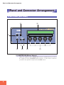 10
10
-
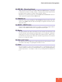 11
11
-
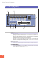 12
12
-
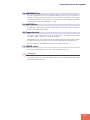 13
13
-
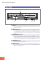 14
14
-
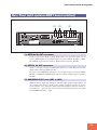 15
15
-
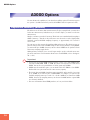 16
16
-
 17
17
-
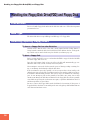 18
18
-
 19
19
-
 20
20
-
 21
21
-
 22
22
-
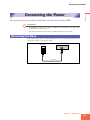 23
23
-
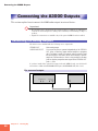 24
24
-
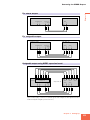 25
25
-
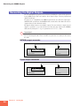 26
26
-
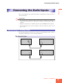 27
27
-
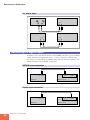 28
28
-
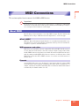 29
29
-
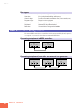 30
30
-
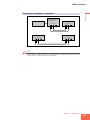 31
31
-
 32
32
-
 33
33
-
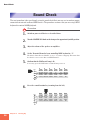 34
34
-
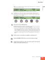 35
35
-
 36
36
-
 37
37
-
 38
38
-
 39
39
-
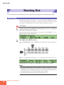 40
40
-
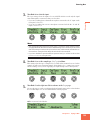 41
41
-
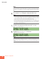 42
42
-
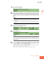 43
43
-
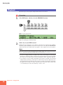 44
44
-
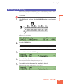 45
45
-
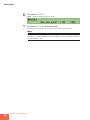 46
46
-
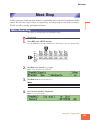 47
47
-
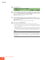 48
48
-
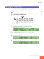 49
49
-
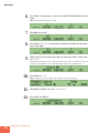 50
50
-
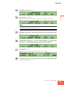 51
51
-
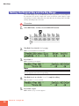 52
52
-
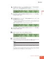 53
53
-
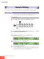 54
54
-
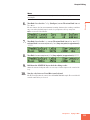 55
55
-
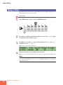 56
56
-
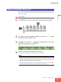 57
57
-
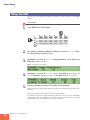 58
58
-
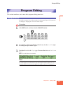 59
59
-
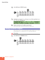 60
60
-
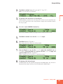 61
61
-
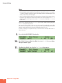 62
62
-
 63
63
-
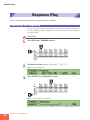 64
64
-
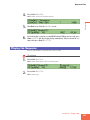 65
65
-
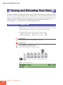 66
66
-
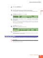 67
67
-
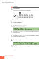 68
68
-
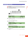 69
69
-
 70
70
-
 71
71
-
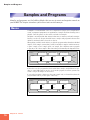 72
72
-
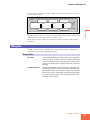 73
73
-
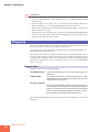 74
74
-
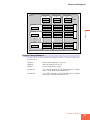 75
75
-
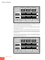 76
76
-
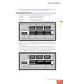 77
77
-
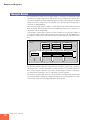 78
78
-
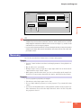 79
79
-
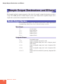 80
80
-
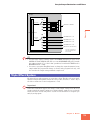 81
81
-
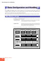 82
82
-
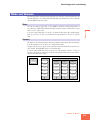 83
83
-
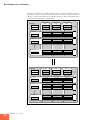 84
84
-
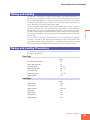 85
85
-
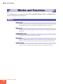 86
86
-
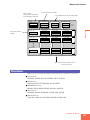 87
87
-
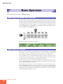 88
88
-
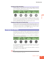 89
89
-
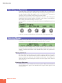 90
90
-
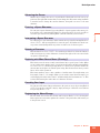 91
91
-
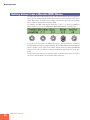 92
92
-
 93
93
-
 94
94
-
 95
95
-
 96
96
-
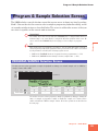 97
97
-
 98
98
-
 99
99
-
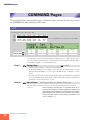 100
100
-
 101
101
-
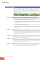 102
102
-
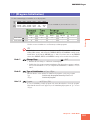 103
103
-
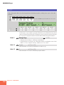 104
104
-
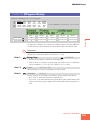 105
105
-
 106
106
-
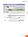 107
107
-
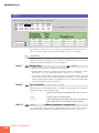 108
108
-
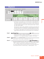 109
109
-
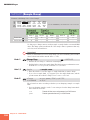 110
110
-
 111
111
-
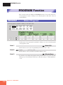 112
112
-
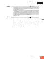 113
113
-
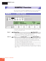 114
114
-
 115
115
-
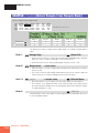 116
116
-
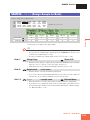 117
117
-
 118
118
-
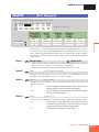 119
119
-
 120
120
-
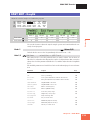 121
121
-
 122
122
-
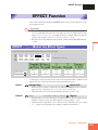 123
123
-
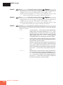 124
124
-
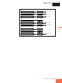 125
125
-
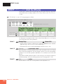 126
126
-
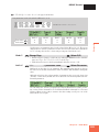 127
127
-
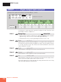 128
128
-
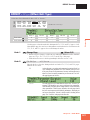 129
129
-
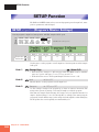 130
130
-
 131
131
-
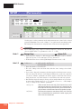 132
132
-
 133
133
-
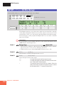 134
134
-
 135
135
-
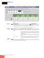 136
136
-
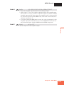 137
137
-
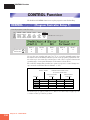 138
138
-
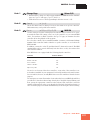 139
139
-
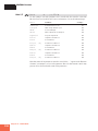 140
140
-
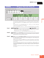 141
141
-
 142
142
-
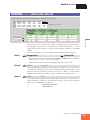 143
143
-
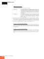 144
144
-
 145
145
-
 146
146
-
 147
147
-
 148
148
-
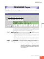 149
149
-
 150
150
-
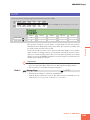 151
151
-
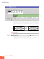 152
152
-
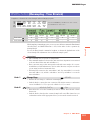 153
153
-
 154
154
-
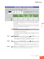 155
155
-
 156
156
-
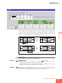 157
157
-
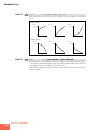 158
158
-
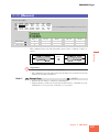 159
159
-
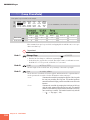 160
160
-
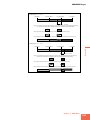 161
161
-
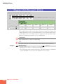 162
162
-
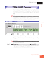 163
163
-
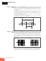 164
164
-
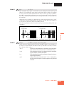 165
165
-
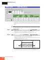 166
166
-
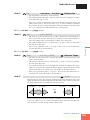 167
167
-
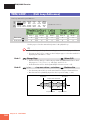 168
168
-
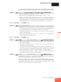 169
169
-
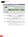 170
170
-
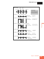 171
171
-
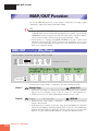 172
172
-
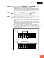 173
173
-
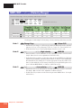 174
174
-
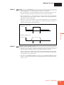 175
175
-
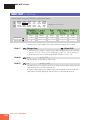 176
176
-
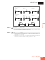 177
177
-
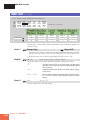 178
178
-
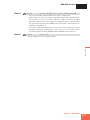 179
179
-
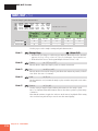 180
180
-
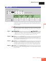 181
181
-
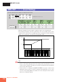 182
182
-
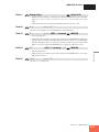 183
183
-
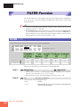 184
184
-
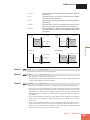 185
185
-
 186
186
-
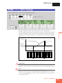 187
187
-
 188
188
-
 189
189
-
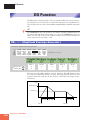 190
190
-
 191
191
-
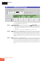 192
192
-
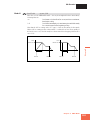 193
193
-
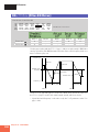 194
194
-
 195
195
-
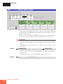 196
196
-
 197
197
-
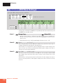 198
198
-
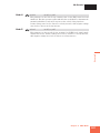 199
199
-
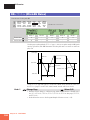 200
200
-
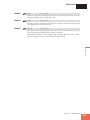 201
201
-
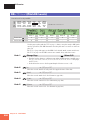 202
202
-
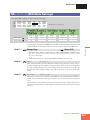 203
203
-
 204
204
-
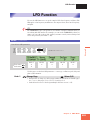 205
205
-
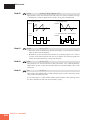 206
206
-
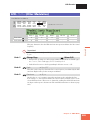 207
207
-
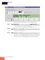 208
208
-
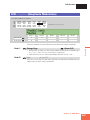 209
209
-
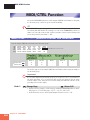 210
210
-
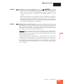 211
211
-
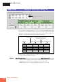 212
212
-
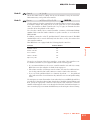 213
213
-
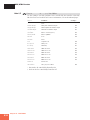 214
214
-
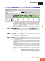 215
215
-
 216
216
-
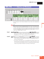 217
217
-
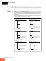 218
218
-
 219
219
-
 220
220
-
 221
221
-
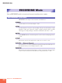 222
222
-
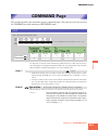 223
223
-
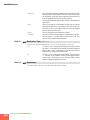 224
224
-
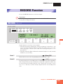 225
225
-
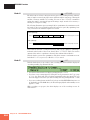 226
226
-
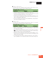 227
227
-
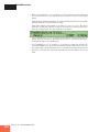 228
228
-
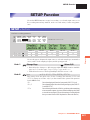 229
229
-
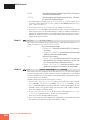 230
230
-
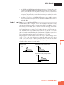 231
231
-
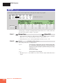 232
232
-
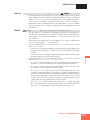 233
233
-
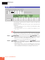 234
234
-
 235
235
-
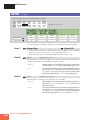 236
236
-
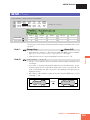 237
237
-
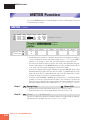 238
238
-
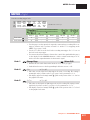 239
239
-
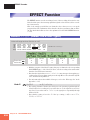 240
240
-
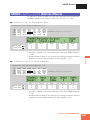 241
241
-
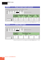 242
242
-
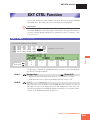 243
243
-
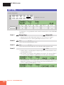 244
244
-
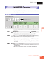 245
245
-
 246
246
-
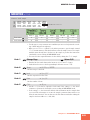 247
247
-
 248
248
-
 249
249
-
 250
250
-
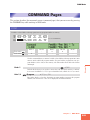 251
251
-
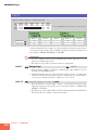 252
252
-
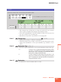 253
253
-
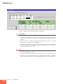 254
254
-
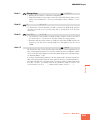 255
255
-
 256
256
-
 257
257
-
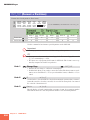 258
258
-
 259
259
-
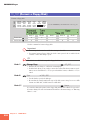 260
260
-
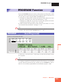 261
261
-
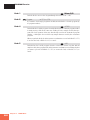 262
262
-
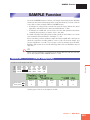 263
263
-
 264
264
-
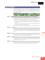 265
265
-
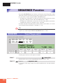 266
266
-
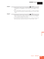 267
267
-
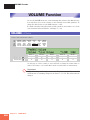 268
268
-
 269
269
-
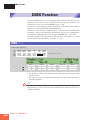 270
270
-
 271
271
-
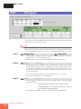 272
272
-
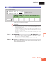 273
273
-
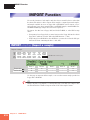 274
274
-
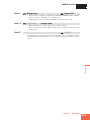 275
275
-
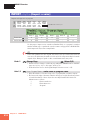 276
276
-
 277
277
-
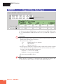 278
278
-
 279
279
-
 280
280
-
 281
281
-
 282
282
-
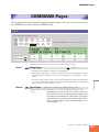 283
283
-
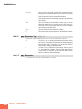 284
284
-
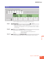 285
285
-
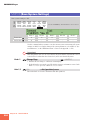 286
286
-
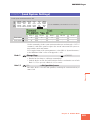 287
287
-
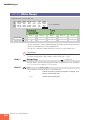 288
288
-
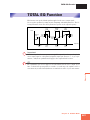 289
289
-
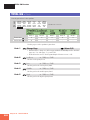 290
290
-
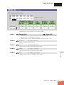 291
291
-
 292
292
-
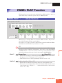 293
293
-
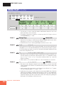 294
294
-
 295
295
-
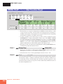 296
296
-
 297
297
-
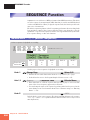 298
298
-
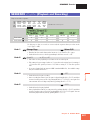 299
299
-
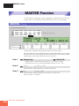 300
300
-
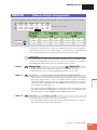 301
301
-
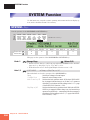 302
302
-
 303
303
-
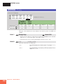 304
304
-
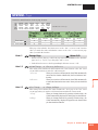 305
305
-
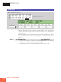 306
306
-
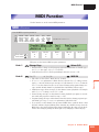 307
307
-
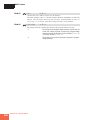 308
308
-
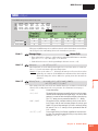 309
309
-
 310
310
-
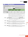 311
311
-
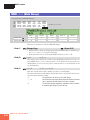 312
312
-
 313
313
-
 314
314
-
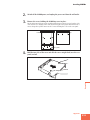 315
315
-
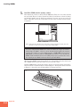 316
316
-
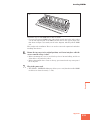 317
317
-
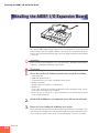 318
318
-
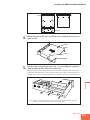 319
319
-
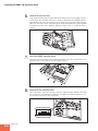 320
320
-
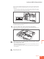 321
321
-
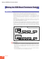 322
322
-
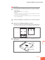 323
323
-
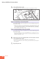 324
324
-
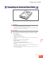 325
325
-
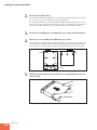 326
326
-
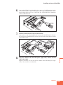 327
327
-
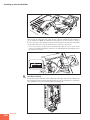 328
328
-
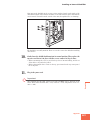 329
329
-
 330
330
-
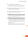 331
331
-
 332
332
-
 333
333
-
 334
334
-
 335
335
-
 336
336
-
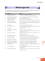 337
337
-
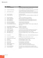 338
338
-
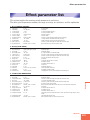 339
339
-
 340
340
-
 341
341
-
 342
342
-
 343
343
-
 344
344
-
 345
345
-
 346
346
-
 347
347
-
 348
348
-
 349
349
-
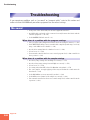 350
350
-
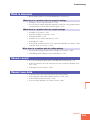 351
351
-
 352
352
-
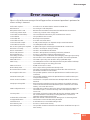 353
353
-
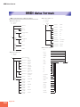 354
354
-
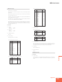 355
355
-
 356
356
-
 357
357
-
 358
358
-
 359
359
-
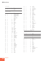 360
360
-
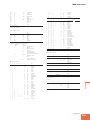 361
361
-
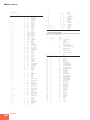 362
362
-
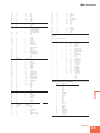 363
363
-
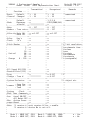 364
364
-
 365
365
-
 366
366
-
 367
367
-
 368
368
-
 369
369
-
 370
370
-
 371
371
-
 372
372
-
 373
373
-
 374
374
-
 375
375
-
 376
376


Yamaha A3000 de handleiding
- Categorie
- Muzikale uitrusting
- Type
- de handleiding
