
Owner's Manual
SAMPLING UNIT

WARNING- When using any electrical or electronic
product, basic precautions should always be followed. These
precautions include, but are not limited to, the following:
1. Read all Safety Instructions, Installation Instructions,
Special Message Section items, and any Assembly Instructions
found in this manual BEFORE making any connections, in-
cluding connection to the main supply.
2. Main Power Supply Verification: Yamaha products are
manufactured specifically for the supply voltage in the area
where they are to be sold. If you should move, or if any doubt
exists about the supply voltage in your area, please contact
your dealer for supply voltage verification and (if applicable)
instructions. The required supply voltage is printed on the
name plate. For name plate location, please refer to the graphic
found in the Special Message Section of this manual.
3. This product may be equipped with a polarized plug
(one blade wider than the other). If you are unable to insert the
plug into the outlet, turn the plug over and try again. If the
problem persists, contact an electrician to have the obsolete
outlet replaced. Do NOT defeat the safety purpose of the plug.
4. Some electronic products utilize external power sup-
plies or adapters. Do NOT connect this type of product to any
power supply or adapter other than one described in the owners
manual, on the name plate, or specifically recommended by
Yamaha.
5. WARNING: Do not place this product or any other
objects on the power cord or place it in a position where any-
one could walk on, trip over, or roll anything over power or
connecting cords of any kind. The use of an extension cord is
not recommended! If you must use an extension cord, the
minimum wire size for a 25' cord (or less) is 18 AWG. NOTE:
The smaller the AWG number, the larger the current handling
capacity. For longer extension cords, consult a local electri-
cian.
6. Ventilation: Electronic products, unless specifically
designed for enclosed installations, should be placed in loca-
tions that do not interfere with proper ventilation. If instruc-
tions for enclosed installations are not provided, it must be
assumed that unobstructed ventilation is required.
7. Temperature considerations: Electronic products
should be installed in locations that do not significantly con-
tribute to their operating temperature. Placement of this prod-
uct close to heat sources such as; radiators, heat registers and
other devices that produce heat should be avoided.
8. This product was NOT designed for use in wet/damp loca-
tions and should not be used near water or exposed to rain. Exam-
ples of wet/damp locations are; near a swimming pool, spa, tub,
sink, or wet basement.
9. This product should be used only with the components
supplied or; a cart, rack, or stand that is recommended by the
manufacturer. If a cart, rack, or stand is used, please observe all
safety markings and instructions that accompany the accessory
product.
10. The power supply cord (plug) should be disconnected from
the outlet when electronic products are to be left unused for ex-
tended periods of time. Cords should also be disconnected when
there is a high probability of lightening and/or electrical storm
activity.
11. Care should be taken that objects do not fall and liquids are
not spilled into the enclosure through any openings that may exist.
12. Electrical/electronic products should be serviced by a
qualified service person when:
a. The power supply cord has been damaged; or
b. Objects have fallen, been inserted, or liquids have been
spilled into the enclosure through openings; or
c. The product has been exposed to rain: or
d. The product dose not operate, exhibits a marked change
in performance; or
e. The product has been dropped, or the enclosure of the
product has been damaged.
13. Do not attempt to service this product beyond that de-
scribed in the user-maintenance instructions. All other servicing
should be referred to qualified service personnel.
14. This product, either alone or in combination with an ampli-
fier and headphones or speaker/s, may be capable of producing
sound levels that could cause permanent hearing loss. DO NOT
operate for a long period of time at a high volume level or at a
level that is uncomfortable. If you experience any hearing loss or
ringing in the ears, you should consult an audiologist.
IMPORTANT: The louder the sound, the shorter the time period
before damage occurs.
15. Some Yamaha products may have benches and/or acces-
sory mounting fixtures that are either supplied as a part of the
product or as optional accessories. Some of these items are de-
signed to be dealer assembled or installed. Please make sure that
benches are stable and any optional fixtures (where applicable) are
well secured BEFORE using. Benches supplied by Yamaha are
designed for seating only. No other uses are recommended.
INFORMATION RELATING TO PERSONAL INJURY, ELECTRICAL SHOCK,
AND FIRE HAZARD POSSIBILITIES HAS BEEN INCLUDED IN THIS LIST.
IMPORTANT SAFETY INSTRUCTIONS
PLEASE KEEP THIS MANUAL
92-469-2

92-469- ➀ (rear)
ENVIRONMENTAL ISSUES: Yamaha strives to
produce products that are both user safe and environmen-
tally friendly. We sincerely believe that our products and
the production methods used to produce them, meet these
goals. In keeping with both the letter and the spirit of the
law, we want you to be aware of the following:
Battery Notice: This product MAY contain a small
non-rechargable battery which (if applicable) is soldered
in place. The average life span of this type of battery is
approximately five years. When replacement becomes
necessary, contact a qualified service representative to
perform the replacement.
Warning: Do not attempt to recharge, disassemble, or
incinerate this type of battery. Keep all batteries away
from children. Dispose of used batteries promptly and as
regulated by applicable laws. Note: In some areas, the
servicer is required by law to return the defective parts.
However, you do have the option of having the servicer
dispose of these parts for you.
Disposal Notice: Should this product become damaged
beyond repair, or for some reason its useful life is consid-
ered to be at an end, please observe all local, state, and
federal regulations that relate to the disposal of products
that contain lead, batteries, plastics, etc.
NOTICE: Service charges incurred due to lack of knowl-
edge relating to how a function or effect works (when the
unit is operating as designed) are not covered by the
manufacturer’s warranty, and are therefore the owners
responsibility. Please study this manual carefully and con-
sult your dealer before requesting service.
NAME PLATE LOCATION: The graphic below indi-
cates the location of the name plate. The model number,
serial number, power requirements, etc., are located on
this plate. You should record the model number, serial
number, and the date of purchase in the spaces provided
below and retain this manual as a permanent record of
your purchase.
CAUTION
RISK OF ELECTRIC SHOCK
DO NOT OPEN
CAUTION: TO REDUCE THE RISK OF ELECTRIC SHOCK.
DO NOT REMOVE COVER (OR BACK).
NO USER-SERVICEABLE PARTS INSIDE.
REFER SERVICING TO QUALIFIED SERVICE PERSONNEL.
PRODUCT SAFETY MARKINGS: Yamaha elec-
tronic products may have either labels similar to the
graphics shown below or molded/stamped facsimiles of
these graphics on the enclosure. The explanation of these
graphics appears on this page. Please observe all cautions
indicated on this page and those indicated in the safety
instruction section.
The exclamation point within the equi-
lateral triangle is intended to alert the
user to the presence of important oper-
ating and maintenance (servicing) in-
structions in the literature accompany-
ing the product.
The lightning flash with arrowhead
symbol, within the equilateral triangle,
is intended to alert the user to the pres-
ence of uninsulated “dangerous volt-
age” within the product’s enclosure that
may be of sufficient magnitude to con-
stitute a risk of electrical shock.
IMPORTANT NOTICE: All Yamaha electronic prod-
ucts are tested and approved by an independent safety
testing laboratory in order that you may be sure that when
it is properly installed and used in its normal and custom-
ary manner, all foreseeable risks have been eliminated.
DO NOT modify this unit or commission others to do so
unless specifically authorized by Yamaha. Product per-
formance and/or safety standards may be diminished.
Claims filed under the expressed warranty may be denied
if the unit is/has been modified. Implied warranties may
also be affected.
SPECIFICATIONS SUBJECT TO CHANGE: The
information contained in this manual is believed to be
correct at the time of printing. However, Yamaha reserves
the right to change or modify any of the specifications
without notice or obligation to update existing units.
SPECIAL MESSAGE SECTION
Model _____________________________________
Serial No. __________________________________
Purchase Date ______________________________

• Do not rest your weight on, or place heavy objects on the instrument, and do
not use excessive force on the buttons, switches or connectors.
• Do not operate the instrument for a long period of time at a high or
uncomfortable volume level, since this can cause permanent hearing loss. If
you experience any hearing loss or ringing in the ears, consult a physician.
■SAVING USER DATA
• Always save data to a floppy disk frequently, in order to help prevent the loss
of important data due to a malfunction or user operating error.
Yamaha cannot be held responsible for damage caused by improper use or
modifications to the instrument, or data that is lost or destroyed.
Always turn the power off when the instrument is not in use.
PRECAUTIONS
PLEASE READ CAREFULLY BEFORE PROCEEDING
* Please keep these precautions in a safe place for future reference.
WARNING
Always follow the basic precautions listed below to avoid the possibility of serious injury or even death from electrical shock,
short-circuiting, damages, fire or other hazards. These precautions include, but are not limited to, the following:
• This instrument contains no user-serviceable parts. Do not attempt to
disassemble or modify the internal components in any way.
• Do not expose the instrument to rain, use it near water or in damp or wet
conditions, or place containers on it containing liquids which might spill
into any openings.
• If the power cord or plug becomes frayed or damaged, or if there is a sudden
loss of sound during use of the instrument, or if any unusual smells or
smoke should appear to be caused by it, immediately turn off the power
switch, disconnect the electric plug from the outlet, and have the instrument
inspected by qualified Yamaha service personnel.
• Only use the voltage specified as correct for the instrument. The required
voltage is printed on the name plate of the instrument.
• Before cleaning the instrument, always remove the electric plug from the
outlet. Never insert or remove an electric plug with wet hands.
• Check the electric plug periodically and remove any dirt or dust which may
have accumulated on it.
CAUTION
Always follow the basic precautions listed below to avoid the possibility of physical injury to you or others, or damage to the
instrument or other property. These precautions include, but are not limited to, the following:
• Do not place the power cord near heat sources such as heaters or radiators,
and do not excessively bend or otherwise damage the cord, place heavy
objects on it, or place it in a position where anyone could walk on, trip over,
or roll anything over it.
• When removing the electric plug from the instrument or an outlet, always
hold the plug itself and not the cord. Pulling by the cord can damage it.
• Do not connect the instrument to an electrical outlet using a multiple-
connector. Doing so can result in lower sound quality, or possibly cause
overheating in the outlet.
• Remove the electric plug from the outlet when the instrument is not to be
used for extended periods of time, or during electrical storms.
• Before connecting the instrument to other electronic components, turn off
the power for all components. Before turning the power on or off for all
components, set all volume levels to minimum.
• Do not expose the instrument to excessive dust or vibrations, or extreme
cold or heat (such as in direct sunlight, near a heater, or in a car during the
day) to prevent the possibility of panel disfiguration or damage to the internal
components.
• Do not use the instrument near other electrical products such as televisions,
radios, or speakers, since this might cause interference which can affect
proper operation of the other products.
• Do not place the instrument in an unstable position where it might accidentally
fall over.
• Before moving the instrument, remove all connected cables.
• When cleaning the instrument, use a soft, dry cloth. Do not use paint thinners,
solvents, cleaning fluids, or chemical-impregnated wiping cloths. Also, do
not place vinyl, plastic or rubber objects on the instrument, since this might
discolor the panel or keyboard.

Intro 5
INTRO
Thank you for your purchase of the Yamaha SU700 sampling unit. The
SU700 is a combination sampler, sequencer, mixer, and multi-effector—
a powerful new tool for a wide range of performance and recording
environments.
This manual will help you learn what you need to know to make effec-
tive use of all of the SU700’s many features. Please read through the
essential parts of the manual carefully before beginning work with the
SU700, and refer back to the manual for additional information as
necessary. Please keep the manual in a safe and handy location so that
you can refer to it as necessary.
Intro Yamaha SU700 Sampling Unit
Owner’s Manual

Intro
6 Intro
Features
The SU700 is an ideal tool for artists in need of sampling and sequencing capabilities
for their recording and performance work. Here is just an abbreviated list of what’s
included.
◆ Forty-two tracks. With 40 sample tracks plus 2 special tracks, you can make your
songs as complex as you wish.
◆ Three different sample track types. LOOP tracks that generate automatic con-
tinuous loops; COMPOSED LOOP tracks that let you build your own custom loop
phrases; and FREE tracks that are ideal for adding fills and playing along in real
time.
◆ AUDIO IN track lets you mix realtime vocals into your songs. You can control
the sound of the realtime audio using both the knob functions and the effects.
◆ Intuitive, playable controls. Use pads and knobs to control an astonishing num-
ber of functions on each track. You can record all control actions as sequence data,
or you can apply controls on the fly during realtime performance. Special ribbon
controller can be set to “scratch out” samples, or can be set to control level, pitch,
or virtually any other parameter.
◆ Powerful sampling capability. Provides high-quality sampling at any of five dif-
ferent sampling frequencies.
◆ Triple-block effect system applies up to three effects at any given time. Select
from a total of 43 great-sounding Yamaha effects. Set effect parameters for the
effect itself, for the effect block, and for each track.
◆ Scene memory stores up to eight scenes. Each scene holds an entire set of knob
settings, mute settings, and effects. You can recall scenes instantly during perfor-
mance, and you can record scene changes directly into your song.
◆ Ample MIDI support. Use an external sequencer to control and synchronize
SU700 track play; or use the SU700 to control playback from an external tone gen-
erator.
◆ Easily expandable. Supports up to 64MB of expansion memory. Optional SCSI
board (ASIB1) enables connection to external SCSI storage device. Optional I/O ex-
pansion board (AIEB1) adds digital and optical input/out and six assignable analog
outputs.
◆ Colorful, easy-to-read fluorescent display gives you all the feedback you need to
maintain full control of the SU700’s power.

Intro 7
INTRO
Accessories
Please check your SU700 package to confirm that all of the following accessories are
present. If any items are missing or damaged, please contact your Yamaha dealer for
assistance.
●
Sampling CD “SU700 Sampling Audio”
●
Demo floppy disk
●
Power cord
●
This Owner’s Manual
●
Flat 40-pin cable and round 3-pin cable (for use with optional AIEB1 board)
Using the Manual
Recommended Approach
Before switching on the machine you should read though Chapter 1 to familiarize
yourself with the SU700 arrangement, and the usage of each of the SU700 controls
and connectors. You may then want to jump into the comprehensive tutorial pro-
vided in Chapter 2, or instead read Chapters 3 and 4 first to familiarize yourself with
the underlying concepts of SU700 operation. Refer also to Chapter 5 for details about
samples and sampling.
Chapters 6 to 10 and various appendixes offer detailed reference information, and
should be referred to as necessary.
Chapter Arrangement
■ Chapter 1: SU700 Components, Connections, And Start-Up
Explains all of the SU700 controls and connectors, and shows you how to connect
up and start the SU700. Please read through this chapter before you begin working
the SU700.
■ Chapter 2: Tutorial
Takes you through a comprehensive tutorial, showing you step-by-step how to
build a complex song using samples provided on the accessory CD. Working
through the tutorial will help you gain rapid mastery of SU700 operation.

Intro
8 Intro
■ Chapter 3: Basic Concepts, Track Types, and Memory
Introduces basic concepts underlying SU700 operation. Also provides a detailed ex-
planation of the different track types, and explains how the SU700 memory is orga-
nized. You should read through this chapter before you begin serious work with
the SU700.
■ Chapter 4: SU700 Operating Modes
Describes the six operating modes. Shows you how you can immediately identify
the current mode by looking at the screen display; explains how you move from
one mode to another; and indicates the operations that are and are not available
from each mode.
■ Chapter 5: Samples and Sampling
Explains samples, sampling, and the various sampling parameters. Provides de-
tailed procedures for recording samples onto the SU700.
■ Chapter 6: Using the Features
Offers detailed, reference-level explanations about how to use each of the SU700’s
song-related features. Describes pad usage, knob usage, ribbon usage, scenes,
markers, quantizing, and more.
■ Chapter 7: Effects
Gives a detailed explanation of the SU700’s effects implementation. Describes the
relation between tracks, effects, and the three effect blocks; explains how to set up
the effects and record your setups into scenes; and explains the difference between
system effects and insertion effects.
■ Chapter 8: Knob Functions
Gives detailed information about the 22 parameters controlled by the track knobs.
■ Chapter 9: Editing Functions
Describes the functions provided by the SU700’s Editing Function panel. You use
these features to clear or set up the effects, to delete note events, to reset knob set-
tings to their defaults, and to assist in name-editing.
■ Chapter 10: Jobs
Provides detailed explanations and procedures for all of the SU700 jobs. You use
these jobs for a wide variety of purposes—to configure your system, to save and
load data, to edit or delete song data, to set the track characteristics, and much
more.

Intro 9
INTRO
■ Appendixes
Appendix 1 provides detailed instructions for installing each of the SU700’s sup-
ported options. Appendix 2 gives the SU700 specifications. Appendix 3 offers a
number of helpful usage tips. Appendix 4 explains the SU700 error messages. Ap-
pendix 5 lists and describes the 43 built-in effects and their associated parameters.
Appendix 6 explains the MIDI implementation.
Notations
This manual employs the following notational conventions.
●
Button names are capitalized printed in uppercase bold and enclosed in brackets.
Examples: [CANCEL] and [OK].
●
Words that appear directly on the screen are printed in a distinctive font.
Examples: SONG01 and SELECT TRACK.
●
Jobs are identified by the job-group selector and job selector that you must press to
access them. The group-selector appears first, followed by a bar, followed by the
job selector.
Examples: SONG | NAME and RESAMPLE | TRACK
In cases where you must then select from multiple jobs by turning the dial, the job
name is appended as shown below.
Example: SAMPLE | PROCESS/TRIM
●
Buttons on the Knob Function panel and Editing Function panel are indicated by
the group name, then a slash, then the button name.
Examples: SOUND/[LEVEL] and NAME/[INSERT]
●
SU700 operating modes are written in uppercase.
Examples: REC STANDBY and PLAY
●
The following icons and symbols are also used.
NOTE
. Indicates reference information indirectly related to the con-
tent of the main text. May contain practical advice or general supple-
mentary information.
Procedure. Step-by-step instructions for carrying out a particular op-
eration. Note that a ▼ mark within a procedure indicates the result
produced by carrying out the immediately preceding instruction.
→number Page reference. Directs to another page for related information.

Intro
10 Intro
Finally, please note that screen illustrations and other drawings presented in this
manual are for explanatory purposes only, and in some cases may differ from actual
displays and configurations.

Table of Contents 11
TABLE OF CONTENTS
Table of Contents
Intro Yamaha SU700 Sampling Unit Owner’s Manual
Features ............................................................................................................. 6
Accessories ........................................................................................................ 7
Using the Manual .............................................................................................. 7
Notations ........................................................................................................... 9
Chapter 1 SU700 Components, Connections, and Startup
1.1 SU700 Layout ........................................................................................ 14
1.2 SU700 Display Configuration............................................................... 23
1.3 Connecting Up....................................................................................... 29
1.4 Starting Up ............................................................................................ 33
Chapter 2 Tutorial
2.1 Setting Up .............................................................................................. 36
2.2 Listening to the Demo Song ................................................................. 37
2.3 Building Your Own Song ...................................................................... 47
2.4 Modifying sampled sounds................................................................... 95
Chapter 3 Basic Concepts, Track Types, and Memory
3.1 Basics ................................................................................................... 132
3.2 Sample-Track Types ............................................................................ 135
3.3 Memory Implementation.................................................................... 137
Chapter 4 SU700 Operating Modes
4.1 Introduction ........................................................................................ 140
4.2 Sequencer Modes ................................................................................ 141
4.3 Other Modes ........................................................................................ 146
Chapter 5 Samples and Sampling
5.1 All about Samples ............................................................................... 150
5.2 Sample Recording Procedure............................................................. 156
Chapter 6 Using the Features
Chapter 7 Effects
7.1 Introduction ........................................................................................ 186
7.2 Using the Effects ................................................................................. 186
7.3 Effect Blocks ....................................................................................... 188
7.4 System Effects ..................................................................................... 189
7.5 Insertion Effects .................................................................................. 190
7.6 Usage Tips............................................................................................ 191
7.7 Changing the Effect Resolution ......................................................... 192

Table of Contents
12 Table of Contents
Chapter 8 Knob Functions
8.1 Overview .............................................................................................. 194
8.2 Knob Settings for Each Track ............................................................ 195
8.3 Quantize and Resolution .................................................................... 196
8.4 Parameter Descriptions ...................................................................... 197
Chapter 9 Editing Functions
9.1 Overview .............................................................................................. 214
9.2 EFFECT SETUP Group ...................................................................... 214
9.3 JOB Group ........................................................................................... 220
9.4 NAME Group ...................................................................................... 221
Chapter 10 Jobs
10.1 Overview and Job List......................................................................... 224
10.2 General Procedure .............................................................................. 225
10.3 Job Explanations ................................................................................. 227
Appendix
Installing the Options ................................................................................... 312
Specifications ................................................................................................ 326
SU700 Usage Hints ....................................................................................... 328
Error Messages ............................................................................................. 331
Effect Type List ............................................................................................. 333
Effect Parameter List .................................................................................... 335
MIDI Data Format ........................................................................................ 345
MIDI Implementation Chart ........................................................................ 348

Chapter 1 SU700 Components, Connections, and Startup 13
CHAPTER 1
Chapter 1
SU700 Components,
Connections, and Startup
CONTENTS
1.1 SU700 Layout 14
1.2 SU700 Display Configuration 23
1.3 Connecting Up 29
1.4 Starting Up 33
This chapter describes the SU700’s layout and screen displays, shows
you how you can connect the SU700 to other devices, and takes you
through the SU700 startup procedure.

Chapter 1
SU700 Components, Connections, and Startup
14 Chapter 1 SU700 Components, Connections, and Startup
1 Display
The display provides all the information you need to work effectively at the
SU700. For a detailed explanation of common screen displays and indications, see
page 23.
1.1 SU700 Layout
This section explains all of the SU700 components.
1.1.1 Main Panel
2
3
4
56
7
8
9
0
A
B
C
D
E
F
G
1
N
O
P
MKJIH
L

Chapter 1 SU700 Components, Connections, and Startup 15
CHAPTER 1
2 TRACK BANK Selectors
You use the track bank selectors in combination with the sample track pads to se-
lect tracks for playback, recording, editing, and control.
The SU700 provides four track banks, each with ten sample tracks. This gives you
a total of 40 sample tracks. This means that each song can utilize anywhere from
1 to 40 samples.
3 Sample Track Pads
You use these 10 pads to control play on the sample tracks, and to select tracks for
sample recording, track editing, and track setup.
Each pad can be used to control a variety of operations. At any given time, each
pad controls a single operation only. You can switch the pad operation using the
PAD FUNCTION selectors (see item 5 below).
The pads for COMPOSED LOOP and FREE tracks include velocity sensors that
are effective for PLAY and LOOP RESTART pad functions. (→ p.167, 301)
4 AUDIO IN Track Pad
You use this pad to set or release the mute for the AUDIO IN track, or to select the
AUDIO IN track during setup work.
5 MASTER Track Pad
Use this pad to set or release the mute on all other tracks, to restart looping on the
LOOP and COMPOSED LOOP tracks, or to select the MASTER track during setup
work.
6 PAD FUNCTION Selectors
The pad function selectors select the operation to be controlled by the pad.
Each track has a default pad function that is effective whenever you are working
at the main screen. You can set these defaults using the TRACK SET | MAIN job
(→ p. 231).
You can override the defaults by pressing any of these selectors during song re-
cording, playback, or standby. This will switch you to a function screen and will
cause all pads to switch to the selected function.
For detailed information about pad functions and their selection, see page 166.
For information about the difference between the main screen and the function
screens, see page 144.

Chapter 1
SU700 Components, Connections, and Startup
16 Chapter 1 SU700 Components, Connections, and Startup
7 Knobs
You use these knobs to control the values of multiple parameters (or knob settings)
on each track. At any given time each knob controls a single parameter only. You
use the KNOB FUNCTION panel (see item 9 below) to switch the parameter con-
trolled by the knobs.
When you are working the main screen, each knob controls its default parameter.
You can set these default separately for each track using the TRACK SET | MAIN
job (→ p.231).
8 [RIBBON TRACK] Button
You use this button when you want to change the track(s) controlled by the rib-
bon. You select the track(s) by holding down the button and pressing the appro-
priate pad.
If you press the pad for a sample track, then the ribbon will work on all four
tracks associated with that pad (the tracks in Banks 1, 2, 3, and 4 for that pad). If
you press the pad for the AUDIO IN or MASTER track, then the ribbon will oper-
ate on that track only.
9 NOTE Display and Button
The bottom right corner of the display indicates relevant Quantize or Resolution
interval. If necessary, you can adjust the setting by pressing the [NOTE] button
(so that the indication starts blinking) and then turning the dial. Intervals are in-
dicated using note images (
, , etc.).
Exception: To set the resolution for the ROLL pad function, you must first press the
[NOTE] button, and then hold down the [ROLL] button while turning the dial.
0 BPM Display and Button
The center right line of the screen indicates the song’s current tempo, in BPM
(beats per minute). You can change the tempo by pressing the [BPM] button (so
that the BPM indication starts blinking) and then turning the dial.
A MEASURE Display and Button
The top right corner of the screen indicates the current song location, by measure
and beat. One way to change the location is to use the
, , and buttons, as
described above. Another way is to press the [MEASURE] button (so that the mea-
sure indication starts blinking) and then turn the dial.
B Ribbon Controller
You can set the ribbon up to control a single selected function with respect to a
single pad. You select the track set using the [RIBBON TRACK] button; see be-
low.

Chapter 1 SU700 Components, Connections, and Startup 17
CHAPTER 1
Once you have set this up, you can rub your finger along the ribbon to control the
selected function on the corresponding track. For example, if you set the function
to LEVEL then you use the ribbon to adjust the level on the track.
Available functions include most of the knob functions, and a special scratch func-
tion that lets you scratch out the sound of a selected track—the same kind of
sound that you would get by manually turning a vinyl record forward or back-
ward. For more information about ribbon use, see page 172.
C [CANCEL] and [OK] Buttons
Use these buttons to confirm or cancel various operations, or to move forward or
backward through the various job screens. Actual operation varies according to
the SU700’s current state.
D Dial
Use this dial to enter and adjust various values. Actual operation varies according
to the SU700’s current state. The value that can be adjusted by the dial is usually
shown in blinking format on the display.
E [BPM COUNTER] button
This button makes it easy to set the tempo to match the tempo of external play-
back that you may be preparing to record or play along with. To get a tempo read-
ing, simply tap on the counter along with the beat (hitting the counter once at
each beat). The SU700 detects a BPM value from your taps, and flashes this value
in the BPM area on the screen. If you wish to keep the new tempo, press [OK]. (If
you do not press [OK], the SU700 will restore the previous setting.)
F Cursor Buttons (
and )
Use these buttons to move the cursor position when editing names on the screen,
or to move from one parameter to another when working at setup screens con-
taining multiple parameters.
G MASTER VOLUME Knob
Turn the knob to adjust the output level to the STEREO OUT jacks. Note that this
adjustment does not affect the output level to any of the outputs on the optional
AIEB1 board.
H SAMPLING: STANDBY/START/STOP Button ([SAMPLING] button)
Use this button to begin and end sample recording. For details about how to
record samples, see the explanation beginning on page 156.
I SAMPLING: ANALOG LEVEL Knob
Turn this knob to adjust the input level when recording a sample from analog in-
put. The screen displays a level meter that will help you set an appropriate level.

Chapter 1
SU700 Components, Connections, and Startup
18 Chapter 1 SU700 Components, Connections, and Startup
J [UNDO/REDO] Button
You use this button to undo or redo all changes that you recorded into your song
during your previous recording pass. This feature is useful for undoing poor re-
sults, or for comparing “before” and “after” versions to determine which you want
to keep. The [UNDO/REDO] button operates only while the sequencer is in PLAY
STANDBY mode. (→ p.183)
K Sequencer Controls
Use these buttons to control the sequencer. Button usage is outlined below. For
detailed information, refer to “Using the Sequencer,” (→ p.162). Also refer to
Chapter 4, “SU700 Operating Modes,” for an overview of the different sequencer
modes (→ p.139).
RECORD
Press to enter recording standby.
TOP OF SONG
Press to jump back to the top of the song (first beat of first measure).
FAST REVERSE
Hold down to move rapidly backward through the song.
STOP
Press to stop song playback or recording.
PLAY
Press to start song playback or recording.
FAST FORWARD
Hold down to move rapidly forward through the song.
L Job Grid
You use these buttons to access various SU700 jobs. These jobs let you carry out
a wide variety of editing, setup, and management tasks.
To select a job, you first press one of the job group selectors along the top of the
grid, and then press one of the job selectors along the left of the grid. You can then
carry out the job using the dial, cursor buttons, [CANCEL] or [OK] buttons, and
any other relevant controls.
For detailed explanations of all jobs, refer to Chapter 10, “Jobs,” on page 223.
M [SCENE/MARKER] Buttons
Operation depends on whether you have selected [SCENE] or [MARKER] with
the scene/marker switch.
If SCENE: The SU700 lets you store up to eight scenes per song. A scene is an
entire environment of knob settings, mute settings, and effect set-
tings. To store the current environment, hold down one of the scene
buttons (from [TOP] to [G]) for approximately 1.5 seconds, until
the screen says SCENE STORED. To recall a scene, press the corre-
sponding scene button briefly.

Chapter 1 SU700 Components, Connections, and Startup 19
CHAPTER 1
If you store a scene into the [TOP] button, this scene will automati-
cally be recalled when you return the song to its start position.
You can use the [INIT] scene button to initialize (clear) the content
of any scene. Simply hold down the [INIT] button and then press
the scene button that you want to initialize. (→ p.180)
Note that you can store and initialize scenes only while the se-
quencer is in PLAY or PLAY STANDBY mode. You can recall scenes
at any time.
For more information about scenes, refer to page 176.
If MARKER: Use markers [1] to [8] to store song positions or to immediately
jump the song to a stored position. These buttons only work while
the sequencer is in PLAY or PLAY STANDBY mode.
To store the current position, hold down one of the marker buttons
for about 1.5 seconds, until the screen says MARKER STORED. To
jump to that position, press the same button briefly.
N SCENE/MARKER Switch
Use this switch to select the operating mode of the [SCENE/MARKER] buttons.
Set the switch to the left if you want the buttons to control scenes; set to the right
if you want the buttons to control markers.
O KNOB FUNCTION Panel
When you press one of these buttons during song standby, recording, or playback,
the display automatically switches to the corresponding function screen, and all
knobs automatically get control of the selected parameter. You can adjust the
value on each track by turning the corresponding knob (and using the bank selec-
tors as necessary to switch the bank).
You can also use these buttons to make selections within certain jobs; for ex-
ample, to select the default knob functions for the TRACK SET | MAIN job.
For detailed information, refer to Chapter 8, page 193.
P Edit Function Panel
You can use these buttons to perform various tasks: to set up each of the three ef-
fect blocks, to switch off any of the effects, to reset knob settings on selected
tracks, and to insert or delete characters within a name you are editing. For de-
tailed information, see Chapter 9, page 213.

Chapter 1
SU700 Components, Connections, and Startup
20 Chapter 1 SU700 Components, Connections, and Startup
1.1.2 Front Panel
3
1
2
4
1 Floppy-Drive Slot
The drive accepts 3.5" floppy disks (2HD or 2DD). You can use the disks to save
and reload all data, and to import commercially available sample or voice data.
2 Floppy Eject Button
Press this button to eject the floppy disk currently inserted in the slot. Remember:
Do not eject the disk while the access lamp is lit.
3 Floppy Access Lamp
This lamp lights up to indicate that the SU700 is currently accessing the disk.
CAUTION
Do not press the EJECT button or switch off the power while this lamp is lit, as doing so
may destroy data on the disk or cause damage to the disk drive.
4 Headphone Jack
Connects to standard stereo headphones. Outputs the same signal as the stereo
output jacks on the rear panel.

Chapter 1 SU700 Components, Connections, and Startup 21
CHAPTER 1
1.1.3 Rear Panel
R L/MONO
STEREO OUT
R L
ANALOG INPUT
AS2 AS1AS3AS4AS5AS6OUTIN
OUTIN
ASSIGNABLE OUTDIGITALOPTICAL
AC INLET
OUT IN
MIDI
POWER
ON/ OFF
ATTENTION :RISQUE DE CHOC ELECTRIQUE ME PAS OUVRIR.
RISK OF ERECTRIC SHOCK
DO NOT OPEN
WARNING
TO REDUCE THE RISK OF FIRE OR ERECTRIC SHOCK
DO NOT EXPOSE THIS PRODUCT TO RAIN OR MOISTURE.
CAUTION
SCSI
1
2
345
9
67 8
∗ Circled numbers indicate standard connectors. Numbers enclosed in squares indicate options.
In its standard configuration, the rear panel provides connectors 1 to 5 above. If
you install the optional AIEB1 board, you also get the assignable and digital outputs
(items 7, 8, and, 9 above). If you install the optional ASIB1 board (SCSI board),
you also get the SCSI connector (number 6 above).
Note that if an option board is not installed, the corresponding area of the panel is
covered with an expansion cover.
1 STEREO OUT Jacks
These jacks output the stereo analog signal produced by the SU700 to powered
speakers or other playback device. (For monaural output, use the left jack only.)
These are the standard outputs.
2 ANALOG INPUT Jacks
Standard analog input jacks accept line or microphone input. Use these jacks to
input analog signals to be recorded (as samples) or fed to the AUDIO IN track
(during realtime performance).
Note that you must use the SYSTEM | SETUP job to inform the system of the
actual audio input you are using (→ p.298).
3 MIDI Connectors
Standard MIDI connectors. Use these connectors to link the SU700 to other MIDI
devices.

Chapter 1
SU700 Components, Connections, and Startup
22 Chapter 1 SU700 Components, Connections, and Startup
4 AC Inlet
Connects to SU700 power cord.
CAUTION
Use the supplied power cord only. Use of a different cord may result in electric shock or
device damage.
5 POWER Switch
Switches the SU700 power ON and OFF.
<If AEIB1 option board is installed>
6 OPTICAL IN/OUT connectors
7 DIGITAL IN/OUT connectors
Use the OPTICAL connectors to input or output digital audio signals over optical-
fiber cable. Use the DIGITAL connectors to input or output digital audio signals
over coaxial (RCA-pin) cable, in CD/DAT (S/P DIF) format.
Each connector can support both mono and stereo signals.
Input Signal: The SU700 can accept input digital frequencies of 11.025kHz,
22.05kHz, 32.0kHz, 44.1kHz, and 48.0kHz. (If you wish to enable
this input, you must open the SYSTEM | SETUP job and set AU-
DIO IN to either OPTICAL or DIGITAL. See page 302.)
Output Signal: The output frequency is always 44.1kHz. The output is the digital
equivalent of the signal directed to the STEREO OUT jacks, but
is not passed through the effects blocks. Note that the OPTICAL
OUT and DIGITAL OUT connectors will always produce the iden-
tical signal.
8 ASSIGNABLE analog output jacks
You can set the output destination independently for each nonempty sample
track. Settings can be entered separately for each song. Note that these settings
are not available for the AUDIO IN track, for the MASTER TRACK, and for
sample tracks that do not currently contain a sample.
Under default conditions, output is directed to the STEREO OUT jacks (and OP-
TICAL and DIGITAL connectors). As an alternative, however, you can use the
TRACK SET | SETUP job to direct the track’s output to any one of the assignable
outputs (AS 1 to AS 6), or to an adjacent pair of outputs (AS 1+2, AS 3+4, or AS
5+6). Note that signals directed to assignable outputs do not pass through the ef-
fects blocks (do not receive any effects).
<If ASIB1 option board is installed>
9 SCSI connector
A SCSI-2 D-sub half-pitch 50-pin connector that can be used to connect to an ex-
ternal SCSI disk device. Allows for convenient saving and loading of large quanti-
ties of data.

Chapter 1 SU700 Components, Connections, and Startup 23
CHAPTER 1
1.2 SU700 Display Configuration
You refer to the SU700 screen for information and guidance during all SU700 opera-
tions. This section presents an overview of the various screen displays.
The first part, “Screen Layout,” introduces the various elements of the display panel.
The second part, “Main-Screen and Function-Screen Displays,” shows screen ex-
amples for the two most frequently used working environments. The third part,
“Other Screen Indication,” gives an overview of less commonly encountered screen
indications.
1.2.1 Screen Layout
The screen is divided into several different areas, each presenting a different type of
information. The general arrangement is described below. The amount of informa-
tion displayed at any given time will vary according to the operating mode and cur-
rent conditions.
MEASURE
BPM
NOTE
1
2
5
4
3
6
7
8
1 Bank ............................ Shows the currently selected bank. Always displayed.
2 REC indicator ............ Comes on to indicate that the sequencer is in REC or REC
STANDBY mode.
3 Pad function .............. Shows the currently selected pad function. Displayed
whenever you are working at a function screen.
4 Parameter data .......... This area shows parameter information and error mes-
sages.
When you are at the main screen, this area shows the cur-
rent song number and song name. When you are at a
function screen, this area shows the current knob func-
tion and the function value. When you are executing a
job, this area shows the job type and/or current setting.
Before you record a sample, you refer to this area to set
the sampling parameters.

Chapter 1
SU700 Components, Connections, and Startup
24 Chapter 1 SU700 Components, Connections, and Startup
5 Track indicator .......... When you are working at the main screen or a function
screen, each vertical bar meter (or track meter) indicates
the relevant knob-function value for the corresponding
track (of the current bank). The brackets (above and be-
low the meter) are visible if the track is not muted; they
disappear if the track is muted.
When you are standing by to record a sample, the meter
area operates as a two-bar horizontal level meter that you
can use to monitor the input level. The upper bar indi-
cates the L-channel level; the lower bar indicates the R-
channel level.
6 MEASURE .................. Shows the current location (measure and beat) within the
current song.
7 BPM ............................. Shows the current tempo (in beats per minute).
8 NOTE ........................... Shows the quantize interval or time resolution, when ap-
plicable.

Chapter 1 SU700 Components, Connections, and Startup 25
CHAPTER 1
1.2.2 Main-Screen and Function-Screen Displays
The screen display content varies according to the current machine state. This sec-
tion shows screen displays for two most commonly used machine states.
Main Screen
This screen that appears immediately following power-on. It is also the default
screen, and will reappear when you exit from job mode, when you finish sample re-
cording, and when you press [OK] to escape from a function screen.
Note that this screen can appear only while the sequencer is operating in PLAY
STANDBY or PLAY mode. (→ p.142)
When you are working at this screen, the knob and pad action for each track is deter-
mined by the settings you make at the TRACK SET | MAIN job (→ p.231). This means
that the knobs and pads on different tracks may operate in different ways.
1
2
4
5
6
3
1 Currently selected bank.
2 Currently selected song number and name. (If the sequencer is in PLAY STANDBY, you can change to a dif-
ferent song by turning the dial and then pressing [OK].)
3 Shows function values and muting for each track within the current bank.
• Note that all meters always indicate the value for the default knob parameter on the most recently con-
trolled track (the track whose pad or knob you last touched). If you hit the pad on a track whose default
knob-function is set to PITCH, for example, then all meters indicate PITCH levels. If you then hit a pad on
another track whose default knob function is set to ATTACK, all meters change to indicate ATTACK levels.
• Brackets are visible if track is non-muted; invisible if track is muted.
4 Current position in song.
5 Tempo setting.
6 The NOTE area is always empty.

Chapter 1
SU700 Components, Connections, and Startup
26 Chapter 1 SU700 Components, Connections, and Startup
Function Screen
You enter this screen from the main screen when you press any knob-function or
pad-function button, or when you press the [REC] button.
When you are working at a function screen, knob functions and pad functions are the
same on all tracks.
A typical display appears as follows.
1 2 4
3
6
5
1 Appears only if you have pressed to set the sequencer into RECORD mode.
2 Indicates the current pad function.
3 Indicates the current knob function.
4 Indicates the knob-function value for the track whose pad or knob you last used.
5 Each meter indicates the knob function’s value ( in this case, the PITCH value) for the corresponding track.
The bracket is visible if the track is not muted; invisible if the track is muted.
6 Indicates the QUANTIZE or RESOLUTION setting, if applicable. (Does not appear for some knob functions.)
1.2.3 Other Screen Indications
Track Selection
Before you can record a sample, you must select the target track. Many job screens
will also require you to select a track.
To select a track, you press the appropriate bank selector and hit the appropriate
track pad (in either order). The bank number will appear at the upper left of the
screen, and brackets will move to indicate the selected track.
When you are making this type of a selection, the screen will also let you know
whether or not the selected track contains a sample. If the track does contain a
sample, then a double bar will appear at the center of the bracketed area. If the track
is empty, then no bar will appear.
The following shows the display you use to select the track when preparing to record
a sample.

Chapter 1 SU700 Components, Connections, and Startup 27
CHAPTER 1
Indicates that the selected track already contains a sample. If the track is empty, this
bar will not appear.
NOTE:
For TRACK EDIT | EVENT COPY, TRACK EDIT | EVENT INIT etc., it is also important to
know whether a selected track contains recorded sequence data. For these jobs, six bars
will appear at the center of the bracketed area to indicate that the track contains both a
sample and some sequence data.
Sample only: Sample plus sequence data:
Sample Recording Meter
When you are standing by to record a sample (or to execute a resampling job), the
meter operates as a two-bar horizontal level meter. The top part of the meter moni-
tors the level for the LEFT channel input, while the bottom part of the meter moni-
tors the level for the RIGHT channel input. In addition, the word CLIP will appear at
the upper right of the screen if the input level exceeds the clip level.
In general, you want to adjust the input level so that the meter peaks all the way to
the right without triggering the CLIP indication.
The following shows how the screen may appear when you are standing by to begin
sample recording.
1
2
3
4
5
1 Shows the recording parameters.
2 Monitors the left-channel input level.
3 Monitors the right-channel input level.
4 Shows the destination track.
5 CLIP indicator

Chapter 1
SU700 Components, Connections, and Startup
28 Chapter 1 SU700 Components, Connections, and Startup
Flashing Parameters
When you are working at a screen that allows you to set more than one parameter
value, the parameter currently selected for setting will be blinking, indicating that
you can proceed to change its value by turning the dial (or pressing an appropriate
button). Note that only one parameter can be blinking at any given time.
In the screen illustration shown above, for example, the 44K value (frequency setting)
is flashing. This tells you that turning the dial will change the frequency setting. If
you wish to change one of the other parameters, then you would first need to press
the
to move the flashing indication to either 16BIT or STEREO.
Multipage Displays
Some setup screens consist of multiple pages. A right-arrow in the display indicates
that you can advance to another page by pressing the
cursor button; a left arrow
means that you can move back to a previous page by pressing the
button.
The following shows the third page of the AMPSIM-effect setup screen.
Ribbon-Track Indication
When you press the [RIBBON TRACK] button, the brackets for the currently se-
lected ribbon track blink on the screen. You can change the selection by pressing a
different pad. (→ p.172)

CHAPTER 1
Chapter 1 SU700 Components, Connections, and Startup 29
1.3 Connecting Up
The SU700 is extremely easy to set up. Simply connect the appropriate components
as described below.
Power
Connect the power as follows.
1.
Confirm that the power switch (on the rear panel) is in the OFF position (pro-
truding from the panel). If the switch is ON, press it so that it pops out into the
OFF position.
2.
Connect the small end of the supplied power cable to the power inlet on the rear
panel.
3.
Connect the other end to a standard wall outlet.
CAUTION
Do not connect the power while the power switch is ON.
Input Source
If you are going to record a sample or supply an audio input signal to accompany
realtime playback, you need to connect an input source. You can connect up one or
more of the following.
●
Connect a microphone to the one of the ANALOG INPUT jacks on the rear panel.
●
Connect analog line input (for example, from a CD player or electronic instrument)
to the ANALOG INPUT jacks on the rear panel. To input a stereo signal, connect to
both jacks.
●
(If you have installed the optional AIEB1 board:) Connect a digital or optical line
to the DIGITAL IN or OPTICAL IN connector on the rear panel.

30 Chapter 1 SU700 Components, Connections, and Startup
Chapter 1
SU700 Components, Connections, and Startup
To enable input, you must set the AUDIO IN parameter to the source you wish to
use. You can set the parameter using the SYSTEM | SETUP job; see page 302. The
SU700 can only accept input from one source at a time.
R L/MONO
STEREO OUT
R L
ANALOG INPUT
Output
You can connect any or all of the following.
●
Connect amplifiers, powered speakers, mixer, analog recorder, or other such device
to the STEREO OUT jacks on the rear panel.
IMPORTANT
If you are connecting up a single speaker or amp only, be sure to connect to the L/MONO
jack.
NOTE:
If connecting to a device with adjustable pan (such as a mixer) set the pan for the channel
receiving the L/MONO output all the way to the left; set the pan for the RIGHT output all
the way to the right.
●
Connect headphones to the PHONES jack on the front panel.
●
(If you have installed the optional AIEB1 board:) Connect speakers to any of the
ASSIGNABLE OUT jacks on the rear panel, or connect a digital device to the DIGI-
TAL OUT or OPTICAL OUT connector on the rear panel.
If using powered speakers, connect as shown below.
CD Record (turntable) Microphone
Electric keyboard

CHAPTER 1
Chapter 1 SU700 Components, Connections, and Startup 31
R L/MONO
STEREO OUT
R L
ANALOG INPUT
Using the AIEB1-board outputs
If you have installed the optional AIEB1 board (input/output expansion
board), you will be able to use the board’s assignable and digital/optical
outputs. Note the following points.
• Under factory defaults, the output goes to the STEREO OUT jacks.
• The signal to the STEREO OUT jacks is also directed to the DIGITAL
OUT and OPTICAL OUT connectors.
• You can use the TRACK SET | SETUP job’s OUTPUT TO parameter to
direct output from selected sample tracks to selected assignable output
jacks. For each track, you can decide whether to output to a single output
jack or to a pair of output jacks.
• Note that that when you direct a track to an assignable output:
(a) The track is directed to the selected jack(s) only. It does not flow to
the STEREO OUT or digital/optical outputs.
(b) The track output does not pass through the effect blocks.
For information about setting up the OUTPUT TO parameter, see page 239.

Chapter 1
SU700 Components, Connections, and Startup
32 Chapter 1 SU700 Components, Connections, and Startup
MIDI Connections
●
If you are going to use an external MIDI device to synchronize SU700 playback or
to control track play, run a MIDI cable from the MIDI OUT connector of the con-
trolling device (or the MIDI THRU connector on an intermediate device) to the
MIDI IN connector on the SU700.
●
If you plan to use the SU700 to control playback from an external tone generator,
external sequencer, or other such device, run a MIDI cable from the SU700’s MIDI
OUT connector to the MIDI IN connector on the target device.
●
Note that you must use the SYSTEM | MIDI jobs to set up the SU700’s MIDI opera-
tion (→ p.303). You can also use the SONG | MTC OFFSET job to set an offset for
an externally supplied MTC synchronization signal.
MIDI Use on the SU700
The SU700 supports the following MIDI operations.
• Sends and received note-on and note-off messages, control-change mes-
sages, and system realtime messages (Timing Clock, Start, Continue, and
Stop).
• Can synchronize with externally supplied MIDI time code (MTC).
• You can set transmit channel independently on each of the 40 sample
tracks. You can set receive channel on up to 16 sample tracks (where
each track must receive on a different channel).
For full details about the SU700’s MIDI implementation, refer to page 345.
Connecting an External SCSI Drive
If you have installed the SCSI expansion board (ASIB1 board), you can connect a
SCSI drive to the SU700. Simply run a SCSI cable from the SCSI connector on the
external device to the SCSI connector on the SU700’s rear panel.
Note the following points.
●
Although you are free to connect together multiple SCSI devices (in a SCSI chain
configuration), the SU700 can recognize only one external SCSI device at a
given time.
●
You use the SYSTEM | SCSI job (→ p.307) to select the SCSI ID of the external de-
vice you wish to recognize. (Note that you must also set a matching ID setting at
the external device side, as well.)

Chapter 1 SU700 Components, Connections, and Startup 33
CHAPTER 1
●
Use good-quality SCSI cable. Cable length should be kept short. For specific limi-
tations on cable length, refer to the documentation provided with your external
SCSI device.
●
If you are connecting multiple devices in a chain, the SU700 must be at one
end of the chain. It cannot be in the middle of the chain.
●
If you are connecting to a single SCSI device, that device must be terminated. If
you are connecting to a chain of SCSI devices, the device at the other end of the
chain must be terminated. For information about SCSI termination, refer to the
instructions provided with your external SCSI device(s).
For information about how to format and use external SCSI disks, refer to the expla-
nations for the DISK | UTILITY jobs (→ p.293).
1.4 Starting Up
Use the following procedure to start up the SU700.
1.
Make sure that the power cable is connected as described above.
2.
If you wish to begin by loading a volume from floppy disk, insert the disk before
switching on the power. (The SU700 will automatically load the floppy-disk vol-
ume during the startup sequence.)
Before starting the SU700 for the first time, therefore, you should insert the
accessory floppy disk in the slot.
NOTE:
Auto-loading does not work with volumes that span multiple disks. If you want to load a
volume from multiple disks, you must start the SU700 first and then use the DISK | LOAD/
LOAD VOLUME
job (
→
p.281).
3.
Press the power switch on the rear panel so that it engages in the ON position.
This causes the SU700 to execute its power-on sequence.
• The SU700 begins by displaying its name.
• It then checks for options and indicates any options that it finds.
• It then checks the amount of installed RAM, and indicates the results.
• It then checks whether a floppy disk with a valid volume has been inserted in
the disk slot. If so, it indicates that it has found the volume, and then proceeds
to load the volume.
• The SU700 enters PLAY STANDBY mode, with SONG 01 selected.

Chapter 1
SU700 Components, Connections, and Startup
34 Chapter 1 SU700 Components, Connections, and Startup

Chapter 2 Tutorial 35
CHAPTER 2
Chapter 2 Tutorial
This chapter takes you through a tutorial that will give you some quick
hands-on experience with the SU700. The first part of the tutorial how
to play the demo song and how to use various features. The second part
of the tutorial takes you through the procedures for recording samples
and building a song.
CONTENTS
2.1 Setting Up 36
2.2 Listening to the Demo Song 37
2.3 Building Your Own Song 47
2.4 Modifying sampled sounds 95

Chapter 2 Tutorial
36 Chapter 2 Tutorial
2.1 Setting Up
First you will need to connect your audio system so that you can listen to the demo
song and monitor the process of creating a song. You will also need to connect a CD
player so that you can playback the sampling sources from the included audio CD.
Connections
Before you make connections, be sure that the power of the SU700, your CD
player, and your audio system is turned off.
1.
Connect the analog outputs from your CD player to the ANALOG INPUT jacks
on the rear of the SU700.
●
The ANALOG INPUT (L, R) jacks are each monaural phone jacks. In order to
connect them to your CD player, you will need to obtain connecting cables that
are appropriate for each type of jack.
2.
Connect powered speakers or another monitoring device to the STEREO OUT
(L/MONO, R) jacks.
●
If you are using a monaural audio system, make connections to the L/MONO
jack.
R L/MONO
STEREO OUT
R L
ANALOG INPUT
AC INLET
OUT IN
MIDI
POWER
ON/ OFF
ATTENTION
:RISQUE DE CHOC ELECTRIQUE ME PAS OUVRIR.
RISK OF ERECTRIC SHOCK
DO NOT OPEN
WARNING
TO REDUCE THE RISK OF FIRE OR ERECTRIC SHOCK
DO NOT EXPOSE THIS PRODUCT TO RAIN OR MOISTURE.
CAUTION
If you are using headphones, connect them to the PHONES jack located on the front
panel of the SU700.
●
The PHONES jack can be used simultaneously with the STEREO OUT jacks.
STEREO
OUT
ANALOG
INPUT
CD player
Audio system for monitoring
(amplified speakers, etc.)

Chapter 2 Tutorial 37
CHAPTER 2
3.
Turn the MASTER VOLUME of the SU700 and the volume controls of your CD
player and audio system all the way down to 0.
Do not turn on the power yet. We still need to prepare the SU700 to auto-load
the demo song when its power is turned on.
2.2 Listening to the Demo Song
This section shows you how to load and play the demo song included in the accessory
floppy disk.
Loading the Demo Song (auto-load)
In order to playback the demo song from the included the following diagram, the
contents of the floppy disk must be loaded into the internal memory of the SU700.
If you insert the included floppy disk into the disk drive and turn on the power, the
SU700 will automatically load the demo song.
CAUTION
If you load the demo song after using the SU700, all data currently in internal memory will
be lost. If memory contains any data you wish to keep, be sure to save it to disk etc. (Save:
→
p.287) before you load the demo song.
Headphones
Turn down to 0
PHONES

Chapter 2 Tutorial
38 Chapter 2 Tutorial
Procedure
1.
Insert the accessory floppy into the slot on the SU700 front panel.
●
Insert with label facing up and shutter facing the front panel. Push in lightly until the
disk clicks into place.
2.
Switch on the power to the SU700.
3.
The SU700 begins automatic loading of the song data. While data is being loaded,
the display will indicate “LOADING …”
●
Do not eject the floppy disk or switch off the SU700 power while the word LOAD-
ING... is on the display, as doing so may cause damage to the disk or the disk drive.
4.
When loading is finished, the screen will look like this.
*“SU_DEMO”
Composer: Takashi MORIO (synthesizer artist)
*This demo-FD features samples from the world’s foremost sample
developer AMG.

Chapter 2 Tutorial 39
CHAPTER 2
Use this knob to adjust
the volume.
Playing the Demo
■ You’re now ready to play the song.
●
Press the sequencer start button ( ) to begin playback of the song.
●
Adjust the volume by turning the MASTER VOLUME knob.
●
You can stop playback by pressing the stop button ( ).
●
You can jump back to the top of the song by pressing .
● Reading the display
Track Bank Indicates the currently selected bank.
Song number Indicates the song number of the currently selected song. (The
SU700 stores up to 20 songs, each identified by a number.)
Song name Name of the currently selected song. (Each song takes a name of
up to eight alphanumeric characters.)
Track Data Shows information about tracks in the currently selected bank.
Brackets (
) indicate that track is not muted. (Brackets disap-
pear if you mute the track.) The bar meters (track meters) indicate
the value on each track for the selected knob setting. (Under fac-
tory defaults, the meters indicate the LEVEL setting.)
Song Location Indicates the current location in the song, by measure and beat.
BPM Indicates the song’s playback tempo, in beats per minute.
Track bank
Song number Song name
Song location
(beat:measure)
Track data BPM (tempo)

Chapter 2 Tutorial
40 Chapter 2 Tutorial
■ Changing the Tempo
1.
Press the [BPM] button.
◆ The BPM indication on the screen begins blinking.
2.
Turn the dial to change the tempo. Turn right to increase the tempo, or left to re-
duce it.
Another way to set the BPM:
You can use the [BPM COUNTER] button to tap out the tempo that you want to use.
The SU700 automatically detects the tempo and displays it in the BPM area. If you
wish to use the newly displayed tempo, press [OK]. (If you don’t press OK within sev-
eral seconds, the old tempo value will reappear.) (→ p.164)
■ Using the Mutes
1.
With the song playing, press the [ON/MUTE] pad-function button. This will
cause the pads to operate as mute switches.
◆ You’ll notice that the ON/MUTE indication appears (in blue) along the top of
the screen.
2.
Try pressing the pads on the various tracks. Tracks that are muted ( unlit)
will not be played. Pressing the same pad again switches the mute back off (the
sound returns and the brackets reappear).
[BPM COUNTER] button

Chapter 2 Tutorial 41
CHAPTER 2
●
When the song data is played back to a location where Track Mute on/off data
was written, the mute settings you made manually will change.
■ Using the ROLL Pad Function
The roll function generates a drum-roll (machine-gun) type of sound by rapidly re-
peating the first part of the sample. The repetition rate is set by the interval, or “reso-
lution.” Let’s try it out now.
1.
Set the roll rate (the “resolution”).
Press the [NOTE] button once. Then hold down the [ROLL] pad-function but-
ton. The NOTE area of the screen will now blink “RESOLUTION=” to indicate
the currently set roll rate (resolution) as a note value symbol.
MEASURE
BPM
NOTE
2.
Continue to hold down the [ROLL] button and turn the dial to change the rate.
Select the rate that you want to try.
3.
With the song playing back, hold down the [ROLL] button and press and hold
the pad for the (un-muted) track that you want to roll. As long as you hold the
pad down, the sample will repeatedly playback from its beginning for the length
that you specified by the Resolution setting.
●
Roll works best with samples that start out with a sharp attack. It does not
work so well with samples that start out quietly, or samples that have a por-
tion of silence at their beginning.
●
The Roll function cannot be used when the sequencer is stopped.
ON
(These tracks
are audible.)
MUTED
(These tracks
are silenced.)

Chapter 2 Tutorial
42 Chapter 2 Tutorial
■ Using the LOOP START Pad Function
You can use this feature to restart the loop on any of the LOOP or COMPOSED
LOOP tracks.
1.
Press the [LOOP RESTART] pad-function button. The upper part of the display
will indicate “LOOP RESTART.”
2.
With the song playing, try pressing the pad on any (un-muted) LOOP or COM-
POSED LOOP track that you wish to restart. The track’s loop phrase jumps back
to the top when you press the pad.
Listening To and Adjusting Samples One Track at a Time
Now let’s try listening the samples with the song stopped.. First, press the button
to stop the song. (This places the sequencer into PLAY STANDBY mode.)
Next, to make sure that pads can be used to play samples on all tracks, you want to
be sure that all mutes (on all tracks) are switched off, and that the pad function is set
to PLAY. Proceed as follows.
1.
First press the [ON/MUTE] pad-function button, so that pads will operate as
mute switches.
2.
Press the MASTER track pad either once or twice, so that meter brackets on all
tracks are visible.
●
You use the MASTER track to control all other tracks at the same time. Setting
the mute on or off on the MASTER track causes all mutes to go on or off.

Chapter 2 Tutorial 43
CHAPTER 2
3.
Now press the [PLAY] pad-function button, so that pads can be used to play the
samples.
Now you can use the pads to play the samples. Try pressing the pad for each track to
hear the sample. By doing this you can identify all of the song’s samples and the
tracks they are located on.
■ Adjusting the Levels
The sound from each track is conditioned by numerous parameter settings. These are
called knob settings, since you control them using the track knobs. First you select the
parameter you want to control by pressing the corresponding button on the Knob
Function panel. You can then adjust the values on each track by turning the knobs.
Let’s try using the knobs to adjust the level on each track (sample) — just as you
might on a conventional mixer.
1.
Press the SOUND/[LEVEL] button on the Knob Function panel.
◆ The display switches to the function screen illustrated below. The track meter
for each track indicates the track’s current LEVEL setting. The numerical
LEVEL value (127 in the figure below) shows the precise level setting for the
track whose pad or knob you last operated. The twelve knobs will now adjust
the volume level of the corresponding track.

Chapter 2 Tutorial
44 Chapter 2 Tutorial
2.
To adjust the level on any track, turn the track’s knob. You can listen to the re-
sult by hitting the track’s pad.
■ Adjusting the Other Parameters
Now try adjusting some of the other parameters in the same way. First press the but-
ton on the Knob Function panel, and then turn the knobs on each track while at the
same time hitting the pad so that you can hear the sound. Try working will all param-
eters, starting with SOUND/[LEVEL] and ending with EFFECT/[EFFECT␣ 3].
NOTE:
• Not all knob settings are supported on all tracks. If a setting is not supported, the dis-
play will show “---” in place of a numerical value.
• You will not be able to hear the results of GROOVE adjustments while the sequencer
is stopped—since the groove feature operates only while the song is playing. You
should adjust the GROOVE-group settings after you start song playback.
• The EFFECT group settings ([EFFECT 1], [EFFECT 2], and [EFFECT 3] control the signal
levels to the three effect blocks. The effects themselves are selected using the Editing
Panel’s [EFFECT SETUP] buttons ([SETUP 1], [SETUP 2], [SETUP 3]). For information
about the effects implementation, see Chapter 7, “Effects,” on page 185.
Rotate the knob for the
LOOP1 track to adjust
the volume

Chapter 2 Tutorial 45
CHAPTER 2
Using the Ribbon Controller
You can use the ribbon controller to control any one of the knob settings, or else to
control a special scratch function. The ribbon controller (or just ribbon) works on
only one selected track at a time. (For details about ribbon setup, see page 172.)
■ Trying Out the Scratch Function
Under factory defaults, the ribbon is set to control the scratch function. Assuming
you haven’t changed the ribbon setup, you can proceed without making any adjust-
ment.
NOTE:
If you have already changed the ribbon function to something other than SCRATCH, you
can change the setting using the SYSTEM | SETUP job, as described following the proce-
dure given below.
1.
Hold down the [RIBBON TRACK] button and press the pad for the first LOOP
track. This sets the ribbon so that it works with the first LOOP track.
The brackets ( ) of the selected track (LOOP1) will blink.
2.
Now try rubbing on the ribbon with your finger. Rubbing upward from the bot-
tom plays the sample out from its start point; rubbing downward from the top
plays the sample out in reverse. Rubbing from the middle of the ribbon starts
playback from somewhere in the middle of the sample.
3.
Note also that the playback rate varies according to the speed of your finger
along the ribbon. Operation simulates the scratch sound you get by manually
rotating a vinyl disk on a turntable.

Chapter 2 Tutorial
46 Chapter 2 Tutorial
Dial
[OK] button
NOTE:
To provide this function, the SU700 maps the sample to the ribbon, with the start point of
the sample mapped to the bottom of the ribbon. Each point on the ribbon corresponds to
a specific location on the sample waveform. For more information, see page 173.
■ Using the Ribbon to Control the Level
Now let’s change the ribbon function so that the ribbon can be used to control the
LEVEL on each track.
1.
Select the SYSTEM | SETUP job. First press the [SYSTEM] job-group selector,
and then press the top job selector.
2.
Turn the dial until the screen displays RIBBON FUNCTION, and then press
[OK].
3.
Now you want to set the function to LEVEL. You can do this either by pressing
the SOUND/[LEVEL] button on the Knob Function panel, or else by turning the
dial all the way to the left.
Sample start point

Chapter 2 Tutorial 47
CHAPTER 2
4.
You can now use the ribbon to control the level on the selected ribbon track (the
first LOOP track, as selected in the previous procedure). Try holding down the
pad as you touch different parts of the ribbon and as you move your finger
along the ribbon.
NOTE:
Touching the ribbon at the very bottom causes the track’s LEVEL setting to immediately
drop to 0; touching the ribbon at the top causes the tracks LEVEL setting to jump to 127.
You can also slide your finger up or down the ribbon so as to adjust the value more
gradually.
■ Using the Ribbon to Control Other Parameters
Now try using the ribbon to control some of the other functions. Repeat the above
procedure but at step 3 select some function other than LEVEL or SCRATCH. Note
that available functions vary somewhat according to track type.
2.3 Building Your Own Song
Now we’ll proceed to build an entire song using the samples provided on the “SU700
Sampling Audio” audio CD included with the SU700.
During these procedures you will gain experience at recording samples and sequence
data.
Song Design Plan
We’ll build the song according to the design plan given below.
A finished version of the song we will be creating is provided on the included audio
CD “SU700 Sampling Audio” (Track 93). You may want to listen the song on your CD
player so that you can hear the type of sound we are trying to create.
●
In this section, the sampling grade and various procedures have been simplified for
instructional purposes, in order to clarify the operations and procedures. For this
reason, the song that you create will differ slightly from the example (Track 93) in
audio quality and other respects.

Chapter 2 Tutorial
48 Chapter 2 Tutorial
● Track Structure
Our song will use all of the tracks in bank 1 plus FREE tracks 1–4 of bank 2, for a
total of fourteen tracks. Tracks 79–92 of the included audio CD (SU700 Sampling
Audio) contain the sample sources that we will use for this tutorial. First let’s sample
these sources and use them to create a song.
NOTE:
Tracks 79-92 were created by processing sources from tracks 1-78. For details on how to
use these original sources to create new sounds, refer to the section “Modifying sampled
sounds,” which begins on page 95.
LOOP 1: ............................. Source used: Track 79 (*Loop 1)
Loop track for drum patterns.
LOOP 2: ............................. Source used: Track 80 (*Loop 2)
Loop track for bass.
COMPOSED LOOP 1: ....... Source used: Track 81 (*Composed Loop 1)
A bass track that plays a 16-beat loop.
COMPOSED LOOP 2: ....... Source used: Track 82 (*Composed Loop 2)
A bass track that plays a 16-beat loop. This is a
sample of the COMPOSED LOOP 1 track with its
pitch shifted upward.
COMPOSED LOOP 3: ....... Source used: Track 83 (*Composed Loop 3)
A synth-sound track which plays a 16 beat loop.
COMPOSED LOOP 4: ....... Source used: Track 84 (*Composed Loop 4)
A synth-sound track which plays a 32 beat loop.
FREE 1: ............................. Source used (sound type A): Track 85 (*Free 1a)
Source used (sound type B): Track 89 (*Free 1b)
These are samples that are 16 or more beats long.
Two different samples are provided for track banks
1 and 2, and will be used in different blocks of the
song.
FREE 2: ............................. Source used (sound type A): Track 86 (*Free 2a)
Source used (sound type B): Track 90 (*Free 2b)
FREE 3: ............................. Source used (sound type A): Track 87 (*Free 3a)
Source used (sound type B): Track 91 (*Free 3b)
FREE 4: ............................. Source used (sound type A): Track 88 (*Free 4a)
Source used (sound type B): Track 92 (*Free 4b)

Chapter 2 Tutorial 49
CHAPTER 2
We’ll use these tracks to play sound effects, drums, and fills at various locations
throughout the song. We’ll also use the ribbon controller to scratch out these
sounds during the Intro and Ending sections.
As with the sample on FREE 1, we’ll set the sound up in two different ways for
track banks 1 and 2, so we can get different sounds in different sections.
* This CD features samples from the world’s foremost sample developer — AMG.
● Structure of the song
Our song will consist of 10 sections, as outlined below.
Measure Section Description
Intro A • Track bank 2 samples are used for FREE tracks 1–4.
• We’ll play the sample on FREE 1 continuously (all the way through to the end
of Intro B).
• We’ll use the ribbon control to scratch out the sound on FREE tracks 2–4
(both in Intro A and again in Intro B).
Intro B • FREE tracks continue as in Intro A, using the samples of track bank 2.
• At start of Intro B, begin bass loop phrases on COMPOSED LOOP 1 and 2.
Break • All tracks muted for two measures.
Section A • At the beginning of section A, we will switch the samples for FREE tracks 1-
4 to different samples (track bank 1) than those that were used in the Intro.
• Start LOOP 1 and LOOP 2 loops at beginning of this section.
• Also start COMPOSED LOOP 1 and 2 loops at beginning of this section.
• Hold FREE 1 sound from start of this section for approximately 2 measures.
• Begin playback of other FREE tracks starting from the middle of this section.
Section B • Start COMPOSED LOOP 3 and 4 loops at beginning of this section.
• Other tracks continue as from section A. All tracks are now playing.
Section C • Switch mute ON for LOOP 1 and LOOP 2 at beginning of this section.
• All COMPOSED LOOP tracks continue playing without change (sound is
same as in Section B).
• At start of this section, switch all FREE tracks back to the samples they had
during the Intro sections (Track Bank 2), and play them in the same way as
during Intro A.
Section D • Switch mute ON for COMPOSED LOOP 1 and 2 at beginning of this section.
• Continue COMPOSED LOOP 3–4 and all FREE tracks from Section C.
Section E • At start of this section, change FREE tracks back to the samples of track bank 2.
• Also at start of this section, release mutes on LOOP tracks 1 and 2, and on
COMPOSED LOOP 1 and 2, so that all tracks are playing.
• Play the same content as Section B (16 measures) twice in succession (32
measures).
Ending A • Switch mute ON for LOOP 1 and 2 tracks and for COMPOSED LOOP 3 and 4.
• Switch the samples of FREE tracks 1–4 back to those of track bank 2, and
play FREE tracks 1–4 in the same way as in Intro B.
Ending B • At start of this section, switch mutes ON for COMPOSED LOOP 1 and 2, so
that all looping tracks are muted and only FREE tracks are unmuted.
• Play FREE tracks 1–4 as in Intro A.
• Hold FREE 1 until measure 130, where the song ends.
001
:
:
:
:
009
:
023
025
:
:
:
:
:
041
:
057
:
:
:
:
:
071
:
073
:
:
:
:
105
:
:
121
:
:
130

Chapter 2 Tutorial
50 Chapter 2 Tutorial
The above design plan is intended to give you an idea of how we will go about build-
ing the song. But note that when building your own songs, you do not need to set up
a detailed plan ahead of time. You can use knobs, pads, and the ribbon controller
freely to try out different ideas while listening to the sounds and using mutes to
switch different combinations of samples on and off. You are also free to replace
samples you don’t like with better ones, to use the “resampling” features, and to edit
your recorded sequence and setup data to customize the sound. You can also change
the settings freely in real time during performance.
Before You Start Sampling...
You always want to make sure you have enough memory before you begin to
record your samples. If you have loaded the demo song into the machine, let’s de-
lete it now to ensure you have plenty of room for the operations described below.
One way is to eject the floppy from the slot (press the EJECT button just under the
slot) and then switch the SU700 power off and back on. Another way is to delete
the song using the SONG | INIT job (→ p.230).
2.3.1 Setting Up The First LOOP Track (“LOOP 1”)
■ Recording the Sample
We begin by recording a one-measure sample of a drum phrase from the sampling
CD (track 79 on the CD). We record the sample onto the first LOOP track (“LOOP 1”).
NOTE:
• Note that the SU700 can record samples only when the sequencer is in PLAY
STANDBY mode. Before proceeding, press once to ensure that the sequencer is in
PLAY STANDBY.
• The following procedure takes you through the basic steps for recording a sample, but
omits many details. For detailed instructions about how to record a sample, detailed
explanations about the various parameters, and information about what to do in the
case of unexpected error or warning messages, refer to Chapter 5, “Samples and
Sampling” starting on page 149.
Procedure
1.
Turn down the MASTER VOLUME knob of the SU700, and all volume controls of
your CD player and audio system. Then turn on the power of your CD player.
2.
Specify the input jacks from which the sample will be recorded.
Press the [SYSTEM] button, and then press the topmost [SETUP] button.

Chapter 2 Tutorial 51
CHAPTER 2
Dial
[OK] button
3.
Now turn the dial as necessary so that the screen says AUDIO IN. Then press [OK].
Then turn the dial again (if necessary) so that the screen says AUDIO␣ IN=LINE. Then
press [OK] once more.
With this setting, the included audio CD can be used as a source for sampling.
NOTE:
You can also supply sound through a microphone connected to the ANALOG IN
input(s), provided that you first set
ANALOG INPUT
to
MIC
. If you have installed the
optional AIEB1 board (optional I/O expansion board), you can also record samples di-
rectly through the board’s OPTICAL or DIGITAL connectors.
4.
Press the [SAMPLING] button. The screen displays the SELECT TRACK message.
NOTE:
• If sampling memory is already full when you try to record a sample, the screen will
display MEMORY FULL. If this occurs, press [CANCEL] to return to the main screen,
and then delete or reduce the size of the samples you have already recorded.
• If you have specified digital input for AUDIO IN, one of the following error messages
may be displayed.
”DIG-IN UNPLUGGED”
Digital input connections have been broken, and the PLL lock has been broken.
”DIG-IN PARITY ER”
A parity error has occurred in the digital input.In either case, press the [CANCEL]
button to exit sampling mode, and resolve the problem before you continue.

Chapter 2 Tutorial
52 Chapter 2 Tutorial
Sampling
frequency.
Bit resolution Format
(stereo or mono)
5.
Now select the track you want to record on. In this case we are going to record on
the first LOOP track in bank 1. (We will call this track “LOOP 1.”) So press TRACK
BANK button [1], and then hit the first (leftmost) LOOP pad. The brackets move to
this track to indicate that it is selected.
First LOOP track in bank 1
NOTE:
If you select a track to which a sample has already been assigned, the bracket display
will be , and when you press the [OK] button the display will ask “REPLACE
SAMPLE?” If you execute sampling, the data in the sampling display will be overwritten
and lost. If you wish to keep the existing data, you should either select a different vacant
track, or save the song to disk etc. before you continue.
6.
Press [OK] to register the track selection and move to the parameter and input-moni-
toring screen. You use this screen to adjust the three recording parameters and to
monitor and adjust the input level.
NOTE:
You can often reverse the action of the [OK] button by pressing the [CANCEL] button. In
this case, for example, you can press [CANCEL] to return to the
SELECT TRACK
screen.
▼The screen presents three parameters, as shown below.
Let’s leave the frequency at 44K and the resolution at 16BIT, but let’s change the
format to “MONO L” (so that the SU700 will record a monaural sample from the
left channel of the stereo CD).

Chapter 2 Tutorial 53
CHAPTER 2
Press twice
NOTE:
On LOOP tracks, stereo samples may sometimes produce an inappropriate click at the
loop ends. You can avoid this problem by using monaural recording for these tracks. Al-
ternatively, you can record these as stereo samples and then convert to monaural later,
if necessary, using the SAMPLE | PROCESS
SAMPLE TO MONO
job (
→
p.270).
To adjust, press the right arrow button twice to select the format parameter, so
that the parameter is blinking on the screen. Then turn the dial to select MONO L.
7.
Now let’s adjust the input level from the CD. First, start playback of track 79 on the
sampling CD.
▼If the CD player is correctly connected to the SU700, you will hear the sound com-
ing through the SU700 and you will see the level meter moving on the screen. Note
that the meter grows to the right as the level increases; and that the word CLIP ap-
pears if the level goes too high.
(The upper horizontal bar indicates the input to the right-channel level. The
lower bar indicates the input to the left-channel level. For monaural record-
ing, both bars move together.)
Turn the ANALOG LEVEL dial to adjust the level. You want to adjust so that peak
levels bring the meter reading all the way to the right
without
triggering the CLIP
warning.
Appears if level
goes too high.
Meter grows this way to indicate rising level.
Lch
Rch

Chapter 2 Tutorial
54 Chapter 2 Tutorial
NOTE:
If you are recording to a digital input on the optional AIEB1 board, the parameter set-
tings and level settings are fixed.
8.
After you have finished setting the level, press the [SAMPLING] button on the SU700
to begin recording. To stop sampling, press the button once again.
●
Track 79 repeats the same phrase four times. You can sample at any location that is
convenient.
NOTE:
You generally want to include excess material at the beginning and end of your record-
ing. This will allow you to freely edit the playback start points and end points to get just
the area you need.
◆ Recording begins. The screen keeps track of remaining free sampling time as re-
cording proceeds.
NOTE:
• If you run out of memory while sampling, the display will indicate “MEMORY FULL,”
and sampling will end automatically.
• You can press [CANCEL] to cancel the recording and return to the
SELECT TRACK
screen. If you cancel before concluding the recording, the previously existing sample
on the target track (if any) will be retained.
• (For LOOP tracks only): If the recorded length is too short or too long, the screen will
display the CANNOT FIND LOOP message. In this case you must press either [CAN-
CEL] or [OK] to escape: the SU700 will discard the recorded data and return you to
the main screen. If the track already held a sample, that sample is retained.
9.
After recording the part of the sample that you want to use, press the [SAMPLING]
button to stop recording.
▼Recording stops. The SU700 displays WAIT... as it process the new data. It then re-
turns to PLAY STANDBY mode and redisplays the main screen.
The sample will automatically be assigned a sample name. For details on naming
rules, refer to page 154.

Chapter 2 Tutorial 55
CHAPTER 2
■ Track editing (Creating an endless loop phrase)
Now you want to listen to the results of your recording, and edit the playback start
and end points to get a clean loop.
NOTE:
• If the recording results are not acceptable, you can simply repeat the previous proce-
dure to record the sample again. When you select the same track as the recording
destination, the SU700 will display the query
REPLACE?
, asking you whether you
wish to replace the data that you have already recorded. Simply press [OK] to proceed.
• The following steps show how to edit the sample’s length. When working on your
own, you may also want to edit the sample in other ways as well. (For example, you
may want to “normalize” the sample to get a better dynamic range.) For information
about the various types of editing you can perform on samples, refer to pages 151 and
152, and also to the explanation of the SAMPLE jobs (pages 262 to 271).
Procedure
1.
Press and hold the LOOP 1 track pad to play the sample.
▼The sample loops continuously as you hold down the pad.
NOTE:
You can also listen to the loop by starting the sequencer (by pressing ), since the
SU700 automatically generates the loop. But you must stop the playback (press )
before you can proceed to edit the sample as described below.
We will now use the SAMPLE | START POINT and SAMPLE | END POINT jobs to ad-
just the playback range (the length) of the sample. (For full details about these jobs,
refer to page 259.)
EXPLANATION:
When recording the sample, you almost certainly did not record the exact area that you
wish to use for your loop. Rather, you presumably recorded some excess. You must there-
fore adjust the start and end points to zero in on the area you want to replay.
Start point End point
2.
First, press the SAMPLE job-group selector to select the SAMPLE job group.

Chapter 2 Tutorial
56 Chapter 2 Tutorial
Then press here or here to
move to start-point or end-
point adjustment screen.
Press here first
(one time only.)
3.
Next, press the top job selector if you wish to adjust the start point, or the second job
selector if you wish to adjust the end point. You can move back and forth between
the two adjustments as necessary by pressing these two buttons.
4.
After selecting the start point (or end point) adjustment screen, you can adjust the
start point (end point) by turning the dial. (You can change the increment of adjust-
ment using the
and buttons.)
Continue holding the pad down while making the adjustments, so that you can hear
the results. Move back and forth between start-point and end-point adjustment screens
until you have selected the precise span of the waveform that you want.
Start-point adjustment End-point adjustment
5.
When you are satisfied with the results, press the [OK] button to return to the main
screen.
NOTE:
You are not locked into these settings. If you decide later that the start and end points are
not quite right, you can always go back and readjust.
6.
Now press the pad for the LOOP 1 track and listen to the playback. Confirm that the
loop sounds good.

Chapter 2 Tutorial 57
CHAPTER 2
2.3.2 Setting Up LOOP 2
■ Recording the Sample
Using the same procedure as we did for the LOOP 1 track, we will now sample Track
80 (bass phrase) from the included audio CD to the LOOP 2 track.
Procedure
1.
Press the [SAMPLING] button to enter sample-recording mode.
The screen displays the [SELECT TRACK] message.
2.
Press the second LOOP pad to select the track. Then press [OK].
3.
Set the sampling parameters as follows:
4.
Start the CD player, play the sample, and adjust the level (using the ANALOG LEVEL
dial) while watching the meter on the display.
5.
Playback the source, and press the [SAMPLING] button to begin sampling.
●
Track 80 repeats the same two-measure phrase four times. Sample two measures at
a convenient location.
6.
When you have finished sampling the sound you need, press [SAMPLING] again to
stop the recording.
■ Editing the track (Creating an endless loop phrase)
Now adjust the start and end points for the sample on LOOP 2 just as you did for the
sample on LOOP 1. Adjust as necessary so that you get a good sounding, smooth
loop.
●
The start/end points can be adjusted only when the sequencer (the song) is
stopped.
Procedure
1.
Press and hold the LOOP 2 track pad to play the sample.
▼The sample loops continuously as you hold down the pad.

Chapter 2 Tutorial
58 Chapter 2 Tutorial
NOTE:
You can also listen to the both loop tracks together by starting the sequencer (by pressing
).You may want to try this to get an idea of how the loops sound when playing to-
gether. But remember that you must stop the sequencer before you can proceed to edit
the sample length.
2.
Now use the SAMPLE | START POINT and SAMPLE | END POINT jobs to adjust the
playback range (the length) of the LOOP 2 sample. (Again, you can find full details
about these jobs on page 258.) After completing the adjustment, press [OK] to return
to the main screen.
■ Matching the LOOP 1 and LOOP 2 tracks
Press the sequencer button, and LOOP 1 (drum) and LOOP 2 (bass) samples will
playback as loops. Now we will set the tempo (BPM) and the volume balance, and
adjust the groove so that the drum and bass match.
● Setting the Tempo (BPM)
The samples for this song have been designed to be played back at BPM=172.0
Start the sequencer in PLAY mode (press the
button). While listening to both
loops play, press the [BPM] button, and turn the dial to adjust the BPM. Set the BPM
value to 172.0.
MEASURE
BPM
NOTE
● Setting the Loop Lengths
If LOOP 1 and LOOP 2 sound different than the finished example on the included au-
dio CD, use TRACK SET/SETUP/LOOP LENGTH (→ p.238) to check the loop length
of the sample.

Chapter 2 Tutorial 59
CHAPTER 2
The sample length of the LOOP 1 and LOOP 2 tracks will be detected automatically
by the SU700. In this example of creating a song — if samples were recorded cor-
rectly — the SU700 should have detected a LOOP LENGTH of 004 for LOOP 1 and
008 for LOOP 2, and a BPM value in the region of 172 for both. Alternatively, the
SU700 may have detected a LOOP LENGTH of 002 for LOOP 1 and 004 for LOOP 2,
with a BPM in the region of 86 for both. In this latter case, you will need to set the
LOOP LENGTH manually to the correct value.
LOOP LENGTH=008 means that the loop is 8 beats long when calculated at
BPM=172. If the display indicates the wrong loop length for the two loops, use the
dial to correct the settings to LOOP LENGTH = 004 for LOOP 1, and LOOP
LENGTH=008 for LOOP 2. The BPM will be recalculated automatically, and should
be a value in the region of 172.
● Adjusting the volume balance
Here’s how to adjust the volume balance between the LOOP 1 track and the LOOP 2
track.
Procedure
1.
Press the SOUND group [LEVEL] button.
2.
Press the LOOP 1 pad. The display will numerically indicate the volume level that is
currently specified for the LOOP 1 track.
Use the knob for the LOOP 1 track to set “LEVEL=127.”
3.
Next press the LOOP 2 pad, and rotate the knob for the LOOP 2 track to set
“LEVEL=075.”

Chapter 2 Tutorial
60 Chapter 2 Tutorial
● Adjusting the groove
When you listen to LOOP 1 (drums) and LOOP 2 (bass) together, the groove may not
match precisely. There are several possible reasons.
●
Loop point connections
If the loop points of the sample do not coincide with beats, the groove will not feel
right.
→Try making fine adjustments to the start/end points of the sample.
Even if the loop length is identical, the location of the connection between start/
end points can affect the groove.
Moving the start/end point forward will “rush” the overall groove, and moving it
backward will “drag” the groove.
●
Differences in groove unique to each sample
Even if a loop by itself has a satisfactory groove, two or more sample loops with
differing grooves may sound wrong when they are played back simultaneously.
→Use the following procedure to adjust the RESOLUTION so that the sample
plays in units of an individual note.
Alternatively, you can adjust the GROOVE function to create new grooves. (→
p.201)
●
Adjusting the RESOLUTION
1.
Press the GROOVE/[TIMING] button.
2.
The NOTE area of the display will indicate “RESOLUTION= note value,” so
press the [NOTE] button to make that display blink.

Chapter 2 Tutorial 61
CHAPTER 2
3.
Press the sequencer button to playback the LOOP 1 and LOOP 2 tracks,
and use the dial to try various note value settings.
Notice how the groove changes.
For this example, let’s set this parameter to an 8th note (
) .
MEASURE
BPM
NOTE
●
Aligning the left and right channels of a stereo sample
In the case of a stereo sample, skewed timing between the left and right channels
may impair the groove.
→This can be solved by converting the stereo sample to a mono sample. (SAMPLE
| PROCESS/STEREO TO MONO. p.270)
Here we will end our work on the LOOP 1 and LOOP 2 tracks.
Next let’s proceed to the COMPOSED LOOP tracks.
2.3.3 Setting Up The First COMPOSED LOOP track (“CL1”)
■ Recording the Sample
Now record the next sample onto the first COMPOSED LOOP track (“COMPOSED
LOOP 1”, or “CL1”). This time please record Track 81 from the sampling CD.
Record the sample in the same manner that you recorded samples for the two LOOP
tracks. Set the recording parameters to 22K, 8BIT, and MONO L.
■ Setting the Loop Length
Using the same procedure as you used to set the LOOP 2 track, set the loop length of
the sample for the CL1 track to “LOOP LENGTH=016.”

Chapter 2 Tutorial
62 Chapter 2 Tutorial
■ Recording to the Sequencer
Now we will record the CL1 track sample to the sequencer. The sample of a COM-
POSED LOOP track will playback as a loop over the specified length (number of
measures).
The CL1 track sample will play as a loop of 16 quarter-note beats (i.e., 4 measures),
and will sound for five beats starting at the beginning of the third measure. (See dia-
gram below.)
[Setting up the Recording Parameters]
Before beginning recording, you will want to set appropriate values for the following
parameters. To keep things as simple as possible, we will leave all of these settings at
their factory defaults. But you should be aware that when building your own songs
you will want to set these carefully. All of these parameters can be set using the SYS-
TEM | SETUP job; for information, see pages 298 to 303.
METRONOME: Determines whether the SU700 produces a metronome sound
(one click per beat) during playback and/or recording. With the
factory settings, the SU700 does not produce this sound.
COUNTDOWN: When the metronome is turned on, you can choose whether re-
cording begins immediately (when you engage REC mode) or
whether the SU700 will produce a click sound as a 1-measure or
2-measure lead-in. The factory default is a 2-measure lead-in.
REC MODE: Determines whether new recording actions “overdub” or “re-
place” actions recorded in previous recording sessions. The fac-
tory default is “replace.”
CL1 sample

Chapter 2 Tutorial 63
CHAPTER 2
[Recording the Loop Phrase]
1.
Press to return the song to the top position, then press to set the se-
quencer in REC STANDBY mode. Also press the [PLAY] pad-function button to
ensure that pads can be used to record notes.
◆ The SU700 displays a function screen (similar to the one shown below). Note
that the “REC” and “PLAY” indications appear along the top of the screen.
2.
Now we want to set the quantize interval. Press the [NOTE] button, so that the
QUANTIZE= indication is blinking. Then turn the dial to set the quantize value
to quarter note (
).
MEASURE
BPM
NOTE
NOTE:
• When recording your input actions, the SU700 automatically adjusts the timing of pad
actions and certain knob actions in accordance with you QUANTIZE setting. Since we
have set quantize to quarter-note, the SU700 will automatically move all of the
quantizable input actions to the nearest quarter-note interval (the nearest beat). For
more information about quantizing, see page 174.
• If you do not see the QUANTIZE= indication on the screen, you can always get it back
by pressing any of the pad-function buttons or the SOUND/[LEVEL], SOUND/[PAN],
SOUND/[LENGTH], or FILTER/[CUTOFF] knob-function button.

Chapter 2 Tutorial
64 Chapter 2 Tutorial
3.
Press to start song recording (to switch the sequencer into REC mode), and
get ready to press the CL1 pad to record the note event for your loop.
Watch the location indicator as the SU700 plays through the lead-in measures
and the first two measures of the song. Press the pad when the indicator is
reaches 003:1, hold it for five beats, and release it just before the indicator
reaches 004:2.
Allow the sequence to keep playing. Since the loop length is set to 16 beats, you
should now hear the note played every four measures (measure 7, measure 11,
and so on).
NOTE:
• Be aware that the SU700 quantizes the pad-press event (note-on event), but does not
quantize the pad-release event (note-off event). Provided that you hit the pad within a
one-eighth note interval on either side of 003:1, the SU700 will record the note-on
event at 003:1 exactly. But you want to be more precise when you release the pad,
since the SU700 will not adjust the timing of the note-off event.
• Since this is a looping track, you can record the pad input at any third measure in the
loop: 003:1, or 007:1, or 011:1, etc. (For more details about the COMPOSED LOOP
implementation, see page 136.)
• If the PAD SENS parameter (in the TRACK SETUP | SETUP job) is set to ON, the COM-
POSED LOOP and FREE track pads are velocity sensitive. This means that the loudness
of the recorded note will depend on the force with which you hit the pad (stronger
force produces a louder sound).
4.
Press to stop recording.
◆ The sequencer stops recording. Press the
button to return to the point at
which you started recording, and the main screen reappears.
Press the
button to start playback, to determine whether the results are ac-
ceptable. Confirm that the sound of the CL1 track repeats every fourth mea-
sure (at 003:1, 007:1, 011:1, and so on). Then press
to stop the playback, re-
turning the SU700 to PLAY STANDBY mode.
● If you make a mistake while recording
The Undo function lets you cancel the result of a single recording operation (i.e.,
from stop → recording → stop). If you make a mistake while recording, press the
[UNDO/REDO] button once. All data recorded by the previous recording operation
will be cancelled, and you will return to the state prior to recording. If you then press
the [UNDO/REDO] button once again, the Undo operation itself will be cancelled. In
other words, the data will return to the state prior to when you pressed the [UNDO/
REDO] button.

Chapter 2 Tutorial 65
CHAPTER 2
●
Undo is valid only for the immediately-previous recording operation (stop → re-
cording → stop). When you perform the next recording operation (stop → record-
ing → stop), it will not be possible to Undo any prior recording operations.
● To delete a sample that was recorded by mistake
Put the sequencer in recording mode (
+ ), and at the location where the sample
you wish to delete is played, hold down the JOB group [NOTE DEL] button and
press the CL1 pad to delete any note-on data for the CL1 sample that occurs in that
area. Since the CL1 track is a loop, the samples deleted from that area will disappear
from the entire song.
●
Since this will delete CL1 note-on data, performing the above operation is enough
to stop the sample from playing.
Alternatively, you can set the recording mode to “REPLACE,” and then re-record over
again while erasing the previously-recorded data.
Redo
Undo
disappears
CL1 sample

Chapter 2 Tutorial
66 Chapter 2 Tutorial
● Tips for recording
●
If the tempo is too fast for you to achieve accurate timing, use the dial to lower the
BPM setting and try recording at a slower tempo.
●
You can press the [MEASURE] button, use the dial to move to the desired mea-
sure location, and begin recording from there.
●
If you do not wish to listen the sound of other tracks while you record, you can
mute those tracks before you begin recording.
● Detailed adjustments of the recorded sample
The sequencer records the timing at which the CL1 track sample is played, its vol-
ume, and its duration (gate time). This data is collectively referred to as an “event,”
and can be edited in detail using the Event Edit group parameters Location and
Value. (→ EVENT EDIT / LOCATION & VALUE: p.246)
EXAMPLE:
If the CL1 sample was recorded by mistake at 003:2
1.
Press the [EVENT EDIT] button, and then press the top button for [LOCA-
TION & VALUE].
2.
A display indicating the track to be edited.
Press the CL1 track pad, and press the [OK] button.
COMPOSED LOOP 1 track of track bank 1
3.
The display will allow you to specify the type of event to be edited.
Rotate the dial to select “NOTE,” and press the [OK] button.
4.
The display will indicate the note event as follows.
Location
Measure Beat Clock

Chapter 2 Tutorial 67
CHAPTER 2
Use the cursor buttons ( , ) to make the “beat” field of the location blink, ro-
tate the dial to set it to “1,” and press the [OK] button.
●
If there is more than one note event, use to move to the previous event, to
the next event, or
to the first event.
●
In addition to the location of a note event, you can also modify its velocity and gate
time.
2.3.4 Setting Up The Second COMPOSED LOOP track (“CL2”)
■ Sampling
As you did for the LOOP 1 track, sample Track 82 from the included audio CD to
COMPOSED LOOP 2 (subsequently referred to as CL2).
●
Set the sampling grade to “22K 8BIT MONO L.”
■ Setting the loop length
Using the same procedure as you did for the LOOP 2 track, set the sample of the CL2
track to “LOOP LENGTH=016.”
■ Recording the Loop Phrase
The sample for the CL2 track will be in a loop that is 16 quarter-note beats long (four
measures), and will play for the final three beats of the loop, starting at beat 004:2
and ending at 005:1, as shown below.
Record this phrase using the same method you used to record on track CL1. Start the
sequencer in REC mode, press the pad when the location indicator gets to 004:2, hold
it for three beats, and release it just as the indicator is about to change to 005:1.
CL2 sample

Chapter 2 Tutorial
68 Chapter 2 Tutorial
2.3.5 Setting Up The Third COMPOSED LOOP track (“CL3”)
■ Sampling
Using the same procedure as you did for the LOOP 1 track, sample Track 83 of the
included audio CD to the COMPOSED LOOP 3 track (hereafter referred to as “CL3”).
●
Set the sampling grade to “22K 8BIT MONO L.”
■ Setting the Loop Length
Using the same procedure as you did for the LOOP 2 track, set the CL3 track to
“LOOP LENGTH=016.”
■ Recording the Loop Phrase
Now we’ll record the sample to the CL3 track of the sequencer.
The CL3 track is 16 quarter-notes long (four measures), and we will play the sample
over the first three beats of the loop, beats 001:1 to 001:4, as shown below.
Record this phrase using the same method you used to record on the other CL tracks.
Start the sequencer in REC mode, press the CL3 pad when the location indicator
reaches 001:1, hold it for three beats, and release it just as the indicator reaches
001:4.
2.3.6 Setting Up The Fourth COMPOSED LOOP track (“CL4”)
■ Sampling
Using the same procedure as for the LOOP 1 track, sample Track 84 from the in-
cluded audio CD to the COMPOSED LOOP 4 track (subsequently referred to as
“CL4”).
●
Set the sampling grade to “22K 8BIT MONO L.”
■ Setting the Loop Length
Using the same procedure as you did for the LOOP 2 track, set the CL4 track to
“LOOP LENGTH=032.”
CL3 sample

Chapter 2 Tutorial 69
CHAPTER 2
■ Recording the Loop Phrase
Now we’ll record the sample to the CL4 track of the sequencer.
The CL4 track is a loop 32 quarter-notes long (eight measures), and will play the
sample starting at the first beat of measure 3 and extending for four beats.
Record this phrase using the same method you used to record on the other CL tracks.
Start the sequencer in REC mode, press the CL4 pad when the location indicator
reaches 003:1, hold it for four beats, and release it just before the indicator reaches
004:1.
2.3.7 Setting Up The FREE Tracks
Recording onto the FREE tracks of the sequencer will be discussed later. First let’s
record samples onto FREE tracks 1–4.
●
Since the FREE tracks do not loop, we do not need to specify the loop length as we
did for the LOOP tracks and COMPOSED LOOP tracks.
■ Sampling
For the FREE tracks 1–4, we will provide different samples for track banks 1 and 2,
and use these two samples in different blocks of the song.
For track bank 1 of FREE tracks 1–4, sample the following sources from the in-
cluded audio CD.
FREE 1 track: Track 85 (*Free 1a)
FREE 2 track: Track 86 (*Free 2a)
FREE 3 track: Track 87 (*Free 3a)
FREE 4 track: Track 88 (*Free 4a)
For track bank 2 of FREE tracks 1–4, sample the following sources from the in-
cluded audio CD.
FREE 1 track: Track 89 (*Free 1b)
FREE 2 track: Track 90 (*Free 2b)
FREE 3 track: Track 91 (*Free 3b)
FREE 4 track: Track 92 (*Free 4b)
CL4 sample

Chapter 2 Tutorial
70 Chapter 2 Tutorial
●
For each sample, set the sampling grade to “22K 8BIT MONO L.”
The sampling procedure is the same as for the LOOP 1 track. (→ p.50)
When sampling to track bank 1, press the TRACK BANK button [1] before selecting
the sampling track (the “SELECT TRACK” display). When sampling to track bank 2,
press the TRACK BANK button [2].
Example: to select TRACK BANK=2 and FREE track 1
2.3.8 Adjusting the levels of each track
Now that all samples have been recorded, let’s adjust the sound levels on each track,
so that the levels are correctly balanced.
Procedure
1.
Set all mutes off. Press the [ON/MUTE] pad-function button, then hit the MASTER
pad either once or twice so that the MASTER track’s mute is off (so that the MASTER
track brackets are visible).
▼When you set the MASTER mute off, all mutes go off.
2.
Press the [PLAY] pad-function button, so that you can use the pads to play the
samples. Then press the SOUND/[LEVEL] button on the Knob Function panel, so that
all knobs will control the LEVEL setting.
3.
Press to start playback. As playback proceeds you will hear sound coming from
both LOOP tracks and all four COMPOSED LOOP tracks.
4.
Turn the knobs on the LOOP and COMPOSED LOOP tracks to adjust the level on
each of these tracks. Adjust so as to get a good balance.
5.
With the sequencer still playing, adjust the sound for each of the FREE tracks. For
each of these tracks, hit the pad to play the sound, and turn the track’s knob to adjust
the level. (See “Note” below.)

Chapter 2 Tutorial 71
CHAPTER 2
6.
If you wish to adjust the overall sound, turn the knob on the MASTER track.
NOTE:
• You can also adjust the overall sound using the MASTER VOLUME knob. But the
MASTER-track setting can be stored into a scene and reproduced each time you play
the song. The MASTER VOLUME setting is not stored as song data.
• LEVEL settings
Track bank 1 Track bank 2
LOOP 1 ...........................127 FREE 1 ............................. 100
LOOP 2 ...........................075 FREE 2 ............................. 055
COMPOSED LOOP 1 ......085 FREE 3 .............................055
COMPOSED LOOP 1 ......080 FREE 4 .............................055
COMPOSED LOOP 1 ......090
COMPOSED LOOP 1 ......075 MASTER...............................127
FREE 1 .............................127
FREE 2 .............................105
FREE 3 .............................090
FREE 4 ............................. 110
2.3.9 Adjusting the effects for each track
Now let’s adjust the effects for each track.
Here we will make the minimum settings necessary to make this song musically in-
teresting.
Procedure
1.
Press the EFFECT/[EFFECT 2] button.
2.
Rotate the knob of the track to which you wish to apply an effect, and set the follow-
ing values.
Track bank 1: COMPOSED LOOP 3,4, FREE 1
1DELAY = 080
Track bank 2: FREE 1–4
1DELAY = 090
3.
Press the EFFECT/[EFFECT 3] button.
4.
Rotate the knob of the track to which you wish to apply an effect, and set the follow-
ing values.
Track bank 2: FREE 1–4
HALL = 090

Chapter 2 Tutorial
72 Chapter 2 Tutorial
2.3.10 Putting the Song Together
Now we’ll build a song using the samples we have recorded into our ten sample
tracks in bank␣ 1.
The song will consist of ten sections, as outlined on page 49 and again below. For
each section we will use a different muting arrangement. For FREE tracks only, we’ll
prepare two different sound setups (Setup “A” and Setup “B”), and use one or the
other of these in each section.
In order to establish the sound changes at the start of each section, we will use
scenes. Each scene stores an entire environment: all mute settings and all knob set-
tings for all tracks we are using. First we will prepare the environments and store
them into scene memory. Then, when recording the song, we will record a scene-
button press at the start of each section. This button-press will record a scene-recall
event that will automatically recall the required environment.
Note that the top scene is a special scene that is automatically recalled whenever you
return the song to its top position.
NOTE:
In addition to mute and knob settings, scenes also store the effects setup. For more about
scenes, refer to pages 176 to 181.

Chapter 2 Tutorial 73
CHAPTER 2
■ Song Transition Structure
We will assign the following content to each of the eight scene buttons, which corre-
spond with places where the track mute settings change during the song. (For details
on the structure of this song, see page 49.)
Track Mutes *1
Measure Section TRACK LOOP C. LOOP FREE FREE-Track Sound Setup Scene
BANK 1 2 123412 34
001:1 Intro A [1] ×× ×××××××× Setup “B” [TOP]
: [2] ×× ××××
009:1
: Intro B [1] ××
×××××× Setup “B” [A]
: [2] ×× ××××
023:1
: Break [1] ×× ×××××××× Setup “A” [B]
: [2] ×× ××××××××
025:1
: Section A [1]
×× Setup “A” [C]
: [2] ×× ××××××××
041:1
: Section B [1]
Setup “A” [D]
: [2] ×× ××××××××
057:1
: Section C [1] ××
×× ×× Setup “B” [E]
: [2] ×× ××××
071:1
: Section D [1] ×× ××
×× ×× Setup “B” [F]
: [2] ×× ××××
073:1
: Section E [1]
Setup “A” [D]
: [2] ×× ××××××××
105:1
: Ending A [1] ××
×××××× Setup “B” [A]
: [2] ×× ××××
121:1
: Ending B [1] ×× ×××××××× Setup “B” [G]
: [2] ×× ××××
130:1
*1:
: ON (track is audible). ×: MUTE (track is silenced).

Chapter 2 Tutorial
74 Chapter 2 Tutorial
■ Storing the mute settings of each block to a scene button
Let’s store the mute settings of the tracks for each song block to a scene button.
● Intro A = scene button [TOP]
● Ending B = scene button [G]
Intro A and Ending B have the same mute settings.
We will defeat muting only for the FREE 1–4 tracks of track bank [2], and mute all
the other tracks.
The same settings will be stored to scene buttons [TOP] and [G].
NOTE:
The settings of the [TOP] button are automatically written at the beginning of the song
even if you do not record any sequence data. When you start from the beginning of the
song, the settings of the [TOP] scene will always be used.
Since the [TOP] scene is a special case, we will store its settings in another scene button
even though they are identical.
TRACK LOOP C.LOOP FREE
BANK 1 2 1234 1234
[1] × × ×××× ××××
[2] × × ××××
Procedure
1.
Press the PAD FUNCTION [ON/MUTE] button.
2.
Press the MASTER track pad to mute all tracks.
The bracket display (
) of all tracks will go dark.All track banks [1]-[4] will be
muted.
3.
Press the TRACK BANK [2] button to select track bank [2], and press the FREE 1–4
track pads to un-mute them.
The bracket display (
) of the FREE 1–4 tracks will reappear.

Chapter 2 Tutorial 75
CHAPTER 2
4.
Press the PAD FUNCTION [PLAY] button.
▼This completes mute settings.
Now we will store this condition to the [TOP] and [G] scene buttons.
5.
Set the [SCENE/MARKER] switch to the SCENE position.
6.
Continue pressing the [TOP] button until the display indicates “SCENE STORED.”
7.
Release the [TOP] button. The settings have now been stored to the [TOP] button.
8.
Next store the same mute settings to the [G] button.
▼Press and hold the [G] button until the display indicates “SCENE STORED.”
9.
Release the [G] button. The settings have now been stored to the [G] button.
● Intro B and Ending A = Scene button [A]
Intro B and Ending A have the same mute settings.
We will defeat muting for the CL1/2 tracks of track bank [1] and the FREE 1–4 tracks
of track bank [2]. All other tracks will be muted.
We will store these settings in scene button [A].
TRACK LOOP C.LOOP FREE
BANK 1 2 1234 1234
[1] ××
×× ××××
[2] × × ××××
set to the SCENE position

Chapter 2 Tutorial
76 Chapter 2 Tutorial
Procedure
1.
Press the PAD FUNCTION [ON/MUTE] button.
2.
We will start with the settings of the [TOP] and [G] scenes, and un-mute the CL1/2
tracks of track bank [1].
▼Press the TRACK BANK [1] button to select track bank [1]. Then press the pads of
CL1/2 tracks to make the bracket (
) appear for the CL1/2 tracks.
3.
Press the PAD FUNCTION [PLAY] button.
4.
Set the [SCENE/MARKER] switch to the SCENE position.
5.
Continue pressing the [A] button until the display indicates “SCENE STORED.”
6.
Release the [A] button. The settings have now been stored.
Using the same procedure as you did for Intro A and Ending B, store mute settings
for each scene button as described below.
● Break = scene button [B]
All tracks are muted.
TRACK LOOP C.LOOP FREE
BANK 1 2 1234 1234
[1] × × ×××× ××××
[2] × × ×××× ××××
●Section A = scene button [C]
Un-mute the LOOP1/2, CL1/2, and FREE 1–4 tracks of track bank [1], so that they
will be heard.
Mute all FREE 1–4 tracks of track bank [2].
TRACK LOOP C.LOOP FREE
BANK 1 2 1234 1234
[1]
××
[2] × × ×××× ××××
●Sections B and E = scene button [D]
Un-mute all tracks of track bank [1] so that they will be heard.
Mute all FREE 1–4 tracks of track bank [2].
TRACK LOOP C.LOOP FREE
BANK 1 2 1234 1234
[1]
[2] × × ×××× ××××

Chapter 2 Tutorial 77
CHAPTER 2
● Section C = scene button [E]
Un-mute CL 1–4 tracks of track bank [1] and FREE 1–4 tracks of track bank [2] so
that they will be heard.
TRACK LOOP C.LOOP FREE
BANK 1 2 1234 1234
[1] ××
××××
[2] × × ××××
●Section D = scene button [F]
Un-mute CL3/4 tracks of track bank [1] and FREE 1–4 tracks of track bank [2] so that
they will be heard.
TRACK LOOP C.LOOP FREE
BANK 1 2 1234 1234
[1] ×× ××
××××
[2] × × ××××
■ Recording Scene-Recall Events Into the Song
Now that we’ve set up the scenes, we’re ready to record the scene-recall events into
our songs. We’ll record a scene-recall event at the start of each section, so that mutes
and sound will change as necessary as we move from section to section.
NOTE:
• We don’t need to record a scene-recall event for Intro A, since the top scene is recalled
automatically.
• To make it easier for you to press buttons at the correct timing, we recommend that
you record with the metronome turned on. (
→
p.298 )
Procedure
1.
Press the button to return the song to its top position. (This will automatically
recall the top scene.) Then press the
button to set the sequencer into REC
STANDBY mode.
▼Confirm that the REC indication appears along the top line of the display
NOTE:
You do not need to worry about the QUANTIZE setting at this point, since scene-recall
events are never quantized. When you use a scene button to record an event, the event
is recorded into the song at the precise location at which you release the button.
2.
Press to begin recording.
▼You will hear the song begin playback. Mutes and knobs are now set in accordance
with the environment you stored into the top scene.

Chapter 2 Tutorial
78 Chapter 2 Tutorial
3.
Watch the location indicator. You now want to press and release the Scene [A] but-
ton, timing your action so that you
release
the button as the song location is chang-
ing from 008:4 to 009:1.
Then press scene buttons to record the remaining scene changes at the measure lo-
cations shown below.
NOTE:
• You can press the button at any time (for example, you can begin pressing it when
the song reaches location 008:1), but you must release it at the exact location at
which you want to recall the scene. The event is recorded when you release the
button, not when you press it.
• Note that when recalling a scene while the sequencer is in PLAY or PLAY STANDBY
mode, you want to be very careful that you don’t hold the scene button down too
long—since doing so will result in a scene-store rather than a scene-recall. During
REC STANDBY and REC modes, however, scene storing is disabled; the scene buttons
produce recalls only, no matter how long they are held down.
• The [UNDO/REDO] button can also be used when recording scenes.
• To delete a scene event, you can use Location and Value of the Event Edit group. (
→
p.246)
Location Button
023:1 Scene button [B]
025:1 Scene button [C]
041:1 Scene button [D]
057:1 Scene button [E]
071:1 Scene button [F]
073:1 Scene button [D]
105:1 Scene button [A]
121:1 Scene button [G]
* Depending on the timing at which a scene is recalled, sound may remain at the
beginning of a measure, or conversely the beginning of a measure may be omitted.
In such cases, use Undo/Redo (→ p.183) or Event Clear (EVENT EDIT/EVENT
CLEAR: → p.251) to correct the scene recall event.
The secret to avoiding cutting off the beginning of a measure is to recall the scene
a sixteenth note before the measure.

Chapter 2 Tutorial 79
CHAPTER 2
End of Intro A (End of top scene)
Start of Intro B
(Recall of Scene A)
4.
Press to stop the sequencer. Then press to return to the top of the song. Fi-
nally, press
to listen to the result. As playback proceeds, you should see and hear
the mute settings and the FREE-track setup (the samples that are played by the FREE
1–4 track pads) change as you move from one section to another.
NOTE:
• Even if the song returns automatically to the top position when you finish recording,
you must nevertheless press the button (or the [TOP] button, briefly) to restore the
top scene.
• If you are not happy with the results, you can use the UNDO/REDO feature to re-
move them. This feature works only while the sequencer is in PLAY STANDBY mode,
and only on the events recorded during the last recording pass. (
→
p.183)
• You can also delete selected scene-recall events using the EVENT EDIT |
LOCATION&VALUE job (
→
p.246).
▼After starting playback, you should notice that the mute-setup changes as follows as
the song location changes from 008:4 (end of Intro A) to 009:1 (start of Intro␣ B).

Chapter 2 Tutorial
80 Chapter 2 Tutorial
2.3.11 Recording the FREE Tracks
Now that we’ve set up the basic structure for our song, we’ll proceed to record note
and ribbon events onto our FREE tracks. This is the final step in the building of our
song.
NOTE:
• If the PAD SENS parameter (in the TRACK SETUP | SETUP job) is set to ON, the COM-
POSED LOOP and FREE track pads are velocity sensitive. This means that the loudness
of the recorded note depends on the force with which you hit the pad (stronger force
produces a louder sound). If you set PAD SENS to OFF, then all pad hits produce the
same loudness.
• If you are not happy with the results of a recording pass, you can undo them using the
UNDO/REDO feature. Alternatively, you are always free to use the EVENT EDIT |
LOCATION&VALUE job to delete or adjust the timing, duration, and velocity of any
recorded note events.
■ Building Intro A and Intro B
The sample we recorded onto the first FREE track (FREE 1) is quite long—long
enough to play continuously for more than 16 measures. We’ll hold this note down all
the way through Intros A and B. Since we will record it from the beginning of the
song (001:1), let’s set a count-in of 2 or 1. (→ SYSTEM/SETUP/COUNTDOWN: p.299)
For the other FREE tracks (2/3/4), we’ll use the ribbon controller to record scratch
actions.
Procedure
Recording Note Play on FREE 1 of track bank 2
1.
So that the sample we prepared for track bank 2 will sound when we press the FREE
1 track pad, press the TRACK BANK [2] button.
▼Press the [PLAY] PAD FUNCTION button to ensure that the pads can be used to
play notes.
2.
Press to return the song to the top position and restore the main scene. Then
press
to set the sequencer into REC standby mode.
▼Confirm that the REC and PLAY indications appears along the top line of the display.
3.
Press the [NOTE] button, so that the NOTE area of the screen is blinking. This area
should now be showing the QUANTIZE= display. Turn the dial to set the quantize
value to a quarter note: QUANTIZE=
.

Chapter 2 Tutorial 81
CHAPTER 2
MEASURE
BPM
NOTE
4.
Press to begin recording. Allow the lead-in measures to pass, while watching the
location indicator. When the position reaches 001:1 (the actual start of the song),
press and hold the FREE 1 track pad. Continue to hold the pad down for 22 mea-
sures, releasing it when the location reaches 023:1.
NOTE:
The number of lead-in measures is determined by the COUNTDOWN parameter in the
SYSTEM | SETUP job (
→
p.299). It is assumed that the SU700 is currently set to give you
two lead-in measures (since this is the factory default).
5.
Press to stop the sequencer. Press to restore the top scene.
Recording Ribbon Actions on FREE 2, FREE 3, and FREE 4 of track bank 2
First we set the ribbon so that it controls the “scratch” function.
1.
Press the [SYSTEM] job-group selector, and then the top job selector. This opens the
SYSTEM | SETUP job.
2.
Turn the dial until the screen displays RIBBON FUNCTION, and press [OK].

Chapter 2 Tutorial
82 Chapter 2 Tutorial
3.
Turn the dial until the screen indicates that the function is set to SCRATCH, and press
[OK].
4.
Now let’s assign the ribbon so that it works with the second FREE track (FREE␣ 2). To
do this, hold down the [RIBBON TRACK] button and press and release the FREE 2
pad.
▼Now you can use the ribbon controller to record scratch actions onto the FREE 2
track.
5.
Press to start recording. Slide your finger up and down the ribbon to record
scratch actions at appropriate places as the song moves through Intro A and Intro B
(from 001:1 through 022:4).
6.
Press to stop the sequencer, and to restore the top scene.
▼Now repeat steps 4–6 to record scratch actions for FREE tracks 3 and 4 wherever
desired.

Chapter 2 Tutorial 83
CHAPTER 2
■ Building Sections A and B
Now we will record FREE tracks 1–4 of track bank 1 for sections A and B.
We will play the sample on FREE track 1 at the beginning of each section.
For the other FREE tracks (FREE 2, 3, 4), you can strike pads to record notes (pad
presses) at any locations you like while listening to the playback from the other
tracks.
●
Since the FREE track pads are velocity-sensitive, the force with which you strike
the pads can be used to change the volume or record other types of data. If you
wish to record each strike at the same volume, turn off the pad sensitivity. (→
p.301: PADSENS)
●
The [UNDO/REDO] button can also be used when recording the FREE tracks.
Procedure
Recording on FREE 1 of track bank 1
1.
Press the [MEASURE] button, and then turn the dial to set the location to 025:1.
NOTE:
If you are not using any lead-in, you may want to set the location to one or two measures
before 025:1, so you have adequate lead-time to prepare to enter pad and knob action.
2.
Press the button to put the sequencer in REC STANDBY mode.
3.
Set the quantize interval to quarter-note (QUANTIZE= ), and press to begin
recording.
4.
When the location reaches 025:1, press and hold the FREE 1 pad of track bank 1.
Continue holding the pad until 026:2.
▼At the location 041:1 once again press the FREE 1 pad, and hold it until 042:2. This
completes the recording for this track.

Chapter 2 Tutorial
84 Chapter 2 Tutorial
Recording on Other Free Tracks (FREE 2, 3, and 4)
Put the sequencer in recording mode, and press the pads for FREE tracks 2/3/4 at the
locations shown in the table below.
MEASURE
FREE Tracks
234
Section A 025:1
028:1 ●
032:1 ●
032:4 ●
036:1 ●
040:1 ●
040:4 ●
Section B 041:1
044:1 ●
048:1 ●
048:4 ●
052:1 ●
056:1 ●
056:3 ●
■ Building Sections C and D
In sections C and D, the LOOP tracks 1 and 2 are muted. FREE track 1 of track bank
2 will play continuously as in Intro A and B, and we will use FREE tracks 2/3/4 of
track bank 2 to record scratch actions.
Procedure
Recording on FREE 1 of track bank 2
1.
Press the [MEASURE] button, and then turn the dial to set the location to 057:1 (the
beginning of section C).
▼If the count-in has been turned off, select a location earlier than 057:1 (such as
055:1).
2.
Press the button to put the sequencer in REC STANDBY mode. Then press to
begin recording.
3.
Set “QUANTIZE= ,” and then press to begin recording.
4.
When the location reaches 057:1, press and hold the FREE 1 pad of track bank 2.
Hold the pad down for 16 measures, releasing it at 072:4.
Recording Ribbon Actions on FREE 2, FREE 3, and FREE 4 of track bank 2
Proceed in the same way as you did when recording these tracks for the Intro A and Intro B
sections, and use the scratch function of the ribbon controller to record FREE tracks 2/3/4.

Chapter 2 Tutorial 85
CHAPTER 2
■ Building Section E
Section E is simply two repetitions of Section B (16 measures). Record section E in
the same way that you did for Section B.
Record each track as shown in the following table.
MEASURE
FREE Tracks
1234
073:1 ●
076:1 ●
080:1 ●
080:4 ●
084:1 ●
088:1 ●
088:4 ●
089:1 ●
092:1 ●
096:1 ●
096:4 ●
100:1 ●
104:1 ●
104:3 ●
Building the Endings (Ending A and Ending B)
Ending A is identical to Intro B, and Ending B to identical to Intro A.
FREE 1 of track bank 2 is a long sample. Press the pad at 105:1 and hold until 120:2.
Then press again at 121:1 and hold until 129:4.
For the other FREE tracks (FREE 2, 3, and 4 of track bank 2), use the ribbon control-
ler to record scratch actions.
Use the same procedure as when recording Intro A and B to record the FREE 1 track
of track bank 2 and FREE 2/3/4 tracks.
2.3.12 Adjusting the Finished Song
Finally, playback the song and make adjustments to the overall volume balance or other finish-
ing touches.
●
If you are not happy with any of the knob settings recalled from a scene, you can
adjust the scene content as follows. With the sequencer stopped (in PLAY
STANDBY), press the scene button briefly to recall the scene. Then adjust only the
settings that you wish to change. Then press and hold the same scene button again
until the screen displays the SCENE STORED message.
●
You can use the MASTER track LEVEL knob setting to adjust the overall level or
to introduce fade-ins and fade-outs. You can record LEVEL knob action on the
MASTER track just as you do on other tracks.

Chapter 2 Tutorial
86 Chapter 2 Tutorial
●
In the same way as for [LEVEL] settings, the parameters set by the KNOB FUNC-
TION buttons can be modified and stored again to a scene button. When the song
is played back, the modified settings will be recalled.
●
Detailed adjustments to note events can be made using the Event Edit function
“LOCATION & VALUE” (→ p.246).
●
Note, mute, roll, loop restart, and scene events can be deleted using an Event Edit
function (→ p.246).
2.3.13 Assigning a Name to the Song
By default, a newly-created song is assigned a name of “SONG01.” Here’s how to as-
sign an original name. This example shows how to assign a song name of “1
GROOVE.”
Procedure
1.
Open the SONG | NAME job: With the sequencer stopped (in PLAY STANDBY),
press the [SONG] job-group selector, and then press the top job selector [NAME].
2.
The following display will appear.
3.
The first character “S” of the name is blinking. Turn the dial until the first letter be-
comes “1”.
4.
Now press the cursor button once to move the cursor to the second character
position. Then turn the dial all the way to the left so that the “O” character changes
to a blinking “_”.
5.
Press the cursor button once more to move to the third character position and
make the “N” blink. Notice that the second character has been set to a blank space.
With the third character “N” blinking, turn the dial to change the “N” to “G.”

Chapter 2 Tutorial 87
CHAPTER 2
6.
Use the same procedure to finish entering the name. Then press [OK] to register the
song name and return to the main screen. (Or press [CANCEL] at any time to restore
the original name and return to the main screen.) The main screen will show the
song name that you specified.
Naming rules
●
Names are limited to eight characters.
●
The following characters can be used in a song name.
Numerals: 0–9
Uppercase alphabet: A–Z
Symbols: space, _ (underline)
●
You can use the JOB/[INSERT] button (on the Editing Function panel) to insert a
space character at the current cursor position (pushing all subsequent characters
ahead one position; the character original in the eighth position, if any, will disap-
pear).
●
You can use the JOB/[DELETE] button to delete the character at the current posi-
tion (all subsequent characters will move forward to fill in the gap).

Chapter 2 Tutorial
88 Chapter 2 Tutorial
●
All names must be unique. If you attempt to use a name already in use by another
song in memory, the screen will briefly display the NAME EXISTS message and
then return you to the editing screen. You can then re-edit the name, or else press
[CANCEL] to restore the original name.
●
If you press the [OK] button when the song name consists only of blank spaces,
the display will indicate “ILLEGAL NAME” for several seconds, and will then re-
turn you to the song name editing screen.
2.3.14 Saving the Song
The SU700 loses all song data when you switch off the power. So let’s save the song to
floppy disk.
To save a song, you must execute a volume save. This will write all existing song data
(all songs currently in SU700 internal memory) to disk. In this case our volume will
have only one song—the song we just created.
Volume: All song data, sample data, markers, and scenes in the memory of the
SU700 is collectively referred to as a Volume.
For this procedure, it is assumed that you are using an empty MS-DOS formatted
floppy disk (2DD or 2HD type), with the disk’s write-protect tab switched off (so that
writing is enabled). In fact it is also possible to use an unformatted or non-empty
floppy disk, although the procedure flow will differ somewhat.
NOTE:
For detailed information about all aspects of data saving and loading, refer to the expla-
nations of the DISK | LOAD and DISK | SAVE jobs (pages 281 to 292). Note that if you
have installed the optional SCSI board (ASIB1 board), you have the option of saving data
to an external SCSI hard disk, MO drive, or ZIP disk. While floppy disks are limited to a
single volume, external SCSI disks can hold multiple volumes.
Procedure
1.
Insert the floppy disk into the disk slot on the front panel.
▼Make sure that the write protect slider of the floppy disk is in the OFF position. (→
p.287)

Chapter 2 Tutorial 89
CHAPTER 2
2.
Open the DISK | SAVE job: Press the [DISK] job-group selector, and then press the
second job selector.
3.
Turn the dial as necessary to select the following, and press the [OK] button.
4.
Confirm that the display appears as follows.
▼If you have installed an ASIB1 board and mounted a SCSI drive, you may need to
turn the dial to select FDD at the above screen.
5.
Press [OK]. The screen will display the volume name for the volume your are saving.
The default volume name for floppy-disk saves is FD VOLUM.
▼If the inserted disk already contains a volume, or its write protect tab is in the ON
position, or is not in MS-DOS format, an appropriate message will appear. (Refer to
SAVE, → p.288)
6.
Press [OK] to execute the save. While the data is being saved, the display will indi-
cate “SAVING…”
▼You cannot use [CANCEL] to stop the operation while the SU700 is writing to disk.
7.
If the volume is too large to fit on a single floppy, the screen will display a slightly
different message: SAVING... FD01. When the first disk becomes full, the screen will
prompt you for another disk. Exchange floppy disks and press [OK]. The next screen
will then display the message SAVING FD02. The SU700 will continue to prompt for
new disks until the entire volume has been saved (or until you press [CANCEL] to
cancel the operation between disks).
NOTE:
Never switch off power or attempt to eject the disk while writing is in progress. Doing
so may cause loss of data and damage to the disk drive.

Chapter 2 Tutorial
90 Chapter 2 Tutorial
8.
When saving is completed, the main screen will reappear.
2.3.15 Loading a song
Here’s how data (a volume) previously saved to a floppy disk can be loaded back into
the SU700. When you load a volume, the previously-created song data as well as the
SU700 setup data will be loaded.
●
It is also possible to load individual samples from data that was saved as a volume.
(→ p.283)
●
If a floppy disk containing a volume is inserted into the disk drive and the SU700’s
power is turned on, the volume will automatically be loaded from disk.
CAUTION
When a volume is loaded, all data currently in the SU700 will be lost. Be sure that any
important data has been saved to disk before you execute the load operation.
Procedure
1.
Insert a floppy disk containing a volume into the floppy disk drive.
2.
Press the [DISK] button, and then press the [LOAD] button located at the top.
3.
Rotate the dial to select “LOAD VOLUME,” and press [OK].

Chapter 2 Tutorial 91
CHAPTER 2
4.
The following display will appear, allowing you to confirm that the load source drive
is the floppy disk drive.
▼If a SCSI drive is connected, use the dial to select “FDD.”
5.
Press the [OK] button, and the load source volume select display will appear. Since
a floppy disk can contain only one volume, that volume name will be displayed.
6.
Press [OK] to load the volume. During this process, the display will indicate “LOAD-
ING…”
▼At this time it is not possible to use [CANCEL] to cancel the loading process.
7.
If you are loading volume data that was distributed across two or more floppy disks,
you will need to insert each floppy disk in the correct order, starting with the first
(FD 01). The display will prompt you for the required disk. If you insert a disk out of
order, the display will indicate “INSERT FD xx” (where xx is the disk number 01–99).
Insert the correct floppy disk and press [OK] to continue the loading process.
▼If you press [CANCEL] at the “INSERT FD xx” prompt, the loading process will be
canceled, and you will return to the main screen.
8.
When loading ends, the main screen will reappear, with the name of the song that
was loaded.

Chapter 2 Tutorial
92 Chapter 2 Tutorial
2.3.16 Techniques for song playback
By taking advantage of various techniques as you playback a song, you can add vari-
ety to the performance.
● Using the function knobs
●
When you press a KNOB FUNCTION button, the knobs of all tracks will perform
the specified function. When the power is turned on, the knobs will control the
volume (LEVEL) of each track.
→ When the [LEVEL] parameter is selected, you can create fade-in/out effects for
an individual track. The MASTER track knob will control the master volume, al-
lowing you to fade-in/out the entire song.
You can use the KNOB FUNCTION buttons to select a parameter, and use the
knobs to control the sound while the song plays back.
●
If you assign knob functions for each track beforehand in the TRACK SET/MAIN
screen (→ p.231), these knob function assignments will be in effect when the main
display is shown. This method lets you assign different knob functions for each
track.
●
If you use SYSTEM/SETUP/REC MODE (→ p.300) to set the sequencer recording
mode to “OVERDUB,” you can record additional knob movements onto existing
song data.
● Pad play
●
You can strike pads to play samples during playback. In addition to simply playing
samples from the pads, you can also use the [ROLL] or [LOOP RESTART] pad
functions.
●
The pad function [ON/MUTE] lets you halt playback of a currently-sounding
sample, or cause a currently-muted loop to be heard.
● Adding an external source (AUDIO IN)
●
While a song plays back, you can mix in an audio source from the ANALOG IN-
PUT. You can use the AUDIO IN track knob to adjust the volume, pan, and effects
of the audio input. You can also mute it.
● Using the ribbon controller
●
The ribbon controller can be used to control parameters in the same way as the
function knobs. Specify the track and the parameter that you wish to control. (→
p.172)

Chapter 2 Tutorial 93
CHAPTER 2
●
The ribbon controller has a “SCRATCH” function that is unique to it, and which
allows you to play a sample manually by scratching the ribbon controller.
● Use scene memory to change the settings of various parameters
●
Function knob data and mute on/off settings can be stored in the scene buttons. (→
p.176)
The scene buttons offer a wide range of possibilities; for example you might pro-
gram a scene button to raise the pitch of all non-rhythm instrument by a semitone,
or switch the LOOP tracks to other tracks, etc.
●
By using SYSTEM/SETUP/REC MODE (→ p.300) to set the sequencer recording
mode to “OVERDUB,” you can add scene changes to existing song data.
● Jump using the marker buttons
●
Measure locations within a song can be stored in the MARKER buttons. Marker
button data cannot be recorded in a song, but by pressing a marker button while a
song plays, you can make the playback jump. If each location at which the song
changes has been stored to a marker button, you can use the marker buttons to
jump to any desired section in the song.
● Synchronized operation with an external MIDI device
●
The SU700 can be synchronized with an external MIDI device. An external MIDI se-
quencer synchronized with a SU700 song can be used to play the melody, or you can
play SU700 samples along with the playback of an external MIDI device.
● Modifying measure, BPM, and note (quantize and grid)
●
When a song is played back, the MEASURE area of the display will show the posi-
tion (measure number and beat) of the song.
By pressing the [MEASURE] button and using the dial, you can move the position
within the song. The position can also be moved by using the sequencer control
buttons
, and , or by storing a song position in a MARKER button.
●
When a song is played back, the BPM area of the display will indicate the BPM
(tempo value) of the currently-playing song.
You can modify the BPM by pressing [BPM] and using the dial. The BPM can also
be modified by striking the [BPM COUNTER] button at regular intervals.
* You can specify what will happen when BPM is modified; either the pitch will
change (as when you modify the rotational speed of an analog record player), or
the pitch will remain unchanged and only the BPM will change. (→ TRACK
SET/SETUP/BPM TRACKING: p.237)

Chapter 2 Tutorial
94 Chapter 2 Tutorial
●
When a song is played back, the NOTE area of the display may indicate “QUAN-
TIZE” or “RESOLUTION,” depending on the selected knob function or pad function.
By setting “QUANTIZE,” you can correct the timing at which a sample is played.
(The accuracy is specified as a note value.)
“RESOLUTION” will appear when you use GROOVE to set the groove, or when
you set the cyclic frequency of an effect, or when you use the [ROLL] button to
roll-playback a sample.

Chapter 2 Tutorial 95
CHAPTER 2
2.4 Modifying sampled sounds
The audio tracks (tracks 79–92 of the audio CD) that we sampled in the previous sec-
tion (“Building Your Own Song”) were all created by processing various sources from
tracks 1–78 of the audio CD.
In this section, we will sample these original sources, use effects, equalizer, and filter
settings to modify them, and finally create a song.
Track Structure
Our song will use ten samples—thereby making use of all tracks in Bank 1. All tracks
will use samples recorded from the included sampling CD (SU700 Sampling Audio).
Using the procedure described in “Building Your Own Song,” go ahead and sample
these unprocessed sources (tracks 79–92).
In the previous section “Building Your Own Song,” we used two banks to provide
a total of eight samples for FREE tracks 1–4, but this time we will use only one
bank and four samples. We will store two sound settings in the scene buttons, and
switch scenes during the song to use a total of eight different samples.
LOOP 1: ......................... Source: Track 14-2 (Dear John B (Wet) - 102 bpm)
We’ll use this track for a drum pattern. We’ll apply an amp-simulator effect, and
use the equalizer to provide emphasis in the lower frequency range.
LOOP 2: ......................... Source: Track 77-5 (Jumping Jaks)
On this bass track we’ll use an effect-type bass sound. We’ll drop down the pitch of
the original sample and apply a band-pass filter to get a kind of drunken walking
bass.
COMPOSED LOOP 1: ... Source: Track 75-1 (Lo Note Rezo C2)
On this bass track we’ll use a four-measure (16 beat) loop phrase. We’ll raise the
pitch and apply a low-pass filter and a delay.
COMPOSED LOOP 2: ... Source: Track 75-1 (Lo Note Rezo C2).
Here we’ll use the same sample as on COMPOSED LOOP 1 track, but we’ll set it to
a different pitch.
COMPOSED LOOP 3: ... Source: Track 45-1 (*Harp Gliss Down)
We’ll build a four-measure effect-type phrase. We’ll raise the pitch of the original
sample, and apply LFO modulation, filtering, and effects.

Chapter 2 Tutrial
96 Chapter 2 Tutorial
COMPOSED LOOP 4: ... Source: Track 45-13 (*Radiator)
We’ll build an eight-measure effect-type phrase. We’ll drop the pitch of the origi-
nal sample, and apply LFO modulation, filtering, and effects.
FREE 1: ......................... Source: Track 64-1 (*Japaneez Rev)
We’ll use a long sample, with a duration of at least four measures (16 beats). We’ll
set the sound up in two different ways, and use the different sounds in different
sections of the song.
FREE 2: ......................... Source: Track 58-10 (*Dance Hall)
FREE 3: ......................... Source: Track 9-1 (Hooper Looper A-88 bpm)
FREE 4: ......................... Source: Track 5-6 (Dry Relaxed Loop-97 bpm)
We’ll use these tracks to include sound effects, drums, and fills at various locations
throughout the song. We’ll also use the ribbon controller to scratch out these
sounds during the Intro and Ending sections. As with the sample on FREE 1, we’ll
set the sound up in two different ways, and use them in different sections of the
song.

Chapter 2 Tutorial 97
CHAPTER 2
Song structure
The song will be structured in the same ten blocks as in the previous section, “Build-
ing Your Own Song.” In the following table, the material printed in bold indicates the
differences from the song you created in “Building Your Own Song.”
Measure Section Description
001 Intro A Sound type B settings are used for FREE tracks 1–4.
We’ll play the sample on FREE 1 continuously (all the way through to the
end of Intro B).
We’ll use the ribbon control to scratch out the sound on FREE tracks 2–4
(both in Intro A and again in Intro B).
009 Intro B FREE tracks continue as in Intro A, using the sound type B settings.
At start of Intro B, begin bass loop phrases on COMPOSED LOOP 1 and 2.
023 Break All tracks muted for two measures.
Here we switch the sounds of FREE tracks 1–4 to different settings (sound
type A) than were used during the intro.
025 Section A Start LOOP 1 and LOOP 2 loops at beginning of this section.
Also start COMPOSED LOOP 1 and 2 loops at beginning of this section.
Hold FREE 1 sound from start of this section for approximately 2 measures.
Begin playback of other FREE tracks starting from the middle of this section.
041 Section B Start COMPOSED LOOP 3 and 4 loops at beginning of this section.
Other tracks continue as from section A. All tracks are now playing.
057 Section C Switch mute ON for LOOP 1 and LOOP 2 at beginning of this section.
All COMPOSED LOOP tracks continue playing without change (sound is
same as in Section B).
At start of this section, switch all FREE tracks back to the sound settings
they had during the Intro sections (sound type B), and play them in the
same way as during Intro A. All FREE tracks play the same as in Intro A.
071 Section D Switch mute ON for COMPOSED LOOP 1 and 2 at beginning of this section.
Continue COMPOSED LOOP 3–4 and all FREE tracks from Section C.
073 Section E At start of this section, change FREE tracks back to the type A sound set-
tings.
Also at start of this section, release mutes on LOOP tracks 1 and 2, and on
COMPOSED LOOP 1 and 2, so that all tracks are playing.
Play the same content as Section B (16 measures) twice in succession (32
measures).
105 Ending A At the beginning of this section, switch mute ON for LOOP 1 and 2 tracks
and for COMPOSED LOOP 3 and 4.
Switch the sounds of FREE tracks 1–4 back to sound type B, and play
FREE tracks 1–4 in the same way as in Intro B.
121 Ending B At the start of this section, switch mutes ON for COMPOSED LOOP 1 and
2, so that all looping tracks are muted and only FREE tracks are unmuted.
Play FREE tracks 1–4 as in Intro A.
130 Hold FREE 1 until measure 130, where the song ends.
.
.
.
.
.
.
.
.
.
.
.
.
.
.
.
.
.
.
.
.
.
.
.
.
.
.
.
.

Chapter 2 Tutrial
98 Chapter 2 Tutorial
Before you sample!
Make sure that you have sufficient memory before you begin sampling. If you have
loaded the demo song or created a song as described in the previous section, turn
the power off and then on again to clear the memory before you begin creating the
song described below.
2.4.1 Creating the LOOP 1 track
■ Sampling
On the LOOP 1 track, we will record the last measure from track 14-2 “Dear John B
(wet)-102 bpm” (drum phrase) of the included audio CD.
●
The sampling procedure is the same as described on page 50 of “Building Your
Own Song.”
●
Set the sampling grade to “44K 16BIT MONO L.”
■ Track editing (creating a looped phrase)
Adjust the start/end points of the sample of the LOOP 1 track to create an endless
loop.
●
The procedure for creating a looped phrase is the same as described on page 55 of
“Building Your Own Song.”
■ Modifying the sound
You can modify the tone of the sample and the way in which it sounds by playing it
back at a different pitch, by applying equalizer or effects, and by modifying the play-
back timing (attack, release, length).
Of the KNOB FUNCTION buttons, changes you make to parameters other than the
GROOVE parameters can be heard by pressing the pads. You can make as many
changes as you wish, even before playing back the sequencer.
● Effect settings
First let’s apply the amp simulator effect that is assigned to the [EFFECT 1] button.
The amp simulator effect simulates the result of playing a sound through a guitar
amplifier.

Chapter 2 Tutorial 99
CHAPTER 2
Procedure
1.
Press the EFFECT/[EFFECT 1] button. The effect type “AMP SIM” that is assigned to
EFFECT 1 will be displayed.
2.
Since the amp simulator effect is a system effect (→ p.189), you can use the knobs to
independently adjust the depth of the effect for each track.
▼Use the LOOP 1 track knob to set “AMP SIM=040.” At this time you can press the
pad to hear the result.
In this example, we simply used the amp simulator that was assigned to [EFFECT
1] by default. However you are free to choose from 43 types of effect, and adjust
the effect parameters as desired.
Rotate the LOOP 1
track knob to set

Chapter 2 Tutrial
100 Chapter 2 Tutorial
LO GAIN setting of LOOP 1 track
● Equalizer (EQ) settings
Next we will use the EQ/[LO GAIN] button to raise the level of the low-frequency re-
gion.
Procedure
1.
Press the EQ/[LO GAIN] button.
2.
The display will indicate “EQ LO GAIN = +00.” Rotate the LOOP 1 track knob to
make the display read “EQ LO GAIN = +24.” At this time you can press the pad to
hear the results.
● Pitch settings
We will raise the playback pitch of the sample.
Procedure
1.
Press the SOUND/[PITCH] button.
LOOP 1 track
LO GAIN setting display for each track

Chapter 2 Tutorial 101
CHAPTER 2
2.
Rotate the LOOP 2 track knob to make the display read “PITCH =+003.”
● Filter resonance settings
We will raise the filter resonance to emphasize the overtones of the sound.
Procedure
1.
Press the FILTER/[RESONANCE] button.
2.
Rotate the LOOP 2 track knob to make the display read “RESONANCE=000.”
2.4.2 Creating the LOOP 2 track
■ Sampling
We will sample track 77-5 “Jumping Jaks” from the included audio CD to the LOOP
2 track.
●
The sampling procedure is the same as described on page 47 of the preceding sec-
tion, “Building Your Own Song.”
●
Set the sampling grade to “22K 8BIT MONO L.”

Chapter 2 Tutrial
102 Chapter 2 Tutorial
■ Track editing (creating a loop phrase)
The LOOP 2 track is a loop that plays back endlessly, as is the LOOP 1 track. We will
adjust the start/end point of the sample to create a loop that is suitable for our song.
●
The loop phrase editing procedure is the same as described on page 55 of “Build-
ing Your Own Song.”
■ Modifying the sound
● Applying a band-pass filter
We will use a band-pass filter to modify the sound of the LOOP 2 sample. By default,
the FILTER group uses a low-pass filter (LPF), so we will first change this to a band-
pass filter (BPF), and then modify the [CUTOFF] and [RESONANCE].
Procedure
1.
Press the [TRACK SET] button, and then press the second button from the top to se-
lect [FILTER TYPE].
2.
The display will indicate “FILTER TYPE=LPF” (default).
▼Rotate the dial to select “FILTER TYPE=BPF,” and press the [OK] button.
The filter type has now been set to BPF.

Chapter 2 Tutorial 103
CHAPTER 2
3.
In the FILTER group of the knob function buttons, press the [CUTOFF] button, and ro-
tate the LOOP 2 track knob to make the display read “FILTER CUTOFF=024.”
4.
Next press the FILTER/[RESONANCE] button, and rotate the LOOP 2 track knob to
make the display read “RESONANCE=050.”
● Effect settings
The amp simulator effect that is assigned to the [EFFECT 1] button will be applied
to the LOOP 2 track as well.
Procedure
1.
Press the EFFECT/[EFFECT 1] button.
2.
Rotate the LOOP 2 track knob to make the display read “AMP SIM=020.”

Chapter 2 Tutrial
104 Chapter 2 Tutorial
● Pitch settings
Since we want to use the sample of the LOOP 2 track to play the bass, we will lower
its pitch.
Procedure
1.
Press the SOUND/[PITCH] button.
2.
Rotate the LOOP 2 track knob to make the display read “PITCH=-045”
At the location where you want to audition the sound, press the sequencer button
and listen to the LOOP 1 and LOOP 2 tracks. When you start the sequencer, the
samples of the LOOP 1 and LOOP 2 tracks will loop repeatedly.
■ Synchronizing with the LOOP 1 track
When you press the sequencer button, the LOOP 1 (drums) and LOOP 2 (bass)
samples will each playback in a loop. Make adjustments so that the drums and bass
are in sync with each other.
● Loop length setting
Since the LOOP 2 sample is the bass, we will lengthen the loop. For example if we
specify a two-measure loop for a one-measure sample, the notes in that one measure
will be stretched so that they are played over two measures.
Procedure
1.
Press the [TRACK SET] button, and then press the bottom button [SETUP].

Chapter 2 Tutorial 105
CHAPTER 2
2.
Rotate the dial to select “LOOP LENGTH,” and press the [OK] button.
3.
The current loop length (which was set automatically) will be displayed. Rotate the
dial to make the display read “LOOP LENGTH=008,” and press the [OK] button.
● BPM setting
Press the sequencer
button, and while you listen to check that LOOP 1 (drums)
and LOOP 2 (bass) are suitably synchronized, set the BPM. Press the [BPM] button,
and set the BPM display to “172.0.”
MEASURE
BPM
NOTE
● Adjusting the volume balance
Let’s adjust the volume balance between the LOOP 1 track and the LOOP 2 track.
Procedure
1.
Press the SOUND/[LEVEL] button.
2.
Press the LOOP 1 pad. The display will numerically indicate the volume level that is
currently specified for the LOOP 1 track.
Use the knob for the LOOP 1 track to set “LEVEL=127.”
3.
Next press the LOOP 2 pad, and rotate the knob for the LOOP 2 track to set
“LEVEL=075.”
This ends our work on the LOOP 1 and LOOP 2 tracks.
Next we will work on the COMPOSED LOOP tracks.

Chapter 2 Tutrial
106 Chapter 2 Tutorial
2.4.3 Creating the COMPOSED LOOP 1 track
■ Sampling
We will sample track 75-1“Lo Note Rezo C2” from the included audio CD to the
COMPOSED LOOP 1 track (subsequently referred to as CL1).
●
The sampling procedure is the same as described on page 50 of the preceding sec-
tion, “Building Your Own Song.”
●
Set the sampling grade to “22K 8BIT MONO L.”
■ Modifying the sound
For the CL1 track, we will set the following four parameters.
[Settings]
SOUND group .......... [PITCH] +042
FILTER group ........... [CUTOFF] +110
[RESONANCE] 050
EFFECT group ......... [EFFECT 2] (1DELAY) 020
To set PITCH, CUTOFF, and RESONANCE, use the same procedure as you did when
making settings for LOOP tracks 1 and 2.
For the CL1 track, we will modify the parameters of EFFECT 2.
● Adjusting the Effect Parameters
By default, effect block 2 applies the 1DELAY effect. We will leave this as the effect
setting, but we will adjust several of the effect’s parameters for the CL1 track.
Procedure
1.
Press the EFFECT SETUP/[SETUP 2] button.

Chapter 2 Tutorial 107
CHAPTER 2
2.
The display will indicate the effect type that is currently selected for EFFECT 2.
▼This will be “1DELAY.”
Since “1DELAY” is a system effect (→ p.189), brackets (
) will be shown in the
meter area for all tracks.
3.
Each effect has several parameters which adjust some aspect of the effect. By modi-
fying the parameter settings, you can change the speed or depth etc. of the effect.
▼Use the cursor buttons (
, ) to select the desired parameter, and use the dial
to modify its value.
For this example, we will set the parameters of the 1DELAY effect to the following
values. (Parameters marked by * differ from their default values.)
FBLVL............ +32
FBHIDMP...... 008
LOWGAIN ..... +00
HI GAIN......... +00
LEVEL ........... 100
PAN ............... C
EF3 SEND..... 030*
NOTE:
• Effect parameter settings are made only for the effects themselves, and cannot be set
for individual tracks.
• The parameters will differ according to the effect type. For details on the parameters
of each effect, refer to the “Effect parameter list” (
→
p.335).
4.
After setting the parameters, press [OK] to return to the main display.
5.
Press the EFFECT/[EFFECT 2] button.
Displayed if previous
setting pages exist
Value of the
FBLVL parameter
Displayed if subsequent
setting pages exist

Chapter 2 Tutrial
108 Chapter 2 Tutorial
CL1 sample
6.
Turn the knob for track CL1 to make the display read “1DELAY=020.”
7.
Now let’s set the delay interval of 1DELAY to match the BPM of the song.
Press the [NOTE] button to that “RESOLUTION=” is blinking. Then turn the dial to
select a note value of
.
■ Loop length setting
Using the same procedure as you did for LOOP 2, set the sample loop length of the
CL1 track to “LOOP LENGTH=016.”
■ Recording to the sequencer
Now we will record the sample for the CL1 track on the sequencer.
Samples for COMPOSED LOOP tracks will playback in a loop for the specified length
(number of measures).
The sample for the CL1 track will be looped over 16 quarter-note beats (four mea-
sures), and will sound for five beats from the beginning of measure 3. (See diagram
below.)
The recording procedure is the same as described on page 63 of “Building Your Own
Song.”

Chapter 2 Tutorial 109
CHAPTER 2
Procedure
1.
Press the sequencer button to move to the beginning of the song, and press the
button to enter record-ready mode.
2.
Press the [NOTE] button, and turn the dial to set Quantize to a quarter note ( ).
3.
Press the sequencer button to start recording, and at the beginning of measure 3
(MEASURE display 003:1), press and hold the CL1 pad for five beats. Release the pad
immediately before you reach 004.2.
2.4.4 Creating the COMPOSED LOOP 2 track
■ Sampling
The CL2 track will use the same sample as the CL1 track, but we will modify its pitch.
For this reason, we won’t need to sample a sound for the CL2. We will simply copy
the sample from the CL1 track.
Procedure
1.
Press the [TRACK EDIT] button, and then press the top button [TRACK COPY].
2.
The display will indicate “SOURCE TRACK.” Press the CL1 pad (the copy source),
and then press the [OK] button.
3.
The display will indicate “DESY. TRACK.” Press the CL2 pad (the copy destination),
and then press the [OK] button.
4.
The sample will be copied, and the main display will reappear.

Chapter 2 Tutrial
110 Chapter 2 Tutorial
■ Modifying the sound
For the CL2 track, only the pitch will be different.
[Settings]
SOUND group .......... [PITCH] +100
Use the same procedure as for the LOOP 1 and 2 tracks to make settings.
■ Loop length setting
Using the same procedure as when you set the LOOP 2 track, set the sample loop
length of the CL2 track to “LOOP LENGTH=016.”
■ Recording to the sequencer
Now we will record the sample for the CL2 track on the sequencer.
The sample for the CL2 track will be looped over 16 quarter-note beats (four mea-
sures), and will sound for three beats from the second beat of measure 4. (See dia-
gram below.)
Begin recording as you did for the CL1 track. When you reach the second beat of
measure 4 (MEASURE display of 004:2), press and hold the CL2 pad. Release it after
three beats (immediately before you reach 005:1).
CL2 sample

Chapter 2 Tutorial 111
CHAPTER 2
2.4.5 Creating the COMPOSED LOOP 3 track
■ Sampling
We will sample track 45-1 “*Harp Gliss Down” from the included audio CD to the
COMPOSED LOOP 3 track (subsequently referred to as CL3).
●
The sampling procedure is the same as described on page 47 of the preceding sec-
tion, “Building Your Own Song.”
●
Set the sampling grade to “22K 8BIT MONO L.”
■ Modifying the sound
For the CL3 track, we will set the following parameters.
[Settings]
SOUND group .......... [PAN] L30
[PITCH] +062
LFO group ................ [SPEED] 026
[FILTER] 068
FILTER group ........... [CUTOFF] 110
[RESONANCE] 080
EFFECT group ......... [EFFECT 1] 025
[EFFECT 2] 080
[EFFECT 3] 070
Make these settings using the same procedure as you did for the LOOP 1 and 2
tracks.
■ Loop length setting
Using the same procedure as you did for LOOP 2, set the sample loop length of the
CL3 track to “LOOP LENGTH=016.”
■ Recording to the sequencer
Now we will record the sample for the CL3 track on the sequencer.
The sample for the CL3 track will be looped over 16 quarter-note beats (four mea-
sures), and will sound for three beats from the beginning of measure 1. (See diagram
below.)
CL3 sample

Chapter 2 Tutorial
112 Chapter 2 Tutorial
Begin recording using the same procedure as for the CL1 track, and at the first beat
of the first measure (MEASURE display 001:1), press and hold the CL3 pad. Continue
holding it for three beats, and release it immediately before 001:4.
2.4.6 Creating the COMPOSED LOOP 4 track
■ Sampling
We will sample track 45-13: “*Radiator” from the included audio CD to the COM-
POSED LOOP 4 track (subsequently referred to as CL3).
●
The sampling procedure is the same as described on page ?? of the preceding sec-
tion, “Building Your Own Song.”
●
Set the sampling grade to “22K 8BIT MONO L.”
■ Modifying the sound
For the CL4 track, we will set the following parameters.
[Settings]
SOUND group .......... [PAN] R20
[PITCH] -035
[ATTACK] 077
[RELEASE] 070
LFO group ................ [SPEED] 021
[FILTER] 020
FILTER group ........... [FILTER TYPE] BPF
[CUTOFF] 082
[RESONANCE] 122
EFFECT group ......... [EFFECT 1] 010
[EFFECT 2] 042
[EFFECT 3] 070
Make these settings using the same procedure as you did for the LOOP 1 and 2
tracks.
■ Loop length setting
Using the same procedure as you did for LOOP 2, set the sample loop length of the
CL4 track to “LOOP LENGTH=032.”

Chapter 2 Tutorial 113
CHAPTER 2
CL4 sample
■ Recording to the sequencer
Now we will record the sample for the CL4 track on the sequencer.
The sample for the CL4 track will be looped over 32 quarter-note beats (eight mea-
sures), and will sound for four beats from the beginning of measure 3. (See diagram
below.)
Begin recording using the same procedure as for the CL1 track, and at the first beat
of the third measure (MEASURE display 003:1), press and hold the CL4 pad. Con-
tinue holding it for four beats, and release it immediately before 004:1.
2.4.7 Creating the FREE tracks
Later, we will record all of the FREE tracks into the sequencer. First, let’s sample the
sounds for the FREE tracks 1–4, and modify the sounds.
NOTE:
Since FREE tracks do not loop, they do not have a loop length setting as the LOOP tracks
and COMPOSED LOOP tracks do.
■ Sampling
Using the same procedure as for LOOP 1, we will sample the following sources from
the included audio CD to FREE tracks 1–4.
FREE 1 track ...... Track 64-1: *Japaneez Rev
FREE 2 track ...... Track 58-10: *Dance Hall
FREE 3 track ...... Track 9-1: Hooper Looper A-88 bpm
FREE 4 track ...... Track 5-8: Dry Relaxed Loop-97 bpm
●
The sampling procedure is the same as described on page 50 of the preceding sec-
tion, “Building Your Own Song.”
●
Set the sampling grade to “22K 8BIT MONO L.”
■ Modifying the sound
Set the following parameters.
* For the samples of FREE tracks 1–4, we will change parameter settings during the
song to switch between two types of sound, but first we will create the settings for
sound type A which will be used in sections A/B/E of the song.

Chapter 2 Tutorial
114 Chapter 2 Tutorial
[Settings]
●
FREE 1 track
SOUND group .......... [PITCH] +24
FILTER group ........... [CUTOFF] 068
[RESONANCE] 070
EFFECT group ......... [EFFECT 1] 005
[EFFECT 2] 080
[EFFECT 3] 65
●
FREE 2 track
SOUND group .......... [PITCH] +005
[RELEASE] 088
EFFECT group ......... [EFFECT 1] 041
[EFFECT 3] 050
●
FREE 3 track
SOUND group .......... [PITCH] +006
[RELEASE] 086
LFO group ................ [SPEED] 003
[FILTER] 085
FILTER group ........... [CUTOFF] 115
[RESONANCE] 070
EFFECT group ......... [EFFECT 1] 075
[EFFECT 3] 050
●
FREE 4 track
SOUND group .......... [PITCH] -038
[RELEASE] 065
LFO group ................ [SPEED] 005
[FILTER] 036
FILTER group ........... [CUTOFF] 122
[RESONANCE] 042
EFFECT group ......... [EFFECT 1] 080
[EFFECT 3] 050

Chapter 2 Tutorial 115
CHAPTER 2
2.4.8 Track mixing
Now that we have recorded all of our samples, let’s adjust the volume balance be-
tween tracks.
Procedure
1.
Press the PAD FUNCTION [ON/MUTE] button, and then press the MASTER track pad
twice to defeat muting for all tracks. (All tracks will now be able to sound.)
2.
Press the PAD FUNCTION [PLAY] button, and then press the SOUND/[LEVEL] but-
ton.
3.
Press the sequencer button to loop-playback the LOOP 1/2 and COMPOSED
LOOP 1/2/3/4 tracks.
4.
Adjust the volume of the LOOP 1/2 and COMPOSED LOOP 1/2/3/4 tracks, using
their respective knobs.
5.
While you listen to the loop playback of the LOOP and COMPOSED LOOP tracks,
press the pads of FREE tracks 1–4, and use their knobs to adjust the volume of each
track.
6.
Use the MASTER track knob to adjust the overall volume.
NOTE:
• You can also use the MASTER VOLUME knob located at the upper right of the panel
to adjust the overall volume, but the setting of this knob is not recorded in the song.
The settings of the MASTER track knob are recorded in the song.
• Level settings used for the finished demo on the CD
Settings for section B (0041:1–056:4)
LOOP 1 ............................ 127
LOOP 2 ............................ 048
COMPOSED LOOP 1...... 078
COMPOSED LOOP 2...... 078
COMPOSED LOOP 3...... 035
COMPOSED LOOP 4...... 022
FREE 1 ............................110
FREE 2 ............................079
FREE 3 ............................063
FREE 4 ............................110
MASTER ......................... 127

Chapter 2 Tutorial
116 Chapter 2 Tutorial
Effect settings
On the SU700, you can assign any desired effect type to each of the three buttons
[EFFECT 1]-[EFFECT 3], and then specify how each of the three effects will be ap-
plied to each track.
Procedure
●
Select the effect type and the depth of the effect
1.
Press the EFFECT SETUP/[SETUP 1] (or [SETUP 2] or [SETUP 3]) button.
2.
The display will indicate the currently selected effect type.
Rotate the data dial to select the desired effect type.
NOTE:
For details on the available effect types and what they do, refer to “Effect type list” (
→
p.333).
▼There are two categories of effect, distinguished by how they are connected; Sys-
tem effects and Insertion effects (→ p.189 to 191).
▼In the case of a System effect, brackets (
) will be displayed in the meter display of
all tracks. Rotate the knobs of one or more tracks to adjust the depth of the effect for
each track. You can strike a pad to hear the sound with the effect applied.
NOTE:
• The depth at which the effect is applied to each track can also be specified when you
press the EFFECT/[EFFECT 1]-[EFFECT 3] button. In this case, the display will indicate
the value that was set.
• If you have selected an effect such as delay that creates cyclic change, the NOTE
area of the display will indicate “RESOLUTION=.” The cycle (resolution) at which
the effect changes will be controlled in units of the note value that you specify here.
We will be making this “RESOLUTION=” setting in step 6 of this procedure.

Chapter 2 Tutorial 117
CHAPTER 2
Indicates the depth at which the 1DELAY
effect is applied to each track
Resolution at which
the effect will change
▼Example display when a system effect (1DELAY) has been selected
▼In the case of an Insertion effect, brackets ( ) will be displayed only in the meter
display of the tracks to which the effect is connected. The effect will apply only to
the sample of the tracks that you selected by pressing their pad. The effect depth is
adjusted by the MASTER track knob. It cannot be adjusted separately for each track
(sample). You can strike a pad to hear the sound processed by the effect.
NOTE:
• The depth at which the effect is applied to each selected track can also be specified
using the MASTER knob when you press the EFFECT group [EFFECT 1]-[EFFECT 3]
button. In this case, the display will indicate the value that was set.
• An insertion effect can be applied to the AUDIO IN track.
• If you have selected an effect such as flanger that creates cyclic change, the NOTE
area of the display will indicate “RESOLUTION=.” The cycle (resolution) at which
the effect changes will be controlled in units of the note value you specify here.
We will be making this “RESOLUTION=” setting in step 6 of this procedure.
▼Example display when an insertion effect (AUTOSYN) has been selected
Resolution at which the
effect will change
Tracks to which the AUTOSYN
effect will be applied
The depth at which
the AUTOSYN
effect is applied to
each track

Chapter 2 Tutorial
118 Chapter 2 Tutorial
●
Setting the effect parameters
3.
Each effect has several parameters that determine how it will process the sound. By
modifying the parameter settings you can change the speed or depth etc. of the ef-
fect.
▼Use the cursor buttons (
, ) to access the parameter that you wish to modify,
and use the dial to set the value.
NOTE:
• For details on the parameters of each effect, refer to “Effect parameter list” (
→
p.335).
• When you change the effect type, the parameters of that effect will be initialized.
4.
After setting the parameters, press the [OK] button to return to the main display.
Select parameters
Set values
Value of the REVTIME parameter

Chapter 2 Tutorial 119
CHAPTER 2
●
Setting the effect depth and rate of change
5.
When you press an EFFECT/[EFFECT 1]-[EFFECT 3] buttons, the effect type selected
for the corresponding button will be displayed.
▼In the case of a system effect, the specified effect can be applied to all tracks. Turn
the knob of the track to which you wish to apply the effect, and specify the effect
depth for that track. You can strike the pad and hear the sound processed by the ef-
fect.
▼In the case of an insertion effect, the effect will be applied only to the tracks to
which the effect was connected in step 2.
Use the MASTER track knob to make adjustments. It is not possible to adjust this in-
dependently for each track (sample). You can strike the pad and hear the sound pro-
cessed by the effect.
NOTE:
• In the screen that appears when you press an EFFECT/[EFFECT 1]-[EFFECT 3] buttons,
it is not possible to select the effect type or to modify parameters.
You can think of this screen as being a place where you set the send levels from each
track to three external effect units, EFFECT 1–3.
• If you press the EFFECT SETUP/[CLEAR 1]-[CLEAR 3] buttons, the effect send levels
will be set to 0 for each track that is using that effect. (
→
Effect clear 1/2/3: p.214)
6.
If the selected effect type allows you to specify the resolution (cycle of change), the
NOTE area of the display will indicate “RESOLUTION=.”
▼Press the [NOTE] button to make “RESOLUTION=” blink, and use the dial to
specify the desired note value symbol.
MEASURE
BPM
NOTE

Chapter 2 Tutorial
120 Chapter 2 Tutorial
2.4.9 Song structure
Now we have provided samples for the ten pads (tracks) of track bank 1.
In the previous section “Building Your Own Song,” we switched between two banks
to play a total of eight samples on FREE tracks 1–4. However this time, we will use
only the four samples of one bank. We will store two different types of sound settings
(knob data) in the scene buttons, and switch scenes during the song to play a total of
eight sampled sounds.
We will also modify the mute settings of each track between the various sections
(intro, main, ending, etc.). Modifications we make to these samples (knob data) and
mute data can be stored in the [TOP] and [A]–[G] scene buttons. Data for switching
the scene buttons will then be recorded in the sequencer, so that scenes will change
automatically as the song plays.
■ Scene change structure
We have assigned the following settings to the eight scene buttons, so that scenes will
be selected at points in the song where the track mute status changes and where
sample sounds (knob data) changes. (Refer to Song Structure: p.97)
Track Mutes Settings *1
Song Block LOOP C. LOOP FREE
FREE-track 1-4 Scene button
12 12341234
Sound type *2 dssignment
001:1
: Intro A ×× ××××
Type “B” Sound [Top]
:
009:1
:
Intro B ××
×× Type “B” Sound [A]
:
023:1
:
Break ×× ×××××××× Type “A” Sound [B]
:
025:1
:
Section A
×× Type “A” Sound [C]
:
041:1
:
Section B
Type “A” Sound [D]
:
057:1
:
Section C ××
Type “B” Sound [E]
:
071:1
:
Section D ×× ××
Type “B” Sound [F]
:
073:1
:
Section E
Type “A” Sound [D]
:
105:1
:
Ending A ××
×× Type “B” Sound [A]
:
121:1
:
Ending B ×× ××××
Type “B” Sound [G]
:
130:1
*1:
indicates ON (track will sound), X indicated MUTE (track will not sound)
*2:We refer to the samples of FREE tracks 1–4 that were created in the process up through page 119 as type “A”
sounds. In the pages that follow, we will specify new type “B” sounds, and store them in scene buttons.

Chapter 2 Tutorial 121
CHAPTER 2
■ Storing settings for type A sounds in the scene buttons
First we will store settings to the scene buttons for the song sections which use type
A sounds on FREE tracks 1–4.
● Section A = scene button [C]
We will mute only the CL4 and CL4 tracks, and store these settings to scene button
[C].
LOOP C.LOOP FREE
1 2 1234 1234
××
Procedure
1.
Press the PAD FUNCTION [ON/MUTE] button.
2.
Press the pads of CL tracks 3 and 4 to mute them (so that they will not sound).
3.
Press the PAD FUNCTION [PLAY] button.
▼This completes the mute settings. Since the FREE tracks 1–4 are currently set to type
A sounds, we will store these settings in scene button [B].
4.
Set the [SCENE/MARKER] switch to the SCENE position.
5.
Press and hold the [B] button until the display indicates “SCENE STORED.”
6.
Release the [B] button. The scene has been stored.
to the SCENE position

Chapter 2 Tutorial
122 Chapter 2 Tutorial
For the following song sections, use the same procedure to store the mute settings to
scenes.
● Sections B and E = scene button [D]
Defeat muting on all tracks (so that they will sound), and store the settings in scene
button [D].
● Break = scene button [B]
Mute all tracks (so that they will not sound), and store the settings in scene button
[B].
■ Storing settings for type B sounds in the scene buttons
Now we will create type B sounds for the FREE tracks 1–4, and store them in the
scene buttons for song sections that use these type B sounds.
● Modifying the sound (type B sounds)
Modify the following parameters for the samples of the current FREE tracks 1–4 to
create our type B sounds.
[Setting]
*Only settings which differ from type A sounds
●
FREE 1
SOUND group........... [LEVEL] 080
[PITCH] -096
[ATTACK] 083
[RELEASE] 086
LFO group ................. [SPEED] 005
[FILTER] 012
[PITCH] 035
EQ group................... [HI GAIN] -30
[LO GAIN] +55
[LO FREQ] 160
FILTER group ........... [CUTOFF] 112
[RESONANCE] 025
EFFECT group ......... [EFFECT 2] 085
[EFFECT 3] 085
●
FREE 2
SOUND group........... [LEVEL] 037
EFFECT group ......... [EFFECT 1] 020
[EFFECT 2] 110
[EFFECT 3] 100
●
FREE 3
SOUND group........... [LEVEL] 080
[PAN] L57
[ATTACK] 099

Chapter 2 Tutorial 123
CHAPTER 2
LFO group................. [PITCH] 116
FILTER group ........... [RESONANCE] 078
EFFECT group ......... [EFFECT 1] 000
[EFFECT 2] 110
[EFFECT 3] 100
●
FREE 4
SOUND group........... [LEVEL] 082
[PAN] R57
[ATTACK] 097
LFO group................. [SPEED] 010
EQ group................... [HI GAIN] +60
[LO GAIN] -64
[LO FREQ] 200
FILTER group ........... [RESONANCE] 075
EFFECT group ......... [EFFECT 1] 000
[EFFECT 2] 120
[EFFECT 3] 120
Now let’s store the settings for song sections of FREE tracks 1–4 which use type B
sounds to the appropriate scene buttons.
NOTE:
At this point, the type B sound settings have not yet been stored, so be careful not to move
any knobs or press any scene buttons before you perform the following procedure.
● Intro A = [TOP] scene button
● Ending B = Scene button [G]
Using the same procedure as you did for the type A sounds, mute all but the FREE
tracks 1–4 and store the mute settings in the [TOP] scene button.
Store the same settings in scene button [G] as well.
NOTE:
The settings of the [TOP] button are automatically written into the beginning of the song
even if you do not store them, and when you start the song from the beginning, it will
always start with the [TOP] settings.
Since [TOP] is a special type of scene, we will store the settings separately in a different
scene even though they are identical.
● Intro B / Ending A = Scene button [A]
Intro B and Ending A use the same settings.
Using the same procedure as you did for the type A sounds, mute LOOP tracks 1/2
and CL tracks 3/4, and store the mute settings in scene button [A].

Chapter 2 Tutorial
124 Chapter 2 Tutorial
● Section C = Scene button [E]
Using the same procedure as you did for the type A sounds, mute only the LOOP
tracks 1 and 2, and store the mute settings in scene button [E].
● Section D = Scene button [F]
Using the same procedure as you did for the type A sounds, mute LOOP tracks 1/2
and CL tracks 1/2, and store the mute settings in scene button [F].
■ Recording scene recall operations on the sequencer
Now we will record scene recall data on the sequencer for these scene buttons.
To make it easier for you to press the buttons at the correct timing, we recommend
that you turn on the metronome when you record.
Procedure
1.
Press the sequencer button to return to the beginning of the song, and press the
button to enter record-ready mode.
▼The upper part of the display will indicate “REC.”
NOTE:
* The NOTE display will indicate “QUANTIZE=,” but quantize will have no effect when
you are recording scene changes.
2.
Press the sequencer button, and recording will start. The song will automatically
start with the settings of the [TOP] button.
3.
During the time that the MEASURE display changes from 008:4 to 009:1, press scene
button [A].
▼Then in the same way, press the appropriate scene button at the MEASURE loca-
tions shown in the following table to record scene changes.
023:1 Scene button [B]
025:1 Scene button [C]
041:1 Scene button [D]
057:1 Scene button [E]
071:1 Scene button [F]
073:1 Scene button [D]
105:1 Scene button [A]
121:1 Scene button [G]

Chapter 2 Tutorial 125
CHAPTER 2
Tracks that begin sounding
from scene [A]
End of the [TOP] scene
Beginning of scene [A]
NOTE:
• The [UNDO/REDO] is available when recording scene changes.
• To delete a scene event, you can use the Event Edit group function Location & Value.
(
→
p.246)
• Depending on the timing at which you recall a scene, sound may remain at the be-
ginning of the measure, or the beginning of a measure may drop out. In such cases,
use the Undo/Redo function (
→
p.183) or Event Clear (EVENT EDIT/EVENT CLEAR:
→
p.251) to correct the scene recall data.
• The secret to avoiding drop-outs at the beginning of a measure is to recall the scene
change an eighth note early.
4.
Press the sequencer button to stop recording. Press the sequencer button to
return to the beginning of the song, and press the
button to hear the song. When
the song reaches a location at which a scene change was recorded, the track mute
settings will change automatically, as will the sounds (samples) that are played back
when you press the pads of FREE tracks 1–4.
●
Changing from the [TOP] scene to scene [A]

Chapter 2 Tutorial
126 Chapter 2 Tutorial
2.4.10 Recording the FREE tracks
Now that the overall form of the song is complete, we have come to the last step —
recording the FREE tracks 1–4 on the sequencer.
■ Recording intro A and B
The FREE 1 track sample which is used in Intro A and B is a long sample that plays
for more than 16 measures.
Since we want to record this from the beginning of the song (001:1), you should first
set a count-in of 2 or 1. (→ SYSTEM/SETUP/COUNTDOWN: p.299)
On FREE tracks 2/3/4, we will use the Scratch function of the ribbon controller to
record effect-type sounds at appropriate places.
Procedure
●
Recording the FREE 1 track
1.
Press the sequencer to return to the beginning of the song, and press the but-
ton to enter record-ready mode. The upper part of the display will indicate “REC.”
2.
Press the [NOTE] button, and use the dial to set the quantize value. Set this to a quar-
ter note (
).
MEASURE
BPM
NOTE
3.
Press the sequencer button to start recording.
▼At MEASURE 001:1, press the pad for the FREE 1 track, and continue holding it until
023:1.
NOTE:
The [UNDO/REDO] button is available when you record the FREE tracks.
●
Recording the FREE 2/3/4 tracks
The procedure is the same as described on p.80 of “Building Your Own Song.”

Chapter 2 Tutorial 127
CHAPTER 2
■ Recording the sections and endings
You can record sections A–E and endings A and B in the same way as explained on
pages 83 to 85 of “Building Your Own Song.” Refer to these pages and following, and
complete your recording.
When you have finished recording the FREE tracks, your song is
complete!
●
Play back the song, and adjust the overall volume balance and other final adjust-
ments.
●
You can assign an original song name to your completed song. (→ p.86)
●
It is a good idea to save your song to a floppy disk etc. (→ p.88)

Chapter 2 Tutorial
128 Chapter 2 Tutorial
Note timing chart
This table shows the timing of the scene changes and the timing of the pad on/off
(note on/off) events for the completed version of the SU700 tutorial song that is in-
cluded as track 93 of the included audio CD (SU700 Sampling Audio).
Scene event :
Note event :
Scratch event :
10
SCENE
FREE1
FREE2
FREE3
FREE4
10 10 10 10 10 10 101
SCENE
FREE1
FREE2
FREE3
FREE4
2345678
(TOP)
Scratch freely
Scratch freely
Scratch freely
10
SCENE
FREE1
FREE2
FREE3
FREE4
10 10 10 10 10 10 10
(TOP)
9
SCENE
FREE1
FREE2
FREE3
FREE4
10 11 12 13 14 15 16
49
SCENE
FREE1
FREE2
FREE3
FREE4
50 51 52 53 54 55 56
SCENE
FREE1
FREE2
FREE3
FREE4
57
SCENE
FREE1
FREE2
FREE3
FREE4
58 59 60 61 62 63 64
SCENE
FREE1
FREE2
FREE3
FREE4
10
SCENE
FREE1
FREE2
FREE3
FREE4
10 10 10 10 10 10 10
(TOP)
25
SCENE
FREE1
FREE2
FREE3
FREE4
26 27 28 29 30 31 32
41
SCENE
FREE1
FREE2
FREE3
FREE4
42 43 44 45 46 47 48
SCENE
FREE1
FREE2
FREE3
FREE4
10
SCENE
FREE1
FREE2
FREE3
FREE4
10 10 10 10 10 10 10
(TOP)
17
SCENE
FREE1
FREE2
FREE3
FREE4
18 19 20 21 22 23 24
33
SCENE
FREE1
FREE2
FREE3
FREE4
34 35 36 37 38 39 40
SCENE
FREE1
FREE2
FREE3
FREE4
Scratch freely
Scratch freely
Scratch freely

Chapter 2 Tutorial 129
CHAPTER 2
81
SCENE
FREE1
FREE2
FREE3
FREE4
82 83 84 85 86 87 88
SCENE
FREE1
FREE2
FREE3
FREE4
10
SCENE
FREE1
FREE2
FREE3
FREE4
10 10 10 10 10 10 1089
SCENE
FREE1
FREE2
FREE3
FREE4
90 91 92 93 94 95 96
10
SCENE
FREE1
FREE2
FREE3
FREE4
10 10 10 10 10 10 10
(TOP)
97
SCENE
FREE1
FREE2
FREE3
FREE4
98 99 100 101 102 103 104
105
SCENE
FREE1
FREE2
FREE3
FREE4
106 107 108 109 110 111 112
SCENE
FREE1
FREE2
FREE3
FREE4
113
SCENE
FREE1
FREE2
FREE3
FREE4
114 115 116 117 118 119 120
SCENE
FREE1
FREE2
FREE3
FREE4
121
SCENE
FREE1
FREE2
FREE3
FREE4
122 123 124 125 126 127 128
SCENE
FREE1
FREE2
FREE3
FREE4
129
SCENE
FREE1
FREE2
FREE3
FREE4
130
SCENE
FREE1
FREE2
FREE3
FREE4
73
SCENE
FREE1
FREE2
FREE3
FREE4
74 75 76 77 78 79 80
SCENE
FREE1
FREE2
FREE3
FREE4
65
SCENE
FREE1
FREE2
FREE3
FREE4
66 67 68 69 70 71 72
SCENE
FREE1
FREE2
FREE3
FREE4
Scratch freely
Scratch freely
Scratch freely

Chapter 2 Tutorial
130 Chapter 2 Tutorial

Chapter 3
Basic Concepts, Track Types, and Memory
131
CHAPTER 3
Chapter 3
Basic Concepts, Track Types, and Memory
This chapter explains the relationship between songs, samples, and
tracks, and introduces some important concepts required for operating
the SU700 effectively. It explains the three different types of sample
tracks (LOOP, COMPOSED LOOP, and FREE). Finally, it describes the
SU700 memory implementation.
CONTENTS
3.1 Basics 132
3.2 Sample-Track Types 135
3.3 Memory Implementation 137

Chapter 3 Basic Concepts, Track Types, and Memory
132 Chapter 3
Basic Concepts, Track Types, and Memory
3.1 Basics
To use the SU700 effectively, you need to understand how songs are generated and
how they are related to samples and tracks. In particular, you need to understand the
following basic points about SU700 operation.
◆ The main objective at the SU700 is to build and perform multitrack sequences
called songs.
◆ The SU700 can hold up to 20 songs within its internal memory. Each song com-
prises action on up to 42 tracks of data: 40 sample tracks (arranged in four banks),
one AUDIO IN track, and one MASTER track. You build the song by setting up
appropriate data for each track.
◆ To build the song, you supply the following data.
Samples
These are the basic sounds for your song. A sample is simply a recorded sound—you
can either record it yourself, or you can import a prerecorded sample.
You can place one sample onto each sample track. This means that you can use up
to 40 samples per song (one sample per sample track).
For more information, see Chapter 5, “Samples and Sampling.” (→ p.149)
Sequence Events
The are the recorded events that determine how the song is played out over time. You
record the events by running the sequencer in REC mode (→ p.143) and entering
various control actions as the song moves forward. These control actions consist of:
●
Pad hits and releases (or equivalent MIDI input)
●
Knob actions (or equivalent MIDI input)
●
Ribbon actions
●
Scene recalls
The SU700 stores these actions as a series of sequence events, with each event keyed
to the song position (measure, beat, and clock) at which you recorded it. When you
replay the song, the SU700 repeats the sequence events so as to reproduce your re-
corded control actions.
Track Settings
These settings determine basic playback characteristics of each track. For example,
you use the LOOP LENGTH setting to select the length (in beats) of the loop on each
LOOP and COMPOSED LOOP track.

Chapter 3
Basic Concepts, Track Types, and Memory
133
CHAPTER 3
Scenes
Scenes make it possible for you to change the entire song sound with a single button
press. Each scene stores an entire environment: knob settings, mute settings, and the
effects setup. You create the scene by setting up an environment and then storing it
into scene memory. Once the scene is stored, you can recall it at any time by pressing
the corresponding scene button.
If you store an environment into the top scene, the environment will be automati-
cally recalled each time you return the song to its start position.
For detailed information about scenes, see pages 176 to 181.
◆ Only sample tracks can store samples. Sample tracks come in three types—LOOP,
COMPOSED LOOP, and FREE—as described in detail below. A sample track is
nonempty if it contains a sample; empty if it does not contain a sample. Empty
sample tracks are useless for your song, and cannot retain sequence data.
◆ The AUDIO IN and MASTER tracks are special tracks that never store samples, but
that can store sequence data.
●
The AUDIO IN track controls realtime audio input that you can supply during
performance. If you record sequence events onto this track, these events will
control the realtime input that you provide later during performance.
●
The MASTER track can be used to simultaneously control playback on all other
41 tracks. If you record a level-change event on the MASTER track, for example,
the event will cause the level to go up on all other tracks. If you switch the mute
on for the MASTER track, then all tracks will be muted.
◆ When working at the SU700, you can only access the knobs and pads for one bank
of sample tracks (ten sample tracks) at any given time. You can change the bank
selection by pressing the appropriate track-bank selector. Note that the controls for
the AUDIO IN and MASTER track are always available, and are not affected by
bank selection.
Sample Tracks
AUDIO
IN
MASTER
BANK 1
BANK 2
BANK 3
BANK 4
TRACK BANK
These knobs and pads work on selected bank only

Chapter 3 Basic Concepts, Track Types, and Memory
134 Chapter 3
Basic Concepts, Track Types, and Memory
◆ Each track stores multiple parameters (level, pan, pitch, and so on) that condition
its sound. For each track, you control all of these parameters using a single knob.
For this reason, these parameters are called knob settings.
At any given time, a knob will control only one of the available parameters. You
use the KNOB FUNCTION buttons to select the parameter to be controlled by the
knobs.
Not all knob functions are supported on all tracks. For a list of supported knob
functions, see page 195.
◆ You use the pads to execute various realtime actions, and to record pad events into
your song. You use the Pad Function selectors to select the type of operation that
the pad will carry out. The four pad functions are as outlined below. (For full de-
tails about pad events, see pages 166 to 171.)
PLAY: Pad press starts sample playback (Note On). Pad release stops
sample playback (Note Off). Effective only on COMPOSED LOOP
and FREE tracks.
ON/MUTE: Each press of the pad toggles the mute on or off. Effective on all
tracks.
ROLL: Sample sound is drum-rolled while the pad is held down. Effective
on all sample tracks.
Each press of the pad causes the loop to jump back to its start
point. Effective only on LOOP, COMPOSED LOOP, and MASTER
tracks.
◆ You use the BPM (beats-per-minute) setting to control the song’s playback tempo
dynamically during recording and performance: simply press the [BPM] button
(so that the BPM value is blinking) and then turn the dial. You can adjust the value
from a minimum of 40.0 to a maximum of 299.9. But note that the BPM setting is
not stored as part of the song itself.
◆ The SU700 provides many features for editing and adjusting the sound of your
songs. You can build up songs one track at a time; you can go back and edit or
delete events using various job screens; and you can overdub or replace recording
on any track over any selected part of the song. In general, song recording is a re-
petitive, interactive procedure, as you move back and forth adjusting the sound
until you finally achieve the results you want.
Press button on KNOB FUNCTION panel to
select function to be controlled by knobs
LOOP
RESTART:

Chapter 3
Basic Concepts, Track Types, and Memory
135
CHAPTER 3
You are also free to control the sound of songs in real time during performance: for
example, by hitting pads, turning knobs, and adjusting the BPM while playback is
in progress. But you should also be aware that realtime adjustments you make on
any track may be cancelled by subsequent sequence data recorded on that track; if
you wish to make active use of realtime adjustments, therefore, you should set up
the song so as to avoid this type of conflict.
◆ The SU700 internal memory will lose all samples, sequence data, scenes, effect
setup, and track settings when power goes off. If you wish to retain your work, you
must save your results to disk before turning off the unit. (→ p.287)
3.2 Sample-Track Types
Sample tracks come in three types: LOOP, COMPOSED LOOP, and FREE. Specifi-
cally, you get eight LOOP tracks, 16 COMPOSED LOOP tracks, and 16 FREE tracks.
Each track type reproduces samples in a different way.
By allowing you to utilize three different playback methods at the same time, the
SU700 makes it easy to build effective, multifaceted songs.
LOOP Tracks
Each loop track automatically plays out its entire sample (from start point to end
point) repeatedly, as a continuous loop. The loop is defined by its loop length, in
beats: if the loop length is 4, for example, then the sample plays out once every four
beats. You can set (or change) the loop length using the TRACK SET | SETUP job’s
LOOP LENGTH setting.
The SU700 automatically adjusts the sample so that it exactly fits the loop-length at
the current tempo. (If you increase the loop length or reduce the tempo, for example,
then the sample must be prolonged.) The SU700 adjusts the sample either by chang-
ing the sample’s pitch or else by slicing the sample up and adjusting the pieces; you
select the adjustment method using the TRACK SET | SETUP job’s BPM TRACKING
setting (→p. 237).

Chapter 3 Basic Concepts, Track Types, and Memory
136 Chapter 3
Basic Concepts, Track Types, and Memory
Loop generation and playback is automatic: you do not use the pad to record note-on
and note-off events. You can, however, use the pad MUTE function to switch the
sound on or off at any point in the song.
The following shows what LOOP playback looks like.
1:1 2:1 3:1 4:1:2 :3 :4 :2 :3 :4 :2 :3 :4 :1
Play back is automatic and continuous. The SU700 automatically adjusts the sample as necessary so
that it exactly fills the loop length.
COMPOSED LOOP Tracks
You use this track to record a loop phrase. You can set (or change) the loop length, in
beats, using the TRACK SET | SETUP job’s LOOP LENGTH setting (→ p.238).
Unlike with LOOP tracks, you must create the pattern yourself by hitting the pad (in
PLAY mode) as necessary. Each hit of the pad generates a note-on event, producing
the sound of the sample; the sound then continues until you release the pad or until
the sample reaches its end point. You can hit the pad as often as necessary to create
the pattern that you want to use for your loop.
Although you can enter note-on at any point in the song, all note-ons are recorded with
respect to the loop. If you are using OVERDUB recording mode (→ p.300), then you
can add notes to the loop phrase during any loop cycle. If you are using REPLACE re-
cording mode, then entering a note during any cycle automatically replaces the
phrase that you have already recorded.
The following illustration shows the difference between OVERDUB and REPLACE
recording in the case where loop length is set to 4 beats.
1:1 2:1 3:1 4:1 5:1:2 :3 :4 :2 :3 :4 :2 :3 :4 :2 :2
• • •
:3 :4
PH PR PH PRPH PR
1:1 2:1 3:1 4:1 5:1:2 :3 :4 :2 :3 :4 :2 :3 :4 :2 :2
• • •
:3 :4
PH PR PH PRPH PR
PH=“Pad hit”
PR=“Pad release”
If sample =
and loop length = 4
Sample
playback
Song location
(measure:beat)
OVERDUB
recording
REPLACE
recording

Chapter 3
Basic Concepts, Track Types, and Memory
137
CHAPTER 3
Once you have recorded one or more notes, loop playback is automatic. Again, you
can use the pad MUTE function to switch the sound on or off at any point in the
song.
FREE Tracks
The sample in the FREE track is played only when you hit the pad (in PLAY mode) to
register a Note On. Playback ends when you release the pad (generating a Note Off)
or when the end of the sample is reached. These tracks do not loop; you will get sound
only in those places where you record a pad press. These pads are great for punctua-
tion your song with odd effect-type sounds.
3.3 Memory Implementation
Internal Memory
The SU700 includes the following types of internal memory.
Sample & Song Memory
Stores the samples (the waveform data) and sequence data for all songs. You can use
the SYSTEM | MEMORY job (→ p.309) to check the amount (percentage) of this
memory that is currently free.
Sequencer Memory
This is the memory that stores the sequence data (note events, pad events, and so on)
for the current song. Again, you can use the SYSTEM | MEMORY job (→00) to check
the amount (percentage) of remaining sequencer memory left at any time.
Volatile Settings
These include scene and marker memory, the TRACK SET and MIDI settings, and
the current BPM setting for each song. These settings are different for each song. All
of this memory is lost at power-off.
Nonvolatile Settings
These are system settings that are stored permanently in memory and are not lost at
power-off. These settings apply to all songs in common, and cannot be saved to disk.
The SYSTEM | SETUP settings are all nonvolatile.
Temporary States
These are state settings that are held during the current session only; they are lost at
power-off and cannot be saved to disk. These include the QUANTIZE setting, the rib-
bon track selection and ribbon-function setting, and the most recent page and param-
eter position within each job. All of these settings apply in common to all songs.

Chapter 3 Basic Concepts, Track Types, and Memory
138 Chapter 3
Basic Concepts, Track Types, and Memory
External Memory
If you wish to retain your samples, sequence data, and volatile settings, you must
save these to a volume on disk before switching the power off. (→ p.287).
The SU700 comes standard with a built-in floppy disk drive that you can use to save
and load data. The SU700 also supports an optional SCSI board (ASIB1 board) that
enables use of external SCSI disk drives.
When saving data to disk, you can select two save types.
●
Save the volume (save all samples, sequence data, and volatile settings for all songs
currently held in the SU700 memory).
●
Export a single selected sample in AIFF format (so that it can be used on other
machines).
When loading data from disk, you can select from three load types.
●
Load entire volume.
●
Load single sample.
●
Import a foreign sample

CHAPTER 4
Chapter 4 SU700 Operating Modes 139
Chapter 4 SU700 Operating
Modes
CONTENTS
4.1 Introduction 140
4.2 Sequencer Modes 141
4.3 Other Modes 146
This chapter briefly describes each of the SU700’s operating
modes. When using the SU700 you will be switching modes often,
so it will be helpful keep in mind that basic purpose of each mode,
the conditions that cause the SU700 to switch from one mode and
another, and the basic operations that you can carry out from
each mode.

Chapter 4 SU700 Operating Modes
140 Chapter 4 SU700 Operating Modes
4.1 Introduction
The SU700 has six operating modes—four sequencer modes, and two modes that
temporarily disable use of the sequencer. The six modes are listed below.
Sequencer Modes
●
PLAY STANDBY
●
PLAY
●
REC STANDBY
●
REC
Other Modes
●
JOB
●
SAMPLE RECORDING
The following diagram shows how the SU700 moves from one mode to another.
Mode Transition Diagram
OK
or
CANCEL
JOB GROUP
SELECTION
CANCEL
SAMPLING
JOB MODE
SAMPLE
RECORDING
RECPLAY
PLAY STANDBY
REC STANDBY

Chapter 4 SU700 Operating Modes 141
CHAPTER 4
4.2 Sequencer Modes
This section briefly describes each of the four sequencer modes. You use these modes
to control song setup, recording, and playback. For practical information about how
to operate the sequencer during actual recording and playback, refer also to pages
162 to 165.
The table on page 145 shows the operations available from each of the sequencer
modes.
OVERVIEW
The general use for each of these modes is as follows.
●
PLAY STANDBY Lets you adjust the song location and set the knob settings,
mutes, effects, and tempo to be used for start of playback (or
recording). Also can be used to set up scenes and markers. Fi-
nally, you must also move through this mode when you want
to transition into job mode (to execute a job) or to sample-re-
cording mode (to record a sample).
●
PLAY Plays the song.
●
REC STANDBY Lets you adjust the song location and set the environment for
start of recording. (You can adjust knob settings and mutes,
and you can recall any scene.)
Not moving
Advancing
Not moving

Chapter 4 SU700 Operating Modes
142 Chapter 4 SU700 Operating Modes
●
REC Plays the song and records your actions into the song.
PLAY STANDBY
DESCRIPTION
This mode becomes active at power-on, and provides direct access to all other oper-
ating modes (with the exception of REC mode). While the sequencer is in this mode,
the song remains locked at its current location. You use this mode to set up for song
playback (or recording).
HOW YOU GET TO THIS MODE
The SU700 automatically enters PLAY STANDBY and displays the main screen for
the currently selected song when you do any of the following.
●
Turn the power-on. (The SU700 automatically selects and displays the main screen
for Song 1.)
●
Press the button to escape from REC STANDBY or REC mode, or to terminate
PLAY mode while the main screen is on display.
●
Exit from job mode (by pressing CANCEL or OK).
●
Exit from sample recording mode.
The SU700 automatically enters PLAY STANDBY and displays a function screen in
the following case:
●
When you press while the sequencer is in play mode and a function screen in
on display. (This sequencer goes into PLAY STANDBY and the function screen re-
mains unchanged.)
PLAY
DESCRIPTION
When you press to enter this mode, the sequencer begins playing the song from
the current location. The song location advances at the speed set by the BPM setting.
While playback is in progress you can modify the sound by using realtime control.
HOW YOU GET TO THIS MODE
●
Press while the sequencer is in PLAY STANDBY mode.
Advancing

Chapter 4 SU700 Operating Modes 143
CHAPTER 4
HOW YOU EXIT THIS MODE
●
Press to return to PLAY STANDBY. (The song will stop at its current location.)
REC STANDBY
DESCRIPTION
You must enter this mode before you can begin recording. While the sequencer is in
this mode, the song remains locked at its current location. You can use this mode to
set up for the start of recording (although in many cases you will complete setup
work in PLAY STANDBY mode), and to wait for the appropriate time to move into
REC mode.
HOW YOU GET TO THIS MODE
●
Press while the sequencer is in PLAY STANDBY mode.
HOW YOU EXIT THIS MODE
●
Press to begin recording from the current song location.
●
Press to return to PLAY STANDBY (at the current song location).
REC
DESCRIPTION
When you press to enter this mode from REC STANDBY mode, the sequencer
counts out some lead-in beats (if specified; see page 299) and then begins recording
from the current location. The song location advances at the speed set by the BPM
setting. The sequencer plays out the song. You use the pads, knobs, ribbon, and
scene-buttons control the sound; the sequencer records all of these actions as you
execute them.
HOW YOU GET TO THIS MODE
●
Press while the sequencer is in REC STANDBY mode.
HOW YOU EXIT THIS MODE
●
Press to return to PLAY STANDBY. The song location jumps back to the point
at which recording was started.

Chapter 4 SU700 Operating Modes
144 Chapter 4 SU700 Operating Modes
MAIN SCREEN and FUNCTION SCREEN
When you are working in PLAY STANDBY or PLAY mode, the SU700 may display ei-
ther the main screen or else a function screen. The main screen shows the song num-
ber and song name, while the function screen shows the name of the currently se-
lected knob function. (For a detailed description of the display confent of main and
function screens, refer to pages 25 to 26.)
When main screen is displayed:
Knobs and pads do not all control the same functions. Instead, each knob controls
the track’s default knob function, and each pad controls the track’s default pad func-
tion, as set up by the TRACK SET | MAIN job (→ p.231). The screen does not indicate
the currently selected knob and pad functions-since the functions vary for each track.
You should keep in mind, however, that the bar meters do not show values for dif-
ferent functions at the same time: at any given time, the levels indicate the values for
the default knob function of the track you last accessed (the track whose pad or knob
you last touched). [On the first screen that comes up following power-on, the meters
show the LEVEL values.]
Note that operations available from the main screen are not identical to those avail-
able from the function screen: for example, the song can be selected only from the
main screen, not from the function screen. For details about operations available un-
der each mode and screen, see the table on page 145.
The following shows typical main and function screens, and indicates how you move
from one to the other.
Press
•Any KNOB FUNCTION button
•Any PAD FUNCTION button
•Any EFFECT SETUP button
•The JOB [DEFAULT] button
•The [MEASURE], [BPM], or
[NOTE] button
[CANCEL] button
Example shows LEVEL function screen

Chapter 4 SU700 Operating Modes 145
CHAPTER 4
When function screen is displayed:
All knobs control the same knob function (as selected by the knob-function button),
and all pads control the same pad function (as selected by the pad-function button).
The screen shows the name of the currently selected knob and pad functions.
Operations Accessible From Each Sequencer Mode
MODE PLAY STBY PLAY
REC STBY
REC
Screen Type Main Function Main Function Function Function
Start playback ●
*1
Start recording ●
*1
Store scene ●●
Recall scene ●●●●
Store/recall marker ●●
Change to different song ●
Adjust song location with seq. buttons ●●●
Adjust song location with dial ●●●
Adjust BPM and NOTE (Quantize) settings ●●●●
*2
Use [BPM COUNTER] button ●●●●
*2
●●
●●●
●●●
●
*4
●
Use UNDO/REDO ●●
Change ribbon-track selection ●●●●
Set up effects assignments ●
*3
●
*3
Clear the effects (cancel the use of the effects.) ●
*3
●
*3
Change bank selection ●●●●
Change knob or pad function ●
*4
●
*4
●●
*1: To start, press
.
*2: These changes are not recorded as sequence data.
*3: Although you can access this feature from either the main screen or a function screen; when you exit the feature you are returned to
the main screen.
*4: Automatically changes the display to the corresponding function screen.
Each pad and knob controls track’s MAIN function
(Actions are different on each track.)
Use pads, knobs, and ribbon to produce and adjust
sound (without recording).
Use pads, knobs, and ribbon to listen to control song play
in real time during performance (without recording).
Record pad actions, knob actions, scene-change ac-
tions, ribbon actions.
All pads and knobs control same (selected) function.

Chapter 4 SU700 Operating Modes
146 Chapter 4 SU700 Operating Modes
4.3 Other Modes
The SU700 offers two special modes that you use for work that is not directly related
to the sequencer. You can access these modes from the sequencer’s PLAY STANDBY
mode.
JOB MODE
DESCRIPTION
Use this mode to carry out one or more of the SU700 jobs. For details, see Chapter
10, “Jobs.” (→ p.223)
WHAT YOU CAN DO IN THIS MODE
●
Carry out any of the SU700 jobs.
Once you are in this mode you can move from job to job. Note that you select the
job by pressing the job group selector first (along the top of the job grid) and then
the job button (along the left side of the grid).
To move from one job to another job in the same group, all you need to do is press
the appropriate job button.
To move from a job in one group to a job in another group, you must press both
the job group button and the job button.
HOW YOU GET TO THIS MODE
● Press any job-group selector (along the top of the job grid) while the sequencer is
in PLAY STANDBY. You must then press a job selector (along the left of the grid) to
select the specific job (or job type).
HOW YOU EXIT THIS MODE
● You leave the mode by completing or aborting the current job (by pressing [OK] or
[CANCEL] at the bottom-level or top-level job screen.) The SU700 automatically
returns you to PLAY STANDBY mode, with the song location set to the top of the
song (001:1).

Chapter 4 SU700 Operating Modes 147
CHAPTER 4
SAMPLE RECORDING
DESCRIPTION
Use this mode to record your samples. While you are working in this mode all se-
quencer operations and all normal pad and knob operations are disabled. For infor-
mation about how to record samples, see Chapter 5, “Samples and Sampling.” (→
p.149)
WHAT YOU CAN DO IN THIS MODE
●
Record a sample into a selected sample track.
HOW YOU GET TO THIS MODE
●
Press the [SAMPLING] button while the sequencer is in PLAY STANDBY mode.
HOW YOU EXIT THIS MODE
●
The mode exits when you press the [SAMPLING] or [CANCEL] button to stop
recording, or when recording terminates automatically when memory becomes
full. The SU700 automatically returns you to PLAY STANDBY mode, with the song
location set to the top of the song (001:1).

Chapter 4 SU700 Operating Modes
148 Chapter 4 SU700 Operating Modes

Chapter 5 Samples and Sampling 149
CHAPTER 5
Chapter 5
Samples and Sampling
This chapter tells you more than you will want to know about SU700
samples. The chapter’s first section explains samples and sample pa-
rameters and presents important information about editing and han-
dling of your samples. The second section presents step-by-step instruc-
tions for recording your own samples.
CONTENTS
5.1 All about Samples 150
5.2 Sample Recording Procedure 156

Chapter 5 Samples and Sampling
150 Chapter 5 Samples and Sampling
5.1 All about Samples
Introduction
Samples are the sounds you use to build up your songs. You can get samples for the
SU700 by recording them yourself, by loading them from commercially available
sampling CDs or other such media, by porting them from other samplers, or by
resampling (re-recording) existing SU700 data.
The SU700 provides you with 40 sample tracks. This means that you can use up to 40
samples for each song (one sample per track). In practice you will probably find that
eight or ten samples is often more than enough for building up full, complex songs.
NOTE:
Resampling is not covered in this chapter. For information, see pages 272 to 280.
What is a Sample?
A sample is a sound recording obtained by taking discrete digital “readings” of an
acoustic analog signal at a rapid rate. Each reading returns a numerical value giving
the amplitude of the acoustic waveform at that point in time; the sample thus con-
sists of a series of numbers that provide a digital picture of the waveform. Once the
sample has been recorded, it can be replayed by converting the values back into an
analog wave.
NOTE:
Because a sample represents an image of a sound wave, it is sometimes referred to as
wave data or waveform data, and editing of samples is often referred to as waveform ed-
iting.
Typical Sample Length
Typical samples are quite short: from a fraction of a second to several seconds in
length. Samples are kept quite short for two reasons.
• They are typically used as building blocks for extended sequences, almost never as
stand-alone recordings. Sequences consists of multiple short samples that are
looped and repeated as necessary.
• They are memory intensive. By keeping samples short, you increase the number of
samples you can use to build your sequences.
Although samples are generally kept short, you are free to record samples of up to
several minutes in length—depending on available memory. (See “Memory Consider-
ations,” below.)

Chapter 5 Samples and Sampling 151
CHAPTER 5
Sampling Parameters
SU700 samples are characterized by three parameters: sampling frequency, bit reso-
lution, and format (stereo or monaural). If you are recording a sample from an ana-
log source, you can set values for each of these parameters. If you are recording a
digital signal, the values are fixed at time of recording (in accordance with the source
signal) but can be changed later using the SAMPLE | PROCESS jobs (→ p.262).
● Sampling Frequency
The rate at which digital readings are taken is referred to as the sampling rate or
sampling frequency. A conventional audio CD uses a sampling frequency of 44.1kHz
(44,100 readings per second). The SU700 supports frequencies of 44.1, 22.05, and
11.025 kHz frequencies. Note that higher frequencies produce higher-fidelity sound
reproduction, but also consume a greater quantity of sampling memory.
Actual Wave Recorded at High Freq Recorded at Low Freq
● Bit Resolution
The precision of each reading is restricted by the number of bits used to record the
value. A conventional audio CD uses 16 bits to store each value. The SU700 allows
you to choose a resolution of either 16 bits or 8 bits. Again, the higher resolution
provides higher-fidelity recording, while the lower resolution cuts memory con-
sumption in half.
● Stereo/Mono
The SU700 supports both stereo and monaural samples.
Sample Editing
You can use the various SAMPLE jobs to edit the samples that have recorded or im-
ported into the SU700. Editing capabilities are outlined below; for more detailed in-
formation, refer to the indicated pages.

Chapter 5 Samples and Sampling
152 Chapter 5 Samples and Sampling
● Start Point and End Point
The start point and end point settings determine the points on the recorded wave-
form at which playback actually begins and ends. You can adjust these values to
eliminate playback of unnecessary material recorded at the beginning and end of
the waveform, and to fine-tune the playback length for LOOP-track samples. You
use the SAMPLE | START POINT and SAMPLE | END POINT jobs to perform this
adjustment (→ p.259 to 261).
Recorded Waveform
Start Only This End
Point Part is Point
Played
NOTE:
The applied end point is actually determined by the end-point setting as adjusted by the
SOUND/RELEASE and SOUND/LENGTH knob functions. (
→
p.199, 200)
● Waveform Editing (SAMPLE | PROCESS and SAMPLE | DELETE jobs).
The following editing jobs are available.
NORMALIZE ...............Increase the dynamic range of the recorded wave-
form. (→ p.265)
REVERSE ...................Reverse the waveform, so that the original sound
plays out backwards. (→ p.264)
FREQ. CONVERT .......Reduce the sampling frequency (number of data
values per second). This frees up additional sam-
pling memory, while reducing the sound fidelity.
(→ p.267)
BIT CONVERT............. Reduce the bit resolution (from 16 to 8) of the sam-
pling data. This frees up additional sampling
memory, while reducing the sound fidelity. (→ p.268)
STEREO TO MONO.... Convert stereo sample to monaural. This frees up
additional memory, and can be used to eliminate
clicking sounds that can occasionally occur on ste-
reo samples on LOOP tracks. (→ p.270)

Chapter 5 Samples and Sampling 153
CHAPTER 5
TRIM............................Delete waveform data existing before the start point
and after the end point. This frees up additional
sampling memory. (→ p.262)
DELETE.......................Deletes the sample from memory, freeing up addi-
tional sampling memory. Also deletes any sequence
data stored on the track. (→ p.271)
Selecting the Appropriate Track for the Sample
When recording, loading, or importing a sample, you must select the track that you
want to place it on. Placing the sample on an inappropriate track is not a critical er-
ror, since you can always move it to a different track using the TRACK | COPY job (→
p.135). But ultimately you need to consider the following two issues when determin-
ing the destination track for each sample.
●
Track Type: Each track type (LOOP, COMPOSED LOOP, and FREE) handles
sample playback differently, as explained on page 236. You want to
place each sample on the track type that will produce the playback
style appropriate for building your song.
Note also that LOOP tracks cannot accept samples that are too
short or too long for generating a loop. (See the next section below.)
If you are recording a sample that is unusually short or long, you
should place it on one of the other track types.
●
Bank: If you plan to use realtime control to adjust the sound of multiple
samples during song play, you will probably find it convenient to
place these samples into the same bank. This will allow you to make
your realtime adjustments using only the knobs and pads, without
having to worry about constantly switching the bank.
Recording Samples on LOOP Tracks
Since the SU700 will automatically play your LOOP-track samples as continuous
loops, it rejects recordings that are too short or too long to generate an acceptable
loop.
• If the length is too short or too long: The SU700 displays the message CANNOT
FIND LOOP. You must then press [OK] or [CANCEL] to return to the main screen.
The SU700 discards the recorded data. If you were attempting to overwrite a
sample already present on the LOOP track, that existing sample remains on the
track.
• If the length is acceptable: The SU700 automatically sets the loop length for you,
based on the length of your recorded input. You can view the loop length and cor-
responding BPM value (and adjust the loop length, if you wish) using the TRACK
SET | SETUP job (→ p.236).

Chapter 5 Samples and Sampling
154 Chapter 5 Samples and Sampling
Listening to Samples
Once you have recorded, loaded, or imported a sample into the SU700, you can listen
to the sample by hitting the corresponding pad—provided that the track mute is off
and that the pad function is set to PLAY. In general, you will want to set the se-
quencer into PLAY STANDBY when using pads to listen to your samples.
In general, you will want to listen to the sample repeatedly to determine whether you
need to perform any of the editing operations described above. You will also want to
listen to the sample as you set up the various knob-function values and effects when
preparing for song recording or playback. Playback will reflect all knob and effect
settings, with the exception of the knob GROOVE settings.
If you are playing a sample on a LOOP track, the sample will loop automatically as
you hold down the pad. On all other tracks, sample play will stop when the sample
reaches its end point.
Moving Samples From Track to Track and From Song to Song
It is easy to move a sample from one track to another track within the same song.
Simply use the TRACK EDIT | TRACK COPY job to copy the sample into the destina-
tion track, then use the TRACK EDIT | TRACK INIT job to remove the sample from
its original track.
If you decide that you need to move one or more samples from one song into another
song, proceed as follows. First, save all data into a volume on disk (→ p.287). Then,
at the main screen, turn the dial to select the destination song. Then use the DISK |
LOAD/ LOAD SAMPLE job (→ p.283) to load the samples you need from the volume
you just saved.
If you wish to move one or more samples into a song that is still empty, there is an-
other alternative: Use the SONG | COPY job (→ p.229) to copy all samples and se-
quence data into the destination song, and then go to the destination song and delete
everything you don’t need.
Sample Names
The SU700 maintains internal names for all of its samples. Names are seven charac-
ters long. The format is:
Sxxyyzz
where
xx
is the song number (01 to 20).
yy
is the track type (LP for LOOP track, CL for COMPOSED LOOP, FR for FREE).
zz
is the track number (01 to 08 if LOOP track, 01 to 16 otherwise, counting from
Bank 1 left to right, then Bank 2 left to right, and so on.)

Chapter 5 Samples and Sampling 155
CHAPTER 5
You will notice that these names appear on the screen when you are carrying out
certain jobs.
When you save all SU700 data to disk as a volume, each sample is stored as a sepa-
rate file under its own name within the disk volume. When you use the DISK | LOAD
SAMPLE job to reload a sample from a volume, you must select the sample by the
name it had at the time the volume was saved.
Memory Considerations
Samples require large quantities of data to produce short intervals of sound, and can
fill up available RAM faster than you might think. It is very likely that at some point
you will find yourself running up against memory limitations.
The total available sampling time on the SU700 will depend on the amount of in-
stalled memory and the sampling parameters that you use, but will in no case exceed
more than several minutes. This will be plenty if you are only recording 40 or 50 rela-
tively short samples; but you will need to exercise some care if you wish to use longer
samples or large numbers of samples. (Keep in mind that the SU700 can theoretically
hold up to 800 samples.)
You can always use the SYSTEM | MEMORY job to percentage of remaining sample
memory (→00). While you are recording a sample, the screen keeps you informed
about the amount of sampling time remaining before memory becomes full.
If you find that you are running up against memory constraints, there are several
things you can do.
• Install more memory. The SU700 comes standard with 4MB of memory, but can
support up to 68MB.
• Delete unnecessary songs and samples to free up more memory. (If you wish
to retain the data for later use, save it to disk before deleting it from memory.)
• Use the SAMPLE jobs to reduce the size of existing samples: by “trimming” the
samples, or by reducing the sampling frequency and bit resolution, or by convert-
ing from stereo format to monaural format.

Chapter 5 Samples and Sampling
156 Chapter 5 Samples and Sampling
5.2 Sample Recording Procedure
The step-by-step instructions below take you through the entire sample-recording
procedure.
Getting Ready
1.
Open the SYSTEM | SETUP job and set the AUDIO IN parameter to match your in-
put source you are going to use. (See page 302.) Then press [OK] to exit the job and
return to the main screen.
· If using a microphone: Set to AUDIO IN=MIC.
· If using analog output from an audio device: Set to AUDIO IN=LINE.
· If using digital output: Set to AUDIO IN=DIGITAL (if coaxial cable) or
AUDIO IN=OPTICAL (if optical cable). [Available only if the AIEB1 board is in-
stalled.]
2.
Connect your audio input line(s) to the SU700.
· If you are using a microphone for your source: Connect the microphone plug to
either of the ANALOG INPUT jacks (either the L jack or the R jack) on the rear
panel.
· If you are recording stereo analog output from a CD player or similar audio device:
Connect the L and R lines from the CD player to the L and R ANALOG INPUT
jacks. (If you are recording a monaural signal, connect the line to either of the L or
R ANALOG INPUT connectors.)
· If you are recording digital output from a CD player or similar audio device: Con-
nect the coaxial or optical cable to the DIGITAL IN or OPTICAL IN connector on
the rear of the SU700. (Available only if the optional AIEB1 expansion board is in-
stalled).
After making the connection, switch the audio device on.
3.
To be sure the system is set up correctly, try supplying some sound. Confirm that you
can hear the sound on your headphones or speakers.
Recording
1.
Be sure that the sequencer is stopped (in PLAY STANDBY mode).
2.
Be sure that you have selected the song into which you want to record the sample. If
necessary, turn the dial now to select the song.

Chapter 5 Samples and Sampling 157
CHAPTER 5
3.
Press the [SAMPLING] button.
▼The screen displays the SELECT TRACK message, instructing you to select the
track that you want to record onto. The bank indicator and brackets indicate the
currently indicated track.
NOTE:
•
From this point on, you can use the [CANCEL] button to move back to a preceding
step or to return to the main screen.
•
If you selected
DIGITAL
or
OPTICAL
as your audio input source, the cable must be
properly connected and the audio device must be switched on. If the audio device is
disconnected or off, the SU700 will display the message
DIG-IN UNPLUGGED
. If the
device is connected incorrectly, the SU700 will display the message
DIG-IN PARITY
ER
. If either of these errors occur, you must press [OK] or [CANCEL] to abort the
recording session. You can then adjust the setup and try again.
4.
Select the sample track you want to use to store the new sample. You can select any
of the 40 sample tracks.
In general, you will want to pick the appropriate track type: LOOP, COMPOSED
LOOP, or FREE. And if you plan to use realtime control of multiple samples, you will
probably want to place these samples into the same bank. For more information, refer
to “Selecting the Appropriate Tracks,” above.
5.
Press [OK].
NOTE:
If the track already contains a sample, the screen displays the
REPLACE SAMPLE?
message, warning you that the operation will overwrite the existing sample. If you wish
to proceed, press [OK]; otherwise press [CANCEL] once and continue from step 4. Note
that actual overwriting of the sample will not occur until recording is successfully com-
pleted; canceling the session at any point in the procedure will leave the existing sample
unchanged. Note also that replacement of a sample does not cause deletion of any se-
quence data that may already exist on that track.
6.
You are now at the parameter and input-level screen. You use this screen to review
or adjust the recording parameters (sampling frequency, bit resolution, and stereo/
mono format) and the input level.
NOTE:
If you are using
DIGITAL
or
OPTICAL
input, the recording parameters are fixed accord-
ing to the source signal. Although you cannot change the values during recording, how-
ever, you can always change them later using the appropriate SAMPLE | PROCESS jobs;
see pages 265 to 271.)

Chapter 5 Samples and Sampling
158 Chapter 5 Samples and Sampling
Selected track Bit resolution Format (stereo or mono)
7.
Adjust the recording parameters and input level as follows.
<Recording Parameters>
If you have already adjusted these values during the current session, the screen
begins by showing your most recent settings; otherwise, the screen will show the de-
faults (44K, 16BIT, and STEREO).
Use the cursor buttons (
and ) to select each parameter you wish to
change (so that it blinks on the screen), and then turn the dial to set the value.
Available settings are as follows.
· Sampling frequency: 44K (44.1 kHz), 22K (22.05 kHz), or 11K (11.025 kHz).
· Bit resolution: 16BIT (16-bit resolution) or 8BIT (8-bit resolution).
· Stereo/mono handling: STEREO: Record as a stereo signal (two waveforms).
L+R:
Record as a monaural signal, mixing the left and
right inputs.
MONO L:
Record the left-channel input only. (Ignore any
right-channel input.)
MONO R:
Record the right-channel input only. (Ignore any
left-channel input.)
<Analog Input Level>
Input the sound you are planning to record and turn the ANALOG LEVEL SAM-
PLING dial so that the peak levels bring the meter all the way to the right side without
triggering the CLIP warning. You can listen to the sound of the input through your
headphones or speakers.
NOTE:
The meter area operates as a two-channel horizontal level meter. The meter grows to the
right as the level increases, and the word
CLIP
appears if the level goes too high. The
upper part of the level meter indicates the level for the right channel; the lower part of
the meter indicates the level for the left channel. If you have set the recording to STE-
REO, the upper and lower parts of the meter will move independently. If you have se-
lected L+R, MONO L, or MONO R, the upper and lower parts of the meter will move in
unison; indicating that when the sample is replayed it will generate equal levels to both
the Left and Right outputs.
Frequency
Lowest
segment of
horizontal
level meter.

Chapter 5 Samples and Sampling 159
CHAPTER 5
8.
Hit the [SAMPLING] button again to start the recording, and at the same time begin
providing the input that you want to record.
▼The screen keeps track of remaining available sampling time as the recording pro-
ceeds. The meter area also operates as a remaining-time indicator, with vertical
segments switch off in sequence from right to left as time runs down.
9.
When you reach the point at which you want to stop sampling, hit the [SAMPLING]
button one last time.
▼Sampling stops. If the SU700 requires significant time to post-process the new
sample data, it may display the WAIT... message. When post-processing is com-
pleted, the SU700 returns you to the main screen.
NOTE:
•
If sampling memory runs out while recording is in progress, the SU700 will terminate
sampling, display the
MEMORY FULL
message for several seconds, and then return
you to the main screen. The sound that you have recorded up to that point will be
retained.
•
If you press the [CANCEL] button to terminate recording, the SU700 will discard your
new data and return you to the track selection screen. If the track you were recording
to already contained a sample, that sample is retained.
•
If you have recorded to a LOOP track but the recorded length is too short or too long,
the screen will display the CANNOT FIND LOOP message. (See “Recording Samples
onto Loop Tracks,” above.) In this case you must press either [CANCEL] or [OK] to
return to the main screen. The SU700 discards the recorded data and returns you to
the main screen. If the track already contained a sample, that sample is retained.
10.
You can now listen to the sound of the sample by hitting the pad. If you wish, you
can immediately proceed to use the various SAMPLE jobs to edit the sample (→
p.259), and you can investigate how the sample sounds as you adjust the various
knob-function values and effects settings.
Selected track.
Remaining time indicators

Chapter 5 Samples and Sampling
160 Chapter 5 Samples and Sampling

Chapter 6 Using the Features 161
CHAPTER 6
Chapter 6 Using the Features
This chapter provides detailed information about how to use each of the
SU700’s main features during song recording, song performance, and
song setup work.

Chapter 6 Using the Features
162 Chapter 6 Using the Features
Using the Sequencer: Recording, Playing, and Adjusting the Po-
sition
This section presents an overview of sequencer operations you will need to use re-
peatedly when recording and playing songs.
How To Start Recording
1.
If the sequencer is not currently in PLAY STANDBY mode, press the or [CAN-
CEL] button to set the sequencer into PLAY STANDBY.
2.
If necessary, adjust the song to the location at which you want to begin recording.
(See “How to Adjust the Location,” below.)
3.
Press to set the sequencer into REC STANDBY mode.
▼The sequencer enters REC standby. The song is stopped at the current location.
You can further adjust the location as necessary before starting to record.
4.
Press the button to set the sequencer into REC mode, so that recording starts.
▼The song begins recording from the song location displayed in the MEASURE
area. The screen changes to a function screen (the last function screen you
were using.)
▼If you have set a countdown value, the sequencer plays one or two lead-in mea-
sures before beginning the actual recording. (→ p.299)
▼While the sequencer is running in REC mode, all of your knob actions, pad ac-
tions, and scene-button actions will be recorded as sequence data into the
song, with each event keyed to the song location at which you entered it (as
adjusted by quantizing).
Position is now advancing. Pad, knob, and scene button
actions are recorded as sequence data.

Chapter 6 Using the Features 163
CHAPTER 6
How To Stop Recording
Press the button to stop recording.
●
The sequencer displays PROCESSING... briefly, then jumps back to the position
at which you started the recording session.
NOTE:
The SU700 does not update the environment when jumping back to the earlier position;
the knob settings, scenes, and mutes remains exactly as they were when you finished re-
cording. If you wish to restore the song’s true environment, you must set up and recall
scenes as necessary.
How To Start Playback
1.
If the sequencer is not currently in PLAY STANDBY mode, press the or [CAN-
CEL] button to set the sequencer into PLAY STANDBY.
2.
If necessary, adjust the song to the location at which you want to begin playback.
3.
Press to begin playback.
●
The sequencer begins playback, starting from the current location.
How To Stop Playback
Press the button.
●
The sequencer stops playback. The song position location does not change. You
can resume playback from the same position simply by pressing
.
How to Adjust the Location
You can adjust the position while the sequencer is in PLAY STANDBY, PLAY, or REC
STANDBY. You cannot adjust the position while the sequencer is recording.
Using the Buttons
◆ Press
to fast-forward.
◆ Press
to fast-reverse.
◆ Press
to jump back to the song start (position 001:1).

Chapter 6 Using the Features
164 Chapter 6 Using the Features
Using the Dial
1.
The screen’s MEASURE indication must be blinking. If it is not blinking, press
the [MEASURE] button once—so that it begins blinking.
2.
Turn the dial to the right to advance the song position, or to the left to move back
in the song.
Using Markers
If you have stored locations into markers, you can use these markers to jump from
location to location. But note that markers can be used only while the sequencer is in
PLAY or PLAY STANDBY mode.
Additional Explanation
●
Remember that when you adjust the location using any of the methods described
above, the environment at the adjusted location may not match the true envi-
ronment that would exist if you had played the song through from the begin-
ning.
●
If you use the sequencer buttons or the dial to adjust the location while the se-
quencer is in PLAY mode, the sequencer will reproduce all knob and mute events
already recorded in the area over which you pass (you may see the readings chang-
ing on the meters), but will not execute scene changes.
For example, if you move from location 10:1 to 20:1, the sequencer will repro-
duce any knob and pad mute events that you previously recorded within these
measures, but it will not reproduce any scene changes that you recorded within
these measures.
●
If you adjust the location while the sequencer is in PLAY STANDBY or REC
STANDBY or by using markers, the sequencer will not reproduce any of the se-
quence events recorded in the area that you pass over. The sequencer’s knob set-
tings, mute settings, and effect setup will be exactly the same at the end of the
move as they were at the beginning.
●
If you move back to the start position, the sequencer will automatically recall the
top scene (provided that you have stored a top scene).
How to Adjust the BPM
The BPM (beats-per-minute) setting controls the tempo of the song during recording
or performance. The current setting is shown in the BPM area at the right of the
screen. You can adjust the value in either of two ways:

Chapter 6 Using the Features 165
CHAPTER 6
●
Press the [BPM] button (so that the BPM display is blinking), and then turn the
dial.
●
Tap a beat on the [BPM COUNTER]. The SU700 detects the tempo you are tap-
ping and displays it in the BPM display area. If you wish to use this tempo, press
the [OK] button to lock it in. (If you do not press [OK] within several seconds, the
original BPM setting is restored.)
Using the Knobs
You use the knobs to set and adjust the various knob settings (level, pan, pitch, and so
on) on each track. At any given time each knob controls one setting on a single track.
For sample tracks, the track-bank selection determines which bank of tracks is cur-
rently under control. (→ p.15).
You select the knob’s function (the setting that the knob controls) by pressing the
appropriate button in the KNOB FUNCTION panel. When you press one of these
buttons, the display switches to the corresponding function screen and all knobs take
control of the setting that you have selected: if you press the [PAN] button, for ex-
ample, then all the knobs will control the pan on their respective tracks. The track
meters indicate the current setting on each track (if you selected PAN, then each
meter indicates the current pan value on the track), while the center part of the
screen indicates the numerical value of the setting for the track whose pad or knob
you last touched.
Press PAN: All knobs control PAN. All meters show PAN values. Screen center shows numerical PAN
value of last track you accessed (in this case, the MASTER track.)
While you are working at the main screen, each knob controls the track’s default
knob function (→ p.144).
For full details about the use of each of the different knob functions, refer to Chapter
8, “Knob Functions” (→ p.193).

Chapter 6 Using the Features
166 Chapter 6 Using the Features
KNOB USAGE and SEQUENCER MODE
Knob usage varies according to the sequencer state as follows.
In REC mode: You use the knobs to record knob changes onto each track. If
you select the SOUND/[PITCH] function and then turn the
knob on the first LOOP track, for example, the sequencer
records a pitch-change event onto that track at the current
song position (as corrected by quantizing).
In PLAY mode: You use the knobs to change the sound in real time. These
changes are transient and are not recorded as sequence data.
The changes will cause the actual environment to deviate
from the song’s “true” environment.
In STANDBY modes: You can use the knobs to arrange the settings that will be ap-
plied when you begin or resume operation in REC or PLAY
mode. Again, these changes are transient, are not recorded as
sequence data, and will cause the actual environment to dif-
fer from the song’s “true” environment.
Using the Pads
You use the pads to generate pad events on each track. At any given time each pad
controls action on a single track. For sample tracks, the track-bank selection deter-
mines which bank of tracks is currently under control (→ p.15)
You use pads to control four different functions: PLAY, ON/MUTE, ROLL, and
LOOP RESTART. You must switch the controlled function as necessary.
●
When you are working at the main screen (during PLAY or PLAY STANDBY only)
each pad controls the track’s default pad function. You can set the default function
using the TRACK SET | MAIN job. The controlled function is not indicated on the
screen.
When main screen is on display, each pad controls the track’s
default function. The pad function is not displayed.

Chapter 6 Using the Features 167
CHAPTER 6
●
You can switch the function to PLAY, ON/MUTE, or LOOP RESTART at any time
by pressing the corresponding function selector. If you are working at the main
screen, pressing the button will move you to a function screen and all pads will be
set to control the selected pad function.
●
If you wish to use the ROLL function, you must hold down the [ROLL] button
while pressing the pad(s). When you release the [ROLL] button, the function selec-
tion automatically switches to PLAY.
●
While you are working at a function screen, the top line of the screen indicates the
currently selected function (see illustration directly above). But note that the ROLL
function is not shown (is indicated as PLAY).
Be aware that the pads for COMPOSED LOOP and FREE tracks include velocity
sensors. If you set the PAD SENS parameter to ON in the SYSTEM | SETUP job
(→ p.301), these pads will be sensitive to velocity (striking force), so that harder
presses will generate louder sound. Pad sensitivity works for both the PLAY function
and the ROLL function; it has no meaning when you are using the MUTE or LOOP
RESTART functions.
The operation of each function varies according to track type and sequencer mode.
The following is an explanation of how each function works under each sequencer
mode. Refer also to Table x-x for a more detailed breakdown.
Function screen. All pads now control the MUTE function. Press pad
once to switch track on; again to switch track mute.

Chapter 6 Using the Features
168 Chapter 6 Using the Features
PLAY Function
Purpose: Use to play notes (to play the sample sound).
Description: Use the pad to record note-on events (sample-playback events) onto
COMPOSED LOOP and FREE tracks, and to play samples out in real
time.
Operation in Each Mode:
REC mode
Pad press records a Note-On; pad release records a Note-Off. (Effec-
tive only on COMPOSED LOOP and FREE tracks.)
Any other mode
Pad press causes sample to play out; pad release causes sample play-
back to stop. (Effective on all sample tracks.)
ON/MUTE Function
Purpose: Use to toggle the track mute on or off. Especially useful for temporarily
switching off playback from LOOP and COMPOSED LOOP tracks.
Description: Use the pad to set the track’s mute on or off. This pad function works
on all tracks, and can be used in all modes. Note that switching the
mute on is the only way to switch off automatic playback from the
LOOP and COMPOSED LOOP tracks.
Additional Information:
●
Setting the mute on [or off] for the MASTER track automatically
sets the mutes for all other tracks on [or off].
●
Although muting a track will shut the track’s sound output off, it
does not prevent you from recording other events (pad, knob, and
scene events) onto that track. Although you will not hear these
events as you record them, they will be stored in the song and you
can play them later by switching off the mute.
ROLL Function
Purpose: Use to roll a note (to play the initial portion of the sample repeatedly,
producing a sound like a drum roll or a machine gun.)

Chapter 6 Using the Features 169
CHAPTER 6
:1 :2 :3 :4 :1 :2 :3 :4
Description: Hold down [ROLL] button and press pad to record or play a “roll”
sound.
Operation in Each Mode:
REC mode
Holding down the [ROLL] button and pressing the pad records a
roll onto the track at the current resolution (see below). Note that if
you are working on a LOOP or COMPOSED LOOP track, the roll
event is not recorded as part of the loop—it is recorded as a se-
quence event that temporarily overrides the sound of the loop.
PLAY mode
Holding down the [ROLL] button and pressing the pad generates
playback of a roll, at the current resolution. Any sample play cur-
rently recorded on that track is automatically silenced while the roll
is in progress.
REC STANDBY or PLAY STANDBY mode
Not effective.
Additional Information:
●
The RESOLUTION setting selects the roll rate. When you press the
[ROLL] button, the current roll resolution appears in the NOTE
area of the screen. To change the resolution, proceed as follows.
(You can change this setting regardless of the sequencer mode.)
1 Press the [NOTE] button on the screen, so that the NOTE dis-
play area is flashing.
If sample looks like this:
At fast RESOLUTION
(Roll at )
At slower RESOLUTION
(Roll at )
Roll might look like this:
Recorded sample =

Chapter 6 Using the Features
170 Chapter 6 Using the Features
2 Hold down the [ROLL] button and turn the dial to select the
new rate. You can select any of the following 18 roll rates:
3
33
333
●
Although it is possible to change the roll resolution while you are
rolling a note (while you are holding down both [ROLL] button and
a pad), the roll rate will not change until the pad is released.
●
When you press the [ROLL] button, the pad-function indicator on
the screen displays PLAY (and not ROLL). When you release the
[ROLL] button, the selected function automatically changes to
PLAY.
LOOP RESTART Function
Purpose: Use to restart the loop on a loop track.
Description: Pressing the pad causes the loop to restart.
Operation in Each Mode:
REC mode
Pressing the pad records a loop-restart event, causing the loop on
the track to restart. Effective only on LOOP, COMPOSED LOOP, and
MASTER tracks. (If you record the event on the MASTER track,
then all loops will restart.)
PLAY mode
Pressing the pad causes the loop to restart (if LOOP or COMPOSED
LOOP track), or causes all loops to restart (if MASTER track.)

Chapter 6 Using the Features 171
CHAPTER 6
Pad Operations by Function, Track Type, and Sequencer Mode
Pad Sequencer Track
Operation
Function Mode Type
LP
● No event is recorded.
● If track is not muted, plays out sample in accordance with current
tempo setting and all current knob and track settings; except that if
BPM TRACKING is set to SLICE, the sample will play out at its origi-
nal speed regardless of the current tempo setting and loop-length set-
ting. If you hold down the pad, the playback will loop.
CL
● Pressing the pad generates a Note On event; releasing the pad gener-
ates a Note Off event.
● These events are recorded with respect to their location within the
loop, not with respect to the location in the song.
FR
● Pressing the pad generates a Note On; releasing it generates a Note Off.
● These events are recorded with respect to their location in the song.
AU, MA ● The pad does not operate.
LP
● If track is muted, no sound.
● If track is not muted, plays out sample in accordance with current
tempo setting and all current knob and track settings; except that if
BPM TRACKING is set to SLICE, the sample will play out at its origi-
nal speed regardless of the current tempo setting and loop-length set-
ting. If you hold down the pad, the playback will loop.
CL, FR
● If track is muted, no sound.
● If track is not muted, plays out sample in accordance with current
knob and track settings.
AU, MA ● The pad does not operate.
LP, CL,
-All-
FR, AU
● Switches track’s mute on or off.
MA ● Switches all mutes on or off.
REC
LP, CL, FR
● While you hold down ROLL and press the pad, the sequencer records
a “roll” at the current song location, at the speed determined by the roll
resolution setting (as of the time the pad was pressed).
AU, MA ● The pad does not operate.
PLAY
LP, CL, FR
● While you hold down ROLL and press the pad, the sequencer produces
a “roll” sound, at the speed determined by the roll resolution setting (as
of the time the pad was pressed).
● Any recorded playback on the track is suppressed while the roll is held.
AU, MA ● The pad does not operate.
REC STBY
PLAY STBY
-All-
● The pad does not operate.
REC
LP, CL
● Causes the loop to restart. The restart event is recorded in the song.
FR, AU ● The pad does not operate.
MA ● Causes all loops to restart. The restart event is recorded in the song.
PLAY
LP, CL
● Causes the loop to restart.
FR, AU ● The pad does not operate.
MA ● Causes all loops to restart.
REC STBY
PLAY STBY
-All-
● The pad does not operate.
Abbreviations: LP: LOOP track; CL: COMPOSED LOOP track; FR: FREE track;
AU: AUDIO IN track; MA: MASTER track; STBY: Standby
ROLL
LOOP
RESTART
REC
PLAY
PLAY STBY
REC STBY
PLAY
ON/
MUTE

Chapter 6 Using the Features
172 Chapter 6 Using the Features
Using the Ribbon Controller
The ribbon controller is a special feature that you can use to control one selected
function on a preselected track. Once you have selected the function, you can control
it by tapping or rubbing the ribbon. The ribbon gives you a tactile type of control not
provided by the knobs.
For the controlled function you can choose one of the knob functions (pitch, pan,
etc.) or you can choose a special scratch function that emulates the effect you would
get by manually rotating a vinyl disc back and forth on a turntable. You select the
function using the SYSTEM | SETUP job (→ p.302).
Selecting the Track
Select the track you want to use the ribbon with by holding down the [RIBBON
TRACK] button and then pressing one of the pads. The meter brackets blink to indi-
cate the pad you have selected.
Note that if you press a pad on a sample track, the ribbon will work with the corre-
sponding track in whichever bank is currently selected. If you press the leftmost pad,
the ribbon will work with the first LOOP track in whichever bank you select. If you
select Bank 1, then ribbon will work with the first LOOP track in bank 1. If you later
change to Bank 2, then the ribbon will work with the first LOOP track in bank 2.
Operating the Ribbon
If Knob Setting: If you set the ribbon to control a knob function, you can adjust the
knob setting simply by tapping once on the ribbon. Tap toward the top of the ribbon
to change the setting to a high value, or toward the bottom to get a low value. This is
a nice feature, as it lets you jump from one value to another instantly, without moving
through intermediate settings. But of course you can also slide your finger up or
down the ribbon to change the value gradually.

Chapter 6 Using the Features 173
CHAPTER 6
(Example: LEVEL)
If Scratch: If you set the ribbon to control the scratch function, the SU700 maps the
first part of the sample along the span of the ribbon, starting from the bottom of the
ribbon. If you set your finger on the bottom of the ribbon and run it upwards, you
can scratch out the sound in the forward direction. If you run your finger in the other
direction, you can scratch the sound out backwards.
SLIDE UP SLIDE DOWN BACK AND FORTH
DO MI
RE
DO MI
RE
IM OD
ER
DO MI
RE
OD
ER
Recording Ribbon Events
Any ribbon action you apply during song recording will be recorded, just like regular
knob action, into the corresponding track. If you select a knob function that supports
quantizing (→ p.174), then the ribbon-generated input will be quantized. If you use
the “scratch” function on a looping track (LOOP or COMPOSED LOOP track), the
handling is the same as for a pad “roll”: the scratch sound temporarily cancels out the
loop sound.
Using Ribbon Controller in Real Time
You can use the ribbon controller while the sequencer is in STANDBY or PLAY mode
to adjust the knob setting or to scratch out the sound. Note that if you use the scratch
function while the song is playing, the handling is the same as for a pad “roll”: the
scratch sound temporarily cancels out the sound recorded on the track.
Tap here
Track’s LEVEL
becomes 0.
Tap here
Track’s LEVEL
becomes 100.
Slide up
Track’s LEVEL rises
from 0 to 127.

Chapter 6 Using the Features
174 Chapter 6 Using the Features
Using Quantizing
You use the quantizing feature to automatically adjust the timing of knob and pad ac-
tions that you input when recording a song. The purpose of the quantize feature is
to allow you to get clean timing even when your input is slightly off time or sloppy.
Quantizing is particularly useful when you need to record precise rhythm pat-
terns (precise pad PLAY actions) onto your COMPOSED LOOP tracks.
Quantizing operates in common on all seven of the following event types.
●
Pad PLAY presses (Note-On events)
●
Pad MUTE presses (Mute-switch events)
●
Pad LOOP RESTART presses (Restart-loop events)
●
Knob rotation for SOUND/LEVEL function (Level-change events)
●
Knob rotation for SOUND/PAN function (Pan-change events)
●
Knob rotation for SOUND/PITCH function (Pitch-change events)
●
Knob rotation for FILTER/CUTOFF function (Cutoff-change events)
Note that SU700 never quantizes scene recalls (SCENE button presses), pad ROLL
action, or knob actions other than those indicated above. Actions that are not quan-
tized are simply recorded at the precise location (measure, beat, and clock) at which
they are input.
Quantizing works only during song recording, and automatically adjusts the loca-
tion of these input actions to the nearest quantize interval. Note that the quantize fea-
ture affects new input only; it does not change any sequence data that has already
been recorded.
The quantize setting applies in common to all of the inputs mentioned above; you
can not set separate settings for different tracks, for example. But you are free to
change the quantize setting at any time, even while recording is in progress. For ex-
ample, you might want to record measures 1 to 20 using
quantize and then switch
to
for recording measures 21 and on. Or you might want to record one of your
COMPOSED LOOP tracks using
quantizing, and then go back and record another
of your COMPOSED LOOP tracks using
quantizing.
For pad input, the quantize feature simply pulls the pad event to the nearest interval.
For slow continuous knob changes, the feature breaks the change into discrete pieces
and pulls each piece to the nearest interval—so that all changes take place on the in-
terval and no changes occur between the intervals.

Chapter 6 Using the Features 175
CHAPTER 6
Examples
1:1 :3 :1 :3:2 :4 :2 :4 :1
Note-On
1:1 :3 :1 :3:2 :4 :2 :4 :1
If QUANTIZE = , adjusted as follows :
1:1 :3 :1 :3:2 :4 :2 :4 :1
If QUANTIZE = , adjusted as follows :
1:1 :3 :1 :3:2 :4 :2 :4 :1
If QUANTIZE = , Knob events are pulled as follows :
Once you have used quantizing, there is no direct way to restore your original timing,
since the SU700 the will not remember your original timing. If you are displeased
with the quantizing results, however, you can use the UNDO feature (→ p.183) to can-
cel your new recording, or you can use the EVENT EDIT | LOCATION & VALUE job
(→ p.246) to adjust the location of your recorded pad-PLAY events (note-on events).
If you are concerned that use of quantizing may cause your COMPOSED LOOP pat-
terns to lose swing, keep in mind that you can always use the knob GROOVE func-
tions (→ p.201) to get a more swinging rhythm.

Chapter 6 Using the Features
176 Chapter 6 Using the Features
How to Set the Quantize Value
To change the quantize setting, proceed as follows. Note that you can change the
quantize setting at any time when working at the main screen or a function screen,
regardless of the sequencer’s current state.
Note that the quantize setting is a temporary state (→ p.137); it cannot be saved into
scenes or onto disk. The SU700 simply retains the current setting until you change it
or switch the power off.
1.
Hit any pad-function selector, any of the four knob-function buttons that support
this feature, or (if you are currently working at a function screen) any pad. The
NOTE area of the screen will then display QUANTIZE=setting (where setting is
either a note image or else is blank, indicating that quantizing is off).
2.
Press the [NOTE] button (if necessary) so that the QUANTIZE area is blinking.
3.
Turn the dial to adjust the value.
The default value (at power-on) is blank (quantizing off).
Using Scenes
Scenes are an extremely important feature of the SU700. This feature makes it pos-
sible for you to prepare and then instantly recall entire setup environments, both
within your recording and during performance. You will probably use scenes exten-
sively both while building and while performing your songs. The SU700 allows you to
store up to eight scenes for each song.
What Do I Use Them For?
●
To store a “top” or “startup” environment, so that you can be sure that the song will
always begin replay using the same setup. If you do not store a top scene, the setup
used at the start of song replay will be more or less unpredictable. (See “What is a
Top Scene...,” below.)

Chapter 6 Using the Features 177
CHAPTER 6
●
To change the entire setup instantly, either within the recorded song itself or on the
fly during realtime playback. This is extremely useful because:
1. It makes it possible for you to switch to an environment that you have already
tried out and that you know will sound good.
2. It allows you to change all settings on all tracks instantly: something that is
physically impossible to do when operating knobs, knob-function buttons, and
pads manually during realtime recording or playback.
●
To hold complete or partial environments temporarily as you build your songs, or
to create temporary backup environments when testing out new possibilities that
you may not want to keep.
Overview
●
Each song contains memory space for eight scenes: TOP, A, B, C, D E, F, and G.
●
When you begin working on a new song (after setting the power on and loading
some samples) all scenes (TOP, A,...,G) are empty.
●
As you work on knob settings, mute settings, and effect settings for the song, you
will eventually arrange these settings into a configuration that you want to save.
You can store this configuration—the current environment—into a scene by hold-
ing down one of the scene buttons. (See “How Do I Save A Scene?,” below.)
●
Once you have saved stored the configuration into the scene, you can recall the
configuration at any time by briefly pressing the scene button. (See “How Do I
Recall A Scene?,” below.) If you record scene-button presses into your song, then
the song will automatically recall each stored environment as it plays past each of
these recorded button presses (scene-recall events).
●
Once you have saved an environment into a scene, it remains in memory until you
do any of the following: (1) store a different environment into the same scene, over-
writing the previously stored data; (2) initialize the environment (as described be-
low), so that the scene becomes empty, or (3) initialize the entire song or switch off
the power, deleting all content from all scenes.
●
Like samples, scene contents are stored together with the song. When you copy a
song, (from one song number into another), the scene contents are also copied.
●
Scene data is lost at power-off. If you wish to save your scenes, you must save all
SU700 content to a volume on disk. (→ p.287). When you reload the volume, the
SU700 will reload all of the scene data.

Chapter 6 Using the Features
178 Chapter 6 Using the Features
What Does the Scene Hold?
When you store a scene, the scene memory stores the current settings for all of the
items listed below. When you recall the scene, the sequencer will recall of these set-
tings.
●
All current knob settings (SOUND/LEVEL, SOUND/PAN, SOUND/PITCH, ...,EF-
FECT/EFFECT 3) for all nonempty sample tracks, and for the AUDIO IN and MAS-
TER tracks.
●
The current GROOVE resolution setting (for all nonempty sample tracks).
●
The current mute ON/OFF state on all tracks (except for empty sample tracks).
●
The three currently assigned effects (the effects assigned to blocks 1, 2, and 3, as
set up by the [EFFECT SETUP] buttons).
●
If one or more of the assigned effects are insertion effects, then the track ON/OFF
connections for each of those effects.
How Do I Store a Scene?
Note that the SU700 will store scenes only while the sequencer is in PLAY or PLAY
STANDBY (although it can recall scenes under any sequencer mode).
1.
Be sure that the SCENE/MARKER switch is set to SCENE.
2.
Be sure that knob settings and mute settings for all tracks, and also the current
effects assignments, are set up the way you want to store them.
3.
If the sequencer is in REC or REC STANDBY mode, press to return it to PLAY
STANDBY mode. (If you wish, can then set the press
to set the sequencer into
PLAY mode, although there is probably no reason to do this.)
4.
Hold down a free or overwritable SCENE button ([TOP], [A],...,[G]) for several
seconds to store the environment into the corresponding scene. Hold the button
down until the screen displays the SCENE STORED message.
Keep holding until the screen shows this message:
Hold down one of these buttons. (Do not a use button
that already contains a scene you want to keep!):

Chapter 6 Using the Features 179
CHAPTER 6
NOTE 1:
Remember that when you save data into a scene, you overwrite any data already existing
in that scene. Do not use a button that contains a scene that you may need later.
NOTE 2:
Be careful that you do not release the button too soon. If the button already contains a
scene, then releasing it too quickly will cause you to lose the settings that you wanted to
store.
How Do I Recall a Scene?
You can recall a scene with the sequencer in any mode (REC, REC STANDBY, PLAY,
or PLAY STANDBY) by briefly pressing and releasing the corresponding SCENE but-
ton ([TOP], [A],...[G]). Note the following points.
●
The scene change occurs (and is recorded) when you release the button, not
when you press it.
●
Be careful that you do not hold the button down too long—or you may inad-
vertently overwrite the scene data that you wanted to recall.
●
If you press the SCENE button for an empty scene, nothing will happen (current
settings will be left unchanged.)
What is the TOP scene, and Why Is It So Important?
You will want to set a TOP scene to insure that the song always starts up with the
same environment. Note the following points.
●
If you store a top scene, then the scene is recalled automatically each time you
return the position to the start of the song (from measure position 001:1).
●
The TOP scene is the only way to store a startup environment. It is not pos-
sible to directly record events at the start position of the song, since you can only
record events while the song is moving forward.
●
Even though you can store the top scene only while the sequencer is in PLAY or
PLAY STANDBY, once you have stored it the scene will be automatically recalled re-
gardless of the sequencer mode. In other words, the scene operates as if it were ac-
tually recorded into the song, even though it isn’t.
●
You are free to use the TOP scene also as a regular scene. While the scene is re-
called automatically when you go back to the beginning of the song, you can also
recall the scene manually at any song position, simply by pressing the button. (And
you can record these presses into your song, too.)

Chapter 6 Using the Features
180 Chapter 6 Using the Features
●
If you do not store a top scene (if the top scene is empty), then: When you move
back to the start of the song from any other position in the song, settings will sim-
ply retain the values they had prior to the move. It will probably be impossible to
predict how the song will sound when you begin playback.
How Are Scene Buttons, Scene-Recall Events, and Scene Contents Related?
When you press a scene button during recording, the song records the button press
as a scene-recall event on the MASTER track. Notice that the song does not store
the scene content itself; it only stores the scene-recall event. If the scene is cur-
rently empty, for example, then the recall event will not cause anything to happen. If
you have recently changed the content of the scene, then the event will recall your
newest scene settings.
For example, assume that you press SCENE button [A] at location 050:1 while re-
cording a song. This tells the song to go and get the content of scene A whenever it
passes position 050:1 during playback. If later you decide that you do not like the
content of scene [A], you can delete the scene using the EVENT EDIT/LOCATION &
VALUE job.
What Does the [INIT] Button Do?
You can use the [INIT] button to initialize (that is, to clear) any scene, so that scene
becomes empty and ineffective. If you initialize scene A, for example, then any scene-
[A] button presses recorded into your song (or executed manually) will simply be
ignored—until such time as you decide to store new data into scene A.
To initialize a scene, proceed as follows. Keep in mind, however, that this operation
will delete all of the scene’s current data.
1.
Be sure that the sequencer is in PLAY or PLAY STANDBY mode. (You cannot ini-
tialize scenes while in REC or REC STANDBY.)
2.
Be sure that the SCENE/MARKER switch is set to SCENE.
3.
Hold down the [INIT] button, and, while continuing to hold it, press and hold
the scene button for the scene you want to initialize.
4.
Continue holding both buttons down until the message INITIALIZED appears on
the screen.
Where are Scene-Recall Events Stored, and How Can I Delete Them?
Scene recall events are stored on the MASTER track. You can delete them by using
the EVENT EDIT | EVENT CLEAR job or the TRACK EDIT | TRACK INIT job to
clear the events from the MASTER track.

Chapter 6 Using the Features 181
CHAPTER 6
Usage Tips
●
When building a song segment (recording and then re-recording over the same sec-
tion), you will want to use a scene to store the environment that exists at the start
of the section, so that you can recall the environment before re-recording from the
start of that segment.
●
When building a song, you may want to use scenes to hold current settings as
you continue to adjust these settings.
●
You may want to set up multiple scenes temporarily as possible alternatives. You
can then recall each scene and see which one you like, and delete the ones you
don’t think you will use.
●
It’s easy to move the content of one scene into another. Assume you want to move
the content of scene D into the TOP scene, for example. Simply set the sequencer
into PLAY STANDBY, press the Scene D button briefly to recall scene D, and then
hold down the TOP scene button to copy the settings into the top scene.
Reviewing and Revising Scene Content
After you have stored a scene, you may at some point want to review or revise its set-
tings. You can carry out the review simply by recalling the (scene/setting in PLAY or
PLAY STANDBY) and checking each one of the settings. Change any of the settings
that you are not happy with, then store the results back into the same scene.
Additional Information About Scenes
●
Remember that SCENE-button actions that you record into the song are not
quantized. There is no way to adjust the timing of a recorded scene-recall
event. (If you are unhappy with the timing, delete or undo the event and then
record it again.)
●
The SU700 does not provide any indication to tell you whether a scene is currently
empty. The best way to check whether a scene is empty is to set various knob set-
tings to unusual values and then briefly press the scene button. If none of the knob
settings changes, then the scene in empty.
●
If you change the song position using , , or the dial while the sequencer is
playing the song (in PLAY mode), the sequencer will execute all recorded knob and
pad events that you pass, but will not execute recorded scene-change events.
●
Scene data is lost at power-off. If you wish to save you scenes, you must save all
SU700 content to a volume on disk. (→ p.287).

Chapter 6 Using the Features
182 Chapter 6 Using the Features
Using Markers
You can use markers to jump to preset locations in the song. You can memorize up to
eight locations for each song. This feature is useful when you want to jump around to
different song locations during performance, or if you wish to jump to specific loca-
tions when building your song.
Markers can only be used while the sequencer is in PLAY or PLAY STANDBY,
and marker-button presses cannot be stored into scenes or otherwise recorded
into your song. All marker setup and all marker jumps must be executed manually.
Marker settings (and scene contents, too) are specific to each song. When you copy a
song (from one song number into another), the marker values (and scene contents)
are also copied.
The most important thing to keep in mind about using markers is this:
When you use a marker to jump from location A to location B, the song will
also skip over all sequence events recorded between locations A and B.
In other words, you need to be careful to avoid jumping over important sequence
changes that are essential for the proper development of your song.
There are two basic uses for markers.
●
When Performing a Song: Use markers to jump to locations where major scene
changes or setup changes occur (or to locations just slightly ahead of such
changes), or to jump back if you want to restart your song from an earlier position.
●
When Building a Song: Use markers to mark the locations where you are plan-
ning to record scene changes or other major environment changes in your song.
This makes it each for you to jump back and forth among these locations as you
continue to design the song.
To memorize a marker location
1.
Be sure that the SCENE/MARKER switch is set to MARKER.
2.
Move the song to the location that you want to memorize.
3.
If the sequencer is in REC or REC STANDBY mode, press to return the se-
quencer into PLAY STANDBY mode.
If you like, you can then press the
button to set the sequencer into PLAY
mode, but you will get better precision if you record your markers while in PLAY
STANDBY.)
4.
Hold down a free marker button until the screen displays the MARKER STORED
message. Do not use a button that already contains a marker that you may want
to use again later, since the new location will overwrite any location already
stored in the marker.

Chapter 6 Using the Features 183
CHAPTER 6
To jump to a marker location
1.
Be sure that the sequencer is in PLAY or PLAY STANDBY mode, and that the
SCENE/MARKER switch is set to MARKER.
2.
Press the appropriate marker button briefly to jump to the stored location. Note
that the position changes when you release the button, not when you press it. Do
not hold the button down too long, or you may inadvertently overwrite the stored
location with the current location.
Using Undo/Redo
You use this feature to undo or restore all sequence events you recorded during your
last recording session. This is useful because:
●
It allows you recover from mistakes you make when recording: you can cancel
the entire recording session, placing the song back into the state it had before
you started the session.
●
It allows you to compare the sound both “before” and “after” the changes you
made during your last session, so that you can decide whether or not to keep the
changes.
Explanation
The SU700 “undo” memory remembers all sequence data—all knob, pad, and scene
actions—that you entered during your last recording session (starting when you en-
tered REC mode and ending when you pressed
). Once you have finished the ses-
sion, you can press the [UNDO/REDO] button once to cancel all of this sequence
data you entered during the session, and then you can press the button again to re-
store all of the data. You can undo and restore the data as many times as you like,
listening to the playback each way to determine whether or not you want to keep the
results.
Set to MARKER
New location (123) is stored in marker A.
Previous content of marker A, if any, is lost.
Hold down until the screen shows message.

Chapter 6 Using the Features
184 Chapter 6 Using the Features
The [UNDO/REDO] button is effective only while the sequencer is in PLAY
STANDBY; you can not execute an undo or redo while playback is in progress. Press-
ing the button will always return the song to position 001:1.
Note that the “undo” memory will lose its content when you do any of the following:
●
Press the [REC] button again to enter RECORDING STANDBY.
●
Change to a different song.
●
Switch off the power.
Example Procedure for Comparing New Recording Results with Previous
Sound
Assume that you have finished recording measures 001:1 to 049:4, and that you now
want to record some sequence data into the song segment from measures 050:1 to
060:1 and then check the result. Proceed as follows.
1.
Play the song normally from 001:1 to 050:1, then press to stop the playback.
Then hold down a free scene button (say the Scene-[B] button) to store the true
environment for 50:1.
2.
Press to start recording from 50:1.
3.
Record sequence data (using knobs, pads, and scene buttons).
4.
Press to stop recording. The sequencer will jump back to the location at you
started recording from (in this case 50:1) and go into PLAY STANDBY state.
5.
Press to listen to the results. Press when you have heard enough.
6.
Press [UNDO/REDO] to remove all of the data you entered at step 3 above. The
screen briefly displays UNDO, and the song jumps back to the start position
(001:1).
7.
Adjust the song position to 050:1, then press the Scene [B] button briefly to recall
the true environment, and then press
to start playback.
8.
When you have heard enough, press to stop the sequencer. You can then press
[UNDO/REDO] again to restore all of the data you entered. The screen briefly
displays REDO, and the data is restored.
9.
Continue as necessary, undo and restoring the data and listening to the playback
both ways, until you decide whether you want to keep the new data.

CHAPTER 7
Chapter 7 Effects 185
Chapter 7 Effects
CONTENTS
7.1 Introduction 186
7.2 Using the Effects 186
7.3 Effect Blocks 188
7.4 System Effects 189
7.5 Insertion Effects 190
7.6 Usage Tips 191
7.7 Changing the Effect Resolution 192
This chapter tells you what you need to know about setting up and us-
ing the SU700’s built-in effects.

Chapter 7 Effects
186 Chapter 7 Effects
7.1 Introduction
The SU700 effects system offers the following features and characteristics:
● A wide variety of built-in effects. Each effect includes a number of dedicated pa-
rameters that give you great control over how the effect is actually applied.
● Three effect blocks. You assign a different effect to each block—so that you can
have three effects working at any given time.
● Effect blocks are interconnected. You can adjust the level of signal flowing from
one effect block into another.
● Effects come in two kinds: system effects and insertion effects. These two kinds of
effects are implemented somewhat differently, and the insertion effects are subject
to some special restrictions, as described later in this chapter.
For a full listing of effects and their dedicated parameters, refer to the effect listings
starting on page 333.
For detailed instructions about how to assign effects to effect blocks and how to set
the parameter values, refer to the explanation for the EFFECT functions (→ p.211).
For information about how to set and adjust effect levels on each track (and how to
instantly cancel the application of an effect), refer to the explanation of the EFFECT
SETUP functions (→ p.214).
7.2 Using the Effects
In order to use effects, you do the following:
1.
Set up the effects.
Use the EFFECT SETUP functions (SETUP 1, SETUP 2, and SETUP 3) to assign
an effect to each block, and to set the various parameters for each of these ef-
fects. If you want to use multiple setups, store each setup into a separate scene.
2.
Use the EFFECT 1, EFFECT 2, and EFFECT 3 knob functions to adjust the sig-
nal level to each block during performance, while recording, or while setting up
scenes.

Chapter 7 Effects 187
CHAPTER 7
NOTE:
If you have installed the optional AIEB1 board (I/O expansion board), be aware that effects
are
not
applied to signals directed to the analog assignable outputs (although they
are
applied to the signals to the DIGITAL and OPTICAL connectors).
USING SCENES
There is only one way to preserve the effect assignments and parameter settings that
you make with the EFFECT SETUP buttons: you must store these into scenes. If you
want to build a song that always starts out with the same setup, you must store this
setup into the top scene.
Note also that it is not possible to use the EFFECT SETUP functions to change as-
signments or parameter values while recording is in progress. If you want to record
a song that changes from one effects setup to another, you must store these setups
into separate scenes, and recall the scenes while recording the song.
If you do not store a top scene for a song, the effect assignments and parameter val-
ues for that song will automatically reset to their defaults when power first comes on,
and whenever you switch into that song from another song.
Example
You want to build a song that begins with the PHASER, 1DELAY , and FLANGER
effects. At measure 20, you want the PHASER effect to change to a PLATE effect, and
you want to the 1DELAY effect to change its sound (by changing its LOWGAIN pa-
rameter value from 0 to +12.
What to Do:
Set up two scenes with the following effect settings.
TOP SCENE: SETUP1 = PHASER
SETUP2 = 1DELAY (with LOWGAIN set to +00)
SETUP3 = FLANGER
SCENE B: SETUP1 = PLATE
SETUP2 = 1DELAY (with LOWGAIN set to +12)
SETUP3 = FLANGER
After setting up these scenes, start the sequencer in REC mode, and then press the
Scene [B] button briefly when the song position reaches 20:1.
Use these knob functions to control the
level through each block.
Use these buttons to select and set up the
effect for each block.

Chapter 7 Effects
188 Chapter 7 Effects
7.3 Effect Blocks
The SU700 provides three effect blocks, with a separate effect assigned to each block.
An effect is applied by passing the signal output from the tracks through the corre-
sponding effect block. You might want to note that the SU700 will never pass the
entire signal through the block; some part of the signal will always bypass the block,
as illustrated below.
Effect Block
The three blocks are interconnected. Blocks 1, 2, and 3 all transmit their signals di-
rectly to the standard STEREO OUT jacks (and phone jacks), but you are also free to
pass output from Block 1 through Blocks 2 and 3, and output from Block 2 through
Block 3.
Specifically, you can set the following interconnection levels (“send” levels):
● Level of Block 1 signal going to Block 2. (Block 1’s EF2SEND parameter)
● Level of Block 1 signal going to Block 3. (Block 1’s EF3SEND parameter)
● Level of Block 2 signal going to Block 3. (Block 3’s EF3SEND parameter)
You set these parameters using the [EFFECT SETUP] buttons. The following illus-
trates the connection. For more information, refer to page 214.
EF2 SEND
PANLEVEL
EF3 SEND
EFFECT 1
PANLEVEL
PANLEVEL
EF3 SEND
EFFECT 3
EFFECT 2
output
Track Output
OutTrack Output

Chapter 7 Effects 189
CHAPTER 7
7.4 System Effects
All tracks (with the exception of the MASTER track) connect directly to all blocks
that contain system effects. If you place system effects into all three blocks, for ex-
ample, then all tracks (except for the MASTER track) will pass their output to all
three blocks.
When working with a system effect, you can control the effect level separately for
each track by pressing the appropriate [EFFECT] button ([EFFECT 1], [EFFECT
2], or [EFFECT 3]) and then turning the knobs. But note that the MASTER-track’s
knob in this case is disabled.
The following shows the function screen produced by pressing the [EFFECT 1] but-
ton, where the function assigned to block 1 is AMP SIM (the default), which is a sys-
tem effect. When working at this screen you can use the knobs to control the level on
all sample tracks and on the AUDIO IN track. But you will notice, if you try it, that
the knob for the MASTER track is disabled.
The following shows the connection configuration of system effect.
LOOPFREE
AUDIO IN
EFFECT 1
* The symbol means that that the level can be controlled by the track’s knob.
The MASTER track does not connect to blocks containing system effects. The MASTER track
knob cannot be used to control the levels to the blocks.
Output

Chapter 7 Effects
190 Chapter 7 Effects
7.5 Insertion Effects
Insertion effects are subject to restrictions that do not apply to system effects. The
following conditions apply to insertion effects.
(a) When setting up the effect, you decide which tracks you want to connect to that
effect. For each track (other than the MASTER track) you can set the connection
either ON or OFF.
(b) You cannot connect a track to more than a single insertion-effect block. If you
place insertion effects into blocks 1, 2, and 3, for example, then for each track
(other than the MASTER track) you can connect to (a) block 1 only, (b) block 2
only, (c) block 3 only, or (d) none of the blocks.
(c) You cannot control effect levels separately for each track. Instead, you use the
knob on the MASTER track to control the overall level through the effect block.
The MASTER knob, in other words, simultaneously controls the effect level for
all tracks that you have connected to the block.
The following shows the function screen produced by pressing the [EFFECT 1] func-
tion button, where the function assigned to block 1 is CHORUS (an insertion effect).
Note that only the MASTER-track knob can be used to adjust the level; all other
knobs are disabled.

Chapter 7 Effects 191
CHAPTER 7
The following illustration shows the connection configuration when insertion effects
have been assigned to all three blocks.
EFFECT
1 2 3
LOOPFREEAUDIO INMASTER
EFFECT
1
2
3
OFF
1
2
3
OFF
1
2
3
OFF
1
2
3
OFF
1
2
3
OFF
EFFECT 1
EFFECT 2
EFFECT 3
7.6 Usage Tips
● Remember that when you use the knobs to control the EFFECT levels during re-
cording, these knob actions are recorded as sequence events. These events apply to
the block, not to the assigned effect itself. If you change the effect assignment
(from system effect to a different system effect, or from insertion effect to a
different insertion effect), the knob actions will be reproduced even though
the effects are different.
● The easiest way to try out the sound of different effects is as follows:
1) Record some song data, and start playing the song.
2) Press the [SETUP 1], [SETUP 2], or [SETUP 3] button.
3) Use the dial to try out the different effects, and use the knobs to adjust the effect
levels. You can quickly try out the sound of many effects to see which one best
meets your needs.
OUT
OUT
OUT
MASTER knob controls level for all connected tracks.

Chapter 7 Effects
192 Chapter 7 Effects
7.7 Changing the Effect Resolution
Many effects include a resolution setting (note-interval) that determines the effect’s
timing. It is important to note that the following points:
• You cannot change the resolution setting using the EFFECT SETUP functions. You
can only change the resolution setting from the EFFECT screens ([EFFECT ␣ 1],
[EFFECT 2], [EFFECT 3]).
• Changes you make to the resolution setting while recording is in progress are not
recorded into the song.
• If you wish to record changes in resolution into your songs, you must do this by
storing the resolution settings into scenes. Assume, for example, that you want to
use resolution changes for the effect assigned to Block 1. Proceed as follows.
1) Set up the effect as necessary using the EFFECT SETUP/[SETUP␣ 1] function.
2) Press the EFFECT/[EFFECT 1] button.
3) Press the [NOTE] button (so that the resolution setting is blinking), then turn
the dial to select one of the resolution values you wish to use. Store the results
into a scene—say Scene A. Now turn the dial to select each of the other resolu-
tion values you want to use, and save the results into other scenes—say Scene B
and Scene C.
4) This completes the setup procedure. You can now record resolution changes into
your song by pressing the [A], [B], and [C] scene buttons while recording the
song.

CHAPTER 8
Chapter 8 Knob Functions 193
CONTENTS
8.1 Overview 194
8.2 Knob Settings for Each Track 195
8.3 Quantize and Resolution 196
8.4 Parameter Descriptions 197
You use the SU700 control knobs to set or adjust values for up
to 22 parameters, or knob settings, on each track. This chapter
describes all of the settings that you can control with the knobs
and the knob-function buttons.
Chapter 8 Knob Functions

Chapter 8 Knob Functions
194 Chapter 8 Knob Functions
8.1 Overview
The SU700 allows you to set and control up to 22 playback parameters (or knob set-
tings) on each track. These parameters determine how the track’s sound is processed
during playback.
For any given track, you control all of these parameters using the track’s single con-
trol knob. This means that you must switch the knob function (the parameter con-
trolled by the knob) frequently as you carry out setup, recording, and playback.
You change the knob function by pressing the appropriate button on the knob-func-
tion panel (the buttons from [LEVEL] to [EFFECT 3].)
Function buttons are arranged in six groups, as follows.
SOUND Controls waveform playback.
GROOVE Adjusts sample playback timing and level to produce a groove.
LFO Controls LFO modulation.
EQ Controls equalization.
FILTER Controls filter cutoff frequency and resonance.
EFFECT Controls the effect levels.
When you press a knob-function button, the SU700 immediately switches to the cor-
responding function screen, and all knobs automatically assume control of the se-
lected parameter. The center of the screen shows the parameter name, as well as the
parameter’s numerical value for the currently selected track (the last track at which
you operated a knob or pad). The twelve track meters indicate the selected
parameter’s value on each track. If the selected parameter supports a QUANTIZE or
RESOLUTION setting, then this setting also appears (as a note image) in the NOTE
area of the screen.
EXAMPLE:
Press the SOUND/
[LEVEL]
button and touch this pad (or turn the knob).
1: Selected knob function = LEVEL
2: LEVEL = 100
3: LEVEL control values for each sample track in Bank 3.
4: LEVEL control values for AUDIO IN and MASTER tracks.
5: QUANTIZE or RESOLUTION setting (see below).
2
5
4
3
1

Chapter 8 Knob Functions 195
CHAPTER 8
Note that the knob function buttons operate during all four sequencer modes. Func-
tion switching is disabled only while you are working at a job screen or while you are
recording a sample.
NOTE:
When you are working at a function screen, as described above, all knobs control the
currently selected function. When you are working at the main screen, however, each
knob controls the function assigned to it by the TRACK SET | MAIN job. For general infor-
mation about the difference between the main screen and function screens, see pages 25
and 144.
8.2 Knob Settings for Each Track
Although 22 knob parameters are provided, not all tracks can store or accept settings
for all parameters. The number of usable parameters depends on the track type, on
various job settings, and on the effect configuration. Details are provided in the expla-
nations below. For reference, you may want to note that the maximum number of
settings supported by each track type are as follows.
Track Type Supported Parameters
LOOP All 22 parameters
COMP. LOOP and FREE 21 parameters (All except SOUND/LENGTH)
AUDIO IN 5 parameters: SOUND/LEVEL, SOUND/PAN and all EFFECT set-
tings
MASTER 9 parameters: SOUND/LEVEL, SOUND/PAN, all EQ settings and
all EFFECT settings

Chapter 8 Knob Functions
196 Chapter 8 Knob Functions
8.3 Quantize and Resolution
Some of the knob functions support a QUANTIZE setting, while several others sup-
port a RESOLUTION setting.
QUANTIZE Setting
The quantize setting determines the interval at which the SU700 sequencer records
knob and pad input. For a detailed explanation of quantizing, refer to “Using Quan-
tizing,” on page 174.
Quantizing is applied to the SOUND/LEVEL, SOUND/PAN, SOUND/PITCH, and FIL-
TER/CUTOFF knob functions, and to pad presses entered while the pad function is
set to PLAY, ON/MUTE, or LOOP RESTART. Pressing any of these knob-function or
pad-function selectors causes the NOTE area of the screen to display the quantizing
interval. You can then change the interval by holding down the [NOTE] button (so
that the quantize area of the screen is blinking) and turning the dial.
Remember that the QUANTIZE setting is meaningful only on new knob and
pad actions that you input while recording a song. Quantizing has no affect on
data that you have already recorded.
RESOLUTION Settings
The GROOVE knob functions utilize a resolution setting that determines the groove
interval. A number of effects also utilize a resolution setting.
Groove Resolution: When you press any of the GROOVE function buttons, the cur-
rent groove resolution setting for the most recently accessed track appears in the
NOTE area of screen. This setting determines the groove interval used on that track.
For detailed information, refer to the explanation of the GROOVE TIMING function,
below.
Effect Resolution: Some effects include a resolution value that determines the inter-
val or period used when applying the effect. If you assign such an effect to one of the
three effect blocks, the resolution value will appear on the screen when you press the
corresponding EFFECT button ([EFFECT 1], [EFFECT 2], or [EFFECT 3].) For
more information, refer to the explanation of the EFFECT group, below.
NOTE:
The pad ROLL function also uses a resolution setting, which appears on the screen when-
ever you hold down the [ROLL] button. This resolution setting is not related to the reso-
lution settings discussed above. For an explanation of the ROLL function, see page 168.

Chapter 8 Knob Functions 197
CHAPTER 8
8.4 Parameter Descriptions
SOUND Group
These parameters control sound output quality by adjusting the waveform playback.
LEVEL
Range: 000 to 127
Default: 100 (on all sample tracks)
077 (on AUDIO IN track)
127 (on MASTER track)
Works on: All tracks
Controls the sound level of the track’s playback. Turn the knob right to increase the
level, or left to decrease it. A value of 000 cuts off the sound.
On sample tracks: The setting controls the output level to all available output desti-
nations (stereo outputs, headphones, and—if the AIEB1 board is installed—the digi-
tal and assignable outputs).
On AUDIO IN: The setting controls the output level to all available output destina-
tions (stereo out and headphones only).
On MASTER: The setting adjusts the output level to the outputs, headphones, and
digital outputs—but has no effect on output to the analog assignable outputs.
NOTE:
The MASTER VOLUME dial operates in much the same way as the MASTER-track setting,
but does not affect the level to the digital outputs.
PAN
Range: L64,...,L01, C, R0,...,R63
Default: C
Works on: All tracks
Controls the pan (the left/right sound position). The default is C (center). Higher “R”
values move the sound to the right; higher “L” values moves the sound to the left.
Turn the knob clockwise to move sound to the right, or counterclockwise to move it
to the left.
If you are playing a stereo sample, the pan operates like a conventional balance con-
trol.

Chapter 8 Knob Functions
198 Chapter 8 Knob Functions
PITCH
Range: -128 to +127
Default: +000
Works on: Sample tracks
Adjusts the pitch of the sample playback. Turn the knob right to increase the pitch, or
left to reduce it. Each increment corresponds to 20 cents (where 100 cents is equiva-
lent to 1 semitone).
On LOOP tracks only: If you set the track’s BPM TRACKING to CHNG PITCH , this
function is disabled and the SU700 automatically controls the pitch so as to match
the tempo. In this case the numerical setting is indicated on the screen as “---” and
the meter indication is fixed at the zero level. (Refer to the explanation of the TRACK
SET | SETUP job on page 236.)
ATTACK
Range: 000 to 127
Default: Loop: 024
C-Loop, Free: 000
Works on: Sample tracks
Applies a fade-in to the sample. Higher values increase the length of the fade; 000 ap-
plies no fade at all.
A fade-in refers to a gradual rise in the sample level, starting at the note-on event (or
pad press). The following illustration shows the concept.
Attack=0 (No fade-in) Attack>0 (Fade-in)
Level
Level
Note-On Note-Off Note-On Note-Off
Time Time

Chapter 8 Knob Functions 199
CHAPTER 8
RELEASE
Range: 000 to 127
Default: 45
Works on: Sample tracks
This function applies a fade-out to the sample. Higher values increase the length of
the fade; 0 applies no fade at all. This feature is primarily intended for use on COM-
POSED LOOP and FREE tracks.
A fade-out refers to a gradual drop in the sample level. The following illustration
shows the concept.
Release=0 (No fade-out) Release>0 (Fade-out)
On COMPOSED LOOP and FREE tracks: The level starts to fade-out at the note off
(pad release). Note that the release cannot extend beyond the current end-point set-
ting of the sample. (If you hold the pad until the sample reaches its end point, you
will not get a release.)
Note that you can use high RELEASE settings to get a sample to overlap its own
sound during playback. In order to enable overlap, you must set the ASSIGN param-
eter (in the TRACK SET | NOTE ASSIGN job) to MULTI (→ p.234). The following il-
lustration shows the kind of overlap you can get on a COMPOSED LOOP track.
Level Level
Note-On Note-Off Note-On Note-Off
Time Time
Level
Sample’s start-
point setting.
Sample’s end-
point setting.
Note-On Note-Off

Chapter 8 Knob Functions
200 Chapter 8 Knob Functions
LENGTH
Range: -64 to +63
Default: +00
Works on: LOOP tracks
This function lets you dynamically adjust the length of a LOOP-track sample. The
adjustment is available only if BPM TRACKING (in the TRACK SET | SETUP job) is
set to SLICE (→ p.237), and only on LOOP tracks. Positive values increase the length,
while negative values reduce the length. Note, however, that SU700 cannot lengthen
the sample past the actual end of the waveform: once you have reached the end of the
waveform, additional lengthening has no effect.
The purpose of this function is to allow you to adjust for loop problems that may
occur when you change the BPM setting. When BPM TRACKING is set to SLICE, the
SU700 slices the loop into a number of pieces (as determined by the groove resolu-
tion) and adjusts the start timing of each piece so as to match the BPM. As you re-
duce the BPM you will begin to get a gap between adjacent pieces. You can use the
LENGTH function to remove the gap and adjust the groove.
Level
Note-On Note-Off Note-On Note-Off
Overlapping sound
Loop start
point
Sample’s start-
point setting.
Sample’s end-
point setting.
Loop end if
length = -64
Loop end if
length = +63
Loop end if
length = 0

Chapter 8 Knob Functions 201
CHAPTER 8
GROOVE Group
These functions let you impart a groove, or swing, to the track playback by adjusting
note values of notes that fall within every second interval. For every four-interval seg-
ment, for example, note events located within the second and fourth intervals are
adjusted according to the function values you control with the knobs, while all other
notes are played without adjustment.
These functions operate only on sample tracks; they do not work on AUDIO IN and
MASTER tracks.
• For COMPOSED LOOP and FREE tracks, adjustments are applied directly to the
recorded note events.
• On LOOP tracks, the function operates only if the BPM TRACKING (in the TRACK
SET | SETUP job) is set to SLICE. If the setting is SLICE, the SU700 breaks the
loop phrase into interval-length pieces and applies the groove adjustment to every
other piece.
You can set the interval (the RESOLUTION) to quarter-note, eighth-note, sixteenth-
note, or 32nd-note, as described below. The interval setting applies in common to
all three groove functions.
Three groove functions are provided, as follows.
TIMING: Shifts the note start time of notes that fall within every other interval.
VELOCITY: Applies an offset to the velocity values (the loudness) of notes within
every other interval.
GATE TIME: Applies an offset to the duration of notes at every other interval.
NOTE:
•
If you change the resolution while recording a song, the change is recorded as a se-
quence event, and will be repeated during playback. Resolution settings are also stored
into scenes.
•
The RESOLUTION setting must be used to set the number of slices for LOOP-track
samples even in cases where you do not want to apply a groove. For information, see
the explanation of BPM TRACKING in the description of the TRACK SET | SETUP job.

Chapter 8 Knob Functions
202 Chapter 8 Knob Functions
To Set the Interval
Procedure
1.
Select the track that you want to adjust.
▼Use the bank selectors to select the bank, and then hit the pad for the track you
wish to adjust.
2.
Press GROOVE/[TIMING].
▼The SU700 displays the GRV TIMING function screen. The NOTE area of the screen
displays the current resolution setting for the track you just selected.
3.
Press the [NOTE] button (so that the RESOLUTION indication on the screen is blink-
ing) and then turn the dial to adjust the resolution on the desired track. You can se-
lect
(32nd note), (sixteenth-note), (eighth-note), or (quarter note). [The
default is
].
Example Screen Display:
4.
Repeat steps 1 to 3 as necessary to adjust the resolution settings on each track.
IMPORTANT
Although you can view the interval setting from any of these function screens, you can only
set the value from the GRV TIMING screen.

Chapter 8 Knob Functions 203
CHAPTER 8
SUPPLEMENTARY EXPLANATION
On LOOP tracks:
Assume that your loop phrase is a two-measure waveform that looks like this.
Gray areas indicate groove intervals. All note events that start within the groove inter-
val are adjusted for groove.
1:1 :2 :3 :4 2:1 :2 :3 :4 3:0
If you set RESOLUTION = , the SU700 slices the phrase into eight pieces (four
quarter-note intervals per measure), and applies groove adjustments to every other
piece.
On COMPOSED LOOP and FREE tracks:
Assume that your original Note-On pattern looks like this.
If RESOLUTION=
If RESOLUTION=
Adjusted for groove
Not adjusted
1:1
1:1
If you set RESOLUTION = , then groove adjustments will target the notes that be-
gin within the indicated intervals.
START POINT END POINT

Chapter 8 Knob Functions
204 Chapter 8 Knob Functions
TIMING [GRV TIMING]
Range: -100 to +100 [%] (if LOOP); +000 to +100[%] (if COMPOSED LOOP or
FREE)
Default: +000
Works on: Sample tracks
This function applies an adjustment to the start location of the notes that fall within
the groove intervals. Turning the knob to the right increases the timing adjustment,
while turning to the left reduces it. Positive values delay the note start.
On LOOP tracks:
This function works only if BPM TRACKING is set to SLICE. If the setting is SLICE,
the function shifts the start timing of every other phrase slice. Note that slicing will
generate a gap at one end of the interval.
If you wish, you can use the SOUND/LENGTH function to adjust the length. Increas-
ing the length will fill in the gaps (and increase the overlap), while reducing the
length will expand the gaps (while reducing the overlap).
If you allow overlapped playback (by setting ASSIGN=MULTI in the TRACK SET |
NOTE ASSIGN) job, then overlapping slices will produce a double sound.
On COMPOSED LOOP and FREE tracks:
The function adjusts the Note On position of the notes within the groove intervals.
RESOLUTION=
GRV TIMING = +000
GRV TIMING = +050
Start time is shifted.
Gaps
START POINT END POINT

Chapter 8 Knob Functions 205
CHAPTER 8
VELOCITY [GRV VELOCITY]
Range: -100 to +100
Default: +000
Works on: Sample tracks
This function applies an offset to the velocity values of the notes (or slices) that start
within the groove intervals. (The velocity determines the loudness at which the note
is reproduced.) Turn the knob to the right to increase the velocity, or left to decrease
it. Although possible offsets range from -100 to +100, be aware that the applied veloc-
ity can never be raised above 127 (maximum loudness) or reduced below 0 (no
sound).
RESOLUTION=
NOTE:
•
The term velocity refers to the force with which a note is played, and therefore corre-
sponds with loudness. Velocity is a standard MIDI parameter, and can take values from
0 to 127. You can edit velocity values directly (on COMPOSED LOOP and FREE tracks
only) using the EVENT EDIT | LOCATION & VALUE job (
→
p.246).
•
You cannot set this value on LOOP tracks on which BPM TRACKING is set to CHNG
PITCH.
GRV VELOCITY = +000
GRV VELOCITY = +050
Velocity is adjusted.

Chapter 8 Knob Functions
206 Chapter 8 Knob Functions
GATE TIME [GRV GATETIM]
Range: -100 to +100
Default: +000
Works on: Sample tracks
This function applies an adjustment to the gate time (duration) of the notes (or slices)
that start within the groove intervals. Turn the knob to the right to increase the gate
time, or left to reduce it.
NOTE:
•
You can edit the gate times directly (on COMPOSED LOOP and FREE tracks only)
using the EVENT EDIT | LOCATION & VALUE job (
→
p.246).
•
You cannot set this value on LOOP tracks on which BPM TRACKING is set to CHNG
PITCH.
RESOLUTION=
LFO Group
Each sample track includes a built-in low frequency oscillator (LFO) that you can use
to modulate the track’s volume, filtering, and pitch. You can use the TRACK SET |
SETUP job (LFO WAVE parameter) to set the shape of the modulation wave gener-
ated by the LFO.
The LFO/SPEED function sets the oscillation rate (the modulation speed), and the
AMP, FILTER, and PITCH functions set the amount of modulation applied to the vol-
ume, filter, and pitch values, respectively.
The LFO wave always restarts at each Note On. The following conceptual illustration
shows how modulation can be applied to vary the track’s output level, assuming that
the wave shape is set to SAW DOWN.
GRV GATETIM = +000
GRV GATETIM = +050

Chapter 8 Knob Functions 207
CHAPTER 8
Original track output
SPEED [LFO SPEED]
Range: 000 to 127
Default: 025
Works on: Sample tracks
Adjusts the frequency of the LFO wave. Higher values produce faster modulation. A
setting of 000 switches modulation off.
AMP [LFO AMP DPTH]
Range: 000 to 127
Default: 000
Works on: Sample tracks
Sets the amount by which the LFO modulates the track’s output volume. A setting of
000 switches volume modulation off, while higher values increase the amount of the
applied modulation.
NOTE:
•
The function name, LFO AMP DPTH (for LFO amplitude depth), refers to the degree
(the depth) by which the modulation waveform acts as an offset on the track
waveform’s amplitude.
•
This function cannot supply a saw-up modulation waveform. If you set the LFO wave
to SAW UP (in the TRACK SET | SETUP job) this function will supply a saw-down
modulation wave. (
→
p.240)
LFO waveform
RESOLUTING LEVEL:
ORIGINAL LEVEL:
Time
SPEED = 00 (no modulation)
SPEED = 64
SPEED = 127
(assuming that LFO WAVE = SQUARE)

Chapter 8 Knob Functions
208 Chapter 8 Knob Functions
FILTER [LFO FIL DPTH]
Range: 000 to 127
Default: 000
Works on: Sample tracks
Sets the amount by which the LFO modulates the filter cutoff frequency. A filter
depth of 000 applies no modulation, while a setting of +127 applies maximum modu-
lation. The LFO modulation is applied as an offset to the filter cutoff value set by the
FILTER/CUTOFF function (→ p.210).
PITCH [LFO PIT DPTH]
Range: 000 to 127
Default: 000
Works on: Sample tracks
Sets the amount by which the LFO modulates the pitch. A setting of 000 applies no
modulation, while a setting of +127 applies maximum modulation. The LFO modu-
lation is applied as an offset to the pitch value set by the SOUND/PITCH function (→
p.198).
EQ Group
The SU700 includes a built-in 2-band equalizer for each track (except for the AUDIO
IN track.)
A 2-band equalizer operates by adjusting the gain at two specified frequency bands:
the high band and the low band. For each equalizer, therefore, you must set the loca-
tion (central frequency) for each band and the gain to be applied at that band.
Note that positive gain values increase the output level (sound volume) within the
band, while negative gain settings reduce the output level within the band.
If both gain settings are positive:
Low Band High Band
Level
Freq
Level
Freq
Sample Smaple
Central frequency
Central frequency

Chapter 8 Knob Functions 209
CHAPTER 8
If both gain settings are negative:
Low Band High Band
HI GAIN [EQ HI GAIN]
Range: -64 to +63
Default: +00
Works on: Sample tracks and MASTER track
Sets the gain applied at the equalizer’s high band. Positive values apply a positive
gain, thereby emphasizing the sound within the high band. Negative values apply a
negative gain, suppressing the sound within the high band. The default setting, +00,
applies no positive or negative emphasis.
HI FREQ [EQ HI FRQ]
Range: 500 to 16K (in 31 steps)
Default: 10K
Works on: Sample tracks and MASTER track
Sets the central frequency for the high band. The minimum possible setting is 500Hz;
the maximum is 16kHz, and the default is 10kHz.
LO GAIN [EQ LO GAIN]
Range: -64 to +63
Default: +00
Works on: Sample tracks and MASTER track
Sets the gain applied at the equalizer’s low band. Positive values apply a positive gain,
thereby emphasizing the sound within the low band. Negative values apply a negative
gain, suppressing the sound within the low band. The default value, +00, applies no
positive or negative emphasis.
LO FREQ [EQ LO FRQ]
Range: 32 to 2.0K (in 37 steps)
Default: 80
Works on: Sample tracks and MASTER track
Sets the central frequency for the low band. The minimum possible setting is 32Hz;
the maximum is 2.0kHz, and the default is 80Hz.
Level
Freq
Level
Freq
Sample Sample
Central frequency
Central frequency

Chapter 8 Knob Functions
210 Chapter 8 Knob Functions
FILTER Group
The SU700 provides one filter for each sample track. This group lets you dynamically
adjust each filter’s cutoff frequency and resonance. Note that the filter type itself is set
by the TRACK SET | FILTER TYPE job (→ p.233).
CUTOFF [FILTR CUTOFF]
Range: 000 to 127
Default: 127
Works on: Sample tracks
Adjusts the filter’s cutoff frequency. Higher values raise the cutoff frequency, while
lower values reduce the frequency.
The sound changes produced by this adjustment will depend on the filter type se-
lected by the TRACK SET | FILTER TYPE job. Filter types (and their relation to cut-
off frequencies) are illustrated on page 233.
RESONANCE
Range: 000 to 127
Default: 016
Works on: Sample tracks
Filter resonance refers to an increase in the sound level in the vicinity of the cutoff fre-
quency. Higher settings will increase the level in this vicinity, adding emphasis to the
sound in the area of the cutoff. Set the value to 000 if you do not want to add any
resonance.
The following illustration shows how resonance operates when the filter type is set to
LPF (low-pass filter).
Frequency
LEVEL
Resonance
Sample
Cutoff Frequency

Chapter 8 Knob Functions 211
CHAPTER 8
EFFECT Group
You use this group to control the effect levels on each track, and to set or change the
effect resolution for each effect.
The SU700 includes a sophisticated effects implementation that provides you with
three separate effect blocks. You can assign a different effect to each block (from a to-
tal of 43 effects), set a variety of parameters for each of these effects, and adjust the
configuration of the signal flow among the three blocks. For full details about the ef-
fect implementation, refer to Chapter 7, “Effects” (→ p.185). For a listing of the avail-
able effects and their parameters, refer to the effect listing starting on page 333.
It is important to remember that there are two different types of effects: system effects
and insertion effects. (Again, see pages 189 and 190.) The difference is as follows.
System effect: You set the effect level separately for each sample track and for the
AUDIO IN track. You cannot set the level for the MASTER track.
Insertion effect: You can set the effect level only at the MASTER track. The MASTER-
track setting determines the effect level applied to all tracks connected to the effect
block. You use the EFFECT SETUP function to switch connection to the effect block
either ON or OFF for each track. See page 190.
EFFECT 1, EFFECT 2, and EFFECT 3
Range: 000 to 127
Default: 000
Works on: If System Effect: All tracks except MASTER
If Insertion Effect: MASTER only
Press [EFFECT 1] to set knobs so that they control the levels for the effect assigned
to Effect Block 1. Press [EFFECT 2] to set knobs so that they control the levels for
the effect assigned to Effect Block 2. Press [EFFECT 3] to set knobs so that they
control the levels for the effect assigned to Effect Block 3.
The screen displays the name of the effect assigned to the corresponding block, to-
gether with the value for the most recently controlled track.

Chapter 8 Knob Functions
212 Chapter 8 Knob Functions
If the effect supports a RESOLUTION setting, then the current setting is indicated at
the lower right of the screen. You can change the RESOLUTION value by pressing the
[NOTE] button and turning the dial. Resolution values can be set separately for each
supporting effect.
If the effect assigned to the block is a system effect, then you can not set a level value
for the MASTER track-the MASTER track setting is null, and is indicated on the
screen by a pattern of three asterisks. If the effect is an insertion effect, then you can
set a value only for the MASTER track; the values for all other tracks are null.
Resolution (for certain
effects only)
Effect name
Level for most recently
controlled track.

Chapter 9 Editing Functions 213
CHAPTER 9
Chapter 9 Editing Functions
CONTENTS
9.1 Overview 214
9.2 EFFECT SETUP Group 214
9.3 JOB Group 220
9.4 NAME Group 221
You use the editing-function panel to set up the effects and to carry out
a number of other tasks. This chapter describes each of the operations
that you can access using this panel.

Chapter 9 Editing Functions
214 Chapter 9 Editing Functions
9.1 Overview
You use the editing function panel to perform the following tasks.
●
Cancel an effect.
Instantly switch off operation of an effect.
●
Set up each effect block.
Select the effect type for each block, and set the effect’s parameters.
●
Reset knob function values.
Reset all values for the selected track to their defaults.
●
Delete note events.
Delete note events over selected range on selected COMPOSED LOOP or FREE
track.
●
Assist in name editing.
Insert or remove a character (when editing a name).
9.2 EFFECT SETUP Group
You use this group to set up the effect blocks, and to instantly switch off the effect on
any block. (For general information about the SU700’s effects implementation, refer
to Chapter 7, “Effects,” on page 185.)
CLEAR 1, CLEAR 2, and CLEAR 3
Use these buttons when you wish to switch off the sound of an effect during play-
back. Pressing any of these buttons and then the [OK] button will instantly cancel all
signal flow to the corresponding effect block, immediately shutting off the effect.
These functions can be accessed only while the sequencer is in PLAY or PLAY
STANDBY. You can not record CLEAR operations directly into your song.
Remember that like all control actions carried out with the sequencer in PLAY or
PLAY STANDBY, the CLEAR operation will cause the current environment to deviate
from the song’s true environment. Knob and scene actions recorded later in the song
may cause the effect to become audible again.
NOTE:
Although you cannot record CLEAR operations directly into your song, you can record
them indirectly by storing the results into a scene, and then recording the appropriate
scene-change event into your song.

Chapter 9 Editing Functions 215
CHAPTER 9
Procedure
1.
With the sequencer in PLAY or PLAY STANDBY, press the button corresponding to
the effect block whose effect you want to cancel.
▼The SU700 displays CLEAR=
effect
_
name
, where
effect
_
name
is the name of the ef-
fect assigned to the block. If the effect supports a RESOLUTION setting, the note
area (at the bottom right of the screen) displays the note image corresponding to the
current setting.
NOTE:
If you wish to cancel the operation at this point, you can do so by pressing [CANCEL],
or by pressing any other knob-function button or edit-function button.
2.
Press [OK] to cut off the effect.
▼If system effect: The effect level on all sample tracks and on the AUDIO IN track
changes to 0, so that the effect is no longer audible.
▼If insertion effect: The effect level on the MASTER track changes to 0, and all tracks
are disconnected from the effect block. (If you wish to reconnect the tracks, you
must use the corresponding EFFECT SETUP/SETUP function; see directly below.)
▼If the effect supports a resolution setting, the setting changes to
.
SETUP 1, SETUP 2, and SETUP 3
Use these functions to set up the effect on each block. To set up the block, you select
the effect type and set the effect’s parameters. (Some parameters are common to all
effects, while others are specific to each effect.) If you select an insertion effect, then
you must also select the tracks that you want to connect to the effect. (For more in-
formation about insertion effects, see page 190.)
The default effect assignments are as follows.
●
Block 1: AMPSIM
●
Block 2: 1DELAY
●
Block 3: HALL
Brackets indicate muting.
(You can operate the
mutes while working at
this screen.)
Currently assigned effect.Meters show the
current effect-level
settings.

Chapter 9 Editing Functions
216 Chapter 9 Editing Functions
These functions can be accessed only while the sequencer is in PLAY or PLAY
STANDBY.
When you press any of these buttons, the SU700 displays the corresponding setup
screen (see illustrations in the procedure below). While working at a setup screen,
you can hear results of your new effect settings immediately. Note that when working
at these screens you can do any of the following:
●
Use the sequencer controls to start and stop song play, or to adjust the song position.
●
Use the knobs to adjust the effect levels on each track (if system effect) or on the
MASTER track (if insertion effect).
●
Use the pads to play the samples. (Pads always produce playback, regardless of the
pad-function setting.)
Here are some important points you should keep in mind about using these SETUP
functions.
◆ Although you can use these functions to set most of the effect parameters, you
cannot use them to set the effect resolution. If you wish to set the resolution, you
must use the EFFECT-group functions. (See pages 192 and 211.)
◆ If you wish to record effect selections into your song, you must store these selec-
tions into scenes. The TOP scene determines the effects that are selected when
song playback starts. If you want your song to automatically change the effects
setup during playback, you must store each setup you wish to use in a different
scene, and then record the appropriate scene changes into your song.
◆
You can easily use this feature to quickly try out the different effects to see which ones
you wish to use. Just press [SETUP 1], [SETUP 2], or [SETUP 3], and then turn the
dial to try out different effects while turning the knobs to adjust the effect levels.
Procedure
1.
With the sequencer in PLAY or PLAY STANDBY mode, press the button correspond-
ing to the block that you want to set up.
▼The SU700 display varies according to whether the effect is an insertion effect or a
system effect, as follows.
If system effect:
Meters indicate current
effect level for each track.
Name of effect.
Current resolution. (Cannot
be changed from this screen.)
Brackets indicate
current mute states.

Chapter 9 Editing Functions 217
CHAPTER 9
If insertion effect:
HINT:
Regardless of other settings, you can always tell whether or not an effect is an insertion
effect by looking the meter brackets for the MASTER track. If the brackets are off, the ef-
fect is an insertion effect; if the brackets are visible, the effect is a system effect.
2.
Turn the dial to select the effect that you wish to assign to the block (so that the ef-
fect name appears on the screen).
▼The new selection becomes effective immediately. You will immediately hear the
sound produced by the newly selected effect. Note that you can use the MASTER-
track knob (if insertion effect) or the other knobs (if system effect) to adjust the effect
levels.
3.
If you have selected an insertion effect, proceed as follows. Otherwise, jump to Step 4.
Connection Settings for Insertion Effect:
Use the bank selectors and pads to select the tracks that you want to connect to this ef-
fect. (You can also set or revise the connections at any of the subsequent parameter-
settings pages.) To switch connection on, press the pad so that the track’s brackets
become visible. To switch connection OFF, press the pad so that the brackets disap-
pear. You can switch connection ON or OFF for all tracks other than the MASTER
track.
EXAMPLE:
ON OFF ON ON OFF ON OFF OFF ON ON OFF
FLANGER is an insertion effect. Only tracks whose
brackets are visible will connect to the selected effect block.
Name of effect.
Current resolution.
(Cannot be changed from this screen.)
Brackets indicate tracks (in bank 2) for
which this effect is currently set ON.

Chapter 9 Editing Functions
218 Chapter 9 Editing Functions
IMPORTANT
Note that you cannot connect a given track to more than one insertion effect. (See il-
lustration, page 191.) If you try to switch on the connection for a track that is already
connected to an insertion effect on one of the other two effect blocks, the screen will
display the
REPLACE?
query. Press [CANCEL] to leave the track’s connections un-
changed, or press [OK] to switch on connection to the selected block and switch off its
connection to the other block.
4.
Press to advance to each of the parameter-setting pages.
At each page, turn the dial as necessary to set the value. (If necessary, you can move
back to a previous page by pressing
). Each page sets the value for a single parameter.
Note that all settings become effective immediately, and cannot be canceled with the
[CANCEL] button. For information about parameters, refer to the “
Parameters” section
at the bottom of this procedure.
EXAMPLE 1: First parameter-setting page for the HALL effect (system effect).
EXAMPLE 2: First parameter-setup page for the TREMOLO effect (insertion effect).
5.
When you have finished making settings, press [OK] or [CANCEL] to return to the
main screen.
Brackets indicate that track is connected to the effect block.
(You can change connection settings using bank selectors and pads.)
Effect level settings for each track. (You can adjust
levels while at this screen, or at any time during
recording, standby, and playback.
Parameter name
Parameter valueIndicates that preceding page exists.
Indicates that next page exists.
Parameter name Parameter value
Brackets indicate mute settings,
and cannot be changed from this
screen.

Chapter 9 Editing Functions 219
CHAPTER 9
Parameters
The first five parameters are different for each effect. For an explanation of each ef-
fect and its parameters, to the effect listings starting on page 333.
The subsequent parameters set up the output from the effect block itself, and are
therefore the same regardless of the selected effect. These parameters are as follows.
Refer also to the diagram below.
LEVEL Sets the output level from the effect block. (See illustration, page 188.)
Range: 000 to 127
Default: 100
PAN Sets the pan (positioning) for the output from the effect block. (See illus-
tration, page 188.)
Range: L64,...,L01, C, R01,...,R63
Default: C (center)
EF2 SEND This parameter is available only for block 1 (only under the [SETUP␣ 1]
function). The parameter sets the level for the signal feed from block 1
into block 2. (See illustration, page 188.)
Range: 000 to 127
Default: 000
EF3 SEND This parameter is available only for blocks 1 and 2 (only under the
[SETUP 1] and [SETUP 2] functions. The parameter sets the level for
the signal feed from the corresponding block into block 3. (See illustra-
tion, page 188.)
Range: 000 to 127
Default: 000

Chapter 9 Editing Functions
220 Chapter 9 Editing Functions
9.3 JOB Group
Use this group to reset knob-function values or delete note events on selected tracks.
KNOB RESET
Use this function to reset all current knob settings on the selected track to their de-
faults. This function is effective in PLAY and PLAY STANDBY modes only.
Procedure
Hold down the [KNOB RESET] button, and press the pad(s) corresponding to the track(s)
that you want to reset.
▼The SU700 resets all knob-function settings for the selected track.
LEVEL → 100 GRV VELOCTY → 000 EQ HI FRQ → 10K
PAN → C GRV GATETIM → 000 EQ LO GAIN → 00
PITCH → 000 LFO SPEED → 064 EQ LO FRQ → 80
ATTACK → 000 LFO AMP DPTH → 000 FILTER CUTOFF → 127
RELEASE → 050 LFO FIL DPTH → 000 RESONANCE → 016
SAMPLE LENCTH → 00 LFO PIT DPTH → 000 EFFECT 1 ~ 3 → 000
GRV TIMING → 000 EQ HI GAIN → 000
NOTE DEL
Use this function to delete note-on events over any span of a selected COMPOSED
LOOP or FREE track. This feature is useful for removing inappropriate notes without
losing the rest of your recording.
This function works on note-on data only. It does not delete other sequence data
(knob adjustments, etc.).
NOTE:
You can also use this button with the EVENT EDIT | LOCATION & VALUE job to delete
seleced note and non-note events. For information, see the job explanation on page 246.
Procedure
1.
Begin recording from an appropriate location in the song.
2.
As the song approaches the location at which you want to start deletion, begin to
hold down the [NOTE DEL] button. When you reach the exact position at which you
want to begin deletion, press and hold the track pad as well.
▼Deletion starts at the first Note On following the press of the track pad. (Notes al-
ready in play are not deleted.)

Chapter 9 Editing Functions 221
CHAPTER 9
3.
Continue holding down both the button and the pad until you reach the location at
which you want to stop deletion. Then release the track pad to stop the deletion.
NOTE:
You can simultaneously delete note events from multiple tracks (in the same bank) by
holding down more than one track pad.
9.4 NAME Group
Use this group to insert a space character or to delete a character when editing a
name (song name, sample name, volume name, etc.). These functions operate only
when you are working at a name-editing screen.
INSERT
Procedure
Press [INSERT] once to insert a blank character at the current cursor position.
▼A blank character appears at the character position, and subsequent characters
move to the right.
●
If the name is already at maximum length, insertion will cause the last letter of the
name to be lost.
●
In general, name changes do not become effective until you press [OK]. If you make
an input error, you can cancel your changes by pressing [CANCEL].
DELETE
Procedure
Press [DELETE] once to delete the character at the current cursor position.
▼The character disappears, and subsequent characters move back to fill in the gap. A
blank character is appended at the end of the name (since names are of fixed
length).

Chapter 9 Editing Functions
222 Chapter 9 Editing Functions


Chapter 10 Jobs
224 Chapter 10 Jobs
10.1 Overview and Job List
You use the SU700 jobs to carry out editing, data management, and utility-type op-
erations.
To select a job, you press the job group selector (along the top of the selector grid)
and then the appropriate job selector (along the left of the grid). In some cases you
will then need to turn the data-entry dial to select from several related jobs.
The following is a brief description of all available jobs. For detailed explanations of
each job, refer to the indicated page. For a general description about how to select
and execute jobs, refer to pages 225 to 227.
Page
SONG:
Song-specific operations
227
NAME Set or edit name of current song.
COPY Copy current song to different song number.
INIT Clear song memory for selected song.
MTC OFFSET Set MTC offset for current song.
TRACK SET:
Set track parameters for each track of current song.
231
MAIN Set default knob and pad functions for each track.
FILTER TYPE Set filter type for each track.
NOTE ASSIGN Set handling of note overlap on each track.
SETUP Set BPM tracking, loop length, output destination, and LFO waveform for each track.
TRACK EDIT:
Edit tracks on current song.
241
TRACK COPY Copy sample and knob data from one track to another.
TRACK INIT Delete all data on track, and reset track values to defaults.
EVENT COPY Copy all recorded sequence data from one track to another.
EVENT INIT Delete specified type of sequence data from selected track.
EVENT EDIT:
Edit events on selected track; or add, delete, or copy measures.
246
LOCATION&VALUE
Edit location, velocity, and gate-time of recorded notes, or delete selected pad events
or scene-recall events
NOTE CLEAR Delete all note events recorded on selected track.
EVENT CLEAR Delete all events of selected type from selected track.
MEASURES Insert measures into song, delete measures from song, or copy segment of sequence
data, one or more times, to a specified location on the same track or on another track
of the same type.

Chapter 10 Jobs 225
CHAPTER 10
Page
SAMPLE:
Edit/convert the waveform on the selected track.
259
START POINT Set the playback start point on the waveform.
END POINT Set the playback end point on the waveform.
PROCESS
TRIM Trim the waveform (remove unused parts at the ends of the waveform),
freeing up additional sample memory.
REVERSE Reverse the direction of the waveform (so sound goes “backwards”).
NORMALIZE Adjust the dynamic range of the waveform.
FREQ. CONVERT
Reduce the waveform’s sampling frequency (freeing up additional waveform memory).
BIT CONVERT Reduce the waveform’s bit resolution (freeing up additional waveform memory).
STEREO TO MONO
Convert stereo sample to mono (freeing up additional waveform memory).
DELETE Delete the sample (and all sequence data) from the selected track.
RESAMPLE:
Record sample from already recorded track or song.
272
TRACK Resample from recorded track.
SEQ Resample from recorded song.
DISK:
Load to disk, save from disk, and manage disks.
281
LOAD Load volume or sample from disk.
SAVE Save data to disk.
DELETE Delete volume from SCSI disk.
UTILITY
DISK INFO View amount of free memory on disk.
DISK FORMAT Format disk.
SYSTEM:
Set system and MIDI parameters; check free memory.
298
SETUP
METRONOME Set up the metronome.
COUNTDOWN Set the number of lead-in measures for song recording.
REC MODE Set song recording mode to REPLACE or OVERDUB.
PAD SENS Set pad velocity sensitivity ON or OFF.
AUDIO IN Select the input source for audio input.
RIBBON FUNCTION
Select the function controlled by the ribbon.
MIDI
SYNC Set the MIDI synchronization type for the current song.
CHANNELS Set the MIDI channel numbers for each track.
CONTROL NUMBERS
Set the MIDI control numbers for each song.
SCSI Set remote and local SCSI IDs.
MEMORY Show remaining sequence or sampling.
10.2 General Procedure
To execute a job, you use the following general procedure.
1.
Be sure that the sequencer is in PLAYBACK STANDBY or JOB mode.

Chapter 10 Jobs
226 Chapter 10 Jobs
2.
Select the job group by pressing one of the job group selectors along the top of
the job grid. Then select the job (or job type) by pressing one of the job selec-
tors along the left of the grid.
●
When you press the group selector, the screen displays the name of the group.
When you press the job selector, the screen displays the top level of the corre-
sponding job screen.
●
You must always press a group selector to begin a job session. Once you have
begun a session, you can move among different jobs within that group without
pressing the group selector again.
●
In the explanations below, an expression such as “press SONG | COPY” means
“(a) press the SONG group selector and then (b) press the COPY job selector.”
3.
Select the appropriate parameters and set their values-using the dial and
other controls-while referring to the screen. If the job has multiple levels, press
[OK] to move to the next level or press [CANCEL] to move back. If the job
executes an operation, press [OK] to execute or press [CANCEL] to cancel.
Note that most jobs are multilevel. You always begin at the top level. You press
[OK] to set the value for the current level and move to the next level. You can press
[CANCEL] to move back up through the levels or to escape the job. In many cases
you can press [OK] and [CANCEL] repeatedly to navigate back and forth though the
levels as you proceed to set multiple values on different tracks.
DISK
LOAD
OK
CANCEL
CANCEL
CANCEL
execute
OK
Job Selectors
Job Group Selectors

Chapter 10 Jobs 227
CHAPTER 10
Some jobs are used to enter new settings, while other are used to execute operations.
Note that most setting changes become effective immediately—even if you use
[CANCEL] to escape from the job. To execute an operation, however, you must al-
ways press [OK]. Details are provided in the procedures below.
Note that you can switch from one job to another at any time by pressing another job
group selector or job selector. The SU700 will immediately display the top screen for
the new job you have selected.
So long as power remains on, the SU700 will remember “job flow” selections that
have no effect on actual operation, and will recall these the next time you run the job.
For example, if you open the DISK | LOAD job and then select LOAD SAMPLE at the
first level, the SU700 remembers this selection even if you press [CANCEL]. The next
time you open this job the screen automatically begins by displaying LOAD SAMPLE.
While you are working at a job screen, the SU700 disables use of all buttons
other than (a) the job group selectors and job selectors, (b) the [OK] and [CAN-
CEL] buttons, and (c) any controls directly related to the job screen you are
working at. Pad-function selectors, knob-function buttons, and sequencer buttons
remained disabled for normal use until you terminate the job and return to the main
screen.
Be sure to save important data to disk to avoid inadvertent data loss. Remember that
the SU700 loses almost all information-including many job settings-when you switch
power off.
10.3 Job Explanations
10.3.1 SONG Group
You use song jobs to assign a name to the current song, to copy the current song into
another song number, to initialize a selected song, and to set the MTC (MIDI Time
Code) offset for the current song.
What The Jobs Do
NAME Edits the name of the current song.
COPY Copies song from the current song number into another
song number.
INIT Deletes song data from the selected song number, and re-
turns the song’s name and settings to their defaults.
MTC OFFSET Sets the MIDI Time Code offset for the current song.

Chapter 10 Jobs
228 Chapter 10 Jobs
SONG | NAME
Use to: Edit the name of the currently selected song.
●
Maximum name length is eight characters.
●
The default song name is SONGxx, where xx is the song number.
●
You cannot use a name that is already assigned to another song.
Procedure
1.
Press SONG | NAME to enter this job.
▼The screen shows both the song number (at the left) and the song’s current name (at
the right). The first character of the name is flashing.
2.
Press or to move the “cursor” to the character position at which you want
to change, insert, or delete a character. (The cursor location is indicated by flashing
character or underscore.)
3.
You can now change the character as necessary. To delete it, press [NAME/DELETE].
To insert a new (space) character, press [NAME/INSERT]. To change the character to a
different character (space, number, uppercase letter, or underscore), turn the dial.
NOTE:
•
The [NAME/INSERT] and [NAME/DELETE] buttons are located below the knob-func-
tion selectors, immediately to the left of the display.
•
Turning the dial from full left to full right selects characters in the following order:
space,
0
to
9
,
A
to
Z
, underscore. (Note that the space character and underscore
character look the same during editing, but will look different once you move the
cursor to a different position.)
4.
Repeat steps 2 and 3 as necessary to enter the entire name. (You can press [CANCEL]
at any time to cancel the job and retain the original name.)
5.
Press [OK] to register the new name and return to the main screen.
NOTE:
If you enter a name that is already assigned to another song, the screen briefly displays
the error message
NAME EXISTS
and then returns you to the name-entry screen. Enter
a unique name and press [OK] again, or else press [CANCEL] as necessary to escape.

Chapter 10 Jobs 229
CHAPTER 10
SONG | COPY
Use to: Copy the content of the current song into another song. After completion
of this job, you will have two copies of the same song. This feature is useful
when you want to edit one copy of the song while retaining another for safe-
keeping, when you want to edit multiple versions of the same basic song
content, or when you want to copy multiple samples from one song to an-
other.
●
This job copies all of the song’s data (samples, sequence data, MTC offset, track
settings, knob settings, ribbon settings, scenes, markers, BPM, quantize, and MIDI
settings).
●
If you copy over an existing song, all of that song’s data (all of its samples, etc.) will
be lost.
Procedure
1.
Press SONG | COPY to enter this job.
▼(The screen shows COPY TO SONG
xx
, where
xx
is the destination song number.
The initial setting for xx is one higher than the source song number (except that if
the original song number is 20, then xx is 19).
2.
Turn the dial as necessary to select the destination song number. Then press [OK].
▼If the destination song number already contains song data, the screen displays the
OVERWRITE? prompt. If you do not mind overwriting (deleting) the song data at
the destination side, press [OK] again. If not, press [CANCEL] to return to the previ-
ous screen, so you can select a different destination. (But note that overwriting is not
actually executed until data is copied at step 4 below.)
▼The name-entry screen appears. The screen shows the default name enclosed in
brackets: [COPYSONG]. The first character is flashing.
3.
Edit the name for the destination song: use and to move to each character
position, and use [NAME/INSERT], [NAME/DELETE], and the dial as necessary to set
the characters. (See Step 3 of the SONG | NAME job explanation, above.)
4.
Then press [OK] to execute the copy and register the new name.
NOTE:
If you enter a name that is already assigned to another song, the screen briefly displays
the error message
NAME EXISTS
and then returns you to the name-entry screen. Enter
a unique name and press [OK] again, or else press [CANCEL] as necessary to escape.
▼The SU700 displays the “working” pattern to indicate that it is copying the data.
When copying is completed, the main screen returns.

Chapter 10 Jobs
230 Chapter 10 Jobs
SONG | INIT
Use to: Initialize the current song. This job deletes all song data stored in the
specified song number. The following information is deleted or reset: all
samples, all sequence data, all knob data, all scene content, all marker set-
tings, MTC offset, track settings, and MIDI settings.
Procedure
1.
Press SONG | INIT to enter this job.
▼The screen displays INIT SONG xx, where xx is the song number of the song to be
initialized (deleted).
2.
Turn the dial as necessary to select the song you wish to delete. Then press [OK] to
execute initialization and return to the main screen.
▼The SU700 initializes the selected song.
SONG | MTC OFFSET
Use to: Set the MTC (MIDI Time Code) offset for the selected song. This setting
allows you to set a timing offset in cases where you are synchronizing song
playback with an externally supplied timecode signal-such as signals re-
corded on videotape or multitrack tape.
●
This setting is effective only if you are using external MIDI time code to synchro-
nize SU700 song play. In particular, the setting is effective only if the SYNC param-
eter (in the SYSTEM | MIDI job) is set to MTC SLAVE (→ p.303).
Procedure
1.
Press SONG | MTC OFFSET to enter this job.
▼The screen displays the currently set offset. The default is 00H, 00M, 00S, 00M,
where H, M, S, and F refer to hours, minutes, seconds, and frames, respectively.
The hour value is flashing.
2.
Press or to move the cursor to the value you wish to enter (hours, minutes,
seconds, or frames). The value at that position flashes to indicate that it is selected.
3.
Turn the dial as necessary to set the value.
4.
Repeat steps 2 and 3 as necessary to enter all values.
5.
When you are finished, press [OK] or [CANCEL] to return to the main screen.

Chapter 10 Jobs 231
CHAPTER 10
10.3.2 TRACK SET Group
You use the jobs to set up the operation of each track for the current song. The set-
tings you make here significantly affect the sound of the song. These settings are
stored together with the song when you save the song to volume on disk, and are
restored when you reload the song from the volume.
What The Jobs Do
MAIN Sets the default action for the selected track’s knob and pad.
FILTER TYPE Sets the type of filter applied to the selected track.
NOTE ASSIGN Selects whether the track is capable of playing multiple (overlap-
ping) instances of itself at the same time.
TRACK SETUP Sets various playback parameters for the track. Specifically, sets
the track’s BPM tracking method, the loop length, the output desti-
nation (if the optional AIEB1 board is installed), and the LFO
waveshape.
TRACK SET | MAIN
Use to: Set (or view) the main knob function and main pad function for each
track.
●
Main functions refers to the functions assigned to the track’s knob and pad when
you are playing a song while the main screen is on the display. When you are
playing from a function screen, these main functions are overridden and all
knobs and pads perform the actions identified on the screen. (For more infor-
mation about the main screen and function screens, see page 144).
●
Default settings (power-on settings) and allowable settings for each track type are
as follows.
Track Type Knob Function Pad Function
Sample Default Possible Default Possible
tracks
LEVEL Any function PLAY PLAY,
(LEVEL, PAN, ..., ON/MUTE,
EFFECT2, EFFECT3)
*1
LOOPRST
*2
AUDIO IN LEVEL LEVEL, PAN, EFFECT1, EFFECT2, NONE
*3
ON/MUTE
EFFECT3
MASTER LEVEL LEVEL, PAN, HI GAIN, HI FREQ, NONE
*3
ON/MUTE,
LO GAIN, LO FREQ, EFFECT1, LOOPRST
EFFECT2, EFFECT3
*1: Exception: SOUND/[LENGTH] function is available on LOOP tracks only.
*2: For FREE tracks, the LOOPRST setting is meaningless; pad presses will be ignored.
*3: NONE means that pad presses are ignored.

Chapter 10 Jobs
232 Chapter 10 Jobs
●
For information about how the track-meter displays operate when you are working
at a main screen, refer to pages 25 and 144.
Procedure
Be sure that you have selected the song containing the track(s) that you want to set up.
1.
Press TRACK SET | MAIN to enter this job.
▼The screen appears as follows. The bank number and meter bracket indicate the
currently selected track (the last track whose pad you pressed). The left value shows
the track’s main knob function; the right value shows its main pad function. The left
value is flashing, indicating that you can change the setting by turning the dial.
2.
If necessary, change the track selection by pressing the appropriate bank selector and
pad.
3.
To set the main knob function, press the corresponding knob-function key. To set the
main pad function, press the corresponding pad-function key.
As an alternative, you can change these settings using the
and kbuttons and
the dial. Use the
or button to select either the knob setting or the pad set-
ting (so that the value is flashing on the screen), and then turn the dial as necessary
to move to the desired setting. If you wish to set the pad function to NONE (on
AUDIO IN or MASTER track only), then you must use the dial-entry method.
4.
Repeat Steps 3 and 4 as necessary to review and change settings on all tracks you are
interested in.
5.
Press [OK] or [CANCEL] to return to the main screen.
Tracks current knob function Track’s current main function
Brackets indicate selected track
Selected
track bank

Chapter 10 Jobs 233
CHAPTER 10
TRACK SET | FILTER TYPE
Use to: Select the filter type for each track.
●
This operation has no affect on the track’s current cutoff-frequency and resonance
settings. To change the cutoff frequency and resonance, use the corresponding
knob functions (→ p.210).
●
This operation does not apply to AUDIO IN and MASTER tracks. You cannot select
these tracks when working on this job.
●
You can select from the following four filter types. The default type is LPF.
LPF Low-pass filter [12dB/oct]. (Suppresses frequencies above the cutoff
frequency.)
BPF BBand-pass filter [12dB/oct]. (Suppresses frequencies outside the band
centered at the cutoff frequency.)
HPF High-pass filter [12dB/oct]. (Suppresses frequencies below the cutoff
frequency.)
BEF Band-eliminate filter [12dB/oct]. (Suppresses frequencies inside the
band centered at the cutoff frequency.)
Level
These frequencies are
cut.
Cutoff frequency
Level
These
frequencies
are cut.
Cutoff frequency
Level
These
frequencies
are cut.
Cutoff frequency
These frequencies pass
These
frequencies
are cut.
Level
Cutoff frequency
These
frequencies
pass.
These
frequencies
pass.
These
frequencies
pass.
These
frequencies
pass.
These frequencies are cut.

Chapter 10 Jobs
234 Chapter 10 Jobs
Brackets
indicate
selected
track.
Track’s current filter type.Selected Bank
Procedure
Be sure that you have selected the song containing the track(s) that you want to set up.
1.
Press TRACK SET | FILTER TYPE to enter this job.
▼The screen appears as follows. The bank number and meter bracket indicate the
currently selected track (the last pad you pressed, except that if this was AUDIO IN
or MASTER then the fourth FREE track of the current bank).
2.
If necessary, change the track selection by pressing the appropriate bank selector and
pad.
3.
Turn the dial to select the filter type.
4.
Repeat Steps 2 and 3 as necessary to review and change settings on all tracks you are
interested in.
5.
Press [OK] or [CANCEL] to return to the main screen.
TRACK SET | NOTE ASSIGN
Use to: Select whether the track can or cannot play overlapping sounds.
●
This feature does not apply to AUDIO IN and MASTER tracks. You cannot select
these tracks when working on this job.
●
You can set the value to either of the following. The default is MULTI.
MULTI The track can play overlapping notes. If a new note-on occurs while
track is already playing a note event, the track will begin playback
for the new Note On while continuing the playback that is already in
progress.
SINGLE The track can only play one note event at a time. Occurrence of a
new note-on forces termination of a previously playing note (if any).

Chapter 10 Jobs 235
CHAPTER 10
Brackets
indicate
selected
track.
Track’s current setting.Selected Bank
●
The setting works separately for notes recorded in the song (recorded note
events ) and notes generated by realtime playback. If you set the value to
SINGLE, for example, then the track can actually play two notes at a time: one
generated by the song and one played by you in real time.
●
The difference between these two settings can be illustrated as follows.
NOTE
ON
NOTE
ON
NOTE
ON
NOTE
ON
NOTE
ON
NOTE
ON
If ASSIGN=MULTI
Sound
If ASSIGN=SINGLE
Procedure
Be sure that you have selected the song containing the track(s) that you want to set up.
1.
Press TRACK SET | NOTE ASSIGN to enter this job.
▼The screen appears as follows. The bank number and meter bracket indicate the
currently selected track (the last pad you pressed, except that if this was AUDIO IN
or MASTER then the fourth FREE track of the current bank).
2.
If necessary, change the track selection by pressing the appropriate bank selector and
pad.
3.
Turn the dial to select the setting.
4.
Repeat Steps 2 and 3 as necessary to review and change settings on all tracks you are
interested in.
5.
Press [OK] or [CANCEL] to return to the main screen.

Chapter 10 Jobs
236 Chapter 10 Jobs
TRACK SET | SETUP
Use to: Set various playback parameters for each track, or to view current set-
tings.
●
Parameters are as follows. See below for a detailed explanation of each setting.
BPM TRACKING Determines how playback reacts to changes in tempo
(BPM). Applies to sample tracks only (cannot be set for AU-
DIO IN or MASTER tracks).
LOOP LENGTH Sets the length of the loop generated by the track. Applies to
LOOP tracks and COMPOSED LOOP tracks only.
OUTPUT TO Selects the output destination for the track. Applies to
sample tracks only. (Available only if optional AIEB1 board
is installed.)
LFO WAVE Selects the waveform for the track’s low-frequency oscillator.
Procedure
Be sure that you have selected the song containing the track(s) that you want to set up.
1.
Press TRACK SET | SETUP to enter this job.
2.
Turn the [mike9]dial to select the parameter you are interested in: BPM TRACKING,
LOOP LENGTH, OUTPUT TO, or LFO WAVE. Then press [OK].
▼The screen moves to the corresponding setup screen, and shows the value for the
currently selected track. The bank number and meter bracket indicate the currently
selected track (If you were working on a track for which this setting is not available,
then the selection will change to the nearest supporting track.)
3.
If necessary, change the track selection by pressing the appropriate bank selector and
pad.
4.
Turn the dial to change the setting.
5.
Repeat steps 3 and 4 as necessary to set values on multiple tracks. When you have
finished making settings, press [OK] once to return to the main display, or press
[CANCEL] once to return to step 2.

Chapter 10 Jobs 237
CHAPTER 10
Explanation of Settings
BPM TRACKING
MODE = SLICE or
CHNG PITCH (on LOOP tracks)
NORMAL or CHNG PITCH (on COMPOSED LOOP and FREE tracks)
(where bold indicates the default)
SLICE The SU700 breaks the track’s sample into slices, and spaces the
slices so that the sample just fills the specified loop length at
the current BPM. The sample always maintains its original
pitch. As BPM increases, the slices move close together, cutting
off part of the sound at the end of each slice (see illustration).
As BPM decreases, the slices move apart, introducing gaps in
the sound. The number of slices is set by the groove resolution
setting (→ p.201 to 203).
NOTE:
To be precise, this processing is not applied to the entire sample waveform, but only to the
playback span of the waveform: the area that begins at the start point (as set by the
SAMPLE | START POINT job) and ends at the applied end point (the end point set by the
SAMPLE | END POINT job), as adjusted by the SOUND/[LENGTH] knob function.
NORMAL The track’s Note On timing changes in accordance with
changes in the BPM, just as on a conventional MIDI se-
quencer: increasing the BPM causes Note-On events to move
closer together. (BPM changes do not cause change in pitch.)
CHNG PITCH The track’s sample changes pitch in accordance with changes
in the song’s tempo (BPM), in the same way that an analog
record’s sound changes when you speed up or slow down the
record. (On LOOP tracks only: If the setting is CHNG PITCH,
the SOUND/[PITCH], SOUND/[LENGTH], and GROOVE-
group knob function are all disabled.)

Chapter 10 Jobs
238 Chapter 10 Jobs
The following illustration shows how the SLICE setting operates on a LOOP-track
sample having a four-beat loop length, assuming that groove resolution is set to quar-
ter note (four slices per measure).
FEEEFAAIFOUWFUMM
FEEEFAAIFOUWFUMM
FEEFAAFOUFUM
FEE••••
FEEE FAAI FOUW FUMM
FEE••••
gap gap gap
LOOP LENGTH
LOOP LENGTH = 001,...,128 (on COMPOSED LOOP tracks) [Default=4]
Variable (on LOOP tracks)
“------” [not available](on FREE tracks)
LOOP track: This value sets the number of beats over which the sample plays out.
If you set the length to 4, for example, the sample will play out once every four
beats. As described above, the SU700 will adjust the playback (either by slicing or
by pitch adjustment) so that the sample exactly fills the loop length.
You will notice that the screen also shows a BPM value, which changes as you
adjust the length setting. The BPM value displayed on the screen shows the play-
back tempo that will reproduce the sample’s original sound and speed with no
need for adjustment. The SU700 will not allow you to set a length that would bring
this BPM indication below 40 or above 299.9.
NOTE:
Remember that the sample plays out only from its start point (as set by the SAMPLE |
START POINT job) to its applied end point (the setting in the SAMPLE | END POINT). The
maximum and minimum available loop-length settings, and the BPM value displayed on
this screen, will vary according to your start and end point settings.
Original sample
Played out matching
BPM (playback time
equals original sample
rength)
At Faster BPM (Each
slices is truncuted)
At slower BPM

Chapter 10 Jobs 239
CHAPTER 10
COMPOSED LOOP track: Sets the number of beats for the loop pattern (rhythm
pattern).
You can set the length from 1 to 128 beats. (The default is 4.) Once you have re-
corded a sequence of Note On events, however, the SU700 will not let you set the
loop length shorter than the beat at which the final Note On occurs. For example,
assume that you first set the length to 10 and then use the pad to produce a loop
that has its final Note On at beat 7. In this case you can shorten the loop length to
8 or 9, but you cannot shorten it to 7 unless you first delete the Note On that oc-
curs at beat 7. (You can delete Note On events using the JOB/NOTE DEL editing
function or the EVENT EDIT | LOCATION&VALUE job).
OUTPUT TO
OUT =
STEREO OUT, AS 1,..., AS 6, AS 1+2, AS 3+4, AS 5+6
[all tracks except AUDIO IN and MASTER]
The default is STEREO OUT.
This value sets the output destination of the selected track. This setting is available
only if you have installed the AIEB1 I/O expansion board. (If you have not installed
the board, the SU700 will not display the OUT= setting screen.) You can direct the
output to the standard STEREO OUT jacks, to a single assignable output jack (AS1
to AS6), or to an adjacent pair of assignable output jacks (AS 1+2, AS 3+4, or AS
5+6).
●
If you direct output to a single jack (AS1 to AS6): The pan is fixed at the center
position, and pan control is ineffective. If the sample is stereo, the two channels
are mixed to produce monaural output.
●
If you direct output to a pair of jacks (AS 1+2, AS 3+4, or AS 5+6): Pan operates
normally. If the sample is stereo, the left channel goes to the lower-numbered
jack, and the right channel goes to the higher-numbered jack.

Chapter 10 Jobs
240 Chapter 10 Jobs
LFO WAVE
LFO WAV = SAW DOWN, SAW UP, TRIANGLE, SQUARE
(Works on sample tracks only. The default is SAW DOWN.)
This value selects the LFO waveform. This waveform provides the modulation for
the LFO group of knob functions (→ p.206).
Note that the LFO/[AMP] knob function can not generate saw-up modulation.
If you select SAW UP, the LFO/[FILTER] and /[PITCH] settings will generate saw-
up modulation but the /[AMP] function will generate saw-down modulation.
SAWDOWN
SAWUP
TRIANGLE
SQUARE
Change
Time
Change
Time
Change
Time
Change
Time

Chapter 10 Jobs 241
CHAPTER 10
10.3.3 TRACK EDIT Group
Use these jobs to copy track data or event data from one track to another, or to reset
track data or event data on a selected track. You must select the appropriate song
before beginning to run these jobs.
What The Jobs Do
TRACK COPY Copies all non-event track data from one track to another.
TRACK INIT Deletes all data on the track (the sample itself, event data, and non-
event data), and returns all track settings to their defaults.
EVENT COPY Copies all events (all sequence data) from one track to another.
EVENT INIT Erases all events (all sequence data) on the selected track.
TRACK EDIT | TRACK COPY
Use to: Copy track content (sample waveform, sample parameters, and current
knob settings and mute setting) from one sample track into another
(within the same song).
●
The track you are copying from is called the source track. The track you are copy-
ing to is the destination track.
●
The destination track type need not match the source track type. You can copy
from any LOOP, COMPOSED LOOP, or FREE track to any other LOOP, COM-
POSED LOOP, or FREE track.
●
You cannot select the AUDIO IN or MASTER track for either the source or the
destination.
●
This job does not copy any of the source track’s recorded sequence data. To copy se-
quence data, use the TRACK EDIT | EVENT COPY job (→ p.243).
●
Specifically, this job copies the following: the sample itself; the sample’s start-point
and end-point settings; the current SOUND, GROOVE, LFO, EQ, FILTER, and
EFFECT settings; the current mute state (ON or MUTE); and the TRACK SET job
settings for MAIN, FILTER TYPE, NOTE ASSIGN, OUTPUT TO, LFO WAVE, and
BPM TRACKING (the last one is copied only if source and destination tracks are
the same type).

Chapter 10 Jobs
242 Chapter 10 Jobs
Procedure
Be sure that you have selected the appropriate song.
1.
Press TRACK EDIT | TRACK COPY to enter this job.
▼The screen displays SOURCE TRACK, and the bank number and meter bracket in-
dicate the last track you were working on (the last pad you pressed, except that if
this was AUDIO IN or MASTER then the fourth FREE track of the current bank).
2.
Press a bank selector and track pad (as necessary) to select a nonempty source track.
▼The bank number and meter bracket move to indicate the track selection. (A double
line must appear at the center of the bracket, indicating that the track contains a
sample.)
Indicates that the selected track contains a sample.
3.
Press [OK].
▼The screen displays DEST. TRACK.
NOTE:
If you selected an empty track at step 2 above, then the screen displays NO SAMPLE in-
stead. Go back to Step 2 and select a nonempty track, or else press [CANCEL] as neces-
sary to escape.
4.
Press a bank selector and track pad (as necessary) to select the destination track.
▼The bank number and meter bracket move to indicate the track selection.
5.
Press [OK].
▼If the destination track already contains a sample, the screen displays the OVER-
WRITE? prompt. If you do not wish to overwrite, press [CANCEL] as necessary to
move back to a previous job level or to return to the main screen. If you agree to
overwrite, press [OK] to execute the copy.
▼The SU700 displays a “processing” pattern to indicate that it is copying the data.
When copying is completed, the main screen returns.

Chapter 10 Jobs 243
CHAPTER 10
TRACK EDIT | TRACK INIT
Use to: Erase the track’s recorded sample and recorded event data (sequence
data), and reset all track settings to their defaults.
●
Be careful when using this job, as it erases data without issuing any warning or con-
firmation prompt. Be sure that you are ready to proceed before you press the [OK]
button.
Procedure
Be sure that you have selected the appropriate song.
1.
Press TRACK EDIT | TRACK INIT to enter this job.
▼The screen displays INIT TRACK, and the bank number and meter bracket indicate
the currently selected track (the last pad you pressed).
2.
Press a bank selector and track pad (as necessary) to select the track you wish to
reinitialize.
▼The bank number and meter bracket move to indicate the track selection.
3.
Press [OK] to reinitialize the track and return to the main screen.
Be aware that the SU700 will not generate a confirmation prompt; it will erase and
reinitialize the track as soon as you press [OK].
TRACK EDIT | EVENT COPY
Use to: Copy all recorded sequence data (sequence events) from one nonempty
sample track into another nonempty sample track of the same type
(within the same song).
●
The source and destination tracks must be of the same type. (It is not possible to
select AUDIO IN or MASTER.) Source and destination tracks must both contain
samples. It is not possible to copy from or to an empty track
●
This job copies all sequence data recorded on the track: all knob actions, all ribbon
actions, and all pad actions (note-on, note-off, mute-on, mute-off, roll-on, roll-off,
and loop restart actions).
●
Note that this job will not necessarily cause the tracks to behave identically during
playback, since track behavior is determined not only by sequence events on the
track itself but also by scene-recall events stored on the MASTER track. This job
has no effect on recorded scene-recall events, which will continue to operate in-
dependently on each track.
●
This operation does not overwrite the sample existing in the destination track, and
does not overwrite the destination track’s current knob settings and track-related
settings. (In particular, the job does not change the settings enumerated in the ex-
planation for the TRACK COPY job above.)

Chapter 10 Jobs
244 Chapter 10 Jobs
●
For you reference, when you select a track the screen will show not only whether
that track contains a sample but also whether it contains sequence data. If the
track has a sample only, then only the two center bars will light up; if it also con-
tains sequence data, then the six center bars light up. If you select a source track
that does not contain any sequence data, then this job will simply delete any se-
quence data already existing in the destination track.
Procedure
Be sure that you have selected the appropriate song.
1.
Press TRACK EDIT | EVENT COPY to enter this job.
▼The screen displays SOURCE TRACK, and the bank number and meter bracket in-
dicate the currently selected (the last pad you pressed, except that if this was AU-
DIO IN or MASTER then the fourth FREE track of the current bank).
2.
Press a bank selector and track pad (as necessary) to select a nonempty source track.
▼The bank number and meter bracket move to indicate the track selection.
3.
Press [OK].
▼The screen displays DEST. TRACK.
NOTE:
If you selected an empty track at step 2 above, then the screen displays NO SAMPLE in-
stead. Go back to Step 2 and select a nonempty track, or else press [CANCEL] as neces-
sary to escape.
4.
Press a bank selector and track pad (as necessary) to select the destination track.
▼The bank number and meter bracket move to indicate the track selection. Remem-
ber that the track type must be the same as the track type of the source track, and
must also be nonempty.
5.
Press [OK].
NOTE:
If you select an empty track and press [OK], the screen will display the message
NOSAMPLE. Go back to Step 4 and select a nonempty track, or else press [CANCEL] as
necessary to escape.

Chapter 10 Jobs 245
CHAPTER 10
▼If the destination track already contains sequence data, the screen displays the
OVERWRITE? prompt. If you do not wish to overwrite, press [CANCEL] as necessary
to move back to a previous job level or to return to the main screen. If you are pre-
pared to overwrite, press [OK] to proceed.
▼The SU700 copies the sequence data and returns you to the main screen.
TRACK EDIT | EVENT INIT
Use to: Clear all recorded sequence data (sequence events) from a selected track.
●
This job clears all sequence data recorded on the track.
●
This operation does not delete the track’s sample, its current knob settings, and its
other track-related data. (In particular, the job does not change the settings enu-
merated in the explanation for the TRACK COPY job above.)
●
If you execute this job on the MASTER track, it will delete all scene-recall events
from the song. Be aware that this may significantly affect the playback on all
other tracks. (But note that the job will never delete the top-scene recall that oc-
curs automatically when you return the song to its top position.)
●
If you execute this job on any track other than the MASTER track, the track will
continue to respond to actions generated by scene-recall events.
Procedure
Be sure that you have selected the appropriate song.
1.
Press TRACK EDIT | EVENT INIT to enter this job.
▼The screen displays INIT TRACK SEQ, and the bank number and meter bracket in-
dicate the currently selected track (the last pad you pressed).
2.
Press a bank selector and track pad (as necessary) to select the track whose events
you wish to clear.
▼The bank number and meter bracket move to indicate the track selection.
NOTE:
The job will be meaningful only if you select a track that contains sequence data. The
screen indicates that a track contains sequence data by lighting up the six lines at the
center of the track meter.
3.
Press [OK] to clear the events and return to the main screen.

Chapter 10 Jobs
246 Chapter 10 Jobs
10.3.4 EVENT EDIT
Use these jobs to edit or delete specific sequence data on a selected track, or to add
measures to or delete measures from the current song.
What The Jobs Do
Allows you to edit or delete actions you recorded using the pads
and scene buttons. In particular, allows you to (a) edit the location,
velocity, and gate time of note events, (b) delete specified pad events
(note events, mute events, roll events, and loop restarts), and (c)
delete specified scene-recall events from the MASTER track.
NOTE CLEAR Deletes all note events on the selected COMPOSED LOOP or FREE
track.
EVENT CLEAR Deletes all occurrences of a selected event type over a selected range
on any track.
MEASURES Inserts, deletes, or copies measures. It [mike16]is important to note
that when inserting measures you can select the meter (1/2, 2/4, 3/
4, or 4/4); this feature allows you to build songs with mixed or non-
standard meter.
EVENT EDIT | LOCATION & VALUE
Use to: Use this job to (a) edit or delete note events recorded on a COMPOSED
LOOP or FREE track, or (b) delete one or more instances of any se-
lected pad event from any track, or (c) delete one or more scene-recall
events from the MASTER track.
●
You can use this job for two general purposes: (a) to edit the start location, velocity,
and duration (gate time) of note events recorded on your COMPOSED LOOP and
FREE tracks, or (b) to delete selected pad or scene events from your song.
●
When editing note events, you can view and adjust the following values.
Start Location: Location at which note starts (location of the Note-On event).
The location is denoted by three separate values: measure-
beat—clock counts (where there are 480 clock counts per
beat). You can move the note any distance up to the start of
the next note or back to the end of the previous note.
Velocity: Sets the note’s velocity (loudness). The value can be set from
000 to 127.
Gate Time: Sets the notes duration (the time between the note’s Note On
and Note Off event). The duration is set by beats and clock
counts, where there are 480 counts per beat. You can increase
the duration an arbitrary amount, provided that Note Off oc-
curs at least one frame prior to the Note On for the next note.
LOCATION
&VALUE

Chapter 10 Jobs 247
CHAPTER 10
Procedure
Be sure that you have selected the song containing the track you want to edit.
1.
Press EVENT EDIT | LOCATION & VALUE.
▼The screen displays EDIT=trackname, where trackname is the name of the track
whose pad you last pressed. The bank number and meter bracket also indicate the
selected track.
Track contains Track contains Track is empty.
Sample and sample only.
sequence data.
2.
Press a bank selector and track pad (as necessary) to select the track you want to
work on. Then press [OK].
▼The screen displays EVNT=
event type
, indicating the event type currently selected
for editing or deletion.
3.
Turn the dial to select type of event you want to edit or delete. (For any event type
other than SCENE, you can also select simply by pressing the corresponding pad-
functionselector.) Available choices are as follows.
Event Type What You Can Do Tracks on Which Available
NOTE Edit/Delete COMPOSED LOOP and FREE
MUTE Delete one or more mute-off and ALL
mute-on events
ROLL Delete one or more roll-off and All sample tracks
roll-on events.
LOOP RESTART Delete one or more loop-restart events. LOOP, COMPOSED LOOP, and
MASTER
SCENE Delete one or more scene-recall events MASTER
4.
Press [OK].
▼If you selected a track that does not contain any events of the selected type, the
screen displays NO EVENTS. Press [CANCEL] to jump back to Step 2.
Operation now depends on the event type you selected.

Chapter 10 Jobs
248 Chapter 10 Jobs
If EVNT=NOTE
4.
The screen now displays information about the note-on event nearest the current
song location, as follows.
5.
Select a note you want to edit or delete by pressing the sequencer’s or but-
ton as necessary. Each press on the
button moves you to the next note event;
each press on
moves you to the preceding note event.
6.
You can delete or edit any note events on the selected track as follows.
●
To Delete the Note: Press the JOB/[DEFAULT] knob-function button. The informa-
tion for the displayed note disappears, and the screen now shows information about
the next note on the track (if any); or, if there is no next note, the screen shows in-
formation about the previous note (if any). If you have deleted all note events, the
screen displays NO EVENTS, and you must then press [CANCEL] or [OK] to termi-
nate the job.
●
To Shift the Start Time: Press as necessary so that the initial screen’s measure,
beat, or clock-count value is flashing, and then turn the dial. (Note that you cannot
shift the timing such that note play would overlap the preceding or subsequent
note.)
●
To Change the Velocity: Press or so that the velocity value is flashing,
and the use the dial to change the value. You can change the velocity to any value
from 000 to 127.
●
To Change the Gate Time: Press or as necessary so that the gate-time
beat or clock-count value is flashing, and then use the dial to adjust the value.
Again, note that you can adjust the gate time such that the note would overlap the
subsequent note.
7.
Repeat steps 5, 6 , and 7 as necessary to edit or delete all notes you wish to change.
When you are finished making changes, press [OK] to register them or else press
[CANCEL] to cancel them. (If you press [CANCEL], all data will be returned to its
original state.)
▼The SU700 returns you to the main screen.
Measure-Beat-clock count
(location of note-one
event)
Note’s velocity valve
Note’s duration (gate time)
Clock count

Chapter 10 Jobs 249
CHAPTER 10
(Indicates that mute was applied at measure 4, beat 1,
clock count 279.)
(Indicates that mute was released at measure 4, beat 2,
clock count 107.)
(where the numbers indicate the event location).
If EVNT=MUTE
4.
The screen now displays the location of the mute event nearest the current song lo-
cation. Two example displays are as follows.
5.
Select the mute event you want to delete by pressing the sequencer’s or but-
ton as necessary. Each press on the
button moves you to the next mute event
(MUTE or ON); each press on
moves you to the preceding mute event.
6.
To delete the event, press the JOB/[DEFAULT] knob-function button. The information
for the displayed event disappears, and the screen jumps to the next mute event (if
any), or else the preceding mute event. Delete as many mute events as you wish. (If
you deleted all mute events, the screen displays NO EVENTS).
7.
When you are finished making changes, press [OK] to register them or else press
[CANCEL] to cancel them. (If you press [CANCEL], all data will be returned to its
original state.)
▼The SU700 returns you to the main screen.
If EVNT=LOOP RESTART, ROLL, or SCENE
The procedure is essentially the same as the mute-event deletion procedure described
above. The differences are as follows.
●
If LOOP RESTART: The event-selection screen looks like this.
●
If ROLL: The screen identifies both roll on and roll off events. But note these events
are always deleted in pairs. If you delete a Roll-On event, the SU700 automatically
deletes the subsequent Roll-Off as well; if you delete a Roll-Off, then the SU700
also deletes the preceding Roll-On.
●
If SCENE: The screen identifies the location and the scene, as in the following example.
Indicates the scene button. A to G for buttons [A] to [G], or T for the [TOP] scene button.

Chapter 10 Jobs
250 Chapter 10 Jobs
EVENT EDIT | NOTE CLEAR
Use to: Delete all note events on the selected COMPOSED LOOP or FREE
track. This job deletes note events only, and leaves all other pad-func-
tion events [ON/MUTE, ROLL, LOOP RESTART events]) in place.
Procedure
Be sure that you have selected the song containing the track you want to edit.
1.
Press EVENT EDIT | NOTE CLEAR.
▼The screen displays CLEAR=
trackname
, indicating the selected track. The bank
number and meter bracket also indicate the selected track. (If the last pad you
pressed was for a COMPOSED LOOP or FREE track, then that track is selected. If
the last pad pressed was for the AUDIO IN or MASTER track, then the fourth FREE
track of the current bank is selected. If your last pad press was on a LOOP track,
then the first COMPOSED LOOP track of the current bank is selected.)
2.
Press a bank selector and track pad (as necessary) to select the FREE or COMPOSED
LOOP track that you want to target.
▼The bank number, meter bracket, and display lettering change to indicate the track
selection.
3.
Press [OK].
▼The SU700 deletes the note events from the track, and returns you to the main
screen.

Chapter 10 Jobs 251
CHAPTER 10
EVENT EDIT | EVENT CLEAR
Use to: Delete all occurrences of a selected event type over a specified range of
measures on the selected track. This job cannot delete note events, but can
delete any other type event (knob events, pad events, and ribbon scratch
events). But be aware that you cannot use it to delete specific instances of an
event—you can only use it to delete all instances over some selected range of
measures.
●
After selecting the track, you can choose to delete any event type supported by the
track (with the exception of note events on LOOP and COMPOSED LOOP tracks).
You cannot select an event type that cannot exist on the track. (For example, you
cannot choose to delete ROLL events from the AUDIO IN track, since the AUDIO
IN track does not support ROLL events.)
●
You can select any of the following for deletion (except where not supported by the
track).
■
All occurrences of a selected knob function
EVNT= LEVEL, PAN, PITCH,..., EFFECT 2, EFFECT 3
■
All occurrences of a selected pad-function event type:
EVNT= MUTE, ROLL, LOOPRESTART
■
All scene-recall events (from MASTER track only)
EVNT= SCENE
(Note that this operation does not affect the content of the scene-memory itself;
it simply deletes all scene-recall events recorded on the track.)
■
All events on the selected track (with the exception of note events on COM-
POSED LOOP and FREE tracks).
Procedure
Be sure that you have selected the song containing the track you want to edit.
1.
Press EVENT EDIT | EVENT CLEAR to enter this job.
▼The track whose pad was last pressed is selected. The bank number and meter
bracket indicate the selection, and the screen shows the name of the selected track.
The screen will look something like this:

Chapter 10 Jobs
252 Chapter 10 Jobs
2.
Press a bank selector and track pad (as necessary) to select the track you want to
work on. Then press [OK].
▼The screen displays EVNT=LEVEL
,
since LEVEL is the event type that is targeted
by default.
3.
Select the type of event you wish to delete from the track, using the dial or the ap-
propriate control buttons .
If you wish to select ALL (to delete all events), you must use the dial. Otherwise, you
can use the following shortcuts.
●
To select a knob-event type
: Press the corresponding knob-function button.
●
To select pad-event type
: Press the corresponding pad-function selector.
●
To select ribbon scratch events
: Rub on the ribbon. (This will work regardless of
the function currently assigned to the ribbon.)
●
To select scene-recall events
(from MASTER track only), press any of the scene
buttons.
4.
Press [OK].
▼The screen now displays the first and last measures of the deletion range.
As a default, the SU700 offers to delete events from the first measure of the song
only. But you can now adjust the start and end values as necessary, using
and
to move among the two parameters, and the dial to set each value.
NOTE:
The SU700 won’t let you set the first value higher than the second, or the second value
lower than the first. Once the values become equal, raising the left value or lowering the
right value will cause both values to move together.
5.
After you have finished setting the values, press [OK].
▼The screen deletes the events and returns you to the main screen.
Final measure of deletion range.
First measure of deletion range.

Chapter 10 Jobs 253
CHAPTER 10
EVENT EDIT | MEASURES
Use to: Insert one or more measures into the current song, or to delete one or
more measures from the song, or to take a copy of sequence data and
write it (one or more times) into the specified location of the same
track or of a different track of the same type.
●
Three jobs are available.
ADD MEASURES Inserts one or more empty measures into the selected
song, at any selected time meter (1/4,...,4/4).
DELETE MEASURES Deletes one or more measures from the selected song.
COPY MEASURES Takes a copy of sequence data from specified measures
of a track, and writes one or more of these copies at the
specified measure location of the same track or of a dif-
ferent track of the same type.
<ADD MEASURES>
This job adds one or more empty measures to the selected song. These measures are
added to all 42 tracks.
When carrying out this job, you must set the following three parameters.
●
Insertion point: The measure position at which new measures are to be in-
serted. For example, a setting of M003 means that you are
inserting new measures starting at measure 3.
●
Number of measures: The number of measures to insert. You can insert any-
where from 1 to 999 measures.
●
Meter: The meter (the beats per measure) for the new measures.
You can set this to 1/4, 2/4, 3/4, or 4/4.
Notice that you can use this feature to set up songs with nonstandard meters. If you
want to set up a waltz sequence, for example, then you can insert a large number of
3/4 measures at the beginning of an unrecorded sequence, and then proceed to
record a waltz.

Chapter 10 Jobs
254 Chapter 10 Jobs
EXAMPLE:
Assume you want to insert 4 measures between measures 2 and 3, and that you want
these new measures to have a meter of 2/4. You would set the screen values as follows:
1:1 2:1 3:1 4:1 5:1:2 :3 :4 :2 :3 :4 :2 :3 :4 :2 :2:3 :3:4 :4
••••
1:1 2:1 3:1 5:14:1 7:16:1:2 :3 :4 :2 :3 :4 :2 :2 :2 :2 :3:2 :4 8:1 :2 :3 :4 9:1 :2 :3 :4
••••
:1 :2 :1 :2 :1 :2 :1 :2
Procedure
1.
Be sure that the song you want to add measures to is currently selected.
You may find it convenient to stop the song at the location at which you wish to in-
sert the new measures. (For example, if you want to insert new measures between
measure 5 and measure 6 of the song, stop the song at measure 6.)
2.
Press EVENT EDIT | MEASURES.
3.
If necessary, turn the dial to select ADD MEASURES. Then press [OK].
▼The screen displays the three parameters: insertion position, number of measures to
insert, and the meter to be used for the new measures. The first parameter is flash-
ing, indicating that you can change its value by turning the dial.
ADD M003 004 2/4
Sequence events
LOOP-track playback
FREE-track playback
Sequence events
LOOP-track playback
FREE-track playback
Meter for new measures
(Number of beats in
each new measure).
Number of
measures to be
inserted.
Insertion position.
(Default is the song’s
current measure
location)

Chapter 10 Jobs 255
CHAPTER 10
4.
Adjust the values as necessary, using and to move among the three param-
eters, and the dial to set each value.
5.
After you have finished setting all values, press [OK].
▼The measures are inserted. The screen may display a “processing” pattern while
processing is in progress. When processing is completed, the job terminates and the
SU700 returns you to the main screen.
<DELETE MEASURES>
This job deletes a segment consisting of one ore more measures from the selected
song. The measures are deleted from all tracks. Measures following the deleted seg-
ment move back to fill in the gap.
When carrying out this job, you specify the measures to be deleted as follows:
Mxxx - yyy
where xxx identifies the first measure to be deleted, and yyy identifies the last mea-
sure to be deleted. If you wanted to delete measures eight to twelve, for example, you
would set the parameters to;
M008 -012
As a default, xxx and yyy are both set to the number of the current measure (so that
the job will delete the current measure only.
Note that when you delete measures, all FREE track note events that occur in
those measures will be lost. Deletion does not alter the note-event structure of the
COMPOSED LOOP pattern (the note content of the COMPOSED LOOP pattern re-
mains unchanged).

Chapter 10 Jobs
256 Chapter 10 Jobs
Procedure
1.
Be sure that the song you want to delete the segment from is currently selected.
▼You may find it convenient to stop the song at the first measure that you want to
delete.
2.
Press EVENT EDIT | MEASURES.
3.
If necessary, turn the dial to select DELETE MEASURES. Then press [OK].
▼The screen displays the start-measure and end-measure parameters, which you use
to select the range of measures you want to delete.
As a default, the screen offers to delete the current measure only. If the song is cur-
rently at measure 50, for example, the display will offer you the following default-
which would delete measure 50 only.
4.
Adjust the values as necessary, using and to move among the two param-
eters, and the dial to set each value.
▼The SU700 won’t let you set the first value higher than the second, or the second
value lower than the first. Once the values become equal, raising the left value or
lowering the right value will cause both values to move together.
5.
After you have finished setting the values, press [OK].
▼The measures are deleted, and subsequent measures are shifted back to fill in the
gap. The screen may display a “processing” pattern while processing is in progress.
When processing is completed, the job terminates and the SU700 returns you to the
main screen.
<COPY MEASURES>
This job copies sequence data from one segment of a track to another segment on the
same track or on a different track of the same type. You can choose to write the cop-
ied data into the destination side more than once: the job will place the copies one
right after the other, as illustrated below.
The operation copies all sequence events (with the exception of note-on and note-off
events) from the specified source segment, and overwrites all sequence events (again,
with the exception of note-on and note-off events) already existing in the destination
segment.

Chapter 10 Jobs 257
CHAPTER 10
EXAMPLE:
The following shows what happens when you copy sequence data from a single measure
(measure 2) of a given track and insert the copy three times starting from measure 10 of
the same track.
1:1 2:1 3:1:2 :3 :4 :2 :3 :4 :2 :3 9:1 10:1 11:1 12:1 13:1 14:1:2 :3 :4 :2 :3 :4 :2 :3 :4 :2 :2:3 :3:4 :4
•••• ••••
ABCDEFGH EFGHEFGHEFGHWXYZABIJ GHIJ
Procedure
1.
Be sure that the song you want to work in is currently selected.
You may find it convenient to stop the song at the first measure from which you want
to copy data.
2.
Press EVENT EDIT | MEASURES.
3.
If necessary, turn the dial to select COPY MEASURES. Then press [OK].
▼The screen displays SOURCE TRACK, and the bank number and meter bracket in-
dicate the currently selected track (the last pad you pressed).
4.
Press a bank selector and track pad (as necessary) to select the track from which you
want to copy the sequence data. Then press [OK].
▼The screen displays FROM M
xxx
-
yyy
, prompting you to select the measures from
which you want to copy data. As the default,
xxx
and
yyy
are both set equal to the
song’s current location.
5.
Adjust the values to select the segment from which you want to copy sequence data,
using
and to move among the two parameters, and the dial to set each
value.
▼The first value gives the starting measure; the second value gives the ending mea-
sure. If you set the values equal, the job will copy data from one measure only.
123
Sequence data

Chapter 10 Jobs
258 Chapter 10 Jobs
EXAMPLES:
FROM M50—50: will copy data from measure 50 only.
FROM M50—59: copies data from measures from 50 to 59 (a ten-measure
segment).
▼The SU700 won’t let you set first value higher than the second, or the second value
lower than the first. Once the values become equal, raising the left value or lower-
ing the right value will cause both values to move together.
6.
Press [OK].
▼The screen displays DEST. TRACK, and indicates the default destination. (As the
default, the job selects the source track as the destination track-so that copying will
be into the same track.)
7.
If necessary, press a bank selector and track pad to select the destination track. Note
that the destination track type must match the source track type. (If your source
track is AUDIO IN or MASTER, then you are forced to use the same track as your
destination.) When you are ready, press [OK].
▼The screen now displays TO Mxxx 001 The first value indicates where the copy is
to begin on the destination side, and the second value indicates the number of cop-
ies to be pasted. As a default, the location is set equal to the start location for the
source copy, and the number of copies is set to 001.
8.
Adjust the two values as necessary, using and to move among the two pa-
rameters, and the dial to set each value. (See the example below.)
●
The SU700 will not allow you to set values such that the copied data would extend
beyond measure 999 on the track.
9.
Press [OK] to execute the copy.
▼The screen may display a “processing” pattern while processing is in progress.
When copying is completed, the SU700 returns you to the main screen.
EXAMPLE:
Assume that all measures in the song are four beats long, and assume that you have set
values as follows:
Source: FROM M050-059
Dest. TO M100 003
In this case, the job will copy the sequence data from measures 50 to 59 on the source
track (10 measures of data), and will paste this copy into measures 100 to 109, and then
again into measures 110 to 119, and then again into 120 to 129 on the destination track.

Chapter 10 Jobs 259
CHAPTER 10
10.3.5 SAMPLE Group
Use these jobs to set a sample’s start or end point, to modify the sample waveform in
any of various ways, or to delete a waveform.
Several of these jobs (the TRIM, FREQ CONVERT, BIT CONVERT, and DELETE
jobs) can be used to increase the amount of memory available for additional sample
recording.
These jobs can only be used on sample tracks that already contain recorded samples.
What The Jobs Do
START POINT Sets the sample’s start point (the point on the waveform
from which playback begins).
END POINT Sets the sample’s end point (the point on the waveform at
which playback ends).
PROCESS These jobs perform various types of processing on the
sample’s waveform.
DELETE Deletes the sample (together with all sequence data) from
the selected sample track.
SAMPLE | START POINT
SAMPLE | END POINT
Use to: Adjust the start point and end point for sample playback, without
changing the waveform itself.
Explanation
As explained elsewhere in this manual, a sample consists of a waveform, together
with start-point and end-point values. You can adjust the start point and end point to
select the span of the waveform that is played out. This makes it possible to eliminate
unnecessary material recorded at the start and end of the waveform. It also makes it
possible to adjust the sample to get the attack and length that you need. You will find
that even small adjustments to the start and end points (the start point in particular)
can have a significant affect on the sound.
Note that adjusting the start and end points simply changes the area of the waveform
that is played out; the unplayed waveform data remains in memory unless you delete
it using the SAMPLE | PROCESS TRIM job (→ p.262).
The start and end point values themselves are in units of frames, where each frame
represents a single reading along the waveform. Samples recorded at 44.1 kHz fre-
quency will consist of approximately 44,100 frames per second; reducing the differ-
ence between the start and end points by 100 units would therefore reduce the play-
back time by 1/441 second (assuming playback at the sample’s original speed).
To eliminate the possibility of an unpleasant clicking effect, the SU700 always forces
the start and end points to the nearest zero-cross point on the waveform (the nearest
location at which the waveform crosses the zero-amplitude line.)

Chapter 10 Jobs
260 Chapter 10 Jobs
●
You can listen to the sample playback as you adjust the start and end points. This
makes it easy to set the points to appropriate locations.
●
When making adjustments, you can switch freely among samples simply by press-
ing the appropriate bank selectors and pads. This makes it easy to set up start and
end points for all of your samples during a single job session.
●
It is not possible to set the end point lower than the start point.
●
This operation can be used only on nonempty sample tracks. You cannot select the
AUDIO IN or MASTER track (since these tracks never contain samples).
●
The start and end points are saved together with the sample waveform when you
save the sample to a volume on disk.
●
For LOOP tracks only: You can use the SOUND/[LENGTH] knob function (→
p.200) to adjust the applied end point dynamically during playback (provided that
the track’s BPM TRACKING is set to SLICE). But this adjustment is temporary and
has no effect on the end-point setting that you make with the SAMPLE | END
POINT job.
Procedure
Be sure that you have selected the song containing the sample(s) you want to work on.
1.
Press SAMPLE | START POINT or SAMPLE | END POINT.
▼The track brackets indicate the currently selected sample track. If the track is empty,
the screen displays the NO SAMPLE message. If the track contains a sample, the
screen shows the eight-digit start-point or end-point value: START=
xxxxxxxx
or
END=
xxxxxxxx
.
2.
If necessary, change the track selection by pressing the appropriate bank selector
and/or pad.
Remember that you can listen to the sound of the sample simply by hitting the pad.
As you make the following adjustments, you should repeatedly hit the pad to monitor
how the adjustments are affecting the sound.
Recorded wave form
Start point End point

Chapter 10 Jobs 261
CHAPTER 10
Increment by
thousands of frames
Use to change
the increment
Increment by
tens of frames
3.
Press the and to select the adjustment increment you want to use (the
number of high-order digits you want to operate on).
This setting determines the increment at which the value changes when you turn the
dial. For example, you can opt to adjust by single units (all eight digits), by incre-
ments of 10 (the first seven digits only), by increments of 100 (the first six digits
only), and so on up to increments of 10,000,000 (the first digit only). Press
to in-
crease the increment, and
to decrease it. The selected digits flash on the screen.
NOTE:
Although the dial will only affect the high-order digits you have selected, you will see
the lower digits changing too. This is because the lower digits are adjusted as necessary
to move to the next zero-cross point on the waveform.
4.
Turn the dial to adjust the value.
5.
Continue making adjustments to start and stop values as necessary. You can switch
between START POINT and END POINT screens simply by pressing the correspond-
ing buttons on the left of the job grid. (You do not need to press the SAMPLE selec-
tor again.) You can switch to different tracks by using the bank selectors and the
pads. You can switch the increment range at any time by pressing the cursor keys.
6.
When you are finished making changes, press [OK] or [CANCEL] to quit the job and
return to the main screen.

Chapter 10 Jobs
262 Chapter 10 Jobs
SAMPLE | PROCESS
Use to: Perform various types of processing on sample waveforms.
●
These jobs can only be used on nonempty sample tracks. You cannot select the AU-
DIO IN or MASTER track (since these tracks never contain samples).
●
Four of these jobs can be used to reduce the size of the selected sample in memory,
thereby freeing up additional space for new sample recording. Specifically, the fol-
lowing jobs can be used for this purpose: TRIM, FREQ. CONVERT, BIT CONVERT,
and STEREO TO MONO.
●
The following jobs are available.
TRIM Deletes the “unused” parts at the beginning and end of
the waveform (the part before the start point and the
part after the end point).
REVERSE Reverses the waveform (so that the sound runs back-
wards).
NORMALIZE Proportional adjustment of waveform amplitude (for
better dynamic range).
FREQ. CONVERT Reduces the sampling frequency.
BIT CONVERT Reduces the bit resolution.
STEREO TO MONO Changes stereo sample (two waveforms) to monaural
sample (one waveform).
<TRIM>
This job erases the extraneous parts or the waveform: specifically, the part of the
waveform existing prior to the current start-point setting, and the part of the wave-
form that follows the current end-point setting. You can use this job to increase the
amount of memory available for new sample recording.
Following execution, the start-point and end-point settings will coincide with the
actual start and end of the waveform. In particular, the start-point value will become
00000000.
Start point
(=00000000)
End point
(=03330000)
Start point
(=00004567)
End point
(=03334567)
TRIM

Chapter 10 Jobs 263
CHAPTER 10
Be aware that the deleted parts of the waveform cannot be recovered (unless you
restore a previous version of the sample from disk). Note that trimming a LOOP
sample may reduce the amount of length adjustment you can get with the SOUND/
[LENGTH] knob function (→ p.200), since the trim operation shortens the actual
waveform and therefore reduces the available length.
Procedure
Be sure that you have selected the song containing the sample(s) you want to work on.
1.
Press SAMPLE | PROCESS.
▼The track brackets indicate the currently selected sample track. The screen briefly
displays PROCESS, and then displays the name of the last process job that you se-
lected.
2.
If the screen displays a job name other than TRIM, turn the dial so that the name
changes to TRIM.
3.
Select the track containing the sample you want to work on by pressing the appropri-
ate bank selector and/or pad. Then press [OK].
NOTE:
If you select an empty track, the screen displays NO SAMPLE. Select a different,
nonempty track.
▼The screen displays the name of the sample existing on the selected track.
4.
Press [OK].
▼The SU700 trims the waveform. The screen may display a “processing” pattern
while processing is in progress. When processing is completed, the job terminates
and the SU700 returns you to the main screen.

Chapter 10 Jobs
264 Chapter 10 Jobs
<REVERSE>
This job reverses the waveform so that the sound is reversed-producing the same type
of sound that you would get by rotating a vinyl record backwards or by playing a tape
in reverse.
Hello••• •••olleH
REVERSE
When you run the job, the SU700 reverses the waveform and then gives you a chance
to listen to the results to determine whether you wish to keep the change. If you are
not pleased with the sound you can cancel the job and retain the original waveform.
Procedure
Be sure that you have selected the song containing the sample(s) you want to work on.
1.
Press SAMPLE | PROCESS.
▼The track brackets indicate the currently selected sample track. The screen briefly
displays PROCESS, and then displays the name of the last process job that you se-
lected.
2.
If the screen displays a job name other than REVERSE, turn the dial so that the name
changes to REVERSE.
3.
Select the track containing the sample you want to work on by pressing the appropri-
ate bank selector and/or pad. Then press [OK].
NOTE:
If you select an empty track, the screen displays NO SAMPLE. Select a different,
nonempty track.
▼The screen displays the name of the sample existing on the selected track.
4.
Press [OK].
▼The SU700 reverses the waveform. The screen may display a “processing” pattern
while processing is in progress. When processing is finished, the screen displays the
word FINISHED.

Chapter 10 Jobs 265
CHAPTER 10
5.
You can now press the pad to listen to the sound of the reversed waveform. If you
are pleased with the result, press [OK] to store the reversed waveform into track
memory, overwriting the original waveform. If you are not pleased with the result,
press [CANCEL] to discard the result and retain the original (unreversed) waveform.
▼The job terminates and the main screen appears.
<NORMALIZE>
This job increases the waveform dynamic range, by multiplying the waveform ampli-
tude at each point along the waveform.
You can set the normalization rate to any value from 100% to 200%, in 1% incre-
ments. The default is 100%.
If you set the value to 100%, the job adjusts the waveform so that the peak amplitude
exactly reaches the CLIP level (so that there will be no distortion). Setting the value
above 100% increase the range even further, although in this case the waveform will
spike above the CLIP level-resulting in transient distortions.
After processing the waveform, the SU700 gives you a chance to listen to the results
to determine whether you wish to keep the change. If you are not pleased with the
sound you can cancel the job and retain the original waveform.
Maximam distortion
free dynamic range
Orignal recording
Normalize to 100%
Normalize to 120%

Chapter 10 Jobs
266 Chapter 10 Jobs
Procedure
Be sure that you have selected the song containing the sample(s) you want to work on.
1.
Press SAMPLE | PROCESS.
▼The track brackets indicate the currently selected sample track. The screen briefly
displays PROCESS, and then displays the name of the last process job that you se-
lected.
2.
If the screen displays a job name other than NORMALIZE, turn the dial so that the
name changes to NORMALIZE.
3.
Select the track containing the sample you want to work on by pressing the appropri-
ate bank selector and/or pad. Then press [OK].
NOTE:
If you select an empty track, the screen displays NO SAMPLE. Select a different,
nonempty track.
▼The screen displays the name of the sample existing on the selected track, and the
normalization rate.
NOTE:
The default rate is 100%. If you have set a different rate previously during the current
session, then the screen will display the most recently set rate.
4.
Press [OK].
▼The SU700 executes normalization. The screen displays a “processing” pattern
while processing is in progress. When processing is finished, the screen displays the
word FINISHED.
5.
You can now press the pad to listen to the sound of the normalized waveform. If you
are pleased with the result, press [OK] to store the normalized waveform into track
memory, overwriting the original waveform. If you are not pleased with the result,
press [CANCEL] to discard the result and retain the original waveform.
▼The job terminates and the main screen appears.

Chapter 10 Jobs 267
CHAPTER 10
<FREQ. CONVERT>
Use this job to decrease the waveform sampling rate. This will produce a rougher
sound that you may find more suitable for certain types of sequences. This operation
will also reduce the size of the waveform data, thereby increasing the amount of free
memory available for additional sample recording.
The sampling rate refers to the number of frames (data readings) per unit time. For
general information about sampling rates, see page 151. For an explanation about
how to set the sampling rate when recording a sample, see page 158.
After processing the waveform, the SU700 gives you a chance to listen to the results
to determine whether you wish to keep the change. If you are not pleased with the
sound you can cancel the job and retain the original waveform.
Note that it is only possible to reduce the frequency; you cannot choose to increase it.
Specifically, the following conversions are available (where rates are in kHz):
Original Freq. Target Freq. (as shown on screen)
48.0kHz 24.0kHz (24K)
44.1 22.05 or 11.025 (22K, 11K)
32.0kHz 16.0kHz (16K)
22.05 11.025 (11K)
Procedure
Be sure that you have selected the song containing the sample(s) you want to work on.
1.
Press SAMPLE | PROCESS.
▼The track brackets indicate the currently selected sample track. The screen briefly
displays PROCESS, and then displays the name of the last process job that you se-
lected.
2.
If the screen displays a job name other than FREQ. CONVERT, turn the dial so that
the name changes to FREQ. CONVERT. Then press [OK].
3.
Select the track containing the sample you want to work on by pressing the appropri-
ate bank selector and/or pad.
NOTE:
If you select an empty track, the screen displays
NO SAMPLE
. If you select an irreduc-
ible frequency, the screen displays
IMPOSSIBLE
, indicating that it is not possible to re-
duce the frequency.

Chapter 10 Jobs
268 Chapter 10 Jobs
4.
Provided that the selected sample has a reducible frequency, the screen prompts you
to select the frequency:
5.
If necessary, use the dial to select the target frequency. (In many cases only one pos-
sibility exists, and the dial is disabled).
6.
Press [OK] to execute the conversion.
▼The SU700 converts the waveform. The screen displays a “processing” pattern
while processing is in progress. When processing is finished, the screen displays the
word FINISHED.
7.
You can now press the pad to listen to the sound of the converted waveform. If you
are pleased with the result, press [OK] to store the waveform into track memory,
overwriting the original waveform. If you are not pleased with the result, press
[CANCEL] to discard the result and retain the original waveform.
▼The job terminates and the main screen appears.
<BIT CONVERT>
Use this job to decrease the bit resolution of the waveform, from 16 bits to 8 bits.
This will produce a rougher sound that you may find more suitable for certain types
of sequences. This operation will also reduce the size of the waveform data, thereby
increasing the amount of free memory available for additional sample recording.
This job is available only on samples that have a bit resolution of 16 bits.
The bit resolution refers to the number of bits used to record each data reading. For
general information about bit resolution and about how to set it when recording a
new sample, see pages 151 and 158.
After processing the waveform, the SU700 gives you a chance to listen to the results
to determine whether you wish to keep the change. If you are not pleased with the
sound you can cancel the job and retain the original waveform.

Chapter 10 Jobs 269
CHAPTER 10
Procedure
Be sure that you have selected the song containing the sample(s) you want to work on.
1.
Press SAMPLE | PROCESS.
▼The track brackets indicate the currently selected sample track. The screen briefly
displays PROCESS, and then displays the name of the last process job that you se-
lected.
2.
If the screen displays a job name other than BIT CONVERT, turn the dial so that the
name changes to BIT CONVERT. Then press [OK].
3.
Select the track containing the sample you want to work on by pressing the appropri-
ate bank selector and/or pad.
NOTE:
If you select an empty track, the screen displays
NO SAMPLE
. If you select a sample
that has 8-bit resolution, the screen displays
IMPOSSIBLE
, indicating that it is not pos-
sible to reduce the resolution. In either case, you can simply select a different sample by
pressing the appropriate bank selector or pad, or you can cancel by pressing the [CAN-
CEL] key as necessary.
4.
If the selected sample has a bit resolution of 16 bits, the screen presents the follow-
ing display to indicate that it is possible to reduce the resolution to 8 bits.
5.
Press [OK] to execute the conversion.
▼The SU700 converts the waveform. The screen displays a “processing” pattern
while processing is in progress. When processing is finished, the screen displays the
word FINISHED.
6.
You can now press the pad to listen to the sound of the converted waveform. If you
are pleased with the result, press [OK] to store the waveform into track memory,
overwriting the original waveform. If you are not pleased with the result, press
[CANCEL] to discard the result and retain the original waveform.
▼The job terminates and the main screen appears.

Chapter 10 Jobs
270 Chapter 10 Jobs
<STEREO TO MONO>
This job changes a stereo sample (L-channel and R-channel waveforms) into a mon-
aural sample (one waveform). In most cases this operation will reduce the size of the
sample in memory, thereby increasing the amount of free memory available for addi-
tional sample recording. The amount of size reduction will depend on the size of each
channel’s waveform and the type of conversion you select.
This operation is available on stereo samples only.
After processing the waveform, the SU700 gives you a chance to listen to the results
to determine whether you wish to keep the change. If you are not pleased with the
sound you can cancel the job and retain the original waveform.
You can select from four types of conversion, as follows.
CH=L Deletes the right-channel data. Retains the left-channel data only.
CH=R Deletes the left-channel data. Retains the right-channel data only.
CH=L+R Mixes the left-channel and right-channel waveforms (and reduces
the resulting level by 3dB).
CH=L-R Subtracts the right-channel waveform from the left-channel wave-
form, thereby canceling out the sound component common to both
channels. This may be useful, for example, when you want to cancel
out a vocal component to produce a karaoke-type instrumental. The
effectiveness of this type of conversion depends on the content of the
original sample.
Procedure
Be sure that you have selected the song containing the sample(s) you want to work on.
1.
Press SAMPLE | PROCESS.
▼The track brackets indicate the currently selected sample track. The screen briefly
displays PROCESS, and then displays the name of the last process job that you se-
lected.
2.
If the screen displays a job name other than STEREO TO MONO, turn the dial so that
the name changes to SAMPLE TO MONO.
3.
Press [OK].

Chapter 10 Jobs 271
CHAPTER 10
4.
Select the track containing the stereo sample you want to work on by pressing the
appropriate bank selector and/or pad.
NOTE:
If you select an empty track, the screen displays NO SAMPLE. If you select a track con-
taining a monaural sample, the screen displays IMPOSSIBLE, indicating that conversion
is not possible. In either case, you can simply select a different sample by pressing the
appropriate bank selector or pad, or you can cancel by pressing the [CANCEL] key as
necessary.
5.
Having selected a stereo sample, turn the dial to select the conversion type: CH=L,
CH=R, CH=L+R, or CH=L-R.
6.
Press [OK] to execute the conversion.
▼The SU700 converts the waveform. The screen displays a “processing” pattern
while processing is in progress. When processing is finished, the screen displays the
word FINISHED.
7.
You can now press the pad to listen to the sound of the converted waveform. If you
are satisfied with the result, press [OK] to store the waveform into track memory,
overwriting the original waveform. If you are not satisfied with the result, press
[CANCEL] to discard the result and retain the original stereo sample.
▼The job terminates and the main screen appears.
SAMPLE | DELETE
Use to: Delete a sample from a selected sample track.
This job deletes the sample on the selected sample track, together with all sequence
data recorded on the track. Note that this deletion will also increase the amount of
memory available to record additional samples.

Chapter 10 Jobs
272 Chapter 10 Jobs
Procedure
Be sure that you have selected the song containing the sample(s) you want to work on.
1.
Press SAMPLE | DELETE.
▼The track brackets indicate the currently selected sample track. If the track is empty,
the screen displays the NO SAMPLE message. If the track contains a sample, the
screen displays the sample name.
2.
If necessary, change the track selection by pressing the appropriate bank selector
and/or pad.
▼The SU700 plays out the sample each time you hit the pad. You may want to listen
to make sure you have selected the correct sample for deletion.
3.
Press [OK].
▼The screen displays ARE YOU SURE?, giving you one last chance to change your
mind. If you do not wish to delete the sample, press [CANCEL] once and return to
step 2, or press twice to exit.
4.
Press [OK].
▼The SU700 deletes the sample and returns you to the main screen.
10.3.6 RESAMPLE Group
Use these jobs to resample an existing sample or to create a single sample from an
entire sequence. When you resample, you record a new sample using the sound of the
source track or source sequence as your source.
What The Jobs Do
TRACK Resamples a single track (the track’s sample as adjusted by
knob data).
SEQ Generates a sample from an entire sequence (song).
RESAMPLE | TRACK
Use to: Resample a selected sample.
Explanation
This job records a new sample of an existing sample. The new sample will capture the
sound of the source sample as modified by the source track’s current knob settings.
In other words, the knob settings are incorporated directly into the new waveform.

Chapter 10 Jobs 273
CHAPTER 10
Notice the difference between this job and the TRACK COPY job. For a TRACK
COPY job, the SU700 simply copies the sample waveform and the various knob set-
tings from one track into another. For a resample job, however, the SU700 records a
new sample, using as its sound source the existing sample as modified by the existing
sample’s knob settings.
Source Track Destination Track
Notice that the copy operation replicates the waveform, while the resample op-
eration changes the waveform so as to incorporate the source track’s knob set-
tings. Following the resampling, the destination track (with its knob settings set to
their defaults) will produce the same sound as the source track under its original,
user-adjusted knob settings.
Note that you can use resampling to magnify knob effects to any desired de-
gree. Suppose, for example, that you want to apply an extremely high resonance to a
sample recorded on track A. To do this, you can set the track A resonance to its maxi-
mum, then resample the sound onto track B. You can then set the resonance on track
B to its maximum and resample the sound back onto track A. You can repeat
resampling as many times as you like so as to build the desired changes directly into
the waveform.
Sample
LEVEL=60
PAN=R16
.
.
.
EFFECT3=50
LEVEL=60
PAN=R16
.
.
.
EFFECT3=50
Knob
Settings
COPY
Waveform is
identical
Settings are
identical
Sample
LEVEL=60
PAN=R16
.
.
.
EFFECT3=50
LEVEL=100
PAN=C
.
.
.
EFFECT3=000
Knob
Settings
PLAY
Waveform modified
accourding to source
Knob settings
Knob settings
are set to
defaults.
TRACK COPY
TRACK RESAMPLE
RECORD AS
NEW SAMPLE

Chapter 10 Jobs
274 Chapter 10 Jobs
Basic Information
●
Resampling is always carried out at 44.1 kHz sampling frequency and 16-bit reso-
lution. The new sample is always monaural. (You cannot change these sampling
conditions.)
●
When carrying out this job, you are prompted to set the GAIN and the L/R channel
mode.
■
The GAIN setting determines the gain applied to the source waveform; positive
values will produce a “louder” waveform (higher amplitude) at the destination
side, while negative values produce a “quieter” waveform (lower amplitude) at
the destination side. You can set the value from -12 to +12. The default gain is
+00.
■
The L/R channel mode determines how the source sample’s channels are
handled. You can select any of three settings. Note that regardless of setting, the
result is always a monaural sample.
L+R Resample the mix of the source sample’s left and right out-
puts. (This is the default.)
MONO L Resample the source sample’s left output only.
MONO R Resample the source sample’s right output only.
●
While this job is selected, the track meters operate as a two-channel horizontal
level meter, just as during normal sampling recording. The meter grows to the right
as the level increases, and the word CLIP appears if the level goes too high. The up-
per part of the level meter indicates the recording level for the right channel; the
lower part of the meter indicates the level for the left channel.
●
For the source track, you can use any nonempty sample track (LOOP, COMPOSED
LOOP, or FREE) track, or you can use the AUDIO IN track to record direct analog
audio input. If you wish to select AUDIO IN, however, the audio input source (the
AUDIO IN parameter in the SYSTEM | SETUP job) must be set to MIC or LINE (→
p.302).
●
For the destination track, you can use any sample track (with the exception of the
source track itself).
●
This job does not change any sequence data already existing on the destination
track.
●
When working at this job, you can listen to the sound of the source track at any
time by pressing the pad. While resampling is in progress, the sound will be au-
dible on speakers or headphone. Note that you cannot adjust knob settings
while working within this job, however; you must set the knob values before
you enter the job.
●
The new sample is not associated with the destination track until you complete the
resampling process (at step 10 below). Canceling the job at any time prior to
completion will restore the destination track to its original state.

Chapter 10 Jobs 275
CHAPTER 10
Procedure
1.
Before entering the job, adjust the knob values on the track you want to resample so
as to get the sound that you want to capture. Play the track (hit the pad) as often as
necessary while adjusting each of the knob settings as desired.
2.
Press RESAMPLE | TRACK to enter this job.
▼The screen displays the gain setting and the channel mode. The initially displayed
settings are the same as those you made the last time you accessed this job. (The
defaults are GAIN=+00,
channels
=L+R). The gain setting is flashing, indicating that
you can now change this value.
3.
Set the gain.
Play the source track (hit the pad as often as necessary), while turning the dial to ad-
just the gain. In general, you want to set the gain so that the maximum level brings
the meter all the way to the right side without triggering the CLIP warning.
NOTE:
If you are going to record from the AUDIO IN track, then hit the AUDIO IN pad to select
the track. You can then supply a realtime audio signal while adjusting the gain. Remem-
ber that in order to use AUDIO IN you must first set the AUDIO IN parameter (in the
SYSTEM | SETUP job) to MIC or LINE (
→
p.302).
4.
Press to move to the L/R channel mode setting, and then turn the dial to select
the L/R channel mode. Then press [OK].
▼The screen displays SOURCE TRACK, prompting you to select the source track.
5.
Select the source track.
You have probably already selected the source track when adjusting the gain at step
3 above. But if necessary, you can change the setting by pressing a bank selector and/
or track pad. The bank number and meter bracket change to indicate the track selec-
tion. When you are ready, press [OK].
If you select an empty sample track, the screen displays the NO SAMPLE message.
Change the track selection, or press [CANCEL] as necessary to return to the main
screen.

Chapter 10 Jobs
276 Chapter 10 Jobs
6.
Press [OK].
▼The screen displays DEST. TRACK, prompting you to select the destination track.
7.
Select the destination track.
You can select any sample track, with the exception of the source track itself.
8.
Press [OK].
NOTE:
If you select a nonempty destination track, the screen displays the
REPLACE SAMPLE?
message, warning you that the operation will overwrite the sample already existing on
the destination track. If you wish to proceed, press [OK]; otherwise press [CANCEL] as
necessary to move to a previous level or to escape from the job. Note that the existing
sample on the destination track will not be lost until you reach step 10 below.
▼The screen displays PRESS START/STOP, indicating that you can begin resampling
by hitting the [SAMPLING] button.
9.
Hit the [SAMPLING] button to begin resampling.
▼Resampling begins. You can hear the sound of the playback through your head-
phones or speakers. The screen updates the available sampling time as sampling
proceeds.
NOTE:
If you are not happy with the way recording is going, you can press [CANCEL] once to
return to step 5 above, or several times to escape from the job. If a sample already exists
on the destination track, that sample will not be overwritten until you proceed to step 10
below.

Chapter 10 Jobs 277
CHAPTER 10
10.
When you reach the point where you wish to terminate resampling, hit the [SAM-
PLING] button once again.
NOTE:
If you allow resampling to continue until memory runs out, resampling will automati-
cally stop and the MEMORY FULL message will briefly appear.
▼Sampling stops. If the SU700 requires some time to post-process the new sample
data, it may display the WAIT... message. When post-processing is completed, the
SU700 returns you to the main screen.
RESAMPLE | SEQ
Use to: Create a sample from a sequence (song).
Explanation
This job plays out a sequence (song) and records the sound as a sample, placing the
sample onto a selected destination track. The new sample captures the sound of the
full song. But note that you can not use realtime controls while taking the sample.
Operation is analogous to taking a sample from an external multitrack recorder or
sampling CD, except that in this case you are taking the sample directly from a se-
quence that you have already set up within the SU700 itself.
This operation is useful for capturing the sound of a fully arranged multitrack se-
quence onto a single destination track.
Basic Information
●
Resampling is always carried out at 44.1KHz sampling frequency and 16-bit reso-
lution. The new sample is always monaural. (You cannot change these sampling
conditions.)
●
When carrying out this job, you are prompted to set the GAIN and the L/R channel
mode.
■
The GAIN setting determines the gain applied to the source sound; positive val-
ues will produce a “louder” waveform (higher amplitude) at the destination side,
while negative values produce a “quieter” waveform (lower amplitude) at the
destination side. You can set the value from -12 to +12. The default gain is +00.
■
The L/R channel mode determines how the source sample’s channels are
handled. You can select any of three settings. Note that regardless of setting, the
result is always a monaural sample.

Chapter 10 Jobs
278 Chapter 10 Jobs
L+R Resample the mix of the source sample’s left and right out-
puts. (This is the default.)
MONO L Resample the source sample’s left output only.
MONO R Resample the source sample’s right output only.
●
While this job is selected, the track meters operate as a two-channel horizontal
level meter, just as during normal sampling recording. The meter grows to the right
as the level increases, and the word CLIP appears if the level goes too high. The up-
per part of the level meter indicates the recording level for the right channel; the
lower part of the meter indicates the level for the left channel.
●
The destination track can be any empty sample track (LOOP, COMPOSED LOOP,
or FREE track). You can not record to a nonempty track, or to the AUDIO IN or
MASTER track.
●
Note that the destination track is associated with the same song as the replayed se-
quence itself. If you are resampling from Song 1, for example, the new sample is
placed onto an empty track within Song 1 itself.
●
The new sample is not associated with the destination track until you complete the
resampling process (at step 10 below). Canceling the job at any time prior to
completion will restore the destination track to its original state.
●
When working at this job, you can listen to the sound of the sequence at any time
by operating the sequencer controls. While resampling is in progress, the sound
will be audible on speakers or headphone.
Procedure
1.
Before entering the job, set up the song to get the sound that you want to capture.
2.
Press RESAMPLE | SEQ to enter this job.
▼The screen displays the gain setting and the channel mode. The initially displayed
settings are the same as those you made the last time you accessed this job. (The
defaults are GAIN=+00, channels=L+R). The gain setting is flashing, indicating that
you can now change this value.
3.
Set the gain.
Play the relevant section of the sequence (operate the sequence buttons so as to play
the sequence over the range of measures that you want to record) while turning the
dial to adjust the gain. In general, you want to set the gain so that the maximum level
brings the meter all the way to the right side without triggering the CLIP warning.

Chapter 10 Jobs 279
CHAPTER 10
4.
Press to move the L/R channel mode setting, and then turn the dial to select the
L/R channel mode. Then press [OK].
▼The screen displays SELECT TRACK, prompting you to select the track on which you
want to record the sample.
5.
Select the destination track.
Select the track by pressing a bank selector and/or track pad. The bank number and
meter bracket change to indicate the track selection. Remember that you must select
an empty LOOP, COMPOSED LOOP, or FREE track.
NOTE:
If you select a track that already has a sample on it, the screen displays the
TRACK NOT
EMPTY
message. Change the track selection, or press [CANCEL] as necessary to return
to the main screen.
6.
Press [OK].
▼The screen displays START SEQ.
You now have two choices:
(1) You can begin to resample immediately from the current song position, simply
by pressing the [SAMPLING] button; or...
(2) You can start song playback first by pressing the
button. The song starts from
the current position, and the screen displays PRESS/START STOP. Wait for the
song to reach the location at which you want to start recording, and then press
the [SAMPLING] button to begin resampling.
NOTE:
In either case you are free to adjust the song position ahead of time using the various se-
quencer buttons, the dial, or your preset markers. But keep in mind that some positional
adjustments may cause the song to jump over important sequence causing the song to
sound different from what you’d expect. To avoid this problem, you may want to allow
the song to play out normally starting from the location of a recorded scene-recall event
(or starting from the top of the song).
7.
Begin resampling as described above.
▼The SU700 begins resampling. The screen keeps you informed of the remaining
available recording time and the current song location, and the current BPM setting.

Chapter 10 Jobs
280 Chapter 10 Jobs
You can hear the sound of the sequence playing back through your headphones.
You are free to adjust the location or the tempo while recording is in progress, but
you cannot use any of the other sound controls (knobs, etc.).
NOTE:
If you are not happy with the way recording is going, you can press [CANCEL] once to
return to step 4 above, or several times to escape from the job.
8.
When you reach the point where you wish to terminate sampling, hit the [SAM-
PLING] button or the sequencer’s stop button (
).
NOTE:
If you allow resampling to continue until memory runs out, resampling will automati-
cally stop and the MEMORY FULL message will briefly appear.
▼Sampling stops. If the SU700 requires significant time to post-process the new
sample data, it may display the WAIT... message. When post-processing is com-
pleted, the SU700 returns you to the main screen.

Chapter 10 Jobs 281
CHAPTER 10
10.3.7 DISK Group
Use these jobs to load data from disk, save data to disk, delete data existing on disk,
format disks, and review information about disks.
What The Jobs Do
LOAD Loads data from disk.
SAVE Saves data to disk
DELETE Deletes volume from SCSI disk.
UTILITY Returns disk information; formats the disk
NOTE:
In its standard configuration, the SU700 can access the floppy drive only. If you have in-
stalled the optional SCSI board (ASIB1) board, then the SU700 can access both the floppy
drive and a single mounted SCSI drive. For information about the SU700’s disk storage
implementation, see page 138.
DISK | LOAD
Use to: Load selected data from disk.
Use these jobs to load the selected data from disk. Three types of loading are avail-
able.
Load Volume: Loads entire set of SU700 song data
Load Sample: Loads a single SU700 sample.
Import: Loads sample data created by a device other than the SU700.
<LOAD VOLUME>
This job loads all data from the selected volume into the SU700. A volume is an en-
tire set of SU700 song data-all songs existing within the SU700 at the time the vol-
ume was saved to disk. The load restores all songs to their original song numbers.
For each song, it restores all samples, all sequence data, all scene data, all marker
data, all track settings, the song’s name, and the song’s BPM setting at the time of
the save.
CAUTION
Be aware that this operation overwrites all song data currently held in the SU700 memory. If
the SU700 contains any song data that you wish to keep, be sure to save the data before pro-
ceeding.

Chapter 10 Jobs
282 Chapter 10 Jobs
NOTE:
•
Remember that a floppy disk can never hold more than a single volume. (In some
cases, a single volume may extend across multiple floppy disks.) SCSI disks, in con-
trast, can hold multiple volumes.
•
If a floppy disk with an SU700 volume is in the disk drive when the SU700 first comes
on, the SU700 will automatically load the volume from the disk.
Procedure
1.
If you are going to load from floppy disk, insert the disk containing the volume. (If
are loading a volume stored on multiple floppy disks, insert the first disk of the set.)
If you are loading from an external SCSI disk, be sure that the SCSI is correctly
mounted (→ p.32), and that the correct disk is inserted (if applicable).
NOTE:
SCSI drives can be used only if the optional SCSI board (ASIB1 board) is installed.
2.
Press DISK | LOAD to enter this job.
3.
Turn the dial as necessary to select LOAD VOLUME, and then press [OK].
The screen displays DRIVE=
drive_name
.
4.
Turn the dial as necessary to select the disk (partition) you wish to load from.
▼To load from floppy disk, select DRIVE=FDD. (This selection is forced if you have
not mounted a SCSI drive.)
▼To load from a SCSI disk, select DRIVE=SCSI (if the disk is unpartitioned) or
DRIVE=SCSI P
x
(where
x
is the partition number).
5.
After selecting the drive, press [OK].
▼The screen shows the volume name of most recently selected volume on the se-
lected drive: VOLUME=
volume name
. (If you are loading from floppy disk, the vol-
ume name will be FD_VOLUM.)
●
If you have selected FDD or a removable-disk SCSI device and no disk is present,
the screen will display NO DISK. If you have selected a disk that does not contain
any volumes, the screen will display VOLUME=(NONE). In either case, press [CAN-
CEL] as necessary to return to a previous step or to escape from the job.
6.
If you are loading from a SCSI disk or partition, turn the dial as necessary to select
the volume. (Remember that floppy disks hold a single volume only; if you are load-
ing from floppy disk, therefore, you will not be able to change the selection.)

Chapter 10 Jobs 283
CHAPTER 10
7.
Press [OK] to execute the load and return to the main screen.
▼The SU700 clears all of its internal data and begins loading all of the data from the
selected volume. The screen displays LOADING... to indicate that loading is in
progress. When loading is finished, the main screen appears. The screen displays
the lowest-numbered nonempty song of the new volume (or Song 1, if all loaded
songs are empty).
●
If you are loading a volume stored on multiple floppy disks, you must insert each
disk in order, then wait for the prompt to insert the next disk
INSERT FD xx
where xx indicates the number of the disk within the set (02, 03, ..., 99). If you insert
a disk in the wrong order, the screen will prompt you again. If you like, you can
cancel the load between disks by pressing the [CANCEL]. This will terminate the job
and return you to the main screen.
●
If the internal memory becomes full while loading is in progress, the SU700 displays
the message MEMORY FULL, and the load is cancelled.
<LOAD SAMPLE>
This job loads a single sample (the waveform data and the start-point and end-point
settings) from the selected disk volume into the selected track of the current song.
The SU700 sample must have been previously saved to disk from the SU700 using the
SAVE VOLUME job (→ p.287).
This operation will overwrite any sample data existing in the destination track.
Procedure
1.
If you are going to load from floppy disk, insert the disk containing the sample you
need. If you are loading from an external SCSI disk, be sure that the SCSI drive is
correctly mounted (→ p.32), and that the correct disk is inserted (if applicable).
●
You cannot load a single sample from a volume stored on multiple floppy disks.
When reloading from multiple floppy disks, you must load the entire volume.
2.
Press DISK | LOAD to enter this job.
3.
Turn the dial as necessary to select LOAD SAMPLE, and then press [OK].
▼The screen displays SELECT TRACK, prompting you to select the destination track.

Chapter 10 Jobs
284 Chapter 10 Jobs
4.
Press a bank selector and track pad (as necessary) to select the destination track.
●
If you select a track that already contains a sample, the screen displays the REPLACE
SAMPLE? warning message, indicating that you will overwrite the existing sample if
you proceed. If you do not wish to overwrite the sample, press [CANCEL] once. You
can then select a different destination.
5.
Press [OK].
▼The screen displays DRIVE=
drive_name
.
6.
Turn the dial as necessary to select the disk (partition) you wish to load from.
●
To load from floppy disk, select DRIVE=FDD. (This selection is forced if you have
not mounted a SCSI drive.)
●
To load from a SCSI disk, select DRIVE=SCSI (if the disk is unpartitioned) or
DRIVE=SCSI P
x
(where
x
is the partition number).
7.
After selecting the drive, press [OK].
▼The screen shows the volume name of most recently selected volume on the se-
lected drive: VOLUME=
volume name
. (If you are loading from floppy disk, the
volume name will be FD_VOLUM.)
●
If you have selected FDD or a removable-disk SCSI device and no disk is present,
the screen will display NO DISK. If you have selected a disk that does not contain
any volumes, the screen will display VOLUME=(NONE). In either case, press [CAN-
CEL] as necessary to return to a previous step or to escape from the job.
8.
If you are loading from a SCSI drive, turn the dial as necessary to select the volume
containing the sample that you want to load. (Remember that floppy disks hold a
single volume only; if you are loading from floppy disk, therefore, you will not be
able to change the selection.)
9.
Press [OK].
▼The screen displays SAMPLE=
sample name
, where
sample name
is the name of the
lowest numbered sample in the selected volume.
●
If the volume on disk contains no samples, the screen displays SAMPLE=(NONE).
Press [CANCEL] as necessary to return to a previous step or to escape from the job.
●
The sample name is a seven-character string indicating the sample’s song and track
location at the time you saved the volume to disk. The first three characters indicate
the song number (S01 to S20). The next two characters indicate the track type (LP
for LOOP track, CL for COMPOSED LOOP, or FR for FREE). The final two charac-
ters indicate the track number, where 01 indicates the first track in bank 1, 02 indi-
cates the second track in bank 1, and so on through all four banks.

Chapter 10 Jobs 285
CHAPTER 10
10.
Turn the dial as necessary to select the sample that you wish to load. Then press
[OK].
▼The SU700 displays LOADING... to indicate that loading is in progress. When load-
ing is finished, the main screen appears.
●
If internal memory becomes full while loading is in progress, the SU700 displays the
message MEMORY FULL, and the load is cancelled.
<IMPORT>
This job loads a standard sample that was generated by a device other than the
SU700. You can use it, for example, to load a sample that you have stored into an
AIFF file on an MS-DOS-formatted floppy disk.
Operation is similar to the Load Sample job described above. The sample loads into
the selected track on the SU700, overwriting any sample that already exists on that
track.
Note that this operation loads the waveform data only; it does not load start and end
addresses.
Procedure
1.
If you are going to import from floppy disk, insert the disk containing the sample you
need. If you are importing from an external SCSI disk, be sure that the SCSI drive is
correctly mounted (→ p.32), and that the correct disk is inserted (if applicable).
2.
Press DISK | LOAD to enter this job.
3.
Turn the dial as necessary to select IMPORT, and then press [OK].
▼The screen displays SELECT TRACK, prompting you to select the destination track.
4.
Press a bank selector and track pad (as necessary) to select the destination track..
●
If you select a track that already contains a sample, the screen displays the REPLACE
SAMPLE? warning message, indicating that you will overwrite the existing sample if
you proceed. If you do not wish to overwrite the sample, press [CANCEL] once. You
can then select a different destination.
Song number
Track type
Track number

Chapter 10 Jobs
286 Chapter 10 Jobs
5.
Press [OK].
▼The screen displays DRIVE=
drive_name
.
6.
Turn the dial as necessary to select the disk (partition) you wish to import from.
●
To import from floppy disk, select DRIVE=FDD. (This selection is forced if you have
not mounted a SCSI drive.)
●
To import from a SCSI disk, select DRIVE=SCSI (if the disk is unpartitioned) or
DRIVE=SCSI P
x
(where
x
is the partition number).
7.
After selecting the drive, press [OK].
▼The screen shows the volume name of most recently selected volume on the se-
lected drive: VOLUME=
volume name
. (If you are importing from floppy disk, then
the name is always FD VOLUM.)
●
If you have selected FDD or a removable-disk SCSI device and no disk is present,
the screen will display NO DISK. If you have selected a disk that does not contain
any volumes, the screen will display VOLUME=(NONE). If you are using a foreign
disk with an unsupported format, the screen displays UNKNOWN FORMAT. In any
of these cases, press [CANCEL] as necessary to return to a previous step or to escape
from the job.
8.
If you are importing from a SCSI drive, turn the dial as necessary to select the volume
containing the sample that you want. (Remember that floppy disks hold a single vol-
ume only; if you are importing from floppy disk, therefore, you will not be able to
change the selection).
▼The screen displays SAMPLE=
sample_name
, where
sample_name
is the name of
one of the samples in the selected volume.
●
If the volume on disk contains no samples, the screen displays NO SAMPLES. Press
[CANCEL] as necessary to return to a previous step or to escape from the job.
9.
Turn the dial as necessary to select the sample that you wish to import, by its
filename.

Chapter 10 Jobs 287
CHAPTER 10
10.
Press [OK] to import the sample and return to the main screen.
●
In some cases the displayed filename may not correspond to a supported sample. If
such cases the SU700 will display UNKNOWN FORMAT when you attempt to load
the file. If this occurs, press [CANCEL] as necessary to move back to an earlier step
or to exit from the job.
●
If internal memory becomes full while loading is in progress, the SU700 displays
the message MEMORY FULL, and the import is cancelled.
●
The filename itself is not loaded into the SU700. Within the SU700, the sample is
renamed according to the SU700’s naming standard: the first three characters will
indicate the song number, and the next four characters will indicate the track.
●
If you are importing to a LOOP track and the sample is too short or too long to meet
the SU700’s limits for loop generation, the screen will display CANNOT FIND
LOOP and will discard the imported data. If you see this message, press [OK] or
[CANCEL] to return to the main screen.
DISK | SAVE
Use to: Save selected data from disk.
Use these jobs to save your SU700 data to disk. Two types of saves are available.
Save Volume: Saves all SU700 song data into a volume on disk.
Export: Saves a selected sample as an AIFF file onto floppy disk.
<SAVE VOLUME>
This job saves all SU700 song data from SU700 internal memory into the selected
disk volume. You will typically want to execute this kind of save before switching
SU700 power off-since the SU700 loses all internal song data when power goes off.
Loading the volume at a later time will restore all of the SU700 song memory to its
current state.
For each song, the following information is saved: the song number, the song name,
the BPM setting, all track settings, all sequence data, all scene data, and all marker
data.
Note that this job does not save system settings stored in nonvolatile memory.
Be aware that if you save data to a floppy disk, the save operation will over-
write all files already stored in that disk. If you save to an existing volume on a
SCSI disk or partition, the operation will overwrite any data already stored in
that disk volume.

Chapter 10 Jobs
288 Chapter 10 Jobs
Procedure
1.
If you are going to save to floppy disk, insert a floppy disk. Be sure that the disk con-
tains no data that you need. (If you think the volume will not fit on a single disk, have
additional disks ready.) If you are saving to an external SCSI disk, be sure that the
SCSI drive is correctly mounted (→ p.32), and that a disk is inserted (if applicable).
NOTE:
SCSI drives can be used only if the optional SCSI board (ASIB1 board) is installed.
2.
Press DISK | SAVE to enter this job.
3.
Turn the dial as necessary to select SAVE VOLUME, and then press [OK].
▼The screen displays DRIVE=
drive_name
.
4.
Turn the dial as necessary to select the disk (partition) you wish to save to.
●
To save to floppy disk, select DRIVE=FDD. (This selection is forced if you have not
mounted a SCSI drive.)
●
To save to a SCSI disk, select DRIVE=SCSI (if the disk is unpartitioned) or
DRIVE=SCSI P
x
(where
x
is the partition number).
Subsequent operation then depends on whether you are saving to floppy disk or SCSI
disk, as follows.
If saving to a floppy disk
5.
Press [OK].
▼Operation now depends on whether you have placed a valid disk in the drive, as
follows.
●
If the disk in the drive is empty and has a valid MS-DOS format, the screen dis-
plays VOLUME=FD VOLUM. This is the volume name that is automatically as-
signed to floppy disks. To proceed with the save, simply press [OK]. The SU700
begins saving as described in step 6 below.
●
If the disk in the drive has a valid format but contains one or more files, the screen
displays OK TO CLEAR ALL?, warning you that the save operation will overwrite
all data in the disk. If you wish to proceed, press [OK]. The SU700 will display EX-
ECUTING... as it erases the disk, then briefly display VOLUME=FD VOLUM, and
then begins saving as described in Step 6 below.
If you do not wish to proceed when you see the OK TO CLEAR ALL? message,
press [CANCEL] once (the screen displays CHANGE DISK), then change the disk
and press [OK], and proceed again from the top of step 5. (Or else press [CANCEL]
twice to abort the job.)

Chapter 10 Jobs 289
CHAPTER 10
●
If the disk in the drive is unformatted (or has a non-MS-DOS format): the FORMAT
NOW? message appears. If you wish to format the disk, press [OK]. (Keep in mind
that this will destroy any data already on the disk.) The SU700 will detect whether
the disk is 2HD-type or 2DD-type and will format it accordingly. When formatting
is completed, the SU700 automatically begins saving as described in step 6 below.
●
If no disk is present in the drive, the screen will display NO DISK. Insert a disk,
then press [OK] and proceed again from the top of step 5 (Or else press [CANCEL]
as necessary to move back to a previous step or quit the job.) When the save is
completed, the display returns to the main screen. (If the data doesn’t fit on a single
disk, you will need to continue on another disk. See step 6 below.)
●
If a disk is present but is write-protected, the WRITE PROTECTED message ap-
pears. Remove the disk, release the write-protect tab (or change to a different, un-
protected disk), insert the disk, and then press [OK] and proceed again from the top
of step 5. (If you press [CANCEL] instead, the SU700 will display the CHANGE
DISK message. In this case, too, you can simply unprotect and reinsert the disk, or
else insert a different disk, and then press [OK] to continue.)
6.
If the volume will fit on a single disk, the SU700 displays SAVING as it saves the
data. When saving is completed, the SU700 returns you to the main screen.
▼If the volume will not fit on a single disk, the SU700 displays SAVING FD01 as it
saves the data into the first disk. When the disk becomes full, the SU700 displays
the CHANGE DISK message. Remove the disk, then insert another empty disk and
press [OK] to proceed with the save. The SU700 will now display SAVING FD02.
Continue as necessary until the volume has been saved.
●
Although you cannot cancel the save while the SU700 is writing to disk, you are
free to cancel whenever the CHANGE DISK message appears. Note that if you can-
cel during a multi-disk save, you will not be able to reload the saved data.
If saving to a SCSI disk
5.
Press [OK].
▼The screen displays VOLUME=
volume_name
, prompting you to select the volume
into which you want to save your data.
6.
Turn the dial to select the disk volume into which you want to save your data.
●
If you wish to create a new volume for the save, turn the dial to select
VOLUME=NEW VOLM. (This selection is forced if the disk does not yet have any
volumes on it.)
●
If you wish to save into an existing disk volume, turn the dial to select the volume
by its name.
IMPORTANT
If you save into an existing disk volume, all data already stored in that volume will be lost.

Chapter 10 Jobs
290 Chapter 10 Jobs
To save into an existing disk volume
7.
After selecting the volume by name, press [OK].
▼The SU700 displays the OK TO CLEAR ALL? message, warning you that the save
operation will overwrite any data already existing in the disk volume.
●
If you decide that you do not want to overwrite the existing volume, press [CAN-
CEL] as necessary to move back to a previous step or to exit from the job.
8.
To proceed with the overwrite, press [OK].
▼The SU700 begins saving the data into the existing volume. The screen displays
SAVING... to indicate that saving is in progress. When the save is finished, the job
terminates and the main screen returns.
To create and save into a new volume
7.
After selecting VOLUME=NEW VOLM, press [OK].
▼The screen displays the following name template.
8.
Edit the name to something more appropriate.
●
Use or to move the cursor to each character position at which you want
to delete, insert, or change a character. (The character at that position flashes to in-
dicate that it is selected.) To delete the selected character, press NAME/[DELETE] (on
the Editing Function panel). To insert a space character, press NAME/[INSERT]. To
change the character, turn the dial.
9.
When you have finished editing the name, press [OK] to execute the save.
▼If you have entered a unique name, the SU700 begins saving the data into the ex-
isting volume. The screen displays SAVING... to indicate that saving is in progress.
When saving is finished, the job terminates and the main screen returns.
●
If the name you have entered matches the name of an existing disk volume, the
screen displays the OVERWRITE? message-asking you if you wish to overwrite the
existing volume. In this case you will probably want to press [CANCEL] to return to
the name-editing screen, where you can adjust the name so that it is unique. If you
are absolutely sure you want to overwrite, however, you can press [OK] to continue.
Note that this will destroy any data already existing in the selected disk volume.
●
If you attempt to create a new volume when there are already 128 volumes on the
disk, the screen will display TOO MANY VOLUMES. In this case you must press
[OK] or [CANCEL] to terminate the job. Remember that you can always use the
DISK | DELETE job to delete unnecessary volumes on disk.

Chapter 10 Jobs 291
CHAPTER 10
<EXPORT>
This job saves the selected sample as an AIFF file into floppy disk. Once you have ex-
ported the sample, you can move it to any of the many machines that recognize this
format.
●
The SU700 can export to a single floppy disk only. It cannot export onto multiple
floppy disks or onto SCSI disks.
Procedure
1.
Insert a floppy disk into the floppy-disk drive.
2.
Press DISK | SAVE to enter this job.
3.
Turn the dial as necessary to select EXPORT, and then press [OK].
▼The screen displays SELECT TRACK, prompting you to select the track containing
the sample you wish to export.
4.
Press a bank selector and track pad (as necessary) to select the track.
▼The bank number and meter bracket move to indicate the track selection. (A double
line must appear at the center of the bracket, indicating that the track contains a
sample.)
●
If you select an empty track, the screen displays the NO SAMPLE message. If you
wish to proceed, press another bank selector and/or track pad to select a nonempty
track. If you wish to quit, press [CANCEL] as necessary to return to the main screen.
5.
Press [OK].
●
If the sample is too large for a floppy disk, the SU700 immediately displays the mes-
sage SAMPLE TOO LARGE. Press [CANCEL] as necessary to return to the main
screen.
●
If no disk is present in the drive, the screen will display NO DISK. Insert a disk, then
press [OK] and proceed again from the top of step 5 (Or else press [CANCEL] as
necessary to move back to a previous step or quit the job.)
▼The screen displays the sample’s internal name (a seven-character name, where the
first three characters give the song number, the next two characters give the track
type, and the final two characters indicate the track number). The first character of
the name is flashing, indicating that you are now free to edit the name to be used for
the AIFF file.

Chapter 10 Jobs
292 Chapter 10 Jobs
If you wish to edit the name, press or to move the cursor to each charac-
ter position at which you want to delete, insert, or change a character. (The charac-
ter at that position flashes to indicate that it is selected.) To delete the selected char-
acter, press NAME/[DELETE] (on the Editing Function panel). To insert a space char-
acter, press NAME/[INSERT]. To change the character, turn the dial.
●
To ensure compatibility with MS-DOS standards, the SU700 will remove any empty
space characters from the name before saving the file to disk. The SU700 will auto-
matically append an “.AIF” file extension to the filename.
6.
Press [OK] to execute the export.
▼If there are no problems (see below), the SU700 displays SAVING... and exports the
sample. When export is completed, the job terminates and the main screen reap-
pears.
●
If the disk becomes full during the export, the SU700 will display DISK FULL and
abort the operation.
▼In the event of an invalid disk or a name duplication, processing is as follows.
●
If a file with the same name already exists on disk, the SU700 will display the
OVERWRITE? warning message before carrying out the save. Press [OK] to pro-
ceed (overwriting the existing file), or press [CANCEL] to move back one step, so
that you can change the name.
●
If the disk in the drive is unformatted (or has a non-MS-DOS format): the FORMAT
NOW? message appears. If you wish to format the disk, press [OK]. (Keep in mind
that this will destroy any data already on the disk.) The SU700 will detect whether
the disk is 2HD-type or 2DD-type and will format it accordingly. When formatting
is completed, the SU700 will automatically proceed to export the sample.
●
If a disk is present but is write-protected, the WRITE PROTECTED message ap-
pears. Remove the disk, release the write-protect tab (or change to a different, un-
protected disk), insert the disk, and then press [OK] and proceed again from the top
of step 6. (Or else you can cancel the operation by pressing either [CANCEL] or
[OK].)

Chapter 10 Jobs 293
CHAPTER 10
DISK | DELETE
Use to: Delete an entire volume on external SCSI disk. This job is effective only
if you have installed the optional SCSI board (ASIB1 board).
Procedure
1.
Be sure that the SCSI drive is correctly mounted (→ p.32), and that the correct disk
is inserted (if applicable).
2.
Press DISK | DELETE to enter this job.
▼The screen shows DISK=SCSI (if your SCSI disk is not partitioned) or DISK=SCSI
P
x
(if your SCSI disk includes multiple partitions; where
x
is a partition number).
3.
If you have multiple partitions on your SCSI disk, turn the dial to select the partition
containing the volume you want to delete.
4.
Press [OK].
▼The screen shows the volume name of one of the volumes on the selected disk (par-
tition): VOLUME=
volum_name
.
5.
Turn the dial as necessary to select the volume you wish to delete. Then press [OK]
to execute the deletion.
▼The screen displays ARE YOU SURE?, giving you one last chance to change your
mind. If you do not wish to proceed, press [CANCEL] as necessary to move back to
a previous step or to escape from the job.
6.
Press [OK] to delete the volume.
▼The SU700 deletes the volume, and returns you to the main screen.
DISK | UTILITY
Use to: Format a disk or to find remaining capacity on a disk. Two job types are
available.
DISK INFO Shows remaining capacity on disk (or SCSI partition)
DISK FORMAT Formats a disk (or a SCSI partition)
<DISK INFO>
Use this job to find the remaining memory capacity of a floppy disk or SCSI disk or
partition. Note that SCSI information is available only if you have installed the op-
tional SCSI board (ASIB1 board) and have correctly mounted a SCSI device (→ p.32).

Chapter 10 Jobs
294 Chapter 10 Jobs
Procedure
1.
Press DISK | UTILITY to enter this job. Then turn the dial as necessary to select DISK
INFO, and press [OK].
▼The SU700 displays DRIVE =
drive_name
.
2.
Turn the dial to select the disk or partition you are interested in. Selections are as
follows.
FDD Floppy disk.
SCSI SCSI disk. (This selection appears only if the mounted SCSI disk is not parti-
tioned [or to be more precise, contains exactly 1 partition]).
SCSI P
x
SCSI disk partition (where x is the number of an existing partition).
3.
Press [OK].
▼The screen displays
xxxx.xxx
B LEFT, indicating the amount of memory remaining
on the selected disk or partition.
4.
If you wish to review the memory on other devices, press [CANCEL] once and return
to Step 3. If you are ready to return to the main screen, press [OK].
<DISK FORMAT>
Use these jobs to format a floppy disk, a SCSI disk, or a selected SCSI partition. Note
that SCSI operations are available only if you have installed the optional SCSI board
(ASIB1 board) and have correctly mounted a SCSI device (→ p.32). Note that all for-
mat operations will destroy all information on the disk or partition.
Specifically, the following format jobs are available.
FD FORMAT Formats a floppy disk into MS-DOS compatible format. This
job will delete any data already stored on the floppy disk.
SCSI QUICK FMT Logically reformats a SCSI disk into as many as eight parti-
tions. Use this job when you want to reformat a SCSI disk
that you have already formatted using the SCSI FORMAT
job (see directly below). You cannot use this job if the target
disk is completely unformatted or if it was formatted by a
device other than the SU700. Since this job generates a logi-
cal format only, it executes relatively quickly. This job will
delete any data already stored on the disk.
SCSI FORMAT Formats a SCSI disk into as many as eight partitions. This
job generates both the physical format and the logical for-
mat, and therefore may take several minutes to execute. You
must use this job if you are formatting a SCSI disk that has
not yet been formatted at the SU700. This job will delete any
data already stored on the disk.

Chapter 10 Jobs 295
CHAPTER 10
PARTITION FMT Physically reformats an existing SCSI partition. This is a
logical format only, and executes rather quickly. This job will
delete any data already stored on the selected partition, but
will not affect data stored on other partitions.
FD FORMAT (Format a floppy disk.)
This job formats a 2HD or 2DD floppy disk.
Procedure
1.
Insert a floppy disk into the floppy-disk drive.
2.
Press DISK | UTILITY to enter this job. Then turn the dial as necessary to select DISK
FORMAT, and press [OK].
3.
Turn the dial to select FD FORMAT, and press [OK].
▼The SU700 displays FD TYPE=
xxx
(where
xxx
is either 2HD or 2DD).
4.
Turn the dial as necessary to select the format type: either 2HD (1.44MB format) or
2DD (720KB format).
▼Be sure that your type selection matches the type indicated on the disk. Use of in-
correct type (for example, using a 2HD format on a 2DD disk) may result in an un-
stable disk format that may eventually fail.
5.
Press [OK].
▼The SU700 displays the ARE YOU SURE? confirmation message. If you do not
wish to continue, press [CANCEL] several times to return to the main screen.
6.
Press [OK] again to begin the format.
▼The SU700displays EXECUTING... to indicate that formatting is in progress, then
returns you to the main screen when formatting is completed.
SCSI QUICK FMT (Reformat an SU700-formatted SCSI disk)
SCSI FORMAT (Format a SCSI disk)
The SCSI QUICK FMT job rapidly reformats a SCSI disk. This job generates a logical
format only. You can use this job only if working on a disk that you have already for-
matted at the SU700. If you are working with a new disk, or with a disk that was origi-
nally formatted at a different machine, you must use the SCSI FORMAT job instead.
The SCSI FORMAT job carries out both physical and logical formatting of the SCSI
disk. If you are using a new SCSI disk or a disk that was formatted elsewhere, you
need to carry out this procedure to enable the disk to be used with the SU700. Note
that the formatting operation itself may take several minutes.

Chapter 10 Jobs
296 Chapter 10 Jobs
When running either of these jobs, you can select anywhere from 1 to 8 partitions.
You cannot select the partition size: the SU700 will automatically generate equal-
sized partitions.
IMPORTANT
SCSI disks formatted at the SU700 cannot be accessed by other devices.
Procedure
1.
Be sure that the SCSI device is correctly mounted (→ p.32). If the device uses remov-
able disks, be sure that you have inserted the disk that you want to format.
2.
Press DISK | UTILITY to enter this job. Then turn the dial as necessary to select DISK
FORMAT, and press [OK].
3.
Turn the dial to select SCSI QUICK FMT or SCSI FORMAT, and press [OK].
▼The SU700 displays PARTITIONS=
x
(where
x
is a value from 1 to 8).
●
If you have not installed the optional SCSI board (ASIB1 board), nothing will happen
when you press [OK]. In this case you should press [CANCEL] as necessary to return
to the main screen.
4.
Turn the dial to select the number of partitions you wish to use (1 to 8).
The SU700 will automatically divide the disk into the specified number of partitions,
allocating equivalent size for each partition.
5.
Press [OK].
▼The SU700 displays the ARE YOU SURE? confirmation message. If you do not
wish to continue, press [CANCEL] several times to return to the main screen.
6.
Press [OK] again to begin the format.
▼The SU700 displays EXECUTING... to indicate that formatting is in progress, then
returns you to the main screen when formatting is completed.
●
If the SCSI disk is not correctly mounted, the SU700 will display the message SCSI
DRV NOT RDY. In this case, press [OK] or [CANCEL] to return to the main screen.
Then check the SCSI drive setup.

Chapter 10 Jobs 297
CHAPTER 10
PARTITION FMT (Reformat a SCSI disk partition)
This job reformats a selected partition on the SCSI disk, deleting any information
contained in that partition. This job has no effect on information in other partitions.
Note that you cannot use this job to add or delete partitions: if you wish to change
the number of partitions on the disk, you must use either the SCSI QUICK FMT job
or the SCSI FORMAT job.
Procedure
1.
Be sure that the SCSI device is correctly mounted (→ p.32). If the device uses remov-
able disks, be sure that you have inserted the disk that you want to format.
2.
Press DISK | UTILITY to enter this job. Then turn the dial as necessary to select DISK
FORMAT, and press [OK].
3.
Turn the dial to select PARTITION FMT, and press [OK].
▼The SU700 displays PARTITION=P
x
(where x is the number of an existing parti-
tion.)
NOTE:
If you have not installed the optional SCSI board (ASIB1 board), nothing will happen
when you press [OK]. In this case you should press [CANCEL] as necessary to return to
the main screen.
4.
Turn the dial to select the partition that you wish to format (P1 to P
y
, where P
y
is the
highest existing partition on the disk).
5.
Press [OK].
▼The SU700 displays the ARE YOU SURE? confirmation message. If you do not
wish to continue, press [CANCEL] several times to return to the main screen.
6.
Press [OK] again to begin the format.
▼The SU700 displays EXECUTING... to indicate that formatting is in progress, then
returns you to the main screen when formatting is completed.
NOTE:
If the SCSI disk is not correctly mounted, the SU700 will display the message SCSI DRV
NOT RDY. In this case, press [OK] or [CANCEL] to return to the main screen. Then
check the SCSI drive setup.

Chapter 10 Jobs
298 Chapter 10 Jobs
10.3.8 SYSTEM Group
Use these jobs to set various system and MIDI parameters and to view remaining
sequence memory and sampling time.
What The Jobs Do
SETUP Selects the ribbon function, and sets the metronome, the recording
countdown, the recording mode, the pad sensitivity, and the audio-input
type.
MIDI Sets the various MIDI parameters.
SCSI Sets SCSI IDs (local ID and remote ID).
MEMORY Shows remaining sample and sequence memory.
SYSTEM | SETUP
Use to: Make various system settings.
●
These settings are stored in nonvolatile memory, and are not lost at power-
off.
●
These settings are common to all songs.
●
Changes that you make on these screens become effective immediately.
●
The following jobs are available.
METRONOME Sets up the metronome.
COUNTDOWN Sets the countdown (number of lead-in measures) for song
recording.
REC MODE Selects the mode used to record songs (either “overdub” or
“replace”).
PAD SENS Sets pad velocity sensitivity on or off.
AUDIO IN Selects the audio input source.
RIBBON
FUNCTION
Selects the function to be controlled by the ribbon.
<METRONOME>
Use this job to set up operation of the metronome. The CLICK parameter selects the
conditions under which metronome sound is produced, and the OUT parameter se-
lects the output destination for the metronome sound.
CLICK = OFF Metronome is always off. (No metronome click.) This is the
factory default setting.
REC Metronome click is produced only during song recording.
REC/PLAY Metronome click is produced during both song recording and
song playback.

Chapter 10 Jobs 299
CHAPTER 10
OUT = STEREO {AS 1, AS 2,..., AS 6, AS 1+2, AS 3+4, AS 5+6}
where STEREO directs the sound to the standard stereo out-
puts, and AS x directs the sound to the corresponding assign-
able output. The factory default setting is STEREO. Note that
the AS x settings are available only if the optional AIEB1
board is installed. Note also that it is not possible to direct the
metronome sound to the AIEB1 board’s digital outputs.
Procedure
1.
Press SYSTEM | SETUP to enter this job. Then turn the dial as necessary to select
METRONOME, and press [OK].
▼The screen now looks something like this.
2.
Turn the dial as necessary to select the desired CLICK setting.
3.
Press the button to move to the OUT parameter display screen.
4.
Turn the dial as necessary to set the OUT parameter.
If you have not installed the AIEB1 board, the OUT value is fixed at STEREO.
5.
Press [OK] to return to the main screen, or press [CANCEL] to move back one level.
<COUNTDOWN>
Use this job to set the number of lead-in measures provided when you begin song
recording. Settings are as follows. The factory default setting is 02.
00 No lead-in measures. Recording begins immediately when you press the
button to start recording.
01 One lead-in measure. When you press the
button to start recording, the
SU700 moves the MEASURE count one measure back from the current posi-
tion and gives you a 1-measure lead-in before beginning actual recording.
02 Two lead-in measures. When you press the
button to start recording, the
SU700 moves the MEASURE count two measures back from the current posi-
tion and gives you a 2-measure lead-in before beginning actual recording.
If you have set metronome click to REC or REC/PLAY, the metronome click will be-
gin playing immediately (at the start of the lead-in period).
Indicates that there is another page.Current “click” setting

Chapter 10 Jobs
300 Chapter 10 Jobs
Procedure
1.
Press SYSTEM | SETUP to enter this job. Then turn the dial as necessary to select
COUNTDOWN, and press [OK].
2.
Turn the dial to set the value to 00, 01, or 02.
3.
Press [OK] to return to the main screen, or press [CANCEL] to move back one level.
<REC MODE>
Use this job to set the recording method for song recording. Two modes are available,
as follows. The factory default setting is REPLACE.
REPLACE Entry of a event during a recording pass automatically deletes any
events of the same type that were recorded during previous passes.
Deletion is track-specific (events only cause deletion of events on the
same track) and is limited to the area of the recording pass (see ex-
planation below).
OVERDUB Newly recorded events are added to previously recorded events.
Supplementary Explanation of Replace Mode
Each knob function and each pad function is recognized as a separate event type.
Ribbon scratch and scene-recall are also separate event types.
As an example of operation, assume that you previously recorded a 20 measure song
(measures 001:1 to 020:4). The song includes a COMPOSED LOOP track with re-
corded knob-level events, knob-pan events, and note events. It also includes some
scene-recall events (which are always stored on the MASTER track).
Assume that you now record a new pass over measures 1 to 10 of this song, and dur-
ing this pass you enter one knob-level event and one note-event on the COMPOSED
LOOP track, and you also enter one scene-recall. The result is as follows.
●
The new knob-level event causes deletion of all previous knob-level events over
measures 1 to 10 of the track.
●
The new note-event causes deletion of all note events recorded on measures of 1 to
10 of the track. Since this is a COMPOSED LOOP track, this deletion changes the
loop phrase itself.
●
The new scene-recall event causes deletion of all previous scene-recall events over
measures 1 to 10. (This is because all scene-recall events are stored on the same
track-the MASTER track.)
●
All previously recorded knob-pan events remain unchanged (since you did not
record any new events of this type.)
●
All events previously recorded on measures 10 to 20 remain unchanged.

Chapter 10 Jobs 301
CHAPTER 10
Procedure
1.
Press SYSTEM | SETUP to enter this job. Then turn the dial as necessary to select REC
MODE, and press [OK].
2.
Turn the dial to set the mode to OVERDUB or REPLACE.
3.
Press [OK] to return to the main screen, or press [CANCEL] to move back one level.
<PAD SENS>
Sets pad velocity sensitivity ON or OFF. The factory default is ON.
This setting applies to COMPOSED LOOP and FREE tracks only. If you set the sen-
sitivity ON, then the loudness produced by striking a pad (when pad function = PLAY
or ROLL) will vary according to the force with which you hit the pad: stronger force
will a louder sound. If you set the sensitivity OFF, then the loudness will be the same
regardless of the force you use to hit the pad.
Supplementary Explanation
Velocity is a standard MIDI parameter that indicates the force used to play a note.
Velocity values range from 0 to 127, where 127 indicates maximum force. Higher
velocity values typically produce a louder sound.
On the SU700, each time you hit a pad to play a note during song recording, the
SU700 records both a Note On event (indicating the start location of the note) and a
velocity value (indicating the force of the note). If PAD SENS=ON, then the velocity
values will vary according to the force you used to hit the pads. If PAD SENS=OFF,
then all velocity values will be set to 127.
Remember that after you have recorded a song you can always go back and adjust
the velocity values as necessary using the EVENT EDIT | LOCATION & VALUE job
(→ p.246).
Procedure
1.
Press SYSTEM | SETUP to enter this job. Then turn the dial as necessary to select
PAD SENS, and press [OK].
2.
Turn the dial to desired setting, either ON or OFF.
3.
Press [OK] to return to the main screen, or press [CANCEL] to move back one level.

Chapter 10 Jobs
302 Chapter 10 Jobs
<AUDIO IN>
This job selects the source for the audio input signal used for recording and for the
AUDIO IN track. Available settings are as follows. The factory default setting is LINE.
LINE Line-level analog input supplied to the L and/or R analog input jacks on
the rear panel. Use this setting when supplying line-level input.
MIC Microphone-level input supplied to the L and/or R analog input jacks
on the rear panel. Use this setting when supplying sound through a
microphone.
OPTICAL Optical signal supplied to the AIEB1 board’s OPTICAL (fiber-cable)
connector. This setting is available only if the optional AEIB1 board is
installed. (See Note below.)
DIGITAL Optical signal supplied to the AIEB1 board’s DIGITAL (coaxial) connec-
tor. This setting is available only if the optional AEIB1 board is in-
stalled. (See Note below.)
OFF The SU700 does not accept realtime audio input from any source. (Dur-
ing sample-recording mode, the SU700 will accept LINE input.)
NOTE:
The OPTICAL and DIGITAL inputs can only be used for recording of samples. They can-
not be used as the source for the AUDIO IN track. If you set the source to OPTICAL or
DIGITAL, therefore, the SU700 will not accept realtime AUDIO IN input.
Procedure
1.
Press SYSTEM | SETUP to enter this job. Then turn the dial as necessary to select
AUDIO IN, and press [OK].
2.
Turn the dial to select the desired value.
3.
Press [OK] to return to the main screen, or press [CANCEL] to move back one level.
<RIBBON FUNCTION>
This job selects the function controlled by the ribbon controller.
You can set the ribbon to control any one of the 17 settings indicated below. With the
exception of the SCRATCH setting (which must be made using the dial), you can
make the setting either by turning the dial or by pressing the appropriate knob-
functionbutton.
For general information about the ribbon controller and the SCRATCH effect, refer
to page 173. For a detailed description of each of the knob functions, refer to Chapter
8, “Knob Functions,” on page 193.

Chapter 10 Jobs 303
CHAPTER 10
Available settings are as follows. The factory default setting is SCRATCH. (Where the
name displayed on the screen differs from the button name, the button name is
shown in parentheses).
LEVEL, PAN, PITCH, ATTACK, RELEASE, SAMPLE LNGTH ([LENGTH]), LFO
SPEED ([SPEED]), LFO AMP DPTH ([AMP]), LFO FIL DPTH ([FILTER]), LFO PIT
DPTH (LFO/[PITCH]), EQ HI GAIN ([HI GAIN]), EQ LO GAIN ([LO GAIN]), FILTR
CUTOFF ([CUTOFF]), RESONANCE, EFFECT 1, EFFECT 2, EFFECT 3, SCRATCH
Procedure
1.
Press SYSTEM | SETUP to enter this job. Then turn the dial as necessary to select
RIBBON FUNCTION, and press [OK].
2.
Turn the dial or press the appropriate knob function button to make your selection.
3.
Press [OK] to return to the main screen, or press [CANCEL] to move back one level.
SYSTEM | MIDI
Use to: Set the MIDI parameters for each song.
●
The following jobs are provided.
SYNC Sets the synchronization type.
CHANNELS Sets the MIDI Receive and Transmit channel for each
track.
CONTROL NUMBERS Sets the MIDI control number for each knob function.
<SYNC>
Use this job to set the MIDI synchronization type. Three settings are available, as
follows. The factory default setting is INTERNAL.
SYNC=INTERNAL The SU700 uses its internal clock to control song-play tim-
ing. It outputs the clock signal through the MIDI OUT ter-
minal, so that the signal can be used to synchronize exter-
nal devices.
SYNC=EXTERNAL The SU700 controls song-play timing in accordance with
an external clock signal supplied to the SU700’s MIDI IN
terminal by an external MIDI device. The SU700 does not
output any clock signal.
SYNC=MTC SLAVE The SU700 controls song-play timing in accordance with
MTC (MIDI time code) supplied to the SU700’s MIDI IN
terminal by an external MIDI device. The SU700 does not
recognize any other incoming messages when this setting is
in effect. (Note that you can set an MTC time offset to ad-
just timing with respect to the incoming time code (→ 230).

Chapter 10 Jobs
304 Chapter 10 Jobs
NOTE:
If you set the value to EXTERNAL or MTC SLAVE, the sequencer will operate only if the
corresponding synchronization signal is being received.
Procedure
Be sure that you have selected the song whose synchronization you want to set.
1.
Press SYSTEM | MIDI to enter this job. Then turn the dial as necessary to select
SYNC, and press [OK].
2.
Turn the dial to set the SYNC parameter, the press [OK].
3.
Turn the dial to select the setting.
4.
Press [OK] to return to the main screen, or press [CANCEL] to move back one level.
<CHANNELS>
Use this job to set the MIDI channel settings for each sample track (each LOOP,
COMPOSED LOOP, and FREE track). Note that you can not make channel settings
for the AUDIO IN and MASTER tracks.
Specifically, for each track you can set a Receive channel (RECEIVE), a Transmit
channel (TRANS), and the note number to be transmitted over the Transmit channel.
The factory default settings are OFF, OFF, and C3, respectively.
RECEIVE= 1,..,16, OFF
This parameter sets the MIDI channel that drives the selected track.
The track will only respond to messages received over the MIDI chan-
nel you select here. If you set the value to OFF, the track will not re-
spond to any MIDI channel messages (Note On messages, Control
Change messages, etc.).
You cannot assign a RECEIVE channel number more than once: each
channel number 1 to 16 can be selected for a maximum of one track
only. This means that it is not possible to assign RECEIVE channels for
more than 16 of the 40 sample tracks (where each of these 16 tracks
must take a different channel number).
TRANS = 1,...,16, OFF
This parameter sets the MIDI channel over which the track sends MIDI
messages (Control Change messages, Note On and Note Off messages,
etc.). If you set the value to OFF, the track will not transmit any MIDI
channel messages. You can set channel values for all 40 sample tracks;
there are no restrictions on channel duplication.

Chapter 10 Jobs 305
CHAPTER 10
Receive-channel setting
Note number
Transmit channel setting
(Note) = Assigns the note number used when transmitting MIDI messages gen-
erated by the track. This setting lets you use each track to drive a given
note on an external device. (Typically, you would use this setting to ar-
range pads so that they drive different drum sounds in an external a
drum kit.) Note that this setting is effective only for MIDI transmission,
and not for reception. The note value is sent over the track’s Transmit
channel. The setting is meaningless if the track’s TRANS setting is OFF.
Procedure
Be sure that you have selected the song whose MIDI values you want to set.
1.
Press SYSTEM | MIDI to enter this job. Then turn the dial as necessary to select
CHANNELS, and press [OK].
▼Notice that you can now move among the three parameters by pressing the
and buttons.
2.
Set the parameter values for each track you are interested in.
▼Use bank selectors and track pads as necessary to select each track.
▼Use the
and to select the parameter you wish to set.
▼Use the dial to set the parameter value.
NOTE:
For the TRANS channel-number setting, the job will not allow you to select numbers that
are already in use on other channels.
3.
When you are finished making settings, press [OK] to return to the main screen, or
[CANCEL] to move back one level in the job.
Setup page 2Setup page 1

Chapter 10 Jobs
306 Chapter 10 Jobs
<CONTROL NUMBERS>
Use this job to set the MIDI controller number (control-change number) associated
with each knob function. Specifically, the settings you make here determine (a) the
outgoing control-change messages generated by SU700 knob action, and (b) the func-
tions controlled by incoming control-change messages received from an external
MIDI device.
As an example, suppose that the LEVEL function is set to 007. (Note that 007 is the
standard MIDI controller number for the “main volume” control-change message.) In
this case, then, any time you turn a knob that is assigned to the LEVEL function, the
SU700 will transmit a 007 control-change message over the track’s MIDI Transmit
channel (assuming that such a channel is set), thereby changing the main volume at
the external device. In addition, any incoming 007 control-change message will
change the level on the track (if any) whose MIDI Receive channel matches the chan-
nel on which the message is received.
You can set controller numbers for the 17 functions listed along the left below. The
values at right are the defaults; available values are OFF, 001,...,095. Note that all nu-
merical settings must be unique; the SU700 will not allow you to set the same num-
ber for multiple parameters.
LEVEL 007
PAN 010
PITCH OFF
ATTACK 073
RELEASE 072
SAMPLE LNGTH OFF
LFO SPEED OFF
LFO AMP DPTH OFF
LFO FIL DPTH OFF
LFO PIT DPTH 01
EQ HI GAIN OFF
EQ LO GAIN OFF
FILTR CUTOFF 074
RESONANCE 071
EFFECT 1 OFF
EFFECT 2 OFF
EFFECT 3 OFF

Chapter 10 Jobs 307
CHAPTER 10
Procedure
Be sure that you have selected the song whose MIDI values you want to set.
1.
Press SYSTEM | MIDI to enter this job. Then turn the dial as necessary to select
CONTROL NUMBERS, and press [OK].
▼The screen now looks something like this.
2.
The left side of the screen selects the function; the right side assigns the control num-
ber for the function. Move from right side to the left side as necessary by pressing
and buttons (the selected side will blink on the screen). Use the dial or
knob function buttons to change the function (on the left side), and use the dial to set
the number (on the right side).
3.
Press [OK] to return to the main screen, or press [CANCEL] to move back one level.
SYSTEM | SCSI
Use to: Set the SCSI ID for the SU700 and for the connected SCSI drive.
This job can be selected only if you have installed the optional SCSI board (ASIB1
board). The settings are stored in nonvolatile memory, and are restored at next
power-on.
Note that all devices connected to a SCSI chain must have unique IDs. Be sure to set
appropriate, nonmatching IDs on all your interconnected devices.
The job lets you set the following two parameters.
DRIVE= 0,...,7 Set this value to the SCSI ID of the external SCSI drive you wish to
access from the SU700. The setting must match the ID setting
made at the SCSI device itself. If your configuration includes mul-
tiple external devices, you can use this setting to switch among dif-
ferent SCSI drives. (Note that the SU700 can only access one SCSI
device at a time.)
The factory default ID is 5. The setting you make here becomes ef-
fective immediately. The setting is stored in nonvolatile memory
and is not lost at power-off.
Control number
Function

Chapter 10 Jobs
308 Chapter 10 Jobs
SU700= 0,...,7 Sets the SCSI ID of the SU700 itself. The factory default is 6. A
change in the setting does not become effective until you restart
the SU700. (If you change the value, the job will offer you the
chance to restart immediately.) This setting is stored in nonvolatile
memory and is not lost at power off.
●
All devices connected to a SCSI chain require IDs. Although the
SU700 ID is not used to support communication directly with
the SU700, it is required to enable other devices on the chain
(computers, samplers, etc.) to communicate with one another.
Procedure
1.
Press SYSTEM | SCSI to enter this job.
NOTE:
This job will execute only if you have installed the optional SCSI board (ASIB1 board) .
▼The DRIVE= and SU700= settings appear. The DRIVE setting is flashing, indicating
that you can now set this value.
2.
Turn the dial as necessary to set the SCSI ID for the external drive.
3.
Press the button to move to the SU700 setting.
▼The SU700 settings is now flashing.
4.
Turn the dial as necessary to set the SCSI ID for the SU700.
If necessary, you can move back and forth between the two settings by pressing
and .
5.
Press [OK] or [CANCEL].
▼A new DRIVE setting becomes effective immediately. If the SU700 setting has not
been changed, the job terminates and the main screen appears.
If you have changed the SU700 setting, the screen displays RESTART? Press [OK]
if you want to restart the SU700 immediately (so that the new SU700 ID setting be-
comes effective immediately.) Press [CANCEL] if you do not wish to restart; in this
case, the SU700 will record the new ID setting, but will not activate it until the next
power-on.
CAUTION
Restarting the SU700 will cause loss of all song data currently stored in the SU700.

Chapter 10 Jobs 309
CHAPTER 10
SYSTEM | MEMORY
Use to: Check the percentage of free sample/song memory or sequencer
memory.
Use this job to get a estimate of the amount of memory remaining for new samples or
for new sequence data. You can view information about two types of memory, as fol-
lows.
Sample & Song Memory: This memory stores the samples (the waveform data)
and sequence data for all songs.
Sequencer Memory: This is the memory that stores the sequence data (note
events, pad events, and so on) for the current song.
The content is replaced each time you change the song
selection.
Procedure
1.
Press SYSTEM | MEMORY to enter this job.
▼The screen displays MEMORY for several seconds, and then displays either
SAMPLE-SONG MEM or SEQUENCE MEMORY (depending on which of these were
viewed most recently).
2.
Turn the dial as necessary to select the memory type you wish to view (either
sample/song memory or sequencing memory). Then press [OK].
▼The screen displays the amount of remaining memory, by percent.
3.
Press [OK] or [CANCEL] to return to the main screen.

Chapter 10 Jobs
310 Chapter 10 Jobs


Appendix
312 Installing the Options
1. Safety Information 313
2. Opening and Closing the SU700 314
3. Installing SIMMs 316
4. Installing the AIEB1 Board 319
5. Installing the ASIB1 Board 323
Installing the Options
This Appendix explains how to install the following SU700 options:
NExpansion memory (SIMMs)
NExpansion I/O board (“AIEB1” board)
NSCSI board (“ASIB1” board)
IMPORTANT
Please read the safety information on the next page carefully before carrying out installation
work.
If you are installing more than one option at this time, please follow the sequence given in this
Appendix (SIMMs first, then AIEB1, then ASIB1).

APPENDIX
Installing the Options 313
1. Safety Information
WARNING
Failure to observe the following warnings may lead to fatality or serious injury from fire or elec-
tric shock.
•
Do not attempt to disassemble or modify boards or SIMMs. Do not apply excessive force to
connectors or other components. (Damage to components may lead to shock, fire hazard, or
equipment failure.)
•
Be sure to disconnect the power cable from the SU700 before carrying out installation work
(to eliminate shock hazard).
CAUTION
Failure to observe the following precautions may lead to personal injury, or may result in damage
to equipment or other property.
•
Be sure to disconnect all devices from the SU700 before beginning work.
•
Be careful to avoid touching the metal connector pins on expansion boards and SIMMs. (Pins
are sharp and may cause hand cuts.)
•
Boards and SIMMs are electrostatic-sensitive. Before handling these components, you should
briefly touch the SU700’s metal casing with your hand to drain static charge from your body.
•
Take care to avoid dropping screws into the SU700 during work. If a screw falls in, be sure to
remove it before reassembling and powering up the SU700. Starting the SU700 with a loose
screw inside may lead to improper operation or to equipment failure.
NOTE:
Improper handling of an expansion board or SIMM may void the warranties for both the
option and the SU700 itself. Yamaha assumes no responsibility for data loss, equipment
damage, or injury caused by inappropriate handling or usage.

Appendix
314 Installing the Options
2. Opening and Closing the SU700
Before you can install an option, you need to open the SU700 by lifting and flipping
over its top cover. When you have completed installation, you will need to reattach
the cover.
Flipping the Cover
1.
Be sure that you have the following items on hand.
π SU700
π The option(s) that you plan to install
π Phillips screwdriver (preferably with magnetic tip)
π Stable work surface (workbench or table)
π Cloth or other soft material placed on the work surface, to protect the SU700 (and
the work surface itself) from damage.
2.
Be sure that the SU700 power switch is in OFF position, and that all cables have
been disconnected from the SU700 jacks and external connectors.
3.
Remove the 15 screws holding the top cover in place (12 screws along the bottom,
and 3 smaller screws along the back rim). The screws are indicated by arrow marks
printed on the unit.
Turn the SU700 upside down, and set it down softly on the cloth laid out on the work
surface. Using the screwdriver, remove the 12 screws along the perimeter. Then turn
the unit right side up again, slide it so that its rear side is facing toward you, and re-
move the 3 screws along the back rim of the cover.
Keep the screws in a safe place, as you will need to reinsert them when you have fin-
ished the installation. (Keep the 12 larger screws separate from the 3 smaller screws.)

APPENDIX
Installing the Options 315
4.
Separate the top cover from the lower unit.
Slide the SU700 around so it is facing you (its normal orientation). Grasp the left and
right sides of the cover, and lift the cover slightly (about 2 inches) to free it from the
lower unit. Then carefully bring the left side of the cover up and over, and lay the
cover upside-down along the right side of the lower unit.
IMPORTANT
Be careful not to disturb the cables running between the top cover and the lower unit;
these cables should remain connected during the entire installation procedure.
5.
You are now ready to install your option(s). Turn to the appropriate page for further
instructions. (If you are installing more than one option, please proceed in the given
order.)
▼ SIMMs ............................... Page 316
▼ AIEB1 board ...................... Page 319
▼ ASIB1 board ...................... Page 323
6.
When you have finished the installation, replace the top cover as described below.
Closing the Cover
1.
Carefully flip the cover over again and place it back in its original position, taking
care to keep all cable connections undisturbed.
Proceed slowly and carefully, making sure that cables running between the cover and
the lower unit remain connected, and that the cables fall into proper position within
the unit. Be sure that cables do not become caught between the top cover and the
lower unit.
After setting the cover back in place, confirm that it fits correctly, and that the empty
screw holes are in good alignment.
2.
Replace the 3 small screws along the back rim of the cover.
Lift up a few inches
and then filp over.
These wires must remain connected.

Appendix
316 Installing the Options
3.
Turn the SU700 upside down, and screw in the 12 larger screws along the bottom
perimeter.
4.
Turn the SU700 right side up again.
3. Installing SIMMs
You can increase the SU700 memory capacity by installing commercially available
SIMMs (single in-line memory modules).
IMPORTANT
•
The SU700 comes standard with 4MB of (non-SIMM) memory, and can accept up to 64MB
of SIMM expansion memory. (Maximum accessible memory space is 68MB.)
•
You may install 4MB, 8MB, 16MB, or 32MB SIMMs. SIMMs are sold in pairs, and you must
install both SIMMs in the pair. (The two SIMMs must have the same size and ratings.)
•
You need to use 72-pin SIMMs with access time of 70ns or less. The SU700 is designed for
use with 32-bit SIMMs, but can also accept 36-bit (parity-type) SIMMs.
•
If you are also installing an AIEB1 board at this time, please be sure that you install the
SIMMs before you install the AIEB1 board.
Preparation
1.
Make sure that you have your two SIMMs ready to install.
Note that SIMMs are extremely sensitive to electrostatic discharge. Please touch the
SU700 case with your hand (to remove electrostatic buildup from your body) before
you handle the SIMMs.
2.
If you have not yet done so, unfasten and lift off the top cover as described in “Flip-
ping the Cover” on page 314 above.

APPENDIX
Installing the Options 317
Cutout goes here
Push into the socket gently.
Insert into right-side socket first.
Remove 3 screws...
(Viewing from rear.)
3.
Only if an optional AIEB1 board is already installed.
If you have already installed the optional AIEB1 board (I/O board), you will need to
push the board out of the way to gain access to the SIMM sockets. To do this, lean over
to the rear side of the unit and remove the three screws holding the board in place.
Then shift the position of the board, within the lower unit, as necessary to gain access
to the sockets.
Installation
1.
Install one of the SIMMs into the memory socket closest to the side.
You must always install into the side socket first (the socket closest to the right side of
the SU700).
Hold the SIMM so that the cutout side is facing down and toward the rear of the
SU700. Set the SIMM into the socket at an angle, as shown in Figure (1) below. Then
push the SIMM in the direction shown in Figure (2) so that it becomes upright and the
hooks snap into place.
(1)
Shift the board position

Appendix
318 Installing the Options
(2)
2.
Insert the remaining SIMM into the remaining socket.
Again, set the SIMM into the socket at an angle (with the cutout facing down and to-
ward the rear), and then push it upright so that it locks into place.
NOTE:
If for some reason you should need to remove a SIMM from its socket:
Hold open the two hooks on the socket (one at each end) and push on the SIMM so that
it moves in the opposite angle from that shown in Figure (2) above. Then pull the SIMM
out.
3.
SIMM installation is now completed.
If you moved a previously installed AIEB1 board out of the way to gain access to the
sockets, move it back into position and refasten it now. (See Step 3 on the preceding
page.)
If you need to install a new AIEB1 board or an ASIB1 board, refer to the appropriate
procedure on the following pages.
If you are finished with installation, replace and refasten the cover, as described in
“Closing the Cover” on page 315 above.
Push upright.

APPENDIX
Installing the Options 319
Disconnect
here.
Ferrite core
Ferrite core must be on unconnected end.
Attach this end
of cable to
board.
4. Installing the AIEB1 Board
1
2
3
The optional AIEB1 Input/Output expansion board adds digital I/O (both optical and
coaxial formats) and six assignable outputs to the SU700.
Preparation
1.
The SU700 package includes a short flat cable and a short round 3-wire cable spe-
cially designed for use with the AIEB1 board. Be sure that you have these cables on
hand. Note that one end of the short flat cable is “banded” (has a bulging ferrite core
near the connector), while the other end has no band.
2.
Remove the AIEB1 board from its package, and check that three cables are attached.
The board ships with three attached cables, as illustrated above.
1 Long flat cable
2 Long round 3-wire cable
3 Round 4-wire cable
3.
Disconnect the long flat cable and the long round 3-wire cable from the board, and
store or discard them. Note the location of the board connectors to which these
cables were attached.
These cables are not appropriate for use in the SU700.
4.
Connect the non-banded end of the short flat cable (described in Step 1 above) to the
now-empty flat-cable connector on the board (connector “CN2”).
Be sure to connect the non-banded end, leaving the banded end free.
Connect short flat cable and short 3-wire cable (supplied with the SU700 package) here.

Appendix
320 Installing the Options
Remove the coverplate.
(Viewing from rear.)
5.
Connect one end of the short 3-wire cable (described in Step 1) to the now-empty 3-
pin connector on the board (connector “CN3”).
6.
If you have not yet done so, unfasten and lift off the top cover as described in “Flip-
ping the Cover” on page 314 above. Also be sure that you have a Phillips screwdriver
at hand.
7.
Only if an optional ASIB1 board is already installed...
If you have already installed an optional ASIB1 (SCSI) board, you should temporarily
unhook the ASIB1 flat cable from the plastic fastener on the FDD, so that you can
work freely with the AIEB1 flat cable. When you are finished installing the AIEB1, you
can set the ASIB1 cable back through the fastener-so that it runs over and then under
the plastic flap (and above the AEIB1 flat cable) as it moves from the board to the
SU700 connector. (See page 325).
Installation
IMPORTANT
Please remember that if you are also installing SIMMs at this time, you must install the SIMMs
before you install the AIEB1.
1.
Remove the three screws holding the long coverplate to the rear panel. Take the
coverplate out.
Keep the three screws handy; you will need them in a minute. You will not need the
coverplate again unless you decide to remove the expansion board.

APPENDIX
Installing the Options 321
(Viewing from rear.)
(Viewing from rear.)
(Viewing from rear.)
2.
Fasten the board into the SU700.
Hold the board so that it fits against the open slot along the rear panel (where the
coverplate was). Fasten it to the rear panel by screwing in the three screws you re-
moved in Step 1.
3.
Arrange the flat cable so that it passes through the vertical flap on the FD drive, and
connect the free end to the black 40-pin connector (“CN4”) located next to the FD
drive.
Pull the cable toward the front of the SU700, then fold it 90 degrees over and to the
left and pass it through the vertical plastic flap mounted on the top left of the FD drive
(viewing from the front of the SU700). Connect the end of the cable to the 40-pin
connector (“CN4”) on the main board. The connectors are notched to ensure that you
connect in the right direction.
Fold the cable gently, using a rounded fold. Do not press down strongly to get a sharp
fold, as this may damage the internal wiring.
Fold cable over.
Please cable into flap,
and connect end to
40-pin connector.

Appendix
322 Installing the Options
Clamp
(Viewing from rear.)
4.
Connect the free end of the 3-wire cable to the 3-pin connector (“CN6”) on the
brown board.
5.
Connect the free end of the 4-wire cable to the 4-pin connector (“CN5”) on the
brown board, and pass the cable through the clamp mounted on the corner of the FD
drive.
Open the clamp, set the cable inside it, and then close it so that it snaps shut.
6.
If you are finished with installation, replace and refasten the cover, as described in
“Closing the Cover” on page 315 above.
NOTE:
Once the board is installed, the SU700 should display the message IO BOARD FOUND
each time it starts up.

APPENDIX
Installing the Options 323
Remove the coverplate.
(Viewing from the rear.)
5. Installing the ASIB1 Board
1
2
The optional ASIB1 board (SCSI board) allows the SU700 to connect to external
SCSI storage devices such as hard drives and MO drives so that you can save and
reload large quantities of data quickly and conveniently.
NOTE: The SU700’s factory-default SCSI ID settings are as follows.
•
SU700 SCSI ID: 6
•
External device ID: 5
Preparation
1.
Check that the ASIB1 board has both of its cables attached.
The board should have two bundled cables extending from it, as shown in the illustra-
tion above.
1 Flat cable, extending from rear center.
2 A red/white 2-wire cable.
2.
If you have not yet done so, unfasten and lift off the top cover as described in “Flip-
ping the Cover” on page 314 above. Also be sure that you have a Phillips screwdriver
at hand.
Installation
1.
Remove the two screws holding the small coverplate to the rear panel. Take the
coverplate out.
Keep the two screws handy; you will need them in a minute. You will not need the
coverplate again unless you decide to remove the board.

Appendix
324 Installing the Options
2.
Connect up the flat cable.
Connect the free end of the flat cable into the corresponding CN2 in the SU700 (the
long black 50-pin connector). The connectors are notched to ensure that you connect
in the right direction.
3.
Connect up the 2-wire cable.
Connect the cable to the 2-pin connector (labeled “CN7 TO SCSI”) on the brown board
inside the SU700. Note that the cable can attach to the connector in one direction
only. Make sure that the direction is correct, and do not try to force the connection.
(Viewing from rear.)
(Viewing from rear.)

APPENDIX
Installing the Options 325
(Viewing from rear.)
(Viewing from rear.)
4.
Fasten the board into the SU700.
Hold the board so that its SCSI connector fits through the open slot along the rear
panel (where the coverplate was). Fasten the board to the rear panel by screwing in the
two screws you removed in Step 1.
5.
Arrange the flat cable so that it passes through the nearest plastic fastener on the FD
drive.
You want to arrange the cable so that it moves over and then under the fastener on its
way from the ASIB1 board to the SU700 connector. The fastener keeps the cable firmly
in place so that it can not interfere with the SU700 internals. (Note that if you also
install an AIEB1 board, then the flat cable from that board will also pass through this
fastener-underneath the flat cable from the ASIB1 board.)
6.
Be sure that the TERM switch (termination switch) on the ASIB1 board is set to ON.
NOTE:
When you connect up a SCSI device, you must also set that device’s terminator ON. (If
connecting up multiple devices, you must switch on the terminator for the final device
in the chain.)
7.
Replace and refasten the cover, as described in “Closing the Cover” on page 315
above.
NOTE:
Once the board is installed, the SU700 should display the message SCSI BOARD
FOUND each time it starts up.

Appendix
326 Specifications
Specifications
1. Sequencer
Memory Approx. 32,000 notes (no backup)
Tempo (BPM) 40.0 to 299.9 (Accurate to 1 decimal place)
Recording Method Realtime
Synchronization Internal, MIDI sync, MTC slave
Tracks 42 tracks (10 sample tracks/bank × 4 banks; plus
one AUDIO IN track and one MASTER track)
Songs Holds up to 20 songs.
2. Tone Generator Section
Tone generation method AWM2
Maximum polyphony 64
Data formats 16-bit linear, 8-bit linear
Signal processing Stereo sampling supported.
A/D 18-bit
D/A 18-bit
Sampling frequencies If analog input: 44.1, 22.05, or 11.025 kHz
(Results can be monitored at any frequency prior
to recording.)
If digital or optical input: 48.0 or 32.0 kHz
Sampling wave memory: 4MB RAM (standard)
Sampling time (with
standard 4MB RAM) At 44.1 kHz, stereo, 16-bit res.: 22.3 sec.
At 22.05 kHz, mono, 16-bit res.: 89.3 sec.
At 11.025 kHz, mono, 8-bit res.: 357.2 sec.
Effect types 43
Multi-effector Can apply up to three effects at once.
Can be applied directly to analog input.
3. Data Storage
Internal drive Floppy drive (accepts 2HD [1.44MB] and 2DD
[720KB] disks)
4. User Interface
Display Custom 4-color flourescent (FL) display
16-alphanumeric display area; segment display
area; custom display area
Pads 12 pads (8 pads are touch [velocity] sensitive)
Knobs 12 rotary-encoder knobs (non-click type)
Ribbon controller 1

APPENDIX
Specifications 327
5. Connection Terminals
Line Out L/MONO and R (standard jacks)
Line/Mic In L and R (standard jacks)
Headphones Stereo jack (High output level)
MIDI MIDI IN and MIDI OUT
AC inlet
6. Power Ratings US: 120V, 30W
Europe: 220V to 240V, 30W
UK 220V to 240V, 30W
7. Dimensions 363(w) × 310 (d) × 115 (h) [mm]
14.3(w) × 12.2 (d) × 4.5 (h) [inches]
8. Weight 6.0 kg [13.2 lb]
9. Included Accessories User’s manual, power cord, CD (SU700 Sampling
Audio), floppy disk (with demo song); 40-pin flat
cable and 3-wire cable for use with optional AIEB1
board (I/O expansion board)
10. Options
Wave memory Maximum 68MB, installed as paired modules of
4MB, 8MB, 16MB, or 32MB capacity.
[FAST PAGE/EDO; with or without parity. ECC is
not supported.]
SCSI Accepts SCSI interface board. Board enables con-
nection to Yamaha-approved external SCSI drives.
Expansion I/O Option board includes SPDIF digital IN/OUT, opti-
cal IN/OUT, six “assignable” analog output jacks

Appendix
328 SU700 Usage Hints
SU700 Usage Hints
How can I change rhythm patterns in the middle of a song?
●
Use different mute combinations to switch LOOP and COMPOSED LOOP track
groupings on and off.
●
Record mute switching directly into the song (as sequence data).
●
Store different mute combinations into scenes. Then record appropriate scene-
recall events into the song.
Example:
Assume that you want to use LOOP 1, CL (COMPOSED LOOP=CL) 1, and CL2
tracks to produce rhythm pattern A, and LOOP 2, CL3, and CL4 tracks to produce
rhythm pattern B.
●
First, switch LOOP 1, CL1, and CL2 mutes OFF and switch LOOP 2, CL3, and
CL4 mutes ON, and store the results into scene [A].
●
Next, switch LOOP 1, CL1, and CL2 mutes ON and switch LOOP 2, CL3, and
CL4 mutes OFF, and store the results into scene [B].
(Also: If you want a particular pattern to start up when you playing the song from
the top, then store that pattern into the TOP scene.)
I want to switch between two different loop phrases (composed loops) using the same
basic sound (the same sample) but with different note patterns and loop lengths.
1. Record the sample onto one of the COMPOSED LOOP tracks and record the first
loop phrase. Also set the appropriate loop length.
2. Copy the results from the first COMPOSED LOOP into a second COMPOSED
LOOP track (using the TRACK | COPY job).
3. Mute the first track and record the loop phrase for the second track. Also set the
appropriate loop length.
4. You can now use mute actions to switch between the two patterns.
My LOOP-track loop doesn’t sound quite right., because…
●
There’s noise at the slices.
Try using a shorter loop length. (If this results in empty gaps in the playback, try
increasing the release (SOUND/[RELEASE] knob function) to fill in the gaps.)
●
I’m losing the attack part (snare sound or initial drum impact) at the top of
the loop.
Shift the start points and end points back (toward the top of the sample) by the
same amount.
●
The sound is overlapping.
●
The loop doesn’t match the rhythm from other tracks or from the metro-
nome.
Shift the start points and end points forward or backward as necessary.

APPENDIX
SU700 Usage Hints 329
I want to adjust the content of an existing scene.
1. Recall the scene.
2. Make the required adjustments.
3. Store the scene back into the same location (the same scene button).
Changing the scene abruptly cuts off the current effect sounds (reverb, delay, etc.).
Effects set up within the new scene take a while to become audible.
●
It may take the SU700 a few moments to switch the effects. Avoid changing the
scene while reverb or other prolonged effect sound is still audible.
●
After changing the setup, wait a few moments before playing tracks that depend on
the new effects.
How can I quickly select a track for solo play?
Switch the mute on for the MASTER track (so that all tracks are muted), then switch
the mute off on the track you want to use for solo play.
How can I get good centering on realtime audio input supplied through a microphone
(or other single-channel connection)?
Apply a mono-input insertion effect.
Examples:
●
Use the ROTARY effect, with DEPTH=0, LOW GAIN=0, HI GAIN=0, LEVEL=70.
●
Use the AUTO PAN effect, with L/R DEPTH=0, F/R DEPTH=0, LEVEL=127.
I want to set up pads so that I can use them to play different notes (pitches) of the same
“instrument.”
●
Use the TRACK EDIT | TRACK COPY job to copy the same sample onto consecu-
tive tracks, and adjust pitch settings so that the pitch increases as you move from
one pad to the next.
Example:
1. Record (or load) an appropriate bass sample onto the first FREE track (FREE 1).
2. Press SOUND/[PITCH] on the Knob Function panel, and adjust the PITCH value
to get the first sound in your scale. (Example: PITCH=00)
3. Copy the sample from on FREE 1 onto each of the other FREE tracks in the bank
(FREE 2, 3, and 4).
4. Set a higher PITCH value on FREE 2. (Perhaps PITCH=20).
5. Set an even higher PITCH value on FREE 3. (Perhaps PITCH=25).
6. Set a still higher PITCH value on FREE 4. (Perhaps PITCH=35).
The sequencer doesn’t start playback or recording when I press the button.
●
The SU700 will not respond to the button if you have set it to work with exter-
nal synchronization. To restore local control, set the SYNC value (in the SYSTEM
| MIDI job) to INTERNAL.

Appendix
330 SU700 Usage Hints
How can I get good distortion sounds?
●
Apply distortion-type effects (such as DISTORTION and AMP SIM).
●
If you want to build distortion directly into a sample: First set the effects to get the
distortion you want, and then resample the result onto another track.
●
Using the SAMPLE | PROCESS/NORMALIZE job, normalize the sample to a value
greater than 100%.
I’d like to get a rougher, lo-fi sound:
●
Apply an appropriate lo-fi effect (such as LO RESO or ATK LOFI).
●
Use resampling to capture the sound of lo-fi effects directly into a sample.
●
Use the SAMPLE | PROCESS/BIT CONVERT or FREQ CONVERT jobs to reduce
the sample resolution or sampling frequency.
I notice that the JOB/[KNOB RESET] button changes the sound more than I expected.
You may have been using a filter type other than LPF.
I’m running out of sample memory.
●
Try saving you data to floppy disk and then reloading it.
●
Use the SAMPLE | PROCESS/TRIM job to delete the unused leading and trailing
ends from your samples.
●
Use the SAMPLE | PROCESS/STEREO TO MONO job to convert stereo samples to
mono.
●
Use the SAMPLE | PROCESS/FREQ CONVERT or BIT CONVERT job to reduce
sample resolution or sampling frequency on some or all of your current samples.
I want the sample to continue playing even after I release the pad.(The track contains a
snare sound; I want the entire sound to play out even if I touch the pad only briefly.)
●
Set a high release value (using the SOUND/[RELEASE] knob function.
The track’s playback volume is too low even though the LEVEL setting is at its maxi-
mum.
●
You probably set the gain too low when recording the sample.
●
Use the SAMPLE | PROCESS/NORMALIZE job to increase the sample’s volume.
I recorded some note-on and note-off events into the song, but the events are not repro-
duced during playback.
●
You tried recording events over recorded ribbon scratch action.
The SU700 ignores note events that occur while a scratch event is in progress.
When recording songs, do not record note events and ribbon scratch events on the
same area of the track.

Error Messages 331
APPENDIX
Error Messages
SIMM CONFIG ERR Installed SIMM configuration is not supported.
TOO MANY VOLUMES Tried to create more than 128 volumes on a single SCSI
partition. (Maximum is 128 volumes per partition.)
NO DISK No disk present in floppy drive or in removable-disk
SCSI drive; or SCSI drive’s power is off.
UNKNOWN DISK Disk is not formatted, or format is not recognized by the
SU700.
NOT SU700 DISK Disk not formatted for use with the SU700.
BAD DISK SU700 unable to access disk.
WRITE PROTECTED Disk’s write protection tab is switched on.
CANNOT WRITE Unable to write to disk.
DISK FULL Disk has no remaining free capacity.
SAMPLE TOO LARGE Sample is too large to fit on floppy disk. (Occurs only
when attempting to export a sample.)
NO VOLUME Volume not present on disk.
FILE NOT FOUND Specified file not found on disk.
ILLEGAL FORMAT File type not recognized by SU700.
ILLEGAL FILE File is corrupted.
NAME EXISTS Attempted to assign a name that is already in use.
OPERATION FAILED Attempted operation failed.
SCSI DRV NOT RDY SCSI drive not ready to be accessed.
TRACKS FULL All sample tracks contain samples. (No empty sample
tracks remaining.)
BUFFER FULL MIDI receive buffer is full. (SU700 received more MIDI
data than it can handle.)
MEMORY FULL No more available sequence memory or sampling
memory.
CANNOT FIND LOOP Recorded sample is too long or too short for loop genera-
tion.

Appendix
332 Error Messages
TOO LONG Sample is too long.
TOO SHORT Sample is too short.
DIG-IN UNPLUGGED Digital or optical cable not connected or improperly con-
nected; or digital device’s power is off.
DIG-IN PARITY ER Unable to receive digital or optical signal. (Check the
connection and try again.)
EFFECT OVERFLOW Too much effect data. (SU700 unable to fully process the
effect data.)
NO SAMPLE Empty sample track selected for sample editing or as
destination for EVENT COPY job.
NO EVENTS No events available for editing.
IMPOSSIBLE Requested waveform processing is not possible.

Effect Type List 333
APPENDIX
Effect Type List
Adds a unique feeling of modulation similar to ring
modulation.
Processes the input signal into a synthesizer-type
sound.
Adds a scratch sound to the input signal.
Cuts apart the input signal and applies extreme
modulation to the playback order or speed.
Changes the pitch of the input signal.
Changes the pitch of the input signal.
Attenuates the vocal part of a CD or other source.
Blurs the stereo positioning of the sound to add
spatial width.
Simulates a lowered resolution for the input signal.
The phase of the Rch can be inverted.
Adds a feeling of noise to the input signal.
Creates a somewhat LoFi feeling, and emphasizes
the attack of the sound. Also has the feel of a
flanger.
Simulates a radio.
Simulates the noise of an analog record.
Adds distortion with an edge. Since a Noise Gate is
included, this is also suitable for A/D input.
Adds mild distortion. Since a Noise Gate is in-
cluded, this is also suitable for A/D input.
Simulates a guitar amp. Since a Noise Gate is
included, this is also suitable for A/D input.
Holds down the output level when a specified input
level is exceeded. A sense of attack can also be
added to the sound.
Since a Compressor is included in the first stage,
steady distortion can be produced regardless of
changes in input level.
The output of a Touch Wah can be distorted by
Distortion.
The output of a Touch Wah can be distorted by
Overdrive.
The output of an Auto Wah can be distorted by
Distortion.
The output of an Auto Wah can be distorted by
Overdrive.
TECHMOD TECH MODULATION INS FREE
AUTOSYN AUTO SYNTH INS SYNC
SCRATCH DIGITAL SCRATCH INS SYNC
JUMP JUMP INS FREE
PITCH1 PITCH CHANGE 1 INS FREE
PITCH2 PITCH CHANGE 2 INS FREE
VCECNCL VOICE CANCELER INS FREE
AMBIENC AMBIENCE INS FREE
LO RESO LOW RESOLUTION INS FREE
NOISY NOISY INS FREE
ATKLOFI ATTACK LOFI INS SYNC
RADIO RADIO INS FREE
TURNTBL DIGITAL TURNTABLE INS FREE
DIST DISTORTION INS FREE
OVERDRV OVERDRIVE INS FREE
AMPSIM AMP SIMULATOR SYS FREE
COMP COMPRESSOR INS FREE
COMP+DS COMP+DIST INS FREE
TWAH+DS TOUCH WAH+DIST INS FREE
TWAH+OD TOUCH WAH+ODRV INS FREE
AWAH+DS AUTO WAH+DIST INS SYNC
AWAH+OD AUTO WAH+OVD INS SYNC
Display Effect Name Mode*
BPM sync*
Description
• Mode*: Either system (SYS) or insertion (INS).
• BPM sync*: Either SYNC (if effect is sychronized to BPM and takes a resolution setting) or FREE (if effect
operates independently of BPM).

Appendix
334 Effect Type List
Cyclically moves the sound between left and right,
front and back.
Cyclically modulates the volume.
Cyclically modulates the volume. Synchronizes
BPM.
Simulates a rotary speaker.
Standard chorus effect.
Cyclically modulates the phase to add modulation
to the sound.
Creates a sound reminiscent of a jet airplane.
Flanger and auto-pan are synchronized.
Adds a modulated delay sound.
Adds noise to the input signal, and uses a delay to
broaden the sound.
Auto-pan is placed in series, moving the sound
image in complex ways.
Produces three delayed sounds: L, R and C (cen-
ter).
Produces two delayed sounds: L and R. Two
feedback delays are provided.
Produces a natural stereo delay.
The feedback of the two delayed sounds is crossed.
Delayed sound is cyclically moved between left and
right.
Reverb simulating the acoustics of a hall.
Reverb simulating the acoustics of a room.
Reverb suitable for a solo instrument.
Reverb simulating a plate reverb unit.
Creates the sound of an imaginary space in which
the sound expands limitlessly.
AUTO PAN AUTO PAN INS SYNC
TREMOLO TREMOLO INS FREE
TRM_BPM TREMOLO(BPM) INS SYNC
ROTARY ROTARY SPEAKER INS FREE
CHORUS CHORUS INS SYNC
PHASER PHASER INS SYNC
FLANGER FLANGER INS SYNC
FLNGPAN FLANGING PAN INS SYNC
NOISDLY NOISY MOD DELAY INS SYNC
NOISAMB NOISE AMBIENT INS SYNC
FLOWPAN FLOW PAN INS SYNC
3DELAY “DELAY L,C,R” SYS FREE
2DELAY “DELAY L,R” SYS SYNC
1DELAY 1DELAY SYS SYNC
X-DELAY CROSS DELAY SYS SYNC
DLY+PAN DELAY+AUTO PAN SYS SYNC
HALL HALL SYS FREE
ROOM ROOM SYS FREE
STAGE STAGE SYS FREE
PLATE PLATE SYS FREE
CANYON CANYON SYS FREE
Display Effect Name Mode*
BPM sync*
Description
• Mode*: Either system (SYS) or insertion (INS).
• BPM sync*: Either SYNC (if effect is sychronized to BPM and takes a resolution setting) or FREE (if effect
operates independently of BPM).

Effect Parameter List 335
APPENDIX
Effect Parameter List
1: TECHMOD [TECH MODULATION]
1 Mod Speed MOD SPD 0,...,127 Modulation speed
2 Mod Depth MOD DPTH 0,...,127 Modulation depth
3 Pre Mod HPF Freq MOD HPF 0,...,52 Frequency at which the high pass filter will
cut the low range
4 Mod Gain MOD GAIN -12,...,+12 Gain of the modulation signal
5 Dry/Wet Balance DRY/WET Balance between the dry sound and effect
sound
2: AUTOSYN [AUTO SYNTH]
1 Mod Speed MOD SPD 0,...,127 Modulation speed
2 Mod Wave Type MODWAVE A,...,D Modulation wave type
3 Mod Depth MODDPTH 0,...,127 Modulation depth
4 Mod Depth Ofst R MODOFSET -63,...,+63 R ch offset relative to modulation depth
5 Delay Level DLY LVL 0,...,127 Delay level
3: SCRATCH [DIGITAL SCRATCH]
1 Input Level INPUT 0,...,127 Scratch depth
2 Initial Delay DELAY 0,...,127 Delay time
3 HPF Cutoff Freq HPF FREQ 0,...,52 Frequency at which the high pass filter will
cut the low range
4 Auto-Pan Depth PANDPTH 0,...,127 Autopan depth
5 Dry/Wet Balance DRY/WET Balance between dry sound and effect
sound
4: JUMP [JUMP]
1 Depth DEPTH 0,...,127 Modulation depth
2 Type TYPE A, B, C Modulation type
3 Jump Wave Type JMPWAVE A,...,D Modulation type
4 Resolution RESOLTN 1, 1/2,...,1/256 Resolution
5 Dry/Wet Balance DRY/WET Balance between the dry sound and effect
sound
5: PITCH1 [PITCH CHANGE 1]
1 Pitch PITCH -24,...,+24 Pitch change in semitone steps
2Fine FINE -50,...,+50 Fine pitch setting
3 Initial Delay INITDLY 0,...,127 Delay length
4 Feedback Level FBLEVEL -63,...,+63 Amount of feedback
5 Dry/Wet Balance DRY/WET Balance of the dry sound and effect sound
D63>W,...,D_W,
...,D<W63
D63>W,...,D_W,
...,D<W63
D63>W,...,D_W,
...,D<W63
D63>W,...,D_W,
...,D<W63

Appendix
336 Effect Parameter List
D63>W,...,D_W,
...,D<W63
6: PITCH2 [PITCH CHANGE 2]
1 Fine 1 PITCH -50,...,+50 Fine pitch setting for first unit
2 Fine 2 FINE1 -50,...,+50 Fine pitch setting for second unit
3 Initial Delay INITDLY 0,...,127 Delay length
4 Feedback Level FBLEVEL -63,...,+63 Amount of feedback
5 Dry/Wet Balance DRY/WET Balance of the dry sound and effect sound
7: VCECNCL [VOICE CANCELLER]
1 Low Adjust LOW ADJ 0,...,26 Adjust the frequency of the lower limit of
the mid range that will be attenuated.
2 High Adjust HI ADJ 0,...,26 Adjust the frequency of the upper limit of
the mid range that will be attenuated.
8: AMBIENC [AMBIENCE]
1 Delay Time DLYTIME 0,...,127 Delay length
2 Wet Output Phase OUT_PHS Invert the phase of the effect sound be-
tween L/R
3 EQ Low Gain LOWGAIN -12,...,+12 Gain with which the EQ will boost/cut the
low range
4 EQ High Gain HI GAIN -12,...,+12 Gain with which the EQ will boost/cut the
high range
5 Dry/Wet Balance DRY/WET Balance of the dry sound and effect sound
9: LO RESO [LOW RESOLUTION]
1 Mod Depth MODDPTH 0,...,127 Modulation depth
2 Mode Delay Offset MODOFST 0,...,127 Modulation delay offset
3 Resolution RESOLTN 1, 1/2,...,1/264 Resolution
4 Phase Invert R PHASINV OFF, WET, Right channel phase reversal
WET+DRY
5 Dry/Wet Balance DRY/WET Balance between dry sound and effect
sound
10: NOISY [NOISY]
1 Drive DRIVE 0,...,127 Degree of distortion
2 Mod Depth MODDPTH 0,...,10 Modulation depth
3 LPF Cutoff Freq LPF FRQ 34,...,60 Frequency at which the low pass filter will
cut the high range
4 LPF Resonance LPF Q 10,...,120 Resonance of the low pass filter
5 Dry/Wet Balance DRY/WET Balance between the dry sound and effect
sound
D63>W,...,D_W,
...,D<W63
NORMAL,
INVERSE
D63>W,...,D_W,
...,D<W63
D63>W,...,D_W,
...,D<W63

Effect Parameter List 337
APPENDIX
11: ATKLOFI [ATTACK LOFI]
1 Sensitivity SENSITV 0,...,127 Sensitivity
2 Resolution RESOLTN 0, 1/2,...,1/16 Resolution
3 Peak Freq. PEAKFRQ 14,...,54 Frequency at which a peak will be created
in the mid range
4 LPF Cutoff Freq LPF FRQ 34,...,60 Frequency at which the low pass filter will
cut the high range
5 Dry/Wet Balance DRY/WET Balance between dry sound and effect
sound
12: RADIO [RADIO, RADIO, INS, FREE]
1 Mod LPF Freq. MOD LPF 0,...,52 Frequency at which the low pass filter will
cut the high range
2 Mod LPF Reso. MOD LPFQ 10,...,120 Resonance of low pass filter
3 HPF Cutoff Freq HPF FRQ 0,...,52 Frequency at which the high pass filter will
cut the low range
4 LPF Cutoff Freq LPF FRQ 34,...,60 Frequency at which the low pass filter will
cut the high range
5 Dry/Wet Balance DRY/WET Balance between dry sound and effect
sound
13: TURNTBL [DIGITAL TURNTABLE]
1 Noise Level NOISLVL 0,...,127 Noise level
2 Noise Tone NS TONE 0,...,6 Tone of noise
3 Noise LPF Q NSLPF Q 10,...,120 Low pass filter resonance
4 Click Level CLICK 0,...,127 Level of the click sounds
5 Dry Send to Noise DRY NOIS 0,..,127 Mixture of dry signal into the noise
14: DIST [DISTORTION]
1 Drive DRIVE 0,...,127 Degree of distortion
2 LPF Cutoff LPF FRQ 34,...,60 Frequency at which the filter will cut the
high range
3 EQ Mid Freq. MIDFREQ 14,...,54 Frequency at which the EQ will boost/cut
the mid range
4 Output Level OUT LVL 0,...,127 Output level
5 Dry/Wet Balance DRY WET Balance between the dry sound and the ef-
fect sound
D63>W,...,D_W,
...,D<W63
D63>W,...,D_W,
...,D<W63
D63>W,...,D_W,
...,D<W63

Appendix
338 Effect Parameter List
15: OVERDRV [OVERDRIVE]
1 Drive DRIVE 0,...,127 Degree of distortion
2 LPF Cutoff LPF FRQ 34,...,60 Frequency at which the filter will cut the
high range
3 EQ Mid Freq. MIDFREQ 14,...,54 Frequency at which the EQ will boost/cut
the mid range
4 Output Level OUT LVL 0,...,127 Output level
5 Dry/Wet Balance DRY WET Balance between the dry sound and the ef-
fect sound
16: AMPSIM [AMP SIMULATOR]
1 Drive DRIVE 0,...,127 Degree of distortion
2 Amp Type AMPTYPE Select the type of amp to be simulated
3 LPF Cutoff Freq LPF FRQ 34,...,60 Frequency at which the low pass filter will
cut the high range
4 Edge EDGE 0,...,127 Curve of distortion characteristics (sharp
(127): distortion begins suddenly;
mild (0): distortion begins gradually)
5 Output Level OUT LVL 0,...,127 Output level
17: COMP [COMPRESSOR]
1 Threshold THRSHLD -48,...,-6 Input level at which compression begins to
be applied
2 Attack ATTACK 1,...,40 Time until when the compressor begins to
take effect
3 Release RELEASE 10,...,680 Time until the compressor effect disappears
4 Ratio RATIO 1.0,...,20.0 Compression ratio of the compressor
5 Output Level OUT LVL 0,...,127 Output level
18: COMP+DS [COMP+DIST]
1 Threshold THRSHLD -48,...,-6 (Compressor) Input level at which compres-
sion begins to be applied
2 Ratio RATIO 1.0,...,20.0 (Compression) Compression ratio of the
compressor
3 Drive DRIVE 0,...,127 Degree of distortion
4 LPF Cutoff LPF FRQ 34,...,60 Frequency at which the low pass filter will
cut the high range
5 Output Level OUT LVL 0,...,127 Output level
OFF, STACK,
COMBO, TUBE
D63>W,...,D_W,
...,D<W63

Effect Parameter List 339
APPENDIX
19: TWAH+DS [TOUCH WAH+DIST]
1 Cutoff Freq. Offset FRQOFST 0,...,127 Offset value for the wah filter control fre-
quency
2 Resonance RESO 10,...,120 Resonance of the wah filter
3 Drive DRIVE 0,...,127 (Distortion) Degree of distortion
4 PostDrive LPF Freq. DR LPF 34,...,60 (Distortion) Frequency at which the filter
will cut the high range
5 Dry/Wet Balance DRY/WET Balance between the dry sound and effect
sound
20: TWAH+OD [TOUCH WAH+ODRV]
1 Cutoff Freq. Offset FRQOFST 0,...,127 Offset value for the wah filter control fre-
quency
2 Resonance RESO 10,...,120 Resonance of the wah filter
3 Drive DRIVE 0,...,127 (Distortion) Degree of distortion
4 PostDrive LPF Freq. DR LPF 34,...,60 (Distortion) Frequency at which the filter
will cut the high range
5 Dry/Wet Balance DRY/WET Balance between the dry sound and effect
sound
21: AWAH+DS [AUTO WAH+DIST]
1 LFO Depth DEPTH 0,...,127 Depth at which the wah filter will be con-
trolled
2 Cutoff Freq. Offset FRQOFST 0,...,127 Offset value for the wah filter control fre-
quency
3 Resonance RESO 10,...,120 Resonance of the wah filter
4 Drive DRIVE 0,...,127 (Distortion) Degree of distortion
5 Dry/Wet Balance DRY/WET Balance between the dry sound and effect
sound
22: AWAH+OD [AUTO WAH+OVD]
1 LFO Depth DEPTH 0,...,127 Depth at which the wah filter will be con-
trolled
2 Cutoff Freq. Offset FRQOFST 0,...,127 Offset value for the wah filter control fre-
quency
3 Resonance RESO 10,...,120 Resonance of the wah filter
4 Drive DRIVE 0,...,127 (Distortion) Degree of distortion
5 Dry/Wet Balance DRY/WET Balance between the dry sound and effect
sound
D63>W,...,D_W,
...,D<W63
D63>W,...,D_W,
...,D<W63
D63>W,...,D_W,
...,D<W63
D63>W,...,D_W,
...,D<W63

Appendix
340 Effect Parameter List
23: AUTOPAN [AUTO PAN]
1 L/R Depth L/RDPTH 0,...,127 Left/right depth of panning
2 F/R Depth F/RDPTH 0,...,127 Front/rear depth of panning
3 Pan Direction DIRECTN Auto pan type (L<->R is sine wave, L/R is
square wave)
4 EQ Low Gain LOWGAIN -12,...,+12 Gain with which the EQ will boost/cut the
low range
5 EQ High Gain HI GAIN -12,...,+12 Gain with which the EQ will boost/cut the
high range
24: TREMOLO [TREMOLO]
1 LFO Freq. LFOFREQ 0,...,127 Modulation frequency
2 AM Depth AMDEPTH 0,...,127 Amplitude modulation depth
3 EQ Low Gain LOWGAIN -12,...,+12 Gain with which the EQ will boost/cut the
low range
4 EQ High Gain HI GAIN -12,...,+12 Gain with which the EQ will boost/cut the
high range
5 Input Mode INMODE Mono/stereo selection for the input
25: TRM_BPM [TREMOLO(BPM)]
1 AM Depth AMDEPTH 0,...,127 Amplitude modulation depth
2 PM Depth PMDEPTH 0,...,127 Delay modulation depth
3 LFO Phase Dif. PHASE -180,...,+180 L/R phase difference of the modulation
waveform (no difference at 0 deg (=+000))
4 Input Mode INMODE Mono/stereo selection for the input
5 EQ Low Gain LOWGAIN -12,...,+12 Gain with which the EQ will boost/cut the
low range
26: ROTARY [ROTARY SPEAKER]
1 LFO Freq. LFOFREQ 0,...,127 Rotation frequency of the speaker
2 LFO Depth DEPTH 0,...,127 Depth of modulation produced by speaker
rotation
3 EQ Low Gain LOWGAIN -12,...,+12 Gain with which the EQ will boost/cut the
low range
4 EQ High Gain HI GAIN -12,...,+12 Gain with which the EQ will boost/cut the
high range
5 Dry/Wet Balance DRY/WET Balance of the dry sound and effect sound
L<>R, L>R,
L<R, L@, R@,
L/R
MONO,
STEREO
MONO,
STEREO
D63>W,...,D_W,
...,D<W63

Effect Parameter List 341
APPENDIX
27: CHORUS [CHORUS]
1 LFO Depth DEPTH 0,...,127 Delay modulation depth
2 EQ Low Gain LOWGAIN -12,...,+12 Gain with which the EQ will boost/cut the
low range
3 EQ High Gain HI GAIN -12,...,+12 Gain with which the EQ will boost/cut the
high range
4 Dry/Wet Balance DRY/WET Balance of the dry sound and effect sound
5 Input Mode INMODE Mono/stereo selection for the input
28: PHASER [PHASER]
1 LFO Depth DEPTH 0,...,127 Depth of phase modulation
2 Phase-Shift Offset PHSHIFT 0,...,127 Phase shift offset value
3 Feedback Level FBLEVEL -63,...,+63 Level at which phaser output will be re-
turned to the input (negative values invert
the phase)
4 Stage STAGE 4,...,12 Number of phaser shifter stages
5 Dry/Wet Balance DRY/WET Balance of the dry sound and effect sound
29: FLANGER [FLANGER]
1 LFO Depth DEPTH 0,...,127 Depth of delay modulation
2 Feedback Level FBLEVEL -63,...,+63 Level at which delay output is returned to
the input
3 Delay Offset OFFSET 0,...,+63 Offset value for delay modulation
4 LFO Phase Dif. PHASE -180,...,+180 L/R phase difference of modulation wave-
form (no difference at 0 deg (=+000))
5 Dry/Wet Balance DRY/WET Balance of the dry sound and effect sound
30: FLNGPAN [FLANGING PAN]
1 Flanger Delay FLN DLY 0,...,127 Delay time (offset)
2 FlangPan Delay PAN DLY 0,...,127 Delay time (offset)
3 FlangPan Feedback PAN FB -63,...,+63 Feedback amount of flange pan
4 Delay Level DLY LVL 0,...,127 Delay level
5 Dry/Wet Balance DRY/WET Balance between the dry sound and the ef-
fect sound
D63>W,...,D_W,
...,D<W63
MONO,
STEREO
D63>W,...,D_W,
...,D<W63
D63>W,...,D_W,
...,D<W63
D63>W,...,D_W,
...,D<W63

Appendix
342 Effect Parameter List
31: NOISDLY [NOISY MOD DELAY]
1 Mod Speed MOD SPD 0,...,127 Delay modulation frequency
2 Mod Depth MODDPTH 0,...,127 Modulation depth
3 Mod Wave Type MODWAVE A,...,D Modulation type
4 Feedback Level FBLEVEL -63,...,+63 Feedback amount
5 Dry/Wet Balance DRY/WET Balance between the dry sound and the ef-
fect sound
32: NOISAMB [NOISE AMBIENT]
1 Mod Speed MOD SPD 1,...,127 Modulation speed
2 Mod Depth MODDPTH 0,...,127 Modulation depth
3 Delay Level DLY LVL A,...,D Delay level
4 AM Depth AMDEPTH 0,...,127 Depth of amplitude modulation
5 Dry/Wet Balance DRY/WET Balance between dry sound and effect
sound
33: FLOWPAN [FLOW PAN]
1 Auto-Pan Speed PAN SPD 0,...,127 Autopan frequency
2 Delay Dry/Wet DLY MIX 0,...,127 Balance between delay sound and effect
sound
3 Feedback Level FBLEVEL -63,...,+63 Feedback amount
4 Feedback Hi Damp FBHIDMP 1,...,10 Adjust the high range attenuation (lower
values will cause the high range to decay
faster)
5 Pre Delay Pan Depth PRPANDP 0,...,127 Depth of the pre-delay autopan
34: 3DELAY [DELAY L, C, R ]
1 Delay Time L TIME L 0,...,127 Length of left channel delay
2 Delay Time R TIME R 0,...,127 Length of right channel delay
3 Delay Time C TIME C 0,...,127 Length of center channel delay
4 Feedback Time FB TIME 0,...,127 Length of feedback delay
5 Feedback Level FBLEVEL -63,...,+63 Feedback amount
35 2DELAY [DELAY L, R]
1 Feedback Level FBLEVEL -63,...,+63 Amount of feedback
2 Feedback Hi Damp FBHIDMP 1,...,10 High range attenuation (lower values cause
the high range to decay faster)
3 EQ Low Gain LOWGAIN -12,...,+12 Gain with which the EQ will boost/cut the
low range
4 EQ High Gain HI GAIN -12,...,+12 Gain with which the EQ will boost/cut the
high range
D63>W,...,D_W,
...,D<W63
D63>W,...,D_W,
...,D<W63

Effect Parameter List 343
APPENDIX
36: 1DELAY [1DELAY]
1 Feedback Level FBLEVEL -63,...,+63 Amount of feedback
2 Feedback Hi Damp FBHIDMP 1,...,10 High range attenuation (lower values cause
the high range to decay faster)
3 EQ Low Gain LOWGAIN -12,...,+12 Gain with which the EQ will boost/cut the
low range
4 EQ High Gain HI GAIN -12,...,+12 Gain with which the EQ will boost/cut the
high range
37: X-DELAY [CROSS DELAY]
1 Feedback Level FBLEVEL -63,...,+63 Amount of feedback
2 Feedback Hi Damp FBHIDMP 1,...,10 High range attenuation (lower values cause
the high range to decay faster)
3 Input Select INSELECT L, R, L/R Input select
4 EQ Low Gain LOWGAIN -12,...,+12 Gain with which the EQ will boost/cut the
low range
5 EQ High Gain HI GAIN -12,...,+12 Gain with which the EQ will boost/cut the
high range
38: DLY+PAN [DELAY+AUTO PAN]
1 Feedback Level FBLEVEL -63,...,+63 Amount of feedback
2 Feedback Hi Damp FBHIDMP 1,...,10 High range attenuation (lower values cause
the high range to decay faster)
3 Auto-Pan Depth INSELECT 0,...,127 Auto-panning depth
4 EQ Mid Gain LOWGAIN -12,...,+12 Gain with which the EQ will boost/cut the
mid range
5 EQ Mid Freq. HI GAIN 4,...,40 Frequency at which the EQ will boost/cut
the mid range
39: HALL [HALL]
1 Reverb Time REVTIME 0,...,69 Reverb length
2 LPF Cutoff Freq. LPF FRQ 34,...,60 Frequency at which the low pass filter will
cut the high range
3 HPF Cutoff Freq. HPF FRQ 0,...,52 Frequency at which the high pass filter will
cut the low range
4 Er/Rev Balance ER/REV Level balance of the early reflections and
the reverberation
5 Diffusion DUFFUSN 0,...,10 Spread of the reverb
63>R,...,E_R,
...,E<R63

Appendix
344 Effect Parameter List
40: ROOM [ROOM]
1 Reverb Time REVTIME 0,...,69 Reverb length
2 LPF Cutoff Freq. LPF FRQ 34,...,60 Frequency at which the low pass filter will
cut the high range
3 HPF Cutoff Freq. HPF FRQ 0,...,52 Frequency at which the high pass filter will
cut the low range
4 Er/Rev Balance ER/REV Level balance of the early reflections and
the reverberation
5 Diffusion DUFFUSN 0,...,10 Spread of the reverb
41: STAGE [STAGE]
1 Reverb Time REVTIME 0,...,69 Reverb length
2 LPF Cutoff Freq. LPF FRQ 34,...,60 Frequency at which the low pass filter will
cut the high range
3 HPF Cutoff Freq. HPF FRQ 0,...,52 Frequency at which the high pass filter will
cut the low range
4 Er/Rev Balance ER/REV Level balance of the early reflections and
the reverberation
5 Diffusion DUFFUSN 0,...,10 Spread of the reverb
42: PLATE [PLATE]
1 Reverb Time REVTIME 0,...,69 Reverb length
2 LPF Cutoff Freq. LPF FRQ 34,...,60 Frequency at which the low pass filter will
cut the high range
3 HPF Cutoff Freq. HPF FRQ 0,...,52 Frequency at which the high pass filter will
cut the low range
4 Er/Rev Balance ER/REV Level balance of the early reflections and
the reverberation
5 Diffusion DUFFUSN 0,...,10 Spread of the reverb
43: CANYON [CANYON]
1 Reverb Time REVTIME 0,...,69 Reverb length
2 LPF Cutoff Freq. LPF FRQ 34,...,60 Frequency at which the low pass filter will
cut the high range
3 HPF Cutoff Freq. HPF FRQ 0,...,52 Frequency at which the high pass filter will
cut the low range
4 Er/Rev Balance ER/REV Level balance of the early reflections and
the reverberation
5 Diffusion DUFFUSN 0,...,10 Spread of the reverb
63>R,...,E_R,
...,E<R63
63>R,...,E_R,
...,E<R63
63>R,...,E_R,
...,E<R63
63>R,...,E_R,
...,E<R63

MIDI Data Format 345
APPENDIX
MIDI Data Format
1. Channel Messages
1.1 Note Off
• Note-off messages are used to switch off note play, and are typically transmitted in
response to releasing of keys on a MIDI keyboard. On the SU700, these messages
correspond to releasing of the track pads.
• Only receiving is supported.
Status Note Number Value
8nH kkH vvH
where:
n: MIDI channel 0H to FH (Ch1 to Ch16)
kk: Note number 0H to 7FH (C-2 to G8)
vv: Ignored.
1.2 Note On
• Note-on messages are used to trigger note play, and are typically transmitted in
response to striking of keys on a MIDI keyboard. On the SU700, these messages
correspond to pressing of the track pads.
• Sending and receiving are both supported.
Status Note Number Value
9nH kkH vvH
where:
n: MIDI channel 0H to FH (Ch1 to Ch16)
kk: Note number 0H to 7FH (C-2 to G8)
vv: Note-on velocity 1H to 7FH (1 to 127)
Note-off 0H (0)
1.3 Control Change
• Corresponds to SU700 knob operation.
• Sending and receiving are both supported.
Status Note Number Value
BnH ccH vvH
where:
n: MIDI channel 0H to FH (Ch1 to Ch16)
cc: Control number 0H to 77H (0 to 119)
vv: Value 0H to 7FH (0 to 127)

Appendix
346 MIDI Data Format
1.4 Program Change
• Not sent.
• Not received.
1.5 Pitchbend
• Not sent.
• Not received.
1.6 Channel Aftertouch
• Not sent.
• Not received.
1.7 Polyphonic Aftertouch
• Not sent.
• Not received.
2. System-Common Messages
2.1 MIDI Time-Code (MTC) Quarter-Frame Message
• Receive only.
• Effective only if MIDI sync is set to MTC SLAVE.
Status 2nd Byte 3rd Byte
F1H nnH(none)
where:
nn: Quarter-frame message
0x: x is LS (least significant) nibble of frame
1x: x is MS (most significant) nibble of frame
2x: x is LS nibble of second
3x: x is MS nibble of second
4x: x is LS nibble of minute
5x: x is MS nibble of minute
6x: x is LS nibble of hour
7x: x gives MS nibble of hour and SMPTE type (bits 1, 2)

MIDI Data Format 347
APPENDIX
2.2 Song Position Pointer
• This message is used to change the song position.
• Sending and receiving are both supported.
Status 2nd Byte 3rd Byte
F2H llH mmH
where:
mm, ll: Song position 00H 00H to 7FH 7FH (0 to 16383)
3. System Realtime Messages
3.1 Timing Clock
• Used to synchronize with external MIDI sequencer.
• Sending and receiving are both supported.
Status 2nd Byte 3rd Byte
F8H (none)(none)
3.2 Start
• Used to synchronize with external MIDI sequencer..
• Sending and receiving are both supported.
Status 2nd Byte 3rd Byte
FAH (none)(none)
3.3 Continue
• Used to synchronize with external MIDI sequencer..
• Sending and receiving are both supported.
Status 2nd Byte 3rd Byte
FBH (none)(none)
3.4 Stop
• Used to synchronize with external MIDI sequencer..
• Sending and receiving are both supported.
Status 2nd Byte 3rd Byte
FCH (none)(none)

Appendix
YAMAHA [ Sampling Unit ]
Model SU700 MIDI Implementation Chart
Function...
Notes: *1 transmit/receive if switch is on.
*2 transmit if sync mode is INTERNAL, MTC SLAVE
*3 receive if sync mode is EXTERNAL.
*4 Assignable Controller
Recive MTC quarter frame message if sync mode is MTC SLAVE.
x
1 - 16
x
1 - 16
Moduration
Volume
Pan
Sound Controller
*4
System :
Real Time:
Prog
Change :
System Exclusive
:
Common :
:
Pitch Bend
Control
Change
Note
Number :
Velocity
After
Touch
Basic
Channel
Mode
Default
Changed
Default
Messages
Altered
True voice
Note ON
Note OFF
Key's
Ch's
1
7
10
71-74
0-95
True #
Song Pos.
Song Sel.
Tune
Clock
Commands
Mode 1 : OMNI ON , POLY Mode 2 : OMNI ON ,MONO o : Yes
Mode 3 : OMNI OFF, POLY Mode 4 : OMNI OFF,MONO x : No
Date :23-OCT-1998
Version : 1.0
Recognized
Transmitted
Remarks
o 9nH,v=1-127 *1
x 9nH,v=0
x
x
x
x
**************
0 - 127
**************
x
o *1
o *1
o *1
o *1
o *1
x
**************
o
x
x
o *2
o *2
x
3
x
x
0 - 127
0 - 127
o 9nH,v=1-127 *1
x
x
x
x
o *1
o *1
o *1
o *1
o *1
x
x
o
x
x
o *3
o *3
x
x
x
x
o
x
: All Sound Off
Aux : Reset All Cntrls
: Local ON/OFF
Mes- : All Notes OFF
sages : Active Sense
: Reset
x
x
x
x
x
x

INDEX
Index 349
Index
Index
A
AC INLET................................................................... 21
ADD MEASURES .................................................... 253
AIEB1 board ...................................................... 31, 319
AMP (LFO) ............................................................... 207
ANALOG INPUT jacks .............................................. 21
ASIB1 board ............................................................ 323
ASSIGNABLE analog output jacks .......................... 22
ATTACK (SOUND) .................................................. 198
AUDIO IN ................................................................. 302
AUDIO IN Track Pad ................................................. 15
B
BEF ........................................................................... 233
BIT CONVERT ................................................ 152, 268
BPF ........................................................................... 233
BPM ...................................................................... 24, 40
BPM COUNTER Button ..................................... 17, 40
BPM Display and Button .......................................... 16
BPM TRACKING ..................................................... 237
C
CANCEL Button ........................................................ 17
CD player ................................................................... 30
CHANNELS ............................................................. 304
COMPOSED LOOP Track ....................................... 136
CONTROL NUMBERS ........................................... 306
COPY (SONG) ......................................................... 229
COPY MEASURES .................................................. 256
COUNTDOWN ......................................................... 299
Cursor Buttons .......................................................... 17
CUTOFF (FILTER) .................................................. 210
D
DELETE (DISK) ..................................................... 293
DELETE (NAME) ................................................... 221
DELETE (SAMPLE)........................................ 153, 271
DELETE MEASURES............................................. 255
Demo Song ................................................................ 37
Dial ............................................................................. 17
DIGITAL IN ............................................................... 22
DIGITAL OUT ............................................................ 22
DISK ......................................................................... 281
DISK FORMAT ........................................................ 294
DISK INFO .............................................................. 293
Display ....................................................................... 14
E
Edit Function Panel .................................................. 19
EFFECT ................................................... 116, 186, 211
EFFECT 1...3 (EFFECT) ................................. 186, 211
EFFECT CLEAR 1...3 (EFFECT SETUP) .............. 214
EFFECT SETUP 1...3 (EFFECT SETUP) .............. 215
END POINT (SAMPLE) .................................. 152, 259
EQ ............................................................................. 208
EVENT CLEAR (EVENT EDIT) ............................ 251
EVENT COPY (TRACK EDIT) ............................... 243
EVENT EDIT ........................................................... 246
EVENT INIT (TRACK EDIT) ................................. 245
EXPORT ................................................................... 291
F
FD FORMAT ............................................................ 295
FILTER ..................................................................... 210
FILTER (LFO) ......................................................... 208
Floppy Access Lamp ................................................. 20
Floppy Drive Slot ...................................................... 20
Floppy Eject Button .................................................. 20
FAST FORWARD ....................................................... 18
FILTER TYPE (TRACK SET) ................................. 233
FAST REVERSE ........................................................ 18
FREE Track ............................................................. 137
FREQ. CONVERT ........................................... 152, 267
G
GATETIME (GROOVE) .......................................... 206
GROOVE .................................................................. 201
H
Headphone Jack .................................................. 20, 36
HI FREQ (EQ) ......................................................... 209
HI GAIN (EQ) .......................................................... 209
HPF ........................................................................... 233
I
IMPORT ................................................................... 285
INIT (SONG) ........................................................... 230
INSERT (NAME) ..................................................... 221
Insertion effect ........................................................ 190
J
JOB ................................................................... 140, 146
Job Grid ..................................................................... 18
Jobs ........................................................................... 223

Index
350 Index
K
Knobs ................................................................. 16, 165
Knob function ......................................................... 193
KNOB FUNCTION Panel.......................................... 19
KNOB RESET (JOB) .............................................. 220
L
LENGTH (SOUND) ................................................. 200
LEVEL (SOUND) .................................................... 197
LFO ........................................................................... 206
LFO WAVE ............................................................... 240
LO FREQ (EQ) ........................................................ 209
LO GAIN (EQ) ......................................................... 209
LOAD (DISK) ........................................................... 281
LOAD SAMPLE ....................................................... 283
LOAD VOLUME ...................................................... 281
LOCATION & VALUE (EVENT EDIT) .................. 246
LOOP LENGTH ....................................................... 238
LOOP RESTART ........................................ 42, 134, 170
LOOP Track ............................................................. 135
LPF ........................................................................... 233
M
MAIN (TRACK SET) ............................................... 231
MARKER ................................................................. 182
MASTER Track Pad .................................................. 15
MASTER VOLUME Knob ........................................ 17
MEASURE ................................................................. 24
MEASURE Display and Button ............................... 16
MEASURES (EVENT EDIT) .................................. 253
MEMORY ................................................................. 137
MEMORY (SYSTEM) ............................................. 309
METRONOME ........................................................ 298
MIDI ........................................................................... 32
MIDI (SYSTEM) ...................................................... 303
MIDI Connectors ....................................................... 21
MIDI Data Format .................................................. 345
MIDI Implementation Chart .................................. 348
MIDI Time Code (MTC) .......................................... 303
MTC SET (SONG) ................................................... 230
MUTE ......................................................................... 40
N
NAME (SONG) ........................................................ 228
NAME DELETE ...................................................... 221
NAME INSERT........................................................ 221
NORMALIZE ................................................... 152, 265
NOTE ......................................................................... 24
NOTE ASSIGN (TRACK SET) ............................... 234
NOTE CLEAR (EVENT EDIT) ............................... 250
NOTE DEL (JOB) .................................................... 220
NOTE Display and Button ........................................ 16
O
OK Button .................................................................. 17
ON/MUTE ........................................................ 134, 168
OPTICAL IN ............................................................... 22
OPTICAL OUT ........................................................... 22
OUTPUT TO............................................................. 239
P
PAD FUNCTION .......................................... 15, 23, 166
PAD SENS ................................................................ 301
Pads .......................................................................... 166
PAN (SOUND) ......................................................... 197
PARTITION FMT ..................................................... 297
PITCH (LFO) ........................................................... 208
PITCH (SOUND) ..................................................... 198
PLAY (PAD FUNCTION) ................................. 134, 168
PLAY (Sequencer Controls) ...................................... 18
PLAY MODE .................................................... 140, 142
POWER Switch ................................................... 22, 29
PROCESS (SAMPLE) ............................................. 262
PLAY STANDBY MODE ................................. 140, 142
Q
QUANTIZE ...................................................... 176, 196
Quantizing ............................................................... 174
R
REC MODE.............................................. 140, 143, 300
REC STANDBY MODE ................................... 140, 143
RECORD .................................................................... 18
RELEASE (SOUND) ............................................... 199
RESAMPLE ............................................................. 272
RESOLUTION ......................................................... 196
RESONANCE (FILTER) ......................................... 210
REVERSE ........................................................ 152, 264
Ribbon Controller ....................................... 16, 45, 172
RIBBON TRACK Button .................................... 16, 45
ROLL .......................................................... 41, 134, 168
S
SAMPLE ................................................... 132, 150, 259
SAMPLE & SONG MEMORY ................................ 137
Sample Track Pads .................................................... 15
SAMPLING .............................................................. 151
SAMPLING ANALOG LEVEL Knob ....................... 17
SAMPLING FREQUENCY ..................................... 151
SAMPLING STANDBY/START/STOP Button ......... 17
SAVE (DISK) ........................................................... 287
SAVE VOLUME ....................................................... 287
SCENE ............................................................. 133, 176
SCENE/MARKER Buttons ....................................... 18
SCENE/MARKER Switch ......................................... 19
SCRATCH ................................................................. 173
SCSI ............................................................................ 32
SCSI (SYSTEM) ...................................................... 307
SCSI connector .......................................................... 22
SCSI FORMAT ......................................................... 295
SCSI ID .................................................................... 323
SCSI Interface Board .............................................. 323

INDEX
Index 351
SCSI QUICK FMT ................................................... 295
SEQ (RESAMPLE) .................................................. 277
SEQUENCE MEMORY ........................................... 137
Sequencer ................................................................ 162
Sequencer Controls ................................................... 18
SETUP (SYSTEM) .................................................. 298
SETUP (TRACK SET) ............................................. 236
SIMM ....................................................................... 316
SLICE ....................................................................... 237
SONG ....................................................................... 227
SOUND ..................................................................... 197
SPEED (LFO) .......................................................... 207
START POINT (SAMPLE) .............................. 152, 259
STEREO OUT jacks .................................................. 21
STEREO TO MONO ....................................... 152, 270
STOP .......................................................................... 18
SYNC ........................................................................ 303
SYSTEM .................................................................. 298
System effect ........................................................... 189
T
TIMING (GROOVE) ................................................ 204
TOP OF SONG ........................................................... 18
TRACK (RESAMPLE) ............................................. 272
TRACK BANK Selectors ........................................... 15
TRACK COPY (TRACK EDIT) ............................... 241
TRACK SET ............................................................. 231
TRACK EDIT ........................................................... 241
TRACK INIT (TRACK EDIT) ................................. 243
TRIM ................................................................ 153, 162
U
UNDO/REDO ..................................................... 18, 183
UTILITY (DISK) ...................................................... 293
V
VELOCITY (GROOVE) ........................................... 205

FCC INFORMATION (U.S.A.)
1. IMPORTANT NOTICE: DO NOT MODIFY THIS UNIT!
This product, when installed as indicated in the instructions con-
tained in this manual, meets FCC requirements. Modifications not
expressly approved by Yamaha may void your authority, granted
by the FCC, to use the product.
2. IMPORTANT: When connecting this product to accessories and/
or another product use only high quality shielded cables. Cable/s
supplied with this product MUST be used. Follow all installation
instructions. Failure to follow instructions could void your FCC
authorization to use this product in the USA.
3. NOTE: This product has been tested and found to comply with
the requirements listed in FCC Regulations, Part 15 for Class “B”
digital devices. Compliance with these requirements provides a
reasonable level of assurance that your use of this product in a
residential environment will not result in harmful interference with
other electronic devices. This equipment generates/uses radio
frequencies and, if not installed and used according to the instruc-
tions found in the users manual, may cause interference harmful
to the operation of other electronic devices. Compliance with FCC
regulations does not guarantee that interference will not occur in
all installations. If this product is found to be the source of inter-
ference, which can be determined by turning the unit “OFF” and
“ON”, please try to eliminate the problem by using one of the
following measures:
Relocate either this product or the device that is being affected by
the interference.
Utilize power outlets that are on different branch (circuit breaker
or fuse) circuits or install AC line filter/s.
In the case of radio or TV interference, relocate/reorient the an-
tenna. If the antenna lead-in is 300 ohm ribbon lead, change the
lead-in to co-axial type cable.
If these corrective measures do not produce satisfactory results,
please contact the local retailer authorized to distribute this type
of product. If you can not locate the appropriate retailer, please
contact Yamaha Corporation of America, Electronic Service Divi-
sion, 6600 Orangethorpe Ave, Buena Park, CA90620
The above statements apply ONLY to those products distributed
by Yamaha Corporation of America or its subsidiaries.
* This applies only to products distributed by YAMAHA CORPORATION OF AMERICA.
(class B)
• This applies only to products distributed by Yamaha-Kemble Music (U.K.) Ltd.
IMPORTANT NOTICE FOR THE UNITED KINGDOM
Connecting the Plug and Cord
IMPORTANT. The wires in this mains lead are coloured in accor-
dance with the following code:
BLUE : NEUTRAL
BROWN : LIVE
As the colours of the wires in the mains lead of this apparatus may
not correspond with the coloured makings identifying the terminals
in your plug proceed as follows:
The wire which is coloured BLUE must be connected to the termi-
nal which is marked with the letter N or coloured BLACK.
The wire which is coloured BROWN must be connected to the
terminal which is marked with the letter L or coloured RED.
Making sure that neither core is connected to the earth terminal of
the three pin plug.
(2 wires)
CAUTION: TO PREVENT ELECTRIC SHOCK, MATCH WIDE
BLADE OF PLUG TO WIDE SLOT, FULLY INSERT.
ATTENTION: POUR ÉVITER LES CHOCS ÉLECTRIQUES,
INTRODUIRE LA LAME LA PLUS LARGE DE LA FICHE DANS LA
BORNE CORRESPONDANTE DE LA PRISE ET POUSSER JUSQU’AU
FOND.
• This applies only to products distributed by Yamaha Canada Music Ltd.
• Ceci ne s’applique qu’aux produits distribués par Yamaha Canada Musique Ltée.
(polarity)

For details of products, please contact your nearest Yamaha or the
authorized distributor listed below.
Pour plus de détails sur les produits, veuillez-vous adresser à Yamaha
ou au distributeur le plus proche de vous figurant dans la liste suivante.
Die Einzelheiten zu Produkten sind bei Ihrer unten aufgeführten Nie-
derlassung und bei Yamaha Vertragshändlern in den jeweiligen
Bestimmungsländern erhältlich.
Para detalles sobre productos, contacte su tienda Yamaha más cercana
o el distribuidor autorizado que se lista debajo.
NORTH AMERICA
CANADA
Yamaha Canada Music Ltd.
135 Milner Avenue, Scarborough, Ontario,
M1S 3R1, Canada
Tel: 416-298-1311
U.S.A.
Yamaha Corporation of America
6600 Orangethorpe Ave., Buena Park, Calif. 90620,
U.S.A.
Tel: 714-522-9011
CENTRAL & SOUTH AMERICA
MEXICO
Yamaha de Mexico S.A. De C.V.,
Departamento de ventas
Javier Rojo Gomez No.1149, Col. Gpe Del
Moral, Deleg. Iztapalapa, 09300 Mexico, D.F.
Tel: 686-00-33
BRAZIL
Yamaha Musical do Brasil LTDA.
Av. Rebouças 2636, São Paulo, Brasil
Tel: 011-853-1377
ARGENTINA
Yamaha Music Argentina S.A.
Viamonte 1145 Piso2-B 1053,
Buenos Aires, Argentina
Tel: 1-371-7021
EUROPE
THE UNITED KINGDOM
Yamaha-Kemble Music (U.K.) Ltd.
Sherbourne Drive, Tilbrook, Milton Keynes,
MK7 8BL, England
Tel: 01908-366700
IRELAND
Danfay Ltd.
61D, Sallynoggin Road, Dun Laoghaire, Co. Dublin
Tel: 01-2859177
GERMANY/SWITZERLAND
Yamaha Europa GmbH.
Siemensstraße 22-34, 25462 Rellingen,
F.R. of Germany
Tel: 04101-3030
AUSTRIA
Yamaha Music Austria
Schleiergasse 20, A-1100 Wien Austria
Tel: 01-60203900
THE NETHERLANDS
Yamaha Music Nederland
Kanaalweg 18G, 3526KL, Utrecht, The Netherlands
Tel: 030-2828411
BELGIUM
Yamaha Music Belgium
Keiberg Imperiastraat 8, 1930 Zaventem, Belgium
Tel: 02-7258220
FRANCE
Yamaha Musique France,
Division Professionnelle
BP 70-77312 Marne-la-Vallée Cedex 2, France
Tel: 01-64-61-4000
AFRICA
Yamaha Corporation,
International Marketing Division
Nakazawa-cho 10-1, Hamamatsu, Japan
430-8650
Tel: 053-460-2312
MIDDLE EAST
TURKEY/CYPRUS
Yamaha Europa GmbH.
Siemensstraße 22-34, 25462 Rellingen,
F.R. of Germany
Tel: 04101-3030
OTHER COUNTRIES
Yamaha Corporation,
International Marketing Division
Nakazawa-cho 10-1, Hamamatsu, Japan
430-8650
Tel: 053-460-2312
ASIA
HONG KONG
Tom Lee Music Co., Ltd.
11/F., Silvercord Tower 1, 30 Canton Road,
Tsimshatsui, Kowloon, Hong Kong
Tel: 2737-7688
INDONESIA
PT. Yamaha Music Indonesia (Distributor)
PT. Nusantik
Gedung Yamaha Music Center, Jalan Jend. Gatot
Subroto Kav. 4, Jakarta 12930, Indonesia
Tel: 21-520-2577
KOREA
Cosmos Corporation
#131-31, Neung-Dong, Sungdong-Ku, Seoul
Korea
Tel: 02-466-0021~5
MALAYSIA
Yamaha Music Malaysia, Sdn., Bhd.
Lot 8, Jalan Perbandaran, 47301 Kelana Jaya,
Petaling Jaya, Selangor, Malaysia
Tel: 3-703-0900
PHILIPPINES
Yupangco Music Corporation
339 Gil J. Puyat Avenue, P.O. Box 885 MCPO,
Makati, Metro Manila, Philippines
Tel: 819-7551
SINGAPORE
Yamaha Music Asia Pte., Ltd.
Blk 202 Hougang, Street 21 #02-01,
Singapore 530202
Tel: 747-4374
TAIWAN
Yamaha KHS Music Co., Ltd.
10F, 150, Tun-Hwa Northroad,
Taipei, Taiwan, R.O.C.
Tel: 02-2713-8999
THAILAND
Siam Music Yamaha Co., Ltd.
121/60-61 RS Tower 17th Floor,
Ratchadaphisek RD., Dindaeng,
Bangkok 10320, Thailand
Tel: 02-641-2951
THE PEOPLE’S REPUBLIC OF CHINA
AND OTHER ASIAN COUNTRIES
Yamaha Corporation,
International Marketing Division
Nakazawa-cho 10-1, Hamamatsu, Japan
430-8650
Tel: 053-460-2317
OCEANIA
AUSTRALIA
Yamaha Music Australia Pty. Ltd.
17-33 Market Street, South Melbourne, Vic. 3205,
Australia
Tel: 3-699-2388
NEW ZEALAND
Music Houses of N.Z. Ltd.
146/148 Captain Springs Road, Te Papapa,
Auckland, New Zealand
Tel: 9-634-0099
COUNTRIES AND TRUST
TERRITORIES IN PACIFIC OCEAN
Yamaha Corporation,
International Marketing Division
Nakazawa-cho 10-1, Hamamatsu, Japan
430-8650
Tel: 053-460-2317
HEAD OFFICE Yamaha Corporation, Electronic Musical Instrument
Division
Nakazawa-cho 10-1, Hamamatsu, Japan 430-8650
Tel: 053-460-2445
SY19
ITALY
Yamaha Musica Italia S.P.A.,
Combo Division
Viale Italia 88, 20020 Lainate (Milano), Italy
Tel: 02-935-771
SPAIN/PORTUGAL
Yamaha-Hazen Electronica Musical, S.A.
Jorge Juan 30, 28001, Madrid, Spain
Tel: 91-577-7270
GREECE
Philippe Nakas S.A.
Navarinou Street 13, P.Code 10680, Athens, Greece
Tel: 01-364-7111
SWEDEN
Yamaha Scandinavia AB
J. A. Wettergrens Gata 1
Box 30053
S-400 43 Göteborg, Sweden
Tel: 031 89 34 00
DENMARK
YS Copenhagen Liaison Office
Generatorvej 8B
DK-2730 Herlev, Denmark
Tel: 44 92 49 00
FINLAND
F-Musiikki Oy
Kluuvikatu 6, P.O. Box 260,
SF-00101 Helsinki, Finland
Tel: 09 618511
NORWAY
Norsk filial av Yamaha Scandinavia AB
Grini Næringspark 1
N-1345 Østerås, Norway
Tel: 67 16 77 70
ICELAND
Skifan HF
Skeifan 17 P.O. Box 8120
IS-128 Reykjavik, Iceland
Tel: 525 5000
OTHER EUROPEAN COUNTRIES
Yamaha Europa GmbH.
Siemensstraße 22-34, 25462 Rellingen, F.R. of
Germany
Tel: 04101-3030
PANAMA AND OTHER LATIN
AMERICAN COUNTRIES/
CARIBBEAN COUNTRIES
Yamaha de Panama S.A.
Torre Banco General, Piso 7, Urbanización Marbella,
Calle 47 y Aquilino de la Guardia,
Ciudad de Panamá, Panamá
Tel: 507-269-5311

M.D.G.,EMI Division,©Yamaha Corporation 1998
VZ14420 812CRIT10.2-01A0 Printed in Japan
-
 1
1
-
 2
2
-
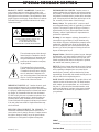 3
3
-
 4
4
-
 5
5
-
 6
6
-
 7
7
-
 8
8
-
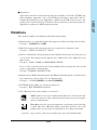 9
9
-
 10
10
-
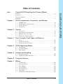 11
11
-
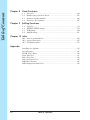 12
12
-
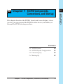 13
13
-
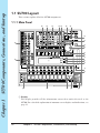 14
14
-
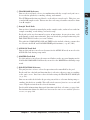 15
15
-
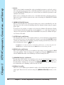 16
16
-
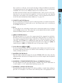 17
17
-
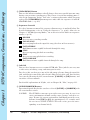 18
18
-
 19
19
-
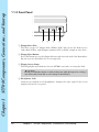 20
20
-
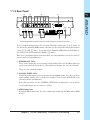 21
21
-
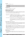 22
22
-
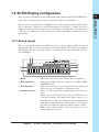 23
23
-
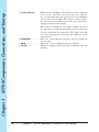 24
24
-
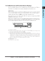 25
25
-
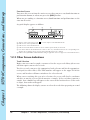 26
26
-
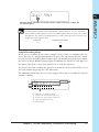 27
27
-
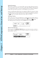 28
28
-
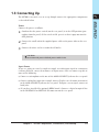 29
29
-
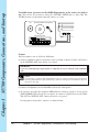 30
30
-
 31
31
-
 32
32
-
 33
33
-
 34
34
-
 35
35
-
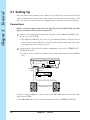 36
36
-
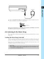 37
37
-
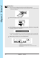 38
38
-
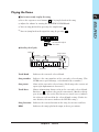 39
39
-
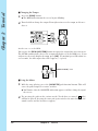 40
40
-
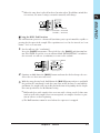 41
41
-
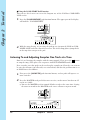 42
42
-
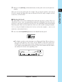 43
43
-
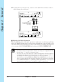 44
44
-
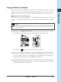 45
45
-
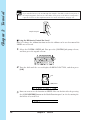 46
46
-
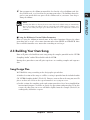 47
47
-
 48
48
-
 49
49
-
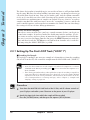 50
50
-
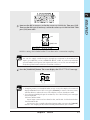 51
51
-
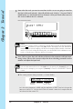 52
52
-
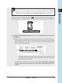 53
53
-
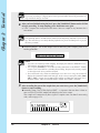 54
54
-
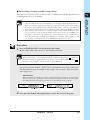 55
55
-
 56
56
-
 57
57
-
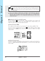 58
58
-
 59
59
-
 60
60
-
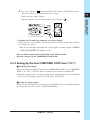 61
61
-
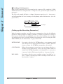 62
62
-
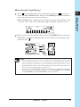 63
63
-
 64
64
-
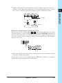 65
65
-
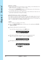 66
66
-
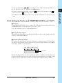 67
67
-
 68
68
-
 69
69
-
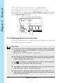 70
70
-
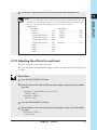 71
71
-
 72
72
-
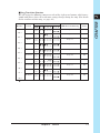 73
73
-
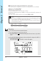 74
74
-
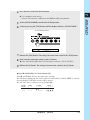 75
75
-
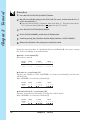 76
76
-
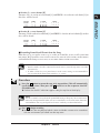 77
77
-
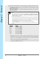 78
78
-
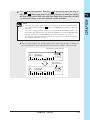 79
79
-
 80
80
-
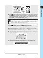 81
81
-
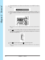 82
82
-
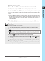 83
83
-
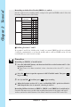 84
84
-
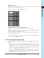 85
85
-
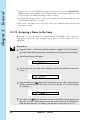 86
86
-
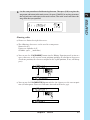 87
87
-
 88
88
-
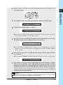 89
89
-
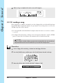 90
90
-
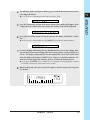 91
91
-
 92
92
-
 93
93
-
 94
94
-
 95
95
-
 96
96
-
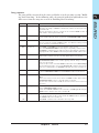 97
97
-
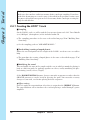 98
98
-
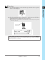 99
99
-
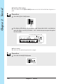 100
100
-
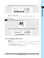 101
101
-
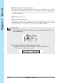 102
102
-
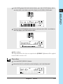 103
103
-
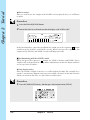 104
104
-
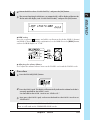 105
105
-
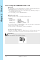 106
106
-
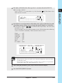 107
107
-
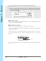 108
108
-
 109
109
-
 110
110
-
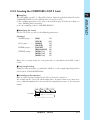 111
111
-
 112
112
-
 113
113
-
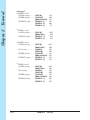 114
114
-
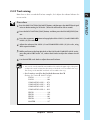 115
115
-
 116
116
-
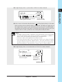 117
117
-
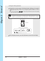 118
118
-
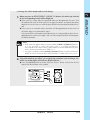 119
119
-
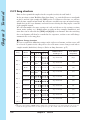 120
120
-
 121
121
-
 122
122
-
 123
123
-
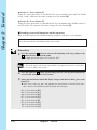 124
124
-
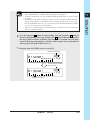 125
125
-
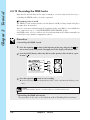 126
126
-
 127
127
-
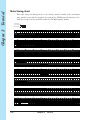 128
128
-
 129
129
-
 130
130
-
 131
131
-
 132
132
-
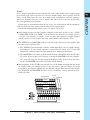 133
133
-
 134
134
-
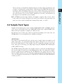 135
135
-
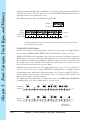 136
136
-
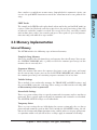 137
137
-
 138
138
-
 139
139
-
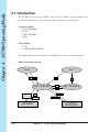 140
140
-
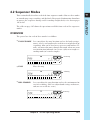 141
141
-
 142
142
-
 143
143
-
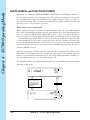 144
144
-
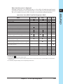 145
145
-
 146
146
-
 147
147
-
 148
148
-
 149
149
-
 150
150
-
 151
151
-
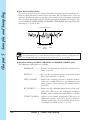 152
152
-
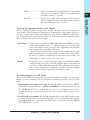 153
153
-
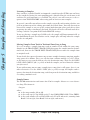 154
154
-
 155
155
-
 156
156
-
 157
157
-
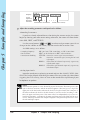 158
158
-
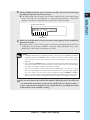 159
159
-
 160
160
-
 161
161
-
 162
162
-
 163
163
-
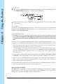 164
164
-
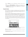 165
165
-
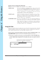 166
166
-
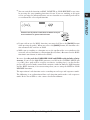 167
167
-
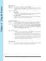 168
168
-
 169
169
-
 170
170
-
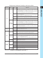 171
171
-
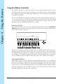 172
172
-
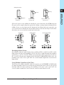 173
173
-
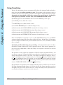 174
174
-
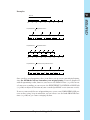 175
175
-
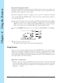 176
176
-
 177
177
-
 178
178
-
 179
179
-
 180
180
-
 181
181
-
 182
182
-
 183
183
-
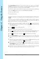 184
184
-
 185
185
-
 186
186
-
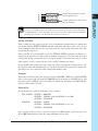 187
187
-
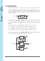 188
188
-
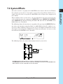 189
189
-
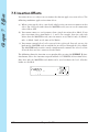 190
190
-
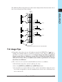 191
191
-
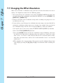 192
192
-
 193
193
-
 194
194
-
 195
195
-
 196
196
-
 197
197
-
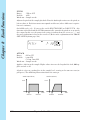 198
198
-
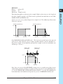 199
199
-
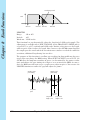 200
200
-
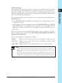 201
201
-
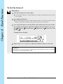 202
202
-
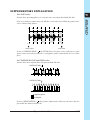 203
203
-
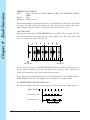 204
204
-
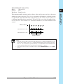 205
205
-
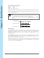 206
206
-
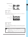 207
207
-
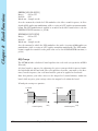 208
208
-
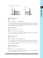 209
209
-
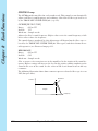 210
210
-
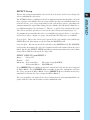 211
211
-
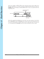 212
212
-
 213
213
-
 214
214
-
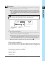 215
215
-
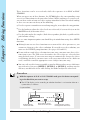 216
216
-
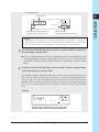 217
217
-
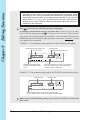 218
218
-
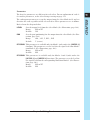 219
219
-
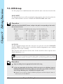 220
220
-
 221
221
-
 222
222
-
 223
223
-
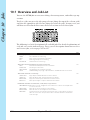 224
224
-
 225
225
-
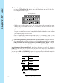 226
226
-
 227
227
-
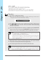 228
228
-
 229
229
-
 230
230
-
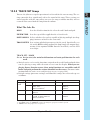 231
231
-
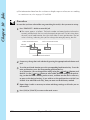 232
232
-
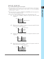 233
233
-
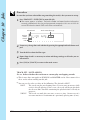 234
234
-
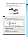 235
235
-
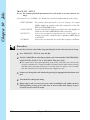 236
236
-
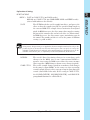 237
237
-
 238
238
-
 239
239
-
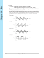 240
240
-
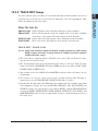 241
241
-
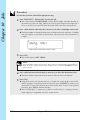 242
242
-
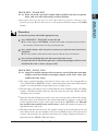 243
243
-
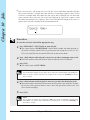 244
244
-
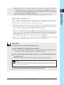 245
245
-
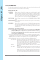 246
246
-
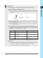 247
247
-
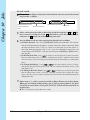 248
248
-
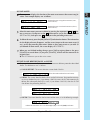 249
249
-
 250
250
-
 251
251
-
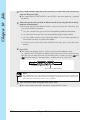 252
252
-
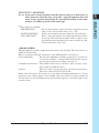 253
253
-
 254
254
-
 255
255
-
 256
256
-
 257
257
-
 258
258
-
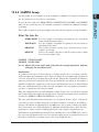 259
259
-
 260
260
-
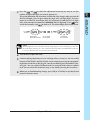 261
261
-
 262
262
-
 263
263
-
 264
264
-
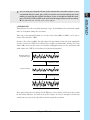 265
265
-
 266
266
-
 267
267
-
 268
268
-
 269
269
-
 270
270
-
 271
271
-
 272
272
-
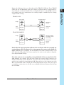 273
273
-
 274
274
-
 275
275
-
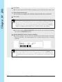 276
276
-
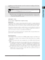 277
277
-
 278
278
-
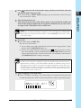 279
279
-
 280
280
-
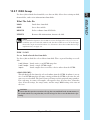 281
281
-
 282
282
-
 283
283
-
 284
284
-
 285
285
-
 286
286
-
 287
287
-
 288
288
-
 289
289
-
 290
290
-
 291
291
-
 292
292
-
 293
293
-
 294
294
-
 295
295
-
 296
296
-
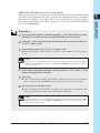 297
297
-
 298
298
-
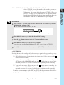 299
299
-
 300
300
-
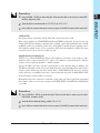 301
301
-
 302
302
-
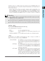 303
303
-
 304
304
-
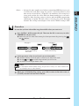 305
305
-
 306
306
-
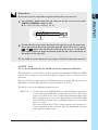 307
307
-
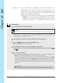 308
308
-
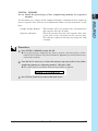 309
309
-
 310
310
-
 311
311
-
 312
312
-
 313
313
-
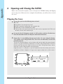 314
314
-
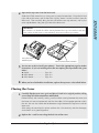 315
315
-
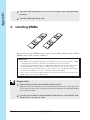 316
316
-
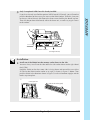 317
317
-
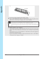 318
318
-
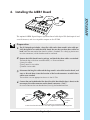 319
319
-
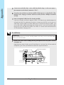 320
320
-
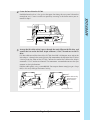 321
321
-
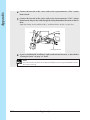 322
322
-
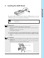 323
323
-
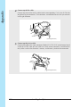 324
324
-
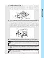 325
325
-
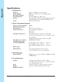 326
326
-
 327
327
-
 328
328
-
 329
329
-
 330
330
-
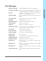 331
331
-
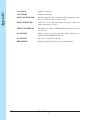 332
332
-
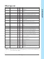 333
333
-
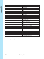 334
334
-
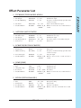 335
335
-
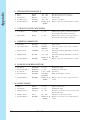 336
336
-
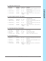 337
337
-
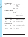 338
338
-
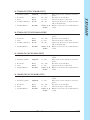 339
339
-
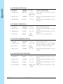 340
340
-
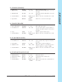 341
341
-
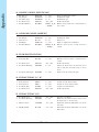 342
342
-
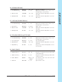 343
343
-
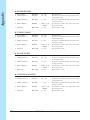 344
344
-
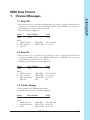 345
345
-
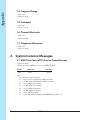 346
346
-
 347
347
-
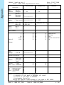 348
348
-
 349
349
-
 350
350
-
 351
351
-
 352
352
-
 353
353
-
 354
354


in andere talen
- English: Yamaha SU700 User manual
- italiano: Yamaha SU700 Manuale utente
- русский: Yamaha SU700 Руководство пользователя
- français: Yamaha SU700 Manuel utilisateur
- español: Yamaha SU700 Manual de usuario
- Deutsch: Yamaha SU700 Benutzerhandbuch
- português: Yamaha SU700 Manual do usuário
- dansk: Yamaha SU700 Brugermanual
- suomi: Yamaha SU700 Ohjekirja
- čeština: Yamaha SU700 Uživatelský manuál
- svenska: Yamaha SU700 Användarmanual
- Türkçe: Yamaha SU700 Kullanım kılavuzu
- polski: Yamaha SU700 Instrukcja obsługi
- română: Yamaha SU700 Manual de utilizare