
ROLL-UP 35

ITALIANO
AVVERTENZE PER L’INSTALLATORE
OBBLIGHI GENERALI PER LA SICUREZZA
ATTENZIONE! È importante per la sicurezza delle persone seguire at-
tentamente tutta l’istruzione. Una errata installazione o un errato
uso del prodotto può portare a gravi danni alle persone.
Leggere attentamente le istruzioni prima di iniziare l’installazione del
prodotto.
I materiali dell’imballaggio (plastica, polistirolo, ecc.) non devono essere
lasciati alla portata dei bambini in quanto potenziali fonti di pericolo.
Conservare le istruzioni per riferimenti futuri.
Questo prodotto è stato progettato e costruito esclusivamente per l’utilizzo
indicato in questa documentazione. Qualsiasi altro utilizzo non espressa-
mente indicato potrebbe pregiudicare l’integrità del prodotto e/o rap-
presentare fonte di pericolo.
GENIUS declina qualsiasi responsabilità derivata dall’uso improprio o di-
verso da quello per cui l’automatismo è destinato.
Non installare l’apparecchio in atmosfera esplosiva: la presenza di gas o
fumi infiammabili costituisce un grave pericolo per la sicurezza.
GENIUS non è responsabile dell’inosservanza della Buona Tecnica nella
costruzione delle chiusure da motorizzare, nonché delle deformazioni che
dovessero intervenire nell’utilizzo.
Prima di effettuare qualsiasi intervento sull’impianto, togliere l’alimentazio-
ne elettrica e scollegare le batterie.
Prevedere sulla rete di alimentazione dell’automazione un interruttore
onnipolare con distanza d’apertura dei contatti uguale o superiore a 3
mm. È consigliabile l’uso di un magnetotermico da 6A con interruzione
onnipolare.
Verificare che a monte dell’impianto vi sia un interruttore differenziale con
soglia da 0,03 A.
GENIUS declina ogni responsabilità ai fini della sicurezza e del buon fun-
zionamento dell’automazione, in caso vengano utilizzati componenti
dell’impianto non di produzione GENIUS.
Per la manutenzione utilizzare esclusivamente parti originali GENIUS.
Non eseguire alcuna modifica sui componenti facenti parte del sistema
d’automazione.
L’installatore deve fornire tutte le informazioni relative al funzionamento
manuale del sistema in caso di emergenza e consegnare all’Utente utiliz-
zatore dell’impianto il libretto d’avvertenze allegato al prodotto.
Non permettere ai bambini o persone di sostare nelle vicinanze del pro-
dotto durante il funzionamento.
Tenere fuori dalla portata dei bambini radiocomandi o qualsiasi altro
datore di impulso, per evitare che l’automazione possa essere azionata
involontariamente.
L’applicazione non può essere utilizzata da bambini, da persone con ridot-
te capacità fisiche, mentali, sensoriali o da persone prive di esperienza o
del necessario addestramento.
L’utente utilizzatore deve astenersi da qualsiasi tentativo di riparazione o
d’intervento e deve rivolgersi solo ed esclusivamente a personale qualifi-
cato GENIUS o centri d’assistenza GENIUS.
L’altezza di installazione minima dell’automazione è 2.5m.
Non collegare assolutamente più motori allo stesso saliscendi.
Non collegare due saliscendi allo stesso motore.
La movimentazione dell’apparecchio deve avvenire sempre a vista.
Tutto quello che non è previsto espressamente in queste istruzioni non
è permesso.
ENGLISH
IMPORTANT NOTICE FOR THE INSTALLER
GENERAL SAFETY REGULATIONS
ATTENTION! To ensure the safety of people, it is important that you
read all the following instructions. Incorrect installation or incor-
rect use of the product could cause serious harm to people.
Carefully read the instructions before beginning to install the product.
Do not leave packing materials (plastic, polystyrene, etc.) within reach
of children as such materials are potential sources of danger.
Store these instructions for future reference.
This product was designed and built strictly for the use indicated in this
documentation. Any other use, not expressly indicated here, could com-
promise the good condition/operation of the product and/or be a source
of danger.
GENIUS declines all liability caused by improper use or use other than that
for which the automated system was intended.
Do not install the equipment in an explosive atmosphere: the presence of
inflammable gas or fumes is a serious danger to safety.
GENIUS is not responsible for failure to observe Good Technique in the con-
struction of the closing elements to be motorised, or for any deformation
that may occur during use.
Before attempting any job on the system, cut out electrical power and
disconnect the batteries.
The mains power supply of the automated system must be fitted with an
all-pole switch with contact opening distance of 3mm or greater. Use of a
6A thermal breaker with all-pole circuit break is recommended.
Make sure that a differential switch with threshold of 0.03 A is fitted up-
stream of the system.
GENIUS declines all liability as concerns safety and efficient operation of
the automated system, if system components not produced by GENIUS
are used.
For maintenance, strictly use original parts by GENIUS.
Do not in any way modify the components of the automated system.
1.
2.
3.
4.
5.
6.
7.
8.
9.
10.
11.
12.
13.
14.
15.
16.
17.
18.
19.
20.
21.
22.
23.
1.
2.
3.
4.
5.
6.
7.
8.
9.
10.
11.
12.
13.
The installer shall supply all information concerning manual operation of
the system in case of an emergency, and shall hand over to the user the
warnings handbook supplied with the product.
Do not allow children or adults to stay near the product while it is ope-
rating.
Keep remote controls or other pulse generators away from children, to
prevent the automated system from being activated involuntarily.
The application cannot be used by children, by people with reduced
physical, mental, sensorial capacity, or by people without experience or
the necessary training.
The User must not in any way attempt to repair or to take direct action
and must solely contact qualified GENIUS personnel or GENIUS service
centres.
The minimum installation height of the automated system is 2.5 m.
Do not, on any account, connect several motors to the same up-and-
down device.
Do not connect two up-and-down devices to the same motor.
The equipment must always be visible when moving.
Anything not expressly specified in these instructions is not permitted.
FRANÇAIS
CONSIGNES POUR L’INSTALLATEUR
RÈGLES DE SÉCURITÉ
ATTENTION! Il est important, pour la sécurité des personnes, de suivre
à la lettre toutes les instructions. Une installation erronée ou un
usage erroné du produit peut entraîner de graves conséquences
pour les personnes.
Lire attentivement les instructions avant d’installer le produit.
Les matériaux d’emballage (matière plastique, polystyrène, etc.) ne doi-
vent pas être laissés à la portée des enfants car ils constituent des sources
potentielles de danger.
Conserver les instructions pour les références futures.
Ce produit a été conçu et construit exclusivement pour l’usage indiqué
dans cette documentation. Toute autre utilisation non expressément indi-
quée pourrait compromettre l’intégrité du produit et/ou représenter une
source de danger.
GENIUS décline toute responsabilité qui dériverait d’usage impropre ou
différent de celui auquel l’automatisme est destiné.
Ne pas installer l’appareil dans une atmosphère explosive: la présence
de gaz ou de fumées inflammables constitue un grave danger pour la
sécurité.
GENIUS n’est pas responsable du non-respect de la Bonne Technique
dans la construction des fermetures à motoriser, ni des déformations qui
pourraient intervenir lors de l’utilisation.
Couper l’alimentation électrique et déconnecter la batterie avant toute
intervention sur l’installation.
Prévoir, sur le secteur d’alimentation de l’automatisme, un interrupteur om-
nipolaire avec une distance d’ouverture des contacts égale ou supérieure
à 3 mm. On recommande d’utiliser un magnétothermique de 6A avec
interruption omnipolaire.
Vérifier qu’il y ait, en amont de l’installation, un interrupteur différentiel
avec un seuil de 0,03 A.
GENIUS décline toute responsabilité quant à la sécurité et au bon fonc-
tionnement de l’automatisme si les composants utilisés dans l’installation
n’appartiennent pas à la production GENIUS.
Utiliser exclusivement, pour l’entretien, des pièces GENIUS originales.
Ne jamais modifier les composants faisant partie du système d’automa-
tisme.
L’installateur doit fournir toutes les informations relatives au fonctionnement
manuel du système en cas d’urgence et remettre à l’Usager qui utilise
l’installation les “Instructions pour l’Usager” fournies avec le produit.
Interdire aux enfants ou aux tiers de stationner près du produit durant le
fonctionnement.
Eloigner de la portée des enfants les radiocommandes ou tout autre
générateur d’impulsions, pour éviter tout actionnement involontaire de
l’automatisme.
Ne pas permettre aux enfants, aux personennes ayant des capacités phy-
siques, mentales et sensorielles limitées ou dépourvues de l’expérience ou
de la formation nécessaires d’utiliser l’application en question.
L’utilisateur doit s’abstenir de toute tentative de réparation ou d’interven-
tion et doit s’adresser uniquement et exclusivement au personnel qualifié
GENIUS ou aux centres d’assistance GENIUS.
La hauteur minimum d’installation de l’automatisme est de 2,5m.
Ne jamais connecter plusieurs moteurs au même commande de mou-
vement.
Ne pas connecter deux commandes de mouvements au même mo-
teur.
Toujours actionner l’appareil à vue.
Tout ce qui n’est pas prévu expressément dans ces instructions est inter-
dit.
ESPAÑOL
ADVERTENCIAS PARA EL INSTALADOR
REGLAS GENERALES PARA LA SEGURIDAD
ATENCION! Es sumamente importante para la seguridad de las
personas seguir atentamente las presentes instrucciones. Una
instalación incorrecta o un uso impropio del producto puede
14.
15.
16.
17.
18.
19.
20.
21.
22.
23.
1.
2.
3.
4.
5.
6.
7.
8.
9.
10.
11.
12.
13.
14.
15.
16.
17.
18.
19.
20.
21.
22.
23.

1
ITALIANO
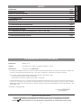
DICHIARAZIONE CE DI CONFORMITÁ
Fabbricante: GENIUS S.p.A.
Indirizzo: Via Padre Elzi, 32 - 24050 - Grassobbio- Bergamo - ITALIA
Dichiara che: L’operatore mod. ROLL-UP 35
è costruito per essere incorporato in una macchina o per essere assemblato con altri macchinari per costituire una
macchina ai sensi della Direttiva 98/37/CE, e successive modifiche 91/368/CEE, 93/44/CEE, 93/68/CEE
è conforme ai requisiti essenziali di sicurezza delle seguenti altre direttive CEE:
73/23/CEE e successiva modifica 93/68/CEE.
89/336/CEE e successiva modifica 92/31/CEE e 93/68/CEE
e inoltre dichiara che non è consentito mettere in servizio il macchinario fino a che la macchina in cui sarà incor-
porato o di cui diverrà componente sia stata identificata e ne sia stata dichiarata la conformità alle condizioni
della Direttiva 98/37/CE, 89/392/CEE e successive modifiche trasposta nella legislazione nazionale dal DPR n° 459
del 24 luglio 1996.
Grassobbio, 20 Maggio 2009
L’Amministratore Delegato
D. Gianantoni
•
•
•
•
•
Note per la lettura dell’istruzione
Leggere completamente questo manuale di installazione prima di iniziare l’installazione del prodotto.
Il simbolo evidenzia note importanti per la sicurezza delle persone e l’integrità dell’automazione.
Il simbolo richiama l’attenzione su note riguardanti le caratteristiche od il funzionamento del prodotto.
INDICE
1 DESCRIZIONE pag.2
2 CARATTERISTICHE TECNICHE pag.2
3 GUIDA ALLA SCELTA DEL MOTORE pag.2
3.1 PER AVVOLGIBILI pag.2
3.2 PER TENDE DA SOLE pag.2
4 INSTALLAZIONE pag.2
4.1 ASSEMBLAGGIO DEL MOTORE TUBOLARE pag.3
4.2 INSTALLAZIONE DEL MOTORE TUBOLARE pag.3
4.3 COLLEGAMENTI ELETTRICI pag.3
5 REGOLAZIONE DEI FINECORSA pag.4
5.1 CORRELAZIONE TRA SENSO DI ROTAZIONE RULLO E FRECCE FINECORSA pag.4
5.2 REGOLAZIONE FINECORSA IN DISCESA pag.4
5.3 REGOLAZIONE FINECORSA IN SALITA pag.4

2
ITALIANO
MOTORI TUBOLARI ROLL-UP 35
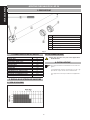
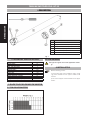
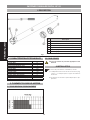
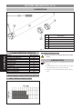
1 DESCRIZIONE
Pos. Descrizione
a
Motore tubolare
b
Esempio di adattatore ruota. (Accessorio)
c
Esempio di adattatore corona. (Accessorio)
d
Ghiera finecorsa
e
Attrezzo di regolazione finecorsa
f
Viti di regolazione finecorsa.
Fig. 1
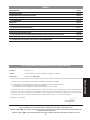
2 CARATTERISTICHE TECNICHE
Modello Roll-up 35/18
Coppia (Nm) 10
Frequenza di utilizzo 20%
Tempo max. utilizzo (min) 4
Velocità (rpm) 14
Tensione (Vac) 230
Frequenza (Hz) 50
Potenza (W) 109
Corrente (A) 0.49
N° Rotazioni max. albero motore 37
Diametro motore (mm) 35
Lunghezza con adattatore (mm) 510
Grado di protezione IP 44
3 GUIDA ALLA SCELTA DEL MOTORE
3.1 PER AVVOLGIBILI
3.2 PER TENDE DA SOLE
Questo tipo di motore non può essere applicato a
tende da sole.
4 INSTALLAZIONE
Prima di procedere all’installazione occorre sce-
gliere:
1) L’adattatore ruota e corona (Fig. 1 rif. b - c)
più idonei al tipo di rullo da movimentare.
2) Il supporto motore più adatto all’applicazio-
ne.

3
ITALIANO
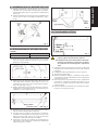
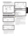
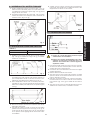
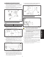
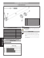
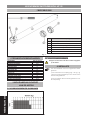
4.1 ASSEMBLAGGIO DEL MOTORE TUBOLARE
Infilare l’adattatore corona (Fig.2 rif. a ) nel motore
tubolare, fino a che questo non sia inserito completa-
mente sulla guida (Fig. 2 rif. b) presente nella ghiera
finecorsa.
Inserire l’adattatore ruota (Fig.2 rif c) nell’albero del
motore e bloccarlo con il seeger in dotazione. (Fig.2
rif. d).
Fig. 2
4.2 INSTALLAZIONE DEL MOTORE TUBOLARE
Tabella 1
MODELLO ROLL-UP 35 MISURA A (mm)
18 475
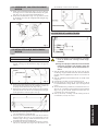
Praticare un foro con una punta Ø 3 mm sul rullo
(Fig. 3 rif. b) alla distanza A (Fig. 3 rif. a), facendo
riferimento alla tabella 1.
Fig. 3
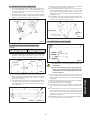
Inserire il motore tubolare assemblato all’interno del
rullo dalla parte opposta alla calotta, fino a che
l’adattatore corona non sia completamente all’in-
terno del rullo (Fig. 4 rif. a).
Fissare l’adattatore ruota al rullo tramite una vite au-
tofilettante 4x10 inserita nel foro precedentemente
realizzato, come in figura 4 rif. b.
Fig. 4
Montare il supporto motore precedentemente scelto
dal lato della predisposizione elettrica.
Inserire il rullo motorizzato, esercitando una legge-
ra pressione nel supporto motore (Fig. 5 rif. a), e sul
supporto calotta (Fig. 5 rif. b), in modo che le viti di
regolazione di finecorsa siano accessibili.
Verificare che il rullo motorizzato sia perfettamente
orizzontale, eventualmente modificare l’altezza dei
supporti calotta o motore.
1.
2.
1.
2.
3.
4.
5.
6.
Fig. 5
4.3 COLLEGAMENTI ELETTRICI
Fig. 6
1) Prima di effettuare qualsiasi intervento sull’im-
pianto, togliere l’alimentazione elettrica.
2) Prevedere sulla rete di alimentazione dell’auto-
mazione un interruttore onnipolare con distan-
za d’apertura dei contatti uguale o superiore a
3mm.
Collegare i fili provenienti dal motore ad un saliscendi
interbloccato e senza ritenuta come nello schema
in figura 6.
Collegare il saliscendi alla linea come in figura 6.
Alimentare l’elettrorullo.
Premere il pulsante di salita, controllare che la rotazio-
ne del rullo avvenga nella direzione di avvolgimento
e fermare il motore.
Nel caso il senso di rotazione sia errato, togliere ali-
mentazione, scambiare nel saliscendi (Fig. 6 rif. a) il
filo nero con quello marrone e verificare il corretto
funzionamento.
Premere il pulsante di discesa per verificarne il funzio-
namento, e fermare il motore.
1.
2.
3.
4.
5.
6.

4
ITALIANO
5 REGOLAZIONE DEI FINECORSA
I Motori tubolari GENIUS hanno al loro interno, un sistema di finecorsa elettromeccanico che permette di interrompere
l’alimentazione del motore quando si arriva al limite di apertura, o chiusura, dell’avvolgibile.
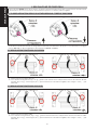
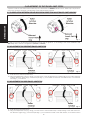
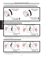
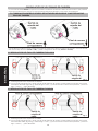
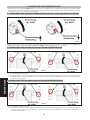
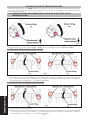
5.1 CORRELAZIONE TRA SENSO DI ROTAZIONE RULLO E FRECCE FINECORSA
Fig. 7
Per facilitare l’individuazione delle viti di regolazione finecorsa, fare riferimento alle figure 8 - 9 in base al lato montaggio
motore (DX o SX), e alla configurazione del cassonetto (interno o esterno).
5.2 REGOLAZIONE FINECORSA IN DISCESA
Fig. 8
Tenere premuto il pulsante discesa
Con l’attrezzo di regolazione (Fig. 1 rif. e) , girare la vite del finecorsa corrispondente al senso di rotazione discesa
del rullo (Fig. 8 rif. a), verso il segno più (+) per aumentare la corsa dell’avvolgibile, verso il segno meno ( - ) per
diminuirla.
5.3 REGOLAZIONE FINECORSA IN SALITA
Fig. 9
Tenere premuto il pulsante salita.
Con l’attrezzo di regolazione (Fig. 1 rif. e) , girare la vite del finecorsa corrispondente al senso di rotazione salita
del rullo (Fig. 9 rif. a), verso il segno più (+) per aumentare la corsa dell’avvolgibile, verso il segno meno ( - ) per
diminuirla.
1.
2.
1.
2.

5
ENGLISH
INDEX
1 DESCRIPTION page.6
2 TECHNICAL SPECIFICATIONS page.6
3 GUIDE FOR CHOOSING THE MOTOR page.6
3.1 FOR ROLLER SHUTTERS page.6
3.2 FOR AWNINGS page.6
4 INSTALLATION page.6
4.1 ASSEMBLY OF TUBULAR MOTOR page.7
4.2 INSTALLATION OF TUBULAR MOTOR page.7
4.3 ELECTRICAL CONNECTIONS page.7
5 ADJUSTMENT OF THE TRAVEL-LIMIT STOPS page.8
5.1 CORRELATION BETWEEN ROLLER ROTATION DIRECTION AND TRAVEL-LIMIT ARROWS page.8
5.2 ADJUSTMENT OF DESCENT TRAVEL-LIMIT STOP page.8
5.3 ADJUSTMENT OF RISE TRAVEL-LIMIT STOP page.8
CE DECLARATION OF CONFORMITY FOR MACHINES
Manufacturer: GENIUS S.p.A.
Address: Via Padre Elzi, 32 - 24050 - Grassobbio- Bergamo - ITALIA
Declares that: Operator model. ROLL-UP 35
is built to be integrated into a machine or to be assembled with other machinery to create a machine under the
provisions of Directive 98/37/EC, and subsequent amendments 91/368/EEC, 93/44/EEC, 93/68/EEC
conforms to the essential safety requirements of the other following EEC directives:
73/23/EEC and subsequent amendment 93/68/EEC.
89/336/EEC and subsequent amendment 92/31/EEC and 93/68/EEC
furthermore, the manufacturer declares that the machinery must not be put into service until the machine into which
it will be incorporated or of which it will become a part has been identified and its conformity to the conditions of
Directive 98/37/EC, 89/392/EEC and subsequent modifications assimilated in Italian National legislation under Presi-
dential Decree No. 459 of 24 July 1996 has been declared.
Grassobbio, 20 May 2009
The Managing Director
D. Gianantoni
•
•
•
•
•
Notes on reading the instruction
Read this installation manual to the full before you begin installing the product.
The symbol indicates notes that are important for the safety of persons and for the good condition of the
automated system.
The symbol draws your attention to the notes on the characteristics and operation of the product.

6
ENGLISH
TUBULAR MOTORS ROLL-UP 35
1 DESCRIPTIONDESCRIPTION
Pos. Description
a
Tubular motor
b
Example of wheel adaptor (Accessory)
c
Example of crown adaptor (Accessory)
d
Travel-limit stop ring-nut
e
Travel-limit stop adjustment tool
f
Travel-limit stop adjustment screws
Fig. 1
2 TECHNICAL SPECIFICATIONS
Model Roll-up 35/18
Torque (Nm) 10
Use frequency 20%
Max. use time (min) 4
Speed (rpm) 14
Voltage (Vac) 230
Frequency (Hz) 50
Power (W) 109
Current (A) 0.49
Motor shaft maz. rotation 37
Motor diameter (mm) 35
Length with adaptator (mm) 510
Protection index IP 44
3 GUIDE FOR CHOOSING THE MOTOR
3.1 FOR ROLLER SHUTTERS
3.2 FOR AWNINGS
This type of engine can not be applied to awnin-
gs
4 INSTALLATION
Before installing, select:
1) The wheel and crown adaptor (Fig.1 ref.b
- c) most suitable for the type of roller to be
moved.
2) The motor support most suitable for the appli-
cation.

7
ENGLISH
4.1 ASSEMBLY OF TUBULAR MOTOR
Fit the crown adaptor (Fig.2 ref.a) on the tubular mo-
tor, until it is completely inserted on the guide (Fig.2
ref.b) on the travel-limit ring-nut.
Insert the wheel adaptor (Fig.2 ref.c) on the motor
shaft and secure it with the supplied Seeger ring (Fig.2
ref.d)
Fig. 2
4.2 INSTALLATION OF TUBULAR MOTOR
Table 1
ROLL-UP 35 MODEL MEASURE A (mm)
18 475
Drill a hole with a 3mm diam. bit on the roller (Fig.3 ref.
b) at distance A (Fig.3 ref.a), referring to table 1.
Fig. 3
Insert the assembled tubular motor inside the roller
from the side opposite the cap, until the crown adap-
tor is completely inside the roller (Fig.4 ref.a).
Secure the wheel adaptor to the roller with a 4x10
self-tapping screw inserted in the hole you had dril-
led, as shown in Fig. 4 ref. b.
Fig. 4
Install the selected motor from the electric facilities
side.
Secure the motorised roller, exerting light pressure on
the motor support (Fig. 5 ref. a), and on the cap sup-
port (Fig. 5 ref. b), so that the travel-limit adjustment
screws are accessible.
Make sure that the motorised roller is perfectly hori-
zontal and, if necessary, modify the height of the cap
or motor supports.
1.
2.
1.
2.
3.
4.
5.
6.
Fig. 5
4.3 ELECTRICAL CONNECTIONS
Fig. 6
1) Before attempting any action on the system, cut
out the electrical power supply.
2) Install an omnipolar switch on the power sup-
ply line for the automated system, with contact
opening distance of 3mm or more.
Connect the wires coming from the motor to an in-
terlocked up-and-down device without reset facility
as in the lay-out of figure 6
Connect the up-and-down device to the power sup
-
ply line as shown in Fig. 6.
Power up the electro-roller
Press the rise push-button and check if the roller rota-
tes in the winding direction and stop the motor.
If the rotation direction is incorrect, cut power and
- in the up-and-down device (Fig. 6 ref.a ) - change
over the black wire with the brown wire and check if
operation is correct.
Press the descent push-button to check operation,
and stop the motor.
1.
2.
3.
4.
5.
6.

8
ENGLISH
5 ADJUSTMENT OF THE TRAVEL-LIMIT STOPS
A system of electro-mechanical travel-limit stop is housed inside the GENIUS tubular motors. These stops cut power to
the motor, when the opening or closing limit of the roller-shutter is reached.
5.1 CORRELATION BETWEEN ROLLER ROTATION DIRECTION AND TRAVEL-LIMIT ARROWS
Fig. 7
To help you find the travel-limit stop adjustment screws, refer to figures 8 - 9, according to the motor installation side
(RH or LH), and to the box configuration (internal or external).
5.2 ADJUSTMENT OF DESCENT TRAVEL-LIMIT STOP
Fig. 8
Hold down the descent push-button
Using the adjustment tool (Fig.1 ref.e), turn the screw of the travel-limit stop corresponding to the roller’s descent
rotation direction (Fig.8 ref.a), toward the plus sign (+) to increase the travel of the roller shutter, or toward the
minus sign (-) to reduce it.
5.3 ADJUSTMENT OF RISE TRAVEL-LIMIT STOP
Fig. 9
Hold down the rise push-button
Using the adjustment tool (Fig.1 ref.e), turn the screw of the travel-limit stop corresponding to the roller’s rise rota-
tion direction (Fig.9 ref.a), toward the plus sign (+) to increase the travel of the roller shutter, or toward the minus
1.
2.
1.
2.

9
FRANÇAIS
sign (-) to reduce it.
INDEX
1 DESCRIPTION page.10
2 CARACTÉRISTIQUES TECHNIQUES page.10
3 COMMENT CHOISIR LE MOTEUR page.10
3.1 POUR RIDEAUX À ENROULEMENT page.10
3.2 POUR STORES page.10
4 INSTALLATION page.10
4.1 ASSEMBLAGE DU MOTEUR TUBULAIRE page.11
4.2 INSTALLATION DU MOTEUR TUBULAIRE page.11
4.3 CONNEXIONS ÉLECTRIQUES page.11
5 RÉGLAGE DES FINS DE COURSE page.12
5.1 LIEN ENTRE LE SENS DE ROTATION DU ROULEAU ET LES FLÈCHES DES FINS DE COURSE page.12
5.2 RÉGLAGE DU FIN DE COURSE EN DESCENTE page.12
5.3 RÉGLAGE DU FIN DE COURSE EN MONTÉE page.12
DÉCLARATION CE DE CONFORMITÉ POUR MACHINES
Fabricant: GENIUS S.p.A.
Adresse: Via Padre Elzi, 32 - 24050 - Grassobbio- Bergamo - ITALIA
Déclare que: L’opérateur mod. ROLL-UP 35
est construit pour être incorporé à une machine ou pour être assemblé à d’autres machines afin de constituer une
machine conforme à la Directive 98/37/CE, et aux modifications 91/368/CEE, 93/44/CEE, 93/68/CEE successives
est conforme aux exigences essentielles de sécurité des directives CEE suivantes:
73/23/CEE et modification 93/68/CEE successive.
89/336/CEE et modifications 92/31/CEE et 93/68/CEE successives
et déclare, en outre, qu’il est interdit de mettre en service l’appareillage jusqu’à ce que la machine dans laquelle il
sera incorporé ou dont il deviendra un composant ait été identifiée et jusqu’à ce que la conformité aux conditions
de la Directive 98/37/CE, 89/392/CEE et modifications successives, transposée dans la législation nationale par le
DPR n° 459 du 24 juillet 1996, en ait été déclarée.
Grassobbio, 20 Mai 2009
L’Administrateur Délégué
D. Gianantoni
•
•
•
•
•
Remarques pour la lecture de l’instruction
Lire ce manuel d’installation dans son ensemble avant de commencer l’installation du produit.
Le symbole souligne des remarques importantes pour la sécurité des personnes et le parfait état de
l’automatisme.
Le symbole attire l’attention sur des remarques concernant les caractéristiques ou le fonctionnement du
produit.

10
FRANÇAIS
MOTEURS TUBULAIRES ROLL-UP 35
1 DESCRIPTION
Pos. Déscription
a
Moteur tubulaire
b
Exemple d’adaptateur de la roue (Accessoire)
c
Exemple d’adaptateur de la couronne
(Accessoire)
d
Bague de fin de course
e
Outil de réglage des fins de course
f
Vis de réglage des fins de course
Fig. 1
2 CARACTÉRISTIQUES TECHNIQUES
Modèle Roll-up 35/18
Couple (Nm) 10
Fréquence d’utilisation 20%
Temps maxi utilisation (min) 4
Vitesse (rpm) 14
Tension (Vac) 230
Fréquence (Hz) 50
Puissance (W) 109
Courrant (A) 0.49
Rotation maxi arbre moteur 37
Diamètre moteur (mm) 35
Longueur avec adaptateur (mm) 510
Indice de protection IP 44
3 COMMENT CHOISIR LE MOTEUR
3.1 POUR RIDEAUX À ENROULEMENT
3.2 POUR STORES
Ce type de moteur ne peut être appliquée à des
auvents.
4 INSTALLATION
Avant de plrocéder à l’installation, choisir:
1) L’adaptateur de la roue et de la couronne (Fig.
1 réf. b - c) indiqué pour le type de roleau à
actionner.
2) Le support du moteur le plus indiqué puor l’ap-
plication.

11
FRANÇAIS
4.1 ASSEMBLAGE DU MOTEUR TUBULAIRE
Enfiler l’adaptateur de la couronne (Fig. 2 réf. a)
dans le moteur tubulaire, jusqu’à ce que celui-ci soit
complètement inséré sur le guide (Fig. 2 réf. b) de la
bague de fin de course.
Introduire l’adaptateur de la roue (Fig. 2 réf. c) dans
l’arbre du moteur et le bloquer avec l’anneau de
retenue fourni. (Fig. 2 réf. d).
Fig. 2
4.2 INSTALLATION DU MOTEUR TUBULAIRE
Tableau 1
MODÈLE ROLL-UP 35 DIMENSION A (mm)
18 475
Réaliser un trou avec un foret Ø 3 mm sur le rouleau
(Fig. 3 réf. b) à la distance A (Fig. 3 réf. a), en faisant
référence au tableau 1.
Fig. 3
Introduire le moteur tubulaire assemblé à l’intérieur
du rouleau du côté opposé à la calotte, jusqu’à ce
que l’adaptateur de la couronne se trouve com-
plètement à l’intérieur du rouleau (Fig. 4 réf. a).
Fixer l’adaptateur de la roue au rouleau par l’inter-
médiaire d’une vis autotaraudeuse 4x10 introduite
dans le trou réalisé précédemment, d’après la figure
4 réf. b.
Fig. 4
Monter le support du moteur choisi du côté de la
disposition électrique.
Introduire le rouleau motorisé, en exerçant une légère
pression dans le support du moteur (Fig. 5 réf. a), et
sur le support de la calotte (Fig. 5 réf. b), de manière
à ce que les vis de réglage de fin de course soient
accessibles.
1.
2.
1.
2.
3.
4.
5.
Vérifier que le rouleau motorisé est parfaitement
horizontal, éventuellement modifier la hauteur des
supports de la calotte ou du moteur.
Fig. 5
4.3 CONNEXIONS ÉLECTRIQUES
Fig. 6
1) Couper le courant électrique avant tout type
d’intervention sur l’installation.
2) Prévoir sur le réseau d’alimentation de l’auto-
matisme un interrupteur omnipolaire avec une
distance d’ouverture des contacts égale ou
supérieure à 3mm.
Connecter les fils venant du moteur à une comman-
de de mouvement interbloquée et sans retenue,
d’après le schéma de la figure 6.
Connecter la commande de mouvement à la ligne
d’après la figure 6.
Mettre l’électrorouleau sous tension.
Appuyer sur le bouton-poussoir de montée, contrôler
que le rouleau tourne dans la direction d’enroule-
ment et arrêter le moteur.
Si le sens de rotation est erroné, mettre hors tension,
inverser les fils noir et marron dans la commande de
mouvement (fig. 6 réf. a) et vérifier le fonctionne-
ment.
Appuyer sur le bouton-poussoir de descente pour en
vérifier le fonctionnement, et arrêter le moteur.
6.
1.
2.
3.
4.
5.
6.

12
FRANÇAIS
5 RÉGLAGE DES FINS DE COURSE
Les Moteurs tubulaires GENIUS contiennent un système de fin de course électromécanique qui permettent de mettre
le moteur hors tension lorsqu’on arrive à la limite d’ouverture, ou de fermeture des rideaux à enroulement.
5.1 LIEN ENTRE LE SENS DE ROTATION DU ROULEAU ET LES FLÈCHES DES FINS DE COURSE
Fig. 7
Pour faciliter l’identification des vis de réglage des fins de course, faire référence aux figures 8 - 9 suivant le côté de
montage du moteur (DR ou GAU), et à la configuration du caisson (interne ou externe).
5.2 RÉGLAGE DU FIN DE COURSE EN DESCENTE
Fig. 8
Maintenir le bouton-poussoir de descente enfoncé.
Avec l’outil de réglage (Fig. 1 réf. e), tourner la vis du fin de course correspondant au sens de rotation de descente
du rouleau (Fig. 8 réf. a), vers le signe plus (+) pour augmenter la course du rideau à enroulement, vers le signe
moins ( - ) pour la diminuer.
5.3 RÉGLAGE DU FIN DE COURSE EN MONTÉE
Fig. 9
Maintenir le bouton-poussoir de montée enfoncé.
Avec l’outil de réglage (Fig. 1 réf. e), tourner la vis du fin de course correspondant au sens de rotation de descente
du rouleau (Fig. 9 réf. a), vers le signe plus (+) pour augmenter la course du rideau à enroulement, vers le signe
moins ( - ) pour la diminuer.
1.
2.
1.
2.

13
ESPAÑOL
ÍNDICE
1 DESCRIPCIÓN pág.14
2 CARACTERÍSTICAS TÉCNICAS pág.14
3 GUÍA PARA LA ELECCIÓN DEL MOTOR pág.14
3.1 PARA PERSIANAS ENROLLABLES pág.14
3.2 PARA TOLDOS DE SOL pág.14
4 INSTALACIÓN pág.14
4.1 ENSAMBLAJE DEL MOTOR TUBULAR pág.15
4.2 INSTALACIÓN DEL MOTOR TUBULAR pág.15
4.3 CONEXIONES ELÉCTRICAS pág.15
5 REGULACIÓN DE LOS FINALES DE CARRERA pág.16
5.1 CORRELACIÓN ENTRE EL SENTIDO DE ROTACIÓN DEL RODILLO Y LAS FLECHAS DEL FINAL DE CARRERA pág.16
5.2 REGULACIÓN DEL FINAL DE CARRERA EN BAJADA pág.16
5.3 REGULACIÓN DEL FINAL DE CARRERA EN SUBIDA pág.16
DECLARACIÓN CE DE CONFORMIDAD PARA MÁQUINAS
Fabricante: GENIUS S.p.A.
Dirección: Via Padre Elzi, 32 - 24050 - Grassobbio- Bergamo - ITALIA
Declara que: L’operatore mod. ROLL-UP 35
ha sido fabricado para ser incorporado en una máquina o para ser ensamblado con otras maquinarias para con-
stituir una máquina de conformidad con la Directiva 98/37/CE, y sucesivas modificaciones 91/368/CEE, 93/44/CEE,
93/68/CEE
cumple con los requisitos esenciales de seguridad de las siguientes directivas CEE:
73/23/CEE y sucesiva modificación 93/68/CEE.
89/336/CEE y sucesiva modificación 92/31/CEE y 93/68/CEE
asimismo declara que no está permitido poner en funcionamiento la maquinaria hasta que la máquina en la que
deberá incorporarse o de la cual será un componente haya sido identificada y se haya declarado su conformidad
con las condiciones de la Directiva 98/37/CE, 89/392/CEE y sucesivas modificaciones incorporada a la legislación
nacional por el DPR n° 459 del 24 de julio de 1996.
Grassobbio, 20 de Mayo de 2009
El Administrador Delegado
D. Gianantoni
•
•
•
•
•
Notas para la lectura de las instrucciones
Leer completamente este manual antes de empezar la instalación del producto.
El símbolo destaca notas importantes para la seguridad de las personas y la integridad de la automación.
El símbolo evidencia notas sobre las características o el funcionamiento del producto.

14
ESPAÑOL
MOTORES TUBULARES ROLL-UP 35
1 DESCRIPCIÓN
Pos. Descripción
a
Motor tubular
b
Ejemplo de adaptador rueda. (Accesorio)
c
Ejemplo de adaptador corona (Accesorio)
d
Tuerca final de carrera
e
Útil de regulación del final de carrera
f
Tornillos de regulación del final de carrera.
Fig. 1
2 CARACTERÍSTICAS TÉCNICAS
Modelo Roll-up 35/18
Par (Nm) 10
Frecuencia de utilización 20%
Tiempo máx. utilizacion (min) 4
Velocidad (rpm) 14
Tensión (Vac) 230
Frecuencia (Hz) 50
Potencia (W) 109
Corriente (A) 0.49
Rotación máx. eje motor 37
Diámetro motor (mm) 35
Longitud con adaptator (mm) 510
Índice de protección IP 44
3 GUÍA PARA LA ELECCIÓN DEL MOTOR
3.1 PARA PERSIANAS ENROLLABLES
3.2 PARA TOLDOS DE SOL
Este tipo de motor no se puede aplicar a los toldos
de sol.
4 INSTALACIÓN
Antes de proceder a la inhstalación hay que
elegir:
1) El adaptador rueda y corona (Fig. 1 ref. b - c)
más adecuados para el tipo de rodillo.
2) El soporte motor más adecuado para la aplica-
ción.

15
ESPAÑOL
4.1 ENSAMBLAJE DEL MOTOR TUBULAR
Introduzca el adaptador corona (Fig. 2 ref. a) en el
motor tubular, hasta que el mismo esté completa-
mente introducido en la guía (Fig. 2 ref. b) presente
en la tuerca de final de carrera.
Introduzca el adaptador de rueda (Fig. 2 ref. c) en
el eje del motor y bloquéelo con el anillo seeger su-
ministrado en dotación. (Fig. 2 ref. d)
Fig. 2
4.2 INSTALACIÓN DEL MOTOR TUBULAR
Tabla 1
MODELO ROLL-UP 35 MEDIDA A (mm)
18 475
Realice un taladrado con una broca Ø 3 mm en el
rodillo (Fig. 3 ref. b) a la distancia A (Fig. 3 ref. a),
tomando como referencia la tabla 1.
Fig. 3
Introduzca el motor tubular ensamblado en el interior
del rodillo por la parte opuesta a la tapa, hasta que
el adaptador corona esté completamente introdu-
cido en el rodillo (Fig. 4 ref. a).
Fije el adaptador de rueda al rodillo por medio de
un tornillo autorroscante 4x10 introducido en el ta-
ladrado anteriormente realizado, como se muestra
en la figura 4 ref. b.
Fig. 4
Monte el soporte motor anteriormente elegido por el
lado opuesto al de la predisposición eléctrica.
Introduzca el rodillo motorizado ejerciendo una ligera
presión en el soporte del motor (Fig.5 ref.a), y en el
soporte de la tapa (Fig.5 ref.b), de forma que los tor-
nillos de regulación de los finales de carrera queden
en una posición de fácil acceso.
1.
2.
1.
2.
3.
4.
5.
Compruebe que el rodillo motorizado esté perfecta-
mente horizontal, si fuera necesario modifique la al-
tura de los soportes de la tapa o del motor.
Fig. 5
4.3 CONEXIONES ELÉCTRICAS
Fig. 6
1) Antes de efectuar cualquier intervención en el
equipo, quite la alimentación eléctrica.
2) La red de alimentación de la automación debe
estar dotada de un interruptor omnipolar con
una distancia de apertura de los contactos
igual o superior a 3mm.
Conecte los hilos en salida del motor a un pulsador
de subida y bajada interbloqueado y sin retención,
como se muestra en el esquema de la figura 6.
Conecte el pulsador de subida y bajada a la línea
como se muestra en la figura 6.
Alimente el rodillo eléctrico.
Presione el pulsador de subida, compruebe que la
rotación del rodillo se realice en la dirección de en-
rollado y pare el motor.
Si el sentido de rotación fuera incorrecto, quite la
alimentación, y en el pulsador de subida y bajada
(Fig. 6 ref. a) invierta el hilo negro con el marrón.
Compruebe de nuevo el funcionamiento.
Presione el pulsador de bajada para comprobar el
funcionamiento, y pare el motor.
6.
1.
2.
3.
4.
5.
6.

16
ESPAÑOL
5 REGULACIÓN DE LOS FINALES DE CARRERA
Los motores tubulares GENIUS incorporan en su interior un sistema de final de carrera electromecánico que permiten
interrumpir la alimentación del motor cuando se llega al límite de apertura, o de cierre, de la persiana.
5.1 CORRELACIÓN ENTRE EL SENTIDO DE ROTACIÓN DEL RODILLO Y LAS FLECHAS DEL
FINAL DE CARRERA
Fig. 7
Para facilitar la localización de los tornillos de regulación del final de carrera, remítase a las figuras 8 - 9 en función del
lado de montaje del motor (DCHO. o IZQ.), y de la configuración de la caja (interna o externa).
5.2 REGULACIÓN DEL FINAL DE CARRERA EN BAJADA
Fig. 8
Mantenga presionado el pulsador de bajada.
Con el útil de regulación (Fig.1 ref.e), gire el tornillo del final de carrera correspondiente al sentido de rotación
de bajada del rodillo (Fig.8 ref.a), hacia el signo “más” (+) para aumentar la carrera de la persiana, y hacia el
signo “menos” ( - ) para disminuirla.
5.3 REGULACIÓN DEL FINAL DE CARRERA EN SUBIDA
Fig. 9
Mantenga presionado el pulsador de subida.
Con el útil de regulación (Fig.1 ref.e), gire el tornillo del final de carrera correspondiente al sentido de rotación
de subida del rodillo (Fig.9 ref.a), hacia el signo “más” (+) para aumentar la carrera de la persiana, y hacia el
signo “menos” ( - ) para disminuirla.
1.
2.
1.
2.

17
DEUTSCH
INHALT
1 BESCHREIBUNG siete.18
2 TECHNISCHE DATEN siete.18
3 ANLEITUNGEN ZUR AUSWAHL DES MOTORS siete.18
3.1 FÜR ROLLLÄDEN siete.18
3.2 FÜR MARKISEN siete.18
4 MONTAGE siete.18
4.1 MONTAGE DES ROHRMOTORS siete.19
4.2 INSTALLATION DES ROHRMOTORS siete.19
4.3 ELEKTRISCHE ANSCHLÜSSE siete.19
5 EINSTELLUNG DER ENDANSCHLÄGE siete.20
5.1 ZUSAMMENHANG ZWISCHEN DREHRICHTUNG DER WELLE UND ENDANSCHLAGPFEILEN siete.20
5.2 EINSTELLUNG DES ENDANSCHLAGS BEI DER ABWÄRTSBEWEGUNG siete.20
5.3 EINSTELLUNG DES ENDANSCHLAGS BEI DER AUFWÄRTSBEWEGUNG siete.20
CE-KONFORMITÄTSERKLÄRUNG FÜR MASCHINEN
Hersteller: GENIUS S.p.A.
Adresse: Via Padre Elzi, 32 - 24050 - Grassobbio- Bergamo – ITALIEN
Erklärt, dass: Antrieb Mod. ROLL-UP 35
zum Einbau in eine Maschine oder mit anderen Maschinen zum Bau einer Maschine im Sinne der Richtlinie 98/37/EG
gebaut ist, und nachträgliche Änderungen 91/368/EWG, 93/44/EWG, 93/68/EWG
den wesentlichen Sicherheitsbestimmungen der folgenden EWG-Richtlinien entspricht:
73/23/EWG und nachträgliche Änderung 93/68/EWG.
89/336/EWG und nachträgliche Änderung 92/31/EWG und 93/68/EWG
und erklärt außerdem, dass die Inbetriebnahme solange untersagt ist, bis die Maschine, in welche diese Maschine
eingebaut wird oder von der sie ein Bestandteil ist, bestimmt wurde und deren Übereinstimmung mit den Voraus-
setzungen der Richtlinie 89/392/EG, 89/392/EWG und nachträgliche Änderungen, umgesetzt von der nationalen
Gesetzgebung durch das Dekret des Präsidenten der Republik Nr. 459 vom 24. Juli 1996, erklärt ist.
Grassobbio, 20. Mai 2009
Geschäftsführer
D. Gianantoni
•
•
•
•
•
Hinweise zu den Anleitungen
Vor der Installation des Produkts sind die Installationsanweisungen vollständig zu lesen.
Mit dem Symbol sind wichtige Anmerkungen für die Sicherheit der Personen und den störungsfreien Betrieb der
Automation gekennzeichnet.
Mit dem Symbol wird auf Anmerkungen zu den Eigenschaften oder dem Betrieb des Produkts verwiesen.

18
DEUTSCH
ROHRMOTOREN ROLL-UP 35
1 BESCHREIBUNG
Pos. Beschreibung
a
Rohrmotor
b
Beispiel für Radadapter. (Zubehör)
c
Beispiel für Kranzadapter. (Zubehör)
d
Endanschlagmutter
e
Werkzeug für die Endanschlageinstellung
f
Schrauben für die Endanschlageinstellung
Abb. 1
2 TECHNISCHE DATEN
Modell Roll-up 35/18
Drehmoment (Nm) 10
Einsatzäufigkeit 20%
Maximale einsatzzeit (min) 4
Drehzahl (rpm) 14
Spannung (Vac) 230
Frequenz (Hz) 50
Leistung (W) 109
Strom-stärke (A) 0.49
Maximale drehung der motorwelle 37
Durchmesser des motors (mm) 35
Länge mit adapter (mm) 510
Schutzart IP 44
3 ANLEITUNGEN ZUR AUSWAHL
DES MOTORS
3.1 FÜR ROLLLÄDEN
3.2 FÜR MARKISEN
Diese Art der Motor kann nicht angewandt werden,
um Markisen.
4 MONTAGE
Vor der montage ist folgendes auszuwählen:
1) Rad-und kranzadapter (Abb. 1, Bez. b - c),
die sich am besten für die zu bewegende welle
eignen.
2) Für die anwendung am besten geeignete
motorhalterung.

19
DEUTSCH
4.1 MONTAGE DES ROHRMOTORS
Den Kronenadapter (Abb. 2, Bez. a) in den Rohrmo-
tor so weit einführen, bis er vollständig in der in der
Endanschlagsmutter enthaltenen Führung eingesetzt
ist (Abb. 2, Bez. b).
Den Radadapter (Abb. 2, Bez. c) in die Motorwelle
einsetzen und mit dem im Lieferumfang enthaltenen
Seeger-Ring festspannen. (Abb. 2, Bez. d).
Abb. 2
4.2 INSTALLATION DES ROHRMOTORS
Tabelle 1
MODELL ROLL-UP 35 MASS A (mm)
18 475
Mit einem Bohrer Ø 3 mm ein Bohrloch auf der Wal-
ze (Abb. 3, Bez. b) im Abstand A (Abb. 3, Bez. a)
bohren und hierzu Bezug auf die Tabelle 1 nehmen.
Abb. 3
Den zusammengebauten Rohrmotor in die Welle von
der entgegengesetzten Seite der Haube so weit ein-
führen, bis der Kranzadapter vollkommen in der Welle
sitzt (Abb. 4, Bez. a).
Den Radadapter mit Hilfe einer selbstschneidenden
Schraube 4x10, die in das zuvor ausgebildete Bohr-
loch eingesetzt wird, an der Welle befestigen (siehe
Abb. 4 Bez. b).
Abb. 4
1.
2.
1.
2.
3.
Die zuvor ausgewählte Motorhalterung von der Seite
der elektrischen Vorrüstung montieren.
Die motorisierte Walze mit leichtem Druck in die Mo-
torhalterung einführen (Abb. 5, Bez. a) und auf die
Halterung der Haube einsetzen (Abb. 5, Bez. b), so-
dass die Schrauben für die Endanschlageinstellung
zugänglich sind.
Sicherstellen, dass die motorisierte Walze perfekt ho-
rizontal liegt und gegebenenfalls die Höhe der Hal-
terungen für Haube oder Motor ändern.
Abb. 5
4.3 ELEKTRISCHE ANSCHLÜSSE
Abb. 6
1) Vor Arbeiten an der Anlage die Stromzufuhr un-
terbrechen.
2) Einen Sicherungsautomaten mit allpoliger Un-
terbrechung und Öffnungsabstand der Kontakte
mindestens 3mm im Versorgungsnetz der Auto-
mation einbauen.
Die aus dem Motor herauskommenden Drähte mit
einer interblockierten AUF-und-AB-Vorrichtung ohne
Haltefunktion anschließen, wie in der Abbildung 6
dargestellt.
Die AUF-und-AB-Vorrichtung an die Linie anschließen,
wie in der Abbildung 6 dargestellt.
Die Elektrowelle mit Strom versorgen.
Die AUF-Taste drücken, sicherstellen, dass die Welle
sich in Wickelrichtung dreht und den Motor anhal-
ten.
Bei einer falschen Drehrichtung ist die Stromversor-
gung zu unterbrechen und den schwarzen Draht mit
dem braunen Draht in der AUF-und-AB-Vorrichtung
(Abb. 6 Bez. a) zu vertauschen. Dann ist der korrekte
Betrieb zu überprüfen.
Die AB-Taste drücken, um die Funktionstüchtigkeit zu
prüfen und dann den Motor anhalten.
4.
5.
6.
1.
2.
3.
4.
5.
6.

20
DEUTSCH
5 EINSTELLUNG DER ENDANSCHLÄGE
Die Rohrmotoren der Marke GENIUS sind im Innenraum mit einem System aus elektromechaniscen Endanschlägen
ausgestattet, dank derer die Stromversorgung des Motors unterbrochen werden kann, wenn der Rollladen an die
maximale Öffnungs- oder Schließposition gelangt.
5.1 ZUSAMMENHANG ZWISCHEN DREHRICHTUNG DER WELLE UND ENDANSCHLAGPFEILEN
Abb. 7
Zur leichteren Erkennung der Schrauben zur Endanschlageinstellung wird je nach Einbauseite des Motors (rechts oder
links) und Konfiguration des Rollkastens (innen oder außen) auf die Abbildungen 8 -9 verwiesen.
5.2 EINSTELLUNG DES ENDANSCHLAGS BEI DER ABWÄRTSBEWEGUNG
Abb. 8
Die AB-Taste gedrückt halten.
Die Schraube des der AB-Bewegung der Welle entsprechenden Endanschlags (Abb. 8, Bez. a) mit dem Einstel-
lwerkzeug (Abb.1, Bez.e) zum Pluszeichen (+) drehen, um den Hub des Rollladens zu erhöhen, zum Minuszeichen
(-), um ihn zu verringern.
5.3 EINSTELLUNG DES ENDANSCHLAGS BEI DER AUFWÄRTSBEWEGUNG
Abb. 9
Die AUF-Taste gedrückt halten.
Die Schraube des der AUF-Bewegung der Welle entsprechenden Endanschlags (Abb. 9, Bez. a) mit dem Einstel-
lwerkzeug (Abb. 1, Bez. e) zum Pluszeichen (+) drehen, um den Hub des Rollladens zu erhöhen, zum Minuszeichen
(-), um ihn zu verringern.
1.
2.
1.
2.

21
NEDERLANDS
INHOUDSOPGAVE
1 BESCHRIJVING pag.22
2 TECHNISCHE EIGENSCHAPPEN pag.22
3 RICHTLIJNEN BIJ DE KEUZE VAN DE MOTOR pag.22
3.1 VOOR ROLLUIKEN EN -GORDIJNEN pag.22
3.2 VOOR ZONNESCHERMEN pag.22
4 INSTALLATIE pag.22
4.1 ASSEMBLAGE VAN DE BUISVORMIGE MOTOR pag.23
4.2 INSTALLATIE VAN DE BUISVORMIGE MOTOR pag.23
4.3 ELEKTRISCHE AANSLUITINGEN pag.23
5 REGELING VAN DE EINDSCHAKELAARS pag.24
5.1 CORRELATIE TUSSEN DE DRAAIRICHTING VAN DE AS EN DE PIJLEN VAN DE EINDSCHAKELAARS pag.24
5.2 REGELING EINDSCHAKELAAR BIJ DALING pag.24
5.3 REGELING EINDSCHAKELAAR BIJ STIJGING pag.24
CE VERKLARING VAN OVEREENSTEMMING VOOR MACHINES
Fabrikant: GENIUS S.p.A.
Adres: Via Padre Elzi, 32 - 24050 - Grassobbio - Bergamo - ITALIE
Verklaart dat: De aandrijving mod. ROLL-UP 35
is vervaardigd om te worden ingebouwd in een machine of om te worden geassembleerd met andere machines, om
een machine te vormen in de zin van Richtlijn 98/37/EG, en latere wijzigingen 91/368/EEG, 93/44/EEG, 93/68/EEG
voldoet aan de fundamentele veiligheidsvereisten van de volgende andere EEG-richtlijnen:
73/23/EEG en latere wijziging 93/68/EEG.
89/336/EEG en latere wijzigingen 92/31/EEG en 93/68/EEG
en verklaart bovendien dat het niet is toegestaan de machine in bedrijf te stellen voordat de machine waarin zij
zal worden ingebouwd of waarvan zij onderdeel zal uitmaken geïdentificeerd is en in overeenstemming is verklaard
met de voorwaarden van de Richtlijn 98/37/EG, 89/392/EEG en latere wijzigingen, overgenomen in de Italiaanse
wetgeving middels het Presidentieel Besluit nr. 459 van 24 juli 1996.
Grassobbio, 20 Mei 2009
De Algemeen Directeur
D. Gianantoni
•
•
•
•
•
Opmerkingen voor het lezen van de instructies
Lees deze installatiehandleiding aandachtig door alvorens te beginnen met de installatie van het product.
Het symbool is een aanduiding voor belangrijke opmerkingen voor de veiligheid van personen en om het automatische
systeem in goede staat te houden.
Het symbool vestigt de aandacht op opmerkingen over de eigenschappen of de werking van het product.

22
NEDERLANDS
BUISVORMIGE MOTOREN ROLL-UP 35
1 BESCHRIJVING
Pos. Beschrijving
a
Buisvormige motor
b
Voorbeeld van meenemer (Accessoire)
c
Voorbeeld van loopring. (Accessoire)
d
Eindschakelaarring
e
Regelstaaf eindschakelaar
f
Stelschroeven eindschakelaar
Fig. 1
2 TECHNISCHE EIGENSCHAPPEN
ModelODEL Roll-up 35/18
Koppel (Nm) 10
Inschakel-frequentie 20%
Max. inschak(min) 4
Snelheid (Rpm) 14
Spanning (Vac) 230
Frequentie (Hz) 50
Vermogen (W) 109
Stroom (A) 0.49
Max. rotatie motoras 37
Diameter motor (mm) 35
Lengte met aanpasstuk (mm) 510
Beccher mingsgraad IP 44
3 RICHTLIJNEN BIJ DE KEUZE
VAN DE MOTOR
3.1 VOOR ROLLUIKEN EN -GORDIJNEN
3.2 VOOR ZONNESCHERMEN
Dit type van de motor niet kan worden toegepast
op de luifels.
4 INSTALLATIE
Voor de installatie moet het volgende worden
gekozen:
1) De meenemer en loopring (Fig. 1 ref. b - c
) die het meest geschikt zijn voor as die moet
worden aangedreven.
2) De motorsteun die het meest geschikt is voor
de toepassing.

23
NEDERLANDS
4.1 ASSEMBLAGE VAN DE BUISVORMIGE
MOTOR
Steek het kransaanpasstuk (Fig. 2 ref. a) in de bui-
svormige motor, totdat deze helemaal op de gelei-
der (Fig. 2 ref. b) in de eindschakelaarring zit.
Plaats het wielaanpasstuk (Fig. 2 ref. c) in de motoras
en blokkeer hem met de meegeleverde seeger-ring.
(Fig. 2 ref. d)
Fig. 2
4.2 INSTALLATIE VAN DE BUISVORMIGE
MOTOR
Tabel 1
MODEL ROLL-UP 35 MAAT A (mm)
18 475
Boor een gat met een boorpunt van Ø 3 mm in de
as (Fig. 3 ref. b) op de afstand A (Fig. 3 ref. a), zie
tabel 1.
Fig. 3
Plaats de geassembleerde buisvormige motor in de
as vanaf de kant tegenover de eindstop, totdat de
loopring helemaal in de as zit (Fig. 4 ref. a).
Bevestig de meenemer aan de as met een zelftap-
pende schroef 4x10 die in het eerder geboorde gat
wordt gestoken, zoals op figuur 4 ref. b.
Fig. 4
Monteer de eerder gekozen motorsteun aan de kant
van de elektrische aansluitingen.
Duw de gemotoriseerde as met een lichte druk in
de motorsteun (Fig. 5 ref. a), en op de steun van de
eindstop (Fig. 5 ref. b), zodat de stelschroeven van
de eindschakelaar te bereiken zijn.
Controleer of de gemotoriseerde as perfect horizon-
taal is, en verander de hoogte van de steunen van
1.
2.
1.
2.
3.
4.
5.
6.
de eindstop of de motor eventueel.
Fig. 5
4.3 ELEKTRISCHE AANSLUITINGEN
Fig. 6
1) Alvorens ingrepen op de installatie te verrichten
moet de elektrische voeding worden uitge-
schakeld.
2) Breng een alpolige schakelaar met een afstand
tussen de contacten van minstens 3mm aan
op het voedingsnet van het automatische sy-
steem.
Sluit de draden afkomstig van de motor aan op een
onderling vergrendelde dubbele drukschakelaar
zonder reset-mogelijkheid, zoals in het schema in
figuur 6.
Sluit de dubbele drukschakelaar aan op de lijn zoals
in figuur 6.
Schakel de voeding van de elektrische as in.
Druk op de knop “omhoog” en controleer of de as
in opwikkelende richting draait; stop vervolgens de
motor.
Als de draairichting verkeerd is, schakel dan de voe-
ding uit en verwissel in de dubbele drukschakelaar
(Fig. 6 ref. a) de zwarte draad met de bruine, en
controleer de correcte werking.
Druk op de knop “omlaag” om de werking ervan te
controleren, en stop de motor.
1.
2.
3.
4.
5.
6.

24
NEDERLANDS
5 REGELING VAN DE EINDSCHAKELAARS
In de buisvormige motoren van GENIUS hebben zit een systeem van elektromechanische eindschakelaars waarmee
de voeding van de motor kan worden uitgeschakeld als de openings- of sluitingslimiet van het rolluik/-gordijn of
zonnescherm bereikt wordt.
5.1 CORRELATIE TUSSEN DE DRAAIRICHTING VAN DE AS EN DE PIJLEN VAN DE
EINDSCHAKELAARS
Fig. 7
Om de stelschroeven van de eindschakelaar gemakkelijker te identificeren, zie de figuren 8 – 9 afhankelijk van de
richting waarin de motor gemonteerd is (links of rechts), en de configuratie van de kast (binnen of buiten).
5.2 REGELING EINDSCHAKELAAR BIJ DALING
Fig. 8
Houd de knop omlaag ingedrukt.
Draai de schroef van de eindschakelaar voor de draairichting “omlaag” van de as (Fig. 8 ref. a) met de regelstaaf
(Fig. 1 ref. e) in de richting van het plusteken (+) om de slag van het rolluik/-gordijn of zonnescherm te vergroten,
in de richting van het minusteken ( - ) om de slag te verkleinen.
5.3 REGELING EINDSCHAKELAAR BIJ STIJGING
Fig. 9
Houd de knop omhhoog ingedrukt.
Draai de schroef van de eindschakelaar voor de draairichting “omhoog” van de as (Fig. 9 ref. a) met de regelstaaf
(Fig. 1 ref. e) in de richting van het plusteken (+) om de slag van de het rolluik/-gordijn of zonnescherm te vergroten,
in de richting van het minusteken ( - ) om de slag te verkleinen.
1.
2.
1.
2.

causar graves daños a las personas.
Lean detenidamente las instrucciones antes de instalar el producto.
Los materiales del embalaje (plástico, poliestireno, etc.) no deben dejar-
se al alcance de los niños, ya que constituyen fuentes potenciales de
peligro.
Guarden las instrucciones para futuras consultas.
Este producto ha sido proyectado y fabricado exclusivamente para la
utilización indicada en el presente manual. Cualquier uso diverso del pre-
visto podría perjudicar el funcionamiento del producto y/o representar
fuente de peligro.
GENIUS declina cualquier responsabilidad derivada de un uso impropio
o diverso del previsto.
No instalen el aparato en atmósfera explosiva: la presencia de gas o
humos inflamables constituye un grave peligro para la seguridad.
GENIUS no es responsable del incumplimiento de las buenas técnicas de
fabricación de los cierres que se han de motorizar, así como de las defor-
maciones que pudieran intervenir en la utilización.
Quiten la alimentación eléctrica y desconecten las baterías antes de
efectuar cualquier intervención en la instalación.
Coloquen en la red de alimentación de la automación un interruptor
omnipolar con distancia de apertura de los contactos igual o superior
a 3 mm. Se aconseja usar un magnetotérmico de 6A con interrupción
omnipolar.
Comprueben que la instalación disponga línea arriba de un interruptor
diferencial con umbral de 0,03 A.
GENIUS declina toda responsabilidad relativa a la seguridad y al buen
funcionamiento de la automación si se utilizan componentes de la insta-
lación que no sean de producción GENIUS.
Para el mantenimiento utilicen exclusivamente piezas originales GENIUS
No efectúen ninguna modificación en los componentes que forman parte
del sistema de automación.
El instalador debe proporcionar todas las informaciones relativas al fun-
cionamiento del sistema en caso de emergencia y entregar al usuario del
equipo el manual de advertencias que se adjunta al producto.
No permitan que niños o personas se detengan en proximidad del pro-
ducto durante su funcionamiento.
Mantengan lejos del alcance los niños los telemandos o cualquier otro
emisor de impulso, para evitar que la automación pueda ser accionada
involuntariamente.
La aplicación no puede ser utilizada por niños, personas con reducida
capacidad física, mental, sensorial o personas sin experiencia o la ne-
cesaria formación.
El usuario debe abstenerse de intentar reparar o de intervenir directa-
mente, y debe dirigirse exclusivamente a personal cualificado GENIUS o
a centros de asistencia GENIUS.
La altura de instalación mínima de la automación es de 2.5m.
No conecten por ningún motivo varios motores al mismo pulsador de
subida y bajada.
No conecten dos pulsadores de subida y bajada al mismo motor.
El movimiento del aparato debe realizarse siempre a la vista.
Todo lo que no esté previsto expresamente en las presentes instrucciones
debe entenderse como no permitido
DEUTSCH
HINWEISE FÜR DEN INSTALLATIONSTECHNIKER
ALLGEMEINE SICHERHEITSVORSCHRIFTEN
ACHTUNG! Um die Sicherheit von Personen zu gewährleisten, sollte
die Anleitung aufmerksam befolgt werden. Eine falsche Instal-
lation oder ein fehlerhafter Betrieb des Produktes können zu
schwerwiegenden Personenschäden führen.
Bevor mit der Installation des Produktes begonnen wird, sollten die Anlei-
tungen aufmerksam gelesen werden.
Das Verpackungsmaterial (Kunststoff, Styropor, usw.) sollte nicht in Reichwei-
te von Kindern aufbewahrt werden, da es eine potentielle Gefahrenquelle
darstellt.
Die Anleitung sollte aufbewahrt werden, um auch in Zukunft Bezug auf
sie nehmen zu können.
Dieses Produkt wurde ausschließlich für den in diesen Unterlagen angege-
benen Gebrauch entwickelt und hergestellt. Jeder andere Gebrauch, der
nicht ausdrücklich angegeben ist, könnte die Unversehrtheit des Produktes
beeinträchtigen und/oder eine Gefahrenquelle darstellen.
Die Firma GENIUS lehnt jede Haftung für Schäden, die durch unsach-
gemäßen oder nicht bestimmungsgemäßen Gebrauch der Automatik
verursacht werden, ab.
Das Gerät sollte nicht in explosionsgefährdeten Umgebungen installiert
werden: das Vorhandensein von entflammbaren Gasen oder Rauch stellt
ein schwerwiegendes Sicherheitsrisiko dar.
Die Firma GENIUS übernimmt keine Haftung im Falle von nicht fachgere-
chten Ausführungen bei der Herstellung der anzutreibenden Schließvor-
richtungen sowie bei Deformationen, die eventuell beim Betrieb ent-
stehen.
Vor der Ausführung jeglicher Eingriffe auf der Anlage sind die elektrische
Versorgung und die Batterie abzunehmen.
Auf dem Versorgungsnetz der Automatik ist ein omnipolarer Schalter mit
Öffnungsabstand der Kontakte von über oder gleich 3 mm einzubauen.
Darüber hinaus wird der Einsatz eines Magnetschutzschalters mit 6A mit
omnipolarer Abschaltung empfohlen.
Es sollte überprüft werden, ob vor der Anlage ein Differentialschalter mit
einer Auslöseschwelle von 0,03 A zwischengeschaltet ist.
Die Firma GENIUS lehnt jede Haftung hinsichtlich der Sicherheit und des
störungsfreien Betriebs der Automatik ab, soweit Komponenten auf der
Anlage eingesetzt werden, die nicht im Hause GENIUS hergestellt urden.
Bei der Instandhaltung sollten ausschließlich Originalteile der Firma GENIUS
verwendet werden.
1.
2.
3.
4.
5.
6.
7.
8.
9.
10.
11.
12.
13.
14.
15.
16.
17.
18.
19.
20.
21.
22.
23.
1.
2.
3.
4.
5.
6.
7.
8.
9.
10.
11.
12.
Auf den Komponenten, die Teil des Automationssystems sind, sollten keine
Veränderungen vorgenommen werden.
Der Installateur sollte alle Informationen hinsichtlich des manuellen Betriebs
des Systems in Notfällen liefern und dem Betreiber der Anlage das Anlei-
tungsbuch, das dem Produkt beigelegt ist, übergeben.
Weder Kinder noch Erwachsene sollten sich während des Betriebs in der
unmittelbaren Nähe der Automation aufhalten.
Die Funksteuerungen und alle anderen Impulsgeber sollten außerhalb
der Reichweite von Kindern aufbewahrt werden, um ein versehentliches
Aktivieren der Automation zu vermeiden.
Die Anwendung darf nicht von Kindern, von Personen mit verminderter kör-
perlicher, geistiger, sensorieller Fähigkeit oder Personen ohne Erfahrungen
oder der erforderlichen Ausbildung verwendet werden.
Der Benutzer darf direkt keine Versuche für Reparaturen oder Arbeiten vor-
nehmen und hat sich ausschließlich an qualifiziertes Fachpersonal GENIUS
oder an Kundendienstzentren GENIUS zu wenden.
Die Mindesthöhe für die Installation der Automation beträgt 2,5 m.
An ein und denselben AUF-und-AB-Vorrichtung dürfen auf keinen Fall
mehrere Motoren angeschlossen werden.
Zwei AUF-und-AB-Vorrichtung dürfen nicht an denselben Motor ange-
schlossen werden.
Die Bewegung des Geräts muss immer sichtbar erfolgen.
Alle Vorgehensweisen, die nicht ausdrücklich in der vorliegenden Anleitung
vorgesehen sind, sind nicht zulässig
NEDERLANDS
WAARSCHUWINGEN VOOR DE INSTALLATEUR
ALGEMENE VEILIGHEIDSVOORSCHRIFTEN
LET OP! Het is belangrijk voor de veiligheid dat deze hele instructie
zorgvuldig wordt opgevolgd. Een onjuiste installatie of foutief
gebruik van het product kunnen ernstig persoonlijk letsel ve-
roorzaken.
Lees de instructies aandachtig door alvorens te beginnen met de instal-
latie van het product.
De verpakkingsmaterialen (plastic, polystyreen, enz.) mogen niet binnen
het bereik van kinderen worden gelaten, want zij vormen een mogelijke
bron van gevaar.
Bewaar de instructies voor raadpleging in de toekomst.
Dit product is uitsluitend ontworpen en gebouwd voor het doel dat in deze
documentatie wordt aangegeven. Elk ander gebruik, dat niet uitdrukkelijk
wordt vermeld, zou het product kunnen beschadigen en/of een bron van
gevaar kunnen vormen.
GENIUS aanvaardt geen enkele aansprakelijkheid voor schade die ont-
staat uit oneigenlijk gebruik of ander gebruik dan waarvoor het automa-
tische systeem is bedoeld.
Installeer het apparaat niet in een explosiegevaarlijke omgeving: de
aanwezigheid van ontvlambare gassen of dampen vormt een ernstig
gevaar voor de veiligheid.
GENIUS is niet aansprakelijk als de regels der goede techniek niet in acht
genomen zijn bij de bouw van het sluitwerk dat gemotoriseerd moet
worden, noch voor vervormingen die zouden kunnen ontstaan bij het
gebruik.
Alvorens ingrepen te gaan verrichten op de installatie moet de elektri-
sche voeding worden weggenomen en moeten de batterijen worden
afgekoppeld.
Zorg op het voedingsnet van het automatische systeem voor een meerpo-
lige schakelaar met een opening tussen de contacten van 3 mm of meer.
Het wordt geadviseerd een magnetothermische schakelaar van 6A te
gebruiken met meerpolige onderbreking.
Controleer of er bovenstrooms van de installatie een differentieelschake-
laar is geplaatst met een limiet van 0,03 A.
GENIUS aanvaardt geen enkele aansprakelijkheid voor wat betreft de
veiligheid en de goede werking van het automatische systeem, als er
in de installatie gebruik gemaakt wordt van componenten die niet door
GENIUS zijn geproduceerd.
Gebruik voor het onderhoud uitsluitend originele GENIUS-onderdelen.
Verricht geen wijzigingen op componenten die deel uitmaken van het
automatische systeem.
De installateur dient alle informatie te verstrekken over de handbedie-
ning van het
Sta het niet toe dat kinderen of volwassenen zich ophouden in de buurt
van het product terwijl dit in werking is.
Houd radio-afstandsbedieningen of alle andere impulsgevers buiten het
bereik van kinderen, om te voorkomen dat het automatische systeem
onopzettelijk kan worden aangedreven.
De toepassing mag niet worden gebruikt door kinderen, personen met li-
chamelijke, geestelijke en sensoriele beperkingen, of door personen zonder
ervaring of de benodigde training.
De gebruiker mag zelf geen pogingen ondernemen tot reparaties of
andere directe ingrepen, en dient zich uitsluitend te wenden tot gekwa-
lificeerd en geautoriseerd GENIUS-personeel of een erkend GENIUS-ser-
vicecentrum.
De minimum installatiehoogte van het automatische systeem is 2,5m.
Het is beslist niet toegestaan meerdere motoren aan te sluiten op dezelfde
dubbele drukschakelaar.
Sluit nooit twee dubbele drukschakelaar aan op dezelfde motor.
Het apparaat mag uitsluitend worden bediend terwijl men er zicht op
heeft.
Alles wat niet uitdrukkelijk in deze instructies wordt aangegeven, is niet
toegestaan
13.
14.
15.
16.
17.
18.
19.
20.
21.
22.
23.
1.
2.
3.
4.
5.
6.
7.
8.
9.
10.
11.
12.
13.
14.
15.
16.
17.
18.
19.
20.
21.
22.
23.

Le descrizioni e le illustrazioni del presente manuale non sono impegnative. GENIUS si riserva il diritto, lasciando inal-
terate le caratteristiche essenziali dell’apparecchiatura, di apportare in qualunque momento e senza impegnarsi
ad aggiornare la presente pubblicazione, le modifiche che essa ritiene convenienti per miglioramenti tecnici o per
qualsiasi altra esigenza di carattere costruttivo o commerciale.
The descriptions and illustrations contained in the present manual are not binding. GENIUS reserves the right, whils
leaving the main features of the equipments unaltered, to undertake any modifications to holds necessary for either
technical or commercial reasons, at any time and without revising the present publication.
Les descriptions et les illustrations du présent manuel sont fournies à titre indicatif. GENIUS se réserve le droit d’apporter
à tout moment les modifications qu’elle jugera utiles sur ce produit tout en conservant les caractéristiques essentielles,
sans devoir pour autant mettre à jour cette publication .
Las descripciones y las ilustraciones de este manual no comportan compromiso alguno. GENIUS se reserva el de-
recho, dejando inmutadas las características esenciales de los aparatos, de aportar, en cualquier momento y sin
comprometerse a poner al día la presente publicación, todas las modificaciones que considere oportunas para el
perfeccionamiento técnico o para cualquier otro tipo de exigencia de carácter constructivo o comercial.
Die Beschreibungen und Abbildungen in vorliegendem Handbuch sind unverbindlich. GENIUS behält sich das Recht
vor, ohne die wesentlichen Eigenschaften dieses Gerätes zu verändern und ohne Verbindlichkeiten in Bezung auf
die Neufassung der vorliegenden Anleitungen, technisch bzw, konstruktiv / kommerziell bedingte Verbesserungen
vorzunehmen.
De beschrijvingen in deze handleiding zijn niet bindend. GENIUS behoudt zich het recht voor op elk willekeurig moment
de veranderingen aan te brengen die het bedrijf nuttig acht met het oog op technische verbeteringen of alle mogelijke
andere productie- of commerciële eisen, waarbij de fundamentele eigenschappen van het apparaat gehandhaafd
blijven, zonder zich daardoor te verplichten deze publicatie bij te werken.
Timbro rivenditore: / Distributor’s stamp: / Timbre de l’agent: / Sello del revendedor: / Fachhändlerstempel: /
Stempel dealer:
Via Padre Elzi, 32
24050 - Grassobbio
BERGAMO-ITALY
tel. 0039.035.4242511
fax. 0039.035.4242600
www.geniusg.com
00058I0823 Rev.0
-
 1
1
-
 2
2
-
 3
3
-
 4
4
-
 5
5
-
 6
6
-
 7
7
-
 8
8
-
 9
9
-
 10
10
-
 11
11
-
 12
12
-
 13
13
-
 14
14
-
 15
15
-
 16
16
-
 17
17
-
 18
18
-
 19
19
-
 20
20
-
 21
21
-
 22
22
-
 23
23
-
 24
24
-
 25
25
-
 26
26
-
 27
27
-
 28
28


in andere talen
- italiano: Genius ROLL UP 35 Istruzioni per l'uso
- français: Genius ROLL UP 35 Mode d'emploi
- español: Genius ROLL UP 35 Instrucciones de operación
- Deutsch: Genius ROLL UP 35 Bedienungsanleitung