Metz mecablitz 54 AF-1 Minolta de handleiding
- Categorie
- Camera knippert
- Type
- de handleiding
Deze handleiding is ook geschikt voor

MECABLITZ 54 AF-1M
Bedienungsanleitung Mode d’emploi
Gebruiksaanwijzing Operating instruction
Manuale istruzioni Manual de instrucciones
54 AF-1 M 03.08.2004 10:53 Uhr Seite 1

1. Sicherheitshinweise . . . . . . . . . . . . . . . . . . . . . . . . . . . . . . . . . . 3
2. Blitzgerät vorbereiten. . . . . . . . . . . . . . . . . . . . . . . . . . . . . . . . . 4
2.1 Montage des Blitzgerätes . . . . . . . . . . . . . . . . . . . . . . . . . . . . . . 4
2.1.1Blitzgerät auf der Kamera montieren . . . . . . . . . . . . . . . . . . . . . . 4
2.1.2Blitzgerät von der Kamera abnehmen. . . . . . . . . . . . . . . . . . . . . . 4
2.2 Stromversorgung . . . . . . . . . . . . . . . . . . . . . . . . . . . . . . . . . . . . 4
2.2.1Batterien- bzw. Akkuauswahl. . . . . . . . . . . . . . . . . . . . . . . . . . . . 4
2.2.2Batterien austauschen . . . . . . . . . . . . . . . . . . . . . . . . . . . . . . . . . 5
2.3 Ein- und Ausschalten des Blitzgerätes . . . . . . . . . . . . . . . . . . . . . 5
2.4 Automatische Geräteabschaltung / Auto - OFF. . . . . . . . . . . . . . . 5
3. Programmblitzautomatik . . . . . . . . . . . . . . . . . . . . . . . . . . . . . . 6
4. Betriebsarten des Blitzgerätes. . . . . . . . . . . . . . . . . . . . . . . . . . . 6
4.1 TTL-Blitzbetrieb . . . . . . . . . . . . . . . . . . . . . . . . . . . . . . . . . . . . . . 6
4.1.1Automatisches TTL-Aufhellblitzen bei Tageslicht . . . . . . . . . . . . . . . 7
4.1.2Manuelle TTL-Blitzbelichtungskorrektur . . . . . . . . . . . . . . . . . . . . . 7
4.1.3Belichtungskontrollanzeige im TTL-Blitzbetrieb . . . . . . . . . . . . . . . . 7
4.2 Mehrzonen-Blitzbelichtungsmessung. . . . . . . . . . . . . . . . . . . . . . . 7
4.3 ADI-Blitzsteuerung . . . . . . . . . . . . . . . . . . . . . . . . . . . . . . . . . . . 8
4.4 Manueller Blitzbetrieb . . . . . . . . . . . . . . . . . . . . . . . . . . . . . . . . . 8
4.4.1Manueller Blitzbetrieb M mit voller Lichtleistung. . . . . . . . . . . . . . . 8
4.4.2Manueller Blitzbetrieb MLo mit Teillichtleistungen. . . . . . . . . . . . . . 8
4.5 Blitztechniken . . . . . . . . . . . . . . . . . . . . . . . . . . . . . . . . . . . . . . . 9
4.5.1Indirektes Blitzen. . . . . . . . . . . . . . . . . . . . . . . . . . . . . . . . . . . . . 9
4.5.2Nahaufnahmen / Makroaufnahmen . . . . . . . . . . . . . . . . . . . . . . 9
4.6 Blitzsynchronisation . . . . . . . . . . . . . . . . . . . . . . . . . . . . . . . . . . 9
4.6.1Normalsynchronisation . . . . . . . . . . . . . . . . . . . . . . . . . . . . . . . . 9
4.6.2Synchronisation auf den 2.Verschlussvorhang (REAR-Betrieb). . . . . 9
4.6.3Langzeitsynchronisation / SLOW. . . . . . . . . . . . . . . . . . . . . . . . 10
5. Blitzgerät- und Kamerafunktionen. . . . . . . . . . . . . . . . . . . . . . . 10
5.1 Blitzbereitschaftsanzeige . . . . . . . . . . . . . . . . . . . . . . . . . . . . . . 10
5.2 Automatische Blitzsynchronzeitsteuerung . . . . . . . . . . . . . . . . . . 10
5.3 Anzeigen im Kamerasucher / Kamera LCD-Monitor . . . . . . . . . . 10
5.3.1Dynax / Maxxum . . . . . . . . . . . . . . . . . . . . . . . . . . . . . . . . . . . 10
5.3.2Dimage 5, 7, 7i . . . . . . . . . . . . . . . . . . . . . . . . . . . . . . . . . . . . 11
5.4 Anzeigen im LC-Display . . . . . . . . . . . . . . . . . . . . . . . . . . . . . . 11
5.4.1Reichweitenanzeige im TTL-Blitzbetrieb. . . . . . . . . . . . . . . . . . . . 11
5.4.2Reichweitenanzeige im manuellen Blitzbetrieb M bzw. MLo . . . . . 11
5.4.3Überschreitung des Anzeigebereichs . . . . . . . . . . . . . . . . . . . . . 11
5.4.4Ausblendung der Reichweitenanzeige . . . . . . . . . . . . . . . . . . . . 11
5.4.5Meter - Feet - Umschaltung (m - ft) . . . . . . . . . . . . . . . . . . . . . . . 11
5.5 LC-Display-Beleuchtung. . . . . . . . . . . . . . . . . . . . . . . . . . . . . . . 12
5.6 Motor-Zoom-Reflektor . . . . . . . . . . . . . . . . . . . . . . . . . . . . . . . . 12
5.6.1„Auto-Zoom“ . . . . . . . . . . . . . . . . . . . . . . . . . . . . . . . . . . . . . . 12
5.6.2Manueller Zoom-Betrieb „M. Zoom“. . . . . . . . . . . . . . . . . . . . . . 12
5.6.3Extended-Zoom-Betrieb. . . . . . . . . . . . . . . . . . . . . . . . . . . . . . . 13
5.7 Autofokus-Messblitz . . . . . . . . . . . . . . . . . . . . . . . . . . . . . . . . . 13
5.8 Zündungssteuerung. . . . . . . . . . . . . . . . . . . . . . . . . . . . . . . . . . 14
5.9 Einstelllicht / Modelling-Light. . . . . . . . . . . . . . . . . . . . . . . . . . . 14
5.10 Zurück zur Grundeinstellung . . . . . . . . . . . . . . . . . . . . . . . . . . . 14
6. Spezielle Kamerahinweise . . . . . . . . . . . . . . . . . . . . . . . . . . . . 15
6.1 Im Blitzbetrieb nicht unterstützte Sonderfunktionen. . . . . . . . . . . . 15
6.1.1Kreativ-Programmsteuerung P
A und P
S . . . . . . . . . . . . . . . . . . . . 15
6.1.2Kurzzeitsynchronisation HSS . . . . . . . . . . . . . . . . . . . . . . . . . . . 15
6.1.3Drahtlose Blitzfernsteuerung REMOTE. . . . . . . . . . . . . . . . . . . . . 15
6.1.4Vorblitzfunktion gegen den “Rote-Augen-Effekt” . . . . . . . . . . . . . 15
7. Sonderzubehör . . . . . . . . . . . . . . . . . . . . . . . . . . . . . . . . . . . . 15
8. Hilfe bei Störungen . . . . . . . . . . . . . . . . . . . . . . . . . . . . . . . . . 16
9. Wartung und Pflege . . . . . . . . . . . . . . . . . . . . . . . . . . . . . . . . . 16
10. Technische Daten . . . . . . . . . . . . . . . . . . . . . . . . . . . . . . . . . . . 16
Leitzahlentabelle für TTL und volle Lichtleistung M im Meter-System . . . . 100
Ķ
2
54 AF-1 M 03.08.2004 10:53 Uhr Seite 2

Vorwort
Vielen Dank, dass Sie sich für ein Metz Produkt entschieden haben. Wir
freuen uns, Sie als Kunde begrüßen zu dürfen.
Natürlich können Sie es kaum erwarten, das Blitzgerät in Betrieb zu nehmen.
Es lohnt sich aber, die Bedienungsanleitung zu lesen, denn nur so lernen Sie,
mit dem Gerät problemlos umzugehen.
Dieses Blitzgerät ist für analoge Minolta „Dynax“ bzw. „Maxxum“ und digi-
tale „Dimage“-Kameras geeignet. Für Kameras anderer Hersteller ist das
Blitzgerät nicht geeignet!
Schlagen Sie bitte auch die Bildseite des Umschlages am Ende der
Anleitung auf.
1. Sicherheitshinweise
• Das Blitzgerät ist ausschließlich zur Verwendung im fotografischen Be-
reich vorgesehen und zugelassen!
• In Umgebung von entflammbaren Gasen oder Flüssigkeiten (Benzin,
Lösungsmittel etc.) darf das Blitzgerät keinesfalls ausgelöst werden!
EXPLOSIONSGEFAHR!
• Auto-, Bus-, Fahrrad-, Motorrad-, oder Zugfahrer etc. niemals während
der Fahrt mit einem Blitzgerät fotografieren. Durch die Blendung kann
der Fahrer einen Unfall verursachen!
• Lösen Sie in unmittelbarer Nähe der Augen keinesfalls einen Blitz aus!
Ein Blitzlicht direkt vor den Augen von Personen und Tieren kann zur
Netzhautschädigung führen und schwere Sehstörungen verursachen - bis
hin zur Blindheit!
• Nur die in der Bedienungsanleitung bezeichneten und zugelassenen
Stromquellen verwenden!
• Batterien/Akkus nicht übermäßiger Wärme wie Sonnenschein, Feuer
oder dergleichen aussetzen!
• Verbrauchte Batterien/Akkus nicht ins Feuer werfen!
☞
• Aus verbrauchten Batterien kann Lauge austreten, was zur Beschädigung
der Kontakte führt. Verbrauchte Batterien deshalb immer aus dem Gerät
entnehmen.
• Trockenbatterien dürfen nicht geladen werden.
• Blitz- und Ladegerät nicht Tropf- und Spritzwasser aussetzen!
• Schützen Sie Ihr Blitzgerät vor großer Hitze und hoher Luftfeuchtigkeit!
Blitzgerät nicht im Handschuhfach des Autos aufbewahren!
• Beim Auslösen eines Blitzes darf sich kein lichtundurchlässiges Material
unmittelbar vor oder direkt auf der Reflektorscheibe befinden. Die
Reflektorscheibe darf nicht verunreinigt sein. Bei Nichtbeachtung kann
es, durch die hohe Energie des Blitzlichtes, zu Verbrennungen des
Materials bzw. der Reflektorscheibe führen.
• Nach mehrfachem Blitzen nicht die Reflektorscheibe berühren.
Verbrennungsgefahr!
• Blitzgerät nicht zerlegen! HOCHSPANNUNG!
Im Geräteinneren befinden sich keine Bauteile, die von einem Laien
repariert werden können.
• Bei Serienblitzaufnahmen mit voller Lichtleistung und den kurzen Blitz-
folgezeiten des Akku-Betriebes ist darauf zu achten, dass nach jeweils
15 Blitzen eine Pause von mindestens 10 Minuten eingehalten wird.
Somit vermeiden Sie eine Überlastung des Gerätes.
• Das Blitzgerät darf nur dann zusammen mit einem in die Kamera einge-
bauten Blitzgerät verwendet werden, wenn dieses vollständig ausge-
klappt werden kann!
• Bei raschem Temperaturwechsel kann Feuchtigkeitsbeschlag auftreten.
Gerät akklimatisieren lassen!
• Keine schadhaften Batterien oder schadhaften Akkus verwenden!
3
Ķ
54 AF-1 M 03.08.2004 10:53 Uhr Seite 3

Ķ
4
Dedicated-Blitzfunktionen
Die dedicated-Blitzfunktionen sind speziell auf das Kamerasystem abge-
stimmte Blitzfunktionen. In Abhängigkeit vom Kameratyp werden dabei ver-
schiedene Blitzfunktionen unterstützt. Im Rahmen dieser Bedienungsanleitung
ist es nicht möglich, alle Kameratypen mit den einzelnen dedicated-Blitzfunk-
tionen detailliert zu beschreiben. Beachten Sie deshalb die Hinweise zum
Blitzbetrieb in der Bedienungsanleitung Ihrer Kamera, da verschiedene dedi-
cated-Blitzfunktionen von Ihrem Kameratyp eventuell nicht unterstützt werden
bzw. an der Kamera selbst eingestellt werden müssen!
• Blitzbereitschaftsanzeige im Kamerasucher / Monitor / Display
• Automatische Blitzsynchronzeitsteuerung
• TTL-Blitzsteuerung
2)
• Mehrzonenblitzbelichtung (Vorblitzmessung) für Dimage Digitalkameras
1)
• ADI-Blitzsteuerung für Dimage Digitalkameras
1)
• Automatisches Aufhellblitzen bei Tageslicht
• Manuelle Blitzbelichtungskorrektur
1)
• Synchronisation auf den 1. oder 2. Verschlussvorhang (REAR)
1)
• Motor-Zoom-Steuerung
• AF-Messblitzsteuerung
• Blitzreichweitenanzeige
• Programmblitzautomatik / Automatik-Blitz (AUTO-FLASH)
1)
• Wake-Up-Funktion
Beachten Sie:
Ohne Zusatz: Automatische Aktivierung der Funktion.
1)
= Einstellung muss an der Kamera erfolgen.
2)
= Einstellung muss am Blitzgerät erfolgen.
2. Blitzgerät vorbereiten
2.1 Montage des Blitzgerätes
2.1.1 Blitzgerät auf der Kamera montieren
Kamera und Blitzgerät vor der Montage oder Demontage ausschalten.
• Rändelmutter bis zum Anschlag gegen das Blitzgerät drehen.
• Blitzgerät mit dem Anschlussfuß bis zum Anschlag in den Zubehörschuh
der Kamera schieben.
• Rändelmutter bis zum Anschlag gegen das Kameragehäuse drehen und
das Blitzgerät festklemmen.
2.1.2 Blitzgerät von der Kamera abnehmen
Kamera und Blitzgerät vor der Montage oder Demontage ausschalten.
• Rändelmutter bis zum Anschlag gegen das Blitzgerät drehen.
• Blitzgerät aus dem Zubehörschuh der Kamera herausziehen.
2.2 Stromversorgung
2.2.1 Batterien- bzw. Akkuauswahl
Das Blitzgerät kann wahlweise betrieben werden mit:
• 4 NC-Akkus Typ IEC KR 15/51 (KR6 / AA / Mignon), sie bieten sehr kur-
ze Blitzfolgezeiten und sparsamen Betrieb, da sie wiederaufladbar sind.
• 4 Nickel-Metall-Hydrid Akkus Typ IEC HR6 (AA / Mignon), deutlich höhere
Kapazität als NC-Akku und weniger umweltschädlich, da cadmiumfrei.
• 4 Alkali-Mangan-Trockenbatterien Typ IEC LR6 (AA / AM3 / Mignon),
wartungsfreie Stromquelle für gemäßigte Leistungsanforderungen.
• 4 Lithium-Batterien Typ IEC FR6 L91 (AA / Mignon), wartungsfreie Strom-
quelle mit hoher Kapazität und geringer Selbstentladung.
Wenn Sie das Blitzgerät längere Zeit nicht benutzen, entfernen Sie bit-
te die Batterien aus dem Gerät.
☞
☞
☞
54 AF-1 M 03.08.2004 10:53 Uhr Seite 4

2.2.2 Batterien austauschen (Bild 1)
Die Akkus / Batterien sind leer bzw. verbraucht, wenn die Blitzfolgezeit (Zeit
vom Auslösen eines Blitzes mit voller Lichtleistung, z.B. bei M, bis zum erneu-
ten Aufleuchten der Blitzbereitschaftsanzeige) über 60 Sekunden ansteigt.
• Blitzgerät mit dem Hauptschalter ausschalten.
• Den Batteriefachdeckel nach vorne schieben und aufklappen.
• Batterien bzw. NC-Akkus in Längsrichtung entsprechend den angegebenen
Batteriesymbolen einsetzen und Batteriedeckel schließen.
Achten Sie beim Einsetzen der Batterien bzw. Akkus auf die richtige
Polarität gemäß den Symbolen im Batteriefach. Vertauschte Pole kön-
nen zur Zerstörung des Gerätes führen!
Ersetzen Sie immer alle Batterien durch gleiche Batterien eines Her-
stellertyps mit gleicher Kapazität!
Verbrauchte Batterien bzw. Akkus gehören nicht in den Hausmüll!
Leisten Sie einen Beitrag zum Umweltschutz und geben Sie verbrauch-
te Batterien / Akkus bei entsprechenden Sammelstellen ab!
2.3 Ein- und Ausschalten des Blitzgerätes
Das Blitzgerät wird mit dem Hauptschalter auf dem Batteriefachdeckel einge-
schaltet. In der oberen Stellung „ON“ ist das Blitzgerät eingeschaltet.
Zum Ausschalten den Hauptschalter in die untere Position schieben.
Wird das Blitzgerät längere Zeit nicht gebraucht, so empfehlen wir:
Blitzgerät mit dem Hauptschalter ausschalten und die Stromquellen
(Batterien, Akkus) entnehmen.
2.4 Automatische Geräteabschaltung / Auto - OFF (Bild 2)
Werksseitig ist das Blitzgerät so eingestellt, dass es ca. 3 Minuten -
• nach dem Einschalten,
• nach dem Auslösen eines Blitzes,
• nach dem Antippen des Kameraauslösers,
• nach dem Ausschalten des Kamerabelichtungsmesssystems...
☞
☞
...in den Standby-Betrieb schaltet (Auto-OFF), um Energie zu sparen und die
Stromquellen vor unbeabsichtigtem Entladen zu schützen. Die Blitzbereit-
schaftsanzeige und die Anzeigen auf dem LC-Display verlöschen.
Die zuletzt benutzte Betriebseinstellung bleibt nach der automatischen Ab-
schaltung erhalten und steht nach dem Einschalten sofort wieder zur Ver-
fügung. Das Blitzgerät wird durch Drücken der Tasten „Mode“ oder „Zoom“
bzw. durch Antippen des Kameraauslösers (Wake-Up-Funktion) wieder ein-
geschaltet.
Wenn das Blitzgerät längere Zeit nicht benötigt wird, sollte das Gerät
grundsätzlich immer mit dem Hauptschalter ausgeschaltet werden!
Bei Bedarf kann die automatische Geräteabschaltung deaktiviert werden:
Ausschalten der automatischen Geräteabschaltung
• Blitzgerät mit dem Hauptschalter einschalten.
• Tastenkombination „Select“ (= Taste „Mode“ + Taste „Zoom“) so oft drü-
cken, bis im LC-Display „3m“ (für 3 Minuten) angezeigt wird.
• Taste „Zoom“ so oft drücken, bis im LC-Display „OFF“ blinkt.
• Die Einstellung wird sofort wirksam. Nach ca. 5 s schaltet das LC-Display
auf die normale Anzeige zurück.
Einschalten der automatischen Geräteabschaltung
• Blitzgerät mit dem Hauptschalter einschalten.
• Tastenkombination „Select“ (= Taste „Mode“ + Taste „Zoom“) so oft drü-
cken, bis im LC-Display „3m“ (für 3 Minuten) angezeigt wird.
• Taste „Zoom“ so oft drücken, bis im LC-Display „On“ blinkt.
• Die Einstellung wird sofort wirksam. Nach ca. 5 s schaltet das LC-Display
auf die normale Anzeige zurück.
☞
5
Ķ
54 AF-1 M 03.08.2004 10:53 Uhr Seite 5

3. Programmblitzautomatik (Blitz-Vollautomatik)
In der Programmblitzautomatik steuert die Kamera die Blende, Verschlusszeit
und das Blitzgerät automatisch so, dass in den meisten Aufnahmesituationen,
auch im Aufhellblitzbetrieb, zusammen mit dem Blitzlicht ein optimales Auf-
nahmeergebnis erzielt wird.
Einstellung an der Kamera
Stellen Sie Ihre Kamera in die Betriebsart Programm „P“, oder ein Motiv-
Programm (Landschaft, Porträt, Sport usw.). An der Kamera die Autofokus-
Betriebsart „Single-AF (S)“ wählen. Einstellvorgang siehe Kamerabedie-
nungsanleitung.
Verwenden Sie beim „Nachtaufnahme-Programm“ ein Stativ, um die
Gefahr von verwackelten Aufnahmen bei langen Verschlusszeiten zu
vermeiden!
Einstellung am Blitzgerät
Stellen Sie das Blitzgerät in die Betriebsart „TTL“ (siehe 4.1).
Bei verschiedenen Kameras wird im Programm „P“ und in den Motiv-
Programmen automatisch in den TTL-Blitzbetrieb geschaltet!
Sowie Sie obige Einstellungen vorgenommen haben, können Sie problemlos
mit Ihren Blitzlichtaufnahmen beginnen, wenn das Blitzgerät seine Blitzbe-
reitschaft anzeigt (siehe 5.1)!
Beachten Sie die Hinweise zur „Kreativ-Programmsteuerung“ (Kap. 6.1).
4. Betriebsarten des Blitzgerätes
4.1 TTL-Blitzbetrieb (Bild 3)
Für die Digitalkameras Dimage 5, 7 und 7i beachten Sie bitte die
Hinweise unter Kap. 4.2 und 4.3.
Im TTL-Blitzbetrieb erreichen Sie auf einfache Art sehr gute Blitzlichtaufnah-
men. In dieser Blitzbetriebsart wird die Belichtungsmessung von einem
Sensor in der Kamera vorgenommen. Dieser misst das durchs Objektiv
(TTL = „T
rough The Lens“) auf den Film auftreffende Licht. Beim Erreichen der
☞
☞
☞
☞
erforderlichen Lichtmenge sendet die Kameraelektronik ein Stopp-Signal an
das Blitzgerät und die Lichtabstrahlung wird sofort unterbrochen. Der Vorteil
dieses Blitzbetriebes liegt darin, dass alle Faktoren, welche die Belichtung des
Films beeinflussen (Aufnahmefilter, Blenden- und Brennweitenänderungen bei
Zoom-Objektiven, Auszugsverlängerungen für Nahaufnahmen usw.), auto-
matisch bei der Regelung des Blitzlichtes berücksichtigt werden. Sie brauchen
sich nicht um die Blitzeinstellung zu kümmern, die Kameraelektronik sorgt
automatisch für die richtige Blitzlichtdosierung. Für die Reichweite des Blitz-
lichtes beachten Sie die entsprechende Anzeige im LC–Display des Blitz-
gerätes (siehe 5.4). Bei einer korrekt belichteten Blitzlichtaufnahme erscheint
für ca. 3 s am LC-Display des Blitzgerätes die „o.k.“-Anzeige (siehe 4.1.3).
Der TTL-Blitzbetrieb wird von allen Kamerabetriebsarten (z.B. Programm „P“,
Zeitautomatik „A“, Blendenautomatik „S“, Motiv-Programme, Manuell „M“
usw.) unterstützt.
Zum Testen der TTL-Funktion muss sich ein Film in der Kamera befin-
den! Beachten Sie bei der Filmauswahl, ob es für Ihre Kamera Ein-
schränkungen hinsichtlich der maximalen Filmempfindlichkeit bzw.
ISO-Zahl (z.B. maximal ISO 1000) für den TTL-Blitzbetrieb gibt (siehe
Kamerabedienungsanleitung)!
Einstellvorgang für den TTL-Blitzbetrieb
Bei verschiedenen Kameras wird der TTL–Blitzbetrieb im Programm
„P“ bzw. den Motiv-Programmen automatisch am Blitzgerät aktiviert.
• Blitzgerät mit dem Hauptschalter einschalten.
• Taste „Mode“ so oft drücken, bis im LC-Display „TTL“ blinkt.
• Die Einstellung wird sofort wirksam. Nach ca. 5 s schaltet das LC-Display
auf die normale Anzeige zurück.
Bei starken Kontrastunterschieden, z.B. dunkles Objekt im Schnee, kann eine
Belichtungskorrektur erforderlich sein (siehe Kapitel 4.1.2).
☞
☞
6
Ķ
54 AF-1 M 03.08.2004 10:53 Uhr Seite 6

4.1.1 Automatisches TTL-Aufhellblitzen bei Tageslicht (Bild 5 und 6)
Bei den meisten Kameratypen wird in der Programmautomatik „P“, und den
Motiv-Programmen bei Tageslicht automatisch der Aufhellblitzbetrieb aktiviert
(siehe Kamerabedienungsanleitung).
Mit dem Aufhellblitz können Sie lästige Schatten beseitigen und bei Gegen-
lichtaufnahmen eine ausgewogene Belichtung zwischen Motiv und Bildhinter-
grund erreichen. Ein computergesteuertes Messsystem der Kamera sorgt für
die geeignete Kombination von Verschlusszeit, Arbeitsblende und Blitzleis-
tung.
Achten Sie darauf, dass die Gegenlichtquelle nicht direkt ins Objektiv
scheint. Das TTL-Messsystem der Kamera würde dadurch getäuscht!
Eine Einstellung oder Anzeige für den automatischen TTL-Aufhellblitzbetrieb
am Blitzgerät erfolgt in diesem Fall nicht.
4.1.2 Manuelle TTL-Blitzbelichtungskorrektur
Die TTL-Blitzbelichtungsautomatik der meisten Kameras ist auf einen Refle-
xionsgrad des Motivs von 25 % (durchschnittlicher Reflexionsgrad von Blitz-
motiven) abgestimmt. Ein dunkler Hintergrund, der viel Licht absorbiert, oder
ein heller Hintergrund, der stark reflektiert, können zu Über- bzw. Unterbe-
lichtung des Motivs führen.
Um den oben genannten Effekt zu kompensieren, kann bei einigen Kameras die
TTL-Blitzbelichtung manuell mit einem Korrekturwert der Aufnahmesituation an-
gepasst werden. Die Höhe des Korrekturwertes ist vom Kontrast zwischen Motiv
und Bildhintergrund abhängig! Die Einstellung des Korrekturwertes erfolgt an
der Kamera. Beachten Sie hierzu die Angaben bzw. Einstellhinweise in der Ka-
merabedienungsanleitung!
Dunkles Motiv vor hellem Bildhintergrund: Positiver Korrekturwert
(etwa 1 bis 2 Blendenwerte). Helles Motiv vor dunklem Bildhinter-
grund: Negativer Korrekturwert (etwa -1 bis -2 Blendenwerte). Beim
Einstellen eines Korrekturwertes kann sich die Reichweitenanzeige im
LC-Display des Blitzgerätes ändern und dem Korrekturwert angepasst
werden (abhängig von Kameratyp)!
☞
☞
Eine Belichtungskorrektur durch Verändern der Objektivblende ist nicht
möglich, da die Belichtungsautomatik der Kamera die geänderte Blende wie-
derum als normale Arbeitsblende betrachtet.
Stellen Sie die TTL-Blitzbelichtungskorrektur nach der Aufnahme an
der Kamera wieder zurück!
4.1.3 Belichtungskontrollanzeige im TTL-Blitzbetrieb (Bild 4)
Die Belichtungskontrollanzeige „o.k.“ erscheint im LC-Display des Blitzgerätes
nur, wenn die Aufnahme im TTL-Blitzbetrieb richtig belichtet wurde!
Erfolgt keine Belichtungskontrollanzeige „o.k.“ nach der Aufnahme, so wurde
die Aufnahme unterbelichtet und Sie müssen die nächst kleinere Blendenzahl
einstellen (z.B. anstatt Blende 11 die Blende 8) oder die Entfernung zum Mo-
tiv bzw. zur Reflexfläche (z.B. beim indirekten Blitzen) verkleinern und die
Aufnahme wiederholen. Beachten Sie die Reichweitenanzeige im LC-Display
des Blitzgerätes (siehe 5.4.1).
Zur Belichtungsanzeige im Kamerasucher siehe auch 5.3.
4.2 Mehrzonen-Blitzbelichtungsmessung (Vorblitzmessung)
Systembedingt nur mit Minolta Dimage 5 und Dimage 7, 7i möglich!
Die Mehrzonen-Blitzbelichtungsmessung (Vorblitzmessung) ist eine
moderne Variante des TTL-Blitzbetriebes. Kamerabedingt ist der Stan-
dard-TTL-Blitzbetrieb ohne Vorblitz nicht möglich.
Bei der Aufnahme wird beim Betätigen des Kameraauslösers zunächst mit
einem Vorblitz die Reflexion des Motivs gemessen. Die Elektronik der Kamera
erfasst mit ihrem Belichtungssystem und der 14-Segment-Wabenfelder-Mehr-
zonenmessung das vom Motiv reflektierte Licht und legt in Abhängigkeit der
gemessenen Lichtverteilung und den Informationen aus dem AF-System die
optimale Gewichtung für die 4 Segmente der Blitzbelichtungsmessung fest.
Der anschließende Hauptblitz und damit die Belichtung der Aufnahme erfol-
gen entsprechend den Messergebnissen aus der Vorblitzmessung.
Das Blitzgerät muss in die Betriebsart TTL geschaltet werden. Eine besondere
Einstellung und Anzeige am Blitzgerät für die Mehrzonen-Blitzbelichtungs-
messung erfolgt nicht. Den Einstellvorgang an der Kamera für die Mehr-
☞
☞
☞
7
Ķ
54 AF-1 M 03.08.2004 10:53 Uhr Seite 7

zonen-Blitzbelichtungsmessung und nähere Hinweise entnehmen Sie der
Kamerabedienungsanleitung.
4.3 ADI-Blitzsteuerung (Advanced Distance Integration)
Systembedingt nur mit Dimage 5 und Dimage 7, 7i möglich! Die ADI-
Blitzsteuerung ist eine moderne Variante des TTL-Blitzbetriebes. Kame-
rabedingt ist der Standard-TTL-Blitzbetrieb ohne Vorblitz nicht möglich.
Die ADI-Blitzsteuerung ist eine Mehrzonen-Blitzlichtmessung (Vorblitzmes-
sung), die um eine zusätzliche Leitzahlsteuerung erweitert ist.
Das Blitzgerät muss in die Betriebsart TTL geschaltet werden. Eine besondere
Anzeige für die ADI-Blitzsteuerung am Blitzgerät erfolgt nicht. Den Einstell-
vorgang an der Kamera für die ADI-Blitzsteuerung und nähere Hinweise ent-
nehmen Sie der Kamerabedienungsanleitung.
4.4 Manueller Blitzbetrieb
Mit verschiedenen Kameras wird in der Programmautomatik P und
den Motiv-Programmen das Blitzgerät automatisch auf den TTL-Blitz-
betrieb umgeschaltet. Der manuelle Blitzbetrieb ist dann nicht möglich!
Im manuellen Blitzbetrieb erfolgt keine Belichtungskontrollanzeige auf
dem LC-Display des Blitzgerätes!
Die Kamera ist in die Betriebsart Zeitautomatik „A“ bzw. in die manuelle
Betriebsart „M“ oder „X“ zu schalten. Blende und Verschlusszeit (bei „M“)
sind an der Kamera entsprechend der Aufnahmesituation zu wählen (siehe
Kamerabedienungsanleitung).
4.4.1 Manueller Blitzbetrieb M mit voller Lichtleistung
In dieser Betriebsart wird vom Blitzgerät stets ein ungeregelter Blitz mit voller
Lichtleistung abgegeben. Die Anpassung an die Aufnahmesituation erfolgt
durch die Blendeneinstellung an der Kamera. Im LC-Display des Blitzgerätes
wird die Entfernung vom Blitzgerät zum Motiv angezeigt, die für eine korrek-
te Blitzbelichtung einzuhalten ist (siehe auch 5.4.2).
☞
☞
Einstellvorgang für den manuellen Blitzbetrieb M
• Blitzgerät mit dem Hauptschalter einschalten.
• Taste „Mode“ so oft drücken, bis im LC-Display „M“ blinkt.
• Die Einstellung wird sofort wirksam. Nach ca. 5 s schaltet das LC-Display
auf die normale Anzeige zurück.
4.4.2 Manueller Blitzbetrieb MLo mit Teillichtleistungen
In dieser Betriebsart wird vom Blitzgerät stets ein ungeregelter Blitz mit einer
manuellen Teillichtleistung (Low) abgegeben. Die Anpassung an die Aufnah-
mesituation erfolgt z.B. durch Auswahl einer geeigneten manuellen Teillicht-
leistung bzw. durch die Blendeneinstellung an der Kamera. Im LC-Display
des Blitzgerätes wird die Entfernung angezeigt, die für eine korrekte Blitz-
belichtung einzuhalten ist (siehe auch 5.4.2).
Einstellvorgang für den manuellen Blitzbetrieb MLo:
• Blitzgerät mit dem Hauptschalter einschalten.
• Taste “Mode” so oft drücken, bis im LC-Display “M” blinkt.
• Tastenkombination “Select” (= Taste “Mode” + Taste “Zoom”) so oft drü-
cken, bis im LC-Display P angezeigt wird.
• Neben P wird der eingestellte Teillichtleistungswert blinkend angezeigt.
• Während die Anzeige für den manuellen Teillichtleistungswert blinkt, wird
mit der Taste “Mode” der Teillichtleistungswert verringert bzw. mit der Taste
“Zoom” der Teillichtleistungswert erhöht. Werte von P 1/8, P 1/4, P 1/2
und P 1/1 (maximale Lichtleistung) sind möglich.
• Die Einstellung wird sofort wirksam. Nach ca. 5 s schaltet das LC-Display
auf die normale Anzeige zurück. Bei eingestelltem Teillichtleistungswert
wird im LC-Display MLo angezeigt. Der Teillichtleistungswert selbst wird
dabei nicht angezeigt. Die Entfernungsanzeige wird dem Teillichtleistungs-
wert angepasst.
Zum Anzeigen des Teillichtleistungswertes die Tastenkombination “Select”
(= Taste “Mode” + Taste “Zoom”) drücken.
8
Ķ
54 AF-1 M 03.08.2004 10:53 Uhr Seite 8

Beim Wechsel der Blitzbetriebsart, z.B. auf TTL wird der manuelle
Teillichtleistungswert auf P 1/1 (maximale Lichtleistung) zurück
gesetzt.
4.5 Blitztechniken
4.5.1 Indirektes Blitzen
Direkt geblitzte Bilder sind nicht selten an ihrer typisch harten und ausge-
prägten Schattenbildung zu erkennen. Oft wirkt auch der physikalisch be-
dingte Lichtabfall vom Vordergrund zum Hintergrund störend. Durch indirek-
tes Blitzen können diese Erscheinungen weitgehend vermieden werden, weil
das Objekt und der Hintergrund mit zerstreutem Licht weich und gleichmäßig
ausgeleuchtet werden kann. Der Reflektor wird dabei so geschwenkt, dass er
geeignete Reflexflächen (z.B. Decke oder Wände des Raumes) beleuchtet.
Der Reflektor des Blitzgerätes ist bis zu 90° vertikal schwenkbar. Beim vertika-
len Schwenken des Reflektors ist darauf zu achten, dass um einen genügend
großen Winkel geschwenkt wird, damit kein direktes Licht vom Reflektor auf
das Motiv fallen kann. Deshalb mindestens bis zur 60° Rastposition schwen-
ken. Im LC-Display erlöschen die Entfernungsangaben. Der Motivabstand, vom
Blitzgerät über Decke oder Wand zum Motiv, ist jetzt eine unbekannte Größe.
Das von den Reflexflächen zerstreut reflektierte Licht ergibt eine weiche Aus-
leuchtung des Objektes. Die reflektierende Fläche muss farbneutral bzw.
weiß sein und sollte keine Strukturen aufweisen (z. B. Holzbalken an der
Decke), die zu Schattenbildung führen können. Für Farbeffekte wählt man
Reflexflächen in der entsprechenden Farbe.
Beachten Sie, dass die Reichweite des Blitzlichtes beim indirekten Blitzen
stark abnimmt. Für normale Zimmerhöhe kann man sich zur Ermittlung
der maximalen Reichweite mit folgender Faustformel behelfen:
Leitzahl
Reichweite = ———————————————
Beleuchtungsabstand x 2
☞
☞
4.5.2 Nahaufnahmen / Makroaufnahmen
Um Parallaxefehler auszugleichen, kann der Blitzreflektor um einen Winkel
von -7° nach unten geschwenkt werden. Dazu den Entriegelungsknopf des
Reflektors drücken und den Reflektor nach unten schwenken.
Bei Aufnahmen im Nahbereich ist zu beachten, dass bestimmte Mindestbeleuch-
tungsabstände eingehalten werden müssen, um eine Überbelichtung zu vermeiden.
Der Mindestbeleuchtungsabstand beträgt ca. 10 % der im LC-Display angezeig-
ten Reichweite. Da beim nach unten geschwenkten Reflektor im LC-Display keine
Reichweite angezeigt wird, sollten Sie sich an der Reichweite orientieren, die das
Blitzgerät anzeigt, wenn sich der Blitzreflektor in der Normalposition befindet.
4.6 Blitzsynchronisation
4.6.1 Normalsynchronisation (Bild 7)
Bei der Normalsynchronisation wird das Blitzgerät zum Beginn der Verschluss-
zeit ausgelöst (Synchronisation auf den 1. Verschlussvorhang). Die Normalsyn-
chronisation ist der Standardbetrieb und wird von allen Kameras ausgeführt. Sie
ist für die meisten Blitzaufnahmen geeignet. Die Kamera wird abhängig von
ihrer Betriebsart auf die Kamerasynchronzeit umgeschaltet. Üblich sind Zeiten
zwischen 1/30 s und 1/125 s (siehe Kamerabedienungsanleitung). Am Blitz-
gerät erfolgt keine Einstellung bzw. Anzeige für diesen Betrieb.
4.6.2 Synchronisation auf den 2.Verschlussvorhang
(REAR-Betrieb) (Bild 8)
Einige Kameras bieten die Möglichkeit zur Synchronisation auf den 2. Ver-
schlussvorhang (REAR-Betrieb). Dabei wird der Blitz erst zum Ende der Ver-
schlusszeit ausgelöst. Dies ist vor allem bei Belichtungen mit langen Verschluss-
zeiten (länger als z.B. 1/30 Sekunde) und bewegten Motiven mit eigener
Lichtquelle von Vorteil, weil bewegte Lichtquellen dann einen Lichtschweif hinter
sich herziehen, anstatt ihn - wie beim Synchronisieren auf den 1. Verschluss-
vorhang - vor sich aufzubauen. Mit dem Synchronisieren auf den 2. Verschluss-
vorhang wird somit bei bewegten Lichtquellen eine „natürlichere“ Wiedergabe
der Aufnahmesituation bewirkt! In Abhängigkeit von ihrer Betriebsart steuert die
Kamera längere Verschlusszeiten als ihre Synchronzeit ein.
9
Ķ
54 AF-1 M 03.08.2004 10:53 Uhr Seite 9

Die REAR-Funktion wird an der Kamera eingestellt (siehe Kamera-
bedienungsanleitung). Eine Anzeige am Blitzgerät erfolgt nicht.
4.6.3 Langzeitsynchronisation / SLOW
Verschiedene Kameras bieten in bestimmten Betriebsarten die Möglichkeit zum
Blitzbetrieb mit Langzeitsynchronisation. Diese Betriebsart bietet die Möglich-
keit, bei geringer Umgebungshelligkeit den Bildhintergrund stärker zur Geltung
zu bringen. Erreicht wird dies durch Kameraverschlusszeiten, die dem Umge-
bungslicht angepasst sind. Dabei werden von der Kamera automatisch Ver-
schlusszeiten, die länger als die Blitzsynchronzeit sind, eingesteuert. Bei ver-
schiedenen Kameras wird die Langzeitsynchronisation in bestimmten
Kameraprogrammen (z.B. Zeitautomatik „Av“, Nachtaufnahme-Programm
usw.) automatisch aktiviert (siehe Kamerabedienungsanleitung). Am Blitzgerät
erfolgt keine Einstellung bzw. Anzeige für diesen Betrieb.
Verwenden Sie bei langen Verschlusszeiten ein Stativ, um verwackelte
Aufnahmen zu vermeiden!
5. Blitzgerät- und Kamerafunktionen
5.1 Blitzbereitschaftsanzeige
Bei aufgeladenem Blitzkondensator leuchtet am Blitzgerät die Blitzbereit-
schaftsanzeige auf und zeigt damit die Blitzbereitschaft an. Das bedeutet,
dass für die nächste Aufnahme Blitzlicht verwendet werden kann. Die Blitz-
bereitschaft wird auch an die Kamera übertragen und sorgt im Kamerasu-
cher für eine entsprechende Anzeige (siehe 5.3).
Wird eine Aufnahme gemacht, bevor im Kamerasucher die Anzeige für die
Blitzbereitschaft erscheint, so wird das Blitzgerät nicht ausgelöst und die
Aufnahme unter Umständen falsch belichtet, falls die Kamera bereits auf die
Blitzsynchronzeit (siehe 5.2) umgeschaltet hat.
5.2 Automatische Blitzsynchronzeitsteuerung
Je nach Kameratyp und Kamerabetriebsart wird bei Erreichen der Blitzbe-
reitschaft die Verschlusszeit auf die Blitzsynchronzeit umgeschaltet (siehe
Kamerabedienungsanleitung).
☞
☞
Kürzere Verschlusszeiten als die Kamerasynchronzeit können nicht eingestellt
werden, bzw. werden auf die Kamerasynchronzeit umgeschaltet.
Verschiedene Kameras verfügen über einen Synchronzeitbereich, z.B.
1/30 s bis 1/125 s (siehe Kamerabedienungsanleitung). Welche Syn-
chronzeit die Kamera einsteuert, ist dann von der Kamerabetriebsart,
vom Umgebungslicht und der verwendeten Objektivbrennweite ab-
hängig.
Längere Verschlusszeiten als die Blitzsynchronzeit können je nach Kamera-
betriebsart und gewählter Blitzsynchronisation (siehe auch 4.6.2 und 4.6.3)
verwendet werden.
Mit den Digitalkameras Dimage 5, 7 und 7i erfolgt keine automatische Blitz-
synchronzeitsteuerung. Bei diesen Kameras kann mit allen Verschlusszeiten
geblitzt werden. Sollten Sie die volle Lichtleistung des Blitzgerätes benötigen,
so sollten Sie keine kürzeren Verschlusszeiten als 1/125 s wählen.
5.3 Anzeigen im Kamerasucher/ Kamera LCD-Monitor
5.3.1 Dynax / Maxxum
Sucher-Anzeige: Bedeutung:
Blitzbereitschaftsanzeige
:
Anzeige leuchtet stetig oder blinkt langsam: Das Blitzgerät ist blitz-
bereit.
Beim Drücken des Kameraauslösers wird ein Blitzlicht ausgelöst.
Belichtungskontrollanzeige
:
Anzeige blinkt nach der Aufnahme schnell:
Die Aufnahme wurde richtig belichtet.
Anzeige blinkt:
Für die aktuelle Aufnahmesituation ist Blitzlicht erforderlich.
Unter Umständen kann die Symboldarstellung im Sucher Ihrer Kamera
von der obigen Tabelle abweichen, bzw. sind verschiedene Symbole nur
bei bestimmten Kameratypen möglich. Näheres zu den Anzeigen im Ka-
merasucher entnehmen Sie der Kamerabedienungsanleitung.
☞
☞
10
Ķ
54 AF-1 M 03.08.2004 10:53 Uhr Seite 10

5.3.2 Dimage 5, 7, 7i
Die unten genannten Anzeigen erfolgen im LCD-Monitor der Kamera nur
dann, wenn der Kameraauslöser angetippt und damit das Messsystem der
Kamera aktiviert ist. Im Wiedergabemodus (z.B. unmittelbar nach der Auf-
nahme) erfolgt keine Anzeige. Beachten Sie bitte auch die Hinweise in der
Kamerabedienungsanleitung.
(weiß) Das Blitzgerät ist eingeschaltet und blitzbereit.
(rot) Das Blitzgerät ist eingeschaltet, aber nicht blitzbereit.
(blau) Die Aufnahme wurde richtig belichtet.
Diese Anzeige erscheint ggf. nur kurzzeitig nach der Aufnahme.
5.4 Anzeigen im LC-Display
Die Kameras übertragen die Werte für Filmempfindlichkeit ISO, Objektiv-
brennweite (mm), Blende und Belichtungskorrektur an das Blitzgerät. Das
Blitzgerät passt seine erforderlichen Einstellungen automatisch an. Er errech-
net aus den Werten und seiner Leitzahl die maximale Reichweite des Blitz-
lichtes. Blitzbetriebsart, Reichweite, Blende und Zoomreflektor-Position wer-
den im LC-Display des Blitzgerätes angezeigt.
Wird das Blitzgerät betrieben, ohne dass es Daten von der Kamera erhalten
hat (z.B. wenn die Kamera ausgeschaltet ist), so wird nur die gewählte Blitz-
betriebsart, die Reflektorposition und „M.Zoom“ angezeigt. Die Anzeigen für
Blende und Reichweite erfolgen erst, wenn das Blitzgerät die erforderlichen
Daten von der Kamera erhalten hat.
Bei verschiedenen Kameras wird die Reichweitenanzeige im LC-Dis-
play des Blitzgerätes bei hohen ISO-Werten (z.B. ISO 6400) bzw.
Blitzbelichtungskorrekturen unterdrückt. Mit den Digitalkameras
Dimage 5 und Dimage 7, 7i erfolgt keine Blendenanzeige im LC–Dis-
play des Blitzgerätes.
5.4.1 Reichweitenanzeige im TTL-Blitzbetrieb
Im LC-Display des Blitzgerätes wird der Wert für die maximale Reichweite
des Blitzlichtes angezeigt. Der angezeigte Wert bezieht sich auf einen Refle-
xionsgrad von 25 % des Motivs, was für die meisten Aufnahmesituationen
☞
zutrifft. Starke Abweichungen des Refexionsgrades, z.B. bei sehr stark oder
sehr schwach reflektierenden Objekten, können die Reichweite des Blitzge-
rätes beeinflussen.
Beachten Sie bei der Aufnahme die Reichweitenanzeige im LC-Display des
Blitzgerätes. Das Motiv sollte sich im Bereich von etwa 40 % bis 70 % des
angezeigten Wertes befinden. Damit wird der Elektronik genügend Spiel-
raum zum Ausgleich gegeben. Der Mindestabstand zum Motiv sollte 10 %
des angezeigten Wertes nicht unterschreiten, um Überbelichtungen zu ver-
meiden! Die Anpassung an die jeweilige Aufnahmesituation kann durch
Ändern der Objektivblende erreicht werden.
5.4.2 Reichweitenanzeige im manuellen Blitzbetrieb M bzw. MLo
Im LC-Display des Blitzgerätes wird der Entfernungswert angezeigt, der für
eine korrekte Blitzbelichtung des Motivs einzuhalten ist. Die Anpassung an
die jeweilige Aufnahmesituation kann durch Ändern der Objektivblende und
durch Wahl zwischen voller Lichtleistung M und der Teillichtleistung MLo er-
reicht werden (siehe 4.4).
5.4.3 Überschreitung des Anzeigebereichs
Das Blitzgerät kann Reichweiten bis maximal 199 m bzw. 199 ft anzeigen.
Bei hohen ISO-Werten (z.B. ISO 6400) und großen Blendenöffnungen kann
der Anzeigebereich überschritten werden. Dies wird durch einen Pfeil bzw.
Dreieck hinter dem Entfernungswert angezeigt.
5.4.4 Ausblendung der Reichweitenanzeige
Wird der Reflektorkopf aus seiner Normalposition nach oben bzw. unten
abgeschwenkt, erfolgt keine Entfernungsanzeige im LC-Display des Blitz-
gerätes!
5.4.5 Meter - Feet - Umschaltung (m - ft)
Die Reichweitenanzeige im LC-Display des Blitzgerätes kann wahlweise in
Meter (m) oder Feet (ft) erfolgen. Zum Wechsel der Anzeige verfahren Sie,
wie nachfolgend beschrieben:
• Blitzgerät mit dem Hauptschalter ausschalten.
11
Ķ
54 AF-1 M 03.08.2004 10:53 Uhr Seite 11

• Tastenkombination „Select“ (= Taste „Mode“ + Taste „Zoom“) gedrückt hal-
ten.
• Blitzgerät mit dem Hauptschalter einschalten.
• Tastenkombination „Select“ (= Taste „Mode“ + Taste „Zoom“) loslassen.
• Die Entfernungsanzeige wechselt von m in ft bzw. von ft in m.
5.5 LC-Display-Beleuchtung
Beim Drücken der Taste „Mode“ bzw. der Taste „Zoom“ wird für ca. 10 s die
LC-Display-Beleuchtung des Blitzgerätes aktiviert. Beim Auslösen eines Blitzes
wird die LC-Display-Beleuchtung ausgeschaltet.
Bei der ersten Betätigung der genannten Tasten erfolgt keine Ände-
rung der Einstellungen am Blitzgerät!
Wurde im TTL-Blitzbetrieb die Aufnahme korrekt belichtet, so wird während
der „o.k.“-Anzeige (siehe 4.1.3) die LC-Display-Beleuchtung aktiviert.
5.6 Motor-Zoom-Reflektor
Der Reflektor des Blitzgerätes kann Objektivbrennweiten ab 24 mm (Klein-
bildformat 24 x 36 mm) ausleuchten.
5.6.1 „Auto-Zoom“
Wenn das Blitzgerät mit einer Kamera betrieben wird, welche die Daten für
die Objektiv-Brennweite an das Blitzgerät meldet, passt sich seine Zoom-
Reflektor-Position automatisch der Objektivbrennweite an. Nach dem Ein-
schalten des Blitzgerätes wird in dessen LC-Display „Auto Zoom“ und die
aktuelle Reflektorposition angezeigt.
Die automatische Reflektoranpassung erfolgt für Objektivbrennweiten ab
24 mm. Wird eine Brennweite von weniger als 24 mm eingesetzt, so blinkt
im LC-Display die Anzeige „24“ mm als Warnhinweis, dass die Aufnahme
vom Blitzgerät an den Bildrändern nicht vollständig ausgeleuchtet werden
kann.
Für Objektive mit Brennweiten ab 20 mm kann eine Weitwinkel-
streuscheibe (Sonderzubehör, siehe Kapitel 7) verwendet werden.
Bei der automatischen Motor-Zoom-Steuerung des Blitzgerätes durch
☞
☞
die Digitalkameras Dimage 5 und 7, 7i kann die angesteuerte Reflek-
torbrennweite von der eingestellten Objektivbrennweite abweichen.
Die Kamera steuert dabei den Reflektor so, dass die Aufnahme weiter
als erforderlich ausgeleuchtet wird (im Prinzip wie ein Extended-
Zoom-Betrieb; siehe 5.6.3).
5.6.2 Manueller Zoom-Betrieb „M. Zoom“
Auf Wunsch kann die Position des Zoom-Reflektors manuell verstellt werden,
um z.B. bestimmte Beleuchtungseffekte zu erzielen (z.B. hot-spot usw.). Durch
wiederholtes Drücken der Taste „Zoom“ am Blitzgerät können nacheinander
folgende Reflektor-Positionen angewählt werden:
24 mm - 28 mm - 35 mm - 50 mm - 70 mm - 85 mm - 105 mm.
Im LC-Display des Blitzgerätes wird „M.Zoom“ (für manuelle Zoomeinstel-
lung) und die aktuelle Zoom-Position (mm) angezeigt. Die Einstellung wird
sofort wirksam. Nach ca. 5 s schaltet das Display auf seine normale Anzeige
zurück.
Führt die manuelle Verstellung des Zoom-Reflektors dazu, dass das
Bild an den Rändern nicht voll ausgeleuchtet werden kann, so blinkt
zur Warnung die Anzeige für die Reflektorposition auf dem Display
des Blitzgerätes.
Beispiel:
• Sie arbeiten mit Objektivbrennweite 50 mm.
• Am Blitzgerät ist die Reflektorposition 70 mm von Hand eingestellt
(Anzeige „M.Zoom“).
•
Im LC-Display des Blitzgerätes blinkt die Anzeige „70“ mm für die Zoomposi-
tion, weil die Bildränder nicht vollständig ausgeleuchtet werden können.
Zurückstellen auf „Auto-Zoom“
Zum Zurückstellen auf „Auto Zoom“ gibt es verschiedene Möglichkeiten:
• Drücken Sie die Taste „Zoom“ am Blitzgerät so oft, bis im Display „Auto
Zoom“ angezeigt wird. Die Einstellung wird sofort wirksam. Nach ca. 5 s
schaltet das LC-Display auf die normale Anzeige zurück.
☞
12
Ķ
54 AF-1 M 03.08.2004 10:53 Uhr Seite 12

Oder:
• Schalten Sie das Blitzgerät mit dem Hauptschalter kurzzeitig aus. Nach dem
Wiedereinschalten wird im Display des Blitzgerätes „Auto Zoom“ angezeigt.
5.6.3 Extended-Zoom-Betrieb
Beim Extended-Zoom-Betrieb (Ex) wird die Brennweite des Blitzgerätes um
eine Stufe gegenüber der Objektiv-Brennweite der Kamera reduziert! Die
resultierende großflächigere Ausleuchtung sorgt in Räumen für zusätzliches
Streulicht (Reflexionen) und damit für eine weichere Blitzlicht-Ausleuchtung.
Beispiel für den Extended-Zoom-Betrieb:
Die Objektiv-Brennweite an der Kamera beträgt 35 mm. Im Extended-Zoom-
Betrieb steuert das Blitzgerät auf die Reflektorposition 28 mm. Im LC–Display
wird jedoch weiterhin 35 mm angezeigt!
Der Extended-Zoom-Betrieb ist nur in der Betriebsart „Auto Zoom“ mit Ob-
jektivbrennweiten ab 28 mm möglich. Da die Anfangsposition des Zoom-
reflektors 24 mm beträgt, wird bei Objektivbrennweiten von weniger als
28 mm im LC-Display „24“ mm blinkend angezeigt. Dies ist ein Warnhin-
weis, dass eine für den Extended-Zoom-Betrieb erforderliche Reflektorposi-
tion nicht angesteuert werden kann.
Aufnahmen mit Objektivbrennweiten ab 24 mm werden auch im Ex-
tended-Zoom-Betrieb korrekt ausgeleuchtet!
Einschalten des Extended-Zoom-Betriebes
• Tastenkombination „Select“ (= Taste „Mode“ + Taste „Zoom“) so oft drü-
cken, bis im LC-Display „Ex“ erscheint.
• Taste „Zoom“ so oft drücken, bis im LC-Display „On“ blinkt.
• Die Einstellung wird sofort wirksam. Nach ca. 5 s schaltet das LC-Display
auf die normale Anzeige zurück.
Das Symbol „Ex“ für den Extended-Zoom-Betrieb bleibt nach der Einstellung
im LC-Display des Blitzgerätes angezeigt!
Beachten Sie, dass sich durch die breitere Ausleuchtung im Extended-
Zoom-Betrieb eine geringere Blitzreichweite ergibt!
☞
☞
Ausschalten des Extended-Zoom-Betriebes
• Tastenkombination „Select“ (= Taste „Mode“ + Taste „Zoom“) so oft drü-
cken, bis im LC-Display „Ex“ erscheint.
• Taste „Zoom“ so oft drücken, bis im LC-Display „Off“ blinkt.
• Die Einstellung wird sofort wirksam. Nach ca. 5 s schaltet das LC-Display
auf die normale Anzeige zurück.
Das Symbol „Ex“ für den Extended-Zoom-Betrieb wird nach dem Speichern
im LC-Display des Blitzgerätes nicht mehr angezeigt!
5.7 Autofokus-Messblitz
Sobald die Umlichtverhältnisse für eine automatische Fokussierung nicht
mehr ausreichen, wird von der Kameraelektronik der Autofokus-Messblitz
aktiviert. Der Autofokusscheinwerfer strahlt dabei ein Streifenmuster ab, wel-
ches auf das Motiv projiziert wird. Auf dieses Streifenmuster kann dann die
Kamera automatisch fokussieren. Die Reichweite des AF-Messblitzes beträgt
ca. 6 m ... 9 m (bei Standardobjektiv 1,7/50 mm). Wegen der Parallaxe
zwischen Objektiv und AF-Rotlicht-Scheinwerfer beträgt die Naheinstellgren-
ze des Autofokus-Messblitzes ca. 0,7 m bis 1 m.
Damit der AF-Messblitz durch die Kamera aktiviert werden kann,
muss das Kameraobjektiv auf AF geschaltet sein. An der Kamera
muss die AF-Betriebsart „Single-AF“ bzw. „ONE-SHOT-AF“ eingestellt
sein (siehe Kamerabedienungsanleitung). Zoomobjektive mit geringer
Anfangsblendenöffnung schränken die Reichweite des AF-Messblitzes
zum Teil erheblich ein!
Das Streifenmuster des AF-Messblitzes unterstützt nur den zentralen AF-Sen-
sor der Kamera. Bei Kameras mit mehreren AF-Sensoren empfehlen wir, nur
das mittlere AF-Messfeld der Kamera zu aktivieren (siehe Kamerabedie-
nungsanleitung).
Wenn der Fotograf manuell oder die Kamera selbstständig einen dezentralen
AF-Sensor auswählt, wird der Scheinwerfer für den AF-Messblitz des Blitzgerätes
nicht aktiviert. Einige Kameras verwenden in diesem Fall den in die Kamera inte-
grierten Scheinwerfer für den AF-Messblitz (siehe Kamerabedienungsanleitung).
☞
13
Ķ
54 AF-1 M 03.08.2004 10:53 Uhr Seite 13

5.8 Zündungssteuerung
Ist das vorhandene Umgebungslicht für eine Belichtung im normalen Modus
ausreichend, so verhindert die Kamera die Blitzauslösung. Die Belichtung
erfolgt dann mit der im Display bzw. Sucher der Kamera angezeigten Ver-
schlusszeit. Die Aktivierung der Zündungssteuerung wird durch das Verlö-
schen der Blitzbereitschaftsanzeige im Kamerasucher signalisiert. Beim Betä-
tigen des Kameraauslösers wird kein Blitzlicht ausgelöst.
Die Zündungssteuerung arbeitet bei verschieden Kameras nur in der Betriebs-
art Programm „P“ und Blendenautomatik „S“ (siehe Kamerabedienungsan-
leitung). Die Zündungssteuerung kann bei verschiedenen Kameras deaktiviert
werden: Drücken Sie dazu an der Kamera die Taste für die Blitzsteuerung
(siehe Kamerabedienungsanleitung) und halten Sie diese bei der Aufnahme
gedrückt. Beim Antippen des Kameraauslösers erscheint im Kamerasucher
nun wieder die Blitzbereitschaftsanzeige. Die Kameraelektronik wählt eine
geeignete Zeit-Blenden-Kombination. Bei der Aufnahme wird ein Blitz ausge-
löst.
Bei der Dynax 800si wird die Zündungssteuerung durch die Indivi-
dualfunktion „5“ aktiviert (siehe Kamerabedienungsanleitung). Bei
der Dynax 7 erfolgt nur in der Kamerabetriebsart „Vollautomatik-
Betrieb“ (grünes P-Symbol) eine Zündungssteuerung!
5.9 Einstelllicht / Modelling-Light
Beim Einstelllicht handelt es sich um ein Stroboskop-Blitzlicht mit hoher Fre-
quenz. Bei einer Dauer von ca. 2 Sekunden entsteht der Eindruck eines
Quasi-Dauerlichtes. Mit dem Einstelllicht kann die Lichtverteilung und Schat-
tenbildung bereits vor einer Aufnahme beurteilt werden.
Einschalten der Einstelllicht-Funktion
• Tastenkombination “Select” (= Taste “Mode” + Taste “Zoom”) so oft drücken, bis
die Blitzbereitschaftsanzeige am Blitzgerät schnell (ca. 4 mal pro Sekunde) blinkt.
• Taste “Mode” bzw. “Zoom” so oft drücken, bis im LC-Display “ON” blinkt.
• Die Einstellung wird sofort wirksam. Nach ca. 5 s schaltet das LC-Display
auf die normale Anzeige zurück.
☞
• Am Blitzgerät blinkt anschließend die Blitzbereitschaftsanzeige ca. 1 mal in
der Sekunde. Damit wird angezeigt, dass die Einstelllichtfunktion aktiviert
ist.
Durch Drücken des Handauslösers am Blitzgerät wird das Einstelllicht ausge-
löst.
Das Auslösen des Einstelllichtes von Slave-Blitzgeräten im drahtlosen
Metz-Remote-System wird nicht unterstützt.
Ausschalten der Einstelllicht-Funktion
• Tastenkombination “Select” (= Taste “Mode” + Taste “Zoom”) so oft drü-
cken, bis die Blitzbereitschaftsanzeige am Blitzgerät schnell (ca. 4 mal pro
Sekunde) blinkt.
• Taste “Mode” bzw. “Zoom” so oft drücken, bis im LC-Display “OFF” blinkt.
• Die Einstellung wird sofort wirksam. Nach ca. 5 s schaltet das LC-Display
auf die normale Anzeige zurück.
• Am Blitzgerät leuchtet anschließend die Blitzbereitschaftsanzeige wieder
stetig. Damit wird angezeigt, dass die Einstelllichtfunktion nicht aktiviert ist.
Durch Drücken des Handauslösers am Blitzgerät wird ein Testblitz ausgelöst.
5.10 Zurück zur Grundeinstellung
Das Blitzgerät kann mit einem Tastendruck von mindestens drei Sekunden auf
die Taste „Mode“ zu seiner Grundeinstellung zurückgesetzt werden.
Folgende Einstellungen werden gesetzt:
• Blitzbetriebsart „TTL“.
• Automatische Geräteabschaltung „Auto-Off“ wird aktiviert (3m On).
• Automatischer Zoom-Betrieb „Auto-Zoom“.
• Der Extended-Zoom-Betrieb „Ex“ wird gelöscht.
• Die Einstelllicht-Funktion wird gelöscht.
☞
14
Ķ
54 AF-1 M 03.08.2004 10:53 Uhr Seite 14

6. Spezielle Kamerahinweise
Wegen der Vielzahl der Kameratypen und deren Eigenschaften ist es im
Rahmen dieser Bedienungsanleitung nicht möglich, auf alle kameraspezifi-
schen Möglichkeiten, Einstellungen, Anzeigen usw. detailliert einzugehen.
Informationen und Hinweise zum Einsatz eines Blitzgerätes entnehmen Sie
bitte den entsprechenden Kapiteln Ihrer Kamerabedienungsanleitung!
6.1 Im Blitzbetrieb nicht unterstützte Sonderfunktionen
6.1.1 Kreativ-Programmsteuerung P
A
und P
S
Verschiedene Kameratypen verfügen über eine Kreativ-Programmsteuerung
P
A
und P
S
(Programmshift).
• In der Kreativ-Programmsteuerung kann kein Blitzgerät verwendet werden.
• Bei eingeschaltetem Blitzgerät kann die Kreativ-Programmsteuerung nicht
aktiviert werden.
Beachten Sie die Hinweise in der Kamerabedienungsanleitung!
6.1.2 Kurzzeitsynchronisation HSS
Systembedingt wird die Kurzzeitsynchronisation vom Blitzgerät nicht unter-
stützt.
6.1.3 Drahtlose Blitzfernsteuerung REMOTE
Systembedingt wird die drahtlose Blitzfernsteuerung REMOTE vom Blitzgerät
nicht unterstützt.
6.1.4 Vorblitzfunktion gegen den „Rote-Augen-Effekt“
Verschiedene Kameras verfügen über die Möglichkeit zur Aktivierung einer
Vorblitzfunktion gegen den „Rote-Augen-Effekt“ (Red-Eye-Reduction). Diese
Funktion unterstützt nur das in der Kamera eingebaute Blitzgerät. Externe
Blitzgeräte werden von dieser Funktion grundsätzlich nicht unterstützt.
☞
7. Sonderzubehör
Für Fehlfunktionen und Schäden am Blitzgerät, verursacht durch die
Verwendung von Zubehör anderer Hersteller, wird keine Gewähr-
leistung übernommen!
• Weitwinkelstreuscheibe 44-21
(Bestellnr. 000044217)
Für die Ausleuchtung von Objektivbrennweiten ab 20 mm. Die Grenz-
reichweiten verringern sich entsprechend dem Lichtverlust ca. um den
Faktor 1,4.
• Farb-Filter-Set 44-32
(Bestellnr. 00004432A)
Umfasst 4 Farbfilter für Effektbeleuchtung und einen klaren Filter zur Auf-
nahme von Farbfolien beliebiger Farbe.
• Mecabounce 44-90
(Bestellnr. 000044900)
Mit diesem Diffusor erreichen Sie auf einfachste Weise eine weiche Aus-
leuchtung. Die Wirkung ist großartig, weil die Bilder einen softartigen Ef-
fekt erhalten. Die Gesichtsfarbe von Personen wird natürlicher wiedergege-
ben. Die Grenzreichweiten verringern sich entsprechend dem Lichtverlust
circa auf die Hälfte.
• Reflexschirm 54-23
(Bestellnr. 000054236)
Mildert durch sein weiches gerichtetes Licht harte Schlagschatten.
☞
15
Ķ
54 AF-1 M 03.08.2004 10:53 Uhr Seite 15

16
Ķ
8. Hilfe bei Störungen
Sollte es einmal vorkommen, dass z.B. im LC-Display des Blitzgerätes unsin-
nige Anzeigen erscheinen oder das Blitzgerät funktioniert nicht so, wie es
soll, so schalten Sie das Blitzgerät für ca. 10 Sekunden mit dem Hauptschal-
ter aus. Überprüfen Sie die korrekte Montage des Blitzgerätefußes im Zube-
hörschuh der Kamera und die Kameraeinstellungen.
Das Blitzgerät sollte nach dem Einschalten wieder „normal“ funktionieren. Ist
dies nicht der Fall, so wenden Sie sich bitte an Ihren Fachhändler.
9. Wartung und Pflege
Entfernen Sie Schmutz und Staub mit einem weichen, trockenen oder silicon-
behandelten Tuch. Verwenden Sie keine Reinigungsmittel - die Kunststoffteile
könnten beschädigt werden.
Formieren des Blitz-Kondensators
Der im Blitzgerät eingebaute Blitzkondensator erfährt eine physikalische Ver-
änderung, wenn das Gerät längere Zeit nicht eingeschaltet wird. Aus diesem
Grund ist es notwendig, das Gerät im vierteljährlichen Abstand für ca. 10 Min.
einzuschalten (beachten Sie hierzu 2.4!). Die Batterien bzw. Akkus müssen da-
bei so viel Energie liefern, dass die Blitzbereitschaft längstens 1 Min. nach dem
Einschalten aufleuchtet.
10. Technische Daten
Max. Leitzahl bei ISO 100/21°; Zoom 105 mm:
Im Metersystem: 54 Im Feet-System: 177
Blitzleuchtzeiten:
Ca. 1/200 ... 1/20.000 Sekunde (im TTL-Betrieb)
Im M - Betrieb ca. 1/200 Sekunde bei voller Lichtleistung
Bei 1/2 Lichtleistung ca. 1/600 Sekunde
Bei 1/4 Lichtleistung ca. 1/1500 Sekunde
Bei 1/8 Lichtleistung ca. 1/5000 Sekunde
Farbtemperatur:
ca. 5600 K
Filmempfindlichkeit:
ISO 6 bis ISO 6400
Synchronisation:
Niederspannungszündung
Blitzanzahlen:
ca. 60 mit NC-Akku (600 mAh)
ca. 100 mit NiMH-Akku (1200 mAh)
ca. 180 mit Hochleistungs-Alkali-Mangan-Batterien
ca. 240 mit Lithium Batterien
(bei jeweils voller Lichtleistung)
Blitzfolgezeit:
ca. 6 s mit NC-Akku
ca. 6 s mit NiMH-Akku
ca. 7 s mit Hochleistungs-Alkali-Mangan-Batterien
ca. 7 s mit Lithium Batterien
(bei jeweils voller Lichtleistung)
54 AF-1 M 03.08.2004 10:53 Uhr Seite 16

17
Ķ
Schwenkbereiche und Raststellungen des Reflektorkopfes:
Nach oben / unten: 60°, 75°, 90° / -7°
Abmaße ca. in mm:
75 x 125 x 108 (B x H x T)
Gewicht:
Blitzgerät mit Stromquellen: ca. 420 Gramm
Auslieferungsumfang:
Blitzgerät, Bedienungsanleitung
Batterie-Entsorgung
Batterien/Akkus gehören nicht in den Hausmüll!
Bitte bedienen Sie sich bei der Rückgabe verbrauchter Batterien/Akkus eines
vorhandenen Rücknahmesystems.
Bitte geben Sie nur entladene Batterien/Akkus ab.
Batterien/Akkus sind in der Regel dann entladen, wenn das damit betriebene
Gerät
- abschaltet und signalisiert „Batterien leer“
- nach längerem Gebrauch der Batterien nicht mehr einwandfrei funktioniert.
Zur Kurzschlusssicherheit sollten die Batteriepole mit einem Klebestreifen
überdeckt werden.
Deutschland: Als Verbraucher sind Sie gesetzlich verpflichtet, gebrauchte
Batterien zurückzugeben.
Sie können Ihre alten Batterien überall dort unentgeltlich abgeben, wo die
Batterien gekauft wurden. Ebenso bei den öffentlichen Sammelstellen in Ihrer
Stadt oder Gemeinde.
Diese Zeichen finden Sie auf schadstoffhaltigen Batterien:
Pb = Batterie enthält Blei
Cd = Batterie enthält Cadmium
Hg = Batterie enthält Quecksilber
Li = Batterie enthält Lithium
Änderungen und Irrtümer vorbehalten !
54 AF-1 M 03.08.2004 10:53 Uhr Seite 17

18
Ķ
1. Die Garantiebestimmungen gelten ausschließlich für Käufe in der
Bundesrepublik Deutschland ab 01.01.2002.
2. Im Ausland gelten die Gewährleistungsregelungen des jeweiligen Landes
bzw. die Garantieregelungen des Verkäufers.
3. Die nachfolgenden Bestimmungen haben nur für den privaten Gebrauch
Gültigkeit.
4. Die Garantiezeit - 24 Monate - beginnt mit dem Abschluß des
Kaufvertrages bzw. mit dem Tag der Auslieferung des Gerätes an den
Käufer (Endverbraucher).
5. Garantieansprüche können nur unter Nachweis des Kaufdatums durch
Vorlage des vom Verkäufer maschinell erstellten Original-Kaufbeleges gel-
tend gemacht werden.
6. Beanstandete Geräte bitten wir zusammen mit dem Kaufbeleg entweder
über den Fachhändler oder direkt an die Firma Metz-Werke GmbH & Co
KG - Zentralkundendienst - Ohmstrasse 55, 90513 Zirndorf, transportsi-
cher verpackt unter genauer Schilderung der Beanstandung einzusenden.
Sie können unter den gleichen Bedingungen auch an die autorisierten
Kundendienststellen der Firma Metz-Werke GmbH & Co KG eingesandt
werden. Hin- und Rücksendung erfolgen auf Gefahr des Käufers.
7.
Die Garantie besteht darin, daß Geräte, die infolge eines anerkannten
Fabrikations- oder Materialfehlers defekt geworden sind, kostenlos repariert
oder, soweit eine Reparatur unverhältnismäßig ist, ausgetauscht werden.
Eine weitergehende Haftung, insbesondere für Schäden, die nicht am Gerät
selbst entstanden sind, ist ausgeschlossen. Dies gilt nicht, soweit im Falle des
Vorsatzes oder der groben Fahrlässigkeit zwingend gehaftet wird.
Garantieleistungen bewirken weder eine Verlängerung der Garantiezeit,
noch wird für die ersetzten oder nachgebesserten Teile eine neue
Garantiezeit begründet.
8. Unsachgemäße Behandlung und Eingriffe durch den Käufer oder Dritte
schließen die Garantieverpflichtungen sowie alle weiteren Ansprüche aus.
Ausgenommen von der Garantie sind ferner Schäden oder Fehler, die
durch Nichtbeachtung der Gebrauchsanleitung, mechanische
Beschädigung, ausgelaufene Batterien oder durch höhere Gewalt, Wasser,
Blitz etc. entstanden sind.
Ferner sind Verschleiß, Verbrauch sowie übermäßige Nutzung von der
Garantie ausgenommen. Hiervon sind vor allem folgende Teile betroffen:
Blitzröhre, fest eingebaute Akkus, Kontakte, Verbindungskabel.
9. Durch diese Garantiebestimmungen werden die
Gewährleistungsansprüche des Käufers gegenüber dem Verkäufer nicht
berührt.
Metz-Werke GmbH & Co KG
Garantiebestimmungen
Bundesrepublik Deutschland
54 AF-1 M 03.08.2004 10:53 Uhr Seite 18

19
Ķ
54 AF-1 M 03.08.2004 10:53 Uhr Seite 19

20
ĸ
1. Consignes de sécurité . . . . . . . . . . . . . . . . . . . . . . . . . . . . . . . . . 21
2. Préparation du flash. . . . . . . . . . . . . . . . . . . . . . . . . . . . . . . . . . 22
2.1 Montage du flash . . . . . . . . . . . . . . . . . . . . . . . . . . . . . . . . . . . . 22
2.1.1Fixation du flash sur l’appareil . . . . . . . . . . . . . . . . . . . . . . . . . . . 22
2.1.2Détacher le flash de l’appareil photo . . . . . . . . . . . . . . . . . . . . . . 22
2.2 Alimentation . . . . . . . . . . . . . . . . . . . . . . . . . . . . . . . . . . . . . . . . 22
2.2.1Choix des piles ou accus . . . . . . . . . . . . . . . . . . . . . . . . . . . . . . . 22
2.2.2Remplacement des piles. . . . . . . . . . . . . . . . . . . . . . . . . . . . . . . . 23
2.3 Mise en marche et coupure du flash . . . . . . . . . . . . . . . . . . . . . . . 23
2.4 Coupure automatique du flash / Auto - OFF . . . . . . . . . . . . . . . . . 23
3. Automatisme programmé au flash . . . . . . . . . . . . . . . . . . . . . . . 24
4. Modes de fonctionnement du flash . . . . . . . . . . . . . . . . . . . . . . . 24
4.1 Mode flash TTL . . . . . . . . . . . . . . . . . . . . . . . . . . . . . . . . . . . . . . 24
4.1.1Fill-in automatique au flash en mode TTL. . . . . . . . . . . . . . . . . . . . 25
4.1.2Correction manuelle d’exposition au flash en mode TTL . . . . . . . . . 25
4.1.3Témoin de bonne exposition avec flash TTL . . . . . . . . . . . . . . . . . . 25
4.2 Mesure au flash multizone . . . . . . . . . . . . . . . . . . . . . . . . . . . . . . 25
4.3 Contrôle du flash ADI . . . . . . . . . . . . . . . . . . . . . . . . . . . . . . . . . 26
4.4 Mode flash manuel . . . . . . . . . . . . . . . . . . . . . . . . . . . . . . . . . . . 26
4.4.1Mode flash manuel M à pleine puissance lumineuse. . . . . . . . . . . . 26
4.4.2Mode flash manuel MLo à puissance partielle . . . . . . . . . . . . . . . . 26
4.5 Techniques de photographie au flash . . . . . . . . . . . . . . . . . . . . . . 27
4.5.1Eclairage indirect au flash . . . . . . . . . . . . . . . . . . . . . . . . . . . . . . 27
4.5.2Macrophotographie . . . . . . . . . . . . . . . . . . . . . . . . . . . . . . . . . . 27
4.6 Synchronisation du flash . . . . . . . . . . . . . . . . . . . . . . . . . . . . . . . 27
4.6.1Synchronisation normale . . . . . . . . . . . . . . . . . . . . . . . . . . . . . . . 27
4.6.2Synchronisation sur le 2ème rideau . . . . . . . . . . . . . . . . . . . . . . . 27
4.6.3Synchronisation en vitesse lente / SLOW . . . . . . . . . . . . . . . . . . . 28
5. Fonctions du flash et de l’appareil photo . . . . . . . . . . . . . . . . . . . 28
5.1 Témoin de disponibilité du flash . . . . . . . . . . . . . . . . . . . . . . . . . . 28
5.2 Commutation automatique sur la vitesse de synchro flash . . . . . . . . 28
5.3 Signalisations dans le viseur / sur l’écran ACL de l’appareil. . . . . . 28
5.3.1Dynax / Maxxum . . . . . . . . . . . . . . . . . . . . . . . . . . . . . . . . . . . . 28
5.3.2Dimage 5, 7, 7i . . . . . . . . . . . . . . . . . . . . . . . . . . . . . . . . . . . . . 29
5.4 Affichages sur l’écran de contrôle ACL . . . . . . . . . . . . . . . . . . . . . 29
5.4.1Affichage de portée en mode flash TTL . . . . . . . . . . . . . . . . . . . . . 29
5.4.2Affichage de portée en mode flash manuel M ou MLo . . . . . . . . . . 29
5.4.3Dépassement de la capacité d’affichage . . . . . . . . . . . . . . . . . . . . 30
5.4.4Suppression de l’affichage de portée . . . . . . . . . . . . . . . . . . . . . . 30
5.4.5Commutation mètres - feet (m - ft). . . . . . . . . . . . . . . . . . . . . . . . . 30
5.5 Eclairage de l’écran de contrôle ACL . . . . . . . . . . . . . . . . . . . . . . 30
5.6 Asservissement de la tête zoom motorisée . . . . . . . . . . . . . . . . . . . 30
5.6.1„Auto-Zoom“ . . . . . . . . . . . . . . . . . . . . . . . . . . . . . . . . . . . . . . . 30
5.6.2Mode zoom manuel „M. Zoom“. . . . . . . . . . . . . . . . . . . . . . . . . . 30
5.6.3Mode zoom étendu . . . . . . . . . . . . . . . . . . . . . . . . . . . . . . . . . . . 31
5.7 Illuminateur AF . . . . . . . . . . . . . . . . . . . . . . . . . . . . . . . . . . . . . . 31
5.8 Inhibition de l’éclair. . . . . . . . . . . . . . . . . . . . . . . . . . . . . . . . . . . 32
5.9 Lumière pilote / Modelling-Light. . . . . . . . . . . . . . . . . . . . . . . . . . 32
5.10 Retour aux réglages initiaux. . . . . . . . . . . . . . . . . . . . . . . . . . . . . 33
6. Conseils spécifiques concernant les reflex . . . . . . . . . . . . . . . . . . 33
6.1 Fonctions spéciales non supportées par le flash . . . . . . . . . . . . . . . 33
6.1.1Modes programme créatif P
A et P
S . . . . . . . . . . . . . . . . . . . . . . . . 33
6.1.2Synchronisaton haute vitesse HSS. . . . . . . . . . . . . . . . . . . . . . . . . 33
6.1.3Mode multi-flash sans cordon REMOTE. . . . . . . . . . . . . . . . . . . . . 33
6.1.4Foncton de pré-éclairs réducteurs d’yeux rouges . . . . . . . . . . . . . . 33
7. Accessoires en option . . . . . . . . . . . . . . . . . . . . . . . . . . . . . . . . . 33
8. Remède en cas de mauvais fonctionnement . . . . . . . . . . . . . . . . . 34
9. Entretien. . . . . . . . . . . . . . . . . . . . . . . . . . . . . . . . . . . . . . . . . . . 34
10. Caractéristiques techniques. . . . . . . . . . . . . . . . . . . . . . . . . . . . . 34
Tableau des nombres-guides pour TTL et pleine puissance M en mètres
. . . . 100
ĸ
54 AF-1 M 03.08.2004 10:53 Uhr Seite 20

Avant-propos
Nous vous remercions d’avoir porté votre choix sur un produit Metz et avons
le plaisir de vous saluer au sein de la grande famille de nos clients.
Nous savons que vous brûlez d’envie d’essayer votre flash. Prenez tout de
même le temps de lire le mode d’emploi. C’est la seule manière de découvrir
les potentialités de votre flash et d’apprendre à les utiliser.
Ce flash convient aux appareils analogiques Minolta “Dynax” et “Maxxum”
et appareils numériques “Dimage”. Ce flash n’est pas compatible avec les
appareils d’autres constructeurs.
Pour la lecture, dépliez le rabat en dernière page.
1. Consignes de sécurité
• Le flash est conçu et agréé pour l’emploi exclusif en photographie.
• Ne déclenchez en aucun cas un éclair à proximité de gaz ou de liquides
inflammables (essence, diluants, ...).
RISQUE D’EXPLOSION ET/OU D’INCENDIE !
• Ne photographiez jamais au flash le conducteur d’un bus, d’un train,
d’une voiture, d’une moto ni un cycliste, car sous le coup de l’éblouisse-
ment il risque de provoquer un accident.
• Ne déclenchez jamais le flash à proximité des yeux !
L’amorçage d’un éclair directement devant les yeux de personnes ou
d’animaux peut entraîner une lésion de la rétine et occasionner de
graves troubles visuels pouvant aller jusqu’à l’aveuglement.
•
Utilisez exclusivement les sources d’énergie autorisées mentionnées dans le
mode d’emploi.
• N’exposez pas les piles ou accus à une trop grande chaleur, par ex. au
soleil, aux flammes ou autre.
• Ne jetez pas au feu les piles ni les accus usés !
☞
• Sortez immédiatement les piles usées du flash !
En effet, les piles usées peuvent „couler“ et provoquer une dégradation
du flash.
• Ne rechargez pas les piles sèches !
• Maintenez votre flash et le chargeur à l’abri de l’eau tombant en gouttes
et des projections d’eau !
• Ne soumettez pas le flash à une trop grande chaleur ni à une trop forte
humidité de l’air ! Ne conservez pas le flash dans la boîte à gants de
votre voiture !
• Au moment de déclencher un éclair, il ne doit pas se trouver de matière
opaque directement devant ni sur la glace du réflecteur. La glace du ré-
flecteur ne doit pas non plus être souillée. En cas de non-respect de cette
consigne de sécurité, l’énergie de l’éclair peut provoquer des brûlures
sur la matière opaque ou sur la glace du réflecteur.
• Après une séquence d’éclairs, la glace du réflecteur est très chaude. Ne
la touchez pas, risque de brûlure !
• Ne pas démonter le flash ! DANGER HAUTE TENSION ! Le flash ne ren-
ferme pas de pièces susceptibles de pouvoir être réparées par un non-
spécialiste.
• Si vous êtes amené à faire des séries de photos au flash à pleine puissance
en bénéficiant du recyclage rapide procuré par le fonctionnement sur
accus, veillez à faire une pause d’au moins 10 minutes après 15 éclairs
pour éviter de surcharger le flash.
• Le flash ne peut être utilisé conjointement avec le flash intégré de l’ap-
pareil photo que si celui-ci peut être complètement déployé !
• Un changement rapide de température peut entraîner la formation de
buée. Laisser le temps à l’appareil pour s’acclimater !
• Ne pas utiliser des piles ou accus défectueux !
21
ĸ
54 AF-1 M 03.08.2004 10:53 Uhr Seite 21

ĸ
22
Fonctions flash dédiées
Les fonctions flash dédiées sont des fonctions de flash adaptées spécialement
à un système d’appareil photo, les fonctions de flash supportées dépendant
du type d’appareil. Dans le cadre du présent mode d’emploi, il n’est pas
possible d’aborder en détail tous les types d’appareils photo et leurs fonc-
tions flash dédiées. Nous vous renvoyons à ce sujet à la description de l’em-
ploi du flash figurant dans le mode d’emploi de l’appareil photo, car il se
peut que certaines fonctions dédiées ne soient pas possibles avec votre type
d’appareil photo ou qu’elles doivent être réglées directement sur l’appareil
photo !
• Signalisation de la disponibilité du flash dans le viseur / sur l’écran ACL
de l’appareil photo
• Commutation automatique sur la vitesse de synchro-flash
• Contrôle TTL du flash
2)
• Mesure au flash multizone (mesure avec pré-éclair) pour appareils numé-
riques Dimage
1)
• Contrôle du flash ADI pour appareils numériques Dimage
1)
• Fill-in automatique au flash en lumière du jour
• Correction manuelle d’exposition au flash
1)
• Synchronisation sur le 1er ou le 2ème rideau (REAR)
1)
• Asservissement de la tête zoom motorisée
• Commande de l’illuminateur AF
• Affichage de la portée de l’éclair
• Automatisme programmé au flash / Flash automatique (AUTO-FLASH)
1)
• Fonction de réveil
Légende :
Sans renvoi : activation automatique de la fonction
1)
= le réglage doit être effectué sur l’appareil photo
2)
= le réglage doit être effectué sur le flash
2. Préparation du flash
2.1 Montage du flash
2.1.1 Fixation du flash sur l’appareil
Couper l’appareil photo et le flash avec l’interrupteur général !
• Tourner l’écrou moleté jusqu’en butée contre le flash.
• Engager le sabot du flash à fond dans la griffe porte-accessoires de l’ap-
pareil photo.
• Tourner l’écrou moleté jusqu’en butée contre le boîtier de l’appareil photo
pour bloquer le flash.
2.1.2 Détacher le flash de l’appareil photo
Couper l’appareil photo et le flash avec l’interrupteur général.
• Tourner l’écrou moleté jusqu’en butée contre le flash.
• Dégager le flash de la griffe porte-accessoires de l’appareil photo.
2.2 Alimentation
2.2.1 Choix des piles ou accus
Le flash peut fonctionner sur :
• 4 accus NiCd type IEC KR 15/51 (KR6 / AA / Mignon), ils procurent des temps
de recyclage très courts et sont économiques à l’usage car rechargeables.
• 4 accus nickel-hydrure métallique type IEC HR6 (AA / Mignon), capacité
nettement supérieure à celle des accus NiCd et moins nuisibles à l’envi-
ronnement car sans cadmium.
• 4 piles alcalines au manganèse type IEC LR6 (AA / AM3 / Mignon),
sources sans entretien pour exigences de performances moyennes.
• 4 piles au lithium type FR6 L91 ;
stockables sans perte de capacité pendant de nombreuses années, con-
viennent donc très bien à l’utilisation sporadique.
Si le flash reste inutilisé pendant une longue période, sortez-en les
piles ou accus.
☞
☞
☞
54 AF-1 M 03.08.2004 10:53 Uhr Seite 22

23
ĸ
2.2.2 Remplacement des piles (Fig. 1)
Les piles ou accus sont vides ou usées lorsque le temps de recyclage (délai
entre le déclenchement d’un éclair à pleine puissance, par ex. sur M, et l’in-
stant d’allumage du témoin de disponibilité) dépasse les 60 secondes.
• Couper le flash avec l’interrupteur général.
• Repousser le couvercle du compartiment des piles dans le sens de la flèche
et le rabattre.
• Introduire les piles ou les accus NiCd dans le sens de la longueur en vous
conformant aux symboles de piles puis refermer le couvercle.
A la mise en place des piles ou accus, respecter la polarité (voir les
symboles de piles figurant dans le compartiment des piles). Une inver-
sion de polarité peut conduire à la destruction de l’appareil ! Toujours
remplacer les piles et accus par jeu complet de piles/accus identiques
d’un même constructeur et de même capacité !
Pensez à la protection de l’environnement ! Ne jetez pas les piles ou
accus à la poubelle, mais apportez-les à un point de collecte !
2.3 Mise en marche et coupure du flash
La mise en marche du flash s’effectue par l’interrupteur général sur le cou-
vercle des piles. Sur la position supérieure „ON“, le flash est en service.
Pour couper le flash, repousser l’interrupteur sur la position inférieure.
Si le flash reste inutilisé pendant une période prolongée, nous recom-
mandons de couper le flash avec l’interrupteur général et de retirer
les piles ou accus.
2.4 Coupure automatique du flash / Auto - OFF (Fig. 2)
En usine, le flash est réglé pour se mettre en veille (Auto-OFF) 3 minutes envi-
ron après
• la mise en marche,
• le déclenchement d’un éclair,
• l’enfoncement à mi-course du déclencheur du reflex,
• la coupure du système de mesure d’exposition du reflex...
☞
☞
pour éviter une consommation inutile d’énergie et ménager ainsi les piles ou
accus. Le témoin de disponibilité et les affichages sur l’écran ACL du flash
s’éteignent.
Les réglages effectués avant la coupure automatique restent conservés et sont
rétablis immédiatement à la remise en service. Le flash est réactivé en appu-
yant sur la touche „Mode“ ou „Zoom“ ou en enfonçant à mi-course le dé-
clencheur de l’appareil photo (fonction de réveil).
Si le flash reste inutilisé pendant une période prolongée, il est conseil-
lé de couper le flash avec l’interrupteur général !
Si on le désire, on peut désactiver la fonction de coupure automatique.
Désactivation de la coupure automatique
• Mettre en marche le flash avec l’interrupteur général.
• Répéter l’appui sur la combinaison de touches „Select“ (= touche „Mode“ +
touche „Zoom“) jusqu’à ce que „3m“ (= 3 minutes) s’affiche sur l’écran
ACL.
• Répéter l’appui sur la touche „Zoom“ jusqu’à ce que „OFF“ clignote sur
l’écran ACL.
• Le réglage prend effet immédiatement. Après env. 5 s, l’écran ACL retour-
ne à l’affichage normal.
Activation de la coupure automatique
• Mettre en marche le flash avec l’interrupteur général.
• Répéter l’appui sur la combinaison de touches „Select“ (= touche „Mode“ +
touche „Zoom“) jusqu’à ce que „3m“ (= 3 minutes) s’affiche sur l’écran
ACL.
• Répéter l’appui sur la touche „Zoom“ jusqu’à ce que „On“ clignote sur
l’écran ACL.
• Le réglage prend effet immédiatement. Après env. 5 s, l’écran ACL retourne à
l’affichage normal.
☞
54 AF-1 M 03.08.2004 10:53 Uhr Seite 23

24
ĸ
3. Automatisme programmé au flash (flash tout automatique)
Dans ce mode tout automatique, l’appareil photo gère l’ouverture, la vitesse
d’obturation et le flash de manière à obtenir un résultat optimal avec l’éclair
du flash, et ce dans la plupart des situations de prise de vue, aussi en fill-in
au flash.
Réglage sur l’appareil photo
Sélectionnez sur votre appareil photo le mode programme “P” ou un pro-
gramme-résultat (portrait, paysage, portrait, sport, etc.). Sélectionez sur l’ap-
pareil le mode autofocus “Single-AF (S)”. Procédure de réglage, voir le mode
d’emploi de l’appareil photo.
Dans le cas du programme „Prise de vue nocturne“, utiliser un tré-
pied pour éviter le bougé dans le cas de longs temps de pose!
Réglage sur le flash
Sélectionner sur le flash le mode „TTL“ (voir 4.1).
Avec certains appareils photo, la sélection du mode programme P ou
d’un programme-résultat active automatiquement le mode TTL.
Dès que vous avez effectué les réglages précités, vous pouvez prendre des
photos au flash lorsque le flash signale sa disponibilité (voir 5.1) !
Tenez compte des remarques concernant les modes programme P
A
et
P
S
(chap. 6.1).
4. Modes de fonctionnement du flash
4.1 Mode flash TTL (Bild 3)
Pour les appareils numériques Dimage 5, 7 et 7i, tenez compte des
remarques données aux chap. 4.2 et 4.3.
La mesure TTL au flash vous permet de réussir sans peine vos photos au flash.
Dans ce mode, la mesure de l’exposition est effectuée par la cellule dans le
reflex. Cette cellule mesure la lumière pénétrant par l’objectif (TTL = „T
rough
T
he Lens“) et qui vient frapper la surface du film. Lorsque la quantité de lu-
mière nécessaire pour une lumination correcte du film est atteinte, l’électro-
☞
☞
☞
☞
nique de l’appareil photo envoie un signal au flash qui provoque l’interrup-
tion immédiate de l’éclair. L’avantage du mode TTL réside dans le fait que
tous les facteurs exerçant une influence sur la lumination sont automatique-
ment pris en compte, tels les filtres, les modifications d’ouverture et de cou-
verture des zooms, l’augmentation du tirage en macrophotographie, etc.
Vous n’avez pas à vous préoccuper du réglage du flash, l’électronique de
l’appareil photo assure automatiquement le dosage correct de la lumière
flash. Pour la portée de l’éclair, observez l’affichage sur l’écran ACL du flash
(voir 5.4). Lorsque la photo est correctement exposée, le témoin „o.k.“ s’al-
lume pendant 3 s sur l’écran ACL du flash (voir 4.1.3).
L’automatisme TTL au flash est supporté par tous les modes de l’appareil
photo (par ex. programme “P”, priorité au diaphragme “A”, priorité à la
vitesse “S”, programmes-résultats, manuel “M”, etc.).
Pour tester la fonction TTL, un film doit être chargé dans le reflex !
Lorsque vous choisirez le film, tenez compte des éventuelles limites
imposées par le reflex concernant la sensibilité maximale du film (par
ex. ISO 1000) pour le mode TTL (voir le mode d’emploi du reflex) !
Réglages pour le mode TTL
Avec certains appareils photo, la sélection du mode programme P ou
d’un programme-résultat active automatiquement le mode TTL sur le
flash.
• Mettre en marche le flash avec l’interrupteur général.
• Répéter l’appui sur la touche „Mode“ jusqu’à ce que „TTL“ clignote sur
l’écran ACL.
• Le réglage prend effet immédiatement. Après env. 5 s, l’écran ACL retourne à
l’affichage normal.
Les contrastes importants, par ex. un sujet sombre devant un champ de
neige, peut exiger une correction d’exposition (voir chapitre 4.1.2).
☞
☞
54 AF-1 M 03.08.2004 10:53 Uhr Seite 24

25
ĸ
4.1.1 Fill-in automatique au flash en mode TTL (Fig. 5 et 6)
Sur la plupart des appareils photo, le fill-in au flash est activé automatique-
ment en lumière du jour dans les modes programme “P” et programmes-
résultats (voir le mode d’emploi de l’appareil photo).
L’éclair de fill-in permet de déboucher les ombres et d’obtenir un éclairage
plus équilibré dans les contre-jours. Le calculateur du système de mesure de
l’appareil photo choisit la combinaison optimale entre vitesse d’obturation,
ouverture de diaphragme et puissance de l’éclair.
Veillez à ce que la source en contre-jour ne frappe pas directement
l’objectif, car cela fausserait la mesure TTL de l’appareil !
Dans ce cas, le réglage automatique et la signalisation du fill-in au flash TTL
n’ont pas lieu sur le flash.
4.1.2 Correction manuelle d’exposition au flash en mode TTL
L’automatisme d’exposition TTL de la plupart des appareils photo est calibré
pour une réflectance de 25 % (réflectance moyenne des sujets pris au flash).
Les fonds sombres qui absorbent beaucoup de lumière ou les fonds clairs très
réfléchissants (par ex. contre-jour) peuvent se traduire respectivement par
une sous-exposition ou une surexposition.
Pour rattraper l’erreur d’exposition mentionnée, certains appareils photo per-
mettent de corriger l’exposition manuellement d’une valeur adaptée à la situ-
ation de prise de vue. La valeur de la correction dépend du contraste entre le
sujet et le fond ! La valeur de correction se règle sur l’appareil photo. Re-
spectez les indications et conseils de réglage donnés dans le mode d’emploi
de l’appareil photo !
Sujet sombre sur fond clair : valeur de correction positive (1 à 2 IL env.).
Sujet clair sur fond sombre : valeur de correction négative (1 à 2 IL env.).
Le réglage d’une valeur de correction peut entraîner la modification de
la portée affichée sur l’écran ACL du flash et son adaptation à la valeur
de correction (suivant le type d’appareil photo) !
☞
☞
Une correction d’exposition par action sur le diaphragme de l’objectif n’est
pas possible puisque l’automatisme d’exposition de l’appareil photo consi-
dérera l’ouverture corrigée comme ouverture de travail normale.
Après la photo, n’oubliez pas d’annuler à nouveau sur l’appareil
photo la correction d’exposition au flash TTL !
4.1.3 Témoin de bonne exposition avec flash TTL (Fig. 4)
Le témoin de bonne exposition „o.k.“ ne s’affiche sur l’écran ACL que si la
prise de vue avec contrôle TTL du flash a été correctement exposée !
Si le témoin de bonne exposition „o.k.“ ne s’allume pas après la prise vue,
c’est que la photo a été sous-exposée et il faut répéter la photo avec une plus
grande ouverture du diaphragme (plus petit indice d’ouverture, par ex. f/8
au lieu de f/11) ou en se rapprochant du sujet ou de la surface réfléchis-
sante (en éclairage indirect). Observer l’indication de portée sur l’écran ACL
du flash (voir 5.4.1).
Pour le témoin de bonne exposition dans le viseur, voir aussi le
chap. 5.3.
4.2 Mesure au flash multizone (mesure avec pré-éclair)
Pour des raisons inhérentes au système, fonction possible uniquement
avec Minolta Dimage 5 et Dimage 7, 7i ! La mesure multizone de
l’exposition au flash (mesure avec pré-éclair) est une variante mo-
derne du contrôle de flash TTL. Avec ces caméras, l’automatisme TTL
standard sans pré-éclair n’est pas possible.
A la prise de vue, l’actionnement du déclencheur provoque l’émission d’un
pré-éclair pour la mesure de la réflectance du sujet. Avec son posemètre et
son système de mesure multizone en nid d’abeilles à 14 zones, l’électronique
de l’appareil photo capte la lumière réfléchie par le sujet et fixe, sur la base
de la répartition de la lumière et des informations du système autofocus, la
pondération optimale des 4 zones pour la mesure de l’exposition au flash.
L’éclair principal déclenché ensuite et donc l’exposition sont dosés en fonc-
tion des résultats de la mesure du pré-éclair.
☞
☞
☞
54 AF-1 M 03.08.2004 10:53 Uhr Seite 25

26
ĸ
Le flash doit se trouver en mode TTL. La mesure multizone de l’exposition au
flash n’exige pas de réglage spécial sur le flash et n’est pas signalée de fa-
çon particulière. Pour les réglages à effectuer sur l’appareil photo pour la
mesure multizone de l’exposition au flash et pour des informations complé-
mentaires, voir le mode d’emploi de l’appareil photo.
4.3 Contrôle du flash ADI (Advanced Distance Integration)
Pour des raisons inhérentes au système, fonction possible uniquement
avec Dimage 5 et Dimage 7, 7i ! Le contrôle de flash ADI est une va-
riante moderne du contrôle de flash TTL. Avec ces caméras, l’automa-
tisme TTL standard sans pré-éclair n’est pas possible.
Le contrôle de flash ADI (par intégration distance-sujet) est une mesure multi-
zone de la lumière flash (pré-éclair) complétée par une commande du nom-
bre guide.
Le flash doit se trouver en mode TTL. Le contrôle de flash ADI n’est pas signa-
lé de façon particulière sur le flash. Pour les réglages à effectuer sur l’appa-
reil photo pour le contrôle de flash ADI et pour des informations complémen-
taires, voir le mode d’emploi de l’appareil photo.
4.4 Mode flash manuel
Avec certains appareils photo, la sélection du mode programme P ou
d’un programme-résultat active automatiquement le mode TTL sur le
flash. Le mode flash manuel n’est alors pas possible ! En mode flash
manuel, il n’y a pas de signalisation de bonne exposition sur l’écran
ACL du flash !
Sélectionner sur l’appareil photo le mode Priorité au diaphragme „A“ ou le
mode manuel „M“ ou „X“. Régler sur l’appareil photo l’ouverture et la vitesse
d’obturation (pour „M“) convenant à la situation de prise de vue (voir le
mode d’emploi du reflex).
4.4.1 Mode flash manuel M à pleine puissance lumineuse
Dans ce mode, le flash émet toujours un éclair non dosé avec sa pleine puis-
sance lumineuse. L’adaptation à la situation de prise de vue s’effectue en jou-
ant sur le réglage de l’ouverture sur l’appareil photo. L’écran ACL du flash
☞
☞
affiche la distance flash-sujet à respecter pour obtenir une photo correcte-
ment exposée au flash (voir aussi 5.4.2).
Procédure de réglage pour le mode flash manuel M
• Mettre en marche le flash avec l’interrupteur général.
• Répéter l’appui sur la touche „Mode“ jusqu’à ce que „M“ clignote sur
l’écran ACL.
• Le réglage prend effet immédiatement. Après env. 5 s, l’écran ACL re-
tourne à l’affichage normal.
4.4.2 Mode flash manuel MLo à puissance partielle
Dans ce mode, le flash émet toujours un éclair non dosé ayant la puissance
partielle réglée manuellement (Low). L’adaptation à la situation de prise de
vue s’effectue en jouant sur le réglage du niveau de puissance partielle ou
sur le réglage de l’ouverture sur l’appareil photo. L’écran ACL du flash af-
fiche la distance flash-sujet à respecter pour obtenir une photo correctement
exposée au flash (voir aussi 5.4.2).
Procédure de réglage pour le mode flash manuel MLo :
• Mettre en marche le flash avec l’interrupteur général.
• Répéter l’appui sur la touche “Mode” jusqu’à ce que “M” clignote sur
l’écran ACL.
• Répéter l’appui sur la combinaison de touches “Select” (= touche “Mode” +
touche “Zoom”) jusqu’à ce que P s’affiche sur l’écran ACL du flash.
• Le niveau de puissance partielle réglé clignote à côté de P.
• Pendant le clignotement du niveau de puissance partielle, il est possible de
diminuer la puissance partielle avec la touche “Mode” ou de l’augmenter
avec la touche “Zoom”. De la sorte, on peut régler une puissance partielle
P 1/8, P 1/4, P 1/2 et P 1/1 (puissance maximale).
• Le réglage prend effet immédiatement. Après env. 5 s, l’écran ACL retour-
ne à l’affichage normal. Après réglage du niveau de puissance partielle,
l’écran ACL affiche MLo. Le niveau de puissance réglé n’apparaît plus. La
distance affichée est adaptée au niveau de puissance.
54 AF-1 M 03.08.2004 10:53 Uhr Seite 26

27
ĸ
Pour afficher le niveau de puissance partielle, appuyer sur la combinaison
de touches “Select” (= touche “Mode” + touche “Zoom”).
Lors du passage à un autre mode de contrôle du flash, par ex. sur
TTL, le niveau manuel de puissance est rétabli à P 1/1 (puissance
lumineuse maximale).
4.5 Techniques de photographie au flash
4.5.1 Eclairage indirect au flash
Les photos prises au flash direct sont presque toutes caractérisées par des
ombres portées souvent inesthétiques. Et sur une grande profondeur de
champ, les lois de la physique font que l’arrière-plan reste souvent dans la
pénombre. Ces phénomènes pourront être évités par l’éclairage indirect qui
donne une lumière diffuse pour un éclairage doux et régulier du sujet et de
l’arrière-plan. Le réflecteur est dirigé vers une surface réfléchissante (p. ex. le
plafond ou les murs de la pièce).
Le réflecteur du flash est orientable dans le sens vertical jusqu’à 90°. On veil-
lera à basculer le réflecteur d’un angle suffisant dans le sens vertical pour
empêcher que de la lumière directe ne vienne frapper le sujet. On basculera
donc au moins jusqu’à la position de crantage à 60°. Les indications de dis-
tance disparaissent de l’écran ACL. La distance flash-sujet en passant par le
plafond est maintenant une grandeur inconnue.
La lumière diffuse renvoyée par la surface réfléchissante donne un éclairage
doux du sujet. La surface réfléchissante devra être de teinte neutre pour éviter
des retours de couleurs, à moins que l’on recherche des effets de couleurs,
auquel cas elle pourra avoir la teinte voulue. On évitera aussi les surfaces
anguleuses (par ex. poutres au plafond) qui risquent de placer dans l’ombre
une partie de la scène.
Notez que la portée du flash diminue fortement en éclairage indirect.
Pour une pièce de hauteur normale, la portée maximale de l’éclair
peut être calculée par la formule approchée suivante :
nombre-guide
Portée = ———————————————
distance d’éclairage x 2
☞
☞
4.5.2 Macrophotographie (photographie rapprochée)
Pour compenser l’erreur de parallaxe, le réflecteur principal est orientable
vers le bas d’un angle de -7°. Pour l’abaisser, appuyer sur le bouton de dé-
verrouillage du réflecteur puis basculer ce dernier vers le bas.
En macrophotographie, il faut veiller à respecter une certaine distance au
sujet pour éviter une surexposition.
La distance d’éclairage minimale est d’environ 10 % de la portée affichée sur
l’écran ACL du flash. Or, comme le flash n’affiche pas de portée lorsque le
réflecteur est basculé vers le bas, on se basera sur la portée affichée par le
flash lorsque le réflecteur se trouve en position normale.
4.6 Synchronisation du flash
4.6.1 Synchronisation normale (Fig. 7)
En synchronisation normale, le flash est déclenché au début du temps de
pose (synchronisation sur le 1er rideau). La synchronisation normale est le
mode de fonctionnement standard et est effectuée par tous les reflex. Elle
convient pour la majorité des prises de vue au flash. Suivant le mode sélec-
tionné, l’appareil photo est commuté sur la vitesse de synchro flash, en géné-
ral comprise entre 1/30e s et 1/125e s (voir le mode d’emploi du reflex). Ce
mode de synchronisation n’exige pas de réglage sur le flash et n’y est pas
signalé de façon particulière.
4.6.2 Synchronisation sur le 2ème rideau (mode REAR) (Fig. 8)
Certains appareils photo offrent la possibilité de synchroniser sur le 2ème rideau
(mode REAR). Dans ce cas, l’éclair n’est déclenché que sur la fin du temps de pose.
La synchronisation sur le second rideau ne produit de l’effet que pour les prises de
vue avec temps de pose long (supérieur à 1/30e de seconde) et pour des sujets
animés portant une source lumineuse, car la source lumineuse mobile laisse alors
derrière elle une traînée, contrairement à ce qui est le cas pour la synchronisation
sur le premier rideau où la „traînée“ précède la source lumineuse. La synchronisa-
tion sur le second rideau permet donc de rendre avec naturel les sujets lumineux
animés ! Suivant le mode sélectionné sur l’appareil photo, celui-ci réglera un temps
de pose plus long que celui correspondant à sa vitesse de synchro X.
54 AF-1 M 03.08.2004 10:53 Uhr Seite 27

28
ĸ
La fonction REAR se règle sur l’appareil photo (voir le mode d’emploi
de l’appareil photo). Elle n’est pas signalée sur le flash !
4.6.3 Synchronisation en vitesse lente / SLOW
Dans certains modes de fonctionnement, certains appareils photos sont com-
patibles avec une synchronisation du flash en vitesse lente. Ce mode de con-
trôle permet une meilleure mise en valeur de l’arrière-plan en faible lumière.
Cela s’obtient en adaptant la vitesse d’obturation au niveau de lumière am-
biante, ce qui donne en règle générale des vitesses plus lente que la vitesse
de synchro-flash. Sur certains appareils photos, la synchronisation en vitesse
lente est activée automatiquement dans certains modes (par ex. priorité au
diaphragme „Av“, programme „nuit“, etc.) (voir le mode d’emploi du reflex).
Ce mode n’exige pas de réglage sur le flash et n’y est pas signalé de façon
particulière.
Pour les temps de pose longs, montez votre appareil sur un trépied
pour éviter les bougés !
5. Fonctions du flash et de l’appareil photo
5.1 Témoin de disponibilité du flash
Lorsque le condensateur du flash est chargé, le témoin de disponibilité
s’allume sur le flash pour signaler que la prochaine photo peut être prise
avec l’éclairage par le flash. La disponibilité du flash est aussi transmise à
l’appareil photo et est signalée dans le viseur (voir 5.3).
Si l’on prend la photo avant l’apparition du témoin de disponibilité, le flash
n’est pas déclenché, ce qui peut conduire éventuellement à une sous-exposi-
tion si l’appareil a déjà été réglé sur la vitesse de synchro-flash (voir 5.2).
5.2 Commutation automatique sur la vitesse de synchro flash
Suivant le type d’appareil et le mode sélectionné, le recyclage du flash s’ac-
compagne de la commutation automatique sur la vitesse de synchro-flash
(voir le mode d’emploi du reflex).
Certains appareils disposent d’une plage de synchronisation, par ex.
entre 1/30e s et 1/125e s (voir le mode d’emploi du reflex). La vi-
☞
☞
☞
tesse de synchronisation choisie par l’appareil dépend alors du mode
sélectionné sur l’appareil, du niveau de l’éclairage ambiant et de la
distance focale de l’objectif.
Suivant le mode sélectionné sur l’appareil et le mode de synchronisation
choisi pour le flash, il est possible de sélectionner une vitesse plus lente que
la vitesse de synchro-flash (voir aussi 4.6.2 et 4.6.3).
Sur les appareils numériques Dimage 5, 7 et 7i, il ne se produit pas de com-
mutation automatique sur la vitesse de synchro-flash. Ces appareils peuvent
prendre des vues au flash à toutes les vitesses d’obturation. Si la situation
réclame la pleine puissance lumineuse du flash, on choisira une vitesse plus
lente que 1/125 s.
5.3 Signalisations dans le viseur / sur l’écran ACL de l’appareil
5.3.1 Dynax / Maxxum
Symbole dans le viseur : Signification :
Témoin de disponibilité du flash :
Allumé en feu fixe ou clignotement lent: le flash est recyclé.
L’actionnement du déclencheur de l’appareil photo fait partir un
éclair.
Témoin de bonne exposition :
Clignotement après la prise de vue :
La photo a été correctement exposée.
Clignotement :
La situation de prise de vue momentanée exige d’utiliser le flash.
Il se peut que les pictogrammes dans le viseur de votre appareil diffè-
rent de ceux du tableau ci-dessus ou que certains d’entre eux seule-
ment existent sur votre appareil. Pour plus de détails concernant les
signalisations dans le viseur de l’appareil photo, prière de se référer
au mode d’emploi de l’appareil photo.
☞
54 AF-1 M 03.08.2004 10:53 Uhr Seite 28

29
ĸ
5.3.2 Dimage 5, 7, 7i
Les signalisations ci-dessous n’apparaissent sur l’écran ACL de l’appareil photo
que si le déclencheur est enfoncé à mi-course, afin d’activer le système de me-
sure de l’appareil. En mode visualisation (par ex. immédiatement après la prise
de vue), il n’y a pas de signalisation. Veuillez aussi tenir compte du mode d’em-
ploi de l’appareil photo.
(blanc) Le flash est allumé et disponible (recyclé).
(rouge) Le flash est allumé mais pas disponible.
(bleu) L’exposition est correcte.
Cette signalisation peut n’apparaître que passagèrement à la
suite de la prise de vue.
5.4 Affichages sur l’écran de contrôle ACL
Les appareils transmettent au flash les valeurs de sensibilité du film (ISO), de
distance focale de l’objectif (mm), d’ouverture et de correction d’exposition. Le
flash adapte automatiquement ses réglages. A partir de ces données et de son
nombre-guide, il calcule la portée maximale de l’éclair. Le mode sélectionné
sur le flash, le diaphragme, la zone de portée et la position de la tête zoom
sont affichés sur l’écran ACL du flash.
Si le flash est utilisé sans qu’il reçoive de données du reflex (par ex. lorsque
l’appareil photo est coupé), seuls le mode de flash sélectionné, la position de
la tête zoom et „M.Zoom“ sont affichés. L’ouverture du diaphragme et la por-
tée ne sont affichées que lorsque le flash aura reçu les informations néces-
saires du reflex.
Avec certains reflex, la portée n’est pas affichée sur l’écran ACL du
flash pour des valeurs élevées de sensibilité (par ex. ISO 6400) ou de
correction d’exposition au flash. Avec les appareils numériques Di-
mage 5 et Dimage 7, 7i, le diaphragme n’est pas affiché sur l’écran
ACL du flash.
☞
5.4.1 Affichage de portée en mode flash TTL
L’écran de contrôle ACL du flash affiche la valeur de la portée maximale de
l’éclair. La valeur affichée se rapporte à une réflectance de 25 % du sujet, ce
qui est le cas dans la plupart des situations de prise de vue. Des écarts im-
portants du degré de réflectance, par ex. pour des objets très fortement ou
très faiblement réfléchissants, peuvent fausser le calcul de la portée du flash.
Lors de la prise de vue, observer l’indication de portée sur l’écran ACL du
flash. Le sujet devrait se trouver dans la zone allant env. de 40 % à 70 % de
la portée affichée pour laisser à l’électronique du reflex une latitude suffi-
sante pour doser la lumière. Pour éviter les surexpositions, il ne faudrait pas
se rapprocher du sujet à moins de 10 % de la valeur de portée affichée.
L’adaptation à la situation de prise de vue peut se faire en jouant sur l’ouver-
ture de l’objectif.
5.4.2 Affichage de portée en mode flash manuel M ou MLo
L’écran de contrôle ACL du flash affiche la distance à respecter pour obtenir
une photo avec une exposition correcte du sujet. L’adaptation à la situation de
prise de vue peut se faire en jouant sur l’ouverture de l’objectif et en choisis-
sant entre la pleine puissance lumineuse M et la puissance partielle MLo
(voir 4.4).
5.4.3 Dépassement de la capacité d’affichage
Le flash peut afficher une portée maximale de 199 m ou 199 ft. Pour des
valeurs élevées de sensibilité ISO (par ex. ISO 6400) et de grandes ouver-
tures du diaphragme, il peut arriver que la portée maximale affichable soit
dépassée. Ceci est signalé par une flèche (triangle) derrière la valeur de por-
tée affichée.
54 AF-1 M 03.08.2004 10:53 Uhr Seite 29

30
ĸ
5.4.4 Suppression de l’affichage de portée
La portée de l’éclair n’est pas affichée sur l’écran ACL du flash lorsque le ré-
flecteur est basculé vers le haut ou le bas !
5.4.5 Commutation mètres - feet (m - ft)
La portée peut être affichée sur l’écran ACL du flash au choix en mètres (m)
ou en pieds (feet = ft). Marche à suivre pour basculer de l’un à l’autre :
• Couper le flash avec l’interrupteur général.
• Maintenir enfoncée la combinaison de touches „Select“ (= touche „Mode“
+ touche „Zoom“).
• Mettre en marche le flash avec l’interrupteur général.
• Relâcher la combinaison de touches „Select“ (= touche „Mode“ + touche
„Zoom“).
• L’affichage de distance bascule de m sur ft ou de ft sur m.
5.5 Eclairage de l’écran de contrôle ACL
Le fait d’appuyer sur la touche „Mode“ ou „Zoom“ a pour effet d’activer
pendant environ 10 s l’éclairage de l’écran ACL du flash. L’éclairage de
l’écran ACL sera coupé immédiatement au déclenchement de l’éclair.
Le premier actionnement des touches mentionnées n’entraîne pas de
modification des réglages sur le flash !
Si la photo a été correctement exposée en mode flash TTL, l’éclairage de
l’écran ACL est allumé pour la durée d’allumage du témoin „o.k.“ (voir 4.1.3).
5.6 Asservissement de la tête zoom motorisée
Le réflecteur du flash peut couvrir les focales d’objectifs à partir de 24 mm
(en format 24 x 36 mm).
5.6.1 „Auto-Zoom“
Si le flash est utilisé avec un appareil photo qui transmet au flash la valeur de la
distance focale de l’objectif, la tête zoom motorisée s’adapte automatiquement
à cette distance focale. Après la mise en marche du flash, la mention „Auto
Zoom“ et la position momentanée du réflecteur sont affichées sur l’écran ACL.
☞
L’asservissement automatique de la tête zoom motorisée a lieu pour des dis-
tances focales à partir de 24 mm. En présence d’un objectif avec une dis-
tance focale de moins que 24 mm, la valeur „24“ mm clignote sur l’écran
ACL du flash à titre d’avertissement de vignettage, du fait que l’éclair ne peut
pas couvrir toute la photo jusqu’aux bords.
Pour les objectifs de focale à partir de 20 mm, on pourra utiliser un
diffuseur grand angle (options, voir chapitre 7). Lors de la commande
automatique de la tête zoom motorisée du flash par les appareils
numériques Dimage 5 et 7, 7i, la focale réglée pour la tête peut diver-
ger de la distance focale réglée sur l’objectif. L’appareil photo com-
mande la tête zoom de manière à obtenir une couverture supérieure à
ce qui serait nécessaire (en principe comme en mode zoom étendu,
cf. 5.6.3).
5.6.2 Mode zoom manuel „M. Zoom“
Si on le désire, la position de la tête zoom peut être modifiée manuellement,
par ex. pour obtenir des effets d’éclairage spéciaux tels que hot-spot, etc. En
répétant l’appui sur la touche „Zoom“ sur le flash, on peut choisir de façon
séquentielle parmi l’une des positions de réflecteur suivantes :
24 mm -28 mm - 35 mm - 50 mm - 70 mm - 85 mm - 105 mm.
L’écran ACL du flash affiche „M.Zoom“ (pour Zoom Manuel) et la position
momentanée de la tête zoom (mm). Le réglage prend effet immédiatement.
Après env. 5 s, l’écran ACL retourne à l’affichage normal.
Si la correction manuelle de position a pour effet d’entraîner un vig-
nettage sur les bords de la photo, la valeur de position de la tête
zoom clignote à titre d’avertissement sur l’écran ACL du flash.
Exemple:
• Vous opérez avec un objectif de focale 50 mm.
• La position de réflecteur 70 mm est réglée à la main sur le flash (affichage
„M.Zoom“).
La valeur de position zoom „70“ mm clignote sur l’écran ACL du flash, car
avec ce réglage l’éclair ne couvre pas la photo jusque dans les coins.
☞
☞
54 AF-1 M 03.08.2004 10:53 Uhr Seite 30

31
ĸ
Retour à „Auto-Zoom“
On a les possibilités suivantes pour retourner à „Auto Zoom“ :
• Répéter l’appui sur la touche „Zoom“ du flash jusqu’à ce que „Auto Zoom“
s’affiche sur l’écran ACL. Le réglage prend effet immédiatement. Après
env. 5 s, l’écran ACL retourne à l’affichage normal.
Ou :
• Couper passagèrement le flash avec l’interrupteur général. A la remise en
marche, l’écran ACL du flash affiche „Auto Zoom“.
5.6.3 Mode zoom étendu
Dans le mode zoom étendu (Ex), le réglage de la tête zoom du flash est dé-
calé automatiquement d’un cran vers les grands angles par rapport à la
focale réglée sur l’objectif. L’élargissement du faisceau procure en intérieur
davantage de lumière diffuse (réflexions) et adoucit ainsi l’éclairage au flash.
Exemple de mode zoom étendu :
La focale de l’objectif monté sur le reflex est de 35 mm. En mode zoom éten-
du, le flash positionne sa tête zoom sur 28 mm. L’écran de contrôle ACL con-
tinue cependant d’afficher 35 mm !
Le mode zoom étendu n’est possible qu’en mode „Auto Zoom“ avec des
objectifs de focale à partir de 28 mm. Etant donné que la position extrême
de la tête zoom est 24 mm, l’utilisation d’objectifs de focale inférieure à
28 mm se traduira par l’affichage clignotant de „24“ mm sur l’écran ACL. Il
s’agit là d’un avertissement signalant que la position qui serait nécessaire
pour la fonction de zoom étendu ne peut pas être réalisée par la tête zoom
du flash.
Les prises de vues avec des objectifs de distance focale comprise à
partir de 24 mm seront tout de même correctement exposées, même
en mode zoom étendu !
Activation du mode zoom étendu
• Répéter l’appui sur la combinaison de touches „Select“ (= touche „Mode“ +
touche „Zoom“) jusqu’à ce que „Ex“ s’affiche sur l’écran ACL.
☞
• Répéter l’appui sur la touche „Zoom“ jusqu’à ce que „On“ clignote sur l’écran ACL.
• Le réglage prend effet immédiatement. Après env. 5 s, l’écran ACL retour-
ne à l’affichage normal.
Le symbole „Ex“ du mode zoom étendu reste affiché sur l’écran ACL du flash
après le réglage !
Notez que l’élargissement du faisceau de l’éclair en mode zoom éten-
du se traduit par une moindre portée de l’éclair !
Désactivation du mode zoom étendu
• Répéter l’appui sur la combinaison de touches „Select“ (= touche „Mode“ +
touche „Zoom“) jusqu’à ce que „Ex“ s’affiche sur l’écran ACL.
• Répéter l’appui sur la touche „Zoom“ jusqu’à ce que „Off“ clignote sur
l’écran ACL.
• Le réglage prend effet immédiatement. Après env. 5 s, l’écran ACL retour-
ne à l’affichage normal.
Le symbole „Ex“ du mode zoom étendu disparaît de l’écran ACL du flash
après mémorisation !
5.7 Illuminateur AF
Lorsque la lumière ambiante est insuffisante pour permettre une mise au
point automatique, l’électronique de l’appareil photo active l’illuminateur AF.
Celui-ci émet un réseau de bandes qu’il projette sur le sujet. Le système auto-
focus de l’appareil photo utilise ces bandes pour réaliser la mise au point
automatique. La portée de l’illuminateur AF est d’environ 6 m ... 9 m (pour
un objectif standard f1,7/50 mm). En raison de l’erreur de parallaxe entre
l’objectif et le faisceau de l’illuminateur AF, la limite de mise au point rappro-
chée de l’illuminateur AF est d’env. 0,7 m à 1 m.
Afin que l’illuminateur AF puisse être activé par l’appareil photo, l’ob-
jectif monté sur le reflex doit être réglé sur AF. Sur le reflex, il faut
sélectionner le mode autofocus „Single-AF“ ou „ONE-SHOT-AF“ (voir
le mode d’emploi du reflex). Les objectif zooms peu lumineux (petite
ouverture maximale) peuvent réduire considérablement la portée de
l’illuminateur AF !
☞
☞
54 AF-1 M 03.08.2004 10:53 Uhr Seite 31

32
ĸ
Le réseau de bandes projeté n’est exploitable que par le collimateur central
des reflex. Sur les appareils comportant plusieurs collimateurs AF, nous re-
commandons de sélectionner uniquement le collimateur AF central (voir
mode d’emploi de l’appareil photo).
Si le photographe ou l’appareil photo de lui-même sélectionne un collimateur
décentré, l’illuminateur AF du flash n’est pas activé. Dans ce cas, certains
appareils utilisent l’illuminateur AF intégré dans l’appareil photo (voir le
mode d’emploi de l’appareil photo).
5.8 Inhibition de l’éclair
Si la lumière ambiante est suffisante pour une exposition en mode normal,
l’appareil empêche le déclenchement de l’éclair. La photo est alors prise avec
la vitesse d’obturation affichée sur l’écran de contrôle de l’appareil photo ou
dans le viseur. L’état d’inhibition de l’éclair est signalé par l’extinction du té-
moin de disponibilité du flash dans le viseur. L’actionnement du déclencheur
de l’appareil photo ne déclenche pas d’éclair.
Sur certains appareils, l’inhibition de l’éclair ne fonctionne qu’en mode Pro-
gramme “P” et en priorité à la vitesse “S” (voir le mode d’emploi de l’appareil
photo). L’inhibition de l’éclair peut être désactivée sur certains appareils photo :
appuyez à cet effet sur la touche flash de l’appareil photo (voir le mode d’em-
ploi de l’appareil photo) et maintenez-la enfoncée pendant que vous prenez la
photo. En enfonçant à mi-course le déclencheur, le témoin de disponibilité du
flash réapparaît dans le viseur. L’électronique de l’appareil photo sélectionne le
couple vitesse-ouverture approprié. L’éclair est déclenché à la prise de vue.
Sur le Dynax 800si, l’inhibition de l’éclair est activée par la fonction
personnalisée “5” (voir le mode d’emploi de l’appareil photo). Avec le
Dynax 7, l’inhibition de l’éclair n’a lieu que dans le mode “tout auto-
matique” (symbole P vert) sur le reflex !
☞
5.9 Lumière pilote / Modelling-Light
La lumière pilote est une séquence d’éclairs stroboscopiques à haute fré-
quence d’une durée de 2 s donnant l’impression d’une lumière continue. La
lumière pilote permet de mieux apprécier la répartition de la lumière et des
ombres avant même la prise de vue.
Activation de la fonction Lumière pilote
• Répéter l’appui sur la combinaison de touches “Select” (= touche “Mode” +
touche “Zoom”) jusqu’à faire clignoter rapidement le témoin de disponibili-
té sur le flash (env. 4 fois par seconde).
• Répéter l’appui sur la touche “Mode” ou “Zoom” jusqu’à ce que “ON”
clignote sur l’écran ACL.
• Le réglage prend effet immédiatement. Après env. 5 s, l’écran ACL retour-
ne à l’affichage normal.
• Suite à cela, le témoin de disponibilité du flash clignote alors lentement
(1 fois par seconde). Ceci signale que la fonction Lumière pilote est activée.
Enfoncer le bouton de test sur le flash pour déclencher l’émission de la lu-
mière pilote.
Le déclenchement de la lumière pilote sur les flashes esclaves d’une
configuration multi-flash sans cordon Metz Remote n’est pas possible.
Désactivation de la fonction Lumière pilote
• Répéter l’appui sur la combinaison de touches “Select” (= touche “Mode” +
touche “Zoom”) jusqu’à faire clignoter rapidement le témoin de disponibili-
té sur le flash (env. 4 fois par seconde).
• Répéter l’appui sur la touche “Mode” ou “Zoom” jusqu’à ce que “OFF”
clignote sur l’écran ACL.
• Le réglage prend effet immédiatement. Après env. 5 s, l’écran ACL retour-
ne à l’affichage normal.
• Suite à cela, le témoin de disponibilité du flash est allumé en feu fixe, sig-
nalant par là que la fonction Lumière pilote est désactivée.
L’actionnement du bouton de test sur le flash déclenche l’émission d’un éclair de test.
☞
54 AF-1 M 03.08.2004 10:53 Uhr Seite 32

33
ĸ
5.10 Retour aux réglages initiaux
Le flash peut être réinitialisé sur ses réglages de base en maintenant pendant
au moins 3 secondes l’appui sur la touche „Mode“.
Les réglages suivants sont effectués :
• Mode flash „TTL“
• Activation de la coupure automatique „Auto-Off“ (3m On)
• Mode zoom automatique „Auto-Zoom“
• Mode zoom étendu „Ex“ sont effacés
• La fonction Lumière pilote est désactivée.
6. Conseils spécifiques concernant les reflex
En considération de la multitude de types de reflex et de leurs propriétés, il
n’est pas possible dans le cadre de ce mode d’emploi de traiter en détail tous
les réglages, affichages et autres possibilités spécifiques aux différents mo-
dèles de reflex. Vous trouverez dans les chapitres correspondants du mode
d’emploi de votre appareil reflex les informations et conseils concernant
l’emploi d’un flash !
6.1 Fonctions spéciales non supportées par le flash
6.1.1 Modes programme créatif P
A
et P
S
Certains appareils disposent des modes programme créatif P
A
et P
S
(déca-
lage du programme).
• Dans les modes programme P
A et PS, on ne peut pas utiliser de flash.
• Lorsque le flash est en marche, on ne peut sélectionner aucun des modes
programme P
A
et P
S
.
Tenez compte des informations données dans le mode d’emploi de
l’appareil photo.
6.1.2 Synchronisation haute vitesse HSS
Pour des raisons inhérentes au système, le flash ne supporte pas la synchro-
nisation en haute vitesse.
☞
6.1.3 Mode multi-flash sans cordon REMOTE
Pour des raisons inhérentes au système, le flash ne supporte pas le mode
multi-flash sans cordon REMOTE.
6.1.4 Fonction de pré-éclairs réducteurs d’yeux rouges
Certains appareils offrent la possibilité de réduire l’effet “yeux rouges” en
déclenchant un pré-éclair. Cette fonction n’est possible qu’avec le flash inté-
gré ! Les flashes externes ne sont pas supportés par cette fonction.
7. Accessoires en option
Nous déclinons toute responsabilité pour le mauvais fonctionnement
et l’endommagement du flash dus à l’utilisation d’accessoires d’autres
constructeurs !
• Diffuseur grand-angle 44-21
(réf. 000044217)
Pour la couverture de focales d’objectifs à partir de 20 mm. Les limites de
portée sont réduites dans le rapport de la perte de lumière, soit environ du
facteur 1,4.
• Jeu de filtres colorés 44-32
(réf. 00004432A)
Comprend 4 filtres de couleur pour des effets d’éclairage et un filtre trans-
parent pouvant recevoir des gélatines de toutes couleurs.
• Mecabounce 44-90
(réf. 000044900)
Ce diffuseur offre un moyen simple pour obtenir un éclairage doux. L’effet
est sensationnel en raison de l’effet soyeux des photos. La teinte des vi-
sages est rendue avec plus de naturel. Les limites de portée sont réduites
dans le rapport de la perte de lumière, soit environ de moitié.
• Ecran réfléchissant 54-23
(réf. 000054236)
Renvoie une lumière diffuse pour atténuer les ombres portées.
☞
54 AF-1 M 03.08.2004 10:53 Uhr Seite 33

34
ĸ
8. Remède en cas de mauvais fonctionnement
S’il devait arriver que l’écran de contrôle ACL du flash affiche des valeurs
aberrantes ou que le flash ne fonctionne pas comme il le devrait dans les dif-
férents modes, couper le flash pendant environ 10 secondes au moyen de
l’interrupteur général. Vérifier les réglages sur l’appareil photo et si le pied
du flash est engagé correctement dans la griffe porte-accessoires.
Le flash devrait alors refonctionner normalement. Si ce n’est pas le cas,
adressez-vous à votre revendeur.
9. Entretien
Eliminez la poussière et la saleté au moyen d’un chiffon doux, sec ou silico-
né. N’utiliser pas de détergent sous risque d’endommager la matière plas-
tique.
Formation du condensateur de flash
Si le flash reste longtemps sans être mis sous tension, le condensateur de
flash subit une modification physique. Pour éviter ce phénomène, il est néces-
saire de mettre le flash en marche pendant 10 minutes env. à intervalles de
trois mois environ (voir à ce propos 2.4!). La charge des piles ou accus doit
être suffisante pour que le témoin de recyclage s’allume au plus tard 1 mi-
nute après la mise en marche.
10. Caractéristiques techniques
Nombre-guide maximal pour ISO 100 / 21°; zoom 105 mm :
en mètres : 54 en feet : 177
Durées de l’éclair :
env. 1/200 ... 1/20.000 s (en mode TTL)
en mode M env. 1/200 s à pleine puissance
Pour 1/2 puissance lumineuse env. 1/600e de seconde
Pour 1/4 puissance lumineuse env. 1/1500e de seconde
Pour 1/8 puissance lumineuse env. 1/5000e de seconde
T
empérature de couleur :
env. 5600 K
Sensibilité du film :
ISO 6 à ISO 6400
Synchronisation :
amorçage à très basse tension
Autonomie :
env. 60 éclairs avec accus NiCd (600 mAh)
env. 100 éclairs avec accus NiMH (1200 mAh)
env. 180 éclairs avec piles alcalines HP au Mg
env. 240 éclairs avec piles Lithium
(à chaque fois à pleine puissance)
T
emps de recyclage :
env. 6 s avec accus NiCd
env. 6 s avec accus NiMH
env. 7 s avec piles alcalines hautes perf. au Mg
env. 7 s avec piles Lithium
(à chaque fois à pleine puissance)
54 AF-1 M 03.08.2004 10:53 Uhr Seite 34

35
ĸ
Orientation et crantages de la tête zoom :
vers le haut / bas : 60°, 75°, 90° / -7°
Dimensions approx. en mm :
75 x 125 x 108 (L x H x P)
Poids :
flash avec piles/accus : env. 420 grammes
Four
niture :
flash, mode d’emploi
Elimination des batteries
Ne pas jeter les batteries dans les ordures ménagères.
Veuillez rendre vos batteries usées là où elles sont éventuellement reprises
dans votre pays.
Veillez à ne rendre que des batteries/accus déchargés.
En règle générale, les batteries/accus sont déchargés lorsque l’appareil
qu’elles alimentaient :
- arrête de fonctionner et signale “batteries vides”
- ne fonctionne plus très bien au bout d’une longue période d’utilisation des
batteries.
Pour éviter les courts-circuits, il est recommandé de couvrir les pôles des bat-
teries de ruban adhésif.
Sous réserve de modifications et d’erreus !
54 AF-1 M 03.08.2004 10:53 Uhr Seite 35

36
ń
1. Veiligheidsvoorschriften 37
2. Flitser voorbereiden 38
2.1 Opzetten van de flitser 38
2.1.1Flitser op de camera aanbrengen 38
2.1.2De flitser van de camera afnemen 38
2.2 Voeding 38
2.2.1Keuze uit batterijen of accu’s 38
2.2.2Batterijen vervangen 39
2.3 In- en uitschakelen van de flitser 39
2.4 Automatische uitschakeling / Auto - OFF 39
3. Geprogrammeerd automatisch flitsen 40
4. Flitsfuncties van de flitser 40
4.1 TTL-flitsfunctie 40
4.1.1Automatisch TTL-invulflitsen bij daglicht 41
4.1.2Met de hand in te stellen correctie op de flitsbelichting 41
4.1.3Aanduiding van de belichtingscontrole in de TTL-flitsfunctie 41
4.2 Meervelds-flitsbelichtingsmeting 41
4.3 ADI-flitsregeling 42
4.4 Flitsen met handinstelling 42
4.4.1Manual flitsfunctie ‘M’ met vol vermogen 42
4.4.2Flitsen met handinstelling ‘MLo’ met deelvermogen 42
4.5 Flitstechnieken 43
4.5.1Indirect flitsen 43
4.5.2Dichtbijopnamen / macro-opnamen 43
4.6 Flitssynchronisatie 43
4.6.1Normale synchronisatie 43
4.6.2Synchronisatie bij het dichtgaan van de sluiter (REAR-functie) 44
4.6.3Synchronisatie met lange belichtingstijden / SLOW 44
5. Flitser- en camerafuncties 44
5.1 De flitsklaar-aanduiding 44
5.2 Automatische omschakeling naar de flitssynchronisatietijd 44
5.3 Aanduidingen in de zoeker van de camera /
LCD-monitor van de camera 45
5.3.1Dynax / Maxxum 45
5.3.2Dimage 5, 7, 7i 45
5.4 Aanduidingen in het LC-display 45
5.4.1Aanduiding van de reikwijdte in de TTL-flitsfunctie 45
5.4.2
Aanduiding van de flitsreikwijdte bij de manual-flitsfunctie M, c.q. MLo
46
5.4.3Overschrijden van het aanduidingenbereik 46
5.4.4Verdwijnen van de aanduiding van de reikwijdte 46
5.4.5Meter - Feet - omschakeling (m - ft) 46
5.5 Verlichting van het LC-display 46
5.6 Motor-zoomreflector 46
5.6.1‘Auto-Zoom’ 46
5.6.2Zoomfunctie ‘M. Zoom’ 47
5.6.3Extended-zoomfunctie 47
5.7 Autofocus-meetflits 48
5.8 Ontsteeksturing 48
5.9 Instellicht / Modelling-Light 48
5.10 Terug naar de basisinstelling 49
6. Speciale aanwijzingen per camera 49
6.1 In de flitsfunctie niet ondersteunde, bijzondere functies 49
6.1.1Creative-programsturingen P
A
en P
S
49
6.1.2Synchronisatie bij korte belichtingstijden HSS 49
6.1.3Draadloze flitssturing op afstand REMOTE 49
6.1.4Flits vooraf tegen het ‘rode ogen-effect’ 49
7. Optionele accessoires 50
8. Hulp bij een eventuele storing 50
9. Onderhoud en verzorging 50
10. Technische gegevens 51
Richtgetallentabel voor TTL en vol vermogen M in het metersysteem 100
ń
54 AF-1 M 03.08.2004 10:53 Uhr Seite 36

37
ń
Voorwoord
Hartelijk dank voor het in ons getoonde vertrouwen door uw keuze van een
Metz product. Wij zijn blij, u als klant te mogen begroeten.
Natuurlijk kunt u nauwelijks wachten met het in gebruik nemen van uw nieu-
we flitser. Het is echter toch wel belangrijk eerst de gebruiksaanwijzing te
lezen want alleen dan leert u hoe u zonder problemen met het apparaat om
kunt gaan.
De flitser 54 AF-1M is voor alle analoge Minolta ’Dynax’, c.q. ’Maxxum’ en
digitale ’Dimage’ - camera’s geschikt. Voor camera’s van andere fabrikanten
is deze flitser niet geschikt!
Sla s.v.p. ook de fotobladzijde aan het eind van deze gebruiksaanwij-
zing open
1. Veiligheidsvoorschriften
• De flitser is uitsluitend voor fotografisch gebruik bedoeld en toegelaten!
• De flitser mag absoluut niet worden ontstoken in de omgeving van ont-
vlambare gassen of vloeistoffen (benzine, oplosmiddelen etc.)! GEVAAR
VOOR EXPLOSIES!
• Fotografeer nooit auto-, bus-, fiets-, motorfiets-, of treinbestuurders enz.
tijdens de rit met een flitser. Door de verblinding zou de bestuurder een
ongeval kunnen veroorzaken!
• Ontsteek nooit een flits in de directe nabijheid van de ogen! Een flits vlak
voor de ogen van mens of dier kan beschadiging van het netvlies en
ernstig letsel aan de ogen veroorzaken - tot blindheid aan toe!
• Gebruik alleen de in deze gebruiksaanwijzing aangegeven en toegela-
ten stroombronnen!
• Stel batterijen / accu+s niet bloot aan overmatige warmte, zoals van
zonneschijn, vuur of iets dergelijks!
• Gooi verbruikte batterijen / accu’s niet in open vuur!
☞
• Uit gebruikte batterijen kan loog lekken met beschadiging van de con-
tacten tot gevolg. Haal verbruikte batterijen dus altijd uit het apparaat.
• Batterijen kunnen niet worden opgeladen.
•
Stel flitser en oplaadapparaat niet bloot aan druip- en spatwater (bijv. regen)!
• Bescherm uw flitser tegen grote hitte en hoge luchtvochtigheid! Bewaar
de flitser niet in het handschoenvak van uw auto!
• Bij het ontsteken van een flits mag er zich vlak voor of op het venster
van de reflector geen materiaal dat geen licht doorlaat bevinden. Het
venster van de reflector mag niet vuil zijn. Als u dit voorschrift niet in
acht neemt, kan dat leiden tot verbranding van het materiaal of van het
venster van de reflector.
• Raak na meervoudig flitsen het venster van de reflector niet aan. Gevaar
voor verbranding!
• Demonteer de flitser niet! HOOGSPANNING! In het apparaat bevinden
zich geen onderdelen die door een leek kunnen worden gerepareerd.
• Bij flitsseries met vol vermogen en de korte flitsoplaadtijden van de
NiCd-accu moet u er op letten, dat u telkens na 15 flitsen een pauze van
minstens 10 minuten aanhoudt! Op die manier voorkomt u overbelasting
van het apparaat.
• De flitser mag alleen tegelijk met de in de camera ingebouwde flitser
worden gebruikt, als deze geheel opengeklapt kan worden!
• Bij snelle temperatuurswisselingen kan het apparaat beslaan. Laat het
apparaat dan eerst acclimatiseren!
• Gebruik geen beschadigde batterijen of accu’s!
54 AF-1 M 03.08.2004 10:53 Uhr Seite 37

ń
38
Dedicated flitsfuncties
Dedicated flitsfuncties zijn speciaal op het camerasysteem afgestemde flits-
functies. Afhankelijk van het type camera worden hierbij verschillende flits-
functies ondersteund. Binnen het kader van deze gebruiksaanwijzing is het
niet mogelijk alle typen camera met de eigen dedicated flitsfuncties gedetail-
leerd te beschrijven. Zie voor de mogelijkheden van het flitsen de gebruiks-
aanwijzing van uw camera, daar sommige dedicated flitsfuncties niet door
uw camera worden ondersteund, c.q. aan de camera zelf moeten worden
ingesteld!
• Aanduiding in zoeker, monitor en/of display van de camera dat de flitser
opgeladen is (flitsklaar-aanduiding);
• Automatische omschakeling naar de flitssynchronisatietijd;
• TTL-flitsregeling
2)
;
• Meervelds-flitsbelichtingsmeting (meting met flits vooraf) voor de Dimage
camera’s
1)
;
• ADI-flitsregeling voor Dimage camera’s
1)
;
• Automatisch invulflitsen bij daglicht;
• Met de hand in te stellen correctie op de flitsbelichting
1)
;
• Synchronisatie bij het open- of dichtgaan van de sluiter (REAR)
1)
;
• Motorische verstelling van de zoomreflector;
• Sturen van de AF-meetflits;
• Aanduiding van de reikwijdte van de flitser;
•
Geprogrammeerd automatisch flitsen / automatisch flitsen (AUTO-FLASH)
1)
;
• Wake-Up-functie;
Let op:
Zonder aanduiding: automatisch op de flitser geactiveerd.
1)
= moet op de camera worden ingesteld.
2)
= moet op de flitser worden ingesteld.
2. Flitser voorbereiden
2.1 Opzetten van de flitser
2.1.1 Flitser op de camera aanbrengen
Schakel camera en flitser via hun hoofdschakelaar uit!
• Draai de kartelmoer tot de aanslag tegen de flitser.
• Schuif de flitser met zijn voet tot de aanslag in de accessoireschoen van de
camera.
• Draai de kartelmoer tot de aanslag tegen het camerahuis en klem de flitser
vast.
2.1.2 De flitser van de camera afnemen
Schakel camera en flitser via hun hoofdschakelaar uit.
• Draai de kartelmoer tot de aanslag tegen de flitser.
• Schuif de flitser uit de accessoireschoen van de camera.
2.2 Voeding
2.2.1 Keuze uit batterijen of accu’s
De flitser kan naar keuze worden gevoed uit:
• 4 NiCd-accu’s, type IEC KR 15/51 (KR6 / AA / Mignon), deze bieden
zeer korte oplaadtijden en een spaarzaam gebruik omdat ze opgeladen
kunnen worden.
• 4 Nikkel-Metaal-Hydride accu’s, type IEC HR6 (AA / Mignon), die een
duidelijk hogere capaciteit hebben dan de NiCd-accu’s en die bovendien
milieuvriendelijker zijn omdat ze geen cadmium bevatten.
• 4 Alkalimangaanbatterijen, type IEC LR6 (AA / AM3 / Mignon), onder-
houdsvrije stroombron voor normale prestaties.
• 4 Lithiumbatterijen, type IEC FR6 L91 (AA / Mignon), onderhoudsvrije
stroombron met hoge capaciteit en geringe zelfontlading.
Neem de voeding uit het apparaat als u verwacht dat u de flitser
gedurende een langere tijd niet gaat gebruiken.
☞
☞
☞
54 AF-1 M 03.08.2004 10:53 Uhr Seite 38

39
ń
2.2.2 Batterijen vervangen (afb. 1)
De accu’s / batterijen zijn leeg (verbruikt) als de oplaadtijd van de flitser (de
tijd tussen het ontsteken van een flits met vol vermogen, bijv. bij M-instelling,
tot het opnieuw oplichten van de flitsklaar-aanduiding) langer dan 60 secon-
den gaat duren.
• Schakel de flitser via zijn hoofdschakelaar uit.
• Schuif het deksel van het batterijvak in de richting van de pijl en klap het
open.
• Leg de batterijen of accu’s in de lengte, in overeenstemming met de aange-
geven batterijsymbolen en sluit het deksel.
Let bij het inleggen van de batterijen of de accu’s op de juiste polari-
teit, in overeenstemming met de symbolen in het batterijvak. Door
verkeerd inzetten van de stroombronnen kan het apparaat kapot
gaan!
Vervang altijd alle batterijen, c.q. accu’s door het zelfde type met de
zelfde capaciteit!
Verbruikte batterijen en accu’s horen niet in het huisvuil!
Lever uw bijdrage aan de milieubescherming en geef lege accu’s /
batterijen af bij de betreffende verzamelplaatsen!
2.3 In- en uitschakelen van de flitser
Met behulp van de hoofdschakelaar op het deksel van het batterijvak wordt
de flitser ingeschakeld. Met de schakelaar in de bovenste stand ‘ON’ is de
flitser ingeschakeld.
Schuif de schakelaar naar beneden om de flitser uit te schakelen.
Als u de flitser gedurende een langere tijd niet gebruikt bevelen wij
aan om de flitser via zijn hoofdschakelaar uit te zetten en de voeding
(batterijen, accu’s) er uit te nemen.
☞
☞
2.4 Automatische uitschakeling / Auto - OFF (afb. 2)
Bij fabricage is de flitser zo ingesteld, dat hij ong. 3 minuten -
• na het inschakelen;
• na het ontsteken van een flits;
• na het aantippen van de ontspanknop op de camera;
• na het uitschakelen van het belichtingsmeetsysteem van de camera...
... naar de standby-functie overschakelt (Auto-OFF), om energie te sparen en
de stroombronnen tegen onbedoeld ontladen te beschermen. De flitsklaar-
aanduiding gaat uit en de aanduidingen in het LC-display verdwijnen.
De laatst gebruikte instellingen blijven bij de automatische uitschakeling inge-
steld staan en zijn onmiddellijk na het inschakelen weer ter beschikking. De
flitser wordt door op de toetsen ’Mode’ of ’Zoom’, c.q. door het aantippen
van de ontspanknop op de camera (Wake-Up-Funktion) weer ingeschakeld.
Wanneer u de flitser gedurende een langere tijd niet nodig hebt, moet
u het apparaat in principe altijd met behulp van de hoofdschakelaar
uitzetten!
Indien nodig kan de automatische uitschakeling gedeactiveerd worden:
Uitschakelen van de automatische uitschakeling
• Schakel de flitser via zijn hoofdschakelaar in.
• Druk zo vaak op de toetscombinatie ’Select’ (= toets ’Mode’ + toets ’Zoom’),
dat in het LC-display ’3 m’ (voor 3 minuten) wordt aangegeven.
• Druk zo vaak op de ’Zoom’-toets, dat in het LC-display van de flitser ’OFF’
knippert.
• De instelling treedt onmiddellijk in werking. Na ong. 5 s. schakelt het LC-dis-
play weer naar de normale weergave terug.
Inschakelen van de automatische uitschakeling
• Schakel de flitser via zijn hoofdschakelaar in.
• Druk zo vaak op de toetscombinatie ’Select’ (= toets ’Mode’ + toets ’Zoom’),
dat in het LC-display ’3 m’ (voor 3 minuten) wordt aangegeven.
☞
54 AF-1 M 03.08.2004 10:53 Uhr Seite 39

40
ń
• Druk zo vaak op de toets ’Zoom’, dat in het LC-display ’ON’ knippert.
• De instelling treedt onmiddellijk in werking. Na ong. 5 s. schakelt het LC-dis-
play naar de normale weergave terug.
3. Geprogrammeerd automatisch flitsen
(volautomatisch flitsen)
Bij geprogrammeerd automatisch flitsen worden het diafragma, de belich-
tingstijd en de flitser door de camera automatisch zo gestuurd, dat in de
meeste opnamesituaties samen met het flitslicht een optimaal belichte opna-
me ontstaat.
Instelling op de camera
Zet uw camera in de functie ’P’, of een onderwerpsprogramma (landschap,
portret, sport enz.). Stel op de camera de autofocusfunctie ’Single-AF (S)’ in.
Zie voor het instellen de gebruiksaanwijzing van de camera.
Gebruik bij het ’Nachtopnameprogramma’ een statief, om het gevaar
van bewegen tijdens de opname met lange belichting te voorkomen!
Instelling op de flitser
Stel de flitser in op de functie ’TTL’ (zie 4.1).
Bij sommige camera’s wordt in de functie Program ’P’ en in de onder-
werpsprogramma’s automatisch naar de TTL-flitsfunctie omgescha-
keld!
Zodra u bovengenoemde instellingen hebt uitgevoerd, kunt u zonder enig
probleem met uw flitsopnamen beginnen zodra op de flitser de flitsklaar-
aanduiding verschijnt (zie 5.1)!
Let op de aanwijzingen voor de sturing van de ’onderwerpsprogam-
ma’s’ (paragraaf 6.1)!
☞
☞
☞
4. Flitsfuncties van de flitser
4.1 TTL-flitsfunctie (afb. 3)
Let op de aanwijzingen onder paragraaf 4.2 en 4.3 voor de camera’s
Dimage 5, 7 en 7i.
Met de flitser in de TTL-functie krijgt u op eenvoudige wijze zeer goede flits-
opnamen. In deze flitsfunctie wordt de belichtingsmeting uitgevoerd door een
sensor in de camera. Deze meet het door het objectief (TTL = ’T
rough T
he
L
ens’) op de film vallende licht. Bij het bereiken van de benodigde hoeveel-
heid licht zendt de elektronica van de camera een stopsignaal naar de flitser
en wordt de lichtafgifte onmiddellijk gestopt. Het voordeel van het op deze
manier flitsen schuilt hierin, dat alle factoren die de belichting van de film
kunnen beònvloeden (opnamefilters, veranderingen van diafragmawaarde
en brandpuntsafstand bij zoomobjectieven, verlenging van de uittrek voor
dichtbijopnamen enz.), automatisch bij de regeling van het flitslicht in acht
worden genomen. U hoeft zich niet te bekommeren om het instellen van de
flitser, de elektronica in de camera zorgt automatisch voor de juiste dosering
van het flitslicht. Voor de reikwijdte van het flitslicht kijkt u naar de betreffen-
de aanduiding in het LC-display van de flitser (zie 5.4). Bij een correct be-
lichte flitsopname verschijnt gedurende ong. 3 s. in het LC-display van de flit-
ser de ’o.k.’-aanduiding (zie 4.1.3).
De TTL-flitsfunctie wordt door alle camerafuncties (bijv. program ’P’, tijdauto-
matiek ’A’, diafragma-automatiek ’S’, de onderwerpsprogramma’s, manual
’M’ enz. ) ondersteund.
Voor het testen van de TTL-functie moet er zich een film in de camera
bevinden! Let er bij het kiezen van een film op, dat deze voor uw ca-
mera geen belemmeringen oplevert met betrekking tot de maximale
filmgevoeligheid, ofwel de ISO-waarde (bijv. maximaal ISO 1000)
voor de TTL-functie (zie de gebruiksaanwijzing van de camera)!
Het instellen van de TTL-functie
Bij sommige camera’s wordt de TTL-functie in het programma ’P’, c.q.
de onderwerpsprogramma’s automatisch op de flitser geactiveerd.
☞
☞
☞
54 AF-1 M 03.08.2004 10:53 Uhr Seite 40

41
ń
•
Schakel de flitser via zijn hoofdschakelaar in.
•
Druk zo vaak op de toets ’Mode’ dat n het LC-display ’TTL’ knippert.
• De instelling treedt onmiddellijk in werking. Na ong. 5 s. schakelt het LC-dis-
play naar de normale weergave terug.
Bi hoog contrast, bijv. donker onderwerp in de sneeuw, kan een correctie op
de belichting noodzakelijk blijken (zie 4.1.2).
4.1.1 Automatisch TTL-invulflitsen bij daglicht (afb. 5 en afb. 6)
Bij de meeste cameratypen wordt bij automatisch geprogrammeerd opnemen
’P’ en de onderwerpsprogramma’s bij daglicht automatisch de invulflitsfunc-
tie geactiveerd (zie de gebruiksaanwijzing van de camera).
Met de invulflits kunt u vervelende schaduwen ophelderen en bij tegenlicht
een uitgebalanceerde belichting tussen onderwerp en achtergrond bereiken.
Een computergestuurd meetsysteem in de camera zorgt voor de juiste combi-
natie van belichtingstijd, werkdiafragma en flitsvermogen.
Let er op, dat de bron van het tegenlicht niet recht in het objectief
schijnt. Het TTL-meetsysteem van de camera zou daardoor worden
bedrogen!
Er vindt op de flitser in dit geval geen instelling of aanduiding voor de auto-
matische TTL-invulflitsfunctie plaats.
4.1.2 Met de hand in te stellen correctie op de flitsbelichting
De TTL-flitsautomatiek van de meeste camera’s is gebaseerd op een reflectie-
graad van het onderwerp van 25 % (gemiddelde reflectie van flitsonderwerpen).
Een donkere achtergrond, die veel licht absorbeert of een lichte achtergrond die
sterk reflecteert kan leiden tot een te ruime of een te krappe belichting van het
onderwerp.
Om bovenstaand effect te compenseren kan bij sommige camera’s de TTL-
flitsbelichting via een met de hand in te voeren correctiewaarde worden aan-
gepast aan de opnamesituatie. De grootte van de correctiewaarde hangt af
van het contrast tussen onderwerp en achtergrond! Het instellen van een cor-
rectiewaarde moet op de camera worden gedaan. Zie hiervoor de aanwij-
zingen in de gebruiksaanwijzing van de camera!
☞
Donker onderwerp tegen een lichte achtergrond: positieve correctie-
waarde (ong. 1 tot 2 stops). Licht onderwerp tegen donkere achter-
grond: negatieve correctiewaarde (ong. -1 tot -2 stops). Bij het instel-
len van een correctiewaarde kan de aanduiding van de reikwijdte in
het LC-display van de flitser veranderen en aangepast worden aan de
correctiewaarde (afhankelijk van het type camera)!
Het is niet mogelijk een correctiewaarde op de flitsbelichting toe te passen
met behulp van het veranderen van de diafragmawaarde op de camera,
daar de belichtingsautomatiek van de camera een dergelijke, veranderde
diafragmawaarde weer als normaal werkdiafragma ziet.
Vergeet niet om de correctie op de TTL-flitsbelichting na de opname op
de camera weer naar ’0’ terug te zetten!
4.1.3 Aanduiding van de belichtingscontrole in de TTL-flitsfunctie
(afb. 4)
De aanduiding van de belichtingscontrole ’o.k.’ verschijnt alleen in het LC-dis-
play van de flitser als de opname in de TTL-flitsfunctie correct werd belicht!
Verschijnt er geen aanduiding van de belichtingscontrole ’o.k.’ na de opna-
me, dan werd de opname onderbelicht en moet u het eerstvolgend lagere
diafragmagetal instellen (bijv. in plaats van diafragma 11 diafragma 8) of
de afstand tot het onderwerp, c.q. (bij indirect flitsen) tot het reflecterende
vlak verkleinen en de opname herhalen. Let op de aanduiding van de reik-
wijdte in het LC-display van de flitser (zie 5.4.1).
Zie ook 5.3 voor de aanduiding van de belichtingscontrole in de zoe-
ker van de camera.
4.2 Meervelds-flitsbelichtingsmeting (meting met flits vooraf)
Alleen mogelijk met de Dimage 5 en Dimage 7, 7i! De meervelds-flits-
belichtingsmeting (meting met flits vooraf) is een moderne variant op
de TTL-flitsfunctie. De standaard TTL-flitsbelichting zonder flits vooraf
is op grond van de camerabouw met deze camera’s niet mogelijk.
Bij de opname wordt bij het bedienen van de ontspanner op de camera eerst,
via een flits vooraf, de reflectie van het onderwerp gemeten. De elektronica in
☞
☞
☞
☞
54 AF-1 M 03.08.2004 10:53 Uhr Seite 41

42
ń
de camera ontvangt met zijn belichtingssysteem en de 14-honingraatvelden-
meerveldsmeting het door het onderwerp weerkaatste licht en stelt, op grond
van de gemeten lichtverdeling en de informaties uit het AF-systeem en de opti-
male afweging voor de 4 segmenten, de flitsbelichtingsmeting vast. De aanslui-
tende hoofdflits en daarmede de belichting van de opname vinden plaats in
overeenstemming met de meetresultaten van de meting van de flits vooraf.
De flitser moet in de functie TTL worden gezet. Op de flitser hoeft geen bij-
zondere instelling te worden gedaan en er vindt geen aanduiding voor de
meerveldsbelichtingsmeting plaats. De methode van het instellen van de ca-
mera voor de meervelds-flitsbelichting en andere details vindt u in de ge-
bruiksaanwijzing van de camera.
4.3 ADI-flitsregeling (Advanced Distance Integration)
Alleen mogelijk met de Dimage 5 en Dimage 7, 7i! De ADI-flitsregeling
is een moderne variant op de TTL-flitsfunctie. De standaard TTL-flitsbe-
lichting zonder flits vooraf is op grond van de camerabouw met deze
camera’s niet mogelijk.
De ADI-flitsregeling is een meervelds-flitsbelichtingsmeting (meting met flits
vooraf) die met een extra richtgetalsturing is uitgebreid.
De flitser moet in de functie TTL worden gezet. Op de flitser hoeft geen bijzon-
dere instelling te worden gedaan en er vind geen aanduiding voor de ADI- flits-
regeling plaats. De methode van het instellen van de camera voor de ADI-flits-
regeling en andere details vindt u in de gebruiksaanwijzing van de camera.
4.4 Flitsen met handinstelling (manual)
Op sommige camera’s wordt in de programautomatiek P en de on-
derwerpsprogramma’s de flitser automatisch naar de TTL-flitsfunctie
omgeschakeld. Flitsen met handinstelling is dan niet mogelijk! In de
manual flitsfunctie ontstaat er geen aanduiding voor de belichtings-
controle in het LC-display van de flitser!
De camera moet in de functie van tijdautomatiek ’A’, c.q. in de manualfunc-
tie ’M’ of ’X’ worden gezet. Diafragma en belichtingstijd (bij ’M’) moeten op
de camera, in overeenstemming met de opnamesituatie worden gekozen (zie
de gebruiksaanwijzing van de camera ).
☞
☞
4.4.1 Manual flitsfunctie ’M’ met vol vermogen
In deze functie geeft de flitser altijd een ongeregelde flits met vol vermogen
af. De aanpassing aan de opnamesituatie geschiedt door het instellen van
een diafragmawaarde op de camera. In het LC-display van de flitser wordt
de afstand van flitser tot onderwerp aangegeven, zoals die aangehouden
moet worden voor een correcte flitsbelichting (zie ook 5.4.2).
Het instellen van flitsen met handinstelling M
•
Schakel de flitser via zijn hoofdschakelaar in.
•
Druk zo vaak op de toets ’Mode’, dat in het LC-display ’M’ knippert.
• De instelling treedt onmiddellijk in werking. Na ong. 5 s. schakelt het LC-dis-
play naar de normale weergave terug.
4.4.2 Flitsen met handinstelling ’MLo’ met deelvermogen
In deze functie geeft de flitser steeds een niet-geregelde flits af met 1/8 (Low)
van zijn volle vermogen. De aanpassing aan de opnamesituatie moet, bijv.
door het instellen van de diafragmawaarde op de camera, worden gekozen.
In het LC-display van de flitser wordt de afstand van flitser tot onderwerp
aangegeven zoals die voor een correcte belichting moet worden aangehou-
den (zie ook 5.4.2).
Het instellen van flitsen met handinstelling MLo
•
Schakel de flitser via zijn hoofdschakelaar in;
•
druk zo vaak op de ’Mode’-toets, dat in het LC-display ’MLo’ knippert.
• Druk zo vaak op de toetscombinatie ’Select’ (= toets ’Mode’ + toets ’Zoom’),
dat in het LC-display P wordt aangegeven.
•
Behalve P wordt het ingestelde deelvermogen knipperend aangegeven.
•
Terwijl da aanduiding voor het met de hand in te stellen deelvermogen
knippert, wordt met de toets ’Mode’ de waarde van het deelvermogen ver-
laagd, c.q. met de toets ’Zoom’ verhoogd. Waarden van P 1/8, P 1/4,
P 1/2 en P 1/1 zijn mogelijk.
• De instelling treedt onmiddellijk in werking. Na ong. 5 s. schakelt het LC-dis-
play weer naar de normale weergave terug. Als een deelvermogen is inge-
54 AF-1 M 03.08.2004 10:53 Uhr Seite 42

43
ń
steld, wordt in het LC-display MLo aangegeven. De aanduiding van de flitsaf-
stand wordt aangepast aan de waarde van het deelvermogen. Door te druk-
ken op de toetscombinatie ’Select’ (= toets ’Mode’ + toets ’Zoom’) wordt het
ingestelde deelvermogen aangegeven. Bij het uitschakelen van de flitser
wordt de waarde van het deelvermogen opgeslagen.
Bij het overstappen op een andere flitsfunctie, bijv. op TTL wordt het
met de hand ingestelde deelvermogen naar P 1/1 (maximaal vermo-
gen) teruggezet.
4.5 Flitstechnieken
4.5.1 Indirect flitsen
Rechtstreeks geflitste opnamen zijn vaak aan hun typisch harde en duidelijke
schaduwen te herkennen. Vaak werkt ook de natuurkundig bepaalde lichtaf-
val van voor- tot achtergrond storend. Door indirect te flitsen kunt u deze ver-
schijnselen sterk verminderen, omdat onderwerp en achtergrond met verstro-
oid licht zacht en gelijkmatig worden verlicht. De reflector wordt hierbij zo
gezwenkt, dat hij op een geschikt reflecterend vlak wordt gericht (bijv. op het
plafond of de muur van de ruimte) en dat verlicht.
De reflector van de flitser is tot 90° verticaal te zwenken. Bij het verticale
zwenken van de reflector moet u er op letten, dat hij voldoende gezwenkt
wordt, minstens tot de 60° klikstand, zodat er geen licht van de reflector
rechtstreeks op het onderwerp kan vallen. De afstandsaanduidingen in het
LC-display verdwijnen. De afstand van de flitser via plafond of muur tot het
onderwerp is nu immers een onbekende grootheid.
Het door het reflectievlak teruggekaatste licht geeft een zachte verlichting van
het onderwerp. Het reflecterende vlak moet wel neutraal van kleur, liefst wit,
zijn en geen structuren hebben (bijv. houten balken in het plafond), die scha-
duwen kunnen oproepen. Voor kleureffecten kiest u reflecterende vlakken in
de betreffende kleur.
☞
Let er op, dat de reikwijdte van de flitser bij indirect flitsen sterk af-
neemt. Bij een normale kamerhoogte kunt u zich voor het bepalen
van de maximale reikwijdte met de volgende vuistregel behelpen:
richtgetal
Reikwijdte = ———————————————
verlichtingsafstand x 2
4.5.2 Dichtbijopnamen / macro-opnamen
Om parallaxfouten te compenseren kan de reflector van de flitser -7° naar
beneden worden gezwenkt. Druk, om de kop van de reflector te zwenken,
op de ontgrendelknop en richt de reflector naar beneden.
Bij opnamen in het dichtbijbereik moet u erop letten, dat bij het opnemen
bepaalde minimumafstanden aangehouden moeten worden om te ruime
belichting van het onderwerp te vermijden.
De minimale flitsafstand bedraagt ong. 10 % van de in het LC-display aan-
gegeven reikwijdte. Daar er bij het naar beneden gezwenkte reflector in het
LC-display geen reikwijdte wordt aangegeven moet u zich oriënteren aan de
reikwijdte die de flitser aangeeft als de reflector zich in de normale stand
bevindt.
4.6 Flitssynchronisatie
4.6.1 Normale synchronisatie (afb. 7)
Bij de normale synchronisatie wordt de flitser ontstoken aan het begin van de
belichting, dus zodra de sluiter geheel openstaat (= synchronisatie bij het
opengaan van de sluiter). De normale synchronisatie is de standaardfunctie
en wordt door alle camera+s ondersteund. Deze methode is voor de meeste
flitsfoto+s dan ook de meest geschikte. De op de camera ingestelde belich-
tingstijd wordt, afhankelijk van de ingestelde functie, naar de flitssynchroni-
satietijd van de camera omgeschakeld. Normaliter zijn dat de belichtingstij-
den tussen 1/30 s. en 1/125 s. (zie de gebruiksaanwijzing van uw camera).
Op de flitser hoeft voor deze functie geen instelling plaats te vinden en ver-
schijnt er geen aanduiding.
☞
54 AF-1 M 03.08.2004 10:53 Uhr Seite 43

44
ń
4.6.2 Synchronisatie bij het dichtgaan van de sluiter (REAR-functie) (afb. 8)
Sommige camera’s bieden de mogelijkheid tot synchronisatie op een moment
vlak vóórdat de sluiter begint dicht te gaan (REAR-functie). Daarbij wordt de
flits pas afgevuurd aan het einde van de belichtingstijd. Dit is vooral bij be-
lichtingen met lange belichtingstijden (langer dan 1/30 seconde) en bewe-
gende onderwerpen die een eigen lichtbron met zich voeren een voordeel,
omdat deze dan een ’lichtstaart’ achter zich aan trekken in plaats van - zoals
bij de normale synchronisatie bij het opengaan van de sluiter - voor zich
opbouwen. Bij het synchroniseren op het moment van dichtgaan van de slui-
ter krijgt u een meer ’natuurlijke’ weergave van de opnamesituatie! Afhan-
kelijk van de op de camera ingestelde functie stuurt deze langere belichtings-
tijd dan zijn flitssynchronisatie aan.
De REAR-functie moet op de camera worden ingesteld (zie de ge-
bruiksaanwijzing van de camera ). Op de flitser verschijnt voor deze
functie geen aanduiding.
4.6.3 Synchronisatie met lange belichtingstijden / SLOW
Sommige camera’s bieden in bepaalde functies de mogelijkheid tot flitsopna-
men in combinatie met een lange belichtingstijd. In deze functie hebt u de
mogelijkheid om in schemerlicht of bij avond de achtergrond van de opname
beter in beeld te krijgen. Dit wordt bereikt door belichtingstijden die aange-
past zijn aan de lage omgevingshelderheid. Daarbij wordt door de camera
automatisch een belichtingstijd gekozen, die langer is dan z’n flitssynchroni-
satietijd. Bij sommige camera’s wordt de synchronisatie met lange belich-
tingstijden in bepaalde cameraprogramma+s (bijv. bij diafragmavoorkeuze
’Av’, nachtopnameprogramma enz.) automatisch geactiveerd (zie de ge-
bruiksaanwijzing van uw camera). Op de flitser hoeft u voor deze functie
niets in te stellen en vindt er ook geen aanduiding plaats.
Gebruik bij lange belichtingen een statief om bewegen van de camera
tijdens het opnemen te voorkomen!
☞
☞
5. Flitser- en camerafuncties
5.1 De flitsklaar-aanduiding
Zodra de condensator in de flitser opgeladen is, licht op de flitser de flits-
klaar-aanduiding op en geeft daarmee aan, dat de flitser gereed is. Dat
betekent, dat bij de eerstvolgende opname flitslicht gebruikt zal worden. Het
signaal dat de flitser opgeladen is wordt ook doorgegeven naar de camera
en zorgt er daar voor dat ook in de zoeker van de camera het betreffende
symbool verschijnt (zie 5.3).
Als u een opname maakt, voordat in de zoeker van de camera het flitssym-
bool te zien is, wordt er geen flits ontstoken en wordt de opname te krap
belicht, ook al werd de camera reeds naar zijn flitssynchronisatietijd omge-
schakeld (zie 5.2).
5.2 Automatische omschakeling naar de flitssynchronisatietijd
Afhankelijk van het type camera en de erop ingestelde functie wordt, zodra
de flitser is opgeladen, naar de flitssynchronisatietijd omgeschakeld (zie de
gebruiksaanwijzing van de camera).
Kortere tijden dan de flitssynchronisatietijd van de camera kunnen niet wor-
den ingesteld, c.q. worden naar de flitssynchronisatietijd van de camera
omgeschakeld.
Sommige camera beschikken over een synchronisatiebereik, bijv. van
1/30 s. tot 1/125 s. (zie de gebruiksaanwijzing van de camera).
Welke synchronisatietijd de camera dan gaat gebruiken, hangt af van
de op de camera ingestelde functie, de omgevingshelderheid en de
gebruikte brandpuntsafstand van het objectief.
Langere belichtingstijden dan de flitssynchronisatietijd kunnen, afhankelijk
van de op de camera ingestelde functie en gekozen flitssynchronisatie (zie
ook 4.6.2 en 4.6.3) worden gebruikt.
Met de camera’s Dimage 5, 7 en 7i vindt er geen automatische omschake-
ling naar een flitssynchronisatietijd plaats. Bij deze camera’s kan met elke
belichtingstijd worden geflitst. Als u het volle vermogen van de flitser nodig
heeft, kunt u het beste geen kortere belichtingstijd dan 1/125 s. kiezen.
☞
54 AF-1 M 03.08.2004 10:53 Uhr Seite 44

45
ń
5.4 Aanduidingen in het LC-display
De camera’s geven de waarde van filmgevoeligheid ISO, brandpuntsafstand
van het objectief (mm), diafragma en belichtingscorrectie door naar de flit-
ser. De flitser past zijn vereiste instellingen automatisch aan. Hij berekent uit
de waarden en zijn richtgetal de maximale reikwijdte van het flitslicht. Flits-
functie, reikwijdte, diafragmawaarde en zoomstand van de reflector worden
in het LC-display van de flitser aangegeven.
Als de flitser wordt gebruikt zonder dat deze de gegevens van de camera
heeft verkregen (bijv. als deze uitgeschakeld is), dan wordt alleen de geko-
zen flitsfunctie, de stand van de zoomreflector en ’M.Zoom’ aangegeven. De
aanduidingen voor diafragma en reikwijdte kunnen alleen worden weerge-
geven als de flitser de vereiste gegevens van de camera heeft ontvangen.
Bij sommige camera’s wordt de reikwijdte in het LC-display van de
flitser bij hoge ISO-waarden (bijv. ISO 6400), c.q. correctie op de flits-
belichting onderdrukt. Met de camera’s Dimage 5 en Dimage 7, 7i
vindt in het LC-display van de flitser geen aanduiding van de diafrag-
mawaarde plaats.
5.4.1 Aanduiding van de reikwijdte in de TTL-flitsfunctie
In het LC-display van de flitser wordt de waarde van de maximale reikwijdte
van het flitslicht aangegeven. De aangegeven waarde is gerelateerd aan een
onderwerpsreflectie van 25 %, die voor de meeste opnamesituaties geldt.
Sterke afwijkingen van deze graad van reflectie, bijv. bij zeer sterk of juist
heel zwak reflecterende onderwerpen kunnen de reikwijdte van de flitser
beïnvloeden.
Let bij de opname op de aanduiding van de reikwijdte in het LC-display van
de flitser. Het onderwerp moet zich het liefst binnen een bereik van ongeveer
40 % tot 70 % van de aangegeven waarde bevinden. Daarmee wordt de
elektronica voldoende speelruimte geboden. De minimumafstand tot het
onderwerp mag, om overbelichting te vermijden, niet korter zijn dan 10 %
van de aangegeven waarde! De aanpassing aan de opnamesituatie kan
door het veranderen van de diafragmawaarde worden bereikt.
☞
5.3 Aanduidingen in de zoeker van de camera /
LCD-monitor van de camera
5.3.1 Dynax / Maxxum
Aanduiding Betekenis:
in de zoeker:
Flitsklaar-aanduiding:
De aanduiding licht constant op of knippert langzaam: de flit-
ser is gereed om te flitsen.
Als de ontspanknop op de camera wordt bediend, wordt een
flits ontstoken.
Aanduiding van de belichtingscontrole:
De aanduiding knippert na de opname snel:
De opname werd correct belicht.
De aanduiding knippert:
Voor de onderhavige opnamesituatie is flitslicht vereist.
Onder bepaalde omstandigheden kunnen de symbolen in de zoeker
van uw camera afwijken van die in bovenstaande tabel, c.q. bepaal-
de symbolen zijn alleen bij sommige cameramodellen mogelijk. De-
tails met betrekking tot de aanduidingen in de zoeker van uw camera
vindt u in de gebruiksaanwijzing van de camera.
5.3.2 Dimage 5, 7, 7i
De hieronder genoemde aanduidingen verschijnen alleen in de LCD-monitor
van de camera als de ontspanknop van de camera aangetipt is en daarmee het
meetsysteem van de camera is ingeschakeld. In de weergavemodus (bijv. direct
na een opname) verschijnt er geen aanduiding. Let s.v.p. ook op de aanwijzin-
gen in de gebruiksaanwijzing van de camera.
(wit) Flitser is ingeschakeld en gereed om te flitsen
(rood) De flitser is ingeschakeld, maar nog niet opgeladen
(blauw) De opname werd correct belicht.
Deze aanduiding verschijnt eventueel na de opname slechts kort.
☞
54 AF-1 M 03.08.2004 10:53 Uhr Seite 45

46
ń
5.4.2 Aanduiding van de flitsreikwijdte bij de
manual-flitsfunctie M, c.q. MLo
In het LC-display van de flitser wordt de afstandswaarde aangegeven die
voor een correcte belichting van het onderwerp moet worden aangehouden.
De aanpassing aan de opnamesituatie kan door het veranderen van de dia-
fragmawaarde en door de keuze tussen vol vermogen M en het deelvermo-
gen MLo worden bereikt (zie 4.4).
5.4.3 Overschrijden van het aanduidingenbereik
De flitser kan reikwijdten tot maximaal 199 m, c.q. 199 ft aangeven. Bij
hoge ISO-waarden (bijv. ISO 6400) en grote diafragmaopeningen kan het
aanduidingenbereik worden overschreden. Dit wordt door een pijl, c.q. drie-
hoekje achter de afstandswaarde aangeduid.
5.4.4 Verdwijnen van de aanduiding van de reikwijdte
Als de reflector vanuit zijn normale stand naar boven, c.q. naar beneden
wordt gezwenkt, verdwijnt de aanduiding van de reikwijdte uit het LC-dis-
play van de flitser!
5.4.5 Meter - Feet - omschakeling (m - ft)
De aanduiding van de reikwijdte in het LC-display van de flitser kan naar
keuze in meters (m) of feet (ft) plaatsvinden. Voor het wisselen van de aan-
duiding gaat u als volgt te werk:
•
Schakel de flitser via zijn hoofdschakelaar uit.
•
Houd de toetscombinatie ’Select’ (= toets ’Mode’ + toets ’Zoom’) ingedrukt.
•
Schakel de flitser via zijn hoofdschakelaar in.
•
Laat de toetscombinatie ’Select’ (= toets ’Mode’ + toets ’Zoom’) los.
•
De afstandsaanduiding wisselt nu van m naar ft, c.q. van ft naar m.
5.5 Verlichting van het LC-display
Door te drukken op de toets ’Mode’, c.q. de toets ’Zoom’ wordt voor ong.
10 s. de verlichting van het LC-display van de flitser geactiveerd. Bij het ont-
steken van een flits wordt de verlichting van het LC-display uitgeschakeld.
Bij de eerste bediening van de toetsen vindt er geen verandering van
de instellingen op de flitser plaats!
Werd in de TTL-flitsfunctie de opname correct belicht, dan wordt gedurende
de ’o.k.’-aanduiding (zie 4.1.3) de verlichting van het LC-display geacti-
veerd.
5.6 Motor-zoomreflector
De reflector van de flitser kan brandpuntsafstanden vanaf 24 mm (klein-
beeldformaat 24 x 36 mm) uitlichten.
5.6.1 ’Auto-Zoom’
Als de flitser wordt gebruikt met een camera die de gegevens van de brand-
puntsafstand aan de flitser doorgeeft, past de stand van de zoomreflector
zich automatisch aan die brandpuntsafstand aan. Na het inschakelen van de
flitser wordt in zijn LC-display ’Auto Zoom’ en de actuele reflectorstand aan-
gegeven.
De automatische aanpassing van de stand van de reflector vindt plaats bij
brandpuntsafstanden vanaf 24 mm. Wordt een brandpuntsafstand van min-
der dan 24 mm ingezet, dan knippert in het LC-display de aanduiding
’24’ mm als waarschuwing dat de randen van de opname niet geheel door
de flitser kunnen worden uitgelicht.
Voor objectieven met brandpuntsafstanden vanaf 20 mm kan een
groothoekvoorzetschijf (Accessoire, zie hoofdstuk 7) worden gebruikt.
Bij de automatische, motorische zoomverstelling van de flitser door de
camera’s Dimage 5 en 7, 7i kan de aangestuurde verlichtingshoek
van de reflector van de ingestelde brandpuntsafstand van het objec-
tief afwijken. De camera stuurt dan de reflector zo, dat de opname
verder dan noodzakelijk wordt uitgelicht (in principe dus als de exten-
ded-zoomfunctie; zie 5.6.3).
☞
☞
54 AF-1 M 03.08.2004 10:53 Uhr Seite 46

47
ń
5.6.2 Zoomfunctie ’M. Zoom’
Indien u dat wenst, kunt u de stand van de zoomreflector ook met de hand
verstellen om bijv. bepaalde verlichtingseffecten te verkrijgen (bijv. hot-spot
enz.). Door op de flitser herhaald te drukken op de toets ’Zoom’ kunnen ach-
tereenvolgens de volgende reflectorstanden worden gekozen:
24 mm - 28 mm - 35 mm - 50 mm - 70 mm - 85 mm - 105 mm.
In het LC-display van de flitser wordt ’M.Zoom’ (voor het met de hand instel-
len van de zoomstand) en de actuele zoomstand ( in mm) aangegeven. De
instelling treedt onmiddellijk in werking. Na ong. 5 s. schakelt het display
naar de normale weergave terug.
Als de met de hand ingestelde stand van de zoomreflector ertoe leidt,
dat de opname aan de randen niet geheel kan worden uitgelicht
knippert als waarschuwing de aanduiding van de zoomstand van de
reflector in het display van de flitser.
Voorbeeld:
•
U fotografeert met een brandpuntsafstand van 50 mm.
•
Op de flitser is met de hand een zoomstand 70 mm ingesteld (aanduiding
’M.Zoom’).
• In het LC-display van de flitser knippert de aanduiding ’70’ mm voor de zoom-
stand, omdat de afbeeldingsranden niet geheel kunnen worden uitgelicht.
Terugzetten naar ’Auto-Zoom’
Om terug te zetten naar ’Auto Zoom’ zijn er verschillende mogelijkheden:
• Druk zo vaak op de flitser op de toets ’Zoom’, dat in het display ’Auto Zoom’
wordt aangegeven. De instelling treedt onmiddellijk in werking. Na ong. 5 s.
schakelt het LC-display naar de normale weergave terug.
Of:
•
Schakel de flitser via de hoofdschakelaar uit en meteen weer in. Na het
opnieuw inschakelen wordt in het display van de flitser ’Auto Zoom’ aan-
gegeven.
☞
5.6.3 Extended-zoomfunctie
Bij de extended-zoomfunctie (Ex) wordt de brandpuntsafstand van de flitser
een stap gereduceerd ten opzichte van de brandpuntsafstand op de camera!
De daaruit resulterende, grotere verlichtingshoek zorgt in ruimten voor extra
strooilicht (reflecties) en daarmee voor een zachtere flitsverlichting.
Voorbeeld voor de extended-zoomfunctie:
De brandpuntsafstand op de camera bedraagt 35 mm. In de extended-
zoomfunctie stuurt de flitser de reflectorstand naar 28 mm. In het LC-display
wordt echter ook nu 35 mm aangegeven!
De extended-zoomfunctie is alleen in de functie ’Auto Zoom’ met brand-
puntsafstanden vanaf 28 mm mogelijk. Daar de beginstand van de zoomre-
flector 24 mm bedraagt, wordt bij brandpuntsafstanden van minder dan
28 mm in het LC-display ’24’ mm knipperend aangegeven. Dit is een waar-
schuwing dat de voor de extended-zoomfunctie vereiste reflectorstand niet
kan worden aangestuurd.
Opnamen met brandpuntsafstanden vanaf 24 mm worden ook in de
extended-zoomfunctie correct uitgelicht!
Inschakelen van de extended-zoomfunctie
• Druk zo vaak op de toetscombinatie ’Select’ (= toets ’Mode’ + toets ’Zoom’),
‘Ex’ verschijnt.
•
Druk zo vaak op de toets ’Zoom’, dat in het LC-display ’On’ knippert.
• De instelling treedt onmiddellijk in werking. Na ong. 5 s. schakelt het LC-dis-
play naar de normale weergave terug.
Het symbool ’Ex’ voor de extended-zoomfunctie blijft na de instelling in het
LC-display van de flitser aangegeven!
Bedenk, dat door de bredere uitlichting in de extended-zoomfunctie
een kleinere flitsreikwijdte ontstaat!
☞
☞
54 AF-1 M 03.08.2004 10:53 Uhr Seite 47

48
ń
Uitschakelen van de extended-zoomfunctie
• Druk zo vaak op de toetscombinatie ’Select’ (= toets ’Mode’ + toets ’Zoom’),
dat in het LC-display ’Ex’ verschijnt.
•
Druk zo vaak op de toets ’Zoom’, dat in het LC-display ’Off’ knippert.
• De instelling treedt onmiddellijk in werking. Na ong. 5 s. schakelt het LC-dis-
play naar de normale weergave terug.
Het symbool ’Ex’ voor de extended-zoomfunctie wordt in het LC-display van
de flitser na het opslaan niet meer aangegeven!
5.7 Autofocus-meetflits
Zodra er niet meer voldoende omgevingslicht is voor de autofocus scherpstel-
ling, activeert de elektronica in de camera de autofocus-meetflits. De autofo-
cusschijnwerper zendt daarbij een streeppatroon uit dat op het onderwerp
wordt geprojecteerd. Op dit streeppatroon kan de camera dan automatisch
scherpstellen. De reikwijdte van de AF-meetflits bedraagt ong. 6 m ... 9 m
(bij standaardobjectief 1,7/50 mm). Vanwege de parallax tussen het objec-
tief en het AF-meetlicht bedraagt de dichtbij-instelling van de autofocus-
meetflits ong. 0,7 m tot 1 m.
Om de AF-meetflits te kunnen activeren moet het objectief op de ca-
mera op AF ingesteld zijn. Op de camera moet de AF-functie ’Single-
AF (S)’, c.q. ’One-Shot-AF’ ingesteld zijn (zie de gebruiksaanwijzing
van de camera ). Zoomobjektieven met een kleine aanvangsdiafrag-
maopening beperken de reikwijdte van de AF-meetflits soms voor een
flink deel!
Het streeppatroon van de AF-meetflits ondersteunt alleen het centrale AF-meetveld
van de camera. Wij bevelen aan om op camera’s met meerdere AF-meetvelden
alleen het centrale meetveld te activeren (zie de gebruiksaanwijzing van de camera).
Als de fotograaf met de hand of de camera zelfstandig een niet-centraal AF-meet-
veld kiest, wordt de schijnwerper voor de AF-meetflits van de flitser niet geacti-
veerd. Sommige camera’s gebruiken in dat geval hun eigen, in de camera inge-
bouwde schijnwerper voor de AF-meetflits (zie de gebruiksaanwijzing van de
camera).
☞
5.8 Ontsteeksturing
Is er voldoende omgevingslicht voor een belichting in de normale modus,
dan verhindert de camera het ontsteken van een flits. De belichting vindt dan
plaats met de in het display van de camera aangegeven belichtingstijd. Het
activeren van de ontsteeksturing wordt aangegeven door het verdwijnen van
de flitsklaar-aanduiding in de zoeker van de camera. Bij het bedienen van
de ontspanknop op de camera wordt geen flits ontstoken.
De ontsteeksturing werkt bij verschillende camera’s alleen in de functie pro-
gram ’P’ en diafragma-automatiek ’S’ (zie de gebruiksaanwijzing van de
camera). De ontsteeksturing kan bij sommige camera’s worden gedeacti-
veerd: druk daarvoor op de camera op de toets voor de flitssturing (zie de
gebruiksaanwijzing van de camera) en houd deze bij de opname ingedrukt.
Bij het aantippen van de ontspanknop op de camera verschijnt in de zoeker
van de camera nu weer de flitsklaar-aanduiding. De elektronica in de ca-
mera kiest een geschikte tijd-diafragmacombinatie. Bij de opname wordt een
flits ontstoken.
Bij de Dynax 800si wordt de ontsteeksturing door de individuele func-
tie ’5’ geactiveerd (zie de gebruiksaanwijzing van de camera ). Bij de
Dynax 7 vindt de ontsteeksturing alleen plaats in de camerafunctie
’Geheel automatisch fotograferen’ (groen P-symbool)!
5.9 Instellicht / Modelling-Light
Bij het instellicht gaat het om een stroboscopisch flitslicht met hoge frequentie.
Bij de duur van ong. 2 seconden ontstaat de indruk van continulicht. Met het
instellicht kan de lichtverdeling en de schaduwvorming reeds voordat de op-
name wordt gemaakt, beoordeeld worden.
Inschakelen van de instellichtfunctie
• Druk zo vaak op de toetscombinatie ’Select’ (= toets ’Mode’ + toets ’Zoom)’,
dat de flitsklaar-aanduiding op de flitser snel (ong. 4 maal per seconde)
knippert.
•
Druk zo vaak op de toets ’Mode’, c.q. ’Zoom’ dat in het LC-display ’On’
knippert.
☞
54 AF-1 M 03.08.2004 10:53 Uhr Seite 48

49
ń
• De instelling treedt onmiddellijk in werking. Na ong. 5 s. schakelt het LC-dis-
play naar de normale weergave terug.
• Op de flitser knippert aansluitend de flitsklaar-aanduiding ong. 1 maal in de
seconde. Daarmee wordt aangegeven, dat de instellichtfunctie geactiveerd is.
Door op de ontspanknop voor handbediening op de flitser te drukken wordt
het instellicht ontstoken.
In het draadloze Metz-Remote-systeem wordt het ontsteken van het
instellicht op de slave-flitsers niet ondersteund.
Uitschakelen van de instellichtfunctie
• Druk zo vaak op de toetscombinatie ’Select’ (= toets ’Mode’ + toets ’Zoom’),
dat de flitsklaar-aanduiding op de flitser snel (ong. 4 maal per seconde)
knippert.
•
Druk zo vaak op de toets ’Mode’, c.q. ’Zoom’, dat in het LC-display ’OFF’
knippert.
• De instelling treedt onmiddellijk in werking. Na ong. 5 s. schakelt het LC-dis-
play naar de normale weergave terug.
•
Op de flitser brandt de flitsklaar-aanduiding weer constant. Daarmee
wordt aangegeven, dat de instellichtfunctie niet geactiveerd is.
Door op de ontspanknop voor handbediening op de flitser te drukken wordt
een proefflits ontstoken.
5.10 Terug naar de basisinstelling
De flitser kan door minstens drie seconden lang op de toets ’Mode’ te drukken
in zijn basisinstelling worden teruggezet.
De volgende instellingen worden gedaan
•
Flitsfunctie ’TTL’.
•
Automatische uitschakeling ’Auto-Off’ wordt geactiveerd (3 m On).
•
Automatische zoomfunctie ’Auto-Zoom’.
•
De extended-zoomfunctie wordt opgeheven.
•
De instellichtfunctie wordt opgeheven.
☞
6. Speciale aanwijzingen per camera
Vanwege het grote aantal typen camera en hun eigenschappen is het in het
kader van deze gebruiksaanwijzing niet mogelijk gedetailleerd op alle ca-
meraspecifieke mogelijkheden, instellingen, aanduidingen enz. in te gaan.
Informaties en aanwijzingen voor het inzetten van een flitser vindt u in de
betreffende hoofdstukken van de gebruiksaanwijzing van de camera!
6.1 In de flitsfunctie niet ondersteunde, bijzondere functies
6.1.1 Creatieve-programsturingen P
A
en P
S
Verschillende typen camera beschikken over de creatieve-programsturingen
P
A
en P
S
(Programshift).
•
In de creatieve-programsturing kan geen flitser worden gebruikt.
•
Bij ingeschakelde flitser kunnen de creatieve-programsturingen niet geacti-
veerd worden.
Let op de aanwijzingen in de gebruiksaanwijzing van de camera!
6.1.2 Synchronisatie bij korte belichtingstijden HSS
Het systeem laat niet toe, dat de synchronisatie bij korte belichtingstijden
door de flitser wordt ondersteund.
6.1.3 Draadloze flitssturing op afstand REMOTE
Het systeem laat niet toe, dat de draadloze flitssturing REMOTE door de flit-
ser wordt ondersteund.
6.1.4 Flits vooraf tegen het ’rode ogen-effect’
Verschillende camera’s beschikken over de mogelijkheid een flits, vooraf-
gaand aan de eigenlijke hoofdflits, te ontsteken om het ’rode ogen-effect’ te
verminderen (Red-Eye-Reduction). Deze functie wordt alleen ondersteund
door de in de camera ingebouwde flitser. Op externe flitsers wordt deze
functie in principe niet ondersteund.
☞
54 AF-1 M 03.08.2004 10:53 Uhr Seite 49

50
ń
7. Optionele accessoires
Wij zijn niet aansprakelijk voor het verkeerd werken of schade aan
de flitser, ontstaan door het gebruik van toebehoren van andere fabri-
kanten dan wijzelf!
•
Groothoekvoorzetschijf 44-21
(Bestelnummer 000044217)
Voor het uitlichten van brandpuntsafstanden vanaf 20 mm. De grensreik-
wijdten moeten vanwege het lichtverlies met ong. een factor 1,4 worden
vermenigvuldigd.
•
Set kleurenfilters 44-32
(Bestelnummer 00004432A)
Omvat 4 kleurenfilters voor effectverlichting en een helder filter voor het
opnemen van filterfolies in een willekeurige kleur.
•
Mecabounce 44-90
(Bestelnummer 000044900)
Met deze diffusor bereikt u op de eenvoudigste manier een zachte verlich-
ting. De werking is groots, omdat de opnamen een soft effect krijgen. De
gelaatskleur van personen wordt natuurlijker weergegeven. De grensreik-
wijdten worden tot ongeveer de helft verkleind.
•
Reflectiescherm 54-23
(Bestelnummer 000054236)
Maakt door zijn zacht gerichte licht harde slagschaduwen milder.
☞
8. Hulp bij een eventuele storing
Zou het ooit voorkomen, dat bijv. in het LC-display van de flitser onzinnige
aanduidingen verschijnen of dat de flitser niet functioneert op de manier die
op grond van de gedane instellingen van hem zouden mogen worden ver-
wacht, schakel dan de flitser voor de duur van ong. 10 seconden via zijn
hoofdschakelaar uit. Controleer de instellingen die op de camera zijn ge-
daan en of de flitsschoen wel op de juiste wijze in de accessoireschoen van
de camera is geschoven.
De flitser zou na het inschakelen weer ’normaal’ moeten functioneren. Is dat
niet het geval, ga er dan mee naar uw fotohandelaar.
9. Onderhoud en verzorging
Verwijder stof en vuil met een zachte, droge, met siliconen behandelde doek.
Gebruik geen reinigingsmiddelen - de kunststof onderdelen zouden bescha-
digd kunnen worden.
Het formeren van de flitscondensator
De in de flitser ingebouwde flitscondensator ondergaat een natuurkundige
verandering als het apparaat gedurende een lange tijd niet wordt ingescha-
keld. Het is daarom noodzakelijk, de flitser elk kwartaal ong. 10 minuten
lang in te schakelen (schakel ’Auto-off’ uit). De batterijen, c.q. accu’s moeten
daarbij zoveel vermogen leveren, dat de flitsklaar-aanduiding binnen 1 mi-
nuut na het inschakelen oplicht.
54 AF-1 M 03.08.2004 10:53 Uhr Seite 50

51
ń
10. Technische gegevens
Maximaal richtgetal bij ISO 100/21
°; Zoom 105 mm:
In meters: 54 In feet: 177
Flitsduur:
Ong. 1/200 + 1/20.000 seconde (in de TTL-functie)
In de M - functie ong. 1/200 seconde bij vol vermogen
Bij 1/2 vermogen ong. 1/600 seconde
Bij 1/4 vermogen ong. 1/1500 seconde
Bij 1/8 vermogen ong. 1/5000 seconde
Kleur
temperatuur:
ong. 5600 K
Filmgevoeligheid:
ISO 6 tot ISO 6400
Synchronisatie:
Laagspanningsontsteking
Aantallen flitsen:
ong. 60 met NiCd-accu (600 mAh)
ong. 100 met NiMH-accu (1200 mAh)
ong. 180 met super-alkalimangaanbatterijen
ong. 240 met lithiumbatterijen
(telkens met vol vermogen)
Flitsvolgtijd:
ong. 6 s. met NiCd-accu
ong. 6 s. met NiMH-accu
ong. 7 s. met super-alkalimangaanbatterijen
ong. 7 s. met lithiumbatterijen
(telkens met vol vermogen)
Zwenkbereiken en klikstanden van de kop van de reflector:
Naar boven / beneden: 60°, 75°, 90° / -7°
Afmetingen ong. in mm:
75 x 125 x 108 (B x H x D)
Gewicht:
Flitser met stroombronnen: ong. 420 gram
Levering bestaat uit:
Flitser, gebruiksaanwijzing
Inleveren batterijen
Batterijen/accu’s horen niet in het huisvuil! Lever lege batterijen en/of accu’s
in op de plaatsen die daarvoor bestemd zijn.
Lever s.v.p. alleen ontladen batterijen / accu’s in. Batterijen zijn in de regel
leeg als het daarmee gevoede apparaat
- Uitschakelt en aangeeft ’batterijen leeg’;
- na lang gebruik van de batterijen niet meer gewoon functioneert.
Bedek, ter voorkoming van kortsluiting, de polen door middel van een plak-
strookje.
Onder voorbehoudvan wijzigingen en vergissingen !
54 AF-1 M 03.08.2004 10:53 Uhr Seite 51

52
ķ
1. Safety instructions . . . . . . . . . . . . . . . . . . . . . . . . . . . . . . . . . . . 53
2. Preparing the flash unit for use . . . . . . . . . . . . . . . . . . . . . . . . . . 54
2.1 Mounting the flash unit . . . . . . . . . . . . . . . . . . . . . . . . . . . . . . . . 54
2.1.1Mounting the flash unit on the camera . . . . . . . . . . . . . . . . . . . . . 54
2.1.2Removing the flash unit from the camera. . . . . . . . . . . . . . . . . . . . 54
2.2 Power supply . . . . . . . . . . . . . . . . . . . . . . . . . . . . . . . . . . . . . . . 54
2.2.1Suitable batteries. . . . . . . . . . . . . . . . . . . . . . . . . . . . . . . . . . . . . 54
2.2.2Replacing batteries . . . . . . . . . . . . . . . . . . . . . . . . . . . . . . . . . . . 55
2.3 Switching the flash unit on and off . . . . . . . . . . . . . . . . . . . . . . . . 55
2.4 Auto-OFF for the flash unit. . . . . . . . . . . . . . . . . . . . . . . . . . . . . . 55
3. Programmed Auto Flash Mode . . . . . . . . . . . . . . . . . . . . . . . . . . 55
4. Operating modes of the flash unit . . . . . . . . . . . . . . . . . . . . . . . . 56
4.1 TTL flash mode . . . . . . . . . . . . . . . . . . . . . . . . . . . . . . . . . . . . . . 56
4.1.1Automatic TTL fill-in flash in daylight. . . . . . . . . . . . . . . . . . . . . . . 56
4.1.2Manual TTL flash exposure correction . . . . . . . . . . . . . . . . . . . . . . 57
4.1.3Correct exposure indication in TTL flash mode . . . . . . . . . . . . . . . . 57
4.2 Multi-zone flash exposure metering . . . . . . . . . . . . . . . . . . . . . . . 57
4.3 ADI flash control . . . . . . . . . . . . . . . . . . . . . . . . . . . . . . . . . . . . . 57
4.4 Manual flash mode . . . . . . . . . . . . . . . . . . . . . . . . . . . . . . . . . . . 58
4.4.1Manual flash mode M with full light output . . . . . . . . . . . . . . . . . . 58
4.4.2Manual flash mode MLo with partial light output levels. . . . . . . . . . 58
4.5 Flash techniques . . . . . . . . . . . . . . . . . . . . . . . . . . . . . . . . . . . . . 58
4.5.1Bounce flash . . . . . . . . . . . . . . . . . . . . . . . . . . . . . . . . . . . . . . . . 58
4.5.2Close-ups / Macrophotography . . . . . . . . . . . . . . . . . . . . . . . . . . 59
4.6 Flash synchronisation . . . . . . . . . . . . . . . . . . . . . . . . . . . . . . . . . 59
4.6.1Normal synchronisation. . . . . . . . . . . . . . . . . . . . . . . . . . . . . . . . 59
4.6.2REAR - Second-curtain synchronisation. . . . . . . . . . . . . . . . . . . . . 59
4.6.3Slow synchronisation / SLOW . . . . . . . . . . . . . . . . . . . . . . . . . . . 59
5. Flash unit and camera functions . . . . . . . . . . . . . . . . . . . . . . . . . 59
5.1 Flash readiness indication . . . . . . . . . . . . . . . . . . . . . . . . . . . . . . 59
5.2 Automatic flash sync speed control . . . . . . . . . . . . . . . . . . . . . . . . 60
5.3 Displays in the camera’s viewfinder or LCD monitor . . . . . . . . . . . . 60
5.3.1Dynax / Maxxum . . . . . . . . . . . . . . . . . . . . . . . . . . . . . . . . . . . . 60
5.3.2Dimage 5, 7, 7i . . . . . . . . . . . . . . . . . . . . . . . . . . . . . . . . . . . . . 60
5.4 Information in the LC display . . . . . . . . . . . . . . . . . . . . . . . . . . . . 61
5.4.1Maximum flash range indication in TTL flash mode . . . . . . . . . . . . 61
5.4.2
Maximum flash range indication in the manual flash modes M and MLo
61
5.4.3Exceeding the display range . . . . . . . . . . . . . . . . . . . . . . . . . . . . 61
5.4.4Blanking out the maximum flash range display . . . . . . . . . . . . . . . 61
5.4.5Meter-Feet changeover (m - ft) . . . . . . . . . . . . . . . . . . . . . . . . . . . 61
5.5 LC display illumination. . . . . . . . . . . . . . . . . . . . . . . . . . . . . . . . . 61
5.6 Motor zoom reflector. . . . . . . . . . . . . . . . . . . . . . . . . . . . . . . . . . 62
5.6.1„Auto-Zoom“ . . . . . . . . . . . . . . . . . . . . . . . . . . . . . . . . . . . . . . . 62
5.6.2Manual zoom mode „M.Zoom“ . . . . . . . . . . . . . . . . . . . . . . . . . . 62
5.6.3Extended zoom mode . . . . . . . . . . . . . . . . . . . . . . . . . . . . . . . . . 62
5.7 AF measuring beam . . . . . . . . . . . . . . . . . . . . . . . . . . . . . . . . . . 63
5.8 Triggering control . . . . . . . . . . . . . . . . . . . . . . . . . . . . . . . . . . . . 63
5.9 Modelling light . . . . . . . . . . . . . . . . . . . . . . . . . . . . . . . . . . . . . . 64
5.10 Return to basic setting . . . . . . . . . . . . . . . . . . . . . . . . . . . . . . . . . 64
6. Special remarks concerning the cameras . . . . . . . . . . . . . . . . . . . 64
6.1 Special functions that are not supported in flash mode . . . . . . . . . . 64
6.1.1Creative P
A and PS program control . . . . . . . . . . . . . . . . . . . . . . . 64
6.1.2High speed synchronisation . . . . . . . . . . . . . . . . . . . . . . . . . . . . . 65
6.1.3Cordless REMOTE flash control. . . . . . . . . . . . . . . . . . . . . . . . . . . 65
6.1.4Preflash function for red-eye reduction . . . . . . . . . . . . . . . . . . . . . 65
7. Optional extras . . . . . . . . . . . . . . . . . . . . . . . . . . . . . . . . . . . . . 65
8. Advice in the event of a fault. . . . . . . . . . . . . . . . . . . . . . . . . . . . 65
9. Maintenance and care . . . . . . . . . . . . . . . . . . . . . . . . . . . . . . . . 65
10. Technical data . . . . . . . . . . . . . . . . . . . . . . . . . . . . . . . . . . . . . . 65
Guide number table for TTL and full light output M in the imperial system
. . 100
ķ
54 AF-1 M 03.08.2004 10:53 Uhr Seite 52

53
ķ
Foreword
We congratulate you on purchasing this flash unit and thank you for your
confidence in Metz products.
It is only natural that you should want to use your flash unit straight away.
However, we recommend that you study these Operating Instructions before-
hand to be able to fully exploit and utilize all the capabilities offered.
This flash unit is compatible with analog Minolta “Dynax” and “Maxxum”
cameras and digital “Dimage” cameras. It cannot be used for cameras made
by other manufacturers.
Please also open the back cover with the illustrations.
1. Safety instructions
• The flash unit is exclusively intended and approved for photographic
use!
• Never fire a flash in the vicinity of flammable gases or liquids (petrol,
solvents, etc.)! DANGER OF EXPLOSION!
• Never take flash shots of car, bus or train drivers, or of motorcycle and
bicycle riders, whilst they are travelling. They could be blinded by the
light and cause an accident!
• Never fire a flash in the immediate vicinity of the eyes! Flash fired direct-
ly in front of the eyes of a person or animal can damage the retina and
lead to severe visual disorders - even blindness!
• Only use the approved power sources listed in the Operating Instruc-
tions!
• Do not expose batteries to excessive heat, sunshine, fire and the like!
• Never throw exhausted batteries on to a fire!
• Exhausted batteries should be immediately removed from the flash unit!
Lye leaking out of spent batteries will damage the unit.
• Never recharge dry-cell batteries!
☞
• Do not expose the flash unit or battery charger to dripping or splashing
water!
• Protect the flash unit from excessive heat and humidity! Do not store the
flash unit in the glove compartment of a car!
• Never place material that is impervious to light in front of, or directly on,
the reflector screen. The reflector screen must be perfectly clean when a
flash is fired. The high energy of the flash light will burn the material or
damage the reflector screen if this is not observed.
• Do not touch the reflector screen after a series of flash shots. Danger of
burns!
• Never disassemble the flashgun! DANGER: HIGH VOLTAGE! There are no
components inside the flashgun that can be repaired by a layman.
• When taking a series of flash shots at full light output and fast recycling
times as provided by NiCad battery operation, make sure to observe an
interval of at least 10 minutes after 15 flashes, otherwise the flash unit
will be overloaded.
• The flash unit may only be used in combination with a camera’s flash
unit if the latter can completely be folded out!
• Quick changes in temperature may cause condensation. Therefore give
the flashgun time to acclimatize!
• Never use defective batteries!
54 AF-1 M 03.08.2004 10:53 Uhr Seite 53

ķ
54
Dedicated flash functions
Dedicated flash functions are flash functions that have been specifically
adapted to a given camera system. The supported flash functions depend on
the type of the camera used. It is impossible to describe in detail all camera
types and their individual dedicated flash functions within the framework of
these instructions. Therefore, please refer to the flash mode description in
your camera’s operating instructions to find out which functions are sup-
ported and which ones have to be set manually on the camera.
• Flash readiness indication in the camera’s viewfinder or display panel
• Automatic flash sync speed control
• TTL flash control
2)
• Multi-zone flash exposure (preflash metering) for Dimage digital cameras
1)
• ADI flash control for Dimage digital cameras
1)
• Automatic fill-in flash in daylight
• Manual flash exposure correction
1)
• 1st or 2nd curtain synchronisation (REAR)
1)
• Motor-zoom control
• AF measuring beam control
• Maximum flash range indication
• Program flash mode / AUTO FLASH
1)
• Wake-up function
Please note:
Without asterisk: Automatic function activation
1)
= Setting has to be made on the camera
2)
= Setting has to be made on the flash unit
2. Preparing the flash unit for use
2.1 Mounting the flash unit
2.1.1 Mounting the flash unit on the camera
Turn off the camera and the flash unit by their main switch!
• Turn the knurled nut against the flash unit housing until the stop point is reached.
• Slide the flash unit foot completely into the cameras’s accessory shoe.
• Turn the knurled nut against the camera body as far as possible, thereby
clamping the flash unit.
2.1.2 Removing the flash unit from the camera
Turn off the camera and the flash unit by their main switch!
• Turn the knurled nut against the flash unit housing until the stop point is
reached.
• Withdraw the flash unit from the camera’s accessory shoe.
2.2 Power supply
2.2.1 Suitable batteries
The flash unit can be operated with any of the following batteries:
• 4 NiCad batteries, type IEC KR 15/51 (KR6, size AA). They permit very
fast recycling and are economical in use because they are rechargeable.
• 4 nickel-metal-hydride batteries, type IEC HR6 (size AA). They have a sig-
nificantly higher capacity than NiCad batteries and are less harmful to the
environment (no cadmium).
• 4 alkaline-manganese dry-cell batteries, type IEC LR6 (size AA/AM3).
Maintenance-free power source for moderate power requirements.
• 4 lithium batteries, type IEC FR6 L91 (size AA). Maintenance-free high-
capacity power source with a low self-discharge rate.
Remove the batteries from the flash unit if it is not going to be used
for an extended period of time.
☞
☞
☞
54 AF-1 M 03.08.2004 10:53 Uhr Seite 54

55
ķ
2.2.2 Replacing batteries (Fig. 1)
The batteries are exhausted if the recycling time (elapsing from the triggering
of a full-power flash, e.g. in the M mode, to the moment the flash ready indi-
cator lights up again) exceeds 60 seconds.
• Turn off the flash unit by its main switch.
• Slide the battery compartment cover in the direction of the arrow and fold open.
• Insert the batteries lengthwise in conformity with the indicated battery sym-
bols and close the battery compartment cover.
When loading batteries ensure correct polarity, as indicated by the
symbols in the battery compartment. Mixed up battery poles may
destroy the flash unit! Replace all batteries at a time and make sure
that the batteries are of the same brand and type and have the same
capacity!
Exhausted batteries must not be thrown in the dustbin! Help protect
the environment and dispose of exhausted batteries at the appro-
priate collecting points.
2.3 Switching the flash unit on and off
The flash unit is switched on with the main switch on top of the battery com-
partment cover. In the upper „ON“ position, the flash unit is on.
To turn off the flash unit push the main switch down to its bottom position.
If your flash unit is not going to be used for an extended period of
time, we recommend to switch it off with the main switch and to re-
move the power sources (batteries).
2.4 Auto-OFF for the flash unit (Fig. 2)
To save battery power and prevent inadvertent battery discharge, the flash
unit is factory-set to automatically switch-over to standby mode (Auto-OFF),
while flash readiness and the LC display are simultaneously switched off,
approx. 3 minutes after:
• Switch-on
• Firing a flash
☞
☞
• Actuating the shutter release
• Switching off the camera’s exposure metering system.
After automatic switch-off the last-used settings are retained and instantly
available when the flash unit is switched on again. The flash unit is reacti-
vated merely by depressing the „Mode“ or „Zoom“ key or by touching the
shutter release (wake-up function).
The flash unit should always be turned off by the main switch if it is
not going to be used for an extended period!
The Auto-OFF function can be deactivated whenever required:
Turning off the Auto-OFF function
• Turn on the flash unit by its main switch.
• Continue depressing the key combination „Select“ (= „Mode“ key +
„Zoom“ key) until the LC display indicates „3m“ (= 3 minutes).
• Continue depressing the „Zoom“ key until „OFF“ flashes on the LC display.
• The setting becomes immediately effective. The LC display returns to normal
display after approx. 5 sec.
Turning on the Auto-OFF function
• Turn on the flash unit by its main switch.
• Continue depressing the key combination „Select“ (= „Mode“ key +
„Zoom“ key) until the LC display indicates „3m“ (= 3 minutes).
• Continue depressing the „Zoom“ key until „ON“ flashes on the LC display.
• The setting becomes immediately effective. The LC display returns to its nor-
mal state after approx. 5 sec.
3. Programmed Auto Flash Mode (Full Auto Mode)
In Programmed Auto Flash Mode the camera controls the aperture and shut-
ter speed, as well as the flash unit, automatically so that optimal results are
always assured in most photographic situations, including fill-in flash.
☞
54 AF-1 M 03.08.2004 10:53 Uhr Seite 55

56
ķ
Settings on the camera
Set your camera to Program “P” or a Subject Program Mode (such as Land-
scape, Portrait, Sports, etc.). Select the autofocus mode “Single-AF (S)” on
the camera. Please refer to the camera’s operating instructions for the setting
procedure.
Use a tripod for the „Night Shots Program“ to avoid the danger of
camera shake in connection with slow shutter speeds!
Settings on the flash unit
Set the „TTL“ mode on the flash unit (see 4.1).
Some cameras automatically switch the flash unit to TTL flash mode
when in Program “P” or a Subject Program Mode.
Having completed the above settings, problem-free flash photography can
commence as soon as the flash unit indicates flash readiness (see 5.1).
Please observe the hints given for PA and PS program control in sec-
tion 6.1.
4. Operating modes of the flash unit
4.1 TTL flash mode (Fig. 3)
For the digital cameras Dimage 5, 7 and 7i please refer to the hints
given in section 4.2 and 4.3.
The TTL flash mode is a very simple way to achieve excellent flash shots. In
this mode exposure readings are taken by a sensor built into the camera,
which measures the light reaching the film through the camera lens. The elec-
tronic control circuit within the camera transmits a stop signal to the flash unit
as soon as the film has been exposed by the correct amount of light, thereby
instantly interrupting the flash. The advantage of this flash mode is that all fac-
tors influencing correct exposure of the film (filters, change of aperture and
focal length with zoom lenses, extensions for close-ups, etc.) are automatically
taken into account. You need not worry about the flash, the camera’s electro-
nic system automatically determines the correct amount of flash light required.
For the maximim flash range please observe the distance given in the LC dis-
☞
☞
☞
☞
play of the flash unit (see 5.4). If flash exposure was correct, the LC display of
the flash unit indicates „o.k.“ for about 3 sec. (see 4.1.3).
The TTL flash mode is supported by all camera modes (such as Program “P”,
Aperture Priority Mode “A”, Shutter Priority Mode “S”, Subject Program
Modes, Manual Mode “M”, etc.).
To test the TTL function a film must be loaded in the camera. When
selecting the film please check whether limits regarding maximum film
speed or ISO value (e.g. maximum ISO 1000) are applicable to the
given camera when in TTL mode (refer to the camera’s operating in-
structions)!
Setting procedure for TTL mode
Various cameras automatically activate TTL flash operation on the
flash unit when in Program “P” or a Subject Program Mode.
• Turn on the flash unit by its main switch.
• Continue depressing the „Mode“ key until „TTL“ flashes on the LC display.
• The setting becomes immediately effective. The LC display returns to its nor-
mal state after approx. 5 sec.
Pronounced differences in contrast, e.g. a dark subject in snow, may make it
necessary to correct the exposure settings (see 4.1.2).
4.1.1 Automatic TTL fill-in flash in daylight (Fig. 5 and 6)
Most cameras automatically activate the fill-in flash mode in daylight (see camera’s
operating instructions) when in Program “P” or a Subject Program Mode.
Fill-in flash overcomes troublesome dense shadows and produces a more
balanced exposure between subject and background with contre-jour shots.
The camera’s computer-controlled metering system sets the most suitable
combination of shutter speed, working aperture and flash output.
Ensure that the contre-jour light source does not shine directly into the
lens as this will mislead the camera’s TTL metering system!
In this instance there is no setting or display on the flash unit for TTL fill-in flash.
☞
☞
☞
54 AF-1 M 03.08.2004 10:53 Uhr Seite 56

57
ķ
4.1.2 Manual TTL flash exposure correction
The TTL auto flash mode of most cameras is matched to a 25 % degree of
light reflection by the subject (average amount of light reflected by flash-shot
subjects). Consequently, a dark background that absorbs a great deal of
light, or a bright background that reflects a great deal of light, can result in
under or over exposure, respectively.
To offset this effect a correction value can be set on some cameras to manual-
ly match the TTL flash exposure with the photographic situation. The actual
extent of correction depends on the contrast prevailing between subject and
background! The correction value is set on the camera. Please refer to the
camera’s operating instructions for details concerning settings!
A dark subject in front of a bright background: Positive correction
value (approx. 1 to 2 f-stops). Light subject in front of a dark back-
ground: Negative correction value (approx. 1 to 2 f-stops). Correction
value settings can change the maximum flash range indicated on the
LC display of the flash unit and match it to the given correction value
(depends upon the camera model)!
Exposure correction by changing the lens diaphragm is not possible because
the camera’s automatic exposure system will automatically regard the
changed diaphragm as the normal working aperture.
After the exposure do not forget to reset the TTL flash exposure cor-
rection back to the normal value on the camera!
4.1.3 Correct exposure indication in TTL flash mode (Fig. 4)
„o.k.“ correct exposure confirmation only appears on the LC display of the
flash unit if the shot was correctly exposed in TTL flash mode!
If „o.k.“ is not displayed after the exposure, then this means that the shot was
underexposed. The shot will then have to be repeated with the next smaller f-num-
ber (e.g. f/8 instead of f/11) or the flash-to-subject distance or reflecting surface
must be reduced (e.g. with bounce flash). Please note the maximum flash range
indicated on the LC display of the flash unit (see 5.4.1).
☞
☞
Also see section 5.3 for the display of exposure symbols in the ca-
mera’s viewfinder.
4.2 Multi-zone flash exposure metering (preflash metering)
For system-induced reasons only possible with Minolta Dimage 5,
Dimage 7 and 7i! Multi-zone flash exposure metering (preflash me-
tering) is a modern variant of TTL flash operation. The cameras do not
permit standard TTL flash operation without preflash.
When the camera’s shutter release is pressed for picture shooting a preflash
is fired to measure the subject’s reflection. With the aid of its exposure system
and the 14-segment honeycomb pattern multi-zone metering, the camera’s
electronics captures the light reflected by the subject and determines the opti-
mal weighting for the 4 segments of flash exposure metering on the basis of
the measured light distribution and the information given by the AF system.
The subsequent main flash and the consequent exposure are performed ac-
cording to the results obtained by preflash metering.
The flash unit must be set to TTL mode. Multi-zone flash exposure metering is
not specifically set or displayed on the flash unit. For the setting procedure of
multi-zone flash metering on the camera and other details please refer to the
camera manual.
4.3 ADI flash control (Advanced Distance Integration)
For system-induced reasons, only possible with Dimage 5, 7 and 7i!
ADI flash control is a modern variant of TTL flash operation. The ca-
meras do not permit standard TTL flash operation without preflash.
ADI flash control is a multi-zone flash metering system (preflash metering)
expanded by additional guide number control.
The flash unit must be set to TTL mode. ADI flash control is not specifically
displayed on the flash unit. Please refer to the camera manual for the setting
procedure of ADI flash control and other details.
☞
☞
☞
54 AF-1 M 03.08.2004 10:53 Uhr Seite 57

58
ķ
4.4 Manual flash mode
Various cameras automatically switch the flash unit to TTL flash mode when
in Program “P” or in one of the Subject Program Modes. Manual flash ope-
ration is then no longer possible. There is no correct exposure confirmation
given on the LC display of the flash unit in the manual flash mode!
Set „Av“ aperture priority or the „M“ or „X“ manual modes on the camera.
Select the aperture and shutter speed (with „M“) on the camera according to
the given photographic situation (see the camera’s operating instructions).
4.4.1 Manual flash mode M with full light output
In this mode the flash unit always fires uncontrolled flashes at full light output.
Adaptation to the given photographic situation is only by adjusting the aper-
ture setting on the camera accordingly. The LC display of the flash unit will
indicate the flash-to-subject distance that has to be maintained for a correct
exposure (see also 5.4.2).
Setting procedure for the manual flash mode M
• Turn on the flash unit by its main switch.
• Continue depressing the „Mode“ key until „M“ flashes on the LC display.
• The setting becomes immediately effective. The LC display is returned to its
normal state after approx. 5 sec.
4.4.2 Manual flash mode MLo with partial light output levels
In this mode the flash unit always fires an uncontrolled flash at a manually set
partial light output level (Low). Adaptation to the prevailing photographic si-
tuation is by selecting an appropriate partial output level or by setting a cor-
responding aperture on the camera. The LC display panel of the flash unit
will indicate the distance required for correct flash exposure (also see 5.4.2).
Setting procedure for the manual flash mode MLo:
• Turn on the flash unit with the main switch.
• Continue depressing the “Mode” key until “M” flashes on the LC display.
• Continue depressing the “Select” key combination (= “Mode” key +
“Zoom” key) until P appears on the LC display.
☞
• Alongside P, the set partial light output value flashes.
• The partial light output level can be diminished with the “Mode” key, or
increased with the “Zoom” key, while the manual partial light output value
is flashing. In this manner, you can set partial light output values of P 1/8 ,
P 1/4, P 1/2 and P 1/1 (maximum output).
• The setting immediately becomes effective. After approx. 5 sec. the LC dis-
play returns to its normal state. When the partial light output level has been
set , MLo is displayed on the LC panel but the set light output value is not
indicated. The indicated distance is adapted to the partial light output level.
Depress the “Select” key combination (= “Mode” key + “Zoom” key) to dis-
play the partial light output value.
Changing the flash mode, e.g. to TTL, resets the manual light output
level to P 1/1 (maximum light output).
4.5 Flash techniques
4.5.1 Bounce flash
Photos shot with full frontal flash are easily recognized by their harsh, dense
shadows. This is often associated with a sharp drop in light from the fore-
ground to the background. This phenomenon can be avoided with bounce
flash because the diffused light will produce a soft and uniform rendition of
both the subject and the background. For this situation the reflector is turned
in such a manner that the flash is bounced off a suitable reflective surface
(e.g. ceiling or wall of the room).
The reflector can be turned verticall up to 90°. When turning the reflector
vertically, it is essential to ensure that it is moved by a sufficiently wide angle
so that direct light can no longer fall on the subject. Consequently, always
turn the reflector at least to the 60° lock-in position. The distance readings on
the LC display will disappear. The flash-to-subject distance via the ceiling or
wall is an unknown magnitude.
☞
54 AF-1 M 03.08.2004 10:53 Uhr Seite 58

59
ķ
The light bounced off the reflecting surfaces produces a soft and uniform illu-
mination of the subject. The reflecting surface must be white or have a neu-
tral colour, and it must not be structured (e.g. wooden beams in a ceiling) as
these might cause shadows. For colour effects just select the reflective surface
in the desired colour.
Take into account that the maximum flash range is considerably dimi-
nished when bouncing the flash. The following rule of thumb will help
you determine the maximum flash range for a room of normal height:
guide number
Maximum flash range = —————————————————
flash-to-subject distance x 2
4.5.2 Close-ups / Macrophotography
The flash reflector can be swivelled down by an angle of -7° to compensate
for parallax error. For this purpose depress the unlocking button of the reflec-
tor and swivel down the reflector.
For close-ups it is necessary to ensure that certain minimum lighting distances
are maintained to avoid overexposure.
The minimum lighting distance is approx. 10 % of the maximum flash range
indicated on the LC display. Since the maximum flash range is not indicated
on the LC display when the reflector is swivelled down, then be guided by the
maximum flash range indicated by the flash unit when the reflector is in its
normal position!
4.6 Flash synchronisation
4.6.1 Normal synchronisation (Fig. 7)
In normal synchronisation the flash unit is triggered at the beginning of the shutter
time (1st curtain synchronisation). Normal synchronisation is the standard mode on
all cameras, and is suitable for most flash shots. Depending upon the given mode,
the camera is changed over to the camera’s sync speed, the customary ones being
between 1/30th sec. and 1/125th sec. (see the camera’s operating instructions). No
settings have to be made on the flash unit, nor is there any display for this mode.
☞
4.6.2 REAR - Second-curtain synchronisation (Fig. 8)
Some cameras offer the facility of second-curtain synchronisation (REAR
mode) triggering the flash unit by the end of the exposure time. Second-cur-
tain synchronisation is particularly advantageous when using slow shutter
speeds (slower than 1/30 s) or when shooting moving objects that have their
own source of light. Second-curtain synchronisation gives a more realistic
impression of movement because the light streaks behind the light source
instead of building up in front of it, as is the case when the flash is synchron-
ised with the 1st shutter curtain! Depending on its operating mode, the ca-
mera uses shutter speeds slower than its sync speed.
The REAR function is set on the camera (see operating instructions of
the camera). It is not displayed on the flash unit.
4.6.3 Slow synchronisation / SLOW
Various cameras feature slow flash synchronisation in certain modes. This
setting will give added prominence to the background at lower ambient light
levels. This is achieved by matching the shutter speed to the ambient light.
Accordingly, shutter speeds that are slower than the flash’s sync speed are
automatically adjusted by the camera. Some cameras automatically activate
SLOW synchronisation in connection with certain camera programs (e.g.
„Av“ aperture priority, night shots program, etc.). No settings are made on
the flash unit nor is there any display for this mode.
Use a tripod to avoid camera shake with slow shutter speeds!
5. Flash unit and camera functions
5.1 Flash readiness indication
The flash readiness symbol lights up on the flash unit when the flash capa-
citor is charged, thereby indicating that flashes can be fired for the next shot.
Flash readiness is also transmitted to the camera for corresponding display in
the viewfinder (see 5.3).
☞
☞
54 AF-1 M 03.08.2004 10:53 Uhr Seite 59

60
ķ
If a picture is shot before flash readiness is signalled in the camera’s view-
finder, then the flash unit will not be triggered so that the exposure may be
incorrect if the camera has changed over to flash sync speed in the meantime
(see 5.2).
5.2 Automatic flash sync speed control
Depending upon the camera model and camera mode, the shutter speed is
changed to flash sync speed when flash readiness is reached (see camera’s
operating instructions).
Shutter speeds faster than the camera sync speed cannot be adjusted or they
are automatically changed to the camera’s sync speed.
Various cameras have a sync speed range, e.g. 1/30th sec. to 1/125th
sec. (see the camera’s operating instructions). The actual sync speed set
by the camera depends upon the camera mode, the ambient light and
the focal length of the lens used.
Shutter speeds slower than the flash sync speed can be set, depending upon
the given camera model and the selected flash synchronisation (see also
4.6.2 and 4.6.3).
There is no automatic flash sync speed control with the digital cameras
Dimage 5, 7 and 7i. These cameras permit flash shots to be taken at all shut-
ter speeds. Shutter speeds faster than 1/125 sec. should not be used for
shooting situations where full light output of the flash unit is required.
☞
5.3 Displays in the camera’s viewfinder or LCD monitor
5.3.1 Dynax / Maxxum
Symbols in viewfinder: Meaning:
Flash readiness indication:
Flash symbol lights constantly or flashes slowly: The flash unit is
ready for firing.
A flash is fired when the camera’s shutter release is pressed.
Correct exposure confir
mation:
Symbol flashes rapidly after shooting:
The picture was correctly exposed.
Symbol flashes:
The existing shooting situation requires the use of flash.
The symbols indicated in your camera’s viewfinder may deviate from
those given in the above table, since some symbols are only possible
on specific cameras. For more details regarding viewfinder informa-
tion please refer to the operating instructions of your camera.
5.3.2 Dimage 5, 7, 7i
The below symbols are only displayed in the camera’s LCD monitor when the
shutter release is lightly touched for activation of the camera’s metering
system. They are not displayed in playback mode (e.g. right after picture
shooting).
Please also refer to the hints given in the operating instructions of your
camera.
(white) The flash unit is switched on and ready for firing.
(red) The flash unit is switched on but not yet ready for firing.
(blue) The shot was correctly exposed. This symbol may only briefly be
indicated after shooting.
☞
54 AF-1 M 03.08.2004 10:53 Uhr Seite 60

61
ķ
5.4 Information in the LC display
The cameras transmit the ISO sensitivity, the focal length (mm), f-stop and
exposure correction to the flash unit which automatically adapts its settings
accordingly. It calculates the maximum flash range on the basis of its guide
number and the transmitted values. Flash mode, maximum flash range, aper-
ture and zoom reflector position are all indicated in the LC display of the
flash unit.
If the flash unit operates without having received data from the camera (e.g.
when the camera is switched off), then only the selected flash mode, the
reflector position and „M.Zoom“ are indicated. Aperture and maximum flash
range are only displayed if the camera transmits the corresponding data to
the flash unit.
Some cameras suppress the maximum flash range indication on the LC dis-
play of the flash unit in the event of high ISO values (e.g. ISO 6400) or
flash exposure corrections.The aperture is not indicated in the LC display of
the flash unit when the digital cameras Dimage 5 and Dimage7, 7i are
used.
5.4.1 Maximum flash range indication in TTL flash mode
The LC display of the flash unit indicates the maximum flash range. The indi-
cated value relates to a factor of 25 % of light reflection by the subject, which
applies to most photographic situations. Pronounced deviations from this re-
flection factor, e.g. highly reflective or poorly reflecting objects, can influence
the maximum flash range of the flash unit.
Always observe the maximum flash range indicated by the LC display of the
flash unit. The subject should be within approx. 40 % and 70 % of the indi-
cated value. This gives the electronic circuit sufficient scope for compensa-
tion. To avoid overexposure, the minimum flash-to-subject distance should not
be less than 10 % of the indicated value. Adaptation to the given photogra-
phic situation is possible by changing the aperture setting on the lens.
☞
5.4.2 Maximum flash range indication in the manual flash modes
M and MLo
The LC display of the flash unit indicates the distance to be maintained for
correct exposure of the subject. Adaptation to the given photographic situa-
tion is achieved by changing the aperture setting on the lens and selecting
either „M“ for full light output or „MLo“ for partial light output (see 4.4).
5.4.3 Exceeding the display range
The flash unit can indicate a maximum range of 199 m or 199 ft. This dis-
play range can be exceeded in the event of high ISO values (e.g. ISO 6400)
and large aperture openings. An arrow or triangle after the distance value
indicates that the display range has been exceeded.
5.4.4 Blanking out the maximum flash range display
The LC display of the flash unit does not indicate any distances when the
reflector head is swivelled up or down out of its normal position!
5.4.5 Meter-Feet changeover (m - ft)
The maximum flash range indicated by the LC display of the flash unit can be
either in meter (m) or feet (ft). To change between the two, proceed in the fol-
lowing manner:
• Turn off the flash unit by its main switch.
• Keep the „Select“ key combination depressed (= „Mode“ key + „Zoom“ key).
• Turn on the flash unit by its main switch.
• Release the „Select“ key combination (= „Mode“ key + „Zoom“ key).
• The flash range indication changes from m to ft or from ft to m.
5.5 LC display illumination
Keep the „Mode“ or „Zoom“ key depressed for approx. 10 sec. to activate
the LC display illuminationof the flash unit. The LC display illumination is
switched off when a flash is triggered.
The settings on the flash unit are not changed when the above keys
are pressed for the first time!
☞
54 AF-1 M 03.08.2004 10:53 Uhr Seite 61

62
ķ
If the shot was correctly exposed in TTL flash mode, then the LC display illu-
mination will be activated during „o.k.“ display (see 4.1.3).
5.6 Motor zoom reflector
The reflector of the flash unit provides full light coverage for lenses of 24 mm
focal length and longer (35 mm format).
5.6.1 „Auto-Zoom“
If the flash unit is operated with a camera that transmits the focal length data
to the flash unit, then the zoom reflector position will be automatically adapted
to the focal length of the lens. When the flash unit is turned on, the LC display
will indicate „Auto Zoom“ and the current reflector position.
Automatic reflector adaptation commences with lenses of 24 mm focal
length. If a focal length shorter than 24 mm is used, then the „24“ indicated
on the LC display will start to flash as an indication that the flash unit cannot
fully illuminate the shot right out to the image corners.
A wide-angle diffuser (optional extra, see section 7) can be used for
lenses as of 20 mm focal length. In cases where the motor zoom re-
flector of the flash unit is automatically controlled by the digital ca-
meras Dimage 5, 7, or 7i, the focal length position of the reflector can
deviate from the focal length set on the lens. This is because the ca-
mera positions the reflector so that the flash coverage is larger than
necessary in order to guarantee a complete illumination of the picture
(comparable to the extended zoom mode described in section 5.6.3).
5.6.2 Manual zoom mode „M.Zoom“
The position of the zoom reflector can also be manually changed, for in-
stance to achieve specific lighting effects (e.g. hot-spot, etc.). Repeated de-
pression of the „Zoom“ key on the flash unit will successively select the fol-
lowing reflector positions:
24 mm - 28 mm - 35 mm - 50 mm - 70 mm - 85 mm - 105 mm
The LC display of the flash unit indicates „M.Zoom“ for manual zoom setting
and the current zoom position (mm). The setting becomes instantly effective.
The display is switched back to its normal state after approx. 5 sec.
☞
If manual adjustment of the zoom reflector results in a setting in which
the shot will not be fully illuminated right out to the image corners,
then the reflector position indicated on the display of the flash unit will
start to flash as a warning.
Example:
• You are using a lens focal length of 50 mm.
• A reflector position of 70 mm has been manually adjusted on the flash unit
(„M.Zoom“ is displayed).
„70 mm“ for zoom position will start to flash on the LC display of the flash
unit because the shot will not be fully illuminated right out to the image cor-
ners.
Returning to „Auto-Zoom“
There are various ways to return to „Auto Zoom“:
• Continue pressing the „Zoom“ key on the flash unit until „Auto Zoom“ ap-
pears on the display. The setting becomes instantly effective. The LC display
is switched back to its normal state after approx. 5 sec.
Or:
• Briefly turn off the flash unit by its main switch. When the flash unit is
turned on again the display of the flash unit will indicate „Auto Zoom“.
5.6.3 Extended zoom mode
The extended zoom mode (Ex) reduces the focal length setting of the flash
unit by one step compared with the focal length of the camera’s lens! The
resulting wider light coverage inside rooms provides additional stray light
(reflections) to achieve softer flash illumination.
Example of extended zoom mode:
The focal length set on the camera lens is 35 mm. The extended zoom mode
sets a 28 mm reflector position on the flash unit even though 35 mm conti-
nues to be indicated on the LC display!
☞
54 AF-1 M 03.08.2004 10:53 Uhr Seite 62

63
ķ
The extended zoom mode is only possible in the „Auto Zoom“ mode with a
focal length setting of 28 mm and longer. Since the start position of the zoom
reflector is 24 mm, a focal length of less than 28 mm will cause „24 mm“ to
flash on the LC display, thereby warning the user that the required reflector
position for extended zoom mode cannot be set.
Shots with a 24 mm and longer focal length of the lens will be correct-
ly illuminated right out to the image corners also in extended zoom
mode!
Turning on the extended zoom mode
• Continue depressing the „Select“ key combination (= „Mode“ key +
„Zoom“ key) until „Ex“ appears on the LC display.
• Continue depressing the „Zoom“ key until „ON“ flashes on the LC display.
• The setting becomes instantly effective. The LC display is switched back to
its normal state after approx. 5 sec.
After the setting procedure, the „Ex“ symbol for extended zoom mode will
continue to be indicated on the LC display of the flash unit!
Please note that the wider illumination coverage in extended zoom
mode results in a diminished maximum flash range!
Turning off the extended zoom mode
• Continue depressing the „Select“ key combination (= „Mode“ key +
„Zoom“ key) until „Ex“ appears on the LC display.
• Continue depressing the „Zoom“ key until „OFF“ flashes on the LC display.
• The setting becomes instantly effective. The LC display is switched back to
its normal state after approx. 5 sec.
After storage in the memory, the „Ex“ symbol for extended zoom mode will
no longer be indicated on the LC display of the flash unit.
5.7 AF measuring beam
The AF measuring beam is activated by the camera electronics when the am-
bient lighting conditions are insufficient for automatic focusing. The AF beam
projects a striped pattern on to the subject, and the camera uses this pattern
☞
☞
to focus automatically. The AF beam has a range of approx. 6 m to 9 m
(with a 50 mm/f/1.7 standard lens). Parallax error between lens and AF red
light emitter limits the close-up range of the AF measuring beam to approx.
0.7 m - 1 m.
The camera lens must be switched to AF so that the AF measuring
beam can be activated by the camera. The AF mode „Single AF“ or
„ONE-SHOT AF“ must be set on the camera (see the camera’s ope-
rating instructions). Zoom lenses with a lower initial aperture can
significantly reduce the range of the AF measuring beam!
The striped pattern of the AF measuring beam only supports the camera’s
central AF sensor. We therefore recommend to activate only the central AF
metering area on cameras that feature several AF sensors (please refer to the
operating instructions of the given camera).
If a decentral AF sensor is manually selected by the photographer, or auto-
matically by the camera, then the emitter of the AF measuring beam on the
flash unit will not be activated. In such instances some cameras will use their
built-in AF illuminator (see camera manual).
5.8 Triggering control
The camera prevents the triggering of a flash if the ambient light level is suffi-
cient for an exposure in the normal mode. The exposure is then completed
with the shutter speed given in the display or viewfinder of the camera. The
triggering control is activated when the flash-ready signal in the camera’s
viewfinder is extinguished. In this event no flash is fired when the camera’s
shutter is tripped.
On various cameras the triggering control only works in the Program “P”
Mode and in the Shutter Priority Mode “S” (see operating instructions for the
camera). The triggering control can be deactivated on some camera models:
To do so, press and hold down the flash button on the camera during
shooting (see camera manual). The flash-ready signal will again be dis-
played in the camera’s viewfinder when the shutter release is lightly touched.
The camera selects a suitable shutter speed/aperture combination and a
flash is fired when a picture is shot.
☞
54 AF-1 M 03.08.2004 10:53 Uhr Seite 63

64
ķ
On the Dynax 800si, triggering control is activated by the individual
function “5” (see camera manual). When a Dynax 7 camera is used,
triggering control is only possible in the camera’s Full Auto Mode
(green P symbol).
5.9 Modelling light
The modelling light is a sequence of stroboscopic flashes at high frequency
that creates the impression of quasi permanent light for the duration of ap-
prox. 2 seconds. This modelling light enables the user to assess light distribu-
tion and the formation of shadows before taking pictures.
Activating the modelling light function
• Continue depressing the “Select” key combination (= “Mode” key + “Zoom”
key) until the readiness indicator flashes rapidly on the flash unit (approx.
4 times per second).
• Press the “Mode” or “Zoom” key a number of times until “ON” flashes on
the LC display.
• The setting becomes immediately effective. The LC display is reset to its nor-
mal state after approx. 5 seconds.
• Thereafter, the flash unit’s readiness indicator will flash approx. once a se-
cond to confirm that the modelling light function has been activated.
The modelling light is triggered by pressing the manual firing button on the flash unit.
Triggering the modelling light of slave flash units in the cordless Metz
Remote System is not possible.
Deactivating the modelling light function
• Continue depressing the “Select” key combination (“Mode” key + “Zoom”
key) until the readiness indicator flashes rapidly on the flash unit (approx.
4 times per second).
• Press the “Mode” or “Zoom” key a number of times until “OFF” flashes on
the LC display.
• The setting becomes immediately effective. The LC display is reset to its nor-
mal state after approx. 5 seconds.
☞
☞
• The readiness indicator on the flash unit then lights permanently to confirm
that the modelling light function is not activated.
Press the flash unit’s manual firing button to fire a test flash.
5.10 Return to basic setting
The flash unit is returned to its basic setting when the „Mode“ key is kept de-
pressed for at least three seconds.
The following settings are adjusted:
• The „TTL“ flash mode
• The „Auto-OFF“ (3m ON) function is activated
• The automatic zoom mode „Auto-Zoom“
• The “Ex” extended zoom mode is cancelled
• The modelling light function is cancelled.
6. Special remarks concerning the cameras
The multitude of camera models and their peculiarities make it impossible to
detail all camera-specific capabilities, settings, displays, etc. For more details
concerning the operation of a flash unit please refer to the corresponding
chapters in the operating instructions for the given camera!
6.1 Special functions that are not supported in flash mode
6.1.1 Creative P
A
and P
S
program control
Various cameras feature a creative P
A
and P
S
program control (shiftable
aperture/shutter program).
• No flash unit can be used in the camera’s P
A
and P
S
modes.
• The creative program control cannot be activated when the flash unit is
switched on.
Please refer to the operating instructions of the given camera.
☞
54 AF-1 M 03.08.2004 10:53 Uhr Seite 64

65
ķ
6.1.2 High-speed synchronisation (HSS)
For system-induced reasons, high-speed synchronisation is not supported by
the flash unit.
6.1.3 Cordless REMOTE flash control
For system-induced reasons the cordless REMOTE flash control is not sup-
ported by the flash unit.
6.1.4 Preflash function for red-eye reduction
Various cameras offer the possibility to activate a preflash for red-eye re-
duction. This function only supports the flash unit integrated in the camera. It
does not support external flash units.
7. Optional extras
No guarantee is given for malfunctions and damage to the flash unit
caused by the use of accessories from other manufacturers!
• Wide-angle diffuser 44-21
(Item No. 000044217)
For full illumination in conjunction with lenses of 20 mm and up. The range
is reduced by the factor 1.4 due to the corresponding loss of light.
• Colour filter set 44-32
(Item No. 00004432A)
Consists of 4 colour filters to achieve special lighting effects, plus a clear fil-
ter to hold colour foils in any colour.
• Mecabounce 44-90
(Item No. 000044900)
A diffuser to achieve soft illumination in the simplest possible manner. The
effect is very impressive because the pictures are given a very soft atmos-
phere. Facial colours are rendered more naturally. However, loss of light
halves the maximum flash range.
• Bounce diffuser 54-23
(Item No. 000054236)
The soft directed light diminishes dense shadows.
☞
8. Advice in the event of a fault
Should the LC display indicate meaningless information or should the flash
unit not work properly in the individual modes, then switch off the flash unit
for about 10 seconds by its main switch. Check the camera settings and find
out if the flash unit’s foot is correctly mounted in the camera’s accessory shoe.
The flash unit must operate properly when it is switched on again. Contact
your local dealer should this not be the case.
9. Maintenance and care
Remove any grime and dust with a soft, dry or silicon-treated cloth. Never
use detergents that could damage plastic parts.
Forming the flash capacitor
The flash capacitor incorporated in the flash unit undergoes a physical change
when the flash unit is not switched on for prolonged periods of time. For this
reason it is necessary to switch on the flash unit for approx. 10 minutes every
3 months (see 2.4!). The batteries must supply sufficient power for flash readi-
ness to be indicated within 1 minute after the flash unit was switched on.
10. Technical data
Maximal guide number at ISO 100/21°, 105 mm zoom:
In the metric system: 54; In the imperial system: 177
Flash durations:
Approx. 1/200th to 1/20,000th sec. (in TTL mode)
In M mode approx. 1/200th sec. at full light output
At 1/2 light output approx. 1/600th second
At 1/4 light output approx. 1/1,500th second
At 1/8 light output approx. 1/5,000th second
Colour temperature:
approx. 5600 K
54 AF-1 M 03.08.2004 10:53 Uhr Seite 65

66
ķ
Film speed:
ISO 6 to ISO 6400
Synchronisation:
Low-voltage ignition
Number of flashes:
approx. 60 with NiCad batteries (600 mAh)
approx. 100 with NiMH batteries (1200 mAh)
approx. 180 with high-capacity alkaline manganese batteries
approx. 240 with lithium batteries
(at full light output)
Recycling time:
approx. 6 s with NiCad batteries
approx. 6 s with NiMH batteries
approx. 7 s with high-capacity alkaline manganese batteries
approx. 7 s with lithium batteries
(at full light output)
Swivelling range and locking positions of flash head:
Upwards / downwards: 60°, 75°, 90° / -7°
Dimensions approx. in mm:
75 x 125 x 108 (WxHxD)
W
eight:
Flash unit with power sources: approx. 420 g
Included:
Flash unit, Operating Instructions
Disposal of batteries
Do not dispose of spent batteries with domestic rubbish.
Please return spent batteries to collecting points should they exist in your
country!
Please return only fully discharged batteries.
Normally, batteries are fully discharged if:
- The device they powered switches itself off and indicates "Spent Batteries".
- They no longer function properly after prolonged use.
To ensure short-circuit safety please cover the battery poles with adhesive
tape.
Errors excepted. Subject to changes!
54 AF-1 M 03.08.2004 10:53 Uhr Seite 66

67
ķ
54 AF-1 M 03.08.2004 10:53 Uhr Seite 67

68
ƴ
1. Per la vostra sicurezza . . . . . . . . . . . . . . . . . . . . . . . . . . . . . . . . 69
2. Preparazione del flash . . . . . . . . . . . . . . . . . . . . . . . . . . . . . . . . 70
2.1 Montaggio del flash . . . . . . . . . . . . . . . . . . . . . . . . . . . . . . . . . . 70
2.1.1Montaggio del flash sulla camera. . . . . . . . . . . . . . . . . . . . . . . . . 70
2.1.2Smontaggio del flash dalla camera. . . . . . . . . . . . . . . . . . . . . . . . 70
2.2 Alimentazione. . . . . . . . . . . . . . . . . . . . . . . . . . . . . . . . . . . . . . . 70
2.2.1Scelta delle pile o delle batterie . . . . . . . . . . . . . . . . . . . . . . . . . . 70
2.2.2Sostituizione delle batterie . . . . . . . . . . . . . . . . . . . . . . . . . . . . . . 71
2.3 Accensione e spegnimento del flash . . . . . . . . . . . . . . . . . . . . . . . 71
2.4 Spegnimento automatico dell’apparecchio / Auto - OFF . . . . . . . . 71
3. Automatismo di programma flash . . . . . . . . . . . . . . . . . . . . . . . . 72
4. Modalità del flash. . . . . . . . . . . . . . . . . . . . . . . . . . . . . . . . . . . . 72
4.1 Modo flash TTL . . . . . . . . . . . . . . . . . . . . . . . . . . . . . . . . . . . . . . 72
4.1.1Lampi di schiarita automatici TTL con luce diurna. . . . . . . . . . . . . . 73
4.1.2Compensazione dell’esposizione manuale TTL. . . . . . . . . . . . . . . . 73
4.1.3Indicazione del controllo dell’esposizione nel Modo flash TTL . . . . . 73
4.2 Misurazione multizone dell’esposizione al flash. . . . . . . . . . . . . . . 73
4.3 Controllo del flash ADI . . . . . . . . . . . . . . . . . . . . . . . . . . . . . . . . 74
4.4 Modo flash manuale . . . . . . . . . . . . . . . . . . . . . . . . . . . . . . . . . . 74
4.4.1Modo flash manuale M con potenza piena . . . . . . . . . . . . . . . . . . 74
4.4.2Modo flash manuale MLo con potenza ridotta . . . . . . . . . . . . . . . . 74
4.5 Tecniche lampo . . . . . . . . . . . . . . . . . . . . . . . . . . . . . . . . . . . . . . 75
4.5.1Lampo riflesso. . . . . . . . . . . . . . . . . . . . . . . . . . . . . . . . . . . . . . . 75
4.5.2Riprese macro (primo piano) . . . . . . . . . . . . . . . . . . . . . . . . . . . . 75
4.6 Sincronizzazione flash. . . . . . . . . . . . . . . . . . . . . . . . . . . . . . . . . 75
4.6.1Sincronizzazione normale . . . . . . . . . . . . . . . . . . . . . . . . . . . . . . 75
4.6.2Sincronizzazione sulla 2a tendina (REAR) . . . . . . . . . . . . . . . . . . . 75
4.6.3Sincronizzazione con tempi lunghi / SLOW . . . . . . . . . . . . . . . . . 76
5. Funzioni del flash e della camera . . . . . . . . . . . . . . . . . . . . . . . . 76
5.1 Indicazione di stato di carica del flash . . . . . . . . . . . . . . . . . . . . . 76
5.2 Controllo automatico del tempo di sincronizzazione . . . . . . . . . . . 76
5.3 Indicazioni sul mirino della camera /monitor LCD della camera . . . 76
5.3.1Dynax / Maxxum . . . . . . . . . . . . . . . . . . . . . . . . . . . . . . . . . . . . 76
5.3.2Dimage 5, 7, 7i . . . . . . . . . . . . . . . . . . . . . . . . . . . . . . . . . . . . . 77
5.4 Indicazioni nel display LC . . . . . . . . . . . . . . . . . . . . . . . . . . . . . . 77
5.4.1Indicazione campo d’utilizzo nel modo TTL . . . . . . . . . . . . . . . . . . 77
5.4.2Indicazione del campo d’utilizzo nel Modo manuale M o MLo . . . . 77
5.4.3Superamento del campo indicato . . . . . . . . . . . . . . . . . . . . . . . . . 77
5.4.4Soppressione dell’indicazione del campo d’utilizzo . . . . . . . . . . . . 78
5.4.5Commutazione metri - piedi (m - ft) . . . . . . . . . . . . . . . . . . . . . . . 78
5.5 Illuminazione display LC . . . . . . . . . . . . . . . . . . . . . . . . . . . . . . . 78
5.6 Parabola zoom motorizzata. . . . . . . . . . . . . . . . . . . . . . . . . . . . . 78
5.6.1„Auto-Zoom“ . . . . . . . . . . . . . . . . . . . . . . . . . . . . . . . . . . . . . . . 78
5.6.2Modo zoom manuale „M. Zoom“. . . . . . . . . . . . . . . . . . . . . . . . . 78
5.6.3Modo „Zoom esteso“. . . . . . . . . . . . . . . . . . . . . . . . . . . . . . . . . . 79
5.7 Illuminatore di assistenza AF . . . . . . . . . . . . . . . . . . . . . . . . . . . . 79
5.8 Soppressione del lampo. . . . . . . . . . . . . . . . . . . . . . . . . . . . . . . . 80
5.9 Luce pilota / Modelling-Light . . . . . . . . . . . . . . . . . . . . . . . . . . . . 80
5.10 Ritorno all’impostazione inizale (reset) . . . . . . . . . . . . . . . . . . . . . 81
6. Avvertenze speciali della camera . . . . . . . . . . . . . . . . . . . . . . . . 81
6.1 Funzioni speciali non supportate nel Modo flash . . . . . . . . . . . . . . 81
6.1.1Controllo programmi creativi P
A e PS . . . . . . . . . . . . . . . . . . . . . . 81
6.1.2Sincronizzazione veloce HSS . . . . . . . . . . . . . . . . . . . . . . . . . . . . 81
6.1.3Controllo flash a distanza senza cavo (REMOTE). . . . . . . . . . . . . . 81
6.1.4Funzione di prelampo contro l’effetto “occhi rossi”. . . . . . . . . . . . . 81
7. Accessori opzionali. . . . . . . . . . . . . . . . . . . . . . . . . . . . . . . . . . . 81
8. In caso di anomalie di funzionamento . . . . . . . . . . . . . . . . . . . . . 82
9. Cura e manutenzione . . . . . . . . . . . . . . . . . . . . . . . . . . . . . . . . . 82
10. Dati tecnici . . . . . . . . . . . . . . . . . . . . . . . . . . . . . . . . . . . . . . . . . 82
Tabella numeri guida per TTL e potenza piena M in metri . . . . . . . . . . . 100
ƴ
54 AF-1 M 03.08.2004 10:53 Uhr Seite 68

69
ƴ
Premessa
Vi ringraziamo vivamente per aver acquistato un prodotto Metz e siamo lieti
di potervi accogliere come nostri Clienti.
Comprendiamo il vostro desiderio di provare subito il nuovo lampeggiatore.
Prima di utilizzarlo, Vi consigliamo tuttavia di leggere con attenzione queste
istruzioni: sarà ben speso il tempo che trascorrerete ad approfondire questo
manuale. Esso vi metterà infatti nelle condizioni di utilizzare il flash corretta-
mente e senza problemi e di sfruttare appieno le sue enormi potenzialità.
Questo lampeggiatore è adatto per camere analogiche Minolta “Dynax” o
“Maxxum” e camere digitali “Dimage”. Per camere di altri costruttori non è
adatto.
Aprite il risvolto di copertina con le illustrazioni.
1. Per la vostra sicurezza
• L’uso del lampeggiatore è previsto ed ammesso esclusivamente nell’am-
bito fotografico!
• Non scattare il flash in prossimità di gas o liquidi infiammabili (benzina,
solventi ecc.). PERICOLO DI ESPLOSIONE!
• Non fotografare mai con il lampeggiatore il conducente di un’auto, di un
autobus, di una bicicletta, di un motorino o di un treno ecc. durante la
guida. A causa dell’abbagliamento il guidatore potrebbe provocare un
incidente!
• Non scattare flash direttamente negli occhi ad una distanza particolar-
mente ridotta! Il lampo diretto negli occhi di persone e animali può pro-
vocare danni alla retina e gravi danni alla vista, in alcuni casi addirittura
la cecità!
• Utilizzare esclusivamente le fonti di energia descritte e ammesse nelle
istruzioni d’uso.
• Non esporre le pile o le batterie a fonti di calore eccessive come il sole, il
fuoco o simili!
☞
• Non gettare nel fuoco le batterie o le pile esaurite!
• Un’eventuale fuoriuscita di acido dalle batterie esaurite può provocare
danni al flash. Rimuovete subito le batterie esaurite dall’apparecchio!
• Le batterie a secco non possono essere ricaricate!
• Non esporre il flash o il caricabatteria a gocce o spruzzi d’acqua (ad es.
pioggia)!
• Proteggete il vostro flash dal calore o dall’umidità eccessivi e non conser-
vatelo nel cassetto portaoggetti della vostra automobile!
• Prima di scattare un flash, accertatevi che non vi sia del materiale opaco
davanti o direttamente a contatto con la parabola e che il vetro di
quest’ultima sia pulito. Trascurando i suddetti accorgimenti l’elevata
energia sprigionata dal lampo potrebbe incendiare il materiale o il riflet-
tore.
• Non taccare la parabola dopo aver scattato diversi flash. Pericolo di
ustione!
• Non smontare il lampeggiatore! ALTA TENSIONE! Le riparazioni devono
essere effettuate esclusivamente da personale esperto e autorizzato.
• Quando si scattano fotografie in serie con flash a piena potenza, vista la
brevità dei tempi di ricarica delle batterie NiCd, dopo ogni 15 scatti far
riposare il flash per circa 10 minuti in modo da non sottoporlo a solleci-
tazioni eccessive.
• Il flash può essere impiegato insieme al flash integrato nella camera,
soltanto se questo può essere aperto completamente!
• Con improvvisi sbalzi di temperatura può formarsi uno strato di umidità.
Lasciare acclimatizzare l’apparecchio!
• Non utilizzare pile o batterie difettose!
54 AF-1 M 03.08.2004 10:53 Uhr Seite 69

ƴ
70
Funzioni flash dedicate
Le funzioni flash dedicate sono funzioni flash messe a punte speficamente
per una determinata camera. A seconda del tipo di camera vengono sup-
portate determinate funzioni flash. In questo manuale d’istruzioni non è pos-
sibile descrivere in dettaglio tutti i modelli di camere e le loro funzioni flash
dedicate. Vi preghiamo pertanto di di osservare le avvertenze sul funziona-
mento del flash nelle istruzioni d’uso della vostra camera, poiché alcune fun-
zioni flash dedicate possono non sono supportate dalla vostra camera o de-
vono essere impostate direttamente sulla camera!
• Indicazione di stato di carica del flash nel mirino della camera / sul dis-
play della camera;
• Controllo automatico del tempo di sincronizzazione;
• Controllo TTL del flash
2)
;
• Esposizione flash a più zone (misurazione prelampo) per camere digitali
Dimage
1)
;
• Controllo flash ADI per camere digitali Dimage
1)
;
• Lampi di schiarita automatici con luce diurna;
• Compensazione manuale dell’esposizione flash
1)
;
• Sincronizzazione sulla 1a o sulla 2a tendina (REAR)
1)
;
• Controllo zoom motorizzato;
• Controllo illuminatore AF;
• Indicazione del campo d’utilizzo del flash;
• Automatismo di programma flash / Flash automatico (AUTO-FLASH)
1)
;
• Funzione Wake-Up;
Legenda:
Senza suppl.: attivazione automatica della funzione
1)
= l’impostazione deve essere effettuata sulla camera
2)
= l’impostazione deve essere effettuata sul flash
2. Preparazione del flash
2.1 Montaggio del flash
2.1.1 Montaggio del flash sulla camera
Spegnete la camera e il flash con l’interruttore principale!
• Ruotate il dado zigrinato fino ad arresto contro il flash.
• Spingete il flash con la base fino all’arresto nella slitta accessori della camera.
• Ruotate il dado zigrinato fino ad arresto contro la camera e fissate il flash.
2.1.2 Smontaggio del flash dalla camera
Spegnete la camera e il flash con l’interruttore principale.
• Ruotate il dado zigrinato fino ad arresto contro il flash.
• Estraete il flash dalla slitta accessori della camera.
2.2 Alimentazione
2.2.1 Scelta delle pile o delle batterie
Il flash può essere alimentato a scelta con:
• 4 batterie al NiCd, tipo IEC KR 15/51 (KR6 / AA / Mignon), offrono il
vantaggio di tempi di ricarica particolarmente brevi e un esercizio econo-
mico, in quanto ricaricabili.
• 4 batterie al nichel metallidruro, tipo IEC HR6 (AA / Mignon); capacità
nettamente superiore rispetto alle batterie NiCd e maggiore compatibilità
ambientale, poiché privi di Cd.
• 4 batterie a secco alcaline al manganese del tipo IEC LR6 (AA / AM3 /
Mignon), una fonte di energia esente da manutenzione, adatta per un
impiego generico.
• 4 batterie al litio del tipo IEC FR6 L91 (AA / Mignon), una fonte d’energía
esente da manutenzione, ad elevata capacità e autoscarica contenuta.
Se prevedete di non usare il flash per lungo tempo, togliete le batterie
dall’apparecchio.
☞
☞
☞
54 AF-1 M 03.08.2004 10:53 Uhr Seite 70

71
ƴ
2.2.2 Sostituizione delle batterie (Fig. 1)
Le pile/batterie sono vuote o esaurite, quando il tempo di ricarica (tempo
che intercorre dall’emissione del lampo a piena potenza, ad es. con M, fino
alla successiva accensione della spia di carica del flash) supera i 60 secondi.
• Spegnete il flash con l’interruttore principale.
• Spingete il coperchio vano batterie in direzione della freccia e apritelo.
• Inserite le pile o le batterie NiCd in senso longitudinale come indicato dai
simboli delle batterie e chiudete il coperchio.
Quando inserite le pile/batterie, assicuratevi sempre che le polarità
(+/-) siano corrette, come indicato dai simboli all’interno del vano
batteria. L’inversione delle polarità può provocare la rottura dell’ap-
parecchio! Sostituite sempre tutte le batterie con batterie equivalenti
dello stesso costruttore e della stessa capacità!
Non gettate mai le pile/batterie esaurite nei rifiuti domestici! Portatele
nei contenitori appositi per il riciclaggio!
2.3 Accensione e spegnimento del flash
Il flash si accende tramite l’interruttore principale sul coperchio del vano bat-
teria. Quando l’interruttore è posizionato in alto su „ON“, il flash è acceso.
Per spegnere il flash, spostate l’interruttore principale in basso.
Se prevedete di non utilizzare il lampeggiatore per lungo tempo, vi
consigliamo di spegnere il lampeggiatore con l’interruttore principale
e di estrarre le sorgenti di alimentazione (pile, batterie).
2.4 Spegnimento automatico dell’apparecchio / Auto - OFF (Fig. 2)
Il flash è impostato di fabbrica in modo tale che circa 3 minuti
• dopo l’accensione,
• dopo l’emissione del lampo,
• dopo aver premuto leggermente il pulsante di scatto della camera,
• dopo lo spegnimento del sistema di misurazione dell’esposizione della
camera...
☞
☞
... commuti su stand-by (Auto-OFF) per risparmiare energia ed evitare che le
sorgenti d’alimentazione si scarichino inutilmente. La spia di carica del flash
e le indicazioni sul display LC si spengono.
La modalità d’esercizio impostata per ultimo rimane memorizzata dopo lo
spegnimento e viene immediatamente ripristimata alla successiva accensio-
ne. Il lampeggiatore si riaccende non appena si premono i tasti „Mode“ o
„Zoom“ oppure si tocca leggermente il pulsante di scatto della camera (fun-
zione Wake-Up).
Se prevedete di non utilizzare il flash per lungo tempo, è opportuno
spegnere l’apparecchio sempre con l’interruttore principale!
Se lo si desidera, è possibile disattivare lo spegnimento automatico dell’ap-
parecchio.
Disattivazione dello spegnimento automatico dell’apparecchio
• Accendete il flash con l’interruttore principale.
• Premete la combinazione di tasti „Select“ (= tasto „Mode“ + tasto „Zoom“) fin-
ché sul display LC non compare l’indicazione „3m“ (3 minuti).
• Premete il tasto „Zoom“ finché sul display LC non lampeggia l’indicazione
„OFF“.
• L’impostazione ha effetto immediato. Dopo circa 5 sec. il display LC ritorna
all’indicazione normale.
Attivazione dello spegnimento automatico dell’apparecchio
• Accendete il flash con l’interruttore principale.
• Premete la combinazione di tasti „Select“ (= tasto „Mode“ + tasto „Zoom“) fin-
ché sul display LC non compare l’indicazione „3m“ (3 minuti).
• Premete il tasto „Zoom“ finché sul display LC non lampegga l’indicazione
„On“.
• L’impostazione ha effetto immediato. Dopo circa 5 sec. il display LC ritorna
all’indicazione normale.
☞
54 AF-1 M 03.08.2004 10:53 Uhr Seite 71

72
ƴ
3. Automatismo di programma flash
(flash completamente automatico)
Nell’automatismo di programma flash, la camera gestisce automaticamente
l’apertura del diaframma, i tempi di posa e il flash, in modo tale che si otten-
ga una ripresa ottimale il flash nelle maggiori situazioni di ripresa, anche
nell’esercizio con lampo di schiarita.
Impostazioni sulla camera
Impostate la camera sul modo Programma “P” o sul modo Programma
“Scene” (paesaggio, ritratto, sport ecc.). Selezionate sulla camera il modo
Autofocus “Single-AF (S)”. Per le impostazioni vedi le istruzioni d’uso.
Nel „Programma riprese notturne“ utilizzate uno stativo per evitare
che la ripresa risulti mossa con tempi di posa lunghi!
Impostazioni sul flash
Impostate il flash nel Modo „TTL“ (vedi 4.1).
Con determinate camere viene attivato automaticamente il Modo TTL
nei programma “P” e nei programmi “scene”!
Una volta effettuate le suddette impostazioni, potete iniziare le riprese con il
flash, non appena il flash è carico (vedi 5.1)!
Osservate le avvertenze relative al “Controllo programmi creativi”
(cap. 6.1).
4. Modalità del flash
4.1 Modo flash TTL (Fig. 3)
Per le camere digitali Dimage 5, 7 e 7i osservate le avvertenze al
cap. 4.2 e 4.3.
Con il modo flash TTL potete ottenere con facilità delle buone riprese con il
flash. La misurazione dell’esposizione nel Modo TTL viene effettuata da un
sensore incorporato nella camera. Questo sensore rileva l’intensità che rag-
giunge la pellicola attraverso l’obiettivo (TTL = „T
hrough The Lens“). Non
appena l’erogazione luminosa è sufficiente per una corretta esposizione, il
☞
☞
☞
☞
circuito di controllo elettronico della fotocamera trasmette al flash un segnale
di stop che interrompe istantaneamente l’emissione del lampo. Questo tipo di
funzionamento è vantaggioso poiché tiene conto, per la regolazione del lam-
po, automaticamente di tutti i fattori che influiscono sull’esposizione, (presen-
za di filtri, variazioni di diaframma o di focale con obiettivi zoom, l’uso di
dispositivi di prolunga nelle riprese macro). Non dovete preoccuparvi
dell’impostazione del flash poiché il sistema elettronico della camera prov-
vede automaticametne ad un corretto dosaggio del flash. Per il campo d’uti-
lizzo del flash osservate le relative indicazioni nel display LC del flash
(vedi 5.4). Se l’esposizione è corretta sul display LC del flash compare per
circa 3 s l’indicazione „o.k.“ (vedi 4.1.3).
Il Modo flash TTL viene supportato da tutti i modi della camera (ad es. Pro-
gramma “P”, Automatismo dei tempi “A”, Automatismo dei diaframmi “S”,
Programmi “scene”, Manuale “M”, ecc.).
Per testare il corretto funzionamento di TTL nella camera deve essere
stata inserita una pellicola! Nella scelta della pellicola fate attenzione
alle eventuali limitazioni della vostra camera per quel che riguarda la
sensibilità massima della pellicola o il valore ISO (ad es. massimo
ISO 1000) per il Modo TTL (vedi istruzioni d’uso della camera)!
Regolazione del Modo TTL
Con determinate camere il Modo flash TTL viene attivato automatica-
mente sul flash nel Programma “P” o nei programmi “scene”.
• Accendete il flash con l’interruttore principale.
• Premete il tasto „Mode“ finché nel display LC non lampeggia il simbolo
„TTL“.
• L’impostazione ha effetto immediato. Dopo circa 5 sec. il display LC ritorna
all’indicazione normale.
In presenza di contrasti molto forti, ad es. oggetto scuro sulla neve, potrebbe
essere necessaria una correzione dell’esposizione (vedi capitolo 4.1.2).
☞
☞
54 AF-1 M 03.08.2004 10:53 Uhr Seite 72

73
ƴ
4.1.1 Lampi di schiarita automatici TTL con luce diurna (Fig. 5 e 6)
Sulla maggior parte delle camere viene attivato automaticamente, in presen-
za di luce diurna, il modo flash lampo di schiarita nell’Automatismo di pro-
gramma “P” e nei Programmi “scene” (vedi istruzioni per l’uso della ca-
mera).
La luce di schiarita consente di eliminare fastidiose ombre e nelle riprese in
controluce di raggiungere un’esposizione equilibrata tra motivo e sfondo. Un
sistema di misurazione computerizzato della camera provvede ad una combi-
nazione adeguata di tempi di posa, aperture di diaframma e potenza del flash.
Fate attenzione che la fonte del controluce non entri direttamente
nell’obiettivo. Il sistema di misurazione TTL della camera non fun-
zionerebbe correttamente!
In questo caso non ha luogo l’impostazione o l’indicazione per il Modo lam-
po di schiarita automatico TTL sul flash.
4.1.2 Compensazione dell’esposizione manuale TTL
I sistemi di esposizione automatica flash TTL della maggior parte delle came-
re sono regolati per un fattore di riflessione pari al 25 % (il fattore medio di
riflessione per i soggetti ripresi con flash). Uno sfondo scuro, che assorbe
molta luce, o uno chiaro che invece la riflette fortemente, possono causare
una sottoesposizione o una sovraesposizione del motivo.
Per correggere l’effetto descritto sopra, è possibile su alcune camere com-
pensare l’esposizione flash TTL manualmente selezionando un valore di com-
pensazione in base alla situazione di ripresa. Il valore di compensazione
dipende dal contrasto esistente tra motivo e sfondo! Il valore di compensa-
zione va impostato sulla camera. Osservate al proposito le indicazioni o le
impostazioni riportate nelle istruzioni d’uso!
Motivo scuro davanti a sfondo chiaro: valore di compensazione positi-
vo (circa da 1 a 2 valori di diaframma). Motivo chiaro davanti a sfon-
do scuro: valore di compensazione negativo (circa da -1 a -2 valori
di diaframma). Impostando il valore di compensazione, sul display LC
del flash l’indicazione del campo d’utilizzo può variare in funzione
del valore impostato (a seconda del tipo di camera)!
☞
☞
Non è possibile correggere l’esposizione modificando l’apertura di diafram-
ma sull’obiettivo, in quanto il sistema di esposizione automatica della
camera considererebbe il nuovo valore come il normale diaframma di
lavoro.
Dopo la ripresa non dimenticate di azzerare sulla camera la compen-
sazione dell’esposizione flash TTL!
4.1.3 Indicazione del controllo dell’esposizione nel Modo flash TTL
(Fig. 4)
L’indicazione del controllo dell’esposizione „o.k.“ compare nel display LC del
flash solo se la ripresa nel Modo TTL era correttamente esposta!
Se dopo la ripresa non compare l’indicazione „o.k.“ di corretta esposizione,
ciò significa che la ripresa era sottoesposta e che quindi è necessario impos-
tare il valore di apertura di daframma successivo inferiore (ad es. al posto
di 11, il valore 8) oppure ridurre la distanza dal motivo o dalla superficie
riflettente (ad es. con lampo riflesso) e ripetere la ripresa. Osservate l’indica-
zione del campo d’utilizzo sul display LC del flash (vedi 5.4.1).
Per l’indicazione di corretta esposizione nel mirino della camera vedi
anche 5.3.
4.2 Misurazione multizone dell’esposizione al flash
(misurazione con prelampo)
Possibile solo con Minolta Dimage 5 e Dimage 7, 7i per ragioni insite
al sistema! La misurazione multizone dell’esposizione al flash (misura-
zione con prelampo) rappresenta una variante moderna del modo
flash TTL. Per ragioni legate alla camera, il modo flash standard TTL
non è possibile senza prelampo.
Premendo il pulsante di scatto della camere viene misurata con un prelampo
innanzitutto la riflessione del soggetto. L’elettronica della camera rileva, con
il proprio esposimetro e un sistema di misurazione a nido d’ape a 14 zone
la luce riflessa dal soggetto e determina, sulla base della ripartizione della
luce e delle informazioni ricevute dal sistema AF, una valutazione ponderata
ottimale dei 4 segmenti per la misurazione dell’esposizione al flash. Il lampo
☞
☞
☞
54 AF-1 M 03.08.2004 10:53 Uhr Seite 73

74
ƴ
principale successivo e quindi l’illuminazione della ripresa avvengono in
base ai risultati di misurazione del prelampo.
Il flash deve essere impostato nel modo TTL. Un’impostazione e un’indicazio-
ne specifiche della misurazione multizone dell’esposizione al flash non
avranno luogo sul flash. L’impostazione sulla camera per la misurazione mul-
tizone dell’esposizione al flash e ulteriori avvertenze in merito sono descritte
nell’istruzione per l’uso della camera.
4.3 Controllo del flash ADI (Advanced Distance Integration)
Possibile sono con Dimage 5 e Dimage 7, 7i per ragioni insite al siste-
ma! Il controllo del flash ADI rappresenta una variante moderna del
modo flash TTL. Per ragioni legate alla camera, il modo flash stan-
dard TTL non è possibile senza prelampo.
Il controllo flash ADI è una misurazione multizone dell’esposizione al flash
(misurazione prelampo) ampliata di un supplementare controllo del numero
guida.
Il flash deve essere impostato sul modo TTL. Sul flash non ha luogo un’indica-
zione specifica per il controllo del flash ADI. Per l’impostazione sulla camera
del controllo flash ADI e per altre informazioni più dettagliate al proposito
consultate le istruzioni per l’uso della camera.
4.4 Modo flash manuale
Con determinate camere il flash viene commutato automaticamente
sul Modo flash TTL nell’Automatismo di programma P e nei Program-
mi “scene”. Il modo flash manuale non è in questo caso possibile! Nel
modo flash manuale non ha luogo alcuna indicazione di corretta es-
posizione sul display LC del flash.
Impostate sulla camera il Modo Automatismo dei tempi „Av“ o il Modo flash
manuale „M“ o „X“. L’apertura del diaframma e il tempo di posa (con „M“)
devono essere selezionati sulla camera in funzione della situazione di ripre-
sa (vedi istruzioni d’uso della camera).
☞
☞
4.4.1 Modo flash manuale M con potenza piena
In questo Modo, il flash emette sempre un lampo non dosato a potenza pie-
na. L’adattamento alla situazione di ripresa avviene tramite regolazione del
diaframma della camera. Sul display LC del flash viene visualizzata la
distanza tra flash e motivo necessaria per una corretta esposizione (vedi
anche 5.4.2).
Impostazione per il Modo flash manuale M
• Accendete il flash con l’interruttore principale.
• Premete il tasto „Mode“ finché non lampeggia sul display LC il simbolo „M“.
• L’impostazione ha effetto immediato. Dopo circa 5 s il display LC ritorna
all’indicazione normale.
4.4.2 Modo flash manuale MLo con potenza ridotta
In questo modo, il flash emette sempre un lampo non dosato con potenza
ridotta regolata manualmente. L’adattamento alla situazione di ripresa avvie-
ne tramite selezione di una potenza ridotta adatta o tramite regolazione del
diaframma della camera. Sul display LC del flash viene visualizzata la dis-
tanza da rispettare per avere una corretta esposizione (vedi anche 5.4.2).
Procedura d’impostazione per il modo flash manuale MLo :
• Accendete il flash con l’interruttore principale.
• Premete il tasto “Mode” finché sul display LC non lampeggia “M”.
• Premete la combinazione di tasti “Select” (= tasto “Mode” + tasto “Zoom”)
finché sul display LC non compare P.
• Accanto a P lampeggia il valore di potenza ridotta impostata.
• Mentre il valore di potenza ridotta impostata lampeggia, è possibile ridur-
re il valore di potenza ridotta con il tasto “Mode” o aumentarlo con il tasto
“Zoom”. Si possono impostare valori di potenza ridotta P 1/8, P 1/4,
P 1/2 e P 1/1 (potenza massima).
• L’impostazione ha effetto immediato. Dopo circa 5 s, il display LC ritorna
all’indicazione normale. Una volta impostato un valore di potenza ridotta,
sul display LC compare MLo. Il valore stesso della potenza ridotta non vie-
54 AF-1 M 03.08.2004 10:53 Uhr Seite 74

75
ƴ
ne visualizzato. La visualizzazione della distanza viene adattata al valore
di potenza ridotta.
Per visualizzare il valore di potenza ridotta premete la combinazione di
tasti “Select” (= tasto “Mode” + tasto “Zoom”).
Se si commuta ad un altro modo di funzionamento del flash, ad es. su
TTL, il valore manuale della potenza ridotta viene reimpostato su
P 1/1 (potenza massima).
4.5 Tecniche lampo
4.5.1 Lampo riflesso
Le foto effettuate con luce diretta del flash sul soggetto spesso si riconoscono
dalle ombre tipicamente dure e accentuate. Anche la naturale caduta di luce
dal primo piano sullo sfondo provoca spesso un effetto poco gradevole.
Questo effetto può essere evitato con il lampo riflesso, poiché il soggetto e lo
sfondo possono essere illuminati in modo morbido e uniforme con la luce dif-
fusa. A questo scopo è necessario orientare la parabola principale del flash
verso una superficie riflettente adatta (ad es. il soffitto o la parete di una
stanza).
La parabola del flash può essere orientata verticalmente fino a 90°.
Quando la parabola viene orientata verticalmente, è essenziale verificare
che sia ruotata di un angolo sufficientemente ampio, in modo che il soggetto
non venga raggiunto da luce diretta. Il riflettore, quindi, si deve trovare al-
meno a 60° con fermo a scatto. Sul display LC i valori della distanza scom-
paiono. La distanza dal flash al soggetto passando per il soffitto o la parete
è ora una grandezza sconosciuta.
La luce diffusa rinviata dalla superficie riflettente offre un’illuminazione tenue
del soggetto.La superficie riflettente deve essere bianca o di colore neutro
nonché priva di rilievi (ad esempio le travi in legno di un soffitto) che posso-
no produrre ombre indesiderate. Può invece essere del colore desiderato se
si vogliono ottenere effetti creativi.
☞
Fate attenzione che il campo d’utilizzo del flash si riduce notevolmente
con il lampo indiretto. Per un’altezza normale di una stanza si può
utilizzare la seguente formula per determinare il campo d’utilizzo
massimo:
numero guida
Campo d’utilizzo = ——————————————————
distanza d’illuminazione x 2
4.5.2 Riprese macro (primo piano)
Per compensare un errore parallattico, la parabola può essere orientata ver-
so il basso di -7°, semplicemente premendo la testa di sbloccaggio della pa-
rabola.
Per le riprese da vicino, bisogna mantenere determinate distanze minime di
illuminazione per evitare sovraesposizioni.
La distanza minima di illuminazione è di ca. il 10 percento del campo d’uti-
lizzo indicato sul display LC. Poiché con la parabola rivolta verso il basso sul
display LC non viene indicato alcun campo di utilizzo, dovete prendere come
riferimento il campo d’utilizzo indicato dal flash quando la parabola si trova
in posizione normale.
4.6 Sincronizzazione flash
4.6.1 Sincronizzazione normale (Fig. 7)
Nel caso della sincronizzazione normale, il flash si attiva all’inizio del tempo di
posa (sincronizzazione sulla 1a tendina). La sincronizzazione normale corri-
sponde all’esercizio standard e viene eseguita da tutte le camere. È adatta alla
maggior parte delle riprese con flash. La camera viene commutata sul tempo sin-
cro della camera in funzione del suo modo d’esercizio. Generalmente i tempi
sono tra 1/30 s e 1/125 s (vedi istruzioni d’uso della camera). Sul flash non vi
è alcuna impostazione o indicazione per questo esercizio.
4.6.2 Sincronizzazione sulla 2a tendina (REAR) (Fig. 8)
Con alcune camere è possibile anche la sincronizzazione sulla 2a tendina
(REAR). In questo caso il flash viene attivato alla fine del tempo di posa. La
sincronizzazione sulla seconda tendina (REAR) è vantaggiosa soprattutto nel-
☞
54 AF-1 M 03.08.2004 10:53 Uhr Seite 75

76
ƴ
le esposizioni con lunghi tempi di posa (più lunghi di 1/30 secondo) e con
soggetti in movimento con fonte di luce propria, poiché la fonte di luce in
movimento lascia dietro di sé una scia luminosa, contrariamente a quanto
avviene con la sincronizzazione sulla prima tendina, in cui la scia precede la
fonte luminosa. Con la sincronizzazione sulla seconda tendina si avrà l’effet-
to di una riproduzione „ naturale „ della situazione di ripresa con fonte di
luce in movimento! A seconda del modo d’esercizio, la camera gestisce tem-
pi di posa più lunghi del suo tempo sincro.
La funzione REAR viene attivata sulla camera (vedi istruzioni per l’uso
della camera). Non ha luogo alcuna indicazione sul flash.
4.6.3 Sincronizzazione con tempi lunghi / SLOW
Alcune camere consentono in determinati Modi l’esercizio del flash con sin-
cronizzazione con tempi lunghi. La sincronizzazione con tempi lunghi La sin-
cronizzazione con tempi lunghi consente di mettere più in luce lo sfondo in
presenza di luminosità ambiente scarsa. Ciò si ottiene adattando i tempo di
posa della camera alla luce ambiente. In questo caso la camera imposta
automaticamente tempi di posa più lunghi del tempo sincro del flash. Su
alcune camere la sincronizzazione con tempi lunghi viene attivata automati-
camente in determinati programmi della camera (ad es. automatismo dei
tempi „Av“, Programmi riprese notturne ecc.) (vedi istruzioni d’uso della
camera). Sul flash non ha luogo alcuna impostazione o visualizzazione per
questo modo.
Con tempi di posa lunghi utilizzate uno stativo per evitare che la foto
venga mossa!
5. Funzioni del flash e della camera
5.1 Indicazione di stato di carica del flash
Quando il condensatore flash è carico, sul flash si accende la spia di carica
del flash per indicare che il flash è pronto. Ciò significa che per la prossi-
ma ripresa si può utilizzare il flash. L’indicazione di flash carico viene tras-
messa alla camera che presenta a sua volta il simbolo corrispondente nel
mirino (vedi 5.3).
☞
☞
Se la ripresa viene fatta prima che sul mirino compaia l’indicazione di flash
carico, il flash non viene attivato e la foto potrebbe avere un’esposizione non
corretta, nel caso in cui la camera abbia già commutato sul tempo sincro-
flash (vedi 5.2).
5.2 Controllo automatico del tempo di sincronizzazione
A seconda del tipo e del Modo della camera, il tempo di posa viene commu-
tato sul tempo sincro-flash, una volta che il flash ha raggiunto lo stato di
carica (vedi istruzioni d’uso della camera).
Tempi di posa più brevi del tempo sincro della camera non possono essere
impostati o vengono commutati sul tempo sincro della camera.
Alcune camere dspongono di un tempo sincro che va, ad esempio, da
1/30 s a 1/125 s (vedi istruzioni d’uso della camera). Il tempo sincro
impostato dalla camera dipende dal Modo della camera, dalla luce
ambiente e dalla focale dell’obiettivo.
Tempi di posa più lunghi del tempo sincro-flash possono essere impiegati a
seconda del Modo della camera e della sincronizzazione flash selezionata
(vedi anche 4.6.2 e 4.6.3).
Con le camere digitali Dimage 5, 7 e 7i non ha luogo alcun controllo auto-
matico del tempo di sincronizzazione flash. Con queste camere si possono
effettuare riprese flash con tutti i tempi di otturazione. Se avete bisogno della
potenza piena del flash, non selezionate tempi di otturazione inferiori a
1/125 s.
5.3 Indicazioni sul mirino della camera/monitor LCD della camera
5.3.1 Dynax/ Maxxum
Simbolo nel mirino: Significato:
Spia di carica del flash:
La spia rimane accesa o lampeggia lentamente: il flash è pronto
per l’uso.
Azionando il pulsante di scatto della camera viene emesso il lam-
po.
☞
54 AF-1 M 03.08.2004 10:53 Uhr Seite 76

77
ƴ
Spia di controllo dell’esposizione:
La spia lampeggia dopo la ripresa velocemente:
Esposizione corretta.
La spia lampeggia:
Per la ripresa è necessario il flash.
In certi casi il simbolo nel mirino della camera può variare rispetto a
quello rappresentato nella tabella sopra oppure alcuni simboli sono
possibili solo con determinati tipi di camere. Per ulteriori dettagli sulle
spie nel mirino della camera consultate le istruzioni per l’uso della
camera.
5.3.2 Dimage 5, 7, 7i
Le indicazioni sottostanti vengono visualizzate sul monitor LCD della camera
soltanto se viene premuto leggermente il pulsante di scatto della camera con
conseguente attivazione del sistema di misurazione della camera. Nella
modalità visualizzazione (ad es. subito dopo una ripresa) non vi è alcuna
indicazione. Osservate le avvertenze riportate nelle istruzioni per l’uso.
(bianco) Il flash è acceso e pronto per l’uso.
(rosso) Il flash è acceso, ma non è ancora pronto per l’uso.
(blu) La ripresa è stata eseguita con un’esposizione corretta. Questa indi-
cazione compare eventualmente solo brevemente dopo la ripresa.
5.4 Indicazioni nel display LC
Le camere trasmettono i valori della sensibilità della pellicola (ISO), la distan-
za focale dell’obiettivo (mm), l’apertura del diaframma e la compensazione
dell’esposizione al flash, che adatta automaticamente le sue impostazioni a
questi valori. Il flash calcola dai valori e dal suo numero guida il massimo
campo d’utilizzo del flash. Il modo, il campo d’utilizzo, l’apertura di dia-
framma e la posizione della parabola zoom vengono visualizzate sul dispaly
LC del flash.
Se viene azionato il flash senza che questo abbia ricevuto i dati dalla
camera (ad es. se la camera è spenta), vengono visualizzati sono il modo
☞
selezionato, la posizione della parabola e „M.Zoom“. Il valore di apertura
del diaframma e il campo d’utilizzo vengono visualizzati solo se il flash ha
ricevuto i dati necessari dalla camera.
Su alcune camere l’indicazione del campo d’utilizzo sul display LC del
flash viene soppresso con valori ISO (ad es.ISO 6400) o compensazio-
ni dell’esposizione elevati.Con le camere digitali Dimage 5 e Dimage
7,7i sul display LC del flash non viene visualizzata l’apertura del dia-
framma.
5.4.1 Indicazione campo d’utilizzo nel modo TTL
Sul display LC del flash viene visualizzato il valore del massimo campo d’utilizzo
del flash. Il valore visualizzato si riferisce ad un fattore di riflessione del 25 % del
motivo: cosa che interessa la maggior parte delle situazioni di ripresa. Scosta-
menti elevati del fattore di riflessione, ad es. in presenza di oggetti molto o poco
riflettenti, possono influenzare il campo d’utilizzo del flash.
Osservate durante la ripresa l’indicazione del campo d’utilizzo sul display
LC del flash. Il motivo dovrebbe trovarsi in un campo compreso tra circa il
40 % e il 70 % del valore visualizzato. Ciò consente all’elettronica di avere
un gioco sufficiente per la compensazione. La distanza minima dal motivo
non dovrebbe essere inferiore al 10 % del valore indicato per evitare sovra-
esposizioni. L’adattamento alle diverse situazioni di ripresa è possibile vari-
ando l’apertura del diaframma sull’obiettivo.
5.4.2 Indicazione del campo d’utilizzo nel Modo manuale M o MLo
Nel display LC del flash viene visualizzata la distanza necessaria per una
corretta esposizione del motivo. L’adattamento alle diverse situazioni di
ripresa è possibile modificando l’apertura del diaframma sull’obiettivo e
selezionando una potenza piena M o una potenza parziale MLo (vedi 4.4).
5.4.3 Superamento del campo indicato
Il flash può visualizzare campi d’utilizzo massimi di 199 m/199 ft. Con
valori ISO elevati (ad es. ISO 6400) e ampie aperture del diaframma è pos-
sibile superare il campo d’indicazione visualizzabile. Ciò viene indicato con
una freccia o un triangolo dietro all’indicazione della distanza.
☞
54 AF-1 M 03.08.2004 10:53 Uhr Seite 77

78
ƴ
5.4.4 Soppressione dell’indicazione del campo d’utilizzo
Orientando verso l’alto o verso il basso la testa della parabola, la distanza
non viene indicata sul display LC del flash!
5.4.5 Commutazione metri - piedi (m - ft)
Il campo d’utilizzo può essere visualizzato sul display LC del flash a scelta in
metri (m) o in piedi (ft). Per commutare l’indicazione procedere come descrit-
to qui di seguito:
• Spegnete il flash con l’interruttore principale.
• Tenete premuta la combinazione di tasti „Select“ (= tasto „Mode“ + tasto
„Zoom“).
• Accendete il flash con l’interruttore principale.
• Rilasciare la combinazione di tasti „Select“ (= tasto „Mode“ + tasto „Zoom“).
• L’indicazione della distanza commuta da m a n ft, oppure da ft ad m.
5.5 Illuminazione display LC
Premendo il tasto „Mode“ oppure il tasto „Zoom“ si attiva per circa 10 s l’il-
luminazione del display LC del flash. Con l’emissione di un lampo l’illumina-
zione del display LC si spegne.
Azionando per la prima volta i suddetti tasti non ha luogo alcuna
variazione delle impostazioni sul flash!
Se nel Modo TTL l’esposizione è corretta, l’illuminazione del display LC viene
attivata durante la visualizzazione del simbolo „o.k.“ (vedi 4.1.3).
5.6 Parabola zoom motorizzata
La parabola del flash può illuminare focali di obiettivo a partire da 24 mm
(formato piccolol 24 x 36mm).
5.6.1 „Auto-Zoom“
Se si impiega il flash in combinazione con una camere che segnala al flash i dati
relativi alla focale dell’obiettivo, la posizione della sua parabola zoom viene adat-
tata automaticamente alla focale dell’obiettivo. Dopo aver acceso il flash, sul
display LC dello stesso compare „Auto Zoom“ e l’attuale posizione della parabola.
☞
L’adattamento automatico della parabola ha luogo per focali d’obiettivo a
partire da 24 mm. Se si impiega una focale inferiore a 24 mm, sul display
LC il simbolo „24“ mm comincia a lampeggiare per indicare che la ripresa
non può essere illuminata ai bordi completamente dal flash.
Per obiettivi con focali a partire da 20 mm si può utilizzare un diffu-
sore grandangolare (accessori opzionali, vedi cap. 7). Con il controllo
automatico della parabola zoom motorizzata del flash da parte delle
camere digitali Dimage 5 e 7, 7i la focale della parabola comandata
può discostarsi da quella dell’obiettivo. La camera comanda la para-
bola in modo tale che la ripresa venga illuminata più del necessario
(in principio come nel modo “Zoom esteso”; vedi 5.6.3).
5.6.2 Modo zoom manuale „M. Zoom“
Se lo si desidera, è possibile impostare la posizione della parabola zoom
manualmente per poter ottenere determinati effetti di illuminazione (ad es.
hot-spot ecc.). Premendo ripetutamente il tasto „Zoom“ sul flash si possono
selezionare una dopo l’altra le seguenti posizioni per la parabola:
24 mm - 28 mm - 35 mm - 50 mm - 70 mm - 85 mm - 105 mm.
Nel display LC del flash compaiono il simbolo „M.Zoom“ (per impostazioni
manuali dello zoom) e la posizione zoom attuale (mm). L’impostazione ha
effet-
to immediato. Dopo circa 5 s il display LC ritorna all’indicazione normale.
Se la regolazione manuale della parabola zoom provoca una illumi-
nazione incompleta dell’immagine ai bordi, l’indicazione della posi-
zione della parabola comincia a lampeggiare sul display del flash
come segnale di avvertimento.
Esempio :
• Lavorate con focale obiettivo 50 mm.
• Sul flash la parabola è posizionata manualmente su 70 mm (indicazione
„M.Zoom“).
• Sul display LC del flash l’indicazione „70“ mm per la posizione zoom lam-
peggia poiché i bordi dell’immagine non possono essere illuminati comple-
tamente.
☞
☞
54 AF-1 M 03.08.2004 10:53 Uhr Seite 78

79
ƴ
Reset su „Auto-Zoom“
Per risettare su „Auto Zoom“ esistono diverse possibilità:
• Premete il tasto „Zoom“ sul flash finché sul display non compare „Auto
Zoom“. L’impostazione ha effetto immediato. Dopo circa 5 s il display LC
ritorna all’indicazione normale
oppure:
• Spegnete brevemente il flash con l’interruttore principale. Una volta riacce-
so, sul display del flash compare „Auto Zoom“.
5.6.3 Modo „Zoom esteso“
Con il modo Zoom esteso (Ex) la focale del flash viene ridotta di un grado rispetto
alla focale dell’obiettivo della camera! L’illuminazione di una superficie maggiore
che ne risulta provvede in ambienti chiusi ad una supplementare luce diffusa (ri-
flessioni) e quindi ad una più morbida illuminazione della luce flash.
Esempio per il modo Zoom esteso:
La focale dell’obiettivo sulla camera è di 35 mm. Nel Modo Zoom esteso il
flash imposta la posizione della parabola su 28 mm. Sul display LC continua
tuttavia ad essere visualizzato 35 mm!
Il Modo Zoom esteso è disponibile solo nel Modo „Auto Zoom“ con focali del-
l’obiettivo a partire da 28 mm. Poiché la posizione iniziale della parabola
zoom è di 24 mm, con focali dell’obiettivo inferiori a 28 mm lampeggia sul
display LC il simbolo „24“ mm. Ciò significa che non può essere impostata la
posizione della parabola necessaria per il Modo Zoom esteso.
Riprese con focali dell’obiettivo che vanno a partire da 24 mm vengo-
no illuminate correttamente anche nel modo Zoom esteso!
Accensione del Modo „Zoom esteso“
• Premete la combinazione di tasti „Select“
(= tasto „Mode“ + tasto „Zoom“) finché sul display LC non compare „Ex“.
• Premete il tasto „Zoom“ finché sul display LC non lampeggia il simbolo „On“.
• L’impostazione ha effetto immediato. Dopo circa 5 sec. il display LC ritorna
all’indicazione normale.
☞
Il simbolo „Ex“ per il Modo Zoom esteso rimane visualizzato dopo l’imposta-
zione sul display LC del flash!
Tenete presente che un’illuminazione più ampia nel Modo Zoom este-
so determina un campo d’utilizzo del flash ridotto!
Spegnimento del Modo Zoom esteso
• Premete la combinazione di tasti „Select“ (= tasto „Mode“ + tasto „Zoom“)
finché sul display LC non compare il simbolo „Ex“.
• Premete il tasto „Zoom“ finché sul display LC non lampeggia il simbolo
„Off“.
• L’impostazione ha effetto immediato. Dopo circa 5 sec. il display LC ritorna
all’indicazione normale.
Il simbolo „Ex“ per il Modo Zoom esteso non viene più visualizzato sul dis-
play LC del flash dopo la memorizzazione!
5.7 Illuminatore di assistenza AF
Non appena la luce ambiente non è più sufficiente per una messa a fuoco
automatica, il sistema elettronico della camera attiva l’illuminatore AF (Auto-
focus). Il proiettore autofocus proietta un fascio di raggi luminosi sul motivo,
la cui riflessione consente alla camera di operare la messa a fuoco. La porta-
ta dell’illuminatore AF è di circa 6 m ... 9 m (con obiettivi standard 1,7/
50 mm). A causa del parallasse tra obiettivo e proiettore AF a luce rossa il
limite della messa a fuoco ravvicinata dell’illuminatore AF va da circa 0,7 m
a 1 m.
Perché l’illuminatore AF possa essere attivato dalla camera, l’obiettivo
della camera deve essere impostato su AF. Sulla camera deve essere
impostato il modo AF „Single-AF“ o „ONE-SHOT-AF“ (vedi istruzioni
d’uso della camera). Obiettivi zoom con apertura ridotta del diafram-
ma iniziale limitano a volte considerevolmente la portata dell’illumi-
natore AF!
☞
☞
54 AF-1 M 03.08.2004 10:53 Uhr Seite 79

80
ƴ
l fascio luminoso dell’illuminatore AF supporta solo il sensore centrale AF
della camera. Con camere dotate di diversi sensori AF vi raccomandiamo di
attivare soltanto il campo di misurazione AF centrale della camera (vedi
istruzioni per l’uso della camera).
Se viene selezionato un sensore AF decentrato manualmente dal fotografo o
automaticamente dalla camera, la parabola per l’illuminatore AF del flash
non viene attivata. Alcune camere utilizzano in questo caso la parabola inte-
grata nella camera per l’illuminatore AF (vedi istruzioni per l’uso della ca-
mera).
5.8 Soppressione del lampo
La camera inibisce l’emissione del lampo se il livello d’illuminazione ambien-
te è sufficiente per un’esposizione normale. L’esposizione viene quindi effet-
tuata con il tempo di posa indicato sul display o nel mirino della camera.
L’attivazione di questa funzione viene segnalata dallo spegnimento della spia
di carica del flash nel mirino della camera. Premendo il pulsante di scatto
della camera non viene emesso alcun lampo.
La soppressione del lampo funziona con alcune camere solo nel modo
Programma “P” e Automatismo di diaframmi “S” (vedi istruzioni per l’uso
della camera). Con diverse camere questa funzione può essere disattivata.
Per far ciò tenete premuto sulla camera durante la ripresa il tasto di controllo
flash (vedi istruzioni per l’uso della camera). Premendo leggermente il
pulsante di scatto della camera compare di nuovo la spia di flash carico. I
circuiti della camera selezionano una combinazione adatta tempi/diafrak-
mi. Il lampo viene emesso al momento della ripresa.
Sulla Dynax 800si la soppressione del lampo viene attivata dalla fun-
zione individuale “5” (vedi istruzioni per l’uso della camera). Sulla
Dynax 7 la soppressione del lampo ha luogo solo nel modo della
camera “Flash completamente automatico” (simbolo P verde)!
☞
5.9 Luce pilota / Modelling-Light
La luce pilota è un lampo stroboscopico ad alta frequenza. Con una durata
di circa 2 secondi si ricava l’impressione di una luce continua. Con la luce
pilota è possibile giudicare la ripartizione della luce e la formazione di om-
bre già prima della ripresa.
Attivazione della funzione luce pilota
• Premete la combinazione di tasti “Select” (= tasto “Mode” + tasto “Zoom”)
finché l’indicazione di stato di carica del flash non lampeggia rapidamente
(4 volte al secondo).
• Premete il tasto “Mode” o “Zoom” finché sul display LC non lampeggia
“ON”.
• L’impostazione ha effetto immediato. Dopo circa 5 s, il display LC ritorna
all’indicazione normale.
• A questo punto sul flash lampeggia l’indicazione di stato di carica del
flash (1 volta al secondo). Ciò indica che la funzione luce pilota è attivata.
Premendo il tasto di scatto sul flash, viene attivata la luce pilota.
L’attivazione della luce pilota sui flash asserviti (slave) nella configura-
zione a distanza Metz senza cavi non viene supportata.
Disattivazione della funzione luce pilota
• Premete la combinazione di tasti “Select” (= tasto “Mode” + tasto “Zoom”)
finché l’indicazione di stato di carica del flash non lampeggia rapidamente
(4 volte al secondo).
• Premete il tasto “Mode” o “Zoom” finché sul display LC non lampeggia
“OFF”.
• L’impostazione ha effetto immediato. Dopo circa 5 s, il display LC ritorna
all’indicazione normale.
• A questo punto sul flash rimane accesa la visualizzazione dell’indicazione
di stato di carica del flash. Ciò indica che la funzione luce pilota è disatti-
vata.
Premendo il tasto di scatto sul flash viene attivato un lampo di prova.
☞
54 AF-1 M 03.08.2004 10:53 Uhr Seite 80

81
ƴ
5.10 Ritorno all’impostazione inizale (reset)
Il flash può essere riportato all’impostazione inizale tenendo premuto il tasto
„Mode“per almeno 3 secondi.
Le impostazioni seguenti vengono attivate:
• Modo flash „TTL“
• Spegnimento automatico dell’apparecchio „Auto-Off“ (3m On)
• Modo Automatico Zoom „Auto-Zoom“
• Modo Zoom esteso “Ex” viene cancellato
• La funzione luce pilota viene cancellata.
6. Avvertenze speciali della camera
Vista la varietà di modelli di camera e delle loro caratteristiche non possia-
mo trattare in questa sede in modo dettagliato tutte le possibilità, impostazio-
ni, indicazioni ecc specifiche per ogni camera. Le informazioni e le avverten-
ze circa l’impiego di un flash sono raccolte nelle istruzioni d’uso della vostra
camera al capitolo rispettivo!
6.1 Funzioni speciali non supportate nel Modo flash
6.1.1 Controllo programmi creativi P
A
e P
S
Diversi tipi di camere dispongono di un controllo del programma creativo P
A
e P
S
(commutazione di programma)
• con il controllo programmi creativi non può essere utilizzato alcun flash
• se il lampeggiatore è acceso il controllo programmi creativi non può essere
attivato.
Osservate le avvertenze riportate nelle istruzioni per l’uso della
camera!
6.1.2 Sincronizzazione veloce HSS
Per ragioni insite al sistema, la sincronizzazione veloce non viene supportata
dal flash.
☞
6.1.3 Controllo flash a distanza senza cavo (REMOTE)
Per ragioni insite al sistema, il controllo flash a distanza senza cavo (REMOTE)
non viene supportato dal flash.
6.1.4 Funzione di prelampo contro l’effetto “occhi rossi”
Diverse camere possono attivare la funzione di prelampo contro l’effetto
“occhi rossi” (Red-Eye-Reduction). Questa funzione supporta soltanto il flash
incorporato nella camera. Flash esterni non vengono di base supportati da
questa funzione.
7. Accessori opzionali
Il cattivo funzionamento e i danni eventualmente provocati al flash
dall’utilizzo di accessori di altre marche non sono coperti dalla nostra
garanzia!
• Diffusore grandangolare 44-21
(numero d’ordinazione 000044217)
Per l’illuminazione di focali di obiettivi a partire da 20 mm. I valori di por-
tata limite si riducono in funzione della perdita di luce di circa il fattore
1,4.
• Set filtro colorati 44-32
(numero d’ordinazione 00004432A)
Comprende 4 filtri a colori per illuminazioni d’effetto e un filtro trasparente
per la ripresa di pellicole colorate di qualsiasi colore.
• Mecabounce 44-90
(numero d’ordinazione 000044900)
Questo diffusore permette di realizzare con estrema semplicità un’illumina-
zione tenue. L’effetto che se ne ricava è straordinario poiché crea un’im-
magine morbida. Il colore della pelle del viso risulta molto naturale. I valori
di portata limite si riducono della metà in funzione alla perdita di luce.
• Schermo riflettente 54-23
(numero d’ordinazione 000054236)
Riflete una luce diffusa per ammorbidire le ombre.
☞
54 AF-1 M 03.08.2004 10:53 Uhr Seite 81

82
ƴ
8. In caso di anomalie di funzionamento
Nel caso il cui il display LC del flash dovesse per esempio fornire indicazioni
senza senso o il flash non funzionasse come dovrebbe, spegnete il flash per
circa 10 secondi con l’interruttore principale. Controllate che la base del
flash sia stata montata correttamente nella slitta portaccessori della camera e
le impostazioni della camera.
Dopo la riaccensione, il flash dovrebbe funzionare di nuovo „normalmente“.
In caso contrario vi preghiamo di rivolgersi al rivenditore specializzato.
9. Cura e manutenzione
Eliminate lo sporco e la polvere con un panno morbido, asciutto e trattato al
silicone. Non utilizzate prodotti detergenti, in quanto potrebbero provocare
danni alle parti in plastica.
Formazione del condensatore del flash
Il condensatore incorporato nel flash tende a deformarsi qundo il lampeggia-
tore resta inutilizzato per lungo tempo. Per questo è necessario accendere
per circa 10 min. l’apparecchio ogni tre mesi (vedi al proposito 2.4). Se le
batterie hanno energia sufficiente, la spia di carica flash impiega non più di
un minuto ad accendersi.
10. Dati tecnici
Numero guida massimo per ISO 100 / 21°; Zoom 105 mm:
in metri: 54 in piedi: 177
Durata del lampo:
ca. 1/200 ... 1/20.000 secondi (nel Modo TTL)
nel Modo M ca. 1/200 secondi a potenza piena
con 1/2 potenza luminosa ca. 1/600 di secondo
con 1/4 potenza luminosa ca. 1/1500 di secondo
con 1/8 potenza luminosa ca. 1/5000 di secondo
T
emperatura di colore:
ca. 5600 K
Sensibilità della pellicola:
da ISO 6 a ISO 6400
Sincronizzazione:
accensione a bassa tensione
Numero lampi:
ca. 60 con batterie NiCd (600 mAh)
ca. 100 con batterie al nichel metallidruro (1200 mAh)
ca. 180 con batterie alcaline al manganese di elevata capacità
ca. 240 con batterie lithium di elevata capacità
(rispettivamente a piena potenza)
T
empo di ricarica:
ca. 6 s con batterie NiCd
ca. 6 s con batterie al nichel metallidruro
ca. 7 s con batterie alcaline al manganese di elevata capacità
ca. 7 s con batterie lithium di elevata capacità
(rispettivamente a piena potenza)
Orientabilità e posizioni di arresto della testa della parabola:
verso l’alto / verso il basso: 60°, 75°, 90° / -7°
54 AF-1 M 03.08.2004 10:53 Uhr Seite 82

83
ƴ
Dimensioni in mm (ca.):
75 x 125 x 108 (larg x alt x prof)
Peso:
flash con batterie: ca. 420 grammi
Dotazione standard:
lampeggiatore, istruzioni d’uso
Smaltimento delle batterie
Le batterie non vanno gettate insieme ai rifiuti domestici.
Si prega di utilizzare un sistema di smaltimento adeguato, p. es. portandole
al negozio dove le si è acquistate o ad un centro di raccolta apposito.
Si prega di effettuare lo smaltimento soltanto di batterie scariche.
Le batterie sono scariche, quando l’apparecchio, alimentato dalle stesse,
- si spegne e segnala „batteria vuota“
- non funziona regolarmente dopo un uso prolungato delle batterie.
Per una protezione contro il cortocircuito si consiglia di coprire i poli della
batteria con del nastro autoadesivo.
Riserva di modifiche e disponibilità di fornitura.
54 AF-1 M 03.08.2004 10:53 Uhr Seite 83

84
į
1. Indicaciones de seguridad. . . . . . . . . . . . . . . . . . . . . . . . . . . . . . 85
2. Preparación del flash . . . . . . . . . . . . . . . . . . . . . . . . . . . . . . . . . 86
2.1 Montaje del flash . . . . . . . . . . . . . . . . . . . . . . . . . . . . . . . . . . . . 86
2.1.1Montar el flash sobre la cámara. . . . . . . . . . . . . . . . . . . . . . . . . . 86
2.1.2Extraer el flash de la cámara . . . . . . . . . . . . . . . . . . . . . . . . . . . . 86
2.2 Alimentación de corriente . . . . . . . . . . . . . . . . . . . . . . . . . . . . . . 86
2.2.1Selección de pilas o acumuladores . . . . . . . . . . . . . . . . . . . . . . . . 86
2.2.2Cambio de las pilas . . . . . . . . . . . . . . . . . . . . . . . . . . . . . . . . . . 87
2.3 Conexión y desconexión del flash. . . . . . . . . . . . . . . . . . . . . . . . . 87
2.4 Desconexión automática del flash / Auto - OFF. . . . . . . . . . . . . . . 87
3. Automatismo programado para flash . . . . . . . . . . . . . . . . . . . . . 88
4. Modos de funcionamiento del flash . . . . . . . . . . . . . . . . . . . . . . . 88
4.1 Funcionamiento del flash TTL . . . . . . . . . . . . . . . . . . . . . . . . . . . . 88
4.1.1Destello de aclaración TTL automático, con luz de día . . . . . . . . . . 89
4.1.2Control manual de exposición del flash TTL . . . . . . . . . . . . . . . . . . 89
4.1.3Indicador del control de la exposición en funcionamiento TTL . . . . . 89
4.2 Medición multizonal de la exposición del flash . . . . . . . . . . . . . . . 90
4.3 Control del flash ADI . . . . . . . . . . . . . . . . . . . . . . . . . . . . . . . . . . 90
4.4 Funcionamiento manual del flash . . . . . . . . . . . . . . . . . . . . . . . . . 90
4.4.1Funcionamiento manual M con plena potencia luminosa . . . . . . . . 90
4.4.2
Modo manual del flash MLo, con potencias parciales de luz
. . . . . . . . 90
4.5 Técnicas de destello. . . . . . . . . . . . . . . . . . . . . . . . . . . . . . . . . . . 91
4.5.1Destellos indirectos . . . . . . . . . . . . . . . . . . . . . . . . . . . . . . . . . . . 91
4.5.2Fotografía de proximidad/primeros planos. . . . . . . . . . . . . . . . . . 92
4.6 Sincronización del flash. . . . . . . . . . . . . . . . . . . . . . . . . . . . . . . . 92
4.6.1Sincronización normal. . . . . . . . . . . . . . . . . . . . . . . . . . . . . . . . . 92
4.6.2Sincronización a la 2ªcortinilla (modo REAR) . . . . . . . . . . . . . . . . 92
4.6.3Sincronización de tiempo largo / SLOW . . . . . . . . . . . . . . . . . . . 92
5. Flash y funciones de la cámara . . . . . . . . . . . . . . . . . . . . . . . . . . 92
5.1 Indicación de disposición de disparo . . . . . . . . . . . . . . . . . . . . . . 92
5.2 Control automático de sincronización del flash . . . . . . . . . . . . . . . 93
5.3 Indicadores en el visor de la cámara . . . . . . . . . . . . . . . . . . . . . . 93
5.3.1Dynax / Maxxum . . . . . . . . . . . . . . . . . . . . . . . . . . . . . . . . . . . . 93
5.3.2Dimage 5, 7, 7i . . . . . . . . . . . . . . . . . . . . . . . . . . . . . . . . . . . . . 93
5.4 Indicadores en el display LC. . . . . . . . . . . . . . . . . . . . . . . . . . . . . 93
5.4.1Indicador del alcance en funcionamiento TTL del flash . . . . . . . . . . 94
5.4.2
Indicador del alcance en funcionamiento manual del flash M, respect. MLo
. 94
5.4.3Superación del margen de indicación. . . . . . . . . . . . . . . . . . . . . . 94
5.4.4Desaparición del indicador del alcance . . . . . . . . . . . . . . . . . . . . 94
5.4.5Conmutación de pies a metros (m - ft). . . . . . . . . . . . . . . . . . . . . . 94
5.5 Iluminación del display LC . . . . . . . . . . . . . . . . . . . . . . . . . . . . . . 94
5.6 Reflector con motor zoom . . . . . . . . . . . . . . . . . . . . . . . . . . . . . . 94
5.6.1„Auto-Zoom“ . . . . . . . . . . . . . . . . . . . . . . . . . . . . . . . . . . . . . . . 95
5.6.2Funcionamiento zoom manual „M. Zoom“ . . . . . . . . . . . . . . . . . . 95
5.6.3Funcionamiento del zoom extendido. . . . . . . . . . . . . . . . . . . . . . . 95
5.7 Destello de medición autofoco . . . . . . . . . . . . . . . . . . . . . . . . . . . 96
5.8 Control de ignición . . . . . . . . . . . . . . . . . . . . . . . . . . . . . . . . . . . 96
5.9 Luz piloto / Modelling-Light . . . . . . . . . . . . . . . . . . . . . . . . . . . . . 97
5.10 Retorno a los ajustes básicos . . . . . . . . . . . . . . . . . . . . . . . . . . . . 97
6. Indicaciones especiales para la cámara. . . . . . . . . . . . . . . . . . . . 97
6.1 Funciones especiales no soportadas en modo flash . . . . . . . . . . . . 97
6.1.1Modo de programas creativos P
A y PS. . . . . . . . . . . . . . . . . . . . . . 97
6.1.2Sincronización de velocidad rápida HSS . . . . . . . . . . . . . . . . . . . 98
6.1.3Control sin cable del flash REMOTE . . . . . . . . . . . . . . . . . . . . . . . 98
6.1.4Función predestello contra el “efecto de ojos rojos” . . . . . . . . . . . . 98
7. Accesorios especiales . . . . . . . . . . . . . . . . . . . . . . . . . . . . . . . . . 98
8. Ayuda en caso de problemas . . . . . . . . . . . . . . . . . . . . . . . . . . . 98
9. Mantenimiento y cuidados . . . . . . . . . . . . . . . . . . . . . . . . . . . . . 98
10. Características técnicas . . . . . . . . . . . . . . . . . . . . . . . . . . . . . . . . 98
Tabla de números guía para TTL y plena potencia de luz M en el sistema de pies
100
į
54 AF-1 M 03.08.2004 10:53 Uhr Seite 84

85
į
Introducción
Le agradecemos que se haya decidido por un producto de Metz y nos com-
place saludarle como usuario de nuestra marca.
Como es natural, deseará ponerlo en funcionamiento cuanto antes, pero le
recomendamos leer primeramente estas instrucciones, pues sólo así podrá
aprender a manejarlo correctamente.
Este flash está indicado para las cámaras digitales Minolta “Dinax” o
“Maxxum” y digitales “Dimage”. ¡El flash no es compatible con cámaras de
otros fabricantes!
Por favor abra la doble página con el dibujo al final de las instruccio-
nes.
1. Indicaciones de seguridad
• ¡El flash está previsto y autorizado para su uso exclusivo en el ámbito
fotográfico!
• ¡No disparar el flash en las proximidades de gases o líquidos inflama-
bles (gasolina, disolventes, etc.)! ¡PELIGRO DE EXPLOSION!
• No fotografiar nunca con flash a conductores de automóviles, autobuses,
bicicletas, motocicletas, o trenes, etc. ¡El conductor se podría deslumbrar
y provocar un accidente!
• ¡En ningún caso disparar un flash en la proximidad inmediata de los
ojos! La luz directa del flash sobre los ojos de personas o animales pue-
de producir daños en la retina y causar graves deterioros en la visión,
incluso la ceguera!
• ¡Emplear solamente las fuentes de energía recomendadas y admitidas
en las instrucciones de servicio!
• ¡No someter las pilas o acumuladores a calor excesivo, como los rayos
del sol, fuego o similares!
• ¡No arrojar las pilas o acumuladores gastados al fuego!
☞
• Las pilas gastadas pueden soltar ácido, lo que podría causar daños en
los contactos. Por tanto, retirar siempre las pilas gastadas del aparato.
• Las pilas secas no se pueden recargar.
• ¡No exponer ni el flash ni el cargador al goteo o salpicaduras de agua
(por ej. lluvia)!
• ¡Proteger el flash contra el calor elevado y la alta humedad del aire! ¡No
guardar el flash en la guantera del automóvil!
• Al disparar un destello, no debe encontrarse ningún material opaco
inmediatamente delante o directamente sobre el reflector. El cristal del
reflector debe estar limpio. Caso contrario, debido a la alta energía de
la luz del flash, se podrían provocar quemaduras del material o del
reflector.
• Después de varios destellos, no se debe tocar el reflector. ¡Peligro de
quemaduras!
• ¡No desmontar el flash! ¡ALTA TENSION! En el interior del aparato no se
encuentra ningún componente que pueda ser reparado por profanos.
• En series de destellos con plena potencia luminosa y cortos intervalos
entre destellos, usando acumuladores de NC, hay que tener en cuenta
que, después de cada 15 destellos es necesaria una pausa de, al menos
10 minutos, para evitar una sobrecarga del flash.
• ¡El flash solamente se puede utilizar en conjunto con un flash incorpora-
do en la cámara, siempre que éste se pueda abatir totalmente!
• ¡Cuando hay cambios rápidos de la temperatura, se puede producir con-
densación de humedad. Esperar a que se aclimate el aparato!
• ¡No utilizar pilas o acumuladores defectuosos!
54 AF-1 M 03.08.2004 10:53 Uhr Seite 85

į
86
Funciones del flash dedicadas
Las funciones dedicadas del flash son aquellas funciones del flash que están
adaptadas especialmente al sistema de la cámara. Entonces, dependiendo
del modelo de la cámara, son soportadas algunas funciones del flash. En el
marco de las presentes instrucciones sería imposible describir detalladamen-
te todos los modelos de cámaras y cada una de sus funciones de flash dedi-
cadas. Por esto les rogamos consulten las indicaciones de empleo del flash,
que figuran en el manual de instrucciones de la cámara, dado que pudiera
ser que, eventualmente, ciertas funciones dedicadas del flash no sean sopor-
tadas por ese modelo de cámara, o que deberían ser ajustadas directamente
en la misma cámara!
• Indicación de la disponibilidad del flash en el visor / monitor / display de
la cámara;
• Control automático de la velocidad de sincronización del flash;
• Control TTL del flash
2)
;
• Exposición multizonal del flash (medición predestello), para cámaras digi-
tales Dimage
1)
;
• Control del flash para cámaras digitales Dimage
1)
;
• Destellos de aclaración automáticos con luz de día;
• Corrección manual de la exposición del flash
1)
;
• Sincronización en la 1ª o la 2ª cortinilla de obturación (REAR)
1)
;
• Control zoom motorizado;
• Control de destello de medición AF;
• Indicación del alcance del flash;
• Automatismo programado del flash / flash automático (AUTO-FLASH)
1)
;
• Función despertador;
Obser
vación:
Sin anotación: activación automática de la función
1)
= el ajuste se debe efectuar en la cámara
2)
= el ajuste se debe efectuar en el flash
2. Preparación del flash
2.1 Montaje del flash
2.1.1 Montar el flash sobre la cámara
Desconectar la cámara y el flash, mediante el interruptor principal.
• Girar la tuerca moleteada, hasta tope, contra el flash.
• Introducir el flash, con el pie de conexión hasta tope, en la zapata por-
taaccesorios de la cámara.
• Girar la rueda moleteada hasta tope, contra la carcasa de la cámara y
fijar el flash.
2.1.2 Extraer el flash de la cámara
Desconectar la cámara y el flash, mediante el interruptor principal.
• Girar la tuerca moleteada, hasta tope, contra el flash.
• Extraer el flash de la zapata portaaccesorios de la cámara.
2.2 Alimentación de corriente
2.2.1 Selección de pilas o acumuladores
El flash se puede hacer funcionar, a elección con:
• 4 acumuladores NC tipo IEC KR 15/51 (KR6 / AA / Mignon), que ofre-
cen intervalos cortos entre destellos y funcionamiento económico, por ser
recargables.
• 4 acumuladores de hidruro metálico de níquel tipo IEC HR6 (AA /
Mignon), con bastante más capacidad que los de NC y más ecológicos,
ya que carecen de cadmio.
• 4 pilas secas alcalino - manganesas tipo IEC LR6 (AA / AM3 / Mignon),
fuente de energía sin mantenimiento, para rendimientos moderados.
• 4 pilas de litio tipo IEC FR6 L91 (AA / Mignon), fuente de energía sin
mantenimiento, de alta capacidad y reducida autodescarga.
Cuando no se vaya a utilizar el flash durante largo tiempo, retirar las
pilas del aparato.
☞
☞
☞
54 AF-1 M 03.08.2004 10:53 Uhr Seite 86

87
į
2.2.2 Cambio de las pilas (Grabado 1)
Se considera que las pilas o los acumuladores están descargadas o usadas,
cuando el intervalo entre destellos (tiempo desde el disparo de un destello,
con plena potencia luminosa, por ej. en modo M, hasta que se ilumina de
nuevo la indicación de disposición de disparo), sobrepasa los 60 segundos.
• Desconectar el flash mediante el interruptor principal.
• Deslizar la tapa del compartimento de las pilas en el sentido de la flecha y
abrir.
• Introducir las pilas o acumuladores NC en sentido longitudinal, según los
símbolos indicados en los mismos y cerrar la tapa.
Al colocar las pilas o los acumuladores, observar la polaridad correc-
ta , según los símbolos en el compartimento de los mismos. El confun-
dir los polos puede originar la inutilización del aparato.
Sustituir siempre todas las pilas por las equivalentes del mismo fabri-
cante y con la misma capacidad!
Las pilas y acumuladores gastados no deben formar parte de la basu-
ra doméstica. Contribuyamos a conservar el medio ambiente, desha-
ciéndonos de las pilas o los acumuladores en los recipientes destina-
dos a ello.
2.3 Conexión y desconexión del flash
El flash se conecta con el interruptor principal en la tapa del compartimento
de las pilas. En la posición superior „ON“, el flash está conectado.
Para desconectar, desplazar el interruptor principal a la posición inferior.
Si no se va a utilizar el flash durante largo tiempo, recomendamos
desconectar el flash con el interruptor principal y retirar las fuentes de
energía (pilas, acumuladores).
☞
☞
2.4 Desconexión automática del flash/ Auto - OFF (Grabado 2)
De fábrica, el flash está ajustado de manera que, aprox. 3 minutos -
• después de la conexión,
• después del disparo de un destello,
• después de pulsar el disparador de la cámara,
• después de desconectar el sistema fotométrico de la cámara...
....conmuta al modo Stand-by (Auto-OFF), para ahorrar energía y proteger
las fuentes de corriente de descargas involuntarias. La indicación de disposi-
ción de disparo y los indicadores en el display LC se apagan.
El ajuste operativo últimamente utilizado, permanece invariable después de
la desconexión automática y está otra vez disponible inmediatamente, tras la
conexión. El flash se conecta de nuevo, al pulsar las teclas „Mode“ o „Zoom“
o al pulsar el disparador de la cámara (función Wake-Up).
¡Cuando no se vaya a utilizar el flash durante largo tiempo, por prin-
cipio hay que desconectarlo siempre, mediante el interruptor princi-
pal!
En caso necesario, se puede desactivar la desconexión automática del apa-
rato:
Desactivación de la desconexión automática del flash
• Conectar el flash mediante el interruptor principal.
• Pulsar tantas veces la combinación „Select“ (= la tecla „Mode“ + la tecla
„Zoom“), hasta que en el display LC aparezca „3m“ (durante 3 minutos).
• Pulsar tantas veces la tecla „Zoom“, hasta que en el display LC parpadee
„OFF“.
• El ajuste entra en efecto inmediatamente. Después de aprox. 5 seg., el
display LC conmuta de nuevo a la indicación normal.
☞
54 AF-1 M 03.08.2004 10:53 Uhr Seite 87

88
į
Activación de la desconexión automática del flash
• Conectar el flash mediante el interruptor principal.
• Pulsar tantas veces la combinación „Select“ (= la tecla „Mode“ + la tecla
„Zoom“), hasta que en el display LC aparezca „3m“ (durante 3 minutos).
• Pulsar tantas veces la tecla „Zoom“, hasta que en el display LC parpadee
„On“.
• El ajuste entra en efecto inmediatamente. Después de aprox. 5 seg., el
display LC conmuta de nuevo a la indicación normal.
3. Automatismo programado para flash
(automatismo total del flash)
En el automatismo programado para flash, la cámara controla automática-
mente el diafragma, la velocidad de obturación y el flash, de tal manera
que, en la mayor parte de las situaciones de toma, incluso en modo de de-
stello de aclaración, junto con la luz del flash, se consigue un óptimo resul-
tado de la toma.
Ajuste en la cámara
Ajustar la cámara al modo de programa “P”, o a un programa creativo de
escenarios (paisajes, retratos, deportes, etc.). Seleccionar en la cámara el
modo de funcionamiento autofoco “Single-AF (S)”. Para el proceso de ajus-
te, ver las instrucciones de empleo de la cámara.
En el „programa de toma nocturna“, utilizar un trípode para evitar el
peligro de tomas movidas, con velocidades de obturación cortas!
Ajuste en el flash
Ajustar el flash al modo de funcionamiento „TTL“ (ver 4.1).
Con distintas cámaras, en el programa “P” y en los programas creati-
vos de escenarios ¡se conmuta automáticamente al modo de funciona-
miento TTL!
☞
☞
Al igual que se han llevado a cabo los ajustes anteriores, se puede comen-
zar, sin problemas, con las tomas con luz del flash, una vez que el flash
haya indicado su disposición de disparo (ver 5.1)!
Tener en cuenta las observaciones sobre “Modo de programas creati-
vo”, (cap. 6.1).
4. Modos de funcionamiento del flash
4.1 Funcionamiento del flash TTL (Grabado 3)
Para las cámaras digitales Dimage 5, 7 y 7i, rogamos tener en cuenta
las observaciones del cap. 4.2 y del 4.3.
Con el funcionamiento TTL, se consiguen de manera sencilla, muy buenas
tomas con luz de flash. En este modo de funcionamiento del flash, la medi-
ción de la exposición se lleva a cabo por un sensor en la cámara. Este sen-
sor mide la luz que llega a la película, a través del objetivo (TTL = „T
rough
T
he Lens“). Al alcanzarse la cantidad de luz necesaria, la electrónica de la
cámara envía al flash una señal de parada, con lo que se interrumpe inme-
diatamente la radiación de luz. La ventaja de este funcionamiento del flash
consiste en que todos los factores que influyen en la exposición de la película
(filtros, modificaciones del diafragma o de la distancia focal con objetivos
zoom, extensiones en primeros planos, etc.), son tenidos en cuenta automáti-
camente en la regulación de la luz del flash. No es necesario preocuparse
del ajuste del flash, ya que la electrónica de la cámara se ocupa automática-
mente de la dosificación correcta de la luz del flash. Para el alcance de la
luz del flash observar el correspondiente indicador en el display LC del flash
(ver 5.4). Cuando hay una toma por luz de flash, correctamente expuesta,
aparece durante aprox. 3 seg. en el display LC del flash, la indicación „o.k.“
( 4.1.3).
El modo TTL del flash es soportado por todos los funcionamientos de la cá-
mara (por ej. programa “P”, automatismo de velocidad “A”, diafragma
automático “S”, programas de sujetos, manual “M”, etc.).
☞
☞
54 AF-1 M 03.08.2004 10:53 Uhr Seite 88

89
į
¡Para probar la función TTL, ha de haber una película dentro de la
cámara! En la selección de la película, observar si existen limitaciones
en la cámara, respecto a la máxima sensibilidad de la película o al
valor ISO (por ej. máximo ISO 1000) para el funcionamiento TTL (ver
instrucciones de servicio de la cámara)!
Proceso de ajuste para el funcionamiento TTL del flash
Con diversas cámaras, el modo de programa “P” o un programa de
sujetos, activa automáticamente en el flash el modo TTL de flash.
• Conectar el flash mediante el interruptor principal.
• Pulsar repetidamente la tecla „Mode“, hasta que en el display LC parpa-
dee „TTL“.
• El ajuste es efectivo inmediatamente. Después de aprox. 5 seg., el display
LC conmuta de nuevo a la indicación normal.
Con fuertes contrastes, por ej. sujetos oscuros en la nieve, podría ser necesa-
ria una corrección de la exposición (ver capítulo 4.1.2).
4.1.1 Destello de aclaración TTL automático, con luz de día (Grabado 5 y 6)
En la mayoría de tipos de cámaras, el modo de destello de aclaración se
activa automáticamente con la luz de día en el automatismo de programa
“P” y en los programas de sujetos, (ver las instrucciones de empleo de la
cámara).
Con el destello de aclaración se pueden eliminar las incómodas sombras y a
la vez, conseguir en tomas a contraluz, una equilibrada exposición entre
sujeto y fondo de la imagen. Un sistema de medición de la cámara, contro-
lado por ordenador, se ocupa de la combinación adecuada de velocidad de
obturación, abertura de trabajo y potencia de destello.
Evitar que la fuente de contraluz incida directamente en el objetivo,
pues entonces, el sistema de medición TTL de la cámara se equivocaría!
En este caso, en el flash no se produce un ajuste o indicación para el destello
de aclaración TTL automático.
☞
☞
☞
4.1.2 Control manual de exposición del flash TTL
El automatismo TTL de la exposición del flash de la mayor parte de las cámaras está
adaptado a un grado de reflexión del sujeto del 25 % (grado medio de reflexión de
los sujetos del destello). Un fondo oscuro, que absorba mucha luz, o un fondo claro
con fuerte reflexión, pueden conducir a sobre o subexposiciones del sujeto.
Para compensar este efecto, en algunas cámaras la exposición TTL del flash
se puede adaptar manualmente a la situación de toma, mediante un valor
de corrección. Este grado de corrección depende del contraste entre el sujeto
y el fondo de la imagen! El ajuste del valor de corrección se lleva a cabo en
la cámara. ¡Tener aquí en cuenta las informaciones o indicaciones de ajuste,
en las instrucciones de servicio de la cámara!
Sujeto oscuro delante de fondo claro: valor de corrección positivo
(aprox. 1, hasta 2 escalones del diafragma). Sujeto claro delante de
fondo oscuro: valor de corrección negativo (aprox. -1, hasta -2 esca-
lones del diafragma). Al ajustar un valor de corrección, puede cam-
biar el indicador del alcance en el display LC del flash y adaptarse al
valor de corrección (según el tipo de cámara)!
No es posible una corrección de la exposición, al modificar el diafragma del
objetivo, puesto que el automatismo de la exposición de la cámara vuelve a
considerar al diafragma modificado, como abertura de trabajo normal.
¡No olvidar volver a ajustar, de nuevo en la cámara, la corrección TTL
de la exposición del flash, después de la toma!
4.1.3 Indicador del control de la exposición en funcionamiento TTL
(Grabado 4)
¡El indicador del control de la exposición „o.k.“ aparece en el display LC del
flash, solamente cuando la toma en funcionamiento TTL del flash no se ha
expuesto correctamente!
Si no aparece la indicación del control de la exposición „o.k.“, después de
la toma, se debe a que estuvo subexpuesta y hay que ajustar el próximo
valor más pequeño del diafragma (por ej. en lugar del diafragma 11, el dia-
fragma 8) o acortar la distancia al sujeto, respect. a la superficie de refle-
☞
☞
54 AF-1 M 03.08.2004 10:53 Uhr Seite 89

90
į
xión (por ej. con destellos indirectos) y repetir la toma. Observar el indica-
dor del alcance en el display LC del flash (ver 5.4.1).
Respecto a la indicación de exposición en el visor de la cámara, ver
también 5.3.
4.2 Medición multizonal de la exposición del flash
(medición de predestello)
¡Condicionado por el sistema, solamente es posible con Minolta
Dimage 5 y Dimage 7, 7i. La medición multizonal de la exposición del
flash (medición de predestello) es una moderna variante del modo TTL
del flash. Condicionado por la cámara, no es posible el funcionamien-
to standard TTL del flash, sin predestello.
En la toma, al accionarse el disparador de la cámara, se mide en primer
lugar mediante un predestello, la reflexión del sujeto. La electrónica de la
cámara capta, con su sistema de exposición y el medidor multizonal en
panal de 14 segmentos, la luz reflejada por el sujeto y fija, en dependencia
de la distribución de la luz medida y de las informaciones del sistema AF, el
valor óptimo para los 4 segmentos de la medición de la exposición del flash.
El destello principal subsiguiente y, con ello, la exposición de la toma, se
realizan según los resultados de la medición con el predestello.
El flash debe estar conmutado en el modo de funcionamiento TTL. La medi-
ción multizonal de la exposición del flash no requiere ni un ajuste ni una
indicación especiales. El proceso de ajuste en la cámara para la medición
multizonal de la exposición del flash, así como otras informaciones, se pue-
den encontrar en las instrucciones de empleo de la cámara.
4.3 Control del flash ADI (Advanced Distance Integration)
Condicionado por el sistema, solamente es posible con Dimage 5 y
Dimage 7, 7i. El control del flash ADI es una moderna variante del
modo TTL del flash. Condicionado por la cámara, no es posible el fun-
cionamiento standard TTL del flash, sin predestello.
El control del flash ADI es una medición multizonal de la luz del flash (medición de
predestello), que está completada por un comando de número - guía adicional.
☞
☞
☞
El flash debe estar conmutado en el modo TTL. En el flash no aparece una
indicación especial para el control ADI del flash. El proceso de ajuste en la
cámara para el control ADI del flash, así como otras informaciones, se pue-
den encontrar en las instrucciones de empleo de la cámara.
4.4 Funcionamiento manual del flash
Con diversas cámaras, el automatismo de programa “P” y los progra-
mas de sujetos, activan automáticamente en el flash el modo TTL del
flash. ¡Entonces, no es posible el modo manual del flash! ¡En el modo
manual del flash no aparece ninguna indicación del control de la
exposición en el display LC del flash!
La cámara hay que conmutarla al modo de automatismo de velocidad „Av“
o a modo manual „M“ o al „X“. El diafragma y la velocidad de obturación
(con „M“) hay que seleccionarlos en la cámara, según la situación de la
toma (ver instrucciones de servicio de la cámara).
4.4.1 Funcionamiento manual M con plena potencia luminosa
En este modo de funcionamiento, el flash libera siempre un destello no regu-
lado, con plena potencia luminosa. La adaptación a la situación de la toma,
se lleva acabo mediante el ajuste del diafragma en la cámara. En el display
LC del flash se indica la distancia del flash al sujeto, que hay que mantener
para una correcta exposición del flash (ver también 5.4.2).
Proceso de ajuste para el funcionamiento manual M del flash
• Conectar el flash mediante el interruptor principal.
• Pulsar tantas veces la tecla „Mode“, hasta que en el display LC parpadee „M“.
• El ajuste entra en efecto inmediatamente. Después de aprox. 5 seg., el
display LC conmuta de nuevo a la indicación normal.
4.4.2 Modo manual del flash MLo con potencias parciales de luz
En este funcionamiento, el flash emite siempre un destello no regulado, con
una potencia parcial de luz ajustada manualmente (Low). La adaptación a la
situación de la toma, se efectúa, por ej., seleccionando una potencia parcial
manual apropiada o mediante el ajuste del diafragma en la cámara. En el
☞
54 AF-1 M 03.08.2004 10:53 Uhr Seite 90

91
į
display LC del flash se indica la distancia que hay que mantener para una
correcta exposición del flash (ver también 5.4.2).
Procedimiento de ajuste para el modo de flash manual MLo:
• Conectar el flash mediante el interruptor principal.
• Pulsar repetidamente la tecla “Mode”, hasta que parpadee “M” en el dis-
play LC.
• Pulsar repetidamente la combinación de teclas “Select” (= tecla “Mode” +
tecla “Zoom”), hasta que aparezca P en el display LC.
• Al lado de P aparece parpadeando el nivel de potencia parcial de luz
ajustado.
• Mientras parpadea la indicación del nivel de potencia parcial manual, se
puede disminuir el nivel de la potencia parcial mediante la tecla “Mode”,
o aumentarlo con la tecla “Zoom”. Son posibles potencias parciales de
P 1/8, P 1/4, P 1/2 y P 1/1 (potencia máxima).
• El ajuste entra en vigor al instante. Después de aprox. 5 seg., retorna el
display LC a la indicación normal. Cuando se ha ajustado un nivel de po-
tencia parcial, el display LC indica MLo. El nivel de potencia parcial ajus-
tado no se visualiza. La indicación de la distancia se adapta al nivel de
potencia parcial.
Para visualizar el nivel de potencia parcial, pulsar la combinación de tec-
las “Select” (= tecla “Mode” + tecla “Zoom”).
Al cambiar a otro modo de funcionamiento del flash, por ej. a TTL, el
nivel manual de potencia parcial retorna a P 1/1 (máxima potencia
luminosa).
☞
4.5 Técnicas de destello
4.5.1 Destellos indirectos
Las imágenes con destellos directos se reconocen, generalmente, por la típi-
ca formación de sombras marcadamente pronunciadas. Con frecuencia,
también es molesto el descenso de luz entre el primer plano y el fondo, con-
dicionado físicamente. Gracias a la iluminación indirecta, se pueden evitar,
en gran manera, estos fenómenos, ya que el sujeto y el fondo se iluminan de
una forma suave y uniforme, con luz difusa. El reflector se gira aquí de ma-
nera que ilumina las superficies de reflexión adecuadas (por ej. techo o pa-
redes del recinto).
El reflector del flash es girable hasta 90º verticalmente. En el giro vertical del
reflector, hay que tener en cuenta de hacerlo con un ángulo suficientemente
grande para que no pueda llegar luz directa del reflector al sujeto. Por tan-
to, girar hasta la mínima posición de encaje, de 60º. En el display LC se bor-
ran las indicaciones sobre la distancia. La distancia del flash al sujeto, a tra-
vés de la pared o del techo, al sujeto, es ahora desconocida.
La luz difusa reflejada desde las superficies de reflexión ofrece una ilumina-
ción suave del sujeto. Las superficies reflectantes han de ser neutras o blan-
cas y no deben presentar estructuras (por ej. vigas de madera en el techo),
que podrían producir sombras. Para efectos de colores, se eligen superficies
de reflexión en el correspondiente color.
Tener en cuenta que, con luz indirecta, se reduce considerablemente el
alcance del destello del flash. Para una altura normal de la habitación,
se puede calcular el máximo alcance, con la ayuda de la fórmula:
número - guía
Alcance = ——————————————————
distancia de iluminación x 2
☞
54 AF-1 M 03.08.2004 10:53 Uhr Seite 91

92
į
4.5.2 Fotografía de proximidad/primeros planos
Para compensar errores de paralaje, el reflector del flash se puede girar en
un ángulo de -7°, hacia abajo. Para ello, presionar el botón de desbloqueo
del reflector y girar el reflector hacia abajo.
En la toma de proximidad tener en cuenta de mantener una cierta distancia
de iluminación, a fin de evitar sobreexposiciones.
La distancia mínima de iluminación es, aprox., el 10 por ciento del alcance indi-
cado en el display LC. Puesto que, al girar hacia abajo el reflector, en el display
LC no se indica ningún alcance, hay que orientarse en el alcance que se indica
en el flash, cuando el reflecto del flash se encuentra en la posición normal.
4.6 Sincronización del flash
4.6.1 Sincronización normal (Grabado 7)
En la sincronización normal, el flash se dispara al comienzo del tiempo de
obturación, (sincronización a la 1ª cortinilla). La sincronización normal es el
modo de funcionamiento estándar y se lleva a cabo en todas las cámaras.
Está indicada para la mayor parte de las tomas con flash. La cámara, según
su modo de funcionamiento, conmuta a la velocidad de sincronización de la
cámara. Son normales velocidades entre 1/30 seg. y 1/125 seg. (ver in-
strucciones de servicio de la cámara). En el flash no se visualiza ningún aju-
ste o indicación para este funcionamiento.
4.6.2 Sincronización a la 2ªcortinilla (modo REAR) (Grabado 8)
Algunas cámaras ofrecen la posibilidad de la sincronización a la 2ª corti-
nilla (modo REAR). Con ella, el flash dispara al final del tiempo de exposi-
ción. Esto es una ventaja, sobre todo en exposiciones con velocidades de
obturación lentas (más lentas, que por ej., 1/30 seg.) y sujetos en movimien-
to, con fuente de luz propia, ya que las fuentes de luz en movimiento dejan
tras de sí una estela luminosa, en vez de delante de ellas, como en la sincro-
nización a la 1ª cortinilla. Con la sincronización a la 2ª cortinilla y con fuen-
tes de luz en movimiento, se conseguirá una reproducción „más natural“ de
la situación de toma. Según el modo de funcionamiento, la cámara activa
velocidades de obturación más cortas que su velocidad de sincronización.
La función REAR se ajusta en la cámara (ver las instrucciones de empleo
de la cámara). En el flash no aparece ninguna indicación.
4.6.3 Sincronización de tiempo largo / SLOW
Algunas cámaras ofrecen, en determinados modos de funcionamiento, la
posibilidad del modo flash con sincronización de tiempo largo. Con este
modo de funcionamiento se puede resaltar fuertemente el fondo de la ima-
gen, con reducida luminosidad ambiente. Esto se consigue mediante veloci-
dades de obturación en la cámara, adaptadas a la luz ambiente. Para ello,
la cámara activa automáticamente velocidades de obturación más cortas
que la velocidad de sincronización del flash. En algunas cámaras, la sincro-
nización de tiempo largo, en determinados programas de la cámara, (por
ej. automatismo de velocidad „Av“, programa de toma nocturna, etc.) se
activa automáticamente (ver instrucciones de servicio de la cámara). En el
flash no se produce una indicación o ajuste para este funcionamiento.
Con velocidades de obturación cortas, utilizar un trípode, para evitar
tomas movidas!
5. Flash y funciones de la cámara
5.1 Indicación de disposición de disparo
Cuando el condensador del flash está cargado, luce en el flash la indicación de
disposición de disparo , indicando así que el flash está preparado para dispa-
rar, lo cual significa que en la siguiente toma se puede hacer uso de la luz del
flash. La disposición de disparo se comunica también a la cámara y se ocupa de
que haya en el visor de la cámara el correspondiente indicador (ver 5.3).
Si se hace una toma, antes de que aparezca en el visor de la cámara el indi-
cador de la disposición de disparo, entonces el flash no dispara y la toma
puede salir con una mala exposición, si es que la cámara ya se conmutó a
la velocidad de sincronización (ver 5.2).
☞
☞
54 AF-1 M 03.08.2004 10:53 Uhr Seite 92

93
į
5.2 Control automático de sincronización del flash
Según el tipo de cámara y su modo de funcionamiento, al conseguirse la
disposición de disparo, la velocidad de obturación se conmuta a la veloci-
dad de sincronización del flash (ver instrucciones de servicio de la cámara).
Las velocidades de obturación más largas que la velocidad de sincroniza-
ción de la cámara o no se pueden ajustar, o se conmutan a la velocidad de
sincronización de la cámara.
Distintas cámaras disponen de un margen de velocidad de sincroniza-
ción, por ej. 1/30 seg. hasta 1/125 seg. (ver instrucciones de servicio
de la cámara). Dependiendo del tipo de cámara, de la luz ambiente y
de la distancia focal empleada del objetivo, la cámara activará una
velocidad de sincronización.
Se pueden emplear velocidades de obturación más cortas que la velocidad
de sincronización del flash, según el modo de funcionamiento de la cámara
y de la sincronización del flash seleccionada (ver también 4.6.2 y 4.6.3).
Con las cámaras digitales Dimage 5, 7 y 7i no se lleva a cabo ningún con-
trol automático de la sincronización del flash. En estas cámaras se pueden
tomar fotos con flash a cualquier velocidad de obturación. Si se precisara la
plena potencia luminosa del flash, no se debería seleccionar ninguna veloci-
dad de sincronización más rápida de 1/125 seg.
5.3 Indicadores en el visor de la cámara
5.3.1 Dynax / Maxxum
Indicador en el visor: Significado:
Indicación de disponibilidad del flash:
La indicación luce fijamente o parpadea lentamente. El flash está
dispuesto.
Al pulsar el disparador de la cámara se produce un destello.
Indicación de control de exposición:
La indicación parpadea rápidamente tras la toma:
La toma estuvo expuesta correctamente.
☞
La indicación parpadea:
Para la situación actual de la toma, es necesaria la iluminación
por flash.
En determinadas circunstancias, los símbolos en el visor de la cámara
pueden diferir de los de la tabla de arriba, o bien, algunos símbolos
sólo son posibles en determinados tipos de cámaras. Para más infor-
mación, rogamos consultar las instrucciones de empleo de la cámara.
5.3.2 Dimage 5, 7, 7i
Las indicaciones abajo citadas aparecen en el monitor LCD de la cámara,
solamente cuando está pulsado el disparador de la cámara y, con ello, está
activado su sistema de medida. En modo de reproducción (por ej. inmedia-
tamente después de la toma), no aparece ninguna indicación. Rogamos
tener también en cuenta las observaciones en las instrucciones de empleo de
la cámara.
(blanco) El flash está conectado y en disposición de disparo.
(rojo)
El flash está conectado, pero no en disposición de disparo.
(azul)
La toma se ha expuesto correctamente.
Caso dado, esta indicación aparece sólo brevemente tras la
toma.
5.4 Indicadores en el display LC
Las cámaras transmiten al flash los valores correspondientes de sensibilidad
ISO de la película, la distancia focal del objetivo (mm), la abertura y la correc-
ción de la exposición. El flash adapta automáticamente sus ajustes necesarios,
y calcula, a partir de los valores y su número - guía, el máximo alcance del
destello. El modo de funcionamiento del flash, el alcance, el diafragma y la
posición del reflector zoom se visualizan en el display del flash.
Si el flash se activa sin que haya recibido datos de la cámara (por ej. cuan-
do la cámara está desconectada), entonces solamente se indica el modo de
funcionamiento seleccionado, la posición del reflector y „M.Zoom“. Los indi-
cadores para diafragma y alcance actúan solamente cuando el flash haya
recibido los datos necesarios de la cámara.
☞
54 AF-1 M 03.08.2004 10:53 Uhr Seite 93

94
į
En distintas cámaras se suprime la indicación del alcance en el dis-
play LC del flash, cuando se dan altos valores ISO (por ej. ISO 6400)
o con correcciones de la exposición del flash. Con las cámaras digita-
les Dimage 5 y Dimage 7, 7i, no aparece ninguna indicación de dia-
fragma en el display LC del flash.
5.4.1 Indicador del alcance en funcionamiento TTL del flash
En el display LC del flash se indica el valor para el máximo alcance de la luz
del flash. El valor indicado se refiere a un grado de reflexión del sujeto del
25 %, lo que se puede aplicar a la mayor parte de las situaciones de toma.
Las pronunciadas desviaciones del grado de reflexión, por ej. con sujetos
fuertemente o débilmente reflectantes, pueden influir en el alcance del flash.
En la toma, recomendamos observar la indicación del alcance en el display
LC del flash. El sujeto se debe encontrar en un ámbito entre aprox. el 40 %
hasta el 70 % del valor indicado. Con ello, se proporciona a la electrónica el
suficiente margen para el ajuste. La distancia mínima al sujeto, no debe ser
inferior al 10 % del valor indicado, para evitar sobreexposiciones! La adap-
tación a la respectiva situación de la toma, se puede conseguir modificando
el diafragma del objetivo.
5.4.2 Indicador del alcance en funcionamiento manual del flash M,
respect. MLo
En el display LC del flash se indica el valor de la distancia, que hay que
mantener para una correcta exposición con flash, de sujetos. La adaptación
a la respectiva situación de la toma se puede conseguir, modificando el dia-
fragma del objetivo y mediante la selección entre plena potencia luminosa M
y las potencias parciales de luz MLo (ver 4.4).
5.4.3 Superación del margen de indicación
El flash puede indicar alcances de hasta máx. 199 m respect. 199 ft. Con
altos valores ISO (por ej. ISO 6400) y grandes aberturas del diafragma, se
puede sobrepasar el margen de indicación. Esto se visualiza mediante una
flecha, respect. un triángulo debajo del valor de la distancia.
☞
5.4.4 Desaparición del indicador del alcance
¡Si se gira la cabeza del reflector desde su posición normal, hacia arriba o
abajo, no aparece ninguna indicación de la distancia en el display LC del
flash!
5.4.5 Conmutación de pies a metros (m - ft)
La indicación del alcance en el display LC del flash se puede realizar, a elec-
ción, en metros (m) o en pies (ft). Para conmutar el indicador, proceder como
se describe a continuación:
• Desconectar el flash mediante el interruptor principal.
• Mantener pulsada la combinación de teclas „Select“ (= la tecla „Mode“ +
la tecla „Zoom“).
• Conectar el flash mediante el interruptor principal.
• Soltar la combinación de teclas „Select“ (= la tecla „Mode“ + la tecla „Zoom“).
• La indicación de la distancia cambia de m a ft, respect. de ft a m.
5.5 Iluminación del display LC
Al pulsar la tecla „Mode“, o la tecla „Zoom“, se activa durante aprox. 10 seg.
la iluminación del display LC del flash. Al disparar un destello, se desconecta la
iluminación del display LC.
Con la primera pulsación de las teclas citadas no se modifican los
ajustes del flash!
Si, en el funcionamiento TTL, la toma tiene una exposición correcta, enton-
ces, durante la indicación „o.k.“ (ver 4.1.3) se activa la iluminación del dis-
play LC.
5.6 Reflector con motor zoom
El reflector del flash puede iluminar distancias focales del objetivo a partir de
24 mm (pequeño formato 24 x 36 mm).
☞
54 AF-1 M 03.08.2004 10:53 Uhr Seite 94

95
į
5.6.1 „Auto-Zoom“
Cuando el flash se acciona con una cámara, que comunica los datos de la
distancia focal del objetivo al flash, se adapta automáticamente su posición
del reflector del zoom, a la distancia focal del objetivo, Después de la cone-
xión del flash, se visualiza en su display LC „Auto Zoom“ y la posición actual
del reflector.
La adaptación automática del reflector se produce para distancias focales
del objetivo, a partir de 24 mm. Si se ajusta una distancia focal inferior a
24 mm, entonces parpadea en el display LC la indicación „24“ mm, como
aviso de que la toma no se puede iluminar plenamente por el flash en los
bordes de la imagen.
Para objetivos con distancia focal a partir de 20 mm, se puede emplear
un difusor gran angular (accesorios especiales, ver capítulo 7). En el
control automático zoom por motor del flash mediante las cámaras digi-
tales Dimage 5 y 7, 7i, la distancia focal activada del reflector puede
diferir de la distancia focal ajustada en el objetivo. La cámara activa el
reflector, de manera que la toma se ilumina más de lo necesario (en
principio, como un modo de zoom extendido, ver 5.6.3).
5.6.2 Funcionamiento zoom manual „M. Zoom“
Bajo deseo, se puede reajustar manualmente la posición del reflector del
zoom, para, por ej., conseguir determinados efectos lumínicos (por ej. hot-
spot, etc.). Pulsando repetidamente la tecla „Zoom“ en el flash se pueden
seleccionar las siguientes posiciones correlativas del reflector:
24 mm - 28 mm - 35 mm - 50 mm - 70 mm - 85 mm - 105 mm
En el display LC del flash se visualiza „M.Zoom“ (para el ajuste manual del
zoom) y la posición actual del zoom (mm). El ajuste se hace efectivo inmedi-
atamente. Después de aprox. 5 seg., el display conmuta de nuevo a su indi-
cación normal.
Si el reajuste manual del reflector del zoom, conduce a que la imagen no
se puede iluminar plenamente en sus bordes, entonces, como aviso, par-
padea la indicación para la posición del reflector en el display del flash.
☞
☞
Ejemplo:
• Se trabaja con una distancia focal del objetivo de 50 mm.
• En el flash se ajusta a mano la posición del reflector de 70 mm (indicación
„M.Zoom“).
En el display LC del flash parpadea la indicación „70“ mm para la posición
del zoom, porque los bordes de la imagen no se pueden iluminar plenamente.
Retorno a „Auto-Zoom“
Para volver a ajustar „Auto Zoom“, existen distintas posibilidades:
• Pulsar repetidamente la tecla „Zoom“ en el flash, hasta que en el display
aparezca „Auto Zoom“. El ajuste es efectivo inmediatamente. Después de
aprox. 5 seg., el display LC retorna de nuevo a la indicación normal.
o:
• Desconectar brevemente el flash con el interruptor principal. Después de
volver a conectar, en el display del flash aparece „Auto Zoom“.
5.6.3 Funcionamiento del zoom extendido
Con el funcionamiento del zoom extendido (Ex) se reduce la distancia focal
del flash en un escalón, con respecto a la distancia focal del objetivo de la
cámara! La iluminación resultante de superficies grandes, en recintos sirve
para una luz difusa adicional (reflejos) y con ello, para una iluminación sua-
ve con la luz del flash.
Ejemplo para el modo Extended-Zoom:
La distancia focal del objetivo en la cámara es de 35 mm. Con funciona-
miento del zoom extendido, el flash se ajusta al posición del reflector de
28 mm. Sin embargo, en el display LC se sigue indicando 35 mm!
El funcionamiento del zoom extendido, solamente es posible en el modo de
funcionamiento „Auto Zoom“, con distancias focales del objetivo a partir de
28 mm. Puesto que la posición de partida del reflector del zoom es de
24 mm, con distancias focales del objetivo inferiores a 28 mm se visualiza
en el display LC con un parpadeo de „24“ mm. Esto representa una indica-
54 AF-1 M 03.08.2004 10:53 Uhr Seite 95

96
į
ción de aviso, de que no se puede activar, para el funcionamiento de zoom
extendido, la posición necesaria del reflector.
Las tomas con distancias focales del objetivo, a partir de 24 mm, tam-
bién en funcionamiento de zoom extendido, se iluminan correctamente!
Activación del modo Extended-Zoom
• Pulsar tantas veces la combinación „Select“ (= la tecla „Mode“ + la tecla
„Zoom“), hasta que en el display LC aparezca „Ex“.
• Pulsar tantas veces la tecla „Zoom“, hasta que en el display LC del flash
parpadee „On“.
• El ajuste entra en efecto inmediatamente. Después de aprox. 5 seg., el dis-
play LC conmuta de nuevo a la indicación normal.
El símbolo „Ex“ para el funcionamiento del zoom extendido, permanece visi-
ble después del ajuste del flash en el display LC!
Observar que, debido a la iluminación más amplia en el funcionamiento
del zoom extendido, resulta un alcance del flash más reducido.
Desactivación del modo Extended-Zoom
• Pulsar tantas veces la combinación „Select“ (= la tecla „Mode“ + la tecla
„Zoom“), hasta que en el display LC aparezca „Ex“.
• Pulsar tantas veces la tecla „Zoom“, hasta que en el display LC parpadee
„Off“.
• El ajuste entra en efecto inmediatamente. Después de aprox. 5 seg., el
display LC conmmuta de nuevo a la indicación normal.
El símbolo „Ex“ para el funcionamiento del zoom extendido ya no aparece,
después de memorizarse el flash en el display LC!
5.7 Destello de medición autofoco
Tan pronto como las condiciones de la luz ambiente para un enfoque auto-
mático no sean suficientes, la electrónica de la cámara activa un destello de
medición para autofoco. El reflector de autofoco emite un dibujo de franjas
que se proyecta sobre el sujeto. La cámara puede enfocar automáticamente
sobre este dibujo. El alcance del destello de medición AF es de aprox. 6 m
☞
☞
... 9 m (con el objetivo estándar de 1,7 / 50 mm). Debido al paralaje entre
el objetivo y el reflector de luz roja AF, el límite de medición autoenfoque
para la corta distancia es de aprox. 0,7 m hasta 1 m.
Para que la cámara pueda activar el destello de medición AF, el obje-
tivo de la cámara debe estar conmutado a AF. El modo de funciona-
miento AF en la cámara debe estar ajustado a „Single-AF“ respect.
„ONE-SHOT-AF“ (ver instrucciones de servicio de la cámara). ¡Los
objetivos zoom con poca abertura inicial del diafragma limitan, en
parte, de forma importante, el alcance de medición AF!
El dibujo de franjas del destello de medición AF solamente es ejecutable por
el sensor central AF de la cámara. En las cámaras con varios sensores AF,
recomendamos activar solamente el campo central de medición AF de la cá-
mara (ver las instrucciones de empleo de la cámara).
Cuando el fotógrafo trabaja en modo manual o la cámara selecciona automá-
ticamente un sensor AF no central, no se activa el reflector para el destello de
medición AF del flash. En ese caso, algunas cámaras utilizan el proyector inte-
grado en la cámara (ver instrucciones de empleo de la cámara).
5.8 Control de ignición
Si la luz ambiente es suficiente para una exposición en modo normal, la cá-
mara evitará disparar el flash. La exposición se realizará entonces, con la
velocidad de obturación indicada en el visor o en el display de la cámara.
La activación del control de ignición se señalizará al borrarse la indicación
de disposición de disparo en el visor. Al pulsar el disparador de la cámara,
no se disparará el flash.
El control de ignición sólo funciona en algunas cámaras en los programas “P” y en
automatismo de diafragmas “S” (ver instrucciones de empleo de la cámara). En
algunas cámaras se puede desactivar la función de control de ignición. Para ello,
pulsar en la cámara la tecla para el control del flash (ver las instrucciones de
empleo de la cámara) y mantener la tecla pulsada durante la toma. Al pulsar el
disparador de la cámara, vuelve a aparecer en el visor la indicación de disposi-
ción de disparo. La electrónica de la cámara selecciona una combinación apropia-
da de velocidad - abertura. Con la toma se disparará un destello de flash.
☞
54 AF-1 M 03.08.2004 10:53 Uhr Seite 96

97
į
¡En la Dynax 800si, el control de ignición se activa mediante la fun-
ción individual “5” (ver las instrucciones de empleo de la cámara). En
la Dynax 7 el control de ignición se realiza sólo con el modo de fun-
cionamiento de la cámara “total automático” (símbolo P verde)!
5.9 Luz piloto / Modelling-Light
Se trata de una secuencia de destellos estroboscópicos a alta frecuencia y
una duración de aprox. 2 seg., produciendo la impresión de una ilumina-
ción casi continua. Con la luz piloto se puede evaluar la distribución de la
luz y la formación de sombras, ya antes de la toma.
Activación de la función Luz piloto
• Pulsar repetidamente la combinación de teclas “Select” (= tecla “Mode” +
tecla “Zoom”), hasta que parpadee la indicación de disponibilidad rápi-
damente (aprox. 4 veces por segundo).
• Pulsar repetidamente la tecla “Mode” o la “Zoom”, hasta que parpadee
“ON” en el display LC.
• El ajuste entra en vigor al instante. Después de aprox. 5 seg., retorna el
display LC a la indicación normal.
• A continuación, parpadea la indicación de disponibilidad del flash, a
aprox. 1 vez por segundo. Con ello se indica que está activada la función
de la luz piloto.
Pulsando el disparador manual en el flash, se libera la emisión de la luz
piloto.
No es posible la liberación de la luz piloto con flashes esclavos en el
sistema sin cables Metz Remote.
Desactivación de la función Luz piloto
• Pulsar repetidamente la combinación de teclas “Select” (= tecla “Mode” +
tecla “Zoom”), hasta que parpadee la indicación de disponibilidad rápi-
damente (aprox. 4 veces por segundo).
• Pulsar repetidamente la tecla “Mode” o la “Zoom”, hasta que parpadee
“OFF” en el display LC.
☞
☞
• El ajuste entra en vigor al instante. Después de aprox. 5 seg., retorna el
display LC a la indicación normal.
• A continuación, parpadea de nuevo la indicación de disponibilidad del flash
en continuo. Con ello se indica que la función de la luz piloto no está activada.
Pulsando el disparador manual en el flash, se libera la emisión de un destel-
lo de prueba.
5.10 Retorno a los ajustes básicos
El flash, mediante una pulsación de, al menos, tres segundos, sobre la tecla
„Mode“, puede volver a sus ajustes básicos.
Se establecen los siguientes ajustes:
• Modo de funcionamiento „TTL“ del flash.
• Se activa la desconexión automática del aparato „Auto-Off“ (3m On).
• Funcionamiento automático del zoom „Auto-Zoom“.
• Se borra el funcionamiento zoom extendido “Ex”.
• Se borra la función de Luz piloto.
6. Indicaciones especiales para la cámara
Debido a la gran variedad de tipos de cámaras y sus características, es imposi-
ble describir detalladamente, en el marco de las presentes instrucciones, todas las
posibilidades, ajustes, indicaciones, etc., específicos de cada cámara. ¡Las infor-
maciones y observaciones para la aplicación de un flash, rogamos tomarlas de
los correspondientes capítulos en las instrucciones de servicio de la cámara!
6.1 Funciones especiales no soportadas en modo flash
6.1.1 Modo de programas creativos P
A
y P
S
Algunos tipos de cámaras disponen de modos de programas creativos P
A
y
P
S
(desplazamiento de programa).
• En los modos de programas creativos no se puede emplear ningún flash.
• Si está conectado el flash, no se puede activar el modo de programas cre
ativos.
¡Tener en cuenta las observaciones del modo de empleo de la cámara!
☞
54 AF-1 M 03.08.2004 10:53 Uhr Seite 97

98
į
6.1.2 Sincronización de velocidad rápida HSS
Condicionado por el sistema, el flash no soporta la sincronización de veloci-
dad rápida.
6.1.3 Control sin cable del flash REMOTE
Condicionado por el sistema, el flash no soporta el control remoto sin cable
del flash REMOTE.
6.1.4 Función predestello contra el “efecto de ojos rojos”
Algunas cámaras disponen de la posibilidad de activar una función de pre-
destello para reducir el efecto de los ojos rojos. Esta función es soportada
solamente por el flash incorporado en la cámara. Los flashes externos por
principio no soportan esta función.
7. Accesorios especiales
¡No asumimos ninguna garantía por funcionamientos erróneos o
daños en el flash, causados al utilizar accesorios de otros fabricantes!
• Difusor gran angular 44-21
(Ref. n° 000044217)
Para la iluminación de distancias focales del objetivo a partir de 20 mm. Los
alcances límite disminuyen según la pérdida de luz aprox en el factor 1,4.
• Juego de filtros de color 44-32
(Ref. n° 00004432A)
Contiene 4 filtros de color para efectos lumínicos y un filtro transparente
que admite láminas de cualquier color.
• Difusor Mecabounce 44-90
(Ref. n° 000044900)
Con este difusor se consigue, de manera sencilla, una iluminación suave.
El efecto es extraordinario, dado que las imágenes logran un aspecto deli-
cado. El color de la piel de las personas resulta muy natural. Los alcances
límite se reducen aprox. a la mitad, según la pérdida de luz.
• Paraguas de reflexión 54-23
(Ref. n° 000054236)
Disminuye sombras duras dirigiendo una luz suave.
☞
8. Ayuda en caso de problemas
Si alguna vez, por ej., aparecen en el display LC del flash indicaciones ab-
surdas, o el flash no funciona como es debido, entonces, desconectar el flash
durante aprox. 10 segundos, mediante el interruptor principal y comprobar
el correcto montaje del pie del flash en la zapata portaaccesorios de la cá-
mara, así como los ajustes de la cámara.
Tras la conexión, el flash debería funcionar de nuevo „normalmente“. Si no
es el caso, rogamos se dirijan a su proveedor especialista.
9. Mantenimiento y cuidados
Retirar la suciedad o el polvo con un paño suave, seco o tratado con silico-
na. No utilizar detergentes, que pudieran dañar los elementos de plástico.
Formación del condensador de destellos
El condensador de destellos incorporado en el flash, se deforma físicamente,
si el aparato no se conecta durante largos periodos. Por este motivo es nece-
sario conectar el flash durante aprox. 10 min., en intervalos trimestrales
(observar aquí 2.4). Las pilas o acumuladores deberán tener la suficiente
energía para que la indicación de disposición de disparo luzca, como máx.,
1 min. después de la conexión.
10. Características técnicas
Máximo número - guía con ISO 100 / 21°; zoom 105 mm:
En metros: 54 en pies: 177
Duración de destellos:
Aprox. 1/200 ... 1/20.000 seg. (en modo TTL)
En modo M, aprox. 1/200 seg. con plena potencia luminosa
Con 1/2 potencia luminosa aprox. 1/600 de segundo
Con 1/4 potencia luminosa aprox. 1/1.500 de segundo
Con 1/8 potencia luminosa aprox. 1/5.000 de segundo
54 AF-1 M 03.08.2004 10:53 Uhr Seite 98

99
į
Temperatura de color:
Aprox. 5600 K
Sensibilidad de la película:
ISO 6 hasta ISO 6400
Sincronización:
Encendido de baja tensión
Cantidad de destellos:
Aprox. 60 con acum. NC (600 mAh)
Aprox. 100 con acum. NiMH (1200 mAh)
Aprox. 180 con pilas alcalino - manganesas de alta capacidad
Aprox. 240 con pilas lithium de alta capacidad
(a plena potencia luminosa)
Inter
valo entre destellos:
Aprox. 6 seg. con acum. NC
Aprox. 6 seg. con acum. NiMH
Aprox. 7 seg. con pilas alcalino - manganesas de alta capacidad
Aprox. 7 seg. con pilas lithium de alta capacidad
(a plena potencia luminosa)
Ambito de giro y posiciones fijas de la cabeza del reflector:
Hacia arriba / abajo: 60°, 75°, 90° / -7°
Dimensiones aprox. in mm:
75 x 125 x 108 (An. x Al. x Pr.)
Peso:
Flash con fuentes de energía: aprox. 420 grs.
Contenido del suministro:
Flash, instrucciones de manejo
Eliminación de las baterías
No se deben tirar las baterías a la basura casera.
Para la devolución de sus baterías gastadas, sírvase utilizar uno de los siste-
mas de reciclaje existente eventualmente en su país.
Sírvase devolver unicamente baterías descargadas.
Por regla general, las baterías están descargadas cuando el aparato alimen-
tado por ellas
- se apaga y señala „baterías gastadas“
- no funciona bien despues de un largo período de uso de las baterías
Para evitar cortocircuitos, es recomendable cubrir los polos de las baterías
con cinta adhesiva.
Con reserva de modificaciones y posibilidades de entrega.
54 AF-1 M 03.08.2004 10:53 Uhr Seite 99

100
Ķ
ĸ
ń
ķ
ƴ
į
Leitzahlentabelle für TTL und volle Lichtleistung M im Meter-System
Leitzahl (ft) = Leitzahl (m) x 3,3
Tableau des nombres-guides pour TTL et pleine puissance M en mètres
nombre-guide (ft) = nombre-guide (m) x 3,3
Richtgetallentabel voor TTL en vol vermogen M in het metersysteem
Richtgetal (ft) = Richtgetall (m) x 3,3
Guide number table for TTL and full light output M in the imperial system
Guide number (ft) = Guide number (m) x 3.3
Tabella numeri guida per TTL e potenza piena M in metri
Numero guida (ft) = Numero guida (m) x 3,3
Tabla de números guía para TTL y plena potencia de luz M en el sistema de pies
Número guía (ft) = Número guía (m) x 3,3
ISO Zoom
24 28 35 50 70 85 105
6/9° 7 7,5 8,5 10 11 11 13
8/10° 8 9 9,5 11 12 12 15
10/11° 9 9,5 10 12 13 14 17
12/12° 10 10,5 12 14 15 16 19
16/13° 11 12 13 15 17 18 21
20/14° 12 13 15 17 19 20 24
25/15° 14 15 17 20 22 23 27
32/16° 15 17 19 22 24 25 30
40/17° 17 19 21 25 27 28 33
50/18° 19 21 24 28 31 32 38
64/19° 22 24 27 31 34 36 42
80/20° 25 27 30 35 39 41 48
100/21° 28 31 34 40 44 46 54
125/22°31343844495160
160/23°35394350555768
200/24°39434856626476
250/25°44495463697385
320/26°50556071788196
400/27°566268808892108
500/28°6369768998103120
650/29° 70 78 86 100 110 115 136
800/30° 79 87 96 113 124 130 152
1000/31° 89 98 108 126 139 145 171
1250/32° 100 110 121 142 156 165 192
1600/33° 112 124 136 160 176 184 216
2000/34° 126 139 153 179 197 206 242
2500/35° 141 156 172 200 220 230 272
3200/36° 159 175 193 226 248 260 304
4000/37° 178 196 216 254 278 292 342
5000/38° 200 220 242 284 312 326 384
6400/39° 224 248 272 320 352 368 432
54 AF-1 M 03.08.2004 10:53 Uhr Seite 100

101
Betriebsartenwahl
Sélecteur de mode
Functieschakelaar
Mode selector
Selettore del modo
di funzionamento
Selección de modos
de funcionamiento
Handauslösetaste und Blitzbereitschaftsanzeige
Bouton d’essai et témoin de recyclage
Ontspanknop voor handbediening en flitsaparaat-aanduiding
Manual firing button and flash-ready indicator
Pulsante test (emissione manuale del lampo) e indicazione di “pronto lampo”
Tecla de disparo manual e indicación de disposición de disparo
A
M
TTL
o.k.
REAR
LoPDE
HSS
P
ISO
EV
M. Zoom
Auto Zoom
E
x
m
m
ft
m
44 AF-02
54 AF-1M
54 AF-1 M 03.08.2004 10:53 Uhr Seite 101

102
44 AF-03
Batteriefachdeckel
Couvercle du compartiment des piles
Deksel batterijvak
Battery compartment lid
Coperchio del vano batteria
Tapa del compartimento de pilas
Entriegelungsknopf Hauptreflektor
Bouton de déverrouillage pour réflecteur
Ontgrendelingsknop Hoofdreflector
Unlocking button for the main reflector
Pulsante di sblocco della parabola principale
Botón de desbloqueo del reflector principal
Hauptschalter
Interrupteur général
Hoofdschakelaar
Main switch
Interruttore principale
Interruptor principal
Zoom
Displaybeleuchtung
Eclairage de l’écran
Diaplayverlichting
Display lighting
Tasto di illuminazione del display
Iluminación de display
54 AF-1M
54 AF-1 M 03.08.2004 10:53 Uhr Seite 102

103
44 AF-3M
AF-Messblitz
Illuminateur AF
AF-meetflits
AF measuring beam
Illuminatore di assistenza AF
Destello de medición AF
Rändelmutter
Écrou moleté
Kartelmoer
Knurled nut
Dato zigrinato
Tuerca moleteada
54 AF-1 M 03.08.2004 10:53 Uhr Seite 103

104
Bild 5 / Fig. 5 / Afb. 5 / Grab. 5
Bild 6 / Fig. 6 / Afb. 6 / Grab. 6
Bild 7 / Fig. 7 / Afb. 7 / Grab. 7
Bild 8 / Fig. 8 / Afb. 8 / Grab. 8
54 AF-1 M 03.08.2004 10:53 Uhr Seite 104

105
Bild 1 / Fig. 1 / Afb. 1 / Grab. 1
Bild 2 / Fig. 2 / Afb. 2 / Grab. 2
m
Bild 3 / Fig. 3 / Afb. 3 / Grab. 3
Sensor
Senseur
Sensor
Sensore
Bild 4 / Fig. 4 / Afb. 4 / Grab. 4
o.k.
54 AF-1 M 03.08.2004 10:53 Uhr Seite 105

106
54 AF-1 M 03.08.2004 10:53 Uhr Seite 106

Hinweis:
Im Rahmen des CE-Zeichens wurde bei
der EMV-Prüfung die korrekte
Belichtung ausgewertet.
SCA-Kontakte nicht berühren !
In Ausnahmefällen kann eine Berüh-
rung zur Beschädigung des Gerätes
führen.
Ķ
Remarque:
L’exposition correcte a été évaluée
lors des essais de CEM dans le
cadre de la certification CE.
Ne pas toucher les contacts du
SCA !
Il paut arriver que le contact avec
les doigts provoque la dégradation
de l’appareil.
ĸ
Opmerking:
In het kader de CE-markering werd
bij de EMV-test de correcte be-lich-
ting bepaald.
SCA Contacten niet aanraken !
In uitzonderlijke gevallen kan aanra-
ken leiden.
ń
Note:
Within the framework of the CE ap-
proval symbol, correct exposure was
evaluated in the course of the electro-
magnetic compatibility test.
Do not touch the SCA contacts !
In exceptional cases the unit can be
damaged if these contacts are touched.
ķ
Avvertenza:
Nell’ambito delle prove EMV per il
segno CE è stata valutata la corretta
esposizione.
Non toccate mai i contatti SCA !
In casi eccezionali il toccare può
causare danni all’apparecchio.
ƴ
Atención:
El símbolo CE significa una valoraci-
ón da exposición correcta con la
prueba EMV (prueba de tolerancia
electromagnética).
No tocar los contactos SCA !
En algunos casos un contacto pue-
de producir daños en el aparato.
į
54 AF-1 M 03.08.2004 10:53 Uhr Seite 107

704 47 0021.A1
Ķĸńķƴį
Consumer electronics Photoelectronics Plastics technology Industrial electronics
Metz - Werke GmbH & Co KG • Postfach 1267 • D-90506 Zirndorf • [email protected] • www.metz.de
Metz. Always first class.
54 AF-1 M 03.08.2004 10:53 Uhr Seite 108
-
 1
1
-
 2
2
-
 3
3
-
 4
4
-
 5
5
-
 6
6
-
 7
7
-
 8
8
-
 9
9
-
 10
10
-
 11
11
-
 12
12
-
 13
13
-
 14
14
-
 15
15
-
 16
16
-
 17
17
-
 18
18
-
 19
19
-
 20
20
-
 21
21
-
 22
22
-
 23
23
-
 24
24
-
 25
25
-
 26
26
-
 27
27
-
 28
28
-
 29
29
-
 30
30
-
 31
31
-
 32
32
-
 33
33
-
 34
34
-
 35
35
-
 36
36
-
 37
37
-
 38
38
-
 39
39
-
 40
40
-
 41
41
-
 42
42
-
 43
43
-
 44
44
-
 45
45
-
 46
46
-
 47
47
-
 48
48
-
 49
49
-
 50
50
-
 51
51
-
 52
52
-
 53
53
-
 54
54
-
 55
55
-
 56
56
-
 57
57
-
 58
58
-
 59
59
-
 60
60
-
 61
61
-
 62
62
-
 63
63
-
 64
64
-
 65
65
-
 66
66
-
 67
67
-
 68
68
-
 69
69
-
 70
70
-
 71
71
-
 72
72
-
 73
73
-
 74
74
-
 75
75
-
 76
76
-
 77
77
-
 78
78
-
 79
79
-
 80
80
-
 81
81
-
 82
82
-
 83
83
-
 84
84
-
 85
85
-
 86
86
-
 87
87
-
 88
88
-
 89
89
-
 90
90
-
 91
91
-
 92
92
-
 93
93
-
 94
94
-
 95
95
-
 96
96
-
 97
97
-
 98
98
-
 99
99
-
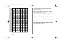 100
100
-
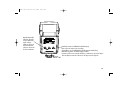 101
101
-
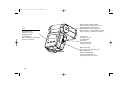 102
102
-
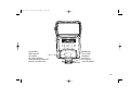 103
103
-
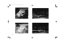 104
104
-
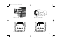 105
105
-
 106
106
-
 107
107
-
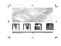 108
108


Metz mecablitz 54 AF-1 Minolta de handleiding
- Categorie
- Camera knippert
- Type
- de handleiding
- Deze handleiding is ook geschikt voor
in andere talen
Gerelateerde papieren
-
Metz mecablitz 54 AF-1 Canon de handleiding
-
-
-
-
-
-
Metz MECABLITZ 58 AF-1 DIGITAL de handleiding
-
Metz MECABLITZ 58 AF-1 Sony de handleiding
-
-