
NL
Cleo Steam Smart
Installatiehandleiding (p.2)
Item no: 90187003
NL2017/07 R01
1
Installation manual (p.34)
EN2017/07 R01
EN

2
Cleopatra B.V.
Oostzijde 295
1508 EN Zaandam
Nederland
Copyright
Alle informatie in dit technische document, evenals de tekeningen en technische
beschrijvingen beschikbaar gesteld door ons, blijven ons eigendom en mogen niet worden
gekopieerd zonder onze toestemming. Wij behouden ons het recht voor om wijzigingen
aan te brengen in het belang van verdere ontwikkelingen.
Actueel op: 20-07-2017
www.cleopatra.nl
www.cleopatra-wellness.com
Info@cleopatra.nl

3
Inhoudsopgave
Installatiehandleiding
1 Voorwoord en veiligheid .......................................................................................4
2 Waarschuwingen ................................................................................................. 5
3 Benodigd gereedschap .........................................................................................6
4 Overzicht stoomgenerator .....................................................................................7
5 Stoomgenerator afmetingen ...................................................................................8
6 Installatie in de technische ruimte ...........................................................................9
7 Montage op de wand ...........................................................................................9
8 Vervolg montage op de wand .............................................................................10
9 Water aansluiting en afvalwater ..........................................................................11
10 Elektrische aansluiting .........................................................................................12
10.1 Vervolg elektrische aansluiting ....................................................................13
11 Stoomleiding .....................................................................................................14
12 Overzicht sensoren .............................................................................................15
13 Overzicht bediening ........................................................................................... 15
14 Overzicht stoominlaat ......................................................................................... 16
15 Componenten plaatsen in de cabine ....................................................................16
15.1 Uitleg freesgaten ......................................................................................17
15.2 Uitleg kabels leggen .................................................................................18
15.3 Afwerken ................................................................................................. 19
15.4 Tegel uitslijpen t.b.v. sensoren.....................................................................19
15.5 Tegel uitslijpen t.b.v. bediening ..................................................................21
15.6 Tegels uitslijpen t.b.v. stoominlaat ...............................................................22
16 Sensoren installeren ............................................................................................23
17 Bediening installeren ..........................................................................................24
18 Stoominlaat installeren ........................................................................................ 24
19 Overzicht controlbox ..........................................................................................25
19.1 Aansluiten bediening, temperatuur- en safety sensor ......................................26
19.2 Aansluiten LED verlichting (optie) ................................................................27
20 Overzicht control-, powerbox en LED verlichting .....................................................28
20.1 Overzicht control- en powerbox ..................................................................29
20.2 Overzicht LED verlichting (optie) .................................................................30
20.3 Verlichting wit (optie) .................................................................................31
21 Terug plaatsen deksel en kap ...............................................................................32
22 Comformiteitsverklaring ......................................................................................33

4
Deze instructies zijn bedoeld voor de installateur. Lees deze instructies goed door om het
product, de onderdelen en de installatie methodiek te leren kennen. De Cleo Steam Smart
stoomgenerator moet worden geïnstalleerd door gekwalificeerde en goed opgeleid personeel.
De Cleo Steam Smart stoomgenerator voldoet aan de geldende Europese normen en
voorschriften en levert geen directe gevaren voor de gebruiker op indien de Cleo Steam Smart
stoomgenerator is geïnstalleerd volgens de instructies van de fabrikant en in navolging van deze
handleiding wordt gebruikt. De elektronische en mechanische onderdelen moeten zorgvuldig
worden onderhouden zodat de Cleo Steam Smart stoomgenerator volledig operationeel blijft.
Om deze reden moeten de instructies nauwgezet worden gevolgd.
Alle informatie en instructies in deze handleiding zijn samengesteld met inachtneming van de
geldende normen en voorschriften, de stand van de techniek en onze jarenlange ervaring en
bevindingen. Nationale en lokale voorschriften moeten worden opgevolgd.
Kijk het product na op eventuele transportschade. Na de installatie zal een vordering tot
(oppervlakte) beschadigingen niet door Cleopatra worden aanvaard.
Elk recht op garantie komt te vervallen als er aanpassingen aan het originele product, of
onderdelen daarvan, zijn gemaakt. Deze handleiding moet dicht bij het product worden
gehouden voor een snelle toegang als dat nodig is.
Gebruik schroeven en pluggen om de Cleo Steam Smart stoomgenerator aan de muur te
hangen. Muren die de Cleo Steam Smartstoomgenerator ondersteunen moeten sterk genoeg
zijn om het gewicht te kunnen dragen anders moeten deze worden versterkt. De meegeleverde
pluggen en schroeven zijn bedoeld voor gebruik en beton of massief stenen muren. Indien de
muren zijn vervaardigd van een ander materiaal gebruik dan materiaal dat geschikt is voor dat
specifieke wand type. (niet bij levering inbegrepen)
Cleopatra aanvaardt geen aansprakelijkheid voor schade veroorzaakt door:
- Het niet in acht nemen van de handleiding.
- Onjuist gebruik.
- Installatie door niet gekwalificeerd personeel.
- Ongeautoriseerde wijzigingen aan het product.
- Technische wijzigingen.
- Het gebruik van niet originele reserve onderdelen.
Correct gebruik:
- De Cleo Steam Smart stoomgenerator mag alleen binnenshuis worden gebruikt.
- Gebruik op een andere wijze is niet toegestaan en is voor eigen risico van de gebruiker.
- Gebruik de Cleo Steam Smart niet wanneer deze niet perfecte staat verkeerd.
- Gebruik dit product niet in een omgeving waar het wordt blootgesteld aan corrosie.
1 Voorwoord en veiligheid
Let op: Algemeen gevaar
Belangrijke instructie of beschrijving

5
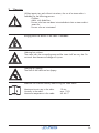
2 Waarschuwingen
Zonder toestemming en zonder aanwijzingen is het gebruik van de
stoomcabine voor de volgende personen verboden:
- Kinderen.
- Volwassenen met psychische, mentale en/of sensorische
beperkingen.
- Personen die niet geïstrueerd zijn, over waar de stoomcabine voor
bedoeld is.
- Personen onder invloed van alcohol of drugs.
Stoomcabine alleen betreden zonder make-up.
Het meebrengen van elektrische apparaten in de cabine is verboden!
Waarschuwing hete oppervlakken.
De stoominlaat, maar ook de nabije omgeving hiervan zijn heel heet. Niet
aanraken i.v.m. verbrandingsgevaar. Niet direct de hete damp aanraken
i.v.m. verbrandingsgevaar.
Waarschuwing voor uitglijden.
De bodem van de cabine kan glad zijn.
Voor het gebruik van de stoomcabine moet de gebruikshandleiding
zorgvuldig worden doorgelezen!
Maximale verblijfstijd in de cabine: 15 min
Luchtvochtigheid in de cabine: max. 100%
Maximale temperatuur in de cabine: 45 - 48 ˚C

6
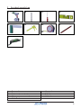
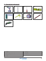
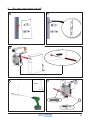
3 Benodigd gereedschap
3: Schroevendraaier kruiskop
2: Boorset
6: Kit pistool 1: Boor machine
4: Waterpas
8: Potlood
5: Winkelhaak
7: Meetlint
9: Multitool
2 3
1
4
6 75 8
9

7
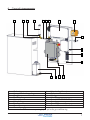
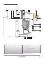
4 Overzicht stoomgenerator
A: Omkasting
E: Stoomuitlaat
F: Waterleiding
J: Waterleiding Kraantje
G: Transformator
H: Controlbox
I: Geurstofpomp*
K: Elektronica box
L: Kabelgoot
M: Kabelklem
N: Drain (NIET VERVORMEN)
*Alleen van toepassing bij de optionele geurstofdosering
A
H
GC
F
J
L
I
M
Q P
O
O: Stoomgenerator
P: Geurstof Reservoir*
Q: Geurstof Reservoir Houder*
N
D
B
K
B: Stoomuitlaat kniekoppeling
C: Slangklem
D: Flexibele slang
E

8
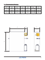
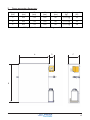
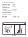
5 Stoomgenerator afmetingen
Vermogen
(kW)
A
(mm)
B
(mm)
C
(mm)
D*
(mm)
Gewicht
(kg)
3 532 710 190 90 +/-17 kg
6 532 710 190 90 +/-17 kg
9 532 710 190 90 +/-17 kg
A
B
C
D
*Alleen van toepassing bij de optionele geurstofdosering
Stoomuitlaat
(Ø)
22
22
28

9
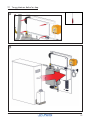
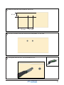
6 Installatie in de technische ruimte
1
Hanteer de minimale afstanden zoals weergegeven in de tekening.
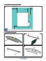
7 Montage op de wand
1
2
3 4
200 mm
200 mm
100 mm
X
X: Ruimte voor waterafvoer en sifon

10
5
6
7
8
9
8 Vervolg montage op de wand
m8
8mm

11
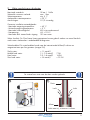
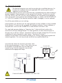
9 Water aansluiting en afvalwater
Lucht moet vrij uitstromen in afvoer
Drain
Afvoer
Lucht Lucht
Maximale waterdruk: 10 bar / 1 MPa
Waterdruk wanneer werkend: max. 1 bar
Watertemperatuur: min. 5 ˚C
Aanbevolen watertemperatuur: < 20 ˚C
Aansluitingen: G 1/2 uitwendig
Gewenste installatie omstandigheden:
- Maximale omgevingstemperatuur: + 40 ˚C
- Minimale omgevingstemperatuur: + 5 ˚C
- Maximale luchtvochtigheid: 80% niet condenserend
- Netspanning: -8% + 10% P
- Maximale druk stoomcilinder uitgang: 100 mm water
Water kwaliteit: De Cleo Steam Smart generatoren kunnen gebruik maken van zowel hard als
zacht water. Aanbevolen is onbehandeld leidingwater.
Waterhardheid: De waterhardheid wordt naar de internationale Millimol/l calcium en
magnesiumionen per liter gemeten (vroeger DH)
Zacht water: < 1.3 mmol/l
Middel hard water: 1.3 - 2.5 mmol/l 7 DH
Hard water: 2.5 - 3.8 mmol/l 14 DH
Zeer hard water: > 3.8 mmol/l > 21 DH
De waterafvoer moet naar de drain worden gebracht.
1
2

12
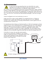
De elektrische aansluiting mag alleen door een erkend elektricien worden
uitgevoerd. Voor de elektrische installatie moeten de actuele van toepassing
zijnde VDE, land specifieke en EU-regelingen worden nageleefd.
Alle installatie- en testwerkzaamheden dienen door een erkend elektricien en volgens de laatste
normen te worden uitgevoerd. Stopcontacten moeten geaard zijn. Het elektriciteitsnetwerk (230
VAC 50Hz of 400 VAC 50 Hz) aan welke componenten zijn aangesloten, moeten voorzien zijn
van een 30 mA foutstroom beschermer (aardlekschakelaar), zoals gesteld in de DIN EN 60335-
2-41 / VDE 0700 norm. Als de elektrische aansluitkabel beschadigd is, moet deze vervangen
worden.
Schakel voorafgaand aan de werkzaamheden de stroom uit.
Lokale voorschriften moeten worden nageleefd. De stoomgenerator dient in de daarvoor
bedoelde ruimte te worden geïnstalleerd. Deze ruimte moet voorzien zijn van voldoende
ventilatie. Bij de installatie moet een meerpolige hoofdschakelaar worden ingebouwd met een
contactafstand van minimaal 3 mm.
De stoombad generatoren behoren tot “Beschermingsklasse I” (elektrische apparaten) en dienen
aangesloten te zijn via een aardlekschakelaar. De stoomgenerator moet, net als alle apparaten
uit klasse I volgens de juiste voorschriften zijn aangesloten. Onderdelen die een hoger voltage
hebben dan 12V moeten buiten handbereik van personen gemonteerd worden wegens
veiligheidsoverwegingen. Het elektriciteits schema is bijgevoegd. Alle verbindingen moeten
volgens dit schema worden gemaakt waarbij alle regionale en nationale voorschriften worden
nageleefd. Het werk mag alleen uitgevoerd worden door een daarvoor bevoegde elektricien.
In het elektrisch schema is de maximale aansluitwaarde
van de externe componenten weergegeven. Deze waarden
mogen niet worden overschreven. Er mogen geen aanpassingen
aan de originele bekabeling worden uitgevoerd. Externe
componenten mogen alleen aan de daarvoor bestemde
klemmen worden aangesloten.
Alle kabels aanleggen conform NEN 1010.
10 Elektrische aansluiting
Stroomonderbreker
(Niet in leveringsomvang)
Stroomaanvoer 230 / 400 V

13
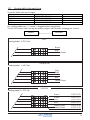
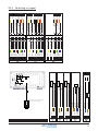
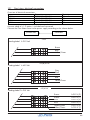
Overzicht elektrische aansluitingen.
Een voedingskabel van +/- 2 meter is meegeleverd en aangesloten.
Sluit de Cleo Steam Smart aan op de voeding volgens het hieronder weergegeven schema:
Vermogen Aansluiting Stroom
3 kW 230VAC-1N-50/60Hz 13A
4.5 kW 400VAC-1N-50/60Hz 13A
3 kW
Lasdoos
Generator
10.1 Vervolg elektrische aansluiting
9 kW 400VAC-1N-50/60Hz 13A
Brown
PE
N
L1
PE
N
L1
PE
N
L1
PE
N
L1
L2
L3
L2
L3
Blue
Yellow/Green
Brown
Blue
Yellow/Green
Black
Grey
9 kW 400VAC-1N-50/60Hz 13A
Voedingskabel: 1x 230 Volt
4.5/6/9 kW
Voedingskabel: 1x 400 Volt
PE
N
L1
PE
N
L1
L2
L3
L2
L3
Blue 1x 230 V (2)
Blue 1x 230 V (1)
Yellow/Green 1x 230 V (2)
Brown 1x 230 V (1)
Brown 1x 230 V (2)
4.5/6 kW
Voedingskabel: 2x 230 Volt
Yellow/Green 1x 230 V (1)

14
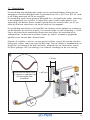
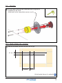
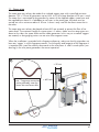
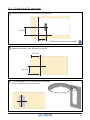
11 S t o o m l e i d i n g
1
> 600 mm
> 50 mm
Euca/Geurstof aansluit stuk
bij voorkeur in nabijheid van
de stoominlaat maar
bereikbaar
De stoomleiding moet altijd gemaakt worden van een geïsoleerde koperen leiding met een
aangegeven minimale leiding doosnede. Bij generatoren tot 6 Kw is dit 22 mm. Bij 9 Kw wordt
er een leiding doorsnede van 28 mm toegepast.
De stoomleiding wordt aan de generator gekoppeld d.m.v. de bijgeleverde, rubber, stoomslang
en de meegeleverde messing bocht. Er mogen beslist geen knieën worden gebruikt in de
stoomleiding. Alle bochten moeten worden uitgevoerd met een minimale radius van 50 mm.
Alleen bij de directe stoominlaat in de cabine wordt een knie toegepast.
De stoomleiding moet altijd eerst minimaal 600 mm omhoog worden geplaatst ter voorkoming
van de doorloop van heetwater druppels. De maximale lengte van een stoomleiding is 3 meter.
Zorg er altijd voor dat de stoomleiding afloopt naar twee kanten, de stoomuitlaat en de
stoomgenerator. Op deze manier ontstaan er geen zg. ‘zakkers’ waardoor er gorgelende
geluiden kunnen ontstaan door stilstaand water.
Wanneer de installatie is voorzien van een geurstof installatie, zorg er dan voor dat ook deze
leiding geen ‘zakkers’ heeft waarin geurstof blijft staan. Voor de kwaliteit en houdbaarheid van
de geurstof is het belangrijk dat deze rechtstreeks, aflopend naar het inlaatstuk kan stromen.
Een kleine ‘gebogen sifon’ (zie tekening) in het inlaatstuk waarborgt hier de juiste werking.

15
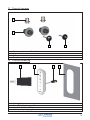
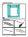
12 Overzicht sensoren
B: Inbouwdeel sensor
C: Safety sensor
A: Buisinvoer t.b.v. invoer flexibele buis
A
B
C D
D: Temperatuur sensor
13 Overzicht bediening
B: Steam Touch bediening
D: Mal t.b.v. uitsparing tegel
A: Verlengkabel vanuit stoomgenerator
C: Aansluitkabel Steam Touch
A
B DC
19101080

16
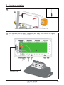
14 Overzicht stoominlaat
A
B
C
D
F
E
I H
G
J
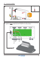
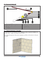
15 Componenten plaatsen in de cabine
A: Messing pijp Ø 22mm
B: Sifon t.b.v. geurstof toepassing
C: Kniestuk
D: Koppelbuis
E: Muurplaat
F: Stoomuitlaat
G: O-ring
H: Ring m6
J: Stoomkap
I: Bout m6x50
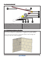
Om duidelijk te maken hoe de componenten in een cabine kunnen worden geplaatst,
geven we een voorbeeld. De voorbeeld cabine is opgebouwd uit gasbeton blokken.
Geef als eerste aan waar de diverse componenten komen en frees vervolgens de
uitsparingen zoals deze worden aangegeven.

17
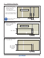
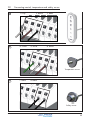
1
2
Min. 40 mm
Min. 140 mm
Frees een uitsparing voor
de buis voor de kabel
(t.b.v. de kabel) en het
inbouwdeel voor:
- De bediening
Frees twee uitsparingen
voor de buizen (t.b.v. de
kabels) en de inbouwdelen
voor:
- De safety sensor
- De temperatuur sensor
Ø 35mm
Min. 100mm
3
Frees een uitsparing voor
de buis voor:
- De stoominlaat
Min. 150 mm
Max. 180 mm
vanaf het
vloer oppervlak
Min. 70 mm
15.1 Uitleg freesgaten
Houd altijd een straal van 100 mm
vrij rondom een sensor.
Sensoren dienen 1,8 meter
vanaf het vloeroppervlak
geplaatst te worden
Min. diepte: 40mm
Min. diepte: 40mm

18
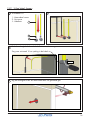
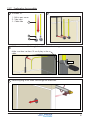
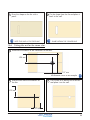
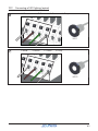
3
2
Trek de verlengkabel door de kabelbuis naar de stoomgenerator.
Zorg voor minimaal 10 cm speling in de kabel.
1
Assembleer 2x:
1 - Inbouwdeel sensor
2 - Buisinvoer
3 - Kabelbuis
1
2
3
4
15.2 Uitleg kabels leggen
Leg het leidingwerk van de stoominlaat door het gefreesde gat.
10 cm

19
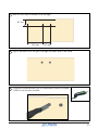
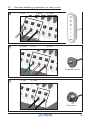
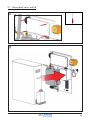
15.3 Afwerken
Stuc de wand
1
Stuc de wand en bevestig de stoominlaat met o-ring met de
wandplaat op de wand.
Achterzijde van de stoomuitlaat voorzien van kit.
1
15.4 Tegel uitslijpen t.b.v. sensoren
Meet de afstanden naar de hartlijnen van het gat.
61 mm
100 mm194 mm
Alle afstanden dienen als voorbeeld

20
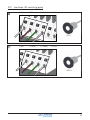
2
3
Meet en teken deze afstanden af op de tegel.
Slijp 2x met boor Ø25 een gat in de tegel en plaats deze in de wand.
100 mm194 mm
61 mm
4
Zaag het uitstekende deel van het inbouwdeel indien dit uitsteekt.
Gebruik hiervoor een multitool.

21
1
Meet de afstanden naar de hartlijnen van het gat.
140 mm
154 mm
Alle afstanden dienen als voorbeeld
15.5 Tegel uitslijpen t.b.v. bediening
2
Meet en teken deze afstanden af op de tegel.
154 mm
140 mm
3
Gebruik de mal: Maak hierbij gebruik van de uitsparingen van de mal. Deze komen
overeen met de hartlijnen.

22
4
5
Teken met een potlood de vorm op de
tegel.
Slijp de vorm uit de tegel en plaats
deze terug in de wand.
HOUD DEZE LIJN ALS BUITENLIJN SLIJP BINNEN DE GETEKENDE LIJN
Meet en teken de afstanden af op de
tegels
Slijp een ronde vorm van Ø 64mm uit
de tegels en plaats deze in de wand.
2
3
320 mm
137 mm
1
Meet de afstanden naar de hartlijnen van het gat.
15.6 Tegels uitslijpen t.b.v. stoominlaat
Alle afstanden dienen als voorbeeld
320 mm
137 mm

23
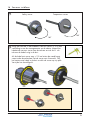
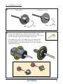
16 Sensoren installeren
1
180 ˚
180 ˚
2
Safety sensor Temperatuur sensor
Breng een trekveer in een kabelbuis van een sensor. Er is nu een
verbinding tussen de stoomgenerator en de cabine. Koppel het
kabeleinde van een sensor aan de trekveer en trek d.m.v. de
trekveer de kabel rustig in de buis.
Als de kabel met sensor nog +/- 30 cm buiten de wand hangt,
voorzie dan de achterkant van de sensor met siliconnekit. Trek
het laatste restje kabel in de buis en druk de sensor op zijn plek.
Verwijder het overtollige kit.

24
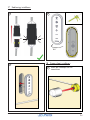
17 Bediening installeren
Klik
Klik
1
180 ˚
2
3
Plaats de stoomkap over de
stoominlaat
18 Stoominlaat installeren
1

25
19 Overzicht controlbox
1
2
Breng de kabels van de bediening, temperatuur- en safety sensor en de LED verlichting
(optie) van onder vandaan naar de CONNECTOR in de controlbox.
CONNECTOR
bediening
sensor
LED
sensor
LED

26
1
19.1 Aansluiten bediening, temperatuur- en safety sensor
2
3
1: Grijs 2: Bruin 3: Zwart
4: Groen 5: Wit 6: Bruin
7: Zwart 8: Zwart
Temperatuur sensor
Safety sensor

27
19.2 Aansluiten LED verlichting (optie)
1
2
1: Wit 2: Bruin 3: Groen 4: Grijs
1: Wit 2: Bruin 3: Groen 4: Grijs
LED 1
LED 2

28
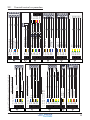
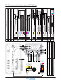
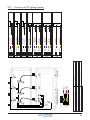
20 Overzicht control-, powerbox en LED verlichting
C4
C6
C3C2C1 C5
C7C8C9
C10
P4
P1
P7
Geel
Groen
Oranje
Rood
Bruin
Zwart
Zwart
Bruin
1
2
3
4
5
6
7
8
Bruin
Oranje
Groen
Paars
Zwart
Rood
Geel
Blauw
1: Communicatiekabel, 12x 0.5, 11.8 VDC
2: Voeding, 2x 0.75, 11.8 VDC
3: Waterinlaatventiel, 2x0.75, 11.5 VDC
4: Verwarmingselement 1, 3x 2.5, 230 VAC
5: Verwarmingselement 2, 3x 2.5, 230 VAC
8: Voeding, 6x 0.5, 11.5 VAC
9: Voeding Transformator, 2x 0.75, 230AC
10: Geurstofpomp, 2x 0.75, 230 VAC
12: Water level sensor, 3x 0.75, 11.8 VAC
11: Voeding, 3/5 x 2.5, 230/400 VAC
6: Verwarmingselement 3, 3x 2.5, 230 VAC 13: Voeding, 1x 0.75
P3P2
P8
9
Trafo
P5P6
C11
14
7: Aarde, 1x 2.5 14: Connector, 8x 0.5, 11.8 VDC
4
5
6
7
3 2 1
13
10
11
12
8
15
15: Drain 9kW, 3x 0.75, 220 V
11.5V 0.8A O utB
1 2 3 4 5 6 7 8 9
Heat OK
Waterlevel Min
GND 0.8A A
5 VDC
1 Wire TLL A
GND
Fragra nc e
12 11 10 9 8 7 6 5 4 3 2 1
12 11 10 9 8 7 6 5 4 3 2 1
1 2
Paars
C7
C8
C10
Grijs
Blauw
Rood
Wit
C4
C5
C6
Roze
Groen
Blauw
C1
C2
C3
1
1
1
14
14
14
1
1
1 2 3 4
C11
GND 0.8A Out
Gr/Rz
1
Zwart
3
11.8 V 0.8A Out
Rd/Bl
1
Bruin
14
Zie LED overzich t
Zie LED overzich t
Zie LED overzich t
Ther mo swit ch Cab in
Zwart
1
Waterlevel Max
Geel
1
2
1
3
4
9
1
3
9
Drain
Gr/Gl
2
Wate r Inl et O ut
Zwart
3
2
3
10
7
He at o n GN D
Groen
1
He at 1 O N
Bruin
1
He at 2 O N
Zwart
1
He at 3 O N
Roze
1
10
8
11
4
12 11 10 9 8 7 6 5 4 3 2 1
C9
Temp se ns VCC
Rood
14
Temp se ns G N D
Oranje
14
Temp se ns D a t a
Geel
14
8
9
7
11.5V 8A In
Bruin
2
GND 8A Out
Blauw
2
2
1

29
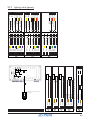
20.1 Overzicht control- en powerbox
PE In
L1 In
N In
L1 Trafo Out
Blauw
Bruin
Gr/Gl
Zwart
P1
P2
S
Zwart
11
11
11
13
9
4.5/6/9 kW: 11; Voeding 1x 400 VAC
11: Voeding, 3 x 2.5, 230 VAC
11a: Voeding, 3 x 2.5, 230 VAC
Kies de juiste P1/voeding die bij uw generator zit en volg de instructies.
L3 In
Grijs
11
L2 In
Zwart
11
PE In (2)
L1 In (1)
N In (1)
Blauw
Bruin
Gr/Gl
P1
S
Zwart
11
11
11a
13
4.5/6 kW: Voeding 2x 230 VAC
Gr/Gl
16
L2 In (2)
Bruin
11a
N In (2)
Blauw
11a
4
5
1
2
3
5
1
2
3
PE In (1 )
Gr/Gl
11
N Trafo Out
Bruin
9
1
2
11.5 V 0.8A InB
11.5 V 0.8A InA
11.5 V 8A In
Rood
Groen
Zwart
P3
8
8
8
11.5 V 8A In
Bruin
8
11.5 V 0.8A InA
Oranje
8
11.5 V 0.8A InB
Geel
8
1
2
3
4
5
6
11: Voeding, 3/5 x 2.5, 230/400 VAC
PE In
L1 In
N In
Blauw
Bruin
Gr/Gl
P1
S
Zwart
11
11
11
13
3 kW: 11; Voeding 1x 230 VAC
Grijs
Zwart
5
1
3
11: Voeding, 3/5 x 2.5, 230/400 VAC
Afdoppen
Afdoppen
3
3
1
3
5
5
11. 5V 0.8A O ut A
11. 5V 8A Out
11. 5 0.8A Out B
Rd/Bl
Grijs
Bruin
P4
1
1
2
GND 8A O ut
Blauw
2
1
2
GND 0.8A O ut B
Gr/Rz
1
3
5
6
Frangrance N
Brug
Brug
GND 0.8 Out A
Waterlevel Max
Heat OK
Water level Min
Heat3 On
Heat 1 On
He at On GND
Fragrance
Heat2 On
2
1
7
8
1011
13
14
18
19
20
Zwart
Geel
Blauw
Groen
Paars
Zwart
Zwart
Wit
Rood
Roze
Bruin
Blauw
P6
P7
1
1
1
1
1
1
1
1
1
SZwart
13
10
Drain
3
Gr/Gl
2
P9
PE In
Gr/Gl
16
Verw.
Gr/Gl
4
Gr/Gl
7
Verw.
Gr/Gl
5
Kete l
Verw.
Gr/Gl
6
Drain 9kWBlauw
15
Drain 9kWBruin
15
Fragrance NOBruin
10
6
5
4
SZwart
13
3
2
1
Heat3, NBlauw
P8
Heat1, NBlauw
4
6
Heat3, LBruin
6
Heat2, LBruin
5
Heat1, LBruin
4
6
5
4
Heat2, NBlauw
5
3
2
1
1
2
3
4
5
Watersensor Ref In
Watersensor Min In
Zwart
Grijs
P5
12
12
Watersensor Max In
Bruin
12
2
1
3

30
20.2 Overzicht LED verlichting (optie)
D1
1 2
C10
11.5V 8A In
Bruin
1
GND 8A Out
Blauw
1
2
1
Rel. Roo d NO
Wit
C1
6
1 2 3 4
Rel. Rood C
Rood
6
2
3
Rel. G ro e n N O
Geel
C2
4
1 2 3 4
Rel. Gro e n C
Groen
4
2
3
Rel. Blauw NO
Zwart
C3
5
1 2 3 4
Rel. Blauw C
Blauw
5
2
3
6 5 4 3 2 1
11.5V G N D O u t
Blauw
1
11.5 GND In
Blauw
2
4
5
11.5 8A In
Bruin
2
11.5V 8A Out
Bruin
1
1
2
D2
6 5 4 3 2 1
11.5V G N D O u t
Blauw
3
11.5 GND In
Blauw
2
4
5
11.5 8A In
Bruin
3
11.5V 8A Out
Bruin
2
1
2
D3
6 5 4 3 2 1
11.5 GND In
Blauw
3
4
11.5V 8A Out
Bruin
3
1
C3
C2
C1
D1
D2 D3
D6D5D4
1
2
3
4
5
6
7
8
Bruin
Oranje
Groen
Paars
Zwart
Rood
Geel
Blauw
9/10/11
C10
1
7 8
2 3
9
10
11
5
4
6
1: Voeding, 2x 0.75, 11.8 VDC
2: Voeding, 2x 0.75, 11.8 VDC
3: Voeding, 2x 0.75, 11.8 VDC
4: Schakel, 2x 0.5
5: Schakel, 2x 0.5
7: Koppel, 3x 0.5
8: Koppel, 3x 0.5
9: Connector, 8x 0.5
11: Connector, 8x 0.5
10: Connector, 8x 0.5
6: Schakel, 2x 0.5

31
1: Aansluitkabel verlichting - controllebox
2: Geschakelde uitgang 11.8 V
C3C2C1
2
3
E1
1
4
Deze stekker past op de bijgeleverde
kabel van de witte verlichting.
3: Centrale voeding 11.5V 8A
4: Centrale voeding GND 8A Out
C10
20.3 Verlichting wit (optie)
GND 8A
Blauw
E1
Zwart
1
2
Zwart
1
Bruin
11. 5 V 8A
4
*Afkomstig uit powerbox d.m.v. kabel “powerbox 2”, connector P4
1 2
C10
11.5V 8A
Bruin
GND 8A
Blauw
p4-1*
2
1
Bruin
C1
3
1 2 3 4
Zwart
2
2
3
Bruin
C2
3
1 2 3 4
Zwart
2
2
3
Bruin
C3
3
1 2 3 4
Zwart
2
2
3
11.5V 8A
Bruin
3
1
GND 8A
Blauw
2
p4-2*
3
D4
LED1 B
Zwart
9
Rel. Gro en NO
12
Geel
4
Rel. Bla uw C
13
Blauw
5
Rel. Groen C
11
Groen
4
Rel. Blauw NO
14
Zwart
5
Rel. Rood C
15
Rood
6
LED2 R
Blauw
9
Rel. Rood NO
5
Wit
7
Rel. Blauw NO
7
Zwart
7
LED1 R
2
Rood
9
LED1 G
3
Bruin
9
LED1 Anode
1
Oranje
9
LED2 Ano de
Paars
9
Rel. Roo d NO
16
Wit
6
LED2 B
17
Geel
9
LED2 G
Groen
9
Rel. Groen NO
9
Geel
7
18
19
20
1 2 3 4 5 6 7 8 9 10
11 12 13 14 15 16 17 18 19 20
4
D5
LED3 B
Zwart
10
Rel. Gro en NO
12
Geel
7
Rel. Blauw NO
14
Zwart
7
LED4 R
Blauw
10
Rel. Rood NO
5
Wit
8
Rel. Blauw NO
7
Zwart
8
LED3 R
2
Rood
10
LED3 G
3
Bruin
10
LED3 Anode
1
Oranje
10
LED4 Ano de
Paars
10
Rel. Roo d NO
16
Wit
7
LED4 B
17
Geel
10
LED4 G
Groen
10
Rel. Groen NO
9
Geel
8
18
19
20
1 2 3 4 5 6 7 8 9 10
11 12 13 14 15 16 17 18 19 20
4
D6
LED5 B
Zwart
11
Rel. Gro en NO
12
Geel
8
Rel. Blauw NO
14
Zwart
8
LED6 R
Blauw
11
LED5 R
2
Rood
11
LED5 G
3
Bruin
11
LED5 Anode
1
Oranje
11
LED6 An ode
Paars
11
Rel. Roo d NO
16
Wit
8
LED6 B
17
Geel
11
LED6 G
Groen
11
18
19
20
1 2 3 4 5 6 7 8 9 10
11 12 13 14 15 16 17 18 19 20
4

32
21 Terug plaatsen deksel en kap
1
2

33
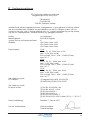
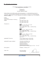
EG-Comformiteitsverklaring conform de
laagspanningsrichtlijn 2014/35/Eu
Cleopatra B.V.
Oostzijde 295
1508 EN Zaandam, Holland
verklaart hierbij dat de volgende beschreven stoomgenerator in onze geleverde uitvoering voldoen
aan de juiste elementaire veiligheids- en gezondheidseis van de EG-richtlijnen op basis van zijn
ontwerp en het type, zoals in omloop gebracht door ons. in geval van aanpassing van het product,
niet met ons overeengekomen, zal deze verklaring zijn geldigheid verliezen.
Product: Stoomgenerator
Bedoeld gebruik: Persoonlijke hygiene
Systeem van het conformiteitscertificaat: 4
Modellen: Cleo Steam Smart 3 kW
Cleo Steam Smart 6 kW
Cleo Steam Smart 9 kW
Eigenschappen: 3 kW
230 V, 1N, AC, 50Hz, max. 3 kW
Max. 14.3A, IPx4 (inside)
IP20 (outside), Class 1, Max. 1,0 MPa (10 bar)
Max. 80 ˚C
6 kW
400 V, 3N, AC, 50Hz, max. 6 kW
Max. 12,5A, IPx4 (inside)
IP20 (outside), Class 1, Max. 1,0 MPa (10 bar)
Max. 80 ˚C
9 kW
400 V, 3N, AC, 50Hz, max. 9 kW
Max. 12,5A, IPx4 (inside)
IP20 (outside), Class 1, Max. 1,0 MPa (10 bar)
Max. 80 ˚C
Van toepassing zijnde
EG-richtlijnen: (1) Laagspanningsrichtlijn 2014/35/EU
(2) EMV-Richtlijn (EMC) 2014/30/EU
Van toepassing zijnde
Europese normen: (1) DIN EN 60335-2-98-1-A2
(1) DIN EN 60335 -1: 2014
(2) DIN EN 61000-6-1
(2) DIN EN 61000-6-3
(2) DIN EN 62233:2008-11
(2) DIN EN 60335-1:2012-10 delen 19.11.4.1 - 19.11.4.7
Datum handtekening Zaandam, 1 Februari 2017
Titel van ondertekenaar: Niels Nieuweboer
General Manager
22 Comformiteitsverklaring

34
Installation manual

35
Cleopatra B.V.
Oostzijde 295
1508 EN Zaandam
Netherlands
www.cleopatra.nl
www.cleopatra-wellness.com
Info@cleopatra.nl
Copyright
All information in this technical document, together with the drawings and technical
specifications made available by Cleopatra B.V., remain the property of Cleopatra B.V. and
may not be copied without permission. Cleopatra B.V. reserves the right to make changes in
the interest of further developments.
Up to date on: 20-07-2017

36
Table of contents
Installation manual
1 Introduction and safety ........................................................................................37
2 Warnings ........................................................................................................38
3 Required tools and materials................................................................................39
4 Steam generator overview ...................................................................................40
5 Steam generator dimensions ................................................................................41
6 Installation in the technical area ........................................................................... 42
7 Mounting on the wall ..........................................................................................42
8 Next steps: mounting on the wall .........................................................................43
9 Water connection and waste water ......................................................................44
10 Electrical connection ........................................................................................... 45
10.1 Next steps: electrical connections ...............................................................46
11 Steam pipe ........................................................................................................47
12 Overview of sensors ...........................................................................................48
13 Overview operation ...........................................................................................48
14 Overview of steam inlet ......................................................................................49
15 Placing components in the cabin ........................................................................49
15.1 Explanation milling holes ...........................................................................50
15.2 Explanation laying cables .......................................................................... 51
15.3 Finishing ..................................................................................................52
15.4 Cuting tiles off for sensors ..........................................................................52
15.5 Cutting tiles off for the control .....................................................................54
15.6 Cutting tiles out for the steam inlet ...............................................................55
16 Installation of sensors ..........................................................................................56
17 Installation of control ..........................................................................................57
18 Installation of steam inlet .....................................................................................57
19 Overview of control box .....................................................................................58
19.1 Connecting control, temperature and safety sensor .......................................59
19.2 Connecting of LED lighting (option) .............................................................60
20 Overview control, power box and LED lighting ......................................................61
20.1 Overview control and power box ...............................................................62
20.2 Overview of LED lighting (option) ...............................................................63
20.3 Lighting white (option) ...............................................................................64
21 Placing back cover and lid ..................................................................................65
22 Declaration of conformity ....................................................................................66

37
These instructions are intented for the installer. Read these instructions carefully to get to know
the product, the parts and the installation method. The Cleo Steam Smart steam generator must
be installed by qualified and well-trained personnel.
The Cleo Steam Smart steam generator complies with the applicable standards and regulations
and does not pose any direct danger for the user if the Cleo Steam Smart is installed according
to the manufacturer’s instructions and is used in accordance with this manual. The electronic and
mechanical parts must be carefully maintained so that the tileable cabin remains fully
operational. For this reason, the instructions must be followed closely.
All information and instructions in this manual have been compiled in accordance to the
applicable standards and regulations, the current technique and our years of experience and
findings. National and local regulations must be followed.
Check the product for possible transport damage. After the installation, a claim for (surface)
damage will not be accepted by Cleopatra.
Every right to warranty expires if adjustments have been made to the original product or parts.
This manual must be kept close to the product for quick access if needed.
Use screws and plugs to mount the Cleo Steam Smart on the wall. Walls that support the Cleo
Steam Smart must be strong enough to carry the weight; otherwise they need to be
strengthened. The supplied plugs and screws are intended for use on concrete or solid stone
walls. If the walls are made of a different material than concrete or solid stones, use material
that is suitable for that specific wall. (not included in delivery).
Cleopatra accepts no liability for damage caused by:
- Failure to follow the manual.
- Wrong use.
- Installation by unqualified personnel.
- Unauthorized changes to the product.
- Technical changes.
- The use of non-original spare parts.
Correct use:
- The Cleo Steam Smart may only be used indoors.
- Use in another way is not permitted and is for the user’s own risk.
- Do not use the Cleo Steam Smart when it is not in perfect condition.
- Do not use this product in an environment where it is exposed to corrosion.
1 Introduction and safety
Important instruction or description
Pay attention: General danger

38
2 Warnings
Without permission and without instructions, the use of a steam cabin is
forbidden for the following persons:
- Children.
- Adults with disabilities.
- Persons who have not been instructed about what a steam cabin is
meant for.
- Persons who are intoxicated.
Bringing electrical devices in the cabin is forbidden!
Warning hot surfaces.
The steam inlet, the surrounding area and the steam itself are very hot. Do
not touch them because of danger of injuries.
Warning for slipping.
The floor of the cabin can be slippery.
Read the user manual carefully before using the steam cabin!
Maximum time to stay in the cabin: 15 min
Humidity in the cabin: max. 100%
Maximum temperature in the cabin: 45- 48 ˚C

39
3 Required tools and materials
3: Screwdriver (cross)
2: Drill set
6: Kit gun 1: Drill
4: Spirit level
8: Pencil
5: Square
7: Tapeline
9: Multitool
2 3
1
4
6 75 8
9

40
4 Steam generator overview
A: Casing
E: Steam outlet
F: Water pipe
J: Water pipe tap
G: Transformer
H: Control box
I: Fragrance pump*
K: Electronics box
L: Cable tray
M: Cable clamp
N: Drain (DO NOT DEFORM)
*Only applicable with the optional fragrance dispenser
A
H
GC
F
J
L
I
M
Q P
O
O: Steam generator
P: Fragrance reservoir*
Q: Fragrance reservoir holder*
N
D
B
K
B: Steam outlet knee fitting
C: Hose clamp
D: Flexible hose
E

41
5 Steam generator dimensions
Power
(kW)
A
(mm)
B
(mm)
C
(mm)
D*
(mm)
Weight
(kg)
3 532 710 190 90 +/-17 kg
6 532 710 190 90 +/-17 kg
9 532 710 190 90 +/-17 kg
A
B
C
D
*Only applicable with the optional fragrance dispenser
Steam outlet
(Ø)
22
22
28

42
6 Installation in the technical area
1
Use the minimum distances as shown in the drawing.
7 Mounting on the wall
1
2
3 4
200 mm
200 mm
100 mm
X
X: Space for water drainage and
siphon

43
5
6
7
8
9
8 Next steps: mounting on the wall
m8
8mm

44
9 Water connection and waste water
Air must flow freely into the drain.
Drain
Drain
Air Air
Maximum water pressure: 10 bar / 1 MPa
Water pressure when working: max. 1 bar
Water temperature: min. 5 ˚C
Recommended water temperature: < 20 ˚C
Connections: G 1/2 external
Desired installation conditions:
- Maximum ambient temperature: + 40 ˚C
- Minimum ambient temperature: + 5 ˚C
- Maximum humidity: 80% not condensing
- Main voltage: -8% + 10% P
- Maximum pressure steam cylinder exit: 100 mm water
Water quality: The Cleo Steam Smart generators can use both hard and soft water.
Recommended is untreated tap water.
Water hardness: The water hardness is measured to the international Millimol / l calcium and
magnesium ions per liter (former DH).
Soft water: < 1.3 mmol/l
Medium hard water: 1.3 - 2.5 mmol/l 7 DH
Hard water: 2.5 - 3.8 mmol/l 14 DH
Very hard water: > 3.8 mmol/l > 21 DH
The water drainage must be brought to the drain.
1
2

45
The electrical connection may only be carried out by a qualified electrician. For
the electrical installation the current applicable VDE, country specific and EU
regulations must be observed.
All installation and test activities must be carried out by a qualified electrician and according to
the latest standards. Electrical outlets must be equiped with a breaker. The electricity network
(230 VAC 50Hz or 400 VAC 50 Hz) to which components are connected must be equipped
with a 30 mA fault current protector (earth leakage breaker), as stated in the DIN EN 60335-2-
41 / VDE 0700 standard. If the electrical connection cable is damaged, it must be replaced.
Turn off the power before you start working.
Local regulations must be observed. The steam generator must be installed in an area intended
for this purpose. This area must be equipped with adequate ventilation. During installation, a
multi-pole main switch must be installed with a contact distance of at least 3 mm.
The steam bath generator belongs to “Protection class I” (electrical divices) and must be
connected via an earth leakage breaker. The steam generator must be connected correct in
the same way as all Class I devices. Components that have a higher voltage than 12V must be
installed out of reach of people for safety reasons. The electricity scheme is
attached. All connections must be done according to this scheme, respecting all regional and
national regulations. The work may only be carried out by a qualified electrician.
In the electrical scheme the maximum connection value
of the external components is shown. These values may not
be exceeded. No modification may be made to the
original wiring. External components may only be
connected to the appropriate clamps.
Connect all cables in accordance with NEN 1010.
10 Electrical connection
Circuit breaker
(Not included in delivery)
Electricity supply 230 / 400 V

46
Overview of electrical connections.
A power cable of +/- 2 meters is included and connected.
Connect the Cleo Steam Smart to the power supply according to the scheme below:
Power Connection Electricity
3 kW 230VAC-1N-50/60Hz 13A
4.5 kW 400VAC-1N-50/60Hz 13A
3 kW
Junction box
Generator
10.1 Next steps: electrical connections
9 kW 400VAC-1N-50/60Hz 13A
Brown
PE
N
L1
PE
N
L1
PE
N
L1
PE
N
L1
L2
L3
L2
L3
Blue
Yellow/Green
Brown
Blue
Yellow/Green
Black
Grey
9 kW 400VAC-1N-50/60Hz 13A
Voedingskabel: 1x 230 Volt
4.5/6/9 kW
Voedingskabel: 1x 400 Volt
PE
N
L1
PE
N
L1
L2
L3
L2
L3
Blue 1x 230 V (2)
Blue 1x 230 V (1)
Yellow/Green 1x 230 V (2)
Brown 1x 230 V (1)
Brown 1x 230 V (2)
4.5/6 kW
Voedingskabel: 2x 230 Volt
Yellow/Green 1x 230 V (1)

47
11 Steam pipe
1
> 600 mm
> 50 mm
Euca / Fragrance connection
piece preferably near the
steam inlet and accessible
The steam pipe must always be made of an isolated copper pipe with a specified minimum
diameter. This is 22 mm for generators up to 6 kW. At 9 kW a pipe diameter of 28 mm is used.
The steam line is connected to the generator by means of the supplied rubber, steam hose and
the supplied brass bend. It is forbidden to use knees in the steam pipe. All bends must be
carried out with a minimum radius of 50 mm. A knee is only used for the direct steam inlet in
the cabin.
The steam pipe must always be placed at least 600 mm upwards to prevent the flow of hot
water drops. The maximum length of a steam pipe is 3 meters. Make sure the steam pipe runs
down to two sides: the steam outlet and the steam generator. In this way no so-called ‘saggers’
are created, so that gurgling noises can not arise from stagnant water.
When the installation is provided with a fragrance dispenser, make sure that this pipe does not
have any ‘sagger’ in which fragrance remains. For the quality and longevite of the fragrance it
is important that it can flow directly downwards to the inlet piece. A small ‘curved siphon’ (see
drawing) in the inlet piece guarantees the correct operation.

48
12 Overview of sensors
B: Built-in part sensor
C: Safety sensor
A: Tube input for the purpose of putting in flexible tube
A
B
C D
D: Temperature sensor
13 Overview operation
B: Steam Touch control
D: Mold for the purpose of the recess tile
A: Extension cable from steam generator
C: Connection cable Steam Touch
A
B DC
19101080

49
14 Overview of steam inlet
A
B
C
D
F
E
I H
G
J
15 Placing components in the cabin
A: Brass pipe Ø 22mm
B: Siphon for fragrance application
C: Knee piece
D: Coupling tube
E: Wall plate
F: Steam outlet
G: O-ring
H: Ring m6
J: Steam hood
I: Bolt m6x50
To make clear how the components can be placed in a cabin, we give an example. The
example cabin is made up of aerated concrete blocks.
First indicate the position of the various components and then cut the recesses as they are
indicated.

50
1
2
Min. 40 mm
Min. 140 mm
Mill two cut-outs for the
pipes (for the cables) and
the built-in part for:
- The control
Mill two cut-outs for the
pipes (for the cables) and
the built-in parts for:
- The safety sensor
- The temperature sensor
Ø 35mm
Min. 100mm
3
Mill a recess for the pipe:
- The steam inlet
Min. 150 mm
Max. 180 mm
from the floor
surface
Min. 70 mm
15.1 Explanation milling holes
Always keep a radius of 100 mm
around a sensor.
Sensors should be placed 1.8
meters from the floor surface.
Min. depth: 40mm
Min. depth: 40mm

51
3
2
Pull the extension cable through the cable tube to the steam generator.
Make sure there isat least 10 cm of play in the
cable.
1
Assemble 2x:
1 - Built-in part sensor
2 - Tube input
3 - Cable tube
1
2
3
4
15.2 Explanation laying cables
Place the piping of the steam inlet through the milled hole.
10 cm

52
15.3 Finishing
Stuc de wand
1
Plaster the wall and fix the steam inlet with o-ring with the wall
plate on the wall.
Lubricate kit on the back of the steam inlet.
1
15.4 Cuting tiles off for sensors
Measure the distances to the center lines of the hole.
61 mm
100 mm194 mm
All distances serve as an example

53
2
3
Measure and mark these distances on the tile.
Cut off 2x a hole in the tile with drill Ø25 and place it in the wall.
100 mm194 mm
61 mm
4
Saw parts that stick out. Use a multitool for this.

54
1
Measure the distances to the centerlines of the hole.
140 mm
154 mm
All distances serve as an example
15.5 Cutting tiles off for the control
2
Measure and mark these distances on the tile.
154 mm
140 mm
3
Use the template: Use the cut outs of the template.
These correspond to the center lines.

55
4
5
Draw the shape on the tile with a
pencil.
Cut the shape from the tile and place it
back in the wall.
KEEP THIS LINE AS OUTSIDE LINE SHARP WITHIN THE SIGNED LINE
Measure and mark the distances on
the tiles
Cut a circle of Ø 64mm out of the tiles
and place it on the wall.
2
3
320 mm
137 mm
1
Measure the distances to the centerlines of the hole.
15.6 Cutting tiles out for the steam inlet
All distances serve as an example
320 mm
137 mm

56
16 Installation of sensors
1
180 ˚
180 ˚
2
Safety sensor Temperature sensor
Insert a tension spring into a cable tube of a sensor. There is now
a connection between the steam generator and the cabin.
Connect the cable end of a sensor to the tension spring and use
the draw spring to gently pull the cable into the tube.
If the cable with sensor is still about 30 cm outside the wall,
provide the back of the sensor with silicone kit. Pull the last
remaining cable into the tube and press the sensor into place.
Remove the excess kit.

57
17 Installation of control
Klik
Klik
1
180 ˚
2
3
Place the steam cover on/
over the steam inlet
18 Installation of steam inlet
1

58
19 Overview of control box
1
2
Bring the cables from the control, temperature and safety sensor and the LED lighting
(option) from below to the CONNECTOR in the control box.
CONNECTOR
control
sensor
LED
sensor
LED

59
1
19.1 Connecting control, temperature and safety sensor
2
3
1: Grey 2: Brown 3: Black
4: Green 5: White 6: Brown
7: Black 8: Black
Temperature sensor
Safety sensor

60
19.2 Connecting of LED lighting (option)
1
2
1: White 2: Brown 3: Green 4: Grey
1: White 2: Brown 3: Green 4: Grey
LED 1
LED 2

61
20 Overview control, power box and LED lighting
C4
C6
C3C2C1 C5
C7C8C9
C10
P4
P1
P7
Yellow
Green
Orange
Red
Brown
Black
Black
Brown
1
2
3
4
5
6
7
8
Brown
Orange
Green
Purple
Black
Red
Yellow
Blue
1: Comm. cable, 12x 0.5, 11.8 VDC
2: Power, 2x 0.75, 11.8 VDC
3: Water inlet valve, 2x0.75, 11.5 VDC
4: Heating element 1, 3x 2.5, 230 VAC
5: Heating element 2, 3x 2.5, 230 VAC
8: Power, 6x 0.5, 11.5 VAC
9: Power Transformator, 2x 0.75, 230AC
10: Fragrance pump, 2x 0.75, 230 VAC
12: Water level sensor, 3x 0.75, 11.8 VAC
11: Power, 3/5 x 2.5, 230/400 VAC
6: Heating element 3, 3x 2.5, 230 VAC
13: Power, 1x 0.75
P3P2
P8
9
Trafo
P5P6
C11
14
7: Earth 1x 2.5 14: Connector, 8x 0.5, 11.8 VDC
4
5
6
7
3 2 1
13
10
11
12
8
15
15: Drain 9kW, 3x 0.75, 220 V
11.5V 0.8A O utB
1 2 3 4 5 6 7 8 9
Heat OK
Waterlevel Min
GND 0.8A A
5 VDC
1 Wire TLL A
GND
Fragra nc e
12 11 10 9 8 7 6 5 4 3 2 1
12 11 10 9 8 7 6 5 4 3 2 1
1 2
Purple
C7
C8
C10
Grey
Blue
Red
White
C4
C5
C6
Pink
Green
Blue
C1
C2
C3
1
1
1
14
14
14
1
1
1 2 3 4
C11
GND 0.8A Out
Gr/Pi
1
Black
3
11.8 V 0.8A Out
Rd/Bl
1
Brown
14
Se e LED ove rview
Se e LED overview
Se e LED ove rview
Ther mo swit ch Cab in
Black
1
Waterlevel Max
Yellow
1
2
1
3
4
9
1
3
9
Drain
Gr/Ye
2
Wate r Inl et O ut
Black
3
2
3
10
7
He at o n GN D
Green
1
He at 1 O N
Brown
1
He at 2 O N
Black
1
He at 3 O N
Pink
1
10
8
11
4
12 11 10 9 8 7 6 5 4 3 2 1
C9
Temp se ns VCC
Red
14
Temp se ns G N D
Orange
14
Temp se ns D a t a
Yellow
14
8
9
7
11.5V 8A In
Brown
2
GND 8A Out
Blue
2
2
1

62
20.1 Overview control and power box
PE In
L1 In
N In
L1 Trafo Out
Blue
Brown
Gr/Ye
Black
P1
P2
S
Black
11
11
11
13
9
4.5/6/9 kW: 11; Power 1x 400 VAC
11:
Power, 3 x 2.5, 230 VAC
11a:
Power, 3 x 2.5, 230 VAC
Choose the right P1/power according to your generator and follow the instructions.
L3 In
Grey
11
L2 In
Black
11
PE In (2)
L1 In (1)
N In (1)
Blauw
Brown
Gr/Ye
P1
S
Zwart
11
11
11a
13
4.5/6 kW: Power 2x 230 VAC
Gr/Ye
16
L2 In (2)
Brown
11a
N In (2)
Blue
11a
4
5
1
2
3
5
1
2
3
PE In (1 )
Gr/Ye
11
N Trafo Out
Brown
9
1
2
11.5 V 0.8A InB
11.5 V 0.8A InA
11.5 V 8A In
Red
Green
Black
P3
8
8
8
11.5 V 8A In
Brown
8
11.5 V 0.8A InA
Orange
8
11.5 V 0.8A InB
Yellow
8
1
2
3
4
5
6
11: Power, 3/5 x 2.5, 230/400 VAC
PE In
L1 In
N In
Blue
Brown
Gr/Ye
P1
S
Black
11
11
11
13
3 kW: 11; Power 1x 230 VAC
Grey
Black
5
1
3
11: Power, 3/5 x 2.5, 230/400 VAC
Capping
Capping
3
3
1
3
5
5
11. 5V 0.8A O ut A
11. 5V 8A Out
11. 5 0.8A Out B
Rd/Bl
Grey
Brown
P4
1
1
2
GND 8A O ut
Blue
2
1
2
GND 0.8A O ut B
Gr/Pi
1
3
5
6
Frangrance N
Bridge
Bridge
GND 0.8 Out A
Waterlevel Max
Heat OK
Water level Min
Heat3 On
Heat 1 On
He at On GND
Fragrance
Heat2 On
2
1
7
8
1011
13
14
18
19
20
Black
Yellow
Blue
Green
Purple
Black
Black
White
Red
Pink
Brown
Blue
P6
P7
1
1
1
1
1
1
1
1
1
SBlack
13
10
Drain
3
Gr/Ye
2
P9
PE In
Gr/Ye
16
Verw.
Gr/Ye
4
Gr/Ye
7
Verw.
Gr/Ye
5
Kete l
Verw.
Gr/Ye
6
Drain 9kWBlue
15
Drain 9kWBrown
15
Fragrance NOBrown
10
6
5
4
SBlack
13
3
2
1
Heat3, NBlue
P8
Heat1, NBlue
4
6
Heat3, LBrown
6
Heat2, LBrown
5
Heat1, LBrown
4
6
5
4
Heat2, NBlue
5
3
2
1
1
2
3
4
5
Watersensor Ref In
Watersensor Min In
Black
Grey
P5
12
12
Watersensor Max In
Brown
12
2
1
3

63
20.2 Overview of LED lighting (option)
D1
1 2
C10
11.5V 8A In
Bruin
1
GND 8A Out
Blauw
1
2
1
Rel. Red N O
White
C1
6
1 2 3 4
Rel. Red C
Red
6
2
3
Rel. G reen NO
Yellow
C2
4
1 2 3 4
Rel. Gre e n C
Green
4
2
3
Rel. BlueNO
Black
C3
5
1 2 3 4
Rel. Blue C
Blue
5
2
3
6 5 4 3 2 1
11.5V G N D O u t
Blue
1
11.5 GND In
Blue
2
4
5
11.5 8A In
Brown
2
11.5V 8A Out
Brown
1
1
2
D2
6 5 4 3 2 1
11.5V G N D O u t
Brown
3
11.5 GND In
Brown
2
4
5
11.5 8A In
Bown
3
11.5V 8A Out
Brown
2
1
2
D3
6 5 4 3 2 1
11.5 GND In
Blue
3
4
11.5V 8A Out
Brown
3
1
C3
C2
C1
D1
D2 D3
D6D5D4
1
2
3
4
5
6
7
8
Brown
Oranjge
Green
Purple
Black
Red
Yellow
Blue
9/10/11
C10
1
7 8
2 3
9
10
11
5
4
6
1: Power, 2x 0.75, 11.8 VDC
2: Power, 2x 0.75, 11.8 VDC
3: Power, 2x 0.75, 11.8 VDC
4: Switch, 2x 0.5
5: Switch, 2x 0.5
7: Link, 3x 0.5
8: Link, 3x 0.5
9: Connector, 8x 0.5
11: Connector, 8x 0.5
10: Connector, 8x 0.5
6: Switch, 2x 0.5

64
20.3 Lighting white (option)
1: Con. cable light - control
2: Switched output 11.8 V
C3C2C1
2
3
E1
1
4
This plug fits with the supplied white
lighting cable.
3: Central power 11.5V 8A
4: Central power GND 8A Out
C10
GND 8A
Blue
E1
Zwart
1
2
Zwart
1
Brown
11. 5 V 8A
4
*Originated from powerbox as cable “powerbox 2”, connector P4
1 2
C10
11.5V 8A
Brown
GND 8A
Blue
p4-1*
2
1
Brown
C1
3
1 2 3 4
Black
2
2
3
Brown
C2
3
1 2 3 4
Black
2
2
3
Brown
C3
3
1 2 3 4
Black
2
2
3
11.5V 8A
Brown
3
1
GND 8A
Blue
2
p4-2*
3
D4
LED1 B
Balck
9
Rel. Gre en NO
12
Yellow
4
Rel. Blue C
13
Blue
5
Rel. Green C
11
Green
4
Rel. Blue NO
14
Black
5
Rel. Red C
15
Red
6
LED2 R
Blue
9
Rel. Red NO
5
White
7
Rel. Blue NO
7
Black
7
LED1 R
2
Red
9
LED1 G
3
Brown
9
LED1 Anode
1
Orange
9
LED2 Ano de
Purple
9
Rel. Red NO
16
White
6
LED2 B
17
Yellow
9
LED2 G
Green
9
Rel. Green NO
9
Yellow
7
18
19
20
1 2 3 4 5 6 7 8 9 10
11 12 13 14 15 16 17 18 19 20
4
D5
LED3 B
Zwart
10
Rel. Gre en NO
12
Yellow
7
Rel. Blue NO
14
Black
7
LED4 R
Blue
10
Rel. Rood NO
5
Wit
8
Rel. Blue NO
7
Zwart
8
LED3 R
2
Rood
10
LED3 G
3
Bruin
10
LED3 Anode
1
Oranje
10
LED4 Ano de
Purple
10
Rel. Red NO
16
White
7
LED4 B
17
Yellow
10
LED4 G
Green
10
Rel. Green NO
9
Geel
8
18
19
20
1 2 3 4 5 6 7 8 9 10
11 12 13 14 15 16 17 18 19 20
4
D6
LED5 B
Brown
11
Rel. Gro en NO
12
Yellow
8
Rel. Blauw NO
14
Black
8
LED6 R
Blue
11
LED5 R
2
Red
11
LED5 G
3
Brown
11
LED5 Anode
1
Orange
11
LED6 An ode
Purple
11
Rel. Roo d NO
16
White
8
LED6 B
17
Yellow
11
LED6 G
Green
11
18
19
20
1 2 3 4 5 6 7 8 9 10
11 12 13 14 15 16 17 18 19 20
4

65
21 Placing back cover and lid
1
2

66
EC Declaration of Conformity in accordance with the
low voltage directives 2014/35/Eu
Cleopatra B.V.
Oostzijde 295
1508 EN Zaandam, Holland
hereby declares that the following described steam generator in our delivered design meets the
correct basic safety and health requirements of the EC directives on the basis of its design and type,
as put into circulation by us. In case of adjustment of the product, not agreed with us, this declaration
will lose its validity.
Product: Steam generator
Intended use: Personal hygiene
System of the certificate of conformity: 4
Models: Cleo Steam Smart 3 kW
Cleo Steam Smart 6 kW
Cleo Steam Smart 9 kW
Characteristics: 3 kW
230 V, 1N, AC, 50Hz, max. 3 kW
Max. 14.3A, IPx4 (inside)
IP20 (outside), Class 1, Max. 1,0 MPa (10 bar)
Max. 80 ˚C
6 kW
400 V, 3N, AC, 50Hz, max. 6 kW
Max. 12,5A, IPx4 (inside)
IP20 (outside), Class 1, Max. 1,0 MPa (10 bar)
Max. 80 ˚C
9 kW
400 V, 3N, AC, 50Hz, max. 9 kW
Max. 12,5A, IPx4 (inside)
IP20 (outside), Class 1, Max. 1,0 MPa (10 bar)
Max. 80 ˚C
Applicable EC directives: (1) Low voltage directives 2014/35/EU
(2) EMV-Directives (EMC) 2014/30/EU
Applicable European standards: (1) DIN EN 60335-2-98-1-A2
(1) DIN EN 60335 -1: 2014
(2) DIN EN 61000-6-1
(2) DIN EN 61000-6-3
(2) DIN EN 62233:2008-11
(2) DIN EN 60335-1:2012-10 parts 19.11.4.1 - 19.11.4.7
Date signature: Zaandam, 1 February 2017
Signer’s title: Niels Nieuweboer
General Manager
22 Declaration of conformity

67

Wij behouden het recht voor om technische veranderingen door te voeren.
07-2017
Cleopatra B.V. Oostzijde 295, 1508 EN Zaandam
T: +31-75-6478200, info@cleopatra.nl, www.cleopatra.nl
90187003
We reserve the right to make technical changes.
07-2017
Cleopatra B.V. Oostzijde 295, 1508 EN Zaandam
T: +31-75-6478200, info@cleopatra.nl, www.cleopatra-wellness.com
90187003
-
 1
1
-
 2
2
-
 3
3
-
 4
4
-
 5
5
-
 6
6
-
 7
7
-
 8
8
-
 9
9
-
 10
10
-
 11
11
-
 12
12
-
 13
13
-
 14
14
-
 15
15
-
 16
16
-
 17
17
-
 18
18
-
 19
19
-
 20
20
-
 21
21
-
 22
22
-
 23
23
-
 24
24
-
 25
25
-
 26
26
-
 27
27
-
 28
28
-
 29
29
-
 30
30
-
 31
31
-
 32
32
-
 33
33
-
 34
34
-
 35
35
-
 36
36
-
 37
37
-
 38
38
-
 39
39
-
 40
40
-
 41
41
-
 42
42
-
 43
43
-
 44
44
-
 45
45
-
 46
46
-
 47
47
-
 48
48
-
 49
49
-
 50
50
-
 51
51
-
 52
52
-
 53
53
-
 54
54
-
 55
55
-
 56
56
-
 57
57
-
 58
58
-
 59
59
-
 60
60
-
 61
61
-
 62
62
-
 63
63
-
 64
64
-
 65
65
-
 66
66
-
 67
67
-
 68
68


Cleopatra Cleo Steam Smart 90187003 de handleiding
- Type
- de handleiding
- Deze handleiding is ook geschikt voor
in andere talen
Andere documenten
-
HARVIA HGS45 de handleiding
-
sauter EGQ 212 Assembly Instructions
-
Victron energy Smart BatteryProtect 65A/100A/220A de handleiding
-
Brink Renovent Excellent 300 Installatie gids
-
Cooler Master Real Power M1000 Specificatie
-
Yarway Std. Duty ATSA Temp Desuperheater IOM Model 24/34 de handleiding
-
Micro Motion Model RFT9739 Referentie gids
-
Electrolux EOB9958ZOZ Handleiding
-
Blitz Condensate Drains Bekomat 13 de handleiding
-