Yamaha S70 Handleiding
- Categorie
- Muziekinstrumenten
- Type
- Handleiding
Deze handleiding is ook geschikt voor

How to Use This Manual
The S90 XS/S70 XS Reference Manual created via the PDF format is equipped with special features that
are exclusive to electronic files, such as the Link function and the Search function which let you jump to
the desired page by clicking the specific term.
The list indicated at the right of each page is equivalent to the table of contents.
By clicking the desired item from this list, you can jump to the corresponding page.
The list in the “Reference” section is equivalent to the function tree of this instrument, which allows you
to find desired parameters easily.
If you come across an unfamiliar parameter on the instrument’s display, find the corresponding
parameter from this list then click it to call up the page which describes the parameter in detail.
This function built in the viewer software is very useful if you want to know the meaning of unfamiliar
terms.
When using Adobe Reader to read this manual, enter a specific word in the search box, then press the
<Enter> key of your computer keyboard to call up the relevant section in this manual.
NOTE
Make sure to check and download the latest version of the Adobe Reader from the following site.
http://www.adobe.com/products/reader/
When using Adobe Reader, click to return to the previous page view/go to the next page view via the
buttons in the toolbar.
This function is very useful if you want to return to the previous page view when jumping to a link page.
NOTE
If the previous page view/next page view buttons are not shown in the toolbar, hold the <Alt> key and press
<>/<> keys to move to the previous/next page view.
NOTE For more information on these and other functions in the software, refer to the owner’s manual of the software.
Contents List
Search Function
Previous Page View/Next Page View
Reference Manual
Example: Reference section,
Performance mode
Modes
Current mode
Current
displays
Displays

Reference Manual
Basic Structure
2
Basic Structure
Functional Blocks
Tone Generator
A/D Input
Arpeggio
Sequencer
Audio Record/Play
Controller
Effect
Internal Memory
Reference
Voice
Performance
Multi
SEQ Play
Master
Remote
File
Audio Rec/Play
Utility
Appendix
About MIDI
Display Messages
Troubleshooting
Basic Structure
The Seven Functional Blocks
The S90 XS/S70 XS system consists of seven main functional blocks: Tone Generator, A/D Input, Sequencer, Arpeggio,
Controller, Effect, and Audio Record/Playback.
AWM2 (Advanced Wave Memory 2)
This instrument is equipped with an AWM2 tone generator block. AWM2 (Advanced Wave Memory 2) is a
synthesis system based on sampled waves (sound material), and is used in many Yamaha synthesizers. For extra
realism, each AWM2 Voice uses multiple samples of a real instrument’s waveform. Furthermore, a wide variety of
parameters—envelope generator, filter, modulation, and others—can be applied.
S90 XS/S70 XS
Controller block
(page 13)
Keyboard
Controllers
Tone Generator
block (page 3)
AWM2 Tone Generator
16 Parts
Voices, Performances,
Multis
Arpeggio block
(page 7)
Arpeggio playback x 4
Sequencer block
(page 12)
Effect block
(page 14)
A/D Input block
(page 7)
MIC Input
Audio Record/
Playback
block
(page 12)
MIDI message flow
Audio signal flow
MIDI Output MIDI Input A/D Input Audio Output
16 track MIDI Sequencer
(playback only)
System Effect
Insertion Effect x 3
Element EQ
Part EQ
Master Effect
Master EQ
USB, MIDI USB, MIDI MIC INPUT OUTPUT,
ASSIGNABLE OUTPUT

Reference Manual
Basic Structure
3
Basic Structure
Functional Blocks
Tone Generator
A/D Input
Arpeggio
Sequencer
Audio Record/Play
Controller
Effect
Internal Memory
Reference
Voice
Performance
Multi
SEQ Play
Master
Remote
File
Audio Rec/Play
Utility
Appendix
About MIDI
Display Messages
Troubleshooting
Tone Generator Block
The tone generator block is what actually produces sound in response to the MIDI messages received from the
Sequencer block, the Controller block, the Arpeggio block and from the external MIDI instrument via the MIDI IN
connector or the USB connector. The MIDI messages are assigned to sixteen independent channels, and this
synthesizer is capable of simultaneously playing sixteen separate parts, via the sixteen MIDI channels. However, the
sixteen-channel limit can be overcome by using separate MIDI “ports,” each supporting sixteen channels. The tone
generator block of this instrument can handle MIDI messages over Port 1. The structure of the tone generator block
differs depending on the mode.
Tone Generator Block in the Voice Mode
Only one MIDI channel can be recognized in the Voice mode because only one part is available in this
mode. This status is referred to as a “single timbre” tone generator. A Voice is played from the keyboard,
using a single part.
To set the MIDI receive channel for single timbre operation (Voice and Performance modes), use the
Basic Receive Ch parameter (page 137) in the Utility MIDI display. In the Voice mode, the instrument
recognizes only data over MIDI Port 1.
NOTE
If you want to play song data on an external MIDI sequencer or computer consisting of multiple MIDI
channels, make sure to use the Multi mode (page 6).
A program that contains the sonic elements for generating a specific musical instrument sound is
referred to as a “Voice.” Internally, there are two Voice types: Normal Voices and Drum Voices. Normal
Voices are mainly pitched musical instrument type sounds that can be played over the range of the
keyboard.
Each Voice consists of up to eight Elements (Normal Voice) or up to 73 keys (Drum Voice).
An Element or Drum Key is the basic and the smallest unit for a Voice. This means that only one Element
or key can produce the musical instrument sound. In addition, a Normal Voice can produce the realistic
sound or various types of sound by combining multiple Elements. Each Voice is created by editing
parameters unique to each element/key (Element Edit parameters/Key Edit parameters) and
parameters common to all the elements/keys (Common Edit parameters). In Element Edit and Key Edit,
you can edit the parameters only on the S90 XS/S70 XS Editor.
NOTE
For instructions on editing a Normal Voice, see page 34. For instructions on editing a Drum Voice, see page
58.
Normal Voices
This is a Voice which is played conventionally from
the keyboard, with standard pitches sounding for
each key. A Normal Voice consists of up to eight
Elements. Depending on the settings in the Voice
Edit mode, these Elements are sounded
simultaneously, or the different Elements are
sounded according to the note range, velocity
range and the XA (Expanded Articulation) settings.
The illustration is an example of a Normal Voice. Since the six Elements here are distributed across both
the note range of the keyboard and the velocity range, a different Element sounds depending on which
note you play and how strongly you play it. In the note distribution, Elements 1 and 2 sound in the lower
range of the keyboard, Elements 3 and 4 sound in the middle range, and Elements 5 and 6 sound in the
higher range. In the velocity distribution, Elements 1, 3 and 5 sound when playing the keyboard softly,
while Elements 2, 4 and 6 sound when playing it strongly. In a practical example of this in use, a piano
Voice could be composed of six different samples. Elements 1, 3 and 5 would be the sounds of the
piano played softly, over the respective note ranges, while Elements 2, 4 and 6 would be strongly
played sounds, for each respective note range. Actually, the S90 XS/S70 XS is even more flexible than
this, since it allows up to eight independent Elements.
Part structure in the Voice mode
Voice
Normal Voices & Drum Voices
Velocity
Element 2
Element 1
Element 4
Element 3
Element 6
Element 5

Reference Manual
Basic Structure
4
Basic Structure
Functional Blocks
Tone Generator
A/D Input
Arpeggio
Sequencer
Audio Record/Play
Controller
Effect
Internal Memory
Reference
Voice
Performance
Multi
SEQ Play
Master
Remote
File
Audio Rec/Play
Utility
Appendix
About MIDI
Display Messages
Troubleshooting
Drum Voice
Drum Voices are mainly percussion/drum sounds that are assigned to individual notes on the keyboard.
A collection of assigned percussion/drum waves or Normal Voices is known as a Drum Kit.
Unlike Elements, the Drum key is equivalent to the corresponding note, meaning that you cannot
change its range. Drum or percussion sounds are assigned to each Drum Key. You can create various
types of Drum Voices by changing the drum or percussion sound assigned to each key and edit the
parameters such as pitch and EG.
Expanded Articulation (XA) is a specially designed tone generation system that provides greater
performance flexibility and acoustic realism.
This feature, adopted from the MOTIF XS synthesizer, allows you to more effectively recreate realistic
sound and natural performance techniques—such as legato and staccato—and provides other unique
modes for random and alternate sound changes as you play.
Realistic legato performance
Conventional synthesizers recreate a legato effect by continuing the volume envelope of a previous note
on to the next one, in the mono mode. However, this results in an unnatural sound different from that of
an actual acoustic instrument. Like the technology of the MOTIF XS series, the S90 XS/S70 XS more
accurately reproduces a legato effect by allowing specific Elements to be sounded when playing legato
and other Elements to be played normally (with the XA Control parameter settings “normal” and
“legato”).
Authentic note release sound
Conventional synthesizers are not good at realizing the sound produced when the note of the acoustic
instrument is released. The S90 XS/S70 XS realizes the sound produced when the note of the acoustic
instrument is released, by setting the XA Control parameter of a certain Element to “key off sound.”
Subtle sound variations for each note played
Conventional synthesizers attempt to reproduce this by randomly changing the pitch and/or filter.
However, this produces an electronic effect and is different from the real sound changes on an acoustic
instrument. The S90 XS/S70 XS more accurately reproduces these subtle sound variations by using the
XA Control parameter settings, “wave cycle” and “wave random.”
Switching among different sounds to recreate the natural performance on an
acoustic instrument
Acoustic instruments have their own unique characteristics—even specific, unique sounds that are
produced only at certain times in a performance. These include the flutter tonguing on a flute or the
playing of high harmonics on an acoustic guitar. Conventional synthesizers (before the MOTIF XS
series) could realize such sounds, for example, by triggering them through high (strong) velocity. The
S90 XS/S70 XS, on the other hand, recreates these special sounds by allowing you to switch between
the sounds while you play-using the ASSIGNABLE FUNCTION buttons and the XA Control parameter
settings, “AF 1 on,” “AF 2 on” and “all AF off.” This gives you a level of natural, expressive control
previously unavailable.
NOTE
You can turn the ASSIGNABLE FUNCTION [1]/[2] button on or off also by transmitting the Control Change
number specified as “A Func 1/2 Ctrl No.” (page 139) in the Utility Controller display from an external device.
New sounds and new styles of playing
The highly versatile functions above can be applied effectively not only to acoustic sounds but also to
synthesizer and electronic Voices as well. The XA feature opens up enormous potential for realizing
authentic sounds, performing expressively and coming up with creative new styles of playing.
Expanded Articulation (XA)
C0
C1 C6
Individual drum sounds
(different for each key)
Key 1 Key 5 Key 10 Key 18 Key 73

Reference Manual
Basic Structure
5
Basic Structure
Functional Blocks
Tone Generator
A/D Input
Arpeggio
Sequencer
Audio Record/Play
Controller
Effect
Internal Memory
Reference
Voice
Performance
Multi
SEQ Play
Master
Remote
File
Audio Rec/Play
Utility
Appendix
About MIDI
Display Messages
Troubleshooting
Elements and Drum Keys are the smallest “building blocks” in this synthesizer that comprise a Voice; in
fact, only one Element or one Drum Key could be used to create a Voice. These small sound units can
be built, enhanced and processed by a variety of traditional synthesizer parameters, such as Oscillator,
Pitch Filter, Amplitude, and LFO (shown below).
IMPORTANT
In Element Edit and Key Edit, you can edit the parameters only on the S90 XS/S70 XS Editor installed to your
computer connected to the S90 XS/S70 XS.
Oscillator
This unit outputs waves which determine the basic pitch. From the Oscillator setup window of the S90
XS/S70 XS Editor, you can assign a waveform (the basic sound “building block”) to each Element of a
Normal Voice or each Key of a Drum Voice. In the case of a Normal Voice, you can set the note range for
the Element (the range of notes on the keyboard over which the Element will sound) as well as the
velocity response (the range of note velocities within which the Element will sound). In addition, the XA
related parameters can be set in this unit.
Each waveform consists of the sample(s) created by recording the actual instrument's sound and
assigned to the set(s) of the keyboard and velocity.
For information on the Oscillator parameters, refer to pages 46 and 60.
Pitch
This unit controls the pitch of the sound (wave) output from the Oscillator. In the case of a Normal Voice,
you can detune separate Elements, apply Pitch Scaling and so on. Also, by setting the PEG (Pitch
Envelope Generator), you can control how the pitch changes over time. Pitch-related parameters can
be set on the S90 XS/S70 XS Editor.
For details, refer to pages 47, 48, and 61.
Filter
This unit modifies the tone of the sound output from Pitch by cutting the output of a specific frequency
portion of the sound. Also, by setting the FEG (Filter Envelope Generator), you can control how the
Cutoff Frequency of the Filter changes over time. The Filter parameters can be set from the S90 XS/S70
XS Editor.
For details, refer to pages 50, 51, 53 and 61.
Amplitude
This unit controls the output level (amplitude) of the sound output from the Filter block. The signals are
then sent at this level to the Effect block. Also, by setting the AEG (Amplitude Envelope Generator), you
can control how the volume changes over time. The Amplitude parameters can be set from the S90 XS/
S70 XS Editor.
For details, refer to pages 53, 55, 62 and 62.
Elements and Drum Keys
OSC
(Oscillator)
LFO
Low Frequency
Oscillator
PITCH
Controls the pitch
of the sound.
FILTER
Changes the tonal
quality of the sound
output from the
PITCH unit.
Waveform
(AWM2)
AMP
Controls the output level
(amplitude) of the sound
output from the FILTER
unit. The signals are then
sent at this level to the
Effect block.
Pitch EG
(Pitch Envelope
Generator)
Filter EG
(Filter Envelope
Generator)
Amplitude EG
(Amplitude Envelope
Generator)

Reference Manual
Basic Structure
6
Basic Structure
Functional Blocks
Tone Generator
A/D Input
Arpeggio
Sequencer
Audio Record/Play
Controller
Effect
Internal Memory
Reference
Voice
Performance
Multi
SEQ Play
Master
Remote
File
Audio Rec/Play
Utility
Appendix
About MIDI
Display Messages
Troubleshooting
LFO (Low Frequency Oscillator)
As its name suggests, the LFO produces a low frequency wave.
These waves can be used to vary the pitch, filter or amplitude of each Element to create effects such as
vibrato, wah and tremolo. LFO can be set independently for each Element; it can also be set globally for
all Elements. The LFO parameters can be set from the S90 XS/S70 XS Editor.
For details, refer to pages 40
and
56
.
Normal Voice
Preset Banks 1 – 8 1024 Normal Voices (128 Voices for each Bank)
GM Bank 128 Voices
User Banks 1 – 4 512 Voices (128 Voices for each Banks)
Drum Voice
Preset Drum Bank 64 Voices
GM Drum Bank 1 Voice
User Drum Bank 32 Voices
Tone Generator Block in the Performance Mode
In this mode, the tone generator block receives MIDI data over a single channel. This status is referred
to as a “single timbre” tone generator. This mode lets you play a Performance (which multiple Voices
(Parts) are combined—in a layer, or in other configurations) using the keyboard. Keep in mind that song
data on an external sequencer consisting of multiple MIDI channels will not play back properly in this
mode. If you are using an external MIDI sequencer or computer to play the instrument, make sure to use
the Multi mode.
A program in which multiple Voices (Parts) are combined in a layer, or in other configurations is referred
to as a “Performance.” Each Performance can contain up to four different Parts (Voices). Each
Performance can be created by editing parameters unique to each Part and parameters common to all
the Parts in the Performance mode (page 69).
Four User Banks are provided. Each Bank contains 128 Performances. Accordingly, a total of 512 User
Performances are provided.
Tone Generator Block in the Multi Mode
The Multi mode lets you use 16 Parts and assign different Voices to be played back for each Part. Since
different MIDI channels can be set for each Part of the tone generator block, you can use an external
MIDI sequencer or computer to play the sounds. The sequence data of each track plays the
corresponding Parts (those having the same MIDI channel assignment) in the tone generator block. A
MIDI tone generator that simultaneously receives over multiple MIDI channels and plays multiple
instrument Parts is referred to as a “multi-timbral” tone generator.
To play the tone generator block in the Multi mode, set the Port of the external sequencer to 1 then set
the MIDI Receive Channel of each Part as “Receive Ch” (page 101) in the Voice display of the Multi Part
Edit.
Memory structure of Voice
Part structure in the Performance mode
Performance
Memory structure of Performance
Part structure in the Multi mode

Reference Manual
Basic Structure
7
Basic Structure
Functional Blocks
Tone Generator
A/D Input
Arpeggio
Sequencer
Audio Record/Play
Controller
Effect
Internal Memory
Reference
Voice
Performance
Multi
SEQ Play
Master
Remote
File
Audio Rec/Play
Utility
Appendix
About MIDI
Display Messages
Troubleshooting
A program in which multiple Voices are assigned to Parts for multi-timbral play in the Multi modes is
referred to as a “Multi.” Each Multi can contain up to 16 Parts.
128 Multi programs are provided in the User Bank.
A/D Input Block
This block handles the audio signal input from the MIC INPUT jack. Audio Signals from the MIC INPUT jack can be
transmitted to the Insertion Effect, System Effect, Master Effect, and Master EQ of the Effect Block.
The A/D Input related parameters can be set in the following display.
Arpeggio Block
This function lets you automatically trigger musical and rhythmic phrases using the current Voice by simply pressing a
note or notes on the keyboard. The Arpeggio sequence also changes in response to the actual notes or chords you
play, giving you a wide variety of inspiring musical phrases and ideas—both in composing and performing. Four
Arpeggio types can be played back at the same time even in the Song mode and Pattern mode.
Arpeggio Category
The Arpeggio types are divided into 18 categories as listed below. The categories are based on the musical instrument.
Category List
NOTE Categories named “GtMG” and “BaMG” include Arpeggio types appropriate for using with a Mega Voice.
Multi
Memory structure of Multi
Maximum Polyphony
Maximum polyphony refers to the highest number of notes that can be sounded simultaneously from the
internal tone generator of the instrument.
The maximum polyphony of this synthesizer is 128. When the internal tone generator block receives a
number of notes exceeding the maximum polyphony, previously played notes are cut off. Keep in mind
this may be especially noticeable with Voices not having decay.
Furthermore, the maximum polyphony applies to the number of Voice Elements used, not the number of
Voices. When Normal Voices that include up to eight Elements are used, the maximum number of
simultaneous notes may be less than 128.
Mode Display Pages
Voice Voice A/D Out display and Voice A/D FX display in the Utility mode Pages 140 and 141
Performance A/D Out display and A/D FX display in the Performance Common Edit Pages 78 and 79
Multi A/D Out display and A/D FX display in the Multi Common Edit Pages 98 and 99
ApKb Acoustic Piano & Keyboard Lead Synth Lead
Organ Organ PdMe Synth Pad / Musical Effect
GtPl Guitar / Plucked CPrc Chromatic Percussion
GtMG Guitar for “MegaVoice” DrPc Drum / Percussion
Bass Bass Seq Synth Seq
BaMG Bass for “MegaVoice” Chord Chord Seq
Strng Strings Hybrd Hybrid Seq
Brass Brass Cntr Control
RdPp Reed / Pipe DrEnd Drum Ending

Reference Manual
Basic Structure
8
Basic Structure
Functional Blocks
Tone Generator
A/D Input
Arpeggio
Sequencer
Audio Record/Play
Controller
Effect
Internal Memory
Reference
Voice
Performance
Multi
SEQ Play
Master
Remote
File
Audio Rec/Play
Utility
Appendix
About MIDI
Display Messages
Troubleshooting
Sub Category
The Arpeggio categories are divided into sub categories as listed below. Because the sub categories are listed based
on the music genre, it is easy to find the sub category appropriate for your desired music style.
Sub Category List
NOTE Arpeggio types belonging to the Sub Categories marked with an asterisk (*) contain certain velocity ranges,
to each of which a different phrase is assigned. When a type of these categories is selected in the Voice
mode, it is a good idea to set the Velocity Limit of each Element to the same range as below.
Velocity ranges of each Arpeggio type
2Z_*****: 1 – 90, 91 – 127
4Z_*****: 1 – 70, 71 – 90, 91 – 110, 111 – 127
8Z_*****: 1 – 16, 17 – 32, 33 – 48, 49 – 64, 65 – 80, 81 – 96, 97 – 108, 109 – 127
PadL_*****: 1 – 1, 2 – 2, 3 – 127
PadH_*****: 1 – 112, 113 – 120, 121 – 127
Arpeggio Type Name
The Arpeggio Types are named according to certain rules and abbreviations. Once you understand these rules and
abbreviations, you will find it easy to browse through and select the desired Arpeggio Types.
Arpeggio type with “_ES” at the end of the type name (example: HipHop1_ES)
These Arpeggio types use the same multi track Arpeggio architecture as the MOTIF ES. This ES type of
arpeggio has the following benefits: These arpeggios can create complex notes and chords even when
triggered by one note. The arpeggio closely follows the notes played on the keyboard (but the area
where the arpeggio is assigned) allowing a good deal of harmonic freedom and the possibility to “solo”
using these arpeggios. For details, see page 11.
Arpeggio type with “_XS” at the end of the type name (example: Rock1_XS)
These Arpeggios use a newly developed chord recognition technology to determine what notes should
be played back by the Arpeggio. This XS type of arpeggio has the following benefits: The arpeggios
respond only to any area on the keyboard where an XS type of arpeggio is assigned. Other areas of the
keyboard do not effect the chord recognition. This allows very natural keyboard playing across the
entire keyboard with arpeggio generated bass and backing parts. The arpeggio will always play
harmonically correct parts. These are especially useful for bass and chordal backing parts. See page
11 for more details.
Arpeggio type with a normal name (example: UpOct1)
In addition to the above types, there are three playback types: the Arpeggios created for use of Normal
Voices and played back using only the played notes and their octave notes (page 11), the Arpeggios
created for use of Drum Voices (page 11), and Arpeggios containing mainly non-note events (page 12).
Mega Voices and Mega Voice Arpeggios
Normal Voices use velocity switching to make the sound quality and/or level of a Voice change
according to how strongly or softly you play the keyboard. This makes these Voices respond naturally.
However Mega Voices have a very complex structure with many different layers that are not suitable for
playing manually. Mega Voices were developed specifically to be played by Mega Voice arpeggios to
produce incredibly realistic results. You should always use Mega Voices with Mega Voice Arpeggios
(included in “GtMG” and “BaMG” category). For information about the Arpeggio type appropriate for
each Mage Voice, refer to the Voice Type of the Arpeggio Type list in the Data List (separate PDF
documentation).
Rock Rock Z.Pad Zone Velocity for Pad*
R&B R&B Filtr Filter
Elect Electronic Exprs Expression
Jazz Jazz Pan Pan
World World Mod Modulation
Genrl General Pbend Pitch Bend
Comb Combination Asign Assign 1/2
Zone Zone Velocity*

Reference Manual
Basic Structure
9
Basic Structure
Functional Blocks
Tone Generator
A/D Input
Arpeggio
Sequencer
Audio Record/Play
Controller
Effect
Internal Memory
Reference
Voice
Performance
Multi
SEQ Play
Master
Remote
File
Audio Rec/Play
Utility
Appendix
About MIDI
Display Messages
Troubleshooting
How to Use the Arpeggio Type List
The Arpeggio Type list in the Data List (separate PDF documentation) contains the following columns.
NOTE
Note that this list is for illustration purposes only. For a complete listing of the Arpeggio Types, refer to the Data List (separate
PDF documentation).
1 Main Category
Indicates an Arpeggio Category.
2 Sub Category
Indicates an Arpeggio Sub Category.
3 ARP No (Arpeggio Number)
Indicates the number of the Arpeggio type.
4 ARP Name (Arpeggio Name)
Indicates the Arpeggio Name.
5 Time Signature
Indicates the time signature or meter of the Arpeggio type.
6 Length
Indicates the data length (amount of measures) of the Arpeggio type. When the Loop parameter* is
set to “off,” the Arpeggio plays back for this length and stops.
7 Original Tempo
Indicates the appropriate tempo value of the Arpeggio type. Note that this tempo is not set
automatically when selecting an Arpeggio type.
8 Accent
The circle indicates that the Arpeggio uses the Accent Phrase feature (page 10).
9 Random SFX
The circle indicates that the Arpeggio uses the SFX feature (page 10).
) Voice Type
Indicates the voice type appropriate for the Arpeggio Type.
When the Voice With Arpeggio parameter (page 104) is set to “on” in the Arp Edit display of the
Multi Part Edit mode, the voice of this type is automatically selected.
*The “Loop” can be set in the Arp Edit display (page 36) of the Voice Edit, Arp Edit display (page 84) of the
Performance Part Edit and Arp Edit display (page 104) of the Multi Part Edit.
Main
Category
Sub
Category
ARP
No.
ARP Name
Time
Signature
Length
Original
Tempo
Accent
Random
SFX
Voice Type
ApKb Rock 1 70sRockB 4 / 4 2 130 Acoustic Piano
ApKb Rock 2 70sRockC 4 / 4 1 130 :
ApKb Rock 3 70sRockD 4 / 4 2 130
ApKb Rock 4 70sRockE 4 / 4 4 130
ApKb Rock 5 70sRockF 4 / 4 2 130
ApKb Rock 6 70sRockG 4 / 4 1 130
ApKb Rock 7 70sRockH 4 / 4 1 130

Reference Manual
Basic Structure
10
Basic Structure
Functional Blocks
Tone Generator
A/D Input
Arpeggio
Sequencer
Audio Record/Play
Controller
Effect
Internal Memory
Reference
Voice
Performance
Multi
SEQ Play
Master
Remote
File
Audio Rec/Play
Utility
Appendix
About MIDI
Display Messages
Troubleshooting
Arpeggio Related Settings
There are several methods for triggering and stopping the Arpeggio playback. In addition, you can set whether or not
SFX sounds and special Accent Phrases are triggered along with the normal sequence data. This section covers the
Arpeggio related parameters which can be set in the Voice, Performance, and Multi modes.
The following operations are available.
NOTE
The Hold and Trigger Mode can be set in the Arp Edit display (page 36) of the Voice Edit, Arp Edit display
(page 84) of the Performance Part Edit and Arp Edit display (page 104) of the Multi Part Edit.
NOTE When receiving the MIDI sustain message (control #64) with “Arp Sw” set to “on,” you can obtain the same
result by setting “Arp Hold” to “on.”
Accent Phrases are composed of sequence data included in some Arpeggio types, sounding only
when you play notes at a velocity higher (stronger) than that specified in the Accent Velocity Threshold
parameter.
If it is hard to play at velocities necessary to trigger the Accent Phrase, set the Accent Velocity
Threshold parameter to a lower value.
NOTE
The “Accnt Vel Th (Accent Velocity Threshold)” can be set in the Arp Edit display (page 36) of the Voice Edit,
Arp Edit display (page 84) of the Performance Part Edit and Arp Edit display (page 104) of the Multi Part Edit.
NOTE For information on Arpeggio types that use this function, refer to the Arpeggio Type List in the Data List
(separate PDF documentation).
Some Arpeggio types feature a Random SFX function which will trigger special sounds (such as guitar
fret noises) when the note is released. The following parameters affecting Random SFX are provided.
NOTE
The “Random SFX,” “SFX Vel Offset,” and “SFX Key on Ctrl” can be set in the Arp Edit display (page 36) of the
Voice Edit, Arp Edit display (page 84) of the Performance Part Edit and Arp Edit display (page 104) of the
Multi Part Edit.
NOTE For information on Arpeggio types that use this function, refer to the Arpeggio Type List in the Data List
(separate PDF documentation).
Turning Arpeggio playback on/off
To play the Arpeggio only when the note is pressed: “Hold”=”off,” “Trigger Mode”=”gate”
To continue the Arpeggio even if the note is released: “Hold”=”on,” “Trigger Mode”=”gate”
To toggle the Arpeggio playback on/off whenever the
note is pressed:
“Trigger Mode”=”toggle” (The Hold parameter can be set
to either “on” or “off.”)
Accent Phrase
Random SFX
For turning the Random SFX on/off: Random SFX
For setting the volume of the SFX sound: SFX Vel Offset
For determining whether or not the volume of the SFX
sound is controlled by velocity:
SFX Key on Ctrl

Reference Manual
Basic Structure
11
Basic Structure
Functional Blocks
Tone Generator
A/D Input
Arpeggio
Sequencer
Audio Record/Play
Controller
Effect
Internal Memory
Reference
Voice
Performance
Multi
SEQ Play
Master
Remote
File
Audio Rec/Play
Utility
Appendix
About MIDI
Display Messages
Troubleshooting
Arpeggio Playback Types
The Arpeggio playback features three main playback types as described below.
Arpeggio types (belonging to the categories except for the DrPC and Cntr) created for use of Normal
Voices have the following three playback types.
Playback only of the played notes
The Arpeggio is played back using only the played note and its octave notes.
Playback of a programmed sequence according to the played notes
These Arpeggio types have the several sequences each of which is suited for a certain chord type.
Even if you press only one note, the Arpeggio is played back using the programmed sequence—
meaning that notes other than the ones you play may be sounded. Pressing another note triggers the
transposed sequence regarding the pressed note as a root note. Adding notes to those already held
changes the sequence accordingly. An Arpeggio with such a playback type has “_ES” at the end of the
type name.
Playback of a programmed sequence according to the played chord
These Arpeggio types created for use with Normal Voices are played back to match the chord type
determined by detecting the notes you play on the keyboard. An Arpeggio with such a playback type
has “_XS” at the end of the type name.
NOTE
When the Key Mode parameter is set to “sort” or “sort+direct,” the same sequence is played back no matter
what order you play the notes. When the Key Mode parameter is set to “thru” or “thru+direct,” a different
sequence is played back depending on the order you play the notes.
NOTE Since these types are programmed for Normal Voices, using them with Drum Voices may not give musically
appropriate results.
These arpeggio types are programmed specifically for use with Drum Voices, giving you instant access
to various rhythm patterns. Three different playback types are available.
Playback of a drum pattern
Pressing any note(s) will trigger the same rhythm pattern.
Playback of a drum pattern, plus additional played notes (assigned drum
instruments)
Pressing any note will trigger the same rhythm pattern. Adding notes to the one already held produces
additional sounds (assigned drum instruments) for the drum pattern.
Playback only of the played notes (assigned drum instruments)
Playing a note or notes will trigger a rhythm pattern using only the notes played (assigned drum
instruments). Adding notes to the one already held produces additional sounds (assigned drum
instruments) for the drum pattern. Keep in mind that even if you play the same notes, the triggered
rhythm pattern differs depending on the order of the notes played. This gives you access to different
rhythm patterns using the same instruments simply by changing the order in which you play the notes
when the Key Mode parameter is set to “thru” or “thru+direct.”
NOTE
The three playback types above are not distinguished by category name or type name. You’ll have to actually
play the types and hear the difference.
NOTE Since these types are programmed for Drum Voices, using them with Normal Voices may not give musically
appropriate results.
Arpeggios for Normal Voices
Arpeggios for Drum/Percussion Voices—Category: DrPc, DrEnd

Reference Manual
Basic Structure
12
Basic Structure
Functional Blocks
Tone Generator
A/D Input
Arpeggio
Sequencer
Audio Record/Play
Controller
Effect
Internal Memory
Reference
Voice
Performance
Multi
SEQ Play
Master
Remote
File
Audio Rec/Play
Utility
Appendix
About MIDI
Display Messages
Troubleshooting
These arpeggio types are programmed primarily with Control Change and Pitch Bend data.
They are used to change the tone or pitch of the sound, rather than play specific notes. In fact, some
types contain no note data at all. When using a type of this category, set the Key Mode parameter to
“direct,” “thru+direct,” or “sort+direct.”
NOTE
The “Key Mode” can be set in the Arp Edit display (page 36) of the Voice Edit, Arp Edit display (page 84) of
the Performance Part Edit and Arp Edit display (page 104) of the Multi Part Edit.
Sequencer Block
This block lets you play the Standard MIDI file including the 16 parts in the Multi/Sequence Play mode. The MIDI
messages played in the Sequencer block will be transmitted to the tone generator block.
Audio Recording/Playback Block
This block lets you record your keyboard performance as audio data to the USB storage device or internal flash memory
and play back the recorded audio data.
Audio Recording
The sound output from the tone generator block of this instrument and the sound input via the MIC INPUT jack will be
transferred to the Effect block then recorded as audio data. The audio data is recorded and saved as the WAVE file
(44.1kHz/16-bit/stereo).
Audio Playback
You can directly play back the files stored on the internal flash memory or saved on the external USB storage device.
The playback sound will bypass the Effect block before being output.
Arpeggios containing mainly non-note events—Category: Cntr
Tips for Arpeggio playback
It not only provides inspiration and full rhythmic passages over which you can perform, it gives you
quality MIDI data you can use in creating songs, or fully formed backing parts to be used in your live
performances. For details, refer to “Arpeggio” in the printed Owner's Manual.

Reference Manual
Basic Structure
13
Basic Structure
Functional Blocks
Tone Generator
A/D Input
Arpeggio
Sequencer
Audio Record/Play
Controller
Effect
Internal Memory
Reference
Voice
Performance
Multi
SEQ Play
Master
Remote
File
Audio Rec/Play
Utility
Appendix
About MIDI
Display Messages
Troubleshooting
Controller Block
This block consists of the keyboard, Pitch Bend and Modulation Wheels, Ribbon Controller, Knobs, Sliders and so on.
The keyboard itself doesn’t generate sounds, but instead generates/transmits note on/off, velocity and other information
(MIDI messages) to the synthesizer's tone generator block when you play notes. The controllers also generate/transmit
MIDI messages. The synthesizer's tone generator block produces the sound according to the MIDI messages
transmitted from the keyboard and controllers.
Keyboard
The keyboard transmits the note on/off messages to the Tone Generator Block (for sounding). The keyboard is also used
for triggering Arpeggio playback. You can change the note range of the keyboard in octaves by using the OCTAVE [+]/
[-] buttons, transpose the notes by using the TRANSPOSE [-]/[+] buttons and set (in the General display of the Utility
mode) how the actual velocity is generated according to the strength with which you play notes.
Pitch Bend Wheel
Use the Pitch Bend wheel to bend notes up (roll the wheel away from you) or down
(roll the wheel toward you) while playing the keyboard. Move the wheel up or down
to bend the pitch up or down. This wheel is self-centering and will automatically
return to normal pitch when released. Each preset Voice has its own default Pitch
Bend Range setting. The Pitch Bend Range setting for each Voice can be
changed in the Play Mode display (page 34) of the Voice Edit mode. From this
display you can also reverse the Pitch Bend function—so that moving the wheel
up lowers the pitch, and moving it down raises the pitch. Functions other than Pitch Bend can be assigned to the Pitch
Bend wheel in the Controller display (page 39) of the Voice Edit mode.
Modulation Wheel
Even though the Modulation wheel is conventionally used to apply vibrato to the
sound, many of the preset Voices have other functions and effects assigned to the
wheel.
The more you move this wheel up, the greater the effect that is applied to the
sound. To avoid accidentally applying effects to the current Voice, make sure the
Modulation wheel is set to minimum before you start playing. Various functions
can be assigned to the Modulation wheel in the Controller display (page 39) of the
Voice Edit mode.
Assignable Function Buttons
According to the XA Mode (Expanded Articulation Mode) settings (page 4), you can call up specific Elements of the
selected Voice by pressing each of these buttons during your keyboard performance. Assignable functions can be set
on the S90 XS/S70 XS Editor. You can select how the on/off status of these buttons is switched by using the Assignable
Function 1 Mode and Assignable Function 2 Mode parameters in the Controller display (page 39) of the Voice Edit
mode. Furthermore, you can assign various functions to these buttons (other than calling up specific Elements).
Knob/Slider
These four knobs let you change various aspects of the Voice's sound in real time—while you play. The four sliders let
you adjust the volume of the Voice Elements, Performance Parts and Mixing Parts.
DAW Remote
Press the [DAW REMOTE] button to enter the Remote mode. Entering the Remote mode will change the functions of the
panel buttons—with the exception of [MIC INPUT ON/OFF], OCTAVE [+]/[-] buttons, TRANSPOSE [+]/[-] buttons and
[UTILITY] buttons—to those exclusive to this mode. For details, refer to page 123.
Pitch Up
Pitch Down
Maximum
Minimum

Reference Manual
Basic Structure
14
Basic Structure
Functional Blocks
Tone Generator
A/D Input
Arpeggio
Sequencer
Audio Record/Play
Controller
Effect
Internal Memory
Reference
Voice
Performance
Multi
SEQ Play
Master
Remote
File
Audio Rec/Play
Utility
Appendix
About MIDI
Display Messages
Troubleshooting
Effect Block
This block applies effects to the output of the tone generator block, and audio input block, processing and enhancing
the sound. Effects are applied in the final stages of editing, letting you change the sound as desired.
Effect Structure
System Effects are applied to the overall sound. With System Effects, the sound of each Part is sent to
the effect according to the Effect Send Level for each Part. The processed sound (referred to as “wet”)
is sent back to the mixer, according to the Return Level, and output—after being mixed with the
unprocessed “dry” sound.
This instrument is equipped with the Reverb and Chorus as System Effects.
In addition, you can set the Send Level from Chorus to Reverb. This parameter is used to apply the
Reverb to the signals output from the Chorus. You can get the natural effect by applying the Reverb
depth to the Chorus sound with the same level as that of the dry sound.
Insertion Effects can be applied individually to each Part. Insertion Effects are mainly used to directly
process a single Part, Voice. Each Voice features one set of Insertion effects (A and B units). The
different Effects can be assigned to the A and B respectively on the Effect Parameter display (page 45)
of the Voice Edit.
This instrument features eight sets of Insertion Effects (each set has two units, A and B). They can be
applied to a maximum of eight Parts selectable from Parts 1 – 16 and A/D Input Part in the Multi mode.
This block applies effects to the final stereo output signal of the entire sound. Multiple Effect types are
available.
The Element EQ is applied to each Element of the Normal Voice and each key of the Drum Voice. You
can specify which shape is used among three types: Parametric EQ of 2-band shelving type,
Parametric EQ of 1-band peaking type and boost EQ. These parameters can be set only on the S90 XS/
S70 XS Editor.
The Part EQ, the 3-band parametric EQ, is applied to each Voice or each part of the Multi. The high
band and low band are the shelving type. The middle band is the peaking type. The Common EQ
parameters offset the settings of the Part EQ parameters.
Master EQ is applied to the final (post-effect), overall sound of the instrument. In this EQ, all five bands
can be set to peaking, or the lowest and highest bands can also be set to shelving.
System Effects—Reverb and Chorus
Insertion Effect
Master Effect
Element EQ
Common EQ/Part EQ
Master EQ

Reference Manual
Basic Structure
15
Basic Structure
Functional Blocks
Tone Generator
A/D Input
Arpeggio
Sequencer
Audio Record/Play
Controller
Effect
Internal Memory
Reference
Voice
Performance
Multi
SEQ Play
Master
Remote
File
Audio Rec/Play
Utility
Appendix
About MIDI
Display Messages
Troubleshooting
Effect Connection in Each Mode
1 Element EQ applied to each Element (for a Normal
Voice) and each Key (for a Drum Voice)
Can be set in the EQ section (pages 57 and 62) of the Voice Element
Edit/Voice Key Edit on the S90 XS/S70 XS Editor.
2 Common EQ applied to all the Elements and Drum
Keys
Can be set in the 3 Band EQ display (page 44) of Voice Edit.
3 Selection which Insertion Effect, A or B is applied to
each Element/Key
Can be set in the Effect display (page 44) of the Voice Edit on the S90
XS/S70 XS Editor.
4 Insertion Effect A/B related parameters
Can be set in the Effect Parameter display (page 45) for “Ins A” and “Ins
B” of Voice Edit.
5 Reverb and Chorus related parameters
Can be set in the Effect Parameter display (page 45) for “Reverb” and
“Chorus” of Voice Edit.
6 Master Effect related parameters
Can be set in the Voice Master FX display (page 142) of the Utility mode.
7 Master EQ related parameters
Can be set in the Voice Master EQ display (page 143) of the Utility mode.
NOTE Regarding the Audio Input signal from the MIC INPUT jack in the
Voice mode, when the “Output Select” parameter (page 141) is set
to something other than “L&R,” the signal can be applied at only 3 –
4 settings as shown above and output.
1 Part EQ applied to each Part
Can be set in the 3 Band EQ display (page 88) of Performance Part Edit.
2 Selection to which Parts the Insertion Effect is
applied
Can be set in the Fx Send display (page 89) of Performance Edit.
3 Reverb and Chorus related parameters
Can be set in the Effect Parameter display (page 77) for “Reverb” and
“Chorus” of Performance Common Edit and the Fx Send display (page
89) of Performance Part Edit.
4 Master Effect related parameters
Can be set in the Effect Parameter display (page 77) for “Master” of
Performance Common Edit Effect Select.
5 Master EQ related parameters
Can be set in the EQ display (page 76) of Performance Common Edit.
NOTE The Effect settings of 1, 3, and 4 in the Voice mode are available
for up to eight parts for which the Insertion Effect is turned on.
NOTE The audio signals of the parts for which the “Output Select”
parameter (page 78)is set to something other than “L&R” can be
applied only at the 1 and 2 settings as shown above and output.
In the Voice mode
In the Performance mode
Element 1 – 8
Drum Key C0 – C6
Voice
Element or Key
Element EQ
Common EQ
Insertion A
Insertion B
Send Level
Chorus
Reverb
Chorus
To R eve r b
Return Level
Master
Effect
Master EQ
Voice
Part EQ
Insertion A/B
Part 1 – 4
Master
Effect
Master EQ
Reverb
Chorus
Send Level
Chorus
To R eve r b
Return Level
Performance

Reference Manual
Basic Structure
16
Basic Structure
Functional Blocks
Tone Generator
A/D Input
Arpeggio
Sequencer
Audio Record/Play
Controller
Effect
Internal Memory
Reference
Voice
Performance
Multi
SEQ Play
Master
Remote
File
Audio Rec/Play
Utility
Appendix
About MIDI
Display Messages
Troubleshooting
1 Part EQ applied to each Part
Can be set in the 3 Band EQ display (page 108) of Multi Part Edit.
2 Selection to which Parts the Insertion Effect is
applied
Can be set in the Fx Send display (page 109) of Multi Part Edit on the
S90 XS/S70 XS instrument and the Effect display of Multi Common Edit in
the S90 XS/S70 XS Editor.
3 Reverb and Chorus related parameters
Can be set in the Effect Parameter display (page 97) for “Reverb” and
“Chorus” of Multi Common Edit and the Fx Send display (page 109) of
Multi Part Edit.
4 Master Effect related parameters
Can be set in the Effect Parameter display (page 96) for “Master” of Multi
Common Edit.
5 Master EQ related parameters
Can be set in the Master EQ display (page 97) of Multi Common Edit.
NOTE The Effect settings of 1, 3, and 4 in the Voice mode illustrated on
page 15 are available for up to eight parts for which the Insertion
Effect is turned on.
NOTE The audio signals of the parts for which the “Output Select”
parameter (page 98) is set to something other than “L&R” can be
applied only at the 1 and 2 settings as shown above and output.
Effect Types Divided into Effect Categories
This instrument provides such a wide and extensive variety of Effect types that it may be difficult to find the desired
Effect type out of the great number that are available. This is why all the Effect types are divided into convenient Effect
categories. This section explains the Effect categories and their types.
The Effect Type list described below for each category contains the columns: Rev (Reverb), Cho (Chorus), Ins
(Insertion) and Mas (Master Effect). The checkmarks indicated in these columns means the Effect Type is available for
each block. These Effect types (with the checkmarks indicated in each list) can be selected from the panel controls.
Reverb
Also called “reverberation,” this refers to the sound energy remaining in a room or closed space after
the original sound stops. Similar to yet different from echo, reverb is the indirect, diffuse sound of
reflections from the walls and ceiling that accompany the direct sound. The characteristics of this
indirect sound depends on the size of the room or space and the materials and furnishings in the room.
In the Multi mode
Effect Type Rev Cho Ins Description
REV-X HALL
— — Reverb emulating the acoustics of a concert hall using the REV-X technology.
R3 HALL
——
Reverb emulating the acoustics of a concert hall using the algorithm derived
from the Yamaha ProR3.
SPX HALL
Reverb emulating the acoustics of a concert hall derived from the Yamaha
SPX1000.
REV-X ROOM
— — Reverb emulating the acoustics of a room using the REV-X technology.
R3 ROOM
——
Reverb emulating the acoustics of a room using the algorithm derived from
the Yamaha ProR3.
SPX ROOM
Reverb emulating the acoustics of a room derived from the Yamaha SPX1000.
R3 PLATE
——
Reverb emulating a metal plate using the algorithm derived from the Yamaha
ProR3.
SPX STAGE
Reverb appropriate for a solo instrument derived from the Yamaha SPX1000.
SPACE SIMULATOR
——
Reverb which lets you set the space size by specifying the width, height, and
depth.
Voice
Part EQ
Insertion A/B
Part 1 – 8
Master
Effect
Master EQ
Reverb
Chorus
Send Level
Chorus
To R ever b
Return Level
Multi

Reference Manual
Basic Structure
17
Basic Structure
Functional Blocks
Tone Generator
A/D Input
Arpeggio
Sequencer
Audio Record/Play
Controller
Effect
Internal Memory
Reference
Voice
Performance
Multi
SEQ Play
Master
Remote
File
Audio Rec/Play
Utility
Appendix
About MIDI
Display Messages
Troubleshooting
Delay
An effect (or device) that delays an audio signal for ambient or rhythmic effects.
Chorus
Depending on the particular chorus type and parameters, this can make a voice sound “larger,” as if
several identical instruments were playing in unison, or it can give a voice greater warmth and depth.
Flanger
The flanger creates a swirling, metallic sound.
Phaser
Cyclically modulates the phase to add modulation to the sound.
Tremolo & Rotary
The Rotary Speaker effect simulates the characteristic vibrato effect of a rotary speaker.
Distortion
This type can be used mainly for guitar, adding distortion with an edge to the sound.
Effect Type Cho Ins Mas Description
CROSS DELAY
— The feedback of the two delayed sounds is crossed.
TEMPO CROSS
DELAY
— Cross delay synchronized with the tempo of Song/Pattern/Arpeggio.
TEMPO DELAY
MONO
— Mono delay synchronized with the tempo of Song/Pattern/Arpeggio.
TEMPO DELAY
STEREO
— Stereo delay synchronized with the tempo of Song/Pattern/Arpeggio.
CONTROL DELAY
— —
Delay with delay time controllable in real time
DELAY LR
— Produces two delayed sounds: L and R.
DELAY LCR
— Produces three delayed sounds: L, R and C (center).
DELAY LR (Stereo)
Produces two delayed sounds in stereo: L and R.
Effect Type Cho Ins Description
G CHORUS
A Chorus Effect that produces a richer and more complex modulation than normal
chorus.
2 MODULATOR
A Chorus Effect consisting of the pitch modulation and the amplitude modulation.
SPX CHORUS
An effect which uses a 3-phase LFO to add modulation and spaciousness to the sound.
SYMPHONIC
A multi-stage version of SPX CHORUS modulation.
ENSEMBLE DETUNE
Chorus effect without modulation, created by adding a slightly pitch-shifted sound.
Effect Type Cho Ins Description
VCM FLANGER
Flanger with VCM technology producing a vintage sound.
CLASSIC FLANGER
Conventional type of flanger.
TEMPO FLANGER
Tempo-synchronized flanger.
DYNAMIC FLANGER
— Dynamically controlled flanger.
Effect Type Cho Ins Description
VCM PHASER MONO
Mono phaser with VCM technology producing a vintage sound.
VCM PHASER STEREO
Stereo phaser with VCM technology producing a vintage sound.
TEMPO PHASER
Tempo-synchronized phaser.
DYNAMIC PHASER
— Dynamically controlled phase shifter.
Effect Type Ins Description
AUTO PAN
An effect which cyclically moves the sound left/right and front/back.
TREMOLO
An effect which cyclically modulates the volume.
ROTARY SPEAKER
Simulation of a rotary speaker.
Effect Type Ins Mas Description
AMP SIMULATOR 1
— A simulation of a guitar amp.
AMP SIMULATOR 2
— A simulation of a guitar amp.
COMP DISTORTION
—
Since a Compressor is included in the first stage, steady distortion can be
produced regardless of changes in input level.
COMP DISTORTION DELAY
Compressor, Distortion and Delay are connected in series.

Reference Manual
Basic Structure
18
Basic Structure
Functional Blocks
Tone Generator
A/D Input
Arpeggio
Sequencer
Audio Record/Play
Controller
Effect
Internal Memory
Reference
Voice
Performance
Multi
SEQ Play
Master
Remote
File
Audio Rec/Play
Utility
Appendix
About MIDI
Display Messages
Troubleshooting
Compressor
Compressor is an effect commonly used to limit and compress the dynamics (softness/loudness) of an
audio signal. When used with gain to boost the overall level, this creates a more powerful, more
consistently high-level sound. Compression can be used to increase sustain for electric guitar, smooth
out the volume of a vocal, or bring a drum kit or rhythm pattern further up-front in the mix.
Wah
This effect cyclically modulates the tone brightness (cutoff frequency of a filter). Auto Wah modulates
the tone via LFO, Touch Wah modulates the tone via volume (note on velocity) and Pedal Wah
modulates the tone the pedal control.
Lo-Fi
This effect intentionally degrades the audio quality of the input signal via several methods, including
lowering of the sampling frequency.
Tech
This effect radically changes the tonal characteristics by using a filter and modulation.
Vocoder
The Vocoder effect does not belong to any category.
Misc
This category includes effect types not included in the other categories.
Effect Type Ins Mas Description
VCM COMPRESSOR 376
Compressor with VCM technology.
CLASSIC COMPRESSOR
— Conventional type of compressor.
MULTI BAND COMP
3-band type compressor.
Effect Type Ins Description
VCM AUTO WAH
Modulates the tone via the LFO.
VCM TOUCH WAH
Modulates the tone via the volume (note on velocity).
VCM PEDAL WAH
Modulates the tone via the pedal control. For best results, assign the Pedal Control
parameter of this Effect type to the Foot Controller in the Controller Set display, then use
the Foot Controller to control this effect in real time.
Effect Type Ins Mas Description
LO-FI
Degrades the audio quality of the input signal to get a lo-fi sound.
NOISY
— Adds the noise to the current sound.
DIGITAL TURNTABLE
— Simulates the noise of an analog record.
Effect Type Ins Mas Description
RING MODULATOR
An effect that modifies the pitch by applying amplitude modulation to the
frequency of the input.
DYNAMIC RING MODULATOR
— Dynamically controlled Ring Modulator
DYNAMIC FILTER
Dynamically controlled filter
AUTO SYNTH
— Processes the input signal into a synthesizer-type sound.
ISOLATOR
Controls the level of a specified frequency band of the input signal.
SLICE
Slices the AEG of the Voice sound.
TECH MODULATION
—
Adds a unique feeling of modulation similar to ring modulation.
Effect Type Ins Description
VOCODER
This effect extracts characteristics from the microphone sound and applies it to the
Voice played from the keyboard. This creates a distinctive, “robot voice” effect which is
generated when you play the keyboard and sing or speak into the microphone at the
same time.
Effect Type Cho Ins Description
VCM EQ 501
— Vintage 5-band parametric EQ with VCM technology.
HARMONIC ENHANCER
— Adds new harmonics to the input signal to make the sound stand out.
TALKING MODULATOR
— Adds a vowel sound to the input signal.
DAMPER RESONANCE
—
Simulates the resonance produced when the damper pedal of the piano is
pressed.
PITCH CHANGE
— Changes the pitch of the input signal.
EARLY REFLECTION
This effect isolates only the early reflection components of the reverb.
NOISE GATE+COMP+EQ
—
This effect combines Noise Gate, Compressor and 3-Band EQ, to provide
optimum processing of the microphone input, especially vocals.

Reference Manual
Basic Structure
19
Basic Structure
Functional Blocks
Tone Generator
A/D Input
Arpeggio
Sequencer
Audio Record/Play
Controller
Effect
Internal Memory
Reference
Voice
Performance
Multi
SEQ Play
Master
Remote
File
Audio Rec/Play
Utility
Appendix
About MIDI
Display Messages
Troubleshooting
VCM is a technology that enables you to model element levels in analog circuits (such as resistors and
capacitors). Effect types using the VCM technology produce the uniquely warm characteristics of
vintage processing gear.
This instrument features the following eight VCM Effect types.
VCM Compressor 376
This effect emulates the characteristics of analog compressors, which are used as a standard effect in
recording studios. It frames and thickens the sound, and is suitable for drum and bass sounds.
VCM Equalizer 501
This effect emulates the characteristics of analog equalizers used in 1970s. It adds drive to the sound
by reproducing distortion typical to analog circuits. This effect consists of two shelving filters and three
peaking filters.
VCM Flanger
This effect emulates the characteristics of analog flanger used in the 1970s, recreating a warm, high-
quality flanger effect.
VCM Phaser Mono, VCM Phaser Stereo
These effects emulate the characteristics of analog phasers used in the 1970s, recreating a warm, high-
quality phaser effect.
VCM Auto Wah, VCM Touch Wah, VCM Pedal Wah
These effects emulate the characteristics of analog Wah used in the 1970s, recreating a warm, high-
quality wah-wah effect.
REV-X is a reverb algorithm developed by Yamaha. It provides high-density, richly reverberant sound
quality, with smooth attenuation, spread and depth that work together to enhance the original sound.
This instrument features two types of REV-X effects: REV-X Hall and REV-X Room.
Effect Parameters
Each of the Effect Types has parameters that determine how the Effect is applied to the sound. A variety of sounds can
be obtained from a single effect type by setting these parameters.
For information about the Effect parameters, see below.
Preset settings for parameters of each effect type are provided as templates and can be selected in the
Effect Type selection display. To get a desired effect sound, try first selecting one of the Presets close to
your imagined sound, then change the parameters as necessary.
To get a desired effect sound, try first selecting one of the Presets close to your imagined sound, then
change the parameters as necessary. For details about the preset settings of each effect type, refer to
the Data List (separate PDF documentation).
VCM (Virtual Circuitry Modeling)
REV-X
Preset settings for Effect parameters

Reference Manual
Basic Structure
20
Basic Structure
Functional Blocks
Tone Generator
A/D Input
Arpeggio
Sequencer
Audio Record/Play
Controller
Effect
Internal Memory
Reference
Voice
Performance
Multi
SEQ Play
Master
Remote
File
Audio Rec/Play
Utility
Appendix
About MIDI
Display Messages
Troubleshooting
Effect parameters making up the affect of the Effect Type are listed here in alphabetical order.
NOTE
Each name of the parameters listed below is indicated with its full or complete spelling, although it is
indicated with the abbreviated spelling on the LCD. The discrepancy in the name may make it difficult to find
the desired parameter. In such a case, confirm the parameters belonging to the Effect Type you want to edit
by referring to the Effect Parameter List in the Data List (separate PDF documentation).
NOTE Some parameters below may appear in different effect types with the same name, but actually have different
functions depending on the particular effect type. For these parameters, two or three types of explanations
are given. The Effect type corresponding to each explanation is described at the top of the sentences.
Effect parameters
Parameter name Descriptions
AEG Phase
Offsets the phase of the AEG.
AM Depth
Determines the depth of the amplitude modulation.
AM Inverse R
Determines the phase of the amplitude modulation for the R channel.
AM Speed
Determines the amplitude modulation speed.
AM Wave
Selects the wave for modulating the amplitude.
AMP Type
Selects the amplifier type to be simulated.
Analog Feel
Adds the characteristics of an analog flanger to the sound.
Attack
Determines the amount of time that elapses between the playing of a key and the start of the
compressor effect.
Attack Offset
Determines the amount of time that elapses between the playing of a key and the start of the wah effect.
Attack Time
Determines the attack time of the envelope follower.
Bit Assign
Determines how the Word Length is applied to the sound.
Bottom
*1
Determines the minimum value of the wah filter.
Click Density
Determines the frequency at which the click sounds.
Click Level
Determines the click level.
Color
*2
Determines the fixed phase modulation.
Common Release
This is a parameter of “Multi Band Comp.” This parameter determines the amount of time that elapses
between the releasing of a note and the end of the effect.
Compress
Determines the minimum input level at which the compressor effect is applied.
Control Type
This is a parameter of “Control Delay.” When set to “Normal,” the delay effect is always applied to the
sound. When set to “Scratch,” the delay effect is not applied if both the Delay Time and Delay Time
Offset are set to “0.”
Damper Control
When the half-damper compatible FC3 footswitch is connected to the SUSTAIN jack, the Damper
Control parameter is controlled by the FC3 over a range of 0 – 127, allowing for partial damper effects,
such as is available on an actual grand piano.
Decay
Controls how the reverb sound decays.
Delay Level C
Determines the level of the delayed sound for the center channel.
Delay Mix
Determines the level of the delayed mixed sound when multiple effects are applied.
Delay Offset
Determines the offset value of the delay modulation.
Delay Time
Determines the delay of the sound in note value or absolute time.
Delay Time C, L, R
Determines the delay time for each channel: center, left and right.
Delay Time L>R
Determines the amount of time between the moment the sound is input from the L channel and the
moment the sound is output to the R channel.
Delay Time Ofst R
Determines the delay time for the R channel as offset.
Delay Time R>L
Determines the amount of time between the moment the sound is input from the R channel and the
moment the sound is output to the L channel.
Delay Transition Rate
Determines the speed (rate) at which the delay time is changed from the current value to the specified
new value.
Density
Determines the density of the reverberations or reflections.
Depth
When “Space Simulator” is selected, this parameter determines the depth of the simulated room.
When “VCM Flanger” is selected, this parameter determines the amplitude of the LFO wave which
controls the cyclic change of the delay modulation.
When “Phaser Type” is selected, this parameter determines the amplitude of the LFO wave which
controls the cyclic change of the phase modulation.
Detune
Determines the amount of pitch to be detuned.
Device
Selects the device for changing how to distort the sound.
Diffusion
Determines the spread of the selected effect.
Direction
Determines the direction of the modulation controlled by the envelope follower.
Divide Freq High
Determines the high frequency for dividing the entire sound into three bands.
Divide Freq Low
Determines the low frequency for dividing the entire sound into three bands.
Divide Min Level
Determines the minimum level of the portions extracted via the slice effect.
Divide Type
Determines how the sound (wave) is sliced by the note length.
Drive
When one of the distortion, noisy and slice effects is selected, this parameter determines the extent to
which the sound is distorted.
When one of the misc effects is selected, this parameter determines the extent to which the enhancer is
applied.
Drive Horn
Determines the depth of the modulation generated via the rotation of the horn.

Reference Manual
Basic Structure
21
Basic Structure
Functional Blocks
Tone Generator
A/D Input
Arpeggio
Sequencer
Audio Record/Play
Controller
Effect
Internal Memory
Reference
Voice
Performance
Multi
SEQ Play
Master
Remote
File
Audio Rec/Play
Utility
Appendix
About MIDI
Display Messages
Troubleshooting
Drive Rotor
Determines the depth of the modulation generated via the rotation of the rotor.
Dry Level
Determines the level of the dry sound (to which the effect is not applied).
Dry LPF Cutoff Frequency
Determines the cutoff frequency of the low pass filter applied to the dry sound.
Dry Mix Level
Determines the level of the dry sound (to which the effect is not applied).
Dry Send to Noise
Determines the level of the dry signal sent to the noise effect.
Dry/Wet Balance
Determines the balance of the dry sound and effect sound.
Dyna Level Offset
Determines the offset value added to the output from the envelope follower.
Dyna Threshold Level
Determines the minimum level at which the envelope follower starts.
Edge
Sets the curve that determines how the sound is distorted.
Emphasis
Determines the change of the characteristics in high frequencies.
EQ Frequency
Determines the center frequency for each band of the EQ.
EQ Gain
Determines the level gain of the EQ center frequency for each band.
EQ High Frequency
Determines the center frequency of the high EQ band that is attenuated/boosted.
EQ High Gain
Determines the amount of boost or attenuation applied to the high EQ band.
EQ Low Frequency
Determines the center frequency of the low EQ band that is attenuated/boosted.
EQ Low Gain
Determines the amount of boost or attenuation applied to the low EQ band.
EQ Mid Frequency
Determines the center frequency of the middle EQ band that is attenuated/boosted.
EQ Mid Gain
Determines the amount of boost or attenuation applied to the middle EQ band.
EQ Mid Width
Determines the width of the middle EQ band.
EQ Width
Determines the width of the EQ band.
ER/Rev Balance
Determines the level balance of the early reflection and reverb sound.
F/R Depth
This parameter of “Auto Pan” (available when PAN Direction is set to “L turn” and “R turn”) determines
the depth of the F/R (front/rear) pan.
FB Hi Damp Ofst R
Determines the amount of decay in high frequencies for the R channel as offset.
FB Level Ofst R
Determines the feedback level for the R channel as offset.
Feedback
Determines the level of the sound signal output from the effect block and returned to its own input.
Feedback High Damp
Determines how the high frequencies of the feedback sound decay.
Feedback Level
When one of the reverb and early reflection effects is selected, this parameter determines the feedback
level of the initial delay.
When one of the delay, chorus, flanger, comp distortion delay, and TEC effects is selected, this
parameter determines the feedback level output from the delay and returned to the input.
When “Tempo Phaser” or “Dynamic Phaser” is selected, this parameter determines the feedback level
output from the phaser and returned to the input.
Feedback Level 1, 2
Determines the feedback level of the delayed sound in each of the 1st and 2nd series.
Feedback Time
Determines the delay time of the feedback.
Feedback Time 1, 2, L, R
Determines the time of the feedback delay 1, 2, L and R.
Filter Type
When “Lo-Fi” is selected, this parameter selects the tonal characteristic type.
When “Dynamic Filter” is selected, this parameter determines the filter type.
Fine 1, 2
Determines the pitch finely for each of the 1st series and 2nd series.
Gate Time
Determines the gate time of the sliced portion.
Height
Determines the height of the simulated room.
Hi Resonance
Adjusts the resonance of the high frequencies.
High Attack
Determines the amount of time from the moment a note is pressed to the moment the compressor is
applied to the high frequencies.
High Gain
Determines the output gain for the high frequencies.
High Level
Determines the level of the high frequencies.
High Mute
Switches the mute status of the high frequencies.
High Ratio
When “REV-X Hall” or “REV-X Room” is selected, this parameter determines the ratio of the high
frequencies.
When “Multi Band Comp” is selected, this parameter determines the ratio of the compressor for the high
frequencies.
High Threshold
Determines the minimum input level at which the effect is applied to the high frequencies.
Horn Speed Fast
Determines the speed of the horn when the slow/fast switch is set to “fast.”
Horn Speed Slow
Determines the speed of the horn when the slow/fast switch is set to “slow.”
Initial Delay
Determines the amount of time that elapses between the direct, original sound and the initial reflections.
Initial Delay 1, 2
Determines the delay time until the initial reflection for each of the 1st series and 2nd series.
Initial Delay Lch, Rch
Determines the amount of time that elapses between the direct, original sound and the initial reflections
(echoes) that follow it for each of R and L channels.
Input Level
Determines the input level of the signal to which the compressor is applied.
Input Mode
Selects mono or stereo configuration for the input sound.
Input Select
Selects an input channel.
L/R Depth
Determines the depth of the L/R pan effect.
L/R Diffusion
Determines the spread of the sound.
Lag
Determines the lagging time additionally applied to the delayed sound specified via a note length.
LFO Depth
When one of “SPX Chorus,” “Symphonic,” “Classic Flanger,” and “Ring Modulator” is selected, this
parameter determines the depth of the modulation.
When “Tempo Phaser” is selected, this parameter determines the frequency of the phase modulation.
Parameter name Descriptions

Reference Manual
Basic Structure
22
Basic Structure
Functional Blocks
Tone Generator
A/D Input
Arpeggio
Sequencer
Audio Record/Play
Controller
Effect
Internal Memory
Reference
Voice
Performance
Multi
SEQ Play
Master
Remote
File
Audio Rec/Play
Utility
Appendix
About MIDI
Display Messages
Troubleshooting
LFO Phase Difference
Determines the L/R phase difference of the modulated wave.
LFO Phase Reset
Determines how to reset the initial phase of the LFO.
LFO Speed
When any of the chorus effects, flanger effects, tremolo and ring modulator is selected, this parameter
determines the frequency of the modulation.
When “Tempo Phaser” or “Tempo Franger” is selected, this parameter determines the modulation speed
via a note type.
When “Auto Pan” is selected, this parameter determines the frequency of the Auto Pan.
LFO Wave
When any of the flanger effects and “Ring Modulator,” this parameter selects the wave for modulation.
When “Auto Pan” is selected, this parameter determines the panning curve.
When “VCM Auto Wah” is selected, this parameter selects the wave, sine or square.
Liveness
Determines the decay characteristic of Early Reflection.
Low Attack
Determines the amount of time from the moment a note is pressed to the moment the compressor is
applied to the low frequencies.
Low Gain
Determines the output gain for the low frequencies.
Low Level
Determines the output level for the low frequencies.
Low Mute
Determines whether the low frequency band is off or on.
Low Ratio
When “REV-X Hall” or “REV-X Room” is selected, this parameter determines the ratio of the low
frequencies.
When “Multi Band Comp” is selected, this parameter determines the ratio of the compressor for the low
frequencies.
Low Threshold
Determines the minimum input level at which the effect is applied to the low frequencies.
LPF Resonance
Determines the resonance of the low pass filter for the input sound.
Manual
When “VCM Flanger” is selected, this parameter determines the offset value of the delay modulation.
When “VCM Phaser mono” or “VCM Phaser stereo” is selected, this parameter determines the offset
value of the phase modulation.
Meter
Changes the meter.
Mic L-R Angle
Determines the L/R angle of the microphone.
Mid Attack
Determines the amount of time from the moment a note is pressed to the moment the compressor is
applied to the mid frequencies.
Mid Gain
Determines the output gain for the mid frequencies.
Mid Level
Determines the output level for the mid frequencies.
Mid Mute
Switches the mute status of the mid frequencies.
Mid Ratio
Determines the ratio of the compressor for the mid frequencies.
Mid Threshold
Determines the minimum input level at which the effect is applied for the mid frequencies.
Mix
Determines the volume of the effect sound.
Mix Level
Determines the level of the effect sound mixed to the dry sound.
Mod Depth
Determines the depth of the modulation.
Mod Depth Ofst R
Determines the depth of the modulation for R channel as offset.
Mod Feedback
Determines the feedback level to the modulation.
Mod Gain
Determines the gain of the modulation.
Mod LPF Cutoff Frequency
Determines the cutoff frequency of the low pass filter applied to the modulated sound.
Mod LPF Resonance
Determines the resonance of the low pass filter for the modulated sound.
Mod Mix Balance
When “Noisy” is selected, this parameter determines the mix level of the modulated element.
When “Tech Modulation” is selected, this parameter determines the volume of the modulated sound.
Mod Speed
Determines the modulation speed.
Mod Wave Type
Selects the wave type for modulation.
Mode
Determines the phaser type, or more specifically, the factor for forming the phaser effect.
Modulation Phase
Determines the L/R phase difference of the modulated wave.
Move Speed
Determines how long it takes to move the sound from the current status to the sound specified via the
Vowel parameter.
Noise Level
Determines the noise level.
Noise LPF Cutoff
Frequency
Determines the cutoff frequency of the low pass filter applied to the noise.
Noise LPF Q
Determines the resonance of the low pass filter applied to the noise.
Noise Mod Depth
Determines the depth of the noise modulation.
Noise Mod Speed
Determines the speed of the noise modulation.
Noise Tone
Determines the characteristics of the noise.
On/Off Switch
Turns the isolator on or off.
OSC Frequency Coarse
Determines the frequency at which the sine wave modulates the amplitude of the input wave.
OSC Frequency Fine
Determines the frequency finely at which the sine wave modulates the amplitude of the input wave.
Output
Determines the level of the signal output from the effect block.
Output Gain
Output Level
Output Level 1, 2
Determines the level of the signal output from the 1st block and 2nd block respectively.
Over Drive
Determines the degree and character of the distortion effect.
Pan 1, 2
Determines the pan for each of the 1st series and 2nd series.
Pan AEG Min Level
This parameter of the Slice effect determines the minimum level of the AEG applied to the panned
sound.
Parameter name Descriptions

Reference Manual
Basic Structure
23
Basic Structure
Functional Blocks
Tone Generator
A/D Input
Arpeggio
Sequencer
Audio Record/Play
Controller
Effect
Internal Memory
Reference
Voice
Performance
Multi
SEQ Play
Master
Remote
File
Audio Rec/Play
Utility
Appendix
About MIDI
Display Messages
Troubleshooting
*1: The Bottom parameter is available only when the value is less than that of the Top parameter.
*2: The Color parameter may not be effective depending on the values of the Mode and Stage parameters.
*3: The Top parameter is available only when the value is more than that of the Bottom parameter.
Pan AEG Type
This parameter of the Slice effect determines the type of the AEG applied to the panned sound.
Pan Depth
Determines the depth of the pan effect.
Pan Direction
Determines the direction toward which the stereo pan position of the sound moves.
Pan Type
Determines the pan type.
Pedal Control
When “VCM Pedal Wah” is selected, this parameter determines the cutoff frequency of the wah filter. For
best results, assign the this parameter to the Foot Controller in the Controller Set display, then use the
Foot Controller to control this parameter.
Pedal Response
Determines how the sound responds to the change of the damper control.
Phase Shift Offset
Determines the offset value of the phase modulation.
Pitch 1, 2
Determines the pitch in semitones for each of the 1st series and 2nd series.
PM Depth
Determines the depth of the pitch modulation.
Pre Mod HPF Cutoff
Frequency
Determines the Cutoff frequency of the High Pass Filter before the modulation.
Pre-LPF Cutoff Frequency
Determines the Cutoff frequency of the Low Pass Filter before the modulation.
Pre-LPF Resonance
Determines the Resonance of the Low Pass Filter for the input sound.
Presence
This parameter of the guitar amp effect controls high frequencies.
Ratio
Determines the ratio of the compressor.
Release
Determines the amount of time that elapses between the releasing of a key and the end of the
compressor effect.
Release Curve
Determines the release curve of the envelope follower.
Release Time
Determines the release time of the envelope follower.
Resonance
Determines the resonance of the filter.
Resonance Offset
Determines the resonance as offset.
Reverb Delay
Determines the delay time from the early reflections until the reverberations.
Reverb Time
Determines the reverb time.
Room Size
Determines the size of the room in which the instrument sounds.
Rotor Speed Fast
Determines the speed of the rotor when the slow/fast switch is set to “fast.”
Rotor Speed Slow
Determines the speed of the rotor when the slow/fast switch is set to “slow.”
Rotor/Horn Balance
Determines the volume balance of the horn and rotor.
Sampling Freq. Control
Controls the sampling frequency.
Sensitivity
When one of “Dynamic Flanger,” “Dynamic Phaser,” and the TEC effects is selected, this parameter
determines the sensitivity of the modulation applied to the input change.
When one of the VCM Touch Wah effects is selected, this parameter determines the sensitivity of the
wah filter's change applied to the input change.
Slow-Fast Time of Horn
Determines how long it takes for the rotation speed of the horn to change from the current speed (slow
or fast) to the other one (fast or slow) when the rotation speed is switched.
Slow-Fast Time of Rotor
Determines how long it takes for the rotation speed of the rotor to change from the current speed (slow
or fast) to the other one (fast or slow) when the rotation speed is switched.
Space Type
Selects the type of space simulation.
Speaker Type
Selects the type of speaker simulation.
Speed
When “VCM Flanger” is selected, this parameter determines the frequency of the LFO wave which
controls the cyclic change of the delay modulation.
When any of the phaser types is selected, this parameter determines the frequency of the LFO wave
which controls the cyclic change of the phase modulation.
When “VCM Auto Wah” is selected, this parameter determines the speed of the LFO.
Speed Control
Switches the rotary speed.
Spread
Determines the spread of the sound.
Stage
Determines the step number of the phase shifter.
Threshold
Determines the minimum input level at which the effect is applied.
To p
*3
Determines the maximum value of the wah filter.
Ty pe
When “VCM Flanger” is selected, this parameter determines the flanger type.
When any of the wah effects is selected, this parameter determines the type of the Auto Wah.
When “Early Reflection” is selected, this parameter determines the type of the reflection sound.
Vowel
Selects a vowel type.
Wall Vary
Determines the wall status of the simulated room. Higher settings produces more diffuse reflections.
Width
Determines the width of the simulated room.
Word Length
Determines the degree of sound roughness.
Parameter name Descriptions

Reference Manual
Basic Structure
24
Basic Structure
Functional Blocks
Tone Generator
A/D Input
Arpeggio
Sequencer
Audio Record/Play
Controller
Effect
Internal Memory
Reference
Voice
Performance
Multi
SEQ Play
Master
Remote
File
Audio Rec/Play
Utility
Appendix
About MIDI
Display Messages
Troubleshooting
Internal Memory
As you use this instrument, you will create many different kinds of data, including Voices, Performances, and Multis. This
section describes how to maintain the various types of data and use the memory devices/media for storing them.
Internal memory of the S90 XS/S70 XS
Flash ROM
ROM (Read Only Memory) is memory designed specifically for reading out data, and as such data
cannot be written to it. Unlike conventional ROM, Flash ROM can be overwritten—allowing you to store
your own original data. The contents of Flash ROM are maintained even when the power is turned off.
DRAM
RAM (Random Access Memory) is memory designed specifically for data writing and data reading
operations. There are two different kinds of RAM, depending on the condition for storing the data: SRAM
(Static RAM) and DRAM (Dynamic RAM). This instrument is equipped with only DRAM. Because data
contained in DRAM is lost when the power is turned off, you should always save any data residing in
DRAM to a USB storage device or internal flash memory in the File mode before turning off the power.
Audio Record
Audio Play
Sequencer Play
File extensions “.X2V”
File extensions “.MID”
File extensions “.wav”
File extensions “.X2G”
File extensions “.aif”
File extensions “.X2A”
(including all data in User Memory)
Voice Edit
Voice Element Edit
(Can be set only on the S90
XS/S70 XS Editor)
Mixing Voice Edit
(Can be set only on the S90
XS/S70 XS Editor)
Performance Edit
Multi Edit
Utility Edit
Master Edit
Remote Template
Sequencer Chain
User Performance
User Multi
Utility
User Master
Remote Template
Sequencer Chain
User Voice
In the Audio Record/Play mode and Sequence Play mode, this type of memory will be accessed
directly by using the functions of these modes.
Recall Buffer
Compare Buffer
(DRAM)
Excluding Master and
Utility settings
Preset Data (ROM)
• Voice
• Preset Arpeggio
• Demo
Computer or MIDI instrument
• DAW Software
• S90 XS/S70 XS Editor
• S90 XS/S70 XS Remote Editor
Internal data communication
Data communication between this
synthesizer and an external device
Edit Buffer
(DRAM)
User Memory
(Flash ROM)
USB storage device/
Internal Flash Memory
Bulk Dump
Load/Save (executed in the File mode)
Store

Reference Manual
Basic Structure
25
Basic Structure
Functional Blocks
Tone Generator
A/D Input
Arpeggio
Sequencer
Audio Record/Play
Controller
Effect
Internal Memory
Reference
Voice
Performance
Multi
SEQ Play
Master
Remote
File
Audio Rec/Play
Utility
Appendix
About MIDI
Display Messages
Troubleshooting
Edit Buffer and User Memory
The edit buffer is the memory location for edited data of these types: Voice, Performance, Master, and
Multi. Data edited in this location will be stored to the User Memory.
If you select another Voice, Performance, Master, or Multi, the entire contents of the edit buffer will be
rewritten with the newly selected Voice/Performance/Master/Multi data. Make sure to store any
important data before selecting another Voice, etc.
Edit Buffer and Recall Buffer
If you’ve selected another Voice/Performance/Multi without storing the one you were editing, you can
recall your original edits, since the edit buffer’s contents are stored in backup memory.
NOTE
Keep in mind that the recall buffer is not available in the Master Edit mode.
Internal Flash Memory
In addition to the above memory types, this instrument also features the internal flash memory which
can be used like an external USB storage device. The internal flash memory can be used as destination
of the files handled in the File mode and audio data created in the Audio Record/Play mode (page 131).
This memory also can be used as destination of data backup because the data saved here is
maintained even when turning the power off.
NOTE
The capacity of the internal flash memory is 192MB.
CAUTION
Executing the Factory Set will format the internal flash memory. Make sure to save any important data to a USB
storage device before executing the Factory Set.

Reference Manual
Reference
26
Voice
Performance
Multi
SEQ Play
Master
Remote
File
Audio Rec/Play
Utility
Voice
Play
Normal Voice Edit
Common Edit
Name
Play Mode
Arpeggio
Arp Edit
Arp 1-5 Type
Controller
LFO
Filter/EG
3 Band EQ
Effect
Element Edit
OSC
Tune
PEG
Filter Type
FEG
Filter Scale
AMP Level/Pan
AEG
AMP Scale
LFO
EQ
Drum Voice Edit
Common Edit
Name
Play Mode
Arpeggio
Controller
Filter/EG
3 Band EQ
Effect
Key Edit
OSC
Tune
Filter Type
AMP Level/Pan
AEG
EQ
Job
Recall
Bulk
Supplementary Info.
Basic Structure
Appendix
Reference
This section covers in detail all of the parameters and settings available on the S90 XS/S70 XS and S90 XS/S70 XS
Editor. In Element Edit and some parameters in Common Edit, you can edit the parameters only on the S90 XS/S70 XS
Editor. When the editing is synchronized between the S90 XS/S70 XS Editor and the S90 XS/S70 XS instrument, editing
a parameter on the S90 XS/S70 XS Editor affects the same parameter on the S90 XS/S70 XS instrument and vice versa.
In other words, any editing you do on either the software Editor or the hardware is automatically reflected on both. This
provides a smooth, seamless interface, and makes it very easy to create and edit your data. For details about how to
synchronize data between the two, refer to the owner's manual of the S90 XS/S70 XS Editor.
About EDITOR ( ) marks
In the Reference section, the parameters that are available only on the S90 XS/S70 XS Editor are marked with EDITOR
marks.
How to use the Edit display
1 These marks mean that up ( ) or down ( ) additional hidden pages. The next or previous page is displayed by pressing the
Cursor [ ]/[ ] buttons to move the cursor in the display.
2 This indicates the name of the Edit display that is currently selected for your edit operations.
3 This number means the currently displayed page number of the selected Edit display. For example, the symbol “2/4” indicates
that the currently selected Edit display has four pages, and the second page is displayed.
4 This indicates the currently selected Part in the Performance/Multi mode. You can change the part with the [PART SELECT]
buttons in the Performance mode. You can select the part by pressing the [PART] button (the lamp lights) then pressing the
desired Number button in the Multi mode.
5 The currently editable parameters are displayed. You can select the desired parameter for editing by using the Cursor [ ]/
[ ]/[ ]/[ ] buttons and change the settings with the Data Dial.

Reference Manual
Reference
27
Voice
Performance
Multi
SEQ Play
Master
Remote
File
Audio Rec/Play
Utility
Voice
Play
Normal Voice Edit
Common Edit
Name
Play Mode
Arpeggio
Arp Edit
Arp 1-5 Type
Controller
LFO
Filter/EG
3 Band EQ
Effect
Element Edit
OSC
Tune
PEG
Filter Type
FEG
Filter Scale
AMP Level/Pan
AEG
AMP Scale
LFO
EQ
Drum Voice Edit
Common Edit
Name
Play Mode
Arpeggio
Controller
Filter/EG
3 Band EQ
Effect
Key Edit
OSC
Tune
Filter Type
AMP Level/Pan
AEG
EQ
Job
Recall
Bulk
Supplementary Info.
Basic Structure
Appendix
Voice Mode
Voice Play
The Voice mode is used for selecting, playing, and editing a desired Voice. The Voice Play mode is the main “portal” by
which you enter the Voice mode, and it is here where you select and play a Voice. Some of the Voice settings can also
be edited in this mode.
Voice Play display
Selecting a preset Voice
This synthesizer has Voices in each of 16 Banks: Preset 1 – 8, User 1 – 4, GM, Preset Drum, User Drum, and GM Drum.
The Bank consists of eight Groups (A to H), each of which contains 16 Voices. To select the desired Voice, select the
Bank, Group, then Number.
1 Press the [VOICE] button.
This calls up the Voice Play display. (The [VOICE] button lamp lights.)
2 Select a Voice Bank with the BANK [DEC]/[INC] buttons.
In this condition, playing the keyboard sounds the Voice indicated in the display.
3 Select a Group.
Press one of the [A] to [H] buttons to select a Voice. If you’ve selected a Preset/User Drum Bank in the previous
step, press one of the [A] to [D] (Preset) or [A] to [B] (User) buttons to select a Group. Note that the GM Drum Bank
contains only one Drum Voice, indicating that you cannot select a Group.
4 Select a Voice.
Press one of the Number [1] to [16] buttons to select a Voice.
In this way (steps 2 – 4), you can call up your desired Voice.
NOTE:
When selecting the Voice within the same Bank or Group, it is not necessary to select the Bank or
Group again. You can use the [DEC] and [INC] buttons or Data Dial to select the Voice number. This
operation lets you call up Voices in subsequent or previous Groups and Banks.
Operation
Press the [VOICE] button.
BANK [DEC]/[INC] buttons
[A] to [H] buttons
Number [1] to [16] buttons

Reference Manual
Reference
28
Voice
Performance
Multi
SEQ Play
Master
Remote
File
Audio Rec/Play
Utility
Voice
Play
Normal Voice Edit
Common Edit
Name
Play Mode
Arpeggio
Arp Edit
Arp 1-5 Type
Controller
LFO
Filter/EG
3 Band EQ
Effect
Element Edit
OSC
Tune
PEG
Filter Type
FEG
Filter Scale
AMP Level/Pan
AEG
AMP Scale
LFO
EQ
Drum Voice Edit
Common Edit
Name
Play Mode
Arpeggio
Controller
Filter/EG
3 Band EQ
Effect
Key Edit
OSC
Tune
Filter Type
AMP Level/Pan
AEG
EQ
Job
Recall
Bulk
Supplementary Info.
Basic Structure
Appendix
Using the Category Search function
The Voices are conveniently divided into certain Categories, irrespective of their bank locations. The categories are
divided based on the general instrument type or sound characteristics. The Category Search function gives you quick
access to the sounds you want.
1 Press the [CATEGORY SEARCH] button in the Voice Play Mode.
The Category Search dialog appears.
2 Turn the Data Dial to select the Main Category.
3 Move the cursor position to “Sub” (Sub Category) with the
Cursor [ ] button, and turn the Data Dial to select the Sub
Category.
4 Press the [ENTER] button, or Cursor [ ] button to actually call
up the Category.
The Voice List of the selected category is shown.
5 Select a Voice via the Cursor [ ]/[ ] buttons, [DEC]/[INC]
buttons, or Data Dial.
If you want to change the Category, press the Cursor [ ] button or [EXIT]
button and go back to step 2.
6 Press the [ENTER] button to actually call up the Voice.
This closes the Category Search dialog.
Grouping your most-used Voices together—Favorite Category
Category Search also has a convenient Favorite Category that lets you bring together your most often used and favorite
Voices for easy selection. This is one more useful way you can quickly select the Voices you need from the huge number
available on the instrument.
1 Perform steps 1 through 4 of the “Using the Category Search Function” on page 28 to call up the
Voice List of the selected Category.
2 Press the Cursor [ ] button to move the cursor position to the Favorite check box column.
3 Press the Cursor [ ]/[ ] buttons, [DEC]/[INC] buttons, or turn the Data Dial to select the favorite
Voice.
4 Press the [ENTER] button to place a check in the Favorite check
box.
The checkmark will be put to the box, and the selected Voice will be
registered to the Favorite Category. To remove the checkmark from the box,
press the [ENTER] button or again.
To register other Voices, repeat steps 3 through 4.
NOTE
The Favorite Category is automatically stored immediately after checking the
box.
5 When you complete registering Voices to the Favorite Category, press the [VOICE] button to
return to the Voice Play display.
The Voice selected in the Category Search dialog is shown.
To register/remove the current Voice to/from the Favorite Category, simply hold the [SHIFT] button then press the
[FAVORITE] button.
Registering your favorite Voices to the Favorite Category
Main Category
Sub Category
Currently selected Main Category
and Sub Category
Voice list of currently selected cate-
gory.
Favorite check box column

Reference Manual
Reference
29
Voice
Performance
Multi
SEQ Play
Master
Remote
File
Audio Rec/Play
Utility
Voice
Play
Normal Voice Edit
Common Edit
Name
Play Mode
Arpeggio
Arp Edit
Arp 1-5 Type
Controller
LFO
Filter/EG
3 Band EQ
Effect
Element Edit
OSC
Tune
PEG
Filter Type
FEG
Filter Scale
AMP Level/Pan
AEG
AMP Scale
LFO
EQ
Drum Voice Edit
Common Edit
Name
Play Mode
Arpeggio
Controller
Filter/EG
3 Band EQ
Effect
Key Edit
OSC
Tune
Filter Type
AMP Level/Pan
AEG
EQ
Job
Recall
Bulk
Supplementary Info.
Basic Structure
Appendix
1 Press the [FAVORITE] button in the Voice Play mode.
The list of Voices registered to the Favorite Category will be shown.
2 Select a Voice via the Cursor [ ]/[ ] buttons, [DEC]/[INC] buttons, or Data Dial.
3 Press the [ENTER] button to actually call up the Voice.
Using Knobs and Sliders
These let you adjust a variety of parameters for the current Voice, such as effect depth, attack/release characteristics,
tonal color, and others. Five functions can be assigned to each knob, alternatively selected via the Knob Function
buttons. Each time the button is pressed, the lamp lights alternatively in descending order, TONE | EG | EQ | EFFECT |
MIC.
Selecting a Voice from the Favorite Category
Functions assigned to Knobs
When the TONE lamp is turned on:
Knob 1 CUTOFF Raises or lowers the Filter Cutoff Frequency to adjust the tone brilliance.
Knob 2 RESONANCE Raises or lowers the Resonance to boost the level of the signal in the area of the cutoff frequency. By
emphasizing the overtones in this area, this can produce a distinctive “peaky” tone, making the sound
brighter and harder.
Knob 3 ASSIGN 1 A variety of functions can be assigned to these Knobs. To check which functions are currently assigned
to the Knobs, call up the Knob Popup display by operating the Knob. The Controller display in the Voice
Common Edit mode lets you assign the functions to these Knobs.
Knob 4 ASSIGN 2
When the EG lamp is turned on:
Knob 1 ATTACK Increases or decreases the EG Attack Time of the current Voice. The smaller the value, the faster the
attack.
Knob DECAY (Decay Time) Increases or decreases the AEG Decay Time of the current Voice, controlling how fast the volume falls
from maximum attack level to the sustain level. The smaller the value, the faster the decay.
Knob 3 SUSTAIN Increases or decreases the EG Sustain Level at which the volume will continue while a key is held, after
the initial attack and decay. Turn the knob counter-clockwise to make the sound cut off more sharply
after the decay.
Knob 4 RELEASE Increases or decreases the EG Release Time of the sound to determine how fast the volume falls from
the sustain level to zero when a key is released. The lower the value, the faster the release.
When the EQ lamp is turned on:
Knob 1 LOW (Low Gain) Increases or decreases the EQ Low Gain to change the sound.
Knob 2 MID F (Middle Frequency) Increases or decreases the EQ Middle Frequency around which the band is adjusted via Knob 3 (MID).
Knob 3 MID (Middle Gain) Increases or decreases the EQ Middle Gain to change the sound.
Knob 4 HIGH (High Gain) Increases or decreases the EQ High Gain to change the sound.
When the EFFECT lamp is turned on:
Knob 1 CHO PRESET (Chorus Preset) Switches the Chorus preset. Changing the preset allows you to simultaneously set a variety of important
related parameters.
Knob 2 CHO RETURN (Chorus Return) Adjusts the Chorus Return Level
Knob 3 REV PRESET (Reverb Preset) Switches the Reverb Preset. Changing the preset allows you to simultaneously set a variety of important
related parameters.
Knob 4 REV RETURN (Reverb Return) Adjusts the Reverb Return Level
When the MIC lamp is turned on:
Knob 1 VOLUME Adjusts the volume of the signals that are input from the rear panel MIC INPUT jack
Knob 2 PAN Adjusts the panning of the signals that are input from the rear panel MIC INPUT jack
Knob 3 CHO SEND (Chorus Send) Adjusts the Chorus Send Level
Knob 4 REV SEND (Reverb Send) Adjusts the Reverb Send Level
Knob Function buttons
Functions assigned to
Knob 1 – 4
Current values of
the functions
Unedited value (previously saved)

Reference Manual
Reference
30
Voice
Performance
Multi
SEQ Play
Master
Remote
File
Audio Rec/Play
Utility
Voice
Play
Normal Voice Edit
Common Edit
Name
Play Mode
Arpeggio
Arp Edit
Arp 1-5 Type
Controller
LFO
Filter/EG
3 Band EQ
Effect
Element Edit
OSC
Tune
PEG
Filter Type
FEG
Filter Scale
AMP Level/Pan
AEG
AMP Scale
LFO
EQ
Drum Voice Edit
Common Edit
Name
Play Mode
Arpeggio
Controller
Filter/EG
3 Band EQ
Effect
Key Edit
OSC
Tune
Filter Type
AMP Level/Pan
AEG
EQ
Job
Recall
Bulk
Supplementary Info.
Basic Structure
Appendix
Four functions can be assigned to each Slider, alternatively selected via the Slider Function button. Each time the button
is pressed, the lamp lights alternatively in descending order, VOLUME | PAN | CHO SEND | REV SEND.
The Slider 1 is only available in the Voice mode. The four sliders let you adjust the parameters of the Play Mode display
in the Voice Edit mode.
NOTE:
When all the lamps are turned off by pressing the Slider Function button a few times in the Voice Edit mode, you can adjust
Element levels 1 – 4 by using the Sliders 1 – 4.
The Edit ( ) indicator
When changing the value of the parameter in the Voice Play or Edit mode, the Edit ( ) Indicator will appear on the top
right corner of the LCD display. This gives a quick confirmation that the current Voice has been modified but not yet
stored. To store the current edited status, press the [STORE] button to store the edited Voice.
Storing the created Voice
1 Press the [STORE] button to call up the Voice Store display.
2 Set the destination for storing the Voice.
Select a Voice Bank and Number as destination by using the Data Dial, [DEC] and [INC] buttons. You can use the
[A] – [H] buttons and [1] – [16] buttons to select a Voice number.
NOTE
When this display is shown, you can hear the original sound at the destination by pressing the [EDIT] button to call up the
Compare mode. Pressing the [EDIT] button again will exit from the Compare mode.
3 Press the [ENTER] button. (The display prompts you for confirmation.)
To cancel the Store operation, press the [EXIT] button.
4 Press the [ENTER] button to execute the Store operation.
After the Voice has been stored, a “Completed” message appears and operation returns to the Voice Play display.
CAUTION
When you execute the Store operation, the settings for the destination memory will be overwritten. Important data should always
be saved to the internal flash memory or a USB storage device connected to the USB TO DEVICE terminal. For detailed
instructions on saving, see page 127.
Function assigned to Sliders
VOLUME Adjusts the level of the Voice
PAN Adjusts the stereo pan position of the current Voice.
CHO SEND (Chorus Send) Adjusts the Chorus Send Level
REV SEND (Reverb Send) Adjusts the Reverb Send Level
Slider Function button
Current value Function of currently operated Slider
Unedited value (previously saved)

Reference Manual
Reference
31
Voice
Performance
Multi
SEQ Play
Master
Remote
File
Audio Rec/Play
Utility
Voice
Play
Normal Voice Edit
Common Edit
Name
Play Mode
Arpeggio
Arp Edit
Arp 1-5 Type
Controller
LFO
Filter/EG
3 Band EQ
Effect
Element Edit
OSC
Tune
PEG
Filter Type
FEG
Filter Scale
AMP Level/Pan
AEG
AMP Scale
LFO
EQ
Drum Voice Edit
Common Edit
Name
Play Mode
Arpeggio
Controller
Filter/EG
3 Band EQ
Effect
Key Edit
OSC
Tune
Filter Type
AMP Level/Pan
AEG
EQ
Job
Recall
Bulk
Supplementary Info.
Basic Structure
Appendix
Keyboard MIDI transmit channel setting
You can set the MIDI transmit channel over which the keyboard/controller performance sends MIDI data (to an external
sequencer, tone generator, or other device).
1 Press the [PART] button.
The [PART] button lights.
2 Press one of the Number [1] – [16]
buttons to determine the MIDI
transmit channel.
3 After setting, press the [PART] button to return to the original status.
The lamp of [PART] button goes off.
NOTE:
This parameter is same as the Keyboard Transmit Channel (page 137) in the MIDI display of the Utility mode. Making a setting
here automatically changes the setting of that parameter as well.
Keyboard Octave/Transpose Setting
To shift the pitch range in playing the keyboard, use the OCTAVE [-]/[+] buttons
and TRANSPOSE [-]/[+] buttons.
The OCTAVE [-]/[+] button lets you shift the pitch of the keyboard in octave and by up to three octaves. For example,
you may want to shift the pitch down lower to get extra bass notes, or shift up to get higher notes for leads and solos.
The OCTAVE [-]/[+] controls let you do this quickly and easily. The range is from -3 to +3, with 0 being standard pitch.
Pressing the [-] and the [+] buttons together at the same time will return the setting to the initial value (0). The current
octave range can be confirmed via the status of the LED lamp of the OCTAVE [-]/[+] buttons. When set to one octave
down or up, the corresponding lamp lights. When set to two octaves down or up, the corresponding lamp flashes slowly.
When set to three octaves down or up, the corresponding lamp flashes quickly.
The TRANSPOSE [-]/[+] button lets you shift the pitch of the keyboard in semitones (up to 11 semitones). This function
allows you to play the same position even if the song data or another instrument player transposes the pitch. The
Transpose Up/Down controls let you do this quickly and easily. Pressing the [-] and the [+] buttons together at the same
time will return the setting to the initial value (0). When set to one semitone down or up, the corresponding lamp lights.
NOTE:
This parameter is same as the Keyboard Octave and Keyboard Transpose (page 133) in the MIDI display of the Utility mode.
Making a setting here automatically changes the setting of that parameter as well.

Reference Manual
Reference
32
Voice
Performance
Multi
SEQ Play
Master
Remote
File
Audio Rec/Play
Utility
Voice
Play
Normal Voice Edit
Common Edit
Name
Play Mode
Arpeggio
Arp Edit
Arp 1-5 Type
Controller
LFO
Filter/EG
3 Band EQ
Effect
Element Edit
OSC
Tune
PEG
Filter Type
FEG
Filter Scale
AMP Level/Pan
AEG
AMP Scale
LFO
EQ
Drum Voice Edit
Common Edit
Name
Play Mode
Arpeggio
Controller
Filter/EG
3 Band EQ
Effect
Key Edit
OSC
Tune
Filter Type
AMP Level/Pan
AEG
EQ
Job
Recall
Bulk
Supplementary Info.
Basic Structure
Appendix
Using the Arpeggio Function
The Arpeggio function lets you trigger rhythm patterns, riffs and phrases using the current Voice by simply playing notes
on the keyboard.
This instrument features 6,779 Arpeggio types (in 18 categories) including Synthesizer, Piano, Guitar, Bass, Strings,
Drum, etc.
To turning Arpeggio playback on or off, press the [ARP ON/OFF] button on the
panel.
1 Press the [EDIT] button in the Voice mode.
2 Select “Arpeggio” by using the Cursor button then press the [ENTER] button.
3
Select “Arp Select,” and select the desired Arp 1 – 5 by using the Data Dial.
When selecting the “ARP SELECT” via the Arpeggio/Effect Function button, you can select the Arp 1 to 5 via the
Function buttons.
4 Select “Arp 1 – 5 Type,” then press [ENTER] button.
5 Select the desired pattern in changing the Main Category/Sub Category/Type by the Data Dial.
6 Store the Arpeggio Pattern by pressing the [STORE] button.
To change the Arpeggio from five types, use the Arpeggio/Effect Function button and Function buttons.
1 To turn the Arpeggio function on, press the [ARP ON/OFF] button.
2 Select “ARP SELECT” by pressing the Arpeggio/Effect Function button.
3 Change the Arpeggio type via the Function buttons.
Arpeggio types
Turning the Arpeggio On/Off
Selecting the drum pattern (Arpeggio Type)
Selecting the Arpeggio 1 – 5
Arpeggio/Effect Function button
Function buttons

Reference Manual
Reference
33
Voice
Performance
Multi
SEQ Play
Master
Remote
File
Audio Rec/Play
Utility
Voice
Play
Normal Voice Edit
Common Edit
Name
Play Mode
Arpeggio
Arp Edit
Arp 1-5 Type
Controller
LFO
Filter/EG
3 Band EQ
Effect
Element Edit
OSC
Tune
PEG
Filter Type
FEG
Filter Scale
AMP Level/Pan
AEG
AMP Scale
LFO
EQ
Drum Voice Edit
Common Edit
Name
Play Mode
Arpeggio
Controller
Filter/EG
3 Band EQ
Effect
Key Edit
OSC
Tune
Filter Type
AMP Level/Pan
AEG
EQ
Job
Recall
Bulk
Supplementary Info.
Basic Structure
Appendix
Using the MIC INPUT jack
By connecting a microphone to the MIC INPUT jack located on the rear panel of this instrument, you can enjoy singing
along with your own performance. To the signal input via the MIC INPUT jack, you can apply the Effect of this instrument,
including the Vocoder Effect. The example below assumes you want to sing while playing the keyboard.
1 Connect the microphone to the MIC INPUT jack.
2 To turn the Mic Input on, press the [MIC ON/OFF] button.
3 Use the INPUT GAIN knob to adjust the input level of the signal.
Adjust the input gain so that the PEAK lamp flashes briefly when you play at your loudest level.
4 Select “MIC” by pressing the Knob Function button then adjust the volume by using the knob to
which the VOLUME is assigned.
5 As necessary, adjust PAN, CHO SEND, REV SEND by using the assigned knobs.
You can also apply various effects to your voice.
1 Press the [UTILITY] button to enter the Utility mode.
2 Select the “Voice” in the Utility Select display, then press [ENTER] button.
3 Select “A/D FX,” then press the [ENTER] button.
4 Select “InsA,” then press the [ENTER] button.
5 Move the cursor to the Effect category, then select the desired category by using the Data Dial,
[DEC] and [INC] buttons.
6 Move the cursor to the Type, then select the desired effect type by using the Data Dial, [DEC] and
[INC] buttons.
Other Functions
In the Voice Play mode, you can select the design of display called “Simple” display by holding the [SHIFT] button then
pressing the cursor [ ][ ] buttons. The Simple display shows the Voice Name in a large font. Three types of character
are available and can be selected.
NOTE:
When changing to the Simple display, the displayed Voice name scrolls. To stop scrolling, press the [EXIT] button. Press the
[ENTER] button to scroll the Voice name again.
The panel lock function can temporarily disable the panel operation and prevent unintended operation during live
performance. When you press the [PANEL LOCK] button, its lamp will light and all the buttons/Knobs/Sliders except for
the Master Volume/Input Gain/Pitch Bend wheel/Modulation wheel/foot switch will be locked. Press the [PANEL LOCK]
button again to cancel the Panel Lock.
NOTE:
You can set the buttons to which the Panel Lock function is applied in the Panel Lock display (page 145) of Utility. When setting
the target of the panel lock as except to “All,” the [PANEL LOCK] button will flash while turned on.
Enhancing the Sound with Effects
Calling up the Simple display
Panel Lock Function
Simple display 1 Simple display 2 Simple display 3

Reference Manual
Reference
34
Voice
Performance
Multi
SEQ Play
Master
Remote
File
Audio Rec/Play
Utility
Voice
Play
Normal Voice Edit
Common Edit
Name
Play Mode
Arpeggio
Arp Edit
Arp 1-5 Type
Controller
LFO
Filter/EG
3 Band EQ
Effect
Element Edit
OSC
Tune
PEG
Filter Type
FEG
Filter Scale
AMP Level/Pan
AEG
AMP Scale
LFO
EQ
Drum Voice Edit
Common Edit
Name
Play Mode
Arpeggio
Controller
Filter/EG
3 Band EQ
Effect
Key Edit
OSC
Tune
Filter Type
AMP Level/Pan
AEG
EQ
Job
Recall
Bulk
Supplementary Info.
Basic Structure
Appendix
Normal Voice Edit
A Normal Voice, which contains pitched musical instrument-type sounds that can be played over the range of the
keyboard, can consist of up to eight Elements. There are two types of Normal Voice Edit displays: those for Common
Edit to edit the settings common to all Elements, and those for Element Edit to edit individual Elements.
In this section, we’ll cover the Normal Voice parameters.
Common Edit
These parameters are for making global (or common) edits to all four Elements of the selected Normal Voice.
Name
Enters the desired name for the Voice. When you move the cursor to “Name,” pressing the [ENTER] button calls up the
Naming dialog, allowing you to enter the desired name. The Voice name can contain up to 20 characters. For detailed
instructions on inputting a character, refer to the S90 XS/S70 XS Owner’s Manual.
Main Ctgry (Main Category)
Sub Ctgry (Sub Category)
Determines the Main Category and Sub Category of the Voice.
“Category” can be used as a keyword representing the characteristic of the Voice. The appropriate setting makes it
easy to find the desired Voice from a variety of Voices.
There are 17 Main Categories which indicate types of instruments. There are up to six Sub Categories for each Main
Category, indicating more detailed types of instruments.
Settings: Refer to the Voice Category List on page 64.
Volume
Determines the output level of the Voice. Set this parameter to adjust the balance between the current Voice and other
Voices. This parameter can be changed via the Slider directly.
Settings: 0 – 127
Pan
Determines the stereo pan position of the Voice. This parameter can be changed via the Slider directly.
Settings: L63 (far left) – C (center) – R63 (far right)
NOTE: Note that this Voice Pan parameter may have little or no audible effect if the Pan for a specific element is set to the left position
and the Pan for another element is set to the right position.
Note Shift
Determines the transpose setting for the amount (in semitones) by which the pitch is raised or lowered.
Settings: -24 – +0 – +24
Operation
[VOICE] Select Normal Voice [EDIT] Select the desired display in the
Voice Edit Select display [ENTER] Edit display
1 Name
2 Play Mode
1
2
8
5
4
7
3
6
Voice Edit Select display
(Normal Voice)
Edit display
(example: Name display)

Reference Manual
Reference
35
Voice
Performance
Multi
SEQ Play
Master
Remote
File
Audio Rec/Play
Utility
Voice
Play
Normal Voice Edit
Common Edit
Name
Play Mode
Arpeggio
Arp Edit
Arp 1-5 Type
Controller
LFO
Filter/EG
3 Band EQ
Effect
Element Edit
OSC
Tune
PEG
Filter Type
FEG
Filter Scale
AMP Level/Pan
AEG
AMP Scale
LFO
EQ
Drum Voice Edit
Common Edit
Name
Play Mode
Arpeggio
Controller
Filter/EG
3 Band EQ
Effect
Key Edit
OSC
Tune
Filter Type
AMP Level/Pan
AEG
EQ
Job
Recall
Bulk
Supplementary Info.
Basic Structure
Appendix
PB Range Upper (Pitch Bend Range Upper)
PB Range Lower (Pitch Bend Range Lower)
Determines the maximum Pitch Bend range in semitones.
Setting the Upper parameter to +12 would result in a maximum pitch rise of one octave when the Pitch Bend wheel is
moved upwards. On the other hand, the Lower setting of -12 would result in the pitch being lowered up to a maximum of
one octave (12 semitones) when the Pitch Bend wheel is moved downwards.
Settings: -48 semi – +0 semi – +24 semi
Mono/Poly
Selects whether the Voice is played monophonically (only one note at a time) or polyphonically (multiple notes sounding
simultaneously).
Settings: mono, poly
Key Assign Mode
This is useful when two or more instances of the same note are received nearly simultaneously, or without a
corresponding Note Off message.
Settings: single, multi
Porta Sw (Portamento Switch)
Determines whether Portamento is applied to the current Voice or not.
Settings: off, on
Porta Time (Portamento Time)
Determines the pitch transition time when Portamento is applied. The effect of the parameter differs depending on the
settings of the “Portamento Time Mode.” Higher values result in a longer pitch change time, or a slow speed.
Settings: 0 – 127
Porta Mode (Portamento Mode)
Determines how Portamento is applied to your keyboard performance.
Settings: fingered, fulltime
Porta Time Mode (Portamento Time Mode)
Determines how the pitch changes in time.
Settings: rate1, time1, rate2, time2
Porta Lgt Slope (Portamento Legato Slope)
When the Mono/Poly is set to “mono,” legato playing may produce an unnatural attack depending on the waveform
assigned to the selected Voice. To solve such a problem, you can use this parameter to adjust the attack of the Voice.
Normally, this should be set to a low value for waveforms with short attack times, and should be set to a high value for
waveforms with long attack times.
Settings: 0 – 7
mono When set to “mono,” the selected Voice is played back monophonically (only a single note is played back simultaneously). For
many instrument sounds (such as bass and synth lead), this allows a more natural and smooth sounding legato performance than
when this parameter is set to “poly.”
poly When set to “poly,” the selected Voice is played back polyphonically (multiple notes can be played back simultaneously or a chord
is played back).
single When this is set to “single” and double playback of the same note are transmitted to the internal tone generator, the first note will be
stopped then the next note will be sounded.
multi When this is set to “multi” and double playback of the same note are transmitted to the internal tone generator, all the notes are
sounded simultaneously.
fingered Portamento is only applied when you play legato (playing the next note before releasing the previous one).
fulltime Portamento is applied to all notes.
rate1 Pitch changes at the specified rate.
time1 Pitch changes in the specified time.
rate2 Pitch changes at the specified rate within a octave.
time2 Pitch changes in the specified time within an octave.

Reference Manual
Reference
36
Voice
Performance
Multi
SEQ Play
Master
Remote
File
Audio Rec/Play
Utility
Voice
Play
Normal Voice Edit
Common Edit
Name
Play Mode
Arpeggio
Arp Edit
Arp 1-5 Type
Controller
LFO
Filter/EG
3 Band EQ
Effect
Element Edit
OSC
Tune
PEG
Filter Type
FEG
Filter Scale
AMP Level/Pan
AEG
AMP Scale
LFO
EQ
Drum Voice Edit
Common Edit
Name
Play Mode
Arpeggio
Controller
Filter/EG
3 Band EQ
Effect
Key Edit
OSC
Tune
Filter Type
AMP Level/Pan
AEG
EQ
Job
Recall
Bulk
Supplementary Info.
Basic Structure
Appendix
Micro Tune Bank (Micro Tuning Bank)
Determines the Micro Tuning Bank.
Settings: preset, user
Micro Tune No. (Micro Tuning Number)
Determines the Micro Tuning number. The Preset Bank provides 13 types including the most common “equal
temperament.” For detail about Micro Tuning, refer to the “Micro Tuning” (page 64) section in the Supplementary
information.
Settings: Preset Bank: 1 – 13 (See the Micro Tuning list on page 64)
User Bank: 1 – 8
Micro Tune Root (Micro Tuning Root)
Sets the base note for each scale. For some scales this setting may not be necessary.
Settings: C – B
Determines whether the item being edited will commonly affect all five Arpeggios assigned to each Voice (“Arp Edit”), or
affect only the selected Arpeggio (“Arp 1 – 5 Type”).
Arp Sw (Arpeggio Switch)
Determines whether Arpeggio is on or off. You can also turn Arpeggio on/off from the front panel with the [ARP ON/OFF]
button.
Settings: off, on
Arp Select (Arpeggio 1 – 5 Select)
Select one of “ARP1” – “ARP5.” The 8th note icon shown in the settings indicates that one of the Arpeggio Types (other
than “off”) is selected for the Arpeggio. When the Arpeggio/Effect Function button is set to “ARP SELECT,” you can
select one of Arp 1 – Arp 5 via the Function buttons.
Settings: Arp 1 – Arp 5
Determines the item being edited will commonly affect all five Arpeggios assigned to each Voice.
Arp Sw (Arpeggio Switch)
Determines whether Arpeggio is on or off. This parameter is same as the “Arp Select” on the Arp Select display in the
Voice Edit.
Settings: off, on
Arp Hold (Arpeggio Hold)
When this is set to “on,” the Arpeggio cycles automatically, even if you release your fingers from the keys, and it
continues to cycle until the next key is pressed.
Settings: sync-off (see below), off, on
NOTE: You can obtain the same result by receiving the Control Change “SUSTAIN” (Control #64) when “Arp Sw” is set to on.
Arp Tempo (Arpeggio Tempo)
Determines the tempo for the Arpeggio.
Settings: 5 – 300
NOTE: If you are using this instrument with an external sequencer, DAW software, or MIDI device, and you want to synchronize it with
that device, set the MIDI Sync parameter in the Utility MIDI display (page 137) to “external” or “auto.” When MIDI Sync is set to
“auto” (only when MIDI clock is transmitted continuously) or “external,” the Tempo parameter here indicates “external” and
cannot be changed.
preset Contains the 13 preset Micro Tuning types.
user Contains your original Micro Tuning types created in the Micro Tune display (page 140) of the Utility mode.
3 Arpeggio
Arp Edit (Arpeggio Edit)
sync-off When set to “sync-off,” the Arpeggio playback continues to run silently, even when you release the keys. Pressing any key turns the
Arpeggio playback on again.

Reference Manual
Reference
37
Voice
Performance
Multi
SEQ Play
Master
Remote
File
Audio Rec/Play
Utility
Voice
Play
Normal Voice Edit
Common Edit
Name
Play Mode
Arpeggio
Arp Edit
Arp 1-5 Type
Controller
LFO
Filter/EG
3 Band EQ
Effect
Element Edit
OSC
Tune
PEG
Filter Type
FEG
Filter Scale
AMP Level/Pan
AEG
AMP Scale
LFO
EQ
Drum Voice Edit
Common Edit
Name
Play Mode
Arpeggio
Controller
Filter/EG
3 Band EQ
Effect
Key Edit
OSC
Tune
Filter Type
AMP Level/Pan
AEG
EQ
Job
Recall
Bulk
Supplementary Info.
Basic Structure
Appendix
Velocity Rate
Determines how much the velocity of the Arpeggio playback is offset from the original value. A setting of 100% means
the original velocities are used. Settings below 100% will shorten the velocities of the Arpeggio notes, whereas settings
above 100% will lengthen them. If the resultant Velocity value is less than zero it will be set to 1, and if the resultant
Velocity value is greater than 127 it will be set to 127.
Settings: 0 – 200%
Gate Time Rate
Determines how much the Gate Time (length) of the Arpeggio notes is offset from the original value. A setting of 100%
means the original gate times are used. Settings below 100% will shorten the gate times of the Arpeggio notes, whereas
settings above 100% will lengthen them. The Gate Time cannot be decreased beyond its normal minimum of 1; any
values outside that range will automatically be limited to the minimum.
Settings: 0 – 200%
Unit Multiply
Adjusts the Arpeggio playback time based on tempo. By using this parameter, you can create a different Arpeggio type
from the original one. For example, if you set a value of 200%, the playback time will be doubled (tempo is halved). On
the other hand, if you set a value of 50%, the playback time will be halved and the tempo doubled. Normal playback
time is 100%.
Settings: 50%, 66%, 75%, 100%, 133%, 150%, 200%
Quantize Value
Determines to what beats the note data in the Song will be aligned, or determines to what beats in the Song the swing is
applied. The number shown at right of each value indicates the resolution of the quarter notes in clocks.
Settings: 60 (32nd note), 80 (16th note triplet), 120 (16th note), 160 (8th note triplet), 240 (8th note), 320 (1/4 note triplet), 480 (1/4 note)
Quantize Strngth (Quantize Strength)
Sets the “strength” by which note events are pulled toward the nearest quantize beats. A setting of 100% produces
exact timing set via the Quantize Value parameter above. A setting of 0% results in no quantization. A setting of 50%
result that the note events are pulled to the half point between the 0% and 100%.
Settings: 0% – 100%
Swing
Delays notes on even-numbered beats (backbeats) to produce a swing feel. Settings above 1 delay the Arpeggio notes,
whereas settings below 1 advance them. A setting of 0 produces exact timing set via the Quantize Value, resulting in no
swing. Judicious use of this setting lets you create swing rhythms and triplet feels, such as shuffle and bounce.
Settings: -120 – +120
NOTE: When the Quantize Value parameter is set to the triplet value, the Swing is applied to the last note of each triplet.
Octave Range
Specifies the maximum Arpeggio range in octaves. Positive value settings increase the octave range of the Arpeggio
playback upward, whereas negative value settings increase it downward.
Settings: -3 – +0 – +3
Change Timing
Determines the actual timing at which the Arpeggio type is switched when you select another type during Arpeggio
playback. When set to “realtime,” the Arpeggio type is switched immediately. When set to “measure,” the Arpeggio type
is switched at the top of the next measure.
Settings: realtime, measure
Velocity Mode
Adjusts the velocity of the Arpeggio notes when receiving the Note On message.
Settings: original, thru
original The Arpeggio plays back at the preset velocities included in the Arpeggio sequence data.
thru The Arpeggio plays back according to the velocity of your playing. For example, if you play the notes strongly, the playback volume
of the Arpeggio increases.

Reference Manual
Reference
38
Voice
Performance
Multi
SEQ Play
Master
Remote
File
Audio Rec/Play
Utility
Voice
Play
Normal Voice Edit
Common Edit
Name
Play Mode
Arpeggio
Arp Edit
Arp 1-5 Type
Controller
LFO
Filter/EG
3 Band EQ
Effect
Element Edit
OSC
Tune
PEG
Filter Type
FEG
Filter Scale
AMP Level/Pan
AEG
AMP Scale
LFO
EQ
Drum Voice Edit
Common Edit
Name
Play Mode
Arpeggio
Controller
Filter/EG
3 Band EQ
Effect
Key Edit
OSC
Tune
Filter Type
AMP Level/Pan
AEG
EQ
Job
Recall
Bulk
Supplementary Info.
Basic Structure
Appendix
Key Mode
Determines how the Arpeggio plays back when receiving Note On messages.
Settings: sort, thru, direct, sort+direct, thru+direct
NOTE: Some Arpeggio types belonging to the “Cntr” Category may not have note events. When such an Arpeggio type is selected and
the Key Mode is set to “sort” or “thru,” no sound is produced even if you press a note on the keyboard.
Note Limit Lo/Hi (Note Limit Low/High)
Determines the lowest and highest notes in the Arpeggio's note range. Notes received in this range trigger the
Arpeggio. For example, setting a Note Limit of “C5 – C4” lets you trigger the Arpeggio by playing notes in the two
ranges of C -2 to C4 and C5 to G8; notes played between C4 and C5 have no effect on the Arpeggio.
Settings: C -2 – G8
NOTE: You can also set the Note directly from the Keyboard, by holding down the [SHIFT] button and pressing the desired key.
Velocity Limit Lo/Hi (Velocity Limit Low/High)
Determines the lowest and highest velocity which can trigger the Arpeggio playback. Arpeggio will only playback for
notes received within its specified velocity range. For example, setting a Velocity Limit of 93 – 34 lets you play the
Arpeggio from two separate velocity ranges: soft (1 – 34) and hard (93 – 127).
Settings: 1 – 127
Octave Shift
Shifts the pitch of the Arpeggio up or down in octaves.
Settings: -10 – +10
Loop
When this is set to “on,” the Arpeggio cycles while notes are held. When this is set to “off,” the Arpeggio plays only once
even if notes are held.
Settings: off, on
Trigger Mode
When this is set to “gate,” pressing the note starts Arpeggio playback and releasing the note stops it. When this is set to
“toggle,” pressing the note starts/stops Arpeggio playback and releasing the note does not affect Arpeggio playback.
Normally, this parameter should be set to “gate.”
Settings: gate, toggle
NOTE: The Trigger Mode “toggle” setting overcomes the Arp Hold settings in the Arp Edit display (page 36). In other words, even when
the Arp Hold parameter is set to “on” or “sync-off,” pressing the note either starts or stops Arpeggio playback when the Trigger
Mode is set to “toggle.”
Accnt Vel Th (Accent Velocity Threshold)
Some Arpeggio types include special sequence data called “Accent Phrases,” which will be played back only when the
velocities higher than a specified value are received. This parameter determined the minimum velocity that will trigger
the Accent Phrase.
Settings: off, 1 – 127
Accnt Strt Qtz (Accent Start Quantize)
Determines the start timing of the Accent Phrase when the Velocity specified in Accent Velocity Threshold above is
received. When set to off, the Accent Phrase starts as soon as the Velocity is received. When set to on, the Accent
Phrase starts on the beat specified for each Arpeggio type after the Velocity is received.
Settings: off, on
sort When you play specific notes (for example, the notes of a chord), the same sequence plays, no matter what order you play the
notes.
thru When you play specific notes (for example, the notes of the chord), the resulting sequence differs depending on the order of the
notes.
direct Note events of the Arpeggio sequence do not play; only the notes you play on the keyboard are heard. When the Arpeggio plays
back, events such as Pan and Brightness are applied to the sound of your tone generator performance. Use this setting when the
Arpeggio types include non-note data or when the Category type “Ctrl” is selected.
sort+direct The Arpeggio is played back according to the “sort” setting here, and the note pressed is also sounded.
thru+direct The Arpeggio is played back according to the “thru” setting here, and the note pressed is also sounded.

Reference Manual
Reference
39
Voice
Performance
Multi
SEQ Play
Master
Remote
File
Audio Rec/Play
Utility
Voice
Play
Normal Voice Edit
Common Edit
Name
Play Mode
Arpeggio
Arp Edit
Arp 1-5 Type
Controller
LFO
Filter/EG
3 Band EQ
Effect
Element Edit
OSC
Tune
PEG
Filter Type
FEG
Filter Scale
AMP Level/Pan
AEG
AMP Scale
LFO
EQ
Drum Voice Edit
Common Edit
Name
Play Mode
Arpeggio
Controller
Filter/EG
3 Band EQ
Effect
Key Edit
OSC
Tune
Filter Type
AMP Level/Pan
AEG
EQ
Job
Recall
Bulk
Supplementary Info.
Basic Structure
Appendix
Random SFX
Some Arpeggio types feature a Random SFX function which will trigger special sounds (such as guitar fret noises) when
a Note Off message is received. This parameter determines whether the Random SFX is active or not.
Settings: off, on
SFX Vel Offset (Random SFX Velocity Offset)
Determines the offset value by which the Random SFX notes will be shifted from their original velocities. If the resultant
Velocity value is less than 1 it will be set to 1, and if the resultant Velocity value is greater than 127 it will be set to 127.
Settings: -64 – +0 – +63
SFX Key on Ctrl (Random SFX Key On Control)
When this is set to “off,” the Random SFX special sound is played with the pre-programmed velocity. When this is set to
“on,” the Random SFX special sound is played with the velocity generated when the note is pressed.
Settings: off, on
Determines the settings of the Arpeggio selected on the “Arp Select”.
Main Ctgry (Main Category)
Sub Ctgry (Sub Category)
Determines the Arpeggio Main Category and Sub Category including the desired Arpeggio type.
Settings: Refer to the Arpeggio Category List on page 7.
Type (Arpeggio Type)
Determines the desired Arpeggio Type number from the specified Category. The number and name of the selected
Arpeggio Type is shown at the second line on the display. Refer to the Arpeggio Type List in Data List (separate PDF
documentation).
Settings: off, pre0001 – 6779, usr0001 – 0256
NOTE: For details about how to use the Arpeggio Type List in Data List (separate PDF documentation), see page 9.
Vel Rate (Velocity Rate Offset)
Determines the offset value by which the Arpeggio notes will be shifted from their original velocities. If the resultant
Velocity value is less than 1 it will be set to 1, and if the resultant Velocity value is greater than 127 it will be set to 127.
Settings: -100% – +0% – +100%
GTime Rate (Gate Time Rate Offset)
Determines the Gate Time (length) of the Arpeggio notes. The Gate Time cannot be decreased beyond its normal
minimum of 1; any values outside that range will automatically be limited to the minimum.
Settings: -100% – +0% – +100%
Assign 1 Value
Assign 2 Value
Determines the offset value by which the functions assigned to the Assign 1/2 knobs will be shifted from their original
settings.
Settings: -64 – +0 – +63
NOTE: The functions assigned to the Assign 1/2 Knobs can be set in “Ctrl Set 1 – 6 Src” of the Controller display.
A. Func 1 Mode (Assignable Function 1 Mode)
A. Func 2 Mode (Assignable Function 2 Mode)
Determines whether the ASSIGNABLE FUNCTION [1] and [2] buttons functions as a latch type or momentary type.
When set to “latch,” pressing the button alternates the lamp status between on and off. When set to “momentary,”
pressing/holding the button turns the lamp on and releasing the button turns the lamp off.
Settings: momentary, latch
Arp 1 – 5 Type (Arpeggio 1 – 5 Type)
4 Controller

Reference Manual
Reference
40
Voice
Performance
Multi
SEQ Play
Master
Remote
File
Audio Rec/Play
Utility
Voice
Play
Normal Voice Edit
Common Edit
Name
Play Mode
Arpeggio
Arp Edit
Arp 1-5 Type
Controller
LFO
Filter/EG
3 Band EQ
Effect
Element Edit
OSC
Tune
PEG
Filter Type
FEG
Filter Scale
AMP Level/Pan
AEG
AMP Scale
LFO
EQ
Drum Voice Edit
Common Edit
Name
Play Mode
Arpeggio
Controller
Filter/EG
3 Band EQ
Effect
Key Edit
OSC
Tune
Filter Type
AMP Level/Pan
AEG
EQ
Job
Recall
Bulk
Supplementary Info.
Basic Structure
Appendix
Ctrl Set 1 – 6 Src (Controller Set 1 – 6 Source)
Determines which panel controller is to be assigned and used for the selected Set. You can also assign multiple
functions to a controller.
Settings: PitchBend (Pitch Bend Wheel), ModWheel (Modulation Wheel), AfterTch (After Touch), FootCtrl1 (Foot Controller 1), FootSw
(Foot Switch), Ribbon (Ribbon Controller), Breath (Breath Controller), Assign 1, Assign 2, FootCtrl2 (Foot Controller 2), A. Func 1
(Assignable Function 1), A. Func 2 (Assignable Function 2)
NOTE: The Control Number in Controller display in the Utility mode can be selected for the controller which can be changed in this
parameter.
NOTE: You can determine the degree to which the Pitch Bend wheel affects the Destination parameter (below) by setting the Pitch
Bend Range Upper and Pitch Bend Range Lower in the Play Mode display (page 35).
Ctrl Set 1 – 6 Dest (Controller Set 1 – 6 Destination)
Determines the parameter that is controlled by the Source controller (above). You can select a parameter for each
controller from the 101 parameters, such as volume, pitch and LFO depth.
Settings: Refer to the Control List in the Data List (separate PDF documentation).
NOTE: Regarding “Insertion Effect A Parameter 1 – 16,” “Insertion Effect B Parameter 1 – 16” and “Vocoder 1 – 32” described in the
Control List, the actual parameter names of the selected Effect type are shown on the display. If “insA/B---(Prm 1 – 16)” is shown
instead of a clear name, no function is assigned to that parameter.
NOTE: When at least one of the “Controller Set 1 – 6 Element Sw” parameters is set to “off” and the Element related parameters are
assigned to any of the “Ctrl Set 1 – 6 Dest” parameters, an exclamation mark (“!”) is shown at the beginning of the value for “Ctrl
Set 1 – 6 Src,” “Ctrl Set 1 – 6 Dest” and “Ctrl Set 1 – 6 Depth.” This indicates that the function specified as destination is not
applied to all the Elements.
Ctrl Set 1 – 6 Depth (Controller Set 1 – 6 Depth)
Determines the degree to which the Source controller affects the Destination parameter. For negative values, the
controller operation is reversed; maximum controller settings produce minimum parameter changes.
Settings: -64 – +0 – +63
Controller Set 1 – 6 Element Sw (Controller Set 1 – 6 Element Switch)
Determines whether or not the selected controller affects each individual Element. This parameter is disabled when the
“Ctrl Set 1 – 6 Dest” described above is set to a parameter unrelated to the Voice Elements. When some buttons are set
to “on,” the corresponding Elements are to be affected by the selected controller.
Determines how the vibrato, tremolo and wah effect are produced by using the LFO (Low Frequency Oscillator). From
the following displays, you can set the basic LFO parameters common to all Elements of the Voice.
Wave
Selects the Wave and determines how the LFO waveform modulates the sound.
Settings: triangle, triangle+, saw up, saw down, squ1/4 (Square 1/4), squ1/3 (Square 1/3), square, squ2/3 (Square 2/3), squ3/4 (Square 3/
4), trapezoid, S/H1 (Sample and Hold 1), S/H2 (Sample and Hold 2), user
Play Mode
Determines whether the LFO cycles repeatedly (loop) or only once (one shot).
Settings: loop, one shot
Speed
Determines the speed of the LFO Wave. The higher the value, the faster the speed. This parameter is disable when the
“Tempo Sync” is set to on.
Settings: 0 – 63
5 LFO (Common LFO)
user You can create your original LFO wave by selecting this. Creating LFO waves is available only on the S90 XS/S70 XS Editor. For
details, refer to “User LFO Template” section (page 43).

Reference Manual
Reference
41
Voice
Performance
Multi
SEQ Play
Master
Remote
File
Audio Rec/Play
Utility
Voice
Play
Normal Voice Edit
Common Edit
Name
Play Mode
Arpeggio
Arp Edit
Arp 1-5 Type
Controller
LFO
Filter/EG
3 Band EQ
Effect
Element Edit
OSC
Tune
PEG
Filter Type
FEG
Filter Scale
AMP Level/Pan
AEG
AMP Scale
LFO
EQ
Drum Voice Edit
Common Edit
Name
Play Mode
Arpeggio
Controller
Filter/EG
3 Band EQ
Effect
Key Edit
OSC
Tune
Filter Type
AMP Level/Pan
AEG
EQ
Job
Recall
Bulk
Supplementary Info.
Basic Structure
Appendix
Phase
Determines the starting phase point for the LFO Wave when it is reset.
Settings: 0°, 90°, 120°, 180°, 240°, 270°
Tempo Sync
Determines whether or not the LFO speed is synchronized to the tempo of the
Arpeggio.
Settings: off (not synchronized), on (synchronized)
NOTE: When this parameter is set to “on” and the MIDI sync parameter in the MIDI display of the Utility mode is set to “auto” (only when
MIDI clock is received continuously) or “external,” the LFO speed is synchronized with the external clock.
Tempo Speed
This parameter is available only when Tempo Sync above has been set to “on.” It allows you to make detailed note value
settings that determine how the LFO pulses in sync with the Arpeggio.
Settings:
NOTE: The note type setting above is synchronized with the tempo of the Arpeggio playback.
Key on Reset
Determines whether or not the LFO is reset each time a Note On message is received. The following three settings are
available.
Settings: off, each-on, 1st-on
off
The LFO cycles freely with no key synchronization. Pressing a key starts the LFO wave at
whatever phase the LFO happens to be at that point.
each-on
The LFO resets with each note you play and starts a wave at the phase specified by the
Phase parameter (above).
1st-on
The LFO resets with each note you play and starts a waveform at the phase specified by
the Phase parameter (above). If you play a second note while the first is being played
(Note Off has not been received), the LFO does not reset to the specified phase (no
synchronization) with the second note and after.
NOTE: The starting phase is determined by the “Phase” parameter although the starting phase is shown as 0 in the illustration.
Random Speed
Determines the degree to which the LFO speed changes at random. A setting of “0” results in the original speed. Higher
values result in a larger degree of speed change. This parameter is disabled when the “Tempo Sync” is set to on.
Settings: 0 – 127
Delay Time
Determines the delay time between the moment a Note On message is received to the moment the LFO comes into
effect. A higher value results in a longer delay time.
Settings: 0 – 127
16th 8th/3 (eighth-note triplets) 16th. (dotted sixteenth notes) 8th
4th/3 (quarter-note triplets) 8th. (dotted eighth notes) 4th (quarter notes) 2nd/3 (half-note triplets)
4th. (dotted quarter notes) 2nd (half notes) whole/3 (whole-note triplets) 2nd. (dotted half notes)
4th x 4 (quarter-note quadruplets;
four quarter notes to the beat)
4th x 5 (quarter-note quintuplets;
five quarter notes to the beat)
4th x 6 (quarter-note sextuplets;
six quarter notes to the beat)
4th x 7 (quarter-note septuplets;
seven quarter notes to the beat)
4th x 8 (quarter-note octuplets;
eight quarter notes to the beat)
4th x 16 (sixteen quarter notes to
the beat)
4th x 32 (32 quarter notes to the
beat)
4th x 64 (64 quarter notes to the
beat)
0° 90°
120°
240°
180°
270°
Time
Phase
Key On
Time
Time
Key On
(first note)
Key On
(second note)
Time
Key On
(first note)
Key On
(second note)

Reference Manual
Reference
42
Voice
Performance
Multi
SEQ Play
Master
Remote
File
Audio Rec/Play
Utility
Voice
Play
Normal Voice Edit
Common Edit
Name
Play Mode
Arpeggio
Arp Edit
Arp 1-5 Type
Controller
LFO
Filter/EG
3 Band EQ
Effect
Element Edit
OSC
Tune
PEG
Filter Type
FEG
Filter Scale
AMP Level/Pan
AEG
AMP Scale
LFO
EQ
Drum Voice Edit
Common Edit
Name
Play Mode
Arpeggio
Controller
Filter/EG
3 Band EQ
Effect
Key Edit
OSC
Tune
Filter Type
AMP Level/Pan
AEG
EQ
Job
Recall
Bulk
Supplementary Info.
Basic Structure
Appendix
Fade in Time
Determines the amount of time for the LFO effect to fade in after the Delay time has elapsed. A higher value results in a
slower fade-in. When set to “0,” the LFO effect will not fade in and reach the maximum level immediately after the Delay
time has elapsed.
Settings: 0 – 127
Hold Time
Determines the length of time for which the LFO is held at its
maximum level. A higher value results in a longer Hold time.
A setting of “hold” produces no fade out.
Settings: 0 – 126, hold
Fade out Time
Determines the amount of time for the LFO effect to fade out (after the Hold time has elapsed). A higher value results in
a slower fade-out.
Settings: 0 – 127
LFO Set 1 – 3 Dest (LFO Set 1 – 3 Destination)
Determines the parameters which are to be controlled (modulated) by the LFO Wave. Three Destinations can be
assigned, and you can choose from several parameters per Destination.
Settings: insA1 – insA16, insB1 – insB16, voco1 – voco32, A mod, P mod, F mod, reso, pan, LFOspd
NOTE: When at least one of the “LFO Set 1 – 3 Element Sw” parameters is set to “off” and the Element related parameters are assigned
to any of the “Ctrl Set 1 – 3 Dest” parameters, an exclamation mark (“!”) is shown at the beginning of the value for “Ctrl Set 1 – 3
Dest” and “Ctrl Set 1 – 3 Depth.” This indicates that the function specified as destination is not applied to all the Elements.
LFO Set 1 – 3 Depth
Determines the LFO Wave Depth.
Settings: 0 – 127
LFO Set 1 – 3 Element Sw (LFO Set 1 – 3 Element Switch)
Determines whether or not each Element is to be affected by the LFO on the S90 XS/S70 XS Editor. When some buttons
are set to “on,” the corresponding Elements are to be affected by the LFO.
Settings: on, off
LFO Set 1 – 3 Depth Offset
Determines the offset values of the LFO Set 1 – 3 Depth parameter (above) for the respective Elements. If the resultant
LFO Set 1 – 3 Depth value is less than zero it will be set to 0, and if the resultant LFO Set 1 – 3 Depth value is greater
than 127 it will be set to 127.
Settings: 0 – 127
LFO Phase Offset
Determines the offset values of the Phase parameter for the respective Elements
on the S90 XS/S70 XS Editor.
Settings: 0°, 90°, 120°, 180°, 240°, 270°
Effect Parameters (insA1 – insA16,
insB1 – insB16, voco 1 – voco 32)
Each parameter of the selected Effect type is modulated cyclically. When one of those parameters
is selected, the corresponding parameter name of the selected Effect type is shown at the lower
section of the display.
A mod (Amplitude Modulation Depth) A tremolo effect produced by cyclically modulating the volume.
P mod (Pitch Modulation Depth) A vibrato effect produced by cyclically modulating the pitch.
F mod (Filter Modulation Depth) A wah effect produced by cyclically modulating the tonal brightness.
reso (Resonance) A special wah effect produced by cyclically modulating the resonance.
pan An effect produced by cyclically modulating the stereo pan position.
LFOspd (Element LFO Speed) When this is selected, the Common LFO speed cyclically modulates the Element LFO speed.
Time
Max
Fade in Fade outHold
0° 90°
120°
240°
180°
270°
Phase
Time

Reference Manual
Reference
43
Voice
Performance
Multi
SEQ Play
Master
Remote
File
Audio Rec/Play
Utility
Voice
Play
Normal Voice Edit
Common Edit
Name
Play Mode
Arpeggio
Arp Edit
Arp 1-5 Type
Controller
LFO
Filter/EG
3 Band EQ
Effect
Element Edit
OSC
Tune
PEG
Filter Type
FEG
Filter Scale
AMP Level/Pan
AEG
AMP Scale
LFO
EQ
Drum Voice Edit
Common Edit
Name
Play Mode
Arpeggio
Controller
Filter/EG
3 Band EQ
Effect
Key Edit
OSC
Tune
Filter Type
AMP Level/Pan
AEG
EQ
Job
Recall
Bulk
Supplementary Info.
Basic Structure
Appendix
User LFO Cycle
Determines the amount of steps for creating the wave on the S90 XS/S70 XS Editor.
Settings: 2, 3, 4, 6, 8, 12, 16
User LFO Slope
Determines the slope or ramp characteristics of the LFO wave on the S90 XS/S70 XS Editor.
Settings: off, up, down, up&down
User LFO Template
You can select a pre-programmed template for the LFO wave on the S90 XS/S70 XS Editor.
Settings:
User LFO Step Value 1 – 16
Determines the value for each step on the S90 XS/S70 XS Editor.
Settings: -64 – +0 – +63
You can set the basic Filter/EG parameters common to all elements of the Voice. These settings let you control the
sound transition from the moment a key is pressed to the moment at which it is released.
Cutoff
Determines the common offset value of filter Cutoff Frequencies for all Elements (page 50). This parameter can be
changed via the Knob directly.
Settings: -64 – +0 – +63
Resonance
Determines the common offset value of filter Resonance/Width for all Elements (page 50). This parameter can be
changed via the Knob directly.
Settings: -64 – +0 – +63
FEG Attack/Decay/Release/Depth (FEG Attack Time/Decay Time/Release Time/Depth)
Determines the FEG (Filter Envelope Generator) parameters for the Voice. Using the Filter EG, you can control the
transition in tonal color (Cutoff Frequency) from the moment the sound starts to the moment the sound stops. The
settings made here will be applied to the same parameters in the Filter EG (page 51) of Element Edit as offset. “FEG
Sustain” is not available here.
Settings: -64 – +0 – +63
AEG Attack/Decay/Sustain/Release (AEG Attack Time/Decay Time/Sustain Level/Release Time)
These can be used to control the change in volume from the moment a note is played to the moment the sound stops.
The settings made here will be applied to the same parameters in the Amplitude EG (page 54) of Element Edit as offset.
Each of the Amplitude EG parameters can be changed directly via the Knob.
Settings: -64 – +0 – +63
off Creates no slope.
up Creates an upward slope.
down Creates a downward slope.
up&down Creates an upward then downward slope.
all 0 Values of all the steps are set to 0.
all -64 Values of all the steps are set to -64.
all +63 Values of all the steps are set to +63.
saw up Creates a saw shaped upward wave.
saw down Creates a saw shaped downward wave.
even step Values of all odd steps are set to +63, and values of all even steps are set to -64.
odd step Values of all even steps are set to +63, and values of all odd steps are set to -64.
random Creates a base wave at random. Each time you click the random button, a different LFO wave appears on the display randomly.
6 Filter/EG

Reference Manual
Reference
44
Voice
Performance
Multi
SEQ Play
Master
Remote
File
Audio Rec/Play
Utility
Voice
Play
Normal Voice Edit
Common Edit
Name
Play Mode
Arpeggio
Arp Edit
Arp 1-5 Type
Controller
LFO
Filter/EG
3 Band EQ
Effect
Element Edit
OSC
Tune
PEG
Filter Type
FEG
Filter Scale
AMP Level/Pan
AEG
AMP Scale
LFO
EQ
Drum Voice Edit
Common Edit
Name
Play Mode
Arpeggio
Controller
Filter/EG
3 Band EQ
Effect
Key Edit
OSC
Tune
Filter Type
AMP Level/Pan
AEG
EQ
Job
Recall
Bulk
Supplementary Info.
Basic Structure
Appendix
This is a parametric EQ featuring three bands (High, Mid and Low). You can attenuate or boost the level of each
frequency band (High, Mid, Low) to change the Voice sound. For the Mid band, you can also set the Q. The parameter
except to “Low Freq”, “High Freq” and “Mid Q” can be changed directly via the Knob.
Freq (Frequency)
Determines the frequency for each frequency band. Set the value to the frequency around which you wish to attenuate or boost.
Settings: Low Freq: 50.1Hz – 2.00kHz, Mid Freq: 139.7Hz – 10.1kHz, High Freq: 503.8Hz – 14.0kHz
Gain
Determines the level gain for the Frequency (set above), or the amount the selected frequency band is attenuated or boosted. The higher
the value, the greater the Gain. The lower the value, the lesser the Gain.
Settings: -12.00dB – +0dB – +12.00dB
Q
Determines the Q for the Mid band. The higher the value, the smaller the bandwidth. The lower the value, the wider the bandwidth.
Settings: 0.7 – 10.3
NOTE: The Q setting is available only for the Mid band, which is a Peaking type EQ. Peaking (referring to the “peak” shape) lets you
attenuate/boost a specific frequency and allows you to control how wide or narrow the bandwidth is. On the other hand, the EQ
shape of the High and Low band is the Shelving type which lets you attenuate/boost the signal at frequencies above or below
the specified Frequency setting.
Ins Connect Type (Insertion Connection Type)
Determines the effect routing for Insertion Effects A and B. The setting changes are shown on the diagram in the display,
giving you a clear picture of how the signal is routed. For details, see page 15.
Settings: parallel, ins A -> B, ins B -> A, vocoder
Chorus Send
Adjusts the chorus send level. The higher the value, the more pronounced the Chorus. This parameter can be changed
via the Slider directly.
Settings: 0 – 127
Chorus Return
Determines the Return level of the Chorus Effect. This parameter can be changed via the Knob directly.
Settings: 0 – 127
Chorus Pan
Determines the pan position of the Chorus Effect sound.
Settings: L63 (far left) – C (center) – R63 (far right)
7 3 Band EQ
Low Freq (Low Frequency)
Low Gain
Mid Freq (Middle Frequency)
Mid Gain (Middle Gain)
Mid Q (Middle Q)
High Freq (High Frequency)
High Gain
8 Effect
parallel Signals processed with the Insertion Effect A and B block will be sent to Master Effect, Master EQ, Reverb and Chorus block.
ins A -> B Signals processed with the Insertion Effect A will be sent to the Insertion Effect B and signals processed with the Insertion Effect B
is sent to Master Effect, Master EQ, Reverb and Chorus block.
ins B -> A Signals processed with the Insertion Effect B will be sent to the Insertion Effect A and signals processed with the Insertion Effect A
is sent to Master Effect, Master EQ, Reverb and Chorus block.
vocoder The Insertion Effects A and B are unified, then used as the Vocoder. Signals processed with the Vocoder block will be sent to the
Master Effect, Master EQ, Reverb and Chorus blocks.

Reference Manual
Reference
45
Voice
Performance
Multi
SEQ Play
Master
Remote
File
Audio Rec/Play
Utility
Voice
Play
Normal Voice Edit
Common Edit
Name
Play Mode
Arpeggio
Arp Edit
Arp 1-5 Type
Controller
LFO
Filter/EG
3 Band EQ
Effect
Element Edit
OSC
Tune
PEG
Filter Type
FEG
Filter Scale
AMP Level/Pan
AEG
AMP Scale
LFO
EQ
Drum Voice Edit
Common Edit
Name
Play Mode
Arpeggio
Controller
Filter/EG
3 Band EQ
Effect
Key Edit
OSC
Tune
Filter Type
AMP Level/Pan
AEG
EQ
Job
Recall
Bulk
Supplementary Info.
Basic Structure
Appendix
Chorus To Reverb
Determines the Send level of the signal sent from the Chorus Effect to the Reverb Effect. The higher the value, the
deeper the Reverb that is applied to the Chorus-processed signal.
Settings: 0 – 127
Reverb Send
Adjusts the reverb send level. The higher the value, the more pronounced the Reverb. This parameter can be changed
via the Slider directly.
Settings: 0 – 127
Reverb Return
Determines the Return level of the Reverb Effect. This parameter can be changed via the Knob directly.
Settings: 0 – 127
Reverb Pan
Determines the pan position of the Reverb effect sound.
Settings: L63 (far left) – C (center) – R63 (far right)
Element Out 1 – 8
Determines which Insertion Effect (A or B) is used to process each individual Element on the S90 XS/S70 XS Editor. The
“thru” setting lets you bypass the Insertion Effects for the specified element.
Settings: thru (through), ins A (Insertion A), ins B (Insertion B)
Ins A (Insertion Effect A)
Ins B (Insertion Effect B)
Vocoder
Chorus
Reverb
When the cursor is located here, pressing the [ENTER] button calls up the Effect Parameter display.
Switch
Determines whether or not the Master Effect can be used. This parameter cannot be selected from this display.
Category
Type
From the Category column, you can select one of the Effect Categories, each of which contains similar Effect types.
From the Type column, you can select one of the Effect Types listed in the selected Category.
Settings: Details about the Effect categories and the Effect types are described on page 16.
NOTE: You need not set the “Category” in the Reverb or the Vocoder parameter display because these Effects have only one category
respectively.
Preset
This lets you call up pre-programmed settings for each Effect type, designed to be used for specific applications and
situations. You can change how the sound is affected by the selected pre-programmed settings.
NOTE:
For a list of the Effect presets, see the Data List (separate PDF documentation).
Effect Parameter 1 – 16
For fine adjustment of the effect parameters.
The effect parameter differs depending on the currently selected effect type. Refer to page 19 for details about the
Effect parameters. For a complete list of the available Effect Types for each Effect block, refer to the Effect Type List in
the Data List (separate PDF documentation).
NOTE:
The Vocoder parameters include 1 to 32.
Effect Parameters

Reference Manual
Reference
46
Voice
Performance
Multi
SEQ Play
Master
Remote
File
Audio Rec/Play
Utility
Voice
Play
Normal Voice Edit
Common Edit
Name
Play Mode
Arpeggio
Arp Edit
Arp 1-5 Type
Controller
LFO
Filter/EG
3 Band EQ
Effect
Element Edit
OSC
Tune
PEG
Filter Type
FEG
Filter Scale
AMP Level/Pan
AEG
AMP Scale
LFO
EQ
Drum Voice Edit
Common Edit
Name
Play Mode
Arpeggio
Controller
Filter/EG
3 Band EQ
Effect
Key Edit
OSC
Tune
Filter Type
AMP Level/Pan
AEG
EQ
Job
Recall
Bulk
Supplementary Info.
Basic Structure
Appendix
Element Edit
If you wish to edit the sounds that make up a Voice and the basic parameters that determine the sound, such as
Oscillator, Pitch, Filter, Amplitude, and EG (Envelope Generator), call up the Element Edit display. These parameters
can be edited only on the S90 XS/S70 XS Editor, and not the device itself. For details on each parameter setting window,
refer to the owner’s manual of the S90 XS/S70 XS Editor.
NOTE:
The S90 XS/S70 XS lets you set the Element level, turn the Element Switch on/off, and change the Solo Element.
The Number [1] – [8] buttons let you select the Element while the Number [9] – [16] buttons let you switch the Element on/off and
select the Solo Element. By pressing the [MUTE] button so that the [MUTE] lamp lights, you can switch the Element on/off via the
Number [9] – [16] buttons. By pressing the [SOLO] button so that the [SOLO] lamp lights, you can select the Solo Element via
the Number [9] – [16] buttons.
In the Voice Edit mode, you can also use the Sliders to control the Element level of the normal Voice when the Slider Function
button is set to “REV SEND” and you press the Slider Function button several times so that all the lamps of the Slider Function
are turned off.
Element Switch 1 – 8
Determines whether the currently selected Element is on or off. When this is set to off, the currently edited Element will
not sound.
Settings: off (inactive), on (active)
Wave Bank (Waveform Bank)
Category (Waveform Category)
Number (Waveform Number)
Name (Waveform Name)
Determines the Waveform assigned to the Element. Only Preset Banks are available for the Waveform Bank. For details
about Preset Waveforms, see the Waveform list in the Data List (separate PDF documentation).
XA Control (Expanded Articulation Control)
Expanded Articulation (XA) is a special feature of the S90 XS/S70 XS that provides greater performance flexibility and
realism. This parameter determines how the XA feature of the Element works. Try setting this parameter referring to the
five types of the XA Mode described below. You can realize the desired sound depending on your performance
articulation by assigning the same Elm Group (Element Group) to the Elements having the same type of the XA mode.
Settings: normal, legato, key off sound, wave cycle, wave random, all AF off, AF 1 on, AF 2 on
Elm Group (Element Group)
Determines the XA Control group so that the Elements of the same group are called up in order or randomly. Assign the
same group number to the Elements having the same type of XA mode.
The setting here is not available when the XA mode parameters of all Elements are set to “normal.”
Settings: 1 – 8
Key on Delay
Determines the time (delay) between the moment that you press a note on the keyboard and the point at which the
sound is actually played. The higher the value, the longer the delay time.
Settings: 0 – 127
OSC (Oscillator)
normal When this is selected, the Element will sound normally each time you press the note.
legato When this is selected and the Mono mode is selected, an alternate Element (different from the one used when XA Control is set to
“normal”) will be played when you play the keyboard in legato fashion (playing the next note of a single-note line or melody before
releasing the previous note).
key off sound When this is selected, the Element will sound each time you release the note.
wave cycle When this is selected for multiple Elements, each Element sounds alternately according to its numerical order each time you play a
note. (In other words, playing the first note will sound Element 1, the second note will sound Element 2, and so on.)
wave random When this is selected for multiple Elements, each Element will sound randomly each time you press the note.
all AF off When this is selected, the Element will sound when both of the ASSIGNABLE FUNCTION buttons are turned off.
AF 1 on When this is selected, the Element will sound when the ASSIGNABLE FUNCTION [1] button is turned on.
AF 2 on When this is selected, the Element will sound when the ASSIGNABLE FUNCTION [2] button is turned on.

Reference Manual
Reference
47
Voice
Performance
Multi
SEQ Play
Master
Remote
File
Audio Rec/Play
Utility
Voice
Play
Normal Voice Edit
Common Edit
Name
Play Mode
Arpeggio
Arp Edit
Arp 1-5 Type
Controller
LFO
Filter/EG
3 Band EQ
Effect
Element Edit
OSC
Tune
PEG
Filter Type
FEG
Filter Scale
AMP Level/Pan
AEG
AMP Scale
LFO
EQ
Drum Voice Edit
Common Edit
Name
Play Mode
Arpeggio
Controller
Filter/EG
3 Band EQ
Effect
Key Edit
OSC
Tune
Filter Type
AMP Level/Pan
AEG
EQ
Job
Recall
Bulk
Supplementary Info.
Basic Structure
Appendix
Tempo Sync (Delay Tempo Sync)
Determines whether or not the Key on Delay parameter is synchronized to the tempo of the Arpeggio.
Settings: off (not synchronized), on (synchronized)
Tempo (Delay Tempo)
Determines the timing of the Key on Delay when the Tempo Sync (Delay Tempo Sync) is set to on.
Settings:
Vel Cross Fade (Velocity Cross Fade)
This determines how gradually the sound of an Element decreases in volume in proportion to the distance of velocity
changes outside the Velocity Limit setting. A setting of 0 produces no sound outside the Velocity Limit. The higher the
value, the more gradual the level decreases. The practical application of this parameter is to create natural-sounding
velocity cross fades, in which different Elements (Waveforms) change gradually depending on how strongly or softly you
play.
Settings: 0 – 127
Velocity Limit
Determines the minimum and maximum values of the velocity range within which each Element will respond. Each
Element will only sound for notes played within its specified velocity range. For example, this lets you have one Element
sound when you play softly and have a different one sound when you play strongly. If you specify the maximum value
first and the minimum value second, for example “93 to 34,” then the velocity range covered will be “1 to 34” and “93 to
127.”
Settings: 1 – 127
Note Limit
Determines the lowest and highest notes of the keyboard range for each Element. The selected Element will sound only
when you play notes within this range. If you specify the highest note first and the lowest note second, for example “C5
to C4,” then the note range covered will be “C -2 to C4” and “C5 to G8.”
Settings: C -2 – G8
NOTE: You can also set the Note directly from the Keyboard, by holding down the [SHIFT] button and pressing the desired key.
Coarse (Coarse Tuning)
Determines the pitch of each Element in semitones.
Settings: -48semi – +0semi – +48semi
Fine (Fine Tuning)
Determines the pitch of each Element in cents.
Settings: -64cent – +0cent – +63cent
Vel Sens (Velocity Sensitivity)
Determines how the pitch of the Drum Key responds to velocity. Positive settings will cause the pitch to rise the more
strongly you play the keyboard and negative settings will cause it to fall. A setting of 0 results in no change in pitch.
Settings: -64 – +0 – +63
16th 8th/3 (eighth-note triplets) 16th. (dotted sixteenth notes) 8th
4th/3 (quarter-note triplets) 8th. (dotted eighth notes) 4th (quarter notes) 2nd/3 (half-note triplets)
4th. (dotted quarter notes) 2nd (half notes) whole/3 (whole-note triplets) 2nd. (dotted half notes)
4th x 4 (quarter-note quadruplets;
four quarter notes to the beat)
4th x 5 (quarter-note quintuplets;
five quarter notes to the beat)
4th x 6 (quarter-note sextuplets;
six quarter notes to the beat)
4th x 7 (quarter-note septuplets;
seven quarter notes to the beat)
4th x 8 (quarter-note octuplets;
eight quarter notes to the beat)
Tune

Reference Manual
Reference
48
Voice
Performance
Multi
SEQ Play
Master
Remote
File
Audio Rec/Play
Utility
Voice
Play
Normal Voice Edit
Common Edit
Name
Play Mode
Arpeggio
Arp Edit
Arp 1-5 Type
Controller
LFO
Filter/EG
3 Band EQ
Effect
Element Edit
OSC
Tune
PEG
Filter Type
FEG
Filter Scale
AMP Level/Pan
AEG
AMP Scale
LFO
EQ
Drum Voice Edit
Common Edit
Name
Play Mode
Arpeggio
Controller
Filter/EG
3 Band EQ
Effect
Key Edit
OSC
Tune
Filter Type
AMP Level/Pan
AEG
EQ
Job
Recall
Bulk
Supplementary Info.
Basic Structure
Appendix
Fine Scaling (Fine Scaling Sensitivity)
Determines the degree to which the notes (specifically, their position or octave range) affect the pitch in fine tuning (set
above) of the selected Element, assuming C3 as the basic pitch. A positive setting will cause the pitch of lower notes to
change lower and that of higher notes to change higher. A negative setting will have the opposite effect.
Settings: -64 – +0 – +63
Random
This lets you randomly vary the pitch of the Element for each time a Note On message is received. The higher the value,
the greater the pitch variation. A value of “0” results in no pitch change.
Settings: 0 – 127
Pitch Key Follow Center Key
Determines the central note number for Pitch Key Follow. The note number set here is the same pitch as normal
regardless of the Pitch Key Follow setting.
Settings: C -2 – G8
Pitch Key Follow (Pitch Key Follow Sensitivity)
Determines the sensitivity of the Key Follow effect (the pitch
interval of adjacent notes), assuming the pitch of the “Pitch Key
Follow Center Key” as standard. At +100% (the normal setting),
adjacent notes are pitched one semitone (100 cents) apart. At
0%, all notes are the same pitch specified as the Center Key. For
negative values, the settings are reversed.
Settings: -200% – +0% – +200%
NOTE: This parameter is useful for creating alternate tunings, or for use
with sounds that do not need to be spaced in semitones, such as
pitched drum sounds in a Normal Voice.
Time
Determines the Pitch EG transition time. The Time parameters let you set the time between the adjoining points of the
Level parameters below. A higher value results in a longer time until reaching the next level.
Settings: 0 – 127
Level
Determines the level settings for the Pitch EG. The Level parameters let you set the amount of the pitch deviation based
on the standard pitch specified at the Coarse Tuning and Fine Tuning in the Tune display at each envelope point.
Settings: -128 – +0 – +127
PEG (Pitch EG)
Hold Time Determines the time between the moment you press a note and the
moment the envelope starts to rise.
Attack Time Determines the speed of attack from the initial pitch (Hold Level) to
the normal pitch (Attack Level) of the Voice after the hold time has
elapsed.
Decay 1 Time Determines how fast the envelope falls from the normal pitch
(Attack Level) of the Voice to the pitch specified as the Decay 1
Level.
Decay 2 Time Determines how fast the envelope falls from the pitch specified as
the Decay 1 Level to the pitch specified as the Decay 2 Level.
Release Time Determines how fast the envelope falls to the pitch specified as the
Release Level when the note is released.
Hold Level Determines the initial pitch at the moment of the note is pressed.
Attack Level Determines the normal pitch of the pressed note.
Decay 1 Level Determines the level which the pitch of sound reaches from the Attack Level after the Decay1 time elapses.
Decay 2 Level Determines the sustain-level pitch which will be maintained while a note is held.
Release Level Determines the final pitch reached after the note is released.
+
–
Pitch Key Follow and Center Key
When Pitch Key Follow is set to 100%
Large
Small
Lower range Center Key = C3 Higher range
Amount of pitch
change
0
Pitch
Hold
Level
Attack
Level
Decay 1
Level
Decay 2
Level
Release
Level
Release
Time
Decay2
Time
Hold
Time
Attack
Time
Decay1
Time
Pressing a key (Note On) Releasing a key (Note Off)
Time

Reference Manual
Reference
49
Voice
Performance
Multi
SEQ Play
Master
Remote
File
Audio Rec/Play
Utility
Voice
Play
Normal Voice Edit
Common Edit
Name
Play Mode
Arpeggio
Arp Edit
Arp 1-5 Type
Controller
LFO
Filter/EG
3 Band EQ
Effect
Element Edit
OSC
Tune
PEG
Filter Type
FEG
Filter Scale
AMP Level/Pan
AEG
AMP Scale
LFO
EQ
Drum Voice Edit
Common Edit
Name
Play Mode
Arpeggio
Controller
Filter/EG
3 Band EQ
Effect
Key Edit
OSC
Tune
Filter Type
AMP Level/Pan
AEG
EQ
Job
Recall
Bulk
Supplementary Info.
Basic Structure
Appendix
Time Velocity Sens (EG Time Velocity Sensitivity)
Determines how the Pitch EG transition time (speed) responds to velocity, or the strength with which the note is pressed.
When this is set to a positive value, high velocities result in a fast Pitch EG transition speed while low velocities result in
a slow speed, as shown below. When this is set to a negative value, high velocities result in a slow Pitch EG transition
speed while low velocities result in a fast speed. When this is set to 0, the Pitch EG transition speed does not change no
matter what the velocity.
Settings: -64 – +0 – +63
Segment (EG Time Velocity Sensitivity Segment)
Determines the part of the Pitch EG affected by the Time Velocity Sens parameter.
Settings: attack, atk+dcy, decay, atk+rls, all
EG Depth
Determines the range over which the pitch envelope changes. A setting of 0 will cause the pitch not to change. The
farther from 0 the value is, the larger the pitch range. For negative values, the pitch change is reversed.
Settings: -64 – +0 – +63
EG Depth Vel Sens (EG Depth Velocity Sensitivity)
Determines how the pitch range of the Element responds to velocity. When this is set to a positive value, high velocities
cause the pitch range to expand and low velocities cause it to contract, as shown below. When this is set to a negative
value, high velocities cause the pitch range to contract and low velocities cause it to expand. When this is set to 0, the
pitch envelope does not change no matter what the velocity.
Settings: -64 – +0 – +63
EG Depth Curve (EG Depth Velocity Sensitivity Curve)
The five curves determine how the pitch range will be generated
according to the velocity (strength) with which you play notes on the
keyboard. The horizontal axis of the graph is the velocity, and the vertical
axis is the pitch range.
Settings: Curve 0 – 4
Time Key Follow Center Key
(EG Time Key Follow Sensitivity Center Key)
Determines the central note for the “Time Key Follow.” When the Center
Key note is played, the Pitch EG behaves according to its actual
settings.
Settings: C -2 – G8
Time Key Follow (EG Time Key Follow Sensitivity)
Determines the degree to which the notes (specifically, their position or
octave range) affect the Pitch EG times of the selected Element. When
this is set to a positive value, high notes result in a high Pitch EG
transition speed while low notes result in a slow speed. When this is set to a negative value, the opposite effect is
produced: High notes result in a slow Pitch EG transition speed while low notes result in a high speed. When this is set
to 0, the Pitch EG transition speed does not change no matter what note is pressed.
Settings: -64 – +0 – +63
attack Time Velocity Sens affects the Attack Time and Hold Time.
atk+dcy (attack+decay) Time Velocity Sens affects the Attack Time, Decay 1 Time, and Hold Time.
decay Time Velocity Sens affects the Decay 1/2 Time.
atk+rls (attack+release) Time Velocity Sens affects the Attack Time, Release Time, and Hold Time.
all Time Velocity Sens affects all the Pitch EG Time parameters.
High Velocity
Low Velocity
Fast pitch transition Slow pitch transition
High Velocity
Low Velocity
Large range Small range
Pitch Change
Velocity
Curve 0
High
High
Low
Low
+63
+30
-40
Center key
Positive value
Negative value
Lower
range
Higher
range
Faster
speed
Slower speed

Reference Manual
Reference
50
Voice
Performance
Multi
SEQ Play
Master
Remote
File
Audio Rec/Play
Utility
Voice
Play
Normal Voice Edit
Common Edit
Name
Play Mode
Arpeggio
Arp Edit
Arp 1-5 Type
Controller
LFO
Filter/EG
3 Band EQ
Effect
Element Edit
OSC
Tune
PEG
Filter Type
FEG
Filter Scale
AMP Level/Pan
AEG
AMP Scale
LFO
EQ
Drum Voice Edit
Common Edit
Name
Play Mode
Arpeggio
Controller
Filter/EG
3 Band EQ
Effect
Key Edit
OSC
Tune
Filter Type
AMP Level/Pan
AEG
EQ
Job
Recall
Bulk
Supplementary Info.
Basic Structure
Appendix
Type
Determines the Filter Type for the current Element. For details about each type, refer to “Filter Type List” in the
Supplementary information (page 65).
Settings: LPF24D, LPF24A, LPF18, LPF18s, LPF12, LPF6, HPF24D, HPF12, BPF12D, BPFw, BPF6, BEF12, BEF6, Dual LPF, Dual HPF,
Dual BPF, Dual BEF, LPF12+BPF6, thru
Cutoff
The Cutoff Frequency is the center frequency at which unwanted frequencies of the audio are cut. This determines the
Cutoff Frequency for the Filter to adjust the Filter effect. The tonal characteristics of the Voice and function of the Cutoff
Frequency differ depending on which Filter type is selected. Set this parameter while confirming the Filter graph shown
on the display.
Settings: 0 – 255
Cutoff Velocity Sens (Cutoff Velocity Sensitivity)
Determines how the Cutoff Frequency (specified in Cutoff above) responds to velocity, or the strength with which you
play notes. Positive settings will cause the Cutoff Frequency to rise the harder you play the keyboard. A setting of 0 will
cause the Cutoff Frequency not to change no matter what velocity. Negative settings will cause the Cutoff Frequency to
rise the more softly you play the keyboard.
Settings: -64 – +0 – +63
Distance
Determines the distance between the two Cutoff frequencies, for the Dual Filter types (which feature two identical filters
combined in parallel), and the LPF12 + BPF6 type. When any of other filter types is selected, this parameter is not
available.
Settings: -128 – +0 – +127
Resonance/Width
This parameter’s function varies according to the selected Type. If the selected filter is an LPF, HPF, BPF (excluding the
BPFw), or BEF, this parameter is used to set the Resonance. For the BPFw, it is used to adjust the Width of the band.
This can be used in combination with the cutoff frequency parameter to add further character to the sound. The Width
parameter is used to adjust the width of the band of signal frequencies passed by the filter with the BPFw. When the
Filter Type is set to “LPF6” or “thru,” this parameter is not available.
Settings: 0 – 127
Resonance Velocity Sens (Resonance Velocity Sensitivity)
Determines the degree to which resonance responds to velocity, or the strength with which you play notes. For positive
values, the higher the velocity, the greater the resonance. A setting of 0 results in no change of the Resonance value.
For negative values, the lower the velocity, the greater the resonance.
Settings: -64 – +0 – +63
Gain
Determines the Gain of the signal sent to the filter. The lower the value, the lower the Gain. The tonal characteristics
generated by the filter differ depending on the value set here.
Settings: 0 – 255
Center Key (Cutoff Key Follow Sensitivity/HPF Cutoff Key Follow Sensitivity Center Key)
This indicates that the central note for Cutoff Key Follow and HPF Key Follow above is C3. The value cannot be
changed. Keep in mind that this is for display purposes only.
Filter Type

Reference Manual
Reference
51
Voice
Performance
Multi
SEQ Play
Master
Remote
File
Audio Rec/Play
Utility
Voice
Play
Normal Voice Edit
Common Edit
Name
Play Mode
Arpeggio
Arp Edit
Arp 1-5 Type
Controller
LFO
Filter/EG
3 Band EQ
Effect
Element Edit
OSC
Tune
PEG
Filter Type
FEG
Filter Scale
AMP Level/Pan
AEG
AMP Scale
LFO
EQ
Drum Voice Edit
Common Edit
Name
Play Mode
Arpeggio
Controller
Filter/EG
3 Band EQ
Effect
Key Edit
OSC
Tune
Filter Type
AMP Level/Pan
AEG
EQ
Job
Recall
Bulk
Supplementary Info.
Basic Structure
Appendix
Cutoff Key Follow (Cutoff Key Follow Sensitivity)
Determines the degree to which the notes (specifically, their
position or octave range) affect the “Cutoff” (set above) of the
selected Element, assuming C3 as the basic pitch. A positive
setting will lower the Cutoff frequency for lower notes and
raise it for higher notes. A negative setting will have the
opposite effect.
Settings: -200% – +0% – +200%
HPF Cutoff (High Pass Filter Cutoff Frequency)
Determines the central frequency for the Key Follow
parameter (below) of the HPF. This parameter is available
only when filter types LPF12 or LPF6 are selected.
Settings: 0 – 255
HPF Key Follow (High Pass Filter Cutoff Key Follow Sensitivity)
Determines the degree to which the notes (specifically, their position or octave range) affect the “Cutoff” (set above) of
the HPF. A positive setting will lower the Cutoff frequency for lower notes and raise it for higher notes. A negative setting
will have the opposite effect. A setting of 0 will result in no change in the note. This parameter is available only when
filter types LPF12 or LPF6 are selected.
Settings: -200% – +0% – +200%
Time
Determines the Filter EG transition time. The Time parameters let you set the time between the adjoining points of the
level parameters below. When the current Level setting is the same as the next, the corresponding Time indicates the
length of time for which the Level is held at the current setting. A higher value results in a longer time until reaching the
next level.
Settings: 0 – 127
Level
Determines the Filter EG transition time. The Level parameters let you set the amount of the filter change at each point
based on the cutoff frequency specified in the Filter Type display (page 50).
Settings: -128 – +0 – +127
FEG (Filter EG)
Hold Time Determines the time between the moment you press a note on the
keyboard and the moment the envelope starts to rise.
Attack Time Determines the speed of attack from the initial cutoff frequency (Hold
Level) to the maximum level (Attack Level) of the Voice after the hold
time has elapsed.
Decay 1 Time Determines how fast the envelope falls from the maximum cutoff
frequency (Attack Level) to the cutoff frequency specified as the
Decay 1 Level.
Decay 2 Time Determines how fast the envelope falls from the cutoff frequency
specified as the Decay 1 Level to the cutoff frequency specified as
the Decay 2 Level.
Release Time Determines how fast the envelope falls to the cutoff frequency
specified as the Release Level when the note is released.
Hold Level Determines the initial cutoff frequency at the moment the note is pressed.
Attack Level Determines the maximum cutoff frequency which the envelope reaches after a note is pressed.
Decay 1 Level Determines the cutoff frequency to which the sound changes from the Attack Level after the Decay 1 Time elapses.
Decay 2 Level Determines the cutoff frequency which will be maintained while a note is held.
Release Level Determines the final pitch reached after the note is released.
+
–
Cutoff Key Follow and Center Key
When Cutoff Key Follow is set to 100%
Large
Small
Lower range Center Key = C3 Higher range
Amount of cutoff
frequency change
0
Cutoff
Frequency
Hold
Level
Attack
Level
Decay 1
Level
Decay 2
Level
Release
Level
Release
Time
Decay2
Time
Hold
Time
Attack
Time
Decay1
Time
Pressing a key (Note On) Releasing a key (Note Off)
Time

Reference Manual
Reference
52
Voice
Performance
Multi
SEQ Play
Master
Remote
File
Audio Rec/Play
Utility
Voice
Play
Normal Voice Edit
Common Edit
Name
Play Mode
Arpeggio
Arp Edit
Arp 1-5 Type
Controller
LFO
Filter/EG
3 Band EQ
Effect
Element Edit
OSC
Tune
PEG
Filter Type
FEG
Filter Scale
AMP Level/Pan
AEG
AMP Scale
LFO
EQ
Drum Voice Edit
Common Edit
Name
Play Mode
Arpeggio
Controller
Filter/EG
3 Band EQ
Effect
Key Edit
OSC
Tune
Filter Type
AMP Level/Pan
AEG
EQ
Job
Recall
Bulk
Supplementary Info.
Basic Structure
Appendix
Time Velocity Sens (EG Time Velocity Sensitivity)
Determines how the Filter EG transition time (speed) responds to velocity, or the strength with which the note is pressed.
When this is set to a positive value, high velocities result in a fast Filter EG transition speed while low velocities result in
a slow speed, as shown below. When this is set to a negative value, high velocities result in a slow Filter EG transition
speed while low velocities result in a fast speed. When this is set to 0, the Filter EG transition speed does not change no
matter what the velocity.
Settings: -64 – +0 – +63
Segment (EG Time Velocity Sensitivity Segment)
Determines the part of the Filter EG affected by the Time Velocity Sens parameter.
Settings: attack, atk+dcy, decay, atk+rls, all
For details on the above settings, see “Segment” (page 49) in the “PEG.”
EG Depth
Determines the range over which the cutoff frequency of the Filter EG changes. A setting of 0 will result in no change in
the cutoff frequency. The farther from 0 the value is, the larger the range of the cutoff frequency. For negative values, the
change of the cutoff frequency is reversed.
Settings: -64 – +0 – +63
EG Depth Vel Sens (EG Depth Velocity Sensitivity)
Determines how the range of the cutoff frequency responds to velocity. When this is set to a positive value, high
velocities cause the Filter EG range to expand and low velocities cause it to contract, as shown below. When this is set
to a negative value, high velocities cause the Filter EG range to contract and low velocities cause it to expand. When
this is set to 0, the Filter EG range does not change no matter what the velocity.
Settings: -64 – +0 – +63
EG Depth Curve (EG Depth Velocity Sensitivity Curve)
The five curves determine how the Filter EG transition range changes
according to the velocity (strength) with which you play notes on the
keyboard. The horizontal axis of the graph is the velocity, and the vertical
axis is the Cutoff Frequency range.
Settings: Curve 0 – 4
Time Key Follow Center Key
(EG Time Key Follow Sensitivity Center Key)
Determines the central note for the “Time Key Follow.” When the Center
Key note is played, the Filter EG behaves according to its actual
settings.
Settings: C -2 – G8
Time Key Follow (EG Time Key Follow Sensitivity)
Determines the degree to which the notes (specifically, their position or
octave range) affect the Filter EG times of the selected Element. When
this is set to a positive value, high notes result in a fast Filter EG
transition speed while low notes result in a slow speed. When this is set to a negative value, the opposite effect is
produced: High velocities result in a slow Filter EG transition speed while low notes result in a fast speed. When this is
set to 0, the Filter EG transition speed does not change no matter what note is pressed.
Settings: -64 – +0 – +63
Playing hard
(High velocity)
Playing softly
(Low velocity)
Fast speed
Slow speed
High Velocity
Low Velocity
Large range Small range
Filter EG
transition range
Velocity
Curve 0
High
High
Low
Low
+63
+30
-40
Center key
Positive value
Negative value
Lower
range
Higher
range
Faster
speed
Slower speed

Reference Manual
Reference
53
Voice
Performance
Multi
SEQ Play
Master
Remote
File
Audio Rec/Play
Utility
Voice
Play
Normal Voice Edit
Common Edit
Name
Play Mode
Arpeggio
Arp Edit
Arp 1-5 Type
Controller
LFO
Filter/EG
3 Band EQ
Effect
Element Edit
OSC
Tune
PEG
Filter Type
FEG
Filter Scale
AMP Level/Pan
AEG
AMP Scale
LFO
EQ
Drum Voice Edit
Common Edit
Name
Play Mode
Arpeggio
Controller
Filter/EG
3 Band EQ
Effect
Key Edit
OSC
Tune
Filter Type
AMP Level/Pan
AEG
EQ
Job
Recall
Bulk
Supplementary Info.
Basic Structure
Appendix
Break Point 1 – 4
Determines the four Break Points by specifying the respective note numbers.
Settings: C -2 – G8
NOTE: Break Point 1 to Break Point 4 will be automatically arranged in ascending order across the keyboard.
Cutoff Offset 1 – 4
Determines the offset value to the Cutoff parameter at each Break Point. For details about Filter Scaling, refer to “Setting
example of Filter Scaling” (page 67) of the Supplementary information.
Settings: -128 – +0 – +127
NOTE: Regardless of the size of these Offsets, the minimum and maximum Cutoff limits (values of 0 and 127, respectively) cannot be
exceeded.
NOTE: Any note played below the Break Point 1 note results in the Break Point 1 Level setting. Likewise, any note played above the
Break Point 4 note results in the Break Point 4 Level setting.
Level
Determines the output level of the Element.
Settings: 0 – 127
Level Velocity Sens (Level Velocity Sensitivity)
Determines how the output level of the Element responds to velocity. Positive settings will cause the output level to rise
the harder you play the keyboard. A setting of 0 will cause the output level not to change. Negative settings will cause
the output level to rise the more softly you play the keyboard.
Settings: -64 – +0 – +63
Level Velocity Curve (Level Velocity Sensitivity Curve)
The five curves determine how the actual velocity will be generated according to
the velocity (strength) with which you play notes on the keyboard. The horizontal
axis of the graph represents velocity, and the vertical axis represents volume
range.
Settings: Curve 0 – 4
Level Velocity Offset (Level Velocity Sensitivity Offset)
Raises or lowers the level specified in Level Velocity Sens above. A setting of 64 results in the original Level Velocity
Sens values being used. Settings above 64 will raise the level specified in Level Velocity Sensitivity. Settings below 64
will reduce the level.
Settings: 0 – 127
Level Key Follow Center Key (Level Key Follow Sensitivity Center Key)
This indicates that the central note for Level Key Follow above is C3. the value cannot be changed. Keep in mind that
this is for display purposes only.
Level Key Follow (Level Key Follow Sensitivity)
Determines the degree to which the notes (specifically, their
position or octave range) affect the amplitude level (set
above) of the selected Element, assuming C3 as the basic
pitch. A positive setting will lower the output level for lower
notes and raise it for higher notes. A setting of 0 will cause the
output level not to change. A negative setting will have the
opposite effect.
Settings: -200% – +0% – +200%
Filter Scale
AMP Level/Pan (Amplitude Level/Pan)
Playing strength (velocity)
High
Strong
Low
Soft
Volume
+
–
Level Key Follow and Center Key
When Level Key Follow is set to 100%
Large
Small
Lower range Center Key = C3 Higher range
Amount of AEG
level change

Reference Manual
Reference
54
Voice
Performance
Multi
SEQ Play
Master
Remote
File
Audio Rec/Play
Utility
Voice
Play
Normal Voice Edit
Common Edit
Name
Play Mode
Arpeggio
Arp Edit
Arp 1-5 Type
Controller
LFO
Filter/EG
3 Band EQ
Effect
Element Edit
OSC
Tune
PEG
Filter Type
FEG
Filter Scale
AMP Level/Pan
AEG
AMP Scale
LFO
EQ
Drum Voice Edit
Common Edit
Name
Play Mode
Arpeggio
Controller
Filter/EG
3 Band EQ
Effect
Key Edit
OSC
Tune
Filter Type
AMP Level/Pan
AEG
EQ
Job
Recall
Bulk
Supplementary Info.
Basic Structure
Appendix
Pan
Adjusts the stereo pan position of the sound.
Settings: L63 (far left) – C (center) – R63 (far right)
Alternate Pan
Determines the amount by which the sound is panned alternately left and right for each note you press, assuming the
pan position set above as center. Higher values increase the width of the Pan range.
Settings: L64 – C – R63
Random Pan
Determines the amount by which the sound of the selected Element is panned randomly left and right for each note you
press. The Pan setting (above) is used as the Center Pan position.
Settings: 0 – 127
Scaling Pan
Determines the degree to which the notes (specifically, their position or octave range) affect the Pan position (set
above), left and right, of the selected Element. At note C3, the main Pan setting (above) is used for the basic Pan
position. A positive setting will move the pan position leftward for lower notes and move it rightward for higher notes. A
negative setting will have the opposite effect.
Settings: -64 – +0 – +63
Time
Determines the Amplitude EG transition time. The Time parameters let you set the time between the adjoining points of
the Level parameters below. A higher value results in a longer time until reaching the next level.
Settings: 0 – 127
Level
Determines the Level settings for the Amplitude EG. The Level parameters let you set the amount of the transition at
each point based on the level specified in the Level/Pan display (page 53).
Settings: 0 – 127
Time Vel Sens (EG Time Velocity Sensitivity)
Determines how the Amplitude EG transition time (speed) responds to velocity, or the strength with which the note is
pressed. When this is set to a positive value, high velocities result in a fast Amplitude EG transition speed while low
velocities result in a slow speed, as shown below. When this is set to a negative value, high velocities result in a slow
Amplitude EG transition speed while low velocities result in a fast speed. When this is set to 0, the Amplitude EG
transition speed does not change no matter what the velocity.
Settings: -64 – +0 – +63
AEG (Amplitude EG)
Attack Time Determines how quickly the sound reaches its maximum level after the
note is pressed.
Decay 1 Time Determines how fast the envelope falls from the Attack Level to the
Decay 1 Level.
Decay 2 Time Determines how fast the envelope falls from the Decay 1 Level to the
Decay 2 Level (sustain level).
Release Time Determines how fast the volume falls from the sustain level to zero
when the note is released.
Initial Level Determines the initial level at the moment the note is pressed.
Attack Level Determines the maximum level which the envelope reaches after a note is pressed.
Decay 1 Level Determines the level to which the envelope reaches from the Attack Level after the Decay 1 Time elapses.
Decay 2 Level Determines the level which will be maintained while a note is held from the Decay 1 Level.
0
Level (Volume)
Initial
Level
Attack
Level
Decay 1
Level
Decay 2
Level
Release
Time
Decay2
Time
Attack
Time
Decay1
Time
Pressing a key (Note On) Releasing a key (Note Off)
Time
High Velocity
Low Velocity
Faster speed Slower speed

Reference Manual
Reference
55
Voice
Performance
Multi
SEQ Play
Master
Remote
File
Audio Rec/Play
Utility
Voice
Play
Normal Voice Edit
Common Edit
Name
Play Mode
Arpeggio
Arp Edit
Arp 1-5 Type
Controller
LFO
Filter/EG
3 Band EQ
Effect
Element Edit
OSC
Tune
PEG
Filter Type
FEG
Filter Scale
AMP Level/Pan
AEG
AMP Scale
LFO
EQ
Drum Voice Edit
Common Edit
Name
Play Mode
Arpeggio
Controller
Filter/EG
3 Band EQ
Effect
Key Edit
OSC
Tune
Filter Type
AMP Level/Pan
AEG
EQ
Job
Recall
Bulk
Supplementary Info.
Basic Structure
Appendix
Segment (EG Time Velocity Sensitivity Segment)
Determines the part of the Amplitude EG affected by the Time Vel Sens parameter.
Settings: attack, atk+dcy, decay, atk+rls, all
Half Damper (Half Damper Switch)
When the Half Damper Switch is set to on, you can produce a “half-pedal” effect just as on a real acoustic piano by
using the external Controller assigned to control change number 64.
Settings: off, on
Half Damper Time
Determines how quickly the sound decays to silence after the key is released while holding down the Foot Controller
FC3 with the Half Damper parameter turned on. After releasing the key, you can control the decay time of the sound via
the Foot Controller position, with the Half Damper Time of the Amplitude EG being the maximum decay value and the
Release Time of the Amplitude EG being the minimum decay value. When you release the pedal, the decay time after
the key is released is equivalent to the AEG Release Time. You can create a piano-like effect by setting the Release
Time to a small value and setting the Half Damper Time to a large value.
The setting here is available only when the Half Damper parameter is set to on and you use the optional FC3 connected
to the rear panel.
Settings: 0 – 127
Time Key Follow Center Key
(EG Time Key Follow Sensitivity Center Key)
Determines the central note for the “Time Key Follow.” When the Center
Key note is played, the Amplitude EG behaves according to its actual
settings.
Settings: C -2 – G8
Time Key Follow (EG Time Key Follow Sensitivity)
Determines the degree to which the notes (specifically, their position or
octave range) affect the Amplitude EG times of the selected Element.
When this is set to a positive value, high notes result in a fast Amplitude
EG transition speed while low notes result in a slow speed. When this is
set to a negative value, high velocities result in a slow Amplitude EG
transition speed while low notes result in a fast speed. When this is set
to 0, the Amplitude EG transition speed does not change no matter
what the pressed note.
Settings: -64 – +0 – +63
Break Point 1 – 4
Determines the four Break Points by specifying the respective note numbers.
Settings: C -2 – G8
NOTE: Break Point 1 to Break Point 4 will be automatically arranged in ascending order across the keyboard.
Level Offset 1 – 4
Determines the offset value to the level at each Break Point. For details about Amplitude Scaling, refer to “Setting
example of Amplitude Scaling” (page 67) in the Supplementary information.
Settings: -128 – +0 – +127
attack Time Vel Sens affects the Attack Time.
atk+dcy (attack+decay) Time Vel Sens affects the Attack Time and Decay 1 Time.
decay Time Vel Sens affects the Decay 1/2 Time.
atk+rls (attack+release) Time Vel Sens affects the Attack Time and Release Time.
all Time Vel Sens affects all the Amplitude EG Time parameters.
AMP Scale (Amplitude Scale)
+63
+30
-40
Center key
Positive value
Negative value
Lower
range
Higher
range
Faster
speed
Slower speed

Reference Manual
Reference
56
Voice
Performance
Multi
SEQ Play
Master
Remote
File
Audio Rec/Play
Utility
Voice
Play
Normal Voice Edit
Common Edit
Name
Play Mode
Arpeggio
Arp Edit
Arp 1-5 Type
Controller
LFO
Filter/EG
3 Band EQ
Effect
Element Edit
OSC
Tune
PEG
Filter Type
FEG
Filter Scale
AMP Level/Pan
AEG
AMP Scale
LFO
EQ
Drum Voice Edit
Common Edit
Name
Play Mode
Arpeggio
Controller
Filter/EG
3 Band EQ
Effect
Key Edit
OSC
Tune
Filter Type
AMP Level/Pan
AEG
EQ
Job
Recall
Bulk
Supplementary Info.
Basic Structure
Appendix
LFO Wave
Selects the Wave and determines how the LFO waveform modulates the sound.
Settings: saw, triangle, square
Speed
Determines the speed of the LFO Wave. The higher the value, the faster the speed.
Settings: 0 – 63
Key on Reset
When this is set to on, the LFO waveform is reset every time a note is played.
Settings: off, on
Delay
Determines the delay time between the moment you press a note on the keyboard to the moment the LFO comes into
effect. A higher value results in a longer delay time.
Settings: 0 – 127
Fade in Time
Determines the amount of time for the LFO effect to fade in after the Delay time has elapsed. A higher value results in a
slower fade-in. When set to “0,” the LFO effect will not fade in and reach the maximum level immediately after the Delay
time has elapsed.
Settings: 0 – 127
P Mod (Pitch Modulation)
Determines the amount (depth) by which the LFO wave varies (modulates) the pitch of the sound. The higher the
setting, the greater the depth of control.
Settings: 0 – 127
F Mod (Filter Modulation)
Determines the amount (depth) by which the LFO wave varies (modulates) the Filter Cutoff frequency. The higher the
setting, the greater the depth of control.
Settings: 0 – 127
A Mod (Amplitude Modulation)
Determines the amount (depth) by which the LFO wave varies (modulates) the amplitude or volume of the sound. The
higher the setting, the greater the depth of control.
Settings: 0 – 127
LFO
off The LFO cycles freely with no key synchronization. Pressing a key starts the LFO wave at whatever phase the LFO happens to be at that
point.
on The LFO resets with each received note and starts a waveform at the phase specified by the Phase parameter.

Reference Manual
Reference
57
Voice
Performance
Multi
SEQ Play
Master
Remote
File
Audio Rec/Play
Utility
Voice
Play
Normal Voice Edit
Common Edit
Name
Play Mode
Arpeggio
Arp Edit
Arp 1-5 Type
Controller
LFO
Filter/EG
3 Band EQ
Effect
Element Edit
OSC
Tune
PEG
Filter Type
FEG
Filter Scale
AMP Level/Pan
AEG
AMP Scale
LFO
EQ
Drum Voice Edit
Common Edit
Name
Play Mode
Arpeggio
Controller
Filter/EG
3 Band EQ
Effect
Key Edit
OSC
Tune
Filter Type
AMP Level/Pan
AEG
EQ
Job
Recall
Bulk
Supplementary Info.
Basic Structure
Appendix
Type (EQ Type)
Determines the EQ Type. The number of parameters and values available differs depending on the selected EQ type.
Settings: 2 Band (2 Band EQ), P.EQ (Parametric EQ), Boost 6 (Boost +6dB), Boost 12 (Boost +12dB), Boost18 (Boost +18dB), thru
Low Freq (Low Frequency)
This parameter is available only when the Type (EQ Type) parameter is set to “2 Band” or “P.EQ.” When setting to “2
Band,” this determines the amount by which signals below the “Low Freq” will be boosted/attenuated. When setting to
“P.EQ,” this determines the center frequency.
Settings: When the Type is set to “2 Band”: 50.1Hz – 2.00kHz, When the Type is set to “P.EQ”: 139.7Hz – 12.9kHz
High Freq (High Frequency)
This parameter is available only when the Type (EQ Type) parameter is set to “2 Band.” Determines the center
frequency of the higher EQ band.
Settings: 503.8Hz – 10.1kHz
Low Gain
This parameter is available only when the Type (EQ Type) parameter is set to “2 Band” or “P.EQ.” When setting to “2
Band,” this determines the amount by which signals below the “Low Freq” will be boosted/attenuated. When setting to
“P.EQ,” this determines the amount by which signals in the area of the center frequency will be boosted/attenuated.
Settings: -12.00dB – +0.00dB – +12.00dB
High Gain
This parameter is available only when the Type (EQ Type) parameter is set to “2 Band.” This determines the amount by
which signals above the “High Freq” will be boosted/attenuated.
Settings: -12.00dB – +0.00dB – +12.00dB
Q
This parameter is available only when the Type (EQ Type) parameter is set to “P.EQ.” Determines the Q for the band.
The lower the setting, the greater the bandwidth. The higher the setting, the smaller the bandwidth.
Settings: 0.7 – 10.3
EQ
2 Band This is a “shelving” equalizer, which combines separate high and low frequency bands.
P.EQ The Parametric EQ for the single band is used to attenuate or boost signal levels (gain) around the Low Freq according to the
settings of Low Gain. Determines the bandwidth with which the sound will be boosted or cut in the “Q” parameter.
Boost 6
Boost 12
Boost 18
Boosts the entire band of the selected Element by +6dB, +12dB, and +18dB respectively. These settings have no adjustable
parameters.
thru The equalizers are bypassed and the entire signal is unaffected.

Reference Manual
Reference
58
Voice
Performance
Multi
SEQ Play
Master
Remote
File
Audio Rec/Play
Utility
Voice
Play
Normal Voice Edit
Common Edit
Name
Play Mode
Arpeggio
Arp Edit
Arp 1-5 Type
Controller
LFO
Filter/EG
3 Band EQ
Effect
Element Edit
OSC
Tune
PEG
Filter Type
FEG
Filter Scale
AMP Level/Pan
AEG
AMP Scale
LFO
EQ
Drum Voice Edit
Common Edit
Name
Play Mode
Arpeggio
Controller
Filter/EG
3 Band EQ
Effect
Key Edit
OSC
Tune
Filter Type
AMP Level/Pan
AEG
EQ
Job
Recall
Bulk
Supplementary Info.
Basic Structure
Appendix
Drum Voice Edit
Each Drum Voice can consist of up to 73 Drum Keys, assigned to notes (C0 to C6). There are two types of Drum Voice
Edit: those for Common Edit to edit the settings common to all keys, and those for Key Edit to edit individual keys. In this
section, we'll show you how to edit a Drum Voice.
Common Edit
These parameters are for making global (or common) edits to all keys of the selected Drum Voice.
Same as the Name display in Normal Voice Common Edit (page 34).
Same as the Play Mode display in Normal Voice Common Edit (page 34). The following settings are not available for
Drum Voice:
Note Shift settings, Mono/Poly settings, Key Assign mode settings, Portamento settings, Micro tuning settings.
Same as the General display in Normal Voice Common Edit. See page 36.
Same as the Controller display in Normal Voice Common Edit (page 39). The Element Switch parameters on the S90 XS/
S70 XS Editor are not available for Drum Voice.
Same as the Filter/EG display in Normal Voice Common Edit (page 43). The following parameters are not available for
Drum Voice:
FEG Attack Time, FEG Decay Time, FEG Release Time, FEG Depth, AEG Sustain Level, AEG Release Time.
Same as the 3 Band EQ display in Normal Voice Common Edit (page 44).
Operation
[VOICE] Select desired Drum Voice [EDIT] Select desired display in the
Voice Edit Select display [ENTER] Edit display
1 Name
2 Play Mode
3 Arpeggio
4 Controller
5 Filter/EG
6 3 Band EQ
1
2
7
4
6
3
5
Voice Play display Drum Voice Edit Select display

Reference Manual
Reference
59
Voice
Performance
Multi
SEQ Play
Master
Remote
File
Audio Rec/Play
Utility
Voice
Play
Normal Voice Edit
Common Edit
Name
Play Mode
Arpeggio
Arp Edit
Arp 1-5 Type
Controller
LFO
Filter/EG
3 Band EQ
Effect
Element Edit
OSC
Tune
PEG
Filter Type
FEG
Filter Scale
AMP Level/Pan
AEG
AMP Scale
LFO
EQ
Drum Voice Edit
Common Edit
Name
Play Mode
Arpeggio
Controller
Filter/EG
3 Band EQ
Effect
Key Edit
OSC
Tune
Filter Type
AMP Level/Pan
AEG
EQ
Job
Recall
Bulk
Supplementary Info.
Basic Structure
Appendix
Same as the Effect in Normal Voice Common Edit (page 44). The main difference is that the Insertion Effect Out
parameter on the S90 XS/S70 XS Editor is set for each Drum Key. In addition to that, four parameters are available. In
this section, we'll describe only those parameters which are different from the Normal Voice.
Key Out (Drum Key Out)
Determines which Insertion Effect (A or B) is used to process each individual Drum Key. This Parameter can be set for
each Drum Key selected in the Key parameter.
Settings: thru (through), Ins A (Insertion A), Ins B (Insertion B)
Key
Determines the Drum Key to be edited. You can select the key by clicking the keyboard on the S90 XS/S70 XS Editor.
The parameters Key Out, Reverb Send (Key Reverb Send) and Chorus Send (Key Chorus Send) can be set for each
Drum Key.
Settings: C0 – C6
Chorus Send (Key Chorus Send)
Determines the level of the Drum Key sound (the bypassed signal) that is sent to Chorus effect. The setting here is
available only when the Key Out parameter is set to “thru.”
Settings: 0 – 127
Reverb Send (Key Reverb Send)
Determines the level of the Drum Key sound (the bypassed signal) that is sent to Reverb effect. The setting here is
available only when the Key Out parameter is set to “thru.”
Settings: 0 – 127
Chorus Ins Send (Insertion Chorus Send)
When the Key Out parameter is set to “Ins A” or “Ins B,” this determines the level of the Drum Key sound (output from
Insertion Effect A or B) that is sent to the Chorus effect.
Settings: 0 – 127
Reverb Ins Send (Insertion Reverb Send)
When the Key Out parameter is set to “Ins A” or “Ins B,” this determines the level of the Drum Key sound (output from
Insertion Effect A or B) that is sent to the Reverb effect.
Settings: 0 – 127
7 Effect

Reference Manual
Reference
60
Voice
Performance
Multi
SEQ Play
Master
Remote
File
Audio Rec/Play
Utility
Voice
Play
Normal Voice Edit
Common Edit
Name
Play Mode
Arpeggio
Arp Edit
Arp 1-5 Type
Controller
LFO
Filter/EG
3 Band EQ
Effect
Element Edit
OSC
Tune
PEG
Filter Type
FEG
Filter Scale
AMP Level/Pan
AEG
AMP Scale
LFO
EQ
Drum Voice Edit
Common Edit
Name
Play Mode
Arpeggio
Controller
Filter/EG
3 Band EQ
Effect
Key Edit
OSC
Tune
Filter Type
AMP Level/Pan
AEG
EQ
Job
Recall
Bulk
Supplementary Info.
Basic Structure
Appendix
Key Edit
If you wish to edit the sounds that make up a Voice and the detailed parameters that determine the sound, such as
Oscillator, Pitch, Filter, Amplitude, and EG (Envelope Generator), call up the Key Edit display. These parameters can be
edited only on the S90 XS/S70 XS Editor, and not the device itself. For details on each parameter setting window, refer to
the owner’s manual of the S90 XS/S70 XS Editor.
Key
Determines the desired drum key. You can also select the key by clicking the keyboard on the S90 XS/S70 XS Editor.
Settings: C0 – C6
Key Sw (Key Switch)
Determines whether the currently selected Key is used or not. When this is set to off, the currently edited Key will not
sound.
Settings: off (inactive), on (active)
Wave Bank (Waveform Bank)
Category (Waveform Category)
Number (Waveform Number)
Name (Waveform Name)
Determines the Waveform assigned to the Drum Key. Only Preset Banks are available for the Waveform Bank. For
details about Preset Waveforms, see the Waveform list in the Data List (separate PDF documentation).
Assign Mode
This is useful when two or more instances of the same note are received nearly simultaneously, or without a
corresponding note off message. To allow playback of each instance of the same note, set this to “multi.” To allow
playback of each instance of the same note, set this to “multi.” In general, you should probably set this to “multi”—
especially for tambourine and cymbal sounds that you would want to ring out to their full decay, when playing them
multiple times in succession. Please keep in mind that the “multi” setting consumes the overall polyphony and it may
cause sounds to be cut off.
Settings: single, multi
Receive Note Off
Determines whether or not the selected Drum Key responds to MIDI Note Off messages. This should be set to on when
the selected Drum Key has a sustained, non-decaying sound (such as a snare roll), so that you can stop the sound by
releasing the note.
Settings: off, on
Alternate Group
Determines the Alternate Group to which the key is assigned. In a real drum kit, some drum sounds cannot physically
be played simultaneously, such as open and closed hi-hats. You can prevent keys from playing back simultaneously by
assigning them to the same Alternate Group. You can also select “off” here if you wish to allow the simultaneous
playback of sounds.
Settings: off, 1 – 127
Ins Effect Output (Insertion Effect Output)
Determines which Insertion Effect (A or B) is used to process each individual Drum Key. This parameter is same as Key
Out (page 59) in the Effect section in Drum Voice Common Edit. Making a setting here automatically changes the setting
of that parameter as well.
Settings: thru (through), Ins A (Insertion A), Ins B (Insertion B)
OSC (Oscillator)
single When this is set to “single” and double playback of the same note are transmitted to the internal tone generator, the first note will be
stopped then the next note will be sounded.
multi When this is set to “multi” and double playback of the same note are transmitted to the internal tone generator, all the notes are
sounded simultaneously.

Reference Manual
Reference
61
Voice
Performance
Multi
SEQ Play
Master
Remote
File
Audio Rec/Play
Utility
Voice
Play
Normal Voice Edit
Common Edit
Name
Play Mode
Arpeggio
Arp Edit
Arp 1-5 Type
Controller
LFO
Filter/EG
3 Band EQ
Effect
Element Edit
OSC
Tune
PEG
Filter Type
FEG
Filter Scale
AMP Level/Pan
AEG
AMP Scale
LFO
EQ
Drum Voice Edit
Common Edit
Name
Play Mode
Arpeggio
Controller
Filter/EG
3 Band EQ
Effect
Key Edit
OSC
Tune
Filter Type
AMP Level/Pan
AEG
EQ
Job
Recall
Bulk
Supplementary Info.
Basic Structure
Appendix
Reverb Send (Key Reverb Send)
Determines the level of the Drum Key sound (the bypassed signal) that is sent to Reverb effect. The setting here is
available only when the “Ins Effect Output” parameter is set to “thru.” This parameter is same as Reverb Send (page 59)
in the Effect section in Drum Voice Common Edit. Making a setting here automatically changes the setting of that
parameter as well.
Settings: 0 – 127
Chorus Send (Key Chorus Send)
Determines the level of the Drum Key sound (the bypassed signal) that is sent to Chorus effect. The setting here is
available only when the “Ins Effect Output” parameter is set to “thru.” This parameter is same as Chorus Send (page 59)
in the Effect section in Drum Voice Common Edit. Making a setting here automatically changes the setting of that
parameter as well.
Settings: 0 – 127
Output Select
Determines the specific output(s) for the individual Drum key signal. You can assign each individual Drum Key sound to
be output from a specific hardware output jack on the rear panel. This function is useful when you wish to apply a
connected external effect to a specific drum instrument. The setting here is available only when the “Ins Effect Output”
parameter is set to “thru.”
Settings: For details, refer to the “Output Select List” (page 68) of the Supplementary information.
Coarse (Coarse Tuning)
Determines the pitch of each Drum Key in semitones.
Settings: -48semi – +0semi – +48semi
Fine (Fine Tuning)
Determines the pitch of each Drum Key in cents.
Settings: -64cent – +0cent – +63cent
Vel Sens (Pitch Velocity Sensitivity)
Determines how the pitch of the Drum Key responds to velocity. Positive settings will cause the pitch to rise the more
strongly you play the keyboard and negative settings will cause it to fall. A setting of 0 will cause the pitch not to change.
Negative settings will cause the pitch to rise the more softly you play the keyboard.
Settings: -64 – +0 – +63
Cutoff
Raises or lowers the cutoff frequency of the low pass filter to adjust the tone brilliance. The sound can be brightened by
raising the cutoff frequency, and darkened or muffled by lowering it.
Settings: 0 – 255
Cutoff Vel Sens (Cutoff Velocity Sensitivity)
Determines how the Cutoff Frequency responds to velocity, or the strength with which you play notes. Positive settings
will cause the Cutoff Frequency to rise the harder you play the keyboard. A setting of 0 will cause the Cutoff Frequency
not to change depending on velocity. Negative settings will cause the Cutoff Frequency to rise the more softly you play
the keyboard.
Settings: -64 – +0 – +63
Resonance
Determines the emphasis given to the Cutoff Frequency to add further character to the sound. Higher values result in a
more pronounced effect. This can be used in combination with the cutoff frequency parameter to add further character
to the sound.
Settings: 0 – 127
Tune
Filter Type

Reference Manual
Reference
62
Voice
Performance
Multi
SEQ Play
Master
Remote
File
Audio Rec/Play
Utility
Voice
Play
Normal Voice Edit
Common Edit
Name
Play Mode
Arpeggio
Arp Edit
Arp 1-5 Type
Controller
LFO
Filter/EG
3 Band EQ
Effect
Element Edit
OSC
Tune
PEG
Filter Type
FEG
Filter Scale
AMP Level/Pan
AEG
AMP Scale
LFO
EQ
Drum Voice Edit
Common Edit
Name
Play Mode
Arpeggio
Controller
Filter/EG
3 Band EQ
Effect
Key Edit
OSC
Tune
Filter Type
AMP Level/Pan
AEG
EQ
Job
Recall
Bulk
Supplementary Info.
Basic Structure
Appendix
HPF Cutoff (High Pass Filter Cutoff Frequency)
Determines the Cutoff Frequency of the High Pass Filter. Higher values result in a more pronounced effect. This can be
used in combination with the cutoff frequency parameter to add further character to the sound.
Settings: 0 – 255
Level
Determines the output level of the Drum Key.
Settings: 0 – 127
Velocity Sens (Velocity Sensitivity)
Determines how the output level of the Drum Key responds to velocity. Positive settings will cause the output level to rise
the harder you play the keyboard. A setting of 0 will cause the output level not to change. Negative settings will cause
the output level to rise the more softly you play the keyboard.
Settings: -64 – +0 – +63
Pan
Adjusts the stereo pan position of the sound.
Settings: L63 (far left) – C (center) – R63 (far right)
Alternate Pan
Determines the amount by which the sound is panned alternately left and right for each note you press, assuming the
pan position parameter above is set to center. Higher values increase the width of the Pan range.
Settings: L64 – C – R63
Random Pan
Determines the amount by which the sound of the selected Drum Key is panned randomly left and right for each note
you press. The Pan setting (above) is used as the Center Pan position.
Settings: 0 – 127
Time
Determines the Amplitude EG transition time. A higher value results in a longer time until reaching the next level.
Settings: Attack (Attack Time), Decay 1 (Decay 1 Time): 0 – 127, Decay 2 (Decay 2 Time): 0 – 126, hold
Level
Determines the Level settings for the Amplitude EG.
Settings: 0 – 127
From this display, you can set the EQ parameters for each Drum Key. This is the same as in Normal Voice Common Edit.
See page 57.
AMP Level/Pan (Amplitude Level/Pan)
AEG (Amplitude EG)
Attack (Attack Time) Determines how long it takes for the sound to reach full volume (Attack Level) when a note is pressed.
Decay 1 (Decay 1 Time) Determines how long it takes for the sound to fall from the Attack Level to the Decay1 Level after the note is
pressed.
Decay 2 (Decay 2 Time) Determines how quickly the sound decays from the Decay1 Level to silence after the note is released.
Decay 1 (Decay 1 Level) Determines the level which the Amplitude EG level reaches from the Attack Level after the Decay1 time elapses.
EQ

Reference Manual
Reference
63
Voice
Performance
Multi
SEQ Play
Master
Remote
File
Audio Rec/Play
Utility
Voice
Play
Normal Voice Edit
Common Edit
Name
Play Mode
Arpeggio
Arp Edit
Arp 1-5 Type
Controller
LFO
Filter/EG
3 Band EQ
Effect
Element Edit
OSC
Tune
PEG
Filter Type
FEG
Filter Scale
AMP Level/Pan
AEG
AMP Scale
LFO
EQ
Drum Voice Edit
Common Edit
Name
Play Mode
Arpeggio
Controller
Filter/EG
3 Band EQ
Effect
Key Edit
OSC
Tune
Filter Type
AMP Level/Pan
AEG
EQ
Job
Recall
Bulk
Supplementary Info.
Basic Structure
Appendix
Voice Job
The Voice Job mode features convenient data initialization and archiving tools.
If you are editing a Voice but you have not stored it before switching to another Voice, the edits you have made will be
cleared. If this happens, you can use the Recall function to restore the Voice with your latest edits intact. Press the
[ENTER] button to execute the Recall.
This function lets you send your edited parameter settings for the currently selected Voice to a computer or another
MIDI device for data archiving. Press the [ENTER] button to execute the Bulk Dump.
NOTE:
To execute this function, simultaneously hold down the [SHIFT] button and press the [VOICE] button.
NOTE: In order to execute Bulk Dump, you will need to set the correct MIDI Device Number. About the MIDI Device Number setting,
refer to page 138.
Operation
[VOICE] Select Voice Program [JOB] Voice Job Select display
Recall
Bulk (Bulk Dump)

Reference Manual
Reference
64
Voice
Performance
Multi
SEQ Play
Master
Remote
File
Audio Rec/Play
Utility
Voice
Play
Normal Voice Edit
Common Edit
Name
Play Mode
Arpeggio
Arp Edit
Arp 1-5 Type
Controller
LFO
Filter/EG
3 Band EQ
Effect
Element Edit
OSC
Tune
PEG
Filter Type
FEG
Filter Scale
AMP Level/Pan
AEG
AMP Scale
LFO
EQ
Drum Voice Edit
Common Edit
Name
Play Mode
Arpeggio
Controller
Filter/EG
3 Band EQ
Effect
Key Edit
OSC
Tune
Filter Type
AMP Level/Pan
AEG
EQ
Job
Recall
Bulk
Supplementary Info.
Basic Structure
Appendix
Supplementary Information
Voice Category List
This is the list of the Main Categories and their Sub Categories to which the respective Voices of the S90 XS/S70 XS
belong.
Micro Tuning
In the sections that follow, we'll explain in detail about the “Micro Tune” parameter in the Play Mode display (page 36) of
the Voice Edit parameters.
What is Micro Tuning?
This function lets you change the keyboard scale from normal tuning (equal temperament) to one of a variety of special
scales. You can determine the scale type for each voice by simply selecting a Tuning number. You can also use original
Micro Tuning types that you've created in the Micro Tune display (page 140) of the Utility parameters.
Micro Tuning List
Main Category Sub Category
Piano (Acoustic Piano) APno
(Acoustic Piano)
Layer Modrn (Modern) Vintg (Vintage) Arp (Arpeggio) ---
Keys (Keyboard) EP (Electric Piano) FM (FM Piano) Clavi Synth Arp ---
Organ Tn Whl (Tone Wheel) Combo Pipe Synth Arp ---
Guitar A. Gtr
(Acoustic Guitar)
E.Cln
(Electric Clean)
E. Dst
(Electric Distortion)
Synth Arp ---
Bass ABass
(Acoustic Bass)
EBass
(Electric Bass)
SynBs
(Synth Bass)
Arp (Arpeggio) ---
String (Strings) Solo Ensem
(Ensemble)
Pizz (Pizzicato) Synth Arp ---
Brass Solo BrsEn
(Brass Ensemble)
Orche (Orchestra) Synth Arp ---
SaxWW (Sax/Woodwind) Sax (Saxophone) Flute WWind (Woodwind) RPipe (Reed/Pipe) Arp ---
SynLd (Synth Lead ) Analg (Analog) Digtl (Digital) H Hop (Hip Hop) Dance Arp ---
Pads (Synth Pad/Choir) Analg (Analog) Warm Brite (Bright) Choir Arp ---
SyCmp (Synth Comp) Analg (Analog) Digtl (Digital) Fade Hook Arp ---
CPerc
(Chro
m
a
ti
c Percussion)
Malet
(Mallet Percussion)
Bell SynBl (Synth Bell) PDrum
(Pitched Drum)
Arp ---
Dr / Pc (Drum/Percussion) Drums Perc (Percussion) Synth Arp (Arpeggio) ---
S.EFX (Sound Effect) Move (Moving) Ambie (Ambient) Natur (Nature) SciFi (Sci-Fi) Arp ---
M. EFX (Musical Effect) Move Ambie Sweep Hit Arp ---
Ethnc (Ethnic) Bowed Pluk (Plucked) Struk (Struck) Blown Arp ---
Vocoder --- --- --- --- --- ---
--- (No Assign) --- --- --- --- --- ---
Micro Tuning
No.
Type Micro Tuning
Root
Comments
1 Equal — The “compromise” tuning used for most of the last 200 years of Western music, and found on most
electronic keyboards. Each half step is exactly 1/12 of an octave, and music can be played in any key
with equal ease. However, none of the intervals are perfectly in tune.
2 PureMajor C – B This tuning is designed so that most of the intervals (especially the major third and perfect fifth) in the
major scale are pure. This means that other intervals will be correspondingly out of tune. You need to
specify the key (C – B) you will be playing in.
3 PureMinor C – B
4 Werckmeist C – B Andreas Werckmeister, a contemporary of Bach, designed this tuning so that keyboard instruments
could be played in any key. Each key has a unique character.
5 Kirnberger C – B Johann Philipp Kirnberger, an 18th century composer, created this tempered scale to allow
performances in any key.
6 Vallot&Yng C – B Francescatonio Vallotti and Thomas Young (both mid-1700s) devised this adjustment to the Pythagorean
tuning, in which the first six fifths are lowered by the same amount.
7 1/4 Shift — This is the normal equal tempered scale shifted up 50 cents.
8 1/4 tone — Twenty-four equally spaced notes per octave. (Play twenty-four notes to move one octave.)
9 1/8 tone — Forty-eight equally spaced notes per octave. (Play forty-eight notes to move one octave.)
10 Indian — Usually observed in Indian music (white keys only).
11 Arabic 1 C – B Usually observed in Arabic music.
12 Arabic 2
13 Arabic 3

Reference Manual
Reference
65
Voice
Performance
Multi
SEQ Play
Master
Remote
File
Audio Rec/Play
Utility
Voice
Play
Normal Voice Edit
Common Edit
Name
Play Mode
Arpeggio
Arp Edit
Arp 1-5 Type
Controller
LFO
Filter/EG
3 Band EQ
Effect
Element Edit
OSC
Tune
PEG
Filter Type
FEG
Filter Scale
AMP Level/Pan
AEG
AMP Scale
LFO
EQ
Drum Voice Edit
Common Edit
Name
Play Mode
Arpeggio
Controller
Filter/EG
3 Band EQ
Effect
Key Edit
OSC
Tune
Filter Type
AMP Level/Pan
AEG
EQ
Job
Recall
Bulk
Supplementary Info.
Basic Structure
Appendix
Setting examples of the Destination
In this section, we'll show you some useful examples how to set the “Ctrl Set 1 – 6 Dest (Controller Set Destination)”
assignments of the Control display in the Voice Common Edit parameters (page 40).
Concerning *1 – *4, the following settings are necessary in addition to the above setting.
*1 Select the “LFO” in the Voice Edit Select display | [ENTER] | “Play Mode” = “loop”
Select the “LFO” in the Voice Edit Select display | [ENTER] | “Dest 1 – 3" = “P mod”
*2 Controller Set in the Voice Common Edit on the S90 XS/S70 XS Editor | “SW (Element Switch)” = “on”
*3 Select the “Effect” in the Voice Edit Select display | [ENTER] | select the “Ins A/B” | [ENTER] | “Type” = “Rotary Speaker”
Effect in the Voice Common Edit on the S90 XS/S70 XS Editor | “Element Out” / “Key Out” = ins A/B (assigned to “Rotary Speaker”
type)
*4 Select the “Effect” in the Voice Edit Select display | [ENTER] | select the “Ins A/B” | [ENTER] | “Type” = “VCM Pedal Wah”
Effect in the Voice Common Edit on the S90 XS/S70 XS Editor | “Element Out” / “Key Out” = ins A/B (assigned to “VCM Pedal Wah”
type)
Filter Type List
In the sections that follow, we'll explain the Filter Type specified in the Filter Type display (page 50) of the Voice Element
Edit.
LPF (Low Pass Filter)
This is a Filter type that only passes signals below the Cutoff Frequency. The sound can be brightened by raising the
cutoff frequency of the filter. On the other hand, the sound can be darkened by lowering the cutoff frequency of the filter.
You can then use Resonance to add further character to the sound. This filter type is most popular and useful for
producing classic synthesizer sounds.
LPF24D
A dynamic 24 dB/oct low-pass filter with a characteristic
digital sound. Compared to the LPF24A type (below), this
filter can produce a more pronounced resonance effect.
LPF24A
A digital dynamic low-pass filter with characteristics similar
to a 4-pole analog synthesizer filter.
LPF18
A 3-pole (-18db/oct) dynamic LPF.
LPF18s
A 3-pole (-18db/oct) dynamic LPF. but with a shallower frequency curve.
HPF (High Pass Filter)
This is a Filter type that only passes signals above the Cutoff Frequency. You can then use the Resonance to add further
character to the sound.
HPF24D
A dynamic 24 dB/oct high-pass filter with a characteristic
digital sound. This filter can produce a pronounced
resonance effect.
HPF12
12 dB/oct dynamic high-pass filter.
To control the volume: Volume (volume)
To apply vibrato to the Voice: Common LFO Depth1 – 3 (C-LFO dpth1 – 3)
*1
To change the pitch: Element Pitch (coarse tune)
*2
To control the brightness of the Voice: Element Filter Frequency (cutoff)
*2
To change the speed of the Rotary Speaker: Insertion A/B Parameter 1 (ins A/B Rotor Slow)
*3
To apply wah pedal effect to the Voice: Insertion A/B Parameter 1 (ins A/B Pedal Ctrl )
*4
Level
These frequencies are
“passed” by the filter.
Resonance
Cutoff Frequency
Frequency
Cutoff range
Level
These frequencies are
“passed” by the filter.
Resonance
Cutoff Frequency
Cutoff range
Frequency

Reference Manual
Reference
66
Voice
Performance
Multi
SEQ Play
Master
Remote
File
Audio Rec/Play
Utility
Voice
Play
Normal Voice Edit
Common Edit
Name
Play Mode
Arpeggio
Arp Edit
Arp 1-5 Type
Controller
LFO
Filter/EG
3 Band EQ
Effect
Element Edit
OSC
Tune
PEG
Filter Type
FEG
Filter Scale
AMP Level/Pan
AEG
AMP Scale
LFO
EQ
Drum Voice Edit
Common Edit
Name
Play Mode
Arpeggio
Controller
Filter/EG
3 Band EQ
Effect
Key Edit
OSC
Tune
Filter Type
AMP Level/Pan
AEG
EQ
Job
Recall
Bulk
Supplementary Info.
Basic Structure
Appendix
BPF (Band Pass Filter)
This Filter type is a combination of a LPF and HPF. When this Filter Type is selected, you can set the Cutoff Frequency
around which the audio signal is passed.
BPF12D
The combination of a -12 dB/oct HPF and LPF with a
characteristic digital sound.
BPF6
The combination of a -6 dB/oct HPF and LPF.
BPFw
A 12 dB/oct BPF that combines HPF and LPF filters to
allow wider bandwidth settings.
BEF (Band Elimination Filter)
When this Filter Type is selected, you can set the Cutoff Frequency around which the audio signal is muted or
eliminated. The Band Elimination Filter has an opposite effect on the sound compared to the Band Pass Filter.
BEF12
BEF6
Dual Type Filter
This type is a combination of two same filter types. You can edit the distance between the two Cutoff Frequencies. You
can edit the distance between the two Cutoff Frequencies.
Dual LPF
Two 12 dB/oct low-pass filters connected in parallel.
Dual HPF
Two -12 dB/oct high-pass filters connected in parallel.
Dual BPF
Two -6 dB/oct band-pass filters connected in parallel.
Dual BEF
Two -6 dB/oct band-elimination filters connected in
parallel.
Level
Frequency
Cutoff range Cutoff range
Range passed
Resonance
Level
Frequency
Cutoff range Cutoff range
Range passed
Resonance
Level
Frequency
Cutoff range Cutoff range
Range passed
Width
Cutoff frequency
Cutoff frequency
Cutoff frequency
Level
Range passed Range passed
Cutoff range
Cutoff Frequency
Frequency
Level
Distance
Only the lower cutoff frequency is set directly on the
window.
Cutoff Frequency Cutoff Frequency
Range passed
Cutoff range
Frequency
Level
Distance
Only the lower cutoff frequency is set directly on the
window.
Cutoff Frequency Cutoff Frequency
Range passed
Cutoff range
Frequency

Reference Manual
Reference
67
Voice
Performance
Multi
SEQ Play
Master
Remote
File
Audio Rec/Play
Utility
Voice
Play
Normal Voice Edit
Common Edit
Name
Play Mode
Arpeggio
Arp Edit
Arp 1-5 Type
Controller
LFO
Filter/EG
3 Band EQ
Effect
Element Edit
OSC
Tune
PEG
Filter Type
FEG
Filter Scale
AMP Level/Pan
AEG
AMP Scale
LFO
EQ
Drum Voice Edit
Common Edit
Name
Play Mode
Arpeggio
Controller
Filter/EG
3 Band EQ
Effect
Key Edit
OSC
Tune
Filter Type
AMP Level/Pan
AEG
EQ
Job
Recall
Bulk
Supplementary Info.
Basic Structure
Appendix
Combination Type Filter
This type is a combination of two different filter types. You can edit the distance between the two Cutoff Frequencies.
LPF12+HPF12
A combination of a -12 dB/oct low-pass filter and high-pass filter. When this Filter Type is selected, HPF Cutoff and HPF Key Follow can
be set. Only the LPF graph is shown on the display.
LPF6+HPF6
A combination of a -6 dB/oct low-pass filter and high-pass filter. When this Filter Type is selected, HPF Cutoff and HPF Key Follow can be
set. Only the LPF graph is shown on the display.
LPF12+BPF6
A combination of a low-pass filter and band-pass filter. You
can edit the distance between the two Cutoff Frequencies.
Setting example of Filter Scaling
Here we’ll show you the setting example of Filter Scaling in Filter Scale (page 53) of the Voice Element Edit parameters.
For the settings shown in the example below, the basic Cutoff frequency value is 127, and the various Cutoff Offset
values at the selected Break Point settings change that basic value accordingly. The Cutoff frequency changes in a
linear fashion between successive Break Points as shown.
Setting example of Amplitude Scaling
Here we’ll show you an example Amplitude Scaling setting in AMP Scale (page 55) of the Voice Element Edit
parameters. For the settings shown in the example below, the basic Amplitude (volume) value for the selected Element
is 80, and the various Level Offset values at the selected Break Point settings change that basic value accordingly. The
Amplitude changes in a linear fashion between successive Break Points as shown.
1234
Break Point C#1 D#2 C3 C4
Cutoff Offset -4 +10 +17 +4
1234
Break Point C1C2C3C4
Level Offset -4 +10 +17 +4
Level
Distance
Only the lower cutoff frequency is set directly on the
window.
Cutoff Frequency Cutoff Frequency
Range passed
Cutoff range
Frequency
123
137
144
131
Cutoff
frequency
Note
Break
Point 1
C#1
Break
Point 2
D#2
Break
Point 3
C3
Break
Point 4
A4
76
90
97
84
Amplitude
Note
Break
Point 1
C1
Break
Point 2
C2
Break
Point 3
C3
Break
Point 4
C4

Reference Manual
Reference
68
Voice
Performance
Multi
SEQ Play
Master
Remote
File
Audio Rec/Play
Utility
Voice
Play
Normal Voice Edit
Common Edit
Name
Play Mode
Arpeggio
Arp Edit
Arp 1-5 Type
Controller
LFO
Filter/EG
3 Band EQ
Effect
Element Edit
OSC
Tune
PEG
Filter Type
FEG
Filter Scale
AMP Level/Pan
AEG
AMP Scale
LFO
EQ
Drum Voice Edit
Common Edit
Name
Play Mode
Arpeggio
Controller
Filter/EG
3 Band EQ
Effect
Key Edit
OSC
Tune
Filter Type
AMP Level/Pan
AEG
EQ
Job
Recall
Bulk
Supplementary Info.
Basic Structure
Appendix
Output Select List
In the sections that follow, we’ll explain the Output Select settings that let you determine the output assignments for the
signals. Output Select is specified in several different places: OSC (Oscillator) of the Drum Key Edit parameters on the
S90 XS/S70 XS Editor, the Voice A/D Out and A/D FX display of the Utility parameters, and Click Output Sel of the Utility
General parameter.
* The “drum” setting can be selected in the Multi Part Edit display of the Parts assigned to the Drum Voice. To the edited Part, the sound
will be output via the destination set in the Drum Key Edit window as the “Output Select.”
NOTE: When the Output Select is set the value other than “L&R” or “drum,” the Reverb/Chorus Send is automatically fixed to 0 and the
Dry Level is automatically fixed to 127.
Display indication Output destination Stereo/Mono
L&R OUTPUT L and R Stereo
asL&R ASSIGNABLE OUTPUT L and R Stereo
asL ASSIGNABLE OUTPUT L Mono
asR ASSIGNABLE OUTPUT R Mono
drum See below* See below*

Reference Manual
Reference
69
Voice
Performance
Multi
SEQ Play
Master
Remote
File
Audio Rec/Play
Utility
Performance
Play
Mixing
Edit Select
Common Edit
Name
Play Mode
Arpeggio
Controller
Filter / EG
EQ
Effect
Parameter
A/D Out
A/D FX
Parameter
Part Edit
Voice
Play Mode
Arpeggio
Arp Edit
Arp 1-5 Type
Filter / EG
3 Band EQ
Rcv Sw
FX Send
Job Select
Recall
Bulk
Copy
Initialize
Supplementary Info.
Basic Structure
Appendix
Performance Mode
Performance Play
The Performance mode is used for selecting, playing, and editing the desired Performance. Performances can be
made up of a maximum of four Parts (Voices), selected from the internal tone generator Parts 1 – 4. The Performance
Play mode is the main “portal” by which you enter the Performance mode, and it is here where you select and play a
Performance. Some of the Performance settings can also be edited in this mode.
Selecting a Performance
The S90 XS/S70 XS contains 128 Performances in each of the User Banks 1 – 4.
Selecting Performances is done in basically the same way as selecting Voices. Refer to page 27. As in the Voice Play
mode, you can use the Category Search (page 28) and Favorite Category (page 28) functions in the Performance Play
mode.
Switching a Part on/off
The Performance Play mode lets you turn the four Parts of the current Performance on or off as desired. You can enable
this by pressing the [PERFORM] button to enter the Performance Play mode.
You can switch the Part on/off by using the [PART ON/OFF] 1 – 4 buttons of the Performance Control Buttons. When the
lamp is turned on, the corresponding Part is set to on.
You can switch the mute/solo of the Parts by using the [MUTE]/[SOLO] buttons and Number [1] – [4] buttons. When the
[MUTE]/[SOLO] lamp is turned on, the on/off status of the Mute and Solo for each Part can be switched respectively via
the Number [1] – [4] buttons. From the Number [1] – [4] buttons, in both cases, only the Parts which are turned on via
the [PART ON/OFF] buttons are switched.
Operation
Press the [PERFORM] button.
Part on/off
Part mute/solo
[PART ON/OFF] 1 – 4 buttons

Reference Manual
Reference
70
Voice
Performance
Multi
SEQ Play
Master
Remote
File
Audio Rec/Play
Utility
Performance
Play
Mixing
Edit Select
Common Edit
Name
Play Mode
Arpeggio
Controller
Filter / EG
EQ
Effect
Parameter
A/D Out
A/D FX
Parameter
Part Edit
Voice
Play Mode
Arpeggio
Arp Edit
Arp 1-5 Type
Filter / EG
3 Band EQ
Rcv Sw
FX Send
Job Select
Recall
Bulk
Copy
Initialize
Supplementary Info.
Basic Structure
Appendix
Using the Arpeggio Function
The Arpeggio function lets you trigger rhythm patterns, riffs and phrases using the current Voice by simply playing notes
on the keyboard. In the Performance mode, each of four Arpeggio types is assigned to each of four Parts. This means
four Arpeggio types can be played back simultaneously. Try selecting different Performances and check out the various
Arpeggio types.
NOTE:
For details about Arpeggio, see page 7.
Since the preset Performances already have their own Arpeggio types pre-
assigned, you can play the Arpeggio by selecting the desired Performance,
turning on the [ARP ON/OFF] button, then pressing any note.
Instructions on using Arpeggio are basically the same as in the Voice mode
(page 32).
You can switch the Part on/off by using the [PART ARP] 1 – 4 buttons in the
Performance Control buttons.
You can turn the Arpeggio Hold parameter (page 84) on or off for each Part of the Performance by using the [HOLD] 1 –
4 buttons. When the Arpeggio Hold parameter is set to “on,” the Arpeggio playback continues even if the note is
released.
Using Knobs
One of the more powerful performance features of the S90 XS/S70 XS is its extensive set of real-time controls—
especially the Knobs. These let you adjust a variety of parameters for the current Performance, such as effect depth,
attack/release characteristics, tonal color, and others. These real-time controls can be used to change the sound as you
play or to quickly edit and customize the Performance.
The function assigned to each knob affects the Part selected via the [COMMON] button or [PART SELECT] 1 – 4 buttons
in the Performance Control buttons. You can change the function by using the Knob Function buttons.
1 Select the function setting to be assigned to the Knobs.
Press the Knob Function buttons several times to select the function assigned to the Knobs. Each time the button is
pressed, the lamp lights alternatively in the following order: TONE, EG, EQ, EFFECT, and MIC. The functions
assigned to the Knobs are changed according to the lamp status.
2 Change tonal color.
Moving the Knobs changes various aspects of the Voice’s sound in real time—while you play. The same functions as
Voice mode are assigned to the Knob 1 – 4. For details, see page 29.
NOTE:
When pressing the [COMMON] button, each function assigned to the knob is applied to all the Parts. By pressing the one of the
[PART SELECT] 1 – 4 buttons, Knob operations will be applied only to the selected Part. Note that the parameters assigned to
ASSIGN 1/2 and EFFECT of TONE are always applied to all the Parts.
Playing an Arpeggio
Turning Arpeggio playback on/off for each Part
Turning the Arpeggio Hold parameter on/off for each Part
[PART ARP] 1 – 4 buttons
[COMMON] button, [PART SELECT] 1 – 4 buttons
Knob Function buttons

Reference Manual
Reference
71
Voice
Performance
Multi
SEQ Play
Master
Remote
File
Audio Rec/Play
Utility
Performance
Play
Mixing
Edit Select
Common Edit
Name
Play Mode
Arpeggio
Controller
Filter / EG
EQ
Effect
Parameter
A/D Out
A/D FX
Parameter
Part Edit
Voice
Play Mode
Arpeggio
Arp Edit
Arp 1-5 Type
Filter / EG
3 Band EQ
Rcv Sw
FX Send
Job Select
Recall
Bulk
Copy
Initialize
Supplementary Info.
Basic Structure
Appendix
Controlling the Volume, Pan, and Effect by using the Slider
The far left four sliders adjust the Volume, Pan, Chorus Send and Reverb Send for each of four Parts. You can change
the function by using the Slider Function buttons.
NOTE:
When the “Slider Mode” parameter is set to “catch” on the General display (page 135) of the Utility mode, if a mark appears,
moving the slider does not affect the sound. Once you move the Slider past this point, the mark disappears and moving the
Slider affects the sound.
The Performance Play display
You can call up the Performance Play display by pressing the
[PERFORM] button.
1 Performance Bank
2 Performance Number
Indicates the Bank and Number of the selected Performance.
A Bank is a memory location that includes data of 128 different
Performances. Four Banks (User 1 – 4) are provided.
Each Performance within a Bank is assigned to a Performance Number
of 001 to 128. This format corresponds to the [A] – [H] buttons and the
Number [1] – [16] buttons. The Performance Numbers and the
corresponding Group/Numbers are listed below.
3 Category (Main Category <Sub Category>)
Indicates the Category of the selected Performance. “Category,”
consisting of Main Category and Sub Category, is a keyword that
indicates the instrument characteristics or the type of sound. Each
Performance can be registered to a Main Category and its Sub
Category. The Category settings can be edited in the Name display
(page 73) of the Performance Common Edit mode.
4 Performance Name
Indicates the name of the current Performance.
5 Current Part
Indicates the selected Part.
6 Tempo
Indicates the tempo for the arpeggio.
7 On/Off Status of the Effects
Indicates the on/off status of the Effects in the current Performance.
The Edit ( ) indicator
When changing the value of the parameter in the Performance Play or Edit mode, the Edit ( ) Indicator will appear on
the top right corner of the LCD display. This gives a quick confirmation that the current Performance has been modified
but not yet stored. To store the current edited status, follow the instructions below.
Slider Function but-
ton
Mark (current value)
Performance
number
Group/Number
001 – 016 A01 – 16
017 – 032 B01 – 16
033 – 048 C01 – 16
049 – 064 D01 – 16
065 – 080 E01 – 16
081 – 096 F01 – 16
097 – 112 G01 – 16
113 – 128 H01 – 16

Reference Manual
Reference
72
Voice
Performance
Multi
SEQ Play
Master
Remote
File
Audio Rec/Play
Utility
Performance
Play
Mixing
Edit Select
Common Edit
Name
Play Mode
Arpeggio
Controller
Filter / EG
EQ
Effect
Parameter
A/D Out
A/D FX
Parameter
Part Edit
Voice
Play Mode
Arpeggio
Arp Edit
Arp 1-5 Type
Filter / EG
3 Band EQ
Rcv Sw
FX Send
Job Select
Recall
Bulk
Copy
Initialize
Supplementary Info.
Basic Structure
Appendix
Storing the created Performance
1 Press the [STORE] button to call up the Performance Store display.
2 Set the destination for storing the Performance.
Select a Performance Bank and Number as destination by using the Data Dial, [DEC] and [INC] buttons. You can
use the [A] – [H] buttons and [1] – [16] buttons to select a Performance number.
NOTE
When you press the [EDIT] button in the Store display, you can check the sound of the Voice/Performance/Multi at the
storing destination.
NOTE You can also determine the store destination with the Category Search function.
3 Press the [ENTER] button. (The display prompts you for confirmation.)
To cancel the Store operation, press the [EXIT] button.
4 Press the [ENTER] button to execute the Store operation.
After the Performance has been stored, a “Completed” message appears and operation returns to the Performance
Play display.
CAUTION
When you execute the Store operation, the settings for the destination memory will be overwritten. Important data should always
be saved to the internal flash memory or a USB storage device connected to the USB TO DEVICE terminal. For details on
operation, refer to the Owner’s Manual.
Mixing
The Mixing display shows the information about each Part of the Performance and lets you make various settings. The
Mixing display lets you exchange the Voice between the different Parts and make the settings such as volume, pan and
split, allowing you to finalize the mix on the instrument itself.
On the Mixing display, the Voice Bank/Number, Volume, Pan, Note Limit, Split Lower/Upper, and Split Point can be set
up. Edit the parameter (selected via the Cursor buttons) by using the data dial or [DEC]/[INC] buttons.
NOTE:
When the cursor is at the parameter of the end of the page, pressing the Cursor [ ]/[ ] buttons calls up the next page. Holding
the [SHIFT] button then pressing the Cursor [ ]/[ ] buttons calls up the next page regardless of the cursor location.
NOTE: When the cursor is at the Note Limit/Split Point, you can determine the Note Limit/Split Point by holding the [SHIFT] button then
pressing the desired note on the keyboard.
NOTE: In order to enable the Split, it is necessary to set the “Split Sw” to “on” in the Play Mode display (page 74) of the Performance
Common Edit.
Operation
[PERFORM] [MIXING]

Reference Manual
Reference
73
Voice
Performance
Multi
SEQ Play
Master
Remote
File
Audio Rec/Play
Utility
Performance
Play
Mixing
Edit Select
Common Edit
Name
Play Mode
Arpeggio
Controller
Filter / EG
EQ
Effect
Parameter
A/D Out
A/D FX
Parameter
Part Edit
Voice
Play Mode
Arpeggio
Arp Edit
Arp 1-5 Type
Filter / EG
3 Band EQ
Rcv Sw
FX Send
Job Select
Recall
Bulk
Copy
Initialize
Supplementary Info.
Basic Structure
Appendix
Performance Edit
Performance Edit consists of the Common Edit parameters for editing the settings common to all Parts, and Part Edit
parameters for editing the individual Parts.
This section covers the Performance Edit parameters.
Common Edit
Common Edit lets you edit the parameters common to all Parts of the selected Performance.
Name (Performance Name)
Enter the desired name for the currently edited Performance. When you move the cursor to “Name,” pressing the
[ENTER] button calls up the Naming dialog, allowing you to enter the desired name. The name can contain up to 20
characters. Use the data dial and cursor buttons to select the desired character (in the lower section of the dialog) then
use the [INC] or [DEC] button to move the cursor (in the top line of the dialog) to the desired location. Repeat this
operation until the desired name is complete. After completing the name, press the [ENTER] button to actually enter the
name, or press the [EXIT] button to cancel naming and return to the original display.
Main Ctgry (Main Category)
Sub Ctgry (Sub Category)
Determines the Main Category and Sub Category of the Performance.
“Category” can be used as a keyword representing the characteristic of the Performance. The appropriate setting
makes it easy to find the desired Performance from a variety of Performances.
There are seven Main Categories which indicate types of music or sound type. There are up to twelve Sub Categories
for each Main Category, indicating more detailed types of instruments.
Settings: Refer to the Performance Category List on page 92.
Volume
Determines the output level of the entire Performance.
Settings: 0 – 127
Pan
Determines the stereo pan position of the Performance.
Settings: L63 (far left) – C (center) – R63 (far right)
NOTE: Note that this Pan parameter may have little or no audible effect if the Pan setting for a specific Part of the Voice is set to the left
position and the Pan for another Part is set to the right position.
Operation
[PERFORM] Select Performance program [EDIT] Select the desired
display in the Performance Edit Select display [ENTER] Edit display
1 Name
2 Play Mode
1
2
8
5
4
7
3
6
9

Reference Manual
Reference
74
Voice
Performance
Multi
SEQ Play
Master
Remote
File
Audio Rec/Play
Utility
Performance
Play
Mixing
Edit Select
Common Edit
Name
Play Mode
Arpeggio
Controller
Filter / EG
EQ
Effect
Parameter
A/D Out
A/D FX
Parameter
Part Edit
Voice
Play Mode
Arpeggio
Arp Edit
Arp 1-5 Type
Filter / EG
3 Band EQ
Rcv Sw
FX Send
Job Select
Recall
Bulk
Copy
Initialize
Supplementary Info.
Basic Structure
Appendix
Chorus Send
Adjusts the chorus send level. The higher the value, the more pronounced the Chorus.
Settings: 0 – 127
Reverb Send
Adjusts the reverb send level. The higher the value, the more pronounced the Reverb.
Settings: 0 – 127
Split Sw (Split Switch)
Determines whether the settings of the Split Point and the Split Lower/Upper position in the Part parameter are enabled
(on) or disabled (off).
Settings: on, off
Split Point
Determines the note number of the Split point, which divides the keyboard into two different sections.
Settings: C -2 – G8
NOTE: When the Split Lower/Upper parameter of each Part is set to “both,” this parameter will have no effect.
NOTE: Sound is produced only when you play notes within the area that matches both the Split setting and Note Limit setting.
NOTE: You can also set the Note directly from the Keyboard, by holding down the [SHIFT] button and pressing the desired key.
Porta Sw (Portamento Common Switch)
Porta Part 1 Sw / Part 2 Sw / Part 3 Sw / Part 4 Sw
Determines whether Portamento is applied to the current Performance or not. You can determine the Portamento on/off
setting for each Part when the Portamento Common Switch is set to on. The Portamento Switch of each Part is not
available when the Portamento Common Switch is set to off (“---” is displayed at each Part Switch).
Settings: on, off
NOTE: This parameter is not available for the Drum Part.
Time Offset (Portamento Time Offset)
Determines the pitch transition time when Portamento is applied. You can adjust Portamento time for the Voice assigned
to each Part as offset. Higher values result in a longer pitch change time, or a slow speed.
Settings: -64 – +63
Determines whether the item being edited will commonly affect all five Arpeggios assigned to each Voice (“Arp Edit”), or
affect only the selected Arpeggio (“Arp 1 – 5 Type”).
Arp Common Sw (Arpeggio Common Switch)
Determines whether Arpeggio is on or off. You can also turn Arpeggio on/off from the front panel with the [ARP ON/OFF]
button.
Settings: off, on
Arp 1 – 5 Select (Arpeggio 1 – 5 Select)
Select one of “ARP1” – “ARP5.” The 8th note icon
shown in the settings indicates that one of the Arpeggio
Types (other than “off”) is selected for the Arpeggio.
When selecting “ARP SELECT” via the Arpeggio/Effect
Function button, you can select Arp 1 to 5 via the
Function buttons.
Settings: Arp 1 – Arp 5
3 Arpeggio
Arpeggio/Effect Function button
Function buttons

Reference Manual
Reference
75
Voice
Performance
Multi
SEQ Play
Master
Remote
File
Audio Rec/Play
Utility
Performance
Play
Mixing
Edit Select
Common Edit
Name
Play Mode
Arpeggio
Controller
Filter / EG
EQ
Effect
Parameter
A/D Out
A/D FX
Parameter
Part Edit
Voice
Play Mode
Arpeggio
Arp Edit
Arp 1-5 Type
Filter / EG
3 Band EQ
Rcv Sw
FX Send
Job Select
Recall
Bulk
Copy
Initialize
Supplementary Info.
Basic Structure
Appendix
Arp Tempo (Arpeggio Tempo)
Determines the tempo for the Arpeggio.
Settings: 5 – 300
NOTE: If you are using this instrument with an external sequencer, DAW software, or MIDI device, and you want to synchronize the
Arpeggio with that device, set the MIDI Sync parameter in the Utility MIDI display (page 137) to “external” or “auto.” When MIDI
Sync is set to “auto” (only when MIDI clock is received continuously) or “external,” the Tempo parameter here indicates
“external” and cannot be changed.
Sync Qntz Val (Sync Quantize Value)
Determines the actual timing at which the next Arpeggio playback starts when you trigger it while the Arpeggio of a
certain Part is played back. When set to “off,” the next Arpeggio starts as soon as you trigger it.
Settings: off, 60 (32nd note), 80 (16th note triplet), 120 (16th note), 160 (8th note triplet), 240 (8th note), 320 (1/4 note triplet), 480 (1/4
note)
A. Func 1 Mode (Assignable Function 1 Mode)
A. Func 2 Mode (Assignable Function 2 Mode)
Determines whether the ASSIGNABLE FUNCTION [1] and [2] buttons functions as a latch type or momentary type.
When set to “latch,” pressing the button alternates the lamp status between on and off. When set to “momentary,”
pressing/holding the button turns the lamp on and releasing the button turns the lamp off.
Settings: momentary, latch
Cutoff
Raises or lowers the cutoff frequency of the low pass filter to adjust the tone brilliance. The sound can be brightened by
raising the cutoff frequency, and darkened or muffled by lowering it. This parameter can be changed via the Knob
directly.
Settings: -64 – +0 – +63
Resonance
Determines the emphasis given to the Cutoff Frequency to add further character to the sound. Higher values result in a
more pronounced effect. This can be used in combination with the cutoff frequency parameter to add further character
to the sound. This parameter can be changed via the Knob directly.
Settings: -64 – +0 – +63
FEG Attack/Decay/Release/Depth (FEG Attack Time/Decay Time/Release Time/Depth)
Determines the FEG (Filter Envelope Generator) parameters for each Part. Using the Filter EG, you can control the
transition in tonal color (Cutoff Frequency) from the moment the sound starts to the moment the sound stops. The
settings made here will be applied to the same parameters in the Filter EG (page 51) of each Voice as offset. “FEG
Sustain” is not available here.
Settings: -64 – +0 – +63
AEG Attack/Decay/Sustain/Release (AEG Attack Time/Decay Time/Sustain Level/Release Time)
These can be used to control the change in volume from the moment a note is played to the moment the sound stops.
The settings mode here will be applied to the same parameters in the Amplitude EG (page 62) of each Part as offset.
Each of the AEG parameters can be changed directly via the Knob.
Settings: -64 – +0 – +63
4 Controller
5 Filter/EG

Reference Manual
Reference
76
Voice
Performance
Multi
SEQ Play
Master
Remote
File
Audio Rec/Play
Utility
Performance
Play
Mixing
Edit Select
Common Edit
Name
Play Mode
Arpeggio
Controller
Filter / EG
EQ
Effect
Parameter
A/D Out
A/D FX
Parameter
Part Edit
Voice
Play Mode
Arpeggio
Arp Edit
Arp 1-5 Type
Filter / EG
3 Band EQ
Rcv Sw
FX Send
Job Select
Recall
Bulk
Copy
Initialize
Supplementary Info.
Basic Structure
Appendix
3 Band EQ
This is a parametric EQ featuring three bands (High, Mid and Low). You can attenuate or boost the level of each
frequency band (High, Mid, Low) to change the Performance sound. For the Mid band, you can also set the Q. These
parameters, with the exception of “Low Freq,” “High Freq” and “Mid Q,” can be changed directly via the Knobs. The
settings here are applied as offsets to the EQ settings of each Part.
Freq (Frequency)
Determines the frequency for each frequency band. Set the value to the frequency around which you wish to attenuate or boost.
Settings: Low Freq: -64 – +0 – +63, Mid Freq: -64 – +0 – +63, High Freq: -64 – +0 – +63
Gain
Determines the level gain for the Frequency (set above), or the amount the selected frequency band is attenuated or boosted. The higher
the value, the greater the Gain. The lower the value, the lesser the Gain.
Settings: -64 – +0 – +63
Q
Determines the Q for the Mid band. The higher the value, the smaller the bandwidth. The lower the value, the wider the bandwidth.
Settings: -64 – +0 – +63
NOTE: The Q setting is available only for the Mid band, which is a Peaking type EQ. Peaking (referring to the “peak” shape) lets you
attenuate/boost a specific frequency and allows you to control how wide or narrow the bandwidth is. On the other hand, the EQ
shape of the High and Low band is the Shelving type which lets you attenuate/boost the signal at frequencies above or below
the specified Frequency setting.
Master EQ
From this display you can apply five-band equalization to all
parts of the selected Performance.
Shape
Enables you to select one of two equalizer shapes: shelving or peaking.
This parameter is available for Low and High.
Settings: shelv, peak
Freq (Frequency)
Frequencies around this point are attenuated /boosted by the “Gain” setting below.
Settings:
When the Shape is set to “shelv”: 32Hz – 2.0kHz
When the Shape is set to “peak”: 63Hz – 2.0kHz
Lo-Mid, Mid, Hi-Mid
100Hz – 10.0kHz
High
500Hz – 16.0kHz
Gain
Determines the level gain for the Frequency (set above), or the amount the selected frequency band is attenuated or boosted.
Settings: -12dB – +0dB – +12dB
6 EQ
Low Freq (Low Frequency)
Low Gain
Mid Freq (Middle Frequency)
Mid Gain (Middle Gain)
Mid Q (Middle Q)
High Freq (High Frequency)
High Gain
–
+
0
Q (frequency bandwidth)
Gain
5 bands Low Lo-Mid Mid Hi-Mid High
Frequency
–
+
0
–
+
0
–
+
0
shelv (Shelving type)
This type of EQ shape lets you attenuate/boost the signal at
frequencies above or below the specified Frequency setting.
peak (Peaking type)
This type of EQ shape lets you attenuate/boost the
signal at the specified Frequency setting.
EQ Low
EQ High
Gain
Frequency
Frequency
Gain
Frequency
Frequency
Gain
Frequency
Frequency

Reference Manual
Reference
77
Voice
Performance
Multi
SEQ Play
Master
Remote
File
Audio Rec/Play
Utility
Performance
Play
Mixing
Edit Select
Common Edit
Name
Play Mode
Arpeggio
Controller
Filter / EG
EQ
Effect
Parameter
A/D Out
A/D FX
Parameter
Part Edit
Voice
Play Mode
Arpeggio
Arp Edit
Arp 1-5 Type
Filter / EG
3 Band EQ
Rcv Sw
FX Send
Job Select
Recall
Bulk
Copy
Initialize
Supplementary Info.
Basic Structure
Appendix
Q
This varies the signal level at the “Freq” (Frequency) setting to create various
frequency curve characteristics. The higher the setting, the smaller the bandwidth.
The lower the setting, the greater the bandwidth.
Settings: 0.1 – 12.0
NOTE: When the Shape parameters of the Low and High are set to “shelv,” the
“Q” parameters of Low and High are not available.
1 Chorus Return
Determines the Return level of the Chorus Effect. This parameter can be
changed via the Knob directly.
Settings: 0 – 127
2 Chorus Pan
Determines the pan position of the Chorus effect sound.
Settings: L63 (far left) – C (center) – R63 (far right)
3 Chorus To Reverb
Determines the Send level of the signal sent from the Chorus Effect to the Reverb Effect. The higher the value, the
deeper the Reverb that is applied to the Chorus-processed signal.
Settings: 0 – 127
4 Reverb Return
Determines the Return level of the Reverb Effect. This parameter can be changed via the Knob directly.
Settings: 0 – 127
5 Reverb Pan
Determines the pan position of the Reverb effect sound.
Settings: L63 (far left) – C (center) – R63 (far right)
6 Chorus
7 Reverb
8 Master
When the cursor is located here, pressing the [ENTER] button calls up the Effect Parameter display.
Switch
Determines whether or not the Master Effect can be used. This parameter cannot be selected from this display. When
the Arpeggio/Effect Function is set to “EFFECT ON/OFF,” you can turn each effect on/off via the Function buttons.
Category
Type
From the Category column, you can select one of the Effect Categories, each of which contains similar Effect types.
From the Type column, you can select one of the Effect Types listed in the selected Category.
Settings: Details about the Effect categories and the Effect types are described on page 16.
NOTE: The “Category” is not edited in the Reverb and the Master effect parameter display because there is only one Reverb/Master
category.
Preset
This lets you call up pre-programmed settings for each Effect type, designed to be used for specific applications and
situations.
You can change how the sound is affected by the selected pre-programmed settings.
NOTE:
For a list of the Effect presets, see the Data List (separate PDF documentation).
7 Effect
Effect Parameters
–
+
0
0.1
12.0
Frequency
Frequency

Reference Manual
Reference
78
Voice
Performance
Multi
SEQ Play
Master
Remote
File
Audio Rec/Play
Utility
Performance
Play
Mixing
Edit Select
Common Edit
Name
Play Mode
Arpeggio
Controller
Filter / EG
EQ
Effect
Parameter
A/D Out
A/D FX
Parameter
Part Edit
Voice
Play Mode
Arpeggio
Arp Edit
Arp 1-5 Type
Filter / EG
3 Band EQ
Rcv Sw
FX Send
Job Select
Recall
Bulk
Copy
Initialize
Supplementary Info.
Basic Structure
Appendix
Effect Parameter 1 – 16
The effect parameter differs depending on the currently selected effect type. Refer to page 19 for details about the
Effect parameters. For a complete list of the available Effect Types for each Effect block, refer to the Effect Type List in
the Data List (separate PDF documentation).
From this display, you can set output settings applied to the A/D Input part signal in the Performance mode.
Volume
Determines the output level of the A/D Input part. This parameter can be changed via the Knob directly.
Settings: 0 – 127
Pan
Determines the stereo pan position of the A/D Input part. This parameter can be changed via the Knob directly.
Settings: L63 (far left) – C (center) – R63 (far right)
Output Select
Determines the output jack assignment for the A/D Input part.
Settings: See below.
Chorus Send
Determines the Send level of the Audio Input Part signal sent to the Chorus effect. The higher the value, the more
pronounced the Chorus. This parameter can be changed via the Knob directly.
Settings: 0 – 127
Reverb Send
Determines the Send level of the Audio Input Part signal sent to the Reverb effect. The higher the value, the more
pronounced the Reverb. This parameter can be changed via the Knob directly.
Settings: 0 – 127
Dry Level
Determines the level of the A/D Input Part which has not been processed with the System Effects (Reverb, Chorus).
Settings: 0 – 127
Ins Effect Sw (Insertion Effect Switch)
Determines whether the Insertion effects are applied to the A/D Input Part signal.
Settings: off, on
NOTE: The Reverb Send, Chorus Send, and Dry Level parameters are not available unless Output Select is set to “L&R.”
8 A/D Out (A/D Output)
Display indication Output destination Stereo/Mono
L&R OUTPUT L and R Stereo
asL&R ASSIGNABLE OUTPUT L and R Stereo
asL ASSIGNABLE OUTPUT L Mono
asR ASSIGNABLE OUTPUT R Mono
vocoder Insertion Effect for Part 1 —

Reference Manual
Reference
79
Voice
Performance
Multi
SEQ Play
Master
Remote
File
Audio Rec/Play
Utility
Performance
Play
Mixing
Edit Select
Common Edit
Name
Play Mode
Arpeggio
Controller
Filter / EG
EQ
Effect
Parameter
A/D Out
A/D FX
Parameter
Part Edit
Voice
Play Mode
Arpeggio
Arp Edit
Arp 1-5 Type
Filter / EG
3 Band EQ
Rcv Sw
FX Send
Job Select
Recall
Bulk
Copy
Initialize
Supplementary Info.
Basic Structure
Appendix
From this display, you can set the Insertion Effect applied to the A/D Input
Part signal in the Performance mode. You can call up the detailed setting
display of Insertion Effect A/B from this display.
Ins Connect Type (Insertion Connection Type)
Determines the connection between Insertion Effects A and B. The setting changes are shown on the diagram in the
display, giving you a clear picture of how the signal is routed. The Effect Type is shown at the top of the display.
Settings: ins A -> B, ins B -> A
Chorus Send
Adjusts the Chorus send level for the A/D Input Part. The higher the value, the more pronounced the Chorus. This
parameter can be changed via the Knob directly.
Settings: 0 – 127
Reverb Send
Adjusts the Reverb send level for the A/D Input Part. The higher the value, the more pronounced the Reverb. This
parameter can be changed via the Knob directly.
Settings: 0 – 127
Dry Level
Determines the level of each Part which has not been processed with the System Effects (Reverb, Chorus).
Settings: 0 – 127
Output Select
Sets the monitor output destination.
Settings: See below.
NOTE: The Reverb Send and Chorus Send values are set to “0”, and Dry Level is set to “127” when Output Select is not set to “L&R.”
Ins A (Insertion Effect A)
Ins B (Insertion Effect B)
When the cursor is located here, pressing the [ENTER] button calls up the Effect Parameter display.
9 A/D FX (A/D Effect)
ins A -> B Signals processed with Insertion Effect A will be sent to Insertion Effect B and signals processed with Insertion Effect B are sent to
Reverb and Chorus.
ins B -> A Signals processed with Insertion Effect B will be sent to Insertion Effect A and signals processed with Insertion Effect A are sent to
Reverb and Chorus.
Display indication Output destination Stereo/Mono
L&R OUTPUT L and R Stereo
asL&R ASSIGNABLE OUTPUT L and R Stereo
asL ASSIGNABLE OUTPUT L Mono
asR ASSIGNABLE OUTPUT R Mono
vocoder Insertion Effect for Part 1 —

Reference Manual
Reference
80
Voice
Performance
Multi
SEQ Play
Master
Remote
File
Audio Rec/Play
Utility
Performance
Play
Mixing
Edit Select
Common Edit
Name
Play Mode
Arpeggio
Controller
Filter / EG
EQ
Effect
Parameter
A/D Out
A/D FX
Parameter
Part Edit
Voice
Play Mode
Arpeggio
Arp Edit
Arp 1-5 Type
Filter / EG
3 Band EQ
Rcv Sw
FX Send
Job Select
Recall
Bulk
Copy
Initialize
Supplementary Info.
Basic Structure
Appendix
Switch
Determines whether or not the Master Effect can be used. This parameter cannot be selected from this display.
Category
Type
From the Category column, you can select one of the Effect Categories, each of which contains similar Effect types.
From the Type column, you can select one of the Effect Types listed in the selected Category.
Settings: Details about the Effect categories and the Effect types are described on page 16.
NOTE: The “Category” is not edited in the Reverb effect parameter display because there is only one Reverb category.
Preset
This lets you call up pre-programmed settings for each Effect type, designed to be used for specific applications and
situations.
You can change how the sound is affected by the selected pre-programmed settings.
NOTE:
For a list of the preset of each effect type, see the Data List (separate PDF documentation).
Effect Parameter 1 – 16
The effect parameter differs depending on the currently selected effect type. Refer to page 19 for details about the
Effect parameters. For a complete list of the available Effect Types for each Effect block, refer to the Effect Type List in
the Data List (separate PDF documentation).
Effect Parameters

Reference Manual
Reference
81
Voice
Performance
Multi
SEQ Play
Master
Remote
File
Audio Rec/Play
Utility
Performance
Play
Mixing
Edit Select
Common Edit
Name
Play Mode
Arpeggio
Controller
Filter / EG
EQ
Effect
Parameter
A/D Out
A/D FX
Parameter
Part Edit
Voice
Play Mode
Arpeggio
Arp Edit
Arp 1-5 Type
Filter / EG
3 Band EQ
Rcv Sw
FX Send
Job Select
Recall
Bulk
Copy
Initialize
Supplementary Info.
Basic Structure
Appendix
Part Edit
These parameters are for editing the individual Parts that make up a Performance.
Part Sw (Part Switch)
Determines whether the currently edited Part is on or off. When this is set to off, the currently edited Part will not sound.
This button works in unison with the [PART ON/OFF] button.
Settings: off (inactive), on (active)
Bank
Number
Determines the Voice assigned to the current Part by specifying the Voice Bank and Number.
NOTE:
You can select a program by using the BANK [DEC]/[INC] buttons, [A] – [H] buttons, and Number [1] – [16] buttons in the
“Bank” or “Number” section when the [PART]/[MUTE]/[SOLO] lamps are turned off. You can select the Voice corresponding to
the current Part by pressing the [CATEGORY SEARCH] button.
Param. with Voice (Parameter with Voice)
Determines whether or not the following parameter settings of the selected Voice are copied from the Voice to the
current Part when you change a Voice for the current Part individually.
Arpeggio settings, Filter Cutoff Frequency, Filter Resonance, Amplitude EG, Filter EG, Pitch Bend Range (Upper/Lower),
Note Shift, Assignable 1/2
NOTE:
Regardless of the Parameter with Voice setting, the following settings are always copied when a Normal Voice is selected:
Mono/Poly, Porta Sw (Portamento Part Switch), Porta Time (Portamento Time) and Porta Mode (Portamento Mode).
Settings: off (not copied), on (copied)
Arp Play Only (Arpeggio Play Only)
Determines whether or not the current Part plays only the note events of the Arpeggio playback. When this parameter is
set to on, only the note events of the Arpeggio playback affect the tone generator block.
Settings: off, on
Operation
[PERFORM] Select Performance programs [EDIT] Select the desired Part
“1” – “4” in the Performance Edit Select display [ENTER] Select the desired
display in the Performance Part Edit Select display [ENTER] Edit display
1 Voice
1
25
4
7
3
6

Reference Manual
Reference
82
Voice
Performance
Multi
SEQ Play
Master
Remote
File
Audio Rec/Play
Utility
Performance
Play
Mixing
Edit Select
Common Edit
Name
Play Mode
Arpeggio
Controller
Filter / EG
EQ
Effect
Parameter
A/D Out
A/D FX
Parameter
Part Edit
Voice
Play Mode
Arpeggio
Arp Edit
Arp 1-5 Type
Filter / EG
3 Band EQ
Rcv Sw
FX Send
Job Select
Recall
Bulk
Copy
Initialize
Supplementary Info.
Basic Structure
Appendix
Volume
Adjusts the Volume for each Part. Use this parameter to adjust the balance between the current Part and other Parts.
This parameter can be changed directly via the Slider.
Settings: 0 – 127
Pan
Determines the stereo pan position for the Part. This parameter can be changed directly via the Slider.
Settings: L63 (far left) – C (center) – R63 (far right)
NOTE: Note that this Part Pan parameter may have little or no audible effect if the Pan for a specific Element of the Voice is set to the left
position and the Pan for another Element is set to the right position.
Voice Elm Pan (Voice Element Pan)
Determines whether the individual pan settings for each Element (of the Voice assigned to the selected Part) are
applied or not. When this is set to “off,” the basic pan position for the selected Part is set to center.
Settings: on, off
Assign 1 Value
Assign 2 Value
Determines the offset value by which the functions assigned to the Assign 1/2 knobs will be shifted from their original
settings. This parameter can be changed via the Knob directly.
Settings: -64 – +0 – +63
Note Shift
Adjusts the pitch of the Part in semitones.
Settings: -24 – +0 – +24
Detune
Adjusts the tuning of the Part in 0.1 Hz increments.
Settings: -12.8Hz – +0Hz – +12.7Hz
PB Range Upper (Pitch Bend Range Upper)
PB Range Lower (Pitch Bend Range Lower)
Determines the maximum Pitch Bend range in semitones. Setting the Upper parameter to +12 would result in a
maximum pitch rise of one octave when the Pitch Bend wheel is moved upwards. On the other hand, a Lower setting of
-12 would result in the pitch being lowered up to a maximum of one octave when the Pitch Bend wheel is moved
downwards.
Settings: -48semi – +0semi – +24semi
Mono / Poly
Selects whether the Voice of the Part is played monophonically (only one note at a time) or polyphonically (multiple
notes sounding simultaneously).
Settings: mono, poly
NOTE: For Parts to which the Drum Voice is assigned, this parameter is not available.
Note Limit Lo/Hi (Note Limit Low/High)
Sets the lowest and highest notes of the keyboard range for each Part. Each Part will only sound for notes played within
its specified range. If you specify the highest note first and the lowest note second, for example “C5 to C4,” then the
note range covered will be “C -2 to C4” and “C5 to G8.”
Settings: C -2 – G8
NOTE: You can also set the Note directly from the Keyboard, by holding down the [SHIFT] button and pressing the desired key.
2 Play Mode
mono When set to “mono,” the selected Voice is played back monophonically (only a single note is played back
simultaneously). For many instrument sounds (such as bass and synth lead), this allows a more natural and smooth
sounding legato performance than when this parameter is set to “poly.”
poly When set to “poly,” the selected Voice is played back polyphonically (multiple notes can be played back simultaneously
or a chord is played back).

Reference Manual
Reference
83
Voice
Performance
Multi
SEQ Play
Master
Remote
File
Audio Rec/Play
Utility
Performance
Play
Mixing
Edit Select
Common Edit
Name
Play Mode
Arpeggio
Controller
Filter / EG
EQ
Effect
Parameter
A/D Out
A/D FX
Parameter
Part Edit
Voice
Play Mode
Arpeggio
Arp Edit
Arp 1-5 Type
Filter / EG
3 Band EQ
Rcv Sw
FX Send
Job Select
Recall
Bulk
Copy
Initialize
Supplementary Info.
Basic Structure
Appendix
Velocity Limit Lo/Hi (Velocity Limit Low/High)
Determines the minimum and maximum values of the velocity range within which each Part will respond. Each Part will
only sound for notes played within its specified velocity range. If you specify the maximum value first and the minimum
value second, for example “93 to 34,” then the velocity range covered will be “1 to 34” and “93 to 127.”
Settings: 1 – 127
NOTE: You can also set the Velocity value directly from the Keyboard, by holding down the [SHIFT] button and pressing a key.
Split Lo/Up (Split Lower/Upper)
Determines which area of the keyboard will produce the sound. When “upper” is selected, the notes of the Split Point
(Common parameter) or upper will produce the sound. When “lower” is selected, the notes lower than the Split Point
(Common parameter) will produce the sound. When “both” is selected, all the notes of the entire keyboard will produce
the sound. Actually, the sound is produced by playing the notes within the area that matches both the settings here and
the Note Limit setting.
Settings: both, lower, upper
Porta Sw (Portamento Switch)
Determines whether Portamento is applied to each Part or not.
Settings: off, on
NOTE: For Parts to which the Drum Voice is assigned, this parameter is not available.
Porta Time (Portamento Time)
Determines the pitch transition time. Higher values result in a longer pitch change time, or a slow speed.
Settings: 0 – 127
NOTE: For Parts to which the Drum Voice is assigned, this parameter is not available.
Porta Mode (Portamento Mode)
Determines how Portamento is applied to your keyboard performance.
Settings: fingered, fulltime
NOTE: For Parts to which the Drum Voice is assigned, this parameter is not available.
Output Select
Determines the specific output(s) for the individual Part. The following settings are available. You can assign each
individual Part sound to be output from a specific hardware output jack on the rear panel.
NOTE:
The Reverb Send, Chorus Send and Dry Level parameters are not available when Output Select is set to something other than
“L&R.”
Settings: L&R, asL&R, asL, asR, drum (only Drum Voice)
Vel Sens Depth (Velocity Sensitivity Depth)
Determines the degree to which the resulting volume of the tone
generator responds to your playing strength. The higher the value, the
more the volume changes in response to your playing strength (as
shown at the right). When this is set to 0, the volume remains the same
no matter how strongly or softly you play. This would be useful, for
example, for authentic playing of an Organ Voice.
Settings: 0 – 127
fingered Portamento is only applied when you play legato (playing the next note before releasing the previous one).
fulltime Portamento is applied to all notes.
127
0
127
When Offset (below) is set to 64:
Depth=127 Depth=64
Depth=32
Depth=0
Velocity with which
you play a note
Actual resulting
velocity
(affecting the tone
generator)

Reference Manual
Reference
84
Voice
Performance
Multi
SEQ Play
Master
Remote
File
Audio Rec/Play
Utility
Performance
Play
Mixing
Edit Select
Common Edit
Name
Play Mode
Arpeggio
Controller
Filter / EG
EQ
Effect
Parameter
A/D Out
A/D FX
Parameter
Part Edit
Voice
Play Mode
Arpeggio
Arp Edit
Arp 1-5 Type
Filter / EG
3 Band EQ
Rcv Sw
FX Send
Job Select
Recall
Bulk
Copy
Initialize
Supplementary Info.
Basic Structure
Appendix
Vel Sens Offset (Velocity Sensitivity Offset)
Determines the amount by which played velocities are adjusted for the actual resulting velocity effect. This lets you raise
or lower all velocities by the same amount—allowing you to automatically compensate for playing too strongly or too
softly. If the result is 1 or less, the value is set to 1. If the result is higher than 127, the value is set to 127.
Settings: 0 – 127
Arp Sw (Arpeggio Switch)
Determines whether Arpeggio is on or off. You can also turn the Arpeggio
Switch on/off from the front panel with the [ARP ON/OFF] button.
Settings: off, on
Arp Select (Arpeggio 1 – 5 Select)
Select one of “ARP1” – “ARP5.” The 8th note icon shown in the settings indicates that one of the Arpeggio Types (other
than “off”) is selected for the Arpeggio. When the Arpeggio/Effect Function is set to “ARP SELECT,” you can select Arp
1 – 5 via the Function buttons.
Settings: Arp 1 – Arp 5
Determines how the item being edited will commonly affect all five Arpeggios assigned to each Voice.
Arp Sw (Arpeggio Switch)
Determines whether Arpeggio is on or off. This parameter is same as the “Arp Select” on the Arp Select display in the
Voice Edit.
Settings: off, on
Arp Hold (Arpeggio Hold)
When this is set to “on,” the Arpeggio cycles automatically, even if you release your fingers from the keys, and it
continues to cycle until the next key is pressed.
Settings: sync-off (see below), off, on
NOTE: You can obtain the same result by receiving the Control Change “SUSTAIN” (Control #64) when “Arp Sw” is set to on.
Arp MIDI Out Sw (Arpeggio MIDI Output Switch)
When this is set to on, Arpeggio playback data is output from the MIDI terminal.
Settings: off (not output), on (output)
Arp Transmit Ch (Arpeggio Transmit Channel)
Determines the MIDI transmit channel for Arpeggio playback data. When the parameter is set to “kbd-ch,” the transmit
channel is set to the same MIDI channel as the “Keyboard Transmit Ch” (page 137) in Utility MIDI display.
Settings: 1 – 16, kbd-ch (Keyboard Channel)
3 Arpeggio
Arp Edit (Arpeggio Edit)
sync-off When set to “sync-off,” the Arpeggio playback continues to run silently, even when you release the keys. Pressing any key turns the
Arpeggio playback on again.
127
0 12764
12764
127
0
127
64
127
0
When Depth = 64 and Offset =32 When Depth = 64 and Offset =96 When Depth = 64 and Offset =64
Actual resulting
velocity
(affecting the tone
generator)
Actual resulting
velocity
(affecting the tone
generator)
Actual resulting
velocity
(affecting the tone
generator)
Velocity with which you play a note Velocity with which you play a noteVelocity with which you play a note

Reference Manual
Reference
85
Voice
Performance
Multi
SEQ Play
Master
Remote
File
Audio Rec/Play
Utility
Performance
Play
Mixing
Edit Select
Common Edit
Name
Play Mode
Arpeggio
Controller
Filter / EG
EQ
Effect
Parameter
A/D Out
A/D FX
Parameter
Part Edit
Voice
Play Mode
Arpeggio
Arp Edit
Arp 1-5 Type
Filter / EG
3 Band EQ
Rcv Sw
FX Send
Job Select
Recall
Bulk
Copy
Initialize
Supplementary Info.
Basic Structure
Appendix
Voice with Arp (Voice with Arpeggio)
Each Arpeggio type is assigned a specific Voice best suited to the type. This parameter determines whether or not the
appropriate Voice registered to each Arpeggio type is assigned to the edited Part. When set to “on,” the appropriate
Voice is assigned to the edited Part in place of the currently assigned Voice. When set to “off,” the appropriate Voice is
not assigned to the edited Part. The currently assigned Voice is maintained.
Settings: off (not copied), on (copied)
Velocity Rate
Determines the offset value by which the Arpeggio notes will be shifted from their original velocities. If the resultant
velocity value is less than 1 it will be set to 1, and if the resultant velocity value is greater than 127 it will be set to 127.
Settings: 0 – 200%
Gate Time Rate
Determines how much the Gate Time (length) of the Arpeggio notes is offset from the original value. A setting of 100%
means the original gate times are used. Settings below 100% will shorten the gate times of the Arpeggio notes, whereas
settings above 100% will lengthen them. The Gate Time cannot be decreased beyond its normal minimum of 1; any
values outside that range will automatically be limited to the minimum.
Settings: 0 – 200%
Unit Multiply
Adjusts the Arpeggio playback time based on tempo. By using this parameter, you can create a different Arpeggio type
from the original one. For example, if you set a value of 200%, the playback time will be doubled (tempo is halved). On
the other hand, if you set a value of 50%, the playback time will be halved and the tempo doubled. Normal playback
time is 100%.
Settings: 50%, 66%, 75%,100%, 133%, 150%, 200%
Quantize Value
Determines to what beats the note data in the Arpeggio will be aligned, or determines to what beats in the Arpeggio the
swing is applied. The number shown at right of each value indicates the resolution of the quarter notes in clocks.
Settings: 60 (32nd note), 80 (16th note triplet), 120 (16th note), 160 (8th note triplet), 240 (8th note), 320 (1/4 note triplet), 480 (1/4 note)
Quantize Strngth (Quantize Strength)
Sets the “strength” by which note events are pulled toward the nearest quantize beats. A setting of 100% produces
exact timing set via the Quantize Value parameter above. A setting of 0% results in no quantization. A setting of 50%
result that the note events are pulled to the half point between the 0% and 100%.
Settings: 0% – 100%
Swing
Delays notes on even-numbered beats (backbeats) to produce a swing feel. Settings above 0 delay the Arpeggio notes,
whereas settings below 0 advance them. A setting of 0 produces exact timing set via the Quantize Value, resulting in no
swing. Judicious use of this setting lets you create swing rhythms and triplet feels, such as shuffle and bounce.
Settings: -120 – +120
NOTE: When the Quantize Value parameter is set to the triplet value, the Swing is applied to the last note of each triplet.
Octave Range
Specifies the maximum Arpeggio range in octaves. Positive value settings increase the octave range of the Arpeggio
playback upward, whereas negative value settings increase it downward.
Settings: -3 – +0 – +3
Change Timing
Determines the actual timing at which the Arpeggio type is switched when you select another type during Arpeggio
playback. When set to “realtime,” the Arpeggio type is switched immediately. When set to “measure,” the Arpeggio type
is switched at the top of the next measure.
Settings: realtime, measure

Reference Manual
Reference
86
Voice
Performance
Multi
SEQ Play
Master
Remote
File
Audio Rec/Play
Utility
Performance
Play
Mixing
Edit Select
Common Edit
Name
Play Mode
Arpeggio
Controller
Filter / EG
EQ
Effect
Parameter
A/D Out
A/D FX
Parameter
Part Edit
Voice
Play Mode
Arpeggio
Arp Edit
Arp 1-5 Type
Filter / EG
3 Band EQ
Rcv Sw
FX Send
Job Select
Recall
Bulk
Copy
Initialize
Supplementary Info.
Basic Structure
Appendix
Velocity Mode
Adjusts the velocity of the Arpeggio notes when receiving the Note On messages.
Settings: original, thru
Key Mode
Determines how the Arpeggio plays back when playing the keyboard.
Settings: sort, thru, direct, sort+direct, thru+direct
NOTE: Some Arpeggio types belonging to the “Cntr” Category may not have note events. When such an Arpeggio type is selected and
the Key Mode is set to “sort” or “thru,” no sound is produced even if you press a note on the keyboard.
Note Limit Lo/Hi (Note Limit Low/High)
Determines the lowest and highest notes in the Arpeggio's note range. Notes received in this range trigger the
Arpeggio. For example, setting a Note Limit of “C5 – C4” lets you trigger the Arpeggio by playing notes in the two
ranges of C -2 to C4 and C5 to G8; notes played between C4 and C5 have no effect on the Arpeggio.
Settings: C -2 – G8
NOTE: You can also set the Note directly from the Keyboard, by holding down the [SHIFT] button and pressing the desired key.
Velocity Limit Lo/Hi (Velocity Limit Low/High)
Determines the lowest and highest velocity which can trigger the Arpeggio playback. Arpeggio will only playback for
notes received within its specified velocity range. For example, setting a Velocity Limit of 93 – 34 lets you play the
Arpeggio from two separate velocity ranges: soft (1 – 34) and hard (93 – 127).
Settings: 001 – 127
NOTE: You can also set the value directly from the Keyboard, by holding down the [SHIFT] button and pressing a key.
Octave Shift
Shifts the pitch of the Arpeggio up or down in octaves.
Settings: -10 – +10
Loop
When this is set to “on,” the Arpeggio cycles while notes are held. When this is set to “off,” the Arpeggio plays only once
even if notes are held.
Settings: off, on
Trigger Mode
When this is set to “gate,” pressing the note starts Arpeggio playback and releasing the note stops it. When this is set to
“toggle,” pressing the note starts/stops Arpeggio playback and releasing the note does not affect Arpeggio playback.
Normally, this parameter should be set to “gate.”
Settings: gate, toggle
NOTE: The Trigger Mode “toggle” setting overcomes the Hold “on” setting in the Arpeggio Edit display (page 84). In other words, even
when the Hold parameter is set to “on,” pressing the note start/stops Arpeggio playback when the Trigger Mode is set to
“toggle.”
Accnt Vel Th (Accent Velocity Threshold)
Some Arpeggio types include special sequence data called “Accent Phrase,” which will be played back only when the
velocities higher than a specified value are received. This parameter determined the minimum velocity that will trigger
the Accent Phrase.
Settings: off, 1 – 127
original The Arpeggio plays back at the preset velocities included in the Arpeggio sequence data.
thru The Arpeggio plays back according to the velocity of your playing. For example, if you play the notes strongly, the playback volume
of the Arpeggio increases.
sort When you play specific notes (for example, the notes of a chord), the same sequence plays, no matter what order you play the
notes.
thru When you play specific notes (for example, the notes of the chord), the resulting sequence differs depending on the order of the
notes.
direct Note events of the Arpeggio sequence do not play; only the notes you play on the keyboard are heard. When the Arpeggio plays
back, events such as Pan and Brightness are applied to the sound of your tone generator performance. Use this setting when the
Arpeggio types includes non-note data or when the Category type “Ctrl” is selected.
sort +direct The Arpeggio is played back according to the “sort” setting here, and the note pressed is also sounded.
thru +direct The Arpeggio is played back according to the “thru” setting here, and the note pressed is also sounded.

Reference Manual
Reference
87
Voice
Performance
Multi
SEQ Play
Master
Remote
File
Audio Rec/Play
Utility
Performance
Play
Mixing
Edit Select
Common Edit
Name
Play Mode
Arpeggio
Controller
Filter / EG
EQ
Effect
Parameter
A/D Out
A/D FX
Parameter
Part Edit
Voice
Play Mode
Arpeggio
Arp Edit
Arp 1-5 Type
Filter / EG
3 Band EQ
Rcv Sw
FX Send
Job Select
Recall
Bulk
Copy
Initialize
Supplementary Info.
Basic Structure
Appendix
Accnt Strt Qtz (Accent Start Quantize)
Determines the start timing of the Accent Phrase when the Velocity specified in Accent Velocity Threshold above is
received. When set to off, the Accent Phrase starts as soon as the Velocity is received. When set to on, the Accent
Phrase starts on the beat specified for each Arpeggio type after the Velocity is received.
Settings: off, on
Random SFX
Some Arpeggio types feature a Random SFX function which will trigger special sounds (such as guitar fret noises) when
Note Off messages are received. This parameter determines whether the Random SFX is active or not.
Settings: off, on
SFX Vel Offset (Random SFX Velocity Offset)
Determines the offset value by which the Random SFX notes will be shifted from their original velocities. If the resultant
Velocity value is less than 1 it will be set to 1, and if the resultant Velocity value is greater than 127 it will be set to 127.
Settings: -64 – +0 – +63
SFX Key on Ctrl (Random SFX Key On Control)
When this is set to “off,” the Random SFX special sound is played with the pre-programmed velocity. When this is set to
“on,” the Random SFX special sound is played with the velocity generated when the note is pressed.
Settings: off, on
Determines the settings of the Arpeggio selected on the “Arp Select”.
Main Ctgry (Main Category)
Sub Ctgry (Sub Category)
Determines the Arpeggio Main Category and Sub Category including the desired Arpeggio type.
Settings: Refer to the Arpeggio Category List on page 7.
Type (Arpeggio Type)
Determines the desired Arpeggio Type number from the specified Category. The number and name of the selected
Arpeggio Type is shown at the second line on the display. Refer to the Arpeggio Type List in Data List (separate PDF
documentation).
NOTE:
For details about how to use the Arpeggio Type List in Data List (separate PDF documentation), see page 9.
Vel Rate (Velocity Rate Offset)
Determines the offset value by which the Arpeggio notes will be shifted from their original velocities. If the resultant
Velocity value is less than 1 it will be set to 1, and if the resultant Velocity value is greater than 127 it will be set to 127.
Settings: -100% – +0% – +100%
GTime Rate (Gate Time Rate Offset)
Determines the Gate Time (length) of the Arpeggio notes. The Gate Time cannot be decreased beyond its normal
minimum of 1; any values outside that range will automatically be limited to the minimum.
Settings: -100% – +0% – +100%
Arp 1 – 5 Type (Arpeggio 1 – 5 Type)

Reference Manual
Reference
88
Voice
Performance
Multi
SEQ Play
Master
Remote
File
Audio Rec/Play
Utility
Performance
Play
Mixing
Edit Select
Common Edit
Name
Play Mode
Arpeggio
Controller
Filter / EG
EQ
Effect
Parameter
A/D Out
A/D FX
Parameter
Part Edit
Voice
Play Mode
Arpeggio
Arp Edit
Arp 1-5 Type
Filter / EG
3 Band EQ
Rcv Sw
FX Send
Job Select
Recall
Bulk
Copy
Initialize
Supplementary Info.
Basic Structure
Appendix
Cutoff
Determines the cutoff frequency for the Filter, The frequency set here is the center frequency at which the signals are
affected when they pass through each filter. This parameter can be changed via the Knob directly.
Settings: -64 – +0 – +63
Resonance
This parameter’s function varies according to the selected Filter Type. If the selected filter is an LPF, HPF, BPF
(excluding the BPFw), or BEF, this parameter is used to set the Resonance. If the selected filter is a BPFw, this
parameter is used to adjust the frequency bandwidth.
Resonance is used to set the amount of Resonance (harmonic emphasis) applied to the signal at the cutoff frequency.
This can be used in combination with the cutoff frequency parameter to add further character to the sound .
The Width parameter is used to adjust the width of the band of signal frequencies passed by the filter with the BPFw.
The settings made here will be applied as offsets to the same parameters in the Filter display (page 50) of Voice
Common Edit.
This parameter can be changed via the Knob directly.
Settings: -64 – +0 – +63
FEG Attack/Decay/Release/Depth (FEG Attack Time/Decay Time/Release Time/Depth)
AEG Attack/Decay/Sustain/Release (AEG Attack Time/Decay Time/Sustain Level/Release Time)
Determines the basic EG settings, both volume and filter, for the selected Part. The parameter values offset the same
parameters of the assigned Element set in Voice Element Edit. For details about Amplitude EG/Filter EG, refer to the
Filter/EG display (page 43) in Voice Edit. However in the case of the Drum Voices, only AEG Attack and AEG Decay are
available. Each of the AEG parameters can be changed directly via the Knob.
Settings: -64 – +0 – +63
You can apply 3-band parametric EQ to each Part to adjust the sound. The EQ shapes for Low and High are fixed as
shelving types.
Freq (Frequency)
Frequencies around this point are attenuated /boosted by the “Gain” setting below. Higher values produce higher
frequencies. The Mid Freq parameter can be changed directly via the Knob.
Settings: Low: 50.1Hz – 2.0kHz, Mid: 139.7Hz – 10.1kHz, High: 503.8Hz – 14.0kHz
Gain
Determines the level gain for the Frequency (set above), or the amount the selected frequency band is attenuated or
boosted. This parameter can be changed via the Knob directly.
Settings: -12dB – +0dB – +12dB
Q
This varies the signal level at the “Freq” (Frequency) setting to create various
frequency curve characteristics. The higher the setting, the smaller the
bandwidth. The lower the setting, the greater the bandwidth.
Settings: 0.7 – 10.3
4 Filter/EG
5 3 Band EQ
–
+
0
0.7
10.3
Frequency
Frequency

Reference Manual
Reference
89
Voice
Performance
Multi
SEQ Play
Master
Remote
File
Audio Rec/Play
Utility
Performance
Play
Mixing
Edit Select
Common Edit
Name
Play Mode
Arpeggio
Controller
Filter / EG
EQ
Effect
Parameter
A/D Out
A/D FX
Parameter
Part Edit
Voice
Play Mode
Arpeggio
Arp Edit
Arp 1-5 Type
Filter / EG
3 Band EQ
Rcv Sw
FX Send
Job Select
Recall
Bulk
Copy
Initialize
Supplementary Info.
Basic Structure
Appendix
From this display you can set how each individual Part responds to various MIDI data, such as Control Change
messages. When the relevant parameter is set to “on,” the corresponding Part responds to the appropriate MIDI data.
Each of the Controller names in this display indicates the MIDI data generated by using the corresponding Controller.
NOTE:
For Parts to which the Drum Voice is assigned, Sustain is not available.
NOTE: The settings Bank Select, Program Change and Pan are not available in the Performance mode.
NOTE: If “Control Change” here is set to “off,” Control Change related parameters are not available.
Settings: off, on
Chorus Send
Determines the Send level of the selected Part signal sent to the Chorus effect. The higher the value, the more
pronounced the Chorus. This parameter can be changed via the Slider directly.
Settings: 0 – 127
Reverb Send
Determines the Send level of the selected Part signal sent to the Reverb effect. The higher the value, the more
pronounced the Reverb. This parameter can be changed via the Slider directly.
Settings: 0 – 127
Dry Level
Determines the level of the selected Part which has not been processed with the System Effects (Reverb, Chorus).
Settings: 0 – 127
NOTE: The Reverb Send, Chorus Send, and Dry Level parameters are not available when Output Select is set to something other than
“L&R.”
Ins Effect Sw (Insertion Effect Switch)
Determines the Parts available for the Insertion Effect. When this switch is set to on, the Insertion Effect of the Voice
assigned to the Part is enabled.
Settings: off, on
6 Rcv Sw (Receive Switch)
7 FX Send (Effect Send)

Reference Manual
Reference
90
Voice
Performance
Multi
SEQ Play
Master
Remote
File
Audio Rec/Play
Utility
Performance
Play
Mixing
Edit Select
Common Edit
Name
Play Mode
Arpeggio
Controller
Filter / EG
EQ
Effect
Parameter
A/D Out
A/D FX
Parameter
Part Edit
Voice
Play Mode
Arpeggio
Arp Edit
Arp 1-5 Type
Filter / EG
3 Band EQ
Rcv Sw
FX Send
Job Select
Recall
Bulk
Copy
Initialize
Supplementary Info.
Basic Structure
Appendix
Performance Job
The Performance Job mode features some convenient data organization and initialization tools, for use when creating
Performances and archiving them.
If you are editing a Performance but you have not stored it before switching to another Performance, the edits you have
made will be cleared. If this happens, you can use the Recall function to restore the Performance with your latest edits
intact. Press the [ENTER] button to execute the Recall.
This function lets you send your edited parameter settings for the currently selected Performance to a computer or
another MIDI device for data archiving. Press the [ENTER] button to execute the Bulk Dump.
NOTE:
You can execute this function by holding down the [SHIFT] button and pressing the [PERFORM] button.
NOTE: In order to execute Bulk Dump, you will need to set the correct MIDI Device Number. For information on the MIDI Device
Number setting, refer to page 137.
Part
This convenient operation lets you copy Common Edit and Part Edit settings
of a certain Performance to the currently edited Performance. This is useful
if you are creating a Performance and wish to use some parameter settings
of another Performance.
NOTE:
When this display is shown, you can hear the original sound at copy source
by pressing the [EDIT] button to call up the Compare mode. Pressing the
[EDIT] button again will exit from the Compare mode.
1 Source Performance
Determines the Bank and the Performance number to be copied. When “current” is selected, the current Performance is specified as
Source Performance. Accordingly, you can copy the parameter settings from a Part to a different Part of the same Performance.
Settings: Bank: USR1 – 4, ---
Performance number: 001(A01) – 128 (H16), current
NOTE: You can select the Performance by pressing the [CATEGORY SEARCH] button when the cursor is at Source Performance.
2 Data type of the source
Determines the source data type including the Part number. According to the setting here, the Data type of the destination will be
automatically set to the appropriate item.
Settings: common, part 1 – 4, A/D
3 Data type of the destination
Determines the destination data type including the Part number. According to the setting here, the Data type of the source will be
automatically set to the appropriate item.
Settings: common, part 1 – 4, A/D
Operation
[PERFORM] Select Performance [JOB] Performance Job Select display
1 Recall
2 Bulk (Bulk Dump)
3 Copy
1
2
4
3

Reference Manual
Reference
91
Voice
Performance
Multi
SEQ Play
Master
Remote
File
Audio Rec/Play
Utility
Performance
Play
Mixing
Edit Select
Common Edit
Name
Play Mode
Arpeggio
Controller
Filter / EG
EQ
Effect
Parameter
A/D Out
A/D FX
Parameter
Part Edit
Voice
Play Mode
Arpeggio
Arp Edit
Arp 1-5 Type
Filter / EG
3 Band EQ
Rcv Sw
FX Send
Job Select
Recall
Bulk
Copy
Initialize
Supplementary Info.
Basic Structure
Appendix
Voice
This convenient operation lets you copy Effect and Master EQ settings of a
certain Voice assigned to a certain Performance to the currently edited
Performance. This would come in handy when a certain Voice has settings
that you want to use in your Performance program.
NOTE:
When this display is shown, you can hear the original sound at copy source
by pressing the [EDIT] button to call up the Compare mode. Pressing the
[EDIT] button again will exit from the Compare mode.
1 Source Voice
Determines the Bank and the Voice number to be copied.
Settings: Bank: PRE1 – 8, USR1 – 4, GM, GMDR, PDR, UDR
Voice number: 001 (A01) – 128 (H16)
2 Determines which Effect units are copied
Determines which Effect or Master EQ settings of the Source Voice will be copied to the current Performance. You can select Effect units
to be copied from Reverb, Chorus, Master Effect and Master EQ.
NOTE: Even when each of the Reverb and Chorus is set to “on,” executing the Job does not copy the Send Level from the Voice to the
Performance. If you want to apply the same depth of the Reverb and Chorus as in the Voice mode to the copied Voice, set the
Reverb Send and Chorus Send in the Voice Output display of the Performance Part Edit mode to the same value manually as in
the Voice Edit mode.
This function lets you reset (initialize) all Performance parameters to their
default settings. It also allows you to selectively initialize certain parameters,
such as Common settings, settings for each Part, and so on.
All (All Parameters)
All settings for the selected Performance are initialized. When this is set to
on, the cursor cannot be moved.
Common (Common Parameters)
Common parameter settings for the selected Performance are initialized.
NOTE:
The Insertion Effect Switch is a Part parameter. Therefore, checkmark the desired boxes of Parts 1 – 4 (described below) if you
wish to initialize the Insertion Effect Switch parameter settings.
Part 1 – 4 (Part 1 – 4 Parameters)
Parameter settings for Parts which are turned on are initialized.
A/D (A/D Input Parameters)
This is the Part input from the external audio equipment connected to the MIC INPUT jack. When this is checkmarked,
parameter settings for the A/D Input Part (page 78) of Common Edit are initialized.
4 Initialize

Reference Manual
Reference
92
Voice
Performance
Multi
SEQ Play
Master
Remote
File
Audio Rec/Play
Utility
Performance
Play
Mixing
Edit Select
Common Edit
Name
Play Mode
Arpeggio
Controller
Filter / EG
EQ
Effect
Parameter
A/D Out
A/D FX
Parameter
Part Edit
Voice
Play Mode
Arpeggio
Arp Edit
Arp 1-5 Type
Filter / EG
3 Band EQ
Rcv Sw
FX Send
Job Select
Recall
Bulk
Copy
Initialize
Supplementary Info.
Basic Structure
Appendix
Supplementary Information
Performance Category List
This is the list of the Main Categories and their Sub Categories to which the respective Performances of the S90 XS/S70
XS belong.
Main
Category
Sub Category
Rock
(Rock / Pops)
Top40 Clsic
(Classic
Rock)
Hard
(Hard
Rock)
Cntry
(Country)
Blues Folk Balad
(Ballad)
Film ---
R&B
(R&B / Hip Hop)
HipHp
(Hip Hop)
Modrn
(Modern
R&B)
Clsic
(Classic
R&B)
Funk ---
Elect
(Electronic)
Tekno
(Techno)
Trnce
(Trance)
House
(Dance
Pop /
House)
D&B
(Breakbeats /
D&B)
Chill
(Chillout /
Ambient)
---
Jazz Swing Modrn
(Modern
Jazz)
Smoth
(Smooth
Jazz)
JzFnk
(Jazz Funk)
Club
(Club
Jazz)
---
World Latin Regae
(Reggae /
Dancehall)
Ethno
(Ethnic /
World)
---
SpLyr
(Splits & Layers)
Piano Organ Synth Symph
(Symphonic)
String
(Strings)
WWind
(Wood-
wind)
Brass Guitr
(Guitar)
Bass Cperc
(Chromatic
Percussion)
Pad ---
FX Seq
(Sequence)
Hard Soft S.EFX
(Sound
Effect)
---
---
(No Assign)
--- --- --- --- --- --- --- --- --- --- --- ---

Reference Manual
Reference
93
Voice
Performance
Multi
SEQ Play
Master
Remote
File
Audio Rec/Play
Utility
Multi
Play
Mixing
Edit Select
Common Edit
Name
Arpeggio
Controller
Effect
Parameter
Master EQ
A/D Out
A/D FX
Parameter
Part Edit
Voice
Play Mode
Arpeggio
Arp Edit
Arp 1-5 Type
Filter/EG
3 Band EQ
Rcv Sw
FX Send
Job Select
Recall
Bulk
Copy
Initialize
Basic Structure
Appendix
Multi Mode
The Multi mode lets you set up the S90 XS/S70 XS as a multi-timbral tone generator for use with computer-based music
software or external sequencers. If each track in a song file uses a different MIDI channel, you can independently
assign each of the Parts in a Multi to those MIDI channels. In this way, you can play back the song data on a sequencer
with each track playing a different Voice. You can create a Multi containing up to 16 Parts using the internal tone
generator (page 6). Since there is only one bank for the Multis, you need not select a Multi Bank.
NOTE:
About the User Bank of Multis
When shipped from the factory, this tone generator contains a full set of specially programmed 128 User Multis in the User Bank.
If a Multi in a User Bank is overwritten, the User Multi will be lost. When you store the edited Multi, be careful not to overwrite any
important User Multis.
Multi Play
In the Multi Play mode, you can select and play any of the Multis.
Selecting a Program
The S90 XS/S70 XS features 128 specially programmed Multis, stored to internal User Memory. The Bank consists of
eight Groups (A to H), each of which contains 16 Multi programs. Selecting Multis is done in basically the same way as
selecting Voices. To call up the desired Multi program, select the appropriate Group and Number via the [A] – [H]
buttons and the Number [1] – [16] buttons.
Multi Play display
1 Multi Number
2 Part Number
3 Multi Name
4 Arpeggio Tempo
5 Bank/Number/Name of the current Voice
6 Ins, Cho, Rev, Master Effect, Master EQ on/off status
NOTE:
To change the view to the Simple display, keep holding down the [SHIFT] button and press the Cursor [ ]/[ ] button.
NOTE: You can select the Voice corresponding to the current Part by pressing the [CATEGORY SEARCH] button.
The Edit ( ) indicator
When changing the value of the parameter in the Multi Play or Edit mode, the Edit ( ) Indicator will appear on the top
right corner of the LCD display. This gives a quick confirmation that the current Multi has been modified but not yet
stored. To store the current edited status, follow the instructions below.
Operation
Press the [MULTI/SEQ PLAY] button.
Multi Play display (default) Simple display

Reference Manual
Reference
94
Voice
Performance
Multi
SEQ Play
Master
Remote
File
Audio Rec/Play
Utility
Multi
Play
Mixing
Edit Select
Common Edit
Name
Arpeggio
Controller
Effect
Parameter
Master EQ
A/D Out
A/D FX
Parameter
Part Edit
Voice
Play Mode
Arpeggio
Arp Edit
Arp 1-5 Type
Filter/EG
3 Band EQ
Rcv Sw
FX Send
Job Select
Recall
Bulk
Copy
Initialize
Basic Structure
Appendix
Storing the created Multi
1 Press the [STORE] button to call up the Multi Store display.
2 Set the destination for storing the Multi.
Select a Multi Number as destination by using the Data Dial, [DEC] and [INC] buttons. You can use the [A] – [H]
buttons and [1] – [16] buttons to select a Multi number.
NOTE
When you press the [EDIT] button in the Store display, you can check the sound of the Multi at the storing destination.
3 Press the [ENTER] button. (The display prompts you for confirmation.)
To cancel the Store operation, press the [EXIT] button.
4 Press the [ENTER] button to execute the Store operation.
After the Multi has been stored, a “Completed” message appears and operation returns to the Multi Play display.
CAUTION
When you execute the Store operation, the settings for the destination memory will be overwritten. Important data should always
be saved to the internal flash memory or a USB storage device connected to the USB TO DEVICE terminal. For details on
operation, refer to the Owner’s Manual.
Mixing
The settings of the tone generator block for song playback in the Multi mode is referred to as Mixing. The Mixing mode
lets you change the Voice and effect settings for each Part.
On the Mixing display, the major parameters for the eight Parts are listed and can be edited. When the cursor is located
on Part 8, press the Cursor [ ] to show the list of Parts 9 to 16. When the cursor is located on Part 16, press the Cursor
[ ] button to show the list of A/D Part. The controllable parameters in this display are the following parameters in the
Part Edit. Refer to the Part Edit section for more information.
• Bank/Number
• Pan
• Volume
• Chorus Send
• Reverb Send
• Dry Level
• Ins Effect Sw (Insertion Effect Switch)
• Arp Sw (Arpeggio Switch)
Operation
[MULTI/SEQ PLAY] [MIXING]
Currently selected parameter
Currently selected Part

Reference Manual
Reference
95
Voice
Performance
Multi
SEQ Play
Master
Remote
File
Audio Rec/Play
Utility
Multi
Play
Mixing
Edit Select
Common Edit
Name
Arpeggio
Controller
Effect
Parameter
Master EQ
A/D Out
A/D FX
Parameter
Part Edit
Voice
Play Mode
Arpeggio
Arp Edit
Arp 1-5 Type
Filter/EG
3 Band EQ
Rcv Sw
FX Send
Job Select
Recall
Bulk
Copy
Initialize
Basic Structure
Appendix
Multi Edit
Multi Edit consists of the Common Edit parameters for editing the settings common to all Parts, and Part Edit parameters
by editing the individual Parts. Common Edit lets you edit the global settings common to all Parts, such as the Master
Effect, the Master EQ, and the Controller settings. Part Edit lets you adjust various parameters for each of 16 Parts
according to the corresponding tracks of the Song data.
This section covers the Multi Edit parameters.
Common Edit
Common Edit lets you edit the parameters common to all Parts of the selected Multi.
Name (Multi Name)
Enter the desired name for the currently edited Multi. When you move the cursor to “Name,” pressing the [ENTER]
button calls up the Naming dialog, allowing you to enter the desired name. The name can contain up to 20 characters.
Use the data dial and cursor buttons to select the desired character (in the lower section of the dialog) then use the
[INC] or [DEC] button to move the cursor (in the top line of the dialog) to the desired location. Repeat this operation until
the desired name is complete. After completing the name, press the [ENTER] button to actually enter the name, or press
the [EXIT] button to cancel naming and return to the original display.
Determines whether the item being edited will commonly affect all five Arpeggios assigned to each Voice (“Arp Edit”), or
affect only the selected Arpeggio (“Arp 1 – 5 Type”).
Arp Common Sw (Arpeggio Common Switch)
Determines whether Arpeggio is on or off. You can also turn the Arpeggio Switch on/off from the front panel with the
[ARP ON/OFF] button.
Settings: off, on
Arp 1 – 5 Select (Arpeggio 1 – 5 Select)
Select one of “ARP1” – “ARP5.” The 8th note icon shown in the settings indicates that one of the Arpeggio Types (other
than “off”) is selected for the Arpeggio. When the Arpeggio/Effect Function is set to “ARP SELECT,” you can select Arp
1 – 5 via the Function buttons.
Settings: Arp 1 – Arp 5
Operation
[MULTI] Select Multi program [EDIT] Select the Common display in the
Multi Edit Select display [ENTER] Edit display
1 Name
2 Arpeggio
1
25
4
7
3
6

Reference Manual
Reference
96
Voice
Performance
Multi
SEQ Play
Master
Remote
File
Audio Rec/Play
Utility
Multi
Play
Mixing
Edit Select
Common Edit
Name
Arpeggio
Controller
Effect
Parameter
Master EQ
A/D Out
A/D FX
Parameter
Part Edit
Voice
Play Mode
Arpeggio
Arp Edit
Arp 1-5 Type
Filter/EG
3 Band EQ
Rcv Sw
FX Send
Job Select
Recall
Bulk
Copy
Initialize
Basic Structure
Appendix
Arp Tempo (Arpeggio Tempo)
Determines the tempo for the Arpeggio.
Settings: 5 – 300
NOTE: If you are using this instrument with an external sequencer, DAW software, or MIDI device, and you want to synchronize the
Arpeggio with that device, set the MIDI Sync parameter in the Utility MIDI display (page 137) to “external” or “auto.” When MIDI
Sync is set to “auto” (only when MIDI clock is received continuously) or “external,” the Tempo parameter here indicates
“external” and cannot be changed.
Sync Qntz Val (Sync Quantize Value)
Determines the actual timing at which the next Arpeggio playback starts when you trigger it while the Arpeggio of a certain
Part is played back. When set to “off,” the next Arpeggio starts as soon as you trigger it.
Settings: 60 (32nd note), 80 (16th note triplet), 120 (16th note), 160 (8th note triplet), 240 (8th note), 320 (1/4 note triplet), 480 (1/4 note),
off
A. Func 1 Mode (Assignable Function 1 Mode)
A. Func 2 Mode (Assignable Function 2 Mode)
Determines whether the ASSIGNABLE FUNCTION [1] and [2] buttons functions as a latch type or momentary type.
When set to “latch,” pressing the button alternates the lamp status between on and off. When set to “momentary,”
pressing/holding the button turns the lamp on and releasing the button turns the lamp off.
Settings: momentary, latch
1 Chorus Return
Determines the Return level of the Chorus Effect. This parameter can be
changed via the Knob directly.
Settings: 0 – 127
2 Chorus Pan
Determines the pan position of the Chorus effect sound.
Settings: L63 (far left) – C (center) – R63 (far right)
3 Chorus To Reverb
Determines the Send level of the signal sent from the Chorus Effect to the Reverb Effect. The higher the value, the
deeper the Reverb that is applied to the Chorus-processed signal.
Settings: 0 – 127
4 Reverb Return
Determines the Return level of the Reverb Effect. This parameter can be changed via the Knob directly.
Settings: 0 – 127
5 Reverb Pan
Determines the pan position of the Reverb effect sound.
Settings: L63 (far left) – C (center) – R63 (far right)
6 Chorus
7 Reverb
8 Master (Master Effect)
When the cursor is located here, pressing the [ENTER] button calls up the Effect Parameter display.
3 Controller
4 Effect

Reference Manual
Reference
97
Voice
Performance
Multi
SEQ Play
Master
Remote
File
Audio Rec/Play
Utility
Multi
Play
Mixing
Edit Select
Common Edit
Name
Arpeggio
Controller
Effect
Parameter
Master EQ
A/D Out
A/D FX
Parameter
Part Edit
Voice
Play Mode
Arpeggio
Arp Edit
Arp 1-5 Type
Filter/EG
3 Band EQ
Rcv Sw
FX Send
Job Select
Recall
Bulk
Copy
Initialize
Basic Structure
Appendix
Switch
This parameter is available only for the Master Effect.
Category
Type
From the Category column, you can select one of the Effect Categories, each of which contains similar Effect types.
From the Type column, you can select one of the Effect Types listed in the selected Category.
Settings: Details about the Effect categories and the Effect types are described on page 16.
NOTE: The “Category” is not edited in the Reverb and the Master effect parameter display because there is only one Reverb/Master
category.
Preset
This lets you call up pre-programmed settings for each Effect type, designed to be used for specific applications and
situations. You can change how the sound is affected by the selected pre-programmed settings.
NOTE:
For a list of the preset of each effect type, see the Data List (separate PDF documentation).
Effect Parameter 1 – 16
The effect parameter differs depending on the currently selected effect type. For details about the Effect parameters,
refer to page 19. For a complete list of the available Effect parameters for each Effect type, refer to the Effect Type List in
the Data List (separate PDF documentation).
From this display you can apply five-band equalization to all parts
of the selected Multi.
Shape
Enables you to select one of two equalizer shapes: shelving or
peaking. This parameter is available for Low and High.
Settings: shelv, peak
Freq (Frequency)
Frequencies around this point are attenuated /boosted by the “Gain” setting below.
Settings:
When the Shape is set to “shelv”: 32Hz – 2.0kHz, When the Shape is set to “peak”: 63Hz – 2.0kHz
Lo-Mid, Mid, Hi-Mid
100Hz – 10.0kHz
High
500Hz – 16.0kHz
Gain
Determines the level gain for the Frequency (set above), or the amount the selected frequency band is attenuated or
boosted.
Settings: -12dB – +0dB – +12dB
Effect Parameters
5 Master EQ
–
+
0
Q (frequency bandwidth)
Gain
5 bands Low Lo-Mid Mid Hi-Mid High
Frequency
–
+
0
–
+
0
–
+
0
shelv (Shelving type)
This type of EQ shape lets you attenuate/boost the signal at
frequencies above or below the specified Frequency setting.
peak (Peaking type)
This type of EQ shape lets you attenuate/boost the
signal at the specified Frequency setting.
EQ Low
EQ High
Gain
Frequency
Frequency
Gain
Frequency
Frequency
Gain
Frequency
Frequency

Reference Manual
Reference
98
Voice
Performance
Multi
SEQ Play
Master
Remote
File
Audio Rec/Play
Utility
Multi
Play
Mixing
Edit Select
Common Edit
Name
Arpeggio
Controller
Effect
Parameter
Master EQ
A/D Out
A/D FX
Parameter
Part Edit
Voice
Play Mode
Arpeggio
Arp Edit
Arp 1-5 Type
Filter/EG
3 Band EQ
Rcv Sw
FX Send
Job Select
Recall
Bulk
Copy
Initialize
Basic Structure
Appendix
Q
This varies the signal level at the “Freq” (Frequency) setting to create
various frequency curve characteristics. The higher the setting, the
smaller the bandwidth. The lower the setting, the greater the bandwidth.
Settings: 0.1 – 12.0
NOTE: When the Shape parameters of the Low and High are set to “shelv,” the
“Q” parameters of Low and High are not available.
From this display, you can set output settings applied to the A/D Input part signal in the Multi mode.
Volume
Determines the output level of the A/D Input part. This parameter can be changed via the Knob directly.
Settings: 0 – 127
Pan
Determines the stereo pan position of the A/D Input part. This parameter can be changed via the Knob directly.
Settings: L63 (far left) – C (center) – R63 (far right)
Output Select
Determines the output jack assignment for the A/D Input part.
Settings: See below.
Chorus Send
Determines the Send level of the Audio Input Part signal sent to the Chorus effect. The higher the value, the more
pronounced the Chorus. This parameter can be changed via the Knob directly.
Settings: 0 – 127
Reverb Send
Determines the Send level of the Audio Input Part signal sent to the Reverb effect. The higher the value, the more
pronounced the Reverb. This parameter can be changed via the Knob directly.
Settings: 0 – 127
Dry Level
Determines the level of the A/D Input Part which has not been processed with the System Effects (Reverb, Chorus).
Settings: 0 – 127
Ins Effect Sw (Insertion Effect Switch)
Determines whether the Insertion effects are applied to the A/D Input Part signal.
Settings: off, on
NOTE: The Reverb Send, Chorus Send, and Dry Level parameters are not available when Output Select is not set to “L&R.”
6 A/D Out (A/D Output)
Display indication Output destination Stereo/Mono
L&R OUTPUT L and R Stereo
asL&R ASSIGNABLE OUTPUT L and R Stereo
asL ASSIGNABLE OUTPUT L Mono
asR ASSIGNABLE OUTPUT R Mono
vocoder Insertion Effect of the Part 1 Voice ----
–
+
0
0.1
12.0
Frequency
Frequency

Reference Manual
Reference
99
Voice
Performance
Multi
SEQ Play
Master
Remote
File
Audio Rec/Play
Utility
Multi
Play
Mixing
Edit Select
Common Edit
Name
Arpeggio
Controller
Effect
Parameter
Master EQ
A/D Out
A/D FX
Parameter
Part Edit
Voice
Play Mode
Arpeggio
Arp Edit
Arp 1-5 Type
Filter/EG
3 Band EQ
Rcv Sw
FX Send
Job Select
Recall
Bulk
Copy
Initialize
Basic Structure
Appendix
From this display, you can set the Insertion Effect Types applied to the
Audio Input signal in the Multi mode. The display for setting the Insertion
Effect A/B parameters can be called up from this display.
Ins Connect Type (Insertion Connection Type)
Determines the effect routing for Insertion Effects A and B when the
cursor is located around the Ins A/B. The setting changes are shown on
the diagram in the display, giving you a clear picture of how the signal is
routed. The Effect Type is shown at the top of the display.
Settings: ins A -> B, ins B -> A
Chorus Send
Determines the level sent to the Chorus Effect. The higher the value, the more pronounced the Chorus. This parameter
can be changed via the Knob directly.
Settings: 0 – 127
Reverb Send
Determines the level sent to the Reverb Effect. The higher the value, the more pronounced the Reverb. This parameter
can be changed via the Knob directly.
Settings: 0 – 127
Dry Level
Determines the level which has not been processed with the System Effects (Reverb, Chorus).
Settings: 0 – 127
Output Select
Determines the output destination.
Settings: See below.
NOTE: The Reverb Send and Chorus Send values are set to “0”, and Dry Level is set to “127” when Output Select is not set to “L&R.”
Ins A (Insertion A)
Ins B (Insertion B)
When the cursor is located here, pressing the [ENTER] button calls up the Insertion Effect Parameter display.
Switch
This parameter is available only for the Master Effect. This cannot be edited here.
Category
Type
From the Category column, you can select one of the Effect Categories, each of which contains similar Effect types.
From the Type column, you can select one of the Effect Types listed in the selected Category.
Settings: Details about the Effect categories and the Effect types are described on page 16.
7 A/D FX (A/D Effect)
ins A -> B Signals processed with Insertion Effect A will be sent to Insertion Effect B and signals processed with Insertion Effect B are sent to
Reverb and Chorus.
ins B -> A Signals processed with Insertion Effect B will be sent to Insertion Effect A and signals processed with Insertion Effect A are sent to
Reverb and Chorus.
Display indication Output destination Stereo/Mono
L&R OUTPUT L and R Stereo
asL&R ASSIGNABLE OUTPUT L and R Stereo
asL ASSIGNABLE OUTPUT L Mono
asR ASSIGNABLE OUTPUT R Mono
vocoder Insertion Effect of the Part 1 Voice ----
Effect Parameters

Reference Manual
Reference
100
Voice
Performance
Multi
SEQ Play
Master
Remote
File
Audio Rec/Play
Utility
Multi
Play
Mixing
Edit Select
Common Edit
Name
Arpeggio
Controller
Effect
Parameter
Master EQ
A/D Out
A/D FX
Parameter
Part Edit
Voice
Play Mode
Arpeggio
Arp Edit
Arp 1-5 Type
Filter/EG
3 Band EQ
Rcv Sw
FX Send
Job Select
Recall
Bulk
Copy
Initialize
Basic Structure
Appendix
Preset
This lets you call up pre-programmed settings for each Effect type, designed to be used for specific applications and
situations. You can change how the sound is affected by the selected pre-programmed settings.
NOTE:
For a list of the preset of each effect type, see the Data List (separate PDF documentation).
Effect Parameter 1 – 16
The effect parameter differs depending on the currently selected effect type. For details about the Effect parameters,
refer to page 19. For a complete list of the available Effect parameters for each Effect type, refer to the Effect Type List in
the Data List (separate PDF documentation).

Reference Manual
Reference
101
Voice
Performance
Multi
SEQ Play
Master
Remote
File
Audio Rec/Play
Utility
Multi
Play
Mixing
Edit Select
Common Edit
Name
Arpeggio
Controller
Effect
Parameter
Master EQ
A/D Out
A/D FX
Parameter
Part Edit
Voice
Play Mode
Arpeggio
Arp Edit
Arp 1-5 Type
Filter/EG
3 Band EQ
Rcv Sw
FX Send
Job Select
Recall
Bulk
Copy
Initialize
Basic Structure
Appendix
Part Edit
Part Edit lets you edit the parameters of the individual Parts that make up a Multi.
Receive Ch (Receive Channel)
Determines the MIDI receive channel for the selected Part. The MIDI transmit channel for the real-time changing of the
controlled data is the same as this parameter setting.
Settings: 01 – 16, off
Bank
Number
Determines the Voice assigned to the current Part by specifying the Voice Bank and Number.
NOTE:
You can select a program by using the BANK [INC]/[DEC] buttons, [A] – [H] buttons, and Number [1] – [16] buttons in the
“Bank” or “Number” section when the cursor is located at “Bank” or “Number” and the [PART]/[MUTE]/[SOLO] lamps are turned
off. You can select the Voice corresponding to the current Part by pressing the [CATEGORY SEARCH] button.
Param. with Voice (Parameter with Voice)
Determines whether or not the following parameter settings of the selected Voice are copied from the Voice to the
current Part when you change a Voice for the current Part individually.
Arpeggio settings, Filter Cutoff Frequency, Filter Resonance, Amplitude EG, Filter EG, Pitch Bend Range (Upper/Lower),
Note Shift, Assignable 1/2
NOTE:
Regardless of the Parameter with Voice setting, the following settings are always copied when a Normal Voice is selected:
Mono/Poly, Porta Sw (Portamento Part Switch), Porta Time (Portamento Time) and Porta Mode (Portamento Mode).
Settings: off (not copied), on (copied)
Arp Play Only (Arpeggio Play Only)
Determines whether or not the current Part plays only the note events of the Arpeggio playback. When this parameter is
set to on, only the note events of the Arpeggio playback affect the tone generator block.
Settings: off, on
Operation
[MULTI/SEQ PLAY] Select Multi programs [EDIT] Select the desired Part
“1” – “16” in the Multi Edit Select display [ENTER] Select the desired
display in the Multi Part Edit Select display [ENTER] Edit display
1 Voice
1
25
4
7
3
6

Reference Manual
Reference
102
Voice
Performance
Multi
SEQ Play
Master
Remote
File
Audio Rec/Play
Utility
Multi
Play
Mixing
Edit Select
Common Edit
Name
Arpeggio
Controller
Effect
Parameter
Master EQ
A/D Out
A/D FX
Parameter
Part Edit
Voice
Play Mode
Arpeggio
Arp Edit
Arp 1-5 Type
Filter/EG
3 Band EQ
Rcv Sw
FX Send
Job Select
Recall
Bulk
Copy
Initialize
Basic Structure
Appendix
Volume
Adjusts the Volume for each Part. Use this parameter to adjust the balance between the current Part and other Parts.
This parameter can be changed via the Slider directly.
Settings: 0 – 127
Pan
Determines the stereo pan position for the Part. This parameter can be changed via the Slider directly.
Settings: L63 (far left) – C (center) – R63 (far right)
NOTE: Note that this Part Pan parameter may have little or no audible effect if the Pan for a specific Element of the Voice is set to the left
position and the Pan for another Element is set to the right position.
Voice Elm Pan (Voice Element Pan)
Determines whether the individual pan settings for each Element (of the Voice assigned to the selected Part) are
applied or not. When this is set to “off,” the basic pan position for the selected Part is set to center.
Settings: on, off
Assign 1 Value
Assign 2 Value
Determines the offset value by which the functions assigned to the Assign 1/2 knobs will be shifted from their original
settings. This parameter can be changed via the Knob directly.
Settings: -64 – +0 – +63
Note Shift
Adjusts the pitch of the Part in semitones.
Settings: -24 – +0 – +24
Detune
Adjusts the tuning of the Part in 0.1 Hz increments.
Settings: -12.8Hz – +0Hz – +12.7Hz
PB Range Upper (Pitch Bend Range Upper)
PB Range Lower (Pitch Bend Range Lower)
Determines the maximum Pitch Bend range in semitones. Setting the Upper parameter to +12 would result in a
maximum pitch rise of one octave when the Pitch Bend wheel is moved upwards. Similarly, setting the Lower parameter
to -12 would result in a maximum pitch down of one octave when the wheel is moved downwards.
Settings: -48semi – +0semi – +24semi
Mono/Poly
Selects whether the Voice of the Part is played monophonically (only one note at a time) or polyphonically (multiple
notes sounding simultaneously).
Settings: mono, poly
Note Limit Lo/Hi (Note Limit Low/High)
Set the lowest and highest notes of the keyboard range for each Part. Each Part will only sound for notes played within
its specified range. If you specify the highest note first and the lowest note second, for example “C5 to C4,” then the
note range covered will be “C -2 to C4” and “C5 to G8.”
Settings: C -2 – G8
NOTE: You can also set the Note directly from the Keyboard, by holding down the [SHIFT] button and pressing the desired key.
2 Play Mode
mono When set to “mono,” the selected Voice is played back monophonically (only a single note is played back simultaneously). For
many instrument sounds (such as bass and synth lead), this allows a more natural and smooth sounding legato performance than
when this parameter is set to “poly.”
poly When set to “poly,” the selected Voice is played back polyphonically (multiple notes can be played back simultaneously or a chord
is played back).

Reference Manual
Reference
103
Voice
Performance
Multi
SEQ Play
Master
Remote
File
Audio Rec/Play
Utility
Multi
Play
Mixing
Edit Select
Common Edit
Name
Arpeggio
Controller
Effect
Parameter
Master EQ
A/D Out
A/D FX
Parameter
Part Edit
Voice
Play Mode
Arpeggio
Arp Edit
Arp 1-5 Type
Filter/EG
3 Band EQ
Rcv Sw
FX Send
Job Select
Recall
Bulk
Copy
Initialize
Basic Structure
Appendix
Velocity Limit Lo/Hi (Velocity Limit Low/High)
Determines the minimum and maximum values of the velocity range within which each Part will respond. Each Part will
only sound for notes played within its specified velocity range. If you specify the maximum value first and the minimum
value second, for example “93 to 34,” then the velocity range covered will be “1 to 34” and “93 to 127.”
Settings: 1 – 127
NOTE: You can also set the velocity value directly from the Keyboard, by holding down the [SHIFT] button and pressing a key.
Porta Sw (Portamento Part Switch)
Determines whether Portamento is applied to each Part or not.
Settings: off, on
Porta Time (Portamento Time)
Determines the pitch transition time. Higher values result in a longer pitch change time, or a slow speed.
Settings: 0 – 127
Porta Mode (Portamento Mode)
Determines how Portamento is applied to your keyboard performance.
Settings: fingered, fulltime
Output Select
Determines the specific output(s) for the individual Part. The following settings are available. You can assign each
individual Part sound to be output from a specific hardware output jack on the rear panel.
Settings: L&R, asL&R, asL, asR, drum (only Drum Voice)
Vel Sens Depth (Velocity Sensitivity Depth)
Determines the degree to which the resulting volume of the tone
generator responds to your playing strength. The higher the value, the
more the volume changes in response to your playing strength (as
shown at the right). When this is set to 0, the volume remains the same
no matter how strongly or softly you play. This would be useful, for
example, for authentic playing of an Organ Voice.
Settings: 0 – 127
Vel Sens Offset (Velocity Sensitivity Offset)
Determines the amount by which played velocities are adjusted for the actual resulting velocity effect. This lets you raise
or lower all velocities by the same amount—allowing you to automatically compensate for playing too strongly or too
softly. If the result is 1 or less, the value is set to 1. If the result is higher than 127, the value is set to 127.
Settings: 0 – 127
fingered Portamento is only applied when you play legato (playing the next note before releasing the previous one).
fulltime Portamento is applied to all notes.
127
0
127
When Offset (below) is set to 64:
Depth=127
Depth=64
Depth=32
Depth=0
Velocity with which
you play a note
Actual resulting
velocity
(affecting the tone
generator)
127
0 12764
12764
127
0
127
64
127
0
When Depth = 64 and Offset =32 When Depth = 64 and Offset =96 When Depth = 64 and Offset =64
Actual resulting
velocity
(affecting the tone
generator)
Actual resulting
velocity
(affecting the tone
generator)
Actual resulting
velocity
(affecting the tone
generator)
Velocity with which you play a note Velocity with which you play a noteVelocity with which you play a note

Reference Manual
Reference
104
Voice
Performance
Multi
SEQ Play
Master
Remote
File
Audio Rec/Play
Utility
Multi
Play
Mixing
Edit Select
Common Edit
Name
Arpeggio
Controller
Effect
Parameter
Master EQ
A/D Out
A/D FX
Parameter
Part Edit
Voice
Play Mode
Arpeggio
Arp Edit
Arp 1-5 Type
Filter/EG
3 Band EQ
Rcv Sw
FX Send
Job Select
Recall
Bulk
Copy
Initialize
Basic Structure
Appendix
Arp Sw (Arpeggio Switch)
Determines whether Arpeggio is on or off. You can also turn the Arpeggio Switch on/off from the front panel with the
[PART ARP] 1 – 4 buttons.
Settings: off, on
Arp Select (Arpeggio 1 – 5 Select)
Select one of “ARP1” – “ARP5.” The 8th note icon shown in the settings indicates that one of the Arpeggio Types (other
than “off”) is selected for the Arpeggio. When the Arpeggio/Effect Function is set to “ARP SELECT,” you can select Arp
1 – 5 via the Function buttons. This parameter can be set to on for up to four Parts.
Settings: Arp1 – Arp 5
Determines the item being edited will commonly affect all five Arpeggios assigned to each Voice.
Arp Sw (Arpeggio Switch)
Determines whether Arpeggio is on or off. This parameter is same as the “Arp Select” on the Arp Select display in the
Part Edit.
Settings: off, on
Arp Hold (Arpeggio Hold)
When this is set to “on,” the Arpeggio cycles automatically, even if you release your fingers from the keys, and it
continues to cycle until the next key is pressed. You can also switch this parameter via the [HOLD] 1 – 4 buttons on the
panel.
Settings: sync-off (see below), off, on
NOTE: You can obtain the same result by receiving the Control Change “SUSTAIN” (Control #64) when “Arp Sw” is set to on.
Arp MIDI Out Sw (Arpeggio MIDI Output Switch)
When this is set to on, Arpeggio playback data is output from the MIDI terminal.
Settings: off (not output), on (output)
Arp Transmit Ch (Arpeggio Transmit Channel)
Determines the MIDI transmit channel for Arpeggio playback data. When the parameter is set to “kbd-ch,” Arpeggio
playback data will be transmitted via the MIDI channel specified as “Receive Ch” of the current Part.
Settings: 1 – 16, kbd-ch (Keyboard Channel)
Voice with Arp (Voice with Arpeggio)
Each Arpeggio type is assigned a specific Voice best suited to the type. This parameter determines whether or not the
appropriate Voice registered to each Arpeggio type is assigned to the edited Part. When set to “on,” the appropriate
Voice is assigned to the edited Part in place of the currently assigned Voice. When set to “off,” the appropriate Voice is
not assigned to the edited Part. The currently assigned Voice is maintained.
Settings: off (not copied), on (copied)
Velocity Rate
Determines the offset value by which the Arpeggio notes will be shifted from their original velocities. If the resultant
velocity value is less than 1 it will be set to 1, and if the resultant velocity value is greater than 127 it will be set to 127.
Settings: 0 – 200%
3 Arpeggio
Arp Edit (Arpeggio Edit)
sync-off When set to “sync-off,” the Arpeggio playback continues to run silently, even when you release the keys. Pressing any key turns the
Arpeggio playback on again.

Reference Manual
Reference
105
Voice
Performance
Multi
SEQ Play
Master
Remote
File
Audio Rec/Play
Utility
Multi
Play
Mixing
Edit Select
Common Edit
Name
Arpeggio
Controller
Effect
Parameter
Master EQ
A/D Out
A/D FX
Parameter
Part Edit
Voice
Play Mode
Arpeggio
Arp Edit
Arp 1-5 Type
Filter/EG
3 Band EQ
Rcv Sw
FX Send
Job Select
Recall
Bulk
Copy
Initialize
Basic Structure
Appendix
Gate Time Rate
Determines how much the Gate Time (length) of the Arpeggio notes is offset from the original value. A setting of 100%
means the original gate times are used. Settings below 100% will shorten the gate times of the Arpeggio notes, whereas
settings above 100% will lengthen them. The Gate Time cannot be decreased beyond its normal minimum of 1; any
values outside that range will automatically be limited to the minimum.
Settings: 0 – 200%
Unit Multiply
Adjusts the Arpeggio playback time based on tempo. By using this parameter, you can create a different Arpeggio type
from the original one. For example, if you set a value of 200%, the playback time will be doubled (tempo is halved). On
the other hand, if you set a value of 50%, the playback time will be halved and the tempo doubled. Normal playback
time is 100%.
Settings: 50%, 66%, 75%, 100%, 133%, 150%, 200%
Quantize Value
Determines to what beats the note data in the Arpeggio will be aligned, or determines to what beats in the Arpeggio the
swing is applied. The number shown at right of each value indicates the resolution of the quarter notes in clocks.
Settings: 60 (32nd note), 80 (16th note triplet), 120 (16th note), 160 (8th note triplet), 240 (8th note), 320 (1/4 note triplet), 480 (1/4 note)
Quantize Strngth (Quantize Strength)
Sets the “strength” by which note events are pulled toward the nearest quantize beats. A setting of 100% produces
exact timing set via the Quantize Value parameter above. A setting of 0% results in no quantization. A setting of 50%
result that the note events are pulled to the half point between the 0% and 100%.
Settings: 0% – 100%
Swing
Delays notes on even-numbered beats (backbeats) to produce a swing feel. Settings above 0 delay the Arpeggio notes,
whereas settings below 0 advance them. A setting of 0 produces exact timing set via the Quantize Value, resulting in no
swing. Judicious use of this setting lets you create swing rhythms and triplet feels, such as shuffle and bounce.
Settings: -120 – +120
NOTE: When the Quantize Value parameter is set to the triplet value, the Swing is applied to the last note of each triplet.
Octave Range
Specifies the maximum Arpeggio range in octaves. Positive value settings increase the octave range of the Arpeggio
playback upward, whereas negative value settings increase it downward.
Settings: -3 – +0 – +3
Change Timing
Determines the actual timing at which the Arpeggio type is switched when you select another type during Arpeggio
playback. When set to “realtime,” the Arpeggio type is switched immediately. When set to “measure,” the Arpeggio type
is switched at the top of the next measure.
Settings: realtime, measure
Velocity Mode
Adjusts the velocity of the Arpeggio notes when receiving the Note On message.
Settings: original, thru
original The Arpeggio plays back at the preset velocities included in the Arpeggio sequence data.
thru The Arpeggio plays back according to the velocity of your playing. For example, if you play the notes strongly, the playback volume
of the Arpeggio increases.

Reference Manual
Reference
106
Voice
Performance
Multi
SEQ Play
Master
Remote
File
Audio Rec/Play
Utility
Multi
Play
Mixing
Edit Select
Common Edit
Name
Arpeggio
Controller
Effect
Parameter
Master EQ
A/D Out
A/D FX
Parameter
Part Edit
Voice
Play Mode
Arpeggio
Arp Edit
Arp 1-5 Type
Filter/EG
3 Band EQ
Rcv Sw
FX Send
Job Select
Recall
Bulk
Copy
Initialize
Basic Structure
Appendix
Key Mode
Determine how the Arpeggio plays back when playing the keyboard.
Settings: sort, thru, direct, sort+direct, thru+direct
NOTE: Some Arpeggio types belonging to the “Cntr” Category may not have note events (page 12). When such an Arpeggio type is
selected and the Key Mode is set to “sort” or “thru,” no sound is produced even if you press a note on the keyboard.
Note Limit Lo/Hi (Note Limit Low/High)
Determines the lowest and highest notes in the Arpeggio’s note range. Notes received in this range trigger the
Arpeggio. For example, setting a Note Limit of “C5 – C4” lets you trigger the Arpeggio by playing notes in the two
ranges of C -2 to C4 and C5 to G8; notes played between C4 and C5 have no effect on the Arpeggio.
Settings: C -2 – G8
NOTE: You can also set the Note directly from the Keyboard, by holding down the [SHIFT] button and pressing the desired key.
Velocity Limit Lo/Hi (Velocity Limit Low/High)
Determines the lowest and highest velocity which can trigger the Arpeggio playback. Arpeggio will only playback for
notes received within its specified velocity range. For example, setting a Velocity Limit of 93 – 34 lets you play the
Arpeggio from two separate velocity ranges: soft (1 – 34) and hard (93 – 127).
Settings: 1 – 127
NOTE: You can also set the velocity value directly from the Keyboard, by holding down the [SHIFT] button and pressing a key.
Octave Shift
Shifts the pitch of the Arpeggio up or down in octaves.
Settings: -10 – +10
Loop
When this is set to “on,” the Arpeggio cycles while notes are held. When this is set to “off,” the Arpeggio plays only once
even if notes are held.
Settings: off, on
Trigger Mode
When this is set to “gate,” pressing the note starts Arpeggio playback and releasing the note stops it. When this is set to
“toggle,” pressing the note starts/stops Arpeggio playback and releasing the note does not affect Arpeggio playback.
Normally, this parameter should be set to “gate.”
Settings: gate, toggle
NOTE: The Trigger Mode “toggle” setting overcomes the Hold “on” setting in the Arpeggio Edit display (page 104). In other words, even
when the Hold parameter is set to “on,” pressing the note start/stops Arpeggio playback when the Trigger Mode is set to
“toggle.”
Accnt Vel Th (Accent Velocity Threshold)
Some Arpeggio types include special sequence data called “Accent Phrase,” which will be played back only when the
velocities higher than a specified value are received. This parameter determined the minimum velocity that will trigger
the Accent Phrase.
Settings: off, 1 – 127
Accnt Strt Qtz (Accent Start Quantize)
Determines the start timing of the Accent Phrase when the Velocity specified in Accent Velocity Threshold above is
received. When set to off, the Accent Phrase starts as soon as the Velocity is received. When set to on, the Accent
Phrase starts on the beat specified for each Arpeggio type after the Velocity is received.
Settings: off, on
sort When you play specific notes (for example, the notes of a chord), the same sequence plays, no matter what order you play the
notes.
thru When you play specific notes (for example, the notes of chord), the resulting sequence differs depending on the order of the notes.
direct Note events of the Arpeggio sequence do not play; only the notes you play on the keyboard are heard. When the Arpeggio plays
back, events such as Pan and Brightness are applied to the sound of your tone generator performance. Use this setting when the
Arpeggio types include non-note data or when the Category type “Ctrl” is selected.
sort +direct The Arpeggio is played back according to the “sort” setting here, and the note pressed is also sounded.
thru +direct The Arpeggio is played back according to the “thru” setting here, and the note pressed is also sounded.

Reference Manual
Reference
107
Voice
Performance
Multi
SEQ Play
Master
Remote
File
Audio Rec/Play
Utility
Multi
Play
Mixing
Edit Select
Common Edit
Name
Arpeggio
Controller
Effect
Parameter
Master EQ
A/D Out
A/D FX
Parameter
Part Edit
Voice
Play Mode
Arpeggio
Arp Edit
Arp 1-5 Type
Filter/EG
3 Band EQ
Rcv Sw
FX Send
Job Select
Recall
Bulk
Copy
Initialize
Basic Structure
Appendix
Random SFX
Some Arpeggio types feature a Random SFX function which will trigger special sounds (such as guitar fret noises) when
Note Off messages are received. This parameter determines whether the Random SFX is active or not.
Settings: off, on
SFX Vel Offset (Random SFX Velocity Offset)
Determines the offset value by which the Random SFX notes will be shifted from their original velocities. If the resultant
Velocity value is less than zero it will be set to 0, and if the resultant Velocity value is greater than 127 it will be set to 127.
Settings: -64 – +0 – +63
SFX Key on Ctrl (Random SFX Key On Control)
When this is set to “off,” the Random SFX special sound is played with the pre-programmed velocity. When this is set to
“on,” the Random SFX special sound is played with the velocity generated when the note is pressed.
Settings: off, on
Determines the settings of the Arpeggio selected on the “Arp Select”.
Main Ctgry (Main Category)
Sub Ctgry (Sub Category)
Determines the Arpeggio Main Category and Sub Category including the desired Arpeggio type.
Settings: See “Category List” in the Basic Structure (page 7).
Type (Arpeggio Type)
Determines the desired Arpeggio Type number from the specified Category. The number and name of the selected
Arpeggio Type is shown at the second line on the display. Refer to the Arpeggio Type List in Data List (separate PDF
documentation).
NOTE:
For details about how to use the Arpeggio Type List in Data List (separate PDF documentation), see page 9.
Vel Rate (Velocity Rate Offset)
Determines the offset value by which the Arpeggio notes will be shifted from their original velocities. If the resultant
Velocity value is less than 1 it will be set to 1, and if the resultant Velocity value is greater than 127 it will be set to 127.
Settings: -100% – +0% – +100%
GTime Rate (Gate Time Rate Offset)
Determines the Gate Time (length) of the Arpeggio notes. The Gate Time cannot be decreased beyond its normal
minimum of 1; any values outside that range will automatically be limited to the minimum.
Settings: -100% – +0% – +100%
Arp 1 – 5 Type (Arpeggio 1 – 5 Type)

Reference Manual
Reference
108
Voice
Performance
Multi
SEQ Play
Master
Remote
File
Audio Rec/Play
Utility
Multi
Play
Mixing
Edit Select
Common Edit
Name
Arpeggio
Controller
Effect
Parameter
Master EQ
A/D Out
A/D FX
Parameter
Part Edit
Voice
Play Mode
Arpeggio
Arp Edit
Arp 1-5 Type
Filter/EG
3 Band EQ
Rcv Sw
FX Send
Job Select
Recall
Bulk
Copy
Initialize
Basic Structure
Appendix
Cutoff
Determines the cutoff frequency for the Filter, The frequency set here is the center frequency at which the signals are
affected when they pass through each filter. This parameter can be changed via the Knob directly.
Settings: -64 – +0 – +63
Resonance
This parameter’s function varies according to the selected Filter Type. If the selected filter is an LPF, HPF, BPF
(excluding the BPFw), or BEF, this parameter is used to set the Resonance. If the selected filter is a BPFw, this
parameter is used to adjust the frequency bandwidth.
Resonance is used to set the amount of Resonance (harmonic emphasis) applied to the signal at the cutoff frequency.
This can be used in combination with the cutoff frequency parameter to add further character to the sound.
The Width parameter is used to adjust the width of the band of signal frequencies passed by the filter with the BPFw.
The settings made here will be applied as offsets to the same parameters in the Filter display (page 50) of Voice
Common Edit.
This parameter can be changed via the Knob directly.
Settings: -64 – +0 – +63
FEG Attack/Decay/Release/Depth (FEG Attack Time/Decay Time/Release Time/Depth)
AEG Attack/Decay/Sustain/Release (AEG Attack Time/Decay Time/Sustain Level/Release Time)
Determines the basic EG settings, both volume and filter, for the selected Part. The parameter values offset the same
parameters of the assigned Element set in Voice Element Edit of the assigned Voice. For details about Amplitude EG/
Filter EG, refer to the Filter/EG display (page 43) in Voice Edit. However in the case of the Drum Voices, only AEG Attack
and AEG Decay are available. Each of the AEG parameters can be changed directly via the Knob.
Settings: -64 – +0 – +63
You can apply 3-band parametric EQ to each Part to adjust the sound. The EQ shapes for Low and High are fixed as
shelving types.
Freq (Frequency)
Frequencies around this point are attenuated /boosted by the “Gain” setting below. Higher values produce higher
frequencies. The Mid Freq parameter can be changed directly via the Knob.
Settings: Low: 50.1Hz – 2.0kHz
Mid: 139.7Hz – 10.1kHz
High: 503.8Hz – 14.0kHz
Gain
Determines the level gain for the Frequency (set above), or the amount the selected frequency band is attenuated or
boosted. This parameter can be changed via the Knob directly.
Settings: -12dB – +0dB – +12dB
Q
This varies the signal level at the “Freq” (Frequency) setting to create various
frequency curve characteristics. The higher the setting, the smaller the
bandwidth. The lower the setting, the greater the bandwidth.
Settings: 0.7 – 10.3
4 Filter/EG
5 3 Band EQ
–
+
0
0.7
10.3
Frequency
Frequency

Reference Manual
Reference
109
Voice
Performance
Multi
SEQ Play
Master
Remote
File
Audio Rec/Play
Utility
Multi
Play
Mixing
Edit Select
Common Edit
Name
Arpeggio
Controller
Effect
Parameter
Master EQ
A/D Out
A/D FX
Parameter
Part Edit
Voice
Play Mode
Arpeggio
Arp Edit
Arp 1-5 Type
Filter/EG
3 Band EQ
Rcv Sw
FX Send
Job Select
Recall
Bulk
Copy
Initialize
Basic Structure
Appendix
From this display you can set how each individual Part responds to various MIDI data, such as Control Change
messages. When the relevant parameter is set to “on,” the corresponding Part responds to the appropriate MIDI data.
Each of the Controller names in this display indicates the MIDI data generated by using the corresponding Controller.
NOTE:
For Parts to which the Drum Voice is assigned, Sustain is not available.
NOTE: If “Control Change” here is set to “off,” Control Change related parameters are not available.
Settings: off, on
Chorus Send
Determines the Send level of the selected Part signal sent to the Chorus effect. The higher the value, the more
pronounced the Chorus. This parameter can be changed via the Slider directly.
Settings: 0 – 127
Reverb Send
Determines the Send level of the selected Part signal sent to the Reverb effect. The higher the value, the more
pronounced the Reverb. This parameter can be changed via the Slider directly.
Settings: 0 – 127
Dry Level
Determines the level of the selected Part which has not been processed with the System Effects (Reverb, Chorus).
Settings: 0 – 127
NOTE: The Reverb Send, Chorus Send, and Dry Level parameters are not available when Output Select is not set to “L&R.”
Ins Effect Sw (Insertion Effect Switch)
Determines the Parts available for the Insertion Effect. When this switch is set to on, the Insertion Effect of the Voice
assigned to the Part is enabled. Make sure that this parameter is set to on for any Parts/Voices to which you need to
apply Insertion Effects.
The S90 XS/S70 XS features eight Insertion effect systems, letting you set this parameter to on for up to eight Parts. If
eight Parts are already turned on, the parameter cannot be turned on for additional Parts.
Settings: off, on
6 Rcv Sw (Receive Switch)
7 FX Send (Effect Send)

Reference Manual
Reference
110
Voice
Performance
Multi
SEQ Play
Master
Remote
File
Audio Rec/Play
Utility
Multi
Play
Mixing
Edit Select
Common Edit
Name
Arpeggio
Controller
Effect
Parameter
Master EQ
A/D Out
A/D FX
Parameter
Part Edit
Voice
Play Mode
Arpeggio
Arp Edit
Arp 1-5 Type
Filter/EG
3 Band EQ
Rcv Sw
FX Send
Job Select
Recall
Bulk
Copy
Initialize
Basic Structure
Appendix
Multi Job
The Multi Job mode features convenient data initialization and archiving tools.
If you are editing a Multi but you have not stored it before switching to another Multi, the edits you have made will be
cleared. If this happens, you can use the Recall function to restore the Multi with your latest edits intact. Press the
[ENTER] button to execute the Recall.
This function lets you send your edited parameter settings for the currently selected Multi to a computer or another MIDI
device for data archiving. Press the [ENTER] button to execute the Bulk Dump.
NOTE:
You can execute this function by holding down the [SHIFT] button and pressing the [MULTI/SEQ PLAY] button.
NOTE: In order to execute Bulk Dump, you will need to set the correct MIDI Device Number. For information on the MIDI Device
Number setting, refer to page 138.
Copy Select display
Part
This convenient operation lets you copy Common Edit and Part Edit settings of
a certain Multi to the currently edited Multi. This is useful if you are creating a
Multi and wish to use some parameter settings of another Multi.
NOTE:
When this display is shown, you can hear the original sound at copy source by
pressing the [EDIT] button to call up the Compare mode. Pressing the [EDIT]
button again will exit from the Compare mode.
1 Source Multi
Determines the Multi number to be copied. When “current” is selected, the current Multi is specified as Source Multi. This means that you
can copy the parameter settings from a Part to a different Part within the current Multi. Accordingly, you can copy the parameter settings
from a Part to a different Part of the same Multi.
Settings: Multi number: 001 (A01) – 128 (H16), current
2 Data type of the source
Determines the source data type including the Part number. According to the setting here, the Data type of the destination below will be
automatically set to the appropriate item.
Settings: common, part 1 – 16, A/D
3 Data type of the destination
Determines the destination data type including the Part number. According to the setting here, the Data type of the destination below will
be automatically set to the appropriate item.
Settings: common, part 1 – 16, A/D
Operation
[MULTI/SEQ PLAY] Select Multi program [JOB] Multi Job Select display
1 Recall
2 Bulk (Bulk Dump)
3 Copy
1
2
4
3

Reference Manual
Reference
111
Voice
Performance
Multi
SEQ Play
Master
Remote
File
Audio Rec/Play
Utility
Multi
Play
Mixing
Edit Select
Common Edit
Name
Arpeggio
Controller
Effect
Parameter
Master EQ
A/D Out
A/D FX
Parameter
Part Edit
Voice
Play Mode
Arpeggio
Arp Edit
Arp 1-5 Type
Filter/EG
3 Band EQ
Rcv Sw
FX Send
Job Select
Recall
Bulk
Copy
Initialize
Basic Structure
Appendix
Voice
This convenient operation lets you copy Effect and Master EQ settings of a
certain Voice to the currently edited Multi. This would come in handy when a
certain Voice has effect settings that you want to use in your Multi.
NOTE:
When this display is shown, you can hear the original sound at copy source by
pressing the [EDIT] button to call up the Compare mode. Pressing the [EDIT]
button again will exit from the Compare mode.
1 Source Voice
Determines the Bank and the Voice number to be copied.
Settings: Bank: PRE1 – 8, USR1 – 4, PDR, UDR, GM, GMDR, Voice number: 001 (A01) – 128 (H16)
2 Determines which Effect units are copied
Determines which Effect or Master EQ settings of the Source Voice will be copied to the current Multi. You can select Effect units to be
copied from Reverb, Chorus, Master Effect and Master EQ.
NOTE: Even when each of the Reverb and Chorus is set to “on,” executing the Job does not copy the Send Level from the Voice to the
Multi. If you want to apply the same depth of the Reverb and Chorus as in the Voice mode to the copied Voice, set the Reverb
Send and Chorus Send in the Multi Mixing display of the Multi Part Edit mode to the same value manually as in the Voice Edit
mode.
Perf (Performance)
This convenient operation lets you copy Effect and Master EQ settings of a
certain Performance to the currently edited Multi. This would come in handy
when a certain Performance has effect settings that you want to use in your
Multi.
NOTE:
When this display is shown, you can hear the original sound at copy source by
pressing the [EDIT] button to call up the Compare mode. Pressing the [EDIT] button again will exit from the Compare mode.
1 Source Performance
Determines the Bank and the Performance number to be copied.
Settings: Bank: USR1 – 4, Performance number: 001(A01) – 128(H16)
2 Determines which Effect units are copied
The Copy Job will copy all the parameters from the specified Performance to the specified Multi, basically. You can select Effect units to
be copied from Reverb, Chorus, Master EQ, Master Effect, A/D, Ins Sw.
3 Data type of the destination
Determines the Part of the destination Multi.
Settings: part 1 – 4, part 5 – 8, part 9 – 12, part 13 – 16
NOTE: The MIDI Receive Channel of the current Multi is specified as follows depending on the target parts.
This function lets you reset (initialize) all Multi parameters to their default
settings. It also allows you to selectively initialize certain parameters, such as
Common settings, settings for each Part, and so on.
All (All Parameters)
All settings for the selected Multi are initialized. When this is set to on, the
cursor cannot be moved.
Common (Common Parameters)
Common parameter settings for the selected Multi are initialized.
NOTE:
The Insertion Effect Switch is a Part parameter. Therefore, checkmark the
desired boxes of Parts 1 – 16 (described below) if you wish to initialize the
Insertion Effect Switch parameter settings.
Part 1 – 16 (Part 1 – 16 Parameters)
Parameter settings for Parts which are turned on are initialized.
A/D (A/D Input Parameters)
This is the Part input from the external audio equipment connected to the MIC INPUT jack. Parameter settings for
the A/D input Part (page 98) of Common Edit are initialized.
part 1 – 4 Ch 1 part 9 – 12 Ch 9
part 5 – 8 Ch 5 part 13 – 16 Ch 13
4 Initialize

Reference Manual
Reference
112
Voice
Performance
Multi
SEQ Play
Master
Remote
File
Audio Rec/Play
Utility
SEQ Play
Play
Edit
Job
Basic Structure
Appendix
Sequence Play Mode
Sequence Play
In the Sequence Play mode you can directly play back SMF (Standard MIDI File Format 0/1) song data or audio files
(.wav and .aif files in 44.1kHz/16-bit/stereo), without the need of a computer or external sequencer.
CAUTION
Never attempt to remove/insert the USB storage device while the Sequence Play mode is active.
Sequence Play display
Setting the playback order of MIDI/audio files (Chain)
From the Sequence Play display, you can set the order of the MIDI/audio files to be played, the particular Multi to be
used for each MIDI file, and the stop location of the chain program by assigning each of them to each Chain Step. The
program set here is executed in the order of the Chain Step number. A maximum number of 100 Chain Steps can be
programmed; after reaching 100, playback returns to 001.
1 Selecting a Multi to play the MIDI file
Select the Chain Step number with the Cursor [ ]/[ ] buttons, then select a Multi using the Data Dial or the [DEC]/
[INC] buttons.
2 Selecting a MIDI/audio file
Select a Chain Step number and press the [ENTER] button to call up the File Load display. You can select a MIDI/
audio file stored to internal flash memory or the external USB storage device. After selecting the file, press the
[EXIT] button to return to the Sequence Play display.
3 Assigning the parameters to each Chain Step
The following parameters can be assigned to the Chain Steps:
• skip: Skips this Chain Step and the Chain program will jump to the next Chain Step.
• end: Stops then returns to Chain Step number 001.
• stop: Stops the Chain program.
These parameters can be selected with the Data Dial or [DEC]/[INC] buttons.
4 Play/Stop playback with the [START/STOP] button
While the Chain program is playing back, the [START/STOP] button flashes. If you want to stop playback during the
middle of the Chain program (in other words, before reaching “stop”), press the [START/STOP] button. Even if you
do not press the [START/STOP] button, playback will stop automatically when the Chain program reaches “end” or
“stop.”
Operation
[MULTI/SEQ PLAY] Multi Play display [MULTI/SEQ PLAY] Sequence Play
display

Reference Manual
Reference
113
Voice
Performance
Multi
SEQ Play
Master
Remote
File
Audio Rec/Play
Utility
SEQ Play
Play
Edit
Job
Basic Structure
Appendix
Changing the Playback Tempo
When playing a MIDI file, you can change the playback tempo with the Data Dial or the [DEC]/[INC] buttons. When you
start playback of the song, it is normal that a tempo value contained in the song file is automatically set to this
parameter. If necessary, you can change the playback tempo.
NOTE:
You cannot change the playback tempo when the “MIDI Sync” parameter in Utility MIDI display (page 137) is set to “external” or
set to “auto” while receiving external MIDI clock.
Storing the order of the Chain Steps
If you want to store the settings in the Sequence Play mode, press the [STORE] button before turning the power off.
When the confirmation message (called up via the [STORE] button) appears, press the [ENTER] button to actually store
the settings.
Sequence Play Edit
In Sequence Play Edit, you can make MIDI settings for each MIDI file assigned to each Chain Step and playback
volume settings for each Audio file assigned to each Chain Step.
CH 1 – 8 display/CH 9 – 16 display
INT (Internal Switch)
Determines whether musical performance data of each track is sent to the internal tone generator block or not. If you
use the internal tone generator, move the cursor to the desired channel then enter the checkmark with the [INC] button.
When removing the checkmark with the [DEC] button, data over the specified MIDI channel will not affect the internal
tone generator.
EXT (External Switch)
Determines whether musical performance data of each track is sent to an external MIDI device or not. If you use an
external MIDI device, move the cursor to the desired channel then enter the checkmark with the [INC] button. When
removing the checkmark with the [DEC] button, data over the specified MIDI channel will not affect the external MIDI
device.
Audio Setting display
When the cursor is located at the parameter in CH16, pressing the Cursor [ ] button calls up the Audio Setting display.
The Audio Setting display shows the current play position of the MIDI/audio file with a slider icon and time value. Here,
you can set the audio playback level by using the Data Dial or [DEC]/[INC] buttons.
NOTE:
The Audio Setting display can be called up only when selecting the Chain Step to which the MIDI/audio file is assigned then
pressing the [EDIT] button.
Operation
Press the [EDIT] button in the Sequence Play display.

Reference Manual
Reference
114
Voice
Performance
Multi
SEQ Play
Master
Remote
File
Audio Rec/Play
Utility
SEQ Play
Play
Edit
Job
Basic Structure
Appendix
Sequence Play Job
The Sequence Play Job lets you insert/delete the Chain Steps, or lets you initialize the entire order of the Chain Steps.
Sequence Play Job Select display
INSERT
Inserts a Chain Step assigned “skip” into the current Chain Step, and increases the numbers of all the already-
programmed steps after the cursor location by 1.
NOTE:
When a value other than “skip” is assigned to the Chain Step number 100 (last step), you cannot insert a new Chain Step.
DELETE
Deletes the currently selected Chain Step, and decreases the numbers of all the already-programmed steps after the
cursor location by 1. When deleting the last Chain Step, a Chain Step to which “skip” is assigned will be inserted to the
last Chain Step.
INITIALIZE
Initializes all the Chain Steps.
Operation
[MULTI/SEQ PLAY] Sequence Play display [JOB]

Reference Manual
Reference
115
Voice
Performance
Multi
SEQ Play
Master
Remote
File
Audio Rec/Play
Utility
Master
Play
Edit Select
Common Select
Name
Memory
Zone Sw
Zone Edit Select
Transmit
Note
Preset
Knob/Slider
Job Select
Bulk
Initialize
Appendix
Basic Structure
Master Mode
The Master mode offers the following two features:
• Up to 128 programs consisting of either a Voice, a Performance, or a Multi can be created, stored and called up.
• For each Master program, four independent keyboard Zones can be set.
You can use the Master mode to memorize the settings you use most often including the information which mode is
used, and call them up instantly anytime you need them with a single button press. Furthermore, you can memorize the
settings for controlling external MIDI devices to the Master, resulting that you can change external MIDI tone generators
connected to this instrument in sequence while performing on the live stage.
Master Play
To enter the Master Play mode and call up the Master Play display, press the [MASTER] button from the current mode.
Selecting a Master Program
The S90 XS/S70 XS features 128 specially programmed Masters, stored to internal User Memory. The Bank consists of
eight Groups (A to H), each of which contains 16 Master programs. Selecting a Master is done in basically the same
way as selecting Voices. To call up the desired Master program, select the appropriate Group and Number.
1 Master Program Number (Group/Number)
2 Master Program Name
3 Mode
4 Program Number (Group/Number)
5 Category <Sub Category>
6 Arpeggio Tempo
7 On/off status of the Insertion Effect/Chorus/Reverb/Master Effect/Master EQ
8 Part Number (Performance/Multi)
9 Voice Bank/Number/Voice Name of the current Part (Multi)
Storing the created Master
1 Press the [STORE] button to call up the Master Store display.
2 Set the destination for storing the Master.
Select a Master Number as destination by using the Data Dial, [DEC] and [INC] buttons. You can use the [A] – [H]
buttons and [1] – [16] buttons to select a Master number.
3 Press the [ENTER] button. (The display prompts you for confirmation.)
To cancel the Store operation, press the [EXIT] button.
4 Press the [ENTER] button to execute the Store operation.
After the Master has been stored, a “Completed” message appears and operation returns to the Master Play
display.
CAUTION
When you execute the Store operation, the settings for the destination memory will be overwritten. Important data should always
be saved to the internal flash memory or a USB storage device connected to the USB TO DEVICE terminal. For details on the
operation, refer to the Owner’s Manual.
Operation
Press the [MASTER] button

Reference Manual
Reference
116
Voice
Performance
Multi
SEQ Play
Master
Remote
File
Audio Rec/Play
Utility
Master
Play
Edit Select
Common Select
Name
Memory
Zone Sw
Zone Edit Select
Transmit
Note
Preset
Knob/Slider
Job Select
Bulk
Initialize
Appendix
Basic Structure
Master Edit
The Master Edit mode lets you create your own original Master programs—containing up to four different Zones
(keyboard areas)—by editing the various parameters.
Common Edit and Zone Edit
In the Master mode, you can divide the keyboard into (up to) four independent
areas (called “Zones”). To each Zone can be assigned different MIDI
channels and different functions of the Knobs and Sliders.
This makes it possible to control several Parts of the multi-timbral tone
generator simultaneously by a single keyboard or to control Voices of an
external MIDI instrument over several different channels in addition to the internal Voices of this synthesizer itself—
letting you use the S90 XS/S70 XS to effectively do the work of several keyboards.
There are two types of Master Edit displays: those for editing parameters common to all eight Zones and those for
editing individual Zones.
Common Edit
Lets you edit the parameters common to all Zones.
Specify the name for the Master. The function is the same as the Name Edit of
the Multi mode. When the cursor is at the “Get Name From Memory” icon,
pressing the [ENTER] button copies the name of the Voice/Performance/Multi
to the name of the Master.
Determines the Program number that is called up when the Master is
selected. The name of the selected Voice/Performance/Multi is shown.
You can select Voices and Performances via the Category Search function.
Operation
[MASTER] Select Master program [EDIT] Master Edit Select display
Operation
[MASTER] Select Master program [EDIT] Select the “Common” in the
Master Edit Select display [ENTER] Master Common Edit Select display
1 Name
2 Memory
1
2
3

Reference Manual
Reference
117
Voice
Performance
Multi
SEQ Play
Master
Remote
File
Audio Rec/Play
Utility
Master
Play
Edit Select
Common Select
Name
Memory
Zone Sw
Zone Edit Select
Transmit
Note
Preset
Knob/Slider
Job Select
Bulk
Initialize
Appendix
Basic Structure
Zone Switch
Determines whether or not the keyboard will be divided into (up to) eight
independent areas (called “Zones”).
Settings: off, on
Knob/Slider
When the “Zone Switch” is set to “on,” the Knobs and Sliders work as the Zone controllers, when set to “off,” they work
as the controller selected by the Knob/ Slider Functions.
When set to “on,” the Knob Function lamps and the Slider Function lamps go out, then the Knobs and Sliders work as
the Zone controller. When the Knobs and Sliders work as the Zone controller, you can determine which functions will be
assigned to the Knobs and Sliders in the Edit display of each Zone.
Settings: off, on
NOTE: When the “Zone Switch” is set to “on,” you can select the on/off status via pressing the Knob Functions buttons.
3 Zone Sw (Zone Switch)

Reference Manual
Reference
118
Voice
Performance
Multi
SEQ Play
Master
Remote
File
Audio Rec/Play
Utility
Master
Play
Edit Select
Common Select
Name
Memory
Zone Sw
Zone Edit Select
Transmit
Note
Preset
Knob/Slider
Job Select
Bulk
Initialize
Appendix
Basic Structure
Zone Edit
Determines the parameters of the Zones.
From this display you can set how each Zone transmits MIDI messages when you play the keyboard.
Tx Ch (Transmit Channel)
Determines the MIDI Transmit Channel for each Zone.
Settings: 1 – 16
Int Sw (Internal Switch)
Determines whether or not MIDI data for each Zone is transmitted to the internal tone generator.
Settings: on (transmitted), off
NOTE: When the Local Control parameter is set to “off” on the MIDI display (page 137) in the Utility mode, MIDI data for each Zone will
not be transmitted to the internal tone generator, even if the Int Sw parameter is set to “on.”
Ext Sw (External Switch)
Determines whether or not MIDI data for each Zone is transmitted to an external MIDI device.
Settings: on (transmitted), off
Int Bank Sel (Internal Bank Select)
Ext Bank Sel (External Bank Select)
Int PC (Internal Program Change)
Ext PC (External Program Change)
From this display, you can determine whether or not MIDI messages controlling Voice selection for each Zone are
transmitted to the internal/external tone generator.
Settings: on, off, ---
NOTE: When the “Ins Sw”/”Ext Sw” is set to “off,” none of these parameters is available.
Vol/Express (Volume/Expression)
Pan
From this display, you can determine whether or not MIDI messages controlling non-Voice-related settings such as
Control Change, Pitch Bend and Channel Aftertouch are transmitted to the internal/external tone generator. When you
wish to transmit a certain MIDI message from a certain Zone to the internal/external tone generator, checkmark the
corresponding box.
Settings: on, off, ---
NOTE: When the “Ins Sw”/”Ext Sw” is set to “off,” each parameter is not available.
Operation
[MASTER] Select Master program [EDIT] Select the “Zone1 – 4” in the
Master Edit Select display [ENTER] Master Zone Edit Select display
1 Transmit
Pitch Bend
After Touch (Channel After Touch)
Modulation
Foot Ctrl 1, 2 (Foot Controller 1, 2)
Sustain (Sustain Pedal)
Foot Switch
Knob
Slider
A. Func 1, 2 (Assignable Function 1, 2)
1
2
4
3

Reference Manual
Reference
119
Voice
Performance
Multi
SEQ Play
Master
Remote
File
Audio Rec/Play
Utility
Master
Play
Edit Select
Common Select
Name
Memory
Zone Sw
Zone Edit Select
Transmit
Note
Preset
Knob/Slider
Job Select
Bulk
Initialize
Appendix
Basic Structure
From this display you can set the pitch- and keyboard-related parameters
for each Zone — allowing you to set up Zone splits and determine the
pitch range for each Zone.
Octave (Octave Shift)
Determines the amount in octaves by which the range of the Zone is
shifted up or down. You can adjust the offset up or down over a maximum
range of three octaves.
Settings: -3 – +0 (Default) – +3
Transpose
Determines the amount in semitones by which the range of the Zone is shifted up or down.
Settings: -11 – +0 (Default) – +11
Note Lmt Lo (Note Limit Low)
Note Lmt Hi (Note Limit High)
Determines the lowest and highest notes of the range for each Zone.
Settings: C -2 – G8
NOTE: You can also set the Note directly from the Keyboard, by holding down the [SHIFT] button and pressing the desired key.
From this display you can make the Voice-related settings for each Zone
which will be transmitted as MIDI messages automatically when the
Master is selected.
Bank MSB (Bank Select MSB)
Bank LSB (Bank Select LSB)
PC (Program Change Number)
Determines the Voice-related settings for each Zone in the selected Master. The selected Voices depend on the external
MIDI devices.
Settings: Bank MSB (Bank Select MSB): 000 – 127
Bank LSB (Bank Select LSB): 000 – 127
PC (Program Change): 001 – 128
Volume
Determines the Volume settings for each Zone in the selected Master.
Settings: 000 – 127
Pan
Determines the Pan settings for each Zone in the selected Master.
Settings: L64 – C – R63
MIDI Send Sw (MIDI Send Switch)
Determines whether the MIDI message is transmitted (on) or not when setting the parameters on this display. When set
to “on,” changing the value in this display transmits the corresponding MIDI messages to an external/internal tone
generator.
Settings: off, on
NOTE: Note that this setting automatically returns to off at power-off.
2 Note
3 Preset

Reference Manual
Reference
120
Voice
Performance
Multi
SEQ Play
Master
Remote
File
Audio Rec/Play
Utility
Master
Play
Edit Select
Common Select
Name
Memory
Zone Sw
Zone Edit Select
Transmit
Note
Preset
Knob/Slider
Job Select
Bulk
Initialize
Appendix
Basic Structure
From this display, you can determine which Control Change numbers are
transmitted to an external/internal tone generator when you use the Knobs
and Sliders for each Zone.
NOTE:
This setting will be in effect only when the “Knob/Slider” parameter in Zone
Switch is set to on. In other words, the Knobs and Sliders work as Zone
controllers when the Knob Function lamps and the Slider Function lamps go
out.
Knob
Slider
Determines which Control Change numbers are transmitted when you use the Knobs/Sliders for each Zone. Knobs 1 – 4
and Sliders 1 – 4 work as the Knobs/Sliders for Zones 1 – 4.
Settings: off, 01 – 95
4 Knob/Slider

Reference Manual
Reference
121
Voice
Performance
Multi
SEQ Play
Master
Remote
File
Audio Rec/Play
Utility
Master
Play
Edit Select
Common Select
Name
Memory
Zone Sw
Zone Edit Select
Transmit
Note
Preset
Knob/Slider
Job Select
Bulk
Initialize
Appendix
Basic Structure
Master Job
The Master Job mode features convenient data initialization and archiving tools. To enter the Master Job mode, press
the [JOB] button in the Master mode. Press the [EXIT] button to return to the original display.
This function lets you send all your edited parameter settings for the currently selected Master to a computer or another
MIDI device for data archiving.
Press the [ENTER] button to execute the Bulk Dump.
NOTE:
In order to execute Bulk Dump, you will need to set the correct MIDI Device Number (page 138). When a bulk message is
transmitted from the S90 XS/S70 XS with the Device number is set to “all,” the S90 XS/S70 XS is recognized as Device Number
1; when the Device number is set to “off,” the S90 XS/S70 XS does not transmit the bulk message.
NOTE: You can also send the Bulk Dump from the Keyboard, by holding down the [SHIFT] button and pressing the [MASTER] button.
This function lets you reset (initialize) all Master parameters to their default
settings. It also allows you to selectively initialize certain parameters, such
as Common settings and Zone settings.
1 All (All Parameters)
Determines whether or not all settings for the selected Master are initialized. When
set to “on,” other parameters in this display cannot be set.
Settings: on (transmitted), off
2 Common
Determines whether or not all Common parameter settings for the selected Master are initialized. When set to “on,” executing the Job
initializes all the parameter settings of Common Edit.
Settings: on (transmitted), off
3 Zone
Determines whether or not all Zone parameter settings for the selected Master are initialized. When set to “on,” executing the Job
initializes all the parameter settings of Zone Edit. You can select the settings after an initialize operation via 4 Init Type.
When this parameter is set to off, the parameter (4 – 7) are not available.
Settings: on (transmitted), off
4 Init Type (Initialize Type)
Determines how the Zone parameter settings for the selected Master are initialized. Three methods of Initializing are available. If you want
to determine other settings, initialize via the nearest type, then edit the Zone Edit parameters.
Settings: split, zone, layer
split
Sets the Zone 1 and Zone 2 to on, then splits the keyboard range using Zone 1 and Zone 2. “Upper Ch” determines the MIDI
transmit channel of the upper range of the keyboard, “Lower Ch” determines the MIDI transmit channel of the lower range of the
keyboard, and “Split Point” determines the note (C -2 – G8) number which separates the upper range and lower range of the
keyboard. .
zone
See below.
Operation
[MASTER] Select Master programs [Job] Master Job Select display
Bulk (Bulk Dump)
Initialize
zone Tx Ch Int Sw Ext Sw Note Low Note High
11ononC -2B0
22ononC1B2
33ononC3B4
44ononC5G8

Reference Manual
Reference
122
Voice
Performance
Multi
SEQ Play
Master
Remote
File
Audio Rec/Play
Utility
Master
Play
Edit Select
Common Select
Name
Memory
Zone Sw
Zone Edit Select
Transmit
Note
Preset
Knob/Slider
Job Select
Bulk
Initialize
Appendix
Basic Structure
layer
Sets the Zone 1 and Zone 2 to on, then lets you layer two Parts. “Upper Ch”
and “Lower Ch” determine the MIDI transmit channels of the two Zones
respectively. This capability is referred to as “Layer.”
5 Upper Ch (Upper Channel)
6 Lower Ch (Lower Channel)
Determines the MIDI transmit channels of Zone 1 and Zone 2 respectively when the
Initialize Type is set to “layer” or “split.”
Settings: 1 – 16
7 Split Point
Determines the Split Point that divides the keyboard into the Zone 1 and Zone 2 when the Initialize Type is set to “split.” By setting this
parameter, the Note Limit High of Zone 1 is automatically set to the note one semitone lower than the Split Point set here and the Note
Limit Low of Zone 2 is automatically set to the note same as the Split Point set here.
Settings: C -2 – G8
NOTE: The Note Limit High and Note Limit Low parameters can be set in the Note display (page 119) of the Zone Edit.
NOTE: You can also set the Note directly from the Keyboard, by holding down the [SHIFT] button and pressing the desired key.

Reference Manual
Reference
123
Voice
Performance
Multi
SEQ Play
Master
Remote
File
Audio Rec/Play
Utility
Remote
Basic Structure
Appendix
Remote Mode
In the Remote mode, you can use the sliders, knobs and buttons of this instrument to control the sequencer tracks and
mixer channels of the DAW software on the computer. For example, you can start/stop playback of the DAW software on
the computer by using the Function buttons and control the song position on the DAW software by using the Data Dial,
instead of using the mouse or keyboard of the computer.
The DAW applications Cubase, Logic Pro, SONAR and Digital Performer can be controlled by the Remote mode of the
S90 XS/S70 XS. The Tuning setting is found in the Utility pages.
The REMOTE display appears (like those shown below), and the panel controls (such as buttons, Knobs, Sliders, and
data dial) are enabled for Remote operation of the computer software (their normal functions are disabled). Press this
button again to exit from the Remote mode.
1 The DAW software name
Shows the DAW software name which is set in the Utility mode (page 143).
2 Control Template Number/Template Name
Up to fifty Control Templates can be saved in the S90 XS/S70 XS. Use the S90 XS/S70 XS Remote Editor for editing the
Control Template. For details, refer to the S90 XS/S70 XS Remote Editor owner’s manual.
3 Parameter Values of the Knob Output Select in each Template
Shows the parameter values of the Knob Output Select set in the Remote Template. The Knob Output Select of the
Remote Template can be set with the S90 XS/S70 XS Editor. In the following situation, the setting of the Knob Out Select
parameter will be shown as “CC” automatically.
• The MIDI In/Out is set to “MIDI.”
• The DAW Select is set to a value other than “Cubase.”
4 Parameter name
Shows the parameters which can be changed via the Knobs and Sliders on the panel. The displayed parameters are
the last four parameters that have been operated via Knobs and Sliders.
Operation
Press the [DAW REMOTE] button.

Reference Manual
Reference
124
Voice
Performance
Multi
SEQ Play
Master
Remote
File
Audio Rec/Play
Utility
Remote
Basic Structure
Appendix
Operation in the Remote mode
Transport
In the Remote mode, the Function buttons will work as transport control buttons.
Knobs
In the Remote mode, two functions can be assigned to each Knob. You can change the function by using the Knob
Function buttons. Four functions can be assigned to each Knob Function button (Upper/Lower). The assigned function
will be shown on the display when pressing the Knob Function button. When pressing the upper Knob Function button,
the “TONE” lamp will flash. When pressing the lower Knob Function button, the “MIC” lamp will flash.
Sliders
In the Remote mode, a function can be assigned to each Slider. The assigned function will be shown on the display
when pressing the Slider Function button. When pressing the Slider Function button, the “VOLUME” lamp will flash.
NOTE:
Note that you need to use the S90 XS/S70 XS Remote Editor to assign functions to the Knobs and Sliders. For details on
operation, refer to the S90 XS/S70 XS Remote Editor Owner’s Manual.
NOTE: When using Cubase series as DAW software, you need to install the S90 XS/S70 XS Remote Tools to your computer beforehand.
The S90 XS/S70 XS Remote Editor and the S90 XS/S70 XS Extension will be installed to your computer when installing the S90
XS/S70 XS Remote Tools. The S90 XS/S70 XS Extension is software which integrates the S90 XS/S70 XS with Cubase.
The S90 XS/S70 XS Remote Tools can be downloaded from the following URL:
http://www.yamahasynth.com/download/
Top (going back to the start of the song)
Repeat
Stop
Play
Record

Reference Manual
Reference
125
Voice
Performance
Multi
SEQ Play
Master
Remote
File
Audio Rec/Play
Utility
Remote
Basic Structure
Appendix
Main Operation by Using the Buttons in the Remote mode
NOTE: The Data Dial and [A] – [H] buttons are not available when using Digital Performer.
Other Functions
Velocity Meter
When the Velocity Meter is set to on in the Remote display of the Utility mode, the [COMMON], [PART SELECT] 1 – 4,
[PART ON/OFF], [ARP ON/OFF], [PART ARP], and [ARP HOLD] lamps will flash as a Velocity Meter according to the
velocity of the keyboard performance.
HID Device Function
The following keys will work as a USB HID device, in the same way as a computer keyboard.
Learning Function
When the mouse cursor position is at a parameter on the VST instrument in Cubase series Version 4.5 or later, operating
the Knob/Slider with holding the Knob Function/Slider Function button can assign the required parameter to the Knob/
Slider. Press the [STORE] button to save the setting to the current Control Template.
NOTE:
This function is not available depending on the particular software. For the most recent information, refer to the following URL:
http://www.yamahasynth.com/
About MIDI Ports
The S90 XS/S70 XS uses two MIDI ports to control DAW software. Each port handles the following messages:
Port 1
• MIDI messages of keyboard, Pitch Bend, and Modulation Wheel.
• Control Change messages via the Knobs when the Knob Out Select is set to “CC” in the Control Template.
• Program Change message when the PC Change Mode is set to “PC” or “PC + Remote” in the Remote display of the Utility mode.
Port 2
• Messages only for Remote Control via operation of the panel of the instrument.
• Remote messages via the Knobs when the Knob Out Select is set to “Remote” in the Control Template.
• Program Change message when the PC Change Mode is set to “Remote” or “PC + Remote” in the Remote display of the Utility mode.
• Communication with Cubase series software.
[SHIFT] When operating the knob with holding this button, the value will be changed slowly.
OCTAVE [-]/[+] Allows the pitch of the keyboard to be shifted down or up in octave steps.
TRANSPOSE [-]/[+] Determines the amount in semitones by which the range of the keyboard is shifted up or down.
Slider Function Shows the Slider Function on the display.
Slider 1 – 4 Controls the assigned parameter.
Knob Function (Upper/Lower) Shows the Knob Function (Upper/Lower) on the display.
Function Works as transport for the DAW software.
[UTILITY] Shows the Remote display in the Utility mode.
[EXIT] Goes back to the default display from the Remote display.
[STORE] Stores the edited Control Template.
[DEC]/[INC] Sends Program Change messages.
Data Dial Changes the location of transport.
BANK SELECT [DEC]/[INC] Changes Control Templates.
[MUTE]/[SOLO] Mutes or solos the selected track in Cubase.
[A] – [H] Works as Function Keys 1 – 8
Cursor [ ]/[ ]/[ ]/[ ] Cursor Keys
[ENTER] Enter Key
[EXIT] Esc Key
Number [1] – [10] Numeric Keys
Number [14] . (period) Key
Number [15] - Key
Number [16] + Key

Reference Manual
Reference
126
Voice
Performance
Multi
SEQ Play
Master
Remote
File
Audio Rec/Play
Utility
File
File Select
Save
Load
File Job
Delete
Rename
New Directory
Format
Copy
Appendix
Basic Structure
File Mode
The File mode provides tools for transferring data (such as Voice and
Performance) between this instrument and an external USB storage device
connected to the USB TO DEVICE terminal.
Terminology in the File mode
It is necessary to understand various terms for using the File mode. This section explains terminology specific to the File
mode.
File
Just as with a computer, various data types such as Voice and Performance created on this instrument can be treated
as a file and saved to an external USB storage device. Each file features a file name and file extension described below.
File Name
Just as with a computer, you can assign the name to the file in the File mode. The file name can contain up to 20
alphabetical characters on the display of this instrument. Files having the same name cannot be saved in the same
directory.
Extension
The three letters following the file name (after the period) such as “.mid” and “.wav” are referred to as a file “extension.”
The extension indicates the type of file and cannot be changed by the panel operation of this instrument. The File mode
of this instrument supports ten different extension types, according to the particular data.
File size
This refers to the memory amount of the file. The file size is determined by the amount of data saved to the file.
Generally, the size of an audio file including the Waveforms is much larger than the size of a MIDI file. File sizes are
indicated in conventional computer terms by B (byte), KB (kilobyte), MB (megabyte) and GB (gigabyte). 1KB is
equivalent to 1024 bytes, 1MB is equivalent to 1024KB, and 1GB is equivalent to 1024MB.
Storage
Refers to a memory storage unit (such as a hard disk) to which the file is saved. This instrument can handle and mount
various types of USB storage devices connected to the USB TO DEVICE terminal.
Directory (Dir)
This is an organizational feature on a data storage device (such as hard disk), allowing you to group data files together
according to type or application. The “directory” is equivalent to the computer term “folder.” The File mode allows you to
assign a name to a directory like a file. Please note that the directory name does not contain an extension.
Hierarchical Structure (Tree Structure)
If you’ve saved a large number of files to memory or hard disk, you’ll want to organize those files into proper folders.
Also, if you have a large number of files and folders, you’ll want to organize those folders into a hierarchical structure,
where multiple folders are grouped into relevant ‘parent’ folders, and so on. The very top location for all your folders
(which is called up when you first open the memory location or hard disk) is called the “root directory.”
Operation
[UTILITY] File Select display Select “Save” or “Load” [ENTER]

Reference Manual
Reference
127
Voice
Performance
Multi
SEQ Play
Master
Remote
File
Audio Rec/Play
Utility
File
File Select
Save
Load
File Job
Delete
Rename
New Directory
Format
Copy
Appendix
Basic Structure
Changing the current directory (folder)
Using the illustration as an example, this shows you
how to change the current directory. First, open the
root directory to find directories A and B. Next, open
directory A to find directories C and D. Finally, open
directory C to find only the files saved in directory C.
This allows you to call up folders nested down in the
lower levels of the folder hierarchy. To select a different directory higher up (for example, moving from directory C to
directory B), first go to the next highest level (directory A). Next, go up one more level (to the root directory). Now that
both A and B are available, open directory B. In this way you can move up or down through the folder hierarchy.
You can save the data you've created on this instrument. Only files which can
be saved to USB memory storage or internal flash memory are displayed on the
Save display. As a volume label to save, USB memory storage is expressed as
“xxx_usb*-*” (name of USB memory storage and number), and internal flash
memory as “internal.”
Use the Cursor [ ]/[ ] buttons to select files in the same directory, use the
Cursor [ ]/[ ] buttons to enter the directory, use the [ENTER] button to save
the file, and use the [EXIT] button to go back to the parent directory.
If the [ENTER] button or the Cursor [ ] button is pressed when cursor is at the
[NEW FILE] in the top of each directory, the file type selection dialog will be
displayed.
Select a file type and press the [ENTER] button to call up the Naming display.
After naming the file, press the [ENTER] button to display the confirmation
display. Press the [ENTER] button again to save the file.
The following file types can be saved.
In the File Load display, the contents in the specified file is loaded to the instrument.
File types which can be loaded are listed below.
Save
All All data in this synthesizer's internal User Memory (Flash ROM) is treated as a single file, and can be saved
to the USB storage device. This file type includes also the Control Template of the Remote mode.
.X2A
All Voice All the User Voice data in this synthesizer’s internal User Memory (Flash ROM) is treated as a single file,
and can be saved to the USB storage device.
.X2V
Seq Chain The Chain data of the Sequence Play mode is treated as a single file and saved to the USB storage device. .X2C
Load
S90 XS/S70 XS File Types All (.X2A), All Voice (.X2V), Seq Chain (.X2C), S90 XS/S70 XS Editor (.X2E)
S90 ES File Types All (.S7A), All Voice (.S7V), S90 ES Voice Editor (.S7E)
MOTIF XS File Types All (.X0A), All Voice (.X0V), All Arpeggio (.X0G), MOTIF XS Editor (.X0E)
MOTIF-RACK XS File Types MOTIF-RACK XS Editor (.X1E)
Other File Types Wave (.wav), AIFF (.aif), SMF format 0/1 (.mid)
(For Wave and AIFF files, only files of 44.1kHz/16-bit are supported.)
Root directory
Directory A Directory B
Directory C Directory D

Reference Manual
Reference
128
Voice
Performance
Multi
SEQ Play
Master
Remote
File
Audio Rec/Play
Utility
File
File Select
Save
Load
File Job
Delete
Rename
New Directory
Format
Copy
Appendix
Basic Structure
When loading the “All” file, you can load only a specific data (Bank or Program) as well as all the data included in the
“All” file. Select the “All” file then press the [ENTER] button or Cursor [ ] button to call up the display which lets you
select one of the following items.
All
When this is selected, all the data will be loaded.
All without system
When this is selected, all the data except for the Utility settings will be loaded.
Voice
When this is selected, press the [ENTER] button to load all User Voices or press the Cursor [ ] button to call up the
Bank Select display.
Performance
When this is selected, press the [ENTER] button to load all User Performances or press the Cursor [ ] button to call up
the Bank Select display.
All Arpeggio
When this is selected, all the Arpeggio data will be loaded.
Seq Chain
When this is selected, all the Chain data of the Sequence Play mode will be loaded.
Bank Select display
From this display that appears when Voice data and Performance data are loaded, you can select the Load source and
Load destination of the Bank.
On the Load source display, select whether all the Voices of the Bank are loaded or just a specific program. Move the
cursor to the desired Bank to be loaded, then press the [ENTER] button to call up the Load destination display. Press
the Cursor [ ] button on the Load source display to call up the Program selection display.
Program Selection display
On the Load source selection display, select the program to be loaded, then press the [ENTER] button or Cursor [ ]
button to call up the Load destination selection display. Select the Bank and Number then press the [ENTER] button to
open the confirmation display.
NOTE:
You can select a program by using the BANK [INC]/[DEC] buttons, [A] – [H] buttons, and Number [1] – [16] buttons in the
“Bank” or “Number” section when the [PART]/[MUTE]/[SOLO] lamps are turned off. You can select the Voice corresponding to
the current Part by pressing the [CATEGORY SEARCH] button.
NOTE: When this display is shown, you can hear the original sound at the destination by pressing the [EDIT] button to call up the
Compare mode. Pressing the [EDIT] button again will exit from the Compare mode.
Loading an “All” file
Load source selection display Load destination selection display
Load source selection display Load destination selection display

Reference Manual
Reference
129
Voice
Performance
Multi
SEQ Play
Master
Remote
File
Audio Rec/Play
Utility
File
File Select
Save
Load
File Job
Delete
Rename
New Directory
Format
Copy
Appendix
Basic Structure
This is the same function as selecting the “Voice” when loading the All data. When selecting and loading All Voice, it is
possible to load all the Voices or to load via each Bank, or just load one Program.
Loads the Chain data of the Sequence Play mode. This is the same function as selecting the “Seq Chain” when loading
the All data.
You can load the User Voice data from S90 XS/S70 XS Editor files. The procedure and parameters for loading are the
same as the loading “All Voice” of the All data.
You can load All Arp files saved on the MOTIF XS. Only loading all of the User Arpeggio data is available. This is the
same function as selecting “All Arp” when loading the All data.
You can load audio files (.wav/.aif) and Standard MIDI Files to add to the required Steps in the Sequence Play mode.
Select a file and press the [ENTER] button to call up the File Load display. Select the Step to which the file is to be
loaded, then press the [ENTER] button to open the confirmation display.
Loading the All Voice data
Loading the Seq Chain data
Loading the Editor data
Loading the All Arpeggio data
Loading other data

Reference Manual
Reference
130
Voice
Performance
Multi
SEQ Play
Master
Remote
File
Audio Rec/Play
Utility
File
File Select
Save
Load
File Job
Delete
Rename
New Directory
Format
Copy
Appendix
Basic Structure
File Job
In the File Job display, deleting a file/directory, changing the name of a file/
directory, creating a directory, and formatting the storage are available.
Deletes the currently selected file or directory. When selecting a storage device or [NEW FILE], this parameter is not
shown.
Changes the name of the currently selected file or directory. Enter the file name on the Naming dialog. The name can
contain up to 20 characters.
NOTE:
This parameter is not available when a storage device or [NEW FILE] is selected.
Creates a new directory in the current directory. Enter the directory name in the Naming dialog. The name can contain
up to 20 characters. When selecting a storage device, this parameter is not shown.
Formats the current USB storage device or the internal flash memory.
NOTE:
You cannot change the name for the volume label of the internal flash memory (internal).
NOTE: The file system is FAT32 when formatting a USB storage device.
Copies the selected file to the root directory of a storage device. This function
is shown only when a file is selected. From the display for selecting a storage
device called up by executing this job, select the desired storage device, then
press the [ENTER] button to copy the file. If a file of the same name already
exists, a confirmation message will appear.
Operation
[FILE] File Select display Select “Save” or “Load” [ENTER] Select a file
or directory [JOB]
Delete
Rename
New Directory
Format
Copy

Reference Manual
Reference
131
Voice
Performance
Multi
SEQ Play
Master
Remote
File
Audio Rec/Play
Utility
Audio Record/Play
Audio Rec/Play Select
Rec
Play
Audio Play Job
Delete
Rename
New Directory
Format
Copy
Basic Structure
Appendix
Audio Record/Play Mode
In the Audio Record/Play mode, your keyboard performance can be recorded and will be saved as an audio file to the
root directory of the external USB storage device or the internal flash memory and you can play back the audio file on
the specified storage device.
This section explains how to record your keyboard performance as a Wave file at 44.1 kHz/16-bit. Your keyboard
performance can be recorded for up to 74 minutes at a fixed recording level.
NOTE:
The recordable time differs depending on the USB storage device. Up to 18 minutes of your performance can be recorded to
internal flash memory.
Rec Storage (Record Storage)
The highest directory of the volume label selected here will be used as recording destination.
As recording destination, the internal flash memory or a USB storage device can be selected. Please keep in mind that
the directories within each of the Volume Labels cannot be selected. The File name is automatically assigned.
Settings: internal, USB storage device
Trigger Level
Determines the signal level at which recording will begin. For best results, set this as low as possible to capture the
entire signal, but not so low as to record unwanted noise. Press the [ENTER] button to call up the Record Standby
display. When “manual” is selected, pressing the [ENTER] button starts recording immediately.
Settings: manual, 1 – 127
Recordable Time (Indication only)
Indicates the available recording time according to the available memory. The time indicated here is calculated
assuming a stereo signal at a recording frequency of 44.1 kHz.
Determines the value of the Rec Storage and Trigger Level.
This indicates that the instrument is waiting for a level exceeding the Trigger
Level. When the playing level is over than the Trigger Level, recording will start.
Pressing the [ENTER] button will start recording in this display. Press the [EXIT]
button to return to the Standby display.
This indicates that recording is ongoing. The Recordable Time decreases during
recording. Press the [ENTER] button after your performance is finished. At the
confirmation message (for saving or not), select “Yes” to save the file to the
storage device. Select “No” to go back to the Standby display.
When pressing the [EXIT] button during recording, you can go back to the Audio
Record/Play Select display and continue recording. The [AUDIO REC/PLAY]
Operation
[AUDIO REC/PLAY] button Audio Record/Play Select display
Rec (Record)
STANDBY display
WAITING display
RECORDING display

Reference Manual
Reference
132
Voice
Performance
Multi
SEQ Play
Master
Remote
File
Audio Rec/Play
Utility
Audio Record/Play
Audio Rec/Play Select
Rec
Play
Audio Play Job
Delete
Rename
New Directory
Format
Copy
Basic Structure
Appendix
lamp flashes during recording, allowing you to easily confirm the recording status. You can also change programs of the
current mode in this situation. Hold the [SHIFT] button and press the [AUDIO REC/PLAY] button to go back to the
Record display, then press the [ENTER] button to finish recording.
You can directly play the audio file stored on the internal flash memory or the external USB storage device. The available
audio file format is .wav/.aif file at 44.1kHz/16-bit/stereo. The operation procedure and the icon of the display is the
same as the File mode (page 126). When finishing recording in the Audio Record/Play mode, this display will appear
automatically.
You can select the audio file to play.
Select the audio file then press the [ENTER] button or Cursor [ ] button to open
the Play display and start playback. Press the [ENTER] button again to call up
the Play Standby display. Press the [EXIT] button or Cursor [ ] button to go
back the File Select display.
NOTE:
If you try to play an unavailable audio file, an error message appears.
The display is shown during playback of the audio file.
At the top of this display, the file name is shown. At the bottom of this display,
the total time and the time of the current playback position of the audio file are
shown as both numeric values and status bars. At the right section of this
display, the playback level meter is shown. The value of the playback level is
shown under the level meter.
You can adjust the playback level of the audio file via the [DEC]/[INC] buttons or the Data Dial. When the playback level
is set to “255,” the audio file will be played at the original recorded level. Press the [ENTER] button to stop playback
briefly.
NOTE:
The internal Effects cannot be applied to the audio playback sound.
NOTE: The playback audio cannot be recorded internally.
This display appears when pressing the [ENTER] button in the Play File display.
Press the [ENTER] button again to start playback from the position in the song
at which playback was last stopped. Press the [EXIT] button or Cursor [ ]
button to go back to the File Select display.
Audio Play Job
Select an audio file, then press the [JOB] button to delete/rename the file.
NOTE:
This function is the same as the “Delete” and “Rename” function in the File mode (page 130).
Play
File Select display
Play File display
Play Standby display
File Select display

Reference Manual
Reference
133
Voice
Performance
Multi
SEQ Play
Master
Remote
File
Audio Rec/Play
Utility
Utility
Utility Select
General
Layer/Split/
Drum Assign
MIDI
Controller
Micro Tune
Voice Select
Arpeggio
A/D Out
A/D FX
Master FX
Master EQ
Remote
Quick Set
Panel Lock
Fctry Set
Basic Structure
Appendix
Utility Mode
In the Utility mode, you can set parameters that apply to the entire system of this instrument. To enter the Utility mode,
press the [UTILITY] button. Pressing the [EXIT] button returns to the original display.
Volume
Determines the overall volume of the instrument.
Settings: 0 – 127
Note Shift
Determines the amount (in semitones) by which the pitch of all notes is shifted.
Settings: -24 semi – +0 semi – +24 semi
Tune
Determines the tuning of the S90 XS/S70 XS’s overall sound. You can adjust the tuning in cent increments.
Settings: -102.4 cents [414.7Hz] – +0 cents [440.0Hz] – +102.3 cents [466.8Hz]
L&R Gain
Determines the output gain of the OUTPUT L/MONO and R jacks.
Settings: 0dB, +6dB
Asgn L&R Gain (Assign L&R Gain)
Determines the output gain of the ASSIGNABLE OUT L and R jacks.
Settings: 0dB, +6dB
Kbd Octave (Keyboard Octave)
Determines the amount in octaves by which the range of the keyboard is shifted up or down. This setting can be
changed also by pressing any of the OCTAVE buttons.
Settings: -3 – +0 – +3
Kbd Transpose (Keyboard Transpose)
Determines the amount in semitones by which the range of the keyboard is shifted up or down. This setting can be
changed also by pressing any of the TRANSPOSE buttons.
Settings: -11 semi – +0 semi – +11 semi
Operation
[UTILITY] Select the desired display in the Utility Select display [ENTER]
Edit display
1 General
1
2
8
5
4
7
3
6
9
Utility Select display Edit display (in case of General)

Reference Manual
Reference
134
Voice
Performance
Multi
SEQ Play
Master
Remote
File
Audio Rec/Play
Utility
Utility
Utility Select
General
Layer/Split/
Drum Assign
MIDI
Controller
Micro Tune
Voice Select
Arpeggio
A/D Out
A/D FX
Master FX
Master EQ
Remote
Quick Set
Panel Lock
Fctry Set
Basic Structure
Appendix
Kbd Vel Curve (Keyboard Velocity Curve)
The five curves determine how the actual velocity will be generated and transmitted according to the velocity (strength)
with which you play notes on the keyboard.
Settings: normal, soft, hard, wide, fixed
Kbd Fixed Vel (Keyboard Fixed Velocity)
This parameter is available only when you select the “fixed” Velocity Curve above. The velocity of the note you play is
fixed at the value set here.
Settings: 1 – 127
FS Sustain Pedal (Footswitch Sustain Pedal Select)
Determines which model of an optional Foot Controller connected to the FOOT SWITCH SUSTAIN jack is recognized.
When the FC3 is used:
When you connect an optional FC3 (equipped with the half-damper feature) for producing the special “half-damper” effect (as on a real
acoustic piano), set this parameter to “FC3 (half on).” If you don’t need the half-damper feature or want to disable and still use an FC3, set
this parameter to “FC3 (half off).”
When the FC4 or FC5 is used:
Select “FC4/5.” The FC4 and FC5 are not equipped with the half-damper feature.
Settings: FC3 (half on), FC3 (half off), FC4/5
NOTE: Note that this setting is not necessary when controlling the half-damper feature via Control Change messages from an external
MIDI device to the instrument.
Knb/Sldr Disp Time (Knob/Slider Display Time)
Determines whether or not operating one of the Knobs or Sliders will cause the Knob popup or Slider popup to appear.
Settings: off, 1 sec, 1.5 sec, 2 sec, 3 sec, 4 sec, 5 sec, keep
Knb/Sldr Func Disp Sw (Knob/Slider Function Display Switch)
Determines whether or not pressing the Knob Function button or Slider Function button will cause the Knob Function
popup (page 29) or Slider Function popup (page 30) to appear. Unlike with the Knob popup and Slider popup, it is
impossible to set the time for which the popup is shown.
Settings: off, on
normal This linear “curve” produces one-to-one correspondence between the strength of your keyboard playing (velocity) and the actual
sound change.
soft This curve provides increased response, especially for lower velocities.
hard This curve effectively lessens the overall response in comparison to the “norm” curve.
wide This setting provides opposite response curves for lower and higher velocities. It widens the apparent dynamic range of the
controller, producing less sound change in the softer range and more change in the higher range.
fixed This setting produces the same amount of sound change (set in Fixed Velocity below), no matter what your playing strength.
off When this selected, the popup is not called up even if you operate the Knobs and Sliders.
1 sec – 5 sec Operating the Knob/Slider will cause the popup to appear for 1 – 5 seconds, before being automatically closed.
keep Operating the Knob/Slider will cause the popup to appear. When the popup is open, calling up a different display/dialog/popup or
pressing the [ENTER] button/[EXIT] button will cause it to close.
Knob popup display Slider popup display
Knob Function popup display Slider Function popup display

Reference Manual
Reference
135
Voice
Performance
Multi
SEQ Play
Master
Remote
File
Audio Rec/Play
Utility
Utility
Utility Select
General
Layer/Split/
Drum Assign
MIDI
Controller
Micro Tune
Voice Select
Arpeggio
A/D Out
A/D FX
Master FX
Master EQ
Remote
Quick Set
Panel Lock
Fctry Set
Basic Structure
Appendix
Knob Curve
Adjusts the touch response sensitivity in five steps. Larger values provide higher sensitivity, letting you make large
changes to the actual value even with slight turning of the Knob.
Settings: 1 – 5
Slider Mode
Determines how the parameter value is affected when you operate the Slider.
Settings: catch, jump
Bank Wrap Around
When using the BANK [DEC]/[INC] buttons to change the Bank/Part of the Voice/Performance mode, this determines
whether pressing the cursor [right] button alternately moves continuously and changes from the last Bank/Part to the
first Bank/Part and vice versa (last to first). When this parameter is set to “on,” continuous change is available.
Settings: off, on
Auto Load
Determines whether the Auto Load function is on or off. When this is on, the instrument will automatically load the
specified files (from the USB storage device or internal flash memory) to User memory—whenever the power is turned
on. The file to be loaded is shown on this display. The Auto Load file will be specified in the File Load display called up
via the [ENTER] button.
Settings: off, on
Power on Mode
This determines the default power-on mode (and memory bank)—letting you select which condition is automatically
called up when you turn the power on.
Settings: performance, voice (USER1), voice (PRE1), voice (GM), master, multi
NOTE: Make sure to store the Utility settings to the internal memory by pressing the [STORE] button before turning the power off.
Please keep in mind that the Utility settings will be lost if you turn off the power without executing the Store operation.
LCD Mode
Switches the backlight of the LCD.
Settings: normal, reverse
Click Sw (Click Switch)
Switches the click (metronome) sound on/off. This parameter can be set also by holding the [SHIFT] button and
pressing the [START/STOP] button.
Settings: off, on
Click Beat
Determines the time signature of the click (metronome). The accent is applied to the first beat of the time signature set
here. The time signature of the Standard MIDI file selected in the Sequence Play mode overrides the value set here.
Settings: 1/4 – 16/4, 1/8 – 16/8, 1/16 – 16/16
catch The Slider operation will not affect the value immediately while it will affect the value after the Slider position reaches the position
corresponding to the current value.
jump The Slider operation will change the value immediately from the current value to the new value corresponding to the Slider position.
performance When turning the power on next time, the Performance mode is entered and the first program number (USR: 001) is selected
automatically.
voice
(USER1)
When turning the power on next time, the Voice mode is entered and the first program number of the User Voices (USR1: 001) is
selected automatically.
voice (PRE1) When turning the power on, the Voice mode is entered and the first program number of the Preset Voices (PRE1: 001) is selected
automatically.
voice (GM) When turning the power on next time, the Voice mode is entered and the first program number of the Preset Voices (GM: 001) is
selected automatically.
master When turning the power on next time, the Master mode is entered and the first program number (001) is selected automatically.
multi When turning the power on next time, the Multi mode is entered and the first program number (001) is selected automatically.

Reference Manual
Reference
136
Voice
Performance
Multi
SEQ Play
Master
Remote
File
Audio Rec/Play
Utility
Utility
Utility Select
General
Layer/Split/
Drum Assign
MIDI
Controller
Micro Tune
Voice Select
Arpeggio
A/D Out
A/D FX
Master FX
Master EQ
Remote
Quick Set
Panel Lock
Fctry Set
Basic Structure
Appendix
Click Tempo
Determines the tempo of the click (metronome) sound. The tempo set here will be applied to the Arpeggio playback.
When MIDI Sync is set to “external” or “auto” with the MIDI clock (F8) received, “external” is shown here, and the tempo
cannot be set.
Settings: 5 – 300, external
NOTE: This parameter can be set also by holding the [SHIFT] button and pressing the [ENTER] button a few times at the desired
tempo. This function is referred to as “Tap Tempo.”
Click Volume
Determines the volume level of the click (metronome) sound.
Settings: 0 – 127
Click Type
Determines the tonal type (Voice) of the click (metronome) sound. Ten types are available.
Settings: 1 – 10
Click Output Sel (Click Output Select)
Determines the output destination of the click (metronome) sound.
Settings: L&R, asL&R, asL, asR
Determines the parameters for the Performance Creator ([LAYER]/[SPLIT]/[DRUM ASSIGN] buttons).
Type
Determines which Voice is assigned first when using the Performance Creator. When “manual” is selected, the Voice
specified as Bank/Number below is assigned. When “random” is selected, a Voice is assigned at random.
Settings: manual, random
Bank
Number
Name
Determines the Voice assigned first when using the Performance Creator. Select the desired Voice by setting the Bank
and Number. The Name is determined automatically.
Settings: Bank: PRE1 – 8, USR1 – 4, PDR, UDR, GM, GMDR
Number: 001 – 128
Name: Indication only
Split Lo/Up (Split Lower/Upper)
Determines the keyboard area to which the first Voice is assigned when executing the Split of the Performance Creator.
When “both” is selected, the first Voice is assigned to all the notes on the keyboard. When “lower” is selected, the first
Voice is assigned to the area lower than the Split Point. When “upper” is selected, the first Voice is assigned to the Split
Point and higher.
Settings: both, lower, upper
Layer/Split/Drum Assign

Reference Manual
Reference
137
Voice
Performance
Multi
SEQ Play
Master
Remote
File
Audio Rec/Play
Utility
Utility
Utility Select
General
Layer/Split/
Drum Assign
MIDI
Controller
Micro Tune
Voice Select
Arpeggio
A/D Out
A/D FX
Master FX
Master EQ
Remote
Quick Set
Panel Lock
Fctry Set
Basic Structure
Appendix
This lets you set the MIDI settings of this instrument.
Local Control
This determines whether or not the tone generator of the instrument responds
to your keyboard playing. If you set “Local Control” to “off,” the Knobs, Sliders,
keyboard and any controllers on the panel are internally disconnected from
the tone generator. Even if this is set to “off,” the data will be transmitted via
MIDI. Also, the internal tone generator will respond to messages received via
MIDI.
Settings: off, on
Keyboard Transmit Ch (Keyboard Transmit Channel)
Determines the MIDI channel over which the instrument sends MIDI data (to an external sequencer, tone generator, or
other device). This parameter is available in the single-timbre tone generator mode (Voice/Performance modes).
Settings: 1 – 16, off
NOTE: In the Multi mode, the MIDI data created by playing the keyboard/knobs/wheels is sent to the tone generator block or the
external MIDI devices via the MIDI channel same as the MIDI Receive channel of the currently selected Part. The Receive
channel for each Part can be set in the Voice display (page 101) of Multi Part Edit.
Basic Receive Ch (Basic Receive Channel)
Determines the MIDI receive channel when this synthesizer is set to single-timbre tone generator mode (Voice/
Performance modes).
Settings: 1 – 16, omni, off
NOTE: In the Multi mode, the Receive channel for each Part can be set in the Voice display (page 101) of Multi Part Edit.
MIDI In/Out
Determines which physical output/input terminal(s) will be used for transmitting/receiving MIDI data.
Settings: MIDI, USB
NOTE: When a USB cable is not connected to the S90 XS/S70 XS, the MIDI terminal will be automatically used for transmitting/receiving
MIDI data, even if this parameter is set to “USB.”
MIDI Sync
Determines whether Arpeggio playback will be synchronized to the instrument’s internal clock or an external MIDI clock.
Settings: internal, external, auto
NOTE: When setting this instrument so that Arpeggio playback is synchronized to an external MIDI clock, make sure to set the devices
so that the MIDI clock from the DAW software/ external MIDI device is properly transmitted to this instrument.
Clock Out
Determines whether MIDI clock (F8H) messages will be transmitted via MIDI.
Settings: off, on
NOTE: When “MIDI Sync” is set to “external,” MIDI clock of this instrument is not transmitted to an external device.
2 MIDI
internal Synchronization to internal clock. You can use this setting when this tone generator is to be used alone or as the master clock
source for other equipment.
external Synchronization to a MIDI clock received from an external MIDI instrument via MIDI. You can use this setting when the external
device is to be used as master.
auto When MIDI clock is transmitted continuously from an external MIDI device or computer, the internal clock of the S90 XS/S70 XS is
not effective and the S90 XS/S70 XS is synchronized with the external clock. When MIDI clock is not transmitted from the external
MIDI device or computer, the internal clock of the S90 XS/S70 XS continues to run in sync with the latest received tempo of the
external MIDI device or computer (DAW software). This setting is useful when you wish to alternate between external clock and
internal clock.

Reference Manual
Reference
138
Voice
Performance
Multi
SEQ Play
Master
Remote
File
Audio Rec/Play
Utility
Utility
Utility Select
General
Layer/Split/
Drum Assign
MIDI
Controller
Micro Tune
Voice Select
Arpeggio
A/D Out
A/D FX
Master FX
Master EQ
Remote
Quick Set
Panel Lock
Fctry Set
Basic Structure
Appendix
Seq Control (Sequencer Control)
Determines whether Sequencer Control signals—start (FAH), continue (FBH), stop (FCH), and song position pointer
(F2H)—will be received and/or transmitted via the MIDI OUT/USB terminal.
Settings: off, in, out, in/out
Bank Select Sw (Bank Select Switch)
This switch enables or disables Bank Select messages, both in transmission and reception. When this is set to “on,” this
tone generator responds to incoming Bank Select messages, and it also transmits appropriate Bank Select messages
(when using the panel). When this is set to “off,” Bank Select messages cannot be transmitted/received.
Settings: off, on
Prg Change Sw (Program Change Switch)
This switch enables or disables Program Change messages, both in transmission and reception. When this is set to
“on,” this tone generator responds to incoming Program Change messages, and it also transmits appropriate Program
Change messages (when using the panel). When this is set to “off,” Program Change messages cannot be transmitted/
received.
Settings: off, on
Controller Reset
Determines the status of the controllers (Modulation Wheel, Aftertouch, Foot Controller, Breath Controller, Knobs, etc.)
when switching between voices. When this is set to “hold,” the controllers are kept at the current setting. When this is set
to “reset,” the controllers are reset to the default states (below).
Settings: hold, reset
If you select “reset,” the controllers will be reset to the following states/positions:
Receive Bulk
Determines whether or not Bulk Dump data from the DAW software or the external MIDI devices can be received.
Settings: protect (not received), on (received)
Bulk Interval
Determines the interval time of the Bulk Dump transmission when the Bulk Dump function is used or the Bulk Dump
Request is received. The Bulk Dump function lets you save the current Voice/Performance/Multi data in the Edit buffer
(DRAM) and transmit as Bulk data (System Exclusive message) to the DAW software on a computer or an external MIDI
instrument.
Settings: 0 – 900ms
Device No. (Device Number)
Determines the device number used by the S90 XS/S70 XS in receiving or transmitting data. This number must match
the Device Number of the DAW software or the external MIDI device when transmitting/receiving Bulk Dump data,
parameter changes or other System Exclusive messages.
Settings: 1 – 16, all, off
off Not transmitted/recognized.
in Recognized but not transmitted.
out Transmitted but not recognized.
in/out Transmitted/recognized.
Pitch Bend: Center Ribbon Controller: Center
Modulation Wheel: Minimum Breath Controller: Maximum
Aftertouch: Minimum Assignable Function: Off
Foot Controller: Maximum Expression: Maximum
Foot switch: Off
all When this is selected, system exclusive messages for all MIDI device numbers are received. This instrument is recognized as
Device Number 1.
off When this is selected, system exclusive messages such as bulk dump and parameter change cannot be transmitted or received.
When you try to execute transmission or reception of system exclusive messages, an error message appears.

Reference Manual
Reference
139
Voice
Performance
Multi
SEQ Play
Master
Remote
File
Audio Rec/Play
Utility
Utility
Utility Select
General
Layer/Split/
Drum Assign
MIDI
Controller
Micro Tune
Voice Select
Arpeggio
A/D Out
A/D FX
Master FX
Master EQ
Remote
Quick Set
Panel Lock
Fctry Set
Basic Structure
Appendix
Determines Controller Assign settings common to the entire system of this
instrument. You can assign MIDI Control Change Numbers to the knobs on the
front panel and the external controllers. For example, you could use the
ASSIGN 1 and 2 knobs to control effect depth for two different effects, while
using the Foot Controller to control modulation. These Control Change
Number assignments are known as “Controller Assign.”
RB Ctrl No. (Ribbon Control Number)
Determines the Control Change number which the instrument recognizes as operation of the Ribbon Controller.
Settings: off, 1 – 95
FC 1 Ctrl No. (Foot Controller 1 Control Number)
FC 2 Ctrl No. (Foot Controller 2 Control Number)
Determines the Control Change number which this instrument recognizes as operation of the Foot Controller 1/2.
Settings: off, 1 – 95
FS Ctrl No. (Footswitch Control Number)
Determines the Control Change number which this instrument recognizes as operation of the Footswitch.
Settings: off, 1 – 95, arp sw, play/stop, PC inc, PC dec, octave reset
AS 1 Ctrl No. (Assignable 1 Control Number)
AS 2 Ctrl No. (Assignable 2 Control Number)
Determines the Control Change number corresponding to the ASSIGN 1 knob and ASSIGN 2 knob.
Settings: off, 1 – 95
A. Func 1 Ctrl No. (Assignable Function 1 Control Number)
A. Func 2 Ctrl No. (Assignable Function 2 Control Number)
Determines the Control Change number which this instrument recognizes as operation of the ASSIGNABLE FUNCTION
[1]/[2] button.
Settings: off, 1 – 95
BC Ctrl No. (Breath Controller Control Number)
Determines the Control Change number which this instrument recognizes as the Breath Controller.
Settings: off, 1 – 95
3 Controller

Reference Manual
Reference
140
Voice
Performance
Multi
SEQ Play
Master
Remote
File
Audio Rec/Play
Utility
Utility
Utility Select
General
Layer/Split/
Drum Assign
MIDI
Controller
Micro Tune
Voice Select
Arpeggio
A/D Out
A/D FX
Master FX
Master EQ
Remote
Quick Set
Panel Lock
Fctry Set
Basic Structure
Appendix
From this display, you can create your original Micro Tuning in the User
Bank. Tuning one octave will affect the notes of all octaves from C -2 to G8.
Number (Micro Tuning Number)
Determines 1 – 8 Parts to which the created Micro Tuning setting is stored.
Settings: 1 – 8
Name (Micro Tuning Name)
Enters the desired name for the Micro Tuning. When the cursor is located here, pressing the [ENTER] button or the
Encoder knob calls up the Naming dialog, where you can enter the desired name. The name can contain up to 20
characters.
C – B (C Tuning Offset – B Tuning Offset)
Lets you tune the individual notes in cents to create your original Micro Tuning.
Settings: -99 cent – +0 cent – +99 cent
Let you select the display including the parameters applied to the entire
Voice mode.
From this display you can make the MIDI settings for the Arpeggio in the
Voice mode.
Arp MIDI Out Sw (Arpeggio MIDI Output Switch)
Determines whether Arpeggio playback data in the Voice mode is output
to the external devices as MIDI messages. When this is set to on, the data
is output.
Settings: off, on
Arp Transmit Ch (Arpeggio Transmit Channel)
Determines the MIDI transmit channel through which Arpeggio playback data will be sent to the external devices as
MIDI messages (when the Switch parameter above is set to on).
Settings: 1 – 16
You can set parameters such as output destination, volume, pan and
Insertion Effect related to the audio signal input from the MIC INPUT jack
in the Voice mode.
Volume
Determines the volume level of the audio signal input from the MIC INPUT jack. This parameter can be changed directly
via the Knob.
Settings: 0 – 127
Pan
Determines the stereo pan position of the audio signal input from the MIC INPUT jack. This parameter can be changed
directly via the Knob.
Settings: L63 (far left) – C (center) – R63 (far right)
4 Micro Tune (Micro Tuning)
5 Voice Select
Arpeggio (Voice Arpeggio)
A/D Out (Voice A/D Output)
Voice Select display
Voice Arpeggio display
Voice A/D Output display

Reference Manual
Reference
141
Voice
Performance
Multi
SEQ Play
Master
Remote
File
Audio Rec/Play
Utility
Utility
Utility Select
General
Layer/Split/
Drum Assign
MIDI
Controller
Micro Tune
Voice Select
Arpeggio
A/D Out
A/D FX
Master FX
Master EQ
Remote
Quick Set
Panel Lock
Fctry Set
Basic Structure
Appendix
Output Select
Determines the output destination of the audio signal input from the MIC INPUT jack.
Settings: See below.
Chorus Send
Determines the Send level of the MIC INPUT signal sent to the Chorus effect. The higher the value, the more
pronounced the Chorus. This parameter can be changed directly via the Knob.
Settings: 0 – 127
Reverb Send
Determines the Send level of the MIC INPUT signal sent to the Reverb effect. The higher the value, the more
pronounced the Reverb. This parameter can be changed directly via the Knob.
Settings: 0 – 127
Dry Level
Determines the level of the MIC INPUT signal which has not been processed with the System Effects (Reverb, Chorus).
Settings: 0 – 127
NOTE: When the Output Select is set the value other than “L&R,” the Reverb/Chorus Send is automatically fixed to 0 and the Dry Level
is automatically fixed to 127.
From this display, you can set the Insertion Effect Types applied to the
Audio Input signal in the Performance mode. The display for setting the
Insertion Effect A/B parameters can be called up from this display.
Ins Connect Type (Insertion Connection Type)
Determines the effect routing for Insertion Effects A and B when the cursor
is located around the Ins A/B. The setting changes are shown on the
diagram in the display, giving you a clear picture of how the signal is
routed. The parameter name and value are shown at the top of the display.
Settings: ins A -> B, ins B -> A
Chorus Send
Determines the level sent to the Chorus Effect. The higher the value, the more pronounced the Chorus. This parameter
is same as Chorus Send in the Voice A/D Output display. This parameter can be changed directly via the Knob.
Settings: 0 – 127
Reverb Send
Determines the level sent to the Reverb Effect. The higher the value, the more pronounced the Reverb. This parameter
is same as Reverb Send in the Voice A/D Output display. This parameter can be changed directly via the Knob.
Settings: 0 – 127
Dry Level
Determines the level which has not been processed with the System Effects (Reverb, Chorus). This parameter is same
as Dry Level in the Voice A/D Output display.
Settings: 0 – 127
Display indication Output destination Stereo/Mono
L&R OUTPUT L and R Stereo
asL&R ASSIGNABLE OUTPUT L and R Stereo
asL ASSIGNABLE OUTPUT L Mono
asR ASSIGNABLE OUTPUT R Mono
vocoder Insertion Effect of the Voice ----
A/D FX (Voice A/D Effect)
ins A -> B Signals processed with Insertion Effect A will be sent to Insertion Effect B and signals processed with Insertion Effect B are sent to
Reverb and Chorus.
ins B -> A Signals processed with Insertion Effect B will be sent to Insertion Effect A and signals processed with Insertion Effect A are sent to
Reverb and Chorus.

Reference Manual
Reference
142
Voice
Performance
Multi
SEQ Play
Master
Remote
File
Audio Rec/Play
Utility
Utility
Utility Select
General
Layer/Split/
Drum Assign
MIDI
Controller
Micro Tune
Voice Select
Arpeggio
A/D Out
A/D FX
Master FX
Master EQ
Remote
Quick Set
Panel Lock
Fctry Set
Basic Structure
Appendix
Output Select
Determines the output destination.
Settings: See below.
NOTE When the Output Select is set the value other than “L&R,” the Reverb/Chorus Send is automatically fixed to 0 and the
Dry Level is automatically fixed to 127.
Ins A (Insertion A)
Ins B (Insertion B)
When the cursor is located here, pressing the [ENTER] button calls up the Insertion Effect Parameter display.
Effect Parameters
Switch
This parameter is available only for the Master Effect and cannot be edited here.
Category
Type
From the Category column, you can select one of the Effect Categories, each of which contains similar Effect types. From the Type
column, you can select one of the Effect Types listed in the selected Category.
Settings: Details about the Effect categories and the Effect types are described on page 16.
Preset
This lets you call up pre-programmed settings for each Effect type, designed to be used for specific applications and situations.
You can change how the sound is affected by the selected pre-programmed settings.
NOTE: For details about the preset settings of each effect type, refer to the Data List (separate PDF documentation).
Effect Parameter 1 – 16
The effect parameter differs depending on the currently selected effect type. For details about the Effect parameters, refer to page 19.
For a complete list of the available Effect parameters for each Effect type, refer to the Effect Type List in the Data List (separate PDF
documentation).
Determines Master Effect parameters in the Voice mode. The settings here affect all Voices.
Switch
Determines whether the Master Effect is applied to the Voice or not. When this is set to “on,” the Master Effect will be
applied.
Settings: off, on
Category
Type
From the Category column, you can select one of the Effect Categories, each of which contains similar Effect types.
From the Type column, you can select one of the Effect Types listed in the selected Category.
Settings: Details about the Effect categories and the Effect types are described on page 16.
Preset
This lets you call up pre-programmed settings for each Effect type, designed to be used for specific applications and
situations. You can change how the sound is affected by the selected pre-programmed settings.
NOTE:
For details about the preset settings of each effect type, refer to the Data List (separate PDF documentation).
Effect Parameter 1 – 16
The effect parameter differs depending on the currently selected effect type. For details about the Effect parameters,
refer to page 19. For a complete list of the available Effect parameters for each Effect type, refer to the Effect Type List in
the Data List (separate PDF documentation).
Display indication Output destination Stereo/Mono
L&R OUTPUT L and R Stereo
asL&R ASSIGNABLE OUTPUT L and R Stereo
asL ASSIGNABLE OUTPUT L Mono
asR ASSIGNABLE OUTPUT R Mono
vocoder Insertion Effect of the Voice ----
Master FX (Voice Master Effect)

Reference Manual
Reference
143
Voice
Performance
Multi
SEQ Play
Master
Remote
File
Audio Rec/Play
Utility
Utility
Utility Select
General
Layer/Split/
Drum Assign
MIDI
Controller
Micro Tune
Voice Select
Arpeggio
A/D Out
A/D FX
Master FX
Master EQ
Remote
Quick Set
Panel Lock
Fctry Set
Basic Structure
Appendix
This display lets you set Master EQ parameters in the Voice mode, allowing you to control EQ over five independent
frequency bands. The settings here affect all Voices.
The parameters are the same as those in the Master EQ display in Multi Common Edit (page 97).
Lets you the set the Remote parameters. You can directly call up the
Remote display by pressing the [DAW REMOTE] button on the panel to
enter the Remote mode then pressing the [UTILITY] button.
DAW Select
Determines the DAW application software to be controlled from the panel
operation of this instrument.
Settings: Cubase, LogicPro, DigiPerf, SONAR
NOTE: When the [DAW REMOTE] lamp is turned on, simply selecting a DAW type calls up the Remote settings automatically.
Knb/Sldr Disp Time (Knob/Slider Display Time)
Determines whether or not operating one of the Knobs or Sliders will cause the Knob popup or Slider popup to appear.
Settings: off, 1 sec, 1.5 sec, 2 sec, 3 sec, 4 sec, 5 sec, keep
Knob Curve
Adjusts the touch response sensitivity in five steps. Larger values provide higher sensitivity, letting you make large
changes to the value with just a little turning of the Knob.
Settings: 1 – 5
NOTE: The parameters here can be set also in the General display of Utility.
Slider Mode
Determines how the parameter value is affected when you operate the Slider.
Settings: catch, jump
Prog Change Mode (Program Change Mode)
Determines what messages will be transmitted to the computer when you operate the [DEC]/[INC] buttons or data dial.
When “PC” is selected, Program Change messages will be transmitted via MIDI Port 1. When “remote” is selected,
Remote Control messages will be transmitted via MIDI Port 2. When “PC+remote” is selected, both types of messages
will be transmitted via MIDI Ports 1 and 2.
Settings: PC+remote, PC, remote
NOTE: This parameter is fixed to “PC” when the “DAW Select” is set to the value other than “Cubase.”
Velocity Meter
Determines whether or not the velocities generated by your keyboard performance will be indicated with the
Performance Control buttons. When set to “on,” the Performance Control buttons function as a velocity meter.
Settings: off, on
Master EQ (Voice Master EQ)
6 Remote
off When this selected, the popup is not called up even if you operate the Knobs and Sliders.
1 sec – 5 sec Operating the Knob and Slider will cause the popup to appear for 1 – 5 seconds, and then the display will automatically be closed.
keep Operating the Knob and Slider will cause the popup display to appear. When the popup display is open, calling up a different
display/dialog/popup or pressing the [ENTER] button/ [EXIT] button will cause it to close.
catch The Slider operation will not affect the value immediately while it will affect the value after the Slider position reaches the position
corresponding to the current value.
jump The Slider operation will change the value immediately from the current value to the new value corresponding to the Slider position.
Knob popup display Slider popup display

Reference Manual
Reference
144
Voice
Performance
Multi
SEQ Play
Master
Remote
File
Audio Rec/Play
Utility
Utility
Utility Select
General
Layer/Split/
Drum Assign
MIDI
Controller
Micro Tune
Voice Select
Arpeggio
A/D Out
A/D FX
Master FX
Master EQ
Remote
Quick Set
Panel Lock
Fctry Set
Basic Structure
Appendix
This lets you call up the parameter settings related to the external connection in the Performance mode/Multi mode
simply by selecting the one from the Preset. This conveniently lets you set the parameters in various displays to the
appropriate values with just a single operation.
Quick Setup
When the cursor is located here, pressing the [ENTER] button calls up the Quick Setup dialog (page 144). This
instrument has three combinations of the following parameter settings that are appropriate for common MIDI
sequencing operations:
• Local Control
• MIDI Sync
• Clock Out
• Arp MIDI Out Sw (Arpeggio MIDI Output Switch)
These combinations can be selected and executed at the Quick Setup dialog, letting you instantly change all settings
depending on your particular application or intended use. The three combinations can be changed by setting the
following parameters in this Utility Quick Setup display.
Setup 1 – 3 Local Control
Setup 1 – 3 MIDI Sync
Setup 1 – 3 Clock Out
Setup 1 – 3 Arp MIDI Out Sw
Adjusts each value of the Quick Setup 1 – 3.
Settings: See below.
Quick Setup dialog
This dialog allows you to execute the Quick Setup by selecting the Quick Setup
Number and pressing the [ENTER] button.
1 Quick Setup Number
This parameter lets you select three types of settings registered to Quick Setup. Three
types of the Initial Settings are shown below.
Settings: 1 – 3
2 Quick Setup parameters (indication only)
Displays the parameters for Quick Setup.
3 Current settings for each parameter (indication only)
4 New settings after executing Quick Setup for each parameter (indication only)
7 Quick Set (Quick Setup)
Local Control off, on
MIDI Sync internal, external, auto
Clock Out off, on
Arp MIDI Out Sw all off, all on
Quick Setup Number Description Parameters Remarks
1
When recording performance data
other than Arpeggio data to a DAW
software on a computer.
Local control: off
MIDI: auto
Clock Out: off
Arp MIDI Out Sw: all off
Make sure that Echo Back (MIDI
Thru) on the DAW software is set to
“on.”
2
When recording performance data
including Arpeggio data to a DAW
software on a computer.
Local control: on
MIDI: auto
Clock Out: off
Arp MIDI Out Sw: all on
Make sure that Echo Back (MIDI
Thru) on the DAW software is set to
“off.”
3
When using the S90 XS/S70 XS as a
stand-alone device, without
connecting to a DAW software or
other MIDI devices.
Local control: on
MIDI: internal
Clock Out: on
Arp MIDI Out Sw: all off

Reference Manual
Reference
145
Voice
Performance
Multi
SEQ Play
Master
Remote
File
Audio Rec/Play
Utility
Utility
Utility Select
General
Layer/Split/
Drum Assign
MIDI
Controller
Micro Tune
Voice Select
Arpeggio
A/D Out
A/D FX
Master FX
Master EQ
Remote
Quick Set
Panel Lock
Fctry Set
Basic Structure
Appendix
Determines which buttons become unavailable when turning on the [PANEL
LOCK] button on the panel.
All (Panel Lock Section All)
Octave & Transpose (Panel Lock Section Octave and Transpose)
Number 1 – 16 (Panel Lock Section Number 1 – 16)
When the checkbox of “All” is entered, all buttons and controllers become unavailable, except for the following.
• Pitch Bend wheel
• Modulation wheel
• INPUT GAIN knob
• Master Volume slider
• Keyboard
When the checkbox of “Octave & Transpose” is entered, the OCTAVE and TRANSPOSE buttons become unavailable.
When the checkbox of “Number 1 – 16” is entered, the Number [1] – [16] buttons become unavailable.
Settings: on, off
You can restore this tone generator’s User memory (page 24) to the factory default settings (Factory Set). Please note
that the setting of the Power On Auto Factory Set on this display will be stored automatically by executing Factory Set.
CAUTION
When you restore the factory default settings, the internal flash memory as well as the internal User memory data (all the User
Voices, Multis, and system settings in the Utility you created) will be overwritten with the factory defaults. Take care so as not to
lose important data. You should back up any important data to a USB storage device as a file with the “All” type in the File mode
or a computer by using the Bulk Dump function (page 127).
Auto Factory Set (Power On Auto Factory Set)
When this parameter is set to “on,” turning the power on will restore the User memory to the factory default settings. If
you change this setting, make sure to execute the Factory Set function to finalize the change.
Settings: off, on
CAUTION
When setting Auto Factory Set to “on” and executing Factory Set, the Factory Set function will automatically be executed each
time you turn the power on. For this reason, this normally should be set to “off.”
8 Panel Lock
9 Fctry Set (Factory Set)

Reference Manual
Appendix
146
Basic Structure
Functional Blocks
Tone Generator
A/D Input
Arpeggio
Sequencer
Audio Record/Play
Controller
Effect
Internal Memory
Reference
Voice
Performance
Multi
SEQ Play
Master
Remote
File
Audio Rec/Play
Utility
Appendix
About MIDI
Display Messages
Troubleshooting
About MIDI
MIDI is an acronym that stands for Musical Instrument Digital Interface, which allows electronic musical instruments to
communicate with each other, by sending and receiving compatible Note, Control Change, Program Change and
various other types of MIDI data, or messages. Data communication is assured even between musical instruments and
equipment from different manufacturers.
This synthesizer can control other MIDI devices by transmitting note related data and various types of controller data. It
can also be controlled by incoming MIDI messages which automatically determine the tone generator mode, select
MIDI channels, voices and effects, change parameter values, and of course play the voices specified for the various
Parts.
Many MIDI messages listed in the MIDI Data Format are expressed in decimal numbers, binary numbers and
hexadecimal numbers. Hexadecimal values have “H (hexadecimal)” at the beginning of the data line or at the end of the
values. Other lowercase characters (usually “n” or “x”) represent any number.
MIDI Channel
MIDI performance data is assigned to one of sixteen MIDI channels. This allows the performance data for sixteen
different instrument parts to be simultaneously sent over one MIDI cable.
Think of the MIDI channels as TV channels. Each TV station
transmits its broadcasts over a specific channel. Your home TV
set receives many different programs simultaneously from
several TV stations and you select the appropriate channel to
watch the desired program.
MIDI operates on the same basic principle. The transmitting
instrument sends MIDI data on a specific MIDI channel (MIDI
Transmit Channel) via a single MIDI cable to the receiving instrument. If the receiving instrument’s MIDI channel (MIDI
Receive Channel) matches the Transmit Channel, the receiving instrument will sound according to the data sent by the
transmitting instrument.
For detailed information on how to set the MIDI transmit channel and the MIDI receive channel, refer to page 138.
MIDI data is assigned to one of sixteen channels, and this synthesizer is capable of simultaneously
playing sixteen separate Parts, via the sixteen MIDI channels. However, the sixteen-channel limit can be
overcome by using separate MIDI “ports,” each supporting sixteen channels. While a single MIDI cable
is equipped to handle data over up to sixteen channels simultaneously, a USB connection is capable of
handling far more—thanks to the use of MIDI ports. Each MIDI port can handle sixteen channels, and
the USB connection allows up to eight ports, letting you use up to 128 channels (8 ports x 16 channels)
on your computer. When connecting this instrument to a computer using a USB cable, the MIDI ports
are defined as follows:
Port 1
The tone generator block in this instrument can recognize and use only this port. When playing the S90
XS/S70 XS as a tone generator from the external MIDI instrument or computer, you should set the MIDI
Port to 1 on the connected MIDI device or computer.
MIDI channels and MIDI ports
1
2
2
Weather Report
News
News
MOTIF-RACK XS
S90 XS/S70 XS
MIDI cable

Reference Manual
Appendix
147
Basic Structure
Functional Blocks
Tone Generator
A/D Input
Arpeggio
Sequencer
Audio Record/Play
Controller
Effect
Internal Memory
Reference
Voice
Performance
Multi
SEQ Play
Master
Remote
File
Audio Rec/Play
Utility
Appendix
About MIDI
Display Messages
Troubleshooting
Port 2
This port is used to control the DAW software on the computer from the S90 XS/S70 XS by using the
Remote Control feature.
Port 3
This port is used as the MIDI Thru Port.
The MIDI data received over Port 3 via the USB TO HOST terminal will be re-transmitted to an external
MIDI device via the MIDI OUT terminal. The MIDI data received over Port 3 via the MIDI IN terminal will
be re-transmitted to an external device (computer, etc.) via the USB TO HOST terminal.
Port 4
This port is used only for data communication of the S90 XS/S70 XS Editor. No other software or device
can use this port.
Port 5
This port is used only for data communication of the S90 XS/S70 XS Remote Editor. No other software or
device can use this port.
When using a USB connection, make sure to match the MIDI transmit port and the MIDI receive port as
well as the MIDI transmit channel and the MIDI receive channel. Make sure to set the MIDI port of the
external device connected to this instrument according to the above information.
MIDI messages transmitted/recognized by this synthesizer
MIDI messages can be divided into two groups: Channel messages and System messages. Below is an explanation of
the various types of MIDI messages which this synthesizer can recognize/transmit. The messages transmitted/
recognized by this synthesizer are shown in the MIDI Data Format and MIDI Implementation Chart of the Data List
(separate PDF document).
Channel messages contain data related to the performance on the keyboard for the specific channel.
Note ON/OFF
Messages which are generated when the keyboard is played.
Note On: Generated when a key is pressed.
Note Off: Generated when a key is released.
Each message includes a specific note number which corresponds to the key which is pressed, plus a
velocity value based on how hard the key is struck.
Reception note range = C -2 (0) – G8 (127), C3 = 60
Velocity range = 1 – 127 (only the Note On velocity is received)
Control Change
Control Change messages let you select a voice bank, control volume, panning, modulation,
portamento time, brightness and various other controller parameters, through specific Control Change
numbers which correspond to each of the various parameters.
Bank Select MSB (Control #0)
Bank Select LSB (Control #32)
Messages which select variation voice bank numbers by combining and sending the MSB and LSB from
an external device. The functions of MSB and LSB messages differ depending on the tone generator
mode.
MSB numbers select voice type (Normal Voice or Drum Voice), and LSB numbers select voice banks.
A new bank selection will not become effective until the next Program Change message is received.
To change the voices (including the voice banks), transmit Bank Select MSB, LSB, then Program Change
in this order as a set.
For more information about Banks and Programs, see Voice List in the Data List (separate PDF document).
Channel Messages

Reference Manual
Appendix
148
Basic Structure
Functional Blocks
Tone Generator
A/D Input
Arpeggio
Sequencer
Audio Record/Play
Controller
Effect
Internal Memory
Reference
Voice
Performance
Multi
SEQ Play
Master
Remote
File
Audio Rec/Play
Utility
Appendix
About MIDI
Display Messages
Troubleshooting
Modulation (Control #1)
Messages which control vibrato depth using the Modulation Wheel. Setting the value to 127 produces
maximum vibrato and 0 results in vibrato off.
Portamento Time (Control #5)
Messages which control the duration of portamento, or a continuous pitch glide between successively
played notes. Setting the value to 127 produces maximum portamento time and 0 results in minimum
portamento time.
When the parameter Portamento Switch (Control #65) is set to on, the value set here can adjust the speed
of pitch change.
Data Entry MSB (Control #6)
Data Entry LSB (Control #38)
These parameters specify the value of RPN MSB and RPN LSB events. Parameter value is determined by
combining the MSB and LSB.
Main Volume (Control #7)
Messages which control the volume of each Part. Setting the value to 127 produces maximum volume and
0 results in volume off. This provides detailed control over the level balance among the parts.
Pan (Control #10)
Messages which control the stereo panning position of each Part (for stereo output). Setting the value to
127 positions the sound to the far right and 0 positions the sound to the far left.
Expression (Control #11)
Messages which control intonation expression of each Part during performance. Setting the value to 127
produces maximum volume and 0 results in volume off. This parameter produces volume variations during
playback.
Hold1 (Control #64)
Messages which control sustain on/off. Notes playing when the pedal is pressed will be sustained. Values
between 64 – 127 turn the sustain on, while values between 0 – 63 turn the sustain off.
Portamento (Control #65)
Messages which control portamento on/off. When the value is set to “0” – “63,” portamento is OFF; when
set to “64” – “127,” portamento is ON.
When “Mono/Poly” is set to “mono,” if this parameter is set to ON, you can effectively perform legato
passages by playing successive notes smoothly with no breaks between notes (in other words, holding
down one key and not releasing it until the next is played).
The length (degree) of the portamento effect is controlled by Portamento Time (Control #5).
Sostenuto (Control #66)
Messages which control sostenuto on/off. Values between 64 – 127 turn sostenuto on, while values
between 0 – 63 turn sostenuto off.
Holding specific notes and then pressing and holding the sostenuto pedal will sustain those notes as you
play subsequent notes, until the pedal is released.
Harmonic Content (Control #71)
Messages which adjust the filter resonance set for each Part. The value set here is an offset value which
will be added to or subtracted from the voice data.
Release Time (Control #72)
Messages which adjust the AEG release time set for each Part.
The value set here is an offset value which will be added to or subtracted from the voice data.
Attack Time (Control #73)
Messages which adjust the AEG attack time set for each Part.
The value set here is an offset value which will be added to or subtracted from the voice data.

Reference Manual
Appendix
149
Basic Structure
Functional Blocks
Tone Generator
A/D Input
Arpeggio
Sequencer
Audio Record/Play
Controller
Effect
Internal Memory
Reference
Voice
Performance
Multi
SEQ Play
Master
Remote
File
Audio Rec/Play
Utility
Appendix
About MIDI
Display Messages
Troubleshooting
Brightness (Control #74)
Messages which adjust the filter cutoff frequency set for each Part. The value set here is an offset value
which will be added to or subtracted from the voice data.
Decay Time (Control #75)
Messages which adjust the AEG decay time set for each Part. The value set here is an offset value which
will be added to or subtracted from the Voice data.
Effect1 Depth (Reverb Send Level) (Control #91)
Messages which adjust the send level for the Reverb effect.
Effect2 Depth (Chorus Send Level) (Control #93)
Messages which adjust the send level for the Chorus effect.
Data Increment (Control #96)
Data Decrement (Control #97)
Messages which increase or decrease the MSB value of pitch bend sensitivity, fine tune, or coarse tune in
steps of 1. You will need to assign one of those parameters using the RPN in the external device in
advance.
RPN LSB (Registered Parameter Number LSB) (Control #100)
RPN MSB (Registered Parameter Number MSB) (Control #101)
Used primarily as offset values for pitch bend sensitivity, tuning, and other part settings.
First send the RPN MSB and RPN LSB to specify the parameter which is to be controlled. Then use Data
Increment/Decrement to set the value of the specified parameter.
Note that once the RPN has been set for a channel, subsequent data entry will be recognized as the same
RPN’s value change. Therefore after you use the RPN, you should set a Null (7FH, 7FH) value to avoid
unexpected results.
The following RPN numbers can be received.
RPN MSB RPN LSB PARA METER
00H 00H Pitch Bend Sensitivity
00H 01H Fine Tune
00H 02H Coarse Tune
7FH 7FH Null

Reference Manual
Appendix
150
Basic Structure
Functional Blocks
Tone Generator
A/D Input
Arpeggio
Sequencer
Audio Record/Play
Controller
Effect
Internal Memory
Reference
Voice
Performance
Multi
SEQ Play
Master
Remote
File
Audio Rec/Play
Utility
Appendix
About MIDI
Display Messages
Troubleshooting
Channel Mode Messages
All Sounds Off (Control #120)
Clears all sounds currently sounding on the specified channel.
However, the status of channel messages such as Note On and Hold On is maintained.
Reset All Controllers (Control #121)
Resets all controllers to their initial values.
The following parameters are affected:
All Notes Off (Control #123)
Clears all notes currently on for the specified channel. However, if Hold1 or Sostenuto is on, notes will
continue sounding until these are turned off.
Mono (Control #126)
Performs the same operation as when an All Sound Off message is received. If the 3rd byte parameter (the
parameter that determines the mono number) is 0 – 16, the Parts corresponding to those channels are set
to mono.
Poly (Control #127)
Performs the same function as when an All Sounds Off message is received, and sets the corresponding
channel to Poly Mode.
Program Change
Messages that determine which voice to select for each Part. With a combination of Bank Select, you
can select not only basic voice numbers, but also variation voice bank numbers.
For a list of the Voices, see the Data List (separate PDF document).
NOTE
When you specify a program change as a number in the range of 0 – 127, specify a number that is one less
than the program number listed in the Voice List. For example, to specify program number 128, you would
actually enter program change 127.
Pitch Bend
Pitch Bend messages are continuous controller messages that allow the pitch of designated notes to be
raised or lowered by a specified amount over a specified duration.
Channel Aftertouch
Messages which let you control the sounds by the pressure you apply to the keys after the initial striking
of the keys, over the entire channel.
Polyphonic Aftertouch
Messages which let you control the sounds by the pressure you apply to the keys after the initial striking
of the keys, for each individual key.
2nd BYTE 3rd BYTE MESSAGE
120 0 All Sounds Off
121 0 Reset All Controllers
123 0 All Notes Off
126 0 – 16 Mono
127 0 Poly
CONTROLLER VALUE
Pitch Bend Change 0 (center)
Aftertouch 0 (off)
Polyphonic Aftertouch 0 (off)
Modulation 0 (off)
Expression 127 (max.)
Hold1 0 (off)
Portamento 0 (off)
Sostenuto 0 (off)
Soft Pedal 0 (off)
Portamento Control Cancels the Portamento source key number
RPN Number not specified; internal data will not
change
NRPN

Reference Manual
Appendix
151
Basic Structure
Functional Blocks
Tone Generator
A/D Input
Arpeggio
Sequencer
Audio Record/Play
Controller
Effect
Internal Memory
Reference
Voice
Performance
Multi
SEQ Play
Master
Remote
File
Audio Rec/Play
Utility
Appendix
About MIDI
Display Messages
Troubleshooting
System messages are the data related to the overall system of the device.
System Exclusive Messages
The Device number of the synthesizer must match the Device Number of the external MIDI device when
transmitting/receiving bulk data, parameter changes or other system exclusive messages. System
Exclusive messages control various functions of this synthesizer, including master volume and master
tuning, tone generator mode, effect type and various other parameters.
Some System Exclusive messages are called “Universal message” (ex. GM System ON), and do not
require the Device Number.
General MIDI (GM) System On
When “General MIDI system on” is received, the synthesizer will receive the MIDI messages which are
compatible with GM System Level 1, and consequently will not receive Bank Select messages.
When the instrument receives the GM System On, each receive channel of Parts 1 – 16 (in a Multi) will be
assigned to “1 – 16.”
F0 7E 7F 09 01 F7 (Hexadecimal)
NOTE Make sure that the interval between this message and the first note data of the song is at least a quarter
note or greater in length.
MIDI Master Volume
When received, the Volume MSB will be effective for the System Parameter.
* mm (MSB) = appropriate volume value, ll (LSB) = ignored
F0 7F 7F 04 01 ll mm F7 (Hexadecimal)
Mode Change
When received, the mode of the synthesizer will be switched.
* n = Device Number (page 138)
* m = 0 – 6 (0: Voice, 1: Performance, 2 – 3: not used, 4: Master, 5: Multi, 6: Demo)
F0 43 1n 7F 0D 0A 00 01 0m F7 (Hexadecimal)
System Realtime Messages
Active Sensing (FEH)
Once FEH (Active Sensing) has been received, if no MIDI data is subsequently received for longer than an
interval of approximately 300 msec, the S90 XS/S70 XS will perform the same function as when All Sounds
Off, All Notes Off, and Reset All Controllers messages are received, and will then return to a status in which
FEH is not monitored.
Timing Clock (F8H)
This message is transmitted with a fixed interval (24 times per 1/4 note) to synchronize connected MIDI
instruments. You can select whether the sequencer block uses the internal Timing Clock, or external
Timing Clock messages received via MIDI IN by setting the MIDI Sync parameter: [UTILITY] MIDI
MIDI Sync.
System Messages

Reference Manual
Appendix
152
Basic Structure
Functional Blocks
Tone Generator
A/D Input
Arpeggio
Sequencer
Audio Record/Play
Controller
Effect
Internal Memory
Reference
Voice
Performance
Multi
SEQ Play
Master
Remote
File
Audio Rec/Play
Utility
Appendix
About MIDI
Display Messages
Troubleshooting
Display Messages
LCD Indication Description
All data is initialized upon power-on.
Continue?
Confirms whether you want to turn on the “Power on auto factory set switch” parameter
or not.
Are you sure?
Confirms whether you want to execute a specified operation or not.
Assign Vocoder Voice to Part 1.
Continue?
Confirms whether you want to select a Vocoder Voice via the Category Search display
when setting the Output Select of the A/D Input part to “Vocoder” when Part 1 is not a
Vocoder Voice in the Performance/Multi mode.
Assign Vocoder Voice. Continue?
Confirms whether you want to select a Vocoder Voice via the Category Search display
when setting the Output Select of the A/D Input part to “Vocoder” when the Voice is not a
Vocoder Voice in the Voice mode.
Audio Rec stopped due to lack of
memory space.
This message appears when memory space has run out and audio recording has been
stopped.
Bad disk or memory.
The external storage device connected to this synthesizer is unusable. Format the
external storage device and try again.
Bulk data protected.
Bulk Data cannot be received because of the setting in the Utility mode.
Can't execute.
The synthesizer cannot execute because of the settings or situations.
Click off.
The Click (metronome) has been turned off.
Click on.
The Click (metronome) has been turned on.
Completed.
The specified load, save, format, or other Job has been completed.
Connecting to USB device...
Recognizing the USB storage device connected to the USB TO DEVICE terminal.
Copied Arpeggio type.
Copied Arpeggio type.
Device number is off.
Bulk data cannot be transmitted/received since the device number is off.
Device number mismatch.
Bulk data cannot be transmitted/received since the device numbers don’t match.
Directory is not empty.
You have attempted to delete a folder that contains data.
Disk or memory is full.
The external storage device is full and no more data can be saved. Use a new external
storage device, or make space by erasing unwanted data from the storage device.
Disk or memory is write-protected.
The external storage device is write protected, or you have attempted to write to a read-
only medium such as CD-ROM.
Disk or memory read/write error.
An error occurred while reading or writing to/from an external storage device.
Executing…
Executing the processing.
Executing… ****.wav
This message appears when creating a audio file via Audio Record function.
“***” is the name of the file.
Executing…
Please keep power on.
This message appears when processing with writing to the internal memory. Please
keep power on while this message is shown.
File already exists.
A file having the same name as the one you are about to save already exists.
File is not found.
The specified file was not found on the external storage device during a load operation.
File path is too long.
The file or directory you tried to access cannot be accessed because the amount of
characters indicating the path is too long.
Illegal bulk data.
An error occurred while receiving the Bulk data or Bulk Request message.
Illegal file name.
The specified file name is invalid. Try entering a different name.
Illegal file.
The file specified for loading is unusable by this synthesizer or cannot be loaded in the
current mode.
Learning…
This message appears when learning a parameter to the Knob/Slider in the Remote
mode.
Load All Arpeggios. Are you sure?
Confirms whether you want to load the “All Arpeggio” or not in the File mode.
Load All Performances. Are you
sure?
Confirms whether you want to load the “All Performances” or not in the File mode.
Load All Voices. Are you sure?
Confirms whether you want to load the “All Voices” or not in the File mode.

Reference Manual
Appendix
153
Basic Structure
Functional Blocks
Tone Generator
A/D Input
Arpeggio
Sequencer
Audio Record/Play
Controller
Effect
Internal Memory
Reference
Voice
Performance
Multi
SEQ Play
Master
Remote
File
Audio Rec/Play
Utility
Appendix
About MIDI
Display Messages
Troubleshooting
Load All without system. Are you
sure?
Confirms whether you want to load the “All without system” or not in the File mode.
Load All. Are you sure?
Confirms whether you want to load the “All” or not in the File mode.
Load Seq Chain file. Are you sure?
Confirms whether you want to load the “Seq Chain file” or not in the File mode.
MIDI buffer full.
Failed to process the MIDI data because too much data was received at one time.
MIDI checksum error.
An error occurred when receiving bulk data.
Mixing Voice full.
The Mixing Voice cannot be stored because the number of Voices already stored has
exceeded the maximum capacity.
No read/write authority to the file.
No permission for reading/writing on the external storage device.
Now executing Factory set...
Please keep power on.
Indicates this synthesizer is restoring the factory-programmed settings.
Now loading...
Indicates that a file is being loaded.
Now receiving MIDI bulk data...
Indicates this synthesizer is receiving MIDI bulk data.
Now saving...
Indicates that a file is being saved.
Now scanning autoload file...
Scanning for the files specified for Auto Load.
Now transmitting MIDI bulk data...
Indicates this synthesizer is transmitting MIDI bulk data.
Overwrite. Are you sure?
A save operation will overwrite data on the external storage device as destination, and
this message confirms whether it is OK to continue or not. Press [ENTER] (Yes) or [EXIT]
(No) as required.
Part x is used for Drum Assign.
This message appears when the Part switches of all Parts are set to on, and the Drum
Assign function used Part “x” for the Drum Part in Performance mode.
Part x is used for Layer.
This message appears when the Part switches of all Parts are set to on, and the Layer
function used Part “x” for the Layer Part in the Performance mode.
Part x is used for Split.
This message appears when the Part switches of all Parts are set to on, and the Split
function used Part “x” for the Split Part in the Performance mode.
Please stop Audio Play/Rec.
The operation you have attempted to execute cannot be done during Audio Rec/Play
recording or playback.
Please stop sequencer.
The operation you have attempted to execute cannot be done during SEQ PLAY
playback.
Save Audio Rec file?
Confirming whether you want to save the recorded file or not in Audio Rec/Play mode.
Seq Chain stored.
This message appears when the Seq Chain settings has been stored.
Sequence memory full.
The internal memory for Sequence data is full, preventing any further operation (such as
recording, editing, Job execution, MIDI reception/transmission, or loading from the
external storage device).
Try again after erasing unwanted Song, Pattern, or User Phrase data.
Set Part 1 Ins Sw to on to use
Vocoder.
Set the Insertion Switch of Part 1 to on to use the Vocoder when setting the Output Select
of the A/D Input part to “Vocoder.”
MIDI data overload.
The amount of MIDI data is too large to play.
Store Voice?
Confirms you want to store the editing Voice when executing the Performance Creator
(Layer/Split/Drum Assign) feature to the editing Voice in the Voice mode.
The received MIDI bulk data’s type is
not compatible with the current mode/
voice type.
This message appears when MIDI bulk data is received in a different mode other than
the currently selected mode. The bulk data is received in the same mode as the
transmitting mode. This message also appears when the Voice type (Normal Voice/Drum
Voice) of the destination Mixing Parts is different from the bulk-dump-transferred Voice
type. The destination Parts assigned to the same Voice type as the bulk-dump-
transferred Voice type are selected.
This Performance uses User Voices.
The loaded Performance uses User Voices. Confirm whether the same Voices as at the
time of saving are stored at the same User Bank/Number or not.
USB connection terminated.
Press any button.
A break in the connection with the USB storage device has occurred because of an
abnormal electric current. Disconnect the USB storage device from the USB TO DEVICE
connector, then press any of the panel buttons.
Utility stored.
The settings in the Utility mode have been stored.
LCD Indication Description

Reference Manual
Appendix
154
Basic Structure
Functional Blocks
Tone Generator
A/D Input
Arpeggio
Sequencer
Audio Record/Play
Controller
Effect
Internal Memory
Reference
Voice
Performance
Multi
SEQ Play
Master
Remote
File
Audio Rec/Play
Utility
Appendix
About MIDI
Display Messages
Troubleshooting
Troubleshooting
The following table provides troubleshooting hints and page references for some common problems. You may solve
your problem by executing the Factory Set (page 145) after backing up your data to an external storage device. If the
problem persists, then contact your Yamaha dealer or service center.
No Sound
Is the S90 XS/S70 XS properly connected to related external equipment (e.g., amplifier,
speaker, headphone) via audio cables?
Since the S90 XS/S70 XS has no built-in speakers, You will need an external audio system or a set of stereo
headphones to properly monitor it.
Is the power of this synthesizer and any external equipment connected to this
synthesizer turned on?
Have you made all the appropriate level settings—including the Master Volume on this
synthesizer and the volume settings on any connected external equipment?
Is the Foot Controller pressed down (when it is connected to the FOOT CONTROLLER jack)?
Are all four sliders set to appropriate levels (other than zero or minimum)?
Is the Local Control set to OFF?
If this is set to off, the internal tone generator will not sound.
[UTILITY] MIDI Local Control (page 137)
Are the MIDI volume or MIDI expression settings too low when using the external
controller?
Are the effect and filter settings appropriate?
If you are using the filter, try changing the cutoff frequency. Some cutoff settings may filter out all of the sound.
[VOICE] [EDIT] Effect (page 44)
[VOICE] [EDIT] Filter/EG (page 43)
[PERFORM] [EDIT] Common Effect (page 77)
[PERFORM] [EDIT] Common Filter/EG (page 75)
[PERFORM] [EDIT] Part selection Filter/EG (page 88)
[MULTI/SEQ PLAY] (selecting Multi mode) [EDIT] Common Effect (page 96)
[MULTI/SEQ PLAY] (selecting Multi mode) [EDIT] Part selection Filter/EG (page 108)
Is “Vocoder” selected as the Insertion Effect Type of the Voice?
If so, set the parameters related to the AD Input Part and MIC INPUT connector to the appropriate values then play
the keyboard while inputting your voice into the microphone connected to the S90 XS/S70 XS. Check whether or not
the INPUT GAIN knob on the panel is set to the minimum position.
[VOICE] [EDIT] Effect Ins Connect Type: vocoder (page 44)
[UTILITY] [VOICE] A/D Out Output Select: vocoder (page 141)
Are the volume or expression settings too low?
[UTILITY] General Volume (page 133)
[VOICE] [EDIT] Play Mode Volume (page 34)
[VOICE] [EDIT] Easy Element Edit mode via the Slider Function button Sliders (page 30)
[PERFORM] [EDIT] Common Play Mode Volume (page 73)
[PERFORM] [EDIT] Part selection Play Mode Volume (page 82)
[MULTI/SEQ PLAY] (selecting Multi mode) [EDIT] Part selection Play Mode Volume (page 102)

Reference Manual
Appendix
155
Basic Structure
Functional Blocks
Tone Generator
A/D Input
Arpeggio
Sequencer
Audio Record/Play
Controller
Effect
Internal Memory
Reference
Voice
Performance
Multi
SEQ Play
Master
Remote
File
Audio Rec/Play
Utility
Appendix
About MIDI
Display Messages
Troubleshooting
Are the parameter settings such as Element Switch, Part Switch, Note Limit and
Velocity Limit appropriate?
[VOICE] [EDIT] [MUTE] (lighting) Number [9] – [16] buttons
[PERFORM] [PART ON/OFF] (page 69)
[PERFORM] [EDIT] Part selection Play Mode Note Limit Lo/Hi (page 82)
[PERFORM] [EDIT] Part selection Play Mode Velocity Limit Lo/Hi (page 83)
When the Performance/Multi produces no sound, has a Voice been assigned to each
Part?
[PERFORM] [EDIT] Part selection Voice (page 81)
[MULTI/SEQ PLAY] (selecting Multi mode) [EDIT] Part selection Voice (page 101)
When the Performance/Multi produces no sound, is the output setting of each Part set
appropriately?
[PERFORM] [EDIT] Part selection Play Mode Output Select (page 83)
[MULTI/SEQ PLAY] (selecting Multi mode) [EDIT] Part selection Play Mode Output Select (page 103)
When the Multi produces no sound, are the output port/channel of each track in the
external sequencer and the receive channel of each Part in the Multi set appropriately?
[MULTI/SEQ PLAY] (selecting Multi mode) [EDIT] Part selection Voice Receive Ch (page 101)
When the Performance/Multi produces no sound, is the “Arpeggio Play Only”
parameter of each Part turned on?
[PERFORM] [EDIT] Part selection Voice Arp Play Only (page 81)
[MULTI/SEQ PLAY] (selecting Multi mode) [EDIT] Part selection Voice Arp Play Only (page 101)
No sound from the MIC INPUT jack
Is the microphone switch turned on?
Is the cable between the microphone and the synthesizer properly connected?
Is the [MIC ON/OFF] button set to on (lamp lights)?
Is the INPUT GAIN knob turned fully counter-clockwise (to the minimum)?
Are the volume settings of the A/D Input Part too low?
Selecting “MIC” via the Knob Function button VOLUME knob (page 29)
Are the effect settings appropriate?
[UTILITY] Voice A/D FX (page 141)
[PERFORM] [EDIT] Common A/D FX (page 79)
[MULTI/SEQ PLAY] (selecting Multi mode) [EDIT] Common A/D FX (page 99)
Is the output setting of the A/D Input Part set appropriately?
[UTILITY] Voice A/D Out Output Select (page 141)
[PERFORM] [EDIT] Common A/D Out Output Select (page 78)
[MULTI/SEQ PLAY] (selecting Multi mode) [EDIT] Common A/D Out Output Select (page 99)
Split does not work via the external MIDI device
The settings of the “Split Sw” parameter and “Split Lower/Upper” parameter in the
Performance mode work only when playing the keyboard of the instrument itself.

Reference Manual
Appendix
156
Basic Structure
Functional Blocks
Tone Generator
A/D Input
Arpeggio
Sequencer
Audio Record/Play
Controller
Effect
Internal Memory
Reference
Voice
Performance
Multi
SEQ Play
Master
Remote
File
Audio Rec/Play
Utility
Appendix
About MIDI
Display Messages
Troubleshooting
Playback continues without stopping
When the [ARP ON/OFF] button is turned on, press it so that its lamp is turned off.
In Sequence Play Mode, press the [START/STOP] button.
When the click (metronome) sound continues, hold down the [SHIFT] button and press
the [START/STOP] button to stop the sound.
The sound is distorted
Are the effect settings appropriate?
Use of an effect at certain settings may produce distortion.
[VOICE] [EDIT] Effect (page 44)
[PERFORM] [EDIT] Common Effect (page 77)
[MULTI/SEQ PLAY] (selecting Multi mode) [EDIT] Common Effect (page 96)
Use of the Master Effect at certain settings may produce distortion.
[UTILITY] Voice Master FX (page 142)
[PERFORM] [EDIT] Common Effect Master (page 77)
[MULTI/SEQ PLAY] (selecting Multi mode) [EDIT] Common Effect Master (page 96)
Are the filter settings appropriate?
Excessively high filter resonance settings can cause distortion.
[VOICE] [EDIT] Filter/EG (page 43)
[PERFORM] [EDIT] Common Filter/EG (page 75)
[PERFORM] [EDIT] Part selection Filter/EG (page 88)
[MULTI/SEQ PLAY] (selecting Multi mode) [EDIT] Part selection Filter/EG (page 108)
Are any of the following volume parameters set so high that clipping is occurring?
[UTILITY] General Volume (page 133)
[UTILITY] General L&R Gain (page 133)
[VOICE] [EDIT] Play Mode Volume (page 34)
[PERFORM] [EDIT] Common Play Mode Volume (page 73)
[PERFORM] [EDIT] Part selection Play Mode Volume (page 82)
[MULTI/SEQ PLAY] (selecting Multi mode) [EDIT] Part selection Play Mode Volume (page 102)
Sound is cut off
Is the entire sound (via your keyboard playback and Sequence playback) exceeding the
maximum polyphony of the synthesizer? (page 7)
Only one note sounds at a time
When this situation occurs, the Mono/Poly parameter in the current mode is set to
“mono.”
If you wish to play chords, set this parameter to “poly.”
[VOICE] [EDIT] Play Mode Mono/Poly (page 35)
[PERFORM] [EDIT] Part selection Play Mode Mono/Poly (page 82)
[MULTI/SEQ PLAY] (selecting Multi mode) [EDIT] Part selection Play Mode Mono/Poly (page 102)

Reference Manual
Appendix
157
Basic Structure
Functional Blocks
Tone Generator
A/D Input
Arpeggio
Sequencer
Audio Record/Play
Controller
Effect
Internal Memory
Reference
Voice
Performance
Multi
SEQ Play
Master
Remote
File
Audio Rec/Play
Utility
Appendix
About MIDI
Display Messages
Troubleshooting
Wrong pitch or unexpected pitch
Is the Tune parameter in the Utility mode set to a value other than “0”?
[UTILITY] General Tune (page 133)
Is the Note Shift parameter in the Utility mode set to a value other than “0”?
[UTILITY] General Note Shift (page 133)
When the Voice produces a wrong pitch, is the appropriate tuning system selected from
Micro Tune parameter in the Voice Edit mode?
[UTILITY] Micro Tune (page 140)
When the Performance/Multi produces a wrong pitch, is the Note Shift parameter of
each Part set to a value other than “0”?
[PERFORM] [EDIT] Part selection Play Mode (page 82)
[MULTI/SEQ PLAY] (selecting Multi mode) [EDIT] Part selection Play Mode (page 102)
No effect is applied
Have the REVERB and CHORUS Knobs/Sliders been turned fully to the minimum?
Have any or all of the effect types been set to “thru” or “off”?
Is the EFFECT ON/OFF parameter of each Effect set to OFF?
When this occurs in the Performance/Multi mode, check whether the Insertion Switch
(Ins Effect Sw) parameters are set properly or not.
[PERFORM] [EDIT] Part selection FX Send Ins Effect Sw (page 89)
[MULTI/SEQ PLAY] (selecting Multi mode) [EDIT] Part selection FX Send Ins Effect Sw (page 109)
Vocoder does not work when selecting a Vocoder Voice
Is the output of the A/D Input Part set to “vocoder”?
[UTILITY] Voice A/D Out Output Select (page 141)
[PERFORM] [EDIT] Common A/D Out Output Select (page 78)
[MULTI/SEQ PLAY] (selecting Multi mode) [EDIT] Common A/D Out Output Select (page 98)
The Edit Indicator appears, even when parameters are not being edited
Keep in mind that even though the Edit mode is not active, simply moving a Knob/
Slider changes the current Voice, Performance, or Multi, causing the Edit Indicator to
appear.
Some Arpeggio types include MIDI Control Change messages. When you play back
such an Arpeggio type, the sound of the current Voice may inadvertently be changed
and the Edit Indicator may appear in the top right of the display.

Reference Manual
Appendix
158
Basic Structure
Functional Blocks
Tone Generator
A/D Input
Arpeggio
Sequencer
Audio Record/Play
Controller
Effect
Internal Memory
Reference
Voice
Performance
Multi
SEQ Play
Master
Remote
File
Audio Rec/Play
Utility
Appendix
About MIDI
Display Messages
Troubleshooting
Cannot start the Arpeggio
Check whether the [ARP ON/OFF] button is turned on or off.
Is the MIDI Sync parameter set to auto or internal (using internal clock)?
[UTILITY] MIDI MIDI Sync (page 137)
Have you selected a User Arpeggio type (with no User Data)?
To use the User Arpeggios, the User Arpeggio data created in the MOTIF XS must be loaded to the S90 XS/S70 XS
(page 129).
Are the Arpeggio related parameters such as Note Limit and Velocity Limit set
appropriately?
[VOICE] [EDIT] Arpeggio Arp Edit Note Limit Lo/Hi (page 38)
[VOICE] [EDIT] Arpeggio Arp Edit Velocity Limit Lo/Hi (page 38)
[PERFORM] [EDIT] Part selection Arpeggio Arp Edit Note Limit Lo/Hi (page 82)
[PERFORM] [EDIT] Part selection Arpeggio Arp Edit Velocity Limit Lo/Hi (page 83)
[MULTI/SEQ PLAY] (selecting Multi mode) [EDIT] Part selection Arpeggio Arp Edit Note Limit Lo/Hi
(page 102)
[MULTI/SEQ PLAY] (selecting Multi mode) [EDIT] Part selection Arpeggio Arp Edit Velocity Limit Lo/Hi
(page 103)
When this situation occurs in the Performance/Multi mode, check the Arpeggio Switch
parameter.
[PERFORM] [EDIT] Part selection Arpeggio Arp Edit Arp Sw (page 84)
[MULTI/SEQ PLAY] (selecting Multi mode) [EDIT] Part selection Arpeggio Arp Edit Arp Sw (page 104)
Cannot stop the Arpeggio
When Arpeggio playback does not stop even when you release the key, set the
Arpeggio Hold parameter to “off” via the [ARP HOLD] 1 – 4 buttons.
The Voice assigned to the Performance produces a different sound from
the one in the Voice mode
This is normal because the Voice sound is determined by the parameter settings in the
Performance mode. For the Performance Parts, you will need to apply basically the
same parameter settings as those used in the Voice mode. Regarding the Effect
settings except for the send level, you can copy the settings in the Voice mode to the
Performance part in the following display. By executing this Job, you can ensure that
the Voice will sound the same in the Performance mode as it does in the Voice mode.
[PERFORM] [JOB] Copy Voice (page 91)
[PERFORM] [EDIT] Part selection FX Send (page 89)
Data communication between the computer and the S90 XS/S70 XS does
not work properly
Check whether the Port setting on the computer is appropriate or not.
Check whether the MIDI In/Out settings of the instrument are appropriate or not.
[UTILITY] [MIDI] MIDI In/Out (page 137)

Reference Manual
Appendix
159
Basic Structure
Functional Blocks
Tone Generator
A/D Input
Arpeggio
Sequencer
Audio Record/Play
Controller
Effect
Internal Memory
Reference
Voice
Performance
Multi
SEQ Play
Master
Remote
File
Audio Rec/Play
Utility
Appendix
About MIDI
Display Messages
Troubleshooting
The S90 XS/S70 XS does not sound properly even when playing back the
song data on the computer or the MIDI instrument connected to the S90
XS/S70 XS
Is the S90 XS/S70 XS set to the Multi mode?
Select the Multi mode to play multiple channels simultaneously.
MIDI bulk data transmission/reception does not work properly
Is the Receive Bulk parameter set to off?
Set the Receive Bulk parameter to on.
[UTILITY] [MIDI] Receive Bulk (page 138)
If the data was saved with the Bulk Dump function of the S90 XS/S70 XS, you need to
set the Device Number to the same number before Bulk Dump transmission.
[UTILITY] [MIDI] Device No. (page 138)
When transmission does not work properly, is the device number of the MIDI
instrument connected to the S90 XS/S70 XS set to match the Device Number Parameter
in the Utility mode?
[UTILITY] [MIDI] Device No. (page 138)
Cannot save data to the external USB storage device
Is the USB storage device being used write protected? (Write-protect should be set to
off for saving data.)
Is the USB storage device being used properly formatted?
[FILE] Save Selecting USB storage device [JOB] FORMAT (page 130)
Cannot play an audio file
Is the format of the audio file correct?
The S90 XS/S70 XS can play only stereo WAVE (.wave)/IFF (.aif) files at 44.1kHz/16-bit.
Cannot enter the Edit mode
Is the S90 XS/S70 XS in the File mode?
After exiting from the File mode, press the [EDIT] button.

U.R.G., Pro Audio & Digital Musical Instrument Division, Yamaha Corporation
© 2009 Yamaha Corporation
906MW-B0
Yamaha Web Site (English only)
http://www.yamahasynth.com/
Yamaha Manual Library
http://www.yamaha.co.jp/manual/
Documenttranscriptie
Reference Manual How to Use This Manual The S90 XS/S70 XS Reference Manual created via the PDF format is equipped with special features that are exclusive to electronic files, such as the Link function and the Search function which let you jump to the desired page by clicking the specific term. Contents List Example: Reference section, Performance mode The list indicated at the right of each page is equivalent to the table of contents. By clicking the desired item from this list, you can jump to the corresponding page. The list in the “Reference” section is equivalent to the function tree of this instrument, which allows you to find desired parameters easily. If you come across an unfamiliar parameter on the instrument’s display, find the corresponding parameter from this list then click it to call up the page which describes the parameter in detail. Modes Search Function This function built in the viewer software is very useful if you want to know the meaning of unfamiliar terms. When using Adobe Reader to read this manual, enter a specific word in the search box, then press the <Enter> key of your computer keyboard to call up the relevant section in this manual. NOTE Make sure to check and download the latest version of the Adobe Reader from the following site. http://www.adobe.com/products/reader/ Previous Page View/Next Page View When using Adobe Reader, click to return to the previous page view/go to the next page view via the buttons in the toolbar. This function is very useful if you want to return to the previous page view when jumping to a link page. NOTE If the previous page view/next page view buttons are not shown in the toolbar, hold the <Alt> key and press <>/<> keys to move to the previous/next page view. NOTE For more information on these and other functions in the software, refer to the owner’s manual of the software. Current mode Current displays Displays Basic Structure Basic Structure Basic Structure Functional Blocks Tone Generator A/D Input The Seven Functional Blocks Arpeggio The S90 XS/S70 XS system consists of seven main functional blocks: Tone Generator, A/D Input, Sequencer, Arpeggio, Sequencer Controller, Effect, and Audio Record/Playback. Audio Record/Play Controller Effect S90 XS/S70 XS Internal Memory MIDI message flow Audio signal flow Sequencer block (page 12) Effect block (page 14) 16 track MIDI Sequencer (playback only) System Effect Insertion Effect x 3 Element EQ Part EQ Master Effect Master EQ Controller block (page 13) Tone Generator block (page 3) Keyboard Controllers AWM2 Tone Generator 16 Parts Voices, Performances, Multis Arpeggio block (page 7) Arpeggio playback x 4 Reference Voice Performance Audio Record/ Playback block (page 12) Multi SEQ Play Master Remote File Audio Rec/Play Utility A/D Input block (page 7) Appendix About MIDI MIC Input Display Messages Troubleshooting MIDI Output MIDI Input A/D Input Audio Output USB, MIDI USB, MIDI MIC INPUT OUTPUT, ASSIGNABLE OUTPUT AWM2 (Advanced Wave Memory 2) This instrument is equipped with an AWM2 tone generator block. AWM2 (Advanced Wave Memory 2) is a synthesis system based on sampled waves (sound material), and is used in many Yamaha synthesizers. For extra realism, each AWM2 Voice uses multiple samples of a real instrument’s waveform. Furthermore, a wide variety of parameters—envelope generator, filter, modulation, and others—can be applied. Reference Manual 2 Basic Structure Tone Generator Block The tone generator block is what actually produces sound in response to the MIDI messages received from the Sequencer block, the Controller block, the Arpeggio block and from the external MIDI instrument via the MIDI IN connector or the USB connector. The MIDI messages are assigned to sixteen independent channels, and this synthesizer is capable of simultaneously playing sixteen separate parts, via the sixteen MIDI channels. However, the Basic Structure Functional Blocks Tone Generator A/D Input Arpeggio sixteen-channel limit can be overcome by using separate MIDI “ports,” each supporting sixteen channels. The tone Sequencer generator block of this instrument can handle MIDI messages over Port 1. The structure of the tone generator block Audio Record/Play differs depending on the mode. Controller Effect Tone Generator Block in the Voice Mode Part structure in the Voice mode Only one MIDI channel can be recognized in the Voice mode because only one part is available in this mode. This status is referred to as a “single timbre” tone generator. A Voice is played from the keyboard, using a single part. To set the MIDI receive channel for single timbre operation (Voice and Performance modes), use the Basic Receive Ch parameter (page 137) in the Utility MIDI display. In the Voice mode, the instrument recognizes only data over MIDI Port 1. Internal Memory Reference Voice Performance Multi SEQ Play Master Remote File NOTE If you want to play song data on an external MIDI sequencer or computer consisting of multiple MIDI channels, make sure to use the Multi mode (page 6). Audio Rec/Play Utility Voice A program that contains the sonic elements for generating a specific musical instrument sound is referred to as a “Voice.” Internally, there are two Voice types: Normal Voices and Drum Voices. Normal Voices are mainly pitched musical instrument type sounds that can be played over the range of the keyboard. Each Voice consists of up to eight Elements (Normal Voice) or up to 73 keys (Drum Voice). An Element or Drum Key is the basic and the smallest unit for a Voice. This means that only one Element or key can produce the musical instrument sound. In addition, a Normal Voice can produce the realistic sound or various types of sound by combining multiple Elements. Each Voice is created by editing parameters unique to each element/key (Element Edit parameters/Key Edit parameters) and parameters common to all the elements/keys (Common Edit parameters). In Element Edit and Key Edit, you can edit the parameters only on the S90 XS/S70 XS Editor. Appendix About MIDI Display Messages Troubleshooting NOTE For instructions on editing a Normal Voice, see page 34. For instructions on editing a Drum Voice, see page 58. Normal Voices & Drum Voices Normal Voices This is a Voice which is played conventionally from Element 2 Element 4 Element 6 the keyboard, with standard pitches sounding for Velocity each key. A Normal Voice consists of up to eight Element 1 Element 3 Element 5 Elements. Depending on the settings in the Voice Edit mode, these Elements are sounded simultaneously, or the different Elements are sounded according to the note range, velocity range and the XA (Expanded Articulation) settings. The illustration is an example of a Normal Voice. Since the six Elements here are distributed across both the note range of the keyboard and the velocity range, a different Element sounds depending on which note you play and how strongly you play it. In the note distribution, Elements 1 and 2 sound in the lower range of the keyboard, Elements 3 and 4 sound in the middle range, and Elements 5 and 6 sound in the higher range. In the velocity distribution, Elements 1, 3 and 5 sound when playing the keyboard softly, while Elements 2, 4 and 6 sound when playing it strongly. In a practical example of this in use, a piano Voice could be composed of six different samples. Elements 1, 3 and 5 would be the sounds of the piano played softly, over the respective note ranges, while Elements 2, 4 and 6 would be strongly played sounds, for each respective note range. Actually, the S90 XS/S70 XS is even more flexible than this, since it allows up to eight independent Elements. Reference Manual 3 Basic Structure Basic Structure Drum Voice Drum Voices are mainly percussion/drum sounds that are assigned to individual notes on the keyboard. A collection of assigned percussion/drum waves or Normal Voices is known as a Drum Kit. Unlike Elements, the Drum key is equivalent to the corresponding note, meaning that you cannot change its range. Drum or percussion sounds are assigned to each Drum Key. You can create various types of Drum Voices by changing the drum or percussion sound assigned to each key and edit the parameters such as pitch and EG. Functional Blocks Tone Generator A/D Input Arpeggio Sequencer Audio Record/Play Controller Effect Internal Memory Individual drum sounds (different for each key) C0 C1 C6 Reference Voice Key 1 Key 5 Key 10 Key 18 Key 73 Performance Multi Expanded Articulation (XA) Expanded Articulation (XA) is a specially designed tone generation system that provides greater performance flexibility and acoustic realism. This feature, adopted from the MOTIF XS synthesizer, allows you to more effectively recreate realistic sound and natural performance techniques—such as legato and staccato—and provides other unique modes for random and alternate sound changes as you play. Realistic legato performance Conventional synthesizers recreate a legato effect by continuing the volume envelope of a previous note on to the next one, in the mono mode. However, this results in an unnatural sound different from that of an actual acoustic instrument. Like the technology of the MOTIF XS series, the S90 XS/S70 XS more accurately reproduces a legato effect by allowing specific Elements to be sounded when playing legato and other Elements to be played normally (with the XA Control parameter settings “normal” and “legato”). SEQ Play Master Remote File Audio Rec/Play Utility Appendix About MIDI Display Messages Troubleshooting Authentic note release sound Conventional synthesizers are not good at realizing the sound produced when the note of the acoustic instrument is released. The S90 XS/S70 XS realizes the sound produced when the note of the acoustic instrument is released, by setting the XA Control parameter of a certain Element to “key off sound.” Subtle sound variations for each note played Conventional synthesizers attempt to reproduce this by randomly changing the pitch and/or filter. However, this produces an electronic effect and is different from the real sound changes on an acoustic instrument. The S90 XS/S70 XS more accurately reproduces these subtle sound variations by using the XA Control parameter settings, “wave cycle” and “wave random.” Switching among different sounds to recreate the natural performance on an acoustic instrument Acoustic instruments have their own unique characteristics—even specific, unique sounds that are produced only at certain times in a performance. These include the flutter tonguing on a flute or the playing of high harmonics on an acoustic guitar. Conventional synthesizers (before the MOTIF XS series) could realize such sounds, for example, by triggering them through high (strong) velocity. The S90 XS/S70 XS, on the other hand, recreates these special sounds by allowing you to switch between the sounds while you play-using the ASSIGNABLE FUNCTION buttons and the XA Control parameter settings, “AF 1 on,” “AF 2 on” and “all AF off.” This gives you a level of natural, expressive control previously unavailable. NOTE You can turn the ASSIGNABLE FUNCTION [1]/[2] button on or off also by transmitting the Control Change number specified as “A Func 1/2 Ctrl No.” (page 139) in the Utility Controller display from an external device. New sounds and new styles of playing The highly versatile functions above can be applied effectively not only to acoustic sounds but also to synthesizer and electronic Voices as well. The XA feature opens up enormous potential for realizing authentic sounds, performing expressively and coming up with creative new styles of playing. Reference Manual 4 Basic Structure Basic Structure Elements and Drum Keys Functional Blocks Elements and Drum Keys are the smallest “building blocks” in this synthesizer that comprise a Voice; in fact, only one Element or one Drum Key could be used to create a Voice. These small sound units can be built, enhanced and processed by a variety of traditional synthesizer parameters, such as Oscillator, Pitch Filter, Amplitude, and LFO (shown below). Tone Generator IMPORTANT Audio Record/Play In Element Edit and Key Edit, you can edit the parameters only on the S90 XS/S70 XS Editor installed to your computer connected to the S90 XS/S70 XS. OSC LFO (Oscillator) Low Frequency Oscillator A/D Input Arpeggio Sequencer Controller Effect Internal Memory Waveform (AWM2) Reference Voice Performance Multi PITCH FILTER AMP Controls the pitch of the sound. Changes the tonal quality of the sound output from the PITCH unit. Controls the output level (amplitude) of the sound output from the FILTER unit. The signals are then sent at this level to the Effect block. Master Amplitude EG (Amplitude Envelope Generator) Utility Pitch EG (Pitch Envelope Generator) Filter EG (Filter Envelope Generator) SEQ Play Remote File Audio Rec/Play Appendix About MIDI Oscillator This unit outputs waves which determine the basic pitch. From the Oscillator setup window of the S90 XS/S70 XS Editor, you can assign a waveform (the basic sound “building block”) to each Element of a Normal Voice or each Key of a Drum Voice. In the case of a Normal Voice, you can set the note range for the Element (the range of notes on the keyboard over which the Element will sound) as well as the velocity response (the range of note velocities within which the Element will sound). In addition, the XA related parameters can be set in this unit. Each waveform consists of the sample(s) created by recording the actual instrument's sound and assigned to the set(s) of the keyboard and velocity. For information on the Oscillator parameters, refer to pages 46 and 60. Display Messages Troubleshooting Pitch This unit controls the pitch of the sound (wave) output from the Oscillator. In the case of a Normal Voice, you can detune separate Elements, apply Pitch Scaling and so on. Also, by setting the PEG (Pitch Envelope Generator), you can control how the pitch changes over time. Pitch-related parameters can be set on the S90 XS/S70 XS Editor. For details, refer to pages 47, 48, and 61. Filter This unit modifies the tone of the sound output from Pitch by cutting the output of a specific frequency portion of the sound. Also, by setting the FEG (Filter Envelope Generator), you can control how the Cutoff Frequency of the Filter changes over time. The Filter parameters can be set from the S90 XS/S70 XS Editor. For details, refer to pages 50, 51, 53 and 61. Amplitude This unit controls the output level (amplitude) of the sound output from the Filter block. The signals are then sent at this level to the Effect block. Also, by setting the AEG (Amplitude Envelope Generator), you can control how the volume changes over time. The Amplitude parameters can be set from the S90 XS/ S70 XS Editor. For details, refer to pages 53, 55, 62 and 62. Reference Manual 5 Basic Structure LFO (Low Frequency Oscillator) As its name suggests, the LFO produces a low frequency wave. These waves can be used to vary the pitch, filter or amplitude of each Element to create effects such as vibrato, wah and tremolo. LFO can be set independently for each Element; it can also be set globally for all Elements. The LFO parameters can be set from the S90 XS/S70 XS Editor. For details, refer to pages 40 and 56. Basic Structure Functional Blocks Tone Generator A/D Input Arpeggio Sequencer Audio Record/Play Memory structure of Voice Effect Normal Voice Preset Banks 1 – 8 GM Bank User Banks 1 – 4 1024 Normal Voices (128 Voices for each Bank) 128 Voices 512 Voices (128 Voices for each Banks) Internal Memory Reference Voice Drum Voice Preset Drum Bank GM Drum Bank User Drum Bank Controller 64 Voices 1 Voice 32 Voices Performance Multi SEQ Play Master Remote Tone Generator Block in the Performance Mode File Audio Rec/Play Utility Part structure in the Performance mode In this mode, the tone generator block receives MIDI data over a single channel. This status is referred to as a “single timbre” tone generator. This mode lets you play a Performance (which multiple Voices (Parts) are combined—in a layer, or in other configurations) using the keyboard. Keep in mind that song data on an external sequencer consisting of multiple MIDI channels will not play back properly in this mode. If you are using an external MIDI sequencer or computer to play the instrument, make sure to use the Multi mode. Appendix About MIDI Display Messages Troubleshooting Performance A program in which multiple Voices (Parts) are combined in a layer, or in other configurations is referred to as a “Performance.” Each Performance can contain up to four different Parts (Voices). Each Performance can be created by editing parameters unique to each Part and parameters common to all the Parts in the Performance mode (page 69). Memory structure of Performance Four User Banks are provided. Each Bank contains 128 Performances. Accordingly, a total of 512 User Performances are provided. Tone Generator Block in the Multi Mode Part structure in the Multi mode The Multi mode lets you use 16 Parts and assign different Voices to be played back for each Part. Since different MIDI channels can be set for each Part of the tone generator block, you can use an external MIDI sequencer or computer to play the sounds. The sequence data of each track plays the corresponding Parts (those having the same MIDI channel assignment) in the tone generator block. A MIDI tone generator that simultaneously receives over multiple MIDI channels and plays multiple instrument Parts is referred to as a “multi-timbral” tone generator. To play the tone generator block in the Multi mode, set the Port of the external sequencer to 1 then set the MIDI Receive Channel of each Part as “Receive Ch” (page 101) in the Voice display of the Multi Part Edit. Reference Manual 6 Basic Structure Basic Structure Multi Functional Blocks A program in which multiple Voices are assigned to Parts for multi-timbral play in the Multi modes is referred to as a “Multi.” Each Multi can contain up to 16 Parts. Tone Generator A/D Input Arpeggio Sequencer Memory structure of Multi Audio Record/Play 128 Multi programs are provided in the User Bank. Controller Effect Internal Memory Maximum Polyphony Maximum polyphony refers to the highest number of notes that can be sounded simultaneously from the internal tone generator of the instrument. The maximum polyphony of this synthesizer is 128. When the internal tone generator block receives a number of notes exceeding the maximum polyphony, previously played notes are cut off. Keep in mind this may be especially noticeable with Voices not having decay. Furthermore, the maximum polyphony applies to the number of Voice Elements used, not the number of Voices. When Normal Voices that include up to eight Elements are used, the maximum number of simultaneous notes may be less than 128. Reference Voice Performance Multi SEQ Play Master Remote File Audio Rec/Play A/D Input Block Utility This block handles the audio signal input from the MIC INPUT jack. Audio Signals from the MIC INPUT jack can be transmitted to the Insertion Effect, System Effect, Master Effect, and Master EQ of the Effect Block. Appendix The A/D Input related parameters can be set in the following display. Mode About MIDI Display Pages Voice Voice A/D Out display and Voice A/D FX display in the Utility mode Pages 140 and 141 Performance A/D Out display and A/D FX display in the Performance Common Edit Pages 78 and 79 Multi A/D Out display and A/D FX display in the Multi Common Edit Pages 98 and 99 Display Messages Troubleshooting Arpeggio Block This function lets you automatically trigger musical and rhythmic phrases using the current Voice by simply pressing a note or notes on the keyboard. The Arpeggio sequence also changes in response to the actual notes or chords you play, giving you a wide variety of inspiring musical phrases and ideas—both in composing and performing. Four Arpeggio types can be played back at the same time even in the Song mode and Pattern mode. Arpeggio Category The Arpeggio types are divided into 18 categories as listed below. The categories are based on the musical instrument. Category List ApKb Acoustic Piano & Keyboard Lead Synth Lead Organ Organ PdMe Synth Pad / Musical Effect GtPl Guitar / Plucked CPrc Chromatic Percussion GtMG Guitar for “MegaVoice” DrPc Drum / Percussion Bass Bass Seq Synth Seq BaMG Bass for “MegaVoice” Chord Chord Seq Strng Strings Hybrd Hybrid Seq Brass Brass Cntr Control RdPp Reed / Pipe DrEnd Drum Ending NOTE Categories named “GtMG” and “BaMG” include Arpeggio types appropriate for using with a Mega Voice. Reference Manual 7 Basic Structure Basic Structure Mega Voices and Mega Voice Arpeggios Functional Blocks Normal Voices use velocity switching to make the sound quality and/or level of a Voice change according to how strongly or softly you play the keyboard. This makes these Voices respond naturally. However Mega Voices have a very complex structure with many different layers that are not suitable for playing manually. Mega Voices were developed specifically to be played by Mega Voice arpeggios to produce incredibly realistic results. You should always use Mega Voices with Mega Voice Arpeggios (included in “GtMG” and “BaMG” category). For information about the Arpeggio type appropriate for each Mage Voice, refer to the Voice Type of the Arpeggio Type list in the Data List (separate PDF documentation). Tone Generator A/D Input Arpeggio Sequencer Audio Record/Play Controller Effect Internal Memory Reference Sub Category Voice The Arpeggio categories are divided into sub categories as listed below. Because the sub categories are listed based Performance on the music genre, it is easy to find the sub category appropriate for your desired music style. Multi SEQ Play Sub Category List Rock Rock Z.Pad Zone Velocity for Pad* Master Remote R&B R&B Filtr Filter Elect Electronic Exprs Expression File Jazz Jazz Pan Pan Audio Rec/Play World World Mod Modulation Utility Genrl General Pbend Pitch Bend Comb Combination Asign Assign 1/2 Zone Zone Velocity* NOTE Arpeggio types belonging to the Sub Categories marked with an asterisk (*) contain certain velocity ranges, to each of which a different phrase is assigned. When a type of these categories is selected in the Voice mode, it is a good idea to set the Velocity Limit of each Element to the same range as below. Appendix About MIDI Display Messages Troubleshooting Velocity ranges of each Arpeggio type 2Z_*****: 1 – 90, 91 – 127 4Z_*****: 1 – 70, 71 – 90, 91 – 110, 111 – 127 8Z_*****: 1 – 16, 17 – 32, 33 – 48, 49 – 64, 65 – 80, 81 – 96, 97 – 108, 109 – 127 PadL_*****: 1 – 1, 2 – 2, 3 – 127 PadH_*****: 1 – 112, 113 – 120, 121 – 127 Arpeggio Type Name The Arpeggio Types are named according to certain rules and abbreviations. Once you understand these rules and abbreviations, you will find it easy to browse through and select the desired Arpeggio Types. Arpeggio type with “_ES” at the end of the type name (example: HipHop1_ES) These Arpeggio types use the same multi track Arpeggio architecture as the MOTIF ES. This ES type of arpeggio has the following benefits: These arpeggios can create complex notes and chords even when triggered by one note. The arpeggio closely follows the notes played on the keyboard (but the area where the arpeggio is assigned) allowing a good deal of harmonic freedom and the possibility to “solo” using these arpeggios. For details, see page 11. Arpeggio type with “_XS” at the end of the type name (example: Rock1_XS) These Arpeggios use a newly developed chord recognition technology to determine what notes should be played back by the Arpeggio. This XS type of arpeggio has the following benefits: The arpeggios respond only to any area on the keyboard where an XS type of arpeggio is assigned. Other areas of the keyboard do not effect the chord recognition. This allows very natural keyboard playing across the entire keyboard with arpeggio generated bass and backing parts. The arpeggio will always play harmonically correct parts. These are especially useful for bass and chordal backing parts. See page 11 for more details. Arpeggio type with a normal name (example: UpOct1) In addition to the above types, there are three playback types: the Arpeggios created for use of Normal Voices and played back using only the played notes and their octave notes (page 11), the Arpeggios created for use of Drum Voices (page 11), and Arpeggios containing mainly non-note events (page 12). Reference Manual 8 Basic Structure Basic Structure How to Use the Arpeggio Type List Functional Blocks The Arpeggio Type list in the Data List (separate PDF documentation) contains the following columns. Tone Generator A/D Input Arpeggio Main Sub ARP Category Category No. ARP Name Time Original Random Signature Length Tempo Accent SFX Voice Type ApKb Rock 1 70sRockB 4/4 2 130 Acoustic Piano ApKb Rock 2 70sRockC 4/4 1 130 : ApKb Rock 3 70sRockD 4/4 2 130 ApKb Rock 4 70sRockE 4/4 4 130 ApKb Rock 5 70sRockF 4/4 2 130 ApKb Rock 6 70sRockG 4/4 1 130 ApKb Rock 7 70sRockH 4/4 1 130 Sequencer Audio Record/Play Controller Effect Internal Memory NOTE Note that this list is for illustration purposes only. For a complete listing of the Arpeggio Types, refer to the Data List (separate PDF documentation). Reference 1 Main Category Indicates an Arpeggio Category. 2 Sub Category Indicates an Arpeggio Sub Category. Voice Performance Multi SEQ Play Master Remote 3 ARP No (Arpeggio Number) Indicates the number of the Arpeggio type. File Audio Rec/Play Utility 4 ARP Name (Arpeggio Name) Indicates the Arpeggio Name. 5 Time Signature Indicates the time signature or meter of the Arpeggio type. Appendix About MIDI Display Messages Troubleshooting 6 Length Indicates the data length (amount of measures) of the Arpeggio type. When the Loop parameter* is set to “off,” the Arpeggio plays back for this length and stops. 7 Original Tempo Indicates the appropriate tempo value of the Arpeggio type. Note that this tempo is not set automatically when selecting an Arpeggio type. 8 Accent The circle indicates that the Arpeggio uses the Accent Phrase feature (page 10). 9 Random SFX The circle indicates that the Arpeggio uses the SFX feature (page 10). ) Voice Type Indicates the voice type appropriate for the Arpeggio Type. When the Voice With Arpeggio parameter (page 104) is set to “on” in the Arp Edit display of the Multi Part Edit mode, the voice of this type is automatically selected. *The “Loop” can be set in the Arp Edit display (page 36) of the Voice Edit, Arp Edit display (page 84) of the Performance Part Edit and Arp Edit display (page 104) of the Multi Part Edit. Reference Manual 9 Basic Structure Basic Structure Arpeggio Related Settings Functional Blocks There are several methods for triggering and stopping the Arpeggio playback. In addition, you can set whether or not Tone Generator SFX sounds and special Accent Phrases are triggered along with the normal sequence data. This section covers the A/D Input Arpeggio related parameters which can be set in the Voice, Performance, and Multi modes. Arpeggio Sequencer Turning Arpeggio playback on/off Audio Record/Play Controller The following operations are available. To play the Arpeggio only when the note is pressed: Effect “Hold”=”off,” “Trigger Mode”=”gate” To continue the Arpeggio even if the note is released: “Hold”=”on,” “Trigger Mode”=”gate” To toggle the Arpeggio playback on/off whenever the note is pressed: “Trigger Mode”=”toggle” (The Hold parameter can be set to either “on” or “off.”) Internal Memory Reference Voice NOTE The Hold and Trigger Mode can be set in the Arp Edit display (page 36) of the Voice Edit, Arp Edit display (page 84) of the Performance Part Edit and Arp Edit display (page 104) of the Multi Part Edit. NOTE When receiving the MIDI sustain message (control #64) with “Arp Sw” set to “on,” you can obtain the same result by setting “Arp Hold” to “on.” Performance Multi SEQ Play Master Remote Accent Phrase File Accent Phrases are composed of sequence data included in some Arpeggio types, sounding only when you play notes at a velocity higher (stronger) than that specified in the Accent Velocity Threshold parameter. If it is hard to play at velocities necessary to trigger the Accent Phrase, set the Accent Velocity Threshold parameter to a lower value. NOTE The “Accnt Vel Th (Accent Velocity Threshold)” can be set in the Arp Edit display (page 36) of the Voice Edit, Arp Edit display (page 84) of the Performance Part Edit and Arp Edit display (page 104) of the Multi Part Edit. Audio Rec/Play Utility Appendix About MIDI Display Messages Troubleshooting NOTE For information on Arpeggio types that use this function, refer to the Arpeggio Type List in the Data List (separate PDF documentation). Random SFX Some Arpeggio types feature a Random SFX function which will trigger special sounds (such as guitar fret noises) when the note is released. The following parameters affecting Random SFX are provided. For turning the Random SFX on/off: Random SFX For setting the volume of the SFX sound: SFX Vel Offset For determining whether or not the volume of the SFX sound is controlled by velocity: SFX Key on Ctrl NOTE The “Random SFX,” “SFX Vel Offset,” and “SFX Key on Ctrl” can be set in the Arp Edit display (page 36) of the Voice Edit, Arp Edit display (page 84) of the Performance Part Edit and Arp Edit display (page 104) of the Multi Part Edit. NOTE For information on Arpeggio types that use this function, refer to the Arpeggio Type List in the Data List (separate PDF documentation). Reference Manual 10 Basic Structure Arpeggio Playback Types Basic Structure Functional Blocks The Arpeggio playback features three main playback types as described below. Tone Generator A/D Input Arpeggios for Normal Voices Arpeggio Sequencer Arpeggio types (belonging to the categories except for the DrPC and Cntr) created for use of Normal Voices have the following three playback types. Playback only of the played notes The Arpeggio is played back using only the played note and its octave notes. Playback of a programmed sequence according to the played notes These Arpeggio types have the several sequences each of which is suited for a certain chord type. Even if you press only one note, the Arpeggio is played back using the programmed sequence— meaning that notes other than the ones you play may be sounded. Pressing another note triggers the transposed sequence regarding the pressed note as a root note. Adding notes to those already held changes the sequence accordingly. An Arpeggio with such a playback type has “_ES” at the end of the type name. Audio Record/Play Controller Effect Internal Memory Reference Voice Performance Multi SEQ Play Master Remote Playback of a programmed sequence according to the played chord File These Arpeggio types created for use with Normal Voices are played back to match the chord type determined by detecting the notes you play on the keyboard. An Arpeggio with such a playback type has “_XS” at the end of the type name. Audio Rec/Play NOTE When the Key Mode parameter is set to “sort” or “sort+direct,” the same sequence is played back no matter what order you play the notes. When the Key Mode parameter is set to “thru” or “thru+direct,” a different sequence is played back depending on the order you play the notes. NOTE Since these types are programmed for Normal Voices, using them with Drum Voices may not give musically appropriate results. Utility Appendix About MIDI Display Messages Troubleshooting Arpeggios for Drum/Percussion Voices—Category: DrPc, DrEnd These arpeggio types are programmed specifically for use with Drum Voices, giving you instant access to various rhythm patterns. Three different playback types are available. Playback of a drum pattern Pressing any note(s) will trigger the same rhythm pattern. Playback of a drum pattern, plus additional played notes (assigned drum instruments) Pressing any note will trigger the same rhythm pattern. Adding notes to the one already held produces additional sounds (assigned drum instruments) for the drum pattern. Playback only of the played notes (assigned drum instruments) Playing a note or notes will trigger a rhythm pattern using only the notes played (assigned drum instruments). Adding notes to the one already held produces additional sounds (assigned drum instruments) for the drum pattern. Keep in mind that even if you play the same notes, the triggered rhythm pattern differs depending on the order of the notes played. This gives you access to different rhythm patterns using the same instruments simply by changing the order in which you play the notes when the Key Mode parameter is set to “thru” or “thru+direct.” NOTE The three playback types above are not distinguished by category name or type name. You’ll have to actually play the types and hear the difference. NOTE Since these types are programmed for Drum Voices, using them with Normal Voices may not give musically appropriate results. Reference Manual 11 Basic Structure Basic Structure Arpeggios containing mainly non-note events—Category: Cntr Functional Blocks These arpeggio types are programmed primarily with Control Change and Pitch Bend data. They are used to change the tone or pitch of the sound, rather than play specific notes. In fact, some types contain no note data at all. When using a type of this category, set the Key Mode parameter to “direct,” “thru+direct,” or “sort+direct.” Tone Generator NOTE The “Key Mode” can be set in the Arp Edit display (page 36) of the Voice Edit, Arp Edit display (page 84) of Audio Record/Play the Performance Part Edit and Arp Edit display (page 104) of the Multi Part Edit. A/D Input Arpeggio Sequencer Controller Effect Internal Memory Tips for Arpeggio playback It not only provides inspiration and full rhythmic passages over which you can perform, it gives you quality MIDI data you can use in creating songs, or fully formed backing parts to be used in your live performances. For details, refer to “Arpeggio” in the printed Owner's Manual. Reference Voice Performance Multi SEQ Play Master Sequencer Block Remote This block lets you play the Standard MIDI file including the 16 parts in the Multi/Sequence Play mode. The MIDI messages played in the Sequencer block will be transmitted to the tone generator block. File Audio Rec/Play Utility Appendix Audio Recording/Playback Block About MIDI This block lets you record your keyboard performance as audio data to the USB storage device or internal flash memory Display Messages and play back the recorded audio data. Troubleshooting Audio Recording The sound output from the tone generator block of this instrument and the sound input via the MIC INPUT jack will be transferred to the Effect block then recorded as audio data. The audio data is recorded and saved as the WAVE file (44.1kHz/16-bit/stereo). Audio Playback You can directly play back the files stored on the internal flash memory or saved on the external USB storage device. The playback sound will bypass the Effect block before being output. Reference Manual 12 Basic Structure Basic Structure Controller Block This block consists of the keyboard, Pitch Bend and Modulation Wheels, Ribbon Controller, Knobs, Sliders and so on. The keyboard itself doesn’t generate sounds, but instead generates/transmits note on/off, velocity and other information (MIDI messages) to the synthesizer's tone generator block when you play notes. The controllers also generate/transmit MIDI messages. The synthesizer's tone generator block produces the sound according to the MIDI messages Functional Blocks Tone Generator A/D Input Arpeggio Sequencer transmitted from the keyboard and controllers. Audio Record/Play Controller Keyboard Effect Internal Memory The keyboard transmits the note on/off messages to the Tone Generator Block (for sounding). The keyboard is also used for triggering Arpeggio playback. You can change the note range of the keyboard in octaves by using the OCTAVE [+]/ [-] buttons, transpose the notes by using the TRANSPOSE [-]/[+] buttons and set (in the General display of the Utility mode) how the actual velocity is generated according to the strength with which you play notes. Reference Voice Performance Multi Pitch Bend Wheel SEQ Play Use the Pitch Bend wheel to bend notes up (roll the wheel away from you) or down (roll the wheel toward you) while playing the keyboard. Move the wheel up or down Master Pitch Up Remote to bend the pitch up or down. This wheel is self-centering and will automatically File return to normal pitch when released. Each preset Voice has its own default Pitch Audio Rec/Play Bend Range setting. The Pitch Bend Range setting for each Voice can be changed in the Play Mode display (page 34) of the Voice Edit mode. From this Utility Pitch Down display you can also reverse the Pitch Bend function—so that moving the wheel up lowers the pitch, and moving it down raises the pitch. Functions other than Pitch Bend can be assigned to the Pitch Appendix About MIDI Bend wheel in the Controller display (page 39) of the Voice Edit mode. Display Messages Troubleshooting Modulation Wheel Even though the Modulation wheel is conventionally used to apply vibrato to the sound, many of the preset Voices have other functions and effects assigned to the Maximum wheel. The more you move this wheel up, the greater the effect that is applied to the sound. To avoid accidentally applying effects to the current Voice, make sure the Modulation wheel is set to minimum before you start playing. Various functions Minimum can be assigned to the Modulation wheel in the Controller display (page 39) of the Voice Edit mode. Assignable Function Buttons According to the XA Mode (Expanded Articulation Mode) settings (page 4), you can call up specific Elements of the selected Voice by pressing each of these buttons during your keyboard performance. Assignable functions can be set on the S90 XS/S70 XS Editor. You can select how the on/off status of these buttons is switched by using the Assignable Function 1 Mode and Assignable Function 2 Mode parameters in the Controller display (page 39) of the Voice Edit mode. Furthermore, you can assign various functions to these buttons (other than calling up specific Elements). Knob/Slider These four knobs let you change various aspects of the Voice's sound in real time—while you play. The four sliders let you adjust the volume of the Voice Elements, Performance Parts and Mixing Parts. DAW Remote Press the [DAW REMOTE] button to enter the Remote mode. Entering the Remote mode will change the functions of the panel buttons—with the exception of [MIC INPUT ON/OFF], OCTAVE [+]/[-] buttons, TRANSPOSE [+]/[-] buttons and [UTILITY] buttons—to those exclusive to this mode. For details, refer to page 123. Reference Manual 13 Basic Structure Basic Structure Effect Block This block applies effects to the output of the tone generator block, and audio input block, processing and enhancing the sound. Effects are applied in the final stages of editing, letting you change the sound as desired. Functional Blocks Tone Generator A/D Input Arpeggio Sequencer Effect Structure Audio Record/Play Controller System Effects—Reverb and Chorus Effect Internal Memory System Effects are applied to the overall sound. With System Effects, the sound of each Part is sent to the effect according to the Effect Send Level for each Part. The processed sound (referred to as “wet”) is sent back to the mixer, according to the Return Level, and output—after being mixed with the unprocessed “dry” sound. This instrument is equipped with the Reverb and Chorus as System Effects. In addition, you can set the Send Level from Chorus to Reverb. This parameter is used to apply the Reverb to the signals output from the Chorus. You can get the natural effect by applying the Reverb depth to the Chorus sound with the same level as that of the dry sound. Insertion Effect Insertion Effects can be applied individually to each Part. Insertion Effects are mainly used to directly process a single Part, Voice. Each Voice features one set of Insertion effects (A and B units). The different Effects can be assigned to the A and B respectively on the Effect Parameter display (page 45) of the Voice Edit. This instrument features eight sets of Insertion Effects (each set has two units, A and B). They can be applied to a maximum of eight Parts selectable from Parts 1 – 16 and A/D Input Part in the Multi mode. Reference Voice Performance Multi SEQ Play Master Remote File Audio Rec/Play Utility Appendix About MIDI Display Messages Troubleshooting Master Effect This block applies effects to the final stereo output signal of the entire sound. Multiple Effect types are available. Element EQ The Element EQ is applied to each Element of the Normal Voice and each key of the Drum Voice. You can specify which shape is used among three types: Parametric EQ of 2-band shelving type, Parametric EQ of 1-band peaking type and boost EQ. These parameters can be set only on the S90 XS/ S70 XS Editor. Common EQ/Part EQ The Part EQ, the 3-band parametric EQ, is applied to each Voice or each part of the Multi. The high band and low band are the shelving type. The middle band is the peaking type. The Common EQ parameters offset the settings of the Part EQ parameters. Master EQ Master EQ is applied to the final (post-effect), overall sound of the instrument. In this EQ, all five bands can be set to peaking, or the lowest and highest bands can also be set to shelving. Reference Manual 14 Basic Structure Basic Structure Effect Connection in Each Mode Functional Blocks Tone Generator In the Voice mode A/D Input Arpeggio 1 Element EQ applied to each Element (for a Normal Voice) and each Key (for a Drum Voice) Voice Element or Key Element EQ Element 1 – 8 Drum Key C0 – C6 Can be set in the EQ section (pages 57 and 62) of the Voice Element Edit/Voice Key Edit on the S90 XS/S70 XS Editor. Audio Record/Play Controller Effect 2 Common EQ applied to all the Elements and Drum Keys Common EQ Sequencer Internal Memory Can be set in the 3 Band EQ display (page 44) of Voice Edit. Reference Insertion A 3 Selection which Insertion Effect, A or B is applied to each Element/Key Insertion B Can be set in the Effect display (page 44) of the Voice Edit on the S90 XS/S70 XS Editor. Send Level Voice Performance Multi SEQ Play Chorus 4 Insertion Effect A/B related parameters Can be set in the Effect Parameter display (page 45) for “Ins A” and “Ins B” of Voice Edit. Reverb Chorus To Reverb Return Level 5 Reverb and Chorus related parameters Can be set in the Effect Parameter display (page 45) for “Reverb” and “Chorus” of Voice Edit. 6 Master Effect related parameters Can be set in the Voice Master FX display (page 142) of the Utility mode. Master Effect 7 Master EQ related parameters Can be set in the Voice Master EQ display (page 143) of the Utility mode. Master Remote File Audio Rec/Play Utility Appendix About MIDI Display Messages Troubleshooting NOTE Regarding the Audio Input signal from the MIC INPUT jack in the Master EQ Voice mode, when the “Output Select” parameter (page 141) is set to something other than “L&R,” the signal can be applied at only 3 – 4 settings as shown above and output. In the Performance mode 1 Part EQ applied to each Part Performance Can be set in the 3 Band EQ display (page 88) of Performance Part Edit. Part EQ Insertion A/B Voice 2 Selection to which Parts the Insertion Effect is applied Can be set in the Fx Send display (page 89) of Performance Edit. Part 1 – 4 Send Level 3 Reverb and Chorus related parameters Chorus Reverb Chorus To Reverb Can be set in the Effect Parameter display (page 77) for “Reverb” and “Chorus” of Performance Common Edit and the Fx Send display (page 89) of Performance Part Edit. 4 Master Effect related parameters Can be set in the Effect Parameter display (page 77) for “Master” of Performance Common Edit Effect Select. 5 Master EQ related parameters Return Level Master Effect Can be set in the EQ display (page 76) of Performance Common Edit. NOTE The Effect settings of 1, 3, and 4 in the Voice mode are available for up to eight parts for which the Insertion Effect is turned on. NOTE The audio signals of the parts for which the “Output Select” parameter (page 78)is set to something other than “L&R” can be applied only at the 1 and 2 settings as shown above and output. Master EQ Reference Manual 15 Basic Structure Basic Structure In the Multi mode Functional Blocks Tone Generator Multi 1 Part EQ applied to each Part Can be set in the 3 Band EQ display (page 108) of Multi Part Edit. Part EQ Insertion A/B Voice 2 Selection to which Parts the Insertion Effect is applied Part 1 – 8 Send Level Chorus Can be set in the Fx Send display (page 109) of Multi Part Edit on the S90 XS/S70 XS instrument and the Effect display of Multi Common Edit in the S90 XS/S70 XS Editor. A/D Input Arpeggio Sequencer Audio Record/Play Controller Effect Internal Memory 3 Reverb and Chorus related parameters Reverb Can be set in the Effect Parameter display (page 97) for “Reverb” and “Chorus” of Multi Common Edit and the Fx Send display (page 109) of Multi Part Edit. Chorus To Reverb 4 Master Effect related parameters Can be set in the Effect Parameter display (page 96) for “Master” of Multi Common Edit. Return Level 5 Master EQ related parameters Master Effect Can be set in the Master EQ display (page 97) of Multi Common Edit. NOTE The Effect settings of 1, 3, and 4 in the Voice mode illustrated on page 15 are available for up to eight parts for which the Insertion Effect is turned on. Master EQ Reference Voice Performance Multi SEQ Play Master Remote File Audio Rec/Play Utility NOTE The audio signals of the parts for which the “Output Select” parameter (page 98) is set to something other than “L&R” can be applied only at the 1 and 2 settings as shown above and output. Appendix About MIDI Display Messages Troubleshooting Effect Types Divided into Effect Categories This instrument provides such a wide and extensive variety of Effect types that it may be difficult to find the desired Effect type out of the great number that are available. This is why all the Effect types are divided into convenient Effect categories. This section explains the Effect categories and their types. The Effect Type list described below for each category contains the columns: Rev (Reverb), Cho (Chorus), Ins (Insertion) and Mas (Master Effect). The checkmarks indicated in these columns means the Effect Type is available for each block. These Effect types (with the checkmarks indicated in each list) can be selected from the panel controls. Reverb Also called “reverberation,” this refers to the sound energy remaining in a room or closed space after the original sound stops. Similar to yet different from echo, reverb is the indirect, diffuse sound of reflections from the walls and ceiling that accompany the direct sound. The characteristics of this indirect sound depends on the size of the room or space and the materials and furnishings in the room. Rev Cho Ins Description REV-X HALL Effect Type — — Reverb emulating the acoustics of a concert hall using the REV-X technology. R3 HALL — — Reverb emulating the acoustics of a concert hall using the algorithm derived from the Yamaha ProR3. SPX HALL Reverb emulating the acoustics of a concert hall derived from the Yamaha SPX1000. REV-X ROOM — — Reverb emulating the acoustics of a room using the REV-X technology. R3 ROOM — — Reverb emulating the acoustics of a room using the algorithm derived from the Yamaha ProR3. SPX ROOM Reverb emulating the acoustics of a room derived from the Yamaha SPX1000. R3 PLATE — — Reverb emulating a metal plate using the algorithm derived from the Yamaha ProR3. SPX STAGE Reverb appropriate for a solo instrument derived from the Yamaha SPX1000. SPACE SIMULATOR — — Reverb which lets you set the space size by specifying the width, height, and depth. Reference Manual 16 Basic Structure Basic Structure Delay An effect (or device) that delays an audio signal for ambient or rhythmic effects. Effect Type Cho Ins Mas Description CROSS DELAY — The feedback of the two delayed sounds is crossed. TEMPO CROSS DELAY — Cross delay synchronized with the tempo of Song/Pattern/Arpeggio. TEMPO DELAY MONO — Mono delay synchronized with the tempo of Song/Pattern/Arpeggio. TEMPO DELAY STEREO — Stereo delay synchronized with the tempo of Song/Pattern/Arpeggio. CONTROL DELAY — — Delay with delay time controllable in real time DELAY LR — Produces two delayed sounds: L and R. DELAY LCR — Produces three delayed sounds: L, R and C (center). DELAY LR (Stereo) Produces two delayed sounds in stereo: L and R. Functional Blocks Tone Generator A/D Input Arpeggio Sequencer Audio Record/Play Controller Effect Internal Memory Reference Voice Chorus Performance Depending on the particular chorus type and parameters, this can make a voice sound “larger,” as if several identical instruments were playing in unison, or it can give a voice greater warmth and depth. Multi Effect Type Cho Ins Description G CHORUS A Chorus Effect that produces a richer and more complex modulation than normal chorus. 2 MODULATOR A Chorus Effect consisting of the pitch modulation and the amplitude modulation. SPX CHORUS An effect which uses a 3-phase LFO to add modulation and spaciousness to the sound. SYMPHONIC A multi-stage version of SPX CHORUS modulation. ENSEMBLE DETUNE Chorus effect without modulation, created by adding a slightly pitch-shifted sound. SEQ Play Master Remote File Audio Rec/Play Utility Appendix Flanger About MIDI The flanger creates a swirling, metallic sound. Effect Type Display Messages Cho Ins Description VCM FLANGER Flanger with VCM technology producing a vintage sound. CLASSIC FLANGER Conventional type of flanger. TEMPO FLANGER Tempo-synchronized flanger. DYNAMIC FLANGER — Dynamically controlled flanger. Troubleshooting Phaser Cyclically modulates the phase to add modulation to the sound. Cho Ins VCM PHASER MONO Effect Type Mono phaser with VCM technology producing a vintage sound. Description VCM PHASER STEREO Stereo phaser with VCM technology producing a vintage sound. TEMPO PHASER Tempo-synchronized phaser. DYNAMIC PHASER — Dynamically controlled phase shifter. Tremolo & Rotary The Rotary Speaker effect simulates the characteristic vibrato effect of a rotary speaker. Effect Type Ins Description AUTO PAN An effect which cyclically moves the sound left/right and front/back. TREMOLO An effect which cyclically modulates the volume. ROTARY SPEAKER Simulation of a rotary speaker. Distortion This type can be used mainly for guitar, adding distortion with an edge to the sound. Ins Mas AMP SIMULATOR 1 Effect Type — A simulation of a guitar amp. AMP SIMULATOR 2 — A simulation of a guitar amp. COMP DISTORTION — Since a Compressor is included in the first stage, steady distortion can be produced regardless of changes in input level. COMP DISTORTION DELAY Compressor, Distortion and Delay are connected in series. Reference Manual Description 17 Basic Structure Basic Structure Compressor Compressor is an effect commonly used to limit and compress the dynamics (softness/loudness) of an audio signal. When used with gain to boost the overall level, this creates a more powerful, more consistently high-level sound. Compression can be used to increase sustain for electric guitar, smooth out the volume of a vocal, or bring a drum kit or rhythm pattern further up-front in the mix. Effect Type Description Functional Blocks Tone Generator A/D Input Arpeggio Ins Mas VCM COMPRESSOR 376 Compressor with VCM technology. Audio Record/Play CLASSIC COMPRESSOR — Conventional type of compressor. Controller MULTI BAND COMP 3-band type compressor. Sequencer Effect Internal Memory Wah This effect cyclically modulates the tone brightness (cutoff frequency of a filter). Auto Wah modulates the tone via LFO, Touch Wah modulates the tone via volume (note on velocity) and Pedal Wah modulates the tone the pedal control. Effect Type Ins Description Reference Voice Performance VCM AUTO WAH Modulates the tone via the LFO. Multi VCM TOUCH WAH Modulates the tone via the volume (note on velocity). SEQ Play Modulates the tone via the pedal control. For best results, assign the Pedal Control parameter of this Effect type to the Foot Controller in the Controller Set display, then use the Foot Controller to control this effect in real time. Master VCM PEDAL WAH Remote File Lo-Fi Audio Rec/Play This effect intentionally degrades the audio quality of the input signal via several methods, including lowering of the sampling frequency. Utility Ins Mas LO-FI Effect Type Degrades the audio quality of the input signal to get a lo-fi sound. Description NOISY — Adds the noise to the current sound. About MIDI DIGITAL TURNTABLE — Simulates the noise of an analog record. Display Messages Appendix Troubleshooting Tech This effect radically changes the tonal characteristics by using a filter and modulation. Effect Type Ins Mas Description RING MODULATOR An effect that modifies the pitch by applying amplitude modulation to the frequency of the input. DYNAMIC RING MODULATOR — Dynamically controlled Ring Modulator DYNAMIC FILTER Dynamically controlled filter AUTO SYNTH — Processes the input signal into a synthesizer-type sound. ISOLATOR Controls the level of a specified frequency band of the input signal. SLICE Slices the AEG of the Voice sound. TECH MODULATION — Adds a unique feeling of modulation similar to ring modulation. Vocoder The Vocoder effect does not belong to any category. Effect Type VOCODER Ins Description This effect extracts characteristics from the microphone sound and applies it to the Voice played from the keyboard. This creates a distinctive, “robot voice” effect which is generated when you play the keyboard and sing or speak into the microphone at the same time. Misc This category includes effect types not included in the other categories. Cho Ins VCM EQ 501 Effect Type — Vintage 5-band parametric EQ with VCM technology. HARMONIC ENHANCER — Adds new harmonics to the input signal to make the sound stand out. TALKING MODULATOR — Adds a vowel sound to the input signal. DAMPER RESONANCE — Simulates the resonance produced when the damper pedal of the piano is pressed. PITCH CHANGE — Changes the pitch of the input signal. EARLY REFLECTION This effect isolates only the early reflection components of the reverb. NOISE GATE+COMP+EQ — This effect combines Noise Gate, Compressor and 3-Band EQ, to provide optimum processing of the microphone input, especially vocals. Reference Manual Description 18 Basic Structure Basic Structure VCM (Virtual Circuitry Modeling) VCM is a technology that enables you to model element levels in analog circuits (such as resistors and capacitors). Effect types using the VCM technology produce the uniquely warm characteristics of vintage processing gear. This instrument features the following eight VCM Effect types. Functional Blocks Tone Generator A/D Input Arpeggio Sequencer Audio Record/Play VCM Compressor 376 Controller This effect emulates the characteristics of analog compressors, which are used as a standard effect in recording studios. It frames and thickens the sound, and is suitable for drum and bass sounds. Effect Internal Memory VCM Equalizer 501 This effect emulates the characteristics of analog equalizers used in 1970s. It adds drive to the sound by reproducing distortion typical to analog circuits. This effect consists of two shelving filters and three peaking filters. Reference Voice Performance Multi VCM Flanger SEQ Play This effect emulates the characteristics of analog flanger used in the 1970s, recreating a warm, highquality flanger effect. VCM Phaser Mono, VCM Phaser Stereo These effects emulate the characteristics of analog phasers used in the 1970s, recreating a warm, highquality phaser effect. VCM Auto Wah, VCM Touch Wah, VCM Pedal Wah These effects emulate the characteristics of analog Wah used in the 1970s, recreating a warm, highquality wah-wah effect. Master Remote File Audio Rec/Play Utility Appendix About MIDI Display Messages Troubleshooting REV-X REV-X is a reverb algorithm developed by Yamaha. It provides high-density, richly reverberant sound quality, with smooth attenuation, spread and depth that work together to enhance the original sound. This instrument features two types of REV-X effects: REV-X Hall and REV-X Room. Effect Parameters Each of the Effect Types has parameters that determine how the Effect is applied to the sound. A variety of sounds can be obtained from a single effect type by setting these parameters. For information about the Effect parameters, see below. Preset settings for Effect parameters Preset settings for parameters of each effect type are provided as templates and can be selected in the Effect Type selection display. To get a desired effect sound, try first selecting one of the Presets close to your imagined sound, then change the parameters as necessary. To get a desired effect sound, try first selecting one of the Presets close to your imagined sound, then change the parameters as necessary. For details about the preset settings of each effect type, refer to the Data List (separate PDF documentation). Reference Manual 19 Basic Structure Basic Structure Effect parameters Functional Blocks Effect parameters making up the affect of the Effect Type are listed here in alphabetical order. NOTE Each name of the parameters listed below is indicated with its full or complete spelling, although it is indicated with the abbreviated spelling on the LCD. The discrepancy in the name may make it difficult to find the desired parameter. In such a case, confirm the parameters belonging to the Effect Type you want to edit by referring to the Effect Parameter List in the Data List (separate PDF documentation). NOTE Some parameters below may appear in different effect types with the same name, but actually have different functions depending on the particular effect type. For these parameters, two or three types of explanations are given. The Effect type corresponding to each explanation is described at the top of the sentences. Tone Generator A/D Input Arpeggio Sequencer Audio Record/Play Controller Effect Internal Memory Parameter name Descriptions AEG Phase Offsets the phase of the AEG. AM Depth Determines the depth of the amplitude modulation. AM Inverse R Determines the phase of the amplitude modulation for the R channel. AM Speed Determines the amplitude modulation speed. AM Wave Selects the wave for modulating the amplitude. AMP Type Selects the amplifier type to be simulated. Analog Feel Adds the characteristics of an analog flanger to the sound. Attack Determines the amount of time that elapses between the playing of a key and the start of the compressor effect. Attack Offset Determines the amount of time that elapses between the playing of a key and the start of the wah effect. Attack Time Determines the attack time of the envelope follower. File Bit Assign Determines how the Word Length is applied to the sound. Audio Rec/Play Bottom*1 Determines the minimum value of the wah filter. Utility Click Density Determines the frequency at which the click sounds. Click Level Determines the click level. Color*2 Determines the fixed phase modulation. Common Release This is a parameter of “Multi Band Comp.” This parameter determines the amount of time that elapses between the releasing of a note and the end of the effect. Compress Determines the minimum input level at which the compressor effect is applied. Control Type This is a parameter of “Control Delay.” When set to “Normal,” the delay effect is always applied to the sound. When set to “Scratch,” the delay effect is not applied if both the Delay Time and Delay Time Offset are set to “0.” Damper Control When the half-damper compatible FC3 footswitch is connected to the SUSTAIN jack, the Damper Control parameter is controlled by the FC3 over a range of 0 – 127, allowing for partial damper effects, such as is available on an actual grand piano. Decay Controls how the reverb sound decays. Delay Level C Determines the level of the delayed sound for the center channel. Delay Mix Determines the level of the delayed mixed sound when multiple effects are applied. Delay Offset Determines the offset value of the delay modulation. Delay Time Determines the delay of the sound in note value or absolute time. Delay Time C, L, R Determines the delay time for each channel: center, left and right. Delay Time L>R Determines the amount of time between the moment the sound is input from the L channel and the moment the sound is output to the R channel. Delay Time Ofst R Determines the delay time for the R channel as offset. Delay Time R>L Determines the amount of time between the moment the sound is input from the R channel and the moment the sound is output to the L channel. Delay Transition Rate Determines the speed (rate) at which the delay time is changed from the current value to the specified new value. Density Determines the density of the reverberations or reflections. Reference Voice Performance Multi SEQ Play Master Remote Appendix About MIDI Display Messages Troubleshooting When “Space Simulator” is selected, this parameter determines the depth of the simulated room. Depth When “VCM Flanger” is selected, this parameter determines the amplitude of the LFO wave which controls the cyclic change of the delay modulation. When “Phaser Type” is selected, this parameter determines the amplitude of the LFO wave which controls the cyclic change of the phase modulation. Detune Determines the amount of pitch to be detuned. Device Selects the device for changing how to distort the sound. Diffusion Determines the spread of the selected effect. Direction Determines the direction of the modulation controlled by the envelope follower. Divide Freq High Determines the high frequency for dividing the entire sound into three bands. Divide Freq Low Determines the low frequency for dividing the entire sound into three bands. Divide Min Level Determines the minimum level of the portions extracted via the slice effect. Divide Type Determines how the sound (wave) is sliced by the note length. Drive Drive Horn When one of the distortion, noisy and slice effects is selected, this parameter determines the extent to which the sound is distorted. When one of the misc effects is selected, this parameter determines the extent to which the enhancer is applied. Determines the depth of the modulation generated via the rotation of the horn. Reference Manual 20 Basic Structure Parameter name Descriptions Basic Structure Drive Rotor Determines the depth of the modulation generated via the rotation of the rotor. Functional Blocks Dry Level Determines the level of the dry sound (to which the effect is not applied). Tone Generator Dry LPF Cutoff Frequency Determines the cutoff frequency of the low pass filter applied to the dry sound. A/D Input Dry Mix Level Determines the level of the dry sound (to which the effect is not applied). Dry Send to Noise Determines the level of the dry signal sent to the noise effect. Dry/Wet Balance Determines the balance of the dry sound and effect sound. Dyna Level Offset Determines the offset value added to the output from the envelope follower. Audio Record/Play Dyna Threshold Level Determines the minimum level at which the envelope follower starts. Controller Edge Sets the curve that determines how the sound is distorted. Effect Emphasis Determines the change of the characteristics in high frequencies. Internal Memory EQ Frequency Determines the center frequency for each band of the EQ. EQ Gain Determines the level gain of the EQ center frequency for each band. EQ High Frequency Determines the center frequency of the high EQ band that is attenuated/boosted. EQ High Gain Determines the amount of boost or attenuation applied to the high EQ band. EQ Low Frequency Determines the center frequency of the low EQ band that is attenuated/boosted. EQ Low Gain Determines the amount of boost or attenuation applied to the low EQ band. EQ Mid Frequency Determines the center frequency of the middle EQ band that is attenuated/boosted. Multi EQ Mid Gain Determines the amount of boost or attenuation applied to the middle EQ band. SEQ Play EQ Mid Width Determines the width of the middle EQ band. Master EQ Width Determines the width of the EQ band. Remote ER/Rev Balance Determines the level balance of the early reflection and reverb sound. F/R Depth This parameter of “Auto Pan” (available when PAN Direction is set to “L turn” and “R turn”) determines the depth of the F/R (front/rear) pan. FB Hi Damp Ofst R Determines the amount of decay in high frequencies for the R channel as offset. FB Level Ofst R Determines the feedback level for the R channel as offset. Feedback Determines the level of the sound signal output from the effect block and returned to its own input. Feedback High Damp Determines how the high frequencies of the feedback sound decay. When one of the reverb and early reflection effects is selected, this parameter determines the feedback level of the initial delay. When one of the delay, chorus, flanger, comp distortion delay, and TEC effects is selected, this parameter determines the feedback level output from the delay and returned to the input. Feedback Level Arpeggio Sequencer Reference Voice Performance File Audio Rec/Play Utility Appendix About MIDI Display Messages Troubleshooting When “Tempo Phaser” or “Dynamic Phaser” is selected, this parameter determines the feedback level output from the phaser and returned to the input. Feedback Level 1, 2 Determines the feedback level of the delayed sound in each of the 1st and 2nd series. Feedback Time Determines the delay time of the feedback. Feedback Time 1, 2, L, R Determines the time of the feedback delay 1, 2, L and R. Filter Type When “Lo-Fi” is selected, this parameter selects the tonal characteristic type. When “Dynamic Filter” is selected, this parameter determines the filter type. Fine 1, 2 Determines the pitch finely for each of the 1st series and 2nd series. Gate Time Determines the gate time of the sliced portion. Height Determines the height of the simulated room. Hi Resonance Adjusts the resonance of the high frequencies. High Attack Determines the amount of time from the moment a note is pressed to the moment the compressor is applied to the high frequencies. High Gain Determines the output gain for the high frequencies. High Level Determines the level of the high frequencies. High Mute Switches the mute status of the high frequencies. High Ratio When “REV-X Hall” or “REV-X Room” is selected, this parameter determines the ratio of the high frequencies. When “Multi Band Comp” is selected, this parameter determines the ratio of the compressor for the high frequencies. High Threshold Determines the minimum input level at which the effect is applied to the high frequencies. Horn Speed Fast Determines the speed of the horn when the slow/fast switch is set to “fast.” Horn Speed Slow Determines the speed of the horn when the slow/fast switch is set to “slow.” Initial Delay Determines the amount of time that elapses between the direct, original sound and the initial reflections. Initial Delay 1, 2 Determines the delay time until the initial reflection for each of the 1st series and 2nd series. Initial Delay Lch, Rch Determines the amount of time that elapses between the direct, original sound and the initial reflections (echoes) that follow it for each of R and L channels. Input Level Determines the input level of the signal to which the compressor is applied. Input Mode Selects mono or stereo configuration for the input sound. Input Select Selects an input channel. L/R Depth Determines the depth of the L/R pan effect. L/R Diffusion Determines the spread of the sound. Lag Determines the lagging time additionally applied to the delayed sound specified via a note length. LFO Depth When one of “SPX Chorus,” “Symphonic,” “Classic Flanger,” and “Ring Modulator” is selected, this parameter determines the depth of the modulation. When “Tempo Phaser” is selected, this parameter determines the frequency of the phase modulation. Reference Manual 21 Basic Structure Parameter name Descriptions Basic Structure LFO Phase Difference Determines the L/R phase difference of the modulated wave. Functional Blocks LFO Phase Reset Determines how to reset the initial phase of the LFO. Tone Generator When any of the chorus effects, flanger effects, tremolo and ring modulator is selected, this parameter determines the frequency of the modulation. A/D Input LFO Speed When “Tempo Phaser” or “Tempo Franger” is selected, this parameter determines the modulation speed via a note type. When “Auto Pan” is selected, this parameter determines the frequency of the Auto Pan. When any of the flanger effects and “Ring Modulator,” this parameter selects the wave for modulation. Arpeggio Sequencer Audio Record/Play When “Auto Pan” is selected, this parameter determines the panning curve. Controller When “VCM Auto Wah” is selected, this parameter selects the wave, sine or square. Effect Liveness Determines the decay characteristic of Early Reflection. Internal Memory Low Attack Determines the amount of time from the moment a note is pressed to the moment the compressor is applied to the low frequencies. Low Gain Determines the output gain for the low frequencies. Low Level Determines the output level for the low frequencies. Low Mute Determines whether the low frequency band is off or on. LFO Wave When “REV-X Hall” or “REV-X Room” is selected, this parameter determines the ratio of the low frequencies. Low Ratio Reference Voice Performance Multi When “Multi Band Comp” is selected, this parameter determines the ratio of the compressor for the low frequencies. SEQ Play Low Threshold Determines the minimum input level at which the effect is applied to the low frequencies. Master LPF Resonance Determines the resonance of the low pass filter for the input sound. Remote When “VCM Flanger” is selected, this parameter determines the offset value of the delay modulation. File Manual When “VCM Phaser mono” or “VCM Phaser stereo” is selected, this parameter determines the offset value of the phase modulation. Audio Rec/Play Meter Changes the meter. Utility Mic L-R Angle Determines the L/R angle of the microphone. Mid Attack Determines the amount of time from the moment a note is pressed to the moment the compressor is applied to the mid frequencies. Mid Gain Determines the output gain for the mid frequencies. Mid Level Determines the output level for the mid frequencies. Mid Mute Switches the mute status of the mid frequencies. Display Messages Mid Ratio Determines the ratio of the compressor for the mid frequencies. Troubleshooting Mid Threshold Determines the minimum input level at which the effect is applied for the mid frequencies. Mix Determines the volume of the effect sound. Mix Level Determines the level of the effect sound mixed to the dry sound. Mod Depth Determines the depth of the modulation. Mod Depth Ofst R Determines the depth of the modulation for R channel as offset. Mod Feedback Determines the feedback level to the modulation. Mod Gain Determines the gain of the modulation. Mod LPF Cutoff Frequency Determines the cutoff frequency of the low pass filter applied to the modulated sound. Mod LPF Resonance Determines the resonance of the low pass filter for the modulated sound. Mod Mix Balance Appendix About MIDI When “Noisy” is selected, this parameter determines the mix level of the modulated element. When “Tech Modulation” is selected, this parameter determines the volume of the modulated sound. Mod Speed Determines the modulation speed. Mod Wave Type Selects the wave type for modulation. Mode Determines the phaser type, or more specifically, the factor for forming the phaser effect. Modulation Phase Determines the L/R phase difference of the modulated wave. Move Speed Determines how long it takes to move the sound from the current status to the sound specified via the Vowel parameter. Noise Level Determines the noise level. Noise LPF Cutoff Frequency Determines the cutoff frequency of the low pass filter applied to the noise. Noise LPF Q Determines the resonance of the low pass filter applied to the noise. Noise Mod Depth Determines the depth of the noise modulation. Noise Mod Speed Determines the speed of the noise modulation. Noise Tone Determines the characteristics of the noise. On/Off Switch Turns the isolator on or off. OSC Frequency Coarse Determines the frequency at which the sine wave modulates the amplitude of the input wave. OSC Frequency Fine Determines the frequency finely at which the sine wave modulates the amplitude of the input wave. Output Determines the level of the signal output from the effect block. Output Gain Determines the gain of the signal output from the effect block. Output Level Determines the level of the signal output from the effect block. Output Level 1, 2 Determines the level of the signal output from the 1st block and 2nd block respectively. Over Drive Determines the degree and character of the distortion effect. Pan 1, 2 Determines the pan for each of the 1st series and 2nd series. Pan AEG Min Level This parameter of the Slice effect determines the minimum level of the AEG applied to the panned sound. Reference Manual 22 Basic Structure Parameter name Descriptions Basic Structure Pan AEG Type This parameter of the Slice effect determines the type of the AEG applied to the panned sound. Functional Blocks Pan Depth Determines the depth of the pan effect. Tone Generator Pan Direction Determines the direction toward which the stereo pan position of the sound moves. A/D Input Pan Type Determines the pan type. Pedal Control When “VCM Pedal Wah” is selected, this parameter determines the cutoff frequency of the wah filter. For best results, assign the this parameter to the Foot Controller in the Controller Set display, then use the Foot Controller to control this parameter. Pedal Response Determines how the sound responds to the change of the damper control. Phase Shift Offset Determines the offset value of the phase modulation. Pitch 1, 2 Determines the pitch in semitones for each of the 1st series and 2nd series. Effect PM Depth Determines the depth of the pitch modulation. Internal Memory Pre Mod HPF Cutoff Frequency Determines the Cutoff frequency of the High Pass Filter before the modulation. Pre-LPF Cutoff Frequency Determines the Cutoff frequency of the Low Pass Filter before the modulation. Pre-LPF Resonance Determines the Resonance of the Low Pass Filter for the input sound. Presence This parameter of the guitar amp effect controls high frequencies. Ratio Determines the ratio of the compressor. Release Determines the amount of time that elapses between the releasing of a key and the end of the compressor effect. Release Curve Determines the release curve of the envelope follower. Release Time Determines the release time of the envelope follower. Resonance Determines the resonance of the filter. Resonance Offset Determines the resonance as offset. File Reverb Delay Determines the delay time from the early reflections until the reverberations. Audio Rec/Play Reverb Time Determines the reverb time. Utility Room Size Determines the size of the room in which the instrument sounds. Rotor Speed Fast Determines the speed of the rotor when the slow/fast switch is set to “fast.” Rotor Speed Slow Determines the speed of the rotor when the slow/fast switch is set to “slow.” Rotor/Horn Balance Determines the volume balance of the horn and rotor. Sampling Freq. Control Controls the sampling frequency. Sensitivity When one of “Dynamic Flanger,” “Dynamic Phaser,” and the TEC effects is selected, this parameter determines the sensitivity of the modulation applied to the input change. Arpeggio Sequencer Audio Record/Play Controller Reference Voice Performance Multi SEQ Play Master Remote Appendix About MIDI Display Messages Troubleshooting When one of the VCM Touch Wah effects is selected, this parameter determines the sensitivity of the wah filter's change applied to the input change. Slow-Fast Time of Horn Determines how long it takes for the rotation speed of the horn to change from the current speed (slow or fast) to the other one (fast or slow) when the rotation speed is switched. Slow-Fast Time of Rotor Determines how long it takes for the rotation speed of the rotor to change from the current speed (slow or fast) to the other one (fast or slow) when the rotation speed is switched. Space Type Selects the type of space simulation. Speaker Type Selects the type of speaker simulation. When “VCM Flanger” is selected, this parameter determines the frequency of the LFO wave which controls the cyclic change of the delay modulation. Speed When any of the phaser types is selected, this parameter determines the frequency of the LFO wave which controls the cyclic change of the phase modulation. When “VCM Auto Wah” is selected, this parameter determines the speed of the LFO. Speed Control Switches the rotary speed. Spread Determines the spread of the sound. Stage Determines the step number of the phase shifter. Threshold Determines the minimum input level at which the effect is applied. Top*3 Determines the maximum value of the wah filter. When “VCM Flanger” is selected, this parameter determines the flanger type. Type When any of the wah effects is selected, this parameter determines the type of the Auto Wah. When “Early Reflection” is selected, this parameter determines the type of the reflection sound. Vowel Selects a vowel type. Wall Vary Determines the wall status of the simulated room. Higher settings produces more diffuse reflections. Width Determines the width of the simulated room. Word Length Determines the degree of sound roughness. *1: The Bottom parameter is available only when the value is less than that of the Top parameter. *2: The Color parameter may not be effective depending on the values of the Mode and Stage parameters. *3: The Top parameter is available only when the value is more than that of the Bottom parameter. Reference Manual 23 Basic Structure Basic Structure Internal Memory As you use this instrument, you will create many different kinds of data, including Voices, Performances, and Multis. This section describes how to maintain the various types of data and use the memory devices/media for storing them. Functional Blocks Tone Generator A/D Input Arpeggio Sequencer Internal memory of the S90 XS/S70 XS Audio Record/Play Controller Recall Buffer Compare Buffer (DRAM) Preset Data (ROM) • Voice • Preset Arpeggio • Demo Excluding Master and Utility settings Internal data communication Effect Data communication between this synthesizer and an external device Internal Memory Computer or MIDI instrument • DAW Software • S90 XS/S70 XS Editor • S90 XS/S70 XS Remote Editor Reference Voice Performance Bulk Dump Multi SEQ Play Edit Buffer (DRAM) User Voice Voice Element Edit (Can be set only on the S90 XS/S70 XS Editor) Performance Edit Store Mixing Voice Edit User Performance Multi Edit User Multi Utility Edit Utility Master Edit User Master Remote Template Remote Template Sequencer Chain Sequencer Chain Load/Save (executed in the File mode) Voice Edit (Can be set only on the S90 XS/S70 XS Editor) USB storage device/ Internal Flash Memory User Memory (Flash ROM) File extensions “.X2V” Master Remote File Audio Rec/Play File extensions “.X2A” (including all data in User Memory) Utility Appendix About MIDI Display Messages Troubleshooting File extensions “.X2G” Audio Record Audio Play Sequencer Play File extensions “.wav” File extensions “.aif” File extensions “.MID” In the Audio Record/Play mode and Sequence Play mode, this type of memory will be accessed directly by using the functions of these modes. Flash ROM ROM (Read Only Memory) is memory designed specifically for reading out data, and as such data cannot be written to it. Unlike conventional ROM, Flash ROM can be overwritten—allowing you to store your own original data. The contents of Flash ROM are maintained even when the power is turned off. DRAM RAM (Random Access Memory) is memory designed specifically for data writing and data reading operations. There are two different kinds of RAM, depending on the condition for storing the data: SRAM (Static RAM) and DRAM (Dynamic RAM). This instrument is equipped with only DRAM. Because data contained in DRAM is lost when the power is turned off, you should always save any data residing in DRAM to a USB storage device or internal flash memory in the File mode before turning off the power. Reference Manual 24 Basic Structure Edit Buffer and User Memory The edit buffer is the memory location for edited data of these types: Voice, Performance, Master, and Multi. Data edited in this location will be stored to the User Memory. If you select another Voice, Performance, Master, or Multi, the entire contents of the edit buffer will be rewritten with the newly selected Voice/Performance/Master/Multi data. Make sure to store any important data before selecting another Voice, etc. Edit Buffer and Recall Buffer If you’ve selected another Voice/Performance/Multi without storing the one you were editing, you can recall your original edits, since the edit buffer’s contents are stored in backup memory. Basic Structure Functional Blocks Tone Generator A/D Input Arpeggio Sequencer Audio Record/Play Controller Effect Internal Memory NOTE Keep in mind that the recall buffer is not available in the Master Edit mode. Internal Flash Memory Reference In addition to the above memory types, this instrument also features the internal flash memory which can be used like an external USB storage device. The internal flash memory can be used as destination of the files handled in the File mode and audio data created in the Audio Record/Play mode (page 131). This memory also can be used as destination of data backup because the data saved here is maintained even when turning the power off. Voice NOTE The capacity of the internal flash memory is 192MB. Remote Performance Multi SEQ Play Master File CAUTION Executing the Factory Set will format the internal flash memory. Make sure to save any important data to a USB storage device before executing the Factory Set. Audio Rec/Play Utility Appendix About MIDI Display Messages Troubleshooting Reference Manual 25 Reference Basic Structure Reference Voice Performance Multi SEQ Play Master Remote File Audio Rec/Play Utility This section covers in detail all of the parameters and settings available on the S90 XS/S70 XS and S90 XS/S70 XS Editor. In Element Edit and some parameters in Common Edit, you can edit the parameters only on the S90 XS/S70 XS Editor. When the editing is synchronized between the S90 XS/S70 XS Editor and the S90 XS/S70 XS instrument, editing a parameter on the S90 XS/S70 XS Editor affects the same parameter on the S90 XS/S70 XS instrument and vice versa. In other words, any editing you do on either the software Editor or the hardware is automatically reflected on both. This provides a smooth, seamless interface, and makes it very easy to create and edit your data. For details about how to synchronize data between the two, refer to the owner's manual of the S90 XS/S70 XS Editor. About EDITOR ( ) marks In the Reference section, the parameters that are available only on the S90 XS/S70 XS Editor are marked with EDITOR Voice marks. Play Normal Voice Edit Common Edit How to use the Edit display Name Play Mode Arpeggio Arp Edit Arp 1-5 Type Controller LFO Filter/EG 3 Band EQ 1 2 3 4 5 Effect These marks mean that up (U) or down (D) additional hidden pages. The next or previous page is displayed by pressing the Cursor [U]/[D] buttons to move the cursor in the display. This indicates the name of the Edit display that is currently selected for your edit operations. This number means the currently displayed page number of the selected Edit display. For example, the symbol “2/4” indicates that the currently selected Edit display has four pages, and the second page is displayed. This indicates the currently selected Part in the Performance/Multi mode. You can change the part with the [PART SELECT] buttons in the Performance mode. You can select the part by pressing the [PART] button (the lamp lights) then pressing the desired Number button in the Multi mode. The currently editable parameters are displayed. You can select the desired parameter for editing by using the Cursor [U]/ [D]/[L]/[R] buttons and change the settings with the Data Dial. Element Edit OSC Tune PEG Filter Type FEG Filter Scale AMP Level/Pan AEG AMP Scale LFO EQ Drum Voice Edit Common Edit Name Play Mode Arpeggio Controller Filter/EG 3 Band EQ Effect Key Edit OSC Tune Filter Type AMP Level/Pan AEG EQ Job Recall Bulk Supplementary Info. Appendix Reference Manual 26 Reference Basic Structure Voice Mode Voice Performance Multi SEQ Play Master Remote File Audio Rec/Play Utility Voice Play The Voice mode is used for selecting, playing, and editing a desired Voice. The Voice Play mode is the main “portal” by which you enter the Voice mode, and it is here where you select and play a Voice. Some of the Voice settings can also be edited in this mode. Operation Press the [VOICE] button. Voice Play Normal Voice Edit Common Edit Voice Play display Name Play Mode Selecting a preset Voice Arpeggio This synthesizer has Voices in each of 16 Banks: Preset 1 – 8, User 1 – 4, GM, Preset Drum, User Drum, and GM Drum. Arp Edit The Bank consists of eight Groups (A to H), each of which contains 16 Voices. To select the desired Voice, select the Arp 1-5 Type Bank, Group, then Number. Controller LFO BANK [DEC]/[INC] buttons Filter/EG 3 Band EQ Effect [A] to [H] buttons Element Edit OSC Tune PEG Filter Type FEG Number [1] to [16] buttons Filter Scale AMP Level/Pan 1 2 AEG Press the [VOICE] button. AMP Scale This calls up the Voice Play display. (The [VOICE] button lamp lights.) LFO EQ Select a Voice Bank with the BANK [DEC]/[INC] buttons. Drum Voice Edit In this condition, playing the keyboard sounds the Voice indicated in the display. 3 Common Edit Name Play Mode Arpeggio Controller Filter/EG 3 Band EQ Select a Group. Press one of the [A] to [H] buttons to select a Voice. If you’ve selected a Preset/User Drum Bank in the previous step, press one of the [A] to [D] (Preset) or [A] to [B] (User) buttons to select a Group. Note that the GM Drum Bank contains only one Drum Voice, indicating that you cannot select a Group. 4 Effect Select a Voice. Key Edit Press one of the Number [1] to [16] buttons to select a Voice. OSC Tune In this way (steps 2 – 4), you can call up your desired Voice. Filter Type NOTE: When selecting the Voice within the same Bank or Group, it is not necessary to select the Bank or AMP Level/Pan Group again. You can use the [DEC] and [INC] buttons or Data Dial to select the Voice number. This operation lets you call up Voices in subsequent or previous Groups and Banks. AEG EQ Job Recall Bulk Supplementary Info. Appendix Reference Manual 27 Reference Basic Structure Using the Category Search function The Voices are conveniently divided into certain Categories, irrespective of their bank locations. The categories are Voice Performance Multi SEQ Play Master Remote File Audio Rec/Play Utility divided based on the general instrument type or sound characteristics. The Category Search function gives you quick access to the sounds you want. 1 Main Category Press the [CATEGORY SEARCH] button in the Voice Play Mode. The Category Search dialog appears. 2 Turn the Data Dial to select the Main Category. 3 Move the cursor position to “Sub” (Sub Category) with the Cursor [D] button, and turn the Data Dial to select the Sub Category. 4 Press the [ENTER] button, or Cursor [R] button to actually call up the Category. The Voice List of the selected category is shown. Sub Category Voice Play Currently selected Main Category and Sub Category Normal Voice Edit Common Edit Name 5 Play Mode Select a Voice via the Cursor [U]/[D] buttons, [DEC]/[INC] buttons, or Data Dial. Arpeggio Arp Edit If you want to change the Category, press the Cursor [L] button or [EXIT] Arp 1-5 Type button and go back to step 2. 6 Press the [ENTER] button to actually call up the Voice. Controller Voice list of currently selected category. LFO Filter/EG This closes the Category Search dialog. 3 Band EQ Effect Element Edit Grouping your most-used Voices together—Favorite Category OSC Category Search also has a convenient Favorite Category that lets you bring together your most often used and favorite Tune Voices for easy selection. This is one more useful way you can quickly select the Voices you need from the huge number PEG available on the instrument. Filter Type FEG Registering your favorite Voices to the Favorite Category 1 2 3 4 Filter Scale AMP Level/Pan Perform steps 1 through 4 of the “Using the Category Search Function” on page 28 to call up the Voice List of the selected Category. AEG AMP Scale LFO Press the Cursor [R] button to move the cursor position to the Favorite check box column. Press the Cursor [U]/[D] buttons, [DEC]/[INC] buttons, or turn the Data Dial to select the favorite Voice. Press the [ENTER] button to place a check in the Favorite check box. EQ Drum Voice Edit Common Edit Name Play Mode Arpeggio Controller Filter/EG 3 Band EQ Favorite check box column The checkmark will be put to the box, and the selected Voice will be registered to the Favorite Category. To remove the checkmark from the box, Effect press the [ENTER] button or again. Key Edit To register other Voices, repeat steps 3 through 4. OSC NOTE The Favorite Category is automatically stored immediately after checking the Tune box. Filter Type 5 AMP Level/Pan When you complete registering Voices to the Favorite Category, press the [VOICE] button to return to the Voice Play display. AEG EQ The Voice selected in the Category Search dialog is shown. Job To register/remove the current Voice to/from the Favorite Category, simply hold the [SHIFT] button then press the [FAVORITE] button. Recall Bulk Supplementary Info. Appendix Reference Manual 28 Reference Basic Structure Selecting a Voice from the Favorite Category 1 Voice Performance Multi SEQ Play Master Remote File Audio Rec/Play Utility Press the [FAVORITE] button in the Voice Play mode. The list of Voices registered to the Favorite Category will be shown. 2 3 Select a Voice via the Cursor [U]/[D] buttons, [DEC]/[INC] buttons, or Data Dial. Press the [ENTER] button to actually call up the Voice. Using Knobs and Sliders These let you adjust a variety of parameters for the current Voice, such as effect depth, attack/release characteristics, tonal color, and others. Five functions can be assigned to each knob, alternatively selected via the Knob Function buttons. Each time the button is pressed, the lamp lights alternatively in descending order, TONE | EG | EQ | EFFECT | Voice Play MIC. Normal Voice Edit Common Edit Functions assigned to Knobs Name Functions assigned to Knob 1 – 4 Play Mode Current values of the functions Arpeggio Arp Edit Arp 1-5 Type Controller LFO Filter/EG Unedited value (previously saved) 3 Band EQ Knob Function buttons Effect Element Edit When the TONE lamp is turned on: Knob 1 CUTOFF Raises or lowers the Filter Cutoff Frequency to adjust the tone brilliance. OSC Knob 2 RESONANCE Raises or lowers the Resonance to boost the level of the signal in the area of the cutoff frequency. By emphasizing the overtones in this area, this can produce a distinctive “peaky” tone, making the sound brighter and harder. Tune Knob 3 ASSIGN 1 Filter Type Knob 4 ASSIGN 2 A variety of functions can be assigned to these Knobs. To check which functions are currently assigned to the Knobs, call up the Knob Popup display by operating the Knob. The Controller display in the Voice Common Edit mode lets you assign the functions to these Knobs. PEG FEG Filter Scale When the EG lamp is turned on: Knob 1 ATTACK Increases or decreases the EG Attack Time of the current Voice. The smaller the value, the faster the attack. Knob DECAY (Decay Time) Increases or decreases the AEG Decay Time of the current Voice, controlling how fast the volume falls from maximum attack level to the sustain level. The smaller the value, the faster the decay. Knob 3 SUSTAIN Increases or decreases the EG Sustain Level at which the volume will continue while a key is held, after the initial attack and decay. Turn the knob counter-clockwise to make the sound cut off more sharply after the decay. Knob 4 RELEASE Increases or decreases the EG Release Time of the sound to determine how fast the volume falls from the sustain level to zero when a key is released. The lower the value, the faster the release. AMP Level/Pan AEG AMP Scale LFO EQ Drum Voice Edit Common Edit When the EQ lamp is turned on: Knob 1 LOW (Low Gain) Increases or decreases the EQ Low Gain to change the sound. Knob 2 MID F (Middle Frequency) Increases or decreases the EQ Middle Frequency around which the band is adjusted via Knob 3 (MID). Knob 3 MID (Middle Gain) Increases or decreases the EQ Middle Gain to change the sound. Knob 4 HIGH (High Gain) Increases or decreases the EQ High Gain to change the sound. Name Play Mode Arpeggio Controller Filter/EG 3 Band EQ When the EFFECT lamp is turned on: Effect Knob 1 CHO PRESET (Chorus Preset) Switches the Chorus preset. Changing the preset allows you to simultaneously set a variety of important related parameters. Knob 2 CHO RETURN (Chorus Return) Adjusts the Chorus Return Level Knob 3 REV PRESET (Reverb Preset) Switches the Reverb Preset. Changing the preset allows you to simultaneously set a variety of important related parameters. Knob 4 REV RETURN (Reverb Return) Adjusts the Reverb Return Level Key Edit OSC Tune Filter Type AMP Level/Pan When the MIC lamp is turned on: AEG Knob 1 VOLUME Adjusts the volume of the signals that are input from the rear panel MIC INPUT jack Knob 2 PAN Adjusts the panning of the signals that are input from the rear panel MIC INPUT jack Knob 3 CHO SEND (Chorus Send) Adjusts the Chorus Send Level Knob 4 REV SEND (Reverb Send) Adjusts the Reverb Send Level EQ Job Recall Bulk Supplementary Info. Appendix Reference Manual 29 Reference Basic Structure Function assigned to Sliders Voice Performance Multi SEQ Play Master Remote File Audio Rec/Play Utility Four functions can be assigned to each Slider, alternatively selected via the Slider Function button. Each time the button is pressed, the lamp lights alternatively in descending order, VOLUME | PAN | CHO SEND | REV SEND. Current value Function of currently operated Slider Slider Function button Unedited value (previously saved) Voice The Slider 1 is only available in the Voice mode. The four sliders let you adjust the parameters of the Play Mode display in the Voice Edit mode. Play Normal Voice Edit VOLUME Adjusts the level of the Voice PAN Adjusts the stereo pan position of the current Voice. CHO SEND (Chorus Send) Adjusts the Chorus Send Level REV SEND (Reverb Send) Adjusts the Reverb Send Level Common Edit Name Play Mode Arpeggio Arp Edit NOTE: When all the lamps are turned off by pressing the Slider Function button a few times in the Voice Edit mode, you can adjust Arp 1-5 Type Element levels 1 – 4 by using the Sliders 1 – 4. Controller LFO Filter/EG The Edit (E) indicator 3 Band EQ When changing the value of the parameter in the Voice Play or Edit mode, the Edit (E) Indicator will appear on the top Effect right corner of the LCD display. This gives a quick confirmation that the current Voice has been modified but not yet Element Edit stored. To store the current edited status, press the [STORE] button to store the edited Voice. OSC Tune PEG Storing the created Voice 1 Filter Type FEG Press the [STORE] button to call up the Voice Store display. Filter Scale AMP Level/Pan AEG AMP Scale LFO EQ Drum Voice Edit 2 Set the destination for storing the Voice. Common Edit Select a Voice Bank and Number as destination by using the Data Dial, [DEC] and [INC] buttons. You can use the Name Play Mode Arpeggio Controller Filter/EG 3 Band EQ [A] – [H] buttons and [1] – [16] buttons to select a Voice number. NOTE When this display is shown, you can hear the original sound at the destination by pressing the [EDIT] button to call up the Compare mode. Pressing the [EDIT] button again will exit from the Compare mode. 3 Press the [ENTER] button. (The display prompts you for confirmation.) Effect To cancel the Store operation, press the [EXIT] button. 4 Key Edit OSC Press the [ENTER] button to execute the Store operation. Tune After the Voice has been stored, a “Completed” message appears and operation returns to the Voice Play display. Filter Type AMP Level/Pan CAUTION When you execute the Store operation, the settings for the destination memory will be overwritten. Important data should always be saved to the internal flash memory or a USB storage device connected to the USB TO DEVICE terminal. For detailed instructions on saving, see page 127. AEG EQ Job Recall Bulk Supplementary Info. Appendix Reference Manual 30 Reference Keyboard MIDI transmit channel setting Basic Structure You can set the MIDI transmit channel over which the keyboard/controller performance sends MIDI data (to an external Voice Performance Multi SEQ Play Master Remote File Audio Rec/Play Utility sequencer, tone generator, or other device). 1 Press the [PART] button. The [PART] button lights. 2 Press one of the Number [1] – [16] buttons to determine the MIDI transmit channel. 3 After setting, press the [PART] button to return to the original status. The lamp of [PART] button goes off. NOTE: This parameter is same as the Keyboard Transmit Channel (page 137) in the MIDI display of the Utility mode. Making a setting here automatically changes the setting of that parameter as well. Voice Play Normal Voice Edit Common Edit Name Play Mode Keyboard Octave/Transpose Setting Arpeggio To shift the pitch range in playing the keyboard, use the OCTAVE [-]/[+] buttons Arp Edit and TRANSPOSE [-]/[+] buttons. Arp 1-5 Type The OCTAVE [-]/[+] button lets you shift the pitch of the keyboard in octave and by up to three octaves. For example, Controller you may want to shift the pitch down lower to get extra bass notes, or shift up to get higher notes for leads and solos. LFO The OCTAVE [-]/[+] controls let you do this quickly and easily. The range is from -3 to +3, with 0 being standard pitch. Filter/EG Pressing the [-] and the [+] buttons together at the same time will return the setting to the initial value (0). The current 3 Band EQ octave range can be confirmed via the status of the LED lamp of the OCTAVE [-]/[+] buttons. When set to one octave Effect down or up, the corresponding lamp lights. When set to two octaves down or up, the corresponding lamp flashes slowly. Element Edit When set to three octaves down or up, the corresponding lamp flashes quickly. OSC The TRANSPOSE [-]/[+] button lets you shift the pitch of the keyboard in semitones (up to 11 semitones). This function Tune allows you to play the same position even if the song data or another instrument player transposes the pitch. The PEG Transpose Up/Down controls let you do this quickly and easily. Pressing the [-] and the [+] buttons together at the same Filter Type time will return the setting to the initial value (0). When set to one semitone down or up, the corresponding lamp lights. FEG NOTE: This parameter is same as the Keyboard Octave and Keyboard Transpose (page 133) in the MIDI display of the Utility mode. Filter Scale Making a setting here automatically changes the setting of that parameter as well. AMP Level/Pan AEG AMP Scale LFO EQ Drum Voice Edit Common Edit Name Play Mode Arpeggio Controller Filter/EG 3 Band EQ Effect Key Edit OSC Tune Filter Type AMP Level/Pan AEG EQ Job Recall Bulk Supplementary Info. Appendix Reference Manual 31 Reference Basic Structure Using the Arpeggio Function The Arpeggio function lets you trigger rhythm patterns, riffs and phrases using the current Voice by simply playing notes Voice Performance Multi SEQ Play Master Remote File Audio Rec/Play Utility on the keyboard. Arpeggio types This instrument features 6,779 Arpeggio types (in 18 categories) including Synthesizer, Piano, Guitar, Bass, Strings, Drum, etc. Turning the Arpeggio On/Off To turning Arpeggio playback on or off, press the [ARP ON/OFF] button on the Voice panel. Play Normal Voice Edit Selecting the drum pattern (Arpeggio Type) Common Edit Name 1 Press the [EDIT] button in the Voice mode. 2 Select “Arpeggio” by using the Cursor button then press the [ENTER] button. Play Mode Arpeggio Arp Edit Arp 1-5 Type 3 Select “Arp Select,” and select the desired Arp 1 – 5 by using the Data Dial. Controller When selecting the “ARP SELECT” via the Arpeggio/Effect Function button, you can select the Arp 1 to 5 via the LFO Function buttons. Filter/EG 3 Band EQ 4 Select “Arp 1 – 5 Type,” then press [ENTER] button. 5 Select the desired pattern in changing the Main Category/Sub Category/Type by the Data Dial. 6 Store the Arpeggio Pattern by pressing the [STORE] button. Effect Element Edit OSC Tune PEG Filter Type FEG Filter Scale Selecting the Arpeggio 1 – 5 AMP Level/Pan To change the Arpeggio from five types, use the Arpeggio/Effect Function button and Function buttons. AEG AMP Scale Arpeggio/Effect Function button LFO EQ Drum Voice Edit Common Edit Name Play Mode Arpeggio Controller Filter/EG 3 Band EQ Function buttons 1 To turn the Arpeggio function on, press the [ARP ON/OFF] button. 2 Select “ARP SELECT” by pressing the Arpeggio/Effect Function button. Effect Key Edit OSC 3 Tune Change the Arpeggio type via the Function buttons. Filter Type AMP Level/Pan AEG EQ Job Recall Bulk Supplementary Info. Appendix Reference Manual 32 Reference Basic Structure Using the MIC INPUT jack By connecting a microphone to the MIC INPUT jack located on the rear panel of this instrument, you can enjoy singing Voice Performance Multi SEQ Play Master Remote File Audio Rec/Play Utility along with your own performance. To the signal input via the MIC INPUT jack, you can apply the Effect of this instrument, including the Vocoder Effect. The example below assumes you want to sing while playing the keyboard. 1 2 3 Connect the microphone to the MIC INPUT jack. To turn the Mic Input on, press the [MIC ON/OFF] button. Use the INPUT GAIN knob to adjust the input level of the signal. Adjust the input gain so that the PEAK lamp flashes briefly when you play at your loudest level. 4 Select “MIC” by pressing the Knob Function button then adjust the volume by using the knob to which the VOLUME is assigned. 5 As necessary, adjust PAN, CHO SEND, REV SEND by using the assigned knobs. Voice Play Normal Voice Edit Common Edit Enhancing the Sound with Effects Name You can also apply various effects to your voice. Play Mode 1 2 3 4 5 Press the [UTILITY] button to enter the Utility mode. Arpeggio 6 Move the cursor to the Type, then select the desired effect type by using the Data Dial, [DEC] and [INC] buttons. Arp Edit Select the “Voice” in the Utility Select display, then press [ENTER] button. Arp 1-5 Type Controller Select “A/D FX,” then press the [ENTER] button. LFO Select “InsA,” then press the [ENTER] button. Filter/EG Move the cursor to the Effect category, then select the desired category by using the Data Dial, [DEC] and [INC] buttons. 3 Band EQ Effect Element Edit OSC Tune PEG Filter Type Other Functions FEG Filter Scale Calling up the Simple display AMP Level/Pan AEG In the Voice Play mode, you can select the design of display called “Simple” display by holding the [SHIFT] button then AMP Scale pressing the cursor [L][R] buttons. The Simple display shows the Voice Name in a large font. Three types of character LFO are available and can be selected. EQ Drum Voice Edit Common Edit Simple display 1 Simple display 2 Name Play Mode Arpeggio Controller Filter/EG 3 Band EQ Simple display 3 NOTE: When changing to the Simple display, the displayed Voice name scrolls. To stop scrolling, press the [EXIT] button. Press the [ENTER] button to scroll the Voice name again. Effect Key Edit OSC Panel Lock Function Tune The panel lock function can temporarily disable the panel operation and prevent unintended operation during live Filter Type performance. When you press the [PANEL LOCK] button, its lamp will light and all the buttons/Knobs/Sliders except for AMP Level/Pan the Master Volume/Input Gain/Pitch Bend wheel/Modulation wheel/foot switch will be locked. Press the [PANEL LOCK] AEG EQ button again to cancel the Panel Lock. NOTE: You can set the buttons to which the Panel Lock function is applied in the Panel Lock display (page 145) of Utility. When setting the target of the panel lock as except to “All,” the [PANEL LOCK] button will flash while turned on. Job Recall Bulk Supplementary Info. Appendix Reference Manual 33 Reference Basic Structure Normal Voice Edit A Normal Voice, which contains pitched musical instrument-type sounds that can be played over the range of the Voice Performance Multi SEQ Play Master Remote File Audio Rec/Play Utility keyboard, can consist of up to eight Elements. There are two types of Normal Voice Edit displays: those for Common Edit to edit the settings common to all Elements, and those for Element Edit to edit individual Elements. In this section, we’ll cover the Normal Voice parameters. Common Edit These parameters are for making global (or common) edits to all four Elements of the selected Normal Voice. Operation [VOICE] Select Normal Voice [EDIT] Select the desired display in the Voice Edit Select display [ENTER] Edit display Voice 2 Play 5 Normal Voice Edit 1 4 7 Common Edit 3 6 Name Play Mode Arpeggio 8 Voice Edit Select display (Normal Voice) Arp Edit Edit display (example: Name display) Arp 1-5 Type Controller LFO Filter/EG 1 Name 3 Band EQ Name Effect Enters the desired name for the Voice. When you move the cursor to “Name,” pressing the [ENTER] button calls up the Element Edit Naming dialog, allowing you to enter the desired name. The Voice name can contain up to 20 characters. For detailed OSC instructions on inputting a character, refer to the S90 XS/S70 XS Owner’s Manual. Tune PEG Main Ctgry (Main Category) Sub Ctgry (Sub Category) Filter Type Determines the Main Category and Sub Category of the Voice. Filter Scale “Category” can be used as a keyword representing the characteristic of the Voice. The appropriate setting makes it AMP Level/Pan easy to find the desired Voice from a variety of Voices. AEG There are 17 Main Categories which indicate types of instruments. There are up to six Sub Categories for each Main AMP Scale Category, indicating more detailed types of instruments. LFO FEG Settings: Refer to the Voice Category List on page 64. EQ Drum Voice Edit Common Edit 2 Play Mode Name Play Mode Arpeggio Controller Filter/EG 3 Band EQ Volume Determines the output level of the Voice. Set this parameter to adjust the balance between the current Voice and other Voices. This parameter can be changed via the Slider directly. Settings: 0 – 127 Effect Key Edit Pan OSC Determines the stereo pan position of the Voice. This parameter can be changed via the Slider directly. Tune Settings: L63 (far left) – C (center) – R63 (far right) Filter Type NOTE: Note that this Voice Pan parameter may have little or no audible effect if the Pan for a specific element is set to the left position AMP Level/Pan and the Pan for another element is set to the right position. AEG EQ Note Shift Determines the transpose setting for the amount (in semitones) by which the pitch is raised or lowered. Job Recall Settings: -24 – +0 – +24 Bulk Supplementary Info. Appendix Reference Manual 34 Reference PB Range Upper (Pitch Bend Range Upper) PB Range Lower (Pitch Bend Range Lower) Basic Structure Voice Performance Multi SEQ Play Master Remote File Audio Rec/Play Utility Determines the maximum Pitch Bend range in semitones. Setting the Upper parameter to +12 would result in a maximum pitch rise of one octave when the Pitch Bend wheel is moved upwards. On the other hand, the Lower setting of -12 would result in the pitch being lowered up to a maximum of one octave (12 semitones) when the Pitch Bend wheel is moved downwards. Settings: -48 semi – +0 semi – +24 semi Mono/Poly Selects whether the Voice is played monophonically (only one note at a time) or polyphonically (multiple notes sounding simultaneously). Settings: mono, poly mono When set to “mono,” the selected Voice is played back monophonically (only a single note is played back simultaneously). For many instrument sounds (such as bass and synth lead), this allows a more natural and smooth sounding legato performance than when this parameter is set to “poly.” poly When set to “poly,” the selected Voice is played back polyphonically (multiple notes can be played back simultaneously or a chord is played back). Voice Play Normal Voice Edit Common Edit Name Key Assign Mode Play Mode This is useful when two or more instances of the same note are received nearly simultaneously, or without a Arpeggio corresponding Note Off message. Arp Edit Settings: single, multi Arp 1-5 Type single When this is set to “single” and double playback of the same note are transmitted to the internal tone generator, the first note will be stopped then the next note will be sounded. multi When this is set to “multi” and double playback of the same note are transmitted to the internal tone generator, all the notes are sounded simultaneously. Controller LFO Filter/EG 3 Band EQ Porta Sw (Portamento Switch) Effect Element Edit Determines whether Portamento is applied to the current Voice or not. OSC Settings: off, on Tune Porta Time (Portamento Time) PEG Determines the pitch transition time when Portamento is applied. The effect of the parameter differs depending on the Filter Type settings of the “Portamento Time Mode.” Higher values result in a longer pitch change time, or a slow speed. FEG Settings: 0 – 127 Filter Scale AMP Level/Pan Porta Mode (Portamento Mode) AEG Determines how Portamento is applied to your keyboard performance. AMP Scale Settings: fingered, fulltime LFO fingered Portamento is only applied when you play legato (playing the next note before releasing the previous one). fulltime Portamento is applied to all notes. EQ Drum Voice Edit Common Edit Name Play Mode Arpeggio Controller Filter/EG 3 Band EQ Porta Time Mode (Portamento Time Mode) Determines how the pitch changes in time. Settings: rate1, time1, rate2, time2 rate1 Pitch changes at the specified rate. time1 Pitch changes in the specified time. rate2 Pitch changes at the specified rate within a octave. time2 Pitch changes in the specified time within an octave. Effect Key Edit OSC Tune Porta Lgt Slope (Portamento Legato Slope) Filter Type When the Mono/Poly is set to “mono,” legato playing may produce an unnatural attack depending on the waveform AMP Level/Pan assigned to the selected Voice. To solve such a problem, you can use this parameter to adjust the attack of the Voice. AEG Normally, this should be set to a low value for waveforms with short attack times, and should be set to a high value for waveforms with long attack times. EQ Job Settings: 0 – 7 Recall Bulk Supplementary Info. Appendix Reference Manual 35 Reference Micro Tune Bank (Micro Tuning Bank) Basic Structure Determines the Micro Tuning Bank. Voice Performance Multi SEQ Play Master Remote File Audio Rec/Play Utility Settings: preset, user preset Contains the 13 preset Micro Tuning types. user Contains your original Micro Tuning types created in the Micro Tune display (page 140) of the Utility mode. Micro Tune No. (Micro Tuning Number) Determines the Micro Tuning number. The Preset Bank provides 13 types including the most common “equal temperament.” For detail about Micro Tuning, refer to the “Micro Tuning” (page 64) section in the Supplementary information. Settings: Preset Bank: 1 – 13 (See the Micro Tuning list on page 64) User Bank: 1 – 8 Micro Tune Root (Micro Tuning Root) Sets the base note for each scale. For some scales this setting may not be necessary. Voice Play Normal Voice Edit Settings: C – B Common Edit Name Play Mode 3 Arpeggio Arpeggio Determines whether the item being edited will commonly affect all five Arpeggios assigned to each Voice (“Arp Edit”), or Arp Edit affect only the selected Arpeggio (“Arp 1 – 5 Type”). Arp 1-5 Type Controller Arp Sw (Arpeggio Switch) LFO Determines whether Arpeggio is on or off. You can also turn Arpeggio on/off from the front panel with the [ARP ON/OFF] Filter/EG button. 3 Band EQ Settings: off, on Effect Element Edit Arp Select (Arpeggio 1 – 5 Select) OSC Select one of “ARP1” – “ARP5.” The 8th note icon shown in the settings indicates that one of the Arpeggio Types (other Tune than “off”) is selected for the Arpeggio. When the Arpeggio/Effect Function button is set to “ARP SELECT,” you can PEG select one of Arp 1 – Arp 5 via the Function buttons. Filter Type Settings: Arp 1 – Arp 5 FEG Filter Scale AMP Level/Pan Arp Edit (Arpeggio Edit) AEG AMP Scale Determines the item being edited will commonly affect all five Arpeggios assigned to each Voice. LFO Arp Sw (Arpeggio Switch) EQ Determines whether Arpeggio is on or off. This parameter is same as the “Arp Select” on the Arp Select display in the Drum Voice Edit Common Edit Voice Edit. Name Play Mode Arpeggio Controller Filter/EG 3 Band EQ Settings: off, on Arp Hold (Arpeggio Hold) When this is set to “on,” the Arpeggio cycles automatically, even if you release your fingers from the keys, and it continues to cycle until the next key is pressed. Effect Settings: sync-off (see below), off, on sync-off Key Edit When set to “sync-off,” the Arpeggio playback continues to run silently, even when you release the keys. Pressing any key turns the Arpeggio playback on again. OSC Tune NOTE: You can obtain the same result by receiving the Control Change “SUSTAIN” (Control #64) when “Arp Sw” is set to on. Filter Type Arp Tempo (Arpeggio Tempo) AMP Level/Pan Determines the tempo for the Arpeggio. AEG EQ Settings: 5 – 300 NOTE: If you are using this instrument with an external sequencer, DAW software, or MIDI device, and you want to synchronize it with that device, set the MIDI Sync parameter in the Utility MIDI display (page 137) to “external” or “auto.” When MIDI Sync is set to “auto” (only when MIDI clock is transmitted continuously) or “external,” the Tempo parameter here indicates “external” and cannot be changed. Job Recall Bulk Supplementary Info. Appendix Reference Manual 36 Reference Basic Structure Velocity Rate Determines how much the velocity of the Arpeggio playback is offset from the original value. A setting of 100% means Voice Performance Multi SEQ Play Master Remote File Audio Rec/Play Utility the original velocities are used. Settings below 100% will shorten the velocities of the Arpeggio notes, whereas settings above 100% will lengthen them. If the resultant Velocity value is less than zero it will be set to 1, and if the resultant Velocity value is greater than 127 it will be set to 127. Settings: 0 – 200% Gate Time Rate Determines how much the Gate Time (length) of the Arpeggio notes is offset from the original value. A setting of 100% means the original gate times are used. Settings below 100% will shorten the gate times of the Arpeggio notes, whereas settings above 100% will lengthen them. The Gate Time cannot be decreased beyond its normal minimum of 1; any values outside that range will automatically be limited to the minimum. Settings: 0 – 200% Voice Unit Multiply Play Adjusts the Arpeggio playback time based on tempo. By using this parameter, you can create a different Arpeggio type Normal Voice Edit from the original one. For example, if you set a value of 200%, the playback time will be doubled (tempo is halved). On Common Edit the other hand, if you set a value of 50%, the playback time will be halved and the tempo doubled. Normal playback Name time is 100%. Play Mode Settings: 50%, 66%, 75%, 100%, 133%, 150%, 200% Arpeggio Arp Edit Quantize Value Arp 1-5 Type Determines to what beats the note data in the Song will be aligned, or determines to what beats in the Song the swing is Controller applied. The number shown at right of each value indicates the resolution of the quarter notes in clocks. LFO Settings: 60 (32nd note), 80 (16th note triplet), 120 (16th note), 160 (8th note triplet), 240 (8th note), 320 (1/4 note triplet), 480 (1/4 note) Filter/EG 3 Band EQ Quantize Strngth (Quantize Strength) Effect Sets the “strength” by which note events are pulled toward the nearest quantize beats. A setting of 100% produces Element Edit exact timing set via the Quantize Value parameter above. A setting of 0% results in no quantization. A setting of 50% OSC result that the note events are pulled to the half point between the 0% and 100%. Tune Settings: 0% – 100% PEG Filter Type Swing FEG Delays notes on even-numbered beats (backbeats) to produce a swing feel. Settings above 1 delay the Arpeggio notes, Filter Scale whereas settings below 1 advance them. A setting of 0 produces exact timing set via the Quantize Value, resulting in no AMP Level/Pan swing. Judicious use of this setting lets you create swing rhythms and triplet feels, such as shuffle and bounce. AEG Settings: -120 – +120 AMP Scale NOTE: When the Quantize Value parameter is set to the triplet value, the Swing is applied to the last note of each triplet. LFO EQ Octave Range Drum Voice Edit Specifies the maximum Arpeggio range in octaves. Positive value settings increase the octave range of the Arpeggio Common Edit playback upward, whereas negative value settings increase it downward. Name Play Mode Arpeggio Controller Filter/EG 3 Band EQ Settings: -3 – +0 – +3 Change Timing Determines the actual timing at which the Arpeggio type is switched when you select another type during Arpeggio playback. When set to “realtime,” the Arpeggio type is switched immediately. When set to “measure,” the Arpeggio type Effect is switched at the top of the next measure. Key Edit Settings: realtime, measure OSC Tune Velocity Mode Filter Type Adjusts the velocity of the Arpeggio notes when receiving the Note On message. AMP Level/Pan Settings: original, thru AEG original The Arpeggio plays back at the preset velocities included in the Arpeggio sequence data. thru The Arpeggio plays back according to the velocity of your playing. For example, if you play the notes strongly, the playback volume of the Arpeggio increases. EQ Job Recall Bulk Supplementary Info. Appendix Reference Manual 37 Reference Basic Structure Key Mode Determines how the Arpeggio plays back when receiving Note On messages. Voice Performance Multi SEQ Play Master Remote File Audio Rec/Play Utility Settings: sort, thru, direct, sort+direct, thru+direct sort When you play specific notes (for example, the notes of a chord), the same sequence plays, no matter what order you play the notes. thru When you play specific notes (for example, the notes of the chord), the resulting sequence differs depending on the order of the notes. direct Note events of the Arpeggio sequence do not play; only the notes you play on the keyboard are heard. When the Arpeggio plays back, events such as Pan and Brightness are applied to the sound of your tone generator performance. Use this setting when the Arpeggio types include non-note data or when the Category type “Ctrl” is selected. sort+direct The Arpeggio is played back according to the “sort” setting here, and the note pressed is also sounded. thru+direct The Arpeggio is played back according to the “thru” setting here, and the note pressed is also sounded. NOTE: Some Arpeggio types belonging to the “Cntr” Category may not have note events. When such an Arpeggio type is selected and the Key Mode is set to “sort” or “thru,” no sound is produced even if you press a note on the keyboard. Note Limit Lo/Hi (Note Limit Low/High) Determines the lowest and highest notes in the Arpeggio's note range. Notes received in this range trigger the Arpeggio. For example, setting a Note Limit of “C5 – C4” lets you trigger the Arpeggio by playing notes in the two Voice Play Normal Voice Edit Common Edit ranges of C -2 to C4 and C5 to G8; notes played between C4 and C5 have no effect on the Arpeggio. Name Settings: C -2 – G8 Play Mode NOTE: You can also set the Note directly from the Keyboard, by holding down the [SHIFT] button and pressing the desired key. Arpeggio Arp Edit Velocity Limit Lo/Hi (Velocity Limit Low/High) Arp 1-5 Type Determines the lowest and highest velocity which can trigger the Arpeggio playback. Arpeggio will only playback for notes received within its specified velocity range. For example, setting a Velocity Limit of 93 – 34 lets you play the Controller Arpeggio from two separate velocity ranges: soft (1 – 34) and hard (93 – 127). LFO Settings: 1 – 127 Filter/EG 3 Band EQ Effect Octave Shift Element Edit Shifts the pitch of the Arpeggio up or down in octaves. OSC Settings: -10 – +10 Tune Loop PEG When this is set to “on,” the Arpeggio cycles while notes are held. When this is set to “off,” the Arpeggio plays only once Filter Type even if notes are held. FEG Settings: off, on Filter Scale AMP Level/Pan Trigger Mode AEG When this is set to “gate,” pressing the note starts Arpeggio playback and releasing the note stops it. When this is set to AMP Scale “toggle,” pressing the note starts/stops Arpeggio playback and releasing the note does not affect Arpeggio playback. LFO EQ Normally, this parameter should be set to “gate.” Drum Voice Edit Settings: gate, toggle Common Edit NOTE: The Trigger Mode “toggle” setting overcomes the Arp Hold settings in the Arp Edit display (page 36). In other words, even when Name Play Mode Arpeggio Controller Filter/EG 3 Band EQ the Arp Hold parameter is set to “on” or “sync-off,” pressing the note either starts or stops Arpeggio playback when the Trigger Mode is set to “toggle.” Accnt Vel Th (Accent Velocity Threshold) Some Arpeggio types include special sequence data called “Accent Phrases,” which will be played back only when the velocities higher than a specified value are received. This parameter determined the minimum velocity that will trigger Effect the Accent Phrase. Key Edit Settings: off, 1 – 127 OSC Tune Accnt Strt Qtz (Accent Start Quantize) Filter Type Determines the start timing of the Accent Phrase when the Velocity specified in Accent Velocity Threshold above is AMP Level/Pan received. When set to off, the Accent Phrase starts as soon as the Velocity is received. When set to on, the Accent AEG Phrase starts on the beat specified for each Arpeggio type after the Velocity is received. Settings: off, on EQ Job Recall Bulk Supplementary Info. Appendix Reference Manual 38 Reference Basic Structure Random SFX Some Arpeggio types feature a Random SFX function which will trigger special sounds (such as guitar fret noises) when Voice Performance Multi SEQ Play Master Remote File Audio Rec/Play Utility a Note Off message is received. This parameter determines whether the Random SFX is active or not. Settings: off, on SFX Vel Offset (Random SFX Velocity Offset) Determines the offset value by which the Random SFX notes will be shifted from their original velocities. If the resultant Velocity value is less than 1 it will be set to 1, and if the resultant Velocity value is greater than 127 it will be set to 127. Settings: -64 – +0 – +63 SFX Key on Ctrl (Random SFX Key On Control) When this is set to “off,” the Random SFX special sound is played with the pre-programmed velocity. When this is set to “on,” the Random SFX special sound is played with the velocity generated when the note is pressed. Settings: off, on Voice Play Normal Voice Edit Common Edit Arp 1 – 5 Type (Arpeggio 1 – 5 Type) Name Determines the settings of the Arpeggio selected on the “Arp Select”. Play Mode Arpeggio Main Ctgry (Main Category) Sub Ctgry (Sub Category) Arp Edit Arp 1-5 Type Determines the Arpeggio Main Category and Sub Category including the desired Arpeggio type. Controller Settings: Refer to the Arpeggio Category List on page 7. LFO Filter/EG Type (Arpeggio Type) 3 Band EQ Determines the desired Arpeggio Type number from the specified Category. The number and name of the selected Effect Arpeggio Type is shown at the second line on the display. Refer to the Arpeggio Type List in Data List (separate PDF Element Edit documentation). OSC Settings: off, pre0001 – 6779, usr0001 – 0256 Tune NOTE: For details about how to use the Arpeggio Type List in Data List (separate PDF documentation), see page 9. PEG Filter Type Vel Rate (Velocity Rate Offset) FEG Determines the offset value by which the Arpeggio notes will be shifted from their original velocities. If the resultant Filter Scale Velocity value is less than 1 it will be set to 1, and if the resultant Velocity value is greater than 127 it will be set to 127. AMP Level/Pan Settings: -100% – +0% – +100% AEG AMP Scale GTime Rate (Gate Time Rate Offset) LFO Determines the Gate Time (length) of the Arpeggio notes. The Gate Time cannot be decreased beyond its normal minimum of 1; any values outside that range will automatically be limited to the minimum. EQ Drum Voice Edit Settings: -100% – +0% – +100% Common Edit Name Play Mode Arpeggio Controller Filter/EG 3 Band EQ 4 Controller Assign 1 Value Assign 2 Value Effect Determines the offset value by which the functions assigned to the Assign 1/2 knobs will be shifted from their original Key Edit settings. OSC Settings: -64 – +0 – +63 Tune NOTE: The functions assigned to the Assign 1/2 Knobs can be set in “Ctrl Set 1 – 6 Src” of the Controller display. Filter Type AMP Level/Pan A. Func 1 Mode (Assignable Function 1 Mode) A. Func 2 Mode (Assignable Function 2 Mode) AEG EQ Determines whether the ASSIGNABLE FUNCTION [1] and [2] buttons functions as a latch type or momentary type. When set to “latch,” pressing the button alternates the lamp status between on and off. When set to “momentary,” pressing/holding the button turns the lamp on and releasing the button turns the lamp off. Job Recall Bulk Settings: momentary, latch Supplementary Info. Appendix Reference Manual 39 Reference Ctrl Set 1 – 6 Src (Controller Set 1 – 6 Source) Basic Structure Determines which panel controller is to be assigned and used for the selected Set. You can also assign multiple Voice Performance Multi SEQ Play Master Remote File Audio Rec/Play Utility functions to a controller. Settings: PitchBend (Pitch Bend Wheel), ModWheel (Modulation Wheel), AfterTch (After Touch), FootCtrl1 (Foot Controller 1), FootSw (Foot Switch), Ribbon (Ribbon Controller), Breath (Breath Controller), Assign 1, Assign 2, FootCtrl2 (Foot Controller 2), A. Func 1 (Assignable Function 1), A. Func 2 (Assignable Function 2) NOTE: The Control Number in Controller display in the Utility mode can be selected for the controller which can be changed in this parameter. NOTE: You can determine the degree to which the Pitch Bend wheel affects the Destination parameter (below) by setting the Pitch Bend Range Upper and Pitch Bend Range Lower in the Play Mode display (page 35). Ctrl Set 1 – 6 Dest (Controller Set 1 – 6 Destination) Determines the parameter that is controlled by the Source controller (above). You can select a parameter for each controller from the 101 parameters, such as volume, pitch and LFO depth. Settings: Refer to the Control List in the Data List (separate PDF documentation). NOTE: Regarding “Insertion Effect A Parameter 1 – 16,” “Insertion Effect B Parameter 1 – 16” and “Vocoder 1 – 32” described in the Control List, the actual parameter names of the selected Effect type are shown on the display. If “insA/B---(Prm 1 – 16)” is shown instead of a clear name, no function is assigned to that parameter. Voice Play Normal Voice Edit Common Edit Name NOTE: When at least one of the “Controller Set 1 – 6 Element Sw” parameters is set to “off” and the Element related parameters are assigned to any of the “Ctrl Set 1 – 6 Dest” parameters, an exclamation mark (“!”) is shown at the beginning of the value for “Ctrl Set 1 – 6 Src,” “Ctrl Set 1 – 6 Dest” and “Ctrl Set 1 – 6 Depth.” This indicates that the function specified as destination is not applied to all the Elements. Play Mode Arpeggio Arp Edit Arp 1-5 Type Ctrl Set 1 – 6 Depth (Controller Set 1 – 6 Depth) Controller Determines the degree to which the Source controller affects the Destination parameter. For negative values, the LFO controller operation is reversed; maximum controller settings produce minimum parameter changes. Filter/EG Settings: -64 – +0 – +63 3 Band EQ Effect Controller Set 1 – 6 Element Sw (Controller Set 1 – 6 Element Switch) Determines whether or not the selected controller affects each individual Element. This parameter is disabled when the Element Edit “Ctrl Set 1 – 6 Dest” described above is set to a parameter unrelated to the Voice Elements. When some buttons are set OSC to “on,” the corresponding Elements are to be affected by the selected controller. Tune PEG Filter Type FEG 5 LFO (Common LFO) Filter Scale Determines how the vibrato, tremolo and wah effect are produced by using the LFO (Low Frequency Oscillator). From AMP Level/Pan the following displays, you can set the basic LFO parameters common to all Elements of the Voice. AEG AMP Scale Wave LFO Selects the Wave and determines how the LFO waveform modulates the sound. Settings: triangle, triangle+, saw up, saw down, squ1/4 (Square 1/4), squ1/3 (Square 1/3), square, squ2/3 (Square 2/3), squ3/4 (Square 3/ EQ Drum Voice Edit 4), trapezoid, S/H1 (Sample and Hold 1), S/H2 (Sample and Hold 2), user user Common Edit Name Play Mode Arpeggio Controller Filter/EG 3 Band EQ You can create your original LFO wave by selecting this. Creating LFO waves is available only on the S90 XS/S70 XS Editor. For details, refer to “User LFO Template” section (page 43). Play Mode Determines whether the LFO cycles repeatedly (loop) or only once (one shot). Effect Settings: loop, one shot Key Edit Speed OSC Determines the speed of the LFO Wave. The higher the value, the faster the speed. This parameter is disable when the Tune “Tempo Sync” is set to on. Filter Type Settings: 0 – 63 AMP Level/Pan AEG EQ Job Recall Bulk Supplementary Info. Appendix Reference Manual 40 Reference Basic Structure Phase Determines the starting phase point for the LFO Wave when it is reset. Voice Performance Multi SEQ Play Master Remote File Audio Rec/Play Utility Settings: 0°, 90°, 120°, 180°, 240°, 270° Time Tempo Sync Determines whether or not the LFO speed is synchronized to the tempo of the Phase 0° Arpeggio. 90° 180° 270° 120° 240° Settings: off (not synchronized), on (synchronized) NOTE: When this parameter is set to “on” and the MIDI sync parameter in the MIDI display of the Utility mode is set to “auto” (only when MIDI clock is received continuously) or “external,” the LFO speed is synchronized with the external clock. Tempo Speed This parameter is available only when Tempo Sync above has been set to “on.” It allows you to make detailed note value settings that determine how the LFO pulses in sync with the Arpeggio. Voice Play Settings: Normal Voice Edit 16th 8th/3 (eighth-note triplets) 16th. (dotted sixteenth notes) 8th 4th/3 (quarter-note triplets) 8th. (dotted eighth notes) 4th (quarter notes) 2nd/3 (half-note triplets) Common Edit 4th. (dotted quarter notes) 2nd (half notes) whole/3 (whole-note triplets) 2nd. (dotted half notes) Name 4th x 4 (quarter-note quadruplets; four quarter notes to the beat) 4th x 5 (quarter-note quintuplets; five quarter notes to the beat) 4th x 6 (quarter-note sextuplets; six quarter notes to the beat) 4th x 7 (quarter-note septuplets; seven quarter notes to the beat) 4th x 8 (quarter-note octuplets; eight quarter notes to the beat) 4th x 16 (sixteen quarter notes to the beat) 4th x 32 (32 quarter notes to the beat) 4th x 64 (64 quarter notes to the beat) Play Mode Arpeggio Arp Edit NOTE: The note type setting above is synchronized with the tempo of the Arpeggio playback. Arp 1-5 Type Controller Key on Reset LFO Determines whether or not the LFO is reset each time a Note On message is received. The following three settings are Filter/EG available. 3 Band EQ Settings: off, each-on, 1st-on Effect off Element Edit The LFO cycles freely with no key synchronization. Pressing a key starts the LFO wave at whatever phase the LFO happens to be at that point. OSC Time Tune PEG Key On Filter Type each-on FEG The LFO resets with each note you play and starts a wave at the phase specified by the Phase parameter (above). Filter Scale Time AMP Level/Pan Key On (first note) AEG Key On (second note) AMP Scale LFO 1st-on The LFO resets with each note you play and starts a waveform at the phase specified by the Phase parameter (above). If you play a second note while the first is being played (Note Off has not been received), the LFO does not reset to the specified phase (no synchronization) with the second note and after. Time EQ Drum Voice Edit Common Edit Key On (first note) Key On (second note) Name Play Mode Arpeggio Controller Filter/EG 3 Band EQ NOTE: The starting phase is determined by the “Phase” parameter although the starting phase is shown as 0 in the illustration. Random Speed Effect Determines the degree to which the LFO speed changes at random. A setting of “0” results in the original speed. Higher Key Edit values result in a larger degree of speed change. This parameter is disabled when the “Tempo Sync” is set to on. OSC Settings: 0 – 127 Tune Delay Time Filter Type Determines the delay time between the moment a Note On message is received to the moment the LFO comes into AMP Level/Pan effect. A higher value results in a longer delay time. AEG EQ Settings: 0 – 127 Job Recall Bulk Supplementary Info. Appendix Reference Manual 41 Reference Basic Structure Fade in Time Determines the amount of time for the LFO effect to fade in after the Delay time has elapsed. A higher value results in a Voice Performance Multi SEQ Play Master Remote File Audio Rec/Play Utility slower fade-in. When set to “0,” the LFO effect will not fade in and reach the maximum level immediately after the Delay time has elapsed. Settings: 0 – 127 Hold Time Fade in Determines the length of time for which the LFO is held at its Hold Fade out Max maximum level. A higher value results in a longer Hold time. A setting of “hold” produces no fade out. Time Settings: 0 – 126, hold Fade out Time Determines the amount of time for the LFO effect to fade out (after the Hold time has elapsed). A higher value results in Voice a slower fade-out. Play Settings: 0 – 127 Normal Voice Edit Common Edit LFO Set 1 – 3 Dest (LFO Set 1 – 3 Destination) Name Determines the parameters which are to be controlled (modulated) by the LFO Wave. Three Destinations can be Play Mode assigned, and you can choose from several parameters per Destination. Arpeggio Arp Edit Settings: insA1 – insA16, insB1 – insB16, voco1 – voco32, A mod, P mod, F mod, reso, pan, LFOspd Arp 1-5 Type Effect Parameters (insA1 – insA16, insB1 – insB16, voco 1 – voco 32) Each parameter of the selected Effect type is modulated cyclically. When one of those parameters is selected, the corresponding parameter name of the selected Effect type is shown at the lower section of the display. A mod (Amplitude Modulation Depth) A tremolo effect produced by cyclically modulating the volume. P mod (Pitch Modulation Depth) A vibrato effect produced by cyclically modulating the pitch. Filter/EG F mod (Filter Modulation Depth) A wah effect produced by cyclically modulating the tonal brightness. 3 Band EQ reso (Resonance) A special wah effect produced by cyclically modulating the resonance. Effect pan An effect produced by cyclically modulating the stereo pan position. LFOspd (Element LFO Speed) When this is selected, the Common LFO speed cyclically modulates the Element LFO speed. Controller LFO Element Edit OSC Tune NOTE: When at least one of the “LFO Set 1 – 3 Element Sw” parameters is set to “off” and the Element related parameters are assigned to any of the “Ctrl Set 1 – 3 Dest” parameters, an exclamation mark (“!”) is shown at the beginning of the value for “Ctrl Set 1 – 3 Dest” and “Ctrl Set 1 – 3 Depth.” This indicates that the function specified as destination is not applied to all the Elements. PEG Filter Type FEG LFO Set 1 – 3 Depth Filter Scale Determines the LFO Wave Depth. AMP Level/Pan Settings: 0 – 127 AEG AMP Scale LFO Set 1 – 3 Element Sw (LFO Set 1 – 3 Element Switch) LFO Determines whether or not each Element is to be affected by the LFO on the S90 XS/S70 XS Editor. When some buttons are set to “on,” the corresponding Elements are to be affected by the LFO. EQ Drum Voice Edit Settings: on, off Common Edit Name Play Mode Arpeggio Controller Filter/EG 3 Band EQ LFO Set 1 – 3 Depth Offset Determines the offset values of the LFO Set 1 – 3 Depth parameter (above) for the respective Elements. If the resultant LFO Set 1 – 3 Depth value is less than zero it will be set to 0, and if the resultant LFO Set 1 – 3 Depth value is greater than 127 it will be set to 127. Settings: 0 – 127 Effect Key Edit LFO Phase Offset OSC Determines the offset values of the Phase parameter for the respective Elements Tune on the S90 XS/S70 XS Editor. Filter Type Settings: 0°, 90°, 120°, 180°, 240°, 270° Time AMP Level/Pan AEG Phase 0° 90° 180° 270° 120° 240° EQ Job Recall Bulk Supplementary Info. Appendix Reference Manual 42 Reference Basic Structure User LFO Cycle Determines the amount of steps for creating the wave on the S90 XS/S70 XS Editor. Voice Performance Multi SEQ Play Master Remote File Audio Rec/Play Utility Settings: 2, 3, 4, 6, 8, 12, 16 User LFO Slope Determines the slope or ramp characteristics of the LFO wave on the S90 XS/S70 XS Editor. Settings: off, up, down, up&down off Creates no slope. up Creates an upward slope. down Creates a downward slope. up&down Creates an upward then downward slope. User LFO Template You can select a pre-programmed template for the LFO wave on the S90 XS/S70 XS Editor. Voice Play Settings: Normal Voice Edit all 0 Values of all the steps are set to 0. all -64 Values of all the steps are set to -64. Common Edit all +63 Values of all the steps are set to +63. Name saw up Creates a saw shaped upward wave. Play Mode saw down Creates a saw shaped downward wave. even step Values of all odd steps are set to +63, and values of all even steps are set to -64. odd step Values of all even steps are set to +63, and values of all odd steps are set to -64. random Creates a base wave at random. Each time you click the random button, a different LFO wave appears on the display randomly. Arpeggio Arp Edit Arp 1-5 Type Controller LFO User LFO Step Value 1 – 16 Filter/EG Determines the value for each step on the S90 XS/S70 XS Editor. 3 Band EQ Settings: -64 – +0 – +63 Effect Element Edit OSC 6 Filter/EG Tune You can set the basic Filter/EG parameters common to all elements of the Voice. These settings let you control the PEG sound transition from the moment a key is pressed to the moment at which it is released. Filter Type FEG Cutoff Filter Scale Determines the common offset value of filter Cutoff Frequencies for all Elements (page 50). This parameter can be AMP Level/Pan changed via the Knob directly. AEG Settings: -64 – +0 – +63 AMP Scale LFO Resonance EQ Determines the common offset value of filter Resonance/Width for all Elements (page 50). This parameter can be Drum Voice Edit changed via the Knob directly. Common Edit Name Play Mode Arpeggio Controller Filter/EG 3 Band EQ Settings: -64 – +0 – +63 FEG Attack/Decay/Release/Depth (FEG Attack Time/Decay Time/Release Time/Depth) Determines the FEG (Filter Envelope Generator) parameters for the Voice. Using the Filter EG, you can control the transition in tonal color (Cutoff Frequency) from the moment the sound starts to the moment the sound stops. The settings made here will be applied to the same parameters in the Filter EG (page 51) of Element Edit as offset. “FEG Effect Sustain” is not available here. Key Edit Settings: -64 – +0 – +63 OSC Tune AEG Attack/Decay/Sustain/Release (AEG Attack Time/Decay Time/Sustain Level/Release Time) Filter Type These can be used to control the change in volume from the moment a note is played to the moment the sound stops. AMP Level/Pan The settings made here will be applied to the same parameters in the Amplitude EG (page 54) of Element Edit as offset. AEG Each of the Amplitude EG parameters can be changed directly via the Knob. Settings: -64 – +0 – +63 EQ Job Recall Bulk Supplementary Info. Appendix Reference Manual 43 Reference Basic Structure 7 3 Band EQ Low Freq (Low Frequency) Mid Freq (Middle Frequency) High Freq (High Frequency) Low Gain Mid Gain (Middle Gain) High Gain Voice Performance Multi SEQ Play Master Remote File Audio Rec/Play Utility Mid Q (Middle Q) This is a parametric EQ featuring three bands (High, Mid and Low). You can attenuate or boost the level of each frequency band (High, Mid, Low) to change the Voice sound. For the Mid band, you can also set the Q. The parameter except to “Low Freq”, “High Freq” and “Mid Q” can be changed directly via the Knob. Freq (Frequency) Determines the frequency for each frequency band. Set the value to the frequency around which you wish to attenuate or boost. Settings: Low Freq: 50.1Hz – 2.00kHz, Mid Freq: 139.7Hz – 10.1kHz, High Freq: 503.8Hz – 14.0kHz Voice Gain Determines the level gain for the Frequency (set above), or the amount the selected frequency band is attenuated or boosted. The higher the value, the greater the Gain. The lower the value, the lesser the Gain. Play Normal Voice Edit Settings: -12.00dB – +0dB – +12.00dB Common Edit Q Name Determines the Q for the Mid band. The higher the value, the smaller the bandwidth. The lower the value, the wider the bandwidth. Play Mode Settings: 0.7 – 10.3 Arpeggio Arp Edit NOTE: The Q setting is available only for the Mid band, which is a Peaking type EQ. Peaking (referring to the “peak” shape) lets you attenuate/boost a specific frequency and allows you to control how wide or narrow the bandwidth is. On the other hand, the EQ shape of the High and Low band is the Shelving type which lets you attenuate/boost the signal at frequencies above or below the specified Frequency setting. Arp 1-5 Type Controller LFO Filter/EG 3 Band EQ 8 Effect Effect Element Edit OSC Tune PEG Filter Type FEG Ins Connect Type (Insertion Connection Type) Filter Scale Determines the effect routing for Insertion Effects A and B. The setting changes are shown on the diagram in the display, AMP Level/Pan giving you a clear picture of how the signal is routed. For details, see page 15. AEG Settings: parallel, ins A -> B, ins B -> A, vocoder AMP Scale parallel Signals processed with the Insertion Effect A and B block will be sent to Master Effect, Master EQ, Reverb and Chorus block. ins A -> B Signals processed with the Insertion Effect A will be sent to the Insertion Effect B and signals processed with the Insertion Effect B is sent to Master Effect, Master EQ, Reverb and Chorus block. ins B -> A Signals processed with the Insertion Effect B will be sent to the Insertion Effect A and signals processed with the Insertion Effect A is sent to Master Effect, Master EQ, Reverb and Chorus block. vocoder The Insertion Effects A and B are unified, then used as the Vocoder. Signals processed with the Vocoder block will be sent to the Master Effect, Master EQ, Reverb and Chorus blocks. LFO EQ Drum Voice Edit Common Edit Name Play Mode Arpeggio Controller Filter/EG 3 Band EQ Chorus Send Adjusts the chorus send level. The higher the value, the more pronounced the Chorus. This parameter can be changed via the Slider directly. Effect Settings: 0 – 127 Key Edit OSC Chorus Return Tune Determines the Return level of the Chorus Effect. This parameter can be changed via the Knob directly. Filter Type Settings: 0 – 127 AMP Level/Pan AEG Chorus Pan Determines the pan position of the Chorus Effect sound. Settings: L63 (far left) – C (center) – R63 (far right) EQ Job Recall Bulk Supplementary Info. Appendix Reference Manual 44 Reference Basic Structure Chorus To Reverb Determines the Send level of the signal sent from the Chorus Effect to the Reverb Effect. The higher the value, the Voice Performance Multi SEQ Play Master Remote File Audio Rec/Play Utility deeper the Reverb that is applied to the Chorus-processed signal. Settings: 0 – 127 Reverb Send Adjusts the reverb send level. The higher the value, the more pronounced the Reverb. This parameter can be changed via the Slider directly. Settings: 0 – 127 Reverb Return Determines the Return level of the Reverb Effect. This parameter can be changed via the Knob directly. Settings: 0 – 127 Voice Reverb Pan Play Determines the pan position of the Reverb effect sound. Normal Voice Edit Common Edit Settings: L63 (far left) – C (center) – R63 (far right) Name Element Out 1 – 8 Play Mode Determines which Insertion Effect (A or B) is used to process each individual Element on the S90 XS/S70 XS Editor. The Arpeggio Arp Edit “thru” setting lets you bypass the Insertion Effects for the specified element. Arp 1-5 Type Settings: thru (through), ins A (Insertion A), ins B (Insertion B) Controller LFO Ins A (Insertion Effect A) Ins B (Insertion Effect B) Vocoder Chorus Reverb Filter/EG 3 Band EQ Effect Element Edit OSC When the cursor is located here, pressing the [ENTER] button calls up the Effect Parameter display. Tune PEG Filter Type Effect Parameters FEG Switch Filter Scale Determines whether or not the Master Effect can be used. This parameter cannot be selected from this display. AMP Level/Pan AEG Category Type AMP Scale LFO From the Category column, you can select one of the Effect Categories, each of which contains similar Effect types. From the Type column, you can select one of the Effect Types listed in the selected Category. EQ Drum Voice Edit Settings: Details about the Effect categories and the Effect types are described on page 16. Common Edit NOTE: You need not set the “Category” in the Reverb or the Vocoder parameter display because these Effects have only one category Name Play Mode Arpeggio Controller Filter/EG 3 Band EQ respectively. Preset This lets you call up pre-programmed settings for each Effect type, designed to be used for specific applications and situations. You can change how the sound is affected by the selected pre-programmed settings. Effect NOTE: For a list of the Effect presets, see the Data List (separate PDF documentation). Key Edit OSC Effect Parameter 1 – 16 Tune For fine adjustment of the effect parameters. Filter Type The effect parameter differs depending on the currently selected effect type. Refer to page 19 for details about the AMP Level/Pan Effect parameters. For a complete list of the available Effect Types for each Effect block, refer to the Effect Type List in AEG the Data List (separate PDF documentation). NOTE: The Vocoder parameters include 1 to 32. EQ Job Recall Bulk Supplementary Info. Appendix Reference Manual 45 Reference Basic Structure Element Edit If you wish to edit the sounds that make up a Voice and the basic parameters that determine the sound, such as Voice Performance Multi SEQ Play Master Remote File Audio Rec/Play Utility Oscillator, Pitch, Filter, Amplitude, and EG (Envelope Generator), call up the Element Edit display. These parameters can be edited only on the S90 XS/S70 XS Editor, and not the device itself. For details on each parameter setting window, refer to the owner’s manual of the S90 XS/S70 XS Editor. NOTE: The S90 XS/S70 XS lets you set the Element level, turn the Element Switch on/off, and change the Solo Element. The Number [1] – [8] buttons let you select the Element while the Number [9] – [16] buttons let you switch the Element on/off and select the Solo Element. By pressing the [MUTE] button so that the [MUTE] lamp lights, you can switch the Element on/off via the Number [9] – [16] buttons. By pressing the [SOLO] button so that the [SOLO] lamp lights, you can select the Solo Element via the Number [9] – [16] buttons. In the Voice Edit mode, you can also use the Sliders to control the Element level of the normal Voice when the Slider Function button is set to “REV SEND” and you press the Slider Function button several times so that all the lamps of the Slider Function are turned off. Voice Play OSC (Oscillator) Normal Voice Edit Common Edit Element Switch 1 – 8 Name Determines whether the currently selected Element is on or off. When this is set to off, the currently edited Element will Play Mode not sound. Arpeggio Settings: off (inactive), on (active) Arp Edit Arp 1-5 Type Wave Bank (Waveform Bank) Category (Waveform Category) Number (Waveform Number) Name (Waveform Name) Controller LFO Filter/EG Determines the Waveform assigned to the Element. Only Preset Banks are available for the Waveform Bank. For details 3 Band EQ about Preset Waveforms, see the Waveform list in the Data List (separate PDF documentation). Effect Element Edit XA Control (Expanded Articulation Control) OSC Expanded Articulation (XA) is a special feature of the S90 XS/S70 XS that provides greater performance flexibility and Tune realism. This parameter determines how the XA feature of the Element works. Try setting this parameter referring to the PEG five types of the XA Mode described below. You can realize the desired sound depending on your performance Filter Type articulation by assigning the same Elm Group (Element Group) to the Elements having the same type of the XA mode. FEG Settings: normal, legato, key off sound, wave cycle, wave random, all AF off, AF 1 on, AF 2 on Filter Scale normal When this is selected, the Element will sound normally each time you press the note. legato When this is selected and the Mono mode is selected, an alternate Element (different from the one used when XA Control is set to “normal”) will be played when you play the keyboard in legato fashion (playing the next note of a single-note line or melody before releasing the previous note). key off sound When this is selected, the Element will sound each time you release the note. wave cycle When this is selected for multiple Elements, each Element sounds alternately according to its numerical order each time you play a note. (In other words, playing the first note will sound Element 1, the second note will sound Element 2, and so on.) wave random When this is selected for multiple Elements, each Element will sound randomly each time you press the note. all AF off When this is selected, the Element will sound when both of the ASSIGNABLE FUNCTION buttons are turned off. AF 1 on When this is selected, the Element will sound when the ASSIGNABLE FUNCTION [1] button is turned on. AF 2 on When this is selected, the Element will sound when the ASSIGNABLE FUNCTION [2] button is turned on. AMP Level/Pan AEG AMP Scale LFO EQ Drum Voice Edit Common Edit Name Play Mode Arpeggio Controller Filter/EG 3 Band EQ Elm Group (Element Group) Determines the XA Control group so that the Elements of the same group are called up in order or randomly. Assign the Effect same group number to the Elements having the same type of XA mode. Key Edit The setting here is not available when the XA mode parameters of all Elements are set to “normal.” OSC Settings: 1 – 8 Tune Filter Type Key on Delay AMP Level/Pan Determines the time (delay) between the moment that you press a note on the keyboard and the point at which the AEG sound is actually played. The higher the value, the longer the delay time. Settings: 0 – 127 EQ Job Recall Bulk Supplementary Info. Appendix Reference Manual 46 Reference Basic Structure Tempo Sync (Delay Tempo Sync) Determines whether or not the Key on Delay parameter is synchronized to the tempo of the Arpeggio. Voice Performance Multi SEQ Play Master Remote File Audio Rec/Play Utility Settings: off (not synchronized), on (synchronized) Tempo (Delay Tempo) Determines the timing of the Key on Delay when the Tempo Sync (Delay Tempo Sync) is set to on. Settings: 16th 8th/3 (eighth-note triplets) 16th. (dotted sixteenth notes) 8th 4th/3 (quarter-note triplets) 8th. (dotted eighth notes) 4th (quarter notes) 2nd/3 (half-note triplets) 4th. (dotted quarter notes) 2nd (half notes) whole/3 (whole-note triplets) 2nd. (dotted half notes) 4th x 4 (quarter-note quadruplets; four quarter notes to the beat) 4th x 5 (quarter-note quintuplets; five quarter notes to the beat) 4th x 6 (quarter-note sextuplets; six quarter notes to the beat) 4th x 7 (quarter-note septuplets; seven quarter notes to the beat) 4th x 8 (quarter-note octuplets; eight quarter notes to the beat) Voice Vel Cross Fade (Velocity Cross Fade) Play This determines how gradually the sound of an Element decreases in volume in proportion to the distance of velocity Normal Voice Edit changes outside the Velocity Limit setting. A setting of 0 produces no sound outside the Velocity Limit. The higher the Common Edit value, the more gradual the level decreases. The practical application of this parameter is to create natural-sounding Name velocity cross fades, in which different Elements (Waveforms) change gradually depending on how strongly or softly you Play Mode play. Arpeggio Settings: 0 – 127 Arp Edit Arp 1-5 Type Velocity Limit Controller Determines the minimum and maximum values of the velocity range within which each Element will respond. Each LFO Element will only sound for notes played within its specified velocity range. For example, this lets you have one Element Filter/EG sound when you play softly and have a different one sound when you play strongly. If you specify the maximum value 3 Band EQ first and the minimum value second, for example “93 to 34,” then the velocity range covered will be “1 to 34” and “93 to Effect 127.” Element Edit Settings: 1 – 127 OSC Tune Note Limit PEG Determines the lowest and highest notes of the keyboard range for each Element. The selected Element will sound only Filter Type when you play notes within this range. If you specify the highest note first and the lowest note second, for example “C5 FEG to C4,” then the note range covered will be “C -2 to C4” and “C5 to G8.” Filter Scale Settings: C -2 – G8 AMP Level/Pan NOTE: You can also set the Note directly from the Keyboard, by holding down the [SHIFT] button and pressing the desired key. AEG AMP Scale LFO Tune EQ Drum Voice Edit Coarse (Coarse Tuning) Common Edit Determines the pitch of each Element in semitones. Name Play Mode Arpeggio Controller Filter/EG 3 Band EQ Settings: -48semi – +0semi – +48semi Fine (Fine Tuning) Determines the pitch of each Element in cents. Settings: -64cent – +0cent – +63cent Effect Key Edit Vel Sens (Velocity Sensitivity) Determines how the pitch of the Drum Key responds to velocity. Positive settings will cause the pitch to rise the more OSC strongly you play the keyboard and negative settings will cause it to fall. A setting of 0 results in no change in pitch. Tune Settings: -64 – +0 – +63 Filter Type AMP Level/Pan AEG EQ Job Recall Bulk Supplementary Info. Appendix Reference Manual 47 Reference Basic Structure Fine Scaling (Fine Scaling Sensitivity) Determines the degree to which the notes (specifically, their position or octave range) affect the pitch in fine tuning (set Voice Performance Multi SEQ Play Master Remote File Audio Rec/Play Utility above) of the selected Element, assuming C3 as the basic pitch. A positive setting will cause the pitch of lower notes to change lower and that of higher notes to change higher. A negative setting will have the opposite effect. Settings: -64 – +0 – +63 Random This lets you randomly vary the pitch of the Element for each time a Note On message is received. The higher the value, the greater the pitch variation. A value of “0” results in no pitch change. Settings: 0 – 127 Pitch Key Follow Center Key Determines the central note number for Pitch Key Follow. The note number set here is the same pitch as normal Voice regardless of the Pitch Key Follow setting. Play Settings: C -2 – G8 Normal Voice Edit Pitch Key Follow (Pitch Key Follow Sensitivity) Common Edit Pitch Key Follow and Center Key Determines the sensitivity of the Key Follow effect (the pitch Name When Pitch Key Follow is set to 100% interval of adjacent notes), assuming the pitch of the “Pitch Key Play Mode Large Arpeggio Follow Center Key” as standard. At +100% (the normal setting), adjacent notes are pitched one semitone (100 cents) apart. At Amount of pitch change 0%, all notes are the same pitch specified as the Center Key. For Arp Edit Small + Arp 1-5 Type negative values, the settings are reversed. Controller Settings: -200% – +0% – +200% LFO NOTE: This parameter is useful for creating alternate tunings, or for use with sounds that do not need to be spaced in semitones, such as pitched drum sounds in a Normal Voice. Filter/EG – Lower range Center Key = C3 3 Band EQ Higher range Effect Element Edit OSC Tune PEG (Pitch EG) PEG Filter Type Time FEG Determines the Pitch EG transition time. The Time parameters let you set the time between the adjoining points of the Filter Scale Level parameters below. A higher value results in a longer time until reaching the next level. AMP Level/Pan Settings: 0 – 127 AEG Hold Time Attack Time Decay 1 Time Determines the time between the moment you press a note and the moment the envelope starts to rise. Pitch Decay 2 Time Determines how fast the envelope falls from the pitch specified as the Decay 1 Level to the pitch specified as the Decay 2 Level. Release Time Determines how fast the envelope falls to the pitch specified as the Release Level when the note is released. AMP Scale Decay 1 Level Decay 2 Level Hold Level Determines the speed of attack from the initial pitch (Hold Level) to the normal pitch (Attack Level) of the Voice after the hold time has elapsed. Determines how fast the envelope falls from the normal pitch (Attack Level) of the Voice to the pitch specified as the Decay 1 Level. Attack Level LFO Release Level EQ Drum Voice Edit 0 Hold Time Release Time Attack Decay1 Decay2 Time Time Time Pressing a key (Note On) Common Edit Time Name Play Mode Arpeggio Controller Filter/EG 3 Band EQ Releasing a key (Note Off) Level Effect Determines the level settings for the Pitch EG. The Level parameters let you set the amount of the pitch deviation based Key Edit on the standard pitch specified at the Coarse Tuning and Fine Tuning in the Tune display at each envelope point. OSC Settings: -128 – +0 – +127 Tune Hold Level Determines the initial pitch at the moment of the note is pressed. Attack Level Determines the normal pitch of the pressed note. Decay 1 Level Determines the level which the pitch of sound reaches from the Attack Level after the Decay1 time elapses. Decay 2 Level Determines the sustain-level pitch which will be maintained while a note is held. Release Level Determines the final pitch reached after the note is released. Filter Type AMP Level/Pan AEG EQ Job Recall Bulk Supplementary Info. Appendix Reference Manual 48 Reference Basic Structure Time Velocity Sens (EG Time Velocity Sensitivity) Determines how the Pitch EG transition time (speed) responds to velocity, or the strength with which the note is pressed. Voice Performance Multi SEQ Play Master Remote File Audio Rec/Play Utility When this is set to a positive value, high velocities result in a fast Pitch EG transition speed while low velocities result in a slow speed, as shown below. When this is set to a negative value, high velocities result in a slow Pitch EG transition speed while low velocities result in a fast speed. When this is set to 0, the Pitch EG transition speed does not change no matter what the velocity. Settings: -64 – +0 – +63 High Velocity Low Velocity Fast pitch transition Slow pitch transition Segment (EG Time Velocity Sensitivity Segment) Determines the part of the Pitch EG affected by the Time Velocity Sens parameter. Voice Settings: attack, atk+dcy, decay, atk+rls, all Play attack Time Velocity Sens affects the Attack Time and Hold Time. atk+dcy (attack+decay) Time Velocity Sens affects the Attack Time, Decay 1 Time, and Hold Time. decay Time Velocity Sens affects the Decay 1/2 Time. atk+rls (attack+release) Time Velocity Sens affects the Attack Time, Release Time, and Hold Time. all Time Velocity Sens affects all the Pitch EG Time parameters. Normal Voice Edit Common Edit Name Play Mode Arpeggio Arp Edit EG Depth Arp 1-5 Type Determines the range over which the pitch envelope changes. A setting of 0 will cause the pitch not to change. The Controller farther from 0 the value is, the larger the pitch range. For negative values, the pitch change is reversed. LFO Settings: -64 – +0 – +63 Filter/EG 3 Band EQ EG Depth Vel Sens (EG Depth Velocity Sensitivity) Effect Determines how the pitch range of the Element responds to velocity. When this is set to a positive value, high velocities cause the pitch range to expand and low velocities cause it to contract, as shown below. When this is set to a negative Element Edit value, high velocities cause the pitch range to contract and low velocities cause it to expand. When this is set to 0, the OSC pitch envelope does not change no matter what the velocity. Tune Settings: -64 – +0 – +63 High Velocity PEG Low Velocity Filter Type FEG Filter Scale Large range Small range AMP Level/Pan AEG EG Depth Curve (EG Depth Velocity Sensitivity Curve) High AMP Scale The five curves determine how the pitch range will be generated according to the velocity (strength) with which you play notes on the Pitch Change LFO Curve 0 EQ keyboard. The horizontal axis of the graph is the velocity, and the vertical Drum Voice Edit Low Low axis is the pitch range. Settings: Curve 0 – 4 High Common Edit Velocity Time Key Follow Center Key (EG Time Key Follow Sensitivity Center Key) Determines the central note for the “Time Key Follow.” When the Center Name Play Mode Arpeggio Controller Filter/EG 3 Band EQ Positive value Negative value Key note is played, the Pitch EG behaves according to its actual Faster speed +63 +30 settings. Lower range Settings: C -2 – G8 Time Key Follow (EG Time Key Follow Sensitivity) -40 Effect Key Edit Higher range OSC Tune Slower speed Filter Type Determines the degree to which the notes (specifically, their position or octave range) affect the Pitch EG times of the selected Element. When AMP Level/Pan Center key AEG this is set to a positive value, high notes result in a high Pitch EG EQ transition speed while low notes result in a slow speed. When this is set to a negative value, the opposite effect is produced: High notes result in a slow Pitch EG transition speed while low notes result in a high speed. When this is set to 0, the Pitch EG transition speed does not change no matter what note is pressed. Job Recall Bulk Settings: -64 – +0 – +63 Supplementary Info. Appendix Reference Manual 49 Reference Basic Structure Filter Type Voice Performance Multi SEQ Play Master Remote File Audio Rec/Play Utility Type Determines the Filter Type for the current Element. For details about each type, refer to “Filter Type List” in the Supplementary information (page 65). Settings: LPF24D, LPF24A, LPF18, LPF18s, LPF12, LPF6, HPF24D, HPF12, BPF12D, BPFw, BPF6, BEF12, BEF6, Dual LPF, Dual HPF, Dual BPF, Dual BEF, LPF12+BPF6, thru Cutoff The Cutoff Frequency is the center frequency at which unwanted frequencies of the audio are cut. This determines the Cutoff Frequency for the Filter to adjust the Filter effect. The tonal characteristics of the Voice and function of the Cutoff Frequency differ depending on which Filter type is selected. Set this parameter while confirming the Filter graph shown on the display. Voice Settings: 0 – 255 Play Cutoff Velocity Sens (Cutoff Velocity Sensitivity) Normal Voice Edit Common Edit Determines how the Cutoff Frequency (specified in Cutoff above) responds to velocity, or the strength with which you Name play notes. Positive settings will cause the Cutoff Frequency to rise the harder you play the keyboard. A setting of 0 will Play Mode cause the Cutoff Frequency not to change no matter what velocity. Negative settings will cause the Cutoff Frequency to Arpeggio rise the more softly you play the keyboard. Arp Edit Settings: -64 – +0 – +63 Arp 1-5 Type Controller Distance LFO Determines the distance between the two Cutoff frequencies, for the Dual Filter types (which feature two identical filters Filter/EG combined in parallel), and the LPF12 + BPF6 type. When any of other filter types is selected, this parameter is not 3 Band EQ available. Effect Settings: -128 – +0 – +127 Element Edit OSC Resonance/Width Tune This parameter’s function varies according to the selected Type. If the selected filter is an LPF, HPF, BPF (excluding the PEG BPFw), or BEF, this parameter is used to set the Resonance. For the BPFw, it is used to adjust the Width of the band. Filter Type This can be used in combination with the cutoff frequency parameter to add further character to the sound. The Width FEG parameter is used to adjust the width of the band of signal frequencies passed by the filter with the BPFw. When the Filter Scale Filter Type is set to “LPF6” or “thru,” this parameter is not available. AMP Level/Pan Settings: 0 – 127 AEG Resonance Velocity Sens (Resonance Velocity Sensitivity) AMP Scale Determines the degree to which resonance responds to velocity, or the strength with which you play notes. For positive LFO EQ values, the higher the velocity, the greater the resonance. A setting of 0 results in no change of the Resonance value. For negative values, the lower the velocity, the greater the resonance. Drum Voice Edit Common Edit Settings: -64 – +0 – +63 Name Play Mode Arpeggio Controller Filter/EG 3 Band EQ Gain Determines the Gain of the signal sent to the filter. The lower the value, the lower the Gain. The tonal characteristics generated by the filter differ depending on the value set here. Settings: 0 – 255 Effect Key Edit Center Key (Cutoff Key Follow Sensitivity/HPF Cutoff Key Follow Sensitivity Center Key) This indicates that the central note for Cutoff Key Follow and HPF Key Follow above is C3. The value cannot be OSC changed. Keep in mind that this is for display purposes only. Tune Filter Type AMP Level/Pan AEG EQ Job Recall Bulk Supplementary Info. Appendix Reference Manual 50 Reference Cutoff Key Follow (Cutoff Key Follow Sensitivity) Basic Structure Cutoff Key Follow and Center Key When Cutoff Key Follow is set to 100% Determines the degree to which the notes (specifically, their position or octave range) affect the “Cutoff” (set above) of the Voice Performance Multi SEQ Play Master Remote File Audio Rec/Play Utility Large selected Element, assuming C3 as the basic pitch. A positive Amount of cutoff frequency change setting will lower the Cutoff frequency for lower notes and Small + raise it for higher notes. A negative setting will have the opposite effect. Settings: -200% – +0% – +200% – HPF Cutoff (High Pass Filter Cutoff Frequency) Lower range Center Key = C3 Higher range Determines the central frequency for the Key Follow parameter (below) of the HPF. This parameter is available only when filter types LPF12 or LPF6 are selected. Voice Settings: 0 – 255 Play HPF Key Follow (High Pass Filter Cutoff Key Follow Sensitivity) Normal Voice Edit Determines the degree to which the notes (specifically, their position or octave range) affect the “Cutoff” (set above) of Common Edit the HPF. A positive setting will lower the Cutoff frequency for lower notes and raise it for higher notes. A negative setting Name will have the opposite effect. A setting of 0 will result in no change in the note. This parameter is available only when Play Mode filter types LPF12 or LPF6 are selected. Arpeggio Arp Edit Settings: -200% – +0% – +200% Arp 1-5 Type Controller FEG (Filter EG) LFO Filter/EG Time 3 Band EQ Determines the Filter EG transition time. The Time parameters let you set the time between the adjoining points of the Effect level parameters below. When the current Level setting is the same as the next, the corresponding Time indicates the Element Edit length of time for which the Level is held at the current setting. A higher value results in a longer time until reaching the OSC next level. Tune Settings: 0 – 127 Hold Time Attack Time Decay 1 Time PEG Cutoff Frequency Determines the time between the moment you press a note on the keyboard and the moment the envelope starts to rise. Determines the speed of attack from the initial cutoff frequency (Hold Level) to the maximum level (Attack Level) of the Voice after the hold time has elapsed. Hold Level Determines how fast the envelope falls from the maximum cutoff frequency (Attack Level) to the cutoff frequency specified as the Decay 1 Level. Decay 2 Time Determines how fast the envelope falls from the cutoff frequency specified as the Decay 1 Level to the cutoff frequency specified as the Decay 2 Level. Release Time Determines how fast the envelope falls to the cutoff frequency specified as the Release Level when the note is released. Filter Type FEG Attack Level Decay 1 Level Decay 2 Level Filter Scale AMP Level/Pan Release Level AEG AMP Scale 0 Hold Time Release Time Attack Decay1 Decay2 Time Time Time Time LFO EQ Pressing a key (Note On) Releasing a key (Note Off) Drum Voice Edit Common Edit Level Name Play Mode Arpeggio Controller Filter/EG 3 Band EQ Determines the Filter EG transition time. The Level parameters let you set the amount of the filter change at each point based on the cutoff frequency specified in the Filter Type display (page 50). Settings: -128 – +0 – +127 Hold Level Determines the initial cutoff frequency at the moment the note is pressed. Attack Level Determines the maximum cutoff frequency which the envelope reaches after a note is pressed. Effect Key Edit Decay 1 Level Determines the cutoff frequency to which the sound changes from the Attack Level after the Decay 1 Time elapses. Decay 2 Level Determines the cutoff frequency which will be maintained while a note is held. OSC Release Level Determines the final pitch reached after the note is released. Tune Filter Type AMP Level/Pan AEG EQ Job Recall Bulk Supplementary Info. Appendix Reference Manual 51 Reference Basic Structure Time Velocity Sens (EG Time Velocity Sensitivity) Determines how the Filter EG transition time (speed) responds to velocity, or the strength with which the note is pressed. Voice Performance Multi SEQ Play Master Remote File Audio Rec/Play Utility When this is set to a positive value, high velocities result in a fast Filter EG transition speed while low velocities result in a slow speed, as shown below. When this is set to a negative value, high velocities result in a slow Filter EG transition speed while low velocities result in a fast speed. When this is set to 0, the Filter EG transition speed does not change no matter what the velocity. Settings: -64 – +0 – +63 Playing softly (Low velocity) Playing hard (High velocity) Slow speed Fast speed Segment (EG Time Velocity Sensitivity Segment) Voice Determines the part of the Filter EG affected by the Time Velocity Sens parameter. Play Settings: attack, atk+dcy, decay, atk+rls, all Normal Voice Edit For details on the above settings, see “Segment” (page 49) in the “PEG.” Common Edit EG Depth Name Determines the range over which the cutoff frequency of the Filter EG changes. A setting of 0 will result in no change in Play Mode the cutoff frequency. The farther from 0 the value is, the larger the range of the cutoff frequency. For negative values, the Arpeggio change of the cutoff frequency is reversed. Arp Edit Settings: -64 – +0 – +63 Arp 1-5 Type Controller EG Depth Vel Sens (EG Depth Velocity Sensitivity) LFO Determines how the range of the cutoff frequency responds to velocity. When this is set to a positive value, high Filter/EG velocities cause the Filter EG range to expand and low velocities cause it to contract, as shown below. When this is set 3 Band EQ to a negative value, high velocities cause the Filter EG range to contract and low velocities cause it to expand. When Effect this is set to 0, the Filter EG range does not change no matter what the velocity. Settings: -64 – +0 – +63 Element Edit High Velocity Low Velocity OSC Tune PEG Large range Filter Type Small range FEG EG Depth Curve (EG Depth Velocity Sensitivity Curve) High Filter Scale The five curves determine how the Filter EG transition range changes according to the velocity (strength) with which you play notes on the Filter EG transition range AMP Level/Pan Curve 0 AEG keyboard. The horizontal axis of the graph is the velocity, and the vertical axis is the Cutoff Frequency range. AMP Scale Low Low Settings: Curve 0 – 4 LFO High Velocity Time Key Follow Center Key (EG Time Key Follow Sensitivity Center Key) Determines the central note for the “Time Key Follow.” When the Center Common Edit Positive value Negative value Key note is played, the Filter EG behaves according to its actual settings. Name Play Mode Arpeggio Controller Filter/EG 3 Band EQ Faster speed +63 +30 Lower range Settings: C -2 – G8 EQ Drum Voice Edit Higher range -40 Time Key Follow (EG Time Key Follow Sensitivity) Slower speed Effect Key Edit Determines the degree to which the notes (specifically, their position or octave range) affect the Filter EG times of the selected Element. When OSC Center key this is set to a positive value, high notes result in a fast Filter EG Tune transition speed while low notes result in a slow speed. When this is set to a negative value, the opposite effect is Filter Type produced: High velocities result in a slow Filter EG transition speed while low notes result in a fast speed. When this is AMP Level/Pan set to 0, the Filter EG transition speed does not change no matter what note is pressed. AEG EQ Settings: -64 – +0 – +63 Job Recall Bulk Supplementary Info. Appendix Reference Manual 52 Reference Basic Structure Filter Scale Voice Performance Multi SEQ Play Master Remote File Audio Rec/Play Utility Break Point 1 – 4 Determines the four Break Points by specifying the respective note numbers. Settings: C -2 – G8 NOTE: Break Point 1 to Break Point 4 will be automatically arranged in ascending order across the keyboard. Cutoff Offset 1 – 4 Determines the offset value to the Cutoff parameter at each Break Point. For details about Filter Scaling, refer to “Setting example of Filter Scaling” (page 67) of the Supplementary information. Settings: -128 – +0 – +127 NOTE: Regardless of the size of these Offsets, the minimum and maximum Cutoff limits (values of 0 and 127, respectively) cannot be Voice exceeded. NOTE: Any note played below the Break Point 1 note results in the Break Point 1 Level setting. Likewise, any note played above the Break Point 4 note results in the Break Point 4 Level setting. Play Normal Voice Edit Common Edit Name AMP Level/Pan (Amplitude Level/Pan) Play Mode Arpeggio Level Arp Edit Determines the output level of the Element. Arp 1-5 Type Settings: 0 – 127 Controller Level Velocity Sens (Level Velocity Sensitivity) LFO Determines how the output level of the Element responds to velocity. Positive settings will cause the output level to rise Filter/EG the harder you play the keyboard. A setting of 0 will cause the output level not to change. Negative settings will cause 3 Band EQ the output level to rise the more softly you play the keyboard. Effect Element Edit Settings: -64 – +0 – +63 OSC Level Velocity Curve (Level Velocity Sensitivity Curve) Tune High PEG The five curves determine how the actual velocity will be generated according to the velocity (strength) with which you play notes on the keyboard. The horizontal Filter Type Volume FEG axis of the graph represents velocity, and the vertical axis represents volume Low Soft Strong Playing strength (velocity) range. Settings: Curve 0 – 4 Filter Scale AMP Level/Pan AEG Level Velocity Offset (Level Velocity Sensitivity Offset) AMP Scale Raises or lowers the level specified in Level Velocity Sens above. A setting of 64 results in the original Level Velocity LFO EQ Sens values being used. Settings above 64 will raise the level specified in Level Velocity Sensitivity. Settings below 64 will reduce the level. Drum Voice Edit Common Edit Settings: 0 – 127 Name Play Mode Arpeggio Controller Filter/EG 3 Band EQ Level Key Follow Center Key (Level Key Follow Sensitivity Center Key) This indicates that the central note for Level Key Follow above is C3. the value cannot be changed. Keep in mind that this is for display purposes only. Level Key Follow (Level Key Follow Sensitivity) Determines the degree to which the notes (specifically, their Effect Level Key Follow and Center Key When Level Key Follow is set to 100% position or octave range) affect the amplitude level (set Key Edit Large OSC above) of the selected Element, assuming C3 as the basic pitch. A positive setting will lower the output level for lower Amount of AEG level change Tune + Small Filter Type notes and raise it for higher notes. A setting of 0 will cause the AMP Level/Pan output level not to change. A negative setting will have the AEG opposite effect. EQ – Settings: -200% – +0% – +200% Lower range Center Key = C3 Job Higher range Recall Bulk Supplementary Info. Appendix Reference Manual 53 Reference Basic Structure Pan Adjusts the stereo pan position of the sound. Voice Performance Multi SEQ Play Master Remote File Audio Rec/Play Utility Settings: L63 (far left) – C (center) – R63 (far right) Alternate Pan Determines the amount by which the sound is panned alternately left and right for each note you press, assuming the pan position set above as center. Higher values increase the width of the Pan range. Settings: L64 – C – R63 Random Pan Determines the amount by which the sound of the selected Element is panned randomly left and right for each note you press. The Pan setting (above) is used as the Center Pan position. Settings: 0 – 127 Voice Scaling Pan Play Determines the degree to which the notes (specifically, their position or octave range) affect the Pan position (set Normal Voice Edit above), left and right, of the selected Element. At note C3, the main Pan setting (above) is used for the basic Pan Common Edit position. A positive setting will move the pan position leftward for lower notes and move it rightward for higher notes. A Name negative setting will have the opposite effect. Play Mode Settings: -64 – +0 – +63 Arpeggio Arp Edit Arp 1-5 Type Controller AEG (Amplitude EG) LFO Time Filter/EG Determines the Amplitude EG transition time. The Time parameters let you set the time between the adjoining points of 3 Band EQ the Level parameters below. A higher value results in a longer time until reaching the next level. Effect Element Edit Settings: 0 – 127 Level (Volume) Attack Time Determines how quickly the sound reaches its maximum level after the note is pressed. Decay 1 Time Determines how fast the envelope falls from the Attack Level to the Decay 1 Level. Decay 2 Time Determines how fast the envelope falls from the Decay 1 Level to the Decay 2 Level (sustain level). Release Time Determines how fast the volume falls from the sustain level to zero when the note is released. OSC Attack Level Tune PEG Decay 1 Level Decay 2 Level Initial Level Filter Type FEG 0 Attack Decay1 Decay2 Time Time Time Release Time Filter Scale Time AMP Level/Pan AEG Pressing a key (Note On) Level Releasing a key (Note Off) AMP Scale LFO Determines the Level settings for the Amplitude EG. The Level parameters let you set the amount of the transition at EQ each point based on the level specified in the Level/Pan display (page 53). Drum Voice Edit Settings: 0 – 127 Common Edit Initial Level Determines the initial level at the moment the note is pressed. Attack Level Determines the maximum level which the envelope reaches after a note is pressed. Decay 1 Level Determines the level to which the envelope reaches from the Attack Level after the Decay 1 Time elapses. Decay 2 Level Determines the level which will be maintained while a note is held from the Decay 1 Level. Name Play Mode Arpeggio Controller Filter/EG 3 Band EQ Time Vel Sens (EG Time Velocity Sensitivity) Effect Key Edit Determines how the Amplitude EG transition time (speed) responds to velocity, or the strength with which the note is pressed. When this is set to a positive value, high velocities result in a fast Amplitude EG transition speed while low OSC velocities result in a slow speed, as shown below. When this is set to a negative value, high velocities result in a slow Tune Amplitude EG transition speed while low velocities result in a fast speed. When this is set to 0, the Amplitude EG Filter Type transition speed does not change no matter what the velocity. AMP Level/Pan Settings: -64 – +0 – +63 High Velocity AEG Low Velocity EQ Job Recall Faster speed Slower speed Bulk Supplementary Info. Appendix Reference Manual 54 Reference Basic Structure Segment (EG Time Velocity Sensitivity Segment) Determines the part of the Amplitude EG affected by the Time Vel Sens parameter. Voice Performance Multi SEQ Play Master Remote File Audio Rec/Play Utility Settings: attack, atk+dcy, decay, atk+rls, all attack Time Vel Sens affects the Attack Time. atk+dcy (attack+decay) Time Vel Sens affects the Attack Time and Decay 1 Time. decay Time Vel Sens affects the Decay 1/2 Time. atk+rls (attack+release) Time Vel Sens affects the Attack Time and Release Time. all Time Vel Sens affects all the Amplitude EG Time parameters. Half Damper (Half Damper Switch) When the Half Damper Switch is set to on, you can produce a “half-pedal” effect just as on a real acoustic piano by using the external Controller assigned to control change number 64. Settings: off, on Voice Play Half Damper Time Determines how quickly the sound decays to silence after the key is released while holding down the Foot Controller Normal Voice Edit Common Edit FC3 with the Half Damper parameter turned on. After releasing the key, you can control the decay time of the sound via Name the Foot Controller position, with the Half Damper Time of the Amplitude EG being the maximum decay value and the Play Mode Release Time of the Amplitude EG being the minimum decay value. When you release the pedal, the decay time after Arpeggio the key is released is equivalent to the AEG Release Time. You can create a piano-like effect by setting the Release Arp Edit Time to a small value and setting the Half Damper Time to a large value. Arp 1-5 Type The setting here is available only when the Half Damper parameter is set to on and you use the optional FC3 connected Controller to the rear panel. LFO Settings: 0 – 127 Filter/EG Time Key Follow Center Key (EG Time Key Follow Sensitivity Center Key) Determines the central note for the “Time Key Follow.” When the Center 3 Band EQ Positive value Negative value Key note is played, the Amplitude EG behaves according to its actual Effect Element Edit Faster speed Lower range Settings: C -2 – G8 Time Key Follow (EG Time Key Follow Sensitivity) OSC +63 +30 settings. -40 Tune Higher range PEG Filter Type Slower speed FEG Filter Scale Determines the degree to which the notes (specifically, their position or octave range) affect the Amplitude EG times of the selected Element. AMP Level/Pan Center key When this is set to a positive value, high notes result in a fast Amplitude AEG EG transition speed while low notes result in a slow speed. When this is AMP Scale set to a negative value, high velocities result in a slow Amplitude EG LFO transition speed while low notes result in a fast speed. When this is set to 0, the Amplitude EG transition speed does not change no matter EQ Drum Voice Edit what the pressed note. Common Edit Settings: -64 – +0 – +63 Name Play Mode Arpeggio Controller Filter/EG 3 Band EQ AMP Scale (Amplitude Scale) Break Point 1 – 4 Effect Determines the four Break Points by specifying the respective note numbers. Key Edit Settings: C -2 – G8 OSC NOTE: Break Point 1 to Break Point 4 will be automatically arranged in ascending order across the keyboard. Tune Filter Type Level Offset 1 – 4 AMP Level/Pan Determines the offset value to the level at each Break Point. For details about Amplitude Scaling, refer to “Setting AEG example of Amplitude Scaling” (page 67) in the Supplementary information. Settings: -128 – +0 – +127 EQ Job Recall Bulk Supplementary Info. Appendix Reference Manual 55 Reference Basic Structure LFO Voice Performance Multi SEQ Play Master Remote File Audio Rec/Play Utility LFO Wave Selects the Wave and determines how the LFO waveform modulates the sound. Settings: saw, triangle, square Speed Determines the speed of the LFO Wave. The higher the value, the faster the speed. Settings: 0 – 63 Key on Reset When this is set to on, the LFO waveform is reset every time a note is played. Voice Settings: off, on off The LFO cycles freely with no key synchronization. Pressing a key starts the LFO wave at whatever phase the LFO happens to be at that point. on The LFO resets with each received note and starts a waveform at the phase specified by the Phase parameter. Play Normal Voice Edit Common Edit Name Delay Play Mode Determines the delay time between the moment you press a note on the keyboard to the moment the LFO comes into Arpeggio effect. A higher value results in a longer delay time. Arp Edit Settings: 0 – 127 Arp 1-5 Type Controller Fade in Time LFO Determines the amount of time for the LFO effect to fade in after the Delay time has elapsed. A higher value results in a Filter/EG slower fade-in. When set to “0,” the LFO effect will not fade in and reach the maximum level immediately after the Delay 3 Band EQ time has elapsed. Effect Settings: 0 – 127 Element Edit OSC P Mod (Pitch Modulation) Tune Determines the amount (depth) by which the LFO wave varies (modulates) the pitch of the sound. The higher the PEG setting, the greater the depth of control. Filter Type Settings: 0 – 127 FEG Filter Scale F Mod (Filter Modulation) AMP Level/Pan Determines the amount (depth) by which the LFO wave varies (modulates) the Filter Cutoff frequency. The higher the AEG setting, the greater the depth of control. AMP Scale Settings: 0 – 127 LFO EQ A Mod (Amplitude Modulation) Determines the amount (depth) by which the LFO wave varies (modulates) the amplitude or volume of the sound. The Drum Voice Edit Common Edit higher the setting, the greater the depth of control. Name Play Mode Arpeggio Controller Filter/EG 3 Band EQ Settings: 0 – 127 Effect Key Edit OSC Tune Filter Type AMP Level/Pan AEG EQ Job Recall Bulk Supplementary Info. Appendix Reference Manual 56 Reference Basic Structure EQ Voice Performance Multi SEQ Play Master Remote File Audio Rec/Play Utility Type (EQ Type) Determines the EQ Type. The number of parameters and values available differs depending on the selected EQ type. Settings: 2 Band (2 Band EQ), P.EQ (Parametric EQ), Boost 6 (Boost +6dB), Boost 12 (Boost +12dB), Boost18 (Boost +18dB), thru 2 Band This is a “shelving” equalizer, which combines separate high and low frequency bands. P.EQ The Parametric EQ for the single band is used to attenuate or boost signal levels (gain) around the Low Freq according to the settings of Low Gain. Determines the bandwidth with which the sound will be boosted or cut in the “Q” parameter. Boost 6 Boost 12 Boost 18 Boosts the entire band of the selected Element by +6dB, +12dB, and +18dB respectively. These settings have no adjustable parameters. thru The equalizers are bypassed and the entire signal is unaffected. Low Freq (Low Frequency) Voice This parameter is available only when the Type (EQ Type) parameter is set to “2 Band” or “P.EQ.” When setting to “2 Band,” this determines the amount by which signals below the “Low Freq” will be boosted/attenuated. When setting to “P.EQ,” this determines the center frequency. Play Normal Voice Edit Common Edit Settings: When the Type is set to “2 Band”: 50.1Hz – 2.00kHz, When the Type is set to “P.EQ”: 139.7Hz – 12.9kHz Name Play Mode High Freq (High Frequency) Arpeggio This parameter is available only when the Type (EQ Type) parameter is set to “2 Band.” Determines the center Arp Edit frequency of the higher EQ band. Arp 1-5 Type Settings: 503.8Hz – 10.1kHz Controller LFO Low Gain Filter/EG This parameter is available only when the Type (EQ Type) parameter is set to “2 Band” or “P.EQ.” When setting to “2 3 Band EQ Band,” this determines the amount by which signals below the “Low Freq” will be boosted/attenuated. When setting to Effect “P.EQ,” this determines the amount by which signals in the area of the center frequency will be boosted/attenuated. Element Edit Settings: -12.00dB – +0.00dB – +12.00dB OSC Tune High Gain PEG This parameter is available only when the Type (EQ Type) parameter is set to “2 Band.” This determines the amount by Filter Type which signals above the “High Freq” will be boosted/attenuated. FEG Settings: -12.00dB – +0.00dB – +12.00dB Filter Scale AMP Level/Pan Q AEG This parameter is available only when the Type (EQ Type) parameter is set to “P.EQ.” Determines the Q for the band. AMP Scale The lower the setting, the greater the bandwidth. The higher the setting, the smaller the bandwidth. LFO Settings: 0.7 – 10.3 EQ Drum Voice Edit Common Edit Name Play Mode Arpeggio Controller Filter/EG 3 Band EQ Effect Key Edit OSC Tune Filter Type AMP Level/Pan AEG EQ Job Recall Bulk Supplementary Info. Appendix Reference Manual 57 Reference Basic Structure Drum Voice Edit Each Drum Voice can consist of up to 73 Drum Keys, assigned to notes (C0 to C6). There are two types of Drum Voice Voice Performance Multi SEQ Play Master Remote File Audio Rec/Play Utility Edit: those for Common Edit to edit the settings common to all keys, and those for Key Edit to edit individual keys. In this section, we'll show you how to edit a Drum Voice. Common Edit These parameters are for making global (or common) edits to all keys of the selected Drum Voice. Operation [VOICE] Select desired Drum Voice [EDIT] Select desired display in the Voice Edit Select display [ENTER] Edit display Voice 2 Play 3 5 1 4 6 Normal Voice Edit Common Edit Name Play Mode 7 Voice Play display Arpeggio Drum Voice Edit Select display Arp Edit Arp 1-5 Type Controller 1 Name LFO Filter/EG Same as the Name display in Normal Voice Common Edit (page 34). 3 Band EQ Effect Element Edit 2 Play Mode OSC Same as the Play Mode display in Normal Voice Common Edit (page 34). The following settings are not available for Tune Drum Voice: PEG Note Shift settings, Mono/Poly settings, Key Assign mode settings, Portamento settings, Micro tuning settings. Filter Type FEG Filter Scale 3 Arpeggio AMP Level/Pan AEG Same as the General display in Normal Voice Common Edit. See page 36. AMP Scale LFO EQ 4 Controller Drum Voice Edit Common Edit Same as the Controller display in Normal Voice Common Edit (page 39). The Element Switch parameters on the S90 XS/ Name Play Mode Arpeggio Controller Filter/EG 3 Band EQ S70 XS Editor are not available for Drum Voice. 5 Filter/EG Effect Same as the Filter/EG display in Normal Voice Common Edit (page 43). The following parameters are not available for Drum Voice: Key Edit FEG Attack Time, FEG Decay Time, FEG Release Time, FEG Depth, AEG Sustain Level, AEG Release Time. OSC Tune Filter Type 6 3 Band EQ AMP Level/Pan AEG Same as the 3 Band EQ display in Normal Voice Common Edit (page 44). EQ Job Recall Bulk Supplementary Info. Appendix Reference Manual 58 Reference Basic Structure 7 Effect Voice Performance Multi SEQ Play Master Remote File Audio Rec/Play Utility Same as the Effect in Normal Voice Common Edit (page 44). The main difference is that the Insertion Effect Out parameter on the S90 XS/S70 XS Editor is set for each Drum Key. In addition to that, four parameters are available. In this section, we'll describe only those parameters which are different from the Normal Voice. Key Out (Drum Key Out) Determines which Insertion Effect (A or B) is used to process each individual Drum Key. This Parameter can be set for each Drum Key selected in the Key parameter. Settings: thru (through), Ins A (Insertion A), Ins B (Insertion B) Key Determines the Drum Key to be edited. You can select the key by clicking the keyboard on the S90 XS/S70 XS Editor. Voice The parameters Key Out, Reverb Send (Key Reverb Send) and Chorus Send (Key Chorus Send) can be set for each Play Drum Key. Normal Voice Edit Settings: C0 – C6 Common Edit Name Chorus Send (Key Chorus Send) Play Mode Determines the level of the Drum Key sound (the bypassed signal) that is sent to Chorus effect. The setting here is Arpeggio available only when the Key Out parameter is set to “thru.” Arp Edit Settings: 0 – 127 Arp 1-5 Type Controller Reverb Send (Key Reverb Send) LFO Determines the level of the Drum Key sound (the bypassed signal) that is sent to Reverb effect. The setting here is Filter/EG available only when the Key Out parameter is set to “thru.” 3 Band EQ Settings: 0 – 127 Effect Element Edit Chorus Ins Send (Insertion Chorus Send) OSC When the Key Out parameter is set to “Ins A” or “Ins B,” this determines the level of the Drum Key sound (output from Tune Insertion Effect A or B) that is sent to the Chorus effect. PEG Settings: 0 – 127 Filter Type FEG Reverb Ins Send (Insertion Reverb Send) Filter Scale When the Key Out parameter is set to “Ins A” or “Ins B,” this determines the level of the Drum Key sound (output from AMP Level/Pan Insertion Effect A or B) that is sent to the Reverb effect. AEG Settings: 0 – 127 AMP Scale LFO EQ Drum Voice Edit Common Edit Name Play Mode Arpeggio Controller Filter/EG 3 Band EQ Effect Key Edit OSC Tune Filter Type AMP Level/Pan AEG EQ Job Recall Bulk Supplementary Info. Appendix Reference Manual 59 Reference Basic Structure Key Edit If you wish to edit the sounds that make up a Voice and the detailed parameters that determine the sound, such as Voice Performance Multi SEQ Play Master Remote File Audio Rec/Play Utility Oscillator, Pitch, Filter, Amplitude, and EG (Envelope Generator), call up the Key Edit display. These parameters can be edited only on the S90 XS/S70 XS Editor, and not the device itself. For details on each parameter setting window, refer to the owner’s manual of the S90 XS/S70 XS Editor. OSC (Oscillator) Key Determines the desired drum key. You can also select the key by clicking the keyboard on the S90 XS/S70 XS Editor. Settings: C0 – C6 Voice Key Sw (Key Switch) Determines whether the currently selected Key is used or not. When this is set to off, the currently edited Key will not Play Normal Voice Edit sound. Common Edit Settings: off (inactive), on (active) Name Wave Bank (Waveform Bank) Category (Waveform Category) Number (Waveform Number) Name (Waveform Name) Play Mode Determines the Waveform assigned to the Drum Key. Only Preset Banks are available for the Waveform Bank. For Controller details about Preset Waveforms, see the Waveform list in the Data List (separate PDF documentation). LFO Arpeggio Arp Edit Arp 1-5 Type Filter/EG Assign Mode 3 Band EQ This is useful when two or more instances of the same note are received nearly simultaneously, or without a Effect corresponding note off message. To allow playback of each instance of the same note, set this to “multi.” To allow Element Edit playback of each instance of the same note, set this to “multi.” In general, you should probably set this to “multi”— OSC especially for tambourine and cymbal sounds that you would want to ring out to their full decay, when playing them Tune multiple times in succession. Please keep in mind that the “multi” setting consumes the overall polyphony and it may PEG cause sounds to be cut off. Filter Type Settings: single, multi FEG single When this is set to “single” and double playback of the same note are transmitted to the internal tone generator, the first note will be stopped then the next note will be sounded. multi When this is set to “multi” and double playback of the same note are transmitted to the internal tone generator, all the notes are sounded simultaneously. Filter Scale AMP Level/Pan AEG AMP Scale LFO Receive Note Off EQ Determines whether or not the selected Drum Key responds to MIDI Note Off messages. This should be set to on when the selected Drum Key has a sustained, non-decaying sound (such as a snare roll), so that you can stop the sound by Drum Voice Edit Common Edit releasing the note. Name Play Mode Arpeggio Controller Filter/EG 3 Band EQ Settings: off, on Alternate Group Determines the Alternate Group to which the key is assigned. In a real drum kit, some drum sounds cannot physically be played simultaneously, such as open and closed hi-hats. You can prevent keys from playing back simultaneously by Effect assigning them to the same Alternate Group. You can also select “off” here if you wish to allow the simultaneous playback of sounds. Key Edit OSC Settings: off, 1 – 127 Tune Ins Effect Output (Insertion Effect Output) Filter Type Determines which Insertion Effect (A or B) is used to process each individual Drum Key. This parameter is same as Key AMP Level/Pan Out (page 59) in the Effect section in Drum Voice Common Edit. Making a setting here automatically changes the setting AEG of that parameter as well. EQ Settings: thru (through), Ins A (Insertion A), Ins B (Insertion B) Job Recall Bulk Supplementary Info. Appendix Reference Manual 60 Reference Reverb Send (Key Reverb Send) Basic Structure Determines the level of the Drum Key sound (the bypassed signal) that is sent to Reverb effect. The setting here is Voice Performance Multi SEQ Play Master Remote File Audio Rec/Play Utility available only when the “Ins Effect Output” parameter is set to “thru.” This parameter is same as Reverb Send (page 59) in the Effect section in Drum Voice Common Edit. Making a setting here automatically changes the setting of that parameter as well. Settings: 0 – 127 Chorus Send (Key Chorus Send) Determines the level of the Drum Key sound (the bypassed signal) that is sent to Chorus effect. The setting here is available only when the “Ins Effect Output” parameter is set to “thru.” This parameter is same as Chorus Send (page 59) in the Effect section in Drum Voice Common Edit. Making a setting here automatically changes the setting of that parameter as well. Settings: 0 – 127 Voice Output Select Play Determines the specific output(s) for the individual Drum key signal. You can assign each individual Drum Key sound to Normal Voice Edit Common Edit be output from a specific hardware output jack on the rear panel. This function is useful when you wish to apply a connected external effect to a specific drum instrument. The setting here is available only when the “Ins Effect Output” Name parameter is set to “thru.” Play Mode Settings: For details, refer to the “Output Select List” (page 68) of the Supplementary information. Arpeggio Arp Edit Arp 1-5 Type Tune Controller LFO Coarse (Coarse Tuning) Filter/EG Determines the pitch of each Drum Key in semitones. 3 Band EQ Settings: -48semi – +0semi – +48semi Effect Element Edit Fine (Fine Tuning) OSC Determines the pitch of each Drum Key in cents. Tune Settings: -64cent – +0cent – +63cent PEG Filter Type Vel Sens (Pitch Velocity Sensitivity) FEG Determines how the pitch of the Drum Key responds to velocity. Positive settings will cause the pitch to rise the more Filter Scale strongly you play the keyboard and negative settings will cause it to fall. A setting of 0 will cause the pitch not to change. AMP Level/Pan Negative settings will cause the pitch to rise the more softly you play the keyboard. AEG Settings: -64 – +0 – +63 AMP Scale LFO EQ Filter Type Drum Voice Edit Common Edit Cutoff Name Play Mode Arpeggio Controller Filter/EG 3 Band EQ Raises or lowers the cutoff frequency of the low pass filter to adjust the tone brilliance. The sound can be brightened by raising the cutoff frequency, and darkened or muffled by lowering it. Settings: 0 – 255 Cutoff Vel Sens (Cutoff Velocity Sensitivity) Effect Determines how the Cutoff Frequency responds to velocity, or the strength with which you play notes. Positive settings Key Edit will cause the Cutoff Frequency to rise the harder you play the keyboard. A setting of 0 will cause the Cutoff Frequency OSC not to change depending on velocity. Negative settings will cause the Cutoff Frequency to rise the more softly you play Tune the keyboard. Filter Type Settings: -64 – +0 – +63 AMP Level/Pan AEG Resonance EQ Determines the emphasis given to the Cutoff Frequency to add further character to the sound. Higher values result in a more pronounced effect. This can be used in combination with the cutoff frequency parameter to add further character Job Recall to the sound. Bulk Settings: 0 – 127 Supplementary Info. Appendix Reference Manual 61 Reference HPF Cutoff (High Pass Filter Cutoff Frequency) Basic Structure Determines the Cutoff Frequency of the High Pass Filter. Higher values result in a more pronounced effect. This can be Voice Performance Multi SEQ Play Master Remote File Audio Rec/Play Utility used in combination with the cutoff frequency parameter to add further character to the sound. Settings: 0 – 255 AMP Level/Pan (Amplitude Level/Pan) Level Determines the output level of the Drum Key. Settings: 0 – 127 Velocity Sens (Velocity Sensitivity) Determines how the output level of the Drum Key responds to velocity. Positive settings will cause the output level to rise Voice the harder you play the keyboard. A setting of 0 will cause the output level not to change. Negative settings will cause Play the output level to rise the more softly you play the keyboard. Normal Voice Edit Common Edit Settings: -64 – +0 – +63 Name Pan Play Mode Adjusts the stereo pan position of the sound. Arpeggio Arp Edit Settings: L63 (far left) – C (center) – R63 (far right) Arp 1-5 Type Alternate Pan Controller Determines the amount by which the sound is panned alternately left and right for each note you press, assuming the LFO pan position parameter above is set to center. Higher values increase the width of the Pan range. Filter/EG Settings: L64 – C – R63 3 Band EQ Effect Random Pan Element Edit Determines the amount by which the sound of the selected Drum Key is panned randomly left and right for each note OSC you press. The Pan setting (above) is used as the Center Pan position. Tune Settings: 0 – 127 PEG Filter Type FEG AEG (Amplitude EG) Filter Scale AMP Level/Pan Time AEG Determines the Amplitude EG transition time. A higher value results in a longer time until reaching the next level. AMP Scale Settings: Attack (Attack Time), Decay 1 (Decay 1 Time): 0 – 127, Decay 2 (Decay 2 Time): 0 – 126, hold LFO Attack (Attack Time) Determines how long it takes for the sound to reach full volume (Attack Level) when a note is pressed. Decay 1 (Decay 1 Time) Determines how long it takes for the sound to fall from the Attack Level to the Decay1 Level after the note is pressed. Decay 2 (Decay 2 Time) Determines how quickly the sound decays from the Decay1 Level to silence after the note is released. EQ Drum Voice Edit Common Edit Name Play Mode Arpeggio Controller Filter/EG 3 Band EQ Level Determines the Level settings for the Amplitude EG. Settings: 0 – 127 Decay 1 (Decay 1 Level) Effect Determines the level which the Amplitude EG level reaches from the Attack Level after the Decay1 time elapses. Key Edit OSC Tune EQ Filter Type From this display, you can set the EQ parameters for each Drum Key. This is the same as in Normal Voice Common Edit. AMP Level/Pan See page 57. AEG EQ Job Recall Bulk Supplementary Info. Appendix Reference Manual 62 Reference Basic Structure Voice Job The Voice Job mode features convenient data initialization and archiving tools. Operation Voice Performance Multi SEQ Play Master Remote File Audio Rec/Play Utility [VOICE] Select Voice Program [JOB] Voice Job Select display Voice Recall Play If you are editing a Voice but you have not stored it before switching to another Voice, the edits you have made will be Normal Voice Edit cleared. If this happens, you can use the Recall function to restore the Voice with your latest edits intact. Press the Common Edit [ENTER] button to execute the Recall. Name Play Mode Arpeggio Bulk (Bulk Dump) Arp Edit Arp 1-5 Type This function lets you send your edited parameter settings for the currently selected Voice to a computer or another Controller MIDI device for data archiving. Press the [ENTER] button to execute the Bulk Dump. LFO NOTE: To execute this function, simultaneously hold down the [SHIFT] button and press the [VOICE] button. Filter/EG NOTE: In order to execute Bulk Dump, you will need to set the correct MIDI Device Number. About the MIDI Device Number setting, 3 Band EQ refer to page 138. Effect Element Edit OSC Tune PEG Filter Type FEG Filter Scale AMP Level/Pan AEG AMP Scale LFO EQ Drum Voice Edit Common Edit Name Play Mode Arpeggio Controller Filter/EG 3 Band EQ Effect Key Edit OSC Tune Filter Type AMP Level/Pan AEG EQ Job Recall Bulk Supplementary Info. Appendix Reference Manual 63 Reference Basic Structure Supplementary Information Voice Performance Multi SEQ Play Master Remote File Audio Rec/Play Utility Voice Category List This is the list of the Main Categories and their Sub Categories to which the respective Voices of the S90 XS/S70 XS belong. Main Category Sub Category Piano (Acoustic Piano) APno (Acoustic Piano) Layer Modrn (Modern) Vintg (Vintage) Arp (Arpeggio) --- Keys (Keyboard) EP (Electric Piano) Organ Tn Whl (Tone Wheel) FM (FM Piano) Clavi Synth Arp --- Combo Pipe Synth Arp Guitar A. Gtr (Acoustic Guitar) --- E.Cln (Electric Clean) E. Dst (Electric Distortion) Synth Arp --- Bass ABass (Acoustic Bass) EBass (Electric Bass) SynBs (Synth Bass) Arp (Arpeggio) --- String (Strings) Solo Ensem (Ensemble) Pizz (Pizzicato) Synth Arp --- Brass Solo BrsEn (Brass Ensemble) Orche (Orchestra) Synth Arp --- SaxWW (Sax/Woodwind) Sax (Saxophone) Flute WWind (Woodwind) RPipe (Reed/Pipe) Arp --- Name SynLd (Synth Lead ) Analg (Analog) Digtl (Digital) H Hop (Hip Hop) Dance Arp --- Play Mode Pads (Synth Pad/Choir) Analg (Analog) Warm Brite (Bright) Choir Arp --- Arpeggio SyCmp (Synth Comp) Analg (Analog) Digtl (Digital) Fade Hook Arp --- CPerc (Chromatic Percussion) Malet (Mallet Percussion) Bell SynBl (Synth Bell) PDrum (Pitched Drum) Arp --- Dr / Pc (Drum/Percussion) Drums Perc (Percussion) Synth Arp (Arpeggio) --- Voice Play Normal Voice Edit Common Edit Arp Edit Arp 1-5 Type Controller S.EFX (Sound Effect) Move (Moving) Ambie (Ambient) Natur (Nature) SciFi (Sci-Fi) Arp --- LFO M. EFX (Musical Effect) Move Ambie Sweep Hit Arp --- Filter/EG Ethnc (Ethnic) Bowed Pluk (Plucked) Struk (Struck) Blown Arp --- 3 Band EQ Vocoder --- --- --- --- --- --- --- (No Assign) --- --- --- --- --- --- Effect Element Edit OSC Tune Micro Tuning PEG In the sections that follow, we'll explain in detail about the “Micro Tune” parameter in the Play Mode display (page 36) of Filter Type the Voice Edit parameters. FEG Filter Scale What is Micro Tuning? AMP Level/Pan This function lets you change the keyboard scale from normal tuning (equal temperament) to one of a variety of special AEG scales. You can determine the scale type for each voice by simply selecting a Tuning number. You can also use original AMP Scale Micro Tuning types that you've created in the Micro Tune display (page 140) of the Utility parameters. LFO EQ Micro Tuning List Micro Tuning No. Type 1 Equal 2 3 Micro Tuning Root Comments Common Edit — The “compromise” tuning used for most of the last 200 years of Western music, and found on most electronic keyboards. Each half step is exactly 1/12 of an octave, and music can be played in any key with equal ease. However, none of the intervals are perfectly in tune. PureMajor C–B PureMinor C–B This tuning is designed so that most of the intervals (especially the major third and perfect fifth) in the major scale are pure. This means that other intervals will be correspondingly out of tune. You need to specify the key (C – B) you will be playing in. 4 Werckmeist C–B Andreas Werckmeister, a contemporary of Bach, designed this tuning so that keyboard instruments could be played in any key. Each key has a unique character. 5 Kirnberger C–B Johann Philipp Kirnberger, an 18th century composer, created this tempered scale to allow performances in any key. 6 Vallot&Yng 7 1/4 Shift 8 1/4 tone 9 1/8 tone 10 Indian 11 Arabic 1 12 Arabic 2 13 Arabic 3 C–B Drum Voice Edit Name Play Mode Arpeggio Controller Filter/EG 3 Band EQ Effect Key Edit Francescatonio Vallotti and Thomas Young (both mid-1700s) devised this adjustment to the Pythagorean tuning, in which the first six fifths are lowered by the same amount. OSC — This is the normal equal tempered scale shifted up 50 cents. Tune — Twenty-four equally spaced notes per octave. (Play twenty-four notes to move one octave.) Filter Type — Forty-eight equally spaced notes per octave. (Play forty-eight notes to move one octave.) AMP Level/Pan — Usually observed in Indian music (white keys only). AEG C–B Usually observed in Arabic music. EQ Job Recall Bulk Supplementary Info. Appendix Reference Manual 64 Reference Basic Structure Setting examples of the Destination In this section, we'll show you some useful examples how to set the “Ctrl Set 1 – 6 Dest (Controller Set Destination)” Voice Performance Multi SEQ Play Master Remote File Audio Rec/Play Utility assignments of the Control display in the Voice Common Edit parameters (page 40). To control the volume: Volume (volume) To apply vibrato to the Voice: Common LFO Depth1 – 3 (C-LFO dpth1 – 3)*1 To change the pitch: Element Pitch (coarse tune)*2 To control the brightness of the Voice: Element Filter Frequency (cutoff)*2 To change the speed of the Rotary Speaker: Insertion A/B Parameter 1 (ins A/B Rotor Slow)*3 To apply wah pedal effect to the Voice: Insertion A/B Parameter 1 (ins A/B Pedal Ctrl )*4 Voice Concerning *1 – *4, the following settings are necessary in addition to the above setting. Play *1 Select the “LFO” in the Voice Edit Select display | [ENTER] | “Play Mode” = “loop” Select the “LFO” in the Voice Edit Select display | [ENTER] | “Dest 1 – 3" = “P mod” *2 Controller Set in the Voice Common Edit on the S90 XS/S70 XS Editor | “SW (Element Switch)” = “on” *3 Select the “Effect” in the Voice Edit Select display | [ENTER] | select the “Ins A/B” | [ENTER] | “Type” = “Rotary Speaker” Effect in the Voice Common Edit on the S90 XS/S70 XS Editor | “Element Out” / “Key Out” = ins A/B (assigned to “Rotary Speaker” type) *4 Normal Voice Edit Common Edit Name Play Mode Arpeggio Select the “Effect” in the Voice Edit Select display | [ENTER] | select the “Ins A/B” | [ENTER] | “Type” = “VCM Pedal Wah” Effect in the Voice Common Edit on the S90 XS/S70 XS Editor | “Element Out” / “Key Out” = ins A/B (assigned to “VCM Pedal Wah” type) Arp Edit Arp 1-5 Type Controller LFO Filter Type List Filter/EG In the sections that follow, we'll explain the Filter Type specified in the Filter Type display (page 50) of the Voice Element 3 Band EQ Edit. Effect Element Edit LPF (Low Pass Filter) OSC This is a Filter type that only passes signals below the Cutoff Frequency. The sound can be brightened by raising the Tune cutoff frequency of the filter. On the other hand, the sound can be darkened by lowering the cutoff frequency of the filter. PEG You can then use Resonance to add further character to the sound. This filter type is most popular and useful for Filter Type producing classic synthesizer sounds. FEG LPF24D Filter Scale Level These frequencies are “passed” by the filter. A dynamic 24 dB/oct low-pass filter with a characteristic digital sound. Compared to the LPF24A type (below), this filter can produce a more pronounced resonance effect. AMP Level/Pan Cutoff range AEG Resonance AMP Scale LPF24A LFO A digital dynamic low-pass filter with characteristics similar to a 4-pole analog synthesizer filter. Cutoff Frequency EQ Frequency Drum Voice Edit LPF18 A 3-pole (-18db/oct) dynamic LPF. Common Edit LPF18s Name Play Mode Arpeggio Controller Filter/EG 3 Band EQ A 3-pole (-18db/oct) dynamic LPF. but with a shallower frequency curve. HPF (High Pass Filter) This is a Filter type that only passes signals above the Cutoff Frequency. You can then use the Resonance to add further character to the sound. Effect HPF24D Level A dynamic 24 dB/oct high-pass filter with a characteristic digital sound. This filter can produce a pronounced resonance effect. Key Edit These frequencies are “passed” by the filter. Cutoff range OSC Resonance Tune Filter Type HPF12 AMP Level/Pan 12 dB/oct dynamic high-pass filter. Cutoff Frequency AEG Frequency EQ Job Recall Bulk Supplementary Info. Appendix Reference Manual 65 Reference BPF (Band Pass Filter) Basic Structure This Filter type is a combination of a LPF and HPF. When this Filter Type is selected, you can set the Cutoff Frequency Voice Performance Multi SEQ Play Master Remote File Audio Rec/Play Utility around which the audio signal is passed. BPF12D Level The combination of a -12 dB/oct HPF and LPF with a characteristic digital sound. Cutoff range Cutoff range Resonance Frequency Range passed BPF6 Level The combination of a -6 dB/oct HPF and LPF. Cutoff range Cutoff range Voice Resonance Play Frequency Normal Voice Edit Common Edit Range passed Name BPFw Level A 12 dB/oct BPF that combines HPF and LPF filters to allow wider bandwidth settings. Play Mode Width Cutoff range Arpeggio Cutoff range Arp Edit Arp 1-5 Type Controller Frequency Cutoff frequency Cutoff frequency Range passed Cutoff frequency LFO Filter/EG BEF (Band Elimination Filter) 3 Band EQ When this Filter Type is selected, you can set the Cutoff Frequency around which the audio signal is muted or Effect eliminated. The Band Elimination Filter has an opposite effect on the sound compared to the Band Pass Filter. Element Edit BEF12 OSC Level BEF6 Range passed Cutoff range Tune Range passed PEG Filter Type FEG Filter Scale Frequency Cutoff Frequency AMP Level/Pan AEG Dual Type Filter AMP Scale This type is a combination of two same filter types. You can edit the distance between the two Cutoff Frequencies. You LFO can edit the distance between the two Cutoff Frequencies. Dual LPF EQ Level Two 12 dB/oct low-pass filters connected in parallel. Drum Voice Edit Cutoff range Range passed Common Edit Dual HPF Name Play Mode Arpeggio Controller Filter/EG 3 Band EQ Two -12 dB/oct high-pass filters connected in parallel. Dual BPF Distance Two -6 dB/oct band-pass filters connected in parallel. Cutoff Frequency Cutoff Frequency Frequency Only the lower cutoff frequency is set directly on the window. Dual BEF Effect Key Edit Level Two -6 dB/oct band-elimination filters connected in parallel. Range passed Distance OSC Cutoff range Tune Filter Type AMP Level/Pan Cutoff Frequency Cutoff Frequency Only the lower cutoff frequency is set directly on the window. AEG Frequency EQ Job Recall Bulk Supplementary Info. Appendix Reference Manual 66 Reference Combination Type Filter Basic Structure This type is a combination of two different filter types. You can edit the distance between the two Cutoff Frequencies. Voice Performance Multi SEQ Play Master Remote File Audio Rec/Play Utility LPF12+HPF12 A combination of a -12 dB/oct low-pass filter and high-pass filter. When this Filter Type is selected, HPF Cutoff and HPF Key Follow can be set. Only the LPF graph is shown on the display. LPF6+HPF6 A combination of a -6 dB/oct low-pass filter and high-pass filter. When this Filter Type is selected, HPF Cutoff and HPF Key Follow can be set. Only the LPF graph is shown on the display. LPF12+BPF6 Level A combination of a low-pass filter and band-pass filter. You can edit the distance between the two Cutoff Frequencies. Range passed Cutoff range Distance Frequency Cutoff Frequency Voice Cutoff Frequency Play Only the lower cutoff frequency is set directly on the window. Normal Voice Edit Common Edit Name Play Mode Arpeggio Setting example of Filter Scaling Arp Edit Here we’ll show you the setting example of Filter Scaling in Filter Scale (page 53) of the Voice Element Edit parameters. Arp 1-5 Type For the settings shown in the example below, the basic Cutoff frequency value is 127, and the various Cutoff Offset Controller values at the selected Break Point settings change that basic value accordingly. The Cutoff frequency changes in a LFO linear fashion between successive Break Points as shown. Filter/EG 1 2 3 4 Break Point C#1 D#2 C3 C4 Cutoff Offset -4 +10 +17 +4 Cutoff frequency 3 Band EQ 144 Effect 137 Element Edit 131 OSC Tune 123 PEG Note Break Point 1 C#1 Break Point 2 D#2 Break Point 3 C3 Break Point 4 A4 Filter Type FEG Filter Scale AMP Level/Pan Setting example of Amplitude Scaling AEG Here we’ll show you an example Amplitude Scaling setting in AMP Scale (page 55) of the Voice Element Edit AMP Scale parameters. For the settings shown in the example below, the basic Amplitude (volume) value for the selected Element LFO is 80, and the various Level Offset values at the selected Break Point settings change that basic value accordingly. The EQ Amplitude changes in a linear fashion between successive Break Points as shown. Drum Voice Edit 1 2 3 4 Break Point C1 C2 C3 C4 Level Offset -4 +10 +17 +4 97 Amplitude Common Edit Name Play Mode Arpeggio Controller Filter/EG 3 Band EQ 90 84 76 Note Break Point 1 C1 Break Point 2 C2 Break Point 3 C3 Break Point 4 C4 Effect Key Edit OSC Tune Filter Type AMP Level/Pan AEG EQ Job Recall Bulk Supplementary Info. Appendix Reference Manual 67 Reference Basic Structure Output Select List In the sections that follow, we’ll explain the Output Select settings that let you determine the output assignments for the Voice Performance Multi SEQ Play Master Remote File Audio Rec/Play Utility signals. Output Select is specified in several different places: OSC (Oscillator) of the Drum Key Edit parameters on the S90 XS/S70 XS Editor, the Voice A/D Out and A/D FX display of the Utility parameters, and Click Output Sel of the Utility General parameter. Display indication Output destination Stereo/Mono L&R OUTPUT L and R Stereo asL&R ASSIGNABLE OUTPUT L and R Stereo asL ASSIGNABLE OUTPUT L Mono asR ASSIGNABLE OUTPUT R Mono drum See below* See below* * The “drum” setting can be selected in the Multi Part Edit display of the Parts assigned to the Drum Voice. To the edited Part, the sound will be output via the destination set in the Drum Key Edit window as the “Output Select.” NOTE: When the Output Select is set the value other than “L&R” or “drum,” the Reverb/Chorus Send is automatically fixed to 0 and the Dry Level is automatically fixed to 127. Voice Play Normal Voice Edit Common Edit Name Play Mode Arpeggio Arp Edit Arp 1-5 Type Controller LFO Filter/EG 3 Band EQ Effect Element Edit OSC Tune PEG Filter Type FEG Filter Scale AMP Level/Pan AEG AMP Scale LFO EQ Drum Voice Edit Common Edit Name Play Mode Arpeggio Controller Filter/EG 3 Band EQ Effect Key Edit OSC Tune Filter Type AMP Level/Pan AEG EQ Job Recall Bulk Supplementary Info. Appendix Reference Manual 68 Reference Performance Mode Performance Play The Performance mode is used for selecting, playing, and editing the desired Performance. Performances can be made up of a maximum of four Parts (Voices), selected from the internal tone generator Parts 1 – 4. The Performance Play mode is the main “portal” by which you enter the Performance mode, and it is here where you select and play a Performance. Some of the Performance settings can also be edited in this mode. Operation Press the [PERFORM] button. Basic Structure Voice Performance Multi SEQ Play Master Remote File Audio Rec/Play Utility Performance Selecting a Performance Play The S90 XS/S70 XS contains 128 Performances in each of the User Banks 1 – 4. Mixing Selecting Performances is done in basically the same way as selecting Voices. Refer to page 27. As in the Voice Play Edit Select mode, you can use the Category Search (page 28) and Favorite Category (page 28) functions in the Performance Play Common Edit Name mode. Play Mode Arpeggio Switching a Part on/off Controller The Performance Play mode lets you turn the four Parts of the current Performance on or off as desired. You can enable Filter / EG this by pressing the [PERFORM] button to enter the Performance Play mode. EQ Effect Part on/off Parameter A/D Out You can switch the Part on/off by using the [PART ON/OFF] 1 – 4 buttons of the Performance Control Buttons. When the lamp is turned on, the corresponding Part is set to on. A/D FX Parameter Part Edit Voice Play Mode [PART ON/OFF] 1 – 4 buttons Arpeggio Arp Edit Arp 1-5 Type Filter / EG 3 Band EQ Rcv Sw FX Send Part mute/solo Job Select You can switch the mute/solo of the Parts by using the [MUTE]/[SOLO] buttons and Number [1] – [4] buttons. When the Recall [MUTE]/[SOLO] lamp is turned on, the on/off status of the Mute and Solo for each Part can be switched respectively via Bulk the Number [1] – [4] buttons. From the Number [1] – [4] buttons, in both cases, only the Parts which are turned on via Copy the [PART ON/OFF] buttons are switched. Initialize Supplementary Info. Appendix Reference Manual 69 Reference Basic Structure Using the Arpeggio Function The Arpeggio function lets you trigger rhythm patterns, riffs and phrases using the current Voice by simply playing notes on the keyboard. In the Performance mode, each of four Arpeggio types is assigned to each of four Parts. This means four Arpeggio types can be played back simultaneously. Try selecting different Performances and check out the various Arpeggio types. NOTE: For details about Arpeggio, see page 7. Playing an Arpeggio Since the preset Performances already have their own Arpeggio types preassigned, you can play the Arpeggio by selecting the desired Performance, turning on the [ARP ON/OFF] button, then pressing any note. Instructions on using Arpeggio are basically the same as in the Voice mode Voice Performance Multi SEQ Play Master Remote File Audio Rec/Play Utility Performance (page 32). Play Mixing Turning Arpeggio playback on/off for each Part Edit Select You can switch the Part on/off by using the [PART ARP] 1 – 4 buttons in the Common Edit Performance Control buttons. Name [PART ARP] 1 – 4 buttons Turning the Arpeggio Hold parameter on/off for each Part Play Mode Arpeggio You can turn the Arpeggio Hold parameter (page 84) on or off for each Part of the Performance by using the [HOLD] 1 – Controller 4 buttons. When the Arpeggio Hold parameter is set to “on,” the Arpeggio playback continues even if the note is Filter / EG released. EQ Effect Parameter Using Knobs A/D Out One of the more powerful performance features of the S90 XS/S70 XS is its extensive set of real-time controls— A/D FX Parameter especially the Knobs. These let you adjust a variety of parameters for the current Performance, such as effect depth, attack/release characteristics, tonal color, and others. These real-time controls can be used to change the sound as you Part Edit play or to quickly edit and customize the Performance. Voice The function assigned to each knob affects the Part selected via the [COMMON] button or [PART SELECT] 1 – 4 buttons Play Mode in the Performance Control buttons. You can change the function by using the Knob Function buttons. Arpeggio Arp Edit [COMMON] button, [PART SELECT] 1 – 4 buttons Arp 1-5 Type Filter / EG 3 Band EQ Rcv Sw FX Send Job Select Recall Bulk Knob Function buttons Copy Initialize 1 Select the function setting to be assigned to the Knobs. Press the Knob Function buttons several times to select the function assigned to the Knobs. Each time the button is pressed, the lamp lights alternatively in the following order: TONE, EG, EQ, EFFECT, and MIC. The functions Supplementary Info. Appendix assigned to the Knobs are changed according to the lamp status. 2 Change tonal color. Moving the Knobs changes various aspects of the Voice’s sound in real time—while you play. The same functions as Voice mode are assigned to the Knob 1 – 4. For details, see page 29. NOTE: When pressing the [COMMON] button, each function assigned to the knob is applied to all the Parts. By pressing the one of the [PART SELECT] 1 – 4 buttons, Knob operations will be applied only to the selected Part. Note that the parameters assigned to ASSIGN 1/2 and EFFECT of TONE are always applied to all the Parts. Reference Manual 70 Reference Basic Structure Controlling the Volume, Pan, and Effect by using the Slider The far left four sliders adjust the Volume, Pan, Chorus Send and Reverb Send for each of four Parts. You can change the function by using the Slider Function buttons. Mark (current value) Slider Function button NOTE: When the “Slider Mode” parameter is set to “catch” on the General display (page 135) of the Utility mode, if a mark appears, moving the slider does not affect the sound. Once you move the Slider past this point, the mark disappears and moving the Slider affects the sound. Voice Performance Multi SEQ Play Master Remote File Audio Rec/Play Utility Performance Play Mixing Edit Select The Performance Play display Common Edit You can call up the Performance Play display by pressing the Name [PERFORM] button. Play Mode Arpeggio 1 Performance Bank Controller 2 Performance Number Filter / EG Indicates the Bank and Number of the selected Performance. A Bank is a memory location that includes data of 128 different Performance number Group/Number 001 – 016 A01 – 16 EQ Effect Performances. Four Banks (User 1 – 4) are provided. 017 – 032 B01 – 16 Each Performance within a Bank is assigned to a Performance Number 033 – 048 C01 – 16 A/D Out of 001 to 128. This format corresponds to the [A] – [H] buttons and the 049 – 064 D01 – 16 A/D FX Number [1] – [16] buttons. The Performance Numbers and the 065 – 080 E01 – 16 corresponding Group/Numbers are listed below. 081 – 096 F01 – 16 097 – 112 G01 – 16 113 – 128 H01 – 16 3 Category (Main Category <Sub Category>) Indicates the Category of the selected Performance. “Category,” consisting of Main Category and Sub Category, is a keyword that Parameter Parameter Part Edit Voice Play Mode Arpeggio Arp Edit indicates the instrument characteristics or the type of sound. Each Arp 1-5 Type Performance can be registered to a Main Category and its Sub Category. The Category settings can be edited in the Name display Filter / EG (page 73) of the Performance Common Edit mode. 3 Band EQ Rcv Sw 4 Performance Name FX Send Indicates the name of the current Performance. Job Select Recall 5 Current Part Bulk Indicates the selected Part. Copy Initialize 6 Tempo Supplementary Info. Indicates the tempo for the arpeggio. Appendix 7 On/Off Status of the Effects Indicates the on/off status of the Effects in the current Performance. The Edit (E) indicator When changing the value of the parameter in the Performance Play or Edit mode, the Edit (E) Indicator will appear on the top right corner of the LCD display. This gives a quick confirmation that the current Performance has been modified but not yet stored. To store the current edited status, follow the instructions below. Reference Manual 71 Reference Storing the created Performance 1 Press the [STORE] button to call up the Performance Store display. 2 Set the destination for storing the Performance. Select a Performance Bank and Number as destination by using the Data Dial, [DEC] and [INC] buttons. You can Basic Structure Voice Performance Multi SEQ Play Master Remote File Audio Rec/Play Utility use the [A] – [H] buttons and [1] – [16] buttons to select a Performance number. NOTE When you press the [EDIT] button in the Store display, you can check the sound of the Voice/Performance/Multi at the storing destination. NOTE You can also determine the store destination with the Category Search function. 3 Press the [ENTER] button. (The display prompts you for confirmation.) To cancel the Store operation, press the [EXIT] button. Performance Play Mixing Edit Select Common Edit Name 4 Press the [ENTER] button to execute the Store operation. Play Mode After the Performance has been stored, a “Completed” message appears and operation returns to the Performance Arpeggio Play display. Controller Filter / EG CAUTION EQ When you execute the Store operation, the settings for the destination memory will be overwritten. Important data should always be saved to the internal flash memory or a USB storage device connected to the USB TO DEVICE terminal. For details on operation, refer to the Owner’s Manual. Effect Parameter A/D Out A/D FX Parameter Mixing Part Edit The Mixing display shows the information about each Part of the Performance and lets you make various settings. The Voice Mixing display lets you exchange the Voice between the different Parts and make the settings such as volume, pan and Play Mode split, allowing you to finalize the mix on the instrument itself. Arpeggio Arp Edit Operation Arp 1-5 Type [PERFORM] [MIXING] Filter / EG 3 Band EQ Rcv Sw FX Send Job Select Recall Bulk On the Mixing display, the Voice Bank/Number, Volume, Pan, Note Limit, Split Lower/Upper, and Split Point can be set up. Edit the parameter (selected via the Cursor buttons) by using the data dial or [DEC]/[INC] buttons. NOTE: When the cursor is at the parameter of the end of the page, pressing the Cursor [L]/[R] buttons calls up the next page. Holding the [SHIFT] button then pressing the Cursor [L]/[R] buttons calls up the next page regardless of the cursor location. NOTE: When the cursor is at the Note Limit/Split Point, you can determine the Note Limit/Split Point by holding the [SHIFT] button then pressing the desired note on the keyboard. Copy Initialize Supplementary Info. Appendix NOTE: In order to enable the Split, it is necessary to set the “Split Sw” to “on” in the Play Mode display (page 74) of the Performance Common Edit. Reference Manual 72 Reference Basic Structure Performance Edit Performance Edit consists of the Common Edit parameters for editing the settings common to all Parts, and Part Edit parameters for editing the individual Parts. This section covers the Performance Edit parameters. Common Edit Common Edit lets you edit the parameters common to all Parts of the selected Performance. [PERFORM] Select Performance program [EDIT] Select the desired display in the Performance Edit Select display [ENTER] Edit display Operation Voice Performance Multi SEQ Play Master Remote File Audio Rec/Play Utility Performance Play Mixing Edit Select Common Edit 2 Name 5 1 4 7 Play Mode 3 6 9 Arpeggio Controller Filter / EG EQ 8 Effect Parameter 1 Name A/D Out A/D FX Name (Performance Name) Parameter Enter the desired name for the currently edited Performance. When you move the cursor to “Name,” pressing the [ENTER] button calls up the Naming dialog, allowing you to enter the desired name. The name can contain up to 20 Part Edit characters. Use the data dial and cursor buttons to select the desired character (in the lower section of the dialog) then Voice use the [INC] or [DEC] button to move the cursor (in the top line of the dialog) to the desired location. Repeat this Play Mode operation until the desired name is complete. After completing the name, press the [ENTER] button to actually enter the Arpeggio name, or press the [EXIT] button to cancel naming and return to the original display. Arp Edit Arp 1-5 Type Main Ctgry (Main Category) Sub Ctgry (Sub Category) Filter / EG Determines the Main Category and Sub Category of the Performance. Rcv Sw 3 Band EQ “Category” can be used as a keyword representing the characteristic of the Performance. The appropriate setting makes it easy to find the desired Performance from a variety of Performances. There are seven Main Categories which indicate types of music or sound type. There are up to twelve Sub Categories for each Main Category, indicating more detailed types of instruments. Settings: Refer to the Performance Category List on page 92. FX Send Job Select Recall Bulk Copy Initialize Supplementary Info. 2 Play Mode Appendix Volume Determines the output level of the entire Performance. Settings: 0 – 127 Pan Determines the stereo pan position of the Performance. Settings: L63 (far left) – C (center) – R63 (far right) NOTE: Note that this Pan parameter may have little or no audible effect if the Pan setting for a specific Part of the Voice is set to the left position and the Pan for another Part is set to the right position. Reference Manual 73 Reference Basic Structure Chorus Send Adjusts the chorus send level. The higher the value, the more pronounced the Chorus. Settings: 0 – 127 Reverb Send Adjusts the reverb send level. The higher the value, the more pronounced the Reverb. Settings: 0 – 127 Split Sw (Split Switch) Determines whether the settings of the Split Point and the Split Lower/Upper position in the Part parameter are enabled (on) or disabled (off). Settings: on, off Voice Performance Multi SEQ Play Master Remote File Audio Rec/Play Utility Performance Split Point Determines the note number of the Split point, which divides the keyboard into two different sections. Play Mixing Settings: C -2 – G8 NOTE: When the Split Lower/Upper parameter of each Part is set to “both,” this parameter will have no effect. NOTE: Sound is produced only when you play notes within the area that matches both the Split setting and Note Limit setting. NOTE: You can also set the Note directly from the Keyboard, by holding down the [SHIFT] button and pressing the desired key. Edit Select Common Edit Name Play Mode Porta Sw (Portamento Common Switch) Porta Part 1 Sw / Part 2 Sw / Part 3 Sw / Part 4 Sw Arpeggio Determines whether Portamento is applied to the current Performance or not. You can determine the Portamento on/off Filter / EG setting for each Part when the Portamento Common Switch is set to on. The Portamento Switch of each Part is not EQ available when the Portamento Common Switch is set to off (“---” is displayed at each Part Switch). Effect Controller Settings: on, off Parameter NOTE: This parameter is not available for the Drum Part. A/D Out A/D FX Time Offset (Portamento Time Offset) Determines the pitch transition time when Portamento is applied. You can adjust Portamento time for the Voice assigned to each Part as offset. Higher values result in a longer pitch change time, or a slow speed. Parameter Part Edit Voice Settings: -64 – +63 Play Mode Arpeggio Arp Edit 3 Arpeggio Arp 1-5 Type Determines whether the item being edited will commonly affect all five Arpeggios assigned to each Voice (“Arp Edit”), or Filter / EG affect only the selected Arpeggio (“Arp 1 – 5 Type”). 3 Band EQ Rcv Sw Arp Common Sw (Arpeggio Common Switch) FX Send Determines whether Arpeggio is on or off. You can also turn Arpeggio on/off from the front panel with the [ARP ON/OFF] button. Job Select Recall Settings: off, on Bulk Arp 1 – 5 Select (Arpeggio 1 – 5 Select) Arpeggio/Effect Function button Select one of “ARP1” – “ARP5.” The 8th note icon Copy Initialize Supplementary Info. shown in the settings indicates that one of the Arpeggio Types (other than “off”) is selected for the Arpeggio. Appendix When selecting “ARP SELECT” via the Arpeggio/Effect Function button, you can select Arp 1 to 5 via the Function buttons. Function buttons Settings: Arp 1 – Arp 5 Reference Manual 74 Reference Basic Structure Arp Tempo (Arpeggio Tempo) Determines the tempo for the Arpeggio. Settings: 5 – 300 NOTE: If you are using this instrument with an external sequencer, DAW software, or MIDI device, and you want to synchronize the Arpeggio with that device, set the MIDI Sync parameter in the Utility MIDI display (page 137) to “external” or “auto.” When MIDI Sync is set to “auto” (only when MIDI clock is received continuously) or “external,” the Tempo parameter here indicates “external” and cannot be changed. Sync Qntz Val (Sync Quantize Value) Determines the actual timing at which the next Arpeggio playback starts when you trigger it while the Arpeggio of a certain Part is played back. When set to “off,” the next Arpeggio starts as soon as you trigger it. Settings: off, 60 (32nd note), 80 (16th note triplet), 120 (16th note), 160 (8th note triplet), 240 (8th note), 320 (1/4 note triplet), 480 (1/4 Voice Performance Multi SEQ Play Master Remote File Audio Rec/Play Utility note) Performance Play 4 Controller Mixing A. Func 1 Mode (Assignable Function 1 Mode) A. Func 2 Mode (Assignable Function 2 Mode) Edit Select Common Edit Determines whether the ASSIGNABLE FUNCTION [1] and [2] buttons functions as a latch type or momentary type. Name When set to “latch,” pressing the button alternates the lamp status between on and off. When set to “momentary,” Play Mode pressing/holding the button turns the lamp on and releasing the button turns the lamp off. Arpeggio Settings: momentary, latch Controller Filter / EG EQ 5 Filter/EG Effect Parameter Cutoff Raises or lowers the cutoff frequency of the low pass filter to adjust the tone brilliance. The sound can be brightened by raising the cutoff frequency, and darkened or muffled by lowering it. This parameter can be changed via the Knob A/D Out A/D FX Parameter directly. Part Edit Settings: -64 – +0 – +63 Voice Resonance Play Mode Determines the emphasis given to the Cutoff Frequency to add further character to the sound. Higher values result in a Arpeggio Arp Edit more pronounced effect. This can be used in combination with the cutoff frequency parameter to add further character Arp 1-5 Type to the sound. This parameter can be changed via the Knob directly. Filter / EG Settings: -64 – +0 – +63 3 Band EQ FEG Attack/Decay/Release/Depth (FEG Attack Time/Decay Time/Release Time/Depth) Determines the FEG (Filter Envelope Generator) parameters for each Part. Using the Filter EG, you can control the transition in tonal color (Cutoff Frequency) from the moment the sound starts to the moment the sound stops. The settings made here will be applied to the same parameters in the Filter EG (page 51) of each Voice as offset. “FEG Sustain” is not available here. Rcv Sw FX Send Job Select Recall Bulk Settings: -64 – +0 – +63 Copy AEG Attack/Decay/Sustain/Release (AEG Attack Time/Decay Time/Sustain Level/Release Time) These can be used to control the change in volume from the moment a note is played to the moment the sound stops. The settings mode here will be applied to the same parameters in the Amplitude EG (page 62) of each Part as offset. Each of the AEG parameters can be changed directly via the Knob. Initialize Supplementary Info. Appendix Settings: -64 – +0 – +63 Reference Manual 75 Reference Basic Structure 6 EQ 3 Band EQ Low Freq (Low Frequency) Mid Freq (Middle Frequency) High Freq (High Frequency) Low Gain Mid Gain (Middle Gain) High Gain Mid Q (Middle Q) This is a parametric EQ featuring three bands (High, Mid and Low). You can attenuate or boost the level of each frequency band (High, Mid, Low) to change the Performance sound. For the Mid band, you can also set the Q. These parameters, with the exception of “Low Freq,” “High Freq” and “Mid Q,” can be changed directly via the Knobs. The settings here are applied as offsets to the EQ settings of each Part. Voice Performance Multi SEQ Play Master Remote File Audio Rec/Play Utility Freq (Frequency) Determines the frequency for each frequency band. Set the value to the frequency around which you wish to attenuate or boost. Performance Settings: Low Freq: -64 – +0 – +63, Mid Freq: -64 – +0 – +63, High Freq: -64 – +0 – +63 Play Gain Mixing Determines the level gain for the Frequency (set above), or the amount the selected frequency band is attenuated or boosted. The higher the value, the greater the Gain. The lower the value, the lesser the Gain. Edit Select Common Edit Settings: -64 – +0 – +63 Name Q Determines the Q for the Mid band. The higher the value, the smaller the bandwidth. The lower the value, the wider the bandwidth. Play Mode Arpeggio Settings: -64 – +0 – +63 NOTE: The Q setting is available only for the Mid band, which is a Peaking type EQ. Peaking (referring to the “peak” shape) lets you attenuate/boost a specific frequency and allows you to control how wide or narrow the bandwidth is. On the other hand, the EQ shape of the High and Low band is the Shelving type which lets you attenuate/boost the signal at frequencies above or below the specified Frequency setting. Master EQ Filter / EG EQ Effect Parameter Gain From this display you can apply five-band equalization to all Controller Q (frequency bandwidth) A/D Out + A/D FX parts of the selected Performance. Parameter 0 Shape Frequency Enables you to select one of two equalizer shapes: shelving or peaking. This parameter is available for Low and High. Settings: shelv, peak Voice – Play Mode 5 bands Low Lo-Mid Mid Hi-Mid High shelv (Shelving type) peak (Peaking type) This type of EQ shape lets you attenuate/boost the signal at frequencies above or below the specified Frequency setting. This type of EQ shape lets you attenuate/boost the signal at the specified Frequency setting. EQ Low + 0 Gain Frequency + + Gain Frequency Frequency – – Frequency Frequency Arp 1-5 Type Filter / EG 3 Band EQ Rcv Sw FX Send 0 0 Arpeggio Arp Edit EQ High Gain Frequency Part Edit – Job Select Recall Bulk Freq (Frequency) Frequencies around this point are attenuated /boosted by the “Gain” setting below. Copy Initialize Settings: Low When the Shape is set to “shelv”: 32Hz – 2.0kHz When the Shape is set to “peak”: 63Hz – 2.0kHz Supplementary Info. Lo-Mid, Mid, Hi-Mid Appendix 100Hz – 10.0kHz High 500Hz – 16.0kHz Gain Determines the level gain for the Frequency (set above), or the amount the selected frequency band is attenuated or boosted. Settings: -12dB – +0dB – +12dB Reference Manual 76 Reference Q Basic Structure + This varies the signal level at the “Freq” (Frequency) setting to create various frequency curve characteristics. The higher the setting, the smaller the bandwidth. The lower the setting, the greater the bandwidth. 0.1 12.0 0 Frequency Settings: 0.1 – 12.0 NOTE: When the Shape parameters of the Low and High are set to “shelv,” the “Q” parameters of Low and High are not available. – Frequency 7 Effect 1 Chorus Return Voice Performance Multi SEQ Play Master Remote File Audio Rec/Play Utility Determines the Return level of the Chorus Effect. This parameter can be changed via the Knob directly. Performance Settings: 0 – 127 Play Mixing 2 Chorus Pan Determines the pan position of the Chorus effect sound. Settings: L63 (far left) – C (center) – R63 (far right) Edit Select Common Edit Name Play Mode 3 Chorus To Reverb Determines the Send level of the signal sent from the Chorus Effect to the Reverb Effect. The higher the value, the deeper the Reverb that is applied to the Chorus-processed signal. Arpeggio Controller Filter / EG Settings: 0 – 127 EQ Effect 4 Reverb Return Parameter Determines the Return level of the Reverb Effect. This parameter can be changed via the Knob directly. A/D Out Settings: 0 – 127 A/D FX 5 Reverb Pan Parameter Determines the pan position of the Reverb effect sound. Settings: L63 (far left) – C (center) – R63 (far right) Part Edit Voice Play Mode 6 Chorus 7 Reverb 8 Master Arpeggio When the cursor is located here, pressing the [ENTER] button calls up the Effect Parameter display. Filter / EG Arp Edit Arp 1-5 Type 3 Band EQ Effect Parameters Rcv Sw FX Send Switch Determines whether or not the Master Effect can be used. This parameter cannot be selected from this display. When the Arpeggio/Effect Function is set to “EFFECT ON/OFF,” you can turn each effect on/off via the Function buttons. Job Select Recall Bulk Copy Category Type Initialize From the Category column, you can select one of the Effect Categories, each of which contains similar Effect types. Supplementary Info. From the Type column, you can select one of the Effect Types listed in the selected Category. Settings: Details about the Effect categories and the Effect types are described on page 16. Appendix NOTE: The “Category” is not edited in the Reverb and the Master effect parameter display because there is only one Reverb/Master category. Preset This lets you call up pre-programmed settings for each Effect type, designed to be used for specific applications and situations. You can change how the sound is affected by the selected pre-programmed settings. NOTE: For a list of the Effect presets, see the Data List (separate PDF documentation). Reference Manual 77 Reference Basic Structure Effect Parameter 1 – 16 The effect parameter differs depending on the currently selected effect type. Refer to page 19 for details about the Effect parameters. For a complete list of the available Effect Types for each Effect block, refer to the Effect Type List in the Data List (separate PDF documentation). 8 A/D Out (A/D Output) From this display, you can set output settings applied to the A/D Input part signal in the Performance mode. Volume Determines the output level of the A/D Input part. This parameter can be changed via the Knob directly. Settings: 0 – 127 Voice Performance Multi SEQ Play Master Remote File Audio Rec/Play Utility Performance Pan Play Determines the stereo pan position of the A/D Input part. This parameter can be changed via the Knob directly. Mixing Settings: L63 (far left) – C (center) – R63 (far right) Edit Select Common Edit Output Select Name Determines the output jack assignment for the A/D Input part. Play Mode Settings: See below. Arpeggio Display indication Output destination Stereo/Mono Controller L&R OUTPUT L and R Stereo Filter / EG asL&R ASSIGNABLE OUTPUT L and R Stereo EQ asL ASSIGNABLE OUTPUT L Mono asR ASSIGNABLE OUTPUT R Mono vocoder Insertion Effect for Part 1 — Effect Parameter A/D Out A/D FX Chorus Send Parameter Determines the Send level of the Audio Input Part signal sent to the Chorus effect. The higher the value, the more pronounced the Chorus. This parameter can be changed via the Knob directly. Part Edit Voice Settings: 0 – 127 Play Mode Reverb Send Arpeggio Determines the Send level of the Audio Input Part signal sent to the Reverb effect. The higher the value, the more Arp Edit pronounced the Reverb. This parameter can be changed via the Knob directly. Settings: 0 – 127 Arp 1-5 Type Filter / EG 3 Band EQ Dry Level Rcv Sw Determines the level of the A/D Input Part which has not been processed with the System Effects (Reverb, Chorus). Settings: 0 – 127 FX Send Job Select Ins Effect Sw (Insertion Effect Switch) Determines whether the Insertion effects are applied to the A/D Input Part signal. Settings: off, on NOTE: The Reverb Send, Chorus Send, and Dry Level parameters are not available unless Output Select is set to “L&R.” Recall Bulk Copy Initialize Supplementary Info. Appendix Reference Manual 78 Reference Basic Structure 9 A/D FX (A/D Effect) From this display, you can set the Insertion Effect applied to the A/D Input Part signal in the Performance mode. You can call up the detailed setting display of Insertion Effect A/B from this display. Ins Connect Type (Insertion Connection Type) Determines the connection between Insertion Effects A and B. The setting changes are shown on the diagram in the display, giving you a clear picture of how the signal is routed. The Effect Type is shown at the top of the display. Settings: ins A -> B, ins B -> A ins A -> B Signals processed with Insertion Effect A will be sent to Insertion Effect B and signals processed with Insertion Effect B are sent to Reverb and Chorus. ins B -> A Signals processed with Insertion Effect B will be sent to Insertion Effect A and signals processed with Insertion Effect A are sent to Reverb and Chorus. Voice Performance Multi SEQ Play Master Remote File Audio Rec/Play Utility Performance Play Chorus Send Mixing Adjusts the Chorus send level for the A/D Input Part. The higher the value, the more pronounced the Chorus. This Edit Select Common Edit parameter can be changed via the Knob directly. Name Settings: 0 – 127 Play Mode Reverb Send Arpeggio Adjusts the Reverb send level for the A/D Input Part. The higher the value, the more pronounced the Reverb. This Controller parameter can be changed via the Knob directly. Filter / EG Settings: 0 – 127 EQ Effect Dry Level Parameter Determines the level of each Part which has not been processed with the System Effects (Reverb, Chorus). Settings: 0 – 127 A/D Out A/D FX Parameter Output Select Part Edit Sets the monitor output destination. Voice Settings: See below. Play Mode Display indication Output destination Stereo/Mono L&R OUTPUT L and R Stereo asL&R ASSIGNABLE OUTPUT L and R Stereo asL ASSIGNABLE OUTPUT L Mono asR ASSIGNABLE OUTPUT R Mono Filter / EG vocoder Insertion Effect for Part 1 — 3 Band EQ NOTE: The Reverb Send and Chorus Send values are set to “0”, and Dry Level is set to “127” when Output Select is not set to “L&R.” Arpeggio Arp Edit Arp 1-5 Type Rcv Sw FX Send Ins A (Insertion Effect A) Ins B (Insertion Effect B) Job Select Recall When the cursor is located here, pressing the [ENTER] button calls up the Effect Parameter display. Bulk Copy Initialize Supplementary Info. Appendix Reference Manual 79 Reference Basic Structure Effect Parameters Switch Determines whether or not the Master Effect can be used. This parameter cannot be selected from this display. Category Type From the Category column, you can select one of the Effect Categories, each of which contains similar Effect types. From the Type column, you can select one of the Effect Types listed in the selected Category. Settings: Details about the Effect categories and the Effect types are described on page 16. NOTE: The “Category” is not edited in the Reverb effect parameter display because there is only one Reverb category. Voice Performance Multi SEQ Play Master Remote File Audio Rec/Play Utility Preset Performance This lets you call up pre-programmed settings for each Effect type, designed to be used for specific applications and Play situations. Mixing You can change how the sound is affected by the selected pre-programmed settings. Edit Select NOTE: For a list of the preset of each effect type, see the Data List (separate PDF documentation). Common Edit Name Effect Parameter 1 – 16 Play Mode The effect parameter differs depending on the currently selected effect type. Refer to page 19 for details about the Arpeggio Effect parameters. For a complete list of the available Effect Types for each Effect block, refer to the Effect Type List in Controller the Data List (separate PDF documentation). Filter / EG EQ Effect Parameter A/D Out A/D FX Parameter Part Edit Voice Play Mode Arpeggio Arp Edit Arp 1-5 Type Filter / EG 3 Band EQ Rcv Sw FX Send Job Select Recall Bulk Copy Initialize Supplementary Info. Appendix Reference Manual 80 Reference Basic Structure Part Edit These parameters are for editing the individual Parts that make up a Performance. Operation [PERFORM] Select Performance programs [EDIT] Select the desired Part “1” – “4” in the Performance Edit Select display [ENTER] Select the desired display in the Performance Part Edit Select display [ENTER] Edit display Voice Performance Multi SEQ Play Master Remote File Audio Rec/Play Utility Performance 2 5 1 4 7 Play 3 6 Mixing Edit Select Common Edit Name Play Mode 1 Voice Arpeggio Controller Part Sw (Part Switch) Filter / EG Determines whether the currently edited Part is on or off. When this is set to off, the currently edited Part will not sound. This button works in unison with the [PART ON/OFF] button. EQ Effect Settings: off (inactive), on (active) Parameter A/D Out Bank Number A/D FX Parameter Determines the Voice assigned to the current Part by specifying the Voice Bank and Number. NOTE: You can select a program by using the BANK [DEC]/[INC] buttons, [A] – [H] buttons, and Number [1] – [16] buttons in the “Bank” or “Number” section when the [PART]/[MUTE]/[SOLO] lamps are turned off. You can select the Voice corresponding to the current Part by pressing the [CATEGORY SEARCH] button. Part Edit Voice Play Mode Arpeggio Param. with Voice (Parameter with Voice) Arp Edit Determines whether or not the following parameter settings of the selected Voice are copied from the Voice to the current Part when you change a Voice for the current Part individually. Arpeggio settings, Filter Cutoff Frequency, Filter Resonance, Amplitude EG, Filter EG, Pitch Bend Range (Upper/Lower), Note Shift, Assignable 1/2 NOTE: Regardless of the Parameter with Voice setting, the following settings are always copied when a Normal Voice is selected: Mono/Poly, Porta Sw (Portamento Part Switch), Porta Time (Portamento Time) and Porta Mode (Portamento Mode). Arp 1-5 Type Filter / EG 3 Band EQ Rcv Sw FX Send Job Select Settings: off (not copied), on (copied) Recall Arp Play Only (Arpeggio Play Only) Bulk Determines whether or not the current Part plays only the note events of the Arpeggio playback. When this parameter is Copy set to on, only the note events of the Arpeggio playback affect the tone generator block. Initialize Supplementary Info. Settings: off, on Appendix Reference Manual 81 Reference Basic Structure 2 Play Mode Volume Adjusts the Volume for each Part. Use this parameter to adjust the balance between the current Part and other Parts. This parameter can be changed directly via the Slider. Settings: 0 – 127 Pan Determines the stereo pan position for the Part. This parameter can be changed directly via the Slider. Settings: L63 (far left) – C (center) – R63 (far right) NOTE: Note that this Part Pan parameter may have little or no audible effect if the Pan for a specific Element of the Voice is set to the left Voice Performance Multi SEQ Play Master Remote File Audio Rec/Play Utility position and the Pan for another Element is set to the right position. Performance Voice Elm Pan (Voice Element Pan) Play Determines whether the individual pan settings for each Element (of the Voice assigned to the selected Part) are Mixing applied or not. When this is set to “off,” the basic pan position for the selected Part is set to center. Settings: on, off Edit Select Common Edit Name Assign 1 Value Assign 2 Value Play Mode Determines the offset value by which the functions assigned to the Assign 1/2 knobs will be shifted from their original settings. This parameter can be changed via the Knob directly. Arpeggio Controller Filter / EG Settings: -64 – +0 – +63 EQ Effect Note Shift Parameter Adjusts the pitch of the Part in semitones. A/D Out Settings: -24 – +0 – +24 A/D FX Detune Parameter Adjusts the tuning of the Part in 0.1 Hz increments. Part Edit Voice Settings: -12.8Hz – +0Hz – +12.7Hz Play Mode PB Range Upper (Pitch Bend Range Upper) PB Range Lower (Pitch Bend Range Lower) Arpeggio Arp Edit Determines the maximum Pitch Bend range in semitones. Setting the Upper parameter to +12 would result in a maximum pitch rise of one octave when the Pitch Bend wheel is moved upwards. On the other hand, a Lower setting of -12 would result in the pitch being lowered up to a maximum of one octave when the Pitch Bend wheel is moved downwards. Arp 1-5 Type Filter / EG 3 Band EQ Rcv Sw Settings: -48semi – +0semi – +24semi FX Send Job Select Mono / Poly Selects whether the Voice of the Part is played monophonically (only one note at a time) or polyphonically (multiple Recall Bulk notes sounding simultaneously). Copy Settings: mono, poly Initialize mono When set to “mono,” the selected Voice is played back monophonically (only a single note is played back simultaneously). For many instrument sounds (such as bass and synth lead), this allows a more natural and smooth sounding legato performance than when this parameter is set to “poly.” Supplementary Info. poly When set to “poly,” the selected Voice is played back polyphonically (multiple notes can be played back simultaneously or a chord is played back). Appendix NOTE: For Parts to which the Drum Voice is assigned, this parameter is not available. Note Limit Lo/Hi (Note Limit Low/High) Sets the lowest and highest notes of the keyboard range for each Part. Each Part will only sound for notes played within its specified range. If you specify the highest note first and the lowest note second, for example “C5 to C4,” then the note range covered will be “C -2 to C4” and “C5 to G8.” Settings: C -2 – G8 NOTE: You can also set the Note directly from the Keyboard, by holding down the [SHIFT] button and pressing the desired key. Reference Manual 82 Reference Basic Structure Velocity Limit Lo/Hi (Velocity Limit Low/High) Determines the minimum and maximum values of the velocity range within which each Part will respond. Each Part will only sound for notes played within its specified velocity range. If you specify the maximum value first and the minimum value second, for example “93 to 34,” then the velocity range covered will be “1 to 34” and “93 to 127.” Settings: 1 – 127 NOTE: You can also set the Velocity value directly from the Keyboard, by holding down the [SHIFT] button and pressing a key. Split Lo/Up (Split Lower/Upper) Determines which area of the keyboard will produce the sound. When “upper” is selected, the notes of the Split Point (Common parameter) or upper will produce the sound. When “lower” is selected, the notes lower than the Split Point (Common parameter) will produce the sound. When “both” is selected, all the notes of the entire keyboard will produce the sound. Actually, the sound is produced by playing the notes within the area that matches both the settings here and the Note Limit setting. Voice Performance Multi SEQ Play Master Remote File Audio Rec/Play Utility Performance Settings: both, lower, upper Play Porta Sw (Portamento Switch) Mixing Determines whether Portamento is applied to each Part or not. Edit Select Common Edit Settings: off, on NOTE: For Parts to which the Drum Voice is assigned, this parameter is not available. Name Play Mode Porta Time (Portamento Time) Arpeggio Determines the pitch transition time. Higher values result in a longer pitch change time, or a slow speed. Controller Settings: 0 – 127 Filter / EG NOTE: For Parts to which the Drum Voice is assigned, this parameter is not available. EQ Effect Porta Mode (Portamento Mode) Parameter Determines how Portamento is applied to your keyboard performance. A/D Out Settings: fingered, fulltime A/D FX fingered Portamento is only applied when you play legato (playing the next note before releasing the previous one). fulltime Portamento is applied to all notes. Parameter Part Edit NOTE: For Parts to which the Drum Voice is assigned, this parameter is not available. Voice Play Mode Output Select Arpeggio Determines the specific output(s) for the individual Part. The following settings are available. You can assign each Arp Edit individual Part sound to be output from a specific hardware output jack on the rear panel. Arp 1-5 Type NOTE: The Reverb Send, Chorus Send and Dry Level parameters are not available when Output Select is set to something other than “L&R.” Filter / EG 3 Band EQ Settings: L&R, asL&R, asL, asR, drum (only Drum Voice) Rcv Sw Vel Sens Depth (Velocity Sensitivity Depth) When Offset (below) is set to 64: Determines the degree to which the resulting volume of the tone generator responds to your playing strength. The higher the value, the more the volume changes in response to your playing strength (as shown at the right). When this is set to 0, the volume remains the same no matter how strongly or softly you play. This would be useful, for Depth=127 Recall Bulk Actual resulting velocity (affecting the tone generator) Depth=32 Depth=0 0 Reference Manual Copy Initialize example, for authentic playing of an Organ Voice. Settings: 0 – 127 Depth=64 127 FX Send Job Select Velocity with which you play a note Supplementary Info. 127 Appendix 83 Reference Basic Structure Vel Sens Offset (Velocity Sensitivity Offset) Determines the amount by which played velocities are adjusted for the actual resulting velocity effect. This lets you raise or lower all velocities by the same amount—allowing you to automatically compensate for playing too strongly or too softly. If the result is 1 or less, the value is set to 1. If the result is higher than 127, the value is set to 127. Settings: 0 – 127 When Depth = 64 and Offset =32 When Depth = 64 and Offset =96 127 0 127 127 Actual resulting velocity (affecting the tone generator) Actual resulting velocity (affecting the tone generator) Actual resulting velocity (affecting the tone generator) 64 127 Velocity with which you play a note 0 When Depth = 64 and Offset =64 64 127 Velocity with which you play a note 0 64 127 Velocity with which you play a note Voice Performance Multi SEQ Play Master Remote File Audio Rec/Play Utility Performance Play Mixing 3 Arpeggio Edit Select Common Edit Arp Sw (Arpeggio Switch) Determines whether Arpeggio is on or off. You can also turn the Arpeggio Switch on/off from the front panel with the [ARP ON/OFF] button. Settings: off, on Name Play Mode Arpeggio Controller Arp Select (Arpeggio 1 – 5 Select) Select one of “ARP1” – “ARP5.” The 8th note icon shown in the settings indicates that one of the Arpeggio Types (other than “off”) is selected for the Arpeggio. When the Arpeggio/Effect Function is set to “ARP SELECT,” you can select Arp Filter / EG EQ Effect Parameter 1 – 5 via the Function buttons. A/D Out Settings: Arp 1 – Arp 5 A/D FX Parameter Arp Edit (Arpeggio Edit) Part Edit Determines how the item being edited will commonly affect all five Arpeggios assigned to each Voice. Voice Play Mode Arp Sw (Arpeggio Switch) Arpeggio Determines whether Arpeggio is on or off. This parameter is same as the “Arp Select” on the Arp Select display in the Arp Edit Voice Edit. Arp 1-5 Type Settings: off, on Filter / EG 3 Band EQ Arp Hold (Arpeggio Hold) When this is set to “on,” the Arpeggio cycles automatically, even if you release your fingers from the keys, and it continues to cycle until the next key is pressed. FX Send Job Select Settings: sync-off (see below), off, on sync-off Rcv Sw When set to “sync-off,” the Arpeggio playback continues to run silently, even when you release the keys. Pressing any key turns the Arpeggio playback on again. NOTE: You can obtain the same result by receiving the Control Change “SUSTAIN” (Control #64) when “Arp Sw” is set to on. Recall Bulk Copy Initialize Arp MIDI Out Sw (Arpeggio MIDI Output Switch) Supplementary Info. When this is set to on, Arpeggio playback data is output from the MIDI terminal. Appendix Settings: off (not output), on (output) Arp Transmit Ch (Arpeggio Transmit Channel) Determines the MIDI transmit channel for Arpeggio playback data. When the parameter is set to “kbd-ch,” the transmit channel is set to the same MIDI channel as the “Keyboard Transmit Ch” (page 137) in Utility MIDI display. Settings: 1 – 16, kbd-ch (Keyboard Channel) Reference Manual 84 Reference Voice with Arp (Voice with Arpeggio) Basic Structure Each Arpeggio type is assigned a specific Voice best suited to the type. This parameter determines whether or not the appropriate Voice registered to each Arpeggio type is assigned to the edited Part. When set to “on,” the appropriate Voice is assigned to the edited Part in place of the currently assigned Voice. When set to “off,” the appropriate Voice is not assigned to the edited Part. The currently assigned Voice is maintained. Settings: off (not copied), on (copied) Velocity Rate Determines the offset value by which the Arpeggio notes will be shifted from their original velocities. If the resultant velocity value is less than 1 it will be set to 1, and if the resultant velocity value is greater than 127 it will be set to 127. Settings: 0 – 200% Gate Time Rate Determines how much the Gate Time (length) of the Arpeggio notes is offset from the original value. A setting of 100% Voice Performance Multi SEQ Play Master Remote File Audio Rec/Play Utility Performance means the original gate times are used. Settings below 100% will shorten the gate times of the Arpeggio notes, whereas Play settings above 100% will lengthen them. The Gate Time cannot be decreased beyond its normal minimum of 1; any Mixing values outside that range will automatically be limited to the minimum. Edit Select Common Edit Settings: 0 – 200% Name Unit Multiply Play Mode Adjusts the Arpeggio playback time based on tempo. By using this parameter, you can create a different Arpeggio type Arpeggio from the original one. For example, if you set a value of 200%, the playback time will be doubled (tempo is halved). On Controller the other hand, if you set a value of 50%, the playback time will be halved and the tempo doubled. Normal playback Filter / EG time is 100%. EQ Settings: 50%, 66%, 75%,100%, 133%, 150%, 200% Effect Parameter Quantize Value Determines to what beats the note data in the Arpeggio will be aligned, or determines to what beats in the Arpeggio the swing is applied. The number shown at right of each value indicates the resolution of the quarter notes in clocks. A/D Out A/D FX Parameter Settings: 60 (32nd note), 80 (16th note triplet), 120 (16th note), 160 (8th note triplet), 240 (8th note), 320 (1/4 note triplet), 480 (1/4 note) Part Edit Quantize Strngth (Quantize Strength) Voice Sets the “strength” by which note events are pulled toward the nearest quantize beats. A setting of 100% produces Play Mode exact timing set via the Quantize Value parameter above. A setting of 0% results in no quantization. A setting of 50% Arpeggio Arp Edit result that the note events are pulled to the half point between the 0% and 100%. Arp 1-5 Type Settings: 0% – 100% Filter / EG Swing 3 Band EQ Delays notes on even-numbered beats (backbeats) to produce a swing feel. Settings above 0 delay the Arpeggio notes, Rcv Sw whereas settings below 0 advance them. A setting of 0 produces exact timing set via the Quantize Value, resulting in no swing. Judicious use of this setting lets you create swing rhythms and triplet feels, such as shuffle and bounce. FX Send Job Select Settings: -120 – +120 Recall NOTE: When the Quantize Value parameter is set to the triplet value, the Swing is applied to the last note of each triplet. Bulk Copy Octave Range Specifies the maximum Arpeggio range in octaves. Positive value settings increase the octave range of the Arpeggio playback upward, whereas negative value settings increase it downward. Settings: -3 – +0 – +3 Initialize Supplementary Info. Appendix Change Timing Determines the actual timing at which the Arpeggio type is switched when you select another type during Arpeggio playback. When set to “realtime,” the Arpeggio type is switched immediately. When set to “measure,” the Arpeggio type is switched at the top of the next measure. Settings: realtime, measure Reference Manual 85 Reference Basic Structure Velocity Mode Adjusts the velocity of the Arpeggio notes when receiving the Note On messages. Settings: original, thru original The Arpeggio plays back at the preset velocities included in the Arpeggio sequence data. thru The Arpeggio plays back according to the velocity of your playing. For example, if you play the notes strongly, the playback volume of the Arpeggio increases. Key Mode Determines how the Arpeggio plays back when playing the keyboard. Settings: sort, thru, direct, sort+direct, thru+direct sort When you play specific notes (for example, the notes of a chord), the same sequence plays, no matter what order you play the notes. thru When you play specific notes (for example, the notes of the chord), the resulting sequence differs depending on the order of the notes. direct Note events of the Arpeggio sequence do not play; only the notes you play on the keyboard are heard. When the Arpeggio plays back, events such as Pan and Brightness are applied to the sound of your tone generator performance. Use this setting when the Arpeggio types includes non-note data or when the Category type “Ctrl” is selected. sort +direct The Arpeggio is played back according to the “sort” setting here, and the note pressed is also sounded. thru +direct The Arpeggio is played back according to the “thru” setting here, and the note pressed is also sounded. Voice Performance Multi SEQ Play Master Remote File Audio Rec/Play Utility Performance Play Mixing Edit Select Common Edit NOTE: Some Arpeggio types belonging to the “Cntr” Category may not have note events. When such an Arpeggio type is selected and the Key Mode is set to “sort” or “thru,” no sound is produced even if you press a note on the keyboard. Name Play Mode Note Limit Lo/Hi (Note Limit Low/High) Arpeggio Determines the lowest and highest notes in the Arpeggio's note range. Notes received in this range trigger the Controller Arpeggio. For example, setting a Note Limit of “C5 – C4” lets you trigger the Arpeggio by playing notes in the two Filter / EG ranges of C -2 to C4 and C5 to G8; notes played between C4 and C5 have no effect on the Arpeggio. EQ Settings: C -2 – G8 Effect Parameter NOTE: You can also set the Note directly from the Keyboard, by holding down the [SHIFT] button and pressing the desired key. A/D Out Velocity Limit Lo/Hi (Velocity Limit Low/High) A/D FX Determines the lowest and highest velocity which can trigger the Arpeggio playback. Arpeggio will only playback for notes received within its specified velocity range. For example, setting a Velocity Limit of 93 – 34 lets you play the Parameter Part Edit Arpeggio from two separate velocity ranges: soft (1 – 34) and hard (93 – 127). Voice Settings: 001 – 127 Play Mode NOTE: You can also set the value directly from the Keyboard, by holding down the [SHIFT] button and pressing a key. Arpeggio Arp Edit Octave Shift Shifts the pitch of the Arpeggio up or down in octaves. Settings: -10 – +10 Arp 1-5 Type Filter / EG 3 Band EQ Rcv Sw Loop When this is set to “on,” the Arpeggio cycles while notes are held. When this is set to “off,” the Arpeggio plays only once FX Send Job Select even if notes are held. Recall Settings: off, on Bulk Copy Trigger Mode When this is set to “gate,” pressing the note starts Arpeggio playback and releasing the note stops it. When this is set to “toggle,” pressing the note starts/stops Arpeggio playback and releasing the note does not affect Arpeggio playback. Initialize Supplementary Info. Normally, this parameter should be set to “gate.” Appendix Settings: gate, toggle NOTE: The Trigger Mode “toggle” setting overcomes the Hold “on” setting in the Arpeggio Edit display (page 84). In other words, even when the Hold parameter is set to “on,” pressing the note start/stops Arpeggio playback when the Trigger Mode is set to “toggle.” Accnt Vel Th (Accent Velocity Threshold) Some Arpeggio types include special sequence data called “Accent Phrase,” which will be played back only when the velocities higher than a specified value are received. This parameter determined the minimum velocity that will trigger the Accent Phrase. Settings: off, 1 – 127 Reference Manual 86 Reference Accnt Strt Qtz (Accent Start Quantize) Basic Structure Determines the start timing of the Accent Phrase when the Velocity specified in Accent Velocity Threshold above is received. When set to off, the Accent Phrase starts as soon as the Velocity is received. When set to on, the Accent Phrase starts on the beat specified for each Arpeggio type after the Velocity is received. Settings: off, on Random SFX Some Arpeggio types feature a Random SFX function which will trigger special sounds (such as guitar fret noises) when Note Off messages are received. This parameter determines whether the Random SFX is active or not. Settings: off, on SFX Vel Offset (Random SFX Velocity Offset) Determines the offset value by which the Random SFX notes will be shifted from their original velocities. If the resultant Velocity value is less than 1 it will be set to 1, and if the resultant Velocity value is greater than 127 it will be set to 127. Voice Performance Multi SEQ Play Master Remote File Audio Rec/Play Utility Performance Play Settings: -64 – +0 – +63 Mixing SFX Key on Ctrl (Random SFX Key On Control) When this is set to “off,” the Random SFX special sound is played with the pre-programmed velocity. When this is set to Edit Select Common Edit “on,” the Random SFX special sound is played with the velocity generated when the note is pressed. Name Settings: off, on Play Mode Arpeggio Controller Arp 1 – 5 Type (Arpeggio 1 – 5 Type) Determines the settings of the Arpeggio selected on the “Arp Select”. Filter / EG EQ Effect Parameter Main Ctgry (Main Category) Sub Ctgry (Sub Category) A/D Out Determines the Arpeggio Main Category and Sub Category including the desired Arpeggio type. A/D FX Parameter Settings: Refer to the Arpeggio Category List on page 7. Part Edit Type (Arpeggio Type) Voice Determines the desired Arpeggio Type number from the specified Category. The number and name of the selected Play Mode Arpeggio Type is shown at the second line on the display. Refer to the Arpeggio Type List in Data List (separate PDF Arpeggio Arp Edit documentation). Arp 1-5 Type NOTE: For details about how to use the Arpeggio Type List in Data List (separate PDF documentation), see page 9. Filter / EG Vel Rate (Velocity Rate Offset) 3 Band EQ Determines the offset value by which the Arpeggio notes will be shifted from their original velocities. If the resultant Rcv Sw Velocity value is less than 1 it will be set to 1, and if the resultant Velocity value is greater than 127 it will be set to 127. Settings: -100% – +0% – +100% FX Send Job Select GTime Rate (Gate Time Rate Offset) Determines the Gate Time (length) of the Arpeggio notes. The Gate Time cannot be decreased beyond its normal minimum of 1; any values outside that range will automatically be limited to the minimum. Settings: -100% – +0% – +100% Recall Bulk Copy Initialize Supplementary Info. Appendix Reference Manual 87 Reference Basic Structure 4 Filter/EG Cutoff Determines the cutoff frequency for the Filter, The frequency set here is the center frequency at which the signals are affected when they pass through each filter. This parameter can be changed via the Knob directly. Settings: -64 – +0 – +63 Resonance This parameter’s function varies according to the selected Filter Type. If the selected filter is an LPF, HPF, BPF (excluding the BPFw), or BEF, this parameter is used to set the Resonance. If the selected filter is a BPFw, this parameter is used to adjust the frequency bandwidth. Voice Performance Multi SEQ Play Master Remote File Audio Rec/Play Utility Resonance is used to set the amount of Resonance (harmonic emphasis) applied to the signal at the cutoff frequency. This can be used in combination with the cutoff frequency parameter to add further character to the sound . Performance The Width parameter is used to adjust the width of the band of signal frequencies passed by the filter with the BPFw. Play The settings made here will be applied as offsets to the same parameters in the Filter display (page 50) of Voice Mixing Common Edit. Edit Select This parameter can be changed via the Knob directly. Common Edit Settings: -64 – +0 – +63 Name FEG Attack/Decay/Release/Depth (FEG Attack Time/Decay Time/Release Time/Depth) AEG Attack/Decay/Sustain/Release (AEG Attack Time/Decay Time/Sustain Level/Release Time) Determines the basic EG settings, both volume and filter, for the selected Part. The parameter values offset the same Play Mode Arpeggio Controller parameters of the assigned Element set in Voice Element Edit. For details about Amplitude EG/Filter EG, refer to the Filter / EG Filter/EG display (page 43) in Voice Edit. However in the case of the Drum Voices, only AEG Attack and AEG Decay are EQ available. Each of the AEG parameters can be changed directly via the Knob. Effect Parameter Settings: -64 – +0 – +63 A/D Out A/D FX 5 3 Band EQ Parameter You can apply 3-band parametric EQ to each Part to adjust the sound. The EQ shapes for Low and High are fixed as shelving types. Part Edit Voice Play Mode Arpeggio Freq (Frequency) Arp Edit Frequencies around this point are attenuated /boosted by the “Gain” setting below. Higher values produce higher Arp 1-5 Type frequencies. The Mid Freq parameter can be changed directly via the Knob. Filter / EG Settings: Low: 50.1Hz – 2.0kHz, Mid: 139.7Hz – 10.1kHz, High: 503.8Hz – 14.0kHz 3 Band EQ Rcv Sw Gain Determines the level gain for the Frequency (set above), or the amount the selected frequency band is attenuated or FX Send Job Select boosted. This parameter can be changed via the Knob directly. Recall Settings: -12dB – +0dB – +12dB Bulk Q + This varies the signal level at the “Freq” (Frequency) setting to create various 10.3 frequency curve characteristics. The higher the setting, the smaller the bandwidth. The lower the setting, the greater the bandwidth. 0.7 Copy Initialize Supplementary Info. 0 Frequency Settings: 0.7 – 10.3 Appendix – Reference Manual Frequency 88 Reference Basic Structure 6 Rcv Sw (Receive Switch) From this display you can set how each individual Part responds to various MIDI data, such as Control Change messages. When the relevant parameter is set to “on,” the corresponding Part responds to the appropriate MIDI data. Each of the Controller names in this display indicates the MIDI data generated by using the corresponding Controller. NOTE: For Parts to which the Drum Voice is assigned, Sustain is not available. NOTE: The settings Bank Select, Program Change and Pan are not available in the Performance mode. NOTE: If “Control Change” here is set to “off,” Control Change related parameters are not available. Settings: off, on Voice Performance Multi SEQ Play Master Remote File Audio Rec/Play Utility 7 FX Send (Effect Send) Performance Chorus Send Determines the Send level of the selected Part signal sent to the Chorus effect. The higher the value, the more pronounced the Chorus. This parameter can be changed via the Slider directly. Play Mixing Edit Select Settings: 0 – 127 Common Edit Reverb Send Name Determines the Send level of the selected Part signal sent to the Reverb effect. The higher the value, the more Play Mode pronounced the Reverb. This parameter can be changed via the Slider directly. Arpeggio Settings: 0 – 127 Controller Filter / EG Dry Level EQ Determines the level of the selected Part which has not been processed with the System Effects (Reverb, Chorus). Effect Parameter Settings: 0 – 127 NOTE: The Reverb Send, Chorus Send, and Dry Level parameters are not available when Output Select is set to something other than “L&R.” A/D Out A/D FX Ins Effect Sw (Insertion Effect Switch) Determines the Parts available for the Insertion Effect. When this switch is set to on, the Insertion Effect of the Voice assigned to the Part is enabled. Parameter Part Edit Voice Play Mode Settings: off, on Arpeggio Arp Edit Arp 1-5 Type Filter / EG 3 Band EQ Rcv Sw FX Send Job Select Recall Bulk Copy Initialize Supplementary Info. Appendix Reference Manual 89 Reference Basic Structure Performance Job The Performance Job mode features some convenient data organization and initialization tools, for use when creating Performances and archiving them. Operation [PERFORM] Select Performance [JOB] Performance Job Select display 2 1 4 3 Voice Performance Multi SEQ Play Master Remote File Audio Rec/Play Utility Performance Play 1 Recall Mixing Edit Select If you are editing a Performance but you have not stored it before switching to another Performance, the edits you have made will be cleared. If this happens, you can use the Recall function to restore the Performance with your latest edits intact. Press the [ENTER] button to execute the Recall. Common Edit Name Play Mode Arpeggio Controller 2 Bulk (Bulk Dump) Filter / EG This function lets you send your edited parameter settings for the currently selected Performance to a computer or EQ another MIDI device for data archiving. Press the [ENTER] button to execute the Bulk Dump. Effect NOTE: You can execute this function by holding down the [SHIFT] button and pressing the [PERFORM] button. NOTE: In order to execute Bulk Dump, you will need to set the correct MIDI Device Number. For information on the MIDI Device Number setting, refer to page 137. Parameter A/D Out A/D FX Parameter Part Edit 3 Copy Voice Part Play Mode This convenient operation lets you copy Common Edit and Part Edit settings Arpeggio Arp Edit of a certain Performance to the currently edited Performance. This is useful if you are creating a Performance and wish to use some parameter settings Arp 1-5 Type of another Performance. Filter / EG NOTE: When this display is shown, you can hear the original sound at copy source 3 Band EQ by pressing the [EDIT] button to call up the Compare mode. Pressing the [EDIT] button again will exit from the Compare mode. Rcv Sw FX Send Job Select 1 Source Performance Determines the Bank and the Performance number to be copied. When “current” is selected, the current Performance is specified as Source Performance. Accordingly, you can copy the parameter settings from a Part to a different Part of the same Performance. Recall Settings: Bank: USR1 – 4, --- Copy Performance number: 001(A01) – 128 (H16), current NOTE: You can select the Performance by pressing the [CATEGORY SEARCH] button when the cursor is at Source Performance. Bulk Initialize Supplementary Info. 2 Data type of the source Determines the source data type including the Part number. According to the setting here, the Data type of the destination will be automatically set to the appropriate item. Appendix Settings: common, part 1 – 4, A/D 3 Data type of the destination Determines the destination data type including the Part number. According to the setting here, the Data type of the source will be automatically set to the appropriate item. Settings: common, part 1 – 4, A/D Reference Manual 90 Reference Basic Structure Voice This convenient operation lets you copy Effect and Master EQ settings of a certain Voice assigned to a certain Performance to the currently edited Performance. This would come in handy when a certain Voice has settings that you want to use in your Performance program. NOTE: When this display is shown, you can hear the original sound at copy source by pressing the [EDIT] button to call up the Compare mode. Pressing the [EDIT] button again will exit from the Compare mode. 1 Source Voice Determines the Bank and the Voice number to be copied. Settings: Bank: PRE1 – 8, USR1 – 4, GM, GMDR, PDR, UDR Voice Performance Multi SEQ Play Master Remote File Audio Rec/Play Utility Voice number: 001 (A01) – 128 (H16) 2 Determines which Effect units are copied Performance Determines which Effect or Master EQ settings of the Source Voice will be copied to the current Performance. You can select Effect units to be copied from Reverb, Chorus, Master Effect and Master EQ. Play NOTE: Even when each of the Reverb and Chorus is set to “on,” executing the Job does not copy the Send Level from the Voice to the Edit Select Performance. If you want to apply the same depth of the Reverb and Chorus as in the Voice mode to the copied Voice, set the Reverb Send and Chorus Send in the Voice Output display of the Performance Part Edit mode to the same value manually as in the Voice Edit mode. Mixing Common Edit Name Play Mode Arpeggio 4 Initialize Controller This function lets you reset (initialize) all Performance parameters to their default settings. It also allows you to selectively initialize certain parameters, such as Common settings, settings for each Part, and so on. Filter / EG EQ Effect Parameter A/D Out All (All Parameters) A/D FX Parameter All settings for the selected Performance are initialized. When this is set to on, the cursor cannot be moved. Part Edit Voice Common (Common Parameters) Play Mode Common parameter settings for the selected Performance are initialized. Arpeggio NOTE: The Insertion Effect Switch is a Part parameter. Therefore, checkmark the desired boxes of Parts 1 – 4 (described below) if you Arp Edit wish to initialize the Insertion Effect Switch parameter settings. Part 1 – 4 (Part 1 – 4 Parameters) Parameter settings for Parts which are turned on are initialized. Arp 1-5 Type Filter / EG 3 Band EQ Rcv Sw FX Send A/D (A/D Input Parameters) This is the Part input from the external audio equipment connected to the MIC INPUT jack. When this is checkmarked, parameter settings for the A/D Input Part (page 78) of Common Edit are initialized. Job Select Recall Bulk Copy Initialize Supplementary Info. Appendix Reference Manual 91 Reference Basic Structure Supplementary Information Performance Category List This is the list of the Main Categories and their Sub Categories to which the respective Performances of the S90 XS/S70 XS belong. Main Category Sub Category Rock (Rock / Pops) Top40 Clsic (Classic Rock) Hard (Hard Rock) Cntry (Country) Blues R&B (R&B / Hip Hop) HipHp (Hip Hop) Modrn (Modern R&B) Clsic (Classic R&B) Funk --- Elect (Electronic) Tekno (Techno) Trnce (Trance) House (Dance Pop / House) D&B Chill --(Breakbeats / (Chillout / D&B) Ambient) Modrn (Modern Jazz) Smoth (Smooth Jazz) JzFnk (Jazz Funk) Regae (Reggae / Dancehall) Ethno (Ethnic / World) --- Organ Synth Symph (Symphonic) String (Strings) Jazz World Swing Latin SpLyr Piano (Splits & Layers) Club (Club Jazz) Balad (Ballad) Film --- Performance Play Mixing Edit Select --- Common Edit Name Play Mode Arpeggio FX Seq Hard (Sequence) Soft S.EFX (Sound Effect) --- --(No Assign) --- --- --- --- --- Folk Voice Performance Multi SEQ Play Master Remote File Audio Rec/Play Utility WWind (Woodwind) Brass Guitr (Guitar) Bass Cperc Pad (Chromatic Percussion) --- Controller Filter / EG EQ Effect Parameter --- --- --- --- --- --- --- A/D Out A/D FX Parameter Part Edit Voice Play Mode Arpeggio Arp Edit Arp 1-5 Type Filter / EG 3 Band EQ Rcv Sw FX Send Job Select Recall Bulk Copy Initialize Supplementary Info. Appendix Reference Manual 92 Reference Basic Structure Multi Mode The Multi mode lets you set up the S90 XS/S70 XS as a multi-timbral tone generator for use with computer-based music software or external sequencers. If each track in a song file uses a different MIDI channel, you can independently assign each of the Parts in a Multi to those MIDI channels. In this way, you can play back the song data on a sequencer with each track playing a different Voice. You can create a Multi containing up to 16 Parts using the internal tone generator (page 6). Since there is only one bank for the Multis, you need not select a Multi Bank. NOTE: About the User Bank of Multis When shipped from the factory, this tone generator contains a full set of specially programmed 128 User Multis in the User Bank. If a Multi in a User Bank is overwritten, the User Multi will be lost. When you store the edited Multi, be careful not to overwrite any important User Multis. Voice Performance Multi SEQ Play Master Remote File Audio Rec/Play Utility Multi Multi Play Play In the Multi Play mode, you can select and play any of the Multis. Mixing Edit Select Operation Common Edit Press the [MULTI/SEQ PLAY] button. Name Arpeggio Controller Effect Parameter Master EQ Multi Play display (default) Simple display A/D Out A/D FX Selecting a Program Parameter The S90 XS/S70 XS features 128 specially programmed Multis, stored to internal User Memory. The Bank consists of Part Edit eight Groups (A to H), each of which contains 16 Multi programs. Selecting Multis is done in basically the same way as Voice selecting Voices. To call up the desired Multi program, select the appropriate Group and Number via the [A] – [H] Play Mode buttons and the Number [1] – [16] buttons. Arpeggio Arp Edit Arp 1-5 Type Multi Play display Filter/EG 1 Multi Number 3 Band EQ 2 Part Number Rcv Sw 3 Multi Name FX Send 4 Arpeggio Tempo Job Select 5 Bank/Number/Name of the current Voice 6 Ins, Cho, Rev, Master Effect, Master EQ on/off status Recall Bulk NOTE: To change the view to the Simple display, keep holding down the [SHIFT] button and press the Cursor [L]/[R] button. Copy NOTE: You can select the Voice corresponding to the current Part by pressing the [CATEGORY SEARCH] button. Initialize Appendix The Edit (E) indicator When changing the value of the parameter in the Multi Play or Edit mode, the Edit (E) Indicator will appear on the top right corner of the LCD display. This gives a quick confirmation that the current Multi has been modified but not yet stored. To store the current edited status, follow the instructions below. Reference Manual 93 Reference Basic Structure Storing the created Multi 1 Press the [STORE] button to call up the Multi Store display. 2 Set the destination for storing the Multi. Select a Multi Number as destination by using the Data Dial, [DEC] and [INC] buttons. You can use the [A] – [H] buttons and [1] – [16] buttons to select a Multi number. NOTE When you press the [EDIT] button in the Store display, you can check the sound of the Multi at the storing destination. 3 Press the [ENTER] button. (The display prompts you for confirmation.) To cancel the Store operation, press the [EXIT] button. 4 Press the [ENTER] button to execute the Store operation. Voice Performance Multi SEQ Play Master Remote File Audio Rec/Play Utility Multi After the Multi has been stored, a “Completed” message appears and operation returns to the Multi Play display. Play Mixing CAUTION When you execute the Store operation, the settings for the destination memory will be overwritten. Important data should always be saved to the internal flash memory or a USB storage device connected to the USB TO DEVICE terminal. For details on operation, refer to the Owner’s Manual. Edit Select Common Edit Name Arpeggio Controller Mixing Effect The settings of the tone generator block for song playback in the Multi mode is referred to as Mixing. The Mixing mode Master EQ Parameter lets you change the Voice and effect settings for each Part. Operation A/D Out A/D FX [MULTI/SEQ PLAY] [MIXING] Parameter Part Edit Currently selected parameter Voice Play Mode Arpeggio Arp Edit Arp 1-5 Type Currently selected Part Filter/EG 3 Band EQ Rcv Sw FX Send Job Select Recall Bulk Copy On the Mixing display, the major parameters for the eight Parts are listed and can be edited. When the cursor is located on Part 8, press the Cursor [R] to show the list of Parts 9 to 16. When the cursor is located on Part 16, press the Cursor [R] button to show the list of A/D Part. The controllable parameters in this display are the following parameters in the Part Edit. Refer to the Part Edit section for more information. Initialize Appendix • Bank/Number • Pan • Volume • Chorus Send • Reverb Send • Dry Level • Ins Effect Sw (Insertion Effect Switch) • Arp Sw (Arpeggio Switch) Reference Manual 94 Reference Basic Structure Multi Edit Multi Edit consists of the Common Edit parameters for editing the settings common to all Parts, and Part Edit parameters by editing the individual Parts. Common Edit lets you edit the global settings common to all Parts, such as the Master Effect, the Master EQ, and the Controller settings. Part Edit lets you adjust various parameters for each of 16 Parts according to the corresponding tracks of the Song data. This section covers the Multi Edit parameters. Common Edit Common Edit lets you edit the parameters common to all Parts of the selected Multi. [MULTI] Select Multi program [EDIT] Select the Common display in the Multi Edit Select display [ENTER] Edit display Operation Voice Performance Multi SEQ Play Master Remote File Audio Rec/Play Utility Multi Play Mixing Edit Select Common Edit Name Arpeggio Controller 2 Effect 5 Parameter 1 4 7 3 6 Master EQ A/D Out A/D FX Parameter Part Edit Voice 1 Name Play Mode Arpeggio Name (Multi Name) Arp Edit Enter the desired name for the currently edited Multi. When you move the cursor to “Name,” pressing the [ENTER] Arp 1-5 Type button calls up the Naming dialog, allowing you to enter the desired name. The name can contain up to 20 characters. Use the data dial and cursor buttons to select the desired character (in the lower section of the dialog) then use the Filter/EG [INC] or [DEC] button to move the cursor (in the top line of the dialog) to the desired location. Repeat this operation until 3 Band EQ the desired name is complete. After completing the name, press the [ENTER] button to actually enter the name, or press Rcv Sw the [EXIT] button to cancel naming and return to the original display. FX Send Job Select Recall 2 Arpeggio Bulk Determines whether the item being edited will commonly affect all five Arpeggios assigned to each Voice (“Arp Edit”), or affect only the selected Arpeggio (“Arp 1 – 5 Type”). Arp Common Sw (Arpeggio Common Switch) Copy Initialize Appendix Determines whether Arpeggio is on or off. You can also turn the Arpeggio Switch on/off from the front panel with the [ARP ON/OFF] button. Settings: off, on Arp 1 – 5 Select (Arpeggio 1 – 5 Select) Select one of “ARP1” – “ARP5.” The 8th note icon shown in the settings indicates that one of the Arpeggio Types (other than “off”) is selected for the Arpeggio. When the Arpeggio/Effect Function is set to “ARP SELECT,” you can select Arp 1 – 5 via the Function buttons. Settings: Arp 1 – Arp 5 Reference Manual 95 Reference Basic Structure Arp Tempo (Arpeggio Tempo) Determines the tempo for the Arpeggio. Settings: 5 – 300 NOTE: If you are using this instrument with an external sequencer, DAW software, or MIDI device, and you want to synchronize the Arpeggio with that device, set the MIDI Sync parameter in the Utility MIDI display (page 137) to “external” or “auto.” When MIDI Sync is set to “auto” (only when MIDI clock is received continuously) or “external,” the Tempo parameter here indicates “external” and cannot be changed. Sync Qntz Val (Sync Quantize Value) Determines the actual timing at which the next Arpeggio playback starts when you trigger it while the Arpeggio of a certain Part is played back. When set to “off,” the next Arpeggio starts as soon as you trigger it. Settings: 60 (32nd note), 80 (16th note triplet), 120 (16th note), 160 (8th note triplet), 240 (8th note), 320 (1/4 note triplet), 480 (1/4 note), Voice Performance Multi SEQ Play Master Remote File Audio Rec/Play Utility off Multi Play 3 Controller Mixing A. Func 1 Mode (Assignable Function 1 Mode) A. Func 2 Mode (Assignable Function 2 Mode) Edit Select Common Edit Determines whether the ASSIGNABLE FUNCTION [1] and [2] buttons functions as a latch type or momentary type. Name When set to “latch,” pressing the button alternates the lamp status between on and off. When set to “momentary,” Arpeggio pressing/holding the button turns the lamp on and releasing the button turns the lamp off. Controller Settings: momentary, latch Effect Parameter Master EQ 4 Effect A/D Out A/D FX Parameter 1 Chorus Return Determines the Return level of the Chorus Effect. This parameter can be Part Edit Voice changed via the Knob directly. Play Mode Settings: 0 – 127 Arpeggio 2 Chorus Pan Arp Edit Determines the pan position of the Chorus effect sound. Arp 1-5 Type Settings: L63 (far left) – C (center) – R63 (far right) Filter/EG 3 Band EQ 3 Chorus To Reverb Rcv Sw Determines the Send level of the signal sent from the Chorus Effect to the Reverb Effect. The higher the value, the FX Send deeper the Reverb that is applied to the Chorus-processed signal. Settings: 0 – 127 Job Select Recall Bulk 4 Reverb Return Copy Determines the Return level of the Reverb Effect. This parameter can be changed via the Knob directly. Initialize Settings: 0 – 127 Appendix 5 Reverb Pan Determines the pan position of the Reverb effect sound. Settings: L63 (far left) – C (center) – R63 (far right) 6 Chorus 7 Reverb 8 Master (Master Effect) When the cursor is located here, pressing the [ENTER] button calls up the Effect Parameter display. Reference Manual 96 Reference Basic Structure Effect Parameters Switch This parameter is available only for the Master Effect. Category Type From the Category column, you can select one of the Effect Categories, each of which contains similar Effect types. From the Type column, you can select one of the Effect Types listed in the selected Category. Settings: Details about the Effect categories and the Effect types are described on page 16. NOTE: The “Category” is not edited in the Reverb and the Master effect parameter display because there is only one Reverb/Master Voice Performance Multi SEQ Play Master Remote File Audio Rec/Play Utility category. Multi Preset Play This lets you call up pre-programmed settings for each Effect type, designed to be used for specific applications and Mixing situations. You can change how the sound is affected by the selected pre-programmed settings. Edit Select NOTE: For a list of the preset of each effect type, see the Data List (separate PDF documentation). Common Edit Name Effect Parameter 1 – 16 The effect parameter differs depending on the currently selected effect type. For details about the Effect parameters, refer to page 19. For a complete list of the available Effect parameters for each Effect type, refer to the Effect Type List in Arpeggio Controller Effect the Data List (separate PDF documentation). Parameter Master EQ A/D Out 5 Master EQ A/D FX From this display you can apply five-band equalization to all parts of the selected Multi. Gain Parameter Q (frequency bandwidth) Part Edit + Voice Play Mode 0 Shape Frequency Enables you to select one of two equalizer shapes: shelving or Arpeggio Arp Edit – peaking. This parameter is available for Low and High. 5 bands Settings: shelv, peak Low Lo-Mid Mid Hi-Mid Arp 1-5 Type High Filter/EG shelv (Shelving type) peak (Peaking type) 3 Band EQ This type of EQ shape lets you attenuate/boost the signal at frequencies above or below the specified Frequency setting. This type of EQ shape lets you attenuate/boost the signal at the specified Frequency setting. Rcv Sw EQ Low + EQ High Gain Frequency 0 Gain + + Frequency Gain Frequency Frequency – – Frequency Frequency Job Select Recall Bulk 0 0 FX Send – Copy Initialize Appendix Freq (Frequency) Frequencies around this point are attenuated /boosted by the “Gain” setting below. Settings: Low When the Shape is set to “shelv”: 32Hz – 2.0kHz, When the Shape is set to “peak”: 63Hz – 2.0kHz Lo-Mid, Mid, Hi-Mid 100Hz – 10.0kHz High 500Hz – 16.0kHz Gain Determines the level gain for the Frequency (set above), or the amount the selected frequency band is attenuated or boosted. Settings: -12dB – +0dB – +12dB Reference Manual 97 Reference Q Basic Structure + 0.1 This varies the signal level at the “Freq” (Frequency) setting to create 12.0 various frequency curve characteristics. The higher the setting, the 0 smaller the bandwidth. The lower the setting, the greater the bandwidth. Frequency Settings: 0.1 – 12.0 NOTE: When the Shape parameters of the Low and High are set to “shelv,” the – “Q” parameters of Low and High are not available. Frequency 6 A/D Out (A/D Output) From this display, you can set output settings applied to the A/D Input part signal in the Multi mode. Voice Performance Multi SEQ Play Master Remote File Audio Rec/Play Utility Volume Multi Determines the output level of the A/D Input part. This parameter can be changed via the Knob directly. Play Settings: 0 – 127 Mixing Edit Select Pan Common Edit Determines the stereo pan position of the A/D Input part. This parameter can be changed via the Knob directly. Settings: L63 (far left) – C (center) – R63 (far right) Name Arpeggio Controller Output Select Effect Determines the output jack assignment for the A/D Input part. Parameter Settings: See below. Master EQ Display indication Output destination Stereo/Mono L&R OUTPUT L and R Stereo asL&R ASSIGNABLE OUTPUT L and R Stereo asL ASSIGNABLE OUTPUT L Mono asR ASSIGNABLE OUTPUT R Mono vocoder Insertion Effect of the Part 1 Voice ---- A/D Out A/D FX Parameter Part Edit Voice Play Mode Arpeggio Chorus Send Determines the Send level of the Audio Input Part signal sent to the Chorus effect. The higher the value, the more Arp Edit pronounced the Chorus. This parameter can be changed via the Knob directly. Arp 1-5 Type Filter/EG Settings: 0 – 127 3 Band EQ Reverb Send Rcv Sw Determines the Send level of the Audio Input Part signal sent to the Reverb effect. The higher the value, the more FX Send pronounced the Reverb. This parameter can be changed via the Knob directly. Settings: 0 – 127 Job Select Recall Bulk Dry Level Copy Determines the level of the A/D Input Part which has not been processed with the System Effects (Reverb, Chorus). Initialize Settings: 0 – 127 Ins Effect Sw (Insertion Effect Switch) Appendix Determines whether the Insertion effects are applied to the A/D Input Part signal. Settings: off, on NOTE: The Reverb Send, Chorus Send, and Dry Level parameters are not available when Output Select is not set to “L&R.” Reference Manual 98 Reference Basic Structure 7 A/D FX (A/D Effect) From this display, you can set the Insertion Effect Types applied to the Audio Input signal in the Multi mode. The display for setting the Insertion Effect A/B parameters can be called up from this display. Ins Connect Type (Insertion Connection Type) Determines the effect routing for Insertion Effects A and B when the cursor is located around the Ins A/B. The setting changes are shown on the diagram in the display, giving you a clear picture of how the signal is routed. The Effect Type is shown at the top of the display. Voice Performance Multi SEQ Play Master Remote File Audio Rec/Play Utility Settings: ins A -> B, ins B -> A ins A -> B Signals processed with Insertion Effect A will be sent to Insertion Effect B and signals processed with Insertion Effect B are sent to Reverb and Chorus. ins B -> A Signals processed with Insertion Effect B will be sent to Insertion Effect A and signals processed with Insertion Effect A are sent to Reverb and Chorus. Multi Play Mixing Edit Select Chorus Send Common Edit Determines the level sent to the Chorus Effect. The higher the value, the more pronounced the Chorus. This parameter Name can be changed via the Knob directly. Arpeggio Settings: 0 – 127 Controller Effect Reverb Send Parameter Determines the level sent to the Reverb Effect. The higher the value, the more pronounced the Reverb. This parameter Master EQ can be changed via the Knob directly. A/D Out Settings: 0 – 127 A/D FX Parameter Dry Level Determines the level which has not been processed with the System Effects (Reverb, Chorus). Settings: 0 – 127 Part Edit Voice Play Mode Arpeggio Output Select Arp Edit Determines the output destination. Arp 1-5 Type Settings: See below. Filter/EG Display indication Output destination Stereo/Mono L&R OUTPUT L and R Stereo asL&R ASSIGNABLE OUTPUT L and R Stereo asL ASSIGNABLE OUTPUT L Mono asR ASSIGNABLE OUTPUT R Mono vocoder Insertion Effect of the Part 1 Voice ---- NOTE: The Reverb Send and Chorus Send values are set to “0”, and Dry Level is set to “127” when Output Select is not set to “L&R.” 3 Band EQ Rcv Sw FX Send Job Select Recall Bulk Copy Ins A (Insertion A) Ins B (Insertion B) Initialize When the cursor is located here, pressing the [ENTER] button calls up the Insertion Effect Parameter display. Appendix Effect Parameters Switch This parameter is available only for the Master Effect. This cannot be edited here. Category Type From the Category column, you can select one of the Effect Categories, each of which contains similar Effect types. From the Type column, you can select one of the Effect Types listed in the selected Category. Settings: Details about the Effect categories and the Effect types are described on page 16. Reference Manual 99 Reference Basic Structure Preset This lets you call up pre-programmed settings for each Effect type, designed to be used for specific applications and situations. You can change how the sound is affected by the selected pre-programmed settings. NOTE: For a list of the preset of each effect type, see the Data List (separate PDF documentation). Effect Parameter 1 – 16 The effect parameter differs depending on the currently selected effect type. For details about the Effect parameters, refer to page 19. For a complete list of the available Effect parameters for each Effect type, refer to the Effect Type List in the Data List (separate PDF documentation). Voice Performance Multi SEQ Play Master Remote File Audio Rec/Play Utility Multi Play Mixing Edit Select Common Edit Name Arpeggio Controller Effect Parameter Master EQ A/D Out A/D FX Parameter Part Edit Voice Play Mode Arpeggio Arp Edit Arp 1-5 Type Filter/EG 3 Band EQ Rcv Sw FX Send Job Select Recall Bulk Copy Initialize Appendix Reference Manual 100 Reference Basic Structure Part Edit Part Edit lets you edit the parameters of the individual Parts that make up a Multi. Operation [MULTI/SEQ PLAY] Select Multi programs [EDIT] Select the desired Part “1” – “16” in the Multi Edit Select display [ENTER] Select the desired display in the Multi Part Edit Select display [ENTER] Edit display 2 Voice Performance Multi SEQ Play Master Remote File Audio Rec/Play Utility Multi 5 Play 1 4 7 3 6 Mixing Edit Select Common Edit Name Arpeggio Controller 1 Voice Effect Parameter Receive Ch (Receive Channel) Determines the MIDI receive channel for the selected Part. The MIDI transmit channel for the real-time changing of the Master EQ controlled data is the same as this parameter setting. A/D Out Settings: 01 – 16, off A/D FX Parameter Bank Number Part Edit Voice Determines the Voice assigned to the current Part by specifying the Voice Bank and Number. Play Mode NOTE: You can select a program by using the BANK [INC]/[DEC] buttons, [A] – [H] buttons, and Number [1] – [16] buttons in the Arpeggio “Bank” or “Number” section when the cursor is located at “Bank” or “Number” and the [PART]/[MUTE]/[SOLO] lamps are turned off. You can select the Voice corresponding to the current Part by pressing the [CATEGORY SEARCH] button. Arp Edit Arp 1-5 Type Param. with Voice (Parameter with Voice) Filter/EG Determines whether or not the following parameter settings of the selected Voice are copied from the Voice to the 3 Band EQ current Part when you change a Voice for the current Part individually. Rcv Sw Arpeggio settings, Filter Cutoff Frequency, Filter Resonance, Amplitude EG, Filter EG, Pitch Bend Range (Upper/Lower), FX Send Job Select Note Shift, Assignable 1/2 NOTE: Regardless of the Parameter with Voice setting, the following settings are always copied when a Normal Voice is selected: Mono/Poly, Porta Sw (Portamento Part Switch), Porta Time (Portamento Time) and Porta Mode (Portamento Mode). Settings: off (not copied), on (copied) Recall Bulk Copy Arp Play Only (Arpeggio Play Only) Determines whether or not the current Part plays only the note events of the Arpeggio playback. When this parameter is set to on, only the note events of the Arpeggio playback affect the tone generator block. Initialize Appendix Settings: off, on Reference Manual 101 Reference Basic Structure 2 Play Mode Volume Adjusts the Volume for each Part. Use this parameter to adjust the balance between the current Part and other Parts. This parameter can be changed via the Slider directly. Settings: 0 – 127 Pan Determines the stereo pan position for the Part. This parameter can be changed via the Slider directly. Settings: L63 (far left) – C (center) – R63 (far right) NOTE: Note that this Part Pan parameter may have little or no audible effect if the Pan for a specific Element of the Voice is set to the left Voice Performance Multi SEQ Play Master Remote File Audio Rec/Play Utility position and the Pan for another Element is set to the right position. Multi Voice Elm Pan (Voice Element Pan) Play Determines whether the individual pan settings for each Element (of the Voice assigned to the selected Part) are Mixing applied or not. When this is set to “off,” the basic pan position for the selected Part is set to center. Settings: on, off Edit Select Common Edit Name Assign 1 Value Assign 2 Value Arpeggio Determines the offset value by which the functions assigned to the Assign 1/2 knobs will be shifted from their original settings. This parameter can be changed via the Knob directly. Controller Effect Parameter Settings: -64 – +0 – +63 Master EQ Note Shift A/D Out Adjusts the pitch of the Part in semitones. A/D FX Parameter Settings: -24 – +0 – +24 Part Edit Detune Voice Adjusts the tuning of the Part in 0.1 Hz increments. Play Mode Settings: -12.8Hz – +0Hz – +12.7Hz Arpeggio Arp Edit PB Range Upper (Pitch Bend Range Upper) PB Range Lower (Pitch Bend Range Lower) Filter/EG Determines the maximum Pitch Bend range in semitones. Setting the Upper parameter to +12 would result in a 3 Band EQ maximum pitch rise of one octave when the Pitch Bend wheel is moved upwards. Similarly, setting the Lower parameter Rcv Sw to -12 would result in a maximum pitch down of one octave when the wheel is moved downwards. Settings: -48semi – +0semi – +24semi Arp 1-5 Type FX Send Job Select Recall Mono/Poly Selects whether the Voice of the Part is played monophonically (only one note at a time) or polyphonically (multiple notes sounding simultaneously). Bulk Copy Initialize Settings: mono, poly mono When set to “mono,” the selected Voice is played back monophonically (only a single note is played back simultaneously). For many instrument sounds (such as bass and synth lead), this allows a more natural and smooth sounding legato performance than when this parameter is set to “poly.” poly When set to “poly,” the selected Voice is played back polyphonically (multiple notes can be played back simultaneously or a chord is played back). Appendix Note Limit Lo/Hi (Note Limit Low/High) Set the lowest and highest notes of the keyboard range for each Part. Each Part will only sound for notes played within its specified range. If you specify the highest note first and the lowest note second, for example “C5 to C4,” then the note range covered will be “C -2 to C4” and “C5 to G8.” Settings: C -2 – G8 NOTE: You can also set the Note directly from the Keyboard, by holding down the [SHIFT] button and pressing the desired key. Reference Manual 102 Reference Basic Structure Velocity Limit Lo/Hi (Velocity Limit Low/High) Determines the minimum and maximum values of the velocity range within which each Part will respond. Each Part will only sound for notes played within its specified velocity range. If you specify the maximum value first and the minimum value second, for example “93 to 34,” then the velocity range covered will be “1 to 34” and “93 to 127.” Settings: 1 – 127 NOTE: You can also set the velocity value directly from the Keyboard, by holding down the [SHIFT] button and pressing a key. Porta Sw (Portamento Part Switch) Determines whether Portamento is applied to each Part or not. Settings: off, on Porta Time (Portamento Time) Determines the pitch transition time. Higher values result in a longer pitch change time, or a slow speed. Voice Performance Multi SEQ Play Master Remote File Audio Rec/Play Utility Multi Settings: 0 – 127 Play Porta Mode (Portamento Mode) Mixing Determines how Portamento is applied to your keyboard performance. Edit Select Common Edit Settings: fingered, fulltime fingered Portamento is only applied when you play legato (playing the next note before releasing the previous one). fulltime Portamento is applied to all notes. Name Arpeggio Controller Effect Output Select Parameter Determines the specific output(s) for the individual Part. The following settings are available. You can assign each individual Part sound to be output from a specific hardware output jack on the rear panel. Master EQ Settings: L&R, asL&R, asL, asR, drum (only Drum Voice) A/D Out A/D FX Vel Sens Depth (Velocity Sensitivity Depth) When Offset (below) is set to 64: Determines the degree to which the resulting volume of the tone Depth=127 more the volume changes in response to your playing strength (as shown at the right). When this is set to 0, the volume remains the same no matter how strongly or softly you play. This would be useful, for Depth=64 127 generator responds to your playing strength. The higher the value, the Parameter Part Edit Voice Play Mode Actual resulting velocity (affecting the tone generator) Depth=32 Arpeggio Arp Edit example, for authentic playing of an Organ Voice. Arp 1-5 Type Depth=0 Settings: 0 – 127 0 Vel Sens Offset (Velocity Sensitivity Offset) Velocity with which you play a note 127 Filter/EG 3 Band EQ Determines the amount by which played velocities are adjusted for the actual resulting velocity effect. This lets you raise or lower all velocities by the same amount—allowing you to automatically compensate for playing too strongly or too Rcv Sw FX Send Job Select softly. If the result is 1 or less, the value is set to 1. If the result is higher than 127, the value is set to 127. Recall Settings: 0 – 127 When Depth = 64 and Offset =32 When Depth = 64 and Offset =96 When Depth = 64 and Offset =64 Bulk Copy 127 64 127 Velocity with which you play a note 0 64 127 Velocity with which you play a note Reference Manual Initialize Actual resulting velocity (affecting the tone generator) Actual resulting velocity (affecting the tone generator) Actual resulting velocity (affecting the tone generator) 0 127 127 0 Appendix 64 127 Velocity with which you play a note 103 Reference Basic Structure 3 Arpeggio Arp Sw (Arpeggio Switch) Determines whether Arpeggio is on or off. You can also turn the Arpeggio Switch on/off from the front panel with the [PART ARP] 1 – 4 buttons. Settings: off, on Arp Select (Arpeggio 1 – 5 Select) Select one of “ARP1” – “ARP5.” The 8th note icon shown in the settings indicates that one of the Arpeggio Types (other than “off”) is selected for the Arpeggio. When the Arpeggio/Effect Function is set to “ARP SELECT,” you can select Arp 1 – 5 via the Function buttons. This parameter can be set to on for up to four Parts. Voice Performance Multi SEQ Play Master Remote File Audio Rec/Play Utility Settings: Arp1 – Arp 5 Multi Play Arp Edit (Arpeggio Edit) Mixing Determines the item being edited will commonly affect all five Arpeggios assigned to each Voice. Edit Select Common Edit Name Arp Sw (Arpeggio Switch) Determines whether Arpeggio is on or off. This parameter is same as the “Arp Select” on the Arp Select display in the Arpeggio Controller Part Edit. Effect Settings: off, on Parameter Arp Hold (Arpeggio Hold) Master EQ When this is set to “on,” the Arpeggio cycles automatically, even if you release your fingers from the keys, and it A/D Out continues to cycle until the next key is pressed. You can also switch this parameter via the [HOLD] 1 – 4 buttons on the A/D FX Parameter panel. Part Edit Settings: sync-off (see below), off, on sync-off When set to “sync-off,” the Arpeggio playback continues to run silently, even when you release the keys. Pressing any key turns the Arpeggio playback on again. NOTE: You can obtain the same result by receiving the Control Change “SUSTAIN” (Control #64) when “Arp Sw” is set to on. Voice Play Mode Arpeggio Arp Edit Arp MIDI Out Sw (Arpeggio MIDI Output Switch) Arp 1-5 Type When this is set to on, Arpeggio playback data is output from the MIDI terminal. Filter/EG Settings: off (not output), on (output) 3 Band EQ Rcv Sw Arp Transmit Ch (Arpeggio Transmit Channel) Determines the MIDI transmit channel for Arpeggio playback data. When the parameter is set to “kbd-ch,” Arpeggio playback data will be transmitted via the MIDI channel specified as “Receive Ch” of the current Part. Settings: 1 – 16, kbd-ch (Keyboard Channel) Voice with Arp (Voice with Arpeggio) Each Arpeggio type is assigned a specific Voice best suited to the type. This parameter determines whether or not the appropriate Voice registered to each Arpeggio type is assigned to the edited Part. When set to “on,” the appropriate Voice is assigned to the edited Part in place of the currently assigned Voice. When set to “off,” the appropriate Voice is FX Send Job Select Recall Bulk Copy Initialize Appendix not assigned to the edited Part. The currently assigned Voice is maintained. Settings: off (not copied), on (copied) Velocity Rate Determines the offset value by which the Arpeggio notes will be shifted from their original velocities. If the resultant velocity value is less than 1 it will be set to 1, and if the resultant velocity value is greater than 127 it will be set to 127. Settings: 0 – 200% Reference Manual 104 Reference Basic Structure Gate Time Rate Determines how much the Gate Time (length) of the Arpeggio notes is offset from the original value. A setting of 100% means the original gate times are used. Settings below 100% will shorten the gate times of the Arpeggio notes, whereas settings above 100% will lengthen them. The Gate Time cannot be decreased beyond its normal minimum of 1; any values outside that range will automatically be limited to the minimum. Settings: 0 – 200% Unit Multiply Adjusts the Arpeggio playback time based on tempo. By using this parameter, you can create a different Arpeggio type from the original one. For example, if you set a value of 200%, the playback time will be doubled (tempo is halved). On the other hand, if you set a value of 50%, the playback time will be halved and the tempo doubled. Normal playback time is 100%. Settings: 50%, 66%, 75%, 100%, 133%, 150%, 200% Voice Performance Multi SEQ Play Master Remote File Audio Rec/Play Utility Multi Quantize Value Play Determines to what beats the note data in the Arpeggio will be aligned, or determines to what beats in the Arpeggio the Mixing swing is applied. The number shown at right of each value indicates the resolution of the quarter notes in clocks. Edit Select Settings: 60 (32nd note), 80 (16th note triplet), 120 (16th note), 160 (8th note triplet), 240 (8th note), 320 (1/4 note triplet), 480 (1/4 note) Common Edit Name Quantize Strngth (Quantize Strength) Arpeggio Sets the “strength” by which note events are pulled toward the nearest quantize beats. A setting of 100% produces Controller exact timing set via the Quantize Value parameter above. A setting of 0% results in no quantization. A setting of 50% Effect result that the note events are pulled to the half point between the 0% and 100%. Settings: 0% – 100% Parameter Master EQ A/D Out Swing Delays notes on even-numbered beats (backbeats) to produce a swing feel. Settings above 0 delay the Arpeggio notes, whereas settings below 0 advance them. A setting of 0 produces exact timing set via the Quantize Value, resulting in no swing. Judicious use of this setting lets you create swing rhythms and triplet feels, such as shuffle and bounce. A/D FX Parameter Part Edit Voice Settings: -120 – +120 NOTE: When the Quantize Value parameter is set to the triplet value, the Swing is applied to the last note of each triplet. Play Mode Arpeggio Octave Range Arp Edit Specifies the maximum Arpeggio range in octaves. Positive value settings increase the octave range of the Arpeggio Arp 1-5 Type playback upward, whereas negative value settings increase it downward. Filter/EG Settings: -3 – +0 – +3 3 Band EQ Rcv Sw Change Timing FX Send Determines the actual timing at which the Arpeggio type is switched when you select another type during Arpeggio Job Select playback. When set to “realtime,” the Arpeggio type is switched immediately. When set to “measure,” the Arpeggio type Recall is switched at the top of the next measure. Bulk Settings: realtime, measure Copy Initialize Velocity Mode Adjusts the velocity of the Arpeggio notes when receiving the Note On message. Appendix Settings: original, thru original The Arpeggio plays back at the preset velocities included in the Arpeggio sequence data. thru The Arpeggio plays back according to the velocity of your playing. For example, if you play the notes strongly, the playback volume of the Arpeggio increases. Reference Manual 105 Reference Basic Structure Key Mode Determine how the Arpeggio plays back when playing the keyboard. Settings: sort, thru, direct, sort+direct, thru+direct sort When you play specific notes (for example, the notes of a chord), the same sequence plays, no matter what order you play the notes. thru When you play specific notes (for example, the notes of chord), the resulting sequence differs depending on the order of the notes. direct Note events of the Arpeggio sequence do not play; only the notes you play on the keyboard are heard. When the Arpeggio plays back, events such as Pan and Brightness are applied to the sound of your tone generator performance. Use this setting when the Arpeggio types include non-note data or when the Category type “Ctrl” is selected. sort +direct The Arpeggio is played back according to the “sort” setting here, and the note pressed is also sounded. thru +direct The Arpeggio is played back according to the “thru” setting here, and the note pressed is also sounded. NOTE: Some Arpeggio types belonging to the “Cntr” Category may not have note events (page 12). When such an Arpeggio type is selected and the Key Mode is set to “sort” or “thru,” no sound is produced even if you press a note on the keyboard. Voice Performance Multi SEQ Play Master Remote File Audio Rec/Play Utility Note Limit Lo/Hi (Note Limit Low/High) Multi Determines the lowest and highest notes in the Arpeggio’s note range. Notes received in this range trigger the Play Arpeggio. For example, setting a Note Limit of “C5 – C4” lets you trigger the Arpeggio by playing notes in the two Mixing ranges of C -2 to C4 and C5 to G8; notes played between C4 and C5 have no effect on the Arpeggio. Edit Select Settings: C -2 – G8 Common Edit NOTE: You can also set the Note directly from the Keyboard, by holding down the [SHIFT] button and pressing the desired key. Name Arpeggio Velocity Limit Lo/Hi (Velocity Limit Low/High) Controller Determines the lowest and highest velocity which can trigger the Arpeggio playback. Arpeggio will only playback for Effect notes received within its specified velocity range. For example, setting a Velocity Limit of 93 – 34 lets you play the Arpeggio from two separate velocity ranges: soft (1 – 34) and hard (93 – 127). Settings: 1 – 127 NOTE: You can also set the velocity value directly from the Keyboard, by holding down the [SHIFT] button and pressing a key. Parameter Master EQ A/D Out A/D FX Parameter Octave Shift Shifts the pitch of the Arpeggio up or down in octaves. Part Edit Voice Settings: -10 – +10 Play Mode Arpeggio Loop When this is set to “on,” the Arpeggio cycles while notes are held. When this is set to “off,” the Arpeggio plays only once Arp Edit even if notes are held. Arp 1-5 Type Filter/EG Settings: off, on 3 Band EQ Trigger Mode Rcv Sw When this is set to “gate,” pressing the note starts Arpeggio playback and releasing the note stops it. When this is set to FX Send “toggle,” pressing the note starts/stops Arpeggio playback and releasing the note does not affect Arpeggio playback. Job Select Normally, this parameter should be set to “gate.” Recall Settings: gate, toggle Bulk NOTE: The Trigger Mode “toggle” setting overcomes the Hold “on” setting in the Arpeggio Edit display (page 104). In other words, even Copy when the Hold parameter is set to “on,” pressing the note start/stops Arpeggio playback when the Trigger Mode is set to “toggle.” Accnt Vel Th (Accent Velocity Threshold) Initialize Appendix Some Arpeggio types include special sequence data called “Accent Phrase,” which will be played back only when the velocities higher than a specified value are received. This parameter determined the minimum velocity that will trigger the Accent Phrase. Settings: off, 1 – 127 Accnt Strt Qtz (Accent Start Quantize) Determines the start timing of the Accent Phrase when the Velocity specified in Accent Velocity Threshold above is received. When set to off, the Accent Phrase starts as soon as the Velocity is received. When set to on, the Accent Phrase starts on the beat specified for each Arpeggio type after the Velocity is received. Settings: off, on Reference Manual 106 Reference Basic Structure Random SFX Some Arpeggio types feature a Random SFX function which will trigger special sounds (such as guitar fret noises) when Note Off messages are received. This parameter determines whether the Random SFX is active or not. Settings: off, on SFX Vel Offset (Random SFX Velocity Offset) Determines the offset value by which the Random SFX notes will be shifted from their original velocities. If the resultant Velocity value is less than zero it will be set to 0, and if the resultant Velocity value is greater than 127 it will be set to 127. Settings: -64 – +0 – +63 SFX Key on Ctrl (Random SFX Key On Control) When this is set to “off,” the Random SFX special sound is played with the pre-programmed velocity. When this is set to “on,” the Random SFX special sound is played with the velocity generated when the note is pressed. Settings: off, on Voice Performance Multi SEQ Play Master Remote File Audio Rec/Play Utility Multi Play Mixing Arp 1 – 5 Type (Arpeggio 1 – 5 Type) Edit Select Common Edit Determines the settings of the Arpeggio selected on the “Arp Select”. Name Arpeggio Main Ctgry (Main Category) Sub Ctgry (Sub Category) Controller Effect Determines the Arpeggio Main Category and Sub Category including the desired Arpeggio type. Settings: See “Category List” in the Basic Structure (page 7). Parameter Master EQ A/D Out Type (Arpeggio Type) Determines the desired Arpeggio Type number from the specified Category. The number and name of the selected A/D FX Parameter Arpeggio Type is shown at the second line on the display. Refer to the Arpeggio Type List in Data List (separate PDF Part Edit documentation). NOTE: For details about how to use the Arpeggio Type List in Data List (separate PDF documentation), see page 9. Voice Play Mode Arpeggio Vel Rate (Velocity Rate Offset) Determines the offset value by which the Arpeggio notes will be shifted from their original velocities. If the resultant Arp Edit Velocity value is less than 1 it will be set to 1, and if the resultant Velocity value is greater than 127 it will be set to 127. Arp 1-5 Type Filter/EG Settings: -100% – +0% – +100% 3 Band EQ GTime Rate (Gate Time Rate Offset) Rcv Sw Determines the Gate Time (length) of the Arpeggio notes. The Gate Time cannot be decreased beyond its normal FX Send minimum of 1; any values outside that range will automatically be limited to the minimum. Settings: -100% – +0% – +100% Job Select Recall Bulk Copy Initialize Appendix Reference Manual 107 Reference Basic Structure 4 Filter/EG Cutoff Determines the cutoff frequency for the Filter, The frequency set here is the center frequency at which the signals are affected when they pass through each filter. This parameter can be changed via the Knob directly. Settings: -64 – +0 – +63 Resonance This parameter’s function varies according to the selected Filter Type. If the selected filter is an LPF, HPF, BPF (excluding the BPFw), or BEF, this parameter is used to set the Resonance. If the selected filter is a BPFw, this parameter is used to adjust the frequency bandwidth. Voice Performance Multi SEQ Play Master Remote File Audio Rec/Play Utility Resonance is used to set the amount of Resonance (harmonic emphasis) applied to the signal at the cutoff frequency. This can be used in combination with the cutoff frequency parameter to add further character to the sound. Multi The Width parameter is used to adjust the width of the band of signal frequencies passed by the filter with the BPFw. Play The settings made here will be applied as offsets to the same parameters in the Filter display (page 50) of Voice Mixing Common Edit. Edit Select This parameter can be changed via the Knob directly. Common Edit Settings: -64 – +0 – +63 Name FEG Attack/Decay/Release/Depth (FEG Attack Time/Decay Time/Release Time/Depth) AEG Attack/Decay/Sustain/Release (AEG Attack Time/Decay Time/Sustain Level/Release Time) Determines the basic EG settings, both volume and filter, for the selected Part. The parameter values offset the same Arpeggio Controller Effect Parameter parameters of the assigned Element set in Voice Element Edit of the assigned Voice. For details about Amplitude EG/ Filter EG, refer to the Filter/EG display (page 43) in Voice Edit. However in the case of the Drum Voices, only AEG Attack Master EQ and AEG Decay are available. Each of the AEG parameters can be changed directly via the Knob. A/D Out Settings: -64 – +0 – +63 A/D FX Parameter Part Edit 5 3 Band EQ Voice You can apply 3-band parametric EQ to each Part to adjust the sound. The EQ shapes for Low and High are fixed as shelving types. Play Mode Arpeggio Arp Edit Arp 1-5 Type Freq (Frequency) Frequencies around this point are attenuated /boosted by the “Gain” setting below. Higher values produce higher Filter/EG 3 Band EQ frequencies. The Mid Freq parameter can be changed directly via the Knob. Rcv Sw Settings: Low: 50.1Hz – 2.0kHz FX Send Mid: 139.7Hz – 10.1kHz High: 503.8Hz – 14.0kHz Job Select Recall Gain Bulk Determines the level gain for the Frequency (set above), or the amount the selected frequency band is attenuated or Copy boosted. This parameter can be changed via the Knob directly. Initialize Settings: -12dB – +0dB – +12dB Appendix Q + This varies the signal level at the “Freq” (Frequency) setting to create various 10.3 frequency curve characteristics. The higher the setting, the smaller the bandwidth. The lower the setting, the greater the bandwidth. 0.7 0 Frequency Settings: 0.7 – 10.3 – Reference Manual Frequency 108 Reference Basic Structure 6 Rcv Sw (Receive Switch) From this display you can set how each individual Part responds to various MIDI data, such as Control Change messages. When the relevant parameter is set to “on,” the corresponding Part responds to the appropriate MIDI data. Each of the Controller names in this display indicates the MIDI data generated by using the corresponding Controller. NOTE: For Parts to which the Drum Voice is assigned, Sustain is not available. NOTE: If “Control Change” here is set to “off,” Control Change related parameters are not available. Settings: off, on 7 FX Send (Effect Send) Chorus Send Voice Performance Multi SEQ Play Master Remote File Audio Rec/Play Utility Multi Determines the Send level of the selected Part signal sent to the Chorus effect. The higher the value, the more pronounced the Chorus. This parameter can be changed via the Slider directly. Settings: 0 – 127 Play Mixing Edit Select Common Edit Reverb Send Determines the Send level of the selected Part signal sent to the Reverb effect. The higher the value, the more Name pronounced the Reverb. This parameter can be changed via the Slider directly. Arpeggio Settings: 0 – 127 Controller Effect Parameter Dry Level Determines the level of the selected Part which has not been processed with the System Effects (Reverb, Chorus). Master EQ Settings: 0 – 127 A/D Out NOTE: The Reverb Send, Chorus Send, and Dry Level parameters are not available when Output Select is not set to “L&R.” A/D FX Parameter Ins Effect Sw (Insertion Effect Switch) Part Edit Determines the Parts available for the Insertion Effect. When this switch is set to on, the Insertion Effect of the Voice Voice assigned to the Part is enabled. Make sure that this parameter is set to on for any Parts/Voices to which you need to Play Mode apply Insertion Effects. Arpeggio The S90 XS/S70 XS features eight Insertion effect systems, letting you set this parameter to on for up to eight Parts. If Arp Edit eight Parts are already turned on, the parameter cannot be turned on for additional Parts. Settings: off, on Arp 1-5 Type Filter/EG 3 Band EQ Rcv Sw FX Send Job Select Recall Bulk Copy Initialize Appendix Reference Manual 109 Reference Basic Structure Multi Job The Multi Job mode features convenient data initialization and archiving tools. Operation [MULTI/SEQ PLAY] Select Multi program [JOB] Multi Job Select display 2 1 4 3 Voice Performance Multi SEQ Play Master Remote File Audio Rec/Play Utility Multi 1 Recall Play If you are editing a Multi but you have not stored it before switching to another Multi, the edits you have made will be Mixing cleared. If this happens, you can use the Recall function to restore the Multi with your latest edits intact. Press the Edit Select [ENTER] button to execute the Recall. Common Edit Name Arpeggio 2 Bulk (Bulk Dump) Controller This function lets you send your edited parameter settings for the currently selected Multi to a computer or another MIDI Effect Parameter device for data archiving. Press the [ENTER] button to execute the Bulk Dump. NOTE: You can execute this function by holding down the [SHIFT] button and pressing the [MULTI/SEQ PLAY] button. Master EQ NOTE: In order to execute Bulk Dump, you will need to set the correct MIDI Device Number. For information on the MIDI Device A/D Out Number setting, refer to page 138. A/D FX Parameter Part Edit 3 Copy Voice Play Mode Arpeggio Arp Edit Arp 1-5 Type Filter/EG Copy Select display 3 Band EQ Rcv Sw Part FX Send This convenient operation lets you copy Common Edit and Part Edit settings of a certain Multi to the currently edited Multi. This is useful if you are creating a Multi and wish to use some parameter settings of another Multi. NOTE: When this display is shown, you can hear the original sound at copy source by pressing the [EDIT] button to call up the Compare mode. Pressing the [EDIT] button again will exit from the Compare mode. Job Select Recall Bulk Copy Initialize 1 Source Multi Determines the Multi number to be copied. When “current” is selected, the current Multi is specified as Source Multi. This means that you can copy the parameter settings from a Part to a different Part within the current Multi. Accordingly, you can copy the parameter settings from a Part to a different Part of the same Multi. Appendix Settings: Multi number: 001 (A01) – 128 (H16), current 2 Data type of the source Determines the source data type including the Part number. According to the setting here, the Data type of the destination below will be automatically set to the appropriate item. Settings: common, part 1 – 16, A/D 3 Data type of the destination Determines the destination data type including the Part number. According to the setting here, the Data type of the destination below will be automatically set to the appropriate item. Settings: common, part 1 – 16, A/D Reference Manual 110 Reference Basic Structure Voice This convenient operation lets you copy Effect and Master EQ settings of a certain Voice to the currently edited Multi. This would come in handy when a certain Voice has effect settings that you want to use in your Multi. NOTE: When this display is shown, you can hear the original sound at copy source by pressing the [EDIT] button to call up the Compare mode. Pressing the [EDIT] button again will exit from the Compare mode. 1 Source Voice Determines the Bank and the Voice number to be copied. Settings: Bank: PRE1 – 8, USR1 – 4, PDR, UDR, GM, GMDR, Voice number: 001 (A01) – 128 (H16) 2 Determines which Effect units are copied Determines which Effect or Master EQ settings of the Source Voice will be copied to the current Multi. You can select Effect units to be copied from Reverb, Chorus, Master Effect and Master EQ. NOTE: Even when each of the Reverb and Chorus is set to “on,” executing the Job does not copy the Send Level from the Voice to the Multi. If you want to apply the same depth of the Reverb and Chorus as in the Voice mode to the copied Voice, set the Reverb Send and Chorus Send in the Multi Mixing display of the Multi Part Edit mode to the same value manually as in the Voice Edit mode. Perf (Performance) Voice Performance Multi SEQ Play Master Remote File Audio Rec/Play Utility Multi Play Mixing Edit Select Common Edit This convenient operation lets you copy Effect and Master EQ settings of a Name certain Performance to the currently edited Multi. This would come in handy Arpeggio when a certain Performance has effect settings that you want to use in your Controller Multi. Effect NOTE: When this display is shown, you can hear the original sound at copy source by Parameter pressing the [EDIT] button to call up the Compare mode. Pressing the [EDIT] button again will exit from the Compare mode. Master EQ 1 Source Performance A/D Out Determines the Bank and the Performance number to be copied. Settings: Bank: USR1 – 4, Performance number: 001(A01) – 128(H16) 2 Determines which Effect units are copied A/D FX Parameter Part Edit The Copy Job will copy all the parameters from the specified Performance to the specified Multi, basically. You can select Effect units to be copied from Reverb, Chorus, Master EQ, Master Effect, A/D, Ins Sw. Voice Play Mode 3 Data type of the destination Arpeggio Determines the Part of the destination Multi. Arp Edit Settings: part 1 – 4, part 5 – 8, part 9 – 12, part 13 – 16 Arp 1-5 Type NOTE: The MIDI Receive Channel of the current Multi is specified as follows depending on the target parts. part 1 – 4 Ch 1 part 9 – 12 Ch 9 part 5 – 8 Ch 5 part 13 – 16 Ch 13 Filter/EG 3 Band EQ Rcv Sw FX Send Job Select 4 Initialize Recall This function lets you reset (initialize) all Multi parameters to their default Bulk settings. It also allows you to selectively initialize certain parameters, such as Copy Common settings, settings for each Part, and so on. Initialize All (All Parameters) All settings for the selected Multi are initialized. When this is set to on, the Appendix cursor cannot be moved. Common (Common Parameters) Common parameter settings for the selected Multi are initialized. NOTE: The Insertion Effect Switch is a Part parameter. Therefore, checkmark the desired boxes of Parts 1 – 16 (described below) if you wish to initialize the Insertion Effect Switch parameter settings. Part 1 – 16 (Part 1 – 16 Parameters) Parameter settings for Parts which are turned on are initialized. A/D (A/D Input Parameters) This is the Part input from the external audio equipment connected to the MIC INPUT jack. Parameter settings for the A/D input Part (page 98) of Common Edit are initialized. Reference Manual 111 Reference Sequence Play Mode Basic Structure Voice Performance Multi SEQ Play Master Remote File Audio Rec/Play Utility Sequence Play In the Sequence Play mode you can directly play back SMF (Standard MIDI File Format 0/1) song data or audio files (.wav and .aif files in 44.1kHz/16-bit/stereo), without the need of a computer or external sequencer. CAUTION Never attempt to remove/insert the USB storage device while the Sequence Play mode is active. Operation [MULTI/SEQ PLAY] Multi Play display [MULTI/SEQ PLAY] Sequence Play display SEQ Play Play Edit Job Appendix Sequence Play display Setting the playback order of MIDI/audio files (Chain) From the Sequence Play display, you can set the order of the MIDI/audio files to be played, the particular Multi to be used for each MIDI file, and the stop location of the chain program by assigning each of them to each Chain Step. The program set here is executed in the order of the Chain Step number. A maximum number of 100 Chain Steps can be programmed; after reaching 100, playback returns to 001. 1 Selecting a Multi to play the MIDI file Select the Chain Step number with the Cursor [U]/[D] buttons, then select a Multi using the Data Dial or the [DEC]/ [INC] buttons. 2 Selecting a MIDI/audio file Select a Chain Step number and press the [ENTER] button to call up the File Load display. You can select a MIDI/ audio file stored to internal flash memory or the external USB storage device. After selecting the file, press the [EXIT] button to return to the Sequence Play display. 3 Assigning the parameters to each Chain Step The following parameters can be assigned to the Chain Steps: • skip: Skips this Chain Step and the Chain program will jump to the next Chain Step. • end: Stops then returns to Chain Step number 001. • stop: Stops the Chain program. These parameters can be selected with the Data Dial or [DEC]/[INC] buttons. 4 Play/Stop playback with the [START/STOP] button While the Chain program is playing back, the [START/STOP] button flashes. If you want to stop playback during the middle of the Chain program (in other words, before reaching “stop”), press the [START/STOP] button. Even if you do not press the [START/STOP] button, playback will stop automatically when the Chain program reaches “end” or “stop.” Reference Manual 112 Reference Changing the Playback Tempo Basic Structure When playing a MIDI file, you can change the playback tempo with the Data Dial or the [DEC]/[INC] buttons. When you Voice Performance Multi SEQ Play Master Remote File Audio Rec/Play Utility start playback of the song, it is normal that a tempo value contained in the song file is automatically set to this parameter. If necessary, you can change the playback tempo. NOTE: You cannot change the playback tempo when the “MIDI Sync” parameter in Utility MIDI display (page 137) is set to “external” or set to “auto” while receiving external MIDI clock. Storing the order of the Chain Steps If you want to store the settings in the Sequence Play mode, press the [STORE] button before turning the power off. When the confirmation message (called up via the [STORE] button) appears, press the [ENTER] button to actually store the settings. SEQ Play Play Edit Sequence Play Edit Job In Sequence Play Edit, you can make MIDI settings for each MIDI file assigned to each Chain Step and playback Appendix volume settings for each Audio file assigned to each Chain Step. Operation Press the [EDIT] button in the Sequence Play display. CH 1 – 8 display/CH 9 – 16 display INT (Internal Switch) Determines whether musical performance data of each track is sent to the internal tone generator block or not. If you use the internal tone generator, move the cursor to the desired channel then enter the checkmark with the [INC] button. When removing the checkmark with the [DEC] button, data over the specified MIDI channel will not affect the internal tone generator. EXT (External Switch) Determines whether musical performance data of each track is sent to an external MIDI device or not. If you use an external MIDI device, move the cursor to the desired channel then enter the checkmark with the [INC] button. When removing the checkmark with the [DEC] button, data over the specified MIDI channel will not affect the external MIDI device. Audio Setting display When the cursor is located at the parameter in CH16, pressing the Cursor [R] button calls up the Audio Setting display. The Audio Setting display shows the current play position of the MIDI/audio file with a slider icon and time value. Here, you can set the audio playback level by using the Data Dial or [DEC]/[INC] buttons. NOTE: The Audio Setting display can be called up only when selecting the Chain Step to which the MIDI/audio file is assigned then pressing the [EDIT] button. Reference Manual 113 Reference Basic Structure Sequence Play Job The Sequence Play Job lets you insert/delete the Chain Steps, or lets you initialize the entire order of the Chain Steps. Operation Voice Performance Multi SEQ Play Master Remote File Audio Rec/Play Utility [MULTI/SEQ PLAY] Sequence Play display [JOB] Sequence Play Job Select display INSERT SEQ Play Inserts a Chain Step assigned “skip” into the current Chain Step, and increases the numbers of all the alreadyprogrammed steps after the cursor location by 1. NOTE: When a value other than “skip” is assigned to the Chain Step number 100 (last step), you cannot insert a new Chain Step. Play Edit Job DELETE Deletes the currently selected Chain Step, and decreases the numbers of all the already-programmed steps after the Appendix cursor location by 1. When deleting the last Chain Step, a Chain Step to which “skip” is assigned will be inserted to the last Chain Step. INITIALIZE Initializes all the Chain Steps. Reference Manual 114 Reference Basic Structure Master Mode The Master mode offers the following two features: • Up to 128 programs consisting of either a Voice, a Performance, or a Multi can be created, stored and called up. • For each Master program, four independent keyboard Zones can be set. You can use the Master mode to memorize the settings you use most often including the information which mode is used, and call them up instantly anytime you need them with a single button press. Furthermore, you can memorize the settings for controlling external MIDI devices to the Master, resulting that you can change external MIDI tone generators connected to this instrument in sequence while performing on the live stage. Master Play Master To enter the Master Play mode and call up the Master Play display, press the [MASTER] button from the current mode. Operation Voice Performance Multi SEQ Play Master Remote File Audio Rec/Play Utility Play Edit Select Press the [MASTER] button Common Select Name Selecting a Master Program The S90 XS/S70 XS features 128 specially programmed Masters, stored to internal User Memory. The Bank consists of eight Groups (A to H), each of which contains 16 Master programs. Selecting a Master is done in basically the same way as selecting Voices. To call up the desired Master program, select the appropriate Group and Number. Memory Zone Sw Zone Edit Select Transmit Note Preset Knob/Slider Job Select Bulk Initialize Appendix 1 Master Program Number (Group/Number) 2 Master Program Name 3 Mode 4 Program Number (Group/Number) 5 Category <Sub Category> 6 Arpeggio Tempo 7 On/off status of the Insertion Effect/Chorus/Reverb/Master Effect/Master EQ 8 Part Number (Performance/Multi) 9 Voice Bank/Number/Voice Name of the current Part (Multi) Storing the created Master 1 Press the [STORE] button to call up the Master Store display. 2 Set the destination for storing the Master. Select a Master Number as destination by using the Data Dial, [DEC] and [INC] buttons. You can use the [A] – [H] buttons and [1] – [16] buttons to select a Master number. 3 Press the [ENTER] button. (The display prompts you for confirmation.) To cancel the Store operation, press the [EXIT] button. 4 Press the [ENTER] button to execute the Store operation. After the Master has been stored, a “Completed” message appears and operation returns to the Master Play display. CAUTION When you execute the Store operation, the settings for the destination memory will be overwritten. Important data should always be saved to the internal flash memory or a USB storage device connected to the USB TO DEVICE terminal. For details on the operation, refer to the Owner’s Manual. Reference Manual 115 Reference Basic Structure Master Edit The Master Edit mode lets you create your own original Master programs—containing up to four different Zones (keyboard areas)—by editing the various parameters. [MASTER] Select Master program [EDIT] Master Edit Select display Operation Common Edit and Zone Edit In the Master mode, you can divide the keyboard into (up to) four independent areas (called “Zones”). To each Zone can be assigned different MIDI channels and different functions of the Knobs and Sliders. This makes it possible to control several Parts of the multi-timbral tone generator simultaneously by a single keyboard or to control Voices of an external MIDI instrument over several different channels in addition to the internal Voices of this synthesizer itself— Voice Performance Multi SEQ Play Master Remote File Audio Rec/Play Utility Master letting you use the S90 XS/S70 XS to effectively do the work of several keyboards. Play There are two types of Master Edit displays: those for editing parameters common to all eight Zones and those for Edit Select editing individual Zones. Common Select Name Memory Common Edit Zone Sw Zone Edit Select Lets you edit the parameters common to all Zones. Transmit [MASTER] Select Master program [EDIT] Select the “Common” in the Master Edit Select display [ENTER] Master Common Edit Select display Operation Note Preset Knob/Slider 2 Job Select Bulk 1 3 Initialize Appendix 1 Name Specify the name for the Master. The function is the same as the Name Edit of the Multi mode. When the cursor is at the “Get Name From Memory” icon, pressing the [ENTER] button copies the name of the Voice/Performance/Multi to the name of the Master. 2 Memory Determines the Program number that is called up when the Master is selected. The name of the selected Voice/Performance/Multi is shown. You can select Voices and Performances via the Category Search function. Reference Manual 116 Reference Basic Structure 3 Zone Sw (Zone Switch) Zone Switch Determines whether or not the keyboard will be divided into (up to) eight independent areas (called “Zones”). Settings: off, on Knob/Slider When the “Zone Switch” is set to “on,” the Knobs and Sliders work as the Zone controllers, when set to “off,” they work as the controller selected by the Knob/ Slider Functions. When set to “on,” the Knob Function lamps and the Slider Function lamps go out, then the Knobs and Sliders work as Voice Performance Multi SEQ Play Master Remote File Audio Rec/Play Utility the Zone controller. When the Knobs and Sliders work as the Zone controller, you can determine which functions will be assigned to the Knobs and Sliders in the Edit display of each Zone. Master Settings: off, on Play NOTE: When the “Zone Switch” is set to “on,” you can select the on/off status via pressing the Knob Functions buttons. Edit Select Common Select Name Memory Zone Sw Zone Edit Select Transmit Note Preset Knob/Slider Job Select Bulk Initialize Appendix Reference Manual 117 Reference Basic Structure Zone Edit Determines the parameters of the Zones. [MASTER] Select Master program [EDIT] Select the “Zone1 – 4” in the Master Edit Select display [ENTER] Master Zone Edit Select display Operation 2 1 4 3 Voice Performance Multi SEQ Play Master Remote File Audio Rec/Play Utility Master Play 1 Transmit Edit Select From this display you can set how each Zone transmits MIDI messages when you play the keyboard. Common Select Name Tx Ch (Transmit Channel) Memory Determines the MIDI Transmit Channel for each Zone. Zone Sw Settings: 1 – 16 Zone Edit Select Transmit Int Sw (Internal Switch) Note Determines whether or not MIDI data for each Zone is transmitted to the internal tone generator. Preset Settings: on (transmitted), off Knob/Slider NOTE: When the Local Control parameter is set to “off” on the MIDI display (page 137) in the Utility mode, MIDI data for each Zone will not be transmitted to the internal tone generator, even if the Int Sw parameter is set to “on.” Job Select Bulk Initialize Ext Sw (External Switch) Determines whether or not MIDI data for each Zone is transmitted to an external MIDI device. Appendix Settings: on (transmitted), off Int Bank Sel (Internal Bank Select) Ext Bank Sel (External Bank Select) Int PC (Internal Program Change) Ext PC (External Program Change) From this display, you can determine whether or not MIDI messages controlling Voice selection for each Zone are transmitted to the internal/external tone generator. Settings: on, off, --- NOTE: When the “Ins Sw”/”Ext Sw” is set to “off,” none of these parameters is available. Pitch Bend After Touch (Channel After Touch) Modulation Foot Ctrl 1, 2 (Foot Controller 1, 2) Sustain (Sustain Pedal) Foot Switch Knob Slider A. Func 1, 2 (Assignable Function 1, 2) Vol/Express (Volume/Expression) Pan From this display, you can determine whether or not MIDI messages controlling non-Voice-related settings such as Control Change, Pitch Bend and Channel Aftertouch are transmitted to the internal/external tone generator. When you wish to transmit a certain MIDI message from a certain Zone to the internal/external tone generator, checkmark the corresponding box. Settings: on, off, --- NOTE: When the “Ins Sw”/”Ext Sw” is set to “off,” each parameter is not available. Reference Manual 118 Reference Basic Structure 2 Note From this display you can set the pitch- and keyboard-related parameters for each Zone — allowing you to set up Zone splits and determine the pitch range for each Zone. Octave (Octave Shift) Determines the amount in octaves by which the range of the Zone is shifted up or down. You can adjust the offset up or down over a maximum range of three octaves. Settings: -3 – +0 (Default) – +3 Transpose Voice Performance Multi SEQ Play Master Remote File Audio Rec/Play Utility Master Determines the amount in semitones by which the range of the Zone is shifted up or down. Play Settings: -11 – +0 (Default) – +11 Edit Select Common Select Note Lmt Lo (Note Limit Low) Note Lmt Hi (Note Limit High) Name Determines the lowest and highest notes of the range for each Zone. Memory Zone Sw Settings: C -2 – G8 NOTE: You can also set the Note directly from the Keyboard, by holding down the [SHIFT] button and pressing the desired key. Zone Edit Select Transmit Note 3 Preset Preset From this display you can make the Voice-related settings for each Zone which will be transmitted as MIDI messages automatically when the Master is selected. Knob/Slider Job Select Bulk Initialize Bank MSB (Bank Select MSB) Bank LSB (Bank Select LSB) PC (Program Change Number) Appendix Determines the Voice-related settings for each Zone in the selected Master. The selected Voices depend on the external MIDI devices. Settings: Bank MSB (Bank Select MSB): 000 – 127 Bank LSB (Bank Select LSB): 000 – 127 PC (Program Change): 001 – 128 Volume Determines the Volume settings for each Zone in the selected Master. Settings: 000 – 127 Pan Determines the Pan settings for each Zone in the selected Master. Settings: L64 – C – R63 MIDI Send Sw (MIDI Send Switch) Determines whether the MIDI message is transmitted (on) or not when setting the parameters on this display. When set to “on,” changing the value in this display transmits the corresponding MIDI messages to an external/internal tone generator. Settings: off, on NOTE: Note that this setting automatically returns to off at power-off. Reference Manual 119 Reference Basic Structure 4 Knob/Slider From this display, you can determine which Control Change numbers are transmitted to an external/internal tone generator when you use the Knobs and Sliders for each Zone. NOTE: This setting will be in effect only when the “Knob/Slider” parameter in Zone Switch is set to on. In other words, the Knobs and Sliders work as Zone controllers when the Knob Function lamps and the Slider Function lamps go out. Knob Slider Determines which Control Change numbers are transmitted when you use the Knobs/Sliders for each Zone. Knobs 1 – 4 and Sliders 1 – 4 work as the Knobs/Sliders for Zones 1 – 4. Voice Performance Multi SEQ Play Master Remote File Audio Rec/Play Utility Master Play Settings: off, 01 – 95 Edit Select Common Select Name Memory Zone Sw Zone Edit Select Transmit Note Preset Knob/Slider Job Select Bulk Initialize Appendix Reference Manual 120 Reference Basic Structure Master Job The Master Job mode features convenient data initialization and archiving tools. To enter the Master Job mode, press the [JOB] button in the Master mode. Press the [EXIT] button to return to the original display. Operation [MASTER] Select Master programs [Job] Master Job Select display Voice Performance Multi SEQ Play Master Remote File Audio Rec/Play Utility Master Bulk (Bulk Dump) Play This function lets you send all your edited parameter settings for the currently selected Master to a computer or another Edit Select Common Select MIDI device for data archiving. Press the [ENTER] button to execute the Bulk Dump. Name NOTE: In order to execute Bulk Dump, you will need to set the correct MIDI Device Number (page 138). When a bulk message is Memory transmitted from the S90 XS/S70 XS with the Device number is set to “all,” the S90 XS/S70 XS is recognized as Device Number 1; when the Device number is set to “off,” the S90 XS/S70 XS does not transmit the bulk message. NOTE: You can also send the Bulk Dump from the Keyboard, by holding down the [SHIFT] button and pressing the [MASTER] button. Zone Sw Zone Edit Select Transmit Note Preset Initialize Knob/Slider This function lets you reset (initialize) all Master parameters to their default Job Select settings. It also allows you to selectively initialize certain parameters, such Bulk as Common settings and Zone settings. Initialize 1 All (All Parameters) Appendix Determines whether or not all settings for the selected Master are initialized. When set to “on,” other parameters in this display cannot be set. Settings: on (transmitted), off 2 Common Determines whether or not all Common parameter settings for the selected Master are initialized. When set to “on,” executing the Job initializes all the parameter settings of Common Edit. Settings: on (transmitted), off 3 Zone Determines whether or not all Zone parameter settings for the selected Master are initialized. When set to “on,” executing the Job initializes all the parameter settings of Zone Edit. You can select the settings after an initialize operation via 4 Init Type. When this parameter is set to off, the parameter (4 – 7) are not available. Settings: on (transmitted), off 4 Init Type (Initialize Type) Determines how the Zone parameter settings for the selected Master are initialized. Three methods of Initializing are available. If you want to determine other settings, initialize via the nearest type, then edit the Zone Edit parameters. Settings: split, zone, layer split Sets the Zone 1 and Zone 2 to on, then splits the keyboard range using Zone 1 and Zone 2. “Upper Ch” determines the MIDI transmit channel of the upper range of the keyboard, “Lower Ch” determines the MIDI transmit channel of the lower range of the keyboard, and “Split Point” determines the note (C -2 – G8) number which separates the upper range and lower range of the keyboard. . zone See below. zone Tx Ch Int Sw Ext Sw Note Low 1 1 on on C -2 B0 2 2 on on C1 B2 3 3 on on C3 B4 4 4 on on C5 G8 Reference Manual Note High 121 Reference Basic Structure layer Sets the Zone 1 and Zone 2 to on, then lets you layer two Parts. “Upper Ch” and “Lower Ch” determine the MIDI transmit channels of the two Zones respectively. This capability is referred to as “Layer.” 5 Upper Ch (Upper Channel) 6 Lower Ch (Lower Channel) Determines the MIDI transmit channels of Zone 1 and Zone 2 respectively when the Initialize Type is set to “layer” or “split.” Settings: 1 – 16 7 Split Point Determines the Split Point that divides the keyboard into the Zone 1 and Zone 2 when the Initialize Type is set to “split.” By setting this parameter, the Note Limit High of Zone 1 is automatically set to the note one semitone lower than the Split Point set here and the Note Limit Low of Zone 2 is automatically set to the note same as the Split Point set here. Settings: C -2 – G8 Voice Performance Multi SEQ Play Master Remote File Audio Rec/Play Utility Master NOTE: The Note Limit High and Note Limit Low parameters can be set in the Note display (page 119) of the Zone Edit. Play NOTE: You can also set the Note directly from the Keyboard, by holding down the [SHIFT] button and pressing the desired key. Edit Select Common Select Name Memory Zone Sw Zone Edit Select Transmit Note Preset Knob/Slider Job Select Bulk Initialize Appendix Reference Manual 122 Reference Basic Structure Remote Mode In the Remote mode, you can use the sliders, knobs and buttons of this instrument to control the sequencer tracks and mixer channels of the DAW software on the computer. For example, you can start/stop playback of the DAW software on the computer by using the Function buttons and control the song position on the DAW software by using the Data Dial, instead of using the mouse or keyboard of the computer. The DAW applications Cubase, Logic Pro, SONAR and Digital Performer can be controlled by the Remote mode of the S90 XS/S70 XS. The Tuning setting is found in the Utility pages. Operation Press the [DAW REMOTE] button. The REMOTE display appears (like those shown below), and the panel controls (such as buttons, Knobs, Sliders, and data dial) are enabled for Remote operation of the computer software (their normal functions are disabled). Press this button again to exit from the Remote mode. Voice Performance Multi SEQ Play Master Remote File Audio Rec/Play Utility Remote Appendix 1 The DAW software name Shows the DAW software name which is set in the Utility mode (page 143). 2 Control Template Number/Template Name Up to fifty Control Templates can be saved in the S90 XS/S70 XS. Use the S90 XS/S70 XS Remote Editor for editing the Control Template. For details, refer to the S90 XS/S70 XS Remote Editor owner’s manual. 3 Parameter Values of the Knob Output Select in each Template Shows the parameter values of the Knob Output Select set in the Remote Template. The Knob Output Select of the Remote Template can be set with the S90 XS/S70 XS Editor. In the following situation, the setting of the Knob Out Select parameter will be shown as “CC” automatically. • The MIDI In/Out is set to “MIDI.” • The DAW Select is set to a value other than “Cubase.” 4 Parameter name Shows the parameters which can be changed via the Knobs and Sliders on the panel. The displayed parameters are the last four parameters that have been operated via Knobs and Sliders. Reference Manual 123 Reference Basic Structure Operation in the Remote mode Transport In the Remote mode, the Function buttons will work as transport control buttons. Top (going back to the start of the song) Record Repeat Play Stop Knobs Voice Performance Multi SEQ Play Master Remote File Audio Rec/Play Utility Remote Appendix In the Remote mode, two functions can be assigned to each Knob. You can change the function by using the Knob Function buttons. Four functions can be assigned to each Knob Function button (Upper/Lower). The assigned function will be shown on the display when pressing the Knob Function button. When pressing the upper Knob Function button, the “TONE” lamp will flash. When pressing the lower Knob Function button, the “MIC” lamp will flash. Sliders In the Remote mode, a function can be assigned to each Slider. The assigned function will be shown on the display when pressing the Slider Function button. When pressing the Slider Function button, the “VOLUME” lamp will flash. NOTE: Note that you need to use the S90 XS/S70 XS Remote Editor to assign functions to the Knobs and Sliders. For details on operation, refer to the S90 XS/S70 XS Remote Editor Owner’s Manual. NOTE: When using Cubase series as DAW software, you need to install the S90 XS/S70 XS Remote Tools to your computer beforehand. The S90 XS/S70 XS Remote Editor and the S90 XS/S70 XS Extension will be installed to your computer when installing the S90 XS/S70 XS Remote Tools. The S90 XS/S70 XS Extension is software which integrates the S90 XS/S70 XS with Cubase. The S90 XS/S70 XS Remote Tools can be downloaded from the following URL: http://www.yamahasynth.com/download/ Reference Manual 124 Reference Main Operation by Using the Buttons in the Remote mode [SHIFT] When operating the knob with holding this button, the value will be changed slowly. OCTAVE [-]/[+] Allows the pitch of the keyboard to be shifted down or up in octave steps. TRANSPOSE [-]/[+] Determines the amount in semitones by which the range of the keyboard is shifted up or down. Slider Function Shows the Slider Function on the display. Slider 1 – 4 Controls the assigned parameter. Knob Function (Upper/Lower) Shows the Knob Function (Upper/Lower) on the display. Function Works as transport for the DAW software. [UTILITY] Shows the Remote display in the Utility mode. [EXIT] Goes back to the default display from the Remote display. [STORE] Stores the edited Control Template. [DEC]/[INC] Sends Program Change messages. Data Dial Changes the location of transport. BANK SELECT [DEC]/[INC] Changes Control Templates. [MUTE]/[SOLO] Mutes or solos the selected track in Cubase. [A] – [H] Works as Function Keys 1 – 8 Basic Structure Voice Performance Multi SEQ Play Master Remote File Audio Rec/Play Utility Remote Appendix NOTE: The Data Dial and [A] – [H] buttons are not available when using Digital Performer. Other Functions Velocity Meter When the Velocity Meter is set to on in the Remote display of the Utility mode, the [COMMON], [PART SELECT] 1 – 4, [PART ON/OFF], [ARP ON/OFF], [PART ARP], and [ARP HOLD] lamps will flash as a Velocity Meter according to the velocity of the keyboard performance. HID Device Function The following keys will work as a USB HID device, in the same way as a computer keyboard. Cursor [U]/[D]/[L]/[R] Cursor Keys [ENTER] Enter Key [EXIT] Esc Key Number [1] – [10] Numeric Keys Number [14] . (period) Key Number [15] - Key Number [16] + Key Learning Function When the mouse cursor position is at a parameter on the VST instrument in Cubase series Version 4.5 or later, operating the Knob/Slider with holding the Knob Function/Slider Function button can assign the required parameter to the Knob/ Slider. Press the [STORE] button to save the setting to the current Control Template. NOTE: This function is not available depending on the particular software. For the most recent information, refer to the following URL: http://www.yamahasynth.com/ About MIDI Ports The S90 XS/S70 XS uses two MIDI ports to control DAW software. Each port handles the following messages: Port 1 • MIDI messages of keyboard, Pitch Bend, and Modulation Wheel. • Control Change messages via the Knobs when the Knob Out Select is set to “CC” in the Control Template. • Program Change message when the PC Change Mode is set to “PC” or “PC + Remote” in the Remote display of the Utility mode. Port 2 • • • • Messages only for Remote Control via operation of the panel of the instrument. Remote messages via the Knobs when the Knob Out Select is set to “Remote” in the Control Template. Program Change message when the PC Change Mode is set to “Remote” or “PC + Remote” in the Remote display of the Utility mode. Communication with Cubase series software. Reference Manual 125 Reference Basic Structure File Mode The File mode provides tools for transferring data (such as Voice and Performance) between this instrument and an external USB storage device connected to the USB TO DEVICE terminal. Operation [UTILITY] File Select display Select “Save” or “Load” [ENTER] Terminology in the File mode Voice Performance Multi SEQ Play Master Remote File Audio Rec/Play Utility It is necessary to understand various terms for using the File mode. This section explains terminology specific to the File mode. File File Select File Just as with a computer, various data types such as Voice and Performance created on this instrument can be treated as a file and saved to an external USB storage device. Each file features a file name and file extension described below. Save Load File Job Delete File Name Just as with a computer, you can assign the name to the file in the File mode. The file name can contain up to 20 alphabetical characters on the display of this instrument. Files having the same name cannot be saved in the same Rename New Directory Format directory. Copy Extension The three letters following the file name (after the period) such as “.mid” and “.wav” are referred to as a file “extension.” Appendix The extension indicates the type of file and cannot be changed by the panel operation of this instrument. The File mode of this instrument supports ten different extension types, according to the particular data. File size This refers to the memory amount of the file. The file size is determined by the amount of data saved to the file. Generally, the size of an audio file including the Waveforms is much larger than the size of a MIDI file. File sizes are indicated in conventional computer terms by B (byte), KB (kilobyte), MB (megabyte) and GB (gigabyte). 1KB is equivalent to 1024 bytes, 1MB is equivalent to 1024KB, and 1GB is equivalent to 1024MB. Storage Refers to a memory storage unit (such as a hard disk) to which the file is saved. This instrument can handle and mount various types of USB storage devices connected to the USB TO DEVICE terminal. Directory (Dir) This is an organizational feature on a data storage device (such as hard disk), allowing you to group data files together according to type or application. The “directory” is equivalent to the computer term “folder.” The File mode allows you to assign a name to a directory like a file. Please note that the directory name does not contain an extension. Hierarchical Structure (Tree Structure) If you’ve saved a large number of files to memory or hard disk, you’ll want to organize those files into proper folders. Also, if you have a large number of files and folders, you’ll want to organize those folders into a hierarchical structure, where multiple folders are grouped into relevant ‘parent’ folders, and so on. The very top location for all your folders (which is called up when you first open the memory location or hard disk) is called the “root directory.” Reference Manual 126 Reference Basic Structure Changing the current directory (folder) Root directory Using the illustration as an example, this shows you how to change the current directory. First, open the Directory A root directory to find directories A and B. Next, open Directory B directory A to find directories C and D. Finally, open directory C to find only the files saved in directory C. Directory C Directory D This allows you to call up folders nested down in the lower levels of the folder hierarchy. To select a different directory higher up (for example, moving from directory C to directory B), first go to the next highest level (directory A). Next, go up one more level (to the root directory). Now that both A and B are available, open directory B. In this way you can move up or down through the folder hierarchy. Save Voice Performance Multi SEQ Play Master Remote File Audio Rec/Play Utility File You can save the data you've created on this instrument. Only files which can File Select be saved to USB memory storage or internal flash memory are displayed on the Save Save display. As a volume label to save, USB memory storage is expressed as Load “xxx_usb*-*” (name of USB memory storage and number), and internal flash File Job memory as “internal.” Delete Use the Cursor [U]/[D] buttons to select files in the same directory, use the Rename Cursor [L]/[R] buttons to enter the directory, use the [ENTER] button to save the file, and use the [EXIT] button to go back to the parent directory. New Directory If the [ENTER] button or the Cursor [R] button is pressed when cursor is at the Format [NEW FILE] in the top of each directory, the file type selection dialog will be Copy displayed. Appendix Select a file type and press the [ENTER] button to call up the Naming display. After naming the file, press the [ENTER] button to display the confirmation display. Press the [ENTER] button again to save the file. The following file types can be saved. All All data in this synthesizer's internal User Memory (Flash ROM) is treated as a single file, and can be saved to the USB storage device. This file type includes also the Control Template of the Remote mode. .X2A All Voice All the User Voice data in this synthesizer’s internal User Memory (Flash ROM) is treated as a single file, and can be saved to the USB storage device. .X2V Seq Chain The Chain data of the Sequence Play mode is treated as a single file and saved to the USB storage device. .X2C Load In the File Load display, the contents in the specified file is loaded to the instrument. File types which can be loaded are listed below. S90 XS/S70 XS File Types All (.X2A), All Voice (.X2V), Seq Chain (.X2C), S90 XS/S70 XS Editor (.X2E) S90 ES File Types All (.S7A), All Voice (.S7V), S90 ES Voice Editor (.S7E) MOTIF XS File Types All (.X0A), All Voice (.X0V), All Arpeggio (.X0G), MOTIF XS Editor (.X0E) MOTIF-RACK XS File Types MOTIF-RACK XS Editor (.X1E) Other File Types Wave (.wav), AIFF (.aif), SMF format 0/1 (.mid) (For Wave and AIFF files, only files of 44.1kHz/16-bit are supported.) Reference Manual 127 Reference Basic Structure Loading an “All” file When loading the “All” file, you can load only a specific data (Bank or Program) as well as all the data included in the “All” file. Select the “All” file then press the [ENTER] button or Cursor [R] button to call up the display which lets you select one of the following items. All When this is selected, all the data will be loaded. All without system When this is selected, all the data except for the Utility settings will be loaded. Voice Performance Multi SEQ Play Master Remote File Audio Rec/Play Utility Voice File When this is selected, press the [ENTER] button to load all User Voices or press the Cursor [R] button to call up the File Select Bank Select display. Save Load Performance File Job When this is selected, press the [ENTER] button to load all User Performances or press the Cursor [R] button to call up Delete the Bank Select display. Rename New Directory All Arpeggio Format When this is selected, all the Arpeggio data will be loaded. Copy Seq Chain Appendix When this is selected, all the Chain data of the Sequence Play mode will be loaded. Bank Select display From this display that appears when Voice data and Performance data are loaded, you can select the Load source and Load destination of the Bank. Load source selection display Load destination selection display On the Load source display, select whether all the Voices of the Bank are loaded or just a specific program. Move the cursor to the desired Bank to be loaded, then press the [ENTER] button to call up the Load destination display. Press the Cursor [R] button on the Load source display to call up the Program selection display. Program Selection display Load source selection display Load destination selection display On the Load source selection display, select the program to be loaded, then press the [ENTER] button or Cursor [R] button to call up the Load destination selection display. Select the Bank and Number then press the [ENTER] button to open the confirmation display. NOTE: You can select a program by using the BANK [INC]/[DEC] buttons, [A] – [H] buttons, and Number [1] – [16] buttons in the “Bank” or “Number” section when the [PART]/[MUTE]/[SOLO] lamps are turned off. You can select the Voice corresponding to the current Part by pressing the [CATEGORY SEARCH] button. NOTE: When this display is shown, you can hear the original sound at the destination by pressing the [EDIT] button to call up the Compare mode. Pressing the [EDIT] button again will exit from the Compare mode. Reference Manual 128 Reference Basic Structure Loading the All Voice data This is the same function as selecting the “Voice” when loading the All data. When selecting and loading All Voice, it is possible to load all the Voices or to load via each Bank, or just load one Program. Loading the Seq Chain data Loads the Chain data of the Sequence Play mode. This is the same function as selecting the “Seq Chain” when loading the All data. Loading the Editor data Voice Performance Multi SEQ Play Master Remote File Audio Rec/Play Utility File You can load the User Voice data from S90 XS/S70 XS Editor files. The procedure and parameters for loading are the same as the loading “All Voice” of the All data. File Select Save Load File Job Loading the All Arpeggio data You can load All Arp files saved on the MOTIF XS. Only loading all of the User Arpeggio data is available. This is the same function as selecting “All Arp” when loading the All data. Delete Rename New Directory Format Copy Loading other data Appendix You can load audio files (.wav/.aif) and Standard MIDI Files to add to the required Steps in the Sequence Play mode. Select a file and press the [ENTER] button to call up the File Load display. Select the Step to which the file is to be loaded, then press the [ENTER] button to open the confirmation display. Reference Manual 129 Reference Basic Structure File Job In the File Job display, deleting a file/directory, changing the name of a file/ directory, creating a directory, and formatting the storage are available. Operation [FILE] File Select display Select “Save” or “Load” [ENTER] Select a file or directory [JOB] Delete Voice Performance Multi SEQ Play Master Remote File Audio Rec/Play Utility Deletes the currently selected file or directory. When selecting a storage device or [NEW FILE], this parameter is not File shown. File Select Save Rename Load Changes the name of the currently selected file or directory. Enter the file name on the Naming dialog. The name can File Job contain up to 20 characters. Delete NOTE: This parameter is not available when a storage device or [NEW FILE] is selected. Rename New Directory Format Copy New Directory Creates a new directory in the current directory. Enter the directory name in the Naming dialog. The name can contain Appendix up to 20 characters. When selecting a storage device, this parameter is not shown. Format Formats the current USB storage device or the internal flash memory. NOTE: You cannot change the name for the volume label of the internal flash memory (internal). NOTE: The file system is FAT32 when formatting a USB storage device. Copy Copies the selected file to the root directory of a storage device. This function is shown only when a file is selected. From the display for selecting a storage device called up by executing this job, select the desired storage device, then press the [ENTER] button to copy the file. If a file of the same name already exists, a confirmation message will appear. Reference Manual 130 Reference Audio Record/Play Mode In the Audio Record/Play mode, your keyboard performance can be recorded and will be saved as an audio file to the root directory of the external USB storage device or the internal flash memory and you can play back the audio file on the specified storage device. Operation [AUDIO REC/PLAY] button Audio Record/Play Select display Basic Structure Voice Performance Multi SEQ Play Master Remote File Audio Rec/Play Utility Audio Record/Play Audio Rec/Play Select Rec Rec (Record) Play This section explains how to record your keyboard performance as a Wave file at 44.1 kHz/16-bit. Your keyboard Audio Play Job performance can be recorded for up to 74 minutes at a fixed recording level. Delete NOTE: The recordable time differs depending on the USB storage device. Up to 18 minutes of your performance can be recorded to Rename internal flash memory. New Directory Rec Storage (Record Storage) Format The highest directory of the volume label selected here will be used as recording destination. Copy As recording destination, the internal flash memory or a USB storage device can be selected. Please keep in mind that the directories within each of the Volume Labels cannot be selected. The File name is automatically assigned. Appendix Settings: internal, USB storage device Trigger Level Determines the signal level at which recording will begin. For best results, set this as low as possible to capture the entire signal, but not so low as to record unwanted noise. Press the [ENTER] button to call up the Record Standby display. When “manual” is selected, pressing the [ENTER] button starts recording immediately. Settings: manual, 1 – 127 Recordable Time (Indication only) Indicates the available recording time according to the available memory. The time indicated here is calculated assuming a stereo signal at a recording frequency of 44.1 kHz. STANDBY display Determines the value of the Rec Storage and Trigger Level. WAITING display This indicates that the instrument is waiting for a level exceeding the Trigger Level. When the playing level is over than the Trigger Level, recording will start. Pressing the [ENTER] button will start recording in this display. Press the [EXIT] button to return to the Standby display. RECORDING display This indicates that recording is ongoing. The Recordable Time decreases during recording. Press the [ENTER] button after your performance is finished. At the confirmation message (for saving or not), select “Yes” to save the file to the storage device. Select “No” to go back to the Standby display. When pressing the [EXIT] button during recording, you can go back to the Audio Record/Play Select display and continue recording. The [AUDIO REC/PLAY] Reference Manual 131 Reference lamp flashes during recording, allowing you to easily confirm the recording status. You can also change programs of the Basic Structure current mode in this situation. Hold the [SHIFT] button and press the [AUDIO REC/PLAY] button to go back to the Record display, then press the [ENTER] button to finish recording. Play You can directly play the audio file stored on the internal flash memory or the external USB storage device. The available audio file format is .wav/.aif file at 44.1kHz/16-bit/stereo. The operation procedure and the icon of the display is the same as the File mode (page 126). When finishing recording in the Audio Record/Play mode, this display will appear automatically. Voice Performance Multi SEQ Play Master Remote File Audio Rec/Play Utility Audio Record/Play Audio Rec/Play Select Rec File Select display Play Audio Play Job File Select display Delete Rename You can select the audio file to play. Select the audio file then press the [ENTER] button or Cursor [R] button to open the Play display and start playback. Press the [ENTER] button again to call up the Play Standby display. Press the [EXIT] button or Cursor [L] button to go back the File Select display. NOTE: If you try to play an unavailable audio file, an error message appears. New Directory Format Copy Appendix Play File display The display is shown during playback of the audio file. At the top of this display, the file name is shown. At the bottom of this display, the total time and the time of the current playback position of the audio file are shown as both numeric values and status bars. At the right section of this display, the playback level meter is shown. The value of the playback level is shown under the level meter. You can adjust the playback level of the audio file via the [DEC]/[INC] buttons or the Data Dial. When the playback level is set to “255,” the audio file will be played at the original recorded level. Press the [ENTER] button to stop playback briefly. NOTE: The internal Effects cannot be applied to the audio playback sound. NOTE: The playback audio cannot be recorded internally. Play Standby display This display appears when pressing the [ENTER] button in the Play File display. Press the [ENTER] button again to start playback from the position in the song at which playback was last stopped. Press the [EXIT] button or Cursor [L] button to go back to the File Select display. Audio Play Job Select an audio file, then press the [JOB] button to delete/rename the file. NOTE: This function is the same as the “Delete” and “Rename” function in the File mode (page 130). Reference Manual 132 Reference Basic Structure Utility Mode In the Utility mode, you can set parameters that apply to the entire system of this instrument. To enter the Utility mode, press the [UTILITY] button. Pressing the [EXIT] button returns to the original display. [UTILITY] Select the desired display in the Utility Select display [ENTER] Edit display Operation 2 5 1 4 7 3 6 9 Utility Utility Select 8 Utility Select display Voice Performance Multi SEQ Play Master Remote File Audio Rec/Play Utility Edit display (in case of General) General Layer/Split/ Drum Assign MIDI 1 General Controller Micro Tune Volume Determines the overall volume of the instrument. Settings: 0 – 127 Voice Select Arpeggio A/D Out A/D FX Note Shift Determines the amount (in semitones) by which the pitch of all notes is shifted. Master FX Master EQ Settings: -24 semi – +0 semi – +24 semi Remote Tune Quick Set Determines the tuning of the S90 XS/S70 XS’s overall sound. You can adjust the tuning in cent increments. Panel Lock Settings: -102.4 cents [414.7Hz] – +0 cents [440.0Hz] – +102.3 cents [466.8Hz] Fctry Set Appendix L&R Gain Determines the output gain of the OUTPUT L/MONO and R jacks. Settings: 0dB, +6dB Asgn L&R Gain (Assign L&R Gain) Determines the output gain of the ASSIGNABLE OUT L and R jacks. Settings: 0dB, +6dB Kbd Octave (Keyboard Octave) Determines the amount in octaves by which the range of the keyboard is shifted up or down. This setting can be changed also by pressing any of the OCTAVE buttons. Settings: -3 – +0 – +3 Kbd Transpose (Keyboard Transpose) Determines the amount in semitones by which the range of the keyboard is shifted up or down. This setting can be changed also by pressing any of the TRANSPOSE buttons. Settings: -11 semi – +0 semi – +11 semi Reference Manual 133 Reference Basic Structure Kbd Vel Curve (Keyboard Velocity Curve) The five curves determine how the actual velocity will be generated and transmitted according to the velocity (strength) with which you play notes on the keyboard. Settings: normal, soft, hard, wide, fixed normal This linear “curve” produces one-to-one correspondence between the strength of your keyboard playing (velocity) and the actual sound change. soft This curve provides increased response, especially for lower velocities. hard This curve effectively lessens the overall response in comparison to the “norm” curve. wide This setting provides opposite response curves for lower and higher velocities. It widens the apparent dynamic range of the controller, producing less sound change in the softer range and more change in the higher range. fixed This setting produces the same amount of sound change (set in Fixed Velocity below), no matter what your playing strength. Voice Performance Multi SEQ Play Master Remote File Audio Rec/Play Utility Kbd Fixed Vel (Keyboard Fixed Velocity) This parameter is available only when you select the “fixed” Velocity Curve above. The velocity of the note you play is fixed at the value set here. Utility Utility Select Settings: 1 – 127 General Layer/Split/ Drum Assign FS Sustain Pedal (Footswitch Sustain Pedal Select) Determines which model of an optional Foot Controller connected to the FOOT SWITCH SUSTAIN jack is recognized. MIDI When the FC3 is used: Controller When you connect an optional FC3 (equipped with the half-damper feature) for producing the special “half-damper” effect (as on a real acoustic piano), set this parameter to “FC3 (half on).” If you don’t need the half-damper feature or want to disable and still use an FC3, set this parameter to “FC3 (half off).” Micro Tune Voice Select Arpeggio When the FC4 or FC5 is used: A/D Out Select “FC4/5.” The FC4 and FC5 are not equipped with the half-damper feature. A/D FX Settings: FC3 (half on), FC3 (half off), FC4/5 Master FX NOTE: Note that this setting is not necessary when controlling the half-damper feature via Control Change messages from an external MIDI device to the instrument. Master EQ Remote Knb/Sldr Disp Time (Knob/Slider Display Time) Quick Set Determines whether or not operating one of the Knobs or Sliders will cause the Knob popup or Slider popup to appear. Panel Lock Fctry Set Settings: off, 1 sec, 1.5 sec, 2 sec, 3 sec, 4 sec, 5 sec, keep off When this selected, the popup is not called up even if you operate the Knobs and Sliders. 1 sec – 5 sec Operating the Knob/Slider will cause the popup to appear for 1 – 5 seconds, before being automatically closed. keep Operating the Knob/Slider will cause the popup to appear. When the popup is open, calling up a different display/dialog/popup or pressing the [ENTER] button/[EXIT] button will cause it to close. Knob popup display Appendix Slider popup display Knb/Sldr Func Disp Sw (Knob/Slider Function Display Switch) Determines whether or not pressing the Knob Function button or Slider Function button will cause the Knob Function popup (page 29) or Slider Function popup (page 30) to appear. Unlike with the Knob popup and Slider popup, it is impossible to set the time for which the popup is shown. Settings: off, on Knob Function popup display Reference Manual Slider Function popup display 134 Reference Basic Structure Knob Curve Adjusts the touch response sensitivity in five steps. Larger values provide higher sensitivity, letting you make large changes to the actual value even with slight turning of the Knob. Settings: 1 – 5 Slider Mode Determines how the parameter value is affected when you operate the Slider. Settings: catch, jump catch The Slider operation will not affect the value immediately while it will affect the value after the Slider position reaches the position corresponding to the current value. jump The Slider operation will change the value immediately from the current value to the new value corresponding to the Slider position. Bank Wrap Around Voice Performance Multi SEQ Play Master Remote File Audio Rec/Play Utility Utility When using the BANK [DEC]/[INC] buttons to change the Bank/Part of the Voice/Performance mode, this determines whether pressing the cursor [right] button alternately moves continuously and changes from the last Bank/Part to the first Bank/Part and vice versa (last to first). When this parameter is set to “on,” continuous change is available. Utility Select General Layer/Split/ Drum Assign Settings: off, on MIDI Auto Load Determines whether the Auto Load function is on or off. When this is on, the instrument will automatically load the specified files (from the USB storage device or internal flash memory) to User memory—whenever the power is turned on. The file to be loaded is shown on this display. The Auto Load file will be specified in the File Load display called up Controller Micro Tune Voice Select Arpeggio via the [ENTER] button. A/D Out Settings: off, on A/D FX Master FX Power on Mode This determines the default power-on mode (and memory bank)—letting you select which condition is automatically Master EQ called up when you turn the power on. Remote Settings: performance, voice (USER1), voice (PRE1), voice (GM), master, multi Quick Set performance When turning the power on next time, the Performance mode is entered and the first program number (USR: 001) is selected automatically. voice (USER1) When turning the power on next time, the Voice mode is entered and the first program number of the User Voices (USR1: 001) is selected automatically. voice (PRE1) When turning the power on, the Voice mode is entered and the first program number of the Preset Voices (PRE1: 001) is selected automatically. voice (GM) When turning the power on next time, the Voice mode is entered and the first program number of the Preset Voices (GM: 001) is selected automatically. master When turning the power on next time, the Master mode is entered and the first program number (001) is selected automatically. multi When turning the power on next time, the Multi mode is entered and the first program number (001) is selected automatically. Panel Lock Fctry Set Appendix NOTE: Make sure to store the Utility settings to the internal memory by pressing the [STORE] button before turning the power off. Please keep in mind that the Utility settings will be lost if you turn off the power without executing the Store operation. LCD Mode Switches the backlight of the LCD. Settings: normal, reverse Click Sw (Click Switch) Switches the click (metronome) sound on/off. This parameter can be set also by holding the [SHIFT] button and pressing the [START/STOP] button. Settings: off, on Click Beat Determines the time signature of the click (metronome). The accent is applied to the first beat of the time signature set here. The time signature of the Standard MIDI file selected in the Sequence Play mode overrides the value set here. Settings: 1/4 – 16/4, 1/8 – 16/8, 1/16 – 16/16 Reference Manual 135 Reference Basic Structure Click Tempo Determines the tempo of the click (metronome) sound. The tempo set here will be applied to the Arpeggio playback. When MIDI Sync is set to “external” or “auto” with the MIDI clock (F8) received, “external” is shown here, and the tempo cannot be set. Settings: 5 – 300, external NOTE: This parameter can be set also by holding the [SHIFT] button and pressing the [ENTER] button a few times at the desired tempo. This function is referred to as “Tap Tempo.” Click Volume Determines the volume level of the click (metronome) sound. Settings: 0 – 127 Voice Performance Multi SEQ Play Master Remote File Audio Rec/Play Utility Click Type Determines the tonal type (Voice) of the click (metronome) sound. Ten types are available. Utility Utility Select Settings: 1 – 10 General Click Output Sel (Click Output Select) Determines the output destination of the click (metronome) sound. Layer/Split/ Drum Assign MIDI Settings: L&R, asL&R, asL, asR Controller Micro Tune Voice Select Layer/Split/Drum Assign Arpeggio Determines the parameters for the Performance Creator ([LAYER]/[SPLIT]/[DRUM ASSIGN] buttons). A/D Out A/D FX Type Master FX Determines which Voice is assigned first when using the Performance Creator. When “manual” is selected, the Voice specified as Bank/Number below is assigned. When “random” is selected, a Voice is assigned at random. Settings: manual, random Master EQ Remote Quick Set Panel Lock Bank Number Name Fctry Set Determines the Voice assigned first when using the Performance Creator. Select the desired Voice by setting the Bank Appendix and Number. The Name is determined automatically. Settings: Bank: PRE1 – 8, USR1 – 4, PDR, UDR, GM, GMDR Number: 001 – 128 Name: Indication only Split Lo/Up (Split Lower/Upper) Determines the keyboard area to which the first Voice is assigned when executing the Split of the Performance Creator. When “both” is selected, the first Voice is assigned to all the notes on the keyboard. When “lower” is selected, the first Voice is assigned to the area lower than the Split Point. When “upper” is selected, the first Voice is assigned to the Split Point and higher. Settings: both, lower, upper Reference Manual 136 Reference Basic Structure 2 MIDI This lets you set the MIDI settings of this instrument. Local Control This determines whether or not the tone generator of the instrument responds to your keyboard playing. If you set “Local Control” to “off,” the Knobs, Sliders, keyboard and any controllers on the panel are internally disconnected from the tone generator. Even if this is set to “off,” the data will be transmitted via MIDI. Also, the internal tone generator will respond to messages received via MIDI. Voice Performance Multi SEQ Play Master Remote File Audio Rec/Play Utility Settings: off, on Utility Keyboard Transmit Ch (Keyboard Transmit Channel) Determines the MIDI channel over which the instrument sends MIDI data (to an external sequencer, tone generator, or other device). This parameter is available in the single-timbre tone generator mode (Voice/Performance modes). Settings: 1 – 16, off NOTE: In the Multi mode, the MIDI data created by playing the keyboard/knobs/wheels is sent to the tone generator block or the external MIDI devices via the MIDI channel same as the MIDI Receive channel of the currently selected Part. The Receive channel for each Part can be set in the Voice display (page 101) of Multi Part Edit. Basic Receive Ch (Basic Receive Channel) Determines the MIDI receive channel when this synthesizer is set to single-timbre tone generator mode (Voice/ Utility Select General Layer/Split/ Drum Assign MIDI Controller Micro Tune Voice Select Arpeggio Performance modes). A/D Out Settings: 1 – 16, omni, off A/D FX NOTE: In the Multi mode, the Receive channel for each Part can be set in the Voice display (page 101) of Multi Part Edit. Master FX Master EQ MIDI In/Out Remote Determines which physical output/input terminal(s) will be used for transmitting/receiving MIDI data. Quick Set Settings: MIDI, USB Panel Lock NOTE: When a USB cable is not connected to the S90 XS/S70 XS, the MIDI terminal will be automatically used for transmitting/receiving Fctry Set MIDI data, even if this parameter is set to “USB.” Appendix MIDI Sync Determines whether Arpeggio playback will be synchronized to the instrument’s internal clock or an external MIDI clock. Settings: internal, external, auto internal Synchronization to internal clock. You can use this setting when this tone generator is to be used alone or as the master clock source for other equipment. external Synchronization to a MIDI clock received from an external MIDI instrument via MIDI. You can use this setting when the external device is to be used as master. auto When MIDI clock is transmitted continuously from an external MIDI device or computer, the internal clock of the S90 XS/S70 XS is not effective and the S90 XS/S70 XS is synchronized with the external clock. When MIDI clock is not transmitted from the external MIDI device or computer, the internal clock of the S90 XS/S70 XS continues to run in sync with the latest received tempo of the external MIDI device or computer (DAW software). This setting is useful when you wish to alternate between external clock and internal clock. NOTE: When setting this instrument so that Arpeggio playback is synchronized to an external MIDI clock, make sure to set the devices so that the MIDI clock from the DAW software/ external MIDI device is properly transmitted to this instrument. Clock Out Determines whether MIDI clock (F8H) messages will be transmitted via MIDI. Settings: off, on NOTE: When “MIDI Sync” is set to “external,” MIDI clock of this instrument is not transmitted to an external device. Reference Manual 137 Reference Basic Structure Seq Control (Sequencer Control) Determines whether Sequencer Control signals—start (FAH), continue (FBH), stop (FCH), and song position pointer (F2H)—will be received and/or transmitted via the MIDI OUT/USB terminal. Settings: off, in, out, in/out off Not transmitted/recognized. in Recognized but not transmitted. out Transmitted but not recognized. in/out Transmitted/recognized. Bank Select Sw (Bank Select Switch) This switch enables or disables Bank Select messages, both in transmission and reception. When this is set to “on,” this Voice Performance Multi SEQ Play Master Remote File Audio Rec/Play Utility tone generator responds to incoming Bank Select messages, and it also transmits appropriate Bank Select messages (when using the panel). When this is set to “off,” Bank Select messages cannot be transmitted/received. Settings: off, on Utility Utility Select General Prg Change Sw (Program Change Switch) This switch enables or disables Program Change messages, both in transmission and reception. When this is set to “on,” this tone generator responds to incoming Program Change messages, and it also transmits appropriate Program Change messages (when using the panel). When this is set to “off,” Program Change messages cannot be transmitted/ received. Layer/Split/ Drum Assign MIDI Controller Micro Tune Settings: off, on Voice Select Arpeggio Controller Reset Determines the status of the controllers (Modulation Wheel, Aftertouch, Foot Controller, Breath Controller, Knobs, etc.) A/D Out when switching between voices. When this is set to “hold,” the controllers are kept at the current setting. When this is set A/D FX to “reset,” the controllers are reset to the default states (below). Master FX Master EQ Settings: hold, reset If you select “reset,” the controllers will be reset to the following states/positions: Remote Pitch Bend: Center Ribbon Controller: Center Quick Set Modulation Wheel: Minimum Breath Controller: Maximum Panel Lock Aftertouch: Minimum Assignable Function: Off Fctry Set Foot Controller: Maximum Expression: Maximum Foot switch: Off Appendix Receive Bulk Determines whether or not Bulk Dump data from the DAW software or the external MIDI devices can be received. Settings: protect (not received), on (received) Bulk Interval Determines the interval time of the Bulk Dump transmission when the Bulk Dump function is used or the Bulk Dump Request is received. The Bulk Dump function lets you save the current Voice/Performance/Multi data in the Edit buffer (DRAM) and transmit as Bulk data (System Exclusive message) to the DAW software on a computer or an external MIDI instrument. Settings: 0 – 900ms Device No. (Device Number) Determines the device number used by the S90 XS/S70 XS in receiving or transmitting data. This number must match the Device Number of the DAW software or the external MIDI device when transmitting/receiving Bulk Dump data, parameter changes or other System Exclusive messages. Settings: 1 – 16, all, off all When this is selected, system exclusive messages for all MIDI device numbers are received. This instrument is recognized as Device Number 1. off When this is selected, system exclusive messages such as bulk dump and parameter change cannot be transmitted or received. When you try to execute transmission or reception of system exclusive messages, an error message appears. Reference Manual 138 Reference Basic Structure 3 Controller Determines Controller Assign settings common to the entire system of this instrument. You can assign MIDI Control Change Numbers to the knobs on the front panel and the external controllers. For example, you could use the ASSIGN 1 and 2 knobs to control effect depth for two different effects, while using the Foot Controller to control modulation. These Control Change Number assignments are known as “Controller Assign.” RB Ctrl No. (Ribbon Control Number) Determines the Control Change number which the instrument recognizes as operation of the Ribbon Controller. Voice Performance Multi SEQ Play Master Remote File Audio Rec/Play Utility Settings: off, 1 – 95 Utility FC 1 Ctrl No. (Foot Controller 1 Control Number) FC 2 Ctrl No. (Foot Controller 2 Control Number) Determines the Control Change number which this instrument recognizes as operation of the Foot Controller 1/2. Settings: off, 1 – 95 Utility Select General Layer/Split/ Drum Assign MIDI FS Ctrl No. (Footswitch Control Number) Controller Determines the Control Change number which this instrument recognizes as operation of the Footswitch. Micro Tune Settings: off, 1 – 95, arp sw, play/stop, PC inc, PC dec, octave reset Voice Select Arpeggio AS 1 Ctrl No. (Assignable 1 Control Number) AS 2 Ctrl No. (Assignable 2 Control Number) Determines the Control Change number corresponding to the ASSIGN 1 knob and ASSIGN 2 knob. Settings: off, 1 – 95 A/D Out A/D FX Master FX Master EQ A. Func 1 Ctrl No. (Assignable Function 1 Control Number) A. Func 2 Ctrl No. (Assignable Function 2 Control Number) Determines the Control Change number which this instrument recognizes as operation of the ASSIGNABLE FUNCTION Remote Quick Set Panel Lock Fctry Set [1]/[2] button. Settings: off, 1 – 95 Appendix BC Ctrl No. (Breath Controller Control Number) Determines the Control Change number which this instrument recognizes as the Breath Controller. Settings: off, 1 – 95 Reference Manual 139 Reference Basic Structure 4 Micro Tune (Micro Tuning) From this display, you can create your original Micro Tuning in the User Bank. Tuning one octave will affect the notes of all octaves from C -2 to G8. Number (Micro Tuning Number) Determines 1 – 8 Parts to which the created Micro Tuning setting is stored. Settings: 1 – 8 Name (Micro Tuning Name) Enters the desired name for the Micro Tuning. When the cursor is located here, pressing the [ENTER] button or the Voice Performance Multi SEQ Play Master Remote File Audio Rec/Play Utility Encoder knob calls up the Naming dialog, where you can enter the desired name. The name can contain up to 20 Utility characters. Utility Select C – B (C Tuning Offset – B Tuning Offset) General Lets you tune the individual notes in cents to create your original Micro Tuning. Layer/Split/ Drum Assign Settings: -99 cent – +0 cent – +99 cent MIDI Controller 5 Voice Select Micro Tune Voice Select Let you select the display including the parameters applied to the entire Arpeggio Voice mode. A/D Out A/D FX Master FX Arpeggio (Voice Arpeggio) Voice Select display Master EQ From this display you can make the MIDI settings for the Arpeggio in the Remote Voice mode. Quick Set Panel Lock Arp MIDI Out Sw (Arpeggio MIDI Output Switch) Fctry Set Determines whether Arpeggio playback data in the Voice mode is output to the external devices as MIDI messages. When this is set to on, the data Voice Arpeggio display Appendix is output. Settings: off, on Arp Transmit Ch (Arpeggio Transmit Channel) Determines the MIDI transmit channel through which Arpeggio playback data will be sent to the external devices as MIDI messages (when the Switch parameter above is set to on). Settings: 1 – 16 A/D Out (Voice A/D Output) You can set parameters such as output destination, volume, pan and Insertion Effect related to the audio signal input from the MIC INPUT jack in the Voice mode. Voice A/D Output display Volume Determines the volume level of the audio signal input from the MIC INPUT jack. This parameter can be changed directly via the Knob. Settings: 0 – 127 Pan Determines the stereo pan position of the audio signal input from the MIC INPUT jack. This parameter can be changed directly via the Knob. Settings: L63 (far left) – C (center) – R63 (far right) Reference Manual 140 Reference Basic Structure Output Select Determines the output destination of the audio signal input from the MIC INPUT jack. Settings: See below. Display indication Output destination Stereo/Mono L&R OUTPUT L and R Stereo asL&R ASSIGNABLE OUTPUT L and R Stereo asL ASSIGNABLE OUTPUT L Mono asR ASSIGNABLE OUTPUT R Mono vocoder Insertion Effect of the Voice ---- Chorus Send Determines the Send level of the MIC INPUT signal sent to the Chorus effect. The higher the value, the more Voice Performance Multi SEQ Play Master Remote File Audio Rec/Play Utility pronounced the Chorus. This parameter can be changed directly via the Knob. Utility Settings: 0 – 127 Utility Select Reverb Send General Determines the Send level of the MIC INPUT signal sent to the Reverb effect. The higher the value, the more pronounced the Reverb. This parameter can be changed directly via the Knob. Layer/Split/ Drum Assign MIDI Settings: 0 – 127 Controller Dry Level Micro Tune Determines the level of the MIC INPUT signal which has not been processed with the System Effects (Reverb, Chorus). Voice Select Settings: 0 – 127 Arpeggio NOTE: When the Output Select is set the value other than “L&R,” the Reverb/Chorus Send is automatically fixed to 0 and the Dry Level A/D Out is automatically fixed to 127. A/D FX Master FX Master EQ A/D FX (Voice A/D Effect) Remote From this display, you can set the Insertion Effect Types applied to the Quick Set Audio Input signal in the Performance mode. The display for setting the Panel Lock Insertion Effect A/B parameters can be called up from this display. Fctry Set Ins Connect Type (Insertion Connection Type) Appendix Determines the effect routing for Insertion Effects A and B when the cursor is located around the Ins A/B. The setting changes are shown on the diagram in the display, giving you a clear picture of how the signal is routed. The parameter name and value are shown at the top of the display. Settings: ins A -> B, ins B -> A ins A -> B Signals processed with Insertion Effect A will be sent to Insertion Effect B and signals processed with Insertion Effect B are sent to Reverb and Chorus. ins B -> A Signals processed with Insertion Effect B will be sent to Insertion Effect A and signals processed with Insertion Effect A are sent to Reverb and Chorus. Chorus Send Determines the level sent to the Chorus Effect. The higher the value, the more pronounced the Chorus. This parameter is same as Chorus Send in the Voice A/D Output display. This parameter can be changed directly via the Knob. Settings: 0 – 127 Reverb Send Determines the level sent to the Reverb Effect. The higher the value, the more pronounced the Reverb. This parameter is same as Reverb Send in the Voice A/D Output display. This parameter can be changed directly via the Knob. Settings: 0 – 127 Dry Level Determines the level which has not been processed with the System Effects (Reverb, Chorus). This parameter is same as Dry Level in the Voice A/D Output display. Settings: 0 – 127 Reference Manual 141 Reference Basic Structure Output Select Determines the output destination. Settings: See below. Display indication Output destination Stereo/Mono L&R OUTPUT L and R Stereo asL&R ASSIGNABLE OUTPUT L and R Stereo asL ASSIGNABLE OUTPUT L Mono asR ASSIGNABLE OUTPUT R Mono vocoder Insertion Effect of the Voice ---- NOTE When the Output Select is set the value other than “L&R,” the Reverb/Chorus Send is automatically fixed to 0 and the Dry Level is automatically fixed to 127. Voice Performance Multi SEQ Play Master Remote File Audio Rec/Play Utility Ins A (Insertion A) Ins B (Insertion B) Utility When the cursor is located here, pressing the [ENTER] button calls up the Insertion Effect Parameter display. Utility Select General Effect Parameters Layer/Split/ Drum Assign Switch MIDI This parameter is available only for the Master Effect and cannot be edited here. Controller Micro Tune Category Type Voice Select From the Category column, you can select one of the Effect Categories, each of which contains similar Effect types. From the Type column, you can select one of the Effect Types listed in the selected Category. Settings: Details about the Effect categories and the Effect types are described on page 16. Preset Arpeggio A/D Out A/D FX Master FX This lets you call up pre-programmed settings for each Effect type, designed to be used for specific applications and situations. You can change how the sound is affected by the selected pre-programmed settings. NOTE: For details about the preset settings of each effect type, refer to the Data List (separate PDF documentation). Master EQ Remote Quick Set Effect Parameter 1 – 16 Panel Lock The effect parameter differs depending on the currently selected effect type. For details about the Effect parameters, refer to page 19. For a complete list of the available Effect parameters for each Effect type, refer to the Effect Type List in the Data List (separate PDF documentation). Fctry Set Appendix Master FX (Voice Master Effect) Determines Master Effect parameters in the Voice mode. The settings here affect all Voices. Switch Determines whether the Master Effect is applied to the Voice or not. When this is set to “on,” the Master Effect will be applied. Settings: off, on Category Type From the Category column, you can select one of the Effect Categories, each of which contains similar Effect types. From the Type column, you can select one of the Effect Types listed in the selected Category. Settings: Details about the Effect categories and the Effect types are described on page 16. Preset This lets you call up pre-programmed settings for each Effect type, designed to be used for specific applications and situations. You can change how the sound is affected by the selected pre-programmed settings. NOTE: For details about the preset settings of each effect type, refer to the Data List (separate PDF documentation). Effect Parameter 1 – 16 The effect parameter differs depending on the currently selected effect type. For details about the Effect parameters, refer to page 19. For a complete list of the available Effect parameters for each Effect type, refer to the Effect Type List in the Data List (separate PDF documentation). Reference Manual 142 Reference Basic Structure Master EQ (Voice Master EQ) This display lets you set Master EQ parameters in the Voice mode, allowing you to control EQ over five independent frequency bands. The settings here affect all Voices. The parameters are the same as those in the Master EQ display in Multi Common Edit (page 97). 6 Remote Lets you the set the Remote parameters. You can directly call up the Remote display by pressing the [DAW REMOTE] button on the panel to enter the Remote mode then pressing the [UTILITY] button. Voice Performance Multi SEQ Play Master Remote File Audio Rec/Play Utility DAW Select Utility Determines the DAW application software to be controlled from the panel Utility Select operation of this instrument. General Settings: Cubase, LogicPro, DigiPerf, SONAR NOTE: When the [DAW REMOTE] lamp is turned on, simply selecting a DAW type calls up the Remote settings automatically. Layer/Split/ Drum Assign MIDI Knb/Sldr Disp Time (Knob/Slider Display Time) Controller Determines whether or not operating one of the Knobs or Sliders will cause the Knob popup or Slider popup to appear. Micro Tune Settings: off, 1 sec, 1.5 sec, 2 sec, 3 sec, 4 sec, 5 sec, keep Voice Select off When this selected, the popup is not called up even if you operate the Knobs and Sliders. Arpeggio 1 sec – 5 sec Operating the Knob and Slider will cause the popup to appear for 1 – 5 seconds, and then the display will automatically be closed. A/D Out keep Operating the Knob and Slider will cause the popup display to appear. When the popup display is open, calling up a different display/dialog/popup or pressing the [ENTER] button/ [EXIT] button will cause it to close. A/D FX Master FX Master EQ Remote Quick Set Panel Lock Fctry Set Knob popup display Slider popup display Appendix Knob Curve Adjusts the touch response sensitivity in five steps. Larger values provide higher sensitivity, letting you make large changes to the value with just a little turning of the Knob. Settings: 1 – 5 NOTE: The parameters here can be set also in the General display of Utility. Slider Mode Determines how the parameter value is affected when you operate the Slider. Settings: catch, jump catch The Slider operation will not affect the value immediately while it will affect the value after the Slider position reaches the position corresponding to the current value. jump The Slider operation will change the value immediately from the current value to the new value corresponding to the Slider position. Prog Change Mode (Program Change Mode) Determines what messages will be transmitted to the computer when you operate the [DEC]/[INC] buttons or data dial. When “PC” is selected, Program Change messages will be transmitted via MIDI Port 1. When “remote” is selected, Remote Control messages will be transmitted via MIDI Port 2. When “PC+remote” is selected, both types of messages will be transmitted via MIDI Ports 1 and 2. Settings: PC+remote, PC, remote NOTE: This parameter is fixed to “PC” when the “DAW Select” is set to the value other than “Cubase.” Velocity Meter Determines whether or not the velocities generated by your keyboard performance will be indicated with the Performance Control buttons. When set to “on,” the Performance Control buttons function as a velocity meter. Settings: off, on Reference Manual 143 Reference Basic Structure 7 Quick Set (Quick Setup) This lets you call up the parameter settings related to the external connection in the Performance mode/Multi mode simply by selecting the one from the Preset. This conveniently lets you set the parameters in various displays to the appropriate values with just a single operation. Quick Setup When the cursor is located here, pressing the [ENTER] button calls up the Quick Setup dialog (page 144). This instrument has three combinations of the following parameter settings that are appropriate for common MIDI sequencing operations: • Local Control Voice Performance Multi SEQ Play Master Remote File Audio Rec/Play Utility • MIDI Sync Utility • Clock Out • Arp MIDI Out Sw (Arpeggio MIDI Output Switch) These combinations can be selected and executed at the Quick Setup dialog, letting you instantly change all settings depending on your particular application or intended use. The three combinations can be changed by setting the following parameters in this Utility Quick Setup display. Utility Select General Layer/Split/ Drum Assign MIDI Setup 1 – 3 Local Control Setup 1 – 3 MIDI Sync Setup 1 – 3 Clock Out Setup 1 – 3 Arp MIDI Out Sw Controller Micro Tune Voice Select Arpeggio Adjusts each value of the Quick Setup 1 – 3. A/D Out Settings: See below. A/D FX Local Control off, on MIDI Sync internal, external, auto Master FX Clock Out off, on Arp MIDI Out Sw all off, all on Master EQ Remote Quick Set Panel Lock Quick Setup dialog Fctry Set This dialog allows you to execute the Quick Setup by selecting the Quick Setup Number and pressing the [ENTER] button. Appendix 1 Quick Setup Number This parameter lets you select three types of settings registered to Quick Setup. Three types of the Initial Settings are shown below. Settings: 1 – 3 Quick Setup Number Description 1 When recording performance data other than Arpeggio data to a DAW software on a computer. Local control: off MIDI: auto Clock Out: off Arp MIDI Out Sw: all off Parameters Make sure that Echo Back (MIDI Thru) on the DAW software is set to “on.” Remarks 2 When recording performance data including Arpeggio data to a DAW software on a computer. Local control: on MIDI: auto Clock Out: off Arp MIDI Out Sw: all on Make sure that Echo Back (MIDI Thru) on the DAW software is set to “off.” 3 When using the S90 XS/S70 XS as a stand-alone device, without connecting to a DAW software or other MIDI devices. Local control: on MIDI: internal Clock Out: on Arp MIDI Out Sw: all off 2 Quick Setup parameters (indication only) Displays the parameters for Quick Setup. 3 Current settings for each parameter (indication only) 4 New settings after executing Quick Setup for each parameter (indication only) Reference Manual 144 Reference Basic Structure 8 Panel Lock Determines which buttons become unavailable when turning on the [PANEL LOCK] button on the panel. All (Panel Lock Section All) Octave & Transpose (Panel Lock Section Octave and Transpose) Number 1 – 16 (Panel Lock Section Number 1 – 16) When the checkbox of “All” is entered, all buttons and controllers become unavailable, except for the following. • Pitch Bend wheel • Modulation wheel Voice Performance Multi SEQ Play Master Remote File Audio Rec/Play Utility • INPUT GAIN knob • Master Volume slider Utility • Keyboard Utility Select When the checkbox of “Octave & Transpose” is entered, the OCTAVE and TRANSPOSE buttons become unavailable. When the checkbox of “Number 1 – 16” is entered, the Number [1] – [16] buttons become unavailable. Settings: on, off General Layer/Split/ Drum Assign MIDI Controller 9 Fctry Set (Factory Set) Micro Tune Voice Select You can restore this tone generator’s User memory (page 24) to the factory default settings (Factory Set). Please note that the setting of the Power On Auto Factory Set on this display will be stored automatically by executing Factory Set. Arpeggio A/D Out A/D FX CAUTION When you restore the factory default settings, the internal flash memory as well as the internal User memory data (all the User Voices, Multis, and system settings in the Utility you created) will be overwritten with the factory defaults. Take care so as not to lose important data. You should back up any important data to a USB storage device as a file with the “All” type in the File mode or a computer by using the Bulk Dump function (page 127). Master FX Master EQ Remote Quick Set Auto Factory Set (Power On Auto Factory Set) Panel Lock When this parameter is set to “on,” turning the power on will restore the User memory to the factory default settings. If Fctry Set you change this setting, make sure to execute the Factory Set function to finalize the change. Appendix Settings: off, on CAUTION When setting Auto Factory Set to “on” and executing Factory Set, the Factory Set function will automatically be executed each time you turn the power on. For this reason, this normally should be set to “off.” Reference Manual 145 Appendix Basic Structure About MIDI Functional Blocks Tone Generator MIDI is an acronym that stands for Musical Instrument Digital Interface, which allows electronic musical instruments to communicate with each other, by sending and receiving compatible Note, Control Change, Program Change and various other types of MIDI data, or messages. Data communication is assured even between musical instruments and equipment from different manufacturers. This synthesizer can control other MIDI devices by transmitting note related data and various types of controller data. It A/D Input Arpeggio Sequencer Audio Record/Play can also be controlled by incoming MIDI messages which automatically determine the tone generator mode, select Controller MIDI channels, voices and effects, change parameter values, and of course play the voices specified for the various Effect Parts. Internal Memory Many MIDI messages listed in the MIDI Data Format are expressed in decimal numbers, binary numbers and hexadecimal numbers. Hexadecimal values have “H (hexadecimal)” at the beginning of the data line or at the end of the values. Other lowercase characters (usually “n” or “x”) represent any number. Reference Voice Performance Multi MIDI Channel SEQ Play Master MIDI performance data is assigned to one of sixteen MIDI channels. This allows the performance data for sixteen Remote different instrument parts to be simultaneously sent over one MIDI cable. File Think of the MIDI channels as TV channels. Each TV station Audio Rec/Play Weather Report Utility transmits its broadcasts over a specific channel. Your home TV set receives many different programs simultaneously from several TV stations and you select the appropriate channel to News watch the desired program. 1 2 News 2 Appendix About MIDI MIDI operates on the same basic principle. The transmitting Display Messages instrument sends MIDI data on a specific MIDI channel (MIDI Troubleshooting Transmit Channel) via a single MIDI cable to the receiving instrument. If the receiving instrument’s MIDI channel (MIDI Receive Channel) matches the Transmit Channel, the receiving instrument will sound according to the data sent by the transmitting instrument. For detailed information on how to set the MIDI transmit channel and the MIDI receive channel, refer to page 138. MIDI cable S90 XS/S70 XS MOTIF-RACK XS MIDI channels and MIDI ports MIDI data is assigned to one of sixteen channels, and this synthesizer is capable of simultaneously playing sixteen separate Parts, via the sixteen MIDI channels. However, the sixteen-channel limit can be overcome by using separate MIDI “ports,” each supporting sixteen channels. While a single MIDI cable is equipped to handle data over up to sixteen channels simultaneously, a USB connection is capable of handling far more—thanks to the use of MIDI ports. Each MIDI port can handle sixteen channels, and the USB connection allows up to eight ports, letting you use up to 128 channels (8 ports x 16 channels) on your computer. When connecting this instrument to a computer using a USB cable, the MIDI ports are defined as follows: Port 1 The tone generator block in this instrument can recognize and use only this port. When playing the S90 XS/S70 XS as a tone generator from the external MIDI instrument or computer, you should set the MIDI Port to 1 on the connected MIDI device or computer. Reference Manual 146 Appendix Basic Structure Port 2 This port is used to control the DAW software on the computer from the S90 XS/S70 XS by using the Functional Blocks Remote Control feature. Tone Generator A/D Input Port 3 Arpeggio This port is used as the MIDI Thru Port. Sequencer The MIDI data received over Port 3 via the USB TO HOST terminal will be re-transmitted to an external Audio Record/Play MIDI device via the MIDI OUT terminal. The MIDI data received over Port 3 via the MIDI IN terminal will Controller be re-transmitted to an external device (computer, etc.) via the USB TO HOST terminal. Effect Internal Memory Port 4 This port is used only for data communication of the S90 XS/S70 XS Editor. No other software or device Reference can use this port. Voice Port 5 Performance This port is used only for data communication of the S90 XS/S70 XS Remote Editor. No other software or Multi device can use this port. SEQ Play Master When using a USB connection, make sure to match the MIDI transmit port and the MIDI receive port as Remote well as the MIDI transmit channel and the MIDI receive channel. Make sure to set the MIDI port of the File external device connected to this instrument according to the above information. Audio Rec/Play Utility MIDI messages transmitted/recognized by this synthesizer Appendix MIDI messages can be divided into two groups: Channel messages and System messages. Below is an explanation of About MIDI the various types of MIDI messages which this synthesizer can recognize/transmit. The messages transmitted/ Display Messages recognized by this synthesizer are shown in the MIDI Data Format and MIDI Implementation Chart of the Data List Troubleshooting (separate PDF document). Channel Messages Channel messages contain data related to the performance on the keyboard for the specific channel. Note ON/OFF Messages which are generated when the keyboard is played. Note On: Generated when a key is pressed. Note Off: Generated when a key is released. Each message includes a specific note number which corresponds to the key which is pressed, plus a velocity value based on how hard the key is struck. Reception note range = C -2 (0) – G8 (127), C3 = 60 Velocity range = 1 – 127 (only the Note On velocity is received) Control Change Control Change messages let you select a voice bank, control volume, panning, modulation, portamento time, brightness and various other controller parameters, through specific Control Change numbers which correspond to each of the various parameters. Bank Select MSB (Control #0) Bank Select LSB (Control #32) Messages which select variation voice bank numbers by combining and sending the MSB and LSB from an external device. The functions of MSB and LSB messages differ depending on the tone generator mode. MSB numbers select voice type (Normal Voice or Drum Voice), and LSB numbers select voice banks. A new bank selection will not become effective until the next Program Change message is received. To change the voices (including the voice banks), transmit Bank Select MSB, LSB, then Program Change in this order as a set. For more information about Banks and Programs, see Voice List in the Data List (separate PDF document). Reference Manual 147 Appendix Modulation (Control #1) Messages which control vibrato depth using the Modulation Wheel. Setting the value to 127 produces maximum vibrato and 0 results in vibrato off. Basic Structure Functional Blocks Tone Generator A/D Input Portamento Time (Control #5) Messages which control the duration of portamento, or a continuous pitch glide between successively played notes. Setting the value to 127 produces maximum portamento time and 0 results in minimum portamento time. When the parameter Portamento Switch (Control #65) is set to on, the value set here can adjust the speed of pitch change. Arpeggio Sequencer Audio Record/Play Controller Effect Internal Memory Data Entry MSB (Control #6) Data Entry LSB (Control #38) These parameters specify the value of RPN MSB and RPN LSB events. Parameter value is determined by combining the MSB and LSB. Reference Voice Performance Main Volume (Control #7) Multi Messages which control the volume of each Part. Setting the value to 127 produces maximum volume and 0 results in volume off. This provides detailed control over the level balance among the parts. SEQ Play Pan (Control #10) Messages which control the stereo panning position of each Part (for stereo output). Setting the value to 127 positions the sound to the far right and 0 positions the sound to the far left. Master Remote File Audio Rec/Play Utility Expression (Control #11) Messages which control intonation expression of each Part during performance. Setting the value to 127 produces maximum volume and 0 results in volume off. This parameter produces volume variations during playback. Appendix About MIDI Display Messages Hold1 (Control #64) Troubleshooting Messages which control sustain on/off. Notes playing when the pedal is pressed will be sustained. Values between 64 – 127 turn the sustain on, while values between 0 – 63 turn the sustain off. Portamento (Control #65) Messages which control portamento on/off. When the value is set to “0” – “63,” portamento is OFF; when set to “64” – “127,” portamento is ON. When “Mono/Poly” is set to “mono,” if this parameter is set to ON, you can effectively perform legato passages by playing successive notes smoothly with no breaks between notes (in other words, holding down one key and not releasing it until the next is played). The length (degree) of the portamento effect is controlled by Portamento Time (Control #5). Sostenuto (Control #66) Messages which control sostenuto on/off. Values between 64 – 127 turn sostenuto on, while values between 0 – 63 turn sostenuto off. Holding specific notes and then pressing and holding the sostenuto pedal will sustain those notes as you play subsequent notes, until the pedal is released. Harmonic Content (Control #71) Messages which adjust the filter resonance set for each Part. The value set here is an offset value which will be added to or subtracted from the voice data. Release Time (Control #72) Messages which adjust the AEG release time set for each Part. The value set here is an offset value which will be added to or subtracted from the voice data. Attack Time (Control #73) Messages which adjust the AEG attack time set for each Part. The value set here is an offset value which will be added to or subtracted from the voice data. Reference Manual 148 Appendix Basic Structure Brightness (Control #74) Messages which adjust the filter cutoff frequency set for each Part. The value set here is an offset value which will be added to or subtracted from the voice data. Functional Blocks Tone Generator A/D Input Decay Time (Control #75) Arpeggio Messages which adjust the AEG decay time set for each Part. The value set here is an offset value which will be added to or subtracted from the Voice data. Sequencer Audio Record/Play Effect1 Depth (Reverb Send Level) (Control #91) Controller Messages which adjust the send level for the Reverb effect. Effect Internal Memory Effect2 Depth (Chorus Send Level) (Control #93) Messages which adjust the send level for the Chorus effect. Reference Voice Data Increment (Control #96) Data Decrement (Control #97) Performance Messages which increase or decrease the MSB value of pitch bend sensitivity, fine tune, or coarse tune in steps of 1. You will need to assign one of those parameters using the RPN in the external device in advance. Multi SEQ Play Master Remote RPN LSB (Registered Parameter Number LSB) (Control #100) RPN MSB (Registered Parameter Number MSB) (Control #101) Used primarily as offset values for pitch bend sensitivity, tuning, and other part settings. First send the RPN MSB and RPN LSB to specify the parameter which is to be controlled. Then use Data Increment/Decrement to set the value of the specified parameter. Note that once the RPN has been set for a channel, subsequent data entry will be recognized as the same RPN’s value change. Therefore after you use the RPN, you should set a Null (7FH, 7FH) value to avoid unexpected results. The following RPN numbers can be received. RPN MSB RPN LSB PARAMETER 00H 00H Pitch Bend Sensitivity 00H 01H Fine Tune 00H 02H Coarse Tune 7FH 7FH Null Reference Manual File Audio Rec/Play Utility Appendix About MIDI Display Messages Troubleshooting 149 Appendix Basic Structure Channel Mode Messages 2nd BYTE 3rd BYTE 120 0 MESSAGE All Sounds Off Functional Blocks Tone Generator 121 0 Reset All Controllers A/D Input 123 0 All Notes Off Arpeggio 126 0 – 16 Mono Sequencer 127 0 Poly Audio Record/Play All Sounds Off (Control #120) Clears all sounds currently sounding on the specified channel. However, the status of channel messages such as Note On and Hold On is maintained. Reset All Controllers (Control #121) Resets all controllers to their initial values. The following parameters are affected: Controller Effect Internal Memory Reference Voice Performance CONTROLLER VALUE Pitch Bend Change 0 (center) Multi Aftertouch 0 (off) SEQ Play Polyphonic Aftertouch 0 (off) Master Modulation 0 (off) Remote Expression 127 (max.) Hold1 0 (off) Portamento 0 (off) Audio Rec/Play Sostenuto 0 (off) Utility Soft Pedal 0 (off) Portamento Control Cancels the Portamento source key number RPN Number not specified; internal data will not change NRPN All Notes Off (Control #123) Clears all notes currently on for the specified channel. However, if Hold1 or Sostenuto is on, notes will continue sounding until these are turned off. File Appendix About MIDI Display Messages Troubleshooting Mono (Control #126) Performs the same operation as when an All Sound Off message is received. If the 3rd byte parameter (the parameter that determines the mono number) is 0 – 16, the Parts corresponding to those channels are set to mono. Poly (Control #127) Performs the same function as when an All Sounds Off message is received, and sets the corresponding channel to Poly Mode. Program Change Messages that determine which voice to select for each Part. With a combination of Bank Select, you can select not only basic voice numbers, but also variation voice bank numbers. For a list of the Voices, see the Data List (separate PDF document). NOTE When you specify a program change as a number in the range of 0 – 127, specify a number that is one less than the program number listed in the Voice List. For example, to specify program number 128, you would actually enter program change 127. Pitch Bend Pitch Bend messages are continuous controller messages that allow the pitch of designated notes to be raised or lowered by a specified amount over a specified duration. Channel Aftertouch Messages which let you control the sounds by the pressure you apply to the keys after the initial striking of the keys, over the entire channel. Polyphonic Aftertouch Messages which let you control the sounds by the pressure you apply to the keys after the initial striking of the keys, for each individual key. Reference Manual 150 Appendix Basic Structure System Messages System messages are the data related to the overall system of the device. Functional Blocks Tone Generator A/D Input System Exclusive Messages Arpeggio The Device number of the synthesizer must match the Device Number of the external MIDI device when Sequencer transmitting/receiving bulk data, parameter changes or other system exclusive messages. System Audio Record/Play Exclusive messages control various functions of this synthesizer, including master volume and master Controller tuning, tone generator mode, effect type and various other parameters. Effect Some System Exclusive messages are called “Universal message” (ex. GM System ON), and do not Internal Memory require the Device Number. General MIDI (GM) System On Reference When “General MIDI system on” is received, the synthesizer will receive the MIDI messages which are compatible with GM System Level 1, and consequently will not receive Bank Select messages. When the instrument receives the GM System On, each receive channel of Parts 1 – 16 (in a Multi) will be assigned to “1 – 16.” Voice F0 7E 7F 09 01 F7 (Hexadecimal) Master NOTE Make sure that the interval between this message and the first note data of the song is at least a quarter Remote note or greater in length. MIDI Master Volume When received, the Volume MSB will be effective for the System Parameter. * mm (MSB) = appropriate volume value, ll (LSB) = ignored F0 7F 7F 04 01 ll mm F7 (Hexadecimal) Performance Multi SEQ Play File Audio Rec/Play Utility Appendix About MIDI Mode Change Display Messages When received, the mode of the synthesizer will be switched. * n = Device Number (page 138) * m = 0 – 6 (0: Voice, 1: Performance, 2 – 3: not used, 4: Master, 5: Multi, 6: Demo) Troubleshooting F0 43 1n 7F 0D 0A 00 01 0m F7 (Hexadecimal) System Realtime Messages Active Sensing (FEH) Once FEH (Active Sensing) has been received, if no MIDI data is subsequently received for longer than an interval of approximately 300 msec, the S90 XS/S70 XS will perform the same function as when All Sounds Off, All Notes Off, and Reset All Controllers messages are received, and will then return to a status in which FEH is not monitored. Timing Clock (F8H) This message is transmitted with a fixed interval (24 times per 1/4 note) to synchronize connected MIDI instruments. You can select whether the sequencer block uses the internal Timing Clock, or external Timing Clock messages received via MIDI IN by setting the MIDI Sync parameter: [UTILITY] MIDI MIDI Sync. Reference Manual 151 Appendix Basic Structure Display Messages Functional Blocks Tone Generator A/D Input LCD Indication Description Arpeggio All data is initialized upon power-on. Continue? Confirms whether you want to turn on the “Power on auto factory set switch” parameter or not. Sequencer Are you sure? Confirms whether you want to execute a specified operation or not. Controller Assign Vocoder Voice to Part 1. Continue? Confirms whether you want to select a Vocoder Voice via the Category Search display when setting the Output Select of the A/D Input part to “Vocoder” when Part 1 is not a Vocoder Voice in the Performance/Multi mode. Effect Assign Vocoder Voice. Continue? Confirms whether you want to select a Vocoder Voice via the Category Search display when setting the Output Select of the A/D Input part to “Vocoder” when the Voice is not a Vocoder Voice in the Voice mode. Audio Record/Play Internal Memory Reference Voice Audio Rec stopped due to lack of memory space. This message appears when memory space has run out and audio recording has been stopped. Performance Bad disk or memory. The external storage device connected to this synthesizer is unusable. Format the external storage device and try again. SEQ Play Bulk data protected. Bulk Data cannot be received because of the setting in the Utility mode. Can't execute. The synthesizer cannot execute because of the settings or situations. File Click off. The Click (metronome) has been turned off. Audio Rec/Play Click on. The Click (metronome) has been turned on. Completed. The specified load, save, format, or other Job has been completed. Connecting to USB device... Recognizing the USB storage device connected to the USB TO DEVICE terminal. Copied Arpeggio type. Copied Arpeggio type. Device number is off. Bulk data cannot be transmitted/received since the device number is off. Device number mismatch. Bulk data cannot be transmitted/received since the device numbers don’t match. Directory is not empty. You have attempted to delete a folder that contains data. Disk or memory is full. The external storage device is full and no more data can be saved. Use a new external storage device, or make space by erasing unwanted data from the storage device. Disk or memory is write-protected. The external storage device is write protected, or you have attempted to write to a readonly medium such as CD-ROM. Disk or memory read/write error. An error occurred while reading or writing to/from an external storage device. Executing… Executing the processing. Executing… ****.wav This message appears when creating a audio file via Audio Record function. “***” is the name of the file. Executing… Please keep power on. This message appears when processing with writing to the internal memory. Please keep power on while this message is shown. File already exists. A file having the same name as the one you are about to save already exists. File is not found. The specified file was not found on the external storage device during a load operation. File path is too long. The file or directory you tried to access cannot be accessed because the amount of characters indicating the path is too long. Illegal bulk data. An error occurred while receiving the Bulk data or Bulk Request message. Illegal file name. The specified file name is invalid. Try entering a different name. Illegal file. The file specified for loading is unusable by this synthesizer or cannot be loaded in the current mode. Learning… This message appears when learning a parameter to the Knob/Slider in the Remote mode. Load All Arpeggios. Are you sure? Confirms whether you want to load the “All Arpeggio” or not in the File mode. Load All Performances. Are you sure? Confirms whether you want to load the “All Performances” or not in the File mode. Load All Voices. Are you sure? Confirms whether you want to load the “All Voices” or not in the File mode. Reference Manual Multi Master Remote Utility Appendix About MIDI Display Messages Troubleshooting 152 Appendix LCD Indication Description Basic Structure Functional Blocks Load All without system. Are you sure? Confirms whether you want to load the “All without system” or not in the File mode. Load All. Are you sure? Confirms whether you want to load the “All” or not in the File mode. Arpeggio Load Seq Chain file. Are you sure? Confirms whether you want to load the “Seq Chain file” or not in the File mode. Sequencer MIDI buffer full. Failed to process the MIDI data because too much data was received at one time. Audio Record/Play MIDI checksum error. An error occurred when receiving bulk data. Mixing Voice full. The Mixing Voice cannot be stored because the number of Voices already stored has exceeded the maximum capacity. No read/write authority to the file. No permission for reading/writing on the external storage device. Now executing Factory set... Please keep power on. Indicates this synthesizer is restoring the factory-programmed settings. Now loading... Indicates that a file is being loaded. Now receiving MIDI bulk data... Indicates this synthesizer is receiving MIDI bulk data. Now saving... Indicates that a file is being saved. Master Now scanning autoload file... Scanning for the files specified for Auto Load. Remote Now transmitting MIDI bulk data... Indicates this synthesizer is transmitting MIDI bulk data. File Overwrite. Are you sure? A save operation will overwrite data on the external storage device as destination, and this message confirms whether it is OK to continue or not. Press [ENTER] (Yes) or [EXIT] (No) as required. Part x is used for Drum Assign. This message appears when the Part switches of all Parts are set to on, and the Drum Assign function used Part “x” for the Drum Part in Performance mode. Part x is used for Layer. This message appears when the Part switches of all Parts are set to on, and the Layer function used Part “x” for the Layer Part in the Performance mode. Tone Generator A/D Input Controller Effect Internal Memory Reference Part x is used for Split. This message appears when the Part switches of all Parts are set to on, and the Split function used Part “x” for the Split Part in the Performance mode. Please stop Audio Play/Rec. The operation you have attempted to execute cannot be done during Audio Rec/Play recording or playback. Please stop sequencer. The operation you have attempted to execute cannot be done during SEQ PLAY playback. Save Audio Rec file? Confirming whether you want to save the recorded file or not in Audio Rec/Play mode. Seq Chain stored. This message appears when the Seq Chain settings has been stored. Sequence memory full. The internal memory for Sequence data is full, preventing any further operation (such as recording, editing, Job execution, MIDI reception/transmission, or loading from the external storage device). Try again after erasing unwanted Song, Pattern, or User Phrase data. Set Part 1 Ins Sw to on to use Vocoder. Set the Insertion Switch of Part 1 to on to use the Vocoder when setting the Output Select of the A/D Input part to “Vocoder.” MIDI data overload. The amount of MIDI data is too large to play. Store Voice? Confirms you want to store the editing Voice when executing the Performance Creator (Layer/Split/Drum Assign) feature to the editing Voice in the Voice mode. The received MIDI bulk data’s type is not compatible with the current mode/ voice type. This message appears when MIDI bulk data is received in a different mode other than the currently selected mode. The bulk data is received in the same mode as the transmitting mode. This message also appears when the Voice type (Normal Voice/Drum Voice) of the destination Mixing Parts is different from the bulk-dump-transferred Voice type. The destination Parts assigned to the same Voice type as the bulk-dumptransferred Voice type are selected. This Performance uses User Voices. The loaded Performance uses User Voices. Confirm whether the same Voices as at the time of saving are stored at the same User Bank/Number or not. USB connection terminated. Press any button. A break in the connection with the USB storage device has occurred because of an abnormal electric current. Disconnect the USB storage device from the USB TO DEVICE connector, then press any of the panel buttons. Utility stored. The settings in the Utility mode have been stored. Reference Manual Voice Performance Multi SEQ Play Audio Rec/Play Utility Appendix About MIDI Display Messages Troubleshooting 153 Appendix Troubleshooting Basic Structure Functional Blocks Tone Generator The following table provides troubleshooting hints and page references for some common problems. You may solve your problem by executing the Factory Set (page 145) after backing up your data to an external storage device. If the problem persists, then contact your Yamaha dealer or service center. A/D Input Arpeggio Sequencer Audio Record/Play Controller No Sound Effect Internal Memory Is the S90 XS/S70 XS properly connected to related external equipment (e.g., amplifier, speaker, headphone) via audio cables? Since the S90 XS/S70 XS has no built-in speakers, You will need an external audio system or a set of stereo headphones to properly monitor it. Is the power of this synthesizer and any external equipment connected to this synthesizer turned on? Reference Voice Performance Multi SEQ Play Master Have you made all the appropriate level settings—including the Master Volume on this synthesizer and the volume settings on any connected external equipment? Is the Foot Controller pressed down (when it is connected to the FOOT CONTROLLER jack)? Are all four sliders set to appropriate levels (other than zero or minimum)? Is the Local Control set to OFF? Remote File Audio Rec/Play Utility Appendix If this is set to off, the internal tone generator will not sound. About MIDI [UTILITY] MIDI Local Control (page 137) Display Messages Are the MIDI volume or MIDI expression settings too low when using the external controller? Troubleshooting Are the effect and filter settings appropriate? If you are using the filter, try changing the cutoff frequency. Some cutoff settings may filter out all of the sound. [VOICE] [EDIT] Effect (page 44) [VOICE] [EDIT] Filter/EG (page 43) [PERFORM] [EDIT] Common Effect (page 77) [PERFORM] [EDIT] Common Filter/EG (page 75) [PERFORM] [EDIT] Part selection Filter/EG (page 88) [MULTI/SEQ PLAY] (selecting Multi mode) [EDIT] Common Effect (page 96) [MULTI/SEQ PLAY] (selecting Multi mode) [EDIT] Part selection Filter/EG (page 108) Is “Vocoder” selected as the Insertion Effect Type of the Voice? If so, set the parameters related to the AD Input Part and MIC INPUT connector to the appropriate values then play the keyboard while inputting your voice into the microphone connected to the S90 XS/S70 XS. Check whether or not the INPUT GAIN knob on the panel is set to the minimum position. [VOICE] [EDIT] Effect Ins Connect Type: vocoder (page 44) [UTILITY] [VOICE] A/D Out Output Select: vocoder (page 141) Are the volume or expression settings too low? [UTILITY] General Volume (page 133) [VOICE] [EDIT] Play Mode Volume (page 34) [VOICE] [EDIT] Easy Element Edit mode via the Slider Function button Sliders (page 30) [PERFORM] [EDIT] Common Play Mode Volume (page 73) [PERFORM] [EDIT] Part selection Play Mode Volume (page 82) [MULTI/SEQ PLAY] (selecting Multi mode) [EDIT] Part selection Play Mode Volume (page 102) Reference Manual 154 Appendix Are the parameter settings such as Element Switch, Part Switch, Note Limit and Velocity Limit appropriate? Basic Structure Functional Blocks [VOICE] [EDIT] [MUTE] (lighting) Number [9] – [16] buttons Tone Generator [PERFORM] [PART ON/OFF] (page 69) A/D Input [PERFORM] [EDIT] Part selection Play Mode Note Limit Lo/Hi (page 82) Arpeggio [PERFORM] [EDIT] Part selection Play Mode Velocity Limit Lo/Hi (page 83) Sequencer When the Performance/Multi produces no sound, has a Voice been assigned to each Part? [PERFORM] [EDIT] Part selection Voice (page 81) Audio Record/Play Controller Effect Internal Memory [MULTI/SEQ PLAY] (selecting Multi mode) [EDIT] Part selection Voice (page 101) When the Performance/Multi produces no sound, is the output setting of each Part set appropriately? Reference Voice [PERFORM] [EDIT] Part selection Play Mode Output Select (page 83) Performance [MULTI/SEQ PLAY] (selecting Multi mode) [EDIT] Part selection Play Mode Output Select (page 103) Multi When the Multi produces no sound, are the output port/channel of each track in the external sequencer and the receive channel of each Part in the Multi set appropriately? [MULTI/SEQ PLAY] (selecting Multi mode) [EDIT] Part selection Voice Receive Ch (page 101) When the Performance/Multi produces no sound, is the “Arpeggio Play Only” parameter of each Part turned on? SEQ Play Master Remote File Audio Rec/Play Utility [PERFORM] [EDIT] Part selection Voice Arp Play Only (page 81) [MULTI/SEQ PLAY] (selecting Multi mode) [EDIT] Part selection Voice Arp Play Only (page 101) Appendix About MIDI Display Messages No sound from the MIC INPUT jack Troubleshooting Is the microphone switch turned on? Is the cable between the microphone and the synthesizer properly connected? Is the [MIC ON/OFF] button set to on (lamp lights)? Is the INPUT GAIN knob turned fully counter-clockwise (to the minimum)? Are the volume settings of the A/D Input Part too low? Selecting “MIC” via the Knob Function button VOLUME knob (page 29) Are the effect settings appropriate? [UTILITY] Voice A/D FX (page 141) [PERFORM] [EDIT] Common A/D FX (page 79) [MULTI/SEQ PLAY] (selecting Multi mode) [EDIT] Common A/D FX (page 99) Is the output setting of the A/D Input Part set appropriately? [UTILITY] Voice A/D Out Output Select (page 141) [PERFORM] [EDIT] Common A/D Out Output Select (page 78) [MULTI/SEQ PLAY] (selecting Multi mode) [EDIT] Common A/D Out Output Select (page 99) Split does not work via the external MIDI device The settings of the “Split Sw” parameter and “Split Lower/Upper” parameter in the Performance mode work only when playing the keyboard of the instrument itself. Reference Manual 155 Appendix Playback continues without stopping Basic Structure Functional Blocks When the [ARP ON/OFF] button is turned on, press it so that its lamp is turned off. Tone Generator A/D Input In Sequence Play Mode, press the [START/STOP] button. Arpeggio When the click (metronome) sound continues, hold down the [SHIFT] button and press the [START/STOP] button to stop the sound. Audio Record/Play Sequencer Controller Effect Internal Memory The sound is distorted Reference Are the effect settings appropriate? Use of an effect at certain settings may produce distortion. Voice Performance [VOICE] [EDIT] Effect (page 44) Multi [PERFORM] [EDIT] Common Effect (page 77) SEQ Play [MULTI/SEQ PLAY] (selecting Multi mode) [EDIT] Common Effect (page 96) Master Use of the Master Effect at certain settings may produce distortion. Remote [UTILITY] Voice Master FX (page 142) File [PERFORM] [EDIT] Common Effect Master (page 77) Audio Rec/Play [MULTI/SEQ PLAY] (selecting Multi mode) [EDIT] Common Effect Master (page 96) Utility Are the filter settings appropriate? Excessively high filter resonance settings can cause distortion. Appendix [VOICE] [EDIT] Filter/EG (page 43) About MIDI [PERFORM] [EDIT] Common Filter/EG (page 75) Display Messages [PERFORM] [EDIT] Part selection Filter/EG (page 88) Troubleshooting [MULTI/SEQ PLAY] (selecting Multi mode) [EDIT] Part selection Filter/EG (page 108) Are any of the following volume parameters set so high that clipping is occurring? [UTILITY] General Volume (page 133) [UTILITY] General L&R Gain (page 133) [VOICE] [EDIT] Play Mode Volume (page 34) [PERFORM] [EDIT] Common Play Mode Volume (page 73) [PERFORM] [EDIT] Part selection Play Mode Volume (page 82) [MULTI/SEQ PLAY] (selecting Multi mode) [EDIT] Part selection Play Mode Volume (page 102) Sound is cut off Is the entire sound (via your keyboard playback and Sequence playback) exceeding the maximum polyphony of the synthesizer? (page 7) Only one note sounds at a time When this situation occurs, the Mono/Poly parameter in the current mode is set to “mono.” If you wish to play chords, set this parameter to “poly.” [VOICE] [EDIT] Play Mode Mono/Poly (page 35) [PERFORM] [EDIT] Part selection Play Mode Mono/Poly (page 82) [MULTI/SEQ PLAY] (selecting Multi mode) [EDIT] Part selection Play Mode Mono/Poly (page 102) Reference Manual 156 Appendix Wrong pitch or unexpected pitch Basic Structure Functional Blocks Is the Tune parameter in the Utility mode set to a value other than “0”? [UTILITY] General Tune (page 133) Is the Note Shift parameter in the Utility mode set to a value other than “0”? [UTILITY] General Note Shift (page 133) When the Voice produces a wrong pitch, is the appropriate tuning system selected from Micro Tune parameter in the Voice Edit mode? Tone Generator A/D Input Arpeggio Sequencer Audio Record/Play Controller Effect Internal Memory [UTILITY] Micro Tune (page 140) When the Performance/Multi produces a wrong pitch, is the Note Shift parameter of each Part set to a value other than “0”? [PERFORM] [EDIT] Part selection Play Mode (page 82) [MULTI/SEQ PLAY] (selecting Multi mode) [EDIT] Part selection Play Mode (page 102) Reference Voice Performance Multi SEQ Play Master Remote No effect is applied File Audio Rec/Play Have the REVERB and CHORUS Knobs/Sliders been turned fully to the minimum? Utility Have any or all of the effect types been set to “thru” or “off”? Is the EFFECT ON/OFF parameter of each Effect set to OFF? When this occurs in the Performance/Multi mode, check whether the Insertion Switch (Ins Effect Sw) parameters are set properly or not. Appendix About MIDI Display Messages Troubleshooting [PERFORM] [EDIT] Part selection FX Send Ins Effect Sw (page 89) [MULTI/SEQ PLAY] (selecting Multi mode) [EDIT] Part selection FX Send Ins Effect Sw (page 109) Vocoder does not work when selecting a Vocoder Voice Is the output of the A/D Input Part set to “vocoder”? [UTILITY] Voice A/D Out Output Select (page 141) [PERFORM] [EDIT] Common A/D Out Output Select (page 78) [MULTI/SEQ PLAY] (selecting Multi mode) [EDIT] Common A/D Out Output Select (page 98) The Edit Indicator appears, even when parameters are not being edited Keep in mind that even though the Edit mode is not active, simply moving a Knob/ Slider changes the current Voice, Performance, or Multi, causing the Edit Indicator to appear. Some Arpeggio types include MIDI Control Change messages. When you play back such an Arpeggio type, the sound of the current Voice may inadvertently be changed and the Edit Indicator may appear in the top right of the display. Reference Manual 157 Appendix Cannot start the Arpeggio Basic Structure Functional Blocks Check whether the [ARP ON/OFF] button is turned on or off. Is the MIDI Sync parameter set to auto or internal (using internal clock)? [UTILITY] MIDI MIDI Sync (page 137) Have you selected a User Arpeggio type (with no User Data)? Tone Generator A/D Input Arpeggio Sequencer Audio Record/Play Controller To use the User Arpeggios, the User Arpeggio data created in the MOTIF XS must be loaded to the S90 XS/S70 XS Effect (page 129). Internal Memory Are the Arpeggio related parameters such as Note Limit and Velocity Limit set appropriately? Reference [VOICE] [EDIT] Arpeggio Arp Edit Note Limit Lo/Hi (page 38) Voice [VOICE] [EDIT] Arpeggio Arp Edit Velocity Limit Lo/Hi (page 38) Performance [PERFORM] [EDIT] Part selection Arpeggio Arp Edit Note Limit Lo/Hi (page 82) Multi [PERFORM] [EDIT] Part selection Arpeggio Arp Edit Velocity Limit Lo/Hi (page 83) SEQ Play [MULTI/SEQ PLAY] (selecting Multi mode) [EDIT] Part selection Arpeggio Arp Edit Note Limit Lo/Hi Master (page 102) Remote [MULTI/SEQ PLAY] (selecting Multi mode) [EDIT] Part selection Arpeggio Arp Edit Velocity Limit Lo/Hi File (page 103) Audio Rec/Play When this situation occurs in the Performance/Multi mode, check the Arpeggio Switch parameter. [PERFORM] [EDIT] Part selection Arpeggio Arp Edit Arp Sw (page 84) [MULTI/SEQ PLAY] (selecting Multi mode) [EDIT] Part selection Arpeggio Arp Edit Arp Sw (page 104) Utility Appendix About MIDI Display Messages Troubleshooting Cannot stop the Arpeggio When Arpeggio playback does not stop even when you release the key, set the Arpeggio Hold parameter to “off” via the [ARP HOLD] 1 – 4 buttons. The Voice assigned to the Performance produces a different sound from the one in the Voice mode This is normal because the Voice sound is determined by the parameter settings in the Performance mode. For the Performance Parts, you will need to apply basically the same parameter settings as those used in the Voice mode. Regarding the Effect settings except for the send level, you can copy the settings in the Voice mode to the Performance part in the following display. By executing this Job, you can ensure that the Voice will sound the same in the Performance mode as it does in the Voice mode. [PERFORM] [JOB] Copy Voice (page 91) [PERFORM] [EDIT] Part selection FX Send (page 89) Data communication between the computer and the S90 XS/S70 XS does not work properly Check whether the Port setting on the computer is appropriate or not. Check whether the MIDI In/Out settings of the instrument are appropriate or not. [UTILITY] [MIDI] MIDI In/Out (page 137) Reference Manual 158 Appendix The S90 XS/S70 XS does not sound properly even when playing back the song data on the computer or the MIDI instrument connected to the S90 XS/S70 XS Basic Structure Functional Blocks Tone Generator A/D Input Arpeggio Is the S90 XS/S70 XS set to the Multi mode? Select the Multi mode to play multiple channels simultaneously. Sequencer Audio Record/Play Controller Effect MIDI bulk data transmission/reception does not work properly Is the Receive Bulk parameter set to off? Internal Memory Reference Set the Receive Bulk parameter to on. Voice [UTILITY] [MIDI] Receive Bulk (page 138) Performance If the data was saved with the Bulk Dump function of the S90 XS/S70 XS, you need to set the Device Number to the same number before Bulk Dump transmission. [UTILITY] [MIDI] Device No. (page 138) When transmission does not work properly, is the device number of the MIDI instrument connected to the S90 XS/S70 XS set to match the Device Number Parameter in the Utility mode? Multi SEQ Play Master Remote File Audio Rec/Play Utility [UTILITY] [MIDI] Device No. (page 138) Appendix About MIDI Cannot save data to the external USB storage device Display Messages Troubleshooting Is the USB storage device being used write protected? (Write-protect should be set to off for saving data.) Is the USB storage device being used properly formatted? [FILE] Save Selecting USB storage device [JOB] FORMAT (page 130) Cannot play an audio file Is the format of the audio file correct? The S90 XS/S70 XS can play only stereo WAVE (.wave)/IFF (.aif) files at 44.1kHz/16-bit. Cannot enter the Edit mode Is the S90 XS/S70 XS in the File mode? After exiting from the File mode, press the [EDIT] button. Reference Manual 159 Yamaha Web Site (English only) http://www.yamahasynth.com/ Yamaha Manual Library http://www.yamaha.co.jp/manual/ U.R.G., Pro Audio & Digital Musical Instrument Division, Yamaha Corporation © 2009 Yamaha Corporation 906MW-B0-
 1
1
-
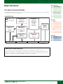 2
2
-
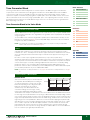 3
3
-
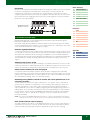 4
4
-
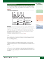 5
5
-
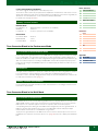 6
6
-
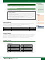 7
7
-
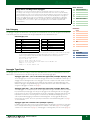 8
8
-
 9
9
-
 10
10
-
 11
11
-
 12
12
-
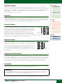 13
13
-
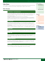 14
14
-
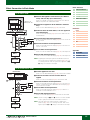 15
15
-
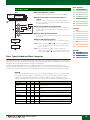 16
16
-
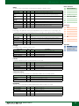 17
17
-
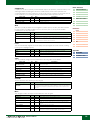 18
18
-
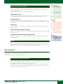 19
19
-
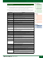 20
20
-
 21
21
-
 22
22
-
 23
23
-
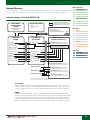 24
24
-
 25
25
-
 26
26
-
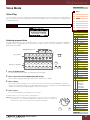 27
27
-
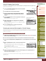 28
28
-
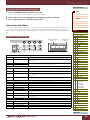 29
29
-
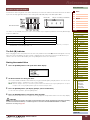 30
30
-
 31
31
-
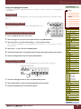 32
32
-
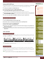 33
33
-
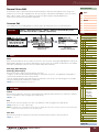 34
34
-
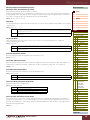 35
35
-
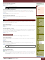 36
36
-
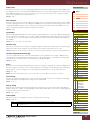 37
37
-
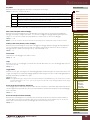 38
38
-
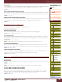 39
39
-
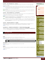 40
40
-
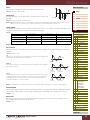 41
41
-
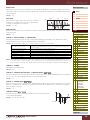 42
42
-
 43
43
-
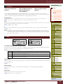 44
44
-
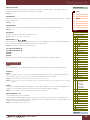 45
45
-
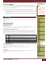 46
46
-
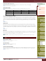 47
47
-
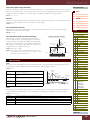 48
48
-
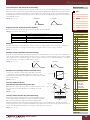 49
49
-
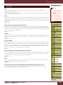 50
50
-
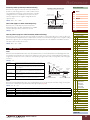 51
51
-
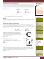 52
52
-
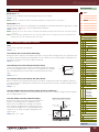 53
53
-
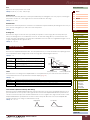 54
54
-
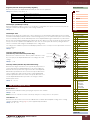 55
55
-
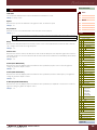 56
56
-
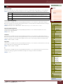 57
57
-
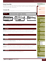 58
58
-
 59
59
-
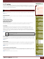 60
60
-
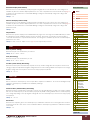 61
61
-
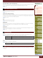 62
62
-
 63
63
-
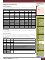 64
64
-
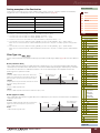 65
65
-
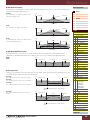 66
66
-
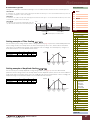 67
67
-
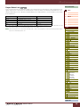 68
68
-
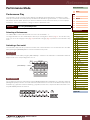 69
69
-
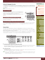 70
70
-
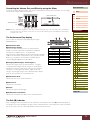 71
71
-
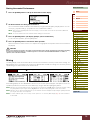 72
72
-
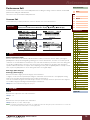 73
73
-
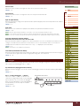 74
74
-
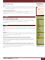 75
75
-
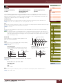 76
76
-
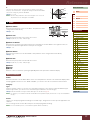 77
77
-
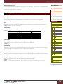 78
78
-
 79
79
-
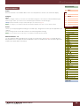 80
80
-
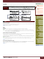 81
81
-
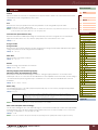 82
82
-
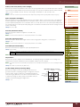 83
83
-
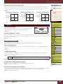 84
84
-
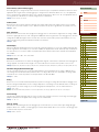 85
85
-
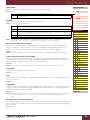 86
86
-
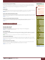 87
87
-
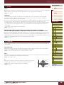 88
88
-
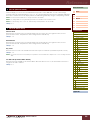 89
89
-
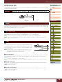 90
90
-
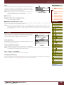 91
91
-
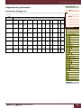 92
92
-
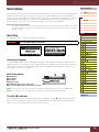 93
93
-
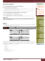 94
94
-
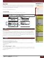 95
95
-
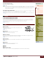 96
96
-
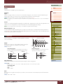 97
97
-
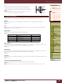 98
98
-
 99
99
-
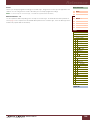 100
100
-
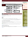 101
101
-
 102
102
-
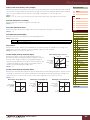 103
103
-
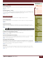 104
104
-
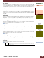 105
105
-
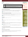 106
106
-
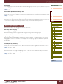 107
107
-
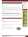 108
108
-
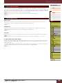 109
109
-
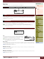 110
110
-
 111
111
-
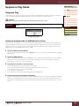 112
112
-
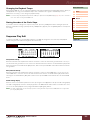 113
113
-
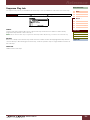 114
114
-
 115
115
-
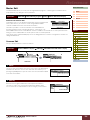 116
116
-
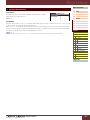 117
117
-
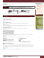 118
118
-
 119
119
-
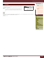 120
120
-
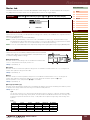 121
121
-
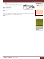 122
122
-
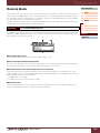 123
123
-
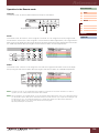 124
124
-
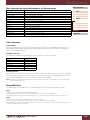 125
125
-
 126
126
-
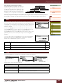 127
127
-
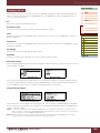 128
128
-
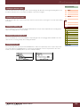 129
129
-
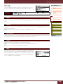 130
130
-
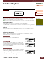 131
131
-
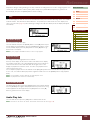 132
132
-
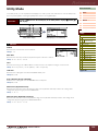 133
133
-
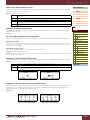 134
134
-
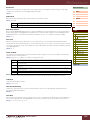 135
135
-
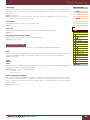 136
136
-
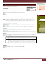 137
137
-
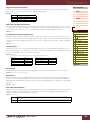 138
138
-
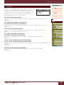 139
139
-
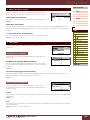 140
140
-
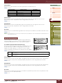 141
141
-
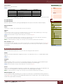 142
142
-
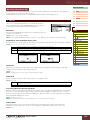 143
143
-
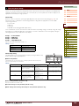 144
144
-
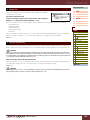 145
145
-
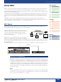 146
146
-
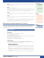 147
147
-
 148
148
-
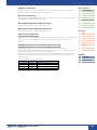 149
149
-
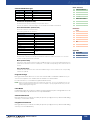 150
150
-
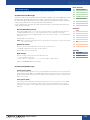 151
151
-
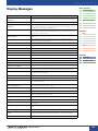 152
152
-
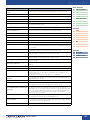 153
153
-
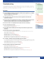 154
154
-
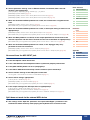 155
155
-
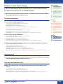 156
156
-
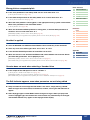 157
157
-
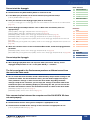 158
158
-
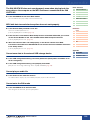 159
159
-
 160
160


Yamaha S70 Handleiding
- Categorie
- Muziekinstrumenten
- Type
- Handleiding
- Deze handleiding is ook geschikt voor
in andere talen
- English: Yamaha S70 User manual
- italiano: Yamaha S70 Manuale utente
- русский: Yamaha S70 Руководство пользователя
- français: Yamaha S70 Manuel utilisateur
- español: Yamaha S70 Manual de usuario
- Deutsch: Yamaha S70 Benutzerhandbuch
- português: Yamaha S70 Manual do usuário
- dansk: Yamaha S70 Brugermanual
- suomi: Yamaha S70 Ohjekirja
- čeština: Yamaha S70 Uživatelský manuál
- svenska: Yamaha S70 Användarmanual
- Türkçe: Yamaha S70 Kullanım kılavuzu
- polski: Yamaha S70 Instrukcja obsługi
- română: Yamaha S70 Manual de utilizare