
Quick Start Guide
ABACUS
Analog Music Computer for Eurorack
V 0.0

2 3Quick Start Guide
ABACUS
(EN) Safety
Instruction
1. Read these instructions.
2. Keep these instructions.
3. Heed all warnings.
4. Follow all instructions.
5. Do not use this apparatus
near water.
6. Clean only with
dry cloth.
7. Do not block any
ventilation openings. Install
in accordance with the
manufacturer’s instructions.
8. Do not install near
any heat sources such as
radiators, heat registers,
stoves, or other apparatus
(including ampli ers) that
produce heat.
9. Use only attachments/
accessories speci ed by
themanufacturer.
10. Use
only with the
cart, stand,
tripod, bracket,
or table speci ed by the
manufacturer, or sold with
the apparatus. When a cart is
used, use caution when
moving the cart/apparatus
combination to avoid injury
from tip-over.
11. Correct
disposal of
this product:
This symbol
indicates that
this product must not be
disposed of with household
waste, according to the
WEEE Directive (2012/19/EU)
and your national law.
This product should be taken
to a collection center licensed
for the recycling of waste
electrical and electronic
equipment (EEE).
The mishandling of this type
of waste could have a
possible negative impact on
the environment and human
health due to potentially
hazardous substances that
are generally associated
with EEE. At the same time,
your cooperation in the
correct disposal of this
product will contribute to the
effi cient use of natural
resources. For more
information about where you
can take your waste
equipment for recycling,
please contact your local
city offi ce, or your household
waste collection service.
12. Do not install in a
con ned space, such as a
book case or similar unit.
13. Do not place naked
ame sources, such as lighted
candles, on the apparatus.
(ES) Instrucción de
seguridad
1. Lea las instrucciones.
2. Conserve estas
instrucciones.
3. Preste atención a todas
las advertencias.
4. Siga todas las
instrucciones.
5. No use este aparato
cerca del agua.
6. Limpie este aparato con
un paño seco.
7.
No bloquee las aberturas
de ventilación. Instale el
equipo de acuerdo con las
instrucciones del fabricante.
8. No instale este equipo
cerca de fuentes de calor
tales como radiadores,
acumuladores de calor,
estufas u otros aparatos
(incluyendo ampli cadores)
que puedan producir calor.
9. Use únicamente los
dispositivos o accesorios
especi cados por el
fabricante.
10. Use
únicamente la
carretilla,
plataforma,
trípode, soporte o mesa
especi cados por el
fabricante o suministrados
junto con el equipo.
Al transportar el equipo,
11.
Cómo debe
deshacerse de
este aparato:
Este símbolo
indica que este aparato no
debe ser tratado como basura
orgánica, según lo indicado
en la Directiva WEEE
(2012/19/EU) y a las
normativas aplicables en su
país. En lugar de ello deberá
llevarlo al punto limpio más
cercano para el reciclaje de
sus elementos eléctricos/
electrónicos (EEE). Al hacer
esto estará ayudando a
prevenir las posibles
consecuencias negativas para
el medio ambiente y la salud
que podrían ser provocadas
por una gestión inadecuada
de este tipo de aparatos.
Además, el reciclaje de
materiales ayudará a
conservar los recursos
naturales. Para más
información acerca del
reciclaje de este aparato,
póngase en contacto con el
Ayuntamiento de su ciudad o
con el punto limpio local.
12. No instale esta unidad
en un espacio muy reducido,
tal como encastrada en una
librería o similar.
13. No coloque objetos
con llama, como una vela
encendida, sobre este
aparato.
(FR) Consignes de
sécurité
1. Lisez ces consignes.
2. Conservez ces consignes.
3. Respectez tous les
avertissements.
4. Respectez toutes les
consignes d’utilisation.
5. N’utilisez jamais
l’appareil à proximité d’un
liquide.
6. Nettoyez l’appareil avec
un chi on sec.
7. Veillez à ne pas
empêcher la bonne
ventilation de l’appareil via
ses ouïes de ventilation.
Respectezles consignes
du fabricant concernant
l’installation del’appareil.
8. Ne placez pas l’appareil
à proximité d’une source de
chaleur telle qu’un chau age,
une cuisinière ou tout
appareil dégageant de la
chaleur (y compris un ampli
depuissance).
9. Utilisez exclusivement
des accessoires et des
appareils supplémentaires
recommandés par
lefabricant.
10. Utilisez
exclusivement
des chariots,
des diables, des
présentoirs, despieds et des
surfaces de travail
recommandés par le
fabricant ou livrés avec le
produit. Déplacez
précautionneusement tout
chariot ou diable chargé pour
éviter d’éventuelles blessures
en cas de chute.
11. Mise
au rebut
appropriée de
ce produit:
Ce symbole
indique qu’en accord avec la
directive DEEE (2012/19/EU)
et les lois en vigueur dans
votre pays, ce produit ne doit
pas être jeté avec les déchets
ménagers. Ce produit doit
être déposé dans un point de
collecte agréé pour le
recyclage des déchets
d’équipements électriques et
électroniques (EEE). Une
mauvaise manipulation de ce
type de déchets pourrait
avoir un impact négatif sur
l’environnement et la santé à

4 5Quick Start Guide
ABACUS
cause des substances
potentiellement dangereuses
généralement associées à ces
équipements. En même
temps, votre coopération
dans la mise au rebut de ce
produit contribuera à
l’utilisation effi cace des
ressources naturelles.
Pour plus d’informations sur
l’endroit où vous pouvez
déposer vos déchets
d’équipements pour le
recyclage, veuillez contacter
votre mairie ou votre centre
local de collecte des déchets.
12. N’installez pas l’appareil
dans un espace con né tel
qu’une bibliothèque ou
meuble similaire.
13. Ne placez jamais
d’objets en ammés, tels que
des bougies allumées,
sur l’appareil.
(DE) Wichtige
Sicherhteitshinweise
1. Lesen Sie diese
Hinweise.
2. Bewahren Sie diese
Hinweise auf.
3. Beachten Sie alle
Warnhinweise.
4. Befolgen Sie alle
Bedienungshinweise.
5. Betreiben Sie das Gerät
nicht in der Nähe vonWasser.
6. Reinigen Sie das Gerät
mit einem trockenen Tuch.
7. Blockieren Sie nicht die
Belüftungsschlitze. Beachten
Sie beim Einbau des Gerätes
die Herstellerhinweise.
8. Stellen Sie das Gerät
nicht in der Nähe von
Wärmequellen auf. Solche
Wärmequellen sind z. B.
Heizkörper, Herde oder
andere Wärme erzeugende
Geräte (auch Verstärker).
9. Verwenden Sie nur
Zusatzgeräte/Zubehörteile,
dielaut Hersteller
geeignet sind.
10.
Verwenden Sie
nur Wagen,
Stand-vorrich-
tungen, Stative, Halter oder
Tische, die vom Hersteller
benannt oder im
Lieferumfang des Geräts
enthalten sind. Falls Sie einen
Wagen benutzen, seien Sie
vorsichtig beim Bewegen der
Wagen- Gerätkombination,
umVerletzungen durch
Stolpern zuvermeiden.
11. Korrekte
Entsorgung
dieses
Produkts:
Dieses Symbol
weist darauf hin, das Produkt
entsprechend der WEEE
Direktive (2012/19/EU) und
der jeweiligen nationalen
Gesetze nicht zusammen mit
Ihren Haushaltsabfällen zu
entsorgen. DiesesProdukt
sollte bei einer autorisierten
Sammelstelle für Recycling
elektrischer und
elektronischer Geräte (EEE)
abgegeben werden. Wegen
bedenklicher Substanzen,
diegenerell mit elektrischen
und elektronischen Geräten
in Verbindung stehen, könnte
eine unsachgemäße
Behandlung dieser Abfallart
eine negative Auswirkung
auf Umwelt und Gesundheit
haben. Gleichzeitig
gewährleistet Ihr Beitrag zur
richtigen Entsorgung dieses
Produkts die e ektive
Nutzung natürlicher
Ressourcen. Fürweitere
Informationen zur
Entsorgung Ihrer Geräte bei
einer Recycling-Stelle
nehmen Sie bitte Kontakt
zum zuständigen städtischen
Büro, Entsorgungsamt oder
zu Ihrem
Haushaltsabfallentsorger
auf.
12. Installieren Sie das
Gerät nicht in einer beengten
Umgebung, zum Beispiel
Bücherregal oder ähnliches.
13. Stellen Sie keine
Gegenstände mit o enen
Flammen, etwa brennende
Kerzen, auf das Gerät.
(PT) Instruções
de Seguranç
Importantes
1. Leia estas instruções.
2. Guarde estas instruções.
3. Preste atenção a todos
os avisos.
4. Siga todas as instruções.
5. Não utilize este
dispositivo perto de água.
6. Limpe apenas com um
pano seco.
7. Não obstrua as entradas
de ventilação. Instale de
acordo com as instruções do
fabricante.
8. Não instale perto de
quaisquer fontes de calor
tais como radiadores, bocas
de ar quente, fogões de
sala ou outros aparelhos
(incluindo ampli cadores)
que produzam calor.
9. Utilize apenas ligações/
acessórios especi cados
pelofabricante.
10. Utilize
apenas com o
carrinho,
estrutura, tripé,
suporte, ou mesa
especi cados pelo fabricante
ou vendidos com o
dispositivo. Quandoutilizar
um carrinho, tenha cuidado
ao mover o conjunto
carrinho/dispositivo para
evitar danos provocados pela
terpidação.
11. Correcta
eliminação
deste produto:
este símbolo
indica que o
produto não deve ser
eliminado juntamente com
os resíduos domésticos,
segundo a Directiva REEE
(2012/19/EU) e a legislação
nacional. Este produto deverá
ser levado para um centro de
recolha licenciado para a
reciclagem de resíduos de
equipamentos eléctricos e
electrónicos (EEE). O
tratamento incorrecto deste
tipo de resíduos pode ter um
eventual impacto negativo
no ambiente e na saúde
humana devido a substâncias
potencialmente perigosas
que estão geralmente
associadas aos EEE. Ao
mesmo tempo, a sua
colaboração para a
eliminação correcta deste
produto irá contribuir para a
utilização e ciente dos
recursos naturais. Paramais
informação acerca dos locais
onde poderá deixar o seu
equipamento usado para
reciclagem, é favor contactar
os serviços municipais locais,
a entidade de gestão de
resíduos ou os serviços de
recolha de resíduos
domésticos.
12. Não instale em lugares
con nados, tais como
estantes ou unidades
similares.
13. Não coloque fontes
de chama, tais como velas
acesas, sobre o aparelho.
(IT) Istruzioni
di sicurezza
importanti
1. Leggere queste
istruzioni.
2. Conservare queste
istruzioni.
3. Prestare attenzione a
tutti gli avvisi.
4. Applicare tutte le
istruzioni.
5. Non utilizzare questo
dispositivo vicino l'acqua.
6. Pulire esclusivamente
con un panno asciutto.
7.
Non bloccare le aperture
di ventilazione. Installare in
conformità con le istruzioni
del produttore.

6 7Quick Start Guide
ABACUS
8. Non installare vicino
a fonti di calore come
radiatori, termoregolatori,
stufe o altri apparecchi
(inclusi ampli catori) che
producono calore.
9. Utilizzare
esclusivamente dispositivi/
accessori speci cati
dal produttore.
10. Utilizzare
solo carrelli,
supporti,
treppiedi, sta e
o tavoli indicati dal
produttore o venduti con
l'apparecchio. Utilizzando un
carrello, prestare attenzione
quando si sposta la
combinazione carrello/
apparecchio per evitare
lesioni dovute al
ribaltamento.
11.
Smaltimento
corretto di
questo
prodotto:
questo simbolo indica che
questo dispositivo non deve
essere smaltito insieme ai
ri uti domestici, secondo la
Direttiva RAEE (2012/19 / UE)
e la vostra legislazione
nazionale. Questo prodotto
deve essere portato in un
centro di raccolta autorizzato
per il riciclaggio di ri uti di
apparecchiature elettriche ed
elettroniche (RAEE). La
cattiva gestione di questo
tipo di ri uti potrebbe avere
un possibile impatto
negativo sull'ambiente e
sulla salute umana a causa di
sostanze potenzialmente
pericolose che sono
generalmente associate alle
apparecchiature elettriche ed
elettroniche. Nello stesso
tempo la vostra
collaborazione al corretto
smaltimento di questo
prodotto contribuirà
all'utilizzo effi ciente delle
risorse naturali. Per ulteriori
informazioni su dove è
possibile trasportare le
apparecchiature per il
riciclaggio vi invitiamo a
contattare l'uffi cio comunale
locale o il servizio di raccolta
dei ri uti domestici.
12. Non installare in
uno spazio ristretto, come
in una libreria o in una
struttura simile.
13. Non collocare sul
dispositivo fonti di amme
libere, come candele accese.
(NL) Belangrijke
veiligheidsvo-
orschriften
1. Lees deze voorschriften.
2. Bewaar deze
voorschriften.
3. Neem alle
waarschuwingen in acht.
4.
Volg alle voorschriften op.
5. Gebruik dit apparaat
niet in de buurt van water.
6. Reinig het uitsluitend
met een droge doek.
7. Let erop geen van
de ventilatie-openingen
te bedekken. Plaats en
installeer het volgens
de voor- schriften van de
fabrikant.
8. Het apparaat mag niet
worden geplaatst in de buurt
van radiatoren, warmte-
uitlaten, kachels of andere
zaken (ook versterkers) die
warmte afgeven.
9.
Gebruik uitsluitend door
de producent gespeci- ceerd
toebehoren c.q. onderdelen.
10.
Gebruik
het apparaat
uitsluitend in
combinatie met
de wagen, het statief, de
driepoot, de beugel of tafel
die door de producent is
aangegeven, of die in
combinatie met het apparaat
wordt verkocht. Bij gebruik
van een wagen dient men
voorzichtig te zijn bij het
verrijden van de combinatie
wagen/apparaat en letsel
door vallen te voorkomen.
11.
Correcte
afvoer van dit
product: dit
symbool geeft
aan dat u dit
product op grond van de
AEEA-richtlijn (2012/19/EU)
en de nationale wetgeving
van uw land niet met het
gewone huishoudelijke afval
mag weggooien. Dit product
moet na a oop van de
nuttige levensduur naar een
offi ciële inzamelpost voor
afgedankte elektrische en
elektronische apparatuur
(AEEA) worden gebracht,
zodat het kan worden
gerecycleerd. Vanwege de
potentieel gevaarlijke sto en
die in elektrische en
elektronische apparatuur
kunnen voorkomen, kan een
onjuiste afvoer van afval van
het onderhavige type een
negatieve invloed op het
milieu en de menselijke
gezondheid hebben. Een
juiste afvoer van dit product
is echter niet alleen beter
voor het milieu en de
gezondheid, maar draagt
tevens bij aan een
doelmatiger gebruik van de
natuurlijke hulpbronnen.
Voor meer informatie over de
plaatsen waar u uw
afgedankte apparatuur kunt
inleveren, kunt u contact
opnemen met uw gemeente
of de plaatselijke
reinigingsdienst.
12. Installeer niet in een
kleine ruimte, zoals een
boekenkast of iets dergelijks.
13. Plaats geen open
vlammen, zoals brandende
kaarsen, op het apparaat.
(SE) Viktiga
säkerhetsanvis-
ningar
1. Läs dessa anvisningar.
2. Spara dessa anvisningar.
3. Beakta alla varningar.
4. Följ alla anvisningar.
5. Använd inte apparaten i
närheten av vatten.
6. Rengör endast med
torr trasa.
7. Blockera inte
ventilationsöppningarna.
Installera enligt tillverkarens
anvisningar.
8. Installera aldrig
intill värmekällor
som värme- element,
varmluftsintag, spisar eller
annan utrustning som avger
värme (inklusive förstärkare).
9. Använd endast
tillkopplingar och tillbehör
som angetts av tillverkaren.
10. Använd
endast med
vagn, stativ,
trefot, hållare
eller bord som angetts av
tillverkaren, eller som sålts
till-sammans med
apparaten. Om du använder
en vagn, var försiktig, när du
för yttar kombinationen
vagn-apparat, för att
förhindra olycksfall genom
snubbling.
11. Kassera
produkten på
rätt sätt: den
här symbolen
indikerar att
produkten inte ska kastas i
hushållssoporna, enligtWEEE
direktivet (2012/19/EU)
ochgällande, nationell
lagstiftning. Produkten ska
lämnas till ett auktoriserat
återvinningsställe för
elektronisk och elektrisk
utrustning (EEE). Om den här
sortens avfall hanteras på fel
sätt kan miljön, och
människors hälsa, påverkas
negativt på grund av
potentiella risksubstanser
som ofta associeras med EEE.
Avfallshanteras produkten
däremot på rätt sätt bidrar
detta till att naturens resurser
används på ett bra sätt.
Kontakta kommun, ansvarig

8 9Quick Start Guide
ABACUS
förvaltning eller
avfallshanteringsföretag för
mer information om
återvinningscentral där
produkten kanlämnas.
12. Installera inte i ett
trångt utrymme, t.ex. i en
bokhylsa eller liknande
enhet.
13. Placera inte källor
med öppen eld, t.ex. tända
ljus, på apparaten.
(PL) Ważne
informacje o
bezpieczeństwie
1. Proszę przeczytać
poniższe wskazówki.
2. Proszę przechowywać
niniejszą instrukcję.
3. Należy przestrzegać
wszystkich wskazówek
ostrzegawczych.
4. Należy postępować
zgodnie z instrukcją obsługi.
5. Urządzenia nie wolno
używać w pobliżu wody.
6. Urządzenie można
czyścić wyłącznie suchą
szmatką.
7. Nie zasłaniać otworów
wentylacyjnych. W czasie
podłączania urządzenia
należy przestrzegać zaleceń
producenta.
8. Nie stawiać urządzenia
w pobliżu źródeł ciepła
takich, jak grzejniki, piece
lub urządzenia produkujące
ciepło (np. wzmacniacze).
9. Używać wyłącznie
sprzętu dodatkowego
i akcesoriów zgodnie z
zaleceniami producenta.
10. Używać
jedynie
zalecanych
przez
producenta lub znajdujących
się w zestawie wózków,
stojaków, statywów,
uchwytów i stołów. W
przypadku posługiwania się
wózkiem należy zachować
szczególną ostrożność w
trakcie przewożenia zestawu,
aby uniknąć
niebezpieczeństwa
potknięcia się i zranienia.
11.
Prawidłowa
utylizacja
produktu:
Ten symbol
wskazuje, że tego produktu
nie należy wyrzucać razem ze
zwykłymi odpadami
domowymi, tylko zgodnie z
dyrektywą w sprawie
zużytego sprzętu
elektrycznego i
elektronicznego (WEEE)
(2012/19/EU) oraz przepisami
krajowymi. Niniejszy produkt
należy przekazać do
autoryzowanego punktu
zbiórki zużytego sprzętu
elektrycznego i
elektronicznego.
Niewłaściwe postępowanie z
tego typu odpadami może
wywołać szkodliwe działanie
na środowisko naturalnej i
zdrowie człowieka z powodu
potencjalnych substancji
niebezpiecznych zaliczanych
jako zużyty sprzęt
elektryczny i elektroniczny.
Jednocześnie, Twój wkład w
prawidłową utylizację
niniejszego produktu
przyczynia się do
oszczędnego
wykorzystywania zasobów
naturalnych. Szczegółowych
informacji o miejscach, w
których można oddawać
zużyty sprzęt do recyklingu,
udzielają urzędy miejskie,
przedsiębiorstwa utylizacji
odpadów lub najbliższy
zakład utylizacji odpadów.
12. Nie instaluj w
ograniczonej przestrzeni,
takiej jak półka na książki lub
podobny zestaw.
13. Nie stawiaj na
urządzeniu źródeł
otwartego ognia, takich jak
zapalone świece.

10 11Quick Start Guide
ABACUS
ABACUS Controls (1) CHANNEL 1 CV INPUT –
Accepts variable voltages in the
range +/- 10 V for processing
by Channel 1. If no voltage is
present the Abacus will use
a self-generated voltage of
approximately +10 V.
(2) CHANNEL 1 TRIGGER INPUT –
Accepts any positive-going
gate or trigger above + 2.5 V.
Causes the Rise/Fall function to
be activated.
(3) CHANNEL 2 CV INPUT –
Accepts voltages in the range
+/- 10 V for attenuverting by
control 20.
(4) CHANNEL 3 CV INPUT –
Accepts voltages in the range
+/- 10 V for attenuverting by
control 21.
(5) CHANNEL 4 TRIGGER INPUT –
Accepts any positive-going
gate or trigger above + 2.5 V.
Causes the Rise/Fall function to
be activated.
(6) CHANNEL 4 CV INPUT –
Accepts variable voltages in the
range +/- 10 V for processing
by Channel 4. If no voltage is
present the Abacus will use
a self-generated voltage of
approximately +10 V.
(7) CHANNEL 1 RISE CV INPUT –
Allows CV control of the
Rise function, in conjunction
with control 8. Accepts voltages
in the range +/- 8 V. Positive
voltages increase the Rise time
until the maximum is achieved;
negative voltages decrease it
until it reaches minimum.
(8) CHANNEL 1 RISE TIME –
Use this control to set the
Rise time. See table below for
maximum times according
to dierent settings. Can be
modulated further by feeding a
CV to socket 7.
(9) CHANNEL 4 RISE TIME –
Use this control to set the
Rise time. See table below for
maximum times according
to dierent settings. Can be
modulated further by feeding
a CV to socket 10.
(10) CHANNEL 4 RISE CV INPUT –
Allows CV control of the
Rise function, in conjunction
with control 9. Accepts voltages
in the range +/- 8 V. Positive
voltages increase the Rise time
until the maximum is achieved;
negative voltages decrease it
until it reaches minimum.
(11) CHANNEL 1 BOTH CV INPUT –
Accepts a voltage in the range
+/- 8 V. A positive voltage will
exponentially decrease the
total Rise/Fall time, until the
minimum is reached; a negative
voltage exponentially increases
it until it reaches maximum.
(EN) Controls

12 13Quick Start Guide
ABACUS
ABACUS Controls
(12) CHANNEL 2 ATTENUVERTER –
Use this control to attenuate
(CW) or invert (CCW) voltages
fed to Channel 2 input on socket
3 or the internally generated
voltage in the range -10 V to
+ 10 V.
(13) CHANNEL 3 ATTENUVERTER –
Use this control to attenuate
(CW) or invert (CCW) voltages
fed to Channel 3 input on socket
4 or the internally generated
voltage in the range -5 V to
+ 6 V.
(14) CHANNEL 4 BOTH CV INPUT –
Accepts a voltage in the range
+/- 8 V. A positive voltage will
exponentially decrease the
total Rise/Fall time, until the
minimum is reached; a negative
voltage exponentially increases
it until it reaches maximum.
(15) CHANNEL 1 FALL CV INPUT –
Allows CV control of the Fall
function, in conjunction with
control 16. Accepts voltages
in the range +/- 8 V. Positive
voltages increase the Fall time
until the maximum is achieved;
negative voltages decrease it
until it reaches minimum.
(16) CHANNEL 1 FALL TIME –
Use this control to set the
Fall time. See table below for
maximum times according
to dierent settings. Can be
modulated further by feeding
a CV to socket 15.
(17) CHANNEL 4 FALL TIME –
Use this control to set the
Fall time. See table below for
maximum times according
to dierent settings. Can be
modulated further by feeding
a CV to socket 18.
(18) CHANNEL 4 FALL CV INPUT –
Allows CV control of the Fall
function, in conjunction with
control 16. Accepts voltages
in the range +/- 8 V. Positive
voltages increase the Fall time
until the maximum is achieved;
negative voltages decrease it
until it reaches minimum.
(19) CHANNEL 1 CYCLE TRIGGER –
Allows an external positive
going gate or trigger of +2.5 V
or more to trigger Channel 1’s
Cycle function.
(20) CHANNEL 1 ATTENUVERTER –
Use this control to attenuate
(CW) or invert (CCW) the
output of Channel 1 after
Rise/Fall processing. Does not
pass internal voltage unless
processing is taking place.
(21) CHANNEL 4 ATTENUVERTER –
Use this control to attenuate
(CW) or invert (CCW) the
output of Channel 1 after
Rise/Fall processing. Does not
pass internal voltage unless
processing is taking place.
(22) CHANNEL 4 CYCLE TRIGGER –
Allows an external positive
going gate or trigger of +2.5 V
or more to trigger Channel 4’s
Cycle function.
(23) CHANNEL 1 RESPONSE –
Use this control to vary the
response of Channel 1 from
logarithmic through linear to
exponential. See table below.
(24) CHANNEL 4 RESPONSE –
Use this control to vary the
response of Channel 4 from
logarithmic through linear
to exponential. See table below.
(25) CHANNEL 1 CYCLE – Use this
button to initiate cycling of
Channel 1; Rise and Fall will
cycle until button is pressed
again to stop the cycle. Button
is illuminated when cycling.
Button ashes when Cycle is
externally triggered via socket
19. Internal Cycle takes priority
over external trigger.
(26) CHANNEL 1 OUTPUT –
Outputs the processed voltage
from Channel 1.
(27) CHANNEL 2 OUTPUT –
Outputs the processed voltage
from Channel 2.
(28) CHANNEL 3 OUTPUT –
Outputs the processed voltage
from Channel 3.
(29) CHANNEL 4 OUTPUT –
Outputs the processed voltage
from Channel 4.
(30) CHANNEL 4 CYCLE – Use this
button to initiate cycling of
Channel 4; Rise and Fall will
cycle until button is pressed
again to stop the cycle.
Button is illuminated when
cycling. Button ashes when
Cycle is externally triggered via
socket 22. Internal cycle takes
priority over external trigger.
(31) CHANNEL 1 END OF
RISE OUTPUT – Outputs a
+ 9 V voltage at the top of the
Rise function, indicated by the
associated LED, which continues
active until the end of the
Fall cycle.
(32) CHANNEL 1 UNITY OUTPUT –
Outputs a 0 - +10 V voltage
following the Rise/Fall
functions when Channel 1 is
cycling; otherwise follows the
channel input unaected by the
attenuverter. LED shows green
for a positive voltage, red for a
negative one.

14 15Quick Start Guide
ABACUS
ABACUS Controls
(33) OR OUTPUT – Outputs the
result of an analog OR function
based on the setting of the
attenuverters for Channels
1 – 4 (controls 12, 13, 20, 21).
Channels 1 and 4 need an
external voltage to be included.
(34) SUM OUTPUT – Outputs a
summed voltage in the range
+/- 10 V based on the settings
of the attenuverters for
Channels 1 – 4 (controls 12,
13, 20, 21). LED shows green
for a positive voltage, red for a
negative one. Channels 1 and 4
need an external voltage to
be included.
(35) INVERTED SUM OUTPUT –
Outputs the inversion of the
Sum output 34.
(36) CHANNEL 4 UNITY OUTPUT –
Outputs a 0 - +10 V voltage
following the Rise/Fall
functions when Channel 4
is cycling; otherwise follows the
channel input unaected by the
attenuverter. LED shows green
for a positive voltage, red for a
negative one.
(37) CHANNEL 4 END OF
CYCLE OUTPUT - Outputs a
+ 9 V voltage at the end of the
Rise/Fall cycle, indicated by the
associated LED.
(ES) Paso 2: Controles
(1) CHANNEL 1 CV INPUT –
Acepta voltajes variables en
el rango de +/- 10 V para su
procesado por el canal 1. Si no
hay ningún voltaje presente,
el Abacus usará un voltaje
auto-generado de
aproximadamente +10 V.
(2) CHANNEL 1 TRIGGER INPUT –
Acepta cualquier señal de
puerta o disparador entrante
positiva que supere los + 2.5 V.
Esta señal hace que la función
Rise/Fall sea activada.
(3) CHANNEL 2 CV INPUT –
Acepta voltajes en el rango
de +/- 10 V para atenuarlos/
invertirlos (“attenuverting”)
por el control 20.
(4) CHANNEL 3 CV INPUT –
Acepta voltajes en el rango
de +/- 10 V para atenuarlos/
invertirlos (“attenuverting”)
por el control 21.
(5) CHANNEL 4 TRIGGER INPUT –
Acepta cualquier señal de
puerta o disparador entrante
positiva que supere los + 2.5 V.
Esta señal hace que la función
Rise/Fall sea activada.
(6) CHANNEL 4 CV INPUT –
Acepta voltajes variables en
el rango de +/- 10 V para su
procesado por el canal 4. Si no
hay ningún voltaje presente,
el Abacus usará un voltaje auto-
generado de aproximadamente
+10 V.
(7) CHANNEL 1 RISE CV INPUT –
Permite el control CV de la
función Rise junto con el
control 8. Acepta voltajes en el
rango de +/- 8 V. Los voltajes
positivos aumentan el tiempo
del Rise (incremento) hasta
que es alcanzado el máximo;
los voltajes negativos lo
reducen hasta que es alcanzado
el mínimo.
(8) CHANNEL 1 RISE TIME – Use
este control para ajustar el
tiempo del incremento o Rise.
Vea en la tabla de abajo los
tiempos máximos obtenidos
de acuerdo con los diferentes
ajustes. Puede modular esto
aún más dando entrada a una
señal CV en la toma 7.
(9) CHANNEL 4 RISE TIME –
Use este control para ajustar el
tiempo del incremento o Rise.
Vea en la tabla de abajo los
tiempos máximos obtenidos
de acuerdo con los diferentes
ajustes. Puede modular esto
aún más dando entrada a una
señal CV en la toma 10.
(10) CHANNEL 4 RISE CV INPUT –
Permite el control CV de la
función Rise junto con el
control 9. Acepta voltajes en el
rango de +/- 8 V. Los voltajes
positivos aumentan el tiempo
del Rise (incremento) hasta que
es alcanzado el máximo;
los voltajes negativos lo
reducen hasta que es alcanzado
el mínimo.
(11) CHANNEL 1 BOTH CV INPUT –
Acepta un voltaje en el rango
de +/- 8 V. Un voltaje positivo
reducirá de forma exponencial
el tiempo Rise/Fall total,
hasta que llegue al mínimo;
un voltaje negativo aumentará
exponencialmente ese tiempo
hasta llegar al máximo.
(12) CHANNEL 2 ATTENUVERTER –
Use este control para atenuar
(derecha) o invertir (izquierda)
los voltajes enviados a la
entrada del canal 2 en la
toma 3 o el voltaje generado
internamente en el rango de
-10 a + 10 V.
(13) CHANNEL 3 ATTENUVERTER –
Use este control para atenuar
(derecha) o invertir (izquierda)
los voltajes enviados a la

16 17Quick Start Guide
ABACUS
ABACUS Controls
entrada del canal 3 en la
toma 4 o el voltaje generado
internamente en el rango de
-5 a + 6 V.
(14) CHANNEL 4 BOTH CV INPUT –
Acepta un voltaje en el rango
de +/- 8 V. Un voltaje positivo
reducirá de forma exponencial
el tiempo Rise/Fall total,
hasta que llegue al mínimo;
un voltaje negativo aumentará
exponencialmente ese tiempo
hasta llegar al máximo.
(15) CHANNEL 1 FALL CV INPUT –
Permite el control CV de la
función Fall junto con el
control 16. Acepta voltajes en
el rango de +/- 8 V. Los voltajes
positivos aumentan el tiempo
del Fall (decremento) hasta que
es alcanzado el máximo;
los voltajes negativos lo
reducen hasta que es alcanzado
el mínimo.
(16) CHANNEL 1 FALL TIME –
Use este control para ajustar el
tiempo del decremento o Fall.
Vea en la tabla de abajo los
tiempos máximos obtenidos
de acuerdo con los diferentes
ajustes. Puede modular esto
aún más dando entrada a una
señal CV en la toma 15.
(17) CHANNEL 4 FALL TIME –
Use este control para ajustar el
tiempo del decremento o Fall.
Vea en la tabla de abajo los
tiempos máximos obtenidos
de acuerdo con los diferentes
ajustes. Puede modular esto
aún más dando entrada a una
señal CV en la toma 18.
(18) CHANNEL 4 FALL CV INPUT –
Permite el control CV de la
función Fall junto con el
control 17. Acepta voltajes en
el rango de +/- 8 V. Los voltajes
positivos aumentan el tiempo
del Fall (decremento) hasta que
es alcanzado el máximo;
los voltajes negativos lo
reducen hasta que es alcanzado
el mínimo.
(19) CHANNEL 1 CYCLE TRIGGER –
Permite que una señal de
puerta o disparador positiva
entrante de +2.5 V o superior
active la función Cycle del
canal 1.
(20) CHANNEL 1 ATTENUVERTER –
Use este control para atenuar
(derecha) o invertir (izquierda)
la salida del canal 1 después del
procesado Rise/Fall. No pasa
voltaje interno salvo que esté
ejecutándose el procesado.
(21) CHANNEL 4 ATTENUVERTER –
Use este control para atenuar
(derecha) o invertir (izquierda)
la salida del canal 4 después del
procesado Rise/Fall. No pasa
voltaje interno salvo que esté
ejecutándose el procesado.
(22) CHANNEL 4 CYCLE TRIGGER –
Permite que una señal de
puerta o disparador positiva
entrante de +2.5 V o superior
active la función Cycle del
canal 4.
(23) CHANNEL 1 RESPONSE –
Use este control para modicar
la respuesta del canal 1 desde
logarítmica a exponencial
pasando por lineal. Vea la tabla
de abajo.
(24) CHANNEL 4 RESPONSE –
Use este control para modicar
la respuesta del canal 4 desde
logarítmica a exponencial
pasando por lineal. Vea la tabla
de abajo.
(25) CHANNEL 1 CYCLE – Use este
botón para iniciar el bucle o
ciclo del canal 1; las funciones
Rise y Fall harán un bucle hasta
que vuelva a pulsar este botón
para detener ese ciclo. El botón
quedará iluminado cuando
el bucle esté activo. El botón
parpadeará cuando el efecto
de bucle sea disparado
externamente a través de la
toma 19. El bucle interno tendrá
prioridad sobre el
bucle externo.
(26) CHANNEL 1 OUTPUT – Emite el
voltaje procesado del canal 1.
(27) CHANNEL 2 OUTPUT – Emite el
voltaje procesado del canal 2.
(28) CHANNEL 3 OUTPUT – Emite el
voltaje procesado del canal 3.
(29) CHANNEL 4 OUTPUT – Emite el
voltaje procesado del canal 4.
(30) CHANNEL 4 CYCLE – Use este
botón para iniciar el bucle o
ciclo del canal 4; las funciones
Rise y Fall harán un bucle
hasta que vuelva a pulsar este
botón para detener ese ciclo.
El botón quedará iluminado
cuando el bucle esté activo.
El botón parpadeará cuando el
efecto de bucle sea disparado
externamente a través de la
toma 22. El bucle interno
tendrá prioridad sobre el
bucle externo.
(31) CHANNEL 1 END OF
RISE OUTPUT – Esta salida
emite un voltaje de + 9 V en el
extremo superior de la función
Rise, indicado por el piloto LED
asociado, que continuará activo
hasta el nal del ciclo Fall.
(32) CHANNEL 1 UNITY OUTPUT –
Emite un voltaje 0 - +10 V
siguiendo las funciones
Rise/Fall cuando hay activo
un bucle en el canal 1; en caso

18 19Quick Start Guide
ABACUS
ABACUS Controls
contrario sigue la señal de la
entrada del canal sin afectación
por el atenuador/inversor.
El piloto LED se ilumina en verde
para un voltaje positivo o en
rojo para uno negativo.
(33) OR OUTPUT – Esta toma da
salida al resultado de una
función OR analógica basada
en el ajuste de los atenuadores/
inversores de los canales 1 – 4
(controles 12, 13, 20, 21). Los
canales 1 y 4 necesitan un
voltaje externo para
ser incluidos.
(34) SUM OUTPUT – Esta salida
emite un voltaje sumado en el
rango +/- 10 V basado en los
ajustes de los atenuadores/
inversores de los canales 1 – 4
(controles 12, 13, 20, 21). El
piloto LED se ilumina en verde
para un voltaje positivo y
en rojo para uno negativo.
Los canales 1 y 4 necesitan
un voltaje externo para
ser incluidos.
(35) INVERTED SUM OUTPUT – Da
salida a la inversión de la salida
Sum 34.
(36) CHANNEL 4 UNITY OUTPUT –
Emite un voltaje 0 - +10 V
siguiendo las funciones
Rise/Fall cuando hay activo
un bucle en el canal 4; en caso
contrario sigue la señal de la
entrada del canal sin afectación
por el atenuador/inversor.
El piloto LED se ilumina en verde
para un voltaje positivo o en
rojo para uno negativo.
(37) CHANNEL 4 END OF
CYCLE OUTPUT – Esta salida
emite un voltaje de + 9 V al
nal del ciclo o bucle de la
función Rise/Fall, indicado por
el piloto LED asociado.
(FR) Etape 2 : Réglages
(1) CHANNEL 1 CV INPUT –
Peut recevoir des tensions
sur une plage de +/- 10 V
pour traitement par le canal 1.
Si aucune tension n’est
détectée, l’Abacus utilise
une tension auto-générée
d’approximativement +10 V.
(2) CHANNEL 1 TRIGGER INPUT –
Peut recevoir des signaux de
gate ou de déclenchement
supérieurs à + 2.5 V. Permet
d’activer la fonction Rise/Fall.
(3) CHANNEL 2 CV INPUT –
Peut recevoir des tensions
sur une plage de +/- 10 V
pour atténuation/inversion
(attenuverting) par le
réglage 20.
(4) CHANNEL 3 CV INPUT –
Peut recevoir des tensions
sur une plage de +/- 10 V
pour atténuation/inversion
(attenuverting) par le
réglage 21.
(5) CHANNEL 4 TRIGGER INPUT –
Peut recevoir des signaux de
gate ou de déclenchement
supérieurs à + 2.5 V. Permet
d’activer la fonction Rise/Fall.
(6) CHANNEL 4 CV INPUT –
Peut recevoir des tensions sur
une plage de +/- 10 V pour
traitement par le canal 4.
Si aucune tension n’est
détectée, l’Abacus utilise
une tension auto-générée
d’approximativement +10 V.
(7) CHANNEL 1 RISE CV INPUT –
Permet de contrôler la fonction
Rise par CV, en conjonction
avec le réglage 8. Peut recevoir
des tensions sur une plage de
+/- 8 V. Une tension positive
augmente la durée de la
fonction Rise jusqu’à ce que la
valeur maximale soit atteinte ;
une tension négative diminue
sa durée jusqu’à ce que la valeur
minimale soit atteinte.
(8) CHANNEL 1 RISE TIME –
Permet de régler la durée de
la fonction Rise. Le tableau
ci-dessous indique des durées
maximales en fonction de
diérents réglages. La durée
peut être modulée avec une CV
reliée à l’entrée 7.
(9) CHANNEL 4 RISE TIME –
Permet de régler la durée de
la fonction Rise. Le tableau
ci-dessous indique des durées
maximales en fonction de
diérents réglages. La durée
peut être modulée avec une CV
reliée à l’entrée 10.
(10) CHANNEL 4 RISE CV INPUT –
Permet de contrôler la fonction
Rise par CV, en conjonction
avec le réglage 9. Peut recevoir
des tensions sur une plage de
+/- 8 V. Une tension positive
augmente la durée de la
fonction Rise jusqu’à ce que la
valeur maximale soit atteinte ;
une tension négative diminue
sa durée jusqu’à ce que la valeur
minimale soit atteinte.
(11) CHANNEL 1 BOTH CV INPUT –
Peut recevoir des tensions
sur une plage de +/- 8 V.
Une tension positive diminue
de manière exponentielle la
durée totale des fonctions Rise
et Fall jusqu’à ce que la valeur
minimale soit atteinte ;
une tension négative augmente
cette durée de manière

20 21Quick Start Guide
ABACUS
ABACUS Controls
exponentielle jusqu’à ce que la
valeur maximale soit atteinte.
(12) CHANNEL 2 ATTENUVERTER –
Ce réglage permet d’atténuer
(vers la droite) ou d’inverser
(vers la gauche) les tensions
transmises à l’entrée 3 du canal
2 ou la tension auto-générée
sur une plage de -10 V à + 10 V.
(13) CHANNEL 3 ATTENUVERTER –
Ce réglage permet d’atténuer
(vers la droite) ou d’inverser
(vers la gauche) les tensions
transmises à l’entrée 4 du canal
3 ou la tension auto-générée
sur une plage de -5 V à + 6 V.
(14) CHANNEL 4 BOTH CV INPUT –
Peut recevoir des tensions
sur une plage de +/- 8 V.
Une tension positive diminue
de manière exponentielle la
durée totale des fonctions
Rise et Fall jusqu’à ce que la
valeur minimale soit atteinte ;
une tension négative augmente
cette durée de manière
exponentielle jusqu’à ce que la
valeur maximale soit atteinte.
(15) CHANNEL 1 FALL CV INPUT –
Permet de contrôler la fonction
Fall par CV, en conjonction avec
le réglage 16. Peut recevoir
des tensions sur une plage de
+/- 8 V. Une tension positive
augmente la durée de la
fonction Fall jusqu’à ce que la
valeur maximale soit atteinte ;
une tension négative diminue
sa durée jusqu’à ce que la valeur
minimale soit atteinte.
(16) CHANNEL 1 FALL TIME –
Permet de régler la durée de
la fonction Fall. Le tableau
ci-dessous indique des durées
maximales en fonction de
diérents réglages. La durée
peut être modulée avec une
CV reliée à l’entrée 15.
(17) CHANNEL 4 FALL TIME –
Permet de régler la durée de
la fonction Fall. Le tableau
ci-dessous indique des durées
maximales en fonction de
diérents réglages. La durée
peut être modulée avec une
CV reliée à l’entrée 18.
(18) CHANNEL 4 FALL CV INPUT –
Permet de contrôler la fonction
Fall par CV, en conjonction avec
le réglage 17. Peut recevoir
des tensions sur une plage de
+/- 8 V. Une tension positive
augmente la durée de la
fonction Fall jusqu’à ce que la
valeur maximale soit atteinte ;
une tension négative diminue
sa durée jusqu’à ce que la valeur
minimale soit atteinte.
(19) CHANNEL 1 CYCLE TRIGGER –
Permet d’activer la fonction
Cycle du canal 1 avec des
signaux de gate ou de
déclenchement externes
supérieurs ou égaux à + 2.5 V.
(20) CHANNEL 1 ATTENUVERTER –
Ce réglage permet d’atténuer
(vers la droite) ou d’inverser
(vers la gauche) la sortie du
canal 1 après le traitement
par la fonction Rise/Fall.
Ne laisse pas passer la tension
interne sauf si le traitement
est en cours.
(21) CHANNEL 4 ATTENUVERTER –
Ce réglage permet d’atténuer
(vers la droite) ou d’inverser
(vers la gauche) la sortie du
canal 4 après le traitement
par la fonction Rise/Fall.
Ne laisse pas passer la tension
interne sauf si le traitement
est en cours.
(22) CHANNEL 4 CYCLE TRIGGER –
Permet d’activer la fonction
Cycle du canal 4 avec des
signaux de gate ou de
déclenchement externes
supérieurs ou égaux à + 2.5 V.
(23) CHANNEL 1 RESPONSE –
Ce réglage permet de faire
varier la réponse du canal 1 de
logarithmique à exponentielle
en passant par linéaire. Voir le
tableau ci-dessous.
(24) CHANNEL 4 RESPONSE –
Ce réglage permet de faire
varier la réponse du canal 1 de
logarithmique à exponentielle
en passant par linéaire. Voir le
tableau ci-dessous.
(25) CHANNEL 1 CYCLE – Utilisez ce
bouton pour initier un cycle sur
le canal 1 ; le cycle des fonctions
Rise et Fall continue jusqu’à ce
que vous appuyiez à nouveau
sur le bouton pour l’arrêter.
Le bouton s’allume lorsque le
cycle est en cours et clignote si
le cycle est déclenché avec un
signal externe (entrée 19).
Le cycle interne est prioritaire
sur le déclenchement externe.
(26) CHANNEL 1 OUTPUT – Permet
de transmettre la tension
traitée du canal 1.
(27) CHANNEL2 OUTPUT – Permet
de transmettre la tension
traitée du canal 2.
(28) CHANNEL 3 OUTPUT – Permet
de transmettre la tension
traitée du canal 3.
(29) CHANNEL 4 OUTPUT – Permet
de transmettre la tension
traitée du canal 4.

22 23Quick Start Guide
ABACUS
ABACUS Controls
(30) CHANNEL 4 CYCLE – Utilisez ce
bouton pour initier un cycle sur
le canal 4 ; le cycle des fonctions
Rise et Fall continue jusqu’à ce
que vous appuyiez à nouveau
sur le bouton pour l’arrêter.
Le bouton s’allume lorsque le
cycle est en cours et clignote si
le cycle est déclenché avec un
signal externe (entrée 22). Le
cycle interne est prioritaire sur
le déclenchement externe.
(31) CHANNEL 1 END OF
RISE OUTPUT – Permet de
transmettre une tension de
+ 9 V lorsque la fonction Rise
atteint son maximum. La LED
adjacente s’allume alors. Cette
tension reste active jusqu’à la
n du cycle de la fonction Fall.
(32) CHANNEL 1 UNITY OUTPUT –
Porte une tension de 0 à +10 V
générée à la n les fonctions
Rise/Fall lors du cycle sur le
canal 1 ; elle suit sinon le signal
d’entrée du canal, non traité par
l’atténuateur/inverseur. La LED
s’allume en vert si la tension est
positive et en rouge pour une
tension négative.
(33) OR OUTPUT – Porte le résultat
d’une fonction OR analogique
basée sur le réglage de
l’atténuateur/inverseur des
canaux 1 à 4 (réglages 12, 13,
20, 21). Une tension externe est
nécessaire pour que les canaux
1 et 4 soient inclus.
(34) SUM OUTPUT – Porte une
tension additionnée sur une
plage de +/- 10 V basée sur
le réglage de l’atténuateur/
inverseur des canaux 1 à 4
(réglages 12, 13, 20, 21). La LED
s’allume en vert si la tension est
positive et en rouge pour une
tension négative. Une tension
externe est nécessaire pour que
les canaux 1 et 4 soient inclus.
(35) INVERTED SUM OUTPUT –
Porte une version inversée de la
sortie Sum (34).
(36) CHANNEL 4 UNITY OUTPUT –
Porte une tension de 0 à +10 V
générée les fonctions Rise/Fall
lors du cycle sur le canal 4 ;
elle suit sinon le signal d’entrée
du canal, non traité par
l’atténuateur/inverseur. La LED
s’allume en vert si la tension est
positive et en rouge pour une
tension négative.
(37) CHANNEL 4 END OF
CYCLE OUTPUT – Porte une
tension de + 9 V générée à la n
du cycle Rise/Fall, indiqué par la
LED correspondante.
(DE) Bedienelemente
(1) CHANNEL 1 CV INPUT –
Akzeptiert variable
Spannungen im Bereich von
+/-10 V zur Verarbeitung durch
Kanal 1. Wenn keine Spannung
anliegt ist, verwendet der
Abacus eine selbst erzeugte
Spannung von etwa +10 V.
(2) CHANNEL 1 TRIGGER INPUT –
Akzeptiert jedes positive Gate-
oder Trigger-Signal über
+2.5 V. Bewirkt, dass die Rise/
Fall-Funktion aktiviert wird.
(3) CHANNEL 2 CV INPUT –
Akzeptiert Spannungen im
Bereich von +/-10 V zum
Abschwächen/Invertieren
(Attenuverting) mit Regler 20.
(4) CHANNEL 3 CV INPUT –
Akzeptiert Spannungen im
Bereich von +/-10 V zum
Abschwächen/Invertieren
(Attenuverting) mit Regler 21.
(5) CHANNEL 4 TRIGGER INPUT –
Akzeptiert jedes positive Gate-
oder Trigger-Signal über
+2.5 V. Bewirkt, dass die Rise/
Fall-Funktion aktiviert wird.
(6) CHANNEL 4 CV INPUT –
Akzeptiert variable
Spannungen im Bereich von
+/-10 V zur Verarbeitung durch
Kanal 4. Wenn keine Spannung
anliegt ist, verwendet der
Abacus eine selbst erzeugte
Spannung von etwa +10 V.
(7) CHANNEL 1 RISE CV INPUT –
Ermöglicht die CV-Steuerung
der Rise-Funktion in
Verbindung mit Regler 8.
Akzeptiert Spannungen im
Bereich von +/-8 V. Positive
Spannungen erhöhen die
Anstiegszeit bis zum Erreichen
des Maximums, negative
Spannungen verringern sie bis
zum Erreichen des Minimums.
(8) CHANNEL 1 RISE TIME – Mit
diesem Regler können Sie die
Anstiegszeit einstellen. Siehe
Tabelle unten für maximale
Zeiten bei verschiedenen
Einstellungen. Kann durch
Einspeisung einer CV in Buchse
7 weiter moduliert werden.
(9) CHANNEL 4 RISE TIME – Mit
diesem Regler können Sie die
Anstiegszeit einstellen. Siehe
Tabelle unten für maximale
Zeiten bei verschiedenen
Einstellungen. Kann durch
Einspeisung einer CV in Buchse
10 weiter moduliert werden.
(10) CHANNEL 4 RISE CV INPUT –
Ermöglicht die CV-Steuerung
der Rise-Funktion in
Verbindung mit Regler 9.
Akzeptiert Spannungen im

24 25Quick Start Guide
ABACUS
ABACUS Controls
Bereichvon +/-8 V. Positive
Spannungen erhöhen die
Anstiegszeit bis zum Erreichen
des Maximums, negative
Spannungen verringern sie bis
zum Erreichen des Minimums.
(11) CHANNEL 1 BOTH CV INPUT –
Akzeptiert eine Spannung
im Bereich von +/-8 V.
Eine positive Spannung
verringert exponentiell die
gesamte Rise/Fall-Zeit, bis das
Minimum erreicht ist.
Eine negative Spannung
erhöht sie exponentiell, bis das
Maximum erreicht ist.
(12) CHANNEL 2 ATTENUVERTER –
Mit diesem Regler können Sie
die über Buchse 3 in Kanal 2
eingespeisten Spannungen
oder die intern erzeugte
Spannung im Bereich von
-10 V bis +10 V abschwächen
(Rechtsdrehung) oder
invertieren (Linksdrehung).
(13) CHANNEL 3 ATTENUVERTER –
Mit diesem Regler können Sie
die über Buchse 4 in Kanal 3
eingespeisten Spannungen
oder die intern erzeugte
Spannung im Bereich von
-5 V bis +6 V abschwächen
(Rechtsdrehung) oder
invertieren (Linksdrehung).
(14) CHANNEL 4 BOTH CV INPUT –
Akzeptiert eine Spannung
im Bereich von +/-8 V.
Eine positive Spannung
verringert exponentiell die
gesamte Rise/Fall-Zeit,
bis das Minimum erreicht ist.
Eine negative Spannung
erhöht sie exponentiell, bis das
Maximum erreicht ist.
(15) CHANNEL 1 FALL CV INPUT –
Ermöglicht die CV-Steuerung
der Fall-Funktion in Verbindung
mit Regler 16. Akzeptiert
Spannungen im Bereich von
+/-8 V. Positive Spannungen
erhöhen die Abfallzeit bis zum
Erreichen des Maximums,
negative Spannungen
verringern sie bis zum Erreichen
des Minimums.
(16) CHANNEL 1 FALL TIME–
Mit diesem Regler können
Sie die Abfallzeit einstellen.
Siehe Tabelle unten für
maximale Zeiten bei
verschiedenen Einstellungen.
Kann durch Einspeisung
einer CV in Buchse 15 weiter
moduliert werden.
(17) CHANNEL 4 FALL TIME –
Mit diesem Regler können
Sie die Abfallzeit einstellen.
Siehe Tabelle unten für
maximale Zeiten bei
verschiedenen Einstellungen.
Kann durch Einspeisung
einer CV in Buchse 18 weiter
moduliert werden.
(18) CHANNEL 4 FALL CV INPUT –
Ermöglicht die CV-Steuerung
der Fall-Funktion in Verbindung
mit Regler 17. Akzeptiert
Spannungen im Bereich von
+/-8 V. Positive Spannungen
erhöhen die Abfallzeit bis zum
Erreichen des Maximums,
negative Spannungen
verringern sie bis zum Erreichen
des Minimums.
(19) CHANNEL 1 CYCLE TRIGGER –
ermöglicht einem externen
positiven Gate- oder Trigger-
Signal von +2.5 V oder mehr,
die Cycle-Funktion von Kanal 1
zu triggern.
(20) CHANNEL 1 ATTENUVERTER –
Mit diesem Regler kann man
den Ausgang von Kanal 1 nach
der Rise/Fall-Verarbeitung
abschwächen (Rechtsdrehung)
oder invertieren (Linksdrehung)
.
Es wird keine interne Spannung
weitergeleitet, wenn keine
Verarbeitung stattndet.
(21) CHANNEL 4 ATTENUVERTER –
Mit diesem Regler kann man
den Ausgang von Kanal 4 nach
der Rise/Fall-Verarbeitung
abschwächen (Rechtsdrehung)
oder invertieren
(Linksdrehung). Es wird
keine interne Spannung
weitergeleitet, wenn keine
Verarbeitung stattndet.
(22) CHANNEL 4 CYCLE TRIGGER –
ermöglicht einem externen
positiven Gate- oder Trigger-
Signal von +2.5 V oder mehr,
die Cycle-Funktion von Kanal 4
zu triggern.
(23) CHANNEL 1 RESPONSE –
Mit diesem Regler können Sie
die Ansprache von Kanal 1 von
logarithmisch über linear bis
exponentiell variieren. Siehe
Tabelle unten.
(24) CHANNEL 4 RESPONSE –
Mit diesem Regler können Sie
die Ansprache von Kanal 4 von
logarithmisch über linear bis
exponentiell variieren. Siehe
Tabelle unten.
(25) CHANNEL 1 CYCLEE –
Mit dieser Taste kann man das
Cycling von Kanal 1 starten.
Rise und Fall werden so lange
zyklisch wiederholt, bis die
Taste erneut gedrückt wird, um
den Zyklus zu stoppen. Die Taste
leuchtet während des Zyklus.
Die Taste blinkt, wenn der
Zyklus über Buchse 19 extern

26 27Quick Start Guide
ABACUS
getriggert wird. Das interne
Cycling hat Vorrang vor dem
externen Trigger.
(26) CHANNEL 1 OUTPUT – Gibt die
verarbeitete Spannung von
Kanal 1 aus.
(27) CHANNEL 2 OUTPUT – Gibt die
verarbeitete Spannung von
Kanal 2 aus.
(28) CHANNEL 3 OUTPUT – Gibt die
verarbeitete Spannung von
Kanal 3 aus.
(29) CHANNEL 4 OUTPUT – Gibt die
verarbeitete Spannung von
Kanal 4 aus.
(30) CHANNEL 4 CYCLE – Mit dieser
Taste kann man das Cycling
von Kanal 4 starten. Rise und
Fall werden so lange zyklisch
wiederholt, bis die Taste erneut
gedrückt wird, um den Zyklus
zu stoppen. Die Taste leuchtet
während des Zyklus. Die Taste
blinkt, wenn der Zyklus über
Buchse 22 extern getriggert
wird. Das interne Cycling hat
Vorrang vor dem
externen Trigger.
(31) CHANNEL 1 END OF
RISE OUTPUT – Gibt an der
Spitze der Rise-Funktion eine
Spannung von +9 V aus. Dies
wird durch die zugehörige LED
angezeigt, die bis zum Ende des
Fall-Zyklus aktiv bleibt.
(32) CHANNEL 1 UNITY OUTPUT –
Gibt eine Spannung von
0 bis +10 V aus, die den
Rise/Fall-Funktionen folgt,
wenn Kanal 1 im Cycling-
Modus ist. Andernfalls folgt
der Ausgang dem
Kanaleingang unbeeinusst
vom Attenuverter. Die LED
leuchtet grün bei positiver
Spannung und rot bei
negativer Spannung.
(33) OR OUTPUT – Gibt das Ergebnis
einer analogen OR-Funktion
aus, basierend auf der
Einstellung der Attenuverter
für die Kanäle 1 - 4 (Regler 12,
13, 20, 21). Die Kanäle 1 und
4 benötigen eine externe
Spannung, um einbezogen
zu werden.
(34) SUM OUTPUT – Gibt eine
Summenspannung im Bereich
von +/-10 V aus, basierend
auf den Einstellungen der
Attenuverter für die Kanäle
1 - 4 (Regler 12, 13, 20, 21).
Die LED leuchtet grün für eine
positive Spannung und rot für
eine negative. Die Kanäle 1
und 4 benötigen eine externe
Spannung, um einbezogen
zu werden.
ABACUS Controls
(35) INVERTED SUM OUTPUT –
Gibt die Inversion des
Summenausgangs 34 aus.
(36) CHANNEL 4 UNITY OUTPUT –
Gibt eine Spannung von 0
bis +10 V aus, die den
Rise/Fall-Funktionen folgt,
wenn Kanal 4 im Cycling-
Modus ist. Andernfalls folgt
der Ausgang dem
Kanaleingang unbeeinusst
vom Attenuverter. Die LED
leuchtet grün bei positiver
Spannung und rot bei
negativer Spannung.
(37) CHANNEL 4 END OF
CYCLE OUTPUT - Gibt am
Ende des Rise/Fall-Zyklus eine
Spannung von +9 V aus, was
durch die zugehörige LED
angezeigt wird.
(PT) Passo 2: Controle
(1) CHANNEL 1 CV INPUT –
Aceita tensões variáveis na
gama de +/- 10 V para o
processamento feito pelo
Canal 1. Se não houver
tensão presente, o Abacus
usará tensão autogerada de
aproximadamente +10 V.
(2) CHANNEL 1 TRIGGER INPUT –
Aceita qualquer gate ou
trigger de andamento positivo
acima de + 2.5 V. Ativa a
função Rise/Fall.
(3) CHANNEL 2 CV INPUT –
Aceita tensões na gama de +/-
10 V para a atenuação/inversão
(attenuverting) do controle 20.
(4) CHANNEL 3 CV INPUT –
Aceita tensões na gama de +/-
10 V para a atenuação/inversão
(attenuverting) do controle 21.
(5) CHANNEL 4 TRIGGER INPUT –
Aceita qualquer gate ou
trigger de andamento positivo
acima de + 2.5 V. Ativa a
função Rise/Fall.
(6) CHANNEL 4 CV INPUT –
Aceita tensões variáveis na
gama de +/- 10 V para o
processamento feito pelo
Canal 4. Se não houver
tensão presente, o Abacus
usará tensão autogerada de
aproximadamente +10 V.
(7) CHANNEL 1 RISE CV INPUT –
Possibilita o controle CV da
função Rise em conjunção
ao controle 8. Aceita tensões
na gama de +/- 8 V. Tensões
positivas aumentam o tempo de
Rise até que chegue ao máximo;
tensões negativas o diminuem
até que cheque ao mínimo.

28 29Quick Start Guide
ABACUS
ABACUS Controls
(8) CHANNEL 1 RISE TIME –
Use este controle para ajustar
o tempo de Rise. Verique a
tabela abaixo para obter os
tempos máximos de acordo
com congurações diferentes.
Pode ser modulado mais ao se
alimentar um CV à tomada 7.
(9) CHANNEL 4 RISE TIME –
Use este controle para ajustar
o tempo de Rise. Verique a
tabela abaixo para obter os
tempos máximos de acordo
com congurações diferentes.
Pode ser modulado mais ao se
alimentar um CV à tomada 10.
(10) CHANNEL 4 RISE CV INPUT –
Possibilita o controle CV da
função Rise em conjunção
ao controle 9. Aceita tensões
na gama de +/- 8 V. Tensões
positivas aumentam o tempo de
Rise até que chegue ao máximo;
tensões negativas o diminuem
até que cheque ao mínimo.
(11) CHANNEL 1 BOTH CV INPUT –
Aceita tensões na gama de
+/- 8 V. Uma tensão positiva
diminui exponencialmente o
tempo total de Rise/Fall até
que chegue ao mínimo; uma
tensão negativa o aumenta
exponencialmente até que
chegue ao máximo.
(12) CHANNEL 2 ATTENUVERTER –
Use este controle para atenuar
(sentido horário) ou inverter
(sentido anti-horário) tensões
alimentadas à entrada do Canal
2 input na tomada 3 ou tensão
gerada internamente na gama
de -10 V to + 10 V.
(13) CHANNEL 3 ATTENUVERTER –
Use este controle para atenuar
(sentido horário) ou inverter
(sentido anti-horário) tensões
alimentadas à entrada do Canal
3 na tomada 4 ou tensão gerada
internamente na gama de
-5 V to + 6 V.
(14) CHANNEL 4 BOTH CV INPUT –
Aceita tensões na gama de
+/- 8 V. Uma tensão positiva
diminui exponencialmente o
tempo total de Rise/Fall até
que chegue ao mínimo; uma
tensão negativa o aumenta
exponencialmente até que
chegue ao máximo.
(15) CHANNEL 1 FALL CV INPUT –
Possibilita o controle CV da
função Fall em conjunção ao
controle 16. Aceita tensões
na gama de +/- 8 V. Tensões
positivas aumentam o tempo de
Fall até que chegue ao máximo;
tensões negativas o diminuem
até que cheque ao mínimo.
(16) CHANNEL 1 FALL TIME –
Use este controle para ajustar
o tempo de Fall. Verique a
tabela abaixo para obter os
tempos máximos de acordo
com congurações diferentes.
Pode ser modulado mais ao se
alimentar um CV à tomada 15.
(17) CHANNEL 4 FALL TIME –
Use este controle para ajustar
o tempo de Fall. Verique a
tabela abaixo para obter os
tempos máximos de acordo
com congurações diferentes.
Pode ser modulado mais ao se
alimentar um CV à tomada 18.
(18) CHANNEL 4 FALL CV INPUT –
Possibilita o controle CV da
função Fall, em conjunção ao
controle 17. Aceita tensões
na gama de +/- 8 V. Tensões
positivas aumentam o tempo de
Fall até que chegue ao máximo;
tensões negativas o diminuem
até que cheque ao mínimo.
(19) CHANNEL 1 CYCLE TRIGGER –
Permite que um gate ou trigger
externo de andamento positivo
com +2.5 V ou mais acione a
função Cycle do Canal 1.
(20) CHANNEL 1 ATTENUVERTER –
Use este controle para atenuar
(sentido horário) ou inverter
(sentido anti-horário) a
saída do Canal 1 depois do
processamento de Rise/Fall.
Não passa tensão interna a não
ser que o processamento
esteja ocorrendo.
(21) CHANNEL 4 ATTENUVERTER –
Use este controle para atenuar
(sentido horário) ou inverter
(sentido anti-horário) a
saída do Canal 4 depois do
processamento de Rise/Fall.
Não passa tensão interna a não
ser que o processamento
esteja ocorrendo.
(22) CHANNEL 4 CYCLE TRIGGER –
Permite que um gate ou trigger
externo de andamento positivo,
com +2.5 V ou mais, acione a
função Cycle do Canal 4.
(23) CHANNEL 1 RESPONSE –
Use este controle para que
a resposta do Canal 1 varie
de logarítmico por linear até
exponencial. Vericar a
tabela abaixo.
(24) CHANNEL 4 RESPONSE –
Use este controle para que
a resposta do Canal 4 varie
de logarítmico por linear até
exponencial. Vericar a
tabela abaixo.
(25) CHANNEL 1 CYCLE – Use este
botão para iniciar o ciclo do
Canal 1; Rise e Fall iniciarão
seu ciclo até que o botão seja

30 31Quick Start Guide
ABACUS
ABACUS Controls
pressionado novamente a m
de parar o ciclo. O botão acende
durante o ciclo. O botão pisca
quando o ciclo é acionado
externamente pela tomada 19.
O ciclo interno (Internal Cycle)
tem mais prioridade do que o
acionador externo.
(26) CHANNEL 1 OUTPUT – Faz a
saída da tensão processada do
Canal 1.
(27) CHANNEL 2 OUTPUT – Faz a
saída da tensão processada do
Canal 2.
(28) CHANNEL 3 OUTPUT – Faz a
saída da tensão processada do
Canal 3.
(29) CHANNEL 4 OUTPUT– Faz a
saída da tensão processada do
Canal 4.
(30) CHANNEL 4 CYCLE– Use este
botão para iniciar o ciclo do
Canal 4; Rise e Fall iniciarão
seu ciclo até que o botão seja
pressionado novamente a m
de parar o ciclo. O botão acende
durante o ciclo. O botão pisca
quando o ciclo é acionado
externamente pela tomada 22.
O ciclo interno (Internal Cycle)
tem mais prioridade do que o
acionador externo.
(31) CHANNEL 1 END OF
RISE OUTPUT – Faz saída da
tensão de + 9 V no topo da
função Rise, indicado pelo LED
associado que continua ativo
até o m do ciclo Fall.
(32) CHANNEL 1 UNITY OUTPUT –
Faz a saída de tensão 0 - +10 V
seguindo as funções Rise/Fall
durante o ciclo (cycling) do
Canal 1; caso contrário,
segue a entrada do canal
não afetada pelo atenuador/
inversor (attenuverter). O LED
ca verde quando há
tensão positiva, e vermelho
quando há tensão negativa.
(33) OR OUTPUT – Faz a saída
do resultado de uma função
analógica OR com base na
conguração dos atenuadores/
inversores (attenuverters) dos
Canais 1 – 4 (controles 12, 13,
20, 21). Os canais 1 e 4 precisam
de tensão externa incluída.
(34) SUM OUTPUT – Faz a saída
da soma de tensões dentro da
gama +/- 10 V com base nas
congurações dos atenuadores/
inversores (attenuverters) dos
Canais 1 – 4 (controles 12, 13,
20, 21). O LED ca verde quando
há tensão positiva, e vermelho
quando há tensão negativa.
Os canais 1 e 4 precisam de
tensão externa incluída.
(35) INVERTED SUM OUTPUT –
Faz a saída da inversão da soma
da saída 34.
(36) CHANNEL 4 UNITY OUTPUT –
Faz a saída de tensão 0 - +10 V,
seguindo as funções Rise/Fall
durante o ciclo (cycling) do
Canal 4; caso contrário,
segue a entrada do canal
não afetada pelo atenuador/
inversor (attenuverter). O LED
ca verde quando há
tensão positiva, e vermelho
quando há tensão negativa.
(37) CHANNEL 4 END OF
CYCLE OUTPUT – Faz saída da
tensão de + 9 V no m do
ciclo Rise/Fall, indicado pelo
LED associado.
(IT) Step 2: Controlli
(1) CHANNEL 1 CV INPUT –
Accetta tensioni variabili
nell’intervallo +/- 10 V per
l’elaborazione dal canale 1.
Se non è presente alcuna
tensione, l’Abacus userà una
tensione autogenerata di
circa +10 V.
(2) CHANNEL 1 TRIGGER INPUT –
Accetta qualsiasi gate o trigger
ad andamento positivo
superiore a + 2.5 V. Attiva la
funzione RISE/FALL.
(3) CHANNEL 2 CV INPUT –
Accetta tensioni variabili
nell’intervallo +/- 10 V per
l’elaborazione ATTENUVERTING
(attenuazione-inversione) dal
controllo 20.
(4) CHANNEL 3 CV INPUT –
Accetta tensioni variabili
nell’intervallo +/- 10 V per
l’elaborazione ATTENUVERTING
dal controllo 21.
(5) CHANNEL 4 TRIGGER INPUT –
Accetta qualsiasi gate o
trigger ad andamento positivo
superiore a + 2.5 V. Attiva la
funzione RISE/FALL.
(6) CHANNEL 4 CV INPUT –
Accetta tensioni variabili
nell’intervallo +/- 10 V per
l’elaborazione dal canale 4. Se
non è presente alcuna tensione,
l’Abacus userà una tensione
autogenerata di circa +10 V.
(7) CHANNEL 1 RISE CV INPUT –
Permette il controllo CV della
funzione RISE, in combinazione
con il controllo 8.
Accetta tensioni nell’intervallo
+/- 8 V. Le tensioni positive
aumentano il tempo di RISE
no al raggiungimento
del massimo; le tensioni
negative lo diminuiscono no
a raggiungere il minimo.

32 33Quick Start Guide
ABACUS
ABACUS Controls
(8) CHANNEL 1 RISE TIME –
Usate questo controllo per
impostare il tempo RISE.
Fate riferimento alla seguente
tabella per i tempi massimi in
base alle diverse impostazioni.
Può essere ulteriormente
modulato inserendo un CV
nella presa 7.
(9) CHANNEL 4 RISE TIME –
Usate questo controllo per
impostare il tempo RISE.
Fate riferimento alla seguente
tabella per i tempi massimi in
base alle diverse impostazioni.
Può essere ulteriormente
modulato inserendo un CV
nella presa 10.
(10) CHANNEL 4 RISE CV INPUT –
Permette il controllo CV della
funzione RISE, in combinazione
con il controllo 9.
Accetta tensioni nell’intervallo
+/- 8 V. Le tensioni positive
aumentano il tempo di RISE f
ino al raggiungimento
del massimo; le tensioni
negative lo diminuiscono no
a raggiungere il minimo.
(11) CHANNEL 1 BOTH CV INPUT –
Accetta una tensione
nell’intervallo +/- 8 V.
Una tensione positiva diminuirà
esponenzialmente il tempo
totale di RISE/FALL, no al
raggiungimento del minimo;
una tensione negativa la
aumenta esponenzialmente
no a raggiungere il massimo.
(12) CHANNEL 2 ATTENUVERTER –
Usate questo controllo per
attenuare (senso orario)
o invertire (senso anti-orario)
le tensioni alimentate
all’ingresso del canale 2 sulla
presa 3 o la tensione generata
internamente nell’intervallo
da -10 V a + 10 V.
(13) CHANNEL 3 ATTENUVERTER –
Usate questo controllo per
attenuare (senso orario) o
invertire (senso anti-orario)
le tensioni alimentate
all’ingresso del canale 3 sulla
presa 4 o la tensione generata
internamente nell’intervallo
da -5 V a + 6 V.
(14) CHANNEL 4 BOTH CV INPUT –
Accetta una tensione
nell’intervallo +/- 8 V.
Una tensione positiva diminuirà
esponenzialmente il tempo
totale di RISE/FALL, no al
raggiungimento del minimo;
una tensione negativa la
aumenta esponenzialmente
no a raggiungere il massimo.
(15) CHANNEL 1 FALL CV INPUT –
Consente il controllo CV della
funzione FALL, in combinazione
con il controllo 16. Accetta
tensioni nell’intervallo
+/- 8 V. Le tensioni positive
aumentano il tempo di caduta
no al raggiungimento del
massimo; le tensioni negative
lo diminuiscono no a
raggiungere il minimo.
(16) CHANNEL 1 FALL TIME –
Usate questo controllo per
impostare il tempo FALL.
Fate riferimento alla seguente
tabella per i tempi massimi in
base alle diverse impostazioni.
Può essere ulteriormente
modulato inserendo un CV alla
presa 15.
(17) CHANNEL 4 FALL TIME –
Usate questo controllo per
impostare il tempo FALL.
Fate riferimento alla seguente
tabella per i tempi massimi in
base alle diverse impostazioni.
Può essere ulteriormente
modulato inserendo un CV
alla presa 18.
(18) CHANNEL 4 FALL CV INPUT –
Consente il controllo CV della
funzione FALL, in combinazione
con il controllo 17.
Accetta tensioni nell’intervallo
+/- 8 V. Le tensioni positive
aumentano il tempo di caduta
no al raggiungimento
del massimo; le tensioni
negative lo diminuiscono no
a raggiungere il minimo.
(19) CHANNEL 1 CYCLE TRIGGER –
Consente a un gate esterno ad
andamento positivo o trigger di
+2.5 V o maggiore di attivare la
funzione CYCLE del canale 1.
(20) CHANNEL 1 ATTENUVERTER –
Usate questo controllo per
attenuare (senso orario)
o invertire (senso anti-orario)
l’uscita del canale 1 dopo
l’elaborazione RISE/FALL.
Non fa passare la tensione
interna a meno che non sia
in corso l’elaborazione.
(21) CHANNEL 4 ATTENUVERTER –
Usate questo controllo per
attenuare (senso orario)
o invertire (senso anti-orario)
l’uscita del canale 4 dopo
l’elaborazione RISE/FALL.
Non fa passare la tensione
interna a meno che non sia
in corso l’elaborazione.
(22) CHANNEL 4 CYCLE TRIGGER –
Consente a un gate esterno ad
andamento positivo o trigger di
+2.5 V o maggiore di attivare la
funzione CYCLE del canale 4.
(23) CHANNEL 1 RESPONSE –
Usate questo controllo per
variare la risposta del canale
1 da logaritmica a lineare

34 35Quick Start Guide
ABACUS
ABACUS Controls
a esponenziale. Vedete la
seguente tabella.
(24) CHANNEL 4 RESPONSE–
Usate questo controllo per
variare la risposta del canale
4 da logaritmica a lineare
a esponenziale. Vedete la
seguente tabella.
(25) CHANNEL 1 CYCLE –
Usate questo pulsante per
avviare il ciclo del canale 1;
RISE e FALL ciclici nché non
sarà premuto nuovamente il
pulsante per interrompere il
ciclo. Il pulsante è illuminato
durante il ciclo. Il pulsante
lampeggia quando il ciclo è
attivato esternamente tramite
la presa 19. Il ciclo interno ha la
priorità sul trigger esterno
(26) CHANNEL 1 OUTPUT –
Emette la tensione elaborata
dal canale 1.
(27) CHANNEL 2 OUTPUT –
Emette la tensione elaborata
dal canale 2.
(28) CHANNEL 3 OUTPUT –
Emette la tensione elaborata
dal canale 3.
(29) CHANNEL 4 OUTPUT –
Emette la tensione elaborata
dal canale 4.
(30) CHANNEL 4 CYCLE –
Usate questo pulsante per
avviare il ciclo del canale 1;
RISE e FALL ciclici nché non
sarà premuto nuovamente il
pulsante per interrompere
il ciclo. Il pulsante è illuminato
durante il ciclo. Il pulsante
lampeggia quando il ciclo è
attivato esternamente tramite
la presa 22. Il ciclo interno ha la
priorità sul trigger esterno.
(31) CHANNEL 1 END OF
RISE OUTPUT – Emette una
tensione di +9 V all’apice
della funzione RISE, indicata
dal relativo led associato, che
rimane attivo no alla ne del
ciclo di FALL
(32) CHANNEL 1 UNITY OUTPUT –
Emette una tensione
nell’intervallo 0 - +10 V
secondo le funzioni di RISE/FALL
quando il canale 1 è in ciclo;
altrimenti segue l’ingresso
del canale non inuenzato
dall’attenuverter . Il led è verde
per una tensione positiva, rosso
per una negativa.
(33) OR OUTPUT – Emette il
risultato della funzione
OR analogica basata
sull’impostazione degli
attenuatori per i canali da 1 a 4
(controlli 12, 13, 20, 21).
Per essere inclusi i canali 1
e 4 necessitano di una
tensione esterna.
(34) SUM OUTPUT – Emette una
tensione sommata
nell’intervallo +/- 10 V in
base alle impostazioni degli
attenuatori per i canali da 1 a 4
(controlli 12, 13, 20, 21). Il led è
verde per una tensione positiva,
rosso per una negativa.
Per essere inclusi i canali 1
e 4 necessitano di una
tensione esterna.
(35) INVERTED SUM OUTPUT –
Emette l’inversione dell’uscita
SUM 34.
(36) CHANNEL 4 UNITY OUTPUT –
Emette una tensione
nell’intervallo 0 - +10 V
secondo le funzioni di RISE/FALL
quando il canale 4 è in ciclo;
altrimenti segue l’ingresso
del canale non inuenzato
dall’attenuverter. Il led è verde
per una tensione positiva,
rosso per una negativa.
(37) CHANNEL 4 END OF
CYCLE OUTPUT - Emette una
tensione di +9 V al termine del
ciclo RISE/FALL, segnalato dal
led associato.
(NL) Stap 2: Regelaars
(1) CHANNEL 1 CV INPUT –
Accepteert variabele spanning
over een bereik van +/– 10 V
voor verwerking door kanaal 1.
Als er geen spanning aanwezig
is, gebruikt de Abacus een zelf
gegenereerde spanning van
ongeveer +10 V.
(2) CHANNEL 1 TRIGGER INPUT –
Accepteert een positieve gate
of trigger boven + 2.5 V.
Activeert de functie Rise/Fall.
(3) CHANNEL 2 CV INPUT –
Accepteert spanning over
een bereik van +/– 10 V
voor dempingsconversie via
regelaar 20.
(4) CHANNEL 3 CV INPUT –
Accepteert spanning over
een bereik van +/– 10 V
voor dempingsconversie via
regelaar 21.
(5) CHANNEL 4 TRIGGER INPUT –
Accepteert positieve gate
of trigger boven + 2.5 V.
Activeert de functie Rise/Fall.
(6) CHANNEL 4 CV INPUT –
Accepteert variabele spanning
over een bereik van +/- 10 V
voor verwerking door kanaal 4.
Als er geen spanning
aanwezig is, gebruikt de Abacus

36 37Quick Start Guide
ABACUS
ABACUS Controls
een zelf gegenereerde spanning
van ongeveer +10 V.
(7) CHANNEL 1 RISE CV INPUT –
Geeft CV-controle over de
functie Rise, in combinatie met
regelaar 8. Accepteert spanning
in een bereik van +/– 8 V.
Positieve spanning verlengt de
Rise-tijd totdat het maximum
is bereikt; negatieve spanning
verkort de Rise-tijd, totdat deze
het minimum bereikt.
(8) CHANNEL 1 RISE TIME –
Gebruik deze regelaar om
de Rise-tijd in te stellen.
Zie onderstaande tabel voor
meer informatie over de
maximale tijden, afhankelijk
van de instellingen. Kan verder
worden gemoduleerd door een
CV naar aansluiting 7 te sturen.
(9) CHANNEL 4 RISE TIME –
Gebruik deze regelaar om de
Rise-tijd in te stellen.
Zie onderstaande tabel voor
meer informatie over de
maximale tijden, afhankelijk
van de instellingen. Kan verder
worden gemoduleerd door
een CV naar aansluiting 10
te sturen.
(10) CHANNEL 4 RISE CV INPUT –
Maakt CV-besturing mogelijk
voor de functie Rise,
in combinatie met regelaar 9.
Accepteert spanning in een
bereik van +/– 8 V.
Positieve spanning verlengt de
Rise-tijd totdat het maximum
is bereikt; negatieve spanning
verkort de Rise-tijd, totdat deze
het minimum bereikt.
(11) CHANNEL 1 BOTH CV INPUT –
Accepteert een spanning in het
bereik +/- 8 V. Een positieve
spanning verkort de totale tijd
van Rise/Fall exponentieel,
totdat het minimum is bereikt;
een negatieve spanning
verlengt de tijd exponentieel
totdat deze het
maximum bereikt.
(12) CHANNEL 2 ATTENUVERTER –
Gebruik deze regelaar om
de via ingang 3 naar kanaal
2 verstuurde voltages of de
intern gegenereerde voltages
te verzwakken (naar rechts
draaien) of te inverteren
(naar links draaien) over een
bereik -10 V tot + 10 V.
(13) CHANNEL 3 ATTENUVERTER –
Gebruik deze regelaar om
de via ingang 4 naar kanaal
3 verstuurde voltages of de
intern gegenereerde voltages
te verzwakken (naar rechts
draaien) of te inverteren
(naar links draaien) over een
bereik -5 V tot + 6 V.
(14) CHANNEL 4 BOTH CV INPUT –
Accepteert een spanning over
een bereik van +/– 8 V.
Een positieve spanning verkort
de totale tijd van Rise/Fall
exponentieel, totdat het
minimum is bereikt; een
negatieve spanning verlengt de
tijd exponentieel totdat deze
het maximum bereikt.
(15) CHANNEL 1 FALL CV INPUT –
Geeft CV-controle over de
Fall-functie, in combinatie
met regelaar 16. Accepteert
spanning in een bereik van
+/– 8 V. Positieve spanning
verlengt de Fall-tijd totdat
het maximum is bereikt;
negatieve spanning verkort
de Fall-tijd, totdat deze het
minimum bereikt.
(16) CHANNEL 1 FALL TIME –
Gebruik deze regelaar om
de Fall-tijd in te stellen.
Zie onderstaande tabel voor
meer informatie over de
maximale tijden, afhankelijk
van de instellingen. Kan verder
worden gemoduleerd door
een CV naar aansluiting
15 te sturen.
(17) CHANNEL 4 FALL TIME –
Gebruik deze regelaar om de
Fall-tijd in te stellen.
Zie onderstaande tabel voor
meer informatie over de
maximale tijden, afhankelijk
van de instellingen. Kan verder
worden gemoduleerd door een
CV naar aansluiting 18
te sturen.
(18) CHANNEL 4 FALL CV INPUT –
Maakt CV-besturing mogelijk
voor de functie Fall,
in combinatie met regelaar 17.
Accepteert spanning in een
bereik van +/– 8 V.
Positieve spanning verlengt de
Fall-tijd totdat het maximum
is bereikt; negatieve spanning
verkort de Fall-tijd, totdat deze
het minimum bereikt.
(19) CHANNEL 1 CYCLE TRIGGER –
Zorgt voor een externe
positieve gate of trigger van
+2.5 V of meer om de
cycle-functie van kanaal 1
te activeren.
(20) CHANNEL 1 ATTENUVERTER –
Gebruik deze regelaar om de
uitgang van kanaal 1 na de
verwerking van Rise/Fall te
dempen (naar rechts draaien)
of te inverteren (naar links
draaien). Geeft geen interne
spanning door totdat de
verwerking plaatsvindt.
(21) CHANNEL 4 ATTENUVERTER –
Gebruik deze regelaar om de
uitgang van kanaal 4 na de

38 39Quick Start Guide
ABACUS
ABACUS Controls
verwerking van Rise/Fall
te dempen (naar rechts draaien)
of te inverteren (naar links
draaien). Geeft geen interne
spanning door totdat de
verwerking plaatsvindt.
(22) CHANNEL 4 CYCLE TRIGGER –
Zorgt voor een externe
positieve gate of trigger van
+2.5 V of meer om de cycle-
functie van kanaal 4
te activeren.
(23) CHANNEL 1 RESPONSE –
Gebruik deze regelaar om
de respons van kanaal 1 te
variëren van logaritmisch tot
lineair en exponentieel. Zie de
onderstaande tabel.
(24) CHANNEL 4 RESPONSE –
Gebruik deze regelaar om
de respons van kanaal 4 te
variëren van logaritmisch tot
lineair en exponentieel. Zie de
onderstaande tabel.
(25) CHANNEL 1 CYCLE –
Gebruik deze knop om het
cyclen (roteren) van kanaal 1
te activeren; Rise en Fall roteren
totdat de knop opnieuw wordt
ingedrukt om de cyclus
te stoppen. Tijdens het roteren
licht de knop op. De knop
knippert als cycle extern wordt
getriggerd via ingang 19.
De interne cyclus krijgt
prioriteit boven externe trigger.
(26) CHANNEL 1 OUTPUT –
Verzendt de verwerkte
spanning van kanaal 1.
(27) CHANNEL 2 OUTPUT –
Verzendt de verwerkte
spanning van kanaal 2.
(28) CHANNEL 3 OUTPUT –
Verzendt de verwerkte
spanning van kanaal 3.
(29) CHANNEL 4 OUTPUT –
Verzendt de verwerkte
spanning van kanaal 4.
(30) CHANNEL 4 CYCLE –
Gebruik deze knop om het
cyclen (roteren) van kanaal 4
te activeren; Rise en Fall roteren
totdat de knop opnieuw wordt
ingedrukt om de cyclus
te stoppen. Tijdens het roteren
licht de knop op. De knop
knippert als cycle extern wordt
getriggerd via ingang 22.
De interne cyclus krijgt
prioriteit boven externe trigger.
(31) CHANNEL 1 END OF
RISE OUTPUT – Stuurt op het
hoogste punt van de functie
Rise een +9 V-spanning uit,
die wordt aangegeven door de
bijbehorende LED, die actief
blijft tot het einde van de
Fall-cyclus.
(32) CHANNEL 1 UNITY OUTPUT –
Verzendt een spanning van 0 -
+10 V na de functies Rise/Fall
als kanaal 1 cycelt (roteert);
volgt anders de kanaalingang
die niet wordt beïnvloed door
de dempingsconverter.
LED geeft groen aan voor een
positieve spanning, rood voor
een negatieve spanning.
(33) OR OUTPUT – Stuurt het
resultaat uit van een analoge
OF-functie die is gebaseerd
op de instelling van de
dempingsconverters voor
kanaal 1 – 4 (regelaars 12, 13,
20, 21). Kanalen 1 en 4 hebben
een externe spanning nodig om
mee te doen.
(34) SUM OUTPUT – Stuurt een
opgeteld (summed) voltage uit
in het bereik +/- 10 V op basis
van de instellingen van de
dempingsconverters voor
kanalen 1 – 4 (regelaars 12, 13,
20, 21). LED geeft groen aan
voor een positieve spanning,
rood voor een negatieve
spanning. Kanalen 1 en 4
hebben een externe spanning
nodig om mee te doen.
(35) INVERTED SUM OUTPUT –
Verzendt de geïnverteerde
versie van SUM-uitgang 34.
(36) CHANNEL 4 UNITY OUTPUT –
Verzendt een spanning van
0 - +10 V na de functies
Rise/Fall als kanaal 4 cycelt
(roteert); volgt anders de
kanaalaansluiting die niet
wordt beïnvloed door
de dempingsconverter.
LED geeft groen aan voor een
positieve spanning, rood voor
een negatieve spanning.
(37) CHANNEL 4 END OF
CYCLE OUTPUT – Stuurt aan
het einde van de Rise/Fall cycle
een + 9 V-spanning uit,
die wordt aangegeven door
de bijbehorende LED.
(SE) Steg 2: Kontroller
(1) CHANNEL 1 CV INPUT –
Tar emot variabla spänningar
i intervallet +/- 10 V för
behandling av kanal 1.
Om ingen spänning nns
kommer Abacus att använda
en egengenererad spänning
på ungefär +10 V.
(2) CHANNEL 1 TRIGGER INPUT –
Tar emot positivt riktad gate
eller trigger över + 2.5 V. Gör så
att Rise/Fall-funktionen
aktiveras.
(3) CHANNEL 2 CV INPUT –
Tar emot spänningar i

40 41Quick Start Guide
ABACUS
ABACUS Controls
intervallet +/- 10 V för
attenuvertering av kontroll 20.
(4) CHANNEL 3 CV INPUT –
Tar emot spänningar i
intervallet +/- 10 V för
attenuvertering av kontroll 21.
(5) CHANNEL 4 TRIGGER INPUT –
Tar emot positivt riktad gate
eller trigger över + 2.5 V. Gör så
att Rise/Fall-funktionen
aktiveras.
(6) CHANNEL 4 CV INPUT –
Tar emot variabla spänningar
i intervallet +/- 10 V för
behandling av kanal 4.
Om ingen spänning nns
kommer Abacus att använda
en egengenererad spänning
på ungefär +10 V.
(7) CHANNEL 1 RISE CV INPUT –
Möjliggör CV-styrning av
Rise-funktionen, tillsammans
med kontroll 8. Tar emot
spänningar i intervallet +/- 8 V.
Positiva spänningar ökar Rise-
tiden tills maximum har nåtts;
negativa spänningar minskar
den tills den når minimum.
(8) CHANNEL 1 RISE TIME –
Använd denna kontroll för
att ställa in Rise-tiden.
Se tabell nedan för maximala
tider enligt olika inställningar.
Kan moduleras vidare genom
matning av en CV till uttag 7.
(9) CHANNEL 4 RISE TIME –
Använd denna kontroll för
att ställa in Rise-tiden.
Se tabell nedan för maximala
tider enligt olika inställningar.
Kan moduleras vidare genom
matning av en CV till uttag 10.
(10) CHANNEL 4 RISE CV INPUT –
Möjliggör CV-styrning av Rise-
funktionen, tillsammans med
kontroll 9. Tar emot spänningar
i intervallet +/- 8 V. Positiva
spänningar ökar Rise-tiden tills
maximum har nåtts; negativa
spänningar minskar den tills
den når minimum.
(11) CHANNEL 1 BOTH CV INPUT –
tar emot en spänning i
intervallet +/- 8 V. En positiv
spänning kommer att
exponentiellt minska den totala
Rise/Fall-tiden tills minimum
nås; en negativ spänning ökar
den exponentiellt tills den
når maximum.
(12) CHANNEL 2 ATTENUVERTER –
Använd denna kontroll för att
dämpa (medurs) eller invertera
(moturs) spänningar som
skickas till kanal 2-ingången
på uttag 3 eller den internt
genererade spänningen i
intervallet -10 V till + 10 V.
(13) CHANNEL 3 ATTENUVERTER –
Använd denna kontroll för att
dämpa (medurs) eller invertera
(moturs) spänningar som
skickas till kanal 3-ingången
på uttag 4 eller den internt
genererade spänningen i
intervallet -5 V till + 6 V.
(14) CHANNEL 4 BOTH CV INPUT –
Tar emot en spänning i
intervallet +/- 8 V. En positiv
spänning kommer att
exponentiellt minska den totala
Rise/Fall-tiden tills minimum
nås; en negativ spänning ökar
den exponentiellt tills den
når maximum.
(15) CHANNEL 1 FALL CV INPUT –
Möjliggör CV-styrning av
Fall-funktionen, tillsammans
med kontroll 16. Tar emot
spänningar i intervallet +/- 8 V.
Positiva spänningar ökar Fall-
tiden tills maximum har nåtts;
negativa spänningar minskar
den tills den når minimum.
(16) CHANNEL 1 FALL TIME –
Använd denna kontroll för att
ställa in Fall-tiden. Se tabell
nedan för maximala tider
enligt olika inställningar.
Kan moduleras vidare genom
matning av en CV till uttag 15.
(17) CHANNEL 4 FALL TIME –
Använd denna kontroll för att
ställa in Fall-tiden. Se tabell
nedan för maximala tider
enligt olika inställningar.
Kan moduleras vidare genom
matning av en CV till uttag 18.
(18) CHANNEL 4 FALL CV INPUT –
Möjliggör CV-styrning av
Fall-funktionen, tillsammans
med kontroll 17. Tar emot
spänningar i intervallet +/- 8 V.
Positiva spänningar ökar Fall-
tiden tills maximum har nåtts;
negativa spänningar minskar
den tills den når minimum.
(19) CHANNEL 1 CYCLE TRIGGER –
Gör det möjligt för en extern
positivt riktad gate eller trigger
på +2.5 V eller mer att trigga
kanal 1:s Cycle-funktion.
(20) CHANNEL 1 ATTENUVERTER –
Använd denna kontroll för att
dämpa (medurs) eller invertera
(moturs) utsignalen från kanal
1 efter Rise/Fall-behandling.
Förmedlar inte intern spänning
om inte behandling sker.
(21) CHANNEL 4 ATTENUVERTER –
Använd denna kontroll för att
dämpa (medurs) eller invertera
(moturs) utsignalen från kanal
4 efter Rise/Fall-behandling.
Förmedlar inte intern spänning
om inte behandling sker.
(22) CHANNEL 4 CYCLE TRIGGER –
Gör det möjligt för en extern
positivt riktad gate eller trigger

42 43Quick Start Guide
ABACUS
ABACUS Controls
på +2.5 V eller mer att trigga
kanal 4:s Cycle-funktion.
(23) CHANNEL 1 RESPONSE –
Använd denna kontroll för att
variera responsen för kanal 1
från logaritmisk via linjär till
exponentiell. Se tabell nedan.
(24) CHANNEL 4 RESPONSE –
Använd denna kontroll för att
variera responsen för kanal 4
från logaritmisk via linjär till
exponentiell. Se tabell nedan.
(25) CHANNEL 1 CYCLE –
Använd den här knappen
för att initiera alternering för
kanal 1; Rise och Fall kommer
att alternera tills knapp
trycks in igen för att stoppa
alterneringen. Knappen lyser
vid alternering.
Knappen blinkar när Cycle
triggas externt via uttag 19.
Intern Cycle prioriteras framför
extern trigger.
(26) CHANNEL 1 OUTPUT –
Skickar ut den behandlade
spänningen från kanal 1.
(27) CHANNEL 2 OUTPUT –
Skickar ut den behandlade
spänningen från kanal 2.
(28) CHANNEL 3 OUTPUT –
Skickar ut den behandlade
spänningen från kanal 3.
(29) CHANNEL 4 OUTPUT –
Skickar ut den behandlade
spänningen från kanal 4.
(30) CHANNEL 4 CYCLE –
Använd den här knappen
för att initiera alternering för
kanal 4; Rise och Fall kommer
att alternera tills knapp
trycks in igen för att stoppa
alterneringen. Knappen lyser
vid alternering.
Knappen blinkar när Cycle
triggas externt via uttag 22.
Intern alternering prioriteras
framför extern trigger.
(31) CHANNEL 1 END OF
RISE OUTPUT – Skickar ut en
+ 9 V-spänning på toppen
av Rise-funktionen,
vilket indikeras av den
tillhörande lysdioden,
som fortsätter att vara aktiv
till slutet av Fall-cykeln.
(32) CHANNEL 1 UNITY OUTPUT –
Skickar ut en 0 – +10 V-
spänning som följer
Rise/Fall-funktionerna när
kanal 1 alternerar; följer annars
kanalinsignalen opåverkad av
attenuvertern. Lysdioden lyser
grönt för en positiv spänning,
röd för en negativ.
(33) OR OUTPUT – Skickar ut
resultatet av en analog
OR-funktion baserat
på inställningen av
attenuvertrarna för kanal 1–4
(kontroll 12, 13, 20, 21).Kanal 1
och 4 behöver en extern
spänning för att inkluderas.
(34) SUM OUTPUT – Skickar ut en
summerad spänning i i
ntervallet +/- 10 V baserat
på inställningen av
attenuvertrarna för kanal
1–4 (kontroll 12, 13, 20, 21).
Lysdioden lyser grönt för en
positiv spänning, röd för
en negativ. Kanal 1 och 4
behöver en extern spänning
för att inkluderas.
(35) INVERTED SUM OUTPUT –
Skickar ut inverteringen av
Sum-utgång 34.
(36) CHANNEL 4 UNITY OUTPUT –
Skickar ut en 0 –
+10 V-spänning som följer
Rise/Fall-funktionerna när
kanal 4 alternerar; följer annars
kanalinsignalen opåverkad av
attenuvertern. Lysdioden lyser
grönt för en positiv spänning,
röd för en negativ.
(37) CHANNEL 4 END OF
CYCLE OUTPUT - Skickar ut
en + 9 V-spänning i slutet
av Rise/Fall-cykeln,
vilket indikeras av den
tillhörande lysdioden.
(PL) Krok 2: Ustawienia
(1) CHANNEL 1 CV INPUT –
Przyjmuje zmienne napięcia
w przedziale +/- 10 V do
przetworzenia przez kanał 1.
Jeśli nie występuje napięcie,
Abacus sam wygeneruje
napięcie o wartości ok. + 10 V.
(2) CHANNEL 1 TRIGGER INPUT –
Przyjmuje każdy sygnał gate
lub trigger o kierunku
dodatnim powyżej +2.5 V.
Powoduje aktywację funkcji
narastania/opadania (Rise/Fall).
(3) CHANNEL 2 CV INPUT –
Przyjmuje napięcia w
przedziale +/- 10 V do redukcji/
odwrócenia („attenuverting”)
przez pokrętło 20.
(4) CHANNEL 3 CV INPUT –
Przyjmuje napięcia w
przedziale +/- 10 V do redukcji/
odwrócenia („attenuverting”)
przez pokrętło 21.
(5) CHANNEL 4 TRIGGER INPUT –
Przyjmuje każdy sygnał gate
lub trigger o kierunku
dodatnim powyżej +2.5 V.
Powoduje aktywację funkcji
narastania/opadania (Rise/Fall).
(6) CHANNEL 4 CV INPUT –
Przyjmuje zmienne napięcia
w przedziale +/- 10 V do

44 45Quick Start Guide
ABACUS
ABACUS Controls
przetworzenia przez kanał 4.
Jeśli nie występuje napięcie,
Abacus sam wygeneruje
napięcie o wartości ok. + 10 V.
(7) CHANNEL 1 RISE CV INPUT –
Pozwala na kontrolę funkcji
Rise za pomocą napięcia CV,
w połączeniu z pokrętłem 8.
Przyjmuje napięcia w
przedziale +/- 8 V.
Dodatnie napięcia zwiększają
czas narastania (Rise) aż do
osiągnięcia maksimum;
ujemne napięcia redukują czas,
aż osiągnie minimum.
(8) CHANNEL 1 RISE TIME –
Użyj tego pokrętła, aby ustawić
czas funkcji narastania (Rise).
Patrz tabela poniżej dla
najdłuższego czasu według
różnych ustawień. Możliwa jest
dalsza modulacja przesyłając
napięcie CV do wejścia 7.
(9) CHANNEL 4 RISE TIME –
Użyj tego pokrętła, aby ustawić
czas funkcji narastania (Rise).
Patrz tabela poniżej dla
najdłuższego czasu według
różnych ustawień. Możliwa jest
dalsza modulacja przesyłając
napięcie CV do wejścia 10.
(10) CHANNEL 4 RISE CV INPUT –
Pozwala na kontrolę funkcji
narastania (Rise) za pomocą
napięcia CV, w połączeniu
z pokrętłem 9.
Przyjmuje napięcia w
przedziale +/- 8 V.
Dodatnie napięcia zwiększają
czas narastania (Rise) aż do
osiągnięcia maksimum;
ujemne napięcia redukują czas,
aż osiągnie minimum.
(11) CHANNEL 1 BOTH CV INPUT
–
Przyjmuje napięcie w
przedziale +/- 8 V. Dodatnie
napięcie wykładniczo zredukuje
ostateczny czas opadania/
narastania (Rise/Fall) aż do
osiągnięcia minimum;
napięcie ujemne wykładniczo
zwiększa czas, aż do
osiągnięcia maksimum.
(12) CHANNEL 2 ATTENUVERTER –
Użyj tego pokrętła, aby
zredukować (w prawo) lub
odwrócić (w lewo) napięcia
przesyłane do wejścia kanału 2
na wejściu 3 lub wewnętrznie
generowane napięcie w
przedziale od -10 V do + 10 V.
(13) CHANNEL 3 ATTENUVERTER –
Użyj tego pokrętła,
aby zredukować (w prawo) lub
odwrócić (w lewo) napięcia
przesyłane do wejścia kanału 3
na wejściu 4 lub wewnętrznie
generowane napięcie w
przedziale od -10 V do + 10 V.
(14) CHANNEL 4 BOTH CV INPUT
–
Przyjmuje napięcie w przedziale
+/- 8 V. Dodatnie napięcie
wykładniczo zredukuje
ostateczny czas opadania/
narastania (Rise/Fall) aż do
osiągnięcia minimum;
napięcie ujemne wykładniczo
zwiększa czas, aż do
osiągnięcia maksimum.
(15) CHANNEL 1 FALL CV INPUT –
Pozwala na kontrolę funkcji opa
dania (Fall) za pomocą
napięcia CV, w połączeniu
z pokrętłem 16. Przyjmuje
napięcia w przedziale +/- 8 V.
Dodatnie napięcia zwiększają
czas opadania (Fall) aż do
osiągnięcia maksimum; ujemne
napięcia redukują czas, aż
osiągnie minimum.
(16) CHANNEL 1 FALL TIME –
Użyj tego pokrętła, aby ustawić
czas opadania (Fall).
Patrz tabela poniżej dla
maksymalnego czasu w
zależności od różnych
ustawień. Może być dodatkowo
modulowany przesyłając
napięcie CV do wejścia 15.
(17) CHANNEL 4 FALL TIME –
Użyj tego pokrętła, aby ustawić
czas opadania (Fall).
Patrz tabela poniżej dla
maksymalnego czasu w
zależności od różnych
ustawień. Może być dodatkowo
modulowany przesyłając
napięcie CV do wejścia 18.
(18) CHANNEL 4 FALL CV INPUT –
Pozwala na kontrolę funkcji
opadania (Fall) za pomocą
napięcia CV, w połączeniu
z pokrętłem 17. Przyjmuje
napięcia w przedziale +/- 8 V.
Dodatnie napięcia zwiększają
czas opadania (Fall) aż do
osiągnięcia maksimum; ujemne
napięcia redukują czas, aż
osiągnie minimum.
(19) CHANNEL 1 CYCLE TRIGGER –
Pozwala zewnętrznemu
sygnałowi gate lub trigger
o kierunku dodatnim i
wartości +2.5 V lub większej
na aktywację funkcji Cycle
kanału 1.
(20) CHANNEL 1 ATTENUVERTER –
Użyj tej regulacji w celu redukcji
(w prawo) lub odwrócenia
(w lewo) sygnału wyjściowego
kanału 1 po procesie Rise/Fall.
Nie przechodzi przez napięcie
wewnętrzne, chyba że sygnał
jest przetwarzany.
(21) CHANNEL 4 ATTENUVERTER –
Użyj tej regulacji w celu redukcji
(w prawo) lub odwrócenia (w
lewo) sygnału wyjściowego

46 47Quick Start Guide
ABACUS
ABACUS Controls
kanału 4 po procesie Rise/Fall.
Nie przechodzi przez napięcie
wewnętrzne, chyba że sygnał
jest przetwarzany.
(22) CHANNEL 4 CYCLE TRIGGER –
Pozwala zewnętrznemu
sygnałowi gate lub trigger
o kierunku dodatnim i
wartości +2.5 V lub większej
na aktywację funkcji Cycle
kanału 4.
(23) CHANNEL 1 RESPONSE –
Użyj tego pokrętła, aby ustawić
charakterystykę reakcji kanału
1 od logarytmicznej, przez
liniową aż do wykładniczej.
Patrz tabela niżej.
(24) CHANNEL 4 RESPONSE –
Użyj tego pokrętła, aby ustawić
charakterystykę reakcji kanału
4 od logarytmicznej, przez
liniową aż do wykładniczej.
Patrz tabela niżej.
(25) CHANNEL 1 CYCLE – Użyj tego
przycisku, aby uruchomić cykl
(Cycle) kanału 1 – narastanie
(Rise) i opadanie (Fall) będą
powtarzać się cyklicznie,
aż do zatrzymania przez
ponowne wciśnięcie przycisku.
Przycisk jest podświetlony,
gdy cykl jest włączony.
Przycisk miga, gdy cykl został
aktywowany zewnętrznie przez
wejście 19. Wewnętrzny cykl ma
wyższy priorytet, niż aktywacja
zewnętrzna.
(26) CHANNEL 1 OUTPUT –
Wyjście przetworzonego
napięcia z kanału 1.
(27) CHANNEL 2 OUTPUT –
Wyjście przetworzonego
napięcia z kanału 2.
(28) CHANNEL 3 OUTPUT –
Wyjście przetworzonego
napięcia z kanału 3.
(29) CHANNEL 4 OUTPUT –
Wyjście przetworzonego
napięcia z kanału 4.
(30) CHANNEL 4 CYCLE – Użyj tego
przycisku, aby uruchomić cykl
(Cycle) kanału 4 – narastanie
(Rise) i opadanie (Fall) będą
powtarzać się cyklicznie, aż do
zatrzymania przez ponowne
wciśnięcie przycisku.
Przycisk jest podświetlony,
gdy cykl jest włączony.
Przycisk miga, gdy cykl został
aktywowany zewnętrznie przez
wejście 22. Wewnętrzny cykl
ma wyższy priorytet,
niż aktywacja zewnętrzna.
(31) CHANNEL 1 END OF
RISE OUTPUT – Wysyła
napięcie + 9 V na szczycie
funkcji narastania (Rise)
wskazywane przez
powiązaną diodę,
które pozostaje aktywne aż
do końca cyklu opadania (Fall).
(32) CHANNEL 1 UNITY OUTPUT –
Wysyła napięcie 0 - +10 V
podążając za funkcjami
Rise/Fall gdy kanał 1 jest
w trybie cyklu; w innym
wypadku podąża za wyjściem
kanału bez przetworzenia
„attenuvertererem”
(bez redukcji/odwrócenia).
Dioda świeci na zielono w
przypadku napięcia dodatniego
lub na czerwono w
przypadku ujemnego.
(33) OR OUTPUT – Wysyła wynik
analogowej funkcji OR
oparty na ustawieniach
attenuverterów dla kanałów
1-4 (pokrętła 12, 13, 20, 21).
Kanały 1 i 4 potrzebują
napięcia zewnętrznego,
aby były włączone.
(34) SUM OUTPUT – Wysyła
zsumowane napięcie w
przedziale +/- 10 V w zależności
od ustawień attenuverterów
dla kanałów 1-4 (pokrętła 12,
13, 20, 21). Dioda świeci na
zielono w przypadku napięcia
dodatniego lub na czerwono w
przypadku ujemnego.
Kanały 1 i 4 potrzebują
napięcia zewnętrznego,
aby były włączone.
(35) INVERTED SUM OUTPUT –
Wysyła odwrotność wyjścia
sumy (34).
(36) CHANNEL 4 UNITY OUTPUT –
Wysyła napięcie 0 - +10 V
podążając za funkcjami
Rise/Fall gdy kanał 4 jest
w trybie cyklu; w innym
wypadku podąża za wyjściem
kanału bez przetworzenia
„attenuvertererem”
(bez redukcji/odwrócenia).
Dioda świeci na zielono w
przypadku napięcia dodatniego
lub na czerwono w
przypadku ujemnego.
(37) CHANNEL 4 END OF
CYCLE OUTPUT – Wysyła
napięcie + 9 V na końcu cyklu
narastania/opadania (Rise/Fall),
wskazywane przez
powiązaną diodę.

48 49Quick Start Guide
ABACUS
(EN) Maximum Function Times – Channel 1 & Channel 4
Control(s) and Attenuverter set to maximum (fully CW)
Rise Time Rise Peak Fall Time Fall Min Cycle
Time
Log 9 m 0 s 9.48 v 25 m 15 s 0.03 v 42 m 45 s
Lin 55 s 9.48 v 50 s 0.03 v 1 m 45 s
Exp 7 s 4.5 v 5 s 0.03 v 10 s
Hints and Tips
• Channels 1 and 4 can be used to modulate each other’s Rise, Fall or
Both functions.
• Channel 4’s EOC trigger can be used to trigger an external Sample & Hold
generator which could then be used as a modulation source.
• Channel 1’s EOR output can be used as a modier to any CV input on
channels 1 and 4; or as an external voltage input to any channel.
• Channels 2 and 3 can be used to provide an oset voltage for the CV inputs
of Channel 1 and 4.
• Experiment with the inverted sum voltage as a control source.
(ES) Tiempos máximos de función – Canal 1 y Canal 4
Control(es) y atenuadores/inversores ajustados al máximo (tope derecho)
Tiempo
Rise Pico Rise Tiempo
Fall Mínimo
Fall Tiempo
Cycle
Log 9 m 0 s 9.48 v 25 m 15 s 0.03 v 42 m 45 s
Lin 55 s 9.48 v 50 s 0.03 v 1 m 45 s
Exp 7 s 4.5 v 5 s 0.03 v 10 s
Notas y avisos
• Puede usar los canales 1 y 4 para modular las funciones Rise, Fall o Both
del otro canal.
• Puede usar el disparador EOC del canal 4 para conmutar un generador S&H
(muestreo y mantenimiento) que puede usar después como una fuente
de modulación.
• Puede usar la salida EOR del canal 1 como un modicador para cualquier
entrada CV de los canales 1 y 4, o como una entrada de voltaje externo para
cualquier canal.
• Puede usar los canales 2 y 3 para ofrecer un voltaje de desfase u oset para
las entradas CV del canal 1 y 4.
• Experimente con el voltaje de suma invertido como una fuente de control.
(FR) Durée maximale des fonctions – Canal 1 et canal 4
Réglage(s) et atténuateur/inverseur au maximum (tournés complètement
à droite)
Durée de
Rise Rise Max Durée de
Fall Fall Min Durée du
cycle
Log 9 m 0 s 9.48 v 25 m 15 s 0.03 v 42 m 45 s
Lin 55 s 9.48 v 50 s 0.03 v 1 m 45 s
Exp 7 s 4.5 v 5 s 0.03 v 10 s
Trucs et astuces
• Les canaux 1 et 4 peuvent être utilisés pour moduler leurs fonctions Rise,
Fall ou Both.
• Le déclencheur EOC du canal 4 peut être utilisé pour déclencher un
générateur externe de Sample & Hold pouvant ensuite être utilisé comme
source de modulation.
• La sortie EOR du canal 1 peut être utilisée pour moduler les entrées CV des
canaux 1 et 4 ou comme générateur externe de tension pour tous
les canaux.

50 51Quick Start Guide
ABACUS
• Les canaux 2 et 3 peuvent fournir une tension d’oset pour les entrées
CV des canaux 1 et 4.
• Essayez d’utiliser la tension additionnée inverse comme une source
de contrôle.
(DE) Maximale Funktionszeiten – Kanal 1 & Kanal 4
Regler und Attenuverter auf Maximum eingestellt (komplette Rechtsdrehung)
Rise-Zeit Rise-
Spitze Fall-Zeit Fall-Min. Cycle-
Zeit
Log 9 m 0 s 9.48 v 25 m 15 s 0.03 v 42 m 45 s
Lin 55 s 9.48 v 50 s 0.03 v 1 m 45 s
Exp 7 s 4.5 v 5 s 0.03 v 10 s
Hinweise und Tipps
• Die Kanäle 1 und 4 können zur gegenseitigen Modulation der
Funktionen Rise, Fall oder Both verwendet werden.
• Der EOC-Trigger von Kanal 4 kann einen externen Sample &
Hold-Generator triggern, der dann als Modulationsquelle verwendet
werden kann.
• Der EOR-Ausgang von Kanal 1 kann als Modier für jeden CV-Eingang
der Kanäle 1 und 4 oder als externer Spannungseingang für jeden Kanal
verwendet werden.
• Die Kanäle 2 und 3 können eine Oset-Spannung für die CV-Eingänge von
Kanal 1 und 4 bereitstellen.
• Experimentieren Sie mit der invertierten Summenspannung
als Steuerquelle.
(PT) Tempos de Função Máxima – Canal 1 e Canal 4
Controle(s) e Attenuverter ajustados ao máximo (sentido horário máximo)
Tempo
de Rise Pico de
Rise Tempo
de Fall Min de
Fall Tempo
do Ciclo
Log 9 m 0 s 9.48 v 25 m 15 s 0.03 v 42 m 45 s
Lin 55 s 9.48 v 50 s 0.03 v 1 m 45 s
Exp 7 s 4.5 v 5 s 0.03 v 10 s
Dicas e Sugestões
• Os Canais 1 e 4 podem ser usados para modular as funções Rise e Fall
(ou ambas) umas das outras.
• O trigger EOC do Canal 4 pode ser usado para acionar um gerador de
Sample & Hold externo que pode então ser usado como fonte
de modulação.
• A saída EOR do Canal 1 pode ser usada como uma modicadora de qualquer
entrada CV nos canais 1 e 4; ou como uma entrada de tensão externa em
qualquer canal.
• Os Canais 2 e 3 podem ser usados para fornecer tensão de oset para as
entradas CV dos Canais 1 e 4.
• Experimente usar a tensão de soma invertida como fonte de controle.
(IT) Tempi massimi di funzionamento – Canale 1 & canale 4
Controllo(i) e Attenuverter impostati al massimo (totalmente in senso orario)
Tempo
RISE Picco
RISE Tempo
FALL Min FALL Tempo
Cycle
Log 9 m 0 s 9.48 v 25 m 15 s 0.03 v 42 m 45 s
Lin 55 s 9.48 v 50 s 0.03 v 1 m 45 s
Exp 7 s 4.5 v 5 s 0.03 v 10 s

52 53Quick Start Guide
ABACUS
Suggerimenti e consigli
• I canali 1 e 4 possono essere usati per modulare le funzioni RISE,
FALL o BOTH dell’altro.
• Il trigger EOC del canale 4 può essere usato per attivare un generatore
Sample & Hold esterno che potrebbe quindi essere utilizzato come
sorgente di modulazione
• L’uscita EOR del canale 1 può essere usata come modicatore per
qualsiasi ingresso CV dei canali 1 e 4 o come ingresso di tensione
esterno a qualsiasi canale.
• I canali 2 e 3 possono essere usati per fornire una tensione di oset per gli
ingressi CV dei canali 1 e 4.
• Sperimentate con la tensione somma invertita come sorgente di controllo.
(NL) Maximumaantal functietijden – kanaal 1 en kanaal 4
Regelaar(s) en dempingsconverter ingesteld op maximum (volledig naar
rechts draaien)
Rise-tijd Rise-piek Fall-Tijd Fall-min Cycletijd
Log 9 m 0 s 9.48 v 25 m 15 s 0.03 v 42 m 45 s
Lin 55 s 9.48 v 50 s 0.03 v 1 m 45 s
Exp 7 s 4.5 v 5 s 0.03 v 10 s
Hints en tips
• Kanalen 1 en 4 kunnen worden gebruikt om de functies Rise,
Fall - afzonderlijk of allebei - van elkaar te moduleren.
• De EOC-trigger van kanaal 4 kan worden gebruikt om een externe sample
& hold-generator te activeren die vervolgens als modulatiebron kan
worden gebruikt.
• De EOR-uitgang van kanaal 1 kan worden gebruikt als een modier voor
elke CV-ingang op kanaal 1 en 4; of als externe spanningsingang voor
elk kanaal.
• Kanalen 2 en 3 kunnen worden gebruikt om een osetspanning te
genereren voor de CV-ingangen van kanaal 1 en 4.
• Experimenteer met de geïnverteerde somspanning
als besturingsbron.
(SE) Maximala funktionstider – kanal 1 och kanal 4
Kontroll(er) och attenuverter inställda på maximum (helt medurs)
Rise-tid Rise-topp Fall-tid Fall-min. Cykeltid
Log 9 m 0 s 9.48 v 25 m 15 s 0.03 v 42 m 45 s
Lin 55 s 9.48 v 50 s 0.03 v 1 m 45 s
Exp 7 s 4.5 v 5 s 0.03 v 10 s
Tips
• Kanal 1 och 4 kan användas för att modulera varandras Rise-,
Fall- eller Both-funktioner.
• Kanal 4:s EOC-trigger kan användas för att trigga en extern Sample and
Hold-generator som sedan kan användas som en modulationskälla.
• Kanal 1:s EOR-utsignal kan användas som en modierare till valfri
CV-ingång på kanal 1 och 4, eller som en extern spänningsinmatning
till valfri kanal.
• Kanal 2 och 3 kan användas för att tillhandahålla en osetspänning
för CV-ingångarna för kanal 1 och 4.
• Experimentera med den inverterade summeringsspänningen som
en styrkälla.

54 55Quick Start Guide
ABACUS
(PL) Maksymalne czasy funkcji – kanał 1 i kanał 4
Pokrętła oraz Attenuverter ustawione na maksimum (całkowicie w prawo)
Czas
narastania Szczyt
narastania Czas
opadania Minimum
opadania Czas cyklu
Log 9 m 0 s 9.48 v 25 m 15 s 0.03 v 42 m 45 s
Lin 55 s 9.48 v 50 s 0.03 v 1 m 45 s
Exp 7 s 4.5 v 5 s 0.03 v 10 s
Podpowiedzi i sugestie
• Kanały 1 i 4 mogą być używane do wzajemnej modulacji funkcji
Rise (narastanie), Fall (opadanie) lub Both (obydwa).
• Sygnał trigger EOC (końca cyklu) kanału 4 może być użyty do wzbudzenia
zewnętrznego generatora Sample & Hold, który może być następnie użyty
jako źródło modulacji.
• Wyjście EOR (końca narastania) kanału 1 może być użyte jako modykator
dowolnego wejścia CV na kanałach 1 i 4, lub jako wejście zewnętrznego
napięcia na dowolnym kanale.
• Kanały 2 i 3 mogą być użyte w celu dostarczenia napięcia równoważącego
dla wejść CV kanałów 1 i 4.
• Eksperymentuj z odwróconą sumą napięć jako źródła kontroli.
(EN) Power Connection
The module comes with the required power cable for connecting to a standard
Eurorack power supply system. Follow these steps to connect power to the
module. It is easier to make these connections before the module has been
mounted into a rack case.
1. Turn the power supply or rack case power o and disconnect the
power cable.
2. Insert the 16-pin connector on the power cable into the socket on the
power supply or rack case. The connector has a tab that will align with the
gap in the socket, so it cannot be inserted incorrectly. If the power supply
does not have a keyed socket, be sure to orient pin 1 (-12 V) with the red
stripe on the cable.
3. Insert the 10-pin connector into the socket on the back of the module. The
connector has a tab that will align with the socket for correct orientation.
4. After both ends of the power cable have been securely attached, you may
mount the module in a case and turn on the power supply.
Installation
The necessary screws are included with the module for mounting in a
Eurorack case. Connect the power cable before mounting.
Depending on the rack case, there may be a series of xed holes spaced 2 HP apart
along the length of the case, or a track that allows individual threaded plates to

56 57Quick Start Guide
ABACUS
slide along the length of the case. The free-moving threaded plates allow precise
positioning of the module, but each plate should be positioned in the approximate
relation to the mounting holes in your module before attaching the screws.
Hold the module against the Eurorack rails so that each of the mounting holes
are aligned with a threaded rail or threaded plate. Attach the screws part way
to start, which will allow small adjustments to the positioning while you get them
all aligned. After the nal position has been established, tighten the screws down.
(ES) Conexión Eléctrica
El módulo viene con el cable de alimentación necesario para conectarse a un
sistema de suministro de energía Eurorack estándar. Siga estos pasos para
conectar la alimentación al módulo. Es más fácil realizar estas conexiones antes de
que el módulo se haya montado en una caja de rack.
1. Apague la fuente de alimentación o la caja del bastidor y desconecte el
cable de alimentación.
2. Inserte el conector de 16 clavijas del cable de alimentación en la toma de
la fuente de alimentación o en la caja del bastidor. El conector tiene una
pestaña que se alineará con el espacio en el zócalo, por lo que no se puede
insertar incorrectamente. Si la fuente de alimentación no tiene un enchufe
con llave, asegúrese de orientar el pin 1 (-12 V) con la raya roja en el cable.
3. Inserte el conector de 10 pines en el zócalo en la parte posterior
del módulo. El conector tiene una pestaña que se alineará con el enchufe
para una orientación correcta.
4. Una vez que ambos extremos del cable de alimentación se hayan
conectado de forma segura, puede montar el módulo en una caja y
encender la fuente de alimentación.
Instalación
Los tornillos necesarios se incluyen con el módulo para su montaje en una
caja Eurorack. Conecte el cable de alimentación antes del montaje.
Dependiendo de la caja del bastidor, puede haber una serie de oricios jos
separados 2 HP a lo largo de la caja, o una pista que permita que las placas
roscadas individuales se deslicen a lo largo de la caja. Las placas roscadas de
movimiento libre permiten un posicionamiento preciso del módulo, pero cada
placa debe colocarse en una relación aproximada con los oricios de montaje en su
módulo antes de colocar los tornillos.
Sostenga el módulo contra los rieles Eurorack de modo que cada uno de los
oricios de montaje esté alineado con un riel o placa roscada. Coloque los
tornillos parcialmente para comenzar, lo que permitirá pequeños ajustes en la
posición mientras los alinea todos. Una vez establecida la posición nal,
apriete los tornillos.
(FR) Connexion Électrique
Le module est livré avec le câble d’alimentation requis pour la connexion à un
système d’alimentation standard Eurorack. Suivez ces étapes pour connecter
l’alimentation au module. Il est plus facile d’eectuer ces connexions avant que le
module n’ait été monté dans un boîtier de rack.
1. Mettez le bloc d’alimentation ou le boîtier de rack hors tension et
débranchez le câble d’alimentation.
2. Insérez le connecteur à 16 broches du câble d’alimentation dans la prise du
bloc d’alimentation ou du boîtier du rack. Le connecteur a une languette
qui s’alignera avec l’espace dans la prise, de sorte qu’il ne peut pas être
inséré de manière incorrecte. Si le bloc d’alimentation n’a pas de prise
à clé, veillez à orienter la broche 1 (-12 V) avec la bande rouge sur le câble.
3. Insérez le connecteur à 10 broches dans la prise à l’arrière du module.
Le connecteur a une languette qui s’alignera avec la prise pour une
orientation correcte.
4. Une fois que les deux extrémités du câble d’alimentation ont été
solidement xées, vous pouvez monter le module dans un boîtier et
allumer l’alimentation.
Installation
Die erforderlichen Schrauben sind im Lieferumfang des Moduls für die Montage
in einem Eurorack-Gehäuse enthalten. Schließen Sie das Netzkabel vor der
Montage an.

58 59Quick Start Guide
ABACUS
Abhängig vom Rack-Gehäuse kann es eine Reihe von festen Löchern geben,
die entlang der Länge des Gehäuses 2 PS voneinander entfernt sind,
oder eine Schiene, mit der einzelne Gewindeplatten entlang der Länge des
Gehäuses gleiten können. Die frei beweglichen Gewindeplatten ermöglichen eine
präzise Positionierung des Moduls. Jede Platte sollte jedoch in der ungefähren
Beziehung zu den Befestigungslöchern in Ihrem Modul positioniert werden,
bevor Sie die Schrauben anbringen.
Halten Sie das Modul so gegen die Eurorack-Schienen, dass jedes der
Befestigungslöcher mit einer Gewindeschiene oder einer Gewindeplatte
ausgerichtet ist. Bringen Sie die Schrauben teilweise an, um zu beginnen.
Dadurch können Sie die Position geringfügig anpassen, während Sie
alle ausrichten. Ziehen Sie die Schrauben fest, nachdem die endgültige
Position festgelegt wurde.
(DE) Netzanschluss
Das Modul wird mit dem erforderlichen Stromkabel für den Anschluss an ein
Standard-Eurorack-Stromversorgungssystem geliefert. Befolgen Sie
diese Schritte, um das Modul mit Strom zu versorgen. Es ist einfacher,
diese Verbindungen herzustellen, bevor das Modul in ein Rackgehäuse
eingebaut wurde.
1. Schalten Sie das Netzteil oder das Rackgehäuse aus und ziehen Sie das
Netzkabel ab.
2. Stecken Sie den 16-poligen Stecker am Netzkabel in die Buchse am
Netzteil oder im Rack-Gehäuse. Der Anschluss verfügt über eine Lasche,
die an der Lücke in der Buchse ausgerichtet ist, sodass sie nicht falsch
eingesetzt werden kann. Wenn das Netzteil keine Schlüsselbuchse hat,
achten Sie darauf, Pin 1 (-12 V) mit dem roten Streifen am
Kabel auszurichten.
3. Stecken Sie den 10-poligen Stecker in die Buchse auf der Rückseite
des Moduls. Der Anschluss verfügt über eine Lasche, die zur korrekten
Ausrichtung an der Buchse ausgerichtet wird.
4. Nachdem beide Enden des Netzkabels fest angeschlossen wurden,
können Sie das Modul in einem Gehäuse montieren und die
Stromversorgung einschalten.
Installation
Die erforderlichen Schrauben sind im Lieferumfang des Moduls für die Montage
in einem Eurorack-Gehäuse enthalten. Schließen Sie das Netzkabel vor der
Montage an.
Abhängig vom Rack-Gehäuse kann es eine Reihe von festen Löchern geben,
die entlang der Länge des Gehäuses 2 PS voneinander entfernt sind, oder eine
Schiene, mit der einzelne Gewindeplatten entlang der Länge des Gehäuses
gleiten können. Die frei beweglichen Gewindeplatten ermöglichen eine präzise
Positionierung des Moduls. Jede Platte sollte jedoch in der ungefähren Beziehung
zu den Befestigungslöchern in Ihrem Modul positioniert werden, bevor Sie die
Schrauben anbringen.
Halten Sie das Modul so gegen die Eurorack-Schienen, dass jedes der
Befestigungslöcher mit einer Gewindeschiene oder einer Gewindeplatte
ausgerichtet ist. Bringen Sie die Schrauben teilweise an, um zu beginnen.
Dadurch können Sie die Position geringfügig anpassen, während Sie alle
ausrichten. Ziehen Sie die Schrauben fest, nachdem die endgültige Position
festgelegt wurde.
(PT) Conexão de Força
O módulo vem com o cabo de alimentação necessário para conectar a um sistema
de fonte de alimentação Eurorack padrão. Siga estas etapas para conectar a
alimentação ao módulo. É mais fácil fazer essas conexões antes que o módulo seja
montado em um gabinete de rack.
1. Desligue a fonte de alimentação ou o gabinete do rack e desconecte o cabo
de alimentação.
2. Insira o conector de 16 pinos do cabo de alimentação no soquete da fonte
de alimentação ou no gabinete do rack. O conector possui uma aba
que se alinhará com a lacuna no soquete, portanto, não pode ser
inserido incorretamente. Se a fonte de alimentação não tiver um
soquete chaveado, certique-se de orientar o pino 1 (-12 V) com a faixa
vermelha no cabo.

60 61Quick Start Guide
ABACUS
3. Insira o conector de 10 pinos no soquete na parte traseira do módulo.
O conector possui uma guia que se alinha ao soquete para
orientação correta.
4. Depois que ambas as extremidades do cabo de alimentação forem
conectadas com segurança, você pode montar o módulo em uma caixa e
ligar a fonte de alimentação.
Instalação
Os parafusos necessários estão incluídos com o módulo para montagem em uma
caixa Eurorack. Conecte o cabo de alimentação antes da montagem.
Dependendo da caixa do rack, pode haver uma série de orifícios xos espaçados
de 2 HP ao longo do comprimento da caixa, ou um trilho que permite que placas
roscadas individuais deslizem ao longo do comprimento da caixa. As placas
roscadas de movimento livre permitem o posicionamento preciso do módulo,
mas cada placa deve ser posicionada em relação aproximada aos orifícios de
montagem em seu módulo antes de prender os parafusos.
Segure o módulo contra os trilhos Eurorack de forma que cada um dos orifícios
de montagem quem alinhados com um trilho ou placa rosqueada. Prenda os
parafusos parcialmente para começar, o que permitirá pequenos ajustes no
posicionamento enquanto você os alinha. Depois de estabelecida a posição nal,
aperte os parafusos.
(IT) Connessione di Alimentazione
Il modulo viene fornito con il cavo di alimentazione necessario per il collegamento
a un sistema di alimentazione Eurorack standard. Seguire questi passaggi per
collegare l’alimentazione al modulo. È più facile eettuare questi collegamenti
prima che il modulo sia stato montato in un case rack.
1. Spegnere l’alimentatore o il case del rack e scollegare il cavo
di alimentazione.
2. Inserire il connettore a 16 pin del cavo di alimentazione nella presa
sull’alimentatore o sulla custodia del rack. Il connettore ha una linguetta
che si allineerà con lo spazio nella presa, quindi non può essere inserito
in modo errato. Se l’alimentatore non dispone di una presa con chiave,
assicurarsi di orientare il pin 1 (-12 V) con la striscia rossa sul cavo.
3. Inserire il connettore a 10 pin nella presa sul retro del modulo.
Il connettore ha una linguetta che si allineerà con la presa per un
corretto orientamento.
4. Dopo che entrambe le estremità del cavo di alimentazione sono state
ssate saldamente, è possibile montare il modulo in una custodia e
accendere l’alimentatore.
Installazione
Le viti necessarie sono incluse con il modulo per il montaggio in una
custodia Eurorack. Collegare il cavo di alimentazione prima del montaggio.
A seconda del case del rack, potrebbero esserci una serie di fori ssi distanziati
di 2 HP l’uno dall’altro lungo la lunghezza del case, o un binario che consente alle
singole piastre lettate di scorrere lungo la lunghezza del case. Le piastre lettate
a movimento libero consentono un posizionamento preciso del modulo,
ma ciascuna piastra deve essere posizionata in relazione approssimativa con i
fori di montaggio nel modulo prima di ssare le viti.
Tenere il modulo contro le guide Eurorack in modo che ciascuno dei fori di
montaggio sia allineato con una guida lettata o una piastra lettata. Attacca le
viti in parte per iniziare, il che consentirà piccoli aggiustamenti al posizionamento
mentre le fai allineare tutte. Dopo aver stabilito la posizione nale, serrare le viti.
(NL) Stroomaansluiting
De module wordt geleverd met de benodigde voedingskabel voor aansluiting op
een standaard Eurorack-voedingssysteem. Volg deze stappen om de module van
stroom te voorzien. Het is gemakkelijker om deze aansluitingen te maken voordat
de module in een rekbehuizing is gemonteerd.
1. Schakel de voeding of de rekbehuizing uit en koppel de voedingskabel los.
2. Steek de 16-pins connector van de voedingskabel in de aansluiting op
de voedingseenheid of rekbehuizing. De connector heeft een lipje dat
wordt uitgelijnd met de opening in de socket, zodat deze niet verkeerd
kan worden geplaatst. Als de voeding geen contactdoos met sleutel heeft,
zorg er dan voor dat pen 1 (-12 V) met de rode streep op de kabel
wordt georiënteerd.

62 63Quick Start Guide
ABACUS
3. Steek de 10-pins connector in de aansluiting aan de achterkant van
de module. De connector heeft een lipje dat uitgelijnd is met de
aansluiting voor de juiste oriëntatie.
4. Nadat beide uiteinden van de voedingskabel stevig zijn bevestigd, kunt u
de module in een hoesje monteren en de voeding inschakelen.
Installatie
De benodigde schroeven worden bij de module geleverd voor montage in een
Eurorack-koer. Sluit de voedingskabel aan voor montage.
Afhankelijk van de rackbehuizing kan er een reeks vaste gaten zijn die 2 HP uit
elkaar liggen over de lengte van de behuizing, of een rail waarmee afzonderlijke
platen met schroefdraad langs de lengte van de behuizing kunnen schuiven.
De vrij bewegende plaatjes met schroefdraad maken een nauwkeurige
positionering van de module mogelijk, maar elke plaat moet ongeveer in
verhouding tot de montagegaten in uw module worden geplaatst voordat u de
schroeven bevestigt.
Houd de module tegen de Eurorack-rails zodat elk van de montagegaten is
uitgelijnd met een rail met schroefdraad of een plaat met schroefdraad.
Bevestig de schroeven halverwege om te beginnen, waardoor kleine aanpassingen
aan de positionering mogelijk zijn terwijl u ze allemaal op één lijn krijgt. Nadat de
denitieve positie is bepaald, draait u de schroeven vast.
(SE) Strömanslutning
Modulen levereras med den strömkabel som krävs för att ansluta till ett vanligt
Eurorack-nätaggregat. Följ dessa steg för att ansluta ström till modulen. Det är
lättare att göra dessa anslutningar innan modulen har monterats i ett rackfodral.
1. Stäng av strömmen eller rackhöljet och koppla bort strömkabeln.
2. Sätt i den 16-poliga kontakten på strömkabeln i uttaget på nätaggregatet
eller rackfodralet. Kontaktdonet har en ik som kommer i linje
med springan i uttaget så att den inte kan sättas in felaktigt. Om
strömförsörjningen inte har ett nyckeluttag, se till att orientera stift 1
(-12 V) med den röda remsan på kabeln.
3. Sätt i 10-polig kontakt i uttaget på baksidan av modulen.
Kontaktdonet har en ik som kommer i linje med uttaget för
korrekt orientering.
4. När båda ändarna av strömkabeln har anslutits ordentligt kan du montera
modulen i ett fodral och slå på strömförsörjningen.
Installation
De nödvändiga skruvarna ingår i modulen för montering i ett Eurorack-fodral.
Anslut strömkabeln före montering.
Beroende på stativhöljet kan det nnas en serie fasta hål som är åtskilda 2
hk längs höljets längd eller ett spår som gör att enskilda gängade plattor kan
glida längs höljets längd. De fritt rörliga gängade plattorna möjliggör exakt
positionering av modulen, men varje platta bör placeras i ungefärlig relation till
monteringshålen i din modul innan skruvarna fästs.
Håll modulen mot Eurorack-skenorna så att var och en av monteringshålen ligger i
linje med en gängad skena eller gängad platta. Fäst skruvarna delvis för att börja,
vilket gör det möjligt att justera små positioner medan du justerar dem alla.
När den slutliga positionen har fastställts drar du åt skruvarna.
(PL) Podłączenie Zasilania
Do modułu dołączony jest wymagany kabel zasilający do podłączenia do
standardowego systemu zasilania Eurorack. Wykonaj poniższe czynności,
aby podłączyć zasilanie do modułu. Łatwiej jest wykonać te połączenia przed
zamontowaniem modułu w obudowie rack.
1. Wyłącz zasilacz lub obudowę szafy i odłącz kabel zasilający.
2. Włóż 16-stykowe złącze przewodu zasilającego do gniazda w zasilaczu
lub w szae typu rack. Złącze ma wypustkę, która będzie wyrównana ze
szczeliną w gnieździe, więc nie można jej nieprawidłowo włożyć.
Jeśli zasilacz nie ma gniazda z kluczem, należy zorientować styk 1 (-12 V)
z czerwonym paskiem na kablu.

64 65Quick Start Guide
ABACUS
3. Włóż 10-pinowe złącze do gniazda z tyłu modułu. Złącze ma wypustkę,
która będzie wyrównana z gniazdem, aby zapewnić
prawidłową orientację.
4. Po solidnym zamocowaniu obu końców kabla zasilającego można
zamontować moduł w obudowie i włączyć zasilacz.
Instalacja
Do modułu dołączone są niezbędne śruby do montażu w skrzynce Eurorack.
Podłącz kabel zasilający przed montażem.
W zależności od obudowy szafy może występować szereg stałych otworów
rozmieszczonych w odstępach 2 HP na całej długości obudowy lub prowadnica,
która umożliwia przesuwanie pojedynczych gwintowanych płyt wzdłuż
całej obudowy. Swobodnie poruszające się gwintowane płytki umożliwiają
precyzyjne ustawienie modułu, ale każda płyta powinna być ustawiona
w przybliżeniu w stosunku do otworów montażowych w module przed
przykręceniem śrub.
Przytrzymaj moduł na szynach Eurorack, tak aby każdy z otworów montażowych
był wyrównany z szyną gwintowaną lub płytą gwintowaną. Wkręć śruby
częściowo, aby rozpocząć, co pozwoli na drobne korekty położenia, gdy wszystkie
zostaną wyrównane. Po ustaleniu ostatecznego położenia dokręcić śruby.

66 67Quick Start Guide
ABACUS
Specications
Inputs CV 1-4, Trig 1-4, Rise 1 & 4, Fall 1 & 4
Both 1 & 4, Cycle 1 & 4: 3.5 mm jack
Outputs CV 1-4, OR, SUM, INV, ƒ1 & 4, 1 EOR, 4 EOC
3.5 mm jack
Controls 1 & 4 Rise, 1 & 4 Fall, 1 & 4 Response knobs
1 - 4 attenuverter knobs
1 & 4 Cycle buttons
Impendances Rise & Both CVs: 100 kΩ
Fall CVs: 33 kΩ
CV Inputs 1 & 4: 33 kΩ
CV Inputs 2 & 3: 75 kΩ
Trigger Inputs: 100 kΩ
Cycle Trigger Inputs: 50 kΩ
Outputs 1-4, INV, SUM, OR: 680 Ω
EOR/EOC: 2.2 kΩ
ƒ 1 & 4: 100 Ω
Sensitivities Trigger 1 & 4: 4 V minimum
Cycle 1 & 4: 1.8 V minimum
Power Consumption 60 mA +12 V / 50 mA -12 V
Dimensions 20 hp
10 cm x 12.8 cm x 2.4 cm
(3.94 " x 5.04 " x 0.94 ")
Weight 191 g (6.74 oz)
Packaged Weight 284 g (10.02 oz)

68 69Quick Start Guide
ABACUS
Other important information
1. Register online.
Pleaseregister your new Music
Tribe equipment right after you
purchase it by visiting musictribe.
com. Registeringyour purchase
using our simple online form helps
us to process your repair claims
more quickly and eciently. Also,
read the terms and conditions of our
warranty, ifapplicable.
2. Malfunction. Should your
Music Tribe Authorized Reseller not
be located in your vicinity, you may
contact the Music Tribe Authorized
Fulller for your country listed
under “Support” at musictribe.com.
Shouldyour country not be listed,
pleasecheck if your problem can be
dealt with by our “OnlineSupport”
which may also be found under
“Support” at musictribe.com.
Alternatively, please submit an
online warranty claim at musictribe.
com BEFORE returning theproduct.
3. Power Connections
Beforeplugging the unit into a
power socket, please make sure
you are using the correct mains
voltage for your particular model.
Faulty fuses must be replaced with
fuses of the same type and rating
withoutexception.
1. Registro online.
Lerecomendamos que registre su
nuevo aparato Music Tribe justo
después de su compra accediendo
a la página web musictribe.com.
Elregistro de su compra a través
de nuestro sencillo sistema online
nos ayudará a resolver cualquier
incidencia que se presente a
la mayor brevedad posible.
Además,aproveche para leer los
términos y condiciones de nuestra
garantía, siesaplicable en sucaso.
2. Averías. En e l caso de que
no exista un distribuidor Music
Tribe en las inmediaciones,
puede ponerse en contacto con el
distribuidor Music Tribe de su país,
queencontrará dentro del apartado
“Support” de nuestra página
web musictribe.com. En caso de
que su país no aparezca en ese
listado, acceda a la sección “Online
Support” (quetambiénencontrará
dentro del apartado “Support” de
nuestra páginaweb) y compruebe
si su problema aparece descrito
y solucionado allí. Deforma
alternativa, envíenos a través de
la página web una solicitud online
de soporte en periodo de garantía
ANTES de devolvernoselaparato.
3. Conexiones de corriente.
Antes de enchufar este aparato a
una salida de corriente, asegúrese
de que dicha salida sea del
voltaje adecuado para su modelo
concreto. En caso de que deba
sustituir un fusible quemado,
deberáhacerlo por otro de idénticas
especicaciones, sinexcepción.
1. Enregistrez-vous enligne.
Prenezle temps d’enregistrer
votre produit Music Tribe aussi vite
que possible sur le site Internet
musictribe.com. Lefait d’enregistrer
le produit en ligne nous permet
de gérer les réparations plus
rapidement et plus ecacement.
Prenezégalement le temps de
lire les termes et conditions de
notregarantie.
2. Dysfonctionnement. Si
vous n’avez pas de revendeur Music
Tribe près de chez vous, contactez
le distributeur Music Tribe de
votre pays: consultez la liste des
distributeurs de votre pays dans
la page “Support” de notre site
Internet musictribe.com. Si votre
pays n’est pas dans la liste, essayez
de résoudre votre problème avec
notre “aideen ligne” que vous
trouverez également dans la section
“Support” du site musictribe.
com. Vouspouvez également
nous faire parvenir directement
votre demande de réparation sous
garantie par Internet sur le site
musictribe.com AVANT de nous
renvoyer leproduit.
3. Raccordement au secteur.
Avant de relier cet équipement
au secteur, assurez-vous que la
tension secteur de votre région
soit compatible avec l’appareil.
Veillez à remplacer les fusibles
uniquement par des modèles
exactement de même taille et de
même valeur électrique — sans
aucuneexception.
1. Online registrieren.
Bitteregistrieren Sie Ihr neues
Music Tribe-Gerät direkt nach dem
Kauf auf der Website musictribe.
com. WennSie Ihren Kauf mit
unserem einfachen online
Formular registrieren, könnenwir
Ihre Reparaturansprüche
schneller und ezienter
bearbeiten. Lesen Sie bitte auch
unsere Garantiebedingungen,
fallszutreend.
2. Funktionsfehler. Sollte sich
kein Music Tribe Händler in Ihrer
Nähe benden, können Sie den
Music Tribe Vertrieb Ihres Landes
kontaktieren, der auf musictribe.
com unter „Support“ aufgeführt
ist. Sollte Ihr Land nicht aufgelistet
sein, prüfen Sie bitte, ob Ihr
Problem von unserem „Online
Support“ gelöst werden kann,
den Sie ebenfalls auf musictribe.
com unter „Support“ nden.
Alternativ reichen Sie bitte Ihren
Garantieanspruch online auf
musictribe.com ein, BEVOR Sie das
Produktzurücksenden.
3. Stromanschluss. Bevor Sie
das Gerät an eine Netzsteckdose
anschließen, prüfen Sie bitte, obSie
die korrekte Netzspannung für
Ihr spezielles Modell verwenden.
Fehlerhafte Sicherungen müssen
ausnahmslos durch Sicherungen
des gleichen Typs und Nennwerts
ersetztwerden.
1. Registre-se online. Porfavor,
registreseu novo equipamento
Music Tribe logo após a compra
visitando o site musictribe.com
Registrar sua compra usando nosso
simples formulário online nos ajuda
a processar seus pedidos de reparos
com maior rapidez e eciência.
Além disso, leia nossos termos
e condições de garantia, caso
sejanecessário.
2. Funcionamento
Defeituoso. Casoseufornecedor
Music Tribe não esteja localizado
nas proximidades, vocêpode
contatar um distribuidor Music
Tribe para o seu país listado abaixo
de “Suporte” emmusictribe.com.
Se seu país não estiver na lista,
favor checar se seu problema
pode ser resolvido com o nosso
“SuporteOnline” que também pode
ser achado abaixo de “Suporte”em
musictribe.com. Alternativamente,
favorenviar uma solicitação de
garantia online em musictribe.com
ANTES da devolução doproduto.
3. Ligações. Antes de ligar a
unidade à tomada, assegure-se
de que está a utilizar a voltagem
correcta para o modelo em questão.
Osfusíveis com defeito terão de
ser substituídos, sem qualquer
excepção, porfusíveis do mesmo
tipo e correntenominal.
1. Registratevi online. Vi
invitiamo a registrare il nuovo
apparecchio Music Tribe subito
dopo averlo acquistato visitando
musictribe.com. La registrazione
dell’acquisto tramite il nostro
semplice modulo online ci
consente di elaborare le richieste di
riparazione in modo più rapido ed
eciente. Leggete anche i termini e
le condizioni della nostra garanzia,
qualora applicabile.
2. Malfunzionamento. Nel
caso in cui il rivenditore autorizzato
Music Tribe non si trovi nelle vostre
vicinanze, potete contattare il
Music Tribe Authorized Fulller
per il vostro paese, elencato in
“Support” @ musictribe.com. Se
la vostra nazione non è elencata,
controllate se il problema può
essere risolto tramite il nostro
“Online Support”che può anche
essere trovato sotto “Support” @
musictribe.com. In alternativa,
inviate una richiesta di garanzia
online su musictribe.com PRIMA di
restituire il prodotto.
3. Collegamento
all’alimentazione. Prima di
collegare l’unità a una presa di
corrente, assicuratevi di utilizzare
la tensione di rete corretta per il
modello specico. I fusibili guasti
devono essere sostituiti, senza
eccezioni, con fusibili dello stesso
tipo e valore nominale.
Important information Informations
importantes
Aspectos importantes Weitere wichtige
Informationen Outras Informações
Importantes Informazioni importanti

70 71Quick Start Guide
ABACUS
FEDERAL COMMUNICATIONS
COMMISSION COMPLIANCE INFORMATION
Responsible Party Name:
Music Tribe Commercial NV Inc.
Address:
122 E. 42nd St.1, 8th Floor NY, NY 10168,
United States
Email Address:
ABACUS
This equipment has been tested and found
to comply with the limits for a Class B
digital device, pursuant to part 15 of the FCC
Rules. These limits are designed to provide
reasonable protection against harmful
interference in a residential installation.
This equipment generates, uses and can
radiate radio frequency energy and, if not
installed and used in accordance with the
instructions, may cause harmful interference
to radio communications. However, there is
no guarantee that interference will not occur
in a particular installation. If this equipment
does cause harmful interference to radio or
television reception, which can be determined
by turning the equipment o and on, the
user is encouraged to try to correct the
interference by one or more of the following
measures:
• •
Reorient or relocate the
receiving antenna.
• •
Increase the separation between the
equipment and receiver.
• •
Connect the equipment into an outlet on
a circuit dierent from that to which the
receiver is connected.
• •
Consult the dealer or an experienced
radio/TV technician for help.
This equipment complies with Part 15 of the
FCC rules. Operation is subject to the following
two conditions:
(1) this device may not cause harmful
interference, and
(2) this device must accept any interference
received, including interference that may
cause undesired operation.
Important information:
Changes or modications to the equipment
not expressly approved by Music Tribe
can void the user’s authority to use the
equipment.
Hereby, Music Tribe declares that this
product is in compliance with Directive
2014/30/EU, Directive 2011/65/EU and
Amendment 2015/863/EU, Directive 2012/19/
EU, Regulation 519/2012 REACH SVHC and
Directive 1907/2006/EC.
Full text of EU DoC is available at https://
community.musictribe.com/
EU Representative: Music Tribe Brands DK A/S
Address: Gammel Strand 44, DK-1202
København K, Denmark
UK Representative: Music Tribe Brands UK Ltd.
Address: 6 Lloyds Avenue, Unit 4CL London
EC3N 3AX, United Kingdom
Behringer
ABACUS
Other important information
1. Registreer online. Registreer
uw nieuwe Music Tribe-apparatuur
direct nadat u deze hebt gekocht
door naar musictribe.com te gaan.
Door uw aankoop te registreren via
ons eenvoudige online formulier,
kunnen wij uw reparatieclaims
sneller en eciënter verwerken.
Lees ook de voorwaarden van onze
garantie, indien van toepassing.
2. Storing. Mocht uw door
Music Tribe geautoriseerde
wederverkoper niet bij u in de buurt
zijn gevestigd, dan kunt u contact
opnemen met de door Music
Tribe Authorized Fulller voor uw
land vermeld onder “Support” op
musictribe.com. Als uw land niet
in de lijst staat, controleer dan of
uw probleem kan worden opgelost
door onze “Online Support”, die u
ook kunt vinden onder “Support”
op musictribe.com. U kunt ook een
online garantieclaim indienen op
musictribe.com VOORDAT u het
product retourneert.
3. Stroomaansluitingen.
Voordat u het apparaat op een
stopcontact aansluit, moet u ervoor
zorgen dat u de juiste netspanning
voor uw specieke model gebruikt.
Defecte zekeringen moeten zonder
uitzondering worden vervangen
door zekeringen van hetzelfde type
en dezelfde waarde.
1. Registrera online. Registrera
din nya Music Tribe-utrustning
direkt efter att du köpt den genom
att besöka musictribe.com. Att
registrera ditt köp med vårt enkla
onlineformulär hjälper oss att
behandla dina reparationsanspråk
snabbare och mer eektivt. Läs
också villkoren i vår garanti, om
tillämpligt.
2. Fel. Om din Music Tribe-
auktoriserade återförsäljare inte
nns i din närhet kan du kontakta
Music Tribe Authorized Fulller för
ditt land listat under “Support” på
musictribe.com. Om ditt land inte är
listat, kontrollera om ditt problem
kan hanteras av vår “Onlinesupport”
som också nns under “Support” på
musictribe.com. Alternativt kan du
skicka in ett online-garantianspråk
på musictribe.com INNAN du
returnerar produkten.
3. Strömanslutningar.
Innan du ansluter enheten till ett
eluttag, se till att du använder rätt
nätspänning för just din modell.
Felaktiga säkringar måste bytas ut
mot säkringar av samma typ och
märkning utan undantag.
1. Zarejestrować online.
Zarejestruj swój nowy sprzęt Music
Tribe zaraz po zakupie na stronie
musictribe.com. Zarejestrowanie
zakupu za pomocą naszego
prostego formularza online
pomaga nam szybciej i efektywniej
rozpatrywać roszczenia dotyczące
naprawy. Przeczytaj również
warunki naszej gwarancji, jeśli
dotyczy.
2. Awaria. Jeśli Twój
autoryzowany sprzedawca
Music Tribe nie znajduje się w
pobliżu, możesz skontaktować
się z autoryzowanym dostawcą
Music Tribe dla swojego kraju,
wymienionym w sekcji „Wsparcie”
na stronie musictribe.com. Jeśli
Twojego kraju nie ma na liście,
sprawdź, czy Twój problem może
zostać rozwiązany przez nasze
„Wsparcie online”, które można
również znaleźć w sekcji „Wsparcie”
na stronie musictribe.com.
Alternatywnie, prześlij zgłoszenie
gwarancyjne online na musictribe.
com PRZED zwrotem produktu.
3. Połączenia zasilania. Przed
podłączeniem urządzenia do
gniazdka sieciowego upewnij się, że
używasz odpowiedniego napięcia
sieciowego dla danego modelu.
Wadliwe bezpieczniki należy bez
wyjątku wymienić na bezpieczniki
tego samego typu i wartości.
Belangrijke informatie Viktig information Ważna informacja

We Hear You
-
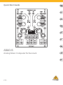 1
1
-
 2
2
-
 3
3
-
 4
4
-
 5
5
-
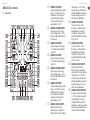 6
6
-
 7
7
-
 8
8
-
 9
9
-
 10
10
-
 11
11
-
 12
12
-
 13
13
-
 14
14
-
 15
15
-
 16
16
-
 17
17
-
 18
18
-
 19
19
-
 20
20
-
 21
21
-
 22
22
-
 23
23
-
 24
24
-
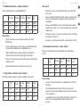 25
25
-
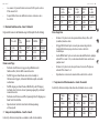 26
26
-
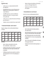 27
27
-
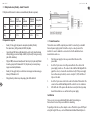 28
28
-
 29
29
-
 30
30
-
 31
31
-
 32
32
-
 33
33
-
 34
34
-
 35
35
-
 36
36
-
 37
37


in andere talen
- italiano: Behringer ABACUS Guida Rapida
- français: Behringer ABACUS Guide de démarrage rapide
- español: Behringer ABACUS Guía de inicio rápido
- Deutsch: Behringer ABACUS Schnellstartanleitung
- português: Behringer ABACUS Guia rápido
- polski: Behringer ABACUS Skrócona instrukcja obsługi
