PEHA Compact 952 JRM Operating Instructions Manual
- Type
- Operating Instructions Manual

O0 O1 O4L0
O8 O11
O12 O15
L2 O19 O22 L3
O3 O5 L0 O6 O7 O9 O10 L1 L1
O13
O14 O16 O17
L2
O18 O20
O21
O23 L3
O2
M0 M1 M2 M3 M4 M5 M6 M7
M8
M9 M10 M11
0VI6 I7 I8I5I4I2I1 I3I0 0VI15 I16I17I14I13I11I10 I12I9 0VI24 I25I26I23I22I20I19 I21I18 0VI33 I34
I35
I32I31I29I28 I30I27
36 x Input 24V
µ µµ µµ µ
µ µ µ µ
µ µ µ µµ µµ µ µ µµ µµ µ
9 m m
95 2 JRM
C o m p a c t
14 : 14 17 . 10. 2012
compact
PRO G E N T E R
Sta tu s
LN
0 24
B u s In B u s O u t
M
12 x 1A
100- 240V
~
/ 50- 6 0Hz
1 0 0 - 240 V
~
5 0 - 6 0 Hz
24V
1 0 0 mA
PEHA_M_952JRM (Rev01-130308)
PEHA Elektro GmbH & Co. KG
Compact 952 JRM
ELEKTROPLANET AG
IHR PARTNER FÜR DIE ELEKTROBRANCHE
INDUSTRIESTRASSE 2
CH - 8335 HITTNAU
+41 (0) 44 950 10 10
+41 (0) 44 950 10 44
WWW.ELEKTROPLANET.CH

ELEKTROPLANET AG
IHR PARTNER FÜR DIE ELEKTROBRANCHE
INDUSTRIESTRASSE 2
CH - 8335 HITTNAU
+41 (0) 44 950 10 10
+41 (0) 44 950 10 44
WWW.ELEKTROPLANET.CH

PEHA Elektro GmbH & Co. KG
Compact 952 JRM
Bedienungsanleitung
D
ELEKTROPLANET AG
IHR PARTNER FÜR DIE ELEKTROBRANCHE
INDUSTRIESTRASSE 2
CH - 8335 HITTNAU
+41 (0) 44 950 10 10
+41 (0) 44 950 10 44
WWW.ELEKTROPLANET.CH

D-2
Aufbau & Beschreibung ............................................ 3
Sicherheit ................................................................. 4
Technische Daten ..................................................... 5
Bedienung ................................................................6
Gerätemenü ..........................................................................6
Schaltuhren (Motor / Gruppe) .................................................. 7
Uhrzeit / Datum .....................................................................8
Sprache ................................................................................ 9
Laufzeiten .............................................................................10
Motor-Typ .............................................................................. 11
Gruppen ................................................................................12
Automatik .............................................................................13
Sensorik ................................................................................14
Windsensor............................................................................15
Gruppe 2 kongurieren ...........................................................16
Versatzzeit ............................................................................ 17
Broadcast .............................................................................. 18
Werkseinstellung / Version ....................................................... 19
Funktionen ............................................................... 20
Prioritäten ................................................................ 23
Erweiterung durch zusätzliche PHC-Module .............24
Montage und Installation ......................................... 25
Sicherheitshinweis ..................................................................25
Montage ................................................................................25
Installation ............................................................................ 25
Compact Bus .........................................................................25
Planungshilfe ...........................................................26
Störungsdiagnose-/behebung (Elektrofachkraft) .....27
Neuanlage oder vorhandene Anlage .......................................... 27
EMV-Probleme........................................................................27
Motor fährt nicht oder in die falsche Richtung .............................27
FAQ - LISTE ..............................................................28
Allgemeines .............................................................. 31
Entsorgung des Gerätes .......................................................... 31
Garantiebestimmungen ........................................................... 31
Kontakt ................................................................................. 31
INHALTSVERZEICHNIS
ELEKTROPLANET AG
IHR PARTNER FÜR DIE ELEKTROBRANCHE
INDUSTRIESTRASSE 2
CH - 8335 HITTNAU
+41 (0) 44 950 10 10
+41 (0) 44 950 10 44
WWW.ELEKTROPLANET.CH

D-3
D
Mit dem Compact 952 JRM wird eine komfortable Ansteuerung von Rollladen, Jalousien und Markisen ermöglicht, bei der keine Programmierung von
dem Anwender vorgenommen werden muss. Alle Funktionen sind vorprogrammiert und den Ein- und Ausgängen zugeordnet. Die Installation kann nach
einer Funktionstabelle und einem Anschlussbild erfolgen.
O0 O1 O4L0
O8 O11
O12 O15
L2 O19 O22 L3
O3 O5 L0 O6 O7 O9 O10 L1 L1
O13
O14 O16 O17
L2
O18 O20
O21
O23 L3
O2
M6 M7
M8
µ µµ µµ µ
9 m m
95 2 JRM
C o m p a c t
14 : 14 17 . 10. 2012
PRO G
Sta tu s
0 24
24V
1 0 0 mA
PROG, ,
, ENTER
Bedienung Gerätemenü
und Geräteeinstellungen
Beleuchtete LCD Anzeige
O0 O1 O4
L0
O12 O15
L2
O19 O22 L3
O3 O5 L0 O6 O7 O9 O10 L1 L1
O0 O1 O4
O3 O5 L0 O6 O7 O9 O10 L1 L1
O0 O1 O4
O8O3 O5 L0 O6 O7 O9 O10 L1 L1O8
O11O3 O5 L0 O6 O7 O9 O10 L1 L1O11
O13
O12 O15
O13
O12 O15
O14 O16 O17
O12 O15O14 O16 O17O12 O15
L2
O18 O20
O19 O22 L3O18 O20O19 O22 L3
O21
O19 O22 L3
O21
O19 O22 L3
O23 L3
O19 O22 L3
O23 L3
O19 O22 L3
O2
O0 O1 O4
O2
O0 O1 O4
M6 M7
M6 M7
M6 M7
M8
µ µµ µµ µ
µ µµ µµ µ
µ µµ µµ µ
µ µµ µµ µ
µ µµ µµ µ
µ µµ µµ µ
µ µµ µµ µ
µ µµ µµ µ
M6 M7
µ µµ µµ µ
M6 M7
M6 M7
µ µµ µµ µ
M6 M7
M6 M7
µ µµ µµ µ
M6 M7
M8
µ µµ µµ µ
M8
9 m m
95 2 JRM95 2 JRM
0 24
0 24
24V
1 0 0 mA
Das Jalousie-/Rollladenmodul (JRM) kann 12 motorgetriebene Rollladen, Jalousien und Markisen ansteuern. Sie können variabel 3 Gruppen (0-2) zuge-
ordnet werden. Die Handbedienung erfolgt lokal, zentral oder in Gruppen mit Doppeltastern. Eine zeitabhängige Ansteuerung der Ausgänge (Motoren)
ist über programmierte Schaltuhren möglich. Mit Sensoren kann die Ansteuerung in Abhängigkeit vom Tageslicht und Wetter erfolgen. Nach einem
Stromausfall sind alle Motoren im Ruhezustand. Im Oberteil des Moduls bendet sich eine Status-LED, die im Betrieb bei angelegter Betriebsspannung
grün blinkt. Leuchtet die Status-LED rot, ist der Bootloader aktiv.
AUFBAU & BESCHREIBUNG
ELEKTROPLANET AG
IHR PARTNER FÜR DIE ELEKTROBRANCHE
INDUSTRIESTRASSE 2
CH - 8335 HITTNAU
+41 (0) 44 950 10 10
+41 (0) 44 950 10 44
WWW.ELEKTROPLANET.CH

D-4
VORSICHT! Gefahr eines Stromschlages!
Im Inneren des Gehäuses benden sich spannungsführende Teile. Eine Berührung kann eine Körperverletzung zur Folge haben!
Alle Arbeiten am Versorgungsnetz und Gerät dürfen nur von autorisierten Elektrofachkräften durchgeführt werden.
• Gerät spannungsfrei schalten.
• Gerät gegen Wiedereinschalten sichern.
• Gerät auf Spannungsfreiheit überprüfen.
• Vor dem Einschalten Gehäuse fest verschließen.
Folgende Punkte sind zu berücksichtigen: Folgende Anlagen dürfen nicht geschaltet werden:
• Die geltenden Gesetze, Normen und Vorschriften. • Sicherheitsschaltungen wie NOT AUS
• Die Bedienungsanleitung des Gerätes. • Notstromversorgungen
• Der Stand der Technik zum Zeitpunkt der Installation. • Feueralarmanlagen
• Eine Bedienungsanleitung kann nur allgemeine Bestimmungen anführen.
• Notbeleuchtungsanlagen
Diese sind im Zusammenhang mit einer spezischen Anlage zu sehen.
Das Gerät ist nur für die bestimmungsgemäße Verwendung vorgesehen. Ein eigenmächtiger Umbau oder eine Veränderung ist verboten! Es darf nicht in
Verbindung mit anderen Geräten verwendet werden, durch deren Betrieb Gefahren für Menschen, Tiere oder Sachwerte entstehen können.
SICHERHEIT
ELEKTROPLANET AG
IHR PARTNER FÜR DIE ELEKTROBRANCHE
INDUSTRIESTRASSE 2
CH - 8335 HITTNAU
+41 (0) 44 950 10 10
+41 (0) 44 950 10 44
WWW.ELEKTROPLANET.CH

D-5
D
Betriebsspannung 952 JRM 100-240V~ /50-60Hz
Absicherung der Versorgungsleitungen Sicherungsautomat max. 10 A
Spannungsversorgung Compact System Nom. 24 V DC (SELV), 21-28 V DC (Brummspannung 5 %)
Sensoranschluss 24 V DC / 100 mA
Motorlast je Ausgang 100-240V~ /50-60Hz maximal 1A
Eigenverbrauch (Standby) ca. 2 W
Eingangswiderstand 1 kΩ
Kontaktwiderstand der Eingänge Max. 33 Ohm (entspricht < 1V DC bei 24 mA)
Eingangssignale > 40ms
Max. Leitungslänge der 24V-Leitung 400 m bei d = 0,8 mm (exible oder starre Leitung max. 1x 1,5 mm²), Abisolierlänge = 8 mm
Leiterquerschnitt der 230V-Leitungen Flexible Leitung: max. 1x 1,5 mm², Starre Leitung: max. 1x 2,5 mm², Abisolierlänge = 8 mm
Umgebungstemperatur +10° bis +40°C
Lagertemperatur –20° bis +60°C
Prüfvorschriften EN 60669-2-1 , EN 50428
Kennzeichnung CE, KEMA
Schutzart IP20
Abmessungen Breite = 216mm (12TE), Höhe = 55mm
TECHNISCHE DATEN
ELEKTROPLANET AG
IHR PARTNER FÜR DIE ELEKTROBRANCHE
INDUSTRIESTRASSE 2
CH - 8335 HITTNAU
+41 (0) 44 950 10 10
+41 (0) 44 950 10 44
WWW.ELEKTROPLANET.CH

D-6
95 2 JRM
R o l l l a d e n m o d u l
Mo 13: 5 7
compact
PRO G E N T E R
Sta tu s
LN
0 24
B u s In B u s O u t
M
12 x 1A
100- 240V
~
/ 50- 6 0Hz
1 0 0 - 240 V
~
5 0 - 6 0 Hz
24V
1 0 0 mA
C o m p a c t
14 : 14 17 . 10. 12
BEDIENUNG
GERÄTEMENÜ
G e r ä t e m e n ü
01 Schaltuhren Seite 7
02 Uhrzeit/Datum Seite 8
03 Sprache Seite 9
04 Laufzeiten Seite 10
05 Motor-Typ Seite 11
06 Gruppen Seite 12
07 Automatik Seite 13
08 Sensorik Seite 14
09 Windsensor Seite 15
10 Gruppe 2 konfig. Seite 16
11 Versatzzeit Seite 17
12 Broadcast Seite 18
13 Werkseinstellung Seite 19
14 Version Seite 19
A u s w a h l :
A k t i v i e r e n : Enter
B e e n d e n : Prog
Beenden
P r o g d r ü c k e n
Aktivieren
P r o g d r ü c k e n
ELEKTROPLANET AG
IHR PARTNER FÜR DIE ELEKTROBRANCHE
INDUSTRIESTRASSE 2
CH - 8335 HITTNAU
+41 (0) 44 950 10 10
+41 (0) 44 950 10 44
WWW.ELEKTROPLANET.CH

D-7
D
BEDIENUNG
SCHALTUHREN (MOTOR /GRUPPE)
Hinweis: Für Motoren und Gruppen können automatische Fahrzeiten (Schaltuhren) eingestellt werden. Wird die Schaltuhr auf 00:00 eingestellt,
ist die Schaltuhr deaktiviert. Eine deaktivierte Schaltuhr wird mit dem Symbol --:-- angezeigt.
Auswahl:
Beenden: Prog
01 Schaltuhren
G e r ä t e m e n ü
Einstellung:
M 0 1
Mo - F r 07: 30
S a - S o 09: 00
M o t o r / G r u p p e
Einstellung:
M01
Mo - F r 07: 30
S a - S o 09: 00
L a u f r i c h t u n g
Enter
Einstellung:
Auswahl: Enter
M01
Mo - F r 07: 30
S a - S o 09: 00
S c h a l t u h r
Enter
Prog
Prog
Enter
Enter
Werkseinstellung Motoren Gruppen
Montag bis Freitag:
(
AUF) = --:-- (Aus)
(
AB) = --:-- (Aus)
M0 - M11 G0, G1, G2 , Zentral
Samstag u. Sonntag:
(
AUF) = --:-- (Aus)
(
AB) = --:-- (Aus)
ELEKTROPLANET AG
IHR PARTNER FÜR DIE ELEKTROBRANCHE
INDUSTRIESTRASSE 2
CH - 8335 HITTNAU
+41 (0) 44 950 10 10
+41 (0) 44 950 10 44
WWW.ELEKTROPLANET.CH

D-8
UHRZEIT /DATUM
Hinweis: Die Uhrzeit (MEZ) muss bei der Inbetriebnahme des Moduls eingestellt werden!
Mit So/Wi wird die automatische Umschaltung der Sommer- und Winterzeit eingestellt.
Werkseinstellung
Sommerzeit (So) / Winterzeit (Wi) Auto: Ja
BEDIENUNG
U h r z e i t: 12: 00
D a tum : 21. 12. 12
U h r z e i t
U h r z e i t: 12: 00
D a tum : 21. 12. 12
D a t u m
Enter
S o / W i A uto : Ja
S o / W i
Enter
Prog
Prog
Enter
Enter
Einstellung:
Auswahl: Enter
Einstellung:
Auswahl: Enter
Einstellung:
Auswahl:
Beenden: Prog
02 Uhrzeit / Datum
G e r ä t e m e n ü
ELEKTROPLANET AG
IHR PARTNER FÜR DIE ELEKTROBRANCHE
INDUSTRIESTRASSE 2
CH - 8335 HITTNAU
+41 (0) 44 950 10 10
+41 (0) 44 950 10 44
WWW.ELEKTROPLANET.CH

D-9
D
SPRACHE
BEDIENUNG
Einstellung:
S pr a c h e
D e uts c h
S p r a c h e
Enter
Prog
Werkseinstellung
Sprache: Deutsch
Auswahl:
Beenden: Prog
03 Sprache
G e r ä t e m e n ü
ELEKTROPLANET AG
IHR PARTNER FÜR DIE ELEKTROBRANCHE
INDUSTRIESTRASSE 2
CH - 8335 HITTNAU
+41 (0) 44 950 10 10
+41 (0) 44 950 10 44
WWW.ELEKTROPLANET.CH

D-10
LAUFZEITEN
BEDIENUNG
Enter
Prog
Einstellung:
M 0 1
120s
M o t o r 0 0 - 1 1
Enter
Prog
Enter
Einstellung:
M01
120 s
L a u f z e i t e n
Auswahl:
Beenden: Prog
04 Laufzeiten
G e r ä t e m e n ü
Werkseinstellung Laufzeit je Motor
Laufzeit: 120s 20 bis 900 Sek.
ELEKTROPLANET AG
IHR PARTNER FÜR DIE ELEKTROBRANCHE
INDUSTRIESTRASSE 2
CH - 8335 HITTNAU
+41 (0) 44 950 10 10
+41 (0) 44 950 10 44
WWW.ELEKTROPLANET.CH

D-11
D
MOTOR-TYP
BEDIENUNG
Hinweis: Die Ausgänge des Compact Moduls sind zur individuellen Ansteuerung von Rollladen, Jalousien oder Markisen geeignet. Für jeden
Ausgang ist der Motor-Typ einstellbar. Bei der Jalousie dient die Verstellzeit (T) zur automatischen Verstellung der Lamellen bei Ein-Signal des
Sonnensensors. Bei der Markise wird die Verstellzeit (T) zur Entlastung beim Schließen der Markise berücksichtigt.
Werkseinstellung Verstellzeit Motor-Typ
Verstellzeit: T: 0.5s 0 bis 5 Sek. Rolllade, Jalousie, Markise
Motor-Typ: Jalousie
Enter
Auswahl:
Beenden: Prog
05 Motor-Typ
G e r ä t e m e n ü
Einstellung:
M 0 1
T : 0. 5s
T y p:
J a l o us i e
M o t o r 0 0 - 1 1
Einstellung:
M0
T : 0. 5s
T y p:
Jalousie
M o t o r - T y p
Enter
Prog
Enter
M0
T: 0.5s
T y p:
J a l o us i e
V e r s t e l l z e i t
Enter
Einstellung:
ELEKTROPLANET AG
IHR PARTNER FÜR DIE ELEKTROBRANCHE
INDUSTRIESTRASSE 2
CH - 8335 HITTNAU
+41 (0) 44 950 10 10
+41 (0) 44 950 10 44
WWW.ELEKTROPLANET.CH

D-12
GRUPPEN
BEDIENUNG
Hinweis: Die Motoren können separat den Gruppen zugeordnet werden. In der Zentral-Gruppe sind ab Werk alle Motoren aktiviert.
Enter
Prog
Einstellung:
G r u p p e 0
012
------- -- --
G r u p p e
Enter
Prog
Enter
Einstellung:
Gruppe 0
012
------- -- --
M o t o r z u o r d n e n
Einstellung:
Gruppe 0
012
------- --
11
M o t o r z u o r d n e n
Enter
Motor
1-11
Auswahl:
Beenden: Prog
06 Gruppen
G e r ä t e m e n ü
Werkseinstellung
Gruppe 0: Motor M0-M2 Gruppe 2: Motor M6-M8
Gruppe 1: Motor M3-M5 Zentral: Motor M0-M11
ELEKTROPLANET AG
IHR PARTNER FÜR DIE ELEKTROBRANCHE
INDUSTRIESTRASSE 2
CH - 8335 HITTNAU
+41 (0) 44 950 10 10
+41 (0) 44 950 10 44
WWW.ELEKTROPLANET.CH

D-13
D
AUTOMATIK
BEDIENUNG
Enter
Prog
Einstellung:
M 0 1
E i n
S c h a l tuh r
M o t o r 0 0 - 1 1
Einstellung:
M01
E i n
S c h a l tuh r
L a u f r i c h t u n g
Enter
Prog
Enter
M01
E i n
S c h a l tuh r
S t a t u s
Enter
Einstellung:
M01
E i n
S c h a l tuh r
S e n s o r i k
Enter
Einstellung:
Hinweis: Die Automatik beinhaltet den Dämmerungssensor, Sonnensensor und die Schaltuhr. Die Automatik kann separat für jeden Ausgang
(Motor) ein- und ausgeschaltet werden. Dämmerungssensor und Schaltuhr sind kombinierbar (s. Seite 21 Automatik).
Werkseinstellung Status Sensorik
Automatik: Ein EIN: Automatik EIN Schaltuhr
AUF-Funktion: Schaltuhr AUS: Automatik AUS Dämmerung
AB-Funktion: Schaltuhr + Dämmerung I32: Automatik EIN/AUS (Schalter am Eingang I32) Schaltuhr + Dämmerung
Auswahl:
Beenden: Prog
07 Automatik
G e r ä t e m e n ü
ELEKTROPLANET AG
IHR PARTNER FÜR DIE ELEKTROBRANCHE
INDUSTRIESTRASSE 2
CH - 8335 HITTNAU
+41 (0) 44 950 10 10
+41 (0) 44 950 10 44
WWW.ELEKTROPLANET.CH

D-14
SENSORIK
BEDIENUNG
Hinweis: Jedem Ausgang (Motor) können separat Sensoren zugeordnet werden. Bei Sonnenfahrten ist es möglich die Senkzeit einzustellen.
Sonnensensor 2 u. 3 stehen zur Verfügung
, wenn der Modus der Gruppe 2 auf
„Sensoren“ eingestellt wurde (s. Seite 16).
Einstellung:
M 0 1
K e i n S e ns o r
M o t o r 0 0 - 1 1
Einstellung:
M01
T : 10s
S o nne 1- 3
S e n s o r
Enter
M01
T : 10s
W i nd + S o nne 1- 3
M01
W i nd
M01
K e i n S e ns o r
Enter
Enter
Enter
Prog
M01
T : 10s
S o nne 1- 3
S e n k z e i t
Einstellung:
M01
T : 10s
W i nd + S o nne 1- 3
Enter
Enter
Enter
Enter
Werkseinstellung Einstellbare Sensorik für Motoren
Sensorik: Kein Sensor Kein Sensor, Wind, Sonne 1-3, Wind + Sonne 1-3
Auswahl:
Beenden: Prog
08 Sensorik
G e r ä t e m e n ü
ELEKTROPLANET AG
IHR PARTNER FÜR DIE ELEKTROBRANCHE
INDUSTRIESTRASSE 2
CH - 8335 HITTNAU
+41 (0) 44 950 10 10
+41 (0) 44 950 10 44
WWW.ELEKTROPLANET.CH

D-15
D
BEDIENUNG
WINDSENSOR
Auswahl:
Beenden: Prog
09 Windsensor
G e r ä t e m e n ü
Enter
Prog
Einstellung:
M 0 1
S ta nd a r d
M o t o r 0 0 - 1 1
Enter
Prog
Enter
Einstellung:
M01
Standard
V e r r i e g e l u n g
Hinweis: Bei Verriegelung „Standard“
fahren die Motoren bei Windalarm AUF
und werden verriegelt. Wird die Verriegelung auf „Blockierend“
eingestellt, bleibt der zugehörige Ausgang bei Windalarm eingeschaltet. Diese Funktion ndet Verwendung in Anlagen, in denen eine Verriegelung
über externe Schütze erfolgt.
Für alle Motoren mit zugeordneten Windsensor ist die lokale Bedienung mit Tastern bei Windalarm gesperrt.
Werkseinstellung Verriegelung
Verriegelung: Standard Standard, Blockierend
ELEKTROPLANET AG
IHR PARTNER FÜR DIE ELEKTROBRANCHE
INDUSTRIESTRASSE 2
CH - 8335 HITTNAU
+41 (0) 44 950 10 10
+41 (0) 44 950 10 44
WWW.ELEKTROPLANET.CH

D-16
BEDIENUNG
GRUPPE 2 KONFIGURIEREN
Hinweis:
Bei der Einstellung „Sensoren“ ist die Gruppe 2 deaktiviert! Der Eingang I30 und I31 der Gruppe 2 steht dann zum Anschluss eines
Sonnensensors 2 und 3 zur Verfügung.
Auswahl:
Beenden: Prog
10 Gruppe2 konf.
G e r ä t e m e n ü
Enter
Prog
Einstellung:
Mo d us G r uppe 2:
Standard
M o d u s
Werkseinstellung Modus
Modus: Standard Standard, Sensoren
ELEKTROPLANET AG
IHR PARTNER FÜR DIE ELEKTROBRANCHE
INDUSTRIESTRASSE 2
CH - 8335 HITTNAU
+41 (0) 44 950 10 10
+41 (0) 44 950 10 44
WWW.ELEKTROPLANET.CH

D-17
D
BEDIENUNG
VERSATZZEIT
Auswahl:
Beenden: Prog
11 Versatzzeit
G e r ä t e m e n ü
Enter
Prog
Einstellung:
Ve r s a tz z e i t
0. 0s
V e r s a t z z e i t
Werkseinstellung Versatzzeit
Versatzzeit: 0,0s 0,0 bis 5,0 Sekunden
Für Gruppen-, Zentralfahrten und Automatikfahrten kann eine Versatzzeit eingestellt werden. Diese ermöglicht es, dass nicht alle Motoren gleich-
zeitig einschalten. Bei einer Versatzzeit von 1 Sekunde schaltet z.B. der erste Motor ein, nach einer Sekunde der Nächste Motor, usw. !
ELEKTROPLANET AG
IHR PARTNER FÜR DIE ELEKTROBRANCHE
INDUSTRIESTRASSE 2
CH - 8335 HITTNAU
+41 (0) 44 950 10 10
+41 (0) 44 950 10 44
WWW.ELEKTROPLANET.CH

D-18
BEDIENUNG
BROADCAST
Hinweis: In einer Anlage mit mehreren Compact Modulen ist es möglich eine gemeinsame Sensorik einzusetzen. Die Module müssen über den
Compact Bus miteinander verbunden sein (s. Seite 24). Das Modul mit den angeschlossenen Sensoren ist das erste Modul im Bus und als Master
zu kongurieren. Alle nachfolgenden Module werden als Slave konguriert. Die Sensordaten werden alle 2 Minuten und bei Änderung eines Sen-
sorenwertes über den Compact Bus gesendet. Bei Änderung des Modus erfolgt ein Neustart des Moduls!
Einstellung:
Mo d us : Aus
M o d u s
Auswahl:
Beenden: Prog
12 Broadcast
G e r ä t e m e n ü
Werkseinstellung Modus Sensorik
Modus: Aus Aus, Master, Slave Extern (Ext.): Externe Sensordaten
Intern (Int.): Interne Sensoren
Enter
Prog
Prog
Enter
Mo d us : Slave
A uto m a ti k : E x t .
D ä m m e r ung : Ext.
S o nne 1: Ext.
S o nne 2: Ext.
S o nne 3: Ext.
W i nd : Ext.
M o d u s
Einstellung:
Auswahl: Enter
Externe Sensordaten (Compact Bus)
• Automatik
• Wind / Regen
• Dämmerung
• Sonne 1
• Sonne 2
• Sonne 3
Interne Sensoren
Moduleingang I30-I35
ELEKTROPLANET AG
IHR PARTNER FÜR DIE ELEKTROBRANCHE
INDUSTRIESTRASSE 2
CH - 8335 HITTNAU
+41 (0) 44 950 10 10
+41 (0) 44 950 10 44
WWW.ELEKTROPLANET.CH

D-19
D
WERKSEINSTELLUNG / VERSION
BEDIENUNG
Auswahl:
Beenden: Prog
13 Werkseinst.
G e r ä t e m e n ü
Enter
Abbruch: Taste P r o g
W e r k s e i ns te l l ung
A b b r uc h OK
W e r k s e i n s t e l l u n g
Wird das Gerät auf die Werkseinstellungen zurückgesetzt, bleibt die Uhrzeit erhalten. Unter dem Menüpunkt „Version“ erfolgt die Anzeige der
aktuellen Version der Gerätesoftware.
B e s tä ti g ung : E nte r 3s d r ü c k e n
Auswahl:
Beenden: Prog
14 Version
G e r ä t e m e n ü
Enter
Prog
Ve r s i o n
1. 0
V e r s i o n
ELEKTROPLANET AG
IHR PARTNER FÜR DIE ELEKTROBRANCHE
INDUSTRIESTRASSE 2
CH - 8335 HITTNAU
+41 (0) 44 950 10 10
+41 (0) 44 950 10 44
WWW.ELEKTROPLANET.CH

D-20
FUNKTIONEN
Funktion Beschreibung
Allgemein
Das JRM kann 12 motorgetriebene Rollladen, Jalousien und Markisen (M0-M11) ansteuern. Sie können variabel 3 Gruppen
(0-2) zugeordnet werden. Die Handbedienung erfolgt lokal, zentral oder in Gruppen mit Doppeltastern. Eine zeitabhängige
Ansteuerung der Ausgänge (Motoren) ist über programmierte Schaltuhren möglich. Mit Sensoren kann die Ansteuerung in
Abhängigkeit von dem Tageslicht und Wetter erfolgen.
– Die Ausgänge sind den Eingängen fest zugeordnet und elektrisch gegeneinander verriegelt.
– Nach einem Stromausfall sind alle Motoren im Ruhezustand.
Tastbetrieb
Rolllade
Bei langem Tastendruck wird die Rolllade mit der eingestellten Laufzeit AUF oder AB gefahren. Mit einem kurzen Tastendruck
wird die Rolllade gestoppt. Der Tippbetrieb ist nicht möglich.
Tastbetrieb
Jalousie
Bei langem Tastendruck wird die Jalousie mit der eingestellten Laufzeit AUF oder AB gefahren. Mit einem kurzen Tastendruck
wird die Jalousie gestoppt. Ein Tippbetrieb zur Verstellung der Lamellen ist möglich.
Hinweis: Nach einer manuellen Bedienung mit einem Taster wird der Sonnensensor solange ignoriert, bis die Jalousie
einmal komplett AUF gefahren wird (z.B. mit Zentral AUF)!
Tastbetrieb
Markise
Bei langem Tastendruck wird die Markise mit der eingestellten Laufzeit geöffnet oder geschlossen. Mit einem kurzen Ta-
stendruck wird die Markise gestoppt. Der Tippbetrieb ist nicht möglich. Wird die Markise ohne Stopp geschlossen, wird eine
einstellbare Verstellzeit (0-5 Sek.) zur Entlastung der Markise berücksichtigt.
ELEKTROPLANET AG
IHR PARTNER FÜR DIE ELEKTROBRANCHE
INDUSTRIESTRASSE 2
CH - 8335 HITTNAU
+41 (0) 44 950 10 10
+41 (0) 44 950 10 44
WWW.ELEKTROPLANET.CH

D-21
D
Funktion Beschreibung
Tastbetrieb
Zentral
Bei langem Tastendruck werden alle Motoren der Zentral-Gruppe AUF oder AB gefahren. Mit einem kurzen Tastendruck
stoppen die Motoren. Ein Tippbetrieb ist nicht möglich! In der Zentral-Gruppe sind ab Werk alle Motoren aktiviert.
Tip: Die Motoren mehrerer JRM können zentral gesteuert werden. Dazu ist zwischen den Tastern für Zentral AUF/AB und
den Eingängen I24 und I25 ein Relais zu schalten.
Tastbetrieb
Gruppe
Bei langem Tastendruck werden die Motoren der Gruppen AUF oder AB gefahren. Mit einem kurzen Tastendruck stoppen
die Motoren. Ein Tippbetrieb ist nicht möglich!
– Die Motoren des JRMs können 3 Gruppen (0-2) variabel zugeordnet werden (s. Seite 12).
– Wenn der Modus von Gruppe 2 auf
„Sensoren“ eingestellt wurde, steht
Gruppe 2 nicht zur Verfügung (s. Seite 16)!
Automatik
Die Automatik beinhaltet den Dämmerungssensor, Sonnensensor und die Schaltuhr. Die Automatik kann separat für jeden
Ausgang ein- und ausgeschaltet werden. Alternativ ist es möglich die Automatik mit einem Schalter am Eingang I32 des
JRM Moduls ein- und auszuschalten. Dazu ist der entsprechende Ausgang dem Eingang I32 zuzuordnen (s. Seite 13).
Dämmerungssensor und Schaltuhr sind miteinander kombinierbar. Morgens fahren die Motoren erst nach Einschalten der
Schaltuhr und Aus-Signal des Dämmerungssensors AUF. Abends fahren die Motoren bei Einschalten der Schaltuhr oder bei
Ein-Signal des Dämmerungssensors AB.
Hinweis: Ist die Automatik ausgeschaltet, können der Sonnen-/ Dämmerungssensor und die Schaltuhr nicht genutzt werden!
FUNKTIONEN
ELEKTROPLANET AG
IHR PARTNER FÜR DIE ELEKTROBRANCHE
INDUSTRIESTRASSE 2
CH - 8335 HITTNAU
+41 (0) 44 950 10 10
+41 (0) 44 950 10 44
WWW.ELEKTROPLANET.CH

D-22
FUNKTIONEN
Funktion Beschreibung
Schaltuhren
Mit den Schaltuhren des JRMs können Motoren und Gruppen zeitgesteuert AUF und AB gefahren werden. Wird die Schaltuhr
auf 00:00 eingestellt ist die Schaltuhr ausgeschaltet. Die Programmierung der Schaltuhren erfolgt über die Tastatur und
Anzeige des JRMs (s. Seite 7). Für eine korrekte Funktion ist die Automatik einzuschalten!
Dämmerungssensor
Bei EIN-Signal des Dämmerungssensors fahren Motoren bei Dämmerung AB. Bei AUS-Signal fahren die Motoren AUF.
Erfolgt
ein Ein-Signal des
Dämmerungssensors
bei aktiven Wind-/Regensensor, wird nach dem AUS-Signal des Wind-/Regensen-
sors das Ein-Signal nachgeholt. Für eine korrekte Funktion ist die Automatik einzuschalten!
Sonnensensor
Bei Ein-Signal des Sonnensensors fahren alle zugeordneten Motoren AB (1s Lamellenverstellung für Jalousien). Bei Aus-
Signal fahren die Motoren AUF. Die Sensorzuordnung und die Senkzeit ist für jeden Motor einstellbar (s. Seite 14). Erfolgt
ein Ein-Signal des Sonnensensors bei aktiven Wind-/Regensensor, wird nach AUS-Signal des Wind-/Regensensors das Ein-
Signal nachgeholt. Für eine korrekte Funktion ist die Automatik einzuschalten!
Hinweis: Bei einer Ansteuerung des Motors mit einem Taster oder anderem Sensor, wird der Sonnensensor solange igno-
riert, bis der Motor einmal komplett AUF gefahren wird (z.B. mit Taster zentral AUF)!
Wind-/ Regensensor
Bei Ein-Signal des Sensors fahren alle zugeordneten Motoren AUF und werden verriegelt. Dies ist besonders für Markisen zu
empfehlen! Eine manuelle Bedienung mit Tastern ist dann nicht möglich. Bei AUS-Signal sind alle Motoren wieder entriegelt.
Die Sensorzuordnung ist für jeden Motor einstellbar (s. Seite 14).
ELEKTROPLANET AG
IHR PARTNER FÜR DIE ELEKTROBRANCHE
INDUSTRIESTRASSE 2
CH - 8335 HITTNAU
+41 (0) 44 950 10 10
+41 (0) 44 950 10 44
WWW.ELEKTROPLANET.CH

D-23
D
Eingangsfunktion Priorität Beschreibung
Wind-/ Regensensor 0
Der Wind-/Regensensor hat die höchste Priorität.
Das Signal eines Sensors mit niedrigerer Priorität oder die Bedienung eines Tasters wird ignoriert.
Taster 1 Die Bedienung eines Tasters beendet alle Eingangsfunktionen mit niedrigerer Priorität.
Dämmerungssensor 2 Die Eingangsfunktion “Dämmerungssensor” beendet alle Eingangsfunktionen mit niedrigerer Priorität.
Sonnensensor 3
Der Sonnensensor hat die niedrigste Priorität. Das Signal eines Sensors mit höherer Priorität oder die Bedienung
eines Tasters beendet die Eingangsfunktion “Sonnensensor” für alle zugeordneten Motoren.
PRIORITÄTEN
ELEKTROPLANET AG
IHR PARTNER FÜR DIE ELEKTROBRANCHE
INDUSTRIESTRASSE 2
CH - 8335 HITTNAU
+41 (0) 44 950 10 10
+41 (0) 44 950 10 44
WWW.ELEKTROPLANET.CH

D-24
ERWEITERUNG DURCH ZUSÄTZLICHE PHC-MODULE
Eine ausführliche Dokumentation zur Erweiterung des Compact JRMs mit zusätzlichen Modulen, kann über die Internetseite www.peha.de
heruntergeladen werden. Diese ist im Bereich PEHA Produkte Gebäudesystemtechnik PHC-Compact zu nden.
Wahlweise kann zur Erweiterung ein PHC Easyclick Funkinterface 940 FU-C oder 941 FU-C angeschlossen werden. Dadurch können mit Funktastern
Rollladen angesteuert werden. Einzelbedienungen und Gruppenbedienungen sind möglich.
Eine weitere Erweiterungsmöglichkeit ergibt sich mit zwei PHC JRM Modulen und einem PHC Eingangsmodul. Durch die Erweiterung können insgesamt
maximal 20 Rollladen angesteuert werden.
Die Erweiterungen sehen wie folgt aus:
O0 O1 O4L0
O8 O11
O12 O15
L2 O19 O22 L3
O3 O5 L0 O6 O7 O9 O10 L1 L1
O13
O14 O16 O17
L2
O18 O20
O21
O23 L3
O2
M0 M1 M2 M3 M4 M5 M6 M7
M8
M9 M10 M11
0VI6 I7 I8I5I4I2I1 I3I0 0VI15I16I17I14I13I11I10 I12I9 0VI24I25I26I23I22I20I19 I21I18 0VI33I34
I35
I32I31I29I28 I30I27
36 x Input 24V
µ µµ µµ µ
µ µ µ µ
µ µ µ µµ µµ µ µ µµ µµ µ
9 m m
95 2 JRM
C o m p a c t
14 : 14 17 . 10. 2012
compact
PRO G E N T E R
Sta tu s
LN
0 24
B u s In B u s O u t
M
12 x 1A
100- 240V
~
/ 50- 6 0Hz
1 0 0 - 240 V
~
5 0 - 6 0 Hz
24V
1 0 0 mA
Send/Clear
Program
941 FU C
Funk-Interface
Empfangen
868,3 MHz
120 Funkeingänge
120 Funkausgänge
für EasyClick Sender/Empfänger
Senden
Rec ei v e
120 R ad i o Inputs/O utputs (86 8, 3 MHz )
PHC System
Inte r f ac e 9 41 F U C
T r a n smit
8 x Input / LED
0
0V
1
2
0V
3
4
0V
5
6
0V
7
I
I
I
I
I
I
I
I
8 x Input/ LED
8
0V
9 10
0V
11 1 2
140V 0V
13 15
I
I I
I
I
I
I I
Art. Nr.: 940/24 EM RÜ diag
Eingangsmodul 24V LED diag
CEBEC
0
1
2
3
4
56
7
8
9
10
11
12
13 14
15
29
16 Eingängefür Taster (16 Eingänge mit Rückmeldungen)
940 / 24 E M RÜ DIAG
PHC System
0123456 7
8 9 10 11 12 13 14 15
16 Inputs 30mA/1V DC f or P ush b uttons
O0 O1 O2 I0 I0 O3
O4 O5 O6 I1 I1 O7
M 0 M 1
M 2 M 3
1
ON
2345678
942 JRM DIAG
Status
CHDown
Up
PHC System
M
4A/250V AC (I
N
max 8x1A)
M
0
1
2
3
O0 O1 O2 I0 I0 O3
O4 O5 O6 I1 I1 O7
M 0 M 1
M 2 M 3
1
ON
2345678
942 JRM DIAG
Status
CHDown
Up
PHC System
M
4A/250V AC (I
N
max 8x1A)
M
0
1
2
3
952 JRM Compact 940/941 FU C PHC-EMD PHC-JRM PHC-JRM
ELEKTROPLANET AG
IHR PARTNER FÜR DIE ELEKTROBRANCHE
INDUSTRIESTRASSE 2
CH - 8335 HITTNAU
+41 (0) 44 950 10 10
+41 (0) 44 950 10 44
WWW.ELEKTROPLANET.CH

D-25
D
SICHERHEITSHINWEIS
Die Installation und Inbetriebnahme darf nur von autorisierten Elektrofachkräften durchgeführt werden. Bei der Installation an das Versorgungs netz
(230V~ /50Hz) ist die elektrische Anlage spannungfrei zu schalten. Es sind die geltenden Gesetze und Normen des Landes einzuhalten, in dem das
Gerät betrieben wird!
MONTAGE
Das 952 JRM ist für die Montage auf eine 35 mm Hutschiene nach EN 50022 im Verteilungs-Ein/Aufbaugehäuse mit geschraubter Abdeckung konzipiert.
Die Geräte können direkt nebeneinander eingebaut werden.
INSTALLATION
Siehe Beiblatt „Installationsanleitung“.
COMPACT BUS
Die Verbindung zwischen den Modulen
wird mit einer Busleitung über die Busanschlüsse (RJ12) hergestellt.
Der „Bus OUT “ Ausgang ist mit dem „Bus IN “ Eingang des nachfolgenden Moduls zu verbinden.
Das erste Modul im Bus ist als Master zu kongurieren. An diesem Modul erfolgt der Anschluss von gemeinsam
genutzten Sensoren über den Compact Bus (externe Sensordaten). Alle nachfolgenden Module werden als Slave
konguriert.
Die Einstellung als
Master/Slave erfolgt im Gerätemenü unter BROADCAST (s. Seite 18).
Achtung!
Vor Trennen der Busleitung ist die Stromversorgung abzuschalten.
Bus In Bus Out Bus In Bus Out
C o m p a c t 9 5 2 J R M C o m p a c t 9 5 2 J R M
B u s l e i t u n g
MONTAGE & INSTALLATION
ELEKTROPLANET AG
IHR PARTNER FÜR DIE ELEKTROBRANCHE
INDUSTRIESTRASSE 2
CH - 8335 HITTNAU
+41 (0) 44 950 10 10
+41 (0) 44 950 10 44
WWW.ELEKTROPLANET.CH

D-26
PLANUNGSHILFE
Ausgang
952 JRM
Motor
gehört zu Ausgangsgruppe
O
U
O
DS
O
SS
O
WS
O
G0
O
G1
O
G2
O1
M0 AUF
O0
M0 AB
O3
M1 AUF
O2
M1 AB
O5
M2 AUF
O4
M2 AB
O7
M3 AUF
O6
M3 AB
O9
M4 AUF
O8
M4 AB
O11
M5 AUF
O10
M5 AB
O
DS
Ausgänge mit zugeordneten Dämmerungssensor O
G0
Ausgänge der Gruppe 0 O
U
Ausgänge mit programmierten Schaltuhren
O
SS
Ausgänge mit zugeordneten Sonnensensor O
G1
Ausgänge der Gruppe 1
O
WS
Ausgänge mit zugeordneten Wind-/ Regensensor O
G2
Ausgänge der Gruppe 2
Ausgang
952 JRM
Motor
gehört zu Ausgangsgruppe
O
U
O
DS
O
SS
O
WS
O
G0
O
G1
O
G2
O13
M6 AUF
O12
M6 AB
O15
M7 AUF
O14
M7 AB
O17
M8 AUF
O16
M8 AB
O19
M9 AUF
O18
M9 AB
O21
M10 AUF
O20
M10 AB
O23
M11 AUF
O22
M11 AB
ELEKTROPLANET AG
IHR PARTNER FÜR DIE ELEKTROBRANCHE
INDUSTRIESTRASSE 2
CH - 8335 HITTNAU
+41 (0) 44 950 10 10
+41 (0) 44 950 10 44
WWW.ELEKTROPLANET.CH

D-27
D
NEUANLAGE ODER VORHANDENE ANLAGE
• Sicherungautomaten und Versorgungsspannungen überprüfen.
• Anschlussleitungen der Eingänge (Taster, Sensoren) prüfen.
• Compact Busanschluss prüfen.
• Der Automatikbetrieb wurde nicht eingeschaltet.
• Die Prioritäten der Eingangsfunktionen sind zu beachten! Wurde z.B. eine Jalousie mit einem Taster lokal AB gefahren, werden die Signale des
Sonnensensors ignoriert (Verriegelung)! Erst eine Eingangsfunktion wie z.B. „Taster lokal AUF“ hebt die Verriegelung auf!
EMV-PROBLEME
• Separate Anschlussleitungen für Steuer-/ und Motorleitungen verwenden!
• Anschlussleitungen nicht hinter dem JRM verlegen!
• Platzierung des JRMs an einem anderen Ort.
MOTOR FÄHRT NICHT ODER IN DIE FALSCHE RICHTUNG
• Anschlussleitungen und Polung der Motoren überprüfen.
• Anschlussleitungen und Polung der Tasterleitungen überprüfen.
• Programmierte Schaltuhren und Sensor-/Gruppenzuordnung prüfen.
• Die Anschlussleitung zur Spannungsversorgung für Motor M1 und M2 oder M2 wurde nicht angeschlossen (getrennte Versorgung)!
STÖRUNGSDIAGNOSE-/BEHEBUNG (ELEKTROFACHKRAFT)
ELEKTROPLANET AG
IHR PARTNER FÜR DIE ELEKTROBRANCHE
INDUSTRIESTRASSE 2
CH - 8335 HITTNAU
+41 (0) 44 950 10 10
+41 (0) 44 950 10 44
WWW.ELEKTROPLANET.CH

D-28
FAQ-LISTE
1
Frage: Werden mehrere JRM in einer Anlage eingesetzt, kann dann der Anschluss der zentralen AUF/AB Funktion gemeinsam (parallel) erfolgen?
Antwort:
Der Anschluss der zentralen AUF/AB Funktion darf nicht parallel erfolgen. Es ist ein potentialfreies Relais zu verwenden.
2
Frage:
Wie kann man mehrere JRM mit einem Sensor betreiben?
Antwort:
Für mehrere JRM können Sensoren gemeinsam über den Compact Bus genutzt werden (s. Seite 24).
3
Frage:
Können auch mehr als 12 Motoren am 952 JRM angeschlossen werden?
Antwort:
Ja, z.B. mit dem Mehrfachsteuerrelais 409 SR.
4
Frage:
Wie kann man verhindern, dass die Rolllade der Terrassentür nicht herunterfährt, während man draußen sitzt?
Antwort:
Es ist möglich die Automatik des Motors durch einen Schalter am Eingang I32 ein- und auszuschalten. Der entsprechende Motor muss
im Gerätemenü AUTOMATIK dem Eingang I32 zugeordnet werden. Zur Automatik zugehörig sind der Dämmerungssensor, Sonnensensor und
die Schaltuhr.
Achtung! Schaltuhren werden nicht nachgeholt.
5
Frage: Müssen die 0V-Klemmen der Eingänge sternförmig verdrahtet werden, oder kann auch ein paralleler Anschluss erfolgen?
Antwort: Es sollte immer die 0V-Klemme verwendet werden, die einem Eingang am nächsten liegt. Ein paralleler Anschluss ist auch erlaubt.
Leitungslänge und Durchmesser sind zu beachten (ca. 400 m bei d= 0,8 mm)!
6
Frage:
Wie werden die Ausgänge (Relais) geschützt oder sind vor den Relais interne Sicherungen vorhanden?
Antwort:
Die Anschlussleitungen zur Spannungsversorgung der Ausgänge (L0-L3) sind mit einem 10 A Sicherungsautomaten abzusichern.
Es ist auf eine gleichmäßige Verteilung der Lasten und die Stromaufnahme (230V~ /50 Hz /1A) zu achten!
ELEKTROPLANET AG
IHR PARTNER FÜR DIE ELEKTROBRANCHE
INDUSTRIESTRASSE 2
CH - 8335 HITTNAU
+41 (0) 44 950 10 10
+41 (0) 44 950 10 44
WWW.ELEKTROPLANET.CH

D-29
D
7
Frage: Wie hoch kann der Sensoranschluss 24V belastet werden?
Antwort: Mit maximal 100 mA.
8
Frage: Können auch Gleichstrommotoren eingesetzt werden?
Antwort: Nein, nur Wechselstrommotoren (230V~/50Hz max. 1A).
9
Frage: Können Motoren parallel angeschlossen werden?
Antwort: Nein, nur ein Motor (230V~/50Hz max. 1A) je Ausgang.
10
Frage: Ist das Compact System zum PHC System kompatibel?
Antwort: Nein!
11
Frage: Können mehrere Taster parallel an einem Eingang angeschlossen werden?
Antwort: Ja, mehrere Taster können parallel angeschlossen werden.
12
Frage: Wie hoch können die Ausgänge belastet werden?
Antwort: Mit 230V~ /50 Hz max. 1A je Ausgang.
13
Frage: Warum ist der Aufdruck der ersten drei Ausgänge (Motoren) auf dem JRM in rot?
Antwort: Der rote Aufdruck dient zur besonderen Kennzeichnung der Ausgänge. Es besteht die Möglichkeit Motor M0, M1, M2 gemeinsam
anzuschließen, oder M0 und M1 getrennt von M2 (z.B. für FI-Schutzschalter). Zur Spannungsversorgung der Motoren (230V~/50Hz) muss ein
Außenleiter (z.B. L1) an die L0-Klemmen angeschlossen werden.
Achtung! Die L0-Klemmen benötigen das gleiche Potenzial!
FAQ-LISTE
ELEKTROPLANET AG
IHR PARTNER FÜR DIE ELEKTROBRANCHE
INDUSTRIESTRASSE 2
CH - 8335 HITTNAU
+41 (0) 44 950 10 10
+41 (0) 44 950 10 44
WWW.ELEKTROPLANET.CH

D-30
FAQ-LISTE
14
Frage: Wie lange ist die Uhrzeit bei Spannungsausfall gespeichert?
Antwort: Ca. 24 Stunden.
15
Frage: Ist das grüne blinken der Status-LED normal?
Antwort: Ja, die LED blinkt grün im Normalbetrieb.
16
Frage: Wird der Eingangsbefehl „Sonnensensor EIN“ nach Freigabe des Windsensors nachgeholt?
Antwort: Ja!
17
Frage: Dürfen Sensor-/ oder Steuerleitungen mit Motorleitungen in einem Kabel verlegt werden?
Antwort: Nein, siehe Installationshinweise!
ELEKTROPLANET AG
IHR PARTNER FÜR DIE ELEKTROBRANCHE
INDUSTRIESTRASSE 2
CH - 8335 HITTNAU
+41 (0) 44 950 10 10
+41 (0) 44 950 10 44
WWW.ELEKTROPLANET.CH

D-31
D
ENTSORGUNG DES GERÄTES
Zur Entsorgung des Gerätes sind die geltenden Gesetze und Normen des Landes einzuhalten, in dem das Gerät betrieben wird! Das Gerät ent-
hält elektrische Bauteile, die als Elektronikschrott entsorgt werden müssen. Das Gehäuse besteht aus recycelbarem Kunststoff.
GARANTIEBESTIMMUNGEN
Diese Bedienungsanleitung ist Bestandteil des Gerätes und der Garantiebedingungen. Sie ist dem Benutzer zu überreichen. Die technische Bauart der
Geräte kann sich ohne vorherige Ankündigung ändern. PEHA Produkte sind mit modernsten Technologien nach geltenden nationalen und internationalen
Vorschriften hergestellt und qualitätsgeprüft. Sollte sich dennoch ein Mangel zeigen, übernimmt PEHA, unbeschadet der Ansprüche des Endverbrauchers
aus dem Kaufvertrag gegenüber seinem Händler, die Mängelbeseitigung wie folgt:
Im Falle eines berechtigten und ordnungsgemäß geltend gemachten
Anspruchs wird PEHA nach eigener Wahl den Mangel des Gerätes beseitigen oder ein mangelfreies Gerät liefern. Weitergehende Ansprüche und Er-
satz von Folgeschäden sind ausgeschlossen. Ein berechtigter Mangel liegt dann vor, wenn das Gerät bei Übergabe an den Endverbraucher durch einen
Konstruktions-, Fertigungs- oder Materialfehler unbrauchbar oder in seiner Brauchbarkeit erheblich beeinträchtigt ist. Die Gewährleistung entfällt bei
natürlichem Verschleiß, unsachgemäßer Verwendung, Falschanschluss, Eingriff ins Gerät oder äußerer Einwirkung. Die Anspruchsfrist beträgt 24 Monate
ab Kauf des Gerätes durch den Endverbraucher bei einem Händler und endet spätestens 36 Monate nach Herstellung des Gerätes. Für die Abwicklung
von Gewährleistungsansprüchen gilt Deutsches Recht.
KONTAKT
Telefon: ............................. +49 (0)2351 185-0
Telefax: .............................. +49 (0)2351 27666
Internet: ............................ www.peha.de
E-Mail: ............................... [email protected]
ALLGEMEINES
ELEKTROPLANET AG
IHR PARTNER FÜR DIE ELEKTROBRANCHE
INDUSTRIESTRASSE 2
CH - 8335 HITTNAU
+41 (0) 44 950 10 10
+41 (0) 44 950 10 44
WWW.ELEKTROPLANET.CH

ELEKTROPLANET AG
IHR PARTNER FÜR DIE ELEKTROBRANCHE
INDUSTRIESTRASSE 2
CH - 8335 HITTNAU
+41 (0) 44 950 10 10
+41 (0) 44 950 10 44
WWW.ELEKTROPLANET.CH

PEHA Elektro GmbH & Co. KG
Compact 952 JRM
Operating instruction
G B
ELEKTROPLANET AG
IHR PARTNER FÜR DIE ELEKTROBRANCHE
INDUSTRIESTRASSE 2
CH - 8335 HITTNAU
+41 (0) 44 950 10 10
+41 (0) 44 950 10 44
WWW.ELEKTROPLANET.CH

GB-2
Structure & Description ............................................ 3
Safety ....................................................................... 4
Technical Specications ...........................................5
Operation ................................................................. 6
Device menu .......................................................................... 6
Timers (Motor / Group) ........................................................... 7
Time / Date ........................................................................... 8
Language .............................................................................. 9
Running times ........................................................................10
Motor-type ............................................................................ 11
Groups ..................................................................................12
Automatic .............................................................................. 13
Sensors ................................................................................. 14
Wind sensor ........................................................................... 15
Group 2 conguring ................................................................ 16
Offset time ............................................................................ 17
Broadcast .............................................................................. 18
Factory setting / Version ..........................................................19
Functions .................................................................20
Priorities .................................................................. 23
Enhancements with additional PHC modules ............24
Mounting and Installation ........................................ 25
Safety information .................................................................. 25
Mounting ............................................................................... 25
Installation ............................................................................ 25
Compact Bus .........................................................................25
Planning assistance ..................................................26
Troubleshooting & remedies (
authorised electrician
) 27
New system or existing system ................................................27
EMC problems ........................................................................ 27
Motor does not move or moves in the wrong direction ................. 27
FAQ - LIST ................................................................ 28
General .................................................................... 31
Disposal of the device .............................................................31
Warranty conditions ................................................................31
Contact .................................................................................31
CONTENTS
ELEKTROPLANET AG
IHR PARTNER FÜR DIE ELEKTROBRANCHE
INDUSTRIESTRASSE 2
CH - 8335 HITTNAU
+41 (0) 44 950 10 10
+41 (0) 44 950 10 44
WWW.ELEKTROPLANET.CH

GB-3
G B
The compact 952 JRM module allows the convenient control of shutters, blinds, and awnings without user programming. All functions are preprogram-
med and assigned to the inputs and outputs. A function table and wiring diagram can also be consulted for the installation.
O8 O11
O12 O15
L2
O3 O5 L0 O6 O7 O9 O10 L1 L1
O13
O14 O16 O17
L2
M3 M4 M5 M6 M7
M8
µ µ µ µ
µ µ µ µµ µµ µ
9 m m
95 2 JRM
C o m p a c t
14 : 14 17 . 10. 2012
PRO G
Sta tu s
LN
0 24
B u s In B u s O u t
1 0 0 - 240 V
~
5 0 - 6 0 Hz
24V
1 0 0 mA
PROG, ,
, ENTER
Device menu
and device settings
Illuminated LCD display
O12 O15
L2
O3 O5 L0 O6 O7 O9 O10 L1 L1
O8O3 O5 L0 O6 O7 O9 O10 L1 L1O8
O11O3 O5 L0 O6 O7 O9 O10 L1 L1O11
O13
O12 O15
O13
O12 O15
O14 O16 O17
O12 O15O14 O16 O17O12 O15
L2
M3
M4 M5
M4 M5
M4 M5
M6 M7
M6 M7
M6 M7
M8
µ µ µ µ
µ µ µ µ
µ µ µ µ
µ µ µ µ
µ µ
µ µ
µ µ
M4 M5
µ µ
M4 M5
M4 M5
µ µ
M4 M5
µ µµ µµ µ
µ µµ µµ µ
µ µµ µµ µ
µ µµ µµ µ
µ µµ µµ µ
µ µµ µµ µ
µ µµ µµ µ
M6 M7
µ µµ µµ µ
M6 M7
M6 M7
µ µµ µµ µ
M6 M7
M6 M7
µ µµ µµ µ
M6 M7
M8
µ µµ µµ µ
M8
9 m m
95 2 JRM95 2 JRM
LN
LN
0 24
0 24
B u s In
B u s O u t
1 0 0 - 240 V
~
5 0 - 6 0 Hz
24V
1 0 0 mA
The blind/shutter module (JRM) can control 12 servo powered blinds, shutters and awnings. They can be variably assigned to 3 groups (0-2). Manual
operation is performed locally, centrally or in groups using dual buttons. Programmed timers can activate the outputs (motors) at specific times. In
addition, they can be activated by sensors, depending on the level of daylight or the weather. After the power fails, all the blinds/roller shutters are in
an idle state. The top section of the module presents a status LED that ashes green when operating voltage is applied. This status LED emits a steady
red light when the bootloader is active.
STRUCTURE & DESCRIPTION
ELEKTROPLANET AG
IHR PARTNER FÜR DIE ELEKTROBRANCHE
INDUSTRIESTRASSE 2
CH - 8335 HITTNAU
+41 (0) 44 950 10 10
+41 (0) 44 950 10 44
WWW.ELEKTROPLANET.CH

GB-4
CAUTION! Danger of electrical shock!
The housing contains current-carrying components. Contact can lead
to personal injury!
All work on the mains network and the device may only be done by an authorised electrician.
• Disconnect power supply from the device.
• Secure the device against being powered on again.
• Check that the device is powered off.
• Close the housing securely before applying power.
The following must be observed: The following systems may not be switched:
• Prevailing statutes, standards and regulations. • Safety switches such as EMERGENCY OFF
• The device’s operating instructions. • Emergency power supplies
• State-of-the-art technology at the time of installation. • Fire alarm systems
• Operating instructions can only cite general stipulations.
• Emergency lighting systems
These are to be viewed in the context of a specific system
.
This device is only intended to be used for its stated application. Unauthorised conversions, modifications or changes are not permissible!
This device may not be used in conjunction with other devices whose operation could present a hazard to persons, animals or property.
SAFETY
ELEKTROPLANET AG
IHR PARTNER FÜR DIE ELEKTROBRANCHE
INDUSTRIESTRASSE 2
CH - 8335 HITTNAU
+41 (0) 44 950 10 10
+41 (0) 44 950 10 44
WWW.ELEKTROPLANET.CH

GB-5
G B
Operating voltage 952 JRM 100-240V~ /50-60Hz
Fusing the supply lines Circuit breaker rated for 10 A, maximum
PHC supply voltage for compact system Nom. 24 V DC (SELV), 21-28 V DC (Ripple voltage 5 %)
Sensor connection 24 V DC / 100 mA
Motor load per output 100-240V~ /50-60Hz max. 1A
Power consumption (Standby) approx. 2 W
Input resistance 1 kΩ
Contact resistance of inputs Max. 33 Ohm (corresponds to < 1V DC at 24 mA)
Input signals > 40ms
Max. length of 24V signal line 400m at d = 0.8 mm (exible or rigid wiring max. 1x 1,5 mm²), Stripped length = 8 mm
Conductor cross–section of 230V lines Flexible wiring: max. 1x 1,5 mm², Rigid wiring: max. 1x 2,5 mm², Stripped length = 8 mm
Ambient temperature +10° to +40°C
Storage temperature –20° to +60°C
Test specifications EN 60669-2-1 , EN 50428
Certifications CE, KEMA
Protection level IP20
Dimensions width = 216mm (12TE), height = 55mm
TECHNICAL SPECIFICATIONS
ELEKTROPLANET AG
IHR PARTNER FÜR DIE ELEKTROBRANCHE
INDUSTRIESTRASSE 2
CH - 8335 HITTNAU
+41 (0) 44 950 10 10
+41 (0) 44 950 10 44
WWW.ELEKTROPLANET.CH

GB-6
95 2 JRM
R o l l l a d e n m o d u l
Mo 13: 5 7
compact
PRO G E N T E R
Sta tu s
LN
0 24
B u s In B u s O u t
M
12 x 1A
100- 240V
~
/ 50- 6 0Hz
1 0 0 - 240 V
~
5 0 - 6 0 Hz
24V
1 0 0 mA
C o m p a c t
14 : 14 17 . 10. 12
OPERATION
DEVICE MENU
G e r ä t e m e n ü
01 Timer Page 7
02 Set Time/Date Page 8
03 Language Page 9
04 Running-time Page 10
05 Motor-Type Page 11
06 Groups Page 12
07 Automatic Page 13
08 Sensors Page 14
09 Wind-Sensor Page 15
10 Group2 conf. Page 16
11 Offset time Page 17
12 Sens. Broadc. Page 18
13 Factory set. Page 19
14 Version Page 19
S e l e c t i o n :
A c t i v a t e : Enter
Fi n i s h : Prog
Finish
P r i nt pr o g
Activate
P r i nt pr o g
ELEKTROPLANET AG
IHR PARTNER FÜR DIE ELEKTROBRANCHE
INDUSTRIESTRASSE 2
CH - 8335 HITTNAU
+41 (0) 44 950 10 10
+41 (0) 44 950 10 44
WWW.ELEKTROPLANET.CH

GB-7
G B
OPERATION
TIMERS (MOTOR /GROUP)
Note: Automatic runtimes (timers) can be configured for motors and groups. Setting the timer to 00:00 deactivates it. A deactivated timer is
displayed as “--:--”.
Selection:
Finish: Prog
01 Timer
D e v i c e m e n u
Setting:
M 0 1
Mo - F r 07: 30
S a - S u 09: 00
M o t o r / G r o u p
Setting:
M01
Mo - F r 07: 30
S a - S u 09: 00
R u n d i r e c t i o n
Enter
Setting:
Selection: Enter
M01
Mo - F r 07: 30
S a - S u 09: 00
T i m e r
Enter
Prog
Prog
Enter
Enter
Factory setting Motors Groups
Monday to Friday:
(
UP) = --:-- (Off)
(DOWN) = --:-- (Off)
M0 - M11 G0, G1, G2 , Central
Saturday a. Sunday:
(
UP) = --:-- (Off)
(
DOWN) = --:-- (Off)
ELEKTROPLANET AG
IHR PARTNER FÜR DIE ELEKTROBRANCHE
INDUSTRIESTRASSE 2
CH - 8335 HITTNAU
+41 (0) 44 950 10 10
+41 (0) 44 950 10 44
WWW.ELEKTROPLANET.CH

GB-8
TIME /DATE
Note: The time (CET) must be set in the commissioning of the module!
So/Wi sets auto summer/winter time.
Factory setting
Standard time (SZ) / Daylight saving time (WZ) Auto: Yes
OPERATION
T i m e : 12: 00
D a te : 21. 12. 12
T i m e
T i m e : 12: 00
D a te : 21. 12. 12
D a t e
Enter
S Z / W Z A uto : Y e s
S Z / W Z
Enter
Prog
Prog
Enter
Enter
Setting:
Selection: Enter
Setting:
Selection: Enter
Setting:
Selection:
Finish: Prog
02 Time / Date
D e v i c e m e n u
ELEKTROPLANET AG
IHR PARTNER FÜR DIE ELEKTROBRANCHE
INDUSTRIESTRASSE 2
CH - 8335 HITTNAU
+41 (0) 44 950 10 10
+41 (0) 44 950 10 44
WWW.ELEKTROPLANET.CH

GB-9
G B
LANGUAGE
OPERATION
Setting:
La ng ua g e
E ng l i s h
L a n g u a g e
Enter
Prog
Factory setting
Language: German
Selection:
Finish: Prog
03 Language
D e v i c e m e n u
ELEKTROPLANET AG
IHR PARTNER FÜR DIE ELEKTROBRANCHE
INDUSTRIESTRASSE 2
CH - 8335 HITTNAU
+41 (0) 44 950 10 10
+41 (0) 44 950 10 44
WWW.ELEKTROPLANET.CH

GB-10
RUNNING TIME
OPERATION
Enter
Prog
Setting:
M 0 1
120s
M o t o r 0 0 - 1 1
Enter
Prog
Enter
Setting:
M01
120 s
R u n n i n g t i m e
Selection:
Finish: Prog
04 Running time
D e v i c e m e n u
Factory setting Runtime per motor
Running time: 120s 20 to 900 Sec.
ELEKTROPLANET AG
IHR PARTNER FÜR DIE ELEKTROBRANCHE
INDUSTRIESTRASSE 2
CH - 8335 HITTNAU
+41 (0) 44 950 10 10
+41 (0) 44 950 10 44
WWW.ELEKTROPLANET.CH

GB-11
G B
MOTOR-TYPE
OPERATION
Note: The compact module’s outputs are suitable for the individual control of blinds, shutters, and awnings. The motor type can be set for each
output. The adjustment time (T) for the shutter denes the automatic adjustment of its slats when the sun sensor transmits an ON signal. The
adjustment time (T) for the awning serves to reduce the load while it is closing.
Factory setting Adjustm. time Motor-Type
Adjustment time: T: 0.5s 0 to 5 sec. Shutter, Blind, Awning
Motor-Type: Blind
Enter
Selection:
Finish: Prog
05 Motor-Type
D e v i c e m e n u
Setting:
M 0 1
T : 0. 5s
T y pe :
B l i nd
M o t o r 0 0 - 1 1
Setting:
M0
T : 0. 5s
T y pe :
Blind
M o t o r - T y p e
Enter
Prog
Enter
M0
T: 0.5s
T y pe :
B l i nd
A d j u s t m e n t t i m e
Enter
Setting:
ELEKTROPLANET AG
IHR PARTNER FÜR DIE ELEKTROBRANCHE
INDUSTRIESTRASSE 2
CH - 8335 HITTNAU
+41 (0) 44 950 10 10
+41 (0) 44 950 10 44
WWW.ELEKTROPLANET.CH

GB-12
GROUPS
OPERATION
Note: The motors can be assigned separately to the groups. All motors in the central group are activated ex works.
Enter
Prog
Setting:
G r o u p 0
012
------- -- --
G r o u p
Enter
Prog
Enter
Setting:
Group 0
012
------- -- --
A s s i g n . t h e m o t o r
Setting:
Group 0
012
------- --
11
A s s i g n . t h e m o t o r
Enter
Motor
1-11
Selection:
Finish: Prog
06 Groups
D e v i c e m e n u
Factory setting
Group 0: Motor M0-M2 Group 2: Motor M6-M8
Group 1: Motor M3-M5 Central: Motor M0-M11
ELEKTROPLANET AG
IHR PARTNER FÜR DIE ELEKTROBRANCHE
INDUSTRIESTRASSE 2
CH - 8335 HITTNAU
+41 (0) 44 950 10 10
+41 (0) 44 950 10 44
WWW.ELEKTROPLANET.CH

GB-13
G B
AUTOMATIC
OPERATION
Enter
Prog
Setting:
M 0 1
On
T i m e r
M o t o r 0 0 - 1 1
Setting:
M01
On
T i m e r
R u n d i r e c t i o n
Enter
Prog
Enter
M01
On
T i m e r
S t a t u s
Enter
Setting:
M01
On
T i m e r
S e n s o r s
Enter
Setting:
Note: Auto mode extends to the twilight sensor, sun sensor, and timer. Auto mode can be switched ON and OFF separately for each output (mo-
tor). The twilight sensor and timer can be combined (see page 21 Auto mode).
Factory setting Status Sensors
Automatic: On ON: Automatic ON Timer
UP-Function: Timer OFF: Automatic OFF Twilight
DOWN-Function: Timer + Twilight I32: Automatic ON/OFF (Switch at input I32) Timer + Twilight
Selection:
Finish: Prog
07 Automatic
D e v i c e m e n u
ELEKTROPLANET AG
IHR PARTNER FÜR DIE ELEKTROBRANCHE
INDUSTRIESTRASSE 2
CH - 8335 HITTNAU
+41 (0) 44 950 10 10
+41 (0) 44 950 10 44
WWW.ELEKTROPLANET.CH

GB-14
SENSORS
OPERATION
Note: Sensors can be assigned separately to every output (motor). The lowering time can be reduced for devices closing in the sun. Sun sensors
2 and 3 are available when Group 2 mode has been set to “Sensors” (see page 16).
Setting:
M 0 1
N o S e ns o r
M o t o r 0 0 - 1 1
Setting:
M01
T : 10s
S un 1- 3
S e n s o r
Enter
M01
T : 10s
W i nd + S un 1- 3
M01
W i nd
M01
N o S e ns o r
Enter
Enter
Enter
Prog
M01
T : 10s
S un 1- 3
L o w e r i n g t i m e
Setting:
M01
T : 10s
W i nd + S un 1- 3
Enter
Enter
Enter
Enter
Factory setting Configurable sensors for motors
Sensors: No Sensor No Sensor, Wind, Sun 1-3, Wind + Sun 1-3
Selection:
Finish: Prog
08 Sensors
D e v i c e m e n u
ELEKTROPLANET AG
IHR PARTNER FÜR DIE ELEKTROBRANCHE
INDUSTRIESTRASSE 2
CH - 8335 HITTNAU
+41 (0) 44 950 10 10
+41 (0) 44 950 10 44
WWW.ELEKTROPLANET.CH

GB-15
G B
OPERATION
WIND SENSOR
Selection:
Finish: Prog
09 Wind sensor
D e v i c e m e n u
Enter
Prog
Setting:
M 0 1
S ta nd a r d
M o t o r 0 0 - 1 1
Enter
Prog
Enter
Setting:
M01
Standard
B l o c k i n g
Note: The “Standard” lock causes the motors to move UP and lock on wind alarm. When the lock is set to “Locking”, the affected output remains
activated on wind alarm. This function is used in systems that are locked via external contactors. Wind alarm disables local pushbutton operation
on all motors with assigned wind sensor.
Factory setting Blocking
Blocking: Standard Standard, Blocking
ELEKTROPLANET AG
IHR PARTNER FÜR DIE ELEKTROBRANCHE
INDUSTRIESTRASSE 2
CH - 8335 HITTNAU
+41 (0) 44 950 10 10
+41 (0) 44 950 10 44
WWW.ELEKTROPLANET.CH

GB-16
OPERATION
GROUP 2 CONFIGURING
Note:
The “Sensors” setting deactivates Group 2! The inputs I30 and I31 for Group 2 are then available for connection to a sun sensor 2 and 3.
Selection:
Finish: Prog
10 Group2 conf.
D e v i c e m e n u
Enter
Prog
Setting:
Mo d e G r o up 2:
Standard
M o d e
Factory setting Mode
Mode: Standard Standard, Sensors
ELEKTROPLANET AG
IHR PARTNER FÜR DIE ELEKTROBRANCHE
INDUSTRIESTRASSE 2
CH - 8335 HITTNAU
+41 (0) 44 950 10 10
+41 (0) 44 950 10 44
WWW.ELEKTROPLANET.CH

GB-17
G B
OPERATION
OFFSET TIME
Selection:
Finish: Prog
11 Offset time
D e v i c e m e n u
Enter
Prog
Setting:
Of f s e t ti m e
0. 0s
O f f s e t t i m e
Factory setting Offset time
Offset time: 0,0s 0,0 to 5,0 Seconds
An offset time can be congured for group, central, and automatic runs. This can be used to prevent the motors from all running at the same
time. When the offset time is set to one second, for instance, the rst motor is switched ON, the next motor after one second, etc.!
ELEKTROPLANET AG
IHR PARTNER FÜR DIE ELEKTROBRANCHE
INDUSTRIESTRASSE 2
CH - 8335 HITTNAU
+41 (0) 44 950 10 10
+41 (0) 44 950 10 44
WWW.ELEKTROPLANET.CH

GB-18
OPERATION
BROADCAST
Note: A system with more than one compact module can be controlled with the one common set of sensors. The modules must be interlinked via
the compact bus (see page 24). The module with the connected sensors must be congured as the rst module in the bus and as the master. All
of the following modules are congured as slaves. The sensor data are transmitted via the compact bus every two minutes and every time the
sensor value changes. A mode change reboots the module!
Setting:
Mo d e : OFF
M o d e
Selection:
Finish: Prog
12 Broadcast
D e v i c e m e n u
Factory setting Mode Sensors
Mode: Off Off, Master, Slave external (Ext.): External Sensor data
Internal (Int.): Internal Sensors
Enter
Prog
Prog
Enter
Mo d e : Slave
A uto m a ti c : E x t .
T w i l i g h t: Ext.
S un 1: Ext.
S un 2: Ext.
S un 3: Ext.
W i nd : Ext.
M o d e
Setting:
Selection: Enter
External sensor data (compact bus)
• Automatic
• Wind / Rain
• Twilight
• Sun 1
• Sun 2
• Sun 3
Internal Sensors
Module inputs I30-I35
ELEKTROPLANET AG
IHR PARTNER FÜR DIE ELEKTROBRANCHE
INDUSTRIESTRASSE 2
CH - 8335 HITTNAU
+41 (0) 44 950 10 10
+41 (0) 44 950 10 44
WWW.ELEKTROPLANET.CH

GB-19
G B
FACTORY SETTING / VERSION
OPERATION
Selection:
Finish: Prog
13 Factory set.
D e v i c e m e n u
Enter
Cancel: Button P r o g
F a c to r y s e t.
C a nc e l OK
Fa c t o r y s e t t i n g
Resetting the device to default retains the time values. The menu item “Version” returns the current version of the device software.
T o c o nf i r m , pr e s s E nte r f o r th r e e s e c o nd s
Selection:
Finish: Prog
14 Version
D e v i c e m e n u
Enter
Prog
Ve r s i o n
1. 0
V e r s i o n
ELEKTROPLANET AG
IHR PARTNER FÜR DIE ELEKTROBRANCHE
INDUSTRIESTRASSE 2
CH - 8335 HITTNAU
+41 (0) 44 950 10 10
+41 (0) 44 950 10 44
WWW.ELEKTROPLANET.CH

GB-20
FUNCTIONS
Function Description
General
The JRM can control 12 servo powered blinds, shutters and awnings (M0-11). They can be variably assigned to 3 groups (0-2).
Manual operation is performed locally, centrally or in groups using dual buttons. Programmed timers can activate the outputs
(motors) at specific times. In addition, they can be activated by sensors, depending on the level of daylight or the weather.
– The assignment of the outputs to the inputs is fixed and electrically locked.
– All motors are in idle state following a power cut.
Pushbutton mode
Shutter
A long press of the pushbutton causes the shutter to move UP or DOWN for the set time. A short button press stops the
shutter. Jog mode is not possible.
Pushbutton mode
Blind
A long press of the pushbutton causes the blind to move UP or DOWN for the set time. A short button press stops the blind.
The slats can be adjusted in jog mode.
Note : After a pushbutton has been pressed manually, the sun sensor is ignored until the blind has moved UP to the top
(e.g. with central UP)!
Pushbutton mode
Awning
A long press of the pushbutton causes the awning to open or close for the set time. A short button press stops the awning.
Jog mode is not possible. When the awning is closed without stopping, a congurable adjustment time (0–5 s) serves to
reduce the load on it.
ELEKTROPLANET AG
IHR PARTNER FÜR DIE ELEKTROBRANCHE
INDUSTRIESTRASSE 2
CH - 8335 HITTNAU
+41 (0) 44 950 10 10
+41 (0) 44 950 10 44
WWW.ELEKTROPLANET.CH

GB-21
G B
Function Description
Pushbutton mode
Central
A long press of the pushbutton causes all motors in the central group to move UP or DOWN. A short button press stops the
motors. Jog mode is not possible! All motors in the central group are activated ex works.
Tip: The motors for multiple JRMs can be controlled centrally. This requires a relay connected between the central UP/
DOWN pushbuttons and the I24 and I25 inputs.
Pushbutton mode
Group
A long press of the pushbutton causes the group motors to move UP or DOWN. A short button press stops the motors. Jog
mode is not possible!
– The JRM motors can be assigned exibly to three groups (0–2; see page 12).
– Group 2 is not available when its mode has been set to “Sensors” (see page 16)!
Automatic
Auto mode extends to the twilight sensor, sun sensor, and timer. Auto mode can be switched ON and OFF separately for
each output. Alternatively, auto mode can be activated and deactivated at a switch on input I32 of the JRM module. This
requires the corresponding output to be assigned to input I32 (see page 13).
The twilight sensor and timer can be combined with each other. In the mornings, the motors do not run until after the timer
has been switched ON and the UP twilight sensor has transmitted an OFF signal. In the evenings, the motors run when the
timer is switched ON or the DOWN twilight sensor transmit an ON signal.
Note:
The sun/twilight sensor and the timer cannot be used when auto mode is switched OFF!
FUNCTIONS
ELEKTROPLANET AG
IHR PARTNER FÜR DIE ELEKTROBRANCHE
INDUSTRIESTRASSE 2
CH - 8335 HITTNAU
+41 (0) 44 950 10 10
+41 (0) 44 950 10 44
WWW.ELEKTROPLANET.CH

GB-22
FUNCTIONS
Function Description
Timer
The JRM’s timers can be used to move the motors UP and DOWN at specific times. Setting the timer to 00:00 deactivates
it. The timers are programmed via the JRM module’s keyboard and display (see page 7). Auto mode must be switched ON
if the device is to function properly!
Twilight sensor
In twilight conditions, the motors run DOWN when the twilight sensor sends an ON signal. When an OFF signal is sent, the mo-
tors run UP. When the twilight sensor transmits an ON signal and the wind/rain sensor is active, the ON signal is retrieved after
the OFF signal from the wind/rain sensor. Auto mode must be switched ON if the device is to function properly!
Sun sensor
All assigned motors move DOWN (with 1s slat adjustment for blinds) when the sensor transmits an ON signal. The motors
move UP when the sun sensor transmits an OFF signal. The sensor assignment and lowering time can be set for each mo-
tor (see Page 14). When the sun sensor transmits an ON signal and the wind/rain sensor is active, the ON signal is retrieved
after the OFF signal from the wind/rain sensor. Auto mode must be switched ON if the device is to function properly!
Note: When the motor is controlled at a pushbutton or with another sensor, the sun sensor is ignored until the motor has
moved UP to the top (e.g. at the central UP button)!
Wind-/ Rain sensor
All assigned motors move UP and are locked when the sensor transmits an ON signal. This is particularly recommended
for awnings! Manual pushbutton operation is then not possible. All motors are disengaged again when the OFF signal is
transmitted. The sensor assignment can be set for each motor (see Page 14).
ELEKTROPLANET AG
IHR PARTNER FÜR DIE ELEKTROBRANCHE
INDUSTRIESTRASSE 2
CH - 8335 HITTNAU
+41 (0) 44 950 10 10
+41 (0) 44 950 10 44
WWW.ELEKTROPLANET.CH

GB-23
G B
Input function Priority Description
Wind- / rain sensor 0
The wind/rain sensor has highest priority.
Signals transmitted by lower priority sensors or button activations are ignored.
Button 1 Button activation terminates all input functions with lower priority.
Twilight sensor 2 A “Twilight sensor” input function terminates all input functions with lower priority.
Sun sensor 3
The sun sensor has the lowest priority. A signal transmitted by higher priority sensor or button activation termi-
nates the “Sun sensor” input function on all assigned motors.
PRIORITIES
ELEKTROPLANET AG
IHR PARTNER FÜR DIE ELEKTROBRANCHE
INDUSTRIESTRASSE 2
CH - 8335 HITTNAU
+41 (0) 44 950 10 10
+41 (0) 44 950 10 44
WWW.ELEKTROPLANET.CH

GB-24
ENHANCEMENTS WITH ADDITIONAL PHC MODULES
Detailed documentation on compact JRM enhancements in the form of additional modules can be downloaded from our website www.peha.de.
This can be found in the section PEHA Products Building Automation PHC Compact.
Enhancements can also be connected in the form of a PHC Easyclick RF interface 940 FU-C or 941 FU-C. Shutters can therefore be controlled at RF
pushbuttons. Devices can also be operated singly and in groups.
An additional enhancement option can take the form of two PHC JRM modules and a PHC input module. This enhancement can be used to control up to
twenty shutters.
The enhancements are as follows:
O0 O1 O4L0
O8 O11
O12 O15
L2 O19 O22 L3
O3 O5 L0 O6 O7 O9 O10 L1 L1
O13
O14 O16 O17
L2
O18 O20
O21
O23 L3
O2
M0 M1 M2 M3 M4 M5 M6 M7
M8
M9 M10 M11
0VI6 I7 I8I5I4I2I1 I3I0 0VI15I16I17I14I13I11I10 I12I9 0VI24I25I26I23I22I20I19 I21I18 0VI33I34
I35
I32I31I29I28 I30I27
36 x Input 24V
µ µµ µµ µ
µ µ µ µ
µ µ µ µµ µµ µ µ µµ µµ µ
9 m m
95 2 JRM
C o m p a c t
14 : 14 17 . 10. 2012
compact
PRO G E N T E R
Sta tu s
LN
0 24
B u s In B u s O u t
M
12 x 1A
100- 240V
~
/ 50- 6 0Hz
1 0 0 - 240 V
~
5 0 - 6 0 Hz
24V
1 0 0 mA
Send/Clear
Program
941 FU C
Funk-Interface
Empfangen
868,3 MHz
120 Funkeingänge
120 Funkausgänge
für EasyClick Sender/Empfänger
Senden
Rec ei v e
120 R ad i o Inputs/O utputs (86 8, 3 MHz )
PHC System
Inte r f ac e 9 41 F U C
T r a n smit
8 x Input / LED
0
0V
1
2
0V
3
4
0V
5
6
0V
7
I
I
I
I
I
I
I
I
8 x Input/ LED
8
0V
9 10
0V
11 1 2
140V 0V
13 15
I
II
I
I II I
Art. Nr.: 940/24 EM RÜ diag
Eingangsmodul 24V LED diag
CEBEC
0
1
2
3
4
56
7
8
9
10
11
12
13 14
15
29
16 Eingängefür Taster (16 Eingänge mit Rückmeldungen)
940 / 24 E M RÜ DIAG
PHC System
0123456 7
8 9 10 11 12 13 14 15
16 Inputs 30mA/1V DC f or P ush b uttons
O0 O1 O2 I0 I0 O3
O4 O5 O6 I1 I1 O7
M 0 M 1
M 2 M 3
1
ON
2345678
942 JRM DIAG
Status
CHDown
Up
PHC System
M
4A/250V AC (I
N
max 8x1A)
M
0
1
2
3
O0 O1 O2 I0 I0 O3
O4 O5 O6 I1 I1 O7
M 0 M 1
M 2 M 3
1
ON
2345678
942 JRM DIAG
Status
CHDown
Up
PHC System
M
4A/250V AC (I
N
max 8x1A)
M
0
1
2
3
952 JRM Compact 940/941 FU C PHC-EMD PHC-JRM PHC-JRM
ELEKTROPLANET AG
IHR PARTNER FÜR DIE ELEKTROBRANCHE
INDUSTRIESTRASSE 2
CH - 8335 HITTNAU
+41 (0) 44 950 10 10
+41 (0) 44 950 10 44
WWW.ELEKTROPLANET.CH

GB-25
G B
SAFETY INFORMATION
Installation and commissioning may only be done by an authorised electrician. Mains power (230 V ~/50 Hz) to electrical equipment must be switched off
during installation. Applicable laws and standards of the country in which the device is operated must be observed
!
MOUNTING
The 952 JRM is designed for mounting on a 35mm top hat rail acc. EN 50022 in in-/on-wall distribution housing. The devices can be mounted directly
next to each other.
INSTALLATION
See supplement „Installation“.
COMPACT BUS
The modules are interconnected with a bus line to the bus ports (RJ12).
The „Bus OUT “ output must be connected to the „Bus IN “ input to the following module.
The rst module in the bus must be congured as the master. This module is used to connect common sensors via
the compact bus (external sensor data). All of the following modules are congured as slaves.
The master/slave
conguration is set in the device menu under
BROADCAST (see page 18).
Caution!! Switch off the power supply before disconnecting the bus line.
Bus In Bus Out Bus In Bus Out
C o m p a c t 9 5 2 J R M C o m p a c t 9 5 2 J R M
b u s l i n e
MOUNTING & INSTALLATION
ELEKTROPLANET AG
IHR PARTNER FÜR DIE ELEKTROBRANCHE
INDUSTRIESTRASSE 2
CH - 8335 HITTNAU
+41 (0) 44 950 10 10
+41 (0) 44 950 10 44
WWW.ELEKTROPLANET.CH

GB-26
PLANNING ASSISTANCE
Output
952 JRM
Motor
belongs to output group
O
U
O
DS
O
SS
O
WS
O
G0
O
G1
O
G2
O1
M0 UP
O0
M0 DOWN
O3
M1 UP
O2
M1 DOWN
O5
M2 UP
O4
M2 DOWN
O7
M3 UP
O6
M3 DOWN
O9
M4 UP
O8
M4 DOWN
O11
M5 UP
O10
M5 DOWN
O
DS
Outputs with assigned twilight sensor O
G0
Group 0 outputs O
U
Outputs with programmed timers
O
SS
Outputs with assigned sun sensor O
G1
Group 1 outputs
O
WS
Outputs with assigned wind/rain sensor O
G2
Group 2 outputs
Output
952 JRM
Motor
belongs to output group
O
U
O
DS
O
SS
O
WS
O
G0
O
G1
O
G2
O13
M6 UP
O12
M6 DOWN
O15
M7 UP
O14
M7 DOWN
O17
M8 UP
O16
M8 DOWN
O19
M9 UP
O18
M9 DOWN
O21
M10 UP
O20
M10 DOWN
O23
M11 UP
O22
M11 DOWN
ELEKTROPLANET AG
IHR PARTNER FÜR DIE ELEKTROBRANCHE
INDUSTRIESTRASSE 2
CH - 8335 HITTNAU
+41 (0) 44 950 10 10
+41 (0) 44 950 10 44
WWW.ELEKTROPLANET.CH

GB-27
G B
NEW SYSTEM OR EXISTING SYSTEM
• Check the automatic circuit breakers and supply voltages.
• Check the connection cables for the inputs (buttons, sensors).
• Check the compact bus port.
• Auto mode has not been switched ON.
• Observe the prioritisation of the input functions! For example, if a local DOWN button is used to move a blind, the signals transmitted by the sun sensor
will be ignored (locked)! An input function, e.g. local UP, must first be activated to unlock the system!
EMC PROBLEMS
• Use separate connections for the control and motor lines!
• Do not lay the wiring behind the JRM!
• Relocate the JRM.
MOTOR DOES NOT MOVE OR MOVES IN THE WRONG DIRECTION
• Check the connecting cables and polarity of the motors.
• Check the connecting cables and polarity of the button lines.
• Check the programmed timers and sensor/group assignment.
• The cable for supplying power to motors M1 and M2 or M2 has not been connected (separate supply)!
TROUBLESHOOTING & REMEDIES (AUTHORISED ELECTRICIAN)
ELEKTROPLANET AG
IHR PARTNER FÜR DIE ELEKTROBRANCHE
INDUSTRIESTRASSE 2
CH - 8335 HITTNAU
+41 (0) 44 950 10 10
+41 (0) 44 950 10 44
WWW.ELEKTROPLANET.CH

GB-28
FAQ LIST
1
Question
:
If several JRMs are used within one system, can the central UP/DOWN function be activated jointly (parallel)?
Answer:
The central UP/DOWN function may not be connected in parallel. A potential-free relay must be used.
2
Question
:
How can I operate more than one JRM with the one sensor?
Answer:
Sensors can be used for more than one JRM via the compact bus (see page 24).
3
Question
:
Can more than 12 motors be connected to the 952 JRM?
Answer:
Yes, for example with the help of the 409 SR multiple control relay.
4
Question
:
How can I prevent the shutter on the terrace door from closing whilst we are sitting outside?
Answer:
The motor’s auto mode can be switched ON and OFF at a switch on input I32. The affected motor must be assigned to input I32 in the
AUTO device menu. Auto mode extends to the twilight sensor, sun sensor, and timer.
Caution: Timer commands are not repeated.
5
Question
:
Do the 0V terminals on the inputs have to be wired in a star pattern or can they be connected in parallel?
Answer:
The 0V terminal that is closest to an input should always be used. Parallel connection is also permitted. Observe the length and dia-
meter of the wires (approx. 400 m when d= 0.8 mm)!
6
Question
:
How are the outputs (relays) protected, or are internal fuses fitted upstream of the relays?
Answer:
The connecting cables for supplying power to the outputs (L0-L3) must be protected with a 10 A automatic circuit breaker.
Make sure the loads and the power consumption (230 V~ /50 Hz /1A) are evenly distributed!
ELEKTROPLANET AG
IHR PARTNER FÜR DIE ELEKTROBRANCHE
INDUSTRIESTRASSE 2
CH - 8335 HITTNAU
+41 (0) 44 950 10 10
+41 (0) 44 950 10 44
WWW.ELEKTROPLANET.CH

GB-29
G B
7
Question
: How high a load can the 24V sensor connection withstand?
Answer: Max. 100 mA.
8
Question
: Can direct current motors be used as well?
Answer: No, only alternating current motors (230V~/50Hz max. 1A).
9
Question
: Can motors be connected in parallel?
Answer: No, only one motor (230V~/50Hz max. 1A) per output.
10
Question
: Is the Compact system compatible with the PHC system?
Answer: No!
11
Question
: Can several buttons be connected to one input in parallel?
Answer
:
Yes, several buttons can be connected in parallel.
12
Question
: How high a load can the outputs withstand?
Answer: At 230 V~ /50 Hz max. 1A per output.
13
Question
: Why is the label on the first three outputs (motors) red on the JRM?
Answer
:
The red label serves to specially identify the outputs. Motors M0, M1, M2 can be connected together, or M0 and M1 can be connected
separately from M2 (e.g. for RCD protective switch). A phase leg (e.g. L1) must be connected to the L0 terminals to supply the motors with
power (230V~/50Hz).
Caution! The L0 terminals require the same potential!
FAQ LIST
ELEKTROPLANET AG
IHR PARTNER FÜR DIE ELEKTROBRANCHE
INDUSTRIESTRASSE 2
CH - 8335 HITTNAU
+41 (0) 44 950 10 10
+41 (0) 44 950 10 44
WWW.ELEKTROPLANET.CH

GB-30
FAQ LIST
14
Question:
How long with the time be stored if the power fails?
Answer: Approx. 24 hours.
15
Question
: Does the status LED normally ash green?
Answer: Yes, the LED ashes green in normal mode.
16
Question
: Is the input command “Sun sensor ON” repeated once the wind sensor has been released?
Answer: Yes!
17
Question
: May the sensor or control lines be laid together with the motor lines in a single cable?
Answer: No, see the installation notes!
ELEKTROPLANET AG
IHR PARTNER FÜR DIE ELEKTROBRANCHE
INDUSTRIESTRASSE 2
CH - 8335 HITTNAU
+41 (0) 44 950 10 10
+41 (0) 44 950 10 44
WWW.ELEKTROPLANET.CH

GB-31
G B
DISPOSAL OF THE DEVICE
The device must be disposed of in compliance with the laws and standards of the country in which it is operated! The device contains electrical
components that must be disposed of as electronics waste. The enclosure is made from recyclable plastic.
WARRANTY CONDITIONS
These operating instructions are an integral part of both the device and our terms of warranty. They must be handed over to the user. The technical design
of the appliance is subject to change without prior notication. PEHA products are manufactured and quality-checked with the latest technology according
to applicable national and international regulations. Nevertheless, if a product should exhibit a defect, PEHA warrants to make remedy as follows (regar-
dless of any claims against the dealer to which the end user may be entitled as a result of the sales transaction): In the event of a justied and properly
established claim, PEHA shall exercise its prerogative to either repair or replace the defective device. Further claims or liability for consequential damage
are explicitly excluded. A justiable deciency is deemed to exist if the device exhibits a structural, manufacturing, or material defect that makes it unus-
able or substantially impairs its utility at the time it is turned over to the end user. The warranty does not apply to natural wear, improper usage, incorrect
connection, device tampering or the effects of external inuences. The warranty period is 24 months from the date of purchase by the end user from a
dealer and ends not later than 36 months after the device’s date of manufacture. German law shall be applicable for the settlement of warranty claims.
CONTACT
Telephone: ......................... +49 (0)2351 185-0
Fax: ................................... +49 (0)2351 27666
Internet: ............................ www.peha.de
E-Mail: ............................... [email protected]
GENERAL
ELEKTROPLANET AG
IHR PARTNER FÜR DIE ELEKTROBRANCHE
INDUSTRIESTRASSE 2
CH - 8335 HITTNAU
+41 (0) 44 950 10 10
+41 (0) 44 950 10 44
WWW.ELEKTROPLANET.CH

ELEKTROPLANET AG
IHR PARTNER FÜR DIE ELEKTROBRANCHE
INDUSTRIESTRASSE 2
CH - 8335 HITTNAU
+41 (0) 44 950 10 10
+41 (0) 44 950 10 44
WWW.ELEKTROPLANET.CH

PEHA Elektro GmbH & Co. KG
Compact 952 JRM
Bedieningshandleiding
N L
ELEKTROPLANET AG
IHR PARTNER FÜR DIE ELEKTROBRANCHE
INDUSTRIESTRASSE 2
CH - 8335 HITTNAU
+41 (0) 44 950 10 10
+41 (0) 44 950 10 44
WWW.ELEKTROPLANET.CH

NL-2
Opbouw en Beschrijving ...........................................3
Veiligheid ................................................................. 4
Technische gegevens ............................................... 5
Bediening ................................................................. 6
Besturingsmenu ..................................................................... 6
Tijdklok (Motor / Groep) .......................................................... 7
Tijd / Datum ..........................................................................8
Taal ...................................................................................... 9
Looptijden ............................................................................. 10
Motor Type ............................................................................11
Groepen ................................................................................ 12
Automatisch ..........................................................................13
Sensoren ...............................................................................14
Wind sensor ........................................................................... 15
Groep 2 congureren .............................................................. 16
Offset tijd .............................................................................. 17
Broadcast .............................................................................. 18
Fabrieksinstelling / Versie ........................................................ 19
Functies ................................................................... 20
Prioriteiten ............................................................... 23
Uitbreiding met extra PHC-modulen .........................24
Montage en installatie ..............................................25
Veiligheidsaanwijzing .............................................................. 25
Montage ................................................................................25
Installatie .............................................................................. 25
Compact Bus .........................................................................25
Ontwerpschema ....................................................... 26
Storingsdiagnose / oplossen (elektricien) ................27
Nieuwe of bestaande installatie ................................................27
EMC-problemen ...................................................................... 27
Motor beweegt niet of in de verkeerde richting ........................... 27
FAQ - LIJST ..............................................................28
Algemeen ................................................................. 31
Afvoer van het apparaat ..........................................................31
Garantiebepalingen .................................................................31
Contact .................................................................................31
INHOUDSOPGAVE
ELEKTROPLANET AG
IHR PARTNER FÜR DIE ELEKTROBRANCHE
INDUSTRIESTRASSE 2
CH - 8335 HITTNAU
+41 (0) 44 950 10 10
+41 (0) 44 950 10 44
WWW.ELEKTROPLANET.CH

NL-3
N L
Met de Compact 952 JRM wordt een comfortabele besturing van rolluiken, jaloezieën en markiezen mogelijk gemaakt, waarbij de gebruiker geen pro-
grammering hoeft uit te voeren. Alle functies zijn al voorgeprogrammeerd en de in- en uitgangen zijn al toegewezen. De installatie kan aan de hand van
een functietabel en een aansluitschema worden uitgevoerd.
O0 O1 O4L0
O8 O11
O12 O15
L2 O19 O22 L3
O3 O5 L0 O6 O7 O9 O10 L1 L1
O13
O14 O16 O17
L2
O18 O20
O21
O23 L3
O2
M6 M7
M8
µ µµ µµ µ
9 m m
95 2 JRM
C o m p a c t
14 : 14 17 . 10. 2012
PRO G
Sta tu s
0 24
24V
1 0 0 mA
PROG, ,
, ENTER
Bediening besturingsmenu
en besturingsinstellingen
Verlicht LCD-scherm
O0 O1 O4
L0
O12 O15
L2
O19 O22 L3
O3 O5 L0 O6 O7 O9 O10 L1 L1
O0 O1 O4
O3 O5 L0 O6 O7 O9 O10 L1 L1
O0 O1 O4
O8O3 O5 L0 O6 O7 O9 O10 L1 L1O8
O11O3 O5 L0 O6 O7 O9 O10 L1 L1O11
O13
O12 O15
O13
O12 O15
O14 O16 O17
O12 O15O14 O16 O17O12 O15
L2
O18 O20
O19 O22 L3O18 O20O19 O22 L3
O21
O19 O22 L3
O21
O19 O22 L3
O23 L3
O19 O22 L3
O23 L3
O19 O22 L3
O2
O0 O1 O4
O2
O0 O1 O4
M6 M7
M6 M7
M6 M7
M8
µ µµ µµ µ
µ µµ µµ µ
µ µµ µµ µ
µ µµ µµ µ
µ µµ µµ µ
µ µµ µµ µ
µ µµ µµ µ
µ µµ µµ µ
M6 M7
µ µµ µµ µ
M6 M7
M6 M7
µ µµ µµ µ
M6 M7
M6 M7
µ µµ µµ µ
M6 M7
M8
µ µµ µµ µ
M8
9 m m
95 2 JRM95 2 JRM
0 24
0 24
24V
1 0 0 mA
De jaloezie-/rolluikenmodule (JRM) kan 12 motoraangedreven rolluiken, jaloezieën en markiezen aansturen.
Er kunnen 3 groepen (0-2) variabel worden
toegewezen.
De handbediening gebeurt lokaal, centraal of in groepen met dubbele druktoetsen. De uitgangen (motoren) kunnen via geprogrammeerde
schakelklokken tijdsafhankelijk worden aangestuurd.
Met sensoren kan de aansturing ook afhankelijk van het daglicht of het weer plaatsvinden. Na een
stroomuitval bevinden alle motoren zich in de uitgangsstand.
In het bovenste gedeelte van de module bevindt zich een status-led, die tijdens bedrijf bij
voldoende bedrijfsspanning groen is en knippert. Als de status-led brandt en rood is, is de bootloader actief.
OPBOUW EN BESCHRIJVING
ELEKTROPLANET AG
IHR PARTNER FÜR DIE ELEKTROBRANCHE
INDUSTRIESTRASSE 2
CH - 8335 HITTNAU
+41 (0) 44 950 10 10
+41 (0) 44 950 10 44
WWW.ELEKTROPLANET.CH

NL-4
VOORZICHTIG! Gevaar voor elektrische schok!
In het apparaat bevinden zich spanningvoerende delen. Bij aanraking kan dit leiden tot lichamelijk letsel!
Alle werkzaamheden aan de voeding en het apparaat mogen alleen door erkende elektriciens worden uitgevoerd.
• Het apparaat spanningsvrij schakelen.
• Het apparaat beveiligen tegen opnieuw inschakelen.
• Het apparaat controleren op spanningsloosheid.
• Vóór het inschakelen de behuizing goed afsluiten.
De volgende punten dienen in acht te worden genomen: De volgende installaties mogen niet worden geschakeld:
• De geldende wetten, normen en voorschriften. • Veiligheidsschakelingen zoals NOODSTOP
• De bedieningshandleiding van het apparaat. • Noodstroomverzorgingen
• De stand der techniek ten tijde van installatie. • Brandalarmen
• De bedieningshandleiding bevat slechts algemene bepalingen.
Deze die-
• Noodverlichtingen
nen in samenhang met de specifieke installatie te worden beschouwd.
Het apparaat mag alleen worden gebruikt voor het doel waarvoor het is ontworpen. Een eigenmachtige ombouw of verandering is verboden! Het apparaat
mag niet worden gebruikt in combinatie met apparaten die door de toepassing ervan gevaren voor personen, dieren of voorwerpen kunnen opleveren.
VEILIGHEID
ELEKTROPLANET AG
IHR PARTNER FÜR DIE ELEKTROBRANCHE
INDUSTRIESTRASSE 2
CH - 8335 HITTNAU
+41 (0) 44 950 10 10
+41 (0) 44 950 10 44
WWW.ELEKTROPLANET.CH

NL-5
N L
Voedingsspanning 952 JRM 100-240V~ /50-60Hz
Veiligheid van de voedingsleidingen Automatische zekering max. 10 A
Voedingsspanning Compact-systeem
nom. 24 V DC (SELV), 21-28 V DC (rimpelspanning 5 %)
Sensoraansluiting 24 V DC / 100 mA
Motorbelasting per uitgang 100-240V~ /50-60Hz max. 1A
Eigen verbruik (Standby) ca. 2 W
Ingangsweerstand 1 kΩ
Contactweerstand van ingangen max. 33 Ohm (komt overeen met < 1V DC bij 24 mA)
Ingangssignalen > 40ms
Max. lengte van de 24 V-signaalleiding 400 m bij d = 0,8 mm (soepele of stijve kabel max. 1x 1,5 mm²), te strippen lengte = 8 mm
Leidingdoorsnede 230 V-leidingen Soepele kabel: max. 1x 1,5 mm², stijve kabel: max. 1x 2,5 mm², te strippen lengte = 8 mm
Omgevingstemperatuur +10° tot +40°C
Opslagtemperatuur –20° tot +60°C
Testvoorschriften EN 60669-2-1 , EN 50428
Labeling CE, KEMA
Beschermingsklasse IP20
Afmetingen breedte = 216 mm (12TE), hoogte = 55 mm
TECHNISCHE GEGEVENS
ELEKTROPLANET AG
IHR PARTNER FÜR DIE ELEKTROBRANCHE
INDUSTRIESTRASSE 2
CH - 8335 HITTNAU
+41 (0) 44 950 10 10
+41 (0) 44 950 10 44
WWW.ELEKTROPLANET.CH

NL-6
95 2 JRM
R o l l l a d e n m o d u l
Mo 13: 5 7
compact
PRO G E N T E R
Sta tu s
LN
0 24
B u s In B u s O u t
M
12 x 1A
100- 240V
~
/ 50- 6 0Hz
1 0 0 - 240 V
~
5 0 - 6 0 Hz
24V
1 0 0 mA
C o m p a c t
14 : 14 17 . 10. 12
BEDIENING
BESTURINGSMENU
B e s t u r i n g s m e n u
01 Schakelkokken pagina 7
02 Tijd/Datum pagina 8
03 Taal pagina 9
04 Looptijden pagina 10
05 Motor Type pagina 11
06 Groepen pagina 12
07 Automatisch pagina 13
08 Sensoren pagina 14
09 Wind sensor pagina 15
10 Groep2 conf. pagina 16
11 Offset tijd pagina 17
12 Broadcast pagina 18
13 Fabrieksinstelling pagina 19
14 Versie pagina 19
S e l e c t i e :
A c t i v e r e n : Enter
A f s l u i t e n : Prog
Afsluiten
P r o g i nd r uk k e n
Activeren
P r o g i nd r uk k e n
ELEKTROPLANET AG
IHR PARTNER FÜR DIE ELEKTROBRANCHE
INDUSTRIESTRASSE 2
CH - 8335 HITTNAU
+41 (0) 44 950 10 10
+41 (0) 44 950 10 44
WWW.ELEKTROPLANET.CH

NL-7
N L
BEDIENING
SCHAKELKLOKKEN (MOTOR /GROEP)
Opmerking: Voor motoren en groepen kunnen automatische bewegingstijden (schakelklokken) worden ingesteld. Als de schakelklok op 00:00
wordt ingesteld, is de schakelklok gedeactiveerd. Een gedeactiveerde schakelklok wordt met het symbool --:-- aangegeven.
Selectie:
Afsluiten: Prog
01 Schakelklokken
B e s t u r i n g s m e n u
Instelling:
M 0 1
Ma - Vr 07: 30
Z a - Z o 09: 00
M o t o r / G r o e p
Instelling:
M01
Ma - Vr 07: 30
Z a - Z o 09: 00
L o o p r i c h t i n g
Enter
Instelling:
Selectie: Enter
M01
Ma - Vr 07: 30
Z a - Z o 09: 00
S c h a k e l k l o k
Enter
Prog
Prog
Enter
Enter
Fabrieksinstelling Motoren Groepen
maandag tot vrijdag:
(
Op) = --:-- (Uit)
(
Neer) = --:-- (Uit)
M0 - M11 G0, G1, G2 , Centraal
zaterdag en zondag:
(
Op) = --:-- (Uit)
(
Neer) = --:-- (Uit)
ELEKTROPLANET AG
IHR PARTNER FÜR DIE ELEKTROBRANCHE
INDUSTRIESTRASSE 2
CH - 8335 HITTNAU
+41 (0) 44 950 10 10
+41 (0) 44 950 10 44
WWW.ELEKTROPLANET.CH

NL-8
TIJD /DATUM
Opmerking: Bij de inbedrijfstelling van de module moet de tijd (MEZ) worden ingesteld!
Met Zo/Wi wordt de automatische omschakeling van de zomer- en wintertijd ingesteld.
Fabrieksinstelling
Zomertijd (ZT) / Wintertijd (WT)Auto: Ja
BEDIENING
T i j d : 12: 00
D a tum : 21. 12. 12
T i j d
T i j d : 12: 00
D a tum : 21. 12. 12
D a t u m
Enter
Z T / W T A uto : Ja
Z T / W T
Enter
Prog
Prog
Enter
Enter
Instelling:
Selectie: Enter
Instelling:
Selectie: Enter
Instelling:
Selectie:
Afsluiten: Prog
02 Tijd / Datum
B e s t u r i n g s m e n u
ELEKTROPLANET AG
IHR PARTNER FÜR DIE ELEKTROBRANCHE
INDUSTRIESTRASSE 2
CH - 8335 HITTNAU
+41 (0) 44 950 10 10
+41 (0) 44 950 10 44
WWW.ELEKTROPLANET.CH

NL-9
N L
TAAL
BEDIENING
Instelling:
T a a l
N e d e r l a nd s
T a a l
Enter
Prog
Fabrieksinstelling
Sprache: Deutsch
Selectie:
Afsluiten: Prog
03 Taal
B e s t u r i n g s m e n u
ELEKTROPLANET AG
IHR PARTNER FÜR DIE ELEKTROBRANCHE
INDUSTRIESTRASSE 2
CH - 8335 HITTNAU
+41 (0) 44 950 10 10
+41 (0) 44 950 10 44
WWW.ELEKTROPLANET.CH

NL-10
LOOPTIJDEN
BEDIENING
Enter
Prog
Instelling:
M 0 1
120s
M o t o r 0 0 - 1 1
Enter
Prog
Enter
Instelling:
M01
120 s
L o o p t i j d e n
Selectie:
Afsluiten: Prog
04 Looptijden
B e s t u r i n g s m e n u
Fabrieksinstelling Looptijd per motor
Looptijd: 120s 20 tot 900 Sek.
ELEKTROPLANET AG
IHR PARTNER FÜR DIE ELEKTROBRANCHE
INDUSTRIESTRASSE 2
CH - 8335 HITTNAU
+41 (0) 44 950 10 10
+41 (0) 44 950 10 44
WWW.ELEKTROPLANET.CH

NL-11
N L
MOTOR TYPE
BEDIENING
Opmerking: De uitgangen van de Compact-module zijn geschikt voor individuele aansturing van rolluiken, jaloezieën en markiezen. Voor elke
uitgang is het soort motor instelbaar. Bij de jaloezie dient de insteltijd (T) voor het automatische verstellen van de lamellen bij een aan-signaal
van de zonnesensor. Bij de markies wordt rekening gehouden met de insteltijd (T) ter ontlasting bij het sluiten van de markies.
Fabrieksinstelling Insteltijd Motor Type
Insteltijd: T: 0.5s 0 tot 5 Sek. Rolluik, Jaloezie, Markieze
Motor Type: Rolluik
Enter
Selectie:
Afsluiten: Prog
05 Motor Type
B e s t u r i n g s m e n u
Instelling:
M 0 1
T : 0. 5s
T y pe :
J a l o e z i e
M o t o r 0 0 - 1 1
Instelling:
M0
T : 0. 5s
T y pe :
J a l o e z i e
M o t o r T y p e
Enter
Prog
Enter
M0
T: 0.5s
T y pe :
J a l o e z i e
I n s t e l t i j d
Enter
Instelling:
ELEKTROPLANET AG
IHR PARTNER FÜR DIE ELEKTROBRANCHE
INDUSTRIESTRASSE 2
CH - 8335 HITTNAU
+41 (0) 44 950 10 10
+41 (0) 44 950 10 44
WWW.ELEKTROPLANET.CH

NL-12
GROEPEN
BEDIENING
Opmerking: De motoren kunnen afzonderlijk aan de groepen worden toegewezen. In de Centraal-groep zijn in de fabrieksinstelling alle motoren
geactiveerd.
Enter
Prog
Instelling:
G r o e p 0
012
------- -- --
G r o e p
Enter
Prog
Enter
Instelling:
Groep 0
012
------- -- --
M o t o r t o e w i j z e n
Instelling:
Groep 0
012
------- --
11
M o t o r t o e w i j z e n
Enter
Motor
1-11
Selectie:
Afsluiten: Prog
06 Groepen
B e s t u r i n g s m e n u
Fabrieksinstelling
Groep 0: Motor M0-M2 Groep 2: Motor M6-M8
Groep 1: Motor M3-M5 Centraal: Motor M0-M11
ELEKTROPLANET AG
IHR PARTNER FÜR DIE ELEKTROBRANCHE
INDUSTRIESTRASSE 2
CH - 8335 HITTNAU
+41 (0) 44 950 10 10
+41 (0) 44 950 10 44
WWW.ELEKTROPLANET.CH

NL-13
N L
AUTOMATISCH
BEDIENING
Enter
Prog
Instelling:
M 0 1
A a n
S c h a k e l k l o k
M o t o r 0 0 - 1 1
Instelling:
M01
A a n
S c h a k e l k l o k
L o o p r i c h t i n g
Enter
Prog
Enter
M01
A a n
S c h a k e l k l o k
S t a t u s
Enter
Instelling:
M01
A a n
S c h a k e l k l o k
S e n s o r e n
Enter
Instelling:
Opmerking: Het automatische bedrijf omvat de schemersensor, zonnesensor en schakelklok. Het automatische bedrijf kan voor elke uitgang
(motor) afzonderlijk in- en uitgeschakeld worden. De schemersensor en schakelklok zijn combineerbaar (zie pag. 21 Automatisch).
Fabrieksinstelling Status Sensoren
Automatisch: Aan AAN: Automatisch AAN Schakelklok
Op-Functie: Schakelklok UIT: Automatisch UIT Schemering
Neer-Functie: Schakelklok + Schemering
I32: Automatisch AAN/UIT (schakelaar op ingang I32)
Schakelklok + Schemering
Selectie:
Afsluiten: Prog
07 Automatisch
B e s t u r i n g s m e n u
ELEKTROPLANET AG
IHR PARTNER FÜR DIE ELEKTROBRANCHE
INDUSTRIESTRASSE 2
CH - 8335 HITTNAU
+41 (0) 44 950 10 10
+41 (0) 44 950 10 44
WWW.ELEKTROPLANET.CH

NL-14
SENSOREN
BEDIENING
Opmerking: Aan elke uitgang (motor) kunnen afzonderlijk sensoren worden toegewezen. Bij zonbewegingen is het mogelijk de neerlaattijd in
te stellen. Zonnesensor 2 en 3 zijn beschikbaar als de modus van groep 2 op "Sensoren" ingesteld is (zie pag. 16).
Instelling:
M 0 1
G e e n S e ns o r
M o t o r 0 0 - 1 1
Instelling:
M01
T : 10s
Z o n 1- 3
S e n s o r
Enter
M01
T : 10s
W i nd + Z o n 1- 3
M01
W i nd
M01
G e e n S e ns o r
Enter
Enter
Enter
Prog
M01
T : 10s
Z o n 1- 3
N e e r l a a t t i j d
Instelling:
M01
T : 10s
W i nd + Z o n 1- 3
Enter
Enter
Enter
Enter
Fabrieksinstelling Instelbare sensoren voor motoren
Sensoren: Geen Sensor Geen Sensor, Wind, Zon 1-3, Wind + Zon 1-3
Selectie:
Afsluiten: Prog
08 Sensoren
B e s t u r i n g s m e n u
ELEKTROPLANET AG
IHR PARTNER FÜR DIE ELEKTROBRANCHE
INDUSTRIESTRASSE 2
CH - 8335 HITTNAU
+41 (0) 44 950 10 10
+41 (0) 44 950 10 44
WWW.ELEKTROPLANET.CH

NL-15
N L
BEDIENING
WIND SENSOR
Selectie:
Afsluiten: Prog
09 Wind sensor
B e s t u r i n g s m e n u
Enter
Prog
Instelling:
M 0 1
S ta nd a a r d
M o t o r 0 0 - 1 1
Enter
Prog
Enter
Instelling:
M01
Standaard
V e r g r e n d e l i n g
Opmerking: Bij vergrendeling "Standaard" gaan de motoren bij windalarm OP en worden ze vergrendeld. Wordt de vergrendeling ingesteld op
"Blokkeren", dan blijft de bijbehorende uitgang bij windalarm ingeschakeld. Deze functie wordt toegepast in installaties waarin een vergrendeling
via externe relais plaatsvindt. Voor alle motoren met toegewezen windsensor is de lokale bediening met knoppen bij windalarm geblokkeerd.
Fabrieksinstelling Vergrendeling
Vergrendeling: Standaard Standaard, Blokkeren
ELEKTROPLANET AG
IHR PARTNER FÜR DIE ELEKTROBRANCHE
INDUSTRIESTRASSE 2
CH - 8335 HITTNAU
+41 (0) 44 950 10 10
+41 (0) 44 950 10 44
WWW.ELEKTROPLANET.CH

NL-16
BEDIENING
GROEP 2 CONFIGUREREN
Opmerking: Bij de instelling "Sensoren" is groep 2 gedeactiveerd! De ingangen I30 en I31 van groep 2 zijn dan beschikbaar voor de aansluiting
van een zonnesensor 2 en 3.
Selectie:
Afsluiten: Prog
10 Groep2 conf.
B e s t u r i n g s m e n u
Enter
Prog
Instelling:
Mo d e G r o e p 2:
Standaard
M o d e
Fabrieksinstelling Mode
Mode: Standaard Standaard, Sensoren
ELEKTROPLANET AG
IHR PARTNER FÜR DIE ELEKTROBRANCHE
INDUSTRIESTRASSE 2
CH - 8335 HITTNAU
+41 (0) 44 950 10 10
+41 (0) 44 950 10 44
WWW.ELEKTROPLANET.CH

NL-17
N L
BEDIENING
OFFSET TIJD
Selectie:
Afsluiten: Prog
11 Offset tijd
B e s t u r i n g s m e n u
Enter
Prog
Instelling:
Of f s e t ti j d
0. 0s
O f f s e t t i j d
Fabrieksinstelling Offset tijd
Offset tijd: 0,0s 0,0 tot 5,0 seconden
Voor groeps- centrale en automatische bewegingen kan een vertragingstijd worden ingesteld. Deze maakt het mogelijk dat niet alle motoren tege-
lijkertijd inschakelen. Bij een vertragingstijd van 1 seconde bijvoorbeeld schakelt eerst de eerste motor in, na een seconde de volgende motor etc.!
ELEKTROPLANET AG
IHR PARTNER FÜR DIE ELEKTROBRANCHE
INDUSTRIESTRASSE 2
CH - 8335 HITTNAU
+41 (0) 44 950 10 10
+41 (0) 44 950 10 44
WWW.ELEKTROPLANET.CH

NL-18
BEDIENING
BROADCAST
Opmerking: In een installatie met meerdere Compact-modulen is het mogelijk om gemeenschappelijke sensoren in te zetten. De modulen
moeten via de Compact Bus met elkaar verbonden zijn (zie pag. 24). De module met de aangesloten sensoren is de eerste module in de bus en
dient als master te worden gecongureerd. Alle volgende modulen worden als slave gecongureerd. De sensordata worden om de 2 minuten en
bij wijziging van een sensorwaarde via de Compact Bus verstuurd. Bij wijziging van de modus start de module opnieuw op!
Instelling:
Mo d e : Uit
M o d e
Selectie:
Afsluiten: Prog
12 Broadcast
B e s t u r i n g s m e n u
Fabrieksinstelling Mode Sensoren
Mode: Uit Uit, Master, Slave Extern (Ext.): externe sensordata
Intern (Int.): interne sensoren
Enter
Prog
Prog
Enter
Mo d e : Slave
A uto m a ti s c h : E x t .
S c h e m e r i ng : Ext.
Z o n 1: Ext.
Z o n 2: Ext.
Z o n 3: Ext.
W i nd : Ext.
M o d e
Instelling:
Selectie: Enter
Externe sensordata (Compact Bus)
• Automatisch
• Wind / Regen
• Schemering
• Zon 1
• Zon 2
• Zon 3
Interne sensoren
Module-ingang I30-I35
ELEKTROPLANET AG
IHR PARTNER FÜR DIE ELEKTROBRANCHE
INDUSTRIESTRASSE 2
CH - 8335 HITTNAU
+41 (0) 44 950 10 10
+41 (0) 44 950 10 44
WWW.ELEKTROPLANET.CH

NL-19
N L
FABRIEKSINSTELLING / VERSIE
BEDIENING
Selectie:
Afsluiten: Prog
13 Fabrieksinst.
B e s t u r i n g s m e n u
Enter
Annuleren: Toets P r o g
F a b r i e k s i ns te l l i ng
A nnul e r e n OK
Fa b r i e k s i n s t e l l i n g
Als de module teruggezet wordt naar de fabrieksinstellingen, blijft de tijd bewaard. Onder het menupunt "Versie" wordt de actuele versie van de
besturingssoftware weergegeven.
B e v e s ti g e n: 3s e nte r i nd r uk k e n
Selectie:
Afsluiten: Prog
14 Version
B e s t u r i n g s m e n u
Enter
Prog
Ve r s i e
1. 0
V e r s i e
ELEKTROPLANET AG
IHR PARTNER FÜR DIE ELEKTROBRANCHE
INDUSTRIESTRASSE 2
CH - 8335 HITTNAU
+41 (0) 44 950 10 10
+41 (0) 44 950 10 44
WWW.ELEKTROPLANET.CH

NL-20
FUNCTIES
Functies Beschrijving
Algemeen
De JRM kan 12 motoraangedreven rolluiken, jaloezieën en markiezen (M0-M11) aansturen. Er kunnen 3 groepen (0-2)
variabel worden toegewezen. De handbediening gebeurt lokaal, centraal of in groepen met dubbele druktoetsen. De uit-
gangen (motoren) kunnen via geprogrammeerde schakelklokken tijdsafhankelijk worden aangestuurd. Met sensoren kan
de aansturing ook afhankelijk van het daglicht of het weer plaatsvinden.
–
De uitgangen zijn vast aan de ingangen toewezen en elektrisch ten opzichte van elkaar vergrendeld.
– Na een stroomuitval bevinden alle motoren zich in de uitgangsstand.
Toetsbediening
Rolluik
Bij lang indrukken van de toets wordt het rolluik met de ingestelde looptijd OP of NEER bewogen. Door de toets kort in te
drukken wordt het rolluik stilgezet. Tipbedrijf is niet mogelijk.
Toetsbediening
Jaloezie
Bij lang indrukken van de toets wordt de jaloezie met de ingestelde looptijd OP of NEER bewogen. Door de toets kort in te
drukken wordt de jaloezie stilgezet. Tipbedrijf voor het verstellen van de lamellen is mogelijk.
Opmerking: Na een handmatige bediening met een toets wordt de zonnesensor net zo lang genegeerd tot de jaloezie een
keer helemaal OP wordt bewogen (bijv. met Centraal OP)!
Toetsbediening
Markieze
Bij lang indrukken van de toets wordt de markies met de ingestelde looptijd geopend of gesloten. Door de toets kort in te
drukken wordt de markies stilgezet. Tipbedrijf is niet mogelijk. Wordt de markies gesloten zonder stilgezet te worden, dan
wordt rekening gehouden met een instelbare insteltijd (0-5 sec.) om de markies te ontlasten.
ELEKTROPLANET AG
IHR PARTNER FÜR DIE ELEKTROBRANCHE
INDUSTRIESTRASSE 2
CH - 8335 HITTNAU
+41 (0) 44 950 10 10
+41 (0) 44 950 10 44
WWW.ELEKTROPLANET.CH

NL-21
N L
Functie Beschrijving
Toetsbediening
Centraal
Door de toets lang in te drukken, worden alle motoren uit de Centraal-groep OP of NEER geschakeld. Door de toets kort in te drukken
worden de motoren stilgezet. Tipbedrijf is niet mogelijk! In de Centraal-groep zijn in de fabrieksinstelling alle motoren geactiveerd.
Tip: De motoren van meerdere JRM's kunnen centraal worden aangestuurd. Hiervoor moet tussen de toetsen voor centraal
OP/NEER en de ingangen I24 en I25 een relais worden geschakeld.
Toetsbediening
Groep
Door de toets lang in te drukken, worden de motoren van de groepen OP of NEER geschakeld. Door de toets kort in te
drukken worden de motoren stilgezet. Tipbedrijf is niet mogelijk!
– De motoren van de JRM kunnen variabel aan 3 groepen (0-2) worden toegewezen (zie pag. 12).
– Indien de modus van groep 2 op "Sensoren" ingesteld is, is groep 2 niet beschikbaar (zie pag. 16)!
Automatisch
Het automatische bedrijf omvat de schemersensor, zonnesensor en schakelklok. Het automatische bedrijf kan voor elke uitgang af-
zonderlijk in- en uitgeschakeld worden. Als alternatief kan het automatische bedrijf met een schakelaar op ingang I32 van de JRM-
module in- en uitgeschakeld worden. Daartoe dient de desbetreffende uitgang aan ingang I32 te worden toegewezen (zie pag. 13).
De schemersensor en schakelklok kunnen met elkaar worden gecombineerd. 's Morgens schakelen de motoren pas OP na
het inschakelen van de schakelklok en een Uit-signaal van de schemersensor. 's Avonds schakelen de motoren NEER bij
inschakelen van de schakelklok of bij een Aan-signaal van de schemersensor.
Opmerking: Als het automatisch bedrijf uitgeschakeld is, kunnen de zonne-/schemersensor en de schakelklok niet worden
gebruikt!
FUNCTIES
ELEKTROPLANET AG
IHR PARTNER FÜR DIE ELEKTROBRANCHE
INDUSTRIESTRASSE 2
CH - 8335 HITTNAU
+41 (0) 44 950 10 10
+41 (0) 44 950 10 44
WWW.ELEKTROPLANET.CH

NL-22
FUNCTIES
Functies Beschrijving
Schakelklokken
Met de schakelklokken van de JRM kunnen motoren tijdgestuurd OP en NEER worden geschakeld. Als de schakelklok 00:00 wordt
ingesteld, is de schakelklok uitgeschakeld. De programmering van de schakelklokken gebeurt met de toetsen en het display
van de JRM (zie pag. 7). Voor een correcte werking dient het automatische bedrijf te worden ingeschakeld!
Schemeringssensor
Bij AAN-signaal van de schemersensor schakelen de motoren bij schemering naar de status NEER. Bij een UIT-signaal schake-
len de motoren naar de status OP. Geeft de schemersensor een AAN-signaal bij een actieve wind-/regensensor, dan wordt na
het UIT-signaal van de wind-/regensensor het AAN-signaal alsnog geactiveerd. Voor een correcte werking dient het automa-
tische bedrijf te worden ingeschakeld!
Zonnesensor
Bij AAN-signaal van de Zonnesensor schakelen alle toegewezen motoren naar de status NEER (met 1 sec. lamellenverstelling voor
jaloezieën)
. Bij UIT-signaal van de zonnesensor schakelen de motoren naar de status OP. De sensortoewijzing en de insteltijden
voor het neerlaten kan voor elke motor worden ingesteld (zie pagina 14)
. Geeft de zonnesensor een AAN-signaal bij een actieve
wind-/regensensor, dan wordt na het UIT-signaal van de wind-/regensensor het AAN-signaal alsnog geactiveerd. Voor een
correcte werking dient het automatische bedrijf te worden ingeschakeld!
Opmerking: Bij aansturing van de motor met een toets of een andere sensor wordt de zonnesensor net zo lang genegeerd
tot de motor een keer helemaal OP wordt bewogen (bijv. met de toets Centraal OP)!
Wind-/ Regensensor
Bij IN-signaal van de sensor schakelen alle toegewezen motoren OP en worden ze vergrendeld.
Dit is met name voor markiezen aan
te bevelen!
Handmatige bediening met toetsen is dan niet mogelijk. Bij een UIT-signaal zijn alle motoren weer ontgrendeld.
De sensortoewijzing kan voor elke motor worden ingesteld (zie pagina 14).
ELEKTROPLANET AG
IHR PARTNER FÜR DIE ELEKTROBRANCHE
INDUSTRIESTRASSE 2
CH - 8335 HITTNAU
+41 (0) 44 950 10 10
+41 (0) 44 950 10 44
WWW.ELEKTROPLANET.CH

NL-23
N L
Ingangsfunctie Prioriteit Beschrijving
Wind-/ Regensensor 0
De wind-/regensensor heeft de hoogste prioriteit.
Het signaal van een sensor met een lagere prioriteit of de bediening van een druktoets wordt genegeerd.
Toets 1
De bediening van een druktoets beëindigt alle ingangsfuncties met een lagere prioriteit.
Schemeringssensor 2
De ingangsfunctie “Schemeringssensor” beëindigt alle ingangsfuncties met een lagere prioriteit.
Zonnesensor 3
De zonnesensor heeft de laagste prioriteit. Het signaal van een sensor met hogere prioriteit of de bediening van een
druktoets beëindigt de ingangsfunctie “Zonnesensor” voor alle toegewezen motoren.
PRIORITEITEN
ELEKTROPLANET AG
IHR PARTNER FÜR DIE ELEKTROBRANCHE
INDUSTRIESTRASSE 2
CH - 8335 HITTNAU
+41 (0) 44 950 10 10
+41 (0) 44 950 10 44
WWW.ELEKTROPLANET.CH

NL-24
UITBREIDING MET EXTRA PHC-MODULEN
Een uitvoerige documentatie voor de uitbreiding van de Compact JRM met extra modulen kan van de internetsite www.peha.de worden gedown-
load. Deze is te vinden onder PEHA Producten House-Control-Systeem PHC-Compact.
Indien gewenst kan ter uitbreiding een PHC Easyclick Funkinterface 940 FU-C of 941 FU-C worden aangesloten. Daardoor kunnen met draadloze funk-
knoppen rolluiken worden aangestuurd. Afzonderlijke bedieningen en groepsbedieningen zijn mogelijk.
Een andere uitbreidingsmogelijkheid wordt gevormd door twee PHC JRM-modulen en een PHC-ingangsmodule. Door de uitbreiding kunnen in totaal
maximaal 20 rolluiken worden aangestuurd.
De uitbreidingen zien er als volgt uit:
O0 O1 O4L0
O8 O11
O12 O15
L2 O19 O22 L3
O3 O5 L0 O6 O7 O9 O10 L1 L1
O13
O14 O16 O17
L2
O18 O20
O21
O23 L3
O2
M0 M1 M2 M3 M4 M5 M6 M7
M8
M9 M10 M11
0VI6 I7 I8I5I4I2I1 I3I0 0VI15I16I17I14I13I11I10 I12I9 0VI24I25I26I23I22I20I19 I21I18 0VI33I34
I35
I32I31I29I28 I30I27
36 x Input 24V
µ µµ µµ µ
µ µ µ µ
µ µ µ µµ µµ µ µ µµ µµ µ
9 m m
95 2 JRM
C o m p a c t
14 : 14 17 . 10. 2012
compact
PRO G E N T E R
Sta tu s
LN
0 24
B u s In B u s O u t
M
12 x 1A
100- 240V
~
/ 50- 6 0Hz
1 0 0 - 240 V
~
5 0 - 6 0 Hz
24V
1 0 0 mA
Send/Clear
Program
941 FU C
Funk-Interface
Empfangen
868,3 MHz
120 Funkeingänge
120 Funkausgänge
für EasyClick Sender/Empfänger
Senden
Rec ei v e
120 R ad i o Inputs/O utputs (86 8, 3 MHz )
PHC System
Inte r f ac e 9 41 F U C
T r a n smit
8 x Input / LED
0
0V
1
2
0V
3
4
0V
5
6
0V
7
I
I
I
I
I
I
I
I
8 x Input/ LED
8
0V
9 10
0V
11 1 2
140V 0V
13 15
I
I I
I
I
I
I I
Art. Nr.: 940/24 EM RÜ diag
Eingangsmodul 24V LED diag
CEBEC
0
1
2
3
4
56
7
8
9
10
11
12
13 14
15
29
16 Eingängefür Taster (16 Eingänge mit Rückmeldungen)
940 / 24 E M RÜ DIAG
PHC System
0123456 7
8 9 10 11 12 13 14 15
16 Inputs 30mA/1V DC f or P ush b uttons
O0 O1 O2 I0 I0 O3
O4 O5 O6 I1 I1 O7
M 0 M 1
M 2 M 3
1
ON
2345678
942 JRM DIAG
Status
CHDown
Up
PHC System
M
4A/250V AC (I
N
max 8x1A)
M
0
1
2
3
O0 O1 O2 I0 I0 O3
O4 O5 O6 I1 I1 O7
M 0 M 1
M 2 M 3
1
ON
2345678
942 JRM DIAG
Status
CHDown
Up
PHC System
M
4A/250V AC (I
N
max 8x1A)
M
0
1
2
3
952 JRM Compact 940/941 FU C PHC-EMD PHC-JRM PHC-JRM
ELEKTROPLANET AG
IHR PARTNER FÜR DIE ELEKTROBRANCHE
INDUSTRIESTRASSE 2
CH - 8335 HITTNAU
+41 (0) 44 950 10 10
+41 (0) 44 950 10 44
WWW.ELEKTROPLANET.CH

NL-25
N L
VEILIGHEIDSAANWIJZING
De installatie en inbedrijfstelling mag alleen door erkende elektriciens worden uitgevoerd. Bij de aansluiting op het voedingsnet (230 V~) /50 Hz dient de elek-
trische installatie spanningsvrij te worden geschakeld. De geldende wetten en normen van het land waarin het apparaat wordt gebruikt, dienen te worden aan-
gehouden.
MONTAGE
Het 952 JRM is geconcipieerd voor montage op een montagerail van 35 mm volgens EN 50022, in een in- en opbouwbehuizing geschroefde afdekplaat in
de verdelerkast. De apparaten kunnen rechtstreeks naast elkaar worden ingebouwd.
INSTALLATIE
Zie bijgevoegde sheet „Installatie“.
COMPACT BUS
De verbinding tussen de modulen wordt met een buskabel via de busaansluitingen (RJ12) tot stand gebracht.
De „Bus OUT “ uitgang dient met de „Bus IN “ ingang van de volgende module te worden verbonden.
De eerste module in de bus dient als master te worden gecongureerd. Op deze module worden de gemeenschap-
pelijk gebruikte sensoren aangesloten via de Compact Bus (externe sensordata). Alle volgende modulen worden als
slave gecongureerd. De instelling als master/slave gebeurt in het besturingsmenu onder BROADCAST (zie pag. 18).
Let op!! Vóór het loskoppelen van de busleiding dient de spanningsverzorging te worden uitgeschakeld.
Bus In Bus Out Bus In Bus Out
C o m p a c t 9 5 2 J R M C o m p a c t 9 5 2 J R M
B u s l e i d i n g
MONTAGE EN INSTALLATIE
ELEKTROPLANET AG
IHR PARTNER FÜR DIE ELEKTROBRANCHE
INDUSTRIESTRASSE 2
CH - 8335 HITTNAU
+41 (0) 44 950 10 10
+41 (0) 44 950 10 44
WWW.ELEKTROPLANET.CH

NL-26
ONTWERPSCHEMA
Uitgang
952 JRM
Motor
Hoort bij uitgangsgroep
O
U
O
DS
O
SS
O
WS
O
G0
O
G1
O
G2
O1
M0 Op
O0
M0 Neer
O3
M1 Op
O2
M1 Neer
O5
M2 Op
O4
M2 Neer
O7
M3 Op
O6
M3 Neer
O9
M4 Op
O8
M4 Neer
O11
M5 Op
O10
M5 Neer
O
DS
uitgangen met toegewezen schemersensor O
G0
uitgangen van groep 0 O
U
uitgangen met geprogrammeerde schakelklokken
O
SS
uitgangen met toegewezen zonnesensor O
G1
uitgangen van groep 1
O
WS
uitgangen met toegewezen wind-/regensensor O
G2
uitgangen van groep 2
Uitgang
952 JRM
Motor
Hoort bij uitgangsgroep
O
U
O
DS
O
SS
O
WS
O
G0
O
G1
O
G2
O13
M6 Op
O12
M6 Neer
O15
M7 Op
O14
M7 Neer
O17
M8 Op
O16
M8 Neer
O19
M9 Op
O18
M9 Neer
O21
M10 Op
O20
M10 Neer
O23
M11 Op
O22
M11 Neer
ELEKTROPLANET AG
IHR PARTNER FÜR DIE ELEKTROBRANCHE
INDUSTRIESTRASSE 2
CH - 8335 HITTNAU
+41 (0) 44 950 10 10
+41 (0) 44 950 10 44
WWW.ELEKTROPLANET.CH

NL-27
N L
NIEUWE OF BESTAANDE INSTALLATIE
• Zekeringsautomaten en voedingsspanning controleren.
• Aansluitleidingen van de ingangen (druktoetsen, sensoren) controleren.
• Compact Bus-aansluiting controleren.
• Het automatisch bedrijf is niet ingeschakeld.
•
De prioriteiten van de ingangsfuncties moeten in acht worden genomen! Als bijvoorbeeld een jaloezie met een druktoets lokaal NEER is gelaten, worden de
signalen van de zonnesensor genegeerd (vergrendeling)! Deze vergrendeling wordt pas opgeheven door een ingangsfunctie zoals bijv. „Druktoets lokaal OP“!
EMC-PROBLEMEN
•
Aparte aansluitleidingen voor stuur- en motorkabels gebruiken!
• Aansluitleidingen niet achter de JRM leggen!
• Plaats de JRM op een andere plek.
MOTOR BEWEEGT NIET OF IN DE VERKEERDE RICHTING
• Aansluitleidingen en polariteit van de motoren controleren.
• Aansluitleidingen en polariteit van de druktoetsen controleren.
• Geprogrammeerde schakelklokken en sensor-/groepentoewijzing controleren.
• De aansluitleiding naar de voedingsspanning voor motor M1 en M2 of M2 is niet aangesloten (gescheiden voeding)!
STORINGSDIAGNOSE EN OPLOSSINGEN (DOOR ELEKTRICIEN)
ELEKTROPLANET AG
IHR PARTNER FÜR DIE ELEKTROBRANCHE
INDUSTRIESTRASSE 2
CH - 8335 HITTNAU
+41 (0) 44 950 10 10
+41 (0) 44 950 10 44
WWW.ELEKTROPLANET.CH

NL-28
FAQ-LIJST
1
Vraag: Als er meerdere JRM modulen in een installatie worden gebruikt, kan de centrale OP/NEER-functie dan gemeenschappelijk (parallel)
worden aangesloten?
Antwoord: De aansluiting van de centrale OP/NEER-functie kan niet parallel plaatsvinden. Er moet een potentiaalvrij relais worden gebruikt.
2
Vraag:
Hoe kunnen meerdere JRM-modulen met één sensor worden aangestuurd?
Antwoord:
Sensoren kunnen via de Compact Bus gemeenschappelijk worden gebruikt voor meerdere JRM-modulen (zie pag. 24).
3
Vraag:
Kunnen er ook meer dan 12 motoren op de 952 JRM worden aangesloten?
Antwoord:
Ja, bijvoorbeeld met het meervoudig stuurrelais 409 SR.
4
Vraag:
Hoe kan worden voorkomen dat de rolluik van de terrasdeur wordt neergelaten terwijl men buiten zit?
Antwoord:
Het is mogelijk om het automatische bedrijf van de motor door een schakelaar op ingang I32 in en uit te schakelen. De desbetreffende
motor moet in het besturingsmenu AUTOMATISCH aan ingang I32 worden toegewezen. Tot het automatische bedrijf behoren de schemersensor,
zonnesensor en schakelklok.
Let op: Schakelklokken (schakeltijden) worden niet achteraf ingehaald.
5
Vraag:
Moeten de 0V-klemmen van de ingangen stervormig worden aangesloten, of kunnen ze ook parallel worden aangesloten?
Antwoord:
Er moeten altijd die 0V-klemmen worden gebruikt die het dichtste bij een ingang liggen. Een parallelle aansluiting is ook toegestaan.
Houd hierbij rekening met de leidinglengte en diameter (ca. 400 m bij d= 0,8 mm)!
6
Vraag:
Hoe worden de uitgangen (relais) beveiligd of zijn er voor de relais interne zekeringen beschikbaar?
Antwoord:
De aansluitleidingen voor de voedingsspanning van de uitgangen (L0-L3) moeten met een 10 A zekeringsautomaat worden beveiligd.
Let hierbij op een gelijkmatige verdeling van de belastingen en op de stroomopname (230 V~ /50 Hz /1A)!
ELEKTROPLANET AG
IHR PARTNER FÜR DIE ELEKTROBRANCHE
INDUSTRIESTRASSE 2
CH - 8335 HITTNAU
+41 (0) 44 950 10 10
+41 (0) 44 950 10 44
WWW.ELEKTROPLANET.CH

NL-29
N L
7
Vraag: Wat is de maximale belasting van de 24V sensoraansluiting?
Antwoord: Maximaal 100 mA.
8
Vraag: Kunnen er ook gelijkstroommotoren worden toegepast?
Antwoord: Nee, alleen wisselstroommotoren (230V~/50Hz max. 1A).
9
Vraag: Kunnen motoren parallel worden aangesloten?
Antwoord: Nee, slechts één motor (230V~/50Hz max. 1A) per uitgang.
10
Vraag: Is het Compact-systeem compatibel met het PHC-systeem?
Antwoord: Nee!
11
Vraag: Kunnen er meerdere druktoetsen parallel op een ingang worden aangesloten?
Antwoord
: Ja, er kunnen meerdere druktoetsen parallel worden aangesloten.
12
Vraag: Wat is de maximale belasting van de uitgangen?
Antwoord: 230 V~ /50 Hz max. 1A per uitgang.
13
Vraag: Waarom zijn de eerste drie uitgangen (motoren) van de JRM voorzien van een rode opdruk?
Antwoord
:
Met de rode opdruk worden de uitgangen speciaal gecodeerd. Het is mogelijk om motor M0, M1, M2 gemeenschappelijk aan te sluiten,
of om M0 en M1 gescheiden van M2 aan te sluiten (bijv. voor aardlekschakelaar). Voor de voedingsspanning van de motoren (230V~/50Hz) moet
een fase (bijv. L1) op de L0-klemmen worden aangesloten.
Let op! De L0-klemmen moeten hetzelfde potentiaal hebben!
FAQ-LIJST
ELEKTROPLANET AG
IHR PARTNER FÜR DIE ELEKTROBRANCHE
INDUSTRIESTRASSE 2
CH - 8335 HITTNAU
+41 (0) 44 950 10 10
+41 (0) 44 950 10 44
WWW.ELEKTROPLANET.CH

NL-30
FAQ-LIJST
14
Vraag
: Hoe lang wordt de tijd bij spanningsuitval opgeslagen?
Antwoord: Ca. 24 uur.
15
Vraag: Is het normaal dat de groene status-led knippert?
Antwoord: Ja, bij normale werking knippert de groene led.
16
Vraag: Wordt de ingangsopdracht „Zonnesensor IN“ na vrijgave van de windsensor alsnog achteraf uitgevoerd?
Antwoord: Ja!
17
Vraag: Mogen sensor-/ of stuurleidingen samen met motorleidingen in één kabel worden gelegd?
Antwoord: Nee, zie installatieaanwijzingen!
ELEKTROPLANET AG
IHR PARTNER FÜR DIE ELEKTROBRANCHE
INDUSTRIESTRASSE 2
CH - 8335 HITTNAU
+41 (0) 44 950 10 10
+41 (0) 44 950 10 44
WWW.ELEKTROPLANET.CH

NL-31
N L
AFVOER VAN HET APPARAAT
Voor de afvoer van het apparaat dienen de wetten en normen te worden aangehouden van het land waarin het apparaat wordt gebruikt! Het
apparaat bevat elektrische onderdelen die als elektronisch afval moeten worden afgevoerd. De behuizing is van recyclebaar kunststof gemaakt.
GARANTIEBEPALINGEN
Deze handleiding is een bestanddeel van het apparaat en de garantievoorwaarden. Deze dient aan de gebruiker te worden overhandigd. De technische
constructie van het apparaat kan zonder voorafgaande aankondiging worden gewijzigd. PEHA-producten zijn met de modernste technologieën volgens
de geldende nationale en internationale voorschriften geproduceerd en op hun kwaliteit gecontroleerd. Mocht toch een gebrek optreden, dan zorgt PEHA,
ongeacht de rechten die de eindverbruiker uit de koopovereenkomst tegenover zijn verkoper heeft, als volgt voor de oplossing van het probleem: In het
geval van een terechte en overeenkomstig de voorwaarden ingediende claim zal PEHA naar eigen keuze het defect van het apparaat repareren of het
apparaat door een zonder gebreken vervangen. Verdergaande rechten en de vergoeding van gevolgschade zijn uitgesloten. Een reclamatie is terecht als
het apparaat bij overhandiging aan de eindverbruiker door een constructie-, fabricage- of materiaalfout onbruikbaar of in zijn bruikbaarheid aanzienlijk
beperkt is. De garantie vervalt in het geval van natuurlijke slijtage, onvakkundig gebruik, verkeerde aansluiting, ingrepen in het apparaat of externe
invloeden. De garantieperiode bedraagt 24 maanden vanaf de aankoop van het apparaat door de eindverbruiker bij een dealer en eindigt ten laatste 36
maanden na de productie van het apparaat. Voor de afhandeling van de garantieclaims geldt het Duitse recht.
KONTAKT
Telefoon: ............................ +31 (0)26 36 875 00
Telefax: .............................. +31 (0)26 36 875 09
Internet: ............................ www.peha.de
mailto: ............................... [email protected]
ALGEMEEN
ELEKTROPLANET AG
IHR PARTNER FÜR DIE ELEKTROBRANCHE
INDUSTRIESTRASSE 2
CH - 8335 HITTNAU
+41 (0) 44 950 10 10
+41 (0) 44 950 10 44
WWW.ELEKTROPLANET.CH

ELEKTROPLANET AG
IHR PARTNER FÜR DIE ELEKTROBRANCHE
INDUSTRIESTRASSE 2
CH - 8335 HITTNAU
+41 (0) 44 950 10 10
+41 (0) 44 950 10 44
WWW.ELEKTROPLANET.CH

PEHA Elektro GmbH & Co. KG
Compact 952 JRM
Mode d'emploi
F
ELEKTROPLANET AG
IHR PARTNER FÜR DIE ELEKTROBRANCHE
INDUSTRIESTRASSE 2
CH - 8335 HITTNAU
+41 (0) 44 950 10 10
+41 (0) 44 950 10 44
WWW.ELEKTROPLANET.CH

F-2
Structure et Description ........................................... 3
Sécurité ....................................................................4
Caractéristiques techniques .....................................5
Commande ............................................................... 6
Menu de l’appareil .................................................................. 6
Minuteries (Moteur / Groupe) ...................................................7
Heure / Date .......................................................................... 8
Langue..................................................................................9
Durées .................................................................................. 10
Moteur-type ........................................................................... 11
Groupes ................................................................................ 12
Automatique ..........................................................................13
Capteurs ............................................................................... 14
Capteurs vent ........................................................................ 15
Groupe 2 congurer ................................................................ 16
Temps de décalage ................................................................. 17
Diffusion ...............................................................................18
Réglage d'usine / Version ........................................................ 19
Fonctions.................................................................. 20
Priorités ................................................................... 23
Extension avec des modules PHC supplémentaires ...24
Montage et installation ............................................. 25
Consignes de sécurité ............................................................. 25
Montage ................................................................................25
Installation ............................................................................ 25
Bus Compact .........................................................................25
Aide à la planification ............................................... 26
Recherche de pannes / dépannage (électriciens) ..... 27
Installation nouvelle ou existante .............................................. 27
Problèmes de CEM ..................................................................27
Le moteur ne fonctionne pas ou dans le mauvais sens .................27
LISTE DES FAQ ......................................................... 28
Généralités ............................................................... 31
Élimination de l’appareil ..........................................................31
Clauses de garantie ................................................................ 31
Contact .................................................................................31
SOMMAIRE
ELEKTROPLANET AG
IHR PARTNER FÜR DIE ELEKTROBRANCHE
INDUSTRIESTRASSE 2
CH - 8335 HITTNAU
+41 (0) 44 950 10 10
+41 (0) 44 950 10 44
WWW.ELEKTROPLANET.CH

F-3
F
Le module Compact 952 JRM permet à l’utilisateur de commander en tout confort les volets roulants, les stores et les stores de terrasse sans program-
mation. Toutes les fonctions sont préprogrammées et affectées aux entrées et aux sorties. L’installation peut être réalisée selon un tableau de fonction-
nement et un schéma de raccordement.
O0 O1 O4L0
O8 O11
O12 O15
L2 O19 O22 L3
O3 O5 L0 O6 O7 O9 O10 L1 L1
O13
O14 O16 O17
L2
O18 O20
O21
O23 L3
O2
M6 M7
M8
µ µµ µµ µ
9 m m
95 2 JRM
C o m p a c t
14 : 14 17 . 10. 2012
PRO G
Sta tu s
0 24
24V
1 0 0 mA
PROG, ,
, ENTER
Commande du menu
et des réglages de l’appareil
Écran LCD éclairé
O0 O1 O4
L0
O12 O15
L2
O19 O22 L3
O3 O5 L0 O6 O7 O9 O10 L1 L1
O0 O1 O4
O3 O5 L0 O6 O7 O9 O10 L1 L1
O0 O1 O4
O8O3 O5 L0 O6 O7 O9 O10 L1 L1O8
O11O3 O5 L0 O6 O7 O9 O10 L1 L1O11
O13
O12 O15
O13
O12 O15
O14 O16 O17
O12 O15O14 O16 O17O12 O15
L2
O18 O20
O19 O22 L3O18 O20O19 O22 L3
O21
O19 O22 L3
O21
O19 O22 L3
O23 L3
O19 O22 L3
O23 L3
O19 O22 L3
O2
O0 O1 O4
O2
O0 O1 O4
M6 M7
M6 M7
M6 M7
M8
µ µµ µµ µ
µ µµ µµ µ
µ µµ µµ µ
µ µµ µµ µ
µ µµ µµ µ
µ µµ µµ µ
µ µµ µµ µ
µ µµ µµ µ
M6 M7
µ µµ µµ µ
M6 M7
M6 M7
µ µµ µµ µ
M6 M7
M6 M7
µ µµ µµ µ
M6 M7
M8
µ µµ µµ µ
M8
9 m m
95 2 JRM95 2 JRM
0 24
0 24
24V
1 0 0 mA
Le module pour les volets roulants/stores (JRM) permet de commander 12 volets roulants, stores et stores de terrasse commandés par moteur. Il est
possible de les affecter, de manière variable, à 3 groupes (0 à 2). La commande manuelle a lieu de manières locale, centralisée ou en groupes au moyen
des boutons-poussoirs doubles. Il est également possible de commander les sorties (moteurs) en fonction du temps via les minuteries programmées.
Les capteurs permettent de commander les volets roulants et les stores en fonction de la lumière du jour et des conditions météorologiques. Tous les
moteurs sont au repos après une panne de secteur. Une LED d’état située dans la partie supérieure du module clignote en vert lorsque l’appareil est sous
tension. Si la LED d’état clignote en rouge, le bootloader (gestionnaire de démarrage) est activé.
STRUCTURE & DESCRIPTION
ELEKTROPLANET AG
IHR PARTNER FÜR DIE ELEKTROBRANCHE
INDUSTRIESTRASSE 2
CH - 8335 HITTNAU
+41 (0) 44 950 10 10
+41 (0) 44 950 10 44
WWW.ELEKTROPLANET.CH

F-4
ATTENTION ! Risque de choc électrique !
L’appareil contient des composants internes sous tension. Risque de lésions corporelles en cas de contact ! Toutes les interventions
sur le réseau d’alimentation et sur l’appareil doivent être effectuées uniquement par des professionnels autorisés.
• Mettre l’appareil hors tension.
• Sécuriser l’appareil contre une remise sous tension.
• Vérifier l’absence de tension dans l’appareil.
• Refermer soigneusement le boîtier avant la remise sous tension.
Tenir compte des points suivants : Il est interdit de connecter les installations suivantes :
• Les lois, normes et directives en vigueur. • Circuits de sécurité comme par ex. ARRET D’URGENCE
• La notice d’utilisation de l’appareil. • Blocs d’alimentation électrique de secours
• Les règles de l’art au moment de l’installation. • Installations d’alerte en cas d’incendies
•
Une notice d’utilisation ne peut donner que des consignes de nature générale.
• Installations d’éclairage de secours
Elles doivent être interprétées dans le contexte d’une installation spécifique.
L’appareil est prévu exclusivement pour une utilisation conforme à sa destination. Toute intervention ou modification par l’utilisateur est interdite ! Ne
pas l’utiliser en liaison avec d’autres appareils dont le fonctionnement pourrait mettre en danger les personnes, les animaux ou les biens.
SÉCURITÉ
ELEKTROPLANET AG
IHR PARTNER FÜR DIE ELEKTROBRANCHE
INDUSTRIESTRASSE 2
CH - 8335 HITTNAU
+41 (0) 44 950 10 10
+41 (0) 44 950 10 44
WWW.ELEKTROPLANET.CH

F-5
F
Tension de service 952 JRM 100-240V~ /50-60Hz
Protection des câbles d’alimentation Coupe-circuit automatique max. 10A
Alimentation du système PHC Compact Nom. 24 VCC (SELV),
21-28 VCC (tension d’ondulation 5 %)
Connexion du capteur 24 V DC / 100 mA
Charge de moteur par sortie 100-240V~ /50-60Hz max. 1A
Consommation propre (veille) ca. 2 W
Résistance d’entrée 1 kΩ
Résistance de contact des entrées Max. 33 Ohm (c‘est-à-dire < 1V CC à 24 mA)
Signaux d’entrée > 40ms
Longueur max. du câble de signaux 24V 400m pour d = 0,8 mm (câble souple ou rigide max. 1 x 1,5 mm²), Longueur de dénudation = 8 mm
Section de connecteur des câbles 230V
Câble souple : max. 1 x 1,5 mm², câble rigide : max. 1 x 2,5 mm², Longueur de dénudation = 8 mm
Température ambiante +10° à +40°C
Température de stockage –20° à +60°C
Spécifications d'essai EN 60669-2-1 , EN 50428
Labels CE, KEMA
Type de protection IP20
Dimensions Largeur = 216mm (12TE), Hauteur = 55mm
CARACTÉRISTIQUES TECHNIQUES
ELEKTROPLANET AG
IHR PARTNER FÜR DIE ELEKTROBRANCHE
INDUSTRIESTRASSE 2
CH - 8335 HITTNAU
+41 (0) 44 950 10 10
+41 (0) 44 950 10 44
WWW.ELEKTROPLANET.CH

F-6
95 2 JRM
R o l l l a d e n m o d u l
Mo 13: 5 7
compact
PRO G E N T E R
Sta tu s
LN
0 24
B u s In B u s O u t
M
12 x 1A
100- 240V
~
/ 50- 6 0Hz
1 0 0 - 240 V
~
5 0 - 6 0 Hz
24V
1 0 0 mA
C o m p a c t
14 : 14 17 . 10. 12
COMMANDE
MENU DE L’APPAREIL
M e n u d e l ’ a p p a r e i l
01 Minuterie Page 7
02 Heure/Date Page 8
03 Langue Page 9
04 Durées Page 10
05 Moteur-type Page 11
06 Groupes Page 12
07 Automatique Page 13
08 Capteurs Page 14
09 Capteurs vent Page 15
10 Groupe 2 conf. Page 16
11 Temps de décalage Page 17
12 Diffusion Page 18
13 réglage d'usine Page 19
14 Version Page 19
S é l e c t i o n :
A c t i v e r : Enter
T e r m i n e r : Prog
Terminer
A ppuy e r s ur P r o g
Activer
A ppuy e r s ur P r o g
ELEKTROPLANET AG
IHR PARTNER FÜR DIE ELEKTROBRANCHE
INDUSTRIESTRASSE 2
CH - 8335 HITTNAU
+41 (0) 44 950 10 10
+41 (0) 44 950 10 44
WWW.ELEKTROPLANET.CH

F-7
F
COMMANDE
MINUTERIES (MOTEUR /GROUPE)
Remarque: Pour les moteurs et les groupes, il est possible de régler des temps de marche automatiques (minuteries). Si la minuterie est réglée
sur 00:00, elle est désactivée. Une minuterie désactivée est indiquée par le symbole --:--.
Sélection:
Terminer: Prog
01 Minuteries
M e n u d e l ’ a p p a r e i l
Réglage:
M 0 1
Lu- Ve 07: 30
S a - D i 09: 00
M o t e u r / G r o u p e
Réglage:
M01
Lu- Ve 07: 30
S a - D i 09: 00
S e n s d e m a r c h e
Enter
Réglage:
Sélection: Enter
M01
Lu- Ve 07: 30
S a - D i 09: 00
M i n u t e r i e
Enter
Prog
Prog
Enter
Enter
Réglage d'usine Moteurs Groupes
Lundi au vendredi:
(
HAUT) = --:-- (Arrêt)
(
BAS) = --:-- (Arrêt)
M0 - M11 G0, G1, G2 , central
Samedi et dimanche:
(
HAUT) = --:-- (Arrêt)
(
BAS) = --:-- (Arrêt)
ELEKTROPLANET AG
IHR PARTNER FÜR DIE ELEKTROBRANCHE
INDUSTRIESTRASSE 2
CH - 8335 HITTNAU
+41 (0) 44 950 10 10
+41 (0) 44 950 10 44
WWW.ELEKTROPLANET.CH

F-8
HEURE/DATE
Remarque : L’heure (HEC) doit être réglée lors de la mise en service du module !
La fonction SZ/WZ permet de régler le passage automatique à l’heure d’été/d’hiver.
Réglage d'usine
heure d'été (SZ) / heure d'hiver (WZ)Auto: Oui
COMMANDE
H e ur e : 12: 00
D a te : 21. 12. 12
H e u r e
H e ur e : 12: 00
D a te : 21. 12. 12
D a t e
Enter
S Z / W Z A uto : Oui
S Z / W Z
Enter
Prog
Prog
Enter
Enter
Réglage:
Sélection: Enter
Réglage:
Sélection: Enter
Réglage:
Sélection:
Terminer: Prog
02 Heure / Date
M e n u d e l ’ a p p a r e i l
ELEKTROPLANET AG
IHR PARTNER FÜR DIE ELEKTROBRANCHE
INDUSTRIESTRASSE 2
CH - 8335 HITTNAU
+41 (0) 44 950 10 10
+41 (0) 44 950 10 44
WWW.ELEKTROPLANET.CH

F-9
F
LANGUE
COMMANDE
Réglage:
La ng ue
F r a nc a i s
L a n g u e
Enter
Prog
Réglage d'usine
langue: allemand
Sélection:
Terminer: Prog
03 Langue
M e n u d e l ’ a p p a r e i l
ELEKTROPLANET AG
IHR PARTNER FÜR DIE ELEKTROBRANCHE
INDUSTRIESTRASSE 2
CH - 8335 HITTNAU
+41 (0) 44 950 10 10
+41 (0) 44 950 10 44
WWW.ELEKTROPLANET.CH

F-10
DUREES
COMMANDE
Enter
Prog
Réglage:
M 0 1
120s
M o t e u r 0 0 - 1 1
Enter
Prog
Enter
Réglage:
M01
120 s
D u r é e s
Sélection:
Terminer: Prog
04 Durées
M e n u d e l ’ a p p a r e i l
Réglage d'usine Durée par moteur
Durée : 120s 20 à 900 sec.
ELEKTROPLANET AG
IHR PARTNER FÜR DIE ELEKTROBRANCHE
INDUSTRIESTRASSE 2
CH - 8335 HITTNAU
+41 (0) 44 950 10 10
+41 (0) 44 950 10 44
WWW.ELEKTROPLANET.CH

F-11
F
MOTEUR-TYPE
COMMANDE
Remarque : Les sorties du module Compact sont destinées à la commande individuelle des volets roulants, des stores ou des stores de terras-
se. Le type de moteur est réglable pour chaque sortie. Pour les stores, le temps de réglage (T) permet d’ajuster automatiquement les lamelles
lorsque le capteur solaire émet le signal Marche. Dans le cas des stores de terrasse, le temps de réglage (T) est pris en compte pour réduire la
charge exercée sur les stores à leur fermeture.
Réglage d'usine Temps de réglage Moteur-Type
Temps de réglage: T: 0.5s 0 á 5 sec. Volets roulants, Store, Stores de terrasse
Moteur-Type: Store
Enter
Sélection:
Terminer: Prog
05 Moteur-Type
M e n u d e l ’ a p p a r e i l
Réglage:
M 0 1
T : 0. 5s
T y pe :
S to r e
M o t e u r 0 0 - 1 1
Réglage:
M0
T : 0. 5s
T y pe :
Store
M o t e u r - T y p e
Enter
Prog
Enter
M0
T: 0.5s
T y pe :
S to r e
T e m p s d e r é g l a g e
Enter
Réglage:
ELEKTROPLANET AG
IHR PARTNER FÜR DIE ELEKTROBRANCHE
INDUSTRIESTRASSE 2
CH - 8335 HITTNAU
+41 (0) 44 950 10 10
+41 (0) 44 950 10 44
WWW.ELEKTROPLANET.CH

F-12
GROUPES
COMMANDE
Remarque : Les moteurs peuvent être affectés séparément aux groupes. Par défaut, tous les moteurs sont activés dans le groupe central.
Enter
Prog
Réglage:
G r o u p e 0
012
------- -- --
G r o u p e
Enter
Prog
Enter
Réglage:
Groupe 0
012
------- -- --
A f f e c t e r m o t e u r
Réglage:
Groupe 0
012
------- --
11
A f f e c t e r m o t e u r
Enter
Moteur
1-11
Sélection:
Terminer: Prog
06 Groupes
M e n u d e l ’ a p p a r e i l
Réglage d'usine
Groupe 0: Moteur M0-M2 Groupe 2: Moteur M6-M8
Groupe 1: Moteur M3-M5 central: Moteur M0-M11
ELEKTROPLANET AG
IHR PARTNER FÜR DIE ELEKTROBRANCHE
INDUSTRIESTRASSE 2
CH - 8335 HITTNAU
+41 (0) 44 950 10 10
+41 (0) 44 950 10 44
WWW.ELEKTROPLANET.CH

F-13
F
AUTOMATIQUE
COMMANDE
Enter
Prog
Réglage:
M 0 1
Ma r c h e
Mi nute r i e
M o t e u r 0 0 - 1 1
Réglage:
M01
Ma r c h e
Mi nute r i e
S e n s d e m a r c h e
Enter
Prog
Enter
M01
Ma rche
Mi nute r i e
É t a t
Enter
Réglage:
M01
Ma r c h e
Mi nute r i e
C a p t e u r s
Enter
Réglage:
Remarque : Le mode automatique comprend le capteur crépusculaire, le capteur solaire et la minuterie. Il peut être activé et désactivé séparé-
ment pour chaque sortie (moteur). Le capteur crépusculaire et la minuterie peuvent être combinés (voir la page 21 Automatique).
Réglage d'usine État Capteurs
Automatique: Marche Marche: Automatique Marche Minuterie
HAUT-Fonction: Minuterie Arrêt: Automatique Arrêt Crépuscule
BAS-Fonction: Minuterie + Crépuscule I32: Automatique Marche/Arrêt (interrupteur à l’entrée I32) Minuterie + Crépuscule
Sélection:
Terminer: Prog
07 Automatique
M e n u d e l ’ a p p a r e i l
ELEKTROPLANET AG
IHR PARTNER FÜR DIE ELEKTROBRANCHE
INDUSTRIESTRASSE 2
CH - 8335 HITTNAU
+41 (0) 44 950 10 10
+41 (0) 44 950 10 44
WWW.ELEKTROPLANET.CH

F-14
CAPTEURS
COMMANDE
Remarque : Des capteurs peuvent être affectés séparément à chaque sortie (moteur). Lorsque le capteur solaire émet un signal, il est possible
de régler le temps de descente des volets/stores. Les capteurs solaires 2 et 3 sont disponibles lorsque le mode du groupe 2 a été réglé en mode
"Capteurs" (voir la page 16).
Réglage:
M 0 1
P a s d e c a pt.
M o t e u r 0 0 - 1 1
Réglage:
M01
T : 10s
S o l e i l 1- 3
C a p t e u r
Enter
M01
T : 10s
Ve nt+ S o l e i l 1- 3
M01
Ve nt
M01
P a s d e c a pt.
Enter
Enter
Enter
Prog
M01
T : 10s
S o l e i l 1- 3
T e m p s d e d e s c e n t e
Réglage:
M01
T : 10s
Ve nt+ S o l e i l 1- 3
Enter
Enter
Enter
Enter
Réglage d'usine Capteurs réglables pour les moteurs
Capteurs: Pas de capt. Pas de capt., Vent, Soleil 1-3, Vent + Soleil 1-3
Sélection:
Terminer: Prog
08 Capteurs
M e n u d e l ’ a p p a r e i l
ELEKTROPLANET AG
IHR PARTNER FÜR DIE ELEKTROBRANCHE
INDUSTRIESTRASSE 2
CH - 8335 HITTNAU
+41 (0) 44 950 10 10
+41 (0) 44 950 10 44
WWW.ELEKTROPLANET.CH

F-15
F
COMMANDE
CAPTEUR DE VENT
Sélection:
Terminer: Prog
09 Capteur de vent
M e n u d e l ’ a p p a r e i l
Enter
Prog
Réglage:
M 0 1
S ta nd a r d
M o t e u r 0 0 - 1 1
Enter
Prog
Enter
Réglage:
M01
Standard
V e r r o u i l l a g e
Remarque : Si le verrouillage est réglé en mode "Standard", les moteurs font monter les stores/volets en cas d’alarme vent et sont verrouil-
lés. Si le verrouillage est réglé en mode "Blocage", la sortie correspondante reste activée en cas d’alarme vent. Cette fonction est utilisée dans
les installations verrouillées par des contacteurs externes. Pour tous les moteurs dotés d’un capteur de vent affecté, la commande locale par
boutons-poussoirs est bloquée en cas d’alarme vent.
Réglage d'usine Verrouillage
Verrouillage: Standard Standard, blocage
ELEKTROPLANET AG
IHR PARTNER FÜR DIE ELEKTROBRANCHE
INDUSTRIESTRASSE 2
CH - 8335 HITTNAU
+41 (0) 44 950 10 10
+41 (0) 44 950 10 44
WWW.ELEKTROPLANET.CH

F-16
COMMANDE
GROUPE 2 CONFIGURER
Remarque :
En cas de réglage en mode "Capteurs", le groupe 2 est désactivé ! Les entrées I30 et I31 du groupe 2 sont alors disponibles pour le
raccordement des capteurs solaires 2 et 3.
Sélection:
Terminer: Prog
10 Groupe2 conf.
M e n u d e l ’ a p p a r e i l
Enter
Prog
Réglage:
Mo d e G r o upe 2:
Standard
M o d e
Réglage d'usine Mode
Mode: Standard Standard, Capteurs
ELEKTROPLANET AG
IHR PARTNER FÜR DIE ELEKTROBRANCHE
INDUSTRIESTRASSE 2
CH - 8335 HITTNAU
+41 (0) 44 950 10 10
+41 (0) 44 950 10 44
WWW.ELEKTROPLANET.CH

F-17
F
COMMANDE
TEMPS DE DECALAGE
Sélection:
Terminer: Prog
11 T. de décalage
M e n u d e l ’ a p p a r e i l
Enter
Prog
Réglage:
T e m p s d e d e c a l a g e
Réglage d'usine Temps de décalage
Temps de décalage: 0,0s 0,0 á 5,0 secondes
Pour les déplacements groupés, centralisés et automatisés, un temps de décalage peut être réglé. Cela permet de ne pas activer tous les moteurs
en même temps. Avec un décalage d’une seconde, le premier moteur est activé, puis le moteur suivant au bout d’une seconde et ainsi de suite.
T e m ps d e d é c a l a g e
0. 0s
ELEKTROPLANET AG
IHR PARTNER FÜR DIE ELEKTROBRANCHE
INDUSTRIESTRASSE 2
CH - 8335 HITTNAU
+41 (0) 44 950 10 10
+41 (0) 44 950 10 44
WWW.ELEKTROPLANET.CH

F-18
COMMANDE
DIFFUSION
Remarque : Dans une installation dotée de plusieurs modules Compact, il est possible d’utiliser des capteurs communs. Les modules doivent être
reliés via le bus Compact (voir la page 24). Le module avec les capteurs raccordés est le premier module du bus et doit être conguré en mode
Master (maître). Tous les modules suivants sont congurés en mode Slave (esclave). Les données de capteurs sont envoyées par le bus Compact
toutes les 2 minutes et en cas de modication d’une valeur. En cas de modication du mode, le module est redémarré !
Réglage:
Mo d e : Arrêt
M o d e
Sélection:
Terminer: Prog
12 Diffusion
M e n u d e l ’ a p p a r e i l
Réglage d'usine Mode Capteurs
Mode: Arrêt Arrêt, Master, Slave Externe (Ext.) : données de capteurs externes
Interne (Int.) : capteurs internes
Enter
Prog
Prog
Enter
Mo d e : Slave
A uto m a ti q ue : E x t .
C r é pus c ul e : Ext.
S o l e i l 1: Ext.
S o l e i l 2: Ext.
S o l e i l 3: Ext.
Ve nt : Ext.
M o d e
Réglage:
Sélection: Enter
Données de capteurs externes (bus Compact)
• Automatique
• Vent / Pluie
• Crépuscule
• Soleil 1
• Soleil 2
• Soleil 3
Capteurs internes
Entrée de module I30-I35
ELEKTROPLANET AG
IHR PARTNER FÜR DIE ELEKTROBRANCHE
INDUSTRIESTRASSE 2
CH - 8335 HITTNAU
+41 (0) 44 950 10 10
+41 (0) 44 950 10 44
WWW.ELEKTROPLANET.CH

F-19
F
RÉGLAGE D'USINE / VERSION
COMMANDE
Sélection:
Terminer: Prog
13 Réglage d'usine
M e n u d e l ’ a p p a r e i l
Enter
Interruption: touche P r o g
R é g l a g e d ' us i ne
Inte r r upti o n OK
R é g l a g e d ' u s i n e
En cas de réinitialisation des réglages d'usine de l’appareil, l’heure est conservée. La version actuelle du logiciel s’afche sous l’option de menu
"Version".
C o nf i r m a ti o n : a ppuy e r s ur E nte r pe nd a nt 3 s
Sélection:
Terminer: Prog
14 Version
M e n u d e l ’ a p p a r e i l
Enter
Prog
Ve r s i o n
1. 0
V e r s i o n
ELEKTROPLANET AG
IHR PARTNER FÜR DIE ELEKTROBRANCHE
INDUSTRIESTRASSE 2
CH - 8335 HITTNAU
+41 (0) 44 950 10 10
+41 (0) 44 950 10 44
WWW.ELEKTROPLANET.CH

F-20
FONCTIONS
Fonction Description
Généralités
Le JRM peut commander 12 stores, volets roulants et stores de terrasse (M0 à M11). Il est possible de les affecter, de ma-
nière variable, à 3 groupes (0 à 2). La commande manuelle a lieu de manières locale, centralisée ou en groupes au moyen
des boutons-poussoirs doubles. Il est également possible de commander les sorties (moteurs) en fonction du temps via des
minuteries programmées. Les capteurs permettent de commander les volets roulants et les stores en fonction de la lumière
du jour et des conditions météorologiques.
– Les sorties sont affectées de manière fixe aux entrées et bloquées électriquement les unes contre les autres.
– Tous les moteurs sont au repos après une panne de secteur.
Mode touche
Volets roulants
Une longue pression de touche permet de monter ou de descendre le volet roulant pendant la durée réglée. Une brève
pression de touche arrête le volet roulant. Le mode pas à pas est impossible.
Mode touche
Store
Une longue pression de touche permet de monter ou de descendre le store pendant la durée réglée. Une brève pression de
touche arrête le store. Il est possible d’ajuster les lamelles en mode pas à pas.
Remarque : Après une commande manuelle par bouton-poussoir, le capteur solaire est ignoré jusqu’à ce que le store soit
complètement monté (par ex. avec le bouton central HAUT) !
Mode touche
Stores de terrasse
Une longue pression de touche permet d’ouvrir ou de fermer le store de terrasse pendant la durée réglée. Une brève pres-
sion de touche arrête le store de terrasse. Le mode pas à pas est impossible. Si le store de terrasse est fermé sans arrêt,
un temps de réglage ajustable (de 0 à 5 s) est pris en compte pour réduire la charge exercée sur le store.
ELEKTROPLANET AG
IHR PARTNER FÜR DIE ELEKTROBRANCHE
INDUSTRIESTRASSE 2
CH - 8335 HITTNAU
+41 (0) 44 950 10 10
+41 (0) 44 950 10 44
WWW.ELEKTROPLANET.CH

F-21
F
Fonction Description
Mode touche
Central
Une longue pression de touche permet de commuter tous les moteurs du groupe central en HAUT ou en BAS. Une brève pression
de touche arrête les moteurs. Le mode pas à pas est impossible ! Par défaut, tous les moteurs sont activés dans le groupe central.
Conseil : Les moteurs de plusieurs modules JRM peuvent être contrôlés au moyen d’une commande centrale. Pour ce faire,
un relais doit être activé entre les boutons-poussoirs Central HAUT/BAS et les entrées I24 et I25.
Mode touche
Groupe
Une longue pression de touche permet de commuter les moteurs des groupes en HAUT ou en BAS. Une brève pression de
touche arrête les moteurs. Le mode pas à pas est impossible !
– Les moteurs du module JRM peuvent être affectés de manière variable à 3 groupes (0-2) (voir la page 12).
– Lorsque le mode du groupe 2 a été réglé sur "Capteurs", le groupe 2 n’est pas disponible (voir la page 16) !
Automatique
Le mode automatique comprend le capteur crépusculaire, le capteur solaire et la minuterie. Il peut être activé et désactivé
séparément pour chaque sortie. Il est également possible d’activer et de désactiver le mode automatique à l’aide d’un inter-
rupteur à l’entrée I32 du module JRM. Pour ce faire, la sortie correspondante doit être affectée à l’entrée I32 (voir la page 13).
Le capteur crépusculaire et la minuterie peuvent être combinés. Le matin, les moteurs commutent en HAUT seulement une
fois que la minuterie a été activée et que le signal Arrêt du capteur crépusculaire a été émis. Le soir, les moteurs commutent
en BAS lorsque la minuterie est activée ou que le capteur crépusculaire émet le signal Marche.
Remarque : Si le mode automatique est désactivé, le capteur solaire/crépusculaire et la minuterie ne peuvent pas être utilisés !
FONCTIONS
ELEKTROPLANET AG
IHR PARTNER FÜR DIE ELEKTROBRANCHE
INDUSTRIESTRASSE 2
CH - 8335 HITTNAU
+41 (0) 44 950 10 10
+41 (0) 44 950 10 44
WWW.ELEKTROPLANET.CH

F-22
FONCTIONS
Fonction Description
Minuteries
Les minuteries du JRM permettent de commuter les moteurs sur Haut et BAS en fonction du temps. Si la minuterie est
réglée sur 00:00, elle est désactivée. La programmation des minuteries s’effectue via le clavier et l’écran du module JRM
(voir la page 7). Le mode automatique doit être activé pour un bon fonctionnement !
Capteur crépuscu-
laire
Lorsque le signal Marche du capteur crépusculaire est émis, les moteurs commutent en BAS à la tombée du jour. Lorsque
le signal Arrêt est émis, les moteurs commutent en HAUT. Lorsque le capteur crépusculaire émet un signal Marche en cas
de capteur de vent/de pluie actif, le signal Marche est répété une fois que le signal Arrêt du capteur de vent/de pluie a été
émis. Le mode automatique doit être activé pour un bon fonctionnement !
Capteur solaire
Avec le signal Marche du capteur solaire, tous les moteurs affectés commutent en BAS (avec un réglage des lamelles de 1 s
pour les stores).
Avec le signal Arrêt du capteur solaire, les moteurs commutent en Haut.
Il est possible de régler l’affectation
des capteurs et le réglage du temps de BAS pour chaque moteur (voir la page 14)
. Lorsque le capteur solaire émet un signal
Marche en cas de capteur de vent/de pluie actif, le signal Marche est répété une fois que le signal Arrêt du capteur de vent/
de pluie a été émis. Le mode automatique doit être activé pour un bon fonctionnement !
Remarque : Lorsque le moteur est commandé par un bouton-poussoir ou un autre capteur, le capteur solaire est ignoré
jusqu’à ce que le moteur fasse monter complètement les volets/stores (par ex. avec le bouton-poussoir Central HAUT) !
Capteur de vent/ de
pluie
En cas de signal MARCHE du capteur, tous les moteurs affectés commutent en Haut et sont verrouillés. Cela est recommandé
particulièrement pour les stores de terrasse ! Une commande manuelle par boutons-poussoirs est alors impossible. En cas de signal
Arrêt, tous les moteurs sont déverrouillés. Il est possible de régler pour chaque moteur l’affectation des capteurs (voir la page 14).
ELEKTROPLANET AG
IHR PARTNER FÜR DIE ELEKTROBRANCHE
INDUSTRIESTRASSE 2
CH - 8335 HITTNAU
+41 (0) 44 950 10 10
+41 (0) 44 950 10 44
WWW.ELEKTROPLANET.CH

F-23
F
Fonction entrée Priorité Description
Capteur de vent/ de
pluie
0
Le capteur de vent/pluie a la priorité la plus élevée.
Le signal d’un capteur à priorité moins élevée ou la commande d’un bouton-poussoir est ignoré(e)
Bouton 1 La commande d’un bouton-poussoir met fin à toutes les fonctions d’entrée a priorité moins élevée.
Capteur crépusculaire
2 La fonction d’entrée "capteur crépusculaire" met fin à toutes les fonctions d’entrée a priorité moins élevée.
Capteur solaire 3
Le capteur solaire a la priorité la plus faible. Le signal d’un capteur à priorité plus élevée ou la commande d’un
bouton-poussoir met fin à la fonction d’entrée "capteur solaire" pour tous les moteurs affectés.
PRIORITÉS
ELEKTROPLANET AG
IHR PARTNER FÜR DIE ELEKTROBRANCHE
INDUSTRIESTRASSE 2
CH - 8335 HITTNAU
+41 (0) 44 950 10 10
+41 (0) 44 950 10 44
WWW.ELEKTROPLANET.CH

F-24
EXTENSION AVEC DES MODULES PHC SUPPLEMENTAIRES
Il est possible de télécharger une documentation détaillée concernant l’extension du module Compact JRM sur le site Internet www.peha.de
rubrique PEHA Produkte Gebäudesystemtechnik PHC-Compact.
Pour l’extension du module, il est possible de raccorder une interface radio PHC Easyclick 940 FU-C ou 941 FU-C. Des boutons radio permettent de
commander les volets roulants. Une commande individuelle ou groupée est possible.
Deux modules PHC JRM et un module d’entrée PHC offrent une autre possibilité d’extension. L’extension du module permet de commander jusqu’à 20
volets roulants.
Aperçu des extensions :
O0 O1 O4L0
O8 O11
O12 O15
L2 O19 O22 L3
O3 O5 L0 O6 O7 O9 O10 L1 L1
O13
O14 O16 O17
L2
O18 O20
O21
O23 L3
O2
M0 M1 M2 M3 M4 M5 M6 M7
M8
M9 M10 M11
0VI6 I7 I8I5I4I2I1 I3I0 0VI15I16I17I14I13I11I10 I12I9 0VI24I25I26I23I22I20I19 I21I18 0VI33I34
I35
I32I31I29I28 I30I27
36 x Input 24V
µ µµ µµ µ
µ µ µ µ
µ µ µ µµ µµ µ µ µµ µµ µ
9 m m
95 2 JRM
C o m p a c t
14 : 14 17 . 10. 2012
compact
PRO G E N T E R
Sta tu s
LN
0 24
B u s In B u s O u t
M
12 x 1A
100- 240V
~
/ 50- 6 0Hz
1 0 0 - 240 V
~
5 0 - 6 0 Hz
24V
1 0 0 mA
Send/Clear
Program
941 FU C
Funk-Interface
Empfangen
868,3 MHz
120 Funkeingänge
120 Funkausgänge
für EasyClick Sender/Empfänger
Senden
Rec ei v e
120 R ad i o Inputs/O utputs (86 8, 3 MHz )
PHC System
Inte r f ac e 9 41 F U C
T r a n smit
8 x Input / LED
0
0V
1
2
0V
3
4
0V
5
6
0V
7
I
I
I
I
I
I
I
I
8 x Input/ LED
8
0V
9 10
0V
11 1 2
140V 0V
13 15
I
I I
I
I
I
I I
Art. Nr.: 940/24 EM RÜ diag
Eingangsmodul 24V LED diag
CEBEC
0
1
2
3
4
56
7
8
9
10
11
12
13 14
15
29
16 Eingängefür Taster (16 Eingänge mit Rückmeldungen)
940 / 24 E M RÜ DIAG
PHC System
0123456 7
8 9 10 11 12 13 14 15
16 Inputs 30mA/1V DC f or P ush b uttons
O0 O1 O2 I0 I0 O3
O4 O5 O6 I1 I1 O7
M 0 M 1
M 2 M 3
1
ON
2345678
942 JRM DIAG
Status
CHDown
Up
PHC System
M
4A/250V AC (I
N
max 8x1A)
M
0
1
2
3
O0 O1 O2 I0 I0 O3
O4 O5 O6 I1 I1 O7
M 0 M 1
M 2 M 3
1
ON
2345678
942 JRM DIAG
Status
CHDown
Up
PHC System
M
4A/250V AC (I
N
max 8x1A)
M
0
1
2
3
952 JRM Compact 940/941 FU C PHC-EMD PHC-JRM PHC-JRM
ELEKTROPLANET AG
IHR PARTNER FÜR DIE ELEKTROBRANCHE
INDUSTRIESTRASSE 2
CH - 8335 HITTNAU
+41 (0) 44 950 10 10
+41 (0) 44 950 10 44
WWW.ELEKTROPLANET.CH

F-25
F
CONSIGNES DE SÉCURITÉ
Le l’installation et la mise en service doivent être effectués uniquement par des électriciens professionnels autorisés. Il est nécessaire de mettre
l’installation électrique hors tension avant de la raccorder au réseau (230V/50 Hz~). Se conformer à la législation et aux normes en vigueur dans le
pays où l’appareil est utilisé.
MONTAGE
Le 952 JRM est conçu pour le montage sur un profilé chapeau de 35 mm, conformément à la norme EN 50022, dans le boîtier de distribution encastré/
apparent avec couvercle vissé. Il est possible de monter les appareils directement les uns à côté des autres.
INSTALLATION
cf. supplément „Installation“.
COMPACT BUS
Une ligne Bus relie les modules via les raccordements au bus (RJ12).
La sortie „Bus OUT “ doit être reliée à l’entrée „Bus IN “ du module suivant.
Le premier module du bus doit être conguré en mode Master (maître). Les capteurs partagés sont reliés à ce module
via le bus Compact (données de capteurs externes). Tous les modules suivants sont congurés en mode Slave (esclave).
Le réglage en mode Master/Slave s’effectue à la rubrique DIFFUSION du menu de l’appareil (voir la page 18).
Attention !! Débrancher de l’alimentation en courant avant de couper la ligne BUS.
Bus In Bus Out Bus In Bus Out
C o m p a c t 9 5 2 J R M C o m p a c t 9 5 2 J R M
L i g n e B u s
MONTAGE ET INSTALLATION
ELEKTROPLANET AG
IHR PARTNER FÜR DIE ELEKTROBRANCHE
INDUSTRIESTRASSE 2
CH - 8335 HITTNAU
+41 (0) 44 950 10 10
+41 (0) 44 950 10 44
WWW.ELEKTROPLANET.CH

F-26
AIDE À LA PLANIFICATION
Sortie
952 JRM
Moteur
fait partie du groupe de sortie
O
U
O
DS
O
SS
O
WS
O
G0
O
G1
O
G2
O1
M0 HAUT
O0
M0 BAS
O3
M1 HAUT
O2
M1 BAS
O5
M2 HAUT
O4
M2 BAS
O7
M3 HAUT
O6
M3 BAS
O9
M4 HAUT
O8
M4 BAS
O11
M5 HAUT
O10
M5 BAS
O
DS
Sorties avec capteur crépusculaire affecté O
G0
Sorties du groupe 0 O
U
Sorties avec minuteries programmées
O
SS
Sorties avec capteur solaire affecté O
G1
Sorties du groupe 1
O
WS
Sorties avec capteur de vent/de pluie affecté O
G2
Sorties du groupe 2
Sortie
952 JRM
Moteur
fait partie du groupe de sortie
O
U
O
DS
O
SS
O
WS
O
G0
O
G1
O
G2
O13
M6 HAUT
O12
M6 BAS
O15
M7 HAUT
O14
M7 BAS
O17
M8 HAUT
O16
M8 BAS
O19
M9 HAUT
O18
M9 BAS
O21
M10 HAUT
O20
M10 BAS
O23
M11 HAUT
O22
M11 BAS
ELEKTROPLANET AG
IHR PARTNER FÜR DIE ELEKTROBRANCHE
INDUSTRIESTRASSE 2
CH - 8335 HITTNAU
+41 (0) 44 950 10 10
+41 (0) 44 950 10 44
WWW.ELEKTROPLANET.CH

F-27
F
INSTALLATION NOUVELLE OU EXISTANTE
• Vérifier les coupe-circuits automatiques et les tensions d’alimentation.
• Contrôler les lignes de raccordement des entrées (boutons-poussoirs, capteurs).
• Vérier le raccordement au bus Compact.
• Le mode automatique n’a pas été activé.
• Respecter les priorités des fonctions d’entrée ! Si, par ex., un store est commuté avec un bouton local BAS, les signaux du capteur solaire sont ignorés
(blocage) !
Ce n’est qu’avec une fonction d’entrée, comme par ex. "Bouton local HAUT", que le blocage est supprimé !
PROBLÈMES DE CEM
• Utiliser des lignes de raccordement séparées pour les lignes de commande et de moteurs !
• Ne pas poser les lignes de raccordement derrière le JRM !
• Mise en place du JRM à un autre emplacement.
LE MOTEUR NE FONCTIONNE PAS OU DANS LE MAUVAIS SENS
• Vérifier les lignes de raccordement et la polarité des moteurs.
• Vérifier les lignes de raccordement et la polarité des câbles des boutons-poussoirs.
• Vérifier les minuteries programmées et l’affectation des capteurs/groupes.
• La ligne de raccordement d’alimentation en tension des moteurs M1 et M2 ou M2 n’a pas été raccordée (alimentation séparée) !
RECHERCHE DE PANNES / DÉPANNAGE (ÉLECTRICIENS)
ELEKTROPLANET AG
IHR PARTNER FÜR DIE ELEKTROBRANCHE
INDUSTRIESTRASSE 2
CH - 8335 HITTNAU
+41 (0) 44 950 10 10
+41 (0) 44 950 10 44
WWW.ELEKTROPLANET.CH

F-28
LISTE DES FAQ
1
Question: Si plusieurs JRM sont utilisés dans une installation, est-il possible de raccorder ensemble (en parallèle) la fonction Haut/BAS centralisée ?
Réponse:
Il est interdit de brancher la fonction Haut/BAS centralisée en parallèle. Utiliser un relais sans potentiel.
2
Question: Comment peut-on utiliser plusieurs modules JRM avec un capteur
?
Réponse: Il est possible d’utiliser en même temps des capteurs pour plusieurs modules JRM via le bus Compact (voir la page 24).
3
Question:
Est-il également possible de brancher plus de 12 moteurs au 952 JRM ?
Réponse:
Oui, par ex. avec le relais à commande multiple 409 SR.
4
Question:
Comment peut-on éviter la BAS du store de la porte de la terrasse tant que l’on est assis dehors ?
Réponse:
Il est possible d’activer et de désactiver le mode automatique du moteur à l’aide d’un interrupteur à l’entrée I32. Le moteur corre-
spondant doit être affecté à l’entrée I32 dans le menu AUTOMATIQUE de l’appareil. Le capteur crépusculaire, le capteur solaire et la minuterie
font partie du menu Automatique.
Attention: Les minuteries ne sont pas reprises.
5
Question:
Faut-il câbler en étoile les bornes 0V des sorties ou est-il possible de réaliser un raccordement en parallèle ?
Réponse:
Il faudrait toujours utiliser la borne 0V qui est la plus proche d’une sortie. Il est interdit de procéder à un raccordement parallèle. Tenir
compte de la longueur de la ligne et des diamètres (env. 400 m pour d= 0,8 mm) !
6
Question:
Comment les sorties (relais)sont-elles/ils protégé(e)s ou y-a-t-il des fusibles internes devant les relais ?
Réponse:
Protéger les lignes de raccordement d’alimentation en tension des sorties (L0 à L3) avec un coupe-circuit automatique de 10 A.
Veiller à une répartition homogène des charges et à l’intensité du courant absorbé (230 V~ /50 Hz /1A) !
ELEKTROPLANET AG
IHR PARTNER FÜR DIE ELEKTROBRANCHE
INDUSTRIESTRASSE 2
CH - 8335 HITTNAU
+41 (0) 44 950 10 10
+41 (0) 44 950 10 44
WWW.ELEKTROPLANET.CH

F-29
F
7
Question: À quel niveau est-il possible de charger le raccordement du capteur de 24 V ?
Réponse: Avec 100 mA au maximum.
8
Question: Est-il possible d’utiliser des moteurs à courant continu ?
Réponse: Non, il n’est possible d’utiliser que des moteurs à courant alternatif (230 V~/50 Hz, au maximum 1A).
9
Question: Est-il possible de brancher les moteurs en parallèle ?
Réponse: Non, il n’est possible d’utiliser qu’un moteur (230 V~/50 Hz, au maximum 1A) par sortie.
10
Question: Est-ce que le Compact System est compatible avec le système PHC ?
Réponse: Non !
11
Question: Est-il possible de raccorder plusieurs boutons-poussoirs en parallèle à une sortie ?
Réponse:
Oui, il est possible de raccorder plusieurs boutons-poussoirs en parallèle.
12
Question: À quel niveau peut-on charger les sorties ?
Réponse: Avec 230 V~ /50 Hz, au maximum 1A par sortie.
13
Question: Pourquoi est-ce que la gravure sur les trois premières sorties (moteurs) est rouge sur le JRM ?
Réponse:
La gravure rouge sert à caractériser de manière spéciale les sorties. Il est possible de brancher ensemble les moteurs M0, M1, M2 ou
de brancher le moteur M0 et M1 séparément de M2 (par ex. pour l’interrupteur de protection contre les courants de court-circuit). Il est néces-
saire de raccorder un conducteur extérieur (par ex. L1) aux bornes L0 afin d’alimenter les moteurs en tension (230 V~/50 Hz).
Attention! Les bornes L0 nécessitent le même potentiel !
LISTE DES FAQ
ELEKTROPLANET AG
IHR PARTNER FÜR DIE ELEKTROBRANCHE
INDUSTRIESTRASSE 2
CH - 8335 HITTNAU
+41 (0) 44 950 10 10
+41 (0) 44 950 10 44
WWW.ELEKTROPLANET.CH

F-30
LISTE DES FAQ
14
Question:
Combien de temps est mémorisée l’heure en cas de panne de secteur ?
Réponse: Environ 24 heures.
15
Question: La LED d’état clignote en vert. Est-ce normal ?
Réponse: Oui, elle clignote en vert en mode de fonctionnement normal.
16
Question: Est-ce que la commande d’entrée "Capteur solaire MARCHE" est reprise après la libération du capteur de vent ?
Réponse: Oui!
17
Question: Est-il possible de poser des lignes de capteurs ou de commandes avec des lignes de moteur dans un même câble ?
Réponse: Non, voir les instructions d’installation !
ELEKTROPLANET AG
IHR PARTNER FÜR DIE ELEKTROBRANCHE
INDUSTRIESTRASSE 2
CH - 8335 HITTNAU
+41 (0) 44 950 10 10
+41 (0) 44 950 10 44
WWW.ELEKTROPLANET.CH

F-31
F
ÉLIMINATION DE L’APPAREIL
Ne jeter jamais les appareils usagés dans les ordures ménagères! Pour l’élimination de l’appareil, se conformer à la législation et aux normes
en vigueur dans le pays où l’appareil est utilisé. L‘appareil comprend des pièces électriques qui doivent être jetées séparément avec les déchets
électroniques. Le boîtier est en matière plastique recyclable.
CLAUSES DE GARANTIE
Cette notice d’utilisation fait partie intégrante de l’appareil et de nos conditions de garantie. Elle doit être remise systématiquement à l’utilisateur. Nous
nous réservons le droit de modier sans préavis la construction technique des appareils. Les produits PEHA sont fabriqués et leur qualité est contrôlée en
ayant recours aux technologies ultramodernes et en tenant compte des directives nationales et internationales en vigueur. Si toutefois un défaut appa-
raissait, PEHA s’engage à remédier au défaut comme suit, sans préjudice des droits du consommateur nal résultant du contrat de vente vis-à-vis de son
revendeur : En cas de l’exercice d’un droit légitime et régulier, PEHA, à son seul gré, éliminera le défaut de l’appareil ou livrera un appareil sans défaut.
Toute revendication allant au-delà et toute demande de réparation de dommages consécutifs est exclue. Un défaut légitime existe si l’appareil est inutili-
sable au moment de sa livraison au consommateur nal en raison d’un vice de construction, de fabrication ou de matière ou si son utilisation pratique est
considérablement limitée. La garantie est annulée en cas d’usure naturelle, d’utilisation incorrecte, de branchement incorrect, d’intervention sur l’appareil
ou d’inuence extérieure. La durée de la garantie est de 24 mois à partir de l’achat de l’appareil par le consommateur nal chez un revendeur et elle prend
n au plus tard 36 mois après la fabrication de l’appareil. Le droit allemand est applicable pour le règlement des droits à la garantie.
CONTACT
Téléphone: ......................... +49 (0)2351 185-0
Télécopie: .......................... +49 (0)2351 27666
Internet: ............................ www.peha.de
E-Mail: ............................... [email protected]
GÉNÉRALITÉS
ELEKTROPLANET AG
IHR PARTNER FÜR DIE ELEKTROBRANCHE
INDUSTRIESTRASSE 2
CH - 8335 HITTNAU
+41 (0) 44 950 10 10
+41 (0) 44 950 10 44
WWW.ELEKTROPLANET.CH

ELEKTROPLANET AG
IHR PARTNER FÜR DIE ELEKTROBRANCHE
INDUSTRIESTRASSE 2
CH - 8335 HITTNAU
+41 (0) 44 950 10 10
+41 (0) 44 950 10 44
WWW.ELEKTROPLANET.CH

ELEKTROPLANET AG
IHR PARTNER FÜR DIE ELEKTROBRANCHE
INDUSTRIESTRASSE 2
CH - 8335 HITTNAU
+41 (0) 44 950 10 10
+41 (0) 44 950 10 44
WWW.ELEKTROPLANET.CH

PEHA Elektro GmbH & Co. KG • Postfach 1727 • D-58467 Lüdenscheid • Tel.: +49 (0)2351 185-0
Fax: +49 (0)2351 27666 • e-mail: [email protected] • Internet: www.peha.de
PEHA Elektro B.V. • Pieter Calandweg 58 • 6827 BK Arnhem • Tel.: +31 (0)26 368 7500
Fax: +31 (0)26 368 7509 • e-mail: [email protected] • Internet: www.peha.de
ELEKTROPLANET AG
IHR PARTNER FÜR DIE ELEKTROBRANCHE
INDUSTRIESTRASSE 2
CH - 8335 HITTNAU
+41 (0) 44 950 10 10
+41 (0) 44 950 10 44
WWW.ELEKTROPLANET.CH
Documenttranscriptie
WWW.ELEKTROPLANET.CH [email protected] PEHA Elektro GmbH & Co. KG L0 O0 O1 O2 O3 O4 O5 L0 O6 O7 O8 O9 O10 O11 L1 L1 µ µ M0 µ µ M1 µ µ M2 µ µ µ M3 O12 O13 O14 O15 O16 O17 L2 L2 O18 O19 O20 O21 O22 O23 L3 L3 µ M4 µ M5 µ M6 µ µ µ M7 µ µ M8 µ µ M9 µ µ M10 µ µ M11 µ 9 m m +41 (0) 44 950 10 10 +41 (0) 44 950 10 44 Compact 952 JRM compact N 24V 1 0 0 mA B u s In 0 24 B u sO u t PRO G 17 . 10. 2012 E N T E R 95 2 JRM 36 x Input 24V I0 I1 I2 I3 I4 I5 I6 I7 I8 0V I9 I10 I11 I12 I13 I14 I15 I16 I17 0V PEHA_M_952JRM (Rev01-130308) I18 I19 I20 I21 I22 I23 I24 I25 I26 0V I27 I28 I29 I30 I31 I32 I33 I34 I35 0V INDUSTRIESTRASSE 2 CH - 8335 HITTNAU 12 x 1A 100- 240V~ / 50- 6 0Hz IHR PARTNER FÜR DIE ELEKTROBRANCHE C o m p a c t 14 : 14 Sta tu s M ELEKTROPLANET AG L 1 0 0 - 240 V ~ 5 0 - 6 0 Hz IHR PARTNER FÜR DIE ELEKTROBRANCHE ELEKTROPLANET AG INDUSTRIESTRASSE 2 CH - 8335 HITTNAU +41 (0) 44 950 10 10 +41 (0) 44 950 10 44 WWW.ELEKTROPLANET.CH [email protected] D INDUSTRIESTRASSE 2 CH - 8335 HITTNAU Bedienungsanleitung IHR PARTNER FÜR DIE ELEKTROBRANCHE +41 (0) 44 950 10 10 +41 (0) 44 950 10 44 Compact 952 JRM ELEKTROPLANET AG PEHA Elektro GmbH & Co. KG WWW.ELEKTROPLANET.CH [email protected] WWW.ELEKTROPLANET.CH [email protected] Prioritäten ................................................................ 23 Sicherheit ................................................................. 4 Erweiterung durch zusätzliche PHC-Module ............. 24 Funktionen ............................................................... 20 D-2 Planungshilfe ........................................................... 26 Störungsdiagnose-/behebung (Elektrofachkraft) ..... 27 Neuanlage oder vorhandene Anlage .......................................... 27 EMV-Probleme........................................................................ 27 Motor fährt nicht oder in die falsche Richtung ............................. 27 FAQ - LISTE .............................................................. 28 Allgemeines.............................................................. 31 INDUSTRIESTRASSE 2 CH - 8335 HITTNAU Gerätemenü .......................................................................... 6 Schaltuhren (Motor / Gruppe) .................................................. 7 Uhrzeit / Datum ..................................................................... 8 Sprache ................................................................................ 9 Laufzeiten ............................................................................. 10 Motor-Typ .............................................................................. 11 Gruppen ................................................................................ 12 Automatik ............................................................................. 13 Sensorik ................................................................................ 14 Windsensor............................................................................ 15 Gruppe 2 konfigurieren ........................................................... 16 Versatzzeit ............................................................................ 17 Broadcast .............................................................................. 18 Werkseinstellung / Version ....................................................... 19 Montage und Installation ......................................... 25 Sicherheitshinweis .................................................................. 25 Montage ................................................................................ 25 Installation ............................................................................ 25 Compact Bus ......................................................................... 25 Entsorgung des Gerätes .......................................................... 31 Garantiebestimmungen ........................................................... 31 Kontakt ................................................................................. 31 IHR PARTNER FÜR DIE ELEKTROBRANCHE Bedienung ................................................................ 6 ELEKTROPLANET AG Technische Daten ..................................................... 5 +41 (0) 44 950 10 10 +41 (0) 44 950 10 44 InHALTSvERzEICHnIS Aufbau & Beschreibung ............................................ 3 WWW.ELEKTROPLANET.CH [email protected] AuFBAu & BESCHREIBunG D Mit dem Compact 952 JRM wird eine komfortable Ansteuerung von Rollladen, Jalousien und Markisen ermöglicht, bei der keine Programmierung von dem Anwender vorgenommen werden muss. Alle Funktionen sind vorprogrammiert und den Ein- und Ausgängen zugeordnet. Die Installation kann nach einer Funktionstabelle und einem Anschlussbild erfolgen. M6 µ µ M7 µ µ O18 O19 O20 O21 O22 O23 L3 L3 M8 µ +41 (0) 44 950 10 10 +41 (0) 44 950 10 44 µ 9 m m Beleuchtete LCD Anzeige C o m p a c t 14 : 14 Sta tu s 24V 1 0 0 mA 0 24 95 2 JRM PRO G 17 . 10. 2012 PROG, , , EnTER Bedienung Gerätemenü und Geräteeinstellungen Das Jalousie-/Rollladenmodul (JRM) kann 12 motorgetriebene Rollladen, Jalousien und Markisen ansteuern. Sie können variabel 3 Gruppen (0-2) zugeordnet werden. Die Handbedienung erfolgt lokal, zentral oder in Gruppen mit Doppeltastern. Eine zeitabhängige Ansteuerung der Ausgänge (Motoren) ist über programmierte Schaltuhren möglich. Mit Sensoren kann die Ansteuerung in Abhängigkeit vom Tageslicht und Wetter erfolgen. Nach einem Stromausfall sind alle Motoren im Ruhezustand. Im Oberteil des Moduls befindet sich eine Status-LED, die im Betrieb bei angelegter Betriebsspannung grün blinkt. Leuchtet die Status-LED rot, ist der Bootloader aktiv. D-3 INDUSTRIESTRASSE 2 CH - 8335 HITTNAU O12 O13 O14 O15 O16 O17 L2 L2 IHR PARTNER FÜR DIE ELEKTROBRANCHE O6 O7 O8 O9 O10 O11 L1 L1 ELEKTROPLANET AG L0 O0 O1 O2 O3 O4 O5 L0 WWW.ELEKTROPLANET.CH [email protected] SICHERHEIT vORSICHT! Gefahr eines Stromschlages! Im Inneren des Gehäuses befinden sich spannungsführende Teile. Eine Berührung kann eine Körperverletzung zur Folge haben! Alle Arbeiten am Versorgungsnetz und Gerät dürfen nur von autorisierten Elektrofachkräften durchgeführt werden. D-4 INDUSTRIESTRASSE 2 CH - 8335 HITTNAU Das Gerät ist nur für die bestimmungsgemäße Verwendung vorgesehen. Ein eigenmächtiger Umbau oder eine Veränderung ist verboten! Es darf nicht in Verbindung mit anderen Geräten verwendet werden, durch deren Betrieb Gefahren für Menschen, Tiere oder Sachwerte entstehen können. IHR PARTNER FÜR DIE ELEKTROBRANCHE Folgende Anlagen dürfen nicht geschaltet werden: • Sicherheitsschaltungen wie NOT AUS • Notstromversorgungen • Feueralarmanlagen • Notbeleuchtungsanlagen ELEKTROPLANET AG Folgende Punkte sind zu berücksichtigen: • Die geltenden Gesetze, Normen und Vorschriften. • Die Bedienungsanleitung des Gerätes. • Der Stand der Technik zum Zeitpunkt der Installation. • Eine Bedienungsanleitung kann nur allgemeine Bestimmungen anführen. Diese sind im Zusammenhang mit einer spezifischen Anlage zu sehen. +41 (0) 44 950 10 10 +41 (0) 44 950 10 44 • Gerät spannungsfrei schalten. • Gerät gegen Wiedereinschalten sichern. • Gerät auf Spannungsfreiheit überprüfen. • Vor dem Einschalten Gehäuse fest verschließen. Sicherungsautomat max. 10 A Spannungsversorgung Compact System Nom. 24 V DC (SELV), 21-28 V DC (Brummspannung 5 %) Sensoranschluss 24 V DC / 100 mA Motorlast je Ausgang 100-240V~ /50-60Hz maximal 1A Eigenverbrauch (Standby) ca. 2 W Eingangswiderstand 1 kΩ Kontaktwiderstand der Eingänge Max. 33 Ohm (entspricht < 1V DC bei 24 mA) Eingangssignale > 40ms Max. Leitungslänge der 24v-Leitung 400 m bei d = 0,8 mm (flexible oder starre Leitung max. 1x 1,5 mm²), Abisolierlänge = 8 mm Leiterquerschnitt der 230v-Leitungen Flexible Leitung: max. 1x 1,5 mm², Starre Leitung: max. 1x 2,5 mm², Abisolierlänge = 8 mm umgebungstemperatur +10° bis +40°C Lagertemperatur –20° bis +60°C Prüfvorschriften EN 60669-2-1 , EN 50428 Kennzeichnung CE, KEMA Schutzart IP20 Abmessungen Breite = 216mm (12TE), Höhe = 55mm WWW.ELEKTROPLANET.CH [email protected] INDUSTRIESTRASSE 2 CH - 8335 HITTNAU Absicherung der versorgungsleitungen D-5 IHR PARTNER FÜR DIE ELEKTROBRANCHE 100-240V~ /50-60Hz +41 (0) 44 950 10 10 +41 (0) 44 950 10 44 D Betriebsspannung 952 JRM ELEKTROPLANET AG TECHnISCHE DATEn WWW.ELEKTROPLANET.CH [email protected] BEDIEnunG PRO G 0 24 E N T E R Aktivieren P ro g d rü c k e n Beenden P ro g d rü c k e n Schaltuhren Uhrzeit/Datum Sprache Laufzeiten Motor-Typ Gruppen Automatik Sensorik Windsensor Gruppe 2 konfig. Versatzzeit Broadcast Werkseinstellung Version A u s w a h l: A k t i v i e r e n : Enter B e e n d e n : Prog D-6 Seite 7 Seite 8 Seite 9 Seite 10 Seite 11 Seite 12 Seite 13 Seite 14 Seite 15 Seite 16 Seite 17 Seite 18 Seite 19 Seite 19 INDUSTRIESTRASSE 2 CH - 8335 HITTNAU B u sO u t G e rä te m e n ü 24V 1 0 0 mA B u s In 01 02 03 04 05 06 07 08 09 10 11 12 13 14 IHR PARTNER FÜR DIE ELEKTROBRANCHE C o m p R a oc t l l l a d e n m o d u l 14 : 14 Mo 13: 5 7 17 . 10. 12 Sta tu s ELEKTROPLANET AG N +41 (0) 44 950 10 10 +41 (0) 44 950 10 44 GERäTEMEnü L 1 0 0 - 240 V ~ 5 0 - 6 0 Hz WWW.ELEKTROPLANET.CH [email protected] BEDIEnunG D SCHALTuHREn (MOTOR /GRuPPE) Auswahl: Beenden: Enter Prog M o to r / G ru p p e M 0 1 Mo - F r 07: 30 S a - S o 09: 00 Einstellung: L a u fr ic h tu n g Enter M01 Mo - F r 07: 30 S a - S o 09: 00 Einstellung: S c h a ltu h r Enter M01 Mo - F r 07: 30 S a - S o 09: 00 Enter +41 (0) 44 950 10 10 +41 (0) 44 950 10 44 G e rä te m e n ü 01 Schaltuhren Einstellung: Auswahl: Enter Prog (AUF) = --:-- (Aus) (AB) = --:-- (Aus) Samstag u. Sonntag: (AUF) = --:-- (Aus) (AB) = --:-- (Aus) Motoren Gruppen M0 - M11 G0, G1, G2 , Zentral D-7 ELEKTROPLANET AG Hinweis: Für Motoren und Gruppen können automatische Fahrzeiten (Schaltuhren) eingestellt werden. Wird die Schaltuhr auf 00:00 eingestellt, ist die Schaltuhr deaktiviert. Eine deaktivierte Schaltuhr wird mit dem Symbol --:-- angezeigt. IHR PARTNER FÜR DIE ELEKTROBRANCHE Werkseinstellung Montag bis Freitag: INDUSTRIESTRASSE 2 CH - 8335 HITTNAU Prog WWW.ELEKTROPLANET.CH [email protected] BEDIEnunG G e rä te m e n ü 02 Uhrzeit / Datum Auswahl: Beenden: Prog Enter Prog U h r z e it U h r z e i t: D a tum : 12: 00 21. 12. 12 Einstellung: Auswahl: Enter D a tu m Enter U h r z e i t: D a tum : 12: 00 21. 12. 12 Einstellung: Auswahl: Enter Enter S o /W i S o / W i A uto : Einstellung: Ja Enter +41 (0) 44 950 10 10 +41 (0) 44 950 10 44 uHRzEIT /DATuM Sommerzeit (So) / Winterzeit (Wi) Auto: Ja D-8 ELEKTROPLANET AG Hinweis: Die Uhrzeit (MEZ) muss bei der Inbetriebnahme des Moduls eingestellt werden! Mit So/Wi wird die automatische Umschaltung der Sommer- und Winterzeit eingestellt. IHR PARTNER FÜR DIE ELEKTROBRANCHE Werkseinstellung INDUSTRIESTRASSE 2 CH - 8335 HITTNAU Prog Auswahl: Beenden: Prog Enter Prog S pr a c h e Werkseinstellung Sprache: Deutsch INDUSTRIESTRASSE 2 CH - 8335 HITTNAU G e rä te m e n ü D e uts c h +41 (0) 44 950 10 10 +41 (0) 44 950 10 44 Einstellung: D-9 IHR PARTNER FÜR DIE ELEKTROBRANCHE 03 Sprache WWW.ELEKTROPLANET.CH [email protected] D ELEKTROPLANET AG BEDIEnunG SPRACHE S p ra c h e WWW.ELEKTROPLANET.CH [email protected] BEDIEnunG LAuFzEITEn Auswahl: Beenden: Prog Enter Prog L a u fz e ite n M o to r 0 0 -1 1 M 0 1 120s Einstellung: Enter M01 Einstellung: 120 s Enter +41 (0) 44 950 10 10 +41 (0) 44 950 10 44 G e rä te m e n ü 04 Laufzeiten 20 bis 900 Sek. D-10 IHR PARTNER FÜR DIE ELEKTROBRANCHE Laufzeit je Motor Laufzeit: 120s ELEKTROPLANET AG Werkseinstellung INDUSTRIESTRASSE 2 CH - 8335 HITTNAU Prog D WWW.ELEKTROPLANET.CH [email protected] BEDIEnunG MOTOR-TyP Auswahl: Beenden: M o to r 0 0 -1 1 Enter Prog M 0 1 T y p: T : 0. 5s J a l o us i e M o to r-T y p Enter Einstellung: M0 T y p: T : 0. 5s Jalousie Einstellung: V e r s te llz e it Enter M0 T y p: T: 0.5s J a l o us i e Enter +41 (0) 44 950 10 10 +41 (0) 44 950 10 44 G e rä te m e n ü 05 Motor-Typ Einstellung: verstellzeit Motor-Typ Verstellzeit: T: 0.5s 0 bis 5 Sek. Rolllade, Jalousie, Markise Jalousie D-11 ELEKTROPLANET AG Hinweis: Die Ausgänge des Compact Moduls sind zur individuellen Ansteuerung von Rollladen, Jalousien oder Markisen geeignet. Für jeden Ausgang ist der Motor-Typ einstellbar. Bei der Jalousie dient die Verstellzeit (T) zur automatischen Verstellung der Lamellen bei Ein-Signal des Sonnensensors. Bei der Markise wird die Verstellzeit (T) zur Entlastung beim Schließen der Markise berücksichtigt. IHR PARTNER FÜR DIE ELEKTROBRANCHE Werkseinstellung Motor-Typ: INDUSTRIESTRASSE 2 CH - 8335 HITTNAU Prog WWW.ELEKTROPLANET.CH [email protected] BEDIEnunG GRuPPEn Auswahl: Beenden: Enter Prog Prog M o to r z u o rd n e n G ru p p e G ru p p e 0 012------- -- -Einstellung: Enter Gruppe 0 012------- -- -Einstellung: Enter Motor 1-11 M o to r z u o rd n e n Gruppe 0 012------- -- 11 Enter Einstellung: +41 (0) 44 950 10 10 +41 (0) 44 950 10 44 G e rä te m e n ü 06 Gruppen Gruppe 0: Motor M0-M2 Gruppe 2: Motor M6-M8 Gruppe 1: Motor M3-M5 Zentral: Motor M0-M11 ELEKTROPLANET AG Hinweis: Die Motoren können separat den Gruppen zugeordnet werden. In der Zentral-Gruppe sind ab Werk alle Motoren aktiviert. D-12 IHR PARTNER FÜR DIE ELEKTROBRANCHE Werkseinstellung INDUSTRIESTRASSE 2 CH - 8335 HITTNAU Prog D WWW.ELEKTROPLANET.CH [email protected] BEDIEnunG AuTOMATIK Enter Auswahl: Beenden: Prog Prog M o to r 0 0 -1 1 E in S c h a l tuh r M 0 1 L a u fr ic h tu n g Enter Einstellung: M01 Einstellung: E in S c h a l tuh r S ta tu s Enter M01 S e n s o r ik E in S c h a l tuh r Einstellung: Enter M01 E in S c h a l tuh r Enter +41 (0) 44 950 10 10 +41 (0) 44 950 10 44 G e rä te m e n ü 07 Automatik Einstellung: Status Sensorik EIN: Automatik EIN Schaltuhr AUS: Automatik AUS Dämmerung I32: Automatik EIN/AUS (Schalter am Eingang I32) Schaltuhr + Dämmerung Ein AUF-Funktion: Schaltuhr AB-Funktion: Schaltuhr + Dämmerung D-13 ELEKTROPLANET AG Hinweis: Die Automatik beinhaltet den Dämmerungssensor, Sonnensensor und die Schaltuhr. Die Automatik kann separat für jeden Ausgang (Motor) ein- und ausgeschaltet werden. Dämmerungssensor und Schaltuhr sind kombinierbar (s. Seite 21 Automatik). IHR PARTNER FÜR DIE ELEKTROBRANCHE Werkseinstellung Automatik: INDUSTRIESTRASSE 2 CH - 8335 HITTNAU Prog WWW.ELEKTROPLANET.CH [email protected] BEDIEnunG SEnSORIK K e i n S e ns o r Einstellung: S e n s o r Enter Enter M01 T : 10s W i nd + S o nne 1- 3 Enter M01 M01 Prog S e n k z e it T : 10s S o nne 1- 3 M01 W i nd K e i n S e ns o r Enter T : 10s S o nne 1- 3 Enter M01 T : 10s W i nd + S o nne 1- 3 Enter M01 Einstellung: Enter Einstellung: Werkseinstellung Einstellbare Sensorik für Motoren Sensorik: Kein Sensor Kein Sensor, Wind, Sonne 1-3, Wind + Sonne 1-3 +41 (0) 44 950 10 10 +41 (0) 44 950 10 44 Prog M 0 1 INDUSTRIESTRASSE 2 CH - 8335 HITTNAU Auswahl: Beenden: M o to r 0 0 -1 1 Enter D-14 ELEKTROPLANET AG Hinweis: Jedem Ausgang (Motor) können separat Sensoren zugeordnet werden. Bei Sonnenfahrten ist es möglich die Senkzeit einzustellen. Sonnensensor 2 u. 3 stehen zur Verfügung, wenn der Modus der Gruppe 2 auf „Sensoren“ eingestellt wurde (s. Seite 16). IHR PARTNER FÜR DIE ELEKTROBRANCHE G e rä te m e n ü 08 Sensorik D WWW.ELEKTROPLANET.CH [email protected] BEDIEnunG WInDSEnSOR Auswahl: Beenden: Enter Prog Prog V e r r ie g e lu n g M o to r 0 0 -1 1 M 0 1 S ta nd a r d Enter Einstellung: M01 Standard Enter +41 (0) 44 950 10 10 +41 (0) 44 950 10 44 G e rä te m e n ü 09 Windsensor Einstellung: verriegelung Verriegelung: Standard Standard, Blockierend D-15 ELEKTROPLANET AG Hinweis: Bei Verriegelung „Standard“ fahren die Motoren bei Windalarm AUF und werden verriegelt. Wird die Verriegelung auf „Blockierend“ eingestellt, bleibt der zugehörige Ausgang bei Windalarm eingeschaltet. Diese Funktion findet Verwendung in Anlagen, in denen eine Verriegelung über externe Schütze erfolgt. Für alle Motoren mit zugeordneten Windsensor ist die lokale Bedienung mit Tastern bei Windalarm gesperrt. IHR PARTNER FÜR DIE ELEKTROBRANCHE Werkseinstellung INDUSTRIESTRASSE 2 CH - 8335 HITTNAU Prog WWW.ELEKTROPLANET.CH [email protected] BEDIEnunG GRuPPE 2 KOnFIGuRIEREn M o d u s Mo d us G r uppe 2: Standard Einstellung: Werkseinstellung Modus Modus: Standard Standard, Sensoren +41 (0) 44 950 10 10 +41 (0) 44 950 10 44 Prog Prog INDUSTRIESTRASSE 2 CH - 8335 HITTNAU Auswahl: Beenden: Enter D-16 ELEKTROPLANET AG Hinweis: Bei der Einstellung „Sensoren“ ist die Gruppe 2 deaktiviert! Der Eingang I30 und I31 der Gruppe 2 steht dann zum Anschluss eines Sonnensensors 2 und 3 zur Verfügung. IHR PARTNER FÜR DIE ELEKTROBRANCHE G e rä te m e n ü 10 Gruppe2 konf. D WWW.ELEKTROPLANET.CH [email protected] BEDIEnunG vERSATzzEIT V e r s a tz z e it Ve r s a tz z e i t +41 (0) 44 950 10 10 +41 (0) 44 950 10 44 Prog Prog 0. 0s Einstellung: Werkseinstellung versatzzeit Versatzzeit: 0,0s 0,0 bis 5,0 Sekunden INDUSTRIESTRASSE 2 CH - 8335 HITTNAU Auswahl: Beenden: Enter D-17 ELEKTROPLANET AG Für Gruppen-, Zentralfahrten und Automatikfahrten kann eine Versatzzeit eingestellt werden. Diese ermöglicht es, dass nicht alle Motoren gleichzeitig einschalten. Bei einer Versatzzeit von 1 Sekunde schaltet z.B. der erste Motor ein, nach einer Sekunde der Nächste Motor, usw. ! IHR PARTNER FÜR DIE ELEKTROBRANCHE G e rä te m e n ü 11 Versatzzeit WWW.ELEKTROPLANET.CH [email protected] BEDIEnunG BROADCAST M o d u s Aus Mo d us : Einstellung: Prog Enter M o d u s Mo d us : Slave A uto m a ti k : E x t. D ä m m e r ung : Ext. S o nne 1: Ext. S o nne 2: Ext. S o nne 3: Ext. W i nd : Ext. Einstellung: Auswahl: Enter Werkseinstellung Modus Sensorik Modus: Aus Aus, Master, Slave Extern (Ext.): Externe Sensordaten Externe Sensordaten (Compact Bus) • • • • • • Automatik Wind / Regen Dämmerung Sonne 1 Sonne 2 Sonne 3 +41 (0) 44 950 10 10 +41 (0) 44 950 10 44 Prog Prog Interne Sensoren Moduleingang I30-I35 Intern (Int.): Interne Sensoren INDUSTRIESTRASSE 2 CH - 8335 HITTNAU Auswahl: Beenden: Enter D-18 ELEKTROPLANET AG Hinweis: In einer Anlage mit mehreren Compact Modulen ist es möglich eine gemeinsame Sensorik einzusetzen. Die Module müssen über den Compact Bus miteinander verbunden sein (s. Seite 24). Das Modul mit den angeschlossenen Sensoren ist das erste Modul im Bus und als Master zu konfigurieren. Alle nachfolgenden Module werden als Slave konfiguriert. Die Sensordaten werden alle 2 Minuten und bei Änderung eines Sensorenwertes über den Compact Bus gesendet. Bei Änderung des Modus erfolgt ein Neustart des Moduls! IHR PARTNER FÜR DIE ELEKTROBRANCHE G e rä te m e n ü 12 Broadcast D WWW.ELEKTROPLANET.CH [email protected] BEDIEnunG WERKSEInSTELLunG / vERSIOn Prog W e r k s e i ns te l l ung A b b r uc h Abbruch: Taste P r o g OK B e s tä ti g ung : E nte r 3s d r ü c k e n 14 Version Auswahl: Beenden: Prog Enter V e r s io n Ve r s i o n 1. 0 Prog D-19 ELEKTROPLANET AG Wird das Gerät auf die Werkseinstellungen zurückgesetzt, bleibt die Uhrzeit erhalten. Unter dem Menüpunkt „Version“ erfolgt die Anzeige der aktuellen Version der Gerätesoftware. IHR PARTNER FÜR DIE ELEKTROBRANCHE INDUSTRIESTRASSE 2 CH - 8335 HITTNAU Auswahl: Beenden: G e rä te m e n ü W e r k s e in s te llu n g Enter +41 (0) 44 950 10 10 +41 (0) 44 950 10 44 G e rä te m e n ü 13 Werkseinst. WWW.ELEKTROPLANET.CH [email protected] FunKTIOnEn – Die Ausgänge sind den Eingängen fest zugeordnet und elektrisch gegeneinander verriegelt. – Nach einem Stromausfall sind alle Motoren im Ruhezustand. Tastbetrieb Jalousie Tastbetrieb Markise D-20 Bei langem Tastendruck wird die Rolllade mit der eingestellten Laufzeit AUF oder AB gefahren. Mit einem kurzen Tastendruck wird die Rolllade gestoppt. Der Tippbetrieb ist nicht möglich. Bei langem Tastendruck wird die Jalousie mit der eingestellten Laufzeit AUF oder AB gefahren. Mit einem kurzen Tastendruck wird die Jalousie gestoppt. Ein Tippbetrieb zur Verstellung der Lamellen ist möglich. Hinweis: Nach einer manuellen Bedienung mit einem Taster wird der Sonnensensor solange ignoriert, bis die Jalousie einmal komplett AUF gefahren wird (z.B. mit Zentral AUF)! INDUSTRIESTRASSE 2 CH - 8335 HITTNAU Tastbetrieb Rolllade +41 (0) 44 950 10 10 +41 (0) 44 950 10 44 Das JRM kann 12 motorgetriebene Rollladen, Jalousien und Markisen (M0-M11) ansteuern. Sie können variabel 3 Gruppen (0-2) zugeordnet werden. Die Handbedienung erfolgt lokal, zentral oder in Gruppen mit Doppeltastern. Eine zeitabhängige Ansteuerung der Ausgänge (Motoren) ist über programmierte Schaltuhren möglich. Mit Sensoren kann die Ansteuerung in Abhängigkeit von dem Tageslicht und Wetter erfolgen. Bei langem Tastendruck wird die Markise mit der eingestellten Laufzeit geöffnet oder geschlossen. Mit einem kurzen Tastendruck wird die Markise gestoppt. Der Tippbetrieb ist nicht möglich. Wird die Markise ohne Stopp geschlossen, wird eine einstellbare Verstellzeit (0-5 Sek.) zur Entlastung der Markise berücksichtigt. IHR PARTNER FÜR DIE ELEKTROBRANCHE Allgemein Beschreibung ELEKTROPLANET AG Funktion – Die Motoren des JRMs können 3 Gruppen (0-2) variabel zugeordnet werden (s. Seite 12). – Wenn der Modus von Gruppe 2 auf „Sensoren“ eingestellt wurde, steht Gruppe 2 nicht zur Verfügung (s. Seite 16)! Die Automatik beinhaltet den Dämmerungssensor, Sonnensensor und die Schaltuhr. Die Automatik kann separat für jeden Ausgang ein- und ausgeschaltet werden. Alternativ ist es möglich die Automatik mit einem Schalter am Eingang I32 des JRM Moduls ein- und auszuschalten. Dazu ist der entsprechende Ausgang dem Eingang I32 zuzuordnen (s. Seite 13). Automatik +41 (0) 44 950 10 10 +41 (0) 44 950 10 44 Bei langem Tastendruck werden die Motoren der Gruppen AUF oder AB gefahren. Mit einem kurzen Tastendruck stoppen die Motoren. Ein Tippbetrieb ist nicht möglich! Dämmerungssensor und Schaltuhr sind miteinander kombinierbar. Morgens fahren die Motoren erst nach Einschalten der Schaltuhr und Aus-Signal des Dämmerungssensors AUF. Abends fahren die Motoren bei Einschalten der Schaltuhr oder bei Ein-Signal des Dämmerungssensors AB. INDUSTRIESTRASSE 2 CH - 8335 HITTNAU Tastbetrieb Gruppe Tip: Die Motoren mehrerer JRM können zentral gesteuert werden. Dazu ist zwischen den Tastern für Zentral AUF/AB und den Eingängen I24 und I25 ein Relais zu schalten. Hinweis: Ist die Automatik ausgeschaltet, können der Sonnen-/ Dämmerungssensor und die Schaltuhr nicht genutzt werden! D-21 IHR PARTNER FÜR DIE ELEKTROBRANCHE Tastbetrieb zentral Beschreibung Bei langem Tastendruck werden alle Motoren der Zentral-Gruppe AUF oder AB gefahren. Mit einem kurzen Tastendruck stoppen die Motoren. Ein Tippbetrieb ist nicht möglich! In der Zentral-Gruppe sind ab Werk alle Motoren aktiviert. ELEKTROPLANET AG Funktion D WWW.ELEKTROPLANET.CH [email protected] FunKTIOnEn WWW.ELEKTROPLANET.CH [email protected] FunKTIOnEn Mit den Schaltuhren des JRMs können Motoren und Gruppen zeitgesteuert AUF und AB gefahren werden. Wird die Schaltuhr auf 00:00 eingestellt ist die Schaltuhr ausgeschaltet. Die Programmierung der Schaltuhren erfolgt über die Tastatur und Anzeige des JRMs (s. Seite 7). Für eine korrekte Funktion ist die Automatik einzuschalten! Dämmerungssensor Bei EIN-Signal des Dämmerungssensors fahren Motoren bei Dämmerung AB. Bei AUS-Signal fahren die Motoren AUF. Erfolgt ein Ein-Signal des Dämmerungssensors bei aktiven Wind-/Regensensor, wird nach dem AUS-Signal des Wind-/Regensensors das Ein-Signal nachgeholt. Für eine korrekte Funktion ist die Automatik einzuschalten! Hinweis: Bei einer Ansteuerung des Motors mit einem Taster oder anderem Sensor, wird der Sonnensensor solange ignoriert, bis der Motor einmal komplett AUF gefahren wird (z.B. mit Taster zentral AUF)! Wind-/ Regensensor D-22 Bei Ein-Signal des Sensors fahren alle zugeordneten Motoren AUF und werden verriegelt. Dies ist besonders für Markisen zu empfehlen! Eine manuelle Bedienung mit Tastern ist dann nicht möglich. Bei AUS-Signal sind alle Motoren wieder entriegelt. Die Sensorzuordnung ist für jeden Motor einstellbar (s. Seite 14). IHR PARTNER FÜR DIE ELEKTROBRANCHE Sonnensensor Bei Ein-Signal des Sonnensensors fahren alle zugeordneten Motoren AB (1s Lamellenverstellung für Jalousien). Bei AusSignal fahren die Motoren AUF. Die Sensorzuordnung und die Senkzeit ist für jeden Motor einstellbar (s. Seite 14). Erfolgt ein Ein-Signal des Sonnensensors bei aktiven Wind-/Regensensor, wird nach AUS-Signal des Wind-/Regensensors das EinSignal nachgeholt. Für eine korrekte Funktion ist die Automatik einzuschalten! INDUSTRIESTRASSE 2 CH - 8335 HITTNAU Schaltuhren +41 (0) 44 950 10 10 +41 (0) 44 950 10 44 Beschreibung ELEKTROPLANET AG Funktion D Der Wind-/Regensensor hat die höchste Priorität. Das Signal eines Sensors mit niedrigerer Priorität oder die Bedienung eines Tasters wird ignoriert. Beschreibung 1 Die Bedienung eines Tasters beendet alle Eingangsfunktionen mit niedrigerer Priorität. 2 Die Eingangsfunktion “Dämmerungssensor” beendet alle Eingangsfunktionen mit niedrigerer Priorität. Sonnensensor 3 Der Sonnensensor hat die niedrigste Priorität. Das Signal eines Sensors mit höherer Priorität oder die Bedienung eines Tasters beendet die Eingangsfunktion “Sonnensensor” für alle zugeordneten Motoren. INDUSTRIESTRASSE 2 CH - 8335 HITTNAU Taster Dämmerungssensor +41 (0) 44 950 10 10 +41 (0) 44 950 10 44 0 D-23 IHR PARTNER FÜR DIE ELEKTROBRANCHE Priorität ELEKTROPLANET AG Eingangsfunktion Wind-/ Regensensor WWW.ELEKTROPLANET.CH [email protected] PRIORITäTEn WWW.ELEKTROPLANET.CH [email protected] ERWEITERunG DuRCH zuSäTzLICHE PHC-MODuLE Eine weitere Erweiterungsmöglichkeit ergibt sich mit zwei PHC JRM Modulen und einem PHC Eingangsmodul. Durch die Erweiterung können insgesamt maximal 20 Rollladen angesteuert werden. Die Erweiterungen sehen wie folgt aus: 952 JRM Compact L0 O0 O1 O2 O3 O4 O5 L0 M0 µ µ M1 µ µ M2 µ 940/941 Fu C O6 O7 O8 O9 O10 O11 L1 L1 µ µ µ µ M3 O12 O13 O14 O15 O16 O17 L2 L2 O18 O19 O20 O21 O22 O23 L3 L3 Program µ M5 µ M6 µ µ µ M7 µ µ M8 µ µ M9 µ µ M10 µ µ M11 µ PHC-EMD I 0 0V I 1 I 2 0V I 3 µ M4 O0 O1 O2 I0 I0 PHC-JRM O3 M0 8 x Input / LED O0 O1 O2 M1 I0 I0 O3 M0 M1 29 compact CEBEC PHC System Inte r f ac e 9 41 F U C C o m p a c t 14 : 14 Sta tu s 12 x 1A 100- 240V~ / 50- 6 0Hz 24V 1 0 0 mA B u s In 0 24 B u sO u t PRO G PHC System E N T E R 0 0 868,3 MHz 941 FU C 1 1 2 2 3 3 4 4 5 5 6 6 7 7 0 2 8 8 T r a n smi t Senden Rec ei v e Empfangen 9 9 10 10 11 11 12 12 13 13 14 14 15 15 I9 I10 I11 I12 I13 I14 I15 I16 I17 0V I18 I19 I20 I21 I22 I23 I24 I25 I26 0V EM RÜ diag 1 3 Status 4A/250V AC (IN I 8 0V I 9 I10 0V I 11 0 2 O4 M 1 3 Status 4A/250V AC (IN Down CH M max 8x1A) M 942 JRM DIAG M2 I12 0V I13 I14 0V I15 Down CH M max 8x1A) 942 JRM DIAG 8 x Input/ LED I27 I28 I29 I30 I31 I32 I33 I34 I35 0V 16 Inputs DC f or mit P ushRückmeldungen) b uttons 16 Eingänge für Taster30mA/1V (16 Eingänge Art. 940 / 24 Nr.: E M RÜ 940/24 DIAG I0 I1 I2 I3 I4 I5 I6 I7 I8 0V Up Eingangsmodul 24V LED diag 120 Funkeingänge 120 Funkausgänge für EasyClick Sender/Empfänger 120 R ad i o Inputs/O utputs (86 8, 3 MHz ) 36 x Input 24V PHC System Up Funk-Interface 17 . 10. 2012 95 2 JRM PHC System M3 ON O5 1 2 3 4 5 6 7 8 O6 I1 I1 O7 M2 O4 M3 ON O5 1 2 3 4 5 6 7 8 O6 I1 I1 O7 INDUSTRIESTRASSE 2 CH - 8335 HITTNAU N D-24 ELEKTROPLANET AG Eine ausführliche Dokumentation zur Erweiterung des Compact JRMs mit zusätzlichen Modulen, kann über die Internetseite www.peha.de heruntergeladen werden. Diese ist im Bereich PEHA Produkte Gebäudesystemtechnik PHC-Compact zu finden. IHR PARTNER FÜR DIE ELEKTROBRANCHE L 1 0 0 - 240 V ~ 5 0 - 6 0 Hz M PHC-JRM I 4 0V I 5 I 6 0V I 7 Send/Clear 9 m m +41 (0) 44 950 10 10 +41 (0) 44 950 10 44 Wahlweise kann zur Erweiterung ein PHC Easyclick Funkinterface 940 FU-C oder 941 FU-C angeschlossen werden. Dadurch können mit Funktastern Rollladen angesteuert werden. Einzelbedienungen und Gruppenbedienungen sind möglich. D WWW.ELEKTROPLANET.CH [email protected] MOnTAGE & InSTALLATIOn Die Installation und Inbetriebnahme darf nur von autorisierten Elektrofachkräften durchgeführt werden. Bei der Installation an das Versorgungsnetz (230V~ /50Hz) ist die elektrische Anlage spannungfrei zu schalten. Es sind die geltenden Gesetze und Normen des Landes einzuhalten, in dem das Gerät betrieben wird! MOnTAGE Das 952 JRM ist für die Montage auf eine 35 mm Hutschiene nach EN 50022 im Verteilungs-Ein/Aufbaugehäuse mit geschraubter Abdeckung konzipiert. Die Geräte können direkt nebeneinander eingebaut werden. +41 (0) 44 950 10 10 +41 (0) 44 950 10 44 SICHERHEITSHInWEIS Siehe Beiblatt „Installationsanleitung“. COMPACT BuS Das erste Modul im Bus ist als Master zu konfigurieren. An diesem Modul erfolgt der Anschluss von gemeinsam genutzten Sensoren über den Compact Bus (externe Sensordaten). Alle nachfolgenden Module werden als Slave konfiguriert. Die Einstellung als Master/Slave erfolgt im Gerätemenü unter BROADCAST (s. Seite 18). C o m p a c t 9 5 2 J R M C o m p a c t 9 5 2 J R M Bus In Bus Out Bus In Bus Out B u s le itu n g D-25 ELEKTROPLANET AG Achtung! Vor Trennen der Busleitung ist die Stromversorgung abzuschalten. IHR PARTNER FÜR DIE ELEKTROBRANCHE Die Verbindung zwischen den Modulen wird mit einer Busleitung über die Busanschlüsse (RJ12) hergestellt. Der „Bus OUT “ Ausgang ist mit dem „Bus IN “ Eingang des nachfolgenden Moduls zu verbinden. INDUSTRIESTRASSE 2 CH - 8335 HITTNAU InSTALLATIOn WWW.ELEKTROPLANET.CH [email protected] PLAnunGSHILFE Motor O0 M0 AUF O13 M6 AUF M0 AB O12 M6 AB O3 M1 AUF O15 M7 AUF O2 M1 AB O14 M7 AB O5 M2 AUF O17 M8 AUF O4 M2 AB O16 M8 AB O7 OSS OWS OG0 OG1 OG2 M3 AUF O19 O6 M3 AB O18 M9 AB O9 M4 AUF O21 M10 AUF O8 M4 AB O20 M10 AB O11 M5 AUF O10 M5 AB ODS Ausgänge mit zugeordneten Dämmerungssensor OSS Ausgänge mit zugeordneten Sonnensensor OWS Ausgänge mit zugeordneten Wind-/ Regensensor D-26 O23 O22 OG0 Ausgänge der Gruppe 0 OG1 Ausgänge der Gruppe 1 OG2 Ausgänge der Gruppe 2 gehört zu Ausgangsgruppe Ou ODS OSS OWS OG0 OG1 OG2 +41 (0) 44 950 10 10 +41 (0) 44 950 10 44 Ausgang 952 JRM ODS M9 AUF M11 AUF INDUSTRIESTRASSE 2 CH - 8335 HITTNAU O1 gehört zu Ausgangsgruppe Ou M11 AB Ou Ausgänge mit programmierten Schaltuhren IHR PARTNER FÜR DIE ELEKTROBRANCHE Motor ELEKTROPLANET AG Ausgang 952 JRM D WWW.ELEKTROPLANET.CH [email protected] STöRunGSDIAGnOSE-/BEHEBunG (ELEKTROFACHKRAFT) nEuAnLAGE ODER vORHAnDEnE AnLAGE +41 (0) 44 950 10 10 +41 (0) 44 950 10 44 • Sicherungautomaten und Versorgungsspannungen überprüfen. • Anschlussleitungen der Eingänge (Taster, Sensoren) prüfen. • Compact Busanschluss prüfen. • Der Automatikbetrieb wurde nicht eingeschaltet. • Die Prioritäten der Eingangsfunktionen sind zu beachten! Wurde z.B. eine Jalousie mit einem Taster lokal AB gefahren, werden die Signale des Sonnensensors ignoriert (Verriegelung)! Erst eine Eingangsfunktion wie z.B. „Taster lokal AUF“ hebt die Verriegelung auf! EMv-PROBLEME • Anschlussleitungen und Polung der Motoren überprüfen. • Anschlussleitungen und Polung der Tasterleitungen überprüfen. • Programmierte Schaltuhren und Sensor-/Gruppenzuordnung prüfen. • Die Anschlussleitung zur Spannungsversorgung für Motor M1 und M2 oder M2 wurde nicht angeschlossen (getrennte Versorgung)! D-27 IHR PARTNER FÜR DIE ELEKTROBRANCHE MOTOR FäHRT nICHT ODER In DIE FALSCHE RICHTunG ELEKTROPLANET AG INDUSTRIESTRASSE 2 CH - 8335 HITTNAU • Separate Anschlussleitungen für Steuer-/ und Motorleitungen verwenden! • Anschlussleitungen nicht hinter dem JRM verlegen! • Platzierung des JRMs an einem anderen Ort. 2 3 Frage: Werden mehrere JRM in einer Anlage eingesetzt, kann dann der Anschluss der zentralen AUF/AB Funktion gemeinsam (parallel) erfolgen? Antwort: Der Anschluss der zentralen AUF/AB Funktion darf nicht parallel erfolgen. Es ist ein potentialfreies Relais zu verwenden. Frage: Wie kann man mehrere JRM mit einem Sensor betreiben? Antwort: Für mehrere JRM können Sensoren gemeinsam über den Compact Bus genutzt werden (s. Seite 24). Frage: Können auch mehr als 12 Motoren am 952 JRM angeschlossen werden? Antwort: Ja, z.B. mit dem Mehrfachsteuerrelais 409 SR. +41 (0) 44 950 10 10 +41 (0) 44 950 10 44 1 WWW.ELEKTROPLANET.CH [email protected] FAQ-LISTE Frage: Wie kann man verhindern, dass die Rolllade der Terrassentür nicht herunterfährt, während man draußen sitzt? Antwort: Es ist möglich die Automatik des Motors durch einen Schalter am Eingang I32 ein- und auszuschalten. Der entsprechende Motor muss im Gerätemenü AUTOMATIK dem Eingang I32 zugeordnet werden. Zur Automatik zugehörig sind der Dämmerungssensor, Sonnensensor und die Schaltuhr. Achtung! Schaltuhren werden nicht nachgeholt. Frage: Müssen die 0V-Klemmen der Eingänge sternförmig verdrahtet werden, oder kann auch ein paralleler Anschluss erfolgen? 5 Antwort: Es sollte immer die 0V-Klemme verwendet werden, die einem Eingang am nächsten liegt. Ein paralleler Anschluss ist auch erlaubt. Leitungslänge und Durchmesser sind zu beachten (ca. 400 m bei d= 0,8 mm)! 6 Antwort: Die Anschlussleitungen zur Spannungsversorgung der Ausgänge (L0-L3) sind mit einem 10 A Sicherungsautomaten abzusichern. Es ist auf eine gleichmäßige Verteilung der Lasten und die Stromaufnahme (230V~ /50 Hz /1A) zu achten! INDUSTRIESTRASSE 2 CH - 8335 HITTNAU 4 IHR PARTNER FÜR DIE ELEKTROBRANCHE D-28 ELEKTROPLANET AG Frage: Wie werden die Ausgänge (Relais) geschützt oder sind vor den Relais interne Sicherungen vorhanden? 10 11 12 +41 (0) 44 950 10 10 +41 (0) 44 950 10 44 Frage: Können auch Gleichstrommotoren eingesetzt werden? Antwort: Nein, nur Wechselstrommotoren (230V~/50Hz max. 1A). Frage: Können Motoren parallel angeschlossen werden? Antwort: Nein, nur ein Motor (230V~/50Hz max. 1A) je Ausgang. Frage: Ist das Compact System zum PHC System kompatibel? Antwort: Nein! Frage: Können mehrere Taster parallel an einem Eingang angeschlossen werden? Antwort: Ja, mehrere Taster können parallel angeschlossen werden. INDUSTRIESTRASSE 2 CH - 8335 HITTNAU 9 Antwort: Mit maximal 100 mA. Frage: Wie hoch können die Ausgänge belastet werden? Antwort: Mit 230V~ /50 Hz max. 1A je Ausgang. Frage: Warum ist der Aufdruck der ersten drei Ausgänge (Motoren) auf dem JRM in rot? 13 Antwort: Der rote Aufdruck dient zur besonderen Kennzeichnung der Ausgänge. Es besteht die Möglichkeit Motor M0, M1, M2 gemeinsam anzuschließen, oder M0 und M1 getrennt von M2 (z.B. für FI-Schutzschalter). Zur Spannungsversorgung der Motoren (230V~/50Hz) muss ein Außenleiter (z.B. L1) an die L0-Klemmen angeschlossen werden. Achtung! Die L0-Klemmen benötigen das gleiche Potenzial! D-29 IHR PARTNER FÜR DIE ELEKTROBRANCHE 8 Frage: Wie hoch kann der Sensoranschluss 24V belastet werden? ELEKTROPLANET AG 7 D WWW.ELEKTROPLANET.CH [email protected] FAQ-LISTE 15 16 Antwort: Ca. 24 Stunden. Frage: Ist das grüne blinken der Status-LED normal? Antwort: Ja, die LED blinkt grün im Normalbetrieb. Frage: Wird der Eingangsbefehl „Sonnensensor EIN“ nach Freigabe des Windsensors nachgeholt? Antwort: Ja! Frage: Dürfen Sensor-/ oder Steuerleitungen mit Motorleitungen in einem Kabel verlegt werden? Antwort: Nein, siehe Installationshinweise! IHR PARTNER FÜR DIE ELEKTROBRANCHE D-30 ELEKTROPLANET AG INDUSTRIESTRASSE 2 CH - 8335 HITTNAU 17 Frage: Wie lange ist die Uhrzeit bei Spannungsausfall gespeichert? +41 (0) 44 950 10 10 +41 (0) 44 950 10 44 14 WWW.ELEKTROPLANET.CH [email protected] FAQ-LISTE D WWW.ELEKTROPLANET.CH [email protected] ALLGEMEInES EnTSORGunG DES GERäTES KOnTAKT INDUSTRIESTRASSE 2 CH - 8335 HITTNAU Diese Bedienungsanleitung ist Bestandteil des Gerätes und der Garantiebedingungen. Sie ist dem Benutzer zu überreichen. Die technische Bauart der Geräte kann sich ohne vorherige Ankündigung ändern. PEHA Produkte sind mit modernsten Technologien nach geltenden nationalen und internationalen Vorschriften hergestellt und qualitätsgeprüft. Sollte sich dennoch ein Mangel zeigen, übernimmt PEHA, unbeschadet der Ansprüche des Endverbrauchers aus dem Kaufvertrag gegenüber seinem Händler, die Mängelbeseitigung wie folgt: Im Falle eines berechtigten und ordnungsgemäß geltend gemachten Anspruchs wird PEHA nach eigener Wahl den Mangel des Gerätes beseitigen oder ein mangelfreies Gerät liefern. Weitergehende Ansprüche und Ersatz von Folgeschäden sind ausgeschlossen. Ein berechtigter Mangel liegt dann vor, wenn das Gerät bei Übergabe an den Endverbraucher durch einen Konstruktions-, Fertigungs- oder Materialfehler unbrauchbar oder in seiner Brauchbarkeit erheblich beeinträchtigt ist. Die Gewährleistung entfällt bei natürlichem Verschleiß, unsachgemäßer Verwendung, Falschanschluss, Eingriff ins Gerät oder äußerer Einwirkung. Die Anspruchsfrist beträgt 24 Monate ab Kauf des Gerätes durch den Endverbraucher bei einem Händler und endet spätestens 36 Monate nach Herstellung des Gerätes. Für die Abwicklung von Gewährleistungsansprüchen gilt Deutsches Recht. D-31 ELEKTROPLANET AG Telefon: ............................. +49 (0)2351 185-0 Telefax:.............................. +49 (0)2351 27666 Internet: ............................ www.peha.de E-Mail: ............................... [email protected] IHR PARTNER FÜR DIE ELEKTROBRANCHE GARAnTIEBESTIMMunGEn +41 (0) 44 950 10 10 +41 (0) 44 950 10 44 Zur Entsorgung des Gerätes sind die geltenden Gesetze und Normen des Landes einzuhalten, in dem das Gerät betrieben wird! Das Gerät enthält elektrische Bauteile, die als Elektronikschrott entsorgt werden müssen. Das Gehäuse besteht aus recycelbarem Kunststoff. IHR PARTNER FÜR DIE ELEKTROBRANCHE ELEKTROPLANET AG INDUSTRIESTRASSE 2 CH - 8335 HITTNAU +41 (0) 44 950 10 10 +41 (0) 44 950 10 44 WWW.ELEKTROPLANET.CH [email protected] G B INDUSTRIESTRASSE 2 CH - 8335 HITTNAU Operating instruction IHR PARTNER FÜR DIE ELEKTROBRANCHE +41 (0) 44 950 10 10 +41 (0) 44 950 10 44 Compact 952 JRM ELEKTROPLANET AG PEHA Elektro GmbH & Co. KG WWW.ELEKTROPLANET.CH [email protected] WWW.ELEKTROPLANET.CH [email protected] Priorities .................................................................. 23 Safety ....................................................................... 4 Enhancements with additional PHC modules ............ 24 Functions ................................................................. 20 GB-2 Planning assistance .................................................. 26 Troubleshooting & remedies (authorised electrician) 27 New system or existing system ................................................ 27 EMC problems ........................................................................ 27 Motor does not move or moves in the wrong direction ................. 27 FAQ - LIST ................................................................ 28 General .................................................................... 31 INDUSTRIESTRASSE 2 CH - 8335 HITTNAU Device menu.......................................................................... 6 Timers (Motor / Group) ........................................................... 7 Time / Date ........................................................................... 8 Language .............................................................................. 9 Running times ........................................................................ 10 Motor-type ............................................................................ 11 Groups .................................................................................. 12 Automatic.............................................................................. 13 Sensors................................................................................. 14 Wind sensor........................................................................... 15 Group 2 configuring ................................................................ 16 Offset time ............................................................................ 17 Broadcast .............................................................................. 18 Factory setting / Version .......................................................... 19 Mounting and Installation ........................................ 25 Safety information .................................................................. 25 Mounting ............................................................................... 25 Installation ............................................................................ 25 Compact Bus ......................................................................... 25 Disposal of the device ............................................................. 31 Warranty conditions ................................................................ 31 Contact ................................................................................. 31 IHR PARTNER FÜR DIE ELEKTROBRANCHE Operation ................................................................. 6 ELEKTROPLANET AG Technical Specifications ........................................... 5 +41 (0) 44 950 10 10 +41 (0) 44 950 10 44 COnTEnTS Structure & Description ............................................ 3 G B WWW.ELEKTROPLANET.CH [email protected] STRuCTuRE & DESCRIPTIOn The compact 952 JRM module allows the convenient control of shutters, blinds, and awnings without user programming. All functions are preprogrammed and assigned to the inputs and outputs. A function table and wiring diagram can also be consulted for the installation. µ µ M4 L O12 O13 O14 O15 O16 O17 L2 L2 µ M5 µ µ M6 µ µ M7 µ µ M8 µ 9 m m Illuminated LCD display N 1 0 0 - 240 V ~ 5 0 - 6 0 Hz C o m p a c t 14 : 14 Sta tu s 24V 1 0 0 mA B u s In 95 2 JRM +41 (0) 44 950 10 10 +41 (0) 44 950 10 44 µ B u sO u t 0 24 PRO G 17 . 10. 2012 PROG, , , EnTER Device menu and device settings The blind/shutter module (JRM) can control 12 servo powered blinds, shutters and awnings. They can be variably assigned to 3 groups (0-2). Manual operation is performed locally, centrally or in groups using dual buttons. Programmed timers can activate the outputs (motors) at specific times. In addition, they can be activated by sensors, depending on the level of daylight or the weather. After the power fails, all the blinds/roller shutters are in an idle state. The top section of the module presents a status LED that flashes green when operating voltage is applied. This status LED emits a steady red light when the bootloader is active. GB-3 INDUSTRIESTRASSE 2 CH - 8335 HITTNAU O6 O7 O8 O9 O10 O11 L1 L1 µ M3 IHR PARTNER FÜR DIE ELEKTROBRANCHE O5 L0 ELEKTROPLANET AG O3 WWW.ELEKTROPLANET.CH [email protected] SAFETy CAuTIOn! Danger of electrical shock! The housing contains current-carrying components. Contact can lead to personal injury! All work on the mains network and the device may only be done by an authorised electrician. GB-4 INDUSTRIESTRASSE 2 CH - 8335 HITTNAU This device is only intended to be used for its stated application. Unauthorised conversions, modifications or changes are not permissible! This device may not be used in conjunction with other devices whose operation could present a hazard to persons, animals or property. IHR PARTNER FÜR DIE ELEKTROBRANCHE The following systems may not be switched: • Safety switches such as EMERGENCY OFF • Emergency power supplies • Fire alarm systems • Emergency lighting systems ELEKTROPLANET AG The following must be observed: • Prevailing statutes, standards and regulations. • The device’s operating instructions. • State-of-the-art technology at the time of installation. • Operating instructions can only cite general stipulations. These are to be viewed in the context of a specific system. +41 (0) 44 950 10 10 +41 (0) 44 950 10 44 • Disconnect power supply from the device. • Secure the device against being powered on again. • Check that the device is powered off. • Close the housing securely before applying power. Circuit breaker rated for 10 A, maximum PHC supply voltage for compact system Nom. 24 V DC (SELV), 21-28 V DC (Ripple voltage 5 %) Sensor connection 24 V DC / 100 mA Motor load per output 100-240V~ /50-60Hz max. 1A Power consumption (Standby) approx. 2 W Input resistance 1 kΩ Contact resistance of inputs Max. 33 Ohm (corresponds to < 1V DC at 24 mA) Input signals > 40ms Max. length of 24v signal line 400m at d = 0.8 mm (flexible or rigid wiring max. 1x 1,5 mm²), Stripped length = 8 mm Conductor cross–section of 230v lines Flexible wiring: max. 1x 1,5 mm², Rigid wiring: max. 1x 2,5 mm², Stripped length = 8 mm Ambient temperature +10° to +40°C Storage temperature –20° to +60°C Test specifications EN 60669-2-1 , EN 50428 Certifications CE, KEMA Protection level IP20 Dimensions width = 216mm (12TE), height = 55mm WWW.ELEKTROPLANET.CH [email protected] INDUSTRIESTRASSE 2 CH - 8335 HITTNAU Fusing the supply lines GB-5 IHR PARTNER FÜR DIE ELEKTROBRANCHE 100-240V~ /50-60Hz +41 (0) 44 950 10 10 +41 (0) 44 950 10 44 G B Operating voltage 952 JRM ELEKTROPLANET AG TECHnICAL SPECIFICATIOnS WWW.ELEKTROPLANET.CH [email protected] OPERATIOn PRO G 0 24 E N T E R Activate P r i nt pr o g Finish P r i nt pr o g Timer Set Time/Date Language Running-time Motor-Type Groups Automatic Sensors Wind-Sensor Group2 conf. Offset time Sens. Broadc. Factory set. Version S e le c tio n : A c tiv a te : Fi n i s h : GB-6 Enter Prog Page 7 Page 8 Page 9 Page 10 Page 11 Page 12 Page 13 Page 14 Page 15 Page 16 Page 17 Page 18 Page 19 Page 19 INDUSTRIESTRASSE 2 CH - 8335 HITTNAU B u sO u t G e rä te m e n ü 24V 1 0 0 mA B u s In 01 02 03 04 05 06 07 08 09 10 11 12 13 14 IHR PARTNER FÜR DIE ELEKTROBRANCHE C o m p R a oc t l l l a d e n m o d u l 14 : 14 Mo 13: 5 7 17 . 10. 12 Sta tu s ELEKTROPLANET AG N +41 (0) 44 950 10 10 +41 (0) 44 950 10 44 DEvICE MEnu L 1 0 0 - 240 V ~ 5 0 - 6 0 Hz G B WWW.ELEKTROPLANET.CH [email protected] OPERATIOn TIMERS (MOTOR /GROuP) Selection: Finish: Enter Prog M o to r / G ro u p R u n d ir e c tio n Mo - F r 07: 30 S a - S u 09: 00 M 0 1 Enter Setting: M01 Mo - F r 07: 30 S a - S u 09: 00 Setting: T im e r Enter M01 Mo - F r 07: 30 S a - S u 09: 00 Setting: Selection: Prog Enter +41 (0) 44 950 10 10 +41 (0) 44 950 10 44 D e v ic e m e n u 01 Timer Enter (UP) = --:-- (Off) (DOWN) = --:-- (Off) Saturday a. Sunday: (UP) = --:-- (Off) (DOWN) = --:-- (Off) Motors Groups M0 - M11 G0, G1, G2 , Central GB-7 ELEKTROPLANET AG Note: Automatic runtimes (timers) can be configured for motors and groups. Setting the timer to 00:00 deactivates it. A deactivated timer is displayed as “--:--”. IHR PARTNER FÜR DIE ELEKTROBRANCHE Factory setting Monday to Friday: INDUSTRIESTRASSE 2 CH - 8335 HITTNAU Prog WWW.ELEKTROPLANET.CH [email protected] OPERATIOn D e v ic e m e n u 02 Time / Date Selection: Finish: Prog Enter Prog T im e D a te 12: 00 21. 12. 12 T im e : D a te : Setting: Selection: Enter Enter T im e : D a te : Setting: Selection: 12: 00 21. 12. 12 Enter Enter S Z /W Z S Z / W Z A uto : Setting: Y e s Enter +41 (0) 44 950 10 10 +41 (0) 44 950 10 44 TIME /DATE Standard time (SZ) / Daylight saving time (WZ) Auto: Yes GB-8 ELEKTROPLANET AG Note: The time (CET) must be set in the commissioning of the module! So/Wi sets auto summer/winter time. IHR PARTNER FÜR DIE ELEKTROBRANCHE Factory setting INDUSTRIESTRASSE 2 CH - 8335 HITTNAU Prog Selection: Finish: Prog Enter Prog La ng ua g e Factory setting Language: German INDUSTRIESTRASSE 2 CH - 8335 HITTNAU D e v ic e m e n u E ng l i s h +41 (0) 44 950 10 10 +41 (0) 44 950 10 44 Setting: GB-9 IHR PARTNER FÜR DIE ELEKTROBRANCHE 03 Language WWW.ELEKTROPLANET.CH [email protected] G B ELEKTROPLANET AG OPERATIOn LAnGuAGE L a n g u a g e WWW.ELEKTROPLANET.CH [email protected] OPERATIOn RunnInG TIME Selection: Finish: Prog Enter Prog R u n n in g tim e M o to r 0 0 -1 1 M 0 1 120s Setting: Enter M01 Setting: 120 s Enter +41 (0) 44 950 10 10 +41 (0) 44 950 10 44 D e v ic e m e n u 04 Running time 20 to 900 Sec. GB-10 IHR PARTNER FÜR DIE ELEKTROBRANCHE Runtime per motor Running time: 120s ELEKTROPLANET AG Factory setting INDUSTRIESTRASSE 2 CH - 8335 HITTNAU Prog G B WWW.ELEKTROPLANET.CH [email protected] OPERATIOn MOTOR-TyPE Selection: Finish: M o to r 0 0 -1 1 Enter Prog M 0 1 T y pe : T : 0. 5s B l i nd Setting: M o to r-T y p e Enter M0 T y pe : Setting: T : 0. 5s Blind A d ju s tm e n t tim e Enter M0 T y pe : T: 0.5s B l i nd Enter +41 (0) 44 950 10 10 +41 (0) 44 950 10 44 D e v ic e m e n u 05 Motor-Type Setting: Adjustm. time Motor-Type Adjustment time: T: 0.5s 0 to 5 sec. Shutter, Blind, Awning Motor-Type: Blind GB-11 ELEKTROPLANET AG Note: The compact module’s outputs are suitable for the individual control of blinds, shutters, and awnings. The motor type can be set for each output. The adjustment time (T) for the shutter defines the automatic adjustment of its slats when the sun sensor transmits an ON signal. The adjustment time (T) for the awning serves to reduce the load while it is closing. IHR PARTNER FÜR DIE ELEKTROBRANCHE Factory setting INDUSTRIESTRASSE 2 CH - 8335 HITTNAU Prog WWW.ELEKTROPLANET.CH [email protected] OPERATIOn GROuPS Selection: Finish: Enter Prog Prog A s s ig n . th e m o to r G ro u p G ro u p 0 012------- -- -Setting: Enter Group 0 012------- -- -Setting: Enter Motor 1-11 A s s ig n . th e m o to r Group 0 012------- -- 11 Enter Setting: +41 (0) 44 950 10 10 +41 (0) 44 950 10 44 D e v ic e m e n u 06 Groups Group 0: Motor M0-M2 Group 2: Motor M6-M8 Motor M3-M5 Central: Motor M0-M11 ELEKTROPLANET AG Note: The motors can be assigned separately to the groups. All motors in the central group are activated ex works. GB-12 IHR PARTNER FÜR DIE ELEKTROBRANCHE Factory setting Group 1: INDUSTRIESTRASSE 2 CH - 8335 HITTNAU Prog G B WWW.ELEKTROPLANET.CH [email protected] OPERATIOn AuTOMATIC Enter Selection: Finish: Prog Prog M o to r 0 0 -1 1 R u n d ir e c tio n On T im e r M 0 1 Enter Setting: M01 On T im e r S ta tu s Enter Setting: M01 S e n s o rs On T im e r Enter Setting: M01 On T im e r Enter +41 (0) 44 950 10 10 +41 (0) 44 950 10 44 D e v ic e m e n u 07 Automatic Setting: Factory setting Sensors On ON: Timer UP-Function: Timer OFF: Automatic OFF Twilight I32: Automatic ON/OFF (Switch at input I32) Timer + Twilight DOWN-Function: Timer + Twilight Automatic ON GB-13 ELEKTROPLANET AG Note: Auto mode extends to the twilight sensor, sun sensor, and timer. Auto mode can be switched ON and OFF separately for each output (motor). The twilight sensor and timer can be combined (see page 21 Auto mode). IHR PARTNER FÜR DIE ELEKTROBRANCHE Status Automatic: INDUSTRIESTRASSE 2 CH - 8335 HITTNAU Prog WWW.ELEKTROPLANET.CH [email protected] OPERATIOn SEnSORS N o S e ns o r S e n s o r Enter Setting: T : 10s S un 1- 3 Enter M01 T : 10s W i nd + S un 1- 3 Enter M01 M01 Prog L o w e r in g tim e M01 W i nd N o S e ns o r Enter M01 T : 10s S un 1- 3 Enter M01 T : 10s W i nd + S un 1- 3 Enter Setting: Enter Setting: Factory setting Configurable sensors for motors Sensors: No Sensor No Sensor, Wind, Sun 1-3, Wind + Sun 1-3 +41 (0) 44 950 10 10 +41 (0) 44 950 10 44 Prog M 0 1 INDUSTRIESTRASSE 2 CH - 8335 HITTNAU Selection: Finish: M o to r 0 0 -1 1 Enter GB-14 ELEKTROPLANET AG Note: Sensors can be assigned separately to every output (motor). The lowering time can be reduced for devices closing in the sun. Sun sensors 2 and 3 are available when Group 2 mode has been set to “Sensors” (see page 16). IHR PARTNER FÜR DIE ELEKTROBRANCHE D e v ic e m e n u 08 Sensors G B WWW.ELEKTROPLANET.CH [email protected] OPERATIOn WInD SEnSOR Selection: Finish: Prog Enter Prog B lo c k in g M o to r 0 0 -1 1 M 0 1 S ta nd a r d Setting: Enter M01 Standard Enter +41 (0) 44 950 10 10 +41 (0) 44 950 10 44 D e v ic e m e n u 09 Wind sensor Setting: Blocking Blocking: Standard Standard, Blocking GB-15 ELEKTROPLANET AG Note: The “Standard” lock causes the motors to move UP and lock on wind alarm. When the lock is set to “Locking”, the affected output remains activated on wind alarm. This function is used in systems that are locked via external contactors. Wind alarm disables local pushbutton operation on all motors with assigned wind sensor. IHR PARTNER FÜR DIE ELEKTROBRANCHE Factory setting INDUSTRIESTRASSE 2 CH - 8335 HITTNAU Prog WWW.ELEKTROPLANET.CH [email protected] OPERATIOn GROuP 2 COnFIGuRInG M o d e Mo d e G r o up 2: Standard Setting: Factory setting Mode Mode: Standard Standard, Sensors +41 (0) 44 950 10 10 +41 (0) 44 950 10 44 Prog Prog INDUSTRIESTRASSE 2 CH - 8335 HITTNAU Selection: Finish: Enter ELEKTROPLANET AG Note: The “Sensors” setting deactivates Group 2! The inputs I30 and I31 for Group 2 are then available for connection to a sun sensor 2 and 3. GB-16 IHR PARTNER FÜR DIE ELEKTROBRANCHE D e v ic e m e n u 10 Group2 conf. G B WWW.ELEKTROPLANET.CH [email protected] OPERATIOn OFFSET TIME O ffs e t tim e Of f s e t ti m e +41 (0) 44 950 10 10 +41 (0) 44 950 10 44 Prog Prog 0. 0s Setting: Factory setting Offset time Offset time: 0,0s 0,0 to 5,0 Seconds INDUSTRIESTRASSE 2 CH - 8335 HITTNAU Selection: Finish: Enter GB-17 ELEKTROPLANET AG An offset time can be configured for group, central, and automatic runs. This can be used to prevent the motors from all running at the same time. When the offset time is set to one second, for instance, the first motor is switched ON, the next motor after one second, etc.! IHR PARTNER FÜR DIE ELEKTROBRANCHE D e v ic e m e n u 11 Offset time WWW.ELEKTROPLANET.CH [email protected] OPERATIOn BROADCAST M o d e OFF Mo d e : Setting: Prog Enter M o d e Mo d e : Slave A uto m a ti c : E x t. T w i l i g h t: Ext. S un 1: Ext. S un 2: Ext. S un 3: Ext. W i nd : Ext. Setting: Selection: External sensor data (compact bus) • • • • • • Automatic Wind / Rain Twilight Sun 1 Sun 2 Sun 3 +41 (0) 44 950 10 10 +41 (0) 44 950 10 44 Prog Prog Internal Sensors Module inputs I30-I35 Enter Factory setting Mode Sensors Mode: Off Off, Master, Slave external (Ext.): External Sensor data Internal (Int.): Internal Sensors INDUSTRIESTRASSE 2 CH - 8335 HITTNAU Selection: Finish: Enter GB-18 ELEKTROPLANET AG Note: A system with more than one compact module can be controlled with the one common set of sensors. The modules must be interlinked via the compact bus (see page 24). The module with the connected sensors must be configured as the first module in the bus and as the master. All of the following modules are configured as slaves. The sensor data are transmitted via the compact bus every two minutes and every time the sensor value changes. A mode change reboots the module! IHR PARTNER FÜR DIE ELEKTROBRANCHE D e v ic e m e n u 12 Broadcast G B WWW.ELEKTROPLANET.CH [email protected] OPERATIOn FACTORy SETTInG / vERSIOn Prog F a c to r y s e t. C a nc e l Cancel: Button P r o g OK T o c o nf i r m , pr e s s E nte r f o r th r e e s e c o nd s 14 Version Selection: Finish: Prog Enter V e r s io n Ve r s i o n 1. 0 Prog GB-19 ELEKTROPLANET AG Resetting the device to default retains the time values. The menu item “Version” returns the current version of the device software. IHR PARTNER FÜR DIE ELEKTROBRANCHE INDUSTRIESTRASSE 2 CH - 8335 HITTNAU Selection: Finish: D e v ic e m e n u Fa c t o r y s e t t i n g Enter +41 (0) 44 950 10 10 +41 (0) 44 950 10 44 D e v ic e m e n u 13 Factory set. WWW.ELEKTROPLANET.CH [email protected] FunCTIOnS – The assignment of the outputs to the inputs is fixed and electrically locked. – All motors are in idle state following a power cut. Pushbutton mode Blind Pushbutton mode Awning GB-20 A long press of the pushbutton causes the shutter to move UP or DOWN for the set time. A short button press stops the shutter. Jog mode is not possible. A long press of the pushbutton causes the blind to move UP or DOWN for the set time. A short button press stops the blind. The slats can be adjusted in jog mode. Note : After a pushbutton has been pressed manually, the sun sensor is ignored until the blind has moved UP to the top (e.g. with central UP)! INDUSTRIESTRASSE 2 CH - 8335 HITTNAU Pushbutton mode Shutter +41 (0) 44 950 10 10 +41 (0) 44 950 10 44 The JRM can control 12 servo powered blinds, shutters and awnings (M0-11). They can be variably assigned to 3 groups (0-2). Manual operation is performed locally, centrally or in groups using dual buttons. Programmed timers can activate the outputs (motors) at specific times. In addition, they can be activated by sensors, depending on the level of daylight or the weather. A long press of the pushbutton causes the awning to open or close for the set time. A short button press stops the awning. Jog mode is not possible. When the awning is closed without stopping, a configurable adjustment time (0–5 s) serves to reduce the load on it. IHR PARTNER FÜR DIE ELEKTROBRANCHE General Description ELEKTROPLANET AG Function A long press of the pushbutton causes the group motors to move UP or DOWN. A short button press stops the motors. Jog mode is not possible! – The JRM motors can be assigned flexibly to three groups (0–2; see page 12). – Group 2 is not available when its mode has been set to “Sensors” (see page 16)! Auto mode extends to the twilight sensor, sun sensor, and timer. Auto mode can be switched ON and OFF separately for each output. Alternatively, auto mode can be activated and deactivated at a switch on input I32 of the JRM module. This requires the corresponding output to be assigned to input I32 (see page 13). Automatic +41 (0) 44 950 10 10 +41 (0) 44 950 10 44 Tip: The motors for multiple JRMs can be controlled centrally. This requires a relay connected between the central UP/ DOWN pushbuttons and the I24 and I25 inputs. The twilight sensor and timer can be combined with each other. In the mornings, the motors do not run until after the timer has been switched ON and the UP twilight sensor has transmitted an OFF signal. In the evenings, the motors run when the timer is switched ON or the DOWN twilight sensor transmit an ON signal. INDUSTRIESTRASSE 2 CH - 8335 HITTNAU Pushbutton mode Group A long press of the pushbutton causes all motors in the central group to move UP or DOWN. A short button press stops the motors. Jog mode is not possible! All motors in the central group are activated ex works. Note: The sun/twilight sensor and the timer cannot be used when auto mode is switched OFF! GB-21 IHR PARTNER FÜR DIE ELEKTROBRANCHE Pushbutton mode Central Description ELEKTROPLANET AG Function G B WWW.ELEKTROPLANET.CH [email protected] FunCTIOnS WWW.ELEKTROPLANET.CH [email protected] FunCTIOnS The JRM’s timers can be used to move the motors UP and DOWN at specific times. Setting the timer to 00:00 deactivates it. The timers are programmed via the JRM module’s keyboard and display (see page 7). Auto mode must be switched ON if the device is to function properly! Twilight sensor In twilight conditions, the motors run DOWN when the twilight sensor sends an ON signal. When an OFF signal is sent, the motors run UP. When the twilight sensor transmits an ON signal and the wind/rain sensor is active, the ON signal is retrieved after the OFF signal from the wind/rain sensor. Auto mode must be switched On if the device is to function properly! Note: When the motor is controlled at a pushbutton or with another sensor, the sun sensor is ignored until the motor has moved UP to the top (e.g. at the central UP button)! Wind-/ Rain sensor GB-22 All assigned motors move UP and are locked when the sensor transmits an On signal. This is particularly recommended for awnings! Manual pushbutton operation is then not possible. All motors are disengaged again when the OFF signal is transmitted. The sensor assignment can be set for each motor (see Page 14). IHR PARTNER FÜR DIE ELEKTROBRANCHE Sun sensor All assigned motors move DOWn (with 1s slat adjustment for blinds) when the sensor transmits an On signal. The motors move uP when the sun sensor transmits an OFF signal. The sensor assignment and lowering time can be set for each motor (see Page 14). When the sun sensor transmits an ON signal and the wind/rain sensor is active, the ON signal is retrieved after the OFF signal from the wind/rain sensor. Auto mode must be switched On if the device is to function properly! INDUSTRIESTRASSE 2 CH - 8335 HITTNAU Timer +41 (0) 44 950 10 10 +41 (0) 44 950 10 44 Description ELEKTROPLANET AG Function G B The wind/rain sensor has highest priority. Signals transmitted by lower priority sensors or button activations are ignored. Description 1 Button activation terminates all input functions with lower priority. 2 A “Twilight sensor” input function terminates all input functions with lower priority. Sun sensor 3 The sun sensor has the lowest priority. A signal transmitted by higher priority sensor or button activation terminates the “Sun sensor” input function on all assigned motors. INDUSTRIESTRASSE 2 CH - 8335 HITTNAU Button Twilight sensor +41 (0) 44 950 10 10 +41 (0) 44 950 10 44 0 GB-23 IHR PARTNER FÜR DIE ELEKTROBRANCHE Priority ELEKTROPLANET AG Input function Wind- / rain sensor WWW.ELEKTROPLANET.CH [email protected] PRIORITIES WWW.ELEKTROPLANET.CH [email protected] EnHAnCEMEnTS WITH ADDITIOnAL PHC MODuLES An additional enhancement option can take the form of two PHC JRM modules and a PHC input module. This enhancement can be used to control up to twenty shutters. The enhancements are as follows: M0 µ µ M1 µ µ M2 µ 940/941 Fu C O6 O7 O8 O9 O10 O11 L1 L1 µ µ µ µ M3 O12 O13 O14 O15 O16 O17 L2 L2 M5 µ M6 µ µ µ M7 µ µ M8 µ µ M9 µ µ M10 µ µ M11 µ C o m p a c t 14 : 14 Sta tu s M 12 x 1A 100- 240V~ / 50- 6 0Hz 24V 1 0 0 mA B u s In 0 24 B u sO u t PRO G E N T E R O1 O2 M1 I0 I0 O3 M0 M1 PHC System 0 2 1 3 Up Status 0 2 1 3 Status 8 x Input / LED 120 Funkeingänge 120 Funkausgänge für EasyClick Sender/Empfänger 941 FU C O0 Up 868,3 MHz 120 R ad i o Inputs/O utputs (86 8, 3 MHz ) PHC-JRM O3 PHC System Funk-Interface 17 . 10. 2012 29 CEBEC T r a n smi t Senden Rec ei v e Empfangen PHC System 0 0 1 1 4A/250V AC (IN 2 2 3 3 4 4 5 5 6 6 7 7 8 8 9 9 10 10 11 11 12 12 13 13 14 14 15 15 Down CH M max 8x1A) 4A/250V AC (IN Down CH M max 8x1A) M 942 JRM DIAG M2 M 942 JRM DIAG Eingangsmodul 24V LED diag 36 x Input 24V I0 I0 I 4 0V I 5 I 6 0V I 7 PHC System Inte r f ac e 9 41 F U C 95 2 JRM O2 M0 I 0 0V I 1 I 2 0V I 3 N 1 0 0 - 240 V ~ 5 0 - 6 0 Hz O1 Send/Clear 9 m m compact L PHC-JRM O0 Program µ PHC-EMD O18 O19 O20 O21 O22 O23 L3 L3 µ M4 M3 ON 1 2 3 4 5 6 7 8 M2 M3 ON 1 2 3 4 5 6 7 8 16 Inputs DC f or mit P ushRückmeldungen) b uttons 16 Eingänge für Taster30mA/1V (16 Eingänge I0 I1 I2 I3 I4 I5 I6 I7 I8 0V I9 I10 I11 I12 I13 I14 I15 I16 I17 0V I18 I19 I20 I21 I22 I23 I24 I25 I26 0V I27 I28 I29 I30 I31 I32 I33 I34 I35 0V Art. 940 / 24 Nr.: E M RÜ 940/24 DIAG EM RÜ diag O4 O5 O6 I1 I1 O7 O4 O5 O6 I1 I1 O7 8 x Input/ LED I 8 0V I 9 I10 0V I 11 INDUSTRIESTRASSE 2 CH - 8335 HITTNAU L0 O0 O1 O2 O3 O4 O5 L0 I12 0V I13 I14 0V I15 GB-24 ELEKTROPLANET AG Detailed documentation on compact JRM enhancements in the form of additional modules can be downloaded from our website www.peha.de. This can be found in the section PEHA Products Building Automation PHC Compact. IHR PARTNER FÜR DIE ELEKTROBRANCHE 952 JRM Compact +41 (0) 44 950 10 10 +41 (0) 44 950 10 44 Enhancements can also be connected in the form of a PHC Easyclick RF interface 940 FU-C or 941 FU-C. Shutters can therefore be controlled at RF pushbuttons. Devices can also be operated singly and in groups. G B WWW.ELEKTROPLANET.CH [email protected] MOunTInG & InSTALLATIOn SAFETy InFORMATIOn MOunTInG The 952 JRM is designed for mounting on a 35mm top hat rail acc. EN 50022 in in-/on-wall distribution housing. The devices can be mounted directly next to each other. +41 (0) 44 950 10 10 +41 (0) 44 950 10 44 Installation and commissioning may only be done by an authorised electrician. Mains power (230 V ~/50 Hz) to electrical equipment must be switched off during installation. Applicable laws and standards of the country in which the device is operated must be observed! InSTALLATIOn COMPACT BuS Caution!! Switch off the power supply before disconnecting the bus line. C o m p a c t 9 5 2 J R M C o m p a c t 9 5 2 J R M Bus In Bus Out Bus In Bus Out b u s lin e GB-25 IHR PARTNER FÜR DIE ELEKTROBRANCHE The first module in the bus must be configured as the master. This module is used to connect common sensors via the compact bus (external sensor data). All of the following modules are configured as slaves. The master/slave configuration is set in the device menu under BROADCAST (see page 18). ELEKTROPLANET AG The modules are interconnected with a bus line to the bus ports (RJ12). The „Bus OUT “ output must be connected to the „Bus IN “ input to the following module. INDUSTRIESTRASSE 2 CH - 8335 HITTNAU See supplement „Installation“. WWW.ELEKTROPLANET.CH [email protected] PLAnnInG ASSISTAnCE OSS OWS OG0 OG1 OG2 Output 952 JRM Motor O1 M0 UP O13 M6 UP O0 M0 DOWN O12 M6 DOWN O3 M1 UP O15 M7 UP O2 M1 DOWN O14 M7 DOWN O5 M2 UP O17 M8 UP O4 M2 DOWN O16 M8 DOWN O7 M3 UP O19 M9 UP O6 M3 DOWN O18 M9 DOWN O9 M4 UP O21 M10 UP O8 M10 DOWN M4 DOWN O20 O11 M5 UP O23 O10 M5 DOWN O22 ODS Outputs with assigned twilight sensor OSS Outputs with assigned sun sensor OWS Outputs with assigned wind/rain sensor GB-26 OG0 Group 0 outputs OG1 Group 1 outputs OG2 Group 2 outputs belongs to output group Ou ODS OSS M11 UP OWS OG0 OG1 OG2 +41 (0) 44 950 10 10 +41 (0) 44 950 10 44 ODS INDUSTRIESTRASSE 2 CH - 8335 HITTNAU belongs to output group Ou M11 DOWN Ou Outputs with programmed timers IHR PARTNER FÜR DIE ELEKTROBRANCHE Motor ELEKTROPLANET AG Output 952 JRM G B WWW.ELEKTROPLANET.CH [email protected] TROuBLESHOOTInG & REMEDIES (AuTHORISED ELECTRICIAn) • Check the automatic circuit breakers and supply voltages. • Check the connection cables for the inputs (buttons, sensors). • Check the compact bus port. • Auto mode has not been switched ON. • Observe the prioritisation of the input functions! For example, if a local DOWN button is used to move a blind, the signals transmitted by the sun sensor will be ignored (locked)! An input function, e.g. local UP, must first be activated to unlock the system! +41 (0) 44 950 10 10 +41 (0) 44 950 10 44 nEW SySTEM OR ExISTInG SySTEM EMC PROBLEMS • Check the connecting cables and polarity of the motors. • Check the connecting cables and polarity of the button lines. • Check the programmed timers and sensor/group assignment. • The cable for supplying power to motors M1 and M2 or M2 has not been connected (separate supply)! GB-27 IHR PARTNER FÜR DIE ELEKTROBRANCHE MOTOR DOES nOT MOvE OR MOvES In THE WROnG DIRECTIOn ELEKTROPLANET AG INDUSTRIESTRASSE 2 CH - 8335 HITTNAU • Use separate connections for the control and motor lines! • Do not lay the wiring behind the JRM! • Relocate the JRM. 2 3 Question: If several JRMs are used within one system, can the central UP/DOWN function be activated jointly (parallel)? Answer: The central UP/DOWN function may not be connected in parallel. A potential-free relay must be used. Question: How can I operate more than one JRM with the one sensor? Answer: Sensors can be used for more than one JRM via the compact bus (see page 24). Question: Can more than 12 motors be connected to the 952 JRM? Answer: Yes, for example with the help of the 409 SR multiple control relay. +41 (0) 44 950 10 10 +41 (0) 44 950 10 44 1 WWW.ELEKTROPLANET.CH [email protected] FAQ LIST Question: How can I prevent the shutter on the terrace door from closing whilst we are sitting outside? 4 Answer: The motor’s auto mode can be switched ON and OFF at a switch on input I32. The affected motor must be assigned to input I32 in the AUTO device menu. Auto mode extends to the twilight sensor, sun sensor, and timer. Answer: The connecting cables for supplying power to the outputs (L0-L3) must be protected with a 10 A automatic circuit breaker. Make sure the loads and the power consumption (230 V~ /50 Hz /1A) are evenly distributed! Question: How are the outputs (relays) protected, or are internal fuses fitted upstream of the relays? GB-28 IHR PARTNER FÜR DIE ELEKTROBRANCHE 6 ELEKTROPLANET AG Answer: The 0V terminal that is closest to an input should always be used. Parallel connection is also permitted. Observe the length and diameter of the wires (approx. 400 m when d= 0.8 mm)! INDUSTRIESTRASSE 2 CH - 8335 HITTNAU Caution: Timer commands are not repeated. Question: Do the 0V terminals on the inputs have to be wired in a star pattern or can they be connected in parallel? 5 10 11 12 +41 (0) 44 950 10 10 +41 (0) 44 950 10 44 Question: Can direct current motors be used as well? Answer: No, only alternating current motors (230V~/50Hz max. 1A). Question: Can motors be connected in parallel? Answer: No, only one motor (230V~/50Hz max. 1A) per output. Question: Is the Compact system compatible with the PHC system? Answer: No! Question: Can several buttons be connected to one input in parallel? Answer: Yes, several buttons can be connected in parallel. INDUSTRIESTRASSE 2 CH - 8335 HITTNAU 9 Answer: Max. 100 mA. Question: How high a load can the outputs withstand? Answer: At 230 V~ /50 Hz max. 1A per output. Question: Why is the label on the first three outputs (motors) red on the JRM? 13 Answer: The red label serves to specially identify the outputs. Motors M0, M1, M2 can be connected together, or M0 and M1 can be connected separately from M2 (e.g. for RCD protective switch). A phase leg (e.g. L1) must be connected to the L0 terminals to supply the motors with power (230V~/50Hz). Caution! The L0 terminals require the same potential! GB-29 IHR PARTNER FÜR DIE ELEKTROBRANCHE 8 Question: How high a load can the 24V sensor connection withstand? ELEKTROPLANET AG 7 G B WWW.ELEKTROPLANET.CH [email protected] FAQ LIST 15 16 Question: Does the status LED normally flash green? Answer: Yes, the LED flashes green in normal mode. Question: Is the input command “Sun sensor ON” repeated once the wind sensor has been released? Answer: Yes! Question: May the sensor or control lines be laid together with the motor lines in a single cable? Answer: No, see the installation notes! IHR PARTNER FÜR DIE ELEKTROBRANCHE GB-30 ELEKTROPLANET AG INDUSTRIESTRASSE 2 CH - 8335 HITTNAU 17 Question: How long with the time be stored if the power fails? Answer: Approx. 24 hours. +41 (0) 44 950 10 10 +41 (0) 44 950 10 44 14 WWW.ELEKTROPLANET.CH [email protected] FAQ LIST G B WWW.ELEKTROPLANET.CH [email protected] GEnERAL DISPOSAL OF THE DEvICE Telephone: ......................... +49 (0)2351 185-0 Fax:................................... +49 (0)2351 27666 Internet: ............................ www.peha.de E-Mail: ............................... [email protected] GB-31 INDUSTRIESTRASSE 2 CH - 8335 HITTNAU COnTACT IHR PARTNER FÜR DIE ELEKTROBRANCHE These operating instructions are an integral part of both the device and our terms of warranty. They must be handed over to the user. The technical design of the appliance is subject to change without prior notification. PEHA products are manufactured and quality-checked with the latest technology according to applicable national and international regulations. Nevertheless, if a product should exhibit a defect, PEHA warrants to make remedy as follows (regardless of any claims against the dealer to which the end user may be entitled as a result of the sales transaction): In the event of a justified and properly established claim, PEHA shall exercise its prerogative to either repair or replace the defective device. Further claims or liability for consequential damage are explicitly excluded. A justifiable deficiency is deemed to exist if the device exhibits a structural, manufacturing, or material defect that makes it unusable or substantially impairs its utility at the time it is turned over to the end user. The warranty does not apply to natural wear, improper usage, incorrect connection, device tampering or the effects of external influences. The warranty period is 24 months from the date of purchase by the end user from a dealer and ends not later than 36 months after the device’s date of manufacture. German law shall be applicable for the settlement of warranty claims. ELEKTROPLANET AG WARRAnTy COnDITIOnS +41 (0) 44 950 10 10 +41 (0) 44 950 10 44 The device must be disposed of in compliance with the laws and standards of the country in which it is operated! The device contains electrical components that must be disposed of as electronics waste. The enclosure is made from recyclable plastic. IHR PARTNER FÜR DIE ELEKTROBRANCHE ELEKTROPLANET AG INDUSTRIESTRASSE 2 CH - 8335 HITTNAU +41 (0) 44 950 10 10 +41 (0) 44 950 10 44 WWW.ELEKTROPLANET.CH [email protected] N L INDUSTRIESTRASSE 2 CH - 8335 HITTNAU Bedieningshandleiding IHR PARTNER FÜR DIE ELEKTROBRANCHE +41 (0) 44 950 10 10 +41 (0) 44 950 10 44 Compact 952 JRM ELEKTROPLANET AG PEHA Elektro GmbH & Co. KG WWW.ELEKTROPLANET.CH [email protected] WWW.ELEKTROPLANET.CH [email protected] Prioriteiten ............................................................... 23 veiligheid ................................................................. 4 uitbreiding met extra PHC-modulen ......................... 24 Functies ................................................................... 20 nL-2 Ontwerpschema ....................................................... 26 Storingsdiagnose / oplossen (elektricien)................ 27 Nieuwe of bestaande installatie ................................................ 27 EMC-problemen ...................................................................... 27 Motor beweegt niet of in de verkeerde richting ........................... 27 FAQ - LIJST .............................................................. 28 Algemeen ................................................................. 31 INDUSTRIESTRASSE 2 CH - 8335 HITTNAU Besturingsmenu ..................................................................... 6 Tijdklok (Motor / Groep) .......................................................... 7 Tijd / Datum .......................................................................... 8 Taal ...................................................................................... 9 Looptijden ............................................................................. 10 Motor Type ............................................................................ 11 Groepen ................................................................................ 12 Automatisch .......................................................................... 13 Sensoren ............................................................................... 14 Wind sensor........................................................................... 15 Groep 2 configureren .............................................................. 16 Offset tijd .............................................................................. 17 Broadcast .............................................................................. 18 Fabrieksinstelling / Versie ........................................................ 19 Montage en installatie .............................................. 25 Veiligheidsaanwijzing .............................................................. 25 Montage ................................................................................ 25 Installatie .............................................................................. 25 Compact Bus ......................................................................... 25 Afvoer van het apparaat .......................................................... 31 Garantiebepalingen ................................................................. 31 Contact ................................................................................. 31 IHR PARTNER FÜR DIE ELEKTROBRANCHE Bediening ................................................................. 6 ELEKTROPLANET AG Technische gegevens ............................................... 5 +41 (0) 44 950 10 10 +41 (0) 44 950 10 44 InHOuDSOPGAvE Opbouw en Beschrijving ........................................... 3 N L WWW.ELEKTROPLANET.CH [email protected] OPBOuW En BESCHRIJvInG Met de Compact 952 JRM wordt een comfortabele besturing van rolluiken, jaloezieën en markiezen mogelijk gemaakt, waarbij de gebruiker geen programmering hoeft uit te voeren. Alle functies zijn al voorgeprogrammeerd en de in- en uitgangen zijn al toegewezen. De installatie kan aan de hand van een functietabel en een aansluitschema worden uitgevoerd. M6 µ µ M7 µ µ O18 O19 O20 O21 O22 O23 L3 L3 M8 µ +41 (0) 44 950 10 10 +41 (0) 44 950 10 44 µ 9 m m verlicht LCD-scherm C o m p a c t 14 : 14 Sta tu s 24V 1 0 0 mA 0 24 95 2 JRM PRO G 17 . 10. 2012 PROG, , , EnTER Bediening besturingsmenu en besturingsinstellingen De jaloezie-/rolluikenmodule (JRM) kan 12 motoraangedreven rolluiken, jaloezieën en markiezen aansturen. Er kunnen 3 groepen (0-2) variabel worden toegewezen. De handbediening gebeurt lokaal, centraal of in groepen met dubbele druktoetsen. De uitgangen (motoren) kunnen via geprogrammeerde schakelklokken tijdsafhankelijk worden aangestuurd. Met sensoren kan de aansturing ook afhankelijk van het daglicht of het weer plaatsvinden. Na een stroomuitval bevinden alle motoren zich in de uitgangsstand. In het bovenste gedeelte van de module bevindt zich een status-led, die tijdens bedrijf bij voldoende bedrijfsspanning groen is en knippert. Als de status-led brandt en rood is, is de bootloader actief. nL-3 INDUSTRIESTRASSE 2 CH - 8335 HITTNAU O12 O13 O14 O15 O16 O17 L2 L2 IHR PARTNER FÜR DIE ELEKTROBRANCHE O6 O7 O8 O9 O10 O11 L1 L1 ELEKTROPLANET AG L0 O0 O1 O2 O3 O4 O5 L0 WWW.ELEKTROPLANET.CH [email protected] vEILIGHEID VOORZICHTIG! Gevaar voor elektrische schok! In het apparaat bevinden zich spanningvoerende delen. Bij aanraking kan dit leiden tot lichamelijk letsel! Alle werkzaamheden aan de voeding en het apparaat mogen alleen door erkende elektriciens worden uitgevoerd. nL-4 INDUSTRIESTRASSE 2 CH - 8335 HITTNAU Het apparaat mag alleen worden gebruikt voor het doel waarvoor het is ontworpen. Een eigenmachtige ombouw of verandering is verboden! Het apparaat mag niet worden gebruikt in combinatie met apparaten die door de toepassing ervan gevaren voor personen, dieren of voorwerpen kunnen opleveren. IHR PARTNER FÜR DIE ELEKTROBRANCHE De volgende installaties mogen niet worden geschakeld: • Veiligheidsschakelingen zoals NOODSTOP • Noodstroomverzorgingen • Brandalarmen • Noodverlichtingen ELEKTROPLANET AG De volgende punten dienen in acht te worden genomen: • De geldende wetten, normen en voorschriften. • De bedieningshandleiding van het apparaat. • De stand der techniek ten tijde van installatie. • De bedieningshandleiding bevat slechts algemene bepalingen. Deze dienen in samenhang met de specifieke installatie te worden beschouwd. +41 (0) 44 950 10 10 +41 (0) 44 950 10 44 • Het apparaat spanningsvrij schakelen. • Het apparaat beveiligen tegen opnieuw inschakelen. • Het apparaat controleren op spanningsloosheid. • Vóór het inschakelen de behuizing goed afsluiten. Veiligheid van de voedingsleidingen Automatische zekering max. 10 A Voedingsspanning Compact-systeem nom. 24 V DC (SELV), 21-28 V DC (rimpelspanning 5 %) Sensoraansluiting 24 V DC / 100 mA Motorbelasting per uitgang 100-240V~ /50-60Hz max. 1A Eigen verbruik (Standby) ca. 2 W Ingangsweerstand 1 kΩ Contactweerstand van ingangen max. 33 Ohm (komt overeen met < 1V DC bij 24 mA) Ingangssignalen > 40ms Leidingdoorsnede 230 v-leidingen Soepele kabel: max. 1x 1,5 mm², stijve kabel: max. 1x 2,5 mm², te strippen lengte = 8 mm Omgevingstemperatuur +10° tot +40°C Opslagtemperatuur –20° tot +60°C Testvoorschriften EN 60669-2-1 , EN 50428 Labeling CE, KEMA Beschermingsklasse IP20 Afmetingen breedte = 216 mm (12TE), hoogte = 55 mm WWW.ELEKTROPLANET.CH [email protected] INDUSTRIESTRASSE 2 CH - 8335 HITTNAU Max. lengte van de 24 V-signaalleiding 400 m bij d = 0,8 mm (soepele of stijve kabel max. 1x 1,5 mm²), te strippen lengte = 8 mm nL-5 IHR PARTNER FÜR DIE ELEKTROBRANCHE 100-240V~ /50-60Hz +41 (0) 44 950 10 10 +41 (0) 44 950 10 44 N L voedingsspanning 952 JRM ELEKTROPLANET AG TECHnISCHE GEGEvEnS WWW.ELEKTROPLANET.CH [email protected] BEDIEnInG PRO G 0 24 E N T E R Activeren P r o g i nd r uk k e n Afsluiten P r o g i nd r uk k e n Schakelkokken Tijd/Datum Taal Looptijden Motor Type Groepen Automatisch Sensoren Wind sensor Groep2 conf. Offset tijd Broadcast Fabrieksinstelling Versie S e le c tie : A c tiv e r e n : A fs lu ite n : nL-6 Enter Prog pagina 7 pagina 8 pagina 9 pagina 10 pagina 11 pagina 12 pagina 13 pagina 14 pagina 15 pagina 16 pagina 17 pagina 18 pagina 19 pagina 19 INDUSTRIESTRASSE 2 CH - 8335 HITTNAU B u sO u t B e s tu r in g s m e n u 24V 1 0 0 mA B u s In 01 02 03 04 05 06 07 08 09 10 11 12 13 14 IHR PARTNER FÜR DIE ELEKTROBRANCHE C o m p R a oc t l l l a d e n m o d u l 14 : 14 Mo 13: 5 7 17 . 10. 12 Sta tu s ELEKTROPLANET AG N +41 (0) 44 950 10 10 +41 (0) 44 950 10 44 BESTuRInGSMEnu L 1 0 0 - 240 V ~ 5 0 - 6 0 Hz N L WWW.ELEKTROPLANET.CH [email protected] BEDIEnInG SCHAKELKLOKKEn (MOTOR /GROEP) Selectie: Afsluiten: Enter Prog M o to r / G ro e p M 0 1 L o o p r ic h tin g Ma - Vr 07: 30 Z a - Z o 09: 00 Instelling: Enter M01 Ma - Vr 07: 30 Z a - Z o 09: 00 Instelling: S c h a k e lk lo k Enter M01 Ma - Vr 07: 30 Z a - Z o 09: 00 Instelling: Selectie: Prog Enter +41 (0) 44 950 10 10 +41 (0) 44 950 10 44 B e s tu r in g s m e n u 01 Schakelklokken Enter (Op) = --:-- (Uit) (Neer) = --:-- (Uit) (Op) = --:-- (Uit) (Neer) = --:-- (Uit) Motoren Groepen M0 - M11 G0, G1, G2 , Centraal nL-7 ELEKTROPLANET AG Opmerking: Voor motoren en groepen kunnen automatische bewegingstijden (schakelklokken) worden ingesteld. Als de schakelklok op 00:00 wordt ingesteld, is de schakelklok gedeactiveerd. Een gedeactiveerde schakelklok wordt met het symbool --:-- aangegeven. IHR PARTNER FÜR DIE ELEKTROBRANCHE Fabrieksinstelling maandag tot vrijdag: zaterdag en zondag: INDUSTRIESTRASSE 2 CH - 8335 HITTNAU Prog WWW.ELEKTROPLANET.CH [email protected] BEDIEnInG B e s tu r in g s m e n u 02 Tijd / Datum Selectie: Afsluiten: Prog Enter Prog T ijd T ijd : D a tum : Instelling: Selectie: D a tu m 12: 00 21. 12. 12 Enter Enter T ijd : D a tum : Instelling: Selectie: 12: 00 21. 12. 12 Enter Enter Z T /W T Z T / W T A uto : Instelling: Ja Enter +41 (0) 44 950 10 10 +41 (0) 44 950 10 44 TIJD /DATuM Zomertijd (ZT) / Wintertijd (WT)Auto: Ja nL-8 ELEKTROPLANET AG Opmerking: Bij de inbedrijfstelling van de module moet de tijd (MEZ) worden ingesteld! Met Zo/Wi wordt de automatische omschakeling van de zomer- en wintertijd ingesteld. IHR PARTNER FÜR DIE ELEKTROBRANCHE Fabrieksinstelling INDUSTRIESTRASSE 2 CH - 8335 HITTNAU Prog Selectie: Afsluiten: Prog Enter Prog T a a l Fabrieksinstelling Sprache: Deutsch INDUSTRIESTRASSE 2 CH - 8335 HITTNAU B e s tu r in g s m e n u N e d e r l a nd s +41 (0) 44 950 10 10 +41 (0) 44 950 10 44 Instelling: nL-9 IHR PARTNER FÜR DIE ELEKTROBRANCHE 03 Taal WWW.ELEKTROPLANET.CH [email protected] N L ELEKTROPLANET AG BEDIEnInG TAAL T a a l WWW.ELEKTROPLANET.CH [email protected] BEDIEnInG LOOPTIJDEn Selectie: Afsluiten: Prog Enter Prog L o o p tijd e n M o to r 0 0 -1 1 M 0 1 120s Instelling: Enter M01 Instelling: 120 s Enter +41 (0) 44 950 10 10 +41 (0) 44 950 10 44 B e s tu r in g s m e n u 04 Looptijden 20 tot 900 Sek. nL-10 IHR PARTNER FÜR DIE ELEKTROBRANCHE Looptijd per motor Looptijd: 120s ELEKTROPLANET AG Fabrieksinstelling INDUSTRIESTRASSE 2 CH - 8335 HITTNAU Prog N L WWW.ELEKTROPLANET.CH [email protected] BEDIEnInG MOTOR TyPE Selectie: Afsluiten: Prog M o to r 0 0 -1 1 Enter M 0 1 T y pe : Instelling: T : 0. 5s J a lo e z ie M o to r T y p e Enter M0 T y pe : T : 0. 5s J a lo e z ie Instelling: In s te ltijd Enter M0 T y pe : T: 0.5s J a lo e z ie Enter +41 (0) 44 950 10 10 +41 (0) 44 950 10 44 B e s tu r in g s m e n u 05 Motor Type Instelling: Insteltijd Motor Type Insteltijd: 0 tot 5 Sek. Rolluik, Jaloezie, Markieze T: 0.5s Motor Type: Rolluik nL-11 ELEKTROPLANET AG Opmerking: De uitgangen van de Compact-module zijn geschikt voor individuele aansturing van rolluiken, jaloezieën en markiezen. Voor elke uitgang is het soort motor instelbaar. Bij de jaloezie dient de insteltijd (T) voor het automatische verstellen van de lamellen bij een aan-signaal van de zonnesensor. Bij de markies wordt rekening gehouden met de insteltijd (T) ter ontlasting bij het sluiten van de markies. IHR PARTNER FÜR DIE ELEKTROBRANCHE Fabrieksinstelling INDUSTRIESTRASSE 2 CH - 8335 HITTNAU Prog WWW.ELEKTROPLANET.CH [email protected] BEDIEnInG GROEPEn Selectie: Afsluiten: Enter Prog Prog M o to r to e w ijz e n G ro e p G ro e p 0 012------- -- -Instelling: Enter Groep 0 012------- -- -- Instelling: Enter Motor 1-11 M o to r to e w ijz e n Groep 0 012------- -- 11 Enter Instelling: +41 (0) 44 950 10 10 +41 (0) 44 950 10 44 B e s tu r in g s m e n u 06 Groepen Groep 0: Motor M0-M2 Groep 2: Motor M6-M8 Motor M3-M5 Centraal: Motor M0-M11 nL-12 ELEKTROPLANET AG Opmerking: De motoren kunnen afzonderlijk aan de groepen worden toegewezen. In de Centraal-groep zijn in de fabrieksinstelling alle motoren geactiveerd. IHR PARTNER FÜR DIE ELEKTROBRANCHE Fabrieksinstelling Groep 1: INDUSTRIESTRASSE 2 CH - 8335 HITTNAU Prog N L WWW.ELEKTROPLANET.CH [email protected] BEDIEnInG AuTOMATISCH Selectie: Afsluiten: Enter Prog Prog M o to r 0 0 -1 1 A a n S c h a k e lk lo k M 0 1 L o o p r ic h tin g Enter Instelling: M01 A a n S c h a k e lk lo k Instelling: S ta tu s Enter M01 S e n s o re n A a n S c h a k e lk lo k Enter Instelling: M01 A a n S c h a k e lk lo k Enter +41 (0) 44 950 10 10 +41 (0) 44 950 10 44 B e s tu r in g s m e n u 07 Automatisch Instelling: Status Sensoren Automatisch: Aan AAN: Automatisch AAN Schakelklok Op-Functie: Schakelklok UIT: Automatisch UIT Schemering I32: Automatisch AAN/UIT (schakelaar op ingang I32) Schakelklok + Schemering Neer-Functie: Schakelklok + Schemering nL-13 ELEKTROPLANET AG Opmerking: Het automatische bedrijf omvat de schemersensor, zonnesensor en schakelklok. Het automatische bedrijf kan voor elke uitgang (motor) afzonderlijk in- en uitgeschakeld worden. De schemersensor en schakelklok zijn combineerbaar (zie pag. 21 Automatisch). IHR PARTNER FÜR DIE ELEKTROBRANCHE Fabrieksinstelling INDUSTRIESTRASSE 2 CH - 8335 HITTNAU Prog WWW.ELEKTROPLANET.CH [email protected] BEDIEnInG SEnSOREn G e e n S e ns o r Instelling: S e n s o r Enter T : 10s Z o n 1- 3 Enter M01 T : 10s W i nd + Z o n 1- 3 Enter M01 M01 Prog N e e r la a ttijd M01 W i nd G e e n S e ns o r Enter M01 T : 10s Z o n 1- 3 Enter M01 T : 10s W i nd + Z o n 1- 3 Enter Instelling: Enter Instelling: Fabrieksinstelling Instelbare sensoren voor motoren Sensoren: Geen Sensor Geen Sensor, Wind, Zon 1-3, Wind + Zon 1-3 +41 (0) 44 950 10 10 +41 (0) 44 950 10 44 Prog M 0 1 INDUSTRIESTRASSE 2 CH - 8335 HITTNAU Selectie: Afsluiten: M o to r 0 0 -1 1 Enter nL-14 ELEKTROPLANET AG Opmerking: Aan elke uitgang (motor) kunnen afzonderlijk sensoren worden toegewezen. Bij zonbewegingen is het mogelijk de neerlaattijd in te stellen. Zonnesensor 2 en 3 zijn beschikbaar als de modus van groep 2 op "Sensoren" ingesteld is (zie pag. 16). IHR PARTNER FÜR DIE ELEKTROBRANCHE B e s tu r in g s m e n u 08 Sensoren N L WWW.ELEKTROPLANET.CH [email protected] BEDIEnInG WInD SEnSOR Selectie: Afsluiten: Enter Prog Prog V e r g r e n d e lin g M o to r 0 0 -1 1 M 0 1 S ta nd a a r d Enter Instelling: M01 Standaard Enter +41 (0) 44 950 10 10 +41 (0) 44 950 10 44 B e s tu r in g s m e n u 09 Wind sensor Instelling: vergrendeling Vergrendeling: Standaard Standaard, Blokkeren nL-15 ELEKTROPLANET AG Opmerking: Bij vergrendeling "Standaard" gaan de motoren bij windalarm OP en worden ze vergrendeld. Wordt de vergrendeling ingesteld op "Blokkeren", dan blijft de bijbehorende uitgang bij windalarm ingeschakeld. Deze functie wordt toegepast in installaties waarin een vergrendeling via externe relais plaatsvindt. Voor alle motoren met toegewezen windsensor is de lokale bediening met knoppen bij windalarm geblokkeerd. IHR PARTNER FÜR DIE ELEKTROBRANCHE Fabrieksinstelling INDUSTRIESTRASSE 2 CH - 8335 HITTNAU Prog WWW.ELEKTROPLANET.CH [email protected] BEDIEnInG GROEP 2 COnFIGuREREn M o d e Mo d e G r o e p 2: Standaard Instelling: Fabrieksinstelling Mode Mode: Standaard Standaard, Sensoren +41 (0) 44 950 10 10 +41 (0) 44 950 10 44 Prog Prog INDUSTRIESTRASSE 2 CH - 8335 HITTNAU Selectie: Afsluiten: Enter nL-16 ELEKTROPLANET AG Opmerking: Bij de instelling "Sensoren" is groep 2 gedeactiveerd! De ingangen I30 en I31 van groep 2 zijn dan beschikbaar voor de aansluiting van een zonnesensor 2 en 3. IHR PARTNER FÜR DIE ELEKTROBRANCHE B e s tu r in g s m e n u 10 Groep2 conf. N L WWW.ELEKTROPLANET.CH [email protected] BEDIEnInG OFFSET TIJD O ffs e t tijd Of f s e t ti j d +41 (0) 44 950 10 10 +41 (0) 44 950 10 44 Prog Prog 0. 0s Instelling: Fabrieksinstelling Offset tijd Offset tijd: 0,0s 0,0 tot 5,0 seconden INDUSTRIESTRASSE 2 CH - 8335 HITTNAU Selectie: Afsluiten: Enter nL-17 ELEKTROPLANET AG Voor groeps- centrale en automatische bewegingen kan een vertragingstijd worden ingesteld. Deze maakt het mogelijk dat niet alle motoren tegelijkertijd inschakelen. Bij een vertragingstijd van 1 seconde bijvoorbeeld schakelt eerst de eerste motor in, na een seconde de volgende motor etc.! IHR PARTNER FÜR DIE ELEKTROBRANCHE B e s tu r in g s m e n u 11 Offset tijd WWW.ELEKTROPLANET.CH [email protected] BEDIEnInG BROADCAST M o d e Uit Mo d e : Instelling: Prog Enter M o d e Mo d e : Slave A uto m a ti s c h : E x t. S c h e m e r i ng : Ext. Z o n 1: Ext. Z o n 2: Ext. Z o n 3: Ext. W i nd : Ext. Instelling: Selectie: Externe sensordata (Compact Bus) • • • • • • Automatisch Wind / Regen Schemering Zon 1 Zon 2 Zon 3 +41 (0) 44 950 10 10 +41 (0) 44 950 10 44 Prog Prog Interne sensoren Module-ingang I30-I35 Enter Fabrieksinstelling Mode Sensoren Mode: Uit Uit, Master, Slave Extern (Ext.): externe sensordata Intern (Int.): interne sensoren INDUSTRIESTRASSE 2 CH - 8335 HITTNAU Selectie: Afsluiten: Enter nL-18 ELEKTROPLANET AG Opmerking: In een installatie met meerdere Compact-modulen is het mogelijk om gemeenschappelijke sensoren in te zetten. De modulen moeten via de Compact Bus met elkaar verbonden zijn (zie pag. 24). De module met de aangesloten sensoren is de eerste module in de bus en dient als master te worden geconfigureerd. Alle volgende modulen worden als slave geconfigureerd. De sensordata worden om de 2 minuten en bij wijziging van een sensorwaarde via de Compact Bus verstuurd. Bij wijziging van de modus start de module opnieuw op! IHR PARTNER FÜR DIE ELEKTROBRANCHE B e s tu r in g s m e n u 12 Broadcast N L WWW.ELEKTROPLANET.CH [email protected] BEDIEnInG FABRIEKSInSTELLInG / vERSIE Prog F a b r i e k s i ns te l l i ng A nnul e r e n Annuleren: Toets P r o g OK B e v e s ti g e n: 3s e nte r i nd r uk k e n 14 Version Selectie: Afsluiten: Prog Enter V e r s ie Ve r s i e 1. 0 Prog nL-19 ELEKTROPLANET AG Als de module teruggezet wordt naar de fabrieksinstellingen, blijft de tijd bewaard. Onder het menupunt "Versie" wordt de actuele versie van de besturingssoftware weergegeven. IHR PARTNER FÜR DIE ELEKTROBRANCHE INDUSTRIESTRASSE 2 CH - 8335 HITTNAU Selectie: Afsluiten: B e s tu r in g s m e n u Fa b r i e k s i n s t e l l i n g Enter +41 (0) 44 950 10 10 +41 (0) 44 950 10 44 B e s tu r in g s m e n u 13 Fabrieksinst. WWW.ELEKTROPLANET.CH [email protected] FunCTIES – De uitgangen zijn vast aan de ingangen toewezen en elektrisch ten opzichte van elkaar vergrendeld. – Na een stroomuitval bevinden alle motoren zich in de uitgangsstand. Toetsbediening Jaloezie Toetsbediening Markieze nL-20 Bij lang indrukken van de toets wordt het rolluik met de ingestelde looptijd OP of NEER bewogen. Door de toets kort in te drukken wordt het rolluik stilgezet. Tipbedrijf is niet mogelijk. Bij lang indrukken van de toets wordt de jaloezie met de ingestelde looptijd OP of NEER bewogen. Door de toets kort in te drukken wordt de jaloezie stilgezet. Tipbedrijf voor het verstellen van de lamellen is mogelijk. Opmerking: Na een handmatige bediening met een toets wordt de zonnesensor net zo lang genegeerd tot de jaloezie een keer helemaal OP wordt bewogen (bijv. met Centraal OP)! INDUSTRIESTRASSE 2 CH - 8335 HITTNAU Toetsbediening Rolluik +41 (0) 44 950 10 10 +41 (0) 44 950 10 44 De JRM kan 12 motoraangedreven rolluiken, jaloezieën en markiezen (M0-M11) aansturen. Er kunnen 3 groepen (0-2) variabel worden toegewezen. De handbediening gebeurt lokaal, centraal of in groepen met dubbele druktoetsen. De uitgangen (motoren) kunnen via geprogrammeerde schakelklokken tijdsafhankelijk worden aangestuurd. Met sensoren kan de aansturing ook afhankelijk van het daglicht of het weer plaatsvinden. Bij lang indrukken van de toets wordt de markies met de ingestelde looptijd geopend of gesloten. Door de toets kort in te drukken wordt de markies stilgezet. Tipbedrijf is niet mogelijk. Wordt de markies gesloten zonder stilgezet te worden, dan wordt rekening gehouden met een instelbare insteltijd (0-5 sec.) om de markies te ontlasten. IHR PARTNER FÜR DIE ELEKTROBRANCHE Algemeen Beschrijving ELEKTROPLANET AG Functies – De motoren van de JRM kunnen variabel aan 3 groepen (0-2) worden toegewezen (zie pag. 12). – Indien de modus van groep 2 op "Sensoren" ingesteld is, is groep 2 niet beschikbaar (zie pag. 16)! Het automatische bedrijf omvat de schemersensor, zonnesensor en schakelklok. Het automatische bedrijf kan voor elke uitgang afzonderlijk in- en uitgeschakeld worden. Als alternatief kan het automatische bedrijf met een schakelaar op ingang I32 van de JRMmodule in- en uitgeschakeld worden. Daartoe dient de desbetreffende uitgang aan ingang I32 te worden toegewezen (zie pag. 13). Automatisch +41 (0) 44 950 10 10 +41 (0) 44 950 10 44 Door de toets lang in te drukken, worden de motoren van de groepen OP of NEER geschakeld. Door de toets kort in te drukken worden de motoren stilgezet. Tipbedrijf is niet mogelijk! De schemersensor en schakelklok kunnen met elkaar worden gecombineerd. 's Morgens schakelen de motoren pas OP na het inschakelen van de schakelklok en een Uit-signaal van de schemersensor. 's Avonds schakelen de motoren NEER bij inschakelen van de schakelklok of bij een Aan-signaal van de schemersensor. INDUSTRIESTRASSE 2 CH - 8335 HITTNAU Toetsbediening Groep Tip: De motoren van meerdere JRM's kunnen centraal worden aangestuurd. Hiervoor moet tussen de toetsen voor centraal OP/NEER en de ingangen I24 en I25 een relais worden geschakeld. Opmerking: Als het automatisch bedrijf uitgeschakeld is, kunnen de zonne-/schemersensor en de schakelklok niet worden gebruikt! nL-21 IHR PARTNER FÜR DIE ELEKTROBRANCHE Toetsbediening Centraal Beschrijving Door de toets lang in te drukken, worden alle motoren uit de Centraal-groep OP of NEER geschakeld. Door de toets kort in te drukken worden de motoren stilgezet. Tipbedrijf is niet mogelijk! In de Centraal-groep zijn in de fabrieksinstelling alle motoren geactiveerd. ELEKTROPLANET AG Functie N L WWW.ELEKTROPLANET.CH [email protected] FunCTIES WWW.ELEKTROPLANET.CH [email protected] FunCTIES Bij AAn-signaal van de Zonnesensor schakelen alle toegewezen motoren naar de status nEER (met 1 sec. lamellenverstelling voor jaloezieën). Bij uIT-signaal van de zonnesensor schakelen de motoren naar de status OP. De sensortoewijzing en de insteltijden voor het neerlaten kan voor elke motor worden ingesteld (zie pagina 14). Geeft de zonnesensor een AAN-signaal bij een actieve zonnesensor wind-/regensensor, dan wordt na het UIT-signaal van de wind-/regensensor het AAN-signaal alsnog geactiveerd. Voor een correcte werking dient het automatische bedrijf te worden ingeschakeld! Opmerking: Bij aansturing van de motor met een toets of een andere sensor wordt de zonnesensor net zo lang genegeerd tot de motor een keer helemaal OP wordt bewogen (bijv. met de toets Centraal OP)! Wind-/ Regensensor nL-22 +41 (0) 44 950 10 10 +41 (0) 44 950 10 44 ingesteld, is de schakelklok uitgeschakeld. De programmering van de schakelklokken gebeurt met de toetsen en het display van de JRM (zie pag. 7). Voor een correcte werking dient het automatische bedrijf te worden ingeschakeld! Bij AAN-signaal van de schemersensor schakelen de motoren bij schemering naar de status NEER. Bij een UIT-signaal schakelen de motoren naar de status OP. Geeft de schemersensor een AAN-signaal bij een actieve wind-/regensensor, dan wordt na het UIT-signaal van de wind-/regensensor het AAN-signaal alsnog geactiveerd. Voor een correcte werking dient het automatische bedrijf te worden ingeschakeld! INDUSTRIESTRASSE 2 CH - 8335 HITTNAU Schemeringssensor Met de schakelklokken van de JRM kunnen motoren tijdgestuurd OP en NEER worden geschakeld. Als de schakelklok 00:00 wordt Bij In-signaal van de sensor schakelen alle toegewezen motoren OP en worden ze vergrendeld. Dit is met name voor markiezen aan te bevelen! Handmatige bediening met toetsen is dan niet mogelijk. Bij een UIT-signaal zijn alle motoren weer ontgrendeld. De sensortoewijzing kan voor elke motor worden ingesteld (zie pagina 14). IHR PARTNER FÜR DIE ELEKTROBRANCHE Schakelklokken Beschrijving ELEKTROPLANET AG Functies N L Beschrijving Toets 1 De bediening van een druktoets beëindigt alle ingangsfuncties met een lagere prioriteit. Schemeringssensor 2 De ingangsfunctie “Schemeringssensor” beëindigt alle ingangsfuncties met een lagere prioriteit. zonnesensor 3 De zonnesensor heeft de laagste prioriteit. Het signaal van een sensor met hogere prioriteit of de bediening van een druktoets beëindigt de ingangsfunctie “Zonnesensor” voor alle toegewezen motoren. +41 (0) 44 950 10 10 +41 (0) 44 950 10 44 De wind-/regensensor heeft de hoogste prioriteit. Het signaal van een sensor met een lagere prioriteit of de bediening van een druktoets wordt genegeerd. INDUSTRIESTRASSE 2 CH - 8335 HITTNAU 0 nL-23 IHR PARTNER FÜR DIE ELEKTROBRANCHE Prioriteit ELEKTROPLANET AG Ingangsfunctie Wind-/ Regensensor WWW.ELEKTROPLANET.CH [email protected] PRIORITEITEn WWW.ELEKTROPLANET.CH [email protected] uITBREIDInG MET ExTRA PHC-MODuLEn Een andere uitbreidingsmogelijkheid wordt gevormd door twee PHC JRM-modulen en een PHC-ingangsmodule. Door de uitbreiding kunnen in totaal maximaal 20 rolluiken worden aangestuurd. De uitbreidingen zien er als volgt uit: 952 JRM Compact L0 O0 O1 O2 O3 O4 O5 L0 M0 µ µ M1 µ µ M2 µ 940/941 Fu C O6 O7 O8 O9 O10 O11 L1 L1 µ µ µ µ M3 O12 O13 O14 O15 O16 O17 L2 L2 O18 O19 O20 O21 O22 O23 L3 L3 Program µ M5 µ M6 µ µ µ M7 µ µ M8 µ µ M9 µ µ M10 µ µ M11 µ PHC-EMD I 0 0V I 1 I 2 0V I 3 µ M4 O0 O1 O2 I0 I0 PHC-JRM O3 M0 8 x Input / LED O0 O1 O2 M1 I0 I0 O3 M0 M1 29 compact CEBEC PHC System Inte r f ac e 9 41 F U C C o m p a c t 14 : 14 Sta tu s 12 x 1A 100- 240V~ / 50- 6 0Hz 24V 1 0 0 mA B u s In 0 24 B u sO u t PRO G Funk-Interface 17 . 10. 2012 E N T E R 1 1 8 8 T r a n smi t Senden Rec ei v e Empfangen 9 9 2 2 3 3 4 4 5 5 6 6 7 7 10 10 11 11 12 12 13 13 14 14 15 15 0 2 I9 I10 I11 I12 I13 I14 I15 I16 I17 0V I18 I19 I20 I21 I22 I23 I24 I25 I26 0V EM RÜ diag 1 3 Up Status 4A/250V AC (IN I 8 0V I 9 I10 0V I 11 0 2 O4 M 1 3 Status 4A/250V AC (IN Down CH M max 8x1A) M 942 JRM DIAG M2 I12 0V I13 I14 0V I15 Down CH M max 8x1A) 942 JRM DIAG 8 x Input/ LED I27 I28 I29 I30 I31 I32 I33 I34 I35 0V 16 Inputs DC f or mit P ushRückmeldungen) b uttons 16 Eingänge für Taster30mA/1V (16 Eingänge Art. 940 / 24 Nr.: E M RÜ 940/24 DIAG I0 I1 I2 I3 I4 I5 I6 I7 I8 0V PHC System Up Eingangsmodul 24V LED diag 120 Funkeingänge 120 Funkausgänge für EasyClick Sender/Empfänger 941 FU C 36 x Input 24V 0 0 868,3 MHz 120 R ad i o Inputs/O utputs (86 8, 3 MHz ) 95 2 JRM PHC System PHC System M3 ON O5 1 2 3 4 5 6 7 8 O6 I1 I1 O7 M2 O4 M3 ON O5 1 2 3 4 5 6 7 8 O6 I1 I1 O7 INDUSTRIESTRASSE 2 CH - 8335 HITTNAU N nL-24 ELEKTROPLANET AG Een uitvoerige documentatie voor de uitbreiding van de Compact JRM met extra modulen kan van de internetsite www.peha.de worden gedownload. Deze is te vinden onder PEHA Producten House-Control-Systeem PHC-Compact. IHR PARTNER FÜR DIE ELEKTROBRANCHE L 1 0 0 - 240 V ~ 5 0 - 6 0 Hz M PHC-JRM I 4 0V I 5 I 6 0V I 7 Send/Clear 9 m m +41 (0) 44 950 10 10 +41 (0) 44 950 10 44 Indien gewenst kan ter uitbreiding een PHC Easyclick Funkinterface 940 FU-C of 941 FU-C worden aangesloten. Daardoor kunnen met draadloze funkknoppen rolluiken worden aangestuurd. Afzonderlijke bedieningen en groepsbedieningen zijn mogelijk. N L WWW.ELEKTROPLANET.CH [email protected] MOnTAGE En InSTALLATIE De installatie en inbedrijfstelling mag alleen door erkende elektriciens worden uitgevoerd. Bij de aansluiting op het voedingsnet (230 V~) /50 Hz dient de elektrische installatie spanningsvrij te worden geschakeld. De geldende wetten en normen van het land waarin het apparaat wordt gebruikt, dienen te worden aangehouden. MOnTAGE Het 952 JRM is geconcipieerd voor montage op een montagerail van 35 mm volgens EN 50022, in een in- en opbouwbehuizing geschroefde afdekplaat in de verdelerkast. De apparaten kunnen rechtstreeks naast elkaar worden ingebouwd. +41 (0) 44 950 10 10 +41 (0) 44 950 10 44 vEILIGHEIDSAAnWIJzInG Zie bijgevoegde sheet „Installatie“. COMPACT BuS De eerste module in de bus dient als master te worden geconfigureerd. Op deze module worden de gemeenschappelijk gebruikte sensoren aangesloten via de Compact Bus (externe sensordata). Alle volgende modulen worden als slave geconfigureerd. De instelling als master/slave gebeurt in het besturingsmenu onder BROADCAST (zie pag. 18). C o m p a c t 9 5 2 J R M C o m p a c t 9 5 2 J R M Bus In Bus Out Bus In Bus Out B u s le id in g nL-25 ELEKTROPLANET AG Let op!! Vóór het loskoppelen van de busleiding dient de spanningsverzorging te worden uitgeschakeld. IHR PARTNER FÜR DIE ELEKTROBRANCHE De verbinding tussen de modulen wordt met een buskabel via de busaansluitingen (RJ12) tot stand gebracht. De „Bus OUT “ uitgang dient met de „Bus IN “ ingang van de volgende module te worden verbonden. INDUSTRIESTRASSE 2 CH - 8335 HITTNAU InSTALLATIE WWW.ELEKTROPLANET.CH [email protected] OnTWERPSCHEMA OSS OWS OG0 OG1 OG2 uitgang 952 JRM Motor O1 M0 Op O13 M6 Op O0 M0 Neer O12 M6 Neer O3 M1 Op O15 M7 Op O2 M1 Neer O14 M7 Neer O5 M2 Op O17 M8 Op O4 M2 Neer O16 M8 Neer O7 M3 Op O19 M9 Op O6 M3 Neer O18 M9 Neer O9 M4 Op O21 M10 Op O8 M10 Neer M4 Neer O20 O11 M5 Op O23 O10 M5 Neer O22 ODS uitgangen met toegewezen schemersensor OSS uitgangen met toegewezen zonnesensor OWS uitgangen met toegewezen wind-/regensensor nL-26 OG0 uitgangen van groep 0 OG1 uitgangen van groep 1 OG2 uitgangen van groep 2 Hoort bij uitgangsgroep Ou ODS OSS OWS OG0 M11 Op OG1 OG2 +41 (0) 44 950 10 10 +41 (0) 44 950 10 44 ODS INDUSTRIESTRASSE 2 CH - 8335 HITTNAU Hoort bij uitgangsgroep Ou M11 Neer Ou uitgangen met geprogrammeerde schakelklokken IHR PARTNER FÜR DIE ELEKTROBRANCHE Motor ELEKTROPLANET AG uitgang 952 JRM N L WWW.ELEKTROPLANET.CH [email protected] STORInGSDIAGnOSE En OPLOSSInGEn (DOOR ELEKTRICIEn) • Zekeringsautomaten en voedingsspanning controleren. • Aansluitleidingen van de ingangen (druktoetsen, sensoren) controleren. • Compact Bus-aansluiting controleren. • Het automatisch bedrijf is niet ingeschakeld. • De prioriteiten van de ingangsfuncties moeten in acht worden genomen! Als bijvoorbeeld een jaloezie met een druktoets lokaal NEER is gelaten, worden de signalen van de zonnesensor genegeerd (vergrendeling)! Deze vergrendeling wordt pas opgeheven door een ingangsfunctie zoals bijv. „Druktoets lokaal OP“! +41 (0) 44 950 10 10 +41 (0) 44 950 10 44 nIEuWE OF BESTAAnDE InSTALLATIE EMC-PROBLEMEn • Aansluitleidingen en polariteit van de motoren controleren. • Aansluitleidingen en polariteit van de druktoetsen controleren. • Geprogrammeerde schakelklokken en sensor-/groepentoewijzing controleren. • De aansluitleiding naar de voedingsspanning voor motor M1 en M2 of M2 is niet aangesloten (gescheiden voeding)! nL-27 IHR PARTNER FÜR DIE ELEKTROBRANCHE MOTOR BEWEEGT nIET OF In DE vERKEERDE RICHTInG ELEKTROPLANET AG INDUSTRIESTRASSE 2 CH - 8335 HITTNAU • Aparte aansluitleidingen voor stuur- en motorkabels gebruiken! • Aansluitleidingen niet achter de JRM leggen! • Plaats de JRM op een andere plek. 2 3 Vraag: Als er meerdere JRM modulen in een installatie worden gebruikt, kan de centrale OP/NEER-functie dan gemeenschappelijk (parallel) worden aangesloten? Antwoord: De aansluiting van de centrale OP/NEER-functie kan niet parallel plaatsvinden. Er moet een potentiaalvrij relais worden gebruikt. vraag: Hoe kunnen meerdere JRM-modulen met één sensor worden aangestuurd? Antwoord: Sensoren kunnen via de Compact Bus gemeenschappelijk worden gebruikt voor meerdere JRM-modulen (zie pag. 24). vraag: Kunnen er ook meer dan 12 motoren op de 952 JRM worden aangesloten? Antwoord: Ja, bijvoorbeeld met het meervoudig stuurrelais 409 SR. +41 (0) 44 950 10 10 +41 (0) 44 950 10 44 1 WWW.ELEKTROPLANET.CH [email protected] FAQ-LIJST Antwoord: Het is mogelijk om het automatische bedrijf van de motor door een schakelaar op ingang I32 in en uit te schakelen. De desbetreffende motor moet in het besturingsmenu AUTOMATISCH aan ingang I32 worden toegewezen. Tot het automatische bedrijf behoren de schemersensor, zonnesensor en schakelklok. Let op: Schakelklokken (schakeltijden) worden niet achteraf ingehaald. vraag: Moeten de 0V-klemmen van de ingangen stervormig worden aangesloten, of kunnen ze ook parallel worden aangesloten? 5 Antwoord: Er moeten altijd die 0V-klemmen worden gebruikt die het dichtste bij een ingang liggen. Een parallelle aansluiting is ook toegestaan. Houd hierbij rekening met de leidinglengte en diameter (ca. 400 m bij d= 0,8 mm)! INDUSTRIESTRASSE 2 CH - 8335 HITTNAU vraag: Hoe kan worden voorkomen dat de rolluik van de terrasdeur wordt neergelaten terwijl men buiten zit? 4 vraag: Hoe worden de uitgangen (relais) beveiligd of zijn er voor de relais interne zekeringen beschikbaar? IHR PARTNER FÜR DIE ELEKTROBRANCHE nL-28 Antwoord: De aansluitleidingen voor de voedingsspanning van de uitgangen (L0-L3) moeten met een 10 A zekeringsautomaat worden beveiligd. Let hierbij op een gelijkmatige verdeling van de belastingen en op de stroomopname (230 V~ /50 Hz /1A)! ELEKTROPLANET AG 6 10 11 12 +41 (0) 44 950 10 10 +41 (0) 44 950 10 44 vraag: Kunnen er ook gelijkstroommotoren worden toegepast? Antwoord: Nee, alleen wisselstroommotoren (230V~/50Hz max. 1A). vraag: Kunnen motoren parallel worden aangesloten? Antwoord: Nee, slechts één motor (230V~/50Hz max. 1A) per uitgang. vraag: Is het Compact-systeem compatibel met het PHC-systeem? Antwoord: Nee! vraag: Kunnen er meerdere druktoetsen parallel op een ingang worden aangesloten? Antwoord: Ja, er kunnen meerdere druktoetsen parallel worden aangesloten. INDUSTRIESTRASSE 2 CH - 8335 HITTNAU 9 Antwoord: Maximaal 100 mA. vraag: Wat is de maximale belasting van de uitgangen? Antwoord: 230 V~ /50 Hz max. 1A per uitgang. vraag: Waarom zijn de eerste drie uitgangen (motoren) van de JRM voorzien van een rode opdruk? 13 Antwoord: Met de rode opdruk worden de uitgangen speciaal gecodeerd. Het is mogelijk om motor M0, M1, M2 gemeenschappelijk aan te sluiten, of om M0 en M1 gescheiden van M2 aan te sluiten (bijv. voor aardlekschakelaar). Voor de voedingsspanning van de motoren (230V~/50Hz) moet een fase (bijv. L1) op de L0-klemmen worden aangesloten. Let op! De L0-klemmen moeten hetzelfde potentiaal hebben! nL-29 IHR PARTNER FÜR DIE ELEKTROBRANCHE 8 vraag: Wat is de maximale belasting van de 24V sensoraansluiting? ELEKTROPLANET AG 7 N L WWW.ELEKTROPLANET.CH [email protected] FAQ-LIJST 15 16 vraag: Is het normaal dat de groene status-led knippert? Antwoord: Ja, bij normale werking knippert de groene led. vraag: Wordt de ingangsopdracht „Zonnesensor IN“ na vrijgave van de windsensor alsnog achteraf uitgevoerd? Antwoord: Ja! vraag: Mogen sensor-/ of stuurleidingen samen met motorleidingen in één kabel worden gelegd? Antwoord: Nee, zie installatieaanwijzingen! IHR PARTNER FÜR DIE ELEKTROBRANCHE nL-30 ELEKTROPLANET AG INDUSTRIESTRASSE 2 CH - 8335 HITTNAU 17 vraag: Hoe lang wordt de tijd bij spanningsuitval opgeslagen? Antwoord: Ca. 24 uur. +41 (0) 44 950 10 10 +41 (0) 44 950 10 44 14 WWW.ELEKTROPLANET.CH [email protected] FAQ-LIJST N L WWW.ELEKTROPLANET.CH [email protected] ALGEMEEn AFvOER vAn HET APPARAAT KOnTAKT INDUSTRIESTRASSE 2 CH - 8335 HITTNAU Deze handleiding is een bestanddeel van het apparaat en de garantievoorwaarden. Deze dient aan de gebruiker te worden overhandigd. De technische constructie van het apparaat kan zonder voorafgaande aankondiging worden gewijzigd. PEHA-producten zijn met de modernste technologieën volgens de geldende nationale en internationale voorschriften geproduceerd en op hun kwaliteit gecontroleerd. Mocht toch een gebrek optreden, dan zorgt PEHA, ongeacht de rechten die de eindverbruiker uit de koopovereenkomst tegenover zijn verkoper heeft, als volgt voor de oplossing van het probleem: In het geval van een terechte en overeenkomstig de voorwaarden ingediende claim zal PEHA naar eigen keuze het defect van het apparaat repareren of het apparaat door een zonder gebreken vervangen. Verdergaande rechten en de vergoeding van gevolgschade zijn uitgesloten. Een reclamatie is terecht als het apparaat bij overhandiging aan de eindverbruiker door een constructie-, fabricage- of materiaalfout onbruikbaar of in zijn bruikbaarheid aanzienlijk beperkt is. De garantie vervalt in het geval van natuurlijke slijtage, onvakkundig gebruik, verkeerde aansluiting, ingrepen in het apparaat of externe invloeden. De garantieperiode bedraagt 24 maanden vanaf de aankoop van het apparaat door de eindverbruiker bij een dealer en eindigt ten laatste 36 maanden na de productie van het apparaat. Voor de afhandeling van de garantieclaims geldt het Duitse recht. nL-31 ELEKTROPLANET AG Telefoon: ............................ +31 (0)26 36 875 00 Telefax:.............................. +31 (0)26 36 875 09 Internet: ............................ www.peha.de mailto: ............................... [email protected] IHR PARTNER FÜR DIE ELEKTROBRANCHE GARAnTIEBEPALInGEn +41 (0) 44 950 10 10 +41 (0) 44 950 10 44 Voor de afvoer van het apparaat dienen de wetten en normen te worden aangehouden van het land waarin het apparaat wordt gebruikt! Het apparaat bevat elektrische onderdelen die als elektronisch afval moeten worden afgevoerd. De behuizing is van recyclebaar kunststof gemaakt. IHR PARTNER FÜR DIE ELEKTROBRANCHE ELEKTROPLANET AG INDUSTRIESTRASSE 2 CH - 8335 HITTNAU +41 (0) 44 950 10 10 +41 (0) 44 950 10 44 WWW.ELEKTROPLANET.CH [email protected] F INDUSTRIESTRASSE 2 CH - 8335 HITTNAU Mode d'emploi IHR PARTNER FÜR DIE ELEKTROBRANCHE +41 (0) 44 950 10 10 +41 (0) 44 950 10 44 Compact 952 JRM ELEKTROPLANET AG PEHA Elektro GmbH & Co. KG WWW.ELEKTROPLANET.CH [email protected] WWW.ELEKTROPLANET.CH [email protected] Priorités ................................................................... 23 Sécurité .................................................................... 4 Extension avec des modules PHC supplémentaires... 24 Fonctions.................................................................. 20 F-2 Aide à la planification ............................................... 26 Recherche de pannes / dépannage (électriciens) ..... 27 Installation nouvelle ou existante.............................................. 27 Problèmes de CEM .................................................................. 27 Le moteur ne fonctionne pas ou dans le mauvais sens ................. 27 LISTE DES FAQ ......................................................... 28 Généralités ............................................................... 31 INDUSTRIESTRASSE 2 CH - 8335 HITTNAU Menu de l’appareil .................................................................. 6 Minuteries (Moteur / Groupe) ................................................... 7 Heure / Date.......................................................................... 8 Langue.................................................................................. 9 Durées .................................................................................. 10 Moteur-type ........................................................................... 11 Groupes ................................................................................ 12 Automatique .......................................................................... 13 Capteurs ............................................................................... 14 Capteurs vent ........................................................................ 15 Groupe 2 configurer ................................................................ 16 Temps de décalage ................................................................. 17 Diffusion ............................................................................... 18 Réglage d'usine / Version ........................................................ 19 Montage et installation ............................................. 25 Consignes de sécurité ............................................................. 25 Montage ................................................................................ 25 Installation ............................................................................ 25 Bus Compact ......................................................................... 25 Élimination de l’appareil .......................................................... 31 Clauses de garantie ................................................................ 31 Contact ................................................................................. 31 IHR PARTNER FÜR DIE ELEKTROBRANCHE Commande ............................................................... 6 ELEKTROPLANET AG Caractéristiques techniques ..................................... 5 +41 (0) 44 950 10 10 +41 (0) 44 950 10 44 SOMMAIRE Structure et Description ........................................... 3 F WWW.ELEKTROPLANET.CH [email protected] STRuCTuRE & DESCRIPTIOn Le module Compact 952 JRM permet à l’utilisateur de commander en tout confort les volets roulants, les stores et les stores de terrasse sans programmation. Toutes les fonctions sont préprogrammées et affectées aux entrées et aux sorties. L’installation peut être réalisée selon un tableau de fonctionnement et un schéma de raccordement. M6 µ µ M7 µ µ O18 O19 O20 O21 O22 O23 L3 L3 M8 µ +41 (0) 44 950 10 10 +41 (0) 44 950 10 44 µ 9 m m Écran LCD éclairé C o m p a c t 14 : 14 Sta tu s 24V 1 0 0 mA 0 24 95 2 JRM PRO G 17 . 10. 2012 PROG, , , EnTER Commande du menu et des réglages de l’appareil Le module pour les volets roulants/stores (JRM) permet de commander 12 volets roulants, stores et stores de terrasse commandés par moteur. Il est possible de les affecter, de manière variable, à 3 groupes (0 à 2). La commande manuelle a lieu de manières locale, centralisée ou en groupes au moyen des boutons-poussoirs doubles. Il est également possible de commander les sorties (moteurs) en fonction du temps via les minuteries programmées. Les capteurs permettent de commander les volets roulants et les stores en fonction de la lumière du jour et des conditions météorologiques. Tous les moteurs sont au repos après une panne de secteur. Une LED d’état située dans la partie supérieure du module clignote en vert lorsque l’appareil est sous tension. Si la LED d’état clignote en rouge, le bootloader (gestionnaire de démarrage) est activé. F-3 INDUSTRIESTRASSE 2 CH - 8335 HITTNAU O12 O13 O14 O15 O16 O17 L2 L2 IHR PARTNER FÜR DIE ELEKTROBRANCHE O6 O7 O8 O9 O10 O11 L1 L1 ELEKTROPLANET AG L0 O0 O1 O2 O3 O4 O5 L0 WWW.ELEKTROPLANET.CH [email protected] • Mettre l’appareil hors tension. • Sécuriser l’appareil contre une remise sous tension. • Vérifier l’absence de tension dans l’appareil. • Refermer soigneusement le boîtier avant la remise sous tension. Tenir compte des points suivants : • Les lois, normes et directives en vigueur. • La notice d’utilisation de l’appareil. • Les règles de l’art au moment de l’installation. • Une notice d’utilisation ne peut donner que des consignes de nature générale. Elles doivent être interprétées dans le contexte d’une installation spécifique. Il est interdit de connecter les installations suivantes : • Circuits de sécurité comme par ex. ARRET D’URGENCE • Blocs d’alimentation électrique de secours • Installations d’alerte en cas d’incendies • Installations d’éclairage de secours +41 (0) 44 950 10 10 +41 (0) 44 950 10 44 ATTEnTIOn ! Risque de choc électrique ! L’appareil contient des composants internes sous tension. Risque de lésions corporelles en cas de contact ! Toutes les interventions sur le réseau d’alimentation et sur l’appareil doivent être effectuées uniquement par des professionnels autorisés. INDUSTRIESTRASSE 2 CH - 8335 HITTNAU SÉCuRITÉ IHR PARTNER FÜR DIE ELEKTROBRANCHE F-4 ELEKTROPLANET AG L’appareil est prévu exclusivement pour une utilisation conforme à sa destination. Toute intervention ou modification par l’utilisateur est interdite ! Ne pas l’utiliser en liaison avec d’autres appareils dont le fonctionnement pourrait mettre en danger les personnes, les animaux ou les biens. Tension de service 952 JRM 100-240V~ /50-60Hz Protection des câbles d’alimentation Coupe-circuit automatique max. 10A Alimentation du système PHC Compact Nom. 24 VCC (SELV), 21-28 VCC (tension d’ondulation 5 %) Connexion du capteur 24 V DC / 100 mA Charge de moteur par sortie 100-240V~ /50-60Hz max. 1A Consommation propre (veille) ca. 2 W Résistance d’entrée 1 kΩ Résistance de contact des entrées Max. 33 Ohm (c‘est-à-dire < 1V CC à 24 mA) INDUSTRIESTRASSE 2 CH - 8335 HITTNAU Câble souple : max. 1 x 1,5 mm², câble rigide : max. 1 x 2,5 mm², Longueur de dénudation = 8 mm Température ambiante +10° à +40°C Température de stockage –20° à +60°C Spécifications d'essai EN 60669-2-1 , EN 50428 Labels CE, KEMA Type de protection IP20 Dimensions Largeur = 216mm (12TE), Hauteur = 55mm F-5 IHR PARTNER FÜR DIE ELEKTROBRANCHE Section de connecteur des câbles 230v WWW.ELEKTROPLANET.CH [email protected] > 40ms Longueur max. du câble de signaux 24v 400m pour d = 0,8 mm (câble souple ou rigide max. 1 x 1,5 mm²), Longueur de dénudation = 8 mm ELEKTROPLANET AG Signaux d’entrée F +41 (0) 44 950 10 10 +41 (0) 44 950 10 44 CARACTÉRISTIQuES TECHnIQuES WWW.ELEKTROPLANET.CH [email protected] COMMAnDE PRO G 0 24 E N T E R Activer A ppuy e r s ur P r o g Terminer A ppuy e r s ur P r o g Minuterie Page 7 Heure/Date Page 8 Langue Page 9 Durées Page 10 Moteur-type Page 11 Groupes Page 12 Automatique Page 13 Capteurs Page 14 Capteurs vent Page 15 Groupe 2 conf. Page 16 Temps de décalage Page 17 Diffusion Page 18 réglage d'usine Page 19 Version Page 19 S é le c tio n : A c tiv e r : T e r m in e r : F-6 Enter Prog INDUSTRIESTRASSE 2 CH - 8335 HITTNAU B u sO u t 01 02 03 04 05 06 07 08 09 10 11 12 13 14 IHR PARTNER FÜR DIE ELEKTROBRANCHE 24V 1 0 0 mA B u s In M e n u d e l’a p p a r e il C o m p R a oc t l l l a d e n m o d u l 14 : 14 Mo 13: 5 7 17 . 10. 12 Sta tu s ELEKTROPLANET AG N +41 (0) 44 950 10 10 +41 (0) 44 950 10 44 MEnu DE L’APPAREIL L 1 0 0 - 240 V ~ 5 0 - 6 0 Hz F WWW.ELEKTROPLANET.CH [email protected] COMMAnDE MInuTERIES (MOTEuR /GROuPE) Sélection: Terminer: Enter Prog M o te u r / G ro u p e M 0 1 S e n s d e m a rc h e Lu- Ve 07: 30 S a - D i 09: 00 Réglage: Enter M01 Lu- Ve 07: 30 S a - D i 09: 00 Réglage: M in u te r ie Enter M01 Lu- Ve 07: 30 S a - D i 09: 00 Réglage: Sélection: Prog Enter +41 (0) 44 950 10 10 +41 (0) 44 950 10 44 M e n u d e l’a p p a r e il 01 Minuteries Enter Samedi et dimanche: (HAUT) = --:-- (Arrêt) (HAUT) = --:-- (Arrêt) (BAS) = --:-- (Arrêt) Moteurs Groupes M0 - M11 G0, G1, G2 , central (BAS) = --:-- (Arrêt) F-7 ELEKTROPLANET AG Remarque: Pour les moteurs et les groupes, il est possible de régler des temps de marche automatiques (minuteries). Si la minuterie est réglée sur 00:00, elle est désactivée. Une minuterie désactivée est indiquée par le symbole --:--. IHR PARTNER FÜR DIE ELEKTROBRANCHE Réglage d'usine Lundi au vendredi: INDUSTRIESTRASSE 2 CH - 8335 HITTNAU Prog WWW.ELEKTROPLANET.CH [email protected] COMMAnDE M e n u d e l’a p p a r e il 02 Heure / Date Sélection: Terminer: Prog Enter Prog H e u re H e ur e : D a te : Réglage: Sélection: 12: 00 21. 12. 12 Enter D a te Enter H e ur e : D a te : Réglage: Sélection: 12: 00 21. 12. 12 Enter Enter S Z /W Z S Z / W Z A uto : Réglage: Oui Enter +41 (0) 44 950 10 10 +41 (0) 44 950 10 44 HEuRE/DATE heure d'été (SZ) / heure d'hiver (WZ)Auto: Oui F-8 ELEKTROPLANET AG Remarque : L’heure (HEC) doit être réglée lors de la mise en service du module ! La fonction SZ/WZ permet de régler le passage automatique à l’heure d’été/d’hiver. IHR PARTNER FÜR DIE ELEKTROBRANCHE Réglage d'usine INDUSTRIESTRASSE 2 CH - 8335 HITTNAU Prog Sélection: Terminer: Prog Enter Prog La ng ue Réglage d'usine langue: allemand INDUSTRIESTRASSE 2 CH - 8335 HITTNAU M e n u d e l’a p p a r e il F r a nc a i s +41 (0) 44 950 10 10 +41 (0) 44 950 10 44 Réglage: F-9 IHR PARTNER FÜR DIE ELEKTROBRANCHE 03 Langue WWW.ELEKTROPLANET.CH [email protected] F ELEKTROPLANET AG COMMAnDE LAnGuE L a n g u e WWW.ELEKTROPLANET.CH [email protected] COMMAnDE DuREES Sélection: Terminer: Enter Prog Prog D u ré e s M o te u r 0 0 -1 1 M 0 1 120s Réglage: Enter M01 Réglage: 120 s Enter +41 (0) 44 950 10 10 +41 (0) 44 950 10 44 M e n u d e l’a p p a r e il 04 Durées 20 à 900 sec. F-10 IHR PARTNER FÜR DIE ELEKTROBRANCHE Durée par moteur Durée : 120s ELEKTROPLANET AG Réglage d'usine INDUSTRIESTRASSE 2 CH - 8335 HITTNAU Prog F WWW.ELEKTROPLANET.CH [email protected] COMMAnDE MOTEuR-TyPE Sélection: Terminer: M o te u r 0 0 -1 1 Enter Prog M 0 1 T y pe : T : 0. 5s S to r e Réglage: M o te u r-T y p e Enter M0 T y pe : Réglage: T : 0. 5s Store T e m p s d e r é g la g e Enter M0 T y pe : T: 0.5s S to r e Enter +41 (0) 44 950 10 10 +41 (0) 44 950 10 44 M e n u d e l’a p p a r e il 05 Moteur-Type Réglage: Temps de réglage Moteur-Type Temps de réglage: T: 0.5s 0 á 5 sec. Volets roulants, Store, Stores de terrasse Moteur-Type: Store F-11 ELEKTROPLANET AG Remarque : Les sorties du module Compact sont destinées à la commande individuelle des volets roulants, des stores ou des stores de terrasse. Le type de moteur est réglable pour chaque sortie. Pour les stores, le temps de réglage (T) permet d’ajuster automatiquement les lamelles lorsque le capteur solaire émet le signal Marche. Dans le cas des stores de terrasse, le temps de réglage (T) est pris en compte pour réduire la charge exercée sur les stores à leur fermeture. IHR PARTNER FÜR DIE ELEKTROBRANCHE Réglage d'usine INDUSTRIESTRASSE 2 CH - 8335 HITTNAU Prog WWW.ELEKTROPLANET.CH [email protected] COMMAnDE GROuPES Sélection: Terminer: Enter Prog Prog A ffe c te r m o te u r G ro u p e G ro u p e 0 012------- -- -- Enter Réglage: Groupe 0 012------- -- -Réglage: Enter Moteur 1-11 A ffe c te r m o te u r Groupe 0 012------- -- 11 Enter Réglage: +41 (0) 44 950 10 10 +41 (0) 44 950 10 44 M e n u d e l’a p p a r e il 06 Groupes Groupe 0: Moteur M0-M2 Groupe 2: Moteur M6-M8 Groupe 1: Moteur M3-M5 central: Moteur M0-M11 ELEKTROPLANET AG Remarque : Les moteurs peuvent être affectés séparément aux groupes. Par défaut, tous les moteurs sont activés dans le groupe central. F-12 IHR PARTNER FÜR DIE ELEKTROBRANCHE Réglage d'usine INDUSTRIESTRASSE 2 CH - 8335 HITTNAU Prog F WWW.ELEKTROPLANET.CH [email protected] COMMAnDE AuTOMATIQuE Enter Sélection: Terminer: Prog Prog M o te u r 0 0 -1 1 S e n s d e m a rc h e Ma r c h e Mi nute r i e M 0 1 Enter Réglage: M01 Ma r c h e Mi nute r i e Réglage: É ta t Enter M01 Ma rche Mi nute r i e C a p te u rs Enter Réglage: M01 Ma r c h e Mi nute r i e Enter +41 (0) 44 950 10 10 +41 (0) 44 950 10 44 M e n u d e l’a p p a r e il 07 Automatique Réglage: État Marche: Automatique Marche Marche Capteurs HAUT-Fonction: Minuterie Arrêt: BAS-Fonction: I32: Automatique Marche/Arrêt (interrupteur à l’entrée I32) Minuterie + Crépuscule Automatique Arrêt Minuterie Crépuscule Minuterie + Crépuscule F-13 ELEKTROPLANET AG Remarque : Le mode automatique comprend le capteur crépusculaire, le capteur solaire et la minuterie. Il peut être activé et désactivé séparément pour chaque sortie (moteur). Le capteur crépusculaire et la minuterie peuvent être combinés (voir la page 21 Automatique). IHR PARTNER FÜR DIE ELEKTROBRANCHE Réglage d'usine Automatique: INDUSTRIESTRASSE 2 CH - 8335 HITTNAU Prog WWW.ELEKTROPLANET.CH [email protected] COMMAnDE CAPTEuRS P a s d e c a pt. Réglage: C a p te u r Enter T : 10s S o l e i l 1- 3 Enter M01 T : 10s Ve nt+ S o l e i l 1- 3 Enter M01 M01 Prog T e m p s d e d e s c e n te M01 Ve nt P a s d e c a pt. Enter M01 T : 10s S o l e i l 1- 3 Enter M01 T : 10s Ve nt+ S o l e i l 1- 3 Enter Réglage: Enter Réglage: Réglage d'usine Capteurs réglables pour les moteurs Capteurs: Pas de capt. Pas de capt., Vent, Soleil 1-3, Vent + Soleil 1-3 +41 (0) 44 950 10 10 +41 (0) 44 950 10 44 Prog M 0 1 INDUSTRIESTRASSE 2 CH - 8335 HITTNAU Sélection: Terminer: M o te u r 0 0 -1 1 Enter F-14 ELEKTROPLANET AG Remarque : Des capteurs peuvent être affectés séparément à chaque sortie (moteur). Lorsque le capteur solaire émet un signal, il est possible de régler le temps de descente des volets/stores. Les capteurs solaires 2 et 3 sont disponibles lorsque le mode du groupe 2 a été réglé en mode "Capteurs" (voir la page 16). IHR PARTNER FÜR DIE ELEKTROBRANCHE M e n u d e l’a p p a r e il 08 Capteurs F WWW.ELEKTROPLANET.CH [email protected] COMMAnDE CAPTEuR DE vEnT Sélection: Terminer: Prog Enter Prog V e r r o u illa g e M o te u r 0 0 -1 1 M 0 1 S ta nd a r d Réglage: Enter M01 Standard Enter +41 (0) 44 950 10 10 +41 (0) 44 950 10 44 M e n u d e l’a p p a r e il 09 Capteur de vent Réglage: verrouillage Verrouillage: Standard Standard, blocage F-15 ELEKTROPLANET AG Remarque : Si le verrouillage est réglé en mode "Standard", les moteurs font monter les stores/volets en cas d’alarme vent et sont verrouillés. Si le verrouillage est réglé en mode "Blocage", la sortie correspondante reste activée en cas d’alarme vent. Cette fonction est utilisée dans les installations verrouillées par des contacteurs externes. Pour tous les moteurs dotés d’un capteur de vent affecté, la commande locale par boutons-poussoirs est bloquée en cas d’alarme vent. IHR PARTNER FÜR DIE ELEKTROBRANCHE Réglage d'usine INDUSTRIESTRASSE 2 CH - 8335 HITTNAU Prog WWW.ELEKTROPLANET.CH [email protected] COMMAnDE GROuPE 2 COnFIGuRER M o d e Mo d e G r o upe 2: Standard Réglage: Réglage d'usine Mode Mode: Standard Standard, Capteurs +41 (0) 44 950 10 10 +41 (0) 44 950 10 44 Prog Prog INDUSTRIESTRASSE 2 CH - 8335 HITTNAU Sélection: Terminer: Enter F-16 ELEKTROPLANET AG Remarque : En cas de réglage en mode "Capteurs", le groupe 2 est désactivé ! Les entrées I30 et I31 du groupe 2 sont alors disponibles pour le raccordement des capteurs solaires 2 et 3. IHR PARTNER FÜR DIE ELEKTROBRANCHE M e n u d e l’a p p a r e il 10 Groupe2 conf. F WWW.ELEKTROPLANET.CH [email protected] COMMAnDE TEMPS DE DECALAGE Prog T e m p s d e d e c a la g e T e m ps d e d é c a l a g e +41 (0) 44 950 10 10 +41 (0) 44 950 10 44 Prog 0. 0s Réglage: Réglage d'usine Temps de décalage Temps de décalage: 0,0s 0,0 á 5,0 secondes INDUSTRIESTRASSE 2 CH - 8335 HITTNAU Sélection: Terminer: Enter F-17 ELEKTROPLANET AG Pour les déplacements groupés, centralisés et automatisés, un temps de décalage peut être réglé. Cela permet de ne pas activer tous les moteurs en même temps. Avec un décalage d’une seconde, le premier moteur est activé, puis le moteur suivant au bout d’une seconde et ainsi de suite. IHR PARTNER FÜR DIE ELEKTROBRANCHE M e n u d e l’a p p a r e il 11 T. de décalage WWW.ELEKTROPLANET.CH [email protected] COMMAnDE DIFFuSIOn M o d e Arrêt Mo d e : Réglage: Prog Enter M o d e Mo d e : Slave A uto m a ti q ue : E x t. C r é pus c ul e : Ext. S o l e i l 1: Ext. S o l e i l 2: Ext. S o l e i l 3: Ext. Ve nt : Ext. Réglage: Sélection: Données de capteurs externes (bus Compact) • • • • • • Automatique Vent / Pluie Crépuscule Soleil 1 Soleil 2 Soleil 3 +41 (0) 44 950 10 10 +41 (0) 44 950 10 44 Prog Prog Capteurs internes Entrée de module I30-I35 Enter Réglage d'usine Mode Capteurs Mode: Arrêt Arrêt, Master, Slave Externe (Ext.) : données de capteurs externes Interne (Int.) : capteurs internes INDUSTRIESTRASSE 2 CH - 8335 HITTNAU Sélection: Terminer: Enter F-18 ELEKTROPLANET AG Remarque : Dans une installation dotée de plusieurs modules Compact, il est possible d’utiliser des capteurs communs. Les modules doivent être reliés via le bus Compact (voir la page 24). Le module avec les capteurs raccordés est le premier module du bus et doit être configuré en mode Master (maître). Tous les modules suivants sont configurés en mode Slave (esclave). Les données de capteurs sont envoyées par le bus Compact toutes les 2 minutes et en cas de modification d’une valeur. En cas de modification du mode, le module est redémarré ! IHR PARTNER FÜR DIE ELEKTROBRANCHE M e n u d e l’a p p a r e il 12 Diffusion F WWW.ELEKTROPLANET.CH [email protected] COMMAnDE RÉGLAGE D'uSInE / vERSIOn Prog R é g l a g e d ' us i ne Inte r r upti o n OK Interruption: touche P r o g C o nf i r m a ti o n : a ppuy e r s ur E nte r pe nd a nt 3 s 14 Version Sélection: Terminer: Prog Enter V e r s io n Ve r s i o n 1. 0 Prog F-19 ELEKTROPLANET AG En cas de réinitialisation des réglages d'usine de l’appareil, l’heure est conservée. La version actuelle du logiciel s’affiche sous l’option de menu "Version". IHR PARTNER FÜR DIE ELEKTROBRANCHE INDUSTRIESTRASSE 2 CH - 8335 HITTNAU Sélection: Terminer: M e n u d e l’a p p a r e il R é g la g e d 'u s in e Enter +41 (0) 44 950 10 10 +41 (0) 44 950 10 44 M e n u d e l’a p p a r e il 13 Réglage d'usine WWW.ELEKTROPLANET.CH [email protected] FOnCTIOnS – Les sorties sont affectées de manière fixe aux entrées et bloquées électriquement les unes contre les autres. – Tous les moteurs sont au repos après une panne de secteur. Mode touche Store Mode touche Stores de terrasse F-20 Une longue pression de touche permet de monter ou de descendre le volet roulant pendant la durée réglée. Une brève pression de touche arrête le volet roulant. Le mode pas à pas est impossible. Une longue pression de touche permet de monter ou de descendre le store pendant la durée réglée. Une brève pression de touche arrête le store. Il est possible d’ajuster les lamelles en mode pas à pas. Remarque : Après une commande manuelle par bouton-poussoir, le capteur solaire est ignoré jusqu’à ce que le store soit complètement monté (par ex. avec le bouton central HAUT) ! INDUSTRIESTRASSE 2 CH - 8335 HITTNAU Mode touche volets roulants +41 (0) 44 950 10 10 +41 (0) 44 950 10 44 Le JRM peut commander 12 stores, volets roulants et stores de terrasse (M0 à M11). Il est possible de les affecter, de manière variable, à 3 groupes (0 à 2). La commande manuelle a lieu de manières locale, centralisée ou en groupes au moyen des boutons-poussoirs doubles. Il est également possible de commander les sorties (moteurs) en fonction du temps via des minuteries programmées. Les capteurs permettent de commander les volets roulants et les stores en fonction de la lumière du jour et des conditions météorologiques. Une longue pression de touche permet d’ouvrir ou de fermer le store de terrasse pendant la durée réglée. Une brève pression de touche arrête le store de terrasse. Le mode pas à pas est impossible. Si le store de terrasse est fermé sans arrêt, un temps de réglage ajustable (de 0 à 5 s) est pris en compte pour réduire la charge exercée sur le store. IHR PARTNER FÜR DIE ELEKTROBRANCHE Généralités Description ELEKTROPLANET AG Fonction Une longue pression de touche permet de commuter les moteurs des groupes en HAUT ou en BAS. Une brève pression de touche arrête les moteurs. Le mode pas à pas est impossible ! – Les moteurs du module JRM peuvent être affectés de manière variable à 3 groupes (0-2) (voir la page 12). – Lorsque le mode du groupe 2 a été réglé sur "Capteurs", le groupe 2 n’est pas disponible (voir la page 16) ! Le mode automatique comprend le capteur crépusculaire, le capteur solaire et la minuterie. Il peut être activé et désactivé séparément pour chaque sortie. Il est également possible d’activer et de désactiver le mode automatique à l’aide d’un interrupteur à l’entrée I32 du module JRM. Pour ce faire, la sortie correspondante doit être affectée à l’entrée I32 (voir la page 13). Automatique +41 (0) 44 950 10 10 +41 (0) 44 950 10 44 Conseil : Les moteurs de plusieurs modules JRM peuvent être contrôlés au moyen d’une commande centrale. Pour ce faire, un relais doit être activé entre les boutons-poussoirs Central HAUT/BAS et les entrées I24 et I25. Le capteur crépusculaire et la minuterie peuvent être combinés. Le matin, les moteurs commutent en HAUT seulement une fois que la minuterie a été activée et que le signal Arrêt du capteur crépusculaire a été émis. Le soir, les moteurs commutent en BAS lorsque la minuterie est activée ou que le capteur crépusculaire émet le signal Marche. INDUSTRIESTRASSE 2 CH - 8335 HITTNAU Mode touche Groupe Une longue pression de touche permet de commuter tous les moteurs du groupe central en HAUT ou en BAS. Une brève pression de touche arrête les moteurs. Le mode pas à pas est impossible ! Par défaut, tous les moteurs sont activés dans le groupe central. Remarque : Si le mode automatique est désactivé, le capteur solaire/crépusculaire et la minuterie ne peuvent pas être utilisés ! F-21 IHR PARTNER FÜR DIE ELEKTROBRANCHE Mode touche Central Description ELEKTROPLANET AG Fonction F WWW.ELEKTROPLANET.CH [email protected] FOnCTIOnS WWW.ELEKTROPLANET.CH [email protected] FOnCTIOnS Capteur crépusculaire Lorsque le signal Marche du capteur crépusculaire est émis, les moteurs commutent en BAS à la tombée du jour. Lorsque le signal Arrêt est émis, les moteurs commutent en HAUT. Lorsque le capteur crépusculaire émet un signal Marche en cas de capteur de vent/de pluie actif, le signal Marche est répété une fois que le signal Arrêt du capteur de vent/de pluie a été émis. Le mode automatique doit être activé pour un bon fonctionnement ! Capteur solaire Avec le signal Marche du capteur solaire, tous les moteurs affectés commutent en BAS (avec un réglage des lamelles de 1 s pour les stores). Avec le signal Arrêt du capteur solaire, les moteurs commutent en Haut. Il est possible de régler l’affectation des capteurs et le réglage du temps de BAS pour chaque moteur (voir la page 14). Lorsque le capteur solaire émet un signal Marche en cas de capteur de vent/de pluie actif, le signal Marche est répété une fois que le signal Arrêt du capteur de vent/ de pluie a été émis. Le mode automatique doit être activé pour un bon fonctionnement ! Remarque : Lorsque le moteur est commandé par un bouton-poussoir ou un autre capteur, le capteur solaire est ignoré jusqu’à ce que le moteur fasse monter complètement les volets/stores (par ex. avec le bouton-poussoir Central HAUT) ! Capteur de vent/ de pluie F-22 INDUSTRIESTRASSE 2 CH - 8335 HITTNAU Les minuteries du JRM permettent de commuter les moteurs sur Haut et BAS en fonction du temps. Si la minuterie est réglée sur 00:00, elle est désactivée. La programmation des minuteries s’effectue via le clavier et l’écran du module JRM (voir la page 7). Le mode automatique doit être activé pour un bon fonctionnement ! En cas de signal MARCHE du capteur, tous les moteurs affectés commutent en Haut et sont verrouillés. Cela est recommandé particulièrement pour les stores de terrasse ! Une commande manuelle par boutons-poussoirs est alors impossible. En cas de signal Arrêt, tous les moteurs sont déverrouillés. Il est possible de régler pour chaque moteur l’affectation des capteurs (voir la page 14). IHR PARTNER FÜR DIE ELEKTROBRANCHE Minuteries +41 (0) 44 950 10 10 +41 (0) 44 950 10 44 Description ELEKTROPLANET AG Fonction F Description Le capteur de vent/pluie a la priorité la plus élevée. Le signal d’un capteur à priorité moins élevée ou la commande d’un bouton-poussoir est ignoré(e) 1 La commande d’un bouton-poussoir met fin à toutes les fonctions d’entrée a priorité moins élevée. 2 La fonction d’entrée "capteur crépusculaire" met fin à toutes les fonctions d’entrée a priorité moins élevée. Capteur solaire 3 Le capteur solaire a la priorité la plus faible. Le signal d’un capteur à priorité plus élevée ou la commande d’un bouton-poussoir met fin à la fonction d’entrée "capteur solaire" pour tous les moteurs affectés. INDUSTRIESTRASSE 2 CH - 8335 HITTNAU Bouton Capteur crépusculaire +41 (0) 44 950 10 10 +41 (0) 44 950 10 44 0 F-23 IHR PARTNER FÜR DIE ELEKTROBRANCHE Priorité ELEKTROPLANET AG Fonction entrée Capteur de vent/ de pluie WWW.ELEKTROPLANET.CH [email protected] PRIORITÉS WWW.ELEKTROPLANET.CH [email protected] ExTEnSIOn AvEC DES MODuLES PHC SuPPLEMEnTAIRES Deux modules PHC JRM et un module d’entrée PHC offrent une autre possibilité d’extension. L’extension du module permet de commander jusqu’à 20 volets roulants. Aperçu des extensions : 952 JRM Compact L0 O0 O1 O2 O3 O4 O5 L0 M0 µ µ M1 µ µ M2 µ 940/941 Fu C O6 O7 O8 O9 O10 O11 L1 L1 µ µ µ µ M3 O12 O13 O14 O15 O16 O17 L2 L2 O18 O19 O20 O21 O22 O23 L3 L3 Program µ M5 µ M6 µ µ µ M7 µ µ M8 µ µ M9 µ µ M10 µ µ M11 µ PHC-EMD I 0 0V I 1 I 2 0V I 3 µ M4 O0 O1 O2 I0 I0 PHC-JRM O3 M0 8 x Input / LED O0 O1 O2 M1 I0 I0 O3 M0 M1 29 compact CEBEC PHC System Inte r f ac e 9 41 F U C C o m p a c t 14 : 14 Sta tu s 12 x 1A 100- 240V~ / 50- 6 0Hz 24V 1 0 0 mA B u s In 0 24 B u sO u t PRO G Funk-Interface 17 . 10. 2012 E N T E R 1 1 8 8 T r a n smi t Senden Rec ei v e Empfangen 9 9 2 2 3 3 4 4 5 5 6 6 7 7 10 10 11 11 12 12 13 13 14 14 15 15 0 2 I9 I10 I11 I12 I13 I14 I15 I16 I17 0V I18 I19 I20 I21 I22 I23 I24 I25 I26 0V EM RÜ diag 1 3 Up Status 4A/250V AC (IN I 8 0V I 9 I10 0V I 11 0 2 O4 M 1 3 Status 4A/250V AC (IN Down CH M max 8x1A) M 942 JRM DIAG M2 I12 0V I13 I14 0V I15 Down CH M max 8x1A) 942 JRM DIAG 8 x Input/ LED I27 I28 I29 I30 I31 I32 I33 I34 I35 0V 16 Inputs DC f or mit P ushRückmeldungen) b uttons 16 Eingänge für Taster30mA/1V (16 Eingänge Art. 940 / 24 Nr.: E M RÜ 940/24 DIAG I0 I1 I2 I3 I4 I5 I6 I7 I8 0V PHC System Up Eingangsmodul 24V LED diag 120 Funkeingänge 120 Funkausgänge für EasyClick Sender/Empfänger 941 FU C 36 x Input 24V 0 0 868,3 MHz 120 R ad i o Inputs/O utputs (86 8, 3 MHz ) 95 2 JRM PHC System PHC System M3 ON O5 1 2 3 4 5 6 7 8 O6 I1 I1 O7 M2 O4 M3 ON O5 1 2 3 4 5 6 7 8 O6 I1 I1 O7 INDUSTRIESTRASSE 2 CH - 8335 HITTNAU N F-24 ELEKTROPLANET AG Il est possible de télécharger une documentation détaillée concernant l’extension du module Compact JRM sur le site Internet www.peha.de rubrique PEHA Produkte Gebäudesystemtechnik PHC-Compact. IHR PARTNER FÜR DIE ELEKTROBRANCHE L 1 0 0 - 240 V ~ 5 0 - 6 0 Hz M PHC-JRM I 4 0V I 5 I 6 0V I 7 Send/Clear 9 m m +41 (0) 44 950 10 10 +41 (0) 44 950 10 44 Pour l’extension du module, il est possible de raccorder une interface radio PHC Easyclick 940 FU-C ou 941 FU-C. Des boutons radio permettent de commander les volets roulants. Une commande individuelle ou groupée est possible. F WWW.ELEKTROPLANET.CH [email protected] MOnTAGE ET InSTALLATIOn Le l’installation et la mise en service doivent être effectués uniquement par des électriciens professionnels autorisés. Il est nécessaire de mettre l’installation électrique hors tension avant de la raccorder au réseau (230V/50 Hz~). Se conformer à la législation et aux normes en vigueur dans le pays où l’appareil est utilisé. MOnTAGE Le 952 JRM est conçu pour le montage sur un profilé chapeau de 35 mm, conformément à la norme EN 50022, dans le boîtier de distribution encastré/ apparent avec couvercle vissé. Il est possible de monter les appareils directement les uns à côté des autres. +41 (0) 44 950 10 10 +41 (0) 44 950 10 44 COnSIGnES DE SÉCuRITÉ cf. supplément „Installation“. COMPACT BuS Le premier module du bus doit être configuré en mode Master (maître). Les capteurs partagés sont reliés à ce module via le bus Compact (données de capteurs externes). Tous les modules suivants sont configurés en mode Slave (esclave). Le réglage en mode Master/Slave s’effectue à la rubrique DIFFUSION du menu de l’appareil (voir la page 18). C o m p a c t 9 5 2 J R M C o m p a c t 9 5 2 J R M Bus In Bus Out Bus In Bus Out L ig n e B u s F-25 ELEKTROPLANET AG Attention !! Débrancher de l’alimentation en courant avant de couper la ligne BUS. IHR PARTNER FÜR DIE ELEKTROBRANCHE Une ligne Bus relie les modules via les raccordements au bus (RJ12). La sortie „Bus OUT “ doit être reliée à l’entrée „Bus IN “ du module suivant. INDUSTRIESTRASSE 2 CH - 8335 HITTNAU InSTALLATIOn WWW.ELEKTROPLANET.CH [email protected] AIDE à LA PLAnIFICATIOn Moteur O0 M0 HAUT O13 M6 HAUT M0 BAS O12 M6 BAS O3 O2 M1 HAUT O15 M7 HAUT M1 BAS O14 O5 O4 M7 BAS M2 HAUT O17 M8 HAUT M2 BAS O16 M8 BAS O7 OSS OG0 OG1 OG2 M3 HAUT O19 O6 M3 BAS O18 M9 BAS O9 M4 HAUT O21 M10 HAUT O8 M4 BAS O20 M10 BAS O11 M5 HAUT O10 M5 BAS ODS Sorties avec capteur crépusculaire affecté OSS Sorties avec capteur solaire affecté OWS Sorties avec capteur de vent/de pluie affecté F-26 OWS O23 O22 OG0 Sorties du groupe 0 OG1 Sorties du groupe 1 OG2 Sorties du groupe 2 fait partie du groupe de sortie Ou ODS OSS OWS OG0 OG1 OG2 +41 (0) 44 950 10 10 +41 (0) 44 950 10 44 Sortie 952 JRM ODS M9 HAUT M11 HAUT INDUSTRIESTRASSE 2 CH - 8335 HITTNAU O1 fait partie du groupe de sortie Ou M11 BAS Ou Sorties avec minuteries programmées IHR PARTNER FÜR DIE ELEKTROBRANCHE Moteur ELEKTROPLANET AG Sortie 952 JRM F WWW.ELEKTROPLANET.CH [email protected] RECHERCHE DE PAnnES / DÉPAnnAGE (ÉLECTRICIEnS) • Vérifier les coupe-circuits automatiques et les tensions d’alimentation. • Contrôler les lignes de raccordement des entrées (boutons-poussoirs, capteurs). • Vérifier le raccordement au bus Compact. • Le mode automatique n’a pas été activé. • Respecter les priorités des fonctions d’entrée ! Si, par ex., un store est commuté avec un bouton local BAS, les signaux du capteur solaire sont ignorés (blocage) ! Ce n’est qu’avec une fonction d’entrée, comme par ex. "Bouton local HAUT", que le blocage est supprimé ! +41 (0) 44 950 10 10 +41 (0) 44 950 10 44 InSTALLATIOn nOuvELLE Ou ExISTAnTE PROBLèMES DE CEM • Vérifier les lignes de raccordement et la polarité des moteurs. • Vérifier les lignes de raccordement et la polarité des câbles des boutons-poussoirs. • Vérifier les minuteries programmées et l’affectation des capteurs/groupes. • La ligne de raccordement d’alimentation en tension des moteurs M1 et M2 ou M2 n’a pas été raccordée (alimentation séparée) ! F-27 IHR PARTNER FÜR DIE ELEKTROBRANCHE LE MOTEuR nE FOnCTIOnnE PAS Ou DAnS LE MAuvAIS SEnS ELEKTROPLANET AG INDUSTRIESTRASSE 2 CH - 8335 HITTNAU • Utiliser des lignes de raccordement séparées pour les lignes de commande et de moteurs ! • Ne pas poser les lignes de raccordement derrière le JRM ! • Mise en place du JRM à un autre emplacement. 2 3 Question: Si plusieurs JRM sont utilisés dans une installation, est-il possible de raccorder ensemble (en parallèle) la fonction Haut/BAS centralisée ? Réponse: Il est interdit de brancher la fonction Haut/BAS centralisée en parallèle. Utiliser un relais sans potentiel. Question: Comment peut-on utiliser plusieurs modules JRM avec un capteur ? Réponse: Il est possible d’utiliser en même temps des capteurs pour plusieurs modules JRM via le bus Compact (voir la page 24). Question: Est-il également possible de brancher plus de 12 moteurs au 952 JRM ? Réponse: Oui, par ex. avec le relais à commande multiple 409 SR. +41 (0) 44 950 10 10 +41 (0) 44 950 10 44 1 WWW.ELEKTROPLANET.CH [email protected] LISTE DES FAQ Question: Comment peut-on éviter la BAS du store de la porte de la terrasse tant que l’on est assis dehors ? Réponse: Il est possible d’activer et de désactiver le mode automatique du moteur à l’aide d’un interrupteur à l’entrée I32. Le moteur correspondant doit être affecté à l’entrée I32 dans le menu AUTOMATIQUE de l’appareil. Le capteur crépusculaire, le capteur solaire et la minuterie font partie du menu Automatique. Attention: Les minuteries ne sont pas reprises. Question: Faut-il câbler en étoile les bornes 0V des sorties ou est-il possible de réaliser un raccordement en parallèle ? 5 Réponse: Il faudrait toujours utiliser la borne 0V qui est la plus proche d’une sortie. Il est interdit de procéder à un raccordement parallèle. Tenir compte de la longueur de la ligne et des diamètres (env. 400 m pour d= 0,8 mm) ! 6 Réponse: Protéger les lignes de raccordement d’alimentation en tension des sorties (L0 à L3) avec un coupe-circuit automatique de 10 A. Veiller à une répartition homogène des charges et à l’intensité du courant absorbé (230 V~ /50 Hz /1A) ! INDUSTRIESTRASSE 2 CH - 8335 HITTNAU 4 IHR PARTNER FÜR DIE ELEKTROBRANCHE F-28 ELEKTROPLANET AG Question: Comment les sorties (relais)sont-elles/ils protégé(e)s ou y-a-t-il des fusibles internes devant les relais ? 10 11 12 +41 (0) 44 950 10 10 +41 (0) 44 950 10 44 Question: Est-il possible d’utiliser des moteurs à courant continu ? Réponse: Non, il n’est possible d’utiliser que des moteurs à courant alternatif (230 V~/50 Hz, au maximum 1A). Question: Est-il possible de brancher les moteurs en parallèle ? Réponse: Non, il n’est possible d’utiliser qu’un moteur (230 V~/50 Hz, au maximum 1A) par sortie. Question: Est-ce que le Compact System est compatible avec le système PHC ? Réponse: Non ! Question: Est-il possible de raccorder plusieurs boutons-poussoirs en parallèle à une sortie ? Réponse: Oui, il est possible de raccorder plusieurs boutons-poussoirs en parallèle. INDUSTRIESTRASSE 2 CH - 8335 HITTNAU 9 Réponse: Avec 100 mA au maximum. Question: À quel niveau peut-on charger les sorties ? Réponse: Avec 230 V~ /50 Hz, au maximum 1A par sortie. Question: Pourquoi est-ce que la gravure sur les trois premières sorties (moteurs) est rouge sur le JRM ? 13 Réponse: La gravure rouge sert à caractériser de manière spéciale les sorties. Il est possible de brancher ensemble les moteurs M0, M1, M2 ou de brancher le moteur M0 et M1 séparément de M2 (par ex. pour l’interrupteur de protection contre les courants de court-circuit). Il est nécessaire de raccorder un conducteur extérieur (par ex. L1) aux bornes L0 afin d’alimenter les moteurs en tension (230 V~/50 Hz). Attention! Les bornes L0 nécessitent le même potentiel ! F-29 IHR PARTNER FÜR DIE ELEKTROBRANCHE 8 Question: À quel niveau est-il possible de charger le raccordement du capteur de 24 V ? ELEKTROPLANET AG 7 F WWW.ELEKTROPLANET.CH [email protected] LISTE DES FAQ 15 16 Question: La LED d’état clignote en vert. Est-ce normal ? Réponse: Oui, elle clignote en vert en mode de fonctionnement normal. Question: Est-ce que la commande d’entrée "Capteur solaire MARCHE" est reprise après la libération du capteur de vent ? Réponse: Oui! Question: Est-il possible de poser des lignes de capteurs ou de commandes avec des lignes de moteur dans un même câble ? Réponse: Non, voir les instructions d’installation ! IHR PARTNER FÜR DIE ELEKTROBRANCHE F-30 ELEKTROPLANET AG INDUSTRIESTRASSE 2 CH - 8335 HITTNAU 17 Question: Combien de temps est mémorisée l’heure en cas de panne de secteur ? Réponse: Environ 24 heures. +41 (0) 44 950 10 10 +41 (0) 44 950 10 44 14 WWW.ELEKTROPLANET.CH [email protected] LISTE DES FAQ F WWW.ELEKTROPLANET.CH [email protected] GÉnÉRALITÉS CLAuSES DE GARAnTIE Cette notice d’utilisation fait partie intégrante de l’appareil et de nos conditions de garantie. Elle doit être remise systématiquement à l’utilisateur. Nous nous réservons le droit de modifier sans préavis la construction technique des appareils. Les produits PEHA sont fabriqués et leur qualité est contrôlée en ayant recours aux technologies ultramodernes et en tenant compte des directives nationales et internationales en vigueur. Si toutefois un défaut apparaissait, PEHA s’engage à remédier au défaut comme suit, sans préjudice des droits du consommateur final résultant du contrat de vente vis-à-vis de son revendeur : En cas de l’exercice d’un droit légitime et régulier, PEHA, à son seul gré, éliminera le défaut de l’appareil ou livrera un appareil sans défaut. Toute revendication allant au-delà et toute demande de réparation de dommages consécutifs est exclue. Un défaut légitime existe si l’appareil est inutilisable au moment de sa livraison au consommateur final en raison d’un vice de construction, de fabrication ou de matière ou si son utilisation pratique est considérablement limitée. La garantie est annulée en cas d’usure naturelle, d’utilisation incorrecte, de branchement incorrect, d’intervention sur l’appareil ou d’influence extérieure. La durée de la garantie est de 24 mois à partir de l’achat de l’appareil par le consommateur final chez un revendeur et elle prend fin au plus tard 36 mois après la fabrication de l’appareil. Le droit allemand est applicable pour le règlement des droits à la garantie. INDUSTRIESTRASSE 2 CH - 8335 HITTNAU Ne jeter jamais les appareils usagés dans les ordures ménagères! Pour l’élimination de l’appareil, se conformer à la législation et aux normes en vigueur dans le pays où l’appareil est utilisé. L‘appareil comprend des pièces électriques qui doivent être jetées séparément avec les déchets électroniques. Le boîtier est en matière plastique recyclable. +41 (0) 44 950 10 10 +41 (0) 44 950 10 44 ÉLIMInATIOn DE L’APPAREIL ELEKTROPLANET AG F-31 IHR PARTNER FÜR DIE ELEKTROBRANCHE COnTACT Téléphone: ......................... +49 (0)2351 185-0 Télécopie: .......................... +49 (0)2351 27666 Internet: ............................ www.peha.de E-Mail: ............................... [email protected] IHR PARTNER FÜR DIE ELEKTROBRANCHE ELEKTROPLANET AG INDUSTRIESTRASSE 2 CH - 8335 HITTNAU +41 (0) 44 950 10 10 +41 (0) 44 950 10 44 WWW.ELEKTROPLANET.CH [email protected] IHR PARTNER FÜR DIE ELEKTROBRANCHE ELEKTROPLANET AG INDUSTRIESTRASSE 2 CH - 8335 HITTNAU +41 (0) 44 950 10 10 +41 (0) 44 950 10 44 WWW.ELEKTROPLANET.CH [email protected] WWW.ELEKTROPLANET.CH [email protected] +41 (0) 44 950 10 10 +41 (0) 44 950 10 44 IHR PARTNER FÜR DIE ELEKTROBRANCHE ELEKTROPLANET AG PEHA Elektro B.V. • Pieter Calandweg 58 • 6827 BK Arnhem • Tel.: +31 (0)26 368 7500 Fax: +31 (0)26 368 7509 • e-mail: [email protected] • Internet: www.peha.de INDUSTRIESTRASSE 2 CH - 8335 HITTNAU PEHA Elektro GmbH & Co. KG • Postfach 1727 • D-58467 Lüdenscheid • Tel.: +49 (0)2351 185-0 Fax: +49 (0)2351 27666 • e-mail: [email protected] • Internet: www.peha.de-
 1
1
-
 2
2
-
 3
3
-
 4
4
-
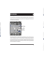 5
5
-
 6
6
-
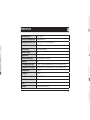 7
7
-
 8
8
-
 9
9
-
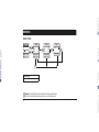 10
10
-
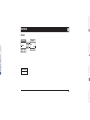 11
11
-
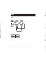 12
12
-
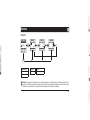 13
13
-
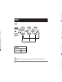 14
14
-
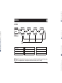 15
15
-
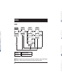 16
16
-
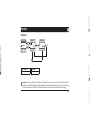 17
17
-
 18
18
-
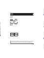 19
19
-
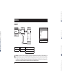 20
20
-
 21
21
-
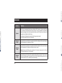 22
22
-
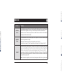 23
23
-
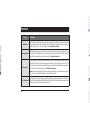 24
24
-
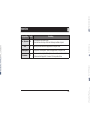 25
25
-
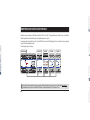 26
26
-
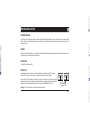 27
27
-
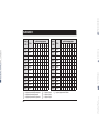 28
28
-
 29
29
-
 30
30
-
 31
31
-
 32
32
-
 33
33
-
 34
34
-
 35
35
-
 36
36
-
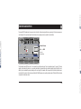 37
37
-
 38
38
-
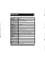 39
39
-
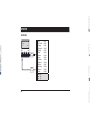 40
40
-
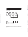 41
41
-
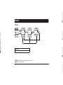 42
42
-
 43
43
-
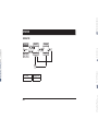 44
44
-
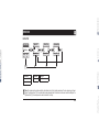 45
45
-
 46
46
-
 47
47
-
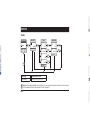 48
48
-
 49
49
-
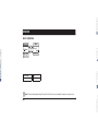 50
50
-
 51
51
-
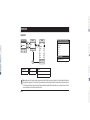 52
52
-
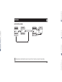 53
53
-
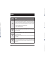 54
54
-
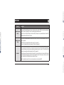 55
55
-
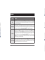 56
56
-
 57
57
-
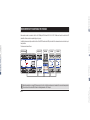 58
58
-
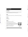 59
59
-
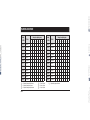 60
60
-
 61
61
-
 62
62
-
 63
63
-
 64
64
-
 65
65
-
 66
66
-
 67
67
-
 68
68
-
 69
69
-
 70
70
-
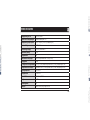 71
71
-
 72
72
-
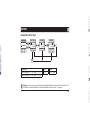 73
73
-
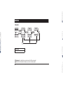 74
74
-
 75
75
-
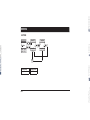 76
76
-
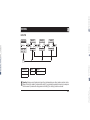 77
77
-
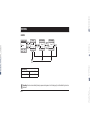 78
78
-
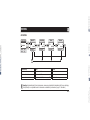 79
79
-
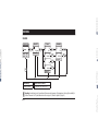 80
80
-
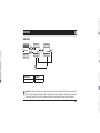 81
81
-
 82
82
-
 83
83
-
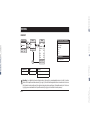 84
84
-
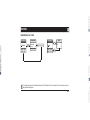 85
85
-
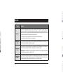 86
86
-
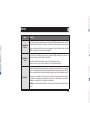 87
87
-
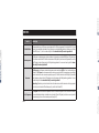 88
88
-
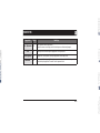 89
89
-
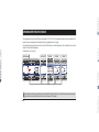 90
90
-
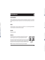 91
91
-
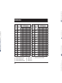 92
92
-
 93
93
-
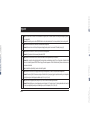 94
94
-
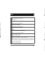 95
95
-
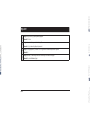 96
96
-
 97
97
-
 98
98
-
 99
99
-
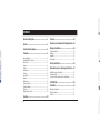 100
100
-
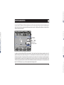 101
101
-
 102
102
-
 103
103
-
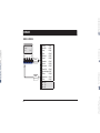 104
104
-
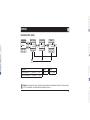 105
105
-
 106
106
-
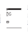 107
107
-
 108
108
-
 109
109
-
 110
110
-
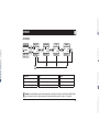 111
111
-
 112
112
-
 113
113
-
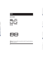 114
114
-
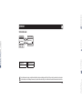 115
115
-
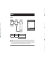 116
116
-
 117
117
-
 118
118
-
 119
119
-
 120
120
-
 121
121
-
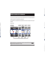 122
122
-
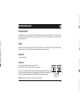 123
123
-
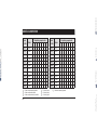 124
124
-
 125
125
-
 126
126
-
 127
127
-
 128
128
-
 129
129
-
 130
130
-
 131
131
-
 132
132


PEHA Compact 952 JRM Operating Instructions Manual
- Type
- Operating Instructions Manual
in andere talen
- English: PEHA Compact 952 JRM
- français: PEHA Compact 952 JRM
- Deutsch: PEHA Compact 952 JRM
Gerelateerde papieren
Andere documenten
-
LIVARNO 321390 de handleiding
-
Chamberlain GWAP120 de handleiding
-
Primare I22 Gebruikershandleiding
-
Chamberlain GWUP180 de handleiding
-
Hager TS 223 User Instruction
-
Me AS-8240 Operating Instructions Manual
-
-
-
DIO ED-GW-04 Handleiding
-
Somfy EASY SUN IO de handleiding