ADEMCO 998mx Installation Instructions Manual
- Type
- Installation Instructions Manual

General Information
This passive infrared motion detector is designed for use
with control panels that support polling loop devices
equipped with DIP switches or polling loop devices that
require their serial number to be “programmed
*
”. It is a
versatile wall-mounted unit employing Fresnel lenses and
offering efficient protection patterns for commercial and
residential applications. Best coverage will be obtained if
mounting is selected such that the likely direction of
intruder motion is
across
the pattern.
*
If the control panel supports Serial No. programming,
you MUST configure the 998MX as a Serial No. device
(see Address/Serial No. ID section).
This detector is also equipped with “downward looking”
optics to cover the normally “dead” zone directly beneath
a detector.
The detector is shipped with the standard wide-angle lens
installed, but also supports the supplied pet alley lens
(99PA) and long-range lens (99LR). An optional swivel
mounting bracket (998SB) is available (purchased sepa-
rately).
Specifications
Coverage: Standard Wide-Angle Lens
50 ft x 50 ft (15.2m x 15.2m), 90
°
Optional Lens: 99PA, Pet Alley Lens
50 ft x 70 ft (15m x 21.3m), 100
°
99LR, Long Range Lens
100 ft x 10 ft (30m x 3m)
Detection Zones:
W/Standard Lens:
18 zones (9 long range,
5 intermediate, 2 short range).
W/Optional Lenses:
99PA: 12 zones
99LR: 5 zones (1 long range,
2 intermediate, 2 short range).
Detector provides one “downward look-
ing” zone with all lenses (downward look-
ing lens must be masked when using the
99PA).
Pulse Count: Installer-selectable (1, 2, or 3)
Detectable
Walk Rate: 0.5–5 ft/Sec (0.15m –1.5m/Sec)
Mount Height: 7 ft nominal (2.1m)
Indicator:
Red LED with enable/disable link
Input Voltage: 8-11V peak to peak at polling
loop terminals.
Current: 1mA (LED disabled)
3mA (alarm LED enabled)
Standby: Power source should be capable
of at least 4 hours of battery
standby.
Operating Temp:
14
°
F to 122
°
F (-10
°
to +50
°
C)
Humidity: Up to 95% RH (max.),non-
condensing.
Dimensions: 2”W x 4”H x 2”D (max protrusion)
(67mm x 111mm x 54mm).
Installation
Normal Mounting:
Mount the unit to a firm vertical surface.The wall wiring
hole should be no more than 5/16” (8mm) in diameter.
1. Remove the front cover as shown in Figure 1.
2. Refer to Figure 2. Knockout holes “A” in the
base are for normal surface mounting on a
wall (slide PC board up for access to bottom
holes, down for access to top holes). For cor-
ner mounting, see Corner Mounting section.
Also break out the desired wire entry hole at
this time (marked X1 or X2 in Fig. 2).
3. Feed wiring emerging from the wall through
the wire access hole near the top of the
detector base.Make sure wires have sufficient
slack to allow the PC board to be moved up
and down freely when the wires are connect-
ed to the terminals on the board.
4. Mount the base.
Note the mounting orienta-
tion of this detector – wire entry at the top,
lens at the bottom!
5. Refer to the Wiring Connections section
before replacing the front cover.
Corner Mounting:
Knockout holes “B” in the base are used for corner
mounting on a wall (slide PC board up for access to
bottom holes, down for access to top holes). Mount in
selected corner with 4 screws (see Fig. 3).
Note the mounting orientation of this detector –
wire entry at the top, lens at the bottom!
Make sure
the board is positioned so that the arrow is in line with
the appropriate setting on the graduated scale (see
Fig. 5 and Table 1).
▲
(1) INSERT SCREWDRIVER
IN GROOVE AND TWIST
▲
(2) REMOVE
COVER
DOWNWARD-LOOKING
WINDOW
▲
Protection Pattern, Standard Lens
®
LED
+5°
-0°
-5°
-10°
-15°
-20°
+ –
1 2 3 4 5 6 7 8 9 10
ON
1
2
4
8
16
32
64
JP1
X1
X2
A
A
B
KNOCKOUT HOLES
A = SURFACE
MOUNTING (4)
B = CORNER
MOUNTING (4)
X1 = TOP WIRE ENTRY
(SURFACE WIRING)
X2 = REAR WIRE ENTRY
(IN-WALL WIRING)
B
Figure 2.
Detector Base
Figure 3. Corner Mounting
Changing lenses (if required)
1. Remove front cover.
2. Release the lens support frame located in
front cover as follows: insert the blade of a
small screwdriver between the locking tab and
the detector case in each of the four corners of
the frame, and lever each tab upward to
release. See Figure 4. When all four corners
are released, remove the lens support frame.
3. Remove the existing lens and replace with the
replacement lens.The lens must be installed
with the smooth side facing outward. Also,
the lens should be oriented with its part
number on the upper right-hand side (see
Fig. 4). Be sure to center the lens.
Note:
Lens surface should be free of dirt,
foreign matter and fingerprints. Use a clean,
dry, soft cloth to wipe lens surfaces.
4. Insert the lens support frame into its original
position and then press downward on the frame
so that the lens locking tabs snap into position in
each of the four corners.
TOP VIEW
25 ft
(7.6m)
25 ft
(7.6m)
0
90˚
7 ft
(2.1m)
8 ft
(2.4m)
25 ft
(7.6m)
50 ft
(15m)
DOWNWARD-LOOKING
BEAM 1 ft (0.3m) FROM WALL
3 ft (1m)
DOWNWARD-LOOKING
BEAM
(FRONT VIEW)
ALTERNATE COUNT POLARITY
EACH ZONE CONSIST OF 2 FIELDS
Protection Pattern, No 99PA Pet Alley Lens
TOP VIEW
Figure 1. Cover Removal
CORNER
OF
WALL
MOUNTING SCREWS (USE 4)
DETECTOR
BASE
998MX
Passive Infrared Detector
Installation Instructions
▲
(1) INSERT SCREWDRIVER
IN GROOVE AND TWIST
▲
(2) REMOVE
COVER
DOWNWARD-LOOKING
WINDOW
▲
IMPORTANT
NOTE THE MOUNTING
ORIENTATION OF THIS
DETECTOR. WIRE ENTRY
IS AT THE TOP, AND LENS
IS AT THE BOTTOM!
Protection Pattern, No.99LR Long Range Lens
N8023-5EN (
Part of N8023-5V1 8/99
)

LED
MARKER
VERTICAL
ADJUSTMENT
SCALE. SLIDE
BOARD UP OR
DOWN TO
APPROPRIATE
SETTING (SEE
TABLE 1).
+5°
-0°
-5°
-10°
-15°
-20°
DET
+ –
DIP
SWITCHES
SHOWN
IN “ON” (UP)
POSITIONS.
SEE “DIP
SWITCH
USAGE”
BELOW.
ON
SWITCH SETTINGS
1 PC: 9 UP, 10 DN
2 PC: 9 DN, 10 UP
3 PC: 9 DN, 10 DN
LED DISABLE: 8 UP
ADDRESS
ON – UP
OFF– DOWN
1
2
4
8
16
32
64
JP1
FOR SERIAL #:
1. SET ALL ADDRESS
SWITCHES TO “OFF”
2. CUT JUMPER JP1
MPX
BUS
SWITCHES 1–7
FOR SETTING
ADDRESS
LED
ENABLE/DISABLE
PULSE
COUNT
DIP SWITCH USAGE
1–7: USED FOR SETTING ADDRESS (FOR USE
WITH CONTROLS THAT DO NOT SUPPORT
“LEARNING” DEVICES). SEE “POINT ID
PROGRAMMING CHART.”
8: LED ENABLE/DISABLE:
UP (ON) DISABLES LED;
DOWN (OFF) ENABLES LED.
9/10: PULSE COUNT SELECTION:
FOR PC 1: 9 UP (ON), 10 DOWN (OFF).
FOR PC 2: 9 DOWN (OFF), 10 UP (ON).
FOR PC 3: 9 DOWN (OFF), 10 DOWN (OFF).
1 2 3 4 5 6 7 8 9 10
Wiring Connections
Bring polling loop wires in through the wire access slot
at the top of the detector base (near the terminal block)
and connect to the screw terminals (see fig.5).Seal any
opening in the base with foam or RTV (not supplied) to
prevent drafts or insects from entering the unit.
Apply
power only after the wiring connections have been
made and are inspected.
Address/Serial No. ID
The 998MX can be configured as either a serial num-
ber polling loop device or a DIP switch polling loop
device (for controls that do not support serial number
devices).
IMPORTANT: You must use the serial number config-
uration if using this PIR with a control that supports
Serial No.devices.
Use the DIP switches
only
if using this PIR with a con-
trol that
does not
support Serial No.devices.
For DIP switch configuration, set DIP switches 1–7
according to the Zone Number Programming Chart on
the next page.
For serial number configuration, cut jumper JP1 off
at the base, and set DIP switches 1–7 to the OFF posi-
tions (DOWN).
If the PIR is to be used with a control that supports
serial number devices, this PIR’s serial number can be
entered by one of the following methods:
1. Downloading (Zone Definition screen of
Compass
Downloading software). Recommended for large
installations and installations where foot traffic
cannot be controlled.
2. Entered in manually at the "learn" prompt during
manual zone programming (see Important note
below). This PIR’s unique factory-assigned serial
number can be found on the bar code label on the
left side of the PC board cover.
3. Entered by faulting the detector twice while at the
"learn" prompt during manual zone programming.
IMPORTANT: If you are programming manually, be
sure that other polling loop sensors are not activated
so that they cannot send a signal to the control while
this PIR is being programmed (mask PIRs, don't
open/close doors, etc.).
To enter the serial number at the control, refer to
the control's programming instructions, noting the
following:
Input Type = 6 (SL: Serial Number Polling Loop Device)
Loop Number = 1
To fault the PIR when prompted, simply move your
hand in front of the detector. The keypad will beep to
confirm the signal. Wait 3–6 seconds before faulting
the second time.
Pulse Count Option
This detector includes Pulse Count circuitry that pro-
vides stability in adverse environments to minimize
false alarms.
Figure 4. Changing Lenses
Figure 5. Wiring Connections
Selectable 1-, 2-, or 3-event pulse count is provided by
setting DIP switches 9 and 10 as shown in Figure 5.
When programmed for 2- or 3- event pulse count, the
detector will signal an alarm within 3 to 4 steps, since
the processing logic requires more complex motion
than just a momentary event.When the detector veri-
fies an intrusion, the LED lights for approximately 1 to
3 seconds.
LED Enable/Disable Option
The Alarm LED is disabled when the LED enable/dis-
able DIP switch (#8) is in the up position.To enable the
LED, set the #8 DIP switch to the down position. See
Figure 5.
Note: The LED is viewed through the front cover lens.
Tamper Switch
Removal of the cover causes a tamper switch to open.
The control panel is automatically notified via the polling
loop when this event occurs.
Test Procedures
IMPORTANT: Two-minute warm-up time is required
after applying power. Testing should be conducted
with the protected area cleared of all people. Disarm
the protective system’s control during the test proce-
dure to prevent reporting of unwanted alarms.
1. Remove front cover and set the Pulse Count
switches for "PC1" switch #9 up, switch #10
down).This will provide instant response.
Set the LED enable/disable switch #8 to the down
position to enable the LED.
2. Replace front cover and walk through protective
zones, observing that the detector’s LED lights
whenever motion is detected.(The LED serves as
a Walk-Test Indicator during this procedure.
Note: In the Instant mode, the LED stays lit for
approximately 1–3 seconds after detecting
motion.
3. Test the downward-looking zone by walking along
the wall directly beneath the detector (this does
not apply to the Pet Alley lens or the standard
lens masked to act as a Pet Alley lens, which
should have the downward-looking window on
the detector masked).
4. If pulse count is to be used, set the pulse count
jumper to desired setting and repeat the walk test
procedure. With pulse count on, the LED serves
as an alarm indicator.
The absolute range of all PIR units is subject to variation
because of different types of clothing, backgrounds and
ambient temperature. For this reason, ensure that the
most likely intruder routes are well within the PIR’s pro-
tective zones and that Walk-Testing is carried out along
these routes.
After the Walk-Test is complete, the LED may be dis-
abled (switch #8 in the down position).
2
5. Refer to
Vertical Pattern Adjustment
and
Table 1 for recommended detector pattern
setting for various mounting heights and
protection ranges.
6. Replace front cover.
Horizontal Adjustment of Lens
The protection pattern can be moved to the left
or right by horizontal adjustment as follows:
1. Remove front cover.
2. Grasp the lens firmly on both sides (front and
back) and slide the lens to the left or right, as
needed. The lens may be moved as much as
4° (from center) in either direction.
3. Replace front cover.
After adjustment, conduct a walk test to ensure
proper coverage of the area to be protected
(see Test Procedures).
Vertical Pattern Adjustment
The protection pattern can be raised or lowered by
re-positioning the PC board in the detector. A gradu-
ated scale to the right of the board (see Fig. 5) indi-
cates the approximate number of degrees by which
the pattern can be raised (max +5°) or lowered
(max -20°). To make this adjustment, loosen the
screw holding the PC board.Slide the board upward
or downward by the number of degrees required,
then tighten the holding screw again. Table 1 indi-
cates the recommended setting at various mount-
ing heights and protection ranges for each of the
available lenses.
After any adjustment, conduct a Walk-Test to ensure
proper coverage of the area to be protected; see
Test Procedures.
Lens Masking
The supplied masking strips can be used to pro-
duce a protection pattern that suits the particular
requirements of the protected area, or eliminate
coverage from areas where you anticipate environ-
mental disturbances that might reduce the PIR’s
stability (a heater or other heat-producing object, for
example).Simply peel off the appropriate pressure-
sensitive adhesive strip(s) and apply over the
desired lens segment(s). Be sure to affix the mask-
ing strips to the inside of the lens (not the outer,
smooth side). Each lens segment that is masked
results in the elimination of one zone of protection
from the coverage pattern.
The standard lens can be used to provide a pet
alley. To do so, mask the bottom two rows (see
Fig. 4) and mount as though the optional pet alley
lens were installed.
IMPORTANT: If using the Pet Alley lens or if you
have masked the standard lens to emulate a pet
alley lens,
you must also mask the look-down
window.

Position 7 6 5 4 3 2 1
Value 1 2 4 8 16 32 64
“Learning” OFF OFF OFF OFF OFF OFF OFF
1 [129] OFF on on on on on on
2 [130] on OFF on on on on on
3 [131] OFF OFF on on on on on
4 [132] on on OFF on on on on
5 [133] OFF on OFF on on on on
6 [134] on OFF OFF on on on on
7 [135] OFF OFF OFF on on on on
8 [136] on on on OFF on on on
9 [137] OFF on on OFF on on on
10 [138] on OFF on OFF on on on
11 [139] OFF OFF ON OFF on on on
12 [140] on on OFF OFF on on on
13 [141] OFF on OFF OFF on on on
14 [142] on OFF OFF OFF on on on
15 [143] OFF OFF OFF OFF on on on
16 [144] on on on on OFF on on
17 [145] OFF on on on OFF on on
18 [146] on OFF on on OFF on on
19 [147] OFF OFF on on OFF on on
20 [148] on on OFF on OFF on on
21 [149] OFF on OFF on OFF on on
22 [150] on OFF OFF on OFF on on
23 [151] OFF OFF OFF on OFF on on
24 [152] on on on OFF OFF on on
25 [153] OFF on on OFF OFF on on
26 [154] on OFF on OFF OFF on on
27 [155] OFF OFF on OFF OFF on on
28 [156] on on OFF OFF OFF on on
29 [157] OFF on OFF OFF OFF on on
30 [158] on OFF OFF OFF OFF on on
31 [159] OFF OFF OFF OFF OFF on on
32 [160] on on on on on OFF on
33 [161] OFF on on on on OFF on
34 [162] on OFF on on on OFF on
35 [163] OFF OFF on on on OFF on
36 [164] on on OFF on on OFF on
37 [165] OFF on OFF on on OFF on
38 [166] on OFF OFF on on OFF on
39 [167] OFF OFF OFF on on OFF on
40 [168] on on on OFF on OFF on
41 [169] OFF on on OFF on OFF on
42 [170] on OFF on OFF on OFF on
43 [171] OFF OFF on OFF on OFF on
44 [172] on on OFF OFF on OFF on
45 [173] OFF on OFF OFF on OFF on
46 [174] on OFF OFF OFF on OFF on
47 [175] OFF OFF OFF OFF on OFF on
48 [176] on on on on OFF OFF on
49 [177] OFF on on on OFF OFF on
50 [178] on OFF on on OFF OFF on
51 [179] OFF OFF on on OFF OFF on
52 [180] on on OFF on OFF OFF on
53 [181] OFF on OFF on OFF OFF on
54 [182] on OFF OFF on OFF OFF on
55 [183] OFF OFF OFF on OFF OFF on
56 [184] on on on OFF OFF OFF on
57 [185] OFF on on OFF OFF OFF on
58 [186] on OFF on OFF OFF OFF on
59 [187] OFF OFF on OFF OFF OFF on
60 [188] on on OFF OFF OFF OFF on
61 [189] OFF on OFF OFF OFF OFF on
62 [190] on OFF OFF OFF OFF OFF on
63 [191] OFF OFF OFF OFF OFF OFF on
64 [192] on on on on on on OFF
Position 7 6 5 4 3 2 1
Value 1 2 4 8 16 32 64
65 [193] OFF on on on on on OFF
66 [194] on OFF on on on on OFF
67 [195] OFF OFF on on on on OFF
68 [196] on on OFF on on on OFF
69 [197] OFF on OFF on on on OFF
70 [198] on OFF OFF on on on OFF
71 [199] OFF OFF OFF on on on OFF
72 [200] on on on OFF on on OFF
73 [201] OFF on on OFF on on OFF
74 [202] on OFF on OFF on on OFF
75 [203] OFF OFF on OFF on on OFF
76 [204] on on OFF OFF on on OFF
77 [205] OFF on OFF OFF on on OFF
78 [206] on OFF OFF OFF on on OFF
79 [207] OFF OFF OFF OFF on on OFF
80 [208] on on on on OFF on OFF
81 [209] OFF on on on OFF on OFF
82 [210] on OFF on on OFF on OFF
83 [211] OFF OFF on on OFF on OFF
84 [212] on on OFF on OFF on OFF
85 [213] OFF on OFF on OFF on OFF
86 [214] on OFF OFF on OFF on OFF
87 [215] OFF OFF OFF on OFF on OFF
88 [216] on on on OFF OFF on OFF
89 [217] OFF on on OFF OFF on OFF
90 [218] on OFF on OFF OFF on OFF
91 [219] OFF OFF on OFF OFF on OFF
92 [220] on on OFF OFF OFF on OFF
93 [221] OFF on OFF OFF OFF on OFF
94 [222] on OFF OFF OFF OFF on OFF
95 [223] OFF OFF OFF OFF OFF on OFF
96 [224] on on on on on OFF OFF
97 [225] OFF on on on on OFF OFF
98 [226] on OFF on on on OFF OFF
99 [227] OFF OFF on on on OFF OFF
100 [228] on on OFF on on OFF OFF
101 [229] OFF on OFF on on OFF OFF
102 [230] on OFF OFF on on OFF OFF
103 [231] OFF OFF OFF on on OFF OFF
104 [232] on on on OFF on OFF OFF
105 [233] OFF on on OFF on OFF OFF
106 [234] on OFF on OFF on OFF OFF
107 [235] OFF OFF on OFF on OFF OFF
108 [236] on on OFF OFF on OFF OFF
109 [237] OFF on OFF OFF on OFF OFF
110 [238] on OFF OFF OFF on OFF OFF
111 [239] OFF OFF OFF OFF on OFF OFF
112 [240] on on on on OFF OFF OFF
113 [241] OFF on on on OFF OFF OFF
114 [242] on OFF on on OFF OFF OFF
115 [243] OFF OFF on on OFF OFF OFF
116 [244] on on OFF on OFF OFF OFF
117 [245] OFF on OFF on OFF OFF OFF
118 [246] on OFF OFF on OFF OFF OFF
119 [247] OFF OFF OFF on OFF OFF OFF
120 [248] on on on OFF OFF OFF OFF
121 [249] OFF on on OFF OFF OFF OFF
122 [250] on OFF on OFF OFF OFF OFF
123 [251] OFF OFF on OFF OFF OFF OFF
124 [252] on on OFF OFF OFF OFF OFF
125 [253] OFF on OFF OFF OFF OFF OFF
126 [254] on OFF OFF OFF OFF OFF OFF
127 OFF OFF OFF OFF OFF OFF OFF
128 on on on on on on on
998MX Point ID Programming Chart
If using DIP Switches: For zone numbers 1–128, do not cut jumper JP1
; for zone numbers [129]–[254], cut JP1.
IMPORTANT: If the control panel supports Serial No. programming, you MUST configure the 998MX as a Serial No. device (not a DIP
Switch device). When programming Serial numbers, cut JP1 and set all DIP switches to the OFF position.
3

LONG RANGE - 998-LR
PROTECTION RANGE
*
Important: When using the Long Range lens, set the
PIR for Instant response (Pulse Count 1).
TABLE 1. INSTALLATION GUIDE FOR LENSES
STANDARD LENSES
PROTECTION RANGE
THE LIMITATIONS OF YOUR PASSIVE
INFRARED MOTION DETECTOR
While the Intrusion Detector is a highly reliable
intrusion detection device, it does not offer guaran-
teed protection against burglary. Any Intrusion
Detection device is subject to compromise or failure
to warn for a variety of reasons:
• Passive Infrared Motion Detectors can only
detect intrusion within the designed ranges as
diagrammed in this installation manual.
• Passive Infrared Motion Detectors do not pro-
vide volumetric area protection. They do create
multiple beams of protection, and intrusion can
only be detected in unobstructed areas covered
by those beams.
• Passive Infrared Detectors cannot detect motion
or intrusion that takes place behind walls, ceil-
ings, floors, closed doors, glass partitions, glass
doors, or windows.
• Mechanical tampering, masking, painting or
spraying of any material on the lenses, windows
or any part of the optical system can reduce the
detection ability of the Passive Infrared Motion
Detector.
• Passive Infrared Detectors sense changes in
temperature; however, as the ambient tempera-
ture of the protected area approaches the tem-
perature range of 90° to 105°F (32° to 40°C), the
detection performance can decrease.
• This Passive Infrared Detector will not operate
without appropriate DC power connected to it, or
if the DC power is improperly connected (i.e.,
reversed polarity connections).
• Passive Infrared Detectors, like other electrical
devices, are subject to component failure. Even
though this equipment is designed to last as long
as 10 years, the electronic components in it
could fail at any time.
We have cited some of the most common reasons
that a Passive Infrared Motion Detector can fail to
catch intrusion. However, this does not imply that
these are the only reasons, and therefore it is rec-
ommended that weekly testing of this type of unit,
in conjunction with weekly testing of the entire
alarm system, be performed to ensure that the
detectors are working properly.
Installing an alarm system may make the owner eli-
gible for a lower insurance rate, but an alarm sys-
tem is not a substitute for insurance. Homeowners,
property owners and renters should continue to act
prudently in protecting themselves and continue to
insure their lives and property.
We continue to develop new and improved protec-
tion devices. Users of alarm systems owe it to
themselves and their loved ones to learn about
these developments.
Mtg 15' 20' 30' 40' 50'
Height (4.6m) (6m) (9m) (12m) (15m)
8.5Ft -20° -16° -11° -8° -7°
(2.6m)
8Ft -20° -15° -10° -8° -6°
(2.4m)
7Ft -16° -12° -8° -6° -5°
(21m)
6Ft -13° -10° -6° -5° -4°
(1.8m)
Mtg 20' 40' 60' 80' 100'
Height (6m) (12m) (18m) (24m) (30.4m)
8.5Ft -15° -9° -6° -5° -5°
(2.6m)
8Ft -14° -8° -6° -5° -4°
(2.4m)
7Ft -11° -6° -5° -4° -4°
(21m)
6Ft -8° -5° -4° -3° -3°
(1.8m)
Mounting Height:
3 ft –3.5 ft (0.9–1m)
Vertical Pattern Setting (for all ranges):
+4°
Important: Be sure to affix the provided masking
label over the look-down window.
ADEMCO
SIX-YEAR LIMITED WARRANTY
Alarm Device Manufacturing Company, a
Division of Pittway Corporation, and its divisions,
subsidiaries and affiliates ("Seller"), 165 Eileen
Way, Syosset, New York 11791, warrants this
detector to be in conformance with its own plans
and specifications and to be free from defects in
materials and workmanship under normal use
and service for 72 months from the date stamp
control on the product. Seller's obligation shall
be limited to replacing, at its option, free of
charge for materials or labor, a detector which is
proved not in compliance with Seller's specifica-
tions or proves defective in materials or work-
manship under normal use and service. Seller
shall have no obligation under this Limited
Warranty or otherwise if the detector is altered or
improperly repaired or serviced by anyone other
than Ademco factory service. In case of defect,
return the detector to ADI or an authorized dis-
tributor for an immediate replacement.
THERE ARE NO WARRANTIES, EXPRESS OR
IMPLIED, OF MERCHANTABILITY, OR FITNESS
FOR A PARTICULAR PURPOSE OR OTHERWISE,
WHICH EXTEND BEYOND THE DESCRIPTION
ON THE FACE HEREOF. IN NO CASE SHALL
SELLER BE LIABLE TO ANYONE FOR ANY CON-
SEQUENTIAL OR INCIDENTAL DAMAGES FOR
BREACH OF THIS OR ANY OTHER WARRANTY,
EXPRESS OR IMPLIED, OR UPON ANY OTHER
BASIS OF LIABILITY WHATSOEVER, EVEN IF
THE LOSS OR DAMAGE IS CAUSED BY THE
SELLER'S OWN NEGLIGENCE OR FAULT.
Seller does not represent that its detector may
not be compromised or circumvented; that the
detector will prevent any personal injury or prop-
erty loss by burglary, robbery, fire or otherwise;
or that the detector will in all cases provide ade-
quate warning or protection. Buyer understands
that a properly installed and maintained alarm
may only reduce the risk of a burglary, robbery,
fire or other events occurring without providing
an alarm, but it is not insurance or a guarantee
that such will not occur or that there will be no
personal injury or property loss as a result.
CONSEQUENTLY, SELLER SHALL HAVE NO
LIABILITY FOR ANY PERSONAL INJURY,
PROPERTY DAMAGE OR OTHER LOSS BASED
ON A CLAIM THE DETECTOR FAILED TO GIVE
WARNING. HOWEVER, IF SELLER IS HELD LI-
ABLE, WHETHER DIRECTLY OR INDIRECTLY,
FOR ANY LOSS OR DAMAGE ARISING UNDER
THIS LIMITED WARRANTY OR OTHERWISE,
REGARDLESS OF CAUSE OR ORIGIN,
SELLER'S MAXIMUM LIABILITY SHALL NOT IN
ANY CASE EXCEED THE PURCHASE PRICE
OF THE DETECTOR, WHICH SHALL BE THE
COMPLETE AND EXCLUSIVE REMEDY
AGAINST SELLER. This warranty replaces any
previous warranties and is the only warranty
made by Seller on this detector. No increase or
alteration, written or verbal, of the obligations of
this Limited Warranty is authorized.
TO THE INSTALLER
Regular maintenance and inspection (at least
annually) by the installer and frequent testing by
the user are vital to continuous satisfactory opera-
tion of any alarm system.
The installer should assume the responsibility of
developing and offering a regular maintenance
program to the user, as well as acquainting the
user with the proper operation and limitations of
the alarm system and its component parts.
Recommendations must be included for a specific
program of frequent testing (at least weekly) to
ensure the system’s operation at all times.
165 Eileen Way, Syosset, N.Y. 11791
Copyright © 1997 PITTWAY CORPORATION
PROBLEM CAUSE REMEDY
Intermittent
Alarm
Rapid temper-
ature change.
Check for electric
or gas heaters,
open flames, elec-
tric arcs, etc.
Locate source and
reposition detector.
Drafts causing
drapes, light
fixtures, display
material to move
.
Eliminate source of
motion.
PIR does
not appear
to be
operating
Polling loop volt-
age supplied to
detector is
inadequate,
intermittent or
polarity reversed.
Assure that proper
polarity is supplied and
that wiring is intact (no
opens or shorts) and
connection secure.
Check for presence of
8–11V PP at terminals
of unit. If too low, pol-
ling loop run to control
may be excessive for
the wire gauge used, or
polling loop current
drain may be exces-
sive. Increase wire
gauge or add Polling
loop extender module
to location in the loop
where voltage boost is
necessary and connect
it to a power source.
Alternatively, the detec-
tor can be tested using
a 9-volt source (such
as a 9-volt battery or a
9-volt power supply).
LED
inoperative.
LED disable
jumper is on
Set LED disable DIP
switch to OFF.
LED malfunc-
tion. Check for
broken or
shorted leads.
Return unit for
service.
Repositioned fur-
niture or equip-
ment in the
protected area.
Caution customer
about layout changes.
Reposition detector.
Mounting surface
is unstable.A few
degrees of
vertical shift can
change range
substantially.
Mount on
secure surface.
Trouble
Code
Improper ID code,
or PIR serial No.
not entered.
Set DIP swiitches1–7
to proper code, or
enter PIR serial No.
Detection
Area
Changes
TROUBLESHOOTING
PET ALLEY LENS– 998-PA
––––
Vertical Pattern Setting
–––––
Vertical Pattern Setting
ÊN8023-5V1z
N8023-5EN (
Part of N8023-5V1 8/99
)

Généralités
Cet IRP a été conçu pour être utilisé avec des centrales
d'alarme qui acceptent des équipements pour bus
multiplexé et dont l'adressage s'effectue à l'aide de mini-
commutateurs ou de l'apprentissage* d'un numéro de
série Il s'agit d'un détecteur universel, prévu pour un
montage au mur (angle ou saillie). Il possède une lentille
de Fresnel et grâce à sa très grande efficacité, il peut être
utilisé dans toutes les applications commerciales ou
résidentielles. Sa zone de couverture optimale est
obtenue lorsque la direction de déplacement de l'intrus
est perpendiculaire à celle des faisceaux.
*Si la centrale utilise la fonction d'apprentissage du
numéro de série pour l'adressage, IL EST IMPERATIF
de configurer en conséquence le 998MX (se reporter
au paragraphe "Adresse / Numéro de série").
Ce détecteur est également muni d'une lentille "zone
basse", qui permet de couvrir la partie se trouvant
normalement dans l'angle mort, sous l'appareil.
Lors de sa livraison, la lentille standard "Grand angle" est
montée.Il peut être ultérieurement équipé de la lentille pour
le passage des animaux de compagnie "99PA" ou de la
lentille longue portée "99LR" (fournies).Il existe un support
optionnel à rotule "998SB" (à acheter séparément).
Spécifications Techniques
Zone de Couverture: Lentille standard grand angle
15,2m x 15,2m, 90
°
Lentille Additionnelle: 99PA, Lentille Pour Le Passage
Des Animaux De Compagnie
15 x 21, 3m/100
°
99LR, Longue Portée
30m x 3m
Zones De Détection:
Avec la lentille standard:
18 faisceaux (9 de grandes
longueurs, 5 intermédiaires, 2
courts)
Avec les lentilles
99PA: 12 faisceaux
optionnelles:
99LR: 5 faisceaux (1 long,
2 intermédiaires, 2 courts)
La zone basse du détecteur est disponible
quel que soit le type de lentilles retenu.
Toutefois, celle-ci doit être masquée lors de
l'utilisation de la lentille 99PA.
Comptage
D’impulsions: Sélectionnable par l'installateur (1, 2, 3)
Vitesse Détectable: 0,15m à 1,5m/s
Hauteur De Montage:2,1m
Voyant:
LED rouge (avec possibilité de validation/
invalidation de son fonctionnement)
Tension
D'alimentation: 8 à 11V crête à crête aux bornes
de boucle à scrutation
Consommation: 1mA (LED désactivée)
3mA (LED activée)
Autonomie: La source d'alimentation doit être
équipée d'une batterie assurant une
autonomie de fonctionnement d'au
moins 4 heures.
Température de Fonctionnement:
-10
°à
+50
°
C
Humidité Relative: Jusqu'à 95% / Sans condensation
Dimensions: 67mm x 111mm x 54mm
Installation
Mountage Normal:
Le détecteur doit être installé sur une surface solide et
verticale.Le diamètre du trou de passage des câbles dans le
mur ne doit pas être supérieur à 8mm.
1. Retirer la face avant comme indiqué sur la figure 1.
2. Se reporter à la figure 2. Les prédécoupes "A" sont
destinées au montage en saillie sur le mur (pour
accéder aux prédécoupes du haut, glisser la carte du
circuit imprimé vers le bas et inversement.) Pour un
montage en angle, se reporter au paragraphe suivant.
Percer en même temps les prédécoupes de passage
des câbles (repérées "X1" ou "X2" sur la figure 2).
3. Faire entrer les câbles par l'ouverture se trouvant au
sommet de l'embase du détecteur. Lors du
raccordement au bornier, s'assurer que les
conducteurs soient suffisamment longs pour que le
jeu permette un déplacement libre du circuit imprimé.
4. Fixer l'embase.
Respecter l'orientation de
l'appareil avec le passage des câbles au haut et la
lentille vers le bas!
5. Avant de remettre en place la face avant, se reporter
au § "Raccordement."
Montage en Angle:
Les prédécoupes "B3" sont prévues à cet effet (suivant
les besoins, déplacer le circuit imprimé vers le haut ou le
bas, comme indiqué précédemment). Fixer l'embase à
l'aide de 4 vis (se reporter à la figure 3). Vérifier
l'orientation correcte du détecteur.
S'assurer de la position de la flèche présente sur
l'embase, par rapport au réglage souhaité sur l'échelle
sérigraphiée sur le circuit imprimé (se reporter à la figure
5 et au tableau 1).
Changement de lentilles (si nécessaire)
1. Retirer la face avant.
2. Oter le support maintenant la lentille de la façon
suivante: insérer la pointe d'un petit tournevis entre
chaque ergot et le boîtier du détecteur au niveau des
angles du support.Tirer doucement vers le haut pour
dégager celui-ci (se reporter à la figure 4). Cette
opération effectuée, enlever la lentille de son support.
3. Changer la lentille. La surface lisse de celle-ci doit
être orientée vers l'extérieur du détecteur, tandis
que son numéro de série doit apparaître dans le
coin supérieur droit. Vérifier que la lentille est bien
centrée.
Remarque: Ne pas exposer la lentille à la poussière,
éviter toute présence de corps étrangers ou de trace de
doigts. Pour la nettoyer, utiliser un chiffon sec et doux.
4. Remettre le support avec la nouvelle lentille dans sa
position initiale. Appuyer aux quatre coins de celui-ci
pour qu'il soit verrouillé en position à l'aide des clips.
5. Se reporter au § "Réglage vertical" et au tableau 1
pour obtenir la zone de couverture requise, en
fonction des différentes hauteurs de montage et de la
portée souhaitée.
6. Remettre en place la face avant.
Réglage Horizontal De LaLentille
La zone de couverture peut être déplacée vers la gauche
ou la droite, grâce au réglage suivant:
1. Retirer la face avant.
2. Maintenir fermement la lentille (devant et derrière) et la
faire glisser vers la droite ou vers la gauche, jusqu'à la
position souhaitée.Elle peut être déplacée de 4° depuis
le centre, dans l'une ou l'autre des directions.
3. Remettre en place la face avant.
Après avoir effectué le réglage, s'assurer par un test de
passage que la zone de couverture correspond à celle
que l'on recherche (se reporter au § "Procédures de test").
Réglage Vertical De La Zone De Couverture
La hauteur de la zone de couverture peut être abaissée
ou relevée, en modifiant la position du circuit imprimé du
détecteur. L'échelle graduée, située sur le côté droit de
celui-ci, donne des indications en degrés quant à
l'élévation de la zone de couverture (+5° max.) ou à son
abaissement (-20° max.). Pour effectuer ce réglage,
desserrer la vis maintenant le circuit. Faire glisser celui-ci
Zone De Couverture (Lentille Standard)
®
LED
+5°
-0°
-5°
-10°
-15°
-20°
+ –
1 2 3 4 5 6 7 8 9 10
ON
1
2
4
8
16
32
64
JP1
X1
X2
A
A
B
PRÉDÉCOUPES
A = MONTAGE
EN SAILLIE (4)
B = MONTAGE
EN ANGLE (4)
X1 = PASSAGE DE CÂBLE
POUR CÂBLES EN
SAILLIE)
X2 = PASSAGE DE CABLE
ARRIÉRE (POUR
CÂBLES ENCASTRÉS)
B
Figure 2. Embase Du Détecteur
Figure 3. Fixation En Angle
VUE DU DESSUS
7,6m
7,6m
0
90˚
2,1m
2,4m
7,6m
15m
ZONE BASSE
FAISCEAUX À 30cm DU MUR
1m
FAISCEAU
"ZONE BASSE"
VUE DE FACE
COMPTAGE DES POLARITÉS ALTERNÉES
CHAQUE ZONE EST COMPOSÉE D'UN FAISCEAU DOUBLE
Zone De Couverture (Lentille Pour Le Passage
Des Animaux De Compagnie 99PA)
ANGLE
DU MUR
VIS DE MONTAGE (4)
EMBASE DU
DÉTECTEUR
998MX
Détecteur IRP
Notice d'installation
Zone De Couverture (Lentille Longue Portée 99LR)
Figure 1. Ouverture Du Détecteur
▲
(1) INSÉRER LA POINTE
D'UN TOURNEVIS DANS
LA FENTE ET TOURNER.
▲
(2) ENLEVER
LA FACE AVANT
LENTILLE ZONE BASSE
▲
IMPORTANT
RESPECTER
L’ORIENTATION DE
L’APPAREIL: PASSAGE
DES CÂBLES VERS
LE HAUT ET
LENTILLE EN BAS!
VUE DE DESSUS
VUE CÔTÉ
6m 12m 18m 24m 30m
ZONE BASSE
2m
3m
6m 12m 18m 24m 30m
VUE DE
DESSUS
VUE CÔTÉ
1m
10,7m
10,7m
N8023-5FR (
Part of N8023-5V1 8/99
)

LED
FLÉCHE
ECHELLE DE RÉGLAGE
VERTICAL. POUR
OBTENIR UNE
POSITION
APPROPRIÉE,
DÉPLACER LE CIRCUIT
IMPRIMÉ VERS LE
HAUT OU LE BAS (VOIR
LE TABLEAU 1)
+5°
-0°
-5°
-10°
-15°
-20°
CAPTEUR
PYROÉLECTRIQUE
+ –
LES MINI-
COMMUTATEURS
SONT
REPRÉSENTÉS
SUR LE SCHÉMA
EN POSITION
HAUTE “ON”
(VOIR L’ENCADRÉ
“UTILISATION
DES MINI-
COMMUTATEURS”
CI-DESSOUS)
ON
MINI-COMMUTATEURS
1 PC: 9 UP, 10 DN
2 PC: 9 DN, 10 UP
3 PC: 9 DN, 10 DN
INVALIDATION
LED: 8 UP
ADRESSAGE
ON – UP
OFF– DOWN
1
2
4
8
16
32
64
JP1
FOR SERIAL #:
1. SET ALL ADDRESS
SWITCHES TO “OFF”
2. CUT JUMPER JP1
BUS
VPLEX
MINI-COMMUTATEUR DE VALIDATION ET
D’INVALIDATION DU FONCTIONNEMENT DE LA LED
FONCTION DE
COMPTAGE
D’IMPULSIONS
UTILISATION DES MINI-COMMUTATEURS
1 À 7: ILS SONT UTILISÉS POUR L’ADRESSAGE
(AVEC LES CENTRALES NE DISPOSANT PAS
DE FONCTION D’APPRENTISSAGE DES
NUMÉROS DE SÉRIE DES ÉQUIPEMENTS
RACCORDÉS SUR LE BUS MULTIPLEXÉ / SE
REPORTER AU TABEAU DE PROGRAMMATION
DES ADDRESSES)
8: VALIDATION OU INVALIDATION DU
FONCTIONNEMENT DE LA LED
9/10: SÉLECTION DU COMPTAGE D’IMPULSIONS:
1 IMPULSION: MINI-COMMUTATEUR 9 VERS
LE HAUT (POSITION ON) ET
10 VERS LE BAS (OFF)
2 IMPULSIONS:MINI-COMMUTATEUR 9 VERS
LE BAS (POSITION OFF) ET 10
VERS LE HAUT (ON)
3 IMPULSIONS:MINI-COMMUTATEUR 9 VERS
LE BAS (POSITION OFF) ET 10
VERS LE BAS (OFF)
1 2 3 4 5 6 7 8 9 10
MINI-
COMMUTATEURS
(1 À 7) DESTINÉS
À L’ADRESSAGE
le logiciel V-Link). Cette méthode est recommandée
dans le cas d'installations de grandes dimensions
ou d'installations distantes.
2. Saisie manuelle lors de l'apparition du message
"Learn" (mémoriser) durant la programmation
manuelle de zones (voir la note importante ci-
dessous).
3. Apprentissage par activation du détecteur deux fois
lors de l'apparition du message "learn" au cours de la
programmation manuelle de zones.
Lors d'une programmation manuelle, s'assurer que les
autres détecteurs présents sur la boucle à scrutation ne
sont pas activés, afin qu'ils ne transmettent pas
d'information à la centrale alors que le paramétrage de
l'IRP est en cours (masquer les autres IRP, ne pas ouvrir
ou fermer les portes et fenêtres, etc.).
IMPORTANT:Lorsqu'on saisit manuellement les numéros
de série, s'assurer qu'aucun autre équipement du bus
multiplexé n'est activé. Supprimer l'alimentation du
système, débrancher le bus (sur la centrale), rétablir
l'alimentation et passer immédiatement en mode
programmation.Commencer à l'étape 1 (ci-dessous).Une
fois la programmation terminée, ne pas oublier de
rebrancher le bus après avoir supprimé à nouveau
l'alimentation du système.
Pour entrer manuellement ou effectuer "l'apprentissage"
du numéro de série d'un détecteur:
1. Entrer en mode de programmation des zones "✱93."
2. Entrer pour l'IRP, le type de zone ou tout autre
information sur celle-ci. Presser sur la touche "✱" pour
passer de message en message.
3. A l'apparition du message "Type d'entrée" (Input Type),
presser la touche "6" pour sélectionner l'option "SL"
(dispositif pour bus multiplexé) et presser la touche
"✱".
4. Une fois le message "AP N° SERIE?" affiché, presser
la touche "1" pour valider.
5. Une fois le message "ENTRER N S/B ?" (Entrer le n°
de série) affiché, saisir manuellement celui-ci (presser
la touche "1" pour le numéro de boucle) ou activer
l'IRP pour que l'apprentissage soit déclenché (le
clavier émet un "bip" pour confirmer la réception du
signal). Attendre 3 à 6 secondes et activer à nouveau
l'IRP (émission d'un nouveau "bip" de confirmation).
L'IRP est maintenant mémorisé et une information "1"
doit apparaître sous la lettre "L" présente dans l'écran
récapitulatif de la zone (si un "N" s'affiche, cela signifie
que le dispositif n'a pas été pris en compte).
6. Appuyer sur la touche "✱" pour continuer la
programmation des zones.
Pour plus d'informations, se reporter au §
"Programmation des zones" dans la notice d'installation
de la centrale d'alarme concernée.
Fonction De Comptage D'impulsions
Ce détecteur est doté d'une fonction de comptage
d'impulsions. Celle-ci permet de minimiser les
déclenchements intempestifs, quand l'appareil se trouve
dans un environnement hostile.
Les options "1, 2 ou 3 impulsions" sont obtenues en
positionnant le cavalier sur les broches appropriées,
comme indiqué sur la figure 5. Si l'on choisit 2 ou 3
impulsions, le détecteur ne transmet une information
d'alarme qu'après 3 ou 4 pas, étant donné que la logique
de traitement exige des déplacements plus complexes
qu'un simple événement fugitif.
Figure 4. Changement De Lentille
Figure 5. Câblage
Quand une intrusion est détectée, la LED s'allume
pendant environ 1 à 3 secondes.
Validation/Invalidation Du
Fonctionnement De La LED
Le fonctionnement de la LED d'alarme est désactivé
quand le cavalier concerné est en place. Pour l'activer, il
suffit de retirer celui-ci (se reporter à la figure 5). Pour
éviter d'égarer ledit cavalier lorsqu'il ne sert pas, il doit
être inséré sur une seule broche.
Remarque : La LED est visible au travers de la lentille.
Si nécessaire la LED peut également être commandée à
distance. Pour ce faire, retirer le cavalier validant ou
invalidant son fonctionnement. Puis, connecter un
conducteur sur la broche droite servant au cavalier (voir
figure 5). Cette ligne de commande doit pouvoir être
raccordée à un 0V ou laissée "en l'air," ce qui aura
respectivement pour effet de désactiver ou d'activer le
fonctionnement de la LED.
Contact D'autoprotection
L'ouverture de la face avant provoque l'ouverture du
contact d'autoprotection. La centrale est alors
immédiatement avertie de la tentative de sabotage via la
boucle à scrutation.
Procédures De Test
IMPORTANT: Après la mise sous tension, deux minutes
de préchauffage sont nécessaires au bon fonctionnement
du détecteur.
Lors des tests, s'assurer que personne ne se trouve dans
la zone surveillée. Mettre le système à l'arrêt, pour éviter
tout déclenchement d'alarme intempestif.
1. Oter la face avant et placer le cavalier de la fonction
"comptage d'impulsions" en position "1" (réponse
immédiate). La LED devant fonctionner, retirer le
cavalier concerné.
2. Remettre la face avant et traverser la zone de
couverture, en observant si la LED s'allume quand un
mouvement est détecté (durant les tests, la LED sert
d'indicateur).
Remarque: En mode "Réponse immédiate," la LED
reste allumée 1 à 3 secondes environ après avoir
détecté un déplacement.
3. Tester la zone basse, en longeant le mur sous le
détecteur. Ce test ne s'applique pas aux détecteurs
dotés d'une lentille pour le passage des animaux de
compagnie ou d'une lentille standard masquée dans
ce but. En effet, dans ce cas, la zone basse doit être
occultée.
4. Si la fonction de comptage d'impulsions est
nécessaire, effectuer le réglage approprié en plaçant
le cavalier dans la position adéquate et renouveler le
test de passage. Dans ce cas, la LED agit comme un
voyant d'alarme.
Les différences de revêtements, de milieux et de
températures ambiantes influent sur tous les détecteurs
IRP. En conséquence, il est nécessaire de s'assurer que
le déplacement probable de l'intrus correspond bien à la
zone de couverture et que le test de passage a bien été
effectué dans ce sens. Une fois ce dernier réalisé, le
fonctionnement de la LED peut être invalidé, si
nécessaire (cavalier en place).
2
vers le haut ou le bas selon la position désirée, puis
resserrer à nouveau la vis. Le tableau 1 fournit des
informations sur les réglages selon les différentes
hauteurs de fixation du détecteur et du type de lentille
retenu.
Après avoir effectué le réglage, s'assurer par un test de
passage que la zone de couverture correspond à celle
que l'on recherche (se reporter au § "Procédures de
test").
Masquage De La Lentille
Les bandes adhésives, fournies avec le détecteur,
peuvent être utilisées pour adapter la zone de couverture
aux exigences propres à l'installation. Elles servent
également à éliminer de cette dernière, certaines zones
où des perturbations environnementales pourraient
influer sur la stabilité du détecteur (un radiateur ou une
autre source de chaleur, par exemple). Retirer la
protection de la bande adhésive et placer cette dernière
à l'endroit requis sur la lentille. L'adhésif doit être
évidemment collé à l'intérieur de la lentille et non sur la
partie lisse, orientée vers l'extérieur.Chaque segment de
lentille masqué par un adhésif provoque l'élimination d'un
ou plusieurs faisceaux de la zone de couverture.
Ainsi, il est possible avec la lentille standard de laisser un
passage pour les animaux de compagnie. Il suffit de
masquer les deux dernières rangées de segments (se
reporter à la figure 4) et monter le détecteur comme s'il
était équipé de la lentille optionnelle prévue à cet effet.
IMPORTANT: Si l'on utilise une lentille conçue pour
le passage des animaux de compagnie ou que l'on
masque la lentille standard à cette fin, la zone basse
doit être également occultée.
Raccordement
Passer le câble du bus par la prédécoupe prévue à cet
effet dans la partie haute de l'embase du détecteur (à
coté du bornier). Raccorder les conducteurs sur les
bornes (se reporter à la figure 5). Reboucher les
ouvertures à l'aide de mastic silicone (non fournie), afin
d'éviter la pénétration de corps étrangers ou d'insectes
dans le détecteur.
Mettre le détecteur sous tension
seulement après avoir effectué et vérifié les
raccordements.
Adressage/ Numéro De Série
Pour les centrales ne disposant pas de fonction
d'apprentissage des numéros de série des équipements
raccordés sur le bus multiplexé, le détecteur est équipé
de mini-commutateurs. Dans ce cas, se reporter au
tableau de programmation des adresses (page
suivante).
IMPORTANT: Si la centrale utilise la fonction
d'apprentissage du numéro de série pour
l'adressage, IL EST IMPERATIF de configurer en
conséquence le 998MX (se reporter au texte ci-
dessous).
Il est à noter, que le numéro de série unique de l'IRP qui
lui a été affecté lors de sa fabrication, figure dans le
"code barre" imprimé dans l'angle gauche du circuit
imprimé. Avant de mémoriser ce code, s'assurer que
le strap JP1 a été coupé et que tous les mini-
commutateurs se trouvent en position OFF.
Si le détecteur est associé à une centrale capable
d'effectuer un "apprentissage" des numéros de série des
équipements, celui-ci peut être mémorisé en utilisant
l'une des méthodes suivantes:
1. Téléchargement (ecran de définition des zones dans
PARTIE LISSE
DE LA LENTILLE
TOURNÉE VERS
L'EXTÉRIEUR
INSÉRER LA
POINTE D'UN
TOURNEVIS
SOUS LES
ERGOTS ET
EXERCER UNE
PRESSION VERS
L'INTÉRIEUR
POUR LIBÉRER
LE SUPPORT DE
LA LENTILLE
ERGOT DE
MAINTIEN
ERGOT DE
MAINTIEN

Position 7 6 5 4 3 2 1
Valeur 1 2 4 8 16 32 64
“Apprentissage”
OFF OFF OFF OFF OFF OFF OFF
1 [129] OFF on on on on on on
2 [130] on OFF on on on on on
3 [131] OFF OFF on on on on on
4 [132] on on OFF on on on on
5 [133] OFF on OFF on on on on
6 [134] on OFF OFF on on on on
7 [135] OFF OFF OFF on on on on
8 [136] on on on OFF on on on
9 [137] OFF on on OFF on on on
10 [138] on OFF on OFF on on on
11 [139] OFF OFF ON OFF on on on
12 [140] on on OFF OFF on on on
13 [141] OFF on OFF OFF on on on
14 [142] on OFF OFF OFF on on on
15 [143] OFF OFF OFF OFF on on on
16 [144] on on on on OFF on on
17 [145] OFF on on on OFF on on
18 [146] on OFF on on OFF on on
19 [147] OFF OFF on on OFF on on
20 [148] on on OFF on OFF on on
21 [149] OFF on OFF on OFF on on
22 [150] on OFF OFF on OFF on on
23 [151] OFF OFF OFF on OFF on on
24 [152] on on on OFF OFF on on
25 [153] OFF on on OFF OFF on on
26 [154] on OFF on OFF OFF on on
27 [155] OFF OFF on OFF OFF on on
28 [156] on on OFF OFF OFF on on
29 [157] OFF on OFF OFF OFF on on
30 [158] on OFF OFF OFF OFF on on
31 [159] OFF OFF OFF OFF OFF on on
32 [160] on on on on on OFF on
33 [161] OFF on on on on OFF on
34 [162] on OFF on on on OFF on
35 [163] OFF OFF on on on OFF on
36 [164] on on OFF on on OFF on
37 [165] OFF on OFF on on OFF on
38 [166] on OFF OFF on on OFF on
39 [167] OFF OFF OFF on on OFF on
40 [168] on on on OFF on OFF on
41 [169] OFF on on OFF on OFF on
42 [170] on OFF on OFF on OFF on
43 [171] OFF OFF on OFF on OFF on
44 [172] on on OFF OFF on OFF on
45 [173] OFF on OFF OFF on OFF on
46 [174] on OFF OFF OFF on OFF on
47 [175] OFF OFF OFF OFF on OFF on
48 [176] on on on on OFF OFF on
49 [177] OFF on on on OFF OFF on
50 [178] on OFF on on OFF OFF on
51 [179] OFF OFF on on OFF OFF on
52 [180] on on OFF on OFF OFF on
53 [181] OFF on OFF on OFF OFF on
54 [182] on OFF OFF on OFF OFF on
55 [183] OFF OFF OFF on OFF OFF on
56 [184] on on on OFF OFF OFF on
57 [185] OFF on on OFF OFF OFF on
58 [186] on OFF on OFF OFF OFF on
59 [187] OFF OFF on OFF OFF OFF on
60 [188] on on OFF OFF OFF OFF on
61 [189] OFF on OFF OFF OFF OFF on
62 [190] on OFF OFF OFF OFF OFF on
63 [191] OFF OFF OFF OFF OFF OFF on
64 [192] on on on on on on OFF
Position 7 6 5 4 3 2 1
Valeur 1 2 4 8 16 32 64
65 [193] OFF on on on on on OFF
66 [194] on OFF on on on on OFF
67 [195] OFF OFF on on on on OFF
68 [196] on on OFF on on on OFF
69 [197] OFF on OFF on on on OFF
70 [198] on OFF OFF on on on OFF
71 [199] OFF OFF OFF on on on OFF
72 [200] on on on OFF on on OFF
73 [201] OFF on on OFF on on OFF
74 [202] on OFF on OFF on on OFF
75 [203] OFF OFF on OFF on on OFF
76 [204] on on OFF OFF on on OFF
77 [205] OFF on OFF OFF on on OFF
78 [206] on OFF OFF OFF on on OFF
79 [207] OFF OFF OFF OFF on on OFF
80 [208] on on on on OFF on OFF
81 [209] OFF on on on OFF on OFF
82 [210] on OFF on on OFF on OFF
83 [211] OFF OFF on on OFF on OFF
84 [212] on on OFF on OFF on OFF
85 [213] OFF on OFF on OFF on OFF
86 [214] on OFF OFF on OFF on OFF
87 [215] OFF OFF OFF on OFF on OFF
88 [216] on on on OFF OFF on OFF
89 [217] OFF on on OFF OFF on OFF
90 [218] on OFF on OFF OFF on OFF
91 [219] OFF OFF on OFF OFF on OFF
92 [220] on on OFF OFF OFF on OFF
93 [221] OFF on OFF OFF OFF on OFF
94 [222] on OFF OFF OFF OFF on OFF
95 [223] OFF OFF OFF OFF OFF on OFF
96 [224] on on on on on OFF OFF
97 [225] OFF on on on on OFF OFF
98 [226] on OFF on on on OFF OFF
99 [227] OFF OFF on on on OFF OFF
100 [228] on on OFF on on OFF OFF
101 [229] OFF on OFF on on OFF OFF
102 [230] on OFF OFF on on OFF OFF
103 [231] OFF OFF OFF on on OFF OFF
104 [232] on on on OFF on OFF OFF
105 [233] OFF on on OFF on OFF OFF
106 [234] on OFF on OFF on OFF OFF
107 [235] OFF OFF on OFF on OFF OFF
108 [236] on on OFF OFF on OFF OFF
109 [237] OFF on OFF OFF on OFF OFF
110 [238] on OFF OFF OFF on OFF OFF
111 [239] OFF OFF OFF OFF on OFF OFF
112 [240] on on on on OFF OFF OFF
113 [241] OFF on on on OFF OFF OFF
114 [242] on OFF on on OFF OFF OFF
115 [243] OFF OFF on on OFF OFF OFF
116 [244] on on OFF on OFF OFF OFF
117 [245] OFF on OFF on OFF OFF OFF
118 [246] on OFF OFF on OFF OFF OFF
119 [247] OFF OFF OFF on OFF OFF OFF
120 [248] on on on OFF OFF OFF OFF
121 [249] OFF on on OFF OFF OFF OFF
122 [250] on OFF on OFF OFF OFF OFF
123 [251] OFF OFF on OFF OFF OFF OFF
124 [252] on on OFF OFF OFF OFF OFF
125 [253] OFF on OFF OFF OFF OFF OFF
126 [254] on OFF OFF OFF OFF OFF OFF
127 OFF OFF OFF OFF OFF OFF OFF
128 on on on on on on on
Table De Programmation Des Adresses Via Les Mini-Commutateurs Pour 998MX
Si l'on utilise l'interrupteur miniature : pour les zones de 1 à 128, ne pas couper le strap JP1. Pour les zones 129 à 254, couper celui-ci.
IMPORTANT: Si la centrale utilise la fonction d'apprentissage du numéro de série pour l'adressage, IL EST IMPERATIF de configurer en conséquence le 998 MX
(dans ce cas, l'adressage ne s'effectue pas via les mini-commutateurs).
Couper alors le strap JP1 et placer tous les mini-commutateurs en position "OFF."
3

LENTILLE POUR LE PASSAGE D'ANIMAUX DE
COMPAGNIE / 998PA
Hauteur de
Montage 6m 12m 18m 24m 30,4m
2,6m -15° -9° -6° -5° -5°
2,4m -14° -8° -6° -5° -4°
21m -11° -6° -5° -4° -4°
1,8m -8° -5° -4° -3° -3°
Réglage Vertical De
La Zone De Couverture
LENTILLE LONGUE PORTÉE 998 LR
ZONE DE COUVERTURE
*
Important: Lorsqu'on utilise une lentille longue portée,
l'option "1" (Réponse instantanée) doit être
choisie pour la fonction de comptage
d'impulsions.
Tableau 1. Guide D'installation En Fonction
Des Dentilles
LENTILLE STANDARD
LIMITATIONS D'UN DÉTECTEUR DE
MOUVEMENT À INFRAROUGE PASSIF
Malgré que ce produit soit un détecteur d'intrusion de
conception perfectionnée, il n'offre pas une protection
garantie contre le vol.Toute installation d'alarme est sujette à
mise en péril ou absence de signalisation pour diverses
raisons. Par exemple:
• Les détecteurs de mouvements à infrarouges passifs
(IRP) peuvent détecter uniquement les intrusions se
situant dans leur zone de couverture comme indiqué
dans leur notice d'installation.
• Les IRP ne sont pas des détecteurs volumétriques. Ils
disposent de plusieurs faisceaux de protection (passifs)
et la détection d'intrusion ne peut avoir lieu que dans les
secteurs non obstrués et couverts par ces faisceaux.
• Ils ne peuvent pas détecter les mouvements ou une
intrusion se déroulant derrière un mur, un plafond, dans
les étages, derrière une porte fermée, une séparation en
verre, une porte vitrée ou une fenêtre.
• Tout sabotage mécanique, masquage par peinture ou par
spray de n'importe quelle pièce constituant la lentille,
miroir, fenêtre ou toute autre partie de l'optique peut
réduire leur capacité de détection.
• Les IRP détectent les changements de température.
Cependant, lorsque la température ambiante de la zone
surveillée approche la gamme +32 à +65°C, les
performances de détection peuvent diminuer.
• Les IRP ne fonctionnent pas sans un raccordement à
alimentation en courant continu appropriée ou si celle-ci
est raccordée de manière incorrecte (inversion de
polarité, par exemple).
• Les IRP, comme tout dispositif électrique, peuvent tomber
en panne à cause de l'un de leurs composants. Malgré
que ces équipements soient conçus pour durer une
dizaine d'années, les composants électroniques dont ils
sont équipés peuvent défaillir à tout moment.
Le texte ci-dessus regroupe la plupart des raisons pour
lesquelles un détecteur IRP peut ne pas détecter une
intrusion. Cependant, il peut exister d'autres raisons de
défaut et c'est pourquoi il est vivement recommandé de
tester de manière hebdomadaire ce type de dispositif, ainsi
que l'ensemble du système afin de s'assurer qu'ils
fonctionnent correctement.
L'installation d'un système d'alarme peut permettre dans
certains cas à son propriétaire d'obtenir une réduction de sa
prime d'assurance, mais il ne se substitue pas à celle-ci.Les
propriétaires d'habitations, les propriétaires fonciers ou les
locataires doivent continuer à agir avec prudence en se
protégeant eux-mêmes et en continuant à assurer leur vie et
leur biens.
La société ADEMCO continue à développer des dispositifs
de protection nouveaux et toujours plus performants. Les
utilisateurs de système d'alarme doivent pour eux-mêmes et
pour leur proches se tenir informer de ces nouveaux
développements.
Hauteur de
Montage 4,6m 6m 9m 12m 15m
2,6m -20° -16° -11° -8° -7°
2,4m -20° -15° -10° -8° -6°
21m -16° -12° -8° -6° -5°
1,8m -13° -10° -6° -5° -4°
Hauteur de Fixation:
90 cm à 1m
Réglage vertical de la zone de couverture
(pour toutes les portées):
+4°
Important: S'assurer que la zone basse est bien
masquée à l'aide d'un adhésif fourni.
GARANTIE LIMITEE 6 ANS ADEMCO
ADEMCO, société du groupe PITTWAY Corporation,
ses divisions, filiales et les entreprises liées
(vendeurs), 165 Eileen Way, Syosset, New York
11791, garantit que ce détecteur est conforme à ses
plans et spécifications. Il est également garanti contre
le vice de fabrication pièces et main-d'oeuvre pendant
une durée de 72 mois à partir de la date de contrôle
imprimée sur le produit, s'il est utilisé et entretenu
normalement. L'obligation du vendeur se limite,
suivant ses conditions, à l'échange ou à la réparation
sans frais, incluant pièces détachées, heures de
main-d'oeuvre ou transport, de n'importe quel produit
reconnu défectueux en pièce ou main-d'oeuvre s'il est
utilisé et entretenu normalement. Le vendeur n'a pas
d'obligation concernant cette garantie ou tout autre
service, si le produit a été modifié, altéré, réparé ou
entretenu de façon incorrecte par qui que ce soit en
dehors d'un service de maintenance agréé. En cas de
défaut, contactez l'entreprise spécialisée qui a
installé et qui entretient votre système ou le vendeur
pour un échange immédiat.
IL N'EST DONNE AUCUNE GARANTIE EXPRESSE,
IMPLICITE, DE QUALITE MARCHANDE OU
D'ADEQUATION A UN USAGE PARTICULIER OU
AUTRE, QUI ETENDE CELLE-CI PAR RAPPORT A LA
DESCRIPTION FAITE PRECEDEMMENT. LE VENDEUR
NE SERA EN AUCUNE FAÇON TENU RESPONSABLE
ENVERS QUI QUE CE SOIT DE TOUT DOMMAGE
INDIRECT OU ACCESSOIRE RESULTANT DU NON
RESPECT DE CECI OU TOUTE AUTRE GARANTIE,
EXPRESSE OU IMPLICITE, OU DE TOUT AUTRE
ELEMENT DE RESPONSABILITE SUR UNE BASE
QUELCONQUE, MEME SI LA PERTE OU LE DOMMAGE
RESULTE DE LA NEGLIGENCE OU D'UNE FAUTE DE
LA PART DU VENDEUR.
Le vendeur ne fait aucune déclaration selon laquelle le
détecteur ne pourra pas être mis en péril ou en échec;
selon laquelle le détecteur empêchera tout risque de
dommage corporel ou de perte de propriété en cas de
cambriolage, de vol, d'incendie ou autre; ou selon
laquelle le détecteur fournira en toutes circonstances
une alarme ou une protection appropriées. L'acheteur
est conscient du fait qu'un système d'alarme
correctement installé et entretenu ne peut prétendre à
d'autres fins que de limiter les risques de cambriolage,
de vol, d'incendie ou de tout autre événement
susceptible de se produire en l'absence d'alarme et
qu'il ne constitue nullement une assurance ou une
garantie contre la survenance d'un tel événement, ni
contre la survenance d'un dommage corporel ou d'une
perte de propriété qui en résulterait.
PAR VOIE DE CONSEQUENCE, LE VENDEUR
N'ENCOURRA AUCUNE RESPONSABILITE POUR UN
QUELCONQUE DOMMAGE CORPOREL, DOMMAGE
MATERIEL OU AUTRE PERTE QUI POURRAIT ETRE
INVOQUEE POUR CAUSE DE NON DELIVRANCE
D'UNE ALARME PAR LE DETECTEUR. CEPENDANT,
SI LE VENDEUR EST TENU RESPONSABLE QUE CE
SOIT DIRECTEMENT OU INDIRECTEMENT, D'UNE
PERTE OU D'UN DOMMAGE QUELCONQUE
RELEVANT DU CHAMP D'APPLICATION DE CETTE
GARANTIE LIMITEE OU D'UNE AUTRE MANIERE,
QUELLE QU'EN SOIT LA CAUSE OU L'ORIGINE, LE
MONTANT AUQUEL LE VENDEUR POURRAIT ETRE
DE CE FAIT CONDAMNE A TITRE DE DOMMAGES
ET INTERETS NE POURRA EN AUCUN CAS
EXCEDER LE PRIX D'ACHAT DU DETECTEUR ET IL
CONSTITUERA LE SEUL ET UNIQUE RECOURS QUI
POURRAIT ETRE EXERCE A L'ENCONTRE DU
VENDEUR. Cette garantie remplace toute autre
garantie précédente et est la seule garantie faite par le
vendeur sur ce produit. Il n'est admis aucune
extension, ni amendement des dispositions de la
présente garantie, que ce soit sous forme écrite ou
verbale.
REMARQUE À L'ATTENTION DE
L'INSTALLATEUR
La maintenance et l'inspection régulière (au moins
une fois par an minimum) par l'installateur ainsi
que des tests effectués de façon fréquente par
l'utilisateur, sont indispensables pour garantir un
fonctionnement optimal de tout système d'alarme.
Il est de la responsabilité de l'installateur de
proposer à son client un contrat de maintenance,
de l'informer sur le fonctionnement du détecteur,
ainsi que sur les limites d'un système d'alarme et
des équipements qui le compose. Des
recommandations concernant un programme
spécifique de tests fréquents (au moins de façon
hebdomadaire) doivent être incluses.
®
ALARM DEVICE MANUFACTURING CO.
A DIVISION OF PITTWAY CORPORATION
165 Eileen Way, Syosset, N.Y. 11791
Copyright © 1999 PITTWAY CORPORATION
D
ÉFAUT
CAUSE PROBABLE REMEDE
Alarme
Intermittente
Changement brusque de
température.Vérifier les
équipements de chauffage
électriques ou au gaz,
l'absence de flammes
visibles ou d'arcs
électriques, etc.
Déterminer la source du défaut
et repositionner le détecteur.
Courant d'air provoquant le
déplacement de rideaux,
appareils d'éclairage,
matériels d'affichage, etc.
Eliminer de la source de
mouvement.
IRP ne semble
pas fonctionner
La tension de la boucle à
scrutation n'est pas
adaptée au détecteur, elle
n'est pas permanente ou la
polarité a été inversée.
Vérifier que la polarité est
respectée et que le câblage n'est
pas défectueux (pas de courts-
circuits ou de fils coupés) et que
les connexions sont correctes.
Vérifier la tension (8 à 11V) aux
bornes du dispositif. Si elle est
trop basse, cela peut signifier
que la longueur du bus est trop
importante pour le diamètre des
conducteurs utilisés ou que le
courant circulant dans la boucle
est trop élevé.
Augmenter le diamètre des
conducteurs ou ajouter un
module d'extension du bus à
l'endroit où l'on souhaite obtenir
une tension à nouveau conforme
et raccorder ce dernier à une
source d'alimentation.
Une autre alternative consiste à
tester le détecteur en lui
raccordant directement une
source d'alimentation externe
(utiliser par exemple une pile 9V
ou un bloc secteur autonome 9V).
La LED ne
fonctionne pas
La LED est désactivée,
car son cavalier est en
place.
Retirer le cavalier d'invalidation
du fonctionnement de la LED.
Dysfonctionnement de la
LED.Vérifier si les broches
du cavalier ne sont pas
cassées et court-circuitées.
Envoyer le détecteur en
réparation.
Déplacement des meubles
ou d'autres équipements
dans la zone de
couverture.
Informer l'utilisateur final des
précautions à prendre s'il
souhaite modifier l'agencement
d'une pièce surveillée.
Repositionner le détecteur.
La surface sur laquelle le
détecteur est fixé n'est pas
stable.Un décalage de
quelques degrés du
réglage vertical peut
entraîner une modification
importante de la zone de
couverture.
Fixer le dispositif sur une
surface stable.
Défaut de
code
Code d'identification erroné
ou détecteur non
mémorisé.
Paramétrer les mini-
commutateurs (1 à 7) pour définir
un code correct ou effectuer un
nouvel "apprentissage" du
numéro de série du détecteur.
Modification de
l'espace dans la
zone de
couverture
RECHERCHE DE DÉFAUT
Réglage Vertical De
La Zone De Couverture
ÊN8023-5V1z
N8023-5FR (
Part of N8023-5V1 8/99
)

Informacion General
Este detector de movimiento infrarrojo pasivo (PIR) ha sido
diseñado para ser utilizado con paneles de control que
utilizan dispositivos multiplexados equipados con micro-
interruptores DIP, o dispositivos multiplexados "auto-
programables" que requieren que su número de serie sea
"registrado". Es una unidad muy flexible para montaje en
pared que utiliza lentes Fresnel y ofrece patrones de
protección eficaces para aplicaciones comerciales y
residenciales. Para obtener la mejor cobertura instale el
detector de tal manera que la dirección más probable de un
intruso sea a través del patrón.
* Si la unidad de control asociada es compatible con
dispositivos "auto-programables", debe configurar el
998MX como un dispositivo con Nº de Serie (véase la
sección de "Dirección/Identificación (ID) del Número de
Serie").
Este detector también está equipado con óptica de ángulo
0
°
(enfoque hacia abajo) para cubrir la zona muerta
normalmente directamente debajo de un detector.
El detector se suministra con la lente gran angular estándar
instalada; sin embargo, también se suministra una lente de
"franja pequeños animales" (99-PA) y una lente de largo
alcance (99-LR). También hay disponible una rótula de
montaje opcional (998SB).
Especificaciones
Cobertura: Lente Estándar Gran Angular
15,2m x 15,2m, 90
°
Con Lente Opcional: 99PA "Franja Pequeños Animales"
15m x 21,3m, 100
°
99LR Lente Largo Alcance
30m x 3m
Zones de Detección:
C/Lente Estándar:
18 zonas (9 largo alcance,
5 intermedias, 2 cortas)
C/Lentes Opcionales:
99PA: 12 zonas
99LR: 5 zonas (1 largo alcance,
2 intermedias, 2 cortas)
El detector incorpora una "zona de detección
de ángulo 0°" para todas las lentes (debe
enmascarar el ángulo 0° cuando utiliza la lente
99PA).
Contador de Impulsos:Seleccionable por el instalador
(1, 2, o 3)
Velocidad de Paso
Detectable: 0,15m –1,5m/Sg.
Altura de Montaje: 2,1m nominal
Indicador:
LED Rojo con opción habilitar/inhabilitar.
Alimentación: 8-11V pico a pico en los terminales
del bucle multiplexado.
Consumo: 1mA (con LED desactivado)
3mA (con LED de alarma activado)
Capacidad en
Reposo: La fuente de alimentación deberá
tener una capacidad de 4 horas de
reserva de batería como mínimo.
Temperatura de
Operación:
-10
°
a +50
°
C
Humedad de
Operación: Hasta 95% HR (max.), sin
condensación.
Dimensiones: 67mm x 111mm x 54mm
Instalacion
Montaje Normal:
Monte la unidad sobre una superficie vertical firme. El
orificio para cableado de la pared no debe ser mayor de
8mm de diámetro.
1. Retire la cubierta delantera como se muestra en la
Ilustración 1.
2. Refiérase a la Ilustración 2. Los agujeros con las
tapas desprendibles "A" en la base del detector
son para montaje normal en superficie, en la pared
(deslice la tarjeta de circuito impreso hacia arriba
para acceder a los agujeros inferiores y hacia
abajo para acceder a los agujeros superiores).
Para montaje en esquina, véase sección de
Montaje en Esquina. En este momento debe
también desprender las tapas del agujero de
entrada de cables deseado (marcados como X1 ó
X2 en la Ilust. 2).
3. Introduzca los cables de la pared a través del
agujero de acceso cerca de la parte superior de
la base del detector. Asegúrese de que los cables
tienen la suficiente longitud para poder deslizar la
tarjeta de circuito impreso hacia arriba y hacia
abajo libremente cuando los cables están
conectados a los terminales de la tarjeta.
4. Monte la base.
Observe la orientación de
montaje de este detector - entrada de cables en
la parte superior, lente en la parte inferior.
5. Refiérase a la sección de Conexiones De
Cableado antes de volver a montar la cubierta
delantera.
Montaje en Esquina:
Se utilizan los agujeros con tapas desprendibles "B" de
la base del detector para montaje en esquina (deslice
la tarjeta de circuito impreso hacia arriba para acceder
a los agujeros inferiores, y hacia abajo para acceder a
los agujeros superiores) y monte la unidad en la
esquina seleccionada con 4 tornillos (véase Ilust. 3).
Observe la orientación de montaje de este detector
- entrada de cables en la parte superior, lente en la
parte inferior.
Asegúrese de que la tarjeta esté
colocada de tal manera que la flecha esté en línea con
la configuración apropiada de la escala graduada
(véase Ilust. 5 y Tabla 1).
Cambio de las Lentes (si es necesario)
1. Retire la cubierta delantera.
2. Libere el marco de soporte de la lente situado en
la cubierta delantera de la siguiente manera:
inserte la punta de un pequeño destornillador
entre la lengüeta y la caja del detector en las
cuatro esquinas del marco, y presione cada
lengüeta hacia arriba para liberarlas. Véase
Ilustración 4. Cuando haya soltado las 4 esquinas,
quite el marco de soporte de la lente.
3. Desmonte la lente existente con cuidado y
sustitúyala por la nueva lente. Debe instalar la
lente con el lado liso orientado hacia fuera.
Además la lente tiene que orientarse con su
número de referencia en la parte superior
derecha (véase Ilust. 4). Asegúrese de centrar la
lente.
Nota: La superficie de la lente tiene que
mantenerse limpia, sin polvo, ni partículas
extrañas, ni huellas dactilares. Utilice un paño
seco y suave para limpiar la superficie de la
lente.
4. Vuelva a colocar el marco de soporte de la lente en
su posición original y presione levemente hacia abajo
para que los cierres del marco de las cuatro equinas
encajen en su posición.
5. Refiérase a la sección de Ajuste Vertical de la
Lente y a la Tabla 1 para la configuración del
patrón de detección para las distintas alturas de
montaje y alcances de protección.
6. Vuelva a colocar la cubierta delantera.
®
LED
+5°
-0°
-5°
-10°
-15°
-20°
+ –
1 2 3 4 5 6 7 8 9 10
ON
1
2
4
8
16
32
64
JP1
X1
X2
A
A
B
KNOCKOUT HOLES
A = SURFACE
MOUNTING (4)
B = CORNER
MOUNTING (4)
X1 = TOP WIRE ENTRY
(SURFACE WIRING)
X2 = REAR WIRE ENTRY
(IN-WALL WIRING)
B
Ilustraci
ó
n 2.
Base del Detector
TOP VIEW
25 ft
(7.6m)
25 ft
(7.6m)
0
90˚
7 ft
(2.1m)
8 ft
(2.4m)
25 ft
(7.6m)
50 ft
(15m)
DOWNWARD-LOOKING
BEAM 1 ft (0.3m) FROM WALL
3 ft (1m)
DOWNWARD-LOOKING
BEAM
(FRONT VIEW)
ALTERNATE COUNT POLARITY
EACH ZONE CONSIST OF 2 FIELDS
Patrón de Protección,
Lente “Franja Pequenos Animales” Nr. 99PA
Ilustraci
ó
n 1. Retirar Cubierta
CORNER
OF
WALL
MOUNTING SCREWS (USE 4)
DETECTOR
BASE
998MX
Detector de Movimiento “Multiplexado”Infrarrojo Pasivo
Instrucciones de Instalacion
▲
(1) INSERT SCREWDRIVER
IN GROOVE AND TWIST
▲
(2) REMOVE
COVER
DOWNWARD-LOOKING
WINDOW
▲
IMPORTANTE
OBSERVE LA ORIENTACION DE
MONTAJE DE ESTE DETECTOR.
LA ENTRADA DE CABLES ESTA EN
LA PARTE SUPERIOR Y LA LENTE
EN LA PARTE INFERIOR!
Patrón de Protección, Lente Largo Alcance Nr. 99LR
Ilustraci
ó
n 2. Montaje en Esquina
Patrón de Protección, Lente Estándar
CONTADOR DE POLARIDAD ALTERNA
CADA ZONA CONSTA DE DOS CAMPOS
VISTA
SUPERIOR
CAMPO DE ANGULO 0° 0,3m
DESDE PARED
CAMPO DE ANGULO 0°
(VISTA FRONTAL)
VISTA SUPERIOR
VISTA LATERAL
CAMPO DE ANGULO 0°
VISTA SUPERIOR
VISTA LATERAL
(2) RETIRE
LA CUBIERTA
VENTANA DE
ANGULO 0°
INSERTE DESTORNILLADOR
EN RANURA Y GÍRELO
AGUJEROS CON TAPAS
DESPRENDIBLES
A = MONTAJE EN
SUPERFICIE (4)
B = MONTAJE EN
ESQUINA (4)
X1 = ENTRADA SUPERIOR
DE CABLES
(MONTAJE EN SUPERFICIE)
X2 = ENTRADA CABLES
POSTERIOR
(CABLEADO EN PARED)
ESQUINA
DE LA
PARED
BASE DEL
DETECTOR
TORNILLOS DE MONTAJE
(UTILICE 4)
7,6m
7,6m
0
2,1m
2,4m 7,6m 15m
2m
6m 12m 18m 24m 30m0
10,7m
0
10,7m
1m
0 3m 6m 9m 12m 15m
1m
N8023-5SP (
Part of N8023-5V1 8/99
)

MARCADOR
ESCALA DE AJUSTE
VERTICAL. DESLICE
LA TARJETA HACIA
ARRIBA O HACIA
ABAJO HASTA LA
CONFIGURACION
APROPIADA (VEASE
TABLA 1).
+5°
-0°
-5°
-10°
-15°
-20°
DET
+ –
MICRO-
INTERRUPTORES
SWITCHES DIP
MICRO-
INTERRUPTORES
DIP MOSTRADOS
EN POSICIÓN “ON”
(ARRIBA).VER
“USO DE MICRO-
INTERRUPTORES
DIP” A
CONTINUACION
ON
INHABILITAR LED: 8 ARRIBA
DIRECCION
ON – ARRIBA
OFF – ABAJO
1
2
4
8
16
32
64
JP1
PARA EL Nº DE SERIE:
1. SITUE TODOS LOS
MICRO-INTERRUPTORES
DE DIRECCION EN “OFF”
2. CORTE EL PUENTE JP1
BUS
MULTIPLEXADO
HABILITAR/INHABILITAR LED
CONTADOR
DE IMPULSOS
USO DE LOS MICROINTERRUPTORES DIP
1–7: SE UTILIZA PARA ESTABLECER LAS
DIRECCIONES (PARA UNIDADES DE
CONTROL QUE NO SEAN COMPATIBLES CON
LOS DISPOSITIVOS “AUTO-PROGRAMMABLES”).
VER TABLA DE PROGRAMACIÓN DE
IDENTIFICACIÓN (ID) DE PUNTOS
8: HABILITAR / INHABILITAR LED:
HACIA ARRIBA (ON) INHABILITA LED;
HACIA ABAJO (OFF) HABILITA EL LED.
9/10: SELECCIÓN CONTADOR DE IMPULSOS:
CI 1: 9 ARRIBA, 10 ABAJO
CI 2: 9 ABAJO, 10 ARRIBA
CI 3: 9 ABAJO, 10 ABAJO
1 2 3 4 5 6 7 8 9 10
MICRO-INTERRUPTORES
1-7 PARA CONFIGURAR
DIRECCION
LED
CONFIGURACION DE
LOS INTERRUPTORES
CI 1: 9 ARRIBA, 10 ABAJO
CI 2: 9 ABAJO, 10 ARRIBA
CI 3: 9 ABAJO, 10 ABAJO
Dirección / Identificación (ID) de Número
de Serie
El 998MX puede configurarse como un dispositivo
multiplexado "auto-programable" por número de serie o
como un dispositivo multiplexado con micro-interruptores
DIP (para unidades de control que no son compatibles
con los dispositivos "auto-programables".
IMPORTANTE: Si el PIR se va a utilizar con una unidad
de control compatible con dispositivos "auto-
programables" deberá utilizar la configuración del número
de serie.
Sólo utilice los micro-interruptores DIP si va a utilizar este
PIR con una unidad de control que no sea compatible con
dispositivos "auto-programables".
Para la configuración mediante micro-interruptores
DIP, configure los micro-interruptores 1-7 de acuerdo con
la Tabla de Programación de Números de Zona de la
página siguiente.
Para la configuración mediante Número de Serie, corte
el puente JP1 de la base y ponga los micro-interruptores
DIP 1-7 en posición OFF (hacia ABAJO).
Si el PIR se va a utilizar con una unidad de control
compatible con dispositivos con números de Serie (auto-
programables), el número de serie de este PIR puede
introducirse de una de las siguientes maneras:
1. Con el programa Bidireccional (pantalla de Definición
de Zonas del software V-Link). Se recomienda este
método para grandes instalaciones y para
instalaciones donde no puede controlarse el
movimiento de personas.
2. Se puede introducir el número de serie manualmente
en la pantalla "Registrar NrS" durante la programación
manual de zonas (véase nota importante a
continuación). El número de serie único del PIR
asignado en fábrica se encuentra en la etiqueta de
código de barras en el lado izquierdo de la cubierta de
la tarjeta de circuito impreso.
3. Puede introducir el número de serie provocando la
activación del detector dos veces en la pantalla de
"Registrar" durante la programación de zonas manual.
IMPORTANTE: Si está programando de forma manual,
asegúrese de que otros detectores multiplexados no sean
activados para que no puedan enviar ninguna señal a la
unidad de control mientras esté programando este PIR
(enmascare los otros PIRs, no abra ni cierre puertas, etc).
Para introducir el número de serie en la unidad de
control, refiérase a las instrucciones de programación
del control/comunicador, observando lo siguiente:
Tipo Sensor = 6 (BS Dispositivo Bucle Multiplexado
Número de Serie)
Número Lazo = 1
Para activar el PIR cuando aparezca la pantalla,
simplemente mueva la mano por delante del detector. La
consola emitirá un pitido para confirmar la señal. Espere
3-6 segundos antes de volver a activarlo una segunda
vez.
Opción de Contador de Impulsos
Este detector incorpora un circuito Contador de Impulsos
que proporciona estabilidad en entornos adversos
minimizando así las falsas alarmas.
Contador de Impulsos seleccionable para 1, 2 ó 3 eventos
configurando los micro-interruptores DIP 9 y 10 como se
muestra en la Ilustración 5.Si se programa el contador de
Ilustraci
ó
n 4. Cambio de Lentes
Ilustraci
ó
n 5.
Conexiones de Cableado
impulsos para 2 ó 3 eventos, el detector señalará una
alarma a los 3 o 4 pasos, ya
que la lógica del proceso
requiere un movimiento más complejo que un solo
evento momentáneo. Cuando el detector verifica una
intrusión, el LED se ilumina durante 1 a 3 segundos
aproximadamente.
Opción Habilitar/Inhabilitar LED
El LED de Alarma está inhabilitado si el micro-
inter
ruptor DIP de habilitar/inhabilitar LED (Nr. 8) está
hacia arriba. Para habilitar el LED, ponga el micro-
interruptor DIP Nr.8 hacia abajo.Ver ilustración 5.
Nota: El LED se ve a través de la lente en la cubierta
delantera.
Interruptor Antisabotaje
Al retirar la tapa del detector se abre el interruptor
antisabotaje. Cuando ocurre este evento el panel de
control recibe automáticamente un informe a través del
bucle multiplexado.
Procedimientos de Prueba
IMPORTANTE: Se precisa un periodo de 2 minutos
después de aplicar tensión.Las pruebas deben realizarse
sin que haya personas dentro del área protegida.
Desconecte la unidad de control del sistema de
protección durante los procedimientos de pruebas para
evitar la transmisión de falsas alarmas.
1. Retire la cubierta delantera y configure los
interruptores del Contador de impulsos para
"CI1", interruptor Nr. 9 hacia arriba e interruptor
Nr. 10 hacia abajo. Esto facilitará la respuesta
instantánea.
Ponga el micro-interruptor Nr. 8 hacia abajo para
habilitar el LED.
2. Vuelva a colocar la cubierta delantera y camine por
las zonas de protección, comprobando que el LED
del detector se enciende cuando detecta
movimiento. (El LED funciona como un indicador
de la Prueba de Paso durante este procedimiento).
Nota: En el modo instantáneo, el LED permanece
encendido durante 1-3 segundos
aproximadamente después de detectar
movimiento.
3. Compruebe la zona de ángulo 0° caminando junto
a la pared directamente debajo del detector (esto
no aplica a la lente "Franja para Pequeños
Animales" ni a la lente estándar enmascarada para
funcionar como lente para animales, que debe
tener la ventana de ángulo 0° enmascarada).
4. Si va a utilizarse el contador de impulsos,
configure los micro-interruptores DIP en la
posición deseada y repite la prueba de paso.Con
el contador de impulsos activado, el LED
funciona como un indicador de alarma.
La serie completa de todas las unidades de infrarrojos
pasivos está sujeta a variaciones debido a diferentes tipos
de vestimenta, entornos y temperatura ambiental. Por
esta razón, asegúrese de que las rutas más probables de
un intruso se encuentran dentro de las zonas de
protección del PIR y que se efectúen pruebas de paso por
estas rutas.
Una vez completada la Prueba de Paso, puede inhabilitar
el LED (micro-interruptor Nr.8 hacia abajo).
2
Ajuste Horizontal de la Lente
Puede desplazar el patrón de protección hacia la
izquierda o hacia la derecha mediante ajuste
horizontal de la siguiente manera:
1. Retire la cubierta.
2. Agarre firmemente la lente por ambos lados
(delante y detrás) y deslice la lente hacia la izquierda
o hacia la derecha según sea necesario. Puede
desplazar la lente hasta 4º (desde el centro) en
ambas direcciones.
3. Vuelva a colocar la cubierta.
Después de ajustar la lente realice una prueba de
paso para asegurarse de que la cobertura del área a
proteger es la correcta; véase Procedimientos de
Prueba.
Ajuste Vertical de la Lente
Puede subir o bajar el patrón de protección cambiando la
posición de la placa de circuito impreso en el detector.La
escala graduada a la derecha de la placa (véase Ilust. 5)
indica el número aproximado de grados que se puede
subir (max. +5º) o bajar (max. -20º) el patrón de
protección. Para realizar este ajuste, afloje el tornillo de
fijación de la placa de circuito impreso. Deslice la placa
hacia arriba o hacia abajo el número de grados
necesario, y a continuación vuelva a apretar el tornillo.La
Tabla 1 indica la configuración recomendada a distintas
alturas de montaje y alcances de protección para cada
lente disponible.
Después de cualquier ajuste, realice una prueba de paso
para asegurarse que la cobertura del área a proteger es
correcta, véase Procedimientos de Prueba.
Enmascaramiento de las Lentes
Las tiras de enmascaramiento suministradas pueden
utilizarse para obtener el patrón de protección que se
adecue a los requisitos particulares del área protegida, o
para eliminar la cobertura de zonas donde usted anticipa
que puedan existir variaciones ambientales que puedan
reducir la estabilidad del PIR (un calefactor u otro objeto
que produzca calor). Despegue la(s) tira(s) adhesiva(s) y
aplíquela(s) sobre el(los) segmento(s) deseado(s). Fije
las tiras de enmascaramiento al interior de la lente (no en
el lado exterior liso). Cada segmento de lente
enmascarado elimina una zona de protección del patrón
de protección.
La lente estándar puede utilizarse para facilitar una
cobertura tipo "franja para pequeños animales".Para ello,
enmascare los dos segmentos inferiores (véase Ilust. 4)
y monte la lente como si instalara la lente opcional de
Franja Pequeños Animales.
IMPORTANTE: Si utiliza la lente de "Franja Pequeños
Animales" o si ha enmascarado la lente estándar
para emular una lente de pequeños animales,
también debe enmascarar la ventana de ángulo 0º.
Conexiones de Cableado
Introduzca todos los cables del bucle multiplexado a
través de la ranura de entrada de cables en la parte
superior de la base del detector (cerca del bloque de
terminales) y conéctelos a los terminales
correspondientes (véase Ilust. 5). Selle cualquier abertura
de la base con espuma o RTV (no suministrado) para
evitar que insectos o corrientes puedan acceder a la
unidad.
Sólo aplique la alimentación después de haber
realizado e inspeccionado todas las conexiones.

Posición 7 6 5 4 3 2 1
Valor1 2 4 8 16 32 64
“Registrar” OFF OFF OFF OFF OFF OFF OFF
1 [129] OFF on on on on on on
2 [130] on OFF on on on on on
3 [131] OFF OFF on on on on on
4 [132] on on OFF on on on on
5 [133] OFF on OFF on on on on
6 [134] on OFF OFF on on on on
7 [135] OFF OFF OFF on on on on
8 [136] on on on OFF on on on
9 [137] OFF on on OFF on on on
10 [138] on OFF on OFF on on on
11 [139] OFF OFF ON OFF on on on
12 [140] on on OFF OFF on on on
13 [141] OFF on OFF OFF on on on
14 [142] on OFF OFF OFF on on on
15 [143] OFF OFF OFF OFF on on on
16 [144] on on on on OFF on on
17 [145] OFF on on on OFF on on
18 [146] on OFF on on OFF on on
19 [147] OFF OFF on on OFF on on
20 [148] on on OFF on OFF on on
21 [149] OFF on OFF on OFF on on
22 [150] on OFF OFF on OFF on on
23 [151] OFF OFF OFF on OFF on on
24 [152] on on on OFF OFF on on
25 [153] OFF on on OFF OFF on on
26 [154] on OFF on OFF OFF on on
27 [155] OFF OFF on OFF OFF on on
28 [156] on on OFF OFF OFF on on
29 [157] OFF on OFF OFF OFF on on
30 [158] on OFF OFF OFF OFF on on
31 [159] OFF OFF OFF OFF OFF on on
32 [160] on on on on on OFF on
33 [161] OFF on on on on OFF on
34 [162] on OFF on on on OFF on
35 [163] OFF OFF on on on OFF on
36 [164] on on OFF on on OFF on
37 [165] OFF on OFF on on OFF on
38 [166] on OFF OFF on on OFF on
39 [167] OFF OFF OFF on on OFF on
40 [168] on on on OFF on OFF on
41 [169] OFF on on OFF on OFF on
42 [170] on OFF on OFF on OFF on
43 [171] OFF OFF on OFF on OFF on
44 [172] on on OFF OFF on OFF on
45 [173] OFF on OFF OFF on OFF on
46 [174] on OFF OFF OFF on OFF on
47 [175] OFF OFF OFF OFF on OFF on
48 [176] on on on on OFF OFF on
49 [177] OFF on on on OFF OFF on
50 [178] on OFF on on OFF OFF on
51 [179] OFF OFF on on OFF OFF on
52 [180] on on OFF on OFF OFF on
53 [181] OFF on OFF on OFF OFF on
54 [182] on OFF OFF on OFF OFF on
55 [183] OFF OFF OFF on OFF OFF on
56 [184] on on on OFF OFF OFF on
57 [185] OFF on on OFF OFF OFF on
58 [186] on OFF on OFF OFF OFF on
59 [187] OFF OFF on OFF OFF OFF on
60 [188] on on OFF OFF OFF OFF on
61 [189] OFF on OFF OFF OFF OFF on
62 [190] on OFF OFF OFF OFF OFF on
63 [191] OFF OFF OFF OFF OFF OFF on
64 [192] on on on on on on OFF
Posición 7 6 5 4 3 2 1
Valor1 2 4 8 16 32 64
65 [193] OFF on on on on on OFF
66 [194] on OFF on on on on OFF
67 [195] OFF OFF on on on on OFF
68 [196] on on OFF on on on OFF
69 [197] OFF on OFF on on on OFF
70 [198] on OFF OFF on on on OFF
71 [199] OFF OFF OFF on on on OFF
72 [200] on on on OFF on on OFF
73 [201] OFF on on OFF on on OFF
74 [202] on OFF on OFF on on OFF
75 [203] OFF OFF on OFF on on OFF
76 [204] on on OFF OFF on on OFF
77 [205] OFF on OFF OFF on on OFF
78 [206] on OFF OFF OFF on on OFF
79 [207] OFF OFF OFF OFF on on OFF
80 [208] on on on on OFF on OFF
81 [209] OFF on on on OFF on OFF
82 [210] on OFF on on OFF on OFF
83 [211] OFF OFF on on OFF on OFF
84 [212] on on OFF on OFF on OFF
85 [213] OFF on OFF on OFF on OFF
86 [214] on OFF OFF on OFF on OFF
87 [215] OFF OFF OFF on OFF on OFF
88 [216] on on on OFF OFF on OFF
89 [217] OFF on on OFF OFF on OFF
90 [218] on OFF on OFF OFF on OFF
91 [219] OFF OFF on OFF OFF on OFF
92 [220] on on OFF OFF OFF on OFF
93 [221] OFF on OFF OFF OFF on OFF
94 [222] on OFF OFF OFF OFF on OFF
95 [223] OFF OFF OFF OFF OFF on OFF
96 [224] on on on on on OFF OFF
97 [225] OFF on on on on OFF OFF
98 [226] on OFF on on on OFF OFF
99 [227] OFF OFF on on on OFF OFF
100 [228] on on OFF on on OFF OFF
101 [229] OFF on OFF on on OFF OFF
102 [230] on OFF OFF on on OFF OFF
103 [231] OFF OFF OFF on on OFF OFF
104 [232] on on on OFF on OFF OFF
105 [233] OFF on on OFF on OFF OFF
106 [234] on OFF on OFF on OFF OFF
107 [235] OFF OFF on OFF on OFF OFF
108 [236] on on OFF OFF on OFF OFF
109 [237] OFF on OFF OFF on OFF OFF
110 [238] on OFF OFF OFF on OFF OFF
111 [239] OFF OFF OFF OFF on OFF OFF
112 [240] on on on on OFF OFF OFF
113 [241] OFF on on on OFF OFF OFF
114 [242] on OFF on on OFF OFF OFF
115 [243] OFF OFF on on OFF OFF OFF
116 [244] on on OFF on OFF OFF OFF
117 [245] OFF on OFF on OFF OFF OFF
118 [246] on OFF OFF on OFF OFF OFF
119 [247] OFF OFF OFF on OFF OFF OFF
120 [248] on on on OFF OFF OFF OFF
121 [249] OFF on on OFF OFF OFF OFF
122 [250] on OFF on OFF OFF OFF OFF
123 [251] OFF OFF on OFF OFF OFF OFF
124 [252] on on OFF OFF OFF OFF OFF
125 [253] OFF on OFF OFF OFF OFF OFF
126 [254] on OFF OFF OFF OFF OFF OFF
127 OFF OFF OFF OFF OFF OFF OFF
128 on on on on on on on
998MX Tabla de Programación de Identificación (ID) de Puntos
Si utiliza micro-interruptores DIP: Para los números de zona 1-128 no corte el puente JP1; para las zonas [129]-[254], corte el JP1.
IMPORTANTE: Si el panel de control es compatible con el registro de Números de Serie, DEBE configurar el 998MX como un dispositivo con Nr. de Serie (no un
dispositivo de Micro-interruptores DIP). Cuando registre los números de Serie, corte el puente JP1 y configure todos los micro-interruptores DIP en posición OFF.
3

LARGO ALCANCE 998-LR
ALCANCE DE PROTECCION
*
Importante: Si utiliza la lente de Largo Alcance,
configure el PIR para respuesta
instantánea (Contador de Impulsos 1).
TABLA 1. GUIDE DE INSTALACION PARA LENTES
LENTES ESTANDAR
ALCANCE DE PROTECCION
LIMITACIONES DEL DETECTOR DE
MOVIMIENTO INFRARROJO PASIVO
Aunque el Detector de Movimiento Infrarrojo Pasivo es
un dispositivo de detección de intrusión de diseño
avanzado, no ofrece protección garantizada contra robo.
Todo dispositivo de detección de intrusión puede fallar a
la hora de transmitir una alarma por numerosas razones:
• Los Detectores de Movimiento por Infrarrojo Pasivo
sólo pueden detectar una intrusión dentro de los
rangos designados, como se muestra en los
diagramas de este manual de instalación.
• Los Detectores de Movimiento por Infrarrojo Pasivo
no proporcionan protección volumétrica. Crean
múltiples rayos de protección, y la intrusión sólo
podrá detectarse en las zonas sin obstrucciones
protegidas por dichos rayos.
• Los Detectores de Movimiento por Infrarrojo Pasivo
no pueden detectar movimiento o una intrusión que
tenga lugar detrás de paredes, techos, suelos,
puertas cerradas, mamparas de cristal, puertas de
cristal, y ventanas.
• La capacidad de detección del Detector de
Movimiento por Infrarrojo Pasivo puede verse
reducida por manipulación mecánica, por
enmascarar, pintar o pulverizar cualquier material
sobre las lentes, ventanas o cualquier parte del
sistema óptico del detector.
• Los Detectores de Movimiento por Infrarrojo Pasivo
detectan cambios de temperatura; sin embargo, a
medida que la temperatura ambiente de la zona
protegida alcanza el rango de 32° a 40°C, la
capacidad de detección puede disminuir.
• Este Detector Infrarrojo Pasivo no funcionará sin no
está conectado a una fuente de alimentación CC
adecuada, o si dicha alimentación CC está mal
conectada (Ej. , conexiones con polaridad invertida).
• Los Detectores de Movimiento por Infrarrojo Pasivo,
al igual que otros dispositivos eléctricos, pueden
tener fallos de componentes. Aunque este equipo ha
sido diseñado para que tenga una duración de 10
años, sus componentes electrónicos podrían fallar en
cualquier momento.
Hemos citado algunas de las razones más comunes por
las que un Detector de Movimiento Infrarrojo Pasivo
podría fallar a la hora de detectar una intrusión. Sin
embargo, esto no implica que éstas sean las únicas
razones y, por tanto, se recomienda realizar pruebas
semanales de este tipo de unidades, junto con pruebas
semanales del sistema de alarma completo para asegurar
que los detectores estén funcionando correctamente.
Con la instalación de un sistema de alarma se puede
obtener una prima de riesgo inferior de seguro, pero un
sistema de alarma no sustituye a un seguro. Los
propietarios y arrendatarios de inmuebles, deberán
seguir actuando prudentemente a la hora de protegerse
y deberán seguir asegurando sus vidas y propiedades.
Seguimos desarrollando nuevos y mejorados equipos
de seguridad. Los usuarios de sistemas de alarma se
deben así mismos y a sus personas queridas y deben
permanecer informados de estos desarrollos.
Altura de
Montaje 4,6m 6m 9m 12m 15m
2,6m -20° -16° -11° -8° -7°
2,4m -20° -15° -10° -8° -6°
21m -16° -12° -8° -6° -5°
1,8m -13° -10° -6° -5° -4°
Altura de
Montaje 6m 12m 18m 24m 30,4m
2,6m -15° -9° -6° -5° -5°
2,4m -14° -8° -6° -5° -4°
21m -11° -6° -5° -4° -4°
1,8m -8° -5° -4° -3° -3°
GARANTIA LIMITADA DE ADEMCO
Alarm Device Manufacturing Company (ADEMCO),
una División de Pittway Corporation, y sus
delegaciones, subsidiarias y afiliadas ("Vendedor"),
165 Eileen Way, Syosset, New York 11791, garantiza
que este Detector Infrarrojo Pasivo se adaptan a sus
planos y especificaciones, que no tiene defectos, ni
de material ni de fabricación en condiciones
normales de uso y operatividad durante 12 meses a
partir de la fecha impresa en la unidad. La
obligación del vendedor se limita a la reparación o
reposición, a su elección, libre de cargo en cuanto a
material o mano de obra, de cualquier PIR que se
demuestre que no cumple las especificaciones del
vendedor o que resulte ser defectuoso en materiales
o fabricación en condiciones normales de uso y
operatividad. El vendedor no tendrá ninguna
obligación bajo esta garantía limitada, ni por ningún
otro concepto, si el PIR ha sido manipulado o
reparado por personas que no pertenezcan al
servicio de fábrica de Ademco. En caso de defectos,
devuelva el PIR, portes pagados a su distribuidor de
Ademco.
NO EXISTE NINGUNA GARANTIA EXPRESA O
IMPLICITA, DE ADECUACION PARA LA
COMERCIALIZACION, O ADECUACION PARA UN
PROPOSITO PARTICULAR, O DE CUALQUIER OTRO
TIPO, QUE SE EXTIENDA MAS ALLA DE LA
DESCRIPCION AQUÍ PRESENTE. EN NINGUN CASO
EL VENDEDOR SERA RESPONSABLE ANTE NADIE
POR CUALESQUIERA DAÑOS CONSECUENCIALES
O INCIDENTALES POR INCUMPLIMIENTO DE ESTA
O CUALQUIER OTRA GARANTIA, EXPRESA O
IMPLICITA, O BAJO NINGUNA OTRA BASE DE
RESPONSABILIDAD CUALQUIERA, AUNQUE LA
PERDIDA O DAÑOS SEAN CAUSADOS POR LA
PROPIA NEGLIGENCIA O FALTA DEL VENDEDOR.
El vendedor no garantiza que este PIR no pueda ser
atenuado o circunvenido; que el PIR evitará lesiones
personales o pérdidas de propiedad por robo,
incendio o por cualquier otra razón; o que el PIR
proporcionará en todos los casos la protección y
alarmas adecuados. El cliente entenderá que una
alarma cuya instalación y mantenimiento se realizan
de la manera apropiada sólo puede reducir el riesgo
de robo, incendio u otros incidentes que ocurran sin
tener un sistema de alarma, pero no es un seguro o
garantía de que esto no ocurrirá o que no resultará
en daños personales o de la propiedad.
CONSECUENTEMENTE, EL VENDEDOR NO TIENE
NINGUNA RESPONSABILIDAD POR
CUALESQUIERA LESIONES PERSONALES,
DAÑOS A LA PROPIEDAD O CUALQUIER OTRA
PERDIDA BASADA EN UNA RECLAMACION DE
QUE EL PIR FALLO A LA HORA DE ACTIVAR UNA
ALARMA. Sin embargo, si el vendedor resulta ser
responsable, ya sea directa o indirectamente de
cualquier pérdida o daño que resulte de esta
garantía limitada o de otra manera,
independientemente de la causa u origen, la
responsabilidad máxima del vendedor no excederá
en ningún caso el precio de compra del PIR, que
será la compensación completa y exclusiva que
podrá obtener contra el vendedor. Esta garantía
sustituye cualquier garantía anterior y es la única
garantía ofrecida por el vendedor sobre este
producto. No se autoriza ningún incremento o
modificación, escrita o verbal, de la obligación
sumida bajo esta Garantía Limitada.
PARA EL INSTALADOR
El mantenimiento e inspecciones regulares del
sistema (por lo menos anualmente) por parte del
instalador y las pruebas frecuentes por parte del
usuario son vitales para la correcta operación de
cualquier sistema de alarma.
El instalador debe asumir la responsabilidad de
desarrollar y ofrecer un programa regular de
mantenimiento al usuario, así como de informar al
usuario sobre la operación adecuada y las
limitaciones del sistema de alarma y de sus
componentes. Deben incluirse recomendaciones
sobre un programa específico de pruebas frecuentes
(semanales) para asegurar la operación del sistema
en todo momento.
165 Eileen Way, Syosset, N.Y. 11791
Copyright © 1999 PITTWAY CORPORATION
PROBLEMA CAUSA SOLUCION
Alarma
Intermitente
Cambio brusco de
temperatura.
Compruebe si existen
calefactores eléctricos
o de gas, llamas,
arcos eléctricos, etc.
Localice la ruente de calor
y vuelva a colocar el
detector.
Corrientes de aire
que causan el
movimiento de
cortinas, de apliques
de luz, o de material
de exposición.
Elimine la fuente del
movimiento.
Parece que no
funciona el PIR
La tensión del bucle
multiplexado
suministrada al
detector no es la
adecuada, es
intermitente, o tiene
la polaridad invertida.
Asegúrese de que la
polaridad es la correcta, de
que se suministra la tensión
adecuada y de que el
cableado está intacto (sin
aberturas ni cortos) y que
las conexiones son seguras.
Compruebe la presencia de
8-11VCC en los terminales
de la unidad. Si es
demasiado baja, la longitud
del cableado del bucle
multiplexado hasta la unidad
de control puede ser
excesiva para la sección de
cable utilizada, o el consumo
del bucle multiplexado puede
ser excesivo. Aumente la
sección de cable o añada un
módulo Amplificador del
bucle multiplexado en el
emplazamiento del circuito
donde es necesario el
aumento de tensión y
conéctelo a una fuente de
alimentación eléctrica.
De manera alternativa, el
detector puede probarse
utilizando una fuente de 9
voltios (un pila de 9 voltios o
una fuente de alimentación
de 9 voltios).
El LED no
funciona
El puente que
inhabilita el LED
está puesto.
Coloque el micro-interruptor
DIP que inhabilita el LED en
la posición OFF.
Avería del LED.
Compruebe si
existen cables rotos
o cortocircuitados.
Devuelva la unidad para
reparación.
Muebles o equipos
cambiados de sitio
en la zona de
protección.
Advierta al cliente sobre la
disposición de los cambios.
Vuelva a colocar el detector.
La superficie de
montaje es inestable.
Unos cuantos
grados de variación
de la vertical pueden
cambiar el alcance
de forma importante.
Instale la unidad sobre una
superficie firme.
Código
Comprobar
Código de
Identificación (ID)
incorrecto ó número
de serie del PIR no
“Registrado”.
Ajuste los micro-
interruptores DIP 1-7 para
el código correcto, o
introduzca el número de
serie del PIR.
Cambios del
Area de
Detección
RESOULUCION DE PROBLEMAS
LENTE “FRANJA PEQUEÑOS ANIMALES” – 998-PA
Ajuste del Patr
ón Vertical
Ajuste del Patr
ón Vertical
Altura de Montaje:
0,9–1m
Ajuste del Patr
ón Vertical
(para todos los alcances):
+4°
Importante: Asegúrese de pegar la etiqueta de
enmascaramiento suministrada
sobre la ventana de ángulo 0°.
ÊN8023-5V1z
N8023-5SP (
Part of N8023-5V1 8/99
)

Informazioni Generali
Questo rivelatore di movimenti ad infrarossi passivi
è stato progettato per funzionare con le centrali
ADEMCO, che permettono l'uso di rivelatori su
linea multiplexata ad "autoapprendimento"* o con
indirizzo programmabile tramite microinterruttori. E'
una unità versatile che utilizza le lenti di FRESNEL
ed offre una efficiente protezione nelle applicazioni
residenziali e commerciali. La migliore copertura si
ottiene montando il rivelatore in modo che
l'eventuale intruso attraversi i fasci di protezione.
*
Se la centrale di controllo permette l'uso dei
rivelatori con Numero Seriale, il 998MX deve
essere configurato come rivelatore con Numero
Seriale (vedere la sezione "Indirizzo/Numero
Seriale")
.
Il rivelatore è equipaggiato con una lente
"antistrisciamento" che controlla l'area sottostante il
rivelatore impedendo l'avvicinamento laterale.
Il rivelatore dispone delle le seguenti tre lenti:
Lente standard grand'angolo
998PA che lascia libero uno spazio di circa
40/50cm di altezza sopra il pavimento, per il
movimento di eventuali animali domestici
998LR che controlla fino a 30m di distanza con
un fascio di 3m.
E' inoltre disponibile, a richiesta, lo snodo 998SB.
Caratteristiche Tecniche
Tipo di Rivelatore: Infrarosso Passivo
Copertura:
con la lente grand’angolo fornita:
15,2m x 15,2m, 90
°
Lenti Opzionali:
998PA con pavimento non protetto:
15m x 21,3m, 100
°
998LR a lunga portata:
30m x 3m
Zone di Rivelazione:
Lente Standard:
18 zone (9 principali,
5 intermedie, 2 a corto raggio)
Lenti Opzionali:
998PA: 12 zone
998LR: 5 zone (1 lungo raggio,
2 intermedie, 2 a corto raggio)
Il rivelatore fornisce un fascio
"antistrisciamento" con tutti i modelli di
lenti (questo fascio deve essere
mascherato quando si usa la lente
speciale per animali 998PA)
Conteggio Impulsi: Selezionabile per 1, 2, o 3
impulsi
Velocità Rivelabile:Da 0,15m –1,5m/Sec
Altezza di
Montaggio: 2,1m nominali
Segnalazione: LED Rosso con possibilità di
esclusione
Tensione di
Alimentazione: Da 8 a 11V picco ai morsetti
della linea multiplex
Assorbimento: 1mA (con LED disabilitato)
3mA (con LED di allarme
abilitato)
Temperatura di
Funzionamento: -10° a +50°C
Umidità Relativa: Fino 95% (senza condensa)
Dimensioni: 67mm x 111mm x 54mm
Installazione
Montaggio A Parete:
Montare l'unità su una superficie verticale stabile. Il
foro passaggio cavo a muro non deve essere
superiore a 8mm:
1. Togliere il coperchio frontale come indicato
nella Figura 1.
2. Con riferimento alla Fig. 2. Per il montaggio a
parete aprire i fori ad espulsione "A" previsti nel
contenitore (far scorrere la scheda in alto per i
fori bassi ed farla scorrere in basso per i fori
alti).Per il montaggio ad angolo vedi il paragrafo
relativo. Occorre inoltre aprire il foro di ingresso
cavi più adatto (i fori disponibili sono indicati
con X1 e X2).
3. Infilare il cavo nel foro di accesso
precedentemente aperto nella parte alta della
base. Assicurarsi di lasciare il cavo
sufficientemente lungo in modo da permettere
alla scheda di scorrere.
4. Fissare la base. Notare che questo rivelatore
ha l'ingresso dei cavi in alto e la lente in
basso.
5. Riferirsi al paragrafo COLLEGAMENTI prima di
chiudere il rivelatore con il coperchio.
Montaggio Ad Angolo:
Aprire i fori "B" per il montaggio ad angolo (far
scorrere la scheda in alto per i fori bassi ed farla
scorrere in basso per i fori alti) e montare la base
con 4 viti.
Notare che questo rivelatore ha l'ingresso dei
cavi in alto e la lente in basso. Assicurarsi che la
scala graduata sulla scheda sia posizionata
correttamente rispetto alla tacca di riferimento.
(Vedi fig,5 e tabella1.)
Sostituzione Delle Lenti (se necessaria)
1. Togliere il coperchio.
2. Rimuovere il telaietto di sostegno della lente in
questo modo: inserire o una lama di cacciavite
nella scanalatura tra il supporto ed il coperchio
nei 4 angoli del telaietto facendo leva per
sganciarlia Fig. 4, quando i quattro angoli sono
stati sganciati estrarre il telaietto di sostegno
della lente.
3. Rimuovere la lente con attenzione e
sostituirla con la nuova lente. La lente deve
essere installata con la faccia liscia
all'esterno, Inoltre la lente deve essere
orientata tenendo il codice numerico in alto
a destra (vedi la figura 4). Accertarsi che la
lente sia centrata.
Nota:
La superficie della lente deve essere
pulita e senza impronte digitali.Usare un panno
soffice per pulire la lente.
4.
Rimettere il telaietto e quindi premerlo (assieme
alla lente) in modo di bloccarlo nella sua sede.
5. Fare riferimento alla Tavola 1 dove per i tre tipi
di lenti sono indicate le portate, in funzione
dell'altezza di montaggio e della regolazione
verticale.
6. Richiudere il rivelatore con il coperchio.
Regolazione Orizzontale Della Lente
Per regolare la protezione verso destra o verso
®
LED
+5°
-0°
-5°
-10°
-15°
-20°
+ –
1 2 3 4 5 6 7 8 9 10
ON
1
2
4
8
16
32
64
JP1
X1
X2
A
A
B
FORI AD ESPULSIONE
A = PER IL MONTAGGIO
A PARETE (4)
B = PER IL MONTAGGIO
AD ANGOLO (4)
X1 = INGRESSO CAVI
SUPERIORE
(CABLAGGIO
SUPERFICIALE)
X2 = INGRESSO CAVI
POSTERIORE
(CABLAGGIO A MURO)
B
Figura 2. Base Del
Rivelatore
TOP VIEW
25 ft
(7.6m)
25 ft
(7.6m)
0
90˚
7 ft
(2.1m)
8 ft
(2.4m)
25 ft
(7.6m)
50 ft
(15m)
DOWNWARD-LOOKING
BEAM 1 ft (0.3m) FROM WALL
3 ft (1m)
DOWNWARD-LOOKING
BEAM
(FRONT VIEW)
ALTERNATE COUNT POLARITY
EACH ZONE CONSIST OF 2 FIELDS
Figura 1. Rimozione Coperchio
ANGOLO
DEL
MURO
VITI DI MONTAGGIO (nº 4)
BASE
RIVELATORE
998MX
Rivelatore Ad Infrarossi Passivi
Istruzioni d’Installazione
▲
(1) INSERT SCREWDRIVER
IN GROOVE AND TWIST
▲
(2) REMOVE
COVER
DOWNWARD-LOOKING
WINDOW
▲
IMPORTANTE
NOTARE IL SENSO DI MONTAGGIO
DI QUESTO RIVELATORE
L’INGRESSO CAVI E’ IN ALTO E LA
LENTE IN BASSO!
Campo Di Protezione, 998LR Lente Lungo Raggio
Figura 3. Montaggio Ad Angolo
Campo Di Protezione, Lente Standard
OGNI FASCIO CONSISTE DI DUE ZONE
VISTA
DALL’ALTO
COPERTURA ANTISTRISCIAMENTO
0,3m DAL MURO
COPERTURA
ANTISTRISCIAMENTO
(VISTA DI FRONTE)
VISTA DALL’ALTO
VISTA DI LATO
COPERTURA
ANTISTRISCIAMENTO
VISTA DALL’ALTO
VISTA DI LATO
(2) RIMUOVERE
IL COPERCHIO
FINESTRA PER
ANTISTRISCIAMENTO
(1) INSERIRE LA LAMA DI UN CACCIAVITE
NELLA SCANALATURE RUOTARE PER
APRIRE IL COPERCHIO
7,6m
7,6m
0
2,1m
2,4m 7,6m 15m
2m
6m 12m 18m 24m 30m0
10,7m
0
10,7m
1m
0 3m 6m 9m 12m 15m
1m
N8023-5IT (
Part of N8023-5V1 8/99
)
Campo Di Protezione, 998PA Lente Antianimali
VISTA DI LATO

LED
TACCA DI
RIFERIMENTO
SCALA DI RIFERI-
MENTO VERTI-
CALE. FAR SCOR-
RERE LA SCHEDA
SU O GIU PER
REGOLAZIONE
(VEDI TABELLA 1).
+5°
-0°
-5°
-10°
-15°
-20°
+ –
MICROINTERRUTTORI
MOSTRATI IN
POSIZIONE “ON” (SU)
VEDI USO DEI
MICROINTERRUTTORI
QUI SOTTO
ON
POSIZIONE MICRINTER.
1 CI: 9 SU, 8 GIU
2 CI: 9 GIU, 8 SU
3 CI: 9 GIU, 8 GIU
LED DISAB. 8 SU
INDIRIZZO
ON – SU
OFF– GIU
1
2
4
8
16
32
64
JP1
PER INDIRIZZO SERIALE:
1. OFF TUTTU MICROINTER.
2. TAGLIARE IL
PONTICELLO JP1
LINEA
MPLEX
MICROINTER.
PER INDIRIZZOI
ABILITAZIONE / DISABILITAZIONE
LED
CONTA
IMPULSI
UTILIZZO MICROINTERRUTTORI
1–7: USATI PER DEFINIRE L’INDIRIZZO (DA
UTILIZZARE CON CENTRALI CHE NON
SUPPORTANO L APPRENDIMENTO DEI
DISPOSITIVO
8: ABILITAZIONE / DISABILITAZIONE LED:
SU (ON) DISABILITA LED;
GIU (OFF) ABILTA LED.
9/10: SELEZIONE CONTAIMPULSI:
1 CI: 9 SU, 8 GIU.
2CI: 9 GIU, 8 SU.
3 CI: 9 GIU, 8 GIU.
1 2 3 4 5 6 7 8 9 10
Indirizo Di Identificazione / Numero
Seriale
Questo infrarosso include una serie di
microinterruttori per la programmazione del numero
di identificazione, per essere utilizzato anche con le
centrali che non accettano i rivelatori con il Numero
di Serie incorporato.
IMPORTANTE:
Se il rivelatore è utilizzato in
abbinamento con le centrali che permettono
l'apprendimento del Numero di Serie, è necessario
configurare questo rivelatore come un sensore con
Numero Seriale durante la fase di programmazione.
I microinterruttori devono essere utilizzati solo con
centrali che non supportano l'identificazione
tramite Numero Seriale.
Per la configurazione tramite microinterruttori,
e necessario posizionare i microint 1-7 seguendo la
tabella di programmazione dei numeri di zona nella
pagina seguente.
Per la configurazione tramite numero seriale,
assicurarsi che tutti gli interruttori siano su OFF e
che il cavallotto JP1 sia tagliato.
Il numero seriale del rivelatore infrarosso può
essere inserito in uno dei seguenti modi:
1.
Tramite programma di teleassistenza
Raccomandato per grosse installazioni e
installazioni dove non è possibile controllare
il movimento delle persone.
2.
Manualmente alla richiesta "apprendo?" durante
la programmazione tramite tastiera (vedere le
note importanti qui sotto) ll Numero di
Identificazione di questo rivelatore può essere
trovato nell'etichetta con il codice a barre posta
nell'angolo a sinistra del circuito stampato.
3.
Appreso attivando due volte il rivelatore alla
richiesta "apprendo?" durante la
programmazione tramite tastiera.
IMPORTANTE:
Se la programmazione del numero
seriale avviene manualmente assicurarsi che altri
dispositivi collegati alla linea multiplex non vengano
attivati inviando segnali alla centrale
contemporaneamente alla programmazione del
rivelatore (mascherare i rivelatori, non
aprire/chiudere porte, ecc)
.
Per inserire ("apprendere") il numero seriale
nella centrale fare riferimento alle istruzioni di
programmazione della centrale, ricordando che:
Tipo di Ingresso = 6 ( SL: dispositivo mplex seriale)
Numero Loop = 1
Per attivare il rivelatore alla richiesta della tastiera
muovere semplicemente le mani davanti al
rivelatore. La tastiera emetterà un suono per
confermare l'avvenuta ricezione. Attendre 3-6 sec
prima di attivare nuovamente il rivelatore.
Contaimpulsi
Il rivelatore include un circuito di contaimpulsi che
serve per migliorarne la stabilità in condizioni
ambientali difficili e ridurre i falsi allarmi. Il contatore
Figura 4. Cambio Lente
Figura 5.
Cablaggio
è programmabile per 1, 2 o 3 impulsi impostare i
microinterruttori 9-10 come mostrato nella figura 5.
Quando il rivelatore è programmato per 2 o 3
impulsi la segnalazione d'allarme avviene dopo tre
a 4 passi, dal momento in cui la logica di analisi
richiede un movimento più complesso che una
semplice attivazione. Quando il sensore rivela un
intrusione, il LED si illumina per un tempo da 1 a 3
secondi.
Abilitazione / Disabilitazione Del LED
Quando il LED d'allarme è disabilitato il
microinterrutore di abil/disabilitazione LED è "ON"
(su). Per abilitare il LED posizionare il
microinterruttore in basso (vedi la Fig. 5).
Interruttore Antimanomissione
Il rivelatore è protetto contro l'apertura con un
interruttore antimanomissione. La centrale viene
automaticamente informata dell'evento, attraverso
la linea multiplex.
Collaudo
IMPORTANTE:
Attendere due minuti prima di
iniziare le prove di movimento. Le prove devono
essere effettuate in condizioni di assenza di
persone nei luoghi protetti dal sistema. Disinserire il
sistema di protezione al fine di evitare l'invio tramite
linea telefonica di allarmi involontari.
1.
Aprire il coperchio spostare il microinterruttore ad
1 impulso. Posizionare il microinterrutore di
abilitazione/disabilitazione LED su abilitato (giù).
2.
Rimettere il coperchio e muoversi all'interno della
zona protetta, osservando che, in conseguenza
del movimento, il LED si illumini (Il LED indica la
rivelazione del movimento in questa procedura).
Nota:
Nel modo Istantaneo il LED rimane
illuminato per 1-3 secondi dopo la
rivelazione del movimento.
3.
Controllare la copertura del fascio
"antistrisciamento" camminando lungo la parete
sulla quale è installato il rivelatore (questa prova
non si effettua quando si usa la lente che
permette la circolazione degli animali domestici).
4.
Nel caso si desideri introdurre il conteggio,
posizionare i microinterruttori per gli impulsi
desiderati e ripetere le prove di movimento. Il LED
si illumina solo quando il rivelatore attiva
l'allarme.
L'area di protezione assoluta di tutti i rivelatori ad
infrarossi passivi subisce variazioni dovute ai diversi
tipi di abbigliamento, all'arredamento e alla
temperatura dell'ambiente. Per questo motivo
verificare che i percorsi più probabilmente seguiti da
un intruso si trovino decisamente entro i fasci di
protezione del rivelatore e che le prove di
movimento vengano effettuate in questi percorsi. Al
termine delle prove il LED può essere disabilitato
microinterrutore n 8 "ON"(su).
2
sinistra (regolazione orizzontale) procedere come
segue:
1. Togliere il coperchio.
2.
Sganciare i due angoli superiore ed inferiore di
un lato del telaietto spostare con fermezza la
lente a sinistra od a destra come è necessario.
La lente può cosi essere spostata fino a 4° dal
centro in entrambe le direzioni
.
3. Rimettere il coperchio ed effettuare una prova
di movimento in modo da verificare la
rispondenza dell'area protetta (vedi
"COLLAUDO").
Dopo ogni regolazione effettuare una prova di
movimento in modo da verificare la rispondenza
dell'area protetta (vedi COLLAUDO).
Regolazione Verticale Della Protezione
Il campo di protezione può essere alzato o
abbassato spostando il circuito stampato, facendo
collimare con il riferimento inciso sulla base, il
valore prescelto della scala graduata. La scala
posta sulla destra del circuito stampato (vedere
figura 5) indica il numero approssimato di gradi di
cui la protezione può essere alzata (max +5°) o
abbassata (max -20°).
Far scivolare la scheda verso l'alto o il basso dei
gradi richiesti. Fare riferimento alla Tavola 1 dove
per i tre tipi di lenti sono indicate le portate, in
funzione dell'altezza di montaggio e della
regolazione verticale.
Dopo ogni regolazione effettuare una prova di
movimento in modo da verificare la rispondenza
dell'area protetta (vedi COLLAUDO).
Mascheratura Della Lente
Le etichette fornite servono per mascherare uno o
più segmenti della lente in modo da ottenere una
protezione adatta ad ogni situazione o per eliminare
la protezione in aree da cui possono nascere dei
disturbi ambientali (quali termosifoni, aerotermi o
altre fonti di calore).Staccare la o l'etichette adesive
della forma richiesta e incollarle sopra il o i
segmenti della lente che si vogliono annullare.
L'etichette vanno incollate sul lato interno della
lente.
Le lenti standard possono essere utilizzate per
ottenere la protezione antianimali. Per fare ciò
mascherate le ultime due linea di rilevazione nella
parete bassa della lente montando il rivelatore.
IMPORTANTE:
Se viene utilizzata la lente 998PA,
che permette la circolazione dei piccoli animali
domestici, mascherare la lente
antistrisciamento.
Collegamenti
Far entrare i cavi dall'apertura prevista nella base
del rivelatore, in alto (vicino alla morsettiera), e
collegare i conduttori come indicato nella Figura 5.
Sigillare con silicone tutte le aperture sulla base del
contenitore per impedire l'ingresso di spifferi d'aria
o di insetti. Alimentare il rivelatore solo dopo aver
effettuato tutti i collegamenti.
INSERIRE O UNA LAMA DI
UN CACCIAVITE NELLA
SCANALATURA TRA IL
SUPPORTO ED IL
COPERCHIO NEI 4 ANGOLI
DEL TELAIETTO FACENDO
LEVA SGANCIARE IL
TELAIETTO DI SOSTEGNO
DELLA LENTE.
CORNICE
LENTE
SUPPORTI
SUPPORTI
LENTI
(LA PARTE
LISCIA VA'
ESTERNA)

Posizione 7 6 5 4 3 2 1
Nº Zona 1 2 4 8 16 32 64
Apprendim. OFF OFF OFF OFF OFF OFF OFF
1 [129] OFF on on on on on on
2 [130] on OFF on on on on on
3 [131] OFF OFF on on on on on
4 [132] on on OFF on on on on
5 [133] OFF on OFF on on on on
6 [134] on OFF OFF on on on on
7 [135] OFF OFF OFF on on on on
8 [136] on on on OFF on on on
9 [137] OFF on on OFF on on on
10 [138] on OFF on OFF on on on
11 [139] OFF OFF ON OFF on on on
12 [140] on on OFF OFF on on on
13 [141] OFF on OFF OFF on on on
14 [142] on OFF OFF OFF on on on
15 [143] OFF OFF OFF OFF on on on
16 [144] on on on on OFF on on
17 [145] OFF on on on OFF on on
18 [146] on OFF on on OFF on on
19 [147] OFF OFF on on OFF on on
20 [148] on on OFF on OFF on on
21 [149] OFF on OFF on OFF on on
22 [150] on OFF OFF on OFF on on
23 [151] OFF OFF OFF on OFF on on
24 [152] on on on OFF OFF on on
25 [153] OFF on on OFF OFF on on
26 [154] on OFF on OFF OFF on on
27 [155] OFF OFF on OFF OFF on on
28 [156] on on OFF OFF OFF on on
29 [157] OFF on OFF OFF OFF on on
30 [158] on OFF OFF OFF OFF on on
31 [159] OFF OFF OFF OFF OFF on on
32 [160] on on on on on OFF on
33 [161] OFF on on on on OFF on
34 [162] on OFF on on on OFF on
35 [163] OFF OFF on on on OFF on
36 [164] on on OFF on on OFF on
37 [165] OFF on OFF on on OFF on
38 [166] on OFF OFF on on OFF on
39 [167] OFF OFF OFF on on OFF on
40 [168] on on on OFF on OFF on
41 [169] OFF on on OFF on OFF on
42 [170] on OFF on OFF on OFF on
43 [171] OFF OFF on OFF on OFF on
44 [172] on on OFF OFF on OFF on
45 [173] OFF on OFF OFF on OFF on
46 [174] on OFF OFF OFF on OFF on
47 [175] OFF OFF OFF OFF on OFF on
48 [176] on on on on OFF OFF on
49 [177] OFF on on on OFF OFF on
50 [178] on OFF on on OFF OFF on
51 [179] OFF OFF on on OFF OFF on
52 [180] on on OFF on OFF OFF on
53 [181] OFF on OFF on OFF OFF on
54 [182] on OFF OFF on OFF OFF on
55 [183] OFF OFF OFF on OFF OFF on
56 [184] on on on OFF OFF OFF on
57 [185] OFF on on OFF OFF OFF on
58 [186] on OFF on OFF OFF OFF on
59 [187] OFF OFF on OFF OFF OFF on
60 [188] on on OFF OFF OFF OFF on
61 [189] OFF on OFF OFF OFF OFF on
62 [190] on OFF OFF OFF OFF OFF on
63 [191] OFF OFF OFF OFF OFF OFF on
64 [192] on on on on on on OFF
Posizione 7 6 5 4 3 2 1
Nº Zona 1 2 4 8 16 32 64
65 [193] OFF on on on on on OFF
66 [194] on OFF on on on on OFF
67 [195] OFF OFF on on on on OFF
68 [196] on on OFF on on on OFF
69 [197] OFF on OFF on on on OFF
70 [198] on OFF OFF on on on OFF
71 [199] OFF OFF OFF on on on OFF
72 [200] on on on OFF on on OFF
73 [201] OFF on on OFF on on OFF
74 [202] on OFF on OFF on on OFF
75 [203] OFF OFF on OFF on on OFF
76 [204] on on OFF OFF on on OFF
77 [205] OFF on OFF OFF on on OFF
78 [206] on OFF OFF OFF on on OFF
79 [207] OFF OFF OFF OFF on on OFF
80 [208] on on on on OFF on OFF
81 [209] OFF on on on OFF on OFF
82 [210] on OFF on on OFF on OFF
83 [211] OFF OFF on on OFF on OFF
84 [212] on on OFF on OFF on OFF
85 [213] OFF on OFF on OFF on OFF
86 [214] on OFF OFF on OFF on OFF
87 [215] OFF OFF OFF on OFF on OFF
88 [216] on on on OFF OFF on OFF
89 [217] OFF on on OFF OFF on OFF
90 [218] on OFF on OFF OFF on OFF
91 [219] OFF OFF on OFF OFF on OFF
92 [220] on on OFF OFF OFF on OFF
93 [221] OFF on OFF OFF OFF on OFF
94 [222] on OFF OFF OFF OFF on OFF
95 [223] OFF OFF OFF OFF OFF on OFF
96 [224] on on on on on OFF OFF
97 [225] OFF on on on on OFF OFF
98 [226] on OFF on on on OFF OFF
99 [227] OFF OFF on on on OFF OFF
100 [228] on on OFF on on OFF OFF
101 [229] OFF on OFF on on OFF OFF
102 [230] on OFF OFF on on OFF OFF
103 [231] OFF OFF OFF on on OFF OFF
104 [232] on on on OFF on OFF OFF
105 [233] OFF on on OFF on OFF OFF
106 [234] on OFF on OFF on OFF OFF
107 [235] OFF OFF on OFF on OFF OFF
108 [236] on on OFF OFF on OFF OFF
109 [237] OFF on OFF OFF on OFF OFF
110 [238] on OFF OFF OFF on OFF OFF
111 [239] OFF OFF OFF OFF on OFF OFF
112 [240] on on on on OFF OFF OFF
113 [241] OFF on on on OFF OFF OFF
114 [242] on OFF on on OFF OFF OFF
115 [243] OFF OFF on on OFF OFF OFF
116 [244] on on OFF on OFF OFF OFF
117 [245] OFF on OFF on OFF OFF OFF
118 [246] on OFF OFF on OFF OFF OFF
119 [247] OFF OFF OFF on OFF OFF OFF
120 [248] on on on OFF OFF OFF OFF
121 [249] OFF on on OFF OFF OFF OFF
122 [250] on OFF on OFF OFF OFF OFF
123 [251] OFF OFF on OFF OFF OFF OFF
124 [252] on on OFF OFF OFF OFF OFF
125 [253] OFF on OFF OFF OFF OFF OFF
126 [254] on OFF OFF OFF OFF OFF OFF
127 OFF OFF OFF OFF OFF OFF OFF
128 on on on on on on on
Tabella Di Programmazione Del Numero Di Zona Del 998MX
Se si usano i microinterruttori : Per la programmazione delle zone da 1 a 128 non tagliare il cavallotto JP1; per le zone da [129] a [254], tagliare il cavallotto JP1.
IMPORTANTE: Se la centrale Accetta la procedura di "apprendimento," bisogna configurare il 998MX come Numero Seriale (non utilizzare i microinterruttori). Tagliare il
cavallotto JP1 e spostare tutti gli interruttori su OFF.
3

LENTE SATANDARD
RAGGIO DI COPERTURA
*
Importante:
Quando si usano le lenti a lunga
portata, programmare il rivelatore per
la risposta immediata (conteggio
impulsi su 1).
TABELLA 1. GUIDA DI INSTALLAZIONE PER
LENTI
AVVISO
Limite Di Questo Sistema
Anche se questo è un sistema di sicurezza avanzato,
esso non può offrire una protezione garantita contro i
furti, l'incendio o altre emergenze. Tutti i sistemi di
sicurezza, sia commerciali che residenziali, possono
non essere in grado di dare l'allarme per numerose
ragioni. Per esempio:
•
I rivelatori di movimento ad Infrarossi Passivi
possono rilevare eventuali intrusi solo nell'area
designata come indicato nel diagramma riportato
nel manuale.
•
I rivelatori ad Infrarossi Passivi non forniscono una
protezione volumetrica. Essi creano dei fasci di
protezione multipli e un eventuale intrusione può
essere rivelata in un area non ostruita, coperta da
uno di questi fasci.
•
Essi non possono rivelare movimenti o intrusioni
che abbiano luogo dietro pareti, soffitti, pavimenti,
porte chiuse, divisioni in vetro o finestre.
•
Manomissioni meccaniche, mascherature, vernici
o spray spruzzati sullo specchio, sulla finestra o
altri parti del sistema ottico, possono ridurre la loro
capacità di rivelazione.
•
I rivelatori ad Infrarossi Passivi rivelano le
variazioni di temperatura, ma se la temperatura
dell'area protetta si approssima ai valori compresi
tra 32 e 40° C la capacità di rivelazione può
diminire.
•
I rivelatori ad Infrarossi Passivi non funzionano in
assenza di alimentazione o in caso di errato
collegamento (ad esempio inversione di polarità).
•
Questa apparecchiatura, come tutti i dispositivi
elettrici, è soggetta a guasti di componenti. Anche
se essa è stata progettata per durare almeno 20
anni, i componenti elettrici possono guastarsi in
ogni momento.
Qui sopra sono state elencate le cause più comuni di
un mancato funzionamento dei rivelatori ad Infrarossi
Passivi.Questo non significa che quelle indicate sono
le sole ragioni e pertanto si raccomandia una
verificata settimanale di questo tipo di apparato in
combinazione con la prova settimanale di tutto
l'impianto, per essere sicuri che tutti i rivelatori
funzionino adeguatamente.
L'installazione di un sistema di allarme può essere
motivo di scontro sul premio assicurativo, ma un
sistema di allarme non è sostituitivo
dell'assicurazione. Propietari e affittuari devono
continuare ad agire prudentemente nella protezione
di se stessi e continuare ad assicurare la loro vita e le
loro proprietà. Continuiamo a sviluppare nuove e
migliori apparecchiature di protezione. Gli utilizzatori
dei sistemi di allarme dovrebbero impegnare se
stessi e i loro cari ad informarsi su questi sviluppi.
Altezza 4,6m 6m 9m 12m 15m
2,6m -20° -16° -11° -8° -7°
2,4m -20° -15° -10° -8° -6°
21m -16° -12° -8° -6° -5°
1,8m -13° -10° -6° -5° -4°
Altezza 6m 12m 18m 24m 30,4m
2,6m -15° -9° -6° -5° -5°
2,4m -14° -8° -6° -5° -4°
21m -11° -6° -5° -4° -4°
1,8m -8° -5° -4° -3° -3°
ADEMCO Limiti Di Garanzia
La società Alarm Device Manufacturing Company, una
divisione della Pittway Corporation e le sue filiali,
sussidiarie e affiliate ("FORNITORE"), 165 Eileen Way,
Syosset, New York 11791, garantiscono questo prodotto,
costruito in conformità con i propri progetti e con le
proprie specifiche, esente da difetti di componenti e di
fabbricazione e, se utilizzato in condizioni di lavoro
normale, per un periodo di 72 mesi dalla data
stampigliata sui prodotti, a meno che i Listini Prezzi o i
cataloghi indichino un periodo più breve, nel qual caso
verrà applicato tale periodo. In ogni caso la
responsabilità del "FORNITORE" sarà limitata alla
riparazione o alla sostituzione, a sua discrezione e senza
oneri per i materiali e per il tempo impiegato, delle parti
riconosciute non conformi alle specifiche del
"FORNITORE" o riconosciute difettose nei materiali o
nella fabbricazione, sempre se utilizzate in normali
condizioni di lavoro. Il "FORNITORE" non riconoscerà
questi LIMITI DI GARANZIA se il prodotto sarà stato
manomesso o utilizzato in modo non conforme alle
condizioni di impiego previste. Per la riparazione in
garanzia, spedire il prodotto in PORTO FRANCO alla
Ademco Italia S.p.A. - Via C. Colombo, 1 - 20094
CORSICO - MILANO.
NON SONO AMMESSE ALTRE GARANZIE ESPRESSE
O IMPLICITE, DI VENDITA O PER PARTICOLARI
SCOPI O CHE POSSANO ESTENDERSI OLTRE
QUANTO QUI ESPOSTO. IN NESSUN CASO IL
"FORNITORE" POTRA' ESSERE RITENUTO
RESPONSABILE PER OGNI E QUALSIASI DANNO
DIRETTO O INDIRETTO CAUSATO A PERSONE O
COSE DALL'IMPIEGO DEI PRODOTTI FORNITI,
ANCHE SE LA PERDITA O IL DANNO E' STATO
CAUSATO DA DIFETTI ATTRIBUIBILI AL "FORNITORE"
STESSO.
Il "FORNITORE" fa presente che il proprio prodotto
potrebbe essere manomesso o eluso, che lo stesso può
non prevenire danni alle persone o alle cose causati da
furti, rapine o incendi o che il prodotto può non
provvedere una adeguata protezione e un tempestivo
preavviso in ogni caso. L'Acquirente deve comprendere
che un sistema installato a regola d'arte e correttamente
mantenuto può solo ridurre i rischi che rapine, furti e
incendi possano avvenire senza causare allarmi, ma che
esso non rappresenta una assicurazione o una garanzia
che questi eventi non possano accadere o che possa
prevenire danni alle persone o alle cose. DI
CONSEGUENZA IL "FORNITORE" NON AVRA'
NESSUNA RESPONSABILITA' PER EVENTUALI
DANNI FISICI, DANNI AL PATRIMONIO O ALTRI DANNI
RECLAMATI NEL CASO DI MANCATO O
INSUFFICIENTE FUNZIONAMENTO DEI PRODOTTI.
Comunque, se il "FORNITORE" fosse ritenuto
responsabile, direttamente o indirettamente di perdite o
danneggiamenti coperti da questi LIMITI DI GARANZIA
od altro, indipendentemente dalle cause, la
responsabilità del "FORNITORE" non eccederà in ogni
caso il prezzo d'acquisto del prodotto, che sarà esaustivo
di ogni e qualsiasi ulteriore onere.
Questa garanzia sostituisce qualsiasi precedente
garanzia ed è l'unica garanzia riconosciuta dal
"FORNITORE" su questo prodotto. Nessuna variazione,
scritta o verbale, delle responsabilità qui sopra esposte è
autorizzata.
Per l’Installatore
La manutenzione regolare e la verifica,almeno
annuale, da parte dell'installatore e test frequenti
da parte dell'utente sono operazioni vitali per il
corretto funzionamento di un sistema di sicurezza.
E' responsabilità dell'installatore proporre al
cliente un programma di manutenzione regolare al
cliente, come è sempre sua responsabilità mettere
a conoscenza il cliente delle modalità di
funzionamento, dei limiti del sistema e delle parti
di cui è composto.
E' necessario consigliare al cliente di
programmare test frequenti (almeno settimanali )
per essere certi sempre del corretto
funzionamento del sistema.
®
Sede Legale - Direzione Generale
Via C. Colombo,1
20094 Corsico MILANO (ITALY)
Tel. 39-02-45.888.61 - Fax 39-02-45.80.762
Direzione Commerciale
Amministrazione e Magazzino
Via Einstein, 45/47/49
52100 Arezzo
Tel. 39-0575-91411 - Fax 39-0575-914127
Copyright © 1999 PITTWAY CORPORATION
SINTOMO CAUSA RIMEDIO
Allarme
Intermittente
Cambiamento
repentino della
temperatura.
Verificare se ci
sono delle fonti di
calore, fiamme
libere, ecc.
Individuare tali fonti e
ricollocare il rivelatore.
Correnti d'aria
causano il
movimento di
tende, lampadari e
cartelli sospesi.
Eliminare gli oggetti che
si muovono.
Il rivelatore
sembra non
funzionare
La tensione fornita
dalla linea multiplex
è inadeguata,
intermittente o ha
la polarità invertita.
Accertarsi che la polarità
sia corretta, verificare
che i cavi di
collegamento non siano
interrotti o in cortocircuito
e che i morsetti siano
serrati. Controllare che la
tensione ai morsetti
dell'unità sia tra 8-11Vpp.
Se è più bassa, il cavo di
collegamento con la
centrale potrebbe essere
troppo lungo per la
sezione usata o la
corrente assorbita troppo
alta. Aumentare la
sezione del cavo o
inserire il modulo
amplificatore e collegarlo
a una fonte di
alimentazione. Eventual-
mente verificare il
funzionamento del
rivelatore con una pila a
9V.
Il LED non
funziona
Lo spinotto è
inserito nel
connettore LED.
Togliere lo spinotto.
LED Guasto.
Verificare se i
reofori sono rotti o
in cortocircuito.
Rispedire l'unità per la
riparazione.
Nell'area protetta
è stata variata la
collocazione dei
mobili.
Informare il responsabile
sulle cause delle
variazioni. Riposizionare
il rivelatore.
Il rivelatore è stato
montato su una
superficie
instabile. Pochi
gradi di
inclinazione
verticale possono
modificare
sostanzialmente
l'area protetta.
Montare il rivelatore su
una superficie stabile.
Codice di
guasto sulla
consolle
Codice di
Identificazione
errato o non
"appreso" dalla
centrale.
Programmare gli
interruttori da 1 a 7 in
maniera adeguata o
ripetere la procedura di
"autoapprendimento."
Variazioni
dell'area
protetta
Ricerche In Caso Di Anomalie
Regolazione Verticale
ÊN8023-5V1z
N8023-5IT (
Part of N8023-5V1 8/99
)
LENTE SATANDARD
RAGGIO DI COPERTURA
Regolazione Verticale
Altezza di Montaggio:
0.9–1m
RegolazioneVerticale (per tutte le portate):
+4°
Importante: Incollare l’etichetta fornita sopra le lente
che guarda verso il basso.
LENTE ANTIABIMALI – 998PA

Allgemeine Informationen
Dieser PIR-Bewegungsmelder ist zur Nutzung mit
Zentralen vorgesehen, die DIP-Schalter
Buskomponenten verwenden oder selbstlernende
Buskomponenten unterstützen. Er ist ein vielseitig
einsetzbarer Melder für Wandoder Eckmontage,
der Fresnel-Linsen nutzt und eine effiziente
Überwachung für kommerzielle und private Zwecke
bietet. Die beste Detektion wird erreicht, wenn der
wahrscheinliche Weg eines Eindringlings quer
durch den Überwachungsbereich führt.
*
Ist die verwendete Zentrale in der Lage mit
Seriennummern zu arbeiten, so müssen diese
auch verwendet werden!
Dieser Melder ist mit Unterkriechschutz ausgestat-
tet, um den sonst „Toten Winkel" direkt unter dem
Melder zu erfassen. Zusätzlich zu den
Standardweitwinkellinsen, mit denen der Melder
geliefert wird, stehen zwei Austauschlinsen zur
Verfügung.
Die 99-PA „Haustier"-Linsen
Die 99-LR Langzonen-Linsen
Ein Schwenkkopf 998 SB steht ebenfalls zur
Verfügung.
Technische Daten
Reichweite: Standard Weitwinkellinse
15,2m x 15,2m, 90
°
Haustier Linse: Austausch 99-PA
15m x 21,3m, 100
°
Austausch 99LR
30m x 3m
Überwachungszonen:
Standardlinse:
18 zonen (9 mit größerer, 2 mit mit-
tlerer und 2 mit kurzer reichweite).
Austausch 99-PA:
12 zonen
Austausch 99-LR:
5 zonen (1 mit größerer, 2 mit mit-
tlerer und 2 mit kurzer reichweite).
Der Melder verfügt über einen
Unterkriechschutz für alle Linsen (Das
Fenster für diese Zone muß bei Nutzung
von 998-PA Linsen abgedeckt werden).
Impulsz
ä
hlung:
Die Impulszählung kann vom
Errichter ausge-wählt (1, 2 oder
3) werden.
Überwachungsgeschwindigkeit: 0,15m –1.5m/Sec
Montageh
ö
he: 2,1m
Anzeige:
Rote LED-Anzeige mit aktivier-
barer/ deaktivierbarer Verbindung
Betriebsspannung:8-11V,
Spitze zu Spitze am Bus
Stromaufnahme: 1mA (kein alarm)
3mA (alarm)
Umgebungstemperatur:
-10
°
bis +50
°
Celsius
Zul
ä
ssige
Luftfeuchtigkeit:
Bis zu 95 % relative
Luftfeuchtigkeit (max.), nicht
kondensierend
Abmessungen: 67mm x 111mm x 54mm
(max protrusion)
Montage
Normale Montage
Montieren Sie den Melder auf einer festen, ver-
tikalen Oberfläche. Der Durchmesser der Bohrung
darf höchstens 8mm betragen.
1. Entfernen Sie das Vordergehäuse, wie in
Abbildung 1 dargestellt.
2. Gehen Sie nach Abbildung 2 vor (Die Platine ist
in der Abbildung nicht dargestellt). Die
Ausbrüche „A" sind für normale Montage auf der
Wand vorgesehen.Bei Wandmontage gehen Sie
nach Punkt B vor. Sie müssen jetzt ebenfalls die
Ausbrüche für die Kabeleingänge vornehmen
(Die verfügbaren Ausbruchöffnungen sind in der
Abbildung 2 mit X1 oder X2 gekennzeichnet.)
3. Führen Sie die Kabel durch die bereits
vorgenommenen Ausbrüche im oberen Teil der
Melderrückwand. Beachten Sie, daß die Platine
nach Anschluß der Kabel noch frei nach oben
und unten verschiebbar sein muß.
4. Dann befestigen Sie die Melderrückwand an der
Wand so, daß die Kabeleingänge nach oben
und die Linsen nach unten zeigen!
5. Lesen Sie bitte den Abschnitt „Verkabelung",
bevor Sie das Vordergehäuse wieder aufsetzen.
Eckmontage
Brechen Sie die zwei Montageöffnungen „B" aus
(siehe Skizze 2). Bringen Sie den Melder mit 4
Schrauben in der vorgesehenen Position an (siehe
Skizze 3). Schieben Sie die Leiterplatte nach oben
und unten, um an die jeweiligen Löcher her-
anzukommen.
®
LED
+5°
-0°
-5°
-10°
-15°
-20°
+ –
1 2 3 4 5 6 7 8 9 10
ON
1
2
4
8
16
32
64
JP1
X1
X2
A
A
B
DOORVOEROPENINGEN
A = BEVESTIGING OP
ONDERGROND (4)
B = HOEKBEVESTIGING (4)
X1 = BOVENSTE DOORVOER
(BEDRADING OP DE
MUUR)
X2 = DOORVOER
ACHTERZIJDE
(BEDRADING IN DE
MUUR)
B
Abbildung 2.
Melder
Abbildung 3. Eckmontage
Beachten Sie bei der Montage, daß der
Linsenbereich unten und der Kabeleingang
oben ist.
Stellen Sie sicher, daß die Leiterplatte so positioniert
ist, daß der Pfeil auf die entsprechende Linie der
Gradeinteilung gerichtet ist (siehe Skizze 5 Tabelle 1).
Austausch Der Linsen (bei bedarf)
1. Entfernen Sie den Melderdeckel.
2. Lösen Sie den Linsenrahmen wie folgt. Schieben
Sie eine schmale Schraubendreherklinge zwis-
chen die Haltenase und Melderdeckel in allen vier
Ecken des Rahmens und drücken Sie ihn nach
innen. (siehe Abbildung 4). Sind alle vier Ecken
gelöst, entnehmen Sie den Rahmen
3. Nehmen Sie sorgfältig die Linsen heraus und
ersetzen Sie diese durch die Austauschlinsen.
Die Linsen müssen mit der glatten Seite nach
außen installiert werden. Die Linsennummern
müssen auf der oberen rechten Seite sein
(siehe Abbildung 4). Überprüfen Sie, daß die
Linsen in der Mitte sind.
Hinweis:
Die Linsenoberfläche muß frei von
Staub, Verunreinigungen und Fingerabdrücken
sein. Bei Bedarf verwenden Sie einen weichen,
trockenen Lappen, um die Linsenoberfläche
abzuwischen.
Abbildung 1. Gehause - Entfernung
HOEK VAN
MUUR
BEVESTIGINGSSCHROEVEN
(GEBRUIK ER 4)
DETECTORBEHUIZING
998MX
Passiver Infrarotbewegungsmelder
Errichteranleitung
▲
(1) PLAATS
SCHROEVENDRAAIER
IN DE SPLEET EN
DRAAI OPEN
▲
(2) OPEN DE
BEHUIZING
RAAM VOOR
KIJKRICHTING
OMLAAG
▲
WICHTIG:
IMMER DEN MELDER MIT
DEM KABELEINGANG
NACH OBEN UND DEN
LINSEN NACH UNTEN
MONTIEREN.
Überwachungssektoren Standarlinse
Überwachungssektoren 99LR,
Linsen Mit Langzone
TOP VIEW
25 ft
(7.6m)
25 ft
(7.6m)
0
90˚
7 ft
(2.1m)
8 ft
(2.4m)
25 ft
(7.6m)
50 ft
(15m)
DOWNWARD-LOOKING
BEAM 1 ft (0.3m) FROM WALL
3 ft (1m)
DOWNWARD-LOOKING
BEAM
(FRONT VIEW)
ALTERNATE COUNT POLARITY
EACH ZONE CONSIST OF 2 FIELDS
VERTAUSCHTE UMPULSPOLARITÄT.
JEDE ZONE BESTEHT AUS 2 SEKTOREN
DRAUFSICHT
NACH UNTEN GERICHTETER STRAHL
(0,3m VON DER WAND ENTFERNT)
NACH UNTEN
GERICHTETER STRAHL
(VORDERANSICHT)
DRAUFSICHT
SEITENANSICHT
NACH UNTEN GERICHTETER STRAHL
(0,3m VON DER WAND)
DRAUFSICHT
SEITENANSICHT
7,6m
7,6m
0
2,1m
2,4m 7,6m 15m
2m
6m 12m 18m 24m 30m0
10,7m
0
10,7m
1m
0 3m 6m 9m 12m 15m
1m
Überwachungssektoren 998-PA
“Haustier”-Linsen
N8023-5GE (
Part of N8023-5V1 8/99
)

LED
SKALE
VERTIKALE
EINSTELLUNG
GESCHIEHT
DURCH
VERSCHIEBEN DER
LEITERPLATTE
(SIEHE TABELLE 1)
+5°
-0°
-5°
-10°
-15°
-20°
DET
+ –
DIP-
CHALTER
IN „ON” POSITION
GEZEIGT. NUTZUNG
ENTSPRECHEND
UNTEREM KASTEN.
ON
SCHALTERSTELLUNGEN
1 PC: 9 UP, 10 DN
2 PC: 9 DN, 10 UP
3 PC: 9 DN, 10 DN
LED INAKTIV: 8 UP
ADRESS
ON – UP
OFF – DOWN
1
2
4
8
16
32
64
JP1
FUER SERIENNUMMER-
NUTZUNG:
1. ALLE ADRESSEN-
SCHALTER AUF “OFF”
2. JUMPER P1
DURCHTRENNEN
BUS-ANSCHLUß
ADRESS-
SCHALTER
LED
KONTROLLE
PULSZÄHLUNG
DIP-SCHALTER
1–7: ADRESSEINSTELLUNG (NUR FÜR
ZENTRALEN OHNE SN-MÖGLICHKEIT!)
8: LED AKTIVIERUNG
ON = DEAKTIVIERT
9/10: PULSZÄHLUNG
1 PULS = 9-ON, 10-OFF
2 PULSE = 9-OFF, 10-ON
1 2 3 4 5 6 7 8 9 10
Kleben Sie die Streifen immer auf die Innenseite
(nicht auf die glatte Außenseite) der Linsen. Jedes
Linsensegment, das abgedeckt wird, führt zur
Eliminierung von einer Zone der
Überwachungssektoren.
Standardlinsen können als „Haustier"-Linsen
genutzt werden. Dazu decken Sie die unteren zwei
Reihen ab (siehe Abbildung 4) und montieren Sie
diese, als wenn „Haustier"-Linsen genutzt wüden.
Hinweis:
Bei Nutzung der „Haustier"-Linsen oder
der Standardlinsen in der Funktion von „Haustier"-
Linsen" müssen die Abdecklabels über das „nach
unten gerichtete" Fenster (Unterkriechschutz) gek-
lebt werden.
Verkabelung
Alle Kabel müssen durch die Kabelöffnung im
oberen Teil der Melderrückwand geführt werden (in
der Nähe des Anschlußblocks) und mit den
Anschlußschrauben verbunden werden (weitere
Details siehe Abbildung 5). Verschließen Sie alle
Öffnungen der Melderrückwand mit Schaum (wird
nicht mitgeliefert), um zu verhindern, daß Luftzug
oder Insekten hineingelangen. Legen Sie erst
Spannung an, wenn alle Anschlüsse hergestellt
und geprüft worden sind.
Adresse / Seriennummer-ID
Der PIR-Melder verfügt über einen DIP-Schalter für
die Nutzung mit Zentralen, die „selbstlernende"
Buskomponenten nicht unterstützen. Siehe DIP-
Schalter-Programmiertabelle am Ende der
Beschreibung.
WICHTIG: DIP-Schalter nur benutzen, wenn die
Zentrale selbstlernende Seriennummern nicht
unterstützt! Vor dem „Lernen" der ID-Nummer des
PIR-Melders überzeugen Sie sich bitte, daß die
DIP-Schalter 1-7 auf „OFF" stehen und der Jumper
JP1 durchtrennt ist.
Die Seriennummer kann nach folgenden zwei
Methoden eingegeben werden:
1.
Downloading (wird bei großen Anlagen emp-
fohlen).
2.
Manuelle Eingabe im „Lernen"-Modus (siehe
wichtiger Hinweis weiter unten). Die SN finden
Sie auf dem Barcode-Aufkleber auf der linken
Seite der Leiterplattenabdeckung.
3.
Lernen der SN durch Auslösen der Melder.
Wichtiger Hinweis: Währen des manuellen
Eingebens der SN darf kein Melder ausgelöst wer-
den!
Achten Sie darauf, daß die MG beim Lernen der SN
wie folgt konfiguriert wurde:
Eingangstyp = 6 (Serienummer)
Schleifennummer = 1
Beim Lernen durch Auslösen muß der Melder
zweimal im Abstand von 5 Sekunden ausgelöst
werden.
Abbildung 4.Wechsel der Linse
Abbildung 5.Verkabelung
Impulszähloption
Dieser Melder verfügt über eine Impulszählung, um
in einer sich verändernden Umgebung die Zahl der
Fehlalarme zu minimieren.
Die Auswahl der 1, 2 oder 3-Ereignisse-
Impulszählung wird mittels DIP-Schalter 9-10
aktiviert (siehe Abbildung 5). Bei einer
Programmierung für 2 oder 3-Ereignis-
Impulszählung sendet der Melder ein Alarmsignal
in 3 oder 4 Schritten, wenn ein komplexer
Bewegungsvorgang und nicht nur eine einzelne
Bewegung registriert wurde. Hat der Melder einen
Einbruch registriert, leuchtet die LED etwa 1 - 3
Sekunden.
Aktivieren / Deaktivieren Der LED
Die LED kann aktiviert werden, indem der DIP-
Schalter 7 auf OFF gestellt wird (siehe auch
Abbildung 5).
Sabotage
Das Öffnen des Melders generiert eine Sabotage,
vorausgesetzt sie wurde programmiert!
Testverfahren
Wichtig: Nach dem Anlegen der Spannung wird
eine Aufwärmzeit von 2 Minuten benötigt. Führen
Sie den Test aus, wenn sich keine Personen im
Überwachungsbereich befinden. Schalten Sie die
Zentrale während des Tests unscharf, um einen
Fehlalarm zu verhindern.
1.
Entfernen Sie den Melderdeckel und schalten
Sie den Impulszähler-DIP auf Sofortreaktion).
Die LED muß gleichzeitig aktiviert sein.
2.
Setzen Sie das Gehäuse wieder auf und gehen
Sie durch den überwachten Bereich. Die LED-
Anzeige (dient in diesem Falle als Gehtest-
Anzeige) muß für 1-3 Sek. aufleuchten, wenn
eine Bewegung registriert wird.
3.
Prüfen Sie den Unterkriechschutz, indem Sie
direkt unter dem Melder entlang gehen (Trifft
nicht auf die „Haustier"- Linsen zu, bei denen
das „nach unten gerichtete" Fenster überklebt
werden muß).
4.
Wird Impulszählung genutzt, installieren Sie den
Impulszähljumper und wiederholen dann den
Gehtest. Bei eingeschalteter Impulszählung
dient die LED als Alarmanzeige.
Die absolute Reichweite der PIR-Melder variiert in
Abhängigkeit von Umgebungstemperaturen,
Hintergrund, Vorhängen u. ä. Sichern Sie, daß
wahrscheinliche Wege, auf denen ein Einbrecher
ein-dringen kann, innerhalb der Über-wachungs-
bereiche der PIR-Melder liegen und daß der
Gehtest auch auf diesen Wegen durchgeführt wird.
Nachdem der Gehtest ausgeführt wurde, kann die
LED deaktiviert werden.
4.
Bringen Sie den Linsenrahmen wieder in
Originalposition und lassen Sie ihn wieder ein-
rasten.
5. Beachten Sie die in Tabelle 1 empfohlenen
Überwachungsbereichseinstellungen für die
unterschiedlichen Montagehöhen und
Überwachungsbereiche der verwendeten
Linsen.
6. Setzen Sie das Vordergehäuse wieder auf.
(Überprüfen Sie, ob das Gehäuse richtig
eingerastet ist.)
Horizontale Justierung Der Linsen
Der Überwachungsbereich der benutzten Linsen
kann durch die horizontale Justierung der Linsen
wie folgt verschoben werden:
1.
Nehmen Sie den Melderdeckel ab.
2.
Drücken Sie auf die oberen und unteren
Linsenhalterungen auf der rechten oder linken
Seite, um die Halterung auf nur einer Seite zu
lösen. Jetzt schieben Sie die Linsen je nach
Bedarf nach links oder rechts. Die Linsen kön-
nen bis zu 4° von der Mitte aus zu jeder Seite
bewegt werden.
3. Setzen Sie den Melderdeckel wieder auf und
prüfen Sie, daß er richtig eingerastet ist.
Nach der Justierung muß ein Gehtest durchgeführt
werden, um zu überprüfen, ob der Bereich, der
überwacht werden soll, abgedeckt wird (siehe
Testverfahren).
Vertikale Bereichsjustierungen
Der Überwachungsbereich der benutzten Linsen
kann nach oben oder unten verändert werden,
indem die Position der Platine im Melder verändert
wird. Eine Skala auf der linken Seite der Platine
(siehe Abbildung 5) zeigt, um wieviel Grad die
Sektoren nach oben (max. +5°) oder nach unten
(max. -20°) erweitert werden können. Um diese
Justierung vornehmen zu können, nehmen Sie den
Melderdeckel ab und lösen Sie die
Befestigungsschraube (befindet sich etwa in der
Mitte der Platine). Schieben Sie die Platine um die
benötigte Gradzahl aufoder abwärts und ziehen Sie
die Schraube wieder fest. Nach jeder Justierung
muß ein Gehtest durchgeführt werden, um zu über-
prüfen, ob der Bereich, der überwacht werden soll,
abgedeckt ist (Siehe Testverfahren).
Linsenabdeckung
Die mitgelieferten Abdeckungsstreifen sind zum
Anbringen auf einem oder mehreren Segmenten
vorgesehen, um Überwachungssektoren zu schaf-
fen, die den spezifischen Anforderungen des
Überwachungsbereiches entsprechen oder um
Umweltstörungen auszuschalten, die die
Melderstabilität negativ beeinflussen können (z. B.
Wärme abstrahlende Objekte). Ziehen Sie einfach
den (die) selbstklebenden Streifen von der
Unterlage ab und kleben Sie den (die) Streifen auf
das (die) entsprechende(n) Segment(e) der Linse.
STEEK EEN
SCHROEVENDRAAIER
ONDER HET LIPJE OM
DE HOEKEN LOS TE
MAKEN, VERWIJDER
DE LENSSTEUN.
LENSSTEUN
LENS
(GLADDE
KANT
BUITEN)
LIPJE
LIPJE
2

Position 7 6 5 4 3 2 1
Wert 1 2 4 8 16 32 64
„
Lernen” OFF OFF OFF OFF OFF OFF OFF
1 [129] OFF on on on on on on
2 [130] on OFF on on on on on
3 [131] OFF OFF on on on on on
4 [132] on on OFF on on on on
5 [133] OFF on OFF on on on on
6 [134] on OFF OFF on on on on
7 [135] OFF OFF OFF on on on on
8 [136] on on on OFF on on on
9 [137] OFF on on OFF on on on
10 [138] on OFF on OFF on on on
11 [139] OFF OFF ON OFF on on on
12 [140] on on OFF OFF on on on
13 [141] OFF on OFF OFF on on on
14 [142] on OFF OFF OFF on on on
15 [143] OFF OFF OFF OFF on on on
16 [144] on on on on OFF on on
17 [145] OFF on on on OFF on on
18 [146] on OFF on on OFF on on
19 [147] OFF OFF on on OFF on on
20 [148] on on OFF on OFF on on
21 [149] OFF on OFF on OFF on on
22 [150] on OFF OFF on OFF on on
23 [151] OFF OFF OFF on OFF on on
24 [152] on on on OFF OFF on on
25 [153] OFF on on OFF OFF on on
26 [154] on OFF on OFF OFF on on
27 [155] OFF OFF on OFF OFF on on
28 [156] on on OFF OFF OFF on on
29 [157] OFF on OFF OFF OFF on on
30 [158] on OFF OFF OFF OFF on on
31 [159] OFF OFF OFF OFF OFF on on
32 [160] on on on on on OFF on
33 [161] OFF on on on on OFF on
34 [162] on OFF on on on OFF on
35 [163] OFF OFF on on on OFF on
36 [164] on on OFF on on OFF on
37 [165] OFF on OFF on on OFF on
38 [166] on OFF OFF on on OFF on
39 [167] OFF OFF OFF on on OFF on
40 [168] on on on OFF on OFF on
41 [169] OFF on on OFF on OFF on
42 [170] on OFF on OFF on OFF on
43 [171] OFF OFF on OFF on OFF on
44 [172] on on OFF OFF on OFF on
45 [173] OFF on OFF OFF on OFF on
46 [174] on OFF OFF OFF on OFF on
47 [175] OFF OFF OFF OFF on OFF on
48 [176] on on on on OFF OFF on
49 [177] OFF on on on OFF OFF on
50 [178] on OFF on on OFF OFF on
51 [179] OFF OFF on on OFF OFF on
52 [180] on on OFF on OFF OFF on
53 [181] OFF on OFF on OFF OFF on
54 [182] on OFF OFF on OFF OFF on
55 [183] OFF OFF OFF on OFF OFF on
56 [184] on on on OFF OFF OFF on
57 [185] OFF on on OFF OFF OFF on
58 [186] on OFF on OFF OFF OFF on
59 [187] OFF OFF on OFF OFF OFF on
60 [188] on on OFF OFF OFF OFF on
61 [189] OFF on OFF OFF OFF OFF on
62 [190] on OFF OFF OFF OFF OFF on
63 [191] OFF OFF OFF OFF OFF OFF on
64 [192] on on on on on on OFF
Position 7 6 5 4 3 2 1
Wert 1 2 4 8 16 32 64
65 [193] OFF on on on on on OFF
66 [194] on OFF on on on on OFF
67 [195] OFF OFF on on on on OFF
68 [196] on on OFF on on on OFF
69 [197] OFF on OFF on on on OFF
70 [198] on OFF OFF on on on OFF
71 [199] OFF OFF OFF on on on OFF
72 [200] on on on OFF on on OFF
73 [201] OFF on on OFF on on OFF
74 [202] on OFF on OFF on on OFF
75 [203] OFF OFF on OFF on on OFF
76 [204] on on OFF OFF on on OFF
77 [205] OFF on OFF OFF on on OFF
78 [206] on OFF OFF OFF on on OFF
79 [207] OFF OFF OFF OFF on on OFF
80 [208] on on on on OFF on OFF
81 [209] OFF on on on OFF on OFF
82 [210] on OFF on on OFF on OFF
83 [211] OFF OFF on on OFF on OFF
84 [212] on on OFF on OFF on OFF
85 [213] OFF on OFF on OFF on OFF
86 [214] on OFF OFF on OFF on OFF
87 [215] OFF OFF OFF on OFF on OFF
88 [216] on on on OFF OFF on OFF
89 [217] OFF on on OFF OFF on OFF
90 [218] on OFF on OFF OFF on OFF
91 [219] OFF OFF on OFF OFF on OFF
92 [220] on on OFF OFF OFF on OFF
93 [221] OFF on OFF OFF OFF on OFF
94 [222] on OFF OFF OFF OFF on OFF
95 [223] OFF OFF OFF OFF OFF on OFF
96 [224] on on on on on OFF OFF
97 [225] OFF on on on on OFF OFF
98 [226] on OFF on on on OFF OFF
99 [227] OFF OFF on on on OFF OFF
100 [228] on on OFF on on OFF OFF
101 [229] OFF on OFF on on OFF OFF
102 [230] on OFF OFF on on OFF OFF
103 [231] OFF OFF OFF on on OFF OFF
104 [232] on on on OFF on OFF OFF
105 [233] OFF on on OFF on OFF OFF
106 [234] on OFF on OFF on OFF OFF
107 [235] OFF OFF on OFF on OFF OFF
108 [236] on on OFF OFF on OFF OFF
109 [237] OFF on OFF OFF on OFF OFF
110 [238] on OFF OFF OFF on OFF OFF
111 [239] OFF OFF OFF OFF on OFF OFF
112 [240] on on on on OFF OFF OFF
113 [241] OFF on on on OFF OFF OFF
114 [242] on OFF on on OFF OFF OFF
115 [243] OFF OFF on on OFF OFF OFF
116 [244] on on OFF on OFF OFF OFF
117 [245] OFF on OFF on OFF OFF OFF
118 [246] on OFF OFF on OFF OFF OFF
119 [247] OFF OFF OFF on OFF OFF OFF
120 [248] on on on OFF OFF OFF OFF
121 [249] OFF on on OFF OFF OFF OFF
122 [250] on OFF on OFF OFF OFF OFF
123 [251] OFF OFF on OFF OFF OFF OFF
124 [252] on on OFF OFF OFF OFF OFF
125 [253] OFF on OFF OFF OFF OFF OFF
126 [254] on OFF OFF OFF OFF OFF OFF
127 OFF OFF OFF OFF OFF OFF OFF
128 on on on on on on on
Tabelle Zur ID-Nummern Programmierung Für 998MX
Bei Nutzung von DIP-Schaltern: Jumper JP1 für die Meldegruppennummern 1 - 128 nicht durchtrennen; für Meldegruppennummern [129] -
[254] Jumper JP1 durchtrennen. Zum „Lernen" der Seriennummern muß der Jumper JP1 durchtrennt werden und alle DIP-Schalter müssen
auf OFF stehen:
3

* Wichtig:
Bei Nutzung von Langzone muß der
Melder auf sofortige Reaktion gestzt wer-
den (Impulszählung1).
EINSCHRÄNKUNGEN DES
BEWEGUNGSMELDERS
Obwohl der Bewegungsmelder ein hochentwickeltes
Einbruchmeldegerät ist, gewährt er keinen sicheren
Schutz vor Einbruch. Jedes Einbruchmeldegerät
unterliegt aus unterschiedlichen Gründen
Beeinträchtigungen und Störungen:
Passive Infrarotbewegungsmelder können ein
Eindringen nur innerhalb der Reichweite anzeigen,
die in der Errichteranleitung aufgeführt ist.
Passive Infrarotmelder gestatten keine räumliche
Sicherung. Sie schaffen mehrere Sicherheitszonen
und ein Eindringen kann nur in dem Bereich reg-
istriert werden, der von dieser Zone abgedeckt
wird.
Passive Infrarotmelder können Bewegungen oder
Eindringen nicht registrieren, wenn es hinter
Wänden, Decken, Fluren, geschlossenen Türen,
Glastrennwänden, Glastüren oder Fenstern statt-
findet.
Mechanische Beeinflussung der Linsen, Fenster
oder anderer Teile des optischen Systems durch
Zudecken, Bemalen oder Besprühen kann die
Überwachungsfähigkeit einschränken.
Die Sensibilität der passiven Infrarotmelder ändert
sich in Abhängigkeit von der Temperatur; erreicht
die Umgebungstemperatur des überwachten
Bereiches eine Temperatur von 32° -40°C, kann die
Meldegenauigkeit zurückgehen.
Der passive Infrarotbewegungsmelder arbeitet
nicht ohne, mit leeren oder nicht richtig installierten
Batterien (Beachten Sie die Polarität).
Der passive Infrarotbewegungsmelder unterliegt,
wie jedes elektrische Gerät, dem Verschleiß einzel-
ner Komponenten. Da dieses Gerät auf eine
Lebensdauer von 10 Jahren ausgerichtet ist, können
die elektronischen Komponenten jederzeit ausfallen.
Wir haben hier nur einige der möglichen
Störungsursachen der passiven
Infrarotbewegungsmelder aufgeführt. Da weitere
Ursachen auftreten können, ist zur Gewährleistung
einer stabilen Funktion ein wöchentlicher Test der
Infrarotbewegungsmelder sowie der gesamten
Alarmanlage angezeigt.
Die Installation eines Alarmsystems könnte den
Eigentümer verleiten, eine geringere
Versicherungsprämie zu vereinbaren. Ein
Alarmsystem ist jedoch kein Ersatz für eine
Versicherung. Haus-, Eigentumsbesitzer und Mieter
sollten sich weiterhin versichern und somit ihr Leben
und ihr Eigentum schützen.
Wir entwickeln weiterhin neue und verbesserte
Sicherungseinrichtungen. Die Nutzer der
Alarmsysteme sind es sich selbst und ihren
Angehörigen schuldig, sich über diese Entwicklungen
zu informieren.
M-H
ö
he 4,6m 6m 9m 12m 15m
2,6m -20° -16° -11° -8° -7°
2,4m -20° -15° -10° -8° -6°
21m -16° -12° -8° -6° -5°
1,8m -13° -10° -6° -5° -4°
M-H
ö
he 6m 12m 18m 24m 30,4m
2,6m -15° -9° -6° -5° -5°
2,4m -14° -8° -6° -5° -4°
21m -11° -6° -5° -4° -4°
1,8m -8° -5° -4° -3° -3°
ADEMCO GARANTIEBESCHRANKUNG
AUF 6 JAHRE
Die Alarm Device Manufacturing Company, eine Abteilung
der Pittway Corporation sowie ihre Abteilungen, Filialen und
Töchter ("Verkäufer"), 165 Eileen Way, Syosset, New York
11791, garantieren für ihre Produkte, daß sie sich in Übere-
instimmung mit den Plänen und Patenten befinden, frei von
Material- und Fertigungsfehlern sind und bei bestimmungs-
gerechter Nutzung und Service für 72 Monate vom
Datumsstempel der Produktionskontrolle an. Die
Verpflichtung des Verkäufers beschränkt sich auf Reparatur
oder Ersatz nach seiner Entscheidung, ohne Zahlung für
Material oder Arbeit, für jedes Produkt, das nicht der
Spezifikation entspricht oder Material oder Fertigungsfehler
bei bestimmungsgerechter Nutzung und Service aufweist.
Der Verkäufer hat keine Verpflichtungen aus dieser
Garantiebeschränkung oder darüber hinaus, wenn das
Produkt verändert wurde oder von einer anderen als der
Ademco Serviceeinrichtung unzureichend repariert oder
gewartet wurde. Für den Garantieservice senden Sie das
Produkt, Transportkosten sind vorausgezahlt, an einen
autorisierten Ademco-Händler ein.
ES GIBT KEINE GARANTIE, WEDER DEN BUCHSTABEN
NOCH DEM SINN NACH, FÜR HANDELSFÄHIGKEIT
ODER EIGNUNG FÜR EINEN BESTIMMTEN ZWECK,
DIE ÜBER DIE HIER VORLIEGENDE BESCHREIBUNG
HINAUSGEHT.DER VERKÄUFER KANN IN KEINEM FALL
GEGENÜBER PERSONEN FÜR FOLGEN ODER
FOLGESCHÄDEN VERANTWORTLICH GEMACHT WER-
DEN, WEDER DEN BUCHSTABEN NOCH DEM SINN
NACH ODER AUF WELCHER ANDEREN VERANTWOR-
TUNGSGRUNDLAGE AUCH IMMER, AUCH WENN DER
VERLUST ODER SCHADEN DURCH FAHRLÄSSIGKEIT
ODER SCHULD DES VERKÄUFERS SELBST VERUR-
SACHT WURDE.
Der Verkäufer darf nicht behaupten, daß die Produkte, die
er vertreibt, nicht gestört oder außer Betrieb gesetzt wer-
den können; daß die Produkte bei Einbruch, Raub, Feuer
oder ähnlichem jegliche Personenschäden oder
Eigentumsverluste verhindern oder daß das Produkt in
allen Fällen eine entsprechende Warnung oder Schutz
geben wird. Der Kunde akzeptiert, daß eine korrekt mon-
tierte und gewartete Alarmanlage das Risiko von Einbruch,
Raub und Feuer nur reduziert oder andere Ereignisse ohne
Alarmauslösung stattfinden können, es aber keine
Versicherung oder Garantie für ein Nichtauftreten von
Personenschäden oder Eigentumsverlusten gibt.
FOLGERICHTIG TRÄGT DER VERKÄUFER KEINE VER-
ANTWORTUNG FÜR JEGLICHE PERSONENSCHÄDEN,
EIGENTUMSBESCHÄDIGUNG ODER ANDERE VER-
LUSTE, DIE DURCH EIN EREIGNIS VERURSACHT WER-
DEN, VOR DEM DAS PRODUKT NICHT GEWARNT HAT.
WENN DER VERKÄUFER AUF GRUNDLAGE DIESER
GARANTIEBESCHRÄNKUNG, OB DIREKT ODER INDI-
REKT, FÜR EINEN VERLUST ODER EINE
BESCHÄDIGUNG HAFTBAR GEMACHT WIRD, ERFOL-
GT UNGEACHTET DER URSACHE ODER DES
URSPRUNGS DIE GARANTIELEISTUNG MAXIMAL IN
HÖHE DES VERKAUFSPREISES DES PRO
DUKTS, ES
IST DAS VOLLSTÄNDIGE UND AUSSCHLIESSLICHE
RECHTSMITTEL GEGENÜBER DEM VERKÄUFER.
Diese Garantie ersetzt alle vorangegangenen
Garantien und ist die einzige Garantie, die durch den
Verkäufer dieses Produkts gewährt wird. Schriftliche
oder mündliche Erweiterungen oder Veränderungen
der Bedingungen dieser Garantiebeschränkung sind
nicht autorisiert.
AN DEN ERRICHTER
Regelmäßige Wartung und Inspektion durch den
Errichter (mindestens jährlich) sowie regelmäßige
Überprüfung durch den Nutzer sind entscheidend für
langanhaltende zuverlässige Arbeit jeder Art von
Alarmsystemen.
Der Errichter sollte die Verantwortung für Entwicklung
und Angebot eines regelmäßigen
Wartungsprogramms für den Nutzer übernehmen
sowie den Nutzer mit den Bedienungsvorschriften und
-grenzen des Alarmsystems und seiner einzelnen
Komponenten vertraut machen.
Empfehlungen für ein spezielles regelmäßiges Über-
prüfungsprogramm (mindestens wöchentlich), um die
sichere Arbeitsweise des Systems stets zu
gewährleisten, sollten eingeschlossen sein.
®
165 Eileen Way, Syosset, N.Y. 11791
Copyright © 1999 PITTWAY CORPORATION
PROBLEM BESEITIGUNG
Periodis cher
Alarm
Schnelle
temperatur
ä
nderun
g. prüfung, ob sich
w
ä
rmequellen,
offene flammen u.
ä
.
im bereich befinden.
Lokalisieren sie die
störquelle und setzen sie
den melder um.
Luftzug verur-
sachende
vorh
ä
nge, beleuch-
tungskörper,
leuchtschrift.
Bewegungsquelle
eliminieren.
PIR-melder
scheint nicht
zu arbeiten
Die spannung auf
dem bus entspricht
nicht den
anforderungen, ist
unterbrochen oder
die polarit
ä
t ist
vertauscht.
Uberprufen sie span-
nungsversorgung, polarit
ä
t
sowie verkabelung (keine
kurzschlusse oder unter-
brechungen). Prüfen sie
busspannung 8-11V
(spitze-su-spitze). Ist
spannung zu niedrig, kann
es sein, da
ß
das kabel-
netz zu gro
ß
bzw.
Stromaufnahme vom bus
zu hoch ist. Erhöhen sie
den kabeldurchmesser
oder schlie
ß
en sie einen
busverst
ä
rker an. Der
melder selbst kann auch
mit einer 9-Volt batterie
getestet werden.
LED arbeitet
nicht
LED
abschaltjumper
gesteckt.
LED abschaltjumper
entfernen.
LED-funktions-
störung.
Prüfen sie, ob leiter
gebrochen oder
kurzgeschlossen
sind.
Geben sie das ger
ä
t zur
reparatur.
Möbel oder
einrichtungs
gegenstande im
ümberwachungs-
bereich wurden
umgestellt.
Informieren sie den kun-
den über die folgen einer
einrichtungs-
ver
ä
nderung. Setzen sie
den melder um.
Montageoberfl
ä
che
instabil.
Verschiebung der
vertikalen position
um wenige grad
kann entscheidende
ver
ä
nderung der
reichweite bewirken.
Montieren sie den melder
auf einer stabilen fl
ä
che.
Störungs
anzeige
ID-adresscode ist
falsch oder nicht
„
gelernt
”
worden.
Setzen sie die schalter
1-7 auf den richtigen
code bzw. Lassen sie
den
„
PIR
”
die serienum-
mer lernen.
Überwa
chungsbere-
ich hat sich
ver
ä
ndert
TROUBLESHOOTING
998-PA
„
HAUSTIER
”
- Linsen
Vertikale Sektoreneinstellung
Vertikale Sektoreneinstellung
Montageh
ö
he: 0,9m - 1m
Vertikale Sektoreneinstellung
(für alle reichweiten)
: +4°
Hinweis:
Abdecklabel mu
ß
auf das nachunten
zeigende Fenster geklebt werden.
MÖGLICHE
URSACHE
TABELLE 1: INSTALLATION VON LINSEN
STANDARD-LINSE
ÜBERWACHUNGSBEREICH
998-LR LINSEN MIT LANGZONE
ÜBERWACHUNGSBEREICH
ÊN8023-5V1z
N8023-5GE (
Part of N8023-5V1 8/99
)

Algemene Informatie
Deze passieve infrarood bewegingsdetector is ontwor-
pen om te gebruiken met bedieningspanelen die door-
geluste apparatuur ondersteunen, uitgerust met DIP-
switches of doorgeluste apparaten die het
serienummer moeten 'leren'. Dit veelzijdige apparaat
dat aan de muur wordt bevestigd is uitgerust met
Fresnel lenzen en biedt bescherming zowel in de
zakelijke als privéomgeving. Het apparaat is het meest
efficiënt als het zo aan de muur bevestigd wordt dat het
dwars gericht staat op de meest waarschijnlijke route
van een mogelijke indringer.
NOOT:
Indien het bedieningspaneel serienummer-"le-
ren" ondersteunt, MOET u de 998MX configureren als
serie nummer apparaat (Zie hoofdstuk Adres/
serienummer identificatie).
Deze detector kan ook omlaag kijken om zo ook de "do-
de hoek" direct onder het apparaat te controleren.
De detector wordt geleverd met groothoeklenzen, maar
ondersteunt ook de leverbare lens voor bewaking van
ruimtes met huisdieren (99PA) en de lens voor lange
afstanden (99LR). Een zwenkarmatuur (998SB) is ook
beschikbaar (apart te bestellen).
Specificaties
Bereik: Standaard Groothoeklens
15,2m x 15,2m, 90
°
Optie: 99PA, Huisdier Bawakingslens
15m x 21, 0.3m, 100
°
99LR, Lange Afstand Lens
30m x 3m
Detectie Zones:
m/Standaard Lens:
18 zones (9 lange-, 5 middel en
2 korte afstanden).
m/Optie Lenzen:
99PA: 12 zones
99LR: 5 zones (1 lange-, 2 middel,
2 korte afstanden).
De detector beschikt over één zone voor
omlaag kijken met alle lenzen (lens die
omlaag kijkt moet afgedekt worden wan-
neer de 99PA (voor huisdieren) wordt
gebruikt).
Pulsteller: Te selecteren bij installatie (1, 2 of 3)
Detecteerbare
Loopsnelheid: 0,15m –1.5m/Sec
Bevestigingshoogte:2,1m
Indicator:
Rood LED met aan/uit jumper
Ingangsvoltage: 8-11V piekspanning bij
aansluitklemmen voor doorgeluste
apparaten.
Stroom: 1mA (LED uitgeschakeld)
3mA (alarm LED aan)
Standby: Krachtbron moet tenminste 4 uur op
batterijen standby.
Omgevingstemperatuur:
-10
°
tot +50
°
C
Vochtigheidsgraad: Tot 95% RH (max.),niet
condesnserend.
Afmetingen: B x H x D: 67mm x 111mm x 54mm,
maximale uitspringing.
Installatie
Gewone Bevestiging:
Bevestig het apparaat op een stevige, verticale onder-
grond. De doorvoer in de muur mag geen grotere dia-
meter hebben dan 8mm.
1. Verwijder behuizing aan voorzijde zoals in figuur 1.
2. Ga naar figuur 2. De voorgedrukte openingen "A" in
de kast zijn bestemd voor normale bevestiging aan de
muur (schuif de printplaat omhoog om bij de onderste
openingen te komen en omlaag om bij de bovenste
openingen te komen).Voor hoekbevestiging, zie deel
Hoekbevestiging. Maak nu ook de doorvoer voor de
bedrading open (ge-markeerd X1 of X2 in figuur 2).
3. Leid de bedrading vanuit de muur door de doorvoer
aan de bovenzijde van de detector behuizing. Let
erop dat de draden voldoende speling hebben
zodat de printplaat op en neer kan worden
bewogen wanneer de dra-den bevestigd zijn aan
de aansluitklemmen op de printplaat.
4. Bevestig de onderzijde van de behuizing. Let op
hoe de detector wordt bevestigd. Doorvoer boven
en lens beneden!
5. Ga naar het hoofdstuk Aansluiting van de
bedrading voordat de behuizing aan de voorzijde
wordt te-rug-geplaatst.
Hoekbevestiging:
Doorvoeropeningen "B" in de kast worden gebruikt bij
bevestiging in een hoek aan de muur. Schuif de print-
plaat omhoog voor toegang tot de onderste openingen,
en naar beneden voor de bovenste openingen, en be-
vestig het apparaat in de daarvoor bestemde hoek met
4 schroeven. (Zie figuur 3).
Let op hoe de detector wordt bevestigd. De doorvoer
boven, en de lens beneden! De printplaat moet zo
gepositioneerd worden dat de hoek overeenkomt met
de juiste instelling op de verdeelschaal (zie figuur 5 en
tabel 1).
Beschermingspatroon, Standaard Lens
®
LED
+5°
-0°
-5°
-10°
-15°
-20°
+ –
1 2 3 4 5 6 7 8 9 10
ON
1
2
4
8
16
32
64
JP1
X1
X2
A
A
B
DOORVOEROPENINGEN
A = BEVESTIGING OP
ONDERGROND (4)
B = HOEKBEVESTIGING (4)
X1 = BOVENSTE DOORVOER
(BEDRADING OP DE
MUUR)
X2 = DOORVOER
ACHTERZIJDE
(BEDRADING IN DE
MUUR)
B
Figuur 2.
Detectorbehuizing
Figuur 3. Hoekbevestiging
Verwisseien Van Lenzen (Indien Nodig)
1. Verwijder voorzijde van behuizing.
2. Maak de lenssteun in de behuizing als volgt los:
steek een kleine schroevendraaier tussen het
sluitlipje en de detector behuizing op alle vier
hoeken van het frame, en duw de lipjes omhoog
zodat ze losschieten. (Zie figuur 4.) Wanneer alle
vier hoeken los zijn, kan de lens-steun worden
verwijderd.
3. Verwissel nu de lenzen. De lens moet erin gezet
worden met de gladde zijde naar buiten. De lens
moet ook zo gericht worden dat het onderdeel
nummer in de rechter bovenhoek zit. (Zie figuur 4.)
Centreer de lens.
Noot:
Het oppervlak van de lens moet schoon
zijn, zonder stofdeeltjes of vingerafdrukken.
Gebruik een droge, zachte doek om de lens
schoon te vegen.
4.
Zet de steun weer op zijn oorspronkelijke positie en
druk deze omlaag zodat de sluitlipjes op alle vier
hoe-ken in positie klikken.
5. Ga nu naar Aanpassing Verticale Patronen en
tabel 1 voor de aanbevolen instellingen voor
verschillende bevestigingshoogten en
beschermingsgebieden.
6. Plaats de behuizing terug.
Beschermingspatroon,
No. 99PA Huisdier Bewakingslens
Figuur 1. Openen Van Behuizing
HOEK VAN
MUUR
BEVESTIGINGSSCHROEVEN
(GEBRUIK ER 4)
DETECTORBEHUIZING
998MX
Passieve Infrarood Detector
N8023-5DU (
Part of N8023-5V1 8/99
)
Installatiehandleiding
▲
(1) PLAATS
SCHROEVENDRAAIER
IN DE SPLEET EN
DRAAI OPEN
▲
(2) OPEN DE
BEHUIZING
RAAM VOOR
KIJKRICHTING
OMLAAG
▲
BELANGRIJK
LET OP HOE DE
DETECTOR WORDT
BEVESTIGD,
DOORVOER BOVEN EN
LENS ONDER!
Beschermingspatroon,
No. 99LR Lange Afstand Lens
TOP VIEW
25 ft
(7.6m)
25 ft
(7.6m)
0
90˚
7 ft
(2.1m)
8 ft
(2.4m)
25 ft
(7.6m)
50 ft
(15m)
DOWNWARD-LOOKING
BEAM 1 ft (0.3m) FROM WALL
3 ft (1m)
DOWNWARD-LOOKING
BEAM
(FRONT VIEW)
ALTERNATE COUNT POLARITY
EACH ZONE CONSIST OF 2 FIELDS
AFWISSELENDE TEL POLARITEIT EIKE
ZONE BESTAAT UIT 2 VELDEN
BOVENAANZICHT
STAAL VAN KIJKRICHTING
OMLAAG (0,3m) VANAF MUUR
STRAAL KIJKRICHTING
OMLAAG (VOORAANZICHT)
BOVENAANZICHT
ZIJAANZICHT
STRAAL KIJKRICHTING OMLAAG
BOVENAANZICHT
ZIJAANZICHT
7,6m
7,6m
0
2,1m
2,4m 7,6m 15m
2m
6m 12m 18m 24m 30m0
10,7m
0
10,7m
1m
0 3m 6m 9m 12m 15m
1m

LED
WIJZER
VERTICALE
VERDEELSCHALL.
SCHUIF PRINT-
PLAAT
OMHOOG/OMLAAG
VOOR DE JUISTE
INSTELLING (ZIE
TABEL 1)
+5°
-0°
-5°
-10°
-15°
-20°
DET
+ –
DIP
SWITCHES
NU IN “AAN”
(OMHOOG)
POSITIE.
ZIE GEBRUIK
DIP SWITCHES
HIERONDER.
ON
SWITCHES INSTELLING
1 PC: 9 UP, 10 DN
2 PC: 9 DN, 10 UP
3 PC: 9 DN, 10 DN
LED UIT: 8 UP
1
2
4
8
16
32
64
JP1
FOR SERIAL #:
1. SET ALL ADDRESS
SWITCHES TO “OFF”
2. CUT JUMPER JP1
MPX
BUS
SWITCHES 1–7 VOOR
ADRESINSTELLING
LED
AAN/UIT
PULSTELLER
GEBRUIK DIP SWITCHES
1–7: GEBRUIKT VOOR ADRESINSTELLING (VOOR
GEBRUIK MET BESTURING DIE GEEN APPARAAT
MET “LEREN” ONDERSTEUNT). ZIE “PUNT
IDENTIFICATIE PROGRAMMEERLABEL”
8: LED AAN/UIT:
OMHOOG (AAN); 10 OMLAAGE (UIT);
DOWN (OFF) ENABLES LED.
9/10: PULSE COUNT SELECTION:
VOOR PC 1: 9 OMHOOG (AAN), 10 OMLAAG (UIT).
VOOR PC 2: 9 OMHOOG (UIT), 10 OMLAAG (AAN).
VOOR PC 3: 9 OMHOOG (UIT), 10 OMLAAG (UIT).
1 2 3 4 5 6 7 8 9 10
ADRES
AAN – OMHOOG
UIT– OMLAAG
of kit (niet meegeleverd) tegen tocht en insecten.
Schakel de elektriciteit pas in nadat de bedrading
aangesloten en ge-controleerd is.
Adres / Serienummer Identificatie
De 998MX kan geconfigureerd worden als een door-
gelust apparaat met serienummer identificatie of als
doorgelust apparaat met DIP switch (voor
controlepanelen die geen appa-raten met serienummer
identificatie ondersteunen).
.
NOOT: U moet de configuratie voor serienummer ge-
bruiken indien u deze PIR gebruikt met een besturing
die apparaten met serienummer ondersteunt. Gebruik
de DIP switches alleen als deze PIR een besturing
heeft die geen apparaten met serienummer onder-
steunt.
DIP Switch Instellingen: Zet de DIP switches 1-7
over-eenkomstig de Zone Nummer Programmeerkaart
op de volgende pagina.
Serienummerconfiguratie: Knip jumper JP1 af en zet
DIP switches 1-7 OFF (omlaag).
Als de PIR wordt gebruikt met een besturing die appa-
raten met serienummer ondersteunt, kan het serie-
nummer van deze PIR op de volgende wijze worden
ingevoerd:
1.
Downloading (Zone Definitie scherm van
Compass downloading software). Aanbevolen
voor grote installaties en installatie waarbij
voetgangersverkeer niet kan worden beheerst
.
2.
Handmatige invoer bij de "leer" stand tijdens
handmatig zoneprogrammering. (Zie belangrijke
opmerking hieronder). Dit unieke door de fabriek
toegewezen serienummer aan de PIR wordt ver-
meld op het label met streepjescode, links op de
behuizing van de printplaat.
3.
Ingevoerd door de detector tweemaal op alarm te
zetten bij de "leer" stand tijdens handmatig zone-
programmering.
NOOT:
Indien u handmatig programmeert, let erop dat
de andere doorgeluste sensoren niet worden
geactiveerd en dus geen signaal kunnen sturen naar
de besturing terwijl deze PIR wordt geprogrammeerd
(dek PIR's af, open of sluit geen deuren, enz.).
Kijk om het serienummer in de besturing in te voeren in
de programmeer instructies voor besturing en let op het
volgende:
Input Type = 6 (SL: Serie Nummer doorgelust apparaat))
Kring Nummer = 1
Om de PIR op alarm te zetten tijdens de "leer" stand,
moet u even uw hand voor de detector bewegen. Het
bedieningspaneel piept om het signaal te bevestigen.
Wacht 3-6 seconden om dit een tweede maal uit te voe-
ren.
Optie Voor Pulsteller
Deze detector is uitgerust met een schakelschema voor
pulsteller dat stabiliteit garandeert in slechte omstan-
digheden om vals alarm tot een minimum te beperken.
Men kan uit pulsteller 1, 2 of 3 per gebeurtenis kiezen
door de DIP switches 9 en 10 te schakelen overeen-
Figuur 4.Verwisselen Van de Lens
Figuur 5.
Aansluiting
Van de Bedrading
komstig figuur 5.Wanneer de detector opeen pulsteller
van 2 of 3 per gebeurtenis wordt ingesteld, gaat het
alarm af binnen 3 tot 4 stappen, omdat de verwer-
kingslogica een complexere beweging vereist dan een
enkele kortstondige gebeurtenis. Wanneer de detector
een indringing waarneemt, licht de LED ongeveer 1-3
seconden op.
Aan / Uit Optie Van LED
De LED van het alarm is uitgeschakeld wanneer de
DIP switch (8) voor aan/uit van LED omhoog staat. Om
de LED in te schakelen, zet de 8 DIP switch omlaag.
Zie Figuur
5.
NOOT:
De LED is te zien door de lens aan de voorzijde
van de behuizing
Sabotageschakelaar
Wanneer de behuizing wordt verwijderd, gaat een sa-
botageschakelaar open. Het bedieningspaneel signa-
leert dit automatisch via de kring van in serie gescha-
kelde apparaten.
Testprocedures
NOOT:
Nadat de stroom is ingeschakeld moet het ap-
paraat twee minuten opwarmen. De test moet worden
uitgevoerd op het te beschermen gebied waar geen
mensen aanwezig zijn. Schakel de besturing van het
beschermingssysteem uit tijdens het testen zodat er
geen ongewild alarm wordt gemeld.
1.
Verwijder de behuizing aan de voorzijde en stel de
schakelaars voor pulsteller voor "PC1" in, switch 9
omhoog, switch 10 omlaag. Dit veroorzaakt een
on-middellijke reactie.
Zet de aan/uit switch van LED 8 omlaag om de
LED in te schakelen.
2.
Plaats de behuizing terug en loop door de be-
schermingszones, en let op of de LED's van de
detector oplichten bij beweging. (De LED is bij de
looptest de indicator tijdens deze procedure.)
NOOT:
In de instant mode brandt de led ongeveer
1-3 seconden nadat er beweging is gesignaleerd.
3.
Test de waarneming recht naar beneden, onder de
detector, door onder de detector door te lopen (dit
geldt niet voor de PA lens of de standaardlens die
afgedekt werd als PA lens, waarbij het venster voor
waarneming recht onder de detector afgedekt is.)
4.
Indien een pulsteller wordt gebruikt, zet dan de
jumper hiervan op de gewenste positie en herhaal
de looptest.Als de pulsteller aan staat, is de led de
alarmmelder.
De absolute reikwijdte van alle PIR units kan variëren
door verschil in bekleding, achtergrond en afwis-
selende temperaturen. Zorg er daarom voor dat routes
waarlangs iemand kan binnendringen echt binnen de
te beschermen zones van de PIR liggen en dat deze
routes gebruikt worden bij het testen.
Na de looptest kan de LED worden uitgeschakeld
(switch 8 omlaag zetten).
2
Horizontale Aanpassing Van Lens
Het beschermingspatroon kan naar links of rechts be-
wogen worden via horizontale aanpassing op de vol-
gende manier:
1.
Verwijder behuizing voorzijde
.
2.
Pak de lens stevig vast aan voor en achterzijde en
schuif de lens naar links of rechts. De lens mag in
beide richtingen maximaal 4° vanuit het centrum
worden bewogen.
3. Plaats de behuizing terug.
Voer een looptest uit na de aanpassing om na te gaan
of het juiste gebied onder bescherming valt. (Zie "Test
Procedures.")
Aanpassing Verticale Patroon
Het beschermingspatroon kan hoger of lager gesteld
worden door de printplaat in de detector anders te po-
sitioneren. Een verdeelschaal rechts van de printplaat
(zie figuur 5.) geeft aan met hoeveel graden het patroon
hoger (max +5°) of lager (max -20°) kan worden afge-
steld. Dit doet men door de schroef die de printplaat
vasthoudt, los te maken. Schuif de printplaat het ver-
eiste aantal graden omhoog of naar beneden en zet
dan de klemschroef weer vast.Tabel 1 geeft de aanbe-
volen instellingen aan voor de verschillende bevesti-
gingshoogten en beschermingsgebieden per
beschikbare lens.
Voer na iedere aanpassing een looptest uit om te zien
of het juiste gebied beschermd wordt. (Zie "Test
Procedures.")
Afdekken Van de Lens
De meegeleverde afdekstrips kunnen worden gebruikt
om een bepaald beschermingspatroon te produceren
dat voldoet aan de bepaalde eisen van het te bescher-
men gebied, of om een bepaald gebied juist af te scher-
men waar u storingen uit de omgeving voorziet (een ra-
diator of hitte producerend apparaat bijvoorbeeld).Trek
de drukgevoelige zelfklevende strips los en plak deze in
de juiste maat over de juiste lenssegmenten. Plak de
af-dekstrips aan de binnenkant van de lens (niet op de
gladde buitenkant). Ieder lenssegment dat afgedekt
wordt betekent één beschermingszone minder.
De standaard lens kan gebruikt worden voor bewaking
van een bereik met huisdieren. Dek hiervoor de onder-
ste twee rijen af (zie figuur 4) en bevestig het apparaat
alsof daar de optionele lens voor bewaking van ruimtes
met huisdieren was geïnstalleerd.
NOOT: Indien de lens voor bewaking van ruimtes
met huisdieren gebruikt wordt,of de standaard lens
voor deze toepassing is afgedekt, dient u ook het
venster voor de kijkrichting omlaag af te dek-ken.
Aansluiting Van de Bedrading
Leid de bedrading van de kring met in serie geschakel-
de apparaten door de toegangssleuf aan de bovenkant
van de detectorbehuizing (vlakbij het aansluitklem-
menblok) en verbind deze met de aansluitklemmen.
(Zie figuur 5).Dicht eventuele openingen af met schuim
STEEK EEN
SCHROEVENDRAAIER
ONDER HET LIPJE OM
DE HOEKEN LOS TE
MAKEN, VERWIJDER
DE LENSSTEUN.
LENSSTEUN
LENS
(GLADDE
KANT
BUITEN)
LIPJE
LIPJE

Position 7 6 5 4 3 2 1
Value 1 2 4 8 16 32 64
“Learning” UIT UIT UIT UIT UIT UIT UIT
1 [129] UIT aan aan aan aan aan aan
2 [130] aan UIT aan aan aan aan aan
3 [131] UIT UIT aan aan aan aan aan
4 [132] aan aan UIT aan aan aan aan
5 [133] UIT aan UIT aan aan aan aan
6 [134] aan UIT UIT aan aan aan aan
7 [135] UIT UIT UIT aan aan aan aan
8 [136] aan aan aan UIT aan aan aan
9 [137] UIT aan aan UIT aan aan aan
10 [138] aan UIT aan UIT aan aan aan
11 [139] UIT UIT AAN UIT aan aan aan
12 [140] aan aan UIT UIT aan aan aan
13 [141] UIT aan UIT UIT aan aan aan
14 [142] aan UIT UIT UIT aan aan aan
15 [143] UIT UIT UIT UIT aan aan aan
16 [144] aan aan aan aan UIT aan aan
17 [145] UIT aan aan aan UIT aan aan
18 [146] aan UIT aan aan UIT aan aan
19 [147] UIT UIT aan aan UIT aan aan
20 [148] aan aan UIT aan UIT aan aan
21 [149] UIT aan UIT aan UIT aan aan
22 [150] aan UIT UIT aan UIT aan aan
23 [151] UIT UIT UIT aan UIT aan aan
24 [152] aan aan aan UIT UIT aan aan
25 [153] UIT aan aan UIT UIT aan aan
26 [154] aan UIT aan UIT UIT aan aan
27 [155] UIT UIT aan UIT UIT aan aan
28 [156] aan aan UIT UIT UIT aan aan
29 [157] UIT aan UIT UIT UIT aan aan
30 [158] aan UIT UIT UIT UIT aan aan
31 [159] UIT UIT UIT UIT UIT aan aan
32 [160] aan aan aan aan aan UIT aan
33 [161] UIT aan aan aan aan UIT aan
34 [162] aan UIT aan aan aan UIT aan
35 [163] UIT UIT aan aan aan UIT aan
36 [164] aan aan UIT aan aan UIT aan
37 [165] UIT aan UIT aan aan UIT aan
38 [166] aan UIT UIT aan aan UIT aan
39 [167] UIT UIT UIT aan aan UIT aan
40 [168] aan aan aan UIT aan UIT aan
41 [169] UIT aan aan UIT aan UIT aan
42 [170] aan UIT aan UIT aan UIT aan
43 [171] UIT UIT aan UIT aan UIT aan
44 [172] aan aan UIT UIT aan UIT aan
45 [173] UIT aan UIT UIT aan UIT aan
46 [174] aan UIT UIT UIT aan UIT aan
47 [175] UIT UIT UIT UIT aan UIT aan
48 [176] aan aan aan aan UIT UIT aan
49 [177] UIT aan aan aan UIT UIT aan
50 [178] aan UIT aan aan UIT UIT aan
51 [179] UIT UIT aan aan UIT UIT aan
52 [180] aan aan UIT aan UIT UIT aan
53 [181] UIT aan UIT aan UIT UIT aan
54 [182] aan UIT UIT aan UIT UIT aan
55 [183] UIT UIT UIT aan UIT UIT aan
56 [184] aan aan aan UIT UIT UIT aan
57 [185] UIT aan aan UIT UIT UIT aan
58 [186] aan UIT aan UIT UIT UIT aan
59 [187] UIT UIT aan UIT UIT UIT aan
60 [188] aan aan UIT UIT UIT UIT aan
61 [189] UIT aan UIT UIT UIT UIT aan
62 [190] aan UIT UIT UIT UIT UIT aan
63 [191] UIT UIT UIT UIT UIT UIT aan
64 [192] aan aan aan aan aan aan UIT
Position 7 6 5 4 3 2 1
Value 1 2 4 8 16 32 64
65 [193] UIT aan aan aan aan aan UIT
66 [194] aan UIT aan aan aan aan UIT
67 [195] UIT UIT aan aan aan aan UIT
68 [196] aan aan UIT aan aan aan UIT
69 [197] UIT aan UIT aan aan aan UIT
70 [198] aan UIT UIT aan aan aan UIT
71 [199] UIT UIT UIT aan aan aan UIT
72 [200] aan aan aan UIT aan aan UIT
73 [201] UIT aan aan UIT aan aan UIT
74 [202] aan UIT aan UIT aan aan UIT
75 [203] UIT UIT aan UIT aan aan UIT
76 [204] aan aan UIT UIT aan aan UIT
77 [205] UIT aan UIT UIT aan aan UIT
78 [206] aan UIT UIT UIT aan aan UIT
79 [207] UIT UIT UIT UIT aan aan UIT
80 [208] aan aan aan aan UIT aan UIT
81 [209] UIT aan aan aan UIT aan UIT
82 [210] aan UIT aan aan UIT aan UIT
83 [211] UIT UIT aan aan UIT aan UIT
84 [212] aan aan UIT aan UIT aan UIT
85 [213] UIT aan UIT aan UIT aan UIT
86 [214] aan UIT UIT aan UIT aan UIT
87 [215] UIT UIT UIT aan UIT aan UIT
88 [216] aan aan aan UIT UIT aan UIT
89 [217] UIT aan aan UIT UIT aan UIT
90 [218] aan UIT aan UIT UIT aan UIT
91 [219] UIT UIT aan UIT UIT aan UIT
92 [220] aan aan UIT UIT UIT aan UIT
93 [221] UIT aan UIT UIT UIT aan UIT
94 [222] aan UIT UIT UIT UIT aan UIT
95 [223] UIT UIT UIT UIT UIT aan UIT
96 [224] aan aan aan aan aan UIT UIT
97 [225] UIT aan aan aan aan UIT UIT
98 [226] aan UIT aan aan aan UIT UIT
99 [227] UIT UIT aan aan aan UIT UIT
100 [228] aan aan UIT aan aan UIT UIT
101 [229] UIT aan UIT aan aan UIT UIT
102 [230] aan UIT UIT aan aan UIT UIT
103 [231] UIT UIT UIT aan aan UIT UIT
104 [232] aan aan aan UIT aan UIT UIT
105 [233] UIT aan aan UIT aan UIT UIT
106 [234] aan UIT aan UIT aan UIT UIT
107 [235] UIT UIT aan UIT aan UIT UIT
108 [236] aan aan UIT UIT aan UIT UIT
109 [237] UIT aan UIT UIT aan UIT UIT
110 [238] aan UIT UIT UIT aan UIT UIT
111 [239] UIT UIT UIT UIT aan UIT UIT
112 [240] aan aan aan aan UIT UIT UIT
113 [241] UIT aan aan aan UIT UIT UIT
114 [242] aan UIT aan aan UIT UIT UIT
115 [243] UIT UIT aan aan UIT UIT UIT
116 [244] aan aan UIT aan UIT UIT UIT
117 [245] UIT aan UIT aan UIT UIT UIT
118 [246] aan UIT UIT aan UIT UIT UIT
119 [247] UIT UIT UIT aan UIT UIT UIT
120 [248] aan aan aan UIT UIT UIT UIT
121 [249] UIT aan aan UIT UIT UIT UIT
122 [250] aan UIT aan UIT UIT UIT UIT
123 [251] UIT UIT aan UIT UIT UIT UIT
124 [252] aan aan UIT UIT UIT UIT UIT
125 [253] UIT aan UIT UIT UIT UIT UIT
126 [254] aan UIT UIT UIT UIT UIT UIT
127 UIT UIT UIT UIT UIT UIT UIT
128 aan aan aan aan aan aan aan
998MX PUNT IDENTIFICATIE PROGRAMMEERTABEL
Indien DIP switches gebruikt worden:Voor zones 1–128, de jumper JP1 niet afknippen. Voor zones [129]–[254], JP1 wel afknippen.
NOOT: Als het controlepaneel serienummer leren ondersteunt, MOET de 998MX als serienummer apparaat geconfigureerd worden. (Niet als een DIP switch
apparaat).Wanneer de serie nummers geleerd worden, moet JP1 afgeknipt worden en moeten alle DIP switches in de OFF stand gezet worden.
3

LANGE AFSTANDSMODEL - 998-LR
*
NOOT: Wanneer de lange afstandslens wordt
gebruikt, zet dan de PIR op onmiddellijke reactie
(Pulsteller op 1).
TABEL 1: SPECIFICATIES DIVERSE LENZEN
STANDAARD LENZEN
DE BEPERKINGEN VAN UW PASSIEVE
INFRARODE BEWEGINGSDETECTOR
Hoewel de detector zeer betrouwbaar is om
indringers te detecteren, biedt het apparaat geen
garantie tegen inbraak. Ieder detectieapparaat kan in
gebreke blijven om een aantal redenen
•
Passieve infrarood bewegingsdetectoren kunnen
slechts binnendringers constateren binnen de
bepaalde bereiken zoals schematisch
weergegeven in de handleiding voor installatie.
•
Passieve infrarood bewegingsdetectoren bieden
geen volumetrische gebiedsbescherming. Ze
creëren veelvoudige beschermingsstralen, en
binnendringing kan alleen worden geconstateerd
in gebieden zonder ob-stakels.
•
Passieve infrarood bewegingsdetectoren
constateren geen beweging achter muren,
plafonds, vloeren, gesloten deuren, glazen
wanden, deuren en ramen.
•
Mechanische sabotage, afdekken, verven of
spuiten met een of andere substantie op de
lenzen, vensters of enig deel van het optische
systeem kunnen het detectievermogen van de
passieve infrarood bewegingsdetectoren
verminderen.
•
Passieve infrarood bewegingsdetectoren zijn
gevoelig voor temperatuurschommelingen; indien
de omgevings-temperatuur van het te beschermen
gebied in de buurt komt van de 32° tot 40°, kan het
detectievermogen afnemen.
•
Deze passieve infrarood bewegingsdetectoren
werken niet zonder de juiste
gelijkspanningsvoeding of wanneer de
gelijkspanning niet goed is aangesloten (d.w.z.
tegengestelde polariteit).
•
Bij passieve infrarood bewegingsdetectoren kan,
net als bij andere apparaten, een storing in een
elektronische component optreden. Hoewel de
apparatuur ont-worpen werd om 10 jaar mee te
gaan, kan een elektronisch onderdeel op ieder
moment stuk gaan.
We hebben een aantal van de meest voorkomende
redenen opgenoemd waardoor passieve infrarood
bewegingsdetectoren niet goed kunnen functioneren.
Dit be-tekent niet, dat dit de enige redenen zijn, en
daarom is het noodzakelijk om dit type unit wekelijks
te testen, in samenhang met een wekelijkse test van
het gehele alarmsysteem om er zeker van te zijn dat
de detectoren goed functioneren.
Wanneer een alarmsysteem wordt geïnstalleerd, kan
de eigenaar in aanmerking komen voor een lagere
verzekeringspremie, maar een alarmsysteem
vervangt geen verzekering. Eigenaren van woningen,
panden en (ver)huurders moeten zich altijd zodanig
gedragen dat zij zichzelf beschermen en hun leven
en eigendommen verzekeren.
Wij blijven nieuwe en verbeterde detectieapparatuur
ontwikkelen. Gebruikers van alarmsystemen zijn het
aan zichzelf en anderen verplicht om op de hoogte
te blijven van deze ontwikkelingen.
Bev
Hoogte 4,6m 6m 9m 12m 15m
2,6m -20° -16° -11° -8° -7°
2,4m -20° -15° -10° -8° -6°
21m -16° -12° -8° -6° -5°
1,8m -13° -10° -6° -5° -4°
Bev
Hoogte 6m 12m 18m 24m 30,4m
2,6m -15° -9° -6° -5° -5°
2,4m -14° -8° -6° -5° -4°
21m -11° -6° -5° -4° -4°
1,8m -8° -5° -4° -3° -3°
Bevestigingshoogte:
0,9–1m
Instelling verticaal patroon (voor ieder bereik):
+4°
BELANGRIJK: Zorg ervoor dat het afdeklabel op
het venster voor waarneming onder
de unit is geplaatst.
ADEMCO
BEPERKTE GARANTIE VAN ZES JAAR
Alarm Device Manufacturing Company, een divisie van
Pittway Corporation, en daarbij behorende divisies,
dochterondernemingen en gelieerde ondernemingen
("Verkoper"), 165 Eileen Way, Syosset, New York
11791, garandeert dat deze detector conform de ont-
werpen en specificatie is van deze detector en vrij is
van materiaal en fabricagefouten bij normaal gebruik
en een service van 72 maanden vanaf de datumaan-
duiding op het product.Verplichting van Verkoper is be-
perkt tot vervanging, naar zijn keuze, zonder kosten
voor materiaal of werkuren, van een detector die niet
conform blijkt te zijn met specificatie van Verkoper of
materiaal en/of fabricagefouten vertoont bij normaal
gebruik en onderhoud. Verkoper is onder deze beperk-
te garantie, of anderszins, hiertoe niet verplicht indien
er veranderingen zijn aangebracht aan de detector of
dat deze onjuist is gerepareerd of onderhouden door
ieder ander dan de Ademco fabrieksservice. In geval
van fouten, retourneer dan de detector naar ADI of een
geautoriseerd distributeur voor onmiddellijke ver-
vanging.
Er zijn geen garanties, uitdrukkelijk of stilzwijgend, op
verhandelbaarheid, of geschiktheid voor een bepaald
doel of anderszins die buiten de beschrijving zoals ver-
meld op de voorzijde vallen. In geen enkel geval zal
Verkoper aansprakelijk zijn tegenover iemand voor
enige gevolg of incidentele schade ten gevolge van
niet-nakoming van garantiebepaling, uitdrukkelijk of
stilzwijgend, of op enige basis van welke aansprake-
lijkheid ook maar, zelf als verlies of schade veroorzaakt
wordt door nalatigheid of fouten van Verkoper.
Verkoper mag niet beweren dat zijn detector geen fou-
ten of afwijkingen vertoont; dat de detector bescher-
ming biedt tegen enig persoonlijk letsel of verlies van
eigendom door inbraak, beroving, brand of anderszins;
of dat de detector in alle gevallen juiste waarschuwing
en bescherming biedt. Koper is zich bewust dat een op
juiste wijze geïnstalleerd en goed onderhouden alarm
alleen het risico vermindert op inbraak, beroving, brand
of andere gebeurtenissen waarvoor geen alarm is,
maar het apparaat biedt geen verzekering of garantie
dat zoiets niet zal plaatsvinden of dat er geen persoon-
lijk letsel of verlies van eigendom zal zijn dientenge-
volge.
Derhalve zal Verkoper niet aansprakelijk zijn voor enig
persoonlijk letsel, schade aan eigendom of ander ver-
lies gebaseerd op een bewering dat detector geen
alarm sloeg. Echter, indien Verkoper verantwoordelijk
wordt gehouden, hetzij direct, hetzij indirect, voor enig
verlies of schade ontstaan onder deze beperkte garan-
tie of anderszins, ongeacht oorzaak of oorsprong, zal
de maximale aansprakelijkheid van Verkoper in alle ge-
vallen niet hoger zijn dan de aanschafprijs van de de-
tector, wat het volledige en uitsluitende verhaal is op
Verkoper. Deze garantie vervangt alle voorafgaande
ga-ranties en is de enige garantie die geboden wordt
door Verkoper betreffende deze detector. Geen toe-
voeging of verandering, geschreven of in woorden, aan
de verplichtingen van deze Beperkte Garantie wordt
aanvaard.
VOOR DE INSTALLATEUR
Regelmatige inspectie en onderhoud (tenminste een
maal per jaar) door installateur en regelmatig testen
door gebruiker zijn essentieel voor een goede werking
van ieder alarmsysteem.
De installateur is verantwoordelijk voor het opstellen
en de uitvoering van een onderhoudsprogramma, en
moet de gebruiker ook attent maken op de juiste
werking en de beperkingen van het alarmsysteem en
bijbehorende onderdelen. Aanbevolen is een
regelmatig testen (tenminste eenmaal per week) om
er zeker van te zijn dat het apparaat altijd goed werkt.
165 Eileen Way, Syosset, N.Y. 11791
Copyright © 1999 PITTWAY CORPORATION
PROBLEEM OORZAAK OPLOSSING
Onderbroken
Alarm
Snelle
temperatuurswisselin
g. Controleer of er
hitte producerende
objecten in de buurt
staan.
Lokaliseer de oorzaak en
verplaats detector.
Tocht waardoor
gordijnen,
lichtarmaturen of
andere objecten
bewegen.
Verwijder bewegingsbron.
PIR lijkt niet in
werking te
staan
Voltage voor kring
van in serie
geschakelde
apparaten naar
detector is
onvoldoende, wordt
onderbroken of
polariteit is
verwisseld.
Controleer of polariteit
juist is, bedrading intact
is (geen open circuit of
kortsluiting) en contact
maakt. Controleer op
aanwezigheid van 8-
11V PP bij de aansluit-
klemmen. Indien dit te
laag is, is de besturing
voor kring van in serie
geschakelde apparaten
te zwaar voor de draad-
dikte, of stroomafname
te hoog. Neem dikkere
bedrading of voeg een
verlengmodule toe op
die plaats in de kring
waar een hogere span-
ning nodig is en verbind
deze met een span-
ningsbron. De detector
kan ook getest worden
met gebruikmaking van
een 9 volts krachtbron
(bijv. een 9 volts batterij
of 9 volts voeding).
LED werkt
niet
LED jumper orn uit
te schakelen, staat
aan LED
functioneert niet.
Zet LED met uitschakel
DIP switch op UIT.
Controleer op
gebroken of
kortgesloten
leidingen.
Retourneer uit voor
service.
Verplaats meubilair
of apparatuur in het
te beschermen
gebied.
Waarschuw klant over
veranderingen in layout.
Plaats van
bevestiging is
onstable.Een
verschuiving
verticaal van enkele
graden kan het
bereik enorm
beïnvloeden.
Verplaats detector
bevestig op stevige
ondergrond.
Probleemcode Onjuiste identificatie
code of PIR
serienummer
ingevoerd.
Stel DIP switches 1-7 in op
juiste code, of voer PIR
serienummer.
Veranderingen
in
detectiegebied
PROBLEMEN OPLOSSEN
LENS VOOR BEVEILIGING MET HUISDIEREN – 998-PA
Instelling Verticaal Patroon
ÊN8023-5V1z
N8023-5DU (
Part of N8023-5V1 8/99
)
Instelling Verticaal Patroon
Documenttranscriptie
N8023-5EN (Part of N8023-5V1 8/99) ® 998MX Coverage: * If the control panel supports Serial No. programming, you MUST configure the 998MX as a Serial No. device (see Address/Serial No. ID section). TOP VIEW 25 ft (7.6m) 0 90˚ 25 ft (7.6m) ALTERNATE COUNT POLARITY EACH ZONE CONSIST OF 2 FIELDS 7 ft (2.1m) 3 ft (1m) 8 ft (2.4m) 25 ft (7.6m) DOWNWARD-LOOKING BEAM 1 ft (0.3m) FROM WALL 50 ft DOWNWARD-LOOKING BEAM (15m) (FRONT VIEW) Protection Pattern, Standard Lens Protection Pattern, No.99LR Long Range Lens TOP VIEW Detection Zones: W/Standard Lens: 18 zones (9 long range, 5 intermediate, 2 short range). W/Optional Lenses: 99PA: 12 zones 99LR: 5 zones (1 long range, 2 intermediate, 2 short range). Detector provides one “downward looking” zone with all lenses (downward looking lens must be masked when using the 99PA). Pulse Count: Installer-selectable (1, 2, or 3) Detectable Walk Rate: 0.5–5 ft/Sec (0.15m –1.5m/Sec) Mount Height: 7 ft nominal (2.1m) Red LED with enable/disable link Indicator: Input Voltage: 8-11V peak to peak at polling loop terminals. Current: 1mA (LED disabled) 3mA (alarm LED enabled) Standby: Power source should be capable of at least 4 hours of battery standby. 14°F to 122°F (-10° to +50°C) Operating Temp: Humidity: Up to 95% RH (max.),noncondensing. Dimensions: 2”W x 4”H x 2”D (max protrusion) (67mm x 111mm x 54mm). Installation Normal Mounting: Mount the unit to a firm vertical surface. The wall wiring hole should be no more than 5/16” (8mm) in diameter. 1. Remove the front cover as shown in Figure 1. 2. Refer to Figure 2. Knockout holes “A” in the base are for normal surface mounting on a wall (slide PC board up for access to bottom holes, down for access to top holes). For corner mounting, see Corner Mounting section. Also break out the desired wire entry hole at this time (marked X1 or X2 in Fig. 2). 3. Feed wiring emerging from the wall through the wire access hole near the top of the detector base. Make sure wires have sufficient slack to allow the PC board to be moved up and down freely when the wires are connected to the terminals on the board. 4. Mount the base. Note the mounting orientation of this detector – wire entry at the top, lens at the bottom! 5. Refer to the Wiring Connections section before replacing the front cover. Corner Mounting: Knockout holes “B” in the base are used for corner mounting on a wall (slide PC board up for access to bottom holes, down for access to top holes). Mount in selected corner with 4 screws (see Fig. 3). Note the mounting orientation of this detector – wire entry at the top, lens at the bottom! Make sure the board is positioned so that the arrow is in line with the appropriate setting on the graduated scale (see Fig. 5 and Table 1). Protection Pattern, No 99PA Pet Alley Lens (2) REMOVE (2) REMOVE COVER COVER IMPORTANT NOTE THE MOUNTING ORIENTATION OF THIS DETECTOR. WIRE ENTRY IS AT THE TOP, AND LENS IS AT THE BOTTOM! ▲ ▲ DOWNWARD-LOOKING ▲ (1) INSERT ▲ SCREWDRIVER WINDOW DOWNWARD-LOOKING IN(1) GROOVE TWIST INSERTAND SCREWDRIVER WINDOW IN GROOVE AND TWIST Figure 1. Cover Removal X1 B B X2 A A + – 1 2 3 4 5 6 7 8 9 10 KNOCKOUT HOLES A = SURFACE MOUNTING (4) B= JP1 1 2 4 8 16 32 64 This detector is also equipped with “downward looking” optics to cover the normally “dead” zone directly beneath a detector. The detector is shipped with the standard wide-angle lens installed, but also supports the supplied pet alley lens (99PA) and long-range lens (99LR). An optional swivel mounting bracket (998SB) is available (purchased separately). Optional Lens: Standard Wide-Angle Lens 50 ft x 50 ft (15.2m x 15.2m), 90° 99PA, Pet Alley Lens 50 ft x 70 ft (15m x 21.3m), 100° 99LR, Long Range Lens 100 ft x 10 ft (30m x 3m) ▲ Specifications This passive infrared motion detector is designed for use with control panels that support polling loop devices equipped with DIP switches or polling loop devices that require their serial number to be “programmed*”. It is a versatile wall-mounted unit employing Fresnel lenses and offering efficient protection patterns for commercial and residential applications. Best coverage will be obtained if mounting is selected such that the likely direction of intruder motion is across the pattern. ▲ General Information Passive Infrared Detector ON Installation Instructions CORNER MOUNTING (4) X1 = TOP WIRE ENTRY (SURFACE WIRING) X2 = REAR WIRE ENTRY (IN-WALL WIRING) LED +5° -0° -5° -10° -15° -20° Figure 2. Detector Base CORNER OF WALL DETECTOR BASE MOUNTING SCREWS (USE 4) Figure 3. Corner Mounting Changing lenses (if required) 1. Remove front cover. 2. Release the lens support frame located in front cover as follows: insert the blade of a small screwdriver between the locking tab and the detector case in each of the four corners of the frame, and lever each tab upward to release. See Figure 4. When all four corners are released, remove the lens support frame. 3. Remove the existing lens and replace with the replacement lens. The lens must be installed with the smooth side facing outward. Also, the lens should be oriented with its part number on the upper right-hand side (see Fig. 4). Be sure to center the lens. Note: Lens surface should be free of dirt, foreign matter and fingerprints. Use a clean, dry, soft cloth to wipe lens surfaces. 4. Insert the lens support frame into its original position and then press downward on the frame so that the lens locking tabs snap into position in each of the four corners. LED ENABLE/DISABLE SWITCHES 1–7 FOR SETTING ADDRESS DIP SWITCH USAGE PULSE COUNT 1–7: USED FOR SETTING ADDRESS (FOR USE WITH CONTROLS THAT DO NOT SUPPORT “LEARNING” DEVICES). SEE “POINT ID PROGRAMMING CHART.” ON MPX BUS + – MARKER VERTICAL ADJUSTMENT SCALE. SLIDE BOARD UP OR DOWN TO APPROPRIATE SETTING (SEE TABLE 1). FOR SERIAL #: 1. SET ALL ADDRESS SWITCHES TO “OFF” 2. CUT JUMPER JP1 +5° -0° -5° -10° -15° -20° 8: LED ENABLE/DISABLE: UP (ON) DISABLES LED; DOWN (OFF) ENABLES LED. JP1 1 2 4 8 16 32 64 ADDRESS ON – UP OFF– DOWN 1 2 3 4 5 6 7 8 9 10 SWITCH SETTINGS 1 PC: 9 UP, 10 DN 2 PC: 9 DN, 10 UP 3 PC: 9 DN, 10 DN LED DISABLE: 8 UP LED DET DIP SWITCHES SHOWN IN “ON” (UP) POSITIONS. SEE “DIP SWITCH USAGE” BELOW. Figure 5. Wiring Connections Figure 4. Changing Lenses 5. Refer to Vertical Pattern Adjustment and Table 1 for recommended detector pattern setting for various mounting heights and protection ranges. 6. Replace front cover. Horizontal Adjustment of Lens The protection pattern can be moved to the left or right by horizontal adjustment as follows: 1. Remove front cover. 2. Grasp the lens firmly on both sides (front and back) and slide the lens to the left or right, as needed. The lens may be moved as much as 4° (from center) in either direction. 3. Replace front cover. After adjustment, conduct a walk test to ensure proper coverage of the area to be protected (see Test Procedures). Vertical Pattern Adjustment The protection pattern can be raised or lowered by re-positioning the PC board in the detector. A graduated scale to the right of the board (see Fig. 5) indicates the approximate number of degrees by which the pattern can be raised (max +5°) or lowered (max -20°). To make this adjustment, loosen the screw holding the PC board. Slide the board upward or downward by the number of degrees required, then tighten the holding screw again. Table 1 indicates the recommended setting at various mounting heights and protection ranges for each of the available lenses. After any adjustment, conduct a Walk-Test to ensure proper coverage of the area to be protected; see Test Procedures. Lens Masking The supplied masking strips can be used to produce a protection pattern that suits the particular requirements of the protected area, or eliminate coverage from areas where you anticipate environmental disturbances that might reduce the PIR’s stability (a heater or other heat-producing object, for example). Simply peel off the appropriate pressuresensitive adhesive strip(s) and apply over the desired lens segment(s). Be sure to affix the masking strips to the inside of the lens (not the outer, smooth side). Each lens segment that is masked results in the elimination of one zone of protection from the coverage pattern. The standard lens can be used to provide a pet alley. To do so, mask the bottom two rows (see Fig. 4) and mount as though the optional pet alley lens were installed. IMPORTANT: If using the Pet Alley lens or if you have masked the standard lens to emulate a pet alley lens, you must also mask the look-down window. 9/10: PULSE COUNT SELECTION: FOR PC 1: 9 UP (ON), 10 DOWN (OFF). FOR PC 2: 9 DOWN (OFF), 10 UP (ON). FOR PC 3: 9 DOWN (OFF), 10 DOWN (OFF). Wiring Connections Bring polling loop wires in through the wire access slot at the top of the detector base (near the terminal block) and connect to the screw terminals (see fig. 5). Seal any opening in the base with foam or RTV (not supplied) to prevent drafts or insects from entering the unit. Apply power only after the wiring connections have been made and are inspected. Address/Serial No. ID The 998MX can be configured as either a serial number polling loop device or a DIP switch polling loop device (for controls that do not support serial number devices). IMPORTANT: You must use the serial number configuration if using this PIR with a control that supports Serial No. devices. Use the DIP switches only if using this PIR with a control that does not support Serial No. devices. Selectable 1-, 2-, or 3-event pulse count is provided by setting DIP switches 9 and 10 as shown in Figure 5. When programmed for 2- or 3- event pulse count, the detector will signal an alarm within 3 to 4 steps, since the processing logic requires more complex motion than just a momentary event. When the detector verifies an intrusion, the LED lights for approximately 1 to 3 seconds. LED Enable/Disable Option The Alarm LED is disabled when the LED enable/disable DIP switch (#8) is in the up position. To enable the LED, set the #8 DIP switch to the down position. See Figure 5. Note: The LED is viewed through the front cover lens. Tamper Switch Removal of the cover causes a tamper switch to open. The control panel is automatically notified via the polling loop when this event occurs. For DIP switch configuration, set DIP switches 1–7 according to the Zone Number Programming Chart on the next page. For serial number configuration, cut jumper JP1 off at the base, and set DIP switches 1–7 to the OFF positions (DOWN). If the PIR is to be used with a control that supports serial number devices, this PIR’s serial number can be entered by one of the following methods: 1. Downloading (Zone Definition screen of Compass Downloading software). Recommended for large installations and installations where foot traffic cannot be controlled. 2. Entered in manually at the "learn" prompt during manual zone programming (see Important note below). This PIR’s unique factory-assigned serial number can be found on the bar code label on the left side of the PC board cover. 3. Entered by faulting the detector twice while at the "learn" prompt during manual zone programming. IMPORTANT: If you are programming manually, be sure that other polling loop sensors are not activated so that they cannot send a signal to the control while this PIR is being programmed (mask PIRs, don't open/close doors, etc.). Test Procedures 3. Test the downward-looking zone by walking along the wall directly beneath the detector (this does not apply to the Pet Alley lens or the standard lens masked to act as a Pet Alley lens, which should have the downward-looking window on the detector masked). To enter the serial number at the control, refer to the control's programming instructions, noting the following: Input Type = 6 (SL: Serial Number Polling Loop Device) Loop Number = 1 To fault the PIR when prompted, simply move your hand in front of the detector. The keypad will beep to confirm the signal. Wait 3–6 seconds before faulting the second time. 4. If pulse count is to be used, set the pulse count jumper to desired setting and repeat the walk test procedure. With pulse count on, the LED serves as an alarm indicator. Pulse Count Option This detector includes Pulse Count circuitry that provides stability in adverse environments to minimize false alarms. 2 IMPORTANT: Two-minute warm-up time is required after applying power. Testing should be conducted with the protected area cleared of all people. Disarm the protective system’s control during the test procedure to prevent reporting of unwanted alarms. 1. Remove front cover and set the Pulse Count switches for "PC1" switch #9 up, switch #10 down). This will provide instant response. Set the LED enable/disable switch #8 to the down position to enable the LED. 2. Replace front cover and walk through protective zones, observing that the detector’s LED lights whenever motion is detected. (The LED serves as a Walk-Test Indicator during this procedure. Note: In the Instant mode, the LED stays lit for approximately 1–3 seconds after detecting motion. The absolute range of all PIR units is subject to variation because of different types of clothing, backgrounds and ambient temperature. For this reason, ensure that the most likely intruder routes are well within the PIR’s protective zones and that Walk-Testing is carried out along these routes. After the Walk-Test is complete, the LED may be disabled (switch #8 in the down position). 998MX Point ID Programming Chart If using DIP Switches: For zone numbers 1–128, do not cut jumper JP1; for zone numbers [129]–[254], cut JP1. IMPORTANT: If the control panel supports Serial No. programming, you MUST configure the 998MX as a Serial No. device (not a DIP Switch device). When programming Serial numbers, cut JP1 and set all DIP switches to the OFF position. Position Value 7 1 6 2 5 4 4 8 3 16 2 32 1 64 “Learning” 1 [129] 2 [130] 3 [131] 4 [132] 5 [133] 6 [134] 7 [135] 8 [136] 9 [137] 10 [138] 11 [139] 12 [140] 13 [141] 14 [142] 15 [143] 16 [144] 17 [145] 18 [146] 19 [147] 20 [148] 21 [149] 22 [150] 23 [151] 24 [152] 25 [153] 26 [154] 27 [155] 28 [156] 29 [157] 30 [158] 31 [159] 32 [160] 33 [161] 34 [162] 35 [163] 36 [164] 37 [165] 38 [166] 39 [167] 40 [168] 41 [169] 42 [170] 43 [171] 44 [172] 45 [173] 46 [174] 47 [175] 48 [176] 49 [177] 50 [178] 51 [179] 52 [180] 53 [181] 54 [182] 55 [183] 56 [184] 57 [185] 58 [186] 59 [187] 60 [188] 61 [189] 62 [190] 63 [191] 64 [192] OFF OFF on OFF on OFF on OFF on OFF on OFF on OFF on OFF on OFF on OFF on OFF on OFF on OFF on OFF on OFF on OFF on OFF on OFF on OFF on OFF on OFF on OFF on OFF on OFF on OFF on OFF on OFF on OFF on OFF on OFF on OFF on OFF on OFF on OFF OFF on on OFF OFF on on OFF OFF on on OFF OFF on on OFF OFF on on OFF OFF on on OFF OFF on on OFF OFF on on OFF OFF on on OFF OFF on on OFF OFF on on OFF OFF on on OFF OFF on on OFF OFF on on OFF OFF on on OFF OFF on OFF on on on OFF OFF OFF OFF on on on ON OFF OFF OFF OFF on on on on OFF OFF OFF OFF on on on on OFF OFF OFF OFF on on on on OFF OFF OFF OFF on on on on OFF OFF OFF OFF on on on on OFF OFF OFF OFF on on on on OFF OFF OFF OFF on OFF on on on on on on on OFF OFF OFF OFF OFF OFF OFF OFF on on on on on on on on OFF OFF OFF OFF OFF OFF OFF OFF on on on on on on on on OFF OFF OFF OFF OFF OFF OFF OFF on on on on on on on on OFF OFF OFF OFF OFF OFF OFF OFF on OFF on on on on on on on on on on on on on on on OFF OFF OFF OFF OFF OFF OFF OFF OFF OFF OFF OFF OFF OFF OFF OFF on on on on on on on on on on on on on on on on OFF OFF OFF OFF OFF OFF OFF OFF OFF OFF OFF OFF OFF OFF OFF OFF on OFF on on on on on on on on on on on on on on on on on on on on on on on on on on on on on on on OFF OFF OFF OFF OFF OFF OFF OFF OFF OFF OFF OFF OFF OFF OFF OFF OFF OFF OFF OFF OFF OFF OFF OFF OFF OFF OFF OFF OFF OFF OFF OFF on OFF on on on on on on on on on on on on on on on on on on on on on on on on on on on on on on on on on on on on on on on on on on on on on on on on on on on on on on on on on on on on on on on OFF Position Value 65 [193] 66 [194] 67 [195] 68 [196] 69 [197] 70 [198] 71 [199] 72 [200] 73 [201] 74 [202] 75 [203] 76 [204] 77 [205] 78 [206] 79 [207] 80 [208] 81 [209] 82 [210] 83 [211] 84 [212] 85 [213] 86 [214] 87 [215] 88 [216] 89 [217] 90 [218] 91 [219] 92 [220] 93 [221] 94 [222] 95 [223] 96 [224] 97 [225] 98 [226] 99 [227] 100 [228] 101 [229] 102 [230] 103 [231] 104 [232] 105 [233] 106 [234] 107 [235] 108 [236] 109 [237] 110 [238] 111 [239] 112 [240] 113 [241] 114 [242] 115 [243] 116 [244] 117 [245] 118 [246] 119 [247] 120 [248] 121 [249] 122 [250] 123 [251] 124 [252] 125 [253] 126 [254] 127 128 3 7 1 OFF on OFF on OFF on OFF on OFF on OFF on OFF on OFF on OFF on OFF on OFF on OFF on OFF on OFF on OFF on OFF on OFF on OFF on OFF on OFF on OFF on OFF on OFF on OFF on OFF on OFF on OFF on OFF on OFF on OFF on OFF on OFF on 6 2 on OFF OFF on on OFF OFF on on OFF OFF on on OFF OFF on on OFF OFF on on OFF OFF on on OFF OFF on on OFF OFF on on OFF OFF on on OFF OFF on on OFF OFF on on OFF OFF on on OFF OFF on on OFF OFF on on OFF OFF on on OFF OFF on 5 4 on on on OFF OFF OFF OFF on on on on OFF OFF OFF OFF on on on on OFF OFF OFF OFF on on on on OFF OFF OFF OFF on on on on OFF OFF OFF OFF on on on on OFF OFF OFF OFF on on on on OFF OFF OFF OFF on on on on OFF OFF OFF OFF on 4 8 on on on on on on on OFF OFF OFF OFF OFF OFF OFF OFF on on on on on on on on OFF OFF OFF OFF OFF OFF OFF OFF on on on on on on on on OFF OFF OFF OFF OFF OFF OFF OFF on on on on on on on on OFF OFF OFF OFF OFF OFF OFF OFF on 3 16 on on on on on on on on on on on on on on on OFF OFF OFF OFF OFF OFF OFF OFF OFF OFF OFF OFF OFF OFF OFF OFF on on on on on on on on on on on on on on on on OFF OFF OFF OFF OFF OFF OFF OFF OFF OFF OFF OFF OFF OFF OFF OFF on 2 32 on on on on on on on on on on on on on on on on on on on on on on on on on on on on on on on OFF OFF OFF OFF OFF OFF OFF OFF OFF OFF OFF OFF OFF OFF OFF OFF OFF OFF OFF OFF OFF OFF OFF OFF OFF OFF OFF OFF OFF OFF OFF OFF on 1 64 OFF OFF OFF OFF OFF OFF OFF OFF OFF OFF OFF OFF OFF OFF OFF OFF OFF OFF OFF OFF OFF OFF OFF OFF OFF OFF OFF OFF OFF OFF OFF OFF OFF OFF OFF OFF OFF OFF OFF OFF OFF OFF OFF OFF OFF OFF OFF OFF OFF OFF OFF OFF OFF OFF OFF OFF OFF OFF OFF OFF OFF OFF OFF on TABLE 1. INSTALLATION GUIDE FOR LENSES PET ALLEY LENS– 998-PA STANDARD LENSES Mounting Height: 3 ft –3.5 ft (0.9–1m) Vertical Pattern Setting (for all ranges): +4° Important: Be sure to affix the provided masking label over the look-down window. PROTECTION RANGE Mtg Height 8.5Ft (2.6m) 8Ft (2.4m) 7Ft (21m) 6Ft (1.8m) 15' 20' 30' 40' 50' (4.6m) (6m) (9m) (12m) (15m) -20° -16° -11° -8° -7° -20° -15° -10° -8° -6° -16° -12° -8° -6° -5° -13° -10° -6° -5° -4° TO THE INSTALLER –––– Vertical Pattern Setting ––––– LONG RANGE - 998-LR PROTECTION RANGE Mtg Height 8.5Ft (2.6m) 8Ft (2.4m) 7Ft (21m) 6Ft (1.8m) 20' (6m) -15° 40' 60' 80' (12m) (18m) (24m) -9° -6° -5° 100' (30.4m) -5° -14° -8° -6° -5° -4° -11° -6° -5° -4° -4° -8° -5° -4° -3° -3° Vertical Pattern Setting * Important: When using the Long Range lens, set the PIR for Instant response (Pulse Count 1). TROUBLESHOOTING PROBLEM Intermittent Alarm CAUSE REMEDY Rapid temperLocate source and ature change. reposition detector. Check for electric or gas heaters, open flames, electric arcs, etc. Drafts causing drapes, light fixtures, display material to move. Eliminate source of motion. PIR does not appear to be operating Polling loop voltage supplied to detector is inadequate, intermittent or polarity reversed. Assure that proper polarity is supplied and that wiring is intact (no opens or shorts) and connection secure. Check for presence of 8–11V PP at terminals of unit. If too low, polling loop run to control may be excessive for the wire gauge used, or polling loop current drain may be excessive. Increase wire gauge or add Polling loop extender module to location in the loop where voltage boost is necessary and connect it to a power source. Alternatively, the detector can be tested using a 9-volt source (such as a 9-volt battery or a 9-volt power supply). LED inoperative. LED disable jumper is on Set LED disable DIP switch to OFF. LED malfunction. Check for broken or shorted leads. Return unit for service. Repositioned furniture or equipment in the protected area. Caution customer about layout changes. Reposition detector. Mounting surface is unstable. A few degrees of vertical shift can change range substantially. Mount on secure surface. Detection Area Changes Trouble Code Improper ID code, Set DIP swiitches1–7 or PIR serial No. to proper code, or not entered. enter PIR serial No. Regular maintenance and inspection (at least annually) by the installer and frequent testing by the user are vital to continuous satisfactory operation of any alarm system. The installer should assume the responsibility of developing and offering a regular maintenance program to the user, as well as acquainting the user with the proper operation and limitations of the alarm system and its component parts. Recommendations must be included for a specific program of frequent testing (at least weekly) to ensure the system’s operation at all times. THE LIMITATIONS OF YOUR PASSIVE INFRARED MOTION DETECTOR While the Intrusion Detector is a highly reliable intrusion detection device, it does not offer guaranteed protection against burglary. Any Intrusion Detection device is subject to compromise or failure to warn for a variety of reasons: • Passive Infrared Motion Detectors can only detect intrusion within the designed ranges as diagrammed in this installation manual. • Passive Infrared Motion Detectors do not provide volumetric area protection. They do create multiple beams of protection, and intrusion can only be detected in unobstructed areas covered by those beams. • Passive Infrared Detectors cannot detect motion or intrusion that takes place behind walls, ceilings, floors, closed doors, glass partitions, glass doors, or windows. • Mechanical tampering, masking, painting or spraying of any material on the lenses, windows or any part of the optical system can reduce the detection ability of the Passive Infrared Motion Detector. • Passive Infrared Detectors sense changes in temperature; however, as the ambient temperature of the protected area approaches the temperature range of 90° to 105°F (32° to 40°C), the detection performance can decrease. • This Passive Infrared Detector will not operate without appropriate DC power connected to it, or if the DC power is improperly connected (i.e., reversed polarity connections). • Passive Infrared Detectors, like other electrical devices, are subject to component failure. Even though this equipment is designed to last as long as 10 years, the electronic components in it could fail at any time. We have cited some of the most common reasons that a Passive Infrared Motion Detector can fail to catch intrusion. However, this does not imply that these are the only reasons, and therefore it is recommended that weekly testing of this type of unit, in conjunction with weekly testing of the entire alarm system, be performed to ensure that the detectors are working properly. Installing an alarm system may make the owner eligible for a lower insurance rate, but an alarm system is not a substitute for insurance. Homeowners, property owners and renters should continue to act prudently in protecting themselves and continue to insure their lives and property. We continue to develop new and improved protection devices. Users of alarm systems owe it to themselves and their loved ones to learn about these developments. ADEMCO SIX-YEAR LIMITED WARRANTY Alarm Device Manufacturing Company, a Division of Pittway Corporation, and its divisions, subsidiaries and affiliates ("Seller"), 165 Eileen Way, Syosset, New York 11791, warrants this detector to be in conformance with its own plans and specifications and to be free from defects in materials and workmanship under normal use and service for 72 months from the date stamp control on the product. Seller's obligation shall be limited to replacing, at its option, free of charge for materials or labor, a detector which is proved not in compliance with Seller's specifications or proves defective in materials or workmanship under normal use and service. Seller shall have no obligation under this Limited Warranty or otherwise if the detector is altered or improperly repaired or serviced by anyone other than Ademco factory service. In case of defect, return the detector to ADI or an authorized distributor for an immediate replacement. THERE ARE NO WARRANTIES, EXPRESS OR IMPLIED, OF MERCHANTABILITY, OR FITNESS FOR A PARTICULAR PURPOSE OR OTHERWISE, WHICH EXTEND BEYOND THE DESCRIPTION ON THE FACE HEREOF. IN NO CASE SHALL SELLER BE LIABLE TO ANYONE FOR ANY CONSEQUENTIAL OR INCIDENTAL DAMAGES FOR BREACH OF THIS OR ANY OTHER WARRANTY, EXPRESS OR IMPLIED, OR UPON ANY OTHER BASIS OF LIABILITY WHATSOEVER, EVEN IF THE LOSS OR DAMAGE IS CAUSED BY THE SELLER'S OWN NEGLIGENCE OR FAULT. Seller does not represent that its detector may not be compromised or circumvented; that the detector will prevent any personal injury or property loss by burglary, robbery, fire or otherwise; or that the detector will in all cases provide adequate warning or protection. Buyer understands that a properly installed and maintained alarm may only reduce the risk of a burglary, robbery, fire or other events occurring without providing an alarm, but it is not insurance or a guarantee that such will not occur or that there will be no personal injury or property loss as a result. CONSEQUENTLY, SELLER SHALL HAVE NO LIABILITY FOR ANY PERSONAL INJURY, PROPERTY DAMAGE OR OTHER LOSS BASED ON A CLAIM THE DETECTOR FAILED TO GIVE WARNING. HOWEVER, IF SELLER IS HELD LIABLE, WHETHER DIRECTLY OR INDIRECTLY, FOR ANY LOSS OR DAMAGE ARISING UNDER THIS LIMITED WARRANTY OR OTHERWISE, REGARDLESS OF CAUSE OR ORIGIN, SELLER'S MAXIMUM LIABILITY SHALL NOT IN ANY CASE EXCEED THE PURCHASE PRICE OF THE DETECTOR, WHICH SHALL BE THE COMPLETE AND EXCLUSIVE REMEDY AGAINST SELLER. This warranty replaces any previous warranties and is the only warranty made by Seller on this detector. No increase or alteration, written or verbal, of the obligations of this Limited Warranty is authorized. 165 Eileen Way, Syosset, N.Y. 11791 Copyright © 1997 PITTWAY CORPORATION ÊN8023-5V1z N8023-5EN (Part of N8023-5V1 8/99) N8023-5FR (Part of N8023-5V1 8/99) ® 998MX Notice d'installation VUE DU DESSUS 7,6m 0 Lentille Additionnelle: 99PA, Lentille Pour Le Passage Des Animaux De Compagnie 15 x 21, 3m/100° 99LR, Longue Portée 30m x 3m Zones De Détection: Avec la lentille standard: 18 faisceaux (9 de grandes longueurs, 5 intermédiaires, 2 courts) Avec les lentilles 99PA: 12 faisceaux optionnelles: 99LR: 5 faisceaux (1 long, 2 intermédiaires, 2 courts) La zone basse du détecteur est disponible quel que soit le type de lentilles retenu. Toutefois, celle-ci doit être masquée lors de l'utilisation de la lentille 99PA. Comptage D’impulsions: Sélectionnable par l'installateur (1, 2, 3) Vitesse Détectable: 0,15m à 1,5m/s Hauteur De Montage:2,1m Voyant: LED rouge (avec possibilité de validation/ invalidation de son fonctionnement) Tension D'alimentation: 8 à 11V crête à crête aux bornes de boucle à scrutation Consommation: 1mA (LED désactivée) 3mA (LED activée) Autonomie: La source d'alimentation doit être équipée d'une batterie assurant une autonomie de fonctionnement d'au moins 4 heures. -10° à +50°C Température de Fonctionnement: Humidité Relative: Jusqu'à 95% / Sans condensation Dimensions: 67mm x 111mm x 54mm 90˚ 7,6m COMPTAGE DES POLARITÉS ALTERNÉES CHAQUE ZONE EST COMPOSÉE D'UN FAISCEAU DOUBLE 2,1m 1m 2,4m 15m 7,6m ZONE BASSE FAISCEAUX À 30cm DU MUR FAISCEAU "ZONE BASSE" VUE DE FACE Zone De Couverture (Lentille Standard) VUE DE DESSUS 3m VUE CÔTÉ 2m 6m 12m 18m 24m 30m ZONE BASSE Zone De Couverture (Lentille Longue Portée 99LR) 10,7m VUE DE DESSUS 10,7m Installation Mountage Normal: Le détecteur doit être installé sur une surface solide et verticale. Le diamètre du trou de passage des câbles dans le mur ne doit pas être supérieur à 8mm. 1. Retirer la face avant comme indiqué sur la figure 1. 2. Se reporter à la figure 2. Les prédécoupes "A" sont destinées au montage en saillie sur le mur (pour accéder aux prédécoupes du haut, glisser la carte du circuit imprimé vers le bas et inversement.) Pour un montage en angle, se reporter au paragraphe suivant. Percer en même temps les prédécoupes de passage des câbles (repérées "X1" ou "X2" sur la figure 2). 3. Faire entrer les câbles par l'ouverture se trouvant au sommet de l'embase du détecteur. Lors du raccordement au bornier, s'assurer que les conducteurs soient suffisamment longs pour que le jeu permette un déplacement libre du circuit imprimé. 4. Fixer l'embase. Respecter l'orientation de l'appareil avec le passage des câbles au haut et la lentille vers le bas! 5. Avant de remettre en place la face avant, se reporter au § "Raccordement." Montage en Angle: Les prédécoupes "B3" sont prévues à cet effet (suivant les besoins, déplacer le circuit imprimé vers le haut ou le bas, comme indiqué précédemment). Fixer l'embase à l'aide de 4 vis (se reporter à la figure 3). Vérifier l'orientation correcte du détecteur. S'assurer de la position de la flèche présente sur l'embase, par rapport au réglage souhaité sur l'échelle VUE CÔTÉ IMPORTANT RESPECTER L’ORIENTATION DE L’APPAREIL: PASSAGE DES CÂBLES VERS LE HAUT ET LENTILLE EN BAS! 1m 12m 18m 24m 30m Zone De Couverture (Lentille Pour Le Passage Des Animaux De Compagnie 99PA) (2) ENLEVER LA FACE AVANT ▲ 6m Spécifications Techniques Zone de Couverture: Lentille standard grand angle 15,2m x 15,2m, 90° ▲ LENTILLE ZONE BASSE ▲ (1) INSÉRER LA POINTE D'UN TOURNEVIS DANS LA FENTE ET TOURNER. Figure 1. Ouverture Du Détecteur X1 B B X2 A A + – 1 2 3 4 5 6 7 8 9 10 PRÉDÉCOUPES A = MONTAGE EN SAILLIE (4) B= LED MONTAGE EN ANGLE (4) X1 = PASSAGE DE CÂBLE POUR CÂBLES EN SAILLIE) X2 = PASSAGE DE CABLE ARRIÉRE (POUR CÂBLES ENCASTRÉS) JP1 1 2 4 8 16 32 64 Cet IRP a été conçu pour être utilisé avec des centrales d'alarme qui acceptent des équipements pour bus multiplexé et dont l'adressage s'effectue à l'aide de minicommutateurs ou de l'apprentissage* d'un numéro de série Il s'agit d'un détecteur universel, prévu pour un montage au mur (angle ou saillie). Il possède une lentille de Fresnel et grâce à sa très grande efficacité, il peut être utilisé dans toutes les applications commerciales ou résidentielles. Sa zone de couverture optimale est obtenue lorsque la direction de déplacement de l'intrus est perpendiculaire à celle des faisceaux. *Si la centrale utilise la fonction d'apprentissage du numéro de série pour l'adressage, IL EST IMPERATIF de configurer en conséquence le 998MX (se reporter au paragraphe "Adresse / Numéro de série"). Ce détecteur est également muni d'une lentille "zone basse", qui permet de couvrir la partie se trouvant normalement dans l'angle mort, sous l'appareil. Lors de sa livraison, la lentille standard "Grand angle" est montée. Il peut être ultérieurement équipé de la lentille pour le passage des animaux de compagnie "99PA" ou de la lentille longue portée "99LR" (fournies). Il existe un support optionnel à rotule "998SB" (à acheter séparément). ON Généralités Détecteur IRP +5° -0° -5° -10° -15° -20° Figure 2. Embase Du Détecteur ANGLE DU MUR EMBASE DU DÉTECTEUR VIS DE MONTAGE (4) Figure 3. Fixation En Angle sérigraphiée sur le circuit imprimé (se reporter à la figure 5 et au tableau 1). Changement de lentilles (si nécessaire) 1. Retirer la face avant. 2. Oter le support maintenant la lentille de la façon suivante: insérer la pointe d'un petit tournevis entre chaque ergot et le boîtier du détecteur au niveau des angles du support. Tirer doucement vers le haut pour dégager celui-ci (se reporter à la figure 4). Cette opération effectuée, enlever la lentille de son support. 3. Changer la lentille. La surface lisse de celle-ci doit être orientée vers l'extérieur du détecteur, tandis que son numéro de série doit apparaître dans le coin supérieur droit. Vérifier que la lentille est bien centrée. Remarque: Ne pas exposer la lentille à la poussière, éviter toute présence de corps étrangers ou de trace de doigts. Pour la nettoyer, utiliser un chiffon sec et doux. 4. Remettre le support avec la nouvelle lentille dans sa position initiale. Appuyer aux quatre coins de celui-ci pour qu'il soit verrouillé en position à l'aide des clips. 5. Se reporter au § "Réglage vertical" et au tableau 1 pour obtenir la zone de couverture requise, en fonction des différentes hauteurs de montage et de la portée souhaitée. 6. Remettre en place la face avant. Réglage Horizontal De LaLentille La zone de couverture peut être déplacée vers la gauche ou la droite, grâce au réglage suivant: 1. Retirer la face avant. 2. Maintenir fermement la lentille (devant et derrière) et la faire glisser vers la droite ou vers la gauche, jusqu'à la position souhaitée. Elle peut être déplacée de 4° depuis le centre, dans l'une ou l'autre des directions. 3. Remettre en place la face avant. Après avoir effectué le réglage, s'assurer par un test de passage que la zone de couverture correspond à celle que l'on recherche (se reporter au § "Procédures de test"). Réglage Vertical De La Zone De Couverture La hauteur de la zone de couverture peut être abaissée ou relevée, en modifiant la position du circuit imprimé du détecteur. L'échelle graduée, située sur le côté droit de celui-ci, donne des indications en degrés quant à l'élévation de la zone de couverture (+5° max.) ou à son abaissement (-20° max.). Pour effectuer ce réglage, desserrer la vis maintenant le circuit. Faire glisser celui-ci MINI-COMMUTATEUR DE VALIDATION ET D’INVALIDATION DU FONCTIONNEMENT DE LA LED BUS VPLEX FONCTION DE COMPTAGE D’IMPULSIONS MINICOMMUTATEURS (1 À 7) DESTINÉS À L’ADRESSAGE LES MINICOMMUTATEURS ON ERGOT DE MAINTIEN INSÉRER LA POINTE D'UN TOURNEVIS SOUS LES ERGOTS ET EXERCER UNE PRESSION VERS L'INTÉRIEUR POUR LIBÉRER LE SUPPORT DE LA LENTILLE ERGOT DE MAINTIEN Figure 4. Changement De Lentille vers le haut ou le bas selon la position désirée, puis resserrer à nouveau la vis. Le tableau 1 fournit des informations sur les réglages selon les différentes hauteurs de fixation du détecteur et du type de lentille retenu. Après avoir effectué le réglage, s'assurer par un test de passage que la zone de couverture correspond à celle que l'on recherche (se reporter au § "Procédures de test"). Masquage De La Lentille Les bandes adhésives, fournies avec le détecteur, peuvent être utilisées pour adapter la zone de couverture aux exigences propres à l'installation. Elles servent également à éliminer de cette dernière, certaines zones où des perturbations environnementales pourraient influer sur la stabilité du détecteur (un radiateur ou une autre source de chaleur, par exemple). Retirer la protection de la bande adhésive et placer cette dernière à l'endroit requis sur la lentille. L'adhésif doit être évidemment collé à l'intérieur de la lentille et non sur la partie lisse, orientée vers l'extérieur. Chaque segment de lentille masqué par un adhésif provoque l'élimination d'un ou plusieurs faisceaux de la zone de couverture. Ainsi, il est possible avec la lentille standard de laisser un passage pour les animaux de compagnie. Il suffit de masquer les deux dernières rangées de segments (se reporter à la figure 4) et monter le détecteur comme s'il était équipé de la lentille optionnelle prévue à cet effet. IMPORTANT: Si l'on utilise une lentille conçue pour le passage des animaux de compagnie ou que l'on masque la lentille standard à cette fin, la zone basse doit être également occultée. Raccordement Passer le câble du bus par la prédécoupe prévue à cet effet dans la partie haute de l'embase du détecteur (à coté du bornier). Raccorder les conducteurs sur les bornes (se reporter à la figure 5). Reboucher les ouvertures à l'aide de mastic silicone (non fournie), afin d'éviter la pénétration de corps étrangers ou d'insectes dans le détecteur. Mettre le détecteur sous tension seulement après avoir effectué et vérifié les raccordements. Adressage/ Numéro De Série Pour les centrales ne disposant pas de fonction d'apprentissage des numéros de série des équipements raccordés sur le bus multiplexé, le détecteur est équipé de mini-commutateurs. Dans ce cas, se reporter au tableau de programmation des adresses (page suivante). IMPORTANT: Si la centrale utilise la fonction d'apprentissage du numéro de série pour l'adressage, IL EST IMPERATIF de configurer en conséquence le 998MX (se reporter au texte cidessous). Il est à noter, que le numéro de série unique de l'IRP qui lui a été affecté lors de sa fabrication, figure dans le "code barre" imprimé dans l'angle gauche du circuit imprimé. Avant de mémoriser ce code, s'assurer que le strap JP1 a été coupé et que tous les minicommutateurs se trouvent en position OFF. Si le détecteur est associé à une centrale capable d'effectuer un "apprentissage" des numéros de série des équipements, celui-ci peut être mémorisé en utilisant l'une des méthodes suivantes: 1. Téléchargement (ecran de définition des zones dans + – ADRESSAGE ON – UP OFF– DOWN FLÉCHE 1 2 3 4 5 6 7 8 9 10 JP1 1 2 4 8 16 32 64 PARTIE LISSE DE LA LENTILLE TOURNÉE VERS L'EXTÉRIEUR MINI-COMMUTATEURS 1 PC: 9 UP, 10 DN FOR SERIAL #: LED 2 PC: 9 DN, 10 UP 1. SET ALL ADDRESS 3 PC: 9 DN, 10 DN SWITCHES TO “OFF” INVALIDATION LED: 8 UP 2. CUT JUMPER JP1 +5° -0° -5° -10° -15° -20° ECHELLE DE RÉGLAGE VERTICAL. POUR OBTENIR UNE POSITION APPROPRIÉE, DÉPLACER LE CIRCUIT IMPRIMÉ VERS LE HAUT OU LE BAS (VOIR LE TABLEAU 1) SONT REPRÉSENTÉS SUR LE SCHÉMA EN POSITION HAUTE “ON” (VOIR L’ENCADRÉ “UTILISATION DES MINICOMMUTATEURS” CI-DESSOUS) CAPTEUR PYROÉLECTRIQUE UTILISATION DES MINI-COMMUTATEURS 1 À 7: ILS SONT UTILISÉS POUR L’ADRESSAGE (AVEC LES CENTRALES NE DISPOSANT PAS DE FONCTION D’APPRENTISSAGE DES NUMÉROS DE SÉRIE DES ÉQUIPEMENTS RACCORDÉS SUR LE BUS MULTIPLEXÉ / SE REPORTER AU TABEAU DE PROGRAMMATION DES ADDRESSES) 8: VALIDATION OU INVALIDATION DU FONCTIONNEMENT DE LA LED 9/10: SÉLECTION DU COMPTAGE D’IMPULSIONS: 1 IMPULSION: MINI-COMMUTATEUR 9 VERS LE HAUT (POSITION ON) ET 10 VERS LE BAS (OFF) 2 IMPULSIONS: MINI-COMMUTATEUR 9 VERS LE BAS (POSITION OFF) ET 10 VERS LE HAUT (ON) 3 IMPULSIONS: MINI-COMMUTATEUR 9 VERS LE BAS (POSITION OFF) ET 10 VERS LE BAS (OFF) Figure 5. Câblage le logiciel V-Link). Cette méthode est recommandée dans le cas d'installations de grandes dimensions ou d'installations distantes. 2. Saisie manuelle lors de l'apparition du message "Learn" (mémoriser) durant la programmation manuelle de zones (voir la note importante cidessous). 3. Apprentissage par activation du détecteur deux fois lors de l'apparition du message "learn" au cours de la programmation manuelle de zones. Lors d'une programmation manuelle, s'assurer que les autres détecteurs présents sur la boucle à scrutation ne sont pas activés, afin qu'ils ne transmettent pas d'information à la centrale alors que le paramétrage de l'IRP est en cours (masquer les autres IRP, ne pas ouvrir ou fermer les portes et fenêtres, etc.). IMPORTANT: Lorsqu'on saisit manuellement les numéros de série, s'assurer qu'aucun autre équipement du bus multiplexé n'est activé. Supprimer l'alimentation du système, débrancher le bus (sur la centrale), rétablir l'alimentation et passer immédiatement en mode programmation. Commencer à l'étape 1 (ci-dessous). Une fois la programmation terminée, ne pas oublier de rebrancher le bus après avoir supprimé à nouveau l'alimentation du système. Pour entrer manuellement ou effectuer "l'apprentissage" du numéro de série d'un détecteur: 1. Entrer en mode de programmation des zones "✱93." 2. Entrer pour l'IRP, le type de zone ou tout autre information sur celle-ci. Presser sur la touche "✱" pour passer de message en message. 3. A l'apparition du message "Type d'entrée" (Input Type), presser la touche "6" pour sélectionner l'option "SL" (dispositif pour bus multiplexé) et presser la touche "✱". 4. Une fois le message "AP N° SERIE?" affiché, presser la touche "1" pour valider. 5. Une fois le message "ENTRER N S/B ?" (Entrer le n° de série) affiché, saisir manuellement celui-ci (presser la touche "1" pour le numéro de boucle) ou activer l'IRP pour que l'apprentissage soit déclenché (le clavier émet un "bip" pour confirmer la réception du signal). Attendre 3 à 6 secondes et activer à nouveau l'IRP (émission d'un nouveau "bip" de confirmation). L'IRP est maintenant mémorisé et une information "1" doit apparaître sous la lettre "L" présente dans l'écran récapitulatif de la zone (si un "N" s'affiche, cela signifie que le dispositif n'a pas été pris en compte). 6. Appuyer sur la touche "✱" pour continuer la programmation des zones. Pour plus d'informations, se reporter au § "Programmation des zones" dans la notice d'installation de la centrale d'alarme concernée. Fonction De Comptage D'impulsions Ce détecteur est doté d'une fonction de comptage d'impulsions. Celle-ci permet de minimiser les déclenchements intempestifs, quand l'appareil se trouve dans un environnement hostile. Les options "1, 2 ou 3 impulsions" sont obtenues en positionnant le cavalier sur les broches appropriées, comme indiqué sur la figure 5. Si l'on choisit 2 ou 3 impulsions, le détecteur ne transmet une information d'alarme qu'après 3 ou 4 pas, étant donné que la logique de traitement exige des déplacements plus complexes qu'un simple événement fugitif. 2 Quand une intrusion est détectée, la LED s'allume pendant environ 1 à 3 secondes. Validation/Invalidation Du Fonctionnement De La LED Le fonctionnement de la LED d'alarme est désactivé quand le cavalier concerné est en place. Pour l'activer, il suffit de retirer celui-ci (se reporter à la figure 5). Pour éviter d'égarer ledit cavalier lorsqu'il ne sert pas, il doit être inséré sur une seule broche. Remarque : La LED est visible au travers de la lentille. Si nécessaire la LED peut également être commandée à distance. Pour ce faire, retirer le cavalier validant ou invalidant son fonctionnement. Puis, connecter un conducteur sur la broche droite servant au cavalier (voir figure 5). Cette ligne de commande doit pouvoir être raccordée à un 0V ou laissée "en l'air," ce qui aura respectivement pour effet de désactiver ou d'activer le fonctionnement de la LED. Contact D'autoprotection L'ouverture de la face avant provoque l'ouverture du contact d'autoprotection. La centrale est alors immédiatement avertie de la tentative de sabotage via la boucle à scrutation. Procédures De Test IMPORTANT: Après la mise sous tension, deux minutes de préchauffage sont nécessaires au bon fonctionnement du détecteur. Lors des tests, s'assurer que personne ne se trouve dans la zone surveillée. Mettre le système à l'arrêt, pour éviter tout déclenchement d'alarme intempestif. 1. Oter la face avant et placer le cavalier de la fonction "comptage d'impulsions" en position "1" (réponse immédiate). La LED devant fonctionner, retirer le cavalier concerné. 2. Remettre la face avant et traverser la zone de couverture, en observant si la LED s'allume quand un mouvement est détecté (durant les tests, la LED sert d'indicateur). Remarque: En mode "Réponse immédiate," la LED reste allumée 1 à 3 secondes environ après avoir détecté un déplacement. 3. Tester la zone basse, en longeant le mur sous le détecteur. Ce test ne s'applique pas aux détecteurs dotés d'une lentille pour le passage des animaux de compagnie ou d'une lentille standard masquée dans ce but. En effet, dans ce cas, la zone basse doit être occultée. 4. Si la fonction de comptage d'impulsions est nécessaire, effectuer le réglage approprié en plaçant le cavalier dans la position adéquate et renouveler le test de passage. Dans ce cas, la LED agit comme un voyant d'alarme. Les différences de revêtements, de milieux et de températures ambiantes influent sur tous les détecteurs IRP. En conséquence, il est nécessaire de s'assurer que le déplacement probable de l'intrus correspond bien à la zone de couverture et que le test de passage a bien été effectué dans ce sens. Une fois ce dernier réalisé, le fonctionnement de la LED peut être invalidé, si nécessaire (cavalier en place). Table De Programmation Des Adresses Via Les Mini-Commutateurs Pour 998MX Si l'on utilise l'interrupteur miniature : pour les zones de 1 à 128, ne pas couper le strap JP1. Pour les zones 129 à 254, couper celui-ci. IMPORTANT: Si la centrale utilise la fonction d'apprentissage du numéro de série pour l'adressage, IL EST IMPERATIF de configurer en conséquence le 998 MX (dans ce cas, l'adressage ne s'effectue pas via les mini-commutateurs). Couper alors le strap JP1 et placer tous les mini-commutateurs en position "OFF." Position Valeur 7 1 “Apprentissage” OFF 1 2 3 4 5 6 7 8 9 10 11 12 13 14 15 16 17 18 19 20 21 22 23 24 25 26 27 28 29 30 31 32 33 34 35 36 37 38 39 40 41 42 43 44 45 46 47 48 49 50 51 52 53 54 55 56 57 58 59 60 61 62 63 64 [129] [130] [131] [132] [133] [134] [135] [136] [137] [138] [139] [140] [141] [142] [143] [144] [145] [146] [147] [148] [149] [150] [151] [152] [153] [154] [155] [156] [157] [158] [159] [160] [161] [162] [163] [164] [165] [166] [167] [168] [169] [170] [171] [172] [173] [174] [175] [176] [177] [178] [179] [180] [181] [182] [183] [184] [185] [186] [187] [188] [189] [190] [191] [192] OFF on OFF on OFF on OFF on OFF on OFF on OFF on OFF on OFF on OFF on OFF on OFF on OFF on OFF on OFF on OFF on OFF on OFF on OFF on OFF on OFF on OFF on OFF on OFF on OFF on OFF on OFF on OFF on OFF on OFF on OFF on OFF on 6 2 5 4 4 8 3 16 2 32 1 64 OFF on OFF OFF on on OFF OFF on on OFF OFF on on OFF OFF on on OFF OFF on on OFF OFF on on OFF OFF on on OFF OFF on on OFF OFF on on OFF OFF on on OFF OFF on on OFF OFF on on OFF OFF on on OFF OFF on on OFF OFF on on OFF OFF on OFF on on on OFF OFF OFF OFF on on on ON OFF OFF OFF OFF on on on on OFF OFF OFF OFF on on on on OFF OFF OFF OFF on on on on OFF OFF OFF OFF on on on on OFF OFF OFF OFF on on on on OFF OFF OFF OFF on on on on OFF OFF OFF OFF on OFF on on on on on on on OFF OFF OFF OFF OFF OFF OFF OFF on on on on on on on on OFF OFF OFF OFF OFF OFF OFF OFF on on on on on on on on OFF OFF OFF OFF OFF OFF OFF OFF on on on on on on on on OFF OFF OFF OFF OFF OFF OFF OFF on OFF on on on on on on on on on on on on on on on OFF OFF OFF OFF OFF OFF OFF OFF OFF OFF OFF OFF OFF OFF OFF OFF on on on on on on on on on on on on on on on on OFF OFF OFF OFF OFF OFF OFF OFF OFF OFF OFF OFF OFF OFF OFF OFF on OFF on on on on on on on on on on on on on on on on on on on on on on on on on on on on on on on OFF OFF OFF OFF OFF OFF OFF OFF OFF OFF OFF OFF OFF OFF OFF OFF OFF OFF OFF OFF OFF OFF OFF OFF OFF OFF OFF OFF OFF OFF OFF OFF on OFF on on on on on on on on on on on on on on on on on on on on on on on on on on on on on on on on on on on on on on on on on on on on on on on on on on on on on on on on on on on on on on on OFF Position Valeur 65 [193] 66 [194] 67 [195] 68 [196] 69 [197] 70 [198] 71 [199] 72 [200] 73 [201] 74 [202] 75 [203] 76 [204] 77 [205] 78 [206] 79 [207] 80 [208] 81 [209] 82 [210] 83 [211] 84 [212] 85 [213] 86 [214] 87 [215] 88 [216] 89 [217] 90 [218] 91 [219] 92 [220] 93 [221] 94 [222] 95 [223] 96 [224] 97 [225] 98 [226] 99 [227] 100 [228] 101 [229] 102 [230] 103 [231] 104 [232] 105 [233] 106 [234] 107 [235] 108 [236] 109 [237] 110 [238] 111 [239] 112 [240] 113 [241] 114 [242] 115 [243] 116 [244] 117 [245] 118 [246] 119 [247] 120 [248] 121 [249] 122 [250] 123 [251] 124 [252] 125 [253] 126 [254] 127 128 3 7 1 OFF on OFF on OFF on OFF on OFF on OFF on OFF on OFF on OFF on OFF on OFF on OFF on OFF on OFF on OFF on OFF on OFF on OFF on OFF on OFF on OFF on OFF on OFF on OFF on OFF on OFF on OFF on OFF on OFF on OFF on OFF on OFF on 6 2 on OFF OFF on on OFF OFF on on OFF OFF on on OFF OFF on on OFF OFF on on OFF OFF on on OFF OFF on on OFF OFF on on OFF OFF on on OFF OFF on on OFF OFF on on OFF OFF on on OFF OFF on on OFF OFF on on OFF OFF on on OFF OFF on 5 4 on on on OFF OFF OFF OFF on on on on OFF OFF OFF OFF on on on on OFF OFF OFF OFF on on on on OFF OFF OFF OFF on on on on OFF OFF OFF OFF on on on on OFF OFF OFF OFF on on on on OFF OFF OFF OFF on on on on OFF OFF OFF OFF on 4 8 on on on on on on on OFF OFF OFF OFF OFF OFF OFF OFF on on on on on on on on OFF OFF OFF OFF OFF OFF OFF OFF on on on on on on on on OFF OFF OFF OFF OFF OFF OFF OFF on on on on on on on on OFF OFF OFF OFF OFF OFF OFF OFF on 3 16 on on on on on on on on on on on on on on on OFF OFF OFF OFF OFF OFF OFF OFF OFF OFF OFF OFF OFF OFF OFF OFF on on on on on on on on on on on on on on on on OFF OFF OFF OFF OFF OFF OFF OFF OFF OFF OFF OFF OFF OFF OFF OFF on 2 32 on on on on on on on on on on on on on on on on on on on on on on on on on on on on on on on OFF OFF OFF OFF OFF OFF OFF OFF OFF OFF OFF OFF OFF OFF OFF OFF OFF OFF OFF OFF OFF OFF OFF OFF OFF OFF OFF OFF OFF OFF OFF OFF on 1 64 OFF OFF OFF OFF OFF OFF OFF OFF OFF OFF OFF OFF OFF OFF OFF OFF OFF OFF OFF OFF OFF OFF OFF OFF OFF OFF OFF OFF OFF OFF OFF OFF OFF OFF OFF OFF OFF OFF OFF OFF OFF OFF OFF OFF OFF OFF OFF OFF OFF OFF OFF OFF OFF OFF OFF OFF OFF OFF OFF OFF OFF OFF OFF on Tableau 1. Guide D'installation En Fonction Des Dentilles LENTILLE STANDARD Hauteur de Montage 4,6m 2,6m -20° 2,4m -20° 21m -16° 1,8m -13° 6m -16° -15° -12° -10° 9m -11° -10° -8° -6° 12m -8° -8° -6° -5° LENTILLE POUR LE PASSAGE D'ANIMAUX DE COMPAGNIE / 998PA Hauteur de Fixation: 90 cm à 1m Réglage vertical de la zone de couverture (pour toutes les portées): +4° Important: S'assurer que la zone basse est bien masquée à l'aide d'un adhésif fourni. 15m -7° -6° -5° -4° REMARQUE À L'ATTENTION DE L'INSTALLATEUR Réglage Vertical De La Zone De Couverture La maintenance et l'inspection régulière (au moins une fois par an minimum) par l'installateur ainsi que des tests effectués de façon fréquente par l'utilisateur, sont indispensables pour garantir un fonctionnement optimal de tout système d'alarme. Il est de la responsabilité de l'installateur de proposer à son client un contrat de maintenance, de l'informer sur le fonctionnement du détecteur, ainsi que sur les limites d'un système d'alarme et des équipements qui le compose. Des recommandations concernant un programme spécifique de tests fréquents (au moins de façon hebdomadaire) doivent être incluses. LENTILLE LONGUE PORTÉE 998 LR ZONE DE COUVERTURE Hauteur de Montage 2,6m 2,4m 21m 1,8m 6m -15° -14° -11° -8° 12m -9° -8° -6° -5° 18m -6° -6° -5° -4° 24m -5° -5° -4° -3° 30,4m -5° -4° -4° -3° Réglage Vertical De La Zone De Couverture * Important: Lorsqu'on utilise une lentille longue portée, l'option "1" (Réponse instantanée) doit être choisie pour la fonction de comptage d'impulsions. RECHERCHE DE DÉFAUT DÉFAUT CAUSE PROBABLE REMEDE Alarme Intermittente Changement brusque de température. Vérifier les équipements de chauffage électriques ou au gaz, l'absence de flammes visibles ou d'arcs électriques, etc. Déterminer la source du défaut et repositionner le détecteur. Courant d'air provoquant le déplacement de rideaux, appareils d'éclairage, matériels d'affichage, etc. Eliminer de la source de mouvement. La tension de la boucle à scrutation n'est pas adaptée au détecteur, elle n'est pas permanente ou la polarité a été inversée. Vérifier que la polarité est respectée et que le câblage n'est pas défectueux (pas de courtscircuits ou de fils coupés) et que les connexions sont correctes. Vérifier la tension (8 à 11V) aux bornes du dispositif. Si elle est trop basse, cela peut signifier que la longueur du bus est trop importante pour le diamètre des conducteurs utilisés ou que le courant circulant dans la boucle est trop élevé. Augmenter le diamètre des conducteurs ou ajouter un module d'extension du bus à l'endroit où l'on souhaite obtenir une tension à nouveau conforme et raccorder ce dernier à une source d'alimentation. Une autre alternative consiste à tester le détecteur en lui raccordant directement une source d'alimentation externe (utiliser par exemple une pile 9V ou un bloc secteur autonome 9V). IRP ne semble pas fonctionner La LED ne fonctionne pas Modification de l'espace dans la zone de couverture Défaut de code La LED est désactivée, car son cavalier est en place. Retirer le cavalier d'invalidation du fonctionnement de la LED. Dysfonctionnement de la LED. Vérifier si les broches du cavalier ne sont pas cassées et court-circuitées. Envoyer le détecteur en réparation. Déplacement des meubles ou d'autres équipements dans la zone de couverture. Informer l'utilisateur final des précautions à prendre s'il souhaite modifier l'agencement d'une pièce surveillée. Repositionner le détecteur. La surface sur laquelle le détecteur est fixé n'est pas stable. Un décalage de quelques degrés du réglage vertical peut entraîner une modification importante de la zone de couverture. Fixer le dispositif sur une surface stable. Code d'identification erroné ou détecteur non mémorisé. Paramétrer les minicommutateurs (1 à 7) pour définir un code correct ou effectuer un nouvel "apprentissage" du numéro de série du détecteur. LIMITATIONS D'UN DÉTECTEUR DE MOUVEMENT À INFRAROUGE PASSIF Malgré que ce produit soit un détecteur d'intrusion de conception perfectionnée, il n'offre pas une protection garantie contre le vol. Toute installation d'alarme est sujette à mise en péril ou absence de signalisation pour diverses raisons. Par exemple: • Les détecteurs de mouvements à infrarouges passifs (IRP) peuvent détecter uniquement les intrusions se situant dans leur zone de couverture comme indiqué dans leur notice d'installation. • Les IRP ne sont pas des détecteurs volumétriques. Ils disposent de plusieurs faisceaux de protection (passifs) et la détection d'intrusion ne peut avoir lieu que dans les secteurs non obstrués et couverts par ces faisceaux. • Ils ne peuvent pas détecter les mouvements ou une intrusion se déroulant derrière un mur, un plafond, dans les étages, derrière une porte fermée, une séparation en verre, une porte vitrée ou une fenêtre. • Tout sabotage mécanique, masquage par peinture ou par spray de n'importe quelle pièce constituant la lentille, miroir, fenêtre ou toute autre partie de l'optique peut réduire leur capacité de détection. • Les IRP détectent les changements de température. Cependant, lorsque la température ambiante de la zone surveillée approche la gamme +32 à +65°C, les performances de détection peuvent diminuer. • Les IRP ne fonctionnent pas sans un raccordement à alimentation en courant continu appropriée ou si celle-ci est raccordée de manière incorrecte (inversion de polarité, par exemple). • Les IRP, comme tout dispositif électrique, peuvent tomber en panne à cause de l'un de leurs composants. Malgré que ces équipements soient conçus pour durer une dizaine d'années, les composants électroniques dont ils sont équipés peuvent défaillir à tout moment. Le texte ci-dessus regroupe la plupart des raisons pour lesquelles un détecteur IRP peut ne pas détecter une intrusion. Cependant, il peut exister d'autres raisons de défaut et c'est pourquoi il est vivement recommandé de tester de manière hebdomadaire ce type de dispositif, ainsi que l'ensemble du système afin de s'assurer qu'ils fonctionnent correctement. L'installation d'un système d'alarme peut permettre dans certains cas à son propriétaire d'obtenir une réduction de sa prime d'assurance, mais il ne se substitue pas à celle-ci. Les propriétaires d'habitations, les propriétaires fonciers ou les locataires doivent continuer à agir avec prudence en se protégeant eux-mêmes et en continuant à assurer leur vie et leur biens. La société ADEMCO continue à développer des dispositifs de protection nouveaux et toujours plus performants. Les utilisateurs de système d'alarme doivent pour eux-mêmes et pour leur proches se tenir informer de ces nouveaux développements. GARANTIE LIMITEE 6 ANS ADEMCO ADEMCO, société du groupe PITTWAY Corporation, ses divisions, filiales et les entreprises liées (vendeurs), 165 Eileen Way, Syosset, New York 11791, garantit que ce détecteur est conforme à ses plans et spécifications. Il est également garanti contre le vice de fabrication pièces et main-d'oeuvre pendant une durée de 72 mois à partir de la date de contrôle imprimée sur le produit, s'il est utilisé et entretenu normalement. L'obligation du vendeur se limite, suivant ses conditions, à l'échange ou à la réparation sans frais, incluant pièces détachées, heures de main-d'oeuvre ou transport, de n'importe quel produit reconnu défectueux en pièce ou main-d'oeuvre s'il est utilisé et entretenu normalement. Le vendeur n'a pas d'obligation concernant cette garantie ou tout autre service, si le produit a été modifié, altéré, réparé ou entretenu de façon incorrecte par qui que ce soit en dehors d'un service de maintenance agréé. En cas de défaut, contactez l'entreprise spécialisée qui a installé et qui entretient votre système ou le vendeur pour un échange immédiat. IL N'EST DONNE AUCUNE GARANTIE EXPRESSE, IMPLICITE, DE QUALITE MARCHANDE OU D'ADEQUATION A UN USAGE PARTICULIER OU AUTRE, QUI ETENDE CELLE-CI PAR RAPPORT A LA DESCRIPTION FAITE PRECEDEMMENT. LE VENDEUR NE SERA EN AUCUNE FAÇON TENU RESPONSABLE ENVERS QUI QUE CE SOIT DE TOUT DOMMAGE INDIRECT OU ACCESSOIRE RESULTANT DU NON RESPECT DE CECI OU TOUTE AUTRE GARANTIE, EXPRESSE OU IMPLICITE, OU DE TOUT AUTRE ELEMENT DE RESPONSABILITE SUR UNE BASE QUELCONQUE, MEME SI LA PERTE OU LE DOMMAGE RESULTE DE LA NEGLIGENCE OU D'UNE FAUTE DE LA PART DU VENDEUR. Le vendeur ne fait aucune déclaration selon laquelle le détecteur ne pourra pas être mis en péril ou en échec; selon laquelle le détecteur empêchera tout risque de dommage corporel ou de perte de propriété en cas de cambriolage, de vol, d'incendie ou autre; ou selon laquelle le détecteur fournira en toutes circonstances une alarme ou une protection appropriées. L'acheteur est conscient du fait qu'un système d'alarme correctement installé et entretenu ne peut prétendre à d'autres fins que de limiter les risques de cambriolage, de vol, d'incendie ou de tout autre événement susceptible de se produire en l'absence d'alarme et qu'il ne constitue nullement une assurance ou une garantie contre la survenance d'un tel événement, ni contre la survenance d'un dommage corporel ou d'une perte de propriété qui en résulterait. PAR VOIE DE CONSEQUENCE, LE VENDEUR N'ENCOURRA AUCUNE RESPONSABILITE POUR UN QUELCONQUE DOMMAGE CORPOREL, DOMMAGE MATERIEL OU AUTRE PERTE QUI POURRAIT ETRE INVOQUEE POUR CAUSE DE NON DELIVRANCE D'UNE ALARME PAR LE DETECTEUR. CEPENDANT, SI LE VENDEUR EST TENU RESPONSABLE QUE CE SOIT DIRECTEMENT OU INDIRECTEMENT, D'UNE PERTE OU D'UN DOMMAGE QUELCONQUE RELEVANT DU CHAMP D'APPLICATION DE CETTE GARANTIE LIMITEE OU D'UNE AUTRE MANIERE, QUELLE QU'EN SOIT LA CAUSE OU L'ORIGINE, LE MONTANT AUQUEL LE VENDEUR POURRAIT ETRE DE CE FAIT CONDAMNE A TITRE DE DOMMAGES ET INTERETS NE POURRA EN AUCUN CAS EXCEDER LE PRIX D'ACHAT DU DETECTEUR ET IL CONSTITUERA LE SEUL ET UNIQUE RECOURS QUI POURRAIT ETRE EXERCE A L'ENCONTRE DU VENDEUR. Cette garantie remplace toute autre garantie précédente et est la seule garantie faite par le vendeur sur ce produit. Il n'est admis aucune extension, ni amendement des dispositions de la présente garantie, que ce soit sous forme écrite ou verbale. ® ALARM DEVICE MANUFACTURING CO. A DIVISION OF PITTWAY CORPORATION 165 Eileen Way, Syosset, N.Y. 11791 Copyright © 1999 PITTWAY CORPORATION ÊN8023-5V1z N8023-5FR (Part of N8023-5V1 8/99) N8023-5SP (Part of N8023-5V1 8/99) ® 998MX Este detector de movimiento infrarrojo pasivo (PIR) ha sido diseñado para ser utilizado con paneles de control que utilizan dispositivos multiplexados equipados con microinterruptores DIP, o dispositivos multiplexados "autoprogramables" que requieren que su número de serie sea "registrado". Es una unidad muy flexible para montaje en pared que utiliza lentes Fresnel y ofrece patrones de protección eficaces para aplicaciones comerciales y residenciales. Para obtener la mejor cobertura instale el detector de tal manera que la dirección más probable de un intruso sea a través del patrón. * Si la unidad de control asociada es compatible con dispositivos "auto-programables", debe configurar el 998MX como un dispositivo con Nº de Serie (véase la sección de "Dirección/Identificación (ID) del Número de Serie"). TOPVISTA VIEW SUPERIOR 25 ft 7,6m (7.6m) 0 0 90˚ 25 ft 7,6m ALTERNATE COUNT POLARITY CONTADOR DE POLARIDAD ALTERNA EACH ZONE CONSIST OF 2 FIELDS CADA ZONA CONSTA DE DOS CAMPOS (7.6m) 7 ft 2,1m (2.1m) 8 ft 2,4m (2.4m) 3 1m ft (1m) 50 ft DOWNWARD-LOOKING 15m CAMPO DE ANGULO 0° BEAM (15m) (VISTAVIEW) FRONTAL) (FRONT 25 ft 7,6m (7.6m) DOWNWARD-LOOKING CAMPO DE ANGULO 0° 0,3m BEAM DESDE 1 ft (0.3m) FROM WALL PARED Patrón de Protección, Lente Estándar VISTA SUPERIOR VISTA LATERAL 2m 0 6m 12m 18m 24m 30m CAMPO DE ANGULO 0° Patrón de Protección, Lente Largo Alcance Nr. 99LR 10,7m VISTA SUPERIOR 0 10,7m VISTA LATERAL 1m 0 3m 6m 9m 12m 15m Patrón de Protección, Lente “Franja Pequenos Animales” Nr. 99PA Especificaciones Cobertura: Lente Estándar Gran Angular 15,2m x 15,2m, 90° RETIRE (2)(2)REMOVE LA CUBIERTA COVER IMPORTANTE OBSERVE LA ORIENTACION DE MONTAJE DE ESTE DETECTOR. LA ENTRADA DE CABLES ESTA EN LA PARTE SUPERIOR Y LA LENTE EN LA PARTE INFERIOR! ▲ ▲ VENTANA DE DOWNWARD-LOOKING WINDOW ANGULO 0° INSERTE (1) INSERTDESTORNILLADOR SCREWDRIVER ENINRANURA Y AND GÍRELO GROOVE TWIST Ilustración 1. Retirar Cubierta X1 AGUJEROS CON TAPAS KNOCKOUT HOLES DESPRENDIBLES B A = SURFACE A = MONTAJE EN MOUNTING SUPERFICIE (4)(4) B X2 A A BB==MONTAJE EN CORNER ESQUINA (4) MOUNTING + – (4) X1 = ENTRADA SUPERIOR X1 = DE TOP WIRE ENTRY CABLES (SURFACE WIRING) (MONTAJE EN SUPERFICIE) 1 2 3 4 5 6 7 8 9 10 1 2 4 8 16 32 64 Este detector también está equipado con óptica de ángulo 0° (enfoque hacia abajo) para cubrir la zona muerta normalmente directamente debajo de un detector. El detector se suministra con la lente gran angular estándar instalada; sin embargo, también se suministra una lente de "franja pequeños animales" (99-PA) y una lente de largo alcance (99-LR). También hay disponible una rótula de montaje opcional (998SB). Con Lente Opcional: 99PA "Franja Pequeños Animales" 15m x 21,3m, 100° 99LR Lente Largo Alcance 30m x 3m Zones de Detección: C/Lente Estándar: 18 zonas (9 largo alcance, 5 intermedias, 2 cortas) C/Lentes Opcionales: 99PA: 12 zonas 99LR: 5 zonas (1 largo alcance, 2 intermedias, 2 cortas) El detector incorpora una "zona de detección de ángulo 0°" para todas las lentes (debe enmascarar el ángulo 0° cuando utiliza la lente 99PA). Contador de Impulsos:Seleccionable por el instalador (1, 2, o 3) Velocidad de Paso Detectable: 0,15m –1,5m/Sg. Altura de Montaje: 2,1m nominal LED Rojo con opción habilitar/inhabilitar. Indicador: Alimentación: 8-11V pico a pico en los terminales del bucle multiplexado. Consumo: 1mA (con LED desactivado) 3mA (con LED de alarma activado) Capacidad en Reposo: La fuente de alimentación deberá tener una capacidad de 4 horas de reserva de batería como mínimo. Temperatura de -10° a +50°C Operación: Humedad de Operación: Hasta 95% HR (max.), sin condensación. Dimensiones: 67mm x 111mm x 54mm ▲ Informacion General Detector de Movimiento “Multiplexado” Infrarrojo Pasivo ON Instrucciones de Instalacion JP1 X2 CABLES X2==ENTRADA REAR WIRE ENTRY POSTERIOR (IN-WALL WIRING) (CABLEADO EN PARED) LED +5° -0° -5° -10° -15° -20° Ilustración 2. Base del Detector Instalacion Montaje Normal: Monte la unidad sobre una superficie vertical firme. El orificio para cableado de la pared no debe ser mayor de 8mm de diámetro. 1. Retire la cubierta delantera como se muestra en la Ilustración 1. 2. Refiérase a la Ilustración 2. Los agujeros con las tapas desprendibles "A" en la base del detector son para montaje normal en superficie, en la pared (deslice la tarjeta de circuito impreso hacia arriba para acceder a los agujeros inferiores y hacia abajo para acceder a los agujeros superiores). Para montaje en esquina, véase sección de Montaje en Esquina. En este momento debe también desprender las tapas del agujero de entrada de cables deseado (marcados como X1 ó X2 en la Ilust. 2). 3. Introduzca los cables de la pared a través del agujero de acceso cerca de la parte superior de la base del detector. Asegúrese de que los cables tienen la suficiente longitud para poder deslizar la tarjeta de circuito impreso hacia arriba y hacia abajo libremente cuando los cables están conectados a los terminales de la tarjeta. 4. Monte la base. Observe la orientación de montaje de este detector - entrada de cables en la parte superior, lente en la parte inferior. 5. Refiérase a la sección de Conexiones De Cableado antes de volver a montar la cubierta delantera. Montaje en Esquina: Se utilizan los agujeros con tapas desprendibles "B" de la base del detector para montaje en esquina (deslice la tarjeta de circuito impreso hacia arriba para acceder a los agujeros inferiores, y hacia abajo para acceder a los agujeros superiores) y monte la unidad en la esquina seleccionada con 4 tornillos (véase Ilust. 3). Observe la orientación de montaje de este detector - entrada de cables en la parte superior, lente en la parte inferior. Asegúrese de que la tarjeta esté colocada de tal manera que la flecha esté en línea con la configuración apropiada de la escala graduada (véase Ilust. 5 y Tabla 1). ESQUINA CORNER DE OFLA PARED WALL BASE DEL DETECTOR DETECTOR BASE TORNILLOS DE MONTAJE MOUNTING SCREWS (USE 4) (UTILICE 4) Ilustración 2. Montaje en Esquina Cambio de las Lentes (si es necesario) 1. Retire la cubierta delantera. 2. Libere el marco de soporte de la lente situado en la cubierta delantera de la siguiente manera: inserte la punta de un pequeño destornillador entre la lengüeta y la caja del detector en las cuatro esquinas del marco, y presione cada lengüeta hacia arriba para liberarlas. Véase Ilustración 4. Cuando haya soltado las 4 esquinas, quite el marco de soporte de la lente. 3. Desmonte la lente existente con cuidado y sustitúyala por la nueva lente. Debe instalar la lente con el lado liso orientado hacia fuera. Además la lente tiene que orientarse con su número de referencia en la parte superior derecha (véase Ilust. 4). Asegúrese de centrar la lente. Nota: La superficie de la lente tiene que mantenerse limpia, sin polvo, ni partículas extrañas, ni huellas dactilares. Utilice un paño seco y suave para limpiar la superficie de la lente. 4. Vuelva a colocar el marco de soporte de la lente en su posición original y presione levemente hacia abajo para que los cierres del marco de las cuatro equinas encajen en su posición. 5. Refiérase a la sección de Ajuste Vertical de la Lente y a la Tabla 1 para la configuración del patrón de detección para las distintas alturas de montaje y alcances de protección. 6. Vuelva a colocar la cubierta delantera. HABILITAR/INHABILITAR LED BUS MULTIPLEXADO USO DE LOS MICROINTERRUPTORES DIP CONTADOR DE IMPULSOS 1–7: ON MICRO-INTERRUPTORES 1-7 PARA CONFIGURAR DIRECCION + – MARCADOR ESCALA DE AJUSTE VERTICAL. DESLICE LA TARJETA HACIA ARRIBA O HACIA ABAJO HASTA LA CONFIGURACION APROPIADA (VEASE TABLA 1). 1 2 3 4 5 6 7 8 9 10 PARA EL Nº DE SERIE: 1. SITUE TODOS LOS MICRO-INTERRUPTORES DE DIRECCION EN “OFF” 2. CORTE EL PUENTE JP1 +5° -0° -5° -10° -15° -20° LED CONFIGURACION DE LOS INTERRUPTORES CI 1: 9 ARRIBA, 10 ABAJO CI 2: 9 ABAJO, 10 ARRIBA CI 3: 9 ABAJO, 10 ABAJO INHABILITAR LED: 8 ARRIBA DET 2. Agarre firmemente la lente por ambos lados (delante y detrás) y deslice la lente hacia la izquierda o hacia la derecha según sea necesario. Puede desplazar la lente hasta 4º (desde el centro) en ambas direcciones. 3. Vuelva a colocar la cubierta. Después de ajustar la lente realice una prueba de paso para asegurarse de que la cobertura del área a proteger es la correcta; véase Procedimientos de Prueba. Ajuste Vertical de la Lente Puede subir o bajar el patrón de protección cambiando la posición de la placa de circuito impreso en el detector. La escala graduada a la derecha de la placa (véase Ilust. 5) indica el número aproximado de grados que se puede subir (max. +5º) o bajar (max. -20º) el patrón de protección. Para realizar este ajuste, afloje el tornillo de fijación de la placa de circuito impreso. Deslice la placa hacia arriba o hacia abajo el número de grados necesario, y a continuación vuelva a apretar el tornillo. La Tabla 1 indica la configuración recomendada a distintas alturas de montaje y alcances de protección para cada lente disponible. Después de cualquier ajuste, realice una prueba de paso para asegurarse que la cobertura del área a proteger es correcta, véase Procedimientos de Prueba. Enmascaramiento de las Lentes Las tiras de enmascaramiento suministradas pueden utilizarse para obtener el patrón de protección que se adecue a los requisitos particulares del área protegida, o para eliminar la cobertura de zonas donde usted anticipa que puedan existir variaciones ambientales que puedan reducir la estabilidad del PIR (un calefactor u otro objeto que produzca calor). Despegue la(s) tira(s) adhesiva(s) y aplíquela(s) sobre el(los) segmento(s) deseado(s). Fije las tiras de enmascaramiento al interior de la lente (no en el lado exterior liso). Cada segmento de lente enmascarado elimina una zona de protección del patrón de protección. La lente estándar puede utilizarse para facilitar una cobertura tipo "franja para pequeños animales". Para ello, enmascare los dos segmentos inferiores (véase Ilust. 4) y monte la lente como si instalara la lente opcional de Franja Pequeños Animales. IMPORTANTE: Si utiliza la lente de "Franja Pequeños Animales" o si ha enmascarado la lente estándar para emular una lente de pequeños animales, también debe enmascarar la ventana de ángulo 0º. Conexiones de Cableado Introduzca todos los cables del bucle multiplexado a través de la ranura de entrada de cables en la parte superior de la base del detector (cerca del bloque de terminales) y conéctelos a los terminales correspondientes (véase Ilust. 5). Selle cualquier abertura de la base con espuma o RTV (no suministrado) para evitar que insectos o corrientes puedan acceder a la unidad. Sólo aplique la alimentación después de haber realizado e inspeccionado todas las conexiones. MICROINTERRUPTORES SWITCHES DIP MICROINTERRUPTORES DIP MOSTRADOS EN POSICIÓN “ON” (ARRIBA). VER “USO DE MICROINTERRUPTORES DIP” A CONTINUACION 9/10: HABILITAR / INHABILITAR LED: HACIA ARRIBA (ON) INHABILITA LED; HACIA ABAJO (OFF) HABILITA EL LED. SELECCIÓN CONTADOR DE IMPULSOS: CI 1: 9 ARRIBA, 10 ABAJO CI 2: 9 ABAJO, 10 ARRIBA CI 3: 9 ABAJO, 10 ABAJO Ilustración 5. Conexiones de Cableado Ilustración 4. Cambio de Lentes Ajuste Horizontal de la Lente Puede desplazar el patrón de protección hacia la izquierda o hacia la derecha mediante ajuste horizontal de la siguiente manera: 1. Retire la cubierta. 8: JP1 1 2 4 8 16 32 64 DIRECCION ON – ARRIBA OFF – ABAJO SE UTILIZA PARA ESTABLECER LAS DIRECCIONES (PARA UNIDADES DE CONTROL QUE NO SEAN COMPATIBLES CON LOS DISPOSITIVOS “AUTO-PROGRAMMABLES”). VER TABLA DE PROGRAMACIÓN DE IDENTIFICACIÓN (ID) DE PUNTOS Dirección / Identificación (ID) de Número de Serie El 998MX puede configurarse como un dispositivo multiplexado "auto-programable" por número de serie o como un dispositivo multiplexado con micro-interruptores DIP (para unidades de control que no son compatibles con los dispositivos "auto-programables". IMPORTANTE: Si el PIR se va a utilizar con una unidad de control compatible con dispositivos "autoprogramables" deberá utilizar la configuración del número de serie. Sólo utilice los micro-interruptores DIP si va a utilizar este PIR con una unidad de control que no sea compatible con dispositivos "auto-programables". Para la configuración mediante micro-interruptores DIP, configure los micro-interruptores 1-7 de acuerdo con la Tabla de Programación de Números de Zona de la página siguiente. Para la configuración mediante Número de Serie, corte el puente JP1 de la base y ponga los micro-interruptores DIP 1-7 en posición OFF (hacia ABAJO). Si el PIR se va a utilizar con una unidad de control compatible con dispositivos con números de Serie (autoprogramables), el número de serie de este PIR puede introducirse de una de las siguientes maneras: 1. Con el programa Bidireccional (pantalla de Definición de Zonas del software V-Link). Se recomienda este método para grandes instalaciones y para instalaciones donde no puede controlarse el movimiento de personas. 2. Se puede introducir el número de serie manualmente en la pantalla "Registrar NrS" durante la programación manual de zonas (véase nota importante a continuación). El número de serie único del PIR asignado en fábrica se encuentra en la etiqueta de código de barras en el lado izquierdo de la cubierta de la tarjeta de circuito impreso. 3. Puede introducir el número de serie provocando la activación del detector dos veces en la pantalla de "Registrar" durante la programación de zonas manual. IMPORTANTE: Si está programando de forma manual, asegúrese de que otros detectores multiplexados no sean activados para que no puedan enviar ninguna señal a la unidad de control mientras esté programando este PIR (enmascare los otros PIRs, no abra ni cierre puertas, etc). Para introducir el número de serie en la unidad de control, refiérase a las instrucciones de programación del control/comunicador, observando lo siguiente: Tipo Sensor = 6 (BS Dispositivo Bucle Multiplexado Número de Serie) Número Lazo = 1 Para activar el PIR cuando aparezca la pantalla, simplemente mueva la mano por delante del detector. La consola emitirá un pitido para confirmar la señal. Espere 3-6 segundos antes de volver a activarlo una segunda vez. Opción de Contador de Impulsos Este detector incorpora un circuito Contador de Impulsos que proporciona estabilidad en entornos adversos minimizando así las falsas alarmas. Contador de Impulsos seleccionable para 1, 2 ó 3 eventos configurando los micro-interruptores DIP 9 y 10 como se muestra en la Ilustración 5. Si se programa el contador de 2 impulsos para 2 ó 3 eventos, el detector señalará una alarma a los 3 o 4 pasos, ya que la lógica del proceso requiere un movimiento más complejo que un solo evento momentáneo. Cuando el detector verifica una intrusión, el LED se ilumina durante 1 a 3 segundos aproximadamente. Opción Habilitar/Inhabilitar LED El LED de Alarma está inhabilitado si el microinterruptor DIP de habilitar/inhabilitar LED (Nr. 8) está hacia arriba. Para habilitar el LED, ponga el microinterruptor DIP Nr. 8 hacia abajo. Ver ilustración 5. Nota: El LED se ve a través de la lente en la cubierta delantera. Interruptor Antisabotaje Al retirar la tapa del detector se abre el interruptor antisabotaje. Cuando ocurre este evento el panel de control recibe automáticamente un informe a través del bucle multiplexado. Procedimientos de Prueba IMPORTANTE: Se precisa un periodo de 2 minutos después de aplicar tensión. Las pruebas deben realizarse sin que haya personas dentro del área protegida. Desconecte la unidad de control del sistema de protección durante los procedimientos de pruebas para evitar la transmisión de falsas alarmas. 1. Retire la cubierta delantera y configure los interruptores del Contador de impulsos para "CI1", interruptor Nr. 9 hacia arriba e interruptor Nr. 10 hacia abajo. Esto facilitará la respuesta instantánea. Ponga el micro-interruptor Nr. 8 hacia abajo para habilitar el LED. 2. Vuelva a colocar la cubierta delantera y camine por las zonas de protección, comprobando que el LED del detector se enciende cuando detecta movimiento. (El LED funciona como un indicador de la Prueba de Paso durante este procedimiento). Nota: En el modo instantáneo, el LED permanece encendido durante 1-3 segundos aproximadamente después de detectar movimiento. 3. Compruebe la zona de ángulo 0° caminando junto a la pared directamente debajo del detector (esto no aplica a la lente "Franja para Pequeños Animales" ni a la lente estándar enmascarada para funcionar como lente para animales, que debe tener la ventana de ángulo 0° enmascarada). 4. Si va a utilizarse el contador de impulsos, configure los micro-interruptores DIP en la posición deseada y repite la prueba de paso. Con el contador de impulsos activado, el LED funciona como un indicador de alarma. La serie completa de todas las unidades de infrarrojos pasivos está sujeta a variaciones debido a diferentes tipos de vestimenta, entornos y temperatura ambiental. Por esta razón, asegúrese de que las rutas más probables de un intruso se encuentran dentro de las zonas de protección del PIR y que se efectúen pruebas de paso por estas rutas. Una vez completada la Prueba de Paso, puede inhabilitar el LED (micro-interruptor Nr. 8 hacia abajo). 998MX Tabla de Programación de Identificación (ID) de Puntos Si utiliza micro-interruptores DIP: Para los números de zona 1-128 no corte el puente JP1; para las zonas [129]-[254], corte el JP1. IMPORTANTE: Si el panel de control es compatible con el registro de Números de Serie, DEBE configurar el 998MX como un dispositivo con Nr. de Serie (no un dispositivo de Micro-interruptores DIP). Cuando registre los números de Serie, corte el puente JP1 y configure todos los micro-interruptores DIP en posición OFF. Posición Valor1 7 2 6 4 5 8 4 16 3 32 2 64 1 “Registrar” 1 [129] 2 [130] 3 [131] 4 [132] 5 [133] 6 [134] 7 [135] 8 [136] 9 [137] 10 [138] 11 [139] 12 [140] 13 [141] 14 [142] 15 [143] 16 [144] 17 [145] 18 [146] 19 [147] 20 [148] 21 [149] 22 [150] 23 [151] 24 [152] 25 [153] 26 [154] 27 [155] 28 [156] 29 [157] 30 [158] 31 [159] 32 [160] 33 [161] 34 [162] 35 [163] 36 [164] 37 [165] 38 [166] 39 [167] 40 [168] 41 [169] 42 [170] 43 [171] 44 [172] 45 [173] 46 [174] 47 [175] 48 [176] 49 [177] 50 [178] 51 [179] 52 [180] 53 [181] 54 [182] 55 [183] 56 [184] 57 [185] 58 [186] 59 [187] 60 [188] 61 [189] 62 [190] 63 [191] 64 [192] OFF OFF on OFF on OFF on OFF on OFF on OFF on OFF on OFF on OFF on OFF on OFF on OFF on OFF on OFF on OFF on OFF on OFF on OFF on OFF on OFF on OFF on OFF on OFF on OFF on OFF on OFF on OFF on OFF on OFF on OFF on OFF on OFF on OFF on OFF OFF on on OFF OFF on on OFF OFF on on OFF OFF on on OFF OFF on on OFF OFF on on OFF OFF on on OFF OFF on on OFF OFF on on OFF OFF on on OFF OFF on on OFF OFF on on OFF OFF on on OFF OFF on on OFF OFF on on OFF OFF on OFF on on on OFF OFF OFF OFF on on on ON OFF OFF OFF OFF on on on on OFF OFF OFF OFF on on on on OFF OFF OFF OFF on on on on OFF OFF OFF OFF on on on on OFF OFF OFF OFF on on on on OFF OFF OFF OFF on on on on OFF OFF OFF OFF on OFF on on on on on on on OFF OFF OFF OFF OFF OFF OFF OFF on on on on on on on on OFF OFF OFF OFF OFF OFF OFF OFF on on on on on on on on OFF OFF OFF OFF OFF OFF OFF OFF on on on on on on on on OFF OFF OFF OFF OFF OFF OFF OFF on OFF on on on on on on on on on on on on on on on OFF OFF OFF OFF OFF OFF OFF OFF OFF OFF OFF OFF OFF OFF OFF OFF on on on on on on on on on on on on on on on on OFF OFF OFF OFF OFF OFF OFF OFF OFF OFF OFF OFF OFF OFF OFF OFF on OFF on on on on on on on on on on on on on on on on on on on on on on on on on on on on on on on OFF OFF OFF OFF OFF OFF OFF OFF OFF OFF OFF OFF OFF OFF OFF OFF OFF OFF OFF OFF OFF OFF OFF OFF OFF OFF OFF OFF OFF OFF OFF OFF on OFF on on on on on on on on on on on on on on on on on on on on on on on on on on on on on on on on on on on on on on on on on on on on on on on on on on on on on on on on on on on on on on on OFF Posición Valor1 65 [193] 66 [194] 67 [195] 68 [196] 69 [197] 70 [198] 71 [199] 72 [200] 73 [201] 74 [202] 75 [203] 76 [204] 77 [205] 78 [206] 79 [207] 80 [208] 81 [209] 82 [210] 83 [211] 84 [212] 85 [213] 86 [214] 87 [215] 88 [216] 89 [217] 90 [218] 91 [219] 92 [220] 93 [221] 94 [222] 95 [223] 96 [224] 97 [225] 98 [226] 99 [227] 100 [228] 101 [229] 102 [230] 103 [231] 104 [232] 105 [233] 106 [234] 107 [235] 108 [236] 109 [237] 110 [238] 111 [239] 112 [240] 113 [241] 114 [242] 115 [243] 116 [244] 117 [245] 118 [246] 119 [247] 120 [248] 121 [249] 122 [250] 123 [251] 124 [252] 125 [253] 126 [254] 127 128 3 7 2 OFF on OFF on OFF on OFF on OFF on OFF on OFF on OFF on OFF on OFF on OFF on OFF on OFF on OFF on OFF on OFF on OFF on OFF on OFF on OFF on OFF on OFF on OFF on OFF on OFF on OFF on OFF on OFF on OFF on OFF on OFF on OFF on 6 4 on OFF OFF on on OFF OFF on on OFF OFF on on OFF OFF on on OFF OFF on on OFF OFF on on OFF OFF on on OFF OFF on on OFF OFF on on OFF OFF on on OFF OFF on on OFF OFF on on OFF OFF on on OFF OFF on on OFF OFF on on OFF OFF on 5 8 on on on OFF OFF OFF OFF on on on on OFF OFF OFF OFF on on on on OFF OFF OFF OFF on on on on OFF OFF OFF OFF on on on on OFF OFF OFF OFF on on on on OFF OFF OFF OFF on on on on OFF OFF OFF OFF on on on on OFF OFF OFF OFF on 4 16 on on on on on on on OFF OFF OFF OFF OFF OFF OFF OFF on on on on on on on on OFF OFF OFF OFF OFF OFF OFF OFF on on on on on on on on OFF OFF OFF OFF OFF OFF OFF OFF on on on on on on on on OFF OFF OFF OFF OFF OFF OFF OFF on 3 32 on on on on on on on on on on on on on on on OFF OFF OFF OFF OFF OFF OFF OFF OFF OFF OFF OFF OFF OFF OFF OFF on on on on on on on on on on on on on on on on OFF OFF OFF OFF OFF OFF OFF OFF OFF OFF OFF OFF OFF OFF OFF OFF on 2 64 on on on on on on on on on on on on on on on on on on on on on on on on on on on on on on on OFF OFF OFF OFF OFF OFF OFF OFF OFF OFF OFF OFF OFF OFF OFF OFF OFF OFF OFF OFF OFF OFF OFF OFF OFF OFF OFF OFF OFF OFF OFF OFF on 1 OFF OFF OFF OFF OFF OFF OFF OFF OFF OFF OFF OFF OFF OFF OFF OFF OFF OFF OFF OFF OFF OFF OFF OFF OFF OFF OFF OFF OFF OFF OFF OFF OFF OFF OFF OFF OFF OFF OFF OFF OFF OFF OFF OFF OFF OFF OFF OFF OFF OFF OFF OFF OFF OFF OFF OFF OFF OFF OFF OFF OFF OFF OFF on TABLA 1. GUIDE DE INSTALACION PARA LENTES LENTE “FRANJA PEQUEÑOS ANIMALES” – 998-PA LENTES ESTANDAR Altura de Montaje: 0,9–1m Ajuste del Patrón Vertical (para todos los alcances): +4° Importante: Asegúrese de pegar la etiqueta de enmascaramiento suministrada sobre la ventana de ángulo 0°. ALCANCE DE PROTECCION Altura de Montaje 2,6m 2,4m 21m 1,8m 4,6m -20° -20° -16° -13° 6m -16° -15° -12° -10° 9m 12m -11° -8° -10° -8° -8° -6° -6° -5° 15m -7° -6° -5° -4° PARA EL INSTALADOR Ajuste del Patrón Vertical LARGO ALCANCE 998-LR ALCANCE DE PROTECCION Altura de Montaje 2,6m 2,4m 21m 1,8m 6m -15° -14° -11° -8° 12m -9° -8° -6° -5° 18m -6° -6° -5° -4° 24m -5° -5° -4° -3° 30,4m -5° -4° -4° -3° Ajuste del Patrón Vertical * Importante: Si utiliza la lente de Largo Alcance, configure el PIR para respuesta instantánea (Contador de Impulsos 1). RESOULUCION DE PROBLEMAS PROBLEMA Alarma Intermitente CAUSA SOLUCION Cambio brusco de Localice la ruente de calor temperatura. y vuelva a colocar el Compruebe si existen detector. calefactores eléctricos o de gas, llamas, arcos eléctricos, etc. Corrientes de aire que causan el movimiento de cortinas, de apliques de luz, o de material de exposición. Elimine la fuente del movimiento. Parece que no La tensión del bucle funciona el PIR multiplexado suministrada al detector no es la adecuada, es intermitente, o tiene la polaridad invertida. Asegúrese de que la polaridad es la correcta, de que se suministra la tensión adecuada y de que el cableado está intacto (sin aberturas ni cortos) y que las conexiones son seguras. Compruebe la presencia de 8-11VCC en los terminales de la unidad. Si es demasiado baja, la longitud del cableado del bucle multiplexado hasta la unidad de control puede ser excesiva para la sección de cable utilizada, o el consumo del bucle multiplexado puede ser excesivo. Aumente la sección de cable o añada un módulo Amplificador del bucle multiplexado en el emplazamiento del circuito donde es necesario el aumento de tensión y conéctelo a una fuente de alimentación eléctrica. De manera alternativa, el detector puede probarse utilizando una fuente de 9 voltios (un pila de 9 voltios o una fuente de alimentación de 9 voltios). El LED no funciona El puente que inhabilita el LED está puesto. Coloque el micro-interruptor DIP que inhabilita el LED en la posición OFF. Avería del LED. Compruebe si existen cables rotos o cortocircuitados. Devuelva la unidad para reparación. Muebles o equipos cambiados de sitio en la zona de protección. Advierta al cliente sobre la disposición de los cambios. Vuelva a colocar el detector. La superficie de montaje es inestable. Unos cuantos grados de variación de la vertical pueden cambiar el alcance de forma importante. Instale la unidad sobre una superficie firme. Código de Identificación (ID) incorrecto ó número de serie del PIR no “Registrado”. Ajuste los microinterruptores DIP 1-7 para el código correcto, o introduzca el número de serie del PIR. Cambios del Area de Detección Código Comprobar El mantenimiento e inspecciones regulares del sistema (por lo menos anualmente) por parte del instalador y las pruebas frecuentes por parte del usuario son vitales para la correcta operación de cualquier sistema de alarma. El instalador debe asumir la responsabilidad de desarrollar y ofrecer un programa regular de mantenimiento al usuario, así como de informar al usuario sobre la operación adecuada y las limitaciones del sistema de alarma y de sus componentes. Deben incluirse recomendaciones sobre un programa específico de pruebas frecuentes (semanales) para asegurar la operación del sistema en todo momento. LIMITACIONES DEL DETECTOR DE MOVIMIENTO INFRARROJO PASIVO Aunque el Detector de Movimiento Infrarrojo Pasivo es un dispositivo de detección de intrusión de diseño avanzado, no ofrece protección garantizada contra robo. Todo dispositivo de detección de intrusión puede fallar a la hora de transmitir una alarma por numerosas razones: • Los Detectores de Movimiento por Infrarrojo Pasivo sólo pueden detectar una intrusión dentro de los rangos designados, como se muestra en los diagramas de este manual de instalación. • Los Detectores de Movimiento por Infrarrojo Pasivo no proporcionan protección volumétrica. Crean múltiples rayos de protección, y la intrusión sólo podrá detectarse en las zonas sin obstrucciones protegidas por dichos rayos. • Los Detectores de Movimiento por Infrarrojo Pasivo no pueden detectar movimiento o una intrusión que tenga lugar detrás de paredes, techos, suelos, puertas cerradas, mamparas de cristal, puertas de cristal, y ventanas. • La capacidad de detección del Detector de Movimiento por Infrarrojo Pasivo puede verse reducida por manipulación mecánica, por enmascarar, pintar o pulverizar cualquier material sobre las lentes, ventanas o cualquier parte del sistema óptico del detector. • Los Detectores de Movimiento por Infrarrojo Pasivo detectan cambios de temperatura; sin embargo, a medida que la temperatura ambiente de la zona protegida alcanza el rango de 32° a 40°C, la capacidad de detección puede disminuir. • Este Detector Infrarrojo Pasivo no funcionará sin no está conectado a una fuente de alimentación CC adecuada, o si dicha alimentación CC está mal conectada (Ej. , conexiones con polaridad invertida). • Los Detectores de Movimiento por Infrarrojo Pasivo, al igual que otros dispositivos eléctricos, pueden tener fallos de componentes. Aunque este equipo ha sido diseñado para que tenga una duración de 10 años, sus componentes electrónicos podrían fallar en cualquier momento. Hemos citado algunas de las razones más comunes por las que un Detector de Movimiento Infrarrojo Pasivo podría fallar a la hora de detectar una intrusión. Sin embargo, esto no implica que éstas sean las únicas razones y, por tanto, se recomienda realizar pruebas semanales de este tipo de unidades, junto con pruebas semanales del sistema de alarma completo para asegurar que los detectores estén funcionando correctamente. Con la instalación de un sistema de alarma se puede obtener una prima de riesgo inferior de seguro, pero un sistema de alarma no sustituye a un seguro. Los propietarios y arrendatarios de inmuebles, deberán seguir actuando prudentemente a la hora de protegerse y deberán seguir asegurando sus vidas y propiedades. Seguimos desarrollando nuevos y mejorados equipos de seguridad. Los usuarios de sistemas de alarma se deben así mismos y a sus personas queridas y deben permanecer informados de estos desarrollos. GARANTIA LIMITADA DE ADEMCO Alarm Device Manufacturing Company (ADEMCO), una División de Pittway Cor poration, y sus delegaciones, subsidiarias y afiliadas ("Vendedor"), 165 Eileen Way, Syosset, New York 11791, garantiza que este Detector Infrarrojo Pasivo se adaptan a sus planos y especificaciones, que no tiene defectos, ni de material ni de fabricación en condiciones normales de uso y operatividad durante 12 meses a par tir de la fecha impresa en la unidad. La obligación del vendedor se limita a la reparación o reposición, a su elección, libre de cargo en cuanto a material o mano de obra, de cualquier PIR que se demuestre que no cumple las especificaciones del vendedor o que resulte ser defectuoso en materiales o fabricación en condiciones normales de uso y operatividad. El vendedor no tendrá ninguna obligación bajo esta garantía limitada, ni por ningún otro concepto, si el PIR ha sido manipulado o reparado por personas que no pertenezcan al servicio de fábrica de Ademco. En caso de defectos, devuelva el PIR, portes pagados a su distribuidor de Ademco. NO EXISTE NINGUNA GARANTIA EXPRESA O IMPLICITA, DE ADECUACION PARA LA COMERCIALIZACION, O ADECUACION PARA UN PROPOSITO PARTICULAR, O DE CUALQUIER OTRO TIPO, QUE SE EXTIENDA MAS ALLA DE LA DESCRIPCION AQUÍ PRESENTE. EN NINGUN CASO EL VENDEDOR SERA RESPONSABLE ANTE NADIE POR CUALESQUIERA DAÑOS CONSECUENCIALES O INCIDENTALES POR INCUMPLIMIENTO DE ESTA O CUALQUIER OTRA GARANTIA, EXPRESA O IMPLICITA, O BAJO NINGUNA OTRA BASE DE RESPONSABILIDAD CUALQUIERA, AUNQUE LA PERDIDA O DAÑOS SEAN CAUSADOS POR LA PROPIA NEGLIGENCIA O FALTA DEL VENDEDOR. El vendedor no garantiza que este PIR no pueda ser atenuado o circunvenido; que el PIR evitará lesiones personales o pérdidas de propiedad por robo, incendio o por cualquier otra razón; o que el PIR proporcionará en todos los casos la protección y alarmas adecuados. El cliente entenderá que una alarma cuya instalación y mantenimiento se realizan de la manera apropiada sólo puede reducir el riesgo de robo, incendio u otros incidentes que ocurran sin tener un sistema de alarma, pero no es un seguro o garantía de que esto no ocurrirá o que no resultará en daños personales o de la propiedad. CONSECUENTEMENTE, EL VENDEDOR NO TIENE NINGUNA RESPONSABILIDAD POR CUALESQUIERA LESIONES PERSONALES, DAÑOS A LA PROPIEDAD O CUALQUIER OTRA PERDIDA BASADA EN UNA RECLAMACION DE QUE EL PIR FALLO A LA HORA DE ACTIVAR UNA ALARMA. Sin embargo, si el vendedor resulta ser responsable, ya sea directa o indirectamente de cualquier pérdida o daño que resulte de esta garantía limitada o de otra manera, independientemente de la causa u origen, la responsabilidad máxima del vendedor no excederá en ningún caso el precio de compra del PIR, que será la compensación completa y exclusiva que podrá obtener contra el vendedor. Esta garantía sustituye cualquier garantía anterior y es la única garantía ofrecida por el vendedor sobre este producto. No se autoriza ningún incremento o modificación, escrita o verbal, de la obligación sumida bajo esta Garantía Limitada. 165 Eileen Way, Syosset, N.Y. 11791 Copyright © 1999 PITTWAY CORPORATION ÊN8023-5V1z N8023-5SP (Part of N8023-5V1 8/99) N8023-5IT (Part of N8023-5V1 8/99) ® 998MX Istruzioni d’Installazione Rivelatore Ad Infrarossi Passivi Informazioni Generali Caratteristiche Tecniche Questo rivelatore di movimenti ad infrarossi passivi è stato progettato per funzionare con le centrali ADEMCO, che permettono l'uso di rivelatori su linea multiplexata ad "autoapprendimento"* o con indirizzo programmabile tramite microinterruttori. E' una unità versatile che utilizza le lenti di FRESNEL ed offre una efficiente protezione nelle applicazioni residenziali e commerciali. La migliore copertura si ottiene montando il rivelatore in modo che l'eventuale intruso attraversi i fasci di protezione. * Se la centrale di controllo permette l'uso dei rivelatori con Numero Seriale, il 998MX deve essere configurato come rivelatore con Numero Seriale (vedere la sezione "Indirizzo/Numero Seriale"). Tipo di Rivelatore: Copertura: TOPVISTA VIEW DALL’ALTO 25 ft 7,6m (7.6m) 0 0 90˚ 25 ft 7,6m (2) (2) RIMUOVERE REMOVE IL COPERCHIO COVER ▲ IMPORTANTE NOTARE IL SENSO DI MONTAGGIO DI QUESTO RIVELATORE L’INGRESSO CAVI E’ IN ALTO E LA LENTE IN BASSO! ▲ FINESTRA PER DOWNWARD-LOOKING ANTISTRISCIAMENTO WINDOW ▲ (1) INSERT INSERIRE LA LAMA DI UN CACCIAVITE (1) SCREWDRIVER NELLA SCANALATURE RUOTARE PER IN GROOVE AND TWIST APRIRE IL COPERCHIO Figura 1. Rimozione Coperchio X1 B B X2 A A + – 1 2 3 4 5 6 7 8 9 10 FORI AD ESPULSIONE A = PER IL MONTAGGIO A PARETE (4) B= ON 15,2m x 15,2m, 90° Lenti Opzionali: 998PA con pavimento non protetto: 15m x 21,3m, 100° 998LR a lunga portata: 30m x 3m Zone di Rivelazione: Lente Standard: 18 zone (9 principali, 5 intermedie, 2 a corto raggio) Lenti Opzionali: 998PA: 12 zone 998LR: 5 zone (1 lungo raggio, 2 intermedie, 2 a corto raggio) Il rivelatore fornisce un fascio "antistrisciamento" con tutti i modelli di lenti (questo fascio deve essere mascherato quando si usa la lente speciale per animali 998PA) Conteggio Impulsi: Selezionabile per 1, 2, o 3 impulsi Velocità Rivelabile: Da 0,15m –1,5m/Sec Altezza di Montaggio: 2,1m nominali Segnalazione: LED Rosso con possibilità di esclusione Tensione di Alimentazione: Da 8 a 11V picco ai morsetti della linea multiplex Assorbimento: 1mA (con LED disabilitato) 3mA (con LED di allarme abilitato) Temperatura di Funzionamento: -10° a +50°C Umidità Relativa: Fino 95% (senza condensa) Dimensioni: 67mm x 111mm x 54mm PER IL MONTAGGIO AD ANGOLO (4) X1 = INGRESSO CAVI SUPERIORE (CABLAGGIO SUPERFICIALE) X2 = INGRESSO CAVI POSTERIORE (CABLAGGIO A MURO) JP1 1 2 4 8 16 32 64 Il rivelatore è equipaggiato con una lente "antistrisciamento" che controlla l'area sottostante il rivelatore impedendo l'avvicinamento laterale. Il rivelatore dispone delle le seguenti tre lenti: Lente standard grand'angolo 998PA che lascia libero uno spazio di circa 40/50cm di altezza sopra il pavimento, per il movimento di eventuali animali domestici 998LR che controlla fino a 30m di distanza con un fascio di 3m. E' inoltre disponibile, a richiesta, lo snodo 998SB. Infrarosso Passivo con la lente grand’angolo fornita: LED +5° -0° -5° -10° -15° -20° Figura 2. Base Del Rivelatore ANGOLO DEL MURO BASE RIVELATORE ALTERNATE COUNT POLARITY (7.6m) OGNI FASCIO CONSISTE DUE ZONE EACH ZONE CONSIST OFDI 2 FIELDS Installazione VISTA DI LATO 7 ft 2,1m (2.1m) 3 1m ft (1m) 8 ft 2,4m (2.4m) 25 ft 7,6m (7.6m) DOWNWARD-LOOKING COPERTURA ANTISTRISCIAMENTO BEAM 0,3m 1 ft (0.3m) FROM WALL DAL MURO 50 ft DOWNWARD-LOOKING COPERTURA 15m BEAM (15m) ANTISTRISCIAMENTO (FRONT VIEW) (VISTA DI FRONTE) Campo Di Protezione, Lente Standard VISTA DALL’ALTO VISTA DI LATO 2m 0 6m 12m 18m 24m 30m COPERTURA ANTISTRISCIAMENTO Campo Di Protezione, 998LR Lente Lungo Raggio 10,7m VISTA DALL’ALTO 0 Montaggio A Parete: Montare l'unità su una superficie verticale stabile. Il foro passaggio cavo a muro non deve essere superiore a 8mm: 1. Togliere il coperchio frontale come indicato nella Figura 1. 2. Con riferimento alla Fig. 2. Per il montaggio a parete aprire i fori ad espulsione "A" previsti nel contenitore (far scorrere la scheda in alto per i fori bassi ed farla scorrere in basso per i fori alti). Per il montaggio ad angolo vedi il paragrafo relativo. Occorre inoltre aprire il foro di ingresso cavi più adatto (i fori disponibili sono indicati con X1 e X2). 3. Infilare il cavo nel foro di accesso precedentemente aperto nella parte alta della base. Assicurarsi di lasciare il cavo sufficientemente lungo in modo da permettere alla scheda di scorrere. 4. Fissare la base. Notare che questo rivelatore ha l'ingresso dei cavi in alto e la lente in basso. 5. Riferirsi al paragrafo COLLEGAMENTI prima di chiudere il rivelatore con il coperchio. Montaggio Ad Angolo: 10,7m VISTA DI LATO 1m 0 3m 6m 9m 12m 15m Campo Di Protezione, 998PA Lente Antianimali Aprire i fori "B" per il montaggio ad angolo (far scorrere la scheda in alto per i fori bassi ed farla scorrere in basso per i fori alti) e montare la base con 4 viti. Notare che questo rivelatore ha l'ingresso dei cavi in alto e la lente in basso. Assicurarsi che la scala graduata sulla scheda sia posizionata VITI DI MONTAGGIO (nº 4) Figura 3. Montaggio Ad Angolo correttamente rispetto alla tacca di riferimento. (Vedi fig,5 e tabella1.) Sostituzione Delle Lenti (se necessaria) 1. Togliere il coperchio. 2. Rimuovere il telaietto di sostegno della lente in questo modo: inserire o una lama di cacciavite nella scanalatura tra il supporto ed il coperchio nei 4 angoli del telaietto facendo leva per sganciarlia Fig. 4, quando i quattro angoli sono stati sganciati estrarre il telaietto di sostegno della lente. 3. Rimuovere la lente con attenzione e sostituirla con la nuova lente. La lente deve essere installata con la faccia liscia all'esterno, Inoltre la lente deve essere orientata tenendo il codice numerico in alto a destra (vedi la figura 4). Accertarsi che la lente sia centrata. Nota: La superficie della lente deve essere pulita e senza impronte digitali. Usare un panno soffice per pulire la lente. 4. Rimettere il telaietto e quindi premerlo (assieme alla lente) in modo di bloccarlo nella sua sede. 5. Fare riferimento alla Tavola 1 dove per i tre tipi di lenti sono indicate le portate, in funzione dell'altezza di montaggio e della regolazione verticale. 6. Richiudere il rivelatore con il coperchio. Regolazione Orizzontale Della Lente Per regolare la protezione verso destra o verso ABILITAZIONE / DISABILITAZIONE LED SUPPORTI CORNICE LENTE SUPPORTI Figura 4. Cambio Lente sinistra (regolazione orizzontale) procedere come segue: 1. Togliere il coperchio. 2. Sganciare i due angoli superiore ed inferiore di un lato del telaietto spostare con fermezza la lente a sinistra od a destra come è necessario. La lente può cosi essere spostata fino a 4° dal centro in entrambe le direzioni. 3. Rimettere il coperchio ed effettuare una prova di movimento in modo da verificare la rispondenza dell'area protetta (vedi "COLLAUDO"). Dopo ogni regolazione effettuare una prova di movimento in modo da verificare la rispondenza dell'area protetta (vedi COLLAUDO). Regolazione Verticale Della Protezione Il campo di protezione può essere alzato o abbassato spostando il circuito stampato, facendo collimare con il riferimento inciso sulla base, il valore prescelto della scala graduata. La scala posta sulla destra del circuito stampato (vedere figura 5) indica il numero approssimato di gradi di cui la protezione può essere alzata (max +5°) o abbassata (max -20°). Far scivolare la scheda verso l'alto o il basso dei gradi richiesti. Fare riferimento alla Tavola 1 dove per i tre tipi di lenti sono indicate le portate, in funzione dell'altezza di montaggio e della regolazione verticale. Dopo ogni regolazione effettuare una prova di movimento in modo da verificare la rispondenza dell'area protetta (vedi COLLAUDO). Mascheratura Della Lente Le etichette fornite servono per mascherare uno o più segmenti della lente in modo da ottenere una protezione adatta ad ogni situazione o per eliminare la protezione in aree da cui possono nascere dei disturbi ambientali (quali termosifoni, aerotermi o altre fonti di calore). Staccare la o l'etichette adesive della forma richiesta e incollarle sopra il o i segmenti della lente che si vogliono annullare. L'etichette vanno incollate sul lato interno della lente. Le lenti standard possono essere utilizzate per ottenere la protezione antianimali. Per fare ciò mascherate le ultime due linea di rilevazione nella parete bassa della lente montando il rivelatore. IMPORTANTE: Se viene utilizzata la lente 998PA, che permette la circolazione dei piccoli animali domestici, mascherare la lente antistrisciamento. Collegamenti Far entrare i cavi dall'apertura prevista nella base del rivelatore, in alto (vicino alla morsettiera), e collegare i conduttori come indicato nella Figura 5. Sigillare con silicone tutte le aperture sulla base del contenitore per impedire l'ingresso di spifferi d'aria o di insetti. Alimentare il rivelatore solo dopo aver effettuato tutti i collegamenti. MICROINTER. PER INDIRIZZOI 8: ABILITAZIONE / DISABILITAZIONE LED: SU (ON) DISABILITA LED; GIU (OFF) ABILTA LED. + – INDIRIZZO ON – SU OFF– GIU TACCA DI RIFERIMENTO 1 2 3 4 5 6 7 8 9 10 JP1 1 2 4 8 16 32 64 LENTI (LA PARTE LISCIA VA' ESTERNA) INSERIRE O UNA LAMA DI UN CACCIAVITE NELLA SCANALATURA TRA IL SUPPORTO ED IL COPERCHIO NEI 4 ANGOLI DEL TELAIETTO FACENDO LEVA SGANCIARE IL TELAIETTO DI SOSTEGNO DELLA LENTE. CONTA IMPULSI ON LINEA MPLEX LED PER INDIRIZZO SERIALE: 1. OFF TUTTU MICROINTER. 2. TAGLIARE IL PONTICELLO JP1 POSIZIONE MICRINTER. 1 CI: 9 SU, 8 GIU 2 CI: 9 GIU, 8 SU 3 CI: 9 GIU, 8 GIU LED DISAB. 8 SU +5° -0° -5° -10° -15° -20° SCALA DI RIFERIMENTO VERTICALE. FAR SCORRERE LA SCHEDA SU O GIU PER REGOLAZIONE (VEDI TABELLA 1). UTILIZZO MICROINTERRUTTORI 1–7: USATI PER DEFINIRE L’INDIRIZZO (DA UTILIZZARE CON CENTRALI CHE NON SUPPORTANO L APPRENDIMENTO DEI DISPOSITIVO 9/10: SELEZIONE CONTAIMPULSI: 1 CI: 9 SU, 8 GIU. 2 CI: 9 GIU, 8 SU. 3 CI: 9 GIU, 8 GIU. MICROINTERRUTTORI MOSTRATI IN POSIZIONE “ON” (SU) VEDI USO DEI MICROINTERRUTTORI QUI SOTTO Figura 5. Cablaggio Indirizo Di Identificazione / Numero Seriale Questo infrarosso include una serie di microinterruttori per la programmazione del numero di identificazione, per essere utilizzato anche con le centrali che non accettano i rivelatori con il Numero di Serie incorporato. IMPORTANTE: Se il rivelatore è utilizzato in abbinamento con le centrali che permettono l'apprendimento del Numero di Serie, è necessario configurare questo rivelatore come un sensore con Numero Seriale durante la fase di programmazione. I microinterruttori devono essere utilizzati solo con centrali che non supportano l'identificazione tramite Numero Seriale. Per la configurazione tramite microinterruttori, e necessario posizionare i microint 1-7 seguendo la tabella di programmazione dei numeri di zona nella pagina seguente. Per la configurazione tramite numero seriale, assicurarsi che tutti gli interruttori siano su OFF e che il cavallotto JP1 sia tagliato. Il numero seriale del rivelatore infrarosso può essere inserito in uno dei seguenti modi: 1. Tramite programma di teleassistenza Raccomandato per grosse installazioni e installazioni dove non è possibile controllare il movimento delle persone. 2. Manualmente alla richiesta "apprendo?" durante la programmazione tramite tastiera (vedere le note importanti qui sotto) ll Numero di Identificazione di questo rivelatore può essere trovato nell'etichetta con il codice a barre posta nell'angolo a sinistra del circuito stampato. 3. Appreso attivando due volte il rivelatore alla richiesta "apprendo?" durante la programmazione tramite tastiera. IMPORTANTE: Se la programmazione del numero seriale avviene manualmente assicurarsi che altri dispositivi collegati alla linea multiplex non vengano attivati inviando segnali alla centrale contemporaneamente alla programmazione del rivelatore (mascherare i rivelatori, non aprire/chiudere porte, ecc). Per inserire ("apprendere") il numero seriale nella centrale fare riferimento alle istruzioni di programmazione della centrale, ricordando che: Tipo di Ingresso = 6 ( SL: dispositivo mplex seriale) Numero Loop = 1 Per attivare il rivelatore alla richiesta della tastiera muovere semplicemente le mani davanti al rivelatore. La tastiera emetterà un suono per confermare l'avvenuta ricezione. Attendre 3-6 sec prima di attivare nuovamente il rivelatore. Contaimpulsi Il rivelatore include un circuito di contaimpulsi che serve per migliorarne la stabilità in condizioni ambientali difficili e ridurre i falsi allarmi. Il contatore 2 è programmabile per 1, 2 o 3 impulsi impostare i microinterruttori 9-10 come mostrato nella figura 5. Quando il rivelatore è programmato per 2 o 3 impulsi la segnalazione d'allarme avviene dopo tre a 4 passi, dal momento in cui la logica di analisi richiede un movimento più complesso che una semplice attivazione. Quando il sensore rivela un intrusione, il LED si illumina per un tempo da 1 a 3 secondi. Abilitazione / Disabilitazione Del LED Quando il LED d'allarme è disabilitato il microinterrutore di abil/disabilitazione LED è "ON" (su). Per abilitare il LED posizionare il microinterruttore in basso (vedi la Fig. 5). Interruttore Antimanomissione Il rivelatore è protetto contro l'apertura con un interruttore antimanomissione. La centrale viene automaticamente informata dell'evento, attraverso la linea multiplex. Collaudo IMPORTANTE: Attendere due minuti prima di iniziare le prove di movimento. Le prove devono essere effettuate in condizioni di assenza di persone nei luoghi protetti dal sistema. Disinserire il sistema di protezione al fine di evitare l'invio tramite linea telefonica di allarmi involontari. 1.Aprire il coperchio spostare il microinterruttore ad 1 impulso. Posizionare il microinterrutore di abilitazione/disabilitazione LED su abilitato (giù). 2.Rimettere il coperchio e muoversi all'interno della zona protetta, osservando che, in conseguenza del movimento, il LED si illumini (Il LED indica la rivelazione del movimento in questa procedura). Nota: Nel modo Istantaneo il LED rimane illuminato per 1-3 secondi dopo la rivelazione del movimento. 3.Controllare la copertura del fascio "antistrisciamento" camminando lungo la parete sulla quale è installato il rivelatore (questa prova non si effettua quando si usa la lente che permette la circolazione degli animali domestici). 4.Nel caso si desideri introdurre il conteggio, posizionare i microinterruttori per gli impulsi desiderati e ripetere le prove di movimento. Il LED si illumina solo quando il rivelatore attiva l'allarme. L'area di protezione assoluta di tutti i rivelatori ad infrarossi passivi subisce variazioni dovute ai diversi tipi di abbigliamento, all'arredamento e alla temperatura dell'ambiente. Per questo motivo verificare che i percorsi più probabilmente seguiti da un intruso si trovino decisamente entro i fasci di protezione del rivelatore e che le prove di movimento vengano effettuate in questi percorsi. Al termine delle prove il LED può essere disabilitato microinterrutore n 8 "ON"(su). Tabella Di Programmazione Del Numero Di Zona Del 998MX Se si usano i microinterruttori : Per la programmazione delle zone da 1 a 128 non tagliare il cavallotto JP1; per le zone da [129] a [254], tagliare il cavallotto JP1. IMPORTANTE: Se la centrale Accetta la procedura di "apprendimento," bisogna configurare il 998MX come Numero Seriale (non utilizzare i microinterruttori). Tagliare il cavallotto JP1 e spostare tutti gli interruttori su OFF. Posizione Nº Zona 7 1 6 2 5 4 4 8 3 16 2 32 1 64 Apprendim. 1 [129] 2 [130] 3 [131] 4 [132] 5 [133] 6 [134] 7 [135] 8 [136] 9 [137] 10 [138] 11 [139] 12 [140] 13 [141] 14 [142] 15 [143] 16 [144] 17 [145] 18 [146] 19 [147] 20 [148] 21 [149] 22 [150] 23 [151] 24 [152] 25 [153] 26 [154] 27 [155] 28 [156] 29 [157] 30 [158] 31 [159] 32 [160] 33 [161] 34 [162] 35 [163] 36 [164] 37 [165] 38 [166] 39 [167] 40 [168] 41 [169] 42 [170] 43 [171] 44 [172] 45 [173] 46 [174] 47 [175] 48 [176] 49 [177] 50 [178] 51 [179] 52 [180] 53 [181] 54 [182] 55 [183] 56 [184] 57 [185] 58 [186] 59 [187] 60 [188] 61 [189] 62 [190] 63 [191] 64 [192] OFF OFF on OFF on OFF on OFF on OFF on OFF on OFF on OFF on OFF on OFF on OFF on OFF on OFF on OFF on OFF on OFF on OFF on OFF on OFF on OFF on OFF on OFF on OFF on OFF on OFF on OFF on OFF on OFF on OFF on OFF on OFF on OFF on OFF on OFF OFF on on OFF OFF on on OFF OFF on on OFF OFF on on OFF OFF on on OFF OFF on on OFF OFF on on OFF OFF on on OFF OFF on on OFF OFF on on OFF OFF on on OFF OFF on on OFF OFF on on OFF OFF on on OFF OFF on on OFF OFF on OFF on on on OFF OFF OFF OFF on on on ON OFF OFF OFF OFF on on on on OFF OFF OFF OFF on on on on OFF OFF OFF OFF on on on on OFF OFF OFF OFF on on on on OFF OFF OFF OFF on on on on OFF OFF OFF OFF on on on on OFF OFF OFF OFF on OFF on on on on on on on OFF OFF OFF OFF OFF OFF OFF OFF on on on on on on on on OFF OFF OFF OFF OFF OFF OFF OFF on on on on on on on on OFF OFF OFF OFF OFF OFF OFF OFF on on on on on on on on OFF OFF OFF OFF OFF OFF OFF OFF on OFF on on on on on on on on on on on on on on on OFF OFF OFF OFF OFF OFF OFF OFF OFF OFF OFF OFF OFF OFF OFF OFF on on on on on on on on on on on on on on on on OFF OFF OFF OFF OFF OFF OFF OFF OFF OFF OFF OFF OFF OFF OFF OFF on OFF on on on on on on on on on on on on on on on on on on on on on on on on on on on on on on on OFF OFF OFF OFF OFF OFF OFF OFF OFF OFF OFF OFF OFF OFF OFF OFF OFF OFF OFF OFF OFF OFF OFF OFF OFF OFF OFF OFF OFF OFF OFF OFF on OFF on on on on on on on on on on on on on on on on on on on on on on on on on on on on on on on on on on on on on on on on on on on on on on on on on on on on on on on on on on on on on on on OFF Posizione Nº Zona 65 [193] 66 [194] 67 [195] 68 [196] 69 [197] 70 [198] 71 [199] 72 [200] 73 [201] 74 [202] 75 [203] 76 [204] 77 [205] 78 [206] 79 [207] 80 [208] 81 [209] 82 [210] 83 [211] 84 [212] 85 [213] 86 [214] 87 [215] 88 [216] 89 [217] 90 [218] 91 [219] 92 [220] 93 [221] 94 [222] 95 [223] 96 [224] 97 [225] 98 [226] 99 [227] 100 [228] 101 [229] 102 [230] 103 [231] 104 [232] 105 [233] 106 [234] 107 [235] 108 [236] 109 [237] 110 [238] 111 [239] 112 [240] 113 [241] 114 [242] 115 [243] 116 [244] 117 [245] 118 [246] 119 [247] 120 [248] 121 [249] 122 [250] 123 [251] 124 [252] 125 [253] 126 [254] 127 128 3 7 1 OFF on OFF on OFF on OFF on OFF on OFF on OFF on OFF on OFF on OFF on OFF on OFF on OFF on OFF on OFF on OFF on OFF on OFF on OFF on OFF on OFF on OFF on OFF on OFF on OFF on OFF on OFF on OFF on OFF on OFF on OFF on OFF on 6 2 on OFF OFF on on OFF OFF on on OFF OFF on on OFF OFF on on OFF OFF on on OFF OFF on on OFF OFF on on OFF OFF on on OFF OFF on on OFF OFF on on OFF OFF on on OFF OFF on on OFF OFF on on OFF OFF on on OFF OFF on on OFF OFF on 5 4 on on on OFF OFF OFF OFF on on on on OFF OFF OFF OFF on on on on OFF OFF OFF OFF on on on on OFF OFF OFF OFF on on on on OFF OFF OFF OFF on on on on OFF OFF OFF OFF on on on on OFF OFF OFF OFF on on on on OFF OFF OFF OFF on 4 8 on on on on on on on OFF OFF OFF OFF OFF OFF OFF OFF on on on on on on on on OFF OFF OFF OFF OFF OFF OFF OFF on on on on on on on on OFF OFF OFF OFF OFF OFF OFF OFF on on on on on on on on OFF OFF OFF OFF OFF OFF OFF OFF on 3 16 on on on on on on on on on on on on on on on OFF OFF OFF OFF OFF OFF OFF OFF OFF OFF OFF OFF OFF OFF OFF OFF on on on on on on on on on on on on on on on on OFF OFF OFF OFF OFF OFF OFF OFF OFF OFF OFF OFF OFF OFF OFF OFF on 2 32 on on on on on on on on on on on on on on on on on on on on on on on on on on on on on on on OFF OFF OFF OFF OFF OFF OFF OFF OFF OFF OFF OFF OFF OFF OFF OFF OFF OFF OFF OFF OFF OFF OFF OFF OFF OFF OFF OFF OFF OFF OFF OFF on 1 64 OFF OFF OFF OFF OFF OFF OFF OFF OFF OFF OFF OFF OFF OFF OFF OFF OFF OFF OFF OFF OFF OFF OFF OFF OFF OFF OFF OFF OFF OFF OFF OFF OFF OFF OFF OFF OFF OFF OFF OFF OFF OFF OFF OFF OFF OFF OFF OFF OFF OFF OFF OFF OFF OFF OFF OFF OFF OFF OFF OFF OFF OFF OFF on TABELLA 1. GUIDA DI INSTALLAZIONE PER LENTI LENTE SATANDARD RAGGIO DI COPERTURA Altezza 2,6m 2,4m 21m 1,8m 4,6m -20° -20° -16° -13° 6m -16° -15° -12° -10° 9m 12m -11° -8° -10° -8° -8° -6° -6° -5° 15m -7° -6° -5° -4° Regolazione Verticale LENTE SATANDARD RAGGIO DI COPERTURA Altezza 2,6m 2,4m 21m 1,8m 6m -15° -14° -11° -8° 12m -9° -8° -6° -5° 18m -6° -6° -5° -4° 24m -5° -5° -4° -3° 30,4m -5° -4° -4° -3° Regolazione Verticale * Importante: Quando si usano le lenti a lunga portata, programmare il rivelatore per la risposta immediata (conteggio impulsi su 1). Ricerche In Caso Di Anomalie SINTOMO CAUSA RIMEDIO Allarme Intermittente Cambiamento repentino della temperatura. Verificare se ci sono delle fonti di calore, fiamme libere, ecc. Individuare tali fonti e ricollocare il rivelatore. Correnti d'aria causano il movimento di tende, lampadari e cartelli sospesi. Eliminare gli oggetti che si muovono. Il rivelatore sembra non funzionare La tensione fornita dalla linea multiplex è inadeguata, intermittente o ha la polarità invertita. Accertarsi che la polarità sia corretta, verificare che i cavi di collegamento non siano interrotti o in cortocircuito e che i morsetti siano serrati. Controllare che la tensione ai morsetti dell'unità sia tra 8-11Vpp. Se è più bassa, il cavo di collegamento con la centrale potrebbe essere troppo lungo per la sezione usata o la corrente assorbita troppo alta. Aumentare la sezione del cavo o inserire il modulo amplificatore e collegarlo a una fonte di alimentazione. Eventualmente verificare il funzionamento del rivelatore con una pila a 9V. Il LED non funziona Lo spinotto è inserito nel connettore LED. Togliere lo spinotto. LED Guasto. Verificare se i reofori sono rotti o in cortocircuito. Rispedire l'unità per la riparazione. Nell'area protetta è stata variata la collocazione dei mobili. Informare il responsabile sulle cause delle variazioni. Riposizionare il rivelatore. Il rivelatore è stato montato su una superficie instabile. Pochi gradi di inclinazione verticale possono modificare sostanzialmente l'area protetta. Montare il rivelatore su una superficie stabile. Codice di Identificazione errato o non "appreso" dalla centrale. Programmare gli interruttori da 1 a 7 in maniera adeguata o ripetere la procedura di "autoapprendimento." Variazioni dell'area protetta Codice di guasto sulla consolle LENTE ANTIABIMALI – 998PA Altezza di Montaggio: 0.9–1m RegolazioneVerticale (per tutte le portate): +4° Importante: Incollare l’etichetta fornita sopra le lente che guarda verso il basso. Per l’Installatore La manutenzione regolare e la verifica,almeno annuale, da parte dell'installatore e test frequenti da parte dell'utente sono operazioni vitali per il corretto funzionamento di un sistema di sicurezza. E' responsabilità dell'installatore proporre al cliente un programma di manutenzione regolare al cliente, come è sempre sua responsabilità mettere a conoscenza il cliente delle modalità di funzionamento, dei limiti del sistema e delle parti di cui è composto. E' necessario consigliare al cliente di programmare test frequenti (almeno settimanali ) per essere certi sempre del corretto funzionamento del sistema. AVVISO Limite Di Questo Sistema Anche se questo è un sistema di sicurezza avanzato, esso non può offrire una protezione garantita contro i furti, l'incendio o altre emergenze. Tutti i sistemi di sicurezza, sia commerciali che residenziali, possono non essere in grado di dare l'allarme per numerose ragioni. Per esempio: • I rivelatori di movimento ad Infrarossi Passivi possono rilevare eventuali intrusi solo nell'area designata come indicato nel diagramma riportato nel manuale. • I rivelatori ad Infrarossi Passivi non forniscono una protezione volumetrica. Essi creano dei fasci di protezione multipli e un eventuale intrusione può essere rivelata in un area non ostruita, coperta da uno di questi fasci. • Essi non possono rivelare movimenti o intrusioni che abbiano luogo dietro pareti, soffitti, pavimenti, porte chiuse, divisioni in vetro o finestre. • Manomissioni meccaniche, mascherature, vernici o spray spruzzati sullo specchio, sulla finestra o altri parti del sistema ottico, possono ridurre la loro capacità di rivelazione. • I rivelatori ad Infrarossi Passivi rivelano le variazioni di temperatura, ma se la temperatura dell'area protetta si approssima ai valori compresi tra 32 e 40° C la capacità di rivelazione può diminire. • I rivelatori ad Infrarossi Passivi non funzionano in assenza di alimentazione o in caso di errato collegamento (ad esempio inversione di polarità). • Questa apparecchiatura, come tutti i dispositivi elettrici, è soggetta a guasti di componenti. Anche se essa è stata progettata per durare almeno 20 anni, i componenti elettrici possono guastarsi in ogni momento. Qui sopra sono state elencate le cause più comuni di un mancato funzionamento dei rivelatori ad Infrarossi Passivi. Questo non significa che quelle indicate sono le sole ragioni e pertanto si raccomandia una verificata settimanale di questo tipo di apparato in combinazione con la prova settimanale di tutto l'impianto, per essere sicuri che tutti i rivelatori funzionino adeguatamente. L'installazione di un sistema di allarme può essere motivo di scontro sul premio assicurativo, ma un sistema di allarme non è sostituitivo dell'assicurazione. Propietari e affittuari devono continuare ad agire prudentemente nella protezione di se stessi e continuare ad assicurare la loro vita e le loro proprietà. Continuiamo a sviluppare nuove e migliori apparecchiature di protezione. Gli utilizzatori dei sistemi di allarme dovrebbero impegnare se stessi e i loro cari ad informarsi su questi sviluppi. ADEMCO Limiti Di Garanzia La società Alarm Device Manufacturing Company, una divisione della Pittway Corporation e le sue filiali, sussidiarie e affiliate ("FORNITORE"), 165 Eileen Way, Syosset, New York 11791, garantiscono questo prodotto, costruito in conformità con i propri progetti e con le proprie specifiche, esente da difetti di componenti e di fabbricazione e, se utilizzato in condizioni di lavoro normale, per un periodo di 72 mesi dalla data stampigliata sui prodotti, a meno che i Listini Prezzi o i cataloghi indichino un periodo più breve, nel qual caso verrà applicato tale periodo. In ogni caso la responsabilità del "FORNITORE" sarà limitata alla riparazione o alla sostituzione, a sua discrezione e senza oneri per i materiali e per il tempo impiegato, delle parti riconosciute non conformi alle specifiche del "FORNITORE" o riconosciute difettose nei materiali o nella fabbricazione, sempre se utilizzate in normali condizioni di lavoro. Il "FORNITORE" non riconoscerà questi LIMITI DI GARANZIA se il prodotto sarà stato manomesso o utilizzato in modo non conforme alle condizioni di impiego previste. Per la riparazione in garanzia, spedire il prodotto in PORTO FRANCO alla Ademco Italia S.p.A. - Via C. Colombo, 1 - 20094 CORSICO - MILANO. NON SONO AMMESSE ALTRE GARANZIE ESPRESSE O IMPLICITE, DI VENDITA O PER PARTICOLARI SCOPI O CHE POSSANO ESTENDERSI OLTRE QUANTO QUI ESPOSTO. IN NESSUN CASO IL "FORNITORE" POTRA' ESSERE RITENUTO RESPONSABILE PER OGNI E QUALSIASI DANNO DIRETTO O INDIRETTO CAUSATO A PERSONE O COSE DALL'IMPIEGO DEI PRODOTTI FORNITI, ANCHE SE LA PERDITA O IL DANNO E' STATO CAUSATO DA DIFETTI ATTRIBUIBILI AL "FORNITORE" STESSO. Il "FORNITORE" fa presente che il proprio prodotto potrebbe essere manomesso o eluso, che lo stesso può non prevenire danni alle persone o alle cose causati da furti, rapine o incendi o che il prodotto può non provvedere una adeguata protezione e un tempestivo preavviso in ogni caso. L'Acquirente deve comprendere che un sistema installato a regola d'arte e correttamente mantenuto può solo ridurre i rischi che rapine, furti e incendi possano avvenire senza causare allarmi, ma che esso non rappresenta una assicurazione o una garanzia che questi eventi non possano accadere o che possa prevenire danni alle persone o alle cose. DI CONSEGUENZA IL "FORNITORE" NON AVRA' NESSUNA RESPONSABILITA' PER EVENTUALI DANNI FISICI, DANNI AL PATRIMONIO O ALTRI DANNI RECLAMATI NEL CASO DI MANCATO O INSUFFICIENTE FUNZIONAMENTO DEI PRODOTTI. Comunque, se il "FORNITORE" fosse ritenuto responsabile, direttamente o indirettamente di perdite o danneggiamenti coperti da questi LIMITI DI GARANZIA od altro, indipendentemente dalle cause, la responsabilità del "FORNITORE" non eccederà in ogni caso il prezzo d'acquisto del prodotto, che sarà esaustivo di ogni e qualsiasi ulteriore onere. Questa garanzia sostituisce qualsiasi precedente garanzia ed è l'unica garanzia riconosciuta dal "FORNITORE" su questo prodotto. Nessuna variazione, scritta o verbale, delle responsabilità qui sopra esposte è autorizzata. ® Sede Legale - Direzione Generale Via C. Colombo,1 20094 Corsico MILANO (ITALY) Tel. 39-02-45.888.61 - Fax 39-02-45.80.762 Direzione Commerciale Amministrazione e Magazzino Via Einstein, 45/47/49 52100 Arezzo Tel. 39-0575-91411 - Fax 39-0575-914127 Copyright © 1999 PITTWAY CORPORATION ÊN8023-5V1z N8023-5IT (Part of N8023-5V1 8/99) N8023-5GE (Part of N8023-5V1 8/99) ® 998MX Passiver Infrarotbewegungsmelder Reichweite: DRAUFSICHT TOP VIEW 25 ft 7,6m (7.6m) 0 0 90˚ 25 ft 7,6m (7.6m) ALTERNATE COUNT POLARITY VERTAUSCHTE UMPULSPOLARITÄT. EACH ZONE CONSIST OF 2 FIELDS JEDE ZONE BESTEHT AUS 2 SEKTOREN 7 ft 2,1m (2.1m) 8 ft 2,4m (2.4m) 25 ft 7,6m (7.6m) NACHDOWNWARD-LOOKING UNTEN GERICHTETER STRAHL BEAM ft (0.3m) FROM WALL (0,3m VON1DER WAND ENTFERNT) 3 1m ft (1m) 50 ft DOWNWARD-LOOKING NACH UNTEN 15m BEAM (15m) GERICHTETER STRAHL (FRONT VIEW) (VORDERANSICHT) Überwachungssektoren Standarlinse DRAUFSICHT SEITENANSICHT 2m 0 6m 12m 18m 24m 30m NACH UNTEN GERICHTETER STRAHL (0,3m VON DER WAND) Überwachungssektoren 99LR, Linsen Mit Langzone 10,7m DRAUFSICHT 0 Standard Weitwinkellinse 15,2m x 15,2m, 90° Haustier Linse: Austausch 99-PA 15m x 21,3m, 100° Austausch 99LR 30m x 3m Überwachungszonen: Standardlinse: 18 zonen (9 mit größerer, 2 mit mittlerer und 2 mit kurzer reichweite). Austausch 99-PA: 12 zonen Austausch 99-LR: 5 zonen (1 mit größerer, 2 mit mittlerer und 2 mit kurzer reichweite). Der Melder verfügt über einen Unterkriechschutz für alle Linsen (Das Fenster für diese Zone muß bei Nutzung von 998-PA Linsen abgedeckt werden). Impulszählung: Die Impulszählung kann vom Errichter ausge-wählt (1, 2 oder 3) werden. Überwachungsgeschwindigkeit: 0,15m –1.5m/Sec 2,1m Montagehöhe: Anzeige: Rote LED-Anzeige mit aktivierbarer/ deaktivierbarer Verbindung Betriebsspannung:8-11V, Spitze zu Spitze am Bus Stromaufnahme: 1mA (kein alarm) 3mA (alarm) Umgebungstemperatur: -10° bis +50° Celsius Zulässige Luftfeuchtigkeit: Bis zu 95 % relative Luftfeuchtigkeit (max.), nicht kondensierend Abmessungen: 67mm x 111mm x 54mm (max protrusion) SEITENANSICHT 1m 0 3m 6m 9m 12m 15m Überwachungssektoren 998-PA “Haustier”-Linsen (2) OPEN DE BEHUIZING RAAM VOOR KIJKRICHTING OMLAAG ▲ ▲ (1) PLAATS SCHROEVENDRAAIER IN DE SPLEET EN DRAAI OPEN Abbildung 1. Gehause - Entfernung X1 B B X2 A A + – 1 2 3 4 5 6 7 8 9 10 JP1 DOORVOEROPENINGEN A = BEVESTIGING OP ONDERGROND (4) B= HOEKBEVESTIGING (4) X1 = BOVENSTE DOORVOER (BEDRADING OP DE MUUR) X2 = DOORVOER ACHTERZIJDE (BEDRADING IN DE MUUR) LED +5° -0° -5° -10° -15° -20° Abbildung 2. Melder DETECTORBEHUIZING HOEK VAN MUUR Montage Normale Montage Montieren Sie den Melder auf einer festen, vertikalen Oberfläche. Der Durchmesser der Bohrung darf höchstens 8mm betragen. 1. Entfernen Sie das Vordergehäuse, wie in Abbildung 1 dargestellt. 2. Gehen Sie nach Abbildung 2 vor (Die Platine ist in der Abbildung nicht dargestellt). Die Ausbrüche „A" sind für normale Montage auf der Wand vorgesehen. Bei Wandmontage gehen Sie nach Punkt B vor. Sie müssen jetzt ebenfalls die Ausbrüche für die Kabeleingänge vornehmen (Die verfügbaren Ausbruchöffnungen sind in der Abbildung 2 mit X1 oder X2 gekennzeichnet.) 3. Führen Sie die Kabel durch die bereits vorgenommenen Ausbrüche im oberen Teil der Melderrückwand. Beachten Sie, daß die Platine nach Anschluß der Kabel noch frei nach oben und unten verschiebbar sein muß. 4. Dann befestigen Sie die Melderrückwand an der Wand so, daß die Kabeleingänge nach oben und die Linsen nach unten zeigen! 5. Lesen Sie bitte den Abschnitt „Verkabelung", bevor Sie das Vordergehäuse wieder aufsetzen. Eckmontage 10,7m WICHTIG: IMMER DEN MELDER MIT DEM KABELEINGANG NACH OBEN UND DEN LINSEN NACH UNTEN MONTIEREN. ▲ Technische Daten Dieser PIR-Bewegungsmelder ist zur Nutzung mit Zentralen vorgesehen, die DIP-Schalter Buskomponenten verwenden oder selbstlernende Buskomponenten unterstützen. Er ist ein vielseitig einsetzbarer Melder für Wandoder Eckmontage, der Fresnel-Linsen nutzt und eine effiziente Überwachung für kommerzielle und private Zwecke bietet. Die beste Detektion wird erreicht, wenn der wahrscheinliche Weg eines Eindringlings quer durch den Überwachungsbereich führt. * Ist die verwendete Zentrale in der Lage mit Seriennummern zu arbeiten, so müssen diese auch verwendet werden! Dieser Melder ist mit Unterkriechschutz ausgestattet, um den sonst „Toten Winkel" direkt unter dem Melder zu erfassen. Zusätzlich zu den Standardweitwinkellinsen, mit denen der Melder geliefert wird, stehen zwei Austauschlinsen zur Verfügung. Die 99-PA „Haustier"-Linsen Die 99-LR Langzonen-Linsen Ein Schwenkkopf 998 SB steht ebenfalls zur Verfügung. 1 2 4 8 16 32 64 Allgemeine Informationen ON Errichteranleitung Brechen Sie die zwei Montageöffnungen „B" aus (siehe Skizze 2). Bringen Sie den Melder mit 4 Schrauben in der vorgesehenen Position an (siehe Skizze 3). Schieben Sie die Leiterplatte nach oben und unten, um an die jeweiligen Löcher heranzukommen. BEVESTIGINGSSCHROEVEN (GEBRUIK ER 4) Abbildung 3. Eckmontage Beachten Sie bei der Montage, daß der Linsenbereich unten und der Kabeleingang oben ist. Stellen Sie sicher, daß die Leiterplatte so positioniert ist, daß der Pfeil auf die entsprechende Linie der Gradeinteilung gerichtet ist (siehe Skizze 5 Tabelle 1). Austausch Der Linsen (bei bedarf) 1. Entfernen Sie den Melderdeckel. 2. Lösen Sie den Linsenrahmen wie folgt. Schieben Sie eine schmale Schraubendreherklinge zwischen die Haltenase und Melderdeckel in allen vier Ecken des Rahmens und drücken Sie ihn nach innen. (siehe Abbildung 4). Sind alle vier Ecken gelöst, entnehmen Sie den Rahmen 3. Nehmen Sie sorgfältig die Linsen heraus und ersetzen Sie diese durch die Austauschlinsen. Die Linsen müssen mit der glatten Seite nach außen installiert werden. Die Linsennummern müssen auf der oberen rechten Seite sein (siehe Abbildung 4). Überprüfen Sie, daß die Linsen in der Mitte sind. Hinweis: Die Linsenoberfläche muß frei von Staub, Verunreinigungen und Fingerabdrücken sein. Bei Bedarf verwenden Sie einen weichen, trockenen Lappen, um die Linsenoberfläche abzuwischen. BUS-ANSCHLUß LED KONTROLLE PULSZÄHLUNG DIP-SCHALTER ADRESSSCHALTER ON LIPJE STEEK EEN SCHROEVENDRAAIER ONDER HET LIPJE OM DE HOEKEN LOS TE MAKEN, VERWIJDER DE LENSSTEUN. + SKALE 1 2 3 4 5 6 7 8 9 10 ADRESS ON – UP OFF – DOWN FUER SERIENNUMMERNUTZUNG: 1. ALLE ADRESSENSCHALTER AUF “OFF” 2. JUMPER P1 DURCHTRENNEN LENSSTEUN LIPJE – 8: +5° -0° -5° -10° -15° -20° VERTIKALE EINSTELLUNG GESCHIEHT DURCH VERSCHIEBEN DER LEITERPLATTE (SIEHE TABELLE 1) SCHALTERSTELLUNGEN 1 PC: 9 UP, 10 DN LED 2 PC: 9 DN, 10 UP 3 PC: 9 DN, 10 DN LED INAKTIV: 8 UP DET Horizontale Justierung Der Linsen Der Überwachungsbereich der benutzten Linsen kann durch die horizontale Justierung der Linsen wie folgt verschoben werden: 1. Nehmen Sie den Melderdeckel ab. 2. Drücken Sie auf die oberen und unteren Linsenhalterungen auf der rechten oder linken Seite, um die Halterung auf nur einer Seite zu lösen. Jetzt schieben Sie die Linsen je nach Bedarf nach links oder rechts. Die Linsen können bis zu 4° von der Mitte aus zu jeder Seite bewegt werden. 3. Setzen Sie den Melderdeckel wieder auf und prüfen Sie, daß er richtig eingerastet ist. Nach der Justierung muß ein Gehtest durchgeführt werden, um zu überprüfen, ob der Bereich, der überwacht werden soll, abgedeckt wird (siehe Testverfahren). Vertikale Bereichsjustierungen Der Überwachungsbereich der benutzten Linsen kann nach oben oder unten verändert werden, indem die Position der Platine im Melder verändert wird. Eine Skala auf der linken Seite der Platine (siehe Abbildung 5) zeigt, um wieviel Grad die Sektoren nach oben (max. +5°) oder nach unten (max. -20°) erweitert werden können. Um diese Justierung vornehmen zu können, nehmen Sie den Melderdeckel ab und lösen Sie die Befestigungsschraube (befindet sich etwa in der Mitte der Platine). Schieben Sie die Platine um die benötigte Gradzahl aufoder abwärts und ziehen Sie die Schraube wieder fest. Nach jeder Justierung muß ein Gehtest durchgeführt werden, um zu überprüfen, ob der Bereich, der überwacht werden soll, abgedeckt ist (Siehe Testverfahren). Linsenabdeckung Die mitgelieferten Abdeckungsstreifen sind zum Anbringen auf einem oder mehreren Segmenten vorgesehen, um Überwachungssektoren zu schaffen, die den spezifischen Anforderungen des Überwachungsbereiches entsprechen oder um Umweltstörungen auszuschalten, die die Melderstabilität negativ beeinflussen können (z. B. Wärme abstrahlende Objekte). Ziehen Sie einfach den (die) selbstklebenden Streifen von der Unterlage ab und kleben Sie den (die) Streifen auf das (die) entsprechende(n) Segment(e) der Linse. ADRESSEINSTELLUNG (NUR FÜR ZENTRALEN OHNE SN-MÖGLICHKEIT!) LED AKTIVIERUNG ON = DEAKTIVIERT PULSZÄHLUNG 1 PULS = 9-ON, 10-OFF 2 PULSE = 9-OFF, 10-ON DIPCHALTER IN „ON” POSITION GEZEIGT. NUTZUNG ENTSPRECHEND UNTEREM KASTEN. Abbildung 5. Verkabelung Abbildung 4. Wechsel der Linse 4. Bringen Sie den Linsenrahmen wieder in Originalposition und lassen Sie ihn wieder einrasten. 5. Beachten Sie die in Tabelle 1 empfohlenen Überwachungsbereichseinstellungen für die unterschiedlichen Montagehöhen und Überwachungsbereiche der verwendeten Linsen. 6. Setzen Sie das Vordergehäuse wieder auf. (Überprüfen Sie, ob das Gehäuse richtig eingerastet ist.) 9/10: JP1 1 2 4 8 16 32 64 LENS (GLADDE KANT BUITEN) 1–7: Kleben Sie die Streifen immer auf die Innenseite (nicht auf die glatte Außenseite) der Linsen. Jedes Linsensegment, das abgedeckt wird, führt zur Eliminierung von einer Zone der Überwachungssektoren. Standardlinsen können als „Haustier"-Linsen genutzt werden. Dazu decken Sie die unteren zwei Reihen ab (siehe Abbildung 4) und montieren Sie diese, als wenn „Haustier"-Linsen genutzt wüden. Hinweis: Bei Nutzung der „Haustier"-Linsen oder der Standardlinsen in der Funktion von „Haustier"Linsen" müssen die Abdecklabels über das „nach unten gerichtete" Fenster (Unterkriechschutz) geklebt werden. Verkabelung Alle Kabel müssen durch die Kabelöffnung im oberen Teil der Melderrückwand geführt werden (in der Nähe des Anschlußblocks) und mit den Anschlußschrauben verbunden werden (weitere Details siehe Abbildung 5). Verschließen Sie alle Öffnungen der Melderrückwand mit Schaum (wird nicht mitgeliefert), um zu verhindern, daß Luftzug oder Insekten hineingelangen. Legen Sie erst Spannung an, wenn alle Anschlüsse hergestellt und geprüft worden sind. Adresse / Seriennummer-ID Der PIR-Melder verfügt über einen DIP-Schalter für die Nutzung mit Zentralen, die „selbstlernende" Buskomponenten nicht unterstützen. Siehe DIPSchalter-Programmiertabelle am Ende der Beschreibung. WICHTIG: DIP-Schalter nur benutzen, wenn die Zentrale selbstlernende Seriennummern nicht unterstützt! Vor dem „Lernen" der ID-Nummer des PIR-Melders überzeugen Sie sich bitte, daß die DIP-Schalter 1-7 auf „OFF" stehen und der Jumper JP1 durchtrennt ist. Die Seriennummer kann nach folgenden zwei Methoden eingegeben werden: 1. Downloading (wird bei großen Anlagen empfohlen). 2. Manuelle Eingabe im „Lernen"-Modus (siehe wichtiger Hinweis weiter unten). Die SN finden Sie auf dem Barcode-Aufkleber auf der linken Seite der Leiterplattenabdeckung. 3. Lernen der SN durch Auslösen der Melder. Wichtiger Hinweis: Währen des manuellen Eingebens der SN darf kein Melder ausgelöst werden! Achten Sie darauf, daß die MG beim Lernen der SN wie folgt konfiguriert wurde: Eingangstyp = 6 (Serienummer) Schleifennummer = 1 Beim Lernen durch Auslösen muß der Melder zweimal im Abstand von 5 Sekunden ausgelöst werden. 2 Impulszähloption Dieser Melder verfügt über eine Impulszählung, um in einer sich verändernden Umgebung die Zahl der Fehlalarme zu minimieren. Die Auswahl der 1, 2 oder 3-EreignisseImpulszählung wird mittels DIP-Schalter 9-10 aktiviert (siehe Abbildung 5). Bei einer Programmierung für 2 oder 3-EreignisImpulszählung sendet der Melder ein Alarmsignal in 3 oder 4 Schritten, wenn ein komplexer Bewegungsvorgang und nicht nur eine einzelne Bewegung registriert wurde. Hat der Melder einen Einbruch registriert, leuchtet die LED etwa 1 - 3 Sekunden. Aktivieren / Deaktivieren Der LED Die LED kann aktiviert werden, indem der DIPSchalter 7 auf OFF gestellt wird (siehe auch Abbildung 5). Sabotage Das Öffnen des Melders generiert eine Sabotage, vorausgesetzt sie wurde programmiert! Testverfahren Wichtig: Nach dem Anlegen der Spannung wird eine Aufwärmzeit von 2 Minuten benötigt. Führen Sie den Test aus, wenn sich keine Personen im Überwachungsbereich befinden. Schalten Sie die Zentrale während des Tests unscharf, um einen Fehlalarm zu verhindern. 1. Entfernen Sie den Melderdeckel und schalten Sie den Impulszähler-DIP auf Sofortreaktion). Die LED muß gleichzeitig aktiviert sein. 2. Setzen Sie das Gehäuse wieder auf und gehen Sie durch den überwachten Bereich. Die LEDAnzeige (dient in diesem Falle als GehtestAnzeige) muß für 1-3 Sek. aufleuchten, wenn eine Bewegung registriert wird. 3. Prüfen Sie den Unterkriechschutz, indem Sie direkt unter dem Melder entlang gehen (Trifft nicht auf die „Haustier"- Linsen zu, bei denen das „nach unten gerichtete" Fenster überklebt werden muß). 4. Wird Impulszählung genutzt, installieren Sie den Impulszähljumper und wiederholen dann den Gehtest. Bei eingeschalteter Impulszählung dient die LED als Alarmanzeige. Die absolute Reichweite der PIR-Melder variiert in Abhängigkeit von Umgebungstemperaturen, Hintergrund, Vorhängen u. ä. Sichern Sie, daß wahrscheinliche Wege, auf denen ein Einbrecher ein-dringen kann, innerhalb der Über-wachungsbereiche der PIR-Melder liegen und daß der Gehtest auch auf diesen Wegen durchgeführt wird. Nachdem der Gehtest ausgeführt wurde, kann die LED deaktiviert werden. Tabelle Zur ID-Nummern Programmierung Für 998MX Bei Nutzung von DIP-Schaltern: Jumper JP1 für die Meldegruppennummern 1 - 128 nicht durchtrennen; für Meldegruppennummern [129] [254] Jumper JP1 durchtrennen. Zum „Lernen" der Seriennummern muß der Jumper JP1 durchtrennt werden und alle DIP-Schalter müssen auf OFF stehen: Position Wert „Lernen” 1 [129] 2 [130] 3 [131] 4 [132] 5 [133] 6 [134] 7 [135] 8 [136] 9 [137] 10 [138] 11 [139] 12 [140] 13 [141] 14 [142] 15 [143] 16 [144] 17 [145] 18 [146] 19 [147] 20 [148] 21 [149] 22 [150] 23 [151] 24 [152] 25 [153] 26 [154] 27 [155] 28 [156] 29 [157] 30 [158] 31 [159] 32 [160] 33 [161] 34 [162] 35 [163] 36 [164] 37 [165] 38 [166] 39 [167] 40 [168] 41 [169] 42 [170] 43 [171] 44 [172] 45 [173] 46 [174] 47 [175] 48 [176] 49 [177] 50 [178] 51 [179] 52 [180] 53 [181] 54 [182] 55 [183] 56 [184] 57 [185] 58 [186] 59 [187] 60 [188] 61 [189] 62 [190] 63 [191] 64 [192] 7 1 6 2 5 4 4 8 3 16 2 32 1 64 OFF OFF on OFF on OFF on OFF on OFF on OFF on OFF on OFF on OFF on OFF on OFF on OFF on OFF on OFF on OFF on OFF on OFF on OFF on OFF on OFF on OFF on OFF on OFF on OFF on OFF on OFF on OFF on OFF on OFF on OFF on OFF on OFF on OFF on OFF OFF on on OFF OFF on on OFF OFF on on OFF OFF on on OFF OFF on on OFF OFF on on OFF OFF on on OFF OFF on on OFF OFF on on OFF OFF on on OFF OFF on on OFF OFF on on OFF OFF on on OFF OFF on on OFF OFF on on OFF OFF on OFF on on on OFF OFF OFF OFF on on on ON OFF OFF OFF OFF on on on on OFF OFF OFF OFF on on on on OFF OFF OFF OFF on on on on OFF OFF OFF OFF on on on on OFF OFF OFF OFF on on on on OFF OFF OFF OFF on on on on OFF OFF OFF OFF on OFF on on on on on on on OFF OFF OFF OFF OFF OFF OFF OFF on on on on on on on on OFF OFF OFF OFF OFF OFF OFF OFF on on on on on on on on OFF OFF OFF OFF OFF OFF OFF OFF on on on on on on on on OFF OFF OFF OFF OFF OFF OFF OFF on OFF on on on on on on on on on on on on on on on OFF OFF OFF OFF OFF OFF OFF OFF OFF OFF OFF OFF OFF OFF OFF OFF on on on on on on on on on on on on on on on on OFF OFF OFF OFF OFF OFF OFF OFF OFF OFF OFF OFF OFF OFF OFF OFF on OFF on on on on on on on on on on on on on on on on on on on on on on on on on on on on on on on OFF OFF OFF OFF OFF OFF OFF OFF OFF OFF OFF OFF OFF OFF OFF OFF OFF OFF OFF OFF OFF OFF OFF OFF OFF OFF OFF OFF OFF OFF OFF OFF on OFF on on on on on on on on on on on on on on on on on on on on on on on on on on on on on on on on on on on on on on on on on on on on on on on on on on on on on on on on on on on on on on on OFF Position Wert 65 [193] 66 [194] 67 [195] 68 [196] 69 [197] 70 [198] 71 [199] 72 [200] 73 [201] 74 [202] 75 [203] 76 [204] 77 [205] 78 [206] 79 [207] 80 [208] 81 [209] 82 [210] 83 [211] 84 [212] 85 [213] 86 [214] 87 [215] 88 [216] 89 [217] 90 [218] 91 [219] 92 [220] 93 [221] 94 [222] 95 [223] 96 [224] 97 [225] 98 [226] 99 [227] 100 [228] 101 [229] 102 [230] 103 [231] 104 [232] 105 [233] 106 [234] 107 [235] 108 [236] 109 [237] 110 [238] 111 [239] 112 [240] 113 [241] 114 [242] 115 [243] 116 [244] 117 [245] 118 [246] 119 [247] 120 [248] 121 [249] 122 [250] 123 [251] 124 [252] 125 [253] 126 [254] 127 128 3 7 1 OFF on OFF on OFF on OFF on OFF on OFF on OFF on OFF on OFF on OFF on OFF on OFF on OFF on OFF on OFF on OFF on OFF on OFF on OFF on OFF on OFF on OFF on OFF on OFF on OFF on OFF on OFF on OFF on OFF on OFF on OFF on OFF on 6 2 on OFF OFF on on OFF OFF on on OFF OFF on on OFF OFF on on OFF OFF on on OFF OFF on on OFF OFF on on OFF OFF on on OFF OFF on on OFF OFF on on OFF OFF on on OFF OFF on on OFF OFF on on OFF OFF on on OFF OFF on on OFF OFF on 5 4 on on on OFF OFF OFF OFF on on on on OFF OFF OFF OFF on on on on OFF OFF OFF OFF on on on on OFF OFF OFF OFF on on on on OFF OFF OFF OFF on on on on OFF OFF OFF OFF on on on on OFF OFF OFF OFF on on on on OFF OFF OFF OFF on 4 8 on on on on on on on OFF OFF OFF OFF OFF OFF OFF OFF on on on on on on on on OFF OFF OFF OFF OFF OFF OFF OFF on on on on on on on on OFF OFF OFF OFF OFF OFF OFF OFF on on on on on on on on OFF OFF OFF OFF OFF OFF OFF OFF on 3 16 on on on on on on on on on on on on on on on OFF OFF OFF OFF OFF OFF OFF OFF OFF OFF OFF OFF OFF OFF OFF OFF on on on on on on on on on on on on on on on on OFF OFF OFF OFF OFF OFF OFF OFF OFF OFF OFF OFF OFF OFF OFF OFF on 2 32 on on on on on on on on on on on on on on on on on on on on on on on on on on on on on on on OFF OFF OFF OFF OFF OFF OFF OFF OFF OFF OFF OFF OFF OFF OFF OFF OFF OFF OFF OFF OFF OFF OFF OFF OFF OFF OFF OFF OFF OFF OFF OFF on 1 64 OFF OFF OFF OFF OFF OFF OFF OFF OFF OFF OFF OFF OFF OFF OFF OFF OFF OFF OFF OFF OFF OFF OFF OFF OFF OFF OFF OFF OFF OFF OFF OFF OFF OFF OFF OFF OFF OFF OFF OFF OFF OFF OFF OFF OFF OFF OFF OFF OFF OFF OFF OFF OFF OFF OFF OFF OFF OFF OFF OFF OFF OFF OFF on TABELLE 1: INSTALLATION VON LINSEN STANDARD-LINSE ÜBERWACHUNGSBEREICH M-Höhe 2,6m 2,4m 21m 1,8m 4,6m -20° -20° -16° -13° 6m -16° -15° -12° -10° 9m 12m -11° -8° -10° -8° -8° -6° -6° -5° 15m -7° -6° -5° -4° AN DEN ERRICHTER Vertikale Sektoreneinstellung 998-LR LINSEN MIT LANGZONE ÜBERWACHUNGSBEREICH M-Höhe 2,6m 2,4m 21m 1,8m 6m -15° -14° -11° -8° 12m -9° -8° -6° -5° 18m -6° -6° -5° -4° 24m -5° -5° -4° -3° 30,4m -5° -4° -4° -3° Vertikale Sektoreneinstellung * Wichtig: Bei Nutzung von Langzone muß der Melder auf sofortige Reaktion gestzt werden (Impulszählung1). TROUBLESHOOTING PROBLEM Periodis cher Alarm PIR-melder scheint nicht zu arbeiten LED arbeitet nicht MÖGLICHE URSACHE BESEITIGUNG Schnelle Lokalisieren sie die temperaturänderun störquelle und setzen sie g. prüfung, ob sich den melder um. wärmequellen, offene flammen u. ä. im bereich befinden. Luftzug verursachende vorhänge, beleuchtungskörper, leuchtschrift. Bewegungsquelle eliminieren. Die spannung auf dem bus entspricht nicht den anforderungen, ist unterbrochen oder die polarität ist vertauscht. Uberprufen sie spannungsversorgung, polarität sowie verkabelung (keine kurzschlusse oder unterbrechungen). Prüfen sie busspannung 8-11V (spitze-su-spitze). Ist spannung zu niedrig, kann es sein, daß das kabelnetz zu groß bzw. Stromaufnahme vom bus zu hoch ist. Erhöhen sie den kabeldurchmesser oder schließen sie einen busverstärker an. Der melder selbst kann auch mit einer 9-Volt batterie getestet werden. LED abschaltjumper gesteckt. LED abschaltjumper entfernen. LED-funktionsGeben sie das gerät zur störung. reparatur. Prüfen sie, ob leiter gebrochen oder kurzgeschlossen sind. Überwa chungsbereich hat sich verändert Möbel oder einrichtungs gegenstande im ümberwachungsbereich wurden umgestellt. Informieren sie den kunden über die folgen einer einrichtungsveränderung. Setzen sie den melder um. Montageoberfläche Montieren sie den melder instabil. auf einer stabilen fläche. Verschiebung der vertikalen position um wenige grad kann entscheidende veränderung der reichweite bewirken. Störungs anzeige ID-adresscode ist falsch oder nicht „gelernt” worden. 998-PA „HAUSTIER” - Linsen Montagehöhe: 0,9m - 1m Vertikale Sektoreneinstellung (für alle reichweiten): +4° Hinweis: Abdecklabel muß auf das nachunten zeigende Fenster geklebt werden. Setzen sie die schalter 1-7 auf den richtigen code bzw. Lassen sie den „PIR” die serienummer lernen. Regelmäßige Wartung und Inspektion durch den Errichter (mindestens jährlich) sowie regelmäßige Überprüfung durch den Nutzer sind entscheidend für langanhaltende zuverlässige Arbeit jeder Art von Alarmsystemen. Der Errichter sollte die Verantwortung für Entwicklung und Angebot eines regelmäßigen Wartungsprogramms für den Nutzer übernehmen sowie den Nutzer mit den Bedienungsvorschriften und -grenzen des Alarmsystems und seiner einzelnen Komponenten vertraut machen. Empfehlungen für ein spezielles regelmäßiges Überprüfungsprogramm (mindestens wöchentlich), um die sichere Arbeitsweise des Systems stets zu gewährleisten, sollten eingeschlossen sein. EINSCHRÄNKUNGEN DES BEWEGUNGSMELDERS Obwohl der Bewegungsmelder ein hochentwickeltes Einbruchmeldegerät ist, gewährt er keinen sicheren Schutz vor Einbruch. Jedes Einbruchmeldegerät unterliegt aus unterschiedlichen Gründen Beeinträchtigungen und Störungen: Passive Infrarotbewegungsmelder können ein Eindringen nur innerhalb der Reichweite anzeigen, die in der Errichteranleitung aufgeführt ist. Passive Infrarotmelder gestatten keine räumliche Sicherung. Sie schaffen mehrere Sicherheitszonen und ein Eindringen kann nur in dem Bereich registriert werden, der von dieser Zone abgedeckt wird. Passive Infrarotmelder können Bewegungen oder Eindringen nicht registrieren, wenn es hinter Wänden, Decken, Fluren, geschlossenen Türen, Glastrennwänden, Glastüren oder Fenstern stattfindet. Mechanische Beeinflussung der Linsen, Fenster oder anderer Teile des optischen Systems durch Zudecken, Bemalen oder Besprühen kann die Überwachungsfähigkeit einschränken. Die Sensibilität der passiven Infrarotmelder ändert sich in Abhängigkeit von der Temperatur; erreicht die Umgebungstemperatur des überwachten Bereiches eine Temperatur von 32° -40°C, kann die Meldegenauigkeit zurückgehen. Der passive Infrarotbewegungsmelder arbeitet nicht ohne, mit leeren oder nicht richtig installierten Batterien (Beachten Sie die Polarität). Der passive Infrarotbewegungsmelder unterliegt, wie jedes elektrische Gerät, dem Verschleiß einzelner Komponenten. Da dieses Gerät auf eine Lebensdauer von 10 Jahren ausgerichtet ist, können die elektronischen Komponenten jederzeit ausfallen. Wir haben hier nur einige der möglichen Störungsursachen der passiven Infrarotbewegungsmelder aufgeführt. Da weitere Ursachen auftreten können, ist zur Gewährleistung einer stabilen Funktion ein wöchentlicher Test der Infrarotbewegungsmelder sowie der gesamten Alarmanlage angezeigt. Die Installation eines Alarmsystems könnte den Eigentümer verleiten, eine geringere Versicherungsprämie zu vereinbaren. Ein Alarmsystem ist jedoch kein Ersatz für eine Versicherung. Haus-, Eigentumsbesitzer und Mieter sollten sich weiterhin versichern und somit ihr Leben und ihr Eigentum schützen. Wir entwickeln weiterhin neue und verbesserte Sicherungseinrichtungen. Die Nutzer der Alarmsysteme sind es sich selbst und ihren Angehörigen schuldig, sich über diese Entwicklungen zu informieren. ADEMCO GARANTIEBESCHRANKUNG AUF 6 JAHRE Die Alarm Device Manufacturing Company, eine Abteilung der Pittway Corporation sowie ihre Abteilungen, Filialen und Töchter ("Verkäufer"), 165 Eileen Way, Syosset, New York 11791, garantieren für ihre Produkte, daß sie sich in Übereinstimmung mit den Plänen und Patenten befinden, frei von Material- und Fertigungsfehlern sind und bei bestimmungsgerechter Nutzung und Service für 72 Monate vom Datumsstempel der Produktionskontrolle an. Die Verpflichtung des Verkäufers beschränkt sich auf Reparatur oder Ersatz nach seiner Entscheidung, ohne Zahlung für Material oder Arbeit, für jedes Produkt, das nicht der Spezifikation entspricht oder Material oder Fertigungsfehler bei bestimmungsgerechter Nutzung und Service aufweist. Der Verkäufer hat keine Verpflichtungen aus dieser Garantiebeschränkung oder darüber hinaus, wenn das Produkt verändert wurde oder von einer anderen als der Ademco Serviceeinrichtung unzureichend repariert oder gewartet wurde. Für den Garantieservice senden Sie das Produkt, Transportkosten sind vorausgezahlt, an einen autorisierten Ademco-Händler ein. ES GIBT KEINE GARANTIE, WEDER DEN BUCHSTABEN NOCH DEM SINN NACH, FÜR HANDELSFÄHIGKEIT ODER EIGNUNG FÜR EINEN BESTIMMTEN ZWECK, DIE ÜBER DIE HIER VORLIEGENDE BESCHREIBUNG HINAUSGEHT. DER VERKÄUFER KANN IN KEINEM FALL GEGENÜBER PERSONEN FÜR FOLGEN ODER FOLGESCHÄDEN VERANTWORTLICH GEMACHT WERDEN, WEDER DEN BUCHSTABEN NOCH DEM SINN NACH ODER AUF WELCHER ANDEREN VERANTWORTUNGSGRUNDLAGE AUCH IMMER, AUCH WENN DER VERLUST ODER SCHADEN DURCH FAHRLÄSSIGKEIT ODER SCHULD DES VERKÄUFERS SELBST VERURSACHT WURDE. Der Verkäufer darf nicht behaupten, daß die Produkte, die er vertreibt, nicht gestört oder außer Betrieb gesetzt werden können; daß die Produkte bei Einbruch, Raub, Feuer oder ähnlichem jegliche Personenschäden oder Eigentumsverluste verhindern oder daß das Produkt in allen Fällen eine entsprechende Warnung oder Schutz geben wird. Der Kunde akzeptiert, daß eine korrekt montierte und gewartete Alarmanlage das Risiko von Einbruch, Raub und Feuer nur reduziert oder andere Ereignisse ohne Alarmauslösung stattfinden können, es aber keine Versicherung oder Garantie für ein Nichtauftreten von Personenschäden oder Eigentumsverlusten gibt. FOLGERICHTIG TRÄGT DER VERKÄUFER KEINE VERANTWORTUNG FÜR JEGLICHE PERSONENSCHÄDEN, EIGENTUMSBESCHÄDIGUNG ODER ANDERE VERLUSTE, DIE DURCH EIN EREIGNIS VERURSACHT WERDEN, VOR DEM DAS PRODUKT NICHT GEWARNT HAT. WENN DER VERKÄUFER AUF GRUNDLAGE DIESER GARANTIEBESCHRÄNKUNG, OB DIREKT ODER INDIREKT, FÜR EINEN VERLUST ODER EINE BESCHÄDIGUNG HAFTBAR GEMACHT WIRD, ERFOLGT UNGEACHTET DER URSACHE ODER DES URSPRUNGS DIE GARANTIELEISTUNG MAXIMAL IN HÖHE DES VERKAUFSPREISES DES PRODUKTS, ES IST DAS VOLLSTÄNDIGE UND AUSSCHLIESSLICHE RECHTSMITTEL GEGENÜBER DEM VERKÄUFER. Diese Garantie ersetzt alle vorangegangenen Garantien und ist die einzige Garantie, die durch den Verkäufer dieses Produkts gewährt wird. Schriftliche oder mündliche Erweiterungen oder Veränderungen der Bedingungen dieser Garantiebeschränkung sind nicht autorisiert. ® 165 Eileen Way, Syosset, N.Y. 11791 Copyright © 1999 PITTWAY CORPORATION ÊN8023-5V1z N8023-5GE (Part of N8023-5V1 8/99) N8023-5DU (Part of N8023-5V1 8/99) ® 998MX Installatiehandleiding Bereik: Deze detector kan ook omlaag kijken om zo ook de "dode hoek" direct onder het apparaat te controleren. BOVENAANZICHT TOP VIEW 25 ft 7,6m (7.6m) 0 0 90˚ 25 ft 7,6m ALTERNATE COUNT POLARITY AFWISSELENDE TEL POLARITEIT EIKE EACH ZONE CONSIST OF 2 FIELDS ZONE BESTAAT UIT 2 VELDEN (7.6m) Detectie Zones: m/Standaard Lens: 18 zones (9 lange-, 5 middel en 2 korte afstanden). m/Optie Lenzen: 99PA: 12 zones 99LR: 5 zones (1 lange-, 2 middel, 2 korte afstanden). De detector beschikt over één zone voor omlaag kijken met alle lenzen (lens die omlaag kijkt moet afgedekt worden wanneer de 99PA (voor huisdieren) wordt gebruikt). Pulsteller: Te selecteren bij installatie (1, 2 of 3) Detecteerbare Loopsnelheid: 0,15m –1.5m/Sec Bevestigingshoogte: 2,1m Indicator: Rood LED met aan/uit jumper Ingangsvoltage: 8-11V piekspanning bij aansluitklemmen voor doorgeluste apparaten. Stroom: 1mA (LED uitgeschakeld) 3mA (alarm LED aan) Standby: Krachtbron moet tenminste 4 uur op batterijen standby. Omgevingstemperatuur:-10° tot +50°C Vochtigheidsgraad: Tot 95% RH (max.),niet condesnserend. Afmetingen: B x H x D: 67mm x 111mm x 54mm, maximale uitspringing. (2) OPEN DE BEHUIZING RAAM VOOR KIJKRICHTING OMLAAG ▲ ▲ (1) PLAATS SCHROEVENDRAAIER IN DE SPLEET EN DRAAI OPEN Figuur 1. Openen Van Behuizing X1 B X2 B A + – A 1 2 3 4 5 6 7 8 9 10 JP1 DOORVOEROPENINGEN A = BEVESTIGING OP ONDERGROND (4) B= HOEKBEVESTIGING (4) X1 = BOVENSTE DOORVOER (BEDRADING OP DE MUUR) X2 = DOORVOER ACHTERZIJDE (BEDRADING IN DE MUUR) LED +5° -0° -5° -10° -15° -20° Figuur 2. Detectorbehuizing DETECTORBEHUIZING HOEK VAN MUUR 7 ft 2,1m (2.1m) BELANGRIJK LET OP HOE DE DETECTOR WORDT B E V E S T I G D , DOORVOER BOVEN EN LENS ONDER! 1 2 4 8 16 32 64 De detector wordt geleverd met groothoeklenzen, maar ondersteunt ook de leverbare lens voor bewaking van ruimtes met huisdieren (99PA) en de lens voor lange afstanden (99LR). Een zwenkarmatuur (998SB) is ook beschikbaar (apart te bestellen). Optie: Standaard Groothoeklens 15,2m x 15,2m, 90° 99PA, Huisdier Bawakingslens 15m x 21, 0.3m, 100° 99LR, Lange Afstand Lens 30m x 3m ▲ Specificaties Deze passieve infrarood bewegingsdetector is ontworpen om te gebruiken met bedieningspanelen die doorgeluste apparatuur ondersteunen, uitgerust met DIPswitches of doorgeluste apparaten die het serienummer moeten 'leren'. Dit veelzijdige apparaat dat aan de muur wordt bevestigd is uitgerust met Fresnel lenzen en biedt bescherming zowel in de zakelijke als privéomgeving. Het apparaat is het meest efficiënt als het zo aan de muur bevestigd wordt dat het dwars gericht staat op de meest waarschijnlijke route van een mogelijke indringer. NOOT: Indien het bedieningspaneel serienummer-"leren" ondersteunt, MOET u de 998MX configureren als serie nummer apparaat (Zie hoofdstuk Adres/ serienummer identificatie). ON Algemene Informatie Passieve Infrarood Detector Installatie 3 1m ft (1m) 8 ft 2,4m (2.4m) 50 ft DOWNWARD-LOOKING 15m STRAAL KIJKRICHTING BEAM (15m) OMLAAG (VOORAANZICHT) (FRONT VIEW) 25 ft 7,6m (7.6m) DOWNWARD-LOOKING STAAL VAN KIJKRICHTING BEAM 1 ft (0.3m)VANAF FROM WALL OMLAAG (0,3m) MUUR Beschermingspatroon, Standaard Lens BOVENAANZICHT Gewone Bevestiging: Bevestig het apparaat op een stevige, verticale ondergrond. De doorvoer in de muur mag geen grotere diameter hebben dan 8mm. 1. Verwijder behuizing aan voorzijde zoals in figuur 1. 2. Ga naar figuur 2. De voorgedrukte openingen "A" in de kast zijn bestemd voor normale bevestiging aan de muur (schuif de printplaat omhoog om bij de onderste openingen te komen en omlaag om bij de bovenste openingen te komen). Voor hoekbevestiging, zie deel Hoekbevestiging. Maak nu ook de doorvoer voor de bedrading open (ge-markeerd X1 of X2 in figuur 2). ZIJAANZICHT 2m 0 6m 12m 18m 24m 30m 3. Leid de bedrading vanuit de muur door de doorvoer aan de bovenzijde van de detector behuizing. Let erop dat de draden voldoende speling hebben zodat de printplaat op en neer kan worden bewogen wanneer de dra-den bevestigd zijn aan de aansluitklemmen op de printplaat. 4. Bevestig de onderzijde van de behuizing. Let op hoe de detector wordt bevestigd. Doorvoer boven en lens beneden! 5. Ga naar het hoofdstuk Aansluiting van de bedrading voordat de behuizing aan de voorzijde wordt te-rug-geplaatst. STRAAL KIJKRICHTING OMLAAG Beschermingspatroon, No. 99LR Lange Afstand Lens 10,7m BOVENAANZICHT 0 BEVESTIGINGSSCHROEVEN (GEBRUIK ER 4) Figuur 3. Hoekbevestiging Verwisseien Van Lenzen (Indien Nodig) 1. 2. 3. Hoekbevestiging: Doorvoeropeningen "B" in de kast worden gebruikt bij bevestiging in een hoek aan de muur. Schuif de printplaat omhoog voor toegang tot de onderste openingen, en naar beneden voor de bovenste openingen, en bevestig het apparaat in de daarvoor bestemde hoek met 4 schroeven. (Zie figuur 3). 10,7m ZIJAANZICHT 1m 0 3m 6m 9m 12m 4. 5. 15m Beschermingspatroon, No. 99PA Huisdier Bewakingslens Let op hoe de detector wordt bevestigd. De doorvoer boven, en de lens beneden! De printplaat moet zo gepositioneerd worden dat de hoek overeenkomt met de juiste instelling op de verdeelschaal (zie figuur 5 en tabel 1). 6. Verwijder voorzijde van behuizing. Maak de lenssteun in de behuizing als volgt los: steek een kleine schroevendraaier tussen het sluitlipje en de detector behuizing op alle vier hoeken van het frame, en duw de lipjes omhoog zodat ze losschieten. (Zie figuur 4.) Wanneer alle vier hoeken los zijn, kan de lens-steun worden verwijderd. Verwissel nu de lenzen. De lens moet erin gezet worden met de gladde zijde naar buiten. De lens moet ook zo gericht worden dat het onderdeel nummer in de rechter bovenhoek zit. (Zie figuur 4.) Centreer de lens. Noot: Het oppervlak van de lens moet schoon zijn, zonder stofdeeltjes of vingerafdrukken. Gebruik een droge, zachte doek om de lens schoon te vegen. Zet de steun weer op zijn oorspronkelijke positie en druk deze omlaag zodat de sluitlipjes op alle vier hoe-ken in positie klikken. Ga nu naar Aanpassing Verticale Patronen en tabel 1 voor de aanbevolen instellingen voor verschillende bevestigingshoogten en beschermingsgebieden. Plaats de behuizing terug. MPX BUS LED AAN/UIT PULSTELLER GEBRUIK DIP SWITCHES 1–7: GEBRUIKT VOOR ADRESINSTELLING (VOOR GEBRUIK MET BESTURING DIE GEEN APPARAAT MET “LEREN” ONDERSTEUNT). ZIE “PUNT IDENTIFICATIE PROGRAMMEERLABEL” SWITCHES 1–7 VOOR ADRESINSTELLING 8: LED AAN/UIT: OMHOOG (AAN); 10 OMLAAGE (UIT); DOWN (OFF) ENABLES LED. 9/10: PULSE COUNT SELECTION: VOOR PC 1: 9 OMHOOG (AAN), 10 OMLAAG (UIT). VOOR PC 2: 9 OMHOOG (UIT), 10 OMLAAG (AAN). VOOR PC 3: 9 OMHOOG (UIT), 10 OMLAAG (UIT). ON LIPJE STEEK EEN SCHROEVENDRAAIER ONDER HET LIPJE OM DE HOEKEN LOS TE MAKEN, VERWIJDER DE LENSSTEUN. + – ADRES AAN – OMHOOG UIT– OMLAAG WIJZER LENSSTEUN VERTICALE VERDEELSCHALL. SCHUIF PRINTPLAAT OMHOOG/OMLAAG VOOR DE JUISTE INSTELLING (ZIE TABEL 1) LIPJE 1 2 3 4 5 6 7 8 9 10 JP1 1 2 4 8 16 32 64 LENS (GLADDE KANT BUITEN) SWITCHES INSTELLING 1 PC: 9 UP, 10 DN FOR SERIAL #: LED 2 PC: 9 DN, 10 UP 1. SET ALL ADDRESS 3 PC: 9 DN, 10 DN SWITCHES TO “OFF” LED UIT: 8 UP 2. CUT JUMPER JP1 +5° -0° -5° -10° -15° -20° DET DIP SWITCHES NU IN “AAN” (OMHOOG) POSITIE. ZIE GEBRUIK DIP SWITCHES HIERONDER. Figuur 5. Aansluiting Van de Bedrading Figuur 4. Verwisselen Van de Lens Horizontale Aanpassing Van Lens Het beschermingspatroon kan naar links of rechts bewogen worden via horizontale aanpassing op de volgende manier: 1. Verwijder behuizing voorzijde. 2. Pak de lens stevig vast aan voor en achterzijde en schuif de lens naar links of rechts. De lens mag in beide richtingen maximaal 4° vanuit het centrum worden bewogen. 3. Plaats de behuizing terug. Voer een looptest uit na de aanpassing om na te gaan of het juiste gebied onder bescherming valt. (Zie "Test Procedures.") Aanpassing Verticale Patroon Het beschermingspatroon kan hoger of lager gesteld worden door de printplaat in de detector anders te positioneren. Een verdeelschaal rechts van de printplaat (zie figuur 5.) geeft aan met hoeveel graden het patroon hoger (max +5°) of lager (max -20°) kan worden afgesteld. Dit doet men door de schroef die de printplaat vasthoudt, los te maken. Schuif de printplaat het vereiste aantal graden omhoog of naar beneden en zet dan de klemschroef weer vast. Tabel 1 geeft de aanbevolen instellingen aan voor de verschillende bevestigingshoogten en beschermingsgebieden per beschikbare lens. Voer na iedere aanpassing een looptest uit om te zien of het juiste gebied beschermd wordt. (Zie "Test Procedures.") of kit (niet meegeleverd) tegen tocht en insecten. Schakel de elektriciteit pas in nadat de bedrading aangesloten en ge-controleerd is. Adres / Serienummer Identificatie De 998MX kan geconfigureerd worden als een doorgelust apparaat met serienummer identificatie of als doorgelust apparaat met DIP switch (voor controlepanelen die geen appa-raten met serienummer identificatie ondersteunen).. NOOT: U moet de configuratie voor serienummer gebruiken indien u deze PIR gebruikt met een besturing die apparaten met serienummer ondersteunt. Gebruik de DIP switches alleen als deze PIR een besturing heeft die geen apparaten met serienummer ondersteunt. DIP Switch Instellingen: Zet de DIP switches 1-7 over-eenkomstig de Zone Nummer Programmeerkaart op de volgende pagina. Serienummerconfiguratie: Knip jumper JP1 af en zet DIP switches 1-7 OFF (omlaag). Als de PIR wordt gebruikt met een besturing die apparaten met serienummer ondersteunt, kan het serienummer van deze PIR op de volgende wijze worden ingevoerd: 1. 2. Afdekken Van de Lens De meegeleverde afdekstrips kunnen worden gebruikt om een bepaald beschermingspatroon te produceren dat voldoet aan de bepaalde eisen van het te beschermen gebied, of om een bepaald gebied juist af te schermen waar u storingen uit de omgeving voorziet (een radiator of hitte producerend apparaat bijvoorbeeld). Trek de drukgevoelige zelfklevende strips los en plak deze in de juiste maat over de juiste lenssegmenten. Plak de af-dekstrips aan de binnenkant van de lens (niet op de gladde buitenkant). Ieder lenssegment dat afgedekt wordt betekent één beschermingszone minder. De standaard lens kan gebruikt worden voor bewaking van een bereik met huisdieren. Dek hiervoor de onderste twee rijen af (zie figuur 4) en bevestig het apparaat alsof daar de optionele lens voor bewaking van ruimtes met huisdieren was geïnstalleerd. 3. Downloading (Zone Definitie scherm van Compass downloading software). Aanbevolen voor grote installaties en installatie waarbij voetgangersverkeer niet kan worden beheerst. Handmatige invoer bij de "leer" stand tijdens handmatig zoneprogrammering. (Zie belangrijke opmerking hieronder). Dit unieke door de fabriek toegewezen serienummer aan de PIR wordt vermeld op het label met streepjescode, links op de behuizing van de printplaat. komstig figuur 5. Wanneer de detector opeen pulsteller van 2 of 3 per gebeurtenis wordt ingesteld, gaat het alarm af binnen 3 tot 4 stappen, omdat de verwerkingslogica een complexere beweging vereist dan een enkele kortstondige gebeurtenis. Wanneer de detector een indringing waarneemt, licht de LED ongeveer 1-3 seconden op. Aan / Uit Optie Van LED De LED van het alarm is uitgeschakeld wanneer de DIP switch (8) voor aan/uit van LED omhoog staat. Om de LED in te schakelen, zet de 8 DIP switch omlaag. Zie Figuur 5. NOOT: De LED is te zien door de lens aan de voorzijde van de behuizing Sabotageschakelaar Wanneer de behuizing wordt verwijderd, gaat een sabotageschakelaar open. Het bedieningspaneel signaleert dit automatisch via de kring van in serie geschakelde apparaten. Testprocedures NOOT: Nadat de stroom is ingeschakeld moet het apparaat twee minuten opwarmen. De test moet worden uitgevoerd op het te beschermen gebied waar geen mensen aanwezig zijn. Schakel de besturing van het beschermingssysteem uit tijdens het testen zodat er geen ongewild alarm wordt gemeld. 1. Zet de aan/uit switch van LED 8 omlaag om de LED in te schakelen. 2. Ingevoerd door de detector tweemaal op alarm te zetten bij de "leer" stand tijdens handmatig zoneprogrammering. NOOT: Indien u handmatig programmeert, let erop dat de andere doorgeluste sensoren niet worden geactiveerd en dus geen signaal kunnen sturen naar de besturing terwijl deze PIR wordt geprogrammeerd (dek PIR's af, open of sluit geen deuren, enz.). Kijk om het serienummer in de besturing in te voeren in de programmeer instructies voor besturing en let op het volgende: Input Type = 6 (SL: Serie Nummer doorgelust apparaat)) Kring Nummer = 1 NOOT: Indien de lens voor bewaking van ruimtes met huisdieren gebruikt wordt, of de standaard lens voor deze toepassing is afgedekt, dient u ook het venster voor de kijkrichting omlaag af te dek-ken. Om de PIR op alarm te zetten tijdens de "leer" stand, moet u even uw hand voor de detector bewegen. Het bedieningspaneel piept om het signaal te bevestigen. Wacht 3-6 seconden om dit een tweede maal uit te voeren. Aansluiting Van de Bedrading Optie Voor Pulsteller Leid de bedrading van de kring met in serie geschakelde apparaten door de toegangssleuf aan de bovenkant van de detectorbehuizing (vlakbij het aansluitklemmenblok) en verbind deze met de aansluitklemmen. (Zie figuur 5). Dicht eventuele openingen af met schuim Deze detector is uitgerust met een schakelschema voor pulsteller dat stabiliteit garandeert in slechte omstandigheden om vals alarm tot een minimum te beperken. Men kan uit pulsteller 1, 2 of 3 per gebeurtenis kiezen door de DIP switches 9 en 10 te schakelen overeen- 2 Verwijder de behuizing aan de voorzijde en stel de schakelaars voor pulsteller voor "PC1" in, switch 9 omhoog, switch 10 omlaag. Dit veroorzaakt een on-middellijke reactie. Plaats de behuizing terug en loop door de beschermingszones, en let op of de LED's van de detector oplichten bij beweging. (De LED is bij de looptest de indicator tijdens deze procedure.) NOOT: In de instant mode brandt de led ongeveer 1-3 seconden nadat er beweging is gesignaleerd. 3. Test de waarneming recht naar beneden, onder de detector, door onder de detector door te lopen (dit geldt niet voor de PA lens of de standaardlens die afgedekt werd als PA lens, waarbij het venster voor waarneming recht onder de detector afgedekt is.) 4. Indien een pulsteller wordt gebruikt, zet dan de jumper hiervan op de gewenste positie en herhaal de looptest. Als de pulsteller aan staat, is de led de alarmmelder. De absolute reikwijdte van alle PIR units kan variëren door verschil in bekleding, achtergrond en afwisselende temperaturen. Zorg er daarom voor dat routes waarlangs iemand kan binnendringen echt binnen de te beschermen zones van de PIR liggen en dat deze routes gebruikt worden bij het testen. Na de looptest kan de LED worden uitgeschakeld (switch 8 omlaag zetten). 998MX PUNT IDENTIFICATIE PROGRAMMEERTABEL Indien DIP switches gebruikt worden:Voor zones 1–128, de jumper JP1 niet afknippen. Voor zones [129]–[254], JP1 wel afknippen. NOOT: Als het controlepaneel serienummer leren ondersteunt, MOET de 998MX als serienummer apparaat geconfigureerd worden. (Niet als een DIP switch apparaat). Wanneer de serie nummers geleerd worden, moet JP1 afgeknipt worden en moeten alle DIP switches in de OFF stand gezet worden. Position Value 7 1 6 2 5 4 4 8 3 16 2 32 1 64 “Learning” 1 [129] 2 [130] 3 [131] 4 [132] 5 [133] 6 [134] 7 [135] 8 [136] 9 [137] 10 [138] 11 [139] 12 [140] 13 [141] 14 [142] 15 [143] 16 [144] 17 [145] 18 [146] 19 [147] 20 [148] 21 [149] 22 [150] 23 [151] 24 [152] 25 [153] 26 [154] 27 [155] 28 [156] 29 [157] 30 [158] 31 [159] 32 [160] 33 [161] 34 [162] 35 [163] 36 [164] 37 [165] 38 [166] 39 [167] 40 [168] 41 [169] 42 [170] 43 [171] 44 [172] 45 [173] 46 [174] 47 [175] 48 [176] 49 [177] 50 [178] 51 [179] 52 [180] 53 [181] 54 [182] 55 [183] 56 [184] 57 [185] 58 [186] 59 [187] 60 [188] 61 [189] 62 [190] 63 [191] 64 [192] UIT UIT aan UIT aan UIT aan UIT aan UIT aan UIT aan UIT aan UIT aan UIT aan UIT aan UIT aan UIT aan UIT aan UIT aan UIT aan UIT aan UIT aan UIT aan UIT aan UIT aan UIT aan UIT aan UIT aan UIT aan UIT aan UIT aan UIT aan UIT aan UIT aan UIT aan UIT aan UIT aan UIT aan UIT UIT aan aan UIT UIT aan aan UIT UIT aan aan UIT UIT aan aan UIT UIT aan aan UIT UIT aan aan UIT UIT aan aan UIT UIT aan aan UIT UIT aan aan UIT UIT aan aan UIT UIT aan aan UIT UIT aan aan UIT UIT aan aan UIT UIT aan aan UIT UIT aan aan UIT UIT aan UIT aan aan aan UIT UIT UIT UIT aan aan aan AAN UIT UIT UIT UIT aan aan aan aan UIT UIT UIT UIT aan aan aan aan UIT UIT UIT UIT aan aan aan aan UIT UIT UIT UIT aan aan aan aan UIT UIT UIT UIT aan aan aan aan UIT UIT UIT UIT aan aan aan aan UIT UIT UIT UIT aan UIT aan aan aan aan aan aan aan UIT UIT UIT UIT UIT UIT UIT UIT aan aan aan aan aan aan aan aan UIT UIT UIT UIT UIT UIT UIT UIT aan aan aan aan aan aan aan aan UIT UIT UIT UIT UIT UIT UIT UIT aan aan aan aan aan aan aan aan UIT UIT UIT UIT UIT UIT UIT UIT aan UIT aan aan aan aan aan aan aan aan aan aan aan aan aan aan aan UIT UIT UIT UIT UIT UIT UIT UIT UIT UIT UIT UIT UIT UIT UIT UIT aan aan aan aan aan aan aan aan aan aan aan aan aan aan aan aan UIT UIT UIT UIT UIT UIT UIT UIT UIT UIT UIT UIT UIT UIT UIT UIT aan UIT aan aan aan aan aan aan aan aan aan aan aan aan aan aan aan aan aan aan aan aan aan aan aan aan aan aan aan aan aan aan aan UIT UIT UIT UIT UIT UIT UIT UIT UIT UIT UIT UIT UIT UIT UIT UIT UIT UIT UIT UIT UIT UIT UIT UIT UIT UIT UIT UIT UIT UIT UIT UIT aan UIT aan aan aan aan aan aan aan aan aan aan aan aan aan aan aan aan aan aan aan aan aan aan aan aan aan aan aan aan aan aan aan aan aan aan aan aan aan aan aan aan aan aan aan aan aan aan aan aan aan aan aan aan aan aan aan aan aan aan aan aan aan aan aan UIT Position Value 65 [193] 66 [194] 67 [195] 68 [196] 69 [197] 70 [198] 71 [199] 72 [200] 73 [201] 74 [202] 75 [203] 76 [204] 77 [205] 78 [206] 79 [207] 80 [208] 81 [209] 82 [210] 83 [211] 84 [212] 85 [213] 86 [214] 87 [215] 88 [216] 89 [217] 90 [218] 91 [219] 92 [220] 93 [221] 94 [222] 95 [223] 96 [224] 97 [225] 98 [226] 99 [227] 100 [228] 101 [229] 102 [230] 103 [231] 104 [232] 105 [233] 106 [234] 107 [235] 108 [236] 109 [237] 110 [238] 111 [239] 112 [240] 113 [241] 114 [242] 115 [243] 116 [244] 117 [245] 118 [246] 119 [247] 120 [248] 121 [249] 122 [250] 123 [251] 124 [252] 125 [253] 126 [254] 127 128 3 7 1 UIT aan UIT aan UIT aan UIT aan UIT aan UIT aan UIT aan UIT aan UIT aan UIT aan UIT aan UIT aan UIT aan UIT aan UIT aan UIT aan UIT aan UIT aan UIT aan UIT aan UIT aan UIT aan UIT aan UIT aan UIT aan UIT aan UIT aan UIT aan UIT aan UIT aan UIT aan UIT aan 6 2 aan UIT UIT aan aan UIT UIT aan aan UIT UIT aan aan UIT UIT aan aan UIT UIT aan aan UIT UIT aan aan UIT UIT aan aan UIT UIT aan aan UIT UIT aan aan UIT UIT aan aan UIT UIT aan aan UIT UIT aan aan UIT UIT aan aan UIT UIT aan aan UIT UIT aan aan UIT UIT aan 5 4 aan aan aan UIT UIT UIT UIT aan aan aan aan UIT UIT UIT UIT aan aan aan aan UIT UIT UIT UIT aan aan aan aan UIT UIT UIT UIT aan aan aan aan UIT UIT UIT UIT aan aan aan aan UIT UIT UIT UIT aan aan aan aan UIT UIT UIT UIT aan aan aan aan UIT UIT UIT UIT aan 4 8 aan aan aan aan aan aan aan UIT UIT UIT UIT UIT UIT UIT UIT aan aan aan aan aan aan aan aan UIT UIT UIT UIT UIT UIT UIT UIT aan aan aan aan aan aan aan aan UIT UIT UIT UIT UIT UIT UIT UIT aan aan aan aan aan aan aan aan UIT UIT UIT UIT UIT UIT UIT UIT aan 3 16 aan aan aan aan aan aan aan aan aan aan aan aan aan aan aan UIT UIT UIT UIT UIT UIT UIT UIT UIT UIT UIT UIT UIT UIT UIT UIT aan aan aan aan aan aan aan aan aan aan aan aan aan aan aan aan UIT UIT UIT UIT UIT UIT UIT UIT UIT UIT UIT UIT UIT UIT UIT UIT aan 2 32 aan aan aan aan aan aan aan aan aan aan aan aan aan aan aan aan aan aan aan aan aan aan aan aan aan aan aan aan aan aan aan UIT UIT UIT UIT UIT UIT UIT UIT UIT UIT UIT UIT UIT UIT UIT UIT UIT UIT UIT UIT UIT UIT UIT UIT UIT UIT UIT UIT UIT UIT UIT UIT aan 1 64 UIT UIT UIT UIT UIT UIT UIT UIT UIT UIT UIT UIT UIT UIT UIT UIT UIT UIT UIT UIT UIT UIT UIT UIT UIT UIT UIT UIT UIT UIT UIT UIT UIT UIT UIT UIT UIT UIT UIT UIT UIT UIT UIT UIT UIT UIT UIT UIT UIT UIT UIT UIT UIT UIT UIT UIT UIT UIT UIT UIT UIT UIT UIT aan TABEL 1: SPECIFICATIES DIVERSE LENZEN LENS VOOR BEVEILIGING MET HUISDIEREN – 998-PA STANDAARD LENZEN Bevestigingshoogte: 0,9–1m Instelling verticaal patroon (voor ieder bereik): +4° BELANGRIJK: Zorg ervoor dat het afdeklabel op het venster voor waarneming onder de unit is geplaatst. Bev Hoogte 2,6m 2,4m 21m 1,8m 4,6m -20° -20° -16° -13° 6m -16° -15° -12° -10° 9m 12m -11° -8° -10° -8° -8° -6° -6° -5° 15m -7° -6° -5° -4° Instelling Verticaal Patroon LANGE AFSTANDSMODEL - 998-LR Bev Hoogte 2,6m 2,4m 21m 1,8m 6m -15° -14° -11° -8° 12m -9° -8° -6° -5° 18m -6° -6° -5° -4° 24m -5° -5° -4° -3° 30,4m -5° -4° -4° -3° Instelling Verticaal Patroon * NOOT: Wanneer de lange afstandslens wordt gebruikt, zet dan de PIR op onmiddellijke reactie (Pulsteller op 1). PROBLEMEN OPLOSSEN PROBLEEM Onderbroken Alarm PIR lijkt niet in werking te staan LED werkt niet Veranderingen in detectiegebied Probleemcode OORZAAK OPLOSSING Snelle temperatuurswisselin g. Controleer of er hitte producerende objecten in de buurt staan. Lokaliseer de oorzaak en verplaats detector. Tocht waardoor gordijnen, lichtarmaturen of andere objecten bewegen. Verwijder bewegingsbron. Voltage voor kring van in serie geschakelde apparaten naar detector is onvoldoende, wordt onderbroken of polariteit is verwisseld. Controleer of polariteit juist is, bedrading intact is (geen open circuit of kortsluiting) en contact maakt. Controleer op aanwezigheid van 811V PP bij de aansluitklemmen. Indien dit te laag is, is de besturing voor kring van in serie geschakelde apparaten te zwaar voor de draaddikte, of stroomafname te hoog. Neem dikkere bedrading of voeg een verlengmodule toe op die plaats in de kring waar een hogere spanning nodig is en verbind deze met een spanningsbron. De detector kan ook getest worden met gebruikmaking van een 9 volts krachtbron (bijv. een 9 volts batterij of 9 volts voeding). LED jumper orn uit te schakelen, staat aan LED functioneert niet. Zet LED met uitschakel DIP switch op UIT. Controleer op gebroken of kortgesloten leidingen. Retourneer uit voor service. Verplaats meubilair of apparatuur in het te beschermen gebied. Waarschuw klant over veranderingen in layout. Plaats van bevestiging is onstable. Een verschuiving verticaal van enkele graden kan het bereik enorm beïnvloeden. Verplaats detector bevestig op stevige ondergrond. Onjuiste identificatie code of PIR serienummer ingevoerd. Stel DIP switches 1-7 in op juiste code, of voer PIR serienummer. VOOR DE INSTALLATEUR Regelmatige inspectie en onderhoud (tenminste een maal per jaar) door installateur en regelmatig testen door gebruiker zijn essentieel voor een goede werking van ieder alarmsysteem. De installateur is verantwoordelijk voor het opstellen en de uitvoering van een onderhoudsprogramma, en moet de gebruiker ook attent maken op de juiste werking en de beperkingen van het alarmsysteem en bijbehorende onderdelen. Aanbevolen is een regelmatig testen (tenminste eenmaal per week) om er zeker van te zijn dat het apparaat altijd goed werkt. DE BEPERKINGEN VAN UW PASSIEVE INFRARODE BEWEGINGSDETECTOR Hoewel de detector zeer betrouwbaar is om indringers te detecteren, biedt het apparaat geen garantie tegen inbraak. Ieder detectieapparaat kan in gebreke blijven om een aantal redenen • Passieve infrarood bewegingsdetectoren kunnen slechts binnendringers constateren binnen de bepaalde bereiken zoals schematisch weergegeven in de handleiding voor installatie. • Passieve infrarood bewegingsdetectoren bieden geen volumetrische gebiedsbescherming. Ze creëren veelvoudige beschermingsstralen, en binnendringing kan alleen worden geconstateerd in gebieden zonder ob-stakels. • Passieve infrarood bewegingsdetectoren constateren geen beweging achter muren, plafonds, vloeren, gesloten deuren, glazen wanden, deuren en ramen. • Mechanische sabotage, afdekken, verven of spuiten met een of andere substantie op de lenzen, vensters of enig deel van het optische systeem kunnen het detectievermogen van de passieve infrarood bewegingsdetectoren verminderen. • Passieve infrarood bewegingsdetectoren zijn gevoelig voor temperatuurschommelingen; indien de omgevings-temperatuur van het te beschermen gebied in de buurt komt van de 32° tot 40°, kan het detectievermogen afnemen. • Deze passieve infrarood bewegingsdetectoren werken niet zonder de juiste gelijkspanningsvoeding of wanneer de gelijkspanning niet goed is aangesloten (d.w.z. tegengestelde polariteit). • Bij passieve infrarood bewegingsdetectoren kan, net als bij andere apparaten, een storing in een elektronische component optreden. Hoewel de apparatuur ont-worpen werd om 10 jaar mee te gaan, kan een elektronisch onderdeel op ieder moment stuk gaan. ADEMCO BEPERKTE GARANTIE VAN ZES JAAR Alarm Device Manufacturing Company, een divisie van Pittway Corporation, en daarbij behorende divisies, dochterondernemingen en gelieerde ondernemingen ("Verkoper"), 165 Eileen Way, Syosset, New York 11791, garandeert dat deze detector conform de ontwerpen en specificatie is van deze detector en vrij is van materiaal en fabricagefouten bij normaal gebruik en een service van 72 maanden vanaf de datumaanduiding op het product. Verplichting van Verkoper is beperkt tot vervanging, naar zijn keuze, zonder kosten voor materiaal of werkuren, van een detector die niet conform blijkt te zijn met specificatie van Verkoper of materiaal en/of fabricagefouten vertoont bij normaal gebruik en onderhoud. Verkoper is onder deze beperkte garantie, of anderszins, hiertoe niet verplicht indien er veranderingen zijn aangebracht aan de detector of dat deze onjuist is gerepareerd of onderhouden door ieder ander dan de Ademco fabrieksservice. In geval van fouten, retourneer dan de detector naar ADI of een geautoriseerd distributeur voor onmiddellijke vervanging. Er zijn geen garanties, uitdrukkelijk of stilzwijgend, op verhandelbaarheid, of geschiktheid voor een bepaald doel of anderszins die buiten de beschrijving zoals vermeld op de voorzijde vallen. In geen enkel geval zal Verkoper aansprakelijk zijn tegenover iemand voor enige gevolg of incidentele schade ten gevolge van niet-nakoming van garantiebepaling, uitdrukkelijk of stilzwijgend, of op enige basis van welke aansprakelijkheid ook maar, zelf als verlies of schade veroorzaakt wordt door nalatigheid of fouten van Verkoper. Verkoper mag niet beweren dat zijn detector geen fouten of afwijkingen vertoont; dat de detector bescherming biedt tegen enig persoonlijk letsel of verlies van eigendom door inbraak, beroving, brand of anderszins; of dat de detector in alle gevallen juiste waarschuwing en bescherming biedt. Koper is zich bewust dat een op juiste wijze geïnstalleerd en goed onderhouden alarm alleen het risico vermindert op inbraak, beroving, brand of andere gebeurtenissen waarvoor geen alarm is, maar het apparaat biedt geen verzekering of garantie dat zoiets niet zal plaatsvinden of dat er geen persoonlijk letsel of verlies van eigendom zal zijn dientengevolge. Derhalve zal Verkoper niet aansprakelijk zijn voor enig persoonlijk letsel, schade aan eigendom of ander verlies gebaseerd op een bewering dat detector geen alarm sloeg. Echter, indien Verkoper verantwoordelijk wordt gehouden, hetzij direct, hetzij indirect, voor enig verlies of schade ontstaan onder deze beperkte garantie of anderszins, ongeacht oorzaak of oorsprong, zal de maximale aansprakelijkheid van Verkoper in alle gevallen niet hoger zijn dan de aanschafprijs van de detector, wat het volledige en uitsluitende verhaal is op Verkoper. Deze garantie vervangt alle voorafgaande ga-ranties en is de enige garantie die geboden wordt door Verkoper betreffende deze detector. Geen toevoeging of verandering, geschreven of in woorden, aan de verplichtingen van deze Beperkte Garantie wordt aanvaard. We hebben een aantal van de meest voorkomende redenen opgenoemd waardoor passieve infrarood bewegingsdetectoren niet goed kunnen functioneren. Dit be-tekent niet, dat dit de enige redenen zijn, en daarom is het noodzakelijk om dit type unit wekelijks te testen, in samenhang met een wekelijkse test van het gehele alarmsysteem om er zeker van te zijn dat de detectoren goed functioneren. Wanneer een alarmsysteem wordt geïnstalleerd, kan de eigenaar in aanmerking komen voor een lagere verzekeringspremie, maar een alarmsysteem vervangt geen verzekering. Eigenaren van woningen, panden en (ver)huurders moeten zich altijd zodanig gedragen dat zij zichzelf beschermen en hun leven en eigendommen verzekeren. Wij blijven nieuwe en verbeterde detectieapparatuur ontwikkelen. Gebruikers van alarmsystemen zijn het aan zichzelf en anderen verplicht om op de hoogte te blijven van deze ontwikkelingen. 165 Eileen Way, Syosset, N.Y. 11791 Copyright © 1999 PITTWAY CORPORATION ÊN8023-5V1z N8023-5DU (Part of N8023-5V1 8/99)-
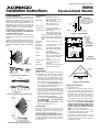 1
1
-
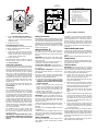 2
2
-
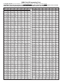 3
3
-
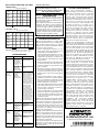 4
4
-
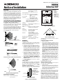 5
5
-
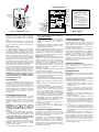 6
6
-
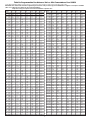 7
7
-
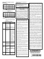 8
8
-
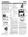 9
9
-
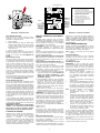 10
10
-
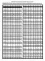 11
11
-
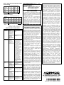 12
12
-
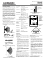 13
13
-
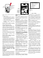 14
14
-
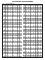 15
15
-
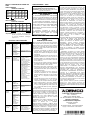 16
16
-
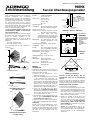 17
17
-
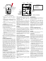 18
18
-
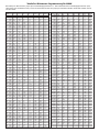 19
19
-
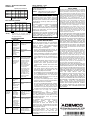 20
20
-
 21
21
-
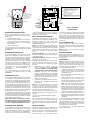 22
22
-
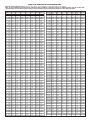 23
23
-
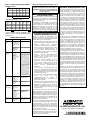 24
24


ADEMCO 998mx Installation Instructions Manual
- Type
- Installation Instructions Manual
in andere talen
- English: ADEMCO 998mx
- italiano: ADEMCO 998mx
- français: ADEMCO 998mx
- español: ADEMCO 998mx
- Deutsch: ADEMCO 998mx
- suomi: ADEMCO 998mx
Gerelateerde papieren
Andere documenten
-
Comelit RF2PIRW Technical Manual
-
Abus AZBW20000 Handleiding
-
Marmitek MS845 Handleiding
-
-
Risco WL T312 Installation Instructions Manual
-
Smanos MD9100 de handleiding
-
Abus FUBW50020 Handleiding
-
Pyronix XDL15TT-AM Installatie gids
-
-
Visonic TOWER 20 de handleiding