Yamaha RX V3900 - AV Network Receiver Handleiding
- Categorie
- AV-ontvangers
- Type
- Handleiding
Deze handleiding is ook geschikt voor

© 2008 Yamaha Corporation All rights reserved.
Printed in Malaysia WP55260
RX-V3900
RX-V3900
AV R e c e i ve r
OWNER’S MANUAL
U
RX-V3900_U-cv.fm Page 1 Friday, August 8, 2008 3:06 PM
Black process 45.0° 240.0 LPI

Caution-i En
• Explanation of Graphical Symbols
The lightning flash with arrowhead symbol, within an
equilateral triangle, is intended to alert you to the
presence of uninsulated “dangerous voltage” within
the product’s enclosure that may be of sufficient
magnitude to constitute a risk of electric shock to
persons.
The exclamation point within an equilateral triangle
is intended to alert you to the presence of important
operating and maintenance (servicing) instructions in
the literature accompanying the appliance.
1 Read these instructions.
2 Keep these instructions.
3 Heed all warnings.
4 Follow all instructions.
5 Do not use this apparatus near water.
6 Clean only with dry cloth.
7 Do not block any ventilation openings. Install in accordance
with the manufacturer’s instructions.
8 Do not install near any heat sources such as radiators, heat
registers, stoves, or other apparatus (including amplifiers)
that produce heat.
9 Do not defeat the safety purpose of the polarized or
grounding-type plug. A polarized plug has two blades with
one wider than the other. A grounding type plug has two
blades and a third grounding prong. The wide blade or the
third prong are provided for your safety. If the provided plug
does not fit into your outlet, consult an electrician for
replacement of the obsolete outlet.
10 Protect the power cord from being walked on or pinched
particularly at plugs, convenience receptacles, and the point
where they exit from the apparatus.
11 Only use attachments/accessories specified by the
manufacturer.
12 Use only with the cart, stand, tripod, bracket,
or table specified by the manufacturer, or sold
with the apparatus. When a cart is used, use
caution when moving the cart/apparatus
combination to avoid injury from tip-over.
13 Unplug this apparatus during lightning storms or when
unused for long periods of time.
14 Refer all servicing to qualified service personnel. Servicing
is required when the apparatus has been damaged in any
way, such as power-supply cord or plug is damaged, liquid
has been spilled or objects have fallen into the apparatus, the
apparatus has been exposed to rain or moisture, does not
operate normally, or has been dropped.
IMPORTANT SAFETY INSTRUCTIONS
Note to CATV system installer:
This reminder is provided to call the CATV system
installer’s attention to Article 820-40 of the NEC that
provides guidelines for proper grounding and, in
particular, specifies that the cable ground shall be
connected to the grounding system of the building, as
close to the point of cable entry as practical.
FCC INFORMATION (for US customers)
1 IMPORTANT NOTICE: DO NOT MODIFY THIS UNIT!
This product, when installed as indicated in the instructions
contained in this manual, meets FCC requirements. Modifications
not expressly approved by Yamaha may void your authority,
granted by the FCC, to use the product.
2 IMPORTANT:
When connecting this product to accessories
and/or another product use only high quality shielded cables.
Cable/s supplied with this product MUST be used. Follow all
installation instructions. Failure to follow instructions could void
your FCC authorization to use this product in the USA.
3NOTE:
This product has been tested and found to comply with
the requirements listed in FCC Regulations, Part 15 for Class “B”
digital devices. Compliance with these requirements provides a
reasonable level of assurance that your use of this product in a
residential environment will not result in harmful interference with
other electronic devices.
This equipment generates/uses radio frequencies and, if not
installed and used according to the instructions found in the users
manual, may cause interference harmful to the operation of other
electronic devices.
Compliance with FCC regulations does not guarantee that
interference will not occur in all installations. If this product is
found to be the source of interference, which can be determined by
turning the unit “OFF” and “ON”, please try to eliminate the
problem by using one of the following measures:
Relocate either this product or the device that is being affected by
the interference.
Utilize power outlets that are on different branch (circuit breaker or
fuse) circuits or install AC line filter/s.
In the case of radio or TV interference, relocate/reorient the
antenna. If the antenna lead-in is 300 ohm ribbon lead, change the
lead-in to coaxial type cable.
If these corrective measures do not produce satisfactory results,
please contact the local retailer authorized to distribute this type of
product. If you can not locate the appropriate retailer, please
contact Yamaha Electronics Corp., U.S.A. 6660 Orangethorpe
Ave, Buena Park, CA 90620.
The above statements apply ONLY to those products distributed by
Yamaha Corporation of America or its subsidiaries.
CAUTION
CAUTION: TO REDUCE THE RISK OF
ELECTRIC SHOCK, DO NOT REMOVE
COVER (OR BACK). NO USER-SERVICEABLE
PARTS INSIDE. REFER SERVICING TO
QUALIFIED SERVICE PERSONNEL.
RISK OF ELECTRIC SHOCK
DO NOT OPEN

Caution-ii En
1 To assure the finest performance, please read this manual
carefully. Keep it in a safe place for future reference.
2 Install this sound system in a well ventilated, cool, dry, clean
place – away from direct sunlight, heat sources, vibration,
dust, moisture, and/or cold. Allow ventilation space of at least
30 cm on the top, 20 cm on the left and right, and 20 cm on
the back of this unit.
3 Locate this unit away from other electrical appliances, motors,
or transformers to avoid humming sounds.
4 Do not expose this unit to sudden temperature changes from
cold to hot, and do not locate this unit in an environment with
high humidity (i.e. a room with a humidifier) to prevent
condensation inside this unit, which may cause an electrical
shock, fire, damage to this unit, and/or personal injury.
5 Avoid installing this unit where foreign objects may fall onto
this unit and/or this unit may be exposed to liquid dripping or
splashing. On the top of this unit, do not place:
– Other components, as they may cause damage and/or
discoloration on the surface of this unit.
– Burning objects (i.e. candles), as they may cause fire,
damage to this unit, and/or personal injury.
– Containers with liquid in them, as they may fall and liquid
may cause electrical shock to the user and/or damage to
this unit.
6 Do not cover this unit with a newspaper, tablecloth, curtain,
etc. in order not to obstruct heat radiation. If the temperature
inside this unit rises, it may cause fire, damage to this unit,
and/or personal injury.
7 Do not plug in this unit to a wall outlet until all connections
are complete.
8 Do not operate this unit upside-down. It may overheat,
possibly causing damage.
9 Do not use force on switches, knobs and/or cords.
10 When disconnecting the power cable from the wall outlet,
grasp the plug; do not pull the cable.
11 Do not clean this unit with chemical solvents; this might
damage the finish. Use a clean, dry cloth.
12 Only voltage specified on this unit must be used. Using this
unit with a higher voltage than specified is dangerous and may
cause fire, damage to this unit, and/or personal injury. Yamaha
will not be held responsible for any damage resulting from use
of this unit with a voltage other than specified.
13 To prevent damage by lightning, keep the power cord and
outdoor antennas disconnected from a wall outlet or the unit
during a lightning storm.
14 Do not attempt to modify or fix this unit. Contact qualified
Yamaha service personnel when any service is needed. The
cabinet should never be opened for any reasons.
15 When not planning to use this unit for long periods of time
(i.e. vacation), disconnect the AC power plug from the wall
outlet.
16 Install this unit near the AC outlet and where the AC power
plug can be reached easily.
17 Be sure to read the “Troubleshooting” section on common
operating errors before concluding that this unit is faulty.
18 Before moving this unit, press
A
MASTER ON/OFF to
release it outward to the OFF position to turn off this unit, the
main room, Zone 2 and Zone 3 and then disconnect the AC
power plug from the AC wall outlet.
19 VOLTAGE SELECTOR (Asia and General models only)
The VOLTAGE SELECTOR on the rear panel of this unit
must be set for your local main voltage BEFORE plugging
into the AC wall outlet. Voltages are:
................................AC 110/120/220/230–240 V, 50/60 Hz
20 The batteries shall not be exposed to excessive heat such as
sunshine, fire or like.
21 Excessive sound pressure from earphones and headphones can
cause hearing loss.
22 When replacing the batteries, be sure to use batteries of the
same type. Danger of explosion may happen if batteries are
incorrectly replaced.
Caution: Read this before operating your unit.
WARNING
TO REDUCE THE RISK OF FIRE OR ELECTRIC
SHOCK, DO NOT EXPOSE THIS UNIT TO RAIN
OR MOISTURE.
As long as this unit is connected to the AC wall outlet,
it is not disconnected from the AC power source even
if you turn off this unit by
A
MASTER ON/OFF. In
this state, this unit is designed to consume a very small
quantity of power.
FOR CANADIAN CUSTOMERS
To prevent electric shock, match wide blade of plug to
wide slot and fully insert.
This Class B digital apparatus complies with Canadian
ICES-003.
POUR LES CONSOMMATEURS CANADIENS
Pour éviter les chocs électriques, introduire la lame la
plus large de la fiche dans la borne correspondante de
la prise et pousser jusqu’au fond.
Cet appareil numérique de la classe B est conforme à
la norme NMB-003 du Canada.
IMPORTANT
Please record the serial number of this unit in the space
below.
MODEL:
Serial No.:
The serial number is located on the rear of the unit.
Retain this Owner’s Manual in a safe place for future
reference.

Caution-iii En
Manufactured under license from Dolby Laboratories.
Dolby, Pro Logic and the double-D symbol are trademarks of
Dolby Laboratories.
Manufactured under license under U.S. Patent No’s:
5,451,942;5,956,674;5,974,380;5,978,762;6,226,616;6,487,535
& other U.S. and worldwide patents issued & pending. DTS is a
registered trademark and the DTS logos, Symbol, DTS-HD and
DTS-HD Master Audio are trademark of DTS, Inc. © 1996-2007
DTS, Inc. All Rights Reserved.
“iPod” is a trademark of Apple Inc., registered in the U.S. and
other countries.
MPEG Layer-3 audio coding technology licensed from
Fraunhofer IIS and Thomson.
This receiver supports network connections.
“HDMI”, the “HDMI” logo and “High-Definition Multimedia
Interface” are trademarks, or registered trademarks of HDMI
Licensing LLC.
x.v.Color™
“x.v.Color” is a trademark of Sony Corporation.
“SILENT CINEMA” is a trademark of Yamaha Corporation.
The XM name and related logos are registered trademarks of XM
Satellite Radio Inc.
This product is manufactured under license from Neural Audio
Corporation and THX Ltd. YAMAHA CORPORATION hereby
grants the user a non-exclusive, non-transferable, limited right of
use to this product under U.S.A. and foreign patent, patent
pending and other technology or trademarks owned by Neural
Audio Corporation and THX Ltd. “Neural Surround”, “Neural
Audio”, “Neural” and “NRL” are trademarks and logos owned by
Neural Audio Corporation. THX is a trademark of THX Ltd.,
which may be registered in some jurisdictions. All rights
reserved.
©2006 SIRIUS Satellite Radio Inc. “SIRIUS”, “SiriusConnect”,
the SIRIUS dog logo, channel names and logos are trademarks of
SIRIUS Satellite Radio Inc.
HD Radio™ Technology Manufactured Under License From
iBiquity Digital Corp. U.S. and Foreign Patents. HD Radio™ and
the HD Radio logo are proprietary trademarks of iBiquity Digital
Corp.
Rhapsody and the Rhapsody logo are registered trademarks of
RealNetworks, Inc.
Circle Surround II, Dialog Clarity, TruBass, SRS and the
symbol are trademarks of SRS Labs, Inc.
Circle Surround II, Dialog Clarity and TruBass technologies are
incorporated under license from SRS Labs, Inc.
Windows XP, Windows Vista, Windows Media Audio, Windows
Media Connect and Windows Media Player are either registered
trademarks or trademarks of Microsoft corporation in the United
States and/or other countries.
iPod
TM

1 En
PREPARATIONINTRODUCTION
BASIC
OPERATION
ADVANCED
OPERATION
ADDITIONAL
INFORMATION
APPENDIX
English
Features ................................................................... 3
Supplied accessories .................................................. 3
Getting started ........................................................ 4
Quick start guide .................................................... 5
L
Connections ............................................................. 9
Optimizing the speaker setting for your
listening room.................................................... 30
Playback ................................................................ 36
Basic procedure ....................................................... 36
Selecting audio input jacks (AUDIO SELECT)...... 37
Selecting the multi-channel input component ......... 37
Selecting the HDMI OUT jack ................................ 37
Using your headphones............................................ 38
Muting the audio output........................................... 38
Displaying the input source information ................. 38
Using the sleep timer ............................................... 39
Sound field programs ........................................... 40
Selecting sound field programs ............................... 40
Using CINEMA DSP 3D mode............................... 46
Enjoying unprocessed input sources........................ 46
Using audio features ............................................. 47
Enjoying pure hi-fi sound ........................................ 47
Adjusting the tonal quality....................................... 47
Adjusting the speaker level...................................... 47
Selecting the recording source................................. 47
FM/AM tuning ...................................................... 48
Overview.................................................................. 48
FM/AM tuning operations ....................................... 48
Preset FM/AM stations ............................................ 49
Using HD Radio™ features
(U.S.A. model only)........................................... 51
Selecting HD Radio™ audio programs ................... 51
Using the iTunes Tagging feature............................ 51
Displaying HD Radio™ information....................... 52
XM
®
Satellite Radio tuning ................................. 53
Connecting XM Mini-Tuner Home Dock ............... 53
Activating XM Satellite Radio ................................ 54
XM Satellite Radio operations................................. 54
Setting the XM Satellite Radio preset channels ...... 55
Displaying the XM Satellite Radio information...... 56
SIRIUS Satellite Radio™ tuning......................... 58
Connecting the SiriusConnect™ tuner .................... 58
Activating SIRIUS Satellite Radio™
subscription ......................................................... 59
SIRIUS Satellite Radio™ operations ...................... 59
Setting the SIRIUS Satellite Radio™
preset channels .................................................... 61
Setting the Parental Lock......................................... 62
Displaying the SIRIUS Satellite Radio™
information .......................................................... 63
Using Bluetooth™ components ........................... 64
Pairing the Bluetooth™ receiver and your
Bluetooth component .......................................... 64
Playback of the Bluetooth™ component ................. 64
Music Content menu ............................................ 65
Music Content menu operations .............................. 65
Using iPod™ ..........................................................66
iPod menu tree ......................................................... 66
Controlling iPod™................................................... 67
Using USB and network features.........................68
USB and network menu tree.................................... 68
Navigating USB and network menus ...................... 69
Using a USB storage device or a USB portable
audio player ......................................................... 69
Using a PC server or Yamaha
MCX-2000........................................................... 70
Using the Internet Radio.......................................... 71
Using the Rhapsody® service
(U.S.A. model only) ............................................ 71
Using shortcut buttons ............................................. 72
Advanced sound configurations...........................74
Selecting decoders ................................................... 74
Graphical user interface (GUI) menu .................76
GUI menu overview ................................................ 78
GUI menu operations............................................... 79
Saving and recalling the system settings
(System Memory) ............................................101
Controlling this unit by using the Web
browser (Web Control Center) ......................105
Remote control features......................................106
Controlling this unit, a TV,
or other components .......................................... 106
Customizing the remote control ............................ 108
Setting the backlight mode of the remote
control................................................................ 109
Setting remote control codes ................................. 109
Programming codes from other remote controls ... 111
Changing source names in the display window..... 112
Macro programming features ................................ 113
Clearing configurations ......................................... 115
Simplified remote control...................................... 116
Using multi-zone configuration..........................117
Connecting the Zone 2 and Zone 3 components ... 117
Controlling Zone 2 or Zone 3 ................................ 119
Advanced setup....................................................121
Using the advanced setup menu ............................ 121
Troubleshooting...................................................124
Resetting the system............................................138
Operation modes of front panel controls ..........139
Glossary................................................................140
Sound field program information......................143
Parametric equalizer information .....................144
Specifications .......................................................145
Index .....................................................................147
(at the end of this manual)
Front panel................................................................i
Remote control ....................................................... ii
Sound output in each sound field program......... iii
List of remote control codes ...................................v
Contents
INTRODUCTION
PREPARATION
BASIC OPERATION
ADVANCED OPERATION
ADDITIONAL INFORMATION
APPENDIX

2 En
By configuring the parameters in the GUI menu of this unit, you can adjust a variety of system settings suited for your
listening environment. The following is a brief description of some of the useful menus you can configure in the GUI
menu. For more detailed information, see “Graphical user interface (GUI) menu” (page 76).
Fine adjusting the speaker settings
In case speaker settings configured by automatic setup
does not match your listening environment, you can
configure them manually.
Setup → Speaker (page 87)
Specifying the muting type
In case you do not want to fully mute audio when you
receive a call while watching your favorite TV program,
you can use this menu to specify the muting level.
Setup → Vo l um e → Muting Type (page 90)
Specifying the initial volume level
By adjusting this parameter, you can automatically control
the initial volume level regardless of the recording level of
the audio source.
Setup → Vo l um e → Initial Volume (page 90)
Adjusting the dynamic range
The dynamic range is the difference between the
minimum and maximum amplitude. The higher the
dynamic range, the more accurate the sound reproduction
for bitstream signals. You can adjust the dynamic range
for speakers and headphones individually. Also, you can
use the adaptive dynamic range control feature to adjust
the dynamic range automatically in conjunction with the
volume level.
Setup → Sound → Dynamic Range (page 90)
Setup → Vo l um e → Adaptive DRC (page 89)
Adjusting the audio and video synchronization
Sometimes, depending on your video source component,
video is delayed relative to audio due to processing
problems. In this case, you need to manually adjust the
audio delay to keep it synchronized with the video. If you
connect the video source component to this unit using an
HDMI connection and your component supports the
LIPSYNC feature, you can adjust the audio/video
synchronization automatically.
Setup → Sound → Lipsync (page 92)
Changing input/output assignment
In case the initial input/output assignments do not
correspond to your needs, you can rearrange them
according to your component to be connected to this unit.
You can also edit the input name to be displayed in the
front panel or in the GUI screen as necessary.
Setup → Option → I/O Assignment (page 98)
Setup → Option → Input Rename (page 98)
Fixing the volume difference between input
sources
The sound output level may vary depending on the audio
source components connected to this unit. In this case, you
can reduce or increase the output level of each input
source using this feature.
Input Select → (input source) → (submenu) →
Volume Trim (page 85)
Setting the background video for discrete multi-
channel input
If you want to enjoy video images in combination with
discrete multi-channel audio input, configure this setting
to specify the video input source. For example, to view
DVD video images while listening to the music sources
from a multi-format player or an external decoder, set this
setting to “DVD”.
Input Select → MULTI CH → (submenu) → BGV
(page 86)
Adjusting the brightness of the front panel
display
You can make the front panel display darker or brighter by
configuring this setting.
Setup → Option → Display Set → Front Panel Display →
Dimmer (page 98)
Turning on or off the short message display
Each time you operate this unit using controls on the front
panel or remote control keys, this unit displays short
messages on the video monitor. If you want to turn off the
short message display, select “Off” in this setting (Initial
factory setting is “On”).
Setup → Option → Display Set → Short Message
(page 98)
Setting the amount of time to display GUI screen
information
You can set the amount of time to display playback
information in the GUI screen after you perform a certain
operation.
Setup → Option → Display Set → Playback Screen
(page 98)
Protecting the setup values
After you have configured the sound field program
parameters and other system settings, you can use this
feature to prevent accidental changes to those setup
values.
Setup → Option → Memory Guard (page 97)
What you can do with the GUI menu

FEATURES
3 En
INTRODUCTION
English
Built-in 7-channel power amplifier
◆
Minimum RMS output power
(20 Hz to 20 kHz, 0.04% THD, 8
Ω
)
Front: 140 W + 140 W
Center: 140 W
Surround: 140 W + 140 W
Surround back: 140 W + 140 W
Various input/output connectors
◆
HDMI (IN x 4, OUT x 2), Component video (IN x 3, OUT x 1), S-
video (IN x 6, OUT x 3), Composite video (IN x 6, OUT x 5),
Coaxial digital audio (IN x 3), Optical digital audio (IN x 5, OUT x
2), Analog audio (IN x 10, OUT x 3)
◆
Speaker out (7-channel), Pre out (7-channel), Subwoofer out,
Presence out, Zone 2/Zone 3 out
◆
Discrete multi-channel input (6 or 8-channel)
Sound field programs
◆
Proprietary Yamaha technology for the creation of sound fields
◆
CINEMA DSP 3D
◆
Compressed Music Enhancer mode
◆
Virtual CINEMA DSP
◆
SILENT CINEMA
Digital audio decoders
◆
Dolby TrueHD, Dolby Digital Plus decoder
◆
DTS-HD Master Audio, DTS-HD High Resolution Audio decoder
◆
Dolby Digital/Dolby Digital EX decoder
◆
DTS/DTS-ES Matrix 6.1, Discrete 6.1, DTS 96/24 decoder
◆
Dolby Pro Logic/Dolby Pro Logic II/Dolby Pro Logic IIx decoder
◆
DTS NEO:6 decoder
◆
Neural-THX Surround decoder
(U.S.A. and Canada models only)
◆
SRS Circle Surround II decoder (U.S.A. model only)
Radio tuners
◆
FM/AM tuning capability, 40-station preset tuning
◆
HD Radio™ digital broadcast reception capability (U.S.A. model
only)
◆
XM Satellite Radio tuning capability (using XM Mini-Tuner and
Home Dock, sold separately)
◆
SIRIUS Satellite Radio™ tuning capability (using SiriusConnect
tuner, sold separately)
HDMI™ (High-Definition Multimedia Interface)
◆
HDMI interface for standard, enhanced or
high-definition video as well as multi-channel digital audio based on
HDMI version 1.3a (HDMI is licensed by HDMI Licensing, LLC.)
– Automatic audio and video synchronization (lip sync) information
capability
– Deep Color video signal (30/36 bit) transmission capability
– “x.v.Color” video signal transmission capability
– High refresh rate and high resolution video signals capability
– High definition digital audio format signals capability
◆
HDCP (High-bandwidth Digital Content Protection System) licensed
by Digital Content Protection, LLC.
◆
Analog video to HDMI digital video up-conversion (composite video
↔
S-video
↔
component video
→
HDMI digital video) capability
for monitor out
◆
Analog and HDMI video up-scaling: 480i(576i)
→
480p(576p)/
720p/1080i/1080p, 480p(576p)
→
720p/1080i/1080p, 720p
→
1080i/1080p, 1080i
→
720p/1080p
DOCK terminal
◆
DOCK terminal to connect a Yamaha iPod universal dock (such as
YDS-11, sold separately) or Bluetooth wireless audio receiver (such
as YBA-10, sold separately)
USB and network features
◆
USB port to connect a USB storage device, USB Hard disc
drive, or USB portable audio player
◆
NETWORK port to connect a PC and Yamaha MCX-2000 or
access the Internet Radio and Rhapsody
®
(U.S.A. model
only) via LAN
◆
DHCP automatic or manual network configuration
◆
Web control capability of this unit by using a Web browser
Automatic speaker setup features
◆
Advanced YPAO (Yamaha Parametric room Acoustic Optimizer) for
automatic speaker setup
◆
Multi-point measurement feature for multiple listening positions
◆
Parametric equalizer select feature
Other features
◆
192-kHz/24-bit D/A converter
◆
GUI (graphic user interface) menus that allow you to optimize this
unit to suit your individual audiovisual system
◆
Music Content menu that allows you to easily navigate music content
menus of your iPod, USB component, Internet Radio, etc.
◆
PURE DIRECT mode for pure hi-fi sound for all sources
◆
Adaptive dynamic range controlling capability
◆
Adaptive DSP effect level controlling capability
◆
Remote control with preset remote control codes, learning and macro
capability
◆
ZONE 2/ZONE 3 custom installation facility
◆
Zone switching capability between the main zone and
ZONE 2/ZONE 3 using ZONE CONTROLS
◆
System Memory capability for saving and recalling multiple system
parameter settings
◆
Sleep timer for each zone
Check that you received all of the following parts.
❏ Remote control
❏ Simplified remote control
❏ Batteries (4) (AAA, LR03, UM-4)
❏ Power cable (Two for Asia model)
❏ Optimizer microphone
❏ AM loop antenna
❏ Indoor FM antenna
Features
Supplied accessories

GETTING STARTED
4 En
■ Installing batteries in the remote control
1 Take off the battery compartment cover.
2 Insert the four supplied batteries
(AAA, LR03, UM-4) according to the polarity
markings (+ and –) on the inside of the
battery compartment.
3 Snap the battery compartment cover back
into place.
• Change all of the batteries if you notice the following
conditions:
– the operation range of the remote control decreases.
– the transmit indicator does not flash or its light becomes dim.
• Do not use old batteries together with new ones.
• Do not use different types of batteries (such as alkaline and
manganese batteries) together. Read the packaging carefully as
these different types of batteries may have the same shape and
color.
• If the batteries have leaked, dispose of them immediately. Avoid
touching the leaked material or letting it come into contact with
clothing, etc. Clean the battery compartment thoroughly before
installing new batteries.
• Do not throw away batteries with general house waste; dispose
of them correctly in accordance with your local regulations.
• If the remote control is without batteries for more than 2
minutes, or if exhausted batteries remain in the remote control,
the contents of the memory may be cleared. When the memory
is cleared, insert new batteries, set up the remote control code
and program any acquired functions that may have been
cleared.
■ VOLTAGE SELECTOR
(Asia and General models only)
Getting started
About this manual
• y indicates a tip for your operation.
• Some operations can be performed by using either the
buttons on the front panel or the ones on the remote
control. In case the button names differ between the front
panel and the remote control, the button name on the
remote control is given in parentheses.
• This manual is printed prior to production. Design and
specifications are subject to change in part as a result of
improvements, etc. In case of differences between the
manual and product, the product has priority.
•“
A
MASTER ON/OFF” or “
3
DVD” (example)
indicates the name of the parts on the front panel or the
remote control. Refer to the attached sheet or the pages at
the end of this manual for the information about each
position of the parts.
1
3
2
Notes
Caution
The VOLTAGE SELECTOR on the rear panel of this
unit must be set for your local voltage BEFORE
plugging the power cable into the AC wall outlet.
Improper setting of the VOLTAGE SELECTOR may
cause damage to this unit and create a potential fire
hazard.
Rotate the VOLTAGE SELECTOR clockwise or
counterclockwise to the correct position using a straight
slot screwdriver.
Voltages are as follows:
........................AC 110/120/220/230–240 V, 50/60 Hz
230-
240V
VOLTAGE
SELECTOR
Voltage indication

QUICK START GUIDE
5 En
INTRODUCTION
English
The following steps describe the easiest way to enjoy DVD movie playback in your home theater.
In these steps, you need the following supplied
accessories.
❏ Power cable
The following items are not included in the package of this
unit.
❏ Speakers
❏ Front speaker ......................................x 2
❏ Center speaker ...................................x 1
❏ Surround speaker ...............................x 4
Select magnetically shielded speakers. The
minimum required speakers are two front speakers.
The priority of the requirement of other speakers is
as follows:
1. Two surround speakers
2. One center speaker
3. One (or two) surround back speaker(s)
❏ Active subwoofer ....................................x 1
Select an active subwoofer equipped with an RCA
input jack.
❏ Speaker cable ..........................................x 7
❏ Subwoofer cable .....................................x 1
Select a monaural RCA cable.
❏ DVD player ...............................................x 1
Select DVD player equipped with coaxial digital
audio output jack and composite video output
jack.
❏ Video monitor...........................................x 1
Select a TV monitor, video monitor or projector
equipped with a composite video input jack.
❏ Video cable ..............................................x 2
Select RCA composite video cables.
❏ Digital coaxial audio cable .....................x 1
Quick start guide
Front right
speaker
Subwoofer
Surround back
right speaker
Surround left
speaker
Front left
speaker
Surround back left
speaker
Surround right
speaker
Center
speaker
Video monitor
DVD player
Enjoy DVD playback!
Step 1: Set up your speakers
☞
P. 6
Step 2: Connect your DVD player
and other components
Step 3: Turn on the power and
start playback
☞
P. 7
☞
P. 8
Preparation: Check the items

Quick start guide
6 En
Place your speakers in the room and connect them to this
unit.
1 Place your speakers and subwoofer in the
room.
2 Connect speaker cables to each speaker.
3 Connect each speaker cable to the
corresponding speaker terminal of this unit.
1 Make sure that this unit and the subwoofer are
unplugged from the AC wall outlets.
2 Twist the exposed wires of the speaker cables
together to prevent short circuits.
3 Do not let the bare speaker wires touch each other.
4 Do not let the bare speaker wires touch any metal
part of this unit.
Be sure to connect the left channel (L), right channel
(R), “+” (red) and “–” (black) properly.
Front speakers and center speaker
Surround and surround back speakers
4 Connect the subwoofer cable to the
SUBWOOFER PRE OUT jack of this unit and
the input jack of the subwoofer.
Step 1: Set up your speakers
AC IN
AC OUTLETS
SWITCHED
SPEAKERS
CENTERSURROUND BACK/BI-AMP PRESENCE/ZONE 2/ZONE 3
FRONT SURROUND ZONE 2/ZONE 3
SINGLE
NETWORK
ANTENNA
FM
GND
AM
75Ω UNBAL.
VIDEO
S VIDEO
MONITOR OUT
VIDEO
REMOTE
PHONO
GND
CD TV
HDMI
COMPONENT VIDEO
AUDIO
DOCK
XM
SIRIUS
DIGITAL INPUT
MULTI CH INPUT
PRE OUT
TRIGGER OUT
RS-232C
DIGITAL OUTPUT
ZONE OUT
SUB SUR.BACK
WOOFER
SUB
WOOFER
CENTER
CENTER
FRONT(6CH)
FRONT
SURROUND
SURROUND
PRESENCE
SUR.BACK/
SINGLE(SB)
ZONE 2
ZONE 3 ZONE
VIDEO
CD
D
V
D
D
V
R
COAXIAL
1
2
TV
BD/
HD DVD
CBL/
SAT
MD/
CD-R
DVD DVR
OPTICAL
987
65
4
321
(8CH)
DVD
OUT(REC)
IN(PLAY)
MD/CD-R
BD/HD DVD
VCR
DVR
CBL/SAT
OUT OUT
ININ
BD/HD DVD DVD CBL/SAT
MONITOR OUT
Y
P
R
Y
P
R
P
B
P
B
IN 1 2
OUT IN OUT
DVR
CBL/
SAT
OUT
1
OUT
2
+
A B C
R
R
L
R
L
+
R
L
+
+
R
L
+
R
L
+
R
L
L
IN1
IN3
DVD
BD/
HD DVD
IN2
IN4
SP1
SP2
SUBWOOFER PRE OUT Speaker terminals
12 3 4
12 3 4
To the front left
speaker
To the front right
speaker
Loosen Insert
To the center
speaker
Tighten
To the surround
back
right speaker
To the surround
left speaker
To the surround back
left speaker
To the surround right
speaker
SUBWOOFER PRE OUT jack
Input jack
AV receiverSubwoofer
Subwoofer cable

Quick start guide
7 En
INTRODUCTION
English
1 Connect the digital coaxial audio cable to the
digital coaxial audio output jack of your DVD
player and the DVD DIGITAL INPUT COAXIAL
jack of this unit.
2 Connect the video cable to the composite
video output jack of your DVD player and
DVD VIDEO jack of this unit.
3 Connect the video cable to the VIDEO
MONITOR OUT jack of this unit and the video
input jack of your video monitor.
4 Connect the supplied power cable to this unit
and then plug of the power cable and other
components into the AC wall outlet.
y
For details about connecting the power cable, see page 25.
■ For other connections
• Other speaker combinations ☞ P. 12
• Information on jacks and cable plugs ☞ P. 15
• Information on HDMI™ ☞ P. 16
• TV monitor or projector ☞ P. 18
• Other components ☞ P. 19
• External amplifier ☞ P. 21
• Multi-format player or external
decoder ☞ P. 22
• Yamaha iPod universal dock or
Bluetooth wireless audio receiver ☞ P. 22
•FM/AM antennas ☞ P. 24
• XM Mini-Tuner Home Dock ☞ P. 53
• SiriusConnect tuner ☞ P. 58
•Network ☞ P. 23
•USB device ☞ P. 23
Step 2: Connect your DVD player
and other components
AC IN
AC OUTLETS
SWITCHED
SPEAKERS
CENTERSURROUND BACK/BI-AMP PRESENCE/ZONE 2/ZONE 3
FRONT SURROUND ZONE 2/ZONE 3
SINGLE
NETWORK
ANTENNA
FM
GND
AM
75Ω UNBAL.
VIDEO
S VIDEO
MONITOR OUT
VIDEO
REMOTE
PHONO
GND
CD TV
HDMI
COMPONENT VIDEO
AUDIO
DOCK
XM
SIRIUS
DIGITAL INPUT
MULTI CH INPUT
PRE OUT
TRIGGER OUT
RS-232C
DIGITAL OUTPUT
ZONE OUT
SUB SUR.BACK
WOOFER
SUB
WOOFER
CENTER
CENTER
FRONT(6CH)
FRONT
SURROUND
SURROUND
PRESENCE
SUR.BACK/
SINGLE(SB)
ZONE 2
ZONE 3 ZONE
VIDEO
CD
D
V
D
D
V
R
COAXIAL
1
2
TV
BD/
HD DVD
CBL/
SAT
MD/
CD-R
DVD DVR
OPTICAL
987
65
4
321
(8CH)
DVD
OUT(REC)
IN(PLAY)
MD/CD-R
BD/HD DVD
VCR
DVR
CBL/SAT
OUT OUT
ININ
BD/HD DVD DVD CBL/SAT
MONITOR OUT
Y
P
R
Y
P
R
P
B
P
B
IN 1 2
OUT IN OUT
DVR
CBL/
SAT
OUT
1
OUT
2
+
A B C
R
R
L
R
L
+
R
L
+
+
R
L
+
R
L
+
R
L
L
IN1
IN3
DVD
BD/
HD DVD
IN2
IN4
SP1
SP2
Make sure that this unit and the DVD
player are unplugged from the AC
wall outlets.
VIDEO MONITOR OUTDVD VIDEO
DVD DIGITAL INPUT
COAXIAL
Digital coaxial
audio output
jack
Digital coaxial audio
cable
DVD DIGITAL INPUT
COAXIAL jack
DVD player
AV receiver
Composite video
output jack
Video cable
DVD VIDEO jack
DVD player
AV receiver
Video monitor
AV receiver
Video cable
VIDEO MONITOR
OUT jack
Video input jack

Quick start guide
8 En
1 Turn on the video monitor connected to this
unit.
2 Press AMASTER ON/OFF inward to the ON
position on the front panel.
3 Rotate the
C
INPUT selector to set the input
source to “DVD”.
4 Start playback of the desired DVD on your
player.
5 Rotate
P
VOLUME to adjust the volume.
6 To set this unit to the standby mode, press
BMAIN ZONE ON/OFF.
y
For details about turning on/off this unit and the standby
mode, see page 26.
■ For other operations
• Optimizing the speaker parameters
automatically ☞ P. 30
• Basic playback operations ☞ P. 36
• Sound field programs ☞ P. 40
• Pure high-fidelity sounds ☞ P. 47
• FM/AM radio tuning ☞ P. 48
• XM Satellite Radio tuning ☞ P. 53
• SIRIUS Satellite Radio tuning ☞ P. 58
• Bluetooth component playback ☞ P. 64
• iPod playback ☞ P. 66
• Playback via USB or network ☞ P. 68
Step 3: Turn on the power and start
playback
Check the type of the connected speakers.
If the speakers are 6-ohm speakers, set “SPEAKER
IMP.” to “6Ω MIN” before using this unit (page 26).
You can also use 4-ohm speakers as the front speakers
(page 121).

9 En
PREPARATION
English
The RS-232C terminal is a control expansion terminal for
factory use only. Consult your dealer for details.
Connections
Rear panel
AC IN
AC OUTLETS
SWITCHED
SPEAKERS
CENTERSURROUND BACK/BI-AMP PRESENCE/ZONE 2/ZONE 3
FRONT SURROUND ZONE 2/ZONE 3
SINGLE
NETWORK
ANTENNA
FM
GND
AM
75Ω UNBAL.
VIDEO
S VIDEO
MONITOR OUT
VIDEO
REMOTE
PHONO
GND
CD TV
HDMI
COMPONENT VIDEO
AUD IO
DOCK
XM
SIRIUS
DIGITAL INPUT
MULTI CH INPUT
PRE OUT
TRIGGER OUT
RS-232C
DIGITAL OUTPUT
ZONE OUT
SUB SUR.BACK
WOOFER
SUB
WOOFER
CENTER
CENTER
FRONT(6CH)
FRONT
SURROUND
SURROUND
PRESENCE
SUR.BACK/
SINGLE(SB)
ZONE 2
ZONE 3 ZONE
VIDEO
CD
D
V
D
D
V
R
COAXIAL
1
2
TV
BD/
HD DVD
CBL/
SAT
MD/
CD-R
DVD DVR
OPTICAL
987
65
4
321
(8CH)
DVD
OUT(REC)
IN(PLAY)
MD/CD-R
BD/HD DVD
VCR
DVR
CBL/SAT
OUT OUT
ININ
BD/HD DVD DVD CBL/SAT
MONITOR OUT
Y
P
R
Y
P
R
P
B
P
B
IN 1 2
OUT IN OUT
DVR
CBL/
SAT
OUT
1
OUT
2
+
A B C
R
R
L
R
L
+
R
L
+
+
R
L
+
R
L
+
R
L
L
IN1
IN3
DVD
BD/
HD DVD
IN2
IN4
SP1
SP2
BCA0
9
D
231456 78
Name Page
1 HDMI jacks 16
2 COMPONENT VIDEO jacks 15
3 Audio component jacks 15
REMOTE IN/OUT jacks 22, 117
4 Video component jacks 15
5 ANTENNA terminals 24
6 NETWORK port 23
7 VOLTAGE SELECTOR
(Asia and General models only)
25
8 AC IN 25
AC OUTLET(S) 25
9 DOCK terminal 22
0 XM jack (U.S.A. and Canada models only) 53
SIRIUS jack
(U.S.A. and Canada models only)
58
A DIGITAL INPUT/OUTPUT jacks 15
B TRIGGER OUT jacks 119
C RS-232C terminal —
D MULTI CH INPUT jacks 22
PRE OUT jacks 21
ZONE OUT jacks 117
Speaker terminals 12
Note
Name Page

10 En
Connections
The speaker layout below shows the speaker setting we recommend.
y
• 7.1-channel speaker layout is highly recommended for playback of the high definition digital audio sources (Dolby TrueHD, DTS-HD
Master Audio, etc.) with sound field programs.
• We recommend that you add the presence speakers for the effect sounds of the CINEMA DSP sound field program.
7.1-channel speaker layout
6.1-channel speaker layout
5.1-channel speaker layout
Placing speakers
FR
FL
SBR
SBL
SL
SR
C
SW
60˚
30˚
SBR
SBL
FL
FR
C
SL
SR
SR
80˚
SL
30 cm (12 in) or more
60˚
30˚
SB
FL
FR
C
SL
SR
SR
80˚
SL
FR
FL
SB
SL
SR
C
SW
FR
FL
SL
SR
SW
C
60˚
30˚
FL
FR
C
SL
SR
SR
80˚
SL

11 En
Connections
PREPARATION
English
■ Speaker types
Front left and right speakers (FL and FR)
The front speakers are used for the main source sound plus
effect sounds. Place these speakers at an equal distance from
the ideal listening position. The distance of each speaker
from each side of the video monitor should be the same.
Center speaker (C)
The center speaker is for the center channel sounds
(dialog, vocals, etc.). If for some reason it is not practical
to use a center speaker, you can do without it. Best results,
however, are obtained with the full system.
Surround left and right speakers (SL and SR)
The surround speakers are used for effect and surround
sounds.
For 5.1-channel speaker layout, place these speakers
farther back compared with the placement in the 7.1-
channel speaker layout.
Surround back left and right speakers (SBL and
SBR) /Surround back speaker (SB)
The surround back speakers supplement the surround
speakers and provide more realistic front-to-back
transitions.
For 6.1-channel speaker layout, surround back left and
right channel signals are mixed down and output at the
single surround back speaker by configuring the
“Surround Back” setting (
page 88
).
For 5.1-channel speaker layout, surround back left and
right channel signals are output at the surround left and
right speakers by configuring the “Surround Back” setting
(
page 88
).
Subwoofer (SW)
The use of a subwoofer with a built-in amplifier, such as
the Yamaha Active Servo Processing Subwoofer System,
is effective not only for reinforcing bass frequencies from
any or all channels, but also for reproducing the high
fidelity sound of the LFE (low-frequency effect) channel
included in bitstreams and multi-channel PCM sources.
The position of the subwoofer is not so critical, because
low bass sounds are not highly directional. But it is better
to place the subwoofer near the front speakers. Turn it
slightly toward the center of the room to reduce wall
reflections.
■ Presence left and right speakers (PL and
PR)
The presence speakers supplement the sound from the front
speakers with extra ambient effects produced by the sound
field programs (page 40). We recommend that you use the
presence speakers especially for the CINEMA DSP sound
field programs. To use the presence speakers, connect the
speakers to SP1 speaker terminals and then set
“
Front
Presence
”
to
“
Yes
”
(page 88).
For other speaker combinations
You can enjoy multi-channel sources with sound field
programs by using a speaker combination other than
the 7.1/6.1/5.1-channel speaker combinations.
Use the automatic setup feature (page 30) or set the
“Speaker” parameters (
page 87
). to output the surround
sounds at the connected speakers.
FR
PRPL
C
FL
1.8 m (6 ft)
0.5 to 1 m (1 to 3 ft) 0.5 to 1 m (1 to 3 ft)
1.8 m (6 ft)

12 En
Connections
Be sure to connect the left channel (L), right channel (R), “+” (red) and “–” (black) properly. If the connections are faulty,
this unit cannot reproduce the input sources accurately.
• A speaker cord is actually a pair of insulated cables running side by side. Cables are colored or shaped differently, perhaps with a
stripe, groove or ridge. Connect the striped (grooved, etc.) cable to the “+” (red) terminals of this unit and your speaker. Connect the
plain cable to the “–” (black) terminals.
• You can connect both surround back and presence speakers to this unit, however they do not output sound simultaneously. This unit
automatically switches the presence speakers and surround back speakers depending on the input sources and the selected sound field
programs.
■ 7.1-channel speaker connection
Connecting speakers
Caution
• Before connecting the speakers, make sure that this unit is turned off (page 26).
• Do not let the bare speaker wires touch each other or do not let them touch any metal part of this unit. This could
damage this unit and/or speakers.
• Use magnetically shielded speakers. If this type of speaker still creates interference with the monitor, place the
speakers away from the monitor.
• If you are to use 6-ohm speakers, be sure to set “SPEAKER IMP.” to “6Ω MIN” before using this unit (page 26).
You can also use 4-ohm speakers as the front speakers (page 121).
Notes
SPEAKERS
CENTERSURROUND BACK/BI-AMP PRESENCE/ZONE 2/ZONE 3
FRONT SURROUND ZONE 2/ZONE 3
SINGLE
SUB
WOOFER
+
R
L
+
R
L
+
+
R
L
+
R
L
+
R
L
SP1
SP2
Front speakers
Surround speakers
Presence speakers
(page 11) or
Zone 2/Zone 3
speakers
(page 117)
Subwoofer
Right
Center speaker
Surround back speakers
Left
Left Left
RightRight
Zone 2/Zone 3 speakers
(page 117)

13 En
Connections
PREPARATION
English
■ 6.1-channel speaker connection
■ 5.1-channel speaker connection
Surround back speaker
SPEAKERS
CENTERPRESENCE/ZONE 2/ZONE 3
FRONT SURROUND ZONE 2/ZONE 3
SINGLE
SUB
WOOFER
+
L
+
R
L
+
+
R
L
+
R
L
+
R
L
SP1
SP2
Surround speakers
Front speakers
Presence speakers
(page 11) or
Zone 2/Zone 3 speakers
(page 117)
Subwoofer
Center speaker
Left
Left
Right
Right
Zone 2/Zone 3
speakers
(page 117)
SPEAKERS
CENTERSURROUND BACK/BI-AMP PRESENCE/ZONE 2/ZONE 3
FRONT SURROUND ZONE 2/ZONE 3
SINGLE
K
SUB
WOOFER
+
R
L
+
R
L
+
+
R
L
+
R
L
+
R
L
SP1
SP2
Surround speakersFront speakers
Subwoofer
Center speaker
Left
LeftRight Right
Zone 2/Zone 3
speakers
(page 117)
Front speakers for the
bi-amplification
connections
(page 14)
Presence speakers
(page 11) or
Zone 2/Zone 3 speakers
(page 117)

14 En
Connections
■ Connecting the speaker cable
1 Remove approximately 10 mm (0.4 in) of
insulation from the end of each speaker
cable and then twist the exposed wires of the
cable together to prevent short circuits.
2 Loosen the knob, insert one bare wire into
the hole and then tighten the knob.
■ Connecting the banana plug
(Except U.K., Europe, Asia and Korea
models)
Tighten the knob and then insert the banana plug
into the end of the terminal.
■ Using bi-amplification connections
You can make bi-amplification connections to one speaker
system which supports bi-amplification connection as
shown below. To activate the connections, configure the
“BI-AMP” setting (page 122).
When you make the conventional connection with the speakers,
make sure that the shorting bars are put into the terminals of the
speakers appropriately. Refer to the instruction manuals of the
speakers for details.
10 mm (0.4 in)
Loosen Insert Tighten
Banana plug
Caution
Remove the shorting bars or bridges of your speakers to
separate the LPF (low pass filter) and HPF (high pass filter)
crossovers.
Note
SURROUND BACK/BI-AMP
FRONT
SINGLE
+
R
L
+
R
L
This unit
LeftRight
Front speakers

15 En
Connections
PREPARATION
English
This unit has three types of audio jacks, three types of video jacks and HDMI jacks. You can choose the connection
method depending on the component to be connected.
■ Audio jacks
AUDIO jacks
For conventional analog audio signals transmitted via left
and right analog audio cables. Connect red plugs to the
right jacks and white plugs to the left jacks.
COAXIAL jacks
For digital audio signals transmitted via coaxial digital
audio cables.
OPTICAL jacks
For digital audio signals transmitted via optical digital
audio cables.
You can use the digital jacks to input PCM, Dolby Digital and
DTS bitstreams. When you connect components to both the
COAXIAL and OPTICAL jacks, priority is given to the signals
input at the COAXIAL jack. All digital input jacks are
compatible with up to 96-kHz sampling digital signals.
■ Video jacks
VIDEO jacks
For conventional composite video signals transmitted via
composite video cables.
S VIDEO jacks
For S-video signals, separated into the luminance (Y) and
chrominance (C) video signals transmitted on separate
wires of S-video cables.
COMPONENT VIDEO jacks
For component video signals, separated into the
luminance (Y) and chrominance (P
B, PR) video signals
transmitted on separate wires of component video cables.
y
This unit is equipped with the video conversion function.
(page 17)
Information on jacks and cable plugs
Note
COAXIAL
DIGITAL
AUDIO
OPTICAL
DIGITAL
R
L
C
O
R
L
Left and right
analog audio
cable plugs
Optical
digital
audio cable
plug
Coaxial
digital audio
cable plug
(Red)(White) (Orange)
VIDEO S VIDEO
COMPONENT VIDEO
Y
R
P
B
P
PB
Y
P
R
S
V
Composite
video cable
plug
S-video
cable plug
Component
video cable
plugs
(Yellow) (Green) (Blue) (Red)

16 En
Connections
This unit has four HDMI input jacks and two HDMI output jacks for digital audio and video signal input/output.
■ HDMI jack and cable plug
y
• We recommend that you use a commercially available HDMI cable
shorter than 5 meters (16 feet) with the HDMI logo printed on it.
• Use a conversion cable (HDMI jack
↔
DVI-D jack) to connect this
unit to other DVI components.
• You can check the potential problem about the HDMI connection
(page 38).
• If you set “Mode” in “Standby Through” to “Last” or “Fix”, this
unit allows the HDMI signals input at an HDMI IN jack to pass
through this unit and output at an HDMI OUT jack (page 94).
• This unit is equipped with two HDMI OUT jacks. You can select
the active HDMI OUT jack(s) (page 37).
• This unit is equipped with the video conversion function (page 17).
• Do not disconnect or connect the cable or turn off the power of
the HDMI components connected to the HDMI OUT jacks of
this unit while data is being transferred. Doing so may disrupt
playback or cause noise.
• The HDMI OUT jacks output the audio signals input at the
HDMI input jacks only.
• If you turn off the video monitor connected to the HDMI OUT
jacks via a DVI connection, the connection may fail.
■ HDMI signal compatibility with this unit
Audio signals
y
• If the input source component can decode the bitstream audio
signals of audio commentaries, you can play back the audio sources
with the audio commentaries mixed down by using the following
connections:
– multi-channel analog audio input (page 22)
– DIGITAL INPUT OPTICAL (or COAXIAL)
• Refer to the instruction manuals of the input source component,
and set the component appropriately.
• When CPPM copy-protected DVD audio is played back, video and
audio signals may not be output depending on the type of the DVD
player.
• This unit is not compatible with HDCP-incompatible HDMI or
DVI components.
• To decode the audio bitstream signals on this unit, set the input
source component appropriately so that the component outputs the
audio bitstream signals directly (does not decode the bitstream
signals on the component).
• This unit is not compatible with the audio commentary features (for
example, the special audio contents downloaded via Internet) of
Blu-ray Disc or HD DVD. This unit does not play back the audio
commentaries of the Blu-ray Disc or HD DVD contents.
Video signals
This unit is compatible with the video signals of the
following resolutions:
– 480i/60 Hz
– 576i/50 Hz
– 480p/60 Hz
– 576p/50 Hz
– 720p/60 Hz, 50 Hz
– 1080i/60 Hz, 50 Hz
– 1080p/60 Hz, 50 Hz, 24Hz
Compatibility with Deep Color and x.v.Color
video signals
This unit accepts Deep Color (30 or 36-bit) and x.v.Color
video signals. To output those video signals from the
HDMI OUT jacks without any processing, set “HDMI `
HDMI” (page 94)” to “Through”.
If the video monitor is not compatible with Deep Color or
x.v.Color video signals, the video source may not be played
back correctly.
■ Default input assignment of HDMI input
jacks
Information on HDMI™
Notes
Audio signal
types
Audio signal
formats
Compatible
media
2ch Linear
PCM
2ch, 32-192 kHz,
16/20/24 bit
CD, DVD-Video,
DVD-Audio, etc.
Multi-ch
Linear PCM
8ch, 32-192 kHz,
16/20/24 bit
DVD-Audio, etc.
DSD 2/5.1ch,
2.8224 MHz,1 bit
SA-CD, etc.
Bitstream Dolby Digital,
DTS
DVD-Video, etc.
Bitstream (High
definition audio)
Dolby TrueHD,
Dolby Digital Plus,
DTS-HD Master
Audio, DTS-HD
High Resolution
Audio
Blu-ray Disc,
HD DVD, etc.
HDMI
HDMI cable plug
Notes
Note
HDMI input jack Assigned input source
IN1 BD/HD DVD
IN2 DVD
IN3 CBL/SAT
IN4 DVR

17 En
Connections
PREPARATION
English
■ Audio signal flow
Only the HDMI input jacks support DSD, Dolby TrueHD,
Dolby Digital Plus, DTS-HD Master Audio and DTS-HD High
Resolution Audio signal inputs.
■ Video signal flow
y
• Analog-to-HDMI video conversion is always possible unless
video signals are being input at the HDMI input jacks or 1080p-
resolution analog video signals are being input.
• To set the analog-to-analog video conversion or change the
other video settings, configure the “Video” parameters
(page 93).
• If different analog video signals are input concurrently, the
following priority order will be applied:
(1) COMPONENT VIDEO, (2) S VIDEO, (3) VIDEO
Audio and video signal flow
Note
DIGITAL AUDIO
(OPTICAL)
DIGITAL AUDIO
(COAXIAL)
HDMI
AUDIO
OutputInput
Analog
Digital
S VIDEO
VIDEO
COMPONENT
VIDEO
HDMI
Through
OutputInput
Video
conversion

18 En
Connections
If you turn off the video monitor connected to the HDMI OUT
jacks via a DVI connection, the connection may fail. In this
case, the HDMI indicator flashes irregularly.
y
To select the types of the audio signals output at the HDMI
OUT jacks, configure the “Audio Output” setting (page 95).
Connecting a TV monitor or projector
Note
Make sure that this unit and other
components are unplugged from the
AC wall outlets.
VIDEO
S VIDEO
MONITOR OUT
VIDEO
TV
HDMI
COMPONENT VIDEO
AUD IO
DIGITAL INPUT
TV
4
MONITOR OUT
Y
P
R
P
B
OUT
1
OUT
2
PRPB
V
S
Y
L R
O
TV
Optical outComponent video in
Video inAudio out
S-video in
HDMI in
Recommended connections Alternative connections
HDMI in
Projector

19 En
Connections
PREPARATION
English
■ Connecting audio and video components
This unit has three types of audio jacks, three types of video jacks and HDMI jacks. You can choose the connection
method depending on the component to be connected.
y
HDMI can transmit both digital audio and video over a single HDMI cable.
Connection example (connecting a DVD player)
Connecting other components
VIDEO
PHONO
GND
CD TV
HDMI
COMPONENT VIDEO
CD
D
VD
D
VR
COAXIAL
TV
BD/
HD DVD
CBL/
SAT
MD/
CD-R
DVD DVR
OPTICAL
987
65
4
321
DVD
OUT(REC)
IN(PLAY)
MD/CD-R
BD/HD DVD
VCR
DVR
CBL/SAT
OUT OUT
ININ
BD/HD DVD DVD CBL/SAT
Y
P
R
P
B
DVR
CBL/
SAT
A B C
R
L
R
L
IN1
IN3
DVD
BD/
HD DVD
IN2
IN4
HDMI jacks
COMPONENT VIDEO VIDEO S VIDEO
AUDIO COAXIAL OPTICAL
Video jacks
Audio jacks
VIDEO
COMPONENT VIDEO
DIGITAL INPUT
D
V
D
COAXIAL
DVD
OPTICAL
6
2
DVD
DVD
Y
PR
PB
B
R
L
HDMI
DVD
IN2
C
O
V
S
L R
PRPBY
DVD player
HDMI out
Coaxial out
Component out
S-video
out
Video out
Optical out
Audio out
Recommended
connections
Alternative
connections

20 En
Connections
Jacks used for audio and video connections
Recommended connections are indicated by boldface. When connecting a recording component, you need to make
additional connections for recording (signal transmission from this unit to the recording component).
y
You can also use the VIDEO AUX jacks (page 24) on the front panel to connect an additional component.
Make sure that this unit and other
components are unplugged from the
AC wall outlets.
Component Signal type
Jacks to connect
On component On this unit
Blu-ray Disc or HD
DVD player
Audio/Video HDMI out HDMI IN1 (BD/HD DVD)
Audio Optical out OPTICAL (BD/HD DVD)
Audio out (analog) AUDIO (BD/HD DVD)
Video Component out COMPONENT VIDEO (BD/HD DVD)
S-video out S VIDEO (BD/HD DVD)
Video out (composite) VIDEO (BD/HD DVD)
DVD player Audio/Video HDMI out HDMI IN2 (DVD)
Audio Optical out OPTICAL (DVD)
Coaxial out COAXIAL (DVD)
Audio out (analog) AUDIO (DVD)
Video Component out COMPONENT VIDEO (DVD)
S-video out S VIDEO (DVD)
Video out (composite) VIDEO (DVD)
Set-top box Audio/Video HDMI out HDMI IN3 (CBL/SAT)
Audio Optical out OPTICAL (CBL/SAT)
Audio out (analog) AUDIO (CBL/SAT)
Video Component out COMPONENT VIDEO (CBL/SAT)
S-video out S VIDEO (CBL/SAT)
Video out (composite) VIDEO (CBL/SAT)
DVD recorder Audio/Video HDMI out HDMI IN4 (DVR)
Audio Coaxial out COAXIAL (DVR)
Audio out (analog) AUDIO (DVR IN)
Video S-video out S VIDEO (DVR IN)
Video out (composite) VIDEO (DVR IN)
Audio recording Optical in OPTICAL (DVR)
Audio in (analog) AUDIO (DVR OUT)
Video recording S-video in S VIDEO (DVR OUT)
Video in (composite) VIDEO (DVR OUT)

21 En
Connections
PREPARATION
English
• Be sure to make the same type of video connections as those made for your TV if the video conversion is disabled. For example, if you
connected your TV to the VIDEO MONITOR OUT jack of this unit, connect other components to the VIDEO jacks.
• Check the copyright laws in your country to record from CDs, radio, etc. Recording of copyrighted material may infringe copyright
laws.
• If you connect your DVD player to both the OPTICAL and COAXIAL jacks, priority is given to the signals input at the COAXIAL
jack.
• GUI signals are not output at the DVR OUT and VCR OUT jacks and cannot be recorded.
• To make a digital connection to a component other than the default one assigned to each DIGITAL INPUT or DIGITAL OUTPUT
jack, configure the “I/O Assignment” setting (page 98).
• When connecting a turntable with a low-output MC cartridge to the PHONO jack, use an in-line boosting transformer or MC-head
amplifier.
• Connect your turntable to the GND terminal of this unit to reduce noise in the signal.
■ Connecting an external amplifier
This unit has more than enough power for any home use.
However, if you want to add more power to the speaker
output or if you want to use another amplifier, connect an
external amplifier to the PRE OUT jacks. Each PRE OUT
jack outputs the same channel signals as the
corresponding SPEAKERS terminals.
• When you make connections to the PRE OUT jacks, do not
make any connections to the SPEAKERS terminals.
• Adjust the volume level of the subwoofer with the control on
the subwoofer.
[1] CENTER PRE OUT jack
Center channel output jack.
[2] FRONT PRE OUT jacks
Front channel output jacks.
[3] SURROUND PRE OUT jacks
Surround channel output jacks.
VCR Audio Audio out (analog) AUDIO (VCR IN)
Video S-video out S VIDEO (VCR IN)
Video out (composite) VIDEO (VCR IN)
Audio recording Audio in (analog) AUDIO (VCR OUT)
Video recording S-video in S VIDEO (VCR OUT)
Video in (composite) VIDEO (VCR OUT)
CD player Audio Coaxial out COAXIAL (CD)
Audio out (analog) AUDIO (CD)
MD or CD recorder Audio Audio out (analog) AUDIO (MD/CD-R IN)
Audio recording Optical in OPTICAL (MD/CD-R)
Audio in (analog) AUDIO (MD/CD-R OUT)
Turntable Audio Audio out (analog) AUDIO (PHONO)
Notes
Component Signal type
Jacks to connect
On component On this unit
Notes
PRE OUT
SUB
WOOFER
CENTER
FRONT
SURROUND
PRESENCE
SUR.BACK/
SINGLE(SB)
R
L
[1] [2]
[5]
[3] [4]

22 En
Connections
[4] SUR.BACK/PRESENCE PRE OUT jacks
Surround back or presence channel output jacks. When
you only connect one external amplifier for the surround
back channel, connect it to the SINGLE (SB) jack.
y
• To output surround back channel signals at these jacks, set
“Front Presence” to “None” and “Surround Back” to any
parameter except “None” (page 88).
• To output presence channel signals at these jacks, set “Front
Presence” to “Yes” and “Surround Back” to “None” (page 88).
[5] SUBWOOFER PRE OUT jack
Connect a subwoofer with a built-in amplifier.
■ Connecting a multi-format player or an
external decoder
This unit is equipped with 6 additional input jacks
(FRONT L/R, CENTER, SURROUND L/R and
SUBWOOFER) for discrete multi-channel input from a
multi-format player, external decoder, etc. If you set
“Input Channels” to “8ch” (page 86), the analog audio
input jacks assigned as “Front Input” can be used as the
front channel input jacks.
• When you select “MULTI CH” as the input source, the digital
sound field processor is automatically disabled.
• Since this unit does not redirect signals input at the MULTI CH
INPUT jacks to accommodate for missing speakers, connect at
least a 5.1-channel speaker system when using this feature.
* The analog audio input jacks assigned as “Front Input” in
“MULTI CH” (page 86).
■ Connecting a Yamaha iPod universal
dock or Bluetooth wireless audio
receiver
This unit is equipped with the DOCK terminal on the rear
panel that allows you to connect a Yamaha iPod universal
dock (such as YDS-11, sold separately) or Bluetooth
wireless audio receiver (such as YBA-10, sold separately).
Connect a Yamaha iPod universal dock or Bluetooth
receiver to the DOCK terminal on the rear panel of this
unit using its dedicated cable.
■ Using REMOTE IN/OUT jacks
When the components are the Yamaha products and have
the capability of the transmission of the remote control
signals, connect the REMOTE IN and REMOTE OUT
jacks to the remote control input and output jack with the
monaural analog mini cable as follows.
* You can connect another set of infrared signal receiver and
Yamaha component to the REMOTE IN/OUT 2 jacks same as
the REMOTE IN/OUT 1 jacks.
Notes
MULTI CH INPUT
SUB
WOOFER
SUB
CENTER
FRONT(6CH)
SURROUND
SUR.BACK
(8CH)
TAPE
MD/
(C)
()
R
L
LR
LRLR
Multi-format player/
External decoder
Front out (8ch)
Subwoofer out
Center out
Surround out
Front out (6ch)
Surround back
out (8ch)
*
DOCK
Yamaha iPod universal dock or
Bluetooth wireless audio
receiver
REMOTE
IN 1 2
OUT IN OUT
Yamaha
component
(CD or DVD
player, etc.)
Remote
control in
Remote
control out
Infrared signal
receiver or
Yamaha
component
*

23 En
Connections
PREPARATION
English
■ Connecting to the network
To connect this unit to your network, plug one end of a network cable (CAT-5 or higher straight cable) into the
NETWORK port of this unit, and plug the other end into one of the LAN ports on your router that supports the DHCP
(Dynamic Host Configuration Protocol) server function. The following diagram shows a connection example where this
unit is connected to one of the LAN ports on a 4-port router. To enjoy music files saved on your PC and Yamaha MCX-
2000, access the Internet Radio, or control this unit by using your PC, each device must be connected properly in the
network.
• You must use an STP (shielded twisted pair) cable (commercially available) to connect a network hub or router and this unit.
• If the DHCP server function on your router is disabled, you need to configure the network settings manually (page 95).
• Yamaha MCX-2000, MCX-A10 and MCX-C15 may not be for sale in some locations.
■ Connecting a USB storage device
Connect a USB memory device or USB portable audio player to the USB port on the front panel of this unit. For
information about the USB storage devices supported by this unit, see page 69.
Notes
NETWORK
LAN
WAN
Router
PC
Modem
Yamaha MCX-2000
Internet
Yamaha MCX-C15
Yamaha MCX-A10
(with optional
speakers)
Network cable
INFO
S
USB
USB memory device or USB
portable audio player

24 En
Connections
Use the VIDEO AUX jacks on the front panel to connect a
game console or a video camera to this unit. To reproduce
the source signals input at these jacks, select “V-AUX” as
the input source.
Both FM and AM indoor antennas are supplied with this
unit. In general, these antennas should provide sufficient
signal strength.
• The types of the supplied antennas and the FM antenna terminal
of this unit are different depending on the models.
• (Asia and General models only) Be sure to set the tuner
frequency step according to the frequency spacing in your area
(page 122).
• The AM loop antenna should be placed away from this unit.
• The AM loop antenna should always be connected, even if an
outdoor AM antenna is connected to this unit.
• If you experience poor reception quality, install an outdoor
antenna. Consult the nearest authorized Yamaha dealer or
service center about outdoor antennas.
Assembling the supplied AM loop antenna
Using the VIDEO AUX jacks on the
front panel
Caution
Be sure to turn down the volume of this unit and other
components before making connections.
MASTER
PURE DIRECT
VOLUME
MAIN ZONE
INPUT
OFF
ON
INFO
ZONE ON/OFF
ZONE CONTROLS
MULTI ZONE
MIC
OPTIMIZER
EFFECT
PROGRAM
YPAO
ZONE 3
RL
OPTICAL
ZONE 2
AUDIO
VIDEO AUX
SILENT CINEMA S VIDEO VIDEO
PHONES
BAND
CATEGORYPRESET/TUNI NG/CH MONO
STEREO/
MODE
SEARCH
MEMORY
STRAIGHT
MENUREC OUT
AUDIO SELECT/
CONTROL
TONE
ENTER
ON/OFF
USB
R
L
OPTICAL
AUDIO
S VIDEO
VIDEO
O
V
S
L
R
Game console or
video camera
S-Video output
Video output
Audio
output
Optical output
Connecting the FM and AM
antennas
Notes
ANTENNA
FM
GND
AM
75Ω UNBAL.
Indoor FM
antenna
(supplied)
Ground (GND terminal)
For maximum safety and minimum
interference, connect the antenna GND
terminal to a good earth ground. A good
earth ground is a metal stake driven into
moist earth.
AM loop
antenna
(supplied)
Outdoor AM antenna
Use a 5 to 10 m (16 to 33 ft)
vinyl-covered wire extended
outdoors from a window.

25 En
Connections
PREPARATION
English
(U.S.A. model)
Connecting the wire of the AM loop antenna
y
The wire of the AM loop antenna does not have any polarity
and you can connect either end of the wire to AM or GND
terminal.
■ Connecting the AC power cable
Plug the supplied AC power cable into the AC inlet after
all other connections are complete, then plug the AC
power cable into an AC wall outlet.
(Asia model only) Select one of the supplied power cables
suitable for the type of AC wall outlet in your location before
plugging this unit into the AC wall outlet.
■ AC OUTLET(S) (SWITCHED)
U.K. and Australia models..................................... 1 outlet
Korea model ............................................................... None
Other models ......................................................... 2 outlets
Use these outlet(s) to supply power to any connected
components. Connect the power cable of your other
components to these outlet(s). Power to these outlet(s) is
supplied when this unit is turned on. However, power to
these outlet(s) is cut off when this unit is turned off. For
information on the maximum power or the total power
consumption of the components that can be connected to
these outlet(s), see “Specifications” (page 145).
y
The rated power of the component (such as a subwoofer)
connected to these outlet(s) cannot exceed the maximum power
supplied by this unit.
Press and hold
Insert
Release
Connecting the power cable
Note
Memory back-up
The memory back-up circuit prevents the stored data
from being lost even if this unit is in the standby mode.
However, the stored data will be lost in case the power
cable is disconnected from the AC wall outlet or if the
power supply is cut off for more than one week.
AC IN
AC OUTLETS
SWITCHED
To the AC wall outlet

26 En
Connections
1 Make sure this unit is turned off.
2 Press and hold NSTRAIGHT on the front
panel and then press
A
MASTER ON/OFF
inward to the ON position.
This unit turns on, and the advanced setup menu
appears in the front panel display.
3 Rotate the
M
PROGRAM selector to select
“SPEAKER IMP.”.
4 Press
N
STRAIGHT repeatedly to select
“6Ω MIN”.
5 Rotate the
M
PROGRAM selector to select
“LANGUAGE”.
6 Press
N
STRAIGHT to select desired
language setting for the GUI screen in the
video monitor.
Choices: ENGLISH (English), JAPANESE,
(Japanese), FRENCH (French), GERMAN
(German), SPANISH (Spanish), RUSSIAN (Russian)
• For details about the display language, see “Language”
(page 123)
• You can also select the display language with the GUI menu
(page 100).
7 Press
A
MASTER ON/OFF to release it
outward to the OFF position to save the new
setting and turn off this unit.
The setting you made is reflected next time you turn on this
unit.
■ Turning on this unit
Press
A
MASTER ON/OFF on the front panel
inward to the ON position.
When you turn on this unit by pressing
A
MASTER ON/
OFF, the main zone is turned on.
■ Turning off this unit
Press
A
MASTER ON/OFF on the front panel
again to release it outward to the OFF position.
■ Set the main zone to the standby mode
Press
B
MAIN ZONE ON/OFF
(or
D
STANDBY
).
■ Turning on the main zone from the
standby mode
Press
B
MAIN ZONE ON/OFF (or
E
POWER).
y
• Basically, we recommend that you use the standby mode to turn
off this unit. In the standby mode, this unit consumes a small
amount of power in order to receive infrared signals from the
remote control.
• BMAIN ZONE ON/OFF, DSTANDBY and EPOWER are
operational only when AMASTER ON/OFF is pressed inward
to the ON position.
• When you turn on this unit, there will be a delay for a few
seconds before this unit can reproduce sound.
Setting the speaker impedance
and GUI language
Caution
If you are to use 6 ohm speakers, set “SPEAKER
IMP.” to “6Ω MIN” as follows BEFORE using this
unit. You can also use 4 ohm speakers as the front
speakers (page 121).
Notes
Note
EFFECT
STRAIGHT
MASTER
While holding
down
Turning this unit on and off
If there are some problems...
• First, turn off and then turn on this unit again.
• If problems persist, initialize the parameters of this
unit (page 138).

27 En
Connections
PREPARATION
English
a CSII indicator (U.S.A. model only)
Lights up when the SRS Circle Surround II decoder is
active (page 74).
b neural indicator
(U.S.A. and Canada models only)
Lights up when the Neural-THX Surround decoder is
active (page 74).
c Headphones indicator
Lights up when headphones are connected (page 38).
d Input source indicators
The corresponding cursor lights up to show the currently
selected input source.
• The XM and SIRIUS indicators are only applicable to the
U.S.A. and Canada models.
• The NET indicator also lights up when “Network Standby”
(page 96) is set to “On” and this unit is in the standby mode.
e Input signal indicators
The respective indicator lights up when this unit is
reproducing DSD (Direct Stream Digital), PCM (Pulse
Code Modulation), WMA (Windows Media Audio) or,
MP3 (MPEG-1 Audio Layer-3) audio signals.
f Multi-information display
Shows the name of the current sound field program and
other information when adjusting or changing settings.
g HDMI indicator
IN indicator
Lights up when the signal of the selected input source
is input at one of the HDMI input jacks (page 16).
OUT 1/OUT 2 indicator
The respective indicator lights up when the HDMI
signal is output at the HDMI OUT jacks. (page 16).
h ENHANCER indicator
Lights up when the Compressed Music Enhancer mode is
turned on (page 45).
i YPAO indicator
Lights up when you run the automatic setup and when the
speaker settings configured by the automatic setup are
used without any modifications (page 30).
j PRESET indicator
Lights up while this unit is in the preset tuning mode.
k DSP indicators
The respective indicator lights up when any of the sound
field programs are selected.
SILENT CINEMA indicator
Lights up when headphones are connected and a
sound field program is selected (page 45).
CINEMA DSP indicator
Lights up when you select a CINEMA DSP sound
field program (page 40).
3D indicator
Lights up when the CINEMA DSP 3D mode is turned
on (page 46).
VIRTUAL indicator
Lights up when Virtual CINEMA DSP is active (see
page 45).
l ADAPTIVE DRC indicator
Lights up when the adaptive dynamic range control
feature is turned on (page 89).
m Decoder indicators
The respective indicator lights up when any of the
decoders of this unit function.
Front panel display
VOLUME
dB
TUNED STEREO
AUTO MEMORY
CATEGORY ALL
HOLD
ZONE2
SLEEP
ZONE3
USB
NET
MASTER AUDIO
MATRIX
DISCRETE
SILENT
CINEMA
YPAO PRESET
ENHANCER
IN
VIRTUAL ADAPTIVE DRC
HD
96
24
q
DIGITAL PLUS
q
TRUE HD
q
EX
q
PL x
3
DOCK V-AUX VCR DVR CBL/SAT DVD BD/HD DVD MD/CD-R TV CD PHONO MULTI CH TUNER
HD
TAG
XM SIRIUS
L C R
SL LFE SR
SBL SB SBR
neural
CS
DSD
PCM
WMA
MP3
OUT 1 OUT 2
YPAO PRESET
VOLUME
dB
TUNED STEREO
AUTO MEMORY
CATEGORY ALL
HOLD
ZONE2
SLEEP
ZONE3
HD
TAG
L C R
SL LFE SR
SBL SB SBR
MASTER AUDIO
MATRIX
DISCRETE
SILENT
CINEMA
ENHANCER
VIRTUAL ADAPTIVE DRC
HD
96
24
q
DIGITAL PLUS
q
TRUE HD
q
EX
q
PL x
3
OUT 1 OUT 2
IN
s
e
b
ca d
f
r
q
k
j
i
l
m
p
n
o
g
h
Notes

28 En
Connections
n Tuner indicators
Light up when this unit is in the FM, AM, XM Satellite
Radio, or SIRIUS Satellite Radio tuning mode.
The HD and TAG indicators are only applicable to the U.S.A.
model and used when this unit is tuned into the HD Radio
reception band.
o Menu browsing indicator
Lights up if any items exist under the current item during
menu browsing for iPod, etc.
p SLEEP indicator
Lights up while the sleep timer is on (page 39).
q VOLUME level indicator
• Indicates the current volume level.
• Flashes while the mute function is on (page 38).
r Input channel and speaker indicators
Input channel indicators
• Indicate the channel components of the current
digital input signal.
• Light up or flash according to the settings of the
speakers when this unit is in the automatic setup
procedure (page 30).
Presence speaker indicators
Light up according to setting for “Front Presence”
(page 88) in “Configuration” when this unit is in the
auto setup procedure (page 30) or the speaker level
setting procedure in the “Level” (page 89).
s ZONE2/ZONE3 indicators
Lights up when Zone 2 or Zone 3 is turned on
(page 119).
The remote control transmits a directional infrared ray.
Be sure to aim the remote control directly at the remote
control sensor on this unit during operation.
6LIGHT
Lights up the remote control buttons and the display
window (4).
Display window (4)
[1] ID1/ID2 indicator
Indicates the currently selected remote control ID
(page 121).
[2] Transmit indicator
Appears while the remote control is sending infrared
signals.
[3] Zone indicators
Indicates the currently controlling zone (page 119).
[4] Information display
Shows the name of the selected input source that you
can control.
Infrared window (1)
Outputs infrared control signals. Aim this window at the
component you want to operate.
Note
L C R
SL LFE SR
SBL SB SBR
Presence speaker indicators
Input channel indicators
Using the remote control
30 30
Approximately 6 m (20 ft)
Remote control sensor
MAIN
ZONE 2
ID 2ID 1
ZONE 3
[1] [2]
[3] [4]

29 En
Connections
PREPARATION
English
Operation mode selector (F)
The function of some buttons depends on the operation
mode selector position.
AMP
Operates the amplifier function of this unit.
SOURCE
Operates the component selected with an input
selector button (page 107).
TV
Operates the TV (page 106).
• Do not spill water or other liquids on the remote control.
• Do not drop the remote control.
• Do not leave or store the remote control in the following
conditions:
– places of high humidity, such as near a bath
– places of high temperatures, such as near a heater or stove
– places of extremely low temperatures
– dusty places
• To set the remote control codes for other components, see
page 109.
When you want to use the controls behind the front panel
door, open the door by gently pressing on the lower part of
the panel. Keep the door closed when not using these
controls.
Notes
Opening and closing the front
panel door

30 En
This unit employs the YPAO (Yamaha Parametric room Acoustic Optimizer) technology which lets you avoid
troublesome listening-based speaker setup and achieves highly accurate sound adjustments automatically. The supplied
optimizer microphone collects and this unit analyzes the sound your speakers produce in your actual listening
environment.
This unit is equipped with various automatic setup features. You can select the automatic setup features according to your
preference.
Quick automatic setup (page 30)
Use this feature to carry out the automatic setup without using the GUI screen.
Basic automatic setup (page 31)
Use this feature to optimize the setup of this unit for one listening position. You can also select the parameters to be
optimized by the automatic setup.
Advanced automatic setup (page 33)
Use this feature to optimize the setup of this unit for multiple listening positions. You can also select the parameters to be
optimized by the automatic setup.
Make sure of the following check points before
starting the automatic setup operations.
❏ Speakers are connected appropriately.
❏ Headphones are disconnected from this unit.
❏ This unit is turned on.
❏ The connected subwoofer is turned on and the
volume level is set to about half way (or slightly
less).
❏ The crossover frequency controls of the
connected subwoofer is set to the maximum.
❏ The room is sufficiently quiet.
❏ Set the operation mode selector on the remote
control to FAMP.
• Be advised that it is normal for loud test tones to be output
during the automatic setup procedure.
• To achieve the best results, make sure the room is as quiet as
possible while the automatic setup procedure is in progress. If
there is too much ambient noise, the results may not be
satisfactory.
Use this feature to carry out the automatic setup without
using the GUI screen.
1 Connect the supplied optimizer microphone
to the OPTIMIZER MIC jack on the front
panel.
The following screen appears in the front panel
display.
“View GUI Menu” appears if the GUI menu screen is
turned on. In this case, press IMENU to turn off the GUI
menu screen or follow “Basic automatic setup” (page 31).
2 Place the optimizer microphone at your
normal listening position on a flat level
surface with the omni-directional
microphone heading upward.
Optimizing the speaker setting for your listening room
Before starting the automatic
setup
Notes
VOLUME
MIN
MAX
MIN MAX
CROSSOVER
HIGH CUT
Controls of a subwoofer (example)
Quick automatic setup
Note
INFO
ZONE ON/OFF
ZONE CONTROLS
MULTI ZONE
MIC
OPTIMIZER
EFFECT
PROGRAM
YPAO
ZONE 3
RL
OPTICAL
ZONE 2
AUDI O
VIDEO AUX
SILENT CINEMA S VIDEO VIDEO
PHONES
BAND
CATEGORYPRESET/TUNING/CH MONO
STEREO/
MODE
SEARCH
MEMORY
STRAIGHT
MENUREC OUT
AUDIO SELECT/
CONTROL
TONE
ENTER
USB
Omni-directional
microphone
AUTO SETUP
ENTER TO START

31 En
Optimizing the speaker setting for your listening room
PREPARATION
English
y
It is recommended that you use a tripod (etc.) to affix the
optimizer microphone at the same height as your ears
would be when you are seated in your listening position.
You can use the attached screw of a tripod (etc.) to fix the
optimizer microphone to the tripod (etc.).
3 Press 9ENTER to start the measurement.
This unit starts to count down from 10 seconds.
y
• To start the measurement immediately, press 9ENTER
again.
• To cancel the automatic setup and return to the previous
screen, press 0RETURN.
Loud test tones are output from each speaker during
the measurement. Once all items are measured,
“COMPLETED” appears.
If an error or warning message appears, see “Automatic
setup” (page 136).
4 Disconnect the optimizer microphone to
complete the automatic setup.
y
You can check the results of the measurements by using
the GUI screen (page 34).
Use this feature to optimize the setup of this unit this unit
for one listening position. You can also select the
parameters to be optimized in the automatic setup.
1 Turn on the video monitor and then follow
steps 1 and 2 in “Quick automatic setup”
(page 30).
2 Press IMENU on the remote control.
The following screen (GUI menu) appears in the
video monitor.
3 To select the parameters to be optimized,
press 9k to select “Setup Menu” and then
press 9h.
When you do not need to select the parameters to be
optimized, skip to step 6.
y
If you do not select the parameters to be optimized, this
unit will optimize the parameters you selected last time.
All the parameters are selected by the initial factory
settings.
4 Press 9k / n repeatedly to select the
parameter and then press 9ENTER to
check or uncheck the box.
Check the boxes for the parameters to be optimized.
Before proceeding next operation
Once you perform the next operation, this unit starts the
automatic setup procedure in 10 seconds. During the
automatic setup procedure, do not perform any operation on
this unit. For more accurate measurements, we recommended
that you get out of the room or move to the wall where
speakers are not around during the measurement. It takes
approximately 3 minutes.
Note
Optimizer microphone
COMPLETED
PLS UNPLUG MIC
ERROR: E-01
PRESS ENTER
Basic automatic setup
Parameter Descriptions
Multi Measure
(Multiple point
measurement)
You can optimize the setup of this unit for
multiple listening positions. For details, see
“Advanced automatic setup” (page 33). In
the basic automatic setup, leave this setting
to the default.
Wiring
(Speaker wiring)
This unit checks and adjusts which speakers
are connected and the polarity of each
speaker.
Information
Setup Menu
Start
NOTICE
Loud test tones are
output.
Please keep quiet
or leave the room.
Start:ENTER

32 En
Optimizing the speaker setting for your listening room
5 If you have finished the settings, press 9l
to return to the previous menu level and then
press 9n to select “Start”.
6 Press 9ENTER to start the measurement.
This unit starts to count down from 10 seconds.
y
• To start the measurement immediately, press 9ENTER
again.
• To cancel the automatic setup and return to the previous
screen, press 0RETURN.
Loud test tones are output from each speaker during
the measurement. Once all items are measured,
“Measurement Completed Successful” appears.
If an error or warning message appears, see “Error and
warning messages” (page 32).
7 Press 9ENTER to exit from the “Result”
screen.
y
• To view the measurement results in detail, press 9h.
Press 9k / n repeatedly to toggle between parameters
(page 35). Press 9l to return to the “Result” screen.
• To retry the measurement from step 4, press 9k.
8 Press 9l to save the measurement results
or 9h to discard them.
9 Press IMENU to turn off the GUI menu and
disconnect the optimizer microphone.
■ Error and warning messages
If an error or warning message appears during the
automatic setup procedure, carry out one of the following
operations. For details on each message, see “Automatic
setup” (page 113).
• To view the details on the error and warning messages,
press 9h. Press 9k / n to display the previous/next
page (if available). Press 9l to return to the previous
menu level.
• To return to the GUI menu, press 9l.
• To retry the measurement, press 9k.
• To ignore the message and continue the process, press
9n.
Some operations cannot be performed depending on the type of
error (or warning).
Distance
(Speaker distance)
This unit checks and adjusts the distance of
each speaker from the listening position and
adjusts the timing of each channel.
Size
(Speaker size)
This unit checks and adjusts the frequency
response of each speaker and sets the
appropriate low-frequency crossover for
each channel.
Equalizing
(Speaker
equalizing)
Parametric equalizer adjusts the level of the
specified frequency bands. This unit
automatically selects the crucial frequency
bands for the listening room and adjusts the
level of the selected frequency bands to
create a cohesive sound field in the room.
Level
(Speaker level)
This unit checks and adjusts the volume
level of each speaker.
Before proceeding next operation
Once you perform the next operation, this unit starts the
automatic setup procedure in 10 seconds. During the
automatic setup procedure, do not perform any operation on
this unit. For more accurate measurements, we recommended
that you get out of the room or move to the wall where
speakers are not around during the measurement. It takes
approximately 3 minutes.
Note
Parameter Descriptions
[ ]
Equalizing
Level
Result
Measurement Completed
Sucessful
Detail:
Exit:ENTER
Note
Pre Check
Main Check
Wiring
Retry
Exit Detail
E09:User Cancel

33 En
Optimizing the speaker setting for your listening room
PREPARATION
English
Use this feature to optimize the setup of this unit for
multiple listening positions. You can also select the
parameters to be optimized by the automatic setup.
1 Turn on the video monitor and then connect
the optimizer microphone to the OPTIMIZER
MIC jack on the front panel.
2 Place the optimizer microphone at the first
listening position.
The following illustration shows how to place the
optimizer microphone in order to optimize the setup
of this unit for seven listening positions for example.
1
/2/3/4/5/6/7: Listening positions
3 Press IMENU on the remote control.
The GUI menu appears in the video monitor.
4 Press 9k to select “Setup Menu” and then
press 9h.
5 Press 9k / n repeatedly to select “Multi
Measure” and then press 9h.
6 Press 9k / n repeatedly to set the number of
listening positions and press 9l.
Choices: 1 (default), 2, 3, 4, 5, 6, 7, 8
7 To select the parameters to be optimized,
press 9k / n to select the parameter and
then press 9ENTER to check or uncheck
the box.
When you do not need to select the parameters to be
optimized, skip to step 8.
y
If you do not select the parameters to be optimized, this
unit will optimize the parameters you selected last time.
All the parameters are selected by the initial factory
settings.
8 Press 9l to return to the previous menu
level and then press 9n to select “Start”.
9 Press 9ENTER to start the measurement.
This unit starts to count down from 10 seconds.
y
• To start the measurement immediately, press 9ENTER
again.
• To cancel the automatic setup and return to the previous
screen, press 0RETURN.
Loud test tones are output from each speaker during
the measurement. Once all items for the first listening
position are measured, the following message
appears.
Advanced automatic setup
1 7
2 6
43 5
Information
Setup Menu
Start
Multi Measure 1
Wiring
Distance
Before proceeding next operation
Once you perform the next operation, this unit starts the
automatic setup procedure in 10 seconds. During the
automatic setup procedure, do not perform any operation on
this unit. For more accurate measurements, we recommended
that you get out of the room or move to the wall where
speakers are not around during the measurement.
Information
Setup Menu
Start
Multi Measure 7
Wiring
Distance
[ ]
Pre Check
Main Check
Wiring
Distance
Put the microphone at
2nd listening position
Next:ENTER
Skip:

34 En
Optimizing the speaker setting for your listening room
If an error or warning message appears, see “Error and
warning messages” (page 32).
10 Move the optimizer microphone to the
second listening position and then press
9ENTER to start the measurement.
y
To skip the measurements at the remaining listening
positions, press 9n.
11 Repeat step 10 until the measurement at all
listening positions are made.
If you have made the measurement at all listening
positions or skipped the measurement at the
remaining listening positions, “Measurement
Completed Successful” appears.
12 Follow steps 7 to 9 in “Basic automatic
setup” (page 31) to view the measurement
results and turn off the GUI menu.
Use this feature to review the result of the automatic setup.
You can also reload the automatic setup parameters in case
you are not satisfied with the speaker setup and sound
adjustments you have configured manually.
If you reload the automatic setup parameters, the settings you
have configured manually are cleared. To save the settings
before reloading the automatic setup parameters, see “System
Memory” (page 101).
1 Set the operation mode selector to FAMP
and then press IMENU.
The GUI menu appears in the video monitor.
y
If the menu directory other than “Top Menu” (page 79) is
displayed, press and hold IMENU to display the top GUI
menu.
2 Press 9k / n repeatedly to select “Setup”
and then press 9h.
3 Press 9k / n repeatedly to select “Auto
Setup” and then press 9h.
4 Press 9k to select “Information” and then
press 9h.
5 Press 9k / n repeatedly to select the
parameter of which you want to check the
setting.
Note
Reviewing and reloading the
automatic setup parameters
Note

35 En
Optimizing the speaker setting for your listening room
PREPARATION
English
y
The results of the measurement that are the causes of the
warning message(s) appear in yellow or pink.
• “–––” appears when no speaker is connected to the
corresponding speaker channel or this unit does not measure the
corresponding speaker channel yet.
• If you change speakers, speaker positions, or the layout of your
listening environment, run the automatic setup again to
recalibrate your system.
• The distances displayed in the “Distance” results may be longer
than the actual distance depending on the characteristics of your
subwoofer or external amplifiers if you connect them.
• In the “Equalizing” results, different values may be set for the
same band to provide finer adjustments.
6 To reload the displayed parameter, press
9ENTER.
7 Press IMENU to turn off the GUI menu.
y
• You can also set the parametric equalizer type with “PEQ
Select” (page 91).
• You can set the phase of the connected subwoofer with “Phase”
(page 88).
Parameter Descriptions
Multi Measure
(Multiple point
measurement)
Displays the number of listening position
actually measured.
Wiring
(Speaker wiring)
Displays the polarity of each connected
speaker.
– “NRM” appears when the polarity of the
connected speaker is normal.
– “REV” appears when the polarity of the
connected speaker is reversed.
– “DET” appears when this unit detects the
subwoofer is connected.
– “–––” appears when no speaker is
connected to the corresponding speaker
channel.
Distance
(Speaker
distance)
Displays the speaker distance from the
listening position. Press 9h repeatedly to
switch the unit to display the value of the
each speaker distance.
Size
(Speaker size)
Displays the size of the connected speakers
and the bass cross over frequency (“Cross”).
– “LRG” appears when the connected
speaker has the ability to reproduce the
low-frequency signals effectively.
– “SML” appears when the connected
speaker does not have the ability to
reproduce the low-frequency signals
effectively.
Equalizing
(Speaker
equalizing)
Displays the result of the adjustment of the
frequency responses of each connected
speaker. You can switch the parametric
equalizer type that appears in the result
display by pressing 9h repeatedly in the
“Equalizing” result display. To apply the
result that is displayed in the display, press
9ENTER.
Choices: Natural, Flat, Front
– Select “Natural” to average out the
frequency response of all speakers with
higher frequencies being less
emphasized. Recommended if the “Flat”
setting sounds a little harsh.
– Select “Flat” to average the frequency
response of all speakers. Recommended
if all of your speakers are of similar
quality.
– Select “Front” to adjust the frequency
response of each speaker in accordance
with the sound of your front speakers.
Recommended if your front speakers are
of much higher quality than your other
speakers.
Level
(Speaker level)
Displays the result of the adjustment of each
connected speaker output level. You can
display the result of the adjustment of the
speaker level for each parametric equalizer
type (see above) by pressing 9h
repeatedly. Select “Through” to display the
result when this unit does not use the
parametric equalizer.
Notes

36 En
1 Turn on the video monitor connected to this
unit.
y
• If you connect two video monitors to the HDMI OUT
jacks of this unit, press RHDMI OUT repeatedly to select
the active video monitor(s). See page 37 for details.
• You can operate this unit by using the graphical user
interface (GUI) screen (page 76).
• You can configure the display settings with “Video”
(page 93) and “Display Set” (page 98).
2 Rotate the
C
INPUT selector (or press one
of the input selector buttons (3))
The name of the selected input source appears for a
few seconds.
3 Start playback on the selected source
component or select a broadcast station.
• Refer to the instruction manuals for the source
component.
• FM/AM radio tuning (page 48)
• XM Satellite Radio tuning (page 53)
• SIRIUS Satellite Radio tuning (page 58)
• Bluetooth component playback (page 64)
• iPod playback (page 66)
• Playback via USB or network (page 68)
4
Rotate
P
VOLUME
(or press
J
VOLUME +/–
)
to adjust the volume to the desired output
level.
y
To adjust the level of each speaker, see page 47.
5 Rotate the
M
PROGRAM selector (or press
one of the sound field program selector
buttons (Q) repeatedly) to select the desired
sound field program.
For details about sound field program, see page 40.
y
To switch the information (current input source, current
sound field program, etc) displayed in the front panel
display, press KINFO (or set the operation mode selector
to FAMP and then press CINFO) repeatedly.
Playback
Caution
Extreme caution should be exercised when you play
back CDs encoded in DTS. If you play back a CD
encoded in DTS on a DTS-incompatible CD player,
you will only hear some unwanted noise that may
damage your speakers. Check whether your CD player
supports CDs encoded in DTS. Also, check the sound
output level of your CD player before you play back a
CD encoded in DTS.
y
To play DTS-encoded CDs when using a digital audio
connection, set “Decoder Mode” in “Input Select” to “DTS”
before the playback (page 85).
Before performing the following operations, set the operation
mode selector on the remote control to
F
AMP.
Basic procedure
DOCK V-AUX VCR DVR CBL/SAT DVD BD/HD DVD MD/CD-R TV CD PHONO MULTI CH TUNER XM SIRIUS
DVD
USB
NET
Selected input source
Available input sources
Movie
Sci-Fi
Selected sound field program
Selected sound field program category

37 En
Playback
BASIC
OPERATION
English
Use this feature (audio input jack select) to switch the
input jack assigned to an input source when more than one
jacks are assigned to an input source.
1 Rotate the
C
INPUT selector (or press one
of the input selector buttons (3)) to select
the desired input source.
2
Press
D
AUDIO SELECT
and then rotate
M
PROGRAM
selector (or set the operation
mode to
FAMP
and then press
FAUDIO
SEL
repeatedly) to select the desired audio
input jack select setting.
y
You can configure the default audio input jack select setting
with “Audio Select” (page 85).
This feature is not available if no digital input jack is assigned
to the selected input source in “I/O Assignment” (page 98).
“HDMI” is available only when an HDMI input jack is
assigned.
Use this feature to select the component connected to the
MULTI CH INPUT jacks (page 22) as the input source.
Rotate the
C
INPUT selector on the front panel
to select “MULTI CH” (or press
3
MULTI).
y
You can configure the multi channel input settings with
“MULTI CH” (page 85).
Sound field programs cannot be selected when “MULTI CH” is
selected as the input source.
Use this feature to select the HDMI OUT jack(s) to output
the input signals.
Set the operation mode selector to
F
AMP and
then press RHDMI OUT on the remote control
repeatedly to select the desired setting.
The HDMI output setting changes as follows.
y
You can select the HDMI OUT jack at which HDMI control
signals are output with “Control Monitor” (page 95).
Selecting audio input jacks
(AUDIO SELECT)
AUTO
Automatically selects input signals in the
following order:
(1) HDMI
(2) Digital signals
(3) Analog signals
HDMI
Selects only HDMI signals. When HDMI
signals are not input, no sound is output.
COAX/OPT
Automatically selects input signals in the
following order:
(1) Digital signals input at the COAXIAL jack.
(2) Digital signals input at the OPTICAL jack.
When no signals are input, no sound is output.
ANALOG
Selects only analog signals. If no analog
signals are input, no sound is output.
Note
DOCK V-AUX VCR DVR CBL/SAT DVD BD/HD DVD MD/CD-R TV CD PHONO MULTI CH TUNER XM SIRIUS
A.SEL: AUTO
USB
NET
Selected audio input jack
select setting
Available input sources
Selecting the multi-channel input
component
Note
Selecting the HDMI OUT jack
OUT 1+2
Outputs the signals at both the HDMI OUT 1
and HDMI OUT 2 jacks simultaneously.
OUT 1
Outputs the signals at the HDMI OUT 1 jack.
OUT 2
Outputs the signals at the HDMI OUT 2 jack.
OFF
Does not output any signals at the HDMI OUT
1 and HDMI OUT 2 jacks. Select this setting
when you do not use the video monitor
connected to one of the HDMI OUT jacks.
OUT1+2 OUT1
OUT2OFF

38 En
Playback
Connect a pair of headphones with a stereo
analog audio cable plug to the PHONES jack on
the front panel.
y
When you select a sound field program, SILENT CINEMA
mode activates automatically (page 45).
• When you connect headphones, no signals are output at the
speaker terminals.
• All digital multi-channel audio signals are mixed down to the
left and right headphone channels.
• When “MULTI CH” is selected as the input source, only the
signals input at the MULTI CH INPUT FRONT jacks are
output.
Press
L
MUTE on the remote control to mute the
audio output. Press
L
MUTE again to resume
the audio output.
y
• The VOLUME level indicator flashes while the mute function is
on.
• You can configure the muting level with “Muting Type”
(page 90).
You can display the format, sampling frequency, channel,
bit rate and flag data of the current input signal.
1 Set the operation mode selector to FAMP
and then press 8STATUS on the remote
control.
The input source information screen appears in the
GUI screen.
2 Press 9l / h to toggle between the audio
and video information.
3 Press 8STATUS on the remote control
again to exit from the input source
information screen.
■ Audio information
• “–––” appears when this unit cannot display the corresponding
information.
• Some high definition audio bitstream contents may not include
the discrete surround back left and right channel signals but are
encoded at the bitrate of 192 kHz.
• Even if you make settings to output bitstreams directly, some
players convert the Dolby TrueHD or Dolby Digital Plus
bitstreams to the Dolby Digital bitstreams, while converting the
DTS-HD Master Audio or DTS-HD High Resolution Audio
bitstreams to the DTS bitstreams.
Using your headphones
Notes
Muting the audio output
MASTER
PURE DIRECT
VOLUME
MAIN ZONE
INPUT
OFF
ON
INFO
ZONE ON/OFF
ZONE CONTROLS
MULTI ZONE
MIC
OPTIMIZER
EFFECT
PROGRAM
YPAO
ZONE 3
RL
OPTICAL
ZONE 2
AUDIO
VIDEO AUX
SILENT CINEMA S VIDEO VIDEO
PHONES
BAND
CATEGORYPRESET/TUNING/CH MONO
STEREO/
MODE
SEARCH
MEMORY
STRAIGHT
MENUREC OUT
AUDIO SELECT/
CONTROL
TONE
ENTER
ON/OFF
USB
Displaying the input source
information
Format Signal format. When this unit cannot detect a
digital signal, it automatically switches to
analog input.
Sampling The number of samples per second taken from
a continuous signal to make a discrete signal.
Channel The number of source channels in the input
signal (front/surround/LFE). For example, a
multi-channel soundtrack with 3 front
channels, 2 surround channels and LFE, is
displayed as “3/2/0.1”.
Bitrate The number of bits passing a given point per
second.
Dialogue The dialogue normalization level preset to the
current input bitstream signal.
Flag1/Flag2 Flag data encoded in the bitstream, or PCM
signals that cue this unit to automatically
switch decoders.
Notes

39 En
Playback
BASIC
OPERATION
English
■ Video information
HDMI error message
Use this feature to automatically set the main zone to the
standby mode after a certain amount of time. The sleep
timer is useful when you are going to sleep while this unit
is playing or recording a source. The sleep timer also
automatically turns off any external components
connected to the AC OUTLET(S) (page 25).
Set the operation mode selector to FAMP and
then press CSLEEP on the remote control
repeatedly to set the amount of time.
The sleep timer setting changes as shown below.
Once the sleep timer is set, the SLEEP indicator lights up
in the front panel display, and the display returns to the
selected sound field program.
To cancel the sleep timer
Set the operation mode selector to FAMP and then press
CSLEEP on the remote control repeatedly to select
“SLEEP OFF”.
y
If you set the main zone to the standby mode, the sleep timer is
automatically canceled.
HDMI signal Type of the source video signals and
the video signals output at the HDMI
OUT jacks of this unit.
HDMI Resolution Resolution of the input signal (analog
or HDMI) and the output signal
(HDMI).
Analog Resolution Resolution of the source video signals
and the analog video signals output at
the COMPONENT MONITOR OUT
jacks of this unit.
HDMI Error Error message for HDMI sources or
connected HDMI devices.
Device Over The number of the connected HDMI
components is over the limit.
HDCP Error
(HDMI Message)
HDCP authentication failed.
Out Of Resolution Out of resolution. The connected
monitor is not compatible with the
resolution of the input video signal.
Using the sleep timer
120min. 90min.
60min.30min.OFF

40 En
This unit is equipped with a variety of precise digital decoders that allow you to enjoy multi-channel playback from
almost any stereo or multi-channel sound source. This unit is also equipped with a Yamaha digital sound field processing
(DSP) chip containing several sound field programs which you can use to enhance your playback experience.
y
The Yamaha CINEMA DSP sound field programs are compatible with all Dolby Digital, DTS, Dolby Surround, Dolby TrueHD and
DTS-HD Master Audio sources.
Rotate the
M
PROGRAM selector (or set the
operation mode selector to FAMP and then
press one of the sound field selector buttons (Q)
repeatedly).
The name of the selected sound field program appears in
the front panel display and in the short message display.
y
• You can select the desired sound field program and setting the
parameters by using the GUI menu (page 80).
• Available sound field parameters and the created sound field
differ depending on the input sources and the settings of this
unit.
• When you select an input source, this unit automatically selects
the last sound field program used with the corresponding input
source.
• Sound field programs cannot be selected when the component
connected to the MULTI CH INPUT jacks is selected as the
input source (page 37) or when this unit is in the PURE
DIRECT mode (page 47).
• When you play back DTS 96/24 sources with any sound field
program, this unit applies the selected program without
activating the DTS 96/24 decoder.
• Sampling frequencies higher than 48 kHz are sampled down to
48 kHz or lower and then sound field programs are applied.
Sound field programs
Selecting sound field programs
Notes

41 En
Sound field programs
BASIC
OPERATION
English
■ For audio music sources
y
For audio music sources, we also recommend using the PURE DIRECT mode (page 47), STRAIGHT mode (page 46), or surround
decode mode (page 74).
CLASSICAL
Descriptions of the characteristics of the sound field programs
Following indexes indicates the characteristics and trends of each sound field program.
Size of sound field space (Size)
Indicates the size of the sound field to be generated. If the
value for this item is small, the sound is that of a small
space, while if the value is large, the sound is that of a vast
space.
Vertical/horizontal balance (V/H balance)
Indicates the balance of the vertical (height) and horizontal
directions for the sound field to be generated. If this item is
more in the horizontal direction, the sound is that of a
space with strong reflections from the walls, while if it is
more in the vertical direction, the sound is that of a space
with strong reflections from the ceiling.
Front/rear balance (F/R balance)
A CINEMA DSP sound field processing expressing
whether the effect is stronger towards the front or rear.
When the effect is stronger towards the front, the listener
senses a feeling of openness and depth towards the screen,
while when the effect is stronger towards the rear, the
listener gets a sense of envelopment and movement. Suits
basically all types of contents for programs with a good
front/rear balance, and is effective when selected
appropriately for programs in which the balance is more
towards either the front or rear.
Sound field atmosphere (Atmosphere)
The sound field to be generated is evaluated according to
whether it is nearer to one or the other of the following;
Simple: Sounds that fade straight-forwardly, with a light,
gentle impression, depending on the program. This suits
almost all contents relatively well, but provides little
brilliance or powerfulness.
Complex: Sounds transform in complex ways as they fade
out, with a rich, brilliant impression, depending on the
program.
This is extremely effective for the right contents, but is
suited for a smaller range of contents.
The sound field to be generated is evaluated according to
whether it is nearer to one or the other of the following;
Calm: An overall composed, moderate effect, stressing the
overall quality of the atmosphere without aiming at any
extreme effects. This suits almost all contents relatively
well, but provides little showiness or powerfulness.
Powerful: Designed with specific contents in mind
(expressing vast spaces, feverish excitement, etc.). This is
extremely effective for the right contents, but is suited for a
smaller range of contents.
Hall in Munich
This sound field simulates a concert hall with approximately 2500
seats in Munich, using stylish wood for the interior finishing as
normal standards for European concert halls. Fine, beautiful
reverberations spread richly, creating a calming atmosphere. The
listener’s virtual seat is at the center left of the arena.
Hall in Vienna
This is an approximately 1700-seated, middle-sized concert hall
with a shoebox shape that is traditional in Vienna. Pillars and
ornate carvings create extremely complex reflections from all
around the audience, producing a very full, rich sound.
The characteristics of the sound field programs may differ depending on the settings of the listening room, etc.
Note
Small Large
Vertical Horizontal
Front Rear
Simple Complex
Calm Powerful
CLASSICAL
1
Size
V/H balance
Atmosphere
Small
Vertical
Simple
Large
Horizontal
Complex
Size
V/H balance
Atmosphere
Small
Vertical
Simple
Large
Horizontal
Complex

42 En
Sound field programs
LIVE/CLUB
Hall in Amsterdam
The large, shoe box shaped hall seats about 2200 around the circle
stage. Reflections are rich and pleasing while the sound travels
freely.
Church in Freiburg
Located in the south of Germany, this grand, stone-built church
has a pointed tower at 120 meters in height. Its long and narrow
shape and the high ceiling enable the elongated reverberation time
and limited initial reflection time. Thus, the rich reverberation
rather than the sound itself reproduces the atmosphere of the
church.
Chamber
This program creates a relatively wide space with a high ceiling
like an audience hall in a palace. It offers pleasant reverberations
that are suitable for courtly music and chamber music.
Village Vanguard
The Jazz club is on 7th Avenue, New York. This small club with
the low ceiling makes the powerful reflections converge toward the
stage located in the corner.
Warehouse Loft
The warehouse resembles some lofts in Soho. Sound reflects off
the concrete walls clearly with a lot of energy.
Cellar Club
This program simulates a live house with a low ceiling and homey
atmosphere. A realistic, live sound field features powerful sound
as if the listener is in a row in front of a small stage.
The Roxy Theatre
This is the sound field of a rock music live house in Los Angeles,
with approximately 460 seats. The listener’s virtual seat is at the
center left of the hall.
The Bottom Line
This is the sound field at stage front in The Bottom Line, that was
a famous New York jazz club once. The floor can seat 300 people
to the left and right in a sound field offering real and vibrant
sound.
Size
V/H balance
Atmosphere
Small
Vertical
Simple
Large
Horizontal
Complex
Size
V/H balance
Atmosphere
Small
Vertical
Simple
Large
Horizontal
Complex
Size
V/H balance
Atmosphere
Small
Vertical
Simple
Large
Horizontal
Complex
LIVE/CLUB
2
Size
V/H balance
Atmosphere
Small
Vertical
Simple
Large
Horizontal
Complex
Size
V/H balance
Atmosphere
Small
Vertical
Simple
Large
Horizontal
Complex
Size
V/H balance
Atmosphere
Small
Vertical
Simple
Large
Horizontal
Complex
Size
V/H balance
Atmosphere
Small
Vertical
Simple
Large
Horizontal
Complex
Size
V/H balance
Atmosphere
Small
Vertical
Simple
Large
Horizontal
Complex

43 En
Sound field programs
BASIC
OPERATION
English
■ For various sources
ENTERTAIN
■ For game programs
ENTERTAIN
■ For visual sources of music
ENTERTAIN
Sports
This program allows the listeners to enjoy stereo sport broadcasts
and studio variety programs with enriched live feeling. In sports
broadcasts, the voices of the commentator and sportscaster are
positioned clearly on the center while the atmosphere of the
stadium expands in an optimum space to offer the listeners with a
feeling of presence in the stadium.
Action Game
This sound field is suitable for action games such as car racing and
FPS games. It uses the reflection data that limits the effects range
per channel in order to offer a powerful playing environment with
a being-there feeling by enhancing various effects tones while
maintaining a clear sense of directions.
Roleplaying Game
This sound field is suitable for role-playing and adventure games.
It combines the sound field effects for movies and the sound field
design used with “Action Game” to represent the depth and spatial
feeling of the field during play, while offering movie-like surround
effects in the movie scenes in the game.
Music Video
This sound field offers an image of a concert hall for live
performance of pop, rock and jazz music. The listener can indulge
oneself in a hot live space thanks to the presence sound field that
emphasizes the vividness of vocals and solo play and the beat of
rhythm instruments, and to the surround sound field that
reproduces the space of a big live hall.
Recital/Opera
This program controls the amount of reverberations at an optimum
level and emphasizes the depth and clarity of human voices.
“Recital/Opera” offers the reverberations of an orchestra box in
front of the listener at the same time as providing the acoustic
positioning and feeling of presence on the stage. The surround
sound field is relatively moderate, but the data for concert hall
effects are used to represent the inherent beauty of music. The
listener will not be fatigued even after long hours of opera
entertainment.
ENTERTAIN
3
Size
V/H balance
F/R balance
Atmosphere
Small
Vertical
Front
Calm
Large
Horizontal
Rear
Powerful
ENTERTAIN
3
Size
V/H balance
F/R balance
Atmosphere
Small
Vertical
Front
Calm
Large
Horizontal
Rear
Powerful
Size
V/H balance
F/R balance
Atmosphere
Small
Vertical
Front
Calm
Large
Horizontal
Rear
Powerful
ENTERTAIN
3
Size
V/H balance
F/R balance
Atmosphere
Small
Vertical
Front
Calm
Large
Horizontal
Rear
Powerful
Size
V/H balance
F/R balance
Atmosphere
Small
Vertical
Front
Calm
Large
Horizontal
Rear
Powerful

44 En
Sound field programs
■ For movie sources
y
You can select the desired decoder (page 74) used with following sound field program (except “Mono Movie”).
MOVIE
Standard
This program create a sound field emphasizing the surrounding
feeling without disturbing the original acoustic positioning of
multi-channel audio such as Dolby Digital and DTS. It has been
designed with the concept of “an ideal movie theater”, in which
the audience is surrounded by beautiful reverberations from the
left, right and rear.
Spectacle
This program represents the spectacular feeling of large-scale
movie productions. It reproduces a broad theater sound field
matching the cinemascope and wider-screen movies with an
excellent dynamic range from very small to extremely large sound.
Sci-Fi
This program clearly reproduces the finely elaborated sound
design of the latest science fiction and special effects-featuring
movies. You can enjoy a variety of cinematographically created
virtual spaces reproduced with clear separation between dialog,
sound effects and background music.
Adventure
This program is ideal for precisely reproducing the sound design
of action and adventure movies. The sound field restrains
reverberations but puts emphasis on reproducing a powerful space
expanded widely to the left and right. The reproduced depth is also
restrained relatively to ensure the separation between audio
channels and the clarity of the sound.
Drama
This sound field features stable reverberations that match a wide
range of movie genres from serious dramas to musicals and
comedies. The reverberations are modest but offer an optimum
spatial feeling, reproducing effects tones and background music
softly but cubically around clear words and center positioning in a
way that does not fatigue the listener even after long hours of
viewing.
Mono Movie
This program is provided for reproducing monaural video sources
such as a classic movie in an atmosphere of a good old movie
theater. The program produces the optimum expansion and
reverberation to the original audio to create a comfortable space
with a certain sound depth.
MOVIE
4
Size
V/H balance
F/R balance
Atmosphere
Small
Vertical
Front
Calm
Large
Horizontal
Rear
Powerful
Size
V/H balance
F/R balance
Atmosphere
Small
Vertical
Front
Calm
Large
Horizontal
Rear
Powerful
Size
V/H balance
F/R balance
Atmosphere
Small
Vertical
Front
Calm
Large
Horizontal
Rear
Powerful
Size
V/H balance
F/R balance
Atmosphere
Small
Vertical
Front
Calm
Large
Horizontal
Rear
Powerful
Size
V/H balance
F/R balance
Atmosphere
Small
Vertical
Front
Calm
Large
Horizontal
Rear
Powerful
Size
V/H balance
F/R balance
Atmosphere
Small
Vertical
Front
Calm
Large
Horizontal
Rear
Powerful

45 En
Sound field programs
BASIC
OPERATION
English
■ Stereo playback
STEREO
■ For compression artifacts
(Compressed Music Enhancer mode)
ENHANCER
■ Surround decoder mode
SUR. DECODE
■ Using sound field programs without
surround speakers
(Virtual CINEMA DSP)
Virtual CINEMA DSP allows you to enjoy the CINEMA
DSP sound field programs without surround speakers. It
creates virtual speakers to reproduce the natural sound
field.
When you set “Surround” to “None” (page 87), Virtual
CINEMA DSP activates automatically whenever you
select a CINEMA DSP sound field program (page 40).
Virtual CINEMA DSP does not activate in the following cases:
– “MULTI CH“ is selected as the input source (page 37).
– headphones are connected to the PHONES jack.
– the unit is in the “7ch Stereo” mode (page 45).
■ Enjoying multi-channel sources and
sound field programs with headphones
(SILENT CINEMA)
SILENT CINEMA allows you to enjoy multi-channel
music or movie sound through ordinary headphones.
SILENT CINEMA activates automatically whenever you
connect headphones to the PHONES jack while listening
to CINEMA DSP sound field programs (page 40). When
activated, the SILENT CINEMA indicator lights up in the
front panel display.
SILENT CINEMA does not activate in the following cases:
– “MULTI CH“ is selected as the input source (page 37).
– the unit is in the “2ch Stereo” (page 45), STRAIGHT
(page 46) or “PURE DIRECT” (page 47) mode.
2ch Stereo
Use this program to mix down multi-channel sources to 2
channels.
7ch Stereo
Use this program to output sound from all speakers. When you
play back multi-channel sources, this unit downmixes the
source to 2 channels, and then output the sound from all
speakers. This program creates a larger sound field and is ideal
for background music at parties, etc.
Straight Enhancer
Use this program to improve the sound enhancer nearest to the
original depth and width of the 2-channel or multi-channel
compression artifacts.
7ch Enhancer
Use this program to play back compression artifacts in 7-
channel stereo.
Surround Decoder
Use this program to play back sources with using the desired
surround decoders (page 74).
STEREO
5
ENHANCER
6
SUR. DECOD
E
7
Note
Note

46 En
Sound field programs
CINEMA DSP 3D mode creates the intensive and
accurate stereoscopic sound field in the listening room.
You can activate and deactivate the CINEMA DSP 3D
mode.
Press
P
3D DSP repeatedly to turn on or off the
CINEMA DSP 3D mode.
While this unit is in the CINEMA DSP 3D mode, the 3D
indicator lights up.
CINEMA DSP 3D does not activate (“3D:--“ appears) in the
following cases:
– the “Front Presence” setting is set to “None” (page 88).
– no CINEMA DSP is selected.
– headphones are connected to the PHONES jack.
When this unit is in the STRAIGHT mode, 2-channel
stereo sources are output from only the front left and right
speakers. Multi-channel sources are decoded straight into
the appropriate channels without any additional effect
processing.
Press
N
STRAIGHT (or
T
STRAIGHT) to select
“STRAIGHT”.
The names of the audio signal format of the input source
and the active decoder appear in the front panel display.
To deactivate the STRAIGHT mode
Press NSTRAIGHT (or TSTRAIGHT) again or select
another sound field program (page 40).
Before performing the following operation, set the operation
mode selector on the remote control to
F
AMP.
Using CINEMA DSP 3D mode
Note
Before performing the following operation, set the operation
mode selector on the remote control to
F
AMP.
Enjoying unprocessed input
sources

47 En
BASIC
OPERATION
English
Use the PURE DIRECT mode to enjoy the pure fidelity
sound of the selected source. When the PURE DIRECT
mode is activated, this unit plays back the selected source
with the least circuitry.
Press LPURE DIRECT (or
N
PURE DIRECT)
to turn on or off the PURE DIRECT mode.
The
L
PURE DIRECT button on the front panel lights up
and the front panel display automatically turns off while
this unit is in the PURE DIRECT mode.
• The following operations are not possible when this unit is in
the PURE DIRECT mode:
– switching the sound field program
– displaying the GUI menu
• The PURE DIRECT mode is automatically canceled whenever
this unit is turned off.
y
To make this unit output video signals during the PURE
DIRECT mode, configure the “Pure Direct” setting (page 93).
Use this feature to adjust the balance of bass and treble for
the front L/R and center speaker channels and the
subwoofer channel.
1 Press
D
TONE CONTROL on the front
panel repeatedly to select the high-frequency
response (TREBLE) or the low-frequency
response (BASS).
2 Rotate the
M
PROGRAM selector to adjust
the high-frequency response (TREBLE) or
the low-frequency response (BASS).
Control range: –6.0 dB to +6.0 dB
• If you increase or decrease the high-frequency or the
low-frequency sound to an extreme level, the tonal quality of
the surround speakers may not match that of the front L/R and
center speakers and the subwoofer.
• TONE CONTROL is not effective when the PURE DIRECT
mode is activated, or when “MULTI CH“ is selected as the input
source.
You can adjust the output level of each speaker while
listening to a music source. This is also possible when
playing sources input at the MULTI CH INPUT jacks.
This operation will override the level adjustments made in the
automatic setup (page 30) and “Level” (page 89).
1 Press
C
LEVEL and then 9k / n repeatedly
to select the speaker you want to adjust.
y
The available speaker channels differ depending on the speaker settings.
2 Press 9l / h on the remote control to
adjust the speaker output level.
Control range: –10.0 dB to +10.0 dB
Use this feature to select a source component from which
you want to record.
1 Press and hold
D
REC OUT until “REC
OUT” appears in the front panel display.
2 Rotate
M
PROGRAM to select the source
component.
y
To record the input source currently selected, select “SOURCE”.
Using audio features
Before performing the following operation, set the operation
mode selector on the remote control to
F
AMP.
Enjoying pure hi-fi sound
Notes
Adjusting the tonal quality
Notes
Before performing the following operation, set the operation
mode selector on the remote control to
F
AMP.
Adjusting the speaker level
Note
Display Adjusted speaker
FRONT L
Front left speaker
FRONT R
Front right speaker
CENTER
Center speaker
SUR.L
Surround left speaker
SUR.R
Surround right speaker
SB L
Surround back left speaker
SB R
Surround back right speaker
FP L
Presence left speaker
FP R
Presence right speaker
SWFR
Subwoofer
Selecting the recording source

48 En
You can use two tuning modes to tune into the desired
FM/AM station:
Frequency tuning mode
You can search or specify the frequency of the desired
FM/AM station automatically or manually (see “FM/AM
tuning operations” on this page).
Preset tuning mode
You can preset the desired FM/AM station in advance, and
then recall the station by specifying the preset group and
number (see “Recalling a preset station” on page 50).
Orient the connected FM and AM antennas for the best
reception.
1 Press JBAND (or 8BAND) to select the
desired reception band.
2 If the PRESET indicator in the front panel
lights up, press HSEARCH MODE (or
ISRCH MODE) to turn it off.
3 To search the station automatically, press
and hold FPRESET/TUNING/CH l / h (or
press 9PRESET/CH k / n) for about 2
seconds. To search the station manually,
press FPRESET/TUNING/CH l / h
repeatedly.
• To tune into a higher frequency, press Fh (or
9k).
• To tune into a lower frequency, press Fl (or
9n).
If the signal from the station you want to select is weak,
search the station manually or enter the frequency directly
(page 48).
y
• When this unit is tuned into a station, the TUNED
indicator lights up.
• To switch the information (current input source, current
sound field program, etc) displayed in the front panel
display, press KINFO (or set the operation mode to
FAMP and then press CINFO) repeatedly.
• To switch between stereo or monaural FM reception, press
ISTEREO/MONO (or OAUDIO).
• (U.S.A. model only)
If this unit is tuned into an HD Radio station (page 51), the
HD indicator lights up in the front panel display.
■ Direct frequency tuning
Use this feature tune into the desired station directly by
entering the frequency.
1 Follow steps 1 and 2 in “FM/AM tuning
operations” (page 48) to select the desired
reception band.
2 Enter the frequency of the desired station by
pressing the numeric buttons (B).
Example: To tune into 103.7 MHz
y
If the entered frequency is out of the range of the FM/AM
tuning, “WRONG STATION!” appears in the front panel
display.
FM/AM tuning
Overview
Note
Before performing the following operations, set the operation
mode selector on the remote control to FSOURCE and then
press 3TUNER.
FM/AM tuning operations
FM 88.9MHz
PRESET turns off
Note
1 0 3
7

49 En
FM/AM tuning
BASIC
OPERATION
English
Use this feature to store up to 40 stations FM/AM stations
(A1 to E8: 8 preset station numbers in each of the 5 preset
station groups). Preset the desired stations to this unit by
using the automatic or manual station preset.
■ Automatic station preset
You can use the automatic preset tuning feature to store up
to 40 FM stations with strong signals in order.
(U.S.A. model only)
You can use the automatic preset tuning feature to store up
to 40 AM HD Radio, FM HD Radio, and analog FM radio
stations with strong signals.
(U.S.A. model only)
1 Press JBAND (or 8BAND) to select the
desired reception band.
This unit searches the stations in the selected band
and then another band.
2 Press and hold JBAND (or 8BAND) for
more than 3 seconds.
The MEMORY indicator flashes and “AUTO
MEMORY” appears in the front panel display. After
approximately 5 seconds, automatic presetting starts
from the current frequency and proceeds toward
higher frequencies.
When automatic preset tuning is completed, the
MEMORY indicator disappears.
y
• To specify the preset group and number from which this unit
stores stations, press FPRESET/TUNING/CH l / h (or
9CAT./A-E l / h and 9PRESET/CH k / n) repeatedly
after you perform step 2.
• To cancel the automatic station preset, press JBAND (or
8BAND) again.
• Any stored station data existing under a preset station number is
cleared when you store a new station under the same preset
station number.
• If the number of received stations does not reach 40 (E8),
automatic preset tuning automatically stops after searching for
all the available stations.
• (U.S.A. model only)
When this unit stores the FM HD Radio stations with this
feature, this unit stores only the main audio program of the
stations (HD1). When you want to store the sub-audio programs
of the FM HD Radio stations, preset the stations manually.
■ Manual station preset
Use this feature to store the FM or AM stations manually.
(U.S.A. model only)
You can store the analog FM/AM radio stations and FM/
AM HD Radio stations manually, and you can also store
the sub-audio programs of FM HD Radio station.
1 Tune into a station.
See page 48 for tuning instructions.
y
(U.S.A. model only)
To store a sub-audio program of the HD Radio station
(HD2 to HD8), press APRG SELECT b / a
repeatedly to select the desired audio program (page 51).
2 Press GMEMORY (or 0MEMORY).
The PRESET indicator lights up in the front panel
and this unit automatically selects an empty preset
number.
y
• To store the selected station under an empty preset number
automatically, press and hold GMEMORY (or
0MEMORY) for more than 2 seconds instead of step 2.
In this case, the following steps are unnecessary.
• To cancel the manual station preset, press GMEMORY
(or 0MEMORY) again.
3 To select the preset group and number (A1 to
E8), press FPRESET/TUNING/CH l / h
(or 9CAT./A-E l / h and 9PRESET/CH k /
n) repeatedly.
• To select a higher preset station group and number,
press Fh (or 9k).
• To select a lower preset station group and number,
press Fl (or 9n).
Before performing the following operations, set the operation
mode selector on the remote control to FSOURCE and then
press 3TUNER.
Preset FM/AM stations
Notes
MEMORY
A1 FM 88.9MHz
AUTO MEMORY
Flashes
Flashes
PRESET
MEMORY A1
FM 88.9MHz
Lights up
PRESET
MEMORY C2
FM 88.9MHz
Preset station group and number

50 En
FM/AM tuning
y
• You can also select a preset number (1 to 8) by pressing
the numeric buttons (B).
• If you select a preset number being used (“*” appears next
to the preset number), the current preset station will be
overwritten.
4 Press EENTER (or 9ENTER).
The preset station is set and the PRESET indicator
disappears.
The reception mode (stereo or monaural) is stored along with
the station frequency.
■ Recalling a preset station
y
(U.S.A. model only)
You can search for preset HD Radio stations by specifying a
keyword (station name) with “Station Search” (page 86).
1 If the PRESET indicator in the front panel
turns off, press HSEARCH MODE (or
ISRCH MODE) to turn it on.
You cannot enter the preset tuning mode if no preset station is
set in advance.
2 Press FPRESET/TUNING/CH l / h (or
9PRESET/CH k / n) repeatedly to select
the desired preset station group and number
(A1 to E8).
y
• Empty preset numbers are skipped.
• You can also select a preset station group (A to E) by pressing
9CAT./A-E l / h and number (1 to 8) by pressing the
numeric buttons (B),
• (U.S.A. model only)
When you recall one of the sub-audio program (HD2 to HD8)
of an FM HD Radio station, it takes a few seconds for this unit
to recall the desired program. While this unit recalls the sub-
audio program, this unit outputs the sound of the analog service
of the station.
• (U.S.A. model only)
If the selected sub-audio program is currently not available, this
unit is tuned into the main audio program, and if the main audio
program is also not available, this unit is tuned into the analog
service.
■ Clearing preset stations
You can clear the assignments of preset stations.
1 Select the preset station you want to clear.
For details, see “Recalling a preset station” (page 50).
2 Press and hold HSEARCH MODE (or
ISRCH MODE) until “CLEAR?” appears in
the front panel display.
3 Press EENTER (or 9ENTER) to clear the
preset station.
y
To cancel the operation, press HSEARCH MODE (or
ISRCH MODE) again.
Note
Note
PRESET
A FM 88.9MHz
Lights up
PRESET
A5 FM 89.5MHz
Preset station group and number
Notes
A1 CLEAR?[ENT]
FM 88.9MHz

51 En
BASIC
OPERATION
English
HD Radio technology is a new technology that enables FM and AM radio stations to broadcast programs digitally.
Digital broadcasting provides listeners with radically improved audio quality and reception as well as new data services.
Furthermore, supplemental program services allow listeners to select from up to 8 HD Radio programs multicast on a
single FM HD Radio channel. For further information on HD Radio technology, visit “http://www.ibiquity.com/”.
This unit is equipped with an HD Radio reception feature, facilitating CD quality FM broadcasts as well as analog FM
stereo quality AM broadcasts. In addition, this unit can receive both audio and data (such as song titles, artist names,
program types, and comments) from supplemental program services (HD1 to HD8).
• The tuning method for HD Radio stations are same as analog FM/AM radio stations; however, you cannot tune into a hybrid HD Radio
station while this unit is in the monaural tuning mode (page 48).
• This unit is capable of receiving both hybrid and all-digital HD Radio station signals. However, this unit may not automatically receive
all-digital FM station signals and the automatic tuning operation may stop. In this case, enter the frequency of the desired all-digital
FM HD Radio station directly by using the numeric buttons (A) (page 48).
Use this feature to select one of the 8 HD Radio audio
programs (HD1 to HD8) when the unit is in the tuner
mode. Each audio program contains data programs.
When the selected FM HD Radio station provides some
audio programs, currently selected audio program number
appears in the front panel display as follows.
Press 0PRG SELECT b / a on the remote
control repeatedly to toggle between HD Radio
audio programs.
y
You can also select the desired HD Radio audio program by
pressing the numeric key. While this unit is in the automatic or
manual tuning mode, press a numeric button (1-8) (A) and then
MENT.
• Only 1 HD Radio audio program (HD1) is available for AM
broadcasts, while up to 8 audio programs (HD1 to HD8) are
available for FM broadcasts. The audio programs from HD2 to
HD8 can be selected only when they contain data programs.
• When reception for an audio program ceases, the
HD indicator
disappears from the front panel display and HD1 is
automatically selected after approximately 20 seconds.
• Some audio programs may not contain data programs
depending on the broadcasting station and the time period.
• For the best reception, adjust the orientation of the antenna so
that “ ” or “ ” is displayed.
This unit is equipped with the iTunes Tagging feature that
enables HD Radio listeners to “tag” songs for subsequent
preview and purchase on iTunes. For details on the iTunes
Tagging feature, visit “http://www.ibiquity.com/”.
1 Tune into an HD Radio station and select HD
Radio audio program (if available).
If the selected station supports the iTunes Tagging
feature, the TAG indicator lights up in the front panel
display and “TAG” appears in the GUI screen.
2 While a song you want to tag is being played
back, press ATAG.
The song is tagged and “TAG OK” appears in the
front panel display and GUI screen.
Using HD Radio™ features (U.S.A. model only)
Notes
Before performing the following operations, set the operation
mode selector on the remote control to FSOURCE and then
press 3TUNER.
Selecting HD Radio™ audio
programs
Notes
HD
FM 88.9MHz1
WXYZ-FM <1/3>
Audio program
Before performing the following operations, set the operation
mode selector on the remote control to FSOURCE and then
press 3TUNER.
Using the iTunes Tagging feature
HD
TAG
FM 88.9MHz1
WXYZ-FM <1/3>
Lights up

52 En
Using HD Radio™ features (U.S.A. model only)
• “Not Available’ appears in the front panel display and GUI
screen if tagging is not available.
• If a status message or an error message appears in the front
panel display or in the GUI screen, see “iTunes Tagging”
(page 129)
y
• This unit transmits the iTunes Tagging information to the
iPod if an iPod that supports iTunes Tagging feature is
stationed in the Yamaha iPod universal dock (YDS-11,
sold separately) connected to the DOCK terminal of this
unit. Otherwise, this unit stores the information in the
internal memory and will transmit it next time your iPod is
stationed.
Use this feature to display the HD Radio information in
the front panel display or in the GUI screen.
y
• You can configure the display settings with “Display Set”
(page 98).
• To hold or release the displayed information, set the operation
mode selector to FSOURCE and then press 9ENTER.
While it is held, the HOLD indicator flashes in the front panel.
■ Front panel display
Press KINFO (or CINFO) repeatedly to toggle
between the following HD Radio information
displays.
Back to “STATION INFO”
■ GUI screen
Press KDISPLAY on the remote control to turn
on or off the information display.
The following information is displayed in the GUI screen.
[1] Preset station group and number, frequency,
station name
[2] Program category
[3] Artist name
[4] Song title
[5] Album title
[6] Antenna reception level
[7] Stereo/mono
[8] “TAG” (only when tagging is available)
[9] Audio program number (currently selected/
total)
Notes
Before performing the following operations, set the operation
mode selector on the remote control to FAMP.
Displaying HD Radio™ information
STATION INFO
Station information such as station name, audio
program (only when multiple audio programs are
available) and frequency
CATEGORY INFO
Program category
SONG INFO
Artist name, song title
ALBUM INFO
Album title
TAG INFO
The number of iTunes Tagging information files stored
in the internal memory, iTunes Tagging message
ANTENNA INFO
Antenna reception level
DSP PROG. INFO
Sound field program
INPUT INFO
Input source
A1 FM 88.9MHZ 1 STEREO
WXYZ-FM HD<1/2> [TAG]
: Classic Rock
: Frankie Zipper
: Road to India
: Made-to-order
Play Information Hold:ENTER
[2]
[3]
[4]
[5]
[1]
[7]
[6]
[8]
[9]

53 En
BASIC
OPERATION
English
XM Satellite Radio offers an extraordinary variety of commercial-free music, plus the best in sports, news, talk and
entertainment. XM is broadcast in superior digital audio from coast to coast. From rock to reggae, from classical to hip
hop, XM has something for every music fan.
The XM Satellite Radio service is only available in the 48 contiguous United States (not available in Alaska and Hawaii) and Canada.
■ Enjoying XM HD Surround content
This unit is equipped with the Neural-THX and Neural-THX Music decoders that play back the XM HD surround sound
content of the XM Satellite Radio broadcasts in multi-channels, resulting in a full surround sound experience (page 74).
Connect XM Mini-Tuner and XM Mini-Tuner Home
Dock (sold separately) to the XM jack on the rear panel of
this unit. For details, see the operating instructions
provided with the XM Mini-Tuner Home Dock.
y
To ensure optimal reception of the XM Satellite Radio signals,
the XM Mini-Tuner Home Dock must be placed at or near a
southerly facing window with no obstacles in the path to the
sky. You can mount it indoors or outdoors. Use the “ANTENNA
INFO” information in the front panel or in the GUI screen
(page 56) to check the antenna reception level and adjust the
orientation of the antenna.
• If “CHECK ANTENNA” or “CHECK XM TUNER” appears in
the front panel display, the connection and setting of the
antenna, XM Mini-Tuner Home Dock, or XM Mini-Tuner may
not be correct.
• If “UPGRADE XM TUNER” appears in the front panel display,
the connected XM Mini-Tuner is incompatible with this unit.
XM
®
Satellite Radio tuning
XM Satellite Radio online information
For U.S. customers: http://www.xmradio.com/
For Canadian customers: http://www.xmradio.ca/
Note
XM READY
legal disclaimer
XM monthly service subscription sold separately. XM Mini-Tuner and Home Dock required (each sold separately) to receive XM
service. It is prohibited to copy, decompile, disassemble, reverse engineer, hack, manipulate or otherwise make available any
technology or software incorporated in receivers compatible with the XM Satellite Radio System. Installation costs and other fees
and taxes, including a one-time activation fee may apply. All fees and programming subject to change. Channels with frequent
explicit language are indicated with an XL. Channel blocking is available for XM radio receivers by calling 1-800-XMRADIO
(U.S. residents) and 1-877-GETXMSR (Canadian residents). XM service only available in the 48 contiguous United States and
Canada. ©2008 XM Satellite Radio Inc. All rights reserved.
Connecting XM Mini-Tuner Home Dock
XM
XM Mini-Tuner and XM Mini-Tuner Home Dock
(sold separately)
Notes

54 En
XM® Satellite Radio tuning
Once you have installed the XM Mini-Tuner Home Dock,
inserted the XM Mini-Tuner, connected the XM Mini-
Tuner Home Dock to your XM Ready
®
home audio
system, and installed the antenna, you are ready to
subscribe and begin receiving XM programming. There
are three places to find your eight character XM Radio ID:
On the XM Mini-Tuner, on the XM Mini-Tuner package,
and on XM Channel 0. Record the XM Radio ID in the
following eight squares for reference.
The XM Radio ID does not use the letters “I”, “O”, “S” or “F”.
Activate your XM Satellite Radio service in the U.S. online at
http://activate.xmradio.com/ or call 1-800-XM-RADIO (1-800-
967-2346). Activate your XM Satellite Radio service in Canada
online at https://activate.xmradio.ca/ or call 1-877-GET-XMSR
(1-877-438-9677). You will need a major credit card. XM will
send a signal from the satellites to activate the full channel
lineup. Activation normally takes 10 to 15 minutes, but during
peak busy periods you may need to keep your XM Ready home
audio system on for up to an hour. When you can access the full
lineup on your XM Ready home audio system you are done.
1 Rotate the CINPUT selector (or press
3XM) to select “XM” as the input source.
The cursor on the left of the XM indicator lights up in
the front panel display and the XM Satellite Radio
information (such as channel number, channel name,
category, artist name, or song title) for the currently
selected channel appears in the front panel display.
y
When you select “XM” as the input source, this unit
automatically recalls the previously selected channel.
• The XM Satellite Radio signals cannot be output at the
analog AUDIO OUT jacks.
• If a status message or an error message appears in the front
panel display or in the GUI screen, see “XM Satellite
Radio” (page 130)
2 Search for a channel by using one of the XM
Satellite Radio search modes.
• To select a channel from the all channel list, see
“All Channel Search mode” (page 54).
• To select a channel by category, see “Category
Search mode” (page 54).
• To select a channel from the preset channels, see
“Preset Search mode” (page 55).
• To select the desired channel directly by entering
the channel number, see “Direct number access
mode” (page 55).
y
• You can use the Neural Surround decoder to enjoy the XM HD
surround sound content of the XM Satellite Radio broadcasts in
multi-channels (page 74).
• You can set the XM Satellite Radio preset channels (page 55).
• You can display the XM Satellite Radio information in the front
panel display or in the GUI screen (page 56).
■ All Channel Search mode
1 Press HSEARCH MODE (or ISRCH
MODE) repeatedly to select “ALL CH
SEARCH”.
2 Press FPRESET/TUNING/CH l / h (or
9PRESET/CH k / n) repeatedly to search
for a channel within all channels.
y
You can search for a channel quickly by pressing and holding
FPRESET/TUNING/CH l / h (or 9PRESET/CH k / n).
■ Category Search mode
1 Press HSEARCH MODE (or ISRCH
MODE) repeatedly to select “CAT SEARCH”.
2 Press JCATEGORY (or 9A-E/CAT. l / h)
repeatedly to change the channel category.
3 Press FPRESET/TUNING/CH l / h (or
9PRESET/CH k / n) repeatedly to search
for a channel within the selected channel
category.
y
You can search for a channel quickly by pressing and holding
FPRESET/TUNING/CH l / h (or 9PRESET/CH k / n).
Activating XM Satellite Radio
Note
Before performing the following operations, set the operation
mode selector on the remote control to FSOURCE.
XM Satellite Radio operations
Notes
DOCK V-AUX VCR DVR CBL/SAT DVD BD/HD DVD MD/CD-R TV CD PHONO MULTI CH TUNER XM SIRIUS
001 Preview
USB
NET
Lights up

55 En
XM® Satellite Radio tuning
BASIC
OPERATION
English
■ Preset Search mode
Prior to selecting a preset channel in the Preset Search
mode, you must preset XM Satellite Radio channels. For
details, see “Setting the XM Satellite Radio preset
channels” (page 55).
1 Press HSEARCH MODE (or ISRCH
MODE) repeatedly to select “PRESET
SEARCH”.
2 Press JCATEGORY (or 9A-E/CAT. l / h)
repeatedly to change the preset channel
group (A to E).
3 Press FPRESET/TUNING/CH l / h (or
9PRESET/CH k / n) repeatedly to change
the preset channel number (1 to 8).
y
You can also select the preset channel number directly by
pressing the numeric buttons (1 to 8) (B).
■ Direct number access mode
1 Press ISRCH MODE on the remote control
repeatedly to select “ALL CH SEARCH” or
“CAT SEARCH”.
2 Press the numeric buttons (B) to enter the
desired three-digit channel number.
For example, to enter the number 123, press the
numeric buttons (B) as shown below.
y
• To display the XM Radio ID number in the front panel display,
select channel “0”.
• To enter a one-digit or two-digit channel number, press the
numeric buttons (
B
) on the remote control and then press
NENT to confirm the input number.
• Instead of pressing NENT to tune into the channel
immediately, you can wait a few seconds until this unit confirms
the entered channel number.
• Pressing a button other than the numeric buttons (
B
) or NENT
cancels the Direct Number Access mode procedure.
You can use this feature to store up to 40 XM Satellite
Radio channels (A1 to E8: 8 preset channel numbers in
each of the 5 preset channel groups). You can then recall
any preset channel easily by selecting the preset channel
group and number as described in “Preset Search mode”
(page 55).
1 Search for a channel you want to set as a
preset channel by using one of the XM
Satellite Radio search modes.
For details, see “XM Satellite Radio operations”
(page 54).
2 Press GMEMORY (or 0MEMORY).
The PRESET indicator lights up in the front panel
and this unit automatically selects an empty preset
number.
y
• To store the selected channel under an empty preset
number automatically, press and hold GMEMORY (or
0MEMORY) for more than 2 seconds instead of step 2.
In this case, the following steps are unnecessary.
• To cancel the preset operation, press GMEMORY (or
0MEMORY) again.
3 To select the preset channel group and
number (A1 to E8), press FPRESET/
TUNING/CH l / h (or 9CAT./A-E l / h
and 9PRESET/CH k / n) repeatedly.
• To select a higher preset channel group and
number, press Fh (or 9k).
• To select a lower preset channel group and number,
press Fl (or 9n).
1 2 3
Before performing the following operations, set the operation
mode selector on the remote control to FSOURCE and then
press 3XM.
Setting the XM Satellite Radio
preset channels
043 XMU
Channel number
PRESET
MEMORY A1
043 XMU
Lights up

56 En
XM® Satellite Radio tuning
y
• You can also select a preset number (1 to 8) by pressing
the numeric buttons (B).
• If you select a preset number being used (“*” appears next
to the preset number), the current preset channel will be
overwritten.
4 Press EENTER (or 9ENTER).
The preset channel is set and the PRESET indicator
disappears.
■ Clearing preset channels
You can clear the assignments of preset XM Satellite
Radio channels.
1 Select the preset XM Satellite Radio channel
to clear.
For details, see “Preset Search mode” (page 55).
2 Press and hold HSEARCH MODE (or
ISRCH MODE) until “CLEAR?” appears in
the front panel display.
3 Press EENTER (or 9ENTER) to clear the
preset channel.
To cancel the operation, press HSEARCH MODE
(or ISRCH MODE).
Use this feature to display the XM Satellite Radio
information in the front panel display or in the GUI
screen.
y
• You can configure the display settings with “Display Set”
(page 98).
• You can hold or release the displayed information by pressing
9ENTER. While it is held, the HOLD indicator flashes in the
front panel.
• If a status message or an error message appears in the front
panel display or GUI screen, see “XM Satellite Radio”
(page 130).
• The current XM Satellite Radio reception level appears on the
top of the XM Satellite Radio information screen. For the best
reception, adjust the orientation of the antenna of Home Dock
so that “ ” or “ ” is displayed here. “ ” is displayed if
the antenna cannot receive the signals correctly. In this case,
adjust the orientation of the antenna (page 53).
■ Front panel display
Press KINFO (or CINFO) repeatedly to toggle
between the following XM Satellite Radio
information display modes.
Before performing the following operations, set the operation
mode selector on the remote control to FAMP.
Displaying the XM Satellite Radio
information
Notes
CATEGORY INFO
Channel category, channel number, channel name
SONG INFO
Artist name, song title, channel number, channel name
ANTENNA INFO
Antenna reception level, channel number, channel name
DSP PROG. INFO
Sound field program
INPUT INFO
Input source, channel number, channel name

57 En
XM® Satellite Radio tuning
BASIC
OPERATION
English
Back to “CATEGORY INFO”
y
• If the XM Satellite Radio information contains a character that
cannot be recognized by this unit, the character will be
displayed with a space.
• When the antenna of the XM Mini-Tuner Home Dock cannot
receive the signals, “NO SIGNAL” appears in the front panel
display.
■ GUI screen
Press KDISPLAY on the remote control to turn
on or off the information display.
The following information is displayed in the GUI screen.
[1] Search mode (page 54)
[2] Channel number, channel name
[3] Channel category
[4] Artist name
[5] Song title
[6] Antenna reception level
Play Information Hold:ENTER
043 : XMU
:Rock
: Cold Play
: Speed of sound
Category Search
[1]
[2]
[4]
[3]
[5]
[6]

58 En
SIRIUS Satellite Radio provides over 130 channels of exclusive entertainment and 100% commercial-free music. Only
SIRIUS has more than 65 original music channels, from today’s hits to R&B, oldies, and classical masterpieces. From
authentic country and real bluegrass to cool jazz, hot latin, reggae, rock and many more. Best of all, it’s all 100%
commercial-free.
SIRIUS also has more than 55 channels of world-class sports, news and entertainment. Included as part of your
subscription, you get up to 16 NFL games a week, up to 40 NBA games a week and up to 40 NHL games a week. (Games
are broadcast during their respective seasons.)
Coupled with great sports news from ESPN, the SIRIUS sports offering is unrivaled. And don't forget a host of other
great news and entertainment, like NPR, CNBC, Fox News, Radio Disney and E! Entertainment Radio. For more
information, visit http://www.sirius.com/.
Connect the SiriusConnect tuner (sold separately) to the
SIRIUS jack on the rear panel of this unit. For details, see
the operating instructions provided with the SiriusConnect
tuner.
y
• To ensure optimal reception of the SIRIUS Satellite Radio
signals, the antenna of the SiriusConnect tuner must be placed
at or near a window with no obstacles in the path to the sky. The
orientation of the antenna for the best reception differs
depending on the area. Refer to the instruction manuals
supplied with the SiriusConnect tuner for the installation of the
antenna.You can mount it indoors or outdoors.
• Use the “ANTENNA INFO” information in the front panel or in
the GUI screen (page 63) to check the antenna reception level
and adjust the orientation of the antenna.
• You need to connect the SiriusConnect tuner to the AC wall
outlet.
• If “CHECK SR TUNER” or “ANTENNA ERROR” appears in
the front panel display, the connection of the SiriusConnect
tuner or antenna is incorrect. In such cases, check the
connection of the SiriusConnect tuner and the antenna.
• If “NOT SUPPORTED” appears in the front panel display, this
unit does not support the connected SiriusConnect tuner.
SIRIUS Satellite Radio™ tuning
SIRIUS Satellite Radio
legal disclaimer
SIRIUS is available in the U.S.A. for subscribers with addresses in the continental U.S.A. and is available in Canada for subscribers
with a Canadian address. To Get SIRIUS Satellite Radio a subscription and compatible tuner and antenna are required and sold
separately. Visit sirius.com for the most complete and up-to-date channel lineup and information.
“SIRIUS” and the SIRIUS dog logo and related marks are trademarks of SIRIUS Satellite Radio Inc.
Connecting the SiriusConnect™
tuner
SIRIUS
D
C
5
V
A
N
T
Notes

59 En
SIRIUS Satellite Radio™ tuning
BASIC
OPERATION
English
Before using the SIRIUS Satellite Radio feature, you need
to activate your SIRIUS Satellite Radio subscription. To
activate the subscription you need the Sirius ID which is
uniquely assigned to the SiriusConnect tuner. Sirius ID is
12-digit number and it appears on the package of the
SiriusConnect tuner, on the label of the SiriusConnect
tuner, and when you tune into the SIRIUS Satellite Radio
channel “0” (see below).
■ Displaying the Sirius ID of your
SiriusConnect tuner
1 Set the operation mode selector on the
remote control to FSOURCE and then press
3SIRIUS.
2 Press B0 and then NENT to display the
Sirius ID of your SiriusConnect tuner.
“000 Sirius IDxxxxxxxxxxxx” (“xxxxxxxxxxxx”
indicates the 12-digit Sirius ID of your SiriusConnect
tuner) appears in the front panel display.
Write the Sirius ID below.
3 Contact SIRIUS Satellite Radio to activate
your subscription.
y
Status messages appear in the front panel display or GUI screen
during the activation. For details, see “SIRIUS Satellite Radio”
(page 131). Once the activation is finished, “SUB UPDATED”
appears.
1 Rotate the CINPUT selector (or press
3SIRIUS) to select “SIRIUS” as the input
source.
The cursor on the left of the SIRIUS indicator lights
up in the front panel display and the SIRIUS Satellite
Radio information (such as channel number, channel
name, category, artist name, or song title) for the
currently selected channel appears in the front panel
display.
y
When you select “SIRIUS” as the input source, this unit
automatically recalls the previously selected channel.
• The SIRIUS Satellite Radio signals cannot be output at the
analog AUDIO OUT jacks.
• When you have not activated your subscription yet, you
can only select channel “184” or “000”.
• If a status message or an error message appears in the front
panel display or in the GUI screen, see “SIRIUS Satellite
Radio” (page 131).
2 Search for a channel by using one of the
SIRIUS Satellite Radio search modes.
• To select a channel from the all channel list, see
“All Channel Search mode” (page 60).
• To select a channel by category, see “Category
Search mode” (page 60).
• To select a channel from the preset channels, see
“Preset Search mode” (page 60).
• To select the desired channel directly by entering
the channel number, see “Direct number access
mode” (page 60).
y
• If you tune into a channel that you do not subscribe, “CALL
888-539-SIRIUS TO SUBSCRIBE” appears in the front panel
display.
• You can set the SIRIUS Satellite Radio preset channels
(page 61).
• You can display the SIRIUS Satellite Radio information in the
front panel display or in the GUI screen (page 63).
Activating SIRIUS Satellite
Radio™ subscription
SIRIUS Satellite Radio online information
Contact for activation
URL: https//activate.siriusradio.com/
Phone: 1-888-539-SIRIUS (1-888-539-7474)
ID:
Before performing the following operations, set the operation
mode selector on the remote control to FSOURCE.
SIRIUS Satellite Radio™
operations
Notes
DOCK V-AUX VCR DVR CBL/SAT DVD BD/HD DVD MD/CD-R TV CD PHONO MULTI CH TUNER XM SIRIUS
USB
NET
184 SIRIUS Wea
Lights up

60 En
SIRIUS Satellite Radio™ tuning
■ All Channel Search mode
1 Press HSEARCH MODE (or ISRCH
MODE) repeatedly to select “ALL CH
SEARCH”.
2 Press FPRESET/TUNING/CH l / h (or
9PRESET/CH k / n) repeatedly to search
for a channel within all channels.
y
• You can search for a channel quickly by pressing and holding
F
PRESET/TUNING/CH
l
/
h
(or
9
PRESET/CH
k
/
n
).
• You can skip channels to the previous or next category by
pressing JCATEGORY (or 9A-E/CAT. l / h).
■ Category Search mode
1 Press HSEARCH MODE (or ISRCH
MODE) repeatedly to select “CAT SEARCH”.
2 Press JCATEGORY (or 9A-E/CAT. l / h)
repeatedly to change the channel category.
3 Press FPRESET/TUNING/CH l / h (or
9PRESET/CH k / n) repeatedly to search
for a channel within the selected channel
category.
y
You can search for a channel quickly by pressing and holding
FPRESET/TUNING/CH l / h (or 9PRESET/CH k / n).
This unit skips the channels when this unit is in the All Channel
Search mode or Category Search mode in the following cases (it
is not malfunction of this unit):
– the channel is locked (page 62).
– the channel is out of service.
– you do not subscribe to the channel.
■ Preset Search mode
Prior to selecting a preset channel in the Preset Search
mode, you must preset SIRIUS channels. For details, see
“Setting the SIRIUS Satellite Radio™ preset channels”
(page 61).
1 Press HSEARCH MODE (or ISRCH
MODE) repeatedly to select “PRESET
SEARCH”.
2 Press JCATEGORY (or 9A-E/CAT. l / h)
repeatedly to change the preset channel
group (A to E).
3 Press FPRESET/TUNING/CH l / h (or
9PRESET/CH k / n) repeatedly to change
the preset channel number (1 to 8).
y
You can also select the preset channel number directly by
pressing the numeric buttons (1 to 8) (B).
■ Direct number access mode
1 Press ISRCH MODE on the remote control
repeatedly to select “ALL CH SEARCH” or
“CAT SEARCH”.
2 Press the numeric buttons (
B
) to enter the
desired three-digit channel number.
For example, to enter the number 123, press the
numeric buttons (
B
) as shown below.
y
• To display the Sirius ID number displayed in the front panel
display, select channel “0”.
• To enter a one-digit or two-digit channel number, press the
numeric buttons (
B
) on the remote control and then press
NENT to confirm the input number.
• Instead of pressing NENT to tune into the channel
immediately, you can wait a few seconds until this unit confirms
the entered channel number.
• If no button is pressed within a few seconds after you enter a
one-digit or two-digit number, this unit automatically confirms
the entered channel number.
• If the selected channel is locked, “PIN:____” appears in the
front panel display. Enter the four-digit Parental Lock code
number by using the numeric buttons (
B
) or press NENT to
cancel (page 62).
Note
1 2 3

61 En
SIRIUS Satellite Radio™ tuning
BASIC
OPERATION
English
You can use this feature to store up to 40 SIRIUS Satellite
Radio channels (A1 to E8: 8 preset channel numbers in
each of the 5 preset channel groups). You can then recall
any preset channel easily by selecting the preset channel
group and number as described in “Preset Search mode”
(page 60).
1 Search for a channel you want to set as a
preset channel by using one of the SIRIUS
Satellite Radio search modes.
For details, see “SIRIUS Satellite Radio™
operations” (page 59).
2 Press GMEMORY (or 0MEMORY).
The PRESET indicator lights up in the front panel
and this unit automatically selects an empty preset
number.
y
• To store the selected channel under an empty preset
number automatically, press and hold GMEMORY (or
0MEMORY) for more than 2 seconds instead of step 2.
In this case, the following steps are unnecessary.
• To cancel the preset operation, press GMEMORY (or
0MEMORY) again.
3 To select the preset channel group and
number (A1 to E8), press FPRESET/
TUNING/CH l / h (or 9CAT./A-E l / h
and 9PRESET/CH k / n) repeatedly.
• To select a higher preset channel group and
number, press Fh (or 9k).
• To select a lower preset channel group and number,
press Fl (or 9n).
y
• You can also select a preset number (1 to 8) by pressing
the numeric buttons (B).
• If you select a preset number being used (“*” appears next
to the preset number), the current preset channel will be
overwritten.
4 Press EENTER (or 9ENTER).
The preset channel is set and the PRESET indicator
disappears.
■ Clearing preset channels
You can clear the assignments of preset SIRIUS Satellite
Radio channels.
1 Select the preset SIRIUS Satellite Radio
channel to clear.
For details, see “Preset Search mode” (page 60).
2 Press and hold HSEARCH MODE (or
ISRCH MODE) until “CLEAR?” appears in
the front panel display.
3 Press EENTER (or 9ENTER) to clear the
preset channel.
To cancel the operation, press HSEARCH MODE
(or ISRCH MODE).
Before performing the following operations, set the operation
mode selector on the remote control to FSOURCE and then
press 3SIRIUS.
Setting the SIRIUS Satellite
Radio™ preset channels
001 SIRIUS Hit
Channel number
PRESET
MEMORY A1
001 SIRIUS HIT
Lights up

62 En
SIRIUS Satellite Radio™ tuning
You can use the Parental Lock feature to limit the access
to the desired SIRIUS Satellite channels. This unit
automatically skips the locked channels when this unit is
in the All Channel Search mode or Category Search mode
and you search a channel by pressing FPRESET/
TUNING/CH l / h (or 9PRESET/CH k / n).
■ Setting the code number and the locking
channels
Use this feature to set the Parental Lock code number
(PIN) and select the channels to be locked.
1 Set the operation mode selector to FAMP
on the remote control and then press
IMENU to display the GUI menu.
y
If the menu directory other than “Top Menu” (page 79) is
displayed, press and hold IMENU to display the top GUI
menu.
2 Press 9k / n repeatedly to select “Input
Select” and then press 9h.
3 Press 9k / n repeatedly to select the SIRIUS
Satellite Radio icon and then press
0SUBMENU.
4 Press 9n to select “Parental Lock” and then
9ENTER.
The following screen appears.
y
If the Parental Lock code number is already set, “PIN ----”
appears instead of “NEW PIN 0000”.
5 Use 9k / n / l / h to enter the desired 4-
digit code number.
• To select a number, press 9k / n.
• To move the digit position, press 9l / h.
y
If the Parental Lock code number is already set, enter it.
6 Press 9ENTER to confirm the code number.
The SIRIUS Satellite Radio channel list screen
appears.
7 Press 9k / n repeatedly to select the desired
channel category and then press 9ENTER.
The SIRIUS Satellite Radio channel list
screen appears.
In the SIRIUS Satellite Radio channel list screen, this unit
outputs the sound of the selected channel even if the
channel is locked.
8 Press 9k / n repeatedly to select the
channel you want to lock and then press
9ENTER.
Check mark appears before the locked channel.
y
When you select the locked channel and press 9ENTER,
this unit unlocks the selected channel.
9 Repeat steps 7 and 8 to lock or unlock
another channel.
y
To switch between the category list screen and channel list
screen, press 9k/n/l/h to select “CAT” or “CHAN”
and then press 9ENTER.
10 Press 9k / n / l / h to select “EXIT” and
then press 9ENTER.
11 Press IMENU to turn off the GUI menu.
This unit is tuned into the last channel you select in
the “Parental Lock” screen. If the channel is locked,
this unit is tuned into “184 SIRIUS Weather &
Emergency” or “000 Sirius ID”.
y
• If you forget or want to change the Parental lock code number,
use “SIRIUS PIN” (page 122) to reset the Parental Lock code
number.
• Selecting “ALL” in “INITIALIZE” (page 122) will cancel all
parental locks.
■ Tuning into the locked channels
You can tune into the locked channels by the Direct
number access mode or preset tuning mode. When you
tune into the locked channel, following message appears
in the front panel display. Enter the code number you set
for the Parental Lock feature by using the numeric buttons
(
B
) or press NENT to cancel the tuning.
Setting the Parental Lock
Parental Lock
NEW PIN
0 0 0 0
Apply:ENTEWR
Note

63 En
SIRIUS Satellite Radio™ tuning
BASIC
OPERATION
English
If the entered code number is incorrect, “Wrong” appears in the
front panel display and this unit is tuned into the previously
selected channel.
Use this feature to display the SIRIUS Satellite Radio
information in the front panel display or in the GUI
screen.
y
• You can configure the display settings with “Display Set”
(page 98).
• You can hold or release the displayed information by pressing
9ENTER. While it is held, the HOLD indicator flashes in the
front panel.
If a status message or an error message appears in the front
panel display or GUI screen, see “SIRIUS Satellite Radio”
(page 131).
■ Front panel display
Press KINFO (or CINFO) repeatedly to toggle
between the following SIRIUS Satellite Radio
information display modes.
Back to “CATEGORY INFO”
y
• If the SIRIUS Satellite Radio information contains a character
that cannot be recognized by this unit, the character will be
displayed with a space.
• When the antenna of the SiriusConnect tuner cannot receive the
signals, “ACQUIRING” appears in the front panel display.
• When an information is unavailable, “––––” appears.
■ GUI screen
Press KDISPLAY on the remote control to turn
on or off the information display.
The following information is displayed in the GUI screen.
[1] Search mode (page 59)
[2] Channel number/name
[3] Channel category
[4] Artist name
[5] Song title
[6] Composer name
[7] Antenna reception level
Note
Before performing the following operations, set the operation
mode selector on the remote control to FAMP.
Displaying the SIRIUS Satellite
Radio™ information
Note
CATEGORY INFO
Channel category, channel number, channel name
SONG INFO
Artist name, song title, channel number, channel name
COMPOSER INFO
Composer name, channel number, channel name
ANTENNA INFO
018 LOCKED
PIN:
____
Channel number
Antenna reception level, channel number, channel name
DSP PROG. INFO
Sound field program
INPUT INFO
Input source, channel number, channel name
Play Information Hold:ENTER
008 :Big ’80s
:Pop
: Sanumemo
: Road to India
: Frankie Zipper
ALL CHANNEL SEARCH
[1]
[2]
[4]
[3]
[6]
[7]
[5]

64 En
You can connect a Yamaha Bluetooth wireless audio receiver (such as YBA-10, sold separately) to the DOCK terminal of
this unit and enjoy the music contents stored in your Bluetooth component (such as a portable music player) without
wiring between this unit and the Bluetooth component. You need to perform “pairing” the connected Bluetooth receiver
and your Bluetooth component in advance.
For details about status messages displayed in the front panel display and in the GUI screen, see “Bluetooth” (page 135).
This unit supports A2DP (Advanced Audio Distribution Profile) Bluetooth profile.
Pairing must be performed when using a Bluetooth
component with the Bluetooth receiver connected to this
unit for the first time or if the pairing data has been
deleted. “Pairing” refers to the operation of registering a
Bluetooth component for Bluetooth communications.
y
• You need the pairing operation only for the first time when you
use the Bluetooth component with the Bluetooth receiver.
• Pairing requires operations on this unit and on the other
component with which Bluetooth communications are to be
established. If necessary, refer to the other component’s
operating instructions.
There are two pairing methods: pairing by using “Pairing”
in the GUI menu and quick pairing.
■ Pairing by using the GUI menu
Use this feature to perform pairing with the GUI screen.
For details, see “Pairing” (page 86).
■ Quick pairing
1 Rotate the CINPUT selector (or set the
operation mode selector to FSOURCE and
then press 3DOCK) to select “DOCK” as
the input source.
2 Turn on your Bluetooth component and then
set the Bluetooth component to the pairing
mode.
For details about how to operate the Bluetooth
component, refer to the manual for it.
3 Press and hold EENTER (or 9ENTER)
until “Searching” appears in the front panel
display.
While the Bluetooth receiver is in the pairing mode,
DOCK indicator flashes in the front panel display.
y
To cancel the pairing, press
E
ENTER
(or
9
ENTER
) again.
4 Check that the Bluetooth component detects
the Bluetooth receiver.
If the Bluetooth component detects the Bluetooth
receiver, “YBA-10 YAMAHA” (example) appears in
the Bluetooth device list.
5 Select the Bluetooth receiver in the
Bluetooth device list and then enter the pass
key “0000” on the Bluetooth component.
When the pairing procedure is successful,
“Completed” appears in the front panel display.
The Yamaha Bluetooth receiver can be paired with up to eight
Bluetooth components. When pairing is conducted successfully
with a ninth component and the pairing data is registered, the
pairing data for the least recently used other component is cleared.
1 Rotate the CINPUT selector (or set the
operation mode selector to FSOURCE and
then press 3DOCK) to select “DOCK” as
the input source.
2 Start playback of your Bluetooth component.
When the connected Bluetooth receiver detects the
Bluetooth component, “BT Connected” appears in
the front panel display.
y
• When you press 9ENTER on the remote control, the
connected Bluetooth receiver searches and connect to the last
connected Bluetooth component. If the Bluetooth receiver
cannot find the Bluetooth component, “Not found” appears in
the front panel display.
• To disconnect the Bluetooth receiver from the Bluetooth
component, press 9ENTER.
Using Bluetooth™ components
Note
Pairing the Bluetooth™ receiver
and your Bluetooth component
To ensure security, a time limit of 8 minutes is set for the
pairing operation. You are recommended to read and fully
understand all the instructions before starting.
Note
Playback of the Bluetooth™
component

65 En
BASIC
OPERATION
English
In “Music Content” menu of the GUI menu, you can browse the music contents of iPod, USB component, PC/
MusicCAST, Internet radio, and Rhapsody
®
(U.S.A. model only). You can also use the playback control feature or
configure the playback style setting for the selected sub input source.
1 Set the operation mode selector to FAMP
on the remote control and then press
IMENU to display the GUI menu.
y
If the menu directory other than “Top Menu” (page 79) is
displayed, press and hold IMENU to display the top GUI
menu.
2 Press 9k / n repeatedly to select “Music
Content” and then press 9h.
3 Press 9k / n repeatedly to select the desired
sub input source and then press 9ENTER.
The menu of the selected sub input source appears in
the GUI screen. The following screen shows the iPod
menu for example.
If the selected sub input source is not available, “Not Available”
appears.
4 Navigate the menu of the selected sub input
source.
For details about the menu items and operation
procedure for each sub input source, see the
following pages.
• iPod (page 66)
• USB (page 68)
• PC/MCX (page 68)
• NET RADIO (page 68)
• Rhapsody (page 68)
5 Press IMENU to turn off the GUI menu.
Music Content menu
Music Content menu operations
Note
iPod
USB
PC/MCX
NET RADIO
Select:ENTER
1 / 4
Music
Videos
Settings
"Simple Remote Mode"

66 En
Once you have stationed your iPod in a Yamaha iPod universal dock (such as YDS-11, sold separately) connected to the
DOCK terminal of this unit (page 22), you can enjoy playback of your iPod using the supplied remote control. You can
also use the Compressed Music Enhancer mode of this unit to enhance the sound quality of the compression artifacts
(such as the MP3 format) stored on your iPod (page 45).
• This unit supports iPod touch, iPod (Click Wheel, including iPod classic), iPod nano and iPod mini.
• Some features may not be compatible depending on the model or the software version of your iPod.
• Some features may not be compatible depending on the model of your Yamaha iPod universal dock. The following description is
based on using YDS-11.
y
• Once the connection between your iPod and this unit is complete, “iPod Connected” appears in the front panel display.
• For details about status messages displayed in the front panel display and in the GUI screen, see “iPod” (page 135).
• You can select whether or not this unit charges the battery of the stationed iPod when this unit is in the standby mode by configuring
the “Standby Charge” setting (page 99).
The following diagram shows the construction of the iPod menu. For information on how to display the iPod menu, see
“Music Content menu operations” (page 65).
* “Videos” does not appear unless your iPod and Yamaha iPod universal dock support the video browsing feature.
Also, the folder structure under “Videos” varies depending on the video contents stored on your iPod.
Using iPod™
Notes
iPod menu tree
Note
Music
Videos *
Settings
“Simple Remote
Mode”
Playlists
Artists
Albums
Songs
Genres
Composers
Repeat
Shuffle
playlists
artist list
album list
song list
genre list
composer list
song list
album list
song list
artist list
album list
song list
album list
song list
song list
iPod

67 En
Using iPod™
BASIC
OPERATION
English
You control your iPod with the following remote control
buttons.
■ GUI menu operation
To navigate the iPod menu using the GUI screen, set the
operation mode selector to FAMP.
You can control your iPod by using the zone OSD. However, the
design and available functions may be different from the iPod
menu displayed in the GUI screen in the main zone.
■ Playback control operation
To operate your iPod using the following remote control
buttons, set the operation mode selector to FSOURCE
and then press 3DOCK.
■ Playback style settings
To change the following playback style settings, select
“Settings” in the iPod menu.
Repeat (Repeat)
Use this feature to set this unit to repeat one song or a
sequence of songs.
Choices: Off, One, All
• Select “Off ” to deactivate this feature.
• Select “One” to set this unit to repeat one song.
• Select “All” to set this unit to repeat a sequence of
songs.
Shuffle (Shuffle)
Use this feature to set this unit to play songs or albums in
random order.
Choices: Off, Songs, Albums
• Select “Off ” to deactivate this feature.
• Select “Songs” to set this unit to play songs in random
order.
• Select “Albums” to set this unit to play albums in
random order.
y
• To toggle between setting parameters, press 9ENTER
repeatedly.
• When “Repeat” is set to “One” or “All”, “ ” or “ ” appears
in the GUI screen.
• When “Shuffle” is on, “ ” appears in the GUI screen.
■ Simple Remote Mode
If you select “Simple Remote Mode” in the iPod menu,
this unit turns off the GUI screen and allows you to
operate your iPod with the remote control of this unit or
controls on your iPod.
y
You can also select the Simple Remote Mode by holding down
KDISPLAY for 3 seconds when the operation mode selector is
set to FAMP.
■ Play information screen
[1] Album art (if available)
[2] Track number/total tracks
[3] Elapsed time
[4] (playback), (pausing), (search
forward) or
(search backward)
[5] Shuffle and repeat icons
[6] Artist name, album title, song title
[7] Progress bar
[8] Remaining time
[9] Submenu icon
Submenu items
Play Control (Playback control)
Select the desired playback control item and then press (or
press and hold) 9ENTER to control your iPod.
Play Style (Playback style)
Select the desired playback style setting and then press
9ENTER repeatedly to toggle between setting
parameters. For details on the playback style settings, see
“Playback style settings” (page 67).
Controlling iPod™
Button Function
9 ENTER Subsequent menu/Play
k Menu up
n Menu down
l Previous menu
h Subsequent menu
0 SUBMENU Turns on/off the submenu when the play
information screen is displayed
I MENU Turns on/off the GUI menu when the play
information screen is not displayed
K DISPLAY Turns on/off the play information screen
Note
Button Function
A ll Search backward (Press and hold)
hh
Search forward
(Press and hold)
a Skip forward
b Skip backward
s Stop
e Pause
p Play
Frankie Zipper
Made-to-order
Road to India
1/12
0:51 -7:44
Play Information SUBMENU
[1]
[2]
[3]
[4]
[5]
[6]
[7]
[8]
[9]

68 En
This unit is equipped with USB and network features that allow you to enjoy WAV (PCM format only), MP3, MPEG-4
AAC, and WMA files saved on your USB storage device, USB portable audio player, PC and Yamaha MCX-2000 or
access the Internet Radio. You can also access the Rhapsody
®
streaming service (U.S.A. model only).
• Yamaha MCX-2000 may not be for sale in some locations.
• For further details about networking, refer to the operation manuals supplied with your network devices. Also refer to technical
reference books, if needed.
• Some WAV, MP3, MPEG-4 AAC, and WMA files may not be playable or may be noisy when played.
y
For details about status messages displayed in the front panel display and in the GUI screen, see “USB and Network” (page 133).
The following diagram shows the construction of the USB, PC/MCX, NET RADIO and Rhapsody menus. For
information on how to display these menus, see “Music Content menu operations” (page 65).
*1The directory hierarchy of the USB menu varies depending on the folder structure of the connected USB component.
*2Only the available PC servers and MCX-2000 are displayed.
*3The folder structure under the location list varies depending on your region.
*4The account setup screen appears if you have not entered your account information yet. For details, see “Account setup for
Rhapsody
®
” (page 71).
*5You can search contents by keyword.
*6You can search contents by category provided by Rhapsody
®
.
Using USB and network features
Notes
USB and network menu tree
Notes
USB
*1
PC/MCX
NET RADIO
Rhapsody
*4
folder list
file list
PC server list
*2
MusicCAST
*2
Bookmarks
Locations
Genres
New Stations
Popular stations
Podcasts
Help
My Library
Search
*5
Rhapsody Music Guide
*6
Rhapsody
Channels
station list
location list
*3
genre list
station list
station list
Podcast list
help item list
Artists
Albums
Tracks
Playlists
Channels
Channels
station list
Podcast list
artist list
album list
track list
playlists
channel list
genre list
album list
track list
track list
channel list
track list

69 En
Using USB and network features
BASIC
OPERATION
English
You can navigate the USB and network menus with the
following remote control buttons.
■ GUI menu operation
To navigate the USB and network menus using the GUI
screen, set the operation mode selector to FAMP.
You can navigate the USB and network menus by using the
zone OSD. However, the design and available functions may be
different from the menus displayed in the GUI screen in the
main zone.
■ Playback control operation
To operate your USB or network component using the
following remote control buttons, set the operation mode
selector to FSOURCE and then press 3USB/NET.
• Some button operations do not work depending on the selected
sub input source.
• (U.S.A. model only)
Ae and Ab do not work during Rhapsody channel
playback. Aa works up to 30 times every 3 hours.
■ Play information screen
The following screen shows the play information screen
displayed for USB content playback for example.
Available information and functions vary depending on
the selected sub input source.
[1] Artist name, album title, song title
[2] Elapsed time
[3] (playback)
[4] Shuffle and repeat icons
[5] Submenu icon
Submenu items
Play Control (Playback control)
Select the desired playback control item and then press (or
press and hold) 9ENTER to control the playback.
Play Style (Playback style)
Select the desired playback style setting and then press
9ENTER repeatedly to toggle between setting
parameters. For details on the playback style settings, see
“Playback style settings” (page 67).
y
To turn on the shuffle feature, set “Shuffle” to “On”.
Use this feature to enjoy WAV (PCM format only), MP3,
WMA and MPEG-4 AAC files saved on your USB storage
device or USB portable audio player connected to the
USB port on the front panel of this unit.
• This unit supports USB mass storage class devices (FAT 16 or
FAT 32 format) or USB MTP devices.
• Only the first partition is displayed in the GUI menu. You
cannot select files in other partitions.
• Up to 8 levels of directory hierarchy and 500 music files per
directory are recognized.
• Some devices may not work properly even if they meet the
requirements.
• Some WAV, MP3, WMA and MPEG-4 AAC files may not be
playable or may be noisy when played.
• When you connect your USB storage device or USB portable
audio player, there may be an about 10 seconds delay.
Navigating USB and network
menus
Button Function
9 ENTER Subsequent menu/Play
k Menu up
n Menu down
l Previous menu
h Subsequent menu
0 SUBMENU Turns on/off the submenu when any submenu
items are available (submenu icon appears on
the bottom right corner of the GUI menu
screen)
I MENU Turns on/off the GUI menu when the play
information screen is not displayed
K DISPLAY Turns on/off the play information screen
Note
Button Function
A a Skip forward (except “NET RADIO”)
b Skip backward (except “NET RADIO”)
s Stop
e Pause/Play (“Rhapsody” only)
p Play (Menu browse mode)
Play/Pause (Simple remote mode)
Notes
Using a USB storage device or a
USB portable audio player
Notes
Frankie Zipper
Made-to-order
Road to India
0:51
[1]
[2]
[3]
[4]
[5]
Play Information SUBMENU

70 En
Using USB and network features
Use this feature to enjoy music files saved on your PC or
Yamaha MCX-2000. MCX-2000 is a music server that
enhances the concept of Yamaha exclusive MusicCAST, a
digital music delivery method over a personal network.
1 Install Windows Media Player 11 on your PC,
or register this unit on your Yamaha MCX-
2000.
• Refer to “Installing Windows Media Player 11 on
your PC” and “Registering this unit on the Yamaha
MCX-2000” (page 70).
• This procedure is needed only for the first time.
• (PC only) You may need to make some settings of
Windows Media Player 11 to start the contents
sharing. Refer to the attached documents of
Windows Media Player 11.
2 Turn on your PC or MCX-2000.
3 Select “PC/MCX” in the “Music Contens”
menu and then select the desired server or
“MusicCAST” to begin playback.
• Yamaha MCX-2000 may not be for sale in some locations.
• You can connect this unit to up to 15 PC servers and 1 MCX-
2000, and each server must be connected to the same subnet as
this unit.
• Some WAV, MP3, MPEG-4 AAC, and WMA files on your PC
may not be playable or may be noisy when played.
• (MCX-2000 only) Files marked with an asterisk (*) have not
been converted to MP3 format. You cannot play back such files
immediately unless you set the “Receive PCM Stream” setting
of this unit to “ON” on MCX-2000. For details, refer to the
instruction manual of MCX-2000.
■ Installing Windows Media Player 11 on
your PC
With Windows Media Player 11, you can play back the
audio files on your PC. For details refer to the documents
of Windows Media Player 11.
y
You can also play back the audio files on your PC with
Windows Media Connect 2.0 installed.
1 Install Windows Media Player 11 on your PC.
You can download the installer of Windows Media
Player 11 from the Microsoft website, or use the
upgrade function of the installed Microsoft Windows
Media Player.
2 Turn on your PC and then share a folder on
the PC.
The shared folder is added to the PC server list in the
top “PC/MCX” menu screen.
• If the operating system (OS) of your PC is Windows Vista,
Windows Media Player 11 is pre-installed (except some
products).
• Some security software installed on your PC (anti-virus
software, firewall software, etc.) may block the access of this
unit to your PC. In such cases, configure the security software
appropriately.
■ Registering this unit on the Yamaha
MCX-2000
You must register this unit on your Yamaha MCX-2000 so
that this unit can be recognized by your Yamaha MCX-
2000. For details, refer to the operation manual supplied
with your Yamaha MCX-2000.
1 Turn off this unit.
2 Set your Yamaha MCX-2000 to the “Auto
Config” mode.
3 Turn on this unit.
• “MusicCAST” appears in the top “PC/MCX”
menu screen.
• if the client ID for this unit appears in the OSD of
your Yamaha MCX-2000 (shown as “CL-
XXXXX”), the automatic configuration is
complete.
• The latter part of the client ID for this unit is same as the last 5
digits of the MAC address of this unit.
• To clear the registered client ID of this unit, use the “Manual
Config” mode of your Yamaha MCX-2000 (refer to the
instruction manual of MCX-2000) and then select
“NETWORK” in “ADVANCED SETUP” on this unit
(page 122).
• The client control functions of MusicCAST over this unit other
than “View Play Info”, “Receive PCM Stream” and “Edit Client
title” are not available. Avoid using these functions as it will
stop the playback on this unit.
Using a PC server or Yamaha
MCX-2000
Notes
Notes
Notes

71 En
Using USB and network features
BASIC
OPERATION
English
Use this feature to listen to Internet Radio stations. This
unit uses the vTuner Internet Radio station database
service particularly customized for this unit, providing
over 2000 radio station database. Further, you can store
your favorite stations with bookmarks.
• This service may be discontinued without notice.
• Some Internet Radio stations may not be played.
• To listen to the Internet Radio, connect this unit to your network
(page 23).
• A narrowband Internet connection (i.e. 56K modem, ISDN) will
not provide satisfactory results, and a broadband connection is
strongly recommended (i.e. a cable modem, an xDSL modem,
etc.). For detailed information, consult with your ISP.
y
• “Podcast” is a type of the Internet Radio service, and there are a
number of Podcast services available on the Internet. The
Podcast is not a continuous service. That is, this unit stops
playback when an episode of the Podcast ends.
• Some security devices (such as firewall) may block the access
of this unit to Internet Radio stations. In such cases, configure
the security settings appropriately.
■ Storing your favorite Internet Radio
stations with bookmarks
Use this feature to select your favorite Internet Radio
stations quickly.
Set the operation mode to FSOURCE and then
press and hold
8
TITLE while the selected
Internet Radio station service is being broadcast.
The stored Internet Radio station is added to the
“Bookmarks” list (page 68).
y
• To remove the stored station from the list, select the station
under “Bookmarks” and then press and hold 8TITLE.
• You can also register your favorite Internet Radio stations to this
unit by accessing the following website with the web browser
on your PC. To use this feature, you need the MAC address of
this unit as the ID number and your e-mail address to create
your personal account. Use “Information” in the “Network”
menu to display the MAC address of this unit (page 96). For
details, refer to the help information on the website.
URL: http://yradio.vtuner.com/
The Rhapsody
®
service is the power behind the
Rhapsody
®
Media Player (the Rhapsody
®
player software
that you can download to your computer). Rhapsody
®
service supplies the music, keeps My Library up to date,
provides you with Rhapsody
®
channels, the Playlist
Central online community, and manages your downloads.
Your software connects to Rhapsody
®
service through the
internet. Because your account information and
Rhapsody
®
content are on servers instead of any
individual computer, your music is infinitely portable.
Much of what you see in the Display area comes from
Rhapsody
®
service. What you can do with Rhapsody
®
service depends on your subscription. You can use
Rhapsody
®
service for free, or get even more from a paid
membership. The Rhapsody
®
service also brings you
Rhapsody
®
Online, a streamlined, internet version of
Rhapsody
®
that you can access from almost anywhere.
Just sign in to your Rhapsody
®
account to start letting the
Rhapsody
®
service work for you.
For more information, http://www.rhapsody-free.com/.
■ Account setup for Rhapsody
®
When you select “Rhapsody” as a sub input source for the
first time, the account setup screen appears in the
“Rhapsody” menu screen. Follow the procedure below to
set up your account for the Rhapsody
®
service.
1 Press 9l / h to select “Formal
registration” or “Trial registration” and then
press 9ENTER.
y
If you select “Trial registration”, the URL for the content of the
trial service appears. If you proceed, press 9l / h to select
“OK” and then press 9ENTER to enter the Rhapsody menu.
2 Press 9l / h to select “OK” and then press
9ENTER.
3 Use 9k / n / l / h and 9ENTER to input
your user name (up to 64 characters), select
“OK” and then press 9ENTER.
4 Press 9l / h to select “OK” and then press
9ENTER.
Using the Internet Radio
Notes
Using the Rhapsody
®
service
(U.S.A. model only)
Prohibition
You may not modify, reproduce, reverse-engineer or create
derivative works based upon the software or any portion
thereof.

72 En
Using USB and network features
5 Use 9k / n / l / h and 9ENTER to input
your password (up to 64 characters), select
“OK” and then press 9ENTER.
“Please wait...” appears and then top “Rhapsody”
menu screen appears.
If registration failed, the error message appears. In this case,
start all over again.
■ Editing/deleting your account or
checking trial information
1 In the top “Rhapsody” menu screen, press
0SUBMENU.
The submenu screen appears.
2 Press 9k / n repeatedly to select “Upgrade
account”, “Remove account” or “Show trial
info” and then press 9ENTER.
• If you selected “Upgrade account”, follow steps 2
to 5 in “Account setup for Rhapsody
®
”.
• If you selected “Remove account”, press 9l / h
to select “OK” and then press 9ENTER to delete
your account.
• If you selected “Show trial info”, check the trial
information and then press 9ENTER.
y
“Show trial info” appears only when you are using the trial
service.
■ Searching contents by keyword
Use this feature to search Rhapsody
®
music contents by
artist, album name, or track name.
1 In the top “Rhapsody” menu screen, press
9k / n to select “Search” and then press
9h.
2 Press 9k / n repeatedly to select the
category you want to search and then press
9ENTER.
3 Use 9k / n / l / h and 9ENTER to input
the desired keyword, select “OK” and then
press 9ENTER.
The list of the contents that match the specified
keyword is displayed.
y
“No match data” appears if no content matches the specified
keyword.
■ Submenu items in the “Rhapsody” menu
In the “Rhapsody” menu, the following submenu items are
also available in addition to “Play Control” and “Play
Style” (page 69).
Add to My Library
Select this item to add the track or album currently
selected to “My Library”.
Add Album to My Library
Select this item to add the album currently selected to “My
Library”.
Remove from My Library
Select this item to remove the track or album currently
selected from “My Library”.
Play
Select this item to start playback of the item currently
selected.
y
Available submenu items vary depending on the screen where
you press 0SUBMENU.
Use this feature to access the desired music sources (WAV,
MP3 and WMA files on the connected PC, MCX-2000 or
USB storage devices, Internet Radio Stations, and
Rhapsody
®
music contents) directly. You can preset 8
items for each sub input source.
■ Assigning the items to the numeric
button (1-8) (B)
1 Select a desired content you want to assign
to a numeric button (1-8) (B), and then play
back the content.
2 Press
G
MEMORY (or
0
MEMORY).
The PRESET indicator lights up in the front panel
and this unit automatically selects an empty preset
number.
Note
Before performing the following operations, set the operation
mode selector on the remote control to FSOURCE and then
press 3USB/NET.
Using shortcut buttons
PRESET
MEMORY 1
SONG
Lights up

73 En
Using USB and network features
BASIC
OPERATION
English
y
• To store the selected content under an empty preset number
automatically, press and hold GMEMORY (or 0MEMORY)
for more than 2 seconds instead of step 2. In this case, the
following steps are unnecessary.
• To cancel the preset, press GMEMORY (or 0MEMORY)
again.
• When you do not complete each of the following steps within
30 seconds, the memory preset mode is automatically canceled.
In this case, start over from step 2.
3 Press a numeric button (1-8) (B) that you
want to assign.
y
If you select a preset number being used (“*” appears next to
the preset number), the current preset number will be
overwritten.
4 Press EENTER (or 9ENTER).
The preset content is set and the PRESET indicator
disappears.
■ Select an item by using numeric buttons
(1-8) (B)
Press one of the numeric button (1-8) (B) to
which the desired item is assigned to select the
item as the input source.
This unit starts the playback of the source assigned to
the selected numeric button.
• “Empty Memory!” appears in the front panel display and
the short message display when you press the numeric
button (1-8) (B) to which no items are assigned.
• This unit does not recall the correct item assigned to the
selected numeric button (1-8) (B) in the following cases:
– the connected USB device is incorrect.
– the PC or MCX-2000 which stores the selected item is
turned off or disconnected from the network.
– the selected Internet Radio station or Rhapsody
®
service
is temporary unavailable or out of service.
– the directory of the selected item has been changed.
y
This unit stores the relative position of the preset items in a
directory or playlist, and does not recall the correct item
by using numeric buttons (1-8) (B) if you add or delete
music files to or from the same directory or playlist as the
preset items. In such cases, preset the desired item to the
numeric buttons (1-8) (B) again.
We recommend the following methods:
USB storage devices
Create eight directories which contain the desired items in a
directory beside the directory which contains all music files,
and then preset the top item of each directory to the numeric
buttons (1-8) (B). When you change the items which are
preset to the numeric buttons (1-8) (B), replace the items in
the directory to the desired items without deleting the
directory.
PC server/MCX-2000
Create eight playlists which contain the desired items, and
then preset the top item of each playlist to the numeric
buttons (1-8) (B). When you change the items which are
preset to the numeric buttons (1-8) (B), replace the
registered items in the playlist with the desired items
without deleting the playlist.
Notes
PRESET
MEMORY 7
SONG
Preset number

74 En
■ Selecting decoders for 2-channel
sources (surround decode mode)
Use this feature to play back sources with selected
decoders. You can play back 2-channel sources on multi-
channels.
Set the operation mode selector to
F
AMP and
then press
S
SUR. DECODE repeatedly on the
remote control to select the surround decode
mode.
You can select desired surround decoder modes depending
on the type of source you are playing and your personal
preference.
y
You can change the decoder parameter settings in “Stereo/
Surround” (page 80).
■ Decoder descriptions
y
When you select the surround decode mode for the multi-
channel digital sources, this unit automatically selects the
corresponding decoder for each source.
■ Selecting decoders used with MOVIE
sound field programs
You can select one of the following decoder types for use
with the MOVIE sound field programs (except “Mono
Movie”). For details about the MOVIE sound field
programs, see “For movie sources” (page 44). For details
on how to select the decoder type, see “Sound field
parameter descriptions” (page 81).
Choices: PLIIx Movie (PLII Movie), Neo:6 Cinema
Advanced sound configurations
Selecting decoders
Pro Logic
Dolby Pro Logic processing for any sources.
PLIIx Movie
PLII Movie
Dolby Pro Logic IIx (or Dolby Pro Logic II) processing for movie
sources. The Pro Logic IIx decoder is not available when
“Surround Back” (page 88) is set to “None” or using headphones.
PLIIx Music
PLII Music
Dolby Pro Logic IIx (or Dolby Pro Logic II) processing for music
sources. The Pro Logic IIx decoder is not available when
“Surround Back” (page 88) is set to “None” or using headphones.
Dolby Pro Logic IIx (or Dolby Pro Logic II) processing for music
sources. The Pro Logic IIx decoder is not available when “Surround
Back” (page 88) is set to “None” or using headphones.
Decoder description
Name of the
decoder
(Decoder Type)
PLIIx Music
PLII Music
PLIIx Game
PLII Game
Dolby Pro Logic IIx (or Dolby Pro Logic II) processing for game
sources. The Pro Logic IIx decoder is not available when
“Surround Back” (page 88) is set to “None” or using headphones.
Neo:6 Cinema
DTS processing for movie sources.
Neo:6 Music
DTS processing for music sources.
CSII Cinema
(U.S.A. model only)
SRS Circle Surround II processing for movie sources.
CSII Music
(U.S.A. model only)
SRS Circle Surround II processing for music sources.
NRL-THX
(U.S.A. and Canada models only)
Neural-THX Surround processing for any sources. The
Neural-THX Surround decoder is especially suitable for the
XM HD Surround program of XM Satellite Radio.
NRL-THX Music
(U.S.A. and Canada models only)
Neural-THX Surround processing for music sources. The
Neural-THX Surround decoder is especially suitable for the
XM HD Surround music program of XM Satellite Radio.

75 En
Advanced sound configurations
ADVANCED
OPERATION
English
■ Selecting decoders for multi-channel
sources
If you connected surround back speakers, use this feature
to enjoy 6.1/7.1-channel playback for multi-channel
sources using the Dolby Pro Logic IIx, Dolby Digital EX,
DTS-ES, or Neural-THX decoders.
Set the operation mode selector to FAMP and
then press MEXTD SUR. on the remote control
repeatedly to switch between 5.1 and 6.1/7.1-
channel playback.
y
Use this feature to activate the desired decoder manually when
this unit cannot detect the signal flag encoded to the input
sources correctly.
• The available decoders vary depending on the setting of the
speakers and the input sources.
• 6.1/7.1-channel playback is not possible in the following cases:
– when “Surround” (page 87) or “Surround Back” (page 88) is
set to “None”.
– when the component connected to the MULTI CH INPUT
jacks is being played.
– when the source being played does not contain surround left
and right channel signals.
– when a Dolby Digital KARAOKE source is being played.
– when this unit is in the stereo playback, 7ch Enhancer
(page 45) or PURE DIRECT (page 47) mode.
– when “BI-AMP” is set to “ON” (page 122).
• If “EXTD Surround” is set to “Auto” (page 99), the decoder
mode is automatically set to “AUTO” every time this unit is
turned off.
• “Neural-THX” is only available on the U.S.A. and Canada
models.
Choice Functions
AUTO
Activates the optimum decoder to play back
signals in 6.1/7.1 channels when this unit
recognizes a signal flag being input.
Decoders
(PLIIx Movie,
PLIIx Music,
EX/ES,
Neural-THX)
Use this feature to activate the desired decoders
for the playback of multi-channel sources
manually.
OFF
Does not use any decoders to create 6.1/7.1
channels.
Notes

76 En
■ GUI menu tree
Graphical user interface (GUI) menu
Stereo/Surround
(page 80)
Input Select
(page 85)
Music Content
(page 87)
Setup
SIRIUS SATELLITE RADIO (U.S.A. and Canada models only)
XM (U.S.A. and Canada models only)
TUNER
MULTI CH
PHONO
CD
TV
MD/CD-R
BD/HD DVD
DVD
CBL/SAT
DVR
VCR
VIDEO AUX
DOCK*
USB
PC/MCX
NET RADIO
Rhapsody (U.S.A. model only)
iPod
USB
PC/MCX
NET RADIO
Rhapsody (U.S.A. model only)
Front
Center
Surround
Surround Back
Front Presence
Subwoofer
Speaker
Headphone
Speaker
Headphone
Control
Bass
Treble
Auto Bypass
Mode
Auto
Manual
Configuration
Distance
Level
Test Tone
Adaptive DRC
Adaptive DSP Level
Max Volume
Initial Volume
Muting Type
LFE Level
Dynamic Range
Parametric EQ
Tone Control
Lipsync
Pure Direct
Channel Mute
Auto Setup
(page 30)
Speaker
(page 87)
Vo l u m e
(page 89)
Sound
(page 90)
Phase
Bass Out

77 En
Graphical user interface (GUI) menu
ADVANCED
OPERATION
English
* “iPod” appears when an iPod is stationed in a Yamaha iPod universal dock connected to the DOCK terminal. “Bluetooth” appears
when a Yamaha Bluetooth receiver is connected to the DOCK terminal.
Note
Video (page 93)
HDMI (page 94)
System Memory
(page 101)
Network
(page 95)
Multi Zone
(page 96)
Option
(page 97)
Analog ` Analog
Analog ` HDMI
HDMI ` HDMI
Processing
Standby Through
Audio Output
Control Monitor
Monitor Info.
Main
Zone2
Zone3
Configuration
Network Standby
Information
Zone SP Assign
Zone2 Set
Zone3 Set
Zone OSD
Zone Rename
Memory Guard
I/O Assignment
Input Rename
Display Set
iPod
Initial Set
Trigger Output
Resolution
Aspect
Prog. Re-Processing
Mode
Input
Output
HDMI OUT1
HDMI OUT2
Main Load
Main Save
Main Rename
Zone2 Load
Zone2 Save
Zone2 Rename
Zone3 Load
Zone3 Save
Zone3 Rename
Zone2 Volume
Zone2 Max Vol.
Zone2 Initial Vol.
Zone2 Balance
Zone2 Tone Control
Zone2 Muting Type
Zone3 Volume
Zone3 Max Vol.
Zone3 Initial Vol.
Zone3 Balance
Zone3 Tone Control
Zone3 Muting Type
Main
Zone2
Zone3
Front Panel Display
Short Message
Playback Screen
Position
Wall Paper
Standby Charge
Audio Select
Decoder Mode
EXTD Surround
Trigger1
Trigger2
Dimmer
Scroll
Language (page 100)

78 En
Graphical user interface (GUI) menu
This unit features a sophisticated graphical user interface (GUI) menu that helps you to control the amplifier function of
this unit. With the GUI menu, you can view the information of the signals being input and the status of this unit.
y
• Refer to “GUI menu tree” (page 76) for the complete menu structure.
• Refer to “GUI menu operations” (page 79) for details about the basic operations in the GUI menu.
■ Stereo/Surround (Stereo/Surround menu)
Use this feature to select the sound field programs and customize the program parameter settings (page 80).
■ Input Select (Input select menu)
Use this feature to select the input source and customize the parameters of each input source (page 85).
■ Music Content (Music content menu)
Use this feature to browse the music contents of iPod, USB component, PC/MusicCAST, Internet radio, and Rhapsody
®
(U.S.A. model only) (page 87).
■ Setup (Setup menu)
Use this feature to manually adjust speaker and system parameters.
Auto Setup (Automatic setup menu)
Use this feature to run the automatic setup and specify which speaker parameters to be adjusted (page 30).
Speaker (Speaker menu)
See page 87 for details.
Volume (Volume menu)
See page 89 for details.
Sound (Sound menu)
See page 90 for details.
Video (Video menu)
See page 93 for details.
HDMI (HDMI menu)
See page 94 for details.
System Memory (System memory menu)
See page 101 for details.
Network (Network menu)
See page 95 for details.
Multi Zone (Multi-zone menu)
See page 96 for details.
Option (Option menu)
See page 97 for details.
■ Language (Display language menu)
Use this feature to select the language that appears in the front panel display or in the GUI menu of this unit (page 100).
GUI menu overview
Input Select
Music Content
Setup
Language
Stereo/Surround
Sound
Video
HDMI
System Memory
Network

79 En
Graphical user interface (GUI) menu
ADVANCED
OPERATION
English
This unit features a sophisticated graphical user interface (GUI) menu that helps you to control the amplifier function of
this unit. With the GUI menu, you can view the information of the signals being input and the status of this unit. You can
also set up this unit using the GUI menu.
■ Items in the GUI menu
■ Remote control operation
y
Set the operation mode selector to FAMP when you operate
the GUI menu using the remote control.
If you simply press IMENU, the menu directory displayed
before you turned off the GUI menu appears. To display the top
GUI menu (Top Menu), press and hold IMENU.
■ Front panel control operation
GUI menu operations
DVD
Top Menu -40.0dB
qPLIIx Movie Sci-Fi
Decoder
Sound field
program
Menu
area
Input
source
Menu
item
Menu directory Volume level
Input Select
Music Content
Setup
Language
Stereo/Surround
Sound
Video
HDMI
System Memory
Network
DVD
Input Select -40.0dB
qPLIIx Movie Sci-Fi
MD/CD-R
BD/HD DVD
DVD
CBL/SAT
DVR
Input Select
[ENTER]
Submenu
icon
SUBMENU
Button Function
9k / n
Selects the item in the current menu level.
9h
Selects the currently selected menu item and
moves to the next menu level.
9l
Returns to the previous menu level.
9ENTER
Selects the currently selected menu item and
moves to the next menu level.
0SUBMENU
Turns on or off the submenu. (The submenu
icon appears when any submenu items exist
under the menu currently selected.)
IMENU
Turns on or off the GUI menu. Press and
hold IMENU to display the top GUI menu
(Top Menu).
Note
Control Function
DMENU
Turns on of off the GUI menu.
Dh
Selects the currently selected menu item and
moves to the next menu level.
Dl
Returns to the previous menu level.
EENTER
Selects the currently selected menu item and
moves to the next menu level.
MPROGRAM
Selects the item in the current menu level.

80 En
Graphical user interface (GUI) menu
You can enjoy good quality sound with the initial factory
settings. Although you do not have to change the initial
factory settings, you can change some of the parameters to
better suit the input source or your listening room.
y
To customize the program parameter settings, press
0SUBMENU to turn on the submenu after you select the
desired program.
■ Basic configuration of sound field
programs
Each sound field program has some parameters defining
the characteristics of the program. To customize the
selected sound field program, adjust “DSP Level” and/or
“Dialogue Lift” first, and then try other parameters.
Adjusting the effect sound level of the sound
field programs (DSP Level)
Sound field programs add effect sounds (DSP effect
sounds) to the original source sound to create sound field
in the listening room. Use the “DSP Level” parameter to
adjust the level of the effect sounds.
Adjust “DSP Level” as follows:
Increase the value of “DSP Level” when
• the effect sound of the selected sound field
program is too weak.
• you cannot recognize any difference between the
sound field programs.
Decrease the value of “DSP Level” when
• the sound is vague.
• you feel that the additional sound effect is
excessive.
Control range: –6 dB to +3 dB
Adjusting the vertical dialogue position
(Dialogue Lift)
Use this feature to adjust the vertical position of the
dialogues in movies. The ideal position of the dialogues is
at the center of the video monitor screen.
If the dialogues are heard at the lower position of the video
monitor screen, increase the value of “Dialogue Lift”.
Choices: 0, 1, 2, 3, 4, 5
“0” (initial setting) is the lowest position, and “5” is the
highest position.
• “Dialogue Lift” is available when “Front Presence” is set to
“Yes” (page 88) and headphones are not connected.
• You cannot move the dialogue position down from the initial
dialogue position.
Stereo/Surround
The DSP effect
sound level is low
The DSP effect sound
level is high
Notes
The ideal
dialogue
position
Move up to the ideal dialogue position

81 En
Graphical user interface (GUI) menu
ADVANCED
OPERATION
English
■ Sound field parameter descriptions
You can adjust the values of certain digital sound field parameters so that the sound fields are recreated accurately in your
listening room. Not all of the following parameters are found in every program.
Sound field parameter Features
Decode Type
Decoder type. Select the decoder used with the selected sound field program. The decoder parameters for
“Surround Decoder” vary depending on the selected decoder type. See page 84 for details.
Init. Delay
Sur. Init.Delay
SB. Init. Delay
Initial delay. Presence, surround, and surround back sound field initial delay. Changes the apparent size of the
sound field by adjusting the delay between the direct sound and the first reflection heard by the listener. The
smaller the value, the smaller the sound field seems to the listener.
y
When you adjust the initial delay parameters, we also recommend that you adjust the corresponding room
size parameters likewise.
Control range: 1 to 99 ms (Init. Delay)
1 to 49 ms (Sur. Init. Delay and SB Init. Delay)
Room Size
Sur. Room Size
SB. Room Size
Room size. Presence, surround, and surround back room size. Adjusts the apparent size of the sound field.
The larger the value, the larger the surround sound field becomes. As the sound is repeatedly reflected around
a room, the larger the hall is, the longer the time between the original reflected sound and the subsequent
reflections. By controlling the time between the reflected sounds, you can change the apparent size of the
virtual venue. Changing this parameter from one to two doubles the apparent length of the room.
y
When you adjust the room size parameters, we also recommend that you adjust the corresponding initial
delay parameters likewise.
Control range: 0.1 to 2.0
Source sound
Early
reflections
Time
Time
Time
Delay
Delay
Delay
Sound source
Reflection face
Level
Small value = 1 ms Large value = 99 ms
Level
Level
Level
Level
Level
Time Time Time
Source sound
Early
reflections
Small value = 0.1
Large value = 2.0
Sound source

82 En
Graphical user interface (GUI) menu
Liveness
Sur. Liveness
SB. Liveness
Liveness. Surround and surround back liveness. Adjusts the reflectivity of the virtual walls in the hall by
changing the rate at which the early reflections decay. The early reflections of a sound source decay much
faster in a room with acoustically absorbent wall surfaces than in one which has highly reflective surfaces. A
room with acoustically absorbent surfaces is referred to as “dead”, while a room with highly reflective
surfaces is referred to as “live”. This parameter lets you adjust the early reflection decay rate and thus the
“liveness” of the room.
Control range: 0 to 10
Rev. Time
Reverberation time. Adjusts the amount of time taken for the dense, subsequent reverberation sound to decay
by 60 dB at 1 kHz. This changes the apparent size of the acoustic environment over an extremely wide range.
Set a longer reverberation time to get more sustaining reverberation sound, and set a shorter time to get
articulate sound.
Control range: 1.0 to 5.0 s
Sound field parameter Features
Source sound
Level
Level
Level
Dead
Live
Time
Time Time
Small reflected
sound
Large reflected
sound
Small value = 0 Large value = 10
Reverberation
ReverberationSource sound
Rev. Time
Rev. Time Rev. Time
Sound source
Short
reverberation
Long
reverberation
Small value = 1.0 s Large value = 5.0 s
Early reflections
60 dB 60 dB 60 dB

83 En
Graphical user interface (GUI) menu
ADVANCED
OPERATION
English
■ Stereo program parameter descriptions
Rev. Delay
Reverberation delay. Adjusts the time difference between the beginning of the direct sound and the beginning
of the reverberation sound. The larger the value, the later the reverberation sound begins. A later
reverberation sound makes you feel as if you are in a larger acoustic environment.
Control range: 0 to 250 ms
Rev. Level
Reverberation level. Adjusts the volume of the reverberation sound. The larger the value, the stronger the
reverberation becomes.
Control range: 0 to 100%
Sound field parameter Features
Direct
(“2ch Stereo” only)
2-channel stereo direct. Bypasses the decoders and DSP processors of this unit for pure hi-fi stereo sound
when playing 2-channel analog sources.
Choices: Auto, Off
y
• Select “Auto” to bypass the decoders, DSP processors and the tone control circuitry only when “BASS” and
“TREBLE” are set to “BYPASS” (page 47).
• Select “Off” not to bypass the decoders, DSP processors and the tone control circuitry when “BASS” and
“TREBLE” are set to “BYPASS”.
• When multi-channel signals are input, they are downmixed to 2 channels and output from the front left and
right speakers.
• The low-frequency signals of the front left and right channels are redirected to the subwoofer in the
following cases:
– “Bass Out” is set to “Front + SWFR” (page 88).
– “Front” is set to “Small” (page 87) and “Bass Out” is set to “SWFR” (page 88).
Center Level
Surround L Level
Surround R Level
Sur.Back L Level
Sur.Back R Level
F.PRNS L Level
F.PRNS R Level
(“7ch Stereo” only)
7-channel stereo center, surround left, surround right, surround back, presence left and presence right levels.
Adjusts the volume level of each channel in the 7-channel stereo mode. The available parameters differ
depending on the speaker settings.
Control range: 0 to 100%
Sound field parameter Features
(dB)
Level
Source sound
Reverberation
Rev. Time
Rev. Delay
Time
60 dB
Source sound
Level
Rev. Level
Time

84 En
Graphical user interface (GUI) menu
■ Compressed Music Enhancer mode parameter descriptions
■ Decoder parameter descriptions
■ Initialize (Parameter initialization)
Use this feature to initialize the parameter of the selected sound field program.
Choices: No, Yes
• Select “Yes” and then press 9ENTER to set the program parameters to the factory default settings.
• Select “No” (or press 9l) to cancel the program parameter initialization.
y
Use “DSP PARAM” of “INITIALIZE” in “Advanced setup” to initialize the parameters of all sound field programs (page 122).
The Compressed Music
Enhancer mode
Features
Level
(“Straight Enhancer” and
“7ch Enhancer” only)
Straight enhancer or 7-channel enhancer effect level. Select “High” or “Low” to adjust the effect for the high-
frequency.
Choices: High, Low
Decoder parameter Features
Panorama
(“PLIIx Music” and “PLII
Music” only)
Pro Logic IIx Music and Pro Logic II Music panorama. Sends stereo signals to the surround speakers as well
as the front speakers for a wraparound effect.
Choices: Off, On
Center Width
(“PLIIx Music” and “PLII
Music” only)
Pro Logic IIx Music and Pro Logic II Music center width. Moves the center channel output completely
towards the center speaker or towards the front left and right speakers. A larger value moves the center
channel output towards the front left and right speakers.
Control range: 0 (center channel sound is output only from the center speaker) to
7 (center channel sound is output only from the front left and right speakers)
Initial setting: 3
Dimension
(“PLIIx Music” and “PLII
Music” only)
Pro Logic IIx Music and Pro Logic II Music dimension. Adjusts the sound field either towards the front or
towards the rear.
Control range: –3 (towards the rear) to +3 (towards the front)
Initial setting: STD (standard)
Center Image
(“Neo:6 Music” only)
DTS Neo:6 Music center image. Adjusts the front left and right channel output relative to the center channel
to make the center channel more or less dominant as necessary.
Control range: 0.0 (center channel sound is output only from the front left and right speakers) to
1.0 (center channel sound output only from the center speaker)
Initial setting: 0.3
FOCUS
(“CSII Cinema” and “CSII
Music” only)
SRS Circle Surround II Cinema and SRS Circle Surround II Music focus. Adjusts the clearness of a sound
image by elevating the perception of the sound image to compensate for non-optimally placed speakers from
a lower location. A larger value makes speakers sound as if they are positioned at ear level.
Control range: 0 (lower location) to 8 (higher location)
TruBass
(“CSII Cinema” and “CSII
Music” only)
SRS Circle Surround II Cinema and SRS Circle Surround II Music TruBass. Adjusts the lower register by
producing the perception of improved low frequency performance. A larger value improves bass even without
a subwoofer and provides deeper, richer bass in the presence of a subwoofer.
Control range: 0 (standard low-frequency performance) to 8 (enhanced low-frequency performance)

85 En
Graphical user interface (GUI) menu
ADVANCED
OPERATION
English
Use this menu to adjust the parameters of each input
source.
y
To customize the input source settings, press 0 SUBMENU to
turn on the submenu after you select the input source.
■ Audio Select (Audio input jack selection)
Use this feature to select the type of the input jack you
want to use.
y
• You can also select the audio input jack by pressing DAUDIO
SELECT (or OAUDIO SEL) (page 37).
• You can set the default audio input jack select of this unit by
using “Audio Select” in “Initial Set” (page 99).
This feature is not available if no digital input jack is assigned
to the selected input source in “I/O Assignment” (page 98).
“HDMI” is available only when an HDMI input jack is
assigned.
■ Decoder Mode (Decoder mode)
Use this feature to switch the decoder mode.
“Decoder Mode” is available only when the digital audio input
jacks (HDMI, OPTICAL and/or COAXIAL) are assigned to the
selected input source.
■ Volume Trim (Volume trimming)
Use this feature to adjust the level of the signal input at
each input source. This feature is useful if you want to
balance the level of each input source to avoid sudden
changes in volume when switching between input sources.
Control range: –6.0 dB to +6.0 dB
Initial setting: 0.0 dB
y
This parameter also affects the signals output at the ZONE OUT
jacks.
Input Select
Input source Parameter
SIRIUS SATELLITE
RADIO
(U.S.A. and Canada
models only)
Volume Trim
Parental Lock
XM
(U.S.A. and Canada
models only)
iPod
USB
PC/MCX
NET RADIO
Rhapsody
(U.S.A. model only)
Volume Trim
TUNER Volume Trim
Station Search (U.S.A. model
only)
MULTI CH Volume Trim
Multi CH Assign
BGV
PHONO
CD
TV
MD/CD-R
BD/HD DVD
DVD
CBL/SAT
DVR
VCR
VIDEO AUX
Audio Select
Decoder Mode
Volume Trim
Bluetooth Volume Trim
Pairing
Connect
Choice Functions
Auto
Automatically selects input signals in the
following order:
(1) HDMI
(2) Digital signals
(3) Analog signals
HDMI
Selects only HDMI signals. When HDMI
signals are not input, no sound is output.
Coax/Opt
Automatically selects input signals in the
following order:
(1) Digital signals input at the COAXIAL
jack.
(2) Digital signals input at the OPTICAL
jack.
When no signals are input, no sound is
output.
Analog
Selects only analog signals. If no analog
signals are input, no sound is output.
Note
Choice Functions
Auto
Automatically detects digital audio signal
input types and selects the appropriate
decoder.
DTS
Activates the DTS decoder when digital
audio signals are input.
Note

86 En
Graphical user interface (GUI) menu
■ Parental Lock
(SIRIUS Satellite Radio parental lock)
Use this feature to set the code number for locking the
desired SIRIUS Satellite Radio channels. Refer to “Setting
the Parental Lock” (page 62) for details.
■ Station Search (Station search)
(U.S.A. model only)
You can search for preset HD Radio stations by specifying
a keyword (station name).
1 Press 9k / n / l / h to select a character or
function and then press 9ENTER to
confirm the selection.
Repeat step 1 until you input a keyword you want to
use.
2 Press 9k / n / l / h to select “OK” and then
press 9ENTER.
The search result is displayed.
y
If your keyword does not match the any station, “Not
Found” appears. Press 9l to return to the previous
screen.
3 Press 9k / n to select the preset HD Radio
station you want to listen to and then press
9ENTER.
■ Multi CH Assign
(Multi channel assignment)
Use this feature to set the direction of the signals input
into the center, subwoofer and surround channels when a
source component is connected to the MULTI CH INPUT
jacks.
Input Channels (Input channels)
Use this setting to select the number of channels input
from an external decoder (page 22).
Depending on the settings of the zone configuration, no sound
is output at the surround back speakers even if you set “Input
Channels” to “8ch”. In this case, select “6ch” and set the audio
output setting of the source component to 6 channels.
Front Input
(Front channel input jacks)
If you selected “8ch” in “Input Channels”, you can select
analog jacks at which front left and right channel signals
from an external decoder will be input.
Choices: CD, TV, MD/CD-R, BD/HD DVD, DVD,
CBL/SAT, DVR, VCR, VIDEO AUX
If you have renamed an input source in “Input Rename”
(page 98), the name of the input source appears in the choices of
this parameter.
■ BGV (Back ground video)
Use this feature to select the video source played in the
background of the sources input at the MULTI CH INPUT
jacks.
If you have renamed an input source in “Input Rename”
(page 98), the name of the input source appears in the choices of
this parameter.
■ Pairing (Bluetooth pairing)
Use this feature to start pairing the connected Yamaha
Bluetooth wireless audio receiver (such as YBA-10, sold
separately) with your Bluetooth component. For details
about the pairing, refer to “Pairing the Bluetooth™
receiver and your Bluetooth component” (page 64).
1 Press 9ENTER to start pairing.
The connected Bluetooth receiver starts searching
Bluetooth components.
2 Check that the Bluetooth component detects
the Bluetooth receiver.
For details, refer to the instruction manual of the
Bluetooth component.
3 Select the Bluetooth receiver in the
Bluetooth device list and then enter the pass
key “0000” on the Bluetooth component.
Once this unit completes the pairing successfully,
“Completed” appears.
Choice Description
6ch
Select “6ch” the connected component
outputs discrete 6-channel audio signals.
8ch
Select “8ch” the connected component
outputs discrete 8-channel audio signals.
Also set “Front Input” (see below) to the
analog audio jacks at which the front left
and right channel signals output from the
connected component are input.
Note
Note
Choice Functions
BD/HD DVD,
DVD, CBL/SAT,
DVR, VCR,
VIDEO AUX
Selects the corresponding input source as the
background video source.
Off
Does not play the video source in the
background.
Note
To ensure security, a time limit of 8 minutes is set for the
pairing operation. You are recommended to read and fully
understand all the instructions before starting.

87 En
Graphical user interface (GUI) menu
ADVANCED
OPERATION
English
4 Press 9l to return to the previous menu
level.
If the connected Bluetooth receiver cannot find any
Bluetooth components, “Not found” appears.
■ Connect (Bluetooth connection)
Use this feature to establish a connection between the
Yamaha Bluetooth wireless audio receiver (such as YBA-
10, sold separately) and your Bluetooth component.
Pairing must be performed when using a Bluetooth component
with the Bluetooth receiver connected to this unit for the first
time of if the pairing data has been deleted.
Press 9ENTER to establish a connection.
The connected Bluetooth receiver starts searching
Bluetooth components. Once the connection is established
successfully, “BT Connected” appears.
If the connected Bluetooth receiver cannot find any Bluetooth
components, “Not found” appears.
y
To terminate the connection, press 9ENTER again.
Use this feature to browse the music contents of iPod,
USB component, PC/MusicCAST, Internet radio and
Rhapsody
®
(U.S.A. model only). See the following pages
for details.
• iPod (page 66)
•USB (page68)
• PC/MCX (page 68)
• NET RADIO (page 68)
• Rhapsody (page 68)
Use this feature to manually adjust the basic speaker
settings. Most of the “Speaker” parameters are set
automatically when you run the automatic setup.
y
• Set “Test Tone” to “On” to output the test tone for the
“Configuration”, “Distance” and “Level” settings.
• If your subwoofer can adjust the output volume and the
crossover frequency, set the volume to about half way (or
slightly less) and set the crossover frequency to the maximum.
■ Configuration (Speaker configurations)
Front (Front speakers)
When “Bass Out” is set to “Front” (page 88), you can select
only “Large” in “Front”. If the value of “Front” is set to other
than “Large” in advance, this unit change the value to “Large”
automatically.
Center (Center speaker)
Surround (Surround left/right speakers)
Note
Note
Note
Music Content
Setup (Speaker)
Measure for the speaker size
The woofer section of a speaker is
– 16 cm (6.5 in) or larger: large
– smaller than 16 cm (6.5 in): small
Choice Descriptions
Large
Select this setting when the front speakers
are large.
Small
Select this setting when the front speakers
are small.
Note
Choice Descriptions
Large
Select this setting when the center speaker is
large.
Small
Select this setting when the center speaker is
small.
None
Select this setting when you do not use the
center speaker. The center channel signals
are directed to the front left and right
speakers.
Choice Descriptions
Large
Select this setting when the surround
speakers are large.
Small
Select this setting when the surround
speakers are small.
None
Select this setting when you do not use the
surround speakers. This unit is set to the
Virtual CINEMA DSP mode (page 45), and
“Surround Back” is automatically set to
“None”.

88 En
Graphical user interface (GUI) menu
Surround Back
(Surround back left/right speakers)
If you are only using one surround back speaker, connect it to
the SUR.BACK SINGLE jack, and configure the “Surround
Back L” settings under “Distance” and “Level”.
Cross Over (Cross over)
Use this feature to select the crossover frequency of the
speaker(s) that is set to “Small”. All frequencies below the
selected frequency will be sent to the subwoofer or to the
speakers set to “Large” in “Configuration”.
Choices: 40Hz, 60Hz, 80Hz, 90Hz, 100Hz, 110Hz,
120Hz, 160Hz, 200Hz
Front Presence (Front presence speakers)
Use this feature if you want to use the front presence
speakers connected to this unit.
Subwoofer (Subwoofer)
Phase (Subwoofer phase)
Use this feature to switch the phase of your
subwoofer if bass sounds are lacking or unclear.
Bass Out (Bass out)
Use this feature to select the speakers that output the
LFE (low-frequency effect) and the low-frequency
signals.
LFE signals output
Low-frequency signals output
■ Distance (Speaker distance)
Use this feature to manually adjust the distance of each
speaker and the delay applied to the respective channel.
Ideally, each speaker should be the same distance from the
main listening position. However, this is not possible in most
home situations. Thus, a certain amount of delay must be
applied to the sound from each speaker so that all sounds will
arrive at the listening position at the same time.
Unit (Unit)
Selects the unit for displaying the values of “Distance”
parameter.
Initial setting: Feet (U.S.A. and Canada models)
Meter (Other models)
Choice Descriptions
Large x1
Select this setting when the single surround
back speaker is large.
Small x1
Select this setting when the single surround
back speaker is small.
Small x2
Select this setting when the surround back
left and right speakers are small.
Large x2
Select this setting when the surround back
left and right speakers are Large.
None
Select this setting when you do not use the
surround back speakers. The surround back
channel signals are directed to the surround
left and right speakers.
Note
Choice Descriptions
Yes
Select this setting when you use the front
presence speakers.
None
Select this setting when you do not use the
front presence speakers.
Choice Functions
Normal
Does not change the phase of your subwoofer.
Reverse
Sets the phase of the subwoofer to reverse.
Choice
Subwoofer and speakers
Subwoofers
Front
speakers
Other
speakers
Front +
SWFR
Output No output No output
SWFR
Output No output No output
Front
No output Output No output
Choice
Subwoofer and speakers
Subwoofers
Front
speakers
Other
speakers
Front +
SWFR
*1
*1 Output(s) the low-frequency signals of the front
channels and other speakers set to “Small”.
*2
*2 Always output the low-frequency signals of the front
channels.
*3
*3 Output the low-frequency signals if the speakers are set
to “Large”.
SWFR
*4
*4 Outputs the low-frequency signals of the speakers set to
“Small”.
*3 *3
Front
No output *1 *3
Choice Functions
Meter (m)
Adjusts speaker distances in meters.
Feet (ft)
Adjusts speaker distances in feet.

89 En
Graphical user interface (GUI) menu
ADVANCED
OPERATION
English
Speaker distances
Control range: 0.30 to 24.00 m (1.0 to 80.0 ft)
Initial setting: 3.00 m (10.0 ft)
Control step: 0.05 m (0.2 ft)
The available speaker channels differ depending on the setting
of the speakers.
■ Level (Speaker level)
Use this feature to manually balance the speaker levels
between the front left or surround left speakers and each
speaker selected in “Configuration” (page 87).
Control range: –10.0 dB to +10.0 dB
Initial setting: 0.0 dB
Control step: 0.5 dB
y
If you use a handheld sound pressure level meter, hold at arm’s
length and point upwards so that the meter is in the listening
position. With the meter set to the 70 dB scale and to C SLOW,
calibrate each speaker to 75 dB.
The available speaker channels differ depending on the setting
of the speakers.
Use this menu to manually adjust the various volume
settings.
Adaptive DRC (Adaptive dynamic range control)
Use this feature to adjust the dynamic range in
conjunction with the volume level. This feature is useful
when you are listening at lower volumes or at night. When
“Adaptive DRC” is set to “Auto”, this unit controls the
dynamic range as follows:
– If the VOLUME setting is low: the dynamic range is
narrow
– If the VOLUME setting is high: the dynamic range
is wide
y
• You can also adjust the dynamic range of the bitstream signal
sources by using “Dynamic Range” in “Sound” (page 90).
• This function is also useful for listening with your headphones.
The adaptive dynamic range control feature does not function
when this unit is in the PURE DIRECT mode (page 47).
Adaptive DSP Level (Adaptive DSP effect level)
Use this feature to make fine adjustments of the DSP
effect level (page 80) automatically in conjunction with
the volume level.
Even if you set “Adaptive DSP Level” to “Auto”, this unit does
not change but fine-tunes the specified value of “DSP Level”
(page 80).
Distance Adjusted speaker
Front L
Front left speaker
Front R
Front right speaker
Center
Center speaker
Surround L
Surround left speaker
Surround R
Surround right speaker
Surround Back L
Surround back left speaker
Surround Back R
Surround back right speaker
Front Presence L
Front presence left speaker
Front Presence R
Front presence right speaker
Subwoofer
Subwoofer
Note
Level Adjusted speaker
Front L
Front left speaker
Front R
Front right speaker
Center
Center speaker
Surround L
Surround left speaker
Surround R
Surround right speaker
Surround Back L
Surround back left speaker
Surround Back R
Surround back right speaker
Front Presence L
Front presence left speaker
Front Presence R
Front presence right speaker
Subwoofer
Subwoofer
Note
Setup (Volume)
Choice Functions
Auto
Adjusts the dynamic range automatically.
Off
Does not adjust the dynamic range
automatically.
Note
Choice Functions
Auto
Adjusts the DSP effect level in conjunction
with the volume level.
Off
Does not adjust the DSP effect level
automatically.
Note
Input level
Output level
Output level
Input level
Auto
Off
Auto
Off
VOLUME: low VOLUME: high

90 En
Graphical user interface (GUI) menu
Max Volume (Maximum volume)
Use this feature to set the maximum volume level in the main
zone. This feature is useful to avoid the unexpected loud
sound by mistake. For example, the original volume range is
–80.0 dB to +16.5 dB. However, when “Max Volume” is set
to –5.0 dB, the volume range becomes –80.0 dB to –5.0 dB.
Control range: –30.0 dB to +15.0 dB, +16.5 dB
Control step: 5.0 dB
Initial Volume (Initial volume)
Use this feature to set the volume level of the main zone
when the power of this unit is turned on.
Choices: Off, Mute, –80.0 dB to +16.5 dB
Control step: 0.5 dB
• When this unit is in the auto setup procedure, the volume level
is automatically set to 0 dB regardless of the current “Max
Volume” setting.
• The “Max Volume” setting takes priority over the initial volume
setting.
Muting Type (Muting type)
Use this feature to adjust how much the mute function
reduces the output volume (page 38).
Use this menu to adjust the sound parameters.
■ LFE Level (Low-frequency effect level)
Use this feature to adjust the output level of the
LFE (low-frequency effect) channel according to the
capacity of your subwoofer or headphones. The LFE
channel carries low-frequency special effects which are
only added to certain scenes. This setting is effective only
when this unit decodes bitstream signals.
Control range: –20.0 to 0.0 dB
Control step: 1.0 dB
Speaker (Speaker low-frequency effect level)
Select to adjust the speaker LFE level.
Headphone
(Headphone low-frequency effect level)
Select to adjust the headphone LFE level.
Depending on the settings of “Bass Out” (page 88), some
signals may not be output at the SUBWOOFER PRE OUT
jacks.
■ Dynamic Range (Dynamic range)
Use this feature to select the amount of dynamic range
compression to be applied to your speakers or
headphones. This setting is effective only when the unit is
decoding bitstream signals.
Speaker (Speaker dynamic range)
Adjusts the dynamic range compression for the speakers.
Headphone (Headphone dynamic range)
Adjusts the dynamic range compression for the
headphones.
■ Parametric EQ (Parametric equalizer)
Use this feature to adjust the parametric equalizer of each
speaker.
PEQ Data Copy (Parametric equalizer data copy)
Use this feature to copy the result data of the automatic
setup to the manual configuration area. You can select the
parametric equalizer type applied to the copied result data
of the automatic setup. See page 35 for the descriptions of
each parametric equalizer type.
Notes
Choice Functions
Full
Mutes all the audio output.
–20dB
Reduces the current volume by 20 dB.
–40dB
Reduces the current volume by 40 dB.
Setup (Sound)
Note
Choice Functions
MAX
Preserves the greatest amount of dynamic
range.
STD
Adjusts the dynamic range to medium.
When this unit is decoding Dolby TrueHD
signals, the dynamic range control is always
active regardless of the instruction of the
input source signals.
MIN/AUTO
• MIN: Adjusts the dynamic range to
narrow when this unit is decoding
bitstream signals (except Dolby TrueHD).
• AUTO: Adjusts the dynamic range
according to the instruction of the input
source signals when this unit is decoding
Dolby TrueHD signals.
Choice Descriptions
Flat h Manual
Copies the result of the automatic setup that
the “Flat” type parametric equalizer is
applied to.
Front h Manual
Manual Copies the result of the automatic
setup that the “Front” type parametric
equalizer is applied to.
Natural
h
Manual
Copies the result of the automatic setup that
the “Natural” type parametric equalizer is
applied to.

91 En
Graphical user interface (GUI) menu
ADVANCED
OPERATION
English
PEQ Select (Parametric equalizer type select)
Use this feature to select the parametric equalizer type that
applied to the results of the automatic setup. page 35 for
the descriptions of each parametric equalizer type.
• When you carry out the automatic setup, this unit automatically
set “PEQ Select” to “Natural”.
• “Level” settings (page 89) also change corresponding to the
setting of “PEQ Select”.
• This unit does not change the configurations of “Manual” even
if you perform the automatic setup.
Manual parametric equalizer configuration of
each speaker
Use this feature to adjust the tonal quality of each speaker.
You can copy the results of the automatic setup for the
base of the manual configuration by using “PEQ Data
Copy”. Set “PEQ Select” to “Manual” in advance.
1 Press
9
k / n / l / h to select “Test Tone” or
the speaker you want to adjust.
Test Tone
Use this feature to select whether to turn on or off the
test tone output while you are adjusting the tonal
quality of each speaker.
2 Press
9
h to access the settings window.
3 Press
9
k / n / l / h to select “PARAM” and
then press
9
ENTER repeatedly to select a
parameter from “Band” (band), “Freq.”
(frequency) or “Q” (Q factor).
y
You can adjust “Gain” (gain) with any parameter.
4 Press
9
n to select “EDIT” and press
9
ENTER to access the edit window.
For more information on the parametric equalizer and
each parameter, see page 144.
The parameter selected in “PARAM” is highlighted.
•Press
9
l / h to adjust the parameter.
•Press
9
k / n to adjust the “Gain”.
•Press
9
ENTER to exit the edit window.
y
• When you select “Band” in step 3, you can use this menu
as a graphic equalizer.
• “Band #5”, “Band #6”, and “Band #7” can adjust the
frequencies of above 500 Hz.
• When you select “Subwoofer” in step 1 and “Band” in
step 3, you can adjust “Band #1”, “Band #2”, “Band #3”
and “Band #4” only. In this case, “Band #1”, “Band #2”,
“Band #3” and “Band #4” adjust the frequencies of below
200 Hz.
Choice Descriptions
Manual Applies the manually configured parametric
equalizer in “Setup”.
Flat
Applies the “Flat” type parametric equalizer.
Front
Applies the “Front” type parametric
equalizer.
Natural
Applies the “Natural” type parametric
equalizer.
Through
Does not use the parametric equalizer.
Notes
Choice Adjusted speaker
Front L
Front left speaker
Front R
Front right speaker
Center
Center speaker
Surround L
Surround left speaker
Surround R
Surround right speaker
Surround Back L
Surround back left speaker
Surround Back R
Surround back right speaker
Front Presence L
Front presence left speaker
Front Presence R
Front presence right speaker
Subwoofer
Subwoofer
Choice Functions
On
Outputs the test tone.
Off
Does not output the test tone.
PEQ Data Copy
PEQ Select
Front L
Front R
Center
PARAM RESET
EDIT EXIT
Band / Gain
PEQ Data Copy
PEQ Select
Front L
Front R
Center
Band #1
Gain 0.0dB
Freq 62.5Hz
Q1.000
Exit:ENTER

92 En
Graphical user interface (GUI) menu
5 Repeat steps 3 and 4 until you are satisfied
with the results.
y
If you want to reset all “Parametric EQ” parameter settings
for the selected speaker, select “RESET” and press
9ENTER.
6 Select “EXIT” and press
9
ENTER to exit
from the settings window.
■ Tone Control (Tone control)
Use this feature to adjust the balance of bass and treble
output to your speakers or headphones.
Tone Control is not effective when:
– the PURE DIRECT mode (page 47) is selected.
– MULTI CH is selected as the input source.
Control (Control mode)
y
“Speaker” and “Headphone” adjustments are stored
independently. The adjustments for “Speaker” affects the front
left/right, center, presence left/right speaker channels and
Subwoofer channel.
Bass (Bass control)
Use this feature to adjust low-frequencies output to your
speakers or headphones.
Choices: 125 Hz, 350 Hz, 500 Hz
Control range: –6.0 dB to +6.0 dB
Initial setting: 0.0 dB
Treble (Treble control)
Use this feature to adjust high-frequencies output to your
speakers or headphones.
Choices: 2.5 kHz, 3.5 kHz, 8.0 kHz
Control range: –6.0 dB to +6.0 dB
Initial setting: 0.0 dB
Auto Bypass (Auto bypass)
Use this feature to select whether the audio output
bypasses the tone control circuitry when “Treble” and
“Bass” are set to 0 dB.
■ Lipsync
(Audio and video synchronization)
Mode (HDMI automatic lip sync mode)
If the video monitor is connected to the HDMI OUT jack
of this unit and compatible with the automatic audio and
video synchronization function (automatic lip sync), this
unit adjusts the audio and video synchronization
automatically. Use this feature to activate or deactivate the
automatic lip sync.
When “HDMI OUT SEL” is set to “OUT 1+2” and video
monitors are connected to both the HDMI OUT 1 and HDMI
OUT 2 jacks, the automatic lip sync function does not work
even if “Auto” is selected.
Auto (Automatic audio delay adjustment)
Use this feature to make fine adjustments of the audio and
video synchronization when you set “Mode” to “Auto”.
Control range: 0 to 240 ms
Control step: 1 ms
y
“Offset” indicates the difference between the value of the audio
delay that this unit sets automatically and the value of the audio
delay that you set in “Mode”. This unit stores the value of
“Offset” and applies the value to other automatic lip sync
compatible video monitors.
Manual (Manual audio delay adjustment)
Use this feature to adjust the delay of the sound output
manually to synchronize audio with video images when
you set “Mode” to “Manual”.
Control range: 0 to 240 ms
Control step: 1 ms
Note
Choice Functions
Speaker
Adjust the bass/treble balance of your speakers.
Headphone
Adjust the bass/treble balance of your
headphones.
Choice Functions
Auto
Automatically bypasses the tone control
circuitry to provide the purest signal possible
when “Treble” and “Bass” are set to 0 dB.
Off
Does not bypass the tone control circuitry.
Choice Descriptions
Auto
Select this setting if the connected video
monitor is compatible with the automatic lip
sync. Use “Auto” to fine adjust the audio and
video synchronization.
Manual
Select this setting if the video monitor is not
compatible with the automatic lip sync or you
do not want to use the automatic lip sync. Use
“Manual” to adjust the audio and video
synchronization.
Note

93 En
Graphical user interface (GUI) menu
ADVANCED
OPERATION
English
■ Pure Direct (Pure Direct)
Use this feature to select whether this unit outputs the
video signals when this unit is in the PURE DIRECT
mode.
You cannot use the GUI menu while this unit is in the PURE
DIRECT mode even if “Pure Direct” is set to “Audio + Video”.
■ Channel Mute (Channel mute)
Use this feature to mute specific speaker channels.
Mode (Mode)
Use this feature to activate or deactivate the “Channel
Mute” setting for each speaker.
Each speaker settings
Select whether this unit mutes each speaker channel when
you set “Mode” to “Enable”.
Use this menu to adjust the video parameters.
y
You can reset the all parameters in “Video” to the initial factory
settings by using “VIDEO” of “INITIALIZE” in “ADVANCED
SETUP” (page 122).
■ Analog ` Analog (Analog-to-analog
video conversion)
Use this feature to enable or disable the video conversion
among the analog video jacks (VIDEO, S VIDEO, and
COMPONENT VIDEO jacks).
• Analog-to-HDMI video conversion is always possible unless
video signals are being input at the HDMI input jacks or 1080p-
resolution analog video signals are being input.
• This unit does not convert 480 line video signals and 576 line
video signals interchangeably.
• 480p-, 576p-, 1080i- and 720p-resolution video signals cannot
be output at the S VIDEO and VIDEO MONITOR OUT jacks.
• The converted video signals are only output at the MONITOR
OUT jacks. When recording a video source, you must make the
same type of video connections between each component.
• When composite video or S-video signals from a VCR are
converted into component video signals, the picture quality may
suffer depending on your VCR.
• Unconventional signals input at the composite video or S-video
jacks cannot be converted or may be output abnormally. In such
cases, set “Analog ` Analog” to “Through”.
■ Analog ` HDMI (Analog-to-HDMI video
signal processing)
Use this feature to select whether this unit processes the
analog-to-HDMI video signals (input at VIDEO,
S VIDEO, or COMPONENT VIDEO input jacks and
output at HDMI OUT jacks).
Choice Functions
Audio
Does not output video signals.
Audio + Video
Outputs video signals. For the better sound
quality, this unit only activates the limited video
features.
Note
Choice Functions
Disable
Deactivates the “Channel Mute” function.
Enable
Activates the “Channel Mute” function.
Channel Mute Speaker channel
Front L
Front left
Front R
Front right
Center
Center
Surround L
Surround left
Surround R
Surround right
Surround Back L
Surround back left
Surround Back R
Surround back right
Front Presence L
Front presence left speaker
Front Presence R
Front presence right speaker
Subwoofer
Subwoofer
Choice Functions
Mute On
Mutes the selected speaker channel.
Mute Off
Does not mute the selected speaker channel.
Setup (Video)
Choice Functions
Through
Disables the video conversion among the analog
video jacks.
Conversion
Enables the video conversion among the analog
video jacks.
Notes
Choice Functions
Through
Select this setting when you do not want this
unit to process the analog-to-HDMI video
signals.
Processing
Select this setting when you want this unit to
apply the video processing configured in
“Processing” to the analog-to-HDMI video
signals.

94 En
Graphical user interface (GUI) menu
■ HDMI ` HDMI (HDMI-to-HDMI video
signal processing)
Use this feature to select whether this unit processes the
HDMI-to-HDMI video signals (input at HDMI input jacks
and output at HDMI OUT jacks).
■ Processing
(HDMI video signal processing)
Use this feature to configure the resolution, aspect, and
progressive re-processing settings for the video signals
output at the HDMI OUT jacks.
This feature is available only when “Analog ` HDMI” or
“HDMI ` HDMI” is set to “Processing”.
Resolution (HDMI video signal resolution)
Use this feature to enable or disable the upscaling of the
analog-to-HDMI video signals and/or HDMI-to-HDMI
video signals.
This unit up-scales the video signals as follows:
• 480i(576i) → 480p(576p)/720p/1080i/1080p
• 480p(576p) → 720p/1080i/1080p
• 720p → 1080i/1080p
• 1080i → 720p/1080p
Aspect (HDMI aspect ratio)
Use this feature to select whether this unit converts the
aspect ratio of the analog-to-HDMI video signals and/or
HDMI-to-HDMI video signals.
• If the aspect ratio of the input video source is other than 4:3, this
unit automatically ignores the setting of “Aspect”.
• When “Aspect” is set to “Smart Zoom”, the video images of the
edge of the video monitor are rather stretched.
Prog. Re-Processing (Progressive re-processing)
Use this feature to enable or disable the progressive re-
processing of the analog-to-HDMI video signals and/or
HDMI-to-HDMI video signals.
This setting is effective only for video signals of which
resolution is 480p(576p), 720p, or 1080p.
Use this feature to set the HDMI functions or check the
information about the video monitors connected to the
HDMI OUT jacks.
■ Standby Through (Standby through)
Mode (Standby through mode)
Use this feature whether this unit allows the HDMI signals
input at the HDMI IN jacks to pass thorough this unit
when this unit is in the standby mode. You can also
designate an HDMI IN jack and HDMI OUT jack(s) that
accept the signals when “Mode” is set to “Fix” and this
unit is in the standby mode.
When “Mode” is set to “Last” or “Fix”, the amount of power
consumption in the standby mode increases.
Choice Functions
Through
Select this setting when you do not want this
unit to process the HDMI-to-HDMI video
signals.
Processing
Select this setting when you want this unit to
apply the video processing configured in
“Processing” to the HDMI-to-HDMI video
signals.
Note
Choice Functions
Through
Does not up-scale any video signals.
480p (or
576p), 1080i,
720p, 1080p
Up-scales video signals to 480p or 576p, 1080i,
720p, or 1080p of resolution.
Choice Functions
Through
Does not make any adjustments to the aspect
ratio for the HDMI video signal sources.
16:9 Normal
Displays video images with the aspect ratio of
4:3 on your video monitor with the aspect ratio
of 16:9. Black stripes appear on the right and
left sides as a result.
Smart Zoom Fits video images with the aspect ratio of 4:3
to your video monitor with the aspect ratio of
16:9.
Notes
Choice Functions
Off
Disables the progressive re-processing of the
HDMI video signals.
On
Enables the progressive re-processing of the
HDMI video signals.
Note
Setup (HDMI)
Choice Functions
Off
Disables the HDMI standby through feature.
HDMI signals do not pass through this unit if
this unit is in the standby mode.
Last
HDMI signals pass through this unit (only from
the HDMI IN jack to the HDMI OUT jack(s)
used when this unit is set to the standby mode)
even when this unit is in the standby mode.
Fix
HDMI signals pass through this unit (from the
HDMI IN jack specified in “Input” to the HDMI
OUT jack(s) specified in “Output”) even when
this unit is in the standby mode.
Note

95 En
Graphical user interface (GUI) menu
ADVANCED
OPERATION
English
Input (HDMI IN jack select)
Use this feature to select an HDMI IN jack that accepts
HDMI signals when this unit is in the standby mode.
This setting is available only when “Mode” is set to “Fix”.
Output (HDMI OUT jack select)
Use this feature to select HDMI OUT jack(s) that output
HDMI signals when this unit is in the standby mode.
This setting is available only when “Mode” is set to “Fix”.
■ Audio Output (HDMI audio output)
Use this feature to select whether to play back HDMI
audio signals on this unit or on another HDMI component
connected to the HDMI OUT jacks on the rear panel of
this unit.
y
If “Audio Output” is set to “TV” or “Amp + TV”, available
audio signals vary depending on the specification of the
connected video monitor.
■ Control Monitor (Control monitor)
Use this feature to select the HDMI OUT jack at which
HDMI control signals are output.
■ Monitor Info. (Monitor information)
Use this feature to check the information (interface and
frequency for each video resolution) about the video
monitors connected to the HDMI OUT 1 and HDMI OUT
2 jacks of this unit.
y
Press 9h repeatedly to toggle between “OUT1” (information
about the video monitor connected to the HDMI OUT 1 jack )
and “OUT2” (information about the video monitor connected to
the HDMI OUT 2 jack ).
Use this menu to adjust the network parameters.
In case you changed your network configuration, you may
need to reconfigure the network settings.
y
You can reset the all parameters in “Network” to the initial
factory settings by using “NETWORK” of “INITIALIZE” in
“ADVANCED SETUP” (page 122).
■ Configuration (Network configurations)
Use this feature to view the network parameters (IP
address, etc.) or to change them manually.
DHCP (DHCP setting)
Use this feature to select whether this unit can obtain the
network parameters (IP address, subnet mask, default
gateway, primary DNS server and secondary DNS server)
from the DHCP server of the connected network.
IP Address (IP address)
Use this parameter to specify an IP address assigned to
this unit. This value must not duplicate the one used for
other devices in the target network.
Subnet Mask (Subnet mask)
Use this parameter to specify the subnet mask value
assigned to this unit.
y
For most of the cases, the subnet mask value can be set as
“255.255.255.0”.
Default Gateway (Default gateway)
Use this parameter to specify the IP address of the default
gateway.
Note
Choice HDMI IN jack
IN1
HDMI IN1 (BD/HD DVD) jack
IN2
HDMI IN2 (DVD) jack
IN3
HDMI IN3 (CBL/SAT) jack
IN4
HDMI IN4 (DVR) jack
Note
Choice HDMI IN jack
OUT1 + 2
HDMI OUT 1 and HDMI OUT 2 jacks
OUT1
HDMI OUT 1 jack
OUT2
HDMI OUT 2 jack
Choice Functions
Amp
Outputs HDMI audio signals at the speakers
connected to this unit.
TV
Outputs HDMI audio signals at the speakers of
the TV connected to this unit.
Amp + TV
Outputs HDMI audio signals at the speakers
connected to this unit and speakers of the TV
connected to this unit.
Choice Functions
HDMI OUT1
Outputs HDMI control signals at the HDMI
OUT 1 jack.
HDMI OUT2
Outputs HDMI control signals at the HDMI
OUT 2 jack.
Setup (Network)
Note
Choice Descriptions
On
Select this setting when this unit can obtain the
network parameters from the DHCP server of
the connected network.
Off
Select this setting when you set the network
parameters manually.

96 En
Graphical user interface (GUI) menu
DNS Server (P) (Primary DNS server)
DNS Server (S) (Secondary DNS server)
Use this parameter to specify the IP address of the primary
and secondary DNS (Domain Name System) servers.
If you have only one DNS address, enter the DNS address in
“DNS Server (P)”. If you have two or more DNS addresses,
enter one of them in “DNS Server (P)” and another in “DNS
Server (S)”.
■ Network Standby (Network standby)
Use this feature to select whether this unit accepts the
commands via LAN network when this unit is in the
standby mode.
When “Network Standby” is set to “On”, the amount of power
consumption in the standby mode increases.
■ Information (Network information)
Use this feature to display the network system
information.
MAC Address
(MAC (Media Access Control) address)
This information displays the MAC address that is
assigned to this unit.
Status (Network status)
This information displays the current link status of the
network.
Display status: 10BASE-T, 100BASE-TX, No Link,
Full Duplex, Half Duplex
“No Link” appears when network connection is not made.
System (System ID)
This information displays the system ID that is assigned to
this unit.
Use this menu to set the functions of the multi-zone
configuration.
■ Zone SP Assign
(Zone speaker assignment)
Use this feature to assign the speaker terminals for Zone 2
and Zone 3.
1 Press 9k / n to select the speaker terminal
and then press 9l / h repeatedly to select
the desired zone of which you want to use
the speakers.
M : Main zone
2 : Zone 2
3 : Zone 3
2 Press 9k / n to select “OK” and then press
9
ENTER to confirm the setting.
y
To return to the previous menu level without change,
select “CANCEL” in step 2.
■ Zone2 Set/Zone3 Set
(Zone 2/Zone 3 settings)
Zone2 Volume/Zone3 Volume
(Zone 2/Zone 3 volume)
Use this menu to select whether this unit controls the
volume level of the audio signals output at the ZONE
OUT (ZONE 2 or ZONE 3) jacks.
Note
Choice Descriptions
Off
Does not accept the operations via LAN
network when this unit is in the standby mode.
On
Accepts the operations via LAN network when
this unit is in the standby mode.
Note
Note
Setup (Multi Zone)
Choice Descriptions
Fixed
Select this setting when you want to control the
volume level of the selected zone on the external
amplifier. This unit fixes the ZONE OUT
(ZONE 2 or ZONE 3) volume level to a standard
line level.
Variable
Select this setting when you want to control the
volume level of the selected zone on this unit.
You can adjust the ZONE OUT (ZONE 2 or
ZONE 3) volume level simultaneously with
J
VOLUME +/– on the remote control.
Zone SP Assign
Zone2 Set
Zone3 Set
SP1
SP2
M2 3
Zone :
SP Terminal :
–23
CANCELOK

97 En
Graphical user interface (GUI) menu
ADVANCED
OPERATION
English
When “Zone2 Volume” or “Zone3 Volume” is set to “Fixed”,
you cannot select the following parameters:
– Zone2 Max Vol./Zone3 Max Vol.
– Zone2 Initial Vol./Zone3 Initial Vol.
Zone2 Max Vol./Zone3 Max Vol.
(Zone 2/Zone 3 Maximum volume setting)
Use this feature to set the maximum volume level in the
Zone 2 or Zone 3.
Control range: –30.0 dB to +15 .0 dB, +16.5 dB
Control step: 5.0 dB
The “Zone2 Max Vol.” or “Zone3 Max Vol.” setting takes
priority over the “Zone2 Initial Vol.” or “Zone3 Initial Vol.”
setting.
Zone2 Initial Vol./Zone3 Initial Vol.
(Zone 2/Zone 3 initial volume setting)
Use this feature to set the volume level of Zone 2 or Zone
3 when the power of each zone is turned on.
Control range: Off, Mute, –80.0 dB to +16.5 dB
Control step: 0.5 dB
The “Zone2 Max Vol.” or “Zone3 Max Vol.” setting takes
priority over the “Zone2 Initial Vol.” or “Zone3 Initial Vol.”
setting.
Zone2 Balance/Zone3 Balance
(Zone 2/Zone 3 balance)
Use this feature to adjust the balance of the volume of the
left and right channels in each zone.
Choices: L10 to L1, 0, R1 to R10
Zone2 Tone Control/Zone3 Tone Control
(Zone 2/Zone 3 tone control)
Use this feature to adjust the balance of bass and treble
output to the selected zone.
Choices: Bass (Bass control), Treble (Treble control)
Control range: –10.0 dB to +10.0 dB
Initial setting: 0.0 dB
Zone2 Muting Type/Zone3 Muting Type
(Zone 2/Zone 3 muting type)
Use this feature to adjust how much the mute function
reduces the output volume of the selected zone.
■ Zone OSD (Zone on-screen display)
Use this feature to display the operational status of Zone 2
and Zone 3 on the Zone 2 video monitor connected to the
ZONE VIDEO jacks on the rear panel of this unit.
■ Zone Rename (Zone Rename)
Main/Zone2/Zone3
(Main/ Zone 2/ Zone 3 rename)
Use this feature to edit the name of the selected zone.
1 Press 9 k / n / l / h to select a character or
function and then press 9ENTER to
confirm the selection.
Repeat step 1 until you input a name you want to use.
2 Press 9 k / n / l / h to select “OK” and then
press 9ENTER.
y
• To reset the name, select “RESET” and then press
9ENTER.
• To cancel the operation without change, select
“CANCEL” and then press 9ENTER.
This menu adjusts the optional system settings.
■ Memory Guard (Memory guard)
Use this feature to prevent accidental changes to sound
field program parameter values and other system settings.
y
When “Memory Guard” is set to “On”, “ ” appears on the left
side of the name of a parameter being protected.
Note
Note
Note
Choice Functions
Full
Mutes all the audio output.
–20dB
Reduces the current volume by 20 dB.
–40dB
Reduces the current volume by 40 dB.
Choice Functions
Off
Turns off the zone on-screen display feature.
Zone2
Displays the operational status of Zone 2 only.
All
Displays the operational status of Zone 2 and
Zone 3.
Setup (Option)
Choice Functions
Off
Turns off the “Memory Guard” feature.
On
Protects the following parameters:
– sound field program parameters
– GUI menu parameters
– speaker levels settings

98 En
Graphical user interface (GUI) menu
■ I/O Assignment
(Input/output assignment)
Use this feature to assign the input/output jacks according
to the component to be used if the initial settings of this
unit do not correspond to your needs. Change the
parameter to reassign the respective jacks and effectively
connect more components.
Once the input/output jacks are reassigned, you can select
the corresponding component by using the CINPUT
selector (or the input selector buttons (3)).
Example: Assigning the CD DIGITAL INPUT
COAXIAL jack to “MD/CD-R”.
1 Press 9ENTER to display the “I/O
Assignment” screen.
2 Press 9k / n /l / h to select the cell in row
“MD/CD-R”, column “Coax In” and then
press 9ENTER.
3 Press 9l / h to select “1” and then press
9ENTER.
Select “None” to clear the existing assignment.
y
To return to the previous screen without change, press
9k.
4 Press 9k / n /l / h to select “EXIT” and
then press 9ENTER.
y
You cannot select a specific item more than once for the
same type of jack.
■ Input Rename (Input rename)
Use this feature to change the name of the input source
that appears in the GUI screen and in the front panel
display.
1 Press 9k / n /l / h to select a character or
function and then press 9ENTER to
confirm the selection.
Repeat step 1 until you input a name you want to use.
2 Press 9k / n /l / h to select “OK” and then
press 9ENTER.
y
• To reset the name, select “RESET” and then press
9ENTER.
• To cancel the operation without change, select
“CANCEL” and then press 9ENTER.
■ Display Set (Display settings)
Front Panel Display (Front panel display setting)
Dimmer (Dimmer)
Use this feature to adjust the brightness of the front panel
display.
Control range: –4 to 0
Scroll (Front panel display message scroll)
Use this feature to set the front panel display message
scroll pattern.
Short Message (Short message display)
Use this feature to activate or deactivate the short message
display displayed in the GUI screen in the main zone.
The short message display (except some status messages) does
not appear when the component video signals with 720p, 1080i
or 1080p resolutions are input.
Playback Screen (Playback screen display time)
Use this feature to set the playback screen display time.
y
This setting is applied to the GUI screen in the main zone and
OSD in Zone 2 or Zone 3.
1
2
4
8
5
6
A
B
IN 1
IN 2
PHONO
CD
TV
MD/CD-R
BD/HD DVD
DVD
Coax
In
Opt
In
Opt
Out
Comp
In
HDMI
In
EXIT
Choice Functions
Continue
Continuous mode.
Select this to display the operation status in the
front panel display in a continuous manner.
Once
Scroll-once mode.
Select this to display the operation status in the
front panel display by the first 14 alphanumeric
characters after scrolling all characters once.
Choice Functions
On
Activates the short message display function.
Off
Deactivates the short message display function.
Note
Choice Functions
Always
Displays the menu unceasingly during an
operation.
10sec
Turns off the menu 10 seconds after you
perform a certain operation.
30sec
Turns off the menu 30 seconds after you
perform a certain operation.

99 En
Graphical user interface (GUI) menu
ADVANCED
OPERATION
English
Position (GUI screen position)
Use this feature to adjust the vertical and horizontal
position of the GUI screen.
Control range: –5 (downward/left) to +5 (upward/right)
Wall Paper (Wall paper)
Use this feature to display the wall paper or gray
background in your video monitor when there is no video
signal being input.
■ iPod (iPod settings)
Standby Charge
(iPod charge on the standby mode)
Use this feature to select whether this unit charges the
battery of the stationed iPod or not when this unit is in the
standby mode.
■ Initial Set (Initial settings)
Audio Select (Default audio input jack select)
Use this feature to designate the default audio input jack
select setting (page 37) for the input sources connected to
the DIGITAL INPUT jacks when you turn on the power of
this unit.
Decoder Mode (Default decoder mode)
Use this feature to designate the default decoder mode
(page 74) for the input sources when you turn on the
power of this unit.
EXTD Surround (Default extended surround
decoder mode setting)
Use this feature to designate the extended surround
decoder mode (page 75) for the input sources connected to
the DIGITAL INPUT jacks when you turn on the power of
this unit.
Button Moving direction of the GUI display
9 k
Up
9 n
Down
9 h
Right
9 l
Left
Choice Functions
None
Does not display any background in your video
monitor.
Piano
Displays a background image (the photograph
of a piano) in your monitor when there is no
video signal being input.
Horn
Displays a background image (the photograph
of a horn) in your monitor when there is no
video signal being input.
Electric Guitar
Displays a background image (the photograph
of an electric guitar) in your monitor when there
is no video signal being input.
Gray
Display a gray background in your monitor
when there is no video signal being input.
Choice Functions
Auto
Charges the battery of the stationed iPod when
this unit is turned on and in the standby mode.
Off
Charges the battery of the stationed iPod only
when this unit is turned on.
Choice Functions
Auto
Automatically detects the type of audio input
signals and selects the appropriate audio input
jack select setting.
Last
Automatically selects the last audio input jack
select setting used for the connected input
source.
Choice Functions
Auto
Automatically detects the type of input signals
and select the appropriate decoder mode setting.
Last
Automatically selects the last decoder mode
setting used for the connected input source.
Choice Functions
Auto
Automatically detects the input digital audio
signals and activates the appropriate decoder.
Last
Selects the last selected extended surround
decoder mode.

100 En
Graphical user interface (GUI) menu
■ Trigger Output (Trigger output)
Use this feature to select the functions of each TRIGGER
OUT jack of this unit.
Trigger Mode (Trigger mode)
Target Zone (Target zone)
This setting is not available when “Trigger Mode” is set to
“Manual”.
Input Level (Input level)
Select the input source and then set the input level applied
to the selected input source.
This setting is available only when “Trigger Mode” is set to
“Source”.
Manual Test (Manual test)
This setting is available only when “Trigger Mode” is set to
“Manual”.
Use this feature to select the language of the menu items
and messages.
Choices:
English (English), (Japanese),
Français (French), Deutsch (German),
Español (Spanish), Русский (Russian)
y
You can also select the display language with the
“LANGUAGE” parameter in “ADVANCED SETUP”
(page 123).
··· The selected language is displayed.
— ··· The selected language is not displayed. The menu
items and messages are displayed in English.
Choice Function
Trigger1
Sets the functions for the TRIGGER OUT 1
jack.
Trigger2
Sets the functions for the TRIGGER OUT 2
jack.
Choice Descriptions
Power
Select this setting to send the voltage signals at
the selected TRIGGER OUT jack while the
selected zone is turned on.
Source
Select this setting to send the voltage signals at
the selected TRIGGER OUT jack while the
selected input source is selected.
Manual
Select this setting to send the voltage signals
manually.
Note
Choice Target zone
Main
Main zone
Zone2
Zone 2
Zone3
Zone 3
All
Main zone, Zone 2, and Zone 3
Note
Choice Descriptions
High
Sends the voltage when the input source is
selected.
Low
Stops sending the voltage when the input source
is selected.
Note
Choice Functions
High
Sends the voltage signals.
Low
Stops sending the voltage signals.
Language
Language GUI menu
Front panel
display
Zone OSD
Русский
(Russian)
—
(Japanese)
——
Other
languages

101 En
ADVANCED
OPERATION
English
Use this feature to save and recall up to six of your favorite
setting for the main zone. You can also save up to four of
your favorite settings for Zone 2 or Zone 3.
■ Saving by the
7
SYSTEM MEMORY
buttons
You can save the system settings stored in “Memory1” to
“Memory4” by pressing the corresponding
7
SYSTEM
MEMORY buttons.
Press and hold one of the 7SYSTEM MEMORY
buttons on the remote control for 4 seconds.
“Memory1 SAVE” (example) appears in the front panel
display, and then this unit saves the current system setting
to the corresponding memory number.
y
• If system settings are already stored in the selected memory
number, this unit overwrites the old settings.
• To save the system settings for Zone 2 or Zone 3, press
HZONE on the remote control repeatedly to select the desired
zone and then press and hold one of the 7SYSTEM
MEMORY buttons for 4 seconds. To save the system settings
for the selected zone, the zone should be turned on.
• This unit saves the parameters in the groups you select by using
the GUI menu when you save the parameters by using the
7SYSTEM MEMORY buttons.
■ Saving by the GUI menu operation
You can save the current system settings stored in
“Memory1” to “Memory6” by using the “System
Memory” menu in the GUI menu.
1 Set the operation mode selector on the
remote control to FAMP and then press
IMENU.
y
If the menu directory other than “Top Menu” (page 79) is
displayed, press and hold IMENU to display the top GUI
menu.
2 Press 9k / n repeatedly to select “Setup”
and then press 9h.
3 Press 9k / n repeatedly to select “System
Memory” and then press 9h.
4 Press 9k / n repeatedly to select the desired
zone and then press 9h.
5 Press 9k / n repeatedly to select “xxx Save”
and then press 9h.
“xxx” indicates the zone you selected in step 4.
6 Press 9 k / n repeatedly to select the
desired memory number and then press
9ENTER.
The list of the parameter groups to be saved appears.
Available parameter groups vary depending on the
selected zone.
y
• If system settings are already stored in the selected memory
number, this unit overwrites the old settings.
• To load the system settings with the 7SYSTEM MEMORY
button operation, use one of “Memory1” to “Memory4”.
7 Press 9k / n repeatedly to select the
parameter group and then press 9ENTER
to check or uncheck the box.
Check the boxes for the parameter groups to be saved.
For details on parameters to be saved, see
“Parameters to be saved” (page 102).
8 Press 9k / n / l / h repeatedly to select
“SAVE” and then press 9ENTER to save
the current system settings to the selected
memory number.
y
To cancel the operation, select “CANCEL” and then press
9ENTER.
9 Press IMENU to turn off the GUI menu.
Saving and recalling the system settings (System Memory)
Saving the system settings
4
3
SYSTEM MEMORY
2
1
Main Save
Input/HDMI Out
Audio
Volume
SP Config
Video/Display Set
Others
SAVE
CANEL

102 En
Saving and recalling the system settings (System Memory)
■ Renaming the stored settings
1 Follow steps 1 to 4 in “Saving by the GUI
menu operation” (page 101).
2 Press 9k / n repeatedly to select “xxx
Rename” and then press 9h.
“xxx” indicates the zone you selected in step 1.
3 Press 9k / n repeatedly to select the desired
memory number and then press 9h.
4 Press 9k / n / l / h to select a character or
function and then press 9ENTER to
confirm the selection.
Repeat step 4 until you input a name you want to use.
5 Press 9k / n / l / h to select “OK” and then
press 9ENTER.
y
• To reset the name, select “RESET” and then press 9ENTER.
• To cancel the operation without change, select “CANCEL” and
then press 9ENTER.
6 Press IMENU to turn off the GUI menu.
If you change the language setting (page 100 or 123), names of
the memory settings will be automatically reset.
■ Parameters to be saved
The parameter groups indicated in bold are selected by
default.
Main zone parameters
Zone 2 and Zone 3 parameters
Note
Group Parameters Page
Input/HDMI
Out
Audio Select
85
Decoder Mode
85
Input source 36
HDMI OUT SEL
37
Audio Stereo/Surround
80
PURE DIRECT on/off 47
EXTD SUR. setting 75
Adaptive DRC
89
Adaptive DSP Level
89
LFE Level
90
Dynamic Range
90
Tone Control
92
Pure Direct
93
CINEMA DSP 3D mode on/off 46
Vo l u m e Vo l u m e l eve l
36
SP Config Parametric EQ
90
Configuration
87
Distance
88
Level
89
Information (Auto Setup)
34
Setup Menu (Auto Setup)
30
Video/
Display Set
Analog ` Analog
93
Analog ` HDMI
93
HDMI ` HDMI
94
Processing
94
Short Message
98
Playback Screen
98
Position
99
Wall Paper
99
Others Lipsync
92
Front Panel Display
98
Audio Output
95
Parameter Descriptions Page
Input
Input source
120
Vo l u m e
Volume level
120
Tone Control
Tone control settings
120
Group Parameters Page

103 En
Saving and recalling the system settings (System Memory)
ADVANCED
OPERATION
English
If you load the system settings, the settings currently configured
are overwritten. If you do not want to erase the current settings,
save the settings using the System Memory feature in advance.
■ Loading by the
7
SYSTEM MEMORY
buttons
You can recall the system settings stored in “Memory1” to
“Memory4” by pressing the corresponding 7SYSTEM
MEMORY buttons.
1 Press one of the 7SYSTEM MEMORY
buttons on the remote control to select the
desired memory number.
“Memory1 LOAD” (example) appears in the front
panel display.
y
“Empty” appears in the menu screen if no system settings
are stored in the selected memory number.
2 Press the selected
7
SYSTEM MEMORY
button once more to confirm the selection.
This unit loads the settings stored in the selected
memory number.
■ Loading by the GUI menu operation
1 Follow steps 1 to 4 in “Saving by the GUI
menu operation” (page 101).
2 Press 9k / n repeatedly to select “xxx Load”
and then press 9h.
“xxx” indicates the zone you selected in step 1.
3 Press 9k / n repeatedly to select the desired
memory number and then press 9h.
y
If the memory number you selected is empty, “Memory
Empty” appears.
4 Press
9
ENTER to load the settings stored
in the selected memory number.
y
To cancel the operation and return to the previous menu
level, press 9l.
5 Press
I
MENU to turn off the GUI menu.
■ Example 1: Comparing the results of the
automatic setup and manual setup
This unit is equipped with three types of parametric
equalizer settings (page 91), and you can also make your
customized configuration of the sound settings of this unit
by using the “Speaker” parameters (page 87). To compare
the results of the automatic setup or your manual
configuration, use the 7SYSTEM MEMORY buttons.
Saving each setting
1 Perform the automatic setup (page 30).
2 Press and hold
7
SYSTEM MEMORY 1 for
4 seconds.
This unit stores the results of the automatic setup
(PEQ Select: Natural) to “Memory1”.
3 Set “PEQ Select” to “Front” (page 91).
4 Press and hold
7
SYSTEM MEMORY 2 for
4 seconds.
This unit stores the results of the automatic setup
(PEQ Select: Front) to “Memory2”.
5 Configure the parameters of “Speaker”
(page 87) and parametric equalizer
configuration of each speaker manually
(page 91).
6 Press and hold
7
SYSTEM MEMORY 3 for
4 seconds.
This unit stores the settings configured manually to
“Memory3”.
Loading the system settings
Note
4
3
SYSTEM MEMORY
2
1
Using examples
4
3
SYSTEM MEMORY
2
1
SYSTEM MEMORY 1
Results of the automatic setup
(PEQ Select: Natural)
SYSTEM MEMORY 2
Results of the automatic setup
(PEQ Select: Front)
SYSTEM MEMORY 3
Settings configured manually

104 En
Saving and recalling the system settings (System Memory)
■ Example 2: Switching the settings for
different room environments
The tonal characteristics of the listening room may vary
depending on the situations of the room (for example,
whether the curtains are open or closed), and the settings
of this unit should be arranged for each situation of the
room. You can switch between the settings of this unit
easily by using 7SYSTEM MEMORY buttons.
Saving each setting
1 Close the curtains of the listening room and
then perform the automatic setup (page 30).
2 Press and hold
7
SYSTEM MEMORY 1 for
4 seconds.
This unit stores the settings for the current room
situation (i.e. the curtains are closed) to “Memory1”.
3 Open the curtains of the listening room and
the perform the automatic setup.
4 Press and hold
7
SYSTEM MEMORY 2 for
4 seconds.
This unit stores the current room situation (i.e. the
curtains are open) to “Memory2”.
4
3
SYSTEM MEMORY
2
1
SYSTEM MEMORY 1
The settings when the curtains of the
listening room are closed
SYSTEM MEMORY 2
The settings when the curtains of
the listening room are open

105 En
ADVANCED
OPERATION
English
You can operate this unit by using a Web browser. You can select the input source and sound field program, browse the
iPod or USB/network contents, select the preset items, and adjust the parameters of this unit by using the graphical user
interface (Web Control Center) that appears in the Web browser. Check the IP address of this unit by using “IP Address”
in “Network” menu (page 95) in advance, and then enter the IP address to the Web browser to access this unit to control
it.
y
• To use this feature, this unit and your PC must be connected properly in the network (page 23).
• We recommend that you use Windows Internet Explorer 6 or 7 that is installed on Windows XP or Windows Vista PC to access this
unit.
• You can select whether this unit accepts the controls by using the Web browser when this unit is in the standby mode (page 96).
• You can register the MAC address of the PCs you want to use to control this unit and limit the PCs that can control this unit by using
the Web browser. You can select that this unit allows the access to this unit by the PCs whose MAC addresses are registered to this unit
or allows the access by any PCs by using “MAC FILTER” in “ADVANCED SETUP” (page 122)
Controlling this unit by using the Web browser (Web Control Center)
Power on/offSelecting the input source
Controlling USB/
Network features
And many other features...Adjusting the system parameters
Web browser
PC
Control

106 En
In addition to controlling this unit, the remote control can also operate other audiovisual components made by Yamaha
and other manufacturers. To control your TV or other components, you must set up the appropriate remote control code
for each input source (page 109).
■ Controlling this unit
Set the operation mode selector to
F
AMP to control this
unit.
*1 These buttons always control this unit regardless of the
operation mode selector position.
*2 These buttons control this unit only when the component
operation mode selector is set to
F
AMP.
■ Controlling a TV
Set the operation mode selector to
F
TV to control your
TV. To control your TV, you must set the appropriate
remote control code for the TV operation mode in advance
(page 109).
y
If no code has been set for the TV operation mode, the remote
control operates the component that is set to the TV control area
(page 109).
*1 2TV POWER can always turn on or off the power of the TV
regardless of the operation mode selector position.
*2 These buttons control your TV only when the operation mode
selector is set to
F
TV. For details, see the “TV” column on
page 107.
*3 These buttons control your TV only when the operation mode
selector is set to
F
TV or
F
SOURCE.
Remote control features
Controlling this unit, a TV, or other components
Notes
ZONE
SETUP ID
MACRO
MODE
DVD CD
V-A UX DOCKMULTI
PHONO
AV
POWER
TV
POWER
TV DVR VCR
XM
SIRIUSTUNER
BD
HD DVD
MD
CD-R
USB
NET
CBL
SAT
SRCH MODE
MENU
BAND
TITLE
STATUS
MEMORY
SUBMENU
RETURN
PLAY INFO
DISPLAY
MUTE
4
3
SYSTEM MEMORY
2
1
3D DSP
STANDBY
POWER
SELECT
VOLUME
PRESET/CH
ENTER
CAT.
A-E
PRG SELECTTAG
CLASSICAL
1
LIVE/CLUB
2
ENTERTAIN
3
MOVIE
4
STEREO
5
ENHANCER
6
SUR.DECODE
7
STRAIGHT
8
PURE DIRECT
ENT
AUDIO SEL
AUDIO
SLEEP
TV
MUTE
INPUT
9 0
HDMI OUT
LEVEL
TV CH
INFO
TV VOL
EXTD SUR.
10
REC
AMP
TV
SOURCE
Set to AMP
*1
*1
*2
*2
Notes
Remote control Functions
TV VOL +/– Increases or decreases the volume level.
TV CH +/– Changes the TV channel.
TV MUTE Mutes the audio output.
TV INPUT Changes the input source.
ZONE
SETUP ID
MACRO
MODE
DVD CD
V-A UX DOCKMULTI
PHONO
AV
POWER
TV
POWER
TV DVR VCR
XM
SIRIUSTUNER
BD
HD DVD
MD
CD-R
USB
NET
CBL
SAT
SRCH MODE
MENU
BAND
TITLE
STATUS
MEMORY
SUBMENU
RETURN
PLAY INFO
DISPLAY
MUTE
4
3
SYSTEM MEMORY
2
1
3D DSP
STANDBY
POWER
SELECT
VOLUME
PRESET/CH
ENTER
CAT.
A-E
PRG SELECTTAG
CLASSICAL
1
LIVE/CLUB
2
ENTERTAIN
3
MOVIE
4
STEREO
5
ENHANCER
6
SUR.DECODE
7
STRAIGHT
8
PURE DIRECT
ENT
AUDIO SEL
AUDIO
SLEEP
TV
MUTE
INPUT
9 0
HDMI OUT
LEVEL
TV CH
INFO
TV VOL
EXTD SUR.
10
REC
AMP
TV
SOURCE
Set to TV
*1
*2
*2
*3

107 En
Remote control features
ADVANCED
OPERATION
English
■ Controlling other components
Set the operation mode selector to FSOURCE to control
other components selected with the input selector buttons
(3). You must set the appropriate remote control code for
each input source in advance (page 109). The following
table shows the function of each control button used to
control other components assigned to each input selector
button (3). Be advised that some buttons may not
correctly operate the selected component.
y
The remote control has 16 modes (input areas) to control
components so that the remote control can operate up to 16
different components.
*1 This button is operational only when the original remote control supplied with the component has a power button.
*2 These buttons operate your video recorder (DVD recorder, etc.) only when you set the appropriate remote control code for DVR
(page 109).
*3 These functions are used for selecting HD Radio audio programs (U.S.A. model only).
SRCH MODE
MENU
BAND
TITLE
STATUS
MEMORY
SUBMENU
RETURN
PLAY INFO
DISPLAY
MUTE
3D DSP
VOLUME
PRESET/CH
ENTER
CAT.
A-E
PRG SELECTTAG
CLASSICAL
1
LIVE/CLUB
2
ENTERTAIN
3
MOVIE
4
STEREO
5
ENHANCER
6
SUR.DECODE
7
STRAIGHT
8
PURE DIRECT
ENT
AUDIO SEL
AUDIO
SLEEP
TV
MUTE
INPUT
9 0
HDMI OUT
LEVEL
TV CH
INFO
TV VOL
EXTD SUR.
10
REC
ZONE
SETUP ID
MACRO
MODE
DVD CD
V-A UX DOCKMULTI
PHONO
AV
POWER
TV
POWER
TV DVR VCR
XM
SIRIUSTUNER
BD
HD DVD
MD
CD-R
USB
NET
CBL
SAT
MENUTITLE
STATUS
4
3
SYSTEM MEMORY
2
1
STANDBY
POWER
SELECT
VOLUME
PRESET/CH
AMP
TV
SOURCE
[
1
]
[2]
[4]
[5]
[6]
[7]
[8]
[9]
[10]
[3]
Set to SOURCE
Blu-ray Disc/
HD DVD
player/
recorder
DVD player LD player
DVD
recorder/
Digital
video
recorder
VCR TV
Cable TV/
Satellite
tuner
CD player
MD
recorder/
CD
recorder
Tape deck Tuner
[1] AV P O W E R
Power
*1
Power
*1
Power
*1
Power
*1
Power
*1
DVR power
*2
Power
*1
Power
*1
Power
*1
Power
*1
Power
*1
[2] TITLE,
BAND
Title Title Title Title Band
[3] PRESET/
CH k
Menu up Menu up Menu up Channel up Menu up Channel up Menu up
PRESET/
CH n
Menu down Menu down Menu down
Channel
down
Menu down
Channel
down
Menu down
CAT. A-E
l
Menu left Menu left Menu left Menu left Menu left
CAT. A-E
h
Menu right Menu right Menu right Menu right
Direction
A/B
Menu right
ENTER Menu enter Menu enter Menu enter Menu enter Menu enter
[4] RETURN,
MEMORY
Return Return Return Return Memory
[5] REC Record
(recorder)
Disc skip Record Record
DVR record
*2
DVR record
*2
Disc skip Record Record
e Pause Pause Pause Pause Pause
DVR pause
*2
DVR pause
*2
Pause Pause Pause
p Play Play Play Play Play
DVR play
*2
DVR play
*2
Play Play Play
s Stop Stop Stop Stop Stop
DVR stop
*2
DVR stop
*2
Stop Stop Stop
ll
Search
backward
Search
backward
Search
backward
Search
backward
Search
backward
DVR search
backward
*2
DVR search
backward
*2
Search
backward
Search
backward
Search
backward
hh
Search
forward
Search
forward
Search
forward
Search
forward
Search
forward
DVR search
forward
*2
DVR search
forward
*2
Search
forward
Search
forward
Search
forward
b
Skip
backward
Skip
backward
Skip
backward
Skip
backward
Skip
backward
DVR skip
backward
*2
DVR skip
backward
*2
Skip
backward
Skip
backward
Direction A
Audio
program
down
*3
a Skip forward
Skip
forward
Skip
forward
Skip
forward
Skip
forward
DVR skip
forward
*2
DVR skip
forward
*2
Skip
forward
Skip
forward
Direction B
Audio
program up
*3
[6] 1-9, 0, +10 Numeric
buttons
Numeric
buttons
Numeric
buttons
Numeric
buttons
Numeric
buttons
Numeric
buttons
Numeric
buttons
Numeric
buttons
Numeric
buttons
Numeric
buttons
[7] MENU,
SRCH
MODE
Menu Menu Menu Menu
Search
mode
[8] DISPLAY Display Display Display Display Display Display Display Display Display Display
[9] ENT
Index Index
Chapter/
time
Index Enter Enter Enter Index Index Enter
[10] AUDIO Audio Audio Audio Audio
Notes

108 En
Remote control features
■ Selecting a component to be controlled
You can select a component to be controlled
independently of the input source selected with the input
selector buttons (3).
Press
5
SELECT l / h repeatedly to select the
desired component.
The name of the component to be controlled appears in the
display window (4) on the remote control.
■ Controlling optional components
(Option mode)
“OPTN1” and “OPTN2” are optional component control
areas that can be programmed with remote control
functions independently from any input source. These
areas are useful for programming commands that are to be
used only as a part of a macro function or for components
that do not have a valid remote control code.
To select the option mode, press
5
SELECT l /
h repeatedly until “OPTN1” or “OPTN2” appears
in the display window (4) on the remote control.
You cannot set a remote control code for the optional areas. See
page 111 to program buttons operated within this component
control area.
Use the setup mode of the remote control to customize the
remote control.
1 Press GSETUP on the remote control using
a ballpoint pen or similar object.
“SETUP” appears in the display window on the
remote control.
2 Press 9k / n repeatedly to select the desired
setup mode.
3 After the configurations, press GSETUP
again to exit from the setup menu.
If you do not complete each of the operations within 30
seconds, this unit automatically exits from the setup menu.
Note
DVD
or
OPTN1 OPTN2
Customizing the remote control
Setup
mode
Descriptions
Page
SETUP
Top setup mode menu.
—
LEARN
Learning mode. Use this feature to program
codes from other remote controls.
111
P-SET
Preset mode. Use this feature to change the
remote control code of each control area.
109
RNAME
Renaming mode.Use this feature to change
the name of each control area.
112
MACRO
Macro programming mode.Use this feature
to set the macro program.
113
CLEAR
Clearing mode. Use this feature to clear the
configurations of this unit.
115
ERASE
Erase mode. Use this feature to erase the
learned functions of each button.
115
EX-IR
Extended IR code mode. This feature is for
the authorized custom installers only.
—
LIGHT
Backlight mode. Use this feature to set the
light up mode of the remote control.
109
Note

109 En
Remote control features
ADVANCED
OPERATION
English
1 Press GSETUP on the remote control using
a ballpoint pen or similar object.
“SETUP” appears in the display window (4) on the
remote control.
2 Press 9k / n repeatedly to select “LIGHT”
and then press 9ENTER.
“LIGHT” and the current “LIGHT” setting appears in
the display window (4) alternately.
3 Press 9k / n to select the desired setting
and then press 9ENTER.
4 Press GSETUP again to exit from the setup
mode.
You can control other components by setting the
appropriate remote control codes. Codes can be set up for
each input area. For a complete list of available remote
control codes, refer to “List of remote control codes” at
the end of this manual.
The following table shows the default component
(Library: component category) and the remote control
code for each control area.
Remote control code default settings
You may not be able to operate your Yamaha component even if
a Yamaha remote control code is preset as listed above.
In this case, try setting another Yamaha remote control code.
1 Check the remote control code for your
component in advance.
For a complete list of available remote control codes,
see “List of remote control codes” at the end of this
manual.
2 Set the operation mode selector on the
remote control to FSOURCE.
If you want to set the remote control code for “TV”,
set the operation mode selector to FTV.
Setting the backlight mode of the
remote control
Choice Descriptions
ON
Lights up the backlight when a button is
pressed.
OFF
Lights up the backlight only when
6LIGHT is pressed.
LIGHT
Setting remote control codes
Control
area
Library
(component
category)
Manufacturer
Default
code
MULTI DVD Yamaha 04306
V-AUX — — —
PHONO — — —
DOCK SOURCE Yamaha 00012
BD
HD DVD
BD Yamaha 04706
DVD DVD Yamaha 04306
CD CD Yamaha 01205
MD
CD-R
CD-R Yamaha 01405
CBL
SAT
———
TV — — —
DVR DVR Yamaha 00707
VCR — — —
TUNER SOURCE Yamaha 00012
XM SOURCE Yamaha 00012
SIRIUS SOURCE Yamaha 00012
USB
NET
SOURCE Yamaha 00012
Note

110 En
Remote control features
3 Press GSETUP using a ballpoint pen or
similar object.
“SETUP” appears in the display window (4) on the
remote control.
4 Press 9k / n repeatedly to select “P-SET”
and then press 9ENTER.
The remote control enters the preset mode. “P-SET”
and name of the currently selected control area
appears in the display window (4) alternately.
5 Press an input selector button (3) or
5SELECT l / h repeatedly to select the
control area you want to customize.
If you selected “TV” in step 2, skip this step.
6 Press 9ENTER.
The current code setting appears.
7 Press the numeric buttons (B) to enter the
five-digit remote control code for your
component.
8 Press 9ENTER to set the number.
“OK” appears in the display window (4) if setting
was successful.
“NG” appears in the display window (4) if the
setting was unsuccessful. In this case, start over from
step 5.
y
If you continuously want to set up another code for
another control area, repeat steps 5 through 8.
9 Press
G
SETUP again to exit from the setup
menu.
10 Press
2
AV POWER or
A
p to confirm
whether you can control your component
using the remote control.
y
• If operation is not possible and the manufacturer of your
component has more than one code, try each of them until you
find the correct one.
• If you set “00012” as the remote control code of the selected
control area, you can operate the currently selected internal
source (DOCK, TUNER, XM, SIRIUS, or USB/NET).
• “ERROR” appears in the display window (4) on the remote
control if you press a button not indicated in the respective step,
or when you press more than one button simultaneously.
• The supplied remote control does not contain all possible codes
for commercially available audio and video components
(including Yamaha components). If operation is not possible
with any of the remote control codes, program the new remote
control function using the learning feature (page 111) or use the
remote control supplied with the component.
• Functions programmed using the learning mode take priority
over remote control code functions.
SETUP
P-SET
DVD
04306
OK
Notes

111 En
Remote control features
ADVANCED
OPERATION
English
You can program remote control codes from other remote
controls. Use the learning feature if you want to program
functions not included in the basic operations covered by
the remote control codes, or an appropriate remote control
code is not available. You can program the function of
other remote control to the buttons in the highlighted areas
in the following illustration. The buttons can be
programmed independently for each control area.
• The remote control transmits infrared rays. If the other remote
control also uses infrared rays, this remote control can learn
most of its functions. However, you may not be able to program
some special signals or extremely long transmissions.
• You cannot program the desired remote control code even if you
select the buttons in the highlighted area in the above
illustration depending on the selected control area and the
assigned library.
1 Set the operation mode selector to
FSOURCE and then press an input selector
button (3) to select the desired control area.
If you want to program the remote control code for
“TV”, set the operation mode selector to FTV.
Make sure that the operation mode selector is set to
F
SOURCE or FTV. When you set the operation mode
selector to FAMP and program a remote control codes
from other remote controls, the programmed key cannot
operate the amplifier function of this unit.
2 Press GSETUP using a ballpoint pen or
similar object.
“SETUP” appears in the display window (4).
3 Press 9k / n repeatedly to select “LEARN”
and then press 9ENTER.
4 Place this remote control about 5 to 10 cm (2
to 4 in) apart from the other remote control
on a flat surface so that their infrared
transmitters are aimed at each other and
then press 9ENTER.
“L–KEY” appears in the display window (4).
5 Press the button for which you want to
program the new function.
“START” appears in the display window (4).
6 Press and hold the button you want to
program on the other remote control until
“OK” appears in the display window (4).
“NG” appears in the display window (4) if learning
was unsuccessful. In this case, start over from step 4.
y
When you want to program another function, repeat steps
4 througn 6.
Programming codes from other
remote controls
Notes
Note
ZONE
SETUP ID
MACRO
MODE
DVD CD
V-AU X DOCKMULTI
PHONO
AV
POWER
TV
POWER
TV DVR VCR
XM
SIRIUSTUNER
BD
HD DVD
MD
CD-R
USB
NET
CBL
SAT
SRCH MODE
MENU
BAND
TITLE
STATUS
MEMORY
SUBMENU
RETURN
PLAY INFO
DISPLAY
MUTE
4
3
SYSTEM MEMORY
2
1
STANDBY
POWER
SELECT
VOLUME
PRESET/CH
ENTER
CAT.
A-E
REC
AMP
TV
SOURCE
SRCH MODE
MENU
BAND
TITLE
STATUS
MEMORY
SUBMENU
RETURN
PLAY INFO
DISPLAY
MUTE
3D DSP
VOLUME
PRESET/CH
ENTER
CAT.
A-E
PRG SELECTTAG
CLASSICAL
1
LIVE/CLUB
2
ENTERTAIN
3
MOVIE
4
STEREO
5
ENHANCER
6
SUR.DECODE
7
STRAIGHT
8
PURE DIRECT
ENT
AUDIO SEL
AUDI O
SLEEP
TV
MUTE
INPUT
9 0
HDMI OUT
LEVEL
TV CH
INFO
TV VOL
EXTD SUR.
10
REC
Set to
SOURCE
ZONE
SETUP ID
MACRO
MODE
DVD CD
V-A UX DOCKMULTI
PHONO
AV
POWER
TV
POWER
TV DV R VCR
XM
SIRIUSTUNER
BD
HD DVD
MD
CD-R
USB
NET
CBL
SAT
SRCH MODE
MENU
BAND
TITLE
STATUS
SUBMENU
RETURN
PLAY INFO
DISPLAY
4
3
SYSTEM MEMORY
2
1
STANDBY
POWER
SELECT
VOLUME
PRESET/CH
ENTER
CAT.
A-E
AMP
TV
SOURCE
5 to 10 cm (2 to 4 in)
Other remote control
ZONE
SETUP ID
MACRO
MODE
DVD CD
V-A UX DOCKMULTI
PHONO
AV
POWER
TV
POWER
TV DV R VCR
XM
SIRIUSTUNER
BD
HD DVD
MD
CD-R
USB
NET
CBL
SAT
SRCH MODE
MENU
BAND
TITLE
STATUS
SUBMENU
RETURN
PLAY INFO
DISPLAY
4
3
SYSTEM MEMORY
2
1
STANDBY
POWER
SELECT
VOLU ME
PRESET/CH
ENTER
CAT.
A-E
AMP
TV
SOURCE
ZONE
SETUP ID
MACRO
MODE
DVD CD
V-A UX DOCKMULTI
PHONO
AV
POWER
TV
POWER
TV DV R VCR
XM
SIRIUSTUNER
BD
HD DVD
MD
CD-R
USB
NET
CBL
SAT
SRCH MODE
MENU
BAND
TITLE
STATUS
4
3
SYSTEM MEMORY
2
1
STANDBY
POWER
SELECT
VOLU ME
PRESET/CH
AMP
TV
SOURCE
Other remote control
OK

112 En
Remote control features
7 Press
G
SETUP again to exit from the setup
menu.
• “ERROR” appears in the display window (4) on the remote
control if you press a button not indicated in the respective step,
or when you press more than one button simultaneously.
• This remote control can learn approximately 200 functions.
However, depending on the signals learned, “FULL” may
appear in the display before you program 200 functions. In this
case, clear unnecessary programmed functions to make room
for further learning (page 115).
• Learning may not be possible in the following cases:
– when the batteries in the remote control for this unit or other
components are weak.
– when the remote control is exposed to direct sunlight.
– when the function to be programmed is continuous or
uncommon.
You can change the name of the control area (input
source) that appears in the display window (4) on the
remote control.
1 Set the operation mode selector to
FSOURCE and then press an input selector
button (3) to select the desired control area.
2 Press GSETUP using a ballpoint pen or
similar object.
“SETUP” appears in the display window.
3 Press 9k / n repeatedly to select “RNAME”
and then press 9ENTER.
4 Press 9k / n repeatedly to select 3-letter
name or 5-letterd name you want to edit and
then press 9ENTER.
Each control area has both 3-letter name and 5-letter
name. You can rename the 3-letter name and 5-letter
name independently.
5 Edit the name of the control area.
To locate the position to edit , press 9l / h.
To select a character, press 9k / n.
y
Press 9k to change the character in the following order,
or press 9n to go in the reverse order: A to Z, a to z, 0 to
9, space, symbols (–, +, /, :).
6 Press 9ENTER to set the new name.
“OK” appears in the display window (4) on the
remote control if renaming was successful.
y
When you want to rename the another control area, press
the input selector button (3) or 5SELECT l / h
repeatedly to select the desired control area and then press
9ENTER and then carry out the operations of steps 4
through 6.
7 Press
G
SETUP again to exit from the setup
menu.
“ERROR” appears in the display window (4) on the remote
control if you press a button not indicated in the respective step,
or when you press more than one button simultaneously.
Notes
Changing source names in the
display window
BD BD/HD
3-letter name 5-letter name
Note
BD/HD

113 En
Remote control features
ADVANCED
OPERATION
English
The macro programming feature makes it possible to
perform a series of operations with the press of a single
button. For example, when you want to play a CD,
normally you would turn on the components, select the
CD input, and press the play button to start playback. The
macro programming feature lets you perform all of these
operations simply by pressing the CD macro button. The
buttons listed as macro buttons below are factory set with
macro programs. You can also program your own macros
(page 114).
■ Recalling programmed macro-
operations
1 Press HMACRO on the remote control.
2 Press the desired macro button.
“M:the 3-letter name of the selected control area” (for
example, “M:DVD”) appears in the display window
(4), and this unit transmits the programmed
functions. When you press DSTANDBY or
EPOWER, “M:STB” or “M:PWR” appears in the
display window (4), and this unit transmits the
programmed functions.
3 Press HMACRO again to exit from the
macro-operation mode.
• While the remote control is running a macro program (the
transmission indicator flashes), it does not accept any other
operation.
• Continue to aim the remote control at the component the macro
is operating until the macro operation is complete.
• If you do not complete each of the operations within 30
seconds, this unit automatically exits from the macro-operation
mode.
■ Default macro functions
*1 Set the appropriate remote control code for TV in advance
(page 109).
*2 This unit plays the last received station or selected contents
before the unit was set in the standby mode.
Macro programming features
Notes
ZONE
SETUP ID
MACRO
MODE
DVD CD
V-A UX DOCKMULTI
PHONO
AV
POWER
TV
POWER
TV DVR VCR
XM
SIRIUSTUNER
BD
HD DVD
MD
CD-R
USB
NET
CBL
SAT
4
3
SYSTEM MEMORY
2
1
STANDBY
POWER
SELECT
AMP
TV
SOURCE
MACRO
Macro buttons
MACRO
Pressing
macro
button
To automatically transmit these
signals in order
First Second
—
STANDBY STANDBY
POWER
POWER
POWER
TV
(*1)
MULTI MULTI
V-AUX V-AUX
PHONO PHONO
DOCK DOCK
BD
HD DVD
BD
HD DVD
DVD DVD
CD CD
MD
CD-R
MD
CD-R
CBL
SAT
CBL
SAT
TV TV
DVR DVR
VCR VCR
TUNER TUNER
(*2)
XM
XM
(*2)
SIRIUS
(*2)
SIRIUS
USB
NET
(*2)
USB
NET

114 En
Remote control features
■ Programming macro operations
You can program your own macro to transmit several
remote control commands in sequence at the press of a
button. Be sure to set up remote control codes or perform
learning operations before programming the macro.
• The default macro is not cleared when a new macro is
programmed for a button. The default macro can be used again
when the programmed macro is cleared.
• It is not possible to add a new signal (macro step) to the default
macro. Programming a macro changes all macro contents.
• We do not recommend that you program continuous operations
(for example, volume control) in a macro.
1 Press GSETUP using a ballpoint pen or
similar object.
“SETUP” appears in the display window (4).
2 Press 9k / n repeatedly to select “MACRO”
and then press 9ENTER.
3 Press the desired macro button you want to
assign the macro program to and then press
9ENTER.
“M:the three-letter name of the selected macro
button” (for example, “M:DVD”) and the name of the
currently selected control area appears in the display
window (4) alternately.
When you press DSTANDBY or EPOWER,
“M:STB” or “M:PWR” and the name of the currently
selected control area appears in the display window
(4) alternately.
4 Press the buttons for the functions you want
to include in the macro operation in
sequence.
Example
Set the input source to DVD
→ Turn on the DVD
player
→ Turn on the video monitor
Step 1 (“MCR1”): Press DVD.
Step 2 (“MCR2”): Press AV POWER.
Step 3 (“MCR3”): Press TV POWER.
•
To change the selected input area, press
5
SELECT
l
/
h
.
Pressing the input selector buttons will program a macro step,
whereas
5
SELECT
l
/
h
only changes the selected input area.
• The position of the operation mode selector (AMP/TV/
SOURCE) affects the assigned function. When the
operation mode selector is set to FAMP or FTV, the
input source selectors do not function.
5 Press HMACRO to confirm the program.
You can set up to 10 steps (10 functions). After you
have set 10 steps, “FULL” appears and the remote
control automatically exits from the macro
programming mode.
6 Press GSETUP again to exit from the setup
menu.
“ERROR” appears in the display window (4) if you press
more than one button simultaneously.
Notes
Notes
Note
Indicates the number of macro
steps entered
Flashes alternately so you can set the
next step
(Selected macro button)
(Selected control area)
MCR 1
M:DVD
DVD
DVD CD
V-AUX DOCKMULTI
PHONO
AV
POWER
TV
POWER
TV DVR VCR
XM
SIRIUSTUNER
BD
HD DVD
MD
CD-R
USB
NET
CBL
SAT
STANDBY
POWER
1
23

115 En
Remote control features
ADVANCED
OPERATION
English
You can clear all changes made in each function set, such
as learned functions, macros, renamed control area names
and setup remote control ID.
■ Clearing function sets
1 Press GSETUP using a ballpoint pen or
similar object.
“SETUP” appears in the display window (4).
2 Press 9k / n repeatedly to select “CLEAR”
and then press 9ENTER.
3 Press 9k / n repeatedly to select the desired
clear mode.
4 Press and hold 9ENTER for about 3
seconds.
When the clearing is successful, “OK” appears in the
display window (4).
• “NG” appears in the display window (4) if clearing was
unsuccessful.
• “ERROR” appears in the display window (4) if you press a
button not indicated in the respective step, or if you press more
than one button simultaneously.
5 Press GSETUP again to exit from the setup
mode.
■ Clearing a learned function
1 Press GSETUP using a ballpoint pen or
similar object.
“SETUP” appears in the display window (4).
2 Press 9k / n repeatedly to select “ERASE”
and then press 9ENTER.
3 Set the operation mode selector to
F
SOURCE and then press an input selector
button (3).
If you want to erase the function learned in the AMP
or TV control area, set the operation mode selector to
F
AMP or
F
TV.
4 Press 9ENTER.
“E-KEY” appears in the display window (4).
5 Press and hold the button you want to clear
for about 3 seconds.
If clearing is successful, “OK” appears in the display
window (4).
y
• If you continuously want to clear another function, repeat
step 3 through 5.
• Once you clear a learned function, the button reverts to the
factory setting (or to the manufacturer setting if you have
set remote control codes).
6 Press GSETUP again to exit from the setup
menu.
• “NG” appears in the display window (4) on the remote control
if clearing was unsuccessful.
• “ERROR” appears in the display window (4) if you press
more than one button simultaneously.
Clearing configurations
Clear mode Descriptions
L:DVD (etc.)
(L:Three-digit name of the selected control area)
Clears all learned functions the respective
control area. You can change the control area to
be cleared by pressing the desired input selector
button (3) or 5SELECT l / h repeatedly.
L:AMP
Sets all learned functions for controlling the
amplifier functions to the initial factory settings.
Set the operation mode selector to FAMP to
select this clear mode.
L:TV
Clears all learned functions for TV control area.
Set the operation mode selector to FTV to
select this clear mode.
L:ALL
Clears all learned functions.
M:DVD (etc.)
(M:Name of the selected macro button) Clears
the macro programmed for the selected macro
button (page 114). The assigned macro to the
selected macro button reverts to the initial
factory macro. Press the desired macro button if
you want to change the macro button you want to
clear the programmed functions of.
M:ALL
Clears all programmed macros. The assigned
macro to the selected macro button reverts to the
initial factory macro.
RNAME
Set all the name of the control areas to the
default settings.
FCTRY
Set all settings of the remote control to the initial
factory settings.
Notes
Notes

116 En
Remote control features
Use the supplied simplified remote control to make basic controls of this unit.
■ Setting the controlling zone of the
simplified remote control
Use this feature to set the controlling zone (page 119) and
remote control ID (page 121) of the simplified remote
control.
Setting the remote control ID
• ID1: Press and hold l (left cursor) and 1 for 3
seconds.
• ID2: Press and hold l (left cursor) and 2 for 3
seconds.
Setting the controlling zone
• Main zone: Press and hold h (right cursor) and 1 for 3
seconds.
• Zone 2: Press and hold h (right cursor) and 2 for 3
seconds.
• Zone 3: Press and hold h (right cursor) and 3 for 3
seconds.
■ Replacing the battery in the simplified
remote control
Change the battery when the operation range of the
simplified remote control decreases.
• Insert the battery according to the polarity markings
(+ and –).
• If the batteries run out, immediately remove them from the
simplified remote control to prevent an explosion or acid leak.
• If a battery starts leaking, dispose of it immediately. Be careful
not to let the leaking battery acid touch your skin or clothing.
• Before inserting new batteries, wipe the compartment clean.
• Dispose of batteries according to your regional regulations.
Simplified remote control
INPUT
MUTE
SYSTEM MEMORY
41 32
POWERSTANDBY
STATUS MENU
ENTER
SUBMENU
RETURN DISPLAY
VOLUME
STANDBY
Sets the selected zone to the
standby mode.
☞ P. 26, 119
SYSTEM MEMORY
Save or recall the system
settings.
☞ P. 101
INPUTl / h
Select the input source.
☞ P. 36
POWER
Turn on the power.
☞ P. 26, 119
VOLUME +/–
Adjust the volume level.
☞ P. 36
MUTE
Mutes the audio output.
☞ P. 38
Remove the insulation sheet before using the remote
control.
These buttons function as
well as the following
identical buttons on the
main remote control (when
the operation selector mode
is set to FAMP).
8STATUS
9k / n / l / h
9ENTER
0RETURN, SUBMENU
IMENU
KDISPLAY
Notes
Use a straight
pin to remove
the cover.
Replace the
battery with a
new CR2025
battery.
Close the
cover.

117 En
ADVANCED
OPERATION
English
This unit allows you to configure a multi-zone audio system. The multi-zone configuration feature enables you to set this
unit to reproduce separate input sources in the main zone, second zone (Zone 2) and third zone (Zone 3). You can control
this unit from the second or third zone using the supplied remote control.
You need the following additional equipment to use the multi-zone functions of this unit:
• An infrared signal receiver in the second zone and/or third zone.
• An infrared signal emitter in the main zone. This emitter transmits the infrared signals from the remote control via the
infrared signal receiver in the second zone and/or third zone to a CD player or a DVD player, etc. in the main zone.
• An amplifier and speakers in the second zone and/or third zone.
• A video monitor for the second room.
y
• Since there are many possible ways to connect and use this unit in a multi-zone configuration, we recommend that you consult with
your nearest authorized Yamaha dealer or service center about the Zone 2 and Zone 3 connections that best meet your requirements.
• Some Yamaha models are able to connect directly to the REMOTE jacks of this unit. If you own these products, you may not need to
use an infrared signal emitter. Up to 6 Yamaha components can be connected as shown below.
■ Using external amplifiers
To use an external amplifier in the second zone and/or third zone, connect the external amplifier to ZONE OUT jacks
with analog audio cables
• To avoid unexpected noise, DO NOT use the Zone 2/Zone 3 feature with CDs encoded in DTS.
• Adjust the the second zone and/or third zone volume by using the amplifier in each zone when “Zone2 Volume” or “Zone3 Volume” is
set to “Fixed” (page 96).
Using multi-zone configuration
Only analog signals are sent to the second and third zones. Any source you want to listen to in the second zone and
third zone must be connected to the analog AUDIO IN jacks of this unit.
Connecting the Zone 2 and Zone 3 components
Notes
OUTOUT
IN
REMOTE
IN
REMOTE
OUT
IN
REMOTE
REMOTE
This unit
Yamaha
component
Yamaha
component
Infrared signal
receiver
MAIN
ZONE 2
ZONE 3
Infrared signal
emitter
DVD player etc.
Amplifier
Remote control
Infrared signal
receiver
Amplifier
Remote control
Infrared signal
receiver
Second zone
(Zone 2)
Third zone
(Zone 3)
Main zone
This unit
From the ZONE OUT (ZONE 2) jacks
From the ZONE OUT (ZONE 3) jacks
To the REMOTE IN jack
To the REMOTE IN jackFrom the REMOTE OUT jack
Analog audio signals only

118 En
Using multi-zone configuration
■ Using the internal amplifiers of this unit
If you want to use one internal amplifier (SP1 or SP2) of this unit
Connect the Zone 2 or Zone 3 speakers directly to the SP1 or SP2 speaker terminals.
If you want to use two internal amplifiers (SP1 and SP2) of this unit
Connect the Zone 2 and Zone 3 speakers directly to the SP1 and SP2 speaker terminals.
■ Connecting zone video monitors
Connect the video monitor(s) in Zone 2 and/or Zone 3 to the ZONE VIDEO jacks. If you connect the multiple zone video
monitors to ZONE VIDEO jacks, the video monitors play back the same source simultaneously.
Important safety notice
The speaker terminals of this Receiver should not be connected to a Passive Loudspeaker Selector Box or more than
one loudspeaker per channel.
Connection to a Passive Loudspeaker Selector Box or multiple speakers per channel could create an abnormally low
impedance load resulting in amplifier damage. See this owner’s manual for correct usage.
Compliance with minimum speaker impedance information for all channels must be maintained at all times. This
information is found on the back panel of your Receiver.
PRESENCE/ZONE 2/ZONE 3
+
R
L
SP1
ZONE 2/ZONE 3
+
R
L
SP2
Speakers
(Zone 3)
This unit
Speakers
(Zone 2)
ZONE
VIDEO
VV
This unit
Source
component
Video In Video In
Video monitor
(Zone2)
Video monitor
(Zone3)

119 En
Using multi-zone configuration
ADVANCED
OPERATION
English
■ Using TRIGGER OUT jacks for Zone 2 and Zone 3
This unit is equipped with two TRIGGER OUT jacks. You can turn on and off the component corresponding to the
selection of the input source of the desired zone or turning on and off the desired zone by configuring the “Trigger
Output” settings (page 100).
You can select the zone you want to control by using the
control buttons on the front panel or on the remote control.
■ Basic operation
Front panel operations
1 Press
O
ZONE 2 or
O
ZONE 3 on the front
panel to individually turn on or off Zone 2 or
Zone 3.
2 Press
O
ZONE CONTROLS on the front
panel repeatedly to select the zone you want
to control.
Each time you press
O
ZONE CONTROLS, the
front panel display changes as shown below, and the
indicator for the currently selected zone flashes for
approximately 10 seconds. However, no indicator
flashes when the main zone is selected.
ZONE2
Controls the Zone 2 amplifier or tuner functions.
ZONE3
Controls the Zone 3 amplifier or tuner functions.
y
You must complete this step within 10 seconds while the
selected zone flashes in the front panel display. Otherwise,
the currently selected zone mode is automatically
canceled.
3 Perform the desired operation in the selected
zone (page 120).
y
To turn off the desired zone, press OZONE 2 or
OZONE 3 again.
Remote control operations
1 Press
H
ZONE repeatedly to select the zone
you want to control.
“MAIN”, “ZONE 2”, or “ZONE 3” indicator appears
in the display window (4) on the remote control.
2 Press EPOWER to turn on the selected
zone.
3 Perform the desired operation in the selected
zone (page 120).
y
To turn off the desired zone, press DSTANDBY.
TRIGGER OUT
1
2
Power amplifier (etc.)
Zone 2 (etc.)
Trigger in
This unit
Trigger in
Projector (etc.) in the
main zone
After the connections, turn on this unit and set the
speaker terminal assignments with “Zone SP Assign”
(page 96).
Controlling Zone 2 or Zone 3
ZONE2
ZONE3
No indicator flashes
when the main zone is selected.
MAIN
ZONE 2 ZONE 3
(Zone 2) (Zone 3) (Main zone)

120 En
Using multi-zone configuration
■ Selecting the input source of Zone 2 or
Zone 3
Rotate the CINPUT selector (or set the
operation mode selector to FAMP and then
press one of the input selector buttons (3)).
• Select “TUNER” as the input source to use the FM/AM
tuning features (page 48) in the selected zone.
• Select “XM” as the input source to use the XM
Satellite Radio features (page 53) in the selected zone.
• Select “SIRIUS” as the input source to use the SIRIUS
Satellite Radio features (page 58) in the selected zone.
• Select “DOCK” as the input source to use the iPod
features (page 66) or Bluetooth features (page 64) in
the selected zone.
• Select “USB/NET” as the input source to use the USB
features (page 69) or network features (page 69) in the
selected zone.
The input sources are shared across all zones.
■ Adjusting the volume level of Zone 2 or
Zone 3
Rotate
P
VOLUME (or press
J
VOLUME +/–) .
y
Press
L
MUTE on the remote control to mute the sound output
to the selected zone.
When you use the external amplifiers in Zone 2 or Zone 3,
J
VOLUME +/– can be used only when “Zone2 Volume” or
“Zone3 Volume” is set to “Variable” (page 96).
■ Adjusting the front speaker balance of
Zone 2 or Zone 3
Press DTONE CONTROL repeatedly to select
“BALANCE” and then rotate the MPROGRAM
selector for adjustment.
■ Adjusting the tonal quality of Zone 2 or
Zone 3
Press DTONE CONTROL repeatedly to select
the high-frequency response (TREBLE) or the
low-frequency response (BASS) and then rotate
the MPROGRAM selector for adjustment.
Control range: -10.0 dB to +10.0 dB
■ Setting the sleep timer for Zone 2 or
Zone 3
Use this feature to turn of the desired zone after a certain
amount of time.
Set the operation mode to FAMP and then press
CSLEEP repeatedly to set the amount of time.
The sleep timer setting changes as shown below.
■ Using the zone OSD
You can display the FM/AM radio, XM Satellite Radio
(U.S.A. and Canada models only), or HD Radio
information (U.S.A. model only) in the video monitor
connected to the ZONE VIDEO jacks. You can also
browse music contents (such as iPod contents) by using
the zone OSD.
1 Set the operation mode selector to
FSOURCE and then press the desired input
selector button (3).
2 Press KDISPLAY to display the menu
screen on the zone OSD.
3 Use 9k / n / l / h and 9ENTER to
navigate the menu on the zone OSD.
• The menu displayed in the zone OSD appears in English
even if Japanese or Russian is selected.
• There are some characters that cannot be displayed in the
front panel display or in the OSD of this unit. Those
characters are replaced with underscores “_”.
y
• You can select the zone(s) of which the operational status
is displayed (page 97).
• You can operate the zone OSD in the same way as GUI
operations.
Note
Note
Notes
120min. 90min.
60min.30min.OFF

121 En
ADVANCED
OPERATION
English
This unit has additional menus that are displayed in the front panel display. The advanced setup menu offers additional
operations to adjust and customize the way this unit operates. Change the initial settings (indicated in bold under each
parameter) to reflect the needs of your listening environment.
• Only
A
MASTER ON/OFF,
N
STRAIGHT and the
M
PROGRAM selector are effective while you are using the advanced setup
menu.
• All the other operations cannot be made while you are using the advanced setup menu.
• The advanced setup menu is only available in the front panel display.
1 Press
A
MASTER ON/OFF on the front
panel to release it outward to the OFF
position to turn off this unit.
2 Press and hold
N
STRAIGHT and then
press
A
MASTER ON/OFF inward to the ON
position to turn on this unit.
This unit turns on, and “ADVANCED SETUP”
appears in the front panel display.
3 Rotate the
M
PROGRAM selector to select
the parameter you want to adjust.
4 Press
N
STRAIGHT repeatedly to change
the selected parameter setting.
5 Press
A
MASTER ON/OFF to release it
outward to the OFF position to save the new
setting and turn off this unit.
y
The settings you made are reflected next time you turn on this
unit.
■ Speaker impedance SPEAKER IMP.
Use this feature to set the speaker impedance of this unit
so that it matches that of your speakers.
■ Remote sensor REMOTE SENSOR
Use this feature to activate or deactivate the signal-
receiving capability of the remote control sensor on the
front panel of this unit.
We recommend setting the parameter to “ON” in most cases.
■ Wake on RS-232C access
RS232C STANDBY
Use this feature to set this unit to transmit data via the RS-
232C interface when this unit is in the standby mode.
Initial setting:
[U.S.A. and Canada models]: YES
[Other models]: NO
■ Remote control ID setting
REMOTE CON AMP
Use this feature to set the remote control ID of this unit for
remote control recognition.
Setting remote control ID
Use this feature to set the remote control ID. This feature
is useful when you control multiple Yamaha AV receiver
or amplifier with using the remote control.
Advanced setup
Notes
Using the advanced setup menu
Choice Descriptions
8ΩMIN
Select this setting to set the speaker impedance to
8 Ω. The impedance of each speaker must be 8 Ω
or higher.
6ΩMIN
Select this setting to set the speaker impedance to
6 Ω. The impedance of each speaker must be 6 Ω
or higher (front speakers only: 4 Ω or higher).
EFFECT
STRAIGHT
MASTER
While holding
down
Choice Descriptions
ON
Select this setting if you want to activate the
signal-receiving capability of the remote control
sensor.
OFF
Select this setting if you want to deactivate the
signal-receiving capability of the remote control
sensor.
Note
Choice Functions
YES
Select this setting to set this unit to transmit data
via the RS-232C interface.
NO
Select this setting to set this unit not to transmit
data via the RS-232C interface.
Choice Descriptions
ID1
Select this setting when the ID of the remote
control is set to “ID1”
ID2
Select this setting when the ID of the remote
control is set to “ID2”

122 En
Advanced setup
Press GID repeatedly using a ballpoint pen or
similar object on the remote control to select the
desired remote control ID.
Each time you press GID, the remote control ID indicator
changes as shown below.
y
To set the remote control ID of the simplified remote control,
see page 116 for details.
■ SIRIUS Satellite Radio Parental Lock
code number reset
SIRIUS PIN
(U.S.A. and Canada models only)
Use this feature to set the code number for the SIRIUS
Satellite Radio Parental Lock feature to the initial factory
setting.
■ Tuner frequency step TUNER FRQ STEP
(Asia and General models only)
Use this feature to set the tuner frequency step according
to the frequency spacing in your area.
■ Bi-amplifier mode BI-AMP
Use this feature to activate or deactivate the bi-amplifier
function.
When “BI-AMP” is set to “ON”, the SURROUND BACK
terminals cannot be used to connect surround back speakers in
that the terminals are already used for the bi-amplifier
connection (page 14).
■ Recovery and backup of the system
settings
RECOV./BACKUP
Use this feature to save and restore the settings of this unit.
• This unit does not save the FM/AM preset stations, preset USB/
network items, and system memory settings.
• If no settings are saved, you cannot select “RECOVERY”.
■ Parameter initialization INITIALIZE
Use this feature to reset the parameters of this unit to the
initial factory settings. You can select the category of
parameters to be initialized.
y
To initialize the parameters of each sound field program, use
“Initialize” in “Stereo/Surround” (page 84).
■ MAC address filter MAC FILTER
Use this feature to filter the access to this unit via LAN to
control this unit by the MAC address of the accessing PC
(page 105).
y
You can register the MAC address that is allowed to access
when “MAC FILTER” is set to “ON” by using the Web browser
(page 105).
Choice Descriptions
RESET
Sets the code number to the initial factory setting.
CANCEL
Cancels the reset of the code number.
Choice Descriptions
AM10/
FM100
Select this setting for North, Central and South
America.
AM9/FM50
Select this setting for all other countries.
Choice Descriptions
ON
Select this setting if you want to activate the bi-
amplifier function.
OFF
Select this setting if you want to deactivate the bi-
amplifier function.
Note
ID
ID1
ID2
Choice Descriptions
RECOVERY
Restoring the saved setting of this unit.
BACKUP
Saves the current settings of this unit.
CANCEL
Cancels the recovery or backup of the settings of
this unit.
Notes
Choice Descriptions
DSP
PARAM
Select this setting to initialize all the parameters of
the sound field parameters (page 80).
VIDEO
Select this setting to initialize all the parameters in
“Video” and “Display Set” (except “Short
Message” and “Playback Screen”).
NETWORK
Select this setting to initialize all the parameters in
“Network” and MusicCAST information stored in
this unit.
ALL
Select this setting to initialize all the parameters of
this unit.
CANCEL
Select this setting to cancel the initialization
procedure.
Choice Descriptions
ON
Only allows to accept the access from the PC
whose MAC address is registered to this unit.
OFF
Allows to accept the access from any PC.

123 En
Advanced setup
ADVANCED
OPERATION
English
■ TV format TV FORMAT
Use this feature to set the color encoding format of your
television.
Choices: NTSC, PAL
Initial setting:
[U.S.A., Canada, General and Korea models]: NTSC
[Other models]: PAL
y
This setting is applied to the video monitor in the main zone,
Zone 2 and Zone 3.
■ HDMI monitor check MONITOR CHECK
Use this feature to activate or deactivate the monitor check
function of this unit.
■ Language LANGUAGE
Use this feature to select the language of your choice that
appears in the GUI (graphical user interface) menu, OSD
display in the zone monitor and the messages that appear
in the front panel display.
Choices: ENGLISH (English), JAPANESE (Japanese),
FRENCH (French), GERMAN (German),
SPANISH (Spanish), RUSSIAN (Russian)
y
You can also select the display language with the GUI menu
(page 100).
··· The selected language is displayed.
— ··· The selected language is not displayed. The menu
items and messages are displayed in English.
■ Firmware update FIRM UPDATE
Use this feature to update the firmware of this unit. For
details on how to update the firmware, refer to information
supplied with updates.
y
To start updating the firmware, rotate the MPROGRAM
selector to select “USB” or “NETWORK” and then press
DMENU.
• Do not use this feature unless you need to update the firmware.
• Be sure to read information supplied with updates before
performing firmware updates.
■ Firmware version VERSION
Use this feature to check the version of the firmware
currently installed on this unit.
Choice Descriptions
YES
This unit receives the information of the available
video signal resolutions from the video monitor
connected via HDMI and you can only select the
resolutions supported by the video monitor in
“Resolution” (page 94).
SKIP
You can select any resolution in “Resolution”
(page 94).
LANGUAGE GUI menu
Front panel
display
Zone OSD
RUSSIAN
—
JAPANESE
——
Other
languages
Choice Descriptions
USB
Updates the firmware of this unit using a USB
memory.
NETWORK
Updates the firmware of this unit via network.
Notes

TROUBLESHOOTING
124 En
Refer to the table below when this unit does not function properly. If the problem you are experiencing is not listed below
or if the instruction below does not help, turn off this unit, disconnect the power cable, and contact the nearest authorized
Yamaha dealer or service center.
■ General
Troubleshooting
Problem Cause Remedy
See
page
This unit fails to turn
on or enters the
standby mode soon
after the power is
turned on.
The power cable is not connected or the
plug is not completely inserted.
Connect the power cable firmly.
—
The speaker impedance setting is
incorrect.
Set the speaker impedance to match your speakers.
26
The protection circuitry has been
activated.
Make sure that all speaker wire connections on this
unit and on all speakers are secure and that the wire
for each connection does not touch anything other
than its respective connection.
12
This unit has been exposed to a strong
external electric shock (such as lightning
or strong static electricity).
Turn off this unit, disconnect the power cable, plug it
back in after 30 seconds and then use it normally.
—
No sound. Incorrect input or output cable
connections.
Connect the cables properly. If the problem persists,
the cables may be defective.
18-24
Audio input jack select is set to “HDMI”,
“COAX/OPT” or “ANALOG”.
Set the audio input jack select to “AUTO”.
37
Audio input jack select is set to
“ANALOG” while the input source
component outputs digital audio signals.
Set the audio input jack select to “AUTO” or
“COAX/OPT”.
37
No appropriate input source has been
selected.
Select an appropriate input source with the
C
INPUT
selector (or the input selector buttons (
3
) ).
36, 37
Speaker connections are not secure. Secure the connections.
12
The volume is turned down or muted. Turn up the volume.
—
Signals this unit cannot reproduce are
being input from a source component,
such as a CD-ROM.
Play a source whose signals can be reproduced by this
unit.
—
The HDMI components connected to this
unit do not support the HDCP copy
protection standards.
Connect HDMI components that support the HDCP
copy protection standards.
16

125 En
Troubleshooting
ADDITIONAL
INFORMATION
English
No picture. Your video monitor is connected to one of
the analog video output jacks of this unit
and the picture is input at different types
of video jacks.
Set “Analog ` Analog” to “Conversion” or connect
your source components in the same way as you
connect your video monitor to this unit.
93
1080p-resolution analog video signals are
only output at the COMPONENT VIDEO
MONITOR OUT jacks.
Connect your video monitor to the COMPONENT
VIDEO MONITOR jacks.
18
480p-, 576p-, 1080i- and 720p-resolution
video signals cannot be output at the S
VIDEO and VIDEO MONITOR OUT
jacks.
Connect your video monitor to the HDMI OUT or
COMPONENT VIDEO MONITOR OUT jacks.
—
This unit outputs the video signals not
supported by the video monitor connected
to the HDMI OUT jack.
Select “VIDEO” in “INITIALIZE” to reset the video
parameters.
122
Set “MONITOR CHECK” to “YES”.
123
PURE DIRECT mode is active. Turn off the PURE DIRECT mode.
47
Set “Pure Direct” to “Audio + Video”.
93
Non-standard video signals are input.
Short message
displays do not
appear on the video
monitor.
“Short Message” is set to “Off”. Set “Short Message” to “On”.
98
The sound suddenly
goes off.
The protection circuitry has been activated
because of a short circuit, etc.
Check that the speaker impedance setting is correct.
26, 121
Check that the speaker wires are not touching each
other and then turn this unit back on.
—
The sleep timer has turned off this unit. Turn on this unit, and play the source again.
—
Sound is heard from
the speaker on one
side only.
Incorrect cable connections. Connect the cables properly. If the problem persists,
the cables may be defective.
12
The speaker level settings are incorrect. Adjust “Level” settings.
89
Only the center
speaker outputs
substantial sound.
When playing a monaural source with a
CINEMA DSP program, the source signal
is directed to the center channel, and the
front and surround speakers output effect
sounds.
No sound is heard
from the center
speaker.
“Center” in “Configuration” is set to
“None”.
Set “Center” to “Small” or “Large”.
87
No sound is heard
from the presence
speakers.
This unit is in the “STRAIGHT” mode.
Press
N
STRAIGHT to turn off the “STRAIGHT”
mode.
46
You are using a source or program
combination that does not output sound
from all channels.
Try another sound field program.
36
No sound is heard
from the surround
speakers.
“Surround” in “Configuration” is set to
“None”.
Set “Surround” to “Small” or “Large”.
87
This unit is in the “STRAIGHT” mode
and a monaural source is being played
back.
Press
N
STRAIGHT to turn off the “STRAIGHT”
mode.
46
The surround speakers are connected to
the SURROUND BACK speaker
terminals.
Connect the surround speakers to the SURROUND
speaker terminals.
46
Problem Cause Remedy
See
page

126 En
Troubleshooting
No sound is heard
from the subwoofer.
“Bass Out” in “Configuration” is set to
“Front” when a Dolby Digital or DTS
signal is being played.
Set “Bass Out” to “SWFR” or “Front + SWFR”.
88
“Bass Out” in “Configuration” is set to
“SWFR” or “Front” when a 2-channel
source is being played.
Set “Bass Out” to “Front + SWFR”.
88
The source does not contain low-
frequency signals.
No sound is heard
from the surround
back speakers.
“Surround Back” in “Configuration” is set
to “None”.
Check whether “Surround” is set to “Small” or
“Large” and configure “Surround Back” properly.
87, 88
While this unit is in the CINEMA DSP 3D
mode, no sound is output at the surround
back speakers.
The audio input
sources cannot be
played in the desired
digital audio signal
format (Desired input
source indicator or
decoder indicator in
the front panel
display does not light
up).
The connected component is not set to
output the desired digital audio signals.
Make an appropriate setting following the operating
instructions for your component.
—
Audio input jack select is set to
“ANALOG”.
Set the audio input jack select to “AUTO”.
37
A humming sound is
heard.
Incorrect cable connections. Connect the audio cables firmly. If the problem
persists, the cables may be defective.
—
No connection from the turntable to the
GND terminal.
Connect the grounding cable of the turntable to the
GND terminal of this unit.
21
The volume level is
low while a record is
being played.
The record is being played on a turntable
with an MC cartridge.
Connect your turntable to this unit through an MC-
head amplifier.
21
The volume level
cannot be increased,
or the sound is
distorted.
The component connected to the AUDIO
OUT (REC) jacks of this unit is turned
off.
Turn on the power of the component.
—
A source cannot be
recorded by the
recording component.
The audio source connected to the MULTI
CH INPUT jacks of this unit cannot be
recorded.
A given input source is not output at the
same output channel (e.g. DVR IN to
DVR OUT).
Connect the recording component to another channel
that is not being used for connecting the source
component.
20
You are trying to record a DTS source.
(DTS signal is a digital bitstream.
Attempting to record the DTS bitstream
digitally will result in noise being
recorded.)
Make a setting so that the analog signal will be output
from your DTS-compatible player and then connect
the DTS-compatible player to the AUDIO IN jacks
while the recording component is connected to the
analog AUDIO OUT (DVR, VCR or MD/CD-R)
jacks.
20
Problem Cause Remedy
See
page

127 En
Troubleshooting
ADDITIONAL
INFORMATION
English
An audio source
cannot be recorded by
the digital recording
component connected
to the DIGITAL
OUTPUT jacks.
The audio source component is not
connected to the DIGITAL INPUT jacks.
Connect the audio source component to the DIGITAL
INPUT jacks.
20
Some components cannot records Dolby
Digital or DTS sources.
You are trying to record an audio source
input at the DOCK terminal by the digital
recording component connected to the
DIGITAL OUTPUT jacks.
Connect the recording component to the analog
AUDIO OUT (DVR, VCR or MD/CD-R) jacks.
20
(U.S.A. model only)
HD Radio signals are not output at the
DIGITAL OUTPUT jacks
Connect the recording component to the analog
AUDIO OUT (DVR, VCR or MD/CD-R) jacks.
20
An audio source
cannot be recorded by
the analog recording
component connected
to the analog AUDIO
OUT (DVR, VCR or MD/
CD-R) jacks.
The audio source component is not
connected to the analog AUDIO IN jacks.
Connect the audio source component to the AUDIO
IN jacks.
20
XM Satellite Radio and SIRIUS Satellite
Radio signals are not output at the analog
AUDIO OUT (DVR, VCR or MD/CD-R)
jacks.
Recorded materials
sound differently.
The settings made on this unit (such as
tonal quality, volume level and sound field
programs) do not affect recorded material.
The sound field
parameters and some
other settings of this
unit cannot be
changed.
“Memory Guard” is set to “On”. Set “Memory Guard” to “Off”.
97
This unit does not
operate properly.
The internal microcomputer has been
frozen by an external electric shock (such
as lightning or excessive static electricity)
or by a power supply with low voltage.
Disconnect the power cable from the AC wall outlet
and then plug it in again after about 30 seconds.
—
“CHECK SP WIRES”
appears in the front
panel display.
Speaker cables are short-circuited. Make sure all speaker cables are connected correctly.
12
There is noise
interference from
digital or radio
frequency equipment.
This unit is too close to the digital or high-
frequency equipment.
Move this unit further away from such equipment.
—
The picture is
disturbed.
The video source uses scrambled or
encoded signals to prevent dubbing.
This unit suddenly
enters the standby
mode.
The internal temperature becomes too
high and the overheat protection circuitry
has been activated.
Wait about 1 hour for this unit to cool down and then
turn it back on.
—
Problem Cause Remedy
See
page

128 En
Troubleshooting
■ HDMI
■ Tuner (FM/AM)
■ HD Radio (U.S.A. model only)
Problem Cause Remedy
See
page
No picture or sound. The number of the connected HDMI
components is over the limit.
Reduce the number of the connected HDMI
components.
—
HDCP authentication failed. Check that the connected HDMI components support
the HDCP copy protection standards.
—
Problem Cause Remedy
See
page
FM
FM stereo reception is
noisy.
The characteristics of FM stereo
broadcasts may cause this problem
when the transmitter is too far away or
the antenna input is poor.
Check the antenna connections.
24
Try using a high-quality directional FM
antenna.
—
Use the manual tuning method.
48
There is distortion, and
clear reception cannot
be obtained even with a
good FM antenna.
There is multi-path interference. Adjust the antenna position to eliminate
multi-path interference.
—
The desired station
cannot be tuned into
with the automatic
tuning method.
The signal is too weak. Use a high-quality directional FM antenna.
—
Use the manual tuning method.
48
Previously preset
stations can no longer
be tuned into.
This unit has been disconnected for a
long period.
Preset the stations again.
49
AM
The desired station
cannot be tuned into
with the automatic
tuning method.
The signal is weak or the antenna
connections are loose.
Tighten the AM loop antenna connections
and orient it for the best reception.
24
Use the manual tuning method.
48
There are continuous
crackling and hissing
noises.
Supplied AM loop antenna is not
connected.
Connect the AM loop antenna correctly even
if you use an outdoor antenna.
24
Noises can result from lightning,
fluorescent lamps, motors, thermostats
and other electrical equipment.
Use an outdoor antenna and a ground wire.
This will help somewhat, but it is difficult to
eliminate all noise.
24
There are buzzing and
whining noises.
A TV set is being used nearby. Move this unit away from the TV set.
—
Problem Cause Remedy
See
page
This unit cannot
receive the HD Radio
signals of the
selected radio
station.
The radio station provides analog FM/
AM radio service only.
Select other radio stations that provides the HD
Radio service.
48
The signal is too weak. Adjust the antenna position.
—
Use a high-quality FM/AM antenna.
—
This unit cannot
select other audio
programs than the
main program.
The radio station provides an audio
program only.
HD Radio information
does not appear.
The radio station does not provide the
information.

129 En
Troubleshooting
ADDITIONAL
INFORMATION
English
■ iTunes Tagging (U.S.A. model only)
Status message Cause Remedy
See
page
Insufficient Data Tag data is not saved because of invalid
data.
The HD Radio station currently selected does not
support the iTunes Tagging feature.
—
Tag already saved Tag data for the same content has been
already saved.
Tag storage full
Connect iPod
Tag data cannot be stored because the
internal memory of this unit is full.
Station your iPod in a Yamaha iPod universal dock
connected to the DOCK terminal of this unit.
22
iPod full
Tags cannot be
stored
Tag data cannot be stored on your iPod
because the HDD space of your iPod is
full.
Delete unnecessary data from your iPod to make
room and try again.
—
Transferring Failed Tag data cannot be transferred to your
iPod.
Check if the Yamaha iPod universal dock is
connected to the DOCK terminal properly. Re-
station your iPod and try again.
22

130 En
Troubleshooting
■ XM Satellite Radio
If an operation takes longer than usual or an error occurs, one of the following messages may appear in the front panel
display. In this case, read the cause and follow the corresponding remedies.
Status message Cause Remedy
See
page
CHECK XM TUNER The XM Mini-Tuner is not installed in
the XM Mini-Tuner Home Dock or the
XM Mini-Tuner Home Dock is not
connected to this unit.
Confirm the XM Mini-Tuner is fully seated in the
dock and check the XM Mini-Tuner Home Dock
cable is connected to this unit.
53
CHECK ANTENNA The XM antenna is not connected to the
XM Mini-Tuner Home Dock or the XM
antenna cable has become damaged.
Check that the XM antenna is securely connected to
the XM Mini-Tuner Home Dock and check the
antenna cable for damage. Replace the XM antenna
if the cable is damaged.
53
LOADING The XM Mini-Tuner is acquiring audio or
program information from the XM
satellite signal. This message can also
occur in weak XM signal conditions.
Note that this unit may not respond to
some operations while this message is
displayed.
This message should disappear in a few seconds in
good signal conditions. If you see this message often,
reposition the XM antenna to get better signal
reception. Use the “ANTENNA INFO” information
in the front panel display or “XM Information”
screen in the video monitor to check the antenna
reception level.
56
NO SIGNAL The XM Mini-Tuner is not receiving the
XM satellite signal. Something may be
blocking the XM antenna’s view of the
satellites or the antenna is not properly
aimed.
Check for antenna obstructions and reposition the
XM antenna to get better signal reception. Use the
“ANTENNA INFO” information in the front panel
display or “XM Information” screen in the video
monitor to check the antenna reception level. See
instructions supplied with the XM Mini-Tuner and
Dock for antenna installation information.
56
CH OFF AIR The XM channel you selected is not
currently broadcasting.
Check back at a later time; in the meantime, select
another channel.
—
CH UNAUTH You may be attempting to tune to an XM
channel that is blocked or that you cannot
receive with your XM subscription
package.
Consult the latest channel guide at
http://www.xmradio.com/ (US residents) and
http://www.xmradio.ca/ (Canadian residents) for the
current list of channels. For information on receiving
this channel, visit http://www.xmradio.com/ (US
residents) and http://www.xmradio.ca/ (Canadian
residents) or contact XM Satellite Radio at
1-800-967-2346 (US residents) and 1-877-438-9677
(Canadian residents).
53
CH UNAVAIL The selected channel is not available. The
channel may have been reassigned to a
different channel number. This message
may occur initially with a new XM Mini-
Tuner or an XM Mini-Tuner that has not
received XM’s signal for an extended
period.
Consult the latest channel guide at
http://www.xmradio.com/ (US residents) and
http://www.xmradio.ca/ (Canadian residents) for the
current list of channels. For cases of a new XM Mini-
Tuner or an XM Mini-Tuner that has not received
XM’s signal for an extended period, allow the XM
Mini-Tuner to receive the XM satellite signal for at
least 5 minutes and then try to select the channel
again.
—
UPGRADE XM
TUNER
The connected XM Mini-Tuner is
incompatible with this unit.
Use the XM Mini-Tuner compatible with the XM
Rev 4x.
—
- - - - No artist name or song title is available
for this selection.
No action required. —

131 En
Troubleshooting
ADDITIONAL
INFORMATION
English
■ SIRIUS Satellite Radio
If an operation takes longer than usual or an error occurs, one of the following messages may appear in the front panel
display. In this case, read the cause and follow the corresponding remedies.
Status message Cause Remedy
See
page
ANTENNA ERROR The antenna is not connected to the
SiriusConnect tuner properly.
Check the connection of the antenna and
SiriusConnect tuner.
58
CHECK SR TUNER The SiriusConnect tuner is not connected
to the SIRIUS jack of this unit correctly.
Check the connection of the SiriusConnect tuner and
this unit.
58
The SiriusConnect tuner is not connected
to the AC wall outlet.
Connect the power cable of the SiriusConnect tuner
to the AC wall outlet.
58
NOT SUPPORTED This unit does not support the connected
SIRIUS Satellite Radio tuner.
Connect the SiriusConnect tuner that this unit
supports.
58
ACQUIRING The signal is too weak. Adjust the orientation of the antenna of the
SiriusConnect tuner. Use the “ANTENNA INFO”
information in the front panel display or “SIRIUS
Information” screen in the video monitor to check
the antenna reception level.
63
UPDATING The SiriusConnect tuner is updating the
channel list.
Wait until the updating is complete. —
The period of the subscription is end. Contact SIRIUS Satellite Radio to renew the
subscription.
59
F/W UPDATING The SiriusConnect tuner is updating the
firmware.
Wait until the updating is complete. —
CALL SIRIUS
(CALL 888-539-
SIRIUS TO
SUBSCRIBE)
The selected channel is not subscribed. Contact SIRIUS Satellite Radio to subscribe the
selected channel.
URL: https://activate.siriusradio.com/
Phone: 1-888-539-SIRIUS (1-888-539-7474)
59
Select another channel.
59
SUB UPDATED The subscription information is updated.
INVALID The selected channel is currently out of
service.
Select another channel.
59
Not Available The operation you made is not available.

132 En
Troubleshooting
■ Remote control
Problem Cause Remedy
See
page
The remote control
does not work or
function properly.
Wrong distance or angle. The remote control will function within a maximum
range of 6 m (20 ft) and no more than 30 degrees off-
axis from the front panel.
28
Direct sunlight or lighting (from an
inverter type of fluorescent lamp, etc.) is
striking the remote control sensor of this
unit.
Reposition this unit.
—
The batteries are weak. Replace all batteries.
4
The batteries do not last long and get
quickly exhausted.
Using alkaline batteries is strongly recommended.
—
Set the backlight mode to “OFF”.
109
The operation mode selector is set
incorrectly.
Set the operation mode selector correctly. When
operating this unit, set it to the
F
AMP position.
When operating the component selected by the input
selector button, set it to the
F
SOURCE position.
When operating the TV set in the
3
TV area, set it to
the
F
TV position.
—
The control zone setting is incorrect. Select the zone you want to control.
119
The remote control code is not correctly
set.
Set the remote control code correctly using
“List of remote control codes” at the end of this
manual.
109
Try setting another code of the same manufacturer
using “List of remote control codes” at the end of this
manual.
109
The remote control ID of the remote
control and this unit do not match.
Match the remote control ID of this unit and the
remote control.
116, 121
Even if the remote control code is
correctly set, there are some models that
do not respond to the remote control.
Program the necessary functions independently into
the programmable buttons using the Learn feature.
111
The remote control
does not learn new
functions.
The batteries of this remote control and/or
the other remote control are too weak.
Replace the batteries.
4
The distance between the two remote
controls is too much or too little.
Place the remote controls at the proper distance.
111
The signal coding or modulation of the
other remote control is not compatible
with this remote control.
Learning is not possible.
—
Memory capacity is full. Delete other unnecessary functions to make room for
the new functions.
115

133 En
Troubleshooting
ADDITIONAL
INFORMATION
English
■ USB and Network
Problem Cause Remedy
See
page
“No Device” is
displayed even when
a USB device is
present.
This unit recognized the USB storage
device as an illegal device.
Turn this unit off then on again.
26
The music files and
directories in the USB
device cannot be
viewed.
The music files and directories are placed
in locations other than the FAT area.
Place music files and directories in the FAT area.
—
You are attempting to browse directory
hierarchies of over 8 levels or a directory
with more than 500 files.
Modify the data structure on your USB device.
—
The PC server/MCX-
2000/Internet Radio
does not function
properly.
The IP address is not set properly. Set the DHCP server function of the router to ON.
Alternately, perform manual configuration according
to the current operating environment.
95
The network cable is not connected. Connect it properly.
23
The music in the PC
server cannot be
played back.
The PC does not have Windows Media
Player 11 or Windows Media Connect 2.0
installed in it.
Install Windows Media Player 11 or Windows Media
Connect 2.0 in the PC.
—
The music is recorded in a format that
cannot be played on this unit. This unit
cannot play music formats other than
WMA, MP3, MPEG-4 AAC, and WAV
(PCM format). Also note that it cannot
play certain music files even if these are
recorded in the WMA, MP3, MPEG-4
AAC, or WAV format.
Play music recorded in a format that this unit is
compatible with.
—
The MusicCAST
server cannot be
connected.
You are attempting to connect to MCX-
1000. The MusicCAST server that can be
connected by this unit is MCX-2000.
Use MCX-2000 or the PC server.
—
Auto Configuration is not executed. Set your Yamaha MCX-2000 to the “Auto Config”
mode.
70
The Internet Radio
cannot be played.
The firewall of the network device is
activated. The Internet Radio can be
played only when it passes through the
port designated by each radio station. The
port number is variable depending on
radio station.
Check the firewall setting of the network device.
—
Connection to the Internet is
disconnected.
Check the configuration of the network device, and
then contact the network connection provider.
—
This unit does not
recall the correct item
by using numeric
buttons (1-8).
The connected USB device is incorrect. Connect the USB device that stores the preset item.
23
The directory that stores the selected item
is changed.
Preset the desired item to the numeric button (1-8)
again.
72
This unit does not
recall the selected
item by using numeric
buttons (1-8).
The USB device is not connected
correctly.
Connect the USB device properly.
23
The PC or MCX-2000 that stores the
selected item is turned off.
Turn on the PC or MCX-2000.
—
The selected Internet Radio station is
temporary unavailable or out of service.
Try again when the selected Internet Radio is
providing the service.
73
Preset other Internet Radio stations.
72

134 En
Troubleshooting
Status message Cause Remedy
See
page
Please wait
(Starting Server)
This unit is in the middle of waking up
MCX-2000 that has been set to the
standby mode.
Wait for approximately 20 seconds.
—
Connect error
There is a problem with the signal path
from your network to this unit.
Check the connection between this unit and the LAN
port on your router or hub.
23
Make sure your router is properly connected and
turned on. Also, make sure your modem is properly
connected and turned on when you are attempting to
listen to Internet Radio.
23
Disconnected
Your USB storage device or USB portable
audio player has been disconnected from
the USB port of this unit.
Check the connection between this unit and your
USB storage device or USB portable audio player.
—
The PC server or MCX-2000 previously
connected to this unit no longer exists.
Connect this unit to the available PC server or MCX-
2000.
23
No Device There is a problem with the signal path
from your USB storage device or USB
portable audio player to this unit.
Turn off this unit and reconnect your USB storage
device or USB portable audio player to the USB port
of this unit.
23
Try resetting your USB storage device or USB
portable audio player.
—
Access error
This unit cannot access your USB storage
device or USB portable audio player.
Try another USB storage device or USB portable
audio player.
—
There is a problem with the signal path
from your USB storage device or USB
portable audio player to this unit.
Turn off this unit and reconnect your USB storage
device or USB portable audio player to the USB port
of this unit.
23
Try resetting your USB storage device or USB
portable audio player.
—
Unable to play
This unit cannot play back the songs
currently stored on your PC.
Make sure Windows Media Player 11 or Windows
Media Connect 2.0 is installed on your PC.
—
Check that the songs currently stored on your PC are
playable (MP3, WMA, MPEG-4 AAC, and WAV).
—
Store some other playable music files (MP3, WMA,
MPEG-4 AAC, and WAV) on your PC.
—
The network may be overloaded with
heavy traffic, and playback is interrupted.
Try preparing a network exclusively for use with this
unit to separate it from general network traffic.
—
List updated
The list of the contents stored on your PC
server or MCX-2000 has been updated.
Bookmark ON
The desired Internet Radio station has
been added to the “Bookmarks” list.
Bookmark OFF
The stored Internet Radio station has been
removed from the “Bookmarks” list.
Empty Memory!
No items are assigned to the selected
numeric button.
Assign the desired item to the numeric button.
72
Not found!
This unit cannot find the assigned item for
the selected numeric button.
Connect the USB device that stores the preset item.
—
Turn on the PC or MCX-2000.
—
Try again when the selected Internet Radio is
providing the service.
73
Preset the desired item to the numeric button (1-8) again.
72
USB Overloaded
Over current passes through the connected
USB device.
Turn off this unit and then disconnect the USB
device. If the message appears when you connect the
USB device again, this unit may not compatible with
the USB device.
—

135 En
Troubleshooting
ADDITIONAL
INFORMATION
English
■ iPod
In case of a transmission error without a status message appearing in the panel display or in the GUI screen, check the connection of
your iPod (page 22).
■ Bluetooth
Note
Status message Cause Remedy
See
page
Loading... This unit is in the middle of recognizing
the connection with your iPod.
This unit is in the middle of acquiring
song lists from your iPod.
Connect error There is a problem with the signal path
from your iPod to this unit.
Turn off this unit and reconnect the Yamaha iPod
universal dock to the DOCK terminal of this unit.
22
Try resetting your iPod.
—
Unknown iPod The iPod being used is not supported by
this unit.
This unit supports iPod touch, iPod (Click Wheel,
including iPod classic), iPod nano and iPod mini.
—
iPod Connected Your iPod is properly stationed in a
Yamaha iPod universal dock (such as
YDS-11, sold separately) connected to the
DOCK terminal of this unit, and the
connection between your iPod and this
unit is complete.
iPod Disconnected Your iPod was removed from a Yamaha
iPod universal dock (such as YDS-11,
sold separately) connected to the DOCK
terminal of this unit.
Station your iPod back in a Yamaha iPod universal
dock (such as YDS-11, sold separately) connected to
the DOCK terminal of this unit.
22
Unable to play This unit cannot play back the songs
currently stored on your iPod.
Check that the songs currently stored on your iPod
are playable.
—
Store some other playable music files on your iPod.
—
Status message Cause Remedy
See
page
Searching... The Bluetooth wireless audio receiver
and the Bluetooth component is in the
middle of the pairing.
The Bluetooth wireless audio receiver
and the Bluetooth component is in the
middle of establishing the connection.
Completed The pairing is completed.
Canceled The pairing is canceled.
BT Connected The connection between the Yamaha
Bluetooth wireless audio receiver (such
as YBA-10, sold separately) and the
Bluetooth component is established.
BT Disconnected The Bluetooth component is
disconnected from the Yamaha Bluetooth
wireless audio receiver (such as YBA-10,
sold separately).

136 En
Troubleshooting
■ Automatic setup
Before automatic setup
During automatic setup
Error message Cause Remedy
See
page
Connect MIC! Optimizer microphone is not connected. Connect the supplied optimizer microphone
to the OPTIMIZER MIC jack on the front
panel.
30
Unplug Phones! Headphones are connected. Unplug the headphones.
—
Select Setup Item! No check items are selected as the
measurement items.
Select the desired check items. 31
Memory Guard! The parameters of this unit are protected. Set “Memory Guard” to “Off”. 97
Error message Cause Remedy
See
page
E01:No Front SP Front L/R channel signals are not detected. Check the front L/R speaker connections. 12
E02:No Sur. SP A surround channel signal is not detected. Check the surround speaker connections. 12
E03:No PRNS SP A presence channel signal is not detected. Check the presence speaker connections. 12
E04:SBR→SBL Only right surround back channel signal is
detected.
Connect the surround back speaker to the
SURROUND BACK (SINGLE) speaker
terminal if you only have one surround
back speaker.
12
E05:Noisy Background noise is too loud. Perform the automatic setup in a quiet
environment.
—
Turn off noisy electric equipment like air
conditioners or move them away from the
optimizer microphone.
—
E06:Check Sur. Surround back speakers are connected,
though surround L/R speakers are not.
Connect surround speakers when you use
surround back speakers.
13
E07:No MIC The optimizer microphone was unplugged
during the “automatic setup” procedure.
Connect the supplied optimizer microphone
to the OPTIMIZER MIC jack on the front
panel.
30
E08:No Signal The optimizer microphone does not detect
test tones.
Check the microphone setting. 30
Check the speaker connections and
placement.
12
The optimizer microphone or OPTIMIZER
MIC jack may be defective. Contact the
nearest Yamaha dealer or service center.
—
E09:User Cancel The “automatic setup” procedure was
cancelled due to user activity.
Perform the automatic setup again. 30
E10:Internal Err. An internal error occurred. Perform the automatic setup again. 30

137 En
Troubleshooting
ADDITIONAL
INFORMATION
English
After automatic setup
• If the “ERROR” or “WARNING” screens appears, check the cause of the problem, then run perform the automatic setup again.
• If warning message “W2” or “W3” appears, the adjustments are made, however the adjustment may not be optimal.
• Depending on the speakers, warning message “W1” may appears even if the speaker connections are correct.
• If error message “E10” occurs repeatedly, contact a qualified Yamaha service center.
Warning message Cause Remedy
See
page
W1:Out of Phase Speaker polarity is not correct. This
message may appear depending on the
speakers even when the speakers are
connected correctly.
Check the speaker connections for proper
polarity (+ or –).
12
W2:Over Distance The distance between the speaker and the
listening position is over 24 m (80 ft).
Bring the speaker closer to the listening
position.
—
W3:Level Error The difference of volume level among
speakers is excessive.
Readjust the speaker installation so that all
speakers are set in locations with similar
conditions.
—
Check the speaker connections. 12
Use speakers of similar quality.
—
Adjust the output volume of the subwoofer. 30
W4:SP Mismatch The result of “Wiring” checked by the
automatic setup is different from the
settings manually configured in
“Configuration”.
Manually configure the speaker settings in
“Configuration”.
87
“Wiring” has not been checked. Manually configure the speaker settings in
“Configuration”.
87
Notes

RESETTING THE SYSTEM
138 En
Use this feature to reset all the parameters of this unit to the initial factory settings.
• This procedure completely resets all the parameters of this unit including the “GUI menu” parameters.
• The initial factory settings are activated next time you turn on this unit.
y
To cancel the initialization procedure at any time without making any changes, press
A
MASTER ON/OFF on the front panel to
release it outward to the OFF position.
1 Press
A
MASTER ON/OFF on the front
panel to release it outward to the OFF
position to turn off this unit.
2 Press and hold
N
STRAIGHT and then
press
A
MASTER ON/OFF inward to the ON
position to turn on this unit.
This unit turns on, and “ADVANCED SETUP”
appears in the front panel display.
3 Rotate the
M
PROGRAM selector to select
“INITIALIZE”.
4 Press
N
STRAIGHT repeatedly to select
“ALL”.
y
Select “CANCEL” to cancel the initialization procedure
without making any changes.
5 Press
A
MASTER ON/OFF to release it
outward to the OFF position to confirm your
selection and turn off this unit.
Resetting the system
Notes
EFFECT
STRAIGHT
MASTER
While holding
down
INITIALIZE
CANCEL
INITIALIZE
ALL

OPERATION MODES OF FRONT PANEL CONTROLS
139 En
ADDITIONAL
INFORMATION
English
If you perform a mode trigger operation using the front panel controls, this unit enters the following mode. In each mode,
you can use the front panel controls as shown below. If no operation is performed for five seconds in each mode, this unit
automatically returns to the default mode.
Available operations in each mode
* In the BT pairing mode, this unit searches for Bluetooth components to be paired. This mode is available only when “DOCK” is
selected as an input source and a Yamaha Bluetooth wireless audio receiver (such as YBA-10, sold separately) is connected to the
DOCK terminal of this unit.
Operation modes of front panel controls
Mode trigger button Mode to enter
—
Default mode
Press DAUDIO SELECT/REC OUT
Audio select mode
Press and hold DAUDIO SELECT/REC
OUT
Rec out mode
Press DMENU
GUI menu mode
Press DTONE CONTROL
Sound adjust mode
Press and hold EENTER
BT pairing mode
Mode
DAUDIO
SELECT/REC
OUT
DMENU
DTONE
CONTROL
EENTER
MPROGRAM
selector
Default
to Audio select mode to GUI menu mode
to Sound adjust
mode
—
Select a sound field
programs (page 40)
Audio select
to default mode to GUI menu mode
to Sound adjust
mode
—
Select an audio input
jack (page 37)
Rec out
to Audio select mode to GUI menu mode
to Sound adjust
mode
—
Select a recording
source (page 47)
GUI menu
to Audio select mode to default mode —
Confirm the
selection in the GUI
menu (page 79)
Menu up/down
Sound adjust
to Audio select mode to GUI menu mode
Select a parameter
for adjustment
(page 47)
—
Adjust parameters
(page 47)
BT pairing*
to Audio select mode
(the pairing process
continues)
to GUI menu mode
(the pairing process
continues)
—
to default mode (the
pairing process
continues)
Select a sound field
program
Note

GLOSSARY
140 En
■ Audio and video synchronization
(lip sync)
Lip sync, an abbreviation for lip synchronization, is a technical
term that involves both a problem and a capability of maintaining
audio and video signals synchronized during post-production and
transmission. Whereas the audio and video latency requires
complex end-user adjustments, HDMI version 1.3 incorporates an
automatic audio and video syncing capability that allows devices
to perform this synchronization automatically and accurately
without user interaction.
■ Bi-amplification connection
A bi-amplification connection uses two amplifiers for a speaker.
One amplifier is connected to the woofer section of a loudspeaker
while the other is connected to the combined mid and tweeter
section. With this arrangement each amplifier operates over a
restricted frequency range. This restricted range presents each
amplifier with a much simpler job and each amplifier is less likely
to influence the sound in some way. The internal crossover of the
speaker consists of a LPF (low pass filter) and a HPF (high pass
filter). As its name implies, the LPF passes frequencies below a
cutoff and rejects frequencies above the cutoff frequency.
Likewise, the HPF passes frequencies above its cutoff.
■ Component video signal
With the component video signal system, the video signal is
separated into the Y signal for the luminance and the P
B and PR
signals for the chrominance. Color can be reproduced more
faithfully with this system because each of these signals is
independent. The component signal is also called the “color
difference signal” because the luminance signal is subtracted
from the color signal. A monitor with component input jacks is
required in order to output component signals.
■ Composite video signal
With the composite video signal system, the video signal is
composed of three basic elements of a video picture: color,
brightness and synchronization data. A composite video jack on a
video component transmits these three elements combined.
■ Deep Color
Deep Color refers to the use of various color depths in displays,
up from the 24-bit depths in previous versions of the HDMI
specification. This extra bit depth allows HDTVs and other
displays go from millions of colors to billions of colors and
eliminate on-screen color banding for smooth tonal transitions
and subtle gradations between colors. The increased contrast ratio
can represent many times more shades of gray between black and
white. Also Deep Color increases the number of available colors
within the boundaries defined by the RGB or YCbCr color space.
■ Dolby Digital
Dolby Digital is a digital surround sound system that gives you
completely independent multi-channel audio. With 3 front
channels (front L/R and center), and 2 surround stereo channels,
Dolby Digital provides 5 full-range audio channels. With an
additional channel especially for bass effects, called LFE (Low
Frequency Effect), the system has a total of 5.1-channels (LFE is
counted as 0.1 channel). By using 2-channel stereo for the
surround speakers, more accurate moving sound effects and
surround sound environment are possible than with Dolby
Surround. The wide dynamic range from maximum to minimum
volume reproduced by the 5 full-range channels and the precise
sound orientation generated using digital sound processing
provide listeners with unprecedented excitement and realism.
With this unit, any sound environment from monaural up to a 5.1-
channel configuration can be freely selected for your enjoyment.
■ Dolby Digital EX
Dolby Digital EX creates 6 full-bandwidth output channels from
5.1-channel sources. This is done using a matrix decoder that
derives 3 surround channels from the 2 in the original recording.
For the best results, Dolby Digital EX should be used with movie
sound tracks recorded with Dolby Digital Surround EX. With this
additional channel, you can experience more dynamic and
realistic moving sound especially with scenes with “fly-over” and
“fly-around” effects.
■ Dolby Digital Plus
Dolby Digital Plus is an advanced audio technology developed
for high-definition programming and media including HD
broadcasts, HD DVD, and Blu-ray Disc. Selected as a mandatory
audio standard for HD DVD and as an optional audio standard for
Blu-ray Disc, this technology delivers multichannel sound with
discrete channel output. Supporting bitrates up to 6.0 Mbps,
Dolby Digital Plus can carry up to 7.1 discreet audio channels
simultaneously. Supported by HDMI version 1.3 and designed for
the optical disc players and AV receivers/amplifiers of the future,
Dolby Digital Plus also remains fully compatible with the
existing multichannel audio systems that incorporate Dolby
Digital.
■ Dolby Pro Logic II
Dolby Pro Logic II is an improved technique used to decode vast
numbers of existing Dolby Surround sources. This new
technology enables a discrete 5-channel playback with 2 front left
and right channels, 1 center channel, and 2 surround left and right
channels instead of only 1 surround channel for conventional Pro
Logic technology. There are three modes available: “Music
mode” for music sources, “Movie mode” for movie sources and
“Game mode” for game sources.
■ Dolby Pro Logic IIx
Dolby Pro Logic IIx is a new technology enabling discrete multi-
channel playback from 2-channel or multi-channel sources. There
are three modes available: “Music mode” for music sources,
“Movie mode” for movie sources (for 2-channel sources only)
and “Game mode” for game sources.
Glossary

141 En
Glossary
ADDITIONAL
INFORMATION
English
■ Dolby Surround
Dolby Surround uses a 4-channel analog recording system to
reproduce realistic and dynamic sound effects: 2 front left and
right channels (stereo), a center channel for dialog (monaural),
and a surround channel for special sound effects (monaural). The
surround channel reproduces sound within a narrow frequency
range. Dolby Surround is widely used with nearly all video tapes
and laser discs, and in many TV and cable broadcasts as well. The
Dolby Pro Logic decoder built into this unit employs a digital
signal processing system that automatically stabilizes the volume
on each channel to enhance moving sound effects and
directionality.
■ Dolby TrueHD
Dolby TrueHD is an advanced lossless audio technology
developed for high-definition disc-based media including HD
DVD and Blu-ray Disc. Selected as a mandatory audio standard
for HD DVD and as an optional audio standard for Blu-ray Disc,
this technology delivers sound that is bit-for-bit identical to the
studio master, offering a high-definition home theater experience.
Supporting bitrates up to 18.0 Mbps, Dolby TrueHD can carry up
to 8 discrete channels of 24-bit/96 kHz audio simultaneously.
Supported by HDMI version 1.3 and designed for the optical disc
players and AV receivers/amplifiers of the future, Dolby TrueHD
also remains fully compatible with the existing multichannel
audio systems and retains the metadata capability of Dolby
Digital, allowing dialog normalization and dynamic range
control.
■ DSD
Direct Stream Digital (DSD) technology stores audio signals on
digital storage media, such as Super Audio CDs. Using DSD,
signals are stored as single bit values at a high-frequency
sampling rate of 2.8224 MHz, while noise shaping and
oversampling are used to reduce distortion, a common occurrence
with very high quantization of audio signals. Due to the high
sampling rate, better audio quality can be achieved than that
offered by the PCM format used for normal audio CDs.
■ DTS 96/24
DTS 96/24 offers an unprecedented level of audio quality for
multi-channel sound on DVD video, and is fully backward-
compatible with all DTS decoders. “96” refers to a 96 kHz
sampling rate compared to the typical 48 kHz sampling rate. “24”
refers to 24-bit word length.
DTS 96/24 offers sound quality transparent to the original 96/24
master, and 96/24 5.1-channel sound with full-quality full-motion
video for music programs and motion picture soundtracks on
DVD video.
■ DTS Digital Surround
DTS digital surround was developed to replace the analog
soundtracks of movies with a 6.1-channel digital sound track, and
is now rapidly gaining popularity in movie theaters around the
world. DTS, Inc. has developed a home theater system so that you
can enjoy the depth of sound and natural spatial representation of
DTS digital surround in your home. This system produces
practically distortion-free 6-channel sound (technically, front left
and right, center, surround left and right, and LFE 0.1
(subwoofer) channels for a total of 5.1 channels). This unit
incorporates a DTS-ES decoder that enables 6.1-channel
reproduction by adding the surround back channel to the existing
5.1-channel format.
■ DTS Express
DTS Express is an advanced audio technology for the optional
feature on Blu-ray Disc or HD DVD, which offers high-quality,
low bit rate audio optimized for network streaming, and Internet
applications. DTS Express is used for the Secondary Audio
feature of Blu-ray Disc or the Sub Audio feature of HD DVD.
These features deliver audio commentaries (for example, the
additional commentaries made by the director of a film) on
demand by the users via the Internet, etc. DTS Express signals are
mixed down with the main audio stream on the player
component, and the component sends the mixed audio stream to
the AV receivers/amplifiers via digital coaxial, digital optical, or
analog connections.
■ DTS-HD High Resolution Audio
DTS-HD High Resolution Audio is an high resolution audio
technology developed for high-definition disc-based media
including HD DVD and Blu-ray Disc. Selected as an optional
audio standard for both HD DVD and Blu-ray Disc, this
technology delivers sound that is virtually indistinguishable from
the original, offering a high-definition home theater experience.
Supporting bitrates up to 3.0 Mbps for HD DVD and 6.0 Mbps
for Blu-ray Disc, DTS-HD High Resolution Audio can carry up
to 7.1 discrete channels of 24-bit/96 kHz audio simultaneously.
Supported by HDMI version 1.3 and designed for the optical disc
players and AV receivers/amplifiers of the future, DTS-HD High
Resolution Audio also remains fully compatible with the existing
multichannel audio systems that incorporate DTS Digital
Surround.
■ DTS-HD Master Audio
DTS-HD Master Audio is an advanced lossless audio technology
developed for high-definition disc-based media including HD
DVD and Blu-ray Disc. Selected as a mandatory audio standard
for both HD DVD and Blu-ray Disc, this technology delivers
sound that is bit-for-bit identical to the studio master, offering a
high-definition home theater experience. Supporting bitrates up to
18.0 Mbps for HD DVD and up to 24.5 Mbps for Blu-ray Disc,
DTS-HD Master Audio can carry up to 7.1 discrete channels of
24-bit/96 kHz audio simultaneously. Supported by HDMI version
1.3 and designed for the optical disc players and AV receivers/
amplifiers of the future, DTS-HD Master Audio also remains
fully compatible with the existing multichannel audio systems
that incorporate DTS Digital Surround.
■ HDMI
HDMI (High-Definition Multimedia Interface) is the first
industry-supported, uncompressed, all-digital audio/video
interface. Providing an interface between any source (such as a
set-top box or AV receiver) and an audio/video monitor (such as a
digital television), HDMI supports standard, enhanced or high-
definition video as well as multi-channel digital audio using a
single cable. HDMI transmits all ATSC HDTV standards and
supports 8-channel digital audio, with bandwidth to spare to
accommodate future enhancements and requirements.
When used in combination with HDCP (High-bandwidth Digital
Content Protection), HDMI provides a secure audio/video
interface that meets the security requirements of content
providers and system operators. For further information on
HDMI, visit the HDMI website at
“http://www.hdmi.org/”.

142 En
Glossary
■ LFE 0.1 channel
This channel reproduces low-frequency signals. The frequency
range of this channel is from 20 Hz to 120 Hz. This channel is
counted as 0.1 because it only enforces a low-frequency range
compared to the full-range reproduced by the other 5/6 channels
in Dolby Digital or DTS 5.1/6.1-channel systems.
■ MP3
One of the audio compression methods used by MPEG. It
employs the irreversible compression method, which achieves a
high compression rate by thinning out the data of hardly audible
part to the human ears. It is said to be capable of compressing the
data quantity by about 1/11 (128 kbps) while maintaining a
similar audio quality to music CD.
■ MPEG-4 AAC
An MPEG-4 audio standard. As it allows compression of data at a
bit rate lower than that of MPEG-2 AAC, it is used among others
for mobile telephones, portable audio players and other low-
capacity devices requiring high sound quality.
In addition to the above types of devices, MPEG-4 AAC is also
used to distribute contents on the Internet, and as such is
supported by computers, media servers and many other devices.
■ Neo:6
Neo:6 decodes the conventional 2-channel sources for 6- channel
playback by the specific decoder. It enables playback with the
full-range channels with higher separation just like digital
discrete signal playback. There are two modes available: “Music
mode” for music sources and “Cinema mode” for movie sources.
■ Neural-THX Surround
“Neural-THX” Surround is taking surround sound to the next
level. This revolutionary new technology delivers the rich
envelopment and discrete image detail of surround sound in a
format that is fully compatible with stereo. Neural-THX Surround
reduces the bandwidth needed for broadcasters to deliver true,
multi-channel surround presentations, and enables 7.1-channel
support for gaming and movies. By unmasking the audio details,
typically lost by other playback systems, audiences will
experience the deep ambience and subtle details of movies, music
and games. And with this technology being used by sound
designers during content creation, as well as embedded into
playback devices, Neural-THX Surround promises a listening
experience that is true to the original mix. Neural-THX Surround
has been chosen as the official surround sound broadcast format
for XM Satellite Radio’s “XM HD Surround”, as well as other
leading FM/HD radio stations worldwide. For additional
information, please visit http://www.neuralsurround.com/.
■ PCM (Linear PCM)
Linear PCM is a signal format under which an analog audio
signal is digitized, recorded and transmitted without using any
compression. This is used as a method of recording CDs and
DVD audio. The PCM system uses a technique for sampling the
size of the analog signal per very small unit of time. Standing for
“Pulse Code Modulation”, the analog signal is encoded as pulses
and then modulated for recording.
■ Sampling frequency and number of
quantized bits
When digitizing an analog audio signal, the number of times the
signal is sampled per second is called the sampling frequency,
while the degree of fineness when converting the sound level into
a numeric value is called the number of quantized bits. The range
of rates that can be played back is determined based on the
sampling rate, while the dynamic range representing the sound
level difference is determined by the number of quantized bits. In
principle, the higher the sampling frequency, the wider the range
of frequencies that can be played back, and the higher the number
of quantized bits, the more finely the sound level can be
reproduced.
■ SRS CS II (SRS Circle Surround II™)
SRS CS II (SRS Circle Surround II) is a high-performance
6.1 channel matrix surround sound decoding system. It is the
next-generation of the original SRS Circle Surround technology,
incorporating powerful industry-first features including the dialog
clarity enhancement technology and added cinema-like bass to
the front channels and subwoofer.
■ S-video signal
With the S-video signal system, the video signal normally
transmitted using a pin cable is separated and transmitted as the Y
signal for the luminance and the C signal for the chrominance
through the S-video cable. Using the
S VIDEO jack eliminates video signal transmission loss and
allows recording and playback of even more beautiful images.
■ WAV
Windows standard audio file format, which defines the method of
recording the digital data obtained by converting audio signals. It
does not specify the compression (coding) method so a desired
compression method can be used with it. By default, it is
compatible with the PCM method (no compression) and some
compression methods including the ADPCM method.
■ WMA
An audio compression method developed by Microsoft
Corporation. It employs the irreversible compression method,
which achieves a high compression rate by thinning out the data
of hardly audible part to the human ears. It is said to be capable of
compressing the data quantity by about 1/22 (64 kbps) while
maintaining a similar audio quality to music CD.
■ “x.v.Color”
A color space standard supported by HDMI version 1.3. It is a
more extensive color space than sRGB, and allows the expression
of colors that could not be expressed before. While remaining
compatible with the color gamut of sRGB standards, “x.v.Color”
expands the color space and can thus produce more vivid, natural
images. It is particularly effective for still pictures and computer
graphics.

SOUND FIELD PROGRAM INFORMATION
143 En
ADDITIONAL
INFORMATION
English
■ Elements of a sound field
What really creates the rich, full tones of a live instrument
are the multiple reflections from the walls of the room. In
addition to making the sound live, these reflections enable
us to tell where the player is situated as well as the size
and shape of the room in which we are sitting.
There are two distinct types of sound reflections that
combine to make up the sound field in addition to the
direct sound coming straight to our ears from the player’s
instrument.
Early reflections
Reflected sounds reach our ears extremely rapidly (50 ms
to 100 ms after the direct sound), after reflecting from one
surface only (for example, from a wall or the ceiling).
Early reflections actually add clarity to the direct sound.
Reverberations
These are caused by reflections from more than one
surface (for example, from the walls, and/or the ceiling) so
numerous that they merge together to form a continuous
sonic afterglow. They are non-directional and lessen the
clarity of the direct sound.
Direct sound, early reflections and subsequent
reverberations taken together help us to determine the
subjective size and shape of the room, and it is this
information that the digital sound field processor
reproduces in order to create sound fields.
If you could create the appropriate early reflections and
subsequent reverberations in your listening room, you
would be able to create your own listening environment.
The acoustics in your room could be changed to those of a
concert hall, a dance floor, or a room with virtually any
size at all. This ability to create sound fields at will is
exactly what Yamaha has done with the digital sound field
processor.
■ CINEMA DSP
Since the Dolby Surround and DTS systems were
originally designed for use in movie theaters, their effect
is best felt in a theater having many speakers designed for
acoustic effects. Since home conditions, such as room
size, wall material, number of speakers, and so on, can
differ so widely, it is inevitable that there are differences in
the sound heard. Based on a wealth of actually measured
data, Yamaha CINEMA DSP provides the audiovisual
experience of a movie theater in the listening room of your
own home by using the Yamaha original sound field
technology combined with various digital audio systems.
■ CINEMA DSP 3D
The actually measured sound field data contain the
information of the height of the sound images. CINEMA
DSP 3D feature achieves the reproduction of the accurate
height of the sound images so that it creates the accurate
and intensive stereoscopic sound fields in a listening
room.
■ SILENT CINEMA
Yamaha has developed a natural, realistic sound effect
DSP algorithm for headphones. Parameters for
headphones have been set for each sound field so that
accurate representations of all the sound field programs
can be enjoyed on headphones.
■ Virtual CINEMA DSP
Yamaha has developed a Virtual CINEMA DSP algorithm
that allows you to enjoy DSP sound field surround effects
even without any surround speakers by using virtual
surround speakers. It is even possible to enjoy Virtual
CINEMA DSP using a minimal two-speaker system that
does not include a center speaker.
■ Compressed Music Enhancer
The Compressed Music Enhancer feature of this unit
enhances your listening experience by regenerating the
missing harmonics in a compression artifact. As a result,
flattened complexity due to the loss of high-frequency
fidelity as well as lack of bass due to the loss of low-
frequency bass is compensated, providing improved
performance of the overall sound system.
Sound field program information

PARAMETRIC EQUALIZER INFORMATION
144 En
This unit employs Yamaha Parametric room Acoustic
Optimizer (YPAO) technology to optimize the frequency
characteristics of its parametric equalizer to match your
listening environment. YPAO uses a combination of the
following three parameters (Frequency, Gain and Q factor)
to provide highly precise adjustment of the frequency
characteristics.
■ Frequency
This parameter is adjustable in one-third octave
increments between 32 Hz and 16 kHz.
■ Gain
This parameter is adjustable in increments of 0.5 dB
between –20 and +6 dB.
■ Q factor
The width of the specified frequency band is referred to as
the Q factor. This parameter is adjustable between the
values 0.5 and 10.
YPAO adjusts frequency characteristics to suit your
listening requirements using a combination of the above
three parameters (Frequency, Gain and Q factor) for each
equalizer band in this unit’s parametric equalizer. This unit
has 7 equalizer bands for each channel.
The use of multiple equalizer bands enables more precise
adjustments of frequency characteristics (as in Figure 2).
This is not possible using only a single equalizer band (as
in Figure 1).
Figure 1
Figure 2
Parametric equalizer information
Gain
Frequency
Original frequency
characteristic
Band 1
Frequency
characteristic after
correction
Gain
Frequency
Band 1
Band 2
Frequency
characteristic after
correction
Original frequency
characteristic

SPECIFICATIONS
145 En
ADDITIONAL
INFORMATION
English
AUDIO SECTION
• Minimum RMS Output Power for Front, Center, Surround,
Surround back
20 Hz to 20 kHz, 0.04% THD, 8 Ω .................................... 140 W
• Dynamic Power (IHF)
[U.S.A., Canada, General, Asia, China, Korea, and Australia models]
Front L/R 8/6/4/2 Ω ....................................... 170/205/265/345 W
• Maximum Useful Output Power (JEITA)
[Asia, General, China and Korea models]
1 kHz, 10% THD, 8 Ω ........................................................ 185 W
• Maximum Output Power [U.K. and Europe models]
1 kHz, 0.7% THD, 4 Ω ....................................................... 200 W
• Dynamic Headroom
8 Ω .................................................................................... 0.84 dB
• IEC Output Power [U.K. and Europe models]
Front L/R 1 kHz, 0.04% THD, 8 Ω .................................... 145 W
• Damping Factor (IHF)
Front L/R 20 Hz to 20 kHz, 8 Ω ................................ 150 or more
• Input Sensitivity/Input Impedance
PHONO .................................................................. 3.5 mV/47 kΩ
CD, etc. ................................................................. 200 mV/47 kΩ
MULTI CH INPUT ............................................... 200 mV/47 kΩ
• Maximum Input Voltage
PHONO (1 kHz, 0.1% THD) ................................ 60 mV or more
CD, etc. (1 kHz, 0.5% THD) .................................. 2.4 V or more
• Rated Output Voltage/Output Impedance
OUT (REC) ........................................................... 200 mV/900 Ω
PRE OUT ................................................................... 1.0 V/500 Ω
SUBWOOFER .......................................................... 1.0 V/1.2 kΩ
ZONE 2/ZONE 3 OUT ............................................. 1.0 V/1.4 kΩ
• Headphone Jack Rated Output/Impedance
CD, etc. (1 kHz, 40 mV, 8 Ω) ............................... 150 mV/100 Ω
• Frequency Response
CD to Front L/R, Pure Direct .......... 10 Hz to 100 kHz, +0/–3 dB
• RIAA Equalization Deviation
PHONO (20 Hz to 20 kHz) .......................................... 0 ± 0.5 dB
• Total Harmonic Distortion
PHONO to OUT (REC)
(20 Hz to 20 kHz, 1 V) ......................................... 0.02% or less
CD, etc. to Front L/R
(20 Hz to 20 kHz, 70 W, 8 Ω) ............................... 0.04% or less
• Signal to Noise Ratio (IHF-A Network)
PHONO (5 mV) to Front L/R
[Australia, U.K. and Europe models] .................... 81 dB or more
[Other models] ....................................................... 86 dB or more
CD, etc. (250 mV) to Front L/R .......................... 100 dB or more
• Residual Noise (IHF-A Network)
Front L/R ............................................................... 150 µV or less
• Channel Separation (1 kHz/10 kHz)
PHONO (shortened) to Front L/R ............... 60 dB/55 dB or more
CD, etc. (5.1 kΩ shortened) to Front L/R .... 60 dB/45 dB or more
• Tone Control (Front L/R, Center, Subwoofer)
BASS Boost/Cut ........................................................ ±6 dB/50 Hz
BASS Turnover Frequency ................................................ 350 Hz
TREBLE Boost/Cut ................................................ ±6 dB/20 kHz
TREBLE Turnover Frequency .......................................... 3.5 kHz
• Zone 2/Zone 3 Tone Control
BASS Boost/Cut .................................................... ±10 dB/100 Hz
BASS Turnover Frequency ................................................ 450 Hz
TREBLE Boost/Cut .............................................. ±10 dB/10 kHz
TREBLE Turnover Frequency .......................................... 2.0 kHz
• Filter Characteristics (fc=40/60/80/90/100/110/120/160/200 Hz)
H.P.F. (Front, Center, Surround, Surround Back, Presence: Small)
................................................................................... 12 dB/oct.
L.P.F. (Subwoofer) ........................................................ 24 dB/oct.
VIDEO SECTION
• Video Format [MONITOR OUT] (Wall Paper)
[U.S.A., Canada, General and Korea models] ............ NTSC/PAL
[U.K., Europe, Australia, Asia and China models]
................................................................................... PAL/NTSC
• Video Format (Video Conversion)
..........................................................................................NTSC/PAL
• Signal Level
Composite ................................................................. 1 Vp-p/75 Ω
S-video ................. 1 Vp-p/75 Ω (Y), 0.286 or 0.3 Vp-p/75 Ω (C)
Component ................... 1 Vp-p/75 Ω (Y), 0.7 Vp-p/75 Ω (PB/PR)
• Maximum Input Level (Video Conversion Off)
............................................................................... 1.5 Vp-p or more
• Signal to Noise Ratio (Video Conversion Off)
.................................................................................... 60 dB or more
• Frequency Response [MONITOR OUT]
Component (Video Conversion Off)
............................................................. 5 Hz to 100 MHz, ±3 dB
• Video Format [ZONE OUT] (Gray Back)
[U.S.A., Canada, General and Korea models] .................... NTSC
[U.K., Europe, Australia, Asia and China models] ................ PAL
FM SECTION
• Tuning Range
[U.S.A. and Canada models] ........................... 87.5 to 107.9 MHz
[Asia and General models] ........ 87.5/87.50 to 108.0/108.00 MHz
[Other models] ............................................ 87.50 to 108.00 MHz
• 50 dB Quieting Sensitivity (IHF)
Mono/Stereo ........................................ 2.0/25 µV (17.3/39.2 dBf)
• Usable Sensitivity (IHF) ....................................... 1.0 µV (11.2 dBf)
• Selectivity (400 kHz) .............................................................. 70 dB
• Signal to Noise Ratio (IHF)
Mono/Stereo .............................................................. 76 dB/70 dB
• Harmonic Distortion (1 kHz)
Mono/Stereo .................................................................... 0.2/0.3%
• Stereo Separation (1 kHz)
Stereo .....................................................................................42 dB
• Frequency Response
Stereo .............................................. 20 Hz to 15 kHz, +0.5, –2 dB
• Antenna Input (unbalanced) ..................................................... 75 Ω
Specifications

146 En
Specifications
AM SECTION
• Tuning Range
[U.S.A. and Canada models] .............................. 530 to 1710 kHz
[Asia and General models] ................. 530/531 to 1710/1611 kHz
[Other models] ................................................... 531 to 1611 kHz
• Usable Sensitivity ............................................................. 300 µV/m
GENERAL
• Power Supply
[U.S.A. and Canada models] .............................. AC 120 V, 60 Hz
[General and Asia models]
....................................... AC 110/120/220/230–240 V, 50/60 Hz
[China model] .................................................... AC 220 V, 50 Hz
[Korea model] .................................................... AC 220 V, 60 Hz
[Australia model] ............................................... AC 240 V, 50 Hz
[U.K. and Europe models] ................................. AC 230 V, 50 Hz
• Power Consumption
[U.S.A. and Canada models] ................................. 500 W/630 VA
[Other models] ................................................................... 500 W
• Standby Power Consumption
[General model] (AC 240 V, 50 Hz) ...................... 0.33 W or less
[Other models] ......................................................... 0.1 W or less
• Maximum Power Consumption [General model]
6ch, 10% THD ................................................................. 1100 W
•AC Outlets
[U.S.A. and Canada models] .... 2 (Total 100 W/0.8 A maximum)
[Asia and General models]..................... 2 (Total 50 W maximum)
[China model] ...................................... 2 (Total 100 W maximum)
[Australia model] ......................................... 1 (100 W maximum)
[U.K. model] ...................................... 1 (100 W/0.4 A maximum)
[Europe model] ......................... 2 (Total 100 W/0.4 A maximum)
• Dimensions (W x H x D) ............................. 435 x 181 x 438.5 mm
(17-1/8 x 7-1/8 x 17-1/4 in)
• Weight
[China model] .............................................. 19.0 kg (41 lbs 14 oz)
[Other models] ............................................... 17.4 kg (38 lbs 6 oz)
* Specifications are subject to change without notice.
(U.S.A. model only)
There is a HOT SURFACE label attached to the top surface of
this unit. This label is required to be attached to a product of
which the temperature of the top cover may rise 40°C or more
during operation (ambient temperature: 25°C).
COMPLIANCE INFORMATION STATEMENT (DECLARATION OF CONFORMITY PROCEDURE
Responsible Party: Yamaha Electronics Corporation, U.S.A.
Address: 6660 Orangethorpe Avenue
Buena Park, CA 90620
Telephone: 714-522-9105
Fax: 714-670-0108
Type of Equipment: AV Receiver
Model Name: RX-V3900
• This device complies with Part 15 of the FCC Rules.
• Operation is subject to the following conditions:
– This device may not cause harmful interference.
– This device must accept any interference received including
interference that may cause undesired operation.
See the “Troubleshooting” section at the end of this manual if
interference to radio reception is suspected.
We Want You Listening For A Lifetime
Yamaha and the Electronic Industries Association’s Consumer Electronics Group want you to get the most out of your
equipment by playing it at a safe level. One that lets the sound come through loud and clear without annoying blaring or
distortion – and, most importantly, without affecting your sensitive hearing. Since hearing damage from loud sounds is
often undetectable until it is too late, Yamaha and the Electronic Industries Association’s Consumer Electronics Group
recommend you to avoid prolonged exposure from excessive volume levels.

147 En
ADDITIONAL
INFORMATION
English
■ Numerics
2ch Stereo, sound field program .......... 45
3D indicator ......................................... 27
5.1-channel speaker connection ........... 13
5.1-channel speaker layout .................. 10
6.1-channel speaker connection ........... 13
6.1-channel speaker layout .................. 10
7.1-channel speaker connection ........... 12
7.1-channel speaker layout .................. 10
7ch Enhancer, sound field program ..... 45
7ch Stereo, sound field program .......... 45
■ A
AC OUTLET(S) .................................. 25
AC power cable connection ................. 25
Action Game, sound field program ...... 43
Activating SIRIUS Satellite Radio
subscription ...................................... 59
Activating XM Satellite Radio ............ 54
ADAPTIVE DRC indicator ................. 27
Adaptive DRC, GUI menu ................... 89
Adaptive DSP effect level,
GUI menu ........................................ 89
Adaptive DSP Level, GUI menu ......... 89
Adaptive dynamic range control,
GUI menu ........................................ 89
Advanced automatic setup ................... 33
Advanced setup .................................. 121
Advanced sound configuration ............ 74
Adventure, sound field program .......... 44
All Channel Search mode,
Sirius Satellite Radio ....................... 60
All Channel Search mode,
XM Radio ........................................ 54
AM antenna connection ....................... 24
AM tuner, toubleshooting .................. 128
AM tuning ............................................ 48
AM tuning operation ............................ 48
AMP, operation mode selector ............ 29
Analog ` Analog, GUI menu ............... 93
Analog ` HDMI, GUI menu ................ 93
Analog Resolution,
input video information ................... 39
Analog-to-analog video conversion,
GUI menu ........................................ 93
ANTENNA terminals ............................ 9
Aspect, GUI menu ............................... 94
Audio and video synchronization,
GUI menu ........................................ 92
Audio input jack selection ................... 37
Audio input jack selection,
GUI menu ........................................ 85
AUDIO jacks ....................................... 15
Audio jacks .......................................... 15
Audio Output, GUI menu .................... 95
AUDIO SELECT ................................. 37
Audio Select, GUI menu ................ 85, 99
Audio signal flow ................................. 17
Audio signals, HDMI ........................... 16
Auto Bypass, GUI menu ...................... 92
Automatic audio delay adjustment,
GUI menu .........................................92
Automatic setup, toubleshooting ........136
Automatic station preset,
FM/AM tuning .................................49
■ B
Back ground video, GUI menu ............86
Banana plug connection .......................14
Bass Out, GUI menu ............................88
Bass, GUI menu ...................................92
BGV, GUI menu ..................................86
BI-AMP, advanced setup ...................122
Bi-amplification connections ...............14
Bi-amplifier mode, advanced setup ....122
Bitrate, input audio information ...........38
Bluetooth component playback ............64
Bluetooth connection, GUI menu ........87
Bluetooth pairing, GUI menu ...............86
Bluetooth wireless audio receiver
connection ........................................22
Bluetooth, troubleshooting .................135
Blu-ray Disc player connection ............20
■ C
Category Search mode,
Sirius Satellite Radio ........................60
Category Search mode, XM Radio ......54
CD player connection ...........................21
CD recorder connection .......................21
Cellar Club, sound field program .........42
Center Image, decoder parameter ........84
CENTER jack .......................................22
Center Level, sound field parameter .... 83
CENTER PRE OUT jack .....................21
Center speaker ......................................11
Center speaker, GUI menu ...................87
Center Width, decoder parameter ........84
Center, GUI menu ................................87
Chamber, sound field program .............42
Channel Mute, GUI menu ....................93
Channel, input audio information ........38
Church in Freiburg,
sound field program .........................42
CINEMA DSP 3D mode ......................46
CINEMA DSP indicator ......................27
CLASSICAL, sound field program ......41
Clearing configurations,
remote control ................................115
Clearing preset channel,
Sirius Satellite Radio ........................61
Clearing preset channels, XM Radio ...56
Clearing preset stations,
FM/AM tuning .................................50
COAXIAL jacks ...................................15
COMPONENT VIDEO jacks ..............15
Compressed Music Enhancer mode .....45
Configuration, GUI menu ..............87, 95
Connect, GUI menu .............................87
Connecting AC power cable ................25
Connecting AM antenna ...................... 24
Connecting banana plug ...................... 14
Connecting Bluetooth receiver ............ 22
Connecting Blu-ray Disc player .......... 20
Connecting CD player ......................... 21
Connecting CD recorder ...................... 21
Connecting DVD player ...................... 20
Connecting DVD recorder ................... 20
Connecting FM antenna ...................... 24
Connecting HD DVD player ............... 20
Connecting iPod universal dock .......... 22
Connecting MD recorder ..................... 21
Connecting power cable ...................... 25
Connecting projector ........................... 18
Connecting set-top box ........................ 20
Connecting SiriusConnect tuner .......... 58
Connecting speaker cable .................... 14
Connecting speakers ............................ 12
Connecting turntable ........................... 21
Connecting TV monitor ....................... 18
Connecting VCR ................................. 21
Connecting XM Mini-Tuner Home
Dock ................................................ 53
Connecting YBA-10 ............................ 22
Connecting YDS-11 ............................ 22
Connecting Zone 2/3 components ..... 117
Connections ........................................... 9
Control Monitor, GUI menu ................ 95
Control, GUI menu .............................. 92
Controlling iPod .................................. 67
Controlling other components,
remote control ............................... 107
Controlling TV, remote control ......... 106
Controlling Zone 2/3 ......................... 119
Cross Over, GUI menu ........................ 88
CSII Cinema, decoder ......................... 74
CSII indicator ...................................... 27
CSII Music, decoder ............................ 74
■ D
Decoder descriptions ........................... 74
Decoder indicators ............................... 27
Decoder Mode, GUI menu ............ 85, 99
Decoder selection ................................ 74
Decoder Type,
sound field parameter ...................... 81
Default Gateway, GUI menu ............... 95
Device Over, HDMI error message ..... 39
DHCP, GUI menu ............................... 95
Dialogue Lift, sound field parameter ... 80
Dialogue, input audio information ...... 38
DIGITAL INPUT jacks ......................... 9
DIGITAL OUTPUT jacks ..................... 9
Dimension, decoder parameter ............ 84
Dimmer, GUI menu ............................. 98
Direct frequency tuning,
FM/AM tuning ................................ 48
Direct number access mode,
Sirius Satellite Radio ....................... 60
Index

Index
148 En
Direct number access mode,
XM Radio ........................................ 55
Direct, sound field parameter ............... 83
Display information,
Sirius Satellite Radio ....................... 63
Display language setting ...................... 26
Display Set, GUI menu ........................ 98
Display settings, GUI menu ................. 98
Display window, remote control .......... 28
Displaying information, HD Radio ...... 52
Displaying information, XM radio ...... 56
Displaying input source information
38, 40
Distance, automatic setup .................... 32
Distance, GUI menu ............................ 88
DNS Server (P), GUI menu ................. 96
DNS Server (S), GUI menu ................. 96
Drama, sound field program ................ 44
DSP indicators ..................................... 27
DSP Level, sound field parameter ....... 80
DVD player connection ....................... 20
DVD recorder connection .................... 20
Dynamic Range, GUI menu ................. 90
■ E
Effect sound level,
sound field parameter ...................... 80
ENHANCER indicator ........................ 27
ENHANCER, sound field program ..... 45
ENTERTAIN, sound field program ..... 43
Equalizing, automatic setup ................. 32
EXTD Surround, GUI menu ................ 99
External amplifier connection .............. 21
■ F
F.PRNS L Level,
sound field parameter ...................... 83
F.PRNS R Level,
sound field parameter ...................... 83
FIRM UPDATE, advanced setup ...... 123
Flag1/Flag2,
input audio information ................... 38
FM antenna connection ........................ 24
FM tuner, toubleshooting ................... 128
FM tuning ............................................ 48
FM tuning operation ............................ 48
FOCUS, decoder parameter ................. 84
Format, input audio information .......... 38
Front channel output jacks. .................. 21
Front Input, GUI menu ........................ 86
FRONT L/R jacks ................................ 22
Front left and right channels input
jacks, GUI menu .............................. 86
Front left/right speaker ......................... 11
Front panel display message scroll,
GUI menu ........................................ 98
Front panel door ................................... 29
FRONT PRE OUT jacks ...................... 21
Front presence speakers, GUI menu .... 88
Front Presence, GUI menu ................... 88
Front speakers, GUI menu ................... 87
Front, GUI menu .................................. 87
■ G
GUI menu operation .............................79
GUI menu tree ......................................76
GUI screen position, GUI menu ..........99
■ H
Hall in Amsterdam,
sound field program .........................42
Hall in Munich, sound field program ... 41
Hall in Vienna, sound field program ....41
HD DVD player connection ................. 20
HD Radio ............................................. 51
HD Radio, toubleshooting ..................128
HDCP Error, HDMI error message ......39
HDMI ` HDMI, GUI menu .................94
HDMI aspect ratio, GUI menu ............. 94
HDMI automatic lip sync mode,
GUI mode ........................................92
HDMI cable plug .................................16
HDMI error message ............................ 39
HDMI Error,
input video information ................... 39
HDMI IN jack select, GUI menu .........95
HDMI indicator ....................................27
HDMI information ...............................16
HDMI jack ........................................... 16
HDMI monitor check,
advanced setup ...............................123
HDMI OUT jack select, GUI menu .....95
HDMI OUT jack selection ...................37
HDMI Resolution,
input video information ................... 39
HDMI signal ........................................16
HDMI signal,
input video information ................... 39
HDMI video signal processing,
GUI menu ........................................94
HDMI video signal resolution,
GUI menu ........................................94
HDMI, GUI menu ................................ 94
HDMI, troubleshooting ...................... 128
Headphones indicator ........................... 27
Headphones using ................................ 38
■ I
I/O Assignment, GUI menu .................98
ID1/ID2 indicator, remote control .......28
INFORMATION ................................ 144
Information display, HD Radio ............ 52
Information display, remote control ..... 28
Information display, XM radio ............56
Infrared window, remote control ......... 28
Init. Delay, sound field parameter ........81
Initial Set, GUI menu ...........................99
Initial Volume, GUI menu ...................90
INITIALIZE, advanced setup ............122
Input channel indicators ....................... 28
Input Channels, GUI menu ..................86
Input Level, GUI menu ......................100
Input Rename, GUI menu .................... 98
Input Select, GUI menu .......................85
Input signal indicators .......................... 27
Input source indicators .........................27
Input source information display ...38, 40
Input/output assignment, GUI menu ....98
IP Address, GUI menu .........................95
iPod charge on the standby mode,
GUI menu .........................................99
iPod menu tree ......................................66
iPod playback .......................................66
iPod universal dock connection ............22
iPod, GUI menu ....................................99
iPod, troubleshooting ..........................135
iTunes tagging, HD radio .....................51
iTunes Tagging, toubleshooting .........129
■ L
LANGUAGE, advanced setup ...........123
Language, advanced setup ..................123
Language, GUI menu .........................100
Level, automatic setup ..........................32
Level, GUI menu ..................................89
Level, music enhancer parameter .........84
LFE Level, GUI menu ..........................90
Lipsync, GUI menu ..............................92
LIVE/CLUB, sound field program .......42
Liveness, sound field parameter ...........82
Loading system settings .....................103
Loading the system settings ...............103
Low-frequency effect level,
GUI menu .........................................90
■ M
MAC address filter, advanced setup ...122
MAC Address, GUI menu ....................96
MAC FILTER, advanced setup ..........122
Macro programming, remote control .113
Manual audio delay adjustment,
GUI menu .........................................92
Manual station preset,
FM/AM tuning .................................49
Manual Test, GUI menu .....................100
Max Volume, GUI menu ......................90
MCX-2000 content playback ...............70
MD recorder connection .......................21
Media Access Control) address,
GUI menu .........................................96
Menu browsing indicator ......................28
Menu tree, iPod ....................................66
Menu tree, network ...............................68
Menu tree, USB ....................................68
MONITOR CHECK,
advanced setup ...............................123
Monitor Info., GUI menu .....................95
Monitor information, GUI menu ..........95
Mono Movie, sound field program .......44
MOVIE, sound field program ..............44
Multi CH Assign, GUI menu ...............86
MULTI CH INPUT jacks .......................9
Multi channel assignment,
GUI menu .........................................86
Multi Measure, automatic setup ...........31
Multi Zone, GUI menu .........................96
Multi-channel input component
selection ............................................37
Multi-channel sources with
headphones .......................................45

Index
149 En
ADDITIONAL
INFORMATION
English
Multiple point measurement,
automatic setup ................................ 31
Multi-zone configuration ................... 117
Music Content menu ............................ 65
Music Content, GUI menu ................... 87
Music Video, sound field program ...... 43
Muting audio output ............................. 38
Muting Type, GUI menu ..................... 90
■ N
Neo:6 Cinema, decoder ........................ 74
Neo:6 Music, decoder .......................... 74
Network connection ............................. 23
Network Standby, GUI menu .............. 96
Network, GUI menu ............................ 95
Network, toubleshooting .................... 133
neural indicator .................................... 27
NRL-THX Music, decoder .................. 74
NRL-THX, decoder ............................. 74
■ O
Operation mode selector,
remote control .................................. 29
OPTICAL jacks ................................... 15
Optimizing speaker setting .................. 30
Option, GUI menu ............................... 97
Out Of Resolution,
HDMI error message ....................... 39
■ P
Pairing with Bluetooth component ...... 64
Pairing, GUI menu ............................... 86
Panorama, decoder parameter .............. 84
Parameter initialization,
advanced setup ............................... 122
Parametric EQ, GUI menu ................... 90
Parametric equalizer data copy,
GUI menu ........................................ 90
Parametric equalizer information ....... 144
Parametric equalizer type select,
GUI menu ........................................ 91
Parametric equalizer, GUI menu ......... 90
Parental Lock, GUI menu .................... 86
Parental Lock, Sirius Satellite Radio ... 62
PC server content playback .................. 70
PEQ Data Copy, GUI menu ................. 90
PEQ Select, GUI menu ........................ 91
PHONES jack ...................................... 38
Placing speakers ................................... 10
Play information screen,
iPod playback .................................. 67
Play information screen,
USB content ..................................... 69
Playback screen display time,
GUI menu ........................................ 98
Playback Screen, GUI menu ................ 98
Playback style, iPod ............................. 67
Playback, Bluetooth component .......... 64
PLII Game, decoder ............................. 74
PLII Movie, decoder ............................ 74
PLII Music, decoder ............................ 74
PLIIx Game, decoder ........................... 74
PLIIx Movie, decoder .......................... 74
PLIIx Music, decoder .......................... 74
Position, GUI menu ..............................99
Power cable connection ........................25
PRE OUT jacks ......................................9
Presence left / right speaker .................11
Presence speaker indicators ..................28
Preset channel clear, XM Radio ...........56
Preset channel setting,
Sirius Satellite Radio ........................61
Preset channel setting, XM Radio ........55
PRESET indicator ................................27
Preset Search mode,
Sirius Satellite Radio ........................60
Preset Search mode, XM Radio ...........55
Preset stations, FM/AM tuner ..............49
Primary DNS server, GUI menu ..........96
Pro Logic, decoder ...............................74
Processing, GUI menu .........................94
Prog. Re-Processing, GUI menu ..........94
Program selection, HD Radio ..............51
Programming other remote controls ...111
Progressive re-processing,
GUI menu .........................................94
Projector connection .............................18
PURE DIRECT mode ..........................47
Pure Direct, GUI menu ........................93
Pure hi-fi sound listening .....................47
■ R
Rear panel ...............................................9
Recalling a preset station,
FM/AM tuning .................................50
Recital/Opera, sound field program .....43
RECOV./BACKUP, advanced setup .122
Recovery and backup of the system
settings,
advanced setup ...............................122
Reloading automatic setup
parameter ..........................................34
REMOTE CON AMP,
advanced setup ...............................121
Remote control ...................................106
Remote control code setting ...............109
Remote control customization ............108
Remote control ID setting,
advanced setup ...............................121
Remote control using ...........................28
Remote control, installing batteries ........4
Remote control, troubleshooting ........132
REMOTE IN/OUT jacks ......................22
REMOTE SENSOR,
advanced setup ...............................121
Remote sensor, advanced setup ..........121
Repeat, iPod playback style .................67
Resetting system .................................138
Resolution, GUI menu .........................94
Rev. Delay, sound field parameter .......83
Rev. Level, sound field parameter .......83
Rev. Time, sound field parameter ........82
Reviewing automatic setup
parameter ..........................................34
Rhapsody® service ..............................71
Roleplaying Game,
sound field program .........................43
Room Size, sound field parameter .......81
RS-232C STANDBY,
advanced setup .............................. 121
■ S
S VIDEO jacks .................................... 15
Sampling, input audio information ...... 38
Saving system settings ....................... 101
SB. Init. Delay,
sound field parameter ...................... 81
SB. Liveness, sound field parameter ... 82
SB. Room Size,
sound field parameter ...................... 81
Sci-Fi, sound field program ................. 44
Scroll, GUI menu ................................. 98
Secondary DNS server, GUI menu ..... 96
Selecting audio input jacks .................. 37
Selecting decoder ................................. 74
Selecting multi-channel input
component ....................................... 37
Setting preset channels, XM Radio ..... 55
Setting remote control ID,
remote control ID setting ............... 121
Set-top box connection ........................ 20
Setup, GUI menu ................................. 87
Short Message, GUI menu .................. 98
Shortcut button,
Network content playback ............... 72
Shortcut button,
USB content playback ..................... 72
Shuffle, iPod playback style ................ 67
Signal flow ........................................... 17
SIGNAL INFO .............................. 38, 40
SILENT CINEMA ............................... 45
SILENT CINEMA indicator ............... 27
Simple Remote Mode,
iPod playback .................................. 67
Simplified remote control .................. 116
Sirius ID diaplay .................................. 59
SIRIUS PIN, advanced setup ............ 122
SIRIUS Satellite Radio operation ........ 59
SIRIUS Satellite Radio Parental Lock
code number reset,
advanced setup .............................. 122
SIRIUS Satellite Radio parental lock,
GUI menu ........................................ 86
SIRIUS Satellite Radio subscription
activation ......................................... 59
SIRIUS Satellite Radio tuning ............. 58
SIRIUS Satellite Radio,
troubleshooting .............................. 131
SiriusConnect tuner connection ........... 58
Size, automatic setup ........................... 32
SLEEP indicator .................................. 28
Sleep timer ........................................... 39
Sound field parameter .......................... 81
Sound field program information ...... 143
Sound field programs .......................... 40
Sound field programs with
headphones ...................................... 45
Sound field programs without
surround speaker ............................. 45
Sound, GUI menu ................................ 90
Source name change,
remote control ............................... 112

Index
150 En
SOURCE, operation mode selector ..... 29
Speaker cable connection ..................... 14
Speaker configurations, GUI menu ..... 87
Speaker connection .............................. 12
Speaker distance, automatic setup ....... 32
Speaker distance, GUI menu ............... 88
Speaker equalizing, automatic setup .... 32
SPEAKER IMP., advanced setup ...... 121
Speaker impedance setting ................... 26
Speaker impedance, advanced setup
... 121
Speaker level adjustment ..................... 47
Speaker level, automatic setup ............. 32
Speaker level, GUI menu ..................... 89
Speaker placement ............................... 10
Speaker setting oprimization ............... 30
Speaker size, automatic setup .............. 32
Speaker terminals ................................... 9
Speaker wiring, automatic setup .......... 31
Speaker, GUI menu .............................. 87
Specifications ..................................... 145
Spectacle, sound field program ............ 44
Sports, sound field program ................. 43
Standard, sound field program ............. 44
Standby Charge, GUI menu ................. 99
Standby mode ...................................... 26
Standby Through, GUI menu ............... 94
Station Search, GUI menu ................... 86
Status, GUI menu ................................. 96
Stereo playback .................................... 45
STEREO, sound field program ............ 45
Stereo/Surround, GUI menu ................ 80
Straight Enhancer,
sound field program ......................... 45
STRAIGHT mode ................................ 46
Subnet Mask, GUI menu ..................... 95
Subwoofer ............................................ 11
SUBWOOFER jack ............................. 22
SUBWOOFER PRE OUT jack ............ 22
Subwoofer, GUI menu ......................... 88
Supplied accessories .............................. 3
SUR. DECODE,
sound field program ......................... 45
Sur. Init.Delay,
sound field parameter ...................... 81
Sur. Liveness, sound field parameter ... 82
Sur. Room Size,
sound field parameter ...................... 81
Sur.Back L Level,
sound field parameter ...................... 83
Sur.Back R Level,
sound field parameter ...................... 83
SUR.BACK/PRESENCE PRE OUT
jacks ................................................. 22
Surround back left/right speaker .......... 11
Surround back left/right speakers,
GUI menu ........................................ 88
Surround back speaker ......................... 11
Surround Back, GUI menu .................. 88
Surround Decode,
sound field program ......................... 45
Surround decoder mode ....................... 45
Surround L Level,
sound field parameter ...................... 83
SURROUND L/R jacks ....................... 22
Surround left / right speaker ................. 11
Surround left/right speakers,
GUI menu ........................................87
SURROUND PRE OUT jacks ............. 21
Surround R Level,
sound field parameter ....................... 83
Surround, GUI menu ............................87
System ID, GUI menu .......................... 96
System Memory ................................. 101
System reset ....................................... 138
System settings ................................... 101
System, GUI menu ............................... 96
■ T
Target Zone, GUI menu ..................... 100
The Bottom Line,
sound field program .........................42
The Roxy Theatre,
sound field program .........................42
Tonal quality adjustment ...................... 47
Tone Control, GUI menu ..................... 92
Treble, GUI menu ................................92
Trigger Mode, GUI menu ..................100
Trigger Output, GUI menu .................100
Troubleshooting .................................124
TruBass, decoder parameter .................84
Tuner frequency step,
advanced setup ...............................122
TUNER FRQ STEP,
advanced setup ...............................122
Tuner indicators ...................................28
Turning off ........................................... 26
Turning on ............................................ 26
Turntable connection ............................ 21
TV FORMAT, advanced setup ..........123
TV format, advanced setup ................123
TV monitor connection ........................ 18
TV, operation mode selector ................29
■ U
Unit, GUI menu ....................................88
Unprocessed input source listening ......46
USB content playback ..........................68
USB device that can be used ................ 69
USB storage device connection ...........23
USB, toubleshooting .......................... 133
■ V
VCR connection ...................................21
VERSION, advanced setup ................123
Vertical dialogue position,
sound field parameter ....................... 80
VIDEO AUX jacks .............................. 24
Video conversion for analog-to-analog,
GUI menu ........................................93
VIDEO jacks ........................................15
Video jacks ...........................................15
Video signal flow ................................. 17
Video signals, HDMI ........................... 16
Video, GUI menu ................................. 93
Village Vanguard,
sound field program .........................42
Virtual CINEMA DSP .........................45
VIRTUAL indicator ............................. 27
VOLTAGE SELECTOR ........................4
VOLUME level indicator .....................28
Volume Trim, GUI menu .....................85
Volume, GUI menu ..............................89
■ W
Wake on RS-232C access,
advanced setup ...............................121
Wall Paper, GUI menu .........................99
Warehouse Loft,
sound field program .........................42
Web browser controlling ....................105
Web Control Center ............................105
Wiring, automatic setup .......................31
■ X
XM Mini-Tuner Home Dock
connection ........................................53
XM Satellite Radio activation ..............54
XM Satellite Radio operations .............54
XM Satellite Radio tuning ....................53
XM Satellite Radio,
troubleshooting ...............................130
■ Y
YBA-10 connection ..............................22
YDS-11 connection ..............................22
YPAO ...................................................30
YPAO indicator ....................................27
■ Z
Zone 2/3 component connection ........117
Zone 2/3 control .................................119
Zone indicators, remote control ............28
Zone on-screen display, GUI menu ......97
Zone OSD, GUI menu ..........................97
ZONE OUT jacks ...................................9
Zone Rename, GUI menu .....................97
Zone SP Assign, GUI menu .................96
Zone speaker assignment,
GUI menu .........................................96
Zone2 Balance, GUI menu ...................97
Zone2 Initial Vol., GUI menu ..............97
Zone2 Max Vol., GUI menu ................97
Zone2 Muting Type, GUI menu ...........97
Zone2 Set, GUI menu ...........................96
Zone2 Volume, GUI menu ...................96
ZONE2/ZONE3 indicators ...................28
Zone3 Balance, GUI menu ...................97
Zone3 Initial Vol., GUI menu ..............97
Zone3 Max Vol., GUI menu ................97
Zone3 Muting Type, GUI menu ...........97
Zone3 Set, GUI menu ...........................96
Zone3 Tone Control, GUI menu ..........97
Zone3 Volume, GUI menu ...................96
“AMASTER ON/OFF” or
“3DVD” (example) indicates the
name of the parts on the front panel
or the remote control. Refer to the
attached sheet or the pages at the
end of this manual for the
information about each position of
the parts.

i
■ Front panel
MASTER
PURE DIRECT
VOLUME
MAIN ZONE
INPUT
OFF
ON
INFO
ZONE ON/OFF
ZONE CONTROLS
MULTI ZONE
MIC
OPTIMIZER
EFFECT
PROGRAM
YPAO
ZONE 3
RL
OPTICAL
ZONE 2
AUDI O
VIDEO AUX
SILENT CINEMA S VIDEO VIDEO
PHONES
BAND
CATEGORYPRESET/TUNING/CH MONO
STEREO/
MODE
SEARCH
MEMORY
STRAIGHT
MENUREC OUT
AUDIO SELECT/
CONTROL
TONE
ENTER
ON/OFF
USB
INFO
ZONE ON/OFF
ZONE CONTROLS
MULTI ZONE
MIC
OPTIMIZER
EFFECT
PROGRAM
YPAO
ZONE 3
RL
OPTICAL
ZONE 2
AUDIO
VIDEO AUX
SILENT CINEMA S VIDEO VIDEO
PHONES
BAND
CATEGORYPRESET/TUNING/CH MONO
STEREO/
MODE
SEARCH
MEMORY
STRAIGHT
MENUREC OUT
AUDIO SELECT/
CONTROL
TONE
ENTER
USB
CBLA
P
OMN
KJHFEDGI

ii
APPENDIX
■ Remote control
ZONE
SETUP ID
MACRO
MODE
DVD CD
V-AUX DOCKMULTI
PHONO
AV
POWER
TV
POWER
TV DVR VCR
XM
SIRIUSTUNER
BD
HD DVD
MD
CD-R
USB
NET
CBL
SAT
SRCH MODE
MENU
BAND
TITLE
STATUS
MEMORY
SUBMENU
RETURN
PLAY INFO
DISPLAY
MUTE
4
3
SYSTEM MEMORY
2
1
3D DSP
STANDBY
POWER
SELECT
VOLUME
PRESET/CH
ENTER
CAT.
A-E
PRG SELECTTAG
CLASSICAL
1
LIVE/CLUB
2
ENTERTAIN
3
MOVIE
4
STEREO
5
ENHANCER
6
SUR.DECODE
7
STRAIGHT
8
PURE DIRECT
ENT
AUDIO SEL
AUDIO
SLEEP
TV
MUTE
INPUT
9 0
HDMI OUT
LEVEL
TV CH
INFO
TV VOL
EXTD SUR.
10
REC
AMP
TV
SOURCE
CLASSICAL
1
LIVE/CLUB
2
ENTERTAIN
3
MOVIE
4
STEREO
5
ENHANCER
6
HDMI OUT
0
SUR.DECODE
7
STRAIGHT
8
1
M
N
O
P
2
3
4
8
5
6
9
0
A
B
C
SR t
Q
D
E
F
G
H
I
J
K
L
7

iii
Sound output in each sound field program
*1 / / / : OFF
*2 / / / : ON or discrete 6.1/7.1-channel audio signals are input.
Front left speaker Surround left speaker Surround back right speaker
Center speaker Surround right speaker Presence left speaker
Front right speaker Surround back left speaker Presence right speaker
Speaker from which sound is being output
Speaker from which no sound is being output
L
SL
SBR
C SR PL
R
SBL
PR
Speaker settings
7-channel 5-channel
1
2
3
4
L
PL
C
R
PR
SL
SBRSBL
SR
L
C
R
SL SR
L
PL
C
R
PR
SL
SBRSBL
SR
L
C
R
SL SR
L
PL
C
R
PR
SL
SBRSBL
SR
L
C
R
SL SR
L
PL
C
R
PR
SL
SBRSBL
SR
L
C
R
SL SR
Speaker settings
7-channel 5-channel
5
6
7
8
L
PL
C
R
PR
SL
SBRSBL
SR
L
C
R
SL SR
L
PL
C
R
PR
SL
SBRSBL
SR
L
C
R
SL SR
L
PL
C
R
PR
SL
SBRSBL
SR
L
C
R
SL SR
L
PL
C
R
PR
SL
SBRSBL
SR
L
C
R
SL SR
EX
PL x
neural
EX
PL x
neural
Program 3D
Input audio source
2-channel
(monaural)
2-channel (stereo)
5.1-channel*
1
6.1/7.1-channel*
2
CLASSICAL
Hall in Munich
Hall in Vienna
Hall in Amsterdam
Church in Freiburg
Chamber
LIVE/CLUB
Village Vanguard
Warehouse Loft
Cellar Club
The Roxy Theatre
The Bottom Line
ON
1122
OFF
1124

iv
APPENDIX
ENTERTAINMENT
Sports
Action Game
Roleplaying Game
Music Video
Recital/Opera
MOVIE
Standard
Spectacle
Sci-Fi
Adventure
Drama
ON
2222
OFF
7424
MOVIE
Mono Movie
ON
2222
OFF
3224
STEREO
2ch Stereo
––
5555
STEREO
7ch Stereo
MUSIC ENHANCER
7ch Enhancer
––
4444
SUR.DECODE
Surround Decoder
(Pro Logic)
(PLII Movie)
(PLII Game)
––
6774
SUR.DECODE
Surround Decoder
(PLII Music)
––
8774
SUR.DECODE
Surround Decoder
(PLIIx Movie)
(PLIIx Game)
(Neo:6 Cinema)
(CSII Cinema)
(NRL-THX)
––
6474
SUR.DECODE
Surround Decoder
(PLIIx Music)
(Neo:6 Music)
(CSII Music)
(NRL-THX Music)
––
8474
STRAIGHT
PURE DIRECT
MUSIC ENHANCER
Straight Enhancer
––
5574
Program 3D
Input audio source
2-channel
(monaural)
2-channel (stereo)
5.1-channel*
1
6.1/7.1-channel*
2

v
List of remote control codes
TV
ACURA 00101
ADDISON 01201, 01601,
08401
ADMIRAL 01301, 02201,
05801
ADVENT 09601
AGB 06801
AIKO 01201
AKAI 00101, 00301,
02901, 04601,
06801, 08901,
10501
AKURA 03701
ALBA 00101, 00401,
04801, 08501
AMERICA ACTION
02701
AMPRO 09401
AMSTRAD 00101, 00401,
02501, 04801,
05101, 05301,
06801
ANAM 00101, 02701,
03401
ANAM NATIONAL
03401, 08301
ANITECH 00101
AOC 00101, 00301,
00901, 01201,
01301, 01601,
02601, 02701,
05601
APEX DIGITAL09301, 09701,
09901
ASA 01401
AUDIOSONIC 00401, 01701
AWA 00101
BANG & OLUFSEN
07201
BASIC 00101
BAUR 00401, 04601,
06701
BAYSONIC 02701
BEAUMARK 02601
BEKO 04701, 06201,
09001, 09101
BELL & HOWELL
02001
BEON 00401
BLAUPUNKT 02801
BLUE SKY 08501, 11401
BONDSTEC 03301
BRADFORD 02701
BRANDT 01701, 04201
BROKSONIC 03101, 05801
BUSH 00101, 00101,
00401, 04801,
04901, 08501,
11401
BYDESIGN 14301, 14401,
14501, 14601
CANDLE 00301
CARNIVALE 00301
CARVER 00801, 02401
CASCADE 00101
CATHAY 00401
CCE 00401
CELEBRITY 00001
CELERA 09701
CENTURION 00401
CGE 03301
CHANGHONG 09701
CHING TAI 00101, 01201
CHUN YUN 00001, 00101,
01201, 02701
CHUNG HSIN 00701, 01601,
02701
CIMLINE 00101
CINERAL 01201, 05601
CITIZEN 00301, 00901,
01201
CLARION 02701
CLARIVOX 00401
CLATRONIC 03301, 04701
CONDOR 04101, 04701
CONRAC 10301
CONTEC 00101, 02701
CRAIG 02701
CROSLEY 00801
CROWN 00101, 00401,
02701, 04701,
05201
CTC 03301
CURTIS MATHES
00301, 00501,
00801, 00901,
01301, 01801,
02001, 02301,
05601, 08901,
11801, 12201
CXC 02701
DAEWOO 00101, 00301,
00401, 01201,
01601, 02001,
02401, 02601,
02701, 04901,
05601, 07901,
08201, 13101
DANSAI 00401
DAYTON 00101
DE GRAAF 02901, 06901
DECCA 00401, 06801
DENON 01801
DIGATRON 00401
DIXI 00101, 00401
DUMONT 00201
DWIN 09201, 10101
ECE 00401
ELBE 03501
ELECTROBAND
00001
ELIN 00401, 06901
ELITE 04101
ELTA 00101
EMERSON 02001, 02601,
02701, 03101,
04601, 05801,
07901
ENVISION 00301, 10601
EPSON 11001
ERRES 00401
ETHER 00101, 00301
ETRON 00101
EUROPHON 06801
FERGUSON 00401, 01001,
01701, 03201,
03801, 04201,
07101
FIDELITY 04601
FINLANDIA 02901, 04401
FINLUX 00401, 01401,
01501, 04401,
06801
FIRSTAR 00101, 03101
FIRSTLINE 00101, 03301,
08501
FISHER 01401, 02001,
02901, 04701
FLINT 05701
FORMENTI 00401, 04101
FORTRESS 01301
FRONTECH 02201, 03301,
03701
FUJITSU 08701, 10401
FUNAI 02501, 02701,
03701
FUTURETECH 02701
GATEWAY 13301, 13401
GE 00301, 00501,
00601, 01201,
02601, 02701,
05601, 07101,
11801, 12201,
12601
GEC 00401, 06801
GELOSO 00101
GENEXXA 02201
GIBRALTER 00201, 00301
GOLDSTAR 00301, 00401,
01701, 02001,
02601, 05001
GOODMANS 00401, 04801,
04901, 08201
GOREMJE 04701
GRADIENTE 00701, 02401
GRAETZ 02201, 04601
GRANADA 00401, 02901,
04301, 06801
GRANDIN 07701
GRUNDIG 00401, 02801,
06301, 07001,
07401
GRUNPY 02701
HALLMARK 02601
HANKOOK 00301, 02601,
02701
HANSEATIC 00401, 04101,
04601, 05201,
07001
HANTAREX 06801
HARMAN/KARDON
00801
HARVARD 02701
HAVERMY 01301
HCM 00101, 05101
HELLO KITTY 05601
HINARI 00101, 00401
HISAWA 05701
HITACHI 00101, 00301,
01201, 01501,
01701, 01801,
02201, 02601,
03001, 04501,
06101, 06901,
07301, 11701,
12101
HUA TUN 00101
HUANYU 04901
HYPSON 00401, 03701
ICE 03701, 04801
IMPERIAL 03301, 04701,
05201
INDIANA 00401
INFINITY 00801
INGELEN 02201
INNO HIT 06801
INNOVA 00401
INTEQ 00201
INTERFUNK 00401, 02201,
03301, 04601,
06701
INTERVISION 00401, 03701,
05001
ITS 04801
ITT 02201, 04601,
06901
JBL 00801
JCB 00001
JEAN 00101, 00601,
01201, 02101,
03101
JENSEN 09601
JVC 00701, 04801,
05801, 08401,
08701
KAISUI 00101
KAPSCH 02201
KARCHER 07701
KATHREIN 07001
KEC 02701
KENDO 00401
KENWOOD 00301
KNEISSEL 03501, 05401
KOLIN 00701, 01601,
02701
KORPEL 00401
KOYODA 00101
KTV 00301, 02701
L&S ELECTRONIC
10301
LEYCO 00401, 03701
LG 00301, 00401,
00901, 01601,
02601, 09001
LIESENK & TTER
00401
LOEWE 06701
LUXOR 04501, 04601
LXI 00501, 00801,
02001, 02101,
02601
M ELECTRONIC
00101, 00401,
01401, 01501,
01701, 02201,
03801, 04401,
04901, 06001
MAGNADYNE 03301, 06801
MAGNAFON 06801
MAGNAVOX 00301, 00801,
12001, 12601
MANESTH 03701, 04101
MARANTZ 00301, 00401,
00801, 07001
MARK 00401
MATSUI 00101, 00401,
02901, 04801,
06301, 06801
MATSUSHITA 03401, 08301
MEDIATOR 00401

vi
APPENDIX
MEDION 08501, 10301,
11401
MEGATRON 01801, 02601
MEMOREX 00101, 01901,
02001, 02601,
03401, 05801,
11401
METZ 05501
MGA 00301, 01901,
02601
MICROMAXX 10301
MICROSTAR 10301
MIDLAND 00201, 00501,
00601
MINERVA 06301
MINOKA 05101
MITSUBISHI 00301, 01301,
01601, 01901,
02001, 02601,
02701, 03101,
03401, 06701,
11201, 11901
MIVAR 03901, 04001,
06801, 07601
MOTOROLA 01301
MTC 00301, 00901,
06701
MULTITECH 00101, 02701
MYRYAD 07001
NAD 02101, 02601,
04601, 11301
NEC 00101, 00301,
00601, 02001,
02101, 02401,
02601, 05701,
06501, 13201
NECKERMANN
00401, 07001
NEI 00401
NETSAT 00401
NEWAVE 00101, 01201,
01301, 02601
NIKKAI 00401, 03701
NIKKO 00301, 01201,
02601
NOKIA 04601, 05901,
06001, 06901,
08101
NORCENT 09301, 10801
NORDMENDE 01701, 03801,
07101
NTC 01201
OCEANIC 02201, 04601
ONWA 02701, 05301
OPTIMUS 02001, 02301,
03401, 08301
OPTONICA 01301
ORION 00401, 03101,
04101, 05801,
06801
OSAKI 03701, 05101
OTTO VERSAND
00401, 04101,
06701, 07001
PALLADIUM 04701, 05201
PANAMA 03701
PANASONIC 00401, 00601,
00801, 02201,
03401, 08301,
12401
PATHE CINEMA
03201, 04101
PAUSA 00101
PENNEY 00301, 00501,
00601, 00901,
02101, 02601,
12201
PERDIO 04101
PHILCO 00301, 00401,
00801, 01801,
02601, 02701,
03301, 05801,
13101
PHILIPS 00001, 00301,
00401, 00601,
00801, 01201,
01601, 02601,
04901, 07001,
08801, 12601
PHONOLA 00401
PILOT 00301
PIONEER 01701, 02201,
02301, 03801,
08601, 09501,
11301
PORTLAND 01201
PRANDONI-PRINCE
06801
PRIMA 09601
PRISM 00601
PROFEX 00101, 04601
PROSCAN 00501
PROTECH 00101, 00401,
03301, 03701,
05201, 08501
PROTON 00101, 00301,
02601
PULSAR 00201
QUASAR 00601, 03401,
08301
QUELLE 00401, 01401,
04601, 06701
RADIOLA 00401
RADIOMARELLI
06801
RADIOSHACK 00301, 00501,
02001, 02601,
02701
RCA 00001, 00301,
00501, 01101,
01201, 02601,
08601, 11501,
11801, 13901,
12201, 12501,
12601, 12801
REALISTIC 00301, 02001,
02601, 02701
REDIFFUSION 04601
REOC 09001
REVOX 00401
REX 02201, 03501,
03701
RFT 05201
R-LINE 00401
ROADSTAR 00101, 03701,
05201
RUNCO 00201, 00301,
06501, 07501
SABA 01701, 02201,
03801, 04201
SACCS 03201
SAGEM 07701
SAISHO 00101, 03701,
06801
SALORA 02201, 04601,
06901
SAMBERS 06801
SAMPO 00101, 00301,
01201, 01301,
02001, 02501,
02601, 08301,
13301
SAMSUNG 00101, 00301,
00401, 00901,
01101, 01201,
02001, 02601,
03701, 04701,
07001, 07401,
07801, 08901,
09801, 10501,
10701
SANSEI 05601
SANSUI 05801
SANYO 01401, 02001,
02701, 02901,
04301, 10201
SBR 00401
SCHAUB LORENZ
04601
SCHNEIDER 00401, 03301,
04801, 08501
SCOTCH 02601
SCOTT 02601, 02701,
03101
SEARS 00501, 00801,
02001, 02101,
02501, 02601
SEG 03701, 08501
SEI 06801
SELECO 02201, 03501
SEMIVOX 02701
SEMP 02101
SHARP 00301, 01301,
08301
SHEN YING 00101, 01201
SHENG CHIA 00101, 01301,
03101
SIAREM 06801
SIEMENS 00401, 02801
SINUDYNE 06801
SKANTIC 04501
SKY 00401
SKYGIANT 02701
SKYWORTH 00401
SOLAVOX 02201
SONITRON 02901
SONOKO 00101, 00401
SONOLOR 02201, 02901
SONTEC 00401
SONY 00001, 08301,
11101, 11601,
12701, 12901
SOUNDESIGN 02601, 02701
SOUNDWAVE 00401, 05201
SOWA 00601, 00901,
01201, 02101,
02601
SQUAREVIEW 02501
SSS 02701
STANDARD 00101
STARLITE 02701
STERN 02201, 03501
SUPREME 00001
SYLVANIA 00301, 00801,
02501
SYMPHONIC 02501, 02701
SYNCO 00001, 00901,
01201, 01301,
02601, 05601
SYSLINE 00401
T + A 05501
TACICO 00101, 01201,
02601
TAI YI 00101
TANDY 01301, 02201
TASHIKO 01201, 08301
TATUNG 00101, 00401,
00601, 00801,
00901, 02001,
02101, 06801
TCM 10301
TEAC 00101, 00401,
03701, 05101,
05201, 05701,
08501, 11401
TEC 03301
TECHNEMA 04101
TECHNICS 00601, 03401,
08301
TECHWOOD 00601
TECO 00101, 00601,
01201, 01301,
02601, 03701,
08401
TEKNIKA 00801, 00901,
01201, 01901,
02701
TELEFUNKEN 01701, 03601,
04201, 08001,
08901
TELEMEISTER04101
TELETECH 00101
TENSAI 04101
TERA 00301
THOMSON 01701, 03801,
07101, 08001,
12501
THORN 00401, 01401,
04601, 06701
TMK 02601
TNCI 00201
TOSHIBA 00901, 02001,
02101, 06601,
07801, 08301,
10901, 12101,
12301, 13001,
13201
TRIUMPH 06801
TUNTEX 00101, 00301,
01201
TVS 05801
UHER 04101
UNIVERSUM 00401, 01401,
01501, 03701,
04401, 04701,
06401
VECTOR RESEARCH
00301
VESTEL 00401
VICTOR 00701, 03401,
08301, 08401
VIDEOSAT 03301
VIDIKRON 00801
VIDTECH 02601
VIEWSONIC 13301
VISION 04101
VOXSON 02201
WALTHAM 04501
WARDS 00301, 00801,
02601, 11301
WATSON 00401, 04101
WAYCON 02101
WHITE WESTINGHOUSE
00401, 04101,
05801, 07901

vii
YAMAHA 00301, 01801,
08301, 10001,
11001, 13501,
13601, 13701,
13801, 14001,
14101, 14201
YAPSHE 03401
YOKO 00401, 03701
ZENITH 00201, 01201,
02601, 05801
VCR
ADMIRAL 01102
ADVENTURA 00002
AIKO 02102
AIWA 00002, 00402,
02202, 02602,
02702
AKAI 00602, 02302
AKIBA 01402
ALBA 01402, 02102,
02302, 02702
AMERICA ACTION
02102
AMERICAN HIGH
00302
AMSTRAD 00002
ANAM 00402, 01902,
02002, 02102,
02902
ANAM NATIONAL
01902, 04502
ANITECH 01402
ASA 00402, 01502
ASHA 02002
ASUKA 00402
AUDIOVOX 00402, 02102
BAIRD 00002, 00602,
01602
BASIC LINE 01402, 02102
BEAUMARK 02002
BELL & HOWELL
01602
BLAUPUNKT 01902
BRANDT 02402
BRANDT ELECTRONIC
00602
BROKSONIC 01702, 02602,
04402
BUSH 01402, 02102,
02702
CALIX 00402
CANON 00302
CARVER 01502
CCE 01402, 02102
CGE 00002
CIMLINE 01402
CINERAL 02102
CITIZEN 00402, 02102,
04302
COLT 01402
COMBITECH 02702
CRAIG 00402, 01002,
01402, 02002
CROWN 01402, 02102
CURTIS MATHES
00302, 00602,
01202, 03702
CYBERNEX 02002
CYRUS 01502
DAEWOO 00902, 01602,
02102, 03402,
04302
DANSAI 01402
DE GRAAF 00702
DECCA 00002, 01502
DENON 00702
DUAL 00602
DUMONT 00002, 01502,
01602
DYNATECH 00002
ELCATECH 01402
ELECTROHOME
00402
ELECTROPHONIC
00402
EMEREX 00102
EMERSON 00002, 00302,
00402, 00802,
00902, 01702,
02002, 02102,
04302, 04402
ESC 02002, 02102
FERGUSON 00602, 02402
FIDELITY 00002
FINLANDIA 01502, 01602
FINLUX 00002, 00702,
01502, 01602
FIRSTLINE 00402, 00802,
00902, 01402
FISHER 01002, 01602
FUJI 00202, 00302
FUJITSU 00002, 00902
FUNAI 00002
GARRARD 00002
GE 00302, 01202,
02002, 03502,
03702, 03802
GEC 01502
GENERAL 00902
GO VIDEO 02802
GOLDHAND 01402
GOLDSTAR 00402, 01802,
02902, 04202
GOODMANS 00002, 00402,
01402, 02102
GRADIENTE 00002
GRAETZ 00602, 01602,
02002
GRANADA 01502, 01602
GRANDIN 00002, 00402,
01402
GRUNDIG 01402, 01502,
01902, 02502
HANSEATIC 00402
HARLEY DAVIDSON
00002
HARMAN/KARDON
01502
HARWOOD 01402
HCM 01402
HINARI 01402, 02002,
02702
HI-Q 01002
HITACHI 00002, 00402,
00602, 00702,
02002
HUGHES NETWORK SYSTEMS
00702
HYPSON 01402
IMPERIAL 00002
INTERFUNK 01502
ITT 00602, 01602,
02002
ITV 00402, 02102
JENSEN 00602
JVC 00602, 00902,
01302
KAISUI 01402
KEC 00402, 02102
KENWOOD 00602, 01302
KLH 01402
KODAK 00302, 00402
KOLIN 00602, 00802
KORPEL 01402
LENCO 02102
LEYCO 01402
LG 00402, 00702,
00902, 02902
LLOYD’S 00002
LOEWE 00402, 01502,
04502
LOGIK 01402, 02002
LUXOR 00802, 01102,
01602
LXI 00402
M ELECTRONIC
00002
MAGNASONIC04302
MAGNAVOX 00002, 00302,
00502, 01502
MAGNIN 02002
MANESTH 00902, 01402
MARANTZ 00302, 01502
MARTA 00402
MATSUI 02602, 02702
MATSUSHITA 00302
MEDION 02602
MEI 00302
MEMOREX 00002, 00302,
00402, 00502,
01002, 01102,
01602, 02002,
02202, 02602,
04202
MEMPHIS 01402
METZ 00402, 02502,
04502
MGA 00802, 02002
MGN TECHNOLOGY
02002
MINOLTA 00702
MITSUBISHI 00602, 00802,
01302, 01502,
03502
MOTOROLA 00302, 01102
MTC 00002, 02002
MULTITECH 00002, 01402
MURPHY 00002
MYRYAD 01502
NAD 01602
NATIONAL 01902
NEC 00302, 00402,
00602, 01102,
01302, 01602
NECKERMANN
01502
NESCO 01402
NEWAVE 00402
NIKKO 00402
NOBLEX 02002
NOKIA 00602, 01602,
02002
NORDMENDE 00602, 02402
OCEANIC 00002, 00602
OKANO 02302, 02602
OLYMPUS 00302, 01902
OPTIMUS 00402, 01102,
01602, 02802
ORION 01702, 02602,
02702, 04402
OSAKI 00002, 00402,
01402
OTTO VERSAND
01502
PALLADIUM 00402, 00602,
01402
PANASONIC 00302, 01802,
01902, 03102,
03702, 04502
PATHE MARCONI
00602
PENNEY 00302, 00402,
00702, 02002,
03702, 04202
PENTAX 00702
PERDIO 00002
PHILCO 00302
PHILIPS 00302, 01502,
03202, 03902,
04002
PHONOLA 01502
PILOT 00402
PIONEER 00702, 01302,
01502
POLK AUDIO 01502
PROFITRONIC 02002
PROLINE 00002
PROSCAN 01202, 03802
PROTEC 01402
PULSAR 00502
PYE 01502
QUASAR 00302, 03702
QUELLE 01502
RADIOLA 01502
RADIOSHACK 00002
RADIX 00402
RANDEX 00402
RCA 00302, 00702,
01202, 02002,
03502, 03702,
03802
REALISTIC 00002, 00302,
00402, 01002,
01102, 01602
REOC 02602
REPLAYTV 03002, 03102
REX 00602
ROADSTAR 00402, 01402,
02002, 02102
RUNCO 00502
SABA 00602, 02402
SALORA 00802
SAMPO 00402, 01102
SAMSUNG 00902, 02002,
02802
SANKY 00502, 01102
SANSUI 00002, 00602,
01302, 04402
SANYO 01002, 01602,
02002
SAVILLE 02702
SBR 01502
SCHAUB LORENZ
00002, 00602,
01602
SCHNEIDER 00002, 01402,
01502
SCOTT 00802, 00902,
01702
SEARS 00002, 00302,
00402, 00702,
01002, 01602,
04202
SEG 02002
SEI 01502
SELECO 00602
SEMP 00902

viii
APPENDIX
SHARP 01102, 03502
SHINTOM 01402, 01602
SIEMENS 00402, 01502,
01602
SILVA 00402
SINGER 00902, 01402
SINUDYNE 01502
SONIC BLUE 03002, 03102
SONTEC 00402
SONY 00002, 00102,
00202, 00302,
03302, 04102
STS 00702
SUNKAI 02602
SUNSTAR 00002
SUNTRONIC 00002
SYLVANIA 00002, 00302,
00802, 01502
SYMPHONIC 00002
TANDY 00002, 01602
TASHIKO 00002, 00402
TATUNG 00002, 00602,
00902, 01302,
01502
TEAC 00002, 00602,
02102, 02202,
03402
TECHNICS 00302, 01902
TECO 00302, 00402,
00602, 01102
TEKNIKA 00002, 00302,
00402
TELEAVIA 00602
TELEFUNKEN 00602, 02402
TENOSAL 01402
TENSAI 00002
THOMAS 00002
THOMSON 00602, 01202,
01302, 02402
THORN 00602, 01602
TIVO 03202, 03302
TMK 02002
TOSHIBA 00602, 00802,
00902, 01302,
01502, 03602
TOTEVISION 00402, 02002
UHER 02002
UNITECH 02002
UNIVERSUM 00002, 00402,
01502, 02002
VECTOR 00902
VICTOR 00602, 01302
VIDEO CONCEPTS
00902
VIDEOMAGIC 00402
VIDEOSONIC 02002
VILLAIN 00002
WARDS 00002, 00302,
00702, 01002,
01102, 01202,
01402, 01502,
02002
WHITE WESTINGHOUSE
01402
XR-1000 00002, 00302,
01402
YAMAHA 00602
YAMISHI 01402
YOKAN 01402
YOKO 02002
ZENITH 00002, 00202,
00502, 04402
CABLE
ABC 00103, 00203
AMERICAST 02003
BELL SOUTH 02003
BIRMINGHAM CABLE
COMMUNICATIONS
00803
BRITISH TELECOM
00103
DAERYUNG 00203, 01403,
01903
DIRECTOR 01303
FILMNET 01203
GENERAL INSTRUMENT
00103, 00803,
01303, 01703
GOLDSTAR 00503
HAMLIN 00303, 00703
JERROLD 00103, 00803,
01303, 01703
LG 00503
MEMOREX 00003
MNET 01203
MOTOROLA 00803, 01303,
01703, 02303
NOOS 01803
PACE 00603, 02203
PANASONIC 00003, 00203,
00403
PARAGON 00003
PHILIPS 01003, 01103
PIONEER 00503, 01603,
01903
PULSAR 00003
PVP STEREO VISUAL MATRIX
00103
QUASAR 00003
RCA 02403, 02503
REGAL 00703, 00903
RUNCO 00003
SAGEM 01803
SAMSUNG 00003, 00503
SCIENTIFIC ATLANTA
00203, 01403,
01903
SONY 02103
STARCOM 00103
SUPERCABLE 00803
TELE+1 01203
TORX 00103
TOSHIBA 00003
TRANS PX 00803
TS 00103
UNITED CABLE
00103
ZENITH 00003, 01503,
02003
SATELLITE TUNER
@SAT 06404
ABSAT 00104
ALBA 01404
ALPHASTAR 02504
AMSTRAD 03004
ASTON 00304, 05004
ASTRO 00604
ATSAT 06404
AVALON 01304
BLAUPUNKT 00604
BRITISH SKY BROADCASTING
03004, 05204
CANAL DIGITAL
03104
CANAL SATELLITE
03104
CANAL+ 03104
CHAPARRAL 00804
CITYCOM 05304
CONNEXIONS 01304
CROSSDIGITAL
04604
CYRUS 00704
DAERYUNG 01304
DAEWOO 06304
D-BOX 02104, 04904
DIGENIUS 01104
DIRECTV 00904, 01204,
01504, 01704,
02204, 02304,
02804, 04104,
04604, 05104,
06904
DISH NETWORK SYSTEM
02604, 03704
DISHPRO 02604, 03704
DISTRATEL 00004
DMT 04004
DNT 00704, 01304
DREAM MULTIMEDIA
05804
ECHOSTAR 00504, 01304,
01604, 02604,
03104, 03604,
03704, 04304
ENGEL 03804
EXPRESSVU 02604
FINLUX 01404
FOXTEL 07004, 07104,
07204, 07304,
07404
FRACARRO 03604
FTE 03404
FUBA 01304
GALAXIS 03404, 04704
GE 01504
GENERAL INSTRUMENT
03504
GOI 02604
GOLD BOX 03104
GRUNDIG 00604, 03004
HIRSCHMANN00604, 01304
HITACHI 01404, 02804
HTS 02604
HUGHES NETWORK SYSTEM
02304, 05104,
06904
HUMAX 03404, 05304
INVIDEO 03604
JVC 02604
KATHREIN 00104, 00604,
00704, 01004,
01804, 05604
KREISELMEYER
00604
LABGEAR 06304
LOGIX 03804
LORENZEN 01104
MAGNAVOX 02004, 02204
MANHATTAN 01404, 03804,
04204
MARANTZ 00704
MEDIASAT 03104
MEMOREX 02204
METRONIC 00004
MITSUBISHI 02304
MOTOROLA 03504
MYRYAD 00704
NEXT LEVEL 03504
NOKIA 01404, 02104,
02404, 04904,
05704, 06804
OCTALTV 03704
ORBITECH 04504
PACE 01404, 03004,
05204, 06604
PANASONIC 00904, 01904,
03004, 06504
PANDA 01404
PAYSAT 02204
PHILIPS 00204, 00704,
01404, 02004,
02204, 02304,
03104, 04104,
05104, 06904
PIONEER 03104
PROMAX 01404
PROSCAN 01204, 01504
RADIOLA 00704
RADIOSHACK 03504
RADIX 01304
RCA 00404, 01204,
01504, 03204
RFT 00704
SABRE 01404
SAGEM 02904, 04804,
05904
SAMSUNG 03804, 04604,
06004, 06204
SAT CONTROL06404
SATSTATION 04204
SCHWAIGER 04704
SEEMANN 01304
SIEMENS 00604
SKY 03004, 03304,
05204
SM ELECTRONIC
05404
SONY 01704, 03004,
06704
STAR CHOICE 03504
STRONG 06404
TANTEC 01404
TECHNISAT 04404, 04504
TELESTAR 04504
THOMSON 01404, 03104,
03904, 06104
TOPFIELD 05504
TOSHIBA 02304, 02704,
06904
TPS 02904, 05904
ULTIMATETV 01204, 01704
UNIDEN 02004, 02204
UNIVERSUM 00604
VENTANA 00704
WISI 00604, 01304,
01404
XSAT 00104
ZEHNDER 04004
ZENITH 03304
CD PLAYER
AIWA 00605
ARCAM 00605
AUDIO RESEARCH
00605
AUDIO TON 00605
AUDIOLAB 00605
AUDIOMECA 00605
CAIRN 00605
CALIFORNIA AUDIO LABS
00205
CARVER 00605, 00805

ix
CYRUS 00605
DENON 01005
DKK 00005
DMX ELECTRONICS
00605
DYNAMIC BASS
00805
EMERSON 00905
FISHER 00805
GENEXXA 00305, 00905
GOODMANS 00905
GRUNDIG 00605
HARMAN/KARDON
00605, 00705
HITACHI 00305
JVC 00505
KENWOOD 00105, 00405
KRELL 00605
LINN 00605
LXI 00905
MAGNAVOX 00605, 00905
MARANTZ 00205, 00605
MATSUI 00605
MCS 00205
MEMOREX 00905
MERIDIAN 00605
MICROMEGA 00605
MIRO 00005
MISSION 00605
MYRYAD 00605
NAD 00005
NAIM 00605
NSM 00605
OPTIMUS 00005, 00305,
00405, 00805,
00905
PANASONIC 00205
PHILIPS 00605
PIONEER 00305, 00905
POLK AUDIO 00605
PROTON 00605
QED 00605
QUAD 00605
QUASAR 00205
RCA 00305, 00805,
00905
REALISTIC 00805
REVOX 00605
ROTEL 00605
SAE 00605
SANSUI 00605, 00905
SANYO 00805
SCOTT 00905
SEARS 00905
SHARP 00405
SIMAUDIO 00605
SONIC FRONTIERS
00605
SONY 00005
SYMPHONIC 00905
TAG MCLAREN
00605
TANDY 00305
TECHNICS 00205
THORENS 00605
THULE 00605
UNIVERSUM 00605
VICTOR 00505
WARDS 00605
YAMAHA 01105, 01205
CD RECORDER
KENWOOD 01305
MARANTZ 01305
PHILIPS 01305
YAMAHA 01405
BLU-RAY/DVD PLAYER
ACOUSTIC SOLUTIONS
02806
ALBA 02606
AMSTRAD 02306
APEX DIGITAL02106, 02606,
03006, 03506,
03606, 03706,
04106
BLAUPINKT 02606
BLUE PARADE01006
BUSH 02306
CENTREX 02106
CLATRONIC 03406
CYBERHOME 02406
DAEWOO 03206, 03306
DANSAI 03206
DECCA 03206
DENON 00006
DIAMOND 03106
DIGITREX 02106
DVD2000 00206
EMERSON 01206
ENTERPRISE 01206
FISHER 02006
GE 00306, 02606
GO VIDEO 02506
GOLDSTAR 02906, 04906
GRADIENTE 01806
GREENHILL 02606
GRUNDIG 00706
HITACHI 01106, 01507,
01906
HITEKER 02106
JVC 00906, 01306
KENWOOD 00006, 00606
KLH 02606
KOSS 01806
LG 02906
LIMIT 03106
MAGNAVOX 00106, 02206
MARANTZ 00706
MEMOREX 03806
MICO 02706
MICROSOFT 00306
MINTEK 02606
MITSUBISHI 00206
MUSTEK 02806
NESA 02606
ONKYO 00106, 04806
ORITRON 01806
PALSONIC 02106
PANASONIC 00006, 00007,
00107, 00207,
01606, 04206,
05006
PHILIPS 00106, 00706,
00807, 01706,
03906, 05206
PIONEER 00406, 00407,
00507, 00607,
01006, 01506,
01606, 05306
POLK AUDIO 00706
PROSCAN 00306
QWESTAR 01806
RCA 00306, 01006,
02606, 04806
ROTEL 01306
SAMSUNG 01106, 04506
SANYO 02006
SHARP 01207, 01307,
01406
SHERWOOD 03206
SHINSONIC 00506
SLIM ART 03306
SM ELECTRONIC
02806
SONY 00506, 00907,
01007, 01107,
04006, 05106
SYLVANIA 02206
TATUNG 03206
TEAC 01006, 02606
TECHNICS 00006
THETA DIGITAL
01006
THOMSON 00306
TOSHIBA 00106, 00307,
04606, 04806,
05406
URBAN CONCEPTS
00106
VICTOR 01407
XBOX 00306
YAMAHA 00006, 00706,
00707, 00806,
04306, 04406,
04706
ZENITH 00106, 01206,
02906
ZEUS 03306
LD PLAYER
CARVER 00108
DENON 00008
MARANTZ 00108
MITSUBISHI 00008
NAD 00008
NAGSMI 00008
OPTIMUS 00008
PHILIPS 00108
PIONEER 00008
SALORA 00108
SONY 00208
TELEFUNKEN 00008
YAMAHA 00308
MD RECORDER
KENWOOD 00109
ONKYO 00309
SHARP 00209
SONY 00009
YAMAHA 00409, 00509,
00609
RECEIVER (TUNER)
ADC 00710
AIWA 00410, 01210,
03610, 03910,
04410
ALCO 03810
ANAM 04310
APEX DIGITAL01810
AUDIOLAB 01510
AUDIOTRONIC01510
AUDIOVOX 03810
BOSE 01610
CAMBRIDGE SOUNDWORKS
03310
CAPETRONIC 00710
CARVER 01210, 01510
CENTREX 01810
DENON 03210
FERGUSON 00710
FINE ARTS 01510
GRUNDIG 01510
HARMAN/KARDON
00210, 02610
INTEGRA 00310, 02510
JBL 00210, 02710
JVC 00110, 00710,
03410, 04110
KENWOOD 01010, 03010
KLH 03810, 04010
MAGNAVOX 00710, 01210,
01510, 02110
MARANTZ 00010, 01210,
01510, 02410
MCS 00010
MICROMEGA 01510
MUSICMAGIC 01210
MYRYAD 01510
NAD 00610
NORCENT 03710
ONKYO 00310, 00810,
02510
OPTIMUS 00710, 00910
PANASONIC 00010, 02310,
04210, 04710
PHILIPS 01210, 01510,
01910, 02010,
02110, 02210,
02410
PIONEER 00710, 00910,
03510
POLK AUDIO 02410
PROSCAN 01710
QUASAR 00010
RCA 00710, 00910,
01710, 03810,
04310
SABA 00710
SANSUI 01210
SCHNEIDER 00710
SONY 00410, 01110,
01310, 04510,
04610
STEREOPHONICS
00910
SUNFIRE 03010
TEAC 03810
TECHNICS 00010, 02810,
02910, 04210
TELEFUNKEN 00710
THOMSON 01710
THORENS 01510
UHER 00710
VENTURER 03810
VICTOR 00110
WARDS 00410
YAMAHA 00510, 01410,
03110, 04810,
05510, 05610,
05710, 05810,
05910, 06010
YAMAHA (iPOD)
05310
YAMAHA (NET)
05410
YAMAHA (TUNER ID1)
04910
YAMAHA (TUNER ID2)
05010
YAMAHA (XM ID1)
05110
YAMAHA (XM ID2)
05210

x
APPENDIX
TAPE DECK
AIWA 00111
CARVER 00111
GRUNDIG 00111
HARMAN/KARDON
00111
MAGNAVOX 00111
MARANTZ 00111
MYRYAD 00111
OPTIMUS 00011
PHILIPS 00111
PIONEER 00011
POLK AUDIO 00111
RCA 00011
REVOX 00111
SANSUI 00111
SONY 00211
THORENS 00111
WARDS 00011
YAMAHA 00311, 00411
Information about software
This product uses the following software.
For information (copyright, etc) about each software, read the original sentences stated below.
■ About The Independent JPEG Group's JPEG
software
The Independent JPEG Group's JPEG software
README for release 6b of 27-Mar-1998
This distribution contains the sixth public release of the Independent JPEG Group's free
JPEG software. You are welcome to redistribute this software and to use it for any
purpose, subject to the conditions under LEGAL ISSUES, below.
Serious users of this software (particularly those incorporating it into larger programs)
should contact IJG at jpeg[email protected] to be added to our electronic mailing list.
Mailing list members are notified of updates and have a chance to participate in
technical discussions, etc.
This software is the work of Tom Lane, Philip Gladstone, Jim Boucher, Lee Crocker,
Julian Minguillon, Luis Ortiz, George Phillips, Davide Rossi, Guido Vollbeding, Ge'
Weijers, and other members of the Independent JPEG Group.
IJG is not affiliated with the official ISO JPEG standards committee.
DOCUMENTATION ROADMAP
This file contains the following sections:
OVERVIEW General description of JPEG and the IJG software.
LEGAL ISSUES Copyright, lack of warranty, terms of distribution.
REFERENCES Where to learn more about JPEG.
ARCHIVE LOCATIONS Where to find newer versions of this software.
RELATED SOFTWARE Other stuff you should get.
FILE FORMAT WARS Software *not* to get.
TO DO Plans for future IJG releases.
Other documentation files in the distribution are:
User documentation:
install.doc How to configure and install the IJG software.
usage.doc Usage instructions for cjpeg, djpeg, jpegtran, rdjpgcom,
and wrjpgcom.
*.1 Unix-style man pages for programs (same info as
usage.doc).
wizard.doc Advanced usage instructions for JPEG wizards only.
change.log Version-to-version change highlights.
Programmer and internal documentation:
libjpeg.doc How to use the JPEG library in your own programs.
example.c Sample code for calling the JPEG library.
structure.doc Overview of the JPEG library's internal structure.
filelist.doc Road map of IJG files.
coderules.doc Coding style rules --- please read if you contribute code.
Please read at least the files install.doc and usage.doc. Useful information can also be
found in the JPEG FAQ (Frequently Asked Questions) article. See ARCHIVE
LOCATIONS below to find out where to obtain the FAQ article.
If you want to understand how the JPEG code works, we suggest reading one or more of
the REFERENCES, then looking at the documentation files (in roughly the order listed)
before diving into the code.
OVERVIEW
This package contains C software to implement JPEG image compression and
decompression. JPEG (pronounced "jay-peg") is a standardized compression method for
full-color and gray-scale images. JPEG is intended for compressing "real-world" scenes;
line drawings, cartoons and other non-realistic images are not its strong suit. JPEG is
lossy, meaning that the output image is not exactly identical to the input image. Hence
you must not use JPEG if you have to have identical output bits. However, on typical
photographic images, very good compression levels can be obtained with no visible
change, and remarkably high compression levels are possible if you can tolerate a low-
quality image. For more details, see the references, or just experiment with various
compression settings.
This software implements JPEG baseline, extended-sequential, and progressive
compression processes. Provision is made for supporting all variants of these processes,
although some uncommon parameter settings aren't implemented yet. For legal reasons,
we are not distributing code for the arithmetic-coding variants of JPEG; see LEGAL
ISSUES. We have made no provision for supporting the hierarchical or lossless
processes defined in the standard.
We provide a set of library routines for reading and writing JPEG image files, plus two
sample applications "cjpeg" and "djpeg", which use the library to perform conversion
between JPEG and some other popular image file formats. The library is intended to be
reused in other applications.
In order to support file conversion and viewing software, we have included considerable
functionality beyond the bare JPEG coding/decoding capability; for example, the color
quantization modules are not strictly part of JPEG decoding, but they are essential for
output to colormapped file formats or colormapped displays. These extra functions can
be compiled out of the library if not required for a particular application. We have also
included "jpegtran", a utility for lossless transcoding between different JPEG processes,
and "rdjpgcom" and "wrjpgcom", two simple applications for inserting and extracting
textual comments in JFIF files.

xi
The emphasis in designing this software has been on achieving portability and
flexibility, while also making it fast enough to be useful. In particular, the software is not
intended to be read as a tutorial on JPEG. (See the REFERENCES section for
introductory material.) Rather, it is intended to be reliable, portable, industrial-strength
code. We do not claim to have achieved that goal in every aspect of the software, but we
strive for it.
We welcome the use of this software as a component of commercial products. No
royalty is required, but we do ask for an acknowledgement in product documentation, as
described under LEGAL ISSUES.
LEGAL ISSUES
In plain English:
1. We don't promise that this software works. (But if you find any bugs, please let us
know!)
2. You can use this software for whatever you want. You don't have to pay us.
3. You may not pretend that you wrote this software. If you use it in a program, you
must acknowledge somewhere in your documentation that you've used the IJG
code.
In legalese:
The authors make NO WARRANTY or representation, either express or implied, with
respect to this software, its quality, accuracy, merchantability, or fitness for a particular
purpose. This software is provided "AS IS", and you, its user, assume the entire risk as
to its quality and accuracy.
This software is copyright (C) 1991-1998, Thomas G. Lane.
All Rights Reserved except as specified below.
Permission is hereby granted to use, copy, modify, and distribute this software (or
portions thereof) for any purpose, without fee, subject to these conditions:
(1) If any part of the source code for this software is distributed, then this README file
must be included, with this copyright and no-warranty notice unaltered; and any
additions, deletions, or changes to the original files must be clearly indicated in
accompanying documentation.
(2) If only executable code is distributed, then the accompanying documentation must
state that "this software is based in part on the work of the Independent JPEG
Group".
(3) Permission for use of this software is granted only if the user accepts full
responsibility for any undesirable consequences; the authors accept NO LIABILITY
for damages of any kind.
These conditions apply to any software derived from or based on the IJG code, not just
to the unmodified library. If you use our work, you ought to acknowledge us.
Permission is NOT granted for the use of any IJG author's name or company name in
advertising or publicity relating to this software or products derived from it. This
software may be referred to only as "the Independent JPEG Group's software".
We specifically permit and encourage the use of this software as the basis of commercial
products, provided that all warranty or liability claims are assumed by the product
vendor.
ansi2knr.c is included in this distribution by permission of L. Peter Deutsch, sole
proprietor of its copyright holder, Aladdin Enterprises of Menlo Park, CA.
ansi2knr.c is NOT covered by the above copyright and conditions, but instead by the
usual distribution terms of the Free Software Foundation; principally, that you must
include source code if you redistribute it. (See the file ansi2knr.c for full details.)
However, since ansi2knr.c is not needed as part of any program generated from the IJG
code, this does not limit you more than the foregoing paragraphs do.
The Unix configuration script "configure" was produced with GNU Autoconf. It is
copyright by the Free Software Foundation but is freely distributable. The same holds
for its supporting scripts (config.guess, config.sub, ltconfig, ltmain.sh). Another support
script, install-sh, is copyright by M.I.T. but is also freely distributable.
It appears that the arithmetic coding option of the JPEG spec is covered by patents
owned by IBM, AT&T, and Mitsubishi. Hence arithmetic coding cannot legally be used
without obtaining one or more licenses. For this reason, support for arithmetic coding
has been removed from the free JPEG software. (Since arithmetic coding provides only
a marginal gain over the unpatented Huffman mode, it is unlikely that very many
implementations will support it.) So far as we are aware, there are no patent restrictions
on the remaining code.
The IJG distribution formerly included code to read and write GIF files. To avoid
entanglement with the Unisys LZW patent, GIF reading support has been removed
altogether, and the GIF writer has been simplified to produce "uncompressed GIFs".
This technique does not use the LZW algorithm; the resulting GIF files are larger than
usual, but are readable by all standard GIF decoders.
We are required to state that
"The Graphics Interchange Format(c) is the Copyright property of CompuServe
Incorporated. GIF(sm) is a Service Mark property of CompuServe Incorporated."
REFERENCES
We highly recommend reading one or more of these references before trying to
understand the innards of the JPEG software.
The best short technical introduction to the JPEG compression algorithm is
Wallace, Gregory K. "The JPEG Still Picture Compression Standard",
Communications of the ACM, April 1991 (vol. 34 no. 4), pp. 30-44.
(Adjacent articles in that issue discuss MPEG motion picture compression, applications
of JPEG, and related topics.) If you don't have the CACM issue handy, a PostScript file
containing a revised version of Wallace's article is available at ftp://ftp.uu.net/graphics/
jpeg/wallace.ps.gz. The file (actually a preprint for an article that appeared in IEEE
Trans. Consumer Electronics) omits the sample images that appeared in CACM, but it
includes corrections and some added material. Note: the Wallace article is copyright
ACM and IEEE, and it may not be used for commercial purposes.
A somewhat less technical, more leisurely introduction to JPEG can be found in "The
Data Compression Book" by Mark Nelson and Jean-loup Gailly, published by M&T
Books (New York), 2nd ed. 1996, ISBN 1-55851-434-1. This book provides good
explanations and example C code for a multitude of compression methods including
JPEG. It is an excellent source if you are comfortable reading C code but don't know
much about data compression in general. The book's JPEG sample code is far from
industrial-strength, but when you are ready to look at a full implementation, you've got
one here...
The best full description of JPEG is the textbook "JPEG Still Image Data Compression
Standard" by William B. Pennebaker and Joan L. Mitchell, published by Van Nostrand
Reinhold, 1993, ISBN 0-442-01272-1. Price US$59.95, 638 pp.
The book includes the complete text of the ISO JPEG standards (DIS 10918-1 and draft
DIS 10918-2). This is by far the most complete exposition of JPEG in existence, and we
highly recommend it.
The JPEG standard itself is not available electronically; you must order a paper copy
through ISO or ITU. (Unless you feel a need to own a certified official copy, we
recommend buying the Pennebaker and Mitchell book instead; it's much cheaper and
includes a great deal of useful explanatory material.)
In the USA, copies of the standard may be ordered from ANSI Sales at (212)642-4900,
or from Global Engineering Documents at (800) 854-7179. (ANSI doesn't take credit
card orders, but Global does.) It's not cheap: as of 1992, ANSI was charging $95 for Part
1 and $47 for Part 2, plus 7% shipping/handling. The standard is divided into two parts,
Part 1 being the actual specification, while Part 2 covers compliance testing methods.
Part 1 is titled "Digital Compression and Coding of Continuous-tone Still Images, Part
1: Requirements and guidelines" and has document numbers ISO/IEC IS 10918-1, ITU-
T T.81. Part 2 is titled "Digital Compression and Coding of Continuous-tone Still
Images, Part 2: Compliance testing" and has document numbers ISO/IEC IS 10918-2,
ITU-T T.83.
Some extensions to the original JPEG standard are defined in JPEG Part 3, a newer ISO
standard numbered ISO/IEC IS 10918-3 and ITU-T T.84. IJG currently does not support
any Part 3 extensions.
The JPEG standard does not specify all details of an interchangeable file format. For the
omitted details we follow the "JFIF" conventions, revision 1.02. A copy of the JFIF spec
is available from:
Literature Department
C-Cube Microsystems, Inc.
1778 McCarthy Blvd.
Milpitas, CA 95035
phone (408) 944-6300, fax (408) 944-6314
A PostScript version of this document is available by FTP at
ftp://ftp.uu.net/graphics/jpeg/jfif.ps.gz. There is also a plain text version at
ftp://ftp.uu.net/graphics/jpeg/jfif.txt.gz, but it is missing the figures.
The TIFF 6.0 file format specification can be obtained by FTP from ftp://ftp.sgi.com/
graphics/tiff/TIFF6.ps.gz. The JPEG incorporation scheme found in the TIFF 6.0 spec
of 3-June-92 has a number of serious problems. IJG does not recommend use of the
TIFF 6.0 design (TIFF Compression tag 6). Instead, we recommend the JPEG design
proposed by TIFF Technical Note #2 (Compression tag 7). Copies of this Note can be
obtained from ftp.sgi.com or from ftp://ftp.uu.net/graphics/jpeg/. It is expected that the
next revision of the TIFF spec will replace the 6.0 JPEG design with the Note's design.
Although IJG's own code does not support TIFF/JPEG, the free libtiff library uses our
library to implement TIFF/JPEG per the Note. libtiff is available from
ftp://ftp.sgi.com/graphics/tiff/.
ARCHIVE LOCATIONS
The "official" archive site for this software is ftp.uu.net (Internet address 192.48.96.9).
The most recent released version can always be found there in directory graphics/jpeg.
This particular version will be archived as
ftp://ftp.uu.net/graphics/jpeg/jpegsrc.v6b.tar.gz. If you don't have direct Internet access,
UUNET's archives are also available via UUCP; contact [email protected] for
information on retrieving files that way.
Numerous Internet sites maintain copies of the UUNET files. However, only ftp.uu.net
is guaranteed to have the latest official version.
You can also obtain this software in DOS-compatible "zip" archive format from the
SimTel archives (ftp://ftp.simtel.net/pub/simtelnet/msdos/graphics/), or on CompuServe
in the Graphics Support forum (GO CIS:GRAPHSUP), library 12 "JPEG Tools". Again,
these versions may sometimes lag behind the ftp.uu.net release.
The JPEG FAQ (Frequently Asked Questions) article is a useful source of general
information about JPEG. It is updated constantly and therefore is not included in this
distribution. The FAQ is posted every two weeks to Usenet newsgroups
comp.graphics.misc, news.answers, and other groups. It is available on the World Wide
Web at http://www.faqs.org/faqs/jpeg-faq/ and other news.answers archive sites,
including the official news.answers archive at rtfm.mit.edu: ftp://rtfm.mit.edu/pub/
usenet/news.answers/jpeg-faq/.
If you don't have Web or FTP access, send e-mail to [email protected] with
body

xii
APPENDIX
send usenet/news.answers/jpeg-faq/part1
send usenet/news.answers/jpeg-faq/part2
RELATED SOFTWARE
Numerous viewing and image manipulation programs now support JPEG. (Quite a few
of them use this library to do so.) The JPEG FAQ described above lists some of the more
popular free and shareware viewers, and tells where to obtain them on Internet.
If you are on a Unix machine, we highly recommend Jef Poskanzer's free PBMPLUS
software, which provides many useful operations on PPM-format image files. In
particular, it can convert PPM images to and from a wide range of other formats, thus
making cjpeg/djpeg considerably more useful. The latest version is distributed by the
NetPBM group, and is available from numerous sites, notably ftp://wuarchive.wustl.edu/
graphics/graphics/packages/NetPBM/.
Unfortunately PBMPLUS/NETPBM is not nearly as portable as the IJG software is; you
are likely to have difficulty making it work on any non-Unix machine.
A different free JPEG implementation, written by the PVRG group at Stanford, is
available from ftp://havefun.stanford.edu/pub/jpeg/. This program is designed for
research and experimentation rather than production use; it is slower, harder to use, and
less portable than the IJG code, but it is easier to read and modify. Also, the PVRG code
supports lossless JPEG, which we do not. (On the other hand, it doesn't do progressive
JPEG.)
FILE FORMAT WARS
Some JPEG programs produce files that are not compatible with our library. The root of
the problem is that the ISO JPEG committee failed to specify a concrete file format.
Some vendors "filled in the blanks" on their own, creating proprietary formats that no
one else could read. (For example, none of the early commercial JPEG implementations
for the Macintosh were able to exchange compressed files.)
The file format we have adopted is called JFIF (see REFERENCES). This format has
been agreed to by a number of major commercial JPEG vendors, and it has become the
de facto standard. JFIF is a minimal or "low end" representation. We recommend the use
of TIFF/JPEG (TIFF revision 6.0 as modified by TIFF Technical Note #2) for "high
end" applications that need to record a lot of additional data about an image. TIFF/JPEG
is fairly new and not yet widely supported, unfortunately.
The upcoming JPEG Part 3 standard defines a file format called SPIFF. SPIFF is
interoperable with JFIF, in the sense that most JFIF decoders should be able to read the
most common variant of SPIFF. SPIFF has some technical advantages over JFIF, but its
major claim to fame is simply that it is an official standard rather than an informal one.
At this point it is unclear whether SPIFF will supersede JFIF or whether JFIF will
remain the de-facto standard. IJG intends to support SPIFF once the standard is frozen,
but we have not decided whether it should become our default output format or not. (In
any case, our decoder will remain capable of reading JFIF indefinitely.)
Various proprietary file formats incorporating JPEG compression also exist. We have
little or no sympathy for the existence of these formats. Indeed, one of the original
reasons for developing this free software was to help force convergence on common,
open format standards for JPEG files. Don't use a proprietary file format!
TO DO
The major thrust for v7 will probably be improvement of visual quality. The current
method for scaling the quantization tables is known not to be very good at low Q values.
We also intend to investigate block boundary smoothing, "poor man's variable
quantization", and other means of improving quality-vs-file-size performance without
sacrificing compatibility.
In future versions, we are considering supporting some of the upcoming JPEG Part 3
extensions --- principally, variable quantization and the SPIFF file format.
As always, speeding things up is of great interest.
Please send bug reports, offers of help, etc. to [email protected].
■ About PNG Reference Library
libpng versions 1.2.6, August 15, 2004, through 1.2.29, May 8, 2008, are Copyright (c)
2004, 2006-2008 Glenn Randers-Pehrson, and are distributed according to the same
disclaimer and license as libpng-1.2.5 with the following individual added to the list of
Contributing Authors
Cosmin Truta
libpng versions 1.0.7, July 1, 2000, through 1.2.5 - October 3, 2002, are Copyright (c)
2000-2002 Glenn Randers-Pehrson, and are distributed according to the same disclaimer
and license as libpng-1.0.6 with the following individuals added to the list of
Contributing Authors
Simon-Pierre Cadieux
Eric S. Raymond
Gilles Vollant
and with the following additions to the disclaimer:
There is no warranty against interference with your enjoyment of the library or
against infringement. There is no warranty that our efforts or the library will
fulfill any of your particular purposes or needs. This library is provided with all
faults, and the entire risk of satisfactory quality, performance, accuracy, and effort
is with the user.
libpng versions 0.97, January 1998, through 1.0.6, March 20, 2000, are Copyright (c)
1998, 1999 Glenn Randers-Pehrson, and are distributed according to the same
disclaimer and license as libpng-0.96, with the following individuals added to the list of
Contributing Authors:
Tom Lane
Glenn Randers-Pehrson
Willem van Schaik
libpng versions 0.89, June 1996, through 0.96, May 1997, are Copyright (c) 1996, 1997
Andreas Dilger Distributed according to the same disclaimer and license as libpng-0.88,
with the following individuals added to the list of Contributing Authors:
John Bowler
Kevin Bracey
Sam Bushell
Magnus Holmgren
Greg Roelofs
Tom Tanner
libpng versions 0.5, May 1995, through 0.88, January 1996, are Copyright (c) 1995,
1996 Guy Eric Schalnat, Group 42, Inc.
For the purposes of this copyright and license, “Contributing Authors” is defined as the
following set of individuals:
Andreas Dilger
Dave Martindale
Guy Eric Schalnat
Paul Schmidt
Tim Wegner
The PNG Reference Library is supplied "AS IS". The Contributing Authors and Group
42, Inc. disclaim all warranties, expressed or implied, including, without limitation, the
warranties of merchantability and of fitness for any purpose. The Contributing Authors
and Group 42, Inc. assume no liability for direct, indirect, incidental, special, exemplary,
or consequential damages, which may result from the use of the PNG Reference Library,
even if advised of the possibility of such damage.
Permission is hereby granted to use, copy, modify, and distribute this source code, or
portions hereof, for any purpose, without fee, subject to the following restrictions:
1. The origin of this source code must not be misrepresented.
2. Altered versions must be plainly marked as such and must not be misrepresented
as being the original source.
3. This Copyright notice may not be removed or altered from any source or altered
source distribution.
The Contributing Authors and Group 42, Inc. specifically permit, without fee, and
encourage the use of this source code as a component to supporting the PNG file format
in commercial products. If you use this source code in a product, acknowledgment is
not required but would be appreciated.
■ About zlib Library
Copyright notice:
(C) 1995-2004 Jean-loup Gailly and Mark Adler
This software is provided 'as-is', without any express or implied warranty. In no event
will the authors be held liable for any damages arising from the use of this software.
Permission is granted to anyone to use this software for any purpose, including
commercial applications, and to alter it and redistribute it freely, subject to the following
restrictions:
1. The origin of this software must not be misrepresented; you must not claim that
you wrote the original software. If you use this software in a product, an
acknowledgment in the product documentation would be appreciated but is not
required.
2. Altered source versions must be plainly marked as such, and must not be
misrepresented as being the original software.
3. This notice may not be removed or altered from any source distribution.
Jean-loup Gailly Mark Adler
If you use the zlib library in a product, we would appreciate *not* receiving lengthy
legal documents to sign. The sources are provided for free but without warranty of any
kind. The library has been entirely written by Jean-loup Gailly and Mark Adler; it does
not include third-party code.
If you redistribute modified sources, we would appreciate that you include in the file
ChangeLog history information documenting your changes. Please read the FAQ for
more information on the distribution of modified source versions.

© 2008 Yamaha Corporation All rights reserved.
Printed in Malaysia WP55260
RX-V3900
RX-V3900
AV R e c e i ve r
OWNER’S MANUAL
U
RX-V3900_U-cv.fm Page 1 Friday, August 8, 2008 3:06 PM
Black process 45.0° 240.0 LPI

The circled numbers and alphabets correspond to those in the Owner’s Manual.
Les nombres et lettres dans un cercle correspondent à ceux du mode d’emploi.
■ Front panel / Face avant
RX-V3900
UC
MASTER
PURE DIRECT
VOLUME
MAIN ZONE
INPUT
OFF
ON
INFO
ZONE ON/OFF
ZONE CONTROLS
MULTI ZONE
MIC
OPTIMIZER
EFFECT
PROGRAM
YPAO
ZONE 3
RL
OPTICAL
ZONE 2
AUDIO
VIDEO AUX
SILENT CINEMA S VIDEO VIDEO
PHONES
BAND
CATEGORYPRESET/TUNING/CH MONO
STEREO/
MODE
SEARCH
MEMORY
STRAIGHT
MENUREC OUT
AUDIO SELECT/
CONTROL
TONE
ENTER
ON/OFF
USB
CB LA KJHFEDGI
POMN

■ Remote control / Boîtier de télécommande
WP55370
Printed in Malaysia
ZONE
SETUP ID
MACRO
MODE
DVD CD
V-AUX DOCKMULTI
PHONO
AV
POWER
TV
POWER
TV DVR VCR
XM
SIRIUSTUNER
BD
HD DVD
MD
CD-R
USB
NET
CBL
SAT
SRCH MODE
MENU
BAND
TITLE
STATUS
MEMORY
SUBMENU
RETURN
PLAY INFO
DISPLAY
MUTE
4
3
SYSTEM MEMORY
2
1
3D DSP
STANDBY
POWER
SELECT
VOLUME
PRESET/CH
ENTER
CAT.
A-E
PRG SELECTTAG
CLASSICAL
1
LIVE/CLUB
2
ENTERTAIN
3
MOVIE
4
STEREO
5
ENHANCER
6
SUR.DECODE
7
STRAIGHT
8
PURE DIRECT
ENT
AUDIO SEL
AUDIO
SLEEP
TV
MUTE
INPUT
9 0
HDMI OUT
LEVEL
TV CH
INFO
TV VOL
EXTD SUR.
10
REC
AMP
TV
SOURCE
CLASSICAL
1
LIVE/CLUB
2
ENTERTAIN
3
MOVIE
4
STEREO
5
ENHANCER
6
HDMI OUT
0
SUR.DECODE
7
STRAIGHT
8
1
M
N
O
P
2
3
4
8
5
6
9
0
A
B
C
SR t
Q
D
E
F
G
H
I
J
K
L
7
Documenttranscriptie
RX-V3900_U-cv.fm Page 1 Friday, August 8, 2008 3:06 PM U RX-V3900 RX-V3900 AV Receiver OWNER’S MANUAL © 2008 Yamaha Corporation All rights reserved. Black process 45.0° 240.0 LPI Printed in Malaysia WP55260 IMPORTANT SAFETY INSTRUCTIONS CAUTION RISK OF ELECTRIC SHOCK DO NOT OPEN CAUTION: TO REDUCE THE RISK OF ELECTRIC SHOCK, DO NOT REMOVE COVER (OR BACK). NO USER-SERVICEABLE PARTS INSIDE. REFER SERVICING TO QUALIFIED SERVICE PERSONNEL. 1 2 3 4 5 6 7 8 9 • Explanation of Graphical Symbols The lightning flash with arrowhead symbol, within an equilateral triangle, is intended to alert you to the presence of uninsulated “dangerous voltage” within the product’s enclosure that may be of sufficient magnitude to constitute a risk of electric shock to persons. The exclamation point within an equilateral triangle is intended to alert you to the presence of important operating and maintenance (servicing) instructions in the literature accompanying the appliance. Note to CATV system installer: This reminder is provided to call the CATV system installer’s attention to Article 820-40 of the NEC that provides guidelines for proper grounding and, in particular, specifies that the cable ground shall be connected to the grounding system of the building, as close to the point of cable entry as practical. 10 11 12 13 14 Read these instructions. Keep these instructions. Heed all warnings. Follow all instructions. Do not use this apparatus near water. Clean only with dry cloth. Do not block any ventilation openings. Install in accordance with the manufacturer’s instructions. Do not install near any heat sources such as radiators, heat registers, stoves, or other apparatus (including amplifiers) that produce heat. Do not defeat the safety purpose of the polarized or grounding-type plug. A polarized plug has two blades with one wider than the other. A grounding type plug has two blades and a third grounding prong. The wide blade or the third prong are provided for your safety. If the provided plug does not fit into your outlet, consult an electrician for replacement of the obsolete outlet. Protect the power cord from being walked on or pinched particularly at plugs, convenience receptacles, and the point where they exit from the apparatus. Only use attachments/accessories specified by the manufacturer. Use only with the cart, stand, tripod, bracket, or table specified by the manufacturer, or sold with the apparatus. When a cart is used, use caution when moving the cart/apparatus combination to avoid injury from tip-over. Unplug this apparatus during lightning storms or when unused for long periods of time. Refer all servicing to qualified service personnel. Servicing is required when the apparatus has been damaged in any way, such as power-supply cord or plug is damaged, liquid has been spilled or objects have fallen into the apparatus, the apparatus has been exposed to rain or moisture, does not operate normally, or has been dropped. FCC INFORMATION (for US customers) 1 IMPORTANT NOTICE: DO NOT MODIFY THIS UNIT! This product, when installed as indicated in the instructions contained in this manual, meets FCC requirements. Modifications not expressly approved by Yamaha may void your authority, granted by the FCC, to use the product. 2 IMPORTANT: When connecting this product to accessories and/or another product use only high quality shielded cables. Cable/s supplied with this product MUST be used. Follow all installation instructions. Failure to follow instructions could void your FCC authorization to use this product in the USA. 3 NOTE: This product has been tested and found to comply with the requirements listed in FCC Regulations, Part 15 for Class “B” digital devices. Compliance with these requirements provides a reasonable level of assurance that your use of this product in a residential environment will not result in harmful interference with other electronic devices. This equipment generates/uses radio frequencies and, if not installed and used according to the instructions found in the users manual, may cause interference harmful to the operation of other electronic devices. Caution-i En Compliance with FCC regulations does not guarantee that interference will not occur in all installations. If this product is found to be the source of interference, which can be determined by turning the unit “OFF” and “ON”, please try to eliminate the problem by using one of the following measures: Relocate either this product or the device that is being affected by the interference. Utilize power outlets that are on different branch (circuit breaker or fuse) circuits or install AC line filter/s. In the case of radio or TV interference, relocate/reorient the antenna. If the antenna lead-in is 300 ohm ribbon lead, change the lead-in to coaxial type cable. If these corrective measures do not produce satisfactory results, please contact the local retailer authorized to distribute this type of product. If you can not locate the appropriate retailer, please contact Yamaha Electronics Corp., U.S.A. 6660 Orangethorpe Ave, Buena Park, CA 90620. The above statements apply ONLY to those products distributed by Yamaha Corporation of America or its subsidiaries. Caution: Read this before operating your unit. 1 To assure the finest performance, please read this manual carefully. Keep it in a safe place for future reference. 2 Install this sound system in a well ventilated, cool, dry, clean place – away from direct sunlight, heat sources, vibration, dust, moisture, and/or cold. Allow ventilation space of at least 30 cm on the top, 20 cm on the left and right, and 20 cm on the back of this unit. 3 Locate this unit away from other electrical appliances, motors, or transformers to avoid humming sounds. 4 Do not expose this unit to sudden temperature changes from cold to hot, and do not locate this unit in an environment with high humidity (i.e. a room with a humidifier) to prevent condensation inside this unit, which may cause an electrical shock, fire, damage to this unit, and/or personal injury. 5 Avoid installing this unit where foreign objects may fall onto this unit and/or this unit may be exposed to liquid dripping or splashing. On the top of this unit, do not place: – Other components, as they may cause damage and/or discoloration on the surface of this unit. – Burning objects (i.e. candles), as they may cause fire, damage to this unit, and/or personal injury. – Containers with liquid in them, as they may fall and liquid may cause electrical shock to the user and/or damage to this unit. 6 Do not cover this unit with a newspaper, tablecloth, curtain, etc. in order not to obstruct heat radiation. If the temperature inside this unit rises, it may cause fire, damage to this unit, and/or personal injury. 7 Do not plug in this unit to a wall outlet until all connections are complete. 8 Do not operate this unit upside-down. It may overheat, possibly causing damage. 9 Do not use force on switches, knobs and/or cords. 10 When disconnecting the power cable from the wall outlet, grasp the plug; do not pull the cable. 11 Do not clean this unit with chemical solvents; this might damage the finish. Use a clean, dry cloth. 12 Only voltage specified on this unit must be used. Using this unit with a higher voltage than specified is dangerous and may cause fire, damage to this unit, and/or personal injury. Yamaha will not be held responsible for any damage resulting from use of this unit with a voltage other than specified. 13 To prevent damage by lightning, keep the power cord and outdoor antennas disconnected from a wall outlet or the unit during a lightning storm. 14 Do not attempt to modify or fix this unit. Contact qualified Yamaha service personnel when any service is needed. The cabinet should never be opened for any reasons. 15 When not planning to use this unit for long periods of time (i.e. vacation), disconnect the AC power plug from the wall outlet. 16 Install this unit near the AC outlet and where the AC power plug can be reached easily. 17 Be sure to read the “Troubleshooting” section on common operating errors before concluding that this unit is faulty. 18 Before moving this unit, press A MASTER ON/OFF to release it outward to the OFF position to turn off this unit, the main room, Zone 2 and Zone 3 and then disconnect the AC power plug from the AC wall outlet. 19 VOLTAGE SELECTOR (Asia and General models only) The VOLTAGE SELECTOR on the rear panel of this unit must be set for your local main voltage BEFORE plugging into the AC wall outlet. Voltages are: ................................AC 110/120/220/230–240 V, 50/60 Hz 20 The batteries shall not be exposed to excessive heat such as sunshine, fire or like. 21 Excessive sound pressure from earphones and headphones can cause hearing loss. 22 When replacing the batteries, be sure to use batteries of the same type. Danger of explosion may happen if batteries are incorrectly replaced. WARNING TO REDUCE THE RISK OF FIRE OR ELECTRIC SHOCK, DO NOT EXPOSE THIS UNIT TO RAIN OR MOISTURE. As long as this unit is connected to the AC wall outlet, it is not disconnected from the AC power source even if you turn off this unit by A MASTER ON/OFF. In this state, this unit is designed to consume a very small quantity of power. FOR CANADIAN CUSTOMERS To prevent electric shock, match wide blade of plug to wide slot and fully insert. This Class B digital apparatus complies with Canadian ICES-003. POUR LES CONSOMMATEURS CANADIENS Pour éviter les chocs électriques, introduire la lame la plus large de la fiche dans la borne correspondante de la prise et pousser jusqu’au fond. Cet appareil numérique de la classe B est conforme à la norme NMB-003 du Canada. IMPORTANT Please record the serial number of this unit in the space below. MODEL: Serial No.: The serial number is located on the rear of the unit. Retain this Owner’s Manual in a safe place for future reference. Caution-ii En Manufactured under license from Dolby Laboratories. Dolby, Pro Logic and the double-D symbol are trademarks of Dolby Laboratories. Manufactured under license under U.S. Patent No’s: 5,451,942;5,956,674;5,974,380;5,978,762;6,226,616;6,487,535 & other U.S. and worldwide patents issued & pending. DTS is a registered trademark and the DTS logos, Symbol, DTS-HD and DTS-HD Master Audio are trademark of DTS, Inc. © 1996-2007 DTS, Inc. All Rights Reserved. iPodTM “iPod” is a trademark of Apple Inc., registered in the U.S. and other countries. MPEG Layer-3 audio coding technology licensed from Fraunhofer IIS and Thomson. This receiver supports network connections. “HDMI”, the “HDMI” logo and “High-Definition Multimedia Interface” are trademarks, or registered trademarks of HDMI Licensing LLC. This product is manufactured under license from Neural Audio Corporation and THX Ltd. YAMAHA CORPORATION hereby grants the user a non-exclusive, non-transferable, limited right of use to this product under U.S.A. and foreign patent, patent pending and other technology or trademarks owned by Neural Audio Corporation and THX Ltd. “Neural Surround”, “Neural Audio”, “Neural” and “NRL” are trademarks and logos owned by Neural Audio Corporation. THX is a trademark of THX Ltd., which may be registered in some jurisdictions. All rights reserved. ©2006 SIRIUS Satellite Radio Inc. “SIRIUS”, “SiriusConnect”, the SIRIUS dog logo, channel names and logos are trademarks of SIRIUS Satellite Radio Inc. HD Radio™ Technology Manufactured Under License From iBiquity Digital Corp. U.S. and Foreign Patents. HD Radio™ and the HD Radio logo are proprietary trademarks of iBiquity Digital Corp. Rhapsody and the Rhapsody logo are registered trademarks of RealNetworks, Inc. “x.v.Color” is a trademark of Sony Corporation. Circle Surround II, Dialog Clarity, TruBass, SRS and the symbol are trademarks of SRS Labs, Inc. Circle Surround II, Dialog Clarity and TruBass technologies are incorporated under license from SRS Labs, Inc. “SILENT CINEMA” is a trademark of Yamaha Corporation. Windows XP, Windows Vista, Windows Media Audio, Windows Media Connect and Windows Media Player are either registered trademarks or trademarks of Microsoft corporation in the United States and/or other countries. x.v.Color™ The XM name and related logos are registered trademarks of XM Satellite Radio Inc. Caution-iii En Contents Features ................................................................... 3 Using iPod™ ..........................................................66 iPod menu tree ......................................................... 66 Controlling iPod™................................................... 67 Using USB and network features.........................68 USB and network menu tree.................................... 68 Navigating USB and network menus ...................... 69 Using a USB storage device or a USB portable audio player ......................................................... 69 Using a PC server or Yamaha MCX-2000........................................................... 70 Using the Internet Radio.......................................... 71 Using the Rhapsody® service (U.S.A. model only) ............................................ 71 Using shortcut buttons ............................................. 72 L PREPARATION Connections ............................................................. 9 Optimizing the speaker setting for your listening room.................................................... 30 BASIC OPERATION Playback ................................................................ 36 Sound field programs ........................................... 40 Using audio features ............................................. 47 Enjoying pure hi-fi sound ........................................ 47 Adjusting the tonal quality....................................... 47 Adjusting the speaker level...................................... 47 Selecting the recording source................................. 47 FM/AM tuning ...................................................... 48 GUI menu overview ................................................ 78 GUI menu operations............................................... 79 Saving and recalling the system settings (System Memory) ............................................101 Controlling this unit by using the Web browser (Web Control Center) ......................105 Remote control features......................................106 Controlling this unit, a TV, or other components .......................................... 106 Customizing the remote control ............................ 108 Setting the backlight mode of the remote control................................................................ 109 Setting remote control codes ................................. 109 Programming codes from other remote controls ... 111 Changing source names in the display window..... 112 Macro programming features ................................ 113 Clearing configurations ......................................... 115 Simplified remote control ...................................... 116 Using HD Radio™ features (U.S.A. model only)........................................... 51 Using multi-zone configuration..........................117 Selecting HD Radio™ audio programs ................... 51 Using the iTunes Tagging feature............................ 51 Displaying HD Radio™ information....................... 52 Advanced setup....................................................121 XM® Satellite Radio tuning ................................. 53 Connecting XM Mini-Tuner Home Dock ............... 53 Activating XM Satellite Radio ................................ 54 XM Satellite Radio operations................................. 54 Setting the XM Satellite Radio preset channels ...... 55 Displaying the XM Satellite Radio information...... 56 Connecting the SiriusConnect™ tuner .................... 58 Activating SIRIUS Satellite Radio™ subscription ......................................................... 59 SIRIUS Satellite Radio™ operations ...................... 59 Setting the SIRIUS Satellite Radio™ preset channels .................................................... 61 Setting the Parental Lock......................................... 62 Displaying the SIRIUS Satellite Radio™ information .......................................................... 63 Using Bluetooth™ components ........................... 64 Music Content menu ............................................ 65 ADDITIONAL INFORMATION Troubleshooting...................................................124 Resetting the system............................................138 Operation modes of front panel controls ..........139 Glossary................................................................140 Sound field program information......................143 Parametric equalizer information .....................144 Specifications .......................................................145 Index .....................................................................147 APPENDIX (at the end of this manual) Front panel................................................................i Remote control ....................................................... ii Sound output in each sound field program......... iii List of remote control codes ...................................v Music Content menu operations .............................. 65 1 En English Pairing the Bluetooth™ receiver and your Bluetooth component .......................................... 64 Playback of the Bluetooth™ component ................. 64 Using the advanced setup menu ............................ 121 APPENDIX SIRIUS Satellite Radio™ tuning......................... 58 Connecting the Zone 2 and Zone 3 components ... 117 Controlling Zone 2 or Zone 3 ................................ 119 ADDITIONAL INFORMATION Overview.................................................................. 48 FM/AM tuning operations ....................................... 48 Preset FM/AM stations ............................................ 49 Selecting decoders ................................................... 74 Graphical user interface (GUI) menu .................76 ADVANCED OPERATION Selecting sound field programs ............................... 40 Using CINEMA DSP 3D mode............................... 46 Enjoying unprocessed input sources........................ 46 Advanced sound configurations...........................74 BASIC OPERATION Basic procedure ....................................................... 36 Selecting audio input jacks (AUDIO SELECT)...... 37 Selecting the multi-channel input component ......... 37 Selecting the HDMI OUT jack ................................ 37 Using your headphones............................................ 38 Muting the audio output........................................... 38 Displaying the input source information ................. 38 Using the sleep timer ............................................... 39 ADVANCED OPERATION PREPARATION Supplied accessories .................................................. 3 Getting started ........................................................ 4 Quick start guide .................................................... 5 INTRODUCTION INTRODUCTION What you can do with the GUI menu By configuring the parameters in the GUI menu of this unit, you can adjust a variety of system settings suited for your listening environment. The following is a brief description of some of the useful menus you can configure in the GUI menu. For more detailed information, see “Graphical user interface (GUI) menu” (page 76). Fine adjusting the speaker settings In case speaker settings configured by automatic setup does not match your listening environment, you can configure them manually. Setup → Speaker (page 87) Specifying the muting type In case you do not want to fully mute audio when you receive a call while watching your favorite TV program, you can use this menu to specify the muting level. Setup → Volume → Muting Type (page 90) Specifying the initial volume level By adjusting this parameter, you can automatically control the initial volume level regardless of the recording level of the audio source. Setup → Volume → Initial Volume (page 90) Adjusting the dynamic range The dynamic range is the difference between the minimum and maximum amplitude. The higher the dynamic range, the more accurate the sound reproduction for bitstream signals. You can adjust the dynamic range for speakers and headphones individually. Also, you can use the adaptive dynamic range control feature to adjust the dynamic range automatically in conjunction with the volume level. Setup → Sound → Dynamic Range (page 90) Setup → Volume → Adaptive DRC (page 89) Adjusting the audio and video synchronization Sometimes, depending on your video source component, video is delayed relative to audio due to processing problems. In this case, you need to manually adjust the audio delay to keep it synchronized with the video. If you connect the video source component to this unit using an HDMI connection and your component supports the LIPSYNC feature, you can adjust the audio/video synchronization automatically. Setup → Sound → Lipsync (page 92) Changing input/output assignment In case the initial input/output assignments do not correspond to your needs, you can rearrange them according to your component to be connected to this unit. You can also edit the input name to be displayed in the front panel or in the GUI screen as necessary. Setup → Option → I/O Assignment (page 98) Setup → Option → Input Rename (page 98) 2 En Fixing the volume difference between input sources The sound output level may vary depending on the audio source components connected to this unit. In this case, you can reduce or increase the output level of each input source using this feature. Input Select → (input source) → (submenu) → Volume Trim (page 85) Setting the background video for discrete multichannel input If you want to enjoy video images in combination with discrete multi-channel audio input, configure this setting to specify the video input source. For example, to view DVD video images while listening to the music sources from a multi-format player or an external decoder, set this setting to “DVD”. Input Select → MULTI CH → (submenu) → BGV (page 86) Adjusting the brightness of the front panel display You can make the front panel display darker or brighter by configuring this setting. Setup → Option → Display Set → Front Panel Display → Dimmer (page 98) Turning on or off the short message display Each time you operate this unit using controls on the front panel or remote control keys, this unit displays short messages on the video monitor. If you want to turn off the short message display, select “Off” in this setting (Initial factory setting is “On”). Setup → Option → Display Set → Short Message (page 98) Setting the amount of time to display GUI screen information You can set the amount of time to display playback information in the GUI screen after you perform a certain operation. Setup → Option → Display Set → Playback Screen (page 98) Protecting the setup values After you have configured the sound field program parameters and other system settings, you can use this feature to prevent accidental changes to those setup values. Setup → Option → Memory Guard (page 97) FEATURES Features ◆ Minimum RMS output power (20 Hz to 20 kHz, 0.04% THD, 8 Ω) Front: 140 W + 140 W Center: 140 W Surround: 140 W + 140 W Surround back: 140 W + 140 W Various input/output connectors ◆ HDMI (IN x 4, OUT x 2), Component video (IN x 3, OUT x 1), Svideo (IN x 6, OUT x 3), Composite video (IN x 6, OUT x 5), Coaxial digital audio (IN x 3), Optical digital audio (IN x 5, OUT x 2), Analog audio (IN x 10, OUT x 3) ◆ Speaker out (7-channel), Pre out (7-channel), Subwoofer out, Presence out, Zone 2/Zone 3 out ◆ Discrete multi-channel input (6 or 8-channel) Sound field programs ◆ ◆ ◆ ◆ ◆ Proprietary Yamaha technology for the creation of sound fields CINEMA DSP 3D Compressed Music Enhancer mode Virtual CINEMA DSP SILENT CINEMA Digital audio decoders ◆ ◆ ◆ ◆ ◆ ◆ ◆ Dolby TrueHD, Dolby Digital Plus decoder DTS-HD Master Audio, DTS-HD High Resolution Audio decoder Dolby Digital/Dolby Digital EX decoder DTS/DTS-ES Matrix 6.1, Discrete 6.1, DTS 96/24 decoder Dolby Pro Logic/Dolby Pro Logic II/Dolby Pro Logic IIx decoder DTS NEO:6 decoder Neural-THX Surround decoder (U.S.A. and Canada models only) ◆ SRS Circle Surround II decoder (U.S.A. model only) Radio tuners ◆ FM/AM tuning capability, 40-station preset tuning ◆ HD Radio™ digital broadcast reception capability (U.S.A. model only) ◆ XM Satellite Radio tuning capability (using XM Mini-Tuner and Home Dock, sold separately) ◆ SIRIUS Satellite Radio™ tuning capability (using SiriusConnect tuner, sold separately) HDMI™ (High-Definition Multimedia Interface) ◆ HDMI interface for standard, enhanced or high-definition video as well as multi-channel digital audio based on HDMI version 1.3a (HDMI is licensed by HDMI Licensing, LLC.) – Automatic audio and video synchronization (lip sync) information capability – Deep Color video signal (30/36 bit) transmission capability – “x.v.Color” video signal transmission capability – High refresh rate and high resolution video signals capability – High definition digital audio format signals capability ◆ HDCP (High-bandwidth Digital Content Protection System) licensed by Digital Content Protection, LLC. ◆ Analog video to HDMI digital video up-conversion (composite video ↔ S-video ↔ component video → HDMI digital video) capability for monitor out ◆ Analog and HDMI video up-scaling: 480i(576i) → 480p(576p)/ 720p/1080i/1080p, 480p(576p) → 720p/1080i/1080p, 720p → 1080i/1080p, 1080i → 720p/1080p INTRODUCTION Built-in 7-channel power amplifier DOCK terminal ◆ DOCK terminal to connect a Yamaha iPod universal dock (such as YDS-11, sold separately) or Bluetooth wireless audio receiver (such as YBA-10, sold separately) USB and network features ◆ USB port to connect a USB storage device, USB Hard disc drive, or USB portable audio player ◆ NETWORK port to connect a PC and Yamaha MCX-2000 or access the Internet Radio and Rhapsody® (U.S.A. model only) via LAN ◆ DHCP automatic or manual network configuration ◆ Web control capability of this unit by using a Web browser Automatic speaker setup features ◆ Advanced YPAO (Yamaha Parametric room Acoustic Optimizer) for automatic speaker setup ◆ Multi-point measurement feature for multiple listening positions ◆ Parametric equalizer select feature Other features ◆ 192-kHz/24-bit D/A converter ◆ GUI (graphic user interface) menus that allow you to optimize this unit to suit your individual audiovisual system ◆ Music Content menu that allows you to easily navigate music content menus of your iPod, USB component, Internet Radio, etc. ◆ PURE DIRECT mode for pure hi-fi sound for all sources ◆ Adaptive dynamic range controlling capability ◆ Adaptive DSP effect level controlling capability ◆ Remote control with preset remote control codes, learning and macro capability ◆ ZONE 2/ZONE 3 custom installation facility ◆ Zone switching capability between the main zone and ZONE 2/ZONE 3 using ZONE CONTROLS ◆ System Memory capability for saving and recalling multiple system parameter settings ◆ Sleep timer for each zone Supplied accessories Check that you received all of the following parts. Remote control Simplified remote control Batteries (4) (AAA, LR03, UM-4) Power cable (Two for Asia model) ❏ Optimizer microphone ❏ AM loop antenna ❏ Indoor FM antenna English ❏ ❏ ❏ ❏ 3 En GETTING STARTED Getting started About this manual Notes • y indicates a tip for your operation. • Some operations can be performed by using either the buttons on the front panel or the ones on the remote control. In case the button names differ between the front panel and the remote control, the button name on the remote control is given in parentheses. • This manual is printed prior to production. Design and specifications are subject to change in part as a result of improvements, etc. In case of differences between the manual and product, the product has priority. • “A MASTER ON/OFF” or “3 DVD” (example) indicates the name of the parts on the front panel or the remote control. Refer to the attached sheet or the pages at the end of this manual for the information about each position of the parts. • Change all of the batteries if you notice the following conditions: – the operation range of the remote control decreases. – the transmit indicator does not flash or its light becomes dim. • Do not use old batteries together with new ones. • Do not use different types of batteries (such as alkaline and manganese batteries) together. Read the packaging carefully as these different types of batteries may have the same shape and color. • If the batteries have leaked, dispose of them immediately. Avoid touching the leaked material or letting it come into contact with clothing, etc. Clean the battery compartment thoroughly before installing new batteries. • Do not throw away batteries with general house waste; dispose of them correctly in accordance with your local regulations. • If the remote control is without batteries for more than 2 minutes, or if exhausted batteries remain in the remote control, the contents of the memory may be cleared. When the memory is cleared, insert new batteries, set up the remote control code and program any acquired functions that may have been cleared. ■ Installing batteries in the remote control 1 3 2 ■ VOLTAGE SELECTOR (Asia and General models only) Caution 1 Take off the battery compartment cover. 2 Insert the four supplied batteries (AAA, LR03, UM-4) according to the polarity markings (+ and –) on the inside of the battery compartment. 3 The VOLTAGE SELECTOR on the rear panel of this unit must be set for your local voltage BEFORE plugging the power cable into the AC wall outlet. Improper setting of the VOLTAGE SELECTOR may cause damage to this unit and create a potential fire hazard. Rotate the VOLTAGE SELECTOR clockwise or counterclockwise to the correct position using a straight slot screwdriver. Voltages are as follows: ........................AC 110/120/220/230–240 V, 50/60 Hz VOLTAGE SELECTOR Snap the battery compartment cover back into place. 4 En 230240V Voltage indication QUICK START GUIDE Quick start guide Video monitor Front right speaker Front left speaker INTRODUCTION The following steps describe the easiest way to enjoy DVD movie playback in your home theater. Preparation: Check the items Subwoofer Surround right speaker In these steps, you need the following supplied accessories. ❏ Power cable The following items are not included in the package of this unit. Center speaker Surround back right speaker DVD player Surround back left speaker Surround left speaker Step 1: Set up your speakers ☞ P. 6 Step 2: Connect your DVD player and other components ☞ P. 7 ❏ Speakers ❏ Front speaker ......................................x 2 ❏ Center speaker ...................................x 1 ❏ Surround speaker ...............................x 4 Select magnetically shielded speakers. The minimum required speakers are two front speakers. The priority of the requirement of other speakers is as follows: 1. Two surround speakers 2. One center speaker 3. One (or two) surround back speaker(s) ❏ Active subwoofer ....................................x 1 Select an active subwoofer equipped with an RCA input jack. ❏ Speaker cable ..........................................x 7 ❏ Subwoofer cable .....................................x 1 Select a monaural RCA cable. ❏ DVD player ...............................................x 1 Select DVD player equipped with coaxial digital audio output jack and composite video output jack. ❏ Video monitor...........................................x 1 Select a TV monitor, video monitor or projector equipped with a composite video input jack. Step 3: Turn on the power and start playback ❏ Video cable ..............................................x 2 Select RCA composite video cables. ❏ Digital coaxial audio cable .....................x 1 ☞ P. 8 Enjoy DVD playback! English 5 En Quick start guide Be sure to connect the left channel (L), right channel (R), “+” (red) and “–” (black) properly. Step 1: Set up your speakers Front speakers and center speaker Place your speakers in the room and connect them to this unit. Loosen HDMI IN4 VIDEO COMPONENT VIDEO MONITOR OUT BD/HD DVD DVD CBL/SAT A B C Y Y PB PB PR PR DVR BD/HD DVD DVD CBL/SAT Insert Tighten NETWORK DVR IN VCR OUT IN OUT MONITOR OUT S VIDEO ANTENNA FM GND AC IN AM VIDEO IN3 75Ω UNBAL. SPEAKERS CBL/ SAT IN(PLAY) OUT(REC) IN2 REMOTE IN 1 SURROUND BACK/BI-AMP L R PRESENCE/ZONE 2/ZONE 3 L SP1 R + + L OUT IN CD TV 2 OUT CENTER + MD/CD-R R DVD GND PHONO IN1 L BD/ HD DVD R CENTER FRONT(6CH) SURROUND CENTER FRONT SURROUND SINGLE(SB) ZONE 2 ZONE 3 ZONE VIDEO AC OUTLETS SWITCHED SINGLE FRONT DOCK AUDIO XM SUR.BACK (8CH) SUB WOOFER MULTI CH INPUT DIGITAL INPUT + SUR.BACK/ PRESENCE PRE OUT 1 CD 2 DVD 3 DVR L R R + ZONE 2/ZONE 3 SP2 L + ZONE OUT DIGITAL OUTPUT OPTICAL COAXIAL OUT 1 SURROUND L R SUB WOOFER OUT 2 4 TV 5 HDBD/ DVD 6 DVD 7 CBL/ SAT MD/ 8 CD-R 9 DVR SIRIUS 1 2 TRIGGER OUT RS-232C SUBWOOFER PRE OUT Speaker terminals 1 Place your speakers and subwoofer in the room. 2 Connect speaker cables to each speaker. To the front right speaker To the front left speaker To the center speaker Surround and surround back speakers 3 Connect each speaker cable to the corresponding speaker terminal of this unit. 1 2 3 4 To the surround back right speaker To the surround left speaker To the surround back left speaker 4 1 Make sure that this unit and the subwoofer are unplugged from the AC wall outlets. 2 Twist the exposed wires of the speaker cables together to prevent short circuits. 3 Do not let the bare speaker wires touch each other. 4 Do not let the bare speaker wires touch any metal part of this unit. To the surround right speaker Connect the subwoofer cable to the SUBWOOFER PRE OUT jack of this unit and the input jack of the subwoofer. Subwoofer AV receiver Input jack Subwoofer cable SUBWOOFER PRE OUT jack 6 En Quick start guide Step 2: Connect your DVD player and other components Connect the video cable to the VIDEO MONITOR OUT jack of this unit and the video input jack of your video monitor. VIDEO MONITOR OUT Video monitor HDMI IN4 VIDEO COMPONENT VIDEO MONITOR OUT Y DVR BD/HD DVD DVD CBL/SAT A B C BD/HD DVD DVD CBL/SAT AV receiver NETWORK DVR IN VCR OUT IN OUT MONITOR OUT S VIDEO Y ANTENNA FM GND AC IN AM VIDEO IN3 PB PB PR PR 75Ω UNBAL. CBL/ SAT IN(PLAY) OUT(REC) IN 1 OUT IN CD TV 2 OUT SPEAKERS 2/ZONE 3 PRESENCE/ZONE SP1 R + L IN2 REMOTE SURROUND BACK/BI-AMP L R CENTER L + + MD/CD-R R DVD GND IN1 PHONO CENTER FRONT(6CH) SURROUND CENTER FRONT SURROUND SINGLE(SB) ZONE 2 ZONE 3 INTRODUCTION DVD VIDEO 3 ZONE VIDEO L AC OUTLETS SWITCHED SINGLE BD/ HD DVD FRONT R DOCK AUDIO XM SUR.BACK (8CH) SUB WOOFER + SUR.BACK/ PRESENCE PRE OUT MULTI CH INPUT DIGITAL INPUT 1 CD 2 DVD 3 DVR L R + R ZONE 2/ZONE 3 SP2 L + ZONE OUT DIGITAL OUTPUT OPTICAL COAXIAL OUT 1 SURROUND L R SUB WOOFER OUT 2 4 TV 5 HDBD/ DVD 6 DVD 7 CBL/ SAT MD/ 8 CD-R 9 DVR SIRIUS 1 2 TRIGGER OUT RS-232C Video input jack DVD DIGITAL INPUT COAXIAL 4 Make sure that this unit and the DVD player are unplugged from the AC wall outlets. Video cable VIDEO MONITOR OUT jack Connect the supplied power cable to this unit and then plug of the power cable and other components into the AC wall outlet. y For details about connecting the power cable, see page 25. ■ For other connections 1 Connect the digital coaxial audio cable to the digital coaxial audio output jack of your DVD player and the DVD DIGITAL INPUT COAXIAL jack of this unit. DVD player Digital coaxial audio output jack 2 AV receiver Digital coaxial audio cable DVD DIGITAL INPUT COAXIAL jack Connect the video cable to the composite video output jack of your DVD player and DVD VIDEO jack of this unit. • Other speaker combinations ☞ P. 12 • Information on jacks and cable plugs ☞ P. 15 • Information on HDMI™ ☞ P. 16 • TV monitor or projector ☞ P. 18 • Other components ☞ P. 19 • External amplifier ☞ P. 21 • Multi-format player or external decoder ☞ P. 22 • Yamaha iPod universal dock or Bluetooth wireless audio receiver ☞ P. 22 • FM/AM antennas ☞ P. 24 • XM Mini-Tuner Home Dock ☞ P. 53 • SiriusConnect tuner ☞ P. 58 • Network ☞ P. 23 • USB device ☞ P. 23 AV receiver DVD player English DVD VIDEO jack Composite video output jack Video cable 7 En Quick start guide Step 3: Turn on the power and start playback 6 To set this unit to the standby mode, press BMAIN ZONE ON/OFF. Check the type of the connected speakers. If the speakers are 6-ohm speakers, set “SPEAKER IMP.” to “6Ω MIN” before using this unit (page 26). You can also use 4-ohm speakers as the front speakers (page 121). 1 Turn on the video monitor connected to this unit. 2 Press AMASTER ON/OFF inward to the ON position on the front panel. y For details about turning on/off this unit and the standby mode, see page 26. ■ For other operations 3 Rotate the C INPUT selector to set the input source to “DVD”. 4 Start playback of the desired DVD on your player. 5 Rotate P VOLUME to adjust the volume. 8 En • Optimizing the speaker parameters automatically ☞ P. 30 • Basic playback operations ☞ P. 36 • Sound field programs ☞ P. 40 • Pure high-fidelity sounds ☞ P. 47 • FM/AM radio tuning ☞ P. 48 • XM Satellite Radio tuning ☞ P. 53 • SIRIUS Satellite Radio tuning ☞ P. 58 • Bluetooth component playback ☞ P. 64 • iPod playback ☞ P. 66 • Playback via USB or network ☞ P. 68 Connections Rear panel 1 2 HDMI IN4 3 4 BD/HD DVD DVD CBL/SAT A B C Y PB PB DVR BD/HD DVD DVD CBL/SAT 7 8 NETWORK DVR VCR IN OUT IN OUT MONITOR OUT S VIDEO ANTENNA FM GND PREPARATION Y 6 VIDEO COMPONENT VIDEO MONITOR OUT 5 AC IN AM VIDEO IN3 75Ω UNBAL. CBL/ SAT IN(PLAY) OUT(REC) PR PR IN 1 + + L IN2 REMOTE SURROUND BACK/BI-AMP L R SPEAKERS PRESENCE/ZONE 2/ZONE 3 L SP1 R OUT IN 2 CENTER + MD/CD-R OUT R DVD GND PHONO IN1 L BD/ HD DVD R CD CENTER FRONT(6CH) SURROUND TV CENTER FRONT SURROUND SINGLE(SB) ZONE 2 ZONE 3 ZONE VIDEO AC OUTLETS SWITCHED SINGLE FRONT SUB WOOFER OUT 2 DOCK AUDIO XM SUR.BACK (8CH) SUB WOOFER MULTI CH INPUT DIGITAL INPUT + SUR.BACK/ PRESENCE PRE OUT 1 CD 2 DVD 3 DVR R ZONE 2/ZONE 3 SP2 + L + OPTICAL 4 TV 5 HDBD/ DVD 6 DVD 7 CBL/ SAT MD/ 8 CD-R 9 DVR SIRIUS 2 1 9 0 A TRIGGER OUT RS-232C B C Name D Name Page D Page MULTI CH INPUT jacks 22 15 PRE OUT jacks 21 15 ZONE OUT jacks 117 Speaker terminals 12 1 HDMI jacks 16 2 COMPONENT VIDEO jacks 3 Audio component jacks REMOTE IN/OUT jacks 22, 117 4 Video component jacks 15 5 ANTENNA terminals 24 6 NETWORK port 23 7 VOLTAGE SELECTOR (Asia and General models only) 25 8 L R ZONE OUT DIGITAL OUTPUT COAXIAL OUT 1 SURROUND L R 25 25 9 DOCK terminal 22 0 XM jack (U.S.A. and Canada models only) 53 SIRIUS jack (U.S.A. and Canada models only) 58 A DIGITAL INPUT/OUTPUT jacks 15 B TRIGGER OUT jacks 119 C RS-232C terminal — The RS-232C terminal is a control expansion terminal for factory use only. Consult your dealer for details. English AC IN AC OUTLET(S) Note 9 En Connections Placing speakers The speaker layout below shows the speaker setting we recommend. y • 7.1-channel speaker layout is highly recommended for playback of the high definition digital audio sources (Dolby TrueHD, DTS-HD Master Audio, etc.) with sound field programs. • We recommend that you add the presence speakers for the effect sounds of the CINEMA DSP sound field program. 7.1-channel speaker layout C FR FL FR 30˚ SW FL SR C SL SR SL 60˚ 80˚ SL SR SBL SBR SBR SBL 30 cm (12 in) or more 6.1-channel speaker layout C FR FL FR 30˚ SW FL SR C SL SR SL 60˚ SL 80˚ SR SB SB 5.1-channel speaker layout C FR FL FR 30˚ SW FL C SL SR SR 60˚ SL 80˚ SR SL 10 En Connections ■ Speaker types Front left and right speakers (FL and FR) The front speakers are used for the main source sound plus effect sounds. Place these speakers at an equal distance from the ideal listening position. The distance of each speaker from each side of the video monitor should be the same. The presence speakers supplement the sound from the front speakers with extra ambient effects produced by the sound field programs (page 40). We recommend that you use the presence speakers especially for the CINEMA DSP sound field programs. To use the presence speakers, connect the speakers to SP1 speaker terminals and then set “Front Presence” to “Yes” (page 88). 0.5 to 1 m (1 to 3 ft) 0.5 to 1 m (1 to 3 ft) PL Surround left and right speakers (SL and SR) The surround speakers are used for effect and surround sounds. For 5.1-channel speaker layout, place these speakers farther back compared with the placement in the 7.1channel speaker layout. 1.8 m (6 ft) PR FL FR 1.8 m (6 ft) C PREPARATION Center speaker (C) The center speaker is for the center channel sounds (dialog, vocals, etc.). If for some reason it is not practical to use a center speaker, you can do without it. Best results, however, are obtained with the full system. ■ Presence left and right speakers (PL and PR) Surround back left and right speakers (SBL and SBR) /Surround back speaker (SB) The surround back speakers supplement the surround speakers and provide more realistic front-to-back transitions. For 6.1-channel speaker layout, surround back left and right channel signals are mixed down and output at the single surround back speaker by configuring the “Surround Back” setting (page 88). For 5.1-channel speaker layout, surround back left and right channel signals are output at the surround left and right speakers by configuring the “Surround Back” setting (page 88). Subwoofer (SW) The use of a subwoofer with a built-in amplifier, such as the Yamaha Active Servo Processing Subwoofer System, is effective not only for reinforcing bass frequencies from any or all channels, but also for reproducing the high fidelity sound of the LFE (low-frequency effect) channel included in bitstreams and multi-channel PCM sources. The position of the subwoofer is not so critical, because low bass sounds are not highly directional. But it is better to place the subwoofer near the front speakers. Turn it slightly toward the center of the room to reduce wall reflections. For other speaker combinations You can enjoy multi-channel sources with sound field programs by using a speaker combination other than the 7.1/6.1/5.1-channel speaker combinations. Use the automatic setup feature (page 30) or set the “Speaker” parameters (page 87). to output the surround sounds at the connected speakers. English 11 En Connections Connecting speakers Be sure to connect the left channel (L), right channel (R), “+” (red) and “–” (black) properly. If the connections are faulty, this unit cannot reproduce the input sources accurately. Caution • Before connecting the speakers, make sure that this unit is turned off (page 26). • Do not let the bare speaker wires touch each other or do not let them touch any metal part of this unit. This could damage this unit and/or speakers. • Use magnetically shielded speakers. If this type of speaker still creates interference with the monitor, place the speakers away from the monitor. • If you are to use 6-ohm speakers, be sure to set “SPEAKER IMP.” to “6Ω MIN” before using this unit (page 26). You can also use 4-ohm speakers as the front speakers (page 121). Notes • A speaker cord is actually a pair of insulated cables running side by side. Cables are colored or shaped differently, perhaps with a stripe, groove or ridge. Connect the striped (grooved, etc.) cable to the “+” (red) terminals of this unit and your speaker. Connect the plain cable to the “–” (black) terminals. • You can connect both surround back and presence speakers to this unit, however they do not output sound simultaneously. This unit automatically switches the presence speakers and surround back speakers depending on the input sources and the selected sound field programs. ■ 7.1-channel speaker connection Surround back speakers Right Left Presence speakers (page 11) or Zone 2/Zone 3 speakers Center speaker (page 117) Subwoofer SURROUND BACK/BI-AMP L R SPEAKERS 2/ZONE 3 PRESENCE/ZONE SP1 R + CENTER L + + SINGLE FRONT SURROUND L R + SUB WOOFER L R + R ZONE 2/ZONE 3 SP2 L + Zone 2/Zone 3 speakers (page 117) Left Right Front speakers 12 En Left Right Surround speakers Connections ■ 6.1-channel speaker connection Surround back speaker Subwoofer Presence speakers (page 11) or Zone 2/Zone 3 speakers (page 117) Center speaker SPEAKERS L PRESENCE/ZONE 2/ZONE 3 L SP1 R + CENTER + + PREPARATION SINGLE FRONT SURROUND L R L R + SUB WOOFER R ZONE 2/ZONE 3 SP2 + L + Zone 2/Zone 3 speakers (page 117) Left Right Front speakers Left Right Surround speakers ■ 5.1-channel speaker connection Subwoofer Presence speakers (page 11) or Zone 2/Zone 3 speakers (page 117) Front speakers for the bi-amplification connections (page 14) Center speaker SPEAKERS SURROUND BACK/BI-AMP L R PRESENCE/ZONE 2/ZONE 3 L SP1 R + + CENTER + SINGLE FRONT + SUB WOOFER SURROUND L R K L R + R ZONE 2/ZONE 3 SP2 L + Zone 2/Zone 3 speakers (page 117) English Right Left Front speakers Left Right Surround speakers 13 En Connections ■ Connecting the speaker cable 1 Remove approximately 10 mm (0.4 in) of insulation from the end of each speaker cable and then twist the exposed wires of the cable together to prevent short circuits. ■ Using bi-amplification connections Caution Remove the shorting bars or bridges of your speakers to separate the LPF (low pass filter) and HPF (high pass filter) crossovers. You can make bi-amplification connections to one speaker system which supports bi-amplification connection as shown below. To activate the connections, configure the “BI-AMP” setting (page 122). 10 mm (0.4 in) This unit 2 Loosen the knob, insert one bare wire into the hole and then tighten the knob. Loosen Insert SURROUND BACK/BI-AMP L R + Tighten SINGLE FRONT L R + ■ Connecting the banana plug (Except U.K., Europe, Asia and Korea models) Tighten the knob and then insert the banana plug into the end of the terminal. Banana plug Right Left Front speakers Note When you make the conventional connection with the speakers, make sure that the shorting bars are put into the terminals of the speakers appropriately. Refer to the instruction manuals of the speakers for details. 14 En Connections Information on jacks and cable plugs This unit has three types of audio jacks, three types of video jacks and HDMI jacks. You can choose the connection method depending on the component to be connected. ■ Audio jacks ■ Video jacks DIGITAL R COAXIAL OPTICAL (White) (Red) (Orange) L R AUDIO Left and right analog audio cable plugs C Coaxial digital audio cable plug VIDEO S VIDEO (Yellow) O V S Optical digital audio cable plug Composite video cable plug S-video cable plug AUDIO jacks For conventional analog audio signals transmitted via left and right analog audio cables. Connect red plugs to the right jacks and white plugs to the left jacks. COAXIAL jacks For digital audio signals transmitted via coaxial digital audio cables. COMPONENT VIDEO Y PB PR (Green) (Blue) (Red) Y PB PR Component video cable plugs VIDEO jacks For conventional composite video signals transmitted via composite video cables. S VIDEO jacks For S-video signals, separated into the luminance (Y) and chrominance (C) video signals transmitted on separate wires of S-video cables. OPTICAL jacks For digital audio signals transmitted via optical digital audio cables. COMPONENT VIDEO jacks For component video signals, separated into the luminance (Y) and chrominance (PB, PR) video signals transmitted on separate wires of component video cables. Note y You can use the digital jacks to input PCM, Dolby Digital and DTS bitstreams. When you connect components to both the COAXIAL and OPTICAL jacks, priority is given to the signals input at the COAXIAL jack. All digital input jacks are compatible with up to 96-kHz sampling digital signals. PREPARATION DIGITAL L This unit is equipped with the video conversion function. (page 17) English 15 En Connections Information on HDMI™ This unit has four HDMI input jacks and two HDMI output jacks for digital audio and video signal input/output. ■ HDMI jack and cable plug HDMI HDMI cable plug connections: – multi-channel analog audio input (page 22) – DIGITAL INPUT OPTICAL (or COAXIAL) • Refer to the instruction manuals of the input source component, and set the component appropriately. Notes y • We recommend that you use a commercially available HDMI cable shorter than 5 meters (16 feet) with the HDMI logo printed on it. • Use a conversion cable (HDMI jack ↔ DVI-D jack) to connect this unit to other DVI components. • You can check the potential problem about the HDMI connection (page 38). • If you set “Mode” in “Standby Through” to “Last” or “Fix”, this unit allows the HDMI signals input at an HDMI IN jack to pass through this unit and output at an HDMI OUT jack (page 94). • This unit is equipped with two HDMI OUT jacks. You can select the active HDMI OUT jack(s) (page 37). • This unit is equipped with the video conversion function (page 17). Notes • Do not disconnect or connect the cable or turn off the power of the HDMI components connected to the HDMI OUT jacks of this unit while data is being transferred. Doing so may disrupt playback or cause noise. • The HDMI OUT jacks output the audio signals input at the HDMI input jacks only. • If you turn off the video monitor connected to the HDMI OUT jacks via a DVI connection, the connection may fail. ■ HDMI signal compatibility with this unit Audio signals Audio signal types Audio signal formats Compatible media 2ch Linear PCM 2ch, 32-192 kHz, 16/20/24 bit CD, DVD-Video, DVD-Audio, etc. Multi-ch Linear PCM 8ch, 32-192 kHz, 16/20/24 bit DVD-Audio, etc. DSD 2/5.1ch, 2.8224 MHz,1 bit SA-CD, etc. Bitstream Dolby Digital, DTS DVD-Video, etc. Bitstream (High definition audio) Dolby TrueHD, Dolby Digital Plus, DTS-HD Master Audio, DTS-HD High Resolution Audio Blu-ray Disc, HD DVD, etc. y • If the input source component can decode the bitstream audio signals of audio commentaries, you can play back the audio sources with the audio commentaries mixed down by using the following 16 En • When CPPM copy-protected DVD audio is played back, video and audio signals may not be output depending on the type of the DVD player. • This unit is not compatible with HDCP-incompatible HDMI or DVI components. • To decode the audio bitstream signals on this unit, set the input source component appropriately so that the component outputs the audio bitstream signals directly (does not decode the bitstream signals on the component). • This unit is not compatible with the audio commentary features (for example, the special audio contents downloaded via Internet) of Blu-ray Disc or HD DVD. This unit does not play back the audio commentaries of the Blu-ray Disc or HD DVD contents. Video signals This unit is compatible with the video signals of the following resolutions: – 480i/60 Hz – 576i/50 Hz – 480p/60 Hz – 576p/50 Hz – 720p/60 Hz, 50 Hz – 1080i/60 Hz, 50 Hz – 1080p/60 Hz, 50 Hz, 24Hz Compatibility with Deep Color and x.v.Color video signals This unit accepts Deep Color (30 or 36-bit) and x.v.Color video signals. To output those video signals from the HDMI OUT jacks without any processing, set “HDMI ` HDMI” (page 94)” to “Through”. Note If the video monitor is not compatible with Deep Color or x.v.Color video signals, the video source may not be played back correctly. ■ Default input assignment of HDMI input jacks HDMI input jack Assigned input source IN1 BD/HD DVD IN2 DVD IN3 CBL/SAT IN4 DVR Connections Audio and video signal flow ■ Audio signal flow Input ■ Video signal flow Input Output Output HDMI HDMI DIGITAL AUDIO (COAXIAL) PREPARATION COMPONENT VIDEO DIGITAL AUDIO (OPTICAL) S VIDEO AUDIO VIDEO Digital Analog Note Only the HDMI input jacks support DSD, Dolby TrueHD, Dolby Digital Plus, DTS-HD Master Audio and DTS-HD High Resolution Audio signal inputs. Through Video conversion y • Analog-to-HDMI video conversion is always possible unless video signals are being input at the HDMI input jacks or 1080presolution analog video signals are being input. • To set the analog-to-analog video conversion or change the other video settings, configure the “Video” parameters (page 93). • If different analog video signals are input concurrently, the following priority order will be applied: (1) COMPONENT VIDEO, (2) S VIDEO, (3) VIDEO English 17 En Connections Connecting a TV monitor or projector y To select the types of the audio signals output at the HDMI OUT jacks, configure the “Audio Output” setting (page 95). Make sure that this unit and other components are unplugged from the AC wall outlets. Note If you turn off the video monitor connected to the HDMI OUT jacks via a DVI connection, the connection may fail. In this case, the HDMI indicator flashes irregularly. Projector HDMI in HDMI VIDEO COMPONENT VIDEO MONITOR OUT S VIDEO MONITOR OUT Y VIDEO PB PR TV OUT 2 AUDIO DIGITAL INPUT 4 TV OUT 1 L R Y PB O PR Component video in Recommended connections 18 En S Optical out Audio out HDMI in V Video in S-video in TV Alternative connections Connections Connecting other components ■ Connecting audio and video components This unit has three types of audio jacks, three types of video jacks and HDMI jacks. You can choose the connection method depending on the component to be connected. y HDMI can transmit both digital audio and video over a single HDMI cable. COMPONENT VIDEO Video jacks S VIDEO VIDEO COMPONENT VIDEO IN4 PREPARATION HDMI VIDEO BD/HD DVD DVD CBL/SAT A B C BD/HD DVD DVD CBL/SAT DVR IN VCR OUT IN OUT Y DVR IN3 PB CBL/ SAT IN(PLAY) OUT(REC) PR L IN2 HDMI jacks MD/CD-R R DVD GND PHONO IN1 L BD/ HD DVD R CD TV OPTICAL COAXIAL 1 CD AUDIO Audio jacks 2 DVD 3 DVR 4 TV 5 HDBD/ DVD 6 DVD COAXIAL 7 CBL/ SAT MD/ 8 CD-R 9 DVR OPTICAL Connection example (connecting a DVD player) DVD player HDMI out Optical out Coaxial out Audio out Component out S-video out C HDMI Y PB PR Video out L V S R O VIDEO COMPONENT VIDEO DVD DVD B Recommended connections Y PB PR L IN2 R DVD Alternative connections DIGITAL INPUT OPTICAL COAXIAL 2 DVD 6 DVD English 19 En Connections Jacks used for audio and video connections Recommended connections are indicated by boldface. When connecting a recording component, you need to make additional connections for recording (signal transmission from this unit to the recording component). Make sure that this unit and other components are unplugged from the AC wall outlets. y You can also use the VIDEO AUX jacks (page 24) on the front panel to connect an additional component. Jacks to connect Component Signal type On component Blu-ray Disc or HD DVD player HDMI out HDMI IN1 (BD/HD DVD) Audio Optical out OPTICAL (BD/HD DVD) Audio out (analog) AUDIO (BD/HD DVD) Component out COMPONENT VIDEO (BD/HD DVD) S-video out S VIDEO (BD/HD DVD) Video out (composite) VIDEO (BD/HD DVD) Audio/Video HDMI out HDMI IN2 (DVD) Audio Optical out OPTICAL (DVD) Video DVD player Coaxial out COAXIAL (DVD) Audio out (analog) AUDIO (DVD) Component out COMPONENT VIDEO (DVD) S-video out S VIDEO (DVD) Video out (composite) VIDEO (DVD) Audio/Video HDMI out HDMI IN3 (CBL/SAT) Audio Optical out OPTICAL (CBL/SAT) Audio out (analog) AUDIO (CBL/SAT) Video Set-top box Video DVD recorder Component out COMPONENT VIDEO (CBL/SAT) S-video out S VIDEO (CBL/SAT) Video out (composite) VIDEO (CBL/SAT) Audio/Video HDMI out HDMI IN4 (DVR) Audio Coaxial out COAXIAL (DVR) Audio out (analog) AUDIO (DVR IN) S-video out S VIDEO (DVR IN) Video out (composite) VIDEO (DVR IN) Optical in OPTICAL (DVR) Audio in (analog) AUDIO (DVR OUT) S-video in S VIDEO (DVR OUT) Video in (composite) VIDEO (DVR OUT) Video Audio recording Video recording 20 En On this unit Audio/Video Connections Jacks to connect Component Signal type On component VCR MD or CD recorder Turntable Audio Audio out (analog) AUDIO (VCR IN) Video S-video out S VIDEO (VCR IN) Video out (composite) VIDEO (VCR IN) Audio recording Audio in (analog) AUDIO (VCR OUT) Video recording S-video in S VIDEO (VCR OUT) Video in (composite) VIDEO (VCR OUT) Coaxial out COAXIAL (CD) Audio out (analog) AUDIO (CD) Audio Audio out (analog) AUDIO (MD/CD-R IN) Audio recording Optical in OPTICAL (MD/CD-R) Audio in (analog) AUDIO (MD/CD-R OUT) Audio out (analog) AUDIO (PHONO) Audio Audio PREPARATION CD player On this unit Notes • Be sure to make the same type of video connections as those made for your TV if the video conversion is disabled. For example, if you connected your TV to the VIDEO MONITOR OUT jack of this unit, connect other components to the VIDEO jacks. • Check the copyright laws in your country to record from CDs, radio, etc. Recording of copyrighted material may infringe copyright laws. • If you connect your DVD player to both the OPTICAL and COAXIAL jacks, priority is given to the signals input at the COAXIAL jack. • GUI signals are not output at the DVR OUT and VCR OUT jacks and cannot be recorded. • To make a digital connection to a component other than the default one assigned to each DIGITAL INPUT or DIGITAL OUTPUT jack, configure the “I/O Assignment” setting (page 98). • When connecting a turntable with a low-output MC cartridge to the PHONO jack, use an in-line boosting transformer or MC-head amplifier. • Connect your turntable to the GND terminal of this unit to reduce noise in the signal. ■ Connecting an external amplifier This unit has more than enough power for any home use. However, if you want to add more power to the speaker output or if you want to use another amplifier, connect an external amplifier to the PRE OUT jacks. Each PRE OUT jack outputs the same channel signals as the corresponding SPEAKERS terminals. [1] [2] CENTER FRONT [3] [4] SURROUND SINGLE(SB) L R Notes SUR.BACK/ SUB PRESENCE WOOFER • When you make connections to the PRE OUT jacks, do not make any connections to the SPEAKERS terminals. • Adjust the volume level of the subwoofer with the control on the subwoofer. PRE OUT [5] [1] CENTER PRE OUT jack Center channel output jack. [2] FRONT PRE OUT jacks Front channel output jacks. English [3] SURROUND PRE OUT jacks Surround channel output jacks. 21 En Connections [4] SUR.BACK/PRESENCE PRE OUT jacks Surround back or presence channel output jacks. When you only connect one external amplifier for the surround back channel, connect it to the SINGLE (SB) jack. y • To output surround back channel signals at these jacks, set “Front Presence” to “None” and “Surround Back” to any parameter except “None” (page 88). • To output presence channel signals at these jacks, set “Front Presence” to “Yes” and “Surround Back” to “None” (page 88). ■ Connecting a Yamaha iPod universal dock or Bluetooth wireless audio receiver This unit is equipped with the DOCK terminal on the rear panel that allows you to connect a Yamaha iPod universal dock (such as YDS-11, sold separately) or Bluetooth wireless audio receiver (such as YBA-10, sold separately). Connect a Yamaha iPod universal dock or Bluetooth receiver to the DOCK terminal on the rear panel of this unit using its dedicated cable. [5] SUBWOOFER PRE OUT jack Connect a subwoofer with a built-in amplifier. ■ Connecting a multi-format player or an external decoder This unit is equipped with 6 additional input jacks (FRONT L/R, CENTER, SURROUND L/R and SUBWOOFER) for discrete multi-channel input from a multi-format player, external decoder, etc. If you set “Input Channels” to “8ch” (page 86), the analog audio input jacks assigned as “Front Input” can be used as the front channel input jacks. Notes • When you select “MULTI CH” as the input source, the digital sound field processor is automatically disabled. • Since this unit does not redirect signals input at the MULTI CH INPUT jacks to accommodate for missing speakers, connect at least a 5.1-channel speaker system when using this feature. ( ) ( C) MD/ L TAPE * CENTER SUB WOOFER R DOCK Yamaha iPod universal dock or Bluetooth wireless audio receiver ■ Using REMOTE IN/OUT jacks When the components are the Yamaha products and have the capability of the transmission of the remote control signals, connect the REMOTE IN and REMOTE OUT jacks to the remote control input and output jack with the monaural analog mini cable as follows. FRONT(6CH) SURROUND SUR.BACK (8CH) SUB MULTI CH INPUT R L R Front out (8ch) L Surround out R Front out (6ch) Surround back out (8ch) Center out Subwoofer out L Multi-format player/ External decoder * The analog audio input jacks assigned as “Front Input” in “MULTI CH” (page 86). REMOTE IN Remote control out 1 OUT IN 2 OUT Remote control in * Infrared signal receiver or Yamaha component Yamaha component (CD or DVD player, etc.) * You can connect another set of infrared signal receiver and Yamaha component to the REMOTE IN/OUT 2 jacks same as the REMOTE IN/OUT 1 jacks. 22 En Connections ■ Connecting to the network To connect this unit to your network, plug one end of a network cable (CAT-5 or higher straight cable) into the NETWORK port of this unit, and plug the other end into one of the LAN ports on your router that supports the DHCP (Dynamic Host Configuration Protocol) server function. The following diagram shows a connection example where this unit is connected to one of the LAN ports on a 4-port router. To enjoy music files saved on your PC and Yamaha MCX2000, access the Internet Radio, or control this unit by using your PC, each device must be connected properly in the network. Notes Internet PREPARATION • You must use an STP (shielded twisted pair) cable (commercially available) to connect a network hub or router and this unit. • If the DHCP server function on your router is disabled, you need to configure the network settings manually (page 95). • Yamaha MCX-2000, MCX-A10 and MCX-C15 may not be for sale in some locations. Yamaha MCX-2000 Yamaha MCX-C15 WAN Yamaha MCX-A10 (with optional speakers) PC LAN Modem Router Network cable NETWORK ■ Connecting a USB storage device Connect a USB memory device or USB portable audio player to the USB port on the front panel of this unit. For information about the USB storage devices supported by this unit, see page 69. INFO S USB English USB memory device or USB portable audio player 23 En Connections Using the VIDEO AUX jacks on the front panel Use the VIDEO AUX jacks on the front panel to connect a game console or a video camera to this unit. To reproduce the source signals input at these jacks, select “V-AUX” as the input source. Connecting the FM and AM antennas Both FM and AM indoor antennas are supplied with this unit. In general, these antennas should provide sufficient signal strength. Notes Caution Be sure to turn down the volume of this unit and other components before making connections. PURE DIRECT VOLUME AUDIO SELECT/ REC OUT MENU TONE CONTROL ENTER PRESET/TUNING/CH MEMORY SEARCH MODE STEREO/ MONO CATEGORY INFO BAND INPUT ZONE ON/OFF STRAIGHT MAIN ZONE ZONE CONTROLS MULTI ZONE EFFECT SILENT CINEMA YPAO ON/OFF PROGRAM OPTIMIZER MIC S VIDEO VIDEO ZONE 2 ZONE 3 L R AUDIO OPTICAL VIDEO AUX PHONES USB ON OFF • The types of the supplied antennas and the FM antenna terminal of this unit are different depending on the models. • (Asia and General models only) Be sure to set the tuner frequency step according to the frequency spacing in your area (page 122). • The AM loop antenna should be placed away from this unit. • The AM loop antenna should always be connected, even if an outdoor AM antenna is connected to this unit. • If you experience poor reception quality, install an outdoor antenna. Consult the nearest authorized Yamaha dealer or service center about outdoor antennas. MASTER Indoor FM antenna (supplied) VIDEO S VIDEO L AUDIO R AM loop antenna (supplied) OPTICAL ANTENNA FM GND AM 75Ω UNBAL. V S L R O Optical output Audio output Video output S-Video output Outdoor AM antenna Use a 5 to 10 m (16 to 33 ft) vinyl-covered wire extended outdoors from a window. Ground (GND terminal) Game console or video camera For maximum safety and minimum interference, connect the antenna GND terminal to a good earth ground. A good earth ground is a metal stake driven into moist earth. Assembling the supplied AM loop antenna 24 En Connections (U.S.A. model) Connecting the power cable ■ Connecting the AC power cable Plug the supplied AC power cable into the AC inlet after all other connections are complete, then plug the AC power cable into an AC wall outlet. AC IN AC OUTLETS SWITCHED Press and hold Insert Release PREPARATION To the AC wall outlet Connecting the wire of the AM loop antenna y The wire of the AM loop antenna does not have any polarity and you can connect either end of the wire to AM or GND terminal. Note (Asia model only) Select one of the supplied power cables suitable for the type of AC wall outlet in your location before plugging this unit into the AC wall outlet. ■ AC OUTLET(S) (SWITCHED) U.K. and Australia models ..................................... 1 outlet Korea model ............................................................... None Other models ......................................................... 2 outlets Use these outlet(s) to supply power to any connected components. Connect the power cable of your other components to these outlet(s). Power to these outlet(s) is supplied when this unit is turned on. However, power to these outlet(s) is cut off when this unit is turned off. For information on the maximum power or the total power consumption of the components that can be connected to these outlet(s), see “Specifications” (page 145). y The rated power of the component (such as a subwoofer) connected to these outlet(s) cannot exceed the maximum power supplied by this unit. Memory back-up The memory back-up circuit prevents the stored data from being lost even if this unit is in the standby mode. However, the stored data will be lost in case the power cable is disconnected from the AC wall outlet or if the power supply is cut off for more than one week. English 25 En Connections Setting the speaker impedance and GUI language Caution If you are to use 6 ohm speakers, set “SPEAKER IMP.” to “6Ω MIN” as follows BEFORE using this unit. You can also use 4 ohm speakers as the front speakers (page 121). 1 Make sure this unit is turned off. 2 Press and hold NSTRAIGHT on the front panel and then press A MASTER ON/OFF inward to the ON position. This unit turns on, and the advanced setup menu appears in the front panel display. STRAIGHT EFFECT While holding down Turning this unit on and off ■ Turning on this unit Press A MASTER ON/OFF on the front panel inward to the ON position. When you turn on this unit by pressing A MASTER ON/ OFF, the main zone is turned on. ■ Turning off this unit Press A MASTER ON/OFF on the front panel again to release it outward to the OFF position. ■ Set the main zone to the standby mode Press B MAIN ZONE ON/OFF (or D STANDBY). ■ Turning on the main zone from the standby mode Press B MAIN ZONE ON/OFF (or E POWER). MASTER y 3 Rotate the M PROGRAM selector to select “SPEAKER IMP.”. 4 Press N STRAIGHT repeatedly to select “6Ω MIN”. 5 Rotate the MPROGRAM selector to select “LANGUAGE”. 6 Press N STRAIGHT to select desired language setting for the GUI screen in the video monitor. Choices: ENGLISH (English), JAPANESE, (Japanese), FRENCH (French), GERMAN (German), SPANISH (Spanish), RUSSIAN (Russian) Notes • For details about the display language, see “Language” (page 123) • You can also select the display language with the GUI menu (page 100). 7 Press A MASTER ON/OFF to release it outward to the OFF position to save the new setting and turn off this unit. Note The setting you made is reflected next time you turn on this unit. 26 En • Basically, we recommend that you use the standby mode to turn off this unit. In the standby mode, this unit consumes a small amount of power in order to receive infrared signals from the remote control. • BMAIN ZONE ON/OFF, DSTANDBY and EPOWER are operational only when AMASTER ON/OFF is pressed inward to the ON position. • When you turn on this unit, there will be a delay for a few seconds before this unit can reproduce sound. If there are some problems... • First, turn off and then turn on this unit again. • If problems persist, initialize the parameters of this unit (page 138). Connections Front panel display a b c neural CS DSD PCM WMA MP3 USB NET V-AUX VCR DVR CBL/SAT DVD BD/HD DVD MD/CD-R TV CD PHONO MULTI CH TUNER XM HD TAG TUNED STEREO AUTO MEMORY CATEGORY ALL HOLD 3 IN OUT 1 OUT 2 VIRTUAL ADAPTIVE DRC ENHANCER DISCRETE MATRIX q DIGITAL PLUS HD 96 24 q PL x q EX q TRUE HD MASTER AUDIO SILENT CINEMA g h DOCK YPAO PRESET SIRIUS dB VOLUME L C R SLEEP ZONE2 SL LFE SR ZONE3 SBL SB SBR YPAO PRESET 3 IN OUT 1 OUT 2 VIRTUAL ADAPTIVE DRC ENHANCER DISCRETE MATRIX q DIGITAL PLUS HD 96 24 q PL x q EX q TRUE HD MASTER AUDIO i j k l m f n o HD TAG TUNED STEREO AUTO MEMORY CATEGORY ALL HOLD q dB VOLUME L C R SLEEP ZONE2 SL LFE SR ZONE3 SBL SB SBR r p s a CSII indicator (U.S.A. model only) Lights up when the SRS Circle Surround II decoder is active (page 74). h ENHANCER indicator Lights up when the Compressed Music Enhancer mode is turned on (page 45). b neural indicator (U.S.A. and Canada models only) Lights up when the Neural-THX Surround decoder is active (page 74). i YPAO indicator Lights up when you run the automatic setup and when the speaker settings configured by the automatic setup are used without any modifications (page 30). c Headphones indicator Lights up when headphones are connected (page 38). j PRESET indicator Lights up while this unit is in the preset tuning mode. d Input source indicators The corresponding cursor lights up to show the currently selected input source. k DSP indicators The respective indicator lights up when any of the sound field programs are selected. Notes • The XM and SIRIUS indicators are only applicable to the U.S.A. and Canada models. • The NET indicator also lights up when “Network Standby” (page 96) is set to “On” and this unit is in the standby mode. e Input signal indicators The respective indicator lights up when this unit is reproducing DSD (Direct Stream Digital), PCM (Pulse Code Modulation), WMA (Windows Media Audio) or, MP3 (MPEG-1 Audio Layer-3) audio signals. f Multi-information display Shows the name of the current sound field program and other information when adjusting or changing settings. g HDMI indicator OUT 1/OUT 2 indicator The respective indicator lights up when the HDMI signal is output at the HDMI OUT jacks. (page 16). SILENT CINEMA indicator Lights up when headphones are connected and a sound field program is selected (page 45). CINEMA DSP indicator Lights up when you select a CINEMA DSP sound field program (page 40). 3D indicator Lights up when the CINEMA DSP 3D mode is turned on (page 46). VIRTUAL indicator Lights up when Virtual CINEMA DSP is active (see page 45). l ADAPTIVE DRC indicator Lights up when the adaptive dynamic range control feature is turned on (page 89). m Decoder indicators The respective indicator lights up when any of the decoders of this unit function. English IN indicator Lights up when the signal of the selected input source is input at one of the HDMI input jacks (page 16). PREPARATION e SILENT CINEMA d 27 En Connections n Tuner indicators Light up when this unit is in the FM, AM, XM Satellite Radio, or SIRIUS Satellite Radio tuning mode. Note Using the remote control The remote control transmits a directional infrared ray. Be sure to aim the remote control directly at the remote control sensor on this unit during operation. The HD and TAG indicators are only applicable to the U.S.A. model and used when this unit is tuned into the HD Radio reception band. Remote control sensor o Menu browsing indicator Lights up if any items exist under the current item during menu browsing for iPod, etc. p SLEEP indicator Lights up while the sleep timer is on (page 39). Approximately 6 m (20 ft) 30 30 q VOLUME level indicator • Indicates the current volume level. • Flashes while the mute function is on (page 38). r Input channel and speaker indicators Presence speaker indicators L C R SL LFE SR SBL SB SBR Input channel indicators Input channel indicators • Indicate the channel components of the current digital input signal. • Light up or flash according to the settings of the speakers when this unit is in the automatic setup procedure (page 30). Presence speaker indicators Light up according to setting for “Front Presence” (page 88) in “Configuration” when this unit is in the auto setup procedure (page 30) or the speaker level setting procedure in the “Level” (page 89). s ZONE2/ZONE3 indicators Lights up when Zone 2 or Zone 3 is turned on (page 119). 6LIGHT Lights up the remote control buttons and the display window (4). Display window (4) [1] [2] MAIN ZONE 2 ZONE 3 [3] ID 1 ID 2 [4] [1] ID1/ID2 indicator Indicates the currently selected remote control ID (page 121). [2] Transmit indicator Appears while the remote control is sending infrared signals. [3] Zone indicators Indicates the currently controlling zone (page 119). [4] Information display Shows the name of the selected input source that you can control. Infrared window (1) Outputs infrared control signals. Aim this window at the component you want to operate. 28 En Connections Operation mode selector (F) The function of some buttons depends on the operation mode selector position. AMP Operates the amplifier function of this unit. SOURCE Operates the component selected with an input selector button (page 107). PREPARATION TV Operates the TV (page 106). Notes • Do not spill water or other liquids on the remote control. • Do not drop the remote control. • Do not leave or store the remote control in the following conditions: – places of high humidity, such as near a bath – places of high temperatures, such as near a heater or stove – places of extremely low temperatures – dusty places • To set the remote control codes for other components, see page 109. Opening and closing the front panel door When you want to use the controls behind the front panel door, open the door by gently pressing on the lower part of the panel. Keep the door closed when not using these controls. English 29 En Optimizing the speaker setting for your listening room This unit employs the YPAO (Yamaha Parametric room Acoustic Optimizer) technology which lets you avoid troublesome listening-based speaker setup and achieves highly accurate sound adjustments automatically. The supplied optimizer microphone collects and this unit analyzes the sound your speakers produce in your actual listening environment. This unit is equipped with various automatic setup features. You can select the automatic setup features according to your preference. Quick automatic setup (page 30) Use this feature to carry out the automatic setup without using the GUI screen. Basic automatic setup (page 31) Use this feature to optimize the setup of this unit for one listening position. You can also select the parameters to be optimized by the automatic setup. Advanced automatic setup (page 33) Use this feature to optimize the setup of this unit for multiple listening positions. You can also select the parameters to be optimized by the automatic setup. Before starting the automatic setup Make sure of the following check points before starting the automatic setup operations. ❏ Speakers are connected appropriately. ❏ Headphones are disconnected from this unit. ❏ This unit is turned on. ❏ The connected subwoofer is turned on and the volume level is set to about half way (or slightly less). ❏ The crossover frequency controls of the connected subwoofer is set to the maximum. VOLUME MIN MAX Quick automatic setup Use this feature to carry out the automatic setup without using the GUI screen. 1 Connect the supplied optimizer microphone to the OPTIMIZER MIC jack on the front panel. AUDIO SELECT/ REC OUT MENU TONE CONTROL PRESET/TUNING/CH MEMORY SEARCH MODE STEREO/ MONO CATEGORY INFO BAND ZONE ON/OFF STRAIGHT ZONE CONTROLS MULTI ZONE EFFECT YPAO PROGRAM CROSSOVER HIGH CUT MIN ENTER OPTIMIZER MIC SILENT CINEMA PHONES S VIDEO VIDEO ZONE 2 ZONE 3 L R AUDIO OPTICAL VIDEO AUX USB Omni-directional microphone The following screen appears in the front panel display. MAX Controls of a subwoofer (example) ❏ ❏ The room is sufficiently quiet. Set the operation mode selector on the remote control to FAMP. AUTO SETUP ENTER TO START Notes • Be advised that it is normal for loud test tones to be output during the automatic setup procedure. • To achieve the best results, make sure the room is as quiet as possible while the automatic setup procedure is in progress. If there is too much ambient noise, the results may not be satisfactory. 30 En Note “View GUI Menu” appears if the GUI menu screen is turned on. In this case, press IMENU to turn off the GUI menu screen or follow “Basic automatic setup” (page 31). 2 Place the optimizer microphone at your normal listening position on a flat level surface with the omni-directional microphone heading upward. Optimizing the speaker setting for your listening room Optimizer microphone 4 Disconnect the optimizer microphone to complete the automatic setup. y You can check the results of the measurements by using the GUI screen (page 34). Basic automatic setup y It is recommended that you use a tripod (etc.) to affix the optimizer microphone at the same height as your ears would be when you are seated in your listening position. You can use the attached screw of a tripod (etc.) to fix the optimizer microphone to the tripod (etc.). 1 Turn on the video monitor and then follow steps 1 and 2 in “Quick automatic setup” (page 30). 2 Press IMENU on the remote control. The following screen (GUI menu) appears in the video monitor. Before proceeding next operation Once you perform the next operation, this unit starts the automatic setup procedure in 10 seconds. During the automatic setup procedure, do not perform any operation on this unit. For more accurate measurements, we recommended that you get out of the room or move to the wall where speakers are not around during the measurement. It takes approximately 3 minutes. Information Setup Menu Start PREPARATION Use this feature to optimize the setup of this unit this unit for one listening position. You can also select the parameters to be optimized in the automatic setup. NOTICE Loud test tones are output. Please keep quiet or leave the room. Start:ENTER 3 Press 9ENTER to start the measurement. This unit starts to count down from 10 seconds. y 3 • To start the measurement immediately, press 9ENTER again. • To cancel the automatic setup and return to the previous screen, press 0RETURN. y Loud test tones are output from each speaker during the measurement. Once all items are measured, “COMPLETED” appears. COMPLETED PLS UNPLUG MIC Note If an error or warning message appears, see “Automatic setup” (page 136). ERROR: E-01 PRESS ENTER To select the parameters to be optimized, press 9k to select “Setup Menu” and then press 9h. When you do not need to select the parameters to be optimized, skip to step 6. If you do not select the parameters to be optimized, this unit will optimize the parameters you selected last time. All the parameters are selected by the initial factory settings. 4 Press 9k / n repeatedly to select the parameter and then press 9ENTER to check or uncheck the box. Check the boxes for the parameters to be optimized. Parameter Descriptions You can optimize the setup of this unit for multiple listening positions. For details, see “Advanced automatic setup” (page 33). In the basic automatic setup, leave this setting to the default. Wiring (Speaker wiring) This unit checks and adjusts which speakers are connected and the polarity of each speaker. 31 En English Multi Measure (Multiple point measurement) Optimizing the speaker setting for your listening room Parameter Descriptions Distance (Speaker distance) This unit checks and adjusts the distance of each speaker from the listening position and adjusts the timing of each channel. Size (Speaker size) This unit checks and adjusts the frequency response of each speaker and sets the appropriate low-frequency crossover for each channel. Equalizing (Speaker equalizing) Parametric equalizer adjusts the level of the specified frequency bands. This unit automatically selects the crucial frequency bands for the listening room and adjusts the level of the selected frequency bands to create a cohesive sound field in the room. Level (Speaker level) 5 Pre Check If you have finished the settings, press 9l to return to the previous menu level and then press 9n to select “Start”. Once you perform the next operation, this unit starts the automatic setup procedure in 10 seconds. During the automatic setup procedure, do not perform any operation on this unit. For more accurate measurements, we recommended that you get out of the room or move to the wall where speakers are not around during the measurement. It takes approximately 3 minutes. Press 9ENTER to start the measurement. This unit starts to count down from 10 seconds. y • To start the measurement immediately, press 9ENTER again. • To cancel the automatic setup and return to the previous screen, press 0RETURN. Detail E09:User Cancel Main Check Wiring 7 Press 9ENTER to exit from the “Result” screen. y • To view the measurement results in detail, press 9h. Press 9k / n repeatedly to toggle between parameters (page 35). Press 9l to return to the “Result” screen. • To retry the measurement from step 4, press 9k. This unit checks and adjusts the volume level of each speaker. Before proceeding next operation 6 Retry Exit 8 Press 9l to save the measurement results or 9h to discard them. 9 Press IMENU to turn off the GUI menu and disconnect the optimizer microphone. ■ Error and warning messages If an error or warning message appears during the automatic setup procedure, carry out one of the following operations. For details on each message, see “Automatic setup” (page 113). • To view the details on the error and warning messages, press 9h. Press 9k / n to display the previous/next page (if available). Press 9l to return to the previous menu level. • To return to the GUI menu, press 9l. • To retry the measurement, press 9k. • To ignore the message and continue the process, press 9n. Note Loud test tones are output from each speaker during the measurement. Once all items are measured, “Measurement Completed Successful” appears. Equalizing Level Measurement Completed Sucessful Result Detail:[ ] Exit:ENTER Note If an error or warning message appears, see “Error and warning messages” (page 32). 32 En Some operations cannot be performed depending on the type of error (or warning). Optimizing the speaker setting for your listening room Advanced automatic setup 6 Use this feature to optimize the setup of this unit for multiple listening positions. You can also select the parameters to be optimized by the automatic setup. 1 Press 9k / n repeatedly to set the number of listening positions and press 9l. Choices: 1 (default), 2, 3, 4, 5, 6, 7, 8 Turn on the video monitor and then connect the optimizer microphone to the OPTIMIZER MIC jack on the front panel. Information Setup Menu Multi Measure Start Wiring 7 Distance Place the optimizer microphone at the first listening position. The following illustration shows how to place the optimizer microphone in order to optimize the setup of this unit for seven listening positions for example. 7 To select the parameters to be optimized, press 9k / n to select the parameter and then press 9ENTER to check or uncheck the box. When you do not need to select the parameters to be optimized, skip to step 8. PREPARATION 2 y 1 2 34 5 If you do not select the parameters to be optimized, this unit will optimize the parameters you selected last time. All the parameters are selected by the initial factory settings. 7 6 8 Press 9l to return to the previous menu level and then press 9n to select “Start”. Before proceeding next operation 1/2/3/4/5/6/7: Listening positions 3 Press IMENU on the remote control. The GUI menu appears in the video monitor. 4 Press 9k to select “Setup Menu” and then press 9h. 5 Press 9k / n repeatedly to select “Multi Measure” and then press 9h. Once you perform the next operation, this unit starts the automatic setup procedure in 10 seconds. During the automatic setup procedure, do not perform any operation on this unit. For more accurate measurements, we recommended that you get out of the room or move to the wall where speakers are not around during the measurement. 9 Press 9ENTER to start the measurement. This unit starts to count down from 10 seconds. y • To start the measurement immediately, press 9ENTER again. • To cancel the automatic setup and return to the previous screen, press 0RETURN. Information Setup Menu Multi Measure Start Wiring Distance 1 Loud test tones are output from each speaker during the measurement. Once all items for the first listening position are measured, the following message appears. Pre Check Wiring Put the microphone at 2nd listening position English Main Check Next:ENTER Skip:[ ] Distance 33 En Optimizing the speaker setting for your listening room Note If an error or warning message appears, see “Error and warning messages” (page 32). 10 Move the optimizer microphone to the second listening position and then press 9ENTER to start the measurement. y To skip the measurements at the remaining listening positions, press 9n. 11 12 Repeat step 10 until the measurement at all listening positions are made. If you have made the measurement at all listening positions or skipped the measurement at the remaining listening positions, “Measurement Completed Successful” appears. Reviewing and reloading the automatic setup parameters Use this feature to review the result of the automatic setup. You can also reload the automatic setup parameters in case you are not satisfied with the speaker setup and sound adjustments you have configured manually. Note If you reload the automatic setup parameters, the settings you have configured manually are cleared. To save the settings before reloading the automatic setup parameters, see “System Memory” (page 101). 1 y If the menu directory other than “Top Menu” (page 79) is displayed, press and hold IMENU to display the top GUI menu. Follow steps 7 to 9 in “Basic automatic setup” (page 31) to view the measurement results and turn off the GUI menu. 34 En Set the operation mode selector to FAMP and then press IMENU. The GUI menu appears in the video monitor. 2 Press 9k / n repeatedly to select “Setup” and then press 9h. 3 Press 9k / n repeatedly to select “Auto Setup” and then press 9h. 4 Press 9k to select “Information” and then press 9h. 5 Press 9k / n repeatedly to select the parameter of which you want to check the setting. Optimizing the speaker setting for your listening room Parameter Descriptions Displays the number of listening position actually measured. Wiring (Speaker wiring) Displays the polarity of each connected speaker. – “NRM” appears when the polarity of the connected speaker is normal. – “REV” appears when the polarity of the connected speaker is reversed. – “DET” appears when this unit detects the subwoofer is connected. – “–––” appears when no speaker is connected to the corresponding speaker channel. Distance (Speaker distance) Displays the speaker distance from the listening position. Press 9h repeatedly to switch the unit to display the value of the each speaker distance. Size (Speaker size) Displays the size of the connected speakers and the bass cross over frequency (“Cross”). – “LRG” appears when the connected speaker has the ability to reproduce the low-frequency signals effectively. – “SML” appears when the connected speaker does not have the ability to reproduce the low-frequency signals effectively. Equalizing (Speaker equalizing) Displays the result of the adjustment of the frequency responses of each connected speaker. You can switch the parametric equalizer type that appears in the result display by pressing 9h repeatedly in the “Equalizing” result display. To apply the result that is displayed in the display, press 9ENTER. Choices: Natural, Flat, Front – Select “Natural” to average out the frequency response of all speakers with higher frequencies being less emphasized. Recommended if the “Flat” setting sounds a little harsh. – Select “Flat” to average the frequency response of all speakers. Recommended if all of your speakers are of similar quality. – Select “Front” to adjust the frequency response of each speaker in accordance with the sound of your front speakers. Recommended if your front speakers are of much higher quality than your other speakers. Level (Speaker level) Displays the result of the adjustment of each connected speaker output level. You can display the result of the adjustment of the speaker level for each parametric equalizer type (see above) by pressing 9h repeatedly. Select “Through” to display the result when this unit does not use the parametric equalizer. Notes • “–––” appears when no speaker is connected to the corresponding speaker channel or this unit does not measure the corresponding speaker channel yet. • If you change speakers, speaker positions, or the layout of your listening environment, run the automatic setup again to recalibrate your system. • The distances displayed in the “Distance” results may be longer than the actual distance depending on the characteristics of your subwoofer or external amplifiers if you connect them. • In the “Equalizing” results, different values may be set for the same band to provide finer adjustments. 6 To reload the displayed parameter, press 9ENTER. 7 Press IMENU to turn off the GUI menu. PREPARATION Multi Measure (Multiple point measurement) y • You can also set the parametric equalizer type with “PEQ Select” (page 91). • You can set the phase of the connected subwoofer with “Phase” (page 88). English y The results of the measurement that are the causes of the warning message(s) appear in yellow or pink. 35 En Playback Caution Extreme caution should be exercised when you play back CDs encoded in DTS. If you play back a CD encoded in DTS on a DTS-incompatible CD player, you will only hear some unwanted noise that may damage your speakers. Check whether your CD player supports CDs encoded in DTS. Also, check the sound output level of your CD player before you play back a CD encoded in DTS. 3 Start playback on the selected source component or select a broadcast station. • Refer to the instruction manuals for the source component. • FM/AM radio tuning (page 48) • XM Satellite Radio tuning (page 53) • SIRIUS Satellite Radio tuning (page 58) • Bluetooth component playback (page 64) • iPod playback (page 66) • Playback via USB or network (page 68) 4 Rotate P VOLUME (or press J VOLUME +/–) to adjust the volume to the desired output level. y To play DTS-encoded CDs when using a digital audio connection, set “Decoder Mode” in “Input Select” to “DTS” before the playback (page 85). Before performing the following operations, set the operation mode selector on the remote control to FAMP. y To adjust the level of each speaker, see page 47. Basic procedure 1 5 Turn on the video monitor connected to this unit. Rotate the M PROGRAM selector (or press one of the sound field program selector buttons (Q) repeatedly) to select the desired sound field program. For details about sound field program, see page 40. y Selected sound field program category • If you connect two video monitors to the HDMI OUT jacks of this unit, press RHDMI OUT repeatedly to select the active video monitor(s). See page 37 for details. • You can operate this unit by using the graphical user interface (GUI) screen (page 76). • You can configure the display settings with “Video” (page 93) and “Display Set” (page 98). 2 Rotate the C INPUT selector (or press one of the input selector buttons (3)) The name of the selected input source appears for a few seconds. Available input sources USB NET DOCK V-AUX VCR DVR CBL/SAT DVD BD/HD DVD MD/CD-R TV CD PHONO MULTI CH TUNER XM DVD Selected input source 36 En SIRIUS Movie Sci-Fi Selected sound field program y To switch the information (current input source, current sound field program, etc) displayed in the front panel display, press KINFO (or set the operation mode selector to FAMP and then press CINFO) repeatedly. Playback Selecting audio input jacks (AUDIO SELECT) Selecting the multi-channel input component Use this feature (audio input jack select) to switch the input jack assigned to an input source when more than one jacks are assigned to an input source. 1 2 Rotate the C INPUT selector (or press one of the input selector buttons (3)) to select the desired input source. Press D AUDIO SELECT and then rotate M PROGRAM selector (or set the operation mode to FAMP and then press FAUDIO SEL repeatedly) to select the desired audio input jack select setting. V-AUX VCR DVR CBL/SAT DVD BD/HD DVD A.SEL: MD/CD-R TV CD PHONO MULTI CH TUNER XM SIRIUS AUTO Selected audio input jack select setting AUTO You can configure the multi channel input settings with “MULTI CH” (page 85). Note Sound field programs cannot be selected when “MULTI CH” is selected as the input source. Use this feature to select the HDMI OUT jack(s) to output the input signals. Set the operation mode selector to FAMP and then press RHDMI OUT on the remote control repeatedly to select the desired setting. The HDMI output setting changes as follows. Automatically selects input signals in the following order: (1) HDMI (2) Digital signals (3) Analog signals HDMI Selects only HDMI signals. When HDMI signals are not input, no sound is output. COAX/OPT Automatically selects input signals in the following order: (1) Digital signals input at the COAXIAL jack. (2) Digital signals input at the OPTICAL jack. When no signals are input, no sound is output. ANALOG y OUT1+2 OFF y You can configure the default audio input jack select setting with “Audio Select” (page 85). OUT1 OUT2 OUT 1+2 Outputs the signals at both the HDMI OUT 1 and HDMI OUT 2 jacks simultaneously. OUT 1 Outputs the signals at the HDMI OUT 1 jack. OUT 2 Outputs the signals at the HDMI OUT 2 jack. OFF Does not output any signals at the HDMI OUT 1 and HDMI OUT 2 jacks. Select this setting when you do not use the video monitor connected to one of the HDMI OUT jacks. Selects only analog signals. If no analog signals are input, no sound is output. BASIC OPERATION DOCK Rotate the C INPUT selector on the front panel to select “MULTI CH” (or press 3 MULTI). Selecting the HDMI OUT jack Available input sources USB NET Use this feature to select the component connected to the MULTI CH INPUT jacks (page 22) as the input source. y You can select the HDMI OUT jack at which HDMI control signals are output with “Control Monitor” (page 95). Note This feature is not available if no digital input jack is assigned to the selected input source in “I/O Assignment” (page 98). “HDMI” is available only when an HDMI input jack is assigned. English 37 En Playback Using your headphones Displaying the input source information Connect a pair of headphones with a stereo analog audio cable plug to the PHONES jack on the front panel. You can display the format, sampling frequency, channel, bit rate and flag data of the current input signal. 1 Set the operation mode selector to FAMP and then press 8STATUS on the remote control. The input source information screen appears in the GUI screen. 2 Press 9l / h to toggle between the audio and video information. 3 Press 8STATUS on the remote control again to exit from the input source information screen. PURE DIRECT VOLUME AUDIO SELECT/ REC OUT MENU TONE CONTROL ENTER PRESET/TUNING/CH MEMORY SEARCH MODE STEREO/ MONO INFO CATEGORY BAND INPUT ZONE ON/OFF STRAIGHT MAIN ZONE ZONE CONTROLS MULTI ZONE EFFECT YPAO ON/OFF PROGRAM OPTIMIZER MIC SILENT CINEMA PHONES S VIDEO VIDEO ZONE 2 ZONE 3 L R AUDIO VIDEO AUX OPTICAL USB ON OFF MASTER y When you select a sound field program, SILENT CINEMA mode activates automatically (page 45). ■ Audio information Format Signal format. When this unit cannot detect a digital signal, it automatically switches to analog input. Sampling The number of samples per second taken from a continuous signal to make a discrete signal. Channel The number of source channels in the input signal (front/surround/LFE). For example, a multi-channel soundtrack with 3 front channels, 2 surround channels and LFE, is displayed as “3/2/0.1”. Bitrate The number of bits passing a given point per second. Dialogue The dialogue normalization level preset to the current input bitstream signal. Flag1/Flag2 Flag data encoded in the bitstream, or PCM signals that cue this unit to automatically switch decoders. Notes • When you connect headphones, no signals are output at the speaker terminals. • All digital multi-channel audio signals are mixed down to the left and right headphone channels. • When “MULTI CH” is selected as the input source, only the signals input at the MULTI CH INPUT FRONT jacks are output. Muting the audio output Press L MUTE on the remote control to mute the audio output. Press L MUTE again to resume the audio output. y • The VOLUME level indicator flashes while the mute function is on. • You can configure the muting level with “Muting Type” (page 90). 38 En Notes • “–––” appears when this unit cannot display the corresponding information. • Some high definition audio bitstream contents may not include the discrete surround back left and right channel signals but are encoded at the bitrate of 192 kHz. • Even if you make settings to output bitstreams directly, some players convert the Dolby TrueHD or Dolby Digital Plus bitstreams to the Dolby Digital bitstreams, while converting the DTS-HD Master Audio or DTS-HD High Resolution Audio bitstreams to the DTS bitstreams. Playback ■ Video information HDMI signal Type of the source video signals and the video signals output at the HDMI OUT jacks of this unit. HDMI Resolution Resolution of the input signal (analog or HDMI) and the output signal (HDMI). Analog Resolution Resolution of the source video signals and the analog video signals output at the COMPONENT MONITOR OUT jacks of this unit. HDMI Error Error message for HDMI sources or connected HDMI devices. Using the sleep timer Use this feature to automatically set the main zone to the standby mode after a certain amount of time. The sleep timer is useful when you are going to sleep while this unit is playing or recording a source. The sleep timer also automatically turns off any external components connected to the AC OUTLET(S) (page 25). Set the operation mode selector to FAMP and then press CSLEEP on the remote control repeatedly to set the amount of time. The sleep timer setting changes as shown below. HDMI error message 120min. The number of the connected HDMI components is over the limit. HDCP Error (HDMI Message) HDCP authentication failed. Out Of Resolution Out of resolution. The connected monitor is not compatible with the resolution of the input video signal. OFF 90min. 30min. 60min. Once the sleep timer is set, the SLEEP indicator lights up in the front panel display, and the display returns to the selected sound field program. To cancel the sleep timer Set the operation mode selector to FAMP and then press CSLEEP on the remote control repeatedly to select “SLEEP OFF”. BASIC OPERATION Device Over y If you set the main zone to the standby mode, the sleep timer is automatically canceled. English 39 En Sound field programs This unit is equipped with a variety of precise digital decoders that allow you to enjoy multi-channel playback from almost any stereo or multi-channel sound source. This unit is also equipped with a Yamaha digital sound field processing (DSP) chip containing several sound field programs which you can use to enhance your playback experience. y The Yamaha CINEMA DSP sound field programs are compatible with all Dolby Digital, DTS, Dolby Surround, Dolby TrueHD and DTS-HD Master Audio sources. Selecting sound field programs Rotate the M PROGRAM selector (or set the operation mode selector to FAMP and then press one of the sound field selector buttons (Q) repeatedly). The name of the selected sound field program appears in the front panel display and in the short message display. y • You can select the desired sound field program and setting the parameters by using the GUI menu (page 80). • Available sound field parameters and the created sound field differ depending on the input sources and the settings of this unit. 40 En Notes • When you select an input source, this unit automatically selects the last sound field program used with the corresponding input source. • Sound field programs cannot be selected when the component connected to the MULTI CH INPUT jacks is selected as the input source (page 37) or when this unit is in the PURE DIRECT mode (page 47). • When you play back DTS 96/24 sources with any sound field program, this unit applies the selected program without activating the DTS 96/24 decoder. • Sampling frequencies higher than 48 kHz are sampled down to 48 kHz or lower and then sound field programs are applied. Sound field programs Descriptions of the characteristics of the sound field programs Following indexes indicates the characteristics and trends of each sound field program. Note The characteristics of the sound field programs may differ depending on the settings of the listening room, etc. Size of sound field space (Size) Small Sound field atmosphere (Atmosphere) Large Simple Complex Indicates the size of the sound field to be generated. If the value for this item is small, the sound is that of a small space, while if the value is large, the sound is that of a vast space. whether it is nearer to one or the other of the following; Calm: An overall composed, moderate effect, stressing the overall quality of the atmosphere without aiming at any Front Rear extreme effects. This suits almost all contents relatively A CINEMA DSP sound field processing expressing well, but provides little showiness or powerfulness. whether the effect is stronger towards the front or rear. Powerful: Designed with specific contents in mind When the effect is stronger towards the front, the listener (expressing vast spaces, feverish excitement, etc.). This is senses a feeling of openness and depth towards the screen, extremely effective for the right contents, but is suited for a while when the effect is stronger towards the rear, the smaller range of contents. listener gets a sense of envelopment and movement. Suits basically all types of contents for programs with a good front/rear balance, and is effective when selected appropriately for programs in which the balance is more towards either the front or rear. BASIC OPERATION The sound field to be generated is evaluated according to whether it is nearer to one or the other of the following; Simple: Sounds that fade straight-forwardly, with a light, gentle impression, depending on the program. This suits almost all contents relatively well, but provides little brilliance or powerfulness. Vertical/horizontal balance (V/H balance) Complex: Sounds transform in complex ways as they fade out, with a rich, brilliant impression, depending on the Vertical Horizontal Indicates the balance of the vertical (height) and horizontal program. directions for the sound field to be generated. If this item is This is extremely effective for the right contents, but is suited for a smaller range of contents. more in the horizontal direction, the sound is that of a space with strong reflections from the walls, while if it is more in the vertical direction, the sound is that of a space Calm Powerful with strong reflections from the ceiling. The sound field to be generated is evaluated according to Front/rear balance (F/R balance) ■ For audio music sources y For audio music sources, we also recommend using the PURE DIRECT mode (page 47), STRAIGHT mode (page 46), or surround decode mode (page 74). CLASSICAL 1 CLASSICAL Hall in Munich Size This sound field simulates a concert hall with approximately 2500 seats in Munich, using stylish wood for the interior finishing as normal standards for European concert halls. Fine, beautiful reverberations spread richly, creating a calming atmosphere. The listener’s virtual seat is at the center left of the arena. This is an approximately 1700-seated, middle-sized concert hall with a shoebox shape that is traditional in Vienna. Pillars and ornate carvings create extremely complex reflections from all around the audience, producing a very full, rich sound. Large V/H balance Vertical Horizontal Atmosphere Simple Complex Size Small Large V/H balance Vertical Horizontal Atmosphere Simple Complex 41 En English Hall in Vienna Small Sound field programs Hall in Amsterdam The large, shoe box shaped hall seats about 2200 around the circle stage. Reflections are rich and pleasing while the sound travels freely. Size Small Large V/H balance Vertical Horizontal Atmosphere Simple Complex Size Small Church in Freiburg Located in the south of Germany, this grand, stone-built church has a pointed tower at 120 meters in height. Its long and narrow shape and the high ceiling enable the elongated reverberation time and limited initial reflection time. Thus, the rich reverberation rather than the sound itself reproduces the atmosphere of the church. Chamber This program creates a relatively wide space with a high ceiling like an audience hall in a palace. It offers pleasant reverberations that are suitable for courtly music and chamber music. LIVE/CLUB 2 Large V/H balance Vertical Horizontal Atmosphere Simple Complex Size Small Large V/H balance Vertical Horizontal Atmosphere Simple Complex Size Small LIVE/CLUB Village Vanguard The Jazz club is on 7th Avenue, New York. This small club with the low ceiling makes the powerful reflections converge toward the stage located in the corner. Warehouse Loft The warehouse resembles some lofts in Soho. Sound reflects off the concrete walls clearly with a lot of energy. Cellar Club This program simulates a live house with a low ceiling and homey atmosphere. A realistic, live sound field features powerful sound as if the listener is in a row in front of a small stage. The Roxy Theatre This is the sound field of a rock music live house in Los Angeles, with approximately 460 seats. The listener’s virtual seat is at the center left of the hall. The Bottom Line This is the sound field at stage front in The Bottom Line, that was a famous New York jazz club once. The floor can seat 300 people to the left and right in a sound field offering real and vibrant sound. 42 En Large V/H balance Vertical Horizontal Atmosphere Simple Complex Size Small Large V/H balance Vertical Horizontal Atmosphere Simple Complex Size Small Large V/H balance Vertical Horizontal Atmosphere Simple Complex Size Small Large V/H balance Vertical Horizontal Atmosphere Simple Complex Size Small Large V/H balance Vertical Horizontal Atmosphere Simple Complex Sound field programs ■ For various sources ENTERTAIN 3 ENTERTAIN Sports This program allows the listeners to enjoy stereo sport broadcasts and studio variety programs with enriched live feeling. In sports broadcasts, the voices of the commentator and sportscaster are positioned clearly on the center while the atmosphere of the stadium expands in an optimum space to offer the listeners with a feeling of presence in the stadium. Size Small Large V/H balance Vertical F/R balance Front Rear Atmosphere Calm Powerful Size Small Large Horizontal ■ For game programs ENTERTAIN 3 ENTERTAIN Action Game Roleplaying Game This sound field is suitable for role-playing and adventure games. It combines the sound field effects for movies and the sound field design used with “Action Game” to represent the depth and spatial feeling of the field during play, while offering movie-like surround effects in the movie scenes in the game. V/H balance Vertical F/R balance Front Rear Atmosphere Calm Powerful Small Large Size V/H balance Vertical Horizontal BASIC OPERATION This sound field is suitable for action games such as car racing and FPS games. It uses the reflection data that limits the effects range per channel in order to offer a powerful playing environment with a being-there feeling by enhancing various effects tones while maintaining a clear sense of directions. Horizontal F/R balance Front Rear Atmosphere Calm Powerful Size Small Large ■ For visual sources of music ENTERTAIN 3 ENTERTAIN Music Video This sound field offers an image of a concert hall for live performance of pop, rock and jazz music. The listener can indulge oneself in a hot live space thanks to the presence sound field that emphasizes the vividness of vocals and solo play and the beat of rhythm instruments, and to the surround sound field that reproduces the space of a big live hall. V/H balance Vertical F/R balance Front Rear Atmosphere Calm Powerful Size Small Large Horizontal Recital/Opera This program controls the amount of reverberations at an optimum level and emphasizes the depth and clarity of human voices. “Recital/Opera” offers the reverberations of an orchestra box in front of the listener at the same time as providing the acoustic positioning and feeling of presence on the stage. The surround sound field is relatively moderate, but the data for concert hall effects are used to represent the inherent beauty of music. The listener will not be fatigued even after long hours of opera entertainment. V/H balance Vertical F/R balance Front Rear Atmosphere Calm Powerful Horizontal English 43 En Sound field programs ■ For movie sources y You can select the desired decoder (page 74) used with following sound field program (except “Mono Movie”). MOVIE 4 MOVIE Standard This program create a sound field emphasizing the surrounding feeling without disturbing the original acoustic positioning of multi-channel audio such as Dolby Digital and DTS. It has been designed with the concept of “an ideal movie theater”, in which the audience is surrounded by beautiful reverberations from the left, right and rear. Spectacle This program represents the spectacular feeling of large-scale movie productions. It reproduces a broad theater sound field matching the cinemascope and wider-screen movies with an excellent dynamic range from very small to extremely large sound. Sci-Fi This program clearly reproduces the finely elaborated sound design of the latest science fiction and special effects-featuring movies. You can enjoy a variety of cinematographically created virtual spaces reproduced with clear separation between dialog, sound effects and background music. Adventure This program is ideal for precisely reproducing the sound design of action and adventure movies. The sound field restrains reverberations but puts emphasis on reproducing a powerful space expanded widely to the left and right. The reproduced depth is also restrained relatively to ensure the separation between audio channels and the clarity of the sound. Size Small V/H balance Vertical Large Horizontal F/R balance Front Rear Atmosphere Calm Powerful Size Small Large V/H balance Vertical Horizontal F/R balance Front Rear Atmosphere Calm Powerful Size Small Large V/H balance Vertical Horizontal F/R balance Front Rear Atmosphere Calm Powerful Size Small Large V/H balance Vertical F/R balance Front Rear Atmosphere Calm Powerful Small Large Horizontal Drama This sound field features stable reverberations that match a wide range of movie genres from serious dramas to musicals and comedies. The reverberations are modest but offer an optimum spatial feeling, reproducing effects tones and background music softly but cubically around clear words and center positioning in a way that does not fatigue the listener even after long hours of viewing. Mono Movie This program is provided for reproducing monaural video sources such as a classic movie in an atmosphere of a good old movie theater. The program produces the optimum expansion and reverberation to the original audio to create a comfortable space with a certain sound depth. 44 En Size V/H balance Vertical F/R balance Front Rear Atmosphere Calm Powerful Size Small Large Horizontal V/H balance Vertical F/R balance Front Rear Atmosphere Calm Powerful Horizontal Sound field programs ■ Stereo playback STEREO 5 STEREO 2ch Stereo Use this program to mix down multi-channel sources to 2 channels. 7ch Stereo Use this program to output sound from all speakers. When you play back multi-channel sources, this unit downmixes the source to 2 channels, and then output the sound from all speakers. This program creates a larger sound field and is ideal for background music at parties, etc. ■ For compression artifacts (Compressed Music Enhancer mode) ENHANCER Straight Enhancer Use this program to improve the sound enhancer nearest to the original depth and width of the 2-channel or multi-channel compression artifacts. 7ch Enhancer Use this program to play back compression artifacts in 7channel stereo. Virtual CINEMA DSP allows you to enjoy the CINEMA DSP sound field programs without surround speakers. It creates virtual speakers to reproduce the natural sound field. When you set “Surround” to “None” (page 87), Virtual CINEMA DSP activates automatically whenever you select a CINEMA DSP sound field program (page 40). Note Virtual CINEMA DSP does not activate in the following cases: – “MULTI CH“ is selected as the input source (page 37). – headphones are connected to the PHONES jack. – the unit is in the “7ch Stereo” mode (page 45). ■ Enjoying multi-channel sources and sound field programs with headphones (SILENT CINEMA) SILENT CINEMA allows you to enjoy multi-channel music or movie sound through ordinary headphones. SILENT CINEMA activates automatically whenever you connect headphones to the PHONES jack while listening to CINEMA DSP sound field programs (page 40). When activated, the SILENT CINEMA indicator lights up in the front panel display. BASIC OPERATION ENHANCER 6 ■ Using sound field programs without surround speakers (Virtual CINEMA DSP) Note SILENT CINEMA does not activate in the following cases: – “MULTI CH“ is selected as the input source (page 37). – the unit is in the “2ch Stereo” (page 45), STRAIGHT (page 46) or “PURE DIRECT” (page 47) mode. ■ Surround decoder mode SUR. DECODE 7 SUR. DECODE Surround Decoder Use this program to play back sources with using the desired surround decoders (page 74). English 45 En Sound field programs Before performing the following operation, set the operation mode selector on the remote control to FAMP. Before performing the following operation, set the operation mode selector on the remote control to FAMP. Using CINEMA DSP 3D mode Enjoying unprocessed input sources CINEMA DSP 3D mode creates the intensive and accurate stereoscopic sound field in the listening room. You can activate and deactivate the CINEMA DSP 3D mode. Press P 3D DSP repeatedly to turn on or off the CINEMA DSP 3D mode. While this unit is in the CINEMA DSP 3D mode, the 3D indicator lights up. Note CINEMA DSP 3D does not activate (“3D:--“ appears) in the following cases: – the “Front Presence” setting is set to “None” (page 88). – no CINEMA DSP is selected. – headphones are connected to the PHONES jack. 46 En When this unit is in the STRAIGHT mode, 2-channel stereo sources are output from only the front left and right speakers. Multi-channel sources are decoded straight into the appropriate channels without any additional effect processing. Press N STRAIGHT (or T STRAIGHT) to select “STRAIGHT”. The names of the audio signal format of the input source and the active decoder appear in the front panel display. To deactivate the STRAIGHT mode Press NSTRAIGHT (or TSTRAIGHT) again or select another sound field program (page 40). Using audio features Before performing the following operation, set the operation mode selector on the remote control to FAMP. Before performing the following operation, set the operation mode selector on the remote control to FAMP. Enjoying pure hi-fi sound Adjusting the speaker level Use the PURE DIRECT mode to enjoy the pure fidelity sound of the selected source. When the PURE DIRECT mode is activated, this unit plays back the selected source with the least circuitry. You can adjust the output level of each speaker while listening to a music source. This is also possible when playing sources input at the MULTI CH INPUT jacks. Note Press LPURE DIRECT (or N PURE DIRECT) to turn on or off the PURE DIRECT mode. The L PURE DIRECT button on the front panel lights up and the front panel display automatically turns off while this unit is in the PURE DIRECT mode. This operation will override the level adjustments made in the automatic setup (page 30) and “Level” (page 89). 1 Press C LEVEL and then 9k / n repeatedly to select the speaker you want to adjust. Display • The following operations are not possible when this unit is in the PURE DIRECT mode: – switching the sound field program – displaying the GUI menu • The PURE DIRECT mode is automatically canceled whenever this unit is turned off. Adjusted speaker FRONT L Front left speaker FRONT R Front right speaker CENTER Center speaker SUR.L Surround left speaker To make this unit output video signals during the PURE DIRECT mode, configure the “Pure Direct” setting (page 93). SUR.R Surround right speaker SB L Surround back left speaker Adjusting the tonal quality SB R Surround back right speaker FP L Presence left speaker FP R Presence right speaker SWFR Subwoofer y Use this feature to adjust the balance of bass and treble for the front L/R and center speaker channels and the subwoofer channel. 1 2 Press D TONE CONTROL on the front panel repeatedly to select the high-frequency response (TREBLE) or the low-frequency response (BASS). Rotate the M PROGRAM selector to adjust the high-frequency response (TREBLE) or the low-frequency response (BASS). Control range: –6.0 dB to +6.0 dB BASIC OPERATION Notes y The available speaker channels differ depending on the speaker settings. 2 Press 9l / h on the remote control to adjust the speaker output level. Control range: –10.0 dB to +10.0 dB Selecting the recording source Use this feature to select a source component from which you want to record. Notes 1 Press and hold D REC OUT until “REC OUT” appears in the front panel display. 2 Rotate M PROGRAM to select the source component. y To record the input source currently selected, select “SOURCE”. 47 En English • If you increase or decrease the high-frequency or the low-frequency sound to an extreme level, the tonal quality of the surround speakers may not match that of the front L/R and center speakers and the subwoofer. • TONE CONTROL is not effective when the PURE DIRECT mode is activated, or when “MULTI CH“ is selected as the input source. FM/AM tuning Overview Note If the signal from the station you want to select is weak, search the station manually or enter the frequency directly (page 48). You can use two tuning modes to tune into the desired FM/AM station: Frequency tuning mode You can search or specify the frequency of the desired FM/AM station automatically or manually (see “FM/AM tuning operations” on this page). y • When this unit is tuned into a station, the TUNED indicator lights up. • To switch the information (current input source, current sound field program, etc) displayed in the front panel display, press KINFO (or set the operation mode to FAMP and then press CINFO) repeatedly. • To switch between stereo or monaural FM reception, press ISTEREO/MONO (or OAUDIO). • (U.S.A. model only) If this unit is tuned into an HD Radio station (page 51), the HD indicator lights up in the front panel display. Preset tuning mode You can preset the desired FM/AM station in advance, and then recall the station by specifying the preset group and number (see “Recalling a preset station” on page 50). Note Orient the connected FM and AM antennas for the best reception. Before performing the following operations, set the operation mode selector on the remote control to FSOURCE and then press 3TUNER. ■ Direct frequency tuning Use this feature tune into the desired station directly by entering the frequency. 1 Follow steps 1 and 2 in “FM/AM tuning operations” (page 48) to select the desired reception band. 2 Enter the frequency of the desired station by pressing the numeric buttons (B). Example: To tune into 103.7 MHz FM/AM tuning operations 1 Press JBAND (or 8BAND) to select the desired reception band. 2 If the PRESET indicator in the front panel lights up, press HSEARCH MODE (or ISRCH MODE) to turn it off. 1 0 3 7 y FM 88.9MHz PRESET turns off 3 To search the station automatically, press and hold FPRESET/TUNING/CH l / h (or press 9PRESET/CH k / n) for about 2 seconds. To search the station manually, press FPRESET/TUNING/CH l / h repeatedly. • To tune into a higher frequency, press Fh (or 9k). • To tune into a lower frequency, press Fl (or 9n). 48 En If the entered frequency is out of the range of the FM/AM tuning, “WRONG STATION!” appears in the front panel display. FM/AM tuning Before performing the following operations, set the operation mode selector on the remote control to FSOURCE and then press 3TUNER. • (U.S.A. model only) When this unit stores the FM HD Radio stations with this feature, this unit stores only the main audio program of the stations (HD1). When you want to store the sub-audio programs of the FM HD Radio stations, preset the stations manually. Preset FM/AM stations ■ Manual station preset Use this feature to store up to 40 stations FM/AM stations (A1 to E8: 8 preset station numbers in each of the 5 preset station groups). Preset the desired stations to this unit by using the automatic or manual station preset. Use this feature to store the FM or AM stations manually. ■ Automatic station preset (U.S.A. model only) You can store the analog FM/AM radio stations and FM/ AM HD Radio stations manually, and you can also store the sub-audio programs of FM HD Radio station. You can use the automatic preset tuning feature to store up to 40 FM stations with strong signals in order. 1 (U.S.A. model only) You can use the automatic preset tuning feature to store up to 40 AM HD Radio, FM HD Radio, and analog FM radio stations with strong signals. Tune into a station. See page 48 for tuning instructions. y (U.S.A. model only) 1 Press JBAND (or 8BAND) to select the desired reception band. This unit searches the stations in the selected band and then another band. 2 Press and hold JBAND (or 8BAND) for more than 3 seconds. The MEMORY indicator flashes and “AUTO MEMORY” appears in the front panel display. After approximately 5 seconds, automatic presetting starts from the current frequency and proceeds toward higher frequencies. 2 Press GMEMORY (or 0MEMORY). The PRESET indicator lights up in the front panel and this unit automatically selects an empty preset number. BASIC OPERATION (U.S.A. model only) To store a sub-audio program of the HD Radio station (HD2 to HD8), press APRG SELECT b / a repeatedly to select the desired audio program (page 51). Lights up PRESET y • To store the selected station under an empty preset number automatically, press and hold GMEMORY (or 0MEMORY) for more than 2 seconds instead of step 2. In this case, the following steps are unnecessary. • To cancel the manual station preset, press GMEMORY (or 0MEMORY) again. Flashes A1 FM 88.9MHz AUTO MEMORY MEMORY Flashes When automatic preset tuning is completed, the MEMORY indicator disappears. y • To specify the preset group and number from which this unit stores stations, press FPRESET/TUNING/CH l / h (or 9CAT./A-E l / h and 9PRESET/CH k / n) repeatedly after you perform step 2. • To cancel the automatic station preset, press JBAND (or 8BAND) again. 3 To select the preset group and number (A1 to E8), press FPRESET/TUNING/CH l / h (or 9CAT./A-E l / h and 9PRESET/CH k / n) repeatedly. • To select a higher preset station group and number, press Fh (or 9k). • To select a lower preset station group and number, press Fl (or 9n). Preset station group and number Notes PRESET MEMORY C2 FM 88.9MHz English • Any stored station data existing under a preset station number is cleared when you store a new station under the same preset station number. • If the number of received stations does not reach 40 (E8), automatic preset tuning automatically stops after searching for all the available stations. MEMORY A1 FM 88.9MHz 49 En FM/AM tuning y • You can also select a preset number (1 to 8) by pressing the numeric buttons (B). • If you select a preset number being used (“*” appears next to the preset number), the current preset station will be overwritten. 4 Press EENTER (or 9ENTER). The preset station is set and the PRESET indicator disappears. Note The reception mode (stereo or monaural) is stored along with the station frequency. Notes • (U.S.A. model only) When you recall one of the sub-audio program (HD2 to HD8) of an FM HD Radio station, it takes a few seconds for this unit to recall the desired program. While this unit recalls the subaudio program, this unit outputs the sound of the analog service of the station. • (U.S.A. model only) If the selected sub-audio program is currently not available, this unit is tuned into the main audio program, and if the main audio program is also not available, this unit is tuned into the analog service. ■ Clearing preset stations ■ Recalling a preset station You can clear the assignments of preset stations. y 1 Select the preset station you want to clear. For details, see “Recalling a preset station” (page 50). 2 Press and hold HSEARCH MODE (or ISRCH MODE) until “CLEAR?” appears in the front panel display. (U.S.A. model only) You can search for preset HD Radio stations by specifying a keyword (station name) with “Station Search” (page 86). 1 If the PRESET indicator in the front panel turns off, press HSEARCH MODE (or ISRCH MODE) to turn it on. PRESET A FM 88.9MHz Lights up You cannot enter the preset tuning mode if no preset station is set in advance. Press FPRESET/TUNING/CH l / h (or 9PRESET/CH k / n) repeatedly to select the desired preset station group and number (A1 to E8). PRESET A5 FM 89.5MHz Preset station group and number y • Empty preset numbers are skipped. • You can also select a preset station group (A to E) by pressing 9CAT./A-E l / h and number (1 to 8) by pressing the numeric buttons (B), 50 En 3 Press EENTER (or 9ENTER) to clear the preset station. y Note 2 A1 CLEAR?[ENT] FM 88.9MHz To cancel the operation, press HSEARCH MODE (or ISRCH MODE) again. Using HD Radio™ features (U.S.A. model only) HD Radio technology is a new technology that enables FM and AM radio stations to broadcast programs digitally. Digital broadcasting provides listeners with radically improved audio quality and reception as well as new data services. Furthermore, supplemental program services allow listeners to select from up to 8 HD Radio programs multicast on a single FM HD Radio channel. For further information on HD Radio technology, visit “http://www.ibiquity.com/”. This unit is equipped with an HD Radio reception feature, facilitating CD quality FM broadcasts as well as analog FM stereo quality AM broadcasts. In addition, this unit can receive both audio and data (such as song titles, artist names, program types, and comments) from supplemental program services (HD1 to HD8). Notes • The tuning method for HD Radio stations are same as analog FM/AM radio stations; however, you cannot tune into a hybrid HD Radio station while this unit is in the monaural tuning mode (page 48). • This unit is capable of receiving both hybrid and all-digital HD Radio station signals. However, this unit may not automatically receive all-digital FM station signals and the automatic tuning operation may stop. In this case, enter the frequency of the desired all-digital FM HD Radio station directly by using the numeric buttons (A) (page 48). Selecting HD Radio™ audio programs • Some audio programs may not contain data programs depending on the broadcasting station and the time period. • For the best reception, adjust the orientation of the antenna so that “ ” or “ ” is displayed. Before performing the following operations, set the operation mode selector on the remote control to FSOURCE and then press 3TUNER. Use this feature to select one of the 8 HD Radio audio programs (HD1 to HD8) when the unit is in the tuner mode. Each audio program contains data programs. When the selected FM HD Radio station provides some audio programs, currently selected audio program number appears in the front panel display as follows. BASIC OPERATION Before performing the following operations, set the operation mode selector on the remote control to FSOURCE and then press 3TUNER. Using the iTunes Tagging feature This unit is equipped with the iTunes Tagging feature that enables HD Radio listeners to “tag” songs for subsequent preview and purchase on iTunes. For details on the iTunes Tagging feature, visit “http://www.ibiquity.com/”. Audio program 1 FM 88.9MHz1 WXYZ-FM <1/3> HD Press 0PRG SELECT b / a on the remote control repeatedly to toggle between HD Radio audio programs. Lights up FM 88.9MHz1 WXYZ-FM <1/3> y You can also select the desired HD Radio audio program by pressing the numeric key. While this unit is in the automatic or manual tuning mode, press a numeric button (1-8) (A) and then MENT. Notes 2 HD TAG While a song you want to tag is being played back, press ATAG. The song is tagged and “TAG OK” appears in the front panel display and GUI screen. English • Only 1 HD Radio audio program (HD1) is available for AM broadcasts, while up to 8 audio programs (HD1 to HD8) are available for FM broadcasts. The audio programs from HD2 to HD8 can be selected only when they contain data programs. • When reception for an audio program ceases, the HD indicator disappears from the front panel display and HD1 is automatically selected after approximately 20 seconds. Tune into an HD Radio station and select HD Radio audio program (if available). If the selected station supports the iTunes Tagging feature, the TAG indicator lights up in the front panel display and “TAG” appears in the GUI screen. 51 En Using HD Radio™ features (U.S.A. model only) Notes TAG INFO • “Not Available’ appears in the front panel display and GUI screen if tagging is not available. • If a status message or an error message appears in the front panel display or in the GUI screen, see “iTunes Tagging” (page 129) The number of iTunes Tagging information files stored in the internal memory, iTunes Tagging message y • This unit transmits the iTunes Tagging information to the iPod if an iPod that supports iTunes Tagging feature is stationed in the Yamaha iPod universal dock (YDS-11, sold separately) connected to the DOCK terminal of this unit. Otherwise, this unit stores the information in the internal memory and will transmit it next time your iPod is stationed. Before performing the following operations, set the operation mode selector on the remote control to FAMP. ANTENNA INFO Antenna reception level DSP PROG. INFO Sound field program INPUT INFO Input source Displaying HD Radio™ information Use this feature to display the HD Radio information in the front panel display or in the GUI screen. y • You can configure the display settings with “Display Set” (page 98). • To hold or release the displayed information, set the operation mode selector to FSOURCE and then press 9ENTER. While it is held, the HOLD indicator flashes in the front panel. Back to “STATION INFO” ■ GUI screen Press KDISPLAY on the remote control to turn on or off the information display. The following information is displayed in the GUI screen. ■ Front panel display Press KINFO (or CINFO) repeatedly to toggle between the following HD Radio information displays. STATION INFO Station information such as station name, audio program (only when multiple audio programs are available) and frequency [6] A1 [1] [2] [3] [4] FM 88.9MHZ 1 WXYZ-FM : Classic Rock : Frankie Zipper STEREO HD<1/2> [TAG] [7] [8] [9] : Road to India [5] : Made-to-order Play Information Hold:ENTER [1] Preset station group and number, frequency, station name [2] Program category [3] Artist name CATEGORY INFO [4] Song title Program category [5] Album title [6] Antenna reception level SONG INFO [7] Stereo/mono Artist name, song title [8] “TAG” (only when tagging is available) ALBUM INFO Album title 52 En [9] Audio program number (currently selected/ total) XM® Satellite Radio tuning XM Satellite Radio offers an extraordinary variety of commercial-free music, plus the best in sports, news, talk and entertainment. XM is broadcast in superior digital audio from coast to coast. From rock to reggae, from classical to hip hop, XM has something for every music fan. XM Satellite Radio online information For U.S. customers: http://www.xmradio.com/ For Canadian customers: http://www.xmradio.ca/ Note The XM Satellite Radio service is only available in the 48 contiguous United States (not available in Alaska and Hawaii) and Canada. XM READY legal disclaimer ■ Enjoying XM HD Surround content BASIC OPERATION XM monthly service subscription sold separately. XM Mini-Tuner and Home Dock required (each sold separately) to receive XM service. It is prohibited to copy, decompile, disassemble, reverse engineer, hack, manipulate or otherwise make available any technology or software incorporated in receivers compatible with the XM Satellite Radio System. Installation costs and other fees and taxes, including a one-time activation fee may apply. All fees and programming subject to change. Channels with frequent explicit language are indicated with an XL. Channel blocking is available for XM radio receivers by calling 1-800-XMRADIO (U.S. residents) and 1-877-GETXMSR (Canadian residents). XM service only available in the 48 contiguous United States and Canada. ©2008 XM Satellite Radio Inc. All rights reserved. This unit is equipped with the Neural-THX and Neural-THX Music decoders that play back the XM HD surround sound content of the XM Satellite Radio broadcasts in multi-channels, resulting in a full surround sound experience (page 74). Connecting XM Mini-Tuner Home Dock Connect XM Mini-Tuner and XM Mini-Tuner Home Dock (sold separately) to the XM jack on the rear panel of this unit. For details, see the operating instructions provided with the XM Mini-Tuner Home Dock. XM y To ensure optimal reception of the XM Satellite Radio signals, the XM Mini-Tuner Home Dock must be placed at or near a southerly facing window with no obstacles in the path to the sky. You can mount it indoors or outdoors. Use the “ANTENNA INFO” information in the front panel or in the GUI screen (page 56) to check the antenna reception level and adjust the orientation of the antenna. Notes • If “CHECK ANTENNA” or “CHECK XM TUNER” appears in the front panel display, the connection and setting of the antenna, XM Mini-Tuner Home Dock, or XM Mini-Tuner may not be correct. • If “UPGRADE XM TUNER” appears in the front panel display, the connected XM Mini-Tuner is incompatible with this unit. XM Mini-Tuner and XM Mini-Tuner Home Dock (sold separately) English 53 En XM® Satellite Radio tuning Activating XM Satellite Radio 2 Once you have installed the XM Mini-Tuner Home Dock, inserted the XM Mini-Tuner, connected the XM MiniTuner Home Dock to your XM Ready® home audio system, and installed the antenna, you are ready to subscribe and begin receiving XM programming. There are three places to find your eight character XM Radio ID: On the XM Mini-Tuner, on the XM Mini-Tuner package, and on XM Channel 0. Record the XM Radio ID in the following eight squares for reference. Search for a channel by using one of the XM Satellite Radio search modes. • To select a channel from the all channel list, see “All Channel Search mode” (page 54). • To select a channel by category, see “Category Search mode” (page 54). • To select a channel from the preset channels, see “Preset Search mode” (page 55). • To select the desired channel directly by entering the channel number, see “Direct number access mode” (page 55). y Note The XM Radio ID does not use the letters “I”, “O”, “S” or “F”. Activate your XM Satellite Radio service in the U.S. online at http://activate.xmradio.com/ or call 1-800-XM-RADIO (1-800967-2346). Activate your XM Satellite Radio service in Canada online at https://activate.xmradio.ca/ or call 1-877-GET-XMSR (1-877-438-9677). You will need a major credit card. XM will send a signal from the satellites to activate the full channel lineup. Activation normally takes 10 to 15 minutes, but during peak busy periods you may need to keep your XM Ready home audio system on for up to an hour. When you can access the full lineup on your XM Ready home audio system you are done. • You can use the Neural Surround decoder to enjoy the XM HD surround sound content of the XM Satellite Radio broadcasts in multi-channels (page 74). • You can set the XM Satellite Radio preset channels (page 55). • You can display the XM Satellite Radio information in the front panel display or in the GUI screen (page 56). ■ All Channel Search mode 1 Press HSEARCH MODE (or ISRCH MODE) repeatedly to select “ALL CH SEARCH”. 2 Press FPRESET/TUNING/CH l / h (or 9PRESET/CH k / n) repeatedly to search for a channel within all channels. Before performing the following operations, set the operation mode selector on the remote control to FSOURCE. y You can search for a channel quickly by pressing and holding FPRESET/TUNING/CH l / h (or 9PRESET/CH k / n). XM Satellite Radio operations 1 ■ Category Search mode Rotate the CINPUT selector (or press 3XM) to select “XM” as the input source. The cursor on the left of the XM indicator lights up in the front panel display and the XM Satellite Radio information (such as channel number, channel name, category, artist name, or song title) for the currently selected channel appears in the front panel display. Lights up USB NET DOCK V-AUX VCR DVR CBL/SAT DVD BD/HD DVD MD/CD-R TV CD PHONO MULTI CH TUNER XM 1 Press HSEARCH MODE (or ISRCH MODE) repeatedly to select “CAT SEARCH”. 2 Press JCATEGORY (or 9A-E/CAT. l / h) repeatedly to change the channel category. 3 Press FPRESET/TUNING/CH l / h (or 9PRESET/CH k / n) repeatedly to search for a channel within the selected channel category. SIRIUS 001 Preview y y When you select “XM” as the input source, this unit automatically recalls the previously selected channel. Notes • The XM Satellite Radio signals cannot be output at the analog AUDIO OUT jacks. • If a status message or an error message appears in the front panel display or in the GUI screen, see “XM Satellite Radio” (page 130) 54 En You can search for a channel quickly by pressing and holding FPRESET/TUNING/CH l / h (or 9PRESET/CH k / n). XM® Satellite Radio tuning ■ Preset Search mode Prior to selecting a preset channel in the Preset Search mode, you must preset XM Satellite Radio channels. For details, see “Setting the XM Satellite Radio preset channels” (page 55). 1 Press HSEARCH MODE (or ISRCH MODE) repeatedly to select “PRESET SEARCH”. 2 Press JCATEGORY (or 9A-E/CAT. l / h) repeatedly to change the preset channel group (A to E). 3 Press FPRESET/TUNING/CH l / h (or 9PRESET/CH k / n) repeatedly to change the preset channel number (1 to 8). Before performing the following operations, set the operation mode selector on the remote control to FSOURCE and then press 3XM. Setting the XM Satellite Radio preset channels You can use this feature to store up to 40 XM Satellite Radio channels (A1 to E8: 8 preset channel numbers in each of the 5 preset channel groups). You can then recall any preset channel easily by selecting the preset channel group and number as described in “Preset Search mode” (page 55). 1 You can also select the preset channel number directly by pressing the numeric buttons (1 to 8) (B). ■ Direct number access mode 1 2 043 XMU Press ISRCH MODE on the remote control repeatedly to select “ALL CH SEARCH” or “CAT SEARCH”. Press the numeric buttons (B) to enter the desired three-digit channel number. For example, to enter the number 123, press the numeric buttons (B) as shown below. BASIC OPERATION y Search for a channel you want to set as a preset channel by using one of the XM Satellite Radio search modes. For details, see “XM Satellite Radio operations” (page 54). Channel number 2 Press GMEMORY (or 0MEMORY). The PRESET indicator lights up in the front panel and this unit automatically selects an empty preset number. Lights up 1 2 3 PRESET y • To display the XM Radio ID number in the front panel display, select channel “0”. • To enter a one-digit or two-digit channel number, press the numeric buttons (B) on the remote control and then press NENT to confirm the input number. • Instead of pressing NENT to tune into the channel immediately, you can wait a few seconds until this unit confirms the entered channel number. • Pressing a button other than the numeric buttons (B) or NENT cancels the Direct Number Access mode procedure. MEMORY A1 043 XMU y • To store the selected channel under an empty preset number automatically, press and hold GMEMORY (or 0MEMORY) for more than 2 seconds instead of step 2. In this case, the following steps are unnecessary. • To cancel the preset operation, press GMEMORY (or 0MEMORY) again. 3 55 En English To select the preset channel group and number (A1 to E8), press FPRESET/ TUNING/CH l / h (or 9CAT./A-E l / h and 9PRESET/CH k / n) repeatedly. • To select a higher preset channel group and number, press Fh (or 9k). • To select a lower preset channel group and number, press Fl (or 9n). XM® Satellite Radio tuning y • You can also select a preset number (1 to 8) by pressing the numeric buttons (B). • If you select a preset number being used (“*” appears next to the preset number), the current preset channel will be overwritten. 4 Press EENTER (or 9ENTER). The preset channel is set and the PRESET indicator disappears. ■ Clearing preset channels You can clear the assignments of preset XM Satellite Radio channels. 1 Select the preset XM Satellite Radio channel to clear. For details, see “Preset Search mode” (page 55). 2 Press and hold HSEARCH MODE (or ISRCH MODE) until “CLEAR?” appears in the front panel display. 3 Press EENTER (or 9ENTER) to clear the preset channel. To cancel the operation, press HSEARCH MODE (or ISRCH MODE). Before performing the following operations, set the operation mode selector on the remote control to FAMP. Displaying the XM Satellite Radio information Use this feature to display the XM Satellite Radio information in the front panel display or in the GUI screen. y • You can configure the display settings with “Display Set” (page 98). • You can hold or release the displayed information by pressing 9ENTER. While it is held, the HOLD indicator flashes in the front panel. Notes • If a status message or an error message appears in the front panel display or GUI screen, see “XM Satellite Radio” (page 130). • The current XM Satellite Radio reception level appears on the top of the XM Satellite Radio information screen. For the best reception, adjust the orientation of the antenna of Home Dock so that “ ” or “ ” is displayed here. “ ” is displayed if the antenna cannot receive the signals correctly. In this case, adjust the orientation of the antenna (page 53). ■ Front panel display Press KINFO (or CINFO) repeatedly to toggle between the following XM Satellite Radio information display modes. CATEGORY INFO Channel category, channel number, channel name SONG INFO Artist name, song title, channel number, channel name ANTENNA INFO Antenna reception level, channel number, channel name DSP PROG. INFO Sound field program INPUT INFO Input source, channel number, channel name 56 En XM® Satellite Radio tuning Back to “CATEGORY INFO” y • If the XM Satellite Radio information contains a character that cannot be recognized by this unit, the character will be displayed with a space. • When the antenna of the XM Mini-Tuner Home Dock cannot receive the signals, “NO SIGNAL” appears in the front panel display. ■ GUI screen Press KDISPLAY on the remote control to turn on or off the information display. The following information is displayed in the GUI screen. [6] [1] [2] [3] [4] Category Search BASIC OPERATION 043 : XMU : Rock : Cold Play : Speed of sound [5] Play Information Hold:ENTER [1] Search mode (page 54) [2] Channel number, channel name [3] Channel category [4] Artist name [5] Song title [6] Antenna reception level English 57 En SIRIUS Satellite Radio™ tuning SIRIUS Satellite Radio provides over 130 channels of exclusive entertainment and 100% commercial-free music. Only SIRIUS has more than 65 original music channels, from today’s hits to R&B, oldies, and classical masterpieces. From authentic country and real bluegrass to cool jazz, hot latin, reggae, rock and many more. Best of all, it’s all 100% commercial-free. SIRIUS also has more than 55 channels of world-class sports, news and entertainment. Included as part of your subscription, you get up to 16 NFL games a week, up to 40 NBA games a week and up to 40 NHL games a week. (Games are broadcast during their respective seasons.) Coupled with great sports news from ESPN, the SIRIUS sports offering is unrivaled. And don't forget a host of other great news and entertainment, like NPR, CNBC, Fox News, Radio Disney and E! Entertainment Radio. For more information, visit http://www.sirius.com/. SIRIUS Satellite Radio legal disclaimer SIRIUS is available in the U.S.A. for subscribers with addresses in the continental U.S.A. and is available in Canada for subscribers with a Canadian address. To Get SIRIUS Satellite Radio a subscription and compatible tuner and antenna are required and sold separately. Visit sirius.com for the most complete and up-to-date channel lineup and information. “SIRIUS” and the SIRIUS dog logo and related marks are trademarks of SIRIUS Satellite Radio Inc. Connecting the SiriusConnect™ tuner Connect the SiriusConnect tuner (sold separately) to the SIRIUS jack on the rear panel of this unit. For details, see the operating instructions provided with the SiriusConnect tuner. y • To ensure optimal reception of the SIRIUS Satellite Radio signals, the antenna of the SiriusConnect tuner must be placed at or near a window with no obstacles in the path to the sky. The orientation of the antenna for the best reception differs depending on the area. Refer to the instruction manuals supplied with the SiriusConnect tuner for the installation of the antenna.You can mount it indoors or outdoors. • Use the “ANTENNA INFO” information in the front panel or in the GUI screen (page 63) to check the antenna reception level and adjust the orientation of the antenna. • You need to connect the SiriusConnect tuner to the AC wall outlet. Notes SIRIUS T AN DC 58 En 5V • If “CHECK SR TUNER” or “ANTENNA ERROR” appears in the front panel display, the connection of the SiriusConnect tuner or antenna is incorrect. In such cases, check the connection of the SiriusConnect tuner and the antenna. • If “NOT SUPPORTED” appears in the front panel display, this unit does not support the connected SiriusConnect tuner. SIRIUS Satellite Radio™ tuning Activating SIRIUS Satellite Radio™ subscription Before using the SIRIUS Satellite Radio feature, you need to activate your SIRIUS Satellite Radio subscription. To activate the subscription you need the Sirius ID which is uniquely assigned to the SiriusConnect tuner. Sirius ID is 12-digit number and it appears on the package of the SiriusConnect tuner, on the label of the SiriusConnect tuner, and when you tune into the SIRIUS Satellite Radio channel “0” (see below). Before performing the following operations, set the operation mode selector on the remote control to FSOURCE. SIRIUS Satellite Radio™ operations 1 ■ Displaying the Sirius ID of your SiriusConnect tuner 1 Set the operation mode selector on the remote control to FSOURCE and then press 3SIRIUS. Rotate the CINPUT selector (or press 3SIRIUS) to select “SIRIUS” as the input source. The cursor on the left of the SIRIUS indicator lights up in the front panel display and the SIRIUS Satellite Radio information (such as channel number, channel name, category, artist name, or song title) for the currently selected channel appears in the front panel display. Lights up 2 Press B0 and then NENT to display the Sirius ID of your SiriusConnect tuner. “000 Sirius IDxxxxxxxxxxxx” (“xxxxxxxxxxxx” indicates the 12-digit Sirius ID of your SiriusConnect tuner) appears in the front panel display. VCR DVR CBL/SAT DVD BD/HD DVD MD/CD-R TV CD PHONO MULTI CH TUNER XM SIRIUS 184 SIRIUS Wea When you select “SIRIUS” as the input source, this unit automatically recalls the previously selected channel. Notes • The SIRIUS Satellite Radio signals cannot be output at the analog AUDIO OUT jacks. • When you have not activated your subscription yet, you can only select channel “184” or “000”. • If a status message or an error message appears in the front panel display or in the GUI screen, see “SIRIUS Satellite Radio” (page 131). ID: Contact SIRIUS Satellite Radio to activate your subscription. SIRIUS Satellite Radio online information Contact for activation URL: https//activate.siriusradio.com/ Phone: 1-888-539-SIRIUS (1-888-539-7474) V-AUX y Write the Sirius ID below. 3 DOCK BASIC OPERATION USB NET 2 y Status messages appear in the front panel display or GUI screen during the activation. For details, see “SIRIUS Satellite Radio” (page 131). Once the activation is finished, “SUB UPDATED” appears. Search for a channel by using one of the SIRIUS Satellite Radio search modes. • To select a channel from the all channel list, see “All Channel Search mode” (page 60). • To select a channel by category, see “Category Search mode” (page 60). • To select a channel from the preset channels, see “Preset Search mode” (page 60). • To select the desired channel directly by entering the channel number, see “Direct number access mode” (page 60). y 59 En English • If you tune into a channel that you do not subscribe, “CALL 888-539-SIRIUS TO SUBSCRIBE” appears in the front panel display. • You can set the SIRIUS Satellite Radio preset channels (page 61). • You can display the SIRIUS Satellite Radio information in the front panel display or in the GUI screen (page 63). SIRIUS Satellite Radio™ tuning ■ All Channel Search mode 1 Press HSEARCH MODE (or ISRCH MODE) repeatedly to select “ALL CH SEARCH”. 2 Press FPRESET/TUNING/CH l / h (or 9PRESET/CH k / n) repeatedly to search for a channel within all channels. y • You can search for a channel quickly by pressing and holding FPRESET/TUNING/CH l / h (or 9PRESET/CH k / n). • You can skip channels to the previous or next category by pressing JCATEGORY (or 9A-E/CAT. l / h). ■ Category Search mode 1 2 3 ■ Preset Search mode Prior to selecting a preset channel in the Preset Search mode, you must preset SIRIUS channels. For details, see “Setting the SIRIUS Satellite Radio™ preset channels” (page 61). 1 Press HSEARCH MODE (or ISRCH MODE) repeatedly to select “PRESET SEARCH”. 2 Press JCATEGORY (or 9A-E/CAT. l / h) repeatedly to change the preset channel group (A to E). 3 Press FPRESET/TUNING/CH l / h (or 9PRESET/CH k / n) repeatedly to change the preset channel number (1 to 8). Press HSEARCH MODE (or ISRCH MODE) repeatedly to select “CAT SEARCH”. Press JCATEGORY (or 9A-E/CAT. l / h) repeatedly to change the channel category. Press FPRESET/TUNING/CH l / h (or 9PRESET/CH k / n) repeatedly to search for a channel within the selected channel category. y y You can also select the preset channel number directly by pressing the numeric buttons (1 to 8) (B). ■ Direct number access mode 1 Press ISRCH MODE on the remote control repeatedly to select “ALL CH SEARCH” or “CAT SEARCH”. 2 Press the numeric buttons (B) to enter the desired three-digit channel number. For example, to enter the number 123, press the numeric buttons (B) as shown below. You can search for a channel quickly by pressing and holding FPRESET/TUNING/CH l / h (or 9PRESET/CH k / n). Note This unit skips the channels when this unit is in the All Channel Search mode or Category Search mode in the following cases (it is not malfunction of this unit): – the channel is locked (page 62). – the channel is out of service. – you do not subscribe to the channel. 1 2 3 y • To display the Sirius ID number displayed in the front panel display, select channel “0”. • To enter a one-digit or two-digit channel number, press the numeric buttons (B) on the remote control and then press NENT to confirm the input number. • Instead of pressing NENT to tune into the channel immediately, you can wait a few seconds until this unit confirms the entered channel number. • If no button is pressed within a few seconds after you enter a one-digit or two-digit number, this unit automatically confirms the entered channel number. • If the selected channel is locked, “PIN:____” appears in the front panel display. Enter the four-digit Parental Lock code number by using the numeric buttons (B) or press NENT to cancel (page 62). 60 En SIRIUS Satellite Radio™ tuning y Before performing the following operations, set the operation mode selector on the remote control to FSOURCE and then press 3SIRIUS. Setting the SIRIUS Satellite Radio™ preset channels You can use this feature to store up to 40 SIRIUS Satellite Radio channels (A1 to E8: 8 preset channel numbers in each of the 5 preset channel groups). You can then recall any preset channel easily by selecting the preset channel group and number as described in “Preset Search mode” (page 60). 1 001 SIRIUS Hit Channel number 2 4 Press EENTER (or 9ENTER). The preset channel is set and the PRESET indicator disappears. ■ Clearing preset channels You can clear the assignments of preset SIRIUS Satellite Radio channels. 1 Select the preset SIRIUS Satellite Radio channel to clear. For details, see “Preset Search mode” (page 60). 2 Press and hold HSEARCH MODE (or ISRCH MODE) until “CLEAR?” appears in the front panel display. 3 Press EENTER (or 9ENTER) to clear the preset channel. To cancel the operation, press HSEARCH MODE (or ISRCH MODE). BASIC OPERATION Search for a channel you want to set as a preset channel by using one of the SIRIUS Satellite Radio search modes. For details, see “SIRIUS Satellite Radio™ operations” (page 59). • You can also select a preset number (1 to 8) by pressing the numeric buttons (B). • If you select a preset number being used (“*” appears next to the preset number), the current preset channel will be overwritten. Press GMEMORY (or 0MEMORY). The PRESET indicator lights up in the front panel and this unit automatically selects an empty preset number. Lights up PRESET MEMORY A1 001 SIRIUS HIT y • To store the selected channel under an empty preset number automatically, press and hold GMEMORY (or 0MEMORY) for more than 2 seconds instead of step 2. In this case, the following steps are unnecessary. • To cancel the preset operation, press GMEMORY (or 0MEMORY) again. 3 English To select the preset channel group and number (A1 to E8), press FPRESET/ TUNING/CH l / h (or 9CAT./A-E l / h and 9PRESET/CH k / n) repeatedly. • To select a higher preset channel group and number, press Fh (or 9k). • To select a lower preset channel group and number, press Fl (or 9n). 61 En SIRIUS Satellite Radio™ tuning Setting the Parental Lock You can use the Parental Lock feature to limit the access to the desired SIRIUS Satellite channels. This unit automatically skips the locked channels when this unit is in the All Channel Search mode or Category Search mode and you search a channel by pressing FPRESET/ TUNING/CH l / h (or 9PRESET/CH k / n). 6 Press 9ENTER to confirm the code number. The SIRIUS Satellite Radio channel list screen appears. 7 Press 9k / n repeatedly to select the desired channel category and then press 9ENTER. The SIRIUS Satellite Radio channel list screen appears. ■ Setting the code number and the locking channels Note Use this feature to set the Parental Lock code number (PIN) and select the channels to be locked. 1 Set the operation mode selector to FAMP on the remote control and then press IMENU to display the GUI menu. In the SIRIUS Satellite Radio channel list screen, this unit outputs the sound of the selected channel even if the channel is locked. 8 y If the menu directory other than “Top Menu” (page 79) is displayed, press and hold IMENU to display the top GUI menu. 2 3 4 Press 9k / n repeatedly to select “Input Select” and then press 9h. y When you select the locked channel and press 9ENTER, this unit unlocks the selected channel. 9 Press 9k / n repeatedly to select the SIRIUS Satellite Radio icon and then press 0SUBMENU. Press 9n to select “Parental Lock” and then 9ENTER. The following screen appears. Repeat steps 7 and 8 to lock or unlock another channel. y To switch between the category list screen and channel list screen, press 9k/n/l/h to select “CAT” or “CHAN” and then press 9ENTER. 10 Press 9k / n / l / h to select “EXIT” and then press 9ENTER. 11 Press IMENU to turn off the GUI menu. This unit is tuned into the last channel you select in the “Parental Lock” screen. If the channel is locked, this unit is tuned into “184 SIRIUS Weather & Emergency” or “000 Sirius ID”. NEW PIN Parental Lock Press 9k / n repeatedly to select the channel you want to lock and then press 9ENTER. Check mark appears before the locked channel. 0000 Apply:ENTEWR y y If the Parental Lock code number is already set, “PIN ----” appears instead of “NEW PIN 0000”. 5 Use 9k / n / l / h to enter the desired 4digit code number. • To select a number, press 9k / n. • To move the digit position, press 9l / h. y If the Parental Lock code number is already set, enter it. 62 En • If you forget or want to change the Parental lock code number, use “SIRIUS PIN” (page 122) to reset the Parental Lock code number. • Selecting “ALL” in “INITIALIZE” (page 122) will cancel all parental locks. ■ Tuning into the locked channels You can tune into the locked channels by the Direct number access mode or preset tuning mode. When you tune into the locked channel, following message appears in the front panel display. Enter the code number you set for the Parental Lock feature by using the numeric buttons (B) or press NENT to cancel the tuning. SIRIUS Satellite Radio™ tuning Channel number 018 LOCKED PIN:____ Antenna reception level, channel number, channel name DSP PROG. INFO Sound field program Note If the entered code number is incorrect, “Wrong” appears in the front panel display and this unit is tuned into the previously selected channel. INPUT INFO Input source, channel number, channel name Before performing the following operations, set the operation mode selector on the remote control to FAMP. Back to “CATEGORY INFO” Displaying the SIRIUS Satellite Radio™ information y • You can configure the display settings with “Display Set” (page 98). • You can hold or release the displayed information by pressing 9ENTER. While it is held, the HOLD indicator flashes in the front panel. • If the SIRIUS Satellite Radio information contains a character that cannot be recognized by this unit, the character will be displayed with a space. • When the antenna of the SiriusConnect tuner cannot receive the signals, “ACQUIRING” appears in the front panel display. • When an information is unavailable, “––––” appears. ■ GUI screen Press KDISPLAY on the remote control to turn on or off the information display. The following information is displayed in the GUI screen. [7] Note If a status message or an error message appears in the front panel display or GUI screen, see “SIRIUS Satellite Radio” (page 131). ■ Front panel display [1] [2] [3] [4] [5] ALL CHANNEL SEARCH 008 : Big ’80s : Pop : Sanumemo : Road to India : Frankie Zipper [6] Play Information Press KINFO (or CINFO) repeatedly to toggle between the following SIRIUS Satellite Radio information display modes. CATEGORY INFO Channel category, channel number, channel name BASIC OPERATION Use this feature to display the SIRIUS Satellite Radio information in the front panel display or in the GUI screen. y Hold:ENTER [1] Search mode (page 59) [2] Channel number/name [3] Channel category [4] Artist name [5] Song title SONG INFO [6] Composer name Artist name, song title, channel number, channel name [7] Antenna reception level COMPOSER INFO Composer name, channel number, channel name English ANTENNA INFO 63 En Using Bluetooth™ components You can connect a Yamaha Bluetooth wireless audio receiver (such as YBA-10, sold separately) to the DOCK terminal of this unit and enjoy the music contents stored in your Bluetooth component (such as a portable music player) without wiring between this unit and the Bluetooth component. You need to perform “pairing” the connected Bluetooth receiver and your Bluetooth component in advance. For details about status messages displayed in the front panel display and in the GUI screen, see “Bluetooth” (page 135). Note This unit supports A2DP (Advanced Audio Distribution Profile) Bluetooth profile. While the Bluetooth receiver is in the pairing mode, DOCK indicator flashes in the front panel display. Pairing the Bluetooth™ receiver and your Bluetooth component y To cancel the pairing, press EENTER (or 9ENTER) again. Pairing must be performed when using a Bluetooth component with the Bluetooth receiver connected to this unit for the first time or if the pairing data has been deleted. “Pairing” refers to the operation of registering a Bluetooth component for Bluetooth communications. 4 Check that the Bluetooth component detects the Bluetooth receiver. If the Bluetooth component detects the Bluetooth receiver, “YBA-10 YAMAHA” (example) appears in the Bluetooth device list. 5 Select the Bluetooth receiver in the Bluetooth device list and then enter the pass key “0000” on the Bluetooth component. When the pairing procedure is successful, “Completed” appears in the front panel display. y • You need the pairing operation only for the first time when you use the Bluetooth component with the Bluetooth receiver. • Pairing requires operations on this unit and on the other component with which Bluetooth communications are to be established. If necessary, refer to the other component’s operating instructions. There are two pairing methods: pairing by using “Pairing” in the GUI menu and quick pairing. ■ Pairing by using the GUI menu Use this feature to perform pairing with the GUI screen. For details, see “Pairing” (page 86). ■ Quick pairing To ensure security, a time limit of 8 minutes is set for the pairing operation. You are recommended to read and fully understand all the instructions before starting. 1 Rotate the CINPUT selector (or set the operation mode selector to FSOURCE and then press 3DOCK) to select “DOCK” as the input source. 2 Turn on your Bluetooth component and then set the Bluetooth component to the pairing mode. For details about how to operate the Bluetooth component, refer to the manual for it. 3 Press and hold EENTER (or 9ENTER) until “Searching” appears in the front panel display. 64 En Note The Yamaha Bluetooth receiver can be paired with up to eight Bluetooth components. When pairing is conducted successfully with a ninth component and the pairing data is registered, the pairing data for the least recently used other component is cleared. Playback of the Bluetooth™ component 1 Rotate the CINPUT selector (or set the operation mode selector to FSOURCE and then press 3DOCK) to select “DOCK” as the input source. 2 Start playback of your Bluetooth component. When the connected Bluetooth receiver detects the Bluetooth component, “BT Connected” appears in the front panel display. y • When you press 9ENTER on the remote control, the connected Bluetooth receiver searches and connect to the last connected Bluetooth component. If the Bluetooth receiver cannot find the Bluetooth component, “Not found” appears in the front panel display. • To disconnect the Bluetooth receiver from the Bluetooth component, press 9ENTER. Music Content menu In “Music Content” menu of the GUI menu, you can browse the music contents of iPod, USB component, PC/ MusicCAST, Internet radio, and Rhapsody® (U.S.A. model only). You can also use the playback control feature or configure the playback style setting for the selected sub input source. Music Content menu operations 1 Navigate the menu of the selected sub input source. For details about the menu items and operation procedure for each sub input source, see the following pages. • iPod (page 66) • USB (page 68) • PC/MCX (page 68) • NET RADIO (page 68) • Rhapsody (page 68) 5 Press IMENU to turn off the GUI menu. Set the operation mode selector to FAMP on the remote control and then press IMENU to display the GUI menu. y If the menu directory other than “Top Menu” (page 79) is displayed, press and hold IMENU to display the top GUI menu. 2 Press 9k / n repeatedly to select “Music Content” and then press 9h. iPod USB PC/MCX BASIC OPERATION 4 Select:ENTER NET RADIO 3 Press 9k / n repeatedly to select the desired sub input source and then press 9ENTER. The menu of the selected sub input source appears in the GUI screen. The following screen shows the iPod menu for example. Music Videos Settings "Simple Remote Mode" 1/4 Note If the selected sub input source is not available, “Not Available” appears. English 65 En Using iPod™ Once you have stationed your iPod in a Yamaha iPod universal dock (such as YDS-11, sold separately) connected to the DOCK terminal of this unit (page 22), you can enjoy playback of your iPod using the supplied remote control. You can also use the Compressed Music Enhancer mode of this unit to enhance the sound quality of the compression artifacts (such as the MP3 format) stored on your iPod (page 45). Notes • This unit supports iPod touch, iPod (Click Wheel, including iPod classic), iPod nano and iPod mini. • Some features may not be compatible depending on the model or the software version of your iPod. • Some features may not be compatible depending on the model of your Yamaha iPod universal dock. The following description is based on using YDS-11. y • Once the connection between your iPod and this unit is complete, “iPod Connected” appears in the front panel display. • For details about status messages displayed in the front panel display and in the GUI screen, see “iPod” (page 135). • You can select whether or not this unit charges the battery of the stationed iPod when this unit is in the standby mode by configuring the “Standby Charge” setting (page 99). iPod menu tree The following diagram shows the construction of the iPod menu. For information on how to display the iPod menu, see “Music Content menu operations” (page 65). iPod Music Playlists Artists Albums Songs Genres Composers playlists artist list album list song list genre list composer list song list album list song list song list artist list album list album list song list Videos * Settings Repeat Shuffle “Simple Remote Mode” Note * “Videos” does not appear unless your iPod and Yamaha iPod universal dock support the video browsing feature. Also, the folder structure under “Videos” varies depending on the video contents stored on your iPod. 66 En song list Using iPod™ You control your iPod with the following remote control buttons. • Select “Off ” to deactivate this feature. • Select “Songs” to set this unit to play songs in random order. • Select “Albums” to set this unit to play albums in random order. ■ GUI menu operation y To navigate the iPod menu using the GUI screen, set the operation mode selector to FAMP. • To toggle between setting parameters, press 9ENTER repeatedly. • When “Repeat” is set to “One” or “All”, “ ” or “ ” appears in the GUI screen. • When “Shuffle” is on, “ ” appears in the GUI screen. Controlling iPod™ Button 9 ENTER Function Subsequent menu/Play k Menu up n ■ Simple Remote Mode Menu down l Previous menu h Subsequent menu If you select “Simple Remote Mode” in the iPod menu, this unit turns off the GUI screen and allows you to operate your iPod with the remote control of this unit or controls on your iPod. Turns on/off the submenu when the play information screen is displayed I MENU Turns on/off the GUI menu when the play information screen is not displayed K DISPLAY Turns on/off the play information screen y You can also select the Simple Remote Mode by holding down KDISPLAY for 3 seconds when the operation mode selector is set to FAMP. ■ Play information screen Note [4] You can control your iPod by using the zone OSD. However, the design and available functions may be different from the iPod menu displayed in the GUI screen in the main zone. [1] Frankie Zipper [5] Made-to-order [6] Road to India ■ Playback control operation [2] To operate your iPod using the following remote control buttons, set the operation mode selector to FSOURCE and then press 3DOCK. [3] [7] 1/12 0:51 Play Information BASIC OPERATION 0 SUBMENU -7:44 SUBMENU [8] [9] [1] Album art (if available) Button A ll Function Search backward (Press and hold) [2] Track number/total tracks hh Search forward (Press and hold) [3] Elapsed time a Skip forward [4] b Skip backward s Stop e Pause [5] Shuffle and repeat icons p Play [6] Artist name, album title, song title (playback), (pausing), forward) or (search backward) ■ Playback style settings [7] Progress bar To change the following playback style settings, select “Settings” in the iPod menu. [8] Remaining time Repeat (Repeat) Use this feature to set this unit to repeat one song or a sequence of songs. Choices: Off, One, All • Select “Off ” to deactivate this feature. • Select “One” to set this unit to repeat one song. • Select “All” to set this unit to repeat a sequence of songs. [9] Submenu icon Submenu items Play Control (Playback control) Select the desired playback control item and then press (or press and hold) 9ENTER to control your iPod. Play Style (Playback style) Select the desired playback style setting and then press 9ENTER repeatedly to toggle between setting parameters. For details on the playback style settings, see “Playback style settings” (page 67). 67 En English Shuffle (Shuffle) Use this feature to set this unit to play songs or albums in random order. Choices: Off, Songs, Albums (search Using USB and network features This unit is equipped with USB and network features that allow you to enjoy WAV (PCM format only), MP3, MPEG-4 AAC, and WMA files saved on your USB storage device, USB portable audio player, PC and Yamaha MCX-2000 or access the Internet Radio. You can also access the Rhapsody® streaming service (U.S.A. model only). Notes • Yamaha MCX-2000 may not be for sale in some locations. • For further details about networking, refer to the operation manuals supplied with your network devices. Also refer to technical reference books, if needed. • Some WAV, MP3, MPEG-4 AAC, and WMA files may not be playable or may be noisy when played. y For details about status messages displayed in the front panel display and in the GUI screen, see “USB and Network” (page 133). USB and network menu tree The following diagram shows the construction of the USB, PC/MCX, NET RADIO and Rhapsody menus. For information on how to display these menus, see “Music Content menu operations” (page 65). USB *1 folder list file list PC/MCX PC server list *2 MusicCAST *2 NET RADIO Bookmarks Locations Genres station list location list *3 genre list New Stations Popular stations Podcasts Help station list station list Podcast list help item list My Library Artists Albums Tracks Playlists Channels Rhapsody *4 Search *5 Rhapsody Music Guide *6 Channels Rhapsody Channels station list Podcast list artist list album list track list playlists channel list album list track list genre list channel list track list track list Notes *1The directory hierarchy of the USB menu varies depending on the folder structure of the connected USB component. *2Only the available PC servers and MCX-2000 are displayed. *3The folder structure under the location list varies depending on your region. *4The account setup screen appears if you have not entered your account information yet. For details, see “Account setup for Rhapsody®” (page 71). *5You can search contents by keyword. *6You can search contents by category provided by Rhapsody®. 68 En Using USB and network features Navigating USB and network menus You can navigate the USB and network menus with the following remote control buttons. ■ Play information screen The following screen shows the play information screen displayed for USB content playback for example. Available information and functions vary depending on the selected sub input source. [3] ■ GUI menu operation [4] To navigate the USB and network menus using the GUI screen, set the operation mode selector to FAMP. Button 9 ENTER Frankie Zipper [1] Made-to-order Road to India Function Subsequent menu/Play [2] 0:51 Play Information SUBMENU k Menu up n Menu down [1] Artist name, album title, song title l Previous menu [2] Elapsed time h Subsequent menu 0 SUBMENU I MENU Turns on/off the GUI menu when the play information screen is not displayed K DISPLAY Turns on/off the play information screen Note You can navigate the USB and network menus by using the zone OSD. However, the design and available functions may be different from the menus displayed in the GUI screen in the main zone. ■ Playback control operation To operate your USB or network component using the following remote control buttons, set the operation mode selector to FSOURCE and then press 3USB/NET. Button A a Function Skip forward (except “NET RADIO”) b Skip backward (except “NET RADIO”) s Stop e Pause/Play (“Rhapsody” only) p Play (Menu browse mode) Play/Pause (Simple remote mode) [3] (playback) [4] Shuffle and repeat icons BASIC OPERATION Turns on/off the submenu when any submenu items are available (submenu icon appears on the bottom right corner of the GUI menu screen) [5] [5] Submenu icon Submenu items Play Control (Playback control) Select the desired playback control item and then press (or press and hold) 9ENTER to control the playback. Play Style (Playback style) Select the desired playback style setting and then press 9ENTER repeatedly to toggle between setting parameters. For details on the playback style settings, see “Playback style settings” (page 67). y To turn on the shuffle feature, set “Shuffle” to “On”. Using a USB storage device or a USB portable audio player Use this feature to enjoy WAV (PCM format only), MP3, WMA and MPEG-4 AAC files saved on your USB storage device or USB portable audio player connected to the USB port on the front panel of this unit. Notes Notes • Some button operations do not work depending on the selected sub input source. • (U.S.A. model only) Ae and Ab do not work during Rhapsody channel playback. Aa works up to 30 times every 3 hours. 69 En English • This unit supports USB mass storage class devices (FAT 16 or FAT 32 format) or USB MTP devices. • Only the first partition is displayed in the GUI menu. You cannot select files in other partitions. • Up to 8 levels of directory hierarchy and 500 music files per directory are recognized. • Some devices may not work properly even if they meet the requirements. • Some WAV, MP3, WMA and MPEG-4 AAC files may not be playable or may be noisy when played. • When you connect your USB storage device or USB portable audio player, there may be an about 10 seconds delay. Using USB and network features Using a PC server or Yamaha MCX-2000 Use this feature to enjoy music files saved on your PC or Yamaha MCX-2000. MCX-2000 is a music server that enhances the concept of Yamaha exclusive MusicCAST, a digital music delivery method over a personal network. 1 Install Windows Media Player 11 on your PC, or register this unit on your Yamaha MCX2000. • Refer to “Installing Windows Media Player 11 on your PC” and “Registering this unit on the Yamaha MCX-2000” (page 70). • This procedure is needed only for the first time. • (PC only) You may need to make some settings of Windows Media Player 11 to start the contents sharing. Refer to the attached documents of Windows Media Player 11. 2 Turn on your PC and then share a folder on the PC. The shared folder is added to the PC server list in the top “PC/MCX” menu screen. Notes • If the operating system (OS) of your PC is Windows Vista, Windows Media Player 11 is pre-installed (except some products). • Some security software installed on your PC (anti-virus software, firewall software, etc.) may block the access of this unit to your PC. In such cases, configure the security software appropriately. ■ Registering this unit on the Yamaha MCX-2000 You must register this unit on your Yamaha MCX-2000 so that this unit can be recognized by your Yamaha MCX2000. For details, refer to the operation manual supplied with your Yamaha MCX-2000. 2 Turn on your PC or MCX-2000. 1 Turn off this unit. 3 Select “PC/MCX” in the “Music Contens” menu and then select the desired server or “MusicCAST” to begin playback. 2 Set your Yamaha MCX-2000 to the “Auto Config” mode. 3 Turn on this unit. • “MusicCAST” appears in the top “PC/MCX” menu screen. • if the client ID for this unit appears in the OSD of your Yamaha MCX-2000 (shown as “CLXXXXX”), the automatic configuration is complete. Notes • Yamaha MCX-2000 may not be for sale in some locations. • You can connect this unit to up to 15 PC servers and 1 MCX2000, and each server must be connected to the same subnet as this unit. • Some WAV, MP3, MPEG-4 AAC, and WMA files on your PC may not be playable or may be noisy when played. • (MCX-2000 only) Files marked with an asterisk (*) have not been converted to MP3 format. You cannot play back such files immediately unless you set the “Receive PCM Stream” setting of this unit to “ON” on MCX-2000. For details, refer to the instruction manual of MCX-2000. ■ Installing Windows Media Player 11 on your PC With Windows Media Player 11, you can play back the audio files on your PC. For details refer to the documents of Windows Media Player 11. y You can also play back the audio files on your PC with Windows Media Connect 2.0 installed. 1 Install Windows Media Player 11 on your PC. You can download the installer of Windows Media Player 11 from the Microsoft website, or use the upgrade function of the installed Microsoft Windows Media Player. 70 En Notes • The latter part of the client ID for this unit is same as the last 5 digits of the MAC address of this unit. • To clear the registered client ID of this unit, use the “Manual Config” mode of your Yamaha MCX-2000 (refer to the instruction manual of MCX-2000) and then select “NETWORK” in “ADVANCED SETUP” on this unit (page 122). • The client control functions of MusicCAST over this unit other than “View Play Info”, “Receive PCM Stream” and “Edit Client title” are not available. Avoid using these functions as it will stop the playback on this unit. Using USB and network features Using the Internet Radio Use this feature to listen to Internet Radio stations. This unit uses the vTuner Internet Radio station database service particularly customized for this unit, providing over 2000 radio station database. Further, you can store your favorite stations with bookmarks. Notes • This service may be discontinued without notice. • Some Internet Radio stations may not be played. • To listen to the Internet Radio, connect this unit to your network (page 23). • A narrowband Internet connection (i.e. 56K modem, ISDN) will not provide satisfactory results, and a broadband connection is strongly recommended (i.e. a cable modem, an xDSL modem, etc.). For detailed information, consult with your ISP. y ■ Storing your favorite Internet Radio stations with bookmarks Use this feature to select your favorite Internet Radio stations quickly. Prohibition You may not modify, reproduce, reverse-engineer or create derivative works based upon the software or any portion thereof. The Rhapsody® service is the power behind the Rhapsody® Media Player (the Rhapsody® player software that you can download to your computer). Rhapsody® service supplies the music, keeps My Library up to date, provides you with Rhapsody® channels, the Playlist Central online community, and manages your downloads. Your software connects to Rhapsody® service through the internet. Because your account information and Rhapsody® content are on servers instead of any individual computer, your music is infinitely portable. Much of what you see in the Display area comes from Rhapsody® service. What you can do with Rhapsody® service depends on your subscription. You can use Rhapsody® service for free, or get even more from a paid membership. The Rhapsody® service also brings you Rhapsody® Online, a streamlined, internet version of Rhapsody® that you can access from almost anywhere. Just sign in to your Rhapsody® account to start letting the Rhapsody® service work for you. For more information, http://www.rhapsody-free.com/. BASIC OPERATION • “Podcast” is a type of the Internet Radio service, and there are a number of Podcast services available on the Internet. The Podcast is not a continuous service. That is, this unit stops playback when an episode of the Podcast ends. • Some security devices (such as firewall) may block the access of this unit to Internet Radio stations. In such cases, configure the security settings appropriately. Using the Rhapsody® service (U.S.A. model only) ■ Account setup for Rhapsody® Set the operation mode to FSOURCE and then press and hold 8 TITLE while the selected Internet Radio station service is being broadcast. The stored Internet Radio station is added to the “Bookmarks” list (page 68). When you select “Rhapsody” as a sub input source for the first time, the account setup screen appears in the “Rhapsody” menu screen. Follow the procedure below to set up your account for the Rhapsody® service. 1 y • To remove the stored station from the list, select the station under “Bookmarks” and then press and hold 8TITLE. • You can also register your favorite Internet Radio stations to this unit by accessing the following website with the web browser on your PC. To use this feature, you need the MAC address of this unit as the ID number and your e-mail address to create your personal account. Use “Information” in the “Network” menu to display the MAC address of this unit (page 96). For details, refer to the help information on the website. URL: http://yradio.vtuner.com/ Press 9l / h to select “Formal registration” or “Trial registration” and then press 9ENTER. y If you select “Trial registration”, the URL for the content of the trial service appears. If you proceed, press 9l / h to select “OK” and then press 9ENTER to enter the Rhapsody menu. Press 9l / h to select “OK” and then press 9ENTER. 3 Use 9k / n / l / h and 9ENTER to input your user name (up to 64 characters), select “OK” and then press 9ENTER. 4 Press 9l / h to select “OK” and then press 9ENTER. 71 En English 2 Using USB and network features 5 ■ Submenu items in the “Rhapsody” menu Use 9k / n / l / h and 9ENTER to input your password (up to 64 characters), select “OK” and then press 9ENTER. “Please wait...” appears and then top “Rhapsody” menu screen appears. Note If registration failed, the error message appears. In this case, start all over again. ■ Editing/deleting your account or checking trial information 1 2 In the top “Rhapsody” menu screen, press 0SUBMENU. The submenu screen appears. Press 9k / n repeatedly to select “Upgrade account”, “Remove account” or “Show trial info” and then press 9ENTER. • If you selected “Upgrade account”, follow steps 2 to 5 in “Account setup for Rhapsody®”. • If you selected “Remove account”, press 9l / h to select “OK” and then press 9ENTER to delete your account. • If you selected “Show trial info”, check the trial information and then press 9ENTER. y “Show trial info” appears only when you are using the trial service. ■ Searching contents by keyword Use this feature to search Rhapsody® music contents by artist, album name, or track name. 1 2 3 In the “Rhapsody” menu, the following submenu items are also available in addition to “Play Control” and “Play Style” (page 69). Add to My Library Select this item to add the track or album currently selected to “My Library”. Add Album to My Library Select this item to add the album currently selected to “My Library”. Remove from My Library Select this item to remove the track or album currently selected from “My Library”. Play Select this item to start playback of the item currently selected. y Available submenu items vary depending on the screen where you press 0SUBMENU. Before performing the following operations, set the operation mode selector on the remote control to FSOURCE and then press 3USB/NET. Using shortcut buttons Use this feature to access the desired music sources (WAV, MP3 and WMA files on the connected PC, MCX-2000 or USB storage devices, Internet Radio Stations, and Rhapsody® music contents) directly. You can preset 8 items for each sub input source. ■ Assigning the items to the numeric button (1-8) (B) In the top “Rhapsody” menu screen, press 9k / n to select “Search” and then press 9h. 1 Select a desired content you want to assign to a numeric button (1-8) (B), and then play back the content. Press 9k / n repeatedly to select the category you want to search and then press 9ENTER. 2 Press G MEMORY (or 0 MEMORY). The PRESET indicator lights up in the front panel and this unit automatically selects an empty preset number. Use 9k / n / l / h and 9ENTER to input the desired keyword, select “OK” and then press 9ENTER. The list of the contents that match the specified keyword is displayed. y “No match data” appears if no content matches the specified keyword. 72 En Lights up PRESET MEMORY 1 SONG Using USB and network features y • To store the selected content under an empty preset number automatically, press and hold GMEMORY (or 0MEMORY) for more than 2 seconds instead of step 2. In this case, the following steps are unnecessary. • To cancel the preset, press GMEMORY (or 0MEMORY) again. • When you do not complete each of the following steps within 30 seconds, the memory preset mode is automatically canceled. In this case, start over from step 2. 3 Press a numeric button (1-8) (B) that you want to assign. Preset number PRESET USB storage devices Create eight directories which contain the desired items in a directory beside the directory which contains all music files, and then preset the top item of each directory to the numeric buttons (1-8) (B). When you change the items which are preset to the numeric buttons (1-8) (B), replace the items in the directory to the desired items without deleting the directory. PC server/MCX-2000 Create eight playlists which contain the desired items, and then preset the top item of each playlist to the numeric buttons (1-8) (B). When you change the items which are preset to the numeric buttons (1-8) (B), replace the registered items in the playlist with the desired items without deleting the playlist. MEMORY 7 SONG BASIC OPERATION y If you select a preset number being used (“*” appears next to the preset number), the current preset number will be overwritten. 4 Press EENTER (or 9ENTER). The preset content is set and the PRESET indicator disappears. ■ Select an item by using numeric buttons (1-8) (B) Press one of the numeric button (1-8) (B) to which the desired item is assigned to select the item as the input source. This unit starts the playback of the source assigned to the selected numeric button. Notes • “Empty Memory!” appears in the front panel display and the short message display when you press the numeric button (1-8) (B) to which no items are assigned. • This unit does not recall the correct item assigned to the selected numeric button (1-8) (B) in the following cases: – the connected USB device is incorrect. – the PC or MCX-2000 which stores the selected item is turned off or disconnected from the network. – the selected Internet Radio station or Rhapsody® service is temporary unavailable or out of service. – the directory of the selected item has been changed. y English This unit stores the relative position of the preset items in a directory or playlist, and does not recall the correct item by using numeric buttons (1-8) (B) if you add or delete music files to or from the same directory or playlist as the preset items. In such cases, preset the desired item to the numeric buttons (1-8) (B) again. We recommend the following methods: 73 En Advanced sound configurations Selecting decoders PLIIx Game PLII Game ■ Selecting decoders for 2-channel sources (surround decode mode) Use this feature to play back sources with selected decoders. You can play back 2-channel sources on multichannels. Set the operation mode selector to FAMP and then press S SUR. DECODE repeatedly on the remote control to select the surround decode mode. You can select desired surround decoder modes depending on the type of source you are playing and your personal preference. y You can change the decoder parameter settings in “Stereo/ Surround” (page 80). ■ Decoder descriptions Dolby Pro Logic IIx (or Dolby Pro Logic II) processing for game sources. The Pro Logic IIx decoder is not available when “Surround Back” (page 88) is set to “None” or using headphones. Neo:6 Cinema DTS processing for movie sources. Neo:6 Music DTS processing for music sources. CSII Cinema (U.S.A. model only) SRS Circle Surround II processing for movie sources. CSII Music (U.S.A. model only) Name of the decoder (Decoder Type) SRS Circle Surround II processing for music sources. PLIIx Music PLII Music NRL-THX (U.S.A. and Canada models only) Dolby Pro Logic IIx (or Dolby Pro Logic II) processing for music sources. The Pro Logic IIx decoder is not available when “Surround Back” (page 88) is set to “None” or using headphones. Neural-THX Surround processing for any sources. The Neural-THX Surround decoder is especially suitable for the XM HD Surround program of XM Satellite Radio. Decoder description Pro Logic Dolby Pro Logic processing for any sources. PLIIx Movie PLII Movie Dolby Pro Logic IIx (or Dolby Pro Logic II) processing for movie sources. The Pro Logic IIx decoder is not available when “Surround Back” (page 88) is set to “None” or using headphones. PLIIx Music PLII Music Dolby Pro Logic IIx (or Dolby Pro Logic II) processing for music sources. The Pro Logic IIx decoder is not available when “Surround Back” (page 88) is set to “None” or using headphones. 74 En NRL-THX Music (U.S.A. and Canada models only) Neural-THX Surround processing for music sources. The Neural-THX Surround decoder is especially suitable for the XM HD Surround music program of XM Satellite Radio. y When you select the surround decode mode for the multichannel digital sources, this unit automatically selects the corresponding decoder for each source. ■ Selecting decoders used with MOVIE sound field programs You can select one of the following decoder types for use with the MOVIE sound field programs (except “Mono Movie”). For details about the MOVIE sound field programs, see “For movie sources” (page 44). For details on how to select the decoder type, see “Sound field parameter descriptions” (page 81). Choices: PLIIx Movie (PLII Movie), Neo:6 Cinema Advanced sound configurations ■ Selecting decoders for multi-channel sources If you connected surround back speakers, use this feature to enjoy 6.1/7.1-channel playback for multi-channel sources using the Dolby Pro Logic IIx, Dolby Digital EX, DTS-ES, or Neural-THX decoders. Set the operation mode selector to FAMP and then press MEXTD SUR. on the remote control repeatedly to switch between 5.1 and 6.1/7.1channel playback. Choice Functions AUTO Activates the optimum decoder to play back signals in 6.1/7.1 channels when this unit recognizes a signal flag being input. Decoders (PLIIx Movie, PLIIx Music, EX/ES, Neural-THX) Use this feature to activate the desired decoders for the playback of multi-channel sources manually. OFF Does not use any decoders to create 6.1/7.1 channels. y ADVANCED OPERATION Use this feature to activate the desired decoder manually when this unit cannot detect the signal flag encoded to the input sources correctly. Notes • The available decoders vary depending on the setting of the speakers and the input sources. • 6.1/7.1-channel playback is not possible in the following cases: – when “Surround” (page 87) or “Surround Back” (page 88) is set to “None”. – when the component connected to the MULTI CH INPUT jacks is being played. – when the source being played does not contain surround left and right channel signals. – when a Dolby Digital KARAOKE source is being played. – when this unit is in the stereo playback, 7ch Enhancer (page 45) or PURE DIRECT (page 47) mode. – when “BI-AMP” is set to “ON” (page 122). • If “EXTD Surround” is set to “Auto” (page 99), the decoder mode is automatically set to “AUTO” every time this unit is turned off. • “Neural-THX” is only available on the U.S.A. and Canada models. English 75 En Graphical user interface (GUI) menu ■ GUI menu tree Stereo/Surround (page 80) Input Select (page 85) SIRIUS SATELLITE RADIO (U.S.A. and Canada models only) XM (U.S.A. and Canada models only) TUNER MULTI CH PHONO CD TV MD/CD-R BD/HD DVD DVD CBL/SAT DVR VCR VIDEO AUX DOCK* USB PC/MCX NET RADIO Rhapsody (U.S.A. model only) Music Content (page 87) iPod USB PC/MCX NET RADIO Rhapsody (U.S.A. model only) Setup Auto Setup (page 30) Speaker (page 87) Configuration Front Center Surround Surround Back Front Presence Subwoofer Distance Level Test Tone Volume (page 89) Adaptive DRC Adaptive DSP Level Max Volume Initial Volume Muting Type Sound (page 90) LFE Level Dynamic Range Parametric EQ Tone Control Lipsync Pure Direct Channel Mute 76 En Speaker Headphone Speaker Headphone Control Bass Treble Auto Bypass Mode Auto Manual Phase Bass Out Graphical user interface (GUI) menu Video (page 93) HDMI (page 94) Analog ` Analog Analog ` HDMI HDMI ` HDMI Processing Standby Through Audio Output Control Monitor Monitor Info. System Memory (page 101) Main Zone2 Zone3 Network (page 95) Configuration Network Standby Information Multi Zone (page 96) Zone SP Assign Zone2 Set Zone OSD Zone Rename Option (page 97) HDMI OUT1 HDMI OUT2 Main Load Main Save Main Rename Zone2 Load Zone2 Save Zone2 Rename Zone3 Load Zone3 Save Zone3 Rename Zone2 Volume Zone2 Max Vol. Zone2 Initial Vol. Zone2 Balance Zone2 Tone Control Zone2 Muting Type Zone3 Volume Zone3 Max Vol. Zone3 Initial Vol. Zone3 Balance Zone3 Tone Control Zone3 Muting Type Main Zone2 Zone3 Memory Guard I/O Assignment Input Rename Display Set Front Panel Display iPod Short Message Playback Screen Position Wall Paper Standby Charge Initial Set Trigger Output Dimmer Scroll Audio Select Decoder Mode EXTD Surround Trigger1 Trigger2 English Language (page 100) Mode Input Output ADVANCED OPERATION Zone3 Set Resolution Aspect Prog. Re-Processing Note * “iPod” appears when an iPod is stationed in a Yamaha iPod universal dock connected to the DOCK terminal. “Bluetooth” appears when a Yamaha Bluetooth receiver is connected to the DOCK terminal. 77 En Graphical user interface (GUI) menu GUI menu overview This unit features a sophisticated graphical user interface (GUI) menu that helps you to control the amplifier function of this unit. With the GUI menu, you can view the information of the signals being input and the status of this unit. y • Refer to “GUI menu tree” (page 76) for the complete menu structure. • Refer to “GUI menu operations” (page 79) for details about the basic operations in the GUI menu. Input Select Sound Music Content Video Setup HDMI Language System Memory Stereo/Surround Network ■ Stereo/Surround (Stereo/Surround menu) Use this feature to select the sound field programs and customize the program parameter settings (page 80). ■ Input Select (Input select menu) Use this feature to select the input source and customize the parameters of each input source (page 85). ■ Music Content (Music content menu) Use this feature to browse the music contents of iPod, USB component, PC/MusicCAST, Internet radio, and Rhapsody® (U.S.A. model only) (page 87). ■ Setup (Setup menu) Use this feature to manually adjust speaker and system parameters. Auto Setup (Automatic setup menu) Use this feature to run the automatic setup and specify which speaker parameters to be adjusted (page 30). Speaker (Speaker menu) See page 87 for details. Volume (Volume menu) See page 89 for details. Sound (Sound menu) See page 90 for details. Video (Video menu) See page 93 for details. HDMI (HDMI menu) See page 94 for details. System Memory (System memory menu) See page 101 for details. Network (Network menu) See page 95 for details. Multi Zone (Multi-zone menu) See page 96 for details. Option (Option menu) See page 97 for details. ■ Language (Display language menu) Use this feature to select the language that appears in the front panel display or in the GUI menu of this unit (page 100). 78 En Graphical user interface (GUI) menu GUI menu operations This unit features a sophisticated graphical user interface (GUI) menu that helps you to control the amplifier function of this unit. With the GUI menu, you can view the information of the signals being input and the status of this unit. You can also set up this unit using the GUI menu. ■ Items in the GUI menu Decoder Input source qPLIIx Movie DVD Menu item Sound field program Sci-Fi Input Select Sound Music Content Video Setup HDMI Language System Memory Stereo/Surround Network DVD qPLIIx Movie Sci-Fi MD/CD-R BD/HD DVD Menu area DVD Input Select [ENTER] CBL/SAT DVR SUBMENU Top Menu -40.0dB Menu directory -40.0dB Submenu icon Volume level y Set the operation mode selector to FAMP when you operate the GUI menu using the remote control. Function 9k / n Selects the item in the current menu level. 9h Selects the currently selected menu item and moves to the next menu level. 9l Returns to the previous menu level. 9ENTER Selects the currently selected menu item and moves to the next menu level. 0SUBMENU Turns on or off the submenu. (The submenu icon appears when any submenu items exist under the menu currently selected.) IMENU Turns on or off the GUI menu. Press and hold IMENU to display the top GUI menu (Top Menu). ■ Front panel control operation Control Function DMENU Turns on of off the GUI menu. Dh Selects the currently selected menu item and moves to the next menu level. Dl Returns to the previous menu level. EENTER Selects the currently selected menu item and moves to the next menu level. MPROGRAM Selects the item in the current menu level. ADVANCED OPERATION ■ Remote control operation Button Input Select Note If you simply press IMENU, the menu directory displayed before you turned off the GUI menu appears. To display the top GUI menu (Top Menu), press and hold IMENU. English 79 En Graphical user interface (GUI) menu Stereo/Surround You can enjoy good quality sound with the initial factory settings. Although you do not have to change the initial factory settings, you can change some of the parameters to better suit the input source or your listening room. y To customize the program parameter settings, press 0SUBMENU to turn on the submenu after you select the desired program. The ideal dialogue position If the dialogues are heard at the lower position of the video monitor screen, increase the value of “Dialogue Lift”. ■ Basic configuration of sound field programs Each sound field program has some parameters defining the characteristics of the program. To customize the selected sound field program, adjust “DSP Level” and/or “Dialogue Lift” first, and then try other parameters. Adjusting the effect sound level of the sound field programs (DSP Level) Sound field programs add effect sounds (DSP effect sounds) to the original source sound to create sound field in the listening room. Use the “DSP Level” parameter to adjust the level of the effect sounds. Move up to the ideal dialogue position Choices: 0, 1, 2, 3, 4, 5 “0” (initial setting) is the lowest position, and “5” is the highest position. Notes • “Dialogue Lift” is available when “Front Presence” is set to “Yes” (page 88) and headphones are not connected. • You cannot move the dialogue position down from the initial dialogue position. The DSP effect sound level is low The DSP effect sound level is high Adjust “DSP Level” as follows: Increase the value of “DSP Level” when • the effect sound of the selected sound field program is too weak. • you cannot recognize any difference between the sound field programs. Decrease the value of “DSP Level” when • the sound is vague. • you feel that the additional sound effect is excessive. Control range: –6 dB to +3 dB Adjusting the vertical dialogue position (Dialogue Lift) Use this feature to adjust the vertical position of the dialogues in movies. The ideal position of the dialogues is at the center of the video monitor screen. 80 En Graphical user interface (GUI) menu ■ Sound field parameter descriptions You can adjust the values of certain digital sound field parameters so that the sound fields are recreated accurately in your listening room. Not all of the following parameters are found in every program. Sound field parameter Features Decode Type Decoder type. Select the decoder used with the selected sound field program. The decoder parameters for “Surround Decoder” vary depending on the selected decoder type. See page 84 for details. Init. Delay Sur. Init.Delay SB. Init. Delay Initial delay. Presence, surround, and surround back sound field initial delay. Changes the apparent size of the sound field by adjusting the delay between the direct sound and the first reflection heard by the listener. The smaller the value, the smaller the sound field seems to the listener. y When you adjust the initial delay parameters, we also recommend that you adjust the corresponding room size parameters likewise. Control range: 1 to 99 ms (Init. Delay) 1 to 49 ms (Sur. Init. Delay and SB Init. Delay) Source sound Level Level Level Early reflections Time Time Time Delay Delay Delay Sound source Reflection face Room size. Presence, surround, and surround back room size. Adjusts the apparent size of the sound field. The larger the value, the larger the surround sound field becomes. As the sound is repeatedly reflected around a room, the larger the hall is, the longer the time between the original reflected sound and the subsequent reflections. By controlling the time between the reflected sounds, you can change the apparent size of the virtual venue. Changing this parameter from one to two doubles the apparent length of the room. y When you adjust the room size parameters, we also recommend that you adjust the corresponding initial delay parameters likewise. Control range: 0.1 to 2.0 Time Early reflections Time Level Level Source sound Level Room Size Sur. Room Size SB. Room Size Large value = 99 ms ADVANCED OPERATION Small value = 1 ms Time Sound source Large value = 2.0 English Small value = 0.1 81 En Graphical user interface (GUI) menu Sound field parameter Liveness Sur. Liveness SB. Liveness Features Liveness. Surround and surround back liveness. Adjusts the reflectivity of the virtual walls in the hall by changing the rate at which the early reflections decay. The early reflections of a sound source decay much faster in a room with acoustically absorbent wall surfaces than in one which has highly reflective surfaces. A room with acoustically absorbent surfaces is referred to as “dead”, while a room with highly reflective surfaces is referred to as “live”. This parameter lets you adjust the early reflection decay rate and thus the “liveness” of the room. Control range: 0 to 10 Source sound Level Level Dead Level Live Time Time Large reflected sound Small reflected sound Small value = 0 Rev. Time Time Large value = 10 Reverberation time. Adjusts the amount of time taken for the dense, subsequent reverberation sound to decay by 60 dB at 1 kHz. This changes the apparent size of the acoustic environment over an extremely wide range. Set a longer reverberation time to get more sustaining reverberation sound, and set a shorter time to get articulate sound. Control range: 1.0 to 5.0 s Reverberation Source sound Reverberation Early reflections 60 dB Rev. Time Sound source Short reverberation Small value = 1.0 s 82 En 60 dB Rev. Time 60 dB Rev. Time Long reverberation Large value = 5.0 s Graphical user interface (GUI) menu Sound field parameter Rev. Delay Features Reverberation delay. Adjusts the time difference between the beginning of the direct sound and the beginning of the reverberation sound. The larger the value, the later the reverberation sound begins. A later reverberation sound makes you feel as if you are in a larger acoustic environment. Level Control range: 0 to 250 ms Source sound (dB) 60 dB Reverberation Time Rev. Delay Rev. Level Rev. Time Reverberation level. Adjusts the volume of the reverberation sound. The larger the value, the stronger the reverberation becomes. Level Control range: 0 to 100% Source sound ADVANCED OPERATION Rev. Level Time ■ Stereo program parameter descriptions Sound field parameter Direct (“2ch Stereo” only) Features 2-channel stereo direct. Bypasses the decoders and DSP processors of this unit for pure hi-fi stereo sound when playing 2-channel analog sources. Choices: Auto, Off y • Select “Auto” to bypass the decoders, DSP processors and the tone control circuitry only when “BASS” and “TREBLE” are set to “BYPASS” (page 47). • Select “Off” not to bypass the decoders, DSP processors and the tone control circuitry when “BASS” and “TREBLE” are set to “BYPASS”. • When multi-channel signals are input, they are downmixed to 2 channels and output from the front left and right speakers. • The low-frequency signals of the front left and right channels are redirected to the subwoofer in the following cases: – “Bass Out” is set to “Front + SWFR” (page 88). – “Front” is set to “Small” (page 87) and “Bass Out” is set to “SWFR” (page 88). 7-channel stereo center, surround left, surround right, surround back, presence left and presence right levels. Adjusts the volume level of each channel in the 7-channel stereo mode. The available parameters differ depending on the speaker settings. Control range: 0 to 100% English Center Level Surround L Level Surround R Level Sur.Back L Level Sur.Back R Level F.PRNS L Level F.PRNS R Level (“7ch Stereo” only) 83 En Graphical user interface (GUI) menu ■ Compressed Music Enhancer mode parameter descriptions The Compressed Music Enhancer mode Level (“Straight Enhancer” and “7ch Enhancer” only) Features Straight enhancer or 7-channel enhancer effect level. Select “High” or “Low” to adjust the effect for the highfrequency. Choices: High, Low ■ Decoder parameter descriptions Decoder parameter Panorama (“PLIIx Music” and “PLII Music” only) Center Width (“PLIIx Music” and “PLII Music” only) Features Pro Logic IIx Music and Pro Logic II Music panorama. Sends stereo signals to the surround speakers as well as the front speakers for a wraparound effect. Choices: Off, On Pro Logic IIx Music and Pro Logic II Music center width. Moves the center channel output completely towards the center speaker or towards the front left and right speakers. A larger value moves the center channel output towards the front left and right speakers. Control range: 0 (center channel sound is output only from the center speaker) to 7 (center channel sound is output only from the front left and right speakers) Initial setting: 3 Dimension (“PLIIx Music” and “PLII Music” only) Pro Logic IIx Music and Pro Logic II Music dimension. Adjusts the sound field either towards the front or towards the rear. Control range: –3 (towards the rear) to +3 (towards the front) Initial setting: STD (standard) Center Image (“Neo:6 Music” only) DTS Neo:6 Music center image. Adjusts the front left and right channel output relative to the center channel to make the center channel more or less dominant as necessary. Control range: 0.0 (center channel sound is output only from the front left and right speakers) to 1.0 (center channel sound output only from the center speaker) Initial setting: 0.3 FOCUS (“CSII Cinema” and “CSII Music” only) SRS Circle Surround II Cinema and SRS Circle Surround II Music focus. Adjusts the clearness of a sound image by elevating the perception of the sound image to compensate for non-optimally placed speakers from a lower location. A larger value makes speakers sound as if they are positioned at ear level. Control range: 0 (lower location) to 8 (higher location) TruBass (“CSII Cinema” and “CSII Music” only) SRS Circle Surround II Cinema and SRS Circle Surround II Music TruBass. Adjusts the lower register by producing the perception of improved low frequency performance. A larger value improves bass even without a subwoofer and provides deeper, richer bass in the presence of a subwoofer. Control range: 0 (standard low-frequency performance) to 8 (enhanced low-frequency performance) ■ Initialize (Parameter initialization) Use this feature to initialize the parameter of the selected sound field program. Choices: No, Yes • Select “Yes” and then press 9ENTER to set the program parameters to the factory default settings. • Select “No” (or press 9l) to cancel the program parameter initialization. y Use “DSP PARAM” of “INITIALIZE” in “Advanced setup” to initialize the parameters of all sound field programs (page 122). 84 En Graphical user interface (GUI) menu ■ Audio Select (Audio input jack selection) Input Select Use this menu to adjust the parameters of each input source. y Use this feature to select the type of the input jack you want to use. Choice Auto Automatically selects input signals in the following order: (1) HDMI (2) Digital signals (3) Analog signals HDMI Selects only HDMI signals. When HDMI signals are not input, no sound is output. Coax/Opt Automatically selects input signals in the following order: (1) Digital signals input at the COAXIAL jack. (2) Digital signals input at the OPTICAL jack. When no signals are input, no sound is output. Analog Selects only analog signals. If no analog signals are input, no sound is output. To customize the input source settings, press 0SUBMENU to turn on the submenu after you select the input source. Input source Functions Parameter SIRIUS SATELLITE RADIO (U.S.A. and Canada models only) Volume Trim Parental Lock XM (U.S.A. and Canada models only) iPod USB PC/MCX NET RADIO Rhapsody (U.S.A. model only) Volume Trim TUNER Volume Trim Station Search (U.S.A. model only) • You can also select the audio input jack by pressing DAUDIO SELECT (or OAUDIO SEL) (page 37). • You can set the default audio input jack select of this unit by using “Audio Select” in “Initial Set” (page 99). MULTI CH Volume Trim Multi CH Assign BGV Note y Audio Select Decoder Mode Volume Trim Bluetooth Volume Trim Pairing Connect This feature is not available if no digital input jack is assigned to the selected input source in “I/O Assignment” (page 98). “HDMI” is available only when an HDMI input jack is assigned. ADVANCED OPERATION PHONO CD TV MD/CD-R BD/HD DVD DVD CBL/SAT DVR VCR VIDEO AUX ■ Decoder Mode (Decoder mode) Use this feature to switch the decoder mode. Choice Functions Auto Automatically detects digital audio signal input types and selects the appropriate decoder. DTS Activates the DTS decoder when digital audio signals are input. Note “Decoder Mode” is available only when the digital audio input jacks (HDMI, OPTICAL and/or COAXIAL) are assigned to the selected input source. ■ Volume Trim (Volume trimming) y This parameter also affects the signals output at the ZONE OUT jacks. 85 En English Use this feature to adjust the level of the signal input at each input source. This feature is useful if you want to balance the level of each input source to avoid sudden changes in volume when switching between input sources. Control range: –6.0 dB to +6.0 dB Initial setting: 0.0 dB Graphical user interface (GUI) menu ■ Parental Lock (SIRIUS Satellite Radio parental lock) Use this feature to set the code number for locking the desired SIRIUS Satellite Radio channels. Refer to “Setting the Parental Lock” (page 62) for details. ■ Station Search (Station search) (U.S.A. model only) You can search for preset HD Radio stations by specifying a keyword (station name). 1 2 Press 9k / n / l / h to select a character or function and then press 9ENTER to confirm the selection. Repeat step 1 until you input a keyword you want to use. Press 9k / n / l / h to select “OK” and then press 9ENTER. The search result is displayed. y If your keyword does not match the any station, “Not Found” appears. Press 9l to return to the previous screen. 3 Press 9k / n to select the preset HD Radio station you want to listen to and then press 9ENTER. ■ Multi CH Assign (Multi channel assignment) Use this feature to set the direction of the signals input into the center, subwoofer and surround channels when a source component is connected to the MULTI CH INPUT jacks. Input Channels (Input channels) Use this setting to select the number of channels input from an external decoder (page 22). Choice Front Input (Front channel input jacks) If you selected “8ch” in “Input Channels”, you can select analog jacks at which front left and right channel signals from an external decoder will be input. Choices: CD, TV, MD/CD-R, BD/HD DVD, DVD, CBL/SAT, DVR, VCR, VIDEO AUX Note If you have renamed an input source in “Input Rename” (page 98), the name of the input source appears in the choices of this parameter. ■ BGV (Back ground video) Use this feature to select the video source played in the background of the sources input at the MULTI CH INPUT jacks. Choice BD/HD DVD, DVD, CBL/SAT, DVR, VCR, VIDEO AUX Selects the corresponding input source as the background video source. Off Does not play the video source in the background. Note If you have renamed an input source in “Input Rename” (page 98), the name of the input source appears in the choices of this parameter. ■ Pairing (Bluetooth pairing) Use this feature to start pairing the connected Yamaha Bluetooth wireless audio receiver (such as YBA-10, sold separately) with your Bluetooth component. For details about the pairing, refer to “Pairing the Bluetooth™ receiver and your Bluetooth component” (page 64). To ensure security, a time limit of 8 minutes is set for the pairing operation. You are recommended to read and fully understand all the instructions before starting. Description 6ch Select “6ch” the connected component outputs discrete 6-channel audio signals. 8ch Select “8ch” the connected component outputs discrete 8-channel audio signals. Also set “Front Input” (see below) to the analog audio jacks at which the front left and right channel signals output from the connected component are input. 1 Press 9ENTER to start pairing. The connected Bluetooth receiver starts searching Bluetooth components. 2 Check that the Bluetooth component detects the Bluetooth receiver. For details, refer to the instruction manual of the Bluetooth component. 3 Select the Bluetooth receiver in the Bluetooth device list and then enter the pass key “0000” on the Bluetooth component. Once this unit completes the pairing successfully, “Completed” appears. Note Depending on the settings of the zone configuration, no sound is output at the surround back speakers even if you set “Input Channels” to “8ch”. In this case, select “6ch” and set the audio output setting of the source component to 6 channels. 86 En Functions Graphical user interface (GUI) menu 4 Press 9l to return to the previous menu level. Note If the connected Bluetooth receiver cannot find any Bluetooth components, “Not found” appears. ■ Connect (Bluetooth connection) Use this feature to establish a connection between the Yamaha Bluetooth wireless audio receiver (such as YBA10, sold separately) and your Bluetooth component. Note Pairing must be performed when using a Bluetooth component with the Bluetooth receiver connected to this unit for the first time of if the pairing data has been deleted. Press 9ENTER to establish a connection. The connected Bluetooth receiver starts searching Bluetooth components. Once the connection is established successfully, “BT Connected” appears. Note If the connected Bluetooth receiver cannot find any Bluetooth components, “Not found” appears. Setup (Speaker) Use this feature to manually adjust the basic speaker settings. Most of the “Speaker” parameters are set automatically when you run the automatic setup. y • Set “Test Tone” to “On” to output the test tone for the “Configuration”, “Distance” and “Level” settings. • If your subwoofer can adjust the output volume and the crossover frequency, set the volume to about half way (or slightly less) and set the crossover frequency to the maximum. ■ Configuration (Speaker configurations) Measure for the speaker size The woofer section of a speaker is – 16 cm (6.5 in) or larger: large – smaller than 16 cm (6.5 in): small Front (Front speakers) Choice Descriptions Large Select this setting when the front speakers are large. Small Select this setting when the front speakers are small. y Music Content Use this feature to browse the music contents of iPod, USB component, PC/MusicCAST, Internet radio and Rhapsody® (U.S.A. model only). See the following pages for details. • iPod (page 66) • USB (page 68) • PC/MCX (page 68) Note When “Bass Out” is set to “Front” (page 88), you can select only “Large” in “Front”. If the value of “Front” is set to other than “Large” in advance, this unit change the value to “Large” automatically. ADVANCED OPERATION To terminate the connection, press 9ENTER again. Center (Center speaker) Choice Descriptions Large Select this setting when the center speaker is large. Small Select this setting when the center speaker is small. None Select this setting when you do not use the center speaker. The center channel signals are directed to the front left and right speakers. • NET RADIO (page 68) • Rhapsody (page 68) Surround (Surround left/right speakers) Choice Descriptions Select this setting when the surround speakers are large. Small Select this setting when the surround speakers are small. None Select this setting when you do not use the surround speakers. This unit is set to the Virtual CINEMA DSP mode (page 45), and “Surround Back” is automatically set to “None”. 87 En English Large Graphical user interface (GUI) menu Surround Back (Surround back left/right speakers) Choice Descriptions Large x1 Select this setting when the single surround back speaker is large. Small x1 Select this setting when the single surround back speaker is small. Small x2 Select this setting when the surround back left and right speakers are small. Large x2 Select this setting when the surround back left and right speakers are Large. None Select this setting when you do not use the surround back speakers. The surround back channel signals are directed to the surround left and right speakers. Bass Out (Bass out) Use this feature to select the speakers that output the LFE (low-frequency effect) and the low-frequency signals. LFE signals output Subwoofer and speakers Choice Subwoofers Front speakers Other speakers Front + SWFR Output No output No output SWFR Output No output No output Front No output Output No output Low-frequency signals output Subwoofer and speakers Note Choice If you are only using one surround back speaker, connect it to the SUR.BACK SINGLE jack, and configure the “Surround Back L” settings under “Distance” and “Level”. Cross Over (Cross over) Use this feature to select the crossover frequency of the speaker(s) that is set to “Small”. All frequencies below the selected frequency will be sent to the subwoofer or to the speakers set to “Large” in “Configuration”. Choices: 40Hz, 60Hz, 80Hz, 90Hz, 100Hz, 110Hz, 120Hz, 160Hz, 200Hz Front Presence (Front presence speakers) Use this feature if you want to use the front presence speakers connected to this unit. Choice Descriptions Yes Select this setting when you use the front presence speakers. None Select this setting when you do not use the front presence speakers. Subwoofer (Subwoofer) Phase (Subwoofer phase) Use this feature to switch the phase of your subwoofer if bass sounds are lacking or unclear. Choice Functions Normal Does not change the phase of your subwoofer. Reverse Sets the phase of the subwoofer to reverse. 88 En Subwoofers Front speakers Other speakers Front + SWFR *1 *2 *3 SWFR *4 *3 *3 Front No output *1 *3 *1 Output(s) the low-frequency signals of the front channels and other speakers set to “Small”. *2 Always output the low-frequency signals of the front channels. *3 Output the low-frequency signals if the speakers are set to “Large”. *4 Outputs the low-frequency signals of the speakers set to “Small”. ■ Distance (Speaker distance) Use this feature to manually adjust the distance of each speaker and the delay applied to the respective channel. Ideally, each speaker should be the same distance from the main listening position. However, this is not possible in most home situations. Thus, a certain amount of delay must be applied to the sound from each speaker so that all sounds will arrive at the listening position at the same time. Unit (Unit) Selects the unit for displaying the values of “Distance” parameter. Initial setting: Feet (U.S.A. and Canada models) Meter (Other models) Choice Functions Meter (m) Adjusts speaker distances in meters. Feet (ft) Adjusts speaker distances in feet. Graphical user interface (GUI) menu Adjusted speaker Front L Front left speaker Front R Front right speaker Center Center speaker Surround L Surround left speaker Surround R Surround right speaker Surround Back L Surround back left speaker Surround Back R Surround back right speaker Front Presence L Front presence left speaker Front Presence R Front presence right speaker Subwoofer Subwoofer Use this menu to manually adjust the various volume settings. Adaptive DRC (Adaptive dynamic range control) Use this feature to adjust the dynamic range in conjunction with the volume level. This feature is useful when you are listening at lower volumes or at night. When “Adaptive DRC” is set to “Auto”, this unit controls the dynamic range as follows: – If the VOLUME setting is low: the dynamic range is narrow – If the VOLUME setting is high: the dynamic range is wide Output level Distance Setup (Volume) Output level Speaker distances Control range: 0.30 to 24.00 m (1.0 to 80.0 ft) Initial setting: 3.00 m (10.0 ft) Control step: 0.05 m (0.2 ft) Auto Off Note Input level ■ Level (Speaker level) Level Adjusted speaker Front L Front left speaker Front R Front right speaker Center Center speaker Surround L Surround left speaker Surround R Surround right speaker Surround Back L Surround back left speaker Surround Back R Surround back right speaker Front Presence L Front presence left speaker Front Presence R Front presence right speaker Subwoofer Subwoofer y Functions Auto Adjusts the dynamic range automatically. Off Does not adjust the dynamic range automatically. y • You can also adjust the dynamic range of the bitstream signal sources by using “Dynamic Range” in “Sound” (page 90). • This function is also useful for listening with your headphones. Note The adaptive dynamic range control feature does not function when this unit is in the PURE DIRECT mode (page 47). Adaptive DSP Level (Adaptive DSP effect level) Use this feature to make fine adjustments of the DSP effect level (page 80) automatically in conjunction with the volume level. Choice Functions Auto Adjusts the DSP effect level in conjunction with the volume level. Off Does not adjust the DSP effect level automatically. Note Even if you set “Adaptive DSP Level” to “Auto”, this unit does not change but fine-tunes the specified value of “DSP Level” (page 80). English If you use a handheld sound pressure level meter, hold at arm’s length and point upwards so that the meter is in the listening position. With the meter set to the 70 dB scale and to C SLOW, calibrate each speaker to 75 dB. VOLUME: high ADVANCED OPERATION Use this feature to manually balance the speaker levels between the front left or surround left speakers and each speaker selected in “Configuration” (page 87). Control range: –10.0 dB to +10.0 dB Initial setting: 0.0 dB Control step: 0.5 dB Choice Off Input level VOLUME: low The available speaker channels differ depending on the setting of the speakers. Auto Note The available speaker channels differ depending on the setting of the speakers. 89 En Graphical user interface (GUI) menu Max Volume (Maximum volume) Use this feature to set the maximum volume level in the main zone. This feature is useful to avoid the unexpected loud sound by mistake. For example, the original volume range is –80.0 dB to +16.5 dB. However, when “Max Volume” is set to –5.0 dB, the volume range becomes –80.0 dB to –5.0 dB. Control range: –30.0 dB to +15.0 dB, +16.5 dB Control step: 5.0 dB ■ Dynamic Range (Dynamic range) Initial Volume (Initial volume) Use this feature to set the volume level of the main zone when the power of this unit is turned on. Choices: Off, Mute, –80.0 dB to +16.5 dB Control step: 0.5 dB Headphone (Headphone dynamic range) Adjusts the dynamic range compression for the headphones. Use this feature to select the amount of dynamic range compression to be applied to your speakers or headphones. This setting is effective only when the unit is decoding bitstream signals. Speaker (Speaker dynamic range) Adjusts the dynamic range compression for the speakers. Choice MAX Preserves the greatest amount of dynamic range. STD Adjusts the dynamic range to medium. When this unit is decoding Dolby TrueHD signals, the dynamic range control is always active regardless of the instruction of the input source signals. MIN/AUTO • MIN: Adjusts the dynamic range to narrow when this unit is decoding bitstream signals (except Dolby TrueHD). • AUTO: Adjusts the dynamic range according to the instruction of the input source signals when this unit is decoding Dolby TrueHD signals. Notes • When this unit is in the auto setup procedure, the volume level is automatically set to 0 dB regardless of the current “Max Volume” setting. • The “Max Volume” setting takes priority over the initial volume setting. Muting Type (Muting type) Use this feature to adjust how much the mute function reduces the output volume (page 38). Choice Functions Full Mutes all the audio output. –20dB Reduces the current volume by 20 dB. –40dB Reduces the current volume by 40 dB. Setup (Sound) Use this menu to adjust the sound parameters. ■ LFE Level (Low-frequency effect level) Use this feature to adjust the output level of the LFE (low-frequency effect) channel according to the capacity of your subwoofer or headphones. The LFE channel carries low-frequency special effects which are only added to certain scenes. This setting is effective only when this unit decodes bitstream signals. Control range: –20.0 to 0.0 dB Control step: 1.0 dB Speaker (Speaker low-frequency effect level) Select to adjust the speaker LFE level. Headphone (Headphone low-frequency effect level) Select to adjust the headphone LFE level. Note Depending on the settings of “Bass Out” (page 88), some signals may not be output at the SUBWOOFER PRE OUT jacks. 90 En Functions ■ Parametric EQ (Parametric equalizer) Use this feature to adjust the parametric equalizer of each speaker. PEQ Data Copy (Parametric equalizer data copy) Use this feature to copy the result data of the automatic setup to the manual configuration area. You can select the parametric equalizer type applied to the copied result data of the automatic setup. See page 35 for the descriptions of each parametric equalizer type. Choice Descriptions Flat h Manual Copies the result of the automatic setup that the “Flat” type parametric equalizer is applied to. Front h Manual Manual Copies the result of the automatic setup that the “Front” type parametric equalizer is applied to. Natural h Manual Copies the result of the automatic setup that the “Natural” type parametric equalizer is applied to. Graphical user interface (GUI) menu Test Tone Use this feature to select whether to turn on or off the test tone output while you are adjusting the tonal quality of each speaker. PEQ Select (Parametric equalizer type select) Use this feature to select the parametric equalizer type that applied to the results of the automatic setup. page 35 for the descriptions of each parametric equalizer type. Choice Descriptions Choice Functions Manual Applies the manually configured parametric equalizer in “Setup”. Flat Applies the “Flat” type parametric equalizer. Front Applies the “Front” type parametric equalizer. Natural Applies the “Natural” type parametric equalizer. PEQ Data Copy Does not use the parametric equalizer. PEQ Select Through 2 On Outputs the test tone. Off Does not output the test tone. Press 9 h to access the settings window. PARAM RESET EDIT EXIT Band / Gain Front L Notes Front R • When you carry out the automatic setup, this unit automatically set “PEQ Select” to “Natural”. • “Level” settings (page 89) also change corresponding to the setting of “PEQ Select”. • This unit does not change the configurations of “Manual” even if you perform the automatic setup. 1 Press 9 k / n / l / h to select “Test Tone” or the speaker you want to adjust. Choice Front L 3 Press 9 k / n / l / h to select “PARAM” and then press 9 ENTER repeatedly to select a parameter from “Band” (band), “Freq.” (frequency) or “Q” (Q factor). y You can adjust “Gain” (gain) with any parameter. 4 Press 9 n to select “EDIT” and press 9 ENTER to access the edit window. For more information on the parametric equalizer and each parameter, see page 144. ADVANCED OPERATION Manual parametric equalizer configuration of each speaker Use this feature to adjust the tonal quality of each speaker. You can copy the results of the automatic setup for the base of the manual configuration by using “PEQ Data Copy”. Set “PEQ Select” to “Manual” in advance. Center Adjusted speaker PEQ Data Copy Front left speaker PEQ Select Front R Front right speaker Front L Center Center speaker Front R Surround L Surround left speaker Surround R Surround right speaker Surround Back L Surround back left speaker Surround Back R Surround back right speaker Front Presence L Front presence left speaker Front Presence R Front presence right speaker Subwoofer Subwoofer Band Gain Freq Q #1 0.0dB 62.5Hz 1.000 Center Exit:ENTER The parameter selected in “PARAM” is highlighted. • Press 9 l / h to adjust the parameter. • Press 9 k / n to adjust the “Gain”. • Press 9 ENTER to exit the edit window. y 91 En English • When you select “Band” in step 3, you can use this menu as a graphic equalizer. • “Band #5”, “Band #6”, and “Band #7” can adjust the frequencies of above 500 Hz. • When you select “Subwoofer” in step 1 and “Band” in step 3, you can adjust “Band #1”, “Band #2”, “Band #3” and “Band #4” only. In this case, “Band #1”, “Band #2”, “Band #3” and “Band #4” adjust the frequencies of below 200 Hz. Graphical user interface (GUI) menu 5 Repeat steps 3 and 4 until you are satisfied with the results. y If you want to reset all “Parametric EQ” parameter settings for the selected speaker, select “RESET” and press 9ENTER. 6 Select “EXIT” and press 9 ENTER to exit from the settings window. ■ Tone Control (Tone control) Use this feature to adjust the balance of bass and treble output to your speakers or headphones. Note ■ Lipsync (Audio and video synchronization) Mode (HDMI automatic lip sync mode) If the video monitor is connected to the HDMI OUT jack of this unit and compatible with the automatic audio and video synchronization function (automatic lip sync), this unit adjusts the audio and video synchronization automatically. Use this feature to activate or deactivate the automatic lip sync. Choice Descriptions Auto Select this setting if the connected video monitor is compatible with the automatic lip sync. Use “Auto” to fine adjust the audio and video synchronization. Manual Select this setting if the video monitor is not compatible with the automatic lip sync or you do not want to use the automatic lip sync. Use “Manual” to adjust the audio and video synchronization. Tone Control is not effective when: – the PURE DIRECT mode (page 47) is selected. – MULTI CH is selected as the input source. Control (Control mode) Choice Functions Speaker Adjust the bass/treble balance of your speakers. Headphone Adjust the bass/treble balance of your headphones. y “Speaker” and “Headphone” adjustments are stored independently. The adjustments for “Speaker” affects the front left/right, center, presence left/right speaker channels and Subwoofer channel. Bass (Bass control) Use this feature to adjust low-frequencies output to your speakers or headphones. Choices: 125 Hz, 350 Hz, 500 Hz Control range: –6.0 dB to +6.0 dB Initial setting: 0.0 dB Treble (Treble control) Use this feature to adjust high-frequencies output to your speakers or headphones. Choices: 2.5 kHz, 3.5 kHz, 8.0 kHz Control range: –6.0 dB to +6.0 dB Initial setting: 0.0 dB Auto Bypass (Auto bypass) Use this feature to select whether the audio output bypasses the tone control circuitry when “Treble” and “Bass” are set to 0 dB. Choice Functions Auto Automatically bypasses the tone control circuitry to provide the purest signal possible when “Treble” and “Bass” are set to 0 dB. Off Does not bypass the tone control circuitry. 92 En Note When “HDMI OUT SEL” is set to “OUT 1+2” and video monitors are connected to both the HDMI OUT 1 and HDMI OUT 2 jacks, the automatic lip sync function does not work even if “Auto” is selected. Auto (Automatic audio delay adjustment) Use this feature to make fine adjustments of the audio and video synchronization when you set “Mode” to “Auto”. Control range: 0 to 240 ms Control step: 1 ms y “Offset” indicates the difference between the value of the audio delay that this unit sets automatically and the value of the audio delay that you set in “Mode”. This unit stores the value of “Offset” and applies the value to other automatic lip sync compatible video monitors. Manual (Manual audio delay adjustment) Use this feature to adjust the delay of the sound output manually to synchronize audio with video images when you set “Mode” to “Manual”. Control range: 0 to 240 ms Control step: 1 ms Graphical user interface (GUI) menu ■ Pure Direct (Pure Direct) Use this feature to select whether this unit outputs the video signals when this unit is in the PURE DIRECT mode. Choice Functions Audio Does not output video signals. Audio + Video Outputs video signals. For the better sound quality, this unit only activates the limited video features. Note You cannot use the GUI menu while this unit is in the PURE DIRECT mode even if “Pure Direct” is set to “Audio + Video”. ■ Channel Mute (Channel mute) Use this feature to mute specific speaker channels. Mode (Mode) Use this feature to activate or deactivate the “Channel Mute” setting for each speaker. Setup (Video) Use this menu to adjust the video parameters. y You can reset the all parameters in “Video” to the initial factory settings by using “VIDEO” of “INITIALIZE” in “ADVANCED SETUP” (page 122). ■ Analog ` Analog (Analog-to-analog video conversion) Use this feature to enable or disable the video conversion among the analog video jacks (VIDEO, S VIDEO, and COMPONENT VIDEO jacks). Choice Functions Through Disables the video conversion among the analog video jacks. Conversion Enables the video conversion among the analog video jacks. Notes Choice Functions Disable Deactivates the “Channel Mute” function. Enable Activates the “Channel Mute” function. Channel Mute Speaker channel Front L Front left Front R Front right Center Center Surround L Surround left Surround R Surround right Surround Back L Surround back left Surround Back R Surround back right Front Presence L Front presence left speaker Front Presence R Front presence right speaker Subwoofer Subwoofer Choice ■ Analog ` HDMI (Analog-to-HDMI video signal processing) Use this feature to select whether this unit processes the analog-to-HDMI video signals (input at VIDEO, S VIDEO, or COMPONENT VIDEO input jacks and output at HDMI OUT jacks). Choice Mutes the selected speaker channel. Mute Off Does not mute the selected speaker channel. Functions Through Select this setting when you do not want this unit to process the analog-to-HDMI video signals. Processing Select this setting when you want this unit to apply the video processing configured in “Processing” to the analog-to-HDMI video signals. Functions Mute On ADVANCED OPERATION Each speaker settings Select whether this unit mutes each speaker channel when you set “Mode” to “Enable”. • Analog-to-HDMI video conversion is always possible unless video signals are being input at the HDMI input jacks or 1080presolution analog video signals are being input. • This unit does not convert 480 line video signals and 576 line video signals interchangeably. • 480p-, 576p-, 1080i- and 720p-resolution video signals cannot be output at the S VIDEO and VIDEO MONITOR OUT jacks. • The converted video signals are only output at the MONITOR OUT jacks. When recording a video source, you must make the same type of video connections between each component. • When composite video or S-video signals from a VCR are converted into component video signals, the picture quality may suffer depending on your VCR. • Unconventional signals input at the composite video or S-video jacks cannot be converted or may be output abnormally. In such cases, set “Analog ` Analog” to “Through”. English 93 En Graphical user interface (GUI) menu ■ HDMI ` HDMI (HDMI-to-HDMI video signal processing) Use this feature to select whether this unit processes the HDMI-to-HDMI video signals (input at HDMI input jacks and output at HDMI OUT jacks). Choice Functions Through Select this setting when you do not want this unit to process the HDMI-to-HDMI video signals. Processing Select this setting when you want this unit to apply the video processing configured in “Processing” to the HDMI-to-HDMI video signals. ■ Processing (HDMI video signal processing) Use this feature to configure the resolution, aspect, and progressive re-processing settings for the video signals output at the HDMI OUT jacks. Note This feature is available only when “Analog ` HDMI” or “HDMI ` HDMI” is set to “Processing”. Resolution (HDMI video signal resolution) Use this feature to enable or disable the upscaling of the analog-to-HDMI video signals and/or HDMI-to-HDMI video signals. This unit up-scales the video signals as follows: • 480i(576i) → 480p(576p)/720p/1080i/1080p • 480p(576p) → 720p/1080i/1080p • 720p → 1080i/1080p • 1080i → 720p/1080p Choice Functions Through Does not up-scale any video signals. 480p (or 576p), 1080i, 720p, 1080p Up-scales video signals to 480p or 576p, 1080i, 720p, or 1080p of resolution. Aspect (HDMI aspect ratio) Use this feature to select whether this unit converts the aspect ratio of the analog-to-HDMI video signals and/or HDMI-to-HDMI video signals. Choice Does not make any adjustments to the aspect ratio for the HDMI video signal sources. 16:9 Normal Displays video images with the aspect ratio of 4:3 on your video monitor with the aspect ratio of 16:9. Black stripes appear on the right and left sides as a result. 94 En • If the aspect ratio of the input video source is other than 4:3, this unit automatically ignores the setting of “Aspect”. • When “Aspect” is set to “Smart Zoom”, the video images of the edge of the video monitor are rather stretched. Prog. Re-Processing (Progressive re-processing) Use this feature to enable or disable the progressive reprocessing of the analog-to-HDMI video signals and/or HDMI-to-HDMI video signals. Choice Fits video images with the aspect ratio of 4:3 to your video monitor with the aspect ratio of 16:9. Functions Off Disables the progressive re-processing of the HDMI video signals. On Enables the progressive re-processing of the HDMI video signals. Note This setting is effective only for video signals of which resolution is 480p(576p), 720p, or 1080p. Setup (HDMI) Use this feature to set the HDMI functions or check the information about the video monitors connected to the HDMI OUT jacks. ■ Standby Through (Standby through) Mode (Standby through mode) Use this feature whether this unit allows the HDMI signals input at the HDMI IN jacks to pass thorough this unit when this unit is in the standby mode. You can also designate an HDMI IN jack and HDMI OUT jack(s) that accept the signals when “Mode” is set to “Fix” and this unit is in the standby mode. Choice Functions Off Disables the HDMI standby through feature. HDMI signals do not pass through this unit if this unit is in the standby mode. Last HDMI signals pass through this unit (only from the HDMI IN jack to the HDMI OUT jack(s) used when this unit is set to the standby mode) even when this unit is in the standby mode. Fix HDMI signals pass through this unit (from the HDMI IN jack specified in “Input” to the HDMI OUT jack(s) specified in “Output”) even when this unit is in the standby mode. Functions Through Smart Zoom Notes Note When “Mode” is set to “Last” or “Fix”, the amount of power consumption in the standby mode increases. Graphical user interface (GUI) menu Input (HDMI IN jack select) Use this feature to select an HDMI IN jack that accepts HDMI signals when this unit is in the standby mode. Note This setting is available only when “Mode” is set to “Fix”. Choice HDMI IN jack IN1 HDMI IN1 (BD/HD DVD) jack IN2 HDMI IN2 (DVD) jack IN3 HDMI IN3 (CBL/SAT) jack IN4 HDMI IN4 (DVR) jack Output (HDMI OUT jack select) Use this feature to select HDMI OUT jack(s) that output HDMI signals when this unit is in the standby mode. Note Use this feature to check the information (interface and frequency for each video resolution) about the video monitors connected to the HDMI OUT 1 and HDMI OUT 2 jacks of this unit. y Press 9h repeatedly to toggle between “OUT1” (information about the video monitor connected to the HDMI OUT 1 jack ) and “OUT2” (information about the video monitor connected to the HDMI OUT 2 jack ). Setup (Network) Use this menu to adjust the network parameters. Note In case you changed your network configuration, you may need to reconfigure the network settings. y This setting is available only when “Mode” is set to “Fix”. Choice ■ Monitor Info. (Monitor information) HDMI IN jack You can reset the all parameters in “Network” to the initial factory settings by using “NETWORK” of “INITIALIZE” in “ADVANCED SETUP” (page 122). OUT1 + 2 HDMI OUT 1 and HDMI OUT 2 jacks ■ Configuration (Network configurations) OUT1 HDMI OUT 1 jack Use this feature to view the network parameters (IP address, etc.) or to change them manually. OUT2 HDMI OUT 2 jack Use this feature to select whether to play back HDMI audio signals on this unit or on another HDMI component connected to the HDMI OUT jacks on the rear panel of this unit. Choice Functions Amp Outputs HDMI audio signals at the speakers connected to this unit. TV Outputs HDMI audio signals at the speakers of the TV connected to this unit. Amp + TV Outputs HDMI audio signals at the speakers connected to this unit and speakers of the TV connected to this unit. y If “Audio Output” is set to “TV” or “Amp + TV”, available audio signals vary depending on the specification of the connected video monitor. ■ Control Monitor (Control monitor) Use this feature to select the HDMI OUT jack at which HDMI control signals are output. Choice Functions Outputs HDMI control signals at the HDMI OUT 1 jack. HDMI OUT2 Outputs HDMI control signals at the HDMI OUT 2 jack. Choice Descriptions On Select this setting when this unit can obtain the network parameters from the DHCP server of the connected network. Off Select this setting when you set the network parameters manually. IP Address (IP address) Use this parameter to specify an IP address assigned to this unit. This value must not duplicate the one used for other devices in the target network. Subnet Mask (Subnet mask) Use this parameter to specify the subnet mask value assigned to this unit. y For most of the cases, the subnet mask value can be set as “255.255.255.0”. Default Gateway (Default gateway) Use this parameter to specify the IP address of the default gateway. English HDMI OUT1 DHCP (DHCP setting) Use this feature to select whether this unit can obtain the network parameters (IP address, subnet mask, default gateway, primary DNS server and secondary DNS server) from the DHCP server of the connected network. ADVANCED OPERATION ■ Audio Output (HDMI audio output) 95 En Graphical user interface (GUI) menu DNS Server (P) (Primary DNS server) DNS Server (S) (Secondary DNS server) Use this parameter to specify the IP address of the primary and secondary DNS (Domain Name System) servers. Note If you have only one DNS address, enter the DNS address in “DNS Server (P)”. If you have two or more DNS addresses, enter one of them in “DNS Server (P)” and another in “DNS Server (S)”. ■ Network Standby (Network standby) Setup (Multi Zone) Use this menu to set the functions of the multi-zone configuration. ■ Zone SP Assign (Zone speaker assignment) Use this feature to assign the speaker terminals for Zone 2 and Zone 3. 1 Use this feature to select whether this unit accepts the commands via LAN network when this unit is in the standby mode. Choice Off Press 9k / n to select the speaker terminal and then press 9l / h repeatedly to select the desired zone of which you want to use the speakers. Descriptions Does not accept the operations via LAN network when this unit is in the standby mode. Zone SP Assign On M 2 3 – 2 3 SP1 Accepts the operations via LAN network when this unit is in the standby mode. Zone2 Set Zone3 Set SP2 OK CANCEL Zone : SP Terminal : Note M : Main zone 2 : Zone 2 3 : Zone 3 When “Network Standby” is set to “On”, the amount of power consumption in the standby mode increases. ■ Information (Network information) Use this feature to display the network system information. MAC Address (MAC (Media Access Control) address) This information displays the MAC address that is assigned to this unit. Status (Network status) This information displays the current link status of the network. Display status: 10BASE-T, 100BASE-TX, No Link, Full Duplex, Half Duplex Note “No Link” appears when network connection is not made. System (System ID) This information displays the system ID that is assigned to this unit. 96 En 2 Press 9k / n to select “OK” and then press 9 ENTER to confirm the setting. y To return to the previous menu level without change, select “CANCEL” in step 2. ■ Zone2 Set/Zone3 Set (Zone 2/Zone 3 settings) Zone2 Volume/Zone3 Volume (Zone 2/Zone 3 volume) Use this menu to select whether this unit controls the volume level of the audio signals output at the ZONE OUT (ZONE 2 or ZONE 3) jacks. Choice Descriptions Fixed Select this setting when you want to control the volume level of the selected zone on the external amplifier. This unit fixes the ZONE OUT (ZONE 2 or ZONE 3) volume level to a standard line level. Variable Select this setting when you want to control the volume level of the selected zone on this unit. You can adjust the ZONE OUT (ZONE 2 or ZONE 3) volume level simultaneously with JVOLUME +/– on the remote control. Graphical user interface (GUI) menu ■ Zone OSD (Zone on-screen display) Note When “Zone2 Volume” or “Zone3 Volume” is set to “Fixed”, you cannot select the following parameters: – Zone2 Max Vol./Zone3 Max Vol. – Zone2 Initial Vol./Zone3 Initial Vol. Zone2 Max Vol./Zone3 Max Vol. (Zone 2/Zone 3 Maximum volume setting) Use this feature to set the maximum volume level in the Zone 2 or Zone 3. Control range: –30.0 dB to +15 .0 dB, +16.5 dB Control step: 5.0 dB Note The “Zone2 Max Vol.” or “Zone3 Max Vol.” setting takes priority over the “Zone2 Initial Vol.” or “Zone3 Initial Vol.” setting. Zone2 Initial Vol./Zone3 Initial Vol. (Zone 2/Zone 3 initial volume setting) Use this feature to set the volume level of Zone 2 or Zone 3 when the power of each zone is turned on. Control range: Off, Mute, –80.0 dB to +16.5 dB Control step: 0.5 dB Use this feature to display the operational status of Zone 2 and Zone 3 on the Zone 2 video monitor connected to the ZONE VIDEO jacks on the rear panel of this unit. Choice Off Zone2 Displays the operational status of Zone 2 only. All Displays the operational status of Zone 2 and Zone 3. ■ Zone Rename (Zone Rename) Main/Zone2/Zone3 (Main/ Zone 2/ Zone 3 rename) Use this feature to edit the name of the selected zone. 1 Press 9 k / n / l / h to select a character or function and then press 9ENTER to confirm the selection. Repeat step 1 until you input a name you want to use. 2 Press 9 k / n / l / h to select “OK” and then press 9ENTER. Note y The “Zone2 Max Vol.” or “Zone3 Max Vol.” setting takes priority over the “Zone2 Initial Vol.” or “Zone3 Initial Vol.” setting. Zone2 Tone Control/Zone3 Tone Control (Zone 2/Zone 3 tone control) Use this feature to adjust the balance of bass and treble output to the selected zone. Choices: Bass (Bass control), Treble (Treble control) Control range: –10.0 dB to +10.0 dB Initial setting: 0.0 dB Zone2 Muting Type/Zone3 Muting Type (Zone 2/Zone 3 muting type) Use this feature to adjust how much the mute function reduces the output volume of the selected zone. Choice Functions Full Mutes all the audio output. –20dB Reduces the current volume by 20 dB. –40dB Reduces the current volume by 40 dB. • To reset the name, select “RESET” and then press 9ENTER. • To cancel the operation without change, select “CANCEL” and then press 9ENTER. ADVANCED OPERATION Zone2 Balance/Zone3 Balance (Zone 2/Zone 3 balance) Use this feature to adjust the balance of the volume of the left and right channels in each zone. Choices: L10 to L1, 0, R1 to R10 Functions Turns off the zone on-screen display feature. Setup (Option) This menu adjusts the optional system settings. ■ Memory Guard (Memory guard) Use this feature to prevent accidental changes to sound field program parameter values and other system settings. Choice Functions Off Turns off the “Memory Guard” feature. On Protects the following parameters: – sound field program parameters – GUI menu parameters – speaker levels settings y When “Memory Guard” is set to “On”, “ ” appears on the left side of the name of a parameter being protected. English 97 En Graphical user interface (GUI) menu ■ I/O Assignment (Input/output assignment) y Use this feature to assign the input/output jacks according to the component to be used if the initial settings of this unit do not correspond to your needs. Change the parameter to reassign the respective jacks and effectively connect more components. Once the input/output jacks are reassigned, you can select the corresponding component by using the CINPUT selector (or the input selector buttons (3)). Example: Assigning the CD DIGITAL INPUT COAXIAL jack to “MD/CD-R”. 1 Press 9ENTER to display the “I/O Assignment” screen. • To reset the name, select “RESET” and then press 9ENTER. • To cancel the operation without change, select “CANCEL” and then press 9ENTER. ■ Display Set (Display settings) Front Panel Display (Front panel display setting) Dimmer (Dimmer) Use this feature to adjust the brightness of the front panel display. Control range: –4 to 0 Scroll (Front panel display message scroll) Use this feature to set the front panel display message scroll pattern. Choice Coax Opt In In PHONO CD TV MD/CD-R BD/HD DVD DVD 2 Opt Comp HDMI Out In In Continue Continuous mode. Select this to display the operation status in the front panel display in a continuous manner. Once Scroll-once mode. Select this to display the operation status in the front panel display by the first 14 alphanumeric characters after scrolling all characters once. 1 EXIT 4 8 2 5 A IN 1 6 B IN 2 Press 9k / n /l / h to select the cell in row “MD/CD-R”, column “Coax In” and then press 9ENTER. Short Message (Short message display) Use this feature to activate or deactivate the short message display displayed in the GUI screen in the main zone. Choice 3 On Activates the short message display function. Off Deactivates the short message display function. y Note Press 9k / n /l / h to select “EXIT” and then press 9ENTER. The short message display (except some status messages) does not appear when the component video signals with 720p, 1080i or 1080p resolutions are input. Playback Screen (Playback screen display time) Use this feature to set the playback screen display time. y You cannot select a specific item more than once for the same type of jack. Choice Use this feature to change the name of the input source that appears in the GUI screen and in the front panel display. 2 Press 9k / n /l / h to select a character or function and then press 9ENTER to confirm the selection. Repeat step 1 until you input a name you want to use. Press 9k / n /l / h to select “OK” and then press 9ENTER. 98 En Functions Always Displays the menu unceasingly during an operation. 10sec Turns off the menu 10 seconds after you perform a certain operation. 30sec Turns off the menu 30 seconds after you perform a certain operation. ■ Input Rename (Input rename) 1 Functions Press 9l / h to select “1” and then press 9ENTER. Select “None” to clear the existing assignment. To return to the previous screen without change, press 9k. 4 Functions y This setting is applied to the GUI screen in the main zone and OSD in Zone 2 or Zone 3. Graphical user interface (GUI) menu Position (GUI screen position) Use this feature to adjust the vertical and horizontal position of the GUI screen. Control range: –5 (downward/left) to +5 (upward/right) Button Moving direction of the GUI display 9 k Up 9 n Down 9 h Right 9 l Left Functions Does not display any background in your video monitor. Piano Displays a background image (the photograph of a piano) in your monitor when there is no video signal being input. Horn Displays a background image (the photograph of a horn) in your monitor when there is no video signal being input. Electric Guitar Displays a background image (the photograph of an electric guitar) in your monitor when there is no video signal being input. Gray Display a gray background in your monitor when there is no video signal being input. ■ iPod (iPod settings) Auto Automatically detects the type of audio input signals and selects the appropriate audio input jack select setting. Last Automatically selects the last audio input jack select setting used for the connected input source. Decoder Mode (Default decoder mode) Use this feature to designate the default decoder mode (page 74) for the input sources when you turn on the power of this unit. Choice Functions Auto Automatically detects the type of input signals and select the appropriate decoder mode setting. Last Automatically selects the last decoder mode setting used for the connected input source. EXTD Surround (Default extended surround decoder mode setting) Use this feature to designate the extended surround decoder mode (page 75) for the input sources connected to the DIGITAL INPUT jacks when you turn on the power of this unit. Choice Standby Charge (iPod charge on the standby mode) Use this feature to select whether this unit charges the battery of the stationed iPod or not when this unit is in the standby mode. Functions ADVANCED OPERATION None Choice Audio Select (Default audio input jack select) Use this feature to designate the default audio input jack select setting (page 37) for the input sources connected to the DIGITAL INPUT jacks when you turn on the power of this unit. Choice Wall Paper (Wall paper) Use this feature to display the wall paper or gray background in your video monitor when there is no video signal being input. Choice ■ Initial Set (Initial settings) Functions Auto Automatically detects the input digital audio signals and activates the appropriate decoder. Last Selects the last selected extended surround decoder mode. Functions Auto Charges the battery of the stationed iPod when this unit is turned on and in the standby mode. Off Charges the battery of the stationed iPod only when this unit is turned on. English 99 En Graphical user interface (GUI) menu ■ Trigger Output (Trigger output) Manual Test (Manual test) Use this feature to select the functions of each TRIGGER OUT jack of this unit. Note Choice Trigger1 Trigger2 Function This setting is available only when “Trigger Mode” is set to “Manual”. Sets the functions for the TRIGGER OUT 1 jack. Sets the functions for the TRIGGER OUT 2 jack. Choice Functions High Sends the voltage signals. Low Stops sending the voltage signals. Trigger Mode (Trigger mode) Choice Descriptions Power Select this setting to send the voltage signals at the selected TRIGGER OUT jack while the selected zone is turned on. Source Select this setting to send the voltage signals at the selected TRIGGER OUT jack while the selected input source is selected. Manual Select this setting to send the voltage signals manually. Language Use this feature to select the language of the menu items and messages. (Japanese), Choices: English (English), Français (French), Deutsch (German), Español (Spanish), Русский (Russian) y Target Zone (Target zone) You can also select the display language with the “LANGUAGE” parameter in “ADVANCED SETUP” (page 123). Note Language This setting is not available when “Trigger Mode” is set to “Manual”. Choice Zone OSD — Target zone Main zone (Japanese) Zone2 Zone 2 Other languages Zone3 Zone 3 All Main zone, Zone 2, and Zone 3 Input Level (Input level) Select the input source and then set the input level applied to the selected input source. Note This setting is available only when “Trigger Mode” is set to “Source”. Descriptions High Sends the voltage when the input source is selected. Low Stops sending the voltage when the input source is selected. 100 En Front panel display Русский (Russian) Main Choice GUI menu — — ··· The selected language is displayed. — ··· The selected language is not displayed. The menu items and messages are displayed in English. Saving and recalling the system settings (System Memory) Use this feature to save and recall up to six of your favorite setting for the main zone. You can also save up to four of your favorite settings for Zone 2 or Zone 3. Saving the system settings ■ Saving by the 7SYSTEM MEMORY buttons You can save the system settings stored in “Memory1” to “Memory4” by pressing the corresponding 7 SYSTEM MEMORY buttons. 4 Press 9k / n repeatedly to select the desired zone and then press 9h. 5 Press 9k / n repeatedly to select “xxx Save” and then press 9h. “xxx” indicates the zone you selected in step 4. 6 Press 9 k / n repeatedly to select the desired memory number and then press 9ENTER. The list of the parameter groups to be saved appears. Available parameter groups vary depending on the selected zone. Press and hold one of the 7SYSTEM MEMORY buttons on the remote control for 4 seconds. “Memory1 SAVE” (example) appears in the front panel display, and then this unit saves the current system setting to the corresponding memory number. Main Save Input/HDMI Out Audio Volume SP Config Video/Display Set Others SYSTEM MEMORY 1 2 3 4 • If system settings are already stored in the selected memory number, this unit overwrites the old settings. • To save the system settings for Zone 2 or Zone 3, press HZONE on the remote control repeatedly to select the desired zone and then press and hold one of the 7SYSTEM MEMORY buttons for 4 seconds. To save the system settings for the selected zone, the zone should be turned on. • This unit saves the parameters in the groups you select by using the GUI menu when you save the parameters by using the 7SYSTEM MEMORY buttons. y • If system settings are already stored in the selected memory number, this unit overwrites the old settings. • To load the system settings with the 7SYSTEM MEMORY button operation, use one of “Memory1” to “Memory4”. 7 Press 9k / n repeatedly to select the parameter group and then press 9ENTER to check or uncheck the box. Check the boxes for the parameter groups to be saved. For details on parameters to be saved, see “Parameters to be saved” (page 102). 8 Press 9k / n / l / h repeatedly to select “SAVE” and then press 9ENTER to save the current system settings to the selected memory number. ■ Saving by the GUI menu operation You can save the current system settings stored in “Memory1” to “Memory6” by using the “System Memory” menu in the GUI menu. 1 Set the operation mode selector on the remote control to FAMP and then press IMENU. y If the menu directory other than “Top Menu” (page 79) is displayed, press and hold IMENU to display the top GUI menu. Press 9k / n repeatedly to select “Setup” and then press 9h. 3 Press 9k / n repeatedly to select “System Memory” and then press 9h. y To cancel the operation, select “CANCEL” and then press 9ENTER. 9 Press IMENU to turn off the GUI menu. English 2 ADVANCED OPERATION y SAVE CANEL 101 En Saving and recalling the system settings (System Memory) ■ Renaming the stored settings 1 2 3 4 5 Group Follow steps 1 to 4 in “Saving by the GUI menu operation” (page 101). Audio 80 PURE DIRECT on/off 47 EXTD SUR. setting 75 Adaptive DRC 89 Adaptive DSP Level 89 LFE Level 90 Dynamic Range 90 Tone Control 92 Pure Direct 93 CINEMA DSP 3D mode on/off 46 Volume Volume level 36 SP Config Parametric EQ 90 Configuration 87 Distance 88 Level 89 Information (Auto Setup) 34 Setup Menu (Auto Setup) 30 Analog ` Analog 93 Analog ` HDMI 93 HDMI ` HDMI 94 Processing 94 Press 9k / n repeatedly to select the desired memory number and then press 9h. Press 9k / n / l / h to select “OK” and then press 9ENTER. y • To reset the name, select “RESET” and then press 9ENTER. • To cancel the operation without change, select “CANCEL” and then press 9ENTER. 6 Press IMENU to turn off the GUI menu. Page Stereo/Surround Press 9k / n repeatedly to select “xxx Rename” and then press 9h. “xxx” indicates the zone you selected in step 1. Press 9k / n / l / h to select a character or function and then press 9ENTER to confirm the selection. Repeat step 4 until you input a name you want to use. Parameters Video/ Display Set Note If you change the language setting (page 100 or 123), names of the memory settings will be automatically reset. Short Message 98 ■ Parameters to be saved Playback Screen 98 The parameter groups indicated in bold are selected by default. Position 99 Wall Paper 99 Lipsync 92 Front Panel Display 98 Audio Output 95 Main zone parameters Others Group Input/HDMI Out 102 En Parameters Page Audio Select 85 Decoder Mode 85 Input source 36 HDMI OUT SEL 37 Zone 2 and Zone 3 parameters Parameter Descriptions Page Input Input source 120 Volume Volume level 120 Tone Control Tone control settings 120 Saving and recalling the system settings (System Memory) Loading the system settings ■ Example 1: Comparing the results of the automatic setup and manual setup Note If you load the system settings, the settings currently configured are overwritten. If you do not want to erase the current settings, save the settings using the System Memory feature in advance. ■ Loading by the 7 SYSTEM MEMORY buttons You can recall the system settings stored in “Memory1” to “Memory4” by pressing the corresponding 7SYSTEM MEMORY buttons. 1 Using examples This unit is equipped with three types of parametric equalizer settings (page 91), and you can also make your customized configuration of the sound settings of this unit by using the “Speaker” parameters (page 87). To compare the results of the automatic setup or your manual configuration, use the 7SYSTEM MEMORY buttons. SYSTEM MEMORY 1 Results of the automatic setup (PEQ Select: Natural) SYSTEM MEMORY 2 Results of the automatic setup (PEQ Select: Front) Press one of the 7SYSTEM MEMORY buttons on the remote control to select the desired memory number. “Memory1 LOAD” (example) appears in the front panel display. SYSTEM MEMORY 1 2 3 4 SYSTEM MEMORY 1 2 3 4 SYSTEM MEMORY 3 Settings configured manually y “Empty” appears in the menu screen if no system settings are stored in the selected memory number. Press the selected 7 SYSTEM MEMORY button once more to confirm the selection. This unit loads the settings stored in the selected memory number. 1 Perform the automatic setup (page 30). 2 Press and hold 7 SYSTEM MEMORY 1 for 4 seconds. This unit stores the results of the automatic setup (PEQ Select: Natural) to “Memory1”. 3 Set “PEQ Select” to “Front” (page 91). 4 Press and hold 7SYSTEM MEMORY 2 for 4 seconds. This unit stores the results of the automatic setup (PEQ Select: Front) to “Memory2”. 5 Configure the parameters of “Speaker” (page 87) and parametric equalizer configuration of each speaker manually (page 91). 6 Press and hold 7SYSTEM MEMORY 3 for 4 seconds. This unit stores the settings configured manually to “Memory3”. ■ Loading by the GUI menu operation 1 Follow steps 1 to 4 in “Saving by the GUI menu operation” (page 101). 2 Press 9k / n repeatedly to select “xxx Load” and then press 9h. “xxx” indicates the zone you selected in step 1. 3 Press 9k / n repeatedly to select the desired memory number and then press 9h. y If the memory number you selected is empty, “Memory Empty” appears. 4 Press 9 ENTER to load the settings stored in the selected memory number. y 5 English To cancel the operation and return to the previous menu level, press 9l. ADVANCED OPERATION 2 Saving each setting Press I MENU to turn off the GUI menu. 103 En Saving and recalling the system settings (System Memory) ■ Example 2: Switching the settings for different room environments The tonal characteristics of the listening room may vary depending on the situations of the room (for example, whether the curtains are open or closed), and the settings of this unit should be arranged for each situation of the room. You can switch between the settings of this unit easily by using 7SYSTEM MEMORY buttons. SYSTEM MEMORY 1 The settings when the curtains of the listening room are closed SYSTEM MEMORY 1 2 3 4 SYSTEM MEMORY 2 The settings when the curtains of the listening room are open Saving each setting 1 Close the curtains of the listening room and then perform the automatic setup (page 30). 2 Press and hold 7 SYSTEM MEMORY 1 for 4 seconds. This unit stores the settings for the current room situation (i.e. the curtains are closed) to “Memory1”. 3 Open the curtains of the listening room and the perform the automatic setup. 4 Press and hold 7SYSTEM MEMORY 2 for 4 seconds. This unit stores the current room situation (i.e. the curtains are open) to “Memory2”. 104 En Controlling this unit by using the Web browser (Web Control Center) You can operate this unit by using a Web browser. You can select the input source and sound field program, browse the iPod or USB/network contents, select the preset items, and adjust the parameters of this unit by using the graphical user interface (Web Control Center) that appears in the Web browser. Check the IP address of this unit by using “IP Address” in “Network” menu (page 95) in advance, and then enter the IP address to the Web browser to access this unit to control it. PC Web browser Control Controlling USB/ Network features Adjusting the system parameters Power on/off ADVANCED OPERATION Selecting the input source And many other features... y • To use this feature, this unit and your PC must be connected properly in the network (page 23). • We recommend that you use Windows Internet Explorer 6 or 7 that is installed on Windows XP or Windows Vista PC to access this unit. • You can select whether this unit accepts the controls by using the Web browser when this unit is in the standby mode (page 96). • You can register the MAC address of the PCs you want to use to control this unit and limit the PCs that can control this unit by using the Web browser. You can select that this unit allows the access to this unit by the PCs whose MAC addresses are registered to this unit or allows the access by any PCs by using “MAC FILTER” in “ADVANCED SETUP” (page 122) English 105 En Remote control features In addition to controlling this unit, the remote control can also operate other audiovisual components made by Yamaha and other manufacturers. To control your TV or other components, you must set up the appropriate remote control code for each input source (page 109). Controlling this unit, a TV, or other components ■ Controlling this unit Set the operation mode selector to FAMP to control this unit. POWER POWER TV AV MULTI BD HD DVD STANDBY POWER V-AUX PHONO DOCK DVD CD MD CD-R CBL SAT TV DVR VCR XM SIRIUS USB NET AMP SETUP If no code has been set for the TV operation mode, the remote control operates the component that is set to the TV control area (page 109). *1 Set to AMP TV SOURCE SELECT Set the operation mode selector to F TV to control your TV. To control your TV, you must set the appropriate remote control code for the TV operation mode in advance (page 109). y *1 TUNER ■ Controlling a TV MACRO ID MODE 2 STATUS TITLE BAND PRESET/CH *2 4 3 VOLUME MENU SRCH MODE V-AUX PHONO DOCK DVD CD MD CD-R CBL SAT TV DVR VCR TUNER XM SIRIUS USB NET AV MULTI BD HD DVD *1 CAT. A-E ENTER POWER POWER TV ZONE SYSTEM MEMORY 1 STANDBY POWER AMP Set to TV TV PLAY INFO DISPLAY SUBMENU RETURN MEMORY SOURCE SELECT MUTE ZONE SYSTEM MEMORY TAG STEREO 5 MACRO ID MODE REC CLASSICAL 1 SETUP LIVE/CLUB 2 PRG SELECT ENTERTAIN 3 MOVIE 4 ENHANCER SUR.DECODE STRAIGHT 6 7 8 9 HDMI OUT 0 INFO LEVEL SLEEP MUTE AUDIO SEL AUDIO TV VOL TV CH TV 3D DSP 1 2 STATUS TITLE BAND PRESET/CH *2 *2 CAT. A-E ENTER PLAY INFO DISPLAY SUBMENU RETURN MEMORY EXTD SUR. PURE DIRECT ENT 10 4 3 VOLUME MENU SRCH MODE MUTE REC INPUT TAG CLASSICAL 1 STEREO 5 *3 LIVE/CLUB 2 PRG SELECT ENTERTAIN 3 MOVIE 4 ENHANCER SUR.DECODE STRAIGHT 6 7 8 9 HDMI OUT 0 INFO LEVEL TV VOL TV CH *2 EXTD SUR. PURE DIRECT ENT 10 SLEEP MUTE AUDIO SEL AUDIO TV 3D DSP INPUT Notes *1 These buttons always control this unit regardless of the operation mode selector position. *2 These buttons control this unit only when the component operation mode selector is set to FAMP. Notes *1 2TV POWER can always turn on or off the power of the TV regardless of the operation mode selector position. *2 These buttons control your TV only when the operation mode selector is set to F TV. For details, see the “TV” column on page 107. *3 These buttons control your TV only when the operation mode selector is set to F TV or F SOURCE. Remote control 106 En Functions TV VOL +/– Increases or decreases the volume level. TV CH +/– Changes the TV channel. TV MUTE Mutes the audio output. TV INPUT Changes the input source. Remote control features ■ Controlling other components Set the operation mode selector to FSOURCE to control other components selected with the input selector buttons (3). You must set the appropriate remote control code for each input source in advance (page 109). The following table shows the function of each control button used to control other components assigned to each input selector button (3). Be advised that some buttons may not correctly operate the selected component. [1] POWER POWER TV AV MULTI V-AUX STANDBY POWER [2] PHONO DOCK [3] BD HD DVD DVD CD MD CD-R CBL SAT TV DVR VCR TUNER XM SIRIUS USB NET [4] STATUS TITLE BAND TAG CLASSICAL 1 MACRO MODE [6] ZONE SYSTEM MEMORY y 1 2 3 STATUS TITLE PRESET/CH MENU The remote control has 16 modes (input areas) to control components so that the remote control can operate up to 16 different components. [8] MUTE [5] TV ID PLAY INFO DISPLAY REC AMP SETUP STEREO 5 4 VOLUME LIVE/CLUB 2 PRG SELECT ENTERTAIN 3 MOVIE 4 ENHANCER SUR.DECODE STRAIGHT 6 7 8 9 HDMI OUT 0 INFO LEVEL EXTD SUR. PURE DIRECT ENT 10 SLEEP MUTE AUDIO SEL AUDIO TV VOL TV CH TV 3D DSP INPUT DVD recorder/ Digital video recorder VCR TV Cable TV/ Satellite tuner CD player MD recorder/ CD recorder Tape deck Tuner Power *1 Power *1 Power *1 Power *1 DVR power Power *1 Power *1 Power *1 Power *1 AV POWER [2] TITLE, BAND Title Title Title [3] PRESET/ CH k Menu up Menu up Menu up Channel up Channel down Power *1 PRESET/ CH n Menu down Menu down Menu down CAT. A-E l Menu left Menu left Menu left [9] [10] Set to SOURCE Blu-ray Disc/ HD DVD DVD player LD player player/ recorder [1] [7] CAT. A-E ENTER SUBMENU RETURN MEMORY SOURCE SELECT VOLUME MENU SRCH MODE PRESET/CH *2 Title Power *1 Band Menu up Channel up Menu up Menu down Channel down Menu down Menu left Menu left Menu right Menu right Menu right Menu right ENTER Menu enter Menu enter Menu enter Menu enter Menu enter Return Return Return Return Memory Record Record DVR record DVR record Disc skip *2 *2 DVR pause DVR pause *2 *2 [4] RETURN, MEMORY [5] REC Record (recorder) Disc skip Record Menu right Record e Pause Pause Pause Pause Pause Pause Pause p Play Play Play Play Play DVR play *2 DVR play *2 Play Play Play s Stop Stop Stop Stop Stop DVR stop *2 DVR stop *2 Stop Stop Stop ll Search backward Search backward Search backward Search backward Search backward DVR search DVR search Search backward *2 backward *2 backward Search backward Search backward hh Search forward Search forward Search forward Search forward Search forward DVR search DVR search Search forward forward *2 forward *2 Search forward Search forward b Skip backward Skip backward Skip backward Skip backward Skip backward DVR skip DVR skip Skip backward *2 backward *2 backward Skip backward Audio Direction A program down *3 a Skip forward Skip forward Skip forward Skip forward Skip forward DVR skip forward *2 DVR skip forward *2 Skip forward Skip forward Audio Direction B program up [6] 1-9, 0, +10 Numeric buttons Numeric buttons Numeric buttons Numeric buttons Numeric buttons Numeric buttons Numeric buttons Numeric buttons Numeric buttons [7] MENU, SRCH MODE Menu Menu [8] DISPLAY Display Display Display Display Display Display Display Display Display Display [9] ENT Index Index Chapter/ time Index Enter Enter Enter Index Index Enter Audio Audio Audio Audio [10] AUDIO Menu Pause ADVANCED OPERATION Direction A/B CAT. A-E h *3 Numeric buttons Search mode Menu Notes 107 En English *1 This button is operational only when the original remote control supplied with the component has a power button. *2 These buttons operate your video recorder (DVD recorder, etc.) only when you set the appropriate remote control code for DVR (page 109). *3 These functions are used for selecting HD Radio audio programs (U.S.A. model only). Remote control features ■ Selecting a component to be controlled You can select a component to be controlled independently of the input source selected with the input selector buttons (3). Press 5 SELECT l / h repeatedly to select the desired component. The name of the component to be controlled appears in the display window (4) on the remote control. DVD Customizing the remote control Use the setup mode of the remote control to customize the remote control. 1 Press GSETUP on the remote control using a ballpoint pen or similar object. “SETUP” appears in the display window on the remote control. 2 Press 9k / n repeatedly to select the desired setup mode. ■ Controlling optional components (Option mode) Setup mode “OPTN1” and “OPTN2” are optional component control areas that can be programmed with remote control functions independently from any input source. These areas are useful for programming commands that are to be used only as a part of a macro function or for components that do not have a valid remote control code. To select the option mode, press 5 SELECT l / h repeatedly until “OPTN1” or “OPTN2” appears in the display window (4) on the remote control. OPTN1 or OPTN2 Note You cannot set a remote control code for the optional areas. See page 111 to program buttons operated within this component control area. 3 Descriptions Page SETUP Top setup mode menu. — LEARN Learning mode. Use this feature to program codes from other remote controls. 111 P-SET Preset mode. Use this feature to change the remote control code of each control area. 109 RNAME Renaming mode.Use this feature to change the name of each control area. 112 MACRO Macro programming mode.Use this feature to set the macro program. 113 CLEAR Clearing mode. Use this feature to clear the configurations of this unit. 115 ERASE Erase mode. Use this feature to erase the learned functions of each button. 115 EX-IR Extended IR code mode. This feature is for the authorized custom installers only. — LIGHT Backlight mode. Use this feature to set the light up mode of the remote control. 109 After the configurations, press GSETUP again to exit from the setup menu. Note If you do not complete each of the operations within 30 seconds, this unit automatically exits from the setup menu. 108 En Remote control features Setting the backlight mode of the remote control 1 2 Press GSETUP on the remote control using a ballpoint pen or similar object. “SETUP” appears in the display window (4) on the remote control. Press 9k / n repeatedly to select “LIGHT” and then press 9ENTER. “LIGHT” and the current “LIGHT” setting appears in the display window (4) alternately. Setting remote control codes You can control other components by setting the appropriate remote control codes. Codes can be set up for each input area. For a complete list of available remote control codes, refer to “List of remote control codes” at the end of this manual. The following table shows the default component (Library: component category) and the remote control code for each control area. Remote control code default settings LIGHT 3 Press 9k / n to select the desired setting and then press 9ENTER. Choice ON OFF Lights up the backlight when a button is pressed. Lights up the backlight only when 6LIGHT is pressed. Press GSETUP again to exit from the setup mode. Library (component category) Manufacturer Default code MULTI DVD Yamaha 04306 V-AUX — — — PHONO — — — DOCK SOURCE Yamaha 00012 BD HD DVD BD Yamaha 04706 DVD DVD Yamaha 04306 CD CD Yamaha 01205 MD CD-R CD-R Yamaha 01405 CBL SAT — — — TV — — — DVR DVR Yamaha 00707 VCR — — — TUNER SOURCE Yamaha 00012 XM SOURCE Yamaha 00012 SIRIUS SOURCE Yamaha 00012 USB NET SOURCE Yamaha 00012 ADVANCED OPERATION 4 Descriptions Control area Note You may not be able to operate your Yamaha component even if a Yamaha remote control code is preset as listed above. In this case, try setting another Yamaha remote control code. Check the remote control code for your component in advance. For a complete list of available remote control codes, see “List of remote control codes” at the end of this manual. 2 Set the operation mode selector on the remote control to FSOURCE. If you want to set the remote control code for “TV”, set the operation mode selector to FTV. 109 En English 1 Remote control features 3 Press GSETUP using a ballpoint pen or similar object. “SETUP” appears in the display window (4) on the remote control. SETUP 4 Press 9k / n repeatedly to select “P-SET” and then press 9ENTER. The remote control enters the preset mode. “P-SET” and name of the currently selected control area appears in the display window (4) alternately. P-SET 5 Press an input selector button (3) or 5SELECT l / h repeatedly to select the control area you want to customize. If you selected “TV” in step 2, skip this step. DVD 6 Press 9ENTER. The current code setting appears. 04306 7 Press the numeric buttons (B) to enter the five-digit remote control code for your component. 8 Press 9ENTER to set the number. “OK” appears in the display window (4) if setting was successful. “NG” appears in the display window (4) if the setting was unsuccessful. In this case, start over from step 5. OK y If you continuously want to set up another code for another control area, repeat steps 5 through 8. 9 Press G SETUP again to exit from the setup menu. 110 En 10 Press 2 AV POWER or A p to confirm whether you can control your component using the remote control. y • If operation is not possible and the manufacturer of your component has more than one code, try each of them until you find the correct one. • If you set “00012” as the remote control code of the selected control area, you can operate the currently selected internal source (DOCK, TUNER, XM, SIRIUS, or USB/NET). Notes • “ERROR” appears in the display window (4) on the remote control if you press a button not indicated in the respective step, or when you press more than one button simultaneously. • The supplied remote control does not contain all possible codes for commercially available audio and video components (including Yamaha components). If operation is not possible with any of the remote control codes, program the new remote control function using the learning feature (page 111) or use the remote control supplied with the component. • Functions programmed using the learning mode take priority over remote control code functions. Remote control features Programming codes from other remote controls Place this remote control about 5 to 10 cm (2 to 4 in) apart from the other remote control on a flat surface so that their infrared transmitters are aimed at each other and then press 9ENTER. “L–KEY” appears in the display window (4). Other remote control MUTE 5 to 10 cm (2 to 4 in) TAG CLASSICAL 1 STEREO 5 2 PRESET/CH 4 3 VOLUME MENU SRCH MODE LIVE/CLUB 2 PRG SELECT ENTERTAIN 3 MOVIE 4 ENHANCER SUR.DECODE STRAIGHT 6 7 8 9 HDMI OUT 0 INFO LEVEL TV VOL TV CH SYSTEM MEMORY 1 STATUS TITLE BAND 5 Press the button for which you want to program the new function. “START” appears in the display window (4). EXTD SUR. PURE DIRECT ENT 10 SLEEP MUTE AUDIO SEL AUDIO TV 3D DSP INPUT ENTER SUBMENU RETURN MEMORY CAT. A-E PLAY INFO DISPLAY TV POWER V-AUX AV POWER DVR CD PHONO STANDBY VCR MD CD-R DOCK POWER ADVANCED OPERATION MULTI TV USB NET DVD SIRIUS TV AMP ZONE SOURCE CBL SAT XM MODE MACRO BD HD DVD TUNER ID BD HD DVD MULTI TV POWER TV DVD V-AUX AV POWER DVR CD PHONO STANDBY VCR MD CD-R DOCK POWER USB NET CBL SAT AMP ZONE TV SOURCE 4 SIRIUS MODE MACRO XM 3 TUNER ID OK y When you want to program another function, repeat steps 4 througn 6. English Press 9k / n repeatedly to select “LEARN” and then press 9ENTER. SETUP SETUP VOLUME MENU SRCH MODE SYSTEM MEMORY 2 PRESET/CH 3 SELECT SELECT 1 STATUS TITLE BAND Other remote control Make sure that the operation mode selector is set to F SOURCE or FTV. When you set the operation mode selector to FAMP and program a remote control codes from other remote controls, the programmed key cannot operate the amplifier function of this unit. Press GSETUP using a ballpoint pen or similar object. “SETUP” appears in the display window (4). 4 Press and hold the button you want to program on the other remote control until “OK” appears in the display window (4). “NG” appears in the display window (4) if learning was unsuccessful. In this case, start over from step 4. Note 2 3 6 2 VOLUME MENU SRCH MODE CAT. A-E Set the operation mode selector to FSOURCE and then press an input selector button (3) to select the desired control area. If you want to program the remote control code for “TV”, set the operation mode selector to FTV. PLAY INFO DISPLAY • The remote control transmits infrared rays. If the other remote control also uses infrared rays, this remote control can learn most of its functions. However, you may not be able to program some special signals or extremely long transmissions. • You cannot program the desired remote control code even if you select the buttons in the highlighted area in the above illustration depending on the selected control area and the assigned library. SYSTEM MEMORY PRESET/CH ENTER Notes 1 STATUS TITLE BAND SUBMENU RETURN MUTE REC 1 POWER ZONE MODE STANDBY DOCK MACRO ID POWER PHONO VCR MD CD-R SETUP POWER CD TV SOURCE SELECT Set to SOURCE AV V-AUX DVR PLAY INFO DISPLAY REC AMP TV MULTI TV DVD USB NET CBL SAT SIRIUS BD HD DVD XM USB NET TUNER SIRIUS TV XM AMP VCR TUNER ZONE MD CD-R SOURCE DVR MODE CD TV MACRO DVD CBL SAT ID BD HD DVD SETUP CAT. A-E ENTER SUBMENU RETURN MEMORY SELECT VOLUME MENU SRCH MODE 4 DOCK PRESET/CH 3 PHONO STATUS TITLE BAND 2 V-AUX POWER SYSTEM MEMORY MULTI STANDBY VOLUME MENU SRCH MODE AV CAT. A-E PLAY INFO DISPLAY POWER TV PRESET/CH ENTER POWER 1 STATUS TITLE BAND SUBMENU RETURN You can program remote control codes from other remote controls. Use the learning feature if you want to program functions not included in the basic operations covered by the remote control codes, or an appropriate remote control code is not available. You can program the function of other remote control to the buttons in the highlighted areas in the following illustration. The buttons can be programmed independently for each control area. 4 111 En Remote control features 7 Press G SETUP again to exit from the setup menu. 5 Edit the name of the control area. To locate the position to edit , press 9l / h. To select a character, press 9k / n. Notes • “ERROR” appears in the display window (4) on the remote control if you press a button not indicated in the respective step, or when you press more than one button simultaneously. • This remote control can learn approximately 200 functions. However, depending on the signals learned, “FULL” may appear in the display before you program 200 functions. In this case, clear unnecessary programmed functions to make room for further learning (page 115). • Learning may not be possible in the following cases: – when the batteries in the remote control for this unit or other components are weak. – when the remote control is exposed to direct sunlight. – when the function to be programmed is continuous or uncommon. BD/HD y Press 9k to change the character in the following order, or press 9n to go in the reverse order: A to Z, a to z, 0 to 9, space, symbols (–, +, /, :). 6 Press 9ENTER to set the new name. “OK” appears in the display window (4) on the remote control if renaming was successful. y When you want to rename the another control area, press the input selector button (3) or 5SELECT l / h repeatedly to select the desired control area and then press 9ENTER and then carry out the operations of steps 4 through 6. Changing source names in the display window You can change the name of the control area (input source) that appears in the display window (4) on the remote control. 7 1 Note Set the operation mode selector to FSOURCE and then press an input selector button (3) to select the desired control area. 2 Press GSETUP using a ballpoint pen or similar object. “SETUP” appears in the display window. 3 Press 9k / n repeatedly to select “RNAME” and then press 9ENTER. 4 Press 9k / n repeatedly to select 3-letter name or 5-letterd name you want to edit and then press 9ENTER. Each control area has both 3-letter name and 5-letter name. You can rename the 3-letter name and 5-letter name independently. 3-letter name BD 112 En 5-letter name BD/HD Press G SETUP again to exit from the setup menu. “ERROR” appears in the display window (4) on the remote control if you press a button not indicated in the respective step, or when you press more than one button simultaneously. Remote control features Macro programming features The macro programming feature makes it possible to perform a series of operations with the press of a single button. For example, when you want to play a CD, normally you would turn on the components, select the CD input, and press the play button to start playback. The macro programming feature lets you perform all of these operations simply by pressing the CD macro button. The buttons listed as macro buttons below are factory set with macro programs. You can also program your own macros (page 114). ■ Recalling programmed macrooperations STANDBY POWER V-AUX PHONO DOCK DVD CD MD CD-R POWER POWER TV AV MULTI BD HD DVD CBL SAT TV DVR VCR TUNER XM SIRIUS USB NET Macro buttons ■ Default macro functions Pressing macro button STANDBY To automatically transmit these signals in order First Second STANDBY — POWER POWER (*1) TV MULTI MULTI V-AUX V-AUX PHONO PHONO DOCK DOCK BD HD DVD BD HD DVD DVD DVD CD CD AMP TV SOURCE SELECT SETUP MACRO ID MODE ZONE MACRO SYSTEM MEMORY 1 3 4 Press HMACRO on the remote control. MACRO 2 3 Press the desired macro button. “M:the 3-letter name of the selected control area” (for example, “M:DVD”) appears in the display window (4), and this unit transmits the programmed functions. When you press DSTANDBY or EPOWER, “M:STB” or “M:PWR” appears in the display window (4), and this unit transmits the programmed functions. Press HMACRO again to exit from the macro-operation mode. Notes • While the remote control is running a macro program (the transmission indicator flashes), it does not accept any other operation. • Continue to aim the remote control at the component the macro is operating until the macro operation is complete. • If you do not complete each of the operations within 30 seconds, this unit automatically exits from the macro-operation mode. MD CD-R POWER MD CD-R CBL SAT CBL SAT TV TV DVR DVR VCR VCR TUNER TUNER (*2) XM XM (*2) SIRIUS SIRIUS (*2) USB NET USB NET ADVANCED OPERATION 1 2 (*2) *1 Set the appropriate remote control code for TV in advance (page 109). *2 This unit plays the last received station or selected contents before the unit was set in the standby mode. English 113 En Remote control features ■ Programming macro operations You can program your own macro to transmit several remote control commands in sequence at the press of a button. Be sure to set up remote control codes or perform learning operations before programming the macro. 4 Press the buttons for the functions you want to include in the macro operation in sequence. Example Set the input source to DVD → Turn on the DVD player → Turn on the video monitor Notes • The default macro is not cleared when a new macro is programmed for a button. The default macro can be used again when the programmed macro is cleared. • It is not possible to add a new signal (macro step) to the default macro. Programming a macro changes all macro contents. • We do not recommend that you program continuous operations (for example, volume control) in a macro. Step 1 (“MCR1”): Press DVD. Step 2 (“MCR2”): Press AV POWER. Step 3 (“MCR3”): Press TV POWER. POWER POWER TV 1 2 3 Press GSETUP using a ballpoint pen or similar object. “SETUP” appears in the display window (4). POWER 2 MULTI V-AUX PHONO DOCK BD HD DVD DVD CD MD CD-R 1 CBL SAT TV DVR VCR TUNER XM SIRIUS USB NET Press 9k / n repeatedly to select “MACRO” and then press 9ENTER. MCR 1 Press the desired macro button you want to assign the macro program to and then press 9ENTER. “M:the three-letter name of the selected macro button” (for example, “M:DVD”) and the name of the currently selected control area appears in the display window (4) alternately. When you press DSTANDBY or EPOWER, “M:STB” or “M:PWR” and the name of the currently selected control area appears in the display window (4) alternately. STANDBY AV 3 M:DVD Indicates the number of macro steps entered (Selected macro button) Flashes alternately so you can set the next step DVD (Selected control area) Notes • To change the selected input area, press 5 SELECT l / h. Pressing the input selector buttons will program a macro step, whereas 5 SELECT l / h only changes the selected input area. • The position of the operation mode selector (AMP/TV/ SOURCE) affects the assigned function. When the operation mode selector is set to FAMP or FTV, the input source selectors do not function. 5 Press HMACRO to confirm the program. You can set up to 10 steps (10 functions). After you have set 10 steps, “FULL” appears and the remote control automatically exits from the macro programming mode. 6 Press GSETUP again to exit from the setup menu. Note “ERROR” appears in the display window (4) if you press more than one button simultaneously. 114 En Remote control features Clearing configurations 4 You can clear all changes made in each function set, such as learned functions, macros, renamed control area names and setup remote control ID. ■ Clearing function sets 1 Press GSETUP using a ballpoint pen or similar object. “SETUP” appears in the display window (4). 2 Press 9k / n repeatedly to select “CLEAR” and then press 9ENTER. 3 Press 9k / n repeatedly to select the desired clear mode. Clear mode L:DVD (etc.) L:AMP Notes • “NG” appears in the display window (4) if clearing was unsuccessful. • “ERROR” appears in the display window (4) if you press a button not indicated in the respective step, or if you press more than one button simultaneously. 5 1 Press GSETUP using a ballpoint pen or similar object. “SETUP” appears in the display window (4). 2 Press 9k / n repeatedly to select “ERASE” and then press 9ENTER. 3 Set the operation mode selector to F SOURCE and then press an input selector button (3). If you want to erase the function learned in the AMP or TV control area, set the operation mode selector to FAMP or F TV. L:TV Clears all learned functions for TV control area. Set the operation mode selector to FTV to select this clear mode. L:ALL Clears all learned functions. M:DVD (etc.) (M:Name of the selected macro button) Clears the macro programmed for the selected macro button (page 114). The assigned macro to the selected macro button reverts to the initial factory macro. Press the desired macro button if you want to change the macro button you want to clear the programmed functions of. 4 Press 9ENTER. “E-KEY” appears in the display window (4). 5 Press and hold the button you want to clear for about 3 seconds. If clearing is successful, “OK” appears in the display window (4). M:ALL Clears all programmed macros. The assigned macro to the selected macro button reverts to the initial factory macro. RNAME Set all the name of the control areas to the default settings. FCTRY Set all settings of the remote control to the initial factory settings. ADVANCED OPERATION Sets all learned functions for controlling the amplifier functions to the initial factory settings. Set the operation mode selector to FAMP to select this clear mode. Press GSETUP again to exit from the setup mode. ■ Clearing a learned function Descriptions (L:Three-digit name of the selected control area) Clears all learned functions the respective control area. You can change the control area to be cleared by pressing the desired input selector button (3) or 5SELECT l / h repeatedly. Press and hold 9ENTER for about 3 seconds. When the clearing is successful, “OK” appears in the display window (4). y • If you continuously want to clear another function, repeat step 3 through 5. • Once you clear a learned function, the button reverts to the factory setting (or to the manufacturer setting if you have set remote control codes). 6 Press GSETUP again to exit from the setup menu. Notes 115 En English • “NG” appears in the display window (4) on the remote control if clearing was unsuccessful. • “ERROR” appears in the display window (4) if you press more than one button simultaneously. Remote control features Simplified remote control Use the supplied simplified remote control to make basic controls of this unit. STANDBY Sets the selected zone to the standby mode. ☞ P. 26, 119 SYSTEM MEMORY Save or recall the system settings. ☞ P. 101 STANDBY POWER POWER Turn on the power. ☞ P. 26, 119 SYSTEM MEMORY 1 2 3 4 INPUTl / h Select the input source. ☞ P. 36 INPUT These buttons function as well as the following identical buttons on the main remote control (when the operation selector mode is set to FAMP). 8STATUS 9k / n / l / h 9ENTER 0RETURN, SUBMENU IMENU KDISPLAY VOLUME STATUS MENU VOLUME +/– Adjust the volume level. ☞ P. 36 ENTER RETURN DISPLAY SUBMENU MUTE MUTE Mutes the audio output. ☞ P. 38 Remove the insulation sheet before using the remote control. ■ Setting the controlling zone of the simplified remote control Use this feature to set the controlling zone (page 119) and remote control ID (page 121) of the simplified remote control. Setting the remote control ID • ID1: Press and hold l (left cursor) and 1 for 3 seconds. • ID2: Press and hold l (left cursor) and 2 for 3 seconds. Setting the controlling zone • Main zone: Press and hold h (right cursor) and 1 for 3 seconds. • Zone 2: Press and hold h (right cursor) and 2 for 3 seconds. • Zone 3: Press and hold h (right cursor) and 3 for 3 seconds. ■ Replacing the battery in the simplified remote control Change the battery when the operation range of the simplified remote control decreases. 116 En Use a straight pin to remove the cover. Replace the battery with a new CR2025 battery. Close the cover. Notes • Insert the battery according to the polarity markings (+ and –). • If the batteries run out, immediately remove them from the simplified remote control to prevent an explosion or acid leak. • If a battery starts leaking, dispose of it immediately. Be careful not to let the leaking battery acid touch your skin or clothing. • Before inserting new batteries, wipe the compartment clean. • Dispose of batteries according to your regional regulations. Using multi-zone configuration This unit allows you to configure a multi-zone audio system. The multi-zone configuration feature enables you to set this unit to reproduce separate input sources in the main zone, second zone (Zone 2) and third zone (Zone 3). You can control this unit from the second or third zone using the supplied remote control. Only analog signals are sent to the second and third zones. Any source you want to listen to in the second zone and third zone must be connected to the analog AUDIO IN jacks of this unit. Connecting the Zone 2 and Zone 3 components You need the following additional equipment to use the multi-zone functions of this unit: • An infrared signal receiver in the second zone and/or third zone. • An infrared signal emitter in the main zone. This emitter transmits the infrared signals from the remote control via the infrared signal receiver in the second zone and/or third zone to a CD player or a DVD player, etc. in the main zone. • An amplifier and speakers in the second zone and/or third zone. • A video monitor for the second room. y • Since there are many possible ways to connect and use this unit in a multi-zone configuration, we recommend that you consult with your nearest authorized Yamaha dealer or service center about the Zone 2 and Zone 3 connections that best meet your requirements. • Some Yamaha models are able to connect directly to the REMOTE jacks of this unit. If you own these products, you may not need to use an infrared signal emitter. Up to 6 Yamaha components can be connected as shown below. REMOTE REMOTE IN REMOTE IN OUT Yamaha component Yamaha component This unit REMOTE IN OUT ■ Using external amplifiers To use an external amplifier in the second zone and/or third zone, connect the external amplifier to ZONE OUT jacks with analog audio cables ADVANCED OPERATION Infrared signal receiver OUT From the ZONE OUT (ZONE 3) jacks From the ZONE OUT (ZONE 2) jacks Amplifier Amplifier Analog audio signals only This unit DVD player etc. Remote control Remote control Infrared signal receiver Infrared signal receiver MAIN ZONE 3 ZONE 2 Infrared signal emitter Main zone From the REMOTE OUT jack Second zone (Zone 2) Third zone (Zone 3) To the REMOTE IN jack To the REMOTE IN jack • To avoid unexpected noise, DO NOT use the Zone 2/Zone 3 feature with CDs encoded in DTS. • Adjust the the second zone and/or third zone volume by using the amplifier in each zone when “Zone2 Volume” or “Zone3 Volume” is set to “Fixed” (page 96). 117 En English Notes Using multi-zone configuration ■ Using the internal amplifiers of this unit Important safety notice The speaker terminals of this Receiver should not be connected to a Passive Loudspeaker Selector Box or more than one loudspeaker per channel. Connection to a Passive Loudspeaker Selector Box or multiple speakers per channel could create an abnormally low impedance load resulting in amplifier damage. See this owner’s manual for correct usage. Compliance with minimum speaker impedance information for all channels must be maintained at all times. This information is found on the back panel of your Receiver. If you want to use one internal amplifier (SP1 or SP2) of this unit Connect the Zone 2 or Zone 3 speakers directly to the SP1 or SP2 speaker terminals. If you want to use two internal amplifiers (SP1 and SP2) of this unit Connect the Zone 2 and Zone 3 speakers directly to the SP1 and SP2 speaker terminals. PRESENCE/ZONE SP1 R 2/ZONE 3 L R ZONE 2/ZONE 3 SP2 L + + Speakers (Zone 2) Speakers (Zone 3) This unit ■ Connecting zone video monitors Connect the video monitor(s) in Zone 2 and/or Zone 3 to the ZONE VIDEO jacks. If you connect the multiple zone video monitors to ZONE VIDEO jacks, the video monitors play back the same source simultaneously. ZONE VIDEO This unit Source component V Video In Video monitor (Zone2) 118 En V Video In Video monitor (Zone3) Using multi-zone configuration ■ Using TRIGGER OUT jacks for Zone 2 and Zone 3 This unit is equipped with two TRIGGER OUT jacks. You can turn on and off the component corresponding to the selection of the input source of the desired zone or turning on and off the desired zone by configuring the “Trigger Output” settings (page 100). This unit Trigger in Trigger in Power amplifier (etc.) Zone 2 (etc.) 2 1 TRIGGER OUT Projector (etc.) in the main zone y After the connections, turn on this unit and set the speaker terminal assignments with “Zone SP Assign” (page 96). Controlling Zone 2 or Zone 3 You must complete this step within 10 seconds while the selected zone flashes in the front panel display. Otherwise, the currently selected zone mode is automatically canceled. 3 You can select the zone you want to control by using the control buttons on the front panel or on the remote control. y Remote control operations Front panel operations 1 Press O ZONE 2 or O ZONE 3 on the front panel to individually turn on or off Zone 2 or Zone 3. 2 Press O ZONE CONTROLS on the front panel repeatedly to select the zone you want to control. Each time you press O ZONE CONTROLS, the front panel display changes as shown below, and the indicator for the currently selected zone flashes for approximately 10 seconds. However, no indicator flashes when the main zone is selected. ZONE3 1 Press H ZONE repeatedly to select the zone you want to control. “MAIN”, “ZONE 2”, or “ZONE 3” indicator appears in the display window (4) on the remote control. ZONE 2 ZONE 3 MAIN (Zone 2) (Zone 3) (Main zone) 2 Press EPOWER to turn on the selected zone. 3 Perform the desired operation in the selected zone (page 120). ADVANCED OPERATION To turn off the desired zone, press OZONE 2 or OZONE 3 again. ■ Basic operation ZONE2 Perform the desired operation in the selected zone (page 120). y To turn off the desired zone, press DSTANDBY. No indicator flashes when the main zone is selected. English ZONE2 Controls the Zone 2 amplifier or tuner functions. ZONE3 Controls the Zone 3 amplifier or tuner functions. 119 En Using multi-zone configuration ■ Selecting the input source of Zone 2 or Zone 3 Rotate the CINPUT selector (or set the operation mode selector to FAMP and then press one of the input selector buttons (3)). • Select “TUNER” as the input source to use the FM/AM tuning features (page 48) in the selected zone. • Select “XM” as the input source to use the XM Satellite Radio features (page 53) in the selected zone. • Select “SIRIUS” as the input source to use the SIRIUS Satellite Radio features (page 58) in the selected zone. • Select “DOCK” as the input source to use the iPod features (page 66) or Bluetooth features (page 64) in the selected zone. • Select “USB/NET” as the input source to use the USB features (page 69) or network features (page 69) in the selected zone. Note The input sources are shared across all zones. ■ Adjusting the volume level of Zone 2 or Zone 3 Rotate P VOLUME (or press J VOLUME +/–) . ■ Setting the sleep timer for Zone 2 or Zone 3 Use this feature to turn of the desired zone after a certain amount of time. Set the operation mode to FAMP and then press CSLEEP repeatedly to set the amount of time. The sleep timer setting changes as shown below. 120min. OFF Note When you use the external amplifiers in Zone 2 or Zone 3, J VOLUME +/– can be used only when “Zone2 Volume” or “Zone3 Volume” is set to “Variable” (page 96). ■ Adjusting the front speaker balance of Zone 2 or Zone 3 Press DTONE CONTROL repeatedly to select “BALANCE” and then rotate the MPROGRAM selector for adjustment. ■ Adjusting the tonal quality of Zone 2 or Zone 3 Press DTONE CONTROL repeatedly to select the high-frequency response (TREBLE) or the low-frequency response (BASS) and then rotate the MPROGRAM selector for adjustment. Control range: -10.0 dB to +10.0 dB 120 En 30min. 60min. ■ Using the zone OSD You can display the FM/AM radio, XM Satellite Radio (U.S.A. and Canada models only), or HD Radio information (U.S.A. model only) in the video monitor connected to the ZONE VIDEO jacks. You can also browse music contents (such as iPod contents) by using the zone OSD. 1 Set the operation mode selector to FSOURCE and then press the desired input selector button (3). 2 Press KDISPLAY to display the menu screen on the zone OSD. 3 Use 9k / n / l / h and 9ENTER to navigate the menu on the zone OSD. y Press L MUTE on the remote control to mute the sound output to the selected zone. 90min. Notes • The menu displayed in the zone OSD appears in English even if Japanese or Russian is selected. • There are some characters that cannot be displayed in the front panel display or in the OSD of this unit. Those characters are replaced with underscores “_”. y • You can select the zone(s) of which the operational status is displayed (page 97). • You can operate the zone OSD in the same way as GUI operations. Advanced setup This unit has additional menus that are displayed in the front panel display. The advanced setup menu offers additional operations to adjust and customize the way this unit operates. Change the initial settings (indicated in bold under each parameter) to reflect the needs of your listening environment. Notes • Only A MASTER ON/OFF, N STRAIGHT and the M PROGRAM selector are effective while you are using the advanced setup menu. • All the other operations cannot be made while you are using the advanced setup menu. • The advanced setup menu is only available in the front panel display. Using the advanced setup menu 1 2 Press A MASTER ON/OFF on the front panel to release it outward to the OFF position to turn off this unit. Press and hold N STRAIGHT and then press A MASTER ON/OFF inward to the ON position to turn on this unit. This unit turns on, and “ADVANCED SETUP” appears in the front panel display. ■ Remote sensor REMOTE SENSOR Use this feature to activate or deactivate the signalreceiving capability of the remote control sensor on the front panel of this unit. Choice Descriptions ON Select this setting if you want to activate the signal-receiving capability of the remote control sensor. OFF Select this setting if you want to deactivate the signal-receiving capability of the remote control sensor. Note EFFECT 3 4 5 While holding down We recommend setting the parameter to “ON” in most cases. ■ Wake on RS-232C access MASTER Rotate the MPROGRAM selector to select the parameter you want to adjust. Press N STRAIGHT repeatedly to change the selected parameter setting. Press A MASTER ON/OFF to release it outward to the OFF position to save the new setting and turn off this unit. y The settings you made are reflected next time you turn on this unit. ■ Speaker impedance SPEAKER IMP. Use this feature to set the speaker impedance of this unit so that it matches that of your speakers. Choice RS232C STANDBY Use this feature to set this unit to transmit data via the RS232C interface when this unit is in the standby mode. Choice YES NO Select this setting to set this unit not to transmit data via the RS-232C interface. Initial setting: [U.S.A. and Canada models]: YES [Other models]: NO ■ Remote control ID setting REMOTE CON AMP Use this feature to set the remote control ID of this unit for remote control recognition. Choice 6ΩMIN Select this setting to set the speaker impedance to 6 Ω. The impedance of each speaker must be 6 Ω or higher (front speakers only: 4 Ω or higher). Descriptions ID1 Select this setting when the ID of the remote control is set to “ID1” ID2 Select this setting when the ID of the remote control is set to “ID2” Setting remote control ID Use this feature to set the remote control ID. This feature is useful when you control multiple Yamaha AV receiver or amplifier with using the remote control. 121 En English Select this setting to set the speaker impedance to 8 Ω. The impedance of each speaker must be 8 Ω or higher. Functions Select this setting to set this unit to transmit data via the RS-232C interface. Descriptions 8ΩMIN ADVANCED OPERATION STRAIGHT Advanced setup Press GID repeatedly using a ballpoint pen or similar object on the remote control to select the desired remote control ID. Each time you press GID, the remote control ID indicator changes as shown below. ID1 ■ Recovery and backup of the system settings RECOV./BACKUP Use this feature to save and restore the settings of this unit. Choice RECOVERY Restoring the saved setting of this unit. BACKUP Saves the current settings of this unit. CANCEL Cancels the recovery or backup of the settings of this unit. ID ID2 y To set the remote control ID of the simplified remote control, see page 116 for details. ■ SIRIUS Satellite Radio Parental Lock code number reset SIRIUS PIN (U.S.A. and Canada models only) Use this feature to set the code number for the SIRIUS Satellite Radio Parental Lock feature to the initial factory setting. Descriptions Notes • This unit does not save the FM/AM preset stations, preset USB/ network items, and system memory settings. • If no settings are saved, you cannot select “RECOVERY”. ■ Parameter initialization INITIALIZE Use this feature to reset the parameters of this unit to the initial factory settings. You can select the category of parameters to be initialized. Choice Descriptions Descriptions DSP PARAM Select this setting to initialize all the parameters of the sound field parameters (page 80). RESET Sets the code number to the initial factory setting. VIDEO CANCEL Cancels the reset of the code number. Select this setting to initialize all the parameters in “Video” and “Display Set” (except “Short Message” and “Playback Screen”). NETWORK Select this setting to initialize all the parameters in “Network” and MusicCAST information stored in this unit. ALL Select this setting to initialize all the parameters of this unit. CANCEL Select this setting to cancel the initialization procedure. Choice ■ Tuner frequency step TUNER FRQ STEP (Asia and General models only) Use this feature to set the tuner frequency step according to the frequency spacing in your area. Choice Descriptions AM10/ FM100 Select this setting for North, Central and South America. AM9/FM50 Select this setting for all other countries. ■ Bi-amplifier mode BI-AMP Use this feature to activate or deactivate the bi-amplifier function. Choice Descriptions ON Select this setting if you want to activate the biamplifier function. OFF Select this setting if you want to deactivate the biamplifier function. Note When “BI-AMP” is set to “ON”, the SURROUND BACK terminals cannot be used to connect surround back speakers in that the terminals are already used for the bi-amplifier connection (page 14). 122 En y To initialize the parameters of each sound field program, use “Initialize” in “Stereo/Surround” (page 84). ■ MAC address filter MAC FILTER Use this feature to filter the access to this unit via LAN to control this unit by the MAC address of the accessing PC (page 105). Choice Descriptions ON Only allows to accept the access from the PC whose MAC address is registered to this unit. OFF Allows to accept the access from any PC. y You can register the MAC address that is allowed to access when “MAC FILTER” is set to “ON” by using the Web browser (page 105). Advanced setup ■ TV format TV FORMAT Use this feature to set the color encoding format of your television. Choices: NTSC, PAL Initial setting: [U.S.A., Canada, General and Korea models]: NTSC [Other models]: PAL ■ Firmware update FIRM UPDATE Use this feature to update the firmware of this unit. For details on how to update the firmware, refer to information supplied with updates. Choice USB NETWORK Updates the firmware of this unit via network. y This setting is applied to the video monitor in the main zone, Zone 2 and Zone 3. ■ HDMI monitor check MONITOR CHECK Use this feature to activate or deactivate the monitor check function of this unit. Choice YES SKIP Descriptions Updates the firmware of this unit using a USB memory. y To start updating the firmware, rotate the MPROGRAM selector to select “USB” or “NETWORK” and then press DMENU. Notes Descriptions This unit receives the information of the available video signal resolutions from the video monitor connected via HDMI and you can only select the resolutions supported by the video monitor in “Resolution” (page 94). You can select any resolution in “Resolution” (page 94). • Do not use this feature unless you need to update the firmware. • Be sure to read information supplied with updates before performing firmware updates. ■ Firmware version VERSION Use this feature to check the version of the firmware currently installed on this unit. ■ Language ADVANCED OPERATION LANGUAGE Use this feature to select the language of your choice that appears in the GUI (graphical user interface) menu, OSD display in the zone monitor and the messages that appear in the front panel display. Choices: ENGLISH (English), JAPANESE (Japanese), FRENCH (French), GERMAN (German), SPANISH (Spanish), RUSSIAN (Russian) y You can also select the display language with the GUI menu (page 100). LANGUAGE GUI menu Front panel display RUSSIAN JAPANESE Zone OSD — — — Other languages ··· The selected language is displayed. — ··· The selected language is not displayed. The menu items and messages are displayed in English. English 123 En TROUBLESHOOTING Troubleshooting Refer to the table below when this unit does not function properly. If the problem you are experiencing is not listed below or if the instruction below does not help, turn off this unit, disconnect the power cable, and contact the nearest authorized Yamaha dealer or service center. ■ General Problem This unit fails to turn on or enters the standby mode soon after the power is turned on. No sound. 124 En Cause Remedy See page The power cable is not connected or the plug is not completely inserted. Connect the power cable firmly. — The speaker impedance setting is incorrect. Set the speaker impedance to match your speakers. 26 The protection circuitry has been activated. Make sure that all speaker wire connections on this unit and on all speakers are secure and that the wire for each connection does not touch anything other than its respective connection. 12 This unit has been exposed to a strong external electric shock (such as lightning or strong static electricity). Turn off this unit, disconnect the power cable, plug it back in after 30 seconds and then use it normally. — Incorrect input or output cable connections. Connect the cables properly. If the problem persists, the cables may be defective. 18-24 Audio input jack select is set to “HDMI”, “COAX/OPT” or “ANALOG”. Set the audio input jack select to “AUTO”. 37 Audio input jack select is set to “ANALOG” while the input source component outputs digital audio signals. Set the audio input jack select to “AUTO” or “COAX/OPT”. 37 No appropriate input source has been selected. Select an appropriate input source with the C INPUT selector (or the input selector buttons (3) ). Speaker connections are not secure. Secure the connections. 12 The volume is turned down or muted. Turn up the volume. — Signals this unit cannot reproduce are being input from a source component, such as a CD-ROM. Play a source whose signals can be reproduced by this unit. — The HDMI components connected to this unit do not support the HDCP copy protection standards. Connect HDMI components that support the HDCP copy protection standards. 16 36, 37 Troubleshooting Problem No picture. Cause Remedy See page Your video monitor is connected to one of the analog video output jacks of this unit and the picture is input at different types of video jacks. Set “Analog ` Analog” to “Conversion” or connect your source components in the same way as you connect your video monitor to this unit. 93 1080p-resolution analog video signals are only output at the COMPONENT VIDEO MONITOR OUT jacks. Connect your video monitor to the COMPONENT VIDEO MONITOR jacks. 18 480p-, 576p-, 1080i- and 720p-resolution video signals cannot be output at the S VIDEO and VIDEO MONITOR OUT jacks. Connect your video monitor to the HDMI OUT or COMPONENT VIDEO MONITOR OUT jacks. — This unit outputs the video signals not supported by the video monitor connected to the HDMI OUT jack. Select “VIDEO” in “INITIALIZE” to reset the video parameters. 122 Set “MONITOR CHECK” to “YES”. 123 PURE DIRECT mode is active. Turn off the PURE DIRECT mode. 47 Set “Pure Direct” to “Audio + Video”. 93 98 Non-standard video signals are input. Short message displays do not appear on the video monitor. “Short Message” is set to “Off”. Set “Short Message” to “On”. The sound suddenly goes off. The protection circuitry has been activated because of a short circuit, etc. Check that the speaker impedance setting is correct. 26, 121 Check that the speaker wires are not touching each other and then turn this unit back on. — The sleep timer has turned off this unit. Turn on this unit, and play the source again. — Incorrect cable connections. Connect the cables properly. If the problem persists, the cables may be defective. 12 The speaker level settings are incorrect. Adjust “Level” settings. 89 Sound is heard from the speaker on one side only. No sound is heard from the center speaker. “Center” in “Configuration” is set to “None”. Set “Center” to “Small” or “Large”. 87 No sound is heard from the presence speakers. This unit is in the “STRAIGHT” mode. Press N STRAIGHT to turn off the “STRAIGHT” mode. 46 You are using a source or program combination that does not output sound from all channels. Try another sound field program. 36 “Surround” in “Configuration” is set to “None”. Set “Surround” to “Small” or “Large”. 87 This unit is in the “STRAIGHT” mode and a monaural source is being played back. Press N STRAIGHT to turn off the “STRAIGHT” mode. 46 The surround speakers are connected to the SURROUND BACK speaker terminals. Connect the surround speakers to the SURROUND speaker terminals. 46 No sound is heard from the surround speakers. English When playing a monaural source with a CINEMA DSP program, the source signal is directed to the center channel, and the front and surround speakers output effect sounds. ADDITIONAL INFORMATION Only the center speaker outputs substantial sound. 125 En Troubleshooting Problem No sound is heard from the subwoofer. Cause Remedy See page “Bass Out” in “Configuration” is set to “Front” when a Dolby Digital or DTS signal is being played. Set “Bass Out” to “SWFR” or “Front + SWFR”. 88 “Bass Out” in “Configuration” is set to “SWFR” or “Front” when a 2-channel source is being played. Set “Bass Out” to “Front + SWFR”. 88 The source does not contain lowfrequency signals. No sound is heard from the surround back speakers. “Surround Back” in “Configuration” is set to “None”. The audio input sources cannot be played in the desired digital audio signal format (Desired input source indicator or decoder indicator in the front panel display does not light up). The connected component is not set to output the desired digital audio signals. Make an appropriate setting following the operating instructions for your component. — Audio input jack select is set to “ANALOG”. Set the audio input jack select to “AUTO”. 37 A humming sound is heard. Incorrect cable connections. Connect the audio cables firmly. If the problem persists, the cables may be defective. — No connection from the turntable to the GND terminal. Connect the grounding cable of the turntable to the GND terminal of this unit. 21 The volume level is low while a record is being played. The record is being played on a turntable with an MC cartridge. Connect your turntable to this unit through an MChead amplifier. 21 The volume level cannot be increased, or the sound is distorted. The component connected to the AUDIO OUT (REC) jacks of this unit is turned off. Turn on the power of the component. — A source cannot be recorded by the recording component. The audio source connected to the MULTI CH INPUT jacks of this unit cannot be recorded. A given input source is not output at the same output channel (e.g. DVR IN to DVR OUT). Connect the recording component to another channel that is not being used for connecting the source component. 20 You are trying to record a DTS source. (DTS signal is a digital bitstream. Attempting to record the DTS bitstream digitally will result in noise being recorded.) Make a setting so that the analog signal will be output from your DTS-compatible player and then connect the DTS-compatible player to the AUDIO IN jacks while the recording component is connected to the analog AUDIO OUT (DVR, VCR or MD/CD-R) jacks. 20 126 En Check whether “Surround” is set to “Small” or “Large” and configure “Surround Back” properly. 87, 88 While this unit is in the CINEMA DSP 3D mode, no sound is output at the surround back speakers. Troubleshooting See page Problem Cause Remedy An audio source cannot be recorded by the digital recording component connected to the DIGITAL OUTPUT jacks. The audio source component is not connected to the DIGITAL INPUT jacks. Connect the audio source component to the DIGITAL INPUT jacks. 20 You are trying to record an audio source input at the DOCK terminal by the digital recording component connected to the DIGITAL OUTPUT jacks. Connect the recording component to the analog AUDIO OUT (DVR, VCR or MD/CD-R) jacks. 20 (U.S.A. model only) HD Radio signals are not output at the DIGITAL OUTPUT jacks Connect the recording component to the analog AUDIO OUT (DVR, VCR or MD/CD-R) jacks. 20 An audio source cannot be recorded by the analog recording component connected to the analog AUDIO OUT (DVR, VCR or MD/ CD-R) jacks. The audio source component is not connected to the analog AUDIO IN jacks. Connect the audio source component to the AUDIO IN jacks. 20 Recorded materials sound differently. The settings made on this unit (such as tonal quality, volume level and sound field programs) do not affect recorded material. The sound field parameters and some other settings of this unit cannot be changed. “Memory Guard” is set to “On”. Set “Memory Guard” to “Off”. 97 This unit does not operate properly. The internal microcomputer has been frozen by an external electric shock (such as lightning or excessive static electricity) or by a power supply with low voltage. Disconnect the power cable from the AC wall outlet and then plug it in again after about 30 seconds. — “CHECK SP WIRES” appears in the front panel display. Speaker cables are short-circuited. Make sure all speaker cables are connected correctly. 12 There is noise interference from digital or radio frequency equipment. This unit is too close to the digital or highfrequency equipment. Move this unit further away from such equipment. — The picture is disturbed. The video source uses scrambled or encoded signals to prevent dubbing. This unit suddenly enters the standby mode. The internal temperature becomes too high and the overheat protection circuitry has been activated. Wait about 1 hour for this unit to cool down and then turn it back on. — Some components cannot records Dolby Digital or DTS sources. XM Satellite Radio and SIRIUS Satellite Radio signals are not output at the analog AUDIO OUT (DVR, VCR or MD/CD-R) jacks. ADDITIONAL INFORMATION English 127 En Troubleshooting ■ HDMI Problem No picture or sound. Cause Remedy See page The number of the connected HDMI components is over the limit. Reduce the number of the connected HDMI components. — HDCP authentication failed. Check that the connected HDMI components support the HDCP copy protection standards. — ■ Tuner (FM/AM) Problem Cause FM stereo reception is noisy. FM AM Remedy The characteristics of FM stereo broadcasts may cause this problem when the transmitter is too far away or the antenna input is poor. See page Check the antenna connections. 24 Try using a high-quality directional FM antenna. — Use the manual tuning method. 48 There is distortion, and clear reception cannot be obtained even with a good FM antenna. There is multi-path interference. Adjust the antenna position to eliminate multi-path interference. — The desired station cannot be tuned into with the automatic tuning method. The signal is too weak. Use a high-quality directional FM antenna. — Use the manual tuning method. 48 Previously preset stations can no longer be tuned into. This unit has been disconnected for a long period. Preset the stations again. 49 The desired station cannot be tuned into with the automatic tuning method. The signal is weak or the antenna connections are loose. Tighten the AM loop antenna connections and orient it for the best reception. 24 Use the manual tuning method. 48 There are continuous crackling and hissing noises. Supplied AM loop antenna is not connected. Connect the AM loop antenna correctly even if you use an outdoor antenna. 24 Noises can result from lightning, fluorescent lamps, motors, thermostats and other electrical equipment. Use an outdoor antenna and a ground wire. This will help somewhat, but it is difficult to eliminate all noise. 24 A TV set is being used nearby. Move this unit away from the TV set. — Remedy See page There are buzzing and whining noises. ■ HD Radio (U.S.A. model only) Problem Cause This unit cannot receive the HD Radio signals of the selected radio station. The radio station provides analog FM/ AM radio service only. Select other radio stations that provides the HD Radio service. 48 The signal is too weak. Adjust the antenna position. — Use a high-quality FM/AM antenna. — This unit cannot select other audio programs than the main program. The radio station provides an audio program only. HD Radio information does not appear. The radio station does not provide the information. 128 En Troubleshooting ■ iTunes Tagging (U.S.A. model only) Status message Cause Insufficient Data Tag data is not saved because of invalid data. Tag already saved Tag data for the same content has been already saved. Tag storage full Connect iPod Remedy See page The HD Radio station currently selected does not support the iTunes Tagging feature. — Tag data cannot be stored because the internal memory of this unit is full. Station your iPod in a Yamaha iPod universal dock connected to the DOCK terminal of this unit. 22 iPod full Tags cannot be stored Tag data cannot be stored on your iPod because the HDD space of your iPod is full. Delete unnecessary data from your iPod to make room and try again. — Transferring Failed Tag data cannot be transferred to your iPod. Check if the Yamaha iPod universal dock is connected to the DOCK terminal properly. Restation your iPod and try again. 22 ADDITIONAL INFORMATION English 129 En Troubleshooting ■ XM Satellite Radio If an operation takes longer than usual or an error occurs, one of the following messages may appear in the front panel display. In this case, read the cause and follow the corresponding remedies. Status message Cause Remedy See page CHECK XM TUNER The XM Mini-Tuner is not installed in the XM Mini-Tuner Home Dock or the XM Mini-Tuner Home Dock is not connected to this unit. Confirm the XM Mini-Tuner is fully seated in the dock and check the XM Mini-Tuner Home Dock cable is connected to this unit. 53 CHECK ANTENNA The XM antenna is not connected to the XM Mini-Tuner Home Dock or the XM antenna cable has become damaged. Check that the XM antenna is securely connected to the XM Mini-Tuner Home Dock and check the antenna cable for damage. Replace the XM antenna if the cable is damaged. 53 LOADING The XM Mini-Tuner is acquiring audio or program information from the XM satellite signal. This message can also occur in weak XM signal conditions. Note that this unit may not respond to some operations while this message is displayed. This message should disappear in a few seconds in good signal conditions. If you see this message often, reposition the XM antenna to get better signal reception. Use the “ANTENNA INFO” information in the front panel display or “XM Information” screen in the video monitor to check the antenna reception level. 56 NO SIGNAL The XM Mini-Tuner is not receiving the XM satellite signal. Something may be blocking the XM antenna’s view of the satellites or the antenna is not properly aimed. Check for antenna obstructions and reposition the XM antenna to get better signal reception. Use the “ANTENNA INFO” information in the front panel display or “XM Information” screen in the video monitor to check the antenna reception level. See instructions supplied with the XM Mini-Tuner and Dock for antenna installation information. 56 CH OFF AIR The XM channel you selected is not currently broadcasting. Check back at a later time; in the meantime, select another channel. — CH UNAUTH You may be attempting to tune to an XM channel that is blocked or that you cannot receive with your XM subscription package. Consult the latest channel guide at http://www.xmradio.com/ (US residents) and http://www.xmradio.ca/ (Canadian residents) for the current list of channels. For information on receiving this channel, visit http://www.xmradio.com/ (US residents) and http://www.xmradio.ca/ (Canadian residents) or contact XM Satellite Radio at 1-800-967-2346 (US residents) and 1-877-438-9677 (Canadian residents). 53 CH UNAVAIL The selected channel is not available. The channel may have been reassigned to a different channel number. This message may occur initially with a new XM MiniTuner or an XM Mini-Tuner that has not received XM’s signal for an extended period. Consult the latest channel guide at http://www.xmradio.com/ (US residents) and http://www.xmradio.ca/ (Canadian residents) for the current list of channels. For cases of a new XM MiniTuner or an XM Mini-Tuner that has not received XM’s signal for an extended period, allow the XM Mini-Tuner to receive the XM satellite signal for at least 5 minutes and then try to select the channel again. — UPGRADE XM TUNER The connected XM Mini-Tuner is incompatible with this unit. Use the XM Mini-Tuner compatible with the XM Rev 4x. — ---- No artist name or song title is available for this selection. No action required. — 130 En Troubleshooting ■ SIRIUS Satellite Radio If an operation takes longer than usual or an error occurs, one of the following messages may appear in the front panel display. In this case, read the cause and follow the corresponding remedies. Status message Cause Remedy See page ANTENNA ERROR The antenna is not connected to the SiriusConnect tuner properly. Check the connection of the antenna and SiriusConnect tuner. 58 CHECK SR TUNER The SiriusConnect tuner is not connected to the SIRIUS jack of this unit correctly. Check the connection of the SiriusConnect tuner and this unit. 58 The SiriusConnect tuner is not connected to the AC wall outlet. Connect the power cable of the SiriusConnect tuner to the AC wall outlet. 58 NOT SUPPORTED This unit does not support the connected SIRIUS Satellite Radio tuner. Connect the SiriusConnect tuner that this unit supports. 58 ACQUIRING The signal is too weak. Adjust the orientation of the antenna of the SiriusConnect tuner. Use the “ANTENNA INFO” information in the front panel display or “SIRIUS Information” screen in the video monitor to check the antenna reception level. 63 UPDATING The SiriusConnect tuner is updating the channel list. Wait until the updating is complete. — The period of the subscription is end. Contact SIRIUS Satellite Radio to renew the subscription. 59 F/W UPDATING The SiriusConnect tuner is updating the firmware. Wait until the updating is complete. — CALL SIRIUS (CALL 888-539SIRIUS TO SUBSCRIBE) The selected channel is not subscribed. Contact SIRIUS Satellite Radio to subscribe the selected channel. URL: https://activate.siriusradio.com/ Phone: 1-888-539-SIRIUS (1-888-539-7474) 59 Select another channel. 59 Select another channel. 59 The subscription information is updated. INVALID The selected channel is currently out of service. Not Available The operation you made is not available. ADDITIONAL INFORMATION SUB UPDATED English 131 En Troubleshooting ■ Remote control Problem The remote control does not work or function properly. The remote control does not learn new functions. 132 En Cause Remedy See page Wrong distance or angle. The remote control will function within a maximum range of 6 m (20 ft) and no more than 30 degrees offaxis from the front panel. 28 Direct sunlight or lighting (from an inverter type of fluorescent lamp, etc.) is striking the remote control sensor of this unit. Reposition this unit. — The batteries are weak. Replace all batteries. 4 The batteries do not last long and get quickly exhausted. Using alkaline batteries is strongly recommended. — Set the backlight mode to “OFF”. 109 The operation mode selector is set incorrectly. Set the operation mode selector correctly. When operating this unit, set it to the FAMP position. When operating the component selected by the input selector button, set it to the F SOURCE position. When operating the TV set in the 3 TV area, set it to the F TV position. — The control zone setting is incorrect. Select the zone you want to control. 119 The remote control code is not correctly set. Set the remote control code correctly using “List of remote control codes” at the end of this manual. 109 Try setting another code of the same manufacturer using “List of remote control codes” at the end of this manual. 109 The remote control ID of the remote control and this unit do not match. Match the remote control ID of this unit and the remote control. Even if the remote control code is correctly set, there are some models that do not respond to the remote control. Program the necessary functions independently into the programmable buttons using the Learn feature. The batteries of this remote control and/or the other remote control are too weak. Replace the batteries. The distance between the two remote controls is too much or too little. Place the remote controls at the proper distance. 111 The signal coding or modulation of the other remote control is not compatible with this remote control. Learning is not possible. — Memory capacity is full. Delete other unnecessary functions to make room for the new functions. 115 116, 121 111 4 Troubleshooting ■ USB and Network Problem Cause Remedy See page This unit recognized the USB storage device as an illegal device. Turn this unit off then on again. 26 The music files and directories in the USB device cannot be viewed. The music files and directories are placed in locations other than the FAT area. Place music files and directories in the FAT area. — You are attempting to browse directory hierarchies of over 8 levels or a directory with more than 500 files. Modify the data structure on your USB device. — The IP address is not set properly. Set the DHCP server function of the router to ON. Alternately, perform manual configuration according to the current operating environment. 95 The network cable is not connected. Connect it properly. 23 The PC does not have Windows Media Player 11 or Windows Media Connect 2.0 installed in it. Install Windows Media Player 11 or Windows Media Connect 2.0 in the PC. — The music is recorded in a format that cannot be played on this unit. This unit cannot play music formats other than WMA, MP3, MPEG-4 AAC, and WAV (PCM format). Also note that it cannot play certain music files even if these are recorded in the WMA, MP3, MPEG-4 AAC, or WAV format. Play music recorded in a format that this unit is compatible with. — You are attempting to connect to MCX1000. The MusicCAST server that can be connected by this unit is MCX-2000. Use MCX-2000 or the PC server. — Auto Configuration is not executed. Set your Yamaha MCX-2000 to the “Auto Config” mode. 70 The firewall of the network device is activated. The Internet Radio can be played only when it passes through the port designated by each radio station. The port number is variable depending on radio station. Check the firewall setting of the network device. — Connection to the Internet is disconnected. Check the configuration of the network device, and then contact the network connection provider. — The connected USB device is incorrect. Connect the USB device that stores the preset item. 23 The directory that stores the selected item is changed. Preset the desired item to the numeric button (1-8) again. 72 The USB device is not connected correctly. Connect the USB device properly. 23 The PC or MCX-2000 that stores the selected item is turned off. Turn on the PC or MCX-2000. — The selected Internet Radio station is temporary unavailable or out of service. Try again when the selected Internet Radio is providing the service. 73 Preset other Internet Radio stations. 72 The PC server/MCX2000/Internet Radio does not function properly. The music in the PC server cannot be played back. The MusicCAST server cannot be connected. The Internet Radio cannot be played. This unit does not recall the correct item by using numeric buttons (1-8). This unit does not recall the selected item by using numeric buttons (1-8). ADDITIONAL INFORMATION “No Device” is displayed even when a USB device is present. English 133 En Troubleshooting Status message Cause Remedy See page Please wait (Starting Server) This unit is in the middle of waking up MCX-2000 that has been set to the standby mode. Wait for approximately 20 seconds. — Connect error There is a problem with the signal path from your network to this unit. Check the connection between this unit and the LAN port on your router or hub. 23 Make sure your router is properly connected and turned on. Also, make sure your modem is properly connected and turned on when you are attempting to listen to Internet Radio. 23 Your USB storage device or USB portable audio player has been disconnected from the USB port of this unit. Check the connection between this unit and your USB storage device or USB portable audio player. — The PC server or MCX-2000 previously connected to this unit no longer exists. Connect this unit to the available PC server or MCX2000. 23 There is a problem with the signal path from your USB storage device or USB portable audio player to this unit. Turn off this unit and reconnect your USB storage device or USB portable audio player to the USB port of this unit. 23 Try resetting your USB storage device or USB portable audio player. — This unit cannot access your USB storage device or USB portable audio player. Try another USB storage device or USB portable audio player. — There is a problem with the signal path from your USB storage device or USB portable audio player to this unit. Turn off this unit and reconnect your USB storage device or USB portable audio player to the USB port of this unit. 23 Try resetting your USB storage device or USB portable audio player. — Make sure Windows Media Player 11 or Windows Media Connect 2.0 is installed on your PC. — Check that the songs currently stored on your PC are playable (MP3, WMA, MPEG-4 AAC, and WAV). — Store some other playable music files (MP3, WMA, MPEG-4 AAC, and WAV) on your PC. — Try preparing a network exclusively for use with this unit to separate it from general network traffic. — Disconnected No Device Access error Unable to play This unit cannot play back the songs currently stored on your PC. The network may be overloaded with heavy traffic, and playback is interrupted. List updated The list of the contents stored on your PC server or MCX-2000 has been updated. Bookmark ON The desired Internet Radio station has been added to the “Bookmarks” list. Bookmark OFF The stored Internet Radio station has been removed from the “Bookmarks” list. Empty Memory! No items are assigned to the selected numeric button. Assign the desired item to the numeric button. 72 Not found! This unit cannot find the assigned item for the selected numeric button. Connect the USB device that stores the preset item. — Turn on the PC or MCX-2000. — Try again when the selected Internet Radio is providing the service. 73 Preset the desired item to the numeric button (1-8) again. 72 Turn off this unit and then disconnect the USB device. If the message appears when you connect the USB device again, this unit may not compatible with the USB device. — USB Overloaded 134 En Over current passes through the connected USB device. Troubleshooting ■ iPod Note In case of a transmission error without a status message appearing in the panel display or in the GUI screen, check the connection of your iPod (page 22). Status message Loading... Cause Remedy See page This unit is in the middle of recognizing the connection with your iPod. This unit is in the middle of acquiring song lists from your iPod. Connect error There is a problem with the signal path from your iPod to this unit. Turn off this unit and reconnect the Yamaha iPod universal dock to the DOCK terminal of this unit. 22 Try resetting your iPod. — This unit supports iPod touch, iPod (Click Wheel, including iPod classic), iPod nano and iPod mini. — Unknown iPod The iPod being used is not supported by this unit. iPod Connected Your iPod is properly stationed in a Yamaha iPod universal dock (such as YDS-11, sold separately) connected to the DOCK terminal of this unit, and the connection between your iPod and this unit is complete. iPod Disconnected Your iPod was removed from a Yamaha iPod universal dock (such as YDS-11, sold separately) connected to the DOCK terminal of this unit. Station your iPod back in a Yamaha iPod universal dock (such as YDS-11, sold separately) connected to the DOCK terminal of this unit. 22 Unable to play This unit cannot play back the songs currently stored on your iPod. Check that the songs currently stored on your iPod are playable. — Store some other playable music files on your iPod. — ■ Bluetooth Searching... Cause Remedy See page The Bluetooth wireless audio receiver and the Bluetooth component is in the middle of the pairing. ADDITIONAL INFORMATION Status message The Bluetooth wireless audio receiver and the Bluetooth component is in the middle of establishing the connection. Completed The pairing is completed. Canceled The pairing is canceled. BT Connected The connection between the Yamaha Bluetooth wireless audio receiver (such as YBA-10, sold separately) and the Bluetooth component is established. BT Disconnected The Bluetooth component is disconnected from the Yamaha Bluetooth wireless audio receiver (such as YBA-10, sold separately). English 135 En Troubleshooting ■ Automatic setup Before automatic setup Error message Cause Remedy See page Connect MIC! Optimizer microphone is not connected. Connect the supplied optimizer microphone to the OPTIMIZER MIC jack on the front panel. 30 Unplug Phones! Headphones are connected. Unplug the headphones. — Select Setup Item! No check items are selected as the measurement items. Select the desired check items. 31 Memory Guard! The parameters of this unit are protected. Set “Memory Guard” to “Off”. 97 During automatic setup Error message Cause Remedy See page E01:No Front SP Front L/R channel signals are not detected. Check the front L/R speaker connections. 12 E02:No Sur. SP A surround channel signal is not detected. Check the surround speaker connections. 12 E03:No PRNS SP A presence channel signal is not detected. Check the presence speaker connections. 12 E04:SBR→SBL Only right surround back channel signal is detected. Connect the surround back speaker to the SURROUND BACK (SINGLE) speaker terminal if you only have one surround back speaker. 12 E05:Noisy Background noise is too loud. Perform the automatic setup in a quiet environment. — Turn off noisy electric equipment like air conditioners or move them away from the optimizer microphone. — E06:Check Sur. Surround back speakers are connected, though surround L/R speakers are not. Connect surround speakers when you use surround back speakers. 13 E07:No MIC The optimizer microphone was unplugged during the “automatic setup” procedure. Connect the supplied optimizer microphone to the OPTIMIZER MIC jack on the front panel. 30 E08:No Signal The optimizer microphone does not detect test tones. Check the microphone setting. 30 Check the speaker connections and placement. 12 The optimizer microphone or OPTIMIZER MIC jack may be defective. Contact the nearest Yamaha dealer or service center. — E09:User Cancel The “automatic setup” procedure was cancelled due to user activity. Perform the automatic setup again. 30 E10:Internal Err. An internal error occurred. Perform the automatic setup again. 30 136 En Troubleshooting After automatic setup Warning message Cause Remedy See page W1:Out of Phase Speaker polarity is not correct. This message may appear depending on the speakers even when the speakers are connected correctly. Check the speaker connections for proper polarity (+ or –). 12 W2:Over Distance The distance between the speaker and the listening position is over 24 m (80 ft). Bring the speaker closer to the listening position. — W3:Level Error The difference of volume level among speakers is excessive. Readjust the speaker installation so that all speakers are set in locations with similar conditions. — Check the speaker connections. 12 Use speakers of similar quality. — Adjust the output volume of the subwoofer. 30 The result of “Wiring” checked by the automatic setup is different from the settings manually configured in “Configuration”. Manually configure the speaker settings in “Configuration”. 87 “Wiring” has not been checked. Manually configure the speaker settings in “Configuration”. 87 W4:SP Mismatch Notes • • • • If the “ERROR” or “WARNING” screens appears, check the cause of the problem, then run perform the automatic setup again. If warning message “W2” or “W3” appears, the adjustments are made, however the adjustment may not be optimal. Depending on the speakers, warning message “W1” may appears even if the speaker connections are correct. If error message “E10” occurs repeatedly, contact a qualified Yamaha service center. ADDITIONAL INFORMATION English 137 En RESETTING THE SYSTEM Resetting the system Use this feature to reset all the parameters of this unit to the initial factory settings. Notes • This procedure completely resets all the parameters of this unit including the “GUI menu” parameters. • The initial factory settings are activated next time you turn on this unit. y To cancel the initialization procedure at any time without making any changes, press A MASTER ON/OFF on the front panel to release it outward to the OFF position. 1 Press A MASTER ON/OFF on the front panel to release it outward to the OFF position to turn off this unit. 2 Press and hold N STRAIGHT and then press A MASTER ON/OFF inward to the ON position to turn on this unit. This unit turns on, and “ADVANCED SETUP” appears in the front panel display. STRAIGHT EFFECT 3 While holding down MASTER Rotate the M PROGRAM selector to select “INITIALIZE”. INITIALIZE CANCEL 4 Press N STRAIGHT repeatedly to select “ALL”. INITIALIZE ALL y Select “CANCEL” to cancel the initialization procedure without making any changes. 5 Press A MASTER ON/OFF to release it outward to the OFF position to confirm your selection and turn off this unit. 138 En OPERATION MODES OF FRONT PANEL CONTROLS Operation modes of front panel controls If you perform a mode trigger operation using the front panel controls, this unit enters the following mode. In each mode, you can use the front panel controls as shown below. If no operation is performed for five seconds in each mode, this unit automatically returns to the default mode. Mode trigger button Mode to enter — Default mode Press DAUDIO SELECT/REC OUT Audio select mode Press and hold DAUDIO SELECT/REC OUT Rec out mode Press DMENU GUI menu mode Press DTONE CONTROL Sound adjust mode Press and hold EENTER BT pairing mode Available operations in each mode Mode DAUDIO SELECT/REC OUT DMENU DTONE CONTROL EENTER MPROGRAM selector Default to Audio select mode to GUI menu mode to Sound adjust mode — Select a sound field programs (page 40) Audio select to default mode to GUI menu mode to Sound adjust mode — Select an audio input jack (page 37) Rec out to Audio select mode to GUI menu mode to Sound adjust mode — Select a recording source (page 47) GUI menu to Audio select mode to default mode Sound adjust to Audio select mode to GUI menu mode BT pairing* to Audio select mode (the pairing process continues) to GUI menu mode (the pairing process continues) — — Menu up/down — Adjust parameters (page 47) to default mode (the pairing process continues) Select a sound field program ADDITIONAL INFORMATION Select a parameter for adjustment (page 47) Confirm the selection in the GUI menu (page 79) Note * In the BT pairing mode, this unit searches for Bluetooth components to be paired. This mode is available only when “DOCK” is selected as an input source and a Yamaha Bluetooth wireless audio receiver (such as YBA-10, sold separately) is connected to the DOCK terminal of this unit. English 139 En GLOSSARY Glossary ■ Audio and video synchronization (lip sync) Lip sync, an abbreviation for lip synchronization, is a technical term that involves both a problem and a capability of maintaining audio and video signals synchronized during post-production and transmission. Whereas the audio and video latency requires complex end-user adjustments, HDMI version 1.3 incorporates an automatic audio and video syncing capability that allows devices to perform this synchronization automatically and accurately without user interaction. ■ Bi-amplification connection A bi-amplification connection uses two amplifiers for a speaker. One amplifier is connected to the woofer section of a loudspeaker while the other is connected to the combined mid and tweeter section. With this arrangement each amplifier operates over a restricted frequency range. This restricted range presents each amplifier with a much simpler job and each amplifier is less likely to influence the sound in some way. The internal crossover of the speaker consists of a LPF (low pass filter) and a HPF (high pass filter). As its name implies, the LPF passes frequencies below a cutoff and rejects frequencies above the cutoff frequency. Likewise, the HPF passes frequencies above its cutoff. ■ Component video signal With the component video signal system, the video signal is separated into the Y signal for the luminance and the PB and PR signals for the chrominance. Color can be reproduced more faithfully with this system because each of these signals is independent. The component signal is also called the “color difference signal” because the luminance signal is subtracted from the color signal. A monitor with component input jacks is required in order to output component signals. ■ Composite video signal With the composite video signal system, the video signal is composed of three basic elements of a video picture: color, brightness and synchronization data. A composite video jack on a video component transmits these three elements combined. ■ Deep Color Deep Color refers to the use of various color depths in displays, up from the 24-bit depths in previous versions of the HDMI specification. This extra bit depth allows HDTVs and other displays go from millions of colors to billions of colors and eliminate on-screen color banding for smooth tonal transitions and subtle gradations between colors. The increased contrast ratio can represent many times more shades of gray between black and white. Also Deep Color increases the number of available colors within the boundaries defined by the RGB or YCbCr color space. ■ Dolby Digital Dolby Digital is a digital surround sound system that gives you completely independent multi-channel audio. With 3 front channels (front L/R and center), and 2 surround stereo channels, Dolby Digital provides 5 full-range audio channels. With an additional channel especially for bass effects, called LFE (Low Frequency Effect), the system has a total of 5.1-channels (LFE is counted as 0.1 channel). By using 2-channel stereo for the surround speakers, more accurate moving sound effects and surround sound environment are possible than with Dolby Surround. The wide dynamic range from maximum to minimum volume reproduced by the 5 full-range channels and the precise sound orientation generated using digital sound processing provide listeners with unprecedented excitement and realism. With this unit, any sound environment from monaural up to a 5.1channel configuration can be freely selected for your enjoyment. ■ Dolby Digital EX Dolby Digital EX creates 6 full-bandwidth output channels from 5.1-channel sources. This is done using a matrix decoder that derives 3 surround channels from the 2 in the original recording. For the best results, Dolby Digital EX should be used with movie sound tracks recorded with Dolby Digital Surround EX. With this additional channel, you can experience more dynamic and realistic moving sound especially with scenes with “fly-over” and “fly-around” effects. ■ Dolby Digital Plus Dolby Digital Plus is an advanced audio technology developed for high-definition programming and media including HD broadcasts, HD DVD, and Blu-ray Disc. Selected as a mandatory audio standard for HD DVD and as an optional audio standard for Blu-ray Disc, this technology delivers multichannel sound with discrete channel output. Supporting bitrates up to 6.0 Mbps, Dolby Digital Plus can carry up to 7.1 discreet audio channels simultaneously. Supported by HDMI version 1.3 and designed for the optical disc players and AV receivers/amplifiers of the future, Dolby Digital Plus also remains fully compatible with the existing multichannel audio systems that incorporate Dolby Digital. ■ Dolby Pro Logic II Dolby Pro Logic II is an improved technique used to decode vast numbers of existing Dolby Surround sources. This new technology enables a discrete 5-channel playback with 2 front left and right channels, 1 center channel, and 2 surround left and right channels instead of only 1 surround channel for conventional Pro Logic technology. There are three modes available: “Music mode” for music sources, “Movie mode” for movie sources and “Game mode” for game sources. ■ Dolby Pro Logic IIx Dolby Pro Logic IIx is a new technology enabling discrete multichannel playback from 2-channel or multi-channel sources. There are three modes available: “Music mode” for music sources, “Movie mode” for movie sources (for 2-channel sources only) and “Game mode” for game sources. 140 En Glossary ■ Dolby Surround ■ DTS Express Dolby Surround uses a 4-channel analog recording system to reproduce realistic and dynamic sound effects: 2 front left and right channels (stereo), a center channel for dialog (monaural), and a surround channel for special sound effects (monaural). The surround channel reproduces sound within a narrow frequency range. Dolby Surround is widely used with nearly all video tapes and laser discs, and in many TV and cable broadcasts as well. The Dolby Pro Logic decoder built into this unit employs a digital signal processing system that automatically stabilizes the volume on each channel to enhance moving sound effects and directionality. DTS Express is an advanced audio technology for the optional feature on Blu-ray Disc or HD DVD, which offers high-quality, low bit rate audio optimized for network streaming, and Internet applications. DTS Express is used for the Secondary Audio feature of Blu-ray Disc or the Sub Audio feature of HD DVD. These features deliver audio commentaries (for example, the additional commentaries made by the director of a film) on demand by the users via the Internet, etc. DTS Express signals are mixed down with the main audio stream on the player component, and the component sends the mixed audio stream to the AV receivers/amplifiers via digital coaxial, digital optical, or analog connections. ■ Dolby TrueHD Dolby TrueHD is an advanced lossless audio technology developed for high-definition disc-based media including HD DVD and Blu-ray Disc. Selected as a mandatory audio standard for HD DVD and as an optional audio standard for Blu-ray Disc, this technology delivers sound that is bit-for-bit identical to the studio master, offering a high-definition home theater experience. Supporting bitrates up to 18.0 Mbps, Dolby TrueHD can carry up to 8 discrete channels of 24-bit/96 kHz audio simultaneously. Supported by HDMI version 1.3 and designed for the optical disc players and AV receivers/amplifiers of the future, Dolby TrueHD also remains fully compatible with the existing multichannel audio systems and retains the metadata capability of Dolby Digital, allowing dialog normalization and dynamic range control. ■ DSD Direct Stream Digital (DSD) technology stores audio signals on digital storage media, such as Super Audio CDs. Using DSD, signals are stored as single bit values at a high-frequency sampling rate of 2.8224 MHz, while noise shaping and oversampling are used to reduce distortion, a common occurrence with very high quantization of audio signals. Due to the high sampling rate, better audio quality can be achieved than that offered by the PCM format used for normal audio CDs. DTS 96/24 offers an unprecedented level of audio quality for multi-channel sound on DVD video, and is fully backwardcompatible with all DTS decoders. “96” refers to a 96 kHz sampling rate compared to the typical 48 kHz sampling rate. “24” refers to 24-bit word length. DTS 96/24 offers sound quality transparent to the original 96/24 master, and 96/24 5.1-channel sound with full-quality full-motion video for music programs and motion picture soundtracks on DVD video. ■ DTS Digital Surround ■ DTS-HD Master Audio DTS-HD Master Audio is an advanced lossless audio technology developed for high-definition disc-based media including HD DVD and Blu-ray Disc. Selected as a mandatory audio standard for both HD DVD and Blu-ray Disc, this technology delivers sound that is bit-for-bit identical to the studio master, offering a high-definition home theater experience. Supporting bitrates up to 18.0 Mbps for HD DVD and up to 24.5 Mbps for Blu-ray Disc, DTS-HD Master Audio can carry up to 7.1 discrete channels of 24-bit/96 kHz audio simultaneously. Supported by HDMI version 1.3 and designed for the optical disc players and AV receivers/ amplifiers of the future, DTS-HD Master Audio also remains fully compatible with the existing multichannel audio systems that incorporate DTS Digital Surround. ■ HDMI HDMI (High-Definition Multimedia Interface) is the first industry-supported, uncompressed, all-digital audio/video interface. Providing an interface between any source (such as a set-top box or AV receiver) and an audio/video monitor (such as a digital television), HDMI supports standard, enhanced or highdefinition video as well as multi-channel digital audio using a single cable. HDMI transmits all ATSC HDTV standards and supports 8-channel digital audio, with bandwidth to spare to accommodate future enhancements and requirements. When used in combination with HDCP (High-bandwidth Digital Content Protection), HDMI provides a secure audio/video interface that meets the security requirements of content providers and system operators. For further information on HDMI, visit the HDMI website at “http://www.hdmi.org/”. 141 En English DTS digital surround was developed to replace the analog soundtracks of movies with a 6.1-channel digital sound track, and is now rapidly gaining popularity in movie theaters around the world. DTS, Inc. has developed a home theater system so that you can enjoy the depth of sound and natural spatial representation of DTS digital surround in your home. This system produces practically distortion-free 6-channel sound (technically, front left and right, center, surround left and right, and LFE 0.1 (subwoofer) channels for a total of 5.1 channels). This unit incorporates a DTS-ES decoder that enables 6.1-channel reproduction by adding the surround back channel to the existing 5.1-channel format. DTS-HD High Resolution Audio is an high resolution audio technology developed for high-definition disc-based media including HD DVD and Blu-ray Disc. Selected as an optional audio standard for both HD DVD and Blu-ray Disc, this technology delivers sound that is virtually indistinguishable from the original, offering a high-definition home theater experience. Supporting bitrates up to 3.0 Mbps for HD DVD and 6.0 Mbps for Blu-ray Disc, DTS-HD High Resolution Audio can carry up to 7.1 discrete channels of 24-bit/96 kHz audio simultaneously. Supported by HDMI version 1.3 and designed for the optical disc players and AV receivers/amplifiers of the future, DTS-HD High Resolution Audio also remains fully compatible with the existing multichannel audio systems that incorporate DTS Digital Surround. ADDITIONAL INFORMATION ■ DTS 96/24 ■ DTS-HD High Resolution Audio Glossary ■ LFE 0.1 channel This channel reproduces low-frequency signals. The frequency range of this channel is from 20 Hz to 120 Hz. This channel is counted as 0.1 because it only enforces a low-frequency range compared to the full-range reproduced by the other 5/6 channels in Dolby Digital or DTS 5.1/6.1-channel systems. ■ MP3 One of the audio compression methods used by MPEG. It employs the irreversible compression method, which achieves a high compression rate by thinning out the data of hardly audible part to the human ears. It is said to be capable of compressing the data quantity by about 1/11 (128 kbps) while maintaining a similar audio quality to music CD. ■ MPEG-4 AAC An MPEG-4 audio standard. As it allows compression of data at a bit rate lower than that of MPEG-2 AAC, it is used among others for mobile telephones, portable audio players and other lowcapacity devices requiring high sound quality. In addition to the above types of devices, MPEG-4 AAC is also used to distribute contents on the Internet, and as such is supported by computers, media servers and many other devices. ■ Neo:6 Neo:6 decodes the conventional 2-channel sources for 6- channel playback by the specific decoder. It enables playback with the full-range channels with higher separation just like digital discrete signal playback. There are two modes available: “Music mode” for music sources and “Cinema mode” for movie sources. ■ Neural-THX Surround “Neural-THX” Surround is taking surround sound to the next level. This revolutionary new technology delivers the rich envelopment and discrete image detail of surround sound in a format that is fully compatible with stereo. Neural-THX Surround reduces the bandwidth needed for broadcasters to deliver true, multi-channel surround presentations, and enables 7.1-channel support for gaming and movies. By unmasking the audio details, typically lost by other playback systems, audiences will experience the deep ambience and subtle details of movies, music and games. And with this technology being used by sound designers during content creation, as well as embedded into playback devices, Neural-THX Surround promises a listening experience that is true to the original mix. Neural-THX Surround has been chosen as the official surround sound broadcast format for XM Satellite Radio’s “XM HD Surround”, as well as other leading FM/HD radio stations worldwide. For additional information, please visit http://www.neuralsurround.com/. ■ PCM (Linear PCM) Linear PCM is a signal format under which an analog audio signal is digitized, recorded and transmitted without using any compression. This is used as a method of recording CDs and DVD audio. The PCM system uses a technique for sampling the size of the analog signal per very small unit of time. Standing for “Pulse Code Modulation”, the analog signal is encoded as pulses and then modulated for recording. 142 En ■ Sampling frequency and number of quantized bits When digitizing an analog audio signal, the number of times the signal is sampled per second is called the sampling frequency, while the degree of fineness when converting the sound level into a numeric value is called the number of quantized bits. The range of rates that can be played back is determined based on the sampling rate, while the dynamic range representing the sound level difference is determined by the number of quantized bits. In principle, the higher the sampling frequency, the wider the range of frequencies that can be played back, and the higher the number of quantized bits, the more finely the sound level can be reproduced. ■ SRS CS II (SRS Circle Surround II™) SRS CS II (SRS Circle Surround II) is a high-performance 6.1 channel matrix surround sound decoding system. It is the next-generation of the original SRS Circle Surround technology, incorporating powerful industry-first features including the dialog clarity enhancement technology and added cinema-like bass to the front channels and subwoofer. ■ S-video signal With the S-video signal system, the video signal normally transmitted using a pin cable is separated and transmitted as the Y signal for the luminance and the C signal for the chrominance through the S-video cable. Using the S VIDEO jack eliminates video signal transmission loss and allows recording and playback of even more beautiful images. ■ WAV Windows standard audio file format, which defines the method of recording the digital data obtained by converting audio signals. It does not specify the compression (coding) method so a desired compression method can be used with it. By default, it is compatible with the PCM method (no compression) and some compression methods including the ADPCM method. ■ WMA An audio compression method developed by Microsoft Corporation. It employs the irreversible compression method, which achieves a high compression rate by thinning out the data of hardly audible part to the human ears. It is said to be capable of compressing the data quantity by about 1/22 (64 kbps) while maintaining a similar audio quality to music CD. ■ “x.v.Color” A color space standard supported by HDMI version 1.3. It is a more extensive color space than sRGB, and allows the expression of colors that could not be expressed before. While remaining compatible with the color gamut of sRGB standards, “x.v.Color” expands the color space and can thus produce more vivid, natural images. It is particularly effective for still pictures and computer graphics. SOUND FIELD PROGRAM INFORMATION Sound field program information ■ Elements of a sound field ■ CINEMA DSP 3D What really creates the rich, full tones of a live instrument are the multiple reflections from the walls of the room. In addition to making the sound live, these reflections enable us to tell where the player is situated as well as the size and shape of the room in which we are sitting. There are two distinct types of sound reflections that combine to make up the sound field in addition to the direct sound coming straight to our ears from the player’s instrument. The actually measured sound field data contain the information of the height of the sound images. CINEMA DSP 3D feature achieves the reproduction of the accurate height of the sound images so that it creates the accurate and intensive stereoscopic sound fields in a listening room. Early reflections Reflected sounds reach our ears extremely rapidly (50 ms to 100 ms after the direct sound), after reflecting from one surface only (for example, from a wall or the ceiling). Early reflections actually add clarity to the direct sound. Reverberations These are caused by reflections from more than one surface (for example, from the walls, and/or the ceiling) so numerous that they merge together to form a continuous sonic afterglow. They are non-directional and lessen the clarity of the direct sound. Direct sound, early reflections and subsequent reverberations taken together help us to determine the subjective size and shape of the room, and it is this information that the digital sound field processor reproduces in order to create sound fields. Yamaha has developed a natural, realistic sound effect DSP algorithm for headphones. Parameters for headphones have been set for each sound field so that accurate representations of all the sound field programs can be enjoyed on headphones. ■ Virtual CINEMA DSP Yamaha has developed a Virtual CINEMA DSP algorithm that allows you to enjoy DSP sound field surround effects even without any surround speakers by using virtual surround speakers. It is even possible to enjoy Virtual CINEMA DSP using a minimal two-speaker system that does not include a center speaker. ■ Compressed Music Enhancer The Compressed Music Enhancer feature of this unit enhances your listening experience by regenerating the missing harmonics in a compression artifact. As a result, flattened complexity due to the loss of high-frequency fidelity as well as lack of bass due to the loss of lowfrequency bass is compensated, providing improved performance of the overall sound system. ADDITIONAL INFORMATION If you could create the appropriate early reflections and subsequent reverberations in your listening room, you would be able to create your own listening environment. The acoustics in your room could be changed to those of a concert hall, a dance floor, or a room with virtually any size at all. This ability to create sound fields at will is exactly what Yamaha has done with the digital sound field processor. ■ SILENT CINEMA ■ CINEMA DSP Since the Dolby Surround and DTS systems were originally designed for use in movie theaters, their effect is best felt in a theater having many speakers designed for acoustic effects. Since home conditions, such as room size, wall material, number of speakers, and so on, can differ so widely, it is inevitable that there are differences in the sound heard. Based on a wealth of actually measured data, Yamaha CINEMA DSP provides the audiovisual experience of a movie theater in the listening room of your own home by using the Yamaha original sound field technology combined with various digital audio systems. English 143 En PARAMETRIC EQUALIZER INFORMATION Parametric equalizer information This unit employs Yamaha Parametric room Acoustic Optimizer (YPAO) technology to optimize the frequency characteristics of its parametric equalizer to match your listening environment. YPAO uses a combination of the following three parameters (Frequency, Gain and Q factor) to provide highly precise adjustment of the frequency characteristics. ■ Q factor The width of the specified frequency band is referred to as the Q factor. This parameter is adjustable between the values 0.5 and 10. ■ Frequency This parameter is adjustable in one-third octave increments between 32 Hz and 16 kHz. ■ Gain This parameter is adjustable in increments of 0.5 dB between –20 and +6 dB. YPAO adjusts frequency characteristics to suit your listening requirements using a combination of the above three parameters (Frequency, Gain and Q factor) for each equalizer band in this unit’s parametric equalizer. This unit has 7 equalizer bands for each channel. The use of multiple equalizer bands enables more precise adjustments of frequency characteristics (as in Figure 2). This is not possible using only a single equalizer band (as in Figure 1). Figure 1 Gain Frequency characteristic after correction Band 1 Frequency Original frequency characteristic Figure 2 Gain Frequency characteristic after correction Band 1 Frequency Band 2 144 En Original frequency characteristic SPECIFICATIONS Specifications AUDIO SECTION • Minimum RMS Output Power for Front, Center, Surround, Surround back 20 Hz to 20 kHz, 0.04% THD, 8 Ω .................................... 140 W • Dynamic Power (IHF) [U.S.A., Canada, General, Asia, China, Korea, and Australia models] Front L/R 8/6/4/2 Ω ....................................... 170/205/265/345 W • Maximum Useful Output Power (JEITA) [Asia, General, China and Korea models] 1 kHz, 10% THD, 8 Ω ........................................................ 185 W • Maximum Output Power [U.K. and Europe models] 1 kHz, 0.7% THD, 4 Ω ....................................................... 200 W • Dynamic Headroom 8 Ω .................................................................................... 0.84 dB • IEC Output Power [U.K. and Europe models] Front L/R 1 kHz, 0.04% THD, 8 Ω .................................... 145 W • Damping Factor (IHF) Front L/R 20 Hz to 20 kHz, 8 Ω ................................ 150 or more • Input Sensitivity/Input Impedance PHONO .................................................................. 3.5 mV/47 kΩ CD, etc. ................................................................. 200 mV/47 kΩ MULTI CH INPUT ............................................... 200 mV/47 kΩ • Maximum Input Voltage PHONO (1 kHz, 0.1% THD) ................................ 60 mV or more CD, etc. (1 kHz, 0.5% THD) .................................. 2.4 V or more • Rated Output Voltage/Output Impedance OUT (REC) ........................................................... 200 mV/900 Ω PRE OUT ................................................................... 1.0 V/500 Ω SUBWOOFER .......................................................... 1.0 V/1.2 kΩ ZONE 2/ZONE 3 OUT ............................................. 1.0 V/1.4 kΩ • Headphone Jack Rated Output/Impedance CD, etc. (1 kHz, 40 mV, 8 Ω) ............................... 150 mV/100 Ω • RIAA Equalization Deviation PHONO (20 Hz to 20 kHz) .......................................... 0 ± 0.5 dB • Total Harmonic Distortion PHONO to OUT (REC) (20 Hz to 20 kHz, 1 V) ......................................... 0.02% or less CD, etc. to Front L/R (20 Hz to 20 kHz, 70 W, 8 Ω) ............................... 0.04% or less • Signal to Noise Ratio (IHF-A Network) PHONO (5 mV) to Front L/R [Australia, U.K. and Europe models] .................... 81 dB or more [Other models] ....................................................... 86 dB or more CD, etc. (250 mV) to Front L/R .......................... 100 dB or more • Residual Noise (IHF-A Network) Front L/R ............................................................... 150 µV or less • Channel Separation (1 kHz/10 kHz) PHONO (shortened) to Front L/R ............... 60 dB/55 dB or more CD, etc. (5.1 kΩ shortened) to Front L/R .... 60 dB/45 dB or more • Zone 2/Zone 3 Tone Control BASS Boost/Cut .................................................... ±10 dB/100 Hz BASS Turnover Frequency ................................................ 450 Hz TREBLE Boost/Cut .............................................. ±10 dB/10 kHz TREBLE Turnover Frequency .......................................... 2.0 kHz • Filter Characteristics (fc=40/60/80/90/100/110/120/160/200 Hz) H.P.F. (Front, Center, Surround, Surround Back, Presence: Small) ................................................................................... 12 dB/oct. L.P.F. (Subwoofer) ........................................................ 24 dB/oct. VIDEO SECTION • Video Format [MONITOR OUT] (Wall Paper) [U.S.A., Canada, General and Korea models] ............ NTSC/PAL [U.K., Europe, Australia, Asia and China models] ................................................................................... PAL/NTSC • Video Format (Video Conversion) ..........................................................................................NTSC/PAL • Signal Level Composite ................................................................. 1 Vp-p/75 Ω S-video ................. 1 Vp-p/75 Ω (Y), 0.286 or 0.3 Vp-p/75 Ω (C) Component ................... 1 Vp-p/75 Ω (Y), 0.7 Vp-p/75 Ω (PB/PR) • Maximum Input Level (Video Conversion Off) ............................................................................... 1.5 Vp-p or more • Signal to Noise Ratio (Video Conversion Off) .................................................................................... 60 dB or more • Frequency Response [MONITOR OUT] Component (Video Conversion Off) ............................................................. 5 Hz to 100 MHz, ±3 dB • Video Format [ZONE OUT] (Gray Back) [U.S.A., Canada, General and Korea models] .................... NTSC [U.K., Europe, Australia, Asia and China models] ................ PAL FM SECTION • Tuning Range [U.S.A. and Canada models] ........................... 87.5 to 107.9 MHz [Asia and General models] ........ 87.5/87.50 to 108.0/108.00 MHz [Other models] ............................................ 87.50 to 108.00 MHz ADDITIONAL INFORMATION • Frequency Response CD to Front L/R, Pure Direct .......... 10 Hz to 100 kHz, +0/–3 dB • Tone Control (Front L/R, Center, Subwoofer) BASS Boost/Cut ........................................................ ±6 dB/50 Hz BASS Turnover Frequency ................................................ 350 Hz TREBLE Boost/Cut ................................................ ±6 dB/20 kHz TREBLE Turnover Frequency .......................................... 3.5 kHz • 50 dB Quieting Sensitivity (IHF) Mono/Stereo ........................................ 2.0/25 µV (17.3/39.2 dBf) • Usable Sensitivity (IHF) ....................................... 1.0 µV (11.2 dBf) • Selectivity (400 kHz) .............................................................. 70 dB • Signal to Noise Ratio (IHF) Mono/Stereo .............................................................. 76 dB/70 dB • Harmonic Distortion (1 kHz) Mono/Stereo .................................................................... 0.2/0.3% • Stereo Separation (1 kHz) Stereo .....................................................................................42 dB • Frequency Response Stereo .............................................. 20 Hz to 15 kHz, +0.5, –2 dB 145 En English • Antenna Input (unbalanced) ..................................................... 75 Ω Specifications AM SECTION • Tuning Range [U.S.A. and Canada models] .............................. 530 to 1710 kHz [Asia and General models] ................. 530/531 to 1710/1611 kHz [Other models] ................................................... 531 to 1611 kHz • Usable Sensitivity ............................................................. 300 µV/m GENERAL • Power Supply [U.S.A. and Canada models] .............................. AC 120 V, 60 Hz [General and Asia models] ....................................... AC 110/120/220/230–240 V, 50/60 Hz [China model] .................................................... AC 220 V, 50 Hz [Korea model] .................................................... AC 220 V, 60 Hz [Australia model] ............................................... AC 240 V, 50 Hz [U.K. and Europe models] ................................. AC 230 V, 50 Hz • Power Consumption [U.S.A. and Canada models] ................................. 500 W/630 VA [Other models] ................................................................... 500 W • Standby Power Consumption [General model] (AC 240 V, 50 Hz) ...................... 0.33 W or less [Other models] ......................................................... 0.1 W or less • Maximum Power Consumption [General model] 6ch, 10% THD ................................................................. 1100 W • AC Outlets [U.S.A. and Canada models] .... 2 (Total 100 W/0.8 A maximum) [Asia and General models]..................... 2 (Total 50 W maximum) [China model] ...................................... 2 (Total 100 W maximum) [Australia model] ......................................... 1 (100 W maximum) [U.K. model] ...................................... 1 (100 W/0.4 A maximum) [Europe model] ......................... 2 (Total 100 W/0.4 A maximum) • Dimensions (W x H x D) ............................. 435 x 181 x 438.5 mm (17-1/8 x 7-1/8 x 17-1/4 in) • Weight [China model] .............................................. 19.0 kg (41 lbs 14 oz) [Other models] ............................................... 17.4 kg (38 lbs 6 oz) * Specifications are subject to change without notice. (U.S.A. model only) There is a HOT SURFACE label attached to the top surface of this unit. This label is required to be attached to a product of which the temperature of the top cover may rise 40°C or more during operation (ambient temperature: 25°C). COMPLIANCE INFORMATION STATEMENT (DECLARATION OF CONFORMITY PROCEDURE Responsible Party: Address: Yamaha Electronics Corporation, U.S.A. 6660 Orangethorpe Avenue Buena Park, CA 90620 Telephone: 714-522-9105 Fax: 714-670-0108 Type of Equipment: AV Receiver Model Name: RX-V3900 • This device complies with Part 15 of the FCC Rules. • Operation is subject to the following conditions: – This device may not cause harmful interference. – This device must accept any interference received including interference that may cause undesired operation. See the “Troubleshooting” section at the end of this manual if interference to radio reception is suspected. We Want You Listening For A Lifetime Yamaha and the Electronic Industries Association’s Consumer Electronics Group want you to get the most out of your equipment by playing it at a safe level. One that lets the sound come through loud and clear without annoying blaring or distortion – and, most importantly, without affecting your sensitive hearing. Since hearing damage from loud sounds is often undetectable until it is too late, Yamaha and the Electronic Industries Association’s Consumer Electronics Group recommend you to avoid prolonged exposure from excessive volume levels. 146 En Index ■ Numerics 2ch Stereo, sound field program .......... 45 3D indicator ......................................... 27 5.1-channel speaker connection ........... 13 5.1-channel speaker layout .................. 10 6.1-channel speaker connection ........... 13 6.1-channel speaker layout .................. 10 7.1-channel speaker connection ........... 12 7.1-channel speaker layout .................. 10 7ch Enhancer, sound field program ..... 45 7ch Stereo, sound field program .......... 45 ■ A ■ B Back ground video, GUI menu ............86 Banana plug connection .......................14 Bass Out, GUI menu ............................88 Bass, GUI menu ...................................92 BGV, GUI menu ..................................86 BI-AMP, advanced setup ...................122 Bi-amplification connections ...............14 Bi-amplifier mode, advanced setup ....122 Bitrate, input audio information ...........38 Bluetooth component playback ............64 Bluetooth connection, GUI menu ........87 Bluetooth pairing, GUI menu ...............86 Bluetooth wireless audio receiver connection ........................................22 Bluetooth, troubleshooting .................135 Blu-ray Disc player connection ............20 ■ C ■ D Decoder descriptions ........................... 74 Decoder indicators ............................... 27 Decoder Mode, GUI menu ............ 85, 99 Decoder selection ................................ 74 Decoder Type, sound field parameter ...................... 81 Default Gateway, GUI menu ............... 95 Device Over, HDMI error message ..... 39 DHCP, GUI menu ............................... 95 Dialogue Lift, sound field parameter ... 80 Dialogue, input audio information ...... 38 DIGITAL INPUT jacks ......................... 9 DIGITAL OUTPUT jacks ..................... 9 Dimension, decoder parameter ............ 84 Dimmer, GUI menu ............................. 98 Direct frequency tuning, FM/AM tuning ................................ 48 Direct number access mode, Sirius Satellite Radio ....................... 60 147 En English Category Search mode, Sirius Satellite Radio ........................60 Category Search mode, XM Radio ......54 CD player connection ...........................21 CD recorder connection .......................21 Cellar Club, sound field program .........42 Center Image, decoder parameter ........84 CENTER jack .......................................22 Center Level, sound field parameter ....83 CENTER PRE OUT jack .....................21 Center speaker ......................................11 Center speaker, GUI menu ...................87 Center Width, decoder parameter ........84 Center, GUI menu ................................87 Chamber, sound field program .............42 Channel Mute, GUI menu ....................93 Channel, input audio information ........38 Church in Freiburg, sound field program .........................42 CINEMA DSP 3D mode ......................46 CINEMA DSP indicator ......................27 CLASSICAL, sound field program ......41 Clearing configurations, remote control ................................115 Clearing preset channel, Sirius Satellite Radio ........................61 Clearing preset channels, XM Radio ...56 Clearing preset stations, FM/AM tuning .................................50 COAXIAL jacks ...................................15 COMPONENT VIDEO jacks ..............15 Compressed Music Enhancer mode .....45 Configuration, GUI menu ..............87, 95 Connect, GUI menu .............................87 Connecting AC power cable ................25 Connecting AM antenna ...................... 24 Connecting banana plug ...................... 14 Connecting Bluetooth receiver ............ 22 Connecting Blu-ray Disc player .......... 20 Connecting CD player ......................... 21 Connecting CD recorder ...................... 21 Connecting DVD player ...................... 20 Connecting DVD recorder ................... 20 Connecting FM antenna ...................... 24 Connecting HD DVD player ............... 20 Connecting iPod universal dock .......... 22 Connecting MD recorder ..................... 21 Connecting power cable ...................... 25 Connecting projector ........................... 18 Connecting set-top box ........................ 20 Connecting SiriusConnect tuner .......... 58 Connecting speaker cable .................... 14 Connecting speakers ............................ 12 Connecting turntable ........................... 21 Connecting TV monitor ....................... 18 Connecting VCR ................................. 21 Connecting XM Mini-Tuner Home Dock ................................................ 53 Connecting YBA-10 ............................ 22 Connecting YDS-11 ............................ 22 Connecting Zone 2/3 components ..... 117 Connections ........................................... 9 Control Monitor, GUI menu ................ 95 Control, GUI menu .............................. 92 Controlling iPod .................................. 67 Controlling other components, remote control ............................... 107 Controlling TV, remote control ......... 106 Controlling Zone 2/3 ......................... 119 Cross Over, GUI menu ........................ 88 CSII Cinema, decoder ......................... 74 CSII indicator ...................................... 27 CSII Music, decoder ............................ 74 ADDITIONAL INFORMATION AC OUTLET(S) .................................. 25 AC power cable connection ................. 25 Action Game, sound field program ...... 43 Activating SIRIUS Satellite Radio subscription ...................................... 59 Activating XM Satellite Radio ............ 54 ADAPTIVE DRC indicator ................. 27 Adaptive DRC, GUI menu ................... 89 Adaptive DSP effect level, GUI menu ........................................ 89 Adaptive DSP Level, GUI menu ......... 89 Adaptive dynamic range control, GUI menu ........................................ 89 Advanced automatic setup ................... 33 Advanced setup .................................. 121 Advanced sound configuration ............ 74 Adventure, sound field program .......... 44 All Channel Search mode, Sirius Satellite Radio ....................... 60 All Channel Search mode, XM Radio ........................................ 54 AM antenna connection ....................... 24 AM tuner, toubleshooting .................. 128 AM tuning ............................................ 48 AM tuning operation ............................ 48 AMP, operation mode selector ............ 29 Analog ` Analog, GUI menu ............... 93 Analog ` HDMI, GUI menu ................ 93 Analog Resolution, input video information ................... 39 Analog-to-analog video conversion, GUI menu ........................................ 93 ANTENNA terminals ............................ 9 Aspect, GUI menu ............................... 94 Audio and video synchronization, GUI menu ........................................ 92 Audio input jack selection ................... 37 Audio input jack selection, GUI menu ........................................ 85 AUDIO jacks ....................................... 15 Audio jacks .......................................... 15 Audio Output, GUI menu .................... 95 AUDIO SELECT ................................. 37 Audio Select, GUI menu ................ 85, 99 Audio signal flow ................................. 17 Audio signals, HDMI ........................... 16 Auto Bypass, GUI menu ...................... 92 Automatic audio delay adjustment, GUI menu .........................................92 Automatic setup, toubleshooting ........136 Automatic station preset, FM/AM tuning .................................49 Index Direct number access mode, XM Radio ........................................ 55 Direct, sound field parameter ............... 83 Display information, Sirius Satellite Radio ....................... 63 Display language setting ...................... 26 Display Set, GUI menu ........................ 98 Display settings, GUI menu ................. 98 Display window, remote control .......... 28 Displaying information, HD Radio ...... 52 Displaying information, XM radio ...... 56 Displaying input source information 38, 40 Distance, automatic setup .................... 32 Distance, GUI menu ............................ 88 DNS Server (P), GUI menu ................. 96 DNS Server (S), GUI menu ................. 96 Drama, sound field program ................ 44 DSP indicators ..................................... 27 DSP Level, sound field parameter ....... 80 DVD player connection ....................... 20 DVD recorder connection .................... 20 Dynamic Range, GUI menu ................. 90 ■ E Effect sound level, sound field parameter ...................... 80 ENHANCER indicator ........................ 27 ENHANCER, sound field program ..... 45 ENTERTAIN, sound field program ..... 43 Equalizing, automatic setup ................. 32 EXTD Surround, GUI menu ................ 99 External amplifier connection .............. 21 ■ F F.PRNS L Level, sound field parameter ...................... 83 F.PRNS R Level, sound field parameter ...................... 83 FIRM UPDATE, advanced setup ...... 123 Flag1/Flag2, input audio information ................... 38 FM antenna connection ........................ 24 FM tuner, toubleshooting ................... 128 FM tuning ............................................ 48 FM tuning operation ............................ 48 FOCUS, decoder parameter ................. 84 Format, input audio information .......... 38 Front channel output jacks. .................. 21 Front Input, GUI menu ........................ 86 FRONT L/R jacks ................................ 22 Front left and right channels input jacks, GUI menu .............................. 86 Front left/right speaker ......................... 11 Front panel display message scroll, GUI menu ........................................ 98 Front panel door ................................... 29 FRONT PRE OUT jacks ...................... 21 Front presence speakers, GUI menu .... 88 Front Presence, GUI menu ................... 88 Front speakers, GUI menu ................... 87 Front, GUI menu .................................. 87 148 En ■ G GUI menu operation .............................79 GUI menu tree ......................................76 GUI screen position, GUI menu ..........99 ■ H Hall in Amsterdam, sound field program .........................42 Hall in Munich, sound field program ...41 Hall in Vienna, sound field program ....41 HD DVD player connection ................. 20 HD Radio .............................................51 HD Radio, toubleshooting ..................128 HDCP Error, HDMI error message ......39 HDMI ` HDMI, GUI menu ................. 94 HDMI aspect ratio, GUI menu .............94 HDMI automatic lip sync mode, GUI mode ........................................92 HDMI cable plug ................................. 16 HDMI error message ............................39 HDMI Error, input video information ...................39 HDMI IN jack select, GUI menu .........95 HDMI indicator .................................... 27 HDMI information ...............................16 HDMI jack ...........................................16 HDMI monitor check, advanced setup ............................... 123 HDMI OUT jack select, GUI menu .....95 HDMI OUT jack selection ...................37 HDMI Resolution, input video information ...................39 HDMI signal ........................................16 HDMI signal, input video information ...................39 HDMI video signal processing, GUI menu ........................................94 HDMI video signal resolution, GUI menu ........................................94 HDMI, GUI menu ................................94 HDMI, troubleshooting ......................128 Headphones indicator ...........................27 Headphones using ................................38 ■ I I/O Assignment, GUI menu ................. 98 ID1/ID2 indicator, remote control .......28 INFORMATION ................................144 Information display, HD Radio ............52 Information display, remote control .....28 Information display, XM radio ............56 Infrared window, remote control .........28 Init. Delay, sound field parameter ........81 Initial Set, GUI menu ...........................99 Initial Volume, GUI menu ...................90 INITIALIZE, advanced setup ............ 122 Input channel indicators .......................28 Input Channels, GUI menu ..................86 Input Level, GUI menu ......................100 Input Rename, GUI menu ....................98 Input Select, GUI menu .......................85 Input signal indicators ..........................27 Input source indicators .........................27 Input source information display ...38, 40 Input/output assignment, GUI menu ....98 IP Address, GUI menu .........................95 iPod charge on the standby mode, GUI menu .........................................99 iPod menu tree ......................................66 iPod playback .......................................66 iPod universal dock connection ............22 iPod, GUI menu ....................................99 iPod, troubleshooting ..........................135 iTunes tagging, HD radio .....................51 iTunes Tagging, toubleshooting .........129 ■ L LANGUAGE, advanced setup ...........123 Language, advanced setup ..................123 Language, GUI menu .........................100 Level, automatic setup ..........................32 Level, GUI menu ..................................89 Level, music enhancer parameter .........84 LFE Level, GUI menu ..........................90 Lipsync, GUI menu ..............................92 LIVE/CLUB, sound field program .......42 Liveness, sound field parameter ...........82 Loading system settings .....................103 Loading the system settings ...............103 Low-frequency effect level, GUI menu .........................................90 ■ M MAC address filter, advanced setup ...122 MAC Address, GUI menu ....................96 MAC FILTER, advanced setup ..........122 Macro programming, remote control .113 Manual audio delay adjustment, GUI menu .........................................92 Manual station preset, FM/AM tuning .................................49 Manual Test, GUI menu .....................100 Max Volume, GUI menu ......................90 MCX-2000 content playback ...............70 MD recorder connection .......................21 Media Access Control) address, GUI menu .........................................96 Menu browsing indicator ......................28 Menu tree, iPod ....................................66 Menu tree, network ...............................68 Menu tree, USB ....................................68 MONITOR CHECK, advanced setup ...............................123 Monitor Info., GUI menu .....................95 Monitor information, GUI menu ..........95 Mono Movie, sound field program .......44 MOVIE, sound field program ..............44 Multi CH Assign, GUI menu ...............86 MULTI CH INPUT jacks .......................9 Multi channel assignment, GUI menu .........................................86 Multi Measure, automatic setup ...........31 Multi Zone, GUI menu .........................96 Multi-channel input component selection ............................................37 Multi-channel sources with headphones .......................................45 Index Multiple point measurement, automatic setup ................................ 31 Multi-zone configuration ................... 117 Music Content menu ............................ 65 Music Content, GUI menu ................... 87 Music Video, sound field program ...... 43 Muting audio output ............................. 38 Muting Type, GUI menu ..................... 90 ■ N Neo:6 Cinema, decoder ........................ 74 Neo:6 Music, decoder .......................... 74 Network connection ............................. 23 Network Standby, GUI menu .............. 96 Network, GUI menu ............................ 95 Network, toubleshooting .................... 133 neural indicator .................................... 27 NRL-THX Music, decoder .................. 74 NRL-THX, decoder ............................. 74 ■ O Operation mode selector, remote control .................................. 29 OPTICAL jacks ................................... 15 Optimizing speaker setting .................. 30 Option, GUI menu ............................... 97 Out Of Resolution, HDMI error message ....................... 39 ■ P ■ R ■ S S VIDEO jacks .................................... 15 Sampling, input audio information ...... 38 Saving system settings ....................... 101 SB. Init. Delay, sound field parameter ...................... 81 SB. Liveness, sound field parameter ... 82 SB. Room Size, sound field parameter ...................... 81 Sci-Fi, sound field program ................. 44 Scroll, GUI menu ................................. 98 Secondary DNS server, GUI menu ..... 96 Selecting audio input jacks .................. 37 Selecting decoder ................................. 74 Selecting multi-channel input component ....................................... 37 Setting preset channels, XM Radio ..... 55 Setting remote control ID, remote control ID setting ............... 121 Set-top box connection ........................ 20 Setup, GUI menu ................................. 87 Short Message, GUI menu .................. 98 Shortcut button, Network content playback ............... 72 Shortcut button, USB content playback ..................... 72 Shuffle, iPod playback style ................ 67 Signal flow ........................................... 17 SIGNAL INFO .............................. 38, 40 SILENT CINEMA ............................... 45 SILENT CINEMA indicator ............... 27 Simple Remote Mode, iPod playback .................................. 67 Simplified remote control .................. 116 Sirius ID diaplay .................................. 59 SIRIUS PIN, advanced setup ............ 122 SIRIUS Satellite Radio operation ........ 59 SIRIUS Satellite Radio Parental Lock code number reset, advanced setup .............................. 122 SIRIUS Satellite Radio parental lock, GUI menu ........................................ 86 SIRIUS Satellite Radio subscription activation ......................................... 59 SIRIUS Satellite Radio tuning ............. 58 SIRIUS Satellite Radio, troubleshooting .............................. 131 SiriusConnect tuner connection ........... 58 Size, automatic setup ........................... 32 SLEEP indicator .................................. 28 Sleep timer ........................................... 39 Sound field parameter .......................... 81 Sound field program information ...... 143 Sound field programs .......................... 40 Sound field programs with headphones ...................................... 45 Sound field programs without surround speaker ............................. 45 Sound, GUI menu ................................ 90 Source name change, remote control ............................... 112 149 En English Rear panel ...............................................9 Recalling a preset station, FM/AM tuning .................................50 Recital/Opera, sound field program .....43 RECOV./BACKUP, advanced setup .122 Recovery and backup of the system settings, advanced setup ...............................122 Reloading automatic setup parameter ..........................................34 REMOTE CON AMP, advanced setup ...............................121 Remote control ...................................106 Remote control code setting ...............109 Remote control customization ............108 Remote control ID setting, advanced setup ...............................121 Remote control using ...........................28 Remote control, installing batteries ........4 Remote control, troubleshooting ........132 REMOTE IN/OUT jacks ......................22 REMOTE SENSOR, advanced setup ...............................121 Remote sensor, advanced setup ..........121 Repeat, iPod playback style .................67 Resetting system .................................138 Resolution, GUI menu .........................94 Rev. Delay, sound field parameter .......83 Rev. Level, sound field parameter .......83 Rev. Time, sound field parameter ........82 Reviewing automatic setup parameter ..........................................34 Rhapsody® service ..............................71 Roleplaying Game, sound field program .........................43 Room Size, sound field parameter .......81 RS-232C STANDBY, advanced setup .............................. 121 ADDITIONAL INFORMATION Pairing with Bluetooth component ...... 64 Pairing, GUI menu ............................... 86 Panorama, decoder parameter .............. 84 Parameter initialization, advanced setup ............................... 122 Parametric EQ, GUI menu ................... 90 Parametric equalizer data copy, GUI menu ........................................ 90 Parametric equalizer information ....... 144 Parametric equalizer type select, GUI menu ........................................ 91 Parametric equalizer, GUI menu ......... 90 Parental Lock, GUI menu .................... 86 Parental Lock, Sirius Satellite Radio ... 62 PC server content playback .................. 70 PEQ Data Copy, GUI menu ................. 90 PEQ Select, GUI menu ........................ 91 PHONES jack ...................................... 38 Placing speakers ................................... 10 Play information screen, iPod playback .................................. 67 Play information screen, USB content ..................................... 69 Playback screen display time, GUI menu ........................................ 98 Playback Screen, GUI menu ................ 98 Playback style, iPod ............................. 67 Playback, Bluetooth component .......... 64 PLII Game, decoder ............................. 74 PLII Movie, decoder ............................ 74 PLII Music, decoder ............................ 74 PLIIx Game, decoder ........................... 74 PLIIx Movie, decoder .......................... 74 PLIIx Music, decoder .......................... 74 Position, GUI menu ..............................99 Power cable connection ........................25 PRE OUT jacks ......................................9 Presence left / right speaker .................11 Presence speaker indicators ..................28 Preset channel clear, XM Radio ...........56 Preset channel setting, Sirius Satellite Radio ........................61 Preset channel setting, XM Radio ........55 PRESET indicator ................................27 Preset Search mode, Sirius Satellite Radio ........................60 Preset Search mode, XM Radio ...........55 Preset stations, FM/AM tuner ..............49 Primary DNS server, GUI menu ..........96 Pro Logic, decoder ...............................74 Processing, GUI menu .........................94 Prog. Re-Processing, GUI menu ..........94 Program selection, HD Radio ..............51 Programming other remote controls ...111 Progressive re-processing, GUI menu .........................................94 Projector connection .............................18 PURE DIRECT mode ..........................47 Pure Direct, GUI menu ........................93 Pure hi-fi sound listening .....................47 Index SOURCE, operation mode selector ..... 29 Speaker cable connection ..................... 14 Speaker configurations, GUI menu ..... 87 Speaker connection .............................. 12 Speaker distance, automatic setup ....... 32 Speaker distance, GUI menu ............... 88 Speaker equalizing, automatic setup .... 32 SPEAKER IMP., advanced setup ...... 121 Speaker impedance setting ................... 26 Speaker impedance, advanced setup ... 121 Speaker level adjustment ..................... 47 Speaker level, automatic setup ............. 32 Speaker level, GUI menu ..................... 89 Speaker placement ............................... 10 Speaker setting oprimization ............... 30 Speaker size, automatic setup .............. 32 Speaker terminals ................................... 9 Speaker wiring, automatic setup .......... 31 Speaker, GUI menu .............................. 87 Specifications ..................................... 145 Spectacle, sound field program ............ 44 Sports, sound field program ................. 43 Standard, sound field program ............. 44 Standby Charge, GUI menu ................. 99 Standby mode ...................................... 26 Standby Through, GUI menu ............... 94 Station Search, GUI menu ................... 86 Status, GUI menu ................................. 96 Stereo playback .................................... 45 STEREO, sound field program ............ 45 Stereo/Surround, GUI menu ................ 80 Straight Enhancer, sound field program ......................... 45 STRAIGHT mode ................................ 46 Subnet Mask, GUI menu ..................... 95 Subwoofer ............................................ 11 SUBWOOFER jack ............................. 22 SUBWOOFER PRE OUT jack ............ 22 Subwoofer, GUI menu ......................... 88 Supplied accessories .............................. 3 SUR. DECODE, sound field program ......................... 45 Sur. Init.Delay, sound field parameter ...................... 81 Sur. Liveness, sound field parameter ... 82 Sur. Room Size, sound field parameter ...................... 81 Sur.Back L Level, sound field parameter ...................... 83 Sur.Back R Level, sound field parameter ...................... 83 SUR.BACK/PRESENCE PRE OUT jacks ................................................. 22 Surround back left/right speaker .......... 11 Surround back left/right speakers, GUI menu ........................................ 88 Surround back speaker ......................... 11 Surround Back, GUI menu .................. 88 Surround Decode, sound field program ......................... 45 Surround decoder mode ....................... 45 Surround L Level, sound field parameter ...................... 83 SURROUND L/R jacks ....................... 22 150 En Surround left / right speaker ................. 11 Surround left/right speakers, GUI menu ........................................87 SURROUND PRE OUT jacks .............21 Surround R Level, sound field parameter .......................83 Surround, GUI menu ............................87 System ID, GUI menu ..........................96 System Memory .................................101 System reset .......................................138 System settings ...................................101 System, GUI menu ...............................96 ■ T Target Zone, GUI menu .....................100 The Bottom Line, sound field program .........................42 The Roxy Theatre, sound field program .........................42 Tonal quality adjustment ......................47 Tone Control, GUI menu .....................92 Treble, GUI menu ................................92 Trigger Mode, GUI menu ..................100 Trigger Output, GUI menu .................100 Troubleshooting .................................124 TruBass, decoder parameter ................. 84 Tuner frequency step, advanced setup ............................... 122 TUNER FRQ STEP, advanced setup ............................... 122 Tuner indicators ...................................28 Turning off ...........................................26 Turning on ............................................26 Turntable connection ............................21 TV FORMAT, advanced setup ..........123 TV format, advanced setup ................123 TV monitor connection ........................18 TV, operation mode selector ................29 ■ U Unit, GUI menu .................................... 88 Unprocessed input source listening ......46 USB content playback ..........................68 USB device that can be used ................69 USB storage device connection ........... 23 USB, toubleshooting ..........................133 ■ V VCR connection ...................................21 VERSION, advanced setup ................123 Vertical dialogue position, sound field parameter .......................80 VIDEO AUX jacks .............................. 24 Video conversion for analog-to-analog, GUI menu ........................................93 VIDEO jacks ........................................15 Video jacks ...........................................15 Video signal flow ................................. 17 Video signals, HDMI ...........................16 Video, GUI menu ................................. 93 Village Vanguard, sound field program .........................42 Virtual CINEMA DSP .........................45 VIRTUAL indicator .............................27 VOLTAGE SELECTOR ........................4 VOLUME level indicator .....................28 Volume Trim, GUI menu .....................85 Volume, GUI menu ..............................89 ■ W Wake on RS-232C access, advanced setup ...............................121 Wall Paper, GUI menu .........................99 Warehouse Loft, sound field program .........................42 Web browser controlling ....................105 Web Control Center ............................105 Wiring, automatic setup .......................31 ■ X XM Mini-Tuner Home Dock connection ........................................53 XM Satellite Radio activation ..............54 XM Satellite Radio operations .............54 XM Satellite Radio tuning ....................53 XM Satellite Radio, troubleshooting ...............................130 ■ Y YBA-10 connection ..............................22 YDS-11 connection ..............................22 YPAO ...................................................30 YPAO indicator ....................................27 ■ Z Zone 2/3 component connection ........117 Zone 2/3 control .................................119 Zone indicators, remote control ............28 Zone on-screen display, GUI menu ......97 Zone OSD, GUI menu ..........................97 ZONE OUT jacks ...................................9 Zone Rename, GUI menu .....................97 Zone SP Assign, GUI menu .................96 Zone speaker assignment, GUI menu .........................................96 Zone2 Balance, GUI menu ...................97 Zone2 Initial Vol., GUI menu ..............97 Zone2 Max Vol., GUI menu ................97 Zone2 Muting Type, GUI menu ...........97 Zone2 Set, GUI menu ...........................96 Zone2 Volume, GUI menu ...................96 ZONE2/ZONE3 indicators ...................28 Zone3 Balance, GUI menu ...................97 Zone3 Initial Vol., GUI menu ..............97 Zone3 Max Vol., GUI menu ................97 Zone3 Muting Type, GUI menu ...........97 Zone3 Set, GUI menu ...........................96 Zone3 Tone Control, GUI menu ..........97 Zone3 Volume, GUI menu ...................96 “AMASTER ON/OFF” or “3DVD” (example) indicates the name of the parts on the front panel or the remote control. Refer to the attached sheet or the pages at the end of this manual for the information about each position of the parts. ■ Front panel A B C L PURE DIRECT VOLUME AUDIO SELECT/ REC OUT MENU TONE CONTROL ENTER PRESET/TUNING/CH MEMORY SEARCH MODE STEREO/ MONO CATEGORY INFO BAND INPUT ZONE ON/OFF STRAIGHT MAIN ZONE ZONE CONTROLS MULTI ZONE EFFECT YPAO ON/OFF PROGRAM OPTIMIZER MIC SILENT CINEMA S VIDEO VIDEO ZONE 2 ZONE 3 L R AUDIO OPTICAL VIDEO AUX PHONES USB ON OFF MASTER P D AUDIO SELECT/ REC OUT MENU TONE CONTROL E F G H I J K ENTER PRESET/TUNING/CH MEMORY SEARCH MODE STEREO/ MONO CATEGORY INFO BAND ZONE ON/OFF STRAIGHT ZONE CONTROLS MULTI ZONE EFFECT YPAO PROGRAM M i OPTIMIZER MIC N SILENT CINEMA S VIDEO VIDEO ZONE 2 ZONE 3 L R AUDIO VIDEO AUX PHONES O OPTICAL USB ■ Remote control 1 D 2 3 STANDBY POWER V-AUX PHONO DOCK BD HD DVD DVD CD MD CD-R CBL SAT TV DVR VCR TUNER XM SIRIUS USB NET POWER POWER TV AV MULTI AMP 4 TV SOURCE 5 6 7 8 SELECT MACRO ID ZONE MODE F G H SYSTEM MEMORY 1 STATUS TITLE BAND 9 0 SETUP E 2 PRESET/CH VOLUME I MENU SRCH MODE J CAT. A-E ENTER SUBMENU RETURN MEMORY 4 3 PLAY INFO DISPLAY MUTE K L Q REC A CLASSICAL 1 TAG CLASSICAL 1 B ENTERTAIN 3 STEREO 5 MOVIE 4 ENHANCER SUR.DECODE STRAIGHT 6 7 8 EXTD SUR. PURE DIRECT ENT 10 MOVIE 4 ENHANCER SUR.DECODE STRAIGHT 6 7 8 HDMI OUT 0 M N 9 HDMI OUT 0 INFO LEVEL SLEEP MUTE AUDIO SEL AUDIO O TV VOL TV CH TV 3D DSP P INPUT ENTERTAIN 3 R S t APPENDIX C STEREO 5 LIVE/CLUB 2 PRG SELECT LIVE/CLUB 2 ii Sound output in each sound field program L Front left speaker SL Surround left speaker SBR Surround back right speaker C Center speaker SR Surround right speaker PL Presence left speaker R Front right speaker SBL Surround back left speaker PR Presence right speaker Speaker from which no sound is being output Speaker from which sound is being output Speaker settings 7-channel PL Speaker settings 5-channel 7-channel PL PR C L L R C R 5-channel PR C L R L SR SL C R 5 1 SL SL SR SBL SBR PL SL SR PL PR C L SBL SBR R L C PR C L R SR R L SR SL C R 6 2 SL SR SBL SBR PL SL SL SR PL PR C L SBL SBR R L C PR C L R SR R L SR SL C R 7 3 SL SL SR SBL SBR PL SL SR PL PR C L SBL SBR R L C PR C L R SR R L SR SL C R 8 4 SL SL SR SBL SBR SL SR SBL SBR *1 EX / PL x / / neural : OFF *2 EX / PL x / / neural : ON or discrete 6.1/7.1-channel audio signals are input. SR Input audio source Program CLASSICAL Hall in Munich Hall in Vienna Hall in Amsterdam Church in Freiburg Chamber LIVE/CLUB Village Vanguard Warehouse Loft Cellar Club The Roxy Theatre The Bottom Line iii 3D ON 2-channel (monaural) 2-channel (stereo) 5.1-channel*1 6.1/7.1-channel*2 1 1 2 2 1 1 2 4 OFF Input audio source Program 3D 2-channel (monaural) 2-channel (stereo) 5.1-channel*1 6.1/7.1-channel*2 2 2 2 2 7 4 2 4 ENTERTAINMENT Sports Action Game Roleplaying Game Music Video Recital/Opera MOVIE Standard Spectacle Sci-Fi Adventure Drama ON MOVIE Mono Movie ON 2 2 2 2 OFF 3 2 2 4 STEREO 2ch Stereo –– 5 5 5 5 STEREO 7ch Stereo MUSIC ENHANCER 7ch Enhancer –– 4 4 4 4 SUR.DECODE Surround Decoder (Pro Logic) (PLII Movie) (PLII Game) –– 6 7 7 4 SUR.DECODE Surround Decoder (PLII Music) –– 8 7 7 4 SUR.DECODE Surround Decoder (PLIIx Movie) (PLIIx Game) (Neo:6 Cinema) (CSII Cinema) (NRL-THX) –– 6 4 7 4 SUR.DECODE Surround Decoder (PLIIx Music) (Neo:6 Music) (CSII Music) (NRL-THX Music) –– 8 4 7 4 STRAIGHT PURE DIRECT MUSIC ENHANCER Straight Enhancer –– 5 5 7 4 OFF APPENDIX iv List of remote control codes TV ACURA ADDISON 00101 01201, 01601, 08401 ADMIRAL 01301, 02201, 05801 ADVENT 09601 AGB 06801 AIKO 01201 AKAI 00101, 00301, 02901, 04601, 06801, 08901, 10501 AKURA 03701 ALBA 00101, 00401, 04801, 08501 AMERICA ACTION 02701 AMPRO 09401 AMSTRAD 00101, 00401, 02501, 04801, 05101, 05301, 06801 ANAM 00101, 02701, 03401 ANAM NATIONAL 03401, 08301 ANITECH 00101 AOC 00101, 00301, 00901, 01201, 01301, 01601, 02601, 02701, 05601 APEX DIGITAL09301, 09701, 09901 ASA 01401 AUDIOSONIC 00401, 01701 AWA 00101 BANG & OLUFSEN 07201 BASIC 00101 BAUR 00401, 04601, 06701 BAYSONIC 02701 BEAUMARK 02601 BEKO 04701, 06201, 09001, 09101 BELL & HOWELL 02001 BEON 00401 BLAUPUNKT 02801 BLUE SKY 08501, 11401 BONDSTEC 03301 BRADFORD 02701 BRANDT 01701, 04201 BROKSONIC 03101, 05801 BUSH 00101, 00101, 00401, 04801, 04901, 08501, 11401 BYDESIGN 14301, 14401, 14501, 14601 CANDLE 00301 CARNIVALE 00301 CARVER 00801, 02401 CASCADE 00101 CATHAY 00401 CCE 00401 CELEBRITY 00001 CELERA 09701 v CENTURION 00401 CGE 03301 CHANGHONG 09701 CHING TAI 00101, 01201 CHUN YUN 00001, 00101, 01201, 02701 CHUNG HSIN 00701, 01601, 02701 CIMLINE 00101 CINERAL 01201, 05601 CITIZEN 00301, 00901, 01201 CLARION 02701 CLARIVOX 00401 CLATRONIC 03301, 04701 CONDOR 04101, 04701 CONRAC 10301 CONTEC 00101, 02701 CRAIG 02701 CROSLEY 00801 CROWN 00101, 00401, 02701, 04701, 05201 CTC 03301 CURTIS MATHES 00301, 00501, 00801, 00901, 01301, 01801, 02001, 02301, 05601, 08901, 11801, 12201 CXC 02701 DAEWOO 00101, 00301, 00401, 01201, 01601, 02001, 02401, 02601, 02701, 04901, 05601, 07901, 08201, 13101 DANSAI 00401 DAYTON 00101 DE GRAAF 02901, 06901 DECCA 00401, 06801 DENON 01801 DIGATRON 00401 DIXI 00101, 00401 DUMONT 00201 DWIN 09201, 10101 ECE 00401 ELBE 03501 ELECTROBAND 00001 ELIN 00401, 06901 ELITE 04101 ELTA 00101 EMERSON 02001, 02601, 02701, 03101, 04601, 05801, 07901 ENVISION 00301, 10601 EPSON 11001 ERRES 00401 ETHER 00101, 00301 ETRON 00101 EUROPHON 06801 FERGUSON 00401, 01001, 01701, 03201, 03801, 04201, 07101 FIDELITY 04601 FINLANDIA 02901, 04401 FINLUX 00401, 01401, 01501, 04401, 06801 FIRSTAR 00101, 03101 FIRSTLINE 00101, 03301, 08501 FISHER 01401, 02001, 02901, 04701 FLINT 05701 FORMENTI 00401, 04101 FORTRESS 01301 FRONTECH 02201, 03301, 03701 FUJITSU 08701, 10401 FUNAI 02501, 02701, 03701 FUTURETECH 02701 GATEWAY 13301, 13401 GE 00301, 00501, 00601, 01201, 02601, 02701, 05601, 07101, 11801, 12201, 12601 GEC 00401, 06801 GELOSO 00101 GENEXXA 02201 GIBRALTER 00201, 00301 GOLDSTAR 00301, 00401, 01701, 02001, 02601, 05001 GOODMANS 00401, 04801, 04901, 08201 GOREMJE 04701 GRADIENTE 00701, 02401 GRAETZ 02201, 04601 GRANADA 00401, 02901, 04301, 06801 GRANDIN 07701 GRUNDIG 00401, 02801, 06301, 07001, 07401 GRUNPY 02701 HALLMARK 02601 HANKOOK 00301, 02601, 02701 HANSEATIC 00401, 04101, 04601, 05201, 07001 HANTAREX 06801 HARMAN/KARDON 00801 HARVARD 02701 HAVERMY 01301 HCM 00101, 05101 HELLO KITTY 05601 HINARI 00101, 00401 HISAWA 05701 HITACHI 00101, 00301, 01201, 01501, 01701, 01801, 02201, 02601, 03001, 04501, 06101, 06901, 07301, 11701, 12101 HUA TUN 00101 HUANYU 04901 HYPSON 00401, 03701 ICE 03701, 04801 IMPERIAL 03301, 04701, 05201 INDIANA 00401 INFINITY 00801 INGELEN 02201 INNO HIT 06801 INNOVA 00401 INTEQ 00201 INTERFUNK 00401, 02201, 03301, 04601, 06701 INTERVISION 00401, 03701, 05001 ITS 04801 ITT 02201, 04601, 06901 JBL 00801 JCB 00001 JEAN 00101, 00601, 01201, 02101, 03101 JENSEN 09601 JVC 00701, 04801, 05801, 08401, 08701 KAISUI 00101 KAPSCH 02201 KARCHER 07701 KATHREIN 07001 KEC 02701 KENDO 00401 KENWOOD 00301 KNEISSEL 03501, 05401 KOLIN 00701, 01601, 02701 KORPEL 00401 KOYODA 00101 KTV 00301, 02701 L&S ELECTRONIC 10301 LEYCO 00401, 03701 LG 00301, 00401, 00901, 01601, 02601, 09001 LIESENK & TTER 00401 LOEWE 06701 LUXOR 04501, 04601 LXI 00501, 00801, 02001, 02101, 02601 M ELECTRONIC 00101, 00401, 01401, 01501, 01701, 02201, 03801, 04401, 04901, 06001 MAGNADYNE 03301, 06801 MAGNAFON 06801 MAGNAVOX 00301, 00801, 12001, 12601 MANESTH 03701, 04101 MARANTZ 00301, 00401, 00801, 07001 MARK 00401 MATSUI 00101, 00401, 02901, 04801, 06301, 06801 MATSUSHITA 03401, 08301 MEDIATOR 00401 MEDION PENNEY 00301, 00501, 00601, 00901, 02101, 02601, 12201 PERDIO 04101 PHILCO 00301, 00401, 00801, 01801, 02601, 02701, 03301, 05801, 13101 PHILIPS 00001, 00301, 00401, 00601, 00801, 01201, 01601, 02601, 04901, 07001, 08801, 12601 PHONOLA 00401 PILOT 00301 PIONEER 01701, 02201, 02301, 03801, 08601, 09501, 11301 PORTLAND 01201 PRANDONI-PRINCE 06801 PRIMA 09601 PRISM 00601 PROFEX 00101, 04601 PROSCAN 00501 PROTECH 00101, 00401, 03301, 03701, 05201, 08501 PROTON 00101, 00301, 02601 PULSAR 00201 QUASAR 00601, 03401, 08301 QUELLE 00401, 01401, 04601, 06701 RADIOLA 00401 RADIOMARELLI 06801 RADIOSHACK 00301, 00501, 02001, 02601, 02701 RCA 00001, 00301, 00501, 01101, 01201, 02601, 08601, 11501, 11801, 13901, 12201, 12501, 12601, 12801 REALISTIC 00301, 02001, 02601, 02701 REDIFFUSION 04601 REOC 09001 REVOX 00401 REX 02201, 03501, 03701 RFT 05201 R-LINE 00401 ROADSTAR 00101, 03701, 05201 RUNCO 00201, 00301, 06501, 07501 SABA 01701, 02201, 03801, 04201 SACCS 03201 SAGEM 07701 SAISHO 00101, 03701, 06801 SALORA 02201, 04601, 06901 SAMBERS 06801 SAMPO 00101, 00301, 01201, 01301, 02001, 02501, 02601, 08301, 13301 SAMSUNG 00101, 00301, 00401, 00901, 01101, 01201, 02001, 02601, 03701, 04701, 07001, 07401, 07801, 08901, 09801, 10501, 10701 SANSEI 05601 SANSUI 05801 SANYO 01401, 02001, 02701, 02901, 04301, 10201 SBR 00401 SCHAUB LORENZ 04601 SCHNEIDER 00401, 03301, 04801, 08501 SCOTCH 02601 SCOTT 02601, 02701, 03101 SEARS 00501, 00801, 02001, 02101, 02501, 02601 SEG 03701, 08501 SEI 06801 SELECO 02201, 03501 SEMIVOX 02701 SEMP 02101 SHARP 00301, 01301, 08301 SHEN YING 00101, 01201 SHENG CHIA 00101, 01301, 03101 SIAREM 06801 SIEMENS 00401, 02801 SINUDYNE 06801 SKANTIC 04501 SKY 00401 SKYGIANT 02701 SKYWORTH 00401 SOLAVOX 02201 SONITRON 02901 SONOKO 00101, 00401 SONOLOR 02201, 02901 SONTEC 00401 SONY 00001, 08301, 11101, 11601, 12701, 12901 SOUNDESIGN 02601, 02701 SOUNDWAVE 00401, 05201 SOWA 00601, 00901, 01201, 02101, 02601 SQUAREVIEW 02501 SSS 02701 STANDARD 00101 STARLITE 02701 STERN 02201, 03501 SUPREME 00001 SYLVANIA 00301, 00801, 02501 SYMPHONIC 02501, 02701 SYNCO 00001, 00901, 01201, 01301, 02601, 05601 SYSLINE 00401 T+A 05501 TACICO 00101, 01201, 02601 TAI YI 00101 TANDY 01301, 02201 TASHIKO 01201, 08301 TATUNG 00101, 00401, 00601, 00801, 00901, 02001, 02101, 06801 TCM 10301 TEAC 00101, 00401, 03701, 05101, 05201, 05701, 08501, 11401 TEC 03301 TECHNEMA 04101 TECHNICS 00601, 03401, 08301 TECHWOOD 00601 TECO 00101, 00601, 01201, 01301, 02601, 03701, 08401 TEKNIKA 00801, 00901, 01201, 01901, 02701 TELEFUNKEN 01701, 03601, 04201, 08001, 08901 TELEMEISTER04101 TELETECH 00101 TENSAI 04101 TERA 00301 THOMSON 01701, 03801, 07101, 08001, 12501 THORN 00401, 01401, 04601, 06701 TMK 02601 TNCI 00201 TOSHIBA 00901, 02001, 02101, 06601, 07801, 08301, 10901, 12101, 12301, 13001, 13201 TRIUMPH 06801 TUNTEX 00101, 00301, 01201 TVS 05801 UHER 04101 UNIVERSUM 00401, 01401, 01501, 03701, 04401, 04701, 06401 VECTOR RESEARCH 00301 VESTEL 00401 VICTOR 00701, 03401, 08301, 08401 VIDEOSAT 03301 VIDIKRON 00801 VIDTECH 02601 VIEWSONIC 13301 VISION 04101 VOXSON 02201 WALTHAM 04501 WARDS 00301, 00801, 02601, 11301 WATSON 00401, 04101 WAYCON 02101 WHITE WESTINGHOUSE 00401, 04101, 05801, 07901 APPENDIX 08501, 10301, 11401 MEGATRON 01801, 02601 MEMOREX 00101, 01901, 02001, 02601, 03401, 05801, 11401 METZ 05501 MGA 00301, 01901, 02601 MICROMAXX 10301 MICROSTAR 10301 MIDLAND 00201, 00501, 00601 MINERVA 06301 MINOKA 05101 MITSUBISHI 00301, 01301, 01601, 01901, 02001, 02601, 02701, 03101, 03401, 06701, 11201, 11901 MIVAR 03901, 04001, 06801, 07601 MOTOROLA 01301 MTC 00301, 00901, 06701 MULTITECH 00101, 02701 MYRYAD 07001 NAD 02101, 02601, 04601, 11301 NEC 00101, 00301, 00601, 02001, 02101, 02401, 02601, 05701, 06501, 13201 NECKERMANN 00401, 07001 NEI 00401 NETSAT 00401 NEWAVE 00101, 01201, 01301, 02601 NIKKAI 00401, 03701 NIKKO 00301, 01201, 02601 NOKIA 04601, 05901, 06001, 06901, 08101 NORCENT 09301, 10801 NORDMENDE 01701, 03801, 07101 NTC 01201 OCEANIC 02201, 04601 ONWA 02701, 05301 OPTIMUS 02001, 02301, 03401, 08301 OPTONICA 01301 ORION 00401, 03101, 04101, 05801, 06801 OSAKI 03701, 05101 OTTO VERSAND 00401, 04101, 06701, 07001 PALLADIUM 04701, 05201 PANAMA 03701 PANASONIC 00401, 00601, 00801, 02201, 03401, 08301, 12401 PATHE CINEMA 03201, 04101 PAUSA 00101 vi YAMAHA YAPSHE YOKO ZENITH 00301, 01801, 08301, 10001, 11001, 13501, 13601, 13701, 13801, 14001, 14101, 14201 03401 00401, 03701 00201, 01201, 02601, 05801 VCR ADMIRAL ADVENTURA AIKO AIWA 01102 00002 02102 00002, 00402, 02202, 02602, 02702 AKAI 00602, 02302 AKIBA 01402 ALBA 01402, 02102, 02302, 02702 AMERICA ACTION 02102 AMERICAN HIGH 00302 AMSTRAD 00002 ANAM 00402, 01902, 02002, 02102, 02902 ANAM NATIONAL 01902, 04502 ANITECH 01402 ASA 00402, 01502 ASHA 02002 ASUKA 00402 AUDIOVOX 00402, 02102 BAIRD 00002, 00602, 01602 BASIC LINE 01402, 02102 BEAUMARK 02002 BELL & HOWELL 01602 BLAUPUNKT 01902 BRANDT 02402 BRANDT ELECTRONIC 00602 BROKSONIC 01702, 02602, 04402 BUSH 01402, 02102, 02702 CALIX 00402 CANON 00302 CARVER 01502 CCE 01402, 02102 CGE 00002 CIMLINE 01402 CINERAL 02102 CITIZEN 00402, 02102, 04302 COLT 01402 COMBITECH 02702 CRAIG 00402, 01002, 01402, 02002 CROWN 01402, 02102 CURTIS MATHES 00302, 00602, 01202, 03702 CYBERNEX 02002 CYRUS 01502 DAEWOO 00902, 01602, 02102, 03402, 04302 DANSAI 01402 vii DE GRAAF DECCA DENON DUAL DUMONT 00702 00002, 01502 00702 00602 00002, 01502, 01602 DYNATECH 00002 ELCATECH 01402 ELECTROHOME 00402 ELECTROPHONIC 00402 EMEREX 00102 EMERSON 00002, 00302, 00402, 00802, 00902, 01702, 02002, 02102, 04302, 04402 ESC 02002, 02102 FERGUSON 00602, 02402 FIDELITY 00002 FINLANDIA 01502, 01602 FINLUX 00002, 00702, 01502, 01602 FIRSTLINE 00402, 00802, 00902, 01402 FISHER 01002, 01602 FUJI 00202, 00302 FUJITSU 00002, 00902 FUNAI 00002 GARRARD 00002 GE 00302, 01202, 02002, 03502, 03702, 03802 GEC 01502 GENERAL 00902 GO VIDEO 02802 GOLDHAND 01402 GOLDSTAR 00402, 01802, 02902, 04202 GOODMANS 00002, 00402, 01402, 02102 GRADIENTE 00002 GRAETZ 00602, 01602, 02002 GRANADA 01502, 01602 GRANDIN 00002, 00402, 01402 GRUNDIG 01402, 01502, 01902, 02502 HANSEATIC 00402 HARLEY DAVIDSON 00002 HARMAN/KARDON 01502 HARWOOD 01402 HCM 01402 HINARI 01402, 02002, 02702 HI-Q 01002 HITACHI 00002, 00402, 00602, 00702, 02002 HUGHES NETWORK SYSTEMS 00702 HYPSON 01402 IMPERIAL 00002 INTERFUNK 01502 ITT 00602, 01602, 02002 ITV 00402, 02102 JENSEN 00602 JVC 00602, 00902, 01302 KAISUI 01402 KEC KENWOOD KLH KODAK KOLIN KORPEL LENCO LEYCO LG 00402, 02102 00602, 01302 01402 00302, 00402 00602, 00802 01402 02102 01402 00402, 00702, 00902, 02902 LLOYD’S 00002 LOEWE 00402, 01502, 04502 LOGIK 01402, 02002 LUXOR 00802, 01102, 01602 LXI 00402 M ELECTRONIC 00002 MAGNASONIC04302 MAGNAVOX 00002, 00302, 00502, 01502 MAGNIN 02002 MANESTH 00902, 01402 MARANTZ 00302, 01502 MARTA 00402 MATSUI 02602, 02702 MATSUSHITA 00302 MEDION 02602 MEI 00302 MEMOREX 00002, 00302, 00402, 00502, 01002, 01102, 01602, 02002, 02202, 02602, 04202 MEMPHIS 01402 METZ 00402, 02502, 04502 MGA 00802, 02002 MGN TECHNOLOGY 02002 MINOLTA 00702 MITSUBISHI 00602, 00802, 01302, 01502, 03502 MOTOROLA 00302, 01102 MTC 00002, 02002 MULTITECH 00002, 01402 MURPHY 00002 MYRYAD 01502 NAD 01602 NATIONAL 01902 NEC 00302, 00402, 00602, 01102, 01302, 01602 NECKERMANN 01502 NESCO 01402 NEWAVE 00402 NIKKO 00402 NOBLEX 02002 NOKIA 00602, 01602, 02002 NORDMENDE 00602, 02402 OCEANIC 00002, 00602 OKANO 02302, 02602 OLYMPUS 00302, 01902 OPTIMUS 00402, 01102, 01602, 02802 ORION 01702, 02602, 02702, 04402 OSAKI 00002, 00402, 01402 OTTO VERSAND 01502 PALLADIUM 00402, 00602, 01402 PANASONIC 00302, 01802, 01902, 03102, 03702, 04502 PATHE MARCONI 00602 PENNEY 00302, 00402, 00702, 02002, 03702, 04202 PENTAX 00702 PERDIO 00002 PHILCO 00302 PHILIPS 00302, 01502, 03202, 03902, 04002 PHONOLA 01502 PILOT 00402 PIONEER 00702, 01302, 01502 POLK AUDIO 01502 PROFITRONIC 02002 PROLINE 00002 PROSCAN 01202, 03802 PROTEC 01402 PULSAR 00502 PYE 01502 QUASAR 00302, 03702 QUELLE 01502 RADIOLA 01502 RADIOSHACK 00002 RADIX 00402 RANDEX 00402 RCA 00302, 00702, 01202, 02002, 03502, 03702, 03802 REALISTIC 00002, 00302, 00402, 01002, 01102, 01602 REOC 02602 REPLAYTV 03002, 03102 REX 00602 ROADSTAR 00402, 01402, 02002, 02102 RUNCO 00502 SABA 00602, 02402 SALORA 00802 SAMPO 00402, 01102 SAMSUNG 00902, 02002, 02802 SANKY 00502, 01102 SANSUI 00002, 00602, 01302, 04402 SANYO 01002, 01602, 02002 SAVILLE 02702 SBR 01502 SCHAUB LORENZ 00002, 00602, 01602 SCHNEIDER 00002, 01402, 01502 SCOTT 00802, 00902, 01702 SEARS 00002, 00302, 00402, 00702, 01002, 01602, 04202 SEG 02002 SEI 01502 SELECO 00602 SEMP 00902 SHARP SHINTOM SIEMENS CABLE ABC 00103, 00203 AMERICAST 02003 BELL SOUTH 02003 BIRMINGHAM CABLE COMMUNICATIONS 00803 BRITISH TELECOM 00103 DAERYUNG 00203, 01403, 01903 DIRECTOR 01303 FILMNET 01203 GENERAL INSTRUMENT 00103, 00803, 01303, 01703 GOLDSTAR 00503 HAMLIN 00303, 00703 JERROLD 00103, 00803, 01303, 01703 LG 00503 MEMOREX 00003 MNET 01203 MOTOROLA 00803, 01303, 01703, 02303 NOOS 01803 PACE 00603, 02203 PANASONIC 00003, 00203, 00403 PARAGON 00003 PHILIPS 01003, 01103 PIONEER 00503, 01603, 01903 PULSAR 00003 PVP STEREO VISUAL MATRIX 00103 QUASAR 00003 RCA 02403, 02503 REGAL 00703, 00903 RUNCO 00003 SAGEM 01803 SAMSUNG 00003, 00503 SCIENTIFIC ATLANTA 00203, 01403, 01903 SONY 02103 STARCOM 00103 SUPERCABLE 00803 TELE+1 01203 TORX 00103 TOSHIBA 00003 TRANS PX 00803 TS 00103 UNITED CABLE 00103 ZENITH 00003, 01503, 02003 SATELLITE TUNER @SAT 06404 ABSAT 00104 ALBA 01404 ALPHASTAR 02504 AMSTRAD 03004 ASTON 00304, 05004 ASTRO 00604 ATSAT 06404 AVALON 01304 BLAUPUNKT 00604 BRITISH SKY BROADCASTING 03004, 05204 CANAL DIGITAL 03104 CANAL SATELLITE 03104 CANAL+ 03104 CHAPARRAL 00804 CITYCOM 05304 CONNEXIONS 01304 CROSSDIGITAL 04604 CYRUS 00704 DAERYUNG 01304 DAEWOO 06304 D-BOX 02104, 04904 DIGENIUS 01104 DIRECTV 00904, 01204, 01504, 01704, 02204, 02304, 02804, 04104, 04604, 05104, 06904 DISH NETWORK SYSTEM 02604, 03704 DISHPRO 02604, 03704 DISTRATEL 00004 DMT 04004 DNT 00704, 01304 DREAM MULTIMEDIA 05804 ECHOSTAR 00504, 01304, 01604, 02604, 03104, 03604, 03704, 04304 ENGEL 03804 EXPRESSVU 02604 FINLUX 01404 FOXTEL 07004, 07104, 07204, 07304, 07404 FRACARRO 03604 FTE 03404 FUBA 01304 GALAXIS 03404, 04704 GE 01504 GENERAL INSTRUMENT 03504 GOI 02604 GOLD BOX 03104 GRUNDIG 00604, 03004 HIRSCHMANN00604, 01304 HITACHI 01404, 02804 HTS 02604 HUGHES NETWORK SYSTEM 02304, 05104, 06904 HUMAX 03404, 05304 INVIDEO 03604 JVC 02604 KATHREIN 00104, 00604, 00704, 01004, 01804, 05604 KREISELMEYER 00604 LABGEAR 06304 LOGIX 03804 LORENZEN 01104 MAGNAVOX 02004, 02204 MANHATTAN 01404, 03804, 04204 MARANTZ 00704 MEDIASAT 03104 MEMOREX 02204 METRONIC 00004 MITSUBISHI 02304 MOTOROLA 03504 MYRYAD 00704 NEXT LEVEL 03504 NOKIA 01404, 02104, 02404, 04904, 05704, 06804 OCTALTV 03704 ORBITECH 04504 PACE 01404, 03004, 05204, 06604 PANASONIC 00904, 01904, 03004, 06504 PANDA 01404 PAYSAT 02204 PHILIPS 00204, 00704, 01404, 02004, 02204, 02304, 03104, 04104, 05104, 06904 PIONEER 03104 PROMAX 01404 PROSCAN 01204, 01504 RADIOLA 00704 RADIOSHACK 03504 RADIX 01304 RCA 00404, 01204, 01504, 03204 RFT 00704 SABRE 01404 SAGEM 02904, 04804, 05904 SAMSUNG 03804, 04604, 06004, 06204 SAT CONTROL06404 SATSTATION 04204 SCHWAIGER 04704 SEEMANN 01304 SIEMENS 00604 SKY 03004, 03304, 05204 SM ELECTRONIC 05404 SONY 01704, 03004, 06704 STAR CHOICE 03504 STRONG 06404 TANTEC 01404 TECHNISAT 04404, 04504 TELESTAR 04504 THOMSON 01404, 03104, 03904, 06104 TOPFIELD 05504 TOSHIBA 02304, 02704, 06904 TPS 02904, 05904 ULTIMATETV 01204, 01704 UNIDEN 02004, 02204 UNIVERSUM 00604 VENTANA 00704 WISI 00604, 01304, 01404 XSAT 00104 ZEHNDER 04004 ZENITH 03304 CD PLAYER AIWA 00605 ARCAM 00605 AUDIO RESEARCH 00605 AUDIO TON 00605 AUDIOLAB 00605 AUDIOMECA 00605 CAIRN 00605 CALIFORNIA AUDIO LABS 00205 CARVER 00605, 00805 viii APPENDIX 01102, 03502 01402, 01602 00402, 01502, 01602 SILVA 00402 SINGER 00902, 01402 SINUDYNE 01502 SONIC BLUE 03002, 03102 SONTEC 00402 SONY 00002, 00102, 00202, 00302, 03302, 04102 STS 00702 SUNKAI 02602 SUNSTAR 00002 SUNTRONIC 00002 SYLVANIA 00002, 00302, 00802, 01502 SYMPHONIC 00002 TANDY 00002, 01602 TASHIKO 00002, 00402 TATUNG 00002, 00602, 00902, 01302, 01502 TEAC 00002, 00602, 02102, 02202, 03402 TECHNICS 00302, 01902 TECO 00302, 00402, 00602, 01102 TEKNIKA 00002, 00302, 00402 TELEAVIA 00602 TELEFUNKEN 00602, 02402 TENOSAL 01402 TENSAI 00002 THOMAS 00002 THOMSON 00602, 01202, 01302, 02402 THORN 00602, 01602 TIVO 03202, 03302 TMK 02002 TOSHIBA 00602, 00802, 00902, 01302, 01502, 03602 TOTEVISION 00402, 02002 UHER 02002 UNITECH 02002 UNIVERSUM 00002, 00402, 01502, 02002 VECTOR 00902 VICTOR 00602, 01302 VIDEO CONCEPTS 00902 VIDEOMAGIC 00402 VIDEOSONIC 02002 VILLAIN 00002 WARDS 00002, 00302, 00702, 01002, 01102, 01202, 01402, 01502, 02002 WHITE WESTINGHOUSE 01402 XR-1000 00002, 00302, 01402 YAMAHA 00602 YAMISHI 01402 YOKAN 01402 YOKO 02002 ZENITH 00002, 00202, 00502, 04402 CYRUS 00605 DENON 01005 DKK 00005 DMX ELECTRONICS 00605 DYNAMIC BASS 00805 EMERSON 00905 FISHER 00805 GENEXXA 00305, 00905 GOODMANS 00905 GRUNDIG 00605 HARMAN/KARDON 00605, 00705 HITACHI 00305 JVC 00505 KENWOOD 00105, 00405 KRELL 00605 LINN 00605 LXI 00905 MAGNAVOX 00605, 00905 MARANTZ 00205, 00605 MATSUI 00605 MCS 00205 MEMOREX 00905 MERIDIAN 00605 MICROMEGA 00605 MIRO 00005 MISSION 00605 MYRYAD 00605 NAD 00005 NAIM 00605 NSM 00605 OPTIMUS 00005, 00305, 00405, 00805, 00905 PANASONIC 00205 PHILIPS 00605 PIONEER 00305, 00905 POLK AUDIO 00605 PROTON 00605 QED 00605 QUAD 00605 QUASAR 00205 RCA 00305, 00805, 00905 REALISTIC 00805 REVOX 00605 ROTEL 00605 SAE 00605 SANSUI 00605, 00905 SANYO 00805 SCOTT 00905 SEARS 00905 SHARP 00405 SIMAUDIO 00605 SONIC FRONTIERS 00605 SONY 00005 SYMPHONIC 00905 TAG MCLAREN 00605 TANDY 00305 TECHNICS 00205 THORENS 00605 THULE 00605 UNIVERSUM 00605 VICTOR 00505 WARDS 00605 YAMAHA 01105, 01205 CD RECORDER KENWOOD MARANTZ ix 01305 01305 PHILIPS YAMAHA 01305 01405 BLU-RAY/DVD PLAYER ACOUSTIC SOLUTIONS 02806 ALBA 02606 AMSTRAD 02306 APEX DIGITAL02106, 02606, 03006, 03506, 03606, 03706, 04106 BLAUPINKT 02606 BLUE PARADE01006 BUSH 02306 CENTREX 02106 CLATRONIC 03406 CYBERHOME 02406 DAEWOO 03206, 03306 DANSAI 03206 DECCA 03206 DENON 00006 DIAMOND 03106 DIGITREX 02106 DVD2000 00206 EMERSON 01206 ENTERPRISE 01206 FISHER 02006 GE 00306, 02606 GO VIDEO 02506 GOLDSTAR 02906, 04906 GRADIENTE 01806 GREENHILL 02606 GRUNDIG 00706 HITACHI 01106, 01507, 01906 HITEKER 02106 JVC 00906, 01306 KENWOOD 00006, 00606 KLH 02606 KOSS 01806 LG 02906 LIMIT 03106 MAGNAVOX 00106, 02206 MARANTZ 00706 MEMOREX 03806 MICO 02706 MICROSOFT 00306 MINTEK 02606 MITSUBISHI 00206 MUSTEK 02806 NESA 02606 ONKYO 00106, 04806 ORITRON 01806 PALSONIC 02106 PANASONIC 00006, 00007, 00107, 00207, 01606, 04206, 05006 PHILIPS 00106, 00706, 00807, 01706, 03906, 05206 PIONEER 00406, 00407, 00507, 00607, 01006, 01506, 01606, 05306 POLK AUDIO 00706 PROSCAN 00306 QWESTAR 01806 RCA 00306, 01006, 02606, 04806 ROTEL 01306 SAMSUNG 01106, 04506 SANYO 02006 SHARP 01207, 01307, 01406 SHERWOOD 03206 SHINSONIC 00506 SLIM ART 03306 SM ELECTRONIC 02806 SONY 00506, 00907, 01007, 01107, 04006, 05106 SYLVANIA 02206 TATUNG 03206 TEAC 01006, 02606 TECHNICS 00006 THETA DIGITAL 01006 THOMSON 00306 TOSHIBA 00106, 00307, 04606, 04806, 05406 URBAN CONCEPTS 00106 VICTOR 01407 XBOX 00306 YAMAHA 00006, 00706, 00707, 00806, 04306, 04406, 04706 ZENITH 00106, 01206, 02906 ZEUS 03306 LD PLAYER CARVER 00108 DENON 00008 MARANTZ 00108 MITSUBISHI 00008 NAD 00008 NAGSMI 00008 OPTIMUS 00008 PHILIPS 00108 PIONEER 00008 SALORA 00108 SONY 00208 TELEFUNKEN 00008 YAMAHA 00308 MD RECORDER KENWOOD ONKYO SHARP SONY YAMAHA 00109 00309 00209 00009 00409, 00509, 00609 RECEIVER (TUNER) ADC AIWA 00710 00410, 01210, 03610, 03910, 04410 ALCO 03810 ANAM 04310 APEX DIGITAL01810 AUDIOLAB 01510 AUDIOTRONIC01510 AUDIOVOX 03810 BOSE 01610 CAMBRIDGE SOUNDWORKS 03310 CAPETRONIC 00710 CARVER 01210, 01510 CENTREX 01810 DENON 03210 FERGUSON 00710 FINE ARTS 01510 GRUNDIG 01510 HARMAN/KARDON 00210, 02610 INTEGRA 00310, 02510 JBL 00210, 02710 JVC 00110, 00710, 03410, 04110 KENWOOD 01010, 03010 KLH 03810, 04010 MAGNAVOX 00710, 01210, 01510, 02110 MARANTZ 00010, 01210, 01510, 02410 MCS 00010 MICROMEGA 01510 MUSICMAGIC 01210 MYRYAD 01510 NAD 00610 NORCENT 03710 ONKYO 00310, 00810, 02510 OPTIMUS 00710, 00910 PANASONIC 00010, 02310, 04210, 04710 PHILIPS 01210, 01510, 01910, 02010, 02110, 02210, 02410 PIONEER 00710, 00910, 03510 POLK AUDIO 02410 PROSCAN 01710 QUASAR 00010 RCA 00710, 00910, 01710, 03810, 04310 SABA 00710 SANSUI 01210 SCHNEIDER 00710 SONY 00410, 01110, 01310, 04510, 04610 STEREOPHONICS 00910 SUNFIRE 03010 TEAC 03810 TECHNICS 00010, 02810, 02910, 04210 TELEFUNKEN 00710 THOMSON 01710 THORENS 01510 UHER 00710 VENTURER 03810 VICTOR 00110 WARDS 00410 YAMAHA 00510, 01410, 03110, 04810, 05510, 05610, 05710, 05810, 05910, 06010 YAMAHA (iPOD) 05310 YAMAHA (NET) 05410 YAMAHA (TUNER ID1) 04910 YAMAHA (TUNER ID2) 05010 YAMAHA (XM ID1) 05110 YAMAHA (XM ID2) 05210 TAPE DECK AIWA 00111 CARVER 00111 GRUNDIG 00111 HARMAN/KARDON 00111 MAGNAVOX 00111 MARANTZ 00111 MYRYAD 00111 OPTIMUS 00011 PHILIPS 00111 PIONEER 00011 POLK AUDIO 00111 RCA 00011 REVOX 00111 SANSUI 00111 SONY 00211 THORENS 00111 WARDS 00011 YAMAHA 00311, 00411 Information about software This product uses the following software. For information (copyright, etc) about each software, read the original sentences stated below. ■ About The Independent JPEG Group's JPEG software The Independent JPEG Group's JPEG software README for release 6b of 27-Mar-1998 This distribution contains the sixth public release of the Independent JPEG Group's free JPEG software. You are welcome to redistribute this software and to use it for any purpose, subject to the conditions under LEGAL ISSUES, below. Serious users of this software (particularly those incorporating it into larger programs) should contact IJG at [email protected] to be added to our electronic mailing list. Mailing list members are notified of updates and have a chance to participate in technical discussions, etc. This software is the work of Tom Lane, Philip Gladstone, Jim Boucher, Lee Crocker, Julian Minguillon, Luis Ortiz, George Phillips, Davide Rossi, Guido Vollbeding, Ge' Weijers, and other members of the Independent JPEG Group. IJG is not affiliated with the official ISO JPEG standards committee. DOCUMENTATION ROADMAP This file contains the following sections: General description of JPEG and the IJG software. Copyright, lack of warranty, terms of distribution. Where to learn more about JPEG. Where to find newer versions of this software. Other stuff you should get. Software *not* to get. Plans for future IJG releases. Other documentation files in the distribution are: User documentation: install.doc usage.doc *.1 wizard.doc change.log How to configure and install the IJG software. Usage instructions for cjpeg, djpeg, jpegtran, rdjpgcom, and wrjpgcom. Unix-style man pages for programs (same info as usage.doc). Advanced usage instructions for JPEG wizards only. Version-to-version change highlights. libjpeg.doc example.c structure.doc filelist.doc coderules.doc How to use the JPEG library in your own programs. Sample code for calling the JPEG library. Overview of the JPEG library's internal structure. Road map of IJG files. Coding style rules --- please read if you contribute code. Please read at least the files install.doc and usage.doc. Useful information can also be found in the JPEG FAQ (Frequently Asked Questions) article. See ARCHIVE LOCATIONS below to find out where to obtain the FAQ article. If you want to understand how the JPEG code works, we suggest reading one or more of the REFERENCES, then looking at the documentation files (in roughly the order listed) before diving into the code. OVERVIEW This package contains C software to implement JPEG image compression and decompression. JPEG (pronounced "jay-peg") is a standardized compression method for full-color and gray-scale images. JPEG is intended for compressing "real-world" scenes; line drawings, cartoons and other non-realistic images are not its strong suit. JPEG is lossy, meaning that the output image is not exactly identical to the input image. Hence you must not use JPEG if you have to have identical output bits. However, on typical photographic images, very good compression levels can be obtained with no visible change, and remarkably high compression levels are possible if you can tolerate a lowquality image. For more details, see the references, or just experiment with various compression settings. This software implements JPEG baseline, extended-sequential, and progressive compression processes. Provision is made for supporting all variants of these processes, although some uncommon parameter settings aren't implemented yet. For legal reasons, we are not distributing code for the arithmetic-coding variants of JPEG; see LEGAL ISSUES. We have made no provision for supporting the hierarchical or lossless processes defined in the standard. We provide a set of library routines for reading and writing JPEG image files, plus two sample applications "cjpeg" and "djpeg", which use the library to perform conversion between JPEG and some other popular image file formats. The library is intended to be reused in other applications. In order to support file conversion and viewing software, we have included considerable functionality beyond the bare JPEG coding/decoding capability; for example, the color quantization modules are not strictly part of JPEG decoding, but they are essential for output to colormapped file formats or colormapped displays. These extra functions can be compiled out of the library if not required for a particular application. We have also included "jpegtran", a utility for lossless transcoding between different JPEG processes, and "rdjpgcom" and "wrjpgcom", two simple applications for inserting and extracting textual comments in JFIF files. x APPENDIX OVERVIEW LEGAL ISSUES REFERENCES ARCHIVE LOCATIONS RELATED SOFTWARE FILE FORMAT WARS TO DO Programmer and internal documentation: The emphasis in designing this software has been on achieving portability and flexibility, while also making it fast enough to be useful. In particular, the software is not intended to be read as a tutorial on JPEG. (See the REFERENCES section for introductory material.) Rather, it is intended to be reliable, portable, industrial-strength code. We do not claim to have achieved that goal in every aspect of the software, but we strive for it. We welcome the use of this software as a component of commercial products. No royalty is required, but we do ask for an acknowledgement in product documentation, as described under LEGAL ISSUES. LEGAL ISSUES In plain English: 1. We don't promise that this software works. (But if you find any bugs, please let us know!) 2. You can use this software for whatever you want. You don't have to pay us. 3. You may not pretend that you wrote this software. If you use it in a program, you must acknowledge somewhere in your documentation that you've used the IJG code. (Adjacent articles in that issue discuss MPEG motion picture compression, applications of JPEG, and related topics.) If you don't have the CACM issue handy, a PostScript file containing a revised version of Wallace's article is available at ftp://ftp.uu.net/graphics/ jpeg/wallace.ps.gz. The file (actually a preprint for an article that appeared in IEEE Trans. Consumer Electronics) omits the sample images that appeared in CACM, but it includes corrections and some added material. Note: the Wallace article is copyright ACM and IEEE, and it may not be used for commercial purposes. A somewhat less technical, more leisurely introduction to JPEG can be found in "The Data Compression Book" by Mark Nelson and Jean-loup Gailly, published by M&T Books (New York), 2nd ed. 1996, ISBN 1-55851-434-1. This book provides good explanations and example C code for a multitude of compression methods including JPEG. It is an excellent source if you are comfortable reading C code but don't know much about data compression in general. The book's JPEG sample code is far from industrial-strength, but when you are ready to look at a full implementation, you've got one here... In legalese: The best full description of JPEG is the textbook "JPEG Still Image Data Compression Standard" by William B. Pennebaker and Joan L. Mitchell, published by Van Nostrand Reinhold, 1993, ISBN 0-442-01272-1. Price US$59.95, 638 pp. The book includes the complete text of the ISO JPEG standards (DIS 10918-1 and draft DIS 10918-2). This is by far the most complete exposition of JPEG in existence, and we highly recommend it. The authors make NO WARRANTY or representation, either express or implied, with respect to this software, its quality, accuracy, merchantability, or fitness for a particular purpose. This software is provided "AS IS", and you, its user, assume the entire risk as to its quality and accuracy. The JPEG standard itself is not available electronically; you must order a paper copy through ISO or ITU. (Unless you feel a need to own a certified official copy, we recommend buying the Pennebaker and Mitchell book instead; it's much cheaper and includes a great deal of useful explanatory material.) This software is copyright (C) 1991-1998, Thomas G. Lane. All Rights Reserved except as specified below. In the USA, copies of the standard may be ordered from ANSI Sales at (212)642-4900, or from Global Engineering Documents at (800) 854-7179. (ANSI doesn't take credit card orders, but Global does.) It's not cheap: as of 1992, ANSI was charging $95 for Part 1 and $47 for Part 2, plus 7% shipping/handling. The standard is divided into two parts, Part 1 being the actual specification, while Part 2 covers compliance testing methods. Part 1 is titled "Digital Compression and Coding of Continuous-tone Still Images, Part 1: Requirements and guidelines" and has document numbers ISO/IEC IS 10918-1, ITUT T.81. Part 2 is titled "Digital Compression and Coding of Continuous-tone Still Images, Part 2: Compliance testing" and has document numbers ISO/IEC IS 10918-2, ITU-T T.83. Permission is hereby granted to use, copy, modify, and distribute this software (or portions thereof) for any purpose, without fee, subject to these conditions: (1) If any part of the source code for this software is distributed, then this README file must be included, with this copyright and no-warranty notice unaltered; and any additions, deletions, or changes to the original files must be clearly indicated in accompanying documentation. (2) If only executable code is distributed, then the accompanying documentation must state that "this software is based in part on the work of the Independent JPEG Group". (3) Permission for use of this software is granted only if the user accepts full responsibility for any undesirable consequences; the authors accept NO LIABILITY for damages of any kind. These conditions apply to any software derived from or based on the IJG code, not just to the unmodified library. If you use our work, you ought to acknowledge us. Permission is NOT granted for the use of any IJG author's name or company name in advertising or publicity relating to this software or products derived from it. This software may be referred to only as "the Independent JPEG Group's software". We specifically permit and encourage the use of this software as the basis of commercial products, provided that all warranty or liability claims are assumed by the product vendor. ansi2knr.c is included in this distribution by permission of L. Peter Deutsch, sole proprietor of its copyright holder, Aladdin Enterprises of Menlo Park, CA. ansi2knr.c is NOT covered by the above copyright and conditions, but instead by the usual distribution terms of the Free Software Foundation; principally, that you must include source code if you redistribute it. (See the file ansi2knr.c for full details.) However, since ansi2knr.c is not needed as part of any program generated from the IJG code, this does not limit you more than the foregoing paragraphs do. The Unix configuration script "configure" was produced with GNU Autoconf. It is copyright by the Free Software Foundation but is freely distributable. The same holds for its supporting scripts (config.guess, config.sub, ltconfig, ltmain.sh). Another support script, install-sh, is copyright by M.I.T. but is also freely distributable. It appears that the arithmetic coding option of the JPEG spec is covered by patents owned by IBM, AT&T, and Mitsubishi. Hence arithmetic coding cannot legally be used without obtaining one or more licenses. For this reason, support for arithmetic coding has been removed from the free JPEG software. (Since arithmetic coding provides only a marginal gain over the unpatented Huffman mode, it is unlikely that very many implementations will support it.) So far as we are aware, there are no patent restrictions on the remaining code. The IJG distribution formerly included code to read and write GIF files. To avoid entanglement with the Unisys LZW patent, GIF reading support has been removed altogether, and the GIF writer has been simplified to produce "uncompressed GIFs". This technique does not use the LZW algorithm; the resulting GIF files are larger than usual, but are readable by all standard GIF decoders. We are required to state that "The Graphics Interchange Format(c) is the Copyright property of CompuServe Incorporated. GIF(sm) is a Service Mark property of CompuServe Incorporated." REFERENCES We highly recommend reading one or more of these references before trying to understand the innards of the JPEG software. The best short technical introduction to the JPEG compression algorithm is Wallace, Gregory K. "The JPEG Still Picture Compression Standard", Communications of the ACM, April 1991 (vol. 34 no. 4), pp. 30-44. xi Some extensions to the original JPEG standard are defined in JPEG Part 3, a newer ISO standard numbered ISO/IEC IS 10918-3 and ITU-T T.84. IJG currently does not support any Part 3 extensions. The JPEG standard does not specify all details of an interchangeable file format. For the omitted details we follow the "JFIF" conventions, revision 1.02. A copy of the JFIF spec is available from: Literature Department C-Cube Microsystems, Inc. 1778 McCarthy Blvd. Milpitas, CA 95035 phone (408) 944-6300, fax (408) 944-6314 A PostScript version of this document is available by FTP at ftp://ftp.uu.net/graphics/jpeg/jfif.ps.gz. There is also a plain text version at ftp://ftp.uu.net/graphics/jpeg/jfif.txt.gz, but it is missing the figures. The TIFF 6.0 file format specification can be obtained by FTP from ftp://ftp.sgi.com/ graphics/tiff/TIFF6.ps.gz. The JPEG incorporation scheme found in the TIFF 6.0 spec of 3-June-92 has a number of serious problems. IJG does not recommend use of the TIFF 6.0 design (TIFF Compression tag 6). Instead, we recommend the JPEG design proposed by TIFF Technical Note #2 (Compression tag 7). Copies of this Note can be obtained from ftp.sgi.com or from ftp://ftp.uu.net/graphics/jpeg/. It is expected that the next revision of the TIFF spec will replace the 6.0 JPEG design with the Note's design. Although IJG's own code does not support TIFF/JPEG, the free libtiff library uses our library to implement TIFF/JPEG per the Note. libtiff is available from ftp://ftp.sgi.com/graphics/tiff/. ARCHIVE LOCATIONS The "official" archive site for this software is ftp.uu.net (Internet address 192.48.96.9). The most recent released version can always be found there in directory graphics/jpeg. This particular version will be archived as ftp://ftp.uu.net/graphics/jpeg/jpegsrc.v6b.tar.gz. If you don't have direct Internet access, UUNET's archives are also available via UUCP; contact [email protected] for information on retrieving files that way. Numerous Internet sites maintain copies of the UUNET files. However, only ftp.uu.net is guaranteed to have the latest official version. You can also obtain this software in DOS-compatible "zip" archive format from the SimTel archives (ftp://ftp.simtel.net/pub/simtelnet/msdos/graphics/), or on CompuServe in the Graphics Support forum (GO CIS:GRAPHSUP), library 12 "JPEG Tools". Again, these versions may sometimes lag behind the ftp.uu.net release. The JPEG FAQ (Frequently Asked Questions) article is a useful source of general information about JPEG. It is updated constantly and therefore is not included in this distribution. The FAQ is posted every two weeks to Usenet newsgroups comp.graphics.misc, news.answers, and other groups. It is available on the World Wide Web at http://www.faqs.org/faqs/jpeg-faq/ and other news.answers archive sites, including the official news.answers archive at rtfm.mit.edu: ftp://rtfm.mit.edu/pub/ usenet/news.answers/jpeg-faq/. If you don't have Web or FTP access, send e-mail to [email protected] with body send usenet/news.answers/jpeg-faq/part1 send usenet/news.answers/jpeg-faq/part2 RELATED SOFTWARE Numerous viewing and image manipulation programs now support JPEG. (Quite a few of them use this library to do so.) The JPEG FAQ described above lists some of the more popular free and shareware viewers, and tells where to obtain them on Internet. If you are on a Unix machine, we highly recommend Jef Poskanzer's free PBMPLUS software, which provides many useful operations on PPM-format image files. In particular, it can convert PPM images to and from a wide range of other formats, thus making cjpeg/djpeg considerably more useful. The latest version is distributed by the NetPBM group, and is available from numerous sites, notably ftp://wuarchive.wustl.edu/ graphics/graphics/packages/NetPBM/. Unfortunately PBMPLUS/NETPBM is not nearly as portable as the IJG software is; you are likely to have difficulty making it work on any non-Unix machine. A different free JPEG implementation, written by the PVRG group at Stanford, is available from ftp://havefun.stanford.edu/pub/jpeg/. This program is designed for research and experimentation rather than production use; it is slower, harder to use, and less portable than the IJG code, but it is easier to read and modify. Also, the PVRG code supports lossless JPEG, which we do not. (On the other hand, it doesn't do progressive JPEG.) Tom Lane Glenn Randers-Pehrson Willem van Schaik libpng versions 0.89, June 1996, through 0.96, May 1997, are Copyright (c) 1996, 1997 Andreas Dilger Distributed according to the same disclaimer and license as libpng-0.88, with the following individuals added to the list of Contributing Authors: John Bowler Kevin Bracey Sam Bushell Magnus Holmgren Greg Roelofs Tom Tanner libpng versions 0.5, May 1995, through 0.88, January 1996, are Copyright (c) 1995, 1996 Guy Eric Schalnat, Group 42, Inc. For the purposes of this copyright and license, “Contributing Authors” is defined as the following set of individuals: Andreas Dilger Dave Martindale Guy Eric Schalnat Paul Schmidt Tim Wegner FILE FORMAT WARS Some JPEG programs produce files that are not compatible with our library. The root of the problem is that the ISO JPEG committee failed to specify a concrete file format. Some vendors "filled in the blanks" on their own, creating proprietary formats that no one else could read. (For example, none of the early commercial JPEG implementations for the Macintosh were able to exchange compressed files.) The file format we have adopted is called JFIF (see REFERENCES). This format has been agreed to by a number of major commercial JPEG vendors, and it has become the de facto standard. JFIF is a minimal or "low end" representation. We recommend the use of TIFF/JPEG (TIFF revision 6.0 as modified by TIFF Technical Note #2) for "high end" applications that need to record a lot of additional data about an image. TIFF/JPEG is fairly new and not yet widely supported, unfortunately. The upcoming JPEG Part 3 standard defines a file format called SPIFF. SPIFF is interoperable with JFIF, in the sense that most JFIF decoders should be able to read the most common variant of SPIFF. SPIFF has some technical advantages over JFIF, but its major claim to fame is simply that it is an official standard rather than an informal one. At this point it is unclear whether SPIFF will supersede JFIF or whether JFIF will remain the de-facto standard. IJG intends to support SPIFF once the standard is frozen, but we have not decided whether it should become our default output format or not. (In any case, our decoder will remain capable of reading JFIF indefinitely.) Various proprietary file formats incorporating JPEG compression also exist. We have little or no sympathy for the existence of these formats. Indeed, one of the original reasons for developing this free software was to help force convergence on common, open format standards for JPEG files. Don't use a proprietary file format! TO DO The major thrust for v7 will probably be improvement of visual quality. The current method for scaling the quantization tables is known not to be very good at low Q values. We also intend to investigate block boundary smoothing, "poor man's variable quantization", and other means of improving quality-vs-file-size performance without sacrificing compatibility. The PNG Reference Library is supplied "AS IS". The Contributing Authors and Group 42, Inc. disclaim all warranties, expressed or implied, including, without limitation, the warranties of merchantability and of fitness for any purpose. The Contributing Authors and Group 42, Inc. assume no liability for direct, indirect, incidental, special, exemplary, or consequential damages, which may result from the use of the PNG Reference Library, even if advised of the possibility of such damage. Permission is hereby granted to use, copy, modify, and distribute this source code, or portions hereof, for any purpose, without fee, subject to the following restrictions: 1. The origin of this source code must not be misrepresented. 2. Altered versions must be plainly marked as such and must not be misrepresented as being the original source. 3. This Copyright notice may not be removed or altered from any source or altered source distribution. The Contributing Authors and Group 42, Inc. specifically permit, without fee, and encourage the use of this source code as a component to supporting the PNG file format in commercial products. If you use this source code in a product, acknowledgment is not required but would be appreciated. ■ About zlib Library Copyright notice: (C) 1995-2004 Jean-loup Gailly and Mark Adler This software is provided 'as-is', without any express or implied warranty. In no event will the authors be held liable for any damages arising from the use of this software. Permission is granted to anyone to use this software for any purpose, including commercial applications, and to alter it and redistribute it freely, subject to the following restrictions: 1. In future versions, we are considering supporting some of the upcoming JPEG Part 3 extensions --- principally, variable quantization and the SPIFF file format. As always, speeding things up is of great interest. Please send bug reports, offers of help, etc. to [email protected]. The origin of this software must not be misrepresented; you must not claim that you wrote the original software. If you use this software in a product, an acknowledgment in the product documentation would be appreciated but is not required. 2. ■ Altered source versions must be plainly marked as such, and must not be misrepresented as being the original software. 3. About PNG Reference Library libpng versions 1.2.6, August 15, 2004, through 1.2.29, May 8, 2008, are Copyright (c) 2004, 2006-2008 Glenn Randers-Pehrson, and are distributed according to the same disclaimer and license as libpng-1.2.5 with the following individual added to the list of Contributing Authors libpng versions 1.0.7, July 1, 2000, through 1.2.5 - October 3, 2002, are Copyright (c) 2000-2002 Glenn Randers-Pehrson, and are distributed according to the same disclaimer and license as libpng-1.0.6 with the following individuals added to the list of Contributing Authors Mark Adler [email protected] If you use the zlib library in a product, we would appreciate *not* receiving lengthy legal documents to sign. The sources are provided for free but without warranty of any kind. The library has been entirely written by Jean-loup Gailly and Mark Adler; it does not include third-party code. If you redistribute modified sources, we would appreciate that you include in the file ChangeLog history information documenting your changes. Please read the FAQ for more information on the distribution of modified source versions. Simon-Pierre Cadieux Eric S. Raymond Gilles Vollant and with the following additions to the disclaimer: There is no warranty against interference with your enjoyment of the library or against infringement. There is no warranty that our efforts or the library will fulfill any of your particular purposes or needs. This library is provided with all faults, and the entire risk of satisfactory quality, performance, accuracy, and effort is with the user. libpng versions 0.97, January 1998, through 1.0.6, March 20, 2000, are Copyright (c) 1998, 1999 Glenn Randers-Pehrson, and are distributed according to the same disclaimer and license as libpng-0.96, with the following individuals added to the list of Contributing Authors: xii APPENDIX Cosmin Truta This notice may not be removed or altered from any source distribution. Jean-loup Gailly [email protected] RX-V3900_U-cv.fm Page 1 Friday, August 8, 2008 3:06 PM U RX-V3900 RX-V3900 AV Receiver OWNER’S MANUAL © 2008 Yamaha Corporation All rights reserved. Black process 45.0° 240.0 LPI Printed in Malaysia WP55260 UC RX-V3900 The circled numbers and alphabets correspond to those in the Owner’s Manual. Les nombres et lettres dans un cercle correspondent à ceux du mode d’emploi. ■ Front panel / Face avant A B C D E F G H I J K L PURE DIRECT VOLUME AUDIO SELECT/ REC OUT MENU TONE CONTROL ENTER PRESET/TUNING/CH MEMORY SEARCH MODE STEREO/ MONO CATEGORY INFO BAND INPUT ZONE ON/OFF STRAIGHT MAIN ZONE ZONE CONTROLS MULTI ZONE EFFECT YPAO ON/OFF PROGRAM OPTIMIZER MIC SILENT CINEMA S VIDEO VIDEO ZONE 2 ZONE 3 L R AUDIO VIDEO AUX PHONES OPTICAL USB ON OFF MASTER M N O P ■ Remote control / Boîtier de télécommande 1 D 2 3 STANDBY POWER V-AUX PHONO DOCK BD HD DVD DVD CD MD CD-R CBL SAT TV DVR VCR TUNER XM SIRIUS USB NET POWER POWER TV AV MULTI AMP 4 TV SOURCE 5 6 7 8 SELECT MACRO ID ZONE MODE F G H SYSTEM MEMORY 1 STATUS TITLE BAND 9 0 SETUP E 2 PRESET/CH VOLUME I MENU SRCH MODE J CAT. A-E ENTER SUBMENU RETURN MEMORY 4 3 PLAY INFO DISPLAY MUTE K L Q REC A CLASSICAL 1 TAG CLASSICAL 1 B C STEREO 5 LIVE/CLUB 2 PRG SELECT ENTERTAIN 3 STEREO 5 MOVIE 4 ENHANCER SUR.DECODE STRAIGHT 6 7 8 EXTD SUR. PURE DIRECT ENT 10 ENTERTAIN 3 MOVIE 4 ENHANCER SUR.DECODE STRAIGHT 6 7 8 HDMI OUT 0 M N 9 HDMI OUT 0 INFO LEVEL SLEEP MUTE AUDIO SEL AUDIO O TV VOL TV CH TV 3D DSP P INPUT LIVE/CLUB 2 R S Printed in Malaysia t WP55370-
 1
1
-
 2
2
-
 3
3
-
 4
4
-
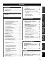 5
5
-
 6
6
-
 7
7
-
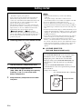 8
8
-
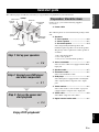 9
9
-
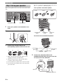 10
10
-
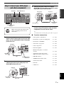 11
11
-
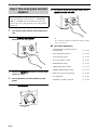 12
12
-
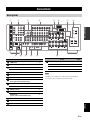 13
13
-
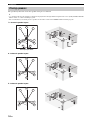 14
14
-
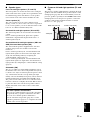 15
15
-
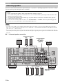 16
16
-
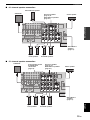 17
17
-
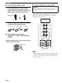 18
18
-
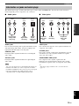 19
19
-
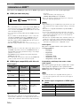 20
20
-
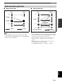 21
21
-
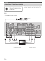 22
22
-
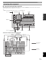 23
23
-
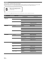 24
24
-
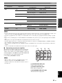 25
25
-
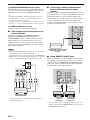 26
26
-
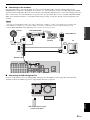 27
27
-
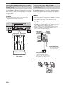 28
28
-
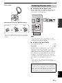 29
29
-
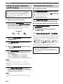 30
30
-
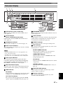 31
31
-
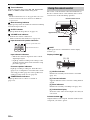 32
32
-
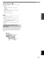 33
33
-
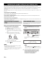 34
34
-
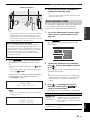 35
35
-
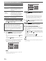 36
36
-
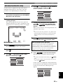 37
37
-
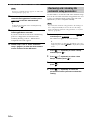 38
38
-
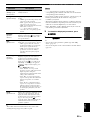 39
39
-
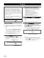 40
40
-
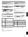 41
41
-
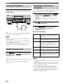 42
42
-
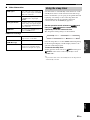 43
43
-
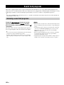 44
44
-
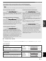 45
45
-
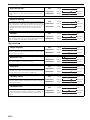 46
46
-
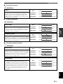 47
47
-
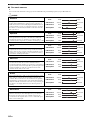 48
48
-
 49
49
-
 50
50
-
 51
51
-
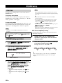 52
52
-
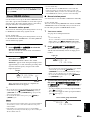 53
53
-
 54
54
-
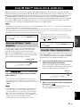 55
55
-
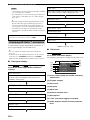 56
56
-
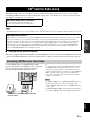 57
57
-
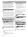 58
58
-
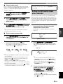 59
59
-
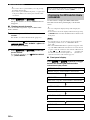 60
60
-
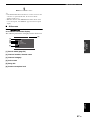 61
61
-
 62
62
-
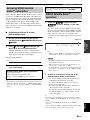 63
63
-
 64
64
-
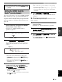 65
65
-
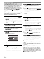 66
66
-
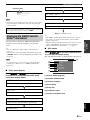 67
67
-
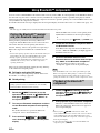 68
68
-
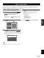 69
69
-
 70
70
-
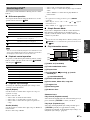 71
71
-
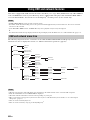 72
72
-
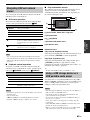 73
73
-
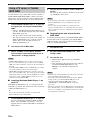 74
74
-
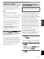 75
75
-
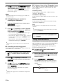 76
76
-
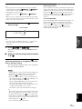 77
77
-
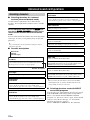 78
78
-
 79
79
-
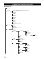 80
80
-
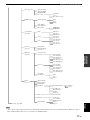 81
81
-
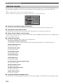 82
82
-
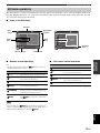 83
83
-
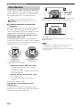 84
84
-
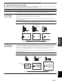 85
85
-
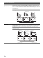 86
86
-
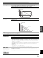 87
87
-
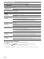 88
88
-
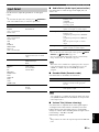 89
89
-
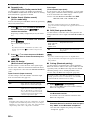 90
90
-
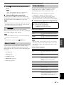 91
91
-
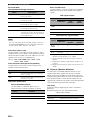 92
92
-
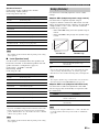 93
93
-
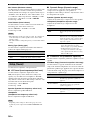 94
94
-
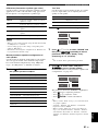 95
95
-
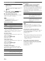 96
96
-
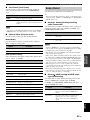 97
97
-
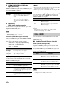 98
98
-
 99
99
-
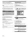 100
100
-
 101
101
-
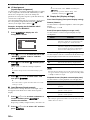 102
102
-
 103
103
-
 104
104
-
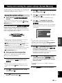 105
105
-
 106
106
-
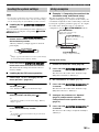 107
107
-
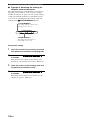 108
108
-
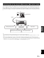 109
109
-
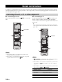 110
110
-
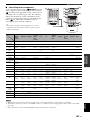 111
111
-
 112
112
-
 113
113
-
 114
114
-
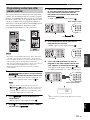 115
115
-
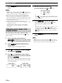 116
116
-
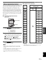 117
117
-
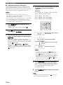 118
118
-
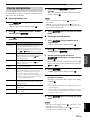 119
119
-
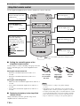 120
120
-
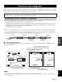 121
121
-
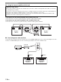 122
122
-
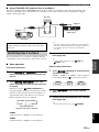 123
123
-
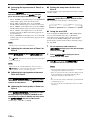 124
124
-
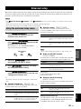 125
125
-
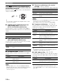 126
126
-
 127
127
-
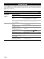 128
128
-
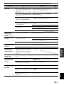 129
129
-
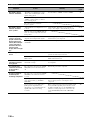 130
130
-
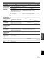 131
131
-
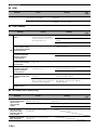 132
132
-
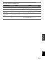 133
133
-
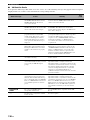 134
134
-
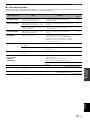 135
135
-
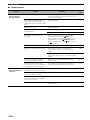 136
136
-
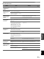 137
137
-
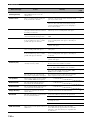 138
138
-
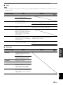 139
139
-
 140
140
-
 141
141
-
 142
142
-
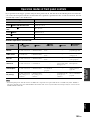 143
143
-
 144
144
-
 145
145
-
 146
146
-
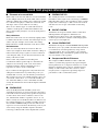 147
147
-
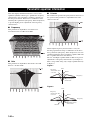 148
148
-
 149
149
-
 150
150
-
 151
151
-
 152
152
-
 153
153
-
 154
154
-
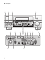 155
155
-
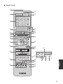 156
156
-
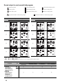 157
157
-
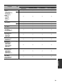 158
158
-
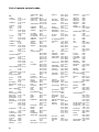 159
159
-
 160
160
-
 161
161
-
 162
162
-
 163
163
-
 164
164
-
 165
165
-
 166
166
-
 167
167
-
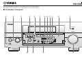 168
168
-
 169
169


Yamaha RX V3900 - AV Network Receiver Handleiding
- Categorie
- AV-ontvangers
- Type
- Handleiding
- Deze handleiding is ook geschikt voor
in andere talen
- English: Yamaha RX V3900 - AV Network Receiver User manual
- italiano: Yamaha RX V3900 - AV Network Receiver Manuale utente
- русский: Yamaha RX V3900 - AV Network Receiver Руководство пользователя
- français: Yamaha RX V3900 - AV Network Receiver Manuel utilisateur
- español: Yamaha RX V3900 - AV Network Receiver Manual de usuario
- Deutsch: Yamaha RX V3900 - AV Network Receiver Benutzerhandbuch
- português: Yamaha RX V3900 - AV Network Receiver Manual do usuário
- dansk: Yamaha RX V3900 - AV Network Receiver Brugermanual
- suomi: Yamaha RX V3900 - AV Network Receiver Ohjekirja
- čeština: Yamaha RX V3900 - AV Network Receiver Uživatelský manuál
- Türkçe: Yamaha RX V3900 - AV Network Receiver Kullanım kılavuzu
- polski: Yamaha RX V3900 - AV Network Receiver Instrukcja obsługi
- română: Yamaha RX V3900 - AV Network Receiver Manual de utilizare
Gerelateerde papieren
-
Yamaha 6240 - HTR AV Receiver de handleiding
-
Yamaha HTR-6250 de handleiding
-
-
-
-
-
-
-
Yamaha DSP-Z7 de handleiding
-
Yamaha DSP-Z11 de handleiding
Andere documenten
-
Pioneer SBX-B30 Handleiding
-
Sharp CP-SS30(BK) de handleiding
-
TEAC MC-DX40 de handleiding
-
Samsung HT-H5200 Handleiding
-
Lenco LPJ-500BU de handleiding
-
-
Philips 32PFL5403/93 Snelstartgids
-
Hama 6 in 1 Universal Remote Control de handleiding
-
-
Sangean WFT-1 Handleiding