
OWNER'S MANUAL
LPX-500
Home Cinema Projector
an (English)
403256900
U C A G B R T

I
IMPORTANT SAFETY INSTRUCTIONS
•
••
•
Explanation of Graphical Symbols
1
Read these instructions.
2
Keep these instructions.
3
Heed all warnings.
4
Follow all instructions.
5
Do not use this apparatus near water.
6
Clean only with dry cloth.
7
Do not block any ventilation openings. Install in
accordance with the manufacturer’s instructions.
8
Do not install near any heat sources such as radiators,
heat registers, stoves, or other apparatus (including
amplifiers) that produce heat.
9
Do not defeat the safety purpose of the polarized or
grounding-type plug. A polarized plug has two blades
with one wider than the other. A grounding type plug
has two blades and a third grounding prong. The wide
blade or the third prong are provided for your safety.
If the provided plug does not fit into your outlet,
consult an electrician for replacement of the obsolete
outlet.
10
Protect the power cord from being walked on or
pinched particularly at plugs, convenience
receptacles, and the point where they exit from the
apparatus.
11
Only use attachments/accessories specified by the
manufacturer.
12
Use only with the cart, stand, tripod,
bracket, or table specified by the
manufacturer, or sold with the
apparatus. When a cart is used, use
caution when moving the cart/
apparatus combination to avoid injury
from tip-over.
13
Unplug this apparatus during lightning storms or
when unused for long periods of time.
14
Refer all servicing to qualified service personnel.
Servicing is required when the apparatus has been
damaged in any way, such as power-supply cord or
plug is damaged, liquid has been spilled or objects
have fallen into the apparatus, the apparatus has been
exposed to rain or moisture, does not operate
normally, or has been dropped.
CAUTION: TO REDUCE THE RISK OF
ELECTRIC SHOCK, DO NOT REMOVE
COVER (OR BACK). NO USER-SERVICEABLE
PARTS INSIDE. REFER SERVICING TO
QUALIFIED SERVICE PERSONNEL.
The lightning flash with arrowhead
symbol, within an equilateral triangle, is
intended to alert you to the presence of
uninsulated “dangerous voltage” within
the product’s enclosure that may be of
sufficient magnitude to constitute a risk
of electric shock to persons.
The exclamation point within an
equilateral triangle is intended to alert
you to the presence of important
operating and maintenance (servicing)
instructions in the literature
accompanying the appliance.
WARNING
TO REDUCE THE RISK OF FIRE OR ELECTRIC
SHOCK, DO NOT EXPOSE THIS UNIT TO RAIN
OR MOISTURE.
IMPORTANT!
Please record the serial number of this unit in the space
below.
Model:
Serial No.:
The serial number is located on the bottom of the unit.
Retain this Owner’s Manual in a safe place for future
reference.
CAUTION
RISK OF ELECTRIC
SHOCK DO NOT
OPEN

II
COMPLIANCE INFORMATION STATEMENT
(DECLARATION OF CONFORMITY PROCEDURE)
Responsible Party: Yamaha Electronics Corporation
Address: 6660 Orangethorpe Avenue
Buena Park, CA90620
Telephone: 714-522-9105
Fax: 714-670-0108
Type of Equipment: Projector
Model Name: LPX-500
This device complies with Part 15 of the FCC Rules.
Operation is subject to the following conditions:
1) this device may not cause harmful interference, and
2) this device must accept any interference received including interference that may cause undesired
operation.
See the user manual instructions if interference to radio reception is suspected.
We Want You Listening For A Lifetime
YAMAHA and the Electronic Industries Association’s Consumer Electronics Group want you to get the most
out of your equipment by playing it at a safe level. One that lets the sound come through loud and clear
without annoying blaring or distortion
—
and, most importantly, without affecting your sensitive hearing.
Since hearing damage from loud sounds is often undetectable until it is too late, YAMAHA and the Electronic
Industries Association’s Consumer Electronics Group recommend you to avoid prolonged exposure from
excessive volume levels.
FCC INFORMATION (for US customers)
1. IMPORTANT NOTICE: DO NOT MODIFY THIS
UNIT!
This product, when installed as indicated in the
instructions contained in this manual, meets FCC
requirements. Modifications not expressly
approved by Yamaha may void your authority,
granted by the FCC, to use the product.
2. IMPORTANT:
When connecting this product to
accessories and/or another product use only high
quality shielded cables. Cable/s supplied with this
product MUST be used. Follow all installation
instructions. Failure to follow instructions could
void your FCC authorization to use this product in
the USA.
3. NOTE:
This product has been tested and found to
comply with the requirements listed in FCC
Regulations, Part 15 for Class “B” digital devices.
Compliance with these requirements provides a
reasonable level of assurance that your use of this
product in a residential environment will not result
in harmful interference with other electronic
devices.
This equipment generates/uses radio frequencies and,
if not installed and used according to the instructions
found in the users manual, may cause interference
harmful to the operation of other electronic devices.
Compliance with FCC regulations does not guarantee
that interference will not occur in all installations. If
this product is found to be the source of interference,
which can be determined by turning the unit “OFF”
and “ON”, please try to eliminate the problem by using
one of the following measures:
Relocate either this product or the device that is being
affected by the interference.
Utilize power outlets that are on different branch
(circuit breaker or fuse) circuits or install AC line
filter/s.
In the case of radio or TV interference, relocate/
reorient the antenna. If the antenna lead-in is 300 ohm
ribbon lead, change the lead-in to coaxial type cable.
If these corrective measures do not produce
satisfactory results, please contact the local retailer
authorized to distribute this type of product. If you can
not locate the appropriate retailer, please contact
Yamaha Electronics Corp., U.S.A. 6660 Orangethorpe
Ave, Buena Park, CA 90620.
The above statements apply ONLY to those products
distributed by Yamaha Corporation of America or its
subsidiaries.

III
Caution: Read this before operating this unit.
•
••
•
To assure the finest performance, please read this
manual carefully. Keep it in a safe place for future
reference.
Installation
•
••
•
Install this unit in a well-ventilated, cool, dry, clean
place with at least 10 cm clearance on the top, right and
left, and at the back of this unit — away from direct
sunlight, heat sources, vibration, dust, moisture, and/or
cold.
•
••
•
Locate this unit away from other electrical appliances,
motors, or transformers to avoid humming sounds. To
prevent fire or electrical shock, do not place this unit
where it may get exposed to rain, water, and/or any type
of liquid.
•
••
•
Do not expose this unit to sudden temperature changes
from cold to hot, and do not locate this unit in an
environment with high humidity (i.e. a room with a
humidifier) to prevent condensation inside this unit,
which may cause an electrical shock, fire, damage to this
unit, and/or personal injury.
•
••
•
On the top of this unit, do not place:
—Other components, as they may cause damage and/or
discoloration on the surface of this unit.
—Burning objects (i.e. candles), as they may cause fire,
damage to this unit, and/or personal injury.
—Containers with liquid in them, as they may cause
electrical shock to the user and/or damage to this unit.
•
••
•
Do not cover this unit with a newspaper, tablecloth,
curtain, etc. in order not to restrict heat dissipation. If the
temperature inside this unit rises too much, it may cause
fire, damage to this unit, and/or personal injury.
•
••
•
When installing this unit on the ceiling, make sure the
ceiling has sufficient strength to support this unit and the
ceiling mounts for an extended period of time.
Installation must be performed only by qualified service
personnel.
Operation
•
••
•
Remove the lens cap before starting any operation of this
unit to prevent the heat from staying around the lens.
Operation with the cap on may cause damage to this
unit.
•
••
•
Do not plug in this unit to a wall outlet until all
connections are complete.
•
••
•
Only the voltage specified on this unit must be used.
Using this unit with a higher voltage than specified is
dangerous and may cause fire, damage to this unit, and/
or personal injury. YAMAHA will not be held
responsible for any damage resulting from use of this
unit with a voltage other than that specified.
•
••
•
Do not use force on switches, knobs and/or cords.
•
••
•
Take care of this unit so that no foreign objects and/or
liquid drop inside this unit.
•
••
•
To prevent damage by lightning, disconnect the power
cord from the wall outlet during an electrical storm.
•
••
•
Do not look into the lens while this unit is turned on. It
may cause serious damage to your eyesight.
•
••
•
Before moving this unit, press
STANDBY/ON
to set
this unit in the standby mode, and disconnect the AC
power plug from the wall outlet.
•
••
•
Do not attempt to modify or fix this unit. Contact
qualified YAMAHA service personnel when any service
is needed. The cabinet should never be opened for any
reason.
•
••
•
When not planning to use this unit for a long period of
time (i.e. vacation), disconnect the AC power plug from
the wall outlet.
•
••
•
When disconnecting the power cord from the wall outlet,
grasp the plug; do not pull the cord.
•
••
•
Be sure to read the “TROUBLESHOOTING” section on
common operating errors before concluding that this unit
is faulty.
Others
•
••
•
Clean the lens carefully so as not to create any scratches
by using a blower or lens paper.
•
••
•
Replace the lamp when the LAMP/COVER indicator
flashes in red after the lamp usage has exceeded 1000
hours. Follow the lamp replacement procedure described
in this manual.
For U.K. customers
•
••
•
If the socket outlets in the home are not suitable for the
plug supplied with this appliance, it should be cut off
and an appropriate 3 pin plug fitted. For details, refer to
the instructions described below.
Note
•
••
•
The plug severed from the mains lead must be destroyed, as
a plug with bared flexible cord is hazardous if engaged in a
live socket outlet.
This unit is not disconnected from the AC power source
as long as it is connected to the wall outlet, even if this
unit itself is turned off. This state is called the standby
mode. In this state, this unit is designed to consume a
very small quantity of power.
IMPORTANT
THE WIRES IN THIS MAINS LEAD ARE
COLOURED IN ACCORDANCE WITH THE
FOLLOWING CODE:
GREEN-AND-YELLOW: EARTH
BLUE: NEUTRAL
BROWN: LIVE
As the colours of the wires in the mains lead of this
apparatus may not correspond with the coloured markings
identifying the terminals in your plug, proceed as follows:
The wire which is coloured GREEN-AND-YELLOW must
be connected to the terminal in the plug which is marked by
the letter E or by the safety earth symbol or coloured
GREEN or GREEN-and-YELLOW.
The wire which is coloured BLUE must be connected to the
terminal which is marked with the letter N or coloured
BLACK.
The wire which is coloured BROWN must be connected to
the terminal which is marked with the letter L or coloured
RED.
For Canadian Customers
To prevent electric shock, match wide blade of plug to
wide slot and fully insert.
This Class B digital apparatus complies with Canadian
ICES-003.

Indications
Notations used in this Owner’s Manual
Indicates procedures where personal injury or damage to the projector may occur if the
procedures are not followed correctly.
Indicates additional information and points which may be useful to know regarding a topic.
Indicates that an explanation of the underlined word or words in front of this symbol appears
in the glossary of terms.
Refer to the “Glossary” in the “Appendix”. (p.61)
Indicates operating methods and the order of operations.
The procedure indicated should be carried out in the order of the numbers.
Procedure

1
Contents
Notes on Handling and Storage ........................................................................2
Accessories .......................................................................................................3
Features of the Projector ...................................................................................4
Basic Operations
Turning On the Projector ...................................................................................6
Connecting the Power Cord .....................................................................................6
Turning On the Power and Projecting Images .........................................................7
Turning Off the Projector ...................................................................................9
Adjusting the Screen Image ............................................................................11
Adjusting the Image Size .......................................................................................11
Adjusting the Image Angle ....................................................................................11
Correcting Keystone Distortion .............................................................................12
Displaying a Test Pattern .......................................................................................13
Adjusting the Image Quality.............................................................................14
Focusing the Screen Image ....................................................................................14
Selecting the picture mode .....................................................................................14
Selecting the Image Aspect Ratio .......................................................................... 15
Automatic Adjustment of Computer Images .........................................................17
Advanced Operations
Functions for Enhancing Projection.................................................................20
Using the Menus.....................................................................................................20
Description of Functions ........................................................................................23
Saving and Retrieving Image Quality Settings (Memory Save)............................ 24
Using the Menu Functions...............................................................................26
Image Menu............................................................................................................26
Signal Menu ...........................................................................................................30
Setup Menu ............................................................................................................31
Info Menu............................................................................................................... 33
Troubleshooting
When Having Some Trouble ...........................................................................36
When the Indicators Provide No Help .............................................................38
Appendices
Maintenance ....................................................................................................46
Cleaning .................................................................................................................46
Replacing Consumables .........................................................................................47
Optional Accessories.......................................................................................51
List of Supported Signal Resolutions...............................................................52
Component Video Input.........................................................................................52
Composite Video/S-Video Input............................................................................52
RGB Input ..............................................................................................................53
Specifications ..................................................................................................54
Appearance .....................................................................................................56
Part Names and Functions ..............................................................................57
Front/Top................................................................................................................57
Control Panel..........................................................................................................58
Rear ........................................................................................................................ 59
Base ........................................................................................................................59
Remote Control ......................................................................................................60
Glossary ..........................................................................................................61
Index................................................................................................................63
Basic Operations
Advanced Operations
TroubleshootingAppendices

2
Notes on Handling and Storage
Be sure to observe the following precautions to avoid malfunctions, operating errors or damage to the projector.
Notes on Handling and Storage
• Do not set up the projector near high-voltage electrical wires or sources of magnetic fields.
These may interfere with correct operation.
• Do not touch the lens with bare hands.
If fingerprints or grease get onto the lens, it can interfere with the quality of the projected images. Attach the lens
cover to the lens when the projector is not in use.
• During projection, some points (dots) may appear lit at all times, or they may be dark at all times.
This is caused by the characteristics of the LCD panel, and is not a sign of a malfunction. The LCD panel is
manufactured using extremely high-precision technology. However, black dots may appear on the panel, or some
red, blue or green dots may light extremely brightly at times. Furthermore, sometimes stripe-shaped color
irregularities or brightness irregularities may also appear.
• Remove the batteries from the remote control before storage.
If the batteries are left in the remote control for long periods, they may leak.
• Always attach the lens cap to the lens when not using the projector, to prevent the lens from becoming dirty or
damaged.
• The mercury lamp that is used as the projector's light source deteriorates as a result of normal use and as a
result of impacts or other damage, and may also break with a loud noise, stop working or reach the end of its
service life more quickly.
At such times, the amount of time remaining before the lamp breaks or stops working may vary greatly depending
on the individual lamp characteristics and the operating environment. These are normal characteristics of mercury
lamps. You should always have a spare lamp ready in case it is needed.
• YAMAHA takes no responsibility for loss or damage caused by damage to the projector or operating failures
outside normal service warranty conditions.
Lamp Operating Errors
The mercury lamp that is used as the light source for this projector may stop operating on occasions. This is a normal
characteristic of mercury lamps. If the lamp does not turn on when the projector's power is turned on, remove the
lamp and check if it is broken. If the lamp is not broken, reinstall it. Refer to "Replacing the Lamp" on page 48 of this
manual for instruction on removing and reinstalling the lamp.
If the lamp is broken, replace it with a new lamp. It is recommended that you have a spare lamp ready at all times in
case it is needed.
Notes on Carrying the Projector
• Turn off the projector power and then disconnect the power cord from the electrical outlet.
Furthermore, check that all other cables have been disconnected.
• Attach the lens cap to the lens.
• Retract the adjustable foot.
• If your model of projector has a handle, hold the projector by the handle when carrying it.

3
Accessories
Check the included accessories
Remote control Setup guide
Battery LR6 (AA) x 2 Power cord

4
Features of the Projector
80-inch
screen
Adoption of a wide 1280 x 720 dot panel
This panel allows high-definition images to be
reproduced accurately.
Adoption of a special high-resolution DCDi video circuit developed by Faroudja.
This circuit greatly reduces the jagged edges that
resulted from conventional progressive conversion,
to produce much smoother and natural movement.
(p.30)
Includes 5 picture modes
You can select the desired color mode to match the
images being projected from five preset modes in order
to obtain the optimum image quality.
(p.14)
Includes a variety of color adjustment modes
Various color settings can be adjusted to suit
your preferences, from individual RGB balance
adjustment to setting the color temperature of
your choice. The adjusted settings can then be
stored in memory and recalled at a touch of a
button on the remote control.
(p.24, 25)
Adoption of a short focal-length lens that can project onto 80-inch screens
at distances of 2.5m (8.2 ft.)
This lens is ideal for projecting onto large
indoor screens. The projector can also
project onto 80-inch screens in rooms
with an area of about 10 m
2
.
(Refer to the Setup Guide.)
2.5m
1280
720

5
Basic Operations
This chapter describes basic operations such as turning the projector on and off and adjusting the
projected images.
Turning On the Projector.................................................................. 6
•
••
• Connecting the Power Cord ........................................................................................6
•
••
• Turning On the Power and Projecting Images..........................................................7
Turning Off the Projector.................................................................. 9
Adjusting the Screen Image ........................................................... 11
•
••
• Adjusting the Image Size ...........................................................................................11
•
••
• Adjusting the Image Angle ........................................................................................11
•
••
•
Correcting Keystone Distortion ................................................................................12
•
••
• Displaying a Test Pattern...........................................................................................13
Adjusting the Image Quality........................................................... 14
•
••
• Focusing the Screen Image ........................................................................................14
•
••
• Selecting the picture mode.........................................................................................14
•
••
• Selecting the Image Aspect Ratio..............................................................................15
• Normal mode...................................................................................................................................15
• Squeeze mode..................................................................................................................................16
• Zoom mode .....................................................................................................................................16
• Zoom -Subtitle- mode .....................................................................................................................16
• Through mode .................................................................................................................................17
• Squeeze Through mode...................................................................................................................17
•
••
•
Automatic Adjustment of Computer Images...........................................................17

6
Turning On the Projector
This section describes the procedure from turning on the power to projecting images.
Procedure
1
Check that the power is turned off for
the projector and all components
connected to the projector.
2
Connect the computer or other video
source to the projector.
Refer to the Setup Guide.
3
Remove the lens cap.
4
Connect the accessory power cord to
the projector.
Check that the power cord connector is facing the
same way as the power inlet on the projector, and
then insert the power cord connector securely into
the projector.
5
Connect the other end of the power
cord to a grounded electrical outlet.
6
Turn on the main power switch at the
rear of the projector.
Wait until the indicator lights orange and
the projector goes to the standby condition.
Connecting the Power Cord
Be sure to read the Safety Instructions in this manual for details on safe handling when using
the projector.
Lights orange

7
Basic Operations
Procedure
1
Turn on the power for all equipment
connected to the projector.
For a video source, press the [Play] button at the
video source to start playback if necessary.
Check that the indicator on the projector has
stopped flashing and lights orange.
2
Press the [STANDBY/ON] button on
either the remote control or the
projector's control panel to turn on the
power.
The indicator flashes green, and after a
short period projection starts.
Check that the indicator has stopped
flashing and lights green. (This takes
approximately 15 seconds.)
3
If more than one signal source has been connected, use the remote control or
control panel buttons to select the port which the signal source that you
would like to use is connected to, while referring to the following table.
*The display disappears approximately 1 second after the signal is output.
Turning On the Power and Projecting Images
The buttons on the remote control and the projector's control panel cannot be operated
while the indicator is flashing green. Wait until it lights steadily.
The message "No Signal" may appear depending on the projector's menu settings. (p.31)
Port
Button to press
Display at top-right of
screen *
Projector Remote control
INPUT A
[INPUT]
[A]
INPUT A (component) or
INPUT A (RGB)
INPUT B [B]
INPUT B (component) or
INPUT B (RGB)
S VIDEO [S VIDEO] S Video
VIDEO [VIDEO] Video
D4 VIDEO [D4] D4 Video
DVI [DVI] DVI
Lights green
Remote control
Projector
Connecting the Power Cord
Turning On the Power and Projecting Images

Turning On the Projector
8
•
••
•
If only one signal source has been connected, the signals from that source will be
projected without needing to press one of the above buttons.
•
••
•
If video signals are being input to several input ports simultaneously, interference
between the various signals may occur, and this may cause interference in the projected
images. If this happens, turn off the power supply or disconnect the video equipment
which is not currently being used.
•
••
•
If the "No Signal" message does not disappear, check the connections again.
No images will be projected during the time that it takes for signals to be input from the
video source.
•
••
•
If a laptop computer or a computer with an LCD screen has been connected to the
projector, the images may not be projected straight away. After making the connections,
check that the computer has been set up to output signals.
The following table shows examples of how to toggle output settings. For details, refer to
the section of the documentation provided with your computer under a heading such as
"External output", "Connecting an external monitor" or similar.
NEC Panasonic Toshiba IBM Sony Fujitsu Macintosh
[Fn]+[F3] [Fn]+[F3] [Fn]+[F5] [Fn]+[F7] [Fn]+[F7] [Fn]+[F10]
After startup, change the
Control Panel adjustments
so that Mirroring is active.

9
Basic Operations
Turning Off the Projector
Follow the procedure below to turn off the power of the projector.
Procedure
1
Turn off the power for the signal
sources that are connected to the
projector.
Check that the power for all connected
components has been tuned off.
2
Press the [STANDBY/ON] button on
either the remote control or the
projector's control panel.
The confirmation message shown at left will
appear.
If you do not want to turn off the power, press
any button except the [STANDBY/ON] button.
If you do not carry out any operation, the
message will disappear after seven seconds. (The
power will not turn off at this time.)
3
Press the [STANDBY/ON] button on the
projector's control panel or remote
control once more.
The lamp will switch off. The indicator will
flash red and cool-down
will start.
After about 90 seconds, the indicator will
change to flashing orange.
4
Check that the indicator has
changed to light orange.
When the indicator lights orange,
cool-down is complete.
The cool-down period lasts for approximately 5
minutes. (This varies depending on factors such
as the ambient air temperature.)
The cool-down period is a 5 minutes long in
order to allow the heat inside the projector to
dissipate sufficiently.
The buttons on the control panel and
remote control cannot be operated while
the indicator is flashing red. Wait until
the indicator flashes orange (takes
approximately 90 seconds).
Please Press Key Again
To Power Off
Projector
Remote control
Lights orange

Turning Off the Projector
10
5
If not using the projector for long
periods of time, turn off the main power
switch at the rear of the projector.
6
Retract the front adjustable foot if it is
extended.
Turn the front adjustable foot to retract it.
7
Attach the lens cap.
Attach the lens cap to the lens when not using the
projector, in order to stop the lens from getting
dusty or dirty.
Do not turn off the main power switch at the rear of the projector while the cool-down
is in progress. If the main power switch is turned off before cool-down is complete,
wait for the lamp to cool down (normally about one hour is required) before turning
the power back on again. If the power is turned off and on before the lamp has
cooled down, it may result in lamp operating errors.
Refer to "Lamp operating error" on page 36.

11
Basic Operations
Adjusting the Screen Image
You can adjust the screen image in order to obtain the best possible picture.
The size of the projected image is basically determined by the distance from the projector to the screen.
(Refer to the Setup Guide.)
The following procedures explain how to adjust the screen image once the projector itself has been set up.
Procedure
Turn the zoom ring on the projector to
adjust the image.
The image can be enlarged in this way to 1.35
times the normal size.
If you would like to enlarge the image further,
move the projector further away from the screen.
(Refer to the Setup Guide.)
The projector should be as perpendicular to the screen as possible.
If the projector cannot be set up so that it is exactly perpendicular to the screen, it can be set up so that it is
tilting slightly horizontally or vertically. To tilt the projector upward, adjust the front adjustable foot to tilt
the projector at an angle of up to a maximum 12.9°.
Procedure
Turn the front adjustable foot
underneath the projector to adjust the
projector angle.
Turn the front adjustable foot until the desired
projection angle is obtained.
Adjusting the Image Size
Adjusting the Image Angle
•
••
•
When the foot is adjusted, it may cause the projected images to become distorted. Use the
keystone correction function to adjust this distortion. (p.12)
•
••
•
If the projector is tilted horizontally, turn the rear adjustable feet at left and right to adjust the
horizontal angle.
To reduce
To enlarge
Zoom ring
Seen from the side
Seen from above
Extend
Retract
Rear
adjustable foot
Extend
Retract
Retract
Extend
Rear
adjustable foot
Adjusting the Image Size Correcting Keystone
Distortion
Adjusting the Image Angle Displaying a Test
Pattern

Adjusting the Screen Image
12
If the projector is set up so that it is at an angle to the screen, a type of distortion known as "keystone
distortion" may occur.
Keystone correction can be carried out if the angle of the projector is within a range of approximately 15°
vertically from the perpendicular.
Procedure
Correcting Keystone Distortion
•
••
•
When keystone correction is carried out, the projected image will become smaller.
•
••
•
The keystone correction settings are memorized, so that if you change the position or angle of
the projector, you may need to readjust the keystone correction settings.
•
••
•
If the images become uneven in appearance after keystone correction is carried out, decrease
the “Sharpness” setting. (p.27, 29)
•
••
•
Keystone correction can also be carried out using the projector menu. (p.31)
•
••
•
If the value displayed in the gauge on the screen stops changing when horizontal or vertical
keystone correction is being carried out, it indicates that the limit for horizontal or vertical
keystone correction has been exceeded. Check that the projector has not been set up at an
angle which exceeds the proper limit.
Approx. 15° above
Approx. 15° below
15°
15°
While holding down the
[SHIFT] button on the
projector's control panel, press
the or button.
Projector Projector

13
Basic Operations
When setting up the projector, you can project a test pattern onto the screen and use this test pattern to adjust
the projected images before a video source has been connected. The following two types of test pattern are
available.
•
••
•
Crosshatch
•
••
•
Grayscale pattern
The test pattern changes as shown below each time the [PATTERN] button on either the remote control or
the projector's control panel is pressed.
Crosshatch → Grayscale pattern → No pattern
Displaying a Test Pattern
The full menu cannot be displayed while a test pattern is being projected. If you need to change a
setting, press the button on either the projector's control panel or the remote control to display
the line menu, and then change the setting. To correct keystone distortion while a test pattern is
being displayed, press and hold the [SHIFT] button and then use the and buttons on the
projector's control panel to make the adjustment. This setting cannot be made using the remote
control.
This can be used to adjust the focus and correct keystone distortion.
This can be used to adjust dark and light shades to the desired shade.
Use the "Color Temp.
", "Flesh Tone" and "Color Balance"
commands in the "Image" menu to adjust the settings.
Adjusting the Image Size Correcting Keystone
Distortion
Adjusting the Image Angle Displaying a Test
Pattern

14
Adjusting the Image Quality
The quality of the screen images can be adjusted as follows.
Procedure
Turn the focus ring to adjust the image
focus.
The following five color modes have been preset for use with images with varying characteristics. You can
use these color modes to obtain the optimum image quality easily, just by selecting whichever color mode
best suits the images. The brightness of the projected images will vary depending on the mode.
Procedure
The picture mode changes as shown
below each time the [PICTURE MODE]
button on the projector's control panel
or the [PICTURE] button on the remote
control is pressed.
A → B → C → PC → sRGB
The current setting appears on the screen each
time the color mode changes.
Focusing the Screen Image
•
••
•
If the surface of the lens is dirty or misted
over as a result of condensation, it may
not be possible to adjust the focus
correctly. If this happens, clean or de-mist
the lens. (p.46)
•
••
•
If the projector is positioned outside the
normal projecting range of 0.9 - 13 m (2.9
- 42.6 ft.), it may not be possible to obtain
the correct focus. If you have trouble
obtaining the correct focus, check the
projection distance.
Selecting the picture mode
Mode name Gamma Color Temp
Priority
element
Use
A Original 1 6700 K
(adjustable)
Color Ideal for enjoying presentations in a natural
atmosphere.
B Original 2 6700 K
(adjustable)
Color Ideal for enjoying presentations such as movies which
have large numbers of dark scenes.
C Original 3 6700 K
(adjustable)
Color Ideal for projecting images with greater modulation
and intensity.
PC 2.2
(Basic)
7500 K
(adjustable)
Brightness Ideal for use in making images as bright as possible
when projecting computer images.
sRGB 2.2
(Basic)
6500 K (fixed) Color Images conform to the sRGB
standard. If the
connected video source has an sRGB mode, set both
the projector and the video source to sRGB.
The color mode setting can also be
changed using the "Picture Mode" item of
the projector's "Image" menu. (p.27, 28)
Focus ring
Projector Remote control
Picture B

15
Basic Operations
The aspect ratio for projected images can be selected from the following five types of setting. However,
the aspect ratio settings that can be selected will vary depending on the input signal.
Procedure
For Video (SDTV) signals, the aspect
mode changes in the following order
each time the [ASPECT] button on
either the projector's control panel or
the remote control is pressed.
Normal → Squeeze → Zoom → Zoom -Subtitle-
→ Through → Squeeze Through
The current setting appears on the screen each
time the aspect ratio changes.
Details of each aspect ratio are as follows.
Selecting the Image Aspect Ratio
Input signal Normal Squeeze Zoom
Zoom
-Subtitle-
Through Squeeze Through
Video (SDTV
)
OO O O O O
Video (HDTV )
O- - -
O
(720p only)
-
Computer (SVGA or lower)
O- O - O -
Computer (XGA or higher)
O- O - - -
Do not use the aspect mode function to elongate or compress image that are being projected for
commercial purposes or in public places such as hotel lobbies or stores, as doing so may infringe
the rights of the original copyright owner for the images under copyright protection laws.
Normal mode
Projector
Remote control
Normal
The aspect ratio of the images being input
is maintained, and the images are
projected into a 16:9 screen area.
When 4:3 images are being projected,
black bands will appear at the left and
right of the image as shown in the
illustration at left.
4:3
i
mage
Focusing the
Screen Image
Selecting the Image
Aspect Ratio
Selecting the
Picture Mode
Automatic Adjustment
of Computer Images

Adjusting the Image Quality
16
Squeeze mode
Zoom mode
Zoom -Subtitle- mode
Use this setting if the connected video
source has a 16:9 output mode (Squeeze
mode).
If images in squeeze mode are viewed on a
4:3 TV screen, the images are compressed
horizontally and elongated vertically. If
Squeeze mode is selected on the projector,
the images are projected correctly in their
native wide-screen (16:9) format.
Wh
en
i
mages
i
n squeeze mo
d
e
are displayed on a 4:3 TV screen
Viewed using the projector
Images output in 4:3 format
When the projector's squeeze
mode is applied
When images output in 4:3 format are
projected using the projector's squeeze
mode, the images will be extended
horizontally and the image will appear
elongated.
4:3
i
mage cut at top an
d
b
ottom
R
es
i
ze
d
to 16:9
Images output in 4:3 format are truncate at
top and bottom by a set amount and then
projected in a 16:9 format.
I
mages output
i
n 4:3
f
ormat
Vi
ewe
d
us
i
ng t
h
e pro
j
ector
When 4:3 images with subtitles included
are projected using the projector's Zoom
Subtitle mode, the images are enlarged in
the vertical and horizontal directions to
resize them to 16:9 size.
Because the images are enlarged
vertically, the subtitles may sometimes be
displayed outside the actual projection
area. If this happens, you can adjust the
display position by choosing the "Signal"
- "Zoom Subtitle" - "V Size", "V Position"
menu command (p.31)
•
••
•
V Size
This adjusts the vertical enlargement
ratio without changing the size in the
horizontal direction.
•
••
•
V Position
This moves the display position up.
Subtitle display position
Subtitle display position
Subtitle display position
Subtitle display position
When adjusted using "Zoom Subtitle"

17
Basic Operations
This adjusts computer images (INPUT A [RGB] and INPUT B [RGB] only) to the optimum condition.
Automatic adjustment involves adjustment of tracking
, display position and synchronization (Sync) for
RGB signals.
Procedure
While an image is being projected from
the computer, press the [AUTO] button
on the remote control.
The screen will appear black while the
adjustment is being made.
Through mode
Squeeze Through mode
Automatic Adjustment of Computer Images
Automatic adjustment may not work properly with some types of signals which are output by
computers. In such cases, you may need to adjust the tracking and synchronization manually
using the projector menu. (p.28)
I
f
t
h
e
i
nput s
i
gna
l
reso
l
ut
i
on
i
s
1280
x 7
20
dots or less, the images are projected onto
the screen with the input signal resolution
unchanged. Because of this, the size of the
displayed images will change depending
on the input resolution.
The picture quality will be the clearest for
portions of the image that have not been
resized horizontally or vertically.
I
f
t
h
e
i
nput s
i
gna
l
reso
l
ut
i
on
i
s
1280
x 7
20
dots or less, the input signal resolution is
elongated horizontally and the images are
projected at an aspect ratio of 16:9.
Because of this, the size of the displayed
images will change depending on the input
resolution.
The portions that are not vertically resized
will appear with higher image quality.
Remote control
Focusing the
Screen Image
Selecting the Image
Aspect Ratio
Selecting the
Picture Mode
Automatic Adjustment
of Computer Images

1
Advanced Operations
This chapter describes functions for enhancing the projection of images, and how to use the menus.
Functions for Enhancing Projection ............................................. 20
•
••
• Using the Menus .........................................................................................................20
• Displaying and Operating Full Menus ............................................................................................20
• Displaying and Operating Line Menus ...........................................................................................22
•
••
•
Description of Functions............................................................................................23
• Black Level Adjustment..................................................................................................................23
• White Level Adjustment .................................................................................................................23
• Color temperature, flesh tone and color balance adjustment ..........................................................24
•
••
• Saving and Retrieving Image Quality Settings
(Memory Save)............................................................................................................24
• Saving Settings................................................................................................................................24
• Retrieving Saved Image Quality Settings .......................................................................................25
Using the Menu Functions ............................................................. 26
•
••
• Image Menu ................................................................................................................26
• Video ...............................................................................................................................................26
• Computer.........................................................................................................................................28
•
••
• Signal Menu ................................................................................................................30
•
••
• Setup Menu .................................................................................................................31
•
••
• Info Menu....................................................................................................................33
• Video ...............................................................................................................................................33
• Computer.........................................................................................................................................33

20
Functions for Enhancing Projection
This section describes the various useful functions that can be used to enhance projection.
The functions described here are used to set the adjustment values using the projector menus.
There are two types of projector menus used:
•
••
•
Full menus : These menus can be used to set all items in the menus.
•
••
•
Line menus : These menus can be used to change the “Image” settings while viewing the images
being projected. The “Image” menu is the most commonly used of the menus.
(p.22)
Menus can be operated using the projector's control panel and also by using the remote control.
Procedure
1
Press the [MENU] button on either the
remote control or the projector's
control panel.
The menu appears.
Full menus consist of a main menu and sub-
menus. The sub-menu that corresponds to the
currently-selected item in the main menu
(displayed in white) appears.
2
Select the items to be changed in the
main menu.
If using the projector's control panel, press the
or button.
If using the remote control, tilt the button to
the left or right.
Function Summary Reference page
Black level adjustment Adjusts the brightness of dark shades.
p.23
White level adjustment Adjusts the brightness of light shades.
p.23
Color Temp., Flesh Tone and Color Balance Adjusts the hues of light shades to the desired level.
p.24
Using the Menus
Displaying and Operating Full Menus
Projector
Remote control
Sub-menu
Mainmenu
-,+ :Select
:Enter
Image SetupSignal Info
1
0
0
0
0
0
0
A B C PC sRGB
2
6700K
3456
Memory Save
Color Balance
Black Level
White Level
Sharpness
Saturation
Hue
Color Temp.
Flesh Tone
Picture Mode
Reset Image
Projector
Remote control

Advanced Operations
21
3
Select a setting item in the sub-menu.
If using the projector's control panel, press the
and buttons.
If using the remote control, tilt the button up
and down.
The items appearing in the “Image” menu and
“Info” menu will vary depending on the input
signal that is being projected.
4
Confirm the selection.
If using the projector's control panel, press the
and buttons.
If using the remote control, tilt the button to
the left and right.
5
Set other items in the same way.
Repeat steps 2 to 4. To return to a previous menu
level while a sub-menu is selected, press the
[ESCAPE] button on the projector's control panel
or the remote control.
6
Exit the menu display.
Press the [MENU] button on either the projector's
control panel or the remote control.
The main menu can be exited by pressing the
[ESCAPE] button on the projector's control panel
or the remote control.
•
••
•
If a setting is executed or a sub-menu
item continues to another level, " "
appears after the item name. In such
cases, press the button on either the
projector's control panel or the remote
control to select a setting value in the
displayed menu.
•
••
•
Refer to using the menu functions for
details of each setting item. (p.26)
:Select -,+ :Adjust
:Return
1
0
0
0
0
A
B C PC sRGB
2
6700K
3456
Memory Save
Color Balance
Black Level
White Level
Hue
Color Temp.
Flesh Tone
Picture Mode
Reset Image
0
Sharpness
ESC
Image SetupSignal Info
0
Saturation
:Select -,+ :Adjust
:Return
1
0
0
0
0
A
B C PC sRGB
2
6700K
3456
Memory Save
Color Balance
Black Level
White Level
Hue
Color Temp.
Flesh Tone
Picture Mode
Reset Image
0
Sharpness
ESC
Image SetupSignal Info
3
Saturation
Projector
Remote control
Using the Menus Memory Save
Description of Functions

Functions for Enhancing Projection
22
Procedure
1
Press the button on either the
projector's control panel or the remote
control while the full menu is being
displayed.
The line menu appears.
2
Select an item to be set.
If using the projector's control panel, press the
and buttons.
If using the remote control, press the button
up and down.
The line menu item changes when a button is
pressed.
3
Select the setting value.
If using the projector's control panel, press the
and buttons.
If using the remote control, press the button to
the left and right.
4
Set other items in the same way.
Repeat steps 2 and 3. To return to a previous
menu level after pressing the button on the
projector's control panel or the remote control so
that a sub-menu is selected, press the [ESCAPE]
button on the projector's control panel or the
remote control.
Displaying and Operating Line Menus
•
••
•
If a setting is executed or a sub-menu
item continues to another level, " "
appears after the item name. In such
cases, press the button on either the
projector's control panel or the remote
control to select a setting value in the
displayed menu.
•
••
•
Refer to using the menu functions for
details of each setting item. (p.26)
0
Black Level
Projector
Remote control
Projector
Remote control
Projector
Remote control

Advanced Operations
23
5
Exit the menu display.
Press the [MENU] or [ESCAPE] button on either
the projector's control panel or the remote
control.
This section describes commonly-used functions.
This adjusts the "Black Level" and "White Level" settings in accordance with the signals being input, so that
the images do not become distorted. To adjust the colours, use the "Color Temp.", "Flesh Tone" and "Color
Balance" commands.
This adjusts the brightness of dark shades. It lets you adjust dark shades without affecting the brightness of
light shades.
Use the "Black Level" item in the "Image" menu to change the setting. (p.26, 28)
If adjusted to the + side, the luminosity of dark scenes
increases and different tones become clearer, but contrast
is reduced.
If adjusted to the - side, the brightness of dark shades is
reduced and images with greater contrast are obtained,
but differences in dark areas become less distinct.
This adjusts the brightness of light shades. It lets you adjust light shades without affecting the brightness of
dark shades.
Use the "White Level" item in the "Image" menu to change the setting. (p.26, 28)
If adjusted to the + side, the luminosity of light scenes
increases and contrast become clearer, but differences in
light tones are reduced.
If adjusted to the - side, differences in light areas become
more distinct, but contrast is reduced.
If you do not press a button for 5 seconds
while a line menu is displayed, the line
menu disappears automatically.
Description of Functions
Black Level Adjustment
White Level Adjustment
Projector
Remote control
Brightness
When adjusted
to the + side
When adjusted
to the - side
Input signal
Brightness
When adjusted
to the + side
When adjusted
to the - side
Input signal
Using the Menus Memory Save
Description of Functions

Functions for Enhancing Projection
24
This adjusts the hues of light shades to the desired hues.
Three modes are available, for adjusting Color Temperature
, flesh tones and each individual RGB color.
These adjustments are cumulative, so first carry out the basic "Color Temp." and "Flesh Tone" adjustments
while referring to the graph below, and then make fine adjustments using the "Color Balance" command.
Use the "Color Temp.", "Flesh Tone" and "Color Balance" commands in the "Image" menu to adjust.
(p.27, 29)
Color temperature and flesh tone adjustment modes
•
••
•
The "Color Temp." setting allows lighter colors to be
adjusted so that they range from having a red tinge to
having a blue tinge. When the color temperature is
lower, the red content is greater and color tones appear
softer. When the color temperature is higher, the blue
content is greater and color tones appear fresher.
•
••
•
The "Flesh Tone" setting adjusts the green component
of image signals. If adjusted to the - side, the green
component is reduced and colors appear purplish. If
adjusted to the + side, the green component is increased.
Adjust until the desired flesh tones are obtained.
Up to a maximum of six adjustment values in the "Image" and "Signal" menus can be memorize per input
source, and settings for six different sources can be recorded, for a total of 36 possible settings. You can save
the adjustment values for particular video scenes, and then use the memory button on the remote control to
retrieve these settings at a single touch. (p.27, 29)
The following adjustment values can be stored in memory.
•
••
•
Image menu:
Black Level, White Level, Saturation, Hue, Picture Mode, Color Temp., Flesh Tone, Color Balance, Sharpness
•
••
•
Signal menu:
Progressive, Noise Reduction, Setup Level
•
••
•
Aspect ratio setting
This is the aspect ratio that is selected using the [ASPECT] button on the projector's control panel or the remote
control.
Procedure
1
Press the [MENU] button on either the
projector's control panel or the remote
control.
The menu will be displayed, with the adjustment
values appearing as are currently set.
Color temperature, flesh tone and color balance adjustment
Saving and Retrieving Image Quality Settings (Memory Save)
Saving Settings
Change in colour
temperature
+ flesh tone correction
Dark object locus
- flesh tone correction
Projector
Remote control

25
Advanced Operations
2
Select "Memory Save" from the sub-
menu of the "Image" menu.
If using the projector's control panel, press the
and buttons.
If using the remote control, tilt the button up
and down.
3
Select the memory number (1 - 6) to use
for saving the settings.
If using the projector's control panel, press the
and buttons.
If using the remote control, tilt the button to
the left and right.
4
Confirm the memory setting.
Press the button on either the projector's
control panel or the remote control.
The number icon for the button number being
memorised will change from to .
Procedure
Press one of the remote control
memory buttons [1] to [6]
corresponding to the image quality
settings to be retrieved.
The selected memory number will appear in the
top-right of the screen, and the setting values will
be applied to the images that are being projected.
Retrieving Saved Image Quality Settings
If you press one of the remote control
memory buttons [1] to [6] that has no stored
memory settings, the images being
projected will not change.
-,+ :Select
:Enter
Image SetupSignal Info
1
0
0
0
0
0
0
A B C PC sRGB
2
6700K
3456
Memory Save
Color Balance
Black Level
White Level
Sharpness
Saturation
Hue
Color Temp.
Flesh Tone
Picture Mode
Reset Image
/-,+:Select :Set
:Return
0
0
0
0
A B C PC sRGB
6700K
Color Balance
Black Level
White Level
Hue
Color Temp.
Flesh Tone
Picture Mode
Reset Image
0
Sharpness
ESC
Image SetupSignal Info
0
Saturation
1 23456
Memory Save
/-,+:Select :Set
:Return
0
0
0
0
A B C PC sRGB
6700K
Color Balance
Black Level
White Level
Hue
Color Temp.
Flesh Tone
Picture Mode
Reset Image
0
Sharpness
ESC
Image SetupSignal Info
0
Saturation
12345 6
Memory Save
Projector
Remote control
Memory 5
Remote control
Using the Menus Memory Save
Description of Functions

26
Using the Menu Functions
The menus are used to make various adjustments and settings. There are two types of projector's menus used: full menus
and line menus. The following pages explain how to change the settings for the various menu commands, using full
menus as illustrations.
Full menus consist of a main menu and sub-menus in a hierarchical structure.
Refer to "Using the menus" (p.20) for details on carrying out the various menu operations.
•
••
•
If no signals are being input, settings other than “Color Temp.”, “Flesh Tone” and “Color Balance” in the
“Image” menu cannot be adjusted.
•
••
•
The items appearing in the “Image” menu will vary depending on the input signal that is being projected.
Items in menus other than the menu for the signal currently being input cannot be adjusted.
Image Menu
Video (INPUT A (Component), INPUT B (Component), D4 VIDEO, S VIDEO,
VIDEO)
Main menu Sub-menu Function
Default
setting
Image Black Level This lets you adjust dark shades without affecting the white level setting.
(p.23)
0
White Level This lets you adjust light shades without affecting the black level setting.
(p.23)
Depending on the combination of the model of VCR and the type of video
tape you are using, the VCR output signal level may be too high and the
white level may become clipped. When playing back SECAM signals,
clipped images will change and appear purplish. If this happens, reduce the
white level slightly to cancel the clipping in order to remove the purplish
tinge.
0
Saturation Adjusts the color intensity for the images. 0
Hue (Adjustment is only possible for NTSC, 480i/p, 576i/p, 720p and 1080i
signals.)
Adjust the image tint.
0
Main menu
Sub-menu
-,+:Select
:Enter
1
0
0
0
0
0
A B C PC sRGB
2
6700K
3456
Memory Save
Color Balance
Black Level
White Level
0
Sharpness
Saturation
Hue
Color Temp.
Flesh Tone
Picture Mode
Reset Image
Image SetupSignal Info
-,+ :Select
:Enter
Image SetupSignal Info
1
0
0
0
0
0
0
A B C PC sRGB
2
6700K
3456
Memory Save
Color Balance
Black Level
White Level
Sharpness
Saturation
Hue
Color Temp.
Flesh Tone
Picture Mode
Reset Image
Video (INPUT A (Component), INPUT B (Component), D4 VIDEO, S VIDEO, VIDEO)

Advanced Operations
27
Image Picture Mode Corrects the vividness of the image color. You can select from five different
quality settings depending on the surroundings.
•
••
•
A :Ideal for enjoying presentations in a natural atmosphere.
•
••
•
B :Ideal for enjoying presentations such as movies which have large
numbers of dark scenes.
•
••
•
C :Ideal for projecting images with greater modulation and intensity.
•
••
•
PC :Ideal for use in making images as bright as possible when
projecting computer images.
•
••
•
sRGB :Images conform to the sRGB standard.
B
Color
Temp.
Allows lighter colors to be adjusted so that they range from having a red
tinge to having a blue tinge. (p.24)
When the color temperature is lower, the red content is greater and color
tones appear softer. When the color temperature is higher, the blue content
is greater and color tones appear fresher.
6700K
Flesh Tone The "Flesh Tone" setting adjusts the green component of image signals.
(p.24)
If adjusted to the - side, the colors appear purplish. If adjusted to the + side,
the green component is increased. Adjust until the desired flesh tones are
obtained.
0
Color
Balance
The Offset
, Gain and Gamma can be adjusted separately for each
RGB component. (p.24)
Offset adjusts coloration for darker shades, Gamma adjusts intermediate
shades, and Gain adjusts brighter shades. The working of each adjustment
is shown below.
Each RGB component can be adjusted to give the desired level of
coloration to dark, intermediate and light ranges.
Offset
R : 0
G : 0
B : 0
Gain
R : 0
G : 0
B : 0
Gamma
R : 0
G : 0
B : 0
Sharpness Adjusts the image sharpness. 0
Memory
Save
This lets you save image adjustment settings and to retrieve them by
pressing the corresponding remote control memory buttons.
The images being projected will be adjusted according to the settings that
are retrieved. (p.24)
•
••
•
The current settings are saved to a particular recording area number when
that number is selected.
•
••
•
The setting values that are saved to memory can be cleared by selecting
"Reset All".
-
Reset Image Resets all adjustment values for the “Image” menu functions to their
default settings. However, all settings that are stored in memory are
retained.
•
••
•
Press the on either the projector's control panel or the remote control
to display the confirmation screen, and select Yes.
•
••
•
Select “Reset All” to return all menu settings to their default settings.
(p.32)
-
Main menu Sub-menu Function
Default
setting
Offset adjustment Gamma adjustment
Gain adjustment
When
adjusted to
the + side
When adjusted
to the - side
Input signal
Input signal
Input signal
Brightness
Brightness
When adjusted
to the - side
When adjusted
to the - side
Brightness
When
adjusted to
the + side
When
adjusted to
the + side
Image menu Setup menu
Signal menu Info menu

Using the Menu Functions
28
Computer (DVI, INPUT A (RGB), INPUT B (RGB))
Main menu Sub-menu Function
Default
setting
Image Black Level This lets you adjust dark shades without affecting the white level setting.
(p.23)
0
White Level This lets you adjust light shades without affecting the black level setting.
(p.23)
0
Tracking
(INPUT A (RGB) and INPUT B (RGB) only)
Adjusts computer images when vertical stripes appear in the images.
0
Sync
.
(INPUT A (RGB) and INPUT B (RGB) only)
Adjusts computer images when flickering, fuzziness or interference appear
in the images.
0
Picture Mode Corrects the vividness of the image color. You can select from five different
quality settings depending on the surroundings.
•
••
•
A :Ideal for enjoying presentations in a natural atmosphere.
•
••
•
B :Ideal for enjoying presentations such as movies which have large
numbers of dark scenes.
•
••
•
C :Ideal for projecting images with greater modulation and intensity.
•
••
•
PC :Ideal for use in making images as bright as possible when
projecting computer images.
•
••
•
sRGB :Images conform to the sRGB standard.
B
-,+ :Select
:Enter
1
0
0
0
0
3
A B C PC sRGB
2
7500K
3456
Memory Save
Color Balance
Black Level
White Level
0
Sharpness
Tracking
Sync.
Color Temp.
Flesh Tone
Picture Mode
Reset Image
Image SetupSignal Info
-,+ :Select
:Enter
1
0
0
3
A B C PC sRGB
2
7500K
3456
Memory Save
Color Balance
Black Level
White Level
0
Sharpness
Color Temp.
Flesh Tone
Picture Mode
Reset Image
Image SetupSignal Info
RGB DVI

Advanced Operations
29
Image Color
Temp.
Allows lighter colors to be adjusted so that they range from having a red
tinge to having a blue tinge. (p.24)
When the color temperature is lower, the red content is greater and color
tones appear softer. When the color temperature is higher, the blue content
is greater and color tones appear fresher.
7500K
Flesh Tone The "Flesh Tone" setting adjusts the green component of image signals.
(p.24)
If adjusted to the - side, the colors appear purplish. If adjusted to the + side,
the green component is increased. Adjust until the desired flesh tones are
obtained.
3
Color
Balance
The Offset
, Gain and Gamma can be adjusted separately for each
RGB component. (p.24)
Offset adjusts coloration for darker shades, Gamma adjusts intermediate
shades, and Gain adjusts brighter shades. The working of each adjustment
is shown below.
Each RGB component can be adjusted to give the desired level of
coloration to dark, intermediate and light ranges.
Offset
R : 0
G : 0
B : 0
Gain
R : 0
G : 0
B : 0
Gamma
R : 0
G : 0
B : 0
Sharpness Adjusts the image sharpness. 0
Memory
Save
This lets you save image adjustment settings and to retrieve them by
pressing the corresponding remote control memory buttons.
The images being projected will be adjusted according to the settings that
are retrieved. (p.24)
•
••
•
The current settings are saved to a particular recording area number when
that number is selected.
•
••
•
The setting values that are saved to memory can be cleared by selecting
"Reset All".
-
Reset Image Resets all adjustment values for the “Image” menu functions to their
default settings. However, all settings that are stored in memory are
retained.
•
••
•
Press the on either the projector's control panel or the remote control
to display the confirmation screen, and select “Yes”.
•
••
•
Select “Reset All” to return all menu settings to their default settings.
(p.32)
-
Main menu Sub-menu Function
Default
setting
Offset adjustment Gamma adjustment
Gain adjustment
When
adjusted to
the + side
When adjusted
to the - side
Input signal
Input signal
Input signal
Brightness
Brightness
When adjusted
to the - side
When adjusted
to the - side
Brightness
When
adjusted to
the + side
When
adjusted to
the + side
Image menu Setup menu
Signal menu Info menu

Using the Menu Functions
30
Signal Menu
Main menu Sub-menu Function
Default
setting
Signal Progressive (Adjustment is only possible when composite, S-Video, 480i and 576i
signals are being input.)
Depending on the combination of the model of VCR and the type of video
tape you are using, the colour in the images being projected may flicker and
the colours may not be projected correctly. If this happens, change the
“Progressive” setting in the “Signal” menu to “OFF”.
Changes signals from Faroudja's interlaced
mode to progressive (IP)
conversion mode.
•
••
•
Off :Progressive (IP) conversion is carried out for the screens in
each field. It is designed for use when viewing images with
large amounts of movement. The DCDi function
does not
operate.
•
••
•
Video :Turns off the Film judgment function . The DCDi function
operates.
•
••
•
Film/Auto :This setting should normally be used. The projector
automatically determines whether the signal source is a film
source or not. If the source is a film source, the 3-2 pull-down
function operates so that film images which match the
original are reproduced. The DCDi function operates.
Film/Auto
Noise
Reduction
(Adjustment is only possible when composite, S-Video, 480i and 576i
signals are being input.)
Reduces image interference and makes the image quality softer. Two
modes are available. Use the setting that best suits the images being
viewed. It is recommended that you set this function to Off when viewing
images sources such as DVDs which are relatively free from interference.
Off
Position (Adjustment is not possible when DVI signals are being input.)
Moves the image display position vertically and horizontally.
•
••
•
Press the button on either the projector's control panel or the remote
control to display the display position sub-menu, and then use the , ,
and buttons to make the adjustment using the display position
adjustment screen that appears.
Depends on
connection
Video Signal (Adjustment is only possible when composite or S-Video signals are being
input.)
Depending on the combination of the model of VCR and the type of video
tape you are using, the “Auto” function may not recognise the signal
correctly, and this may result in the images being truncated or colours not
being displayed correctly. If this happens, change the setting from “Auto”
to the signal format for the signals being played back.
Sets the video signal format.
•
••
•
Press the on either the projector's control panel or the remote control,
and select the setting using the menu that appears.
•
••
•
When set to “Auto”, the video signal format is set automatically, but if
projecting signals in PAL-N format, the setting needs to be made
manually.
Auto
INPUT A
Signal
Selects the type of signal being input to the INPUT A port. Component
INPUT B
Signal
Selects the type of signal being input to the INPUT B port. RGB
-,+ :Select
:Enter
Progressive
Off Video Film/Auto
Off
Auto
Component
NR1
0% 7.5%
NR2
RGB
Component RGB
Noise Reduction
Position
Video Signal
INPUT A Signal
Setup Level
Zoom Subtittle
INPUT B Signal
Image SetupSignal Info

Advanced Operations
31
Signal Setup Level (Adjustment is only possible when NTSC, 480i/p, 576i/p, 720p and 1080i
signals are being input.)
This setting does not normally need to be changed when connecting the
projector to video equipment that is designed for use within Japan.
If connecting the projector to video equipment outside Japan that has
different black level settings, or if connecting to equipment in Japan that
lets you vary the black level setting, you may need to use this command to
adjust the projected images so that they display correctly. Check the
specifications of the video equipment being connected before changing this
setting.
0%
Zoom
Subtitle
Sets the display position and vertical enlargement ratio for "Zoom
-Subtitle-" images according to the selected aspect ratio.
•
••
•
V size :This adjusts the vertical enlargement ratio without changing
the size in the horizontal direction.
•
••
•
V position :This moves the display position up.
V Size : 2
V Position : 10
Setup Menu
Main menu Sub-menu Function
Default
setting
Setup Installation Selects the projection method in accordance with the projector and screen
setting-up method.
•
••
•
:Projection from the front of the screen
•
••
•
:Projection from the front of the screen with the
projector installed to the ceiling (upside down)
•
••
•
:Projection from the rear of the screen
•
••
•
:Projection from the rear of the screen with the projector
installed to the ceiling (upside down)
Keystone
•
••
•
Corrects keystone distortion in images. (p.12)
•
••
•
When keystone correction is carried out, the projected image will become
smaller.
•
••
•
The keystone correction settings are memorized, so that if you change the
position or angle of the projector, you may need to readjust the keystone
correction setting.
•
••
•
If the images become uneven in appearance after keystone correction is
carried out, decrease the “Sharpness” setting.
0
No Signal Sets the screen status when no video signal is being input.
•
••
•
Off :Screen is completely black.
•
••
•
Black :Screen is completely black and a no signal message appears.
•
••
•
Blue :Screen is completely blue and a no signal message appears.
Blue
Startup
Screen
This sets whether a starting-up screen (YAMAHA logo) is used or not. On
Hide Screen Sets the screen status when the [HIDE] button on the remote control is
pressed. The screen status can be selected from either “Blue” or “Black”.
Black
Main menu Sub-menu Function
Default
setting
+,- :Select
:Enter
Keystone
Off Black
Off On
Blue
Black
English
Blue
Off 30min. 60min.
No Signal
Startup Screen
Hide Screen
Auto Power Off
Trigger Out
Language
Reset All
0
Installation
External Auto
Image InfoSetupSignal
Image menu Setup menu
Signal menu Info menu

Using the Menu Functions
32
Setup Auto Power
Off
This sets whether the projector's power turns off automatically or not when
the signal from the input source that was selected using the [INPUT] button
stops being input.
Setting value range : Off, 30 min., 60 min.
•
••
•
If a time is set, and if the connected source is equipped with a timer Off
function, the projector's power will be turned off once the set time has
elapsed after the input signal has switched off.
This can be used to ensure the projector turns off even if the viewer falls
asleep while viewing.
•
••
•
When Auto Power Off has been activated so that the projector is in
standby mode, the power will not turn back on again even if an image
signal is input once more. Press the [STANDBY/ON] button on either the
projector's control panel or the remote control to turn the power back on.
Off
Trigger Out This is an output signal for controlling external equipment.
•
••
•
While projection is in progress, a voltage of +12 V is output.
•
••
•
When “Auto” is selected, the trigger out signal turns ON and OFF in
accordance with the illumination of the projector's lamp. When
“External” is selected, the trigger out signal turns ON and OFF in
accordance with control signals received via the RS-232C port.
Auto
Language Sets the display language for messages and menus.
•
••
•
Press the on either the projector's control panel or the remote control,
and select the language from the selection menu that appears.
English
Reset All Resets all items in all menus to their default settings.
•
••
•
Press the on either the projector's control panel or the remote control
to display the confirmation screen, and select “Yes”.
•
••
•
To reset the "Image" menu settings to their default values, select "Reset"
from the sub-menu.
The "Lamp" and "Language" settings will not be reset.
-
Main menu Sub-menu Function
Default
setting

Advanced Operations
33
•
••
•
The “Info” menu displays the settings for the input source for the images being projected, and also shows
the lamp status.
•
••
•
The "Lamp" shows times between 0 and 10 hours as 0H. Times greater than 10 hours appear in units of
one hour.
Info Menu
Video (INPUT A (Component), INPUT B (Component), D4 VIDEO, S VIDEO,
VIDEO)
Main menu Sub-menu Function
Default
setting
Info Lamp
Displays the cumulative lamp operating time.
When the lamp warning period is reached, the display characters appear in red.
•
••
•
Press the button on either the projector's control panel or the remote
control to display the “Reset Lamp Timer” menu.
•
••
•
You should reset the lamp operating time when the lamp is replaced.
When this is done, the cumulative lamp operating time will be cleared and
reset to the default value.
0H
Video Source Displays the image source which is currently being projected. Depends on
connection
Input Signal Displays the video signal format. Auto
Computer (DVI, INPUT A (RGB), INPUT B (RGB))
Main menu Sub-menu Function
Default
setting
Info Lamp
Displays the cumulative lamp operating time.
When the lamp warning period is reached, the display characters appear in red.
•
••
•
Press the button on either the projector's control panel or the remote
control to display the “Reset Lamp Timer” menu.
•
••
•
You should reset the lamp operating time when the lamp is replaced.
When this is done, the cumulative lamp operating time will be cleared and
reset to the default value.
0H
Video Source Displays the image source which is currently being projected. Depends on
connection
-,+ :Select
:Enter
Lamp
0H
Video
Auto(NTSC)
Video Source
Input Signal
Image InfoSetupSignal
Video (INPUT A (Component), INPUT B (Component), D4 VIDEO, S VIDEO, VIDEO)
-,+:Select
:Enter
Lamp
H
INPUT B
––––––
––––––
––––––
––––––
V
–––.––kHz
–––.– Hz
H
V
–––– x ––––
0H
Video Source
Input Signal
Frequency
Sync Polarity
Sync Mode
Resolution
–––.– Hz
Refresh Rate
Image InfoSetupSignal
Computer
Image menu Set up menu
Signal menu Info menu

Using the Menu Functions
34
Info Input Signal Displays the input signal settings. -
Frequency Displays the horizontal and vertical scanning frequencies. -
Sync Polarity Displays the synchronization
polarity. -
Sync Mode Displays the synchronization attributes. -
Resolution Displays the input resolution. -
Refresh
Rate
Displays the refresh rate. -
Main menu Sub-menu Function
Default
setting


36
When Having Some Trouble
If you are having a problem with the projector, first check the projector's indicators.
The projector is provided with the following three indicators. These indicators alert you to problems with projector
operation.
The following tables show what the indicators mean and how to remedy problems that they indicate.
: lit : flashing : off
Indicator status Projector status Problem and remedy
Reference
page
Internal problem Stop using the projector, disconnect the power cord from the
electrical outlet, and contact your dealer.
Fan problem/Sensor
problem
Stop using the projector, disconnect the power cord from the
electrical outlet, and contact your dealer.
Lamp problem/
Lamp cover problem
Replace the lamp with a new one.
When replacing the lamp, check that the lamp and the lamp cover
are securely installed. If the lamp or lamp cover is not securely
installed, the projector power will not turn on.
p.48
Lamp operating
error
This can happen when the main power switch at the rear of the
projector was turned off before the cool-down
period had
finished the last time the projector was turned off, and it was then
turned back on again before one hour had passed.
When turning off the projector, wait 2 minutes. After about 2
minutes, the cooling fan will stop. When the cooling fan stops,
turn off the main power switch and then turn it back on again.
When the main power switch is turned back on, the projector will
return to its previous state, so press the [STANDBY/ON] button
on either the remote control or the projector's control panel to
turn it back on. If the lamp operating error happens again when
the power is turned back on, remove the lamp and check if the
lamp is broken. If it is not broken, reinstall it. If it is broken,
replace it. Then turn on the main power switch at the rear of the
projector and press the [STANDBY/ON] button on either the
remote control or the projector's control panel.
If the indicators still show a problem, stop using the projector,
turn off the main power switch, disconnect the power cord from
the electrical outlet, and contact your dealer.
p.48
indicator
LAMP/COVER indicator
TEMP/FAN indicator
Red
Red
Red
Red
Red
Red
Red
Red
Red

37
Troubleshooting
High temperature
inside projector
(overheating)
The lamp will turn off automatically and projection will stop.
Wait for about 5 minutes without operating the projector. After 5
minutes have elapsed, the projector's cooling fan will stop. When
the cooling fan stops, turn off the main power switch and then
turn it back on again.
If the projector overheats, check the following two points.
•
••
•
Is the setting-up location well ventilated?
Check that the air inlet and air outlet are clear, and that the
projector is not positioned against a wall.
•
••
•
Is the air filter blocked with dust?
If the air filter is dirty, it should be cleaned.
When the main power switch is turned back on, the projector will
return to its previous state, so press the [
STANDBY/ON
] button
on either the remote control or the projector's control panel to turn
it back on. If the projector continues to overheat even after the
above points have been checked, or if the indicators show a
problem when the power is turned back on, stop using the
projector, turn off the main power switch, disconnect the power
cord from the electrical outlet, and contact your dealer.
“Setup
Guide”
p.46
High-speed cooling
in progress
(This is not an abnormality, but if the temperature rises too high
again, projection will stop automatically.)
•
••
•
Set the projector up in a place which is well-ventilated, and so
that the air inlet and exhaust vents are clear.
•
••
•
Clean the air filter.
* The appearance of the indicator at this time will vary
depending on the status of the projector.
“Setup
Guide”
p.46
Lamp will soon need
to be replaced.
(No abnormality)
Have a new replacement lamp ready.
The lamp service life can become shorter than normal as a result
of the usage conditions, and so the lamp should be replaced as
soon as possible.
* The appearance of the indicator at this time will vary
depending on the status of the projector.
p.47
Standby condition (No abnormality)
Projection starts when the [STANDBY/ON] button on either the
remote control or the projector's control panel is pressed.
p.6
Warm-up in progress (No abnormality)
Wait for a short while. The indicator will stop flashing and light
with a green color.
p.7
Projecting in
progress
(No abnormality) p.7
Cool-down in
progress
(No abnormality)
•
••
•
Wait for a short while.
The cool-down
(lamp cooling operation) period lasts for
about 5 minutes. The actual time will vary depending on factors
such as the ambient air temperature.
•
••
•
The [STANDBY/ON] buttons on both the projector's control
panel and the remote control will not operate while the
indicator is flashing red. When the indicator changes to
flashing orange (after approximately 90 seconds), the
[STANDBY/ON] buttons on the projector's control panel and
the remote control will then work.
•
••
•
If the main power switch at the rear of the projector is turned
off before cool-down is complete, wait for the lamp to cool
down (normally about one hour is required) before turning the
power back on again.
p.9
•
••
•
If the projector is not operating properly even though the indicators are all showing normal, refer
to "When the Indicators Provide No Help" on the following page.
•
••
•
If an indicator is showing a status which does not appear in the previous tables, contact your
dealer.
Indicator status Projector status Problem and remedy
Reference
page
Red
Red
Orange
Orange
Orange
Green
Green
Red/
Orange

38
When the Indicators Provide No Help
If any of the following problems occur and the indicators do not offer a solution, refer to the pages given for
each problem.
No images appear p.38, p.39 Images appear dark p.42
Poor image quality p.40 Images appear green p.42
Only part of the image is displayed (Large/small) p.41 The remote control does not work p.42
The image colors are not right p.41 The power does not turn off p.43
Condition
No images appear (Nothing at all appears)
Probable cause Remedy
Is the lens cap still attached?
Remove the lens cap. (p.6)
Is the power cord disconnected?
Check the power cable connection at the power inlet of
the projector and at the wall outlet. (p.6)
Is the main power switch turned off?
Turn on the main power switch at the rear of the
projector. (p.6)
Was the power turned off and then straight
back on again?
The [STANDBY/ON] buttons on both the projector's
control panel and the remote control will not operate
while the indicator is flashing red (during cool-
down ).
When the indicator changes to flashing orange, the
[STANDBY/ON] buttons on the projector's control
panel and the remote control will then operate. (p.9)
Have you pressed the [STANDBY/ON]
button on either the remote control or the
projector's control panel?
Press the [STANDBY/ON] button on either the remote
control or the projector's control panel. (p.7)
Is automatic power off activated?
If an automatic power off time has been set, the lamp
turns off automatically if no video signal is input and
no operations are carried out for the length of time set.
The indicator flashes orange at this time.
Turn the projector's power off and then back on again.
To cancel the automatic power off setting, set “Auto
Power Off” in the “Setting” menu to “Off”.
“Setup” - “Auto Power Off” (p.32)
Is the hide screen activated?
Press the [HIDE] button on the remote control to cancel
the Hide function.
“Setup” - “Hide Screen” (p.31)
Is the projected image completely black?
Some input images, such as screen savers, may be
completely black.
Cancel the screen saver, or re-check the images being
input.
Is a image signal being input?
If “No Signal” in the “Setup” menu is set to “Off”, no
message will be displayed.
Change the "No Signal" setting to "Black" or "Blue"
for messages to be displayed.
“Setup” - “
No Signal”
(p.31)
If a message is displayed, refer to the item indicated.
Try resetting all of the current settings.
“Reset All” (p.32)

39
Troubleshooting
Condition
No images appear (Messages do appear)
“Not Supported” message appears on the screen.
“No Signal”message appear on the screen.
Probable cause Remedy
Does the input signal setting match the
connected source?
Use the “Video Signal”, “INPUT A Signal” or “INPUT
B Signal” commands in the “Signal” menu to set the
signal format that matches the signal from the
connected equipment.
“Signal” - “Video Signal”, “INPUT A Signal”,
“INPUT B Signal” (p.30)
Has the correct image input port been
selected?
Press the [INPUT] button on the projector's control
panel (or the [DVI], [A], [B], [VIDEO] or [S VIDEO]
button on the remote control) to change the image
source. (p.7)
Is the power for the computer or video source
turned on?
Turn on the power. (p.7)
Check the mode which corresponds to the
frequency of the image signals being output
from the computer.
Refer to the documentation provided with your
computer for details on changing the resolution and
frequency of the image signals being output from the
computer. (p.52)
If a laptop computer or a computer with a
LCD screen has been connected to the
projector, it is necessary to output the image
signals to the projector rather than to the
screen.
Normally image signals are output to only the
computer's LCD screen, so you need to change the
output to an external destination. For some computer
models, when the image signals are output externally,
they no longer appear on the LCD screen. For details,
refer to the section of the documentation provided with
your computer under a heading such as "External
output", "Connecting an external monitor" or similar.
(p.7)

When the Indicators Provide No Help
40
Condition
Poor image quality
•
••
•
The image is fuzzy
•
••
•
Part of the image is out of focus
•
••
•
The whole image is out of focus
•
••
•
The image is distorted
•
••
•
The image contains interference
Probable cause Remedy
Has the focus been adjusted correctly?
Adjust the focus. (p.14)
Has the front adjustable foot been adjusted
so that the projection angle is too big?
If the projection angle is too big, the image will be out
of focus vertically.
Adjust the projection angle. (p.11)
Is the projector at the correct distance?
The recommended distance from the projector to the
screen is within 0.9 - 13 m (2.9 - 42.6 ft). Set up the
projector so that the projection distance is within this
range. (
Setup Guide
)
Is the projector beam perpendicular to the
screen?
Adjust the projection angle so that the projector beam
is perpendicular to the screen. (p.11)
Is the lens dirty?
Clean the lens. (p.46)
Has condensation formed on the lens?
If the projector is suddenly taken from a cold
environment to a warm environment, condensation may
form on the lens, and this may cause the images to
appear fuzzy.
Turn off the power and wait for the condensation to
disappear.
Does the input signal setting match the
connected source?
Use the “Video Signal”, “INPUT A Signal” or “INPUT
B Signal” commands in the “Signal” menu to select the
signal format that matches the connected source.
“Signal” - “Video Signal”, “INPUT A Signal”,
“INPUT B Signal” (p.30)
Are the cables connected correctly?
Check that all cables that are required for projection are
connected correctly. (
Setup Guide
)
Is an extension cable being used?
If an extension cable is used, electrical interference
may increase.
Use the accessory cables provided, or connect a signal
amplifier and see if this helps.
Have the synchronization , tracking and
display position been adjusted correctly?
(When connected to a computer)
Press the [AUTO] button on either the remote control
or the projector's control panel to adjust these settings.
You can also use the menus to make the adjustment.
(p.17, “Image” - “Tracking” , “Sync.” p.28)
Has the correct resolution been selected?
(When connected to a computer)
Set the computer so that the signals that are output are
compatible with this projector. Refer to the
documentation provided with your computer for details
on changing the settings. (p.52)

41
Troubleshooting
Condition
•
••
•
Image is too large (Only part of the image is displayed)
•
••
•
Image is too small
Probable cause Remedy
The display mode (aspect ratio ) setting may
not be selected correctly.
Press the [ASPECT] button on either the remote control
or the projector's control panel. (p.15)
Has the "Position" setting been adjusted
correctly?
Use the “Position” command in the “Signal” menu to
adjust. (p.30)
Has the correct resolution been selected?
Set the computer so that the signals that are output are
compatible with this projector. Refer to the
documentation provided with your computer for details
on changing the settings. (p.52)
Change the resolution for the laptop
computer or computer with a LCD screen.
Change the resolution so that the image is displayed in
the whole of the projection area, or set the image signal
to external output only. (p.7)
Has the computer been set for dual display?
If dual display has been activated in the “Display
Properties” of the computer's “Control Panel”, the
projector will only project about half of the image on
the computer screen. To display the whole of the image
on the computer screen, turn off the dual display setting.
Refer to the video driver manual for the computer's
monitor for further details.
Condition
The image colors are not right
Probable cause Remedy
Are the cables connected correctly?
Check that all cables that are required for projection are
connected correctly. (
Setup Guide
)
Has the image contrast been adjusted
correctly?
Use the “White Level” command in the “Video” menu
to adjust the contrast.
“Image” - “White Level” (p.26, 28)
Have the color temperature, flesh tone and
color balance been set correctly?
Use the “Image” menu to adjust the contrast.
“Image” - “Color Temp.”, “Flesh Tone”, “Color
Balance” (p.27, 29)
Have the color intensity and tint been
adjusted correctly?
(The colors may not exactly match the colors in the
image on the computer screen or LCD screen, but this is
normal and is not the sign of a problem.)
Use the “Image” menu to adjust the “Saturation” and
“Hue” settings
“Image” - “Saturation”, “Hue” (p.26)
Is the lamp due for replacement?
If the LAMP/COVER indicator is flashing orange, it
means that the lamp will soon be due for replacement.
When the lamp is nearly due for replacement, the image
will become darker and the tint will become poorer.
Replace the lamp with a new one. (p.48, 49)
Does the input signal setting match the
connected source?
Use the “Video Signal”, “INPUT A Signal” or “INPUT
B Signal” commands in the “Signal” menu to select the
signal format that matches the connected source.
“Signal” - “Video Signal”, “I
NPUT
A
Signal
”, “I
NPUT
B
Signal
” (p.30)

When the Indicators Provide No Help
42
Condition
Images appear dark
Probable cause Remedy
Is the lamp due for replacement?
If the LAMP/COVER indicator is flashing orange, it
means that the lamp will soon be due for replacement.
When the lamp is nearly due for replacement, the
image will become darker and the tint will become
poorer.
Replace the lamp with a new one. (p.48, 49)
Condition
Images appear green
Probable cause Remedy
Do the settings for component video input
signals match the signals from the connected
device?
If the “Component” or “RGB” settings are incorrect,
the images may appear greenish.
Use the “INPUT A Signal” or “INPUT B Signal”
commands in the “Signal” menu to select the signal
format that matches the connected source.
“Signal” - “INPUT A Signal” , “INPUT B Signal”
(p.30)
Condition
The remote control does not work
Probable cause Remedy
Is the remote control being pointed at the
right angle?
The operating angle for the remote control is
approximately 30
°
horizontally and approximately 30
°
vertically. Use the remote control within these ranges.
(
Setup Guide
)
Is the remote control too far from the
projector?
The operating distance for the remote control is
approximately 7 m (23 ft.). Use the remote control
within this distance. (
Setup Guide
)
Is direct sunlight or strong light from
fluorescent lamps shining onto the remote
control light-receiving area?
Avoid using projector in places where the remote
control light-receiving area is exposed to strong light.
Are there batteries in the remote control?
Insert batteries into the remote control. (
Setup Guide
)
Are the batteries dead?
Replace the batteries with new ones. (
Setup Guide
)
Have the batteries been inserted correctly?
Insert the batteries so that they face in the correct
direction. (
Setup Guide
)

43
Troubleshooting
Condition
The power does not turn off (after the [STANDBY/ON]
button is pressed)
Probable cause Remedy
Is the indicator still orange?
This projector is designed so that the indicator
remains lit even when after the power has been turned
off.
When the main power switch at the rear of the projector
is turned off, the indicator switches off.
Is the fan operating?
After the [STANDBY/ON] button on either the remote
control or the projector's control panel is pressed to
turn off the power, the cool-down
period starts.
After the cool-down period is complete, the
indicator lights orange, and you can then turn off the
main power switch.
* The cool-down period is approximately 5 minutes.
The actual time will vary depending on the external
air temperature.

4
Appendices
This chapter provides information on maintenance procedures to ensure the best level of
performance for the projector for a long time.
Maintenance..................................................................................... 46
•
••
• Cleaning.......................................................................................................................46
• Cleaning the Projector Case ............................................................................................................46
• Cleaning the Lens............................................................................................................................46
• Cleaning the Air Filter.....................................................................................................................46
•
••
• Replacing Consumables .............................................................................................47
• Lamp Replacement Period ..............................................................................................................47
• Replacing the Lamp ........................................................................................................................48
• Resetting the Lamp Operating Time ...............................................................................................49
• Replacing the Air Filter...................................................................................................................50
Optional Accessories...................................................................... 51
List of Supported Signal Resolutions ........................................... 52
•
••
• Component Video Input ............................................................................................52
•
••
• Composite Video/S-Video Input................................................................................52
•
••
• RGB Input...................................................................................................................53
Specifications .................................................................................. 54
Appearance...................................................................................... 56
Part Names and Functions ............................................................. 57
•
••
•
Front/Top ....................................................................................................................57
•
••
•
Control Panel ..............................................................................................................58
•
••
•
Rear..............................................................................................................................59
•
••
•
Base ..............................................................................................................................59
•
••
•
Remote Control...........................................................................................................60
Glossary ........................................................................................... 61
Index ................................................................................................. 63

46
Maintenance
This section describes maintenance tasks such as cleaning the projector and replacing consumable parts.
You should clean the projector if it becomes dirty or if the quality of projected images starts to deteriorate.
Clean the projector case by wiping it gently with a soft cloth.
If the projector is particularly dirty, moisten the cloth with water containing a small amount of neutral
detergent, and then firmly wring the cloth dry before using it to wipe the projector case. Then wipe the case
again with a soft, dry cloth.
Use a commercially-available air blower, or use a lens cleaning paper to gently wipe the lens.
If the air filter becomes clogged with dust, it can cause overheating and damage the projector.
Stand up the projector in order to prevent dust getting inside the projector, and then use a vacuum cleaner to
clean away the dust from the air filter.
Cleaning
Cleaning the Projector Case
Cleaning the Lens
Cleaning the Air Filter
•
••
•
If the air filter is difficult to clean or if it is broken,
it should be replaced. Contact your dealer for a
spare air filter.
•
••
•
Replacement lamps are provided with a spare
air filter. The air filter should also be replaced
when the lamp is replaced.
Be sure to read the Safety Instructions in this manual for details on safe handling of
the projector during cleaning.
Do not use volatile substances such as wax, alcohol or thinner to clean the projector
case. These can cause the case to warp and make the coating finish peel off.
Do not rub the lens with harsh materials or subject the lens to shocks, as it can
easily become damaged.

47
Appendices
This section describes how to replace the lamp and the air filter.
It is time to replace the lamp when:
•
••
•
The message "Lamp Replace" appears on the screen when projection starts.
•
••
•
The LAMP/COVER indicator flashes orange or lights red.
•
••
•
The projected image gets darker or starts to deteriorate.
Replacing Consumables
Lamp Replacement Period
•
••
•
In order to maintain the brightness and quality of the projected images, replace the lamp as
soon as possible after the warning message appears.
•
••
•
The replacement warning message is set to appear after 2900 hours of lamp use in order to
maintain the brightness and quality of the projected images. If you continue to use the lamp after
this period, the possibility of the lamp breaking becomes greater. When the lamp replacement
message appears, replace the lamp with a new one as soon as possible, even if it is still
working.
•
••
•
The warning message appears after 2900 hours of use, but the actual life of each individual
lamp will vary depending on the characteristics of the lamp and on the way it has been used.
Some lamps may stop operating before 2900 hours of use, so you should always have a spare
lamp ready in case.
•
••
•
When the lamp replacement warning message appears, the user's logo will not appear even if
the “Startup Screen” setting is “ON”.
•
••
•
Contact your dealer for a spare lamp.
A message will be displayed.
The message appears for 30 seconds, and disappears again
after 30 seconds have passed.
Lamp indicator flashes orange or lights red.
Cleaning
Replacing Consumables

Maintenance
48
Procedure
1
Turn off the main power switch at the
rear of the projector. (p.9)
2
After the lamp has cooled down
sufficiently, open the lamp cover.
After the cool-down period has finished, it takes
approximately a further 30 minutes for the lamp
to be cool enough.
Use the screwdriver that is provided with the
replacement lamp to slide the lamp cover opening
switch so that the lamp cover lifts up. Clasp the
lifted-up portion of the lamp cover with your
fingers and slide the cover toward the front of the
projector to open it.
3
Loosen the two lamp fixing screws.
Use the screwdriver that is supplied with the
replacement lamp to loosen the two lamp fixing
screws that are securing the lamp to the projector.
4
Take out the lamp.
Hold the lamp so that it faces the correct way to
fit into the projector, and then push it in securely
and tighten the two fixing screws.
Replacing the Lamp
•
••
•
If the lamp stops working and needs to be replaced, there is the danger that the lamp may
break when handled.
If replacing the lamp of a projector which has been installed to the ceiling, you should
remove the projector from the ceiling before replacing the lamp. If the projector cannot be
removed from the ceiling, you should always assume that the lamp is broken and handle it
with extreme care during removal. Furthermore, you should stand to the side of the
projector, not underneath it.
•
••
•
Wait until the lamp has cooled down sufficiently before opening the lamp cover. After the
cool-down period has finished, it takes approximately a further 30 minutes for the lamp to
be cool enough.

49
Appendices
5
Install the new lamp.
Hold the lamp so that it faces the correct way to
fit into the projector, and then insert the lamp
until it clicks into place and tighten the two fixing
screws.
6
Install the lamp cover.
Close the lamp cover, slide it toward the rear of
the projector, and then push the front part
downward until it clicks into place.
The projector has a built-in counter which keeps track of the lamp operating time. When the cumulative
operating time reaches a certain point, it causes the replacement warning message to be displayed. Therefore,
the counter needs to be reset after the lamp has been replaced with a new one. You can do this using the
projector menu.
Procedure
1
Press the [MENU] button on either the
remote control or the projector's
control panel.
The menu will be displayed.
2
Select “Lamp” from the “Info” menu.
Press the on either the projector's control
panel or the remote control.
•
••
•
Install the lamp securely. For safety, the lamp will turn off automatically when the lamp cover is
opened. Moreover, the lamp will not turn on if the lamp or the lamp cover is not installed
correctly.
•
••
•
Replacement lamps are provided with a spare air filter. The air filter should also be replaced
when the lamp is replaced.
•
••
•
Dispose of used lamps properly in accordance with your local regulations.
Resetting the Lamp Operating Time
Do not reset the lamp operating time except after the lamp has been replaced, otherwise the lamp
replacement period will not be indicated correctly.
Projector
Remote control
Video Source
Input Signal
Lamp
0H
Cleaning
Replacing Consumables

Maintenance
50
3
Reset the lamp operating time.
Select “Yes”, and then press the on either the
projector's control panel or the remote control.
Procedure
1
Turn off the power switch at the rear of
the projector, and then disconnect the
power cord. (p.9)
2
Put your finger into the recess in the air
filter hook, and lift up the air filter to
remove it.
Be sure to keep the projector standing up while
working in order to stop foreign particles from
the air filter getting inside the projector.
3
Install the new air filter.
First insert the tabs, and then press down on the
opposite side until it clicks into place.
Replacing the Air Filter
Dispose of used air filters properly in accordance with your local regulations.
Reset Lamp Timer
Execute?
Yes
No

51
Appendices
Optional Accessories
The following optional accessories are available for purchase if required. This list of optional accessories is
current as of July 2002. Details of optional accessories are subject to change without notice.
*A special method of installation is required in order to suspend the projector from the ceiling. Please
contact the place of purchase if you would like to use this installation method.
Spare lamp PJL-5015
Use as a replacement for spent lamps.
Ceiling mount (for low ceilings) * PMT-L21
Use when installing the projector to a low ceiling.
Ceiling mount (for high ceilings) * PMT-H25
Use when installing the projector to a high ceiling.

52
List of Supported Signal Resolutions
Units: dots
Units: dots
Component Video Input
Signal Resolution
Aspect
Normal
(Default)
Squeeze Zoom
Zoom
-Subtitle-
Through
Squeeze
Through
SDTV
(480i, 60Hz)
640 × 480
640 × 360
(When zoomed)
960 × 720
(4:3 aspect)
1280 × 720
(16:9 aspect)
1280 × 720
(16:9 aspect)
1280 × ***
(Variable)
590 × 442
(4:3 aspect)
786 × 442
(16:9 aspect)
SDTV
(576i, 50Hz)
768 × 576
768 × 432
(When zoomed)
960 × 720
(4:3 aspect)
1280 × 720
(16:9 aspect)
1280 × 720
(16:9 aspect)
1280 × ***
(Variable)
700 × 525
(4:3 aspect)
934 × 525
(16:9 aspect)
SDTV (480p) 640 × 480
640 × 360
(When zoomed)
960 × 720
(4:3 aspect)
1280 × 720
(16:9 aspect)
1280 × 720
(16:9 aspect)
1280 × ***
(Variable)
590 × 442
(4:3 aspect)
786 × 442
(16:9 aspect)
SDTV (576p) 768 × 576
768 × 432
(When zoomed)
960 × 720
(4:3 aspect)
1280 × 720
(16:9 aspect)
1280 × 720
(16:9 aspect)
1280 × ***
(Variable)
700 × 525
(4:3 aspect)
934 × 525
(16:9 aspect)
HDTV
(720p) 16:9
1280 × 720 1280 × 720
(16:9 aspect)
–––1178 × 664
(16:9 aspect)
–
HDTV
(1080p)16:9
1920 × 1080 1280 × 720
(16:9 aspect)
–––––
Composite Video/S-Video Input
Signal Resolution
Aspect
Normal
(Default)
Squeeze Zoom
Zoom
-Subtitle-
Through
Squeeze
Through
TV (NTSC) 640 × 480
640 × 360
(When zoomed)
960 × 720
(4:3 aspect)
1280 × 720
(16:9 aspect)
1280 × 720
(16:9 aspect)
1280 × ***
(Variable)
590 × 442
(4:3 aspect)
786 × 442
(16:9 aspect)
TV
(PAL,
SECAM)
768 × 576
768 × 432
(When zoomed)
960 × 720
(4:3 aspect)
1280 × 720
(16:9 aspect)
1280 × 720
(16:9 aspect)
1280 × ***
(Variable)
700 × 525
(4:3 aspect)
934 × 525
(16:9 aspect)

53
Appendices
Units: dots
* indicates resolutions that are compatible with both analog and digital formats.
RGB Input
Signal
Resolution
(When zoomed)
Aspect
Normal
(Default)
Squeeze Zoom
Zoom
-Subtitle-
Through
Squeeze
Through
PC98 640 × 480
(640 × 360)
1152 × 720 1280 × 720 640 × 400
640 × 350
70
640 × 350
(640 × 350)
1280 × 700 1280 × 700 640 × 350
VGA
60 *,
SDTV (480p)
640 × 480
(640 × 360)
960 × 720
(4:3 aspect)
1280 × 720
(16:9 aspect)
1280 × 720
(16:9 aspect)
1280 × ***
(Variable)
640 × 480
(4:3 aspect)
854 × 480
(16:9 aspect)
VGA
72/75/85,
iMac_VGA
640 × 480
(640 × 360)
960 × 720 1280 × 720 640 × 480
SVGA
56/
60*/72/75/85,
iMac_SVGA
800 × 600
(800 × 450)
960 × 720 1280 × 720 800 × 600
XGA
43i/60*/70/75/
85
1024 × 768
(1024 × 576)
960 × 720 1280 × 720 –
1152 × 864
75
1152 × 864
(1152 × 648)
960 × 720 1280 × 720 –
QVGA
60*/85
1280 × 960
(1280 × 720)
960 × 720 1280 × 720 –
SXGA
60*/75/85
1280 × 1024
(1280 × 720)
900 × 720 1280 × 720 –
MAC13” 640 × 480
(640 × 360)
960 × 720 1280 × 720 640 × 480
MAC16” 832 × 624
(832 × 468)
960 × 720 1280 × 720 832 × 624
MAC19” 1024 × 768
(1024 × 576)
960 × 720 1280 × 720 –
MAC21” 1152 × 870
(1152 × 648)
954 × 720 1280 × 720 –
SDTV
(480i, 60Hz)
640 × 480
(640 × 360)
960 × 720
(4:3 aspect)
1280 × 720
(16:9 aspect)
1280 × 720
(16:9 aspect)
1280 × ***
(Variable)
590 × 442
(4:3 aspect)
786 × 442
(16:9 aspect)
SDTV
(576i, 50Hz)
768 × 576
(768 × 432)
960 × 720
(4:3 aspect)
1280 × 720
(16:9 aspect)
1280 × 720
(16:9 aspect)
1280 × ***
(Variable)
700 × 525
(4:3 aspect)
934 × 525
(16:9 aspect)
SDTV
(576p)
768 × 576
(768 × 432)
960 × 720
(4:3 aspect)
1280 × 720
(16:9 aspect)
1280 × 720
(16:9 aspect)
1280 × ***
(Variable)
700 × 525
(4:3 aspect)
934 × 525
(16:9 aspect)
HDTV
(720p)
1280 × 720 1280 × 720
(16:9 aspect)
– 1280 × 720
(16:9 aspect)
HDTV
(1080i, 1080p)
1920 × 1080 1280 × 720
(16:9 aspect)
–
Component Video Input RGB Input
Composite Video/S-Video Input

54
Specifications
Product name
LPX-500 Home cinema projector
Dimensions
409 (W) x 111 (H) x 281 (D) mm
(16.1 (W) x 4.37 (H) x 11.06 (D) inches) (not including protruding parts)
Panel size
2.2mm (0.87 inches)
Display method
Polysilicon TFT active matrix
Drive method
Full-line 12-phase block sequential writing
Resolution
921,600 pixels (1280 (W) x 720 (H) dots) x 3
Focus adjustment
Manual
Zoom adjustment
Manual (approx. 1:1.35)
Lamp (light source)
UHP lamp, 150 W, Model No.: PJL-5015
Power supply
100
–
120 VAC, 2.7A
200
–
240 VAC, 1.3A
50/60 Hz
Operating
temperature
+5°C
–
+35°C (41°F - 95°F) (No condensation)
Storage
temperature
-10°C
–
+60°C (14°F - 140°F) (No condensation)
Weight
Approx. 4.8 kg (10.6 lbs)
Connectors
DVI 1 DVI-D
INPUT A 1 4RCA pin jack
INPUT B 1 Mini D-Sub 15-pin (female)
VIDEO 1 RCA pin jack
S VIDEO 1 Mini DIN 4-pin
D4 VIDEO 1 D4 terminal
RS-232C 1 D-Sub 9-pin (male)
TRIGGER OUT 1 3.5 mm mini jack

55
Appendices
Safety
USA
UL1950 3
rd
Edition
Canada
CSA C22.2 No.950 -95 (cUL)
European Community
The Low Voltage Directive (73/23/EEC)
IEC60950 2
nd
Edition, +Amd.1, +Amd.2, +Amd.3, +Amd.4
EMC
USA
FCC 47CFR Part15B Class B (DoC)
Canada
ICES-003 Class B
European Community
The EMC Directive (89/336/EEC)
EN55022, 1998 Class B
EN55024, 1998
IEC61000-4-2, IEC61000-4-3, IEC61000-4-4, IEC61000-4-5,
IEC61000-4-6, IEC61000-4-8, IEC61000-4-11,
IEC61000-3-2, IEC61000-3-3
Australia/New Zealand
AS/NZS 3548:1995, A1:1997, A2:1997 Class B
CISPR Pub.22:1993, A1:1995, A2:1996, Class B

56
Appearance
281
(11.06)
125
(4.92)
409
(16.1)
111
(4.37)
Units: mm (inch)

57
Appendices
Part Names and Functions
Front/Top
Zoom ring (p.11)
Adjusts the image size.
Focus ring (p.14)
Adjusts the image focus.
Lamp cover (p.48)
Open this cover when replacing
the lamp unit inside the projector.
Air exhaust vent
Remote control light-
receiving area
(Setup Guide)
Receives signals from the
remote control.
Front adjustable foot
(p.11)
Extend and retract to adjust
the projection angle.
Lens cap
Attach when not using the
projector to prevent the lens from
becoming dirty or damaged.
Control panel (p.58)
Lamp cover opening switch
(p.48)
Slide this switch to unlock the lamp
cover when removing it.
Front/Top Rear Remote control
Control panel Base

Part Names and Functions
58
Control Panel
[MENU] button (p.20)
The menus turn on and off each time the
[MENU] button is pressed.
and buttons (p.12, 21, 22, 25)
Press to select an item in the menu or help
menu.
Press and hold the [SHIFT] button while
pressing these buttons to correct keystone
distortion of images.
button (p.21, 22, 25)
Displays the line menu.
Pressing the button while viewing the menu
or the online help selects the menu item and
proceeds to the next display.
indicator (p.36)
Flashes or lights to indicate the operating status
of the projector.
[STANDBY/ON] button (p.7, 9)
Press to turn the projector power on and off.
LAMP/COVER indicator (p.36)
Indicates a problem with the projection lamp or
that the lamp needs to be replaced.
TEMP/FAN indicator (p.36)
Indicates abnormalities in the internal projector
termperature.
[INPUT] button (p.7)
Switches the input source between INPUT A
→
INPUT B
→
D4 VIDEO
→
S VIDEO
→
VIDEO
→
DVI each time the button is pressed.
[PATTERN] button (p.13)
Projects a test pattern for image adjustment.
The test pattern switches between Crosshatch
→
Grayscale Pattern
→
Off each time the
button is pressed.
[ASPECT] button (p.15)
Selects the aspect ratio for projected images
from one of five settings.
The aspect ratio switches between Normal
→
Squeeze
→
Zoom
→
Zoom -Subtitle-
→
Through
→
Squeeze Through each time the
button is pressed.
[PICTURE MODE] button (p.14)
This selects the picture mode. The picture mode
changes in the order A
→
B
→
C
→
PC
→
sRGB each time the button is pressed.
[ESCAPE] button (p.21, 22)
Pressing [ESCAPE] while viewing the menu or
the online help displays the previous screen or
menu.
and buttons (p.20, 21, 22, 25)
These buttons select adjustment values in the
menus and the online help.
[SHIFT] button (p.12)
This button does not function by itself. Press
and hold this button while pressing the
button or the button to correct keystone
distortion of images.

59
Appendices
Rear
Base
TRIGGER OUT port
When the projector power is turned
on, 12 V DC is output from this
port. When the projector's power is
turned off, the output becomes 0 V
to communicate the projector's
power ON/OFF status to an
external device.
Remote control light-
receiving area
(Setup Guide)
Receives signals from
the remote control.
Main power switch
(p.6)
Press to turn the main
projector’s power on
and off. When the power
is off, the power
consumption is 0 W.
Rear adjustable foot
Extend and retract to
adjust the horizontal
projection angle.
Power inlet (p.6)
Connects the power
cord.
INPUT A port (Setup Guide)
Inputs component video signals
and RGB video signals from other
video sources.
S VIDEO port (Setup Guide)
Inputs an S-Video signal to the
projector from other video sources.
DVI port (Setup Guide)
Inputs digital RGB video signals from
a computer.
INPUT B port (Setup Guide)
Inputs analog RGB video signals from a
computer, and component video
signals and
RGB video signals from other video sources.
RS-232C port
Connects the projector to a computer using an
RS-232C cable.
This port is for service use, and should not
normally be used.
VIDEO port
(Setup Guide)
Inputs composite video signals to
the projector from other video sources.
Rear adjustable foot
Extend and retract to
adjust the horizontal
projection angle.
D4 VIDEO port (Setup Guide)
Inputs component video signals from D ports of
AV equipment.other video sources.
Air filter (air inlet) (p.46, 50)
Prevents dust and other foreign particles from being drawn into the projector.
When replacing the lamp, replace the air filter also.
Rear adjustable foot
Suspension bracket fixing points (4 points) (p.51, Setup Guide)
Install the optional ceiling mount here when suspending the projector from the
ceiling.
Front adjustable foot
Rear adjustable foot
Front/Top Rear Remote control
Control panel Base

Part Names and Functions
60
Remote Control
Remote control light-
emitting area (Setup Guide)
Outputs infrared remote control
signals.
[PATTERN] button (p.13)
Projects a test pattern for image
adjustment.
The test pattern switches between
Crosshatch
→
Grayscale Pattern
→
Off each time the button is pressed.
[ESCAPE] button (p.21, 22)
If pressed while a menu is being
displayed, the display returns to the
next-highest level.
button (p.20, 22, 25)
When this button is pressed, the line
menu appears.
When a menu is being displayed, tilt
the button up, down or to the left or
right to select menu commands, and
press to accept and activate selected
commands.
[PICTURE] button (p.14)
This selects the picture mode. The
picture mode changes in the order A
→
B
→
C
→
PC
→
sRGB each time
the button is pressed.
[HIDE] button (p.31)
The projected images switch off and
on each time the [HIDE] button is
pressed.
When the images are switched off, the
screen will appear in accordance with
the setting made using the “Hide
Screen” command in the “Setup”
menu.
However, the video playback still
continues while moving images are
paused, so image playback will not
resume exactly from the point where
playback was paused.
[MEMORY] buttons (p.24)
Retrieves settings that have been
saved using the
“
Memory Save
”
command in the
“
Image
”
menu and
applies them to the images being
projected.
[INPUT] button (p.7)
[S VIDEO] : Changes video input to the source connected to the
S VIDEO port.
[VIDEO] : Changes video input to the source connected to the
VIDEO port.
[A] : Changes video input to the source connected to the
INPUT A port.
[B] : Changes video input to the source connected to the
INPUT B port.
[DVI] : Changes video input to the source connected to the
DVI port.
[D4] : Changes video input to the source connected to the
D4 VIDEO port.
[STILL] button
Screen image playback pauses and
resumes each time the [STILL]
button is pressed. However, the
video and audio playback still
continues while moving images are
paused, so image playback will not
resume exactly from the point where
playback was paused.
[AUTO] button (p.17)
Automatically adjusts computer
images to the optimum images.
[ASPECT] button (p.15)
S
elects the aspect ratio for projected
i
mages from one of five settings.
T
he aspect ratio switches between
N
ormal
→
Squeeze
→
Zoom
→
Z
oom -Subtitle-
→
Through
→
S
queeze Through each time the button
i
s pressed.
[MENU] button (p.20)
The menus turn on and off each
time the [MENU] button is
pressed.
[LIGHT] button
(Setup Guide)
When slid up or down, the
[STANDBY/ON], [PATTERN],
[AUTO], [MENU], [ESCAPE],
[ASPECT] and [PICTURE] buttons
illuminate for 10 seconds.
[STANDBY/ON] button (p.7)
Press to turn the projector power on
and off.

61
Appendices
Glossary
Following is an explanation of some of the terms used in this guide which may be unfamiliar or which were
not explained in the manual itself. Further information can be obtained by referring to other commercially-
available publications.
3-2 pull-down
detection-type IP
conversion
This function directly converts image sources that have been recorded in the same 24-frame
format used for movies into 60-frame progressive signals. This allows data such as DVD
software that has been recorded in 24-frame format to be played back on large screens with
more natural and accurate reproduction, without any loss of image quality from the original
movie.
Aspect ratio
The ratio between an image's length and its height. HDTV images have an aspect ratio of 16:9
and appear elongated. The aspect ratio for standard images is 4:3.
Color
difference
signal
(component)
A type of video signal output by video equipment which actually consists of three separate
signals: a red + luminance signal (R-Y), a luminance signal (Y) and a blue + luminance signal
(B-Y). Each signal is transmitted along a separate cable. Color difference signals generally
result in a better image than composite signals (in which the red, green and blue signals and
the luminance signal are all transmitted along a single cable).
Color
temperature
The temperature of an object which is emitting light. If the color temperature is high, the
colors tend to take on a bluish tinge. If the color temperature is lower, the colors tend to take
on a reddish tinge.
Component video Video signals which have the video brightness signals and color signals separated, in order to
provide better image quality.
In high-definition TV (HDTV), it refers to images which consist of three independent signals:
Y (luminance signal), and P
B
and P
R
(color difference signals).
Composite video Video signals which have the video brightness signals and color signals mixed together. The
type of signals commonly used by household video equipment (NTSC format).
The signals consist of the carrier signal Y (luminance signal) and the chroma (color) signal
which are contained in the color signal.
Contrast The relative brightness of the light and dark areas of an image can be increased or decreased
in order to make text and graphics stand out more clearly, or to make them appear softer.
Cool-down
The cooling process for the projector lamp continues even after the [STANDBY/ON] button
on either the remote control or the projector's control panel has been pressed to turn off the
projector. All button operations for the emote control and the projector's control panel are
disabled while the cooling fan is operating at this time. The length of time that this is
happening is called the "cool-down period". The cool-down period lasts for about 5 minutes.
The actual time will vary depending on the external air temperature.
DCDi function An abbreviation for Directional Correlational Deinterlacing. Refers to a high-resolution
image circuit function developed by Faroudja. It incorporates the latest in edge cutting
technology to smooth the jaggedness from the edges of images that have been converted from
interlaced to progressive video, in order to provide more natural images.
DVI Abbreviation for Digital Visual Interface. Refers to a standard method for digital
transmission of video signals.
DVI is a standard that is also targeted towards digital household appliances other than
computers.
Film judgment
function
This function determines whether or not the video source is a 24 Hz progressive film source.
Gain
The adjustment of minute changes in color that occur as result of factors such as differences
in the equipment used to display images. It adjusts the coloration in brighter ranges separately
for R, G and B components.
Gamma The adjustment of minute changes in color that occur as result of factors such as differences
in the equipment used to display images. It adjusts the coloration in intermediate ranges
separately for R, G and B components.
HDTV An abbreviation for High-Definition Television. It refers to high-definition systems which
satisfy the following conditions.
•
••
•
It may also include vertical resolutions of 720p or 1080i or above (p = progressive
scanning; i = interlaced scanning) or 480p.
•
••
•
Screen aspect ratio of 16:9
•
••
•
Dolby Digital audio reception and playback (or output)

Glossary
62
Interlaced A method of image scanning whereby the lines in a single image are divided into two sections
or "fields". The signal bandwidth used for interlaced scanning is approximately half that
required for progressive scanning when images with the same still picture resolution are
broadcast.
Offset The adjustment of minute changes in color that occur as result of factors such as differences
in the equipment used to display images. It adjusts the coloration in darker ranges separately
for R, G and B components.
Refresh Rate The light-emitting element of a display maintains the same luminosity and color for an
extremely short time. Because of this, the image must be scanned many times per second in
order to refresh the light emitting element. The number of refresh operations per second is
called the "refresh rate", and is expressed in hertz (Hz).
S-Video images A video signal which has the luminance component and color component separated in order
to provide better image quality.
It refers to images which consist of two independent signals: Y (luminance signal), and C
(color signal).
SDTV
An abbreviation for Standard Definition Television. It refers to standard television systems
which do not satisfy the conditions for High-Definition Television.
sRGB An international standard for color intervals that was formulated so that colors which are
reproduced by video equipment can be handled easily by computer operating systems (OS)
and the Internet.
SVGA
A type of image signal with a resolution of 800 (horizontal) x 600 (vertical) dots which is
used by IBM PC/AT-compatible computers (DOS/V computers).
SXGA A type of image signal with a resolution of 1280 (horizontal) x 1024 (vertical) dots which is
used by IBM PC/AT-compatible computers (DOS/V computers).
Synchronization
(Sync.)
The signals output from computers have a specific frequency. If the projector frequency does
not match this frequency, the resulting images will not be of a good quality. The process of
matching the phases of these signals (the relative position of the crests and troughs in the
signal) is called "synchronization". If the signals are not synchronized, problems such as
flickering, blurriness and horizontal interference can occur.
Tracking The signals output from computers have a specific frequency. If the projector frequency does
not match this frequency, the resulting images will not be of a good quality. The process of
matching the frequency of these signals (the number of crests in the signal) is called
“tracking”. If tracking is not carried out correctly, wide vertical stripes will appear in the
projected images.
UXGA
A type of image signal with a resolution of 1600 (horizontal) x 1200 (vertical) dots which is
used by IBM PC/AT-compatible computers (DOS/V computers).
VGA
A type of image signal with a resolution of 640 (horizontal) x 480 (vertical) dots which is
used by IBM PC/AT-compatible computers (DOS/V computers).
XGA
A type of image signal with a resolution of 1,024 (horizontal) x 768 (vertical) dots which is
used by IBM PC/AT-compatible computers (DOS/V computers).

63
Appendices
Index
General Terms
indicator.............................. 36, 58
Adjustment Foot ................................ 11
Appearance ........................................ 56
Aspect ratio........................................ 15
Automatic Adjustment of Computer
Images ...................................... 17, 60
Auto power off................................... 32
Battery compartment cover (Remote
control) ........................... Setup Guide
Battery replacement period (Remote
control) ........................... Setup Guide
Black level ....................... 23, 24, 26, 28
Ceiling.................................... 31, 51, 59
Cleaning............................................. 46
Cleaning the air filter ......................... 46
Color ............................................ 14, 24
Color Balance ........................ 24, 27, 29
Color Temp............................ 24, 27, 29
Component video
............................ 52, 59, Setup Guide
Composite video
............................ 52, 59, Setup Guide
Computer connections ....... Setup Guide
Connectors ................................... 54, 59
Contrast........................................ 23, 41
Control panel...................................... 58
Cool-down ..................................... 9, 38
Crosshatch.......................................... 13
D4 VIDEO port........ 7, 59, Setup Guide
DVI port................... 7, 59, Setup Guide
Flesh Tone.............................. 24, 27, 29
Focus.................................................. 14
Focus ring .................................... 14, 57
Frequency........................................... 34
Front adjustable foot .................... 11, 57
Full menus.................................... 20, 26
Gain.............................................. 27, 29
Gamma......................................... 27, 29
Glossary ............................................. 61
Grayscale ........................................... 13
HDTV .................................... 15, 52, 53
Hue............................................... 24, 26
Image menu.................................. 24, 26
Image size...........................................11
Indicators......................................36, 58
Info menu ...........................................33
Input signal...................................33, 34
INPUT A port.................................7, 59
INPUT B port.................................7, 59
Inserting batteries (Remote control)
........................................Setup Guide
Installation..........................Setup Guide
Keystone correction .....................12, 31
Lamp ............................................33, 49
Lamp cover...................................48, 57
LAMP/COVER indicator.............36, 58
Lamp replacement..............................47
Lamp replacement period...................47
Language............................................32
Lens cleaning .....................................46
Lens cap .............................................57
Main menu ...................................20, 26
Main Power switch ..................6, 10, 59
Memory Save .........................24, 27, 29
Menus...........................................20, 26
Noise reduction ............................24, 30
No Signal............................................31
Offset adjustment .........................27, 29
Operating temperature........................54
Optional accessories...........................51
Overheating........................................37
Part Names and Functions..................57
Picture mode.....................14, 24, 27, 28
Position...................................16, 17, 30
Power cord ...........................................6
Power inlet .....................................6, 59
Progressive ...................................24, 30
Projection angle..................................11
Rear adjustable foot......................11, 59
Refresh Rate.......................................34
Remote control.............60, Setup Guide
Remote control light-receiving area
............................57, 59, Setup Guide
Remote control light-emitting area
..................................60, Setup Guide
Replacing the air filter........................50
Reset All menu...................................32
Reset Lamp Timer..............................33
Resolution ..........................................34
RGB setting..................................27, 29
RGB video..........................Setup Guide
Saturation..................................... 24, 26
Screen size..........................Setup Guide
SDTV..................................... 15, 52, 53
Setup Level.................................. 24, 31
Setup menu........................................ 31
Sharpness............................... 24, 27, 29
Signal menu................................. 24, 30
Specifications .................................... 54
Squeeze Through mode ... 15, 17, 52, 53
sRGB ..................................... 14, 27, 28
Startup screen .............................. 31, 47
Storage temperature........................... 54
Sub-menu..................................... 20, 26
Supported signal resolutions ............. 52
S-Video.........................52, Setup Guide
S VIDEO port...........7, 59, Setup Guide
Sync Mode......................................... 34
Sync Polarity ..................................... 34
Sync. ........................................... 17, 28
Synchronization........................... 17, 28
TEMP/FAN indicator.................. 36, 58
Test pattern........................................ 13
Through ........................... 15, 17, 52, 53
Tracking....................................... 17, 28
TRIGGER OUT port ........................ 59
Turning off .......................................... 9
Using the menus ................................ 20
Using the menu functions.................. 26
VIDEO port ..............7, 59, Setup Guide
Video Signal...................................... 30
Video Source ..................................... 33
Video source connection
........................................Setup Guide
V Size .......................................... 16, 31
V Position.................................... 16, 31
White level ...................... 23, 24, 26, 28
Zoom mode...................... 15, 16, 52, 53
Zoom ring .................................... 11, 57
Zoom -Subtitle- ............... 15, 16, 52, 53
A
B
C
D
F
G
H
I
K
L
M
N
O
P
R
S
T
U
V
W
Z

All rights reserved. No part of this publication may be reproduced, stored in a retrieval system, or
transmitted in any form or by any means, electronic, mechanical, photocopying, recording, or
otherwise, without the prior written permission of YAMAHA CORPORATION. No patent liability is
assumed with respect to the use of the information contained herein. Neither is any liability assumed
for damages resulting from the use of the information contained herein.
Neither YAMAHA CORPORATION nor its affiliates shall be liable to the purchaser of this product
or third parties for damages, losses, costs, or expenses incurred by purchaser or third parties as a result
of: accident, misuse, or abuse of this product or unauthorized modifications, repairs, or alterations to
this product, or (excluding the U.S.) failure to strictly comply with YAMAHA CORPORATION’s
operating and maintenance instructions.
YAMAHA CORPORATION shall not be liable against any damages or problems arising from the
use of any options or any consumable products other than those designated as Original YAMAHA
Products or YAMAHA Approved Products by YAMAHA CORPORATION.
General Notice: The following trademarks and registered trademarks are the property of their
respective owners and are used in this publication for identification purposes only.
• Macintosh, PowerBook/Apple Computer Inc.
• IBM/International Business Machine Corp.
• Windows/Microsoft Corp.
• 2001 Sage Inc. All rights reserved. DCDi is a registered trademark of the Faroudja business
division of Sage Inc.
Other product names used herein are also for identification purposes only and may be trademarks of
their respective owners. YAMAHA disclaims any and all rights in those marks.
Copyright 2002 by YAMAHA CORPORATION

OWN
YAMAHA ELECTRONICS CORPORATION, USA 6660 ORANGETHORPE AVE., BUENA PARK, CALIF. 90620, U.S.A.
YAMAHA CANADA MUSIC LTD. 135 MILNER AVE., SCARBOROUGH, ONTARIO M1S 3R1, CANADA
YAMAHA ELECTRONIK EUROPA G.m.b.H. SIEMENSSTR. 22-34, 25462 RELLINGEN BEI HAMBURG, F.R. OF GERMANY
YAMAHA ELECTRONIQUE FRANCE S.A. RUE AMBROISE CROIZAT BP70 CROISSY-BEAUBOURG 77312 MARNE-LA-VALLEE CEDEX02, FRANCE
YAMAHA ELECTRONICS (UK) LTD. YAMAHA HOUSE, 200 RICKMANSWORTH ROAD WATFORD, HERTS WD1 7JS, ENGLAND
YAMAHA SCANDINAVIA A.B. J A WETTERGRENS GATA 1, BOX 30053, 400 43 VÄSTRA FRÖLUNDA, SWEDEN
YAMAHA MUSIC AUSTRALIA PTY, LTD. 17-33 MARKET ST., SOUTH MELBOURNE, 3205 VIC., AUSTRALIA
Printed in Japan (English)
403256900

Connecting to a Video Source
Connecting to a Computer
Setup
Screen Size and Setting-up Distance
Setting-up Methods
Battery Replacement Period and
Using the Remote Control
Remote Control Operating Range
Before Using the Remote Control
Inserting the Batteries
Printed in Japan (English)
403257000
Essen SET UP GUIDE English-hyoshi

The batteries are not inserted into the remote control at the time of purchase, so you need
to insert them before the remote control can be used.
Inserting the Batteries
1
1
2
Remove the battery compartment cover.
Insert the batteries.
Make sure the polarities of the batteries are
correct.
Replace the battery compartment cover.
After inserting the tab of the battery cover,
push the cover down until it clicks into place.
3
While pressing the cover here, lift the cover up.
Before Using the Remote Control
Essen SET UP GUIDE English-01

[LIGHT] (illumination) button
When the [LIGHT] button is pressed, the
buttons shown in colour in the illustration at left
are illuminated for 10 seconds. If you press the
[LIGHT] button again during this 10-second
period, the illumination continues for another
10 seconds.
Using the Remote Control
Do not allow sunlight or light from fluorescent lamps to shine directly
onto the projector's remote control light-receiving area, otherwise it may
interfere with the reception of signals from the remote control.
Battery Replacement Period
If the remote control becomes slow in responding or if it stops working, the batteries may
be spent. If this happens, replace the batteries with fresh ones.
Guide for battery replacement: Approximately 3 months if used for 30
minutes per day
* The replacement period given above may vary depending on the amount of usage and
the ambient conditions.
Use the following type of batteries as replacements.
Battery LR6 (AA) x 2
Remote control light-receiving area
illumination
button
Battery Replacement Period and
Using the Remote Control
Point the remote control
light-emitting area toward one of
the remote control light-receiving
area on the projector and operate
the remote control buttons.
Essen SET UP GUIDE English-02
2

Use the remote control within the ranges indicated below. If the distance or angle between
the remote control and the remote control light-receiving area is outside the normal
operating range, the remote control may not work.
Approx.
7 m
(23 ft)
Approx. ±30˚ horizontally
Approx. ±30˚ vertically
Approx. 30˚
Approx. 30˚
Approx. 30˚
Approx. 30˚
Approx. 7 m
(23 ft)
Operating distance
Operating angle
Approx. 7 m (23 ft)
Approx. 30˚ vertically and horizontally
Remote Control Operating Range
Approx. 30˚
Approx. 30˚
Approx. 30˚
Approx. 30˚
Approx. 7 m
(23 ft)
3
Essen SET UP GUIDE English-03

The distance between the projector and the screen (16:9) determines the actual image size.
Recommended distance : 0.9m - 13.0m (2.9 - 42.6 feet)
While referring to the table below, position the projector so that the image size is smaller
than the screen size.
Screen Size and Setting-up Distance
100"
(220 × 125 (7.2 × 4.1))
110"
(243 × 137 (7.9 × 4.4))
3.1 – 4.3
(10.1 – 14.1)
3.5 – 4.7
(11.4 – 15.4)
3.8 – 5.1
(12.4 – 16.7)
4.8 – 6.5
(15.7 – 21.3)
6.4 – 8.7
(20.9 – 28.5)
80"
(177 × 100 (5.8 × 3.2))
Approximate projection
distance* (m (feet))
Distance in Fig.
A below (cm (feet))
2.8 – 3.9
(9.1 – 12.7)
13.6 – 13.7
(0.44 – 0.45)
15.3 – 15.4
(0.50 – 0.51)
17.0 – 17.2
(0.55 – 0.56)
18.7 – 18.9
(0.61 – 0.62)
20.4 – 20.6
(0.67 – 0.68)
25.5 – 25.7
(0.83 – 0.84)
34.0 – 34.3
(1.11 – 1.12)
* Distance and dimensions should be used as a guide for installation. The actual distance will vary depending on
projection conditions.
4
2.8 – 3.9
3.1 – 4.3
3.5 – 4.7
3.8 – 5.1
4.8 – 6.5
6.4 – 8.7
90"
(200 × 112)
100"
(220 × 125)
80"
(177 × 100)
13.6
|
13.7
15.3
|
15.4
17.0
|
17.2
18.7
|
18.9
A
90"
(200 × 112 (6.5 × 3.6))
20.4
|
20.6
110"
(243 × 137)
120"
(266 × 150)
25.5
|
25.7
150"
(332 × 187)
Screen size
200"
(442 × 250)
34.0
|
34.3
* When installing to a wall, leave a space of about 0.2 m (7.8 inches)
between the projector and the wall.
Distance from center
of lens to bottom edge
of screen (cm)
0.2 m
(7.8 inches)*
The projector’s lens allows a zoom ratio of up to about 1.35.
The image size at the maximum zoom setting is about 1.35
times bigger than the image size at the minimum zoom setting.
The image size will be reduced when keystone correction is
carried out.
Screen size (cm (feet))
200"
(442 × 250 (14.4 × 8.2))
150"
(332 × 187 (10.8 × 6.1))
120"
(266 × 150 (8.7 × 4.9))
2.5 – 3.4
(8.2 – 11.1)
2.5 – 3.4
Setup
Essen SET UP GUIDE English-04
4

5
Front projection
Rear projection using a
translucent screen
Rear projection onto a
translucent screen with the
projector installed to the ceiling
The projector supports the following 4 projection methods, allowing you to choose the best
method for displaying your images.
After setting up the projector, refer to the OWNER'S MANUAL for details on turning on the
power and adjusting settings such as the screen size. ( "Basic Operations" in OWNER'S
MANUAL)
Setting-up Methods
Be sure to read "Caution" in OWNER'S MANUAL for details on safe
handling when setting up the projector.
A special method of installation is required in order to suspend the
projector from the ceiling. Please contact the place of purchase if you
would like to use this installation method.
* When installing to the ceiling or projecting from behind the screen, set the "Installation" command in the
"Setup" menu to match the method of projection being used.
(
"Setup" menu in OWNER'S MANUAL)
Front/ceiling projection
Essen SET UP GUIDE English-05

Connecting to a Video Source
To Component
Video port
To INPUT B port
Turn off the power for both the projector and the video source before connecting them.
If the power for either device is on at the time of connection, damage may result.
Check the shapes of the cable connectors and the device ports before making the
connections. If you try to force a connector to fit a device port with a different shape or
number of terminals, a malfunction or damage to the connector or port may result.
Projecting Component Video Images
If connecting to the INPUT A port
Component video cable
To INPUT A port
Red
Blue
Green
If connecting to the INPUT B port
To Component
Video port
Component video cable
If more than one peripheral device is being connected to the projector,
make the connections and then change the "INPUT A Signal" or "INPUT
B Signal" commands in the "Signal" menu to "Component" to match the
signals from these devices.
("Signal" menu in
OWNER'S MANUAL
)
If video signals are being input to several input ports simultaneously,
interference between the various signals may occur, and this may cause
interference in the projected images. If this happens, turn off the power
supply or disconnect the video equipment which is not currently being
used.
Essen SET UP GUIDE English-06
6

Projecting Composite Video Images
To Video output port
(yellow)
To VIDEO port (yellow)
RCA video cable (yellow)
Projecting S-Video Images
To S-Video output port
S-Video cable
7
To S VIDEO port
Depending on the combination of the VCR and the video cassette used for
the playback, the color of the projected images may flicker or the correct
color may not be displayed. In this case, select "Signal" and set
"Progressive" to OFF for improving the playback quality.
("Signal" menu in
OWNER'S MANUAL
)
Essen SET UP GUIDE English-07

Red
Blue
Green
Projecting RGB Video Images
If connecting to the INPUT A port
To RGB output port
To INPUT A port
Computer cable
If connecting to the INPUT B port
To RGB output port
To INPUT B port
Computer cable
If more than one peripheral device is being connected to the projector,
make the connections and then change the "INPUT A Signal" or "INPUT
B Signal" commands in the "Signal" menu to "RGB" to match the signals
from these devices.
("Signal" menu in
OWNER'S MANUAL
)
Essen SET UP GUIDE English-08
8

Connecting to a Computer
Turn off the power for both the projector and the computer before connecting them.
If the power for either device is on at the time of connection, damage may result.
Check the shapes of the cable connectors and the device ports before making the
connections. If you try to force a connector to fit a device port with a different shape
or number of terminals, damage to the connector or port may result.
The projector cannot be connected to some types of computer, or projection of images
may not be possible even if actual connection is possible. Make sure that the computer you
intend to use satisfies the conditions given below.
Condition 1: The computer must have a image signal output port.
Check that the computer has a port such as an RGB port, monitor port or video port which
can output image signals. If the computer has a built-in monitor, or if using a laptop
computer, it may not be possible to connect the computer to the projector, or alternatively
you may need to purchase a separate external output port. Refer to the OWNER'S
MANUAL for your computer under a heading such as "Connecting an external monitor" or
similar for further details.
Condition 2: The display resolution and frequency of the computer must be listed
in the "List of Supported Signal Resolutions".
Some computers may have functions for changing the output resolution. Refer to the
OWNER'S MANUAL for the computer and change the setting to within a range given in
the list of supported resolutions.
You may need to purchase a separate adapter to connect the
computer to the projector, depending on the shape of the computer's
monitor port. Refer to the
OWNER'S MANUAL
for the computer for
details.
The optional Mac Adapter Set is required in order to connect the
projector to a Macintosh computer.
9
Essen SET UP GUIDE English-09

If connecting using a computer cable
To monitor port
(video port)
Computer cable
To INPUT B port
If connecting more than one projector together, make the
connection and then use the menus to change the "INPUT B
Signal" setting in the "Signal" menu to "RGB".
("Signal" menu in
OWNER'S MANUAL
)
If video signals are being input to several input ports
simultaneously, interference between the various signals may occur,
and this may cause interference in the projected images. If this
happens, turn off the power supply or disconnect the video
equipment which is not currently being used.
Essen SET UP GUIDE English-10
10

To DVI-D port
To DVI-D port
(video port)
DVI-D cable (digital)
If the computer is equipped with a DVI-D output port
Do not bind the power cord together with the computer cable or DVI-D
cable (digital), otherwise it may cause interference in the projected images
or operating errors.
Two kinds of DVI cable are available. Use a DVI-D cable to connect to this
projector.
Esssen SET UP GUIDE English-11
Documenttranscriptie
UCAGBRT LPX-500 Home Cinema Projector an (English) 403256900 OWNER'S MANUAL IMPORTANT SAFETY INSTRUCTIONS CAUTION RISK OF ELECTRIC SHOCK DO NOT OPEN CAUTION: TO REDUCE THE RISK OF ELECTRIC SHOCK, DO NOT REMOVE COVER (OR BACK). NO USER-SERVICEABLE PARTS INSIDE. REFER SERVICING TO QUALIFIED SERVICE PERSONNEL. • 1 2 3 4 5 6 7 8 Explanation of Graphical Symbols The lightning flash with arrowhead symbol, within an equilateral triangle, is intended to alert you to the presence of uninsulated “dangerous voltage” within the product’s enclosure that may be of sufficient magnitude to constitute a risk of electric shock to persons. 9 The exclamation point within an equilateral triangle is intended to alert you to the presence of important operating and maintenance (servicing) instructions in the literature accompanying the appliance. 10 WARNING 11 12 TO REDUCE THE RISK OF FIRE OR ELECTRIC SHOCK, DO NOT EXPOSE THIS UNIT TO RAIN OR MOISTURE. IMPORTANT! Please record the serial number of this unit in the space below. Model: Serial No.: The serial number is located on the bottom of the unit. Retain this Owner’s Manual in a safe place for future reference. 13 14 Read these instructions. Keep these instructions. Heed all warnings. Follow all instructions. Do not use this apparatus near water. Clean only with dry cloth. Do not block any ventilation openings. Install in accordance with the manufacturer’s instructions. Do not install near any heat sources such as radiators, heat registers, stoves, or other apparatus (including amplifiers) that produce heat. Do not defeat the safety purpose of the polarized or grounding-type plug. A polarized plug has two blades with one wider than the other. A grounding type plug has two blades and a third grounding prong. The wide blade or the third prong are provided for your safety. If the provided plug does not fit into your outlet, consult an electrician for replacement of the obsolete outlet. Protect the power cord from being walked on or pinched particularly at plugs, convenience receptacles, and the point where they exit from the apparatus. Only use attachments/accessories specified by the manufacturer. Use only with the cart, stand, tripod, bracket, or table specified by the manufacturer, or sold with the apparatus. When a cart is used, use caution when moving the cart/ apparatus combination to avoid injury from tip-over. Unplug this apparatus during lightning storms or when unused for long periods of time. Refer all servicing to qualified service personnel. Servicing is required when the apparatus has been damaged in any way, such as power-supply cord or plug is damaged, liquid has been spilled or objects have fallen into the apparatus, the apparatus has been exposed to rain or moisture, does not operate normally, or has been dropped. I COMPLIANCE INFORMATION STATEMENT (DECLARATION OF CONFORMITY PROCEDURE) Responsible Party: Address: Telephone: Fax: Type of Equipment: Model Name: Yamaha Electronics Corporation 6660 Orangethorpe Avenue Buena Park, CA90620 714-522-9105 714-670-0108 Projector LPX-500 This device complies with Part 15 of the FCC Rules. Operation is subject to the following conditions: 1) this device may not cause harmful interference, and 2) this device must accept any interference received including interference that may cause undesired operation. See the user manual instructions if interference to radio reception is suspected. FCC INFORMATION (for US customers) 1. IMPORTANT NOTICE: DO NOT MODIFY THIS UNIT! This product, when installed as indicated in the instructions contained in this manual, meets FCC requirements. Modifications not expressly approved by Yamaha may void your authority, granted by the FCC, to use the product. 2. IMPORTANT: When connecting this product to accessories and/or another product use only high quality shielded cables. Cable/s supplied with this product MUST be used. Follow all installation instructions. Failure to follow instructions could void your FCC authorization to use this product in the USA. 3. NOTE: This product has been tested and found to comply with the requirements listed in FCC Regulations, Part 15 for Class “B” digital devices. Compliance with these requirements provides a reasonable level of assurance that your use of this product in a residential environment will not result in harmful interference with other electronic devices. This equipment generates/uses radio frequencies and, if not installed and used according to the instructions found in the users manual, may cause interference harmful to the operation of other electronic devices. Compliance with FCC regulations does not guarantee that interference will not occur in all installations. If this product is found to be the source of interference, which can be determined by turning the unit “OFF” and “ON”, please try to eliminate the problem by using one of the following measures: Relocate either this product or the device that is being affected by the interference. Utilize power outlets that are on different branch (circuit breaker or fuse) circuits or install AC line filter/s. In the case of radio or TV interference, relocate/ reorient the antenna. If the antenna lead-in is 300 ohm ribbon lead, change the lead-in to coaxial type cable. If these corrective measures do not produce satisfactory results, please contact the local retailer authorized to distribute this type of product. If you can not locate the appropriate retailer, please contact Yamaha Electronics Corp., U.S.A. 6660 Orangethorpe Ave, Buena Park, CA 90620. The above statements apply ONLY to those products distributed by Yamaha Corporation of America or its subsidiaries. We Want You Listening For A Lifetime YAMAHA and the Electronic Industries Association’s Consumer Electronics Group want you to get the most out of your equipment by playing it at a safe level. One that lets the sound come through loud and clear without annoying blaring or distortion — and, most importantly, without affecting your sensitive hearing. Since hearing damage from loud sounds is often undetectable until it is too late, YAMAHA and the Electronic Industries Association’s Consumer Electronics Group recommend you to avoid prolonged exposure from excessive volume levels. II Caution: Read this before operating this unit. • To assure the finest performance, please read this manual carefully. Keep it in a safe place for future reference. Installation • • • • • • Install this unit in a well-ventilated, cool, dry, clean place with at least 10 cm clearance on the top, right and left, and at the back of this unit — away from direct sunlight, heat sources, vibration, dust, moisture, and/or cold. Locate this unit away from other electrical appliances, motors, or transformers to avoid humming sounds. To prevent fire or electrical shock, do not place this unit where it may get exposed to rain, water, and/or any type of liquid. Do not expose this unit to sudden temperature changes from cold to hot, and do not locate this unit in an environment with high humidity (i.e. a room with a humidifier) to prevent condensation inside this unit, which may cause an electrical shock, fire, damage to this unit, and/or personal injury. On the top of this unit, do not place: —Other components, as they may cause damage and/or discoloration on the surface of this unit. —Burning objects (i.e. candles), as they may cause fire, damage to this unit, and/or personal injury. —Containers with liquid in them, as they may cause electrical shock to the user and/or damage to this unit. Do not cover this unit with a newspaper, tablecloth, curtain, etc. in order not to restrict heat dissipation. If the temperature inside this unit rises too much, it may cause fire, damage to this unit, and/or personal injury. When installing this unit on the ceiling, make sure the ceiling has sufficient strength to support this unit and the ceiling mounts for an extended period of time. Installation must be performed only by qualified service personnel. Operation • • • • • • • • • Remove the lens cap before starting any operation of this unit to prevent the heat from staying around the lens. Operation with the cap on may cause damage to this unit. Do not plug in this unit to a wall outlet until all connections are complete. Only the voltage specified on this unit must be used. Using this unit with a higher voltage than specified is dangerous and may cause fire, damage to this unit, and/ or personal injury. YAMAHA will not be held responsible for any damage resulting from use of this unit with a voltage other than that specified. Do not use force on switches, knobs and/or cords. Take care of this unit so that no foreign objects and/or liquid drop inside this unit. To prevent damage by lightning, disconnect the power cord from the wall outlet during an electrical storm. Do not look into the lens while this unit is turned on. It may cause serious damage to your eyesight. Before moving this unit, press STANDBY/ON to set this unit in the standby mode, and disconnect the AC power plug from the wall outlet. Do not attempt to modify or fix this unit. Contact qualified YAMAHA service personnel when any service is needed. The cabinet should never be opened for any reason. • • • When not planning to use this unit for a long period of time (i.e. vacation), disconnect the AC power plug from the wall outlet. When disconnecting the power cord from the wall outlet, grasp the plug; do not pull the cord. Be sure to read the “TROUBLESHOOTING” section on common operating errors before concluding that this unit is faulty. Others • • Clean the lens carefully so as not to create any scratches by using a blower or lens paper. Replace the lamp when the LAMP/COVER indicator flashes in red after the lamp usage has exceeded 1000 hours. Follow the lamp replacement procedure described in this manual. This unit is not disconnected from the AC power source as long as it is connected to the wall outlet, even if this unit itself is turned off. This state is called the standby mode. In this state, this unit is designed to consume a very small quantity of power. IMPORTANT THE WIRES IN THIS MAINS LEAD ARE COLOURED IN ACCORDANCE WITH THE FOLLOWING CODE: GREEN-AND-YELLOW: EARTH BLUE: NEUTRAL BROWN: LIVE As the colours of the wires in the mains lead of this apparatus may not correspond with the coloured markings identifying the terminals in your plug, proceed as follows: The wire which is coloured GREEN-AND-YELLOW must be connected to the terminal in the plug which is marked by the letter E or by the safety earth symbol or coloured GREEN or GREEN-and-YELLOW. The wire which is coloured BLUE must be connected to the terminal which is marked with the letter N or coloured BLACK. The wire which is coloured BROWN must be connected to the terminal which is marked with the letter L or coloured RED. For U.K. customers • If the socket outlets in the home are not suitable for the plug supplied with this appliance, it should be cut off and an appropriate 3 pin plug fitted. For details, refer to the instructions described below. Note • The plug severed from the mains lead must be destroyed, as a plug with bared flexible cord is hazardous if engaged in a live socket outlet. For Canadian Customers To prevent electric shock, match wide blade of plug to wide slot and fully insert. This Class B digital apparatus complies with Canadian ICES-003. III Notations used in this Owner’s Manual Indications Indicates procedures where personal injury or damage to the projector may occur if the procedures are not followed correctly. Indicates additional information and points which may be useful to know regarding a topic. Indicates that an explanation of the underlined word or words in front of this symbol appears in the glossary of terms. Refer to the “Glossary” in the “Appendix”. (p.61) Procedure Indicates operating methods and the order of operations. The procedure indicated should be carried out in the order of the numbers. Turning On the Projector ...................................................................................6 Connecting the Power Cord ..................................................................................... 6 Turning On the Power and Projecting Images ......................................................... 7 Turning Off the Projector ...................................................................................9 Adjusting the Screen Image ............................................................................11 Adjusting the Image Size ....................................................................................... 11 Adjusting the Image Angle .................................................................................... 11 Correcting Keystone Distortion ............................................................................. 12 Displaying a Test Pattern ....................................................................................... 13 Adjusting the Image Quality.............................................................................14 Focusing the Screen Image .................................................................................... 14 Selecting the picture mode ..................................................................................... 14 Selecting the Image Aspect Ratio .......................................................................... 15 Automatic Adjustment of Computer Images ......................................................... 17 Advanced Operations Functions for Enhancing Projection.................................................................20 Using the Menus..................................................................................................... 20 Description of Functions ........................................................................................ 23 Saving and Retrieving Image Quality Settings (Memory Save) ............................ 24 Using the Menu Functions...............................................................................26 Image Menu............................................................................................................ 26 Signal Menu ........................................................................................................... 30 Setup Menu ............................................................................................................ 31 Info Menu............................................................................................................... 33 Troubleshooting When Having Some Trouble ...........................................................................36 When the Indicators Provide No Help .............................................................38 Advanced Operations Basic Operations Troubleshooting Notes on Handling and Storage ........................................................................2 Accessories .......................................................................................................3 Features of the Projector ...................................................................................4 Basic Operations Contents Maintenance ....................................................................................................46 Cleaning ................................................................................................................. 46 Replacing Consumables ......................................................................................... 47 Optional Accessories.......................................................................................51 List of Supported Signal Resolutions...............................................................52 Component Video Input ......................................................................................... 52 Composite Video/S-Video Input ............................................................................ 52 RGB Input .............................................................................................................. 53 Specifications ..................................................................................................54 Appearance .....................................................................................................56 Part Names and Functions ..............................................................................57 Front/Top................................................................................................................ 57 Control Panel.......................................................................................................... 58 Rear ........................................................................................................................ 59 Base ........................................................................................................................ 59 Remote Control ...................................................................................................... 60 Glossary ..........................................................................................................61 Index................................................................................................................63 Appendices Appendices 1 Notes on Handling and Storage Be sure to observe the following precautions to avoid malfunctions, operating errors or damage to the projector. Notes on Handling and Storage • Do not set up the projector near high-voltage electrical wires or sources of magnetic fields. These may interfere with correct operation. • Do not touch the lens with bare hands. • • • • • If fingerprints or grease get onto the lens, it can interfere with the quality of the projected images. Attach the lens cover to the lens when the projector is not in use. During projection, some points (dots) may appear lit at all times, or they may be dark at all times. This is caused by the characteristics of the LCD panel, and is not a sign of a malfunction. The LCD panel is manufactured using extremely high-precision technology. However, black dots may appear on the panel, or some red, blue or green dots may light extremely brightly at times. Furthermore, sometimes stripe-shaped color irregularities or brightness irregularities may also appear. Remove the batteries from the remote control before storage. If the batteries are left in the remote control for long periods, they may leak. Always attach the lens cap to the lens when not using the projector, to prevent the lens from becoming dirty or damaged. The mercury lamp that is used as the projector's light source deteriorates as a result of normal use and as a result of impacts or other damage, and may also break with a loud noise, stop working or reach the end of its service life more quickly. At such times, the amount of time remaining before the lamp breaks or stops working may vary greatly depending on the individual lamp characteristics and the operating environment. These are normal characteristics of mercury lamps. You should always have a spare lamp ready in case it is needed. YAMAHA takes no responsibility for loss or damage caused by damage to the projector or operating failures outside normal service warranty conditions. Lamp Operating Errors The mercury lamp that is used as the light source for this projector may stop operating on occasions. This is a normal characteristic of mercury lamps. If the lamp does not turn on when the projector's power is turned on, remove the lamp and check if it is broken. If the lamp is not broken, reinstall it. Refer to "Replacing the Lamp" on page 48 of this manual for instruction on removing and reinstalling the lamp. If the lamp is broken, replace it with a new lamp. It is recommended that you have a spare lamp ready at all times in case it is needed. Notes on Carrying the Projector • Turn off the projector power and then disconnect the power cord from the electrical outlet. Furthermore, check that all other cables have been disconnected. • Attach the lens cap to the lens. • Retract the adjustable foot. • If your model of projector has a handle, hold the projector by the handle when carrying it. 2 Accessories Check the included accessories Remote control Battery LR6 (AA) x 2 Setup guide Power cord 3 Features of the Projector 1280 Adoption of a wide 1280 x 720 dot panel This panel allows high-definition images to be reproduced accurately. 720 Adoption of a special high-resolution DCDi video circuit developed by Faroudja. This circuit greatly reduces the jagged edges that resulted from conventional progressive conversion, to produce much smoother and natural movement. (p.30) Adoption of a short focal-length lens that can project onto 80-inch screens at distances of 2.5m (8.2 ft.) This lens is ideal for projecting onto large indoor screens. The projector can also project onto 80-inch screens in rooms with an area of about 10 m2. (Refer to the Setup Guide.) Includes 5 picture modes You can select the desired color mode to match the images being projected from five preset modes in order to obtain the optimum image quality. (p.14) Includes a variety of color adjustment modes Various color settings can be adjusted to suit your preferences, from individual RGB balance adjustment to setting the color temperature of your choice. The adjusted settings can then be stored in memory and recalled at a touch of a button on the remote control. (p.24, 25) 4 80-inch screen 2.5m Basic Operations This chapter describes basic operations such as turning the projector on and off and adjusting the projected images. Turning On the Projector.................................................................. 6 Connecting the Power Cord ........................................................................................6 • Turning On the Power and Projecting Images..........................................................7 • Turning Off the Projector.................................................................. 9 Adjusting the Screen Image ........................................................... 11 Adjusting the Image Size ...........................................................................................11 • Adjusting the Image Angle ........................................................................................11 • Correcting Keystone Distortion ................................................................................12 • Displaying a Test Pattern...........................................................................................13 • Adjusting the Image Quality........................................................... 14 Focusing the Screen Image ........................................................................................14 • Selecting the picture mode.........................................................................................14 • Selecting the Image Aspect Ratio..............................................................................15 • • Normal mode...................................................................................................................................15 • Squeeze mode..................................................................................................................................16 • Zoom mode .....................................................................................................................................16 • Zoom -Subtitle- mode .....................................................................................................................16 • Through mode .................................................................................................................................17 • Squeeze Through mode...................................................................................................................17 • Automatic Adjustment of Computer Images...........................................................17 5 Turning On the Projector This section describes the procedure from turning on the power to projecting images. Be sure to read the Safety Instructions in this manual for details on safe handling when using the projector. Connecting the Power Cord Procedure 1 Check that the power is turned off for the projector and all components connected to the projector. 2 Connect the computer or other video source to the projector. Refer to the Setup Guide. 3 Remove the lens cap. 4 5 6 6 Connect the accessory power cord to the projector. Check that the power cord connector is facing the same way as the power inlet on the projector, and then insert the power cord connector securely into the projector. Connect the other end of the power cord to a grounded electrical outlet. Lights orange Turn on the main power switch at the rear of the projector. Wait until the indicator lights orange and the projector goes to the standby condition. Connecting the Power Cord Turning On the Power and Projecting Images Turning On the Power and Projecting Images Procedure 1 2 Lights green Projector Remote control Basic Operations Turn on the power for all equipment connected to the projector. For a video source, press the [Play] button at the video source to start playback if necessary. Check that the indicator on the projector has stopped flashing and lights orange. Press the [STANDBY/ON] button on either the remote control or the projector's control panel to turn on the power. The indicator flashes green, and after a short period projection starts. Check that the indicator has stopped flashing and lights green. (This takes approximately 15 seconds.) The buttons on the remote control and the projector's control panel cannot be operated while the indicator is flashing green. Wait until it lights steadily. The message "No Signal" may appear depending on the projector's menu settings. (p.31) 3 If more than one signal source has been connected, use the remote control or control panel buttons to select the port which the signal source that you would like to use is connected to, while referring to the following table. Port Projector INPUT A [A] INPUT B S VIDEO VIDEO D4 VIDEO DVI Button to press Remote control [B] [INPUT] [S VIDEO] [VIDEO] [D4] [DVI] Display at top-right of screen * INPUT A (component) or INPUT A (RGB) INPUT B (component) or INPUT B (RGB) S Video Video D4 Video DVI *The display disappears approximately 1 second after the signal is output. 7 Turning On the Projector • If only one signal source has been connected, the signals from that source will be projected without needing to press one of the above buttons. • If video signals are being input to several input ports simultaneously, interference between the various signals may occur, and this may cause interference in the projected images. If this happens, turn off the power supply or disconnect the video equipment which is not currently being used. • If the "No Signal" message does not disappear, check the connections again. No images will be projected during the time that it takes for signals to be input from the video source. • If a laptop computer or a computer with an LCD screen has been connected to the projector, the images may not be projected straight away. After making the connections, check that the computer has been set up to output signals. The following table shows examples of how to toggle output settings. For details, refer to the section of the documentation provided with your computer under a heading such as "External output", "Connecting an external monitor" or similar. NEC [Fn]+[F3] 8 Panasonic [Fn]+[F3] Toshiba [Fn]+[F5] IBM [Fn]+[F7] Sony [Fn]+[F7] Fujitsu Macintosh [Fn]+[F10] After startup, change the Control Panel adjustments so that Mirroring is active. Turning Off the Projector Follow the procedure below to turn off the power of the projector. Procedure 1 Please Press To Power Off Key Again 3 Projector Remote control Basic Operations 2 Turn off the power for the signal sources that are connected to the projector. Check that the power for all connected components has been tuned off. Press the [STANDBY/ON] button on either the remote control or the projector's control panel. The confirmation message shown at left will appear. If you do not want to turn off the power, press any button except the [STANDBY/ON] button. If you do not carry out any operation, the message will disappear after seven seconds. (The power will not turn off at this time.) Press the [STANDBY/ON] button on the projector's control panel or remote control once more. The lamp will switch off. The indicator will flash red and cool-down will start. After about 90 seconds, the indicator will change to flashing orange. The buttons on the control panel and remote control cannot be operated while the indicator is flashing red. Wait until the indicator flashes orange (takes approximately 90 seconds). 4 Lights orange Check that the indicator has changed to light orange. When the indicator lights orange, cool-down is complete. The cool-down period lasts for approximately 5 minutes. (This varies depending on factors such as the ambient air temperature.) The cool-down period is a 5 minutes long in order to allow the heat inside the projector to dissipate sufficiently. 9 Turning Off the Projector 5 If not using the projector for long periods of time, turn off the main power switch at the rear of the projector. Do not turn off the main power switch at the rear of the projector while the cool-down is in progress. If the main power switch is turned off before cool-down is complete, wait for the lamp to cool down (normally about one hour is required) before turning the power back on again. If the power is turned off and on before the lamp has cooled down, it may result in lamp operating errors. Refer to "Lamp operating error" on page 36. 6 7 10 Retract the front adjustable foot if it is extended. Turn the front adjustable foot to retract it. Attach the lens cap. Attach the lens cap to the lens when not using the projector, in order to stop the lens from getting dusty or dirty. Adjusting the Screen Image Adjusting the Image Size Correcting Keystone Distortion Adjusting the Image Angle Displaying a Test Pattern You can adjust the screen image in order to obtain the best possible picture. Adjusting the Image Size The size of the projected image is basically determined by the distance from the projector to the screen. (Refer to the Setup Guide.) The following procedures explain how to adjust the screen image once the projector itself has been set up. Turn the zoom ring on the projector to adjust the image. The image can be enlarged in this way to 1.35 times the normal size. If you would like to enlarge the image further, move the projector further away from the screen. (Refer to the Setup Guide.) To reduce To enlarge Basic Operations Procedure Zoom ring Adjusting the Image Angle The projector should be as perpendicular to the screen as possible. If the projector cannot be set up so that it is exactly perpendicular to the screen, it can be set up so that it is tilting slightly horizontally or vertically. To tilt the projector upward, adjust the front adjustable foot to tilt the projector at an angle of up to a maximum 12.9°. Seen from above Seen from the side Turn the front adjustable foot underneath the projector to adjust the projector angle. Turn the front adjustable foot until the desired projection angle is obtained. Procedure Extend Retract • When the foot is adjusted, it may cause the projected images to become distorted. Use the keystone correction function to adjust this distortion. (p.12) • If the projector is tilted horizontally, turn the rear adjustable feet at left and right to adjust the horizontal angle. Rear adjustable foot Rear adjustable foot Extend Retract Extend Retract 11 Adjusting the Screen Image Correcting Keystone Distortion If the projector is set up so that it is at an angle to the screen, a type of distortion known as "keystone distortion" may occur. Keystone correction can be carried out if the angle of the projector is within a range of approximately 15° vertically from the perpendicular. Approx. 15° above Approx. 15° below 15° 15° Procedure While holding down the [SHIFT] button on the projector's control panel, press the or button. Projector Projector • When keystone correction is carried out, the projected image will become smaller. • The keystone correction settings are memorized, so that if you change the position or angle of the projector, you may need to readjust the keystone correction settings. • If the images become uneven in appearance after keystone correction is carried out, decrease the “Sharpness” setting. (p.27, 29) • Keystone correction can also be carried out using the projector menu. (p.31) • If the value displayed in the gauge on the screen stops changing when horizontal or vertical keystone correction is being carried out, it indicates that the limit for horizontal or vertical keystone correction has been exceeded. Check that the projector has not been set up at an angle which exceeds the proper limit. 12 Adjusting the Image Size Correcting Keystone Distortion Adjusting the Image Angle Displaying a Test Pattern Displaying a Test Pattern When setting up the projector, you can project a test pattern onto the screen and use this test pattern to adjust the projected images before a video source has been connected. The following two types of test pattern are available. • Crosshatch • Basic Operations This can be used to adjust the focus and correct keystone distortion. Grayscale pattern This can be used to adjust dark and light shades to the desired shade. Use the "Color Temp. ", "Flesh Tone" and "Color Balance" commands in the "Image" menu to adjust the settings. The test pattern changes as shown below each time the [PATTERN] button on either the remote control or the projector's control panel is pressed. Crosshatch → Grayscale pattern → No pattern The full menu cannot be displayed while a test pattern is being projected. If you need to change a setting, press the button on either the projector's control panel or the remote control to display the line menu, and then change the setting. To correct keystone distortion while a test pattern is being displayed, press and hold the [SHIFT] button and then use the and buttons on the projector's control panel to make the adjustment. This setting cannot be made using the remote control. 13 Adjusting the Image Quality The quality of the screen images can be adjusted as follows. Focusing the Screen Image Turn the focus ring to adjust the image focus. Procedure • If the surface of the lens is dirty or misted over as a result of condensation, it may not be possible to adjust the focus correctly. If this happens, clean or de-mist the lens. (p.46) • If the projector is positioned outside the normal projecting range of 0.9 - 13 m (2.9 - 42.6 ft.), it may not be possible to obtain the correct focus. If you have trouble obtaining the correct focus, check the projection distance. Focus ring Selecting the picture mode The following five color modes have been preset for use with images with varying characteristics. You can use these color modes to obtain the optimum image quality easily, just by selecting whichever color mode best suits the images. The brightness of the projected images will vary depending on the mode. Mode name Gamma Priority element Color Temp Use A Original 1 6700 K (adjustable) Color Ideal for enjoying presentations in a natural atmosphere. B Original 2 6700 K (adjustable) Color Ideal for enjoying presentations such as movies which have large numbers of dark scenes. C Original 3 6700 K (adjustable) Color Ideal for projecting images with greater modulation and intensity. PC 2.2 (Basic) 7500 K (adjustable) Brightness Ideal for use in making images as bright as possible when projecting computer images. sRGB 2.2 (Basic) 6500 K (fixed) Color Images conform to the sRGB standard. If the connected video source has an sRGB mode, set both the projector and the video source to sRGB. The picture mode changes as shown below each time the [PICTURE MODE] button on the projector's control panel or the [PICTURE] button on the remote control is pressed. Procedure A → B → C → PC → sRGB Projector Remote control Picture B The current setting appears on the screen each time the color mode changes. The color mode setting can also be changed using the "Picture Mode" item of the projector's "Image" menu. (p.27, 28) 14 Focusing the Screen Image Selecting the Image Aspect Ratio Selecting the Picture Mode Automatic Adjustment of Computer Images Selecting the Image Aspect Ratio Input signal Video (SDTV ) Video (HDTV ) Computer (SVGA Computer (XGA Normal Squeeze Zoom Zoom -Subtitle- O O O Through Squeeze Through O O O - O - - - O (720p only) or lower) O - O - O - or higher) O - O - - - Basic Operations The aspect ratio for projected images can be selected from the following five types of setting. However, the aspect ratio settings that can be selected will vary depending on the input signal. Do not use the aspect mode function to elongate or compress image that are being projected for commercial purposes or in public places such as hotel lobbies or stores, as doing so may infringe the rights of the original copyright owner for the images under copyright protection laws. For Video (SDTV) signals, the aspect mode changes in the following order each time the [ASPECT] button on either the projector's control panel or the remote control is pressed. Procedure Projector Remote control Normal Normal → Squeeze → Zoom → Zoom -Subtitle→ Through → Squeeze Through The current setting appears on the screen each time the aspect ratio changes. Details of each aspect ratio are as follows. Normal mode 4:3 image The aspect ratio of the images being input is maintained, and the images are projected into a 16:9 screen area. When 4:3 images are being projected, black bands will appear at the left and right of the image as shown in the illustration at left. 15 Adjusting the Image Quality Squeeze mode When images in squeeze mode are displayed on a 4:3 TV screen Viewed using the projector Use this setting if the connected video source has a 16:9 output mode (Squeeze mode). If images in squeeze mode are viewed on a 4:3 TV screen, the images are compressed horizontally and elongated vertically. If Squeeze mode is selected on the projector, the images are projected correctly in their native wide-screen (16:9) format. Images output in 4:3 format When the projector's squeeze mode is applied When images output in 4:3 format are projected using the projector's squeeze mode, the images will be extended horizontally and the image will appear elongated. Zoom mode 4:3 image cut at top and bottom Resized to 16:9 Images output in 4:3 format are truncate at top and bottom by a set amount and then projected in a 16:9 format. Zoom -Subtitle- mode Images output in 4:3 format Viewed using the projector Subtitle display position Subtitle display position Subtitle display position • V Size This adjusts the vertical enlargement ratio without changing the size in the horizontal direction. • V Position This moves the display position up. When adjusted using "Zoom Subtitle" Subtitle display position 16 When 4:3 images with subtitles included are projected using the projector's Zoom Subtitle mode, the images are enlarged in the vertical and horizontal directions to resize them to 16:9 size. Because the images are enlarged vertically, the subtitles may sometimes be displayed outside the actual projection area. If this happens, you can adjust the display position by choosing the "Signal" - "Zoom Subtitle" - "V Size", "V Position" menu command (p.31) Focusing the Screen Image Selecting the Image Aspect Ratio Selecting the Picture Mode Automatic Adjustment of Computer Images Through mode If the input signal resolution is 1280 x 720 dots or less, the images are projected onto the screen with the input signal resolution unchanged. Because of this, the size of the displayed images will change depending on the input resolution. The picture quality will be the clearest for portions of the image that have not been resized horizontally or vertically. Basic Operations Squeeze Through mode If the input signal resolution is 1280 x 720 dots or less, the input signal resolution is elongated horizontally and the images are projected at an aspect ratio of 16:9. Because of this, the size of the displayed images will change depending on the input resolution. The portions that are not vertically resized will appear with higher image quality. Automatic Adjustment of Computer Images This adjusts computer images (INPUT A [RGB] and INPUT B [RGB] only) to the optimum condition. Automatic adjustment involves adjustment of tracking , display position and synchronization (Sync) for RGB signals. While an image is being projected from the computer, press the [AUTO] button on the remote control. The screen will appear black while the adjustment is being made. Procedure Remote control Automatic adjustment may not work properly with some types of signals which are output by computers. In such cases, you may need to adjust the tracking and synchronization manually using the projector menu. (p.28) 17 Advanced Operations This chapter describes functions for enhancing the projection of images, and how to use the menus. Functions for Enhancing Projection ............................................. 20 • Using the Menus .........................................................................................................20 • Displaying and Operating Full Menus ............................................................................................20 • Displaying and Operating Line Menus ...........................................................................................22 • Description of Functions ............................................................................................23 • Black Level Adjustment..................................................................................................................23 • White Level Adjustment .................................................................................................................23 • Color temperature, flesh tone and color balance adjustment ..........................................................24 • Saving and Retrieving Image Quality Settings (Memory Save)............................................................................................................24 • Saving Settings................................................................................................................................24 • Retrieving Saved Image Quality Settings .......................................................................................25 Using the Menu Functions ............................................................. 26 • Image Menu ................................................................................................................26 • Video ...............................................................................................................................................26 • Computer.........................................................................................................................................28 Signal Menu ................................................................................................................30 • Setup Menu .................................................................................................................31 • Info Menu....................................................................................................................33 • • Video ...............................................................................................................................................33 • Computer.........................................................................................................................................33 1 Functions for Enhancing Projection This section describes the various useful functions that can be used to enhance projection. Function Summary Reference page Black level adjustment Adjusts the brightness of dark shades. p.23 White level adjustment Adjusts the brightness of light shades. p.23 Color Temp., Flesh Tone and Color Balance Adjusts the hues of light shades to the desired level. p.24 Using the Menus The functions described here are used to set the adjustment values using the projector menus. There are two types of projector menus used: : These menus can be used to set all items in the menus. • Full menus : These menus can be used to change the “Image” settings while viewing the images • Line menus being projected. The “Image” menu is the most commonly used of the menus. (p.22) Displaying and Operating Full Menus Menus can be operated using the projector's control panel and also by using the remote control. Procedure 1 Projector Image Signal Black Level White Level Saturation Hue Picture Mode Color Temp. Flesh Tone Color Balance Sharpness Memory Save Reset Image -,+ :Select Remote control Setup Mainmenu Info 0 0 0 0 A B 6700K 0 C PC sRGB 3 4 Sub-menu 0 1 2 5 6 :Enter 2 Select the items to be changed in the main menu. If using the projector's control panel, press the or button. If using the remote control, tilt the button to the left or right. Projector 20 Press the [MENU] button on either the remote control or the projector's control panel. The menu appears. Full menus consist of a main menu and submenus. The sub-menu that corresponds to the currently-selected item in the main menu (displayed in white) appears. Remote control Using the Menus Memory Save Description of Functions Image ESC 4 Signal Black Level White Level Saturation Hue Picture Mode Color Temp. Flesh Tone Color Balance Sharpness Memory Save Reset Image :Return Image :Return Info 0 0 0 0 A B 6700K 0 C PC sRGB 3 4 0 2 1 :Select Signal Black Level White Level Saturation Hue Picture Mode Color Temp. Flesh Tone Color Balance Sharpness Memory Save Reset Image ESC Setup 5 6 The items appearing in the “Image” menu and “Info” menu will vary depending on the input signal that is being projected. -,+ :Adjust Setup Info 0 0 3 0 A B 6700K 0 C PC sRGB 3 4 0 1 2 Select a setting item in the sub-menu. If using the projector's control panel, press the and buttons. If using the remote control, tilt the button up and down. 5 Confirm the selection. If using the projector's control panel, press the and buttons. If using the remote control, tilt the button to the left and right. 6 • If a setting is executed or a sub-menu :Select item continues to another level, " " appears after the item name. In such cases, press the button on either the projector's control panel or the remote control to select a setting value in the displayed menu. • Refer to using the menu functions for details of each setting item. (p.26) -,+ :Adjust 5 Advanced Operations 3 Set other items in the same way. Repeat steps 2 to 4. To return to a previous menu level while a sub-menu is selected, press the [ESCAPE] button on the projector's control panel or the remote control. 6 Exit the menu display. Press the [MENU] button on either the projector's control panel or the remote control. The main menu can be exited by pressing the [ESCAPE] button on the projector's control panel or the remote control. Projector Remote control 21 Functions for Enhancing Projection Displaying and Operating Line Menus Procedure 1 Press the button on either the projector's control panel or the remote control while the full menu is being displayed. The line menu appears. Projector Black Level Remote control 0 2 Select an item to be set. If using the projector's control panel, press the and buttons. If using the remote control, press the button up and down. Projector Remote control 3 The line menu item changes when a button is pressed. Select the setting value. If using the projector's control panel, press the and buttons. If using the remote control, press the button to the left and right. • If a setting is executed or a sub-menu Projector 4 22 Remote control item continues to another level, " " appears after the item name. In such cases, press the button on either the projector's control panel or the remote control to select a setting value in the displayed menu. • Refer to using the menu functions for details of each setting item. (p.26) Set other items in the same way. Repeat steps 2 and 3. To return to a previous menu level after pressing the button on the projector's control panel or the remote control so that a sub-menu is selected, press the [ESCAPE] button on the projector's control panel or the remote control. Using the Menus Memory Save Description of Functions 5 Exit the menu display. Press the [MENU] or [ESCAPE] button on either the projector's control panel or the remote control. If you do not press a button for 5 seconds while a line menu is displayed, the line menu disappears automatically. Projector Remote control Description of Functions This section describes commonly-used functions. This adjusts the "Black Level" and "White Level" settings in accordance with the signals being input, so that the images do not become distorted. To adjust the colours, use the "Color Temp.", "Flesh Tone" and "Color Balance" commands. Black Level Adjustment This adjusts the brightness of dark shades. It lets you adjust dark shades without affecting the brightness of light shades. Use the "Black Level" item in the "Image" menu to change the setting. (p.26, 28) When adjusted to the + side Advanced Operations If adjusted to the + side, the luminosity of dark scenes increases and different tones become clearer, but contrast is reduced. Brightness If adjusted to the - side, the brightness of dark shades is reduced and images with greater contrast are obtained, but differences in dark areas become less distinct. When adjusted to the - side Input signal White Level Adjustment This adjusts the brightness of light shades. It lets you adjust light shades without affecting the brightness of dark shades. Use the "White Level" item in the "Image" menu to change the setting. (p.26, 28) If adjusted to the + side, the luminosity of light scenes increases and contrast become clearer, but differences in light tones are reduced. Brightness When adjusted to the + side When adjusted to the - side If adjusted to the - side, differences in light areas become more distinct, but contrast is reduced. Input signal 23 Functions for Enhancing Projection Color temperature, flesh tone and color balance adjustment This adjusts the hues of light shades to the desired hues. Three modes are available, for adjusting Color Temperature , flesh tones and each individual RGB color. These adjustments are cumulative, so first carry out the basic "Color Temp." and "Flesh Tone" adjustments while referring to the graph below, and then make fine adjustments using the "Color Balance" command. Use the "Color Temp.", "Flesh Tone" and "Color Balance" commands in the "Image" menu to adjust. (p.27, 29) Color temperature and flesh tone adjustment modes • Change in colour + flesh tone correction temperature • - flesh tone correction Dark object locus The "Color Temp." setting allows lighter colors to be adjusted so that they range from having a red tinge to having a blue tinge. When the color temperature is lower, the red content is greater and color tones appear softer. When the color temperature is higher, the blue content is greater and color tones appear fresher. The "Flesh Tone" setting adjusts the green component of image signals. If adjusted to the - side, the green component is reduced and colors appear purplish. If adjusted to the + side, the green component is increased. Adjust until the desired flesh tones are obtained. Saving and Retrieving Image Quality Settings (Memory Save) Up to a maximum of six adjustment values in the "Image" and "Signal" menus can be memorize per input source, and settings for six different sources can be recorded, for a total of 36 possible settings. You can save the adjustment values for particular video scenes, and then use the memory button on the remote control to retrieve these settings at a single touch. (p.27, 29) The following adjustment values can be stored in memory. • Image menu: Black Level, White Level, Saturation, Hue, Picture Mode, Color Temp., Flesh Tone, Color Balance, Sharpness • Signal menu: Progressive, Noise Reduction, Setup Level • Aspect ratio setting This is the aspect ratio that is selected using the [ASPECT] button on the projector's control panel or the remote control. Saving Settings Procedure 1 Press the [MENU] button on either the projector's control panel or the remote control. The menu will be displayed, with the adjustment values appearing as are currently set. Projector 24 Remote control Using the Menus Memory Save Description of Functions Image Signal Black Level White Level Saturation Hue Picture Mode Color Temp. Flesh Tone Color Balance Sharpness Memory Save Reset Image -,+ :Select 3 Image Info 0 0 0 0 A B 6700K 0 C PC sRGB 3 4 0 1 2 5 6 Select "Memory Save" from the submenu of the "Image" menu. If using the projector's control panel, press the and buttons. If using the remote control, tilt the button up and down. :Enter Signal Black Level White Level Saturation Hue Picture Mode Color Temp. Flesh Tone Color Balance Sharpness Memory Save Reset Image ESC Setup :Return Setup Info 0 0 0 0 A B 6700K 0 C PC sRGB 3 4 0 1 2 /-,+:Select 5 6 Select the memory number (1 - 6) to use for saving the settings. If using the projector's control panel, press the and buttons. If using the remote control, tilt the button to the left and right. :Set 4 Confirm the memory setting. Press the button on either the projector's control panel or the remote control. The number icon for the button number being memorised will change from to . Projector Remote control Image Signal Black Level White Level Saturation Hue Picture Mode Color Temp. Flesh Tone Color Balance Sharpness Memory Save Reset Image ESC Advanced Operations 2 :Return Setup Info 0 0 0 0 A B 6700K 0 C PC sRGB 3 4 0 1 /-,+:Select 2 5 6 :Set Retrieving Saved Image Quality Settings Press one of the remote control memory buttons [1] to [6] corresponding to the image quality settings to be retrieved. The selected memory number will appear in the top-right of the screen, and the setting values will be applied to the images that are being projected. Procedure Remote control Memory 5 If you press one of the remote control memory buttons [1] to [6] that has no stored memory settings, the images being projected will not change. 25 Using the Menu Functions The menus are used to make various adjustments and settings. There are two types of projector's menus used: full menus and line menus. The following pages explain how to change the settings for the various menu commands, using full menus as illustrations. Full menus consist of a main menu and sub-menus in a hierarchical structure. Refer to "Using the menus" (p.20) for details on carrying out the various menu operations. Image Signal Black Level White Level Saturation Hue Picture Mode Color Temp. Flesh Tone Color Balance Sharpness Memory Save Reset Image Setup Main menu Info 0 0 0 0 A B 6700K 0 C PC sRGB 3 4 Sub-menu 0 1 2 5 6 :Enter -,+:Select Image Menu • • If no signals are being input, settings other than “Color Temp.”, “Flesh Tone” and “Color Balance” in the “Image” menu cannot be adjusted. The items appearing in the “Image” menu will vary depending on the input signal that is being projected. Items in menus other than the menu for the signal currently being input cannot be adjusted. Video (INPUT A (Component), INPUT B (Component), D4 VIDEO, S VIDEO, VIDEO) Video (INPUT A (Component), INPUT B (Component), D4 VIDEO, S VIDEO, VIDEO) Image Signal Black Level White Level Saturation Hue Picture Mode Color Temp. Flesh Tone Color Balance Sharpness Memory Save Reset Image -,+ :Select Setup A B 6700K 0 26 C PC sRGB 3 4 0 1 2 5 6 :Enter Main menu Image Info 0 0 0 0 Sub-menu Default setting Function Black Level This lets you adjust dark shades without affecting the white level setting. (p.23) 0 White Level This lets you adjust light shades without affecting the black level setting. (p.23) Depending on the combination of the model of VCR and the type of video tape you are using, the VCR output signal level may be too high and the white level may become clipped. When playing back SECAM signals, clipped images will change and appear purplish. If this happens, reduce the white level slightly to cancel the clipping in order to remove the purplish tinge. 0 Saturation Adjusts the color intensity for the images. 0 Hue (Adjustment is only possible for NTSC, 480i/p, 576i/p, 720p and 1080i signals.) Adjust the image tint. 0 Image Sub-menu Setup menu Signal menu Info menu Default setting Function Picture Mode Corrects the vividness of the image color. You can select from five different quality settings depending on the surroundings. :Ideal for enjoying presentations in a natural atmosphere. •A :Ideal for enjoying presentations such as movies which have large •B numbers of dark scenes. :Ideal for projecting images with greater modulation and intensity. •C :Ideal for use in making images as bright as possible when • PC projecting computer images. • sRGB :Images conform to the sRGB standard. B Color Temp. Allows lighter colors to be adjusted so that they range from having a red tinge to having a blue tinge. (p.24) When the color temperature is lower, the red content is greater and color tones appear softer. When the color temperature is higher, the blue content is greater and color tones appear fresher. 6700K Flesh Tone The "Flesh Tone" setting adjusts the green component of image signals. (p.24) If adjusted to the - side, the colors appear purplish. If adjusted to the + side, the green component is increased. Adjust until the desired flesh tones are obtained. 0 Color Balance The Offset , Gain and Gamma can be adjusted separately for each RGB component. (p.24) Offset adjusts coloration for darker shades, Gamma adjusts intermediate shades, and Gain adjusts brighter shades. The working of each adjustment is shown below. Offset R:0 G:0 B:0 Offset adjustment Gain adjustment Gamma adjustment Brightness Brightness Brightness When adjusted to the + side When adjusted to the + side When adjusted to the + side When adjusted to the - side Input signal When adjusted to the - side Input signal When adjusted to the - side Gain R:0 G:0 B:0 Advanced Operations Main menu Image menu Gamma R:0 G:0 B:0 Input signal Each RGB component can be adjusted to give the desired level of coloration to dark, intermediate and light ranges. Sharpness Adjusts the image sharpness. 0 Memory Save This lets you save image adjustment settings and to retrieve them by pressing the corresponding remote control memory buttons. The images being projected will be adjusted according to the settings that are retrieved. (p.24) • The current settings are saved to a particular recording area number when that number is selected. • The setting values that are saved to memory can be cleared by selecting "Reset All". - Reset Image Resets all adjustment values for the “Image” menu functions to their default settings. However, all settings that are stored in memory are retained. on either the projector's control panel or the remote control • Press the to display the confirmation screen, and select Yes. • Select “Reset All” to return all menu settings to their default settings. (p.32) - 27 Using the Menu Functions Computer (DVI, INPUT A (RGB), INPUT B (RGB)) RGB Image DVI Signal Black Level White Level Tracking Sync. Picture Mode Color Temp. Flesh Tone Color Balance Sharpness Memory Save Reset Image -,+ :Select 28 Image Info 0 0 0 0 A B 7500K 3 C PC sRGB 0 1 2 3 4 5 Signal Black Level White Level Picture Mode Color Temp. Flesh Tone Color Balance Sharpness Memory Save Reset Image Setup Info 0 0 A B 7500K 3 C PC sRGB 3 4 0 1 2 5 6 6 -,+ :Select :Enter Main menu Image Setup Sub-menu :Enter Default setting Function Black Level This lets you adjust dark shades without affecting the white level setting. (p.23) 0 White Level This lets you adjust light shades without affecting the black level setting. (p.23) 0 Tracking (INPUT A (RGB) and INPUT B (RGB) only) Adjusts computer images when vertical stripes appear in the images. 0 Sync. (INPUT A (RGB) and INPUT B (RGB) only) Adjusts computer images when flickering, fuzziness or interference appear in the images. 0 Picture Mode Corrects the vividness of the image color. You can select from five different quality settings depending on the surroundings. :Ideal for enjoying presentations in a natural atmosphere. •A :Ideal for enjoying presentations such as movies which have large •B numbers of dark scenes. :Ideal for projecting images with greater modulation and intensity. •C :Ideal for use in making images as bright as possible when • PC projecting computer images. • sRGB :Images conform to the sRGB standard. B Image Sub-menu Setup menu Signal menu Info menu Default setting Function Color Temp. Allows lighter colors to be adjusted so that they range from having a red tinge to having a blue tinge. (p.24) When the color temperature is lower, the red content is greater and color tones appear softer. When the color temperature is higher, the blue content is greater and color tones appear fresher. 7500K Flesh Tone The "Flesh Tone" setting adjusts the green component of image signals. (p.24) If adjusted to the - side, the colors appear purplish. If adjusted to the + side, the green component is increased. Adjust until the desired flesh tones are obtained. 3 Color Balance The Offset , Gain and Gamma can be adjusted separately for each RGB component. (p.24) Offset adjusts coloration for darker shades, Gamma adjusts intermediate shades, and Gain adjusts brighter shades. The working of each adjustment is shown below. Offset R:0 G:0 B:0 Offset adjustment Gain adjustment Gamma adjustment Brightness Brightness Brightness When adjusted to the + side When adjusted to the + side When adjusted to the + side When adjusted to the - side Input signal When adjusted to the - side Input signal When adjusted to the - side Input signal Gain R:0 G:0 B:0 Gamma R:0 G:0 B:0 Each RGB component can be adjusted to give the desired level of coloration to dark, intermediate and light ranges. Sharpness Adjusts the image sharpness. 0 Memory Save This lets you save image adjustment settings and to retrieve them by pressing the corresponding remote control memory buttons. The images being projected will be adjusted according to the settings that are retrieved. (p.24) • The current settings are saved to a particular recording area number when that number is selected. • The setting values that are saved to memory can be cleared by selecting "Reset All". - Reset Image Resets all adjustment values for the “Image” menu functions to their default settings. However, all settings that are stored in memory are retained. on either the projector's control panel or the remote control • Press the to display the confirmation screen, and select “Yes”. • Select “Reset All” to return all menu settings to their default settings. (p.32) - Advanced Operations Main menu Image menu 29 Using the Menu Functions Signal Menu Image Signal Progressive Noise Reduction Position Video Signal INPUT A Signal INPUT B Signal Setup Level Zoom Subtittle -,+ :Select 30 Video NR1 Auto Component Component 0% Info Film/Auto NR2 RGB RGB 7.5% :Enter Main menu Signal Setup Off Off Sub-menu Function Default setting Progressive (Adjustment is only possible when composite, S-Video, 480i and 576i signals are being input.) Depending on the combination of the model of VCR and the type of video tape you are using, the colour in the images being projected may flicker and the colours may not be projected correctly. If this happens, change the “Progressive” setting in the “Signal” menu to “OFF”. Changes signals from Faroudja's interlaced mode to progressive (IP) conversion mode. :Progressive (IP) conversion is carried out for the screens in • Off each field. It is designed for use when viewing images with large amounts of movement. The DCDi function does not operate. :Turns off the Film judgment function . The DCDi function • Video operates. • Film/Auto :This setting should normally be used. The projector automatically determines whether the signal source is a film source or not. If the source is a film source, the 3-2 pull-down function operates so that film images which match the original are reproduced. The DCDi function operates. Film/Auto Noise Reduction (Adjustment is only possible when composite, S-Video, 480i and 576i signals are being input.) Reduces image interference and makes the image quality softer. Two modes are available. Use the setting that best suits the images being viewed. It is recommended that you set this function to Off when viewing images sources such as DVDs which are relatively free from interference. Off Position (Adjustment is not possible when DVI signals are being input.) Moves the image display position vertically and horizontally. button on either the projector's control panel or the remote • Press the control to display the display position sub-menu, and then use the , , and buttons to make the adjustment using the display position adjustment screen that appears. Depends on connection Video Signal (Adjustment is only possible when composite or S-Video signals are being input.) Depending on the combination of the model of VCR and the type of video tape you are using, the “Auto” function may not recognise the signal correctly, and this may result in the images being truncated or colours not being displayed correctly. If this happens, change the setting from “Auto” to the signal format for the signals being played back. Sets the video signal format. on either the projector's control panel or the remote control, • Press the and select the setting using the menu that appears. • When set to “Auto”, the video signal format is set automatically, but if projecting signals in PAL-N format, the setting needs to be made manually. Auto INPUT A Signal Selects the type of signal being input to the INPUT A port. Component INPUT B Signal Selects the type of signal being input to the INPUT B port. RGB Main menu Signal Image menu Setup menu Signal menu Info menu Default setting Sub-menu Function Setup Level (Adjustment is only possible when NTSC, 480i/p, 576i/p, 720p and 1080i signals are being input.) This setting does not normally need to be changed when connecting the projector to video equipment that is designed for use within Japan. If connecting the projector to video equipment outside Japan that has different black level settings, or if connecting to equipment in Japan that lets you vary the black level setting, you may need to use this command to adjust the projected images so that they display correctly. Check the specifications of the video equipment being connected before changing this setting. 0% Zoom Subtitle Sets the display position and vertical enlargement ratio for "Zoom -Subtitle-" images according to the selected aspect ratio. :This adjusts the vertical enlargement ratio without changing • V size the size in the horizontal direction. • V position :This moves the display position up. V Size : 2 V Position : 10 Setup Menu Signal Installation Keystone No Signal Startup Screen Hide Screen Auto Power Off Trigger Out Language Reset All +,- :Select 0 Off Off Black Off External English Info Black On Blue 30min. Blue 60min. Auto :Enter Main menu Setup Setup Advanced Operations Image Sub-menu Default setting Function Installation Selects the projection method in accordance with the projector and screen setting-up method. :Projection from the front of the screen • :Projection from the front of the screen with the • projector installed to the ceiling (upside down) :Projection from the rear of the screen • :Projection from the rear of the screen with the projector • installed to the ceiling (upside down) Keystone • Corrects keystone distortion in images. (p.12) • When keystone correction is carried out, the projected image will become 0 smaller. • The keystone correction settings are memorized, so that if you change the position or angle of the projector, you may need to readjust the keystone correction setting. • If the images become uneven in appearance after keystone correction is carried out, decrease the “Sharpness” setting. No Signal Sets the screen status when no video signal is being input. • Off :Screen is completely black. • Black :Screen is completely black and a no signal message appears. • Blue :Screen is completely blue and a no signal message appears. Blue Startup Screen This sets whether a starting-up screen (YAMAHA logo) is used or not. On Hide Screen Sets the screen status when the [HIDE] button on the remote control is pressed. The screen status can be selected from either “Blue” or “Black”. Black 31 Using the Menu Functions Main menu Setup 32 Default setting Sub-menu Function Auto Power Off This sets whether the projector's power turns off automatically or not when the signal from the input source that was selected using the [INPUT] button stops being input. Setting value range : Off, 30 min., 60 min. • If a time is set, and if the connected source is equipped with a timer Off function, the projector's power will be turned off once the set time has elapsed after the input signal has switched off. This can be used to ensure the projector turns off even if the viewer falls asleep while viewing. • When Auto Power Off has been activated so that the projector is in standby mode, the power will not turn back on again even if an image signal is input once more. Press the [STANDBY/ON] button on either the projector's control panel or the remote control to turn the power back on. Off Trigger Out This is an output signal for controlling external equipment. • While projection is in progress, a voltage of +12 V is output. • When “Auto” is selected, the trigger out signal turns ON and OFF in accordance with the illumination of the projector's lamp. When “External” is selected, the trigger out signal turns ON and OFF in accordance with control signals received via the RS-232C port. Auto Language Sets the display language for messages and menus. on either the projector's control panel or the remote control, • Press the and select the language from the selection menu that appears. English Reset All Resets all items in all menus to their default settings. on either the projector's control panel or the remote control • Press the to display the confirmation screen, and select “Yes”. • To reset the "Image" menu settings to their default values, select "Reset" from the sub-menu. The "Lamp" and "Language" settings will not be reset. - Image menu Set up menu Signal menu Info menu Info Menu • • The “Info” menu displays the settings for the input source for the images being projected, and also shows the lamp status. The "Lamp" shows times between 0 and 10 hours as 0H. Times greater than 10 hours appear in units of one hour. Video (INPUT A (Component), INPUT B (Component), D4 VIDEO, S VIDEO, VIDEO) Video (INPUT A (Component), INPUT B (Component), D4 VIDEO, S VIDEO, VIDEO) Signal Setup Info 0H Lamp Video Source Input Signal Video Auto(NTSC) :Enter -,+ :Select Main menu Info Sub-menu Lamp Default setting Function Displays the cumulative lamp operating time. 0H When the lamp warning period is reached, the display characters appear in red. button on either the projector's control panel or the remote • Press the control to display the “Reset Lamp Timer” menu. • You should reset the lamp operating time when the lamp is replaced. When this is done, the cumulative lamp operating time will be cleared and reset to the default value. Video Source Displays the image source which is currently being projected. Depends on connection Input Signal Auto Displays the video signal format. Advanced Operations Image Computer (DVI, INPUT A (RGB), INPUT B (RGB)) Computer Image Signal Sync Polarity Sync Mode Resolution Refresh Rate -,+:Select Info :Enter Main menu Info Setup 0H INPUT B –––––– –––.––kHz H V –––.– Hz H –––––– V –––––– –––––– –––– x –––– –––.– Hz Lamp Video Source Input Signal Frequency Sub-menu Lamp Default setting Function Displays the cumulative lamp operating time. 0H When the lamp warning period is reached, the display characters appear in red. button on either the projector's control panel or the remote • Press the control to display the “Reset Lamp Timer” menu. • You should reset the lamp operating time when the lamp is replaced. When this is done, the cumulative lamp operating time will be cleared and reset to the default value. Video Source Displays the image source which is currently being projected. Depends on connection 33 Using the Menu Functions Main menu Info Sub-menu Input Signal Displays the input signal settings. Frequency Displays the horizontal and vertical scanning frequencies. Sync Polarity Displays the synchronization 34 Default setting Function polarity. - Sync Mode Displays the synchronization attributes. - Resolution Displays the input resolution. - Refresh Rate Displays the refresh rate. - Troubleshooting This chapter describes troubleshooting procedures for the projector. When Having Some Trouble........................................................... 36 When the Indicators Provide No Help ........................................... 38 3 When Having Some Trouble If you are having a problem with the projector, first check the projector's indicators. The projector is provided with the following three indicators. These indicators alert you to problems with projector operation. indicator LAMP/COVER indicator TEMP/FAN indicator The following tables show what the indicators mean and how to remedy problems that they indicate. : lit Indicator status 36 Projector status : flashing Problem and remedy : off Reference page Red Red Red Internal problem Stop using the projector, disconnect the power cord from the electrical outlet, and contact your dealer. Red Red Fan problem/Sensor problem Stop using the projector, disconnect the power cord from the electrical outlet, and contact your dealer. Red Red Lamp problem/ Lamp cover problem Replace the lamp with a new one. When replacing the lamp, check that the lamp and the lamp cover are securely installed. If the lamp or lamp cover is not securely installed, the projector power will not turn on. p.48 Red Red Lamp operating error This can happen when the main power switch at the rear of the projector was turned off before the cool-down period had finished the last time the projector was turned off, and it was then turned back on again before one hour had passed. When turning off the projector, wait 2 minutes. After about 2 minutes, the cooling fan will stop. When the cooling fan stops, turn off the main power switch and then turn it back on again. When the main power switch is turned back on, the projector will return to its previous state, so press the [STANDBY/ON] button on either the remote control or the projector's control panel to turn it back on. If the lamp operating error happens again when the power is turned back on, remove the lamp and check if the lamp is broken. If it is not broken, reinstall it. If it is broken, replace it. Then turn on the main power switch at the rear of the projector and press the [STANDBY/ON] button on either the remote control or the projector's control panel. If the indicators still show a problem, stop using the projector, turn off the main power switch, disconnect the power cord from the electrical outlet, and contact your dealer. p.48 Indicator status Red Red Orange Projector status High temperature inside projector (overheating) High-speed cooling in progress Problem and remedy The lamp will turn off automatically and projection will stop. Wait for about 5 minutes without operating the projector. After 5 minutes have elapsed, the projector's cooling fan will stop. When the cooling fan stops, turn off the main power switch and then turn it back on again. If the projector overheats, check the following two points. • Is the setting-up location well ventilated? Check that the air inlet and air outlet are clear, and that the projector is not positioned against a wall. • Is the air filter blocked with dust? If the air filter is dirty, it should be cleaned. When the main power switch is turned back on, the projector will return to its previous state, so press the [STANDBY/ON] button on either the remote control or the projector's control panel to turn it back on. If the projector continues to overheat even after the above points have been checked, or if the indicators show a problem when the power is turned back on, stop using the projector, turn off the main power switch, disconnect the power cord from the electrical outlet, and contact your dealer. (This is not an abnormality, but if the temperature rises too high again, projection will stop automatically.) • Set the projector up in a place which is well-ventilated, and so that the air inlet and exhaust vents are clear. • Clean the air filter. Reference page “Setup Guide” p.46 “Setup Guide” p.46 * The appearance of the indicator at this time will vary depending on the status of the projector. Orange Lamp will soon need to be replaced. (No abnormality) Have a new replacement lamp ready. The lamp service life can become shorter than normal as a result of the usage conditions, and so the lamp should be replaced as soon as possible. p.47 (No abnormality) Projection starts when the [STANDBY/ON] button on either the remote control or the projector's control panel is pressed. p.6 Warm-up in progress (No abnormality) Wait for a short while. The indicator will stop flashing and light with a green color. p.7 Green Projecting in progress (No abnormality) p.7 Red/ Orange Cool-down in progress (No abnormality) • Wait for a short while. The cool-down (lamp cooling operation) period lasts for about 5 minutes. The actual time will vary depending on factors such as the ambient air temperature. • The [STANDBY/ON] buttons on both the projector's control panel and the remote control will not operate while the indicator is flashing red. When the indicator changes to flashing orange (after approximately 90 seconds), the [STANDBY/ON] buttons on the projector's control panel and the remote control will then work. • If the main power switch at the rear of the projector is turned off before cool-down is complete, wait for the lamp to cool down (normally about one hour is required) before turning the power back on again. p.9 Orange Green Standby condition Troubleshooting * The appearance of the indicator at this time will vary depending on the status of the projector. • If the projector is not operating properly even though the indicators are all showing normal, refer to "When the Indicators Provide No Help" on the following page. • If an indicator is showing a status which does not appear in the previous tables, contact your dealer. 37 When the Indicators Provide No Help If any of the following problems occur and the indicators do not offer a solution, refer to the pages given for each problem. No images appear p.38, p.39 Images appear dark p.42 Poor image quality p.40 Images appear green p.42 Only part of the image is displayed (Large/small) p.41 The remote control does not work p.42 The image colors are not right The power does not turn off p.41 p.43 Condition No images appear (Nothing at all appears) Probable cause Remove the lens cap. (p.6) Is the power cord disconnected? Check the power cable connection at the power inlet of the projector and at the wall outlet. (p.6) Is the main power switch turned off? Turn on the main power switch at the rear of the projector. (p.6) Was the power turned off and then straight back on again? When the indicator changes to flashing orange, the [STANDBY/ON] buttons on the projector's control panel and the remote control will then operate. (p.9) The [STANDBY/ON] buttons on both the projector's control panel and the remote control will not operate while the indicator is flashing red (during cooldown ). Have you pressed the [STANDBY/ON] button on either the remote control or the projector's control panel? Press the [STANDBY/ON] button on either the remote control or the projector's control panel. (p.7) Is automatic power off activated? Turn the projector's power off and then back on again. To cancel the automatic power off setting, set “Auto Power Off” in the “Setting” menu to “Off”. “Setup” - “Auto Power Off” (p.32) If an automatic power off time has been set, the lamp turns off automatically if no video signal is input and no operations are carried out for the length of time set. The indicator flashes orange at this time. Is the hide screen activated? Press the [HIDE] button on the remote control to cancel the Hide function. “Setup” - “Hide Screen” (p.31) Is the projected image completely black? Cancel the screen saver, or re-check the images being input. Some input images, such as screen savers, may be completely black. Is a image signal being input? 38 Remedy Is the lens cap still attached? If “No Signal” in the “Setup” menu is set to “Off”, no message will be displayed. Change the "No Signal" setting to "Black" or "Blue" for messages to be displayed. “Setup” - “No Signal” (p.31) If a message is displayed, refer to the item indicated. Try resetting all of the current settings. “Reset All” (p.32) Condition No images appear (Messages do appear) “Not Supported” message appears on the screen. “No Signal”message appear on the screen. Remedy Does the input signal setting match the connected source? Use the “Video Signal”, “INPUT A Signal” or “INPUT B Signal” commands in the “Signal” menu to set the signal format that matches the signal from the connected equipment. “Signal” - “Video Signal”, “INPUT A Signal”, “INPUT B Signal” (p.30) Has the correct image input port been selected? Press the [INPUT] button on the projector's control panel (or the [DVI], [A], [B], [VIDEO] or [S VIDEO] button on the remote control) to change the image source. (p.7) Is the power for the computer or video source turned on? Turn on the power. (p.7) Check the mode which corresponds to the frequency of the image signals being output from the computer. Refer to the documentation provided with your computer for details on changing the resolution and frequency of the image signals being output from the computer. (p.52) If a laptop computer or a computer with a LCD screen has been connected to the projector, it is necessary to output the image signals to the projector rather than to the screen. Normally image signals are output to only the computer's LCD screen, so you need to change the output to an external destination. For some computer models, when the image signals are output externally, they no longer appear on the LCD screen. For details, refer to the section of the documentation provided with your computer under a heading such as "External output", "Connecting an external monitor" or similar. (p.7) Troubleshooting Probable cause 39 When the Indicators Provide No Help Condition Poor image quality • The image is fuzzy • Part of the image is out of focus • The whole image is out of focus • The image is distorted • The image contains interference Probable cause Remedy Has the focus been adjusted correctly? Adjust the focus. (p.14) Has the front adjustable foot been adjusted so that the projection angle is too big? Adjust the projection angle. (p.11) If the projection angle is too big, the image will be out of focus vertically. Is the projector at the correct distance? The recommended distance from the projector to the screen is within 0.9 - 13 m (2.9 - 42.6 ft). Set up the projector so that the projection distance is within this range. (Setup Guide) Is the projector beam perpendicular to the screen? Adjust the projection angle so that the projector beam is perpendicular to the screen. (p.11) Is the lens dirty? Clean the lens. (p.46) Has condensation formed on the lens? Turn off the power and wait for the condensation to disappear. If the projector is suddenly taken from a cold environment to a warm environment, condensation may form on the lens, and this may cause the images to appear fuzzy. Does the input signal setting match the connected source? Use the “Video Signal”, “INPUT A Signal” or “INPUT B Signal” commands in the “Signal” menu to select the signal format that matches the connected source. “Signal” - “Video Signal”, “INPUT A Signal”, “INPUT B Signal” (p.30) Are the cables connected correctly? Check that all cables that are required for projection are connected correctly. (Setup Guide) Is an extension cable being used? Use the accessory cables provided, or connect a signal amplifier and see if this helps. If an extension cable is used, electrical interference may increase. 40 Have the synchronization , tracking and display position been adjusted correctly? (When connected to a computer) Press the [AUTO] button on either the remote control or the projector's control panel to adjust these settings. You can also use the menus to make the adjustment. (p.17, “Image” - “Tracking” , “Sync.” p.28) Has the correct resolution been selected? (When connected to a computer) Set the computer so that the signals that are output are compatible with this projector. Refer to the documentation provided with your computer for details on changing the settings. (p.52) Condition • Image is too large (Only part of the image is displayed) • Image is too small Probable cause Remedy The display mode (aspect ratio ) setting may not be selected correctly. Press the [ASPECT] button on either the remote control or the projector's control panel. (p.15) Has the "Position" setting been adjusted correctly? Use the “Position” command in the “Signal” menu to adjust. (p.30) Has the correct resolution been selected? Set the computer so that the signals that are output are compatible with this projector. Refer to the documentation provided with your computer for details on changing the settings. (p.52) Change the resolution for the laptop computer or computer with a LCD screen. Change the resolution so that the image is displayed in the whole of the projection area, or set the image signal to external output only. (p.7) Has the computer been set for dual display? If dual display has been activated in the “Display Properties” of the computer's “Control Panel”, the projector will only project about half of the image on the computer screen. To display the whole of the image on the computer screen, turn off the dual display setting. Refer to the video driver manual for the computer's monitor for further details. Condition The image colors are not right Remedy Are the cables connected correctly? Check that all cables that are required for projection are connected correctly. (Setup Guide) Has the image contrast correctly? Use the “White Level” command in the “Video” menu to adjust the contrast. “Image” - “White Level” (p.26, 28) been adjusted Have the color temperature, flesh tone and color balance been set correctly? Use the “Image” menu to adjust the contrast. “Image” - “Color Temp.”, “Flesh Tone”, “Color Balance” (p.27, 29) Have the color intensity and tint been adjusted correctly? Use the “Image” menu to adjust the “Saturation” and “Hue” settings “Image” - “Saturation”, “Hue” (p.26) (The colors may not exactly match the colors in the image on the computer screen or LCD screen, but this is normal and is not the sign of a problem.) Is the lamp due for replacement? Troubleshooting Probable cause Replace the lamp with a new one. (p.48, 49) If the LAMP/COVER indicator is flashing orange, it means that the lamp will soon be due for replacement. When the lamp is nearly due for replacement, the image will become darker and the tint will become poorer. Does the input signal setting match the connected source? Use the “Video Signal”, “INPUT A Signal” or “INPUT B Signal” commands in the “Signal” menu to select the signal format that matches the connected source. “Signal” - “Video Signal”, “INPUT A Signal”, “INPUT B Signal” (p.30) 41 When the Indicators Provide No Help Condition Images appear dark Probable cause Remedy Is the lamp due for replacement? Replace the lamp with a new one. (p.48, 49) If the LAMP/COVER indicator is flashing orange, it means that the lamp will soon be due for replacement. When the lamp is nearly due for replacement, the image will become darker and the tint will become poorer. Condition Images appear green Probable cause Remedy Do the settings for component video input signals match the signals from the connected device? If the “Component” or “RGB” settings are incorrect, the images may appear greenish. Use the “INPUT A Signal” or “INPUT B Signal” commands in the “Signal” menu to select the signal format that matches the connected source. “Signal” - “INPUT A Signal” , “INPUT B Signal” (p.30) Condition The remote control does not work Probable cause 42 Remedy Is the remote control being pointed at the right angle? The operating angle for the remote control is approximately 30° horizontally and approximately 30° vertically. Use the remote control within these ranges. (Setup Guide) Is the remote control too far from the projector? The operating distance for the remote control is approximately 7 m (23 ft.). Use the remote control within this distance. (Setup Guide) Is direct sunlight or strong light from fluorescent lamps shining onto the remote control light-receiving area? Avoid using projector in places where the remote control light-receiving area is exposed to strong light. Are there batteries in the remote control? Insert batteries into the remote control. (Setup Guide) Are the batteries dead? Replace the batteries with new ones. (Setup Guide) Have the batteries been inserted correctly? Insert the batteries so that they face in the correct direction. (Setup Guide) Condition The power does not turn off (after the [STANDBY/ON] button is pressed) Remedy indicator still orange? When the main power switch at the rear of the projector is turned off, the indicator switches off. This projector is designed so that the indicator remains lit even when after the power has been turned off. Is the fan operating? After the [STANDBY/ON] button on either the remote control or the projector's control panel is pressed to turn off the power, the cool-down period starts. After the cool-down period is complete, the indicator lights orange, and you can then turn off the main power switch. * The cool-down period is approximately 5 minutes. The actual time will vary depending on the external air temperature. Troubleshooting Is the Probable cause 43 Appendices This chapter provides information on maintenance procedures to ensure the best level of performance for the projector for a long time. Maintenance..................................................................................... 46 • Cleaning.......................................................................................................................46 • Cleaning the Projector Case ............................................................................................................46 • Cleaning the Lens............................................................................................................................46 • Cleaning the Air Filter.....................................................................................................................46 • Replacing Consumables .............................................................................................47 • Lamp Replacement Period ..............................................................................................................47 • Replacing the Lamp ........................................................................................................................48 • Resetting the Lamp Operating Time ...............................................................................................49 • Replacing the Air Filter...................................................................................................................50 Optional Accessories...................................................................... 51 List of Supported Signal Resolutions ........................................... 52 • Component Video Input ............................................................................................52 • Composite Video/S-Video Input................................................................................52 • RGB Input...................................................................................................................53 Specifications .................................................................................. 54 Appearance...................................................................................... 56 Part Names and Functions ............................................................. 57 • Front/Top ....................................................................................................................57 • Control Panel ..............................................................................................................58 • Rear..............................................................................................................................59 • Base ..............................................................................................................................59 • Remote Control...........................................................................................................60 Glossary ........................................................................................... 61 Index ................................................................................................. 63 4 Maintenance This section describes maintenance tasks such as cleaning the projector and replacing consumable parts. Cleaning You should clean the projector if it becomes dirty or if the quality of projected images starts to deteriorate. Be sure to read the Safety Instructions in this manual for details on safe handling of the projector during cleaning. Cleaning the Projector Case Clean the projector case by wiping it gently with a soft cloth. If the projector is particularly dirty, moisten the cloth with water containing a small amount of neutral detergent, and then firmly wring the cloth dry before using it to wipe the projector case. Then wipe the case again with a soft, dry cloth. Do not use volatile substances such as wax, alcohol or thinner to clean the projector case. These can cause the case to warp and make the coating finish peel off. Cleaning the Lens Use a commercially-available air blower, or use a lens cleaning paper to gently wipe the lens. Do not rub the lens with harsh materials or subject the lens to shocks, as it can easily become damaged. Cleaning the Air Filter If the air filter becomes clogged with dust, it can cause overheating and damage the projector. Stand up the projector in order to prevent dust getting inside the projector, and then use a vacuum cleaner to clean away the dust from the air filter. • If the air filter is difficult to clean or if it is broken, it should be replaced. Contact your dealer for a spare air filter. • Replacement lamps are provided with a spare air filter. The air filter should also be replaced when the lamp is replaced. 46 Cleaning Replacing Consumables Replacing Consumables This section describes how to replace the lamp and the air filter. Lamp Replacement Period It is time to replace the lamp when: • The message "Lamp Replace" appears on the screen when projection starts. The message appears for 30 seconds, and disappears again after 30 seconds have passed. A message will be displayed. • The LAMP/COVER indicator flashes orange or lights red. Lamp indicator flashes orange or lights red. The projected image gets darker or starts to deteriorate. • In order to maintain the brightness and quality of the projected images, replace the lamp as soon as possible after the warning message appears. • The replacement warning message is set to appear after 2900 hours of lamp use in order to maintain the brightness and quality of the projected images. If you continue to use the lamp after this period, the possibility of the lamp breaking becomes greater. When the lamp replacement message appears, replace the lamp with a new one as soon as possible, even if it is still working. • The warning message appears after 2900 hours of use, but the actual life of each individual lamp will vary depending on the characteristics of the lamp and on the way it has been used. Some lamps may stop operating before 2900 hours of use, so you should always have a spare lamp ready in case. • When the lamp replacement warning message appears, the user's logo will not appear even if the “Startup Screen” setting is “ON”. • Contact your dealer for a spare lamp. Appendices • 47 Maintenance Replacing the Lamp • If the lamp stops working and needs to be replaced, there is the danger that the lamp may break when handled. If replacing the lamp of a projector which has been installed to the ceiling, you should remove the projector from the ceiling before replacing the lamp. If the projector cannot be removed from the ceiling, you should always assume that the lamp is broken and handle it with extreme care during removal. Furthermore, you should stand to the side of the projector, not underneath it. • Wait until the lamp has cooled down sufficiently before opening the lamp cover. After the cool-down period has finished, it takes approximately a further 30 minutes for the lamp to be cool enough. Procedure 1 2 3 4 48 Turn off the main power switch at the rear of the projector. (p.9) After the lamp has cooled down sufficiently, open the lamp cover. After the cool-down period has finished, it takes approximately a further 30 minutes for the lamp to be cool enough. Use the screwdriver that is provided with the replacement lamp to slide the lamp cover opening switch so that the lamp cover lifts up. Clasp the lifted-up portion of the lamp cover with your fingers and slide the cover toward the front of the projector to open it. Loosen the two lamp fixing screws. Use the screwdriver that is supplied with the replacement lamp to loosen the two lamp fixing screws that are securing the lamp to the projector. Take out the lamp. Hold the lamp so that it faces the correct way to fit into the projector, and then push it in securely and tighten the two fixing screws. Cleaning Replacing Consumables 5 Install the new lamp. Hold the lamp so that it faces the correct way to fit into the projector, and then insert the lamp until it clicks into place and tighten the two fixing screws. 6 Install the lamp cover. Close the lamp cover, slide it toward the rear of the projector, and then push the front part downward until it clicks into place. • Install the lamp securely. For safety, the lamp will turn off automatically when the lamp cover is opened. Moreover, the lamp will not turn on if the lamp or the lamp cover is not installed correctly. • Replacement lamps are provided with a spare air filter. The air filter should also be replaced when the lamp is replaced. • Dispose of used lamps properly in accordance with your local regulations. Resetting the Lamp Operating Time The projector has a built-in counter which keeps track of the lamp operating time. When the cumulative operating time reaches a certain point, it causes the replacement warning message to be displayed. Therefore, the counter needs to be reset after the lamp has been replaced with a new one. You can do this using the projector menu. Do not reset the lamp operating time except after the lamp has been replaced, otherwise the lamp replacement period will not be indicated correctly. Procedure 1 Press the [MENU] button on either the remote control or the projector's control panel. The menu will be displayed. 2 Lamp Video Source Input Signal Remote control 0H Select “Lamp” from the “Info” menu. Press the on either the projector's control panel or the remote control. Appendices Projector 49 Maintenance 3 Reset Lamp Timer Execute? No Reset the lamp operating time. Select “Yes”, and then press the on either the projector's control panel or the remote control. Yes Replacing the Air Filter Procedure 1 2 3 Turn off the power switch at the rear of the projector, and then disconnect the power cord. (p.9) Put your finger into the recess in the air filter hook, and lift up the air filter to remove it. Be sure to keep the projector standing up while working in order to stop foreign particles from the air filter getting inside the projector. Install the new air filter. First insert the tabs, and then press down on the opposite side until it clicks into place. Dispose of used air filters properly in accordance with your local regulations. 50 Optional Accessories The following optional accessories are available for purchase if required. This list of optional accessories is current as of July 2002. Details of optional accessories are subject to change without notice. Spare lamp PJL-5015 Use as a replacement for spent lamps. Ceiling mount (for low ceilings) * PMT-L21 Use when installing the projector to a low ceiling. Ceiling mount (for high ceilings) * PMT-H25 Use when installing the projector to a high ceiling. Appendices *A special method of installation is required in order to suspend the projector from the ceiling. Please contact the place of purchase if you would like to use this installation method. 51 List of Supported Signal Resolutions Component Video Input Units: dots Aspect Signal Resolution Normal (Default) SDTV (480i, 60Hz) 640 × 480 640 × 360 (When zoomed) 960 × 720 (4:3 aspect) SDTV (576i, 50Hz) 768 × 576 768 × 432 (When zoomed) SDTV (480p) Zoom -Subtitle- Through Squeeze Through 1280 × 720 1280 × 720 (16:9 aspect) (16:9 aspect) 1280 × *** (Variable) 590 × 442 (4:3 aspect) 786 × 442 (16:9 aspect) 960 × 720 (4:3 aspect) 1280 × 720 1280 × 720 (16:9 aspect) (16:9 aspect) 1280 × *** (Variable) 700 × 525 (4:3 aspect) 934 × 525 (16:9 aspect) 640 × 480 640 × 360 (When zoomed) 960 × 720 (4:3 aspect) 1280 × 720 1280 × 720 (16:9 aspect) (16:9 aspect) 1280 × *** (Variable) 590 × 442 (4:3 aspect) 786 × 442 (16:9 aspect) SDTV (576p) 768 × 576 768 × 432 (When zoomed) 960 × 720 (4:3 aspect) 1280 × 720 1280 × 720 (16:9 aspect) (16:9 aspect) 1280 × *** (Variable) 700 × 525 (4:3 aspect) 934 × 525 (16:9 aspect) HDTV (720p) 16:9 1280 × 720 1280 × 720 (16:9 aspect) – – – 1178 × 664 (16:9 aspect) – HDTV (1080p)16:9 1920 × 1080 1280 × 720 (16:9 aspect) – – – – – Squeeze Zoom Composite Video/S-Video Input Units: dots Aspect 52 Signal Resolution Normal (Default) TV (NTSC) 640 × 480 640 × 360 (When zoomed) 960 × 720 (4:3 aspect) TV (PAL, SECAM) 768 × 576 768 × 432 (When zoomed) 960 × 720 (4:3 aspect) Zoom -Subtitle- Through Squeeze Through 1280 × 720 1280 × 720 (16:9 aspect) (16:9 aspect) 1280 × *** (Variable) 590 × 442 (4:3 aspect) 786 × 442 (16:9 aspect) 1280 × 720 1280 × 720 (16:9 aspect) (16:9 aspect) 1280 × *** (Variable) 700 × 525 (4:3 aspect) 934 × 525 (16:9 aspect) Squeeze Zoom Component Video Input RGB Input Composite Video/S-Video Input RGB Input Units: dots Signal Resolution (When zoomed) Aspect Normal (Default) Squeeze Zoom Zoom -Subtitle- Through Squeeze Through PC98 640 × 480 (640 × 360) 1152 × 720 1280 × 720 640 × 400 640 × 350 70 640 × 350 (640 × 350) 1280 × 700 1280 × 700 640 × 350 VGA 60 *, SDTV (480p) 640 × 480 (640 × 360) 960 × 720 (4:3 aspect) VGA 72/75/85, iMac_VGA 640 × 480 (640 × 360) 960 × 720 1280 × 720 640 × 480 SVGA 56/ 60*/72/75/85, iMac_SVGA 800 × 600 (800 × 450) 960 × 720 1280 × 720 800 × 600 XGA 43i/60*/70/75/ 85 1024 × 768 (1024 × 576) 960 × 720 1280 × 720 – 1152 × 864 75 1152 × 864 (1152 × 648) 960 × 720 1280 × 720 – QVGA 60*/85 1280 × 960 (1280 × 720) 960 × 720 1280 × 720 – SXGA 60*/75/85 1280 × 1024 (1280 × 720) 900 × 720 1280 × 720 – MAC13” 640 × 480 (640 × 360) 960 × 720 1280 × 720 640 × 480 MAC16” 832 × 624 (832 × 468) 960 × 720 1280 × 720 832 × 624 MAC19” 1024 × 768 (1024 × 576) 960 × 720 1280 × 720 – MAC21” 1152 × 870 (1152 × 648) 954 × 720 1280 × 720 – SDTV (480i, 60Hz) 640 × 480 (640 × 360) 960 × 720 (4:3 aspect) 1280 × 720 1280 × 720 (16:9 aspect) (16:9 aspect) 1280 × *** (Variable) 590 × 442 (4:3 aspect) 786 × 442 (16:9 aspect) SDTV (576i, 50Hz) 768 × 576 (768 × 432) 960 × 720 (4:3 aspect) 1280 × 720 1280 × 720 (16:9 aspect) (16:9 aspect) 1280 × *** (Variable) 700 × 525 (4:3 aspect) 934 × 525 (16:9 aspect) SDTV (576p) 768 × 576 (768 × 432) 960 × 720 (4:3 aspect) 1280 × 720 1280 × 720 (16:9 aspect) (16:9 aspect) 1280 × *** (Variable) 700 × 525 (4:3 aspect) 934 × 525 (16:9 aspect) HDTV (720p) 1280 × 720 1280 × 720 (16:9 aspect) – HDTV (1080i, 1080p) 1920 × 1080 1280 × 720 (16:9 aspect) – 1280 × 720 1280 × 720 (16:9 aspect) (16:9 aspect) 1280 × *** (Variable) 640 × 480 (4:3 aspect) 854 × 480 (16:9 aspect) 1280 × 720 (16:9 aspect) Appendices * indicates resolutions that are compatible with both analog and digital formats. 53 Specifications 54 Product name LPX-500 Home cinema projector Dimensions 409 (W) x 111 (H) x 281 (D) mm (16.1 (W) x 4.37 (H) x 11.06 (D) inches) (not including protruding parts) Panel size 2.2mm (0.87 inches) Display method Polysilicon TFT active matrix Drive method Full-line 12-phase block sequential writing Resolution 921,600 pixels (1280 (W) x 720 (H) dots) x 3 Focus adjustment Manual Zoom adjustment Manual (approx. 1:1.35) Lamp (light source) UHP lamp, 150 W, Model No.: PJL-5015 Power supply 100 – 120 VAC, 2.7A 200 – 240 VAC, 1.3A 50/60 Hz Operating temperature +5°C – +35°C (41°F - 95°F) (No condensation) Storage temperature -10°C – +60°C (14°F - 140°F) (No condensation) Weight Approx. 4.8 kg (10.6 lbs) Connectors DVI 1 DVI-D INPUT A 1 4RCA pin jack INPUT B 1 Mini D-Sub 15-pin (female) VIDEO 1 RCA pin jack S VIDEO 1 Mini DIN 4-pin D4 VIDEO 1 D4 terminal RS-232C 1 D-Sub 9-pin (male) TRIGGER OUT 1 3.5 mm mini jack Safety USA UL1950 3rd Edition Canada CSA C22.2 No.950 -95 (cUL) European Community The Low Voltage Directive (73/23/EEC) IEC60950 2nd Edition, +Amd.1, +Amd.2, +Amd.3, +Amd.4 EMC USA FCC 47CFR Part15B Class B (DoC) Canada ICES-003 Class B European Community The EMC Directive (89/336/EEC) EN55022, 1998 Class B EN55024, 1998 IEC61000-4-2, IEC61000-4-3, IEC61000-4-4, IEC61000-4-5, IEC61000-4-6, IEC61000-4-8, IEC61000-4-11, IEC61000-3-2, IEC61000-3-3 Appendices Australia/New Zealand AS/NZS 3548:1995, A1:1997, A2:1997 Class B CISPR Pub.22:1993, A1:1995, A2:1996, Class B 55 Appearance 281 (11.06) 111 (4.37) 125 (4.92) 409 (16.1) Units: mm (inch) 56 Part Names and Functions Front/Top Rear Control panel Base Remote control Front/Top Focus ring (p.14) Adjusts the image focus. Zoom ring (p.11) Adjusts the image size. Lamp cover (p.48) Open this cover when replacing the lamp unit inside the projector. Lamp cover opening switch (p.48) Slide this switch to unlock the lamp cover when removing it. Control panel (p.58) Air exhaust vent Lens cap Attach when not using the projector to prevent the lens from becoming dirty or damaged. Remote control lightreceiving area (Setup Guide) Receives signals from the remote control. Appendices Front adjustable foot (p.11) Extend and retract to adjust the projection angle. 57 Part Names and Functions Control Panel [MENU] button (p.20) The menus turn on and off each time the [MENU] button is pressed. and buttons (p.12, 21, 22, 25) Press to select an item in the menu or help menu. Press and hold the [SHIFT] button while pressing these buttons to correct keystone distortion of images. button (p.21, 22, 25) Displays the line menu. Pressing the button while viewing the menu or the online help selects the menu item and proceeds to the next display. indicator (p.36) Flashes or lights to indicate the operating status of the projector. [ASPECT] button (p.15) Selects the aspect ratio for projected images from one of five settings. The aspect ratio switches between Normal → Squeeze → Zoom → Zoom -Subtitle- → Through → Squeeze Through each time the button is pressed. [PICTURE MODE] button (p.14) This selects the picture mode. The picture mode changes in the order A → B → C → PC → sRGB each time the button is pressed. [STANDBY/ON] button (p.7, 9) Press to turn the projector power on and off. [ESCAPE] button (p.21, 22) Pressing [ESCAPE] while viewing the menu or the online help displays the previous screen or menu. LAMP/COVER indicator (p.36) Indicates a problem with the projection lamp or that the lamp needs to be replaced. These buttons select adjustment values in the menus and the online help. TEMP/FAN indicator (p.36) Indicates abnormalities in the internal projector termperature. [INPUT] button (p.7) Switches the input source between INPUT A → INPUT B → D4 VIDEO → S VIDEO → VIDEO → DVI each time the button is pressed. 58 [PATTERN] button (p.13) Projects a test pattern for image adjustment. The test pattern switches between Crosshatch → Grayscale Pattern → Off each time the button is pressed. and buttons (p.20, 21, 22, 25) [SHIFT] button (p.12) This button does not function by itself. Press and hold this button while pressing the button or the button to correct keystone distortion of images. Front/Top Rear Control panel Base Remote control Rear TRIGGER OUT port When the projector power is turned on, 12 V DC is output from this port. When the projector's power is turned off, the output becomes 0 V to communicate the projector's power ON/OFF status to an external device. Remote control lightreceiving area (Setup Guide) Receives signals from the remote control. RS-232C port Connects the projector to a computer using an RS-232C cable. This port is for service use, and should not normally be used. D4 VIDEO port (Setup Guide) Inputs component video signals from D ports of AV equipment.other video sources. INPUT B port (Setup Guide) Inputs analog RGB video signals from a computer, and component video signals and RGB video signals from other video sources. DVI port (Setup Guide) Inputs digital RGB video signals from a computer. Main power switch (p.6) Press to turn the main projector’s power on and off. When the power is off, the power consumption is 0 W. Rear adjustable foot Extend and retract to adjust the horizontal projection angle. Power inlet (p.6) Connects the power cord. INPUT A port (Setup Guide) Inputs component video signals and RGB video signals from other video sources. VIDEO port (Setup Guide) Inputs composite video signals to the projector from other video sources. Rear adjustable foot Extend and retract to adjust the horizontal projection angle. S VIDEO port (Setup Guide) Inputs an S-Video signal to the projector from other video sources. Base Air filter (air inlet) (p.46, 50) Prevents dust and other foreign particles from being drawn into the projector. When replacing the lamp, replace the air filter also. Rear adjustable foot Appendices Front adjustable foot Rear adjustable foot Suspension bracket fixing points (4 points) (p.51, Setup Guide) Install the optional ceiling mount here when suspending the projector from the ceiling. 59 Part Names and Functions Remote Control Remote control lightemitting area (Setup Guide) Outputs infrared remote control signals. [AUTO] button (p.17) Automatically adjusts computer images to the optimum images. [ESCAPE] button (p.21, 22) If pressed while a menu is being displayed, the display returns to the next-highest level. [LIGHT] button (Setup Guide) When slid up or down, the [STANDBY/ON], [PATTERN], [AUTO], [MENU], [ESCAPE], [ASPECT] and [PICTURE] buttons illuminate for 10 seconds. [ASPECT] button (p.15) Selects the aspect ratio for projected images from one of five settings. The aspect ratio switches between Normal → Squeeze → Zoom → Zoom -Subtitle- →Through → Squeeze Through each time the button is pressed. [STILL] button Screen image playback pauses and resumes each time the [STILL] button is pressed. However, the video and audio playback still continues while moving images are paused, so image playback will not resume exactly from the point where playback was paused. [INPUT] button (p.7) [S VIDEO] : Changes video input to the source connected to the S VIDEO port. [VIDEO] : Changes video input to the source connected to the VIDEO port. [A] : Changes video input to the source connected to the INPUT A port. [B] : Changes video input to the source connected to the INPUT B port. [DVI] : Changes video input to the source connected to the DVI port. [D4] : Changes video input to the source connected to the D4 VIDEO port. 60 [PATTERN] button (p.13) Projects a test pattern for image adjustment. The test pattern switches between Crosshatch → Grayscale Pattern → Off each time the button is pressed. [STANDBY/ON] button (p.7) Press to turn the projector power on and off. [MENU] button (p.20) The menus turn on and off each time the [MENU] button is pressed. button (p.20, 22, 25) When this button is pressed, the line menu appears. When a menu is being displayed, tilt the button up, down or to the left or right to select menu commands, and press to accept and activate selected commands. [PICTURE] button (p.14) This selects the picture mode. The picture mode changes in the order A → B→ C → PC → sRGB each time the button is pressed. [HIDE] button (p.31) The projected images switch off and on each time the [HIDE] button is pressed. When the images are switched off, the screen will appear in accordance with the setting made using the “Hide Screen” command in the “Setup” menu. However, the video playback still continues while moving images are paused, so image playback will not resume exactly from the point where playback was paused. [MEMORY] buttons (p.24) Retrieves settings that have been saved using the “Memory Save” command in the “Image” menu and applies them to the images being projected. Glossary 3-2 pull-down detection-type IP conversion This function directly converts image sources that have been recorded in the same 24-frame format used for movies into 60-frame progressive signals. This allows data such as DVD software that has been recorded in 24-frame format to be played back on large screens with more natural and accurate reproduction, without any loss of image quality from the original movie. Aspect ratio The ratio between an image's length and its height. HDTV images have an aspect ratio of 16:9 and appear elongated. The aspect ratio for standard images is 4:3. Color difference signal (component) A type of video signal output by video equipment which actually consists of three separate signals: a red + luminance signal (R-Y), a luminance signal (Y) and a blue + luminance signal (B-Y). Each signal is transmitted along a separate cable. Color difference signals generally result in a better image than composite signals (in which the red, green and blue signals and the luminance signal are all transmitted along a single cable). Color temperature The temperature of an object which is emitting light. If the color temperature is high, the colors tend to take on a bluish tinge. If the color temperature is lower, the colors tend to take on a reddish tinge. Component video Video signals which have the video brightness signals and color signals separated, in order to provide better image quality. In high-definition TV (HDTV), it refers to images which consist of three independent signals: Y (luminance signal), and PB and PR (color difference signals). Composite video Video signals which have the video brightness signals and color signals mixed together. The type of signals commonly used by household video equipment (NTSC format). The signals consist of the carrier signal Y (luminance signal) and the chroma (color) signal which are contained in the color signal. Contrast The relative brightness of the light and dark areas of an image can be increased or decreased in order to make text and graphics stand out more clearly, or to make them appear softer. Cool-down The cooling process for the projector lamp continues even after the [STANDBY/ON] button on either the remote control or the projector's control panel has been pressed to turn off the projector. All button operations for the emote control and the projector's control panel are disabled while the cooling fan is operating at this time. The length of time that this is happening is called the "cool-down period". The cool-down period lasts for about 5 minutes. The actual time will vary depending on the external air temperature. DCDi function An abbreviation for Directional Correlational Deinterlacing. Refers to a high-resolution image circuit function developed by Faroudja. It incorporates the latest in edge cutting technology to smooth the jaggedness from the edges of images that have been converted from interlaced to progressive video, in order to provide more natural images. DVI Abbreviation for Digital Visual Interface. Refers to a standard method for digital transmission of video signals. DVI is a standard that is also targeted towards digital household appliances other than computers. Film judgment function This function determines whether or not the video source is a 24 Hz progressive film source. Gain The adjustment of minute changes in color that occur as result of factors such as differences in the equipment used to display images. It adjusts the coloration in brighter ranges separately for R, G and B components. Gamma The adjustment of minute changes in color that occur as result of factors such as differences in the equipment used to display images. It adjusts the coloration in intermediate ranges separately for R, G and B components. HDTV An abbreviation for High-Definition Television. It refers to high-definition systems which satisfy the following conditions. • It may also include vertical resolutions of 720p or 1080i or above (p = progressive scanning; i = interlaced scanning) or 480p. • Screen aspect ratio of 16:9 • Dolby Digital audio reception and playback (or output) Appendices Following is an explanation of some of the terms used in this guide which may be unfamiliar or which were not explained in the manual itself. Further information can be obtained by referring to other commerciallyavailable publications. 61 Glossary 62 Interlaced A method of image scanning whereby the lines in a single image are divided into two sections or "fields". The signal bandwidth used for interlaced scanning is approximately half that required for progressive scanning when images with the same still picture resolution are broadcast. Offset The adjustment of minute changes in color that occur as result of factors such as differences in the equipment used to display images. It adjusts the coloration in darker ranges separately for R, G and B components. Refresh Rate The light-emitting element of a display maintains the same luminosity and color for an extremely short time. Because of this, the image must be scanned many times per second in order to refresh the light emitting element. The number of refresh operations per second is called the "refresh rate", and is expressed in hertz (Hz). S-Video images A video signal which has the luminance component and color component separated in order to provide better image quality. It refers to images which consist of two independent signals: Y (luminance signal), and C (color signal). SDTV An abbreviation for Standard Definition Television. It refers to standard television systems which do not satisfy the conditions for High-Definition Television. sRGB An international standard for color intervals that was formulated so that colors which are reproduced by video equipment can be handled easily by computer operating systems (OS) and the Internet. SVGA A type of image signal with a resolution of 800 (horizontal) x 600 (vertical) dots which is used by IBM PC/AT-compatible computers (DOS/V computers). SXGA A type of image signal with a resolution of 1280 (horizontal) x 1024 (vertical) dots which is used by IBM PC/AT-compatible computers (DOS/V computers). Synchronization (Sync.) The signals output from computers have a specific frequency. If the projector frequency does not match this frequency, the resulting images will not be of a good quality. The process of matching the phases of these signals (the relative position of the crests and troughs in the signal) is called "synchronization". If the signals are not synchronized, problems such as flickering, blurriness and horizontal interference can occur. Tracking The signals output from computers have a specific frequency. If the projector frequency does not match this frequency, the resulting images will not be of a good quality. The process of matching the frequency of these signals (the number of crests in the signal) is called “tracking”. If tracking is not carried out correctly, wide vertical stripes will appear in the projected images. UXGA A type of image signal with a resolution of 1600 (horizontal) x 1200 (vertical) dots which is used by IBM PC/AT-compatible computers (DOS/V computers). VGA A type of image signal with a resolution of 640 (horizontal) x 480 (vertical) dots which is used by IBM PC/AT-compatible computers (DOS/V computers). XGA A type of image signal with a resolution of 1,024 (horizontal) x 768 (vertical) dots which is used by IBM PC/AT-compatible computers (DOS/V computers). Index indicator.............................. 36, 58 A Adjustment Foot ................................ 11 Appearance ........................................ 56 Aspect ratio ........................................ 15 Automatic Adjustment of Computer Images ...................................... 17, 60 Auto power off................................... 32 B Battery compartment cover (Remote control) ........................... Setup Guide Battery replacement period (Remote control) ........................... Setup Guide Black level ....................... 23, 24, 26, 28 C Ceiling.................................... 31, 51, 59 Cleaning ............................................. 46 Cleaning the air filter ......................... 46 Color ............................................ 14, 24 Color Balance ........................ 24, 27, 29 Color Temp. ........................... 24, 27, 29 Component video ............................ 52, 59, Setup Guide Composite video ............................ 52, 59, Setup Guide Computer connections ....... Setup Guide Connectors ................................... 54, 59 Contrast........................................ 23, 41 Control panel...................................... 58 Cool-down ..................................... 9, 38 Crosshatch.......................................... 13 D D4 VIDEO port........ 7, 59, Setup Guide DVI port................... 7, 59, Setup Guide F Flesh Tone.............................. 24, 27, 29 Focus.................................................. 14 Focus ring .................................... 14, 57 Frequency........................................... 34 Front adjustable foot .................... 11, 57 Full menus.................................... 20, 26 G Gain.............................................. 27, 29 Gamma......................................... 27, 29 Glossary ............................................. 61 Grayscale ........................................... 13 H HDTV .................................... 15, 52, 53 Hue............................................... 24, 26 I Image menu.................................. 24, 26 Image size...........................................11 Indicators......................................36, 58 Info menu ...........................................33 Input signal...................................33, 34 INPUT A port.................................7, 59 INPUT B port.................................7, 59 Inserting batteries (Remote control) ........................................Setup Guide Installation..........................Setup Guide K Keystone correction .....................12, 31 L Lamp ............................................33, 49 Lamp cover...................................48, 57 LAMP/COVER indicator.............36, 58 Lamp replacement..............................47 Lamp replacement period...................47 Language ............................................32 Lens cleaning .....................................46 Lens cap .............................................57 M Main menu ...................................20, 26 Main Power switch ..................6, 10, 59 Memory Save .........................24, 27, 29 Menus...........................................20, 26 N Noise reduction ............................24, 30 No Signal............................................31 O Offset adjustment .........................27, 29 Operating temperature........................54 Optional accessories...........................51 Overheating ........................................37 P Part Names and Functions..................57 Picture mode.....................14, 24, 27, 28 Position...................................16, 17, 30 Power cord ...........................................6 Power inlet .....................................6, 59 Progressive ...................................24, 30 Projection angle..................................11 RGB video ..........................Setup Guide S Saturation..................................... 24, 26 Screen size ..........................Setup Guide SDTV..................................... 15, 52, 53 Setup Level.................................. 24, 31 Setup menu ........................................ 31 Sharpness............................... 24, 27, 29 Signal menu ................................. 24, 30 Specifications .................................... 54 Squeeze Through mode ... 15, 17, 52, 53 sRGB ..................................... 14, 27, 28 Startup screen .............................. 31, 47 Storage temperature........................... 54 Sub-menu..................................... 20, 26 Supported signal resolutions ............. 52 S-Video.........................52, Setup Guide S VIDEO port ...........7, 59, Setup Guide Sync Mode......................................... 34 Sync Polarity ..................................... 34 Sync. ........................................... 17, 28 Synchronization........................... 17, 28 T TEMP/FAN indicator .................. 36, 58 Test pattern ........................................ 13 Through ........................... 15, 17, 52, 53 Tracking....................................... 17, 28 TRIGGER OUT port ........................ 59 Turning off .......................................... 9 U Using the menus ................................ 20 Using the menu functions.................. 26 V VIDEO port ..............7, 59, Setup Guide Video Signal ...................................... 30 Video Source ..................................... 33 Video source connection ........................................Setup Guide V Size .......................................... 16, 31 V Position .................................... 16, 31 W White level ...................... 23, 24, 26, 28 R Z Rear adjustable foot......................11, 59 Refresh Rate .......................................34 Remote control ............. 60, Setup Guide Remote control light-receiving area ............................ 57, 59, Setup Guide Remote control light-emitting area ..................................60, Setup Guide Replacing the air filter........................50 Reset All menu...................................32 Reset Lamp Timer..............................33 Resolution ..........................................34 RGB setting..................................27, 29 Zoom mode...................... 15, 16, 52, 53 Zoom ring .................................... 11, 57 Zoom -Subtitle- ............... 15, 16, 52, 53 Appendices General Terms 63 All rights reserved. No part of this publication may be reproduced, stored in a retrieval system, or transmitted in any form or by any means, electronic, mechanical, photocopying, recording, or otherwise, without the prior written permission of YAMAHA CORPORATION. No patent liability is assumed with respect to the use of the information contained herein. Neither is any liability assumed for damages resulting from the use of the information contained herein. Neither YAMAHA CORPORATION nor its affiliates shall be liable to the purchaser of this product or third parties for damages, losses, costs, or expenses incurred by purchaser or third parties as a result of: accident, misuse, or abuse of this product or unauthorized modifications, repairs, or alterations to this product, or (excluding the U.S.) failure to strictly comply with YAMAHA CORPORATION’s operating and maintenance instructions. YAMAHA CORPORATION shall not be liable against any damages or problems arising from the use of any options or any consumable products other than those designated as Original YAMAHA Products or YAMAHA Approved Products by YAMAHA CORPORATION. General Notice: The following trademarks and registered trademarks are the property of their respective owners and are used in this publication for identification purposes only. • Macintosh, PowerBook/Apple Computer Inc. • IBM/International Business Machine Corp. • Windows/Microsoft Corp. • 2001 Sage Inc. All rights reserved. DCDi is a registered trademark of the Faroudja business division of Sage Inc. Other product names used herein are also for identification purposes only and may be trademarks of their respective owners. YAMAHA disclaims any and all rights in those marks. Copyright 2002 by YAMAHA CORPORATION YAMAHA YAMAHA YAMAHA YAMAHA YAMAHA YAMAHA YAMAHA ELECTRONICS CORPORATION, USA 6660 ORANGETHORPE AVE., BUENA PARK, CALIF. 90620, U.S.A. CANADA MUSIC LTD. 135 MILNER AVE., SCARBOROUGH, ONTARIO M1S 3R1, CANADA ELECTRONIK EUROPA G.m.b.H. SIEMENSSTR. 22-34, 25462 RELLINGEN BEI HAMBURG, F.R. OF GERMANY ELECTRONIQUE FRANCE S.A. RUE AMBROISE CROIZAT BP70 CROISSY-BEAUBOURG 77312 MARNE-LA-VALLEE CEDEX02, FRANCE ELECTRONICS (UK) LTD. YAMAHA HOUSE, 200 RICKMANSWORTH ROAD WATFORD, HERTS WD1 7JS, ENGLAND SCANDINAVIA A.B. J A WETTERGRENS GATA 1, BOX 30053, 400 43 VÄSTRA FRÖLUNDA, SWEDEN MUSIC AUSTRALIA PTY, LTD. 17-33 MARKET ST., SOUTH MELBOURNE, 3205 VIC., AUSTRALIA Printed in Japan (English) 403256900 OWN Essen SET UP GUIDE English-hyoshi Before Using the Remote Control Inserting the Batteries Battery Replacement Period and Using the Remote Control Remote Control Operating Range Setup Screen Size and Setting-up Distance Setting-up Methods Connecting to a Video Source Connecting to a Computer Printed in Japan (English) 403257000 Essen SET UP GUIDE English-01 Inserting the Batteries Before Using the Remote Control 1 The batteries are not inserted into the remote control at the time of purchase, so you need to insert them before the remote control can be used. 1 Remove the battery compartment cover. While pressing the cover here, lift the cover up. 2 3 Insert the batteries. Make sure the polarities of the batteries are correct. Replace the battery compartment cover. After inserting the tab of the battery cover, push the cover down until it clicks into place. Essen SET UP GUIDE English-02 Battery Replacement Period and Using the Remote Control Battery Replacement Period If the remote control becomes slow in responding or if it stops working, the batteries may be spent. If this happens, replace the batteries with fresh ones. Guide for battery replacement: Approximately 3 months if used for 30 minutes per day * The replacement period given above may vary depending on the amount of usage and the ambient conditions. Use the following type of batteries as replacements. Battery LR6 (AA) x 2 Using the Remote Control Remote control light-receiving area Point the remote control light-emitting area toward one of the remote control light-receiving area on the projector and operate the remote control buttons. Do not allow sunlight or light from fluorescent lamps to shine directly onto the projector's remote control light-receiving area, otherwise it may interfere with the reception of signals from the remote control. [LIGHT] (illumination) button illumination button When the [LIGHT] button is pressed, the buttons shown in colour in the illustration at left are illuminated for 10 seconds. If you press the [LIGHT] button again during this 10-second period, the illumination continues for another 10 seconds. 2 Essen SET UP GUIDE English-03 Remote Control Operating Range Use the remote control within the ranges indicated below. If the distance or angle between the remote control and the remote control light-receiving area is outside the normal operating range, the remote control may not work. Operating distance Operating angle Approx. 7 m (23 ft) Approx. 30˚ vertically and horizontally Approx. ±30˚ horizontally Approx. 7m (23 ft) Approx. 30˚ Approx. 30˚ Approx. 30˚ Approx. 30˚ Approx. ±30˚ vertically Approx. 7 m (23 ft) 3 Approx. 7 m (23 ft) Approx. 30˚ Approx. 30˚ Approx. 30˚ Approx. 30˚ Essen SET UP GUIDE English-04 Screen Size and Setting-up Distance Setup The distance between the projector and the screen (16:9) determines the actual image size. Recommended distance : 0.9m - 13.0m (2.9 - 42.6 feet) While referring to the table below, position the projector so that the image size is smaller than the screen size. Distance in Fig. A below (cm (feet)) Screen size (cm (feet)) Approximate projection distance* (m (feet)) 80" (177 × 100 (5.8 × 3.2)) 90" (200 × 112 (6.5 × 3.6)) 2.5 – 3.4 (8.2 – 11.1) 2.8 – 3.9 (9.1 – 12.7) 13.6 – 13.7 (0.44 – 0.45) 15.3 – 15.4 (0.50 – 0.51) 100" (220 × 125 (7.2 × 4.1)) 110" (243 × 137 (7.9 × 4.4)) 120" (266 × 150 (8.7 × 4.9)) 150" (332 × 187 (10.8 × 6.1)) 200" (442 × 250 (14.4 × 8.2)) 3.1 – 4.3 (10.1 – 14.1) 3.5 – 4.7 (11.4 – 15.4) 3.8 – 5.1 (12.4 – 16.7) 4.8 – 6.5 (15.7 – 21.3) 6.4 – 8.7 (20.9 – 28.5) 17.0 – 17.2 (0.55 – 0.56) 18.7 – 18.9 (0.61 – 0.62) 20.4 – 20.6 (0.67 – 0.68) 25.5 – 25.7 (0.83 – 0.84) 34.0 – 34.3 (1.11 – 1.12) * Distance and dimensions should be used as a guide for installation. The actual distance will vary depending on projection conditions. 6.4 – 8.7 4.8 – 6.5 3.8 – 5.1 3.5 – 4.7 Screen size 3.1 – 4.3 150" 120" 2.8 – 3.9 110" 2.5 – 3.4 100" 200" (442 × 250) (332 × 187) (266 × 150) (243 × 137) (220 × 125) 90" 80" (200 × 112) (177 × 100) 0.2 m (7.8 inches)* A Distance from center of lens to bottom edge of screen (cm) 13.6 | 13.7 15.3 | 15.4 17.0 | 17.2 18.7 | 18.9 20.4 | 20.6 25.5 | 25.7 34.0 | 34.3 * When installing to a wall, leave a space of about 0.2 m (7.8 inches) between the projector and the wall. 4 The projector’s lens allows a zoom ratio of up to about 1.35. The image size at the maximum zoom setting is about 1.35 times bigger than the image size at the minimum zoom setting. The image size will be reduced when keystone correction is carried out. 4 Essen SET UP GUIDE English-05 Setting-up Methods The projector supports the following 4 projection methods, allowing you to choose the best method for displaying your images. After setting up the projector, refer to the OWNER'S MANUAL for details on turning on the power and adjusting settings such as the screen size. ( "Basic Operations" in OWNER'S MANUAL) Be sure to read "Caution" in OWNER'S MANUAL for details on safe handling when setting up the projector. Front projection Front/ceiling projection Rear projection using a translucent screen Rear projection onto a translucent screen with the projector installed to the ceiling * When installing to the ceiling or projecting from behind the screen, set the "Installation" command in the "Setup" menu to match the method of projection being used. ("Setup" menu in OWNER'S MANUAL) A special method of installation is required in order to suspend the projector from the ceiling. Please contact the place of purchase if you would like to use this installation method. 5 Essen SET UP GUIDE English-06 Connecting to a Video Source Turn off the power for both the projector and the video source before connecting them. If the power for either device is on at the time of connection, damage may result. Check the shapes of the cable connectors and the device ports before making the connections. If you try to force a connector to fit a device port with a different shape or number of terminals, a malfunction or damage to the connector or port may result. Projecting Component Video Images If connecting to the INPUT A port To Component Video port Green Blue Red To INPUT A port Component video cable If connecting to the INPUT B port To INPUT B port To Component Video port Component video cable If more than one peripheral device is being connected to the projector, make the connections and then change the "INPUT A Signal" or "INPUT B Signal" commands in the "Signal" menu to "Component" to match the signals from these devices. ("Signal" menu in OWNER'S MANUAL) If video signals are being input to several input ports simultaneously, interference between the various signals may occur, and this may cause interference in the projected images. If this happens, turn off the power supply or disconnect the video equipment which is not currently being used. 6 Essen SET UP GUIDE English-07 Projecting Composite Video Images To VIDEO port (yellow) To Video output port (yellow) RCA video cable (yellow) Projecting S-Video Images To S VIDEO port To S-Video output port S-Video cable 7 Depending on the combination of the VCR and the video cassette used for the playback, the color of the projected images may flicker or the correct color may not be displayed. In this case, select "Signal" and set "Progressive" to OFF for improving the playback quality. ("Signal" menu in OWNER'S MANUAL) Essen SET UP GUIDE English-08 Projecting RGB Video Images If connecting to the INPUT A port To RGB output port Green Blue Red To INPUT A port Computer cable If connecting to the INPUT B port To RGB output port To INPUT B port Computer cable If more than one peripheral device is being connected to the projector, make the connections and then change the "INPUT A Signal" or "INPUT B Signal" commands in the "Signal" menu to "RGB" to match the signals from these devices. ("Signal" menu in OWNER'S MANUAL) 8 Essen SET UP GUIDE English-09 Connecting to a Computer 9 Turn off the power for both the projector and the computer before connecting them. If the power for either device is on at the time of connection, damage may result. Check the shapes of the cable connectors and the device ports before making the connections. If you try to force a connector to fit a device port with a different shape or number of terminals, damage to the connector or port may result. The projector cannot be connected to some types of computer, or projection of images may not be possible even if actual connection is possible. Make sure that the computer you intend to use satisfies the conditions given below. Condition 1: The computer must have a image signal output port. Check that the computer has a port such as an RGB port, monitor port or video port which can output image signals. If the computer has a built-in monitor, or if using a laptop computer, it may not be possible to connect the computer to the projector, or alternatively you may need to purchase a separate external output port. Refer to the OWNER'S MANUAL for your computer under a heading such as "Connecting an external monitor" or similar for further details. Condition 2: The display resolution and frequency of the computer must be listed in the "List of Supported Signal Resolutions". Some computers may have functions for changing the output resolution. Refer to the OWNER'S MANUAL for the computer and change the setting to within a range given in the list of supported resolutions. You may need to purchase a separate adapter to connect the computer to the projector, depending on the shape of the computer's monitor port. Refer to the OWNER'S MANUAL for the computer for details. The optional Mac Adapter Set is required in order to connect the projector to a Macintosh computer. Essen SET UP GUIDE English-10 If connecting using a computer cable To INPUT B port To monitor port (video port) Computer cable If connecting more than one projector together, make the connection and then use the menus to change the "INPUT B Signal" setting in the "Signal" menu to "RGB". ("Signal" menu in OWNER'S MANUAL) If video signals are being input to several input ports simultaneously, interference between the various signals may occur, and this may cause interference in the projected images. If this happens, turn off the power supply or disconnect the video equipment which is not currently being used. 10 Esssen SET UP GUIDE English-11 If the computer is equipped with a DVI-D output port To DVI-D port To DVI-D port (video port) DVI-D cable (digital) Do not bind the power cord together with the computer cable or DVI-D cable (digital), otherwise it may cause interference in the projected images or operating errors. Two kinds of DVI cable are available. Use a DVI-D cable to connect to this projector.-
 1
1
-
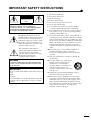 2
2
-
 3
3
-
 4
4
-
 5
5
-
 6
6
-
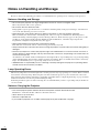 7
7
-
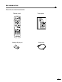 8
8
-
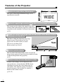 9
9
-
 10
10
-
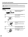 11
11
-
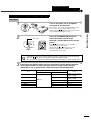 12
12
-
 13
13
-
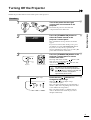 14
14
-
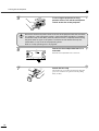 15
15
-
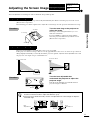 16
16
-
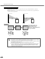 17
17
-
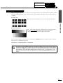 18
18
-
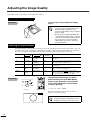 19
19
-
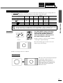 20
20
-
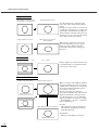 21
21
-
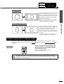 22
22
-
 23
23
-
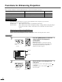 24
24
-
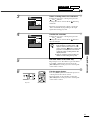 25
25
-
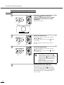 26
26
-
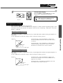 27
27
-
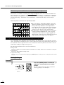 28
28
-
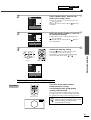 29
29
-
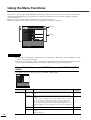 30
30
-
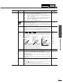 31
31
-
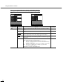 32
32
-
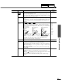 33
33
-
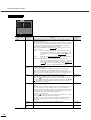 34
34
-
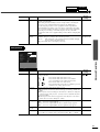 35
35
-
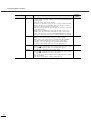 36
36
-
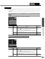 37
37
-
 38
38
-
 39
39
-
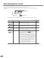 40
40
-
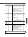 41
41
-
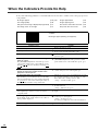 42
42
-
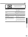 43
43
-
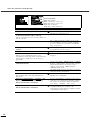 44
44
-
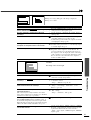 45
45
-
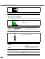 46
46
-
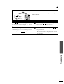 47
47
-
 48
48
-
 49
49
-
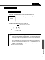 50
50
-
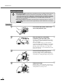 51
51
-
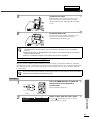 52
52
-
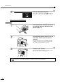 53
53
-
 54
54
-
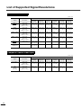 55
55
-
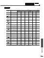 56
56
-
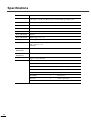 57
57
-
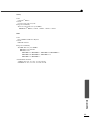 58
58
-
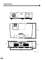 59
59
-
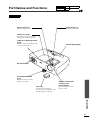 60
60
-
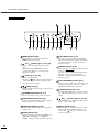 61
61
-
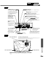 62
62
-
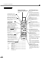 63
63
-
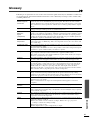 64
64
-
 65
65
-
 66
66
-
 67
67
-
 68
68
-
 69
69
-
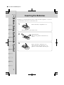 70
70
-
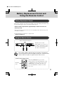 71
71
-
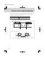 72
72
-
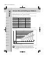 73
73
-
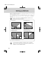 74
74
-
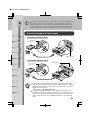 75
75
-
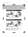 76
76
-
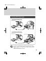 77
77
-
 78
78
-
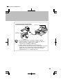 79
79
-
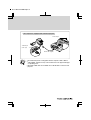 80
80


in andere talen
- English: Yamaha LPX-500 User manual
- italiano: Yamaha LPX-500 Manuale utente
- русский: Yamaha LPX-500 Руководство пользователя
- français: Yamaha LPX-500 Manuel utilisateur
- español: Yamaha LPX-500 Manual de usuario
- Deutsch: Yamaha LPX-500 Benutzerhandbuch
- português: Yamaha LPX-500 Manual do usuário
- dansk: Yamaha LPX-500 Brugermanual
- suomi: Yamaha LPX-500 Ohjekirja
- čeština: Yamaha LPX-500 Uživatelský manuál
- svenska: Yamaha LPX-500 Användarmanual
- Türkçe: Yamaha LPX-500 Kullanım kılavuzu
- polski: Yamaha LPX-500 Instrukcja obsługi
- română: Yamaha LPX-500 Manual de utilizare
Gerelateerde artikelen
-
Yamaha DPX-530 de handleiding
-
-
-
-
-
Yamaha DPX-1200 Handleiding
-
-
-
-
