
GTC E (0699204)
0664120
User Manual
Gebruikshandleiding
EN
NL

2
Contents
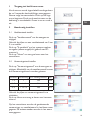
1 Entrance to the home menu................................................................................. 3
2 Automatic Manual setting.................................................................................... 3
2.1 Fan level................................................................................................................................................ 3
2.2 Heat level............................................................................................................................................. 3
3 Automatic Frost Protect (AS).............................................................................. 4
3.1 Turning the Frost Protect (AS) on................................................................................................. 4
3.2 Frost Protect (AS) Set the target temperature........................................................................... 4
4 Automatic Room Temp (RT)................................................................................5
4.1 Turning Room Temp (RT) on............................................................................................................5
4.2 Setting the target temperature for room Temp (RT)..................................................................5
5 Automatic Door Switch (TK)..............................................................................6
5.1 Turning theDoor Switch (TK) on....................................................................................................6
5.2 Door Switch (TK) fan level Setting..................................................................................................6
5.3 Door Switch (TK) Heat Level setting.............................................................................................7
5.4 Door Switch (TK) with Overtime setting......................................................................................7
6 Automatic Blow Temp (AT)..................................................................................8
6.1 Turning Blow Temp (AT) on..............................................................................................................8
6.2 Setting the target temperature for Blow Temp (AT)..................................................................8
6.3 Blow out temp (AT) fan level Setting..............................................................................................9
7 Timer..................................................................................................................9
8 Combination of AS, RT, TK and AT automatic .............................................10
9 Settings.............................................................................................................10
9.1 Language.............................................................................................................................................10
9.2 Runtime Filter.....................................................................................................................................11
9.3 Screen..................................................................................................................................................11
9.3.1 Display Brightness.............................................................................................................................11
9.3.2 Rotate the screen............................................................................................................................11
9.3.3 Screen lock.........................................................................................................................................12
9.4 Date/Time....................................................................................................................12
9.5 Overtime.............................................................................................................................12
9.6 Factory Setting...................................................................................................................................13
9.7 Memory....................................................................................................................13
10 Screen saver..........................................................................................................13
11 Error messages.....................................................................................................14
11.1 COM Error.........................................................................................................................................14
11.2 Frost alarm (optional)......................................................................................................................14
11.3 No enabled.........................................................................................................................................14
11.4 Filter cleaning.....................................................................................................................................14
11.5 Sensor Error.......................................................................................................................................15
11.6 Motor Error........................................................................................................................................15
11.7 Heater Error.......................................................................................................................................15
12 Help.........................................................................................................15
13 Circuit diagram (PCB EC)...................................................................................16
14 Circuit diagram (PCB AC)...................................................................................17

EN
3
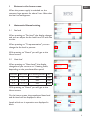
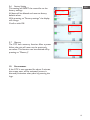
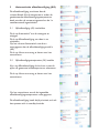
1 Entrace to the home menu
When the power supply is switched on, the
company logo appears for about 5 sec. After that
the start screen appears.
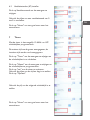
2 Automatic Manual setting
2.1 Fan level
When pressing on "Fan level", the display changes
and you can adjust the fan level from 0-5 with the
arrows.
When pressing on "% representation", you can
change the fan level in percent.
With pressing on "Home" you will get to the
Home screen.
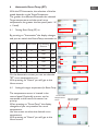
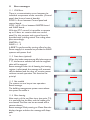
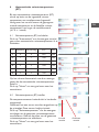
2.2 Heat level
When pressing on "Heat Level", the display
changes and you can turn on 3 heating levels,
depending on the preselected fan speed.
Fan level Heat Level PTC Heating Element MV
1 - 5 1 ON ON
3 - 5 1 + 2 ON ON
4 - 5 1 + 2 + 3 ON ON
With pressing on "Home" you will get to the
Home screen.
On the home screen, the preselected heat level
and fan level will be displayed in blue.
Levels which are in operation are displayed in
black.
3
1. Entrance to the home menu
When the power supply is switched on, appears
the company logo for about 5 sec.
After that the start screen appears.
2. Automatic Manual setting
2.1 Fan level
With pressing on the fan level the display changes and
you can adjust the fan level 0 - 5 with the arrows.
With pressing on % representation then you can change
the fan level in percent.
With Pressing on Home you will get to the Home
screen.
2.2 Heat level
With pressing on heat level, the display changes and you
can turn on 3 heating levels, depending on the preselec-
ted fan speed.
With pressing on Home you will get to the Home-
screen.
On the home screen, appears the preselected heat level
and fan level will be displayed in blue.
Levels which are in operation are displayed in black.
Fan Level Heat Level PTC Heating
element
MV
1 — 5 1 ON ON
3 — 5 1 + 2 ON ON
4 — 5 1 + 2 + 3 ON ON

4
4
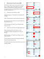
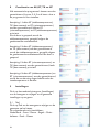
3. Automatic Frost Protect (AS)
With the Frost Protect, it prevents the room from cooling.
When the temperature drops below the preselected cooling
protection temperature, the first heating level and fan level
are then switched on.
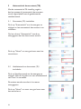
3.1 Turning the Frost Protect on
(AS)
With pressing on automatic the display will changes.
Press Frost Protect and the AS will switch on.
On the automatic screen you can see that the Frost Protect
is on.
with Pressing on Home you will get to the Home
screen.
3.2 Frost Protect (AS) Set the tar-
get temperature
After pressing the Frost Protect you can preselect the desi-
red temperature with the arrows.
With pressing on Home you will get to the Home
screen.
On the start screen you can see the selected Frost Protect
temperature.
Frost Protect has priority even if the system is in standby
mode.
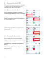
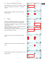
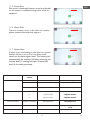
3 Automatic Frost Protect (AS)
With the Frost Protect, it prevents the room
from cooling. When the temperature drops
below the preselected cooling protection
temperature, the rst heating level and fan level
are then switched on.
3.1 Turning the Frost Protect on (AS)
With pressing on "Automatics" the display will
change.
Press "Frost Protect" and the AS will switch on.
On the automatics screen you can see that the
Frost Protect is on.
With pressing on "Home" you will get to the
Home screen.
3.2 Frost Protect (AS) Set the target temperature
After pressing the Frost Protect you can
preselect the desired temperature with the
arrow.
With pressing on "Home" you will get to the
Home screen.
On the home screen you can see the selected
Frost Protect temperature.
Frost Protect has priority even if the system is in
standby mode.

EN
5
5
Target tempe-
rature value
4. Automatic Room Temp (RT)
With the RT automatic, the selection of the fan speed depends
on the Target Temperatur.
The greater the difference between the selected Target tempe-
rature and the actual room temperature, the greater the fan
speed. (each 1 K = 1 level).
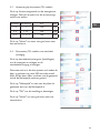
4.1 Turning Room Temp (RT) on
By pressing on automatic the display changes and you can
switch the Room Temp automatic on.
On the automatic screen you can see that the "RT" room
temperature is on.
With Home you get to the start screen.
4.2 Setting the target temperature
for Room Temp (RT)
The temperature sensor is located in the control panel.
Optionally a sensor can be connected to the board.
this sensor has priority.
With pressing on room Temp the display changes and you
can preselect the room temperature.
Use the arrows to select the desired Target room tempera-
ture.
With pressing on Home you will get to the Home
screen.
current state
temperature
value
DT
Fan Level Heat
Level
PTC Heating
element
MV
0 0 0 OFF ON
1 K 1 1 ON ON
2 K 2 1 ON ON
3 K 3 2 ON ON
4 K 4 3 ON ON
5 k 5 3 ON ON
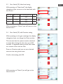
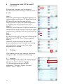
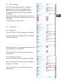
4 Automatic Room Temp (RT)
With the RT Automatics, the selection of the fan
speed depends on the Target Temperatur.
The greater the difference between the selected
Target temperature and the actual room
temperature, the greater the fan speed (each 1 K
= 1 level).
4.1 Turning Room Temp (RT) on
By pressing on "Automatics" the display changes
and you can switch the Room Temp automatic on.
ΔT Fan level Heat Level PTC Heating
Element
MV
0 0 0 OFF ON
1K 1 1 ON ON
2K 2 1 ON ON
3K 3 2 ON ON
4K 4 3 ON ON
5K 5 3 ON ON
On the Automatics screen you can see that the
"RT" room temperature is on.
With pressing on "Home" you will get to the
Home screen.
4.2 Setting the target temperature for Room Temp
The temperature sensor is located in the
control panel. Optionally a sensor can be
connected to the board, this sensor has
priority.
When pressing on "Room Temp" the display
changes and you can preselect the room
temperature.
Use the arrows to select the desired room
temperature.
With pressing on "Home" you will get to the
Home screen.

6
6
5. Automatic Door Switch (TK)
With the TK automatic, the system is switched on after prese-
lection of the fan speed and operation of the door contact
switch.
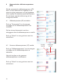
5.1 Turning the Door Switch (TK)
on
With pressing on automatic the display changes and you
can switch on the TK automatic.
On the automatic screen you can see that the TK "Door
Switch" is on.
With pressing on Home you will get to the Home screen.
5.2 Door Switch (TK) fan level Set-
ting
With pressing on the fan level, the display changes and
you can preselect the level of the fan with the arrows
in 5 steps.
Levels which are in operation are displayed in black.
With pressing on Home you will get to the Home screen.
5 Automatic Door Swith (TK)
With the TK Automatics, the system is switched
on after preselection of the fan speed and
operation of the door contact switch.
5.1 Turning the Door Switch (TK) on
With pressing on "Automatics" the display
changes and you can switch on the TK automatic.
On the automatics screen you can see that the
TK "Door Switch" is on.
With pressing on "Home" you will get to the
Home screen.
5.2 Door Switch (TK) fan level Setting
With pressing on the fan level, the display
changes and you can preselect the level of the fan
with the arrows in 5 steps.
Levels which are in operation are displayed in
black.
With pressing on "Home" you will get to the
Home screen.

EN
7
7
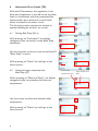
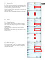
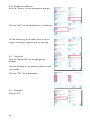
5.3 Door Switch (TK) Heat Level
setting
With pressing on the heat level, the display changes and
you can turn on the heat level with the arrows.
With pressing on Home you will get to the Home screen.
5.4 Door Switch (TK) with Overtime
setting
With pressing on gear (settings) the display changes and
you can change the Overrun time.
This ensures that the system remains switched on even af-
ter closing the door for up to 300 seconds. A repeated ope-
ning of the door leads to a restart of the overrun time.
Press on Overtime and you can set a desired overrun time
using the arrows.
Confirm the setting with OK.
With pressing on Home you will get to the Home screen.
Fan Level Heat
Level
PTC Heating
element
MV
1 — 5 1 ON ON
3 — 5 1 + 2 ON ON
4 — 5 1 + 2 + 3 ON ON
5.3 Door Switch (TK) Heat Level setting
With pressing on "Heat Level", the display
changes and you can turn on the heat level with
the arrows.
Fan level Heat Level PTC Heating Element MV
1 - 5 1 ON ON
3 - 5 1 + 2 ON ON
4 - 5 1 + 2 + 3 ON ON
When pressing on "Home" you will return to the
home screen.
5.4 Door Switch (TK) with Overtime setting
When pressing on the gear (settings) the display
changes and you can change the Overrun time.
This ensures that the system remains switched
on, even after closing the door for up to 300
seconds. A repeated opening of the door leads
to a restart of the overrun time.
Press on Overtime and you can set a desired
overrun time using the arrows.
Conrm the setting with OK.
With pressing on "Home" you will get to the
Home screen.

8
8
6. Automatic Blow Temp (AT)
With the AT automatic the regulation of the blow-out tempera-
ture is carried out by the Heat levels in combination with the
preselected Fan levels and alsoby an electronic control valve
which is located in the water circuit.
The fan level remains constant, to achieve an optimal shiel-
ding by the door air curtain.
6.1 Turning Blow Temp (AT) on
With pressing on automatic the display changes and you
can switch the blow Temp automatic on.
On the automatic screen you can see that the AT "blow
Temp" is active.
With pressing on Home you will get to the Home screen.
6.2 Setting the target temperature
for Blow Temp (AT)
With pressing on blow-out temperature the display chan-
ges and you can preselect the blow-out temperature.
Use the arrows to select the desired outlet temperature.
With pressing on Home you will get to the Home screen.
current state
temperature value
Target temperature
value
6 Automatic Door Swith (TK)
With the AT Automatics, the regulation of the
blow-out temperature is carried out by the Heat
levels in combination with the preselected Fan
levels and also by an electronic control valve
which is located in the water circuit.
The fan level remains constant, to achieve an
optimal shielding by the door air curtain.
6.1 Turning Blow Temp (AT) on
With pressing on "Automatics", the display
changes and you can switch on the Blow Temp
automatics.
On the automatic screen you can see that the AT
"Blow Temp" is active.
With pressing on "Home" you will get to the
Home screen.
6.2 Setting the target temperature for
Blow Temp (AT)
When pressing on "Blow-out Temp", the display
changes and you can preselect the blow-out
temperature.
Use the arrows to select the desired outlet
temperature.
With pressing on "Home" you will get to the
Home screen.

EN
9
9
6.3 Blow out temp (AT) fan level
Setting
With pressing on the fan speed the display changes and
you can select the fan level 0 - 5 with the arrows.
With pressing on Home you will get to the Home screen.
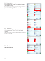
7. Timer
With the weekly timer, there is the possibility
To program 12 ON and OFF switching times.
Active time is displayed in green and inactive time is dis-
played in red.
With pressing on the timer, the display changes and you
can switch on the timer.
With pressing on New the display changes and you can
Program the Timer.
Use the arrows to set the time and day.
Press Save.
With the arrow you can set another switching time.
With pressing on Home you will get to the Home screen.
6.3 Blow out temp (AT) fan level Setting
With pressing on "Fan Level" the display changes
and you can select the fan level 0 - 5 with the
arrows.
With pressing on "Home" you will get to the
Home screen.
7 Timer
With the weekly timer, there is the possibility
To program 12 ON and OFF switching times.
Active time is displayed in green and inactive time
is displayed in red.
When pressing on "Timer", the display changes
and you can switch on the timer.
With pressing on "New" the display changes and
you can Program the Timer.
Use the arrows to set the time and day. Press
Save.
With the arrow you can set another switching
time.
With pressing on "Home" you will return to the
home screen.

10
10
8. Combination of AS, RT, TK
and AT automatic
All automatic programs can be combined.
The description of the setting is made in points 3. 4. and
5.
Note 1:
When AT (blow Temp) and RT (Room Temp) are combi-
ned then in this case AT (blow Temp) and RT (Room
Temp) have the same priority.
When the door is open, the outlet temperature is regu-
lated with the preselected fan level.
Note 2 :
When AT (blow Temp) and TK (Door Switch) are combi-
ned thenWhen the door is open, the outlet temperature
is regulated with the preselected fan level.
Note 3 :
RT (Room Temp) has priority when combining RT (Room
Temp) and TK (Door Switch) together.
Note 4:
When AT (blow-out temperature) and RT (room tempe-
rature) are combined,the heating will switch off as soon
as one of the target temperatures is reached.
9.Settings
With pressing on gear (settings), the display changes
and you can make various settings.
9.1 Language
9.2 Runtime Filter
9.3 Screen
9.4 Date / Time
9.5 Overtime
9.6 Factory Setting
9.7 Memory
9.1 Language
With pressing on Language the display changes and
you can select a desired language.
The following languages are available:
Nederlands - Francais - English - Deutsch - Italiano -
Polski - Dansk
8 Combination of AS, RT, TK and AT
automatic
All automatic programs can be combined.
The description of the setting is made in points 3,
4, and 5.
Note 1:
When AT (blow Temp) and RT (Room Temp) are
combined, then, in this case, AT (blow Temp) and
RT (Room Temp) have the same priority.
When the door is open, the outlet temperature
is regulated with the preselected fan level.
Note 2:
When AT (blow Temp) and TK (Door Switch) are
combined then, when the door is open, the outlet
temperature is regulated with the preselected fan
level.
Note 3:
RT (Room Temp) has priority when combining RT
(Room Temp) and TK (Door Switch) together.
Note 4:
When AT (blow-out temperature) and RT
(room temperature) are combined, the heating
will switch off as soon as one of the target
temperatures is reached.
9 Settings
With pressing on the gear (settings), the display
changes and you can make various settings.
9.1 Language
With pressing on "Language" the display changes
and you can select a desired language.
The following languages are available:
Nederlands - Francais - English - Deutsch -
Italiano - Polski - Dansk

EN
11
11
9.2 Runtime Filter
If a filter time is preselected, a note appears after the time
expires. This should make you aware of an early cleaning
of the suction filter.
Select the desired filter time with the arrows and confirm
with Save.
The filter time is selectable between 0h to 999h.
9.3 Screen
9.3.1 Display Brightness
With pressing on screen the display changes.
Then press om Display brightness, the display changes
again.
Use the arrows to select the desired display brightness.
With pressing on Home you will get to the Home screen.
9.3.2 Rotate the screen
With pressing on screen the display changes .
Then press on Rotate to Rotate the display in clockwise
direction.
9.1 Runtime Filter
If a lter time is preselected, a note appears after
the time expires. This should make you aware of
an early cleaning of the suction lter.
Select the desired lter time with the arrows and
conrm with Save.
The lter time is selectable between 0h to 999h.
9.3 Screen
9.3.1 Display Brightness
With pressing on "Screen" the display changes.
Then press om "Display brightness", the display
changes again.
Use the arrows to select the desired display
brightness.
With pressing on "Home" you will return to the
home screen.
9.3.2 Rotate the screen
With pressing on "Screen" the display changes.
Then press on "Rotate" to rotate the display in
clockwise direction.

12
12
9.3.3 Screen lock
With pressing on screen the display changes.
Then press on lock.
To unlock press the big company logo and then press the
small logo 3 times.
9.4 Date/Time
With pressing on Date / Time changes the display.
Use the arrows to set the desired date and time.
Confirm with OK.
9.5 Overtime
See under point 5.4
9.3.3 Screen lock
With pressing on "Screen" the display changes.
Then press on lock.
To unlock, press the big company logo and then
press the small logo 3 times.
9.4 Date/Time
With pressing on "Date / Time", the display
changes.
Use the arrows to set the desired date and time.
Conrm with OK.
9.5 Overtime
See under point 5.4

EN
13
13
9.6 Factory Setting
It will RESET the controller to the factory settings.
All data will be deleted and reset to factory default values.
With pressing on the factory setting the display will chan-
ge.
Confirm with OK.
9.7 Memory
The GTC has a memory function. After a power failure,
the unit will revert to the previously set values. This func-
tion can be switched off by pressing on Memory.
10. Screensaver
If the GTC is not operated for about 5 minutes, The screen
saver will be activated (screen is dimmed).
Activation takes place by pressing the logo.
9.6 Factory Setting
This setting will RESET the controller to the
factory settings.
All data will be deleted and reset to factory
default values.
With pressing on "Factory settings" the display
will change.
Conrm with OK.
9.7 Memory
The GTC has a memory function. After a power
failure, the unit will revert to the previously
set values. This function can be switched off by
pressing on "Memory".
10 Screensaver
If the GTC is not operated for about 5 minutes,
the screen saver will be activated (screen is
dimmed). Activation takes place by pressing the
logo.

14
14
11. Error messages
11.1 COM Error
There is a communication error between the individual com-
ponents of the controller. (Control panel, data line and con-
trol boards)
COM 0 = Error between Control panel and control board.
COM 1 till 9 = Error between MASTER board and SLAVE
board.
With the GTC control it is possible to operate up to 10 door
air curtains with one control panel. For this purpose, each
control board is provided with a coding switch. The coding
takes place accordingly:
MASTER = 0
SLAVE = 1 - 9
A RESET is performed by turning off and on the Power
supply.
It is essential to provide the SLAVE systems with power
first!
11.2 Frost alarm (optional)
When the intake temperature falls below approx. 7 ° C, the
fans are switched off and the magnetic valve will be ope-
ned.
Reset message:
If the risk of freezing the heating register is eliminated, the
message will automatically be deleted and the door air cur-
tain system resumes normal operation.
This function has priority!
11.3 No enabled
The system can not be put into operation.
Reset message:
The building management system must release the system
to enable it.
11.4 Filter cleaning
After expiry of the set filter time, (see point 7.2), it is es-
sential that the filter and the intake grille is cleaned. The
filter can be vacuumed with a vacuum cleaner.
Reset message:
With pressing on Clean filter the display changes and then
the message will disappear.
11 Error messages
11.1 COM Error
There is a communication error between the
individual components of the controller (Control
panel, data line and control boards).
COM 0 = Error between Control panel and
control board.
COM 1 till 9 = Error between MASTER board
and SLAVE board.
With the GTC control it is possible to operate
up to 10 door air curtains with one control
panel. For this purpose, each control board is
provided with a coding switch. The coding takes
place accordingly:
MASTER = 0
SLAVE = 1 - 9
A RESET is performed by turning off and on the
Power supply. It is essential to provide the SLAVE
systems with power rst!
11.2 Frost alarm (optional)
When the intake temperature falls below approx.
7 °C, the fans are switched off and the magnetic
valve will be opened.
Reset message: If the risk of freezing the heating
register is eliminated, the message will automati-
cally be deleted and the door air curtain system
resumes normal operation. This function has
priority!
11.3 Not enabled
The system can not be put into operation.
Reset message:
The building management system must release
the system to enable it.
11.4 Filter cleaning
After expiry of the set lter time, (see point 7.2),
it is essential that the lter and the intake grille
are cleaned. The lter can be vacuumed with a
vacuum cleaner.
Reset message: With pressing on Clean lter the
display changes and then the message will disap-
pear.

EN
15
15
11.5 Sensor Error
No sensor connected (sensor must be ordered), or the
sensor is malfunctioning it must be replaced.
11.6 Motor Error
There is a motor error in the door air curtain, please con-
tact the technical support.
11.7 Heater Error
If there is an overheating in the door air curtain, the fan
will turn on or if it is on then it will switch to the next high-
er level. The heating will automatically be switched off af-
ter achieving the last fan level, (1 heating level per 30
seconds) until all the heat goes away.
12. Help
Error Display notifi-
cation
Possible Cause
Solution
Device without function Screen is off No voltage
Switch voltage on
No enabled BMS – enable missing
See point 11.3
Frostalarm Inlet temperature too is low
Increase inlet temperature
No temperature control
Sensor defect
U-
K-
No sensor connected
Cable break
Short circuit
See point 11.5
Replace sensor
Replace sensor
Too low airflow Engine overheat Fan defective
See point 11.6
Runtime filter Suction filter dirty
Filter cleaning (See point
11.4)
COM error Error in the data transfer
See point 11.1
15
11.5 Sensor Error
No sensor connected (sensor must be ordered), or the
sensor is malfunctioning it must be replaced.
11.6 Motor Error
There is a motor error in the door air curtain, please con-
tact the technical support.
11.7 Heater Error
If there is an overheating in the door air curtain, the fan
will turn on or if it is on then it will switch to the next high-
er level. The heating will automatically be switched off af-
ter achieving the last fan level, (1 heating level per 30
seconds) until all the heat goes away.
12. Help
Error Display notifi-
cation
Possible Cause Solution
Device without function Screen is off No voltage Switch voltage on
No enabled BMS – enable missing See point 11.3
Frostalarm Inlet temperature too is low Increase inlet temperature
No temperature control
Sensor defect
U-
K-
No sensor connected
Cable break
Short circuit
See point 11.5
Replace sensor
Replace sensor
Too low airflow Engine overheat Fan defective See point 11.6
Runtime filter Suction filter dirty Filter cleaning (See point
11.4)
COM error Error in the data transfer See point 11.1
11.5 Sensor Error
No sensor connected (sensor must be ordered),
or the sensor is malfunctioning and it must be
replaced.
11.6 Motor Error
There is a motor error in the door air curtain,
please contact the technical support.
11.7 Heater Error
If there is an overheating in the door air curtain,
the fan will turn on or if it is on then it will
switch to the next higher level. The heating will
automatically be switched off after achieving the
last fan level, (1 heating level per 30 seconds)
until all the heat goes away.

16
16
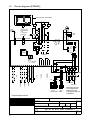
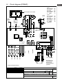
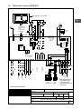
13. Circuit diagram (PCB EC)
Blow out Temp sensor
CONTROL
PCB EC
Technical changes reserved
1 211 12 133 4 514 15
0
to input
CONTROL
next PCB
8
AUXILIAR
8
AUX MON
02.01.2019
Sa
gezeichnet/signet
Tei le
Gruppe
vonPos.
Werkstoff
Maßstab
Blatt
Erstelldatum
GTC E EC UK 190201
Kunde
Benennung
Name
Kundenzeichnung Nr.:
DatumName
1 von 1
6 716 17
8 9 10 1918 20
CPU
Adress
switch
0 = MASTER
1 - 9 = SLAVE
5
1
2
3
4
9
8
7
6
Failure
Operation
free
Standard supplied
shielded datacable
(20 m)
1:1 straight wired
RJ-45 Stecker
S 50°
K1
K1 K2 K3
S 80°
S 60°
q
q
q
q
K1
Connecting box
Mains switch and fuses
to be installed by third
parties must comply
to all applicable rules and
requirements!
BMS On/Off
1
M
PE
N
L1
next
FAn
blau/blue
gelb/yellow
weiss/white
rot/red
optional
4
free
step 2
step 3 = step 1 + step 2
step 1
N
L2
PE
PE
NL2
intern
230V / 50Hz
K3 K2
230V/ 50Hz
3
3~400V/ 50Hz
4
K0
q
ext. Signal
optional
Frost thermostat
optional
Room Temp sensor
q
q
Room temperature. Sensor installed
S 45°
YPWM
0 V
+10 V
imp.
L N PE31 2
S 100°
F 16 AT
Timer
off
Fr 21.09.2018
07:52
Heat level
0 / 0
Automatic
Hand
Room Temp
10°C
Fan level
0 / 0
13 Circuit diagram (PCB EC)

EN
17
17
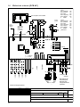
14. Circuit diagram (PCB AC)
1
M
CONTROL
PCB AC
connecting box
q
1 211 12 133 4 514 15
2
12
Trafo 8 A
Stufe 1 - Schwarz/black 120 V
Stufe 2 - Braun/brown 140 V
Stufe 3 - Rot/red 170 V
Stufe 4 - Orange/orange 200 V
Stufe 5 - Gelb/yellow 230 V
N - Blau/blue 0 V
Trafo 16 A
Stufe 0 - Schwarz/black 100 V *
Stufe 1 - Braun/brown 126 V
Stufe 2 - Rot/red 140 V
Stufe 3 - Orange/orange 170 V
Stufe 4 - Grün green 200 V
Stufe 5 - Gelb/yellow 230 V
N - Blau/blue 0 V
* Without function
8
AUXILIAR
N
L2
PE
230V / 50Hz
8
PE
NL2
intern
02.01.2019
SE
gezeichnet/signet
Tei le
Gruppe
Werkstoff
Maßstab
Blatt
Erstelldatum
GTC E AC UK 190102
Kunde
Benennung
Name
Kundenzeichnung Nr.:
DatumName
1 von 1
7 17
8 9 10 1918 20
CPU
0
Adress
Schalter
0 = MASTER
1 - 9 = SLAVE
5
1
2
3
4
9
8
7
6
L1
N
PE
AUX MON
optional
Mains switch and fuses
to be installed by third
parties must comply
to all applicable rules and
requirements!
thermo-
junction
next
Fan
Standard supplied
shielded datacable
(20 m)
1:1 straight wired
RJ-45 connectors
to input
CONTROL
next PCB
ext. Contact
temperature sensor
BMS On/Off
thermojunction
free
Failure
Operation
technical changes reserved
Step 2 Step1
Step 1+2 = Step 3
K3 K2
L N PE31 2
230V/ 50Hz
3
3~400V/ 50Hz
4
K0
S 100°
q
F 16 AT
S 50°
K1
K1 K2 K3
S 80°
S 60°
S 45°
q
q
q
q
K1
optional
Room temperature. Sensor installed
Timer
off
Fr 21.09.2018
07:52
Heat level
0 / 0
Automatic
Hand
Room Temp
10°C
Fan level
0 / 0
Blow out Temp sensor
6 16
q
Frost protection thermostat
optional
0V
ST3 ST4ST1 ST2
Fan level 1 - 5
ST5
T1
optional
14 Circuit diagram (PCB AC)

18
Inhoudsopgave
1 Toegang tot het Home menu.............................................................................. 19
2 Handmatig instellen............................................................................................. 19
2.1 Ventilatorstand instellen..................................................................................................................19
2.2 Verwarmingsstand instellen............................................................................................................19
3 Automatische afkoelbeveiliging (AS)................................................................ 20
3.1 Afkoelbeveiliging (AS) inschakelen............................................................................................... 20
3.2 Afkoelbeveiligingstemperatuur (AS) instellen............................................................................ 20
4 Automatische ruimtetemperatuur (RT)...........................................................21
4.1 Ruimtetemperatuur (RT) inschakelen..........................................................................................21
4.2 Ruimtetemperatuur (RT) instellen................................................................................................21
5 Automatisch deurcontact (TK)..........................................................................22
5.1 Deurcontact (TK) inschakelen.......................................................................................................22
5.2 Ventilatiestand van deurcontact (TK) inschakelen.....................................................................22
5.3 Verwarming bij deurcontact (TK) instellen.................................................................................23
5.4 Deurcontact (TK) instellen met uitschakelvertraging................................................................23
6 Automatische uitblaastemperatuur (AT)...........................................................24
6.1 Uitblaastemperatuur (AT) inschakelen........................................................................................24
6.2 Gewenste uitblaastemperatuur (UT) instellen..........................................................................24
6.3 Ventilatiestanden (AT) instellen.....................................................................................................25
7 Timer..................................................................................................................25
8 Combinatie van AS, RT, TK en AT.......................................................................26
9 Instellingen........................................................................................................26
9.1 Taal.............................................................................................................................................26
9.2 Filter vervangen................................................................................................................................27
9.3 Beeldscherm........................................................................................................................27
9.3.1 Helderheid.............................................................................................................................27
9.3.2 Beeldscherm draaien.......................................................................................................................27
9.3.3 Beeldscherm blokkeren..................................................................................................................28
9.4 Datum/Tijd....................................................................................................................28
9.5 Nalooptijd.............................................................................................................................28
9.6 Fabrieksinstellingen........................................................................................................29
9.7 Geheugenfunctie..................................................................................................................29
10 Screensaver.......................................................................................................29
11 Foutberichten....................................................................................................30
11.1 COM-fouten..................................................................................................................30
11.2 Vorstbeveiliging (optioneel)............................................................................................................30
11.3 Geen vrijgave.....................................................................................................................................30
11.4 Filter reinigen.....................................................................................................................................30
11.5 Sensor defect.....................................................................................................................................31
11.6 Motorstoring.............................................................................................................................31
11.7 Verwarmerstoring........................................................................................................31
12 Problemen oplossen.............................................................................................32
13 Schakelschema (EC-printplaat)..........................................................................33
14 Schakelschema (AC-printplaat)..........................................................................34

NL
19
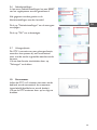
1 Toegang tot het Home menu
Als de stroom wordt ingeschakeld wordt geduren-
de ca. 5 seconden het bedrijfslogo weergegeven.
Daarna volgt het startscherm. Druk op het logo
om te beginnen. Druk op de aan/uit toets om de
bediening in te schakelen. Groen is aan en rood is
uit.
2 Handmatig instellen
2.1 Ventilatorstand instellen
Druk op "Ventilatorstand" om de weergave te
wijzigen.
Gebruik de pijlen om een ventilatiestand van 0 tot
5 in te stellen.
Druk op "%-ventilatie" om het systeem traploos
te regelen (alleen mogelijk bij gebruik van EC-
motoren).
Druk op "Home" om terug te keren naar het
startscherm.
2.2 Verwarmingsstand instellen
Druk op "Verwarmingsstand" om de weergave te
wijzigen. Afhankelijk van de ventilatorstand kunnen
drie verwarmingsniveau’s worden gekozen.
Ventilator Verwarming PTC Heating Element MV
1 - 5 1 ON ON
3 - 5 1 + 2 ON ON
4 - 5 1 + 2 + 3 ON ON
Gebruik de pijlen om verwarmingsstand in te
schakelen.
Druk op Home om terug te keren naar het start-
scherm.
Op het startscherm worden de geselecteerde
verwarmings- en ventilatiestand in het blauw weer-
gegeven. De actieve standen worden in het zwart
weergegeven.

20
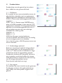
3 Automatische afkoelbeveiliging (AS)
De afkoelbeveiliging voorkomt dat de
ruimte afkoelt. Als de temperatuur onder de
geselecteerde afkoelbeveiligingstemperatuur
daalt, worden de verwarmingsstand en de 1e
ventilatorstand ingeschakeld.
3.1 Afkoelbeveiliging (AS) inschakelen
Druk op Automatics" om de weergave te
wijzigen.
Druk op Afkoelbeveiliging om deze in te
schakelen.
Op het scherm Automatisch wordt nu
weergegeven dat de afkoelbeveiliging actief is.
(AS)
Druk op Home om terug te keren naar het
startscherm.
3.2 Afkoelbeveiligingstemperatuur (AS) instellen
Als u op Afkoelbeveiliging drukt, kunt u met de
pijlen de gewenste insteltemperatuur selecteren.
Druk op Home om terug te keren naar het
startscherm.
Op het startscherm wordt de ingestelde
afkoelbeveiligingstemperatuur weergegeven.
De afkoelbeveiliging heeft altijd prioriteit, ook als
het systeem zich in standby bevindt.

NL
21
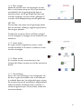
4 Automatische ruimtetemperatuur
(RT)
Bij een automatische ruimtetemperatuur (RT)
wordt op basis van de ingestelde ruimte-
temperatuur een ventilatorstand ingesteld.
Hoe groter het verschil tussen de geprogram-
meerde temperatuur en de feitelijke ruimte-
temperatuur, hoe hoger de ventilatorstand.
(Δ1 K = 1 stand)
4.1 Ruimtetemperatuur (RT) inschakelen
Druk op "Automatisch" om de weergave te wijzi-
gen en een automatische ruimtetemperatuur in te
schakelen.
ΔT Ventilator Verwarming PTC MV
0 0 0 OFF ON
1K 1 1 ON ON
2K 2 1 ON ON
3K 3 2 ON ON
4K 4 3 ON ON
5K 5 3 ON ON
Op het scherm Automatisch wordt nu weerge-
geven dat de automatische ruimtetemperatuur
actief is.
Druk op "Home" om terug te keren naar het
startscherm.
4.2 Ruimtetemperatuur (RT) instellen
De temperatuursensor bevindt zich in het bedie-
ningspaneel.
Optioneel kan een sensor worden aangesloten op
de printplaat. Deze sensor heeft prioriteit.
Druk op "Ruimtetemperatuur" om de weergave
te wijzigen en de gewenste ruimtetemperatuur
te selecteren. Gebruik de pijlen om de gewenste
ruimtetemperatuur te selecteren.
Druk op "Home" om terug te keren naar het
startscherm.
Actuele
waarde
Gewenste
waarde

22
5 Automatisch deurcontact (TK)
Met de automatische TK-instelling regelt u
dat het systeem bij automatisch deurcontact
wordt ingeschakeld met de geselecteerde
ventilatorstand.
5.1 Deurcontact (TK) inschakelen
Druk op "Automatisch" om de weergave te
wijzigen en het automatisch deurcontact in te
schakelen.
Op het scherm "Automatisch" wordt nu
weergegeven dat het deurcontact actief is.
Druk op "Home" om terug te keren naar het
startscherm.
5.2 Ventilatiestand van deurcontact (TK)
inschakelen
Druk op Ventilatorstand om de weergave te
wijzigen. Gebruik de pijlen om een ventilatiestand
van 0 tot 5 in te stellen.
De actieve standen worden in het zwart
weergegeven.
Druk op "Home" om weer terug te keren naar
het startscherm.

NL
23
5.3 Verwarming bij deurcontact (TK) instellen
Druk op Verwarmingsstand om de weergave te
wijzigen. Gebruik de pijlen om de verwarmings-
stand in te stellen.
Ventilator Verwarming PTC MV
1 - 5 1 ON ON
3 - 5 1 + 2 ON ON
4 - 5 1 + 2 + 3 ON ON
Druk op "Home" om weer terug te keren naar
het startscherm.
5.4 Deurcontact (TK) instellen met uitschakel-
vertraging
Druk op het tandwiel-pictogram (Instellingen)
om de weergave te wijzigen en de
uitschakelvertraging te wijzigen.
Daarmee stelt u in dat het systeem ook nadat de
deur is gesloten nog max. 300 seconden actief
blijft. Als de deur vaker na elkaar wordt geopend,
wordt de Nalooptijd opnieuw gestart.
Druk op "Nalooptijd" en stel met de pijlen de
gewenste duur van de Nalooptijd in.
Druk op "OK" om de instelling te bevestigen.
Druk op "Home" om terug te keren naar het
startscherm.

24
6 Automatische uitblaastemperatuur
(AT)
Met de automatische uitblaastemperatuur (AT)
kunt u via een elektronische regelklep in het
watercircuit de temperatuur van de uitgeblazen
lucht instellen. De ventilatorstand blijft constant.
Zo wordt een optimale afscherming via het
luchtgordijn bereikt.
6.1 Uitblaastemperatuur (AT) inschakelen
Druk op "Automatisch" om de weergave
te wijzigen en de uitblaastemperatuur in te
schakelen.
Op het scherm Automatisch wordt nu
weergegeven dat de uitblaastemperatuur actief is.
Druk op "Home" om terug te keren naar het
startscherm.
6.2 Gewenste uitblaastemperatuur (UT) instellen
Druk op "Uitblaastemperatuur" om de weergave
te wijzigen en de uitblaastemperatuur te
selecteren.
Gebruik de pijlen om de gewenste
uitblaastemperatuur te selecteren.
Druk op "Home" om terug te keren naar het
startscherm.
Actuele
waarde
Gewenste
waarde

NL
25
6.3 Ventilatiestanden (AT) instellen
Druk op Ventilatorstand om de weergave te
wijzigen.
Gebruik de pijlen om een ventilatiestand van 0
tot 5 in te stellen.
Druk op "Home" om terug te keren naar het
startscherm.
7 Timer
Met de timer is het mogelijk 12 AAN- en UIT-
schakeltijden programmeren.
De actieve tijd wordt groen weergegeven, de
inactieve tijd wordt rood weergegeven.
Druk op "Timer" om de weergave te wijzigen en
de schakeltijden in te schakelen.
Druk op "Nieuw" om de weergave te wijzigen en
de schakeltijden te programmeren.
Druk op "aan" om de timer te activeren.
Gebruik de pijlen om de tijd en dag in te stellen.
Druk op "Opslaan".
Gebruik de pijl om de volgende schakeltijd in te
stellen.
Druk op "Home" om terug te keren naar het
startscherm.

26
8 Combinatie van AS, RT, TK en AT
Alle automatische programma's kunnen worden
gecombineerd. In punt 3, 4, 5 en 6 leest u hoe u
de programma's kunt instellen.
Aanwijzing 1: Indien AT (uitblaastemperatuur),
TK (deurcontact) en RT (ruimtetemperatuur)
worden gecombineerd, hebben RT
(ruimtetemperatuur) en AT (uitblaastemperatuur)
prioriteit.
Als de deur is geopend, wordt de
uitblaastemperatuur geregeld volgens de
geselecteerde ventilatiestand.
Aanwijzing 2: Indien AT (uitblaastemperatuur)
en TK (deurcontact) worden gecombineerd,
wordt de uitblaastemperatuur geregeld volgens
de geselecteerde ventilatiestand als de deur is
geopend.
Aanwijzing 3: Indien RT (ruimtetemperatuur) en
TK (deurcontact) worden gecombineerd, heeft
TK (deurcontact) prioriteit.
Aanwijzing 4: Indien AT (uitblaastemperatuur) en
RT (ruimtetemperatuur) worden gecombineerd,
wordt de verwarming uitgeschakeld zodra de
insteltemperatuur is bereikt.
9 Instellingen
Druk op het tandwiel-pictogram (Instellingen)
om de weergave te wijzigen en de gewenste
instellingen op te geven.
9.1 Taal
Druk op Taal om de weergave te wijzigen en de
gewenste taal te kiezen.
De volgende talen zijn beschikbaar:
Nederlands - Frans - Deens - Engels - Duits -
Italiaans - Pools - Deens

NL
27
9.1 Filter vervangen
Als er een vervangingstijd voor het lter is
geselecteerd, wordt er na het aopen van
deze tijd een bericht weergegeven, dat het
luchtaanvoerlter binnenkort moet worden
vervangen.
Gebruik de pijlen om de gewenste tijd voor het
vervangen van het lter te selecteren en druk op
"Opslaan".
U kunt kiezen uit 0 tot 999 uur.
9.3 Beeldscherm
9.3.1 Helderheid
Druk op "Scherm" om de weergave te wijzigen.
Druk vervolgens op "Helderheid". De weergave
verandert opnieuw.
Gebruik de pijlen om de gewenste helderheid van
het beeldscherm te selecteren.
Druk op "Home" om terug te keren naar het
startscherm.
9.3.2 Beeldscherm draaien
Druk op "Scherm" om de weergave te wijzigen.
Druk vervolgens op "draaien" om de weergave
rechtsom te draaien.
Druk op "Home" om terug te keren naar het
startscherm.

28
9.3.3 Beeldscherm blokkeren
Druk op "Scherm" om de weergave te wijzigen.
Druk op "slot" om het beeldscherm te blokkeren.
Om de blokkering op te heffen, drukt u op het
logo en vervolgens nog drie keer op het logo.
9.4 Datum/tijd
Druk op "Datum/tijd" om de weergave te
wijzigen.
Gebruik de pijlen om de gewenste datum en tijd
in te stellen.
Druk op "OK" om te bevestigen.
9.5 Nalooptijd
Zie punt 5.4.

NL
29
9.6 Fabrieksinstellingen
In het menu Fabrieksinstellingen kan een RESET
van het regelsysteem worden gerealiseerd.
Alle gegevens worden gewist en de
fabrieksinstellingen worden hersteld.
Druk op "Fabrieksinstellingen" om de weergave
te wijzigen.
Druk op "OK" om te bevestigen.
9.7 Geheugenfunctie
De GTC is voorzien van een geheugenfunctie,
waardoor het systeem bij een stroomuitval
weer met de eerder ingestelde waarden wordt
herstart.
U kunt deze functie uitschakelen door op
"Geheugen" te drukken.
10 Screensaver
Indien de GTC na 5 minuten niet meer wordt
bediend, wordt automatisch de screensaver
ingeschakeld (beeldscherm wordt donker).
U kunt de GTC activeren door op het logo te
drukken.

30
11 Foutberichten
Foutberichten worden gemeld op het scherm
door middel van een gevarendriehoek.
11.1 COM-fouten
Er is sprake van een communicatiefout tussen de
afzonderlijke onderdelen van het regelsysteem.
(Bedieningspaneel, datakabel en besturingskaart.)
COM 0 = Fout tussen bedieningspaneel en bestu-
ringskaart
COM 1 tot 9 = Fouten tussen MASTER-print-
plaat en SLAVE-printplaat. U kunt met het GTC-
regelsysteem maximaal 10 luchtgordijninstallaties
bedienen via één bedieningspaneel. Hiervoor is
elke printplaat voorzien van een coderings-
schakelaar. De codering luidt:
MASTER = 0
SLAVE = 1 - 9
COM-fout E is voor overige busfouten.
U kunt een RESET doorvoeren door de voeding
uit en vervolgens weer in te schakelen.
Let er daarbij op dat u SLAVE-systemen eerst van
stroom voorziet!
11.2 Vorstbeveiliging (optioneel)
Enkel van toepassing bij hybride luchtgordijnen!
Als de temperatuur van de aangevoerde lucht
onder ca. 7° daalt, worden de ventilatoren uitge-
schakeld en wordt de magneetklep geopend.
Foutbericht annuleren: Als het gevaar op bevrie-
zing is geweken, wordt het foutbericht automa-
tisch geannuleerd en wordt de normale werking
van de luchtgordijninstallatie hervat.
Deze functie heeft altijd voorrang!
11.3 Geen vrijgave
De installatie kan niet in bedrijf worden genomen.
Foutbericht annuleren: Het gebouwbeheersys-
teem (GBS) moet het systeem vrijgeven voor
gebruik.

NL
31
11.4 Filter reinigen
Nadat de periode voor het vervangen van het
lter is verstreken (zie punt 9.2) is het absoluut
noodzakelijk dat het geïntegreerde lter of
aanvoerrooster wordt gereinigd. Het lter kan
met een stofzuiger worden schoon gezogen of
met een milde zeepoplossing worden gewassen.
LET OP!
Als het lter met water wordt gereinigd, wacht
dan tot het lter volledig is opgedroogd alvorens
het terug te plaatsen.
Foutbericht annuleren: Druk op"Filter reinigen"
om de weergave te wijzigen en het foutbericht te
annuleren.
11.5 Sensor defect
Er is geen sensor aangesloten (sensor moet
worden besteld), of de sensor is defect en moet
worden vervangen.
11.6 Motor overhit
Er is sprake van een motorstoring in het
luchtgordijn. Neem contact op met de technische
dienst.
11.7 Oververhitting
Als er een oververhitting in het luchtgordijn van
de deur is, gaat de ventilator aan of als deze aan
is, schakelt deze naar het volgende hogere niveau.
De verwarming wordt automatisch uitgeschakeld
nadat het laatste ventilatorniveau is bereikt (1
verwarmingsniveau per 30 seconden) totdat alle
warmte verdwijnt.

32
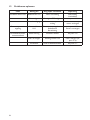
12 Problemen oplossen
Fout Weergave Mogelijke oorzaken Oplossing
Installatie werkt niet Beeldscherm uit Geen netvoeding Netvoeding
inschakelen
Geen vrijgave Storing in GBS-vrijgave zie punt 11.3
Vorstbeveiliging Luchtaanvoertemperatuur
te laag
Luchtaanvoertempe-
ratuur verhogen
Geen temperatuur-
regeling
Sensor defect
U-K
Geen sensor aangelosten
Kabelbreuk
Kortsluiting
zie punt 11.5
Sensor vervangen
Onvoldoende lucht-
stroomsnelheid
Motorstoring Ventilator defect zie punt 11.6
Filter vervangen Aanzuigrooster vuil Filter reinigen (zie
punt 11.4)
COM-fout Fout in dataoverdracht zie punt 11.1

NL
33
16
13. Circuit diagram (PCB EC)
Blow out Temp sensor
CONTROL
PCB EC
Technical changes reserved
1 211 12 133 4 514 15
0
to input
CONTROL
next PCB
8
AUXILIAR
8
AUX MON
02.01.2019
Sa
gezeichnet/signet
Tei le
Gruppe
vonPos.
Werkstoff
Maßstab
Blatt
Erstelldatum
GTC E EC UK 190201
Kunde
Benennung
Name
Kundenzeichnung Nr.:
DatumName
1 von 1
6 716 17
8 9 10 1918 20
CPU
Adress
switch
0 = MASTER
1 - 9 = SLAVE
5
1
2
3
4
9
8
7
6
Failure
Operation
free
Standard supplied
shielded datacable
(20 m)
1:1 straight wired
RJ-45 Stecker
S 50°
K1
K1 K2 K3
S 80°
S 60°
q
q
q
q
K1
Connecting box
Mains switch and fuses
to be installed by third
parties must comply
to all applicable rules and
requirements!
BMS On/Off
1
M
PE
N
L1
next
FAn
blau/blue
gelb/yellow
weiss/white
rot/red
optional
4
free
step 2
step 3 = step 1 + step 2
step 1
N
L2
PE
PE
NL2
intern
230V / 50Hz
K3 K2
230V/ 50Hz
3
3~400V/ 50Hz
4
K0
q
ext. Signal
optional
Frost thermostat
optional
Room Temp sensor
q
q
Room temperature. Sensor installed
S 45°
YPWM
0 V
+10 V
imp.
L N PE31 2
S 100°
F 16 AT
Timer
off
Fr 21.09.2018
07:52
Heat level
0 / 0
Automatic
Hand
Room Temp
10°C
Fan level
0 / 0
13 Elektrisch schema (PCB EC)

34
17
14. Circuit diagram (PCB AC)
1
M
CONTROL
PCB AC
connecting box
q
1 211 12 133 4 514 15
2
12
Trafo 8 A
Stufe 1 - Schwarz/black 120 V
Stufe 2 - Braun/brown 140 V
Stufe 3 - Rot/red 170 V
Stufe 4 - Orange/orange 200 V
Stufe 5 - Gelb/yellow 230 V
N - Blau/blue 0 V
Trafo 16 A
Stufe 0 - Schwarz/black 100 V *
Stufe 1 - Braun/brown 126 V
Stufe 2 - Rot/red 140 V
Stufe 3 - Orange/orange 170 V
Stufe 4 - Grün green 200 V
Stufe 5 - Gelb/yellow 230 V
N - Blau/blue 0 V
* Without function
8
AUXILIAR
N
L2
PE
230V / 50Hz
8
PE
NL2
intern
02.01.2019
SE
gezeichnet/signet
Tei le
Gruppe
Werkstoff
Maßstab
Blatt
Erstelldatum
GTC E AC UK 190102
Kunde
Benennung
Name
Kundenzeichnung Nr.:
DatumName
1 von 1
7 17
8 9 10 1918 20
CPU
0
Adress
Schalter
0 = MASTER
1 - 9 = SLAVE
5
1
2
3
4
9
8
7
6
L1
N
PE
AUX MON
optional
Mains switch and fuses
to be installed by third
parties must comply
to all applicable rules and
requirements!
thermo-
junction
next
Fan
Standard supplied
shielded datacable
(20 m)
1:1 straight wired
RJ-45 connectors
to input
CONTROL
next PCB
ext. Contact
temperature sensor
BMS On/Off
thermojunction
free
Failure
Operation
technical changes reserved
Step 2 Step1
Step 1+2 = Step 3
K3 K2
L N PE31 2
230V/ 50Hz
3
3~400V/ 50Hz
4
K0
S 100°
q
F 16 AT
S 50°
K1
K1 K2 K3
S 80°
S 60°
S 45°
q
q
q
q
K1
optional
Room temperature. Sensor installed
Timer
off
Fr 21.09.2018
07:52
Heat level
0 / 0
Automatic
Hand
Room Temp
10°C
Fan level
0 / 0
Blow out Temp sensor
6 16
q
Frost protection thermostat
optional
0V
ST3 ST4ST1 ST2
Fan level 1 - 5
ST5
T1
optional
14 Elektrisch schema (PCB AC)

NL
35

36
MARK BV
BENEDEN VERLAAT 87-89
VEENDAM (NEDERLAND)
POSTBUS 13, 9640 AA VEENDAM
TELEFOON +31(0)598 656600
FAX +31 (0)598 624584
www.mark.nl
MARK EIRE BV
COOLEA, MACROOM
CO. CORK
P12 W660 (IRELAND)
PHONE +353 (0)26 45334
FAX +353 (0)26 45383
www.markeire.com
MARK BELGIUM b.v.b.a.
ENERGIELAAN 12
2950 KAPELLEN
(BELGIË/BELGIQUE)
TELEFOON +32 (0)3 6669254
www.markbelgium.be
MARK DEUTSCHLAND GmbH
MAX-PLANCK-STRASSE 16
46446 EMMERICH AM RHEIN
(DEUTSCHLAND)
TELEFON +49 (0)2822 97728-0
TELEFAX +49 (0)2822 97728-10
www.mark.de
MARK POLSKA Sp. z o.o
UL. JASNOGÓRSKA 27
42-202 CZĘSTOCHOWA (POLSKA)
PHONE +48 34 3683443
FAX +48 34 3683553
www.markpolska.pl
S.C. MARK ROMANIA S.R.L.
STR. KOS KAROLY NR. 1 A
540297 TARGU MURES
(ROMANIA)
TEL/FAX +40 (0)265-266.332
www.markromania.ro
CERTIFICATION N°: 17.07.011
AIRSTREAM
CERTIFICATION N°: 17.07.011
AIRSTREAM
CERTIFICATION N°: 17.07.011
AIRSTREAM
CERTIFICATION N°: 17.07.011
AIRSTREAM
-
 1
1
-
 2
2
-
 3
3
-
 4
4
-
 5
5
-
 6
6
-
 7
7
-
 8
8
-
 9
9
-
 10
10
-
 11
11
-
 12
12
-
 13
13
-
 14
14
-
 15
15
-
 16
16
-
 17
17
-
 18
18
-
 19
19
-
 20
20
-
 21
21
-
 22
22
-
 23
23
-
 24
24
-
 25
25
-
 26
26
-
 27
27
-
 28
28
-
 29
29
-
 30
30
-
 31
31
-
 32
32
-
 33
33
-
 34
34
-
 35
35
-
 36
36


in andere talen
- English: Mark GTC E User manual
- eesti: Mark GTC E Kasutusjuhend
