Dometic RMDT10.5T, RMDT10.5XT Installatie gids
- Categorie
- Koelkasten
- Type
- Installatie gids

RMDT10.5T, RMDT10.5XT
Absorber-refrigerator with oven
Installation Manual. . . . . . . . . . . . . . . . . . . . 16
Absorber-Kühlschrank mit Ofen
Montageanleitung. . . . . . . . . . . . . . . . . . . .34
Réfrigérateur à absorption avec
four
Instructions de montage . . . . . . . . . . . . . . .53
Absorberkoelkast met oven
Montagehandleiding . . . . . . . . . . . . . . . . .72
EN
DE
FR
NL
REFRIGERATION
10-SERIES

© 2023 Dometic Group. The visual appearance of the contents of this manual is pro-
tected by copyright and design law. The underlying technical design and the prod-
ucts contained herein may be protected by design, patent or pending patent. The
trademarks mentioned in this manual belong to Dometic Sweden AB. All rights are
reserved.

RMDT10.5(X)T
3
NOTICE
NOTICE
d 90°

RMDT10.5(X)T
4
523 mm
1566 mm
550 mm
1534 mm
523 mm
1566 mm
605 mm
1534 mm
RMDT 10.5XTRMDT 10.5T
1534 mm
605 mm
523 mm
1590 mm
1534 mm
550 mm
523 mm
1590 mm
RMDT 10.5T RMDT 10.5XT
A
B
1

RMDT10.5(X)T
5
6
2
3
4
5
1
≥ 55 mm
min.15 mm –
max. 25 mm
2
≥ 55 mm
≥ 90 mm
≥ 90 mm
≥ 55 mm
AB
3

RMDT10.5(X)T
6
≥ 1250 mm ≥ 250 mm
< 1250 mm < 250 mm
4
15 – 25 mm
> 25 mm > 25 mm
5

RMDT10.5(X)T
7
≥ 1800 mm
15 – 25 mm
1
2
6
≥ 300 mm
1 2
7

RMDT10.5(X)T
8
1
min.15 mm –
max. 25 mm
≥ 55 mm
8

RMDT10.5(X)T
9
A
3
1
2
B< 5 mm
5 mm – 10 mm
C
1
4
9

RMDT10.5(X)T
10
t 40 mm
1
2
0

RMDT10.5(X)T
11
1.
2.
3.
A
B
a
2
3
1
5
3
4
1
2
≥ 170 mm
≤ 1300 mm
Ø65
Ø55
≥ 10°
Ø3,5
b

RMDT10.5(X)T
12
1
c
3
2
1
4
d
e
f

RMDT10.5(X)T
13
1.
2.
3.
g
1
2
h
i
j
k

RMDT10.5(X)T
14
bk bn bu rd pk vt wh
EN Black Brown Blue Red Pink Violet White
DE Schwarz Braun Blau Rot Pink Violett Weiß
FR Noir Marron Bleu Rouge Rosa Violeta Blanc
NL Zwart Bruin Blauw Rood Roze Paars Wit
l
1
2
2
31
4
m

RMDT10.5(X)T
15
X32
X12
X13
X07
X15
X2X1
X22
X20 X17
X16
X15
X09
X30
X3
X6
2A Fuse
X4
X32
wh
(
+
)
bn
(–)
vt (bu)
S+ Optional
L
L
N
N
Interface RS232
gy (gn)
D+ (wh)
rd (+)
pk (bu) (+)
bk (–)
86
bn (–)
bn (–)
bn(–)
bn
bn
rd (+) rd (+)
12V DC Internal
rd (+)
rd (+)
bk (-)
bk (–)
bk
bk
NTC2
ye (wh) (+)
wh (ye) (+)
wh
rd (+) rd (+)
EBAD C F
E
BA
D
C
F
NTC1
20A rd
30 87
85
1
2
5
4
7
6
8
3
9
10
11
13
14
15
16 20
12
17
18
19
21
22 23 24
L
PE
N
WAGO
n

EN
Explanation of symbols RMDT10.5(X)T
16
Please read these instructions carefully and follow all instructions, guidelines, and warnings included in this product manual in order to ensure
that you install, use, and maintain the product properly at all times. These instructions MUST stay with this product.
By using the product, you hereby confirm that you have read all instructions, guidelines, and warnings carefully and that you understand and
agree to abide by the terms and conditions as set forth herein. You agree to use this product only for the intended purpose and application
and in accordance with the instructions, guidelines, and warnings as set forth in this product manual as well as in accordance with all appli-
cable laws and regulations. A failure to read and follow the instructions and warnings set forth herein may result in an injury to yourself and
others, damage to your product or damage to other property in the vicinity. This product manual, including the instructions, guidelines, and
warnings, and related documentation, may be subject to changes and updates. For up-to-date product information, please visit
dometic.com.
Contents
1 Explanation of symbols . . . . . . . . . . . . . . . . . . . . . . . . . . . . . . . . . . . . . . . . . .16
2 Safety instructions . . . . . . . . . . . . . . . . . . . . . . . . . . . . . . . . . . . . . . . . . . . . . .17
3 Accessories . . . . . . . . . . . . . . . . . . . . . . . . . . . . . . . . . . . . . . . . . . . . . . . . . . .19
4 Intended use . . . . . . . . . . . . . . . . . . . . . . . . . . . . . . . . . . . . . . . . . . . . . . . . . .19
5 Installing the refrigerator-oven combination . . . . . . . . . . . . . . . . . . . . . . . . 20
6 Connecting the refrigerator-oven combination . . . . . . . . . . . . . . . . . . . . . 28
7 Disposal . . . . . . . . . . . . . . . . . . . . . . . . . . . . . . . . . . . . . . . . . . . . . . . . . . . . . 32
8 Technical data . . . . . . . . . . . . . . . . . . . . . . . . . . . . . . . . . . . . . . . . . . . . . . . . 33
1 Explanation of symbols
!
!
A
I
WARNING!
Safety instruction: Indicates a hazardous situation that, if not avoided,
could result in death or serious injury.
CAUTION!
Safety instruction: Indicates a hazardous situation that, if not avoided,
could result in minor or moderate injury.
NOTICE!
Indicates a situation that, if not avoided, can result in property damage.
NOTE
Supplementary information for operating the product.

EN
RMDT10.5(X)T Safety instructions
17
2 Safety instructions
!WARNING! Failure to obey these warnings could result in death
or serious injury.
Explosion hazard
• Never open the absorber unit. It is under high pressure and can cause
injury if it is opened.
•Only operate the device at the pressure shown on the type plate.
Only use pressure controllers with a fixed setting which comply with
the national regulations (in Europe EN 12864).
Fire hazard
• Ensure clean and residue-free handling if silicon sealant or similar is
used. There is a risk of fire if silicone filaments come into contact with
hot parts or naked flames.
• Never use a naked flame to check the device for leaks.
• Only use propane or butane gas (not natural gas).
Health hazard
• Do not operate the device if it is visibly damaged.
• If the AC power cable for this device is damaged, it must be replaced
by the manufacturer, a service agent or a similarly qualified person in
order to prevent safety hazards.
• This device may only be repaired by qualified personnel. Inadequate
repairs may cause serious hazards.
Risk of asphyxiation
• Dismantle all device doors for the disposal of the old device and leave
the shelves in the device to prevent accidental enclosure and suffoca-
tion.
!CAUTION! Failure to obey these cautions could result in minor or
moderate injury.
Electrical shock
• Before starting the device, ensure that the power supply line and the
plug are dry.
Risk of crushing
• Do not put your fingers into the hinge.

EN
Safety instructions RMDT10.5(X)T
18
ANOTICE! Damage hazard
• Only hold the device at the body of the device during transport. Never
hold the device at the absorber unit, the cooling fins, the gas pipes,
the door or the control panel.
• Make sure that the device circuit is not damaged during
transportation. The refrigerant in the device circuit is highly
flammable.
In the event of any damage to the device circuit (smell of ammonia):
– Switch off the device if applicable.
– Avoid naked flames and sparks.
– Air the room well.
• Do not install the device near naked flames or other heat sources (heat-
ers, direct sunlight, gas ovens etc.).
•Danger of overheating!
Always ensure sufficient ventilation so that the heat generated during
operation can dissipate. Make sure that the device is sufficiently far
away from walls and other objects so that the air can circulate.
• Check that the voltage specification on the type plate is the same as
that of the power supply.
• Do not open the refrigerant circuit under any circumstances.
• Only use the AC connection cable supplied to connect the device to
the AC mains.
• Only use cables with a suitable size.
• Never pull the plug out of the socket by the connection cable.
• The device may not be exposed to rain.

EN
RMDT10.5(X)T Accessories
19
3Accessories
4 Intended use
The refrigerator-oven combination is suitable for:
• Installation in caravans and motor homes
The refrigerator is suitable exclusively for:
• Cooling, deep-freezing and storing food
The refrigerator is not suitable for:
• Storing medications
• Storing corrosive substances or substances that contain solvents
• Quick-freezing food
The oven is suitable exclusively for:
• Cooking, baking and grilling food
Description
Flexible gas piping
Seal for draft-proof installation for gaps of 1 – 5 mm (fig. 9B, page 9)
Seal for draft-proof installation for gaps of 5 – 10 mm (fig. 9C, page 9)
Winter cover LS300 for the ventilation grill
Adapter cable
• WAGO to CEE
• WAGO to UK
• WAGO to JST
• WAGO to MATE-N-LOK
Optional Fan Kit REF-FANKIT
Optional Battery pack Pack R10-BP for stand-alone gas operation
Frame Kit for installing the refrigerator-oven combination flush with the furniture
Optional Ø2,5/5,5 mm connector for stand-alone gas operation with a 9 Vg powerbank

EN
Installing the refrigerator-oven combination RMDT10.5(X)T
20
The oven is particularly not suitable for:
•Heating
This product is only suitable for the intended purpose and application in accordance
with these instructions.
This manual provides information that is necessary for proper installation and/or
operation of the product. Poor installation and/or improper operating or mainte-
nance will result in unsatisfactory performance and a possible failure.
The manufacturer accepts no liability for any injury or damage to the product
resulting from:
• Incorrect installation, assembly or connection, including excess voltage
• Incorrect maintenance or use of spare parts other than original spare parts
provided by the manufacturer
• Alterations to the product without express permission from the manufacturer
• Use for purposes other than those described in this manual
Dometic reserves the right to change product appearance and product
specifications.
5 Installing the refrigerator-oven
combination
I
The device is suitable for installation in:
• Caravans
• Motor homes
NOTE
If you want to mount the refrigerator-oven combination flush with the fur-
niture (see fig. 3B, page 5), you need the optional frame kit (accesso-
ries). Consider the additional height (see fig. 1B, page 4) when
planning the installation.
Find the instructions for changing the door stop and the decorative plate
online at:
documents.dometic.com/?object_id=63258

EN
RMDT10.5(X)T Installing the refrigerator-oven combination
21
5.1 Preparing the installation
A
When installing the refrigerator, note the following:
• To enable the refrigerant to circulate properly, the refrigerator may not exceed an
angle of 3°.
Park the vehicle horizontally for this purpose.
• The refrigerator must be installed so that:
– The refrigerator is easily accessible for service work.
– The refrigerator is easy to de-install and install.
– The refrigerator can be easily removed from the vehicle.
• The refrigerator-oven combination must be installed in a recess so that it stands
firm when the vehicle is in motion. Note the dimensions in fig. 1, page 4 for this
purpose.
• The outer wall must be fitted with an air inlet vent (fig. 21, page 5) and an outlet
vent (fig. 22, page 5) with ventilation grills so that the heat generated can be
easily released to the outside:
– Air inlet vent: Fit ventilation grill as flush as possible with the base of the instal-
lation niche with a minimum cross-section of 400 cm².
– Outlet vent: fit as far above the refrigerator as possible.
– The distance between the air inlet and outlet vents must be at least 1250 mm
(fig. 4, page 6).
• If the ventilation grille of the air inlet vent cannot be installed flush to the ground,
an additional inlet vent (fig. 26, page 5) must be provided in the floor for
releasing leaked gas.
• Fit a nonflammable heat conduction plate (fig. 23, page 5) above the refriger-
ator so that the heat does not accumulate in the vehicle.
• The distance between the refrigerator and the rear wall must be at least 15 mm
but no more than 25 mm.
• A distance of more than 25 mm between the refrigerator and rear wall leads to
poor performance and increases the power consumption of the refrigerator.
Reduce the space behind the refrigerator to create adequate air inlet and outlet
ventilation (fig. 5, page 6). Use a ventilation plate, for example, to do this.
NOTICE!
• The refrigerator may not be installed in the rear of mobile homes with
the door pointing in the direction of travel without the manufac-
turer’s approval.
• Use exclusively original Dometic ventilation grills to ensure safe
operation.

EN
Installing the refrigerator-oven combination RMDT10.5(X)T
22
• If the minimum distance between the air inlet and outlet vents cannot be met, a
roof vent must be installed instead of the air outlet vent.
– The roof vent should be installed directly above the back of the refrigerator as
far as this is possible. Use an air duct (fig. 61, page 7) if you need to install
the roof vent offset; otherwise, heat will accumulate there.
– Fit a nonflammable heat conduction plate (fig. 62, page 7) above the
refrigerator so that the refrigerator does not heat up the oven.
– The distance between the air inlet vent and the roof vent must be at least
1800 mm (fig. 6, page 7).
– If a roof air conditioner is provided, the distance between the roof vent
(fig. 71, page 7) and the air outlet of the roof air conditioner
(fig. 72, page 7) must be at least 300 mm.
• The distance between the top of the oven and the ceiling must be at least 55 mm
(fig. 2, page 5).
• The distance in front of the oven between the top of the oven to the ceiling must
be at least 90 mm (fig. 3, page 5).
• The distance between the top of the oven and the flue outlet of the roof flue must
be between 250 mm and 1500 mm (fig. 4, page 6).
• If a roof flue (fig. 24, page 5) is being used: Fit a detachable panel
(fig. 25, page 5) above the oven so that you can always reach the flue pipe.
• If you do not have a roof flue: Fit a panel with a ventilation grille (fig. 81, page 8)
above the oven.
• The refrigerator-oven combination must not be installed at the side of the air inlet
and outlet vents as this leads to poor performance and increases the power con-
sumption of the refrigerator.
• The air inlet and outlet vents must not be covered by vehicle parts (such as an
open door or by installing accessories such as bicycle racks) while operating.
• Install the refrigerator-oven combination so that it is protected from excessive
heat, as this leads to poor performance and increases the power consumption of
the refrigerator.
• The refrigerator-oven combination must be installed in a draft-proof location, see
chapter “Installing the refrigerator-oven combination in a draft-proof location” on
page 23.
• The electrical installation must comply with national and local regulations.
European standards: EN 60335-1, EN 60335-2-24, EN 1648-1 and EN 1648-2.
• The gas installation must comply with national and local regulations.
European standard: EN 1949.

EN
RMDT10.5(X)T Installing the refrigerator-oven combination
23
5.2 Installing the refrigerator-oven combination in a
draft-proof location
Gas-powered refrigerators in camper vans or mobile homes must be installed in a
draft-free location. This means that the combustion air is not extracted from the inte-
rior and the exhaust fumes are prevented from directly entering the living space.
A suitable seal must be fitted between the rear panel of the refrigerator-oven combi-
nation and the interior of the vehicle.
!
The manufacturer recommends using a flexible seal to ease removal and installation
for maintenance purposes.
Select one of the three versions for draft-proof installation (fig. 9, page 9):
Stop bar behind the fridge (A)
1. Glue a flexible sealing lip (1) to a stop bar (2) behind the refrigerator (3).
2. Push the refrigerator-oven combination against the stop bar with the flexible
sealing lips.
✔The space behind the refrigerator is sealed to the interior of the vehicle.
Side gap distance of up to 5 mm between refrigerator and furniture (B)
1. Glue the sealing lips (see chapter “Accessories” on page 19) on the side of the
furniture (4).
2. Push the refrigerator-oven combination against the flexible sealing lips on
furniture.
✔The space behind the refrigerator is sealed to the interior of the vehicle.
WARNING! Fire hazard
• Do not use flammable materials such as silicone sealants, foam or
similar for the draft-proof installation.
• Use materials that are resistant to temperatures of up to 200 °C in the
vicinity of the oven.
• Position the device so that no connection cable is damaged or
pinched.
• Do not use multiple sockets or portable power adapters behind the
device.

EN
Installing the refrigerator-oven combination RMDT10.5(X)T
24
Side gap distance of 5 mm to 10 mm between refrigerator and
furniture (B)
1. Glue the double lipped sealing (see chapter “Accessories” on page 19) on the
side of the furniture (4).
2. Push the refrigerator-oven combination against the double lipped sealing on
furniture.
✔The space behind the refrigerator is sealed to the interior of the vehicle.
5.3 Making air inlet and outlet vents
I
➤Make an air inlet vent and an air outlet vent in the outer wall with the size of
249 mm x 490 mm. When doing so, observe the information, see chapter “Pre-
paring the installation” on page 21.
If the ventilation grill of the air inlet vent cannot be installed flush with the floor of the
niche, install an inlet vent in the floor. Any leaking gas can thus flow downwards.
1. Make an air inlet vent of at least Ø 40 mm in the floor (fig. 01, page 10) behind
the refrigerator-oven combination near the gas burner.
2. Shield the outside of the opening with a deflector to prevent sludge or dirt from
getting inside while driving (fig. 02, page 10).
If you have to use a roof vent instead of the air outlet vent:
➤Cut out a section in the roof. Refer to the roof vent instruction manual for the
required dimensions.
When doing so, observe the information in chapter “Preparing the installation”
on page 21.
NOTE
• Deviations from the inlet and outlet variations shown here must be
approved by the manufacturer.
• At high ambient temperatures, the refrigerator can only provide its
maximum cooling capacity if the optimum ventilation has been pro-
vided.

EN
RMDT10.5(X)T Installing the refrigerator-oven combination
25
5.4 Oven ventilation using a roof flue
A
Proceed as follows (fig. a, page 11 to fig. b, page 11):
1. Cut one lug of the pre-punched hole with a cutter knife (A).
2. Turn the metal plate upwards and cut the second lug to remove the metal plate
completely (B).
3. Remove the three screws on the protective cap on the outlet of the exhaust gas
outlet.
4. Remove the protective cap.
5. Secure the roof flue (1) in the hole.
6. Slide the flexible flue pipe (2) up into the roof flue.
7. Insert the bottom end of the flue pipe (4) onto the end of the flue outlet (5).
8. Attach the flue pipe using the screws which were supplied with the roof flue (3).
Alternatively, you can use a worm gear hose clamp.
9. Fit a detachable panel (fig. 25, page 5) above the oven.
5.5 Interior oven ventilation (oven without roof flue)
If you are providing the ventilation and flue duct in the vehicle interior, the supply of
fresh air must not be obstructed. Make ventilation holes that allow fresh air to enter
(safety ventilation according to EN 721). A combination of roof and wall ventilation
holes is possible.
Ventilation holes in the lower part may not be more than 100 mm above the interior
floor. The ventilation holes must not be closed under any circumstances. Keep the
grids and covers clean and free of dust.
➤Make ventilation holes in the vehicle interior with a total cross-section of at least
100 cm2.
NOTICE!
• Use a Truma AK 3 roof flue and Truma flue pipes. These have been
tested and approved for use.
• Materials must not be located near the roof flue and flue pipe which
are unsuitable for temperatures of above 120 °C.
• Lay the flue duct so that it rises gradually. The installation height of the
flue pipe between the top of the oven and the air outlet on the roof
flue must be at least 200 mm. A maximum of 1500 mm is possible.
• Keep the surrounding walls and components at a distance of at least
50 mm.

EN
Installing the refrigerator-oven combination RMDT10.5(X)T
26
➤Make one or more ventilation openings above the oven with a total cross-section
of at least 150 cm2.
➤Fit a panel above the oven and a ventilation grille in the panel with
468 mm x 90 mm (fig. c1, page 12).
✔Fresh air enters through ventilation slots into the oven under the door, is heated
and escapes from the oven through ventilation slots in the top of the door
(fig. c, page 12).
I
5.6 Installing the ventilation grill
I
1. Seal the installation frame to make the connection waterproof (fig. e, page 12).
2. Insert the installation frame and screw it down tightly (fig. f, page 12). Use all
the fixing holes for this.
3. Fit the ventilation grill (fig. g1–2, page13).
4. Insert the slider and lock the ventilation grill with it (fig. g3, page 13).
5.7 Installing condensation drain
I
NOTE
Check and clean the ventilation holes regularly.
NOTE
Use exclusively original Dometic ventilation grills to ensure safe
operation.
No. in
fig. d, page 12 Description
1Slider
2 Ventilation grill
3 Installation frame
4 Fastening for condensation drain
NOTE
• Condensation can form inside the refrigerator due to frequent door
opening, incorrectly stored food or food that is stored when it is too
warm.
• Condensation must be drained with a constant slope.

EN
RMDT10.5(X)T Installing the refrigerator-oven combination
27
Install the condensation drain as follows:
Variant 1
➤Run the condensation hose from the refrigerator through an opening in the floor
which goes outside under the vehicle.
Variant 2
➤Attach the condensation hose directly to the fitting intended for it on the
ventilation grill (fig. d4, page 12).
5.8 Install the roof vent
1. Seal the installation frame to make the connection waterproof (fig. i, page 13).
2. Insert the installation frame and screw it down tightly (fig. j, page 13). Use all
the fixing holes for this.
3. Insert the hood and screw it down tightly (fig. k, page 13).
5.9 Securing the refrigerator-oven combination
!
I
1. Move the refrigerator-oven combination into its final location.
2. Fasten the six screws (fig. l1, page 14) through the six plastic washers in the
sides of the refrigerator, and further into the wall.
3. Put the caps (fig. l2, page 14) onto the screw heads.
No. in
fig. h, page 13 Description
1 Hood
2 Installation frame
CAUTION!
Only screw through the receptacles provided, otherwise foamed com-
ponents, such as cables, can be damaged.
NOTE
Attach the side walls or the attached strips so that the screws are tight,
even when under increased loads (while driving).

EN
Connecting the refrigerator-oven combination RMDT10.5(X)T
28
6 Connecting the refrigerator-oven
combination
6.1 Connecting to the gas supply
A
I
It must be possible to shut off the refrigerator-oven combination from the gas line
separately by means of a shut-off device. The shut-off device must be easily
accessible.
NOTICE!
• This refrigerator may only be connected to the gas supply by a spe-
cialist in accordance with the applicable guidelines and standards.
• A hose connection is not permitted.
• Use a metal-sealed screw connection.
• The gas filter (white) in the refrigerator gas connection must not be
removed.
• Only use cylinders of propane or butane gas (not natural gas or city
gas) with an approved pressure reduction valve and suitable head.
Compare the pressure information on the type plate with the pres-
sure information on the pressure regulator on the propane or butane
gas cylinder.
•Only operate the refrigerator at the pressure shown on the type
plate.
•Only operate the refrigerator with the type of gas shown on the type
plate.
• Please note the pressures which are permitted in your country. Only
use pressure controllers with a fixed setting which comply with the
national regulations.
NOTE
Optionally, you can use the Dometic flexible gas connection pipe to
keep the installation tensionless.

EN
RMDT10.5(X)T Connecting the refrigerator-oven combination
29
➤Connect the refrigerator securely by hand to the gas supply (fig. m, page 14).
A
➤Have a leak test and a flame test performed by an authorized specialist after
professional installation.
Ensure you are issued with a certificate of inspection.
NOTICE!
Always use a backup wrench (size 12 mm) when connecting the gas
supply line to the refrigerator’s gas inlet fitting.
Item in
fig. m,
page 14
Description
1 Screw M4 (Torx TX20)
Tightening torque: 2 Nm
2 Refrigerator gas connection:
M14 x 1.5 (d = 8 mm/ISO8434 (DIN2353))
3 Gas pipe with ring coupling (size 17)
Tightening torque: 25 Nm
4 Backup wrench (12 mm)

EN
Connecting the refrigerator-oven combination RMDT10.5(X)T
30
6.2 Connecting to DC and AC
A
I
➤Connect the refrigerator according to fig. n, page 15:
NOTICE!
The electrical installation and repairs may only be performed by a spe-
cialist in accordance with the applicable regulations and standards.
NOTE
• The device plug must not be placed directly behind the ventilation
grill in order to prevent the air circulation from being impaired and to
protect the device plug from splashes of water.
• The device plug of the AC connection cable must not be cut off.
• The connection cables must be laid so that they do not come in con-
tact with hot parts of the unit/burner or with sharp edges.
• Changes to the internal electrical installation or the connection of
other electrical components (e.g. extra third party fans) to the inter-
nal wiring of the refrigerator will void any claims from the guarantee
and product liability.
• The refrigerator has a CI bus interface and can be controlled through
a compatible central vehicle display.
Item in
fig. n, page 15 Description
1 Fan 2 (if options module is not available)
2 Fan 1 (if options module is not available)
3 S+ (optional)
4 Heating element DC
5 12 V relay with 20 A fuse for heating cartridge
6 NTC 1: Refrigeration room
NTC 2: Outside temperature (optional)
7 Gas valve
8 AC supply cable
9 Heating element AC
10 Gas burner
11 Connection block
12 Lightning/electronics

EN
RMDT10.5(X)T Connecting the refrigerator-oven combination
31
DC power
!
A
13 Display
14 Heating frame
15 Fan 2 (if options module is available)
16 Fan 1 (if options module is available)
17 Options module
18 12 V supply oven (if options module is available)
19 12 V supply options module
20 CI-Bus Data connection
21 12 V DC supply cable
22 12 V terminal housing (front view)
• AMP/TE Tyco: 180906
• CS Colombo: 63N025
23 12 V supply cable electronics
24 12 V supply cable heating
25 12 V internal supply cable (options module, oven, fan)
WARNING! Fire hazard!
• The supply line to the heating element must be protected with a
20 A fuse.
• The supply line to the electronics must be protected with a 2 A fuse.
NOTICE!
The respective positive and negative supply lines of the DC connections
for electronics (fig. n23, page 15) and heating element (fig. n24,
page 15) may not be joined with one another and carried on a single
wire. This can cause electrical interference or damage to electrical com-
ponents.
Item in
fig. n, page 15 Description

EN
Disposal RMDT10.5(X)T
32
Please note the following cable sizes:
• Connections heating element: min. 6 mm²
To guarantee a proper cooling performance ensure that the voltage loss is
<0.8 Vg from the power supply to the refrigerator connection terminal.
• Connections electronics and heating element: 0.75 mm2
• Connections D+ and S+: 0.75 mm2
• Cable fed via drawbar (caravans only): 2.5 mm2
1. Assemble your DC socket as follows (fig. n, page 15):
– Connect A and C to the positive pole of the battery.
– Connect D and F to Connect D and F to ground.
– Connect B to the D + signal.
The electronics of the refrigerator uses the signal D+ from the light system to
detect the running engine. In automatic mode, the refrigerator selects the
most favorable mode available. The refrigerator is only operated with direct
current when the vehicle engine is running.
– Connect E to the CI-BUS.
2. Connect 3 with the S+ signal (optional).
3. Protect the supply line A with a 2 A fuse in the power distribution box of the
vehicle.
4. Protect the supply line C with a 20 A fuse in the power distribution box of the
vehicle.
5. Run the supply line C via an ignition-controlled relay.
This prevents the battery from completely discharging if the engine is switched
off accidentally.
AC power
➤Connect the refrigerator to an AC socket using the device plug.
7Disposal
I
Recycling packaging material
NOTE
This device contains flammable insulation blowing gas.
Only have the device removed and disposed of by a specialist.
➤Place the packaging material in the appropriate recycling waste bins wher-
ever possible.

EN
RMDT10.5(X)T Technical data
33
8 Technical data
For the current EU declaration of conformity for your device please refer to the
respective product page on dometic.com or contact the manufacturer directly
(see dometic.com/dealer).
RMDT10.5T RMDT10.5XT
Connection voltage 230 Vw/50 Hz
12 Vg
Capacity
Gross capacity
Refrigerator compartment
Ice compartment
Total net capacity
153 l
124 l
29 l
147 l
177 l
142 l
35 l
171 l
Power consumption 250 W (230 Vw)
170 W (12 Vg)
Energy consumption 4.4 kWh/24 h (230 Vw)
Gas consumption
Refrigerator
Oven
Oven with grill
580 g/24 h
80 g/1 h
95 g/1 h
Gas connecting pressure 2.75 kPA
Climate class SN
Batteries (optional) 12 x AA 1.5 V
Dimensions H x W x D
Standard frame
Optional frame for flush
mounting
fig. 1A, page 4
fig. 1B, page 4
Weight 60.4 kg 62.7 kg
Inspection/certification

DE
Erläuterung der Symbole RMDT10.5(X)T
34
Lesen und befolgen Sie bitte alle Anweisungen, Richtlinien und Warnhinweise in diesem Produkthandbuch sorgfältig, um sicherzustellen,
dass Sie das Produkt ordnungsgemäß installieren und stets ordnungsgemäß betreiben und warten. Diese Anleitung MUSS bei dem Produkt
verbleiben.
Durch die Verwendung des Produktes bestätigen Sie hiermit, dass Sie alle Anweisungen, Richtlinien und Warnhinweise sorgfältig gelesen
haben und dass Sie die hierin dargelegten Bestimmungen verstanden haben und ihnen zustimmen. Sie erklären sich damit einverstanden,
dieses Produkt nur für den angegebenen Verwendungszweck und gemäß den Anweisungen, Richtlinien und Warnhinweisen dieses Pro-
dukthandbuchs sowie gemäß allen geltenden Gesetzen und Vorschriften zu verwenden. Eine Nichtbeachtung der hierin enthaltenen Anwei-
sungen und Warnhinweise kann zu einer Verletzung Ihrer selbst und anderer Personen, zu Schäden an Ihrem Produkt oder zu Schäden an
anderem Eigentum in der Umgebung führen. Dieses Produkthandbuch, einschließlich der Anweisungen, Richtlinien und Warnhinweise,
sowie die zugehörige Dokumentation können Änderungen und Aktualisierungen unterliegen. Aktuelle Produktinformationen finden Sie
unter dometic.com.
Inhalt
1 Erläuterung der Symbole . . . . . . . . . . . . . . . . . . . . . . . . . . . . . . . . . . . . . . . 34
2 Sicherheitshinweise . . . . . . . . . . . . . . . . . . . . . . . . . . . . . . . . . . . . . . . . . . . 35
3 Zubehör. . . . . . . . . . . . . . . . . . . . . . . . . . . . . . . . . . . . . . . . . . . . . . . . . . . . . 37
4 Bestimmungsgemäßer Gebrauch . . . . . . . . . . . . . . . . . . . . . . . . . . . . . . . . 37
5 Kühlschrank-Ofen-Kombination einbauen. . . . . . . . . . . . . . . . . . . . . . . . . . 38
6 Kühlschrank-Ofen-Kombination anschließen . . . . . . . . . . . . . . . . . . . . . . . 47
7 Entsorgung . . . . . . . . . . . . . . . . . . . . . . . . . . . . . . . . . . . . . . . . . . . . . . . . . . .51
8 Technische Daten . . . . . . . . . . . . . . . . . . . . . . . . . . . . . . . . . . . . . . . . . . . . . 52
1 Erläuterung der Symbole
!
!
A
WARNUNG!
Sicherheitshinweis: Kennzeichnet eine Gefahrensituation, die zum
Tod oder schwerer Verletzung führen könnte, wenn die jeweiligen
Anweisungen nicht befolgt werden.
VORSICHT!
Sicherheitshinweis: Kennzeichnet eine Gefahrensituation, die zu
geringer oder mittelschwerer Verletzung führen könnte, wenn die
jeweiligen Anweisungen nicht befolgt werden.
ACHTUNG!
Kennzeichnet eine Situation, die zu Sachschäden führen kann, wenn die
jeweiligen Anweisungen nicht befolgt werden.

DE
RMDT10.5(X)T Sicherheitshinweise
35
I
2 Sicherheitshinweise
!WARNUNG! Nichtbeachtung dieser Warnungen kann zum Tod
oder schwerer Verletzung führen.
Explosionsgefahr
• Öffnen Sie niemals das Absorberaggregat. Es steht unter hohem
Druck und kann Verletzungen verursachen, wenn es geöffnet wird.
• Das Gerät darf ausschließlich mit dem auf dem Typenschild angege-
benen Druck betrieben werden. Verwenden Sie nur festeingestellte
Druckregler, die den nationalen Vorschriften entsprechen (in Europa
EN 12864).
Brandgefahr
• Achten Sie auf eine saubere und rückstandsfreie Verarbeitung, wenn
Silikon-Dichtungsmasse o. Ä. verwendet wird. Kommen Silikonfäden
mit heißen Teilen oder offenen Flammen in Berührung, besteht Brand-
gefahr.
• Prüfen Sie das Gerät niemals mit einer offenen Flamme auf Undichtig-
keit.
• Verwenden Sie nur Propan- oder Butangas (kein Erdgas).
Gesundheitsgefahr
• Wenn das Gerät sichtbare Beschädigungen aufweist, dürfen Sie es
nicht in Betrieb nehmen.
• Wenn das Wechselstrom-Anschlusskabel dieses Geräts beschädigt
wird, muss es durch den Hersteller, einen Kundendienstmitarbeiter
oder eine ähnlich qualifizierte Person ersetzt werden, um Gefährdun-
gen zu vermeiden.
• Reparaturen an diesem Gerät dürfen nur von Fachkräften durchge-
führt werden. Durch unsachgemäße Reparaturen können erhebliche
Gefahren entstehen.
Erstickungsgefahr
• Demontieren Sie alle Türen des Geräts bei Entsorgung des Altgeräts
und belassen Sie die Einlegeböden im Gerät, um ein versehentliches
Einschließen und Ersticken zu verhindern.
HINWEIS
Ergänzende Informationen zur Bedienung des Produktes.

DE
Sicherheitshinweise RMDT10.5(X)T
36
!VORSICHT! Nichtbeachtung dieser Hinweise kann zu leichten bis
mittelschweren Verletzungen führen.
Elektrischer Schlag
• Achten Sie vor der Inbetriebnahme darauf, dass Zuleitung und Stecker
trocken sind.
Quetschgefahr
• Fassen Sie nicht in das Scharnier.
AACHTUNG! Beschädigungsgefahr
• Halten Sie das Gerät beim Transport nur am Gerätekorpus fest. Halten
Sie das Gerät niemals am Absorberaggregat, den Kühlrippen, den
Gasleitungen, der Tür oder dem Bedienfeld fest.
• Achten Sie beim Transport darauf, den Gerätekreislauf nicht zu
beschädigen. Das Kühlmittel im Gerätekreislauf ist leicht entflammbar.
Bei einer Beschädigung des Gerätekreislaufs (Ammoniakgeruch):
– Schalten Sie das Gerät gegebenenfalls aus.
– Vermeiden Sie offenes Feuer und Zündfunken.
–Lüften Sie den Raum gut.
• Bauen Sie das Gerät nicht in der Nähe von offenen Flammen oder
anderen Wärmequellen (Heizung, Gasöfen usw.) ein.
•Überhitzungsgefahr!
Achten Sie stets darauf, dass beim Betrieb entstehende Wärme ausrei-
chend abgeführt werden kann. Sorgen Sie dafür, dass das Gerät in
ausreichendem Abstand zu Wänden oder Gegenständen steht,
sodass die Luft zirkulieren kann.
• Prüfen Sie, ob die Spannungsangabe auf dem Typenschild mit der
vorhandenen Netzspannung übereinstimmt.
• Öffnen Sie auf keinen Fall den Kühlkreislauf.
• Schließen Sie das Gerät nur mit dem zugehörigen Wechselstrom-
Anschlusskabel an die Wechselstromsteckdose an.
• Verwenden Sie nur Kabel mit passendem Leitungsquerschnitt.
• Ziehen Sie den Stecker nie am Anschlusskabel aus der Steckdose.
• Das Gerät darf keinem Regen ausgesetzt werden.

DE
RMDT10.5(X)T Zubehör
37
3Zubehör
4 Bestimmungsgemäßer Gebrauch
Die Kühlschrank-Ofen-Kombination ist geeignet für:
• Einbau in Wohnwagen und Wohnmobile
Der Kühlschrank ist ausschließlich für folgende Verwendungszwecke geeignet:
• Kühlung, Tiefkühlung und Lagerung von Lebensmitteln
Der Kühlschrank ist nicht für folgende Verwendungszwecke geeignet:
• Lagerung von Medikamenten
• Lagerung von ätzenden oder lösungsmittelhaltigen Stoffen
• Einfrieren von Lebensmitteln
Der Backofen ist ausschließlich für folgende Verwendungszwecke geeignet:
• Kochen, Backen und Grillen von Lebensmitteln
Beschreibung
Flexible Gasleitung
Dichtung für zugluftsicheren Einbau bei einem Spalt von 1 – 5 mm (Abb. 9B, Seite 9)
Dichtung für zugluftsicheren Einbau bei einem Spalt von 5 – 10 mm (Abb. 9B, Seite 9)
Winterabdeckung LS300 für das Lüftungsgitter
Adapterkabel
• WAGO zu CEE
• WAGO zu UK
• WAGO zu JST
• WAGO zu MATE-N-LOK
Optionaler Lüftersatz REF-FANKIT
Optionaler Batteriesatz Pack R10-BP für den autarken Gasbetrieb
Rahmenkit für den Einbau der Kühlschrank-Ofen-Kombination bündig zum Möbel
Optionaler Anschlussstecker mit Ø2,5/5,5 mm für autarken Gasbetrieb mit einer 9-Vg -
Powerbank

DE
Kühlschrank-Ofen-Kombination einbauen RMDT10.5(X)T
38
Der Backofen ist nicht für folgende Verwendungszwecke geeignet:
•Heizung
Dieses Produkt ist nur für den angegebenen Verwendungszweck und die Anwen-
dung gemäß dieser Anleitung geeignet.
Dieses Handbuch enthält Informationen, die für die ordnungsgemäße Installation
und/oder den ordnungsgemäßen Betrieb des Produkts erforderlich sind. Installati-
onsfehler und/oder ein nicht ordnungsgemäßer Betrieb oder eine nicht ordnungs-
gemäße Wartung haben eine unzureichende Leistung und u. U. einen Ausfall des
Geräts zur Folge.
Der Hersteller übernimmt keine Haftung für Verletzungen oder Schäden am Pro-
dukt, die durch Folgendes entstehen:
• unsachgemäße Montage oder falscher Anschluss, einschließlich Überspannung
• unsachgemäße Wartung oder Verwendung von anderen als den vom Hersteller
gelieferten Original-Ersatzteilen
• Veränderungen am Produkt ohne ausdrückliche Genehmigung des Herstellers
• Verwendung für andere als die in der Anleitung beschriebenen Zwecke
Dometic behält sich das Recht vor, das Erscheinungsbild des Produkts und dessen
technische Daten zu ändern.
5 Kühlschrank-Ofen-Kombination
einbauen
I
Das Gerät ist geeignet für den Einbau in:
•Wohnwagen
• Wohnmobilen
HINWEIS
Wenn Sie die Kühlschrank-Ofen-Kombination bündig mit dem Möbel-
stück (siehe Abb. 3B, Seite 5) einbauen möchten, ist das optionale
Rahmenkit (Zubehör) erforderlich. Berücksichtigen Sie bei der Planung
des Einbaus die zusätzliche Höhe (siehe Abb. 1B, Seite 4).
Die Anleitung zum Wechseln des Türanschlags und der Dekorplatte fin-
den Sie online unter:
documents.dometic.com/?object_id=63258

DE
RMDT10.5(X)T Kühlschrank-Ofen-Kombination einbauen
39
5.1 Einbau vorbereiten
A
Beachten Sie bei der Montage des Kühlschranks folgende Hinweise:
• Damit das Kältemittel ordnungsgemäß zirkulieren kann, darf der Kühlschrank
einen Neigungswinkel von 3° nicht überschreiten.
Stellen Sie das Fahrzeug zu diesem Zweck waagrecht ab.
• Der Kühlschrank muss so installiert werden, dass:
– der Kühlschrank für Wartungsarbeiten leicht zugänglich ist.
– der Kühlschrank leicht zu deinstallieren und zu installieren ist.
– der Kühlschrank leicht aus dem Fahrzeug entfernt werden kann.
• Die Kühlschrank-Ofen-Kombination muss in eine Nische eingebaut werden,
damit sie bei Bewegung des Fahrzeugs fest steht. Beachten Sie die Abmessun-
gen in Abb. 1, Seite 4 zu diesem Zweck.
• In der Außenwand müssen eine Belüftungsöffnung (Abb. 21, Seite 5) und eine
Entlüftungsöffnung (Abb. 22, Seite 5) mit Lüftungsgitter vorgesehen werden,
damit die entstehende Wärme gut nach außen abgegeben werden kann:
– Belüftungsöffnung: Lüftungsgitter möglichst bündig zum Boden der Einbau-
nische mit einem Querschnitt von mindestens 400 cm².
– Entlüftungsöffnung: möglichst weit oberhalb des Kühlschranks.
– Der Abstand zwischen Belüftungsöffnung und Entlüftungsöffnung muss min-
destens 1250 mm betragen (Abb. 4, Seite 6).
• Falls das Lüftungsgitter der Belüftungsöffnung nicht bündig zum Boden einge-
baut werden kann, muss zusätzlich eine Belüftungsöffnung (Abb. 26, Seite 5)
im Fußboden zum Abführen von ausgetretenem Gas vorgesehen werden.
• Sehen Sie oberhalb des Kühlschranks ein nicht entflammbares Wärmeleitblech
vor (Abb. 23, Seite 5), damit sich die Wärme nicht im Fahrzeug staut.
• Der Abstand zwischen Kühlschrank und Rückwand muss mindestens 15 mm,
höchstens jedoch 25 mm betragen.
• Ein Abstand von über 25 mm zwischen Kühlschrank und Rückwand führt zu Leis-
tungseinbußen und erhöhtem Energieverbrauch des Kühlschranks. Verkleinern
Sie den Hohlraum hinter dem Kühlschrank entsprechend, um eine ausreichende
Be- und Entlüftung herzustellen (Abb. 5, Seite 6). Nutzen Sie hierzu z. B. ein
Luftleitblech.
ACHTUNG!
• Der Kühlschrank darf ohne Zustimmung des Herstellers nicht im
Heck von Wohnmobilen installiert werden, wenn die Tür in Fahrtrich-
tung zeigt.
• Verwenden Sie ausschließlich Original-Lüftungsgitter von Dometic,
um einen sicheren Betrieb zu gewährleisten.

DE
Kühlschrank-Ofen-Kombination einbauen RMDT10.5(X)T
40
• Falls der Mindestabstand zwischen Belüftungsöffnung und Entlüftungsöffnung
nicht eingehalten werden kann, muss statt der Entlüftungsöffnung ein Dachent-
lüfter verbaut werden.
– Der Dachentlüfter sollte möglichst direkt über der Rückseite des Kühlschranks
angebracht werden. Nutzen Sie einen Luftkanal (Abb. 61, Seite 7), wenn
Sie den Dachentlüfter versetzt anbringen müssen, da sonst ein Wärmestau
entsteht.
– Sehen Sie oberhalb des Kühlschranks ein nicht entflammbares Wärmeleit-
blech vor (Abb. 62, Seite 7), damit der Kühlschrank nicht den Ofen
erwärmt.
– Der Abstand zwischen Belüftungsöffnung und Dachentlüfter muss mindes-
tens 1800 mm betragen (Abb. 6, Seite 7).
– Falls eine Dachklimaanlage vorhanden ist, muss der Abstand zwischen Dach-
entlüfter (Abb. 71, Seite 7) und Luftauslass der Dachklimaanlage
(Abb. 72, Seite 7) mindestens 300 mm betragen.
• Der Abstand zwischen der Oberkante des Ofens und der Raumdecke muss min-
destens 55 mm betragen (Abb. 2, Seite 5).
• Der Abstand vor dem Ofen zwischen der Oberkante des Ofens und der Raumde-
cke muss mindestens 90 mm betragen (Abb. 3, Seite 5).
• Der Abstand zwischen der Oberkante des Ofens und dem Abgasaustritt des
Dachkamins muss zwischen 250 mm und 1500 mm betragen (Abb. 4, Seite 6).
• Falls Sie einen Dachkamin (Abb. 24, Seite 5) verwenden: Montieren Sie ober-
halb des Ofens eine abnehmbare Blende (Abb. 25, Seite 5), damit Sie das
Kaminrohr immer erreichen können.
• Falls Sie keinen Dachkamin verwenden: Montieren Sie oberhalb des Ofens eine
Blende mit einem Lüftungsgitter (Abb. 81, Seite 8).
• Die Kühlschrank-Ofen-Kombination darf nicht seitlich zu den Be- und Entlüftungs-
öffnungen eingebaut werden, da dies zu Leistungseinbußen und erhöhtem Ener-
gieverbrauch des Kühlschranks führt.
• Die Belüftungs- und Entlüftungsöffnung dürfen im Betrieb nicht durch Fahrzeug-
teile abgedeckt werden (z. B. geöffnete Tür oder durch den Anbau von Zubehör
wie Fahrradträger).
• Installieren Sie die Kühlschrank-Ofen-Kombination geschützt gegen übermäßige
Wärmeeinstrahlung, da diese zu Leistungseinbußen und erhöhtem Energiever-
brauch des Kühlschranks führt.
• Die Kühlschrank-Ofen-Kombination muss zugdicht eingebaut werden (siehe
Kapitel „Kühlschrank-Ofen-Kombination zugdicht einbauen“ auf Seite 41).
• Die elektrische Installation muss nach den nationalen und örtlichen Vorschiften
erfolgen.
Europäische Normen: EN 60335-1, EN 60335-2-24, EN 1648-1 und EN 1648-2.

DE
RMDT10.5(X)T Kühlschrank-Ofen-Kombination einbauen
41
• Die Gas-Installation muss nach den nationalen und örtlichen Vorschriften erfol-
gen.
Europäische Norm: EN 1949.
5.2 Kühlschrank-Ofen-Kombination zugdicht einbauen
Gasbetriebene Kühlschränke in Wohnwagen oder Wohnmobilen müssen zugdicht
eingebaut werden. Das bedeutet, dass die Verbrennungsluft nicht dem Innenraum
entnommen wird und die Abgase am direkten Eintritt in den Wohnraum gehindert
werden.
Zwischen Rückwand der Kühlschrank-Ofen-Kombination und dem Innenraum des
Fahrzeugs muss eine geeignete Abdichtung vorgesehen werden.
!
Der Hersteller empfiehlt, eine flexible Dichtung zu verwenden, um den Aus- und Ein-
bau für Wartungszwecke zu vereinfachen.
Wählen Sie eine der drei Versionen für einen zugluftsicheren Einbau
(Abb. 9, Seite 9):
Anschlagleiste hinter dem Kühlschrank (A)
1. Kleben Sie eine flexible Dichtlippe (1) an eine Anschlagleiste (2) hinter dem
Kühlschrank (3).
2. Schieben Sie die Kühlschrank-Ofen-Kombination gegen die Anschlagleiste mit
den flexiblen Dichtlippen.
✔Der Raum hinter dem Kühlschrank ist zum Innenraum des Fahrzeugs hin abge-
dichtet.
WARNUNG! Brandgefahr!
• Verwenden Sie zum zugdichten Einbau keine leicht entflammbaren
Materialien wie Silikon-Dichtungsmassen, Montageschaum oder
Ähnliches.
• Verwenden Sie im Bereich des Ofens Materialien, die bis 200 °C
temperaturbeständig sind.
• Positionieren Sie das Gerät so, dass kein Anschlusskabel beschädigt
oder eingeklemmt wird.
• Platzieren Sie nicht mehrere Steckdosen oder tragbare Netzteile hin-
ter dem Gerät.

DE
Kühlschrank-Ofen-Kombination einbauen RMDT10.5(X)T
42
Seitlicher Spaltabstand von bis zu 5 mm zwischen Kühlschrank und
Möbelstück (B)
1. Kleben Sie die Dichtlippen (siehe Kapitel „Zubehör“ auf Seite 37) an die Seite
des Möbelstücks (4).
2. Schieben Sie die Kühlschrank-Ofen-Kombination gegen die flexiblen Dichtungs-
lippen an dem Möbelstück.
✔Der Raum hinter dem Kühlschrank ist zum Innenraum des Fahrzeugs hin abge-
dichtet.
Seitlicher Spaltabstand von 5 mm bis 10 mm zwischen Kühlschrank und
Möbelstück (B)
1. Kleben Sie die doppellippige Dichtung (siehe Kapitel „Zubehör“ auf Seite 37)
an die Seite des Möbelstücks (4).
2. Schieben Sie die Kühlschrank-Ofen-Kombination gegen die doppellippige
Dichtung an dem Möbelstück.
✔Der Raum hinter dem Kühlschrank ist zum Innenraum des Fahrzeugs hin abge-
dichtet.
5.3 Be- und Entlüftungsöffnungen herstellen
I
➤Fertigen Sie eine Belüftungs- und eine Entlüftungsöffnung in der Außenwand in
der Größe 249 mm × 490 mm an. Beachten Sie dabei die Hinweise, siehe Kapi-
tel „Einbau vorbereiten“ auf Seite 39.
Falls das Lüftungsgitter der Belüftungsöffnung nicht bündig zum Boden der Einbau-
nische eingebaut werden kann, bauen Sie eine Belüftungsöffnung im Fußboden ein.
Austretendes Gas kann so nach unten strömen.
1. Fertigen Sie hinter der Kühlschrank-Ofen-Kombination im Bereich des Gasbren-
ners eine Belüftungsöffnung von mindestens Ø 40 mm im Boden an
(Abb. 01, Seite 10).
HINWEIS
• Abweichungen von den hier gezeigten Einlass- und Auslassvarian-
ten müssen vom Hersteller genehmigt werden.
• Bei hohen Umgebungstemperaturen kann der Kühlschrank nur dann
seine maximale Kühlleistung erbringen, wenn für eine optimale Be-
und Entlüftung gesorgt ist.

DE
RMDT10.5(X)T Kühlschrank-Ofen-Kombination einbauen
43
2. Schirmen Sie die Außenseite der Öffnung mit einem Ablenker ab, damit wäh-
rend der Fahrt kein Schlamm oder Dreck eindringen kann (Abb. 02, Seite 10).
Falls Sie statt der Entlüftungsöffnung einen Dachentlüfter nutzen müssen:
➤Fertigen Sie einen Rahmenausschnitt im Dach an. Entnehmen Sie das erforderli-
che Maß der Anleitung des Dachentlüfters.
Beachten Sie dabei die Hinweise in Kapitel „Einbau vorbereiten“ auf Seite 39.
5.4 Entlüftung des Ofens über einen Dachkamin
A
Gehen Sie wie folgt vor (Abb. a, Seite 11 bis Abb. b, Seite 11):
1. Schneiden Sie eine Lasche des vorgestanzten Lochs mit einem Cuttermesser (A)
ab.
2. Drehen Sie die Metallplatte nach oben, und schneiden Sie die zweite Lasche ab,
um die Metallplatte vollständig zu entfernen (B).
3. Entfernen Sie die drei Schrauben der Schutzkappe am Abgasauslass.
4. Entfernen Sie die Schutzkappe.
5. Verschrauben Sie den Dachkamin (1) im Ausschnitt.
6. Schieben Sie das flexible Kaminrohr (2) oben in den Dachkamin.
7. Stecken Sie das untere Ende des Kaminrohrs (4) auf die Mündung des Abgas-
austritts (5).
8. Fixieren Sie das Kaminrohr mit den Schrauben, die beim Dachkamin mitgeliefert
wurden (3). Verwenden Sie alternativ eine Schneckengewindeschelle.
9. Montieren Sie oberhalb des Ofens eine abnehmbare Blende (Abb. 25,
Seite 5).
ACHTUNG!
• Verwenden Sie einen Truma Dachkamin AK3 und Truma Kamin-
rohre. Diese sind für die Anwendung geprüft und zugelassen.
• In der Nähe des Dachkamins und der Kaminrohre dürfen sich keine
Materialien befinden, die nicht für Temperaturen über 120 °C geeig-
net sind.
• Verlegen Sie die Abgasführung durchgehend steigend. Die Installa-
tionshöhe des Kaminrohrs zwischen der Oberkante des Ofens und
dem Abgasaustritt am Dachkamin muss mindestens 200 mm betra-
gen. Maximal sind 1.500 mm möglich.
• Halten Sie zu umliegenden Wänden und Bauteilen einen Abstand
von mindestens 50 mm ein.

DE
Kühlschrank-Ofen-Kombination einbauen RMDT10.5(X)T
44
5.5 Entlüftung des Ofens nach innen (Ofen ohne
Dachkamin)
Wenn Sie die Lüftung und Abgasführung in das Fahrzeuginnere vorsehen, darf die
Frischluftzufuhr nicht behindert werden. Stellen Sie Lüftungsöffnungen her, die den
Eintritt von Frischluft ermöglichen (Sicherheitslüftung gemäß EN 721). Eine Kombi-
nation aus Dach- und Wandabzugsöffnungen ist möglich.
Lüftungsöffnungen im unteren Bereich dürfen höchstens 100 mm über dem Innen-
boden liegen. Die Lüftungsöffnungen dürfen auf keinen Fall verschlossen werden.
Halten Sie Gitter und Abdeckungen sauber und staubfrei.
➤Fertigen Sie im Fahrzeuginnenraum Lüftungsöffnungen mit einem Gesamtquer-
schnitt von mindestens 100 cm2 an.
➤Fertigen Sie über dem Ofen eine oder mehrere Lüftungsöffnungen mit einem
Gesamtquerschnitt von mindestens 150 cm2 an.
➤Montieren Sie oberhalb des Ofens eine Blende und in der Blende ein Lüftungs-
gitter mit den Maßen 468 mm × 90 mm (Abb. c1, Seite 12).
✔Frischluft tritt durch Lüftungsschlitze an der Unterseite der Tür in den Ofen ein,
wird erwärmt und entweicht durch Lüftungsschlitze an der Oberseite der Tür wie-
der aus dem Ofen (Abb. c, Seite 12).
IHINWEIS
Überprüfen und reinigen Sie die Lüftungsöffnungen regelmäßig.

DE
RMDT10.5(X)T Kühlschrank-Ofen-Kombination einbauen
45
5.6 Lüftungsgitter montieren
I
1. Dichten Sie den Einbaurahmen ab, um die Verbindung wasserdicht zu machen
(Abb. e, Seite 12).
2. Setzen Sie den Einbaurahmen ein und schrauben Sie ihn fest (Abb. f,
Seite 12). Benutzen Sie dafür alle Befestigungsbohrungen.
3. Setzen Sie das Lüftungsgitter ein (Abb. g1–2, Seite13).
4. Setzen Sie die Schieber ein und verriegeln Sie mit ihnen das Lüftungsgitter
(Abb. g3, Seite 13).
5.7 Kondensatablauf installieren
I
Installieren Sie den Kondensatablauf wie folgt:
Variante 1
➤Führen Sie den Kondenswasserschlauch des Kühlschranks durch eine Öffnung
im Boden, die nach außen unter das Fahrzeug führt.
Variante 2
➤Schließen Sie den Kondenswasserschlauch direkt am dafür vorgesehenen
Anschluss am Lüftungsgitter an (Abb. d4, Seite 12).
HINWEIS
Verwenden Sie ausschließlich Original-Lüftungsgitter von Dometic, um
einen sicheren Betrieb zu gewährleisten.
Nr. in
Abb. d, Seite 12 Beschreibung
1Schieber
2 Lüftungsgitter
3 Einbaurahmen
4 Halterung für Kondenswasserablauf
HINWEIS
• Durch häufiges Türöffnen, falsch gelagerte Lebensmittel oder zu
warm gelagerte Lebensmittel kann sich im Inneren des Kühlschranks
Kondensat bilden.
• Das Kondensat muss mit konstantem Gefälle abgelassen werden.

DE
Kühlschrank-Ofen-Kombination einbauen RMDT10.5(X)T
46
5.8 Dachentlüfter montieren
1. Dichten Sie den Einbaurahmen ab, um die Verbindung wasserdicht zu machen
(Abb. i, Seite 13).
2. Setzen Sie den Einbaurahmen ein und schrauben Sie ihn fest (Abb. j,
Seite 13). Benutzen Sie dafür alle Befestigungsbohrungen.
3. Setzen Sie die Haube auf und schrauben Sie sie fest (Abb. k, Seite 13).
5.9 Kühlschrank-Ofen-Kombination befestigen
!
I
1. Bringen Sie die Kühlschrank-Ofen-Kombination in ihre endgültige Lage.
2. Drehen Sie sechs Schrauben (Abb. l1, Seite 14) durch die sechs Kunststoff-
buchsen in den Seitenwänden des Kühlschranks und weiter in die Nischen-
wand.
3. Setzen Sie die Abdeckkappen (Abb. l2, Seite 14) auf die Schraubenköpfe.
Nr. in
Abb. h, Seite 13 Beschreibung
1Haube
2 Einbaurahmen
VORSICHT!
Schrauben Sie nur durch die dafür vorgesehenen Buchsen, da ansons-
ten eingeschäumte Bauteile wie Leitungen beschädigt werden können.
HINWEIS
Befestigen Sie die Seitenwände oder die angebrachten Leisten so, dass
die Schrauben auch bei erhöhter Beanspruchung (während der Fahrt)
fest sitzen.

DE
RMDT10.5(X)T Kühlschrank-Ofen-Kombination anschließen
47
6 Kühlschrank-Ofen-Kombination
anschließen
6.1 An die Gasversorgung anschließen
A
I
Die Kühlschrank-Ofen-Kombination muss durch eine Absperreinrichtung in der Gas-
leitung separat absperrbar sein. Die Absperreinrichtung muss leicht zugänglich sein.
ACHTUNG!
• Der Kühlschrank darf nur von einer Fachkraft gemäß den
geltenden Vorschriften und Normen an die Gasversorgung ange-
schlossen werden.
• Ein Schlauchanschluss ist nicht zulässig.
• Verwenden Sie eine Schraubverbindung mit Metalldichtung.
• Der Gasfilter (Weiß) im Gasanschluss des Kühlschranks darf nicht ent-
fernt werden.
• Verwenden Sie nur Propan- oder Butangasflaschen (kein Erdgas
oder Stadtgas) mit geprüftem Druckreduzierventil und passendem
Kopfstück. Vergleichen Sie die Druckangabe auf dem Typenschild
mit der Druckangabe auf dem Druckregler der Propan- oder Butan-
gasflasche.
•Der Kühlschrank darf ausschließlich mit dem auf dem Typenschild
angegebenen Druck betrieben werden.
•Der Kühlschrank darf ausschließlich mit der auf dem Typenschild
angegebenen Gasart betrieben werden.
• Bitte beachten Sie die in Ihrem Land zugelassenen Drücke. Verwen-
den Sie nur festeingestellte Druckregler, die den nationalen Vor-
schriften entsprechen.
HINWEIS
Optional können Sie die flexible Gasanschlussleitung von Dometic ver-
wenden, um die Installation spannungsfrei zu halten.

DE
Kühlschrank-Ofen-Kombination anschließen RMDT10.5(X)T
48
➤Verbinden Sie den Kühlschrank fest und spannungsfrei mit der Gasversorgung
(Abb. m, Seite 14).
A
➤Lassen Sie nach der fachgerechten Installation eine Dichtheitsprüfung und eine
Flammprobe von einer autorisierten Fachkraft durchführen.
Lassen Sie eine Bescheinigung dieser Prüfung ausstellen.
6.2 An Gleichstrom und Wechselstrom anschließen
A
ACHTUNG!
Verwenden Sie für den Anschluss der Gaszuleitung an den Gaseinlass-
anschluss des Kühlschranks stets einen zweiten Schraubenschlüssel
(Größe 12 mm).
Pos. in
Abb. m,
Seite 14
Beschreibung
1 Schraube M4 (Torx TX20)
Anzugsmoment: 2 Nm
2 Gasanschluss Kühlschrank:
M14 × 1,5 (d = 8 mm/ISO8434 (DIN2353))
3 Gasrohr mit Ringkupplung (Größe 17)
Anzugsmoment: 25 Nm
4 zweiter Schraubenschlüssel (12 mm)
ACHTUNG!
Die elektrische Installation sowie Reparaturen dürfen nur von einer Fach-
kraft gemäß den geltenden Vorschriften und Normen ausgeführt wer-
den.

DE
RMDT10.5(X)T Kühlschrank-Ofen-Kombination anschließen
49
I
➤Schließen Sie den Kühlschrank gemäß Abb. n, Seite 15 an:
HINWEIS
• Der Gerätestecker darf nicht direkt hinter dem Lüftungsgitter plat-
ziert werden, um eine Beeinträchtigung der Luftzirkulation zu verhin-
dern und den Gerätestecker vor Wasserspritzern zu schützen.
• Der Gerätestecker des Wechselstrom-Anschlusskabels darf nicht
abgeschnitten werden.
• Die Anschlusskabel müssen so verlegt sein, dass sie nicht mit heißen
Teilen des Aggregats/Brenners oder mit scharfen Kanten in Berüh-
rung kommen.
• Veränderungen an der internen elektrischen Installation oder der
Anschluss anderer elektrischer Komponenten (z. B. fremder Zusatz-
lüfter) an der internen Verkabelung des Kühlschranks führen zum
Erlöschen jeglicher Ansprüche aus Gewährleistung und Produkthaf-
tung!
• Der Kühlschrank verfügt über eine CI-Bus-Schnittstelle und kann
über ein kompatibles zentrales Fahrzeugdisplay gesteuert werden.
Pos. in
Abb. n, Seite 15 Beschreibung
1 Lüfter 2 (falls Optionsmodul nicht verfügbar ist)
2 Lüfter 1 (falls Optionsmodul nicht verfügbar ist)
3 S+ (optional)
4 Heizelement (Gleichstrom)
5 12-V-Relais mit 20-A-Sicherung für Heizpatrone
6 NTC 1: Kühlraum
NTC 2: Außentemperatur (optional)
7 Gasventil
8 Kabel Wechselstromversorgung
9 Heizelement (Wechselstrom)
10 Gasbrenner
11 Anschlussblock
12 Beleuchtung/Elektronik
13 Display
14 Heizrahmen

DE
Kühlschrank-Ofen-Kombination anschließen RMDT10.5(X)T
50
Gleichstrom
!
A
Beachten Sie folgende Leitungsquerschnitte:
• Anschlüsse Heizelement: min. 6 mm²
Um eine gute Kühlleistung zu gewährleisten, stellen Sie sicher, dass der Span-
nungsverlust von der Stromversorgung zur Anschlussklemme des Kühlschranks
<0,8 Vg beträgt.
15 Lüfter 2 (falls Optionsmodul verfügbar ist)
16 Lüfter 1 (falls Optionsmodul verfügbar ist)
17 Optionsmodul
18 12-V-Versorgung Ofen (falls Optionsmodul verfügbar ist)
19 12-V-Versorgung Optionsmodul
20 CI-Bus-Datenanschluss
21 Kabel 12-V-Gleichstromversorgung
22 Gehäuse 12-V-Klemme (Vorderansicht)
• AMP/TE Tyco: 180906
• CS Colombo: 63N025
23 12-V-Versorgungskabel Elektronik
24 12-V-Versorgungskabel Heizung
25 Internes Versorgungskabel 12 V (Optionsmodul, Ofen, Lüfter)
WARNUNG! Brandgefahr!
• Die Versorgungsleitung zum Heizelement muss mit einer 20-A-
Sicherung abgesichert sein.
• Die Versorgungsleitung zur Elektronik muss mit einer 2-A-Sicherung
abgesichert sein.
ACHTUNG!
Die jeweiligen positiven und negativen Versorgungsleitungen der
Gleichstromanschlüsse für Elektronik (Abb. n23, Seite 15) und Heiz-
element (Abb. n24, Seite 15) dürfen nicht miteinander verbunden
und auf einem einzigen Draht geführt werden. Es kann sonst zu elektri-
scher Beeinflussung oder Beschädigung elektrischer Bauteile kommen.
Pos. in
Abb. n, Seite 15 Beschreibung

DE
RMDT10.5(X)T Entsorgung
51
• Anschlüsse Elektronik und Heizelement: 0,75 mm2
• Verbindungen D+ und S+: 0,75 mm2
• Kabelzuführung über Deichsel (nur Wohnwagen): 2,5 mm2
1. Montieren Sie die Gleichstromsteckdose wie folgt (Abb. n, Seite 15):
– Schließen Sie A und C an den Pluspol der Batterie an.
– Schließen Sie D und F an Masse an.
– Schließen Sie B an das D+-Signal an.
Die Elektronik des Kühlschranks nutzt das Signal D+ der Lichtmaschine, um
den laufenden Fahrzeugmotor zu erkennen. Der Kühlschrank wählt im auto-
matischen Betriebsmodus die günstigste vorhandene Betriebsart aus. Der
Kühlschrank wird nur mit Gleichstrom betrieben, wenn der Fahrzeugmotor
läuft.
– Schließen Sie E an den CI-BUS an.
2. Schließen Sie 3 an das S+-Signal an (optional).
3. Sichern Sie die Versorgungsleitung A mit einer 2-A-Sicherung im Stromverteiler-
kasten des Fahrzeugs ab.
4. Sichern Sie die Versorgungsleitung C mit einer 20-A-Sicherung im Stromvertei-
lerkasten des Fahrzeugs ab.
5. Verlegen Sie die Versorgungsleitung C über ein zündungsgesteuertes Relais.
Dadurch wird verhindert, dass sich die Batterie vollständig entlädt, wenn der
Motor versehentlich abgestellt wird.
Wechselstrom
➤Schließen Sie den Kühlschrank mit dem Gerätestecker an eine Wechselstrom-
steckdose an.
7Entsorgung
I
Recycling von Verpackungsmaterial
HINWEIS
Dieses Gerät enthält entzündliches Treibgas zur Isolation.
Der Ausbau und die Entsorgung des Geräts dürfen nur durch Fachper-
sonal vorgenommen werden.
➤Geben Sie das Verpackungsmaterial möglichst in den entsprechenden Recy-
cling-Müll.

DE
Technische Daten RMDT10.5(X)T
52
8 Technische Daten
Die aktuelle EU-Konformitätserklärung für Ihr Gerät erhalten Sie auf der jeweiligen
Produktseite auf dometic.com oder direkt über den Hersteller
(siehe dometic.com/dealer).
RMDT10,5T RMDT10.5XT
Anschlussspannung 230 Vw/50 Hz
12 Vg
Kapazität
Bruttoinhalt
Kühlschrankfach
Frosterfach
Nutzinhalt insgesamt
153 l
124 l
29 l
147 l
177 l
142 l
35 l
171 l
Leistungsaufnahme 250 W (230 Vw)
170 W (12 Vg)
Energieverbrauch 4,4 kWh/24 h (230 Vw)
Verbrauch Gas
Kühlschrank
Ofen
Backofen mit Grill
580 g/24 h
80 g/1 h
95 g/1 h
Gasanschlussdruck 2,75 kPa
Klimaklasse SN
Batterien (optional) 12 × AA 1,5 V
Abmessungen H x B x T
Standardrahmen
Optionaler Rahmen für flä-
chenbündige Montage
Abb. 1A, Seite 4
Abb. 1B, Seite 4
Gewicht 60,4 kg 62,7 kg
Prüfung/Zertifikat

FR
RMDT10.5(X)T Signification des symboles
53
Veuillez lire et suivre attentivement l’ensemble des instructions, directives et avertissements figurant dans ce manuel afin d’installer, d’utiliser
et d’entretenir le produit correctement à tout moment. Ces instructions DOIVENT rester avec le produit.
En utilisant ce produit, vous confirmez expressément avoir lu attentivement l’ensemble des instructions, directives et avertissements et que
vous comprenez et acceptez de respecter les modalités et conditions énoncées dans le présent document. Vous acceptez d’utiliser ce pro-
duit uniquement pour l’usage et l’application prévus et conformément aux instructions, directives et avertissements figurant dans le présent
manuel, ainsi qu’à toutes les lois et réglementations applicables. En cas de non-respect des instructions et avertissements figurant dans ce
manuel, vous risquez de vous blesser ou de blesser d’autres personnes, d’endommager votre produit ou d’endommager d’autres biens à
proximité. Le présent manuel produit, y compris les instructions, directives et avertissements, ainsi que la documentation associée peuvent
faire l’objet de modifications et de mises à jour. Pour obtenir des informations actualisées sur le produit, veuillez consulter le
site dometic.com.
Sommaire
1 Signification des symboles . . . . . . . . . . . . . . . . . . . . . . . . . . . . . . . . . . . . . . 53
2 Consignes de sécurité . . . . . . . . . . . . . . . . . . . . . . . . . . . . . . . . . . . . . . . . . 54
3 Accessoires . . . . . . . . . . . . . . . . . . . . . . . . . . . . . . . . . . . . . . . . . . . . . . . . . . 56
4 Usage conforme . . . . . . . . . . . . . . . . . . . . . . . . . . . . . . . . . . . . . . . . . . . . . . 56
5 Montage de la combinaison réfrigérateur-four . . . . . . . . . . . . . . . . . . . . . . 57
6 Raccordement de la combinaison réfrigérateur-four . . . . . . . . . . . . . . . . . 66
7 Mise au rebut. . . . . . . . . . . . . . . . . . . . . . . . . . . . . . . . . . . . . . . . . . . . . . . . . 70
8 Caractéristiques techniques. . . . . . . . . . . . . . . . . . . . . . . . . . . . . . . . . . . . . .71
1 Signification des symboles
!
!
A
AVERTISSEMENT !
Consignes de sécurité : indiquent une situation dangereuse qui, si
elle n’est pas évitée, est susceptible d’entraîner des blessures graves,
voire mortelles.
ATTENTION !
Consignes de sécurité : indiquent une situation dangereuse qui, si
elle n’est pas évitée, est susceptible d’entraîner des blessures légères
ou de gravité modérée.
AVIS !
Indiquent une situation dangereuse qui, si elle n’est pas évitée, peut
entraîner des dommages matériels.

FR
Consignes de sécurité RMDT10.5(X)T
54
I
2 Consignes de sécurité
!AVERTISSEMENT ! Le non-respect de ces mises en garde peut
entraîner des blessures graves, voire mortelles.
Risque d’explosion
• N’ouvrez jamais l’unité de l’absorbeur. Il se trouve sous haute pres-
sion et peut provoquer des blessures s’il est ouvert.
• Utilisez uniquement l’appareil avec la pression indiquée sur la
plaque signalétique. Utilisez uniquement des régulateurs de pression
à réglage fixe correspondant aux prescriptions nationales (en Europe
EN 12864).
Risque d’incendie
• Assurez un traitement propre et sans traces lorsque du mastic au sili-
cone ou un produit similaire est utilisé. Tout contact de fils de silicone
avec des pièces chaudes ou des flammes nues présente un risque
d’incendie.
• Ne contrôlez jamais l’étanchéité de l’appareil à l’aide d’une flamme
nue.
• Utilisez uniquement du gaz propane ou butane (pas de gaz naturel).
Risque pour la santé
• Si l’appareil présente des dégâts visibles, ne le mettez pas en service.
• Si le câble de raccordement en courant alternatif de l’appareil est
endommagé, il doit être remplacé par le fabricant, un agent de service
ou une personne de qualification similaire, afin d’éviter tout danger.
• Seul un personnel qualifié est habilité à effectuer des réparations sur
l’appareil. Une réparation incorrecte peut entraîner de graves dan-
gers.
Risque d’asphyxie
• Démontez toutes les portes de l’appareil lors du retraitement d’un
ancien appareil et laissez les tablettes dans l’appareil afin d’éviter tout
risque d’enfermement et d’asphyxie accidentels.
REMARQUE
Informations complémentaires sur l’utilisation de ce produit.

FR
RMDT10.5(X)T Consignes de sécurité
55
!ATTENTION ! Le non-respect de ces mises en garde peut entraî-
ner des blessures légères ou de gravité modérée.
Choc électrique
• Avant de mettre l’appareil en service, assurez-vous que la ligne d’ali-
mentation électrique et le connecteur sont secs.
Risque d’écrasement
• Ne touchez pas la charnière.
AAVIS ! Risque d’endommagement
• Lors du transport, ne fixez l’appareil que par le corps de l’appareil. Ne
le fixez jamais au module de l’absorbeur, aux ailettes de refroidisse-
ment, aux conduites de gaz, à la porte ou au panneau de commande.
• Lors du transport, veillez à ne pas endommager le circuit de l’appareil.
Le réfrigérant du circuit de l’appareil s’enflamme facilement.
En cas d’endommagement du circuit de l’appareil (odeur
d’ammoniaque) :
– Le cas échéant, éteignez l’appareil.
– Évitez toute flamme nue et/ou étincelle.
– Aérez bien la pièce.
• Ne montez pas l’appareil près de flammes nues ou d’autres sources
de chaleur (chauffage, fours à gaz, etc.).
•Risque de surchauffe !
Veillez toujours à ce que la chaleur produite lors du fonctionnement
puisse se dissiper suffisamment. Veillez à ce que l’appareil se trouve à
une distance suffisante des murs ou des objets, de sorte que l’air
puisse circuler.
• Vérifiez que la tension indiquée sur la plaque signalétique correspond
à l’alimentation électrique dont vous disposez.
• N’ouvrez jamais le circuit frigorifique.
• Pour raccorder l’appareil au courant alternatif, veuillez utiliser exclusi-
vement la prise de courant correspondante.
• Utilisez uniquement des câbles de la section appropriée.
• Ne tirez jamais sur le câble de raccordement pour sortir la fiche de la
prise.
• L’appareil ne doit pas être exposé à la pluie.

FR
Accessoires RMDT10.5(X)T
56
3Accessoires
4Usage conforme
La combinaison réfrigérateur-four est conçue pour :
• Le montage dans des caravanes ou camping-cars
Le réfrigérateur est conçu uniquement pour :
• Le refroidissement, la congélation et le stockage d’aliments
Le réfrigérateur n’est pas conçu pour :
•Le stockage de médicaments
• Le stockage de substances corrosives ou contenant des solvants
• La surgélation d’aliments
Description
Conduites de gaz flexibles
Joints pour une installation à l’épreuve des courants d’air en cas d’écarts de 1 – 5 mm
(fig. 9B, page 9)
Joints pour une installation à l’épreuve des courants d’air en cas d’écarts de 5 – 10 mm
(fig. 9C, page 9)
Couvercle d’hivernage LS300 pour la grille d’aération
Câble adaptateur
• WAGO > CEE
• WAGO > UK
• WAGO > JST
• WAGO > MATE-N-LOK
Kit de ventilateur optionnel REF-FANKIT
Bloc de piles optionnel R10-BP pour fonctionnement autonome au gaz
Kit de cadre pour installer la combinaison réfrigérateur-four à fleur avec le mobilier
Connecteur Ø2,5/5,5 mm en option pour un fonctionnement autonome au gaz avec banc
d’alimentation de 9 Vg

FR
RMDT10.5(X)T Montage de la combinaison réfrigérateur-four
57
Le four est conçu uniquement pour :
• La cuisson d’aliments, au four et au gril
Le four n’est en particulier pas conçu pour :
• Chauffage
Ce produit convient uniquement à l’usage et à l’application prévus, conformément
au présent manuel d’instructions.
Ce manuel fournit les informations nécessaires à l’installation et/ou à l’utilisation cor-
recte du produit. Une installation, une utilisation ou un entretien inappropriés entraî-
nera des performances insatisfaisantes et une éventuelle défaillance.
Le fabricant décline toute responsabilité en cas de blessure ou de dommage
résultant :
• d’un montage ou d’un raccordement incorrect, y compris d’une surtension
• d’un entretien inadapté ou de l’utilisation de pièces de rechange autres que les
pièces de rechange d’origine fournies par le fabricant
• de modifications apportées au produit sans autorisation explicite du fabricant
• d’usages différents de ceux décrits dans ce manuel.
Dometic se réserve le droit de modifier l’apparence et les spécifications produit.
5 Montage de la combinaison réfrigéra-
teur-four
I
L’appareil est conçu pour le montage dans :
• Caravanes
• Camping-cars
REMARQUE
Pour installer la combinaison réfrigérateur-four à fleur du mobilier (voir
fig. 3B, page 5), vous devez disposer du kit de cadre en option
(accessoires). Tenez compte de la hauteur supplémentaire (voir
fig. 1B, page 4) lors de la planification de l’installation.
Les instructions relatives au remplacement de la butée de porte et de la
façade sont disponibles en ligne, à l’adresse :
documents.dometic.com/?object_id=63258

FR
Montage de la combinaison réfrigérateur-four RMDT10.5(X)T
58
5.1 Préparation au montage
A
Tenez compte des remarques suivantes lors du montage du réfrigérateur :
• Pour que le frigorigène puisse circuler correctement, le réfrigérateur ne doit pas
dépasser un angle d’inclinaison de 3°.
Garez le véhicule horizontalement à cet effet.
• Le réfrigérateur doit être installé en respectant les consignes suivantes :
– Le réfrigérateur doit être facilement accessible pour les travaux de mainte-
nance.
– Le réfrigérateur doit pouvoir être retiré et réinstallé facilement.
– Le réfrigérateur doit pouvoir être retiré facilement du véhicule.
• La combinaison réfrigérateur-four doit être montée dans une alcôve, afin qu’elle
soit stable lorsque le véhicule se déplace. Notez les dimensions de la
fig. 1, page 4 à cette fin.
• La paroi extérieure doit comporter une entrée d’air (fig. 21, page 5) et une sor-
tie d’air (fig. 22, page 5) équipées d’une grille d’aération, afin que la chaleur
générée puisse être évacuée correctement vers l’extérieur :
– Entrée d’air : Placez la grille d’aération autant que possible au même niveau
que le plancher de l’alcôve d’encastrement, avec une surface de découpe
d’au moins 400 cm².
– Sortie d’air : Aussi loin que possible au-dessus du réfrigérateur.
– La distance entre l’entrée d’air et la sortie d’air doit être d’au moins 1250 mm
(fig. 4, page 6).
• Si la grille d’aération de l’entrée d’air ne peut pas être montée à fleur du plan-
cher, prévoyez une entrée d’air supplémentaire (fig. 26, page 5) dans le plan-
cher pour évacuer les gaz.
• Prévoyez un déflecteur de chaleur non inflammable (fig. 23, page 5) au-dessus
du réfrigérateur afin que la chaleur ne s’accumule pas dans le véhicule.
• La distance entre le réfrigérateur et le mur arrière doit être d’au moins 15 mm et
d’au plus 25 mm.
AVIS !
• Le réfrigérateur ne doit pas être installé à l’arrière des caravanes avec
la porte orientée dans le sens de la marche sans l’approbation du
fabricant.
• Utilisez uniquement des grilles de ventilation Dometic d’origine
pour garantir un fonctionnement en toute sécurité.

FR
RMDT10.5(X)T Montage de la combinaison réfrigérateur-four
59
• Une distance de plus de 25 mm entre le réfrigérateur et la paroi arrière conduit à
de mauvaises performances et à une consommation d’énergie accrue du réfrigé-
rateur. Par conséquent, réduisez la cavité derrière le réfrigérateur pour produire
une entrée et une sortie d’air appropriées (fig. 5, page 6). Pour ce faire, utilisez
par exemple un déflecteur d’air.
• Si la distance minimale entre l’entrée d’air et la sortie d’air ne peut être respectée,
un ventilateur de toit doit être installé à la place de la sortie d’air.
– Le ventilateur de toit doit être situé, autant que possible, directement au-des-
sus de la paroi arrière du réfrigérateur. Utilisez un canal d’air
(fig. 61, page 7) si vous avez besoin d’installer le ventilateur de toit de
manière décalée, car sinon la chaleur s’accumule.
– Prévoyez un déflecteur de chaleur non inflammable (fig. 62, page 7) au-
dessus du réfrigérateur afin que le réfrigérateur ne réchauffe pas le four.
– La distance entre l’entrée d’air et le ventilateur de toit doit être d’au moins
1800 mm (fig. 6, page 7).
– Si un climatiseur de toit existe, la distance entre le ventilateur de toit
(fig. 71, page 7) et la sortie d’air du climatiseur de toit (fig. 72, page 7)
doit être d’au moins 300 mm.
• L’écart entre le bord supérieur du four et le plafond de la pièce doit être d’au
moins 55 mm (fig. 2, page 5).
• L’écart entre le bord supérieur du four et le plafond de la pièce doit être d’au
moins 90 mm (fig. 3, page 5).
• L’écart entre le bord supérieur du four et la sortie de gaz de la cheminée de toit
doit être compris entre 250 mm et 1500 mm (fig. 4, page 6).
• Si vous utilisez une cheminée de toit (fig. 24, page 5) : Montez un cache amo-
vible (fig. 25, page 5) au-dessus du four afin de toujours pouvoir atteindre le
tuyau de la cheminée.
• Si vous n’utilisez pas de cheminée de toit : Montez un cache avec une grille
d’aération (fig. 81, page 8) au-dessus du four.
• La combinaison réfrigérateur-four ne doit pas être installée latéralement par rap-
port à l’entrée d’air et à la sortie d’air, car cela entraînerait une baisse des perfor-
mances et une augmentation de la consommation d’énergie du réfrigérateur.
• L’entrée d’air et la sortie d’air ne doivent pas être recouvertes par des pièces du
véhicule pendant le fonctionnement (p. ex. porte ouverte ou accessoires,
comme porte-vélos).
• Installez la combinaison réfrigérateur-four à l’abri d’un rayonnement excessif de
chaleur, car cela conduit sinon à des pertes de la performance et augmente la
consommation d’énergie du réfrigérateur.

FR
Montage de la combinaison réfrigérateur-four RMDT10.5(X)T
60
• La combinaison réfrigérateur-four doit être encastrée sans passage d’air, voir
chapitre « Montage sans passage d’air de la combinaison réfrigérateur-four »,
page 60.
• L’installation électrique doit être effectuée conformément aux règlements locaux
et nationaux.
Normes européennes : EN 60335-1, EN 60335-2-24, EN 1648-1 et EN 1648-2.
• L’installation de gaz doit être effectuée conformément aux règlements locaux et
nationaux.
Norme européenne : EN 1949.
5.2 Montage sans passage d’air de la combinaison
réfrigérateur-four
Les appareils de refroidissement fonctionnant au gaz dans des camping-cars ou cara-
vanes doivent être encastrés hermétiquement. Cela signifie que l’air nécessaire à la
combustion n’est pas pris dans l’habitacle et que les gaz d’échappement ne
pénètrent pas directement dans l’espace habitable.
Un colmatage adapté doit être prévu entre l’arrière de la combinaison réfrigérateur-
four et l’intérieur du véhicule.
!
Le fabricant recommande d’utiliser un joint flexible afin de simplifier le démontage et
le montage à des fins de maintenance.
Sélectionnez l’une des trois versions pour une installation à l’épreuve des courants
d’air (fig. 9, page 9) :
AVERTISSEMENT ! Risque d’incendie !
• Pour l’encastrement hermétique, n’utilisez pas de matériaux facile-
ment inflammables comme les mastics en silicone, mousse de mon-
tage, etc.
• Dans la zone du four, utilisez des matériaux résistant à des tempéra-
tures de jusqu’à 200 °C.
• Placez l’appareil de sorte qu’aucun câble de raccordement ne soit
endommagé ou écrasé.
• N’utilisez pas de multiprises ou d’adaptateurs portables placés der-
rière l’appareil.

FR
RMDT10.5(X)T Montage de la combinaison réfrigérateur-four
61
Barre de butée derrière le réfrigérateur (A)
1. Fixez une lèvre d’étanchéité flexible (1) sur une barre de butée (2) derrière le
réfrigérateur (3).
2. Poussez le réfrigérateur-four contre la barre de butée avec les lèvres d’étanchéité
flexibles.
✔L’espace se trouvant derrière le réfrigérateur est hermétiquement solidaire de
l’habitacle.
Distance d’écart latéral de jusqu’à 5 mm entre le réfrigérateur et le
mobilier (B)
1. Collez les lèvres d’étanchéité (voir chapitre « Accessoires », page 56) sur le côté
du mobilier (4).
2. Poussez la combinaison réfrigérateur-four contre les lèvres d’étanchéité flexibles
sur le mobilier.
✔L’espace se trouvant derrière le réfrigérateur est hermétiquement solidaire de
l’habitacle.
Distance d’écart latéral de 5 mm à 10 mm entre le réfrigérateur et le
mobilier (B)
1. Collez la double lèvre d’étanchéité (voir chapitre « Accessoires », page 56) sur le
côté du mobilier (4).
2. Poussez la combinaison réfrigérateur-four contre la double lèvre d’étanchéité sur
le mobilier.
✔L’espace se trouvant derrière le réfrigérateur est hermétiquement solidaire de
l’habitacle.
5.3 Réalisation de l’entrée et de la sortie d’air
I
➤Réalisez une entrée d’air et une sortie d’air de 249 mm x 490 mm dans la paroi
extérieure. Ce faisant, respectez les consignes, voir chapitre « Préparation au
montage », page 58.
REMARQUE
• Les écarts par rapport aux variations d’entrée et de sortie indiquées
ici doivent être approuvés par le fabricant.
• En cas de températures ambiantes élevées, le réfrigérateur ne peut
fournir sa puissance frigorifique maximale que si l’aération et la venti-
lation sont optimales.

FR
Montage de la combinaison réfrigérateur-four RMDT10.5(X)T
62
Si la grille d’aération de l’entrée d’air ne peut pas être montée au même niveau que
le plancher de la niche, prévoyez une entrée d’air supplémentaire dans le plancher
du véhicule. Toute fuite de gaz peut ainsi s’écouler vers le bas.
1. Réalisez une entrée d’air d’au moins Ø 40 mm dans le plancher (fig. 01,
page 10) derrière la combinaison réfrigérateur-four, dans la zone du brûleur.
2. Protégez l’extérieur de l’ouverture avec un déflecteur pour que ni boue ni salis-
sures ne puissent y pénétrer pendant le trajet (fig. 02, page 10).
Si vous avez besoin d’utiliser un ventilateur de toit au lieu de la sortie d’air :
➤Faites une découpe du cadre dans le toit. Pour connaître les mesures requises,
consultez les instructions de la ventilation de toit.
Ce faisant, respectez les consignes, voir chapitre « Préparation au montage »,
page 58.
5.4 Ventilation du four par une cheminée de toit
A
Procédez comme suit (fig. a, page 11 à fig. b, page 11) :
1. Coupez un ergot du trou pré-percé à l’aide d’un cutter (A).
2. Tournez la plaque de métal vers le haut et coupez le second ergot pour retirer la
plaque complètement (B).
3. Retirez les trois vis du cache de protection sur la sortie des gaz d’échappement.
4. Retirez le cache de protection.
5. Vissez la cheminée de toit (1) dans la découpe.
6. Insérez le tuyau flexible de cheminée (2) en haut dans la cheminée de toit.
AVIS !
• Utilisez une cheminée de toit Truma AK 3 et des tuyaux de cheminée
Truma. Ils ont été testés et homologués pour cette utilisation.
• Aucun matériau ne résistant pas à des températures supérieures à
120 °C ne doit se trouver à proximité de la cheminée de toit et des
tuyaux de toit.
• Posez la conduite d’échappement des gaz vers le haut. La hauteur
d’installation du tuyau de la cheminée entre le bord supérieur du four
et la sortie des gaz au niveau de la cheminée de toit doit être d’au
moins 200 mm. 1500 mm sont possibles au maximum.
• Respectez une distance d’au moins 50 mm avec les murs et élé-
ments environnants.

FR
RMDT10.5(X)T Montage de la combinaison réfrigérateur-four
63
7. Enfichez l’extrémité inférieure du tuyau de la cheminée (4) sur l’embouchure de
la sortie des gaz (5).
8. Fixez le tuyau de cheminée avec les vis fournies dans la livraison de la cheminée
de toit (3). Vous pouvez également utiliser un collier à vis filetée sans fin.
9. Montez un cache amovible (fig. 25, page 5) au-dessus du four.
5.5 Ventilation du four vers l’intérieur (four sans chemi-
née de toit)
Si vous prévoyez que la ventilation et la sortie des gaz se fasse dans l’habitacle du
véhicule, l’arrivée d’air frais ne doit pas être empêchée. Fabriquez des ouvertures
d’aération permettant l’entrée d’air frais (aération de sécurité selon la norme
EN 721). Il est possible de combiner des ouvertures d’évacuation dans le toit et dans
les parois.
Les ouvertures d’aération dans la partie inférieure doivent se trouver au maximum à
100 mm au-dessus du plancher intérieur. Les ouvertures d’aération ne doivent en
aucun cas être fermées. Veillez à ce que les grilles et les caches soient toujours
propres et exempts de poussière.
➤Pratiquez dans l’habitacle du véhicule des ouvertures d’aération, avec une sur-
face totale d’au moins 100 cm2.
➤Pratiquez au-dessus du four une ou plusieurs ouvertures d’aération, avec une sur-
face transversale totale d’au moins 150 cm2.
➤Montez un cache au-dessus du four, comprenant une grille d’aération de dimen-
sions 468 mm x 90 mm (fig. c1, page 12).
✔L’air frais entre par les fentes d’aération du bas de la porte dans le four, est chauffé
et s’échappe par les fentes d’aération dans la partie supérieure de la porte du
four (fig. c, page 12).
I
5.6 Montage de la grille de ventilation
I
REMARQUE
Vérifiez et nettoyez régulièrement les orifices de ventilation.
REMARQUE
Utilisez uniquement des grilles de ventilation Dometic d’origine pour
garantir un fonctionnement en toute sécurité.

FR
Montage de la combinaison réfrigérateur-four RMDT10.5(X)T
64
1. Scellez le cadre d’installation pour rendre la connexion étanche (fig. e,
page 12).
2. Insérez le cadre de montage et vissez-le (fig. f, page 12). Utilisez tous les trous
de fixation pour cela.
3. Insérez la grille de ventilation (fig. g1–2, page13).
4. Insérez le coulisseau et utilisez-le pour verrouiller la grille de ventilation
(fig. g3, page 13).
5.7 Installation de l’évacuation de condensation
I
Installez l’évacuation de condensation comme suit :
Variante 1
➤Faites passer le tuyau de condensation du réfrigérateur à travers une ouverture
dans le plancher qui passe à l’extérieur, sous le véhicule.
Variante 2
➤Fixez le tuyau de condensation directement sur le raccord prévu sur la grille de
ventilation (fig. d4, page 12).
No. dans
fig. d, page 12 Description
1Glissière
2 Grille d’aération
3 Cadre de montage
4 Fixation pour évacuation de la condensation
REMARQUE
• De la condensation peut se former à l’intérieur du réfrigérateur en rai-
son de l’ouverture fréquente de la porte, d’aliments stockés de
manière incorrecte ou d’aliments stockés lorsqu’il fait trop chaud.
• La condensation doit être évacuée avec une pente constante.

FR
RMDT10.5(X)T Montage de la combinaison réfrigérateur-four
65
5.8 Montage du ventilateur de toit
1. Scellez le cadre d’installation pour rendre la connexion étanche (fig. i,
page 13).
2. Insérez le cadre de montage et vissez-le (fig. j, page 13). Utilisez tous les trous
de fixation pour cela.
3. Placez le capot par dessus et vissez-le (fig. k, page 13).
5.9 Fixation de la combinaison réfrigérateur-four
!
I
1. Placez la combinaison réfrigérateur-four dans sa position définitive.
2. Vissez les six vis (fig. l1, page 14) dans les six douilles en plastique des parois
latérales du réfrigérateur puis dans la niche murale.
3. Placez les bouchons (fig. l2, page 14) sur les têtes des vis.
No. dans
fig. h, page 13 Description
1Capot
2 Cadre de montage
ATTENTION !
Vissez toujours à travers les douilles prévues ; dans le cas contraire, les
composants en mousse et les câbles, entre autres, pourraient être
endommagés.
REMARQUE
Fixez les parois latérales ou les plinthes de telle sorte que les vis soient
bien serrées, même sous une charge accrue (pendant la conduite).

FR
Raccordement de la combinaison réfrigérateur-four RMDT10.5(X)T
66
6 Raccordement de la combinaison réfri-
gérateur-four
6.1 Raccordement à l’alimentation en gaz
A
I
La combinaison réfrigérateur-four doit pouvoir être séparée de la conduite de gaz
par un dispositif de blocage. Le dispositif de blocage doit être facile d’accès.
AVIS !
• Seul un spécialiste est habilité à raccorder le réfrigérateur à l’alimen-
tation au gaz, conformément aux directives et normes en vigueur.
•Il est interdit d’utiliser un raccord pour tuyaux.
• Utilisez un raccord à vis métallique.
• Le filtre à gaz (blanc) du raccordement de gaz du réfrigérateur ne doit
pas être retiré.
• Utilisez uniquement des bouteilles de gaz propane ou butane (pas
de gaz naturel ou gaz de ville) dont la vanne de réduction de pres-
sion a été contrôlée et un embout correspondant. Vérifiez que les
données inscrites sur le régulateur de pression de la bouteille de
propane ou de butane correspondent aux données inscrites sur la
plaque signalétique.
• Faites fonctionner le réfrigérateur uniquement avec une pression
correspondant à celle indiquée sur la plaque signalétique.
• Faites fonctionner le réfrigérateur uniquement avec le type de gaz
correspondant à celui indiqué sur la plaque signalétique.
• Veuillez tenir compte des pressions autorisées dans votre pays. Utili-
sez uniquement des régulateurs de pression à réglage fixe corres-
pondant aux prescriptions nationales.
REMARQUE
Vous pouvez aussi utiliser le tube-raccord de gaz flexible Dometic pour
conserver l’installation hors tension.

FR
RMDT10.5(X)T Raccordement de la combinaison réfrigérateur-four
67
➤Raccordez le réfrigérateur à l’alimentation en gaz à la main et de manière sécuri-
sée (fig. m, page 14).
A
➤Faites effectuer un test de fuite et un test de flamme par un spécialiste autorisé
après une installation professionnelle.
Faites-vous remettre un certificat de ce test.
6.2 Raccordement au CC et CA
A
AVIS !
Utilisez toujours une clé de maintien (de 12 mm) lors du raccordement
de la conduite d’alimentation en gaz au raccord d’entrée de gaz.
Élément dans
fig. m, page 14 Description
1 Vis M4 (Torx TX20)
Couple de serrage : 2 Nm
2 Raccordement du gaz du réfrigérateur :
M14 x 1,5 (d = 8 mm/ISO8434 (DIN2353))
3 Tuyau de gaz avec couplage à bague (taille 17)
Couple de serrage : 25 Nm
4 Clé de maintien (12 mm)
AVIS !
L’installation électrique et les réparations doivent être effectuées par un
spécialiste, en conformité avec les règlements et les normes appli-
cables.

FR
Raccordement de la combinaison réfrigérateur-four RMDT10.5(X)T
68
I
➤Raccordez le réfrigérateur au courant conformément à la fig. n, page 15 :
REMARQUE
• Le connecteur de l’appareil ne doit pas être placé directement der-
rière la grille d’aération afin de ne pas compromettre la circulation
d’air et de protéger le connecteur de l’appareil des projections
d’eau.
• Le connecteur de l’appareil au courant alternatif ne doit pas être
coupé.
• Les câbles de raccordement doivent être posés de telle sorte qu’ils
ne sont pas en contact avec les parties chaudes de l’unité / du brû-
leur ou avec des arêtes vives.
• Des modifications de l’installation électrique interne ou le raccorde-
ment d’autres composants électriques (p. ex. ventilateur supplé-
mentaire d’un autre fabricant) au câblage interne du réfrigérateur
annulent toute réclamation issue de la garantie et de la responsabilité
du fabricant.
• Le réfrigérateur possède une interface de bus CI et peut être contrôlé
par un écran central compatible du véhicule.
Élément dans
fig. n, page 15 Description
1 Ventilateur 2 (si le module d’options n’est pas disponible)
2 Ventilateur 1 (si le module d’options n’est pas disponible)
3 S+ (en option)
4 Élément de chauffage CC
5 Relais 12 V avec fusible de 20 A pour la cartouche chauffante
6 NTC1 : Chambre de réfrigération
NTC2 : Température extérieure (en option)
7 Vanne du gaz
8 Câble d’alimentation en courant alternatif
9 Élément de chauffage CA
10 Brûleur de gaz
11 Bloc de connexion
12 Foudre/composants électroniques
13 Écran

FR
RMDT10.5(X)T Raccordement de la combinaison réfrigérateur-four
69
Source d’alimentation CC
!
A
Respectez les sections de câbles suivantes :
• Raccordements à l’élément de chauffage : min. 6 mm²
14 Cadre de chauffage
15 Ventilateur 2 (si le module d’options est disponible)
16 Ventilateur 1 (si le module d’options est disponible)
17 Module d’options
18 Four alimentation 12 V (si le module d’options est disponible)
19 Module d’options alimentation 12 V
20 Connexion de données de bus CI
21 Câble CC alimentation 12 V
22 Carter terminal 12 V (vue avant)
• AMP/TE Tyco : 180906
• CS Colombo : 63N025
23 Électronique câble alimentation 12 V
24 Chauffage câble alimentation 12 V
25 Câble alimentation interne 12 V (module d’options, four, ventila-
teur)
AVERTISSEMENT ! Risque d’incendie !
• La ligne d’alimentation vers l’élément de chauffage doit être proté-
gée par un fusible de 20 A.
• La ligne d’alimentation vers l’électronique doit être protégée par un
fusible de 2 A.
AVIS !
Les lignes d’alimentation positive et négative des connexions CC pour
l’électronique (fig. n23, page 15) et l’élément de chauffage
(fig. n24, page 15) ne doivent pas être raccordées ensemble sur un
seul fil. Cela peut provoquer des interférences électriques ou endom-
mager des composants électriques.
Élément dans
fig. n, page 15 Description

FR
Mise au rebut RMDT10.5(X)T
70
Pour garantir des performances de refroidissement satisfaisantes, assurez-vous
que la perte de tension est < 0,8 Vg entre l’alimentation et la borne de raccor-
dement du réfrigérateur.
• Électronique de connexions et élément de chauffage : 0,75 mm2
• Raccordements D+ et S+ : 0,75 mm2
• Câble sur timon (caravanes uniquement) : 2,5 mm2
1. Montez votre prise de courant continu comme suit (fig. n, page 15) :
– Raccordez A et C au pôle positif de la batterie.
– Raccordez D et F à la masse.
– Raccordez B au signal D +.
L’électronique du réfrigérateur utilise le signal D+ de la dynamo afin de recon-
naître la marche du moteur du véhicule. En mode automatique, le réfrigéra-
teur sélectionne le mode le plus favorable. Le réfrigérateur ne fonctionne
avec du courant continu que lorsque le moteur du véhicule est en marche.
– Raccordez E au bus CI.
2. Raccordez 3 au signal S+ (en option).
3. Protégez la ligne d’alimentation A avec un fusible 2 A dans le répartiteur du véhi-
cule.
4. Protégez la ligne d’alimentation C avec un fusible 20 A dans le répartiteur du
véhicule.
5. Faites passer la ligne d’alimentation C par un relais à commande d’allumage.
Ceci évite une décharge complète de la batterie lorsque le moteur est éteint
accidentellement.
Source d’alimentation CA
➤Connectez le réfrigérateur à une prise CA à l’aide du connecteur de l’appareil.
7Mise au rebut
I
Recyclage des emballages
REMARQUE
Cet appareil contient des gaz volatils inflammables.
Cet appareil doit être enlevé et mis au rebut par un spécialiste unique-
ment.
➤Dans la mesure du possible, jetez les emballages dans les conteneurs de
déchets recyclables prévus à cet effet.

FR
RMDT10.5(X)T Caractéristiques techniques
71
8 Caractéristiques techniques
Pour consulter la déclaration de conformité UE actuelle liée à votre appareil, repor-
tez-vous à la page produit correspondante sur dometic.com ou contactez directe-
ment le fabricant (voir dometic.com/dealer).
RMDT10,5T RMDT10.5XT
Tension de raccordement 230 Vw/50 Hz
12 Vg
Capacité
Capacité brute
Compartiment réfrigérateur
Compartiment congélateur
Capacité nette totale
153 l
124 l
29 l
147 l
177 l
142 l
35 l
171 l
Puissance absorbée 250 W (230 Vw)
170 W (12 Vg)
Consommation d’énergie 4,4 kWh/24 h (230 Vw)
Consommation de gaz
Réfrigérateur
Four
Four avec gril
580 g/24 h
80 g/1 h
95 g/1 h
Pression de raccordement
du gaz
2,75 kPA
Classe climatique SN
Batteries (en option) 12 x AA 1,5 V
Dimensions h x L x l
Cadre standard
Cadre en option pour mon-
tage à fleur
fig. 1A, page 4
fig. 1B, page 4
Poids 60.4 kg 62.7 kg
Contrôle/certification

NL
Verklaring van de symbolen RMDT10.5(X)T
72
Lees deze gebruiksaanwijzing zorgvuldig door en volg alle instructies, richtlijnen en waarschuwingen in deze handleiding op om ervoor te
zorgen dat u het product te allen tijde op de juiste manier installeert, gebruikt en onderhoudt. Deze gebruiksaanwijzing MOET bij dit product
bewaard worden.
Door het product te gebruiken, bevestigt u hierbij dat u alle instructies, richtlijnen en waarschuwingen zorgvuldig hebt gelezen en dat u de
voorwaarden zoals hierin beschreven begrijpt en accepteert. U gaat ermee akkoord dit product alleen te gebruiken voor het beoogde doel
en de beoogde toepassing en in overeenstemming met de instructies, richtlijnen en waarschuwingen zoals beschreven in deze gebruiksaan-
wijzing en in overeenstemming met de geldende wet- en regelgeving. Het niet lezen en opvolgen van de hierin beschreven instructies en
waarschuwingen kan leiden tot letsel voor uzelf en anderen, schade aan uw product of schade aan andere eigendommen in de omgeving.
Deze gebruiksaanwijzing, met inbegrip van de instructies, richtlijnen en waarschuwingen, en de bijbehorende documentatie kan onderhe-
vig zijn aan wijzigingen en updates. Actuele productinformatie vindt u op dometic.com.
Inhoud
1 Verklaring van de symbolen . . . . . . . . . . . . . . . . . . . . . . . . . . . . . . . . . . . . . 72
2 Veiligheidsaanwijzingen. . . . . . . . . . . . . . . . . . . . . . . . . . . . . . . . . . . . . . . . 73
3 Accessoires . . . . . . . . . . . . . . . . . . . . . . . . . . . . . . . . . . . . . . . . . . . . . . . . . . .74
4 Beoogd gebruik . . . . . . . . . . . . . . . . . . . . . . . . . . . . . . . . . . . . . . . . . . . . . . 75
5 Koelkast-ovencombinatie monteren . . . . . . . . . . . . . . . . . . . . . . . . . . . . . . 76
6 Koelkast-ovencombinatie aansluiten . . . . . . . . . . . . . . . . . . . . . . . . . . . . . . 84
7 Afvalverwijdering . . . . . . . . . . . . . . . . . . . . . . . . . . . . . . . . . . . . . . . . . . . . . 88
8 Technische gegevens. . . . . . . . . . . . . . . . . . . . . . . . . . . . . . . . . . . . . . . . . . 89
1 Verklaring van de symbolen
!
!
A
I
WAARSCHUWING!
Veiligheidsaanwijzing: duidt op een gevaarlijke situatie die, indien
deze niet wordt voorkomen, kan leiden tot ernstig letsel of de dood.
VOORZICHTIG!
Veiligheidsaanwijzing: duidt op een gevaarlijke situatie die, indien
deze niet wordt voorkomen, kan leiden tot licht of matig letsel.
LET OP!
Duidt op een situatie die, indien deze niet wordt voorkomen, kan leiden
tot materiële schade.
INSTRUCTIE
Aanvullende informatie voor het gebruik van het product.

NL
RMDT10.5(X)T Veiligheidsaanwijzingen
73
2 Veiligheidsaanwijzingen
!WAARSCHUWING! Het niet in acht nemen van deze waarschu-
wingen kan leiden tot ernstig letsel of de dood.
Explosiegevaar
• Open het absorptieaggregaat nooit. Het staat onder hoge druk en
kan letsel veroorzaken, als het wordt geopend.
• Gebruik het toestel uitsluitend met de op het typeplaatje aangege-
ven druk. Gebruik alleen vast ingestelde drukregelaars die voldoen
aan de nationale voorschriften (in Europa EN 12864).
Brandgevaar
• Let op een schone en restloze verwerking als siliconenafdichtingsmid-
del of iets dergelijks wordt gebruikt. Bij contact van siliconendraden
met hete delen of open vuur bestaat brandgevaar.
• Controleer het toestel nooit met open vuur op lekkage.
• Gebruik uitsluitend propaan- of butaangas (geen aardgas).
Gevaar voor de gezondheid
• Gebruik het toestel niet als het zichtbaar beschadigd is.
• Als de wisselstroomaansluitkabel voor dit toestel beschadigd is, moet
deze om gevaar uit te sluiten worden vervangen door de fabrikant,
een klantenservice of gelijkwaardig gekwalificeerd personeel.
• Dit toestel mag uitsluitend worden gerepareerd door bevoegd perso-
neel. Door ondeskundige reparaties kunnen grote gevaren ontstaan.
Verstikkingsgevaar
• Demonteer bij het afvoeren van het oude toestel alle toesteldeuren en
laat de legplanken in het toestel om opsluiting en stikken te voorko-
men.
!VOORZICHTIG! Het niet in acht nemen van deze waarschuwin-
gen kan leiden tot licht of matig letsel.
Elektrische schok
• Let er voor de ingebruikname op dat voedingskabel en stekker droog
zijn.
Gevaar voor beknelling
• Grijp niet in het scharnier.

NL
Accessoires RMDT10.5(X)T
74
ALET OP! Gevaar voor schade
• Houd het toestel tijdens het transport alleen aan de toestelbehuizing
vast. Houd het toestel nooit aan het absorptieaggregaat, de koelrib-
ben, gasleidingen, deur of het bedieningspaneel vast.
• Voorkom beschadiging van de koelkring van het toestel tijdens trans-
port. Het koelmiddel in de koelkring van het toestel is licht ontvlam-
baar.
Bij een beschadiging van de koelkring van het toestel (geur van
ammoniak):
– Schakel het toestel eventueel uit.
– Vermijd open vuur en vonken.
– Ventileer de ruimte goed.
• Plaats het toestel niet in de buurt van open vuur of andere warmte-
bronnen (verwarming, gasovens etc.).
•Gevaar voor oververhitting!
Let er altijd op dat de warmte die bij het gebruik ontstaat goed afge-
voerd kan worden. Zorg ervoor dat het toestel op voldoende afstand
tot wanden en andere voorwerpen staat, zodat de lucht kan circule-
ren.
• Controleer of de spanning op het typeplaatje overeenkomt met de
aanwezige stroomvoorziening.
• Open in geen geval de koelkring.
• Sluit het toestel uitsluitend met de bijbehorende wisselstroomaansl-
uitkabel aan op de wisselstroomcontactdoos.
• Gebruik alleen kabels met passende kabeldiameter.
• Trek de stekker nooit aan de aansluitkabel uit de contactdoos.
• Het toestel mag niet aan regen worden blootgesteld.
3Accessoires
Beschrijving
Flexibele gasleiding
Afdichting voor tochtvrije montage voor openingen van 1 – 5 mm (afb. 9B, pagina 9)
Afdichting voor tochtvrije montage voor openingen van 5 – 10 mm (afb. 9C, pagina 9)
Winterafdekking LS300 voor het ventilatierooster

NL
RMDT10.5(X)T Beoogd gebruik
75
4 Beoogd gebruik
De koelkast-ovencombinatie is geschikt voor:
• Installatie in caravans en campers
De koelkast is uitsluitend geschikt voor:
• Koelen, diepvriezen en bewaren van levensmiddelen
De koelkast is niet bedoeld voor:
• De opslag van geneesmiddelen
• De opslag van corroderende substanties of substanties die oplosmiddelen
bevatten
• Snel invriezen van levensmiddelen
De oven is uitsluitend geschikt voor:
• Het koken, bakken en grillen van levensmiddelen
De oven is niet bedoeld voor:
• Verwarmen
Dit product is alleen geschikt voor het beoogde gebruik en de toepassing in over-
eenstemming met deze gebruiksaanwijzing.
Adapterkabel
• WAGO naar CEE
• WAGO naar UK
• WAGO naar JST
• WAGO naar MATE-N-LOK
Optionele ventilatorset REF-FANKIT
Optioneel accupack Pack R10-BP voor standalone-gasbedrijf
Frameset voor de montage van de koelkast-ovencombinatie in één lijn met het meubilair
Optionele Ø 2,5/5,5 mm-stekker voor autonoom gebruik op gas met een
9Vg-powerbank
Beschrijving

NL
Koelkast-ovencombinatie monteren RMDT10.5(X)T
76
Deze handleiding geeft informatie die nodig is voor een correcte installatie en/of
correct gebruik van het product. Een slechte installatie en/of onjuist gebruik of
onderhoud leidt tot onbevredigende prestaties en mogelijke storingen.
De fabrikant aanvaardt geen aansprakelijkheid voor letsel of schade aan het product
die het gevolg is van:
• Onjuiste montage of aansluiting, inclusief te hoge spanning
• Onjuist onderhoud of gebruik van andere dan door de fabrikant geleverde origi-
nele reserveonderdelen
• Wijzigingen aan het product zonder uitdrukkelijke toestemming van de fabrikant
• Gebruik voor andere doeleinden dan beschreven in deze handleiding
Dometic behoudt zich het recht voor om het uiterlijk en de specificaties van het pro-
duct te wijzigen.
5 Koelkast-ovencombinatie monteren
I
Het toestel is bedoeld voor installatie in:
• Caravans
•Campers
5.1 De montage voorbereiden
A
INSTRUCTIE
Als u de koelkast-ovencombinatie in één lijn met het meubilair wilt mon-
teren (zie afb. 3B, pagina 5), heeft u de aanvullende frameset nodig
(toebehoren). Bepaal de extra hoogte (zie afb. 1B, pagina 4) bij het
plannen van de montage.
De instructies voor het wijzigen van de deurstop en de decoratieplaat
vindt u online op:
documents.dometic.com/?object_id=63258
LET OP!
• De koelkast kan zonder toestemming van de fabrikant niet worden
geïnstalleerd aan de achterzijde van een camper met de deur in rij-
richting.
• Gebruik voor veilig gebruik alleen originele Dometic ventilatieroos-
ters.

NL
RMDT10.5(X)T Koelkast-ovencombinatie monteren
77
Neem bij de montage van de koelkast volgende aanwijzingen in acht:
• Voor een optimale circulatie van het koudemiddel mag de koelkast een hellings-
hoek van hooguit 3° hebben.
Parkeer het voertuig hiervoor horizontaal.
• De koelkast moet zodanig worden geïnstalleerd dat:
– de koelkast eenvoudig toegankelijk is voor onderhoud.
– de koelkast eenvoudig kan worden gedemonteerd en gemonteerd.
– de koelkast eenvoudig uit het voertuig kan worden verwijderd.
• De koelkast-ovencombinatie moet in een nis worden ingebouwd, zodat hij bij
beweging van het voertuig vast staat. Noteer hiervoor de afmetingen in
afb. 1, pagina 4.
• In de buitenwand moeten een beluchtingsopening (afb. 21, pagina 5) en een
ontluchtingsopening (afb. 22, pagina 5) met ventilatierooster voorhanden zijn
om de warmte die ontstaat goed naar buiten te kunnen leiden:
– Beluchtingsopening: Beluchtingsrooster moet indien mogelijk in een lijn met
de ondergrond van de inbouwnis zijn en een diameter hebben van hooguit
400 cm².
– Ontluchtingsopening: zo ver mogelijk boven de koelkast.
– De afstand tussen beluchtingsopening en ontluchtingsopening moet min-
stens 1250 mm bedragen (afb. 4, pagina 6).
• Indien het ventilatierooster van de beluchtingsopening niet in een lijn met de
ondergrond kan worden ingebouwd, moet ook een beluchtingsopening
(afb. 26, pagina 5) in de ondergrond voor het afvoeren van uitgetreden gas
worden aangebracht.
• Monteer boven de koelkast een niet-ontvlambare warmtegeleideplaat
(afb. 23, pagina 5) zodat zich geen warmte in het voertuig verzamelt.
• De afstand tussen de koelkast en achterwand moet minstens 15 mm maat niet
meer dan 25 mm bedragen.
• Een afstand van meer dan 25 mm tussen koelkast en achterwand leidt tot vermo-
gensverlies en een verhoogd energieverbruik van de koelkast. Verklein de holle
ruimte achter de koelkast zodanig dat voldoende be- en ontluchting is gegaran-
deerd (afb. 5, pagina 6). Gebruik hiervoor bijvoorbeeld een luchtgeleidings-
plaat.

NL
Koelkast-ovencombinatie monteren RMDT10.5(X)T
78
• Indien de minimumafstand tussen beluchtingsopening en ontluchtingsopening
niet kan worden aangehouden, moet in plaats van de ontluchtingsopening een
dakontluchting worden ingebouwd.
– De dakontluchting moet indien mogelijk direct boven de achterzijde van de
koelkast worden aangebracht. Gebruik een luchtkanaal (afb. 61, pagina 7)
indien u de dakontluchting verschoven moet aanbrengen, omdat anders
warmteophoping ontstaat.
– Monteer boven de koelkast een niet-ontvlambare warmtegeleideplaat
(afb. 62, pagina 7) zodat de koelkast de oven niet opwarmt.
– De afstand tussen de beluchtingsopening en dakontluchting moet minstens
1800 mm bedragen (afb. 6, pagina 7).
– Als een dakairco voorhanden is, moet de afstand tussen de dakontluchter
(afb. 71, pagina 7) en de luchtafvoer van de dakairco (afb. 72, pagina 7)
minstens 300 mm bedragen.
• De afstand tussen de bovenzijde van de oven en het plafond moet minstens
55 mm (afb. 2, pagina 5) zijn.
• De afstand voor de oven tussen de bovenzijde van de oven tot het plafond moet
minstens 90 mm bedragen (afb. 3, pagina 5).
• De afstand tussen de bovenkant van de oven en de afvoergasuitlaat van het dak-
kanaal moet tussen 250 mm en 1500 mm bedragen (afb. 4, pagina 6).
• Als een dakkanaal (afb. 24, pagina 5) wordt gebruikt: Monteer boven de oven
een afneembare afdekking (afb. 25, pagina 5) zodatt u het dakkanaal altijd
kunt bereiken.
• Als u geen dakkanaal gebruikt: Plaats een paneel met ventilatierooster
(afb. 81, pagina 8) boven de oven.
• De koelkast-ovencombinatie mag niet zijdelings ten opzichte van de be- en ont-
luchtingsopeningen worden ingebouwd, omdat dit leidt tot vermogensverlies
en een verhoogd energieverbruik van de koelkast.
• De be- en ontluchtingsopeningen mogen tijdens gebruikt niet door voertuigde-
len worden afgedekt (bijvoorbeeld geopende deur of door de aanbouw van toe-
behoren zoals fietsdrager).
• Monteer de koelkast-ovencombinatie beschermd tegen overmatige warmte-
instraling, omdat dit leidt tot vermogensverlies en verhoogd energieverbruik van
de koelkast.
• De koelkast-ovencombinatie moet tochtvrij worden ingebouwd, zie hoofdstuk
„Koelkast-ovencombinatie tochtvrij monteren” op pagina 79.
• De elektrische installatie moet volgens de nationale en regionale voorschriften
worden uitgevoerd.
Europese normen: EN 60335-1, EN 60335-2-24, EN 1648-1 en EN 1648-2.

NL
RMDT10.5(X)T Koelkast-ovencombinatie monteren
79
• De gasinstallatie moet volgens de nationale en regionale voorschriften worden
uitgevoerd.
Europese norm: EN 1949.
5.2 Koelkast-ovencombinatie tochtvrij monteren
Koeltoestellen op gas in caravans of campers in moeten tochtvrij worden inge-
bouwd. Dit betekent dat de verbrandingslucht niet uit de binnenruimte wordt geno-
men en de afvoergassen niet direct in de woonruimte kunnen dringen.
Tussen de achterwand van de koelkast-ovencombinatie en de binnenruimte van het
voertuig moet een geschikte afdichting worden aangebracht.
!
De fabrikant raadt aan om een flexibele afdichting te gebruiken om in- en uitbouwen
voor onderhoud te vereenvoudigen.
Kies een van de drie versies voor tochtvrije installatie (afb. 9, pagina 9):
Stopbalk achter de koelkast (A)
1. Lijm een flexibele afdichtlip (1) op een lijst (2) achter de koelkast (3).
2. Duw de koelkast-ovencombinatie bij montage tegen de lijst met de flexibele
afdichtlippen.
✔De ruimte achter de koelkast is verzegeld aan het voertuiginterieur.
Afstand zijruimte van maximaal 5 mm tussen koelkast en meubilair (B)
1. Lijm de afdichtlippen (zie hoofdstuk „Accessoires” op pagina 74) op de zijkant
van het meubilair (4).
2. Duw de koelkast-ovencombinatie tegen de flexibele afdichtlippen op het meu-
bilair.
✔De ruimte achter de koelkast is verzegeld aan het voertuiginterieur.
WAARSCHUWING! Brandgevaar!
• Gebruik voor de tochtvrije inbouw geen licht ontvlambaar materiaal
zoals siliconenafdichtingsmiddel, montageschuim en dergelijke.
• Gebruik in het bereik van de oven materialen die tot 200 °C tempe-
ratuurbestendig zijn.
• Positioneer het apparaat zodanig dat geen verbindingskabel is
beschadigd of geknikt.
• Gebruik geen meervoudige aansluitingen of draagbare adapters
achter het apparaat.

NL
Koelkast-ovencombinatie monteren RMDT10.5(X)T
80
Zijopening-afstand van 5 mm tot 10 mm tussen koelkast en meubilair (B)
1. Lijm de afdichting met dubbele lippen (zie hoofdstuk „Accessoires” op
pagina 74) op de zijkant van het meubilair (4).
2. Duw de koelkast-ovencombinatie tegen de flexibele afdichting met dubbele lip-
pen op het meubilair.
✔De ruimte achter de koelkast is verzegeld aan het voertuiginterieur.
5.3 Be- en ontluchtingsopeningen maken
I
➤Maak een in- en uitlaatventilatie in de buitenwand van 249 mm x 490 mm. Neem
hierbij de informatie in acht, zie hoofdstuk „De montage voorbereiden” op
pagina 76.
Indien het ventilatierooster van de beluchtingsopening niet in een lijn met de onder-
grond van de inbouwnis kan worden ingebouwd, moet een beluchtingsopening in
de ondergrond worden ingebouwd. Lekkend gas kan dan omlaag stromen.
1. Maak achter de koelkast-ovencombinatie bij de gasbrander een beluch-
tingsopening van minstens Ø 40 mm in de ondergrond (afb. 01, pagina 10).
2. Scherm de buitenzijde van de opening af met een bochtstuk zodat tijdens rijden
geen modder of vuil kan binnendringen (afb. 02, pagina 10).
Indien u in plaats van de ontluchtingsopening een dakontluchting moet gebruiken:
➤Maak een uitsnede in het dak. De vereiste afmetingen staan in de handleiding
van de dakontluchting.
Neem hierbij de aanwijzingen in acht, zie hoofdstuk „De montage voorberei-
den” op pagina 76.
INSTRUCTIE
• Afwijkingen van de hier afgebeelde in- en uitlaatvariaties moeten
door de fabrikant worden toegestemd.
• Bij hoge omgevingstemperatuur functioneert de koelkast alleen
optimaal, als de be- en ontluchting optimaal is.

NL
RMDT10.5(X)T Koelkast-ovencombinatie monteren
81
5.4 Ontluchting van de oven via een dakkanaal
A
Ga als volgt te werk (afb. a, pagina 11 tot afb. b, pagina 11):
1. Snijd een uitsteeksel van het voorgestanste gat met een mes (A) door.
2. Buig de metalen plaat omhoog en snijd het tweede uitsteeksel door om de
metalen plaat (B) compleet te verwijderen.
3. Verwijder de drie schroeven op de beschermingskap op de uitlaat van de gasaf-
voer.
4. Verwijder de beschermkap.
5. Schroef de dakschoorsteen (1) in de uitsnijding vast.
6. Schuif de flexibele schoorsteenbuis (2) naar boven in de dakschoorsteen.
7. Steek het onderste einde van de schoorsteenbuis (4) op de monding van de
afvoergasuitlaat (5).
8. Bevestig de schoorsteenbuis met de schroeven die bij de dakschoorsteen mee-
geleverd werden (3). Gebruik eventueel een wormdraadklem.
9. Monteer boven de oven een afneembare afdekking (afb. 25, pagina 5).
5.5 Ontlucht de oven naar binnen (oven zonder
dakkanaal)
Als u de ventilatie en afvoer binnenin het voertuig plant, mag de verseluchttoevoer
niet gehinderd worden. Maak ventilatieopeningen die de toevoer van verse lucht
mogelijk maken (veiligheidsventilatie conform EN 721). Een combinatie van dak- en
wandafvoeropeningen is mogelijk.
LET OP!
• Gebruik een Truma dakkanaal AK 3 en Truma dakkanaalbuizen.
Deze zijn voor de toepassing gekeurd en toegestaan.
• In de omgeving van het dakkanaal en de dakkanaalbuizen mogen
zich geen materialen bevinden die niet voor temperaturen boven
120 °C geschikt zijn.
• Plaats de afvoer continu stijgend. De installatiehoogte van de dakka-
naalbuis tussen de bovenkant van de oven en de afvoergasuitlaat aan
het dakkanaal moet minstens 200 mm bedragen. Maximaal is
1500 mm mogelijk.
• Houd tot omliggende muren en bouwdelen een afstand van min-
stens 50 mm in acht.

NL
Koelkast-ovencombinatie monteren RMDT10.5(X)T
82
Ventilatieopeningen in het onderste bereik mogen maximaal 100 mm boven de bin-
nenbodem liggen. De ventilatieopeningen mogen in geen geval afgesloten wor-
den. Houd roosters en afdekkingen schoon en stofvrij.
➤Maak binnenin het voertuig ventilatieopeningen met een totale doorsnede van
minstens 100 cm2.
➤Maak boven de oven één of meerdere ventilatieopeningen met een totale door-
snede van minstens 150 cm2.
➤Monteer boven de oven een afdekking en in de afdekking een ventilatierooster
met de afmetingen 468 mm x 90 mm (afb. c1, pagina 12).
✔Verse lucht komt door ventilatiesleuven aan de onderkant van de deur in de
oven, wordt opgewarmd en ontsnapt door ventilatiesleuven aan de bovenkant
van de deur opnieuw uit de oven (afb. c, pagina 12).
I
5.6 Ventilatierooster monteren
I
1. Dicht het montageframe af om de verbinding waterdicht te maken
(afb. e, pagina 12).
2. Plaats het montageframe en schroef het vast (afb. f, pagina 12). Gebruik hier-
voor alle bevestigingsopeningen.
3. Bevestig het ventilatierooster (afb. g1–2, pagina13).
4. Plaats de schuif en vergrendel het met het ventilatierooster
(afb. g3, pagina 13).
INSTRUCTIE
Controleer en reinig de ventilatieopeningen regelmatig.
INSTRUCTIE
Gebruik voor veilig gebruik alleen originele Dometic ventilatieroosters.
Nr. in
afb. d, pagina 12 Beschrijving
1Schuif
2 Ventilatierooster
3 Montageframe
4 Bevestiging voor condensafvoer

NL
RMDT10.5(X)T Koelkast-ovencombinatie monteren
83
5.7 Condensafvoer monteren
I
Monteer de condensafvoer als volgt:
Variant 1
➤Leid de condensslang van de koelkastbuitenzijde door een opening in de vloer
uit het voertuig weg naar buiten.
Variant 2
➤Bevestig de condensslang direct aan de hiervoor bedoelde bevestiging van het
ventilatierooster (afb. d4, pagina 12).
5.8 Dakventilator monteren
1. Dicht het montageframe af om de verbinding waterdicht te maken
(afb. i, pagina 13).
2. Plaats het montageframe en schroef het vast (afb. j, pagina 13). Gebruik hier-
voor alle bevestigingsopeningen.
3. Plaats de kap en schroef deze goed vast (afb. k, pagina 13).
5.9 Koelkast-ovencombinatie bevestigen
!
INSTRUCTIE
• Door openen van de deur, onjuist bewaren van levensmiddelen of
door warme levensmiddelen kan in de koelkast condens ontstaan.
• Condens moet worden afgevoerd.
Nr. in
afb. h, pagina 13 Beschrijving
1Kap
2 Montageframe
VOORZICHTIG!
Schroef alleen de hiervoor bedoelde bussen vast, anders kunnen inge-
schuimde bouwdelen zoals leidingen en dergelijke worden bescha-
digd.

NL
Koelkast-ovencombinatie aansluiten RMDT10.5(X)T
84
I
1. Breng de koelkast-ovencombinatie in zijn definitieve positie.
2. Draai de zes schroeven (afb. l1, pagina 14) door de zes kunststof bussen in de
zijwanden van de koelkast en verder in de wand.
3. Plaats de kappen (afb. l2, pagina 14) op de schroefkoppen.
6 Koelkast-ovencombinatie aansluiten
6.1 Op de gastoevoer aansluiten
A
I
De koelkast-ovencombinatie moet door een afsluitinrichting in de gasleiding afzon-
derlijk kunnen worden afgesloten. De afsluitinrichting moet goed toegankelijk zijn.
INSTRUCTIE
Bevestig de zijwanden of de aangebrachte lijsten zodanig dat de
schroeven ook bij verhoogde belasting (tijdens rijden) vast zitten.
LET OP!
• De koelkast mag alleen door een vakman volgens de geldende voor-
schriften en normen op de gasvoorziening worden aangesloten.
• Een slangaansluiting is niet toegestaan.
• Gebruik een metaal-afgedichte schroefverbinding.
• Het gasfilter (wit) in de koelkastgasverbinding mag niet worden ver-
wijderd.
• Gebruik uitsluitend propaan- of butaangasflessen (geen aardgas of
stadsgas) met gekeurd drukreduceerventiel en passend kopstuk.
Vergelijk de druk op het typeplaatje met de druk op de drukregelaar
van de propaan- of butaangasfles.
• De koelkast mag uitsluitend met de op het typeplaatje aangege-
ven druk worden gebruikt.
• De koelkast mag uitsluitend met het op het typeplaatje aangege-
ven gas worden gebruikt.
• Neem a.u.b. de in uw land toegestane drukwaarden in acht.
Gebruik alleen vast ingestelde drukregelaars die voldoen aan de
nationale voorschriften.
INSTRUCTIE
Optioneel kunt u de flexibele Dometic gaspijp gebruiken om spannin-
gen te vermijden.

NL
RMDT10.5(X)T Koelkast-ovencombinatie aansluiten
85
➤Verbind de koelkast stevig handmatig met de gastoevoer (afb. m, pagina 14).
A
➤Laat na professionele installatie een lek- en een vlamtest uitvoeren door een
geautoriseerde specialist.
Laat een protocol van deze controle maken.
6.2 Op gelijkstroom en wisselstroom aansluiten
A
LET OP!
Gebruik altijd een tegenhoudsleutel (maat 12 mm) wanneer u de
gastoevoerleiding aansluit op de gasinlaat van de koelkast.
Nr. in
afb. m, pagina 14 Beschrijving
1 Schroef M4 (Torx TX20)
Moment: 2 Nm
2 Koelkast-gasverbinding:
M14 x 1,5 (d = 8 mm/ISO8434 (DIN2353))
3 Gasleiding met ringkoppeling (maat 17)
Moment: 25 Nm
4 Tegenhoudsleutel (12 mm)
LET OP!
De elektrische installatie alsmede reparaties mogen alleen door een vak-
man conform de gelden voorschriften en normen worden uitgevoerd.

NL
Koelkast-ovencombinatie aansluiten RMDT10.5(X)T
86
I
➤Sluit de koelkast aan volgens afb. n, pagina 15:
INSTRUCTIE
• De toestelstekker mag zich niet direct achter het ventilatierooster
worden bevinden, anders kan de luchtcirculatie worden gehinderd
en kan de stekker nat worden.
• De stekker van de wisselstroom-aansluitkabel mag niet worden afge-
sneden.
• De aansluitkabel moet zodanig gemonteerd zijn dat deze niet met
hete delen van aggregaat/brander of met scherpe randen in contact
komen.
• Wijzigingen van de interne elektrische installatie of de aansluiting
van andere elektrische componenten (bijvoorbeeld externe extra
ventilator) aan de interne bekabeling van de koelkast doen elke aan-
spraak op garantie vervallen.
• De koelkast heeft een CI bus-interface en kan worden geregeld via
een compatibel, centraal voertuigdisplay.
Nr. in
afb. n, pagina 15 Beschrijving
1 Ventilator 2 (als optiemodule niet beschikbaar is)
2 Ventilator 1 (als optiemodule niet beschikbaar is)
3S+ (optioneel)
4 Verwarmingselement gelijkstroom
5 12 V relais met 20 A zekering voor verwarmingspatroon
6 NTC 1: Koelruimte
NTC 2: Buitentemperatuur (optioneel)
7Gasklep
8 Wisselstroom-voedingskabel
9 Verwarmingselement wisselstroom
10 Gasbrander
11 Verbindingsblok
12 Verlichting/elektronica
13 Weergave
14 Verwarmingsframe
15 Ventilator 2 (als optiemodule beschikbaar is)

NL
RMDT10.5(X)T Koelkast-ovencombinatie aansluiten
87
Gelijkstroom
!
A
Neem volgende leidingdiameters in acht:
• Aansluitingen verwarmingselement: min. 6 mm²
Om een goede koeling te garanderen, dient u ervoor te zorgen dat het span-
ningsverlies van de voeding tot de aansluitklem op de koelkast <0,8 Vg
bedraagt.
• Verbindingen elektronica en verwarmingselement: 0,75 mm2
• Verbindingen D+ en S+: 0,75 mm2
16 Ventilator 1 (als optiemodule beschikbaar is)
17 Optiemodule
18 12 V voeding-oven (als optiemodule beschikbaar is)
19 12 V voeding-optiemodule
20 CI-busgegevens-verbinding
21 12 V gelijkstroom-voedingskabel
22 12 V terminalbehuizing (frontaanzicht)
• AMP/TE Tyco: 180906
• CS Colombo: 63N025
23 12 V voedingskabel elektronica
24 12 V voedingskabel verwarming
25 12 V interne voedingskabel (optiemodule, oven, ventilator)
WAARSCHUWING! Brandgevaar!
• De toevoerleiding naar het verwarmingselement moet worden
beveiligd met een 20 A zekering.
• De toevoerleiding naar de elektronica moet worden beveiligd met
een 2 A zekering.
LET OP!
De positieve en negatieve voedingslijnen van de gelijkstroomverbindin-
gen voor elektronica (afb. n23, pagina 15) en verwarmingselement
(afb. n24, pagina 15) mogen niet met elkaar worden verbonden en
op één draad worden gedragen. Anders kunnen elektrische bouwde-
len elektrisch worden beïnvloed of beschadigd.
Nr. in
afb. n, pagina 15 Beschrijving

NL
Afvalverwijdering RMDT10.5(X)T
88
• Kabel gevoed via trekstang (alleen caravans): 2,5 mm2
1. Monteer uw gelijkstroomaansluiting als volgt (afb. n, pagina 15):
–Verbind A en C met de pluspool van de accu.
–Verbind D en F met massa.
–Verbind B met het D + signaal.
Het elektronisch systeem van de koelkast gebruikt het signaal D+ van de
dynamo om het draaien van de voertuigmotor te herkennen. De koelkast
kiest in automatische bedrijfsmodus de gunstigste bedrijfsmodus. De koel-
kast wordt alleen met gelijkstroom bedreven, als de motor draait.
–Verbind E met de CI-BUS.
2. Verbind 3 met het S+ signaal (optioneel).
3. Beveilig de voedingsleiding A met een 2 A zekering in de verdeelkast van het
voertuig.
4. Beveilig de voedingsleiding C met een 20 A zekering in de verdeelkast van het
voertuig.
5. Leid de voedingsleiding C via een ontstekingsgeregeld relais.
Dit voorkomt dat de accu compleet wordt ontladen, als de motor onbedoeld
wordt uitgeschakeld.
Wisselstroom
➤Sluit de koelkast met de apparaatstekker aan op de wisselstroomdoos.
7 Afvalverwijdering
I
Verpakkingsmateriaal recyclen
INSTRUCTIE
Dit toestel bevat ontvlambaar isolerend blaasgas.
Laat het toestel alleen door een specialist verwijderen en afvoeren.
➤Gooi het verpakkingsmateriaal indien mogelijk altijd in recyclingafvalbakken.

NL
RMDT10.5(X)T Technische gegevens
89
8 Technische gegevens
Voor de actuele EU-verklaring van overeenstemming voor uw toestel gaat u naar de
desbetreffende productpagina op dometic.com of neemt u direct contact op met
de fabrikant (zie dometic.com/dealer).
RMDT10,5T RMDT10.5XT
Aansluitspanning 230 Vw/50 Hz
12 Vg
Capaciteit
Bruto inhoud
Koelvak
Vriesvak
Totale nettocapaciteit
153 l
124 l
29 l
147 l
177 l
142 l
35 l
171 l
Elektriciteitsverbruik 250 W (230 Vw)
170 W (12 Vg)
Energieverbruik 4,4 kWh/24 uur (230 Vw)
Gasverbruik
Koelkast
Oven
Oven met grill
580 g/24 h
80 g/1 h
95 g/1 h
Gasaansluitdruk 2,75 kPA
Klimaatklasse SN
Batterijen (optioneel) 12 x AA 1,5 V
Afmetingen h x b x d
Standaardframe
Optioneel frame voor uitge-
lijnde montage
afb. 1A, pagina 4
afb. 1B, pagina 4
Gewicht 60,4 kg 62,7 kg
Inspectie/certificering


4445102823 289079310 2023-11-20
-
 1
1
-
 2
2
-
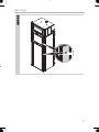 3
3
-
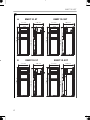 4
4
-
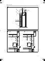 5
5
-
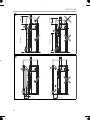 6
6
-
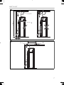 7
7
-
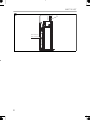 8
8
-
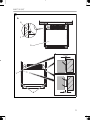 9
9
-
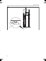 10
10
-
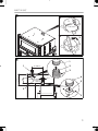 11
11
-
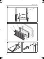 12
12
-
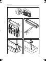 13
13
-
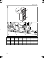 14
14
-
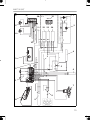 15
15
-
 16
16
-
 17
17
-
 18
18
-
 19
19
-
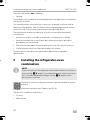 20
20
-
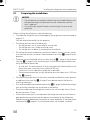 21
21
-
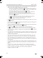 22
22
-
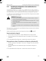 23
23
-
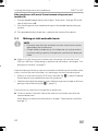 24
24
-
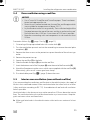 25
25
-
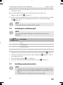 26
26
-
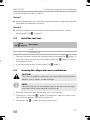 27
27
-
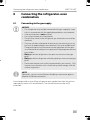 28
28
-
 29
29
-
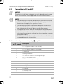 30
30
-
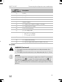 31
31
-
 32
32
-
 33
33
-
 34
34
-
 35
35
-
 36
36
-
 37
37
-
 38
38
-
 39
39
-
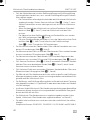 40
40
-
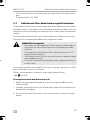 41
41
-
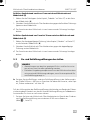 42
42
-
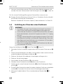 43
43
-
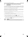 44
44
-
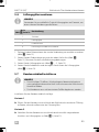 45
45
-
 46
46
-
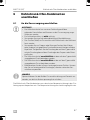 47
47
-
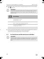 48
48
-
 49
49
-
 50
50
-
 51
51
-
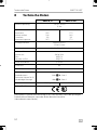 52
52
-
 53
53
-
 54
54
-
 55
55
-
 56
56
-
 57
57
-
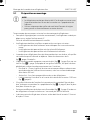 58
58
-
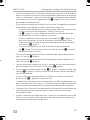 59
59
-
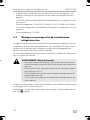 60
60
-
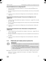 61
61
-
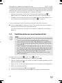 62
62
-
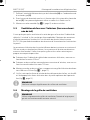 63
63
-
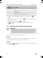 64
64
-
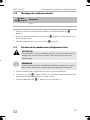 65
65
-
 66
66
-
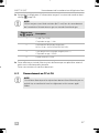 67
67
-
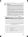 68
68
-
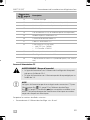 69
69
-
 70
70
-
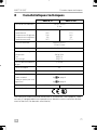 71
71
-
 72
72
-
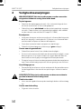 73
73
-
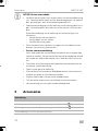 74
74
-
 75
75
-
 76
76
-
 77
77
-
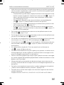 78
78
-
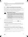 79
79
-
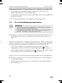 80
80
-
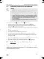 81
81
-
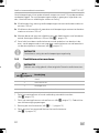 82
82
-
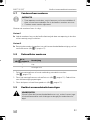 83
83
-
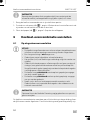 84
84
-
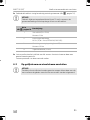 85
85
-
 86
86
-
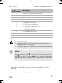 87
87
-
 88
88
-
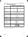 89
89
-
 90
90
-
 91
91
-
 92
92


Dometic RMDT10.5T, RMDT10.5XT Installatie gids
- Categorie
- Koelkasten
- Type
- Installatie gids
in andere talen
Gerelateerde papieren
-
Dometic RML10.4, RML10.4S, RML 10.4T Installatie gids
-
-
-
-
-
-
-
-
Dometic RM5310, RM5330, RM5380, RM5385 Installatie gids