
Passion.Technology.Design.
IT
MANUALE
TECNICO
EN
TECHNICAL
MANUAL
FR
MANUEL
TECHNIQUE
NL
TECHNISCHE
HANDLEIDING
DE
TECHNISCHES
HANDBUCH
ES
MANUAL
TÉCNICO
Unità di controllo accessi art. SK9001I
Access control unit art. SK9001I
Module contrôle d’accès art. SK9001I
Toegangscontrolemodule art. SK9001I
Einzeltϋr steuereinheit art. SK9001I
Módulo de control de accesos art. SK9001I

2
IT
Descrizione generale
SK9001l è un'unità di controllo autonoma con lettore integrato che
consente di gestire le chiavi elettroniche SK9050, SK9051 e SK9052.
È utilizzata per controllare l'accesso ad una porta dotata di serratura
elettrica o un automatismo.
È fornita pronta per l'uso. L'inizializzazione dell'unità si effettua
passando il primo badge programmato con il software SIMPLEKEY
ADVANCED davanti all'unità collegata per la prima volta. Gli altri
badge saranno poi salvati automaticamente in memoria al loro primo
passaggio.
Struttura dell'unità
La scheda è fornita di:
• 1 deviatore per accedere alla programmazione
• 3 pulsanti che vengono usati per cambiare i parametri
• 3 LED che mostrano gli stati dell’unità
• le morsettiere
• 1 connettore (J5) per l’aggiornamento firmware
1
Descrizione dei morsetti
AL: Alimentazione 12 - 33 V CC o 12 - 24 V CA
J1: Rete RS485
J2: Uscita relè NA/NC
J3: pulsante di uscita + allarme
J4: lettore integrato
PROGRAMMAZIONE
Il deviatore S3 è utilizzato per entrare in programmazione:
S3 in posizione “0” Modalità operativa
S3 in posizione “ON” Modalità di programmazione
Nota: In modalità di programmazione il LED L2 e il LED del lettore
lampeggiano rapidamente.
Per gestire gli accessi l’unità deve essere in modalità operativa.
Modifica del tempo di apertura
- Spostare il deviatore S3 su “ON” (programmazione)
- Premere S1 ripetutamente per impostare il tempo di apertura
(un secondo per ogni pressione). Successivamente, rimettere
S3 in modalità operativa. Un doppio bip confermerà la riuscita
dell’operazione.
Il tempo minimo impostabile è 1 secondo.
Il tempo massimo impostabile è 99 secondi.
Il tempo di apertura è impostato di fabbrica a 5 secondi.
Gestione dei badge residenti
Per funzionare sull'unità SK9001l, i badge devono essere programmati
con il software SIMPLEKEY ADVANCED fornito nel kit SK9091.
Per la programmazione, fare riferimento al manuale del software.
1. Inizializzazione
L'unità SK9001l è fornita vergine e deve essere inizializzata.
A tal fine, basta collegarla all'alimentazione e passare uno dei
badge programmati davanti al lettore. L'unità resta in modalità di
programmazione per alcuni secondi (il LED rosso e quello verde
lampeggiano contemporaneamente) mentre l'unità registra il Codice
edificio e il Codice installazione.
Quando l'unità sarà ritornata alla Modalità operativa normale, tutti i
badge dello stesso edifi cio saranno in grado di aprire la porta senza
ulteriore programmazione e i corrispondenti parametri saranno
memorizzati automaticamente alla loro prima presentazione.
N.B.: Programmazione Multi-edificio:
Nel caso abbastanza frequente di edifi ci con un ingresso principale
e alcuni ingressi secondari, è possibile programmare e autorizzare
badge appartenenti a edifi ci diversi (massimo 30). A tal fine, basta
passare davanti all'unità, uno dopo l'altro, i badge appartenenti a
edifici diversi con l'unità in Modalità di Programmazione per la sua
inizializzazione. In questo modo l'unità sarà programmata con Codici
edificio multipli e tutti i badge di questi edifi ci potranno aprire la porta.
Per Aggiunta di codici edificio vedi punto 6.
2. Aggiunta di un badge
Per aggiungere un badge, basta programmarlo nel software
SIMPLEKEY e presentarlo al lettore. I corrispondenti parametri
saranno registrati automaticamente.
3. Sostituzione di un badge
Per eliminare un badge, basta selezionarlo nel software SIMPLEKEY
per cancellarlo e riprogrammare un nuovo badge. Al primo
utilizzo del nuovo badge, i corrispondenti parametri sostituiranno
automaticamente quelli del vecchio badge.
4. Modifica dei parametri di un badge
Per modifi care i parametri di un badge, basta selezionarlo nel
software SIMPLEKEY e riprogrammarlo. I corrispondenti parametri
saranno automaticamente aggiornati al suo successivo utilizzo.
S1: Tempo
S2: RAZ
S3: Prog
S4: Reset
Ingresso allarme
Ingresso allarme
Massa
• Questo prodotto Comelit è progettato e realizzato con lo scopo di essere utilizzato nella realizzazione di impianti per comunicazione audio e video in edifici
residenziali, commerciali, industriali e in edifici pubblici o ad uso pubblico.
• Tutte le attività connesse all’installazione dei prodotti Comelit devono essere realizzate da personale tecnicamente qualificato, seguendo attentamente le
indicazioni di manuali / istruzioni dei prodotti stessi.
• Togliere l’alimentazione prima di effettuare qualsiasi operazione.
• Utilizzare conduttori con sezione adeguata in funzione delle distanze, rispettando le indicazioni riportate nel manuale di sistema.
• Si consiglia di non posare i conduttori per l’impianto nella stessa tubazione dove transitano i cavi di potenza (230V o superiori).
• Per l’utilizzo sicuro dei prodotti Comelit è necessario: seguire con attenzione le indicazioni di manuali e istruzioni; curare che l’impianto realizzato con i
prodotti Comelit non sia manomesso / danneggiato.
• I prodotti Comelit non prevedono interventi di manutenzione ad eccezione delle normali operazioni di pulizia, da effettuarsi comunque secondo quanto
indicato in manuali / istruzioni. Eventuali riparazioni devono essere effettuate: per i prodotti, esclusivamente da Comelit Group S.p.A., per gli impianti, da
personale tecnicamente qualificato.
• Comelit Group S.p.A. non assume alcuna responsabilità per usi differenti da quello previsto e mancato rispetto di indicazioni ed avvertenze presenti in
questo manuale / istruzioni. Comelit Group S.p.A. si riserva comunque il diritto di modificare in qualsiasi momento e senza preavviso quanto descritto nel
presente manuale / istruzioni.
Avvertenze

3
IT
5. Reinizializzazione dei dati
- Portare il deviatore S3 su “ON” (Programmazione)
- Per il reset totale, premere S2 per 15 secondi. Il LED L2 si spegne e
dopo 15 secondi si accende il LED L3. L’unità in tal modo si resetta
completamente.
- Ritornare alla modalità operativa (un doppio bip confermerà la
riuscita dell’operazione).
Il reset totale abilita l’inizializzazione dell’unità:
- password di accesso all’unità « 0000 ».
- eliminazione dei badge utente.
6. Aggiunta di codici edificio
(Programmazione valida dalla versione V3.2 di SK9001I)
Nel caso di programmazione Multi-Edificio è possibile aggiungere dei
codici edificio (massimo 30) anche dopo la fase di inizializzazione.
I codici edificio già presenti nella centrale non subiranno modifiche.
- Spostare il deviatore S3 su “ON” (Programmazione)
- Tener premuto il tasto S2 per 5 secondi
- Rilasciare nel momento in cui inizia a suonare il buzzer
- Presentare al lettore i nuovi badge contenenti i nuovi codici edificio
Dopo 15 secondi di inattività il buzzer si spegnerà per indicare che la
fase di "Aggiunta codici edificio" è terminata
- Rimettere lo switch S3 su OFF.
7. Regolazione della data e dell’ora
Per funzionare correttamente, l’orologio interno dell’unità SK9001l
deve essere tassativamente regolato. L’orologio è regolato in fabbrica
sull’ora universale (GMT) e si imposterà automaticamente sul fuso
corrispondente al luogo di utilizzo al momento dell’inizializzazione
(presentazione della prima chiave).
Se necessario, tuttavia, è possibile regolare la data e l’ora manualmente
mediante il software SK9093 fornito separatamente. A tal fine, basta
collegare all’unità il cavo fornito nel kit e lanciare il programma.
- Cliccare su « orologio » e seguire le istruzioni per modificare la
regolazione.
- Sono disponibili anche altre funzioni (modifica della password,
reinizializzazione dell’unità, ecc.). A tale proposito, fare riferimento alle
istruzioni del software.
FUNZIONI AVANZATE
Modalità « Porta Principale »
L’unità SK9001l può essere utilizzata per gestire la Porta principale in
modo che possa essere aperta da tutte le chiavi di un’installazione,
e non soltanto come nella programmazione Multi-edifi cio per edifici
diversi (per es. Accesso a un’abitazione, ecc.).
Per inizializzare un’unità SK9001l in Modalità « Porta principale »,
premere il pulsante S2 dell’unità per 5 secondi fi no ad avvertire un
bip. A questo punto, tutti i badge appartenenti alla stessa installazione
del primo badge presentato apriranno la Porta principale.
È sempre possibile ritornare alla modalità normale (edificio o
multiedificio) premendo nuovamente il pulsante S2 per 5 secondi fino
ad avvertire un doppio bip (che indica che l’unità è nuovamente in
Modalità di funzionamento normale).
Gestione degli eventi
L’unità SK9001l conserva in memoria gli ultimi 1400 eventi (accesso
autorizzato, accesso rifi utato, badge annullato, ecc.).
Gli eventi possono essere richiamati utilizzando un badge di
trasferimento (rif. SK9053) fornito separatamente. Dopo averlo
inizializzato con il software SIMPLEKEY ADVANCED, posizionare il
badge di trasferimento davanti al lettore fi nché il LED rosso smette di
lampeggiare. Una volta caricato, è suffi ciente posizionarlo
sull’encoder collegato al microcomputer e seguire le istruzioni del
software per trasferire gli eventi nel database.
Allarme
L’unità SK9001l dispone di una funzione di allarme in grado di
attivare un dispositivo di segnalazione. La funzione di allarme si attiva
all’apertura di un contatto azionando il dispositivo di segnalazione.
La funzione si disattiva per 1 minuto ogni qualvolta è autorizzato un
accesso mediante badge o pulsante di uscita.
Questo consente l’attivazione immediata dell’allarme in caso di
forzatura della porta o l’attivazione dopo 1 minuto quando la porta
resta aperta dopo un passaggio autorizzato.
Quando si utilizza la Funzione di allarme, il jumper JP1 dell’unità
deve essere rimosso.
N.B.: non è necessario collegare gli ingressi e le uscite di allarme
dell’unità se questa funzione non è utilizzata.
Modalità ascensore
L'unità SK9001l può essere utilizzata insieme a scatole relè SK9071
per controllare i comandi ai piani di un ascensore.
La funzione deve essere stata attivata nel software SIMPLEKEY e sui
badge codifi cati dopo aver selezionato i piani autorizzati.
Si possono collegare fi no a 12 scatole relè SK9071 su un'unità per il
controllo di 120 piani.
Modalità di collegamento
È possibile collegare in rete le diverse unità di un'installazione per
gestire le seguenti funzioni a partire dal microcomputer di gestione:
• Modifica dei parametri delle unità
• Regolazione della data e dell'ora
• Richiamo degli eventi
• Comando di apertura remota
• Eliminazione immediata di un badge perduto
È possibile gestire fino a 254 unità in rete su un'installazione.
• Rete cablata RS485 con il convertitore USB rif. SK9073. Ogni
convertitore può gestire fi no a 32 unità. È indispensabile riportare
sull'unità l'indirizzo logico corrispondente a quello riportato sul
software. A tal fi ne, utilizzare il pulsante S1 impartendo il numero di
impulsi corrispondente all'indirizzo (da 1 a 254), quindi confermare
mantenendo premuto il pulsante S1 per 5 secondi.
Per l'uso dettagliato delle funzioni, fare riferimento alle istruzioni del
software SIMPLEKEY ADVANCED
Funzionamento normale dell'unità
Quando l'unità è in Modalità operativa normale, 2 LED all'interno
dell'unità lampeggiano e il LED rosso sul lettore è acceso.
Se l'unità non funziona correttamente, questi LED forniscono segnali
diversi. In tal caso, togliere e ridare alimentazione.
Se questo non è sufficiente, contattare l'assistenza tecnica.
Caratteristiche tecniche
• Tempo di apertura regolabile da 1 a 99 secondi
• Uscita a contatto pulito max 5A a 12-24V CA/CC
• Assorbimento: 70 mA a riposo, 160 mA con relè attivo
• Temperatura di funzionamento: -30°c / +55°c
• Tensione di funzionamento : 12-33V CC o 12-24V CA
• Dimensioni (A x L x P) : 62 x 88 x 23 mm

4
EN
General introduction
The SK9001l unit is a stand-alone control unit with an integral reader
which is used to manage the electronic keys SK9050, SK9051 and
SK9052. It is used to control access to a door fitted with an electronic
lock or an automatic device.
It is supplied ready for use. It is initialised by swiping the first token
programmed with the SIMPLEKEY ADVANCED software over the
unused unit. The other tokens are then saved automatically in the
memory when they are first swiped.
Layout of the unit
The card is made up of:
• a switch used to access the programming
• three push buttons that are used to affect the parameters
• the three LED’s that show the statuses of the switchboard
• connection terminals
• a J5 firmware update connector
1
Description of terminals
AL: Power supply 12 - 33 V DC or 12 - 24 V AC
J1: RS485 network
J2: NO/NC relay output
J3: Exit push button + alarm
J4: Integral reader
PROGRAMMING
The S3 switch is used to switch between programming modes:
S3 in “0” position Operating mode
S3 in “ON” position Programming mode
NOTE: In programming mode the L2 LED and the reader LED flash
rapidly.
You must go back to operating mode for the unit to manage access
Setting the opening timer
- Set switch S3 to “ON” (Programming)
- Press button S1 several times to adjust the time units (one press
per second). Once S3 has switched back to operating mode a double
confirmation beep will validate this for you.
The minimum timing setting is 1 second.
The maximum timing setting is 99 seconds.
The unit is supplied with a 5 second opening time set by the factory.
User token management
The tokens must be programmed using the SIMPLEKEY ADVANCED
software contained in the SK9091 kit so that they can work on the
SK9001l unit. Refer to the software programming instructions.
1. Initialisation
The SK9001l is supplied blank and must be initialised. To do this, you
just have to plug it in, turn it on and swipe one of the programmed
token to the reader. The unit will remain in PRG mode for few seconds
( Green and Red LEDs flushing simultaneously ), because the units is
recoding Building Code and Site Code of the token.
Once back to normal operating mode, all tokens of the same
Building will open the door without any other programming and their
parameters will be stored automatically as they are first swiped.
NOTE: Multi-Building Programming:
Typically for situation with Main and Secondary entrances, for Main
entrance Reader it is possible to program and authorise tokens from
several Buildings ( Max 30 ). To do this we simply have to swipe, one
after the other, tokens from different Buildings, while the unit is in PRG
mode for Initialisation.
In this way the unit will be programmed with more Building Codes and
all tokens of those Buildings can open the door.
See step 6 for Adding building codes.
2. Adding a token
To add a token later you just have to programme it into the SIMPLEKEY
software and swipe it past the reader. Its parameters will be recorded
automatically.
3. Replacing a token
To delete a token you just have to select its location in the SIMPLEKEY
software and re-programme a new token. Its parameters will
automatically replace the old one when it is first used.
4. Modifying a token’s parameters
To modify a token’s parameters you just have to select it from the
SIMPLEKEY software and re-programme it. Its parameters will be
updated automatically when it is first used.
S1: Time
S2: Reset
S3: Prog
S4: Restart
Alarm input
Alarm output
Ground
• This Comelit product was designed for use in the creation of audio and video communication systems in residential, commercial or industrial settings and in
public buildings or buildings used by the public.
• All activities connected to the installation of Comelit products must be carried out by qualified technical personnel, with careful observation of the indications
provided in the manuals / instruction sheets supplied with those products.
• Cut off the power supply before carrying out any maintenance procedures.
• Use wires with a cross-section suited to the distances involved, observing the instructions provided in the system manual.
• We advise against running the system wires through the same duct as the power cables (230V or higher).
• To ensure Comelit products are used safely: carefully observe the indications provided in the manuals / instruction sheets and make sure the system created
using Comelit products has not been tampered with / damaged.
• Comelit products do not require maintenance aside from routine cleaning, which should be carried out in accordance with the indications provided in the
manuals / instruction sheets. Any repair work must be carried out: for the products themselves, exclusively by Comelit Group S.p.A., for systems, by
qualified technical personnel.
• Comelit Group S.p.A. does not assume any responsibility for: any usage other than the intended use; non-observance of the indications and warnings
contained in this manual / instruction sheet. Comelit Group S.p.A. nonetheless reserves the right to change the information provided in this manual /
instruction sheet at any time and without prior notice.
Warning

5
EN
5. Complete reset
- Set switch S3 to “ON” (Programming)
- To reset to zero completely, press S2 for 15 seconds. The L2 LED
will go out and after 15 seconds the L3 LED will come on. The unit
has been totally reset to zero.
- Switching back to operating mode (a double beep tells you that the
unit has been reset).
Complete resetting enables the initialisation process:
- the password to access the switchboard is “0000”.
- deleting user tokens.
6. Adding building codes
(Programming valid from version V3.2 of SK9001I)
In the case of Multi-Building programming it is possible to add
building codes (up to a maximum of 30) after the initialisation stage.
The building codes already present in the control panel will not be
modified.
- Set switch S3 to “ON” (Programming)
- Hold pressed key S2 for 5 seconds
- release it as soon as the buzzer sounds
- Present to the reader the new badges containing the new building
codes
After 15 seconds of inactivity the buzzer will switch off to indicate that
the “Add Building Codes” stage has terminated.
- Reset switch S3 to OFF
7. Setting the date and time
To work properly the SK9001l unit’s internal clock must be set
correctly. This is set in the factory to GMT time (universal time) and
will be adjusted automatically to the corresponding time zone in the
place it is being used when it is initialised (first key swiped).
If necessary, it is, however, possible to set the time and date manually
using the SK9093 software supplied separately. To do this you just
have to connect to the unit using the cable supplied with the kit and
launch the program.
- Click on “Clock” and then follow the instructions to change the
setting.
- Other functions are possible (changing the password, resetting the
unit etc.). Refer to the software instructions.
ADVANCED FUNCTIONS
“Main SITE Door” mode
The SK9001l unit can be used to control the Main Door which may be
opened by all keys on a site, not only many Buildings as Multi-Building
programming (e.g. Access to residence, Gated Community etc.).
To initialise a SK9001l unit in “Main SITE Door” mode, press S2 button
on the unit for 5 seconds, until you hear a beep. In this moment, all
tokens of the same site of the 1st swiped one will open the Main Site
door.
It is always possible to switch back to normal mode (Building or Multi-
Building Door) by pressing S2 button again for 5 seconds, until you
hear a double beep (which indicates that you are back to normal
operation mode).
Event management
The SK9001l unit stores the last 1400 events in its memory (access
authorised, access refused, cancelled token etc.).
It is possible to retrieve them using a transfer token (ref. SK9053)
supplied separately. After initialising it with the SIMPLEKEY
ADVANCED software, place the transfer token in front of the reader
until the red LED stops flashing. Once saved, you just have to put it
in the encoder linked to the micro-computer and follow the software
instructions to transfer the events in the database.
Alarm
The SK9001l unit has alarm functions which may be used to trigger
an alarm device.
This is how to use it. When the alarm input is triggered by a contact
opening, the output is activated. This function is disabled for 1 minute
each time access by token or an exit push button is validated.
This allows the alarm to be triggered immediately if the door is forced
or after 1 minute if the door is still open after an authorised entry.
When Alarm Function it is used, JP1 jumper on the unit must be
removed.
NOTE: It is not necessary to wire the unit alarm inputs and outputs
if this function is not used.
Lift mode
The SK9001l unit can be used to control the SK9071 relay boxes in
order to control the lift floor commands.
The function must have been enabled in the SIMPLEKEY software
and the tokens coded after selecting the authorised floors.
It is possible to connect up to 12 SK9001l boxes to one unit which
enables 120 floors to be controlled.
Network Mode
It is possible to network the various system units in order to
take advantage of the following functions from the management
microcomputer:
• Modifying unit parameters
• Setting the date and time
• Retrieving events
• Remote opening command
• Immediate deletion of a lost token
It is possible to network up to 254 units in one system.
• An RS485 wired network using a USB converter ref. SK9073 (one
per system) - a maximum of 32 units.
It is vital to record on the unit the same logical address as the one
recorded in the software. To do this use the S1 push button giving the
pulse number corresponding to the address (between 1 and 254) then
validate it by holding the S1 push button down for 5 seconds.
For detailed use of the functions please refer to the SIMPLEKEY
ADVANCED software instructions.
Normal working of the unit
When the unit is in normal Operating Mode, 2 LEDs inside the units
are flushing and the Red LED on the reader is ON.
If the unit is not working properly, these LEDs are giving different
indications. In this case turn the power OFF and then ON again. If
this does not work, please contact our after sales service department.
Technical characteristics
• Opening time can be adjusted from between 1 and 99 seconds
• Output via dry contact max. 5A 12-24V AC/DC
• Power consumption: 70 mA when idle, 160 mA when relay active
• Operating temperature: -30°C - +55°C
• Operating voltage: 12-33V DC or 12-24V AC
• Dimensions (H X L X D): 62 x 88 x 23 mm

6
FR
• Ce produit Comelit a été conçu et réalisé pour être utilisé dans la réalisation d'installations de communication audio et vidéo dans des bâtiments résidentiels,
commerciaux, industriels et publics ou à usage public.
• Toutes les opérations liées à l'installation des produits Comelit sont réservées à des techniciens qualifiés qui devront suivre attentivement les consignes des
Manuels / Instructions desdits produits.
• Couper l'alimentation avant d'effectuer toute opération.
• Utiliser des conducteurs d'une section adéquate en fonction des distances et en respectant les explications contenues dans le manuel du système.
• Il est conseillé de ne pas poser les conducteurs destinés à l’installation dans la canalisation destinée aux câbles de puissance (230 V ou plus).
• Pour utiliser les produits Comelit en toute sécurité : suivre attentivement les consignes contenues dans les Manuels / Instructions; s'assurer que l’installation
réalisée avec les produits Comelit n'est pas sabotée / endommagée.
• Les produits Comelit sont sans maintenance, exception faite pour les opérations de nettoyage qui devront être effectuées selon les consignes contenues
dans les Manuels / Instructions. Les réparations concernant : les produits, sont réservées exclusivement à Comelit Group S.p.A., les installations, sont
réservées à des techniciens qualifiés.
• Comelit Group S.p.A. ne sera pas tenue pour responsable en cas d'utilisation contraire aux indications, de non-respect des indications et des
recommandations présentes dans ce Manuel / Instructions. Comelit Group S.p.A. se réserve le droit de modifier à tout moment et sans préavis le contenu
de ce Manuel / Instructions.
Avertissements
Présentation générale
Le module SK9001l est une unité de contrôle autonome avec antenne
de lecture intégré qui permet de gérer les clés électroniques SK9050,
SK9051 et SK9052. Il permet de contrôler l’accès à une porte équipée
d’une serrure électrique ou un dispositif automatique.
Il est livré prêt à fonctionner. L’initialisation est réalisée par
présentation du premier badge programmé à l’aide du logiciel
SIMPLEKEY ADVANCED sur la centrale vierge ; Les autres badges
sont ensuite mémorisés automatiquement en mémoire lors de leur
premier passage.
Présentation du module
La carte est composée :
• d’un switch permettant d’accéder à la programmation
• de trois poussoirs permettant d’agir sur les paramètres
• de trois voyants LED rouges indiquant les états de la centrale
• de borniers de raccordement
• d’un connecteur de mise à jour du firmware J5
1
Description des bornes
AL : Alimentation 12 à 33 V CC ou 12 à 24 V CA
J1 : Réseau RS485
J2 : Sortie relais NO/NF
J3 : poussoir de sortie + alarme
J4 : antenne intégrée
PROGRAMMATION
Le switch S3 permet de basculer en mode de programmation :
S3 en position "0" Mode fonctionnement
S3 en position "ON" Mode programmation
Nota : En mode programmation le voyant L2 ainsi que celui de la tête
de lecture clignotent rapidement.
Pour que la centrale puisse gérer les accès, il faut impérativement
revenir en mode fonctionnement
Réglage de la temporisation d’ouverture
- Mettre le switch S3 sur "ON" (Programmation)
- Appuyer plusieurs fois sur le bouton S1 pour régler les unités de la
temporisation (un appui par seconde). Une fois S3 rebasculé en mode
fonctionnement, un double bip de confirmation vous informe de la
validation.
La valeur minimum de la temporisation est de 1 seconde.
La valeur maximum de la temporisation est de 99 secondes.
Le module est livré avec un réglage d'usine de temporisation
d’ouverture de 5 secondes.
Gestion des badges résidents
Il est nécessaire de programmer les badges à l’aide du logiciel
SIMPLEKEY ADVANCED contenu dans le kit SK9091 pour qu’ils
puissent fonctionner sur le module SK9001l.
Reportez-vous à la notice du logiciel pour la programmation.
1. Initialisation
Le SK9001l est fourni vierge et doit être initialisé. Pour faire cela vous
devez simplement le connecter à l’alimentation et présenter au lecteur
un des badges programmés. Le module restera en Programmation
pendant quelques secondes (la LED rouge et elle verte clignoteront au
même temps), car le module est en train de recoder le Code Immeuble
et le Code Installation.
Une fois revenu au Mode de Fonctionnement normal, tous le badges
du même immeuble ouvrira la porte sans autre programmation et leur
paramètres seront mémorisés automatiquement lors de leur première
présentation.
Nota : Programmation Multi - Immeubles :
Dans une situation assez typique avec une Entrée Principale et des
Entrées Secondaires il est possible de programmer et autoriser des
badges appartenant à des immeubles différents (30 Maximum). Pour
faire cela on doit simplement présenter au module, un après l’autre,
les badges provenant d’immeubles différents tandis que le module
est en Programmation pour son Initialisation. De cette façon le
module sera programmé avec plusieurs Codes Immeuble, et tous les
badges de ces immeubles pourront ouvrir la Porte.
Voir point 6 pour “Ajout de codes immeuble”.
2. Ajout d'un badge
Pour ajouter ultérieurement un badge, il suffit de le programmer sur
le logiciel SIMPLEKEY et de le présenter devant l’antenne de lecture.
Ses paramètres seront automatiquement enregistrés.
3. Remplacement d’un badge
Pour supprimer un badge, il suffit de sélectionner son emplacement
sur le logiciel SIMPLEKEY et de reprogrammer un nouveau badge.
Ses paramètres viendront automatiquement remplacer l’ancien lors
de sa première utilisation.
S1: Tempo.
S2: RAZ
S3: Prog
S4: Reset
Alarm input
Alarm output
Masse

7
FR
4. Modification des paramêtres d’un badge
Pour modifier les paramètres d’un badge, il suffit de le sélectionner
sur le logiciel SIMPLEKEY et de le reprogrammer. Ses paramètres
seront automatiquement mis à jour lors de sa prochaine utilisation.
5. Réinitialisation des données
- Mettre le switch S3 sur "ON" (Programmation)
- Pour la remise à zéro totale, appuyer sur S2 pendant 15 secondes,
le voyant L2 s’éteint, après 15 secondes le voyant L3 s’allume. La
remise à zéro totale est effectuée.
- Rebasculer en mode fonctionnement. (Un double bip vous informe
de la remise à zéro)
La remise à zéro permet l’initialisation :
- mot de passe d’accès à la centrale à « 0000 ».
- suppression des badges utilisateurs.
6. Ajout de Codes Immeuble
À partir de la version V3.2 du SK9001I.
Dan le cas de Programmation Multi - Immeubles, il est possible
d’ajouter des Codes immeubles après la phase d’initialisation initiale.
Ceci sans affecter les codes immeubles déjà présent dans la centrale.
- Mettre le switch S3 sur « ON » (Programmation)
- Appuyer sur le bouton S2 pendant 5 secondes, le buzzer va alors
retentir toutes les secondes
- Relâcher le bouton dès l’apparition du buzzer
- Présenter les nouveaux badges contenant les nouveaux Codes
immeubles
Après 15 secondes sans aucune présentation de badge, le buzzer s’arrête
pour indiquer que la phase d’ajout de Codes immeuble est terminé.
- Remettre alors le switch S3 sur « OFF »
7. Réglage de la date et l’heure
Pour fonctionner correctement, l’horloge interne du module SK9001l
doit impérativement être correctement réglé. Celui-ci est réglé en
usine à l’heure GMT (temps universel) et sera automatiquement
ajusté sur le fuseau correspondant au lieu d’utilisation au moment de
l’initialisation (présentation de la première clé).
En cas de nécessité, il est toutefois possible d’agir manuellement
sur le réglage de la date et l’heure à l’aide du logiciel SK9093 fourni
séparément. Pour cela, il suffit de se connecter à la centrale à l’aide
du cordon livré avec le kit et de lancer le programme.
- Cliquez sur « horloge » puis suivez les instructions pour modifier le
réglage.
- D’autres fonctions sont possibles (changement du mot de passe,
réinitialisation du module, etc.) reportez-vous aux instructions du
logiciel.
FONCTIONS AVANCÉES
Mode « Porte Principale »
Le module SK9001l peut être utilisé pour gérer la Porte Principale,
qui peut être ouverte par tous les clés sur une installation, et pas
seulement plusieurs Immeubles comme la programmation Multi –
Immeubles (ex. Accès à une résidence, etc.).
Pour initialiser un module SK9001l en Mode « Porte Principale », appuyez
sur le bouton S2 du module pendant 5 secondes, jusqu’à ce que vous
entendez un bip. Maintenant tous les badges appartenant à la même
installation du premier badge présenté ouvriront la Porte Principale.
Il est toujours possible de basculer au mode normal (Immeuble ou
Multi – Immeubles) en appuyant sur le bouton S2 de nouveau pendant
5 secondes, jusqu’à ce que vous entendez un double bip (qui indique
que le module est de nouveau en Mode de Fonctionnement normal).
Gestion des événements
Le module SK9001l garde en mémoire les 1400 derniers événements
(accès autorisé, accès refusé, badge annulé, etc.).
Il est possible de les récupérer à l’aide d’un badge de transfert ref.
SK9053 fourni séparément. Après l’avoir initialisé depuis le logiciel
SIMPLEKEY ADVANCED, placez le badge de transfert devant
l’antenne de lecture jusqu’à ce que la LED rouge arrête de clignoter.
Une fois chargé, il suffit de le poser sur l’encodeur relié au
microordinateur et suivre les instructions du logiciel pour transférer
les événements sur la base de donnée.
Alarme
Le module SK9001l dispose de fonctions d’alarme qui peuvent être
utilisées pour déclencher un dispositif d’alerte. L’utilisation est la
suivante : lorsque l’entrée d’alarme est actionnée par l’ouverture d’un
contact, la sortie est activée. Cette fonction est désactivée durant 1
minute à chaque fois qu’un accès par badge ou poussoir de sortie
est validé.
Ceci permet de déclencher l’alerte immédiatement en cas de porte
forcée ou après 1 minute lorsque la porte est restée ouverte après un
passage autorisé.
Quand on utilise la Fonction Alarme, le jumper JP1 du module doit
être enlevé.
Nota : il n’est pas nécessaire de câbler les entrées et sorties alarme
du module si cette fonction n’est pas utilisée.
Mode ascenseur
Le module SK9001l peut être utilisé pour commander les boîtiers relais
SK9071 afin de contrôler les commandes d’étages d’un ascenseur.
La fonction doit avoir été activé sur le logiciel SIMPLEKEY et les
badges encodés après avoir sélectionné les étages autorisés.
Il est possible de raccorder jusqu’à 12 boîtiers SK9071 sur un module,
permettant de contrôler 120 étages.
Mode connecté
Il est possible de raccorder en réseau les différents modules d’une
installation afin de bénéficier des fonctions suivantes depuis le
microordinateur
de gestion :
• Modification des paramètres des modules
• Réglage de la date et l’heure
• Récupération des événements
• Commande d’ouverture distante
• Suppression immédiate d’un badge perdu
Il est possible de gérer jusqu’à 254 modules en réseau sur une
installation.
• Réseau filaire RS485 à l’aide du convertisseur USB ref.
SK9073. Chaque convertisseur peut gérer jusqu'à 32 modules. Il
est indispensable de renseigner sur le module l’adresse logique
correspondant à celle inscrite sur le logiciel. Pour ce faire, utilisez
le poussoir S1 en donnant le nombre d’impulsion correspondant
à l’adresse. (de 1 à 254) puis validez en maintenant le poussoir S1
pendant 5 secondes.
Pour l’utilisation détaillée des fonctions, reportez-vous aux instructions
du logiciel SIMPLEKEY ADVANCED
Fonctionnement normal du module autonome
Quand le module est en Mode de Fonctionnement normale, 2 LED
à l’intérieur du module clignotent et la LED Rouge sur le lecteur est
allumée.
Si le module ne fonctionne pas correctement, ces LEDs donneront
des indications différentes. En ce cas éteignez l’alimentation et après
allumez-la de nouveau. Si cela ne fonctionne pas, veuillez s’il –vous -
plaît contacter notre Service Après - Ventes.
Caractéristiques techniques
• Réglage de la temporisation d’ouverture entre 1 et 99 secondes
• Sortie par contact sec maxi 5A 12-24V CA/CC
• Consommation : 70 mA au repos, 160 mA relais actif
• Température de fonctionnement : -30°c à +55°c
• Tension de fonctionnement : 12 à 33V CC ou 12 à 24V CA
• Dimension (h x l x p) : 62 x 88 x 23 mm

8
NL
Waarschuwingen
• Dit product van Comelit is ontworpen en ontwikkeld om te worden gebruikt bij de realisatie van audio- en videocommunicatiesystemen In woningen,
winkels, bedrijven en openbare gebouwen of in openbare ruimtes.
• Alle functies die zijn aangesloten op de installatie van de Comelit-producten moeten zijn uitgevoerd door gekwalificeerd technisch personeel, volgens de
aanwijzingen in de handleiding/instructies van de betreffende producten.
• Sluit de voeding af voordat u onderhoudswerkzaamheden uitvoert.
• Gebruik geleiders met een geschikte doorsnede, afhankelijk van de afstanden, volgens de aanwijzingen in de handleiding van de installatie.
• Het is raadzaam om de geleiders voor de installatie in dezelfde leiding te plaatsen als die waar de vermogenskabels (230V of hoger) doorheen lopen.
• Voor een veilig gebruik van de producten Comelit is het volgende noodzakelijk: het zorgvuldig opvolgen van de aanwijzingen in de handleiding/instructies,
ervoor zorgen dat de installatie die met de Comelit-producten is uitgevoerd niet wordt gesaboteerd / beschadigd raakt.
• De producten van Comelit hebben geen onderhoud nodig, behalve de normale reiniging, welke moet worden uitgevoerd zoals is aangegeven in de
handleiding/instructies. Eventuele reparaties moeten worden uitgevoerd voor de producten, uitsluitend door Comelit Group S.p.A., voor de installatie,
door gekwalificeerd technisch personeel.
• Comelit Group S.p.A. is niet verantwoordelijkheid voor andere toepassingen dan het beoogde gebruik, het niet in acht nemen van de aanwijzingen en
waarschuwingen in deze handleiding/instructies. Comelit Group S.p.A. behoudt zich het recht voor om op elk moment, zonder waarschuwing vooraf,
wijzigingen aan te brengen in deze handleiding/instructies.
Algemene informatie
De module SK9001l is een onafhankelijke regeleenheid met
eengeïntegreerde leesantenne voor het beheren van de elektronische
sleutels SK9050, SK9051 en SK9052. De module controleert
detoegang tot een deur met een elektrisch slot of een automatische
inrichting.
Hij wordt gebruiksklaar geleverd. De initialisatie vindt plaats
door deeerste met de SIMPLEKEY ADVANCED-software
geprogrammeerde badge voor de lege centrale te houden. De andere
badges wordenvervolgens automatisch in het geheugen opgeslagen
op het moment dat zij voor het eerst worden gebruikt.
Beschrijving van de module
De kaart bestaat uit:
• een switch voor toegang tot de programmering
• drie drukknoppen voor het instellen van de parameters
• drie rode LED’s die de status van de centrale aangeven
• aansluitblokken
• een connector voor het updaten van de firmware J5
1
Beschrijving van de klemmen
AL: Voeding 12 - 33 V DC of 12 - 24 V AC
J1: Netwerk RS485
J2: Uitgang relais NO/NG
J3: Drukknop uitgang + alarm
J4: Geïntegreerde antenne
PROGRAMMERINGEN
Met de switch S3 kan worden overgeschakeld naar de
programmeermode:
S3 in positie “0” Bedrijfsmode
S3 in positie “ON” Programmeermode
Opmerking: In de programmeermode knipperen de LED L2 en de LED
van de leesknop snel.
De centrale moet altijd in de bedrijfsmode staan om de toegang te
kunnen beheren.
Regeling van de openingstijd
- Plaats de switch S3 op “ON” (Programmering)
- Druk meerdere keren op de drukknop S1 om de tijdseenheden in te
stellen (een druk per seconde). Staat S3 eenmaal in de bedrijfsmode,
dan wordt dit bevestigd door twee geluidssignalen.
De minimale tijdswaarde is 1 seconde.
De maximale tijdswaarde is 99 seconden.
Af fabriek wordt de module geleverd met een ingestelde openingstijd
van 5 seconden.
Beheer van residente badges
De badges moeten worden geprogrammeerd met de
SIMPLEKEYADVANCED-software die in kit SK9091 zit, zodat ze
kunnen werken op de module SK9001l.
Raadpleeg de gebruiksaanwijzing van de software voor informatie
over de programmering.
1. Initialisatie
De SK9001l wordt leeg geleverd en moet worden geïnitialiseerd.
Daarvoor hoeft u de module alleen maar op de voeding aan te sluiten
en een van de geprogrammeerde badges voor de lezer te houden.
De module blijft enkele seconden in Programmering staan (de rode
en de groende LED knipperen tegelijkertijd), omdat deze bezig is de
gebouwcode en de installatiecode te hercoderen.
In de normale bedrijfsmode zal met alle badges van hetzelfde gebouw
de deur kunnen worden geopend zonder verdere programmering
en de bijbehorende parameters worden automatisch opgeslagen
op het moment dat de badges voor het eerst worden gebruikt.
Opmerking: Meervoudige programmering - Gebouwen
In een typische situatie met een hoofdingang en secundaire ingangen
kunnen badges worden geprogrammeerd en geautoriseerd die tot
verschillende gebouwen behoren (maximaal 30). Daarvoor hoeven
alleen na elkaar de badges van de verschillende gebouwen voor de
module te worden gehouden, terwijl de module in de programmering
voor de initialisatie staat. Op deze wijze zal de module met meerdere
gebouwcodes worden geprogrammeerd en kan de deur met alle
badges van deze gebouwen worden geopend.
Zie punt 6 “Toevoegen van gebouwcodes”
2. Toevoegen van een badge
Moet er nog een badge worden toegevoegd, dan is het voldoende
deze met de SIMPLEKEY-software te programmeren en hem voor
de leesantenne te houden. De parameters van deze badge zullen
automatisch worden geregistreerd.
3. Vervangen van een badge
Om een badge te verwijderen, is het voldoende de locatie ervan in
de SIMPLEKEY-software te selecteren en een nieuwe badge te
herprogrammeren. De parameters van deze badge zullen op het
moment van het eerste gebruik automatisch de oude parameters
vervangen.
S1: Tijd
S2: Reset
S3: Prog
S4: Herstarten
Alarm input
Alarm output
Min

9
NL
4. Wijzigen van de parameters van een badge
Om de parameters van een badge te wijzigen, is het voldoende deze in de
SIMPLEKEY-software te selecteren en de badge teherprogrammeren.
De parameters van deze badge zullen automatisch worden bijgewerkt
op het moment dat die weer wordt gebruikt.
5. Herinitialiseren van gegevens
- Plaats de switch S3 op “ON” (Programmering)
- Druk voor een volledige nulstelling op S2 gedurende 15 seconden.
De LED L2 dooft en na 15 seconden gaat de LED L3 branden. De
volledige nulstelling is uitgevoerd.
- Omschakelen naar de werkingsmode. (Twee geluidssignalen geven
aan dat de nulstelling heeft plaatsgevonden)
De nulstelling maakt initialisatie mogelijk:
- het wachtwoord voor toegang tot de centrale kan worden
teruggesteld op «0000».
- de gebruikersbadges kunnen worden verwijderd.
6. Toevoegen van gebouwcodes
(Programmering geldt vanaf versie V3.2 van SK9001I)
Bij meervoudige programmering- gebouwen is het mogelijk om ook
na de initialisatiefase gebouwcodes toe te voegen (maximaal 30). De
reeds in de centrale aanwezige gebouwcodes veranderen niet.
- Zet de schakelaar S3 op "ON" (Programmering)
- Houd de toets S2 gedurende 5 seconden ingedrukt
- laat los zodra u de zoemer hoort
-
Houd de nieuwe badges met de nieuwe gebouwcodes voor de lezer
Na 15 seconden van inactiviteit gaat de zoemer uit om aan te geven
dat de fase "Toevoegen gebouwcodes" is afgelopen.
- Zet de schakelaar S3 terug op OFF
7. Instellen van datum en tijd
Voor een correcte werking moet de interne klok van de module
SK9001l altijd goed zijn ingesteld. Deze klok is af fabriek op GMT
(universele tijd) ingesteld en zal op het moment van initialisatie
automatisch op de tijdzone worden ingesteld die hoort bij de plaats
van gebruik (tonen van de eerste sleutel).
Indien nodig kunnen de datum en de tijd ook handmatig worden
ingesteld met behulp van de los te leveren software SK9093. Daarvoor
hoeft alleen met de bij de kit geleverde kabel een verbinding met de
centrale tot stand te worden gebracht en het programma te worden
gestart.
- Klik op «klok» en volg de aanwijzingen om de instelling te wijzigen.
- Er zijn ook andere functies mogelijk (wijzigen van het wachtwoord,
herinitialiseren van de module, enz.). Raadpleeg daarvoor de
aanwijzingen van de software.
GEAVANCEERDE FUNCTIES
Mode “Hoofdingang”
De module SK9001l kan worden gebruikt voor het beheer van de
hoofdingang die kan worden geopend met alle bij een installatie
behorende sleutels en niet alleen voor meerdere gebouwen, zoals bij
de Meervoudige programmering - Gebouwen (bijv. Toegang tot een
residentie, enz.)
Om een module SK9001l in de mode «Hoofdingang» te initialiseren,
moet de drukknop S2 van de module 5 seconden ingedrukt worden
gehouden, tot een geluidssignaal klinkt. Nu kan de hoofdingang
worden geopend met alle badges die bij dezelfde installatie als de
eerste badge horen.
Er kan altijd worden overgeschakeld naar de normale mode (Gebouw
of Meervoudig - Gebouwen) door de drukknop S2 opnieuw 5 seconden
ingedrukt te houden tot u twee geluidssignalen hoort (wat betekent
dat de module zich weer in de normale bedrijfsmode bevindt).
Beheer van gebeurtenissen
De module SK9001l bewaart de laatste 1400 gebeurtenissen in
het geheugen (toegang toegestaan, toegang geweigerd, badge
geannuleerd, enz.)
Deze kunnen worden teruggevonden met een transferbadge ref.
SK9053 , die los wordt geleverd. Nadat de transferbadge met behulp
van de SIMPLEKEY ADVANCED-software is geïnitialiseerd, moet deze
badge voor de leesantenne worden gehouden tot de rode LED stopt
met knipperen. Is deze badge geladen, dan is het voldoende hem op
de op de PC aangesloten encoder te plaatsen en de aanwijzingen van
de software te volgen om de gebeurtenissen in de database over te
dragen.
Alarm
De module SK9001l beschikt over alarmeringsfuncties die gebruikt
kunnen worden om een alarmsysteem te laten afgaan. Het werkt
als volgt: zodra de alarmingang in werking wordt gezet doordat een
contact opengaat, wordt de uitgang geactiveerd. Deze functie wordt
1 minuut gedeactiveerd wanneer de toegang via een badge of een
uitgangsknop wordt goedgekeurd.
Het alarm kan zo onmiddellijk afgaan als een deur wordt geforceerd
of na 1 minuut als de deur is open gebleven nadat de toegang was
goedgekeurd.
Wordt de Alarmfunctie gebruikt, dan moet de jumper JP1 van de
module worden verxwijderd.
Opmerking: het is niet nodig de in- en uitgangen van de module van
bedrading te voorzien als deze functie niet wordt gebruikt.
Liftmode
De module SK9001l kan worden gebruikt voor de bediening van
de relaiskasten SK9071 om de etagecommando’s van een lift te
controleren.
De functie moet in de SIMPLEKEY-software en de gecodeerde badges
zijn geselecteerd nadat de toegestane etages zijn geselecteerd.
Het is mogelijk om maximaal 12 kasten SK9071 op een module aan te
sluiten om 120 etages te controleren.
Aansluitmode
De verschillende modulen van een installatie kunnen in een netwerk
worden aangesloten om gebruik te kunnen maken van de volgende
functies vanaf de beherende PC:
• Wijzigen van de parameters van de modulen
• Instellen van datum en tijd
• Commando terugvinden van gebeurtenissen
• Commando voor opening op afstand
• Onmiddellijk verwijderen van een verloren batch
Er kunnen per installatie maximaal 254 modulen in een netwerk
worden aangesloten.
• Kabelnetwerk RS485 met behulp van een USB-omzetter ref.
SK9073(een per installatie) - 32 modulen als maximum In de module
moet altijd het logisch adres worden ingevoerd dat overeenkomt
met het adres dat in de software is ingevoerd. Gebruik daarvoor
de drukknop S1 en geef het aantal impulsen dat met het adres
overeenkomt (1 tot 254); valideer vervolgens door de drukknop S1
gedurende 5 seconden ingedrukt te houden.
Raadpleeg de aanwijzingen van de SIMPLEKEY ADVANCEDsoftware
voor specifiek gebruik van de functies.
Normale bedrijfsmode van de onafhankelijke module
Bevindt de module zich in de normale bedrijfsmode, dan zullen 2
LED’s in de module gaan knipperen en brandt de rode led op de lezer.
Werkt de module niet naar behoren, dan zullen deze LED’s
verschillende aanwijzingen geven. Schakel in dat geval de voeding
uit en weer in. Helpt dit niet, neem dan alstublieft contact op met ons
servicecentrum.
Technische gegevens
• Regeling van de openingstijd tussen 1 en 99 seconden.
• Uitgang met droog contact, maximaal 5A, 12-24V AC/DC
• Verbruik: 70 mA in standby, 160 mA bij ingeschakeld relais
• Bedrijfstemperatuur: -30°C tot +55°C
• Bedrijfsspanning: 12-33V DC of 12-24V AC
• Afmetingen (h x l x d): 62 x 88 x 23 mm

10
DE
Hinweise
• Dieses Comelit-Produktist für den Einsatz in Anlagen für Audio- und Video-Kommunikation in Wohngebäuden, Gewerbe- und Industrieanlagen, in öffentlichen
Gebäuden und für den öffentlichen Gebrauch konzipiert.
• Die Installation der Comelit-Produkte darf nur durch Fachkräfte unter genauer Befolgung der Anweisungen in den technischen Handbüchern / den
Bedienungsanleitungen erfolgen.
• Vor Eingriffen an der Anlage immer die Spannungsversorgung unterbrechen.
• Leiter mit einem für die Entfernung bemessenen Querschnitt verwenden und die im Handbuch der Anlage aufgeführten Anweisungen einhalten.
• Es wird empfohlen, die Leiter derAnlage nella nicht in den Rohren der Leistungskabel (230 V oder höher) zu verlegen.
• Sicherer Umgang mit Comelit-Produkten: Halten Sie sich strikt an die Angaben in den technischen Handbüchern / den Bedienungsanleitungen, Nehmen Sie
keine Änderungen an der Anlage mit Comelit-Produkten vor und vermeiden Sie Beschädigungen.
• Die Comelit-Produkte erfordern keine Wartungsarbeiten, abgesehen von der normalen Reinigung, die entsprechend den Anweisungen in den technischen
Handbüchern / den Bedienungsanleitungen auszuführen ist. Eventuelle Reparaturen dürfen für die Produkte nur durch die Firma Comelit Group S.p.A., an
der Anlage nur durch Fachkräfte ausgeführt werden.
• Comelit Group S.p.A. lehnt jede Haftung ab bei Schäden durch bestimmungsfremden Gebrauch, Missachtung der Anweisungen und Hinweise in dem
vorliegenden technischen Handbuch / den Bedienungsanleitungen. Comelit Group S.p.A. behält sich vor, jeder Zeit und ohne Vorankündigung Änderungen
an dem vorliegenden technischen Handbuch / den Bedienungsanleitungen vorzunehmen.
Allgemeine Informationen
Die SK9001l ist eine Stand-Alone Steuereinheit mit integriertem Leser
für die Verwaltung der elektronischen Schlüssel SK9050, SK9051
und SK9052. Die Steuereinheit wird für die Zugangskontrolle von
Türen eingesetzt, die mit einem elektronischen Schloss oder einem
automatischen Türöffner ausgestattet sind.
Das Gerät ist gebrauchsfertig. Zur Initialisierung das erste Token, das
mit der SIMPLEKEY ADVANCED Software programmiert worden ist,
durch die unbenutzte Einheit ziehen. Die anderen Tokens werden
automatisch im Speicher gespeichert, wenn sie das erste Mal durch
die Einheit gezogen werden.
Layout der Steuereinheit
Die Karte besteht aus:
- einem Switch zum Aufrufen der Programmierung
- drei Tasten zur Einstellung der Parameter
- drei LEDs, die den Status der Steuereinheit anzeigen
- Anschlussklemmen
- einem J5 Firmware Update Stecker
1
Beschreibung der Klemmen:
AL: Stromversorgung 12-33 V DC oder 12-24 V AC
J1: RS485 Netzwerk
J2: NO/NC Relay Output
J3: Taste Beenden + Alarm
J4: eingebauter Reader
PROGRAMMIERUNG
Mit dem Switch S3 kann zwischen Programmierungsmodus und
Betriebsmodus umgeschaltet werden:
S3 in Position “0” Betriebsmodus
S3 in Position “ON” Programmierungsmodus
Hinweis: Im Programmierungsmodus blinken die LED L2 und die LED
vom Leser schnell.
Die Steuereinheit muss auf Betriebsmodus geschaltet sein, um den
Zugang zu steuern.
Einstellen vom Önungs-Timer
- Den Switch S3 auf “ON” stellen (Programmieren).
- Die Taste S1 mehrmals drücken, um die Zeiteinheiten einzustellen
(ein Mal drücken entspricht einer Sekunde). Wenn der Switch S3
wieder auf Betriebsmodus gestellt wird, wird das Umschalten mit
einem doppelten Piepton bestätigt.
Der Timer muss mindestens auf 1 Sekunden gesetzt werden.
Der Timer kann höchstens auf 99 Sekunden gesetzt werden.
Die Steuereinheit wird mit einer Öffnungszeit von 5 Sekunden
geliefert (Werkseinstellung).
Verwaltung Benutzer-Tokens
Die Tokens werden mit der SIMPLEKEY ADVANCED Software
programmiert, die zum Lieferumfang vom SK9091 gehört, damit
dieser mit dem Steuergerät SK9001l verwendet werden kann.
Nähere Informationen hierzu können den Anweisungen zur
Softwareprogrammierung entnommen werden.
1. Initialisierung
Die Steuereinheit SK9001l wird leer geliefert und muss initialisiert
werden. Dazu die Steuereinheit an das Stromnetz anschließen,
einschalten und dann eins der programmierten Tokens durch den
Leser ziehen. Die Steuereinheit bleibt einige Sekunden lang im PRG
Modus (grüne und rote LEDs schalten sich gleichzeitig ein), damit der
Gebäudecode und der Standortcode vom Token gespeichert werden
können. Wenn das Steuergerät wieder im Betriebsmodus ist, kann die
Tür mit allen Tokens vom gleichen Gebäude geöffnet werden, ohne
dass eine weitere Programmierung erforderlich ist, und die Parameter
der Tokens werden automatisch gespeichert, sobald sie das erste Mal
durch den Leser gezogen werden.
HINWEIS: Programmierung für mehrere Gebäude:
Bei Gebäuden mit Haupt- und Nebeneingängen können normalerweise
für den Leser vom Haupteingang Tokens von mehreren Gebäuden
(max. 30) programmiert und zugelassen werden. Dazu einfach die
Tokens von den anderen Gebäuden eins nach dem anderen durch
den Leser ziehen, während sich die Steuereinheit zur Initialisierung im
PRG Modus befindet.
Mit dieser Vorgehensweise wird die Steuereinheit mit mehreren
Gebäudecodes programmiert und die Tür kann mit allen Tokens
dieser Gebäude geöffnet werden.
Siehe Punkt 6 “Hinzufügen von Gebäudecodes”
2. Ein Token hinzufügen
Wenn ein Token zu einem späteren Zeitpunkt hinzugefügt werden
soll, das Token dazu in der SIMPLEKEY Software programmieren
und durch den Leser ziehen. Die Parameter vom Token werden
automatisch gespeichert.
3. Ein Token ersetzen
Um ein Token zu löschen, die Speicherstelle vom Token in der
SIMPLEKEY Software auswählen und ein neues Token programmieren.
Beim ersten Gebrauch vom neuen Token werden die Parameter vom
alten Token automatisch überschrieben.
S1: Zeit
S2: Reset
S3: Prog
S4: Neustart
Alarm Eingang
Alarm Ausgang
Erde

11
DE
4. Bearbeiten der Parameter eines Tokens
Um die Parameter eines Tokens zu bearbeiten, das Token in der
SIMPLEKEY Software auswählen und neu programmieren. Die
Parameter werden automatisch aktualisiert, wenn das Token das
erste Mal verwendet wird.
5. Vollständiger Reset
- Den Switch S3 auf “ON” stellen (Programmieren).
- Um einen vollständigen Reset durchzuführen, die Taste S2 15
Sekunden lang gedrückt halten. Die LED L2 geht aus und die LED L3
schaltet sich nach 15 Sekunden ein. Damit wurde die Steuereinheit
auf Null zurückgesetzt.
- Die Steuereinheit wieder auf Betriebsmodus schalten. Ein doppelter
Piepton zeigt an, dass die Steuereinheit vollständig zurückgesetzt
worden ist.
Eine vollständige Rückstellung aktiviert den Initialisierungsprozess:
- Das Passwort zum Aufrufen vom Steuergerät ist “0000”.
- Die Benutzer-Tokens werden gelöscht.
6. Hinzufügen von Gebäudecodes
(Programmierung gültig ab Version V3.2 von SK9001I)
Im Falle der Programmierung für mehrere Gebäude können die
Gebäudecodes (maximal 30) auch nach der Initialisierungsphase
hinzugefügt werden. Die bereits in der Zentrale vorhandenen
Gebäudecodes bleiben unverändert.
- Den Schalter S3 auf "ON" stellen (Programmierung)
- Die Taste S2 für 5 Sekunden niederdrücken und loslassen, wenn
der Summer ertönt
- Die neuen Badge mit den neuen Gebäudecodes vor das Lesegerät halten
Nach 15 Sekunden verstummt der Summer und zeigt damit an, dass
die Phase "Einfügen von Gebäudecodes" beendet ist
- Den Schalter S3 wieder auf OFF stellen
7. Einstellen von Datum und Uhrzeit
Damit die Steuereinheit SK9001l korrekt funktioniert, muss die
interne Uhr korrekt eingestellt werden. In den Werkseinstellungen
ist die Uhr auf GMT-Zeit (UTC) gestellt und wird automatisch an
die entsprechende Zeitzone vom Standort angepasst, wenn die
Steuereinheit initialisiert wird (erster Schlüssel durchgezogen).
Falls erforderlich, können Datum und Uhrzeit manuell mit der separat
gelieferte Software SK9093 eingestellt werden. Dazu das Kabel, das
mit dem Kit geliefert wird, an die Steuereinheit anschließen und das
Programm starten.
- Auf “Uhr” klicken und dann den Anweisungen folgen, um die
Einstellungen durchzuführen.
- Es gibt noch weitere Funktionen (Ändern vom Passwort, Rückstellen
der Steuereinheit. usw.). Nähere Informationen hierzu können der
Bedienungsanweisung der Software entnommen werden.
ERWEITERTE FUNKTIONEN
Modus “Haupttür STANDORT”
Die Steuereinheit SK9001l kann verwendet werden, um die Haupttür
zu kontrollieren, die mit allen Schlüsseln von einem Standort
geöffnet werden kann, nicht nur von vielen Gebäude, wie bei der
Programmierung mehrere Gebäude (z.B. Zugang zu einer Residenz,
bewachte Wohnsiedlung, usw.).
Um die Steuereinheit SK9001l im Modus “Haupttür STANDORT” zu
initialisieren, die Taste S2 der Steuereinheit 5 Sekunden lang drücken,
bis ein Piepton ertönt. Jetzt kann die Tür mit allen Tokens vom
gleichen Standort als dem vom ersten Token geöffnet werden, das
durch den Leser gezogen wird.
Ein Umschalten auf den normalen Modus (Gebäude oder Tür für
mehrere Gebäude) ist jederzeit möglich. Dazu die Taste S2 nochmals
5 Sekunden lang gedrückt halten, bis zwei Pieptöne ertönen und
anzeigen, dass die Steuereinheit wieder auf normalen Betriebsmodus
geschaltet ist.
Ereignisverwaltung
Die Steuereinheit SK9001l speichert die letzten 1400 Ereignisse im
Speicher (Zugang genehmigt, Zugang verweigert, Token gelöscht,
usw.).
Diese Daten können mit einem Transfer-Token (SK9053), das separat
geliefert wird, übertragen werden. Das Transfer-Token nach der
Initialisierung mit der SIMPLEKEY ADVANCED Software vor den
Leser halten, bis die rote LED zu blinken aufhört. Das Token nach
dem Speichern in den Encoder vom Mikrocomputer schieben und
die Anweisungen der Software befolgen, um die Ereignisse in die
Datenbank zu übertragen.
Alarm
Die Steuereinheit SK9001l hat eine Alarmfunktion, die für das
Auslösen einer Alarmvorrichtung verwendet werden kann.
Die Alarmfunktion funktioniert wie folgt: Wenn ein Alarm Input durch
das Öffnen eines Kontakts ausgelöst wird, wird der Output aktiviert.
Diese Funktion wird jedes Mal dann 1 Minute lang deaktiviert, wenn
ein Zugang mit einem Token erfolgt oder eine Taste vom Ausgang
gedrückt wird.
Dadurch wird sofort ein Alarm ausgelöst, wenn die Tür aufgebrochen
wird oder wenn die Tür nach einem genehmigten Zugang nach 1
Minute immer noch offen ist.
Wenn die Alarmfunktion verwendet wird, muss die JP1
Steckbrücke entfernt werden.
HINWEIS: Ein Verkabeln der Inputs und Outputs der Alarmeinheit ist
nicht erforderlich, wenn diese Funktion nicht verwendet wird.
Aufzug-Modus
Die Steuereinheit SK9001l kann verwendet werden, um die SK9071
Relaisdosen für eine Aufzugsteuerung zu kontrollieren.
Diese Funktion muss in der SIMPLEKEY Software aktiviert werden
und die Tokens müssen codiert werden, nachdem die zugelassenen
Stockwerke ausgewählt worden sind.
Es können bis zu 12 SK9001l Relaisdosen an eine Steuereinheit
angeschlossen werden, womit sich 120 Stockwerke kontrollieren
lassen.
Netzwerk-Modus
Die verschiedenen Systemeinheiten können vernetzt werden, um
folgende Funktionen vom Mikrocomputer der Steuerung zu nutzen:
• Bearbeiten der Parameter der Steuereinheit
• Einstellen von Datum und Uhrzeit
• Übertragen von Ereignissen
• Öffnen mit Fernbedienung
• Sofortiges Löschen eines verlorenen Tokens
Es können bis zu 254 Steuereinheiten zu einem System vernetzt
werden.
• Ein drahtgebundenes RS485 Netzwerk mit einem USB Konverter
SK9073 (einer pro System) für maximal 32 Steuereinheiten.
Es wird ausdrücklich darauf hingewiesen, dass in der Steuereinheit
die gleiche logische Adresse registriert werden muss wie in der
Software. Dazu mit der Taste S1 die Impulsnummer der Adresse (1
bis 254) eingeben und dann die Taste S1 5 Sekunden lang gedrückt
halten, um die Eingabe zu bestätigen.
Nähere Informationen zu dieser Funktion können der
Bedienungsanleitung der SIMPLEKEY ADVANCED Software
entnommen werden.
Normaler Betrieb der Steuereinheit
Wenn sich die Steuereinheit im Betriebsmodus befindet, blinken die 2
LEDs in der Steuereinheit und die rote LED am Leser ist ON.
Wenn die Steuereinheit nicht ordnungsmäßig funktioniert, sehen die
LEDs anders aus. In diesem Fall den Strom AUS und dann wieder
EIN schalten. Falls das Problem weiterhin besteht, bitte unseren
Kundendienst kontaktieren.
Technische Daten
• Einstellen der Öffnungszeit im Bereich von 1 bis 99 Sekunden
• Output über potentialfreien Kontakt max. 5A 12-24V AC/DC
• Stromverbrauch: 70 mA in Standby, 160 mA im aktiven Modus
• Betriebstemperatur: -30°C - +55°C
• Betriebsspannung: 12-33 V DC oder 12-24 V AC
• Abmessungen (H X L X D): 62 x 88 x 23 mm

12
ES
• Este producto Comelit ha sido diseñado y realizado para usarse en instalaciones de comunicación audio y vídeo tanto en edificios residenciales, comerciales
e industriales como en edificios públicos o de uso público.
• Todos los productos Comelit deben ser instalados por personal técnicamente cualificado, siguiendo con atención las indicaciones de los manuales / las
instrucciones proporcionados con cada producto.
• Antes de efectuar cualquier operación hay que cortar la alimentación.
• Utilizar conductores de sección adecuada teniendo en cuenta las distancias y respetando las instrucciones del manual de sistema.
• Se aconseja no colocar los conductores de la instalación en el mismo conducto eléctrico por donde pasan los cables de potencia (230 V o superiores).
• Para el uso seguro de los productos Comelit, es necesario seguir con atención las indicaciones de los manuales / las instrucciones e garantizar que la
instalación realizada con los productos Comelit no pueda ser manipulada ni dañada.
• Los productos Comelit no prevén intervenciones de mantenimiento, salvo las normales operaciones de limpieza, que se deben efectuar siempre según
lo indicado en los manuales / las instrucciones. Las reparaciones deben ser efectuadas: exclusivamente por Comelit Group S.p.A. cuando afecten a
productos, por personal técnicamente cualificado cuando afecten a instalaciones.
• Comelit Group S.p.A. quedará libre de cualquier responsabilidad en caso de usos diferentes a los previstos e incumplimiento de las indicaciones y
advertencias proporcionadas en el manual / las instrucciones. Comelit Group S.p.A. se reserva siempre el derecho de modificar en cualquier momento y
sin preaviso el manual / las instrucciones.
Advertencias
Descripción general
El módulo SK9001l es una unidad de control autónoma con antena
de lectura integrada que permite gestionar las llaves electrónicas
SK9050, SK9051 y SK9052 . Permite controlar el acceso a una puerta
equipada con una cerradura eléctrica o un dispositivo automático.
Se entrega listo para funcionar. Se inicializa poniendo el primer
dispositivo de identificación (a continuación, llamado identificador)
programado con el software SIMPLEKEY ADVANCED en la
centralita virgen. Luego, los otros identificadores se memorizan
automáticamente cuando se pasan por primera vez.
Descripción del módulo
La tarjeta está formada por:
• un interruptor para acceder a la programación
• tres pulsadores para configurar los parámetros
• tres testigos rojos para indicar el estado de la centralita
• regletas de conexiones
• un conector J5 para actualizar el firmware
1
Descripción de los bornes
AL: alimentación de 12 a 33 V CC o 12 a 24 V CA
J1 : red RS485
J2 : salida del relé NA/NC
J3 : pulsador de salida y alarma
J4 : antena integrada
PROGRAMACIÓN
El interruptor S3 permite seleccionar el modo programación:
S3 en “0” modo funcionamiento
S3 en “ON” modo programación
Nota: en modo programación, el testigo L2 y el testigo de la antena
de lectura parpadean rápidamente.
Para que la centralita pueda gestionar los accesos, el interruptor tiene
que estar obligatoriamente en modo funcionamiento.
Regulación del tiempo de apertura
- Poner el interruptor S3 en “ON” (Programación)
- Presionar varias veces el pulsador S1 para configurar el tiempo
deseado (una pulsación corresponde a un segundo). Tras poner
otra vez el interruptor S3 en modo funcionamiento, un doble pitido
confirma que la operación se ha efectuado correctamente.
El valor mínimo de temporización es de 1 s.
El valor máximo de temporización es de 99 s.
El módulo se entrega con un tiempo de apertura regulado en fábrica
en 5 segundos.
Gestión de los identifi cadores de residentes
Para que los identificadores puedan funcionar en el módulo SK9091,
es necesario programarlos con el software SIMPLEKEY ADVANCED
entregado con el kit SK9001l. Para la programación, consúltense las
instrucciones del software.
1. Inicialización
El SK9001l se entrega virgen y se tiene que inicializar. Para ello,
hay que suministrarle tensión y pasar uno de los identificadores
programados por delante del lector. El módulo permanece en
programación durante algunos segundos (el LED rojo y el verde
parpadean al mismo tiempo) mientras se transfiere el Código del
Edificio y el Código de la Instalación.
Cuando se vuelve al modo de funcionamiento normal, todos los
identificadores del mismo edificio abrirán la puerta, sin necesitar otra
programación, y sus parámetros se memorizarán automáticamente
cuando dichos identificadores pasen por primera vez.
Nota: Programación para varios edificios
En un caso bastante típico con una entrada principal y varias entradas
secundarias, es posible programar y autorizar identificadores
que pertenecen a edificios diferentes (30 como máximo). Para
ello, sólo hay que pasar por delante del módulo, uno tras otro, los
identificadores de los diferentes edificios mientras el módulo está
en fase de programación para su inicialización. De esta manera, el
módulo quedará programado con los Códigos de los Edificios y, por
consiguiente, los identificadores de los diferentes edificios podrán
abrir la puerta. Véase punto 6 Añadir los códigos del edificio.
2. Añadido de un identifi cador
Para añadir un identificador posteriormente, sólo hay que programarlo
en el software SIMPLEKEY y pasarlo por delante de la antena de
lectura. Los parámetros se memorizan automáticamente.
3. Sustitución de un identifi cador
Para eliminar un identificador, sólo hay que seleccionarlo en el software
SIMPLEKEY y, en su lugar, programar un nuevo identificador. Cuando
se utilice por primera vez el nuevo identificador, sus parámetros
reemplazarán automáticamente los del anterior.
4. Modificación de los parámetros de un identifi cador
Para modificar los parámetros de un identificador, sólo hay que
seleccionarlo en el software SIMPLEKEY y reprogramarlo. Cuando
el identificador se utilice de nuevo, sus parámetros se actualizarán
automáticamente.
S1: Tiempo
S2: Reset
S3: Prog
S4: Restart
Alarm input
Alarm output
Menos

13
ES
5. Restablecimiento de los datos
- Poner el interruptor S3 en “ON” (Programación).
- Para la puesta a cero total, presionar el pulsador S2 durante 15
segundos: el testigo L2 se apaga y, transcurridos 15 s, el testigo L3
se enciende. La puesta a cero total se ha efectuado.
- Poner el interruptor en el modo funcionamiento. Un doble pitido
informa que se ha efectuado la puesta a cero.
La puesta a cero permite:
- restablecer la contraseña de acceso a la centralita, que es «0000».
- eliminar los identificadores de los usuarios.
6. Añadir los códigos del edificio
(Programación válida a partir de la versión V3.2 de SK9001I)
En caso de programación multiedificio, es posible añadir los códigos
del edificio (máximo 30) también después de la fase de inicialización.
Los códigos del edificio ya presentes en la centralita no se modificarán.
- Poner el switch S3 en "ON" (Programación).
- Mantener pulsada la tecla S2 durante 5 segundos y soltarla cuando
empiece a sonar el zumbador.
- Presentar al lector las nuevas tarjetas con los nuevos códigos del
edificio.
- Transcurridos 15 segundos de inactividad, el zumbador se apagará
para indicar que la fase de "Añadir códigos edificio" ha terminado.
- Colocar el switch S3 en "OFF".
7. Ajuste de la fecha y la hora
Para funcionar correctamente, el reloj interno del módulo SK9001l
tiene que marcar obligatoriamente la hora correcta. El reloj se ha
configurado en fábrica con la hora GMT (tiempo universal) y se
ajustará automáticamente al huso horario del lugar donde se emplea
durante la inicialización (presentación de la primera llave).
Si es necesario, es posible intervenir manualmente y ajustar la fecha y
la hora mediante el software SK9093 suministrado por separado. Para
ello, sólo hay que conectarse a la centralita con el cable suministrado
con el kit y ejecutar el programa.
- Hacer clic en «Reloj» y, luego, seguir las correspondientes
instrucciones.
- También es posible efectuar otras operaciones, como modificar la
contraseña, reinicializar el módulo, etc. (véanse las instrucciones del
software).
FUNCIONES AVANZADAS
Modo “Puerta principal”
El módulo SK9001l puede emplearse para controlar una puerta
principal, que podrá abrirse con todas las llaves de una instalación
y no solamente con las de los diferentes edificios, como sucede
en la programación para varios edificios (por ejemplo, acceso a un
complejo residencial, etc.)
Para inicializar el módulo SK9001l en modo puerta principal, hay
que presionar el pulsador S2 durante 5 s, hasta que se oiga un
pitido. Entonces, todos los identificadores que pertenecen a la
misma instalación del primer identificador que se ha puesto ante el
módulopodrán abrir la puerta principal.
Siempre es posible volver al modo normal (un edificio o varios
edificios) presionando otra vez el pulsador S2 durante 5 segundos,
hasta que se oiga un doble pitido, que indica que el módulo está en el
modo de funcionamiento normal.
Gestión de eventos
El módulo SK9001l memoriza los últimos 1400 eventos: acceso
autorizado, acceso rechazado, identificador anulado, etc.
Es posible recuperarlos con ayuda de un identificador de transferencia
(art.SK9053) suministrado por separado. Tras inicializar el identificador
de transferencia con el software SIMPLEKEY ADVANCED, colocarlo
delante de la antena de lectura hasta que el testigo rojo deje de
parpadear. Una vez cargado, sólo hay que ponerlo en el codificador
conectado al microordenador y seguir las instrucciones del software
para transferir los eventos a la base de datos.
Alarma
El módulo SK9001l dispone de funciones de alarma que pueden
emplearse para conectar un dispositivo de aviso. Funciona de la
siguiente manera: cuando se activa la entrada de alarma mediante la
apertura de un contacto, la salida también se activa. Esta función se
desactiva durante 1 minuto si se produce un acceso con identificador
o pulsador de salida debidamente validado.
Esto permite activar la alarma de inmediato si se fuerza la puerta
o si, tras un acceso autorizado, la puerta queda abierta una vez
transcurrido 1 minuto.
Cuando se utiliza la función alarma, se ha de quitar el puente JP1.
Nota: no es necesario cablear las entradas y las salidas de alarma del
módulo si no se emplea esta función.
Modo ascensor
El módulo SK9001l puede emplearse para mandar las cajas de relés
SK9071 y controlar, así, la caja de pulsadores de un ascensor.
Para ello, se ha de activar la función en el software SIMPLEKEY
y, tras seleccionar los pisos autorizados, se han de codificar los
identificadores.
Es posible conectar hasta 12 cajas de relés SK9071 a un módulo con
lo cual se pueden controlar 120 pisos.
Modo conectado
Es posible conectar en red los diferentes módulos de una instalación
para, así, disponer de las siguientes funciones en el microordenador
de gestión:
• Modificación de los parámetros de los módulos
• Ajuste de la fecha y la hora
• Recuperación de los eventos
• Mando a distancia de apertura
• Eliminación inmediata de un identificador perdido
Es posible conectar hasta 254 módulos en red en una instalación.
• Red cableada RS485 con ayuda del convertidor USB ref.
SK9073(uno por instalación) – 32 módulos como máximo
Es indispensable comunicar, al módulo, la dirección lógica
correspondiente al software. Para ello, hay que presionar el pulsador
S1 la cantidad de veces correspondiente a la dirección (de 1 a 254)
y, luego, confirmarla manteniendo presionado el pulsador S1 durante
5 s.
Para el uso detallado de las funciones de transferencia, consultar las
instrucciones del software SIMPLEKEY ADVANCED.
Funcionamiento normal del módulo autónomo
Cuando el módulo está en modo de funcionamiento normal, 2 leds en
su interior parpadean y el LED rojo del lector está encendido.
Si el módulo no funciona correctamente, estos leds se encienden de
manera diferente para indicarlo. En este caso, hay que desconectar
la alimentación y conectarla de nuevo. Si no funcionan, hay que
contactar con el Servicio Postventa.
Características técnicas
• Regulación del tiempo de apertura: entre 1 y 99 s.
• Salida por contacto seco: máximo 5A 12-24 V CA/CC
• Consumo: 70 mA en reposo y 160 mA con el relé activado
• Temperatura de funcionamiento: -de 30°C a +55°C
• Tensión de funcionamiento: de 12 a 33 V CC o 12 a 24 V CA
• Dimensiones (h x l x p): 62 x 88 x 23 mm

14
Installation with Powercom art. 3329
Installation with Vandalcom art. 3179
Installation with Ikall art. 3349
Installatie met Powercom art. 3329
Installatie met Vandalcom art. 3179
Installatie met Ikall art. 3349
Installation avec Powercom art. 3329
Installation avec Vandalcom art. 3179
Installation avec Ikall art. 3349
Installation mit Powercom art. 3329
Installation mit Vandalcom art. 3179
Installation mit Ikall art. 3349
Instalación con Powercom art. 3329
Instalación con Vandalcom art. 3179
Instalación con Ikall art. 3349
Installazione con Powercom art. 3329
Installazione con Vandalcom art. 3179
Installazione con Ikall art. 3349

15
Installation with art. 3330
Installation with art. SK9040
Installatie met art. 3330
Installatie met art. SK9040
Installation avec art. 3330
Installation avec art. SK9040
Installation mit art. 3330
Installation mit art. SK9040
Instalación con art. 3330
Instalación con art. SK9040
Installazione con art. 3330
Installazione con art. SK9040

16
12 - 24 Vca
12 - 33 Vcc
serratura elettrica
electric lock
èlectro-serrire
ktrish slot
electro cerradura
Elektroschloss
per “Alimentazione serratura”
for “Lock power supply”
par “Alimentation serrure”
voor “Voeding sluiting”
para “Alimentación de la cerradura”
für “Stromanschluss Schloss”
1
12 - 24 Vca
12 - 33 Vcc
Overall dimensions of the art. SK9001l
Wiring diagram
Alarm function
Afmetingen van art. SK9001l
Aansluitschema
Alarmfunctie
Dimensions d’encombrement de art. SK9001l
Schéma de raccordement
Fonction alarme
Außenabmessungen art. SK9001l
Schaltplan
Alarmfunktion
Dimensiones generales del art. SK9001l
Esquema de conexión
Función alarma
Dimensioni art. SK9001l
Collegamenti di base
É necessario usare un’alimentazione separata per la serratura elettrica
It is necessary to use a separate Power Supply for the Electric Lock
Il est nécessaire d’utiliser une alimentation séparée pour la gâche électrique
Er moet een gescheiden voeding voor het elektrische slot worden gebruikt
Das Elektroschloss benötigt einen separaten Stromanschluss
Es necesario utilizar una fuente de alimentación independiente para la electrocerradura
Funzione allarme

17
RS 485*
D+ D-
12 - 24 Vca
12 - 33 Vcc
12 - 24 Vca
12 - 33 Vcc
12 - 24 Vca
12 - 33 Vcc
IT
FR
NL
ES
EN
DE
* Cavo RS485 – impedenza 120 Ohm, capacità consigliata inferiore a 50
pF/m: Cavo BELDEN rif. “BLN 9841T2” o “BLN 9841T3” o equivalente
* RS485 cable - 120 Ohms impedence, capacity less than 50pF/m suggested:
BELDEN cable ref. “BLN 9841T2” or “BLN 9841T3” or equivalent
* Câble RS485 - Impédance 120 ohms, capacité inférieure à 50 pF/m
suggéré : Câble BELDEN réf. “BLN 9841T2” ou “BLN 9841T3” ou équivalent
* kabel RS485 - impedantie 120 Ohm, capaciteit minder dan 50pF/m
aanbevolen: BELDEN kabel ref. “BLN 9841T2” of “BLN 9841T3” of
gelijkwaardig
* RS485 Kabel - 120 Ohm Impedanz, Kapazität weniger als 50pF/m
empfohlen: BELDEN Kabel “BLN 9841T2” oder “BLN 9841T3” oder
gleichwertig
* Cable RS485 - 120 Ohms de impedancia, capacidad inferior a 50pF/m,
recomendado: Cable BELDEN ref. “BLN 9841T2” o “BLN 9841T3” o
equivalente
RS485 network
Netwerk RS485
Réseau RS485
RS485 Netzwerk
Red RS485
Rete RS485

18
1
12 - 24 Vca
12 - 33 Vcc
Lift function
Liftfunctie
Fonction ascenseur
Aufzug-Funktion
Función ascensor
Funzione Ascensore

19
12/24V
AC/DC
12/24V
AC/DC
Anschluss art. SK9001l an Simplebus-Systeme, Vandalcom Tastenfeld
Conexión del art. SK9001l al sistema Simplebus, unidad externa Vandalcom
Connexion art. SK9001l sur système Simplebus, plaque de rue Vandalcom
Connecting art. SK9001l on Simplebus systems, Vandalcom panel
Aansluiting art. SK9001l op het Simplebus-systeem, Vandalcom-buitenpost
Collegamento dell’art. SK9001l su impianto Simplebus, posto esterno Vandalcom
Conexión del art. SK9001l al sistema Simplebus, unidad externa Powercom
Anschluss art. SK9001l an Simplebus-Systeme, Powercom Tastenfeld
Connexion art. SK9001l sur système Simplebus, plaque de rue Powercom
Connecting art. SK9001l on Simplebus systems, Powercom panel
Aansluiting art. SK9001l op het Simplebus-systeem, Powercom-buitenpost
Collegamento dell’art. SK9001l su impianto Simplebus, posto esterno Powercom
É necessario usare un’alimentazione separata per la serratura elettrica
It is necessary to use a separate Power Supply for the Electric Lock
Il est nécessaire d’utiliser une alimentation séparée pour la gâche électrique
Er moet een gescheiden voeding voor het elektrische slot worden gebruikt
Das Elektroschloss benötigt einen separaten Stromanschluss
Es necesario utilizar una fuente de alimentación independiente para la electrocerradura
SK_AAC
SK_AAD

12/24V
AC/DC
Conexión del art. SK9001l al sistema Simplebus, unidad externa Ikall
Anschluss art. SK9001l an Simplebus-Systeme, Ikall Tastenfeld
Connexion art. SK9001l sur système Simplebus, plaque de rue Ikall
Connecting art. SK9001l on Simplebus systems, Ikall panel
Aansluiting art. SK9001l op het Simplebus-systeem, Ikall-buitenpost
Collegamento dell’art. SK9001l su impianto Simplebus, posto esterno Ikall
SK_AAV
6ª edizione 11/2017
cod. 2G40002133
[Check for updates]
www.comelitgroup.com
Via Don Arrigoni, 5 - 24020 Rovetta (BG) - Italy
CERTIFIED MANAGEMENT SYSTEMS
É necessario usare un’alimentazione separata per la serratura elettrica
It is necessary to use a separate Power Supply for the Electric Lock
Il est nécessaire d’utiliser une alimentation séparée pour la gâche électrique
Er moet een gescheiden voeding voor het elektrische slot worden gebruikt
Das Elektroschloss benötigt einen separaten Stromanschluss
Es necesario utilizar una fuente de alimentación independiente para la electrocerradura
Documenttranscriptie
IT EN FR NL DE ES MANUALE TECNICO TECHNICAL MANUAL MANUEL TECHNIQUE TECHNISCHE HANDLEIDING TECHNISCHES HANDBUCH MANUAL TÉCNICO Unità di controllo accessi art. SK9001I Access control unit art. SK9001I Module contrôle d’accès art. SK9001I Toegangscontrolemodule art. SK9001I Einzeltϋr steuereinheit art. SK9001I Módulo de control de accesos art. SK9001I Passion.Technology. Design. Avvertenze IT • Questo prodotto Comelit è progettato e realizzato con lo scopo di essere utilizzato nella realizzazione di impianti per comunicazione audio e video in edifici residenziali, commerciali, industriali e in edifici pubblici o ad uso pubblico. • Tutte le attività connesse all’installazione dei prodotti Comelit devono essere realizzate da personale tecnicamente qualificato, seguendo attentamente le indicazioni di manuali / istruzioni dei prodotti stessi. • Togliere l’alimentazione prima di effettuare qualsiasi operazione. • Utilizzare conduttori con sezione adeguata in funzione delle distanze, rispettando le indicazioni riportate nel manuale di sistema. • Si consiglia di non posare i conduttori per l’impianto nella stessa tubazione dove transitano i cavi di potenza (230V o superiori). • Per l’utilizzo sicuro dei prodotti Comelit è necessario: seguire con attenzione le indicazioni di manuali e istruzioni; curare che l’impianto realizzato con i prodotti Comelit non sia manomesso / danneggiato. • I prodotti Comelit non prevedono interventi di manutenzione ad eccezione delle normali operazioni di pulizia, da effettuarsi comunque secondo quanto indicato in manuali / istruzioni. Eventuali riparazioni devono essere effettuate: per i prodotti, esclusivamente da Comelit Group S.p.A., per gli impianti, da personale tecnicamente qualificato. • Comelit Group S.p.A. non assume alcuna responsabilità per usi differenti da quello previsto e mancato rispetto di indicazioni ed avvertenze presenti in questo manuale / istruzioni. Comelit Group S.p.A. si riserva comunque il diritto di modificare in qualsiasi momento e senza preavviso quanto descritto nel presente manuale / istruzioni. Descrizione generale Modifica del tempo di apertura SK9001l è un'unità di controllo autonoma con lettore integrato che consente di gestire le chiavi elettroniche SK9050, SK9051 e SK9052. - Spostare il deviatore S3 su “ON” (programmazione) - Premere S1 ripetutamente per impostare il tempo di apertura (un secondo per ogni pressione). Successivamente, rimettere S3 in modalità operativa. Un doppio bip confermerà la riuscita dell’operazione. È utilizzata per controllare l'accesso ad una porta dotata di serratura elettrica o un automatismo. È fornita pronta per l'uso. L'inizializzazione dell'unità si effettua passando il primo badge programmato con il software SIMPLEKEY ADVANCED davanti all'unità collegata per la prima volta. Gli altri badge saranno poi salvati automaticamente in memoria al loro primo passaggio. Gestione dei badge residenti Struttura dell'unità La scheda è fornita di: • 1 deviatore per accedere alla programmazione • 3 pulsanti che vengono usati per cambiare i parametri • 3 LED che mostrano gli stati dell’unità • le morsettiere • 1 connettore (J5) per l’aggiornamento firmware 1 Ingresso allarme Ingresso allarme Massa S1: Tempo S2: RAZ S3: Prog S4: Reset Descrizione dei morsetti Il tempo minimo impostabile è 1 secondo. Il tempo massimo impostabile è 99 secondi. Il tempo di apertura è impostato di fabbrica a 5 secondi. AL: Alimentazione 12 - 33 V CC o 12 - 24 V CA J1: Rete RS485 J2: Uscita relè NA/NC J3: pulsante di uscita + allarme J4: lettore integrato Per funzionare sull'unità SK9001l, i badge devono essere programmati con il software SIMPLEKEY ADVANCED fornito nel kit SK9091. Per la programmazione, fare riferimento al manuale del software. 1. Inizializzazione L'unità SK9001l è fornita vergine e deve essere inizializzata. A tal fine, basta collegarla all'alimentazione e passare uno dei badge programmati davanti al lettore. L'unità resta in modalità di programmazione per alcuni secondi (il LED rosso e quello verde lampeggiano contemporaneamente) mentre l'unità registra il Codice edificio e il Codice installazione. Quando l'unità sarà ritornata alla Modalità operativa normale, tutti i badge dello stesso edifi cio saranno in grado di aprire la porta senza ulteriore programmazione e i corrispondenti parametri saranno memorizzati automaticamente alla loro prima presentazione. N.B.: Programmazione Multi-edificio: Nel caso abbastanza frequente di edifi ci con un ingresso principale e alcuni ingressi secondari, è possibile programmare e autorizzare badge appartenenti a edifi ci diversi (massimo 30). A tal fine, basta passare davanti all'unità, uno dopo l'altro, i badge appartenenti a edifici diversi con l'unità in Modalità di Programmazione per la sua inizializzazione. In questo modo l'unità sarà programmata con Codici edificio multipli e tutti i badge di questi edifi ci potranno aprire la porta. Per Aggiunta di codici edificio vedi punto 6. 2. Aggiunta di un badge Per aggiungere un badge, basta programmarlo nel software SIMPLEKEY e presentarlo al lettore. I corrispondenti parametri saranno registrati automaticamente. 3. Sostituzione di un badge Il deviatore S3 è utilizzato per entrare in programmazione: Per eliminare un badge, basta selezionarlo nel software SIMPLEKEY per cancellarlo e riprogrammare un nuovo badge. Al primo utilizzo del nuovo badge, i corrispondenti parametri sostituiranno automaticamente quelli del vecchio badge. S3 in posizione “0” Modalità operativa S3 in posizione “ON” Modalità di programmazione 4. Modifica dei parametri di un badge PROGRAMMAZIONE Nota: In modalità di programmazione il LED L2 e il LED del lettore lampeggiano rapidamente. Per gestire gli accessi l’unità deve essere in modalità operativa. 2 Per modifi care i parametri di un badge, basta selezionarlo nel software SIMPLEKEY e riprogrammarlo. I corrispondenti parametri saranno automaticamente aggiornati al suo successivo utilizzo. Allarme - Portare il deviatore S3 su “ON” (Programmazione) L’unità SK9001l dispone di una funzione di allarme in grado di attivare un dispositivo di segnalazione. La funzione di allarme si attiva all’apertura di un contatto azionando il dispositivo di segnalazione. La funzione si disattiva per 1 minuto ogni qualvolta è autorizzato un accesso mediante badge o pulsante di uscita. - Per il reset totale, premere S2 per 15 secondi. Il LED L2 si spegne e dopo 15 secondi si accende il LED L3. L’unità in tal modo si resetta completamente. - Ritornare alla modalità operativa (un doppio bip confermerà la riuscita dell’operazione). Il reset totale abilita l’inizializzazione dell’unità: - password di accesso all’unità « 0000 ». - eliminazione dei badge utente. 6. Aggiunta di codici edificio (Programmazione valida dalla versione V3.2 di SK9001I) Nel caso di programmazione Multi-Edificio è possibile aggiungere dei codici edificio (massimo 30) anche dopo la fase di inizializzazione. I codici edificio già presenti nella centrale non subiranno modifiche. - Spostare il deviatore S3 su “ON” (Programmazione) - Tener premuto il tasto S2 per 5 secondi - Rilasciare nel momento in cui inizia a suonare il buzzer - Presentare al lettore i nuovi badge contenenti i nuovi codici edificio Dopo 15 secondi di inattività il buzzer si spegnerà per indicare che la fase di "Aggiunta codici edificio" è terminata - Rimettere lo switch S3 su OFF. 7. Regolazione della data e dell’ora Per funzionare correttamente, l’orologio interno dell’unità SK9001l deve essere tassativamente regolato. L’orologio è regolato in fabbrica sull’ora universale (GMT) e si imposterà automaticamente sul fuso corrispondente al luogo di utilizzo al momento dell’inizializzazione (presentazione della prima chiave). Se necessario, tuttavia, è possibile regolare la data e l’ora manualmente mediante il software SK9093 fornito separatamente. A tal fine, basta collegare all’unità il cavo fornito nel kit e lanciare il programma. - Cliccare su « orologio » e seguire le istruzioni per modificare la regolazione. - Sono disponibili anche altre funzioni (modifica della password, reinizializzazione dell’unità, ecc.). A tale proposito, fare riferimento alle istruzioni del software. Questo consente l’attivazione immediata dell’allarme in caso di forzatura della porta o l’attivazione dopo 1 minuto quando la porta resta aperta dopo un passaggio autorizzato. Quando si utilizza la Funzione di allarme, il jumper JP1 dell’unità deve essere rimosso. N.B.: non è necessario collegare gli ingressi e le uscite di allarme dell’unità se questa funzione non è utilizzata. Modalità ascensore L'unità SK9001l può essere utilizzata insieme a scatole relè SK9071 per controllare i comandi ai piani di un ascensore. La funzione deve essere stata attivata nel software SIMPLEKEY e sui badge codifi cati dopo aver selezionato i piani autorizzati. Si possono collegare fi no a 12 scatole relè SK9071 su un'unità per il controllo di 120 piani. Modalità di collegamento È possibile collegare in rete le diverse unità di un'installazione per gestire le seguenti funzioni a partire dal microcomputer di gestione: • Modifica dei parametri delle unità • Regolazione della data e dell'ora • Richiamo degli eventi • Comando di apertura remota • Eliminazione immediata di un badge perduto È possibile gestire fino a 254 unità in rete su un'installazione. • Rete cablata RS485 con il convertitore USB rif. SK9073. Ogni convertitore può gestire fi no a 32 unità. È indispensabile riportare sull'unità l'indirizzo logico corrispondente a quello riportato sul software. A tal fi ne, utilizzare il pulsante S1 impartendo il numero di impulsi corrispondente all'indirizzo (da 1 a 254), quindi confermare mantenendo premuto il pulsante S1 per 5 secondi. Per l'uso dettagliato delle funzioni, fare riferimento alle istruzioni del software SIMPLEKEY ADVANCED FUNZIONI AVANZATE Funzionamento normale dell'unità Modalità « Porta Principale » Quando l'unità è in Modalità operativa normale, 2 LED all'interno dell'unità lampeggiano e il LED rosso sul lettore è acceso. L’unità SK9001l può essere utilizzata per gestire la Porta principale in modo che possa essere aperta da tutte le chiavi di un’installazione, e non soltanto come nella programmazione Multi-edifi cio per edifici diversi (per es. Accesso a un’abitazione, ecc.). Per inizializzare un’unità SK9001l in Modalità « Porta principale », premere il pulsante S2 dell’unità per 5 secondi fi no ad avvertire un bip. A questo punto, tutti i badge appartenenti alla stessa installazione del primo badge presentato apriranno la Porta principale. È sempre possibile ritornare alla modalità normale (edificio o multiedificio) premendo nuovamente il pulsante S2 per 5 secondi fino ad avvertire un doppio bip (che indica che l’unità è nuovamente in Modalità di funzionamento normale). Gestione degli eventi Se l'unità non funziona correttamente, questi LED forniscono segnali diversi. In tal caso, togliere e ridare alimentazione. Se questo non è sufficiente, contattare l'assistenza tecnica. Caratteristiche tecniche • Tempo di apertura regolabile da 1 a 99 secondi • Uscita a contatto pulito max 5A a 12-24V CA/CC • Assorbimento: 70 mA a riposo, 160 mA con relè attivo • Temperatura di funzionamento: -30°c / +55°c • Tensione di funzionamento : 12-33V CC o 12-24V CA • Dimensioni (A x L x P) : 62 x 88 x 23 mm L’unità SK9001l conserva in memoria gli ultimi 1400 eventi (accesso autorizzato, accesso rifi utato, badge annullato, ecc.). Gli eventi possono essere richiamati utilizzando un badge di trasferimento (rif. SK9053) fornito separatamente. Dopo averlo inizializzato con il software SIMPLEKEY ADVANCED, posizionare il badge di trasferimento davanti al lettore fi nché il LED rosso smette di lampeggiare. Una volta caricato, è suffi ciente posizionarlo sull’encoder collegato al microcomputer e seguire le istruzioni del software per trasferire gli eventi nel database. 3 IT 5. Reinizializzazione dei dati Warning EN • This Comelit product was designed for use in the creation of audio and video communication systems in residential, commercial or industrial settings and in public buildings or buildings used by the public. • All activities connected to the installation of Comelit products must be carried out by qualified technical personnel, with careful observation of the indications provided in the manuals / instruction sheets supplied with those products. • Cut off the power supply before carrying out any maintenance procedures. • Use wires with a cross-section suited to the distances involved, observing the instructions provided in the system manual. • We advise against running the system wires through the same duct as the power cables (230V or higher). • To ensure Comelit products are used safely: carefully observe the indications provided in the manuals / instruction sheets and make sure the system created using Comelit products has not been tampered with / damaged. • Comelit products do not require maintenance aside from routine cleaning, which should be carried out in accordance with the indications provided in the manuals / instruction sheets. Any repair work must be carried out: for the products themselves, exclusively by Comelit Group S.p.A., for systems, by qualified technical personnel. • Comelit Group S.p.A. does not assume any responsibility for: any usage other than the intended use; non-observance of the indications and warnings contained in this manual / instruction sheet. Comelit Group S.p.A. nonetheless reserves the right to change the information provided in this manual / instruction sheet at any time and without prior notice. General introduction Setting the opening timer The SK9001l unit is a stand-alone control unit with an integral reader which is used to manage the electronic keys SK9050, SK9051 and SK9052. It is used to control access to a door fitted with an electronic lock or an automatic device. - Set switch S3 to “ON” (Programming) It is supplied ready for use. It is initialised by swiping the first token programmed with the SIMPLEKEY ADVANCED software over the unused unit. The other tokens are then saved automatically in the memory when they are first swiped. - Press button S1 several times to adjust the time units (one press per second). Once S3 has switched back to operating mode a double confirmation beep will validate this for you. The minimum timing setting is 1 second. The maximum timing setting is 99 seconds. The unit is supplied with a 5 second opening time set by the factory. Layout of the unit User token management The card is made up of: The tokens must be programmed using the SIMPLEKEY ADVANCED software contained in the SK9091 kit so that they can work on the SK9001l unit. Refer to the software programming instructions. • a switch used to access the programming • three push buttons that are used to affect the parameters • the three LED’s that show the statuses of the switchboard • connection terminals 1. Initialisation The SK9001l is supplied blank and must be initialised. To do this, you just have to plug it in, turn it on and swipe one of the programmed token to the reader. The unit will remain in PRG mode for few seconds ( Green and Red LEDs flushing simultaneously ), because the units is recoding Building Code and Site Code of the token. • a J5 firmware update connector 1 Alarm input Alarm output Ground S1: Time S2: Reset S3: Prog S4: Restart Once back to normal operating mode, all tokens of the same Building will open the door without any other programming and their parameters will be stored automatically as they are first swiped. NOTE: Multi-Building Programming: Typically for situation with Main and Secondary entrances, for Main entrance Reader it is possible to program and authorise tokens from several Buildings ( Max 30 ). To do this we simply have to swipe, one after the other, tokens from different Buildings, while the unit is in PRG mode for Initialisation. In this way the unit will be programmed with more Building Codes and all tokens of those Buildings can open the door. See step 6 for Adding building codes. Description of terminals 2. Adding a token AL: Power supply 12 - 33 V DC or 12 - 24 V AC To add a token later you just have to programme it into the SIMPLEKEY software and swipe it past the reader. Its parameters will be recorded automatically. J1: RS485 network J2: NO/NC relay output J3: Exit push button + alarm 3. Replacing a token J4: Integral reader To delete a token you just have to select its location in the SIMPLEKEY software and re-programme a new token. Its parameters will automatically replace the old one when it is first used. PROGRAMMING The S3 switch is used to switch between programming modes: S3 in “0” position Operating mode S3 in “ON” position Programming mode NOTE: In programming mode the L2 LED and the reader LED flash rapidly. You must go back to operating mode for the unit to manage access 4 4. Modifying a token’s parameters To modify a token’s parameters you just have to select it from the SIMPLEKEY software and re-programme it. Its parameters will be updated automatically when it is first used. 5. Complete reset Alarm - Set switch S3 to “ON” (Programming) The SK9001l unit has alarm functions which may be used to trigger an alarm device. - To reset to zero completely, press S2 for 15 seconds. The L2 LED will go out and after 15 seconds the L3 LED will come on. The unit has been totally reset to zero. - Switching back to operating mode (a double beep tells you that the unit has been reset). Complete resetting enables the initialisation process: - deleting user tokens. 6. Adding building codes This allows the alarm to be triggered immediately if the door is forced or after 1 minute if the door is still open after an authorised entry. When Alarm Function it is used, JP1 jumper on the unit must be removed. EN - the password to access the switchboard is “0000”. This is how to use it. When the alarm input is triggered by a contact opening, the output is activated. This function is disabled for 1 minute each time access by token or an exit push button is validated. NOTE: It is not necessary to wire the unit alarm inputs and outputs if this function is not used. (Programming valid from version V3.2 of SK9001I) Lift mode In the case of Multi-Building programming it is possible to add building codes (up to a maximum of 30) after the initialisation stage. The building codes already present in the control panel will not be modified. The SK9001l unit can be used to control the SK9071 relay boxes in order to control the lift floor commands. - Set switch S3 to “ON” (Programming) - Hold pressed key S2 for 5 seconds The function must have been enabled in the SIMPLEKEY software and the tokens coded after selecting the authorised floors. It is possible to connect up to 12 SK9001l boxes to one unit which enables 120 floors to be controlled. - release it as soon as the buzzer sounds - Present to the reader the new badges containing the new building codes Network Mode After 15 seconds of inactivity the buzzer will switch off to indicate that the “Add Building Codes” stage has terminated. It is possible to network the various system units in order to take advantage of the following functions from the management microcomputer: - Reset switch S3 to OFF • Modifying unit parameters • Setting the date and time 7. Setting the date and time • Retrieving events To work properly the SK9001l unit’s internal clock must be set correctly. This is set in the factory to GMT time (universal time) and will be adjusted automatically to the corresponding time zone in the place it is being used when it is initialised (first key swiped). • Remote opening command If necessary, it is, however, possible to set the time and date manually using the SK9093 software supplied separately. To do this you just have to connect to the unit using the cable supplied with the kit and launch the program. • An RS485 wired network using a USB converter ref. SK9073 (one per system) - a maximum of 32 units. • Immediate deletion of a lost token It is possible to network up to 254 units in one system. - Click on “Clock” and then follow the instructions to change the setting. It is vital to record on the unit the same logical address as the one recorded in the software. To do this use the S1 push button giving the pulse number corresponding to the address (between 1 and 254) then validate it by holding the S1 push button down for 5 seconds. - Other functions are possible (changing the password, resetting the unit etc.). Refer to the software instructions. For detailed use of the functions please refer to the SIMPLEKEY ADVANCED software instructions. Normal working of the unit ADVANCED FUNCTIONS When the unit is in normal Operating Mode, 2 LEDs inside the units are flushing and the Red LED on the reader is ON. “Main SITE Door” mode If the unit is not working properly, these LEDs are giving different indications. In this case turn the power OFF and then ON again. If this does not work, please contact our after sales service department. The SK9001l unit can be used to control the Main Door which may be opened by all keys on a site, not only many Buildings as Multi-Building programming (e.g. Access to residence, Gated Community etc.). To initialise a SK9001l unit in “Main SITE Door” mode, press S2 button on the unit for 5 seconds, until you hear a beep. In this moment, all tokens of the same site of the 1st swiped one will open the Main Site door. Technical characteristics It is always possible to switch back to normal mode (Building or MultiBuilding Door) by pressing S2 button again for 5 seconds, until you hear a double beep (which indicates that you are back to normal operation mode). • Power consumption: 70 mA when idle, 160 mA when relay active • Opening time can be adjusted from between 1 and 99 seconds • Output via dry contact max. 5A 12-24V AC/DC • Operating temperature: -30°C - +55°C • Operating voltage: 12-33V DC or 12-24V AC • Dimensions (H X L X D): 62 x 88 x 23 mm Event management The SK9001l unit stores the last 1400 events in its memory (access authorised, access refused, cancelled token etc.). It is possible to retrieve them using a transfer token (ref. SK9053) supplied separately. After initialising it with the SIMPLEKEY ADVANCED software, place the transfer token in front of the reader until the red LED stops flashing. Once saved, you just have to put it in the encoder linked to the micro-computer and follow the software instructions to transfer the events in the database. 5 Avertissements Présentation générale Réglage de la temporisation d’ouverture Le module SK9001l est une unité de contrôle autonome avec antenne de lecture intégré qui permet de gérer les clés électroniques SK9050, SK9051 et SK9052. Il permet de contrôler l’accès à une porte équipée d’une serrure électrique ou un dispositif automatique. - Mettre le switch S3 sur "ON" (Programmation) Il est livré prêt à fonctionner. L’initialisation est réalisée par présentation du premier badge programmé à l’aide du logiciel SIMPLEKEY ADVANCED sur la centrale vierge ; Les autres badges sont ensuite mémorisés automatiquement en mémoire lors de leur premier passage. - Appuyer plusieurs fois sur le bouton S1 pour régler les unités de la temporisation (un appui par seconde). Une fois S3 rebasculé en mode fonctionnement, un double bip de confirmation vous informe de la validation. La valeur minimum de la temporisation est de 1 seconde. La valeur maximum de la temporisation est de 99 secondes. Le module est livré avec un réglage d'usine de temporisation d’ouverture de 5 secondes. Présentation du module La carte est composée : • d’un switch permettant d’accéder à la programmation • de trois poussoirs permettant d’agir sur les paramètres • de trois voyants LED rouges indiquant les états de la centrale • de borniers de raccordement • d’un connecteur de mise à jour du firmware J5 Gestion des badges résidents Il est nécessaire de programmer les badges à l’aide du logiciel SIMPLEKEY ADVANCED contenu dans le kit SK9091 pour qu’ils puissent fonctionner sur le module SK9001l. Reportez-vous à la notice du logiciel pour la programmation. 1. Initialisation 1 S1: Tempo. S2: RAZ S3: Prog S4: Reset Le SK9001l est fourni vierge et doit être initialisé. Pour faire cela vous devez simplement le connecter à l’alimentation et présenter au lecteur un des badges programmés. Le module restera en Programmation pendant quelques secondes (la LED rouge et elle verte clignoteront au même temps), car le module est en train de recoder le Code Immeuble et le Code Installation. Une fois revenu au Mode de Fonctionnement normal, tous le badges du même immeuble ouvrira la porte sans autre programmation et leur paramètres seront mémorisés automatiquement lors de leur première présentation. Alarm input Alarm output Masse FR • Ce produit Comelit a été conçu et réalisé pour être utilisé dans la réalisation d'installations de communication audio et vidéo dans des bâtiments résidentiels, commerciaux, industriels et publics ou à usage public. • Toutes les opérations liées à l'installation des produits Comelit sont réservées à des techniciens qualifiés qui devront suivre attentivement les consignes des Manuels / Instructions desdits produits. • Couper l'alimentation avant d'effectuer toute opération. • Utiliser des conducteurs d'une section adéquate en fonction des distances et en respectant les explications contenues dans le manuel du système. • Il est conseillé de ne pas poser les conducteurs destinés à l’installation dans la canalisation destinée aux câbles de puissance (230 V ou plus). • Pour utiliser les produits Comelit en toute sécurité : suivre attentivement les consignes contenues dans les Manuels / Instructions; s'assurer que l’installation réalisée avec les produits Comelit n'est pas sabotée / endommagée. • Les produits Comelit sont sans maintenance, exception faite pour les opérations de nettoyage qui devront être effectuées selon les consignes contenues dans les Manuels / Instructions. Les réparations concernant : les produits, sont réservées exclusivement à Comelit Group S.p.A., les installations, sont réservées à des techniciens qualifiés. • Comelit Group S.p.A. ne sera pas tenue pour responsable en cas d'utilisation contraire aux indications, de non-respect des indications et des recommandations présentes dans ce Manuel / Instructions. Comelit Group S.p.A. se réserve le droit de modifier à tout moment et sans préavis le contenu de ce Manuel / Instructions. Description des bornes AL : Alimentation 12 à 33 V CC ou 12 à 24 V CA J1 : Réseau RS485 J2 : Sortie relais NO/NF Nota : Programmation Multi - Immeubles : Dans une situation assez typique avec une Entrée Principale et des Entrées Secondaires il est possible de programmer et autoriser des badges appartenant à des immeubles différents (30 Maximum). Pour faire cela on doit simplement présenter au module, un après l’autre, les badges provenant d’immeubles différents tandis que le module est en Programmation pour son Initialisation. De cette façon le module sera programmé avec plusieurs Codes Immeuble, et tous les badges de ces immeubles pourront ouvrir la Porte. Voir point 6 pour “Ajout de codes immeuble”. J3 : poussoir de sortie + alarme J4 : antenne intégrée 2. Ajout d'un badge PROGRAMMATION Pour ajouter ultérieurement un badge, il suffit de le programmer sur le logiciel SIMPLEKEY et de le présenter devant l’antenne de lecture. Ses paramètres seront automatiquement enregistrés. Le switch S3 permet de basculer en mode de programmation : S3 en position "0" Mode fonctionnement S3 en position "ON" Mode programmation Nota : En mode programmation le voyant L2 ainsi que celui de la tête de lecture clignotent rapidement. Pour que la centrale puisse gérer les accès, il faut impérativement revenir en mode fonctionnement 6 3. Remplacement d’un badge Pour supprimer un badge, il suffit de sélectionner son emplacement sur le logiciel SIMPLEKEY et de reprogrammer un nouveau badge. Ses paramètres viendront automatiquement remplacer l’ancien lors de sa première utilisation. 4. Modification des paramêtres d’un badge Pour modifier les paramètres d’un badge, il suffit de le sélectionner sur le logiciel SIMPLEKEY et de le reprogrammer. Ses paramètres seront automatiquement mis à jour lors de sa prochaine utilisation. 5. Réinitialisation des données - Mettre le switch S3 sur "ON" (Programmation) - Pour la remise à zéro totale, appuyer sur S2 pendant 15 secondes, le voyant L2 s’éteint, après 15 secondes le voyant L3 s’allume. La remise à zéro totale est effectuée. - Rebasculer en mode fonctionnement. (Un double bip vous informe de la remise à zéro) La remise à zéro permet l’initialisation : - mot de passe d’accès à la centrale à « 0000 ». - suppression des badges utilisateurs. Une fois chargé, il suffit de le poser sur l’encodeur relié au microordinateur et suivre les instructions du logiciel pour transférer les événements sur la base de donnée. Alarme Le module SK9001l dispose de fonctions d’alarme qui peuvent être utilisées pour déclencher un dispositif d’alerte. L’utilisation est la suivante : lorsque l’entrée d’alarme est actionnée par l’ouverture d’un contact, la sortie est activée. Cette fonction est désactivée durant 1 minute à chaque fois qu’un accès par badge ou poussoir de sortie est validé. Ceci permet de déclencher l’alerte immédiatement en cas de porte forcée ou après 1 minute lorsque la porte est restée ouverte après un passage autorisé. À partir de la version V3.2 du SK9001I. Quand on utilise la Fonction Alarme, le jumper JP1 du module doit être enlevé. Dan le cas de Programmation Multi - Immeubles, il est possible d’ajouter des Codes immeubles après la phase d’initialisation initiale. Ceci sans affecter les codes immeubles déjà présent dans la centrale. Nota : il n’est pas nécessaire de câbler les entrées et sorties alarme du module si cette fonction n’est pas utilisée. - Mettre le switch S3 sur « ON » (Programmation) - Appuyer sur le bouton S2 pendant 5 secondes, le buzzer va alors retentir toutes les secondes - Relâcher le bouton dès l’apparition du buzzer - Présenter les nouveaux badges contenant les nouveaux Codes immeubles Mode ascenseur Après 15 secondes sans aucune présentation de badge, le buzzer s’arrête pour indiquer que la phase d’ajout de Codes immeuble est terminé. - Remettre alors le switch S3 sur « OFF » Il est possible de raccorder jusqu’à 12 boîtiers SK9071 sur un module, permettant de contrôler 120 étages. 7. Réglage de la date et l’heure Pour fonctionner correctement, l’horloge interne du module SK9001l doit impérativement être correctement réglé. Celui-ci est réglé en usine à l’heure GMT (temps universel) et sera automatiquement ajusté sur le fuseau correspondant au lieu d’utilisation au moment de l’initialisation (présentation de la première clé). Le module SK9001l peut être utilisé pour commander les boîtiers relais SK9071 afin de contrôler les commandes d’étages d’un ascenseur. La fonction doit avoir été activé sur le logiciel SIMPLEKEY et les badges encodés après avoir sélectionné les étages autorisés. Mode connecté Il est possible de raccorder en réseau les différents modules d’une installation afin de bénéficier des fonctions suivantes depuis le microordinateur de gestion : En cas de nécessité, il est toutefois possible d’agir manuellement sur le réglage de la date et l’heure à l’aide du logiciel SK9093 fourni séparément. Pour cela, il suffit de se connecter à la centrale à l’aide du cordon livré avec le kit et de lancer le programme. • Modification des paramètres des modules • Réglage de la date et l’heure • Récupération des événements • Commande d’ouverture distante • Suppression immédiate d’un badge perdu - Cliquez sur « horloge » puis suivez les instructions pour modifier le réglage. Il est possible de gérer jusqu’à 254 modules en réseau sur une installation. - D’autres fonctions sont possibles (changement du mot de passe, réinitialisation du module, etc.) reportez-vous aux instructions du logiciel. • Réseau filaire RS485 à l’aide du convertisseur USB ref. FONCTIONS AVANCÉES SK9073. Chaque convertisseur peut gérer jusqu'à 32 modules. Il est indispensable de renseigner sur le module l’adresse logique correspondant à celle inscrite sur le logiciel. Pour ce faire, utilisez le poussoir S1 en donnant le nombre d’impulsion correspondant à l’adresse. (de 1 à 254) puis validez en maintenant le poussoir S1 pendant 5 secondes. Mode « Porte Principale » Pour l’utilisation détaillée des fonctions, reportez-vous aux instructions du logiciel SIMPLEKEY ADVANCED Le module SK9001l peut être utilisé pour gérer la Porte Principale, qui peut être ouverte par tous les clés sur une installation, et pas seulement plusieurs Immeubles comme la programmation Multi – Immeubles (ex. Accès à une résidence, etc.). Pour initialiser un module SK9001l en Mode « Porte Principale », appuyez sur le bouton S2 du module pendant 5 secondes, jusqu’à ce que vous entendez un bip. Maintenant tous les badges appartenant à la même installation du premier badge présenté ouvriront la Porte Principale. Il est toujours possible de basculer au mode normal (Immeuble ou Multi – Immeubles) en appuyant sur le bouton S2 de nouveau pendant 5 secondes, jusqu’à ce que vous entendez un double bip (qui indique que le module est de nouveau en Mode de Fonctionnement normal). Gestion des événements Le module SK9001l garde en mémoire les 1400 derniers événements (accès autorisé, accès refusé, badge annulé, etc.). Il est possible de les récupérer à l’aide d’un badge de transfert ref. Fonctionnement normal du module autonome Quand le module est en Mode de Fonctionnement normale, 2 LED à l’intérieur du module clignotent et la LED Rouge sur le lecteur est allumée. Si le module ne fonctionne pas correctement, ces LEDs donneront des indications différentes. En ce cas éteignez l’alimentation et après allumez-la de nouveau. Si cela ne fonctionne pas, veuillez s’il –vous plaît contacter notre Service Après - Ventes. Caractéristiques techniques • Réglage de la temporisation d’ouverture entre 1 et 99 secondes • Sortie par contact sec maxi 5A 12-24V CA/CC • Consommation : 70 mA au repos, 160 mA relais actif • Température de fonctionnement : -30°c à +55°c • Tension de fonctionnement : 12 à 33V CC ou 12 à 24V CA • Dimension (h x l x p) : 62 x 88 x 23 mm 7 FR 6. Ajout de Codes Immeuble SK9053 fourni séparément. Après l’avoir initialisé depuis le logiciel SIMPLEKEY ADVANCED, placez le badge de transfert devant l’antenne de lecture jusqu’à ce que la LED rouge arrête de clignoter. Waarschuwingen Algemene informatie Regeling van de openingstijd De module SK9001l is een onafhankelijke regeleenheid met eengeïntegreerde leesantenne voor het beheren van de elektronische sleutels SK9050, SK9051 en SK9052. De module controleert detoegang tot een deur met een elektrisch slot of een automatische inrichting. Hij wordt gebruiksklaar geleverd. De initialisatie vindt plaats door deeerste met de SIMPLEKEY ADVANCED-software geprogrammeerde badge voor de lege centrale te houden. De andere badges wordenvervolgens automatisch in het geheugen opgeslagen op het moment dat zij voor het eerst worden gebruikt. - Plaats de switch S3 op “ON” (Programmering) - Druk meerdere keren op de drukknop S1 om de tijdseenheden in te stellen (een druk per seconde). Staat S3 eenmaal in de bedrijfsmode, dan wordt dit bevestigd door twee geluidssignalen. Beschrijving van de module De badges moeten worden geprogrammeerd met de SIMPLEKEYADVANCED-software die in kit SK9091 zit, zodat ze kunnen werken op de module SK9001l. De kaart bestaat uit: • een switch voor toegang tot de programmering • drie drukknoppen voor het instellen van de parameters • drie rode LED’s die de status van de centrale aangeven • aansluitblokken • een connector voor het updaten van de firmware J5 De SK9001l wordt leeg geleverd en moet worden geïnitialiseerd. Daarvoor hoeft u de module alleen maar op de voeding aan te sluiten en een van de geprogrammeerde badges voor de lezer te houden. De module blijft enkele seconden in Programmering staan (de rode en de groende LED knipperen tegelijkertijd), omdat deze bezig is de gebouwcode en de installatiecode te hercoderen. S1: Tijd S2: Reset S3: Prog S4: Herstarten In de normale bedrijfsmode zal met alle badges van hetzelfde gebouw de deur kunnen worden geopend zonder verdere programmering en de bijbehorende parameters worden automatisch opgeslagen op het moment dat de badges voor het eerst worden gebruikt. Opmerking: Meervoudige programmering - Gebouwen In een typische situatie met een hoofdingang en secundaire ingangen kunnen badges worden geprogrammeerd en geautoriseerd die tot verschillende gebouwen behoren (maximaal 30). Daarvoor hoeven alleen na elkaar de badges van de verschillende gebouwen voor de module te worden gehouden, terwijl de module in de programmering voor de initialisatie staat. Op deze wijze zal de module met meerdere gebouwcodes worden geprogrammeerd en kan de deur met alle badges van deze gebouwen worden geopend. Zie punt 6 “Toevoegen van gebouwcodes” Beschrijving van de klemmen AL: Voeding 12 - 33 V DC of 12 - 24 V AC J1: Netwerk RS485 J2: Uitgang relais NO/NG J3: Drukknop uitgang + alarm J4: Geïntegreerde antenne 2. Toevoegen van een badge PROGRAMMERINGEN kan worden overgeschakeld naar de S3 in positie “0” Bedrijfsmode S3 in positie “ON” Programmeermode Opmerking: In de programmeermode knipperen de LED L2 en de LED van de leesknop snel. De centrale moet altijd in de bedrijfsmode staan om de toegang te kunnen beheren. 8 Beheer van residente badges 1. Initialisatie 1 Met de switch S3 programmeermode: De minimale tijdswaarde is 1 seconde. De maximale tijdswaarde is 99 seconden. Af fabriek wordt de module geleverd met een ingestelde openingstijd van 5 seconden. Raadpleeg de gebruiksaanwijzing van de software voor informatie over de programmering. Alarm input Alarm output Min NL • Dit product van Comelit is ontworpen en ontwikkeld om te worden gebruikt bij de realisatie van audio- en videocommunicatiesystemen In woningen, winkels, bedrijven en openbare gebouwen of in openbare ruimtes. • Alle functies die zijn aangesloten op de installatie van de Comelit-producten moeten zijn uitgevoerd door gekwalificeerd technisch personeel, volgens de aanwijzingen in de handleiding/instructies van de betreffende producten. • Sluit de voeding af voordat u onderhoudswerkzaamheden uitvoert. • Gebruik geleiders met een geschikte doorsnede, afhankelijk van de afstanden, volgens de aanwijzingen in de handleiding van de installatie. • Het is raadzaam om de geleiders voor de installatie in dezelfde leiding te plaatsen als die waar de vermogenskabels (230V of hoger) doorheen lopen. • Voor een veilig gebruik van de producten Comelit is het volgende noodzakelijk: het zorgvuldig opvolgen van de aanwijzingen in de handleiding/instructies, ervoor zorgen dat de installatie die met de Comelit-producten is uitgevoerd niet wordt gesaboteerd / beschadigd raakt. • De producten van Comelit hebben geen onderhoud nodig, behalve de normale reiniging, welke moet worden uitgevoerd zoals is aangegeven in de handleiding/instructies. Eventuele reparaties moeten worden uitgevoerd voor de producten, uitsluitend door Comelit Group S.p.A., voor de installatie, door gekwalificeerd technisch personeel. • Comelit Group S.p.A. is niet verantwoordelijkheid voor andere toepassingen dan het beoogde gebruik, het niet in acht nemen van de aanwijzingen en waarschuwingen in deze handleiding/instructies. Comelit Group S.p.A. behoudt zich het recht voor om op elk moment, zonder waarschuwing vooraf, wijzigingen aan te brengen in deze handleiding/instructies. Moet er nog een badge worden toegevoegd, dan is het voldoende deze met de SIMPLEKEY-software te programmeren en hem voor de leesantenne te houden. De parameters van deze badge zullen automatisch worden geregistreerd. 3. Vervangen van een badge Om een badge te verwijderen, is het voldoende de locatie ervan in de SIMPLEKEY-software te selecteren en een nieuwe badge te herprogrammeren. De parameters van deze badge zullen op het moment van het eerste gebruik automatisch de oude parameters vervangen. 4. Wijzigen van de parameters van een badge Deze kunnen worden teruggevonden met een transferbadge ref. Om de parameters van een badge te wijzigen, is het voldoende deze in de SIMPLEKEY-software te selecteren en de badge teherprogrammeren. De parameters van deze badge zullen automatisch worden bijgewerkt op het moment dat die weer wordt gebruikt. SK9053 , die los wordt geleverd. Nadat de transferbadge met behulp 5. Herinitialiseren van gegevens - Plaats de switch S3 op “ON” (Programmering) - Druk voor een volledige nulstelling op S2 gedurende 15 seconden. De LED L2 dooft en na 15 seconden gaat de LED L3 branden. De volledige nulstelling is uitgevoerd. - Omschakelen naar de werkingsmode. (Twee geluidssignalen geven aan dat de nulstelling heeft plaatsgevonden) De nulstelling maakt initialisatie mogelijk: - het wachtwoord voor toegang tot de centrale kan worden teruggesteld op «0000». - de gebruikersbadges kunnen worden verwijderd. 6. Toevoegen van gebouwcodes (Programmering geldt vanaf versie V3.2 van SK9001I) - Zet de schakelaar S3 op "ON" (Programmering) - Houd de toets S2 gedurende 5 seconden ingedrukt - laat los zodra u de zoemer hoort - Houd de nieuwe badges met de nieuwe gebouwcodes voor de lezer Na 15 seconden van inactiviteit gaat de zoemer uit om aan te geven dat de fase "Toevoegen gebouwcodes" is afgelopen. - Zet de schakelaar S3 terug op OFF 7. Instellen van datum en tijd Voor een correcte werking moet de interne klok van de module SK9001l altijd goed zijn ingesteld. Deze klok is af fabriek op GMT (universele tijd) ingesteld en zal op het moment van initialisatie automatisch op de tijdzone worden ingesteld die hoort bij de plaats van gebruik (tonen van de eerste sleutel). Indien nodig kunnen de datum en de tijd ook handmatig worden ingesteld met behulp van de los te leveren software SK9093. Daarvoor hoeft alleen met de bij de kit geleverde kabel een verbinding met de centrale tot stand te worden gebracht en het programma te worden gestart. - Klik op «klok» en volg de aanwijzingen om de instelling te wijzigen. - Er zijn ook andere functies mogelijk (wijzigen van het wachtwoord, herinitialiseren van de module, enz.). Raadpleeg daarvoor de aanwijzingen van de software. GEAVANCEERDE FUNCTIES Mode “Hoofdingang” De module SK9001l kan worden gebruikt voor het beheer van de hoofdingang die kan worden geopend met alle bij een installatie behorende sleutels en niet alleen voor meerdere gebouwen, zoals bij de Meervoudige programmering - Gebouwen (bijv. Toegang tot een residentie, enz.) Om een module SK9001l in de mode «Hoofdingang» te initialiseren, moet de drukknop S2 van de module 5 seconden ingedrukt worden gehouden, tot een geluidssignaal klinkt. Nu kan de hoofdingang worden geopend met alle badges die bij dezelfde installatie als de eerste badge horen. Er kan altijd worden overgeschakeld naar de normale mode (Gebouw of Meervoudig - Gebouwen) door de drukknop S2 opnieuw 5 seconden ingedrukt te houden tot u twee geluidssignalen hoort (wat betekent dat de module zich weer in de normale bedrijfsmode bevindt). Beheer van gebeurtenissen De module SK9001l bewaart de laatste 1400 gebeurtenissen in het geheugen (toegang toegestaan, toegang geweigerd, badge geannuleerd, enz.) Alarm De module SK9001l beschikt over alarmeringsfuncties die gebruikt kunnen worden om een alarmsysteem te laten afgaan. Het werkt als volgt: zodra de alarmingang in werking wordt gezet doordat een contact opengaat, wordt de uitgang geactiveerd. Deze functie wordt 1 minuut gedeactiveerd wanneer de toegang via een badge of een uitgangsknop wordt goedgekeurd. Het alarm kan zo onmiddellijk afgaan als een deur wordt geforceerd of na 1 minuut als de deur is open gebleven nadat de toegang was goedgekeurd. Wordt de Alarmfunctie gebruikt, dan moet de jumper JP1 van de module worden verxwijderd. Opmerking: het is niet nodig de in- en uitgangen van de module van bedrading te voorzien als deze functie niet wordt gebruikt. Liftmode De module SK9001l kan worden gebruikt voor de bediening van de relaiskasten SK9071 om de etagecommando’s van een lift te controleren. De functie moet in de SIMPLEKEY-software en de gecodeerde badges zijn geselecteerd nadat de toegestane etages zijn geselecteerd. Het is mogelijk om maximaal 12 kasten SK9071 op een module aan te sluiten om 120 etages te controleren. Aansluitmode De verschillende modulen van een installatie kunnen in een netwerk worden aangesloten om gebruik te kunnen maken van de volgende functies vanaf de beherende PC: • Wijzigen van de parameters van de modulen • Instellen van datum en tijd • Commando terugvinden van gebeurtenissen • Commando voor opening op afstand • Onmiddellijk verwijderen van een verloren batch Er kunnen per installatie maximaal 254 modulen in een netwerk worden aangesloten. • Kabelnetwerk RS485 met behulp van een USB-omzetter ref. SK9073(een per installatie) - 32 modulen als maximum In de module moet altijd het logisch adres worden ingevoerd dat overeenkomt met het adres dat in de software is ingevoerd. Gebruik daarvoor de drukknop S1 en geef het aantal impulsen dat met het adres overeenkomt (1 tot 254); valideer vervolgens door de drukknop S1 gedurende 5 seconden ingedrukt te houden. Raadpleeg de aanwijzingen van de SIMPLEKEY ADVANCEDsoftware voor specifiek gebruik van de functies. Normale bedrijfsmode van de onafhankelijke module Bevindt de module zich in de normale bedrijfsmode, dan zullen 2 LED’s in de module gaan knipperen en brandt de rode led op de lezer. Werkt de module niet naar behoren, dan zullen deze LED’s verschillende aanwijzingen geven. Schakel in dat geval de voeding uit en weer in. Helpt dit niet, neem dan alstublieft contact op met ons servicecentrum. Technische gegevens • Regeling van de openingstijd tussen 1 en 99 seconden. • Uitgang met droog contact, maximaal 5A, 12-24V AC/DC • Verbruik: 70 mA in standby, 160 mA bij ingeschakeld relais • Bedrijfstemperatuur: -30°C tot +55°C • Bedrijfsspanning: 12-33V DC of 12-24V AC • Afmetingen (h x l x d): 62 x 88 x 23 mm 9 NL Bij meervoudige programmering- gebouwen is het mogelijk om ook na de initialisatiefase gebouwcodes toe te voegen (maximaal 30). De reeds in de centrale aanwezige gebouwcodes veranderen niet. van de SIMPLEKEY ADVANCED-software is geïnitialiseerd, moet deze badge voor de leesantenne worden gehouden tot de rode LED stopt met knipperen. Is deze badge geladen, dan is het voldoende hem op de op de PC aangesloten encoder te plaatsen en de aanwijzingen van de software te volgen om de gebeurtenissen in de database over te dragen. Hinweise • Dieses Comelit-Produktist für den Einsatz in Anlagen für Audio- und Video-Kommunikation in Wohngebäuden, Gewerbe- und Industrieanlagen, in öffentlichen Gebäuden und für den öffentlichen Gebrauch konzipiert. • Die Installation der Comelit-Produkte darf nur durch Fachkräfte unter genauer Befolgung der Anweisungen in den technischen Handbüchern / den Bedienungsanleitungen erfolgen. • Vor Eingriffen an der Anlage immer die Spannungsversorgung unterbrechen. • Leiter mit einem für die Entfernung bemessenen Querschnitt verwenden und die im Handbuch der Anlage aufgeführten Anweisungen einhalten. • Es wird empfohlen, die Leiter derAnlage nella nicht in den Rohren der Leistungskabel (230 V oder höher) zu verlegen. • Sicherer Umgang mit Comelit-Produkten: Halten Sie sich strikt an die Angaben in den technischen Handbüchern / den Bedienungsanleitungen, Nehmen Sie keine Änderungen an der Anlage mit Comelit-Produkten vor und vermeiden Sie Beschädigungen. • Die Comelit-Produkte erfordern keine Wartungsarbeiten, abgesehen von der normalen Reinigung, die entsprechend den Anweisungen in den technischen Handbüchern / den Bedienungsanleitungen auszuführen ist. Eventuelle Reparaturen dürfen für die Produkte nur durch die Firma Comelit Group S.p.A., an der Anlage nur durch Fachkräfte ausgeführt werden. • Comelit Group S.p.A. lehnt jede Haftung ab bei Schäden durch bestimmungsfremden Gebrauch, Missachtung der Anweisungen und Hinweise in dem vorliegenden technischen Handbuch / den Bedienungsanleitungen. Comelit Group S.p.A. behält sich vor, jeder Zeit und ohne Vorankündigung Änderungen an dem vorliegenden technischen Handbuch / den Bedienungsanleitungen vorzunehmen. Allgemeine Informationen Einstellen vom Öffnungs-Timer Die SK9001l ist eine Stand-Alone Steuereinheit mit integriertem Leser für die Verwaltung der elektronischen Schlüssel SK9050, SK9051 und SK9052. Die Steuereinheit wird für die Zugangskontrolle von Türen eingesetzt, die mit einem elektronischen Schloss oder einem automatischen Türöffner ausgestattet sind. - Den Switch S3 auf “ON” stellen (Programmieren). - Die Taste S1 mehrmals drücken, um die Zeiteinheiten einzustellen (ein Mal drücken entspricht einer Sekunde). Wenn der Switch S3 wieder auf Betriebsmodus gestellt wird, wird das Umschalten mit einem doppelten Piepton bestätigt. Das Gerät ist gebrauchsfertig. Zur Initialisierung das erste Token, das mit der SIMPLEKEY ADVANCED Software programmiert worden ist, durch die unbenutzte Einheit ziehen. Die anderen Tokens werden automatisch im Speicher gespeichert, wenn sie das erste Mal durch die Einheit gezogen werden. Der Timer muss mindestens auf 1 Sekunden gesetzt werden. Der Timer kann höchstens auf 99 Sekunden gesetzt werden. Die Steuereinheit wird mit einer Öffnungszeit von 5 Sekunden geliefert (Werkseinstellung). Verwaltung Benutzer-Tokens Die Karte besteht aus: - einem Switch zum Aufrufen der Programmierung - drei Tasten zur Einstellung der Parameter - drei LEDs, die den Status der Steuereinheit anzeigen - Anschlussklemmen - einem J5 Firmware Update Stecker 1 S1: Zeit S2: Reset S3: Prog S4: Neustart Die Tokens werden mit der SIMPLEKEY ADVANCED Software programmiert, die zum Lieferumfang vom SK9091 gehört, damit dieser mit dem Steuergerät SK9001l verwendet werden kann. Nähere Informationen hierzu können den Anweisungen zur Softwareprogrammierung entnommen werden. 1. Initialisierung Die Steuereinheit SK9001l wird leer geliefert und muss initialisiert werden. Dazu die Steuereinheit an das Stromnetz anschließen, einschalten und dann eins der programmierten Tokens durch den Leser ziehen. Die Steuereinheit bleibt einige Sekunden lang im PRG Modus (grüne und rote LEDs schalten sich gleichzeitig ein), damit der Gebäudecode und der Standortcode vom Token gespeichert werden können. Wenn das Steuergerät wieder im Betriebsmodus ist, kann die Tür mit allen Tokens vom gleichen Gebäude geöffnet werden, ohne dass eine weitere Programmierung erforderlich ist, und die Parameter der Tokens werden automatisch gespeichert, sobald sie das erste Mal durch den Leser gezogen werden. HINWEIS: Programmierung für mehrere Gebäude: Alarm Eingang Alarm Ausgang Erde DE Layout der Steuereinheit Beschreibung der Klemmen: AL: Stromversorgung 12-33 V DC oder 12-24 V AC J1: RS485 Netzwerk J2: NO/NC Relay Output J3: Taste Beenden + Alarm J4: eingebauter Reader PROGRAMMIERUNG Mit dem Switch S3 kann zwischen Programmierungsmodus und Betriebsmodus umgeschaltet werden: S3 in Position “0” Betriebsmodus S3 in Position “ON” Programmierungsmodus Hinweis: Im Programmierungsmodus blinken die LED L2 und die LED vom Leser schnell. Die Steuereinheit muss auf Betriebsmodus geschaltet sein, um den Zugang zu steuern. 10 Bei Gebäuden mit Haupt- und Nebeneingängen können normalerweise für den Leser vom Haupteingang Tokens von mehreren Gebäuden (max. 30) programmiert und zugelassen werden. Dazu einfach die Tokens von den anderen Gebäuden eins nach dem anderen durch den Leser ziehen, während sich die Steuereinheit zur Initialisierung im PRG Modus befindet. Mit dieser Vorgehensweise wird die Steuereinheit mit mehreren Gebäudecodes programmiert und die Tür kann mit allen Tokens dieser Gebäude geöffnet werden. Siehe Punkt 6 “Hinzufügen von Gebäudecodes” 2. Ein Token hinzufügen Wenn ein Token zu einem späteren Zeitpunkt hinzugefügt werden soll, das Token dazu in der SIMPLEKEY Software programmieren und durch den Leser ziehen. Die Parameter vom Token werden automatisch gespeichert. 3. Ein Token ersetzen Um ein Token zu löschen, die Speicherstelle vom Token in der SIMPLEKEY Software auswählen und ein neues Token programmieren. Beim ersten Gebrauch vom neuen Token werden die Parameter vom alten Token automatisch überschrieben. 4. Bearbeiten der Parameter eines Tokens Um die Parameter eines Tokens zu bearbeiten, das Token in der SIMPLEKEY Software auswählen und neu programmieren. Die Parameter werden automatisch aktualisiert, wenn das Token das erste Mal verwendet wird. 5. Vollständiger Reset - Den Switch S3 auf “ON” stellen (Programmieren). - Um einen vollständigen Reset durchzuführen, die Taste S2 15 Sekunden lang gedrückt halten. Die LED L2 geht aus und die LED L3 schaltet sich nach 15 Sekunden ein. Damit wurde die Steuereinheit auf Null zurückgesetzt. - Die Steuereinheit wieder auf Betriebsmodus schalten. Ein doppelter Piepton zeigt an, dass die Steuereinheit vollständig zurückgesetzt worden ist. Eine vollständige Rückstellung aktiviert den Initialisierungsprozess: - Das Passwort zum Aufrufen vom Steuergerät ist “0000”. - Die Benutzer-Tokens werden gelöscht. 6. Hinzufügen von Gebäudecodes (Programmierung gültig ab Version V3.2 von SK9001I) Im Falle der Programmierung für mehrere Gebäude können die Gebäudecodes (maximal 30) auch nach der Initialisierungsphase hinzugefügt werden. Die bereits in der Zentrale vorhandenen Gebäudecodes bleiben unverändert. - Den Schalter S3 auf "ON" stellen (Programmierung) - Die Taste S2 für 5 Sekunden niederdrücken und loslassen, wenn der Summer ertönt - Die neuen Badge mit den neuen Gebäudecodes vor das Lesegerät halten Nach 15 Sekunden verstummt der Summer und zeigt damit an, dass die Phase "Einfügen von Gebäudecodes" beendet ist 7. Einstellen von Datum und Uhrzeit Damit die Steuereinheit SK9001l korrekt funktioniert, muss die interne Uhr korrekt eingestellt werden. In den Werkseinstellungen ist die Uhr auf GMT-Zeit (UTC) gestellt und wird automatisch an die entsprechende Zeitzone vom Standort angepasst, wenn die Steuereinheit initialisiert wird (erster Schlüssel durchgezogen). Falls erforderlich, können Datum und Uhrzeit manuell mit der separat gelieferte Software SK9093 eingestellt werden. Dazu das Kabel, das mit dem Kit geliefert wird, an die Steuereinheit anschließen und das Programm starten. - Auf “Uhr” klicken und dann den Anweisungen folgen, um die Einstellungen durchzuführen. - Es gibt noch weitere Funktionen (Ändern vom Passwort, Rückstellen der Steuereinheit. usw.). Nähere Informationen hierzu können der Bedienungsanweisung der Software entnommen werden. ERWEITERTE FUNKTIONEN Modus “Haupttür STANDORT” Die Steuereinheit SK9001l kann verwendet werden, um die Haupttür zu kontrollieren, die mit allen Schlüsseln von einem Standort geöffnet werden kann, nicht nur von vielen Gebäude, wie bei der Programmierung mehrere Gebäude (z.B. Zugang zu einer Residenz, bewachte Wohnsiedlung, usw.). Um die Steuereinheit SK9001l im Modus “Haupttür STANDORT” zu initialisieren, die Taste S2 der Steuereinheit 5 Sekunden lang drücken, bis ein Piepton ertönt. Jetzt kann die Tür mit allen Tokens vom gleichen Standort als dem vom ersten Token geöffnet werden, das durch den Leser gezogen wird. Ein Umschalten auf den normalen Modus (Gebäude oder Tür für mehrere Gebäude) ist jederzeit möglich. Dazu die Taste S2 nochmals 5 Sekunden lang gedrückt halten, bis zwei Pieptöne ertönen und anzeigen, dass die Steuereinheit wieder auf normalen Betriebsmodus geschaltet ist. Ereignisverwaltung Die Steuereinheit SK9001l speichert die letzten 1400 Ereignisse im Speicher (Zugang genehmigt, Zugang verweigert, Token gelöscht, usw.). Alarm Die Steuereinheit SK9001l hat eine Alarmfunktion, die für das Auslösen einer Alarmvorrichtung verwendet werden kann. Die Alarmfunktion funktioniert wie folgt: Wenn ein Alarm Input durch das Öffnen eines Kontakts ausgelöst wird, wird der Output aktiviert. Diese Funktion wird jedes Mal dann 1 Minute lang deaktiviert, wenn ein Zugang mit einem Token erfolgt oder eine Taste vom Ausgang gedrückt wird. Dadurch wird sofort ein Alarm ausgelöst, wenn die Tür aufgebrochen wird oder wenn die Tür nach einem genehmigten Zugang nach 1 Minute immer noch offen ist. Wenn die Alarmfunktion verwendet wird, muss die JP1 Steckbrücke entfernt werden. HINWEIS: Ein Verkabeln der Inputs und Outputs der Alarmeinheit ist nicht erforderlich, wenn diese Funktion nicht verwendet wird. Aufzug-Modus Die Steuereinheit SK9001l kann verwendet werden, um die SK9071 Relaisdosen für eine Aufzugsteuerung zu kontrollieren. Diese Funktion muss in der SIMPLEKEY Software aktiviert werden und die Tokens müssen codiert werden, nachdem die zugelassenen Stockwerke ausgewählt worden sind. Es können bis zu 12 SK9001l Relaisdosen an eine Steuereinheit angeschlossen werden, womit sich 120 Stockwerke kontrollieren lassen. Netzwerk-Modus Die verschiedenen Systemeinheiten können vernetzt werden, um folgende Funktionen vom Mikrocomputer der Steuerung zu nutzen: • Bearbeiten der Parameter der Steuereinheit • Einstellen von Datum und Uhrzeit • Übertragen von Ereignissen • Öffnen mit Fernbedienung • Sofortiges Löschen eines verlorenen Tokens Es können bis zu 254 Steuereinheiten zu einem System vernetzt werden. • Ein drahtgebundenes RS485 Netzwerk mit einem USB Konverter SK9073 (einer pro System) für maximal 32 Steuereinheiten. Es wird ausdrücklich darauf hingewiesen, dass in der Steuereinheit die gleiche logische Adresse registriert werden muss wie in der Software. Dazu mit der Taste S1 die Impulsnummer der Adresse (1 bis 254) eingeben und dann die Taste S1 5 Sekunden lang gedrückt halten, um die Eingabe zu bestätigen. Nähere Informationen zu dieser Funktion können der Bedienungsanleitung der SIMPLEKEY ADVANCED Software entnommen werden. Normaler Betrieb der Steuereinheit Wenn sich die Steuereinheit im Betriebsmodus befindet, blinken die 2 LEDs in der Steuereinheit und die rote LED am Leser ist ON. Wenn die Steuereinheit nicht ordnungsmäßig funktioniert, sehen die LEDs anders aus. In diesem Fall den Strom AUS und dann wieder EIN schalten. Falls das Problem weiterhin besteht, bitte unseren Kundendienst kontaktieren. Technische Daten • Einstellen der Öffnungszeit im Bereich von 1 bis 99 Sekunden • Output über potentialfreien Kontakt max. 5A 12-24V AC/DC • Stromverbrauch: 70 mA in Standby, 160 mA im aktiven Modus • Betriebstemperatur: -30°C - +55°C • Betriebsspannung: 12-33 V DC oder 12-24 V AC • Abmessungen (H X L X D): 62 x 88 x 23 mm 11 DE - Den Schalter S3 wieder auf OFF stellen Diese Daten können mit einem Transfer-Token (SK9053), das separat geliefert wird, übertragen werden. Das Transfer-Token nach der Initialisierung mit der SIMPLEKEY ADVANCED Software vor den Leser halten, bis die rote LED zu blinken aufhört. Das Token nach dem Speichern in den Encoder vom Mikrocomputer schieben und die Anweisungen der Software befolgen, um die Ereignisse in die Datenbank zu übertragen. Advertencias • Este producto Comelit ha sido diseñado y realizado para usarse en instalaciones de comunicación audio y vídeo tanto en edificios residenciales, comerciales e industriales como en edificios públicos o de uso público. • Todos los productos Comelit deben ser instalados por personal técnicamente cualificado, siguiendo con atención las indicaciones de los manuales / las instrucciones proporcionados con cada producto. • Antes de efectuar cualquier operación hay que cortar la alimentación. • Utilizar conductores de sección adecuada teniendo en cuenta las distancias y respetando las instrucciones del manual de sistema. • Se aconseja no colocar los conductores de la instalación en el mismo conducto eléctrico por donde pasan los cables de potencia (230 V o superiores). • Para el uso seguro de los productos Comelit, es necesario seguir con atención las indicaciones de los manuales / las instrucciones e garantizar que la instalación realizada con los productos Comelit no pueda ser manipulada ni dañada. • Los productos Comelit no prevén intervenciones de mantenimiento, salvo las normales operaciones de limpieza, que se deben efectuar siempre según lo indicado en los manuales / las instrucciones. Las reparaciones deben ser efectuadas: exclusivamente por Comelit Group S.p.A. cuando afecten a productos, por personal técnicamente cualificado cuando afecten a instalaciones. • Comelit Group S.p.A. quedará libre de cualquier responsabilidad en caso de usos diferentes a los previstos e incumplimiento de las indicaciones y advertencias proporcionadas en el manual / las instrucciones. Comelit Group S.p.A. se reserva siempre el derecho de modificar en cualquier momento y sin preaviso el manual / las instrucciones. Descripción general Regulación del tiempo de apertura El módulo SK9001l es una unidad de control autónoma con antena de lectura integrada que permite gestionar las llaves electrónicas SK9050, SK9051 y SK9052 . Permite controlar el acceso a una puerta equipada con una cerradura eléctrica o un dispositivo automático. - Poner el interruptor S3 en “ON” (Programación) - Presionar varias veces el pulsador S1 para configurar el tiempo deseado (una pulsación corresponde a un segundo). Tras poner otra vez el interruptor S3 en modo funcionamiento, un doble pitido confirma que la operación se ha efectuado correctamente. Se entrega listo para funcionar. Se inicializa poniendo el primer dispositivo de identificación (a continuación, llamado identificador) programado con el software SIMPLEKEY ADVANCED en la centralita virgen. Luego, los otros identificadores se memorizan automáticamente cuando se pasan por primera vez. El valor mínimo de temporización es de 1 s. El valor máximo de temporización es de 99 s. El módulo se entrega con un tiempo de apertura regulado en fábrica en 5 segundos. Descripción del módulo Gestión de los identifi cadores de residentes La tarjeta está formada por: Para que los identificadores puedan funcionar en el módulo SK9091, es necesario programarlos con el software SIMPLEKEY ADVANCED entregado con el kit SK9001l. Para la programación, consúltense las instrucciones del software. • un interruptor para acceder a la programación • tres pulsadores para configurar los parámetros • tres testigos rojos para indicar el estado de la centralita • regletas de conexiones • un conector J5 para actualizar el firmware ES 1 Alarm input Alarm output Menos S1: Tiempo S2: Reset S3: Prog S4: Restart Descripción de los bornes AL: alimentación de 12 a 33 V CC o 12 a 24 V CA J1 : red RS485 J2 : salida del relé NA/NC J3 : pulsador de salida y alarma J4 : antena integrada 1. Inicialización El SK9001l se entrega virgen y se tiene que inicializar. Para ello, hay que suministrarle tensión y pasar uno de los identificadores programados por delante del lector. El módulo permanece en programación durante algunos segundos (el LED rojo y el verde parpadean al mismo tiempo) mientras se transfiere el Código del Edificio y el Código de la Instalación. Cuando se vuelve al modo de funcionamiento normal, todos los identificadores del mismo edificio abrirán la puerta, sin necesitar otra programación, y sus parámetros se memorizarán automáticamente cuando dichos identificadores pasen por primera vez. Nota: Programación para varios edificios En un caso bastante típico con una entrada principal y varias entradas secundarias, es posible programar y autorizar identificadores que pertenecen a edificios diferentes (30 como máximo). Para ello, sólo hay que pasar por delante del módulo, uno tras otro, los identificadores de los diferentes edificios mientras el módulo está en fase de programación para su inicialización. De esta manera, el módulo quedará programado con los Códigos de los Edificios y, por consiguiente, los identificadores de los diferentes edificios podrán abrir la puerta. Véase punto 6 Añadir los códigos del edificio. 2. Añadido de un identifi cador Para añadir un identificador posteriormente, sólo hay que programarlo en el software SIMPLEKEY y pasarlo por delante de la antena de lectura. Los parámetros se memorizan automáticamente. PROGRAMACIÓN 3. Sustitución de un identifi cador El interruptor S3 permite seleccionar el modo programación: Para eliminar un identificador, sólo hay que seleccionarlo en el software SIMPLEKEY y, en su lugar, programar un nuevo identificador. Cuando se utilice por primera vez el nuevo identificador, sus parámetros reemplazarán automáticamente los del anterior. S3 en “0” modo funcionamiento S3 en “ON” modo programación Nota: en modo programación, el testigo L2 y el testigo de la antena de lectura parpadean rápidamente. Para que la centralita pueda gestionar los accesos, el interruptor tiene que estar obligatoriamente en modo funcionamiento. 12 4. Modificación de los parámetros de un identifi cador Para modificar los parámetros de un identificador, sólo hay que seleccionarlo en el software SIMPLEKEY y reprogramarlo. Cuando el identificador se utilice de nuevo, sus parámetros se actualizarán automáticamente. 5. Restablecimiento de los datos Alarma - Poner el interruptor S3 en “ON” (Programación). El módulo SK9001l dispone de funciones de alarma que pueden emplearse para conectar un dispositivo de aviso. Funciona de la siguiente manera: cuando se activa la entrada de alarma mediante la apertura de un contacto, la salida también se activa. Esta función se desactiva durante 1 minuto si se produce un acceso con identificador o pulsador de salida debidamente validado. - Para la puesta a cero total, presionar el pulsador S2 durante 15 segundos: el testigo L2 se apaga y, transcurridos 15 s, el testigo L3 se enciende. La puesta a cero total se ha efectuado. - Poner el interruptor en el modo funcionamiento. Un doble pitido informa que se ha efectuado la puesta a cero. - restablecer la contraseña de acceso a la centralita, que es «0000». Esto permite activar la alarma de inmediato si se fuerza la puerta o si, tras un acceso autorizado, la puerta queda abierta una vez transcurrido 1 minuto. - eliminar los identificadores de los usuarios. Cuando se utiliza la función alarma, se ha de quitar el puente JP1. 6. Añadir los códigos del edificio Nota: no es necesario cablear las entradas y las salidas de alarma del módulo si no se emplea esta función. La puesta a cero permite: (Programación válida a partir de la versión V3.2 de SK9001I) En caso de programación multiedificio, es posible añadir los códigos del edificio (máximo 30) también después de la fase de inicialización. Los códigos del edificio ya presentes en la centralita no se modificarán. Modo ascensor - Poner el switch S3 en "ON" (Programación). - Mantener pulsada la tecla S2 durante 5 segundos y soltarla cuando empiece a sonar el zumbador. - Presentar al lector las nuevas tarjetas con los nuevos códigos del edificio. - Transcurridos 15 segundos de inactividad, el zumbador se apagará para indicar que la fase de "Añadir códigos edificio" ha terminado. Para ello, se ha de activar la función en el software SIMPLEKEY y, tras seleccionar los pisos autorizados, se han de codificar los identificadores. - Colocar el switch S3 en "OFF". 7. Ajuste de la fecha y la hora Para funcionar correctamente, el reloj interno del módulo SK9001l tiene que marcar obligatoriamente la hora correcta. El reloj se ha configurado en fábrica con la hora GMT (tiempo universal) y se ajustará automáticamente al huso horario del lugar donde se emplea durante la inicialización (presentación de la primera llave). Si es necesario, es posible intervenir manualmente y ajustar la fecha y la hora mediante el software SK9093 suministrado por separado. Para ello, sólo hay que conectarse a la centralita con el cable suministrado con el kit y ejecutar el programa. - Hacer clic en «Reloj» y, luego, seguir las correspondientes instrucciones. FUNCIONES AVANZADAS Modo “Puerta principal” El módulo SK9001l puede emplearse para controlar una puerta principal, que podrá abrirse con todas las llaves de una instalación y no solamente con las de los diferentes edificios, como sucede en la programación para varios edificios (por ejemplo, acceso a un complejo residencial, etc.) Para inicializar el módulo SK9001l en modo puerta principal, hay que presionar el pulsador S2 durante 5 s, hasta que se oiga un pitido. Entonces, todos los identificadores que pertenecen a la misma instalación del primer identificador que se ha puesto ante el módulopodrán abrir la puerta principal. Siempre es posible volver al modo normal (un edificio o varios edificios) presionando otra vez el pulsador S2 durante 5 segundos, hasta que se oiga un doble pitido, que indica que el módulo está en el modo de funcionamiento normal. Es posible conectar hasta 12 cajas de relés SK9071 a un módulo con lo cual se pueden controlar 120 pisos. Modo conectado Es posible conectar en red los diferentes módulos de una instalación para, así, disponer de las siguientes funciones en el microordenador de gestión: • Modificación de los parámetros de los módulos • Ajuste de la fecha y la hora • Recuperación de los eventos • Mando a distancia de apertura • Eliminación inmediata de un identificador perdido Es posible conectar hasta 254 módulos en red en una instalación. • Red cableada RS485 con ayuda del convertidor USB ref. SK9073(uno por instalación) – 32 módulos como máximo Es indispensable comunicar, al módulo, la dirección lógica correspondiente al software. Para ello, hay que presionar el pulsador S1 la cantidad de veces correspondiente a la dirección (de 1 a 254) y, luego, confirmarla manteniendo presionado el pulsador S1 durante 5 s. Para el uso detallado de las funciones de transferencia, consultar las instrucciones del software SIMPLEKEY ADVANCED. Funcionamiento normal del módulo autónomo Cuando el módulo está en modo de funcionamiento normal, 2 leds en su interior parpadean y el LED rojo del lector está encendido. Si el módulo no funciona correctamente, estos leds se encienden de manera diferente para indicarlo. En este caso, hay que desconectar la alimentación y conectarla de nuevo. Si no funcionan, hay que contactar con el Servicio Postventa. Características técnicas • Regulación del tiempo de apertura: entre 1 y 99 s. • Salida por contacto seco: máximo 5A 12-24 V CA/CC • Consumo: 70 mA en reposo y 160 mA con el relé activado • Temperatura de funcionamiento: -de 30°C a +55°C • Tensión de funcionamiento: de 12 a 33 V CC o 12 a 24 V CA • Dimensiones (h x l x p): 62 x 88 x 23 mm Gestión de eventos El módulo SK9001l memoriza los últimos 1400 eventos: acceso autorizado, acceso rechazado, identificador anulado, etc. Es posible recuperarlos con ayuda de un identificador de transferencia (art.SK9053) suministrado por separado. Tras inicializar el identificador de transferencia con el software SIMPLEKEY ADVANCED, colocarlo delante de la antena de lectura hasta que el testigo rojo deje de parpadear. Una vez cargado, sólo hay que ponerlo en el codificador conectado al microordenador y seguir las instrucciones del software para transferir los eventos a la base de datos. 13 ES - También es posible efectuar otras operaciones, como modificar la contraseña, reinicializar el módulo, etc. (véanse las instrucciones del software). El módulo SK9001l puede emplearse para mandar las cajas de relés SK9071 y controlar, así, la caja de pulsadores de un ascensor. 14 Installazione con Powercom art. 3329 Installatie met Powercom art. 3329 Installation with Powercom art. 3329 Installation mit Powercom art. 3329 Installation avec Powercom art. 3329 Instalación con Powercom art. 3329 Installazione con Vandalcom art. 3179 Installatie met Vandalcom art. 3179 Installation with Vandalcom art. 3179 Installation mit Vandalcom art. 3179 Installation avec Vandalcom art. 3179 Instalación con Vandalcom art. 3179 Installazione con Ikall art. 3349 Installatie met Ikall art. 3349 Installation with Ikall art. 3349 Installation mit Ikall art. 3349 Installation avec Ikall art. 3349 Instalación con Ikall art. 3349 Installazione con art. 3330 Installatie met art. 3330 Installation with art. 3330 Installation mit art. 3330 Installation avec art. 3330 Instalación con art. 3330 Installazione con art. SK9040 Installatie met art. SK9040 Installation with art. SK9040 Installation mit art. SK9040 Installation avec art. SK9040 Instalación con art. SK9040 15 Dimensioni art. SK9001l Afmetingen van art. SK9001l Overall dimensions of the art. SK9001l Außenabmessungen art. SK9001l Dimensions d’encombrement de art. SK9001l Dimensiones generales del art. SK9001l Collegamenti di base Aansluitschema Wiring diagram Schaltplan Schéma de raccordement Esquema de conexión É necessario usare un’alimentazione separata per la serratura elettrica It is necessary to use a separate Power Supply for the Electric Lock Il est nécessaire d’utiliser une alimentation séparée pour la gâche électrique Er moet een gescheiden voeding voor het elektrische slot worden gebruikt Das Elektroschloss benötigt einen separaten Stromanschluss Es necesario utilizar una fuente de alimentación independiente para la electrocerradura 12 - 24 Vca 12 - 33 Vcc per “Alimentazione serratura” for “Lock power supply” par “Alimentation serrure” voor “Voeding sluiting” para “Alimentación de la cerradura” für “Stromanschluss Schloss” Funzione allarme Alarmfunctie Alarm function Alarmfunktion Fonction alarme Función alarma 1 12 - 24 Vca 12 - 33 Vcc 16 serratura elettrica electric lock èlectro-serrire ktrish slot electro cerradura Elektroschloss Rete RS485 Netwerk RS485 RS485 network RS485 Netzwerk Réseau RS485 Red RS485 12 - 24 Vca 12 - 33 Vcc 12 - 24 Vca 12 - 33 Vcc 12 - 24 Vca 12 - 33 Vcc RS 485* D+ D- IT * Cavo RS485 – impedenza 120 Ohm, capacità consigliata inferiore a 50 pF/m: Cavo BELDEN rif. “BLN 9841T2” o “BLN 9841T3” o equivalente EN * RS485 cable - 120 Ohms impedence, capacity less than 50pF/m suggested: BELDEN cable ref. “BLN 9841T2” or “BLN 9841T3” or equivalent FR * Câble RS485 - Impédance 120 ohms, capacité inférieure à 50 pF/m suggéré : Câble BELDEN réf. “BLN 9841T2” ou “BLN 9841T3” ou équivalent NL * kabel RS485 - impedantie 120 Ohm, capaciteit minder dan 50pF/m aanbevolen: BELDEN kabel ref. “BLN 9841T2” of “BLN 9841T3” of gelijkwaardig ES DE * Cable RS485 - 120 Ohms de impedancia, capacidad inferior a 50pF/m, recomendado: Cable BELDEN ref. “BLN 9841T2” o “BLN 9841T3” o equivalente * RS485 Kabel - 120 Ohm Impedanz, Kapazität weniger als 50pF/m empfohlen: BELDEN Kabel “BLN 9841T2” oder “BLN 9841T3” oder gleichwertig 17 Funzione Ascensore Liftfunctie Lift function Aufzug-Funktion Fonction ascenseur Función ascensor 1 12 - 24 Vca 12 - 33 Vcc 18 Collegamento dell’art. SK9001l su impianto Simplebus, posto esterno Powercom Connecting art. SK9001l on Simplebus systems, Powercom panel Connexion art. SK9001l sur système Simplebus, plaque de rue Powercom Aansluiting art. SK9001l op het Simplebus-systeem, Powercom-buitenpost Anschluss art. SK9001l an Simplebus-Systeme, Powercom Tastenfeld Conexión del art. SK9001l al sistema Simplebus, unidad externa Powercom É necessario usare un’alimentazione separata per la serratura elettrica It is necessary to use a separate Power Supply for the Electric Lock Il est nécessaire d’utiliser une alimentation séparée pour la gâche électrique Er moet een gescheiden voeding voor het elektrische slot worden gebruikt Das Elektroschloss benötigt einen separaten Stromanschluss Es necesario utilizar una fuente de alimentación independiente para la electrocerradura SK_AAC 12/24V AC/DC Collegamento dell’art. SK9001l su impianto Simplebus, posto esterno Vandalcom Connecting art. SK9001l on Simplebus systems, Vandalcom panel Connexion art. SK9001l sur système Simplebus, plaque de rue Vandalcom Aansluiting art. SK9001l op het Simplebus-systeem, Vandalcom-buitenpost Conexión del art. SK9001l al sistema Simplebus, unidad externa Vandalcom Anschluss art. SK9001l an Simplebus-Systeme, Vandalcom Tastenfeld É necessario usare un’alimentazione separata per la serratura elettrica It is necessary to use a separate Power Supply for the Electric Lock Il est nécessaire d’utiliser une alimentation séparée pour la gâche électrique Er moet een gescheiden voeding voor het elektrische slot worden gebruikt Das Elektroschloss benötigt einen separaten Stromanschluss Es necesario utilizar una fuente de alimentación independiente para la electrocerradura SK_AAD 12/24V AC/DC 19 Collegamento dell’art. SK9001l su impianto Simplebus, posto esterno Ikall Connecting art. SK9001l on Simplebus systems, Ikall panel Connexion art. SK9001l sur système Simplebus, plaque de rue Ikall Aansluiting art. SK9001l op het Simplebus-systeem, Ikall-buitenpost Anschluss art. SK9001l an Simplebus-Systeme, Ikall Tastenfeld Conexión del art. SK9001l al sistema Simplebus, unidad externa Ikall É necessario usare un’alimentazione separata per la serratura elettrica It is necessary to use a separate Power Supply for the Electric Lock Il est nécessaire d’utiliser une alimentation séparée pour la gâche électrique Er moet een gescheiden voeding voor het elektrische slot worden gebruikt Das Elektroschloss benötigt einen separaten Stromanschluss Es necesario utilizar una fuente de alimentación independiente para la electrocerradura 12/24V AC/DC [Check for updates] CERTIFIED MANAGEMENT SYSTEMS w w w.comelitgroup.com Via Don Arrigoni, 5 - 24020 Rovetta (BG) - Italy 6ª edizione 11/2017 cod. 2G40002133 SK_AAV-
 1
1
-
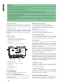 2
2
-
 3
3
-
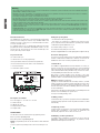 4
4
-
 5
5
-
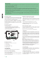 6
6
-
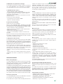 7
7
-
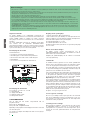 8
8
-
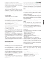 9
9
-
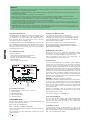 10
10
-
 11
11
-
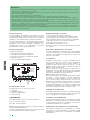 12
12
-
 13
13
-
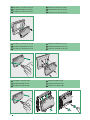 14
14
-
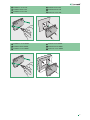 15
15
-
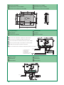 16
16
-
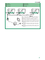 17
17
-
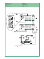 18
18
-
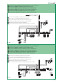 19
19
-
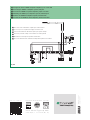 20
20


in andere talen
- English: Comelit SK9001I
- italiano: Comelit SK9001I
- français: Comelit SK9001I
- español: Comelit SK9001I
- Deutsch: Comelit SK9001I
Gerelateerde papieren
-
Comelit SK9020 Technical Manual
-
-
-
-
-
-
-
-
-
