
Erweiterungsmodul
Module d’extension
Uitbreidingsmodule
Expansion module
DFNLGB
Handbuch für Einbau und Bedienung
Manuel de l’utilisateur : Montage et service
Montage- en bedieningshandleiding
Manual for installation and operation

2 Handbuch für Einbau und Bedienung, Erweiterungsmodul D (#80044)
2. Inhaltsverzeichnis
Vorsicht!
Gefahr von Personenschäden!
Hier folgen wichtige Sicherheits -
hinweise, die zur Vermeidung von
Personen schäden unbedingt
beachtet werden müssen!
Achtung!
Gefahr von Sachschäden!
Hier folgen wichtige Sicherheits-
hinweise, die zur Vermeidung von
Sachschäden unbedingt beachtet
werden müssen!
Hinweis / Tipp
Kontrolle
Verweis
i
Hinweise
1. Symbolerklärung . . . . . . . . . . . .2
2. Inhaltsverzeichnis . . . . . . . . . . . .2
3. Allgemeine Sicherheitshinweise 3
4. Produktübersicht . . . . . . . . . . . .5
4.1 Lieferumfang . . . . . . . . . . . . . .5
4.2 Leistungsmerkmale . . . . . . . . .5
5. Montage . . . . . . . . . . . . . . . . . . .6
5.1 Erweiterungsmodul montieren .6
5.2 Anschluss . . . . . . . . . . . . . . . .6
6. Programmierung . . . . . . . . . . . . .9
6.1 Einstellung Fahrbahnregelung .9
6.2 Einstellungen . . . . . . . . . . . . .12
7. Anhang . . . . . . . . . . . . . . . . . . .13
EG-Konformitätserklärung . . . . . . . . .13
1. Symbolerklärung

Handbuch für Einbau und Bedienung, Erweiterungsmodul D (#80044) 3
3. Allgemeine Sicherheitshinweise
Zielgruppe
Dieses Produkt darf nur von qualifiziertem und geschultem Fachpersonal montiert, angeschlossen und in
Betrieb genommen werden!
Qualifiziertes und geschultes Fachpersonal im Sinne dieser Beschreibung sind Personen
- mit Kenntnis der allgemeinen und speziellen Sicherheits- und Unfallverhütungsvorschriften,
- mit Kenntnis der einschlägigen elektro technischen Vorschriften,
- mit Ausbildung in Gebrauch und Pflege angemessener Sicherheitsausrüstung,
- mit ausreichender Unterweisung und Beaufsichtigung durch Elektrofachkräfte,
- mit der Fähigkeit, Gefahren zu erkennen, die durch Elektrizität verursacht werden können,
- mit Kenntnis in der Anwendung der EN 12635 (Anforderungen an Installation und Nutzung).
Gewährleistung
Für eine Gewährleistung in Bezug auf Funktion und Sicherheit müssen die Hinweise in dieser Anleitung
beachtet werden.
Bei Missachtung der Warnhinweise können Körperverletzungen und Sachschäden auftreten.
Für Schäden, die durch Nichtbeachtung der Hinweise eintreten, haftet der Hersteller nicht.
Um Einbaufehler und Schäden am Gerät zu vermeiden, ist unbedingt nach den Montage an weisungen der
Einbauanleitung vorzugehen. Das Produkt darf erst nach Kenntnisnahme der zugehörigen Einbau- und
Bedienungs anleitung betrieben werden.
Die Einbau- und Bedienungsanleitung ist dem Betreiber der Toranlage zu übergeben und aufzubewahren.
Sie beinhaltet wichtige Hinweise für Bedienung, Prüfung und Wartung.
Das Produkt wird gemäß den in der Hersteller- und Konformitäts erklärung aufgeführten Richtlinien und
Normen gefertigt. Das Produkt hat das Werk in sicherheitstechnisch einwandfreiem Zustand verlassen.
Kraftbetätigte Fenster, Türen und Tore müssen vor der ersten Inbetrieb nahme und nach Bedarf, jedoch
jährlich mindestens einmal von einem Sachkundigen geprüft werden (mit schriftlichem Nachweis).
Bestimmungsgemäße Verwendung
Das Erweiterungsmodul erweitert die Steuerung x.21 um die Funktionen Funksteuerung, Ampelfunktion
und Durchfahrtslichtschranke.
Neben den Hinweisen in dieser Anleitung sind die allgemein gültigen Sicherheits- und Unfall vor-
schriften zu beachten! Es gelten unsere Verkaufs- und Lieferbedingungen.
Bitte unbedingt lesen!

3. Allgemeine Sicherheitshinweise
Hinweise zum Einbau
• Stellen Sie sicher, dass sich die anzuschließenden Anlagen (Türen etc.) mechanisch in einem
einwandfreien Zustand befinden.
• Vor Verkabelungsarbeiten trennen Sie das System unbedingt von der Stromversorgung.
Stellen Sie sicher, dass während der Verkabelungsarbeiten die Stromversorgung unterbrochen bleibt.
• Beachten Sie die örtlichen Schutzbestimmungen.
• Verlegen Sie die Netz- und Steuerleitungen unbedingt getrennt. Die Betriebsspannung beträgt 24 V.
Hinweise zur Reinigung
Auf keinen Fall dürfen zur Reinigung eingesetzt werden: direkter Wasserstrahl, Hochdruckreiniger, Säuren
oder Laugen.
Bitte unbedingt lesen!
4 Handbuch für Einbau und Bedienung, Erweiterungsmodul D (#80044)

4.1 Lieferumfang 4.2 Leistungsmerkmale
1 Gehäuse
2 Erweiterungsmodul
3 Schraubenset
Das Erweiterungsmodul erweitert die
Steuerung x.21 um die Funktionen:
- Ampelfunktion (Fahrbahnregelung)
- Durchfahrtslichtschranke
1
2
4. Produktübersicht
Handbuch für Einbau und Bedienung, Erweiterungsmodul D (#80044) 5
4.1 / 1
3
Hinweis:
Um das Erweiterungsmodul an der
Steuerung x.21 betreiben zu können,
muss eine 2-Draht-Lichtschranke an-
geschlossen und aktiviert sein.

6 Handbuch für Einbau und Bedienung, Erweiterungsmodul D (#80044)
Art / Funktion
A Dippschalter
XB99 Anschluss Bedienelement
B Entriegelungsschieber
XB48
Anschlussbuchse für
Steuerung x.21
C
Anzeige Signalleuchte
Ausfahrt Rot/Grün
D
Anzeige Signalleuchte
Einfahrt Rot/Grün
E Anzeige Lichtschranke ZU
F Anzeige Endposition AUF / ZU
XH19A Anschluss Signalleuchten EIN
XH19B Anschluss Signalleuchten
XH14 Anschluss Wischimpuls
5.1 Erweiterungsmodul
montieren
5.2 Anschluss
5. Montage
• Öffnen Sie das Gehäuse.
• Nehmen Sie die Abdeckungen (A) an beiden
Gehäusen heraus.
• Schrauben Sie das Gehäuse an einen festen
Untergrund.
• Stecken Sie das Erweiterungsmodul auf die
Schiene im Gehäuse.
• Führen Sie das Anschlusskabel aus der
Steuerung x.21 in das Gehäuse Erweiterungs-
modul.
5.2.1 Steuerungsübersicht
5.1 / 1
Hinweis:
Um einen Anschluss an die Steue-
rung x.21 zu gewährleisten, muss
das Gehäuse des Erweiterungsmo-
duls direkt neben die Steuerung x.21
montiert werden.
A
A
5.2.1 / 1
B
CDEF
XB99
XB48 XH19A
XH19BXH14

Handbuch für Einbau und Bedienung, Erweiterungsmodul D (#80044) 7
5. Montage
5.2.2 Verkabelung
XB48
• Schließen Sie die Steuerung x.21 an die
Anschlussbuchse XB48 an.
• Schließen Sie alle Erweiterungen an.
5.2.2 / 1
5.2.2 / 2
Art / Funktion
SB31 Schaltkontakt Vorrang
SB33 Schaltkontakt Tor AUF
SB36 Impulstaster Einfahrt
SB37 Impulstaster Ausfahrt
Anschluss XB99
M07E026

-XH19A
L1
N
H1 94 H1 94A92A 94B92B
-XH19B
-HH92A
-HH92B
-HH94B
-HH94A
8 Handbuch für Einbau und Bedienung, Erweiterungsmodul D (#80044)
5. Montage
5.2.2 / 4
Art / Funktion
HH92A Signalleuchte Ausfahrt Grün
HH92B Signalleuchte Einfahrt Grün
HH94A Signalleuchte Ausfahrt Rot
HH94B Signalleuchte Einfahrt Rot
L1 Bauseitige Versorgungsspannung
N Bauseitige Versorgungsspannung
Anschluss XH19A / XH19B
-XH14
L1
N
H1 42A 42B
-KH42
A2 A1
5.2.2 / 3
Anschluss XH14
Art / Funktion
KH42 Zentralrelais 3-min.-Licht
L1 Bauseitige Versorgungsspannung
N Bauseitige Versorgungsspannung
M07E026 M07E026

Handbuch für Einbau und Bedienung, Erweiterungsmodul D (#80044) 9
Funktion Anschluss SB36 Anschluss SB37
Keine Fahrbahnregelung
(Standardeinstellung)
Taster AUF Taster ZU
Fahrbahnregelung Taster Einfahrt Taster Ausfahrt
6. Programmierung
6.1 Einstellung Fahrbahnregelung
Wenn eine Zeitschaltuhr am Anschluss XB99 angeschlossen ist, können mit den Dippschaltern
verschiedene Einstellungen für die Fahrbahnregelung gewählt werden.
Tasteranschlüsse
Standardeinstellung (keine Fahrbahnregelung – Dippschalter auf 000)
Die Anschlüsse XH19A, XH19B und XH14 sind für potentialfreie Endtastermeldungen AUF und ZU
verwendbar. Der Anschluss XB99 kann für einen Impulstaster verwendet werden.
Fahrbahnregelung
Die unterschiedlichen Einstellungen der Fahrbahnregelungen sind in nachstehender Tabelle aufgeführt.

6. Programmierung
10 Handbuch für Einbau und Bedienung, Erweiterungsmodul D (#80044)
S1 S2 S3 Fahrbahnregelung
1 0 0
Zeitschaltuhr an SB33
Zeitschaltung schaltet ein:
- Das Tor öffnet sich.
- Das Tor bleibt für die gewählte Zeitspanne offen.
- Die Ampeln leuchten rot.
- Tasterbetätigung gibt Grünlicht in Fahrtrichtung.
0 1 0
Zeitschaltuhr an SB33
Zeitschaltung schaltet ein:
- Tor öffnet bei Betätigung eines Tasters.
- Das Tor bleibt für die gewählte Zeitspanne offen.
- Die Ampeln leuchten rot.
- Tasterbetätigung gibt Grünlicht in Fahrtrichtung.
1 1 0
Zeitschaltuhr an SB33
Zeitschaltung schaltet ein:
- Das Tor öffnet sich.
- Das Tor bleibt für die gewählte Zeitspanne offen.
- Die Ampeln leuchten rot.
- Tasterbetätigung gibt Grünlicht in Fahrtrichtung.
- Beim Verlassen der Lichtschranke wird die Grünzeit beendet.
0 0 1
Zeitschaltuhr an SB33
Zeitschaltung schaltet ein:
- Das Tor öffnet sich.
- Das Tor bleibt für die gewählte Zeitspanne offen.
- Die Ampeln leuchten rot.
- Tasterbetätigung gibt Grünlicht in Fahrtrichtung.
- Beim Verlassen der Lichtschranke wird die Grünzeit beendet und die Rotzeit verkürzt.
1 0 1
Zeitschaltuhr an SB33
Zeitschaltung schaltet ein:
- Das Tor öffnet sich.
- Das Tor bleibt für die gewählte Zeitspanne offen.
- Die Ampeln leuchten rot und grün im Wechsel.
Dippschaltereinstellung

Handbuch für Einbau und Bedienung, Erweiterungsmodul D (#80044) 11
6. Programmierung
S1 S2 S3 Fahrbahnregelung
0 1 1
Zeitschaltuhr an SB33
(Zeitschaltung mit zwei Zeitschaltuhren)
Zeitschaltung 1 schaltet ein:
- Das Tor öffnet sich.
- Das Tor bleibt für die gewählte Zeitspanne offen.
- Ein- / Ausfahrt 1 leuchtet dauerhaft grün.
- Ein- / Ausfahrt 2 leuchtet dauerhaft rot.
- Ein- / Ausfahrt 2 bekommt grün durch Tasterbetätigung.
Zeitschaltuhr an SB31
(Zeitschaltung mit zwei Zeitschaltuhren)
Zeitschaltung 2 schaltet ein:
- Das Tor öffnet sich.
- Das Tor bleibt für die gewählte Zeitspanne offen.
- Ein- / Ausfahrt 1 leuchtet dauerhaft rot.
- Ein- / Ausfahrt 2 leuchtet dauerhaft grün.
- Ein- / Ausfahrt 1 bekommt grün durch Tasterbetätigung.
1 1 1 -

12 Handbuch für Einbau und Bedienung, Erweiterungsmodul D (#80044)
6. Programmierung
6.2 Einstellungen
Funksteuerung
• Programmieren Sie die Funksteuerung
(falls vorhanden).
Erweitertes Programmiermenü:
- Ebene 4 / Menü 1: Einfahrt
- Ebene 4 / Menü 2: Ausfahrt
Grün- und Rotzeit
• Programmieren Sie Zeiteinstellungen für die
Grün- und Rotzeit.
Erweitertes Programmiermenü:
- Ebene 3 / Menü 3: Toraufzeit grün
- Ebene 3 / Menü 4: Vorwarnzeit rot
Durchfahrtslichtschranke
• Aktivieren Sie die Durchfahrtslichtschranke.
Erweitertes Programmiermenü:
- Ebene 8 / Menü 1: Lichtschranke
Verweis:
Die Einstellungen für die Funktionen
des Erweiterungsmoduls werden in
der Steuerung x.21 vorgenommen.
Die Einstellungen sind im Kapitel
“Erweiterte Antriebsfunktionen”
der Antriebsanleitung beschrieben.
i
Hinweis:
Bei Anschluss des Erweiterungs-
moduls ändert sich die Programmie-
rungsbelegung der Antriebs steuerung
auf “Einfahrt” und “Ausfahrt”.

Handbuch für Einbau und Bedienung, Erweiterungsmodul D (#80044) 13
EG-Konformitätserklärung
Hiermit erklären wir, dass das nachfolgend bezeich-
nete Produkt aufgrund seiner Konzipierung und
Bauart sowie in der von uns in Verkehr gebrachten
Ausführung den einschlägigen grundlegenden
Sicherheits- und Gesundheitsanforderungen der
EG-Richtlinie Elektromagnetische Ver träg lichkeit,
der Maschinen-Richtlinie und der Nieder spannungs-
richtlinie entspricht.
Bei einer nicht mit uns abgestimmten Änderung
der Produkte verliert diese Erklärung ihre Gültigkeit.
Produkt:
Einschlägige EG-Richtlinien:
EG-Richtlinie Elektromagnetische Verträglichkeit
(89/336/EWG),
Maschinen-Richtlinie
(98/37/EWG)
und Niederspannungsrichtlinie
(73/23/EWG und 93/68/EWG).
Angewandte harmonisierte Normen,
insbesondere:
EN 292-1 / EN 61000-6-2 / EN 61000-6-3 /
EN 55014 / EN 61000-3-2 / EN 61000-3-3 /
EN 60335-1 / EN 60335-2-95 / EN 12445 /
EN 12453 / EN 300220-1 / EN 301489-3 /
ETS 300683
Datum / Unterschrift
7. Anhang

14 Manuel de l’utilisateur : Montage et service, Module d’extension F (#80044)
2. Table des matières
Prudence !
Risque de dommages corporels !
Vous trouverez ici d’importantes
consignes de sécurité à observer
scrupuleusement pour éviter des
dommages corporels !
Attention !
Risque de dommages matériels !
Vous trouverez ici d’importantes
consignes de sécurité à respecter
scrupuleusement pour éviter des
dommages matériels !
Remarque / Conseil
Contrôle
Référence
i
Remarques
1. Explication des symboles . . . . .14
2. Table des matières . . . . . . . . . .14
3. Consignes générales de
sécurité . . . . . . . . . . . . . . . . . . .15
4. Vue d’ensemble du produit . . .17
4.1 Fourniture . . . . . . . . . . . . . . .17
4.2 Caractéristiques . . . . . . . . . . .17
5. Montage . . . . . . . . . . . . . . . . . .18
5.1 Montage du module
d’extension . . . . . . . . . . . . . .18
5.2 Branchement . . . . . . . . . . . . .18
6. Programmation . . . . . . . . . . . . .21
6.1 Réglage de la régulation de
la circulation . . . . . . . . . . . . .21
6.2 Réglages . . . . . . . . . . . . . . . .24
7. Annexe . . . . . . . . . . . . . . . . . . .25
Certificat de conformité CE . . . . . . . .25
1. Explication des symboles

Manuel de l’utilisateur : Montage et service, Module d’extension F (#80044) 15
3. Consignes générales de sécurité
Groupe-cible
Cet opérateur doit être monté, raccordé et mis en service exclusivement par un personnel qualifié et
instruit qui :
- dispose de connaissance relatives aux dangers liés aux interventions sur des installations électriques,
- dispose de connaissances sur les règles se rapportant à l’électrotechnique,
- dispose d’une formation aux premiers secours et à l’utilisation d’équipements de sécurité,
- est suffisamment instruits et encadrés par des électriciens qualifiés,
- a la capacité de reconnaître les dangers liés à l’électricité,
- dispose de connaissances dans l’application de la norme EN 12635
(exigences concernant l’installation et l’utilisation).
Garantie
La garantie concernant la fonctionnalité et la sécurité d’utilisation entrera en vigueur si les consignes
contenues dans ces instructions ont été respectées. La non-observation des présentes consignes peut
conduire à des blessures corporelles et des dégâts matériels. Le fabricant ne sera pas responsable des
dommages imputables à un non-respect des consignes.
Afin d'éviter toute erreur pouvant occasionner un endommagement de l’appareil, il convient de suivre
impérativement les indications de la notice de montage. Le produit ne doit être mis en service qu’après
avoir pris connaissance du contenu de cette notice de montage et de service.
Les instructions de montage et de service sont à remettre à l’utilisateur de l’installation et à conserver.
Elles contiennent d’importantes informations concernant l’utilisation, les vérifications et la maintenance.
Le produit est fabriqué conformément aux normes et directives citées dans la déclaration de conformité
constructeur et le certificat de conformité. Le produit a quitté l’usine dans un état de sécurité technique
sans défauts.
Avant la première mise en service, les fenêtres, portes et portails motorisés doivent être vérifiés par un
spécialiste et entretenus au moins une fois par an et selon les besoins (avec justificatif écrit).
Application conforme
Le module est une extension de la commande x.21 des fonctions Télécommande, Feu et Cellule
photoélectrique de passage.
En plus des consignes contenues dans ces instructions, il faut respecter les règlements généraux
sur la sécurité et sur la prévention des accidents ! Nos conditions générales de vente et de
livraison entrent en vigueur.
A lire absolument !

3. Consignes générales de sécurité
Consignes concernant le montage
• Vérifiez l'état mécanique irréprochable des installations à brancher (Portes etc.).
• Avant les travaux de câblage, il est indispensable de débrancher le système.
Pendant les travaux, l'alimentation électrique doit impérativement restée coupée.
• Respectez les normes locales de sécurité en vigueur.
• Pour éviter les phénomènes d'induction, il est impératif de séparer dans des gaines différentes les câbles
d'asservissement des câbles d'alimentation du moteur. La tension de service est de 24 V.
Consignes concernant le nettoyage
A proscrire : un jet d’eau direct, un nettoyeur haute pression, des acides ou une eau savonneuse.
A lire absolument !
16 Manuel de l’utilisateur : Montage et service, Module d’extension F (#80044)

4.1 Fourniture 4.2 Caractéristiques
1 Boîtier
2 Module d’extension
3 Sachet de visserie
Le module est une extension de la commande x.21
des fonctions :
- Fonction de feu (réglage de la circulation)
- Cellule photoélectrique de passage
1
2
4. Vue d’ensemble du produit
Manuel de l’utilisateur : Montage et service, Module d’extension F (#80044) 17
4.1 / 1
3
Remarque :
Pour assurer l’exploitation du module
d’extension sur la commande x.21,
il convient de raccorder une barrière
photoélectrique bifilaire et de l’activer.

18 Manuel de l’utilisateur : Montage et service, Module d’extension F (#80044)
Type / Fonction
A Commutateur DIP
XB99
Branchement élément de commande
B Vanne de déverrouillage
XB48 Connecteur de la commande x.21
C
Affichage feux de signalisation
Sortie rouge/vert
D
Affichage feux de signalisation
Entrée rouge/vert
E
Indication cellule photoélectrique
FERMETURE
F
Affichage position de fin de course
OUVERTURE / FERMETURE
XH19A
Branchement feux de signalisation
ALLUMÉE
XH19B Branchement feux de signalisation
XH14 Branchement impulsion de balayage
5.1 Montage du module
d’extension
5.2 Branchement
5. Montage
• Ouvrez le boîtier.
• Déposez le capot de protection (A) sur les deux
boîtiers.
• Vissez le boîtier sur un support fixe.
• Glissez le module d’extension sur le rail qui se
trouve dans le boîtier.
• Introduisez le câble de branchement provenant
de la commande x.21 dans le boîtier du module
d’extension.
5.2.1 Aperçu de la commande
5.1 / 1
Remarque :
Pour assurer le branchement sur
la commande x.21, le boîtier
du module d’extension doit être
monté directement à côté de
la commande x.21.
A
A
5.2.1 / 1
B
CDEF
XB99
XB48 XH19A
XH19BXH14

Manuel de l’utilisateur : Montage et service, Module d’extension F (#80044) 19
5. Montage
5.2.2 Câblage
XB48
• Branchez la commande x.21 sur le
connecteur XB48.
• Branchez tous les extensions.
5.2.2 / 1
Type / Fonction
SB31
Contact de commutation
de priorité
SB33
Contact de commutation
d’OUVERTURE du portail
SB36 Contacteur à impulsion Entrée
SB37 Contacteur à impulsion Sortie
Branchement XB99
5.2.2 / 2
M07E026

20 Manuel de l’utilisateur : Montage et service, Module d’extension F (#80044)
5. Montage
Type / Fonction
HH92A Feu de signalisation Sortie vert
HH92B Feu de signalisation Entrée vert
HH94A Feu de signalisation Sortie rouge
HH94B Feu de signalisation Entrée rouge
L1 Tension d'alimentation sur place
N Tension d'alimentation sur place
Branchement XH19A / XH19BBranchement XH14
Type / Fonction
KH42 Relais central éclairage 3 minutes
L1 Tension d'alimentation sur place
N Tension d'alimentation sur place
-XH19A
L1
N
H1 94 H1 94A92A 94B92B
-XH19B
-HH92A
-HH92B
-HH94B
-HH94A
5.2.2 / 4
-XH14
L1
N
H1 42A 42B
-KH42
A2 A1
5.2.2 / 3
M07E026 M07E026

Manuel de l’utilisateur : Montage et service, Module d’extension F (#80044) 21
Fonction Branchement SB36 Branchement SB37
Aucune régulation de circulation
(Réglage par défaut)
Contacteur OUVRIR Contacteur FERMER
Régulation de la circulation Contacteur ENTREE Contacteur SORTIE
6. Programmation
6.1 Réglage de la régulation de la circulation
Si une minuterie est raccordée sur le contact XB99, il est possible de choisir différents réglages pour les
commutateurs DIP réguler la circulation.
Branchements pour contacteurs
Réglage standard (aucun réglage de circulation - commutateurs DIP à 000)
Les branchements XH19A, XH19B et XH14 peuvent être utilisés pour messages de contact de fin de
course libre de potentiel OUVERTURE et FERMETURE.
Régulation de circulation
Les différents paramètres de la régulation de la circulation sont listés dans le tableau suivant.

6. Programmation
22 Manuel de l’utilisateur : Montage et service, Module d’extension F (#80044)
S1 S2 S3 Régulation de la circulation
1 0 0
Minuterie sur SB33
La minuterie se met en marche :
- La porte s'ouvre.
- Pendant la période choisie, la porte reste ouverte.
- Les feux sont au rouge.
- Une impulsion sur le bouton fait passer le feu au vert dans le sens de circulation.
0 1 0
Minuterie sur SB33
La minuterie se met en marche :
- Lors de l’actionnement d'un contacteur, la porte s'ouvre.
- Pendant la période choisie, la porte reste ouverte.
- Les feux sont au rouge.
- Une impulsion sur le bouton fait passer le feu au vert dans le sens de circulation.
1 1 0
Minuterie sur SB33
La minuterie se met en marche :
- La porte s'ouvre.
- Pendant la période choisie, la porte reste ouverte.
- Les feux sont au rouge.
- Une impulsion sur le bouton fait passer le feu au vert dans le sens de circulation.
- En quittant la barrière photoélectrique, la phase verte est terminée.
0 0 1
Minuterie sur SB33
Minuterie se met en marche :
- La porte s'ouvre.
- Pendant la période choisie, la porte reste ouverte.
- Les feux sont au rouge.
- Une impulsion sur le bouton fait passer le feu au vert dans le sens de circulation.
- En quittant la barrière photoélectrique, la phase verte est terminée et la phase rouge est réduite.
1 0 1
Minuterie sur SB33
La minuterie se met en marche :
- La porte s'ouvre.
- Pendant la période choisie, la porte reste ouverte.
- Les feux passent alternativement du rouge au vert.
Réglage du commutateur DIP

Manuel de l’utilisateur : Montage et service, Module d’extension F (#80044) 23
6. Programmation
S1 S2 S3 Régulation de la circulation
0 1 1
Minuterie sur SB33
(Temporisateur avec deux minuteries)
Le temporisateur 1 se met en marche :
- La porte s'ouvre.
- Pendant la période choisie, la porte reste ouverte.
- Entrée / Sortie 1 restent de manière permanente au vert.
- Entrée / Sortie 2 restent de manière permanente au rouge.
- Une impulsion sur le bouton fait passer Entrée / Sortie 2 au vert.
Minuterie sur SB31
(Temporisateur avec deux minuteries)
Temporisateur 2 se met en marche :
- La porte s'ouvre.
- Pendant la période choisie, la porte reste ouverte.
- Entrée / Sortie 1 restent de manière permanente au rouge.
- Entrée / Sortie 1 restent de manière permanente au vert.
- Une impulsion sur le bouton fait passer Entrée / Sortie 1 au vert.
1 1 1 -

24 Manuel de l’utilisateur : Montage et service, Module d’extension F (#80044)
6. Programmation
6.2 Réglages
Télécommande
• Programmez la télécommande (le cas échéant).
Menu élargi de programmation:
- Niveau 4 / Menu 1: Entrée
- Niveau 4 / Menu 2: Sortie
Phases vertes et rouges
• Programmez les réglages de la temporisation
pour les phases vertes et rouges.
Menu étendu de programmation :
- Niveau 3 / Menu 3 : Phase verte d'ouverture
du portail
- Niveau 3 / Menu 4 : Phase rouge d'avertissement
Barrière photoélectrique de passage
• Activez la barrière photoélectrique de passage
Menu évolué de programmation :
- Niveau 8 / Menu 1 : Barrière photoélectrique
Référence :
Les réglages des fonctions du module
d'extension s’effectuent dans
la commande x.21.
Ces réglages sont décrits dans
le chapitre « Fonctions évoluées
de l’opérateur » du manuel.
i
Remarque :
Lors du branchement du module
d'extension, l’affectation de
programmation de la commande
d'opérateur passe de « Entrée »
à « Sortie ».

Manuel de l’utilisateur : Montage et service, Module d’extension F (#80044) 25
Certificat de conformité CE
Par la présente, nous déclarons que le produit
ci-après répond, de par sa conception et sa
construction ainsi que de par le modèle que nous
avons mis sur le marché, aux exigences de
sécurité et d’hygiène de la CE, à la compatibilité
électromagnétique, aux directives sur les
machines et sur les basses tensions.
En cas de modification du produit effectuée sans
notre accord, cette déclaration perd sa validité.
Produit :
Directives CE correspondantes :
Directive CE sur la compatibilité
électromagnétique (89/336/EWG),
Directives sur les machines
(98/37/EWG)
et directives sur les basses tensions
(73/23/EWG und 93/68/EWG).
Normes harmonisées appliquées, en particulier :
EN 292-1 / EN 61000-6-2 / EN 61000-6-3 /
EN 55014 / EN 61000-3-2 / EN 61000-3-3 /
EN 60335-1 / EN 60335-2-95 / EN 12445 /
EN 12453 / EN 300220-1 / EN 301489-3 /
ETS 300683
Date / signature
7. Annexe

26 Montage- en bedieningshandleiding, Uitbreidingsmodule NL (#80044)
2. Inhoudsopgave
Voorzichtig!
Gevaar voor lichamelijk letsel!
Hier volgen belangrijke
veiligheidsinstructies die absoluut in
acht moeten worden genomen ter
voorkoming van lichamelijk letsel!
Attentie!
Gevaar voor materiële schade!
Hier volgen belangrijke
veiligheidsinstructies die absoluut in
acht moeten worden genomen ter
voorkoming van materiële schade!
Opmerking / Tip
Controle
Informatie
i
Aanwijzingen
1. Verklaring van de symbolen . .26
2. Inhoudsopgave . . . . . . . . . . . . .26
3. Algemene
veiligheidsinstructies . . . . . . . .27
4. Productoverzicht . . . . . . . . . . . .29
4.1 Leveringspakket . . . . . . . . . . .29
4.2 Prestatiekenmerken . . . . . . . .29
5. Montage . . . . . . . . . . . . . . . . . .30
5.1 Uitbreidingsmodule monteren 30
5.2 Aansluiting . . . . . . . . . . . . . .30
6. Programmering . . . . . . . . . . . . .33
6.1 Instelling verkeersregeling . . .33
6.2 Instellingen . . . . . . . . . . . . . .36
7. Bijlage . . . . . . . . . . . . . . . . . . . .37
EG-Conformiteitsverklaring . . . . . . . . .37
1. Verklaring van de
symbolen

Montage- en bedieningshandleiding, Uitbreidingsmodule NL (#80044) 27
3. Algemene veiligheidsinstructies
Doelgroep
Dit aandrijfsysteem mag uitsluitend door gekwalificeerd en geschoold personeel worden gemonteerd,
aangesloten en in bedrijf worden gesteld!
Gekwalificeerd en geschoold personeel overeenkomstig deze beschrijving zijn personen:
- met kennis van de algemene en speciale veiligheidsvoorschriften en voorschriften voor de preventie
van ongevallen,
- met kennis van de geldende elektrotechnische voorschriften,
- met een opleiding in gebruik en onderhoud van de toegepaste veiligheidsuitrusting,
- met voldoende scholing en onder toezicht staan bij gespecialiseerde elektrotechnici,
- met het vermogen om gevaren te herkennen die door elektriciteit kunnen worden veroorzaakt,
- met kennis over de toepassing van de norm EN 12635 (eisen inzake installatie en gebruik).
Garantie
Voor een garantie met betrekking tot de werking en veiligheid moeten de aanwijzingen in deze
handleiding in acht worden genomen. Bij niet-inachtneming van de waarschuwingen kan lichamelijk letsel
en materiële schade optreden. Voor beschadigingen die ontstaan door niet-inachtneming van de
aanwijzingen aanvaardt de fabrikant geen aansprakelijkheid.
Teneinde fouten bij de inbouw en schade aan het apparaat te vermijden, moeten de montageaanwijzingen
in de inbouwhandleiding beslist worden opgevolgd. Het product mag pas worden gebruikt nadat is kennis
genomen van de bijbehorende inbouw- en bedieningshandleiding.
De montage- en bedieningshandleiding moet aan de gebruiker van de deurinstallatie worden overhandigd
en dient te worden bewaard. Deze bevat belangrijke aanwijzingen voor bediening, controle en onder-
houd.
Het product wordt vervaardigd overeenkomstig de richtlijnen en normen die vermeld zijn in de
fabrikantenverklaring en de conformiteitsverklaring. Het product heeft de fabriek in veiligheidstechnisch
foutloze toestand verlaten.
Mechanisch aangedreven ramen, deuren en hekken moeten voor de eerste inbedrijfstelling en wanneer
nodig, maar minstens één keer per jaar, door een deskundige worden gecontroleerd (met schriftelijk
bewijs).
Eigenlijk gebruik
De uitbreidingsmodule voegt de volgende functies toe aan de besturing x.21: draadloze besturing,
verkeerslichtfunctie en doorrijfotocel.
Naast de aanwijzingen in deze handleiding moeten de algemeen geldende veiligheids-
voorschriften en de voorschriften voor de preventie van ongevallen in acht worden genomen!
Onze algemene leverings- en betalingsvoorwaarden zijn van toepassing.
Lees het onderstaande grondig door!

3. Algemene veiligheidsinstructies
Aanwijzingen voor de inbouw
• Zorg er voor dan de aan te sluiten installaties (deuren etc.) mechanisch in perfecte staat verkeren.
• Het systeem voorafgaand aan bekabelingswerkzaamheden beslist van het elektriciteitsnet scheiden.
Overtuig u ervan dat tijdens de bekabelingswerkzaamheden de stroomvoorziening onderbroken blijft.
• Neem de plaatselijke veiligheidsvoorschriften in acht.
• Leg de net- en besturingskabels beslist gescheiden aan. De bedrijfsspanning bedraagt 24 V.
Aanwijzingen voor reiniging
Voor reiniging mag in geen geval worden gebruikt:
Een directe waterstraal, een hogedrukreiniger, zuren en logen.
Lees het onderstaande grondig door!
28 Montage- en bedieningshandleiding, Uitbreidingsmodule NL (#80044)

4.1 Leveringspakket 4.2 Prestatiekenmerken
1 Behuizing
2 Uitbreidingsmodule
3 Schroevenset
De uitbreidingsmodule verruimt de besturing x.21
met de functies:
- Verkeerslichtfunctie (verkeersregeling)
- Doorrijfotocel
1
2
4. Productoverzicht
Montage- en bedieningshandleiding, Uitbreidingsmodule NL (#80044) 29
4.1 / 1
3
Opmerking:
Om de uitbreidingsmodule aan de
besturing x.21 te kunnen gebruiken,
moet een 2-draads fotocel zijn
geactiveerd en aangesloten.

30 Montage- en bedieningshandleiding, Uitbreidingsmodule NL (#80044)
Soort / Functie
A Dipschakelaar
XB99 Aansluiting bedieningselement
B Ontgrendelingsschuif
XB48 Aansluitbus voor besturing x.21
C
Weergave signaallamp
Uitrit rood/groen
D
Weergave signaallamp
Inrit rood/groen
E Weergave fotocel DICHT
F Weergave eindpositie OPEN / DICHT
XH19A Aansluiting signaallampen AAN
XH19B Aansluiting signaallampen
XH14 Aansluiting wisimpuls
5.1 Uitbreidingsmodule monteren 5.2 Aansluiting
5. Montage
• Open de behuizing.
• Neem de afdekplaten (A) van beide behuizingen
eruit.
• Schroef de behuizing op een stevige
ondergrond vast.
• Steek de uitbreidingsmodule op de rails in
de behuizing.
• Leid de aansluitkabel uit de besturing x.21 in
de behuizing van de uitbreidingsmodule.
5.2.1 Besturingsoverzicht
5.1 / 1
Opmerking:
Om een aansluiting op de besturing x.21
te realiseren, moet de behuizing
van de uitbreidingsmodule direct
naast de besturing x.21 worden
gemonteerd.
A
A
5.2.1 / 1
B
CDEF
XB99
XB48 XH19A
XH19BXH14

Montage- en bedieningshandleiding, Uitbreidingsmodule NL (#80044) 31
5. Montage
5.2.2 Bekabeling
XB48
• Sluit de besturing x.21 aan op de
aansluitbus XB48.
• Sluit alle uitbreidingen aan.
5.2.2 / 1
Soort / Functie
SB31 Schakelcontact voorrang
SB33 Schakelcontact deur OPEN
SB36 Impulsschakelaar inrit
SB37 Impulsschakelaar uitrit
Aansluiting XB99
5.2.2 / 2
M07E026

32 Montage- en bedieningshandleiding, Uitbreidingsmodule NL (#80044)
5. Montage
Soort / Functie
HH92A Signaallamp uitrit groen
HH92B Signaallamp inrit groen
HH94A Signaallamp uitrit rood
HH94B Signaallamp inrit rood
L1 Voedingspanning bouwplaats
N Voedingspanning bouwplaats
Aansluiting XH19A / XH19BAansluiting XH14
Soort / Functie
KH42 Centraal relais 3-min.-licht
L1 Voedingspanning bouwplaats
N Voedingspanning bouwplaats
-XH19A
L1
N
H1 94 H1 94A92A 94B92B
-XH19B
-HH92A
-HH92B
-HH94B
-HH94A
5.2.2 / 4
-XH14
L1
N
H1 42A 42B
-KH42
A2 A1
5.2.2 / 3
M07E026 M07E026

Montage- en bedieningshandleiding, Uitbreidingsmodule NL (#80044) 33
Functie Aansluiting SB36 Aansluiting SB37
Geen verkeersregeling
(Standaard instelling)
Schakelaar OPEN Schakelaar DICHT
Verkeersregeling Schakelaar inrit Schakelaar uitrit
6. Programmering
6.1 Instelling verkeersregeling
Wanneer een tijdschakelklok op de aansluiting XB99 is aangesloten, kunnen met de dipschakelaars diverse
instellingen voor de verkeersregeling worden gekozen.
Schakelaaraansluitingen
Standaard instelling (geen verkeersregeling – dipschakelaar op 000)
De aansluitingen XH19A, XH19B en XH14 zijn te gebruiken voor potentiaalvrije eindpostiemldingen OPEN
en DICHT. De aansluiting XB99 kan voor een impulsschakelaar worden gebruikt.
Verkeersregeling
De diverse instellingen van de verkeersregelingen staan in onderstaande tabel.

6. Programmering
34 Montage- en bedieningshandleiding, Uitbreidingsmodule NL (#80044)
S1 S2 S3 Verkeersregeling
1 0 0
Tijdschakelklok aan SB33
Tijdschakeling schakelt in:
- De deur gaat open.
- De deur blijft open gedurende de gekozen tijdsduur.
- De verkeerslichten staan op rood.
- Schakelaarbediening geeft groen licht in de rijrichting.
0 1 0
Tijdschakelklok aan SB33
Tijdschakeling schakelt in:
- De deur opent bij bedienen van een schakelaar.
- De deur blijft open gedurende de gekozen tijdsduur.
- De verkeerslichten staan op rood.
- Schakelaarbediening geeft groen licht in rijrichting.
1 1 0
Tijdschakelklok aan SB33
Tijdschakeling schakelt in:
- De deur gaat open.
- De deur blijft open gedurende de gekozen tijdsduur.
- De verkeerslichten staan op rood.
- Schakelaarbediening geeft groen licht in rijrichting.
- Bij het verlaten van de fotocel wordt de periode van de groenstand beëindigd.
0 0 1
Tijdschakelklok aan SB33
Tijdschakeling schakelt in:
- De deur gaat open.
- De deur blijft open gedurende de gekozen tijdsduur.
- De verkeerslichten staan op rood.
- Schakelaarbediening geeft groen licht in rijrichting.
- Bij het verlaten van de fotocel wordt de periode van de groene stand beeïndigd en
de tijd van de roodstand verkort.
1 0 1
Tijdschakelklok aan SB33
Tijdschakeling schakelt in:
- De deur gaat open.
- De deur blijft open gedurende de gekozen tijdsduur.
- De verkeerslichten staan afwisselend op rood en groen.
Instelling dipschakelaar

Montage- en bedieningshandleiding, Uitbreidingsmodule NL (#80044) 35
6. Programmering
S1 S2 S3 Verkeersregeling
0 1 1
Tijdschakelklok aan SB33
(Tijdschakeling met twee tijdschakelklokken)
Tijdschakeling 1 schakelt in:
- De deur gaat open.
- De deur blijft open gedurende de gekozen tijdsduur.
- In- / uitrit 1 staat continu op groen.
- In- / uitrit 2 staat continu op rood.
- In- / uitrit 2 krijgt groen door schakelaarbediening.
Tijdschakelklok aan SB31
(Tijdschakeling met twee tijdschakelklokken)
Tijdschakeling 2 schakelt in:
- De deur gaat open.
- De deur blijft open gedurende de gekozen tijdsduur.
- In- / uitrit 1 staat continu op rood.
- In- / uitrit 2 staat continu op groen.
- In- / uitrit 1 krijgt groen door schakelaarbediening.
1 1 1 -

36 Montage- en bedieningshandleiding, Uitbreidingsmodule NL (#80044)
6. Programmering
6.2 Instellingen
Draadloze besturing
• Programmeer de draadloze besturing
(indien aanwezig).
Uitgebreid programmeermenu:
- Niveau 4 / Menu 1: inrit
- Niveau 4 / Menu 2: uitrit
Groene- en rode tijd
• Programmeer de tijdsinstellingen voor de
groene en de rode tijd.
Uitgebreid programmeermenu:
- Niveau 3 / Menu 3: Deur open groen
- Niveau 3 / Menu 4: Voorwaarschuwingstijd rood
Doorrijfotocel
• Activeer de doorrijfotocel.
Uitgebreid programmeermenu:
- Niveau 8 / Menu 1: fotocel
Informatie:
De instellingen voor de functies van
de uitbreidingsmodule worden bij de
besturing x.21 uitgevoerd.
De instellingen worden beschreven in
het hoofdstuk “Uitgebreide
aandrijffuncties” van de aandrijvings-
handleiding.
i
Opmerking:
Bij het aansluiten van de uitbreidings-
module wijzigt de programmeer -
bezetting van de aandrijfbesturing
op “inrit” en “uitrit”.

Montage- en bedieningshandleiding, Uitbreidingsmodule NL (#80044) 37
EG-Conformiteitsverklaring
Hierbij verklaren wij dat het hierna beschreven
product op basis van zijn ontwerp en model alsook
in de door ons in omloop gebrachte uitvoering
voldoet aan de geldende fundamentele veiligheids-
en gezondheidseisen van de EG-richtlijn inzake
elektromagnetische compatibiliteit, de
machinerichtlijn en de laagspanningsrichtlijn.
Bij een niet met ons afgesproken wijziging van
de producten verliest deze verklaring haar
geldigheid.
Product: Uitbreidingsmodule
Geldende EG-richtlijnen:
EG-richtlijn elektromagnetische compatibiliteit
(89/336/EEG),
machinerichtlijn
(98/37/EEG)
en laagspanningsrichtlijn
(73/23/EEG und 93/68/EEG).
Toegepaste geharmoniseerde normen, in het
bijzonder:
EN 292-1 / EN 61000-6-2 / EN 61000-6-3 /
EN 55014 / EN 61000-3-2 / EN 61000-3-3 /
EN 60335-1 / EN 60335-2-95 / EN 12445 /
EN 12453 / EN 300220-1 / EN 301489-3 /
ETS 300683
Datum / handtekening
7. Bijlage

38 Manual for installation and operation, Expansion module GB (#80044)
2. Table of contents
Caution!
Danger of personal injury!
The following safety advice must be
observed at all times so as to avoid
personal injury!
Attention!
Danger of material damage!
The following safety advice must be
observed at all times so as to avoid
material damage!
Advice / Tip
Check
Reference
i
Advice
1. Meaning of symbols . . . . . . . . .38
2. Table of contents . . . . . . . . . . .38
3. General safety advice . . . . . . . .39
4. Product overview . . . . . . . . . . .41
4.1 Supply package . . . . . . . . . . .41
4.2 Performance Features . . . . . .41
5. Installation . . . . . . . . . . . . . . . .42
5.1 Mount the expansion
module . . . . . . . . . . . . . . . . .42
5.2 Connection . . . . . . . . . . . . . .42
6. Programming . . . . . . . . . . . . . .45
6.1 Adjustment of traffic control .45
6.2 Settings . . . . . . . . . . . . . . . . .48
7. Attachment . . . . . . . . . . . . . . . .49
EC Declaration of Conformity . . . . . . .49
1. Meaning of symbols

Manual for installation and operation, Expansion module GB (#80044) 39
3. General safety advice
Target group
This operator system may only be installed, connected and put into operation by qualified and trained
professionals!
Qualified and trained specialist personnel are persons
- who have knowledge of the general and special safety regulations,
- who have knowledge of the relevant electro-technical regulations,
- with training in the use and maintenance of suitable safety equipment,
- who are sufficiently trained and supervised by qualified electricians,
- who are able to recognise the particular hazards involved when working with electricity,
- with knowledge regarding applications of the EN 12635 standard (installation and usage requirements).
Warranty
For an operations and safety warranty, the advice in this instruction manual has to be observed.
Disregarding these warnings may lead to personal injury or material damage. If this advice is disregarded,
the manufacturer will not be liable for damages that might occur.
To avoid installation errors and damage to the device, it is imperative that the installation instructions are
followed. The product may only be operated after reading these installation and operating instructions.
The installation and operating instructions are to be given to the door system user, who must keep them
safe. They contain important advice for operation, checks and maintenance.
This item is produced according to the directives and standards mentioned in the Manufacturer's
Declaration and in the Declaration of Conformity. The product has left the factory in perfect condition with
regard to safety.
Power-operated windows, doors and gates must be checked by an expert (and this must be documented)
before they are put into operation and thereafter as required, but at least once a year.
Correct use
The expansion module expands the x.21 control unit by the functions: radio control, traffic light function
and photocell drive-through barrier.
Beside the advice in these instructions, please observe the general safety and accident
prevention regulations! Our sales and supply terms and conditions are effective.
Please read carefully!

3. General safety advice
Installation tips
• Ensure that the devices to be connected (doors etc.) are in a mechanically faultless state.
• Before commencing cabling works it is very important to disconnect the system from the electricity
supply.
Ensure that the electricity supply remains disconnected throughout the cabling works.
• Adhere to the local protection regulations.
• Lay the electricity supply cables and control cables; these MUST be laid separately.
The operating voltage is 24 V.
Cleaning tips
Never use water jets, high pressure cleaners, acids or bases for cleaning.
Please read carefully!
40 Manual for installation and operation, Expansion module GB (#80044)

4.1 Supply package 4.2 Performance Features
1 Housing
2 Expansion module
3 Screw set
The expansion module expands the x.21 control
unit by the functions:
- traffic light functions (traffic control)
- photocell drive-through barrier
1
2
4. Product overview
Manual for installation and operation, Expansion module GB (#80044) 41
4.1 / 1
3
Advice:
In order to operate the expansion
module at the x.21 control unit,
a 2-wire photocell barrier has to be
connected and activated.

42 Manual for installation and operation, Expansion module GB (#80044)
Type / function
A DIP switch
XB99 Connection of control element
B Release slide
XB48 Connection of x.21 control unit
C
Display signal light
Drive-out red/green
D
Display signal light
Drive-in red/green
E Display photocell CLOSED
F Display OPEN/CLOSED end position
XH19A Connection signal lights ON
XH19B Connection of signal lights
XH14 Connection of wiping impulse
5.1 Mount the expansion module 5.2 Connection
5. Installation
• Open the housing.
• Remove the covers (A) from both housings.
• Screw the housing onto a firm surface.
• Fit the expansion module onto the rail in the
housing.
• Feed the connection cable from the x.21 control
unit into the expansion module housing.
5.2.1 Overview of control unit
5.1 / 1
Advice:
To ensure a proper connection to the
x.21 controls, the expansion module
housing must be mounted right next
to the x.21 control unit.
A
A
5.2.1 / 1
B
CDEF
XB99
XB48 XH19A
XH19BXH14

Manual for installation and operation, Expansion module GB (#80044) 43
5. Installation
5.2.2 Cabling
XB48
• Connect the x.21 control unit to the
XB48 terminal.
• Connect all expansions.
5.2.2 / 1
Type / function
SB31 Switching contact priority
SB33 Switching contact door OPEN
SB36 Impulse button, drive-in
SB37 Impulse button, drive-out
Terminal XB99
5.2.2 / 2
M07E026

44 Manual for installation and operation, Expansion module GB (#80044)
5. Installation
Type / function
HH92A Signal light drive-out green
HH92B Signal light drive-in green
HH94A Signal light drive-out red
HH94B Signal light drive-in red
L1 On-site supply voltage
N On-site supply voltage
Terminal XH19A / XH19BTerminal XH14
Type / function
KH42 Central relay, 3 minute light
L1 On-site supply voltage
N On-site supply voltage
-XH19A
L1
N
H1 94 H1 94A92A 94B92B
-XH19B
-HH92A
-HH92B
-HH94B
-HH94A
5.2.2 / 4
-XH14
L1
N
H1 42A 42B
-KH42
A2 A1
5.2.2 / 3
M07E026 M07E026

Manual for installation and operation, Expansion module GB (#80044) 45
Function Terminal SB36 Terminal SB37
no traffic control
(default)
OPEN button CLOSE button
Traffic control DRIVE-IN button DRIVE-OUT button
6. Programming
6.1 Adjustment of traffic control
If a timer is connected to terminal XB99, different settings for the traffic control system can be selected
with the DIP switches.
Button connections
Standard setting (no traffic control – DIP switches set to 000)
Terminals XH19A, XH19B and XH14 can be used for potential-free limit switch messages, OPEN and
CLOSE. Terminal XB99 can be used for an impulse button.
Traffic control
The different traffic control settings are listed in the table below.

6. Programming
46 Manual for installation and operation, Expansion module GB (#80044)
S1 S2 S3 Traffic control
1 0 0
Timer at SB33
Timer switches on:
- The door opens.
- The door remains open for the selected time.
- The traffic lights light up red.
- Pressing the button switches the green light on in the direction of travel.
0 1 0
Timer at SB33
Timer switches on:
- Door opens when a button is pushed.
- The door remains open for the selected time.
- The traffic lights light up red.
- Pressing the button switches the green light on in the direction of travel.
1 1 0
Timer at SB33
Timer switches on:
- The door opens.
- The door remains open for the selected time.
- The traffic lights light up red.
- Pressing the button switches the green light on in the direction of travel.
- When the photocell barrier has been driven past, the green phase ends.
0 0 1
Timer at SB33
Timer switches on:
- The door opens.
- The door remains open for the selected time.
- The traffic lights light up red.
- Pressing the button switches the green light on in the direction of travel.
- When the photocell barrier has been driven past, the green phase ends and the red phase is
shortened.
1 0 1
Timer at SB33
Timer switches on:
- The door opens.
- The door remains open for the selected time.
- The traffic lights alternate between red and green.
DIP switch setting

Manual for installation and operation, Expansion module GB (#80044) 47
6. Programming
S1 S2 S3 Traffic control
0 1 1
Timer at SB33
(Timed switching with two timers)
Time switch 1 switches on:
- The door opens.
- The door remains open for the selected time.
- Drive-in/drive out 1 lights continuously green.
- Drive-in/drive out 2 lights continuously red.
- Drive-in/drive out 2 gets green light when button is pressed.
Timer at SB33
(Timed switching with two timers)
Time switch 2 switches on:
- The door opens.
- The door remains open for the selected time.
- Drive-in/drive out 1 lights continuously red.
- Drive-in/drive out 2 lights continuously green.
- Drive-in/drive out 1 gets green light when button is pressed.
1 1 1 -

48 Manual for installation and operation, Expansion module GB (#80044)
6. Programming
6.2 Settings
Remote control
• Programme the remote control (if available).
Extended programme menu:
- Level 4 / Menu 1: Drive-in
- Level 4 / Menu 2: Drive-out
Green phase and red phase
• Program the time settings for the green phase
and the red phase.
Extended programme menu:
- Level 3 / Menu 3: door open time, green
- Level 3 / Menu 4: warning time, red
Photocell drive-through barrier
• Activate the photocell drive-through barrier.
Extended programme menu:
- Level 8 / Menu 1: Photocell
Reference:
The settings for the expansion
module functions are changed via
the x.21 control unit.
The settings are described under the
heading “Extended operator
functions” in the drive instructions.
i
Advice:
When the expansion module is
connected, the programming
configuration of the drive controls
changes to “Drive-in” and “Drive-
out”.

Manual for installation and operation, Expansion module GB (#80044) 49
EC Declaration of Conformity
We hereby declare that the product sold by us
and mentioned below corresponds in its design,
construction and version to the relevant and basic
health and safety requirements of the following
EC regulations: EMC Directive, Machinery
Directive and Low Voltage Directive.
Product changes made without our consent will
render this Declaration void.
Product:
Relevant EC Regulations:
- EC EMC Directive
(89/336/EWG),
- Machinery Directive
(98/37/EWG) and
- Low Voltage Directive
(73/23/EWG und 93/68/EWG).
Applied harmonised standards, in particular:
EN 292-1 / EN 61000-6-2 / EN 61000-6-3 /
EN 55014 / EN 61000-3-2 / EN 61000-3-3 /
EN 60335-1 / EN 60335-2-95 / EN 12445 /
EN 12453 / EN 300220-1 / EN 301489-3 /
ETS 300683
Date / Signature
7. Attachment

50 Manual for installation and operation, Expansion module GB (#80044)

Manual for installation and operation, Expansion module GB (#80044) 51

Deutsch Urheberrechtlich geschützt.
Nachdruck, auch auszugsweise, nur mit unserer Genehmigung.
Änderungen, die dem technischen Fortschritt dienen, vorbehalten.
Stand: 08.2009
#80 044
1 - D/F/NL/GB/KD 36-1-0163 - M - 0.5 - 0407
80044
Français Protégé par droits d’auteur.
Reproduction, même partielle, seulement après autorisation de notre part.
Sous réserve de modifications servant au progrès technique.
Nederlands Auteursrechtelijk beschermd.
Nadruk, ook gedeeltelijk, uitsluitend met onze toestemming.
Wijzigingen met het oog op de technische vooruitgang voorbehouden.
English Copyright.
No part of this manual may be reproduced without our prior consent.
Subject to changes which are in the interest of technical improvements.
Documenttranscriptie
GB NL F D Erweiterungsmodul Module d’extension Uitbreidingsmodule Expansion module Handbuch für Einbau und Bedienung Manuel de l’utilisateur : Montage et service Montage- en bedieningshandleiding Manual for installation and operation 1. Symbolerklärung Hinweise Vorsicht! Gefahr von Personenschäden! Hier folgen wichtige Sicherheitshinweise, die zur Vermeidung von Personenschäden unbedingt beachtet werden müssen! 2. Inhaltsverzeichnis 1. Symbolerklärung . . . . . . . . . . . .2 2. Inhaltsverzeichnis . . . . . . . . . . . .2 3. Allgemeine Sicherheitshinweise 3 4. Produktübersicht . . . . . . . . . . . .5 4.1 4.2 5. Gefahr von Sachschäden! Hier folgen wichtige Sicherheitshinweise, die zur Vermeidung von Sachschäden unbedingt beachtet werden müssen! 6. Erweiterungsmodul montieren .6 Anschluss . . . . . . . . . . . . . . . .6 Programmierung . . . . . . . . . . . . .9 6.1 6.2 7. Hinweis / Tipp Montage . . . . . . . . . . . . . . . . . . .6 5.1 5.2 Achtung! Lieferumfang . . . . . . . . . . . . . .5 Leistungsmerkmale . . . . . . . . .5 Einstellung Fahrbahnregelung .9 Einstellungen . . . . . . . . . . . . .12 Anhang . . . . . . . . . . . . . . . . . . .13 EG-Konformitätserklärung . . . . . . . . .13 Kontrolle i 2 Verweis Handbuch für Einbau und Bedienung, Erweiterungsmodul D (#80044) 3. Allgemeine Sicherheitshinweise Bitte unbedingt lesen! Zielgruppe Dieses Produkt darf nur von qualifiziertem und geschultem Fachpersonal montiert, angeschlossen und in Betrieb genommen werden! Qualifiziertes und geschultes Fachpersonal im Sinne dieser Beschreibung sind Personen - mit Kenntnis der allgemeinen und speziellen Sicherheits- und Unfallverhütungsvorschriften, - mit Kenntnis der einschlägigen elektrotechnischen Vorschriften, - mit Ausbildung in Gebrauch und Pflege angemessener Sicherheitsausrüstung, - mit ausreichender Unterweisung und Beaufsichtigung durch Elektrofachkräfte, - mit der Fähigkeit, Gefahren zu erkennen, die durch Elektrizität verursacht werden können, - mit Kenntnis in der Anwendung der EN 12635 (Anforderungen an Installation und Nutzung). Gewährleistung Für eine Gewährleistung in Bezug auf Funktion und Sicherheit müssen die Hinweise in dieser Anleitung beachtet werden. Bei Missachtung der Warnhinweise können Körperverletzungen und Sachschäden auftreten. Für Schäden, die durch Nichtbeachtung der Hinweise eintreten, haftet der Hersteller nicht. Um Einbaufehler und Schäden am Gerät zu vermeiden, ist unbedingt nach den Montageanweisungen der Einbauanleitung vorzugehen. Das Produkt darf erst nach Kenntnisnahme der zugehörigen Einbau- und Bedienungsanleitung betrieben werden. Die Einbau- und Bedienungsanleitung ist dem Betreiber der Toranlage zu übergeben und aufzubewahren. Sie beinhaltet wichtige Hinweise für Bedienung, Prüfung und Wartung. Das Produkt wird gemäß den in der Hersteller- und Konformitätserklärung aufgeführten Richtlinien und Normen gefertigt. Das Produkt hat das Werk in sicherheitstechnisch einwandfreiem Zustand verlassen. Kraftbetätigte Fenster, Türen und Tore müssen vor der ersten Inbetriebnahme und nach Bedarf, jedoch jährlich mindestens einmal von einem Sachkundigen geprüft werden (mit schriftlichem Nachweis). Bestimmungsgemäße Verwendung Das Erweiterungsmodul erweitert die Steuerung x.21 um die Funktionen Funksteuerung, Ampelfunktion und Durchfahrtslichtschranke. Neben den Hinweisen in dieser Anleitung sind die allgemein gültigen Sicherheits- und Unfallvorschriften zu beachten! Es gelten unsere Verkaufs- und Lieferbedingungen. Handbuch für Einbau und Bedienung, Erweiterungsmodul D (#80044) 3 3. Allgemeine Sicherheitshinweise Bitte unbedingt lesen! Hinweise zum Einbau • Stellen Sie sicher, dass sich die anzuschließenden Anlagen (Türen etc.) mechanisch in einem einwandfreien Zustand befinden. • Vor Verkabelungsarbeiten trennen Sie das System unbedingt von der Stromversorgung. Stellen Sie sicher, dass während der Verkabelungsarbeiten die Stromversorgung unterbrochen bleibt. • Beachten Sie die örtlichen Schutzbestimmungen. • Verlegen Sie die Netz- und Steuerleitungen unbedingt getrennt. Die Betriebsspannung beträgt 24 V. Hinweise zur Reinigung Auf keinen Fall dürfen zur Reinigung eingesetzt werden: direkter Wasserstrahl, Hochdruckreiniger, Säuren oder Laugen. 4 Handbuch für Einbau und Bedienung, Erweiterungsmodul D (#80044) 4. Produktübersicht 4.1 Lieferumfang 4.1 / 1 1 4.2 Leistungsmerkmale Das Erweiterungsmodul erweitert die Steuerung x.21 um die Funktionen: - Ampelfunktion (Fahrbahnregelung) - Durchfahrtslichtschranke Hinweis: 2 Um das Erweiterungsmodul an der Steuerung x.21 betreiben zu können, muss eine 2-Draht-Lichtschranke angeschlossen und aktiviert sein. 3 1 2 3 Gehäuse Erweiterungsmodul Schraubenset Handbuch für Einbau und Bedienung, Erweiterungsmodul D (#80044) 5 5. Montage 5.1 Erweiterungsmodul montieren Hinweis: 5.2 Anschluss 5.2.1 Steuerungsübersicht 5.2.1 / 1 Um einen Anschluss an die Steuerung x.21 zu gewährleisten, muss das Gehäuse des Erweiterungsmoduls direkt neben die Steuerung x.21 montiert werden. B XB99 A XH14 XH19B 5.1 / 1 XB48 A Art / Funktion • Öffnen Sie das Gehäuse. • Nehmen Sie die Abdeckungen (A) an beiden Gehäusen heraus. • Schrauben Sie das Gehäuse an einen festen Untergrund. • Stecken Sie das Erweiterungsmodul auf die Schiene im Gehäuse. • Führen Sie das Anschlusskabel aus der Steuerung x.21 in das Gehäuse Erweiterungsmodul. 6 C D E F XH19A A Dippschalter XB99 Anschluss Bedienelement B Entriegelungsschieber XB48 Anschlussbuchse für Steuerung x.21 C Anzeige Signalleuchte Ausfahrt Rot/Grün D Anzeige Signalleuchte Einfahrt Rot/Grün E Anzeige Lichtschranke ZU F Anzeige Endposition AUF / ZU XH19A Anschluss Signalleuchten EIN XH19B Anschluss Signalleuchten XH14 Anschluss Wischimpuls Handbuch für Einbau und Bedienung, Erweiterungsmodul D (#80044) 5. Montage 5.2.2 Verkabelung Anschluss XB99 5.2.2 / 1 5.2.2 / 2 M07E026 XB48 • Schließen Sie die Steuerung x.21 an die Anschlussbuchse XB48 an. Art / Funktion • Schließen Sie alle Erweiterungen an. SB31 Schaltkontakt Vorrang SB33 Schaltkontakt Tor AUF SB36 Impulstaster Einfahrt SB37 Impulstaster Ausfahrt Handbuch für Einbau und Bedienung, Erweiterungsmodul D (#80044) 7 5. Montage Anschluss XH14 Anschluss XH19A / XH19B 5.2.2 / 3 5.2.2 / 4 M07E026 H1 42A M07E026 42B H1 94 H1 92A 94A 92B 94B -XH14 -HH92B A1 -HH94B L1 L1 -HH94A -XH19B -HH92A -XH19A -KH42 A2 N N Art / Funktion 8 Art / Funktion KH42 Zentralrelais 3-min.-Licht HH92A Signalleuchte Ausfahrt Grün L1 Bauseitige Versorgungsspannung HH92B Signalleuchte Einfahrt Grün N Bauseitige Versorgungsspannung HH94A Signalleuchte Ausfahrt Rot HH94B Signalleuchte Einfahrt Rot L1 Bauseitige Versorgungsspannung N Bauseitige Versorgungsspannung Handbuch für Einbau und Bedienung, Erweiterungsmodul D (#80044) 6. Programmierung 6.1 Einstellung Fahrbahnregelung Wenn eine Zeitschaltuhr am Anschluss XB99 angeschlossen ist, können mit den Dippschaltern verschiedene Einstellungen für die Fahrbahnregelung gewählt werden. Tasteranschlüsse Funktion Anschluss SB36 Anschluss SB37 Keine Fahrbahnregelung (Standardeinstellung) Taster AUF Taster ZU Fahrbahnregelung Taster Einfahrt Taster Ausfahrt Standardeinstellung (keine Fahrbahnregelung – Dippschalter auf 000) Die Anschlüsse XH19A, XH19B und XH14 sind für potentialfreie Endtastermeldungen AUF und ZU verwendbar. Der Anschluss XB99 kann für einen Impulstaster verwendet werden. Fahrbahnregelung Die unterschiedlichen Einstellungen der Fahrbahnregelungen sind in nachstehender Tabelle aufgeführt. Handbuch für Einbau und Bedienung, Erweiterungsmodul D (#80044) 9 6. Programmierung Dippschaltereinstellung S1 1 0 1 0 1 10 S2 0 1 1 0 0 S3 Fahrbahnregelung 0 Zeitschaltuhr an SB33 Zeitschaltung schaltet ein: - Das Tor öffnet sich. - Das Tor bleibt für die gewählte Zeitspanne offen. - Die Ampeln leuchten rot. - Tasterbetätigung gibt Grünlicht in Fahrtrichtung. 0 Zeitschaltuhr an SB33 Zeitschaltung schaltet ein: - Tor öffnet bei Betätigung eines Tasters. - Das Tor bleibt für die gewählte Zeitspanne offen. - Die Ampeln leuchten rot. - Tasterbetätigung gibt Grünlicht in Fahrtrichtung. 0 Zeitschaltuhr an SB33 Zeitschaltung schaltet ein: - Das Tor öffnet sich. - Das Tor bleibt für die gewählte Zeitspanne offen. - Die Ampeln leuchten rot. - Tasterbetätigung gibt Grünlicht in Fahrtrichtung. - Beim Verlassen der Lichtschranke wird die Grünzeit beendet. 1 Zeitschaltuhr an SB33 Zeitschaltung schaltet ein: - Das Tor öffnet sich. - Das Tor bleibt für die gewählte Zeitspanne offen. - Die Ampeln leuchten rot. - Tasterbetätigung gibt Grünlicht in Fahrtrichtung. - Beim Verlassen der Lichtschranke wird die Grünzeit beendet und die Rotzeit verkürzt. 1 Zeitschaltuhr an SB33 Zeitschaltung schaltet ein: - Das Tor öffnet sich. - Das Tor bleibt für die gewählte Zeitspanne offen. - Die Ampeln leuchten rot und grün im Wechsel. Handbuch für Einbau und Bedienung, Erweiterungsmodul D (#80044) 6. S1 Programmierung S2 S3 0 1 1 1 1 1 Fahrbahnregelung Zeitschaltuhr an SB33 (Zeitschaltung mit zwei Zeitschaltuhren) Zeitschaltung 1 schaltet ein: - Das Tor öffnet sich. - Das Tor bleibt für die gewählte Zeitspanne offen. - Ein- / Ausfahrt 1 leuchtet dauerhaft grün. - Ein- / Ausfahrt 2 leuchtet dauerhaft rot. - Ein- / Ausfahrt 2 bekommt grün durch Tasterbetätigung. Zeitschaltuhr an SB31 (Zeitschaltung mit zwei Zeitschaltuhren) Zeitschaltung 2 schaltet ein: - Das Tor öffnet sich. - Das Tor bleibt für die gewählte Zeitspanne offen. - Ein- / Ausfahrt 1 leuchtet dauerhaft rot. - Ein- / Ausfahrt 2 leuchtet dauerhaft grün. - Ein- / Ausfahrt 1 bekommt grün durch Tasterbetätigung. - Handbuch für Einbau und Bedienung, Erweiterungsmodul D (#80044) 11 6. Programmierung 6.2 Einstellungen i Verweis: Die Einstellungen für die Funktionen des Erweiterungsmoduls werden in der Steuerung x.21 vorgenommen. Die Einstellungen sind im Kapitel “Erweiterte Antriebsfunktionen” der Antriebsanleitung beschrieben. Funksteuerung • Programmieren Sie die Funksteuerung (falls vorhanden). Erweitertes Programmiermenü: - Ebene 4 / Menü 1: Einfahrt - Ebene 4 / Menü 2: Ausfahrt Hinweis: Bei Anschluss des Erweiterungsmoduls ändert sich die Programmierungsbelegung der Antriebssteuerung auf “Einfahrt” und “Ausfahrt”. Grün- und Rotzeit • Programmieren Sie Zeiteinstellungen für die Grün- und Rotzeit. Erweitertes Programmiermenü: - Ebene 3 / Menü 3: Toraufzeit grün - Ebene 3 / Menü 4: Vorwarnzeit rot Durchfahrtslichtschranke • Aktivieren Sie die Durchfahrtslichtschranke. Erweitertes Programmiermenü: - Ebene 8 / Menü 1: Lichtschranke 12 Handbuch für Einbau und Bedienung, Erweiterungsmodul D (#80044) 7. Anhang EG-Konformitätserklärung Hiermit erklären wir, dass das nachfolgend bezeichnete Produkt aufgrund seiner Konzipierung und Bauart sowie in der von uns in Verkehr gebrachten Ausführung den einschlägigen grundlegenden Sicherheits- und Gesundheitsanforderungen der EG-Richtlinie Elektromagnetische Verträglichkeit, der Maschinen-Richtlinie und der Niederspannungsrichtlinie entspricht. Bei einer nicht mit uns abgestimmten Änderung der Produkte verliert diese Erklärung ihre Gültigkeit. Produkt: Einschlägige EG-Richtlinien: EG-Richtlinie Elektromagnetische Verträglichkeit (89/336/EWG), Maschinen-Richtlinie (98/37/EWG) und Niederspannungsrichtlinie (73/23/EWG und 93/68/EWG). Angewandte harmonisierte Normen, insbesondere: EN 292-1 / EN 61000-6-2 / EN 61000-6-3 / EN 55014 / EN 61000-3-2 / EN 61000-3-3 / EN 60335-1 / EN 60335-2-95 / EN 12445 / EN 12453 / EN 300220-1 / EN 301489-3 / ETS 300683 Datum / Unterschrift Handbuch für Einbau und Bedienung, Erweiterungsmodul D (#80044) 13 1. Explication des symboles Remarques Prudence ! Risque de dommages corporels ! Vous trouverez ici d’importantes consignes de sécurité à observer scrupuleusement pour éviter des dommages corporels ! 2. Table des matières 1. Explication des symboles . . . . .14 2. Table des matières . . . . . . . . . .14 3. Consignes générales de sécurité . . . . . . . . . . . . . . . . . . .15 4. Vue d’ensemble du produit . . .17 4.1 4.2 5. Attention ! Risque de dommages matériels ! Vous trouverez ici d’importantes consignes de sécurité à respecter scrupuleusement pour éviter des dommages matériels ! Montage . . . . . . . . . . . . . . . . . .18 5.1 5.2 6. 6.2 7. Montage du module d’extension . . . . . . . . . . . . . .18 Branchement . . . . . . . . . . . . .18 Programmation . . . . . . . . . . . . .21 6.1 Remarque / Conseil Fourniture . . . . . . . . . . . . . . .17 Caractéristiques . . . . . . . . . . .17 Réglage de la régulation de la circulation . . . . . . . . . . . . .21 Réglages . . . . . . . . . . . . . . . .24 Annexe . . . . . . . . . . . . . . . . . . .25 Certificat de conformité CE . . . . . . . .25 Contrôle i 14 Référence Manuel de l’utilisateur : Montage et service, Module d’extension F (#80044) 3. Consignes générales de sécurité A lire absolument ! Groupe-cible Cet opérateur doit être monté, raccordé et mis en service exclusivement par un personnel qualifié et instruit qui : - dispose de connaissance relatives aux dangers liés aux interventions sur des installations électriques, - dispose de connaissances sur les règles se rapportant à l’électrotechnique, - dispose d’une formation aux premiers secours et à l’utilisation d’équipements de sécurité, - est suffisamment instruits et encadrés par des électriciens qualifiés, - a la capacité de reconnaître les dangers liés à l’électricité, - dispose de connaissances dans l’application de la norme EN 12635 (exigences concernant l’installation et l’utilisation). Garantie La garantie concernant la fonctionnalité et la sécurité d’utilisation entrera en vigueur si les consignes contenues dans ces instructions ont été respectées. La non-observation des présentes consignes peut conduire à des blessures corporelles et des dégâts matériels. Le fabricant ne sera pas responsable des dommages imputables à un non-respect des consignes. Afin d'éviter toute erreur pouvant occasionner un endommagement de l’appareil, il convient de suivre impérativement les indications de la notice de montage. Le produit ne doit être mis en service qu’après avoir pris connaissance du contenu de cette notice de montage et de service. Les instructions de montage et de service sont à remettre à l’utilisateur de l’installation et à conserver. Elles contiennent d’importantes informations concernant l’utilisation, les vérifications et la maintenance. Le produit est fabriqué conformément aux normes et directives citées dans la déclaration de conformité constructeur et le certificat de conformité. Le produit a quitté l’usine dans un état de sécurité technique sans défauts. Avant la première mise en service, les fenêtres, portes et portails motorisés doivent être vérifiés par un spécialiste et entretenus au moins une fois par an et selon les besoins (avec justificatif écrit). Application conforme Le module est une extension de la commande x.21 des fonctions Télécommande, Feu et Cellule photoélectrique de passage. En plus des consignes contenues dans ces instructions, il faut respecter les règlements généraux sur la sécurité et sur la prévention des accidents ! Nos conditions générales de vente et de livraison entrent en vigueur. Manuel de l’utilisateur : Montage et service, Module d’extension F (#80044) 15 3. Consignes générales de sécurité A lire absolument ! Consignes concernant le montage • Vérifiez l'état mécanique irréprochable des installations à brancher (Portes etc.). • Avant les travaux de câblage, il est indispensable de débrancher le système. Pendant les travaux, l'alimentation électrique doit impérativement restée coupée. • Respectez les normes locales de sécurité en vigueur. • Pour éviter les phénomènes d'induction, il est impératif de séparer dans des gaines différentes les câbles d'asservissement des câbles d'alimentation du moteur. La tension de service est de 24 V. Consignes concernant le nettoyage A proscrire : un jet d’eau direct, un nettoyeur haute pression, des acides ou une eau savonneuse. 16 Manuel de l’utilisateur : Montage et service, Module d’extension F (#80044) 4. Vue d’ensemble du produit 4.1 Fourniture 4.1 / 1 1 4.2 Caractéristiques Le module est une extension de la commande x.21 des fonctions : - Fonction de feu (réglage de la circulation) - Cellule photoélectrique de passage Remarque : 2 Pour assurer l’exploitation du module d’extension sur la commande x.21, il convient de raccorder une barrière photoélectrique bifilaire et de l’activer. 3 1 2 3 Boîtier Module d’extension Sachet de visserie Manuel de l’utilisateur : Montage et service, Module d’extension F (#80044) 17 5. Montage 5.1 Montage du module d’extension Remarque : 5.2 Branchement 5.2.1 Aperçu de la commande 5.2.1 / 1 Pour assurer le branchement sur la commande x.21, le boîtier du module d’extension doit être monté directement à côté de la commande x.21. B XB99 A XH14 XH19B 5.1 / 1 XB48 A C D E F XH19A Type / Fonction A Commutateur DIP XB99 Branchement élément de commande B Vanne de déverrouillage • Ouvrez le boîtier. XB48 Connecteur de la commande x.21 • Déposez le capot de protection (A) sur les deux boîtiers. C Affichage feux de signalisation Sortie rouge/vert D Affichage feux de signalisation Entrée rouge/vert E Indication cellule photoélectrique FERMETURE F Affichage position de fin de course OUVERTURE / FERMETURE XH19A Branchement feux de signalisation ALLUMÉE XH19B Branchement feux de signalisation XH14 Branchement impulsion de balayage • Vissez le boîtier sur un support fixe. • Glissez le module d’extension sur le rail qui se trouve dans le boîtier. • Introduisez le câble de branchement provenant de la commande x.21 dans le boîtier du module d’extension. 18 Manuel de l’utilisateur : Montage et service, Module d’extension F (#80044) 5. Montage 5.2.2 Câblage Branchement XB99 5.2.2 / 1 5.2.2 / 2 M07E026 XB48 • Branchez la commande x.21 sur le connecteur XB48. Type / Fonction • Branchez tous les extensions. SB31 Contact de commutation de priorité SB33 Contact de commutation d’OUVERTURE du portail SB36 Contacteur à impulsion Entrée SB37 Contacteur à impulsion Sortie Manuel de l’utilisateur : Montage et service, Module d’extension F (#80044) 19 5. Montage Branchement XH14 Branchement XH19A / XH19B 5.2.2 / 3 5.2.2 / 4 M07E026 H1 42A M07E026 42B H1 94 H1 92A 94A 92B 94B -XH14 -HH92B A1 -HH94B L1 L1 -HH94A -XH19B -HH92A -XH19A -KH42 A2 N N Type / Fonction Type / Fonction KH42 Relais central éclairage 3 minutes HH92A Feu de signalisation Sortie vert L1 Tension d'alimentation sur place HH92B Feu de signalisation Entrée vert N Tension d'alimentation sur place HH94A Feu de signalisation Sortie rouge HH94B Feu de signalisation Entrée rouge L1 Tension d'alimentation sur place N Tension d'alimentation sur place 20 Manuel de l’utilisateur : Montage et service, Module d’extension F (#80044) 6. Programmation 6.1 Réglage de la régulation de la circulation Si une minuterie est raccordée sur le contact XB99, il est possible de choisir différents réglages pour les commutateurs DIP réguler la circulation. Branchements pour contacteurs Fonction Branchement SB36 Branchement SB37 Aucune régulation de circulation (Réglage par défaut) Contacteur OUVRIR Contacteur FERMER Régulation de la circulation Contacteur ENTREE Contacteur SORTIE Réglage standard (aucun réglage de circulation - commutateurs DIP à 000) Les branchements XH19A, XH19B et XH14 peuvent être utilisés pour messages de contact de fin de course libre de potentiel OUVERTURE et FERMETURE. Régulation de circulation Les différents paramètres de la régulation de la circulation sont listés dans le tableau suivant. Manuel de l’utilisateur : Montage et service, Module d’extension F (#80044) 21 6. Programmation Réglage du commutateur DIP S1 1 0 1 0 1 22 S2 0 1 1 0 0 S3 Régulation de la circulation 0 Minuterie sur SB33 La minuterie se met en marche : - La porte s'ouvre. - Pendant la période choisie, la porte reste ouverte. - Les feux sont au rouge. - Une impulsion sur le bouton fait passer le feu au vert dans le sens de circulation. 0 Minuterie sur SB33 La minuterie se met en marche : - Lors de l’actionnement d'un contacteur, la porte s'ouvre. - Pendant la période choisie, la porte reste ouverte. - Les feux sont au rouge. - Une impulsion sur le bouton fait passer le feu au vert dans le sens de circulation. 0 Minuterie sur SB33 La minuterie se met en marche : - La porte s'ouvre. - Pendant la période choisie, la porte reste ouverte. - Les feux sont au rouge. - Une impulsion sur le bouton fait passer le feu au vert dans le sens de circulation. - En quittant la barrière photoélectrique, la phase verte est terminée. 1 Minuterie sur SB33 Minuterie se met en marche : - La porte s'ouvre. - Pendant la période choisie, la porte reste ouverte. - Les feux sont au rouge. - Une impulsion sur le bouton fait passer le feu au vert dans le sens de circulation. - En quittant la barrière photoélectrique, la phase verte est terminée et la phase rouge est réduite. 1 Minuterie sur SB33 La minuterie se met en marche : - La porte s'ouvre. - Pendant la période choisie, la porte reste ouverte. - Les feux passent alternativement du rouge au vert. Manuel de l’utilisateur : Montage et service, Module d’extension F (#80044) 6. S1 Programmation S2 S3 0 1 1 1 1 1 Régulation de la circulation Minuterie sur SB33 (Temporisateur avec deux minuteries) Le temporisateur 1 se met en marche : - La porte s'ouvre. - Pendant la période choisie, la porte reste ouverte. - Entrée / Sortie 1 restent de manière permanente au vert. - Entrée / Sortie 2 restent de manière permanente au rouge. - Une impulsion sur le bouton fait passer Entrée / Sortie 2 au vert. Minuterie sur SB31 (Temporisateur avec deux minuteries) Temporisateur 2 se met en marche : - La porte s'ouvre. - Pendant la période choisie, la porte reste ouverte. - Entrée / Sortie 1 restent de manière permanente au rouge. - Entrée / Sortie 1 restent de manière permanente au vert. - Une impulsion sur le bouton fait passer Entrée / Sortie 1 au vert. - Manuel de l’utilisateur : Montage et service, Module d’extension F (#80044) 23 6. Programmation 6.2 Réglages i Référence : Les réglages des fonctions du module d'extension s’effectuent dans la commande x.21. Ces réglages sont décrits dans le chapitre « Fonctions évoluées de l’opérateur » du manuel. Télécommande • Programmez la télécommande (le cas échéant). Menu élargi de programmation: - Niveau 4 / Menu 1: Entrée - Niveau 4 / Menu 2: Sortie Remarque : Lors du branchement du module d'extension, l’affectation de programmation de la commande d'opérateur passe de « Entrée » à « Sortie ». Phases vertes et rouges • Programmez les réglages de la temporisation pour les phases vertes et rouges. Menu étendu de programmation : - Niveau 3 / Menu 3 : Phase verte d'ouverture du portail - Niveau 3 / Menu 4 : Phase rouge d'avertissement Barrière photoélectrique de passage • Activez la barrière photoélectrique de passage Menu évolué de programmation : - Niveau 8 / Menu 1 : Barrière photoélectrique 24 Manuel de l’utilisateur : Montage et service, Module d’extension F (#80044) 7. Annexe Certificat de conformité CE Par la présente, nous déclarons que le produit ci-après répond, de par sa conception et sa construction ainsi que de par le modèle que nous avons mis sur le marché, aux exigences de sécurité et d’hygiène de la CE, à la compatibilité électromagnétique, aux directives sur les machines et sur les basses tensions. En cas de modification du produit effectuée sans notre accord, cette déclaration perd sa validité. Produit : Directives CE correspondantes : Directive CE sur la compatibilité électromagnétique (89/336/EWG), Directives sur les machines (98/37/EWG) et directives sur les basses tensions (73/23/EWG und 93/68/EWG). Normes harmonisées appliquées, en particulier : EN 292-1 / EN 61000-6-2 / EN 61000-6-3 / EN 55014 / EN 61000-3-2 / EN 61000-3-3 / EN 60335-1 / EN 60335-2-95 / EN 12445 / EN 12453 / EN 300220-1 / EN 301489-3 / ETS 300683 Date / signature Manuel de l’utilisateur : Montage et service, Module d’extension F (#80044) 25 1. Verklaring van de symbolen Aanwijzingen Voorzichtig! Gevaar voor lichamelijk letsel! Hier volgen belangrijke veiligheidsinstructies die absoluut in acht moeten worden genomen ter voorkoming van lichamelijk letsel! Inhoudsopgave 1. Verklaring van de symbolen . .26 2. Inhoudsopgave . . . . . . . . . . . . .26 3. Algemene veiligheidsinstructies . . . . . . . .27 4. Productoverzicht . . . . . . . . . . . .29 4.1 4.2 5. Attentie! Gevaar voor materiële schade! Hier volgen belangrijke veiligheidsinstructies die absoluut in acht moeten worden genomen ter voorkoming van materiële schade! Opmerking / Tip 2. Montage . . . . . . . . . . . . . . . . . .30 5.1 5.2 6. Uitbreidingsmodule monteren 30 Aansluiting . . . . . . . . . . . . . .30 Programmering . . . . . . . . . . . . .33 6.1 6.2 7. Leveringspakket . . . . . . . . . . .29 Prestatiekenmerken . . . . . . . .29 Instelling verkeersregeling . . .33 Instellingen . . . . . . . . . . . . . .36 Bijlage . . . . . . . . . . . . . . . . . . . .37 EG-Conformiteitsverklaring . . . . . . . . .37 Controle i 26 Informatie Montage- en bedieningshandleiding, Uitbreidingsmodule NL (#80044) 3. Algemene veiligheidsinstructies Lees het onderstaande grondig door! Doelgroep Dit aandrijfsysteem mag uitsluitend door gekwalificeerd en geschoold personeel worden gemonteerd, aangesloten en in bedrijf worden gesteld! Gekwalificeerd en geschoold personeel overeenkomstig deze beschrijving zijn personen: - met kennis van de algemene en speciale veiligheidsvoorschriften en voorschriften voor de preventie van ongevallen, - met kennis van de geldende elektrotechnische voorschriften, - met een opleiding in gebruik en onderhoud van de toegepaste veiligheidsuitrusting, - met voldoende scholing en onder toezicht staan bij gespecialiseerde elektrotechnici, - met het vermogen om gevaren te herkennen die door elektriciteit kunnen worden veroorzaakt, - met kennis over de toepassing van de norm EN 12635 (eisen inzake installatie en gebruik). Garantie Voor een garantie met betrekking tot de werking en veiligheid moeten de aanwijzingen in deze handleiding in acht worden genomen. Bij niet-inachtneming van de waarschuwingen kan lichamelijk letsel en materiële schade optreden. Voor beschadigingen die ontstaan door niet-inachtneming van de aanwijzingen aanvaardt de fabrikant geen aansprakelijkheid. Teneinde fouten bij de inbouw en schade aan het apparaat te vermijden, moeten de montageaanwijzingen in de inbouwhandleiding beslist worden opgevolgd. Het product mag pas worden gebruikt nadat is kennis genomen van de bijbehorende inbouw- en bedieningshandleiding. De montage- en bedieningshandleiding moet aan de gebruiker van de deurinstallatie worden overhandigd en dient te worden bewaard. Deze bevat belangrijke aanwijzingen voor bediening, controle en onderhoud. Het product wordt vervaardigd overeenkomstig de richtlijnen en normen die vermeld zijn in de fabrikantenverklaring en de conformiteitsverklaring. Het product heeft de fabriek in veiligheidstechnisch foutloze toestand verlaten. Mechanisch aangedreven ramen, deuren en hekken moeten voor de eerste inbedrijfstelling en wanneer nodig, maar minstens één keer per jaar, door een deskundige worden gecontroleerd (met schriftelijk bewijs). Eigenlijk gebruik De uitbreidingsmodule voegt de volgende functies toe aan de besturing x.21: draadloze besturing, verkeerslichtfunctie en doorrijfotocel. Naast de aanwijzingen in deze handleiding moeten de algemeen geldende veiligheidsvoorschriften en de voorschriften voor de preventie van ongevallen in acht worden genomen! Onze algemene leverings- en betalingsvoorwaarden zijn van toepassing. Montage- en bedieningshandleiding, Uitbreidingsmodule NL (#80044) 27 3. Algemene veiligheidsinstructies Lees het onderstaande grondig door! Aanwijzingen voor de inbouw • Zorg er voor dan de aan te sluiten installaties (deuren etc.) mechanisch in perfecte staat verkeren. • Het systeem voorafgaand aan bekabelingswerkzaamheden beslist van het elektriciteitsnet scheiden. Overtuig u ervan dat tijdens de bekabelingswerkzaamheden de stroomvoorziening onderbroken blijft. • Neem de plaatselijke veiligheidsvoorschriften in acht. • Leg de net- en besturingskabels beslist gescheiden aan. De bedrijfsspanning bedraagt 24 V. Aanwijzingen voor reiniging Voor reiniging mag in geen geval worden gebruikt: Een directe waterstraal, een hogedrukreiniger, zuren en logen. 28 Montage- en bedieningshandleiding, Uitbreidingsmodule NL (#80044) 4. Productoverzicht 4.1 Leveringspakket 4.1 / 1 1 4.2 Prestatiekenmerken De uitbreidingsmodule verruimt de besturing x.21 met de functies: - Verkeerslichtfunctie (verkeersregeling) - Doorrijfotocel Opmerking: 2 Om de uitbreidingsmodule aan de besturing x.21 te kunnen gebruiken, moet een 2-draads fotocel zijn geactiveerd en aangesloten. 3 1 2 3 Behuizing Uitbreidingsmodule Schroevenset Montage- en bedieningshandleiding, Uitbreidingsmodule NL (#80044) 29 5. Montage 5.1 Uitbreidingsmodule monteren Opmerking: 5.2 Aansluiting 5.2.1 Besturingsoverzicht 5.2.1 / 1 Om een aansluiting op de besturing x.21 te realiseren, moet de behuizing van de uitbreidingsmodule direct naast de besturing x.21 worden gemonteerd. B XB99 A XH14 XH19B 5.1 / 1 XB48 A Soort / Functie • Open de behuizing. • Neem de afdekplaten (A) van beide behuizingen eruit. • Schroef de behuizing op een stevige ondergrond vast. • Steek de uitbreidingsmodule op de rails in de behuizing. • Leid de aansluitkabel uit de besturing x.21 in de behuizing van de uitbreidingsmodule. 30 C D E F XH19A A Dipschakelaar XB99 Aansluiting bedieningselement B Ontgrendelingsschuif XB48 Aansluitbus voor besturing x.21 C Weergave signaallamp Uitrit rood/groen D Weergave signaallamp Inrit rood/groen E Weergave fotocel DICHT F Weergave eindpositie OPEN / DICHT XH19A Aansluiting signaallampen AAN XH19B Aansluiting signaallampen XH14 Aansluiting wisimpuls Montage- en bedieningshandleiding, Uitbreidingsmodule NL (#80044) 5. Montage 5.2.2 Bekabeling Aansluiting XB99 5.2.2 / 1 5.2.2 / 2 M07E026 XB48 • Sluit de besturing x.21 aan op de aansluitbus XB48. Soort / Functie • Sluit alle uitbreidingen aan. SB31 Schakelcontact voorrang SB33 Schakelcontact deur OPEN SB36 Impulsschakelaar inrit SB37 Impulsschakelaar uitrit Montage- en bedieningshandleiding, Uitbreidingsmodule NL (#80044) 31 5. Montage Aansluiting XH14 Aansluiting XH19A / XH19B 5.2.2 / 3 5.2.2 / 4 M07E026 H1 42A 42B M07E026 H1 94 H1 92A 94A 92B 94B -XH14 -HH92B A1 -HH94B L1 L1 -HH94A -XH19B -HH92A -XH19A A2 -KH42 N N Soort / Functie Soort / Functie KH42 Centraal relais 3-min.-licht HH92A Signaallamp uitrit groen L1 Voedingspanning bouwplaats HH92B Signaallamp inrit groen N Voedingspanning bouwplaats HH94A Signaallamp uitrit rood HH94B Signaallamp inrit rood L1 Voedingspanning bouwplaats N Voedingspanning bouwplaats 32 Montage- en bedieningshandleiding, Uitbreidingsmodule NL (#80044) 6. Programmering 6.1 Instelling verkeersregeling Wanneer een tijdschakelklok op de aansluiting XB99 is aangesloten, kunnen met de dipschakelaars diverse instellingen voor de verkeersregeling worden gekozen. Schakelaaraansluitingen Functie Aansluiting SB36 Aansluiting SB37 Geen verkeersregeling (Standaard instelling) Schakelaar OPEN Schakelaar DICHT Verkeersregeling Schakelaar inrit Schakelaar uitrit Standaard instelling (geen verkeersregeling – dipschakelaar op 000) De aansluitingen XH19A, XH19B en XH14 zijn te gebruiken voor potentiaalvrije eindpostiemldingen OPEN en DICHT. De aansluiting XB99 kan voor een impulsschakelaar worden gebruikt. Verkeersregeling De diverse instellingen van de verkeersregelingen staan in onderstaande tabel. Montage- en bedieningshandleiding, Uitbreidingsmodule NL (#80044) 33 6. Programmering Instelling dipschakelaar S1 1 0 1 0 1 34 S2 0 1 1 0 0 S3 Verkeersregeling 0 Tijdschakelklok aan SB33 Tijdschakeling schakelt in: - De deur gaat open. - De deur blijft open gedurende de gekozen tijdsduur. - De verkeerslichten staan op rood. - Schakelaarbediening geeft groen licht in de rijrichting. 0 Tijdschakelklok aan SB33 Tijdschakeling schakelt in: - De deur opent bij bedienen van een schakelaar. - De deur blijft open gedurende de gekozen tijdsduur. - De verkeerslichten staan op rood. - Schakelaarbediening geeft groen licht in rijrichting. 0 Tijdschakelklok aan SB33 Tijdschakeling schakelt in: - De deur gaat open. - De deur blijft open gedurende de gekozen tijdsduur. - De verkeerslichten staan op rood. - Schakelaarbediening geeft groen licht in rijrichting. - Bij het verlaten van de fotocel wordt de periode van de groenstand beëindigd. 1 Tijdschakelklok aan SB33 Tijdschakeling schakelt in: - De deur gaat open. - De deur blijft open gedurende de gekozen tijdsduur. - De verkeerslichten staan op rood. - Schakelaarbediening geeft groen licht in rijrichting. - Bij het verlaten van de fotocel wordt de periode van de groene stand beeïndigd en de tijd van de roodstand verkort. 1 Tijdschakelklok aan SB33 Tijdschakeling schakelt in: - De deur gaat open. - De deur blijft open gedurende de gekozen tijdsduur. - De verkeerslichten staan afwisselend op rood en groen. Montage- en bedieningshandleiding, Uitbreidingsmodule NL (#80044) 6. S1 Programmering S2 S3 0 1 1 1 1 1 Verkeersregeling Tijdschakelklok aan SB33 (Tijdschakeling met twee tijdschakelklokken) Tijdschakeling 1 schakelt in: - De deur gaat open. - De deur blijft open gedurende de gekozen tijdsduur. - In- / uitrit 1 staat continu op groen. - In- / uitrit 2 staat continu op rood. - In- / uitrit 2 krijgt groen door schakelaarbediening. Tijdschakelklok aan SB31 (Tijdschakeling met twee tijdschakelklokken) Tijdschakeling 2 schakelt in: - De deur gaat open. - De deur blijft open gedurende de gekozen tijdsduur. - In- / uitrit 1 staat continu op rood. - In- / uitrit 2 staat continu op groen. - In- / uitrit 1 krijgt groen door schakelaarbediening. - Montage- en bedieningshandleiding, Uitbreidingsmodule NL (#80044) 35 6. Programmering 6.2 Instellingen i Informatie: De instellingen voor de functies van de uitbreidingsmodule worden bij de besturing x.21 uitgevoerd. De instellingen worden beschreven in het hoofdstuk “Uitgebreide aandrijffuncties” van de aandrijvingshandleiding. Draadloze besturing • Programmeer de draadloze besturing (indien aanwezig). Uitgebreid programmeermenu: - Niveau 4 / Menu 1: inrit - Niveau 4 / Menu 2: uitrit Opmerking: Bij het aansluiten van de uitbreidingsmodule wijzigt de programmeerbezetting van de aandrijfbesturing op “inrit” en “uitrit”. Groene- en rode tijd • Programmeer de tijdsinstellingen voor de groene en de rode tijd. Uitgebreid programmeermenu: - Niveau 3 / Menu 3: Deur open groen - Niveau 3 / Menu 4: Voorwaarschuwingstijd rood Doorrijfotocel • Activeer de doorrijfotocel. Uitgebreid programmeermenu: - Niveau 8 / Menu 1: fotocel 36 Montage- en bedieningshandleiding, Uitbreidingsmodule NL (#80044) 7. Bijlage EG-Conformiteitsverklaring Hierbij verklaren wij dat het hierna beschreven product op basis van zijn ontwerp en model alsook in de door ons in omloop gebrachte uitvoering voldoet aan de geldende fundamentele veiligheidsen gezondheidseisen van de EG-richtlijn inzake elektromagnetische compatibiliteit, de machinerichtlijn en de laagspanningsrichtlijn. Bij een niet met ons afgesproken wijziging van de producten verliest deze verklaring haar geldigheid. Product: Uitbreidingsmodule Geldende EG-richtlijnen: EG-richtlijn elektromagnetische compatibiliteit (89/336/EEG), machinerichtlijn (98/37/EEG) en laagspanningsrichtlijn (73/23/EEG und 93/68/EEG). Toegepaste geharmoniseerde normen, in het bijzonder: EN 292-1 / EN 61000-6-2 / EN 61000-6-3 / EN 55014 / EN 61000-3-2 / EN 61000-3-3 / EN 60335-1 / EN 60335-2-95 / EN 12445 / EN 12453 / EN 300220-1 / EN 301489-3 / ETS 300683 Datum / handtekening Montage- en bedieningshandleiding, Uitbreidingsmodule NL (#80044) 37 1. Meaning of symbols Advice Caution! Danger of personal injury! The following safety advice must be observed at all times so as to avoid personal injury! 2. Table of contents 1. Meaning of symbols . . . . . . . . .38 2. Table of contents . . . . . . . . . . .38 3. General safety advice . . . . . . . .39 4. Product overview . . . . . . . . . . .41 4.1 4.2 5. Attention! Danger of material damage! The following safety advice must be observed at all times so as to avoid material damage! Installation . . . . . . . . . . . . . . . .42 5.1 5.2 6. 7. Mount the expansion module . . . . . . . . . . . . . . . . .42 Connection . . . . . . . . . . . . . .42 Programming . . . . . . . . . . . . . .45 6.1 6.2 Advice / Tip Supply package . . . . . . . . . . .41 Performance Features . . . . . .41 Adjustment of traffic control .45 Settings . . . . . . . . . . . . . . . . .48 Attachment . . . . . . . . . . . . . . . .49 EC Declaration of Conformity . . . . . . .49 Check i 38 Reference Manual for installation and operation, Expansion module GB (#80044) 3. General safety advice Please read carefully! Target group This operator system may only be installed, connected and put into operation by qualified and trained professionals! Qualified and trained specialist personnel are persons - who have knowledge of the general and special safety regulations, - who have knowledge of the relevant electro-technical regulations, - with training in the use and maintenance of suitable safety equipment, - who are sufficiently trained and supervised by qualified electricians, - who are able to recognise the particular hazards involved when working with electricity, - with knowledge regarding applications of the EN 12635 standard (installation and usage requirements). Warranty For an operations and safety warranty, the advice in this instruction manual has to be observed. Disregarding these warnings may lead to personal injury or material damage. If this advice is disregarded, the manufacturer will not be liable for damages that might occur. To avoid installation errors and damage to the device, it is imperative that the installation instructions are followed. The product may only be operated after reading these installation and operating instructions. The installation and operating instructions are to be given to the door system user, who must keep them safe. They contain important advice for operation, checks and maintenance. This item is produced according to the directives and standards mentioned in the Manufacturer's Declaration and in the Declaration of Conformity. The product has left the factory in perfect condition with regard to safety. Power-operated windows, doors and gates must be checked by an expert (and this must be documented) before they are put into operation and thereafter as required, but at least once a year. Correct use The expansion module expands the x.21 control unit by the functions: radio control, traffic light function and photocell drive-through barrier. Beside the advice in these instructions, please observe the general safety and accident prevention regulations! Our sales and supply terms and conditions are effective. Manual for installation and operation, Expansion module GB (#80044) 39 3. General safety advice Please read carefully! Installation tips • Ensure that the devices to be connected (doors etc.) are in a mechanically faultless state. • Before commencing cabling works it is very important to disconnect the system from the electricity supply. Ensure that the electricity supply remains disconnected throughout the cabling works. • Adhere to the local protection regulations. • Lay the electricity supply cables and control cables; these MUST be laid separately. The operating voltage is 24 V. Cleaning tips Never use water jets, high pressure cleaners, acids or bases for cleaning. 40 Manual for installation and operation, Expansion module GB (#80044) 4. Product overview 4.1 Supply package 4.1 / 1 1 4.2 Performance Features The expansion module expands the x.21 control unit by the functions: - traffic light functions (traffic control) - photocell drive-through barrier Advice: 2 In order to operate the expansion module at the x.21 control unit, a 2-wire photocell barrier has to be connected and activated. 3 1 2 3 Housing Expansion module Screw set Manual for installation and operation, Expansion module GB (#80044) 41 5. Installation 5.1 Mount the expansion module Advice: 5.2 Connection 5.2.1 Overview of control unit 5.2.1 / 1 To ensure a proper connection to the x.21 controls, the expansion module housing must be mounted right next to the x.21 control unit. B XB99 A XH14 XH19B 5.1 / 1 XB48 C D E F XH19A A Type / function A DIP switch XB99 Connection of control element B Release slide XB48 Connection of x.21 control unit C Display signal light Drive-out red/green D Display signal light Drive-in red/green E Display photocell CLOSED F Display OPEN/CLOSED end position XH19A Connection signal lights ON XH19B Connection of signal lights XH14 Connection of wiping impulse • Open the housing. • Remove the covers (A) from both housings. • Screw the housing onto a firm surface. • Fit the expansion module onto the rail in the housing. • Feed the connection cable from the x.21 control unit into the expansion module housing. 42 Manual for installation and operation, Expansion module GB (#80044) 5. Installation 5.2.2 Cabling Terminal XB99 5.2.2 / 1 5.2.2 / 2 M07E026 XB48 • Connect the x.21 control unit to the XB48 terminal. Type / function • Connect all expansions. SB31 Switching contact priority SB33 Switching contact door OPEN SB36 Impulse button, drive-in SB37 Impulse button, drive-out Manual for installation and operation, Expansion module GB (#80044) 43 5. Installation Terminal XH14 Terminal XH19A / XH19B 5.2.2 / 3 5.2.2 / 4 M07E026 H1 42A 42B M07E026 H1 94 H1 92A 94A 92B 94B -XH14 -HH92B A1 -HH94B L1 L1 -HH94A -XH19B -HH92A -XH19A A2 -KH42 N N Type / function Type / function KH42 Central relay, 3 minute light HH92A Signal light drive-out green L1 On-site supply voltage HH92B Signal light drive-in green N On-site supply voltage HH94A Signal light drive-out red HH94B Signal light drive-in red L1 On-site supply voltage N On-site supply voltage 44 Manual for installation and operation, Expansion module GB (#80044) 6. Programming 6.1 Adjustment of traffic control If a timer is connected to terminal XB99, different settings for the traffic control system can be selected with the DIP switches. Button connections Function Terminal SB36 Terminal SB37 no traffic control (default) OPEN button CLOSE button Traffic control DRIVE-IN button DRIVE-OUT button Standard setting (no traffic control – DIP switches set to 000) Terminals XH19A, XH19B and XH14 can be used for potential-free limit switch messages, OPEN and CLOSE. Terminal XB99 can be used for an impulse button. Traffic control The different traffic control settings are listed in the table below. Manual for installation and operation, Expansion module GB (#80044) 45 6. Programming DIP switch setting S1 1 0 1 0 1 46 S2 0 1 1 0 0 S3 Traffic control 0 Timer at SB33 Timer switches on: - The door opens. - The door remains open for the selected time. - The traffic lights light up red. - Pressing the button switches the green light on in the direction of travel. 0 Timer at SB33 Timer switches on: - Door opens when a button is pushed. - The door remains open for the selected time. - The traffic lights light up red. - Pressing the button switches the green light on in the direction of travel. 0 Timer at SB33 Timer switches on: - The door opens. - The door remains open for the selected time. - The traffic lights light up red. - Pressing the button switches the green light on in the direction of travel. - When the photocell barrier has been driven past, the green phase ends. 1 Timer at SB33 Timer switches on: - The door opens. - The door remains open for the selected time. - The traffic lights light up red. - Pressing the button switches the green light on in the direction of travel. - When the photocell barrier has been driven past, the green phase ends and the red phase is shortened. 1 Timer at SB33 Timer switches on: - The door opens. - The door remains open for the selected time. - The traffic lights alternate between red and green. Manual for installation and operation, Expansion module GB (#80044) 6. S1 Programming S2 S3 0 1 1 1 1 1 Traffic control Timer at SB33 (Timed switching with two timers) Time switch 1 switches on: - The door opens. - The door remains open for the selected time. - Drive-in/drive out 1 lights continuously green. - Drive-in/drive out 2 lights continuously red. - Drive-in/drive out 2 gets green light when button is pressed. Timer at SB33 (Timed switching with two timers) Time switch 2 switches on: - The door opens. - The door remains open for the selected time. - Drive-in/drive out 1 lights continuously red. - Drive-in/drive out 2 lights continuously green. - Drive-in/drive out 1 gets green light when button is pressed. - Manual for installation and operation, Expansion module GB (#80044) 47 6. Programming 6.2 Settings i Reference: The settings for the expansion module functions are changed via the x.21 control unit. The settings are described under the heading “Extended operator functions” in the drive instructions. Remote control • Programme the remote control (if available). Extended programme menu: - Level 4 / Menu 1: Drive-in - Level 4 / Menu 2: Drive-out Advice: When the expansion module is connected, the programming configuration of the drive controls changes to “Drive-in” and “Driveout”. Green phase and red phase • Program the time settings for the green phase and the red phase. Extended programme menu: - Level 3 / Menu 3: door open time, green - Level 3 / Menu 4: warning time, red Photocell drive-through barrier • Activate the photocell drive-through barrier. Extended programme menu: - Level 8 / Menu 1: Photocell 48 Manual for installation and operation, Expansion module GB (#80044) 7. Attachment EC Declaration of Conformity We hereby declare that the product sold by us and mentioned below corresponds in its design, construction and version to the relevant and basic health and safety requirements of the following EC regulations: EMC Directive, Machinery Directive and Low Voltage Directive. Product changes made without our consent will render this Declaration void. Product: Relevant EC Regulations: - EC EMC Directive (89/336/EWG), - Machinery Directive (98/37/EWG) and - Low Voltage Directive (73/23/EWG und 93/68/EWG). Applied harmonised standards, in particular: EN 292-1 / EN 61000-6-2 / EN 61000-6-3 / EN 55014 / EN 61000-3-2 / EN 61000-3-3 / EN 60335-1 / EN 60335-2-95 / EN 12445 / EN 12453 / EN 300220-1 / EN 301489-3 / ETS 300683 Date / Signature Manual for installation and operation, Expansion module GB (#80044) 49 50 Manual for installation and operation, Expansion module GB (#80044) Manual for installation and operation, Expansion module GB (#80044) 51 Urheberrechtlich geschützt. Nachdruck, auch auszugsweise, nur mit unserer Genehmigung. Änderungen, die dem technischen Fortschritt dienen, vorbehalten. Français Protégé par droits d’auteur. Reproduction, même partielle, seulement après autorisation de notre part. Sous réserve de modifications servant au progrès technique. Nederlands Auteursrechtelijk beschermd. Nadruk, ook gedeeltelijk, uitsluitend met onze toestemming. Wijzigingen met het oog op de technische vooruitgang voorbehouden. English Copyright. No part of this manual may be reproduced without our prior consent. Subject to changes which are in the interest of technical improvements. 80044 Stand: 08.2009 #80 044 1 - D/F/NL/GB/KD 36-1-0163 - M - 0.5 - 0407 Deutsch-
 1
1
-
 2
2
-
 3
3
-
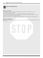 4
4
-
 5
5
-
 6
6
-
 7
7
-
 8
8
-
 9
9
-
 10
10
-
 11
11
-
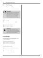 12
12
-
 13
13
-
 14
14
-
 15
15
-
 16
16
-
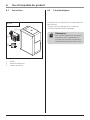 17
17
-
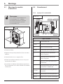 18
18
-
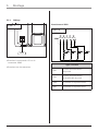 19
19
-
 20
20
-
 21
21
-
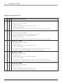 22
22
-
 23
23
-
 24
24
-
 25
25
-
 26
26
-
 27
27
-
 28
28
-
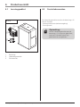 29
29
-
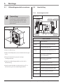 30
30
-
 31
31
-
 32
32
-
 33
33
-
 34
34
-
 35
35
-
 36
36
-
 37
37
-
 38
38
-
 39
39
-
 40
40
-
 41
41
-
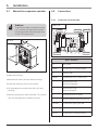 42
42
-
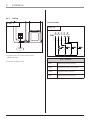 43
43
-
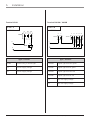 44
44
-
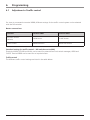 45
45
-
 46
46
-
 47
47
-
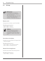 48
48
-
 49
49
-
 50
50
-
 51
51
-
 52
52


