HQ Power Krystal RGV380 RGV laser projector Handleiding
- Categorie
- Stroboscopen
- Type
- Handleiding
Deze handleiding is ook geschikt voor

V
K
R
K
R
P
R
P
R
K
R
U
S
G
E
N
O
M
A
B
E
DP230
1
R
YSTAL
R
YSTAL
R
OJECT
E
R
OYECT
O
R
YSTAL
S
ER MAN
E
BRUIKE
R
O
TICE D’
E
A
NUAL D
E
DIENUN
1
RGVL
D
RGV /
R
RGV /
R
E
UR LAS
E
O
R L
Á
S
E
RGV- /
R
UA
L
R
SHAND
L
E
MPLOI
EL USUA
R
GSANLEI
T
D
10 -
V
R
GY LAS
E
R
GY LAS
E
E
R KRY
S
E
R KRYS
T
R
GY-LA
S
L
EIDING
R
IO
T
UNG
V
DP260
E
R PROJ
E
E
RPROJ
E
S
TAL RG
V
T
AL RG
V
S
ERSCH
E
3
11
19
27
35
1RGYL
D
E
CTO
R
-
E
CTOR -
M
V
/ RGY
V
/ RGY-
E
INWER
F
D
10 -
V
with S
D
M
ET SD
-
- AVEC
C
CON TA
R
F
ER - MI
T
V
DP380
D
CARD
-
KAART
C
ARTE S
R
JETA S
D
T
SD-K
A
1RGVL
D
D
D
A
RTE
D
10

11
H
o
C
o
M
o
M
o
Di
e
/08/2011
o
w to turn
t
o
ntroller li
n
o
difier la li
g
o
dificar la l
e
Controll
e
VDP
2
t
he control
n
e van 3-pi
n
g
ne du con
t
ínea del c
o
e
r-Linie vo
n
2
301RGVL
D
ler line fro
m
n
naar 5-pi
t
rôleur de
3
o
ntrolador
d
n
3-Pin nac
h
D
10 - VDP2
6
m
3-pins i
n
n aanpass
e
3
broches
e
d
e 3 polos
y
h
5-Pin an
z
6
01RGYLD
1
2
n
to 5-pins
(
e
n (stekke
r
e
n 5 broch
e
y
5 polos (
c
z
upassen (
S
1
0 - VDP3
8
(
plug and s
r
en contac
t
e
s (fiche e
t
c
onector y
S
tecker un
d
8
01RGVLD
1
termi
n
eindweers
t
résistan
c
termin
a
termin
a
Terminie
r
ocket).
t
).
t
contact).
contacto).
d
Kontakt)
.
1
0
n
ator
t
and
c
e de
a
ison
a
ción
r
ung
.
©Vellema
n
n
nv

11
1
.
T
o
I
m
Th
If
t
Th
op
As
2
.
•
•
•
•
/08/2011
.
Introd
u
o
all reside
n
m
portant e
n
This
har
m
shou
distri
If in
ank you for
t
he device
w
e VDP230
1
erated in 3
m
sociation) s
t
VDP2
3
VDP3
8
VDP2
6
.
Safety
I
Be
Do
Ke
e
Un
p
Us
e
Wh
NE
V
ey
e
Do
Ke
e
VDP23
0
VDP38
0
VDP26
0
Damage ca
dealer will
n
A qualified
Do not swi
t
device agai
This device
qualified p
e
VDP
2
u
ction
n
ts of the
E
n
vironmen
t
symbol on t
h
m
the enviro
n
ld be taken
t
butor or to
a
doubt, co
n
choosing H
Q
w
as damage
d
1
RGVLD10,
m
odes: DM
X
t
andard mo
d
3
01RGVLD
1
8
01RGVLD
1
6
01RGYLD
1
I
nstruct
very careful
not touch t
h
e
p this devi
c
p
lug the ma
i
e
extreme c
a
en device is
V
ER point t
h
e
s or skin. B
not point t
h
e
p out of re
a
0
1RGVLD1
0
0
1RGVLD1
0
0
1RGYLD1
0
used by dis
r
n
ot accept r
e
technician s
t
ch the devi
c
nst damage
falls under
e
rson carry
o
2
301RGVL
D
E
uropean U
n
t
al informa
t
h
e device o
r
n
ment. Do n
t
o a speciali
a
local recy
c
n
tact your l
Q
-power! Pl
e
d
in transit,
VDP2601
R
X
/sound con
t
d
e. Each pro
j
1
0: 230mW
1
0: 380mW
1
0: 260mW
ions
during the
h
e device d
u
c
e away fro
m
i
ns lead bef
o
a
ution when
in use, do
N
h
e laser bea
urns and pe
h
e laser bea
m
a
ch of all chi
Th
e
AV
O
AP
E
0
0
0
r
egard of ce
r
e
sponsibilit
y
hould instal
l
c
e on imme
d
by leaving
i
protection c
o
ut the elec
t
D
10 - VDP2
6
Us
e
n
ion
t
ion about
t
r
the packag
ot dispose
o
zed compan
c
ling service
.
ocal waste
e
ase read th
do not insta
R
GYLD10 a
n
t
rolled, SD
c
j
ector has 1
RGV (Red
G
RGV (Red
G
RGY (Red
G
installation:
u
ring operati
m
rain and
m
o
re opening
the laser b
e
N
OT look d
m directly
o
rmanent ey
e
m
towards h
ldren.
e
arrow indi
c
O
ID EXPO
S
E
RTURE
r
tain guideli
n
y
for any en
s
l
and servic
e
d
iately after
i
t switched
o
lass I. It is
t
t
ric connecti
o
6
01RGYLD
1
3
e
r man
t
his produ
c
e indicates
t
o
f the unit (
o
y for recycli
.
Respect th
e
disposal a
e manual th
ll or use it a
n
d VDP380
1
c
ard mode o
0 DMX chan
G
reen Violet
)
G
reen Violet
)
G
reen) laser
touching li
v
on as the h
o
m
oisture.
the housing
e
am is turn
e
irectly or i
n
o
r via a refle
c
e
damage w
ighly explos
c
ates the las
S
URE - LAS
E
n
es in this
m
s
uing defect
s
e
this device
it has been
o
ff until it h
a
t
herefore es
s
o
n.
1
0 - VDP3
8
ual
c
t
t
hat disposa
o
r batteries)
ng. This de
v
e
local envi
r
uthorities.
oroughly be
nd contact
y
1
RGVLD10
r via PC – I
L
nels (6 in S
D
)
laser proje
c
)
laser proje
c
projector
v
e wires can
o
using heat
s
.
e
d on.
n
directly (
r
c
ting surfac
e
ill result.
ive gasses.
er aperture.
E
R RADIAT
m
anual is no
t
s
or proble
m
.
exposed to
c
a
s reached r
o
s
ential that
t
8
01RGVLD
1
l of the devi
as unsorte
d
v
ice should
b
r
onmental r
u
fore bringin
g
y
our dealer.
are laser pr
o
L
DA (Intern
a
D
card mod
e
c
tor
c
tor
cause life-t
h
s
up.
r
eflectance
e
towards o
t
ION IS EM
I
t
covered b
y
m
s.
c
hanges in
t
o
om temper
t
he device b
1
0
ce after its l
d
municipal
w
b
e returned
t
u
les.
g
this devic
e
o
jectors tha
t
a
tional Lase
r
e
).
h
reatening
e
) into the l
a
t
her people’
s
I
TTED FRO
y
the warran
t
emperature
ature.
e earthed.
H
©Vellema
n
ifecycle cou
l
w
aste; it
t
o your
e
into servic
e
t
can be
r
Display
e
lectroshock
s
a
ser beam
.
s
or animals
’
M THIS
ty and the
. Protect th
e
H
ave a
n
nv
l
d
e
.
s
.
.
’
e

VDP2301RGVLD10 - VDP2601RGYLD10 - VDP3801RGVLD10
11/08/2011 ©Velleman nv
4
• Make sure that the available voltage does not exceed the voltage stated in the specifications of this manual.
• Do not crimp the power cord and protect it against damage. Have an authorised dealer replace it if
necessary.
• Disconnect the device from the mains to clean it or when it is not in use. Handle the power cord by the plug
only.
• Keep the device away from splashing and dripping liquids. Never put objects filled with liquid on top of the
device.
• Note that damage caused by user modifications to the device is not covered by the warranty.
• Mechanical wear is not covered by warranty.
• Keep the device away from children and unauthorised users.
3. General Guidelines
Refer to the Velleman® Service and Quality Warranty on the last pages of this manual.
• Nor Velleman nv nor its dealers can be held responsible for any damage (extraordinary, incidental or
indirect) – of any nature (financial, physical…) arising from the possession, use or failure of this product.
• This device is designed for professional use on stage, in discos, theatres, etc. The laser projector should
only be used indoors with an alternating current of max. 230VAC / 50Hz.
• Lighting effects are not designed for permanent operation: regular operation breaks will prolong their lives.
• Do not shake the device. Avoid brute force when installing or operating the device.
• Select a location where the device is protected against extreme heat, dust and moisture.
• Use an appropriate safety cable to fix the device (e.g. VDLSC7 or VDLSC8).
• Familiarise yourself with the functions of the device before actually using it. Do not allow operation by
unqualified people. Any damage that may occur will most probably be due to unprofessional use of the
device.
• Use the original packaging if the device is to be transported.
• All modifications of the device are forbidden for safety reasons.
• Only use the device for its intended purpose. All other uses may lead to short circuits, burns, electroshocks,
crash, etc. Using the device in an unauthorised way will void the warranty.
4. Mounting/connecting the device
• Have the device installed by a qualified person, respecting EN 60598-2-17 and all other applicable norms.
• The carrying construction must be able to support 10 times the weight of the device for 1 hour without
deforming.
• The installation must always be secured with a secondary attachment e.g. a safety cable.
• Never stand directly below the device when it is being mounted, removed or serviced. Have a qualified
technician check the device once a year and once before you bring it into service.
• Install the device in a location with few passers-by that is inaccessible to unauthorised persons.
• Overhead mounting requires extensive experience: calculating workload limits, determining the installation
material to be used… Have the material and the device itself checked regularly. Do not attempt to install the
device yourself if you lack these qualifications as improper installation may result in injuries.
• Adjust the desired inclination angle via the mounting bracket and tighten the bracket screws.
• Make sure there is no flammable material within a 0.5m radius of the device.
• Have a qualified electrician carry out the electric connection.
• Connect the device to the mains with the power plug. Do not connect it to a dimming pack.
• The installation has to be approved by an expert before the device is taken into service.
• For installations using DMX512:
• Connection
Connect the provided XLR cable to the female 3-pin XLR output of your controller and the other side to
the male 3-pin XLR input of the laser projector [7]. Multiple laser projectors can be linked through serial
linking. The linking cable should be a two-core screened cable with XLR input and output connectors (see
page 2 for pin-out).
• Chain with Termination
A DMX terminator is recommended for installations where the DMX cable has to run a long distance or is
in an electrically noisy environment (e.g. discos). The terminator prevents corruption of the digital control
signal by electrical noise. The DMX terminator is simply an XLR plug with a 120Ω resistor between pins 2
and 3, which is then plugged into the XLR output socket [8] of the last device in the chain (see page 2).
• For installations using ILDA (PC mode) use following ILDA cable layout (DB-25F):
PIN signal name remarks
1 X+ -5V to +5V
2 Y+ -5V to +5V
5 Red+ 0V to 2.5V
6 Green+ 0V to 2.5V
14 X- Connected to ground
15 Y- Connected to ground
18 Red- Connected to ground
19 Green- Connected to ground
25 Ground Cable shield

11
5
.
Re
2
3
4
5
6
7
8
9
1
1
1
1
6
.
Re
•
•
6.
•
•
/08/2011
.
Descri
p
fer to the ill
1 MIC
2
VOLUM
E
3
READY
ERROR
4
FUNC S
E
5
SD CAR
6
MODE
S
7
DMX IN
8
DMX O
U
9
DIP SW
I
1
0 ILDA IN
1
1 ILDA T
H
1
2 ON/OF
F
1
3 AC IN
~
.
Use
f
er to the ill
The laser p
o Sound/
D
o SD card
o PC cont
r
Select the
d
1 Sou
n
Press the S
Use the DI
P
o Sound
/
auto an
d
o DMX c
o
DMX st
a
• Star
t
All D
M
sign
a
cont
r
You
c
ever
y
Whe
n
parti
c
VDP
2
p
tion
ustrations o
E
DMX
DATA
E
LECT UP
D SLOT
S
WITCHES
U
T
I
TCH
H
RU
F
*
~
ustrations o
rojector can
D
MX controll
controlled
r
olled (via I
L
d
esired mod
n
d/DMX
c
OUND&DM
X
P
switch [9]
/
auto/slav
e
d
slave mod
e
Fu
n
sou
n
aut
o
slav
cou
n
o
ntrol mod
e
a
rt address (
addr
e
5
19
40
t
Address
S
M
X-controll
e
a
ls. This sta
r
r
oller.
c
an use the
s
y
device.
n
all devices
c
ular chann
e
2
301RGVL
D
n page 2 of
microph
volume
status L
SD card
slot for
S
select o
p
DMX in
p
DMX ou
t
set the
D
ILDA st
a
ILDA st
a
on/off k
e
AC inpu
t
n page 2 of
work in 3 d
ed
L
DA standar
d
e by pressi
n
c
ontrolle
d
X
mode swit
c
to configur
e
e
mode: sw
i
e
.
n
ction
n
d mode (m
o
mode
e mode
n
tdown mod
e
: switch 10
max. 511).
e
ss
D
S
etting
e
d devices n
e
r
t address is
s
ame starti
n
have the s
a
e
l. In other
w
D
10 - VDP2
6
this manual
one
control
EDs for SD
c
controls
S
D card
p
erating mo
d
p
ut port (3 p
t
put port (3
D
MX addres
s
a
ndard inpu
t
a
ndard sign
a
e
y switch
t
110~240V
a
* depe
n
this manual
ifferent mo
d
d
)
n
g the corre
s
d
mode
c
h [6] to se
l
e
sound or
D
i
tch 10 mus
t
aster)
e*
* the la
must be se
t
Examples:
D
IP Switch
e
e
ed a digita
l
the channe
l
n
g address f
o
a
me addres
s
w
ords: chan
g
6
01RGYLD
1
5
.
c
ard mode
d
e
ins)
pins
s
t
a
l throughpu
a
c 50/60Hz
n
ding on th
e
.
d
es:
s
ponding m
o
l
ect Sound/
D
D
MX mode:
t
be set to t
h
ser projects
t
to the ON
p
e
s
l
start addr
e
l
number fr
o
o
r a whole
g
s
, all laser p
r
g
ing the set
t
1
0 - VDP3
8
t
(and fuse h
o
e
model an
a
o
de switch [
6
D
MX controll
h
e OFF posi
t
DIP Sw
a countdo
w
p
osition. Sw
i
s
w
e
ss so that t
h
o
m which th
e
g
roup of dev
i
r
ojectors wil
l
t
ings of one
8
01RGVLD
1
o
lder)
a
dditional o
n
6
].
ed mode.
t
ion. Switch
e
itches
w
n sequence
i
tches 1 thr
o
w
itch
1
2
3
4
5
6
7
8
9
h
e correct d
e
e
device sta
r
i
ces or ente
r
l
“listen” to
t
channel wil
l
1
0
n
/off switch
m
e
s 1 and 2 t
h
from 9 to 0
o
ugh 9 than
represe
n
1
2
4
8
16
32
64
128
256
e
vice respo
n
r
ts to
“
listen
r
an individ
u
t
he control
s
l
affect all d
e
©Vellema
n
m
ay be pre
s
h
an determi
n
.
determine
t
n
ts
n
ds to the
” to the DM
X
u
al one for
s
ignal on on
e
e
vices
n
nv
s
ent
n
e
t
he
X
e

VDP2301RGVLD10 - VDP2601RGYLD10 - VDP3801RGVLD10
11/08/2011 ©Velleman nv
6
simultaneously. If you set different addresses, each device will “listen” to a separate channel number.
Changing the settings of one channel will only affect the device in question.
In the case of the 10-channel laser projector, you will have to set the start address of the first laser
projector to 1, the second laser projector to 11 (10 + 1), the third to 21 (10 + 11) and so on.
• DMX5 channel assignment
Channel DMX512
value
function
1 control mode
0--63 Sound control (channel 3~10 not used)
64--127 Auto mode (channel 3~10 not used)
128--191 DMX control
192--255 Auto mode
2 blanking & blackout
VDP2301RGVLD10
VDP3801RGVLD10
VDP2601RGYLD10
0--5 blackout blackout
6--10 white
red
11--15 red
16--25 yellow
green
21--25 green
26--30 cyan
yellow
31--35 blue
36--40 purple 36--105 single colour (auto)
41--110 single colour (auto) 106--175 tri-colour (auto)
111--180 multi-colour (auto) 176--245 tri-colour (move)
181--251 multi-colour (move) 246--255 bounded colour
251--255 bounded colour
3 pattern 0--255 124 patterns (0-255)
4 vertical move
0--127 manual vertical move
128--191 auto down, speed up accordingly
192--255 auto up, speed up accordingly
5 horizontal move
0-127 manual horizontal move
128--191 manual right, speed up accordingly
192-255 manual left, speed up accordingly
6 vertical roll
0--127 manual vertical rotation
128--255 auto vertical rotation, speed up accordingly
7 horizontal roll
0--127 manual horizontal rotation
128--255 auto horizontal rotation
8 rotation
0--127 manual rotation
128--191 auto clockwise rotation, speed up accordingly
192--255 auto anti-clockwise rotation, speed up accordingly
9 zoom in & out
0--85 from small to large, speed up accordingly
86--170 from large to small, speed up accordingly
171--255
large ←→ small, speed up accordingly
10 point draw 0--255 0=nil / 1~255=faint ~bright
6.2 SD Card controlled mode
• Press the SD CARD mode switch [6] to select SD CARD controlled mode.
• In SD CARD mode, a DMX address (and thus a controller) is still required.
SD card notes:
• Only use high quality SD cards of well known brands to avoid reading errors.
• Max. supported capacity = 2GB.
• The card must be formatted as FAT16 file system. The card that comes with the device is already correctly
formatted.
• Do not place files in sub-directories.
• Do not place more than 260 files in the root directory.
• File name length is limited to 8 characters (followed by the .ild extension).
• 5animated) files (shows) must be created using an appropriate ILDA software program (not included).
• The root directory may contain 3 reserved files. Do not remove these files:
o CONFIG.DAT: contains setting information for the laser projector. See further for instructions on creating
and modifying this file.
o FLASHMP.BIN: control program for firmware updates

VDP2301RGVLD10 - VDP2601RGYLD10 - VDP3801RGVLD10
11/08/2011 ©Velleman nv
7
o FWUPxxx.BIN: specific update (xxx=update number). This file is removed automatically when the update
procedure is completed.
Definitions:
• A show contains a number of frames which are played (projected) in sequence.
• Each frame is drawn by a laser as a series of points. The time between the points determine the
smoothness of the frame. The overall speed is expressed in Kilo points per second (Kpps). When this value
is set too low, the frame will not be completely visible or flickers.
Note: setting the speed at max. (= 20Kpps) all the time puts a lot of stress on the internal moving parts of
the projector.
• The time between to consecutive frames (= the speed of the animation) is set by the frame repeat
parameter. A low (DMX-) value will produce a low animation speed.
Note: running the animations at max. speed all the time puts a lot of stress on the internal moving parts of
the projector.
• When the laser has to draw two non-consecutive points, it will switch off for a brief period of time, the so
called blank shift. A low value will switch off the laser immediately at one point and switch it on again in
the next; increasing the value will delay laser switching.
DMX channels:
• In SD CARD mode, the laser projector becomes a 16-channel DMX device. However, only 9 of these
channels can be controlled, the other ones are defined by the projected animation.
• Use the output of the DMX-controller (not incl.) to control the channels. Refer to CONFIG.DAT below for an
overview of the DMX channels.
SD card controls:
• There are 3 buttons to control the SD card mode:
o FUNC [A]
Select the parameter to change:
“Adr” = DMX address (1~512)
“Int” = max. colour/laser output intensity (0~99).
“Ort” = orientation of the projection (0~7)
0 normal 4 X and Y swapped
1 X inverted 5 X and Y swapped; X inverted
2 Y inverted 6 X and Y swapped; Y inverted
3 X and Y inverted 7 X and Y swapped, X and Y inverted
o SEL [B]
Press this button to see the current setting of “Adr”, “Int” or “Ort”.
Press again to edit the setting. The right digit starts blinking and can be changed using the UP button.
Press SEL again to edit the middle digit; press again to edit the left digit. Press FUNC to store and exit.
o UP [C]
Press this button to increase the value of the blinking digit (0~9).
Note: the LCD will return to normal display after 10s of inactivity
Status LEDs:
• Refer to the table below for the meaning of the status LEDs.
READY
(green)
DMX
(green)
ERROR
(red)
DATA
(yellow)
X no MMC/SD card present
X X no FAT16 file system found
X X X data error while reading card
X X file not found or invalid
X X no DMX signal
X X laser projector ready
Note: X = ON
• Not every error will cause the laser output to stop. This will only be the case when access or read/write
errors on the memory card occur or files are corrupted.
CONFIG.DAT:
• The file CONFIG.DAT contains configuration information for the laser projector. It can be created and
modified by using the software tool EditConfig.exe which is shipped with every laser projector.
• Insert the included SD card in a suitable PC, locate EditConfig.exe and double click it to open the
configuration file:

VDP2301RGVLD10 - VDP2601RGYLD10 - VDP3801RGVLD10
11/08/2011 ©Velleman nv
8
• To start a new configuration, select New Config; to adjust and existing configuration, click Load Config.
Select the desired file in the pop-up window.
Global data:
• Set the DMX base address of the laser projector between 1 and 511.
When multiple laser projectors are linked, and they must produce the same output, their addresses must
be set to the same value and their CONFIG.DAT files must be identical.
If they are controlled individually, their addresses must be separated by 16 as each device needs 16 DMX
channels. So the first should be at 1, the second at 17 the third on 33 and so on.
DMX-Channels 1-16:
• Define the DMX channel numbers to control the laser animation. Every function must have a unique
channel number (1~16).
• Except for the first two parameter (show select L and show select H) all parameters can be set to a
fixed value by checking the none-box and entering the desired value in the dropdown box behind the
parameter or in the showtable below the parameters. In this case, the parameter can not be changed via
DMX anymore.
• The Show Select H parameter can be set to none by checking the checkbox. By doing this, only the first
16 files in the showtable are accessible.
show select L Select one of the first 16 shows on the card (including pause). Each show occupies
16 DMX values.
show select H Select one of the 16 banks of shows, each bank containing 16 shows (total=256
shows). A bank uses 16 DMX values.
Speed Kpps Set the frame drawing speed (Kpps).
Note: this setting might influence the blank shift setting.
Frame repeat Control the animation speed.
projection size Change the size of the projection (see important note below).
Changing the size too fast will result in a ‘jumping’ display.
offset X 0 = maximum negative offset
128 = centre position
255 = maximum positive offset
Note: projected display might ‘jump’ due to the slow DMX signal rate
offset Y 0 = maximum negative offset
128 = centre position
255 = maximum positive offset
Note: projected display might ‘jump’ due to the slow DMX signal rate
Blank shift Control the laser off-time between non-consecutive points of the frame.
Intensity Control the intensity of the laser output.

VDP2301RGVLD10 - VDP2601RGYLD10 - VDP3801RGVLD10
11/08/2011 ©Velleman nv
9
IMPORTANT NOTE
Setting the projection size to zero can cause a standing laser beam. This is a hazardous
condition that must be avoided at all times.
Showtable:
Note: the show in the first data entry field, DMX value 0, is displayed when the laser projector is paused
or when an empty data location (no filename provided) is opened. For safety reasons it is strongly
advised to leave this empty.
• Enter up to 256 shows into the filename-fields. Click on a filename field to open an explorer dialog box.
Select the desired .ild file.
Note: the .ild file must be on the SD card.
Notes:
• Every show occupies 16 DMX values. The relationship between DMX control and DMX Value (=
filename) is given in the table below:
Showselect H
0-
15
16-
31
32-
47
48-
63
64-
79
80-
95
96-
111
112-
127
128-
143
144-
159
160-
175
176-
191
192-
207
208-
223
224-
239
240-
255
Showselect L
240-255 15 31 47 63 79 95 111 127 143 159 175 191 207 223 239 255
224-239 14 30 46 62 78 94 110 126 142 158 174 190 206 222 238 254
208-223 13 29 45 61 77 93 109 125 141 157 173 189 205 221 237 253
192-207 12 28 44 60 76 92 108 124 140 156 172 188 204 220 236 252
176-191 11 27 43 59 75 91 107 123 139 155 171 187 203 219 235 251
160-175 10 26 42 58 74 90 106 122 138 154 170 186 202 218 234 250
144-159 9 25 41 57 73 89 105 121 137 153 169 185 201 217 233 249
128-143 8 24 40 56 72 88 104 120 136 152 168 184 200 216 232 248
112-127 7 23 39 55 71 87 103 119 135 151 167 183 199 215 231 247
96-111 6 22 38 54 70 86 102 118 134 150 166 182 198 214 230 246
80-95 5 21 37 53 69 85 101 117 133 149 165 181 197 213 229 245
64-79 4 20 36 52 68 84 100 116 132 148 164 180 196 212 228 244
48-63 3 19 35 51 67 83 99 115 131 147 163 179 195 211 227 243
32-47 2 18 34 50 66 82 98 114 130 146 162 178 194 210 226 242
16-31 1 17 33 49 65 81 97 113 129 145 161 177 193 209 225 241
0-15 0 16 32 48 64 80 96 112 128 144 160 176 192 208 224 240
• Set the desired frame drawing speed, framerepeat and display mode by clicking on either one of those
fields:
Displaymode
oneshot/complete The show is shown 1 time completely. It can not be interrupted. When
finished, the projector goes into pause mode.
oneshot/interruptable The show is shown 1 time completely. It can be interrupted via DMX. When
finished, the projector goes into pause mode.
loop/complete The show is shown in a continuous loop. It can only be interrupted at the
end of the show.
loop/interruptable The show is shown in a continuous loop. It can be interrupted at any time
via DMX.

VDP2301RGVLD10 - VDP2601RGYLD10 - VDP3801RGVLD10
11/08/2011 ©Velleman nv
10
• Click on No File to remove the file from the list.
• Click OK to save the settings.
• When desired, a list of all DMX settings can be printed by clicking the Print button.
• To save the configuration, click on Save Config. The file must be saved as CONFIG.DAT as this is the
file that will be loaded automatically by the laser projector.
• Place the SD card back in the laser projector and switch the projector on. Make sure the SD CARD mode
switch [6] is pressed and the correct DMX address is set via the SD card controls.
6.3 PC controlled mode
• The PC controlled mode uses the ILDA (International Laser Display Association) standard for control signal
and file formats. The laser projector must be connected to a suitable PC running appropriate software (e.g.
Pangolin, Mamba, Phoenix…). Refer to §5 for the cable layout of the ILDA cable. More on the ILDA standard
can be found on http://www.laserist.org/standards.htm
.
IMPORTANT NOTE
Make sure to set the scan rate in the software equal to or lower than the actual scan rate of
the laser projector. Setting the scan rate too high may damage the laser projector; this
damage is not covered by the warranty.
• Press the PC MODE switch [6] to select PC mode.
• In this mode, the laser projector will receive its instructions and shows via the ILDA input port [10].
• Multiple laser projectors can be linked via the ILDA THRU port [9].
7. Cleaning and Maintenance
• All screws should be tightened and free of corrosion.
• The housing, visible parts, mounting supports and the installation location (e.g. ceiling, suspension,
trussing) should not be deformed, modified or tampered with e.g. do not drill extra holes in mounting
supports, do not change the location of the connections.
• Moving mechanic parts must not show any signs of wear and tear.
• The electric power supply cables must not show any damage. Have a qualified technician maintain the
device.
• Disconnect the device from the mains prior to maintenance activities.
• Wipe the device regularly with a moist, lint-free cloth. Do not use alcohol or solvents.
• There are no user-serviceable parts apart from the fuse.
• Contact your dealer for spare parts if necessary.
8. Technical specifications
VDP2301RGVLD10 VDP3801RGVLD10 VDP2601RGYLD10
Laser colour
/power
red 663nm/160mW 665nm/215mW 662nm/200mW
green 533nm/100mW 533nm/85mW 533nm/100mW
purple 408nm/200mW 405nm/200mW -
max. total output power 460mW 500mW 300mW
max. scan speed 20 Kpps 20 Kpps 20 Kpps
optical angle ±20° ±20° ±20°
Power supply AC 110-240V 50/60Hz
Power consumption 300W
Dimensions 200 x 260 x 450mm 200 x 260 x 310mm
Total Weight 7.0kg ±5.5kg
Laser type DPSSL (Diode Pumped Solid State Laser) green: DPSSL
red: semiconductor laser diode
Laser class Class 3B
Laser life >5000h
Use this device with original accessories only. Velleman nv cannot be held responsible in the event
of damage or injury resulted from (incorrect) use of this device. For more info concerning this
product and the latest version of this user manual, please visit our website www.hqpower.eu. The
information in this manual is subject to change without prior notice.
© COPYRIGHT NOTICE
The copyright to this manual is owned by Velleman nv. All worldwide rights reserved.
No part of this manual or may be copied, reproduced, translated or reduced to any electronic medium or otherwise without
the prior written consent of the copyright holder.

11
1
.
A
a
B
e
H
e
D
a
be
D
e
aa
As
2
.
•
D
z
•
L
•
O
t
e
•
D
t
e
•
D
/08/2011
.
Inleidi
n
a
n alle ing
e
e
langrijke
m
Dit s
y
wegg
e
batte
r
terec
h
bren
g
e
bt u vrage
a
nk u voor u
w
schadigd tij
d
e
VDP2301
R
nstuurmoge
sociation).
E
VDP2
3
VDP2
6
VDP3
8
.
Veili
g
h
e
W
e
el
e
Ra
a
Be
s
Ve
r
Ge
Ki
j
re
c
ve
r
Ri
c
Ho
VDP23
0
VDP38
0
VDP26
0
D
e garantie
g
z
al de veran
t
L
aat dit toes
t
O
m beschadi
e
mperatuur
s
D
it toestel v
a
e
chnicus m
o
D
e beschikb
a
VDP
2
ng
e
zetenen v
a
m
ilieu-info
r
y
mbool op h
e
e
worpen, di
t
r
ijen) niet bi
h
tkomen vo
o
g
en. Respec
t
n, contact
e
w
aankoop!
d
ens het tra
R
GVLD10,
V
lijkheden:
D
E
lke project
o
3
01RGVLD
1
6
01RGYLD
1
8
01RGVLD
1
e
idsinst
r
e
es voorzich
t
e
ktroshocks
t
a
k het toest
s
cherm dit t
r
zeker u er
v
bruik een in
j
k niet rec
h
c
htsreeks of
r
mijden.
c
ht de lasers
ud buiten h
e
0
1RGVLD1
0
0
1RGVLD1
0
0
1RGYLD1
0
g
eldt niet v
o
t
woordelijkh
t
el installer
e
ging te ver
m
s
chommelin
g
a
lt onder be
s
o
et de elekt
r
a
re netspan
n
2
301RGVL
D
G
a
n de Euro
p
r
matie bet
r
e
t toestel of
t
toestel sch
j het gewon
o
r recyclage
t
eer de plaa
t
e
er dan de
Lees deze
h
nsport, inst
a
V
DP2601R
G
D
MX-/muzie
k
o
r heeft 10
D
1
0: 230 m
W
1
0: 260 m
W
1
0: 380 m
W
r
ucties
t
ig bij de in
s
t
e vermijde
n
el niet aan
w
oestel tege
n
v
an dat het t
geschakeld
e
h
tsreeks of
via reflectie
traal nooit
n
e
t bereik va
n
De
VE
R
0
0
0
o
or schade d
eid afwijzen
e
n en onder
h
m
ijden, zet
u
g
en. Wacht
s
chermings
k
r
ische aansl
u
n
ing mag ni
e
D
10 - VDP2
6
G
ebrui
k
p
ese Unie
r
effende di
t
de verpakk
i
ade kan toe
e huishoud
e
. U moet dit
t
selijke mili
e
plaatselijk
e
h
andleiding
g
a
lleer het da
G
YLD10 en
k
sturing, stu
D
MX-kanale
n
W
RGV (rood
-
W
RGY (rood
-
W
RGV (rood
-
s
tallatie: raa
n
.
w
anneer het
n
regen en v
oestel niet
a
e
laserproje
c
onrechtstr
naar perso
n
n
aar explosi
e
n
kinderen.
pijl geeft d
e
R
MIJD BLO
oor het neg
e
voor defect
h
ouden door
u
het toestel
tot het toes
t
k
lasse I, wat
u
iting verzor
e
t hoger zijn
6
01RGYLD
1
11
k
ersha
n
t
product
i
ng geeft aa
n
brengen aa
n
e
lijke afval;
h
toestel naa
r
e
uwetgeving
.
e
autoritei
t
g
rondig voo
r
n niet en ra
a
VDP3801
R
ring via SD
-
n
(6 via SD-
k
-
groen-viole
-
groen) lase
r
-
groen-viole
k geen kab
e
in gebruik i
ochtigheid.
a
angesloten
c
tor met de
g
eeks (refl
e
n
en of diere
n
e
ve gassen.
e
laseropeni
n
OTSTELLI
N
e
ren van be
p
en of probl
e
een gescho
best niet a
a
t
el op kame
r
wil zeggen
gen.
dan de spa
1
0 - VDP3
8
n
dleidin
n
dat, als h
e
n
het milieu.
h
et moet bij
r
uw verdel
e
.
t
en betreff
e
r
u het toest
e
a
dpleeg uw
R
GVLD10 zij
-
kaart of via
k
aart).
t) laserproj
e
r
projector
t) laserproj
e
e
ls aan die o
s: de behui
z
is op een st
r
g
rootste vo
o
e
ctie) in de
n
om onher
r
n
g weer.
N
G – OPEN
I
p
aalde richtl
e
men die hie
olde technic
a
n onmiddel
l
r
temperatu
u
dat het toe
s
nning in de
8
01RGVLD
1
g
e
t na zijn le
v
Gooi dit to
e
een gespe
c
e
r of naar e
e
e
nde de ve
r
e
l in gebrui
k
dealer.
n laserproje
pc – ILDA (
e
ctor
e
ctor
nder stroo
m
z
ing wordt
w
r
oombron al
o
rzichtigheid
laserstraa
l
r
oepelijke sc
I
NG MET L
A
ijnen in dez
e
r rechtstree
us.
l
ijk nadat h
e
u
r gekomen
i
s
tel geaard
m
specificatie
s
1
0
v
enscyclus
w
e
stel (en ev
e
c
ialiseerd be
d
e
n lokaal rec
r
wijdering.
k
neemt. W
e
ctoren met
3
Internation
a
m
staan om
d
w
arm.
vorens het
t
.
l
. Richt de l
a
c
hade aan o
g
A
SERSTRA
A
e handleidi
n
ks verband
m
e
t werd bloo
t
is.
m
oet zijn. E
e
s
achteraan
d
©Vellema
n
w
ordt
e
ntuele
d
rijf
y
clagepunt
rd het toest
3
a
l Laser Dis
p
d
odelijke
t
e openen.
a
serstraal n
o
g
en en huid
t
A
L
n
g en uw de
a
m
ee houde
n
t
gesteld aa
n
e
n geschool
d
d
e handleidi
n
nv
el
p
lay
o
oit
t
e
a
ler
n
.
n
d
e
ng.

VDP2301RGVLD10 - VDP2601RGYLD10 - VDP3801RGVLD10
11/08/2011 ©Velleman nv
12
• De voedingskabel mag niet omgeplooid of beschadigd zijn. Laat uw dealer zo nodig een nieuwe kabel
plaatsen.
• Trek de stekker uit het stopcontact (trek niet aan de kabel!) voordat u het toestel reinigt en als u het niet
gebruikt.
• Houd dit toestel uit de buurt van opspattende en druppelende vloeistoffen. Plaats geen objecten gevuld met
vloeistof op het toestel.
• Schade door wijzigingen die de gebruiker heeft aangebracht aan het toestel vallen niet onder de garantie.
• Mechanische slijtage valt niet onder de garantie.
• Houd dit toestel uit de buurt van kinderen en onbevoegden.
3. Algemene richtlijnen
Raadpleeg de Velleman
®
service- en kwaliteitsgarantie achteraan deze handleiding.
• Noch Velleman nv noch zijn verdelers kunnen aansprakelijk gesteld worden voor schade (buitengewoon,
incidenteel of onrechtstreeks) – van welke aard dan ook (financieel, fysisch…) voortvloeiend uit het bezit,
gebruik of falen van dit product.
• Dit toestel is ontworpen voor professioneel gebruik op podia, in disco's, enz. U mag dit toestel enkel
binnenshuis gebruiken en aansluiten op een wisselspanning van maximum 230VAC / 50Hz.
• Lichteffecten zijn niet ontworpen voor continue werking: regelmatige onderbrekingen doen ze langer
meegaan.
• Schud het toestel niet dooreen. Vermijd brute kracht tijdens de installatie en de bediening van dit toestel.
• Installeer het toestel weg van extreme temperaturen, vochtigheid en stof.
• Maak het toestel vast met een geschikte veiligheidskabel (bvb. VDLSC7 of VDLSC8).
• Leer eerst de functies van het toestel kennen voor u het gaat gebruiken. Ongeschoolde personen mogen dit
toestel niet gebruiken. Meestal is beschadiging het gevolg van onprofessioneel gebruik.
• Gebruik de oorspronkelijke verpakking wanneer u het toestel vervoert.
• Om veiligheidsredenen mag de gebruiker geen wijzigingen aanbrengen aan het toestel.
• Gebruik het toestel enkel waarvoor het gemaakt is. Andere toepassingen kunnen leiden tot kortsluitingen,
brandwonden, elektrische schokken, enz. Bij onoordeelkundig gebruik vervalt de garantie.
4. Het toestel monteren en aansluiten
• Laat een geschoolde technicus dit toestel installeren conform EN 60598-2-17 en andere toepasselijke normen.
• De constructie waaraan het toestel wordt bevestigd, moet gedurende 1 uur 10 x het gewicht van dit toestel
kunnen dragen zonder te vervormen.
• Maak het toestel ook vast met een veiligheidskabel.
• Sta nooit recht onder het toestel wanneer u het monteert, verwijdert of schoonveegt. Laat het toestel
controleren door een geschoolde technicus voor u het in gebruik neemt en laat het 1 x per jaar volledig
nakijken.
• Installeer dit toestel op een plaats waar niemand langs moet lopen, kan neerzitten of het toestel kan
aanraken.
• Een degelijke praktijkervaring is vereist voor de plaatsing van dit toestel. U moet de maximumbelasting van
de draagconstructie kunnen berekenen, weten welk constructiemateriaal u kunt gebruiken en u moet het
gebruikte materiaal en het toestel af en toe laten nakijken. Monteer het toestel niet zelf indien u er geen
ervaring mee heeft. Een slechte montage kan leiden tot verwondingen.
• Regel de gewenste invalshoek door middel van de montagebeugel en draai de regelschroeven stevig aan.
• Verwijder alle brandbaar materiaal in een straal van 0.5m rond het toestel.
• Een geschoolde elektricien moet het toestel aansluiten.
• Sluit het toestel via de stekker aan op het lichtnet. Sluit het niet aan op een dimmerpack.
• De installatie moet voor het eerste gebruik gekeurd worden door een expert.
• Installaties met DMX512-sturing:
o aansluiting
Sluit de meegeleverde XLR-kabel aan de vrouwelijke 3-pin XLR-uitgang van de controller en de andere kant
van de mannelijke 3-pin XLR-ingang [7] van de laser projector. U kunt verscheidene laser projectoren aan
elkaar koppelen met behulp van een seriële koppeling. Gebruik daarvoor een 2-aderige afgeschermde kabel
met XLR ingang- en uitgangsaansluitingen (zie de afbeeldingen op pagina 2).
o keten met eindweerstand
Een DMX eindweerstand is aanbevolen als de DMX-kabel vrij lang is of wordt gebruikt in een omgeving met
veel elektrische ruis (bv. een discotheek). De eindweerstand voorkomt corruptie van het digitale
controlesignaal door elektrische ruis. De DMX eindweerstand is niets meer dan een XLR-stekker met een
weerstand van 120 Ω van pin 2 naar 3 (zie de afbeeldingen op pagina 2). Deze XLR-stekker wordt dan
aangesloten op de XLR-uitgang [8] van het laatste toestel in de reeks.
• Voor installaties met ILDA-sturing via pc, gebruik volgende ILDA-bekabeling (DB-25F):
pin signaal opmerking
1 X+ -5 V ~ +5 V
2 Y+ -5 V ~ +5 V
5 rood+ 0 V ~ 2,5 V
6 groen+ 0 V ~ 2,5 V
14 X- aansluiting op aarding
15 Y- aansluiting op aarding

11
5
.
Ra
2
3
4
5
6
7
8
9
1
1
1
1
6
.
Ra
•
D
o
o
o
•
K
6.
•
D
•
C
o
o
/08/2011
.
Omsch
r
adpleeg de
a
1 MIC
2
VOLUM
E
3
READY
ERROR
4
FUNC S
E
5
SD CAR
6
MODE
S
7
DMX IN
8
DMX O
U
9
DIP SW
I
1
0 ILDA IN
1
1 ILDA T
H
1
2 ON/OF
F
1
3 AC IN
~
.
Gebrui
k
adpleeg de
a
D
e laserproj
e
o
muziek-
/
D
M
o
sturing via
o
pc-sturing
v
K
ies de aans
t
1 Muzi
e
D
ruk op SO
U
C
onfigureer
d
o
Muziek/a
u
1 en 2.
o
DMX-sturi
Voorbeeld:
• Instelle
n
Alle DMX
-
signalen.
de DMX c
o
VDP
2
18
19
25
r
i
j
vin
g
a
fbeelding
o
E
DMX
DATA
E
LECT UP
D SLOT
S
WITCHES
U
T
I
TCH
H
RU
F
*
~
k
a
fbeelding
o
e
ctor beschi
k
M
X-sturing
SD-kaart
v
ia ILDA-sta
t
uurfunctie
e
e
k-/DM
X
U
ND&DMX [
6
d
e functie
m
u
to/slave:
P
Fu
n
mu
z
aut
o
slav
afte
ng: Plaats
s
adre
5
19
40
n
van het s
t
-
gestuurde t
o
Dit digitale
s
o
ntroller.
2
301RGVL
D
g
a
o
p pagina 2
v
microfo
o
volume
r
statusle
d
bedieni
n
slot voo
keuzek
n
3-pin D
M
3-pin D
M
DIP-sch
a
ILDA-in
g
ILDA-d
o
aan-uit
s
AC-inga
o
p pagina 2
v
k
t over 3 aa
ndaard
e
n druk op
d
X
-sturing
6
] om de m
u
m
et de DIP-s
c
P
laats scha
k
n
ctie
z
ieksturing (
o
matische s
t
efunctie
lfunctie
s
chakelaar 1
0
s DI
t
artadres
o
estellen he
s
tartadres i
s
D
10 - VDP2
6
rood-
g
roen-
arding
v
an deze ha
o
n
r
egeling
d
s voor stur
n
gen voor st
r SD-kaart
n
oppen aans
t
M
X-ingang
M
X-uitgang
a
kelaars DM
g
ang
o
organg
s
chakeling
ng 110 ~ 2
4
v
an deze ha
nstuurfuncti
d
e overeenk
o
u
ziek-/DMX-
c
hakelaars
[
k
elaar 10 op
master)
t
uring
* De la
s
0
op ON. St
e
P-schakel
a
bben een di
g
s
het kanaal
n
6
01RGYLD
1
13
ndleiding.
ing via SD-
k
uring via S
D
t
uurfuncties
X-adres
4
0 VAC, 50/
6
ndleiding.
es:
o
mstige keu
sturing te s
e
[
9]:
OFF. Stel d
e
s
erprojector
e
l het DMX-
a
a
ars
g
itaal starta
n
ummer va
n
1
0 - VDP3
8
aansluitin
g
aansluitin
g
afscher
m
k
aart
D
-kaart
6
0 Hz (met
z
*
zeknop [6]
.
e
lecteren.
e
automatis
c
DIP-scha
projecteert
a
dres (max.
sch
dres nodig,
n
waarop he
t
8
01RGVLD
1
g
op aarding
g
op aarding
m
ing kabel
z
ekering)
extra aan-u
.
c
he en slav
e
kelaars
een aftellin
g
511) in me
t
akelaar
1
2
3
4
5
6
7
8
9
zodat het j
u
t
toestel ‘lui
s
1
0
itschakelaa
r
e
functie in
m
g
van 9 tot
0
t
schakelaar
binaire w
a
1
2
4
8
16
32
64
128
256
u
iste toestel
s
tert’ naar h
©Vellema
n
r
volgens m
o
m
et schakela
a
0
.
1 tot 9.
a
arde
reageert op
et signaal v
a
n
nv
o
del
a
r
de
a
n

VDP2301RGVLD10 - VDP2601RGYLD10 - VDP3801RGVLD10
11/08/2011 ©Velleman nv
14
U kunt één enkel startadres gebruiken voor een groep toestellen of u kunt per toestel een nieuw startadres
ingeven.
Wanneer u één enkel startadres instelt, zullen alle toestellen ‘luisteren’ naar hetzelfde kanaal. Met andere
woorden: wanneer u de instellingen voor 1 kanaal verandert, zullen alle toestellen er tegelijk op reageren.
Wanneer u verschillende adressen instelt, dan luistert elk toestel naar een ander kanaal. Met andere
woorden: wanneer u de instellingen van een kanaal verandert, zal enkel het toestel op dat kanaal
reageren.
In het geval van de 10-kanaals laser projector, zult u het startadres van het eerste toestel op 1 moeten
instellen, van het tweede toestel op 11 (10 + 1), van het derde op 21 (10 + 11) enz.
• Waarde-instelling per kanaal
kanaal DMX512-
waarde
functie
1 aanstuurfunctie
0--63 muzieksturing (kanaal 3~10 niet gebruikt)
64--127 automatische sturing (kanaal 3~10 niet gebruikt)
128--191 DMX-sturing
192--255 automatische sturing
2 black-out
VDP2301RGVLD10
VDP3801RGVLD10
VDP2601RGYLD10
0--5 black-out black-out
6--10 wit
rood
11--15 rood
16--25 geel
groen
21--25 groen
26--30 cyaan
geel
31--35 blauw
36--40 purper 36--105 enkele kleur (auto)
41--110 enkele kleur (auto) 106--175 driekleurig (auto)
111--180 meerkleurig (auto) 176--245 driekleurig (move)
181--251 meerkleurig (move) 246--255 verspringen
251--255 verspringen
3 patroon 0--255 124 patronen (0-255)
4 verticale beweging
0--127 manuele, verticale beweging
128--191 automatisch neerwaarts, traag naar snel
192--255 automatisch opwaarts, traag naar snel
5
horizontale
beweging
0-127 manuele, horizontale beweging
128--191 manueel rechts, traag naar snel
192-255 manueel links, traag naar snel
6 verticale rol
0--127 manuele, verticale rolbeweging
128--255 automatische, verticale rolbeweging, traag naar snel
7 horizontale rol
0--127 manuele, horizontale rolbeweging
128--255 automatische, horizontale rolbeweging
8 rotatie
0--127 manuele rolbeweging
128--191 automatische rotatie naar rechts, traag naar snel
192--255 automatische rotatie naar links, traag naar snel
9 in- & uitzoomen
0--85 klein naar groot, traag naar snel
86--170 groot naar klein, traag naar snel
171--255
groot ←→ klein, traag naar snel
10 puntgrootte 0--255 0= nul / 1~255= dof ~ helder
6.2 Sturing via SD-kaart
• Druk op SD CARD [6].
• In deze aanstuurfunctie moet u nog steeds het DMX-adres ingeven.
Opmerkingen over de SD-kaart:
• Gebruik enkel een hoogwaardige SD-kaart van een gerenommeerd merk.
• Max. capaciteit = 2 GB.
• Formatteer de SD-kaart als FAT16. De meegeleverde kaart werd in de fabriek geformatteerd.
• Gebruik geen subdirectories.
• Beperk het aantal bestanden in de rootdirectory tot 260.
• Beperk de bestandsnaam tot 8 karakters (gevolgd door .ild).
• Creëer 5 animatiebestanden (shows) met een ILDA-software (niet meegeleverd).

VDP2301RGVLD10 - VDP2601RGYLD10 - VDP3801RGVLD10
11/08/2011 ©Velleman nv
15
• De rootdirectory kan 3 gereserveerde bestanden bevatten. Wis deze bestanden niet!
o CONFIG.DAT: Bevat instellinggegevens voor de laserprojector. Zie verder voor instructies.
o FLASHMP.BIN: Aanstuurprogramma voor firmware-updates.
o FWUPxxx.BIN: Specifieke update (xxx= updatenummer). Dit bestand wordt automatisch gewist na de
update.
Definities:
• Een show bevat een aantal frames in sequentiële volgorde afgespeeld.
• Elk frame wordt gevormd door een aantal punten. Het interval tussen twee punten bepaalt de vlotheid van
elk frame. De snelheid wordt uitgedrukt in kilopunten per seconde (Kpps). Bij een te lage waarde zal het
frame flikkeren of zelfs onzichtbaar zijn.
Opmerking: Gebruik niet voortdurend de maximale snelheid (= 20 Kpps) om de interne onderdelen niet
overmatig te belasten.
• De frameparameter bepaalt het interval tussen twee opeenvolgende frames (= de snelheid van de
animatie). Een lage (DMX-) waarde zorgt voor een trage animatie.
Opmerking: Laat de animaties niet voortdurend op maximale snelheid afspelen om de interne onderdelen
niet overmatig te belasten.
• De projector zal eventjes uitschakelen bij het projecteren van twee niet-opeenvolgende punten. Dit heet
verschuiving. Bij een lage waarde zal de projector onmiddellijk uit- en inschakelen. Verhoog de waarde om
het schakelen te vertragen.
DMX-kanalen:
• Bij gebruik van een SD-kaart beschikt u over 16 DMX-kanalen. U kunt echter slechts 9 van deze kanalen zelf
instellen; de overige kanalen zijn voor de animatie voorbehouden.
• Stel de kanalen in via de uitgang van de DMX-controller (niet meegeleverd). Raadpleeg CONFIG.DAT
hieronder voor een overzicht van de DMX-kanalen.
Bedieningen:
• Bedien de projector met de volgende drie knoppen:
o FUNC [A]
Selecteer de te wijzigen parameter:
‘Adr’ = DMX-adres (1~512)
‘Int’ = maximale intensiteit kleur/laser (0~99)
‘Ort’ = straalrichting van de projectie (0~7)
0 normaal 4 X en Y omgewisseld
1 X omgekeerd 5 X en Y omgewisseld; X omgekeerd
2 Y omgekeerd 6 X en Y omgewisseld; Y omgekeerd
3 X en Y omgekeerd 7 X en Y omgewisseld, X en Y omgekeerd
o SEL [B]
Druk op deze knop om de instellingen voor ‘Adr’, ‘Int’ of ‘Ort’ weer te geven.
Druk opnieuw om de instellingen te wijzigen. Wijzig de knipperende digit met UP, druk op SEL om de
volgende digit te selecteren. Bewaar de wijziging met FUNC.
o UP [C]
Wijzig de waarde van de knipperende digit (0~9).
Opmerking: De display keert na 10 seconden terug naar de normale uitlezing.
Statusleds:
• Raadpleeg de tabel hieronder:
READY
(groen)
DMX
(groen)
ERROR
(rood)
DATA
(geel)
X geen MMC- of SD-kaart aanwezig
X X geen FAT16 bestandsysteem gevonden
X X X datafout bij het lezen van de kaart
X X bestand niet gevonden
X X geen DMX-signaal
X X laserprojector klaar voor gebruik
Opmerking: X = ON
• De projector schakelt niet uit bij elke fout maar enkel bij datafouten bij het lezen van en schrijven naar de
SD-kaart.
CONFIG.DAT:
• Het CONFIG.DAT-bestand bevat de configuratiegegevens voor de laserprojector. Wijzig het bestand met de
meegeleverde EditConfig.exe-tool.
• Koppel de meegeleverde SD-kaart aan een compatibele pc en open EditConfig.exe:

VDP2301RGVLD10 - VDP2601RGYLD10 - VDP3801RGVLD10
11/08/2011 ©Velleman nv
16
• Klik op New Config om een nieuwe configuratie op te starten, of klik op Load Config om een bestaande
configuratie te wijzigen. Selecteer het gewenste bestand in het pop-upvenster.
Global data:
• Stel het DMX-adres van de projector in (tussen 1 en 511).
Voor elke seriële koppeling van meerdere projectoren die eenzelfde animatie projecteren, moet u het adres
en het CONFIG.DAT-bestand van alle projectoren identiek zijn.
Wordt elke projector afzonderlijk aangestuurd, dan moet de waarde van het adres van elke projector telkens
met 16 eenheden verschillen. Stel het adres van de eerste projector op 1, de tweede op 17, de derde op 33,
enz.
DMX-Channels 1-16:
• Bepaal hoeveel DMX-kanalen u nodig heeft om de animatie aan te sturen. Elke functie heeft een eigen
kanaalnummer (1~16).
• Buiten de twee eerste parameters (show select L en show select H) kunt u de parameters op een bepaalde
vaste waarde instellen. Vink hiervoor het none-vakje achter het uitrolmenu aan en geef de waarde in het
uitrolmenu of in de tabel in. In deze opstelling kunnen de waarden niet meer via DMX gewijzigd worden.
• Vink het none-vakje achter Show Select H aan om de eerste 16 bestanden in de tabel beschikbaar te maken.
Show select L Kies één van de 16 shows op de kaart. Elk show bezet 16 DMX-waarden.
Show select H Kies één van de 16 banken. Elke bank bevat 16 shows (totaal=256 shows). Een
bank bezet 16 DMX-waarden.
Speed Kpps Bepaal de weergavesnelheid van het frame (Kpps).
Opmerking: Deze instelling beïnvloedt de verschuivinginstelling.
Frame repeat Bepaal de snelheid van de animatie.
Size Bepaal de grootte van het geprojecteerde beeld (zie BELANGRIJKE OPMERKING
hieronder). Bij een te snelle wijziging kan het beeld verspringen.
Offset X 0 = maximale negatieve offset
128 = centrale positie
255 = maximale positieve offset
Opmerking: Bij een te lage DMX-waarde kan het beeld verspringen.
Offset Y 0 = maximale negatieve offset
128 = centrale positie
255 = maximale positieve offset
Opmerking: Bij een te lage DMX-waarde kan het beeld verspringen.
Blank shift Bepaal de uitschakeltijd bij het projecteren van twee niet-opeenvolgende punten.
Intensity Bepaal de intensiteit van de laser.

VDP2301RGVLD10 - VDP2601RGYLD10 - VDP3801RGVLD10
11/08/2011 ©Velleman nv
17
BELANGRIJKE OPMERKING
Stel de grootte van de projectie nooit in op 0 (nul). Een geconcentreerde laserstraal kan
gevaar opleveren.
Showtable:
Opmerking: De show in het eerste veld (waarde 0) verschijnt wanneer de laserprojector gepauzeerd is of
wanneer er geen bestandsnaam is ingegeven. Voor veiligheidsredenen raden wij aan deze waarde niet te
wijzigen.
• In de kolom Filename kunt u tot 256 shows ingeven. Klik in het veld om een venster te openen en selecteer
het gewenste .ild-bestand.
Opmerking: Het .ild-bestand moet zich op de SD-kaart bevinden.
Opmerkingen:
• Elke show bezet 16 DMX-waarden. Raadpleeg de tabel hieronder voor een overzicht van de shows en banken:
Showselect H
0-
15
16-
31
32-
47
48-
63
64-
79
80-
95
96-
111
112-
127
128-
143
144-
159
160-
175
176-
191
192-
207
208-
223
224-
239
240-
255
Showselect L
240-255 15 31 47 63 79 95 111 127 143 159 175 191 207 223 239 255
224-239 14 30 46 62 78 94 110 126 142 158 174 190 206 222 238 254
208-223 13 29 45 61 77 93 109 125 141 157 173 189 205 221 237 253
192-207 12 28 44 60 76 92 108 124 140 156 172 188 204 220 236 252
176-191 11 27 43 59 75 91 107 123 139 155 171 187 203 219 235 251
160-175 10 26 42 58 74 90 106 122 138 154 170 186 202 218 234 250
144-159 9 25 41 57 73 89 105 121 137 153 169 185 201 217 233 249
128-143 8 24 40 56 72 88 104 120 136 152 168 184 200 216 232 248
112-127 7 23 39 55 71 87 103 119 135 151 167 183 199 215 231 247
96-111 6 22 38 54 70 86 102 118 134 150 166 182 198 214 230 246
80-95 5 21 37 53 69 85 101 117 133 149 165 181 197 213 229 245
64-79 4 20 36 52 68 84 100 116 132 148 164 180 196 212 228 244
48-63 3 19 35 51 67 83 99 115 131 147 163 179 195 211 227 243
32-47 2 18 34 50 66 82 98 114 130 146 162 178 194 210 226 242
16-31 1 17 33 49 65 81 97 113 129 145 161 177 193 209 225 241
0-15 0 16 32 48 64 80 96 112 128 144 160 176 192 208 224 240
• Klik in één van de velden en geef de waarde in:
Displaymode
oneshot/complete De show wordt één keer volledig en onafgebroken afgespeeld. Daarna
pauzeert de projector.
oneshot/interruptable De show wordt één keer volledig en afgespeeld. Daarna pauzeert de
projector. Onderbreek de show via DMX.
loop/complete De show wordt doorlopend afgespeeld en kan enkel op het einde van een
volledige beurt onderbroken worden.
loop/interruptable De show wordt doorlopend afgespeeld en kan om het ven wanneer via DMX
onderbroken worden.
• Klik op No File om het bestand uit de lijst te verwijderen.
• Klik op OK om de instellingen te bewaren.
• Druk op Print om een lijst met DMX-waarden af te drukken.

VDP2301RGVLD10 - VDP2601RGYLD10 - VDP3801RGVLD10
11/08/2011 ©Velleman nv
18
• Klik op Save Config om de configuratie te bewaren. Bewaar het bestand als CONFIG.DAT (dit bestand
wordt automatisch door de projector aangesproken).
• Steek de SD-kaart in de laserprojector en schakel de projector in. Druk op de knop SD CARD 6] en stel
het correcte DMX-adres in via de SD-kaartsturing.
6.3 Sturing via pc
• De projector gebruikt hier het ILDA-protocol (International Laser Display Association). Sluit de projector aan
op een pc met de gepaste software (bv. Pangolin, Mamba, Phoenix …). Raadpleeg §5 voor opstelling van de
ILDA-kabel of http://www.laserist.org/standards.htm voor meer info.
BELANGRIJKE OPMERKING
Stel de scansnelheid in de software gelijk aan of lager dan de scansnelheid van de
laserprojector. Een te hoge scansnelheid kan de laserprojector beschadigen. Deze schade valt
niet onder de garantie.
• Druk op PC MODE [6].
• In deze functie krijgt de projector instructies via de ILDA ingangspoort [10].
• Koppel twee projectoren aan elkaar via de ILDA THRU-poort [9].
7. Reiniging en onderhoud
• Alle gebruikte schroeven moeten goed zijn aangespannen en mogen geen sporen van roest vertonen.
• De behuizing, de lenzen, de montagebeugels en de montageplaats (bv. het plafond of het gebinte) mogen niet
vervormd zijn of aangepast worden (geen extra gaten in montagebeugels, aansluitingen niet verplaatsen,
enz.)
• Mechanisch bewegende delen mogen geen sporen van slijtage vertonen en mogen niet onregelmatig
bewegen.
• De voedingskabels mogen niet beschadigd zijn. Laat het toestel onderhouden door een geschoolde technicus.
• Ontkoppel het toestel van het lichtnet voor u aan onderhoudswerkzaamheden begint.
• Maak het toestel geregeld schoon met een vochtige, niet pluizende doek. Gebruik geen alcohol of solvent.
• De gebruiker mag geen onderdelen vervangen uitgenomen de zekering.
• Bestel eventuele reserveonderdelen bij uw dealer.
8. Technische specificaties
VDP2301RGVLD10 VDP3801RGVLD10 VDP2601RGYLD10
kleur/vermogen
laser
rood 663nm/160mW 665nm/215mW 662nm/200mW
groen 533nm/100mW 533nm/85mW 533nm/100mW
paars 408nm/200mW 405nm/200mW -
max. totaal vermogen 460mW 500mW 300mW
max. scansnelheid 20 Kpps 20 Kpps 20 Kpps
optische hoek ±20° ±20° ±20°
voeding AC 110 ~ 240 V, 50/60 Hz
verbruik 300 W
afmetingen 200 x 260 x 450 mm 200 x 260 x 310 mm
gewicht 7,0 kg ± 5,5 kg
lasertype
DPSSL (Diode Pumped Solid State Laser) groen: DPSSL
rood: halfgeleider laserdiode
laserklasse klasse 3B
levensduur laser > 5000 u
Gebruik dit toestel enkel met originele accessoires. Velleman nv is niet aansprakelijk voor schade of
kwetsuren bij (verkeerd) gebruik van dit toestel. Voor meer informatie over dit product en de meest
recente versie van deze handleiding, zie www.hqpower.eu. De informatie in deze handleiding kan te
allen tijde worden gewijzigd zonder voorafgaande kennisgeving.
© AUTEURSRECHT
Velleman nv heeft het auteursrecht voor deze handleiding.
Alle wereldwijde rechten voorbehouden. Het is niet toegestaan om deze handleiding of gedeelten ervan over te
nemen, te kopiëren, te vertalen, te bewerken en op te slaan op een elektronisch medium zonder voorafgaande
schriftelijke toestemming van de rechthebbende.

11
1
.
A
u
D
e
E
n
N
o
l’a
p
Le
s
D
M
pr
o
2
.
•
L
v
•
C
•
N
d
/08/2011
.
Introd
u
u
x résident
s
e
s informa
t
Ce s
y
pollu
e
parm
Renv
o
resp
e
n
cas de qu
e
o
us vous re
m
p
pareil. Si l’
a
s
VDP2301
M
X/par le so
n
o
jecteur int
è
VDP2
3
VDP2
6
VDP3
8
.
Prescri
Ê
tre
mor
t
Ne p
Prot
é
Déb
r
Utili
s
Ne p
faisc
e
de l’
œ
ne j
a
Gard
VDP2
VDP3
VDP2
L
a garantie
n
v
otre revend
C
onfier l’inst
a
N
e pas bran
c
d
ommages,
a
VDP
2
u
ction
s
de l'Unio
n
t
ions envir
o
y
mbole sur l'
e
r l'environn
i les déchet
s
o
yer les équ
e
cter la régl
e
e
stions, co
n
m
ercions de
v
a
ppareil a é
t
RGVLD10,
V
n
, par carte
è
gre 10 can
a
3
01RGVLD
1
6
01RGYLD
1
8
01RGVLD
1
ptions d
prudent lor
s
t
els.
as toucher l
é
ger l’appar
e
r
ancher le c
â
s
er un proje
c
as regarder
,
e
au laser di
r
œ
il ou de la
a
mais point
e
er hors de l
a
301RGVLD
801RGVLD
601RGYLD
n
e s’appliqu
e
eur décliner
a
llation et l’
e
c
her le proje
a
ttendre jus
q
2
301RGVL
D
n
europée
n
o
nnementa
appareil ou
ement. Ne
p
s
municipau
x
ipements u
s
e
mentation l
o
n
tacter les
v
otre achat
t
é endomm
a
V
DP2601R
SD ou depu
a
ux DMX (6
e
1
0 : project
e
1
0 : project
e
1
0 : project
e
e sécuri
t
s
de l’install
a
’appareil lor
s
e
il contre la
â
ble d'alime
n
c
teur allum
é
,
directeme
n
r
ectement o
peau.
e
r le faiscea
u
a
portée de
s
L
E
P
10
10
10
e
pas aux d
o
a toute res
p
e
ntretien à
u
cteur laser
a
q
u’à ce que
D
10 - VDP2
6
Noti
n
ne
les import
a
l'emballage
p
as jeter un
x
non sujets
s
agés à votr
e
o
cale relati
v
autorités l
! Lire la pré
s
a
gé pendant
GYLD10 et
is le protoc
o
e
n mode de
e
ur à laser
R
e
ur à laser
R
e
ur à laser
R
t
é
a
tion : touc
h
s
qu’il est en
pluie et l’hu
n
tation avan
é
avec prude
n
t ou indirec
t
u via réflexi
o
u
laser vers
d
s
enfants.
L
a flèche in
d
E
XPOSITI
O
P
AR CETTE
o
mmages su
p
onsabilité p
o
u
n personne
a
près expos
i
le projecte
u
6
01RGYLD
1
19
ce d’e
m
a
ntes conc
e
indique que
appareil éle
au tri sélec
t
e
fournisseu
v
e à la prote
c
ocales pou
s
ente notice
le transpor
t
VDP3801
R
o
le ILDA (In
t
pilotage pa
r
R
GV 230 m
W
R
GY 260 m
W
R
GV 380 m
W
h
er un câble
service : le
midité.
t d'ouvrir le
nce.
t
ement (réfl
o
n vers des
d
es matéria
u
d
ique l’ouve
r
O
N DANGE
R
OUVERTU
R
rvenus en n
é
o
ur les prob
l qualifié.
i
tion à des v
u
r laser ait a
t
1
0 - VDP3
8
m
ploi
e
rnant ce
p
l’éliminatio
n
ctrique ou é
t
i
f
; une dé
c
r ou à un s
e
c
tion de l’en
r éliminati
o
attentivem
e
t
, ne pas l’in
R
GVLD10 s
o
t
ernational
L
r
carte SD).
W
(rouge/ve
r
W
(rouge/ver
W
(rouge/ve
r
sous tensio
n
boîtier cha
u
boîtier.
exion) dans
personnes
o
u
x explosifs
.
r
ture du las
e
R
EUSE – U
N
R
E
é
gligeant ce
lèmes et les
ariations de
t
teint la te
m
8
01RGVLD
1
p
roduit
n
d’un appa
r
lectronique
c
hèterie trai
t
e
rvice de rec
vironnemen
o
n.
e
nt avant la
staller et co
o
nt des proj
e
L
aser Displa
y
r
t/violet)
t)
r
t/violet)
n
peut caus
e
u
ffe !
le faisceau
o
u des anim
a
.
e
r.
N
RAYONN
E
rtaines dire
c
défauts qui
températur
m
pérature a
m
1
0
r
eil en fin d
e
(et des pile
s
t
era l’appar
e
c
yclage local
t.
mise en se
r
nsulter votr
e
e
cteurs lase
r
y
Associatio
n
e
r des électr
laser. Ne ja
m
a
ux afin d’é
v
E
MENT LAS
E
c
tives de ce
t
en résulten
e. Afin d’évi
t
m
biante ava
n
©Vellema
n
e
vie peut
s
éventuelle
s
il en questi
o
. Il convient
r
vice de
e
revendeur
r
à pilotage
n
). Chaque
ochocs
m
ais pointe
r
v
iter les lési
o
E
R EST
É
M
I
t
te notice et
t.
t
er des
n
t de l’utilis
e
n
nv
s
)
o
n.
de
.
r
le
o
ns
I
S
e
r.

VDP2301RGVLD10 - VDP2601RGYLD10 - VDP3801RGVLD10
11/08/2011 ©Velleman nv
20
• Ce projecteur laser ressort à la classe de protection I, ce qui implique que le projecteur laser doit être mis à la
terre. Un technicien qualifié doit établir la connexion électrique.
• La tension réseau ne peut pas dépasser la tension mentionnée dans les spécifications à la fin de cette notice.
• Le câble d’alimentation ne peut pas être replissé ou endommagé. Demander à votre revendeur de renouveler
le câble d’alimentation si nécessaire.
• Débrancher le projecteur laser s’il n’est pas utilisé ou pour le nettoyer. Tirer la fiche pour débrancher
l'appareil ; non pas le câble.
• La première mise en service peut s’accompagner d’un peu de fumée ou d’une odeur particulière. C’est normal.
Toute fumée ou odeur disparaîtra graduellement.
• Les dommages occasionnés par des modifications à l’appareil par le client, ne tombent pas sous la garantie.
• L’usure mécanique ne tombe pas sous la garantie.
• Garder le projecteur laser hors de la portée de personnes non qualifiées et de jeunes enfants.
3. Directives générales
Se référer à la garantie de service et de qualité Velleman
®
en fin de notice.
• Ni Velleman nv ni ses distributeurs ne peuvent être tenus responsables des dommages exceptionnels,
imprévus ou indirects, quelles que soient la nature (financière, corporelle, etc.), causés par la possession,
l’utilisation ou le dysfonctionnement de ce produit.
• Ce projecteur laser a été développé pour usage professionnel dans des discothèques, des théâtres, etc.
Employer cet appareil à l’intérieur et le raccorder à une source de courant CA de max. 230 VCA ~ 50 Hz.
• Un effet lumineux
n’est pas conçu pour une opération continue. Des pauses régulières prolongeront sa vie.
• Éviter de secouer le projecteur laser et le traiter avec circonspection pendant l’installation et l’opération.
• Choisir un endroit où le projecteur laser est protégé contre la poussière, l’humidité et des températures
extrêmes.
• Fixer le projecteur laser à l’aide d’un câble de sécurité adéquat (p.ex. VDLSC7 ou VDLSC8).
• Se familiariser avec le fonctionnement du projecteur laser avant de l’utiliser. Ne pas permettre pas aux
personnes non qualifiées d’opérer ce projecteur laser. La plupart des dégâts sont causés par un usage non
professionnel.
• Transporter le projecteur laser dans son emballage originel.
• Toute modification du projecteur laser est interdite pour des raisons de sécurité.
• N’utiliser le projecteur laser qu’à sa fonction prévue. Tout autre usage peut causer des courts-circuits, des
brûlures, des électrochocs etc. Un usage impropre annule d'office la garantie.
4. Montage/connexion du projecteur
• Un technicien qualifié doit installer l’appareil en respectant EN 60598-2-17 et toute autre norme applicable.
• La construction portante de l’appareil doit être capable de supporter 10 x le poids de l’appareil pendant une
heure, sans qu’une déformation de la construction en résulte.
• Fixer le projecteur laser à l’aide d’un câble de sécurité (sécurité supplémentaire).
• Éviter de vous positionner en dessous de l’appareil pour l’enlever ou lors du montage ou du nettoyage. Un
technicien qualifié doit réviser l’appareil avant la mise en service. Organiser une révision minutieuse annuelle.
• Installer l’appareil à un endroit où personne ne peut passer ou s’asseoir et où personne ne peut le toucher.
• L’installation de cet appareil exige une solide expérience pratique : le calcul de la charge max. de la
construction, les matériaux d’installation requis etc. De temps en temps, un technicien qualifié doit vérifier la
construction portante et l’appareil même. Ne pas essayer d’installer cet appareil vous-même si vous n’avez
pas les qualifications requises ; une installation incorrecte peut entraîner des blessures.
• Déterminer l’angle d’inclinaison au moyen de l’étrier de montage et serrer les vis de montage.
• Enlever tout matériau inflammable dans un rayon de 0,5 m autour de l’appareil.
• Un électricien qualifié doit établir la connexion électrique.
• Brancher l’appareil sur le réseau électrique par la fiche d’alimentation. Ne pas le brancher sur un bloc de
puissance.
• Un expert doit approuver l’installation avant qu’elle puisse être prise en service.
• Pour des installations à pilotage DMX512 :
o Connexion DMX512
Connecter le câble à fiche XLR inclus à la sortie XLR femelle à 3 broches de votre contrôleur et l’autre fiche
XLR mâle à 3 broches à l’entrée [7] du projecteur laser. Il est possible de relier plusieurs projecteurs à
partir d’une connexion sérielle. Utiliser un câble de connexion blindé à 2 conducteurs avec des connecteurs
d’entrée et de sortie XLR (voir l’illustration en page 2).
o Connexion DMX512 avec une résistance de terminaison
Une résistance de terminaison DMX est à recommander si le câble DMX doit couvrir une grande distance ou
s’il est utilisé dans un environnement avec beaucoup de bruit électrique (p.ex. une discothèque). La
résistance de terminaison prévient la corruption du signal de contrôle numérique par le bruit électrique. La
résistance de terminaison DMX n’est rien d’autre qu’une fiche XLR avec une résistance de 120Ω de broche 2
vers broche 3 (voir l’illustration en page 2). Cette fiche XLR est connectée à la sortie XLR [8] du dernier
appareil de la série.
• Pour des installations à pilotage ILDA, utiliser la disposition ILDA suivante (DB-25F) :
broche signal remarque
1 X+ -5 V ~ +5 V
2 Y+ -5 V ~ +5 V

11
5
.
Se
2
3
4
5
6
7
8
9
1
1
1
1
6
.
Se
•
L
o
o
o
•
S
6.
•
E
•
C
o
o
/08/2011
.
Descri
p
référer aux
1 MIC
2
VOLUM
E
3
READY
ERROR
4
FUNC S
E
5
SD CAR
6
MODE
S
7
DMX IN
8
DMX O
U
9
DIP SW
I
1
0 ILDA IN
1
1 ILDA T
H
1
2 ON/OF
F
1
3 AC IN
~
.
Emploi
référer aux
L
e projecteu
r
o
par le son/
D
o
par carte S
o
depuis un
o
S
électionner
1 Pilot
a
E
nfoncer le
b
C
onfigurer l
e
o
Pilotage p
automatiq
u
o
Pilotage
D
interrupteu
VDP
2
5
6
14
15
18
19
25
p
tion
illustration
s
E
DMX
DATA
E
LECT UP
D SLOT
S
WITCHES
U
T
I
TCH
H
RU
F
*
~
illustration
s
r
laser intèg
D
MX
D
o
rdinateur e
t
le mode de
a
ge par l
e
b
outon SOU
N
e
mode de pi
ar le son/
a
u
e ou esclav
e
fon
c
pilo
t
pilo
t
mo
d
co
m
D
MX : Placer
rs 1 à 9. Ex
e
adres
s
5
19
40
2
301RGVL
D
r
o
v
r
s
en page 2
microphon
e
réglage de
LED d’état
boutons de
port pour c
a
boutons de
port d’entr
é
port de sor
t
interrupteu
port d’entr
é
port d’inte
r
interrupteu
prise d’ent
r
s
en page 2
re 3 modes
t
le protocol
e
pilotage en
e
son/D
M
N
D&DMX [6
]
lotage par l
e
a
utomatiqu
e
avec les in
c
tion
t
age par le
s
t
age autom
a
d
e esclave
m
pte à rebou
l’interrupte
u
e
mples :
s
e int
e
D
10 - VDP2
6
o
uge+
v
ert+
X-
Y-
r
ouge-
vert-
terre
de cette no
t
e
volume
pour le pilot
fonction po
a
rte SD
sélection
m
é
e DMX (3 p
t
ie DMX (3
p
rs d’adress
a
é
e ILDA
r
connexion I
r marche/a
r
r
ée d’alimen
t
de cette no
t
de pilotage
e
ILDA
enfonçant l
e
M
X
]
pour sélec
t
e
son ou D
M
e/esclave
terrupteurs
s
on (maître)
a
tique
rs
u
r 10 sur O
N
e
rrupteurs
6
01RGYLD
1
21
t
ice.
age par car
t
ur le pilotag
m
ode de pilo
t
oints)
p
oints)
a
ge DIP
LDA
r
rêt
t
ation 110
~
t
ice.
:
e
bouton co
r
t
ionner le m
M
X avec les i
n
: Placer l’int
e
1 et 2.
* Le projec
t
N
. Configure
DIP
1
0 - VDP3
8
0 V
~
0 V
~
mise à
mise à
mise à
mise à
blindag
e
t
e SD
e par carte
S
t
age
~
240 VCA,
5
* int
e
r
respondant
ode de pilot
a
n
terrupteur
s
e
rrupteur 1
0
interrupt
e
t
eur affiche
u
r l’adresse
d
inte
r
8
01RGVLD
1
~
2,5 V
~
2,5 V
la terre
la terre
la terre
la terre
e
du câble
S
D
5
0/60 Hz (a
v
e
rrupteur su
[6].
a
ge par le s
o
s
DIP [9] :
0
sur OFF. S
e
urs DIP
u
n compte
à
d
e départ D
M
r
rupteur
1
2
3
4
5
6
7
8
9
1
0
v
ec fusible)
pplémentai
r
o
n/DMX.
électionner
l
à
rebours de
M
X (max. 51
valeur bi
n
1
2
4
8
16
32
64
128
256
©Vellema
n
r
e selon mo
d
l
e mode
9 à 0.
1) avec les
n
aire
n
nv
d
èle

VDP2301RGVLD10 - VDP2601RGYLD10 - VDP3801RGVLD10
11/08/2011 ©Velleman nv
22
• Adresse de départ
Tous les appareils pilotés par un signal DMX demandent une adresse de départ DMX pour assurer que les
appareils corrects réagissent sur les signaux de contrôle. Cette adresse de départ numérique indique le
numéro de canal sur lequel l’appareil écoute le contrôleur DMX. Déterminez cette adresse avec les
interrupteurs DIP au dos de l’appareil.
Vous avez le choix entre une seule adresse de départ pour toute une série d’appareils ou une adresse de
départ par appareil. Dans le cas d’une seule adresse, tous les appareils « écouteront » les mêmes signaux,
sur un seul canal. Tous les appareils seront donc influencés lorsque vous changez les réglages d’un seul
canal. Avec des adresses de départ individuelles, chaque appareil « écoutera » son propre canal. Par
conséquent, un ajustement des réglages d’un canal n’influence que l'appareil sur ce canal.
Pour ce projecteur laser à 10 canaux, l’adresse de départ du premier appareil est 1, du deuxième 10 (10 +
1), du troisième 21 (10 + 11), etc.
• Valeur DMX pour chaque canal
canal valeur
DMX512
fonction
1 mode de pilotage
0--63 pilotage par le son (canaux 3~10 N/A)
64--127 pilotage automatique (canaux 3~10 N/A)
128--191 pilotage DMX
192--255 pilotage automatique
2 black-out
VDP2301RGVLD10
VDP3801RGVLD10
VDP2601RGYLD10
0--5 black-out black-out
6--10 blanc
rouge
11--15 rouge
16--25 jaune
vert
21--25 vert
26--30 cyan
jaune
31--35 bleu
36--40 violet 36--105 unicolore (auto)
41--110 unicolore (auto) 106--175 tricolore (auto)
111--180 multicolore (auto) 176--245 tricolore (mouvement)
181--251 multicolore (mouvement) 246--255 transition
251--255 transition
3 image 0--255 124 images (0-255)
4
mouvement
vertical
0--127 mouvement vertical manuel
128--191 descente automatique, de lent à rapide
192--255 montée automatique, de lent à rapide
5
mouvement
horizontal
0-127 mouvement horizontal manuel
128--191 droite manuel, de lent à rapide
192-255 gauche manuel, de lent à rapide
6
roulement
vertical
0--127 rotation verticale manuelle
128--255 rotation verticale automatique, de lent à rapide
7
roulement
horizontal
0--127 rotation horizontale manuelle
128--255 rotation horizontale automatique
8 rotation
0--127 rotation manuelle
128--191 rotation automatique vers la droite, de lent à rapide
192--255 rotation automatique vers la gauche, de lent à rapide
9
zoom
avant et arrière
0--85 agrandissant, de lent à rapide
86--170 rapetissant, de lent à rapide
171--255
grand ←→ petit, de lent à rapide
10 taille du pixel 0--255 0 = zéro / 1~255 = faible ~ forte intensité
6.2 Pilotage par carte SD
• Enfoncer le bouton SD CARD [6] pour sélectionner le mode de pilotage par carte SD.
• Le mode de pilotage SD CARD nécessite une configuration manuelle de l’adresse DMX.
Remarque concernant les cartes SD :
• N’utiliser que des cartes SD haute qualité pour éviter les risques d’erreur.
• N’utiliser qu’une carte SD d’une capacité maximale de 2 Go.
• Formater la carte SD au format FAT16. La carte incluse est pré-formatée au format correct.
• Ne pas placer des fichiers dans des sous-répertoires.

VDP2301RGVLD10 - VDP2601RGYLD10 - VDP3801RGVLD10
11/08/2011 ©Velleman nv
23
• Limiter le nombre de fichiers dans le répertoire racine à 260.
• Limiter le nombre de caractères du nom du fichier à 8 (suivi de l’extension .ild).
• Créer 5 fichiers d’animation (shows) à l’aide d’un logiciel ILDA (non inclus).
• Le répertoire racine peut contenir 3 fichiers réservés. Ne pas supprimer ces fichiers:
o CONFIG.DAT : Fichier contenant les données de configuration du projecteur. Voir les instructions ci-dessous.
o FLASHMP.BIN : Application de pilotage pour les mises à niveau.
o FWUPxxx.BIN : Mise à niveau spécifique (xxx = numéro de la mise à niveau). Ce fichier se détruit
automatiquement après la mise à niveau.
Définitions :
• Un show contient un nombre d’images projetés en séquence.
• Chaque image est formée par une série de points. L’intervalle de projection de chacun de ces points
détermine la fluidité de l’image. La vitesse est exprimée en kilo-points par seconde (Kpps). Lors d’une valeur
trop basse, l’image pourrait scintiller, voire ne pas s’afficher du tout.
Remarque : Ne pas projeter l’image continuellement à la vitesse la plus élevée (= 20 Kpps) afin de ne pas
trop pousser les parties internes du projecteur.
• L’intervalle entre deux images consécutives (= la vitesse de l’animation) est déterminé par le paramètre de
répétition. Une valeur DMX basse résultera en une vitesse d’animation faible.
Remarque : Ne pas projeter les animations continuellement à la vitesse la plus élevée afin de ne pas trop
pousser les parties internes du projecteur.
• Lors de la projection de deux points non consécutifs, le laser s’éteindra pendant un très bref instant (le
masquage). Lors d’une valeur basse, le laser s’éteindra et se rallumera immédiatement. Augmenter la valeur
pour ralentir le masquage.
Canaux DMX :
• En mode SD CARD, le projecteur intègre 16 canaux DMX. Cependant, seulement 9 de ces canaux sont
configurables, les autres étant définis par l’animation projetée.
• Piloter les canaux via la sortie du contrôleur DMX (non inclus). Se reporter à CONFIG.DAT pour un aperçu
des canaux DMX.
Les boutons de fonction :
• Le mode SD CARD se pilote depuis 3 boutons :
o FUNC [A]
Sélection du paramètre à modifier :
« Adr » = adresse DMX (1~512)
« Int » = intensité lumineuse maximale couleur/laser (0~99)
« Ort » = orientation de la projection (0~7)
0 normal 4 permutation X et Y
1 inversion X 5 permutation X et Y, inversion X
2 inversion Y 6 permutation X et Y, inversion Y
3 inversion X et Y 7 permutation X et Y, inversion X et Y
o SEL [B]
Enfoncer SEL pour afficher la configuration du paramètre « Adr », « Int » ou « Ort ».
Renfoncer SEL pour modifier le paramétrage. Modifier le digit clignotant avec UP, sélectionner le digit suivant
avec SEL, sauvegarder la modification avec FUNC.
o UP [C]
Augmenter la valeur du digit clignotant (0~9).
Remarque : L’afficheur revient au mode d’affichage normal après 10 secondes.
LED d’état :
• Se référer au tableau ci-dessous.
READY
(vert)
DMX
(vert)
ERROR
(rouge)
DATA
(jaune)
X pas de carte MMC/SD
X X pas de système de fichiers FAT16
X X X erreur de lecture de la carte
X X fichier non trouvé ou invalide
X X pas de signal DMX
X X projecteur laser prêt
Remarque : X = ON
• Le projecteur ne se désactivera qu’en cas d’erreur de lecture de / d’écriture vers la carte SD.
CONFIG.DAT :
• Le fichier CONFIG.DAT contient les données de configuration du projecteur laser. Modifier ces données avec
l’outil EditConfig.exe inclus.
• Connecter la carte SD incluse à un ordinateur compatible et ouvrir le fichier EditConfig.exe :

VDP2301RGVLD10 - VDP2601RGYLD10 - VDP3801RGVLD10
11/08/2011 ©Velleman nv
24
• Cliquer sur New Config pour établir une nouvelle configuration ; cliquer sur Load Config pour ouvrir une
configuration existante.
Global data :
• Déterminer l’adresse DMX de base du projecteur laser (entre 1 et 511).
L’adresse et le fichier CONFIG.DAT doivent être identiques pour chaque projecteur dans une série projetant
la même animation.
Si chaque projecteur est piloté séparément, séparer la valeur de l’adresse pour chacun des appareils de 16
unités. Placer l’adresse du premier projecteur sur 1, du deuxième sur 17, du troisième sur 33, etc.
Canaux DMX 1-16 :
• Déterminer le nombre de canaux pour piloter l’animation. Chaque fonction doit avoir son propre canal
(1~16).
• Tous les paramètres, excepté les deux premiers (show select L et show select H), acceptent une
configuration fixe. Cocher la case none et entrer la valeur dans le champ derrière le paramètre ou dans le
tableau. Le cas échéant, la valeur n’est plus modifiable via DMX.
• Cocher la case none derrière le paramètre Show Select H pour n’accéder qu’aux 16 premiers canaux.
Show select L Sélectionner un des 16 shows sur la carte. Chaque show occupe 16 valeurs DMX.
Show select H Sélectionner une des 16 banques. Chaque banque contient 16 shows (total = 256
shows). Une banque occupe 16 valeurs DMX.
Speed Kpps Déterminer la vitesse d’affichage (Kpps).
Remarque : Ce paramètre influence le paramètre de masquage.
Frame repeat Déterminer la vitesse de l’animation.
Size Déterminer la taille de la projection (voir REMARQUE IMPORTANTE ci-dessous).
Une modification trop rapide peut résulter en une image scintillante.
Offset X 0 = offset négatif maximal
128 = position centrale
255 = offset positif maximal
Remarque : L’image peut scintiller en cas de signal DMX trop fiable.
Offset Y 0 = offset négatif maximal
128 = position centrale
255 = offset positif maximal
Remarque : L’image peut scintiller en cas de signal DMX trop fiable.
Blank shift Déterminer la vitesse de masquage entre deux points non consécutifs.
Intensity Déterminer l’intensité du laser.

VDP2301RGVLD10 - VDP2601RGYLD10 - VDP3801RGVLD10
11/08/2011 ©Velleman nv
25
REMARQUE IMPORTANTE
Éviter de placer la taille de la projection sur 0 (zéro). Un faisceau laser concentré peut
engendrer des risques de brûlures et/ou d’incendie.
Showtable :
Remarque : Le show dans le premier champ (valeur DMX 0) s’affiche lorsque le projecteur laser est mis sur
pause ou lorsqu’aucun nom de fichier n’est connu. Il est conseillé ne pas modifier cette valeur.
• Entrer jusqu’à 256 shows dans la colonne Filename. Cliquer dans le champ pour ouvrir une fenêtre et
sélectionner le fichier .ild souhaité.
Remarque : Le fichier .ild doit se trouver sur la carte SD.
Remarque :
• Chaque show occupe 16 valeurs DMX. Se référer au tableau ci-dessous pour un aperçu des shows et des
banques :
Showselect H
0-
15
16-
31
32-
47
48-
63
64-
79
80-
95
96-
111
112-
127
128-
143
144-
159
160-
175
176-
191
192-
207
208-
223
224-
239
240-
255
Showselect L
240-255 15 31 47 63 79 95 111 127 143 159 175 191 207 223 239 255
224-239 14 30 46 62 78 94 110 126 142 158 174 190 206 222 238 254
208-223 13 29 45 61 77 93 109 125 141 157 173 189 205 221 237 253
192-207 12 28 44 60 76 92 108 124 140 156 172 188 204 220 236 252
176-191 11 27 43 59 75 91 107 123 139 155 171 187 203 219 235 251
160-175 10 26 42 58 74 90 106 122 138 154 170 186 202 218 234 250
144-159 9 25 41 57 73 89 105 121 137 153 169 185 201 217 233 249
128-143 8 24 40 56 72 88 104 120 136 152 168 184 200 216 232 248
112-127 7 23 39 55 71 87 103 119 135 151 167 183 199 215 231 247
96-111 6 22 38 54 70 86 102 118 134 150 166 182 198 214 230 246
80-95 5 21 37 53 69 85 101 117 133 149 165 181 197 213 229 245
64-79 4 20 36 52 68 84 100 116 132 148 164 180 196 212 228 244
48-63 3 19 35 51 67 83 99 115 131 147 163 179 195 211 227 243
32-47 2 18 34 50 66 82 98 114 130 146 162 178 194 210 226 242
16-31 1 17 33 49 65 81 97 113 129 145 161 177 193 209 225 241
0-15 0 16 32 48 64 80 96 112 128 144 160 176 192 208 224 240
• Cliquer dans un champ et entrer la valeur :
Displaymode
oneshot/complete Le show est projeté une seule fois en entier. Il ne peut pas être interrompu.
Une fois le show projeté, le projecteur se met en veille.
oneshot/interruptable Le show est projeté une seule fois en entier. Il peut être interrompu via
DMX. Une fois le show projeté, le projecteur se met en veille.
loop/complete Le show est projeté en boucle continue. Il ne peut être interrompu qu’en fin
de chaque séquence.
loop/interruptable Le show est projeté en boucle continue. Il peut être interrompu à tout
moment via DMX.

VDP2301RGVLD10 - VDP2601RGYLD10 - VDP3801RGVLD10
11/08/2011 ©Velleman nv
26
• Cliquer sur No File pour supprimer le fichier de la liste.
• Cliquer sur OK pour sauvegarder la configuration.
• Cliquer sur Print pour imprimer une liste des valeurs DMX.
• Cliquer sur Save Config pour sauvegarder la configuration. Sauvegarder le fichier comme fichier
CONFIG.DAT (ce fichier est automatiquement consulté par le projecteur).
• Insérer la carte SD dans le projecteur et allumer le projecteur. Activer la fonction SD CARD [6] et configurer
correctement l’adresse DMX via le pilotage par carte SD.
6.3 Pilotage depuis ordinateur
• Le pilotage depuis ordinateur se fait grâce au protocole ILDA (International Laser Display Association).
Connecter le projecteur à l’ordinateur muni du logiciel approprié (p.ex. Pangolin, Mamba, Phoenix…). Se
référer au chapitre §5 ou visiter le site http://www.laserist.org/standards.htm pour plus d’infos.
REMARQUE IMPORTANTE
Veiller à sélectionner une vitesse de balayage égale ou inférieure à celle du projecteur laser.
Une vitesse trop élevée peut endommager le circuit interne. Les endommagements résultant
d’une vitesse de balayage trop élevée ne tombent pas sous la garantie.
• Enfoncer le bouton PC MODE [6].
• Le projecteur reçoit les instructions depuis le port d’entrée ILDA [10].
• Interconnecter les projecteurs en utilisant le port ILDA THRU [9].
7. Nettoyage et entretien
• Serrer les écrous et les vis et vérifier qu’ils ne rouillent pas.
• Le boîtier, les lentilles, les supports de montage et la construction portante ne peuvent pas être déformés,
adaptés ou bricolés p.ex. pas de trous additionnels dans un support, ne pas déplacer les connexions etc.
• Les parties mécaniques mobiles ne peuvent pas être usées ou bouger de manière irrégulière.
• Les câbles d'alimentation ne peuvent pas être endommagés. Un technicien qualifié doit entretenir l’appareil.
• Débrancher l’appareil avant de le nettoyer.
• Essuyer l’appareil régulièrement avec un chiffon humide non pelucheux. Éviter l’usage d’alcool et de solvants.
• Il n’y a aucune pièce maintenable par l’utilisateur sauf le fusible.
• Commander des pièces de rechange éventuelles chez votre revendeur.
8. Spécifications techniques
VDP2301RGVLD10 VDP3801RGVLD10 VDP2601RGYLD10
couleur/puissance
laser
rouge 663nm/160mW 665nm/215mW 662nm/200mW
vert 533nm/100mW 533nm/85mW 533nm/100mW
violet 408nm/200mW 405nm/200mW -
puissance totale max. 460mW 500mW 300mW
vitesse de balayage max. 20 Kpps 20 Kpps 20 Kpps
angle optique ±20° ±20° ±20°
alimentation CA 110 ~ 240 V, 50/60 Hz
consommation 300 W
dimensions 200 x 260 x 450 mm 200 x 260 x 310 mm
poids 7,0 kg ± 5,5 kg
type de laser DPSSL (Diode Pumped Solid State Laser)
vert : DPSSL
rouge : laser à semi-conducteur
classe laser classe 3B
durée de vie du laser > 5000 h
N’employer cet appareil qu’avec des accessoires d’origine. SA Velleman ne sera aucunement
responsable de dommages ou lésions survenus à un usage (incorrect) de cet appareil. Pour plus
d’information concernant cet article et la version la plus récente de cette notice, visiter notre site
web www.hqpower.eu. Toutes les informations présentées dans cette notice peuvent être modifiées
sans notification préalable.
© DROITS D’AUTEUR
SA Velleman est l’ayant droit des droits d’auteur pour cette notice.
Tous droits mondiaux réservés. Toute reproduction, traduction, copie ou diffusion, intégrale ou partielle, du
contenu de cette notice par quelque procédé ou sur tout support électronique que se soit est interdite sans
l’accord préalable écrit de l’ayant droit.

11
1
.
A
l
I
m
Si
¡G
Si
El
la
in
c
2
.
•
•
•
•
•
•
/08/2011
.
Introd
u
l
os ciudad
a
m
portantes
Este sí
medio
No tir
e
especi
a
Respe
t
tiene dud
a
racias por h
a
el aparato
h
VDP2301
R
música, por
c
luye 10 can
VDP2
3
VDP2
6
VDP3
8
.
Instru
c
Cuid
a
volt
a
¡No
t
No e
x
Des
c
Utili
c
No
m
con l
los o
Nun
c
Man
t
VDP2
VDP3
VDP2
Los daños
c
su distribui
d
La instalaci
No conecte
aparato lle
g
Este apara
t
tierra. La c
o
Asegúrese
d
No aplaste
VDP
2
u
cción
a
nos de la
U
informaci
o
mbolo en e
s
ambiente.
e
este apara
t
a
lizada en r
e
t
e las leyes l
a
s, contact
e
a
ber compr
a
h
a sufrido al
g
R
GVLD10, V
tarjeta SD
o
ales DMX (
6
3
01RGVLD
1
6
01RGYLD
1
8
01RGVLD
1
c
ciones
d
a
do durante
a
je peligroso
t
oque el apa
x
ponga est
e
c
onecte el c
a
c
e un proye
c
m
ire directa
m
a ayuda de
jos o la piel
.
c
a apunte el
t
enga el apa
301RGVLD
801RGVLD
601RGYLD
c
ausados po
d
or no será
ón y el man
t
el aparato
s
g
ue a la te
m
t
o pertenec
e
o
nexión elé
c
d
e que la te
el cable de
a
2
301RGVL
D
M
U
nión Euro
p
o
nes sobre
s
te aparato
o
t
o (ni las pil
a
e
ciclaje. De
v
ocales en r
e
e
con las a
u
a
do el proye
c
g
ún daño e
n
DP2601RG
Y
o
el PC - pr
o
6
en el mod
o
1
0: proyect
o
1
0: proyect
o
1
0: proyect
o
d
e se
g
ur
la instalaci
ó
.
rato durant
e
e
equipo a ll
u
a
ble de alim
e
c
tor activad
o
m
ente ni indi
un objeto r
e
.
rayo láser
a
rato lejos d
e
L
E
A
10
10
10
r descuido
d
responsabl
e
t
enimiento
d
s
i ha estado
m
peratura a
m
e
a la clase
d
c
trica debe ll
nsión de re
d
a
limentació
n
D
10 - VDP2
6
M
ANUA
L
p
ea
el medio a
m
o
el embalaj
e
a
s, si las hu
b
v
uelva este
a
e
lación con
e
u
toridades
c
tor láser! L
n
el transpor
t
Y
LD10 y V
D
o
tocolo ILDA
o
de control
p
o
r láser RG
V
o
r láser RGY
o
r láser RG
V
idad
ó
n: puede s
u
e
su operaci
ó
u
via ni hum
e
e
ntación de
o
cuidadosa
m
rectamente
e
flectante a
l
a
un gas ex
p
e
l alcance d
e
L
a flecha in
d
E
XPOSICI
Ó
A
BERTURA
d
e las instru
c
e
de ningún
d
d
eben ser r
e
expuesto a
m
biente.
d
e protecció
n
evarla a ca
b
d
no sea ma
y
n
y protéjalo
6
01RGYLD
1
27
L
DEL
U
m
biente c
o
e
indica que
b
iera) en la
a
parato a su
e
l medio am
b
locales pa
r
ea atentam
e
t
e no lo inst
D
P3801RG
V
(Internatio
n
p
or tarjeta
S
V
230 mW (r
o
260 mW (r
o
V
380 mW (r
o
u
frir una pel
ó
n: la caja
s
e
dad.
la red antes
m
ente.
(reflexión)
a
l
os ojos de
u
p
losivo.
e
niños.
d
ica la abert
Ó
N PELIGR
O
c
ciones de s
e
d
año u otro
s
e
alizados po
r
grandes ca
m
n
I. Por lo ta
b
o un técnic
o
y
or que la t
e
contra posi
1
0 - VDP3
8
U
SUARI
o
ncernient
e
, si tira las
m
basura dom
distribuido
r
b
iente.
r
a residuos
e
nte las inst
a
le y pónga
s
V
LD10 son
p
n
al Laser Di
s
S
D).
o
jo/verde/vi
o
jo/verde)
o
jo/verde/vi
igrosa desc
a
s
e calienta!
de abrir la
c
a
l rayo láse
r
u
na persona
ura del láse
r
O
SA – UN
R
e
guridad de
s
problemas
r
personal e
s
m
bios de te
m
nto, es ese
n
o
cualificado
e
nsión indic
a
bles daños
c
8
01RGVLD
1
O
e
a este pr
o
m
uestras in
s
éstica; deb
e
r
o a la unid
a
.
rucciones d
e
s
e en conta
c
p
royectores
s
play Associ
a
oleta)
oleta)
a
rga eléctric
a
c
aja.
r
. Nunca ap
u
o un anima
r
.
R
AYO L
Á
SE
R
este manu
a
resultantes
.
s
pecializado
.
m
peratura.
E
n
cial que el
a
.
a
da en las e
s
c
ausados po
1
0
o
ducto
s
ervibles, p
o
e
ir a una e
m
a
d de recicl
a
e
l manual a
n
c
to con su di
láser con c
o
a
tion). Cada
a
al tocar lo
s
u
nte el rayo
l para evita
r
R
SE EMIT
E
a
l invalidará
n
.
.
E
spere hasta
a
parato esté
s
pecificacion
r algún tipo
©Vellema
n
o
drían dañar
m
presa
a
je local.
n
tes de usar
l
stribuidor.
o
ntrol DMX/
p
proyector
s
cables con
directament
r
lesiones en
E
POR EST
A
n
su garantí
a
que el
puesto a
es.
de superfici
e
n
nv
el
l
o.
p
or
un
e o
A
a
y
e

VDP2301RGVLD10 - VDP2601RGYLD10 - VDP3801RGVLD10
11/08/2011 ©Velleman nv
28
afilada. Si es necesario, pida a su distribuidor reemplazar el cable de alimentación.
• Desconecte siempre el aparato si no va a usarlo durante un largo período de tiempo o antes de limpiarlo.
Tire siempre del enchufe para desconectar el cable de red, nunca del propio cable.
• Puede producirse humo u olor durante la primera puesta en marcha. Es normal y el humo o el olor
desaparecerá poco a poco.
• Por razones de seguridad, las modificaciones no autorizadas del aparato están prohibidas.
• El desgaste mecánico no está cubierto por la garantía.
• Mantenga el aparato lejos del alcance de personas no capacitadas y niños.
3. Normas generales
Véase la Garantía de servicio y calidad Velleman
®
al final de este manual del usuario.
• Ni Velleman nv ni sus distribuidores serán responsables de los daños extraordinarios, ocasionales o
indirectos, sea cual sea la índole (financiera, física, etc.), causados por la posesión, el uso o el fallo de este
producto.
• Este aparato ha sido diseñado para un uso profesional en una discoteca, un teatro, etc. Utilice este aparato
en interiores y conéctelo a una fuente de corriente CA de máx. 230VCA / 50Hz.
• No ha sido diseñado para un uso ininterrumpido. Introduzca frecuentemente una pausa para prolongar la
vida del aparato
• No agite el aparato. Evite usar excesiva fuerza durante la instalación y la reparación.
• Seleccione un lugar de montaje donde el aparato no esté expuesto a polvo, humedad y temperaturas
extremas.
• Fije el aparato con un cable de seguridad adecuado (p.ej. VDLSC7 o VDLSC8).
• Familiarícese con el funcionamiento del aparato. Sólo personas cualificadas pueden manejar este aparato. La
mayoría de los daños son causados por un uso inadecuado.
• Transporte el aparato en su embalaje original.
• Por razones de seguridad, las modificaciones no autorizadas del aparato están prohibidas.
• Utilice sólo el aparato para aplicaciones descritas en este manual a fin de evitar p.ej. cortocircuitos,
quemaduras, descargas eléctricas, etc. Un uso desautorizado puede causar daños y anula la garantía
completamente.
4. Montaje/conexión del proyector
• Respete la directiva EN 60598-2-17 y toda norma nacional antes de instalar el aparato. La instalación debe
ser realizada por un técnico especializado.
• El soporte donde irá el aparato, debe ser capaz de sostener 10 veces el peso de éste durante una hora, sin
que se produzca una deformación de dicho soporte.
• Fije el aparato con un cable de seguridad (seguridad adicional).
• Evite ponerse debajo del aparato durante el montaje, la limpieza, etc. Un técnico especializado debe revisar
el aparato antes de la puesta en marcha. Después, debe revisarlo una vez al año.
• Instale el aparato fuera del alcance de personas no autorizadas y en un lugar con poca gente.
• La instalación de este aparato exige una sólida experiencia práctica: debe poder calcular la carga máx. del
soporte, debe conocer los materiales necesarios para la instalación, etc. De vez en cuando, una verificación
de la estructura y del aparato mismo debe ser llevada a cabo por un técnico especializado. No intente
instalar este aparato si no tiene las cualificaciones requeridas; una instalación incorrecta puede causar
lesiones.
• Ajuste el ángulo de inclinación a su gusto con un soporte de montaje y fije los tornillos del soporte.
• Quite todo material inflamable en un radio de 0.5m alrededor del aparato.
• Un electricista cualificado debe conectar el aparato.
• Conecte el aparato a la red eléctrica. Normalmente, no se conectan efectos luminosos a dimmer packs.
• Un experto debe probar la instalación antes de la puesta en marcha.
• Para instalaciones con control DMX512:
o Conexión DMX512
o Conexión
Conecte el cable con conector XLR (incl.) a la salida XLR hembra de 3 polos del controlador y el otro
conector XLR macho de 3 polos a la entrada del aparato [7]. Es posible conectar varios aparatos en serie.
Use un cable blindado de doble hilo conductor con conectores XLR de entrada y de salida (véase la figura en
la página 2).
o Conexión DMX512 con una terminación
Se recomienda una terminación DMX si el cable DMX debe cubrir una gran distancia o si se usa en un medio
ambiente con mucho ruido eléctrico (p.ej. una discoteca). La terminación impide que el ruido eléctrico
corrompa la señal de control numérico. La terminación DMX no es más que un conector XLR con una
resistencia de 120Ω de polo 2 a polo 3 (véase la figura en la página 2). Este conector XLR está conectado a
la salida XLR [8] del último aparato de la serie.
• Para instalaciones con control ILDA por PC, utilice el siguiente cableado ILDA (DB-25F):
polo señal observación
1 X+ -5 V ~ +5 V
2 Y+ -5 V ~ +5 V
5 rojo+ 0 V ~ 2,5 V
6 verde+ 0 V ~ 2,5 V
14 X- conexión a tierra
15 Y- conexión a tierra

11
5
.
Vé
2
3
4
5
6
7
8
9
1
1
1
1
6
.
Vé
•
E
o
o
o
•
S
6.
•
P
•
A
o
o
/08/2011
.
Descri
p
ase las figu
r
1 MIC
2
VOLUM
E
3
READY
ERROR
4
FUNC S
E
5
SD CAR
6
MODE
S
7
DMX IN
8
DMX O
U
9
DIP SW
I
1
0 ILDA IN
1
1 ILDA T
H
1
2 ON/OF
F
1
3 AC IN
~
.
Uso
ase las figu
r
E
l proyector
o
por la músi
o
por tarjeta
o
por PC y el
S
eleccione e
l
1 Cont
r
P
ulse el botó
A
juste el mo
d
o
Control p
o
Seleccione
o
Control D
M
interruptor
e
• Direcció
n
Si se us
a
aparato
s
el cual
e
interrup
t
VDP
2
18
19
25
p
ción
r
as en la pá
g
E
DMX
DATA
E
LECT UP
D SLOT
S
WITCHES
U
T
I
TCH
H
RU
F
*
~
r
as en la pá
g
láser incluy
e
ca/DMX
SD
protocolo I
L
l
modo de c
o
r
ol por l
a
n SOUND&
D
d
o de contr
o
o
r la músic
a
el modo au
t
fun
c
con
t
con
t
mo
d
cue
n
M
X: Ponga
e
e
s de 1 a 9.
direcc
i
5
19
40
n
inicial
a
una señal
s
reaccione
n
e
l aparato re
t
ores DIP d
e
2
301RGVL
D
v
g
ina 2 de es
t
micrófono
ajuste del
v
LED de est
a
botones de
puerto par
a
botones de
puerto de
e
puerto de
s
interruptor
e
puerto de
e
puerto de i
n
interruptor
entrada de
g
ina 2 de es
t
e
3 modos d
L
DA
o
ntrol al pul
s
a
música
/
D
MX [6] par
a
o
l por la mú
s
a
/modo au
t
t
omático o e
c
ión
t
rol por la m
t
rol automá
t
d
o esclavo
n
ta atrás
e
l interrupto
r
Ejemplos:
i
ón int
e
DMX, cada
a
n
a las señal
e
accionará a
e
la parte tr
a
D
10 - VDP2
6
rojo-
v
erde-
masa
t
e manual d
v
olumen
a
do para el
m
función par
a
tarjeta SD
selección p
a
e
ntrada DM
X
s
alida DMX (
e
s DIP para
e
ntrada ILD
A
n
terconexió
n
ON/OFF
alimentació
t
e manual d
e control:
s
ar el botón
/
DMX
a
selecciona
s
ica o DMX
c
t
omático/
m
l modo escl
a
úsica (mae
s
t
ico
r
10 en la p
o
e
rruptores
a
parato tien
e
e
s de contr
o
las señales
a
sera del ap
a
6
01RGYLD
1
29
el usuario.
m
odo de co
n
a el modo d
a
ra el modo
X
(3 polos)
3 polos)
la dirección
A
n
ILDA
n 110 ~ 24
0
el usuario.
correspondi
r el modo d
e
c
on los inter
r
m
odo escla
v
a
vo con los i
s
tro)
* El proyec
t
o
sición ON.
A
DIP
e
su propia
d
o
l correctas.
DMX del co
n
a
rato.
1
0 - VDP3
8
conexió
n
conexió
n
blindaje
n
trol por tar
j
e
control po
de control
DMX
0
VCA, 50/6
0
ente [6].
e
control po
r
r
uptores DI
P
v
o: Ponga
e
nterruptore
s
interrupt
o
t
or visualiza
A
juste la dir
e
int
e
d
irección ini
c
Esta direcci
ó
n
trolador D
M
8
01RGVLD
1
n
a tierra
n
a tierra
del cable
j
eta SD
r tarjeta SD
0
Hz (con fu
* interru
p
r
la música/
D
P
[9]:
e
l interrupto
r
s
1 y 2.
o
res DIP
una cuenta
e
cción inicia
e
rruptor
1
2
3
4
5
6
7
8
9
c
ial DMX pa
r
ó
n inicial di
g
M
X. Determi
n
1
0
sible)
p
tor adiciona
DMX.
r
10 en la p
o
atrás de 9
a
l DMX (máx
.
valor bin
1
2
4
8
16
32
64
128
256
r
a asegurar
g
ital es el pri
n
e esta func
i
©Vellema
n
l según mo
d
o
sición OFF.
a
0.
.
511) con l
o
ario
que los
mer canal e
i
ón con los
n
nv
d
elo
o
s
n

VDP2301RGVLD10 - VDP2601RGYLD10 - VDP3801RGVLD10
11/08/2011 ©Velleman nv
30
Es posible elegir entre una sola dirección inicial para toda una serie de aparatos o una dirección inicial por
aparato. Con una sola dirección inicial para una serie de aparatos, todos los aparatos reaccionarán
sincronizadamente a la misma señal. Por lo tanto, cambiar los ajustes de un solo canal afecta a los
ajustes de todos los canales. Con varias direcciones iniciales, cada aparato reaccionará
independientemente. Por lo tanto, cambiar los ajustes de un solo canal sólo afecta al canal en cuestión.
Para el proyector láser de 10 canales, la dirección inicial del primer aparato es 1. Introduzca 11 (10 + 1)
para el segundo aparato, introduzca 21 (10 + 11) para el tercer aparato, etc.
• Valores DMX detallados por canal
canal valor
DMX512
función
1 modo de control
0--63 control por la música (canales 3~10 N/A)
64--127 control automático (canales 3~10 N/A)
128--191 control DMX
192--255 control automático
2 black-out
VDP2301RGVLD10
VDP3801RGVLD10
VDP2601RGYLD10
0--5 black-out black-out
6--10 blanco
rojo
11--15 rojo
16--25 amarillo
verde
21--25 verde
26--30 cian
amarillo
31--35 azul
36--40 violeta 36--105 unicolor (auto)
41--110 unicolor (auto) 106--175 tricolor (auto)
111--180 multicolor (auto) 176--245 tricolor (movimiento)
181--251 multicolor (movimiento) 246--255 transición
251--255 transición
3 imagen 0--255 124 imágenes (0-255)
4 movimiento vertical
0--127 movimiento vertical manual
128--191 movimiento automático hacia abajo, de lento a rápido
192--255 movimiento automático hacia arriba, de lento a rápido
5
movimiento
horizontal
0-127 movimiento horizontal manual
128--191 derecha manual, de lento a rápido
192-255 izquierda manual, de lento a rápido
6
rotación
vertical
0--127 rotación vertical manual
128--255 rotación vertical automática, de lento a rápido
7 rotación horizontal
0--127 rotación horizontal manual
128--255 rotación horizontal automática
8 rotación
0--127 rotación manual
128--191 rotación automática hacia la derecha, de lento a rápido
192--255 rotación automática hacia la izquierda, de lento a rápido
9 acercar y alejar
0--85 de pequeño a grande, de lento a rápido
86--170 de grande a pequeño, de lento a rápido
171--255
grande ←→ pequeño, de lento a rápido
10 tamaño del pixel 0--255 0 = cero / 1~255 = débil ~ fuerte intensidad
6.2 Control por tarjeta SD
• Pulse el botón SD CARD [6] para seleccionar el modo de control por tarjeta SD.
• El modo de control SD CARD necesita una configuración manual de la dirección DMX.
Observaciones sobre las tarjetas SD:
• Utilice sólo tarjetas SD de alta calidad para evitar errores.
• Utilice sólo una tarjeta SD de una capacidad máx. de 2 GB.
• Formatee la tarjeta SD al formato FAT16. La tarjeta incluida está preformateada en el formato correcto.
• No ponga ficheros en los subdirectorios.
• Limite el número de ficheros en el directorio raíz a 260.
• Limite el número de caracteres del nombre del fichero a 8 (seguido de la extensión .ild).
• Cree 5 ficheros de animación (shows) con el software ILDA (no incl.).
• El directorio raíz puede incluir 3 ficheros reservados. ¡No borre estos ficheros!
o CONFIG.DAT: incluye los datos de configuración del proyector. Véase las instrucciones a continuación.

VDP2301RGVLD10 - VDP2601RGYLD10 - VDP3801RGVLD10
11/08/2011 ©Velleman nv
31
o FLASHMP.BIN: programa para actualizar el software.
o FWUPxxx.BIN: Actualización específica (xxx = número de la actualización). Este fichero se borra
automáticamente después de la actualización.
Definiciones:
• Un show incluye un número de imágenes proyectadas en secuencia.
• Cada imagen está formada por una serie de puntos. El intervalo de proyección de cada uno de estos puntos
determina la fluidez de la imagen. La velocidad se pone en kilo paquetes por segundo (Kpps). Si el valor es
demasiado bajo, la imagen puede centellear o incluso ser invisible.
Observación: No proyecte la imagen continuamente a la velocidad más elevada (= 20 Kpps) para no
sobrecargar demasiado las partes internas.
• El intervalo entre dos imágenes consecutivas (= la velocidad de la animación) se determina por el parámetro
de repetición de la imagen. Un bajo valor DMX causa una débil velocidad de animación.
Observación: No proyecte las animaciones continuamente a la velocidad más elevada para no sobrecargar
demasiado las partes internas.
• Al proyectar dos puntos no consecutivos, el láser se desactiva durante un momento (el enmascaramiento). Si
el valor es bajo, el láser se desactiva y vuelve a activarse inmediatamente. Aumente el valor para ralentizar el
enmascaramiento.
Canales DMX:
• En el modo SD CARD, el aparato incluye 16 canales DMX. Sin embargo, se pueden sólo configurar 9 de estos
canales. Los otros canales están previstos para la animación.
• Controle los canales con la salida del controlador DMX (no incl.). Véase CONFIG.DAT para obtener un
resumen de los canales DMX.
Los botones de función:
• El modo SD CARD se controla con 3 botones:
o FUNC [A]
Seleccionar el parámetro que quiere modificar:
« Adr » = dirección DMX (1~512)
« Int » = intensidad luminosa máxima color/láser (0~99)
« Ort » = orientación de la proyección (0~7)
0 normal 4 permutación X e Y
1 inversión X 5 permutación X e Y, inversión X
2 inversión Y 6 permutación X e Y, inversión Y
3 inversión X e Y 7 permutación X e Y, inversión X e Y
o SEL [B]
Pulse SEL para visualizar la configuración del parámetro « Adr », « Int » o « Ort ».
Vuelva a pulsar SEL para modificar el ajuste. Modifique el dígito intermitente con UP, selección el siguiente
dígito con SEL, guarde la modificación con FUNC.
o UP [C]
Aumente el valor del dígito intermitente (0~9).
Observación: La pantalla se vuelve al modo de visualización normal después de 10 segundos.
LEDs de estado:
• Véase la siguiente lista.
READY
(verde)
DMX
(verde)
ERROR
(rojo)
DATA
(amarillo)
X no hay tarjeta MMC/SD
X X no hay sistema de ficheros FAT16
X X X error de reproducción de la tarjeta
X X no se ha encontrado el fichero o fichero inválido
X X no hay una señal DMX
X X el proyector láser está listo
Observación: X = ON
• El aparato sólo se desactiva en caso de errores de reproducción de / la escritura a la tarjeta SD.
CONFIG.DAT:
• El fichero CONFIG.DAT incluye los datos de configuración del proyector láser. Modifique estos datos con la
herramienta EditConfig.exe incl.
• Conecte la tarjeta SD incl. a un ordenador compatible y abra el fichero EditConfig.exe:

VDP2301RGVLD10 - VDP2601RGYLD10 - VDP3801RGVLD10
11/08/2011 ©Velleman nv
32
• Haga clic en New Config para iniciar una nueva configuración; Haga clic en Load Config para abrir una
configuración existente.
Global data:
• Determine la dirección DMX del proyector láser (entre 1 y 511).
Asegúrese de que la dirección y el fichero CONFIG.DAT sean idénticos para cada proyector en una serie
proyectando la misma animación.
Si controla cada proyector por separado, asegúrese de que el valor de la dirección para cada uno de los
aparatos difiera de 16 unidades. Ponga la dirección del primer proyector en 1, del segundo en 17, del tercer
en 33, etc.
Canales DMX 1-16:
• Determine el número de canales para controlar la animación. Asegúrese de que cada función tenga su propio
canal (1~16).
• Todos los parámetros, salvo los dos primeros (show select L y show select H), aceptan una configuración
fija. Marque la casilla none e introduzca el valor en el menú desplegable o la lista. Si es el caso, es
imposible modificar el valor por DMX.
• Marque la casilla none detrás del parámetro Show Select H para sólo acceder a los 16 primeros canales.
Show select L Seleccione uno de los 16 shows de la tarjeta. Cada show ocupa 16 valores DMX.
Show select H Seleccione una de las 16 posiciones de memoria. Cada posición de memoria incluye
16 shows (total = 256 shows). Una posición de memoria ocupa 16 valores DMX.
Speed Kpps Determine la velocidad de visualización (Kpps).
Observación: Este parámetro influye el parámetro de enmascaramiento.
Frame repeat Determine la velocidad de la animación.
Size Determine el tamaño de la proyección (véase OBSERVACIÓN IMPORTANTE a
continuación).
Una modificación demasiado rápida puede causar una imagen centelleante.
Offset X 0 = offset negativo máx.
128 = posición central
255 = offset positivo máx.
Observación: La imagen puede centellear en caso de una señal DMX demasiado
débil.
Offset Y 0 = offset negativo máx.
128 = posición central
255 = offset positivo máx.
Observación: a imagen puede centellear en caso de una señal DMX demasiado
débil.
Blank shift Determine la velocidad de enmascaramiento entre dos puntos no consecutivos.
Intensity Determine la intensidad del láser.

VDP2301RGVLD10 - VDP2601RGYLD10 - VDP3801RGVLD10
11/08/2011 ©Velleman nv
33
OBSERVACIÓN IMPORTANTE
No ponga el tamaño de la proyección en la posición 0 (cero). Un rayo láser concentrado
puede causar quemaduras y/o un incendio.
Showtable:
Observación: El show en el primer campo (valor DMX 0) se visualiza al poner el proyector láser en la
posición ‘pausa’ o si no está conocido el nombre del fichero. No modifique este valor.
• Introduzca hasta 256 shows en la columna Filename. Haga clic en el campo para abrir una pantalla y
seleccione el fichero .ild deseado.
Observación: El fichero .ild debe encontrarse en la tarjeta SD.
Observación:
• Cada show ocupa 16 valores DMX. Véase la siguiente lista para una vista general de los shows y las
posiciones de memoria:
Showselect H
0-
15
16-
31
32-
47
48-
63
64-
79
80-
95
96-
111
112-
127
128-
143
144-
159
160-
175
176-
191
192-
207
208-
223
224-
239
240-
255
Showselect L
240-255 15 31 47 63 79 95 111 127 143 159 175 191 207 223 239 255
224-239 14 30 46 62 78 94 110 126 142 158 174 190 206 222 238 254
208-223 13 29 45 61 77 93 109 125 141 157 173 189 205 221 237 253
192-207 12 28 44 60 76 92 108 124 140 156 172 188 204 220 236 252
176-191 11 27 43 59 75 91 107 123 139 155 171 187 203 219 235 251
160-175 10 26 42 58 74 90 106 122 138 154 170 186 202 218 234 250
144-159 9 25 41 57 73 89 105 121 137 153 169 185 201 217 233 249
128-143 8 24 40 56 72 88 104 120 136 152 168 184 200 216 232 248
112-127 7 23 39 55 71 87 103 119 135 151 167 183 199 215 231 247
96-111 6 22 38 54 70 86 102 118 134 150 166 182 198 214 230 246
80-95 5 21 37 53 69 85 101 117 133 149 165 181 197 213 229 245
64-79 4 20 36 52 68 84 100 116 132 148 164 180 196 212 228 244
48-63 3 19 35 51 67 83 99 115 131 147 163 179 195 211 227 243
32-47 2 18 34 50 66 82 98 114 130 146 162 178 194 210 226 242
16-31 1 17 33 49 65 81 97 113 129 145 161 177 193 209 225 241
0-15 0 16 32 48 64 80 96 112 128 144 160 176 192 208 224 240
• Haga clic en un campo e introduzca el valor:
Displaymode
oneshot/complete El show se proyecta en su totalidad una sola vez. No es posible
interrumpirlo. Después de que el aparato haya proyectado el show, se pone
en el modo de espera (standby).
oneshot/interruptable El show se proyecta en su totalidad una sola vez. Es posible interrumpirlo
por DMX. Después de que el aparato haya proyectado el show, se pone en el
modo de espera (standby).
loop/complete El show se proyecta en bucle continuo. Es sólo posible interrumpirlo al final
de cada secuencia.
loop/interruptable El show se proyecta en bucle continuo. Es posible interrumpirlo en cualquier
momento por DMX.

VDP2301RGVLD10 - VDP2601RGYLD10 - VDP3801RGVLD10
11/08/2011 ©Velleman nv
34
Haga clic en No File para borrar el fichero de la lista.
• Haga clic en OK para guardar la configuración.
• Haga clic en Print para imprimir una lista de los valores DMX.
• Haga clic en Save Config para guardar la configuración. Guarde el fichero como fichero CONFIG.DAT (por
el proyector carga este fichero automáticamente).
• Introduzca la tarjeta SD en el aparato y actívela. Active la función SD CARD [6] y configure correctamente
la dirección DMX por el control por tarjeta SD.
6.3 Control por el ordenador
• El control por ordenador se hace gracias al protocolo ILDA (International Laser Display Association). Conecte
el aparato al ordenador equipado del software adecuado (p.ej. Pangolin, Mamba, Phoenix…). Véase §5 o visite
la página http://www.laserist.org/standards.htm para más información.
OBSERVACIÓN IMPORTANTE
Asegúrese de que seleccione una velocidad de exploración idéntica o inferior a la del proyector
láser. Una velocidad demasiado elevada puede dañar el circuito interno. Los daños causados
por una velocidad de exploración demasiado elevada no están cubiertos por la garantía.
• Pulse el botón PC MODE [6].
• El aparato recibe las instrucciones desde el puerto de entrada ILDA [10].
• Interconecte los proyectores al utilizar el puerto ILDA THRU [9].
7. Limpieza y mantenimiento
• Apriete bien las tuercas y los tornillos y verifique que no hay señales de oxidación.
• No modifique la caja, los soportes y las conexiones p.ej. no taladre agujeros adicionales en un soporte o no
modifique las conexiones, etc.
• Las partes móviles no pueden mostrar ningún rastro de desgaste y deben estar bien equilibradas.
• No dañe los cables de alimentación. Contacte con un técnico especializado para instalar el aparato.
• Desconecte el aparato de toda fuente antes de limpiarlo.
• Limpie el aparato regularmente con un paño húmedo y sin pelusas. Evite el uso de alcohol y de disolventes.
• El usuario no habrá de efectuar el mantenimiento de ninguna pieza.
• Contacte con su distribuidor si necesita piezas de recambio.
8. Especificaciones
VDP2301RGVLD10 VDP3801RGVLD10 VDP2601RGYLD10
color/potencia
láser
rojo 663nm/160mW 665nm/215mW 662nm/200mW
verde 533nm/100mW 533nm/85mW 533nm/100mW
violeta 408nm/200mW 405nm/200mW -
potencia total máx. 230 mW 460mW 500mW
velocidad de exploración máx. 20 Kpps 20 Kpps 20 Kpps
ángulo óptico ±20° ±20° ±20°
alimentación CA 110 ~ 240 V, 50/60 Hz
consumo 300 W
dimensiones 200 x 260 x 450 mm 200 x 260 x 310 mm
peso 7,0 kg ± 5,5 kg
tipo de láser DPSSL (Diode Pumped Solid State Laser)
verde : DPSSL
rojo : láser con semiconductor
clase láser clase 3B
duración de vida del láser > 5000 h
Utilice este aparato sólo con los accesorios originales. Velleman NV no será responsable de daños ni
lesiones causados por un uso (indebido) de este aparato.
Para más información sobre este producto y la versión más reciente de este manual del usuario,
visite nuestra página www.hqpower.eu.
Se pueden modificar las especificaciones y el contenido de este manual sin previo aviso.
© DERECHOS DE AUTOR
Velleman NV dispone de los derechos de autor para este manual del usuario.
Todos los derechos mundiales reservados. Está estrictamente prohibido reproducir, traducir, copiar, editar y
guardar este manual del usuario o partes de ello sin previo permiso escrito del derecho habiente.

11
1
.
A
n
W
i
Wi
so
r
G
e
D
e
An
La
s
2
.
•
•
•
•
/08/2011
.
Einfüh
r
n
alle Einw
o
i
chtige Um
w
Dies
e
nach
verw
müs
s
Hän
d
Um
w
Ihre örtli
c
r bedanken
r
gfältig dur
c
e
rät nicht un
e
r VDP230
1
steuermögli
s
er Display
A
VDP2
3
VDP2
6
VDP3
8
.
Sicher
h
Se
i
st
e
Be
r
Sc
h
Tr
e
Se
i
Bli
La
s
Au
g
Ri
c
Ha
VDP23
0
VDP38
0
VDP26
0
Bei Schäde
Garantiean
s
Lassen Sie
Das Gerät
b
indem Sie
e
Der Aufbau
Der elektri
s
VDP
2
r
un
g
o
hner der
E
w
eltinfor
m
e
s Symbol a
u
seinem Leb
endeten Ba
t
s
en von ein
e
d
ler oder ein
w
eltvorschrif
t
c
he Behör
d
uns für den
c
h. Überprüf
e
d wenden S
1
RGVLD10,
chkeiten: D
M
A
ssociation)
3
01RGVLD
1
6
01RGYLD
1
8
01RGVLD
1
h
eitshin
w
i
en Sie wäh
r
e
henden Lei
t
r
ühren Sie
d
h
ützen Sie
d
e
nnen Sie d
a
i
en Sie vors
i
cken Sie n
i
s
erstrahl NI
g
enschäden
c
hten Sie de
n
lten Sie Kin
d
0
1RGVLD1
0
0
1RGVLD1
0
0
1RGYLD1
0
n, die durch
s
pruch. Für
dieses Gerä
t
b
ei Tempera
e
s ausgesch
a
des Geräte
s
s
che Anschl
u
2
301RGVL
D
E
uropäisch
e
m
ationen ü
b
u
f dem Prod
enszyklus d
e
t
terien) nich
t
e
r spezialisie
örtliches R
e
t
en. Falls Z
w
d
e.
Kauf des S
c
e
n Sie, ob T
r
ie sich an I
h
VDP2601
R
M
X-
/
Musiks
t
. Jeder Sch
e
1
0: 230 m
W
1
0: 260 m
W
1
0: 380 m
W
w
eise
r
end der Ins
t
ungen könn
d
as Gehäuse
d
as Gerät vo
a
s Gerät vo
m
i
chtig wenn
i
emals dir
e
E direkt od
e
oder Hautv
e
n
Laserstra
h
d
er und Unb
De
r
NI
C
0
0
0
Nichtbeach
t
daraus resu
t
von einem
turschwank
u
a
ltet lassen
s
entspricht
u
ss darf nur
D
10 - VDP2
6
Bedien
e
n Union
b
er dieses
P
ukt oder de
r
e
r Umwelt
S
t
als unsorti
e
rten Firma
z
e
cycling-Unt
e
w
eifel best
e
c
heinwerfer
s
r
ansportsch
ä
h
ren Händle
r
R
GYLD10 u
n
t
euerung, S
t
e
inwerfer ha
t
W
RGV (rot-g
W
RGY (rot-g
W
RGV (rot-g
tallation de
s
te zu leben
s
während d
e
r Regen un
d
m
Netz bevo
r
der Laser ei
e
kt oder in
d
e
r über eine
e
rbrennung
e
h
l NIE auf E
x
efugte vom
r
Pfeil zeigt
d
C
HT DEM S
T
t
ung der Be
d
ltierende Fo
Fachmann
i
u
ngen nicht
bis es akkli
m
der Schutz
k
von einer F
a
6
01RGYLD
1
35
un
g
sa
n
P
rodukt
r
Verpackun
S
chaden zuf
ü
e
rtes Haus
m
z
wecks Recy
c
e
rnehmen r
e
e
hen, wen
d
s
! Lesen Sie
ä
den vorlieg
r
.
n
d VDP380
1
t
euerung üb
e
t
10 DMX-K
a
rün-violett)
rün) Lasers
c
rün-violett)
s
Gerätes se
h
s
gefährliche
n
e
s Betriebs
n
d
Feuchte.
r
Sie das G
e
ngeschaltet
d
irekt (Refl
reflektieren
d
e
n zu verm
e
x
plosivstoff
e
Gerät fern.
d
ie Laseröff
n
T
RAHL AU
S
d
ienungsanl
e
lgeschäden
ü
i
nstallieren
u
sofort einsc
m
atisiert ist
k
lasse I. Ge
m
a
chkraft dur
c
1
0 - VDP3
8
n
leitun
g
g zeigt an,
d
ü
gen kann.
E
m
üll; die Ein
h
c
ling entsor
g
e
tourniert w
e
d
en Sie sic
h
diese Bedie
n
en. Sollte d
i
1
RGVLD10
e
r SD-Karte
a
näle (6 üb
e
Laserschein
c
heinwerfer
Laserschein
h
r vorsichti
g
n
elektrisch
e
n
icht, denn
d
e
häuse öffne
ist.
exion) in d
d
e Oberfläc
h
iden.
e
.
n
ung an.
S
SETZEN –
Ö
e
itung veru
r
ü
bernimmt
d
u
nd warten.
halten. Sch
ü
(Zimmerte
m
m
äß den Vo
r
c
hgeführt w
e
8
01RGVLD
1
g
d
ass die Ent
s
E
ntsorgen Si
h
eit oder ve
r
g
t werden.
D
e
rden. Resp
h
für Entso
n
ungsanleit
u
i
es der Fall
s
sind Lasers
c
oder über
P
e
r SD-Karte)
werfer
wer
f
er
g
: das Berü
h
e
n Schlägen
d
as Gehäus
e
n.
en Laserst
r
h
e auf Mens
c
Ö
FFNUNG
M
r
sacht werd
e
d
er Herstell
e
ü
tzen Sie da
m
peratur err
e
r
schriften m
u
e
rden.
1
0
s
orgung die
s
e die Einhei
t
r
wendeten
B
D
iese Einhei
t
ektieren Sie
rgungsrich
u
ng vor Inb
e
s
ein, verwe
n
c
heinwerfer
m
P
C – ILDA (I
n
.
h
ren von unt
führen.
e
heizt auf.
r
ahl. Richte
c
hen oder Ti
e
M
IT LASER
S
e
n, erlischt
d
e
r keine Haf
t
s Gerät vor
e
icht hat).
u
ss das Ger
ä
©Vellema
n
s
es Produkt
e
t
(oder
B
atterien
t
muss an d
e
die örtliche
tlinien an
e
triebnahme
den Sie das
m
it 3
n
ternational
er Spannun
g
n Sie den
e
re, um
S
TRAHL
d
er
t
ung.
Beschädigu
n
ä
t geerdet s
e
n
nv
e
s
e
n
n
g
n
g,
e
in.

VDP2301RGVLD10 - VDP2601RGYLD10 - VDP3801RGVLD10
11/08/2011 ©Velleman nv
36
• Vergewissern Sie sich, dass die anzuschließende Netzspannung nicht höher ist als die Netzspannung
beschrieben in dieser Bedienungsanleitung.
• Achten Sie darauf, dass die Netzleitung nicht gequetscht oder durch scharfe Kanten beschädigt werden
kann. Bei Beschädigungen soll eine Fachkraft das Kabel ersetzen.
• Trennen Sie das Gerät bei Nichtbenutzung und vor jeder Reinigung vom Netz. Fassen Sie dazu den
Netzstecker an der Grifffläche an und ziehen Sie nie an der Netzleitung.
• Bei der ersten Inbetriebnahme kann es zu Rauch- und Geruchserzeugung kommen. Dies ist normal und
Rauch oder Geruch werden allmählich verschwinden.
• Bei Schäden verursacht durch eigenmächtige Änderungen erlischt der Garantieanspruch.
• Mechanischer Schaden werden nicht durch die Garantie gedeckt.
• Halten Sie Kinder und Unbefugte vom Gerät fern.
3. Allgemeine Richtlinien
Siehe Velleman® Service- und Qualitätsgarantie am Ende dieser Bedienungsanleitung.
• Weder Velleman nv noch die Händler können für außergewöhnliche, zufällige oder indirekte Schäden
irgendwelcher Art (finanziell, physisch, usw.), die durch Besitz, Gebrauch oder Defekt verursacht werden,
haftbar gemacht werden.
• Dieses Gerät wurde für den professionellen Einsatz auf Bühnen, in Discotheken, Theatern, usw. entworfen.
Verwenden Sie das Gerät nur in Innenräumen und mit einer Wechselspannung von max. 230VAC / 50Hz.
• Das Gerät eignet sich nicht für permanenten Betrieb: eine regelmäßige Pause verlängert die Lebensdauer.
• Vermeiden Sie Erschütterungen. Vermeiden Sie rohe Gewalt während der Installation und Bedienung des
Gerätes.
• Achten Sie bei der Wahl des Installationsortes darauf, dass das Gerät keinem Staub, keiner Feuchtigkeit und
extremen Temperaturen ausgesetzt wird.
• Machen Sie das Gerät mit einem geeigneten Sicherheitskabel fest (z.B. VDLSC7 oder VDLSC8).
• Nehmen Sie das Gerät erst in Betrieb, nachdem Sie sich mit seinen Funktionen vertraut gemacht haben.
Lassen Sie das Gerät nicht von Personen bedienen, die sich nicht mit dem Gerät auskennen. Meist ist die
Beschädigung des Gerätes das Ergebnis von unfachmännischer Bedienung.
• Verwenden Sie die Originalverpackung, wenn das Gerät transportiert werden soll.
• Eigenmächtige Änderungen sind aus Sicherheitsgründen verboten.
• Verwenden Sie das Gerät nur für Anwendungen in dieser Bedienungsanleitung beschrieben, sonst kann dies
zu Schäden am Produkt führen und erlischt der Garantieanspruch. Jede andere Verwendung ist mit Gefahren
wie Kurzschluss, Brandwunden, elektrischem Schlag, usw. verbunden.
4. Das Gerät montieren und anschließen
• Lassen Sie das Gerät von einem Fachmann und gemäß den EN 60598-2-17 und allen anderen zutreffenden
Normen installieren.
• Die Konstruktion muss während einer Stunde eine Punktlast von maximal 10 x dem Gewicht des Geräts
tragen können, ohne dass Verformung verursacht wird.
• Das Gerät muss immer mit einer zweiten Befestigung z.B. mit einem Sicherheitskabel gesichert werden.
• Stehen Sie während der Montage, Entfernung oder Wartung nie direkt unter dem Gerät. Lassen Sie das
Gerät jährlich und vor der Inbetriebnahme von einem Fachmann prüfen.
• Montieren Sie das Gerät an einem Ort, an dem es wenig Vorübergehende gibt und der unzugänglich ist für
Unbefugte.
• Nehmen Sie das Gerät erst in Betrieb, nachdem Sie sich mit seinen Funktionen vertraut gemacht haben.
Lassen Sie das Gerät nicht von Personen bedienen, die sich nicht mit dem Gerät auskennen. Meist ist die
Beschädigung des Gerätes das Ergebnis von unfachmännischer Bedienung.
• Regeln Sie den Neigungswinkel über den Montagebügel und drehen Sie die Schrauben fest an.
• Entfernen Sie alle entflammbaren Materialen in einem Abstand von 0.5m.
• Lassen Sie das Gerät von einem qualifizierten Elektriker anschließen.
• Schließen Sie das Gerät über den Stecker an das Netz an. Schalten Sie das Gerät nicht über Dimmerpacks.
• Die Installation muss vor Inbetriebnahme von einem Experten genehmigt werden.
• Installationen mit DMX512-Steuerung:
o Anschluss
Verbinden Sie ein XLR-Kabel mit dem 3-Pin XLR-Ausgang der Steuerung und die andere Seite mit dem 3-Pin
XLR-Eingang des Laserscheinwerfers [7]. Sie können verschiedene Laserscheinwerfer in Serie schalten.
Verwenden Sie ein zwei-adriges abgeschirmtes Kabel mit XLR Ein- und Ausgangsanschlüssen (siehe Abb.,
Seite 2).
• Kette mit Abschlusswiderstand
Ein DMX-Abschlusswiderstand ist empfehlenswert für Installationen, bei denen das DMX-Kabel lang ist oder
in einer Umgebung mit vielem elektrischem Rauschen (z.B. Discos). Der Abschlusswiderstand verhindert
Störung des digitalen Steuersignals durch elektrisches Rauschen. Der DMX-Abschlusswiderstand ist nur eine
XLR-Buchse mit einem 120Ω Widerstand zwischen 2 und 3 (Siehe Seite 2), die den XLR-Ausgang [8] des
letzten Geräts in der Kette angeschlossen wird.
• Für Installationen mit ILDA-Steuerung über PC, verwenden Sie nachfolgende ILDA-Verdrahtung (DB-25F):

11
5
.
Si
e
2
3
4
5
6
7
8
9
1
1
1
1
6
.
Si
e
•
D
o
o
o
•
W
6.
•
D
•
S
o
o
/08/2011
.
Umsch
r
e
he Abbildu
n
1 MIC
2
VOLUM
E
3
READY
ERROR
4
FUNC S
E
5
SD CAR
6
MODE
S
7
DMX IN
8
DMX O
U
9
DIP SW
I
1
0 ILDA IN
1
1 ILDA T
H
1
2 ON/OF
F
1
3 AC IN
~
.
Anwen
d
e
he Abbildu
n
D
er Lasersch
o
Musik-
/
DM
X
o
Steuerung
o
PC-Steueru
W
ählen Sie
d
1 Musi
k
D
rücken Sie
S
tellen Sie d
i
o
Musik/Au
t
Funktion m
o
DMX-Steu
e
bis 9 ein. B
VDP
2
Pol
1
2
5
6
14
15
18
19
25
r
eibun
g
n
gen, Seite
2
E
DMX
DATA
E
LECT UP
D SLOT
S
WITCHES
U
T
I
TCH
H
RU
F
*
~
d
un
g
n
gen, Seite
2
einwerfer v
e
X
-Steuerun
g
über SD-Ka
r
ng über IL
D
d
ie Ansteuer
f
k
-/DMX-
S
SOUND&DM
i
e Funktion
m
t
o/Slave:
S
it Schalter
1
Fu
n
Mus
aut
o
Sla
v
Cou
e
rung: Stel
eispiel:
Adres
5
19
40
2
301RGVL
D
S
g
g
M
2
dieser Be
d
Mikrofo
n
Lautstä
r
Status-
L
Bedienu
Einschu
b
Wählsc
h
3-pol. D
3-pol D
M
DIP-Sch
ILDA-Ei
n
ILDA-A
n
EIN/AU
S
AC-Eing
2
dieser Be
d
e
rfügt über
3
g
r
te
D
A-Standard
f
unktion au
s
S
teueru
n
X [6] um d
i
m
it den DIP
-
S
tellen Sie S
c
1
und 2 ein.
n
ktion
iksteuerung
o
matische S
t
v
e-Funktion
ntdown-Fun
* D
len Sie Sch
a
se
D
D
10 - VDP2
6
S
ignal
X+
Y+
rot+
g
rün+
X-
Y-
rot-
g
rün-
M
asse
d
ienungsanl
e
n
r
keregelung
L
EDs für Ste
ngen für St
e
b
für SD-Ka
r
h
alter Anste
u
MX-Eingang
M
X-Ausgang
alter DMX-
A
n
gang
n
schluss
S
-Schalter
ang 110 ~
2
d
ienungsanl
e
3
Ansteuerf
u
s
und drück
e
n
g
i
e Musik-
/
D
M
-
Schaltern [
c
halter 10 a
(Master)
t
euerung
ktion
er Lasersch
e
a
lter 10 auf
O
D
IP-Schalt
e
6
01RGYLD
1
37
e
itung.
uerung übe
r
e
uerung üb
e
r
te
u
erfunktione
A
dresse
2
40 VAC, 50
/
e
itung.
u
nktionen:
e
n Sie auf d
e
M
X-Steueru
n
9]:
uf OFF. Stel
l
e
inwerfer ze
O
N. Stellen
S
e
r
1
0 - VDP3
8
Bem
e
-5 V
~
-5 V
~
0 V
~
0 V
~
Anschlus
s
Anschlus
s
Anschlus
s
Anschlus
s
Abschir
m
r
SD-Karte
e
r SD-Karte
n
/
60 Hz (mit
* zusät
z
e
n entsprec
h
n
g auszuwä
h
l
en Sie die
a
DIP-Sc
h
igt das Rüc
k
S
ie die DMX
S
c
8
01RGVLD
1
e
rkung
~
+5 V
~
+5 V
~
2,5 V
~
2,5 V
s
an Masse
s
an Masse
s
an Masse
s
an Masse
m
ung Kabel
Sicherung)
z
licher EIN/
A
h
enden Wäh
l
h
len.
a
utomatisch
e
h
alter
k
wärtszähle
n
-Adresse (
m
c
halter
1
2
3
4
5
6
7
8
9
1
0
A
US-Schalte
l
schalter [6
]
e
Funktion u
n
von 9 bis
0
m
ax. 511) mi
binärer
W
1
2
4
8
16
32
64
128
256
©Vellema
n
r
gemäß Mo
d
]
.
nd die Slav
e
0
.
t Schalter 1
W
ert
n
nv
d
ell
e
-

VDP2301RGVLD10 - VDP2601RGYLD10 - VDP3801RGVLD10
11/08/2011 ©Velleman nv
38
• DMX- Startadresse
Jedes Gerät muss eine separate DMX-Startadresse haben wenn ein DMX-Signal verwendet wird, damit das
richtige Gerät auf die richtigen Kontrollesignale reagiert. Die digitale Startadresse ist der erste Kanal, auf den
der Projektor auf Signale vom DMX-Controller reagiert.
Sie können dieselbe Startadresse für eine ganze Gruppe von Geräten verwenden oder eine separate
Startadresse für jedes Gerät eingeben. Wenn alle Geräte dieselbe Startadresse haben, werden sie auf einem
spezifischen Kanal das Steuersignal empfangen. Mit anderen Worten, wenn Sie die Einstellungen von einem
Kanal ändern, werden alle Geräte zur gleichen Zeit beeinflusst. Wenn Sie verschiedene Adressen einstellen,
wird jedes Gerät auf einem anderen Kanal Signale empfangen. Wenn Sie die Einstellungen ändern, wird nur das
besagte Gerät beeinflusst.
Im Falle des 10-Kanal-Laserscheinwerfers, werden Sie die Startadresse der ersten Einheit auf 1, der zweiten
Einheit auf 11 (10 + 1), der dritten Einheit auf 21 (10 + 11), usw. einstellen müssen.
• Detaillierte DMX-Werte pro Kanal
Kanal DMX512-
Wert
Funktion
1 Ansteuerfunktion
0--63 Musiksteuerung (Kanal 3~10 werden nicht verwendet)
64--127 automatische Steuerung (Kanal 3~10 werden nicht verwendet)
128--191 DMX-Steuerung
192--255 automatische Steuerung
2 Blackout
VDP2301RGVLD10
VDP3801RGVLD10
VDP2601RGYLD10
0--5 Blackout Blackout
6--10 weiß
rot
11--15 rot
16--25 gelb
grün
21--25 grün
26--30 Cyan
gelb
31--35 blau
36--40 Purpur 36--105 einfarbig (auto)
41--110 einfarbig (auto) 106--175 dreifarbig (auto)
111--180 mehrfarbig (auto) 176--245 dreifarbig (move)
181--251 mehrfarbig (move) 246--255 Übergang
251--255 Übergang
3 Muster 0--255 124 Muster (0-255)
4 vertikale Bewegung
0--127 manuelle, vertikale Bewegung
128--191 automatisch abwärts, langsam auf schnell
192--255 automatisch aufwärts, langsam auf schnell
5
horizontale
Bewegung
0-127 manuelle, horizontale Bewegung
128--191 manuell rechts, langsam auf schnell
192-255 manuell links, langsam auf schnell
6
vertikale
Rollbewegung
0--127 manuelle, vertikale Rollbewegung
128--255 automatische, vertikale Rollbewegung, langsam auf schnell
7
horizontale
Rollbewegung
0--127 manuelle, horizontale Rollbewegung
128--255 automatische, horizontale Rollbewegung
8 Rotation
0--127 manuelle Rollbewegung
128--191 automatische Rotation nach rechts, langsam auf schnell
192--255 automatische Rotation nach links, langsam auf schnell
9
heran- &
herauszoomen
0--85 klein nach groß, langsam auf schnell
86--170 groß nach klein, langsam auf schnell
171--255
groß ←→ klein, langsam auf schnell
10 Punktgröße 0--255 0= Null / 1~255= matt ~ hell
6.2 Steuerung über SD-Karte
• Drücken Sie auf SD CARD [6].
• In dieser Ansteuerfunktion müssen Sie nach wie vor die DMX-Adresse eingeben.
Bemerkungen über die SD-Karte:
• Verwenden Sie nu reine hochwertige SD-Karte einer renommierten Marke.
• Max. Kapazität = 2 GB.
• Formattieren Sie die SD-Karte als FAT16. Die mitgelieferte Karte wird in der Fabrik formattiert.
• Verwenden Sie keine Subverzeichnisse.

VDP2301RGVLD10 - VDP2601RGYLD10 - VDP3801RGVLD10
11/08/2011 ©Velleman nv
39
• Beschränken Sie die Anzahl Verzeichnisse im Hauptverzeichnis auf 260.
• Beschränken Sie den Dateinamen bis 8 Zeichen (gefolgt von .ild).
• Kreieren Sie 5 Animationsdateien (Shows) mit einer ILDA-Software (nicht mitgeliefert).
• Das Hauptverzeichnis kann 3 reservierte Dateien enthalten. Löschen Sie diese Dateien nicht!
o CONFIG.DAT: Enthält Konfigurationsdaten für den Laserscheinwerfer. Siehe Weiter für Anweisungen.
o FLASHMP.BIN: Ansteuerprogramm für Firmware-Aktualisierungen.
o FWUPxxx.BIN: Spezifisches Update (xxx= Update-Nummer). Diese Datei wird nach dem Update automatisch
gelöscht.
Definitionen:
• Eine Show enthält eine Anzahl Einzelbilder, die in sequentieller Reihenfolge abgespielt werden.
• Jedes Einzelbild wird von einer Anzahl Punkte geformt. Das Intervall zwischen zwei Punkten bestimmt die
Gewandtheit jedes Einzelbildes. Die Geschwindigkeit wird in Kilo Puls pro Sekunde (Kpps) ausgedrückt. Bei
einem zu niedrigen Wert flimmert das Einzelbild oder ist es sogar unsichtbar.
Bemerkung: Verwenden Sie die Höchstgeschwindigkeit (= 20 Kpps) nicht ständig, um die internen Teile nicht
übermäßig zu belasten.
• Der Bildparameter bestimmt das Intervall zwischen zwei aufeinanderfolgenden Bildern (= die
Geschwindigkeit der Animation). Ein niedriger (DMX-) Wert sorgt für eine langsame Animation.
Bemerkung: Spielen Sie die Animationen nicht ständig mit Höchstgeschwindigkeit ab, um die internen Teile
nicht übermäßig zu belasten.
• Der Scheinwerfer schaltet beim Projizieren von zwei nicht-aufeinanderfolgenden Punkten kurz aus. Dies heißt
Verschiebung. Bei einem niedrigen Wert schaltet der Scheinwerfer sofort aus und ein. Erhöhen Sie den Wert
um das Schalten zu verlangsamen.
DMX-Kanäle:
• Bei Gebrauch einer SD-Karte verfügen Sie über 16 DMX-Kanäle. Sie können aber nur 9 dieser Kanäle selber
einstellen; die übrigen Kanäle sind für die Animation vorbehalten.
• Stellen Sie die Kanäle über den Ausgang des DMX-Controllers (nicht mitgeliefert) ein. Siehe CONFIG.DAT
unten für eine Übersicht der DMX-Kanäle.
Bedienungen:
• Bedienen Sie den Scheinwerfer mit den folgenden drei Tasten:
o FUNC [A]
Wählen Sie die Parameter, die Sie ändern möchten:
‘Adr’ = DMX-Adresse (1~512)
‘Int’ = Höchstintensität Farbe/Laser (0~99)
‘Ort’ = Strahlrichtung der Projektion (0~7)
0 normal 4 X und Y gewechselt
1 X umgekehrt 5 X und Y gewechselt; X umgekehrt
2 Y umgekehrt 6 X und Y gewechselt; Y umgekehrt
3 X und Y umgekehrt 7 X und Y gewechselt, X und Y umgekehrt
o SEL [B]
Drücken Sie diese Taste, um die Einstellungen für ‘Adr’, ‘Int’ oder ‘Ort’ anzuzeigen.
Drücken Sie wieder, um die Einstellungen zu ändern. Ändern Sie die blinkende Ziffer mit UP, drücken Sie
SEL um die nächste Ziffer auszuwählen. Speichern Sie die Änderung mit FUNC.
o UP [C]
Ändern Sie den Wert der blinkenden Ziffer (0~9).
Bemerkung: Das Display kehrt nach 10 Sekunden zur normalen Anzeige zurück.
Status-LEDs:
• Siehe folgende Liste:
READY
(grün)
DMX
(grün)
ERROR
(rot)
DATA
(gelb)
X keine MMC- oder SD-Karte anwesend
X X kein FAT16 Dateisystem gefunden
X X X Datenfehler beim Lesen der Karte
X X Datei nicht gefunden
X X kein DMX-Signal
X X Laserscheinwerfer gebrauchsfertig
Bemerkung: X = ON
• Der Scheinwerfer schaltet nicht bei jedem Fehler aus, sondern nur bei Datenfehler beim Lesen von und
schreiben auf SD-Karte.
CONFIG.DAT:
• Die CONFIG.DAT-Datei enthält die Konfigurationsdaten für den Laserscheinwerfer. Ändern Sie die Datei mit
dem mitgelieferten EditConfig.exe-Tool.
• Verbinden Sie die mitgelieferte SD-Karte mit einem kompatiblen PC und öffnen Sie EditConfig.exe:

VDP2301RGVLD10 - VDP2601RGYLD10 - VDP3801RGVLD10
11/08/2011 ©Velleman nv
40
• Klicken Sie auf New Config um eine neue Konfiguration zu starten, oder klicken Sie auf Load Config um
eine bestehende Konfiguration zu ändern. Wählen Sie die gewünschte Datei im Dialogfenster aus.
Global data:
• Stellen Sie die DMX-Adresse des Scheinwerfers ein (zwischen 1 und 511).
Für jede serielle Kupplung mehrerer Scheinwerfer, die dieselbe Animation projizieren, müssen Sie die
Adresse und die CONFIG.DAT-Datei aller Scheinwerfer identisch sein.
Wird jeder Scheinwerfer separat angesteuert, dann muss der Wert jeder Adresse sich mit 16 Einheiten
unterscheiden. Stellen Sie die die Startadresse der ersten Einheit auf 1, der zweiten Einheit auf 17, der
dritten Einheit auf 33, usw. einstellen.
DMX-Channels 1-16:
• Bestimmen Sie wie viel DMX-Kanäle Sie brauchen, um die Animation anzusteuern. Jede Funktion hat eine
eigene Kanalnummer (1~16).
• Außer den zwei ersten Parametern (show select L und show select H) können Sie die Parameter auf einen
bestimmten festen Wert einstellen. Markieren Sie hierfür das none-Kästchen und geben Sie den Wert im
Aufklappmenü oder in der Liste ein. In dieser Aufstellung können die Werte nicht mehr über DMX geändert
werden.
• Markieren Sie das none-Kästchen hinter Show Select H um die ersten 16 Dateien der Liste zur Verfügung zu
stellen.
Show select L Wählen Sie eine der 16 Shows auf der Karte aus. Jede Show verfügt über 16 DMX-
Werte.
Show select H Wählen Sie einen der 16 Speicherplätze aus. Jeder Speicherplatz enthält 16 Shows
(insgesamt=256 Shows). Ein Speicherplatz belegt 16 DMX-Werte.
Speed Kpps Bestimmen Sie die Anzeigegeschwindigkeit des Einzelbildes (Kpps).
Bemerkung: Diese Einstellung beeinflusst die Verschiebungseinstellung.
Frame repeat Bestimmen Sie die Geschwindigkeit der Animation.
Size Bestimmen Sie die Größe des projizierten Bildes (siehe WICHTIGE BEMERKUNG
unten). Bei einer zu schnellen Änderung kann das Bild verschieben.
Offset X 0 = max. negatives Offset
128 = zentrale Position
255 = max. positives Offset
Bemerkung: Bei einem zu niedrigen DMX-Wert kann das Bild verschieben.
Offset Y 0 = max. negatives Offset
128 = zentrale Position
255 = max. positives Offset
Bemerkung: Bei einem zu niedrigen DMX-Wert kann das Bild verschieben.
Blank shift Bestimmen Sie die Abschaltzeit beim Projizieren von zwei nicht-
aufeinanderfolgenden Punkten.
Intensity Bestimmen Sie die Intensität des Lasers.

VDP2301RGVLD10 - VDP2601RGYLD10 - VDP3801RGVLD10
11/08/2011 ©Velleman nv
41
WICHTIGE BEMERKUNG
Stellen Sie die Größe der Projektion nie auf 0 (Null) ein. Ein konzentrierter Laserstrahl kann
Gefahr verursachen.
Showtable:
Bemerkung: Die Show im ersten Feld (Wert 0) erscheint wenn der Laserscheinwerfer pausiert ist oder
wenn da kein Dateinamen eingegeben ist. Aus Sicherheitsgründen raten wir, diesen Wert nicht zu ändern.
• In der Spalte Filename können Sie bis zu 256 Shows eingeben. Klicken Sie das Feld an, um ein Fenster zu
öffnen und wählen Sie die gewünschte .ild-Datei aus.
Bemerkung: Die .ild-Datei muss sich auf der SD-Karte befinden.
Bemerkungen:
• Jede Show belegt 16 DMX-Werte. Siehe nachfolgende Liste für eine Übersicht der Shows und Speicherplätze:
Showselect H
0-
15
16-
31
32-
47
48-
63
64-
79
80-
95
96-
111
112-
127
128-
143
144-
159
160-
175
176-
191
192-
207
208-
223
224-
239
240-
255
Showselect L
240-255 15 31 47 63 79 95 111 127 143 159 175 191 207 223 239 255
224-239 14 30 46 62 78 94 110 126 142 158 174 190 206 222 238 254
208-223 13 29 45 61 77 93 109 125 141 157 173 189 205 221 237 253
192-207 12 28 44 60 76 92 108 124 140 156 172 188 204 220 236 252
176-191 11 27 43 59 75 91 107 123 139 155 171 187 203 219 235 251
160-175 10 26 42 58 74 90 106 122 138 154 170 186 202 218 234 250
144-159 9 25 41 57 73 89 105 121 137 153 169 185 201 217 233 249
128-143 8 24 40 56 72 88 104 120 136 152 168 184 200 216 232 248
112-127 7 23 39 55 71 87 103 119 135 151 167 183 199 215 231 247
96-111 6 22 38 54 70 86 102 118 134 150 166 182 198 214 230 246
80-95 5 21 37 53 69 85 101 117 133 149 165 181 197 213 229 245
64-79 4 20 36 52 68 84 100 116 132 148 164 180 196 212 228 244
48-63 3 19 35 51 67 83 99 115 131 147 163 179 195 211 227 243
32-47 2 18 34 50 66 82 98 114 130 146 162 178 194 210 226 242
16-31 1 17 33 49 65 81 97 113 129 145 161 177 193 209 225 241
0-15 0 16 32 48 64 80 96 112 128 144 160 176 192 208 224 240
• Klicken Sie ein Feld an und geben Sie den Wert ein:
Displaymode
oneshot/complete Die Show wird einmal völlig und ununterbrochen abgespielt. Danach pausiert
der Scheinwerfer.
oneshot/interruptable Die Show wird einmal völlig abgespielt. Danach pausiert der Scheinwerfer.
Unterbrechen Sie die Show über DMX.
loop/complete Die Show wird ständig abgespielt und kann nur am Ende der vollständigen
Wiedergabe unterbrochen werden.
loop/interruptable Die Show wird ständig abgespielt und kann gleich wann über DMX
unterbrochen werden.
• Klicken Sie auf No File um die Datei aus der Liste zu entfernen.
• Klicken Sie auf OK um die Einstellungen zu speichern.
• Drücken Sie Print um eine Liste mit DMX-Werte zu drucken.

VDP2301RGVLD10 - VDP2601RGYLD10 - VDP3801RGVLD10
11/08/2011 ©Velleman nv
42
• Klicken Sie auf Save Config um die Konfiguration zu speichern. Speichern Sie die Datei als
CONFIG.DAT (der Scheinwerfer lädt diese Datei automatisch).
• Stecken Sie die SD-Karte in den Laserscheinwerfer und schalten Sie diesen ein. Drücken Sie SD CARD
[6] und stellen Sie die korrekte DMX-Adresse über die SD-Kartensteuerung ein.
6.3 Steuerung über PC
• Der Scheinwerfer verwendet hier das ILDA-Protokoll (International Laser Display Association). Verbinden Sie
den Scheinwerfer mit einem PC mit der geeigneten Software (z.B. Pangolin, Mamba, Phoenix …). Siehe §5
oder http://www.laserist.org/standards.htm für mehr Information.
WICHTIGE BEMERKUNG
Beachten Sie, dass die Abtastgeschwindigkeit in der Software übereinstimmt mit oder
niedriger ist als die Abtastgeschwindigkeit des Laserscheinwerfers. Eine zu hohe
Abtastgeschwindigkeit kann der Laserscheinwerfer beschädigen. Bei Schäden erlischt der
Garantieanspruch.
• Drücken Sie PC MODE [6].
• In dieser Funktion bekommt der Scheinwerfer Anweisungen über den ILDA-Eingangsport [10].
• Verbinden Sie zwei Scheinwerfer über den ILDA THRU-Port [9] miteinander.
7. Reinigung und Wartung
• Alle verwendeten Schrauben müssen fest angespannt werden und dürfen keine Rostspuren zeigen.
• Das Gehäuse, die Linsen, die Montagebügel und der Montageort (z.B. Decke oder Gebinde) dürfen nicht
angepasst werden, z.B. bohren Sie keine zusätzlichen Löcher in Montagebügel, verändern Sie die Anschlüsse
nicht, usw.)
• Mechanische bewegende Teile dürfen keine Spuren von Verschleiß aufweisen.
• Sorgen Sie dafür, dass die Netzkabel nicht beschädigt sind. Lassen Sie das Gerät von einer Fachkraft
warten.
• Trennen Sie das Gerät vom Netz ehe Sie mit den Servicearbeiten anfangen.
• Verwenden Sie zur Reinigung ein feuchtes, fusselfreies Tuch. Verwenden Sie auf keinen Fall Alkohol oder
irgendwelche Lösungsmittel.
• Die Teile dürfen nicht eigenmächtig ersetzt werden.
• Bestellen Sie eventuelle Ersatzteile bei Ihrem Fachhändler.
8. Technische Daten
VDP2301RGVLD10 VDP3801RGVLD10 VDP2601RGYLD10
Farbe/Leistung
Laser
rot 663nm/160mW 665nm/215mW 662nm/200mW
grün 533nm/100mW 533nm/85mW 533nm/100mW
violett 408nm/200mW 405nm/200mW -
max. Gesamtleistung 230 mW 460mW 500mW
max. Abtastgeschwindigkeit 20 Kpps 20 Kpps 20 Kpps
optischer Winkel ±20° ±20° ±20°
Stromversorgung AC 110 ~ 240 V, 50/60 Hz
Stromverbrauch 300 W
Abmessungen 200 x 260 x 450 mm 200 x 260 x 310 mm
Gewicht 7,0 kg ± 5,5 kg
Lasertyp
DPSSL (Diode Pumped Solid State Laser) grün: DPSSL
rot: Halbleiter Laserdiode
Laserklasse Klasse 3B
Lebensdauer Laser > 5000 Std.
Verwenden Sie dieses Gerät nur mit originellen Zubehörteilen. Velleman NV übernimmt keine
Haftung für Schaden oder Verletzungen bei (falscher) Anwendung dieses Gerätes.
Für mehr Informationen zu diesem Produkt und die neueste Version dieser Bedienungsanleitung,
siehe www.hqpower.eu
.
Alle Änderungen ohne vorherige Ankündigung vorbehalten.
© URHEBERRECHT
Velleman NV besitzt das Urheberrecht für diese Bedienungsanleitung.
Alle weltweiten Rechte vorbehalten. Ohne vorherige schriftliche Genehmigung des Urhebers ist es nicht
gestattet, diese Bedienungsanleitung ganz oder in Teilen zu reproduzieren, zu kopieren, zu übersetzen, zu
bearbeiten oder zu speichern.

Velleman® Service and Quality Warranty
Velleman® has over 35 years of experience in the electronics
world and distributes its products in more than 85 countries.
All our products fulfil strict quality requirements and legal
stipulations in the EU. In order to ensure the quality, our
products regularly go through an extra quality check, both by
an internal quality department and by specialized external
organisations. If, all precautionary measures
notwithstanding, problems should occur, please make appeal
to our warranty (see guarantee conditions).
General Warranty Conditions Concerning Consumer
Products (for EU):
• All consumer products are subject to a 24-month warranty
on production flaws and defective material as from the
original date of purchase.
• Velleman® can decide to replace an article with an
equivalent article, or to refund the retail value totally or
partially when the complaint is valid and a free repair or
replacement of the article is impossible, or if the expenses
are out of proportion.
You will be delivered a replacing article or a refund at the
value of 100% of the purchase price in case of a flaw
occurred in the first year after the date of purchase and
delivery, or a replacing article at 50% of the purchase price
or a refund at the value of 50% of the retail value in case of
a flaw occurred in the second year after the date of purchase
and delivery.
• Not covered by warranty:
- all direct or indirect damage caused after delivery to the
article (e.g. by oxidation, shocks, falls, dust, dirt,
humidity...), and by the article, as well as its contents (e.g.
data loss), compensation for loss of profits;
- frequently replaced consumable goods, parts or accessories
such as batteries, lamps, rubber parts, drive belts...
(unlimited list);
- flaws resulting from fire, water damage, lightning, accident,
natural disaster, etc. …;
- flaws caused deliberately, negligently or resulting from
improper handling, negligent maintenance, abusive use or
use contrary to the manufacturer’s instructions;
- damage caused by a commercial, professional or collective
use of the article (the warranty validity will be reduced to six
(6) months when the article is used professionally);
- damage resulting from an inappropriate packing and
shipping of the article;
- all damage caused by modification, repair or alteration
performed by a third party without written permission by
Velleman®.
• Articles to be repaired must be delivered to your
Velleman® dealer, solidly packed (preferably in the original
packaging), and be completed with the original receipt of
purchase and a clear flaw description.
• Hint: In order to save on cost and time, please reread the
manual and check if the flaw is caused by obvious causes
prior to presenting the article for repair. Note that returning
a non-defective article can also involve handling costs.
• Repairs occurring after warranty expiration are subject to
shipping costs.
• The above conditions are without prejudice to all
commercial warranties.
The above enumeration is subject to modification
according to the article (see article’s manual).
Velleman® service- en kwaliteitsgarantie
Velleman® heeft ruim 35 jaar ervaring in de
elektronicawereld en verdeelt in meer dan 85 landen.
Al onze producten beantwoorden aan strikte kwaliteitseisen
en aan de wettelijke bepalingen geldig in de EU. Om de
kwaliteit te waarborgen,
ondergaan onze producten op regelmatige tijdstippen een
extra kwaliteitscontrole, zowel door onze eigen
kwaliteitsafdeling als door externe gespecialiseerde
organisaties. Mocht er ondanks deze voorzorgen toch een
probleem optreden, dan kunt u steeds een beroep doen op
onze waarborg (zie waarborgvoorwaarden).
Algemene waarborgvoorwaarden
consumentengoederen (voor Europese Unie):
• Op alle consumentengoederen geldt een garantieperiode
van 24 maanden op productie- en materiaalfouten en dit
vanaf de oorspronkelijke aankoopdatum.
• Indien de klacht gegrond is en een gratis reparatie of
vervanging van een artikel onmogelijk is of indien de kosten
hiervoor buiten verhouding zijn, kan Velleman® beslissen
het desbetreffende artikel te vervangen door een
gelijkwaardig artikel of de aankoopsom van het artikel
gedeeltelijk of volledig terug te betalen. In dat geval krijgt u
een vervangend product of terugbetaling ter waarde van
100% van de aankoopsom bij ontdekking van een gebrek tot
één jaar na aankoop en levering, of een vervangend product
tegen 50% van de kostprijs of terugbetaling van 50 % bij
ontdekking na één jaar tot 2 jaar.
• Valt niet onder waarborg:
- alle rechtstreekse of onrechtstreekse schade na de levering
veroorzaakt aan het toestel (bv. door oxidatie, schokken, val,
stof, vuil, vocht...), en door het toestel, alsook zijn inhoud
(bv. verlies van data), vergoeding voor eventuele
winstderving.
- verbruiksgoederen, onderdelen of hulpstukken die
regelmatig dienen te worden vervangen, zoals bv. batterijen,
lampen, rubberen onderdelen, aandrijfriemen... (onbeperkte
lijst).
- defecten ten gevolge van brand, waterschade, bliksem,
ongevallen, natuurrampen, enz.
- defecten veroorzaakt door opzet, nalatigheid of door een
onoordeelkundige behandeling, slecht onderhoud of
abnormaal gebruik of gebruik van het toestel strijdig met de
voorschriften van de fabrikant.
- schade ten gevolge van een commercieel, professioneel of
collectief gebruik van het apparaat (bij professioneel gebruik
wordt de garantieperiode herleid tot 6 maand).
- schade veroorzaakt door onvoldoende bescherming bij
transport van het apparaat.
- alle schade door wijzigingen, reparaties of modificaties
uitgevoerd door derden zonder toestemming van Velleman®.
• Toestellen dienen ter reparatie aangeboden te worden bij
uw Velleman®-verdeler. Het toestel dient vergezeld te zijn
van het oorspronkelijke aankoopbewijs. Zorg voor een
degelijke verpakking (bij voorkeur de originele verpakking)
en voeg een duidelijke foutomschrijving bij.
• Tip: alvorens het toestel voor reparatie aan te bieden, kijk
nog eens na of er geen voor de hand liggende reden is
waarom het toestel niet naar behoren werkt (zie
handleiding). Op deze wijze kunt u kosten en tijd besparen.
Denk eraan dat er ook voor niet-defecte toestellen een kost
voor controle aangerekend kan worden.
• Bij reparaties buiten de waarborgperiode zullen
transportkosten aangerekend worden.
• Elke commerciële garantie laat deze rechten onverminderd.
Bovenstaande opsomming kan eventueel aangepast
worden naargelang de aard van het product (zie
handleiding van het betreffende product).

Garantie de service et de qualité Velleman®
Velleman® jouit d’une expérience de plus de 35 ans dans le
monde de l’électronique avec une distribution dans plus de
85 pays.
Tous nos produits répondent à des exigences de qualité
rigoureuses et à des dispositions légales en vigueur dans
l’UE. Afin de garantir la qualité, nous soumettons
régulièrement nos produits à des contrôles de qualité
supplémentaires, tant par notre propre service qualité que
par un service qualité externe. Dans le cas improbable d’un
défaut malgré toutes les précautions, il est possible
d’invoquer notre garantie (voir les conditions de garantie).
Conditions générales concernant la garantie sur les
produits grand public (pour l’UE) :
• tout produit grand public est garanti 24 mois contre tout
vice de production ou de matériaux à dater du jour
d’acquisition effective ;
• si la plainte est justifiée et que la réparation ou le
remplacement d’un article est jugé impossible, ou lorsque les
coûts s’avèrent disproportionnés, Velleman® s’autorise à
remplacer ledit article par un article équivalent ou à
rembourser la totalité ou une partie du prix d’achat. Le cas
échéant, il vous sera consenti un article de remplacement ou
le remboursement complet du prix d’achat lors d’un défaut
dans un délai de 1 an après l’achat et la livraison, ou un
article de remplacement moyennant 50% du prix d’achat ou
le remboursement de 50% du prix d’achat lors d’un défaut
après 1 à 2 ans.
• sont par conséquent exclus :
- tout dommage direct ou indirect survenu à l’article après
livraison (p.ex. dommage lié à l’oxydation, choc, chute,
poussière, sable, impureté…) et provoqué par l’appareil, ainsi
que son contenu (p.ex. perte de données) et une
indemnisation éventuelle pour perte de revenus ;
- tout bien de consommation ou accessoire, ou pièce qui
nécessite un remplacement régulier comme p.ex. piles,
ampoules, pièces en caoutchouc, courroies… (liste illimitée) ;
- tout dommage qui résulte d’un incendie, de la foudre, d’un
accident, d’une catastrophe naturelle, etc. ;
- out dommage provoqué par une négligence, volontaire ou
non, une utilisation ou un entretien incorrects, ou une
utilisation de l’appareil contraire aux prescriptions du
fabricant ;
- tout dommage à cause d’une utilisation commerciale,
professionnelle ou collective de l’appareil (la période de
garantie sera réduite à 6 mois lors d’une utilisation
professionnelle) ;
- tout dommage à l’appareil qui résulte d’une utilisation
incorrecte ou différente que celle pour laquelle il a été
initialement prévu comme décrit dans la notice ;
- tout dommage engendré par un retour de l’appareil emballé
dans un conditionnement non ou insuffisamment protégé.
- toute réparation ou modification effectuée par une tierce
personne sans l’autorisation explicite de SA Velleman® ; -
frais de transport de et vers Velleman® si l’appareil n’est
plus couvert sous la garantie.
• toute réparation sera fournie par l’endroit de l’achat.
L’appareil doit nécessairement être accompagné du bon
d’achat d’origine et être dûment conditionné (de préférence
dans l’emballage d’origine avec mention du défaut) ;
• tuyau : il est conseillé de consulter la notice et de contrôler
câbles, piles, etc. avant de retourner l’appareil. Un appareil
retourné jugé défectueux qui s’avère en bon état de marche
pourra faire l’objet d’une note de frais à charge du
consommateur ;
• une réparation effectuée en-dehors de la période de
garantie fera l’objet de frais de transport ;
• toute garantie commerciale ne porte pas atteinte aux
conditions susmentionnées.
La liste susmentionnée peut être sujette à une
complémentation selon le type de l’article et être
mentionnée dans la notice d’emploi.
Velleman® Service- und Qualitätsgarantie
Velleman® hat gut 35 Jahre Erfahrung in der Elektronikwelt
und vertreibt seine Produkte in über 85 Ländern.
Alle Produkte entsprechen den strengen Qualitätsforderungen
und gesetzlichen Anforderungen in der EU. Um die Qualität
zu gewährleisten werden unsere Produkte regelmäßig einer
zusätzlichen Qualitätskontrolle unterworfen, sowohl von
unserer eigenen Qualitätsabteilung als auch von externen
spezialisierten Organisationen. Sollten, trotz aller
Vorsichtsmaßnahmen, Probleme auftreten, nehmen Sie bitte
die Garantie in Anspruch (siehe Garantiebedingungen).
Allgemeine Garantiebedingungen in Bezug auf
Konsumgüter (für die Europäische Union):
• Alle Produkte haben für Material- oder Herstellungsfehler
eine Garantieperiode von 24 Monaten ab Verkaufsdatum.
• Wenn die Klage berechtigt ist und falls eine kostenlose
Reparatur oder ein Austausch des Gerätes unmöglicht ist,
oder wenn die Kosten dafür unverhältnismäßig sind, kann
Velleman® sich darüber entscheiden, dieses Produkt durch
ein gleiches Produkt zu ersetzen oder die Kaufsumme ganz
oder teilweise zurückzuzahlen. In diesem Fall erhalten Sie ein
Ersatzprodukt oder eine Rückzahlung im Werte von 100%
der Kaufsumme im Falle eines Defektes bis zu 1 Jahr nach
Kauf oder Lieferung, oder Sie bekommen ein Ersatzprodukt
im Werte von 50% der Kaufsumme oder eine Rückzahlung im
Werte von 50 % im Falle eines Defektes im zweiten Jahr.
• Von der Garantie ausgeschlossen sind:
- alle direkten oder indirekten Schäden, die nach Lieferung
am Gerät und durch das Gerät verursacht werden (z.B.
Oxidation, Stöße, Fall, Staub, Schmutz, Feuchtigkeit, ...),
sowie auch der Inhalt (z.B. Datenverlust), Entschädigung für
eventuellen Gewinnausfall.
- Verbrauchsgüter, Teile oder Zubehörteile, die regelmäßig
ausgewechselt werden, wie z.B. Batterien, Lampen,
Gummiteile, Treibriemen, usw. (unbeschränkte Liste).
- Schäden verursacht durch Brandschaden, Wasserschaden,
Blitz, Unfälle, Naturkatastrophen, usw.
- Schäden verursacht durch absichtliche, nachlässige oder
unsachgemäße Anwendung, schlechte Wartung,
zweckentfremdete Anwendung oder Nichtbeachtung von
Benutzerhinweisen in der Bedienungsanleitung.
- Schäden infolge einer kommerziellen, professionellen oder
kollektiven Anwendung des Gerätes (bei gewerblicher
Anwendung wird die Garantieperiode auf 6 Monate
zurückgeführt).
- Schäden verursacht durch eine unsachgemäße Verpackung
und unsachgemäßen Transport des Gerätes.
- alle Schäden verursacht durch unautorisierte Änderungen,
Reparaturen oder Modifikationen, die von einem Dritten ohne
Erlaubnis von Velleman® vorgenommen werden.
• Im Fall einer Reparatur, wenden Sie sich an Ihren
Velleman®-Verteiler. Legen Sie das Produkt ordnungsgemäß
verpackt (vorzugsweise die Originalverpackung) und mit dem
Original-Kaufbeleg vor. Fügen Sie eine deutliche
Fehlerumschreibung hinzu.
• Hinweis: Um Kosten und Zeit zu sparen, lesen Sie die
Bedienungsanleitung nochmals und überprüfen Sie, ob es
keinen auf de Hand liegenden Grund gibt, ehe Sie das Gerät
zur Reparatur zurückschicken. Stellt sich bei der Überprüfung
des Geräts heraus, dass kein Geräteschaden vorliegt, könnte
dem Kunden eine Untersuchungspauschale berechnet.
• Für Reparaturen nach Ablauf der Garantiefrist werden
Transportkosten berechnet.
• Jede kommerzielle Garantie lässt diese Rechte unberührt.
Die oben stehende Aufzählung kann eventuell
angepasst werden gemäß der Art des Produktes (siehe
Bedienungsanleitung des Gerätes).

Garantía de servicio y calidad Velleman®
Velleman® disfruta de una experiencia de más de 35 años en
el mundo de la electrónica con una distribución en más de 85
países.
Todos nuestros productos responden a normas de calidad
rigurosas y disposiciones legales vigentes en la UE. Para
garantizar la calidad, sometimos nuestros productos
regularmente a controles de calidad adicionales, tanto por
nuestro propio servicio de calidad como por un servicio de
calidad externo. En el caso improbable de que surgieran
problemas a pesar de todas las precauciones, es posible
apelar a nuestra garantía (véase las condiciones de
garantía).
Condiciones generales referentes a la garantía sobre
productos de venta al público (para la Unión Europea):
• Todos los productos de venta al público tienen un período
de garantía de 24 meses contra errores de producción o
errores en materiales desde la adquisición original;
• Si la queja está fundada y si la reparación o la sustitución
de un artículo es imposible, o si los gastos son
desproporcionados, Velleman® autoriza reemplazar el
artículo por un artículo equivalente o reembolsar la totalidad
o una parte del precio de compra. En este caso, recibirá un
artículo de recambio o el reembolso completo del precio de
compra al descubrir un defecto hasta un año después de la
compra y la entrega, o un artículo de recambio al 50% del
precio de compra o la sustitución de un 50% del precio de
compra al descubrir un defecto después de 1 a 2 años.
• Por consiguiente, están excluidos entre otras cosas:
- todos los daños causados directamente o indirectamente al
aparato y su contenido después de la entrega (p.ej. por
oxidación, choques, caída,...) y causados por el aparato, al
igual que el contenido (p.ej. pérdida de datos) y una
indemnización eventual para falta de ganancias;
- partes o accesorios que deban ser reemplazados
regularmente, como por ejemplo baterías, lámparas, partes
de goma, ... (lista ilimitada)
- defectos causados por un incendio, daños causados por el
agua, rayos, accidentes, catástrofes naturales, etc. ;
- defectos causados a conciencia , descuido o por malos
tratos, un mantenimiento inapropiado o un uso anormal del
aparato contrario a las instrucciones del fabricante;
- daños causados por un uso comercial, profesional o
colectivo del aparato (el período de garantía se reducirá a 6
meses con uso profesional) ;
- daños causados por un uso incorrecto o un uso ajeno al que
est está previsto el producto inicialmente como está descrito
en el manual del usuario ;
- daños causados por una protección insuficiente al
transportar el aparato.
- daños causados por reparaciones o modificaciones
efectuadas por una tercera persona sin la autorización
explicita de SA Velleman® ;
- se calcula gastos de transporte de y a Velleman® si el
aparato ya no está cubierto por la garantía.
• Cualquier reparación se efectuará por el lugar de compra.
Devuelva el aparato con la factura de compra original y
transpórtelo en un embalaje sólido (preferentemente el
embalaje original). Incluya también una buena descripción
del defecto ;
• Consejo: Lea el manual del usuario y controle los cables,
las pilas, etc. antes de devolver el aparato. Si no se
encuentra un defecto en el artículo los gastos podrían correr
a cargo del cliente;
• Los gastos de transporte correrán a carga del cliente para
una reparación efectuada fuera del periode de garantía.
• Cualquier gesto comercial no disminuye estos derechos.
La lista previamente mencionada puede ser adaptada
según el tipo de artículo (véase el manual del usuario
del artículo en cuestión)
Garantia de serviço e de qualidade
Velleman®
Velleman® tem uma experiência de mais de 35 anos no
mundo da electrónica com uma distribuição em mais de 85
países.
Todos os nossos produtos respondem a exigências rigorosas
e a disposições legais em vigor na UE. Para garantir a
qualidade, submetemos regularmente os nossos produtos a
controles de qualidade suplementares, com o nosso próprio
serviço qualidade como um serviço de qualidade externo. No
caso improvável de um defeito mesmo com as nossas
precauções, é possível invocar a nossa garantia. (ver as
condições de garantia).
Condições gerais com respeito a garantia sobre os
produtos grande público (para a UE):
• qualquer produto grande público é garantido 24 mês contra
qualquer vício de produção ou materiais a partir da data de
aquisição efectiva;
• no caso da reclamação ser justificada e que a reparação ou
substituição de um artigo é impossível, ou quando os custo
são desproporcionados, Velleman® autoriza-se a substituir o
dito artigo por um artigo equivalente ou a devolver a
totalidade ou parte do preço de compra. Em outro caso, será
consentido um artigo de substituição ou devolução completa
do preço de compra no caso de um defeito no prazo de 1 ano
depois da data de compra e entrega, ou um artigo de
substituição pagando o valor de 50% do preço de compra ou
devolução de 50% do preço de compra para defeitos depois
de 1 a 2 anos.
• estão por consequência excluídos :
- todos os danos directos ou indirectos depois da entrega do
artigo (p.ex. danos ligados a oxidação, choques, quedas,
poeiras, areias, impurezas…) e provocado pelo aparelho,
como o seu conteúdo (p.ex. perca de dados) e uma
indemnização eventual por perca de receitas ;
- todos os bens de consumo ou acessórios, ou peças que
necessitam uma substituição regular e normal como p.ex.
pilhas, lâmpadas, peças em borracha, correias… (lista
ilimitada) ;
- todos os danos que resultem de um incêndio, raios, de um
acidente, de una catastrophe natural, etc. ;
- danos provocados por negligencia, voluntária ou não, uma
utilização ou manutenção incorrecta, ou uma utilização do
aparelho contrária as prescrições do fabricante ;
- todos os danos por causa de uma utilização comercial,
profissional ou colectiva do aparelho ( o período de garantia
será reduzido a 6 meses para uma utilização profissional);
- todos os danos no aparelho resultando de uma utilização
incorrecta ou diferente daquela inicialmente prevista e
descrita no manual de utilização ;
- todos os danos depois de uma devolução não embalada ou
mal protegida ao nível do acondicionamento.
- todas as reparações ou modificações efectuadas por
terceiros sem a autorização de SA Velleman® ;
- despesas de transporte de e para Velleman® se o aparelho
não estiver coberto pela garantia.
• qualquer reparação será fornecida pelo local de compra. O
aparelho será
obrigatoriamente acompanhado do talão ou factura de
origem e bem acondicionado (de
preferência dentro da embalagem de origem com indicação
do defeito ou avaria) ;
• dica : aconselha-mos a consulta do manual e controlar
cabos, pilhas, etc. antes de
devolver o aparelho. Um aparelho devolvido que estiver em
bom estado será cobrado despesas a cargo do consumidor ;
• uma reparação efectuada fora da garantia, será cobrado
despesas de transporte ;
• qualquer garantia comercial não prevalece as condições
aqui mencionadas.
A lista pode ser sujeita a um complemento conforme o
tipo de artigo e estar mencionada no manual de
utilização.
Documenttranscriptie
VDP2301 1RGVLD D10 - VDP260 V 1RGYLD D10 - VDP380 V 1RGVLD D10 KR RYSTAL RGV / RGY R LASE ER PROJE ECTOR - with SD D CARD KR RYSTAL RGV / RGY R LASE ERPROJE ECTOR - MET M SD--KAART PR ROJECTE EUR LASE ER KRYS STAL RGV V / RGY - AVEC CARTE C SD PR ROYECTO OR LÁSE ER KRYST TAL RGV V / RGY- CON TAR RJETA SD D KR RYSTAL RGV- / RGY-LAS R SERSCHE EINWERF FER - MIT T SD-KA ARTE US SER MANUAL GE EBRUIKER RSHANDL LEIDING NO OTICE D’E EMPLOI MA ANUAL DEL USUAR RIO BE EDIENUNGSANLEIT TUNG 3 11 19 27 35 VDP2 2301RGVLD D10 - VDP26 601RGYLD1 10 - VDP38 801RGVLD1 10 termin nator eindweersttand résistanc ce de termina aison termina ación Terminierrung Ho ow to turn the t controller line from m 3-pins in nto 5-pins (plug ( and socket). Co ontroller lin ne van 3-pin n naar 5-pin aanpasse en (stekker r en contactt). Mo odifier la lig gne du conttrôleur de 3 broches en e 5 broche es (fiche ett contact). Mo odificar la línea del co ontrolador de d 3 polos y 5 polos (c conector y contacto). Die e Controlle er-Linie von n 3-Pin nach h 5-Pin anz zupassen (S Stecker und d Kontakt).. 11/08/2011 2 ©Velleman n nv VDP2 2301RGVLD D10 - VDP26 601RGYLD1 10 - VDP38 801RGVLD1 10 Use er manual 1.. Introdu uction To o all residen nts of the European E Un nion Im mportant en nvironmenttal informattion about this t produc ct This symbol on th he device orr the package indicates that t disposal of the device after its lifecycle coulld harm m the environ nment. Do not dispose of o the unit (o or batteries) as unsorted d municipal waste; w it should be taken to t a specialized company for recycling. This dev vice should b be returned to t your distributor or to a local recyc cling service.. Respect the e local envirronmental ru ules. If in doubt, con ntact your local waste disposal authorities. Thank you for choosing HQ Q-power! Ple ease read the manual thoroughly before bringing g this device e into service e. If the t device was w damaged d in transit, do not install or use it and contact your y dealer. The VDP2301 1RGVLD10, VDP2601R RGYLD10 an nd VDP3801 1RGVLD10 are laser pro ojectors thatt can be operated in 3 modes: m DMX X/sound conttrolled, SD card c mode or via PC – IL LDA (Interna ational Laserr Display Association) sttandard mod de. Each projjector has 10 DMX channels (6 in SD D card mode e). VDP23 301RGVLD1 10: 230mW RGV (Red Green G Violet)) laser projec ctor VDP38 801RGVLD1 10: 380mW RGV (Red Green G Violet)) laser projec ctor VDP26 601RGYLD1 10: 260mW RGY (Red Green) G laser projector 2.. Safety Instruct I ions ve wires can cause life-th hreatening electroshocks e s. Be very careful during the installation: touching liv he device du uring operation as the ho ousing heats s up. Do not touch th ep this devic ce away from m rain and moisture. m Kee plug the maiins lead befo ore opening the housing. Unp Use e extreme ca aution when the laser be eam is turne ed on. When device is in use, do NOT N look directly or in ndirectly (rreflectance) into the la aser beam.. NEV VER point th he laser beam directly or o via a reflec cting surface e towards otther people’s s or animals’’ eye es or skin. Burns and permanent eye e damage will result. Do not point th he laser beam m towards highly explosive gasses. Kee ep out of rea ach of all children. The e arrow indic cates the laser aperture. AVO OID EXPOS SURE - LASE ER RADIATION IS EMI ITTED FROM THIS APE ERTURE VDP230 01RGVLD10 0 VDP380 01RGVLD10 0 VDP260 01RGYLD10 0 • • • • Damage caused by disrregard of cerrtain guidelin nes in this manual m is nott covered by y the warranty and the dealer will not n accept re esponsibility y for any ens suing defects s or problem ms. A qualified technician should installl and service e this device. Do not swittch the devic ce on immed diately after it has been exposed to changes c in ttemperature. Protect the e device against damage by leaving it i switched off o until it ha as reached ro oom temperature. This device falls under protection class I. It is therefore t ess sential that the t device be earthed. Have H a qualified pe erson carry out o the electtric connectio on. 11/08/2011 3 ©Velleman n nv • • • • • • • VDP2301RGVLD10 - VDP2601RGYLD10 - VDP3801RGVLD10 Make sure that the available voltage does not exceed the voltage stated in the specifications of this manual. Do not crimp the power cord and protect it against damage. Have an authorised dealer replace it if necessary. Disconnect the device from the mains to clean it or when it is not in use. Handle the power cord by the plug only. Keep the device away from splashing and dripping liquids. Never put objects filled with liquid on top of the device. Note that damage caused by user modifications to the device is not covered by the warranty. Mechanical wear is not covered by warranty. Keep the device away from children and unauthorised users. 3. General Guidelines Refer to the Velleman® Service and Quality Warranty on the last pages of this manual. • Nor Velleman nv nor its dealers can be held responsible for any damage (extraordinary, incidental or indirect) – of any nature (financial, physical…) arising from the possession, use or failure of this product. • This device is designed for professional use on stage, in discos, theatres, etc. The laser projector should only be used indoors with an alternating current of max. 230VAC / 50Hz. • Lighting effects are not designed for permanent operation: regular operation breaks will prolong their lives. • Do not shake the device. Avoid brute force when installing or operating the device. • Select a location where the device is protected against extreme heat, dust and moisture. • Use an appropriate safety cable to fix the device (e.g. VDLSC7 or VDLSC8). • Familiarise yourself with the functions of the device before actually using it. Do not allow operation by unqualified people. Any damage that may occur will most probably be due to unprofessional use of the device. • Use the original packaging if the device is to be transported. • All modifications of the device are forbidden for safety reasons. • Only use the device for its intended purpose. All other uses may lead to short circuits, burns, electroshocks, crash, etc. Using the device in an unauthorised way will void the warranty. 4. Mounting/connecting the device • • • • • • • • • • • • • Have the device installed by a qualified person, respecting EN 60598-2-17 and all other applicable norms. The carrying construction must be able to support 10 times the weight of the device for 1 hour without deforming. The installation must always be secured with a secondary attachment e.g. a safety cable. Never stand directly below the device when it is being mounted, removed or serviced. Have a qualified technician check the device once a year and once before you bring it into service. Install the device in a location with few passers-by that is inaccessible to unauthorised persons. Overhead mounting requires extensive experience: calculating workload limits, determining the installation material to be used… Have the material and the device itself checked regularly. Do not attempt to install the device yourself if you lack these qualifications as improper installation may result in injuries. Adjust the desired inclination angle via the mounting bracket and tighten the bracket screws. Make sure there is no flammable material within a 0.5m radius of the device. Have a qualified electrician carry out the electric connection. Connect the device to the mains with the power plug. Do not connect it to a dimming pack. The installation has to be approved by an expert before the device is taken into service. For installations using DMX512: • Connection Connect the provided XLR cable to the female 3-pin XLR output of your controller and the other side to the male 3-pin XLR input of the laser projector [7]. Multiple laser projectors can be linked through serial linking. The linking cable should be a two-core screened cable with XLR input and output connectors (see page 2 for pin-out). • Chain with Termination A DMX terminator is recommended for installations where the DMX cable has to run a long distance or is in an electrically noisy environment (e.g. discos). The terminator prevents corruption of the digital control signal by electrical noise. The DMX terminator is simply an XLR plug with a 120Ω resistor between pins 2 and 3, which is then plugged into the XLR output socket [8] of the last device in the chain (see page 2). For installations using ILDA (PC mode) use following ILDA cable layout (DB-25F): PIN 1 2 5 6 14 15 18 19 25 11/08/2011 signal name X+ Y+ Red+ Green+ XYRedGreenGround remarks -5V to +5V -5V to +5V 0V to 2.5V 0V to 2.5V Connected to ground Connected to ground Connected to ground Connected to ground Cable shield 4 ©Velleman nv VDP2 2301RGVLD D10 - VDP26 601RGYLD1 10 - VDP38 801RGVLD1 10 5.. Descrip ption Refer to the illustrations on page 2 of this manual. 1 2 3 4 5 6 7 8 9 1 10 1 11 1 12 1 13 MIC VOLUME E READY DMX ERROR DATA FUNC SE ELECT UP SD CARD SLOT MODE SWITCHES S DMX IN DMX OU UT DIP SWIITCH ILDA IN ILDA TH HRU ON/OFF F* AC IN ~ microphone volume control status LEDs for SD card c mode SD card controls slot for SD S card select op perating mod de DMX inp put port (3 pins) DMX outtput port (3 pins set the DMX D address s ILDA sta andard inputt ILDA sta andard signa al throughput on/off ke ey switch AC inputt 110~240Va ac 50/60Hz (and fuse ho older) * depen nding on the e model an additional a on n/off switch may m be pres sent 6.. Use Refer to the illustrations on page 2 of this manual. • • des: The laser projector can work in 3 different mod DMX controlled o Sound/D o SD card controlled o PC contrrolled (via IL LDA standard d) Select the desired d mode by pressin ng the corres sponding mo ode switch [6 6]. 6.1 • • Soun nd/DMX controlled c d mode Press the SOUND&DMX X mode switc ch [6] to sellect Sound/D DMX controlled mode. Use the DIP P switch [9] to configure e sound or DMX D mode: o Sound/ /auto/slave e mode: swiitch 10 mustt be set to th he OFF posittion. Switche es 1 and 2 th han determin ne auto and d slave mode e. Fun nction DIP Switches soun nd mode (master) auto o mode slave mode coun ntdown mode* * the laser projects a countdow wn sequence from 9 to 0. o DMX co ontrol mode e: switch 10 must be sett to the ON position. p Swiitches 1 thro ough 9 than determine the t DMX sta art address (max. 511). Examples: addre ess sw witch 1 2 3 4 5 6 7 8 9 D DIP Switche es 5 19 40 • represen nts 1 2 4 8 16 32 64 128 256 Startt Address Setting S All DM MX-controlle ed devices ne eed a digitall start addre ess so that th he correct de evice respon nds to the signa als. This starrt address is the channell number fro om which the e device starrts to “listen” to the DMX X contrroller. You can c use the same s startin ng address fo or a whole group g of deviices or enterr an individu ual one for every y device. When n all devices have the sa ame address s, all laser prrojectors willl “listen” to tthe control signal s on one e partic cular channe el. In other words: w chang ging the setttings of one channel willl affect all de evices 11/08/2011 5 ©Velleman n nv VDP2301RGVLD10 - VDP2601RGYLD10 - VDP3801RGVLD10 simultaneously. If you set different addresses, each device will “listen” to a separate channel number. Changing the settings of one channel will only affect the device in question. In the case of the 10-channel laser projector, you will have to set the start address of the first laser projector to 1, the second laser projector to 11 (10 + 1), the third to 21 (10 + 11) and so on. • DMX5 channel assignment Channel 1 control mode 2 blanking & blackout 3 pattern 4 vertical move 5 horizontal move 6 vertical roll 7 horizontal roll 8 rotation 9 zoom in & out 10 point draw 6.2 • • DMX512 value 0--63 64--127 128--191 192--255 0--5 6--10 11--15 16--25 21--25 26--30 31--35 36--40 41--110 111--180 181--251 251--255 0--255 0--127 128--191 192--255 0-127 128--191 192-255 0--127 128--255 0--127 128--255 0--127 128--191 192--255 0--85 86--170 171--255 0--255 function Sound control (channel 3~10 not used) Auto mode (channel 3~10 not used) DMX control Auto mode VDP2301RGVLD10 VDP2601RGYLD10 VDP3801RGVLD10 blackout blackout white red red yellow green green cyan yellow blue purple 36--105 single colour (auto) single colour (auto) 106--175 tri-colour (auto) multi-colour (auto) 176--245 tri-colour (move) multi-colour (move) 246--255 bounded colour bounded colour 124 patterns (0-255) manual vertical move auto down, speed up accordingly auto up, speed up accordingly manual horizontal move manual right, speed up accordingly manual left, speed up accordingly manual vertical rotation auto vertical rotation, speed up accordingly manual horizontal rotation auto horizontal rotation manual rotation auto clockwise rotation, speed up accordingly auto anti-clockwise rotation, speed up accordingly from small to large, speed up accordingly from large to small, speed up accordingly large ←→ small, speed up accordingly 0=nil / 1~255=faint ~bright SD Card controlled mode Press the SD CARD mode switch [6] to select SD CARD controlled mode. In SD CARD mode, a DMX address (and thus a controller) is still required. SD card notes: • • • • • • • • Only use high quality SD cards of well known brands to avoid reading errors. Max. supported capacity = 2GB. The card must be formatted as FAT16 file system. The card that comes with the device is already correctly formatted. Do not place files in sub-directories. Do not place more than 260 files in the root directory. File name length is limited to 8 characters (followed by the .ild extension). 5animated) files (shows) must be created using an appropriate ILDA software program (not included). The root directory may contain 3 reserved files. Do not remove these files: o CONFIG.DAT: contains setting information for the laser projector. See further for instructions on creating and modifying this file. o FLASHMP.BIN: control program for firmware updates 11/08/2011 6 ©Velleman nv VDP2301RGVLD10 - VDP2601RGYLD10 - VDP3801RGVLD10 o FWUPxxx.BIN: specific update (xxx=update number). This file is removed automatically when the update procedure is completed. Definitions: • • • • A show contains a number of frames which are played (projected) in sequence. Each frame is drawn by a laser as a series of points. The time between the points determine the smoothness of the frame. The overall speed is expressed in Kilo points per second (Kpps). When this value is set too low, the frame will not be completely visible or flickers. Note: setting the speed at max. (= 20Kpps) all the time puts a lot of stress on the internal moving parts of the projector. The time between to consecutive frames (= the speed of the animation) is set by the frame repeat parameter. A low (DMX-) value will produce a low animation speed. Note: running the animations at max. speed all the time puts a lot of stress on the internal moving parts of the projector. When the laser has to draw two non-consecutive points, it will switch off for a brief period of time, the so called blank shift. A low value will switch off the laser immediately at one point and switch it on again in the next; increasing the value will delay laser switching. DMX channels: • In SD CARD mode, the laser projector becomes a 16-channel DMX device. However, only 9 of these channels can be controlled, the other ones are defined by the projected animation. • Use the output of the DMX-controller (not incl.) to control the channels. Refer to CONFIG.DAT below for an overview of the DMX channels. SD card controls: • There are 3 buttons to control the SD card mode: o FUNC [A] Select the parameter to change: “Adr” = DMX address (1~512) “Int” = max. colour/laser output intensity (0~99). “Ort” = orientation of the projection (0~7) 0 normal 4 X and Y swapped 1 X inverted 5 X and Y swapped; X inverted 2 Y inverted 6 X and Y swapped; Y inverted 3 X and Y inverted 7 X and Y swapped, X and Y inverted o SEL [B] Press this button to see the current setting of “Adr”, “Int” or “Ort”. Press again to edit the setting. The right digit starts blinking and can be changed using the UP button. Press SEL again to edit the middle digit; press again to edit the left digit. Press FUNC to store and exit. o UP [C] Press this button to increase the value of the blinking digit (0~9). Note: the LCD will return to normal display after 10s of inactivity Status LEDs: • Refer to the table below for the meaning of the status LEDs. READY (green) DMX (green) ERROR (red) X X • DATA (yellow) X X X X no MMC/SD card present no FAT16 file system found data error while reading card file not found or invalid no DMX signal laser projector ready X X X X X X Note: X = ON Not every error will cause the laser output to stop. This will only be the case when access or read/write errors on the memory card occur or files are corrupted. CONFIG.DAT: • The file CONFIG.DAT contains configuration information for the laser projector. It can be created and modified by using the software tool EditConfig.exe which is shipped with every laser projector. • Insert the included SD card in a suitable PC, locate EditConfig.exe and double click it to open the configuration file: 11/08/2011 7 ©Velleman nv VDP2301RGVLD10 - VDP2601RGYLD10 - VDP3801RGVLD10 • To start a new configuration, select New Config; to adjust and existing configuration, click Load Config. Select the desired file in the pop-up window. Global data: • Set the DMX base address of the laser projector between 1 and 511. When multiple laser projectors are linked, and they must produce the same output, their addresses must be set to the same value and their CONFIG.DAT files must be identical. If they are controlled individually, their addresses must be separated by 16 as each device needs 16 DMX channels. So the first should be at 1, the second at 17 the third on 33 and so on. DMX-Channels 1-16: • • • Define the DMX channel numbers to control the laser animation. Every function must have a unique channel number (1~16). Except for the first two parameter (show select L and show select H) all parameters can be set to a fixed value by checking the none-box and entering the desired value in the dropdown box behind the parameter or in the showtable below the parameters. In this case, the parameter can not be changed via DMX anymore. The Show Select H parameter can be set to none by checking the checkbox. By doing this, only the first 16 files in the showtable are accessible. show select L show select H Speed Kpps Frame repeat projection size offset X offset Y Blank shift Intensity 11/08/2011 Select one of the first 16 shows on the card (including pause). Each show occupies 16 DMX values. Select one of the 16 banks of shows, each bank containing 16 shows (total=256 shows). A bank uses 16 DMX values. Set the frame drawing speed (Kpps). Note: this setting might influence the blank shift setting. Control the animation speed. Change the size of the projection (see important note below). Changing the size too fast will result in a ‘jumping’ display. 0 = maximum negative offset 128 = centre position 255 = maximum positive offset Note: projected display might ‘jump’ due to the slow DMX signal rate 0 = maximum negative offset 128 = centre position 255 = maximum positive offset Note: projected display might ‘jump’ due to the slow DMX signal rate Control the laser off-time between non-consecutive points of the frame. Control the intensity of the laser output. 8 ©Velleman nv VDP2301RGVLD10 - VDP2601RGYLD10 - VDP3801RGVLD10 IMPORTANT NOTE Setting the projection size to zero can cause a standing laser beam. This is a hazardous condition that must be avoided at all times. Showtable: • Note: the show in the first data entry field, DMX value 0, is displayed when the laser projector is paused or when an empty data location (no filename provided) is opened. For safety reasons it is strongly advised to leave this empty. Enter up to 256 shows into the filename-fields. Click on a filename field to open an explorer dialog box. Select the desired .ild file. Note: the .ild file must be on the SD card. Notes: • Every show occupies 16 DMX values. The relationship between DMX control and DMX Value (= filename) is given in the table below: Showselect L 240-255 224-239 208-223 192-207 176-191 160-175 144-159 128-143 112-127 96-111 80-95 64-79 48-63 32-47 16-31 0-15 • 0- 1615 31 15 31 14 30 13 29 12 28 11 27 10 26 9 25 8 24 7 23 6 22 5 21 4 20 3 19 2 18 1 17 0 16 3247 47 46 45 44 43 42 41 40 39 38 37 36 35 34 33 32 4863 63 62 61 60 59 58 57 56 55 54 53 52 51 50 49 48 6479 79 78 77 76 75 74 73 72 71 70 69 68 67 66 65 64 Showselect H 80- 96- 112- 128- 14495 111 127 143 159 95 111 127 143 159 94 110 126 142 158 93 109 125 141 157 92 108 124 140 156 91 107 123 139 155 90 106 122 138 154 89 105 121 137 153 88 104 120 136 152 87 103 119 135 151 86 102 118 134 150 85 101 117 133 149 84 100 116 132 148 83 99 115 131 147 82 98 114 130 146 81 97 113 129 145 80 96 112 128 144 160175 175 174 173 172 171 170 169 168 167 166 165 164 163 162 161 160 176191 191 190 189 188 187 186 185 184 183 182 181 180 179 178 177 176 192207 207 206 205 204 203 202 201 200 199 198 197 196 195 194 193 192 208223 223 222 221 220 219 218 217 216 215 214 213 212 211 210 209 208 224239 239 238 237 236 235 234 233 232 231 230 229 228 227 226 225 224 240255 255 254 253 252 251 250 249 248 247 246 245 244 243 242 241 240 Set the desired frame drawing speed, framerepeat and display mode by clicking on either one of those fields: Displaymode oneshot/complete oneshot/interruptable loop/complete loop/interruptable 11/08/2011 The show is shown 1 time completely. It can not be interrupted. When finished, the projector goes into pause mode. The show is shown 1 time completely. It can be interrupted via DMX. When finished, the projector goes into pause mode. The show is shown in a continuous loop. It can only be interrupted at the end of the show. The show is shown in a continuous loop. It can be interrupted at any time via DMX. 9 ©Velleman nv • • • • • 6.3 • VDP2301RGVLD10 - VDP2601RGYLD10 - VDP3801RGVLD10 Click on No File to remove the file from the list. Click OK to save the settings. When desired, a list of all DMX settings can be printed by clicking the Print button. To save the configuration, click on Save Config. The file must be saved as CONFIG.DAT as this is the file that will be loaded automatically by the laser projector. Place the SD card back in the laser projector and switch the projector on. Make sure the SD CARD mode switch [6] is pressed and the correct DMX address is set via the SD card controls. PC controlled mode The PC controlled mode uses the ILDA (International Laser Display Association) standard for control signal and file formats. The laser projector must be connected to a suitable PC running appropriate software (e.g. Pangolin, Mamba, Phoenix…). Refer to §5 for the cable layout of the ILDA cable. More on the ILDA standard can be found on http://www.laserist.org/standards.htm. IMPORTANT NOTE Make sure to set the scan rate in the software equal to or lower than the actual scan rate of the laser projector. Setting the scan rate too high may damage the laser projector; this damage is not covered by the warranty. • • • Press the PC MODE switch [6] to select PC mode. In this mode, the laser projector will receive its instructions and shows via the ILDA input port [10]. Multiple laser projectors can be linked via the ILDA THRU port [9]. 7. Cleaning and Maintenance • • • • • • • • All screws should be tightened and free of corrosion. The housing, visible parts, mounting supports and the installation location (e.g. ceiling, suspension, trussing) should not be deformed, modified or tampered with e.g. do not drill extra holes in mounting supports, do not change the location of the connections. Moving mechanic parts must not show any signs of wear and tear. The electric power supply cables must not show any damage. Have a qualified technician maintain the device. Disconnect the device from the mains prior to maintenance activities. Wipe the device regularly with a moist, lint-free cloth. Do not use alcohol or solvents. There are no user-serviceable parts apart from the fuse. Contact your dealer for spare parts if necessary. 8. Technical specifications VDP2301RGVLD10 VDP3801RGVLD10 VDP2601RGYLD10 red 663nm/160mW 665nm/215mW 662nm/200mW Laser colour green 533nm/100mW 533nm/85mW 533nm/100mW /power purple 408nm/200mW 405nm/200mW max. total output power 460mW 500mW 300mW max. scan speed 20 Kpps 20 Kpps 20 Kpps optical angle ±20° ±20° ±20° Power supply AC 110-240V 50/60Hz Power consumption 300W Dimensions 200 x 260 x 450mm 200 x 260 x 310mm Total Weight 7.0kg ±5.5kg Laser type DPSSL (Diode Pumped Solid State Laser) green: DPSSL red: semiconductor laser diode Laser class Class 3B Laser life >5000h Use this device with original accessories only. Velleman nv cannot be held responsible in the event of damage or injury resulted from (incorrect) use of this device. For more info concerning this product and the latest version of this user manual, please visit our website www.hqpower.eu. The information in this manual is subject to change without prior notice. © COPYRIGHT NOTICE The copyright to this manual is owned by Velleman nv. All worldwide rights reserved. No part of this manual or may be copied, reproduced, translated or reduced to any electronic medium or otherwise without the prior written consent of the copyright holder. 11/08/2011 10 ©Velleman nv VDP2 2301RGVLD D10 - VDP26 601RGYLD1 10 - VDP38 801RGVLD1 10 G Gebruik kershan ndleiding 1.. Inleidin ng Aa an alle inge ezetenen va an de Europ pese Unie Be elangrijke milieu-infor m rmatie betrreffende ditt product Dit sy ymbool op he et toestel of de verpakkiing geeft aan n dat, als he et na zijn lev venscyclus wordt w wegge eworpen, ditt toestel schade kan toebrengen aan n het milieu. Gooi dit toe estel (en eve entuele batterrijen) niet bij het gewone huishoude elijke afval; het h moet bij een gespec cialiseerd bed drijf terech htkomen voo or recyclage. U moet dit toestel naarr uw verdele er of naar ee en lokaal recyclagepunt breng gen. Respectteer de plaattselijke milie euwetgeving.. He ebt u vragen, contacte eer dan de plaatselijke e autoriteitten betreffe ende de verrwijdering. Da ank u voor uw w aankoop! Lees deze handleiding h g grondig voorr u het toeste el in gebruik k neemt. Werd het toestel beschadigd tijd dens het transport, insta alleer het dan niet en raa adpleeg uw dealer. e VDP2301R RGVLD10, VDP2601RG V GYLD10 en VDP3801R RGVLD10 zijn laserprojectoren met 3 De aanstuurmogelijkheden: DMX-/muziek D ksturing, sturing via SD--kaart of via pc – ILDA (Internationa al Laser Disp play E projecto or heeft 10 DMX-kanalen D n (6 via SD-k kaart). Association). Elke VDP23 301RGVLD1 10: 230 mW W RGV (rood--groen-violet) laserproje ector VDP26 601RGYLD1 10: 260 mW W RGY (rood--groen) laserrprojector VDP38 801RGVLD1 10: 380 mW W RGV (rood--groen-violet) laserproje ector 2.. Veilighe eidsinstrructies We ees voorzichttig bij de ins stallatie: raak geen kabe els aan die onder stroom m staan om dodelijke d ele ektroshocks te t vermijden n. Raa ak het toestel niet aan wanneer w het in gebruik is: de behuiz zing wordt w warm. scherm dit toestel tegen n regen en vochtigheid. Bes Verrzeker u erv van dat het toestel niet aangesloten a is op een strroombron alvorens het te t openen. Gebruik een ingeschakelde e laserprojec ctor met de grootste g voo orzichtigheid. htsreeks of onrechtstreeks (refle ectie) in de laserstraall. Richt de la aserstraal no ooit Kijjk niet rech rec chtsreeks of via reflectie naar person nen of dieren n om onherrroepelijke sc chade aan og gen en huid te t verrmijden. Ric cht de laserstraal nooit naar n explosie eve gassen. Houd buiten he et bereik van n kinderen. e laseropenin ng weer. De pijl geeft de RMIJD BLOOTSTELLIN NG – OPENI ING MET LA ASERSTRAA AL VER VDP230 01RGVLD10 0 VDP380 01RGVLD10 0 VDP260 01RGYLD10 0 •D De garantie geldt g niet vo oor schade door het nege eren van bep paalde richtlijnen in deze e handleidin ng en uw dea aler z de veranttwoordelijkheid afwijzen voor defecten of proble zal emen die hier rechtstreeks verband mee m houden n. • Laat L dit toesttel installere en en onderh houden door een geschoolde technicus. • Om O beschadiging te verm mijden, zet u het toestel best niet aa an onmiddelllijk nadat he et werd bloottgesteld aan n te emperatuurs schommeling gen. Wacht tot het toesttel op kamerrtemperatuu ur gekomen iis. • Dit D toestel va alt onder bes schermingsk klasse I, wat wil zeggen dat het toes stel geaard m moet zijn. Ee en geschoold de te echnicus mo oet de elektrrische aanslu uiting verzorgen. • De D beschikba are netspann ning mag nie et hoger zijn dan de spanning in de specificaties s achteraan de d handleiding. 11/08/2011 11 ©Velleman n nv VDP2301RGVLD10 - VDP2601RGYLD10 - VDP3801RGVLD10 • De voedingskabel mag niet omgeplooid of beschadigd zijn. Laat uw dealer zo nodig een nieuwe kabel plaatsen. • Trek de stekker uit het stopcontact (trek niet aan de kabel!) voordat u het toestel reinigt en als u het niet gebruikt. • Houd dit toestel uit de buurt van opspattende en druppelende vloeistoffen. Plaats geen objecten gevuld met vloeistof op het toestel. • Schade door wijzigingen die de gebruiker heeft aangebracht aan het toestel vallen niet onder de garantie. • Mechanische slijtage valt niet onder de garantie. • Houd dit toestel uit de buurt van kinderen en onbevoegden. 3. Algemene richtlijnen Raadpleeg de Velleman® service- en kwaliteitsgarantie achteraan deze handleiding. • Noch Velleman nv noch zijn verdelers kunnen aansprakelijk gesteld worden voor schade (buitengewoon, incidenteel of onrechtstreeks) – van welke aard dan ook (financieel, fysisch…) voortvloeiend uit het bezit, gebruik of falen van dit product. • Dit toestel is ontworpen voor professioneel gebruik op podia, in disco's, enz. U mag dit toestel enkel binnenshuis gebruiken en aansluiten op een wisselspanning van maximum 230VAC / 50Hz. • Lichteffecten zijn niet ontworpen voor continue werking: regelmatige onderbrekingen doen ze langer meegaan. • Schud het toestel niet dooreen. Vermijd brute kracht tijdens de installatie en de bediening van dit toestel. • Installeer het toestel weg van extreme temperaturen, vochtigheid en stof. • Maak het toestel vast met een geschikte veiligheidskabel (bvb. VDLSC7 of VDLSC8). • Leer eerst de functies van het toestel kennen voor u het gaat gebruiken. Ongeschoolde personen mogen dit toestel niet gebruiken. Meestal is beschadiging het gevolg van onprofessioneel gebruik. • Gebruik de oorspronkelijke verpakking wanneer u het toestel vervoert. • Om veiligheidsredenen mag de gebruiker geen wijzigingen aanbrengen aan het toestel. • Gebruik het toestel enkel waarvoor het gemaakt is. Andere toepassingen kunnen leiden tot kortsluitingen, brandwonden, elektrische schokken, enz. Bij onoordeelkundig gebruik vervalt de garantie. 4. Het toestel monteren en aansluiten • Laat een geschoolde technicus dit toestel installeren conform EN 60598-2-17 en andere toepasselijke normen. • De constructie waaraan het toestel wordt bevestigd, moet gedurende 1 uur 10 x het gewicht van dit toestel kunnen dragen zonder te vervormen. • Maak het toestel ook vast met een veiligheidskabel. • Sta nooit recht onder het toestel wanneer u het monteert, verwijdert of schoonveegt. Laat het toestel controleren door een geschoolde technicus voor u het in gebruik neemt en laat het 1 x per jaar volledig nakijken. • Installeer dit toestel op een plaats waar niemand langs moet lopen, kan neerzitten of het toestel kan aanraken. • Een degelijke praktijkervaring is vereist voor de plaatsing van dit toestel. U moet de maximumbelasting van de draagconstructie kunnen berekenen, weten welk constructiemateriaal u kunt gebruiken en u moet het gebruikte materiaal en het toestel af en toe laten nakijken. Monteer het toestel niet zelf indien u er geen ervaring mee heeft. Een slechte montage kan leiden tot verwondingen. • Regel de gewenste invalshoek door middel van de montagebeugel en draai de regelschroeven stevig aan. • Verwijder alle brandbaar materiaal in een straal van 0.5m rond het toestel. • Een geschoolde elektricien moet het toestel aansluiten. • Sluit het toestel via de stekker aan op het lichtnet. Sluit het niet aan op een dimmerpack. • De installatie moet voor het eerste gebruik gekeurd worden door een expert. • Installaties met DMX512-sturing: o aansluiting Sluit de meegeleverde XLR-kabel aan de vrouwelijke 3-pin XLR-uitgang van de controller en de andere kant van de mannelijke 3-pin XLR-ingang [7] van de laser projector. U kunt verscheidene laser projectoren aan elkaar koppelen met behulp van een seriële koppeling. Gebruik daarvoor een 2-aderige afgeschermde kabel met XLR ingang- en uitgangsaansluitingen (zie de afbeeldingen op pagina 2). o keten met eindweerstand Een DMX eindweerstand is aanbevolen als de DMX-kabel vrij lang is of wordt gebruikt in een omgeving met veel elektrische ruis (bv. een discotheek). De eindweerstand voorkomt corruptie van het digitale controlesignaal door elektrische ruis. De DMX eindweerstand is niets meer dan een XLR-stekker met een weerstand van 120 Ω van pin 2 naar 3 (zie de afbeeldingen op pagina 2). Deze XLR-stekker wordt dan aangesloten op de XLR-uitgang [8] van het laatste toestel in de reeks. • Voor installaties met ILDA-sturing via pc, gebruik volgende ILDA-bekabeling (DB-25F): pin 1 2 5 6 14 15 11/08/2011 signaal X+ Y+ rood+ groen+ XY- opmerking -5 V ~ +5 V -5 V ~ +5 V 0 V ~ 2,5 V 0 V ~ 2,5 V aansluiting op aarding aansluiting op aarding 12 ©Velleman nv VDP2 2301RGVLD D10 - VDP26 601RGYLD1 10 - VDP38 801RGVLD1 10 18 roodaansluiting g op aarding 19 g groenaansluiting g op aarding 25 aarding afscherm ming kabel 5.. Omschrrijving Raadpleeg de afbeelding a o pagina 2 van op v deze handleiding. 1 2 3 4 5 6 7 8 9 1 10 1 11 1 12 1 13 MIC VOLUME E READY DMX ERROR DATA FUNC SE ELECT UP SD CARD SLOT MODE SWITCHES S DMX IN DMX OU UT DIP SWIITCH ILDA IN ILDA TH HRU ON/OFF F* AC IN ~ microfoo on volumerregeling statusled ds voor sturing via SD-k kaart bedienin ngen voor sturing via SD D-kaart slot voor SD-kaart keuzekn noppen aansttuurfuncties 3-pin DM MX-ingang 3-pin DM MX-uitgang DIP-scha akelaars DMX-adres ILDA-ing gang ILDA-do oorgang aan-uits schakeling AC-ingang 110 ~ 24 40 VAC, 50/6 60 Hz (met zekering) z * extra aan-uitschakelaarr volgens mo odel 6.. Gebruik k Raadpleeg de afbeelding a o pagina 2 van op v deze handleiding. De laserproje ector beschik kt over 3 aanstuurfuncties: •D o muziek-/DM MX-sturing o sturing via SD-kaart o pc-sturing via v ILDA-standaard • Kies K de aansttuurfunctie en e druk op de d overeenko omstige keuzeknop [6].. 6.1 Muzie ek-/DMX X-sturing •D Druk op SOU UND&DMX [6 6] om de mu uziek-/DMX-sturing te se electeren. • Configureer C d functie met de m de DIP-sc chakelaars [9]: [ o Muziek/au uto/slave: Plaats P schak kelaar 10 op OFF. Stel de e automatisc che en slave efunctie in met m schakelaa ar 1 en 2. Fun nctie DIP-schakelaars muz zieksturing (master) auto omatische stturing slavefunctie aftelfunctie * De las serprojector projecteert een aftelling g van 9 tot 0. 0 o DMX-sturing: Plaats schakelaar s 10 0 op ON. Ste el het DMX-a adres (max. 511) in mett schakelaar 1 tot 9. Voorbeeld: adres schakelaar 1 2 3 4 5 6 7 8 9 DIP-schakela aars 5 19 40 binaire wa aarde 1 2 4 8 16 32 64 128 256 • Instellen n van het sttartadres Alle DMX--gestuurde to oestellen hebben een dig gitaal startadres nodig, zodat het ju uiste toestel reageert op de signalen. Dit digitale startadres s is s het kanaaln nummer van n waarop hett toestel ‘luis stert’ naar het signaal va an de DMX co ontroller. 11/08/2011 13 ©Velleman n nv VDP2301RGVLD10 - VDP2601RGYLD10 - VDP3801RGVLD10 U kunt één enkel startadres gebruiken voor een groep toestellen of u kunt per toestel een nieuw startadres ingeven. Wanneer u één enkel startadres instelt, zullen alle toestellen ‘luisteren’ naar hetzelfde kanaal. Met andere woorden: wanneer u de instellingen voor 1 kanaal verandert, zullen alle toestellen er tegelijk op reageren. Wanneer u verschillende adressen instelt, dan luistert elk toestel naar een ander kanaal. Met andere woorden: wanneer u de instellingen van een kanaal verandert, zal enkel het toestel op dat kanaal reageren. In het geval van de 10-kanaals laser projector, zult u het startadres van het eerste toestel op 1 moeten instellen, van het tweede toestel op 11 (10 + 1), van het derde op 21 (10 + 11) enz. • Waarde-instelling per kanaal kanaal 1 aanstuurfunctie 2 black-out 3 patroon 4 verticale beweging 5 horizontale beweging 6 verticale rol 7 horizontale rol 8 rotatie 9 in- & uitzoomen 10 puntgrootte 6.2 DMX512waarde 0--63 64--127 128--191 192--255 0--5 6--10 11--15 16--25 21--25 26--30 31--35 36--40 41--110 111--180 181--251 251--255 0--255 0--127 128--191 192--255 0-127 128--191 192-255 0--127 128--255 0--127 128--255 0--127 128--191 192--255 0--85 86--170 171--255 0--255 functie muzieksturing (kanaal 3~10 niet gebruikt) automatische sturing (kanaal 3~10 niet gebruikt) DMX-sturing automatische sturing VDP2301RGVLD10 VDP2601RGYLD10 VDP3801RGVLD10 black-out black-out wit rood rood geel groen groen cyaan geel blauw purper 36--105 enkele kleur (auto) enkele kleur (auto) 106--175 driekleurig (auto) meerkleurig (auto) 176--245 driekleurig (move) meerkleurig (move) 246--255 verspringen verspringen 124 patronen (0-255) manuele, verticale beweging automatisch neerwaarts, traag naar snel automatisch opwaarts, traag naar snel manuele, horizontale beweging manueel rechts, traag naar snel manueel links, traag naar snel manuele, verticale rolbeweging automatische, verticale rolbeweging, traag naar snel manuele, horizontale rolbeweging automatische, horizontale rolbeweging manuele rolbeweging automatische rotatie naar rechts, traag naar snel automatische rotatie naar links, traag naar snel klein naar groot, traag naar snel groot naar klein, traag naar snel groot ←→ klein, traag naar snel 0= nul / 1~255= dof ~ helder Sturing via SD-kaart • Druk op SD CARD [6]. • In deze aanstuurfunctie moet u nog steeds het DMX-adres ingeven. Opmerkingen over de SD-kaart: • • • • • • • Gebruik enkel een hoogwaardige SD-kaart van een gerenommeerd merk. Max. capaciteit = 2 GB. Formatteer de SD-kaart als FAT16. De meegeleverde kaart werd in de fabriek geformatteerd. Gebruik geen subdirectories. Beperk het aantal bestanden in de rootdirectory tot 260. Beperk de bestandsnaam tot 8 karakters (gevolgd door .ild). Creëer 5 animatiebestanden (shows) met een ILDA-software (niet meegeleverd). 11/08/2011 14 ©Velleman nv VDP2301RGVLD10 - VDP2601RGYLD10 - VDP3801RGVLD10 • De rootdirectory kan 3 gereserveerde bestanden bevatten. Wis deze bestanden niet! o CONFIG.DAT: Bevat instellinggegevens voor de laserprojector. Zie verder voor instructies. o FLASHMP.BIN: Aanstuurprogramma voor firmware-updates. o FWUPxxx.BIN: Specifieke update (xxx= updatenummer). Dit bestand wordt automatisch gewist na de update. Definities: • Een show bevat een aantal frames in sequentiële volgorde afgespeeld. • Elk frame wordt gevormd door een aantal punten. Het interval tussen twee punten bepaalt de vlotheid van elk frame. De snelheid wordt uitgedrukt in kilopunten per seconde (Kpps). Bij een te lage waarde zal het frame flikkeren of zelfs onzichtbaar zijn. Opmerking: Gebruik niet voortdurend de maximale snelheid (= 20 Kpps) om de interne onderdelen niet overmatig te belasten. • De frameparameter bepaalt het interval tussen twee opeenvolgende frames (= de snelheid van de animatie). Een lage (DMX-) waarde zorgt voor een trage animatie. Opmerking: Laat de animaties niet voortdurend op maximale snelheid afspelen om de interne onderdelen niet overmatig te belasten. • De projector zal eventjes uitschakelen bij het projecteren van twee niet-opeenvolgende punten. Dit heet verschuiving. Bij een lage waarde zal de projector onmiddellijk uit- en inschakelen. Verhoog de waarde om het schakelen te vertragen. DMX-kanalen: • Bij gebruik van een SD-kaart beschikt u over 16 DMX-kanalen. U kunt echter slechts 9 van deze kanalen zelf instellen; de overige kanalen zijn voor de animatie voorbehouden. • Stel de kanalen in via de uitgang van de DMX-controller (niet meegeleverd). Raadpleeg CONFIG.DAT hieronder voor een overzicht van de DMX-kanalen. Bedieningen: • Bedien de projector met de volgende drie knoppen: o FUNC [A] Selecteer de te wijzigen parameter: ‘Adr’ = DMX-adres (1~512) ‘Int’ = maximale intensiteit kleur/laser (0~99) ‘Ort’ = straalrichting van de projectie (0~7) 0 normaal 4 X en Y omgewisseld 1 X omgekeerd 5 X en Y omgewisseld; X omgekeerd 2 Y omgekeerd 6 X en Y omgewisseld; Y omgekeerd 3 X en Y omgekeerd 7 X en Y omgewisseld, X en Y omgekeerd o SEL [B] Druk op deze knop om de instellingen voor ‘Adr’, ‘Int’ of ‘Ort’ weer te geven. Druk opnieuw om de instellingen te wijzigen. Wijzig de knipperende digit met UP, druk op SEL om de volgende digit te selecteren. Bewaar de wijziging met FUNC. o UP [C] Wijzig de waarde van de knipperende digit (0~9). Opmerking: De display keert na 10 seconden terug naar de normale uitlezing. Statusleds: • Raadpleeg de tabel hieronder: READY (groen) DMX (groen) ERROR (rood) X X DATA (geel) X X X X geen MMC- of SD-kaart aanwezig geen FAT16 bestandsysteem gevonden datafout bij het lezen van de kaart bestand niet gevonden geen DMX-signaal laserprojector klaar voor gebruik X X X X X X Opmerking: X = ON • De projector schakelt niet uit bij elke fout maar enkel bij datafouten bij het lezen van en schrijven naar de SD-kaart. CONFIG.DAT: • Het CONFIG.DAT-bestand bevat de configuratiegegevens voor de laserprojector. Wijzig het bestand met de meegeleverde EditConfig.exe-tool. • Koppel de meegeleverde SD-kaart aan een compatibele pc en open EditConfig.exe: 11/08/2011 15 ©Velleman nv VDP2301RGVLD10 - VDP2601RGYLD10 - VDP3801RGVLD10 • Klik op New Config om een nieuwe configuratie op te starten, of klik op Load Config om een bestaande configuratie te wijzigen. Selecteer het gewenste bestand in het pop-upvenster. Global data: • Stel het DMX-adres van de projector in (tussen 1 en 511). Voor elke seriële koppeling van meerdere projectoren die eenzelfde animatie projecteren, moet u het adres en het CONFIG.DAT-bestand van alle projectoren identiek zijn. Wordt elke projector afzonderlijk aangestuurd, dan moet de waarde van het adres van elke projector telkens met 16 eenheden verschillen. Stel het adres van de eerste projector op 1, de tweede op 17, de derde op 33, enz. DMX-Channels 1-16: • Bepaal hoeveel DMX-kanalen u nodig heeft om de animatie aan te sturen. Elke functie heeft een eigen kanaalnummer (1~16). • Buiten de twee eerste parameters (show select L en show select H) kunt u de parameters op een bepaalde vaste waarde instellen. Vink hiervoor het none-vakje achter het uitrolmenu aan en geef de waarde in het uitrolmenu of in de tabel in. In deze opstelling kunnen de waarden niet meer via DMX gewijzigd worden. • Vink het none-vakje achter Show Select H aan om de eerste 16 bestanden in de tabel beschikbaar te maken. Show select L Show select H Kies één van de 16 shows op de kaart. Elk show bezet 16 DMX-waarden. Kies één van de 16 banken. Elke bank bevat 16 shows (totaal=256 shows). Een bank bezet 16 DMX-waarden. Speed Kpps Bepaal de weergavesnelheid van het frame (Kpps). Opmerking: Deze instelling beïnvloedt de verschuivinginstelling. Bepaal de snelheid van de animatie. Bepaal de grootte van het geprojecteerde beeld (zie BELANGRIJKE OPMERKING hieronder). Bij een te snelle wijziging kan het beeld verspringen. 0 = maximale negatieve offset 128 = centrale positie 255 = maximale positieve offset Opmerking: Bij een te lage DMX-waarde kan het beeld verspringen. 0 = maximale negatieve offset 128 = centrale positie 255 = maximale positieve offset Opmerking: Bij een te lage DMX-waarde kan het beeld verspringen. Bepaal de uitschakeltijd bij het projecteren van twee niet-opeenvolgende punten. Bepaal de intensiteit van de laser. Frame repeat Size Offset X Offset Y Blank shift Intensity 11/08/2011 16 ©Velleman nv VDP2301RGVLD10 - VDP2601RGYLD10 - VDP3801RGVLD10 BELANGRIJKE OPMERKING Stel de grootte van de projectie nooit in op 0 (nul). Een geconcentreerde laserstraal kan gevaar opleveren. Showtable: Opmerking: De show in het eerste veld (waarde 0) verschijnt wanneer de laserprojector gepauzeerd is of wanneer er geen bestandsnaam is ingegeven. Voor veiligheidsredenen raden wij aan deze waarde niet te wijzigen. • In de kolom Filename kunt u tot 256 shows ingeven. Klik in het veld om een venster te openen en selecteer het gewenste .ild-bestand. Opmerking: Het .ild-bestand moet zich op de SD-kaart bevinden. Showselect L Opmerkingen: • Elke show bezet 16 DMX-waarden. Raadpleeg de tabel hieronder voor een overzicht van de shows en banken: 240-255 224-239 208-223 192-207 176-191 160-175 144-159 128-143 112-127 96-111 80-95 64-79 48-63 32-47 16-31 0-15 0- 1615 31 15 31 14 30 13 29 12 28 11 27 10 26 9 25 8 24 7 23 6 22 5 21 4 20 3 19 2 18 1 17 0 16 3247 47 46 45 44 43 42 41 40 39 38 37 36 35 34 33 32 4863 63 62 61 60 59 58 57 56 55 54 53 52 51 50 49 48 6479 79 78 77 76 75 74 73 72 71 70 69 68 67 66 65 64 Showselect H 80- 96- 112- 128- 14495 111 127 143 159 95 111 127 143 159 94 110 126 142 158 93 109 125 141 157 92 108 124 140 156 91 107 123 139 155 90 106 122 138 154 89 105 121 137 153 88 104 120 136 152 87 103 119 135 151 86 102 118 134 150 85 101 117 133 149 84 100 116 132 148 83 99 115 131 147 82 98 114 130 146 81 97 113 129 145 80 96 112 128 144 160175 175 174 173 172 171 170 169 168 167 166 165 164 163 162 161 160 176191 191 190 189 188 187 186 185 184 183 182 181 180 179 178 177 176 192207 207 206 205 204 203 202 201 200 199 198 197 196 195 194 193 192 208223 223 222 221 220 219 218 217 216 215 214 213 212 211 210 209 208 224239 239 238 237 236 235 234 233 232 231 230 229 228 227 226 225 224 240255 255 254 253 252 251 250 249 248 247 246 245 244 243 242 241 240 • Klik in één van de velden en geef de waarde in: Displaymode oneshot/complete oneshot/interruptable loop/complete loop/interruptable De show wordt één keer volledig en onafgebroken afgespeeld. Daarna pauzeert de projector. De show wordt één keer volledig en afgespeeld. Daarna pauzeert de projector. Onderbreek de show via DMX. De show wordt doorlopend afgespeeld en kan enkel op het einde van een volledige beurt onderbroken worden. De show wordt doorlopend afgespeeld en kan om het ven wanneer via DMX onderbroken worden. • Klik op No File om het bestand uit de lijst te verwijderen. • Klik op OK om de instellingen te bewaren. • Druk op Print om een lijst met DMX-waarden af te drukken. 11/08/2011 17 ©Velleman nv VDP2301RGVLD10 - VDP2601RGYLD10 - VDP3801RGVLD10 • Klik op Save Config om de configuratie te bewaren. Bewaar het bestand als CONFIG.DAT (dit bestand wordt automatisch door de projector aangesproken). • Steek de SD-kaart in de laserprojector en schakel de projector in. Druk op de knop SD CARD 6] en stel het correcte DMX-adres in via de SD-kaartsturing. 6.3 Sturing via pc • De projector gebruikt hier het ILDA-protocol (International Laser Display Association). Sluit de projector aan op een pc met de gepaste software (bv. Pangolin, Mamba, Phoenix …). Raadpleeg §5 voor opstelling van de ILDA-kabel of http://www.laserist.org/standards.htm voor meer info. BELANGRIJKE OPMERKING Stel de scansnelheid in de software gelijk aan of lager dan de scansnelheid van de laserprojector. Een te hoge scansnelheid kan de laserprojector beschadigen. Deze schade valt niet onder de garantie. • Druk op PC MODE [6]. • In deze functie krijgt de projector instructies via de ILDA ingangspoort [10]. • Koppel twee projectoren aan elkaar via de ILDA THRU-poort [9]. 7. Reiniging en onderhoud • Alle gebruikte schroeven moeten goed zijn aangespannen en mogen geen sporen van roest vertonen. • De behuizing, de lenzen, de montagebeugels en de montageplaats (bv. het plafond of het gebinte) mogen niet vervormd zijn of aangepast worden (geen extra gaten in montagebeugels, aansluitingen niet verplaatsen, enz.) • Mechanisch bewegende delen mogen geen sporen van slijtage vertonen en mogen niet onregelmatig bewegen. • De voedingskabels mogen niet beschadigd zijn. Laat het toestel onderhouden door een geschoolde technicus. • Ontkoppel het toestel van het lichtnet voor u aan onderhoudswerkzaamheden begint. • Maak het toestel geregeld schoon met een vochtige, niet pluizende doek. Gebruik geen alcohol of solvent. • De gebruiker mag geen onderdelen vervangen uitgenomen de zekering. • Bestel eventuele reserveonderdelen bij uw dealer. 8. Technische specificaties rood kleur/vermogen groen laser paars max. totaal vermogen max. scansnelheid optische hoek voeding verbruik afmetingen gewicht lasertype laserklasse levensduur laser VDP2301RGVLD10 663nm/160mW 533nm/100mW 408nm/200mW 460mW 20 Kpps ±20° VDP3801RGVLD10 VDP2601RGYLD10 665nm/215mW 662nm/200mW 533nm/85mW 533nm/100mW 405nm/200mW 500mW 300mW 20 Kpps 20 Kpps ±20° ±20° AC 110 ~ 240 V, 50/60 Hz 300 W 200 x 260 x 450 mm 200 x 260 x 310 mm 7,0 kg ± 5,5 kg DPSSL (Diode Pumped Solid State Laser) groen: DPSSL rood: halfgeleider laserdiode klasse 3B > 5000 u Gebruik dit toestel enkel met originele accessoires. Velleman nv is niet aansprakelijk voor schade of kwetsuren bij (verkeerd) gebruik van dit toestel. Voor meer informatie over dit product en de meest recente versie van deze handleiding, zie www.hqpower.eu. De informatie in deze handleiding kan te allen tijde worden gewijzigd zonder voorafgaande kennisgeving. © AUTEURSRECHT Velleman nv heeft het auteursrecht voor deze handleiding. Alle wereldwijde rechten voorbehouden. Het is niet toegestaan om deze handleiding of gedeelten ervan over te nemen, te kopiëren, te vertalen, te bewerken en op te slaan op een elektronisch medium zonder voorafgaande schriftelijke toestemming van de rechthebbende. 11/08/2011 18 ©Velleman nv VDP2 2301RGVLD D10 - VDP26 601RGYLD1 10 - VDP38 801RGVLD1 10 Notice d’em mploi 1.. Introdu uction Au ux résidents s de l'Union n européen nne De es informattions enviro onnementales importa antes conce ernant ce produit p Ce sy ymbole sur l'appareil ou l'emballage indique que l’élimination n d’un apparreil en fin de e vie peut pollue er l'environnement. Ne pas p jeter un appareil électrique ou électronique (et des piles s éventuelles s) parmi les déchets s municipaux x non sujets au tri sélecttif ; une déc chèterie traittera l’appareil en questio on. Renvo oyer les équipements us sagés à votre e fournisseur ou à un se ervice de rec cyclage local. Il convient de respe ecter la régle ementation lo ocale relativ ve à la protec ction de l’environnement. En n cas de que estions, con ntacter les autorités locales pour éliminatio on. No ous vous rem mercions de votre v achat ! Lire la prés sente notice attentiveme ent avant la mise en serrvice de l’ap ppareil. Si l’a appareil a étté endomma agé pendant le transportt, ne pas l’installer et consulter votre e revendeur. Les s VDP2301RGVLD10, VDP2601R V RGVLD10 so ont des proje ecteurs laserr à pilotage GYLD10 et VDP3801R DM MX/par le son n, par carte SD ou depuis le protoco ole ILDA (Intternational Laser L Display y Association n). Chaque pro ojecteur intè ègre 10 cana aux DMX (6 en e mode de pilotage parr carte SD). VDP23 301RGVLD1 10 : projecte eur à laser RGV R 230 mW W (rouge/verrt/violet) VDP26 601RGYLD1 10 : projecte eur à laser RGY R 260 mW W (rouge/vert) VDP38 801RGVLD1 10 : projecte eur à laser R RGV 380 mW W (rouge/verrt/violet) 2.. Prescriptions de sécuritté Être prudent lors s de l’installa ation : touch her un câble sous tension n peut cause er des électrochocs morttels. Ne pas toucher l’appareil lors squ’il est en service : le boîtier chau uffe ! Proté éger l’appare eil contre la pluie et l’humidité. Débrrancher le câ âble d'alimen ntation avant d'ouvrir le boîtier. Utilis ser un projec cteur allumé é avec prudence. Ne pas regarder,, directemen nt ou indirecttement (réflexion) dans le faisceau laser. Ne jam mais pointerr le faisce eau laser dirrectement ou via réflexio on vers des personnes ou o des anima aux afin d’év viter les lésio ons de l’œ œil ou de la peau. ne ja amais pointe er le faisceau u laser vers des d matériau ux explosifs.. Garder hors de la a portée des s enfants. La flèche ind L dique l’ouverrture du lase er. E EXPOSITIO ON DANGER REUSE – UN N RAYONNE EMENT LASE ER EST ÉMI IS P PAR CETTE OUVERTUR RE VDP2301RGVLD10 VDP3801RGVLD10 VDP2601RGYLD10 •L La garantie ne n s’applique e pas aux do ommages survenus en né égligeant certaines direc ctives de cettte notice et v votre revendeur déclinera toute resp ponsabilité po our les problèmes et les défauts qui en résultent. • Confier C l’insta allation et l’e entretien à un u personnel qualifié. • Ne N pas branc cher le projecteur laser après a exposiition à des variations de température. Afin d’évitter des d dommages, a attendre jusq qu’à ce que le projecteu ur laser ait attteint la tem mpérature am mbiante avan nt de l’utilise er. 11/08/2011 19 ©Velleman n nv VDP2301RGVLD10 - VDP2601RGYLD10 - VDP3801RGVLD10 • Ce projecteur laser ressort à la classe de protection I, ce qui implique que le projecteur laser doit être mis à la terre. Un technicien qualifié doit établir la connexion électrique. • La tension réseau ne peut pas dépasser la tension mentionnée dans les spécifications à la fin de cette notice. • Le câble d’alimentation ne peut pas être replissé ou endommagé. Demander à votre revendeur de renouveler le câble d’alimentation si nécessaire. • Débrancher le projecteur laser s’il n’est pas utilisé ou pour le nettoyer. Tirer la fiche pour débrancher l'appareil ; non pas le câble. • La première mise en service peut s’accompagner d’un peu de fumée ou d’une odeur particulière. C’est normal. Toute fumée ou odeur disparaîtra graduellement. • Les dommages occasionnés par des modifications à l’appareil par le client, ne tombent pas sous la garantie. • L’usure mécanique ne tombe pas sous la garantie. • Garder le projecteur laser hors de la portée de personnes non qualifiées et de jeunes enfants. 3. Directives générales Se référer à la garantie de service et de qualité Velleman® en fin de notice. • Ni Velleman nv ni ses distributeurs ne peuvent être tenus responsables des dommages exceptionnels, imprévus ou indirects, quelles que soient la nature (financière, corporelle, etc.), causés par la possession, l’utilisation ou le dysfonctionnement de ce produit. • Ce projecteur laser a été développé pour usage professionnel dans des discothèques, des théâtres, etc. Employer cet appareil à l’intérieur et le raccorder à une source de courant CA de max. 230 VCA ~ 50 Hz. • Un effet lumineux n’est pas conçu pour une opération continue. Des pauses régulières prolongeront sa vie. • Éviter de secouer le projecteur laser et le traiter avec circonspection pendant l’installation et l’opération. • Choisir un endroit où le projecteur laser est protégé contre la poussière, l’humidité et des températures extrêmes. • Fixer le projecteur laser à l’aide d’un câble de sécurité adéquat (p.ex. VDLSC7 ou VDLSC8). • Se familiariser avec le fonctionnement du projecteur laser avant de l’utiliser. Ne pas permettre pas aux personnes non qualifiées d’opérer ce projecteur laser. La plupart des dégâts sont causés par un usage non professionnel. • Transporter le projecteur laser dans son emballage originel. • Toute modification du projecteur laser est interdite pour des raisons de sécurité. • N’utiliser le projecteur laser qu’à sa fonction prévue. Tout autre usage peut causer des courts-circuits, des brûlures, des électrochocs etc. Un usage impropre annule d'office la garantie. 4. Montage/connexion du projecteur • Un technicien qualifié doit installer l’appareil en respectant EN 60598-2-17 et toute autre norme applicable. • La construction portante de l’appareil doit être capable de supporter 10 x le poids de l’appareil pendant une heure, sans qu’une déformation de la construction en résulte. • Fixer le projecteur laser à l’aide d’un câble de sécurité (sécurité supplémentaire). • Éviter de vous positionner en dessous de l’appareil pour l’enlever ou lors du montage ou du nettoyage. Un technicien qualifié doit réviser l’appareil avant la mise en service. Organiser une révision minutieuse annuelle. • Installer l’appareil à un endroit où personne ne peut passer ou s’asseoir et où personne ne peut le toucher. • L’installation de cet appareil exige une solide expérience pratique : le calcul de la charge max. de la construction, les matériaux d’installation requis etc. De temps en temps, un technicien qualifié doit vérifier la construction portante et l’appareil même. Ne pas essayer d’installer cet appareil vous-même si vous n’avez pas les qualifications requises ; une installation incorrecte peut entraîner des blessures. • Déterminer l’angle d’inclinaison au moyen de l’étrier de montage et serrer les vis de montage. • Enlever tout matériau inflammable dans un rayon de 0,5 m autour de l’appareil. • Un électricien qualifié doit établir la connexion électrique. • Brancher l’appareil sur le réseau électrique par la fiche d’alimentation. Ne pas le brancher sur un bloc de puissance. • Un expert doit approuver l’installation avant qu’elle puisse être prise en service. • Pour des installations à pilotage DMX512 : o Connexion DMX512 Connecter le câble à fiche XLR inclus à la sortie XLR femelle à 3 broches de votre contrôleur et l’autre fiche XLR mâle à 3 broches à l’entrée [7] du projecteur laser. Il est possible de relier plusieurs projecteurs à partir d’une connexion sérielle. Utiliser un câble de connexion blindé à 2 conducteurs avec des connecteurs d’entrée et de sortie XLR (voir l’illustration en page 2). o Connexion DMX512 avec une résistance de terminaison Une résistance de terminaison DMX est à recommander si le câble DMX doit couvrir une grande distance ou s’il est utilisé dans un environnement avec beaucoup de bruit électrique (p.ex. une discothèque). La résistance de terminaison prévient la corruption du signal de contrôle numérique par le bruit électrique. La résistance de terminaison DMX n’est rien d’autre qu’une fiche XLR avec une résistance de 120Ω de broche 2 vers broche 3 (voir l’illustration en page 2). Cette fiche XLR est connectée à la sortie XLR [8] du dernier appareil de la série. • Pour des installations à pilotage ILDA, utiliser la disposition ILDA suivante (DB-25F) : broche 1 2 11/08/2011 signal X+ Y+ remarque -5 V ~ +5 V -5 V ~ +5 V 20 ©Velleman nv 2301RGVLD D10 - VDP26 601RGYLD1 10 - VDP38 801RGVLD1 10 VDP2 5 ro ouge+ 0 V ~ 2,5 V 6 v vert+ 0 V ~ 2,5 V 14 Xmise à la terre 15 Ymise à la terre 18 r rougemise à la terre 19 vertmise à la terre 25 terre blindage e du câble 5.. Descrip ption Se référer aux illustrations s en page 2 de cette nottice. 1 2 3 4 5 6 7 8 9 1 10 1 11 1 12 1 13 MIC VOLUME E READY DMX ERROR DATA FUNC SE ELECT UP SD CARD SLOT MODE SWITCHES S DMX IN DMX OU UT DIP SWIITCH ILDA IN ILDA TH HRU ON/OFF F* AC IN ~ e microphone réglage de volume LED d’état pour le pilotage par cartte SD boutons de fonction pour le pilotage par carte SD S port pour ca arte SD boutons de sélection mode m de pilottage port d’entré ée DMX (3 points) port de sorttie DMX (3 points) p interrupteurs d’adressa age DIP port d’entré ée ILDA port d’interrconnexion ILDA interrupteur marche/arrrêt prise d’entrrée d’alimenttation 110 ~ 240 VCA, 50/60 5 Hz (av vec fusible) * inte errupteur supplémentairre selon mod dèle 6.. Emploi Se référer aux illustrations s en page 2 de cette nottice. Le projecteurr laser intègre 3 modes de pilotage : •L o par le son/D DMX o par carte SD o depuis un ordinateur o ett le protocole e ILDA • Sélectionner S le mode de pilotage en enfonçant le e bouton corrrespondant [6]. 6.1 Pilota age par le e son/DM MX •E Enfoncer le bouton b SOUN ND&DMX [6] ] pour sélecttionner le mode de pilota age par le so on/DMX. • Configurer C le e mode de pilotage par le e son ou DM MX avec les in nterrupteurs s DIP [9] : o Pilotage par le son/a automatique/esclave : Placer l’inte errupteur 10 0 sur OFF. Sélectionner le l mode automatiqu ue ou esclave e avec les interrupteurs 1 et 2. fonc ction interrupte eurs DIP pilottage par le son s (maître) pilottage automa atique mod de esclave com mpte à rebours * Le projectteur affiche un u compte à rebours de 9 à 0. o Pilotage DMX D : Placer l’interrupteu ur 10 sur ON N. Configurer l’adresse de d départ DM MX (max. 511) avec les interrupteurs 1 à 9. Exe emples : adress se inte errupteurs DIP 5 19 40 11/08/2011 21 interrrupteur 1 2 3 4 5 6 7 8 9 naire valeur bin 1 2 4 8 16 32 64 128 256 ©Velleman n nv VDP2301RGVLD10 - VDP2601RGYLD10 - VDP3801RGVLD10 • Adresse de départ Tous les appareils pilotés par un signal DMX demandent une adresse de départ DMX pour assurer que les appareils corrects réagissent sur les signaux de contrôle. Cette adresse de départ numérique indique le numéro de canal sur lequel l’appareil écoute le contrôleur DMX. Déterminez cette adresse avec les interrupteurs DIP au dos de l’appareil. Vous avez le choix entre une seule adresse de départ pour toute une série d’appareils ou une adresse de départ par appareil. Dans le cas d’une seule adresse, tous les appareils « écouteront » les mêmes signaux, sur un seul canal. Tous les appareils seront donc influencés lorsque vous changez les réglages d’un seul canal. Avec des adresses de départ individuelles, chaque appareil « écoutera » son propre canal. Par conséquent, un ajustement des réglages d’un canal n’influence que l'appareil sur ce canal. Pour ce projecteur laser à 10 canaux, l’adresse de départ du premier appareil est 1, du deuxième 10 (10 + 1), du troisième 21 (10 + 11), etc. • Valeur DMX pour chaque canal canal 1 mode de pilotage 2 black-out 3 image 4 mouvement vertical 5 mouvement horizontal 6 roulement vertical 7 roulement horizontal 8 rotation 9 zoom avant et arrière 10 taille du pixel 6.2 valeur DMX512 0--63 64--127 128--191 192--255 0--5 6--10 11--15 16--25 21--25 26--30 31--35 36--40 41--110 111--180 181--251 251--255 0--255 0--127 128--191 192--255 0-127 128--191 192-255 0--127 128--255 0--127 128--255 0--127 128--191 192--255 0--85 86--170 171--255 0--255 fonction pilotage par le son (canaux 3~10 N/A) pilotage automatique (canaux 3~10 N/A) pilotage DMX pilotage automatique VDP2301RGVLD10 VDP2601RGYLD10 VDP3801RGVLD10 black-out black-out blanc rouge rouge jaune vert vert cyan jaune bleu violet 36--105 unicolore (auto) unicolore (auto) 106--175 tricolore (auto) multicolore (auto) 176--245 tricolore (mouvement) multicolore (mouvement) 246--255 transition transition 124 images (0-255) mouvement vertical manuel descente automatique, de lent à rapide montée automatique, de lent à rapide mouvement horizontal manuel droite manuel, de lent à rapide gauche manuel, de lent à rapide rotation verticale manuelle rotation verticale automatique, de lent à rapide rotation horizontale manuelle rotation horizontale automatique rotation manuelle rotation automatique vers la droite, de lent à rapide rotation automatique vers la gauche, de lent à rapide agrandissant, de lent à rapide rapetissant, de lent à rapide grand ←→ petit, de lent à rapide 0 = zéro / 1~255 = faible ~ forte intensité Pilotage par carte SD • Enfoncer le bouton SD CARD [6] pour sélectionner le mode de pilotage par carte SD. • Le mode de pilotage SD CARD nécessite une configuration manuelle de l’adresse DMX. Remarque concernant les cartes SD : • • • • N’utiliser que des cartes SD haute qualité pour éviter les risques d’erreur. N’utiliser qu’une carte SD d’une capacité maximale de 2 Go. Formater la carte SD au format FAT16. La carte incluse est pré-formatée au format correct. Ne pas placer des fichiers dans des sous-répertoires. 11/08/2011 22 ©Velleman nv • • • • VDP2301RGVLD10 - VDP2601RGYLD10 - VDP3801RGVLD10 Limiter le nombre de fichiers dans le répertoire racine à 260. Limiter le nombre de caractères du nom du fichier à 8 (suivi de l’extension .ild). Créer 5 fichiers d’animation (shows) à l’aide d’un logiciel ILDA (non inclus). Le répertoire racine peut contenir 3 fichiers réservés. Ne pas supprimer ces fichiers: o CONFIG.DAT : Fichier contenant les données de configuration du projecteur. Voir les instructions ci-dessous. o FLASHMP.BIN : Application de pilotage pour les mises à niveau. o FWUPxxx.BIN : Mise à niveau spécifique (xxx = numéro de la mise à niveau). Ce fichier se détruit automatiquement après la mise à niveau. Définitions : • Un show contient un nombre d’images projetés en séquence. • Chaque image est formée par une série de points. L’intervalle de projection de chacun de ces points détermine la fluidité de l’image. La vitesse est exprimée en kilo-points par seconde (Kpps). Lors d’une valeur trop basse, l’image pourrait scintiller, voire ne pas s’afficher du tout. Remarque : Ne pas projeter l’image continuellement à la vitesse la plus élevée (= 20 Kpps) afin de ne pas trop pousser les parties internes du projecteur. • L’intervalle entre deux images consécutives (= la vitesse de l’animation) est déterminé par le paramètre de répétition. Une valeur DMX basse résultera en une vitesse d’animation faible. Remarque : Ne pas projeter les animations continuellement à la vitesse la plus élevée afin de ne pas trop pousser les parties internes du projecteur. • Lors de la projection de deux points non consécutifs, le laser s’éteindra pendant un très bref instant (le masquage). Lors d’une valeur basse, le laser s’éteindra et se rallumera immédiatement. Augmenter la valeur pour ralentir le masquage. Canaux DMX : • En mode SD CARD, le projecteur intègre 16 canaux DMX. Cependant, seulement 9 de ces canaux sont configurables, les autres étant définis par l’animation projetée. • Piloter les canaux via la sortie du contrôleur DMX (non inclus). Se reporter à CONFIG.DAT pour un aperçu des canaux DMX. Les boutons de fonction : • Le mode SD CARD se pilote depuis 3 boutons : o FUNC [A] Sélection du paramètre à modifier : « Adr » = adresse DMX (1~512) « Int » = intensité lumineuse maximale couleur/laser (0~99) « Ort » = orientation de la projection (0~7) 0 normal 4 permutation X et Y 1 inversion X 5 permutation X et Y, inversion X 2 inversion Y 6 permutation X et Y, inversion Y 3 inversion X et Y 7 permutation X et Y, inversion X et Y o SEL [B] Enfoncer SEL pour afficher la configuration du paramètre « Adr », « Int » ou « Ort ». Renfoncer SEL pour modifier le paramétrage. Modifier le digit clignotant avec UP, sélectionner le digit suivant avec SEL, sauvegarder la modification avec FUNC. o UP [C] Augmenter la valeur du digit clignotant (0~9). Remarque : L’afficheur revient au mode d’affichage normal après 10 secondes. LED d’état : • Se référer au tableau ci-dessous. READY (vert) DMX (vert) ERROR (rouge) X X DATA (jaune) X X X X pas de carte MMC/SD pas de système de fichiers FAT16 erreur de lecture de la carte fichier non trouvé ou invalide pas de signal DMX projecteur laser prêt X X X X X X Remarque : X = ON • Le projecteur ne se désactivera qu’en cas d’erreur de lecture de / d’écriture vers la carte SD. CONFIG.DAT : • Le fichier CONFIG.DAT contient les données de configuration du projecteur laser. Modifier ces données avec l’outil EditConfig.exe inclus. • Connecter la carte SD incluse à un ordinateur compatible et ouvrir le fichier EditConfig.exe : 11/08/2011 23 ©Velleman nv VDP2301RGVLD10 - VDP2601RGYLD10 - VDP3801RGVLD10 • Cliquer sur New Config pour établir une nouvelle configuration ; cliquer sur Load Config pour ouvrir une configuration existante. Global data : • Déterminer l’adresse DMX de base du projecteur laser (entre 1 et 511). L’adresse et le fichier CONFIG.DAT doivent être identiques pour chaque projecteur dans une série projetant la même animation. Si chaque projecteur est piloté séparément, séparer la valeur de l’adresse pour chacun des appareils de 16 unités. Placer l’adresse du premier projecteur sur 1, du deuxième sur 17, du troisième sur 33, etc. Canaux DMX 1-16 : • Déterminer le nombre de canaux pour piloter l’animation. Chaque fonction doit avoir son propre canal (1~16). • Tous les paramètres, excepté les deux premiers (show select L et show select H), acceptent une configuration fixe. Cocher la case none et entrer la valeur dans le champ derrière le paramètre ou dans le tableau. Le cas échéant, la valeur n’est plus modifiable via DMX. • Cocher la case none derrière le paramètre Show Select H pour n’accéder qu’aux 16 premiers canaux. Show select L Show select H Speed Kpps Frame repeat Size Offset X Offset Y Blank shift Intensity 11/08/2011 Sélectionner un des 16 shows sur la carte. Chaque show occupe 16 valeurs DMX. Sélectionner une des 16 banques. Chaque banque contient 16 shows (total = 256 shows). Une banque occupe 16 valeurs DMX. Déterminer la vitesse d’affichage (Kpps). Remarque : Ce paramètre influence le paramètre de masquage. Déterminer la vitesse de l’animation. Déterminer la taille de la projection (voir REMARQUE IMPORTANTE ci-dessous). Une modification trop rapide peut résulter en une image scintillante. 0 = offset négatif maximal 128 = position centrale 255 = offset positif maximal Remarque : L’image peut scintiller en cas de signal DMX trop fiable. 0 = offset négatif maximal 128 = position centrale 255 = offset positif maximal Remarque : L’image peut scintiller en cas de signal DMX trop fiable. Déterminer la vitesse de masquage entre deux points non consécutifs. Déterminer l’intensité du laser. 24 ©Velleman nv VDP2301RGVLD10 - VDP2601RGYLD10 - VDP3801RGVLD10 REMARQUE IMPORTANTE Éviter de placer la taille de la projection sur 0 (zéro). Un faisceau laser concentré peut engendrer des risques de brûlures et/ou d’incendie. Showtable : Remarque : Le show dans le premier champ (valeur DMX 0) s’affiche lorsque le projecteur laser est mis sur pause ou lorsqu’aucun nom de fichier n’est connu. Il est conseillé ne pas modifier cette valeur. • Entrer jusqu’à 256 shows dans la colonne Filename. Cliquer dans le champ pour ouvrir une fenêtre et sélectionner le fichier .ild souhaité. Remarque : Le fichier .ild doit se trouver sur la carte SD. Showselect L Remarque : • Chaque show occupe 16 valeurs DMX. Se référer au tableau ci-dessous pour un aperçu des shows et des banques : 240-255 224-239 208-223 192-207 176-191 160-175 144-159 128-143 112-127 96-111 80-95 64-79 48-63 32-47 16-31 0-15 0- 1615 31 15 31 14 30 13 29 12 28 11 27 10 26 9 25 8 24 7 23 6 22 5 21 4 20 3 19 2 18 1 17 0 16 3247 47 46 45 44 43 42 41 40 39 38 37 36 35 34 33 32 4863 63 62 61 60 59 58 57 56 55 54 53 52 51 50 49 48 6479 79 78 77 76 75 74 73 72 71 70 69 68 67 66 65 64 Showselect H 80- 96- 112- 128- 14495 111 127 143 159 95 111 127 143 159 94 110 126 142 158 93 109 125 141 157 92 108 124 140 156 91 107 123 139 155 90 106 122 138 154 89 105 121 137 153 88 104 120 136 152 87 103 119 135 151 86 102 118 134 150 85 101 117 133 149 84 100 116 132 148 83 99 115 131 147 82 98 114 130 146 81 97 113 129 145 80 96 112 128 144 160175 175 174 173 172 171 170 169 168 167 166 165 164 163 162 161 160 176191 191 190 189 188 187 186 185 184 183 182 181 180 179 178 177 176 192207 207 206 205 204 203 202 201 200 199 198 197 196 195 194 193 192 208223 223 222 221 220 219 218 217 216 215 214 213 212 211 210 209 208 224239 239 238 237 236 235 234 233 232 231 230 229 228 227 226 225 224 240255 255 254 253 252 251 250 249 248 247 246 245 244 243 242 241 240 • Cliquer dans un champ et entrer la valeur : Displaymode oneshot/complete oneshot/interruptable loop/complete loop/interruptable 11/08/2011 Le show est projeté une seule fois en entier. Il ne peut pas être interrompu. Une fois le show projeté, le projecteur se met en veille. Le show est projeté une seule fois en entier. Il peut être interrompu via DMX. Une fois le show projeté, le projecteur se met en veille. Le show est projeté en boucle continue. Il ne peut être interrompu qu’en fin de chaque séquence. Le show est projeté en boucle continue. Il peut être interrompu à tout moment via DMX. 25 ©Velleman nv VDP2301RGVLD10 - VDP2601RGYLD10 - VDP3801RGVLD10 Cliquer sur No File pour supprimer le fichier de la liste. Cliquer sur OK pour sauvegarder la configuration. Cliquer sur Print pour imprimer une liste des valeurs DMX. Cliquer sur Save Config pour sauvegarder la configuration. Sauvegarder le fichier comme fichier CONFIG.DAT (ce fichier est automatiquement consulté par le projecteur). • Insérer la carte SD dans le projecteur et allumer le projecteur. Activer la fonction SD CARD [6] et configurer correctement l’adresse DMX via le pilotage par carte SD. • • • • 6.3 Pilotage depuis ordinateur • Le pilotage depuis ordinateur se fait grâce au protocole ILDA (International Laser Display Association). Connecter le projecteur à l’ordinateur muni du logiciel approprié (p.ex. Pangolin, Mamba, Phoenix…). Se référer au chapitre §5 ou visiter le site http://www.laserist.org/standards.htm pour plus d’infos. REMARQUE IMPORTANTE Veiller à sélectionner une vitesse de balayage égale ou inférieure à celle du projecteur laser. Une vitesse trop élevée peut endommager le circuit interne. Les endommagements résultant d’une vitesse de balayage trop élevée ne tombent pas sous la garantie. • Enfoncer le bouton PC MODE [6]. • Le projecteur reçoit les instructions depuis le port d’entrée ILDA [10]. • Interconnecter les projecteurs en utilisant le port ILDA THRU [9]. 7. Nettoyage et entretien • Serrer les écrous et les vis et vérifier qu’ils ne rouillent pas. • Le boîtier, les lentilles, les supports de montage et la construction portante ne peuvent pas être déformés, adaptés ou bricolés p.ex. pas de trous additionnels dans un support, ne pas déplacer les connexions etc. • Les parties mécaniques mobiles ne peuvent pas être usées ou bouger de manière irrégulière. • Les câbles d'alimentation ne peuvent pas être endommagés. Un technicien qualifié doit entretenir l’appareil. • Débrancher l’appareil avant de le nettoyer. • Essuyer l’appareil régulièrement avec un chiffon humide non pelucheux. Éviter l’usage d’alcool et de solvants. • Il n’y a aucune pièce maintenable par l’utilisateur sauf le fusible. • Commander des pièces de rechange éventuelles chez votre revendeur. 8. Spécifications techniques rouge couleur/puissance vert laser violet puissance totale max. vitesse de balayage max. angle optique alimentation consommation dimensions poids type de laser classe laser durée de vie du laser VDP2301RGVLD10 663nm/160mW 533nm/100mW 408nm/200mW 460mW 20 Kpps ±20° VDP3801RGVLD10 VDP2601RGYLD10 665nm/215mW 662nm/200mW 533nm/85mW 533nm/100mW 405nm/200mW 500mW 300mW 20 Kpps 20 Kpps ±20° ±20° CA 110 ~ 240 V, 50/60 Hz 300 W 200 x 260 x 450 mm 200 x 260 x 310 mm 7,0 kg ± 5,5 kg vert : DPSSL DPSSL (Diode Pumped Solid State Laser) rouge : laser à semi-conducteur classe 3B > 5000 h N’employer cet appareil qu’avec des accessoires d’origine. SA Velleman ne sera aucunement responsable de dommages ou lésions survenus à un usage (incorrect) de cet appareil. Pour plus d’information concernant cet article et la version la plus récente de cette notice, visiter notre site web www.hqpower.eu. Toutes les informations présentées dans cette notice peuvent être modifiées sans notification préalable. © DROITS D’AUTEUR SA Velleman est l’ayant droit des droits d’auteur pour cette notice. Tous droits mondiaux réservés. Toute reproduction, traduction, copie ou diffusion, intégrale ou partielle, du contenu de cette notice par quelque procédé ou sur tout support électronique que se soit est interdite sans l’accord préalable écrit de l’ayant droit. 11/08/2011 26 ©Velleman nv VDP2 2301RGVLD D10 - VDP26 601RGYLD1 10 - VDP38 801RGVLD1 10 M MANUAL L DEL USUARI U O 1.. Introdu ucción A los l ciudada anos de la Unión U Europ pea Im mportantes informacio ones sobre el medio am mbiente co oncerniente e a este pro oducto Este símbolo en es ste aparato o el embalaje e indica que, si tira las muestras m ins servibles, po odrían dañar el medio ambiente. No tire e este aparatto (ni las pila as, si las hub biera) en la basura doméstica; debe e ir a una em mpresa especia alizada en re eciclaje. Dev vuelva este aparato a a su distribuidorr o a la unida ad de recicla aje local. Respette las leyes locales en re elación con el e medio amb biente. Si tiene duda as, contacte e con las au utoridades locales par ra residuos. ¡Gracias por ha aber compra ado el proyec ctor láser! Lea atentame ente las instrucciones de el manual an ntes de usarllo. Si el aparato ha h sufrido alg gún daño en n el transportte no lo instale y póngas se en contac cto con su distribuidor. RGVLD10, VDP2601RGY YLD10 y VD DP3801RGV VLD10 son proyectores p láser con co ontrol DMX/p por El VDP2301R otocolo ILDA (Internation nal Laser Dis splay Associa ation). Cada proyector la música, por tarjeta SD o el PC - pro inc cluye 10 canales DMX (6 6 en el modo o de control por p tarjeta SD). S 301RGVLD1 10: proyecto or láser RGV V 230 mW (ro ojo/verde/violeta) VDP23 VDP26 601RGYLD1 10: proyecto or láser RGY 260 mW (ro ojo/verde) VDP38 801RGVLD1 10: proyecto or láser RGV V 380 mW (ro ojo/verde/violeta) 2.. Instruc cciones de d seguridad Cuida ado durante la instalació ón: puede su ufrir una peligrosa desca arga eléctrica a al tocar los s cables con un volta aje peligroso. t el aparato durante e su operació ón: la caja se s calienta! ¡No toque xponga este e equipo a llu uvia ni hume edad. No ex Desc conecte el ca able de alime entación de la red antes de abrir la caja. c Utilic ce un proyec ctor activado o cuidadosam mente. No mire m directam mente ni indirectamente (reflexión) al a rayo láserr. Nunca apu unte el rayo directamente o con la ayuda de un objeto re eflectante a los l ojos de una u persona o un animal para evitarr lesiones en los ojos o la piel.. Nunc ca apunte el rayo láser a un gas exp plosivo. Manttenga el aparato lejos de el alcance de e niños. La flecha ind L dica la abertura del láserr. E EXPOSICIÓ ÓN PELIGRO OSA – UN RAYO R LÁSER R SE EMITE E POR ESTA A A ABERTURA VDP2301RGVLD10 VDP3801RGVLD10 VDP2601RGYLD10 • • • • • • Los daños causados c por descuido de d las instruc cciones de se eguridad de este manua al invalidarán n su garantía ay su distribuid dor no será responsable e de ningún daño d u otros s problemas resultantes.. La instalación y el manttenimiento deben d ser re ealizados porr personal es specializado.. No conecte el aparato si s ha estado expuesto a grandes cam mbios de tem mperatura. E Espere hasta que el aparato lleg gue a la tem mperatura am mbiente. Este aparatto pertenece e a la clase de d protección n I. Por lo tanto, es esen ncial que el a aparato esté puesto a tierra. La co onexión eléc ctrica debe llevarla a cab bo un técnico o cualificado. Asegúrese de d que la tensión de red d no sea may yor que la te ensión indica ada en las es specificaciones. No aplaste el cable de alimentación a n y protéjalo contra posibles daños causados c por algún tipo de superficie e 11/08/2011 27 ©Velleman n nv • • • • • VDP2301RGVLD10 - VDP2601RGYLD10 - VDP3801RGVLD10 afilada. Si es necesario, pida a su distribuidor reemplazar el cable de alimentación. Desconecte siempre el aparato si no va a usarlo durante un largo período de tiempo o antes de limpiarlo. Tire siempre del enchufe para desconectar el cable de red, nunca del propio cable. Puede producirse humo u olor durante la primera puesta en marcha. Es normal y el humo o el olor desaparecerá poco a poco. Por razones de seguridad, las modificaciones no autorizadas del aparato están prohibidas. El desgaste mecánico no está cubierto por la garantía. Mantenga el aparato lejos del alcance de personas no capacitadas y niños. 3. Normas generales Véase la Garantía de servicio y calidad Velleman ® al final de este manual del usuario. • Ni Velleman nv ni sus distribuidores serán responsables de los daños extraordinarios, ocasionales o indirectos, sea cual sea la índole (financiera, física, etc.), causados por la posesión, el uso o el fallo de este producto. • Este aparato ha sido diseñado para un uso profesional en una discoteca, un teatro, etc. Utilice este aparato en interiores y conéctelo a una fuente de corriente CA de máx. 230VCA / 50Hz. • No ha sido diseñado para un uso ininterrumpido. Introduzca frecuentemente una pausa para prolongar la vida del aparato • No agite el aparato. Evite usar excesiva fuerza durante la instalación y la reparación. • Seleccione un lugar de montaje donde el aparato no esté expuesto a polvo, humedad y temperaturas extremas. • Fije el aparato con un cable de seguridad adecuado (p.ej. VDLSC7 o VDLSC8). • Familiarícese con el funcionamiento del aparato. Sólo personas cualificadas pueden manejar este aparato. La mayoría de los daños son causados por un uso inadecuado. • Transporte el aparato en su embalaje original. • Por razones de seguridad, las modificaciones no autorizadas del aparato están prohibidas. • Utilice sólo el aparato para aplicaciones descritas en este manual a fin de evitar p.ej. cortocircuitos, quemaduras, descargas eléctricas, etc. Un uso desautorizado puede causar daños y anula la garantía completamente. 4. Montaje/conexión del proyector • Respete la directiva EN 60598-2-17 y toda norma nacional antes de instalar el aparato. La instalación debe ser realizada por un técnico especializado. • El soporte donde irá el aparato, debe ser capaz de sostener 10 veces el peso de éste durante una hora, sin que se produzca una deformación de dicho soporte. • Fije el aparato con un cable de seguridad (seguridad adicional). • Evite ponerse debajo del aparato durante el montaje, la limpieza, etc. Un técnico especializado debe revisar el aparato antes de la puesta en marcha. Después, debe revisarlo una vez al año. • Instale el aparato fuera del alcance de personas no autorizadas y en un lugar con poca gente. • La instalación de este aparato exige una sólida experiencia práctica: debe poder calcular la carga máx. del soporte, debe conocer los materiales necesarios para la instalación, etc. De vez en cuando, una verificación de la estructura y del aparato mismo debe ser llevada a cabo por un técnico especializado. No intente instalar este aparato si no tiene las cualificaciones requeridas; una instalación incorrecta puede causar lesiones. • Ajuste el ángulo de inclinación a su gusto con un soporte de montaje y fije los tornillos del soporte. • Quite todo material inflamable en un radio de 0.5m alrededor del aparato. • Un electricista cualificado debe conectar el aparato. • Conecte el aparato a la red eléctrica. Normalmente, no se conectan efectos luminosos a dimmer packs. • Un experto debe probar la instalación antes de la puesta en marcha. • Para instalaciones con control DMX512: o Conexión DMX512 o Conexión Conecte el cable con conector XLR (incl.) a la salida XLR hembra de 3 polos del controlador y el otro conector XLR macho de 3 polos a la entrada del aparato [7]. Es posible conectar varios aparatos en serie. Use un cable blindado de doble hilo conductor con conectores XLR de entrada y de salida (véase la figura en la página 2). o Conexión DMX512 con una terminación Se recomienda una terminación DMX si el cable DMX debe cubrir una gran distancia o si se usa en un medio ambiente con mucho ruido eléctrico (p.ej. una discoteca). La terminación impide que el ruido eléctrico corrompa la señal de control numérico. La terminación DMX no es más que un conector XLR con una resistencia de 120Ω de polo 2 a polo 3 (véase la figura en la página 2). Este conector XLR está conectado a la salida XLR [8] del último aparato de la serie. • Para instalaciones con control ILDA por PC, utilice el siguiente cableado ILDA (DB-25F): polo 1 2 5 6 14 15 11/08/2011 señal X+ Y+ rojo+ verde+ XY- observación -5 V ~ +5 V -5 V ~ +5 V 0 V ~ 2,5 V 0 V ~ 2,5 V conexión a tierra conexión a tierra 28 ©Velleman nv VDP2 2301RGVLD D10 - VDP26 601RGYLD1 10 18 rojo19 v verde25 masa - VDP38 801RGVLD1 10 conexión n a tierra conexión n a tierra blindaje del cable 5.. Descrip pción Véase las figurras en la pág gina 2 de estte manual del usuario. 1 2 3 4 5 6 7 8 9 1 10 1 11 1 12 1 13 MIC VOLUME E READY DMX ERROR DATA FUNC SE ELECT UP SD CARD SLOT MODE SWITCHES S DMX IN DMX OU UT DIP SWIITCH ILDA IN ILDA TH HRU ON/OFF F* AC IN ~ micrófono ajuste del volumen v LED de esta ado para el modo m de con ntrol por tarjjeta SD botones de función para el modo de control por tarjeta SD puerto para a tarjeta SD botones de selección pa ara el modo de control puerto de entrada e DMX X (3 polos) puerto de salida s DMX (3 polos) interruptore es DIP para la dirección DMX puerto de entrada e ILDA A puerto de in nterconexión n ILDA interruptor ON/OFF entrada de alimentación 110 ~ 240 0 VCA, 50/60 0 Hz (con fusible) * interrup ptor adicional según mod delo 6.. Uso Véase las figurras en la pág gina 2 de estte manual del usuario. El proyector láser incluye e 3 modos de control: •E o por la música/DMX o por tarjeta SD o por PC y el protocolo IL LDA • Seleccione S ell modo de co ontrol al puls sar el botón correspondiente [6]. 6.1 Contrrol por la a música/ /DMX DMX. •P Pulse el botón SOUND&D DMX [6] para a seleccionar el modo de e control porr la música/D • Ajuste A el mod do de contro ol por la mús sica o DMX con c los interrruptores DIP P [9]: o Control po or la música a/modo auttomático/m modo esclav vo: Ponga el e interruptorr 10 en la po osición OFF. Seleccione el modo auttomático o el modo escla avo con los interruptores s 1 y 2. func ción interrupto ores DIP conttrol por la música (maes stro) conttrol automáttico mod do esclavo cuen nta atrás * El proyecttor visualiza una cuenta atrás de 9 a 0. o Control DM MX: Ponga el e interruptorr 10 en la po osición ON. Ajuste A la dire ección inicial DMX (máx.. 511) con lo os interruptore es de 1 a 9. Ejemplos: direcciión inte erruptores DIP 5 19 40 inte erruptor 1 2 3 4 5 6 7 8 9 valor binario 1 2 4 8 16 32 64 128 256 • Dirección n inicial Si se usa a una señal DMX, cada aparato a tiene e su propia dirección d inic cial DMX parra asegurar que los aparatos s reaccionen n a las señale es de contro ol correctas. Esta direcció ón inicial dig gital es el primer canal en el cual el e aparato reaccionará a las señales DMX del con ntrolador DM MX. Determin ne esta funciión con los interrupttores DIP de e la parte tra asera del apa arato. 11/08/2011 29 ©Velleman n nv VDP2301RGVLD10 - VDP2601RGYLD10 - VDP3801RGVLD10 Es posible elegir entre una sola dirección inicial para toda una serie de aparatos o una dirección inicial por aparato. Con una sola dirección inicial para una serie de aparatos, todos los aparatos reaccionarán sincronizadamente a la misma señal. Por lo tanto, cambiar los ajustes de un solo canal afecta a los ajustes de todos los canales. Con varias direcciones iniciales, cada aparato reaccionará independientemente. Por lo tanto, cambiar los ajustes de un solo canal sólo afecta al canal en cuestión. Para el proyector láser de 10 canales, la dirección inicial del primer aparato es 1. Introduzca 11 (10 + 1) para el segundo aparato, introduzca 21 (10 + 11) para el tercer aparato, etc. • Valores DMX detallados por canal canal 1 modo de control 2 black-out 3 imagen 4 movimiento vertical 5 movimiento horizontal 6 rotación vertical 7 rotación horizontal 8 rotación 9 acercar y alejar 10 tamaño del pixel 6.2 valor DMX512 0--63 64--127 128--191 192--255 0--5 6--10 11--15 16--25 21--25 26--30 31--35 36--40 41--110 111--180 181--251 251--255 0--255 0--127 128--191 192--255 0-127 128--191 192-255 0--127 128--255 0--127 128--255 0--127 128--191 192--255 0--85 86--170 171--255 0--255 función control por la música (canales 3~10 N/A) control automático (canales 3~10 N/A) control DMX control automático VDP2301RGVLD10 VDP2601RGYLD10 VDP3801RGVLD10 black-out black-out blanco rojo rojo amarillo verde verde cian amarillo azul violeta 36--105 unicolor (auto) unicolor (auto) 106--175 tricolor (auto) multicolor (auto) 176--245 tricolor (movimiento) multicolor (movimiento) 246--255 transición transición 124 imágenes (0-255) movimiento vertical manual movimiento automático hacia abajo, de lento a rápido movimiento automático hacia arriba, de lento a rápido movimiento horizontal manual derecha manual, de lento a rápido izquierda manual, de lento a rápido rotación vertical manual rotación vertical automática, de lento a rápido rotación horizontal manual rotación horizontal automática rotación manual rotación automática hacia la derecha, de lento a rápido rotación automática hacia la izquierda, de lento a rápido de pequeño a grande, de lento a rápido de grande a pequeño, de lento a rápido grande ←→ pequeño, de lento a rápido 0 = cero / 1~255 = débil ~ fuerte intensidad Control por tarjeta SD • Pulse el botón SD CARD [6] para seleccionar el modo de control por tarjeta SD. • El modo de control SD CARD necesita una configuración manual de la dirección DMX. Observaciones sobre las tarjetas SD: • • • • • • • • Utilice sólo tarjetas SD de alta calidad para evitar errores. Utilice sólo una tarjeta SD de una capacidad máx. de 2 GB. Formatee la tarjeta SD al formato FAT16. La tarjeta incluida está preformateada en el formato correcto. No ponga ficheros en los subdirectorios. Limite el número de ficheros en el directorio raíz a 260. Limite el número de caracteres del nombre del fichero a 8 (seguido de la extensión .ild). Cree 5 ficheros de animación (shows) con el software ILDA (no incl.). El directorio raíz puede incluir 3 ficheros reservados. ¡No borre estos ficheros! o CONFIG.DAT: incluye los datos de configuración del proyector. Véase las instrucciones a continuación. 11/08/2011 30 ©Velleman nv VDP2301RGVLD10 - VDP2601RGYLD10 - VDP3801RGVLD10 o FLASHMP.BIN: programa para actualizar el software. o FWUPxxx.BIN: Actualización específica (xxx = número de la actualización). Este fichero se borra automáticamente después de la actualización. Definiciones: • Un show incluye un número de imágenes proyectadas en secuencia. • Cada imagen está formada por una serie de puntos. El intervalo de proyección de cada uno de estos puntos determina la fluidez de la imagen. La velocidad se pone en kilo paquetes por segundo (Kpps). Si el valor es demasiado bajo, la imagen puede centellear o incluso ser invisible. Observación: No proyecte la imagen continuamente a la velocidad más elevada (= 20 Kpps) para no sobrecargar demasiado las partes internas. • El intervalo entre dos imágenes consecutivas (= la velocidad de la animación) se determina por el parámetro de repetición de la imagen. Un bajo valor DMX causa una débil velocidad de animación. Observación: No proyecte las animaciones continuamente a la velocidad más elevada para no sobrecargar demasiado las partes internas. • Al proyectar dos puntos no consecutivos, el láser se desactiva durante un momento (el enmascaramiento). Si el valor es bajo, el láser se desactiva y vuelve a activarse inmediatamente. Aumente el valor para ralentizar el enmascaramiento. Canales DMX: • En el modo SD CARD, el aparato incluye 16 canales DMX. Sin embargo, se pueden sólo configurar 9 de estos canales. Los otros canales están previstos para la animación. • Controle los canales con la salida del controlador DMX (no incl.). Véase CONFIG.DAT para obtener un resumen de los canales DMX. Los botones de función: • El modo SD CARD se controla con 3 botones: o FUNC [A] Seleccionar el parámetro que quiere modificar: « Adr » = dirección DMX (1~512) « Int » = intensidad luminosa máxima color/láser (0~99) « Ort » = orientación de la proyección (0~7) 0 normal 4 permutación X e Y 1 inversión X 5 permutación X e Y, inversión X 2 inversión Y 6 permutación X e Y, inversión Y 3 inversión X e Y 7 permutación X e Y, inversión X e Y o SEL [B] Pulse SEL para visualizar la configuración del parámetro « Adr », « Int » o « Ort ». Vuelva a pulsar SEL para modificar el ajuste. Modifique el dígito intermitente con UP, selección el siguiente dígito con SEL, guarde la modificación con FUNC. o UP [C] Aumente el valor del dígito intermitente (0~9). Observación: La pantalla se vuelve al modo de visualización normal después de 10 segundos. LEDs de estado: • Véase la siguiente lista. READY (verde) DMX (verde) ERROR (rojo) X X DATA (amarillo) X X X X no hay tarjeta MMC/SD no hay sistema de ficheros FAT16 error de reproducción de la tarjeta no se ha encontrado el fichero o fichero inválido no hay una señal DMX el proyector láser está listo X X X X X X Observación: X = ON • El aparato sólo se desactiva en caso de errores de reproducción de / la escritura a la tarjeta SD. CONFIG.DAT: • El fichero CONFIG.DAT incluye los datos de configuración del proyector láser. Modifique estos datos con la herramienta EditConfig.exe incl. • Conecte la tarjeta SD incl. a un ordenador compatible y abra el fichero EditConfig.exe: 11/08/2011 31 ©Velleman nv VDP2301RGVLD10 - VDP2601RGYLD10 - VDP3801RGVLD10 • Haga clic en New Config para iniciar una nueva configuración; Haga clic en Load Config para abrir una configuración existente. Global data: • Determine la dirección DMX del proyector láser (entre 1 y 511). Asegúrese de que la dirección y el fichero CONFIG.DAT sean idénticos para cada proyector en una serie proyectando la misma animación. Si controla cada proyector por separado, asegúrese de que el valor de la dirección para cada uno de los aparatos difiera de 16 unidades. Ponga la dirección del primer proyector en 1, del segundo en 17, del tercer en 33, etc. Canales DMX 1-16: • Determine el número de canales para controlar la animación. Asegúrese de que cada función tenga su propio canal (1~16). • Todos los parámetros, salvo los dos primeros (show select L y show select H), aceptan una configuración fija. Marque la casilla none e introduzca el valor en el menú desplegable o la lista. Si es el caso, es imposible modificar el valor por DMX. • Marque la casilla none detrás del parámetro Show Select H para sólo acceder a los 16 primeros canales. Show select L Show select H Seleccione uno de los 16 shows de la tarjeta. Cada show ocupa 16 valores DMX. Seleccione una de las 16 posiciones de memoria. Cada posición de memoria incluye 16 shows (total = 256 shows). Una posición de memoria ocupa 16 valores DMX. Speed Kpps Determine la velocidad de visualización (Kpps). Observación: Este parámetro influye el parámetro de enmascaramiento. Determine la velocidad de la animación. Determine el tamaño de la proyección (véase OBSERVACIÓN IMPORTANTE a continuación). Una modificación demasiado rápida puede causar una imagen centelleante. 0 = offset negativo máx. 128 = posición central 255 = offset positivo máx. Observación: La imagen puede centellear en caso de una señal DMX demasiado débil. 0 = offset negativo máx. 128 = posición central 255 = offset positivo máx. Observación: a imagen puede centellear en caso de una señal DMX demasiado débil. Determine la velocidad de enmascaramiento entre dos puntos no consecutivos. Determine la intensidad del láser. Frame repeat Size Offset X Offset Y Blank shift Intensity 11/08/2011 32 ©Velleman nv VDP2301RGVLD10 - VDP2601RGYLD10 - VDP3801RGVLD10 OBSERVACIÓN IMPORTANTE No ponga el tamaño de la proyección en la posición 0 (cero). Un rayo láser concentrado puede causar quemaduras y/o un incendio. Showtable: Observación: El show en el primer campo (valor DMX 0) se visualiza al poner el proyector láser en la posición ‘pausa’ o si no está conocido el nombre del fichero. No modifique este valor. • Introduzca hasta 256 shows en la columna Filename. Haga clic en el campo para abrir una pantalla y seleccione el fichero .ild deseado. Observación: El fichero .ild debe encontrarse en la tarjeta SD. Showselect L Observación: • Cada show ocupa 16 valores DMX. Véase la siguiente lista para una vista general de los shows y las posiciones de memoria: 240-255 224-239 208-223 192-207 176-191 160-175 144-159 128-143 112-127 96-111 80-95 64-79 48-63 32-47 16-31 0-15 0- 1615 31 15 31 14 30 13 29 12 28 11 27 10 26 9 25 8 24 7 23 6 22 5 21 4 20 3 19 2 18 1 17 0 16 3247 47 46 45 44 43 42 41 40 39 38 37 36 35 34 33 32 4863 63 62 61 60 59 58 57 56 55 54 53 52 51 50 49 48 6479 79 78 77 76 75 74 73 72 71 70 69 68 67 66 65 64 Showselect H 80- 96- 112- 128- 14495 111 127 143 159 95 111 127 143 159 94 110 126 142 158 93 109 125 141 157 92 108 124 140 156 91 107 123 139 155 90 106 122 138 154 89 105 121 137 153 88 104 120 136 152 87 103 119 135 151 86 102 118 134 150 85 101 117 133 149 84 100 116 132 148 83 99 115 131 147 82 98 114 130 146 81 97 113 129 145 80 96 112 128 144 160175 175 174 173 172 171 170 169 168 167 166 165 164 163 162 161 160 176191 191 190 189 188 187 186 185 184 183 182 181 180 179 178 177 176 192207 207 206 205 204 203 202 201 200 199 198 197 196 195 194 193 192 208223 223 222 221 220 219 218 217 216 215 214 213 212 211 210 209 208 224239 239 238 237 236 235 234 233 232 231 230 229 228 227 226 225 224 240255 255 254 253 252 251 250 249 248 247 246 245 244 243 242 241 240 • Haga clic en un campo e introduzca el valor: Displaymode oneshot/complete oneshot/interruptable loop/complete loop/interruptable 11/08/2011 El show se proyecta en su totalidad una sola vez. No es posible interrumpirlo. Después de que el aparato haya proyectado el show, se pone en el modo de espera (standby). El show se proyecta en su totalidad una sola vez. Es posible interrumpirlo por DMX. Después de que el aparato haya proyectado el show, se pone en el modo de espera (standby). El show se proyecta en bucle continuo. Es sólo posible interrumpirlo al final de cada secuencia. El show se proyecta en bucle continuo. Es posible interrumpirlo en cualquier momento por DMX. 33 ©Velleman nv VDP2301RGVLD10 - VDP2601RGYLD10 - VDP3801RGVLD10 Haga clic en No File para borrar el fichero de la lista. • Haga clic en OK para guardar la configuración. • Haga clic en Print para imprimir una lista de los valores DMX. • Haga clic en Save Config para guardar la configuración. Guarde el fichero como fichero CONFIG.DAT (por el proyector carga este fichero automáticamente). • Introduzca la tarjeta SD en el aparato y actívela. Active la función SD CARD [6] y configure correctamente la dirección DMX por el control por tarjeta SD. 6.3 Control por el ordenador • El control por ordenador se hace gracias al protocolo ILDA (International Laser Display Association). Conecte el aparato al ordenador equipado del software adecuado (p.ej. Pangolin, Mamba, Phoenix…). Véase §5 o visite la página http://www.laserist.org/standards.htm para más información. OBSERVACIÓN IMPORTANTE Asegúrese de que seleccione una velocidad de exploración idéntica o inferior a la del proyector láser. Una velocidad demasiado elevada puede dañar el circuito interno. Los daños causados por una velocidad de exploración demasiado elevada no están cubiertos por la garantía. • Pulse el botón PC MODE [6]. • El aparato recibe las instrucciones desde el puerto de entrada ILDA [10]. • Interconecte los proyectores al utilizar el puerto ILDA THRU [9]. 7. Limpieza y mantenimiento • • • • • • • • Apriete bien las tuercas y los tornillos y verifique que no hay señales de oxidación. No modifique la caja, los soportes y las conexiones p.ej. no taladre agujeros adicionales en un soporte o no modifique las conexiones, etc. Las partes móviles no pueden mostrar ningún rastro de desgaste y deben estar bien equilibradas. No dañe los cables de alimentación. Contacte con un técnico especializado para instalar el aparato. Desconecte el aparato de toda fuente antes de limpiarlo. Limpie el aparato regularmente con un paño húmedo y sin pelusas. Evite el uso de alcohol y de disolventes. El usuario no habrá de efectuar el mantenimiento de ninguna pieza. Contacte con su distribuidor si necesita piezas de recambio. 8. Especificaciones rojo color/potencia verde láser violeta potencia total máx. velocidad de exploración máx. ángulo óptico alimentación consumo dimensiones peso tipo de láser clase láser duración de vida del láser VDP2301RGVLD10 663nm/160mW 533nm/100mW 408nm/200mW 230 mW 20 Kpps ±20° VDP3801RGVLD10 VDP2601RGYLD10 665nm/215mW 662nm/200mW 533nm/85mW 533nm/100mW 405nm/200mW 460mW 500mW 20 Kpps 20 Kpps ±20° ±20° CA 110 ~ 240 V, 50/60 Hz 300 W 200 x 260 x 450 mm 200 x 260 x 310 mm 7,0 kg ± 5,5 kg verde : DPSSL DPSSL (Diode Pumped Solid State Laser) rojo : láser con semiconductor clase 3B > 5000 h Utilice este aparato sólo con los accesorios originales. Velleman NV no será responsable de daños ni lesiones causados por un uso (indebido) de este aparato. Para más información sobre este producto y la versión más reciente de este manual del usuario, visite nuestra página www.hqpower.eu. Se pueden modificar las especificaciones y el contenido de este manual sin previo aviso. © DERECHOS DE AUTOR Velleman NV dispone de los derechos de autor para este manual del usuario. Todos los derechos mundiales reservados. Está estrictamente prohibido reproducir, traducir, copiar, editar y guardar este manual del usuario o partes de ello sin previo permiso escrito del derecho habiente. 11/08/2011 34 ©Velleman nv VDP2 2301RGVLD D10 - VDP26 601RGYLD1 10 - VDP38 801RGVLD1 10 Bedienungsan nleitung g 1.. Einführrung An n alle Einwo ohner der Europäische E en Union Wiichtige Umw weltinform mationen üb ber dieses Produkt P Diese es Symbol au uf dem Produkt oder derr Verpackung zeigt an, dass d die Ents sorgung dies ses Produkte es nach seinem Lebenszyklus de er Umwelt Schaden S zufü ügen kann. Entsorgen E Sie die Einheitt (oder ertes Hausm müll; die Einh heit oder verrwendeten Batterien B verwendeten Battterien) nichtt als unsortie müss sen von eine er spezialisierten Firma zwecks z Recyc cling entsorg gt werden. D Diese Einheitt muss an de en Händ dler oder ein örtliches Re ecycling-Unte ernehmen re etourniert we erden. Respektieren Sie die örtlichen Umw weltvorschriftten. Falls Zw weifel beste ehen, wend den Sie sich h für Entsorgungsrichtlinien an Ihre örtlic che Behörd de. Wir bedanken uns für den Kauf des Sc cheinwerfers s! Lesen Sie diese Bedien nungsanleitu ung vor Inbe etriebnahme sorrgfältig durc ch. Überprüfe en Sie, ob Trransportschä äden vorliegen. Sollte diies der Fall s sein, verwenden Sie das Ge erät nicht und wenden Sie sich an Ih hren Händlerr. De er VDP2301 1RGVLD10, VDP2601R RGYLD10 un nd VDP3801 1RGVLD10 sind Lasersc cheinwerfer mit m 3 Ansteuermöglichkeiten: DM MX-/Musikstteuerung, Stteuerung übe er SD-Karte oder über P PC – ILDA (In nternational Las ser Display Association) A . Jeder Sche einwerfer hatt 10 DMX-Ka anäle (6 übe er SD-Karte). VDP23 301RGVLD1 10: 230 mW W RGV (rot-grün-violett) Laserscheinwerfer VDP26 601RGYLD1 10: 260 mW W RGY (rot-grün) Lasersc cheinwerfer VDP38 801RGVLD1 10: 380 mW W RGV (rot-grün-violett) Laserscheinwerfer 2.. Sicherh heitshinw weise s Gerätes seh hr vorsichtig g: das Berüh hren von unter Spannung g Seiien Sie währrend der Installation des ste ehenden Leittungen könnte zu lebens sgefährlichen n elektrische en Schlägen führen. d Gehäuse während de es Betriebs nicht, n denn das d Gehäuse e heizt auf. Berrühren Sie das hützen Sie das d Gerät vor Regen und d Feuchte. Sch ennen Sie da as Gerät vom m Netz bevorr Sie das Ge ehäuse öffnen. Tre Seiien Sie vorsiichtig wenn der Laser eingeschaltet ist. Blicken Sie niiemals dire ekt oder ind direkt (Reflexion) in den Laserstrrahl. Richten Sie den Las serstrahl NIE direkt ode er über eine reflektierend de Oberfläch he auf Mensc chen oder Tie ere, um Aug genschäden oder Hautve erbrennunge en zu vermeiden. Ric chten Sie den n Laserstrah hl NIE auf Ex xplosivstoffe e. Halten Sie Kind der und Unbefugte vom Gerät fern. d Laseröffn nung an. Derr Pfeil zeigt die NIC CHT DEM ST TRAHL AUS SSETZEN – ÖFFNUNG Ö M MIT LASERS STRAHL VDP230 01RGVLD10 0 VDP380 01RGVLD10 0 VDP260 01RGYLD10 0 • • • • Bei Schäden, die durch Nichtbeachttung der Bed dienungsanle eitung verurrsacht werde en, erlischt der d Garantieans spruch. Für daraus resultierende Folgeschäden übernimmt ü d Herstelle der er keine Hafttung. Lassen Sie dieses Gerätt von einem Fachmann installieren i und u warten. Das Gerät bei b Temperaturschwanku ungen nicht sofort einschalten. Schü ützen Sie das Gerät vor Beschädigun ng, indem Sie es e ausgescha altet lassen bis es akklim matisiert ist (Zimmertem mperatur erre eicht hat). Der Aufbau des Gerätes s entspricht der Schutzk klasse I. Gem mäß den Vorrschriften mu uss das Gerä ät geerdet se ein. Der elektris sche Anschlu uss darf nur von einer Fa achkraft durc chgeführt we erden. 11/08/2011 35 ©Velleman n nv • • • • • • • VDP2301RGVLD10 - VDP2601RGYLD10 - VDP3801RGVLD10 Vergewissern Sie sich, dass die anzuschließende Netzspannung nicht höher ist als die Netzspannung beschrieben in dieser Bedienungsanleitung. Achten Sie darauf, dass die Netzleitung nicht gequetscht oder durch scharfe Kanten beschädigt werden kann. Bei Beschädigungen soll eine Fachkraft das Kabel ersetzen. Trennen Sie das Gerät bei Nichtbenutzung und vor jeder Reinigung vom Netz. Fassen Sie dazu den Netzstecker an der Grifffläche an und ziehen Sie nie an der Netzleitung. Bei der ersten Inbetriebnahme kann es zu Rauch- und Geruchserzeugung kommen. Dies ist normal und Rauch oder Geruch werden allmählich verschwinden. Bei Schäden verursacht durch eigenmächtige Änderungen erlischt der Garantieanspruch. Mechanischer Schaden werden nicht durch die Garantie gedeckt. Halten Sie Kinder und Unbefugte vom Gerät fern. 3. Allgemeine Richtlinien Siehe Velleman® Service- und Qualitätsgarantie am Ende dieser Bedienungsanleitung. • • • • • • • • • • Weder Velleman nv noch die Händler können für außergewöhnliche, zufällige oder indirekte Schäden irgendwelcher Art (finanziell, physisch, usw.), die durch Besitz, Gebrauch oder Defekt verursacht werden, haftbar gemacht werden. Dieses Gerät wurde für den professionellen Einsatz auf Bühnen, in Discotheken, Theatern, usw. entworfen. Verwenden Sie das Gerät nur in Innenräumen und mit einer Wechselspannung von max. 230VAC / 50Hz. Das Gerät eignet sich nicht für permanenten Betrieb: eine regelmäßige Pause verlängert die Lebensdauer. Vermeiden Sie Erschütterungen. Vermeiden Sie rohe Gewalt während der Installation und Bedienung des Gerätes. Achten Sie bei der Wahl des Installationsortes darauf, dass das Gerät keinem Staub, keiner Feuchtigkeit und extremen Temperaturen ausgesetzt wird. Machen Sie das Gerät mit einem geeigneten Sicherheitskabel fest (z.B. VDLSC7 oder VDLSC8). Nehmen Sie das Gerät erst in Betrieb, nachdem Sie sich mit seinen Funktionen vertraut gemacht haben. Lassen Sie das Gerät nicht von Personen bedienen, die sich nicht mit dem Gerät auskennen. Meist ist die Beschädigung des Gerätes das Ergebnis von unfachmännischer Bedienung. Verwenden Sie die Originalverpackung, wenn das Gerät transportiert werden soll. Eigenmächtige Änderungen sind aus Sicherheitsgründen verboten. Verwenden Sie das Gerät nur für Anwendungen in dieser Bedienungsanleitung beschrieben, sonst kann dies zu Schäden am Produkt führen und erlischt der Garantieanspruch. Jede andere Verwendung ist mit Gefahren wie Kurzschluss, Brandwunden, elektrischem Schlag, usw. verbunden. 4. Das Gerät montieren und anschließen • • • • • • • • • • • • • Lassen Sie das Gerät von einem Fachmann und gemäß den EN 60598-2-17 und allen anderen zutreffenden Normen installieren. Die Konstruktion muss während einer Stunde eine Punktlast von maximal 10 x dem Gewicht des Geräts tragen können, ohne dass Verformung verursacht wird. Das Gerät muss immer mit einer zweiten Befestigung z.B. mit einem Sicherheitskabel gesichert werden. Stehen Sie während der Montage, Entfernung oder Wartung nie direkt unter dem Gerät. Lassen Sie das Gerät jährlich und vor der Inbetriebnahme von einem Fachmann prüfen. Montieren Sie das Gerät an einem Ort, an dem es wenig Vorübergehende gibt und der unzugänglich ist für Unbefugte. Nehmen Sie das Gerät erst in Betrieb, nachdem Sie sich mit seinen Funktionen vertraut gemacht haben. Lassen Sie das Gerät nicht von Personen bedienen, die sich nicht mit dem Gerät auskennen. Meist ist die Beschädigung des Gerätes das Ergebnis von unfachmännischer Bedienung. Regeln Sie den Neigungswinkel über den Montagebügel und drehen Sie die Schrauben fest an. Entfernen Sie alle entflammbaren Materialen in einem Abstand von 0.5m. Lassen Sie das Gerät von einem qualifizierten Elektriker anschließen. Schließen Sie das Gerät über den Stecker an das Netz an. Schalten Sie das Gerät nicht über Dimmerpacks. Die Installation muss vor Inbetriebnahme von einem Experten genehmigt werden. Installationen mit DMX512-Steuerung: o Anschluss Verbinden Sie ein XLR-Kabel mit dem 3-Pin XLR-Ausgang der Steuerung und die andere Seite mit dem 3-Pin XLR-Eingang des Laserscheinwerfers [7]. Sie können verschiedene Laserscheinwerfer in Serie schalten. Verwenden Sie ein zwei-adriges abgeschirmtes Kabel mit XLR Ein- und Ausgangsanschlüssen (siehe Abb., Seite 2). • Kette mit Abschlusswiderstand Ein DMX-Abschlusswiderstand ist empfehlenswert für Installationen, bei denen das DMX-Kabel lang ist oder in einer Umgebung mit vielem elektrischem Rauschen (z.B. Discos). Der Abschlusswiderstand verhindert Störung des digitalen Steuersignals durch elektrisches Rauschen. Der DMX-Abschlusswiderstand ist nur eine XLR-Buchse mit einem 120Ω Widerstand zwischen 2 und 3 (Siehe Seite 2), die den XLR-Ausgang [8] des letzten Geräts in der Kette angeschlossen wird. Für Installationen mit ILDA-Steuerung über PC, verwenden Sie nachfolgende ILDA-Verdrahtung (DB-25F): 11/08/2011 36 ©Velleman nv VDP2 2301RGVLD D10 - VDP26 601RGYLD1 10 - VDP38 801RGVLD1 10 Pol S Signal Beme erkung 1 X+ -5 V ~ +5 V 2 Y+ -5 V ~ +5 V 5 rot+ 0 V ~ 2,5 V 6 g grün+ 0 V ~ 2,5 V 14 XAnschluss s an Masse 15 YAnschluss s an Masse 18 rotAnschluss s an Masse 19 g grünAnschluss s an Masse 25 M Masse Abschirm mung Kabel 5.. Umschrreibung Sie ehe Abbildun ngen, Seite 2 dieser Bed dienungsanle eitung. 1 2 3 4 5 6 7 8 9 1 10 1 11 1 12 1 13 MIC VOLUME E READY DMX ERROR DATA FUNC SE ELECT UP SD CARD SLOT MODE SWITCHES S DMX IN DMX OU UT DIP SWIITCH ILDA IN ILDA TH HRU ON/OFF F* AC IN ~ Mikrofon n Lautstärrkeregelung Status-L LEDs für Steuerung überr SD-Karte Bedienungen für Ste euerung übe er SD-Karte Einschub b für SD-Karrte Wählsch halter Ansteu uerfunktionen 3-pol. DMX-Eingang 3-pol DM MX-Ausgang DIP-Schalter DMX-A Adresse ILDA-Ein ngang ILDA-An nschluss EIN/AUS S-Schalter AC-Eingang 110 ~ 240 2 VAC, 50//60 Hz (mit Sicherung) * zusätz zlicher EIN/A AUS-Schalter gemäß Mod dell 6.. Anwend dung Sie ehe Abbildun ngen, Seite 2 dieser Bed dienungsanle eitung. •D Der Laserscheinwerfer ve erfügt über 3 Ansteuerfu unktionen: o Musik-/DMX X-Steuerung g o Steuerung über SD-Karrte o PC-Steuerung über ILD DA-Standard • Wählen W Sie die d Ansteuerffunktion aus s und drücke en Sie auf de en entsprech henden Wähllschalter [6] ]. 6.1 Musik k-/DMX-S Steuerun ng •D Drücken Sie SOUND&DMX [6] um diie Musik-/DM MX-Steuerun ng auszuwäh hlen. • Stellen S Sie diie Funktion mit m den DIP--Schaltern [9]: o Musik/Autto/Slave: Stellen S Sie Sc chalter 10 auf OFF. Stelllen Sie die automatische a e Funktion und die Slave eFunktion mit Schalter 1 und 2 ein. Fun nktion DIP-Sch halter Musiksteuerung (Master) auto omatische Stteuerung Slav ve-Funktion Countdown-Funktion * Der Lasersche einwerfer zeigt das Rück kwärtszählen n von 9 bis 0. 0 o DMX-Steue erung: Stellen Sie Scha alter 10 auf ON. O Stellen Sie S die DMX-Adresse (m max. 511) mit Schalter 1 bis 9 ein. Beispiel: Adresse D DIP-Schalte er Sc chalter 1 2 3 4 5 6 7 8 9 5 19 40 11/08/2011 37 binärer Wert W 1 2 4 8 16 32 64 128 256 ©Velleman n nv VDP2301RGVLD10 - VDP2601RGYLD10 - VDP3801RGVLD10 • DMX- Startadresse Jedes Gerät muss eine separate DMX-Startadresse haben wenn ein DMX-Signal verwendet wird, damit das richtige Gerät auf die richtigen Kontrollesignale reagiert. Die digitale Startadresse ist der erste Kanal, auf den der Projektor auf Signale vom DMX-Controller reagiert. Sie können dieselbe Startadresse für eine ganze Gruppe von Geräten verwenden oder eine separate Startadresse für jedes Gerät eingeben. Wenn alle Geräte dieselbe Startadresse haben, werden sie auf einem spezifischen Kanal das Steuersignal empfangen. Mit anderen Worten, wenn Sie die Einstellungen von einem Kanal ändern, werden alle Geräte zur gleichen Zeit beeinflusst. Wenn Sie verschiedene Adressen einstellen, wird jedes Gerät auf einem anderen Kanal Signale empfangen. Wenn Sie die Einstellungen ändern, wird nur das besagte Gerät beeinflusst. Im Falle des 10-Kanal-Laserscheinwerfers, werden Sie die Startadresse der ersten Einheit auf 1, der zweiten Einheit auf 11 (10 + 1), der dritten Einheit auf 21 (10 + 11), usw. einstellen müssen. • Detaillierte DMX-Werte pro Kanal Kanal 1 Ansteuerfunktion 2 Blackout 3 Muster 4 vertikale Bewegung 5 horizontale Bewegung 6 vertikale Rollbewegung 7 horizontale Rollbewegung 8 Rotation 9 heran- & herauszoomen 10 Punktgröße 6.2 DMX512Wert 0--63 64--127 128--191 192--255 0--5 6--10 11--15 16--25 21--25 26--30 31--35 36--40 41--110 111--180 181--251 251--255 0--255 0--127 128--191 192--255 0-127 128--191 192-255 0--127 128--255 0--127 128--255 0--127 128--191 192--255 0--85 86--170 171--255 0--255 Funktion Musiksteuerung (Kanal 3~10 werden nicht verwendet) automatische Steuerung (Kanal 3~10 werden nicht verwendet) DMX-Steuerung automatische Steuerung VDP2301RGVLD10 VDP2601RGYLD10 VDP3801RGVLD10 Blackout Blackout weiß rot rot gelb grün grün Cyan gelb blau Purpur 36--105 einfarbig (auto) einfarbig (auto) 106--175 dreifarbig (auto) mehrfarbig (auto) 176--245 dreifarbig (move) mehrfarbig (move) 246--255 Übergang Übergang 124 Muster (0-255) manuelle, vertikale Bewegung automatisch abwärts, langsam auf schnell automatisch aufwärts, langsam auf schnell manuelle, horizontale Bewegung manuell rechts, langsam auf schnell manuell links, langsam auf schnell manuelle, vertikale Rollbewegung automatische, vertikale Rollbewegung, langsam auf schnell manuelle, horizontale Rollbewegung automatische, horizontale Rollbewegung manuelle Rollbewegung automatische Rotation nach rechts, langsam auf schnell automatische Rotation nach links, langsam auf schnell klein nach groß, langsam auf schnell groß nach klein, langsam auf schnell groß ←→ klein, langsam auf schnell 0= Null / 1~255= matt ~ hell Steuerung über SD-Karte • Drücken Sie auf SD CARD [6]. • In dieser Ansteuerfunktion müssen Sie nach wie vor die DMX-Adresse eingeben. Bemerkungen über die SD-Karte: • • • • Verwenden Sie nu reine hochwertige SD-Karte einer renommierten Marke. Max. Kapazität = 2 GB. Formattieren Sie die SD-Karte als FAT16. Die mitgelieferte Karte wird in der Fabrik formattiert. Verwenden Sie keine Subverzeichnisse. 11/08/2011 38 ©Velleman nv • • • • VDP2301RGVLD10 - VDP2601RGYLD10 - VDP3801RGVLD10 Beschränken Sie die Anzahl Verzeichnisse im Hauptverzeichnis auf 260. Beschränken Sie den Dateinamen bis 8 Zeichen (gefolgt von .ild). Kreieren Sie 5 Animationsdateien (Shows) mit einer ILDA-Software (nicht mitgeliefert). Das Hauptverzeichnis kann 3 reservierte Dateien enthalten. Löschen Sie diese Dateien nicht! o CONFIG.DAT: Enthält Konfigurationsdaten für den Laserscheinwerfer. Siehe Weiter für Anweisungen. o FLASHMP.BIN: Ansteuerprogramm für Firmware-Aktualisierungen. o FWUPxxx.BIN: Spezifisches Update (xxx= Update-Nummer). Diese Datei wird nach dem Update automatisch gelöscht. Definitionen: • Eine Show enthält eine Anzahl Einzelbilder, die in sequentieller Reihenfolge abgespielt werden. • Jedes Einzelbild wird von einer Anzahl Punkte geformt. Das Intervall zwischen zwei Punkten bestimmt die Gewandtheit jedes Einzelbildes. Die Geschwindigkeit wird in Kilo Puls pro Sekunde (Kpps) ausgedrückt. Bei einem zu niedrigen Wert flimmert das Einzelbild oder ist es sogar unsichtbar. Bemerkung: Verwenden Sie die Höchstgeschwindigkeit (= 20 Kpps) nicht ständig, um die internen Teile nicht übermäßig zu belasten. • Der Bildparameter bestimmt das Intervall zwischen zwei aufeinanderfolgenden Bildern (= die Geschwindigkeit der Animation). Ein niedriger (DMX-) Wert sorgt für eine langsame Animation. Bemerkung: Spielen Sie die Animationen nicht ständig mit Höchstgeschwindigkeit ab, um die internen Teile nicht übermäßig zu belasten. • Der Scheinwerfer schaltet beim Projizieren von zwei nicht-aufeinanderfolgenden Punkten kurz aus. Dies heißt Verschiebung. Bei einem niedrigen Wert schaltet der Scheinwerfer sofort aus und ein. Erhöhen Sie den Wert um das Schalten zu verlangsamen. DMX-Kanäle: • Bei Gebrauch einer SD-Karte verfügen Sie über 16 DMX-Kanäle. Sie können aber nur 9 dieser Kanäle selber einstellen; die übrigen Kanäle sind für die Animation vorbehalten. • Stellen Sie die Kanäle über den Ausgang des DMX-Controllers (nicht mitgeliefert) ein. Siehe CONFIG.DAT unten für eine Übersicht der DMX-Kanäle. Bedienungen: • Bedienen Sie den Scheinwerfer mit den folgenden drei Tasten: o FUNC [A] Wählen Sie die Parameter, die Sie ändern möchten: ‘Adr’ = DMX-Adresse (1~512) ‘Int’ = Höchstintensität Farbe/Laser (0~99) ‘Ort’ = Strahlrichtung der Projektion (0~7) 0 normal 4 X und Y gewechselt 1 X umgekehrt 5 X und Y gewechselt; X umgekehrt 2 Y umgekehrt 6 X und Y gewechselt; Y umgekehrt 3 X und Y umgekehrt 7 X und Y gewechselt, X und Y umgekehrt o SEL [B] Drücken Sie diese Taste, um die Einstellungen für ‘Adr’, ‘Int’ oder ‘Ort’ anzuzeigen. Drücken Sie wieder, um die Einstellungen zu ändern. Ändern Sie die blinkende Ziffer mit UP, drücken Sie SEL um die nächste Ziffer auszuwählen. Speichern Sie die Änderung mit FUNC. o UP [C] Ändern Sie den Wert der blinkenden Ziffer (0~9). Bemerkung: Das Display kehrt nach 10 Sekunden zur normalen Anzeige zurück. Status-LEDs: • Siehe folgende Liste: READY (grün) DMX (grün) ERROR (rot) X X DATA (gelb) X X X X keine MMC- oder SD-Karte anwesend kein FAT16 Dateisystem gefunden Datenfehler beim Lesen der Karte Datei nicht gefunden kein DMX-Signal Laserscheinwerfer gebrauchsfertig X X X X X X Bemerkung: X = ON • Der Scheinwerfer schaltet nicht bei jedem Fehler aus, sondern nur bei Datenfehler beim Lesen von und schreiben auf SD-Karte. CONFIG.DAT: • Die CONFIG.DAT-Datei enthält die Konfigurationsdaten für den Laserscheinwerfer. Ändern Sie die Datei mit dem mitgelieferten EditConfig.exe-Tool. • Verbinden Sie die mitgelieferte SD-Karte mit einem kompatiblen PC und öffnen Sie EditConfig.exe: 11/08/2011 ©Velleman nv 39 VDP2301RGVLD10 - VDP2601RGYLD10 - VDP3801RGVLD10 • Klicken Sie auf New Config um eine neue Konfiguration zu starten, oder klicken Sie auf Load Config um eine bestehende Konfiguration zu ändern. Wählen Sie die gewünschte Datei im Dialogfenster aus. Global data: • Stellen Sie die DMX-Adresse des Scheinwerfers ein (zwischen 1 und 511). Für jede serielle Kupplung mehrerer Scheinwerfer, die dieselbe Animation projizieren, müssen Sie die Adresse und die CONFIG.DAT-Datei aller Scheinwerfer identisch sein. Wird jeder Scheinwerfer separat angesteuert, dann muss der Wert jeder Adresse sich mit 16 Einheiten unterscheiden. Stellen Sie die die Startadresse der ersten Einheit auf 1, der zweiten Einheit auf 17, der dritten Einheit auf 33, usw. einstellen. DMX-Channels 1-16: • Bestimmen Sie wie viel DMX-Kanäle Sie brauchen, um die Animation anzusteuern. Jede Funktion hat eine eigene Kanalnummer (1~16). • Außer den zwei ersten Parametern (show select L und show select H) können Sie die Parameter auf einen bestimmten festen Wert einstellen. Markieren Sie hierfür das none-Kästchen und geben Sie den Wert im Aufklappmenü oder in der Liste ein. In dieser Aufstellung können die Werte nicht mehr über DMX geändert werden. • Markieren Sie das none-Kästchen hinter Show Select H um die ersten 16 Dateien der Liste zur Verfügung zu stellen. Show select L Show select H Speed Kpps Frame repeat Size Offset X Offset Y Blank shift Intensity 11/08/2011 Wählen Sie eine der 16 Shows auf der Karte aus. Jede Show verfügt über 16 DMXWerte. Wählen Sie einen der 16 Speicherplätze aus. Jeder Speicherplatz enthält 16 Shows (insgesamt=256 Shows). Ein Speicherplatz belegt 16 DMX-Werte. Bestimmen Sie die Anzeigegeschwindigkeit des Einzelbildes (Kpps). Bemerkung: Diese Einstellung beeinflusst die Verschiebungseinstellung. Bestimmen Sie die Geschwindigkeit der Animation. Bestimmen Sie die Größe des projizierten Bildes (siehe WICHTIGE BEMERKUNG unten). Bei einer zu schnellen Änderung kann das Bild verschieben. 0 = max. negatives Offset 128 = zentrale Position 255 = max. positives Offset Bemerkung: Bei einem zu niedrigen DMX-Wert kann das Bild verschieben. 0 = max. negatives Offset 128 = zentrale Position 255 = max. positives Offset Bemerkung: Bei einem zu niedrigen DMX-Wert kann das Bild verschieben. Bestimmen Sie die Abschaltzeit beim Projizieren von zwei nichtaufeinanderfolgenden Punkten. Bestimmen Sie die Intensität des Lasers. 40 ©Velleman nv VDP2301RGVLD10 - VDP2601RGYLD10 - VDP3801RGVLD10 WICHTIGE BEMERKUNG Stellen Sie die Größe der Projektion nie auf 0 (Null) ein. Ein konzentrierter Laserstrahl kann Gefahr verursachen. Showtable: Bemerkung: Die Show im ersten Feld (Wert 0) erscheint wenn der Laserscheinwerfer pausiert ist oder wenn da kein Dateinamen eingegeben ist. Aus Sicherheitsgründen raten wir, diesen Wert nicht zu ändern. • In der Spalte Filename können Sie bis zu 256 Shows eingeben. Klicken Sie das Feld an, um ein Fenster zu öffnen und wählen Sie die gewünschte .ild-Datei aus. Bemerkung: Die .ild-Datei muss sich auf der SD-Karte befinden. Showselect L Bemerkungen: • Jede Show belegt 16 DMX-Werte. Siehe nachfolgende Liste für eine Übersicht der Shows und Speicherplätze: 240-255 224-239 208-223 192-207 176-191 160-175 144-159 128-143 112-127 96-111 80-95 64-79 48-63 32-47 16-31 0-15 0- 1615 31 15 31 14 30 13 29 12 28 11 27 10 26 9 25 8 24 7 23 6 22 5 21 4 20 3 19 2 18 1 17 0 16 3247 47 46 45 44 43 42 41 40 39 38 37 36 35 34 33 32 4863 63 62 61 60 59 58 57 56 55 54 53 52 51 50 49 48 6479 79 78 77 76 75 74 73 72 71 70 69 68 67 66 65 64 Showselect H 80- 96- 112- 128- 14495 111 127 143 159 95 111 127 143 159 94 110 126 142 158 93 109 125 141 157 92 108 124 140 156 91 107 123 139 155 90 106 122 138 154 89 105 121 137 153 88 104 120 136 152 87 103 119 135 151 86 102 118 134 150 85 101 117 133 149 84 100 116 132 148 83 99 115 131 147 82 98 114 130 146 81 97 113 129 145 80 96 112 128 144 160175 175 174 173 172 171 170 169 168 167 166 165 164 163 162 161 160 176191 191 190 189 188 187 186 185 184 183 182 181 180 179 178 177 176 192207 207 206 205 204 203 202 201 200 199 198 197 196 195 194 193 192 208223 223 222 221 220 219 218 217 216 215 214 213 212 211 210 209 208 224239 239 238 237 236 235 234 233 232 231 230 229 228 227 226 225 224 240255 255 254 253 252 251 250 249 248 247 246 245 244 243 242 241 240 • Klicken Sie ein Feld an und geben Sie den Wert ein: Displaymode oneshot/complete oneshot/interruptable loop/complete loop/interruptable Die Show wird einmal völlig und ununterbrochen abgespielt. Danach pausiert der Scheinwerfer. Die Show wird einmal völlig abgespielt. Danach pausiert der Scheinwerfer. Unterbrechen Sie die Show über DMX. Die Show wird ständig abgespielt und kann nur am Ende der vollständigen Wiedergabe unterbrochen werden. Die Show wird ständig abgespielt und kann gleich wann über DMX unterbrochen werden. • Klicken Sie auf No File um die Datei aus der Liste zu entfernen. • Klicken Sie auf OK um die Einstellungen zu speichern. • Drücken Sie Print um eine Liste mit DMX-Werte zu drucken. 11/08/2011 41 ©Velleman nv VDP2301RGVLD10 - VDP2601RGYLD10 - VDP3801RGVLD10 • Klicken Sie auf Save Config um die Konfiguration zu speichern. Speichern Sie die Datei als CONFIG.DAT (der Scheinwerfer lädt diese Datei automatisch). • Stecken Sie die SD-Karte in den Laserscheinwerfer und schalten Sie diesen ein. Drücken Sie SD CARD [6] und stellen Sie die korrekte DMX-Adresse über die SD-Kartensteuerung ein. 6.3 Steuerung über PC • Der Scheinwerfer verwendet hier das ILDA-Protokoll (International Laser Display Association). Verbinden Sie den Scheinwerfer mit einem PC mit der geeigneten Software (z.B. Pangolin, Mamba, Phoenix …). Siehe §5 oder http://www.laserist.org/standards.htm für mehr Information. WICHTIGE BEMERKUNG Beachten Sie, dass die Abtastgeschwindigkeit in der Software übereinstimmt mit oder niedriger ist als die Abtastgeschwindigkeit des Laserscheinwerfers. Eine zu hohe Abtastgeschwindigkeit kann der Laserscheinwerfer beschädigen. Bei Schäden erlischt der Garantieanspruch. • Drücken Sie PC MODE [6]. • In dieser Funktion bekommt der Scheinwerfer Anweisungen über den ILDA-Eingangsport [10]. • Verbinden Sie zwei Scheinwerfer über den ILDA THRU-Port [9] miteinander. 7. Reinigung und Wartung • • • • • • • • Alle verwendeten Schrauben müssen fest angespannt werden und dürfen keine Rostspuren zeigen. Das Gehäuse, die Linsen, die Montagebügel und der Montageort (z.B. Decke oder Gebinde) dürfen nicht angepasst werden, z.B. bohren Sie keine zusätzlichen Löcher in Montagebügel, verändern Sie die Anschlüsse nicht, usw.) Mechanische bewegende Teile dürfen keine Spuren von Verschleiß aufweisen. Sorgen Sie dafür, dass die Netzkabel nicht beschädigt sind. Lassen Sie das Gerät von einer Fachkraft warten. Trennen Sie das Gerät vom Netz ehe Sie mit den Servicearbeiten anfangen. Verwenden Sie zur Reinigung ein feuchtes, fusselfreies Tuch. Verwenden Sie auf keinen Fall Alkohol oder irgendwelche Lösungsmittel. Die Teile dürfen nicht eigenmächtig ersetzt werden. Bestellen Sie eventuelle Ersatzteile bei Ihrem Fachhändler. 8. Technische Daten rot Farbe/Leistung grün Laser violett max. Gesamtleistung max. Abtastgeschwindigkeit optischer Winkel Stromversorgung Stromverbrauch Abmessungen Gewicht Lasertyp Laserklasse Lebensdauer Laser VDP2301RGVLD10 663nm/160mW 533nm/100mW 408nm/200mW 230 mW 20 Kpps ±20° VDP3801RGVLD10 VDP2601RGYLD10 665nm/215mW 662nm/200mW 533nm/85mW 533nm/100mW 405nm/200mW 460mW 500mW 20 Kpps 20 Kpps ±20° ±20° AC 110 ~ 240 V, 50/60 Hz 300 W 200 x 260 x 450 mm 200 x 260 x 310 mm 7,0 kg ± 5,5 kg DPSSL (Diode Pumped Solid State Laser) grün: DPSSL rot: Halbleiter Laserdiode Klasse 3B > 5000 Std. Verwenden Sie dieses Gerät nur mit originellen Zubehörteilen. Velleman NV übernimmt keine Haftung für Schaden oder Verletzungen bei (falscher) Anwendung dieses Gerätes. Für mehr Informationen zu diesem Produkt und die neueste Version dieser Bedienungsanleitung, siehe www.hqpower.eu. Alle Änderungen ohne vorherige Ankündigung vorbehalten. © URHEBERRECHT Velleman NV besitzt das Urheberrecht für diese Bedienungsanleitung. Alle weltweiten Rechte vorbehalten. Ohne vorherige schriftliche Genehmigung des Urhebers ist es nicht gestattet, diese Bedienungsanleitung ganz oder in Teilen zu reproduzieren, zu kopieren, zu übersetzen, zu bearbeiten oder zu speichern. 11/08/2011 42 ©Velleman nv Velleman® Service and Quality Warranty Velleman® service- en kwaliteitsgarantie Velleman® has over 35 years of experience in the electronics world and distributes its products in more than 85 countries. All our products fulfil strict quality requirements and legal stipulations in the EU. In order to ensure the quality, our products regularly go through an extra quality check, both by an internal quality department and by specialized external organisations. If, all precautionary measures notwithstanding, problems should occur, please make appeal to our warranty (see guarantee conditions). Velleman® heeft ruim 35 jaar ervaring in de elektronicawereld en verdeelt in meer dan 85 landen. Al onze producten beantwoorden aan strikte kwaliteitseisen en aan de wettelijke bepalingen geldig in de EU. Om de kwaliteit te waarborgen, ondergaan onze producten op regelmatige tijdstippen een extra kwaliteitscontrole, zowel door onze eigen kwaliteitsafdeling als door externe gespecialiseerde organisaties. Mocht er ondanks deze voorzorgen toch een probleem optreden, dan kunt u steeds een beroep doen op onze waarborg (zie waarborgvoorwaarden). General Warranty Conditions Concerning Consumer Products (for EU): • All consumer products are subject to a 24-month warranty on production flaws and defective material as from the original date of purchase. • Velleman® can decide to replace an article with an equivalent article, or to refund the retail value totally or partially when the complaint is valid and a free repair or replacement of the article is impossible, or if the expenses are out of proportion. You will be delivered a replacing article or a refund at the value of 100% of the purchase price in case of a flaw occurred in the first year after the date of purchase and delivery, or a replacing article at 50% of the purchase price or a refund at the value of 50% of the retail value in case of a flaw occurred in the second year after the date of purchase and delivery. • Not covered by warranty: - all direct or indirect damage caused after delivery to the article (e.g. by oxidation, shocks, falls, dust, dirt, humidity...), and by the article, as well as its contents (e.g. data loss), compensation for loss of profits; - frequently replaced consumable goods, parts or accessories such as batteries, lamps, rubber parts, drive belts... (unlimited list); - flaws resulting from fire, water damage, lightning, accident, natural disaster, etc. …; - flaws caused deliberately, negligently or resulting from improper handling, negligent maintenance, abusive use or use contrary to the manufacturer’s instructions; - damage caused by a commercial, professional or collective use of the article (the warranty validity will be reduced to six (6) months when the article is used professionally); - damage resulting from an inappropriate packing and shipping of the article; - all damage caused by modification, repair or alteration performed by a third party without written permission by Velleman®. • Articles to be repaired must be delivered to your Velleman® dealer, solidly packed (preferably in the original packaging), and be completed with the original receipt of purchase and a clear flaw description. • Hint: In order to save on cost and time, please reread the manual and check if the flaw is caused by obvious causes prior to presenting the article for repair. Note that returning a non-defective article can also involve handling costs. • Repairs occurring after warranty expiration are subject to shipping costs. • The above conditions are without prejudice to all commercial warranties. The above enumeration is subject to modification according to the article (see article’s manual). Algemene waarborgvoorwaarden consumentengoederen (voor Europese Unie): • Op alle consumentengoederen geldt een garantieperiode van 24 maanden op productie- en materiaalfouten en dit vanaf de oorspronkelijke aankoopdatum. • Indien de klacht gegrond is en een gratis reparatie of vervanging van een artikel onmogelijk is of indien de kosten hiervoor buiten verhouding zijn, kan Velleman® beslissen het desbetreffende artikel te vervangen door een gelijkwaardig artikel of de aankoopsom van het artikel gedeeltelijk of volledig terug te betalen. In dat geval krijgt u een vervangend product of terugbetaling ter waarde van 100% van de aankoopsom bij ontdekking van een gebrek tot één jaar na aankoop en levering, of een vervangend product tegen 50% van de kostprijs of terugbetaling van 50 % bij ontdekking na één jaar tot 2 jaar. • Valt niet onder waarborg: - alle rechtstreekse of onrechtstreekse schade na de levering veroorzaakt aan het toestel (bv. door oxidatie, schokken, val, stof, vuil, vocht...), en door het toestel, alsook zijn inhoud (bv. verlies van data), vergoeding voor eventuele winstderving. - verbruiksgoederen, onderdelen of hulpstukken die regelmatig dienen te worden vervangen, zoals bv. batterijen, lampen, rubberen onderdelen, aandrijfriemen... (onbeperkte lijst). - defecten ten gevolge van brand, waterschade, bliksem, ongevallen, natuurrampen, enz. - defecten veroorzaakt door opzet, nalatigheid of door een onoordeelkundige behandeling, slecht onderhoud of abnormaal gebruik of gebruik van het toestel strijdig met de voorschriften van de fabrikant. - schade ten gevolge van een commercieel, professioneel of collectief gebruik van het apparaat (bij professioneel gebruik wordt de garantieperiode herleid tot 6 maand). - schade veroorzaakt door onvoldoende bescherming bij transport van het apparaat. - alle schade door wijzigingen, reparaties of modificaties uitgevoerd door derden zonder toestemming van Velleman®. • Toestellen dienen ter reparatie aangeboden te worden bij uw Velleman®-verdeler. Het toestel dient vergezeld te zijn van het oorspronkelijke aankoopbewijs. Zorg voor een degelijke verpakking (bij voorkeur de originele verpakking) en voeg een duidelijke foutomschrijving bij. • Tip: alvorens het toestel voor reparatie aan te bieden, kijk nog eens na of er geen voor de hand liggende reden is waarom het toestel niet naar behoren werkt (zie handleiding). Op deze wijze kunt u kosten en tijd besparen. Denk eraan dat er ook voor niet-defecte toestellen een kost voor controle aangerekend kan worden. • Bij reparaties buiten de waarborgperiode zullen transportkosten aangerekend worden. • Elke commerciële garantie laat deze rechten onverminderd. Bovenstaande opsomming kan eventueel aangepast worden naargelang de aard van het product (zie handleiding van het betreffende product). Garantie de service et de qualité Velleman® Velleman® Service- und Qualitätsgarantie Velleman® jouit d’une expérience de plus de 35 ans dans le monde de l’électronique avec une distribution dans plus de 85 pays. Tous nos produits répondent à des exigences de qualité rigoureuses et à des dispositions légales en vigueur dans l’UE. Afin de garantir la qualité, nous soumettons régulièrement nos produits à des contrôles de qualité supplémentaires, tant par notre propre service qualité que par un service qualité externe. Dans le cas improbable d’un défaut malgré toutes les précautions, il est possible d’invoquer notre garantie (voir les conditions de garantie). Velleman® hat gut 35 Jahre Erfahrung in der Elektronikwelt und vertreibt seine Produkte in über 85 Ländern. Alle Produkte entsprechen den strengen Qualitätsforderungen und gesetzlichen Anforderungen in der EU. Um die Qualität zu gewährleisten werden unsere Produkte regelmäßig einer zusätzlichen Qualitätskontrolle unterworfen, sowohl von unserer eigenen Qualitätsabteilung als auch von externen spezialisierten Organisationen. Sollten, trotz aller Vorsichtsmaßnahmen, Probleme auftreten, nehmen Sie bitte die Garantie in Anspruch (siehe Garantiebedingungen). Conditions générales concernant la garantie sur les produits grand public (pour l’UE) : • tout produit grand public est garanti 24 mois contre tout vice de production ou de matériaux à dater du jour d’acquisition effective ; • si la plainte est justifiée et que la réparation ou le remplacement d’un article est jugé impossible, ou lorsque les coûts s’avèrent disproportionnés, Velleman® s’autorise à remplacer ledit article par un article équivalent ou à rembourser la totalité ou une partie du prix d’achat. Le cas échéant, il vous sera consenti un article de remplacement ou le remboursement complet du prix d’achat lors d’un défaut dans un délai de 1 an après l’achat et la livraison, ou un article de remplacement moyennant 50% du prix d’achat ou le remboursement de 50% du prix d’achat lors d’un défaut après 1 à 2 ans. • sont par conséquent exclus : - tout dommage direct ou indirect survenu à l’article après livraison (p.ex. dommage lié à l’oxydation, choc, chute, poussière, sable, impureté…) et provoqué par l’appareil, ainsi que son contenu (p.ex. perte de données) et une indemnisation éventuelle pour perte de revenus ; - tout bien de consommation ou accessoire, ou pièce qui nécessite un remplacement régulier comme p.ex. piles, ampoules, pièces en caoutchouc, courroies… (liste illimitée) ; - tout dommage qui résulte d’un incendie, de la foudre, d’un accident, d’une catastrophe naturelle, etc. ; - out dommage provoqué par une négligence, volontaire ou non, une utilisation ou un entretien incorrects, ou une utilisation de l’appareil contraire aux prescriptions du fabricant ; - tout dommage à cause d’une utilisation commerciale, professionnelle ou collective de l’appareil (la période de garantie sera réduite à 6 mois lors d’une utilisation professionnelle) ; - tout dommage à l’appareil qui résulte d’une utilisation incorrecte ou différente que celle pour laquelle il a été initialement prévu comme décrit dans la notice ; - tout dommage engendré par un retour de l’appareil emballé dans un conditionnement non ou insuffisamment protégé. - toute réparation ou modification effectuée par une tierce personne sans l’autorisation explicite de SA Velleman® ; frais de transport de et vers Velleman® si l’appareil n’est plus couvert sous la garantie. • toute réparation sera fournie par l’endroit de l’achat. L’appareil doit nécessairement être accompagné du bon d’achat d’origine et être dûment conditionné (de préférence dans l’emballage d’origine avec mention du défaut) ; • tuyau : il est conseillé de consulter la notice et de contrôler câbles, piles, etc. avant de retourner l’appareil. Un appareil retourné jugé défectueux qui s’avère en bon état de marche pourra faire l’objet d’une note de frais à charge du consommateur ; • une réparation effectuée en-dehors de la période de garantie fera l’objet de frais de transport ; • toute garantie commerciale ne porte pas atteinte aux conditions susmentionnées. La liste susmentionnée peut être sujette à une complémentation selon le type de l’article et être mentionnée dans la notice d’emploi. Allgemeine Garantiebedingungen in Bezug auf Konsumgüter (für die Europäische Union): • Alle Produkte haben für Material- oder Herstellungsfehler eine Garantieperiode von 24 Monaten ab Verkaufsdatum. • Wenn die Klage berechtigt ist und falls eine kostenlose Reparatur oder ein Austausch des Gerätes unmöglicht ist, oder wenn die Kosten dafür unverhältnismäßig sind, kann Velleman® sich darüber entscheiden, dieses Produkt durch ein gleiches Produkt zu ersetzen oder die Kaufsumme ganz oder teilweise zurückzuzahlen. In diesem Fall erhalten Sie ein Ersatzprodukt oder eine Rückzahlung im Werte von 100% der Kaufsumme im Falle eines Defektes bis zu 1 Jahr nach Kauf oder Lieferung, oder Sie bekommen ein Ersatzprodukt im Werte von 50% der Kaufsumme oder eine Rückzahlung im Werte von 50 % im Falle eines Defektes im zweiten Jahr. • Von der Garantie ausgeschlossen sind: - alle direkten oder indirekten Schäden, die nach Lieferung am Gerät und durch das Gerät verursacht werden (z.B. Oxidation, Stöße, Fall, Staub, Schmutz, Feuchtigkeit, ...), sowie auch der Inhalt (z.B. Datenverlust), Entschädigung für eventuellen Gewinnausfall. - Verbrauchsgüter, Teile oder Zubehörteile, die regelmäßig ausgewechselt werden, wie z.B. Batterien, Lampen, Gummiteile, Treibriemen, usw. (unbeschränkte Liste). - Schäden verursacht durch Brandschaden, Wasserschaden, Blitz, Unfälle, Naturkatastrophen, usw. - Schäden verursacht durch absichtliche, nachlässige oder unsachgemäße Anwendung, schlechte Wartung, zweckentfremdete Anwendung oder Nichtbeachtung von Benutzerhinweisen in der Bedienungsanleitung. - Schäden infolge einer kommerziellen, professionellen oder kollektiven Anwendung des Gerätes (bei gewerblicher Anwendung wird die Garantieperiode auf 6 Monate zurückgeführt). - Schäden verursacht durch eine unsachgemäße Verpackung und unsachgemäßen Transport des Gerätes. - alle Schäden verursacht durch unautorisierte Änderungen, Reparaturen oder Modifikationen, die von einem Dritten ohne Erlaubnis von Velleman® vorgenommen werden. • Im Fall einer Reparatur, wenden Sie sich an Ihren Velleman®-Verteiler. Legen Sie das Produkt ordnungsgemäß verpackt (vorzugsweise die Originalverpackung) und mit dem Original-Kaufbeleg vor. Fügen Sie eine deutliche Fehlerumschreibung hinzu. • Hinweis: Um Kosten und Zeit zu sparen, lesen Sie die Bedienungsanleitung nochmals und überprüfen Sie, ob es keinen auf de Hand liegenden Grund gibt, ehe Sie das Gerät zur Reparatur zurückschicken. Stellt sich bei der Überprüfung des Geräts heraus, dass kein Geräteschaden vorliegt, könnte dem Kunden eine Untersuchungspauschale berechnet. • Für Reparaturen nach Ablauf der Garantiefrist werden Transportkosten berechnet. • Jede kommerzielle Garantie lässt diese Rechte unberührt. Die oben stehende Aufzählung kann eventuell angepasst werden gemäß der Art des Produktes (siehe Bedienungsanleitung des Gerätes). Garantía de servicio y calidad Velleman® Velleman® disfruta de una experiencia de más de 35 años en el mundo de la electrónica con una distribución en más de 85 países. Todos nuestros productos responden a normas de calidad rigurosas y disposiciones legales vigentes en la UE. Para garantizar la calidad, sometimos nuestros productos regularmente a controles de calidad adicionales, tanto por nuestro propio servicio de calidad como por un servicio de calidad externo. En el caso improbable de que surgieran problemas a pesar de todas las precauciones, es posible apelar a nuestra garantía (véase las condiciones de garantía). Garantia de serviço e de qualidade Velleman® Velleman® tem uma experiência de mais de 35 anos no mundo da electrónica com uma distribuição em mais de 85 países. Todos os nossos produtos respondem a exigências rigorosas e a disposições legais em vigor na UE. Para garantir a qualidade, submetemos regularmente os nossos produtos a controles de qualidade suplementares, com o nosso próprio serviço qualidade como um serviço de qualidade externo. No caso improvável de um defeito mesmo com as nossas precauções, é possível invocar a nossa garantia. (ver as condições de garantia). Condiciones generales referentes a la garantía sobre productos de venta al público (para la Unión Europea): Condições gerais com respeito a garantia sobre os produtos grande público (para a UE): • Todos los productos de venta al público tienen un período de garantía de 24 meses contra errores de producción o errores en materiales desde la adquisición original; • Si la queja está fundada y si la reparación o la sustitución de un artículo es imposible, o si los gastos son desproporcionados, Velleman® autoriza reemplazar el artículo por un artículo equivalente o reembolsar la totalidad o una parte del precio de compra. En este caso, recibirá un artículo de recambio o el reembolso completo del precio de compra al descubrir un defecto hasta un año después de la compra y la entrega, o un artículo de recambio al 50% del precio de compra o la sustitución de un 50% del precio de compra al descubrir un defecto después de 1 a 2 años. • Por consiguiente, están excluidos entre otras cosas: - todos los daños causados directamente o indirectamente al aparato y su contenido después de la entrega (p.ej. por oxidación, choques, caída,...) y causados por el aparato, al igual que el contenido (p.ej. pérdida de datos) y una indemnización eventual para falta de ganancias; - partes o accesorios que deban ser reemplazados regularmente, como por ejemplo baterías, lámparas, partes de goma, ... (lista ilimitada) - defectos causados por un incendio, daños causados por el agua, rayos, accidentes, catástrofes naturales, etc. ; - defectos causados a conciencia , descuido o por malos tratos, un mantenimiento inapropiado o un uso anormal del aparato contrario a las instrucciones del fabricante; - daños causados por un uso comercial, profesional o colectivo del aparato (el período de garantía se reducirá a 6 meses con uso profesional) ; - daños causados por un uso incorrecto o un uso ajeno al que est está previsto el producto inicialmente como está descrito en el manual del usuario ; - daños causados por una protección insuficiente al transportar el aparato. - daños causados por reparaciones o modificaciones efectuadas por una tercera persona sin la autorización explicita de SA Velleman® ; - se calcula gastos de transporte de y a Velleman® si el aparato ya no está cubierto por la garantía. • Cualquier reparación se efectuará por el lugar de compra. Devuelva el aparato con la factura de compra original y transpórtelo en un embalaje sólido (preferentemente el embalaje original). Incluya también una buena descripción del defecto ; • Consejo: Lea el manual del usuario y controle los cables, las pilas, etc. antes de devolver el aparato. Si no se encuentra un defecto en el artículo los gastos podrían correr a cargo del cliente; • Los gastos de transporte correrán a carga del cliente para una reparación efectuada fuera del periode de garantía. • Cualquier gesto comercial no disminuye estos derechos. • qualquer produto grande público é garantido 24 mês contra qualquer vício de produção ou materiais a partir da data de aquisição efectiva; • no caso da reclamação ser justificada e que a reparação ou substituição de um artigo é impossível, ou quando os custo são desproporcionados, Velleman® autoriza-se a substituir o dito artigo por um artigo equivalente ou a devolver a totalidade ou parte do preço de compra. Em outro caso, será consentido um artigo de substituição ou devolução completa do preço de compra no caso de um defeito no prazo de 1 ano depois da data de compra e entrega, ou um artigo de substituição pagando o valor de 50% do preço de compra ou devolução de 50% do preço de compra para defeitos depois de 1 a 2 anos. • estão por consequência excluídos : - todos os danos directos ou indirectos depois da entrega do artigo (p.ex. danos ligados a oxidação, choques, quedas, poeiras, areias, impurezas…) e provocado pelo aparelho, como o seu conteúdo (p.ex. perca de dados) e uma indemnização eventual por perca de receitas ; - todos os bens de consumo ou acessórios, ou peças que necessitam uma substituição regular e normal como p.ex. pilhas, lâmpadas, peças em borracha, correias… (lista ilimitada) ; - todos os danos que resultem de um incêndio, raios, de um acidente, de una catastrophe natural, etc. ; - danos provocados por negligencia, voluntária ou não, uma utilização ou manutenção incorrecta, ou uma utilização do aparelho contrária as prescrições do fabricante ; - todos os danos por causa de uma utilização comercial, profissional ou colectiva do aparelho ( o período de garantia será reduzido a 6 meses para uma utilização profissional); - todos os danos no aparelho resultando de uma utilização incorrecta ou diferente daquela inicialmente prevista e descrita no manual de utilização ; - todos os danos depois de uma devolução não embalada ou mal protegida ao nível do acondicionamento. - todas as reparações ou modificações efectuadas por terceiros sem a autorização de SA Velleman® ; - despesas de transporte de e para Velleman® se o aparelho não estiver coberto pela garantia. • qualquer reparação será fornecida pelo local de compra. O aparelho será obrigatoriamente acompanhado do talão ou factura de origem e bem acondicionado (de preferência dentro da embalagem de origem com indicação do defeito ou avaria) ; • dica : aconselha-mos a consulta do manual e controlar cabos, pilhas, etc. antes de devolver o aparelho. Um aparelho devolvido que estiver em bom estado será cobrado despesas a cargo do consumidor ; • uma reparação efectuada fora da garantia, será cobrado despesas de transporte ; • qualquer garantia comercial não prevalece as condições aqui mencionadas. La lista previamente mencionada puede ser adaptada según el tipo de artículo (véase el manual del usuario del artículo en cuestión) A lista pode ser sujeita a um complemento conforme o tipo de artigo e estar mencionada no manual de utilização.-
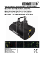 1
1
-
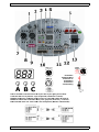 2
2
-
 3
3
-
 4
4
-
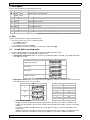 5
5
-
 6
6
-
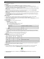 7
7
-
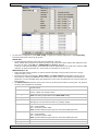 8
8
-
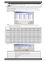 9
9
-
 10
10
-
 11
11
-
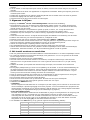 12
12
-
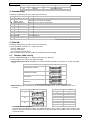 13
13
-
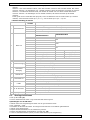 14
14
-
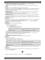 15
15
-
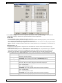 16
16
-
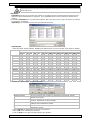 17
17
-
 18
18
-
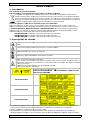 19
19
-
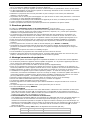 20
20
-
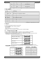 21
21
-
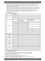 22
22
-
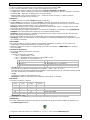 23
23
-
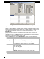 24
24
-
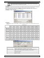 25
25
-
 26
26
-
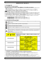 27
27
-
 28
28
-
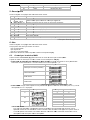 29
29
-
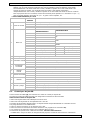 30
30
-
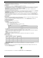 31
31
-
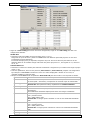 32
32
-
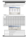 33
33
-
 34
34
-
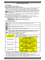 35
35
-
 36
36
-
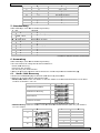 37
37
-
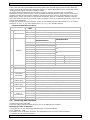 38
38
-
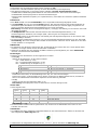 39
39
-
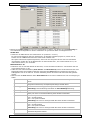 40
40
-
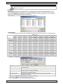 41
41
-
 42
42
-
 43
43
-
 44
44
-
 45
45


HQ Power Krystal RGV380 RGV laser projector Handleiding
- Categorie
- Stroboscopen
- Type
- Handleiding
- Deze handleiding is ook geschikt voor


