Yamaha P50 Handleiding
- Categorie
- Muziekinstrumenten
- Type
- Handleiding
Deze handleiding is ook geschikt voor


FCC INFORMATION (U.S.A)
1. IMPORTANT NOTICE : DO NOT MODIFY THIS UNIT!
This product, when installed as indicated in the instructions contained in this manual, meets FCC requirements. Modifications not expressly
approved by Yamaha may void your authority, granted by the FCC, to use the product.
2. IMPORTANT: When connecting this product to accessories and/or another product use only high quality shielded cables. Cable/s
supplied with this product MUST be used. Follow all installation instructions. Failure to follow instructions could void your FCC
authorization to use this product in the USA.
3. NOTE: This product has been tested and found to comply with the requirements listed in FCC Regulations, Part 15 for Class “B” digital
devices. Compliance with these requirements provides a reasonable level of assurance that your use of this product in a residential
environment will not result in harmful interference with other electronic devices. This equipment generates/uses radio frequencies and, if
not installed and used according to the instructions found in the user’s manual, may cause interference harmful to the operation of other
electronic devices. Compliance with FCC regulations does not guarantee that interference will not occur in all installations. If this product
is found to be the source of interference, which can be determined by turning the unit “OFF” and “ON”, please try to eliminate the problem
by using one of the following measures:
Relocate either this product or the device that is being affected by the interference.
Utilize power outlets that are on different branch (circuit breaker or fuse) circuits or install AC line filter/s.
In the case of radio or TV interference, relocate/reorient the antenna. If the antenna lead-in is 300 ohm ribbon lead, change the lead-in to
co-axial type cable.
If these corrective measures do not produce satisfactory results, please contact the your local retailer authorized to distribute this type of
product. If you can not locate the appropriate retailer, please contact Yamaha Corporation of America, Electronic Service Division, 6600
Orangethorpe Ave, Buena Park, CA 90620
*
The above statements apply ONLY to those products distributed by Yamaha Corporation of America or its subsidiaries.
NEDERLAND
NETHERLAND
● Dit apparaat bevat een lithium batterij voor geheugen back-up.
● This apparatus contains a lithium battery for memory back-up.
● Raadpleeg uw leverancier over de verwijdering van de batterij
op het moment dat u het apparaat aan het einde van de
levensduur afdankt of de volgende Yamaha Service Afdeiing:
Yamaha Music Nederland Service Afdeiing
Kanaalweg 18-G, 3526 KL UTRECHT
Tel. 030-2828425
● For the removal of the battery at the moment of the disposal at
the end of the service life please consult your retailer or Yamaha
Service Center as follows:
Yamaha Music Nederland Service Center
Address : Kanaalweg 18-G, 3526 KL UTRECHT
Tel : 030-2828425
● Gooi de batterij niet weg, maar lever hem in als KCA.
● Do not throw away the battery. Instead, hand it in as small
chemical waste.
ADVARSEL!
Lithiumbatteri—Eksplosionsfare ved fejlagtig håndtering.
Udskiftning må kun ske med batteri af samme fabrikat og
type. Levér det brugte batteri tilbage til leverandoren.
VARNING
Explosionsfara vid felaktigt batteribyte. Använd samma
batterityp eller en ekvivalent typ som rekommenderas av
apparattillverkaren. Kassera använt batteri enligt fabrikantens
instruktion.
VAROITUS
Paristo voi räjähtää, jos se on virheellisesti asennettu. Vaihda
paristo ainoastaan laitevalmistajan suosittelemaan tyyppiin.
Hävitä käytetty paristo valmistajan ohjeiden mukaisesti.

This product utilizes batteries or an external power supply
(adapter). DO NOT connect this product to any power sup-
ply or adapter other than one described in the manual, on
the name plate, or specifically recommended by Yamaha.
WARNING: Do not place this product in a position where
anyone could walk on, trip over, or roll anything over
power or connecting cords of any kind. The use of an
extension cord is not recommended! If you must use an
extension cord, the minimum wire size for a 25' cord (or
less ) is 18 AWG. NOTE: The smaller the AWG number,
the larger the current handling capacity. For longer exten-
sion cords, consult a local electrician.
This Product should be used only with the components
supplied or; a cart, rack, or stand that is recommended by
Yamaha. If a cart, etc., is used, please observe all safety
markings and instructions that accompany the accessory
product.
SPECIFICATIONS SUBJECT TO CHANGE: The in-
formation contained in this manual is believed to be correct
at the time of printing. However, Yamaha reserves the right
to change or modify any of the specifications without no-
tice or obligation to update existing units.
This product, either alone or in combination with an ampli-
fier and headphones or speaker/s, may be capable of produc-
ing sound levels that could cause permanent hearing loss.
DO NOT operate for long periods of time at a high volume
level or at a level that is uncomfortable. If you experience
any hearing loss or ringing in the ears, you should consult
an audiologist. IMPORTANT: The louder the sound, the
shorter the time period before damage occurs.
Some Yamaha products may have benches and/or acces-
sory mounting fixtures that are either supplied with the
product or as optional accessories. Some of these items are
designed to be dealer assembled or installed. Please make
sure that benches are stable and any optional fixtures
(where applicable) are well secured BEFORE using.
Benches supplied by Yamaha are designed for seating only.
No other uses are recommended.
NOTICE: Service charges incurred due to lack of knowl-
edge relating to how a function or effect works (when the
unit is operating as designed) are not covered by the manu-
facturer’s warranty, and are therefore the owners responsi-
bility. Please study this manual carefully and consult your
dealer before requesting service.
ENVIRONMENTAL ISSUES: Yamaha strives to pro-
duce products that are both user safe and environmentally
friendly. We sincerely believe that our products and the
production methods used to produce them, meet these
goals. In keeping with both the letter and the spirit of the
law, we want you to be aware of the following:
Battery Notice: This product MAY contain a small non-
rechargeable battery which (if applicable) is soldered in
place. The average life span of this type of battery is ap-
proximately five years. When replacement becomes neces-
sary, contact a qualified service representative to perform
the replacement.
This Product may also use “household” type batteries.
Some of these may be rechargeable. Make sure that the
battery being charged is a rechargeable type and that the
charger is intended for the battery being charged.
When installing batteries, do not mix old batteries with
new, or with batteries of a different type. Batteries MUST
be installed correctly. Mismatches or incorrect installation
may result in overheating and battery case rupture.
Warning: Do not attempt to disassemble, or incinerate any
battery. Keep all batteries away from children. Dispose of
used batteries promptly and as regulated by the laws in
your area.
Note: Check with any retailer of household type batteries
in your area for battery disposal information.
Disposal Notice: Should this Product become damaged be-
yond repair, or for some reason its useful life is considered
to be at an end, please observe all local, state, and federal
regulations that relate to the disposal of products that con-
tain lead, batteries, plastics, etc. If your dealer is unable to
assist you, Please contact Yamaha directly.
NAME PLATE LOCATION: The name Plate is located
on the top of the product. The model number, serial
number, power requirements, etc., are located on this plate.
You should record the model number, serial number, and
the date of purchase in the spaces provided below and
retain this manual as a permanent record of your purchase.
Model
Serial No.
Purchase Date
SPECIAL MESSAGE SECTION
92-BP
PLEASE KEEP THIS MANUAL

i
WELCOME TO THE P50-m
Welcome to the P50-m
Congratulations and thank you for purchasing the Yamaha
P50-m Piano Tone Generator!
The P50-m is an advanced tone generator with piano and
other keyboard Voices. It provides exceptionally realistic and
high-quality piano Voices — with complete 32-note polyphony —
when connected to a MIDI keyboard or when used with a
sequencer or computer. Reverb and Chorus effects are also built
into the Voices for a rich, natural sound.
The P50-m gives you easy and intuitive control over the
sound, including Brightness, Reverb Send, fine and coarse tuning,
and touch sensitivity. Convenient EQ sliders on the panel let you
adjust the timbre in real time. Other special controls such as
Program Change Table and MIDI OUT ensure easy and trouble
free operation when using the P50-m in General MIDI applica-
tions and with additional tone generators. What’s more, you can
combine two P50-m units together (using the Receive Mode
control) for full 64-note polyphony.

ii
UNPACKING
Unpacking
Your P50-m package should include the items listed below. Make
sure that you have them all. Also, write down the serial number
of your P50-m in the box below, for future reference.
• P50-m
Serial No.:
• PA-3B AC Adaptor
• Owner’s Manual

iii
TABLE OF CONTENTS
Table of Contents
Welcome to the P50-m ......................................................................................................... i
Unpacking............................................................................................................................... ii
Table of Contents................................................................................................................. iii
How to Use This Manual .....................................................................................................iv
Precautions ............................................................................................................................ v
The Controls of the P50-m .................................................................................................1
Front Panel.......................................................................................................................... 1
Rear Panel ...........................................................................................................................3
Setting Up and Playing Your P50-m ................................................................................. 4
What You’ll Need ........................................................................................................... 4
Making the Connections................................................................................................4
Using in Larger MIDI Systems ....................................................................................... 6
Powering Up and Playing the Demo Song ....................................................................6
Powering Up ............................................................................................................ 7
Playing the Demo Song ........................................................................................... 7
Playing all Demo Songs ...........................................................................................8
OPERATION GUIDE
Voice Controls.....................................................................................................................9
Selecting a Voice ........................................................................................................... 9
Selecting Voices From Your MIDI Keyboard...............................................................10
Tone Controls....................................................................................................................11
Changing the Brightness of a Voice ............................................................................11
Changing the Reverb Send for a Voice........................................................................12
3-Band EQ Sliders.............................................................................................................13
Tune Controls....................................................................................................................14
Changing the Master Tune Setting ..............................................................................14
Changing the Note Shift Setting..................................................................................15
Utility Controls ..................................................................................................................16
Changing the Touch Sensitivity ...................................................................................16
Changing the MIDI Receive Channel...........................................................................17
Advanced Functions ..........................................................................................................18
Program Change Table................................................................................................18
Changing the Device Number......................................................................................19
Receive Mode ..............................................................................................................20
Changing the MIDI OUT Setting .................................................................................21
Factory Set ..................................................................................................................22
APPENDIX
Troubleshooting.................................................................................................................23
Error Messages ..................................................................................................................25
Specifications ....................................................................................................................26
Index................................................................................................................................. 27
SOUND LISTS & MIDI DATA
Voice List...........................................................................................................................30
Effect Lists.........................................................................................................................31
MIDI Data Format .............................................................................................................33
MIDI Implementation Chart...............................................................................................42

iv
HOW TO USE THIS MANUAL
How to Use This Manual
You are probably eager to play your new P50-m Piano Tone
Generator right away, rather than have to read through a lot of
instructions before you can even get a sound out of it.
However, to get the most out of your P50-m, we strongly
suggest that you read the following sections in the order given:
1) Precautions
This gives you important information on how to care for
your new P50-m, how to avoid damaging it, and how to
ensure long-term, reliable operation.
2) The Controls of the P50-m
This section introduces you to the panel controls and
connectors.
3) Setting Up and Playing Your P50-m
This very important section gets you started using your
P50-m. It guides you in connecting and setting up the
instrument for different example systems, and shows you
how to play the special Demo song.
4) Operation Guide
Once you’re familiar with everything above, go over this
comprehensive guide to all P50-m functions. You won’t
need (or want) to read everything at once, but it is there for
you to refer to when you need information about a certain
feature or function.
5) Appendix
Finally, use the sections in the Appendix as necessary.
Specifically, if you run into some problem or difficulty, refer
to the Troubleshooting section for help.

v
PRECAUTIONS
Precautions
Your P50-m will give you years of reliable service if you follow
the simple precautions below:
■ LOCATION
Keep the instrument away from locations where it is likely to be
exposed to high temperatures (such as direct sunlight) or
humidity. Also avoid locations which are subject to excessive dust
accumulation or vibration which could cause mechanical damage.
■ USE THE CORRECT POWER ADAPTOR
Use only the recommended PA-3B or PA-1207 Power Adaptor
for supplying power to the instrument. Use of another adaptor
may cause serious damage to the instrument or the adaptor itself.
■ MAKE SURE POWER IS OFF WHEN MAKING OR REMOVING
CONNECTIONS
To prevent damage to the instrument and other connected
equipment, always turn off the power prior to connecting or
disconnecting cables. Also, turn the power off when the instru-
ment is not in use, and disconnect the power adaptor during
electric storms.
■ HANDLE THE INSTRUMENT WITH CARE
Although the instrument has been constructed to withstand the
rigors of normal use for optimum sturdiness and reliability, avoid
subjecting it to strong physical shocks (such as dropping or hitting
it). Since the P50-m is a precision-made electronic device, also
avoid applying excessive force to the various controls. When
moving the instrument, first unplug the power adaptor and all
other cables to prevent damage to cords and jacks. Always unplug
cables by gripping the plug firmly, not by pulling on the cable.
■ CLEAN WITH A SOFT, DRY CLOTH
Never use solvents such as benzine or thinner to clean the
instrument, since these will damage the panel finish. Wipe clean
with a soft, dry cloth. If necessary, use a soft, clean, slightly
moistened cloth — making sure to wipe the case off again with a
dry cloth.

vi
PRECAUTIONS
■ ELECTROMAGNETIC INTERFERENCE
Avoid using the unit near televisions, radios or other equipment
generating electromagnetic fields. Proximity to such equipment
may cause the unit to malfunction, and may generate
interference noise in the other appliance as well.
■ DO NOT OPEN THE CASE OR TRY REPAIRING THE INSTRUMENT
YOURSELF
The instrument contains no user-serviceable parts. Never open
the case or tamper with the internal circuitry in any way, since
doing so may result in damage to the instrument. Refer all
servicing to qualified Yamaha service personnel.
■ MIDI CABLES
When connecting the instrument to other MIDI equipment, be
sure to use only high-quality cables made especially for MIDI data
transmission. Also, avoid using cables longer than 15 meters,
since long cables can result in data errors.
Yamaha is not responsible for damage caused by improper
handling or operation.

1
THE CONTROLS OF THE P50-m
The Controls of the P50-m
Front Panel
1 POWER/VOL control
Pressing this turns the power on and off. Turning it adjusts the overall
volume of the P50-m.
2 PHONES jack
For connection to a set of stereo headphones (mini-pin).
3 VOICE SELECT button
For selection of the internal Voices. (See page 9.) Also for changing
the Program Change Table setting. (See page 18.)
TONE Controls
4 BRIGHT button
For adjusting the brightness of the selected Voice. (See page 11.)
5 REVERB SEND button
For adjusting the amount of sound processed with the Reverb effect.
(See page 12.)
2
5
3
1
4

2
THE CONTROLS OF THE P50-m
TUNE Controls
6 MASTER TUNE button
For adjusting the overall fine tuning of the instrument. (See page 14.)
Also used with the NOTE SHIFT button for playing the Demo song.
(See page 7.)
7 NOTE SHIFT button
For changing the key transposition setting of the instrument. (See
page 15.) Also used with the MASTER TUNE button for playing the
Demo song. (See page 7.)
UTILITY Controls
8 TOUCH button
For changing the touch (velocity) response of the instrument. (See
page 16.) Also for changing the Device Number setting. (See page
19.) Also used with the MIDI CH button for changing the Receive
Mode of the instrument. (See page 20.)
9 MIDI CH (Channel) button
For setting the MIDI Receive channel for the instrument. (See page
17.) Also for setting the MIDI OUT setting. (See page 21.) Also used
with the TOUCH button for changing the Receive Mode of the
instrument. (See page 20.)
10 LED display
11 DATA dial
For adjusting values or changing settings of the various parameters.
12 EQ sliders (LOW, MID, HIGH)
For making fine changes to the tonal quality of the sound. (See page
13.)
6 8
10
11
12
7 9

3
THE CONTROLS OF THE P50-m
Rear Panel
1 MIDI OUT/IN terminals
For connection to other MIDI devices, such as a MIDI keyboard, tone
generator, sequencer, or to a computer that has a MIDI interface.
(See pages 4–6 for more information on MIDI connections.)
2 DC IN jack
For connection to the PA-3B AC power adaptor.
3 OUTPUT R, L/MONO jacks (Right, Left/Mono)
For connection to a stereo amplifier/speaker system. When using a
mono system, connect it to the L/MONO jack.
1
2
3

4
SETTING UP AND PLAYING YOUR P50-m
Setting Up and Playing Your
P50-m
In this section, you’ll learn how to set up the P50-m for use with
a MIDI keyboard. You’ll also learn how to set it up for use with a
computer or sequencer and a second tone generator. Finally,
you’ll learn how to play the Demo song and hear the realistic and
dynamic Voices of the P50-m.
What You’ll Need
❏ The P50-m and the included power adaptor.
❏ A MIDI keyboard, electronic piano, or any instrument that can
output MIDI data.
❏ An amplifier/speaker system, preferably stereo. Alternately, you
can use a set of stereo headphones.
❏ Audio connecting cables.
❏ A MIDI cable.
Making the Connections
Before making any connections, make sure that all equipment to
be connected is turned off, and that the P50-m power adaptor is
not connected to an electrical outlet.
1.
Connect one end of the MIDI cable to the MIDI OUT
terminal of the MIDI keyboard and the other to the MIDI IN
terminal of the P50-m (as shown in the illustration below).
Also, make sure that the MIDI send channel on the
keyboard and the MIDI Receive Channel on the P50-m (see
page 17) are set to the same value. (Refer to the owner’s
manual of the MIDI keyboard if necessary.)
2.
Connect the audio cables from the R and L/MONO OUTPUT
jacks of the P50-m to the appropriate inputs on the amplifier
speaker system (as shown in the illustration below).
If the amplifier has only one input, use the L/MONO jack
on the P50-m. If you are using stereo headphones,
connect them to the front panel PHONES jack.
3.
Connect the power adaptor to the DC IN terminal on the
P50-m and plug the adaptor into an appropriate electrical
outlet.

5
SETTING UP AND PLAYING YOUR P50-m
MIDI Keyboard
MIDI OUT
MIDI IN
MIDI CABLE
R
Amplifier
Speaker System
PHONES
DC INL/MONO
Power
Adaptor
• Do not attempt to use an AC adaptor other than the PA-3B or
PA-1207. The use of an incompatible adaptor may result in
irreparable damage to the P50-m, and even pose a serious shock
hazard.
• Be sure to disconnect the power adaptor from the outlet when
the P50-m is not in use.

6
SETTING UP AND PLAYING YOUR P50-m
Using in Larger MIDI Systems
The P50-m is equipped with MIDI IN and OUT terminals,
allowing you to use it in any MIDI system. In the system example
shown below, the P50-m is connected to both a computer and
another tone generator. Here, the computer (with sequencer or
other music software) plays back song data using the Voices of
the P50-m and the connected tone generator.
In systems such as this, you should make sure that:
• The MIDI Receive Channel on the P50-m (see page 17) is set
to the same channel as that for the piano part (or track) on
the software.
• The MIDI OUT Mode is set to “ot2.” (See page 21.) This
ensures that the piano part data will play the Voices of the
P50-m, and not the other tone generator.
Also, if you are using General MIDI (GM) compatible software,
set the Program Change Table to “on.” (See page 18.) This
ensures that the Voices on the P50-m will match the intended
program changes in the software.
Powering Up and Playing the
Demo Song
Once you’ve connected everything properly, you’re ready to turn
the P50-m on and start playing it. However, a small word of
caution before you begin: Follow the instructions given below to
avoid possible damage to your equipment and speakers.
Computer
MIDI Interface
Tone GeneratorP50-m

7
SETTING UP AND PLAYING YOUR P50-m
Powering Up
1.
If you haven’t done so already, press the POWER/VOL
control on the P50-m.
2.
Turn on the power of your MIDI keyboard.
3.
Make sure that all volume controls (on the P50-m and the
connected amplifier) are turned down. Then, turn on the
power of your amplifier speaker system.
4.
Finally, set the volume control on the P50-m to about the
midway position initially (you can raise it later if needed),
and set the volume on the amplifier to a suitable level.
Playing the Demo Song
Now that you’ve set everything up properly, try playing the built-
in Demo Song. This showcases the high-quality Voices and the
AWM2 tone generation system of the P50-m.
Simultaneously press the MASTER TUNE and NOTE SHIFT
buttons.
The Demo song for the selected Voice starts playing
immediately and repeats indefinitely until stopped (by pressing
any panel button). (The LEDs and lamps flash in a pattern dur-
ing playback.)
More about Demo Song
There are actually two Demo Song modes. In the Single
Demo Play mode (described above), the currently selected
Voice is used for the Demo song. Each Voice has its own
Demo song, specially programmed to suit and showcase
that particular Voice.
In the All Demo Play mode (described below), all Demo
songs can be played back in succession.

8
SETTING UP AND PLAYING YOUR P50-m
Playing all Demo Songs
With the power off, simultaneously hold down the
MASTER TUNE and NOTE SHIFT buttons and turn the
power on.
Demo song number 1 (for Voice 01) starts playing
immediately and is followed by the other Demo songs in
succession. Playback of all songs repeats indefinitely until
stopped (by pressing any panel button). (The LEDs and
lamps flash in a pattern during playback.)
Using the All Demo Play mode resets the P50-m to the original
factory settings. If you have made custom settings that you want
to keep, make a note of them before using All Demo Play.
Hold down
Hold down
Push (power off)

9
OPERATION GUIDE
Operation Guide
Voice Controls
Selecting a Voice
The P50-m has 28 different piano and other keyboard Voices.
(See list on page 30.) These can be selected either from the
panel controls or remotely from a connected MIDI device.
Range: 01 — 29
1.
Press the SELECT button.
2.
Use the DATA dial to change the Voice number.
Play this new Voice from the connected keyboard (or other
device). Try selecting other Voices and playing them as well.
(For a list of all available Voices, see page 30.)
The polyphony (maximum simultaneous notes) of the P50-m is 32.
However, for two-layered Voices (see page 30), this is reduced to 16.
Voice number (program number)
Lamp lights.

10
OPERATION GUIDE
Selecting Voices From Your MIDI
Keyboard
You can also select Voices remotely from a connected MIDI key-
board. Though the actual operation may differ depending on the
keyboard used, the general procedure is the same. (Refer to the
owner’s manual of your instrument for specific instructions.)
1.
Make sure that your keyboard is set up to send Program
Change messages.
2.
Use your keyboard’s panel controls to select a program.
Generally, if everything has been set up properly, the Voice
number on the P50-m will change, and will be the same
number as the program number you selected on your key-
board.
• Keep in mind that the Voices of the P50-m number up to 29. Program
change numbers higher than 28 select only the highest Voice (#29).
• Depending on the MIDI device you are using, the program numbers
(on the device) may not match the Voice numbers on the P50-m. This
is because the numbering system of some MIDI devices starts at #00,
rather than #01. In such a case, for example, you would use program
#12 to select Voice 13 on the P50-m.

11
OPERATION GUIDE
Tone Controls
The Tone controls of the P50-m, BRIGHT and REVERB SEND,
let you adjust the sound of individual Voices. Brightness
(BRIGHT) determines the tonal quality of the Voice, while Reverb
Send determines how much Reverb effect is applied to the
selected Voice.
Both of these controls let you make independent settings for
different Voices, and all settings are automatically saved as they
are made.
Changing the Brightness of a Voice
Lower values produce a soft, mellow sound, while higher values
produce a bright, crisp sound. The normal setting is 00.
Range: –64 — 63
1.
Press the BRIGHT button.
2.
Use the DATA dial to change the Brightness setting.
Lamp lights.
Brightness setting for the currently selected Voice.

12
OPERATION GUIDE
Changing the Reverb Send for a Voice
The higher the value, the greater the amount of Reverb sound. A
value of 0 results in a completely “dry” Voice sound.
Range: 000 — 127
1.
Press the REVERB SEND button.
2.
Use the DATA dial to change the Reverb Send setting.
Lamp lights.
Reverb Send setting for the currently selected Voice.

13
OPERATION GUIDE
3-Band EQ Sliders
The P50-m features 3-band EQ sliders on the panel. These are
convenient for real-time adjustment of the overall timbre of the
sound over three separate frequency bands.
Range: –12 — 12 dB
(for each frequency range: LOW, MID, HIGH)
For stereo Voices (see page 26), the MID slider has no effect.

14
OPERATION GUIDE
Tune Controls
The Tune controls of the P50-m, MASTER TUNE and NOTE
SHIFT, let you adjust the overall pitch of the instrument. Master
Tune lets you make fine adjustments to the tuning, while Note
Shift lets you change the key transposition of the instrument.
Both of these controls affect all Voices, and the settings are
automatically saved as they are made.
Changing the Master Tune Setting
Master Tune is especially useful for adjusting the pitch of the
P50-m when playing with other instruments. The normal setting
is 440 Hz (or 00 cents).
Range: 415 — 466 Hz (–100 — 100 cents)
1.
Press the MASTER TUNE button.
2.
Use the DATA dial to change the Master Tune setting.
To switch the LED between displaying the value in Hertz
(Hz) or cents, double-click the MASTER TUNE button
(press it twice quickly).
Lamp lights.
Master Tune setting.

15
OPERATION GUIDE
Changing the Note Shift Setting
Note Shift is especially useful for instantly transposing the key of
the P50-m. The normal setting is 00.
Range: –12 — 12 semitones (–/+ one octave)
1.
Press the NOTE SHIFT button.
2.
Use the DATA dial to change the Note Shift setting.
Lamp lights.
Note Shift setting.

16
OPERATION GUIDE
Utility Controls
The Utility controls, TOUCH and MIDI CH (Channel), let you
access some of the other important functions of the P50-m.
Changing the Touch Sensitivity
This function lets you determine how the volume of the P50-m’s
Voices respond to your playing touch (velocity). Eight different
Touch Sensitivity settings (or curves) are available, letting you
tailor the response to your own preference.
Settings: 1 — 8
1.
Press the TOUCH button.
2.
Use the DATA dial to change the Touch Sensitivity setting.
Settings:
1 — Normal
2 — Easy 1
3 — Easy 2
4 — Easy 3
5 — Hard 1
6 — Hard 2
7 — Cross 1
8 — Cross 2
Lamp lights.
Touch Sensitivity setting.

17
OPERATION GUIDE
The Normal (1) setting provides standard touch response. Easy 1
to 3 allow you to produce a reasonably high volume with a soft,
light touch (low velocities). Hard 1 and 2 produce high volume
only with a hard, strong touch (high velocities). Cross 1 and 2
produce nearly the same volume no matter how soft or hard the
touch.
Changing the MIDI Receive Channel
In order to properly use the P50-m with another MIDI device, the
MIDI channels on both machines must match. The MIDI Receive
Channel setting allows you to set which MIDI channel the P50-m
responds over.
The “ALL” setting allows the P50-m to respond over all 16
MIDI channels.
Settings: 01 — 16, ALL
1.
Press the MIDI CH button.
2.
Use the DATA dial to change the MIDI Receive Channel
setting.
Lamp lights.
MIDI Receive Channel setting.

18
OPERATION GUIDE
Advanced Functions
The advanced functions are special functions not generally used
in normal operation, but for specific applications. These are also
“hidden” functions, accessed by double-clicking a button or
pressing two buttons together.
Program Change Table
The Program Change Table setting is for use with XG applica-
tions, specifically when using the P50-m to replace the piano
sounds of a connected second tone generator.
Settings: off (oFF), on
Normally (and when power is turned on), this is set to “oFF.”
When set to “oFF,” the P50-m responds only to program
changes 0 — 28. All other numbers are ignored, and the last
selected Voice stays active.
When set to “on,” the P50-m functions as a XG module for
piano parts only. In this case, program changes (0 — 5, 7)
corresponding to piano parts (according to XG) will select similar
Voices on the P50-m, and all other numbers select a “blank” si-
lent Voice (Voice No. 29). This ensures that the P50-m will play
only the piano parts in XG song data.
1.
Double-click the SELECT button (press it twice quickly).
2.
Use the DATA dial to change the Program Change Table setting.
Double-click.
Lamp flashes.
Program Change Table setting.

19
OPERATION GUIDE
● When Program Change Table is set to “oFF”
The P50-m does not respond to XG System On or GM Mode On
messages.
● When Program Change Table is set to “on”
The P50-m responds to XG System On or GM Mode On messages and
performs the following:
•Resets all controllers to default or “zero” values.
•Selects Voice number 9 (the Voice most similar to GM voice 001,
Grand Piano).
•Parameters of all voices are set to the same values as the Voice
number 9 (Grand Piano).
•Sets Reverb Send of selected Voice to 040.
•Sets Transpose to 00.
Changing the Device Number
Device Number is a kind of MIDI “identification” number. This is
convenient when using two or more P50-m units together in a
MIDI chain. It is also important when sending System Exclusive
data. When each unit in a chain is assigned a different Device
Number, the controlling MIDI device can distinguish between
different units.
The “ALL” setting allows the P50-m to respond to all 16
Device Numbers. For normal operation, this should be set to
“ALL.”
Settings: 01 — 16, ALL
1.
Double-click the TOUCH button (press it twice quickly).
2.
Use the DATA dial to change the Device Number setting.
Double-click.
Lamp flashes.
Device Number setting.

20
OPERATION GUIDE
Receive Mode
When connecting two P50-m units together, the Receive Mode
allows you to expand the maximum polyphony (simultaneous
number of notes) from 32 to 64.
When set to “ALL” (normal operation), the P50-m plays all
incoming MIDI notes. When set to “E0n,” the P50-m plays only
even-numbered MIDI notes. Similarly, when set to “odd,” only
odd-numbered MIDI notes are played. When combining two units
for 64-note polyphony, set the Receive Mode to “E0n” on one
unit and to “odd” on the other.
Settings: ALL, Evn (even), odd
1.
Simultaneously press the TOUCH and MIDI CH buttons.
2.
Use the DATA dial to change the Receive Mode setting.
Both lamps light.
Receive Mode setting.

21
OPERATION GUIDE
Changing the MIDI OUT Setting
The MIDI OUT setting determines what incoming MIDI data is
relayed via MIDI OUT terminal on the rear panel.
With “ot1,”
all
incoming MIDI data (over all MIDI channels)
is relayed via the MIDI OUT terminal. With “ot2,” data received
over the selected MIDI Receive Channel (see page 17) is filtered
out, and only the data on the other channels is relayed.
Generally, when connecting another tone generator to the
MIDI OUT and using the P50-m with a sequencer or computer,
this should be set to “ot2.”
If MIDI Receive Channel is set to “ALL” or the Voice number is set to 29
(no sound), all incoming MIDI data is relayed, regardless of the MIDI
OUT setting.
Settings: ot1, ot2
1.
Double-click the MIDI CH button (press it twice quickly).
2.
Use the DATA dial to change the MIDI OUT setting.
Double-click.
Lamp flashes.
MIDI OUT setting.

22
OPERATION GUIDE
Factory Set
This function restores the original factory settings of the P50-m.
When you make changes to the various controls of the P50-m,
the new settings automatically replace the original factory settings
and are retained in memory even when power is turned off. Use
Factory Set to cancel your own settings and restore the factory
settings.
Keep in mind that this function completely alters any changes you
have made to the settings. If you want to keep your custom
settings, make a note of them before using Factory Set.
Simultaneously hold down the SELECT button and turn the
power on. (The message “FAc” appears in the display.)
Factory Set resets the following parameters and values:
Voice Number 01
Brightness 00 (all voices)
Reverb Send (varies according to the Voice)
Master Tune 440 (Hz)
Note Shift 00
Touch 0
MIDI Channel 01
Program Change Table off
Device Number ALL
Receive Mode ALL
MIDI OUT Mode ot1
Hold down
Push (power on)

23
APPENDIX
APPENDIX
Troubleshooting
Even though the P50-m is exceptionally easy to use, it may
occasionally not function as you expect it to. If that happens,
check the possible problems and solutions below before assuming
that the instrument is faulty.
Problem
No power.
No sound.
No sound when play-
ing the P50-m from a
computer, sequencer
or external keyboard.
Devices connected to
MIDI OUT do not
sound.
Possible Cause and Solution
If you are using an AC adaptor, check that the adaptor is
properly plugged into both the AC outlet and the P50-m
(See page 4.)
Check that:
• The panel volume control is set to an appropriate level.
• All connections have been properly made, including the
PHONES jack (if used), external amplifier/speaker system,
and MIDI.
• The MIDI channel settings on the P50-m match those of
the connected device.
• One of the valid Voices (numbers 0–28) has been selected.
Voice number 29 has no sound, and the P50-m has no
Voices beyond 29.
Check all MIDI connections, making sure that the MIDI OUT
of the external device is connected to the MIDI IN of the
P50-m, and that the MIDI IN of the external device is
connected to the MIDI OUT of the P50-m. (See pages 4–5.)
Also, make sure that you have turned on the connected
MIDI instrument or computer before turning on the P50-m.
If you haven’t, simply turning the P50-m off and back on
again may solve the problem.
Try setting the MIDI OUT setting to “ot2.”

24
APPENDIX
Problem
Sound is distorted.
Volume is too low.
Sound is incorrect or
unexpected.
Pitch is incorrect.
Notes are cut off or
omitted.
Cannot set Reverb
and Chorus effects via
MIDI.
Possible Cause and Solution
Check all volume settings, especially on the external
amplifier/speaker system.
Check that incoming volume and expression data is set
appropriately (not at or near minimum).
Check:
• The program change messages on your MIDI software.
• The Bright and EQ settings on the P50-m.
Check the Master Tune and Note Shift settings. Also, make
sure that there are no incoming MIDI detune messages.
The maximum polyphony of the P50-m may be exceeded.
The P50-m can play no more than 32 notes at once; for the
two-layered Voices, this is reduced to 16 (see page 27).
Check that appropriate Reverb return and Chorus return
messages are being sent.

25
APPENDIX
Error Messages
Er1
The battery voltage (for internal memory backup) may be too
low. Bring the unit to your local Yamaha dealer or any other
autorized Yamaha service personnel.
Er2
The address of the received System Exclusive message is
incorrect. Check the address and try transmitting again.
Er3
The data of the received System Exclusive message is incorrect.
Check the data (as to whether it requires an MSB or LSB header)
and try transmitting again.
Er4
The data size of the received System Exclusive message is
incorrect. Check the size of the message and try transmitting
again.
Er5
The checksum of the received System Exclusive message is
incorrect. Check the checksum of the message and try
transmitting again.

26
APPENDIX
Specifications
Tone Generation Method
AWM2 (Advanced Wave Memory 2)
Maximum Simultaneous Polyphony
32-note
Voices
28
Effects
Reverb (with Reverb Send control),
Chorus; effects are built into certain Voices
3 band EQ
Demo Songs
28 (not editable, stored in ROM)
Display
Three 8-segment LEDs
Controls
POWER/VOL control; VOICE SELECT button; BRIGHT button; REVERB SEND
button; MASTER TUNE button; NOTE SHIFT button; TOUCH button; MIDI
CH button; DATA dial; EQ sliders
Jacks and Terminals
MIDI OUT/IN terminals; DC IN jack; OUTPUT R, L/MONO jacks; PHONES
jack
Power Supply
Yamaha PA-3B AC Adaptor (included)
Dimensions
220 × 210 × 44 mm (8-5/8” × 8-1/4” × 1-3/4”)
Weight
1.2 kg (2 lbs., 10 oz.)
Included Accessories
Owner’s Manual, Yamaha PA-3B AC Adaptor

27
APPENDIX
Index
A
All Demo Play mode............................ 7–8
B
BRIGHT button .................................1, 11
Brightness.............................................. 11
C
connections, audio................................... 4
connections, MIDI ............................... 4–6
D
DATA dial ................................................ 2
DC IN jack ............................................... 3
Demo Song ............................................. 7
Device Number ...................................... 19
E
Effect Lists ............................................. 31
EQ sliders ..........................................2, 13
Error Messages ...................................... 25
F
Factory Set ............................................ 22
M
MASTER TUNE button ................ 2, 7, 14
Master Tune........................................... 14
MIDI CH button....................2, 17, 20, 21
MIDI Data Format ................................. 33
MIDI Implementation Chart................... 42
MIDI IN/OUT terminals .................. 3, 4–6
MIDI OUT setting ..............................6, 21
MIDI Receive Channel .................. 4, 6, 17
N
NOTE SHIFT button .................... 2, 7, 15
Note Shift .............................................. 15
O
OUTPUT R, L/MONO jacks........... 3, 4–5
P
PHONES jack.......................................... 1
POWER/VOL control ............................. 1
Precautions ..............................................vi
Program Channge Table....................6, 18
R
Receive Mode ........................................ 20
REVERB SEND button ......................1, 12
Reverb Send .......................................... 12
S
Specifications......................................... 26
T
Tone controls......................................... 11
TOUCH button.....................2, 16, 19, 20
Touch Sensitivity.................................... 16
Troubleshooting ..................................... 23
Tune controls......................................... 14
U
Utility controls ....................................... 16
V
VOICE SELECT button ................ 1, 9, 18
Voice controls .......................................... 9
Voice List............................................... 30
Voice, selecting........................................ 9
Voices, selecting from MIDI keyboard.... 10


30
SOUND LISTS & MIDI DATA
Voice List
STEREO/MONO Layer
PGM NO. VOICE NAME
(Note 1) (Note 2)
BANK NUMBER PROGRAM
(LSB) CHANGE NUMBER
01 BRIGHT PIANO STEREO* 2 — —
02 STEREO 2 3 1
03 MONO* 1 — —
04 MONO 1 0 1
05 DARK PIANO STEREO 2 18 1
0 6 GRAND PIANO STEREO* 2 — —
07 STEREO 2 3 0
08 MONO* 1 — —
09 MONO 1 0 0
10 DANCE STEREO 2 16 1
11 HONKYTONK STEREO 2 0 3
12 HYBRID PIANO MONO 2 40 2
13 CP80 MONO 1 0 2
14 MONO* 1 — —
1 5 CP80 WITH CHORUS MONO 1 32 2
16 DX EP MONO 1 0 5
17 DX PAD MONO 1 41 5
18 DX EP WITH CHORUS MONO 1 32 5
1 9 ROADS MONO 1 0 4
2 0 ROADS WITH CHORUS MONO 1 32 4
21 SOFT ROADS MONO 1 18 4
22 HARD ROADS MONO 1 40 4
23 DYNO MONO 1 45 4
24 RESONANT DYNO MONO 1 20 4
25 DYNO WITH CHORUS MONO 1 33 4
26 WURLI MONO 1 64 4
27 CLAVI MONO 1 0 7
28 CLAVI WITH WAH MONO 1 27 7
29 (no sound) — — 8Å`
(Note 1)
*
: stretch-tuned
(Note 2) The polyphony of the P50-m is 32. However, for two-layered voices, this is reduced to 16.
(Note 3) The setting samples when the Program Change Table is set to “on.” (See page 18.)
Example of the Program Change
Table setting (Note 3)

31
SOUND LISTS & MIDI DATA
Effect Lists
Effect Type List
REVERB
Exclusive
Effect Type Description
MSB LSB
0 0 NO EFFECT E f fe ct tur ned off.
1 0 HALL1 Reverb simulating the resonance of a hall.
1 1 HALL2 Reverb simulating the resonance of a hall.
2 0 ROOM1 Reverb simulating the resonance of a room.
2 1 ROOM2 Reverb simulating the resonance of a room.
2 2 ROOM3 Reverb simulating the resonance of a room.
3 0 STAGE1 Reverb appropriate for a solo instrument.
3 1 STAGE2 Reverb appropriate for a solo instrument.
4 0 PLATE Reverb simulating a metal plate reverb unit.
10 0 WHITE ROOM A unique short reverb with a bit of initial delay.
11 0 TUNNEL Simulation of a tunnel space expanding to left and right.
13 0 BASEMENT A bit of initial delay followed by reverb with a unique resonance.
CHORUS
Exclusive
Effect Type Description
MSB LSB
0 0 NO EFFECT E f fe ct tu rned off.
41 0 CHORUS1 Conventional chorus program that adds natural spaciousness.
41 1 CHORUS2 Conventional chorus program that adds natural spaciousness.
41 2 CHORUS3 Conventional chorus program that adds natural spaciousness.
41 8 CHORUS4
Chorus with stereo input. The pan setting specified for the Part will also apply to the effect sound.
42 0 CELESTE1 A 3-phase LFO adds modulation and spaciousness to the sound.
42 1 CELESTE2 A 4-phase LFO adds modulation and spaciousness to the sound.
42 2 CELESTE3 A 5-phase LFO adds modulation and spaciousness to the sound.
4 2 8 CELESTE4
CELESTE with stereo input. The pan setting specified for the Part will also apply to the effect sound.
43 0 FLANGER1 Adds a jet-airplane effect to the sound.
43 1 FLANGER2 Adds a jet-airplane effect to the sound.
43 8 FLANGER3 Adds a jet-airplane effect to the sound.
MSB and LSB values are in hexadecimal. *LSB=0 selects the basic type.
WHITE ROOM, TUNNEL, BASEMENT
No. Parameter Range Value → P32** Control
1 Reverb Time 0.3~30.0s 0-69 table#4
2 Diffusion 0~10 0-10
3 Initial Delay 0~63 0-63 table#5
4 HPF Cutoff Thru~8.0kHz 0-52 table#3
5 LPF Cutoff 1.0k~Thru 34-60 table#3
6 Width 0.5~10.2m 0-37 table#11
7 Heigt 0.5~20.2m 0-73 table#11
8 Depth 0.5~30.2m 0-104 table#11
9 Wall Vary 0~30 0-30
10 Dry/Wet D63>W~D=W~D<W63 1-127 ●
11 Rev Delay 0~63 0-63 table#5
12 Density 0~3 0-3
13 Er/Rev Balance E63>R~E=R~E<R63 1-127
14
15 Feedback Level –63~+63 1-127
16
CHORUS1,2,3,4, CELESTE1,2,3,4
No. Parameter Range Value → P32** Control
1 LFO Frequency 0.00~39.7Hz 0-127 table#1
2 LFO PM Depth 0~127 0-63
3 Feedback Level –63~+63 1-127
4 Delay Offset 0~12a7 0-127 table#2
5
6 EQ Low Frequency 50Hz~2.0kHz 8-40 table#3
7 EQ Low Gain –12~+12dB 52-76
8 EQ High Frequency 500Hz~16.0kHz 28-58 table#3
9 EQ High Gain –12~+12dB 52-76
10 Dry/Wet D63>W~D=W~D<W63 1-127 ●
11
12
13
14
15 Input Mode mono/stereo 0-1
16
Effect Parameter List
FLANGER1,2,3
No. Parameter Range Value → P32** Control
1 LFO Frequency 0.00~39.7Hz 0-127 table#1
2 LFO Depth 0~127 0-127
3 Feedback Level –63~+63 1-127
4 Delay Offset 0~63 0-63 table#2
5
6 EQ Low Frequency 50Hz~2.0kHz 8-40 table#3
7 EQ Low Gain –12~+12dB 52-76
8 EQ High Frequency 500Hz~16.0kHz 28-58 table#3
9 EQ High Gain –12~+12dB 52-76
10 Dry/Wet D63>W~D=W~D<W63 1-127 ●
11
12
13
14 LFO Phase Difference –180~+180deg 4-124
resolution =
15
30deg.
16
HALL1,HALL2, ROOM1,ROOM2,ROOM3, STAGE1,STAGE2, PLATE
No. Parameter Range Value → P32** Control
1 Reverb Time 0.3~30.0s 0-69 table#4
2 Diffusion 0~10 0-10
3 Initial Delay 0~63 0-63 table#5
4 HPF Cutoff Thru~8.0kHz 0-52 table#3
5 LPF Cutoff 1.0k~Thru 34-60 table#3
6
7
8
9
10 Dry/Wet D63>W~D=W~D<W63 1-127 ●
11 Rev Delay 0~63 0-63 table#5
12 Density 0~3 0-3
13 Er/Rev Balance E63>R~E=R~E<R63 1-127
14 High Damp 0.1~1.0 1-10
15 Feedback Level –63~+63 1-127
16
●: Indicates that AC1 (Assignable Controller 1) can be used to control the parameter value.
No.*: Corresponds to parameter number given in Appended Table 1-3 on page 38.
→P32**: Refer to the Effect-Data Assignment Table.

32
SOUND LISTS & MIDI DATA
Effect-Data Assignment Table
Data Value
00.00
10.04
20.08
30.12
40.16
50.21
60.25
70.29
80.33
90.37
10 0.42
11 0.46
12 0.50
13 0.54
14 0.58
15 0.63
16 0.67
17 0.71
18 0.75
19 0.79
20 0.84
21 0.88
22 0.92
23 0.96
24 1.00
25 1.05
26 1.09
27 1.13
28 1.17
29 1.22
30 1.26
31 1.30
32 1.34
33 1.38
34 1.43
35 1.47
36 1.51
37 1.55
38 1.59
39 1.64
40 1.68
41 1.72
42 1.76
Data Value
43 1.80
44 1.85
45 1.89
46 1.93
47 1.97
48 2.01
49 2.06
50 2.10
51 2.14
52 2.18
53 2.22
54 2.27
55 2.31
56 2.35
57 2.39
58 2.43
59 2.48
60 2.52
61 2.56
62 2.60
63 2.65
64 2.69
65 2.77
66 2.86
67 2.94
68 3.02
69 3.11
70 3.19
71 3.28
72 3.36
73 3.44
74 3.53
75 3.61
76 3.70
77 3.86
78 4.03
79 4.20
80 4.37
81 4.54
82 4.71
83 4.87
84 5.04
85 5.21
Data Value
86 5.38
87 5.55
88 5.72
89 6.05
90 6.39
91 6.72
92 7.06
93 7.40
94 7.73
95 8.07
96 8.41
97 8.74
98 9.08
99 9.42
100 9.75
101 10.0
102 10.7
103 11.4
104 12.1
105 12.7
106 13.4
107 14.1
108 14.8
109 15.4
110 16.1
111 16.8
112 17.5
113 18.1
114 19.5
115 20.8
116 22.2
117 23.5
118 24.8
119 26.2
120 27.5
121 28.9
122 30.2
123 31.6
124 32.9
125 34.3
126 37.0
127 39.7
table#1
LFO Frequency (Hz)
table#2
Modulation Delay Offset (msec)
Data Value
0 0.0
1 0.1
2 0.2
3 0.3
4 0.4
5 0.5
6 0.6
7 0.7
8 0.8
9 0.9
10 1.0
11 1.1
12 1.2
13 1.3
14 1.4
15 1.5
16 1.6
17 1.7
18 1.8
19 1.9
20 2.0
21 2.1
22 2.2
23 2.3
24 2.4
25 2.5
26 2.6
27 2.7
28 2.8
29 2.9
30 3.0
31 3.1
32 3.2
33 3.3
34 3.4
35 3.5
36 3.6
37 3.7
38 3.8
39 3.9
40 4.0
41 4.1
42 4.2
Data Value
43 4.3
44 4.4
45 4.5
46 4.6
47 4.7
48 4.8
49 4.9
50 5.0
51 5.1
52 5.2
53 5.3
54 5.4
55 5.5
56 5.6
57 5.7
58 5.8
59 5.9
60 6.0
61 6.1
62 6.2
63 6.3
64 6.4
65 6.5
66 6.6
67 6.7
68 6.8
69 6.9
70 7.0
71 7.1
72 7.2
73 7.3
74 7.4
75 7.5
76 7.6
77 7.7
78 7.8
79 7.9
80 8.0
81 8.1
82 8.2
83 8.3
84 8.4
85 8.5
Data Value
86 8.6
87 8.7
88 8.8
89 8.9
90 9.0
91 9.1
92 9.2
93 9.3
94 9.4
95 9.5
96 9.6
97 9.7
98 9.8
99 9.9
100 10.0
101 11.1
102 12.2
103 13.3
104 14.4
105 15.5
106 17.1
107 18.6
108 20.2
109 21.8
110 23.3
111 24.9
112 26.5
113 28.0
114 29.6
115 31.2
116 32.8
117 34.3
118 35.9
119 37.5
120 39.0
121 40.6
122 42.2
123 43.7
124 45.3
125 46.9
126 48.4
127 50.0
Data Value
0 THRU (20)
122
225
328
432
536
640
745
850
956
10 63
11 70
12 80
13 90
14 100
15 110
16 125
17 140
18 160
19 180
20 200
21 225
22 250
23 280
24 315
25 355
26 400
27 450
28 500
29 560
30 630
31 700
32 800
33 900
34 1.0k
35 1.1k
36 1.2k
37 1.4k
38 1.6k
39 1.8k
40 2.0k
41 2.2k
42 2.5k
table#3
EQ Frequency (Hz)
Data Value
43 2.8k
44 3.2k
45 3.6k
46 4.0k
47 4.5k
48 5.0k
49 5.6k
50 6.3k
51 7.0k
52 8.0k
53 9.0k
54 10.0k
55 11.0k
56 12.0k
57 14.0k
58 16.0k
59 18.0k
6 0 THRU (20.0k)
Data Value
0 0.3
1 0.4
2 0.5
3 0.6
4 0.7
5 0.8
6 0.9
7 1.0
8 1.1
9 1.2
10 1.3
11 1.4
12 1.5
13 1.6
14 1.7
15 1.8
16 1.9
17 2.0
18 2.1
19 2.2
20 2.3
21 2.4
22 2.5
23 2.6
24 2.7
25 2.8
26 2.9
27 3.0
28 3.1
29 3.2
30 3.3
31 3.4
32 3.5
33 3.6
34 3.7
35 3.8
36 3.9
37 4.0
38 4.1
39 4.2
40 4.3
41 4.4
42 4.5
Data Value
43 4.6
44 4.7
45 4.8
46 4.9
47 5.0
48 5.5
49 6.0
50 6.5
51 7.0
52 7.5
53 8.0
54 8.5
55 9.0
56 9.5
57 10.0
58 11.0
59 12.0
60 13.0
61 14.0
62 15.0
63 16.0
64 17.0
65 18.0
66 19.0
67 20.0
68 25.0
69 30.0
table#4
Reverb Time (sec)
table#5
Delay Time (msec)
Data Value
0 0.1
1 1.7
2 3.2
3 4.8
4 6.4
5 8.0
6 9.5
7 11.1
8 12.7
9 14.3
10 15.8
11 17.4
12 19.0
13 20.6
14 22.1
15 23.7
16 25.3
17 26.9
18 28.4
19 30.0
20 31.6
21 33.2
22 34.7
23 36.3
24 37.9
25 39.5
26 41.0
27 42.6
28 44.2
29 45.7
30 47.3
31 48.9
32 50.5
33 52.0
34 53.6
35 55.2
36 56.8
37 58.3
38 59.9
39 61.5
40 63.1
41 64.6
42 66.2
Data Value
43 67.8
44 69.4
45 70.9
46 72.5
47 74.1
48 75.7
49 77.2
50 78.8
51 80.4
52 81.9
53 83.5
54 85.1
55 86.7
56 88.2
57 89.8
58 91.4
59 93.0
60 94.5
61 96.1
62 97.7
63 99.3
64 100.8
65 102.4
66 104.0
67 105.6
68 107.1
69 108.7
70 110.3
71 111.9
72 113.4
73 115.0
74 116.6
75 118.2
76 119.7
77 121.3
78 122.9
79 124.4
80 126.0
81 127.6
82 129.2
83 130.7
84 132.3
85 133.9
Data Value
86 135.5
87 137.0
88 138.6
89 140.2
90 141.8
91 143.3
92 144.9
93 146.5
94 148.1
95 149.6
96 151.2
97 152.8
98 154.4
99 155.9
100 157.5
101 159.1
102 160.6
103 162.2
104 163.8
105 165.4
106 166.9
107 168.5
108 170.1
109 171.7
110 173.2
111 174.8
112 176.4
113 178.0
114 179.5
115 181.1
116 182.7
117 184.3
118 185.8
119 187.4
120 189.0
121 190.6
122 192.1
123 193.7
124 195.3
125 196.9
126 198.4
127 200.0
table#6
Reverb Width; Depth; Height (meter)
Data Value
0 0.5
1 0.8
2 1.0
3 1.3
4 1.5
5 1.8
6 2.0
7 2.3
8 2.6
9 2.8
10 3.1
11 3.3
12 3.6
13 3.9
14 4.1
15 4.4
16 4.6
17 4.9
18 5.2
19 5.4
20 5.7
21 5.9
22 6.2
23 6.5
24 6.7
25 7.0
26 7.2
27 7.5
28 7.8
29 8.0
30 8.3
31 8.6
32 8.8
33 9.1
34 9.4
35 9.6
36 9.9
37 10.2
38 10.4
39 10.7
40 11.0
41 11.2
42 11.5
Data Value
43 11.8
44 12.1
45 12.3
46 12.6
47 12.9
48 13.1
49 13.4
50 13.7
51 14.0
52 14.2
53 14.5
54 14.8
55 15.1
56 15.4
57 15.6
58 15.9
59 16.2
60 16.5
61 16.8
62 17.1
63 17.3
64 17.6
65 17.9
66 18.2
67 18.5
68 18.8
69 19.1
70 19.4
71 19.7
72 20.0
73 20.2
74 20.5
75 20.8
76 21.1
77 21.4
78 21.7
79 22.0
80 22.4
81 22.7
82 23.0
83 23.3
84 23.6
85 23.9
Data Value
86 24.2
87 24.5
88 24.9
89 25.2
90 25.5
91 25.8
92 26.1
93 26.5
94 26.8
95 27.1
96 27.5
97 27.8
98 28.1
99 28.5
100 28.8
101 29.2
102 29.5
103 29.9
104 30.2

33
SOUND LISTS & MIDI DATA
MIDI Data Format
1. Channel voice messages
1.1 Note Off
1000nnnn 8n Status n=channel number
0kkkkkkk kk Note No. k=0 (C-2)~127 (G8)
0vvvvvvv vv Velocity v=0~127
Velocity is not received.
Not received when the Part Parameter setting Rcv NOTE
MESSAGE = OFF.
1.2 Note On / Note Off
1001nnnn 9n Status n= channel number
0kkkkkkk kk Note No. k=0 (C-2)~127 (G8)
0vvvvvvv vv Velocity v=0: Note off,
v=1~127: Note on
Velocity is received only for Note On.
Not received when the Part Parameter setting Rcv NOTE
MESSAGE = OFF.
1.3 Polyphonic Aftertouch
1010nnnn An Status n= channel number
0kkkkkkk kk Note No. k=0 (C-2)~127 (G8)
0vvvvvvv vv Value v=0~127
With the default settings, has no function.
Polyphonic Aftertouch is not received when the Part
Parameter setting Rcv POLYPHONIC AFTER TOUCH =
OFF.
The effect will apply only to the range of note numbers
36~97.
1.4 Control Changes
1011nnnn Bn Status n= channel number
0ccccccc cc Control No.
The range of possible values for
“c” is described in section 1.4.1
and following.
0vvvvvvv vv Control Value v=0~127
Control Changes are not received when the Part Parameter
setting Rcv CONTROL CHANGE = OFF.
1.4.1 Bank Select
Cntrl No. parameter Data Range
0 Bank Select MSB
0:Normal,
1~127:Silent
32 Bank Select LSB 0~127
Bank Select messages are not received when PROGRAM
CHANGE TABLE = OFF, and Rcv BANK SELECT = OFF.
Bank Select processing is suspended until a Program
Change message is received.
1.4.2 Modulation
Cntrl No. parameter Data Range
1 Modulation 0~127
Modulation is not received if the Part Parameter setting Rcv
MODULATION = OFF.
1.4.3 Portamento Time
Cntrl No. parameter Data Range
5 Portamento Time 0~127
1.4.9 When Portamento = ON, this adjusts the speed of the
pitch change.
A value of 0 is the shortest portamento time, and 127 is the
longest portamento time.
1.4.4 Data Entry
Cntrl No. parameter Data Range
6 Data Entry MSB 0~127
38 Data Entry LSB 0~127
Used to set the value of the parameter specified by RPN and
NRPN.
1.4.5 Main Volume
Cntrl No. parameter Data Range
7 Main Volume 0~127
Volume is not received when the Part Parameter setting Rcv
VOLUME = OFF.
1.4.6 Pan
Cntrl No. parameter Data Range
10 Pan 0~127
0 is left, 127 is right.
Pan is not received when the Part Parameter setting Rcv
PAN = OFF.
1.4.7 Expression
Cntrl No. parameter Data Range
11 Expression 0~127
Expression is not received when the Part Parameter setting
Rcv EXPRESSION = OFF.
1.4.8 Hold1
Cntrl No. parameter Data Range
64 Hold1
0~127 (0-63:off, 64-127:on)
Hold1 is not received when the Part Parameter setting Rcv
HOLD1 = OFF.
1.4.9 Portamento
Cntrl No. parameter Data Range
65 Portamento
0~127 (0-63:off, 64-127:on)
Portamento is not received when the Part Parameter setting
Rcv PORTAMENTO = OFF.
1.4.10 Sostenuto
Cntrl No. parameter Data Range
66 Sostenuto
0~127 (0-63:off, 64-127:on)
Sostenuto is not received when the Part Parameter setting
Rcv SOSTENUTO = OFF.
1.4.11 Soft Pedal
Cntrl No. parameter Data Range
67 Soft Pedal
0~127 (0-63:off, 64-127:on)
Soft Pedal is not received when the Part Parameter setting
Rcv SOFT PEDAL= OFF.
1.4.12 Harmonic Content
Cntrl No. parameter Data Range
71 Harmonic Content
0~127 (0:-64, 64:+0, 127:+63)
This parameter adjusts the resonance specified by the voice.
Since it is a relative change parameter, it produces a boost or
cut relative to a mid-point of 64. Higher values will produce a
more distinctive sound.
Depending on the voice, the effective range of this parameter
may be narrower than the range that can be set.

34
SOUND LISTS & MIDI DATA
1.4.13 Release Time
Cntrl No. parameter Data Range
72 Release Time
0~127 (0:–64, 64:+0, 127:+63)
This adjusts the Envelope Release Time specified by the
voice. Since it is a relative change parameter, it produces an
increase or decrease relative to a mid-point of 64.
1.4.14 Attack Time
Cntrl No. parameter Data Range
73 Attack Time
0~127 (0:–64, 64:+0, 127:+63)
This parameter adjusts the Envelope Attack Time specified
by the voice. Since it is a relative change parameter, it pro-
duces an increase or decrease relative to a mid-point of 64.
1.4.15 Brightness
Cntrl No. parameter Data Range
74 Brightness
0~127 (0:–64, 64:+0, 127:+63)
This parameter adjusts the Cutoff Frequency specified by
the voice. Since it is a relative change parameter, it pro-
duces an increase or decrease relative to a mid-point of 64.
Decreasing the value will make the sound more mellow.
For some voices, the effective range may be narrower than
the range of settings.
Since this parameter is remembered for each voice, the
Brightness value is stored for the currently selected voice
number, and when you change the voice number the
Brightness value will also change.
Since the Brightness which can be adjusted from the panel
is an absolute adjustment, it will not match the value set
using this parameter.
When a Brightness value of 64(+0) is received, the value
indicated on the panel will be the ideal value for the
currently selected voice.
1.4.16 Portamento Control
Cntrl No. parameter Data Range
84
Portamento Control
0~127
When transmitting Portamento Control, you specify a
currently-sounding Note On key.
The value 0~127 specifies the Portamento Source Key
number. When Portamento Control is received, the currently
sounding note will change at a Portamento Time of 0 to the
key of the Note On that is received next on the same channel.
This is received even if Rcv PORTAMENTO = OFF.
1.4.17 Effect1 Depth (Reverb Send Level)
Cntrl No. parameter Data Range
91 Effect1 Depth 0~127
This sets the send level to the Reverb effect.
Since this parameter is remembered independently for each
voice, the Reverb Send Level value of the currently selected
voice number will be stored, and when the voice number is
changed the Reverb Send Level value will also change.
1.4.18 Effect3 Depth ( Chorus Send Level )
Cntrl No. parameter Data Range
93 Effect3 Depth 0~127
This sets the send level to the Chorus effect.
When the voice number is changed, this will change to the
value that is preset for each voice number.
1.4.19 Data Increment/Decrement (for RPN)
Cntrl No. parameter Data Range
96 RPN Increment 0~127
97 RPN Decrement 0~127
The data bytes are ignored.
These messages increment/decrement the MSB values of
Pitch Bend Sensitivity, Fine Tune, or Coarse Tune in steps
of 1. When the value being incremented/decremented
reaches is maximum/minimum value, further change will
not occur. (Nor will incrementing Fine Tune to the maxi-
mum value cause the Coarse Tune to be incremented, etc.)
1.4.20 NRPN (Non-registered Parameter Numbers)
Cntrl No. parameter Data Range
98 NRPN LSB 0~127
99 NRPN MSB 0~127
NRPN is not received if the Part Parameter setting Rcv
NRPN = OFF.
First transmit the NRPN MSB and NRPN LSB to specify
the parameter which is to be controlled, then specify the
parameter which is to be controlled, and then use Data
Entry to set the value of the specified parameter.
Now the next NRPN can be received.
NRPN Data entry
MSB LSB MSB Parameter name and range of values
01H 08H mmH Vibrato Rate
mm : 00H~40H~7FH (–64~0~+63)
01H 09H mmH Vibrato Depth
mm : 00H~40H~7FH (–64~0~+63)
01H 0AH mmH Vibrato Delay
mm : 00H~40H~7FH (–64~0~+63)
01H 20H mmH Filter Cutoff Frequency
mm : 00H~40H~7FH (–64~0~+63)
01H 21H mmH Filter Resonance
mm : 00H~40H~7FH (–64~0~+63)
01H 63H mmH EG Attack Time
mm : 00H~40H~7FH (–64~0~+63)
01H 64H mmH EG Decay Time
mm : 00H~40H~7FH (–64~0~+63)
01H 66H mmH EG Release Time
mm : 00H~40H~7FH (–64~0~+63)
1.4.21 RPN (Registered Parameter Numbers)
Cntrl No. parameter Data Range
100 RPN LSB 0~127
101 RPN MSB 0~127
Default:LSB=127, MSB=127
This is not received by a Part if its Part Parameter setting
Rcv RPN = OFF.
The next RPN can be received.
RPN Data entry
MSB LSB MSB LSB
Parameter name and range of values
00H 00H mmH — Pitch Bend Sensitivity
mm:00~18H(0~2 semitones)
Settable in semitone steps up to 2
octaves
Default:02H
The LSB value is ignored.
00H 01H mmH 11H Fine Tuning
mm:00H~40H~7FH
(–64~0~+63)
00H 02H mmH — Coarse Tuning
mm:28H~40H~58H
(–24~+24 semitones)
The LSB value is ignored.
7FH 7FH — — RPN null
This message specifies a condition in which RPN and
NRPN numbers are un-set.
Values of internal settings will not change.

35
SOUND LISTS & MIDI DATA
1.5 Program Change
1100nnnn Cn Status n= channel number
0ppppppp pp Program No. p=0~127
Program Change messages are not received when the Part
Parameter setting Rcv PROGRAM CHANGE = OFF.
When MIDI PROGRAM CHANGE TABLE = OFF, values
other than 0~28 are ignored.
1.6 Channel Aftertouch
1101nnnn Dn Status n= channel number
0vvvvvvv vv Value v=0~127
With the default settings, this has no function.
Channel Aftertouch messages are not received when the
Part Parameter setting Rcv CHANNEL AFTER TOUCH =
OFF.
1.7 Pitch Bend Change
1110nnnn En Status n= channel number
0lllllll ll Value LSB
0mmmmmmm mm Value MSB
Pitch Bend Change messages are not received when the Part
Parameter setting Rcv PITCH BEND CHANGE = OFF.
2. Channel Mode Messages
2.1 All Sound Off
1011nnnn Bn Status n= channel number
01111000 78 Control No.
00000000 00 Control Value
All sounding notes on the corresponding channel will be
silenced.
However the status of channel messages such as Note On
and Hold On will be maintained.
2.2 Reset All Controllers
1011nnnn Bn Status n= channel number
01111001 79 Control No.
00000000 00 Control Value
The values of the following controllers will change.
Controller Setting value
Pitch Bend Range +/–0 (center)
Channel Aftertouch 0 (off)
Polyphonic Aftertouch 0 (off)
Modulation 0 (off)
Expression 127(maximum)
Hold 0 (off)
Portamento 0 (off)
Sostenuto 0 (off)
Soft Pedal 0 (off)
Portamento Control Reset the Portamento Source
Note number that was received
RPN Number un-specified, internal
data not changed.
NRPN Number un-specified, internal
data not changed.
2.3 All Note Off
1011nnnn Bn Status n= channel number
01111011 7B Control No.
00000000 00 Control Value
All notes of the corresponding channel that are currently on
will be turned off.
However if Hold1 or Sostenuto are on, the sound will con-
tinue until these are off.
2.4 Omni Off
1011nnnn Bn Status n= channel number
01111100 7C Control No.
00000000 00 Control Value
This performs the same processing as when All Note Off is
received.
2.5 Omni On
1011nnnn Bn Status n= channel number
01111101 7D Control No.
00000000 00 Control Value
This performs the same processing as when All Note Off is
received.
2.6 Mono
1011nnnn Bn Status n= channel number
01111110 7E Control No.
00000000 00 Control Value
This performs the same processing as when All Sound Off
is received, and if the 3rd byte (the mono number) is in the
range 0~16, sets the instrument to Mode 4 (m=1).
2.7 Poly
1011nnnn Bn Status n= channel number
01111111 7E Control No.
00000000 00 Control Value
This performs the same processing as when All Sound Off
is received, and sets the instrument to Mode 3.
3. System Exclusive Messages
3.1 Parameter Changes
This instrument receives the following parameter changes.
[ UNIVERSAL REALTIME MESSAGE ]
1) Master Volume
[ UNIVERSAL NON REALTIME MESSAGE ]
1) General MIDI Mode On
[ XG NATIVE ]
1) XG System on
2) XG System Data parameter change
3) Multi Effect1 Data parameter change
4) Part Data parameter change
[ P50-m NATIVE ]
1) P50-m System data parameter change
2) Remote switch
[ Other ]
1) Master tuning
3.1.1 Universal Realtime Messages
3.1.1.1 Master Volume
11110000 F0 Exclusive status
01111111 7F Universal Real Time
01111111 7F ID of target device
00000100 04
Sub-ID #1=Device Control Message
00000001 01 Sub-ID #2=Master Volume
0sssssss ss Volume LSB
0ttttttt tt Volume MSB
11110111 F7 End of Exclusive
Alternatively,
11110000 F0 Exclusive status
01111111 7F Universal Real Time
0xxxnnnn xn Device No.xxx = don’t care

36
SOUND LISTS & MIDI DATA
00000100 04
Sub-ID #1=Device Control Message
00000001 01 Sub-ID #2=Master Volume
0sssssss ss Volume LSB
0ttttttt tt Volume MSB
11110111 F7 End of Exclusive
When this is received, the Volume MSB will be reflected in
the System Parameter MASTER VOLUME setting.
3.1.2 Universal Non-realtime Messages
3.1.2.1 General MIDI Mode On
11110000 F0 Exclusive status
01111110 7E Universal Non-Real Time
01111111 7F ID of target device
00001001 09
Sub-ID #1=General MIDI Message
00000001 01 Sub-ID #2=General MIDI On
11110111 F7 End of Exclusive
Alternatively,
11110000 F0 Exclusive status
01111110 7E Universal Non-Real Time
0xxxnnnn xn Device No.xxx = don’t care
00001001 09
Sub-ID #1=General MIDI Message
00000001 01 Sub-ID #2=General MIDI On
11110111 F7 End of Exclusive
This is not received when Rcv GM EXCLUSIVE = OFF.
This is not received when MIDI PROGRAM CHANGE
TABLE = OFF.
When an On message is received, the controller values will
be reset, and the voice number will be 09.REVERB and
CHORUS settings will be the settings of voice number 09.
3.1.3 XG Native Parameter Changes
11110000 F0 Exclusive status
01000011 43 YAMAHA ID
0001nnnn 1n Device No.
01001100 4C XG Model ID
0aaaaaaa aa Address High
0aaaaaaa aa Address Mid
0aaaaaaa aa Address Low
0ddddddd dd Data
| |
11110111 F7 End of Exclusive
Parameters with a Data Size of 2 or 4 transmit data of the
corresponding size.
3.1.3.1 XG Sytem On
11110000 F0 Exclusive status
01000011 43 YAMAHA ID
0001nnnn 1n Device No.
01001100 4C XG Model ID
00000000 00 Address High
00000000 00 Address Mid
01111110 7E Address Low
00000000 00 Data
11110111 F7 End of Exclusive
This is not received when MIDI PROGRAM CHANGE
TABLE = OFF.
When an On message is received, the controller values will
be reset, and the voice number will be 09.
REVERB and CHORUS settings will be the settings of
voice number 09.
3.1.3.2 XG System Data parameter change
Refer to tables <1-1> and <1-2>.
3.1.3.3 Multi Effect1 Data parameter change
Refer to tables <1-1> and <1-3>.
3.1.3.4 Part Data parameter change
Refer to tables <1-1> and <1-4>.
3.1.4 P50-m Native Parameter Changes
11110000 F0 Exclusive status
01000011 43 YAMAHA ID
0001nnnn 1n Device No.
01010101 55 P50-m Model ID
0aaaaaaa aa Address High
0aaaaaaa aa Address Mid
0aaaaaaa aa Address Low
0ddddddd dd Data
|
|
11110111 F7 End of Exclusive
Parameters with a Data Size of 2 or 4 transmit the corre-
sponding amount of data.
3.1.4.1 P50-m System Data parameter change
Refer to tables <2-1> and <2-2>.
3.1.4.2 Remote Switch
Refer to tables <2-1> and <2-3>.
3.1.5 Other parameter changes
3.1.5.1 Master Tuning
11110000 F0 Exclusive status
01000011 43 YAMAHA ID
0001nnnn 1n Device No.
00100111 27 Model ID
00000001 30 Sub ID2
00000000 00
00000000 00
0mmmmmmm mm Master Tune MSB
0lllllll ll Master Tune LSB
0ccccccc cc
11110111 F7 End of Exclusive
This message modifies the pitch of all channels at once.
3.2 Bulk Dump
This instrument receives the following bulk data.
[ XG NATIVE ]
1) XG System Data
2) Multi Effect1 Data
3) Part Data
[ P50-m NATIVE ]
1) P50-m System data
3.2.1 XG Native Bulk Dump
11110000 F0 Exclusive status
01000011 43 YAMAHA ID
0000nnnn 0n Device No.
01001100 4C XG Model ID
0bbbbbbb bb Byte Count
0bbbbbbb bb Byte Count
0aaaaaaa aa Address High
0aaaaaaa aa Address Mid
0aaaaaaa aa Address Low
00000000 00 Data
|
|
0ccccccc cc Check-sum
11110111 F7 End of Exclusive
For the Address and Byte Count, refer to the accompanying
tables.
Check sum is the value which produces a lower 7 bits of
zero when the Start Address, Byte Count, and Check-sum
itself are added.

37
SOUND LISTS & MIDI DATA
513 bytes or more shall not be received at one time. Thus,
if a dump request for 513 bytes or more is received, the data
must be divided into packets of 512 bytes or less, and the
packets transmitted with an appropriate time interval (120
msec or more).
3.2.1.1 XG System Data bulk dump
Refer to tables <1-1> and <1-2>.
3.2.1.2 Multi Effect1 Data bulk dump
Refer to tables <1-1> and <1-3>.
3.2.1.3 Part Data bulk dump
Refer to tables <1-1> and <1-4>.
3.2.2 P50-m Native bulk dump
11110000 F0 Exclusive status
01000011 43 YAMAHA ID
0000nnnn 0n Device No.
01010101 55 P50-m Model ID
0bbbbbbb bb Byte Count
0bbbbbbb bb Byte Count
0aaaaaaa aa Address High
0aaaaaaa aa Address Mid
0aaaaaaa aa Address Low
00000000 00 Data
|
|
0ccccccc cc Check-sum
11110111 F7 End of Exclusive
For the Address and Byte Count, refer to the accompanying
tables.
Check sum is the value which produces a lower 7 bits of
zero when the Start Address, Byte Count, and Check-sum
itself are added.
513 bytes or more shall not be received at one time. Thus,
if a dump request for 513 bytes or more is received, the data
must be divided into packets of 512 bytes or less, and the
packets transmitted with an appropriate time interval (120
msec or more).
3.2.2.1 P50-m System Data bulk dump
Refer to tables <2-1> and <2-2>.
4. Realtime Messages
4.1 Active Sensing
Once FE has been received, failure to receive subsequent
MIDI messages for an interval greater than approximately
300 msec will cause
the same processing to be performed as when SOUND OFF,
ALL NOTE OFF, and RESET ALL CONTROLLERS are
received, and then the instrument will return to the status of
not having received FE.
5. MIDI thru out
MIDI data that is received is re-transmitted (thru out) in the
following 2 modes.
5.1 When MIDI OUT=ot1
Data received at MIDI IN is re-transmitted (thru out) with-
out change.
5.2 When MIDI OUT=ot2
Data other than Key ON/OFF messages of the receive chan-
nel specified by MIDI CH will be re-transmitted (thru out).
However if the Receive Channel is set to ALL, or if the
voice number is 29 (Silence), all data will be re-transmitted
(thru out) without change.
When the setting is changed from ot1 to ot2, the change is
made simply, without performing any management of notes
which may be currently on. In some cases this can cause
problems; switching the setting to ot2 while notes are on
can cause stuck notes on a tone generator connected to
MIDI OUT.
Parameter Change
Address
(H) (M) (L)
Description
XG SYSTEM
00 00 00 System
00 00 7E XG System On
00 00 7F All Parameter Reset
EFFECT 1 02 01 00 Effect1(Reverb,Chorus)
PART 08 00 00 Part
< Table 1-1>
Parameter Base Address
Model ID = 4C [XG]

38
SOUND LISTS & MIDI DATA
< Table 1-2 >
MIDI Parameter Change table ( SYSTEM ) [XG]
Address (H) Size (H) Data (H) Parameter Description Default value (H)
00 00 00 4 0000 - 07FF MASTER TUNE –102.4 - +102.3[cent] 00 04 00 00
1st bit3 - 30→bit15-12
2nd bit3 - 0→bit11-8
3rd bit3 - 0→bit7-4
4th bit3 - 0→bit3-0
04 1 00 - 7F MASTER VOLUME 0 - 127 7F
05 1 00 - 7F not used
06 1 28 - 58 TRANSPOSE –24 - +24[semitones] 40
7D 00 - 7F not used
7E 00 XG SYSTEM ON 00=XG sytem ON (receive only)
7F 00 ALL PARAMETER RESET 00=ON (receive only)
TOTAL SIZE
07
XG SYSTEM ON and ALL PARAMETER RESET are not received when PROGRAM CHANGE TABLE = OFF.
< Table 1-3 >
MIDI Parameter Change table ( EFFECT 1) [XG]
Address (H) Size (H) Data (H) Parameter Description Default value (H)
02 01 00 2 00-7F REVERB TYPE MSB refer to Effect Program List depends on voice number
00-7F REVERB TYPE LSB 00 : basic type 00
02 1 00-7F REVERB PARAMETER 1 refer to Effect Program List depends on reverb type
03 1 00-7F REVERB PARAMETER 2 " "
04 1 00-7F REVERB PARAMETER 3 " "
05 1 00-7F REVERB PARAMETER 4 " "
06 1 00-7F REVERB PARAMETER 5 " "
07 1 00-7F REVERB PARAMETER 6 " "
08 1 00-7F REVERB PARAMETER 7 " "
09 1 00-7F REVERB PARAMETER 8 " "
0A 1 00-7F REVERB PARAMETER 9 " "
0B 1 00-7F REVERB PARAMETER 10 " "
0C 1 00-7F REVERB RETURN
–∞dB…0dB…+6dB(0…64…127)
depends on voice number
0D 1 01-7F REVERB PAN L63...C...R63(1...64...127) depends on voice number
TOTAL SIZE
0E
02 01 10 1 00-7F
REVERB PARAMETER 11 [L2-OP]
refer to Effect Parameter List depends on reverb type
11 1 00-7F
REVERB PARAMETER 12 [L2-OP]
" "
12 1 00-7F
REVERB PARAMETER 13 [L2-OP]
" "
13 1 00-7F
REVERB PARAMETER 14 [L2-OP]
" "
14 1 00-7F
REVERB PARAMETER 15 [L2-OP]
" "
15 1 00-7F
REVERB PARAMETER 16 [L2-OP]
" "
TOTAL SIZE
6
02 01 20 2 00-7F CHORUS TYPE MSB refer to Effect Program List depends on voice number
00-7F CHORUS TYPE LSB 00 : basic type 00
22 1 00-7F CHORUS PARAMETER 1 refer to Effect Parameter List depends on chorus Type
23 1 00-7F CHORUS PARAMETER 2 " "
24 1 00-7F CHORUS PARAMETER 3 " "
25 1 00-7F CHORUS PARAMETER 4 " "
26 1 00-7F CHORUS PARAMETER 5 " "
27 1 00-7F CHORUS PARAMETER 6 " "
28 1 00-7F CHORUS PARAMETER 7 " "
29 1 00-7F CHORUS PARAMETER 8 " "
2A 1 00-7F CHORUS PARAMETER 9 " "
2B 1 00-7F CHORUS PARAMETER 10 " "
2C 1 00-7F CHORUS RETURN
–∞dB…0dB…+6dB(0…64…127)
depends on voice number
2D 1 01-7F CHORUS PAN L63...C...R63(1...64...127) depends on voice number
2E 1 00-7F SEND CHORUS TO REVERB
–∞dB…0dB…+6dB(0…64…127)
depends on voice number
TOTAL SIZE
0F
02 01 30 1 00-7F CHORUS PARAMETER 11 [L2-OP] refer to Effect Parameter
List depends on chorus Type
31 1 00-7F CHORUS PARAMETER 12 [L2-OP] " "
32 1 00-7F CHORUS PARAMETER 13 [L2-OP] " "
33 1 00-7F CHORUS PARAMETER 14 [L2-OP] " "
34 1 00-7F CHORUS PARAMETER 15 [L2-OP] " "
35 1 00-7F CHORUS PARAMETER 16 [L2-OP] " "
TOTAL SIZE
6
When the voice number is changed, EFFECT 1 will have the value that is preset for the new voice number.

39
SOUND LISTS & MIDI DATA
< Table 1-4 >
MIDI Parameter Change table ( PART ) [XG]
Address (H) Size (H) Data (H) Parameter Description Default value (H)
08 00 00 1 NOT USED
00 01 1 00 - 7F BANK SELECT MSB 0 - 127 00
00 02 1 00 - 7F BANK SELECT LSB 0 - 127 00
00 03 1 00 - 1C PROGRAM NUMBER 1 - 29 00
00 04 1 00 - 10 Rcv CHANNEL “1 - 16,ALL” 00
00 05 1 00 - 01 MONO/POLY MODE 0:MONO 01
1:POLY
00 06 1 00 - 02 SAME NOTE NUMBER 0:SINGLE 00
KEY ON ASSIGN 1:MULTI
00 07 1 NOT USED
00 08 1 34 - 4C NOTE SHIFT –12 - +12[semitones] 40
00 09 2 00 - FF DETUNE –12.8 - +12.7[Hz] 08 00
00 0A 1st bit3-0→bit7-4 (80)
2nd bit3-0→bit3-0
00 0B 1 00 - 7F VOLUME 0 - 127 64
00 0C 1 00 - 7F VELOCITY SENSE DEPTH 0 - 127 40
00 0D 1 00 - 7F VELOCITY SENSE OFFSET 0 - 127 40
00 0E 1 00 - 7F PAN
“0/random, 1/L63 - 64/C - 127/R63”
40
00 0F 1 00 - 7F NOTE LIMIT LOW C-2 - G8 00
00 10 1 00 - 7F NOTE LIMIT HIGH C-2 - G8 7F
00 11 1 NOT USED
00 12 1 00 - 7F CHORUS SEND 0 - 127 00
00 13 1 00 - 7F REVERB SEND 0 - 127 28
00 14 1 00 - 7F NOT USED
00 15 1 00 - 7F VIBRATO RATE –64 - +63 40
00 16 1 00 - 7F VIBRATO DEPTH –64 - +63 40
00 17 1 00 - 7F VIBRATO DELAY –64 - +63 40
00 18 1 00 - 7F
FILTER CUTOFF FREQUENCY
0 - 127 40
00 19 1 00 - 7F FILTER RESONANCE –64 - +63 40
00 1A 1 00 - 7F EG ATTACK TIME –64 - +63 40
00 1B 1 00 - 7F EG DECAY TIME –64 - +63 40
00 1C 1 00 - 7F EG RELEASE TIME –64 - +63 40
00 1D 1 28 - 58 MW PITCH CONTROL –24 - +24[semitones] 40
00 1E 1 00 - 7F MW FILTER CONTROL –9600 - +9450[cent] 40
00 1F 1 00 - 7F MW AMPLITUDE CONTROL –64 - +63 40
00 20 1 00 - 7F MW LFO PMOD DEPTH 0 - 127 0A
00 21 1 00 - 7F MW LFO FMOD DEPTH 0 - 127 00
00 22 1 00 - 7F
MW LFO AMOD DEPTH [L3-80]
0 - 127 00
00 23 1 28 - 58 BEND PITCH CONTROL –24 - +24[semitones] 42
00 24 1 00 - 7F BEND FILTER CONTROL –9600 - +9450[cent] 40
00 25 1 00 - 7F
BEND AMPLITUDE CONTROL
–64 - +63 40
00 26 1 00 - 7F BEND LFO PMOD DEPTH –100 - +100[%] 40
00 27 1 00 - 7F BEND LFO FMOD DEPTH –100 - +100[%] 40
00 28 1 00 - 7F
BEND LFO AMOD DEPTH [L3-80]
–100 - +100[%] 40
TOTAL SIZE
29
00 30 1 00 - 01 Rcv PITCH BEND [L2-OP] “0/OFF,1/ON” 01
00 31 1 00 - 01
Rcv CH AFTER TOUCH(CAT) [L2-OP]
“0/OFF,1/ON” 01
00 32 1 00 - 01
Rcv PROGRAM CHANGE [L2-OP]
“0/OFF,1/ON” 01
00 33 1 00 - 01
Rcv CONTROL CHANGE [L2-OP]
“0/OFF,1/ON” 01
00 34 1 00 - 01
Rcv POLY AFTER TOUCH(PAT) [L2-OP]
“0/OFF,1/ON” 01
00 35 1 00 - 01 Rcv NOTE MESSAGE [L2-OP] “0/OFF,1/ON” 01
00 36 1 00 - 01 Rcv RPN [L2-OP] “0/OFF,1/ON” 01
00 37 1 00 - 01 Rcv NRPN [L2-OP] “0/OFF,1/ON” 01
00 38 1 00 - 01 Rcv MODURATION [L2-OP] “0/OFF,1/ON” 01
00 39 1 00 - 01 Rcv VOLUME [L2-OP] “0/OFF,1/ON” 01
00 3A 1 00 - 01 Rcv PAN [L2-OP] “0/OFF,1/ON” 01
00 3B 1 00 - 01 Rcv EXPRESSION [L2-OP] “0/OFF,1/ON” 01
00 3C 1 00 - 01 Rcv HOLD1 [L2-OP] “0/OFF,1/ON” 01
00 3D 1 00 - 01 Rcv PORTAMENTO [L2-OP] “0/OFF,1/ON” 01
00 3E 1 00 - 01 Rcv SOSTENUTO [L2-OP] “0/OFF,1/ON” 01
00 3F 1 00 - 01 Rcv SOFT PEDAL [L2-OP] “0/OFF,1/ON” 01
00 40 1 00 - 01 Rcv BANK SELECT [L2-OP] “0/OFF,1/ON” 01
00 41 1 00 - 7F SCALE TUNING C [L2-OP] –64 - +63[cent] 40
00 42 1 00 - 7F SCALE TUNING C# [L2-OP] –64 - +63[cent] 40
00 43 1 00 - 7F SCALE TUNING D [L2-OP] –64 - +63[cent] 40
00 44 1 00 - 7F SCALE TUNING D# [L2-OP] –64 - +63[cent] 40
00 45 1 00 - 7F SCALE TUNING E [L2-OP] –64 - +63[cent] 40
00 46 1 00 - 7F SCALE TUNING F [L2-OP] –64 - +63[cent] 40
00 47 1 00 - 7F SCALE TUNING F# [L2-OP] –64 - +63[cent] 40
00 48 1 00 - 7F SCALE TUNING G [L2-OP] –64 - +63[cent] 40
00 49 1 00 - 7F SCALE TUNING G# [L2-OP] –64 - +63[cent] 40
00 4A 1 00 - 7F SCALE TUNING A [L2-OP] –64 - +63[cent] 40

40
SOUND LISTS & MIDI DATA
< Table 2-2 >
MIDI Parameter Change table ( SYSTEM ) [P50-m]
Address (H) Size (H) Data (H) Parameter Description Default value (H)
00 00 00 1 00-1C PROGRAM NUMBER 1 - 29 0
01 1 00-01
MASTER TUNE DISPLAY MODE
“0:Hz, 1:cent” 0
02 4 0000-07FF MASTER TUNE –100.0 - +100.0[cent] 00 04 00 00
1st bit3-0→bit15-12
2nd bit3-0→bit11-8
3rd bit3-0→bit3-0
4th bit3-0→bit3-0
06 1 34-4C NOTE SHIFT –12 - +12[semitones] 40
07 1 00-06 TOUCH CURVE 1 - 7 0
08 1 00-10 MIDI RECEIVE CHANNEL “1 - 16, ALL” 0
09 1 00-02 RECEIVE MODE “0:ALL, 1:EVEN, 2:ODD” 0
0A 1 00-01 MIDI OUT MODE “0:ot1, 1:ot2” 0
0B 1 00-01 PROGRAM CHANGE TABLE “0:OFF, 1:ON” 0
0C 1 00-7F VOICE 1 BRIGHTNESS –64 - 63 40
0D 1 00-7F VOICE 1 REVERB SEND 0 - 127 30
0E 1 00-7F VOICE 2 BRIGHTNESS –64 - 63 40
Address (H) Size (H) Data (H) Parameter Description Default value (H)
00 4B 1 00 - 7F SCALE TUNING A# [L2-OP] –64 - +63[cent] 40
00 4C 1 00 - 7F SCALE TUNING B [L2-OP] –64 - +63[cent] 40
00 4D 1 28 - 58
CAT PITCH CONTROL [L2-OP]
–24 - +24[semitones] 40
00 4E 1 00 - 7F
CAT FILTER CONTROL [L2-OP]
–9600 - +9450[cent] 40
00 4F 1 00 - 7F
CAT AMPLITUDE CONTROL [L2-OP]
–64 - +63 40
00 50 1 00 - 7F
CAT LFO PMOD DEPTH [L2-OP]
0 - 127 00
00 51 1 00 - 7F
CAT LFO FMOD DEPTH [L2-OP]
0 - 127 00
00 52 1 00 - 7F
CAT LFO AMOD DEPTH [L3-80]
0 - 127 00
00 53 1 28 - 58
PAT PITCH CONTROL [L2-OP]
–24 - +24[semitones] 40
00 54 1 00 - 7F
PAT FILTER CONTROL [L2-OP]
–9600 - +9450[cent] 40
00 55 1 00 - 7F
PAT AMPLITUDE CONTROL [L2-OP]
–64 - +63 40
00 56 1 00 - 7F
PAT LFO PMOD DEPTH [L2-OP]
0 - 127 00
00 57 1 00 - 7F
PAT LFO FMOD DEPTH [L2-OP]
0 - 127 00
00 58 1 00 - 7F
PAT LFO AMOD DEPTH [L3-80]
0 - 127 00
00 59 1 00 - 5F
AC1 CONTROLLER NUMBER [L2-OP]
0 - 95 10
00 5A 1 28 - 58
AC1 PITCH CONTROL [L2-OP]
–24 - +24[semitones] 40
00 5B 1 00 - 7F
AC1 FILTER CONTROL [L2-OP]
–9600 - +9450[cent] 40
00 5C 1 00 - 7F
AC1 AMPLITUDE CONTROL [L2-OP]
–64 - +63 40
00 5D 1 00 - 7F
AC1 LFO PMOD DEPTH [L2-OP]
0 - 127 00
00 5E 1 00 - 7F
AC1 LFO FMOD DEPTH [L2-OP]
0 - 127 00
00 5F 1 00 - 7F
AC1 LFO AMOD DEPTH [L3-80]
0 - 127 00
00 60 1 00 - 5F
AC2 CONTROLLER NUMBER [L2-OP]
0 - 95 11
00 61 1 28 - 58
AC2 PITCH CONTROL [L2-OP]
–24 - +24[semitones] 40
00 62 1 00 - 7F
AC2 FILTER CONTROL [L2-OP]
–9600 - +9450[cent] 40
00 63 1 00 - 7F
AC2 AMPLITUDE CONTROL [L2-OP]
–64 - +63 40
00 64 1 00 - 7F
AC2 LFO PMOD DEPTH [L2-OP]
0 - 127 00
00 65 1 00 - 7F
AC2 LFO FMOD DEPTH [L2-OP]
0 - 127 00
00 66 1 00 - 7F
AC2 LFO AMOD DEPTH [L3-80]
0 - 127 00
00 67 1 00 - 01
PORTAMENTO SWITCH [L2-OP]
“0/OFF,1/ON” 00
00 68 1 00 - 7F PORTAMENTO TIME [L2-OP] 0 - 127 00
00 69 1 00 - 7F
PITCH EG INITIAL LEVEL [L2-OP]
–64 - +63 40
00 6A 1 00 - 7F
PITCH EG ATTACK TIME [L2-OP]
–64 - +63 40
00 6B 1 00 - 7F
PITCH EG RELEASE LEVEL [L2-OP]
–64 - +63 40
00 6C 1 00 - 7F
PITCH EG RELEASE TIME [L2-OP]
–64 - +63 40
00 6D 1 01 - 7F
VELOCITY LIMIT LOW [L2-OP]
1 - 127 01
00 6E 1 01 - 7F
VELOCITY LIMIT HIGH [L2-OP]
1 - 127 7F
TOTAL SIZE
3F
If a Stereo voice is not selected, setting PAN to “random” will produce the same result as “center.”
Parameter Change
Address
(H) (M) (L)
Address
P50-m SYSTEM 00 00 00 System
REMOTE SWITCH
0A 00 00 Switch Remote
< Table 2-1>
Parameter Base Address
Model ID = 55 [P50-m]

41
SOUND LISTS & MIDI DATA
Address (H) Size (H) Data (H) Parameter Description Default value (H)
0F 1 00-7F VOICE 2 REVERB SEND 0 - 127 30
10 1 00-7F VOICE 3 BRIGHTNESS –64 - 63 40
11 1 00-7F VOICE 3 REVERB SEND 0 - 127 30
12 1 00-7F VOICE 4 BRIGHTNESS –64 - 63 40
13 1 00-7F VOICE 4 REVERB SEND 0 - 127 30
14 1 00-7F VOICE 5 BRIGHTNESS –64 - 63 40
15 1 00-7F VOICE 5 REVERB SEND 0 - 127 30
16 1 00-7F VOICE 6 BRIGHTNESS –64 - 63 40
17 1 00-7F VOICE 6 REVERB SEND 0 - 127 30
18 1 00-7F VOICE 7 BRIGHTNESS –64 - 63 40
19 1 00-7F VOICE 7 REVERB SEND 0 - 127 30
1A 1 00-7F VOICE 8 BRIGHTNESS –64 - 63 40
1B 1 00-7F VOICE 8 REVERB SEND 0 - 127 30
1C 1 00-7F VOICE 9 BRIGHTNESS –64 - 63 40
1D 1 00-7F VOICE 9 REVERB SEND 0 - 127 30
1E 1 00-7F VOICE 10 BRIGHTNESS –64 - 63 40
1F 1 00-7F VOICE 10 REVERB SEND 0 - 127 47
20 1 00-7F VOICE 11 BRIGHTNESS –64 - 63 40
21 1 00-7F VOICE 11 REVERB SEND 0 - 127 47
22 1 00-7F VOICE 12 BRIGHTNESS –64 - 63 40
23 1 00-7F VOICE 12 REVERB SEND 0 - 127 30
24 1 00-7F VOICE 13 BRIGHTNESS –64 - 63 40
25 1 00-7F VOICE 13 REVERB SEND 0 - 127 30
26 1 00-7F VOICE 14 BRIGHTNESS –64 - 63 40
27 1 00-7F VOICE 14 REVERB SEND 0 - 127 30
28 1 00-7F VOICE 15 BRIGHTNESS –64 - 63 40
29 1 00-7F VOICE 15 REVERB SEND 0 - 127 30
2A 1 00-7F VOICE 16 BRIGHTNESS –64 - 63 40
2B 1 00-7F VOICE 16 REVERB SEND 0 - 127 30
2C 1 00-7F VOICE 17 BRIGHTNESS –64 - 63 40
2D 1 00-7F VOICE 17 REVERB SEND 0 - 127 30
2E 1 00-7F VOICE 18 BRIGHTNESS –64 - 63 40
2F 1 00-7F VOICE 18 REVERB SEND 0 - 127 30
30 1 00-7F VOICE 19 BRIGHTNESS –64 - 63 40
31 1 00-7F VOICE 19 REVERB SEND 0 - 127 30
32 1 00-7F VOICE 20 BRIGHTNESS –64 - 63 40
33 1 00-7F VOICE 20 REVERB SEND 0 - 127 30
34 1 00-7F VOICE 21 BRIGHTNESS –64 - 63 40
35 1 00-7F VOICE 21 REVERB SEND 0 - 127 30
36 1 00-7F VOICE 22 BRIGHTNESS –64 - 63 40
37 1 00-7F VOICE 22 REVERB SEND 0 - 127 30
38 1 00-7F VOICE 23 BRIGHTNESS –64 - 63 40
39 1 00-7F VOICE 23 REVERB SEND 0 - 127 30
3A 1 00-7F VOICE 24 BRIGHTNESS –64 - 63 40
3B 1 00-7F VOICE 24 REVERB SEND 0 - 127 20
3C 1 00-7F VOICE 25 BRIGHTNESS –64 - 63 40
3D 1 00-7F VOICE 25 REVERB SEND 0 - 127 30
3E 1 00-7F VOICE 26 BRIGHTNESS –64 - 63 40
3F 1 00-7F VOICE 26 REVERB SEND 0 - 127 30
40 1 00-7F VOICE 27 BRIGHTNESS –64 - 63 40
41 1 00-7F VOICE 27 REVERB SEND 0 - 127 30
42 1 00-7F VOICE 28 BRIGHTNESS –64 - 63 40
43 1 00-7F VOICE 28 REVERB SEND 0 - 127 30
TOTAL SIZE
44
< Table 2-3 >
MIDI Parameter Change table ( REMOTE SWITCH ) [P50-m]
Address (H) Size (H) Data (H) Parameter Description
0A 00 00 1 00-01 VOICE SELECT switch “0:OFF, 1:ON”
0A 00 01 1 00-01 BRIGHTNESS switch “0:OFF, 1:ON”
0A 00 02 1 00-01 MASTER TUNE switch “0:OFF, 1:ON”
0A 00 03 1 00-01 TOUCH switch “0:OFF, 1:ON”
0A 00 04 1 00-01 REVERB SEND switch “0:OFF, 1:ON”
0A 00 05 1 00-01 NOTE SHIFT switch “0:OFF, 1:ON”
0A 00 06 1 00-01 MIDI CHANNEL switch “0:OFF, 1:ON”
0A 00 07 1 00-01 MIDI OUT switch “0:OFF, 1:ON”
0A 00 08 1 00-01 DEVICE NUMBER switch “0:OFF, 1:ON”
0A 00 09 1 00-01
PROGRAM CHANGE TABLE switch
“0:OFF, 1:ON”
0A 00 0A 1 00-01 RECEIVE MODE switch “0:OFF, 1:ON”
0A 00 0B 1 00-01 DEMO switch “0:OFF, 1:ON”
0A 00 0C 1 00-01
MASTER TUNE CHANGE switch
“0:OFF, 1:ON”
0A 00 0D 1 00-7F DATA inc/dec “0/DEC,1/INC”
0A 00 0E 2 00-FF DATA set 1st bit0→bit7
2nd bit6-0→bit6-0
0A 00 10 1 00-7F EQ LOW slider –12 - +12 [dB]
0A 00 11 1 00-7F EQ MID slider –12 - +12 [dB]
0A 00 12 1 00-7F EQ HIGH slider –12 - +12 [dB]
TOTAL SIZE
13

42
SOUND LISTS & MIDI DATA
YAMAHA [ Piano Tone Generator ] Date:09-APR-1996
Model P50-m MIDI Implementation Chart Version : 1.1
+----------------------------------------------------------------------+
: : Transmitted : Recognized : Remarks :
: Function ... : : : :
:-------------------+----------------+----------------+----------------:
:Basic Default : x : 1 - 16 : :
:Channel Changed : x : 1 - 16 : :
:-------------------+----------------+----------------+----------------:
: Default : x : 3 : :
:Mode Messages : x : 3,4(m = 1) *2 : :
: altered : ************** : x : :
:-------------------+----------------+----------------+----------------:
:Note : x : 0 - 127 : :
:Number : True voice: ************** : 0 - 127 : :
:-------------------+----------------+----------------+----------------:
:Velocity Note ON : x : o 9nH,v=1-127 : :
: Note OFF : x : x : :
:-------------------+----------------+----------------+----------------:
:After Key's : x : o *1 : :
:Touch Ch's : x : o *1 : :
:-------------------+----------------+----------------+----------------:
:Pitch Bender : x : o 0-24 semi *1 : :
:-------------------+----------------+----------------+----------------:
: 0,32 : x : o *1 :Bank Select :
: 1,5,7,10,11 : x : o *1 : :
: 6,38 : x : o *1 :Data Entry :
: 64-67 : x : o *1 : :
: Control 71-74 : x : o *1 :Sound Controller:
: 84 : x : o *1 :Portamento Cntrl:
: Change 91,93,94 : x : o *1 :Effect Depth :
: 96-97 : x : o *1 :RPN Inc,Dec :
: 98-99 : x : o *1 :NRPN LSB,MSB :
: 100-101 : x : o *1 :RPN LSB,MSB :
: 120 : x : o :All Sound Off :
: 121 : x : o :Reset All Cntrls:
: : : : :
MIDI Implementation Chart

43
SOUND LISTS & MIDI DATA
:-------------------+----------------+----------------+----------------:
:Prog : x : o 0 - 28 *3 : :
:Change : True # : *********** : : :
:-------------------+----------------+----------------+----------------:
:System Exclusive : x : o : :
:-------------------+----------------+----------------+----------------:
: : Song Pos. : x : x : :
:common : Song Sel. : x : x : :
: : Tune : x : x : :
:-------------------+----------------+----------------+----------------:
:System :Clock : x : x : :
:Real Time :Commands: x : x : :
:-------------------+----------------+----------------+----------------:
:Aux :Local ON/OFF : x : x : :
: :All Notes OFF: x : o(123-127) : :
:Mes- :Active Sense : x : o : :
:sages:Reset : x : x : :
:-------------------+----------------+----------------+----------------:
:Note: *1 ; receive if switch is on. :
: *2 ; m is always treated as “1” regardless of its value. :
: *3 ; extent is 0-127 if program change table switch is on. :
: :
: :
+-------------------+----------------+----------------+----------------+
Mode 1 : OMNI ON, POLY Mode 2 : OMNI ON, MONO o : Yes
Mode 3 : OMNI OFF, POLY Mode 4 : OMNI OFF, MONO x : No

Documenttranscriptie
FCC INFORMATION (U.S.A) 1. IMPORTANT NOTICE : DO NOT MODIFY THIS UNIT! This product, when installed as indicated in the instructions contained in this manual, meets FCC requirements. Modifications not expressly approved by Yamaha may void your authority, granted by the FCC, to use the product. 2. IMPORTANT: When connecting this product to accessories and/or another product use only high quality shielded cables. Cable/s supplied with this product MUST be used. Follow all installation instructions. Failure to follow instructions could void your FCC authorization to use this product in the USA. 3. NOTE: This product has been tested and found to comply with the requirements listed in FCC Regulations, Part 15 for Class “B” digital devices. Compliance with these requirements provides a reasonable level of assurance that your use of this product in a residential environment will not result in harmful interference with other electronic devices. This equipment generates/uses radio frequencies and, if not installed and used according to the instructions found in the user’s manual, may cause interference harmful to the operation of other electronic devices. Compliance with FCC regulations does not guarantee that interference will not occur in all installations. If this product is found to be the source of interference, which can be determined by turning the unit “OFF” and “ON”, please try to eliminate the problem by using one of the following measures: Relocate either this product or the device that is being affected by the interference. Utilize power outlets that are on different branch (circuit breaker or fuse) circuits or install AC line filter/s. In the case of radio or TV interference, relocate/reorient the antenna. If the antenna lead-in is 300 ohm ribbon lead, change the lead-in to co-axial type cable. If these corrective measures do not produce satisfactory results, please contact the your local retailer authorized to distribute this type of product. If you can not locate the appropriate retailer, please contact Yamaha Corporation of America, Electronic Service Division, 6600 Orangethorpe Ave, Buena Park, CA 90620 * The above statements apply ONLY to those products distributed by Yamaha Corporation of America or its subsidiaries. ADVARSEL! Lithiumbatteri—Eksplosionsfare ved fejlagtig håndtering. Udskiftning må kun ske med batteri af samme fabrikat og type. Levér det brugte batteri tilbage til leverandoren. VARNING Explosionsfara vid felaktigt batteribyte. Använd samma batterityp eller en ekvivalent typ som rekommenderas av apparattillverkaren. Kassera använt batteri enligt fabrikantens instruktion. VAROITUS Paristo voi räjähtää, jos se on virheellisesti asennettu. Vaihda paristo ainoastaan laitevalmistajan suosittelemaan tyyppiin. Hävitä käytetty paristo valmistajan ohjeiden mukaisesti. NEDERLAND NETHERLAND ● Dit apparaat bevat een lithium batterij voor geheugen back-up. ● This apparatus contains a lithium battery for memory back-up. ● Raadpleeg uw leverancier over de verwijdering van de batterij op het moment dat u het apparaat aan het einde van de levensduur afdankt of de volgende Yamaha Service Afdeiing: Yamaha Music Nederland Service Afdeiing Kanaalweg 18-G, 3526 KL UTRECHT Tel. 030-2828425 ● For the removal of the battery at the moment of the disposal at the end of the service life please consult your retailer or Yamaha Service Center as follows: Yamaha Music Nederland Service Center Address : Kanaalweg 18-G, 3526 KL UTRECHT Tel : 030-2828425 ● Gooi de batterij niet weg, maar lever hem in als KCA. ● Do not throw away the battery. Instead, hand it in as small chemical waste. SPECIAL MESSAGE SECTION This product utilizes batteries or an external power supply (adapter). DO NOT connect this product to any power supply or adapter other than one described in the manual, on the name plate, or specifically recommended by Yamaha. WARNING: Do not place this product in a position where anyone could walk on, trip over, or roll anything over power or connecting cords of any kind. The use of an extension cord is not recommended! If you must use an extension cord, the minimum wire size for a 25' cord (or less ) is 18 AWG. NOTE: The smaller the AWG number, the larger the current handling capacity. For longer extension cords, consult a local electrician. This Product should be used only with the components supplied or; a cart, rack, or stand that is recommended by Yamaha. If a cart, etc., is used, please observe all safety markings and instructions that accompany the accessory product. SPECIFICATIONS SUBJECT TO CHANGE: The information contained in this manual is believed to be correct at the time of printing. However, Yamaha reserves the right to change or modify any of the specifications without notice or obligation to update existing units. This product, either alone or in combination with an amplifier and headphones or speaker/s, may be capable of producing sound levels that could cause permanent hearing loss. DO NOT operate for long periods of time at a high volume level or at a level that is uncomfortable. If you experience any hearing loss or ringing in the ears, you should consult an audiologist. IMPORTANT: The louder the sound, the shorter the time period before damage occurs. Some Yamaha products may have benches and/or accessory mounting fixtures that are either supplied with the product or as optional accessories. Some of these items are designed to be dealer assembled or installed. Please make sure that benches are stable and any optional fixtures (where applicable) are well secured BEFORE using. Benches supplied by Yamaha are designed for seating only. No other uses are recommended. NOTICE: Service charges incurred due to lack of knowledge relating to how a function or effect works (when the unit is operating as designed) are not covered by the manufacturer’s warranty, and are therefore the owners responsibility. Please study this manual carefully and consult your dealer before requesting service. ENVIRONMENTAL ISSUES: Yamaha strives to produce products that are both user safe and environmentally friendly. We sincerely believe that our products and the production methods used to produce them, meet these goals. In keeping with both the letter and the spirit of the law, we want you to be aware of the following: Battery Notice: This product MAY contain a small nonrechargeable battery which (if applicable) is soldered in place. The average life span of this type of battery is approximately five years. When replacement becomes necessary, contact a qualified service representative to perform the replacement. This Product may also use “household” type batteries. Some of these may be rechargeable. Make sure that the battery being charged is a rechargeable type and that the charger is intended for the battery being charged. When installing batteries, do not mix old batteries with new, or with batteries of a different type. Batteries MUST be installed correctly. Mismatches or incorrect installation may result in overheating and battery case rupture. Warning: Do not attempt to disassemble, or incinerate any battery. Keep all batteries away from children. Dispose of used batteries promptly and as regulated by the laws in your area. Note: Check with any retailer of household type batteries in your area for battery disposal information. Disposal Notice: Should this Product become damaged beyond repair, or for some reason its useful life is considered to be at an end, please observe all local, state, and federal regulations that relate to the disposal of products that contain lead, batteries, plastics, etc. If your dealer is unable to assist you, Please contact Yamaha directly. NAME PLATE LOCATION: The name Plate is located on the top of the product. The model number, serial number, power requirements, etc., are located on this plate. You should record the model number, serial number, and the date of purchase in the spaces provided below and retain this manual as a permanent record of your purchase. Model Serial No. Purchase Date PLEASE KEEP THIS MANUAL 92-BP Welcome to the P50-m Congratulations and thank you for purchasing the Yamaha P50-m Piano Tone Generator! The P50-m is an advanced tone generator with piano and other keyboard Voices. It provides exceptionally realistic and high-quality piano Voices — with complete 32-note polyphony — when connected to a MIDI keyboard or when used with a sequencer or computer. Reverb and Chorus effects are also built into the Voices for a rich, natural sound. The P50-m gives you easy and intuitive control over the sound, including Brightness, Reverb Send, fine and coarse tuning, and touch sensitivity. Convenient EQ sliders on the panel let you adjust the timbre in real time. Other special controls such as Program Change Table and MIDI OUT ensure easy and trouble free operation when using the P50-m in General MIDI applications and with additional tone generators. What’s more, you can combine two P50-m units together (using the Receive Mode control) for full 64-note polyphony. i WELCOME TO THE P50-m Unpacking Your P50-m package should include the items listed below. Make sure that you have them all. Also, write down the serial number of your P50-m in the box below, for future reference. • P50-m Serial No.: • PA-3B AC Adaptor • Owner’s Manual ii UNPACKING Table of Contents Welcome to the P50-m ......................................................................................................... i Unpacking ............................................................................................................................... ii Table of Contents ................................................................................................................. iii How to Use This Manual ..................................................................................................... iv Precautions ............................................................................................................................ v The Controls of the P50-m ................................................................................................. 1 Front Panel .......................................................................................................................... 1 Rear Panel ........................................................................................................................... 3 Setting Up and Playing Your P50-m ................................................................................. 4 What You’ll Need ........................................................................................................... 4 Making the Connections ................................................................................................ 4 Using in Larger MIDI Systems ....................................................................................... 6 Powering Up and Playing the Demo Song .................................................................... 6 Powering Up ............................................................................................................ 7 Playing the Demo Song ........................................................................................... 7 Playing all Demo Songs ........................................................................................... 8 OPERATION GUIDE Voice Controls ..................................................................................................................... 9 Selecting a Voice ........................................................................................................... 9 Selecting Voices From Your MIDI Keyboard ............................................................... 10 Tone Controls .................................................................................................................... 11 Changing the Brightness of a Voice ............................................................................ 11 Changing the Reverb Send for a Voice ........................................................................ 12 3-Band EQ Sliders ............................................................................................................. 1 3 Tune Controls .................................................................................................................... 14 Changing the Master Tune Setting .............................................................................. 14 Changing the Note Shift Setting .................................................................................. 15 Utility Controls .................................................................................................................. 16 Changing the Touch Sensitivity ................................................................................... 16 Changing the MIDI Receive Channel ........................................................................... 17 Advanced Functions .......................................................................................................... 18 Program Change Table ................................................................................................ 18 Changing the Device Number ...................................................................................... 19 Receive Mode .............................................................................................................. 20 Changing the MIDI OUT Setting ................................................................................. 21 Factory Set .................................................................................................................. 22 APPENDIX Troubleshooting ................................................................................................................. 23 Error Messages .................................................................................................................. 25 Specifications .................................................................................................................... 26 Index ................................................................................................................................. 27 SOUND LISTS & MIDI DATA Voice List ........................................................................................................................... 30 Effect Lists ......................................................................................................................... 31 MIDI Data Format ............................................................................................................. 33 MIDI Implementation Chart ............................................................................................... 42 iii TABLE OF CONTENTS How to Use This Manual You are probably eager to play your new P50-m Piano Tone Generator right away, rather than have to read through a lot of instructions before you can even get a sound out of it. However, to get the most out of your P50-m, we strongly suggest that you read the following sections in the order given: 1) Precautions This gives you important information on how to care for your new P50-m, how to avoid damaging it, and how to ensure long-term, reliable operation. 2) The Controls of the P50-m This section introduces you to the panel controls and connectors. 3) Setting Up and Playing Your P50-m This very important section gets you started using your P50-m. It guides you in connecting and setting up the instrument for different example systems, and shows you how to play the special Demo song. 4) Operation Guide Once you’re familiar with everything above, go over this comprehensive guide to all P50-m functions. You won’t need (or want) to read everything at once, but it is there for you to refer to when you need information about a certain feature or function. 5) Appendix Finally, use the sections in the Appendix as necessary. Specifically, if you run into some problem or difficulty, refer to the Troubleshooting section for help. iv HOW TO USE THIS MANUAL Precautions Your P50-m will give you years of reliable service if you follow the simple precautions below: ■ LOCATION Keep the instrument away from locations where it is likely to be exposed to high temperatures (such as direct sunlight) or humidity. Also avoid locations which are subject to excessive dust accumulation or vibration which could cause mechanical damage. ■ USE THE CORRECT POWER ADAPTOR Use only the recommended PA-3B or PA-1207 Power Adaptor for supplying power to the instrument. Use of another adaptor may cause serious damage to the instrument or the adaptor itself. ■ MAKE SURE POWER IS OFF WHEN MAKING OR REMOVING CONNECTIONS To prevent damage to the instrument and other connected equipment, always turn off the power prior to connecting or disconnecting cables. Also, turn the power off when the instrument is not in use, and disconnect the power adaptor during electric storms. ■ HANDLE THE INSTRUMENT WITH CARE Although the instrument has been constructed to withstand the rigors of normal use for optimum sturdiness and reliability, avoid subjecting it to strong physical shocks (such as dropping or hitting it). Since the P50-m is a precision-made electronic device, also avoid applying excessive force to the various controls. When moving the instrument, first unplug the power adaptor and all other cables to prevent damage to cords and jacks. Always unplug cables by gripping the plug firmly, not by pulling on the cable. ■ CLEAN WITH A SOFT, DRY CLOTH Never use solvents such as benzine or thinner to clean the instrument, since these will damage the panel finish. Wipe clean with a soft, dry cloth. If necessary, use a soft, clean, slightly moistened cloth — making sure to wipe the case off again with a dry cloth. v PRECAUTIONS ■ ELECTROMAGNETIC INTERFERENCE Avoid using the unit near televisions, radios or other equipment generating electromagnetic fields. Proximity to such equipment may cause the unit to malfunction, and may generate interference noise in the other appliance as well. ■ DO NOT OPEN THE CASE OR TRY REPAIRING THE INSTRUMENT YOURSELF The instrument contains no user-serviceable parts. Never open the case or tamper with the internal circuitry in any way, since doing so may result in damage to the instrument. Refer all servicing to qualified Yamaha service personnel. ■ MIDI CABLES When connecting the instrument to other MIDI equipment, be sure to use only high-quality cables made especially for MIDI data transmission. Also, avoid using cables longer than 15 meters, since long cables can result in data errors. Yamaha is not responsible for damage caused by improper handling or operation. vi PRECAUTIONS The Controls of the P50-m Front Panel 1 2 3 4 5 1 POWER/VOL control Pressing this turns the power on and off. Turning it adjusts the overall volume of the P50-m. 2 PHONES jack For connection to a set of stereo headphones (mini-pin). 3 VOICE SELECT button For selection of the internal Voices. (See page 9.) Also for changing the Program Change Table setting. (See page 18.) TONE Controls 4 BRIGHT button For adjusting the brightness of the selected Voice. (See page 11.) 5 REVERB SEND button For adjusting the amount of sound processed with the Reverb effect. (See page 12.) 1 THE CONTROLS OF THE P50-m 6 8 7 9 10 11 12 TUNE Controls 6 MASTER TUNE button For adjusting the overall fine tuning of the instrument. (See page 14.) Also used with the NOTE SHIFT button for playing the Demo song. (See page 7.) 7 NOTE SHIFT button For changing the key transposition setting of the instrument. (See page 15.) Also used with the MASTER TUNE button for playing the Demo song. (See page 7.) UTILITY Controls 8 TOUCH button For changing the touch (velocity) response of the instrument. (See page 16.) Also for changing the Device Number setting. (See page 19.) Also used with the MIDI CH button for changing the Receive Mode of the instrument. (See page 20.) 9 MIDI CH (Channel) button For setting the MIDI Receive channel for the instrument. (See page 17.) Also for setting the MIDI OUT setting. (See page 21.) Also used with the TOUCH button for changing the Receive Mode of the instrument. (See page 20.) 10 LED display 11 DATA dial For adjusting values or changing settings of the various parameters. 12 EQ sliders (LOW, MID, HIGH) For making fine changes to the tonal quality of the sound. (See page 13.) 2 THE CONTROLS OF THE P50-m Rear Panel 2 1 3 1 MIDI OUT/IN terminals For connection to other MIDI devices, such as a MIDI keyboard, tone generator, sequencer, or to a computer that has a MIDI interface. (See pages 4–6 for more information on MIDI connections.) 2 DC IN jack For connection to the PA-3B AC power adaptor. 3 OUTPUT R, L/MONO jacks (Right, Left/Mono) For connection to a stereo amplifier/speaker system. When using a mono system, connect it to the L/MONO jack. 3 THE CONTROLS OF THE P50-m Setting Up and Playing Your P50-m In this section, you’ll learn how to set up the P50-m for use with a MIDI keyboard. You’ll also learn how to set it up for use with a computer or sequencer and a second tone generator. Finally, you’ll learn how to play the Demo song and hear the realistic and dynamic Voices of the P50-m. What You’ll Need ❏ The P50-m and the included power adaptor. ❏ A MIDI keyboard, electronic piano, or any instrument that can output MIDI data. ❏ An amplifier/speaker system, preferably stereo. Alternately, you can use a set of stereo headphones. ❏ Audio connecting cables. ❏ A MIDI cable. Making the Connections Before making any connections, make sure that all equipment to be connected is turned off, and that the P50-m power adaptor is not connected to an electrical outlet. 4 1. Connect one end of the MIDI cable to the MIDI OUT terminal of the MIDI keyboard and the other to the MIDI IN terminal of the P50-m (as shown in the illustration below). Also, make sure that the MIDI send channel on the keyboard and the MIDI Receive Channel on the P50-m (see page 17) are set to the same value. (Refer to the owner’s manual of the MIDI keyboard if necessary.) 2. Connect the audio cables from the R and L/MONO OUTPUT jacks of the P50-m to the appropriate inputs on the amplifier speaker system (as shown in the illustration below). If the amplifier has only one input, use the L/MONO jack on the P50-m. If you are using stereo headphones, connect them to the front panel PHONES jack. 3. Connect the power adaptor to the DC IN terminal on the P50-m and plug the adaptor into an appropriate electrical outlet. SETTING UPAND PLAYING YOUR P50-m • Do not attempt to use an AC adaptor other than the PA-3B or PA-1207. The use of an incompatible adaptor may result in irreparable damage to the P50-m, and even pose a serious shock hazard. • Be sure to disconnect the power adaptor from the outlet when the P50-m is not in use. Power Adaptor Amplifier Speaker System L/MONO R DC IN MIDI IN MIDI CABLE PHONES MIDI OUT MIDI Keyboard 5 SETTING UPAND PLAYING YOUR P50-m Using in Larger MIDI Systems The P50-m is equipped with MIDI IN and OUT terminals, allowing you to use it in any MIDI system. In the system example shown below, the P50-m is connected to both a computer and another tone generator. Here, the computer (with sequencer or other music software) plays back song data using the Voices of the P50-m and the connected tone generator. MIDI Interface Computer P50-m Tone Generator In systems such as this, you should make sure that: • The MIDI Receive Channel on the P50-m (see page 17) is set to the same channel as that for the piano part (or track) on the software. • The MIDI OUT Mode is set to “ot2.” (See page 21.) This ensures that the piano part data will play the Voices of the P50-m, and not the other tone generator. Also, if you are using General MIDI (GM) compatible software, set the Program Change Table to “on.” (See page 18.) This ensures that the Voices on the P50-m will match the intended program changes in the software. Powering Up and Playing the Demo Song Once you’ve connected everything properly, you’re ready to turn the P50-m on and start playing it. However, a small word of caution before you begin: Follow the instructions given below to avoid possible damage to your equipment and speakers. 6 SETTING UPAND PLAYING YOUR P50-m Powering Up 1. If you haven’t done so already, press the POWER/VOL control on the P50-m. 2. 3. Turn on the power of your MIDI keyboard. 4. Finally, set the volume control on the P50-m to about the midway position initially (you can raise it later if needed), and set the volume on the amplifier to a suitable level. Make sure that all volume controls (on the P50-m and the connected amplifier) are turned down. Then, turn on the power of your amplifier speaker system. Playing the Demo Song Now that you’ve set everything up properly, try playing the builtin Demo Song. This showcases the high-quality Voices and the AWM2 tone generation system of the P50-m. Simultaneously press the MASTER TUNE and NOTE SHIFT buttons. The Demo song for the selected Voice starts playing immediately and repeats indefinitely until stopped (by pressing any panel button). (The LEDs and lamps flash in a pattern during playback.) More about Demo Song There are actually two Demo Song modes. In the Single Demo Play mode (described above), the currently selected Voice is used for the Demo song. Each Voice has its own Demo song, specially programmed to suit and showcase that particular Voice. In the All Demo Play mode (described below), all Demo songs can be played back in succession. 7 SETTING UPAND PLAYING YOUR P50-m Playing all Demo Songs With the power off, simultaneously hold down the MASTER TUNE and NOTE SHIFT buttons and turn the power on. Hold down Push (power off) Hold down Demo song number 1 (for Voice 01) starts playing immediately and is followed by the other Demo songs in succession. Playback of all songs repeats indefinitely until stopped (by pressing any panel button). (The LEDs and lamps flash in a pattern during playback.) Using the All Demo Play mode resets the P50-m to the original factory settings. If you have made custom settings that you want to keep, make a note of them before using All Demo Play. 8 SETTING UPAND PLAYING YOUR P50-m Operation Guide Voice Controls Selecting a Voice The P50-m has 28 different piano and other keyboard Voices. (See list on page 30.) These can be selected either from the panel controls or remotely from a connected MIDI device. Range: 1. 01 — 29 Press the SELECT button. Lamp lights. 2. Use the DATA dial to change the Voice number. Voice number (program number) Play this new Voice from the connected keyboard (or other device). Try selecting other Voices and playing them as well. (For a list of all available Voices, see page 30.) The polyphony (maximum simultaneous notes) of the P50-m is 32. However, for two-layered Voices (see page 30), this is reduced to 16. 9 OPERATION GUIDE S e l e c t i n g Vo i c e s F r o m Yo u r M I D I Keyboard You can also select Voices remotely from a connected MIDI keyboard. Though the actual operation may differ depending on the keyboard used, the general procedure is the same. (Refer to the owner’s manual of your instrument for specific instructions.) 1. Make sure that your keyboard is set up to send Program Change messages. 2. Use your keyboard’s panel controls to select a program. Generally, if everything has been set up properly, the Voice number on the P50-m will change, and will be the same number as the program number you selected on your keyboard. • Keep in mind that the Voices of the P50-m number up to 29. Program change numbers higher than 28 select only the highest Voice (#29). • Depending on the MIDI device you are using, the program numbers (on the device) may not match the Voice numbers on the P50-m. This is because the numbering system of some MIDI devices starts at #00, rather than #01. In such a case, for example, you would use program #12 to select Voice 13 on the P50-m. 10 OPERATION GUIDE Tone Controls The Tone controls of the P50-m, BRIGHT and REVERB SEND, let you adjust the sound of individual Voices. Brightness (BRIGHT) determines the tonal quality of the Voice, while Reverb Send determines how much Reverb effect is applied to the selected Voice. Both of these controls let you make independent settings for different Voices, and all settings are automatically saved as they are made. Changing the Brightness of a Voice Lower values produce a soft, mellow sound, while higher values produce a bright, crisp sound. The normal setting is 00. Range: 1. –64 — 63 Press the BRIGHT button. Lamp lights. 2. Use the DATA dial to change the Brightness setting. Brightness setting for the currently selected Voice. 11 OPERATION GUIDE Changing the Reverb Send for a Voice The higher the value, the greater the amount of Reverb sound. A value of 0 results in a completely “dry” Voice sound. Range: 1. 000 — 127 Press the REVERB SEND button. Lamp lights. 2. Use the DATA dial to change the Reverb Send setting. Reverb Send setting for the currently selected Voice. 12 OPERATION GUIDE 3-Band EQ Sliders The P50-m features 3-band EQ sliders on the panel. These are convenient for real-time adjustment of the overall timbre of the sound over three separate frequency bands. Range: –12 — 12 dB (for each frequency range: LOW, MID, HIGH) For stereo Voices (see page 26), the MID slider has no effect. 13 OPERATION GUIDE Tune Controls The Tune controls of the P50-m, MASTER TUNE and NOTE SHIFT, let you adjust the overall pitch of the instrument. Master Tune lets you make fine adjustments to the tuning, while Note Shift lets you change the key transposition of the instrument. Both of these controls affect all Voices, and the settings are automatically saved as they are made. Changing the Master Tune Setting Master Tune is especially useful for adjusting the pitch of the P50-m when playing with other instruments. The normal setting is 440 Hz (or 00 cents). Range: 1. 415 — 466 Hz (–100 — 100 cents) Press the MASTER TUNE button. Lamp lights. 2. Use the DATA dial to change the Master Tune setting. Master Tune setting. To switch the LED between displaying the value in Hertz (Hz) or cents, double-click the MASTER TUNE button (press it twice quickly). 14 OPERATION GUIDE Changing the Note Shift Setting Note Shift is especially useful for instantly transposing the key of the P50-m. The normal setting is 00. Range: 1. –12 — 12 semitones (–/+ one octave) Press the NOTE SHIFT button. Lamp lights. 2. Use the DATA dial to change the Note Shift setting. Note Shift setting. 15 OPERATION GUIDE Utility Controls The Utility controls, TOUCH and MIDI CH (Channel), let you access some of the other important functions of the P50-m. Changing the Touch Sensitivity This function lets you determine how the volume of the P50-m’s Voices respond to your playing touch (velocity). Eight different Touch Sensitivity settings (or curves) are available, letting you tailor the response to your own preference. Settings: 1 — 8 1. Press the TOUCH button. Lamp lights. 2. Use the DATA dial to change the Touch Sensitivity setting. Touch Sensitivity setting. Settings: 1 — 2— 3— 4— 5 — 6 — 7 — 8 — 16 Normal Easy 1 Easy 2 Easy 3 Hard 1 Hard 2 Cross 1 Cross 2 OPERATION GUIDE The Normal (1) setting provides standard touch response. Easy 1 to 3 allow you to produce a reasonably high volume with a soft, light touch (low velocities). Hard 1 and 2 produce high volume only with a hard, strong touch (high velocities). Cross 1 and 2 produce nearly the same volume no matter how soft or hard the touch. Changing the MIDI Receive Channel In order to properly use the P50-m with another MIDI device, the MIDI channels on both machines must match. The MIDI Receive Channel setting allows you to set which MIDI channel the P50-m responds over. The “ALL” setting allows the P50-m to respond over all 16 MIDI channels. Settings: 01 — 16, ALL 1. Press the MIDI CH button. Lamp lights. 2. Use the DATA dial to change the MIDI Receive Channel setting. MIDI Receive Channel setting. 17 OPERATION GUIDE Advanced Functions The advanced functions are special functions not generally used in normal operation, but for specific applications. These are also “hidden” functions, accessed by double-clicking a button or pressing two buttons together. Program Change Table The Program Change Table setting is for use with XG applications, specifically when using the P50-m to replace the piano sounds of a connected second tone generator. Settings: off (oFF), on Normally (and when power is turned on), this is set to “oFF.” When set to “oFF,” the P50-m responds only to program changes 0 — 28. All other numbers are ignored, and the last selected Voice stays active. When set to “on,” the P50-m functions as a XG module for piano parts only. In this case, program changes (0 — 5, 7) corresponding to piano parts (according to XG) will select similar Voices on the P50-m, and all other numbers select a “blank” silent Voice (Voice No. 29). This ensures that the P50-m will play only the piano parts in XG song data. 1. Double-click the SELECT button (press it twice quickly). Lamp flashes. Double-click. 2. Use the DATA dial to change the Program Change Table setting. Program Change Table setting. 18 OPERATION GUIDE ● When Program Change Table is set to “oFF” The P50-m does not respond to XG System On or GM Mode On messages. ● When Program Change Table is set to “on” The P50-m responds to XG System On or GM Mode On messages and performs the following: • Resets all controllers to default or “zero” values. • Selects Voice number 9 (the Voice most similar to GM voice 001, Grand Piano). • Parameters of all voices are set to the same values as the Voice number 9 (Grand Piano). • Sets Reverb Send of selected Voice to 040. • Sets Transpose to 00. Changing the Device Number Device Number is a kind of MIDI “identification” number. This is convenient when using two or more P50-m units together in a MIDI chain. It is also important when sending System Exclusive data. When each unit in a chain is assigned a different Device Number, the controlling MIDI device can distinguish between different units. The “ALL” setting allows the P50-m to respond to all 16 Device Numbers. For normal operation, this should be set to “ALL.” Settings: 01 — 16, ALL 1. Double-click the TOUCH button (press it twice quickly). Lamp flashes. Double-click. 2. Use the DATA dial to change the Device Number setting. Device Number setting. 19 OPERATION GUIDE Receive Mode When connecting two P50-m units together, the Receive Mode allows you to expand the maximum polyphony (simultaneous number of notes) from 32 to 64. When set to “ALL” (normal operation), the P50-m plays all incoming MIDI notes. When set to “E0n,” the P50-m plays only even-numbered MIDI notes. Similarly, when set to “odd,” only odd-numbered MIDI notes are played. When combining two units for 64-note polyphony, set the Receive Mode to “E0n” on one unit and to “odd” on the other. Settings: ALL, Evn (even), odd 1. Simultaneously press the TOUCH and MIDI CH buttons. Both lamps light. 2. Use the DATA dial to change the Receive Mode setting. Receive Mode setting. 20 OPERATION GUIDE Changing the MIDI OUT Setting The MIDI OUT setting determines what incoming MIDI data is relayed via MIDI OUT terminal on the rear panel. With “ot1,” all incoming MIDI data (over all MIDI channels) is relayed via the MIDI OUT terminal. With “ot2,” data received over the selected MIDI Receive Channel (see page 17) is filtered out, and only the data on the other channels is relayed. Generally, when connecting another tone generator to the MIDI OUT and using the P50-m with a sequencer or computer, this should be set to “ot2.” If MIDI Receive Channel is set to “ALL” or the Voice number is set to 29 (no sound), all incoming MIDI data is relayed, regardless of the MIDI OUT setting. Settings: ot1, ot2 1. Double-click the MIDI CH button (press it twice quickly). Lamp flashes. Double-click. 2. Use the DATA dial to change the MIDI OUT setting. MIDI OUT setting. 21 OPERATION GUIDE Factory Set This function restores the original factory settings of the P50-m. When you make changes to the various controls of the P50-m, the new settings automatically replace the original factory settings and are retained in memory even when power is turned off. Use Factory Set to cancel your own settings and restore the factory settings. Keep in mind that this function completely alters any changes you have made to the settings. If you want to keep your custom settings, make a note of them before using Factory Set. Simultaneously hold down the SELECT button and turn the power on. (The message “FAc” appears in the display.) Hold down Push (power on) Factory Set resets the following parameters and values: 22 Voice Number 01 Brightness 00 (all voices) Reverb Send (varies according to the Voice) Master Tune 440 (Hz) Note Shift 00 Touch 0 MIDI Channel 01 Program Change Table off Device Number ALL Receive Mode ALL MIDI OUT Mode ot1 OPERATION GUIDE APPENDIX Troubleshooting Even though the P50-m is exceptionally easy to use, it may occasionally not function as you expect it to. If that happens, check the possible problems and solutions below before assuming that the instrument is faulty. Problem Possible Cause and Solution No power. If you are using an AC adaptor, check that the adaptor is properly plugged into both the AC outlet and the P50-m (See page 4.) No sound. Check that: • The panel volume control is set to an appropriate level. • All connections have been properly made, including the PHONES jack (if used), external amplifier/speaker system, and MIDI. • The MIDI channel settings on the P50-m match those of the connected device. • One of the valid Voices (numbers 0–28) has been selected. Voice number 29 has no sound, and the P50-m has no Voices beyond 29. No sound when playing the P50-m from a computer, sequencer or external keyboard. Check all MIDI connections, making sure that the MIDI OUT of the external device is connected to the MIDI IN of the P50-m, and that the MIDI IN of the external device is connected to the MIDI OUT of the P50-m. (See pages 4–5.) Also, make sure that you have turned on the connected MIDI instrument or computer before turning on the P50-m. If you haven’t, simply turning the P50-m off and back on again may solve the problem. Devices connected to MIDI OUT do not sound. Try setting the MIDI OUT setting to “ot2.” 23 APPENDIX Problem Possible Cause and Solution Sound is distorted. Check all volume settings, especially on the external amplifier/speaker system. Volume is too low. Check that incoming volume and expression data is set appropriately (not at or near minimum). Sound is incorrect or unexpected. Check: • The program change messages on your MIDI software. • The Bright and EQ settings on the P50-m. Pitch is incorrect. Check the Master Tune and Note Shift settings. Also, make sure that there are no incoming MIDI detune messages. Notes are cut off or omitted. The maximum polyphony of the P50-m may be exceeded. The P50-m can play no more than 32 notes at once; for the two-layered Voices, this is reduced to 16 (see page 27). Cannot set Reverb and Chorus effects via MIDI. Check that appropriate Reverb return and Chorus return messages are being sent. 24 APPENDIX Error Messages Er1 The battery voltage (for internal memory backup) may be too low. Bring the unit to your local Yamaha dealer or any other autorized Yamaha service personnel. Er2 The address of the received System Exclusive message is incorrect. Check the address and try transmitting again. Er3 The data of the received System Exclusive message is incorrect. Check the data (as to whether it requires an MSB or LSB header) and try transmitting again. Er4 The data size of the received System Exclusive message is incorrect. Check the size of the message and try transmitting again. Er5 The checksum of the received System Exclusive message is incorrect. Check the checksum of the message and try transmitting again. 25 APPENDIX Specifications Tone Generation Method AWM2 (Advanced Wave Memory 2) Maximum Simultaneous Polyphony 32-note Voices 28 Effects Reverb (with Reverb Send control), Chorus; effects are built into certain Voices 3 band EQ Demo Songs 28 (not editable, stored in ROM) Display Three 8-segment LEDs Controls POWER/VOL control; VOICE SELECT button; BRIGHT button; REVERB SEND button; MASTER TUNE button; NOTE SHIFT button; TOUCH button; MIDI CH button; DATA dial; EQ sliders Jacks and Terminals MIDI OUT/IN terminals; DC IN jack; OUTPUT R, L/MONO jacks; PHONES jack Power Supply Yamaha PA-3B AC Adaptor (included) Dimensions 220 × 210 × 44 mm (8-5/8” × 8-1/4” × 1-3/4”) Weight 1.2 kg (2 lbs., 10 oz.) Included Accessories Owner’s Manual, Yamaha PA-3B AC Adaptor 26 APPENDIX Index A O All Demo Play mode ............................ 7–8 B OUTPUT R, L/MONO jacks ........... 3, 4–5 P BRIGHT button ................................. 1, 11 Brightness .............................................. 11 C connections, audio ................................... 4 connections, MIDI ............................... 4–6 D DATA dial ................................................ 2 DC IN jack ............................................... 3 Demo Song ............................................. 7 Device Number ...................................... 19 E PHONES jack .......................................... 1 POWER/VOL control ............................. 1 Precautions .............................................. vi Program Channge Table .................... 6, 18 R Receive Mode ........................................ 20 REVERB SEND button ...................... 1, 12 Reverb Send .......................................... 12 S Specifications ......................................... 26 T Effect Lists ............................................. 31 EQ sliders .......................................... 2, 13 Error Messages ...................................... 25 F Tone controls ......................................... 11 TOUCH button ..................... 2, 16, 19, 20 Touch Sensitivity .................................... 16 Troubleshooting ..................................... 23 Tune controls ......................................... 14 Factory Set ............................................ 22 U Utility controls ....................................... 16 M MASTER TUNE button ................ 2, 7, 14 Master Tune ........................................... 14 MIDI CH button .................... 2, 17, 20, 21 MIDI Data Format ................................. 33 MIDI Implementation Chart ................... 42 MIDI IN/OUT terminals .................. 3, 4–6 MIDI OUT setting .............................. 6, 21 MIDI Receive Channel .................. 4, 6, 17 V VOICE SELECT button ................ 1, 9, 18 Voice controls .......................................... 9 Voice List ............................................... 30 Voice, selecting ........................................ 9 Voices, selecting from MIDI keyboard .... 10 N NOTE SHIFT button .................... 2, 7, 15 Note Shift .............................................. 15 27 APPENDIX Voice List PGM NO. 01 VOICE NAME BRIGHTPIANO Layer (Note 2) Example of the Program Change Table setting (Note 3) BANK NUMBER (LSB) PROGRAM CHANGE NUMBER STEREO* 2 — — 02 STEREO 2 3 1 03 MONO* 1 — — 04 MONO 1 0 1 05 DARKPIANO STEREO 2 18 1 06 GRAND PIANO STEREO* 2 — — 07 STEREO 2 3 0 08 MONO* 1 — — 09 MONO 1 0 0 10 DANCE STEREO 2 16 1 11 HONKYTONK STEREO 2 0 3 12 HYBRIDPIANO MONO 2 40 2 13 CP80 MONO 1 0 2 MONO* 1 — — 14 15 CP80 WITH CHORUS MONO 1 32 2 16 DXEP MONO 1 0 5 17 DX PAD MONO 1 41 5 18 DX EP WITH CHORUS MONO 1 32 5 19 ROADS MONO 1 0 4 20 ROADSWITHCHORUS MONO 1 32 4 21 SOFTROADS MONO 1 18 4 22 HARDROADS MONO 1 40 4 23 DYNO MONO 1 45 4 24 RESONANTDYNO MONO 1 20 4 25 DYNO WITH CHORUS MONO 1 33 4 26 WURLI MONO 1 64 4 27 CLAVI MONO 1 0 7 28 CLAVI WITH WAH MONO 1 27 7 29 (no sound) — — (Note 1) (Note 2) (Note 3) 30 STEREO/MONO (Note 1) *: stretch-tuned The polyphony of the P50-m is 32. However, for two-layered voices, this is reduced to 16. The setting samples when the Program Change Table is set to “on.” (See page 18.) SOUND LISTS & MIDI DATA 8Å` E ff e c t L i s t s Effect Type List REVERB Exclusive MSB LSB 0 1 1 2 2 2 3 3 4 10 11 13 0 0 1 0 1 2 0 1 0 0 0 0 Effect Type NOEFFECT HALL1 HALL2 ROOM1 ROOM2 ROOM3 STAGE1 STAGE2 PLATE WHITE ROOM TUNNEL BASEMENT Description Effect turned off. Reverb simulating the resonance of a hall. Reverb simulating the resonance of a hall. Reverb simulating the resonance of a room. Reverb simulating the resonance of a room. Reverb simulating the resonance of a room. Reverb appropriate for a solo instrument. Reverb appropriate for a solo instrument. Reverb simulating a metal plate reverb unit. A unique short reverb with a bit of initial delay. Simulation of a tunnel space expanding to left and right. A bit of initial delay followed by reverb with a unique resonance. CHORUS Exclusive MSB LSB 0 41 41 41 41 42 42 42 42 43 43 43 0 0 1 2 8 0 1 2 8 0 1 8 Effect Type NOEFFECT CHORUS1 CHORUS2 CHORUS3 CHORUS4 CELESTE1 CELESTE2 CELESTE3 CELESTE4 FLANGER1 FLANGER2 FLANGER3 Description Effect turned off. Conventional chorus program that adds natural spaciousness. Conventional chorus program that adds natural spaciousness. Conventional chorus program that adds natural spaciousness. Chorus with stereo input. The pan setting specified for the Part will also apply to the effect sound. A 3-phase LFO adds modulation and spaciousness to the sound. A 4-phase LFO adds modulation and spaciousness to the sound. A 5-phase LFO adds modulation and spaciousness to the sound. CELESTE with stereo input. The pan setting specified for the Part will also apply to the effect sound. Adds a jet-airplane effect to the sound. Adds a jet-airplane effect to the sound. Adds a jet-airplane effect to the sound. MSB and LSB values are in hexadecimal. *LSB=0 selects the basic type. Effect Parameter List CHORUS1,2,3,4,CELESTE1,2,3,4 No. 1 2 3 4 5 6 7 8 9 10 11 12 13 14 15 16 Parameter Range HALL1,HALL2, ROOM1,ROOM2,ROOM3, STAGE1,STAGE2, PLATE Value →P 3 2 * * Control table#1 LFO Frequency LFO PM Depth Feedback Level Delay Offset 0.00~39.7Hz 0~127 –63~+63 0~12a7 0-127 0-63 1-127 0-127 EQ Low Frequency EQ Low Gain EQ High Frequency EQ High Gain Dry/Wet 50Hz~2.0kHz –12~+12dB 500Hz~16.0kHz –12~+12dB D63>W~D=W~D<W63 8-40 52-76 28-58 52-76 1-127 Input Mode mono/stereo table#2 table#3 table#3 ● 0-1 FLANGER1,2,3 No. 1 2 3 4 5 6 7 8 9 10 11 12 13 14 15 16 Parameter No. 1 2 3 4 5 6 7 8 9 10 11 12 13 14 15 16 Value →P 3 2 * * Control Reverb Time Diffusion Initial Delay HPF Cutoff LPF Cutoff 0.3~30.0s 0~10 0~63 Thru~8.0kHz 1.0k~Thru 0-69 0-10 0-63 0-52 34-60 table#5 table#3 table#3 Dry/Wet Rev Delay Density Er/Rev Balance High Damp Feedback Level D63>W~D=W~D<W63 0~63 0~3 E63>R~E=R~E<R63 0.1~1.0 –63~+63 1-127 0-63 0-3 1-127 1-10 1-127 Parameter Range table#4 ● table#5 WHITE ROOM, TUNNEL, BASEMENT Range Value →P 3 2 * * Control table#1 LFO Frequency LFO Depth Feedback Level Delay Offset 0.00~39.7Hz 0~127 –63~+63 0~63 0-127 0-127 1-127 0-63 EQ Low Frequency EQ Low Gain EQ High Frequency EQ High Gain Dry/Wet 50Hz~2.0kHz –12~+12dB 500Hz~16.0kHz –12~+12dB D63>W~D=W~D<W63 8-40 52-76 28-58 52-76 1-127 LFO Phase Difference –180~+180deg 4-124 table#2 table#3 table#3 ● resolution = 30deg. No. 1 2 3 4 5 6 7 8 9 10 11 12 13 14 15 16 Value →P 3 2 * * Control Reverb Time Diffusion Initial Delay HPF Cutoff LPF Cutoff Width Heigt Depth Wall Vary Dry/Wet Rev Delay Density Er/Rev Balance 0.3~30.0s 0~10 0~63 Thru~8.0kHz 1.0k~Thru 0.5~10.2m 0.5~20.2m 0.5~30.2m 0~30 D63>W~D=W~D<W63 0~63 0~3 E63>R~E=R~E<R63 0-69 0-10 0-63 0-52 34-60 0-37 0-73 0-104 0-30 1-127 0-63 0-3 1-127 table#4 Feedback Level –63~+63 1-127 Parameter Range ●: Indicates that AC1 (Assignable Controller 1) can be used to control the parameter value. No.*: Corresponds to parameter number given in Appended Table 1-3 on page 38. →P32**: Refer to the Effect-Data Assignment Table. SOUND LISTS & MIDI DATA table#5 table#3 table#3 table#11 table#11 table#11 ● table#5 31 Effect-Data Assignment Table table#1 LFO Frequency (Hz) Data 0 1 2 3 4 5 6 7 8 9 10 11 12 13 14 15 16 17 18 19 20 21 22 23 24 25 26 27 28 29 30 31 32 33 34 35 36 37 38 39 40 41 42 Value 0.00 0.04 0.08 0.12 0.16 0.21 0.25 0.29 0.33 0.37 0.42 0.46 0.50 0.54 0.58 0.63 0.67 0.71 0.75 0.79 0.84 0.88 0.92 0.96 1.00 1.05 1.09 1.13 1.17 1.22 1.26 1.30 1.34 1.38 1.43 1.47 1.51 1.55 1.59 1.64 1.68 1.72 1.76 Data 43 44 45 46 47 48 49 50 51 52 53 54 55 56 57 58 59 60 61 62 63 64 65 66 67 68 69 70 71 72 73 74 75 76 77 78 79 80 81 82 83 84 85 table#2 Modulation Delay Offset (msec) Value 1.80 1.85 1.89 1.93 1.97 2.01 2.06 2.10 2.14 2.18 2.22 2.27 2.31 2.35 2.39 2.43 2.48 2.52 2.56 2.60 2.65 2.69 2.77 2.86 2.94 3.02 3.11 3.19 3.28 3.36 3.44 3.53 3.61 3.70 3.86 4.03 4.20 4.37 4.54 4.71 4.87 5.04 5.21 table#4 Reverb Time (sec) Data 0 1 2 3 4 5 6 7 8 9 10 11 12 13 14 15 16 17 18 19 20 21 22 23 24 25 26 27 28 29 30 31 32 33 34 35 36 37 38 39 40 41 42 32 Value 0.3 0.4 0.5 0.6 0.7 0.8 0.9 1.0 1.1 1.2 1.3 1.4 1.5 1.6 1.7 1.8 1.9 2.0 2.1 2.2 2.3 2.4 2.5 2.6 2.7 2.8 2.9 3.0 3.1 3.2 3.3 3.4 3.5 3.6 3.7 3.8 3.9 4.0 4.1 4.2 4.3 4.4 4.5 Data 43 44 45 46 47 48 49 50 51 52 53 54 55 56 57 58 59 60 61 62 63 64 65 66 67 68 69 Data 86 87 88 89 90 91 92 93 94 95 96 97 98 99 100 101 102 103 104 105 106 107 108 109 110 111 112 113 114 115 116 117 118 119 120 121 122 123 124 125 126 127 Value 5.38 5.55 5.72 6.05 6.39 6.72 7.06 7.40 7.73 8.07 8.41 8.74 9.08 9.42 9.75 10.0 10.7 11.4 12.1 12.7 13.4 14.1 14.8 15.4 16.1 16.8 17.5 18.1 19.5 20.8 22.2 23.5 24.8 26.2 27.5 28.9 30.2 31.6 32.9 34.3 37.0 39.7 Data 0 1 2 3 4 5 6 7 8 9 10 11 12 13 14 15 16 17 18 19 20 21 22 23 24 25 26 27 28 29 30 31 32 33 34 35 36 37 38 39 40 41 42 Value 0.0 0.1 0.2 0.3 0.4 0.5 0.6 0.7 0.8 0.9 1.0 1.1 1.2 1.3 1.4 1.5 1.6 1.7 1.8 1.9 2.0 2.1 2.2 2.3 2.4 2.5 2.6 2.7 2.8 2.9 3.0 3.1 3.2 3.3 3.4 3.5 3.6 3.7 3.8 3.9 4.0 4.1 4.2 Data 43 44 45 46 47 48 49 50 51 52 53 54 55 56 57 58 59 60 61 62 63 64 65 66 67 68 69 70 71 72 73 74 75 76 77 78 79 80 81 82 83 84 85 Value 4.3 4.4 4.5 4.6 4.7 4.8 4.9 5.0 5.1 5.2 5.3 5.4 5.5 5.6 5.7 5.8 5.9 6.0 6.1 6.2 6.3 6.4 6.5 6.6 6.7 6.8 6.9 7.0 7.1 7.2 7.3 7.4 7.5 7.6 7.7 7.8 7.9 8.0 8.1 8.2 8.3 8.4 8.5 Data 86 87 88 89 90 91 92 93 94 95 96 97 98 99 100 101 102 103 104 105 106 107 108 109 110 111 112 113 114 115 116 117 118 119 120 121 122 123 124 125 126 127 table#3 EQ Frequency (Hz) Value 8.6 8.7 8.8 8.9 9.0 9.1 9.2 9.3 9.4 9.5 9.6 9.7 9.8 9.9 10.0 11.1 12.2 13.3 14.4 15.5 17.1 18.6 20.2 21.8 23.3 24.9 26.5 28.0 29.6 31.2 32.8 34.3 35.9 37.5 39.0 40.6 42.2 43.7 45.3 46.9 48.4 50.0 table#5 Delay Time (msec) Value 4.6 4.7 4.8 4.9 5.0 5.5 6.0 6.5 7.0 7.5 8.0 8.5 9.0 9.5 10.0 11.0 12.0 13.0 14.0 15.0 16.0 17.0 18.0 19.0 20.0 25.0 30.0 Data 0 1 2 3 4 5 6 7 8 9 10 11 12 13 14 15 16 17 18 19 20 21 22 23 24 25 26 27 28 29 30 31 32 33 34 35 36 37 38 39 40 41 42 Value 0.1 1.7 3.2 4.8 6.4 8.0 9.5 11.1 12.7 14.3 15.8 17.4 19.0 20.6 22.1 23.7 25.3 26.9 28.4 30.0 31.6 33.2 34.7 36.3 37.9 39.5 41.0 42.6 44.2 45.7 47.3 48.9 50.5 52.0 53.6 55.2 56.8 58.3 59.9 61.5 63.1 64.6 66.2 Data 43 44 45 46 47 48 49 50 51 52 53 54 55 56 57 58 59 60 61 62 63 64 65 66 67 68 69 70 71 72 73 74 75 76 77 78 79 80 81 82 83 84 85 Data 0 1 2 3 4 5 6 7 8 9 10 11 12 13 14 15 16 17 18 19 20 21 22 23 24 25 26 27 28 29 30 31 32 33 34 35 36 37 38 39 40 41 42 Value THRU (20) 22 25 28 32 36 40 45 50 56 63 70 80 90 100 110 125 140 160 180 200 225 250 280 315 355 400 450 500 560 630 700 800 900 1.0k 1.1k 1.2k 1.4k 1.6k 1.8k 2.0k 2.2k 2.5k Data 43 44 45 46 47 48 49 50 51 52 53 54 55 56 57 58 59 60 Value 2.8k 3.2k 3.6k 4.0k 4.5k 5.0k 5.6k 6.3k 7.0k 8.0k 9.0k 10.0k 11.0k 12.0k 14.0k 16.0k 18.0k THRU (20.0k) table#6 Reverb Width; Depth; Height (meter) Value 67.8 69.4 70.9 72.5 74.1 75.7 77.2 78.8 80.4 81.9 83.5 85.1 86.7 88.2 89.8 91.4 93.0 94.5 96.1 97.7 99.3 100.8 102.4 104.0 105.6 107.1 108.7 110.3 111.9 113.4 115.0 116.6 118.2 119.7 121.3 122.9 124.4 126.0 127.6 129.2 130.7 132.3 133.9 Data 86 87 88 89 90 91 92 93 94 95 96 97 98 99 100 101 102 103 104 105 106 107 108 109 110 111 112 113 114 115 116 117 118 119 120 121 122 123 124 125 126 127 Value 135.5 137.0 138.6 140.2 141.8 143.3 144.9 146.5 148.1 149.6 151.2 152.8 154.4 155.9 157.5 159.1 160.6 162.2 163.8 165.4 166.9 168.5 170.1 171.7 173.2 174.8 176.4 178.0 179.5 181.1 182.7 184.3 185.8 187.4 189.0 190.6 192.1 193.7 195.3 196.9 198.4 200.0 SOUND LISTS & MIDI DATA Data 0 1 2 3 4 5 6 7 8 9 10 11 12 13 14 15 16 17 18 19 20 21 22 23 24 25 26 27 28 29 30 31 32 33 34 35 36 37 38 39 40 41 42 Value 0.5 0.8 1.0 1.3 1.5 1.8 2.0 2.3 2.6 2.8 3.1 3.3 3.6 3.9 4.1 4.4 4.6 4.9 5.2 5.4 5.7 5.9 6.2 6.5 6.7 7.0 7.2 7.5 7.8 8.0 8.3 8.6 8.8 9.1 9.4 9.6 9.9 10.2 10.4 10.7 11.0 11.2 11.5 Data 43 44 45 46 47 48 49 50 51 52 53 54 55 56 57 58 59 60 61 62 63 64 65 66 67 68 69 70 71 72 73 74 75 76 77 78 79 80 81 82 83 84 85 Value 11.8 12.1 12.3 12.6 12.9 13.1 13.4 13.7 14.0 14.2 14.5 14.8 15.1 15.4 15.6 15.9 16.2 16.5 16.8 17.1 17.3 17.6 17.9 18.2 18.5 18.8 19.1 19.4 19.7 20.0 20.2 20.5 20.8 21.1 21.4 21.7 22.0 22.4 22.7 23.0 23.3 23.6 23.9 Data 86 87 88 89 90 91 92 93 94 95 96 97 98 99 100 101 102 103 104 Value 24.2 24.5 24.9 25.2 25.5 25.8 26.1 26.5 26.8 27.1 27.5 27.8 28.1 28.5 28.8 29.2 29.5 29.9 30.2 MIDI Data Format 1. Channel voice messages 1.4.4 1.1 Note Off 1000nnnn 0kkkkkkk 0vvvvvvv 8n kk vv Status Note No. Velocity n=channel number k=0 (C-2)~127 (G8) v=0~127 Velocity is not received. Not received when the Part Parameter setting Rcv NOTE MESSAGE = OFF. 9n kk vv Status Note No. Velocity n= channel number k=0 (C-2)~127 (G8) v=0: Note off, v=1~127: Note on 1.4.5 1.4.6 Status Note No. Value n= channel number k=0 (C-2)~127 (G8) v=0~127 With the default settings, has no function. Polyphonic Aftertouch is not received when the Part Parameter setting Rcv POLYPHONIC AFTER TOUCH = OFF. The effect will apply only to the range of note numbers 36~97. 1.4.7 0vvvvvvv Bn cc vv Status n= channel number Control No. The range of possible values for “c” is described in section 1.4.1 and following. Control Value v=0~127 Control Changes are not received when the Part Parameter setting Rcv CONTROL CHANGE = OFF. 1.4.1 Bank Select Cntrl No. parameter 0 Bank Select MSB 32 Bank Select LSB Data Range 0:Normal, 1~127:Silent 0~127 Bank Select messages are not received when PROGRAM CHANGE TABLE = OFF, and Rcv BANK SELECT = OFF. Bank Select processing is suspended until a Program Change message is received. 1.4.2 Modulation Cntrl No. parameter 1 Modulation Data Range 0~127 Modulation is not received if the Part Parameter setting Rcv MODULATION = OFF. 1.4.3 Portamento Time Cntrl No. parameter 5 Portamento Time Data Range 0~127 1.4.9 When Portamento = ON, this adjusts the speed of the pitch change. A value of 0 is the shortest portamento time, and 127 is the longest portamento time. Pan Cntrl No. 10 parameter Pan Data Range 0~127 Expression Cntrl No. parameter 11 Expression Data Range 0~127 Expression is not received when the Part Parameter setting Rcv EXPRESSION = OFF. 1.4.8 Hold1 Cntrl No. 64 1.4 Control Changes 1011nnnn 0ccccccc Data Range 0~127 0 is left, 127 is right. Pan is not received when the Part Parameter setting Rcv PAN = OFF. 1.3 Polyphonic Aftertouch An kk vv Main Volume Cntrl No. parameter 7 Main Volume Volume is not received when the Part Parameter setting Rcv VOLUME = OFF. Velocity is received only for Note On. Not received when the Part Parameter setting Rcv NOTE MESSAGE = OFF. 1010nnnn 0kkkkkkk 0vvvvvvv Data Range 0~127 0~127 Used to set the value of the parameter specified by RPN and NRPN. 1.2 Note On / Note Off 1001nnnn 0kkkkkkk 0vvvvvvv Data Entry Cntrl No. parameter 6 Data Entry MSB 38 Data Entry LSB parameter Hold1 Data Range 0~127 (0-63:off, 64-127:on) Hold1 is not received when the Part Parameter setting Rcv HOLD1 = OFF. 1.4.9 Portamento Cntrl No. parameter 65 Portamento Data Range 0~127 (0-63:off, 64-127:on) Portamento is not received when the Part Parameter setting Rcv PORTAMENTO = OFF. 1.4.10 Sostenuto Cntrl No. 66 parameter Sostenuto Data Range 0~127 (0-63:off, 64-127:on) Sostenuto is not received when the Part Parameter setting Rcv SOSTENUTO = OFF. 1.4.11 Soft Pedal Cntrl No. parameter Data Range 67 Soft Pedal 0~127 (0-63:off, 64-127:on) Soft Pedal is not received when the Part Parameter setting Rcv SOFT PEDAL= OFF. 1.4.12 Harmonic Content Cntrl No. parameter Data Range 71 Harmonic Content 0~127 (0:-64, 64:+0, 127:+63) This parameter adjusts the resonance specified by the voice. Since it is a relative change parameter, it produces a boost or cut relative to a mid-point of 64. Higher values will produce a more distinctive sound. Depending on the voice, the effective range of this parameter may be narrower than the range that can be set. 33 SOUND LISTS & MIDI DATA 1.4.13 Release Time Cntrl No. parameter 72 Release Time These messages increment/decrement the MSB values of Pitch Bend Sensitivity, Fine Tune, or Coarse Tune in steps of 1. When the value being incremented/decremented reaches is maximum/minimum value, further change will not occur. (Nor will incrementing Fine Tune to the maximum value cause the Coarse Tune to be incremented, etc.) Data Range 0~127 (0:–64, 64:+0, 127:+63) This adjusts the Envelope Release Time specified by the voice. Since it is a relative change parameter, it produces an increase or decrease relative to a mid-point of 64. 1.4.14 Attack Time Cntrl No. parameter 73 Attack Time Data Range 0~127 (0:–64, 64:+0, 127:+63) 1.4.20 NRPN (Non-registered Parameter Numbers) Cntrl No. parameter Data Range 98 NRPN LSB 0~127 99 NRPN MSB 0~127 This parameter adjusts the Envelope Attack Time specified by the voice. Since it is a relative change parameter, it produces an increase or decrease relative to a mid-point of 64. 1.4.15 Brightness Cntrl No. parameter 74 Brightness Data Range 0~127 (0:–64, 64:+0, 127:+63) This parameter adjusts the Cutoff Frequency specified by the voice. Since it is a relative change parameter, it produces an increase or decrease relative to a mid-point of 64. Decreasing the value will make the sound more mellow. For some voices, the effective range may be narrower than the range of settings. Since this parameter is remembered for each voice, the Brightness value is stored for the currently selected voice number, and when you change the voice number the Brightness value will also change. Since the Brightness which can be adjusted from the panel is an absolute adjustment, it will not match the value set using this parameter. When a Brightness value of 64(+0) is received, the value indicated on the panel will be the ideal value for the currently selected voice. 1.4.16 Portamento Control Cntrl No. parameter 84 Portamento Control NRPN is not received if the Part Parameter setting Rcv NRPN = OFF. First transmit the NRPN MSB and NRPN LSB to specify the parameter which is to be controlled, then specify the parameter which is to be controlled, and then use Data Entry to set the value of the specified parameter. Now the next NRPN can be received. NRPN Data entry MSB 01H LSB 08H 01H 09H 01H 0AH 01H 20H 01H 21H 01H 63H 01H 64H 01H 66H MSB Parameter name and range of values mmH Vibrato Rate mm : 00H~40H~7FH (–64~0~+63) mmH Vibrato Depth mm : 00H~40H~7FH (–64~0~+63) mmH Vibrato Delay mm : 00H~40H~7FH (–64~0~+63) mmH Filter Cutoff Frequency mm : 00H~40H~7FH (–64~0~+63) mmH Filter Resonance mm : 00H~40H~7FH (–64~0~+63) mmH EG Attack Time mm : 00H~40H~7FH (–64~0~+63) mmH EG Decay Time mm : 00H~40H~7FH (–64~0~+63) mmH EG Release Time mm : 00H~40H~7FH (–64~0~+63) Data Range 0~127 When transmitting Portamento Control, you specify a currently-sounding Note On key. The value 0~127 specifies the Portamento Source Key number. When Portamento Control is received, the currently sounding note will change at a Portamento Time of 0 to the key of the Note On that is received next on the same channel. This is received even if Rcv PORTAMENTO = OFF. 1.4.17 Effect1 Depth (Reverb Send Level) Cntrl No. parameter Data Range 91 Effect1 Depth 0~127 This sets the send level to the Reverb effect. Since this parameter is remembered independently for each voice, the Reverb Send Level value of the currently selected voice number will be stored, and when the voice number is changed the Reverb Send Level value will also change. 1.4.18 Effect3 Depth ( Chorus Send Level ) Cntrl No. parameter Data Range 93 Effect3 Depth 0~127 This sets the send level to the Chorus effect. When the voice number is changed, this will change to the value that is preset for each voice number. 1.4.19 Data Increment/Decrement (for RPN) Cntrl No. parameter Data Range 96 RPN Increment 0~127 97 RPN Decrement 0~127 1.4.21 RPN (Registered Parameter Numbers) Cntrl No. parameter Data Range 100 RPN LSB 0~127 101 RPN MSB 0~127 Default:LSB=127, MSB=127 This is not received by a Part if its Part Parameter setting Rcv RPN = OFF. The next RPN can be received. RPN MSB LSB 00H 00H Data entry MSB LSB mmH — 00H 01H mmH 11H 00H 02H mmH — 7FH — 7FH This message specifies a condition in which RPN and NRPN numbers are un-set. Values of internal settings will not change. The data bytes are ignored. 34 — Parameter name and range of values Pitch Bend Sensitivity mm:00~18H(0~2 semitones) Settable in semitone steps up to 2 octaves Default:02H The LSB value is ignored. Fine Tuning mm:00H~40H~7FH (–64~0~+63) Coarse Tuning mm:28H~40H~58H (–24~+24 semitones) The LSB value is ignored. RPN null SOUND LISTS & MIDI DATA 1.5 Program Change 1100nnnn 0ppppppp Cn pp 2.4 Omni Off Status n= channel number Program No. p=0~127 Program Change messages are not received when the Part Parameter setting Rcv PROGRAM CHANGE = OFF. When MIDI PROGRAM CHANGE TABLE = OFF, values other than 0~28 are ignored. 1011nnnn 01111100 00000000 Bn 7C 00 Status n= channel number Control No. Control Value This performs the same processing as when All Note Off is received. 2.5 Omni On 1.6 Channel Aftertouch 1101nnnn 0vvvvvvv Dn vv Status Value n= channel number v=0~127 With the default settings, this has no function. Channel Aftertouch messages are not received when the Part Parameter setting Rcv CHANNEL AFTER TOUCH = OFF. 1.7 Pitch Bend Change 1110nnnn 0lllllll 0mmmmmmm En ll mm Status Value LSB Value MSB n= channel number Pitch Bend Change messages are not received when the Part Parameter setting Rcv PITCH BEND CHANGE = OFF. 1011nnnn 01111101 00000000 Bn 7D 00 Status n= channel number Control No. Control Value This performs the same processing as when All Note Off is received. 2.6 Mono 1011nnnn 01111110 00000000 Bn 7E 00 Status n= channel number Control No. Control Value This performs the same processing as when All Sound Off is received, and if the 3rd byte (the mono number) is in the range 0~16, sets the instrument to Mode 4 (m=1). 2.7 Poly 1011nnnn 01111111 00000000 2. Channel Mode Messages 2.1 All Sound Off 1011nnnn 01111000 00000000 Bn 78 00 Status n= channel number Control No. Control Value All sounding notes on the corresponding channel will be silenced. However the status of channel messages such as Note On and Hold On will be maintained. Bn 79 00 Status n= channel number Control No. Control Value This performs the same processing as when All Sound Off is received, and sets the instrument to Mode 3. 3. System Exclusive Messages 3.1 Parameter Changes This instrument receives the following parameter changes. [ UNIVERSAL REALTIME MESSAGE ] 2.2 Reset All Controllers 1011nnnn 01111001 00000000 Bn 7E 00 Status n= channel number Control No. Control Value The values of the following controllers will change. 1) Master Volume [ UNIVERSAL NON REALTIME MESSAGE ] 1) General MIDI Mode On [ XG NATIVE ] Controller Pitch Bend Range Channel Aftertouch Polyphonic Aftertouch Modulation Expression Hold Portamento Sostenuto Soft Pedal Portamento Control RPN NRPN Setting value +/–0 (center) 0 (off) 0 (off) 0 (off) 127(maximum) 0 (off) 0 (off) 0 (off) 0 (off) Reset the Portamento Source Note number that was received Number un-specified, internal data not changed. Number un-specified, internal data not changed. 2.3 All Note Off 1011nnnn 01111011 00000000 Bn 7B 00 Status n= channel number Control No. Control Value All notes of the corresponding channel that are currently on will be turned off. However if Hold1 or Sostenuto are on, the sound will continue until these are off. 1) 2) 3) 4) XG System on XG System Data parameter change Multi Effect1 Data parameter change Part Data parameter change [ P50-m NATIVE ] 1) P50-m System data parameter change 2) Remote switch [ Other ] 1) Master tuning 3.1.1 Universal Realtime Messages 3.1.1.1 Master Volume 11110000 F0 Exclusive status 01111111 7F Universal Real Time 01111111 7F ID of target device 00000100 04 Sub-ID #1=Device Control Message 00000001 01 Sub-ID #2=Master Volume 0sssssss ss Volume LSB 0ttttttt tt Volume MSB 11110111 F7 End of Exclusive Alternatively, 11110000 F0 Exclusive status 01111111 7F Universal Real Time 0xxxnnnn xn Device No.xxx = don’t care 35 SOUND LISTS & MIDI DATA 00000100 00000001 0sssssss 0ttttttt 11110111 04 01 ss tt F7 Sub-ID #1=Device Control Message Sub-ID #2=Master Volume Volume LSB Volume MSB End of Exclusive When this is received, the Volume MSB will be reflected in the System Parameter MASTER VOLUME setting. 3.1.2 Universal Non-realtime Messages 3.1.2.1 General MIDI Mode On 11110000 F0 Exclusive status 01111110 7E Universal Non-Real Time 01111111 7F ID of target device 00001001 09 Sub-ID #1=General MIDI Message 00000001 01 Sub-ID #2=General MIDI On 11110111 F7 End of Exclusive Alternatively, 11110000 F0 Exclusive status 01111110 7E Universal Non-Real Time 0xxxnnnn xn Device No.xxx = don’t care 00001001 09 Sub-ID #1=General MIDI Message 00000001 01 Sub-ID #2=General MIDI On 11110111 F7 End of Exclusive This is not received when Rcv GM EXCLUSIVE = OFF. This is not received when MIDI PROGRAM CHANGE TABLE = OFF. When an On message is received, the controller values will be reset, and the voice number will be 09.REVERB and CHORUS settings will be the settings of voice number 09. 3.1.3 XG Native Parameter Changes 11110000 F0 Exclusive status 01000011 43 YAMAHA ID 0001nnnn 1n Device No. 01001100 4C XG Model ID 0aaaaaaa aa Address High 0aaaaaaa aa Address Mid 0aaaaaaa aa Address Low 0ddddddd dd Data | | 11110111 F7 End of Exclusive Parameters with a Data Size of 2 or 4 transmit data of the corresponding size. 3.1.3.1 XG Sytem On 11110000 F0 Exclusive status 01000011 43 YAMAHA ID 0001nnnn 1n Device No. 01001100 4C XG Model ID 00000000 00 Address High 00000000 00 Address Mid 01111110 7E Address Low 00000000 00 Data 11110111 F7 End of Exclusive This is not received when MIDI PROGRAM CHANGE TABLE = OFF. When an On message is received, the controller values will be reset, and the voice number will be 09. REVERB and CHORUS settings will be the settings of voice number 09. 3.1.3.2 XG System Data parameter change Refer to tables <1-1> and <1-2>. 3.1.3.3 Multi Effect1 Data parameter change Refer to tables <1-1> and <1-3>. 36 3.1.3.4 Part Data parameter change Refer to tables <1-1> and <1-4>. 3.1.4 P50-m Native Parameter Changes 11110000 F0 Exclusive status 01000011 43 YAMAHA ID 0001nnnn 1n Device No. 01010101 55 P50-m Model ID 0aaaaaaa aa Address High 0aaaaaaa aa Address Mid 0aaaaaaa aa Address Low 0ddddddd dd Data | | 11110111 F7 End of Exclusive Parameters with a Data Size of 2 or 4 transmit the corresponding amount of data. 3.1.4.1 P50-m System Data parameter change Refer to tables <2-1> and <2-2>. 3.1.4.2 Remote Switch Refer to tables <2-1> and <2-3>. 3.1.5 Other parameter changes 3.1.5.1 Master Tuning 11110000 F0 Exclusive status 01000011 43 YAMAHA ID 0001nnnn 1n Device No. 00100111 27 Model ID 00000001 30 Sub ID2 00000000 00 00000000 00 0mmmmmmm mm Master Tune MSB 0lllllll ll Master Tune LSB 0ccccccc cc 11110111 F7 End of Exclusive This message modifies the pitch of all channels at once. 3.2 Bulk Dump This instrument receives the following bulk data. [ XG NATIVE ] 1) XG System Data 2) Multi Effect1 Data 3) Part Data [ P50-m NATIVE ] 1) P50-m System data 3.2.1 XG Native Bulk Dump 11110000 F0 Exclusive status 01000011 43 YAMAHA ID 0000nnnn 0n Device No. 01001100 4C XG Model ID 0bbbbbbb bb Byte Count 0bbbbbbb bb Byte Count 0aaaaaaa aa Address High 0aaaaaaa aa Address Mid 0aaaaaaa aa Address Low 00000000 00 Data | | 0ccccccc cc Check-sum 11110111 F7 End of Exclusive For the Address and Byte Count, refer to the accompanying tables. Check sum is the value which produces a lower 7 bits of zero when the Start Address, Byte Count, and Check-sum itself are added. SOUND LISTS & MIDI DATA 513 bytes or more shall not be received at one time. Thus, if a dump request for 513 bytes or more is received, the data must be divided into packets of 512 bytes or less, and the packets transmitted with an appropriate time interval (120 msec or more). 3.2.1.1 XG System Data bulk dump Refer to tables <1-1> and <1-2>. 5.2 When MIDI OUT=ot2 Data other than Key ON/OFF messages of the receive channel specified by MIDI CH will be re-transmitted (thru out). However if the Receive Channel is set to ALL, or if the voice number is 29 (Silence), all data will be re-transmitted (thru out) without change. When the setting is changed from ot1 to ot2, the change is made simply, without performing any management of notes which may be currently on. In some cases this can cause problems; switching the setting to ot2 while notes are on can cause stuck notes on a tone generator connected to MIDI OUT. 3.2.1.2 Multi Effect1 Data bulk dump Refer to tables <1-1> and <1-3>. 3.2.1.3 Part Data bulk dump Refer to tables <1-1> and <1-4>. 3.2.2 P50-m Native bulk dump 11110000 F0 Exclusive status 01000011 43 YAMAHA ID 0000nnnn 0n Device No. 01010101 55 P50-m Model ID 0bbbbbbb bb Byte Count 0bbbbbbb bb Byte Count 0aaaaaaa aa Address High 0aaaaaaa aa Address Mid 0aaaaaaa aa Address Low 00000000 00 Data | | 0ccccccc cc Check-sum 11110111 F7 End of Exclusive For the Address and Byte Count, refer to the accompanying tables. Check sum is the value which produces a lower 7 bits of zero when the Start Address, Byte Count, and Check-sum itself are added. 513 bytes or more shall not be received at one time. Thus, if a dump request for 513 bytes or more is received, the data must be divided into packets of 512 bytes or less, and the packets transmitted with an appropriate time interval (120 msec or more). < Table 1-1> Parameter Base Address Model ID = 4C [XG] Parameter Change Address Description (H) (M) (L) XG SYSTEM 00 00 00 System 00 00 7E XG System On 00 00 7F All Parameter Reset EFFECT 1 02 01 00 Effect1(Reverb,Chorus) PART 08 00 00 Part 3.2.2.1 P50-m System Data bulk dump Refer to tables <2-1> and <2-2>. 4. Realtime Messages 4.1 Active Sensing Once FE has been received, failure to receive subsequent MIDI messages for an interval greater than approximately 300 msec will cause the same processing to be performed as when SOUND OFF, ALL NOTE OFF, and RESET ALL CONTROLLERS are received, and then the instrument will return to the status of not having received FE. 5. MIDI thru out MIDI data that is received is re-transmitted (thru out) in the following 2 modes. 5.1 When MIDI OUT=ot1 Data received at MIDI IN is re-transmitted (thru out) without change. 37 SOUND LISTS & MIDI DATA < Table 1-2 > MIDI Parameter Change table ( SYSTEM ) [XG] Address (H) 00 00 00 Size (H) 4 Data (H) 0000 - 07FF Parameter MASTER TUNE 04 05 06 7D 7E 7F TOTAL SIZE 1 1 1 00 - 7F 00 - 7F 28 - 58 00 - 7F 00 00 MASTER VOLUME not used TRANSPOSE not used XG SYSTEM ON ALL PARAMETER RESET Description –102.4 - +102.3[cent] 1st bit3 - 30→bit15-12 2nd bit3 - 0→bit11-8 3rd bit3 - 0→bit7-4 4th bit3 - 0→bit3-0 0 - 127 Default value (H) 00 04 00 00 –24 - +24[semitones] 40 7F 00=XG sytem ON (receive only) 00=ON (receive only) 07 XG SYSTEM ON and ALL PARAMETER RESET are not received when PROGRAM CHANGE TABLE = OFF. < Table 1-3 > MIDI Parameter Change table ( EFFECT 1) [XG] Address (H) 02 01 00 Size (H) 2 02 03 04 05 06 07 08 09 0A 0B 0C 0D TOTAL SIZE 1 1 1 1 1 1 1 1 1 1 1 1 0E 02 01 10 11 12 13 14 15 TOTAL SIZE 02 01 20 22 23 24 25 26 27 28 29 2A 2B 2C 2D 2E TOTAL SIZE Data (H) 00-7F 00-7F 00-7F 00-7F 00-7F 00-7F 00-7F 00-7F 00-7F 00-7F 00-7F 00-7F 00-7F 01-7F Parameter REVERB TYPE MSB REVERB TYPE LSB REVERB PARAMETER 1 REVERB PARAMETER 2 REVERB PARAMETER 3 REVERB PARAMETER 4 REVERB PARAMETER 5 REVERB PARAMETER 6 REVERB PARAMETER 7 REVERB PARAMETER 8 REVERB PARAMETER 9 REVERB PARAMETER 10 REVERB RETURN REVERB PAN 1 1 1 1 1 1 6 00-7F 00-7F 00-7F 00-7F 00-7F 00-7F REVERB PARAMETER 11 [L2-OP] refer to Effect Parameter List REVERB PARAMETER 12 [L2-OP] " REVERB PARAMETER 13 [L2-OP] " REVERB PARAMETER 14 [L2-OP] " REVERB PARAMETER 15 [L2-OP] " REVERB PARAMETER 16 [L2-OP] " depends on reverb type " " " " " 2 00-7F 00-7F 00-7F 00-7F 00-7F 00-7F 00-7F 00-7F 00-7F 00-7F 00-7F 00-7F 00-7F 01-7F 00-7F CHORUS TYPE MSB CHORUS TYPE LSB CHORUS PARAMETER 1 CHORUS PARAMETER 2 CHORUS PARAMETER 3 CHORUS PARAMETER 4 CHORUS PARAMETER 5 CHORUS PARAMETER 6 CHORUS PARAMETER 7 CHORUS PARAMETER 8 CHORUS PARAMETER 9 CHORUS PARAMETER 10 CHORUS RETURN CHORUS PAN SEND CHORUS TO REVERB depends on voice number 00 depends on chorus Type " " " " " " " " " depends on voice number depends on voice number depends on voice number 1 1 1 1 1 1 1 1 1 1 1 1 1 0F 02 01 30 1 00-7F List depends on chorus Type 31 1 00-7F 32 1 00-7F 33 1 00-7F 34 1 00-7F 35 1 00-7F TOTAL SIZE 6 Description refer to Effect Program List 00 : basic type refer to Effect Program List " " " " " " " " " –∞dB…0dB…+6dB(0…64…127) L63...C...R63(1...64...127) refer to Effect Program List 00 : basic type refer to Effect Parameter List " " " " " " " " " –∞dB…0dB…+6dB(0…64…127) L63...C...R63(1...64...127) –∞dB…0dB…+6dB(0…64…127) CHORUS PARAMETER 11 [L2-OP] CHORUS PARAMETER 12 [L2-OP] CHORUS PARAMETER 13 [L2-OP] CHORUS PARAMETER 14 [L2-OP] CHORUS PARAMETER 15 [L2-OP] CHORUS PARAMETER 16 [L2-OP] When the voice number is changed, EFFECT 1 will have the value that is preset for the new voice number. 38 SOUND LISTS & MIDI DATA Default value (H) depends on voice number 00 depends on reverb type " " " " " " " " " depends on voice number depends on voice number refer to Effect Parameter " " " " " " " " " " < Table 1-4 > MIDI Parameter Change table ( PART ) [XG] Address (H) 08 00 00 00 01 00 02 00 03 00 04 Size (H) 1 1 1 1 1 Data (H) Description Default value (H) 00 - 7F 00 - 7F 00 - 1C 00 - 10 Parameter NOT USED BANK SELECT MSB BANK SELECT LSB PROGRAM NUMBER Rcv CHANNEL 0 - 127 0 - 127 1 - 29 “1 - 16,ALL” 00 00 00 00 0:MONO 1:POLY 0:SINGLE 1:MULTI 01 00 05 1 00 - 01 MONO/POLY MODE 00 06 1 00 - 02 00 00 00 00 07 1 08 1 09 2 0A 34 - 4C 00 - FF SAME NOTE NUMBER KEY ON ASSIGN NOT USED NOTE SHIFT DETUNE 00 00 00 00 00 00 00 00 00 00 0B 0C 0D 0E 0F 10 11 12 13 14 1 1 1 1 1 1 1 1 1 1 00 - 7F 00 - 7F 00 - 7F 00 - 7F 00 - 7F 00 - 7F 00 - 7F 00 - 7F 00 - 7F VOLUME VELOCITY SENSE DEPTH VELOCITY SENSE OFFSET PAN NOTE LIMIT LOW NOTE LIMIT HIGH NOT USED CHORUS SEND REVERB SEND NOT USED 00 00 00 00 00 00 00 00 15 16 17 18 19 1A 1B 1C 1 1 1 1 1 1 1 1 00 - 7F 00 - 7F 00 - 7F 00 - 7F 00 - 7F 00 - 7F 00 - 7F 00 - 7F 00 00 00 00 00 00 1D 1E 1F 20 21 22 1 1 1 1 1 1 00 23 00 24 00 25 00 26 00 27 00 28 TOTAL SIZE 00 00 00 00 00 00 00 00 00 00 00 00 00 00 00 00 00 00 00 00 00 00 00 00 00 00 00 00 –12 - +12[semitones] –12.8 - +12.7[Hz] 1st bit3-0→bit7-4 2nd bit3-0→bit3-0 0 - 127 0 - 127 0 - 127 “0/random, 1/L63 - 64/C - 127/R63” C-2 - G8 C-2 - G8 64 40 40 40 00 7F 0 - 127 0 - 127 00 28 VIBRATO RATE VIBRATO DEPTH VIBRATO DELAY FILTER CUTOFF FREQUENCY FILTER RESONANCE EG ATTACK TIME EG DECAY TIME EG RELEASE TIME –64 - +63 –64 - +63 –64 - +63 0 - 127 –64 - +63 –64 - +63 –64 - +63 –64 - +63 40 40 40 40 40 40 40 40 28 - 58 00 - 7F 00 - 7F 00 - 7F 00 - 7F 00 - 7F MW PITCH CONTROL MW FILTER CONTROL MW AMPLITUDE CONTROL MW LFO PMOD DEPTH MW LFO FMOD DEPTH MW LFO AMOD DEPTH [L3-80] –24 - +24[semitones] –9600 - +9450[cent] –64 - +63 0 - 127 0 - 127 0 - 127 40 40 40 0A 00 00 1 1 1 1 1 1 29 28 - 58 00 - 7F 00 - 7F 00 - 7F 00 - 7F 00 - 7F BEND PITCH CONTROL BEND FILTER CONTROL BEND AMPLITUDE CONTROL BEND LFO PMOD DEPTH BEND LFO FMOD DEPTH BEND LFO AMOD DEPTH [L3-80] –24 - +24[semitones] –9600 - +9450[cent] –64 - +63 –100 - +100[%] –100 - +100[%] –100 - +100[%] 42 40 40 40 40 40 30 31 32 33 34 35 36 37 38 39 3A 3B 3C 3D 3E 3F 40 1 1 1 1 1 1 1 1 1 1 1 1 1 1 1 1 1 00 - 01 00 - 01 00 - 01 00 - 01 00 - 01 00 - 01 00 - 01 00 - 01 00 - 01 00 - 01 00 - 01 00 - 01 00 - 01 00 - 01 00 - 01 00 - 01 00 - 01 Rcv PITCH BEND [L2-OP] Rcv CH AFTER TOUCH(CAT) [L2-OP] Rcv PROGRAM CHANGE [L2-OP] Rcv CONTROL CHANGE [L2-OP] Rcv POLY AFTER TOUCH(PAT) [L2-OP] Rcv NOTE MESSAGE [L2-OP] Rcv RPN [L2-OP] Rcv NRPN [L2-OP] Rcv MODURATION [L2-OP] Rcv VOLUME [L2-OP] Rcv PAN [L2-OP] Rcv EXPRESSION [L2-OP] Rcv HOLD1 [L2-OP] Rcv PORTAMENTO [L2-OP] Rcv SOSTENUTO [L2-OP] Rcv SOFT PEDAL [L2-OP] Rcv BANK SELECT [L2-OP] “0/OFF,1/ON” “0/OFF,1/ON” “0/OFF,1/ON” “0/OFF,1/ON” “0/OFF,1/ON” “0/OFF,1/ON” “0/OFF,1/ON” “0/OFF,1/ON” “0/OFF,1/ON” “0/OFF,1/ON” “0/OFF,1/ON” “0/OFF,1/ON” “0/OFF,1/ON” “0/OFF,1/ON” “0/OFF,1/ON” “0/OFF,1/ON” “0/OFF,1/ON” 01 01 01 01 01 01 01 01 01 01 01 01 01 01 01 01 01 41 42 43 44 45 46 47 48 49 4A 1 1 1 1 1 1 1 1 1 1 00 - 7F 00 - 7F 00 - 7F 00 - 7F 00 - 7F 00 - 7F 00 - 7F 00 - 7F 00 - 7F 00 - 7F SCALE SCALE SCALE SCALE SCALE SCALE SCALE SCALE SCALE SCALE –64 - +63[cent] –64 - +63[cent] –64 - +63[cent] –64 - +63[cent] –64 - +63[cent] –64 - +63[cent] –64 - +63[cent] –64 - +63[cent] –64 - +63[cent] –64 - +63[cent] 40 40 40 40 40 40 40 40 40 40 TUNING TUNING TUNING TUNING TUNING TUNING TUNING TUNING TUNING TUNING C [L2-OP] C# [L2-OP] D [L2-OP] D# [L2-OP] E [L2-OP] F [L2-OP] F# [L2-OP] G [L2-OP] G# [L2-OP] A [L2-OP] 40 08 00 (80) 39 SOUND LISTS & MIDI DATA Address (H) Size (H) 00 4B 1 00 4C 1 Data (H) 00 - 7F 00 - 7F Parameter SCALE TUNING A# [L2-OP] SCALE TUNING B [L2-OP] Description –64 - +63[cent] –64 - +63[cent] Default value (H) 40 40 00 00 00 00 00 00 4D 4E 4F 50 51 52 1 1 1 1 1 1 28 - 58 00 - 7F 00 - 7F 00 - 7F 00 - 7F 00 - 7F CAT PITCH CONTROL [L2-OP] CAT FILTER CONTROL [L2-OP] CAT AMPLITUDE CONTROL [L2-OP] CAT LFO PMOD DEPTH [L2-OP] CAT LFO FMOD DEPTH [L2-OP] CAT LFO AMOD DEPTH [L3-80] –24 - +24[semitones] –9600 - +9450[cent] –64 - +63 0 - 127 0 - 127 0 - 127 40 40 40 00 00 00 00 00 00 00 00 00 53 54 55 56 57 58 1 1 1 1 1 1 28 - 58 00 - 7F 00 - 7F 00 - 7F 00 - 7F 00 - 7F PAT PITCH CONTROL [L2-OP] PAT FILTER CONTROL [L2-OP] PAT AMPLITUDE CONTROL [L2-OP] PAT LFO PMOD DEPTH [L2-OP] PAT LFO FMOD DEPTH [L2-OP] PAT LFO AMOD DEPTH [L3-80] –24 - +24[semitones] –9600 - +9450[cent] –64 - +63 0 - 127 0 - 127 0 - 127 40 40 40 00 00 00 00 00 00 00 00 00 00 59 5A 5B 5C 5D 5E 5F 1 1 1 1 1 1 1 00 - 5F 28 - 58 00 - 7F 00 - 7F 00 - 7F 00 - 7F 00 - 7F AC1 CONTROLLER NUMBER [L2-OP] AC1 PITCH CONTROL [L2-OP] AC1 FILTER CONTROL [L2-OP] AC1 AMPLITUDE CONTROL [L2-OP] AC1 LFO PMOD DEPTH [L2-OP] AC1 LFO FMOD DEPTH [L2-OP] AC1 LFO AMOD DEPTH [L3-80] 0 - 95 –24 - +24[semitones] –9600 - +9450[cent] –64 - +63 0 - 127 0 - 127 0 - 127 10 40 40 40 00 00 00 00 00 00 00 00 00 00 60 61 62 63 64 65 66 1 1 1 1 1 1 1 00 - 5F 28 - 58 00 - 7F 00 - 7F 00 - 7F 00 - 7F 00 - 7F AC2 CONTROLLER NUMBER [L2-OP] AC2 PITCH CONTROL [L2-OP] AC2 FILTER CONTROL [L2-OP] AC2 AMPLITUDE CONTROL [L2-OP] AC2 LFO PMOD DEPTH [L2-OP] AC2 LFO FMOD DEPTH [L2-OP] AC2 LFO AMOD DEPTH [L3-80] 0 - 95 –24 - +24[semitones] –9600 - +9450[cent] –64 - +63 0 - 127 0 - 127 0 - 127 11 40 40 40 00 00 00 00 00 67 68 1 1 00 - 01 00 - 7F PORTAMENTO SWITCH [L2-OP] PORTAMENTO TIME [L2-OP] “0/OFF,1/ON” 0 - 127 00 00 1 1 1 1 1 1 3F 00 - 7F 00 - 7F 00 - 7F 00 - 7F 01 - 7F 01 - 7F PITCH EG INITIAL LEVEL [L2-OP] PITCH EG ATTACK TIME [L2-OP] PITCH EG RELEASE LEVEL [L2-OP] PITCH EG RELEASE TIME [L2-OP] VELOCITY LIMIT LOW [L2-OP] VELOCITY LIMIT HIGH [L2-OP] –64 - +63 –64 - +63 –64 - +63 –64 - +63 1 - 127 1 - 127 40 40 40 40 01 7F 00 69 00 6A 00 6B 00 6C 00 6D 00 6E TOTAL SIZE If a Stereo voice is not selected, setting PAN to “random” will produce the same result as “center.” < Table 2-1> Parameter Base Address Model ID = 55 [P50-m] Parameter Change Address Address (H) (M) (L) P50-m SYSTEM 00 00 00 System 0A 00 00 Switch Remote REMOTE SWITCH < Table 2-2 > MIDI Parameter Change table ( SYSTEM ) [P50-m] Address (H) 00 00 00 01 02 06 07 08 09 0A 0B 0C 0D 0E 40 Size (H) 1 1 4 Data (H) 00-1C 00-01 0000-07FF Parameter PROGRAM NUMBER MASTER TUNE DISPLAY MODE MASTER TUNE 1 1 1 1 1 1 1 1 1 34-4C 00-06 00-10 00-02 00-01 00-01 00-7F 00-7F 00-7F NOTE SHIFT TOUCH CURVE MIDI RECEIVE CHANNEL RECEIVE MODE MIDI OUT MODE PROGRAM CHANGE TABLE VOICE 1 BRIGHTNESS VOICE 1 REVERB SEND VOICE 2 BRIGHTNESS Description 1 - 29 “0:Hz, 1:cent” –100.0 - +100.0[cent] 1st bit3-0→bit15-12 2nd bit3-0→bit11-8 3rd bit3-0→bit3-0 4th bit3-0→bit3-0 –12 - +12[semitones] 1-7 “1 - 16, ALL” “0:ALL, 1:EVEN, 2:ODD” “0:ot1, 1:ot2” “0:OFF, 1:ON” –64 - 63 0 - 127 –64 - 63 SOUND LISTS & MIDI DATA Default value (H) 0 0 00 04 00 00 40 0 0 0 0 0 40 30 40 Address (H) 0F 10 11 12 13 14 15 16 17 18 19 1A 1B 1C 1D 1E 1F 20 21 22 23 24 25 26 27 28 29 2A 2B 2C 2D 2E 2F 30 31 32 33 34 35 36 37 38 39 3A 3B 3C 3D 3E 3F 40 41 42 43 TOTAL SIZE Size (H) 1 1 1 1 1 1 1 1 1 1 1 1 1 1 1 1 1 1 1 1 1 1 1 1 1 1 1 1 1 1 1 1 1 1 1 1 1 1 1 1 1 1 1 1 1 1 1 1 1 1 1 1 1 44 Data (H) 00-7F 00-7F 00-7F 00-7F 00-7F 00-7F 00-7F 00-7F 00-7F 00-7F 00-7F 00-7F 00-7F 00-7F 00-7F 00-7F 00-7F 00-7F 00-7F 00-7F 00-7F 00-7F 00-7F 00-7F 00-7F 00-7F 00-7F 00-7F 00-7F 00-7F 00-7F 00-7F 00-7F 00-7F 00-7F 00-7F 00-7F 00-7F 00-7F 00-7F 00-7F 00-7F 00-7F 00-7F 00-7F 00-7F 00-7F 00-7F 00-7F 00-7F 00-7F 00-7F 00-7F Parameter VOICE 2 REVERB SEND VOICE 3 BRIGHTNESS VOICE 3 REVERB SEND VOICE 4 BRIGHTNESS VOICE 4 REVERB SEND VOICE 5 BRIGHTNESS VOICE 5 REVERB SEND VOICE 6 BRIGHTNESS VOICE 6 REVERB SEND VOICE 7 BRIGHTNESS VOICE 7 REVERB SEND VOICE 8 BRIGHTNESS VOICE 8 REVERB SEND VOICE 9 BRIGHTNESS VOICE 9 REVERB SEND VOICE 10 BRIGHTNESS VOICE 10 REVERB SEND VOICE 11 BRIGHTNESS VOICE 11 REVERB SEND VOICE 12 BRIGHTNESS VOICE 12 REVERB SEND VOICE 13 BRIGHTNESS VOICE 13 REVERB SEND VOICE 14 BRIGHTNESS VOICE 14 REVERB SEND VOICE 15 BRIGHTNESS VOICE 15 REVERB SEND VOICE 16 BRIGHTNESS VOICE 16 REVERB SEND VOICE 17 BRIGHTNESS VOICE 17 REVERB SEND VOICE 18 BRIGHTNESS VOICE 18 REVERB SEND VOICE 19 BRIGHTNESS VOICE 19 REVERB SEND VOICE 20 BRIGHTNESS VOICE 20 REVERB SEND VOICE 21 BRIGHTNESS VOICE 21 REVERB SEND VOICE 22 BRIGHTNESS VOICE 22 REVERB SEND VOICE 23 BRIGHTNESS VOICE 23 REVERB SEND VOICE 24 BRIGHTNESS VOICE 24 REVERB SEND VOICE 25 BRIGHTNESS VOICE 25 REVERB SEND VOICE 26 BRIGHTNESS VOICE 26 REVERB SEND VOICE 27 BRIGHTNESS VOICE 27 REVERB SEND VOICE 28 BRIGHTNESS VOICE 28 REVERB SEND Description 0 - 127 –64 - 63 0 - 127 –64 - 63 0 - 127 –64 - 63 0 - 127 –64 - 63 0 - 127 –64 - 63 0 - 127 –64 - 63 0 - 127 –64 - 63 0 - 127 –64 - 63 0 - 127 –64 - 63 0 - 127 –64 - 63 0 - 127 –64 - 63 0 - 127 –64 - 63 0 - 127 –64 - 63 0 - 127 –64 - 63 0 - 127 –64 - 63 0 - 127 –64 - 63 0 - 127 –64 - 63 0 - 127 –64 - 63 0 - 127 –64 - 63 0 - 127 –64 - 63 0 - 127 –64 - 63 0 - 127 –64 - 63 0 - 127 –64 - 63 0 - 127 –64 - 63 0 - 127 –64 - 63 0 - 127 –64 - 63 0 - 127 Default value (H) 30 40 30 40 30 40 30 40 30 40 30 40 30 40 30 40 47 40 47 40 30 40 30 40 30 40 30 40 30 40 30 40 30 40 30 40 30 40 30 40 30 40 30 40 20 40 30 40 30 40 30 40 30 < Table 2-3 > MIDI Parameter Change table ( REMOTE SWITCH ) [P50-m] Address (H) 0A 00 00 0A 00 01 0A 00 02 0A 00 03 0A 00 04 0A 00 05 0A 00 06 0A 00 07 0A 00 08 0A 00 09 0A 00 0A 0A 00 0B 0A 00 0C 0A 00 0D 0A 00 0E Size (H) 1 1 1 1 1 1 1 1 1 1 1 1 1 1 2 Data (H) 00-01 00-01 00-01 00-01 00-01 00-01 00-01 00-01 00-01 00-01 00-01 00-01 00-01 00-7F 00-FF Parameter VOICE SELECT switch BRIGHTNESS switch MASTER TUNE switch TOUCH switch REVERB SEND switch NOTE SHIFT switch MIDI CHANNEL switch MIDI OUT switch DEVICE NUMBER switch PROGRAM CHANGE TABLE switch RECEIVE MODE switch DEMO switch MASTER TUNE CHANGE switch DATA inc/dec DATA set 0A 00 10 0A 00 11 0A 00 12 TOTAL SIZE 1 1 1 13 00-7F 00-7F 00-7F EQ LOW slider EQ MID slider EQ HIGH slider Description “0:OFF, 1:ON” “0:OFF, 1:ON” “0:OFF, 1:ON” “0:OFF, 1:ON” “0:OFF, 1:ON” “0:OFF, 1:ON” “0:OFF, 1:ON” “0:OFF, 1:ON” “0:OFF, 1:ON” “0:OFF, 1:ON” “0:OFF, 1:ON” “0:OFF, 1:ON” “0:OFF, 1:ON” “0/DEC,1/INC” 1st bit0→bit7 2nd bit6-0→bit6-0 –12 - +12 [dB] –12 - +12 [dB] –12 - +12 [dB] 41 SOUND LISTS & MIDI DATA [ Piano Tone Generator ] Date:09-APR-1996 Model P50-m MIDI Implementation Chart Version : 1.1 +----------------------------------------------------------------------+ : : Transmitted : Recognized : Remarks : : Function ... : : : : :-------------------+----------------+----------------+----------------: :Basic Default : x : 1 - 16 : : :Channel Changed : x : 1 - 16 : : :-------------------+----------------+----------------+----------------: : Default : x : 3 : : :Mode Messages : x : 3,4(m = 1) *2 : : : altered : ************** : x : : :-------------------+----------------+----------------+----------------: :Note : x : 0 - 127 : : :Number : True voice: ************** : 0 - 127 : : :-------------------+----------------+----------------+----------------: :Velocity Note ON : x : o 9nH,v=1-127 : : : Note OFF : x : x : : :-------------------+----------------+----------------+----------------: :After Key's : x : o *1 : : :Touch Ch's : x : o *1 : : :-------------------+----------------+----------------+----------------: :Pitch Bender : x : o 0-24 semi *1 : : :-------------------+----------------+----------------+----------------: : 0,32 : x : o *1 :Bank Select : : 1,5,7,10,11 : x : o *1 : : : 6,38 : x : o *1 :Data Entry : : 64-67 : x : o *1 : : : Control 71-74 : x : o *1 :Sound Controller: : 84 : x : o *1 :Portamento Cntrl: : Change 91,93,94 : x : o *1 :Effect Depth : : 96-97 : x : o *1 :RPN Inc,Dec : : 98-99 : x : o *1 :NRPN LSB,MSB : : 100-101 : x : o *1 :RPN LSB,MSB : : 120 : x : o :All Sound Off : : 121 : x : o :Reset All Cntrls: : : : : : YAMAHA MIDI Implementation Chart 42 SOUND LISTS & MIDI DATA SOUND LISTS & MIDI DATA 43 :-------------------+----------------+----------------+----------------: :Prog : x : o 0 - 28 *3 : : :Change : True # : *********** : : : :-------------------+----------------+----------------+----------------: :System Exclusive : x : o : : :-------------------+----------------+----------------+----------------: : : Song Pos. : x : x : : :common : Song Sel. : x : x : : : : Tune : x : x : : :-------------------+----------------+----------------+----------------: :System :Clock : x : x : : :Real Time :Commands: x : x : : :-------------------+----------------+----------------+----------------: :Aux :Local ON/OFF : x : x : : : :All Notes OFF: x : o(123-127) : : :Mes- :Active Sense : x : o : : :sages:Reset : x : x : : :-------------------+----------------+----------------+----------------: :Note: *1 ; receive if switch is on. : : *2 ; m is always treated as “1” regardless of its value. : : *3 ; extent is 0-127 if program change table switch is on. : : : : : +-------------------+----------------+----------------+----------------+ Mode 1 : OMNI ON, POLY Mode 2 : OMNI ON, MONO o : Yes Mode 3 : OMNI OFF, POLY Mode 4 : OMNI OFF, MONO x : No-
 1
1
-
 2
2
-
 3
3
-
 4
4
-
 5
5
-
 6
6
-
 7
7
-
 8
8
-
 9
9
-
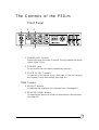 10
10
-
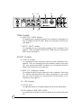 11
11
-
 12
12
-
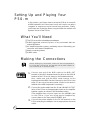 13
13
-
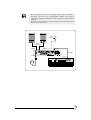 14
14
-
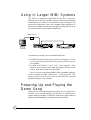 15
15
-
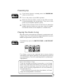 16
16
-
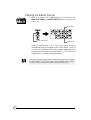 17
17
-
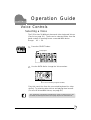 18
18
-
 19
19
-
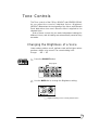 20
20
-
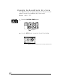 21
21
-
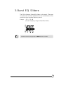 22
22
-
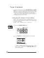 23
23
-
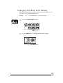 24
24
-
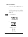 25
25
-
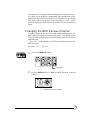 26
26
-
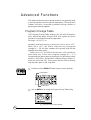 27
27
-
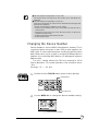 28
28
-
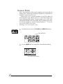 29
29
-
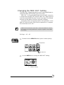 30
30
-
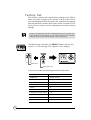 31
31
-
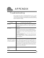 32
32
-
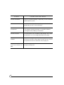 33
33
-
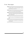 34
34
-
 35
35
-
 36
36
-
 37
37
-
 38
38
-
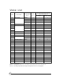 39
39
-
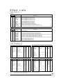 40
40
-
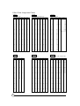 41
41
-
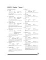 42
42
-
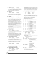 43
43
-
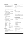 44
44
-
 45
45
-
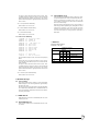 46
46
-
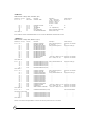 47
47
-
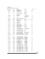 48
48
-
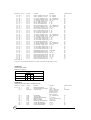 49
49
-
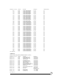 50
50
-
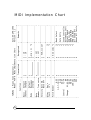 51
51
-
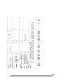 52
52
-
 53
53


Yamaha P50 Handleiding
- Categorie
- Muziekinstrumenten
- Type
- Handleiding
- Deze handleiding is ook geschikt voor
in andere talen
- English: Yamaha P50 User manual
- italiano: Yamaha P50 Manuale utente
- русский: Yamaha P50 Руководство пользователя
- français: Yamaha P50 Manuel utilisateur
- español: Yamaha P50 Manual de usuario
- Deutsch: Yamaha P50 Benutzerhandbuch
- português: Yamaha P50 Manual do usuário
- dansk: Yamaha P50 Brugermanual
- suomi: Yamaha P50 Ohjekirja
- čeština: Yamaha P50 Uživatelský manuál
- svenska: Yamaha P50 Användarmanual
- Türkçe: Yamaha P50 Kullanım kılavuzu
- polski: Yamaha P50 Instrukcja obsługi
- română: Yamaha P50 Manual de utilizare