
TONE GENERATOR
XG
TG
300
B
PERFORM
MODE EQ
UTIL EFFECT
PLAY EDIT
ALL
MUTE/
SOLO
PART
PART
SELECT
VALUE
SELECT
VALUE
ENTER
EXIT
SELECT
PART GROUP
StringsBassGuitarOrgan
Chrom.perc.
Piano
Ensemble Brass Reed Pipe Synth lead Synth pad
DrumModel excl.SFXPercussiveEthnic
Synth effects
PHONESMIDI IN A
STAND BY
ON
VOLUME
2
PART VOL EXP PAN
BANK/PGM
REV CHO VAR KEY
A/D INPUT
1
MU PLG-1 PLG-2 PLG-3
English
Deutsch
Français

2
MU128
92-BP
FCC INFORMATION (U.S.A)
1. IMPORTANT NOTICE : DO NOT MODIFY THIS UNIT!
This product, when installed as indicated in the instructions contained in this manual, meets FCC requirements. Modifications not
expressly approved by Yamaha may void your authority, granted by the FCC, to use the product.
2. IMPORTANT: When connecting this product to accessories and/or another product use only high quality shielded cables. Cable/s
supplied with this product MUST be used. Follow all installation instructions. Failure to follow instructions could void your FCC
authorization to use this product in the USA.
3. NOTE: This product has been tested and found to comply with the requirements listed in FCC Regulations, Part 15 for Class “B”
digital devices. Compliance with these requirements provides a reasonable level of assurance that your use of this product in a
residential environment will not result in harmful interference with other electronic devices. This equipment generates/uses radio
frequencies and, if not installed and used according to the instructions found in the user’s manual, may cause interference harmful to
the operation of other electronic devices. Compliance with FCC regulations does not guarantee that interference will not occur in all
installations. If this product is found to be the source of interference, which can be determined by turning the unit “OFF” and “ON”,
please try to eliminate the problem by using one of the following measures:
Relocate either this product or the device that is being affected by the interference.
Utilize power outlets that are on different branch (circuit breaker or fuse) circuits or install AC line filter/s.
In the case of radio or TV interference, relocate/reorient the antenna. If the antenna lead-in is 300 ohm ribbon lead, change the lead-in
to co-axial type cable.
If these corrective measures do not produce satisfactory results, please contact the your local retailer authorized to distribute this type of
product. If you can not locate the appropriate retailer, please contact Yamaha Corporation of America, Electronic Service Division,
6600 Orangethorpe Ave, Buena Park, CA 90620
*
This applies only to products distributed by YAMAHA CORPORATION OF AMERICA.
NEDERLAND / THE NETHERLANDS
• Dit apparaat bevat een lithium batterij voor geheugen back-up.
• This apparatus contains a lithium battery for memory back-up.
• Raadpleeg uw leverancier over de verwijdering van de batterij
op het moment dat u het apparaat ann het einde van de
levensduur afdankt of de volgende Yamaha Service Afdeiing:
Yamaha Music Nederland Service Afdeiing
Kanaalweg 18-G, 3526 KL UTRECHT
Tel. 030-2828425
• For the removal of the battery at the moment of the disposal at
the end of the service life please consult your retailer or Yamaha
Service Center as follows:
Yamaha Music Nederland Service Center
Address: Kanaalweg 18-G, 3526 KL UTRECHT
Tel : 030-2828425
• Gooi de batterij niet weg, maar lever hem in als KCA.
• Do not throw away the battery. Instead, hand it in as small
chemical waste.
ADVARSEL!
Lithiumbatteri—Eksplosionsfare ved fejlagtig håndtering.
Udskiftning må kun ske med batteri af samme fabrikat og
type. Levér det brugte batteri tilbage til leverandoren.
VARNING
Explosionsfara vid felaktigt batteribyte. Använd samma
batterityp eller en ekvivalent typ som rekommenderas av
apparattillverkaren. Kassera använt batteri enligt fabrikantens
instruktion.
VAROITUS
Paristo voi räjähtää, jos se on virheellisesti asennettu. Vaihda
paristo ainoastaan laitevalmistajan suosittelemaan tyyppiin.
Hävitä käytetty paristo valmistajan ohjeiden mukaisesti.

MU128
3
English
This product utilizes batteries or an external power supply
(adapter). DO NOT connect this product to any power
supply or adapter other than one described in the manual,
on the name plate, or specifically recommended by
Yamaha.
WARNING: Do not place this product in a position
where anyone could walk on, trip over, or roll anything
over power or connecting cords of any kind. The use of
an extension cord is not recommended! If you must use
an extension cord, the minimum wire size for a 25' cord
(or less ) is 18 AWG. NOTE: The smaller the AWG
number, the larger the current handling capacity. For
longer extension cords, consult a local electrician.
This Product should be used only with the components
supplied or; a cart, rack, or stand that is recommended by
Yamaha. If a cart, etc., is used, please observe all safety
markings and instructions that accompany the accessory
product.
SPECIFICATIONS SUBJECT TO CHANGE: The in-
formation contained in this manual is believed to be cor-
rect at the time of printing. However, Yamaha reserves
the right to change or modify any of the specifications
without notice or obligation to update existing units.
This product, either alone or in combination with an ampli-
fier and headphones or speaker/s, may be capable of pro-
ducing sound levels that could cause permanent hearing
loss. DO NOT operate for long periods of time at a high
volume level or at a level that is uncomfortable. If you
experience any hearing loss or ringing in the ears, you
should consult an audiologist. IMPORTANT: The louder
the sound, the shorter the time period before damage oc-
curs.
Some Yamaha products may have benches and/or acces-
sory mounting fixtures that are either supplied with the
product or as optional accessories. Some of these items
are designed to be dealer assembled or installed. Please
make sure that benches are stable and any optional fix-
tures (where applicable) are well secured BEFORE using.
Benches supplied by Yamaha are designed for seating
only. No other uses are recommended.
NOTICE: Service charges incurred due to lack of knowl-
edge relating to how a function or effect works (when the
unit is operating as designed) are not covered by the
manufacturer’s warranty, and are therefore the owners re-
sponsibility. Please study this manual carefully and con-
sult your dealer before requesting service.
ENVIRONMENTAL ISSUES: Yamaha strives to pro-
duce products that are both user safe and environmentally
friendly. We sincerely believe that our products and the
production methods used to produce them, meet these
goals. In keeping with both the letter and the spirit of the
law, we want you to be aware of the following:
Battery Notice: This product MAY contain a small non-
rechargeable battery which (if applicable) is soldered in
place. The average life span of this type of battery is
approximately five years. When replacement becomes
necessary, contact a qualified service representative to
perform the replacement.
This Product may also use “household” type batteries.
Some of these may be rechargeable. Make sure that the
battery being charged is a rechargeable type and that the
charger is intended for the battery being charged.
When installing batteries, do not mix old batteries with
new, or with batteries of a different type. Batteries MUST
be installed correctly. Mismatches or incorrect installation
may result in overheating and battery case rupture.
Warning: Do not attempt to disassemble, or incinerate
any battery. Keep all batteries away from children. Dis-
pose of used batteries promptly and as regulated by the
laws in your area.
Note: Check with any retailer of household type batteries
in your area for battery disposal information.
Disposal Notice: Should this Product become damaged
beyond repair, or for some reason its useful life is consid-
ered to be at an end, please observe all local, state, and
federal regulations that relate to the disposal of products
that contain lead, batteries, plastics, etc. If your dealer is
unable to assist you, Please contact Yamaha directly.
NAME PLATE LOCATION: The name Plate is located
on the top of the product. The model number, power re-
quirements, etc., are located on this plate. (The serial
number is located on the rear panel.) You should record
the model number, serial number, and the date of pur-
chase in the spaces provided below and retain this manual
as a permanent record of your purchase.
Model
Serial No.
Purchase Date
SPECIAL MESSAGE SECTION
PLEASE KEEP THIS MANUAL
TONE GENERATOR
XG
TG
300
B
PERFORM
MODE EQ
UTIL EFFECT
PLAY EDIT
ALL
MUTE/
SOLO
PART
PART
SELECT
VALUE
SELECT
VALUE
ENTER
EXIT
SELECT
PART GROUP
StringsBassGuitarOrgan
Chrom.perc.
Piano
Ensemble Brass Reed Pipe Synth lead Synth pad
DrumModel excl.SFXPercussiveEthnic
Synth effects
PHONESMIDI IN A
STAND BY
ON
VOLUME
2
PART VOL EXP PAN
BANK/PGM
REV CHO VAR KEY
A/D INPUT
1
MU PLG-1 PLG-2 PLG-3
92-BP

4
MU128
Welcome to the MU128
Welcome to the MU128
Congratulations and thank you for purchasing the Yamaha MU128 Tone
Generator!
The MU128 is an advanced tone generator providing an amazing total of
1342 high-quality Voices, full General MIDI compatibility — including
Yamaha’s XG — plus flexible computer interfacing in a compact, easy-
to-use half-rack mount unit.
With the convenient built-in host computer interface and MIDI termi-
nals, the MU128 is ideal for any computer music system — from connec-
tion to a simple laptop to integration in a complete MIDI studio. With its
large LCD and the intuitive graphic controls on the display, the MU128 is
remarkably easy to use.
The MU128 also features completely independent dual MIDI inputs, 64
Part multi-timbral capacity and full 128-note polyphony for playback
of even the most sophisticated song data. A special Performance mode
gives you flexible four-Voice operation, for live performance applications.
Also built into the system are five digital multi-effects and two EQ sec-
tions (one per-part, and one overall), which give you enormous versatility
in “sweetening” the sound. What’s more, the MU128 provides a host of
comprehensive, yet easy-to-use editing tools for getting just the sound you
need.
The MU128 is also compatible with the powerful XG Plug-in System,
allowing you to install up to three optional XG Plug-in boards for
additional Voices and effects. Currently available plug-in boards include
the:
PLG100-VL Virtual Acoustic — which provides stunning monophonic
synthesizer Voices with the powerful physical modeling tone generation
system.
PLG100-VH Vocal Harmony — which produces automatic
“harmonizer” effects, letting you apply one-, two- or three-part harmonies
to a vocal signal (via a microphone connected to the A/D Inputs).
PLG100-DX Advanced DX/TX — which provides vintage FM
synthesis Voices, the same as found on the famous Yamaha DX7.
Three boards (in any combination) can be installed simultaneously. With
the easy-to-remove rear panel cover and the special guide slots, installation
is also exceptionally simple.
The MU128 also has convenient A/D inputs that allow you to connect a
microphone, electric guitar or other instrument, and mix those signals with

MU128Welcome to the MU100R
5
Welcome to the MU128
English
the MU128’s Voices.
* Company names and product names in this Owner’s Manual are the trade-
marks or registered trademarks of their respective companies and are
hereby acknowledged.
GM System Level 1
“GM System Level 1 is a standard specification that defines the arrange-
ment of voices in a tone generator and its MIDI functionality, ensuring that
data can be played back with substantially the same sounds on any GM-
compatible tone generator, regardless of its manufacturer or model.
Tone generators and song data that meet the “GM System Level 1” bear this
GM logo.
XG
“XG” is a tone generator format that expands the voice arrangement of the
“GM System Level 1” specification to meet the ever-increasing demands of
today’s computer peripheral environment, providing richer expressive power
while maintaining upward compatibility of data. “XG” greatly expands “GM
System Level 1” by defining the ways in which voices are expanded or
edited and the structure and type of effects.
When commercially available song data bearing the XG logo is played
back on a tone generator which bears the XG logo, you will enjoy a full
musical experience that includes unlimited expansion voices and effect
functions.
About the XG Plug-in System
This system offers powerful expansion and upgrade capabilities for XG-
Plug-in-compatible tone generators.
The XG Plug-in System enables you to equip the tone generator with the
latest and most sophisticated technology, ensuring that you keep pace with
the rapid and multi-faceted advances in modern music production.

Unpacking
6
MU128
MU128 Serial No.:
PA-6 AC Power Adaptor*
Owner’s Manual set
(this book and the “Sound List & MIDI Data” booklet)
CD-ROM (XGtools)
XGtools Setup Guide
Unpacking
Your MU128 package should include the items listed below. Make sure that
you have them all. Also, write down the serial number of your MU128 in the
box below, for future reference.
* Power supply recommendation may vary from country to country.
Please check with your nearest Yamaha dealer for further details.

MU128ts
7
TABLE OF CONTENTS
English
Table of Contents
Welcome to the MU128 ......................................................................................................... 4
Unpacking ............................................................................................................................... 6
Table of Contents ................................................................................................................... 7
How to Use This Manual ..................................................................................................... 11
PRECAUTIONS .................................................................................................................. 13
The Controls of the MU128 ................................................................................................ 14
Front Panel.................................................................................................................. 14
Rear Panel................................................................................................................... 17
The MU128 — What It Is and What It Can Do ............................................................... 19
What It Is... ..................................................................................................................... 19
About General MIDI .................................................................................................. 19
About XG ................................................................................................................... 20
What It Can Do... ........................................................................................................... 20
Using With MIDI Keyboard ....................................................................................... 20
Using With a Computer or Sequencer........................................................................ 20
About the Modes of the MU128 .................................................................................... 21
Play Modes and the Part Controls .............................................................................. 22
Part Edit Mode............................................................................................................ 22
Utility Mode ............................................................................................................... 22
Modes and Function Tree ................................................................................................... 23
GUIDED TOUR
Setting Up Your MU128R ............................................................................................. 26
What You'll Need........................................................................................................ 26
Making the Connections............................................................................................. 26
Powering Up.................................................................................................................... 29
Playing the Demo Song .................................................................................................. 30
About the Demo Song ................................................................................................ 31
Setting Up the MU128 in Your Music System ............................................................ 32
Connecting to MIDI Devices ..................................................................................... 32
Connecting Directly to a Computer ........................................................................... 35
Selecting and Playing the Performances...................................................................... 38
Calling Up the Performance Play Mode and Playing the Performances................... 38
Selecting and Playing Individual Voices ...................................................................... 42
Calling Up the XG Mode ........................................................................................... 42
Selecting Voice Banks and Voices From the Panel .................................................... 43
Selecting Voices with the Voice Category Buttons .................................................... 43
Manually Selecting Voice Banks and Voices ............................................................. 45
Selecting Voices From a MIDI Keyboard .................................................................. 48
About the Parts and Voices of the MU128 .................................................................. 49
Parts ............................................................................................................................ 49
Voices..........................................................................................................................49

8
MU128
TABLE OF CONTENTS
Normal Voices and Drum Voices ............................................................................... 50
Maximum Simultaneous Sounds (Polyphony) .......................................................... 50
Selecting the Voices.................................................................................................... 50
Use of bank select MSB and LSB when the Sound Module mode is set to
“XG” or “PFM” ................................................................................................... 51
Use of bank select MSB and LSB when the Sound Module mode is
set to “TG300B” ................................................................................................... 52
Part Mode ................................................................................................................... 53
How to select a Voice ................................................................................................. 54
Selecting Voices when the Sound Module mode is set to “XG” or “PFM” ........ 55
Selecting Voices when the Sound Module mode is set to “TG300B” ................. 56
Editing in the Multi Mode ............................................................................................. 58
Single Part Controls.................................................................................................... 59
Changing the Volume and Pan settings of a Part.................................................. 60
On Your Own... ............................................................................................... 61
Edit Menu Parameters ................................................................................................ 62
Changing the Filter and EG Settings of a Part ..................................................... 62
On Your Own... ............................................................................................... 64
Editing Drum Kits — with the Drum Setup Controls ............................................... 65
Making Changes to Individual Drum Sounds — the "Drum" Parameters .......... 66
On Your Own... ............................................................................................... 68
Editing in the Performance Mode ................................................................................ 69
All Part Controls......................................................................................................... 70
Transposing the Overall Key of a Performance ......................................................... 71
Single Part Controls — Selecting Different Voices for the Performance.................. 72
On Your Own... ............................................................................................... 73
Edit Menu Parameters — Creating a Two-Voice Layer ............................................ 74
Setting Up a Keyboard Split....................................................................................... 76
On Your Own... ............................................................................................... 77
Using the Assignable Controller in a Performance.................................................... 77
Saving Your Original Performance ............................................................................ 78
Assignable Controller (AC1)......................................................................................... 79
Controllers and Control Numbers .............................................................................. 79
Control Numbers and the Actual Sound .................................................................... 80
Assigning the Assignable Controller.......................................................................... 81
Using the Assignable Controller — Setting Up ......................................................... 82
Using the Assignable Controller — Some Applications............................................ 83
Changing the Brightness on a Piano Voice........................................................... 83
Experssive Volume Control of a Part ................................................................... 85
Expressive Control of Individual Drum Sounds .................................................. 85
On Your Own... ............................................................................................... 87
Effects .............................................................................................................................. 88
Using Reverb and Chorus........................................................................................... 88
Applying Distortion to a Part — Using the Variation Effects ................................... 90

MU128ts
9
TABLE OF CONTENTS
English
Equalizer (EQ)................................................................................................................ 92
Adjusting the Tone of a Specific Part — Part EQ...................................................... 92
Adjusting the Overall Tone — Main EQ ................................................................... 94
Mute/Solo ........................................................................................................................ 95
Using Mute/Solo......................................................................................................... 95
A/D Inputs ....................................................................................................................... 97
Using the A/D Inputs .................................................................................................. 97
MIDI/Computer Connecting Cables .......................................................................... 101
REFERENCE
Multi Mode.................................................................................................................... 104
Part Controls ............................................................................................................. 104
Single Part Control.............................................................................................. 105
All Part Control................................................................................................... 109
Multi Edit Mode ....................................................................................................... 111
Filter (FIL) .......................................................................................................... 111
Envelope Generator (EG) ................................................................................... 113
Equalizer (EQ) .................................................................................................... 116
Vibrato................................................................................................................. 117
Others .................................................................................................................. 118
Drum Setup Controls .......................................................................................... 126
Performance Mode....................................................................................................... 131
Performance Part Control......................................................................................... 132
All Part ................................................................................................................ 132
Single Part ........................................................................................................... 134
Performance Edit Mode............................................................................................ 137
Common.............................................................................................................. 137
Part ...................................................................................................................... 140
Copy and Store Operations ...................................................................................... 142
Copy .................................................................................................................... 142
Store .................................................................................................................... 143
Recall Function......................................................................................................... 145
Effect Edit Mode .......................................................................................................... 146
Reverb (REV) ........................................................................................................... 147
Chorus (CHO)........................................................................................................... 148
Variation (VAR) ........................................................................................................ 149
Insertion 1, 2 (INS 1, 2)............................................................................................ 151
About the Effect Connections — System and Insertion .......................................... 152
Equalizer (Multi EQ) Edit........................................................................................... 155

10
MU128
TABLE OF CONTENTS
Utility Mode .................................................................................................................. 156
System Functions (SYSTEM) .................................................................................. 157
Dump Out Functions (DUMPOUT)......................................................................... 162
Saving and Restoring Data via MIDI ................................................................. 162
Saving and Restoring Data via TO HOST.......................................................... 162
Initialize Functions (INITIAL)................................................................................. 166
Demo Song Play (DEMO) ....................................................................................... 169
Other Functions............................................................................................................ 170
Sound Module Mode (MODE)................................................................................. 170
Show MIDI Data ...................................................................................................... 171
Plug-in System .............................................................................................................. 173
About the XG Plug-in System.................................................................................. 173
Structure of the XG Plug-in System ................................................................... 174
Optional XG Plug-in Boards .............................................................................. 174
Installing the Plug-in Boards.................................................................................... 176
Before Installing the Plug-in Board.................................................................... 176
Setting the Part Assign Parameter ...................................................................... 177
Setting Part Assign from an External MIDI Device........................................... 178
Selecting Voices of an XG Plug-in Board .......................................................... 178
Installing the Plug-in Board................................................................................ 179
APPENDIX
Troubleshooting ............................................................................................................ 184
Error Messages ............................................................................................................. 185
Specifications ................................................................................................................ 187
Glossary......................................................................................................................... 189
Index .............................................................................................................................. 191

MU128
11
How to Use This Manual
English
How to Use This Manual
You are probably eager to try out your new MU128 Tone Generator right away and
hear what it can do, rather than have to read through a lot of instructions before you
can even get a sound out of it.
The structure of the manual is very straightforward. You can approach it in a linear
manner, reading through from beginning to end, or on an “on-demand” basis, going
directly to the information you need as you need it.
However, to get the most out of your MU128, we strongly suggest that you read the
following sections in the order given:
1) Precautions
This gives you important information on how to care for your new MU128,
how to avoid damaging it, and how to ensure long-term, reliable operation.
2) The MU128 — What It Is and What It Can Do
This briefly provides an overview of the functions and features of the MU128
and offers some important hints on how you can use it effectively. It also
provides convenient page references so that you can easily find out about
features and functions of interest.
3) The Controls of the MU128
This section introduces you to the panel controls and connectors.
4) Guided Tour
This is perhaps the most important and valuable section of the manual. It gets
you started using your new MU128, helping you set up the instrument and
play it — and it introduces you to virtually all of the important functions and
features. The hands-on experience you gain in this section will help you
quickly master the instrument and aid you in navigating the more detailed
sections of the manual.
5) Setting Up the MU128 in Your Music System
This section (within the Guided Tour) provides all you need to know to effec-
tively integrate the MU128 into your present computer music system.
6) Reference
Once you’re familiar with everything above, lightly go over this comprehen-
sive guide to all editing functions. You won’t need (or want) to read
everything at once, but it is there for you to refer to when you need
information about a certain feature or function.
7) Appendix
Use the sections in the Appendix as necessary. For example, the Index will
come in handy when you need to quickly find information on a specific topic.
Other sections, such as the Glossary, Troubleshooting and Error Messages
provide additional useful information.
8) Sound List & MIDI Data booklet
This separate booklet features lists of the Performances, Voices, drum sounds,
effect types and parameters, as well as details on all relevant MIDI messages
and data.

12
MU128
How to Use This Manual
NOTES
•The illustrations and LCD screens as shown in this owner’s manual are for instruc-
tional purposes only, and may appear somewhat different from those on your in-
strument.
•Installing an XG Plug-in Board to the MU128 increases the number of menu items
and parameters shown in the display. Unless otherwise indicated, the example
displays printed in this manual correspond to a MU128 with no boards installed.

PRECAUTIONS
13
English
• Do not place object in front of the instrument's air vent, since this may
prevent adequate ventilation of the internal components, and possibly
result in the instrument overheating.
• Do not operate the instrument for a long period of time at a high or
uncomfortable volume level, since this can cause permanent hearing
loss. If you experience any hearing loss or ringing in the ears, consult a
physician.
■ REPLACING THE BACKUP BATTERY
• This instrument contains a non rechargeable internal backup battery
which permits internal data to remain stored even when the power is off.
When the backup battery needs replacing, the message “Battery Low!”
will display in the display. When this happens, immediately back up
your data (using an external device such as the floppy disk-based
Yamaha MIDI Data Filer MDF3), then have qualified Yamaha service
personnel replace the backup battery.
• Do not attempt to replace the backup battery yourself, in order to prevent
the possible serious hazards. Always have qualified Yamaha service
personnel replace the backup battery.
• Never place the backup battery in a location that a child can reach, since
a child might accidentally swallow the battery. If this should happen,
consult a physician immediately.
■ SAVING USER DATA
• Save all data to an external device such as the Yamaha MIDI Data Filer
MDF3, in order to help prevent the loss of important data due to a
malfunction or user operating error.
Yamaha cannot be held responsible for damage caused by improper
use or modifications to the instrument, or data that is lost or destroyed.
Always turn the power off when the instrument is not in use.
PRECAUTIONS
PLEASE READ CAREFULLY BEFORE PROCEEDING
* Please keep these precautions in a safe place for future reference.
WARNING
Always follow the basic precautions listed below to avoid the possibility of serious injury or even death from electrical
shock, short-circuiting, damages, fire or other hazards. These precautions include, but are not limited to, the following:
• Do not open the instrument or attempt to disassemble the internal parts
or modify them in any way. The instrument contains no user-serviceable
parts. If it should appear to be malfunctioning, discontinue use
immediately and have it inspected by qualified Yamaha service
personnel.
• Do not expose the instrument to rain, use it near water or in damp or wet
conditions, or place containers on it containing liquids which might
spill into any openings.
• If the AC adaptor cord or plug becomes frayed or damaged, or if there is
a sudden loss of sound during use of the instrument, or if any unusual
smells or smoke should appear to be caused by it, immediately turn off
the power switch, disconnect the adaptor plug from the outlet, and have
the instrument inspected by qualified Yamaha service personnel.
• Use the specified adaptor (PA-6 or an equivalent recommended by
Yamaha) only. Using the wrong adaptor can result in damage to the
instrument or overheating.
• Before cleaning the instrument, always remove the electric plug from
the outlet. Never insert or remove an electric plug with wet hands.
• Check the electric plug periodically and remove any dirt or dust which
may have accumulated on it.
CAUTION
Always follow the basic precautions listed below to avoid the possibility of physical injury to you or others, or damage
to the instrument or other property. These precautions include, but are not limited to, the following:
• Do not place the AC adaptor cord near heat sources such as heaters or
radiators, and do not excessively bend or otherwise damage the cord,
place heavy objects on it, or place it in a position where anyone could
walk on, trip over, or roll anything over it.
• When removing the electric plug from the instrument or an outlet, always
hold the plug itself and not the cord.
• Do not connect the instrument to an electrical outlet using a multiple-
connector. Doing so can result in lower sound quality, or possibly cause
overheating in the outlet.
• Unplug the AC power adaptor when not using the instrument, or during
electrical storms.
• Before connecting the instrument to other electronic components, turn
off the power for all components. Before turning the power on or off for
all components, set all volume levels to minimum.
• Do not expose the instrument to excessive dust or vibrations, or extreme
cold or heat (such as in direct sunlight, near a heater, or in a car during
the day) to prevent the possibility of panel disfiguration or damage to
the internal components.
• Do not use the instrument near other electrical products such as
televisions, radios, or speakers, since this might cause interference which
can affect proper operation of the other products.
• Do not place the instrument in an unstable position where it might
accidentally fall over.
• Before moving the instrument, remove all connected adaptor and other
cables.
• When cleaning the instrument, use a soft, dry cloth. Do not use paint
thinners, solvents, cleaning fluids, or chemical-impregnated wiping
cloths. Also, do not place vinyl, plastic or rubber objects on the
instrument, since this might discolor the panel or keyboard.
• Do not rest your weight on, or place heavy objects on the instrument,
and do not use excessive force on the buttons, switches or connectors.
(3)-3

14
MU128of the MU90R
The Controls of the MU128
1 A/D INPUT 1, 2 jacks
For connection of a microphone, electric guitar or other electronic instruments
(1/4” mono).
2 A/D INPUT VOLUME control
For control of the level of the A/D inputs.
3 VOLUME control
For adjusting the overall volume of the MU128. (This does not affect the exter-
nal signal received via the rear panel INPUT jacks.).
4 STAND BY/ON switch (Power Switch)
Pressing this turns the power on and off (stand by).
1
CAUTION
Even when the switch is in the “STAND BY” position, electricity is still flowing to the
instrument at the minimum level. When you are not using the MU128, make sure you
unplug the AC power adaptor from the wall AC outlet.
5 MIDI IN A terminal (front panel)
For connection to other MIDI devices, such as a MIDI keyboard or sequencer.
When the HOST SELECT switch is set to “MIDI,” this receives MIDI data for
controlling Parts set to receive over channels A01 - A16. When the HOST
SELECT switch is set to “Mac,” “PC-1,” or “PC-2,” it transmits the received
MIDI data to the TO HOST terminal. The front panel MIDI IN A terminal can
be selected for operation in the Utility mode (page 157). A rear panel MIDI
IN-A terminal is also provided; however both the front and rear panel termi-
nals cannot be used simultaneously.
6 PHONES jack
For connection to a set of stereo headphones (stereo mini pin).
The Controls of the MU128
Front Panel
TONE GENERATOR
XG
TG
300
B
PERFORM
MODE EQ
UTIL EFFECT
PLAY EDIT
ALL
MUTE/
SOLO
PART
PART
SELECT
VALUE
SELECT
VALUE
ENTER
EXIT
SELECT
PART GROUP
StringsBassGuitarOrgan
Chrom.perc.
Piano
Ensemble Brass Reed Pipe Synth lead Synth pad
DrumModel excl.SFXPercussiveEthnic
Synth effects
PHONESMIDI IN A
STAND BY
ON
VOLUME
2
PART VOL EXP PAN
BANK/PGM
REV CHO VAR KEY
A/D INPUT
1
MU PLG-1 PLG-2 PLG-3
1
4
2
5 6 JLK
39A8:
DEF
G
H
I
BCM
7 N

MU128 MU90R
15
The Controls of the MU128
English
7 Voice Category buttons
For selection of basic Voice categories. Use these buttons to call up the desired
Voice category in the Multi Play mode (Single Part controls; page 59) or in the
Performance Play mode (Single Part controls; page 72), then select a specific
Voices from the category by using the [VALUE -/+] buttons or data dial.
(page 43.)
8 MODE button
For calling up the Sound Module mode display. (page 170.)
9 PLAY button
For entering the Play mode and switching among the different Play displays.
(pages 41, 47.)
0 EDIT button
For entering the Edit mode. (pages 58, 69.)
A UTIL (UTILITY) button
For entering the Utility mode. (page 156.)
B EFFECT button
For entering the Effect Edit mode. (page 146.)
C EQ button
For entering the EQ Edit mode. (page 155.)
D MUTE/SOLO button
Pressing this alternately mutes or solos the selected Part. (page 95.)
E ENTER button
For calling up menu items in the display and for executing certain functions
and operations. Double-clicking this (pressing it twice quickly) calls up the
Show MIDI data function. (page 171.)
F EXIT button
For leaving various display pages and returning to previous displays. Also for
canceling certain functions and operations.
G PART -/+ buttons
For selecting different Parts. In the Effect Edit mode, these can be used to
switch among the different effects. Pressing these together alternately switches
between All Part and Single Part control. (page 61.)
H SELECT </> buttons
For selecting the various menu items, parameters and controls on the display.
I VALUE -/+ buttons
For changing the value of a selected parameter or control.

16
MU128of the MU90R
The Controls of the MU128
Hint
You can rapidly move through the values by holding down one of the [VALUE
-
/
+
]
buttons. You can move even more rapidly by holding down one button and then press-
ing and holding down the other. For example, to rapidly advance (increase) the value,
hold down the [VALUE
+
] button and simultaneously press and hold down the [VALUE
-
] button.
J Data dial
For rapidly adjusting/changing values of the selected function or parameter.
Rotate this clockwise to increase the value.
K SELECT button
For switching among the internal Voices of the MU128 and the Voices of any
installed optional XG Plug-in boards (page 174). (This applies to tone genera-
tor type boards only; effect type boards are selected by a different method.)
Press this repeatedly to select the desired board and its Voices. The appropri-
ate LED flashes briefly and the corresponding icon for the board appears in the
LCD. (This button has no effect unless a tone generator type plug-in board is
installed.) (page 178.)
L PART GROUP button
For switching among the Part groups. Press this repeatedly to select the de-
sired Part group (A, B, C, or D).
M Display
This back-lit LCD displays all necessary operation information for the MU128.
N LEDs
These indicate how many plug-in boards are installed. The MU LED indicates
the MU128 itself and its built-in Voices and remains lit. PLG-1, PLG-2, and
PLG-3 are lit according to the number of XG Plug-in boards installed. When
using the SELECT button to select a board, the corresponding LED flashes
briefly.
During playback of song data (from a sequencer, etc.), these flash to indicate
usage of the various sound sources.

MU128 MU90R
17
The Controls of the MU128
English
Rear Panel
1 MIDI terminals
For connection to other MIDI devices, such as a MIDI keyboard, tone genera-
tor, or sequencer, or to a computer that has a MIDI interface.
• MIDI IN-A terminal
When the HOST SELECT switch is set to “MIDI,” this receives MIDI data for
controlling Parts set to receive over channels A01 - A16. When the HOST
SELECT switch is set to “Mac,” “PC-1,” or “PC-2,” it transmits the received
MIDI data to the TO HOST terminal. The front and rear panel MIDI IN-A
terminals cannot be used simultaneously. The rear panel MIDI IN-A terminal
can be selected for operation in the Utility mode (page 157).
• MIDI IN-B terminal
When the HOST SELECT switch is set to “MIDI,” this receives MIDI data for
controlling Parts set to receive over channels B01 - B16.
• MIDI OUT terminal
This is for transmitting data to another MIDI device, in the case of sending
bulk data to a computer or MIDI data storage device (when the HOST SE-
LECT switch is set to “MIDI”). It also can be used for outputting the data
received via the TO HOST terminal, letting you connect other MIDI instru-
ments and use the MU128 as a MIDI interface for your computer (when the
HOST SELECT switch is set to “Mac,” “PC-1,” or “PC-2”).
• MIDI THRU terminal
This is for outputting the data received via the MIDI IN-A terminal as is, with-
out any additional data generated by the MU128 itself. This is commonly used
for “daisy-chain” connection of other MIDI instruments.
2 HOST SELECT switch
For selecting the type of host computer. (page 35.)
1
8
2 3 4 6 7
5
MIDI
THRU
OUT IN-A IN-B
HOST SELECT
MIDI
Mac
PC-2 PC-1
TO HOST DC IN
OUTPUT INPUT
L
R
SER NO.

18
MU128of the MU90R
The Controls of the MU128
3 TO HOST terminal
For connection to a host computer that does not have a MIDI interface. ( page
36.)
4 DC IN jack
For connection to the PA-6 AC power adaptor.
1
WARNING
Use ONLY a Yamaha PA-6 AC Power Adaptor (or other adaptor specifically recom-
mended by Yamaha) to power your instrument from the AC mains. The use of other
adaptors may result in irreparable damage to both the adaptor and the MU128.
1
CAUTION
When connecting the AC power adaptor, first make sure that the MU128 is turned off
(set to STAND BY). Next, connect one end of the power adaptor to the DC IN jack on
the MU128, and connect the other end to an appropriate AC outlet.
5 Power cord hook
Use this to secure the AC power adaptor’s cord and connector to the MU128,
to prevent accidental disconnection. Plug the connector into the DC IN jack,
then wrap the cord inside both ends of the hook.
6 OUTPUT L, R jacks (Left, Right)
For connection to a stereo amplifier/speaker system.
7 INPUT L, R jacks (Left, Right)
These are for connection to external sound sources, such as CD players, cas-
sette decks, etc. Neither the front panel VOLUME control nor the built-in
effects and equalizer of the MU128 have any effect on the input sound.
8 XG Plug-in Board expansion bay
This bay accommodates up to three XG Plug-in Boards. To install a board,
first remove the expansion bay cover (page 179). Since the screw is tightened
securely at the factory, you may need to use a screwdriver to loosen it at first.
Normally, it can be fastened and removed simply by using your fingers.

MU128
19
The MU128 — What It Is and What It Can Do
English
The MU128 — What It Is and What It Can Do
What It Is...
The MU128 is a full-featured and easy-to-use tone generator, that provides an
unprecedented wealth of Voices and expressive sonic control. It features full
General MIDI Level 1 compatibility. It also provides XG compatibility, with an
huge total of 1149 Voices and 37 drum kits.
The MU128 has 128-note polyphony and is 64-Part multi-timbral. In other
words, the MU128 has 64 different Parts, each with its own Voice, so that up to
64 different Voices can be sounded simultaneously.
Additional A/D Parts let you connect up to two external signals — such as a
microphone, electric guitar or CD player — and mix them with the MU128’s
Voices.
Although Voices cannot be directly edited, the various Part controls and Edit
mode give you tools for transforming or customizing the sound of the Voices.
What’s more, the MU128 has a built-in multi-effect processor, with seven inde-
pendent digital effect “units” for enhancing the sound.
The MU128 also features a special Performance mode, in which four Parts
are played simultaneously over a single MIDI channel. Connected to a MIDI
keyboard, this effectively gives you four tone generators in one. The MU128
gives you 100 factory-programmed Preset Performances plus 100 Internal Per-
formance locations for storing your own original Performances.
About General MIDI
General MIDI is a new addition to the worldwide MIDI standard. MIDI, as
you know, stands for Musical Instrument Digital Interface, and makes it
possible for various electronic musical instruments and other devices to “com-
municate” with each other. For example, by connecting a sequencer to the
MU128’s MIDI IN terminal, you could play back a song on the sequencer
using the Voices of the MU128.
So, where does General MIDI fit in all of this? One of the most important
features of General MIDI is in the standardization of Voices. This means that a
song recorded in the General MIDI format can be played back on any General
MIDI compatible tone generator and sound just as the composer intended. For
example, if there is an alto sax solo in the song, it will be played by an alto sax
Voice on the General MIDI tone generator (and not by a tuba or harpsichord!).
Since the MU128 is fully compatible with General MIDI, you can take advan-
tage of the vast wealth of musical material recorded in that format.

20
MU128an Do
The MU128 — What It Is and What It Can Do
About XG
The new XG format is an extension of General MIDI, and provides a number of
significant improvements and enhancements. XG-compatible song data takes
advantage of the extensive MIDI control and built-in effects of the MU128 (and
other MU-series instruments).
To take greatest advantage of the powerful capabilities of XG, we recom-
mend using XG-compatible instruments and software. For example, XG-com-
patible keyboards such as the Yamaha CBX-K2 keyboard and software give you
direct controls for accessing the full expressive potential of the MU128’s XG
Voices and the XG-related parameters.
What It Can Do...
Here are a few ideas on how you can use the MU128. The list below is not
comprehensive, but is meant to be a general guide to the possibilities and pro-
vide a starting point or springboard for your own creative ideas and explorations.
Using With MIDI Keyboard
Use the MU128 as supplementary tone generator with your MIDI keyboard
and play the Voices of both instruments in a layer together. Or, use the
convenient Performance mode, and play four Voices on the MU128 at once.
You can split the four Voices across the keyboard, playing each from a dif-
ferent register. Or you can create sophisticated velocity splits, in which a
different Voice is heard depending on how strongly you play the keyboard.
Or use keyboard and velocity splits together for even greater flexibility.
Using With a Computer or Sequencer
Home Studio Setup
The MU128 integrates instantly and easily into any existing setup. If you have a
MIDI keyboard, computer and sequencing software, the MU128 with its high-qual-
ity Voices and multi-timbral capabilities can expand your home studio system.
Carry It With You
If you have a laptop computer (and sequencing software), simply connect the
MU128, plug in some headphones and you’ve got a complete, high-powered
music making system that’s ready to go wherever you go. Use it for composing,
arranging, practicing or making/playing demos for your band.
Use It on a Gig
Similarly, you can connect a laptop or a MIDI data filer and playback song data with
the MU128’s Voices. Plug a microphone into one of the A/D inputs and a guitar into

MU128
21
The MU128 — What It Is and What It Can Do
English
the other, and you can mix your own live performance with the sequencer tracks.
Multimedia
Since it’s compatible with General MIDI and XG, the MU128 is a natural for
multimedia applications. Bring it with you to a presentation — since the com-
puter interface is built-in to the MU128, it hooks up instantly and easily to the
computer’s serial port or printer port, without the need for any other equipment.
About the Modes of the MU128
The MU128 has two main operating modes: Multi and Performance. In Multi
mode, the MU128 is a 64-Part multi-timbral tone generator; in Performance
mode, the MU128 effectively functions as four tone generators controlled
over a single MIDI channel.
Which mode the MU128 is in depends on the selected Sound Module
mode. If XG or TG300B are selected, the MU128 automatically sets itself to
the Multi mode. When PFM is selected, the MU128 is in the Performance
mode. (For information on selecting the Sound Module mode, see page 170.)
Each mode provides compatibility with different music software and hard-
ware.
XG: This mode provides the full potential of the MU128, giving you
access to the 1149 XG Voices.
TG300B: This mode provides compatibility with the GM-B mode of the
TG300 Tone Generator.
PFM: This mode (Performance) lets you play four Voices simultaneously
over a single MIDI channel. (For more information on using the
Performance mode, see pages 38 and 70.)
The bottom right of the display indicates the currently selected Sound Mod-
ule mode.
Selected Sound Module mode.
XG
TG300B
PERFORM

22
MU128an Do
The MU128 — What It Is and What It Can Do
NOTE
When set to the TG300B mode, the MU128 may not be able to play TG300-specific
song data with complete accuracy. However, MIDI data designed for other computer
music tone generators is compatible with the MU128.
Play Modes and the Part Controls
Once the operating mode of the MU128 is set (Multi or Performance), there
are two main ways you can use the MU128: playing and editing. In the Play
modes, you play the Voices; in the various Edit modes, you change their
settings.
Within the Play modes are the Part controls. These let you make basic
settings for the Parts. The Single Part controls allow you to make indepen-
dent settings for each Part, while the All Part controls allow you to change
the overall settings of all Parts. (See pages 59 and 61 for more information.)
The MU128 has several different Edit modes, each with various menus and
operations:
Part Edit Mode
The Part Edit mode allows you to change certain settings for each individual
Part, such as those of the Filter, EG (Envelope Generator), and many other
settings. The internal Voices can be sounded during editing, allowing you to
hear the effects of your edits.
Utility Mode
The Utility mode lets you set functions related to the overall operation of the
MU128, such as Master Tune, display Contrast and reception of certain MIDI
messages that affect the entire instrument. Included also are miscellaneous
operations, such as sending bulk data to a data storage device, initializing of
the MU128 settings, and playing the special Demo song.

MU128t Is and What It Can Do
23
Modes and Function Tree
English
Modes and Function Tree
Multi Play Mode
P. 105
P. 109
P. 134
P. 111
P. 111
P. 113
P. 116
P. 126
P. 117
P. 118
P. 132
P. 137
P. 137
P. 140
P. 141
P. 141
P. 141
P. 141
P. 141
P. ??
P. 143
P. 145
[SELECT </>] Multi Part Control
[SELECT </>] Multi All Part Control
[SELECT </>] Performance Control
[SELECT </>] Performance Part Control
[EDIT] Performance Edit Mode
[SELECT <] Common Edit [ENTER]
[SELECT <] Filter Edit [ENTER]
[SELECT </>] EG Edit [ENTER]
[SELECT </>] EQ Edit [ENTER]
[SELECT </>] Vibrato Edit [ENTER]
P. 142
[SELECT >] Others Edit [ENTER]
[SELECT </>] Part Edit [ENTER]
[SELECT </>] Copy [ENTER]
[SELECT </>] Store [ENTER]
[SELECT >] Recall [ENTER]
[PLAY]
[PLAY]
[EDIT] Multi Part Edit Mode
[SELECT <] Filter Edit [ENTER]
[SELECT </>] EQ Edit (Only when Normal Part is selected.) [ENTER]
[SELECT </>] Drum Setup Edit
(Only when Drum Part is selected.)
[ENTER]
[SELECT </>] Vibrato Edit [ENTER]
[SELECT >] Others Edit [ENTER]
P. 170
P. 170
[PART-++]
[SELECT </>] EG Edit [ENTER]
[PART-++]
( When the sound module mode is “XG” or “TG300B”)
Performance Play Mode ( When the sound module mode is ”PFM”)

24
MU128
Modes and Function Tree
P. 156
: Mode
: Submode
[SELECT <] System Setup [ENTER]
[SELECT </>] Dump Out [ENTER]
[SELECT </>] Initialize [ENTER]
[SELECT >] Demo Song Play [ENTER]
[UTIL]
[MODE]
[EFFECT]
[EQ]
P. 157
P. 170
P. 170
P. 170
P. 170
P. 147
P. 148
P. 149
P. 151
P. 155
P. 162
P. 166
P. 169
[SELECT </>] Chorus Edit [ENTER]
[SELECT </>] Variation Edit [ENTER]
[SELECT </>] Insertion 1 Edit [ENTER]
[SELECT <] Reverb Edit [ENTER]
[SELECT <] or [VALUE-] XG
[SELECT </>] or [VALUE+/-] TG300
P. 146
[SELECT >] or [VALUE+] PFM
A slash mark ( / ) indicates that either button can be pressed.
(For example, SELECT < / > means that either < or > can be
pressed.)
A Plus sign ( + ) indicates that both buttons should be pressed
simultaneously. (For example, PART -+ + means that both
PART - and + should be pressed.)
Utility Mode
Sound Module Mode
Effect Mode
Equalizer (Multi EQ) Mode
P. 151
[SELECT >] Insertion 2 Edit [ENTER]

MU128 Guided Tour
G
UIDED
T
OUR
When using your MU128 for the first time, read through this
short section of the manual. It guides you step-by-step in
using many of the basic operations: setting the instrument up,
connecting it properly to other equipment, and — most im-
portantly — playing it. It also introduces you to most of the
other, advanced features and operations of the instrument —
enabling you to quickly and effectively get the most out of
your new MU128.

26
MU128 Guided Tour
Setting Up Your MU128
In this section, you’ll learn how to:
© Connect the MU128 in the most basic setup — with a MIDI keyboard and
an external amplifier/speaker system.
Other setup examples are covered in later sections; for example, setting up
for use with a computer is on page 35. Once you’ve set up the MU128, we
urge you to play the Demo song (page 30) and hear what the instrument is
capable of.
What You’ll Need
☛ The MU128 and the included PA-6 power adaptor.
☛ A MIDI keyboard, electronic piano, or any instrument that can output
MIDI data.
☛ An amplifier/speaker system, preferably stereo. Alternately, you can use
a set of stereo headphones.
☛ Audio connecting cables.
☛ A MIDI cable.
Making the Connections
1
CAUTION
Before making any connections, turn all related equipment off, and make sure the
MU128 power adaptor is not connected to an electrical outlet.
Operation
1 Connect the MIDI cable.
Connect the MIDI OUT terminal of the MIDI keyboard to the
MIDI IN-A of the MU128 (as shown in the illustration).
NOTE
The MU128 features both rear and front panel MIDI IN-A terminals. Since both
cannot be used simultaneously, you must determine which of them you will use.
At the factory, the MIDI IN-A is set for rear panel operation. This can be changed
to front panel operation in the Utility mode’s System parameters (page 157).
2 Connect the audio cables.
Connect the R and L OUTPUT jacks of the MU128 to the
appropriate inputs on the amplifier speaker system (as shown in
the illustration).
Setting Up Your MU128

MU128 Guided Tour
27
English
•If you are using stereo headphones, connect them to the front
panel PHONES jack.
3 Set the HOST SELECT switch.
Set this rear panel switch to MIDI (see illustration).
4 Connect the AC power adaptor.
Plug the DC output cable of the PA-6 into the DC IN terminal
on the rear panel, then plug the adaptor into an appropriate
electrical outlet.
•Wrap the DC output cable of the adaptor
around the cable clip (as shown at right) to
prevent accidental unplugging of the cable
during operation.
1
WARNING
• Use ONLY a Yamaha PA-6 AC Power Adaptor (or other adaptor specifically rec-
ommended by Yamaha) to power your instrument from the AC mains. The use of
other adaptors may result in irreparable damage to both the adaptor and the
MU128.
1
CAUTION
• Unplug the AC Power Adaptor when not using the MU128, or during electrical
storms.
Setting Up Your MU128
HOST SELECT
MIDI
Mac
PC-2 PC-1
TO HOST DC IN
OUTPUT INPUT
L
R
SER NO.
MIDI Keyboard
MIDI OUT
MIDI IN-A
MIDI CABLE
R
Amplifier
Speaker System
PHONES
DC IN
L
TONE GENERATOR
XG
TG
300
B
PERFORM
MODE EQ
UTIL EFFECT
PLAY EDIT
ALL
MUTE/
SOLO
PART
PART
SELECT
VALUE
SELECT
VALUE
ENTER
EXIT
SELECT
PART GROUP
StringsBassGuitarOrgan
Chrom.perc.
Piano
Ensemble Brass Reed Pipe Synth lead Synth pad
DrumModel excl.SFXPercussiveEthnic
Synth effects
PHONESMIDI IN A
STAND BY
ON
VOLUME
2
PART VOL EXP PAN
BANK/PGM
REV CHO VAR KEY
A/D INPUT
1
MU PLG-1 PLG-2 PLG-3
OUTPUT

28
MU128 Guided Tour
Now that you’ve set up the MU128, we urge you to go on to the next section,
turn on the instrument, and play the Demo song (page 30) to hear what the
instrument is capable of. If you need information on setting up the MU128
for a different type of system, refer to “Setting Up the MU128 in Your
Music System” on page 32.
Setting up your MU128

MU128 Guided Tour
29
English
Powering Up
Admittedly this is a simple operation, but you should be careful to follow the
instructions below to avoid possible damage to your equipment and speakers.
Operation
1 Turn on the power of your MIDI keyboard.
2 Turn on the power of the MU128.
Press the STAND BY/ON switch.
After the animated greeting display finishes, the following dis-
play appears:
3 Turn down all volume controls.
This includes the MU128 and any connected equipment.
4 Turn on the amplifier/speaker system.
5 Set the volume controls.
First, set the volume control on the MU128 to about the midway
position, then set the volume on the amplifier to a suitable level.
Powering Down
When you turn the power off, make sure to do it in the following order:
1) Amplifier/speaker system
2) MU128
3) Other connected equipment (MIDI keyboard, etc.)
This prevents possible damage to the speakers.
Powering up

30
MU128 Guided Tour
Playing the Demo Song
Now that you’ve set everything up properly, try playing the built-in Demo
song. This showcases the high-quality Voices and the AWM2 tone genera-
tion system of the MU128. It also is an excellent demonstration of the 64-
part multi-timbral capacity and the various expressive controls and effects
that can be used simultaneously. Most importantly, the Demo song will give
you an idea of how powerful the MU128 can be in your own MIDI/com-
puter music setup.
NOTE
All System Setup and Multi Part Edit settings are initialized to their default values
when playing back the demo song. Save your important data to a computer or the
MDF3 MIDI Data Filer by using the Dump Out functions (page 162).
Operation
1 Press the [UTIL] button.
2 Select and open the DEMO menu.
Use the [SELECT </>] buttons to select “DEMO” (the menu
icon flashes), then press the [ENTER] button.
3 Start the Demo song.
Press the [ENTER] button. The Demo Song starts playing imme-
diately and repeats indefinitely until stopped (in step 4 below).
NOTES
• During Demo Song playback, none of the panel controls (with the exception of
the [EXIT] button and the VOLUME control) can be used.
• In the Multi mode, the default setting for Variation Connection is Insertion. In
the Performance mode, the default setting differs depending on the selected
Performance.
Playing the Demo Song

MU128 Guided Tour
31
English
4 Stop playback of the song.
Press the [EXIT] button.
5 Exit from the Demo Song function.
Press the [EXIT] button again — twice to return to the Play
mode. (Or you can simply press the [PLAY] button.)
About the Demo Song
All instrument sounds and processing heard in the demo song were realized
exclusively with the Voices and effects of the MU128. It demonstrates just
how powerful and realistic sounding the MU128 can be on its own, as the
only tone generator in a MIDI sequencing system.
The demo song starts out with a soft orchestral introduction, using the rich
and realistic orchestra Voices, then swiftly segues into a hard rock section
showcasing fast and furious distorted guitar followed by jazz guitar and
overdriven guitar Voices. This breaks into a big band passage, starting with
a 40's style swinging sax section and continuing with a powerful full brass
arrangement. A rhythm and blues band, complete with an authentic
sounding organ and horn section, rounds out the demo, followed by a
luscious ambient/world music ending.
Make sure to read the display as the demo plays back — this shows the
names of some of the Voices used in creating this dynamic piece. Listen to
the demo often, as well — it’ll give you ideas and directions for interesting
paths to take as you use the MU128 in creating your own music.
Demo Song Credits
Programmed by Paul Lawley
Remixed by Graham Lee
Produced by XG Tokyo Office and Yamaha MusicSoft Europe
Data edited by Yasunori Ogawa
Playing the DemoSong

32
MU128 Guided Tour
Setting Up the MU128 in Your Music System
As you learned in the section The MU128 — What It Is and What It Can
Do on page 19, the MU128 can be integrated into a variety of setups. It
would be impossible to cover all connection possibilities in a short manual
as this; however, the section below will help in quickly setting up the MU128
and using it in your system.
Connecting to MIDI Devices
The MU128 is equipped with MIDI IN, OUT, and THRU terminals, allow-
ing you to use it in any MIDI system. Moreover, the two MIDI IN terminals
are independent 16-channel ports, effectively giving you two tone genera-
tors in one. Refer to the example that most closely matches your setup, then
read the Operation steps at the end of this section.
• MIDI keyboard
In this setup, you can play the sounds of the MU128 from the connected
keyboard.
NOTES
• Connect the MIDI OUT terminal of the keyboard or sequencer to the MIDI IN-A
terminal of the MU128.
• The MU128 features both rear and front panel MIDI IN-A terminals. Since both
cannot be used simultaneously, you must determine which of them you will use.
At the factory, the MIDI IN-A is set for rear panel operation. This can be changed
to front panel operation in the Utility mode’s System parameters (page 157).
Setting Up the MU128 in Your Music System
MIDI
OUT
TO HOST
MIDI
IN-A
MIDI
THRU
OUT IN-A IN-B
HOST SELECT
MIDI
Mac
PC-2 PC-1
TO HOST DC IN
OUTPUT INPUT
L
R
SER NO.
MIDI Keyboard

MU128 Guided Tour
33
English
• Hardware sequencer
In this setup, a hardware sequencer (such as the Yamaha QY700) is used.
The main advantage of such a setup is its portability.
• MIDI data storage device
This setup is used for backing up your important data — including original
Performances you’ve created, as well as settings you’ve changed in the Part
Edit, Effect, EQ, or Utility modes.
In this example, a Yamaha MDF3 MIDI Data Filer is used. To back up
data, connect the MIDI IN of the MDF3 to the MIDI OUT of the MU128. To
restore the data to the MU128, connect the MIDI OUT of the MDF3 to the
MIDI IN-A of the MU128. Refer to the owner’s manual of the MDF3 (or
your particular data storage device) for specific operating instructions in
receiving or sending data.
With the MDF3, you can also play compatible song data on the MU128
directly from the MDF3 itself, without the need of a sequencer. In this case,
the MIDI OUT of the MDF3 should be connected to the MIDI IN-A of the
MU128.
Setting Up the MU128 in Your Music System
MIDI
OUT
TO HOST
MIDI
IN-A
MIDI
THRU
OUT IN-A IN-B
HOST SELECT
MIDI
Mac
PC-2 PC-1 TO HOST DC IN
OUTPUT INPUT
L
R
SER NO.
OCT
DOWN
OCT
UP
OCT
DOWN
OCT
UP
ON
BASS
F
#
E FG AB C
D
M
add9
M7
add9
a
m
mM7
m6
c
C
#
D
#
REST
TRACK
DOWN
TRACK
UP
SOLOMUTE
EDIT
CONTRAST
OUT BOUT AIN B
IN B
MIDI
MIDI
OUT BOUT A
IN A
IN A
PLAYREC
JOB
LOC 2LOC 1
TIE
7
(
#
5)
7
(
b
5)
7
(
#
9)
7
sus4
sus4
SECTION
A
G
b
D
b
E
b
7
(
b
9)
m7
(
b
5
)
M7
(9)
6
6
(9)
7
7
(9)
m7
(9)
m7
dim
ZWV
/
HGF
UTSRQPO
#
N
CBA
?
MLK
_
!
S
%
&
E
)
D
(
_
YX
aug
7
(
b
13
)
7
(13)
7
(
#
11)
JI
m7
(11)
ORG
BASS
CAPS
SHIFT
SPACE
3
DEL
YESNO
c
G
#
A
b
A
#
B
b
789
456
123
0
-
VOICE
SHIFT F1 F2 F3 F4 F5 F6 SHIFT EXIT
-1 +1
MAX
VOLUME
EFFECT
DISK
SONG
PITCH ASSIGNABLE
PATTERN
UTILITY
3
B C D E F G H
FOOT SWRL/MONO
OUTPUT
MUSIC SEQUENCER
MDF3
MIDI OUT
MIDI
THRU
OUT IN-A IN-B
HOST SELECT
MIDI
Mac
PC-2 PC-1 TO HOST DC IN
OUTPUT INPUT
L
R
SER NO.
MIDI IN

34
MU128 Guided Tour
• Computer equipped with a MIDI interface
In this setup, you can control the MU128 from a computer (using sequenc-
ing or other song playback software).
NOTES
• The MU128 features both rear and front panel MIDI IN-A terminals. Since both
cannot be used simultaneously, you must determine which of them you will use.
At the factory, the MIDI IN-A is set for rear panel operation. This can be changed
to front panel operation in the Utility mode’s System parameters (page 157).
• For Macintosh computers, you may have to change the MIDI interface clock set-
ting on the application software to match your particular MIDI interface.
MIDI Data Flow
Setting Up the MU128 in Your Music System
MIDI
OUT
MIDI
OUT
MIDI
IN
MIDI
OUT
MIDI
IN-A
THRU OUT
TO HOST
MIDI
IN-B
MU128
MIDI Interface
CBX-K2
Parts set to
receive over
channels
A1-A16
Parts set to
receive over
channels
B1-B16
MU128
MIDI
IN-A
MIDI
OUT
MIDI
IN
MIDI interface
MIDI
OUT
MIDI
IN
MIDI
OUT1
MIDI
OUT2
MIDI
OUT
MIDI
IN-B
HOST SELECT
MIDI Mac
Macintosh computer
TONE GENERATOR
XG
TG
300
B
PERFORM
MODE EQ
UTIL EFFECT
PLAY EDIT
ALL
MUTE/
SOLO
PART
PART
SELECT
VALUE
SELECT
VALUE
ENTER
EXIT
SELECT
PART GROUP
StringsBassGuitarOrgan
Chrom.perc.
Piano
Ensemble Brass Reed Pipe Synth lead Synth pad
DrumModel excl.SFXPercussiveEthnic
Synth effects
PHONESMIDI IN A
STAND BY
ON
VOLUME
2
PART VOL EXP PAN
BANK/PGM
REV CHO VAR KEY
A/D INPUT
1
MU PLG-1 PLG-2 PLG-3
HOST SELECT
MIDI Mac
IBM-PC/AT or compatible
computer
MIDI keyboard controller
Connecting to a Macintosh computer
(with MIDI interface)
Connecting to an IBM PC/AT compatible
computer (with MIDI interface)

MU128 Guided Tour
35
English
NOTES
• Data received via the MIDI IN-A terminal plays back Parts set to channels A01 -
A16, and data received via the MIDI IN-B terminal plays back Parts set to chan-
nels B01 - B16.
• When the the HOST SELECT switch is set to MIDI, up to 32 Parts can be played
simultaneously.
Operation
1 Set the HOST SELECT switch to MIDI.
2 Connect the MU128 to the appropriate MIDI device.
Refer to the illustrations above. Use a standard MIDI cable (see
page ??).
3 Turn on the the connected device, then the MU128.
4 If you are using a computer, start up your music software, and
set up the appropriate options on the software for operation with
the MU128.
Connecting Directly to a Computer
The MU128 features a built-in host computer interface, allowing you to di-
rectly connect it to your computer — eliminating the need of installing a
special MIDI interface to your computer. The MU128 can be used with the
following computers: Apple Macintosh and compatibles, IBM PC/AT and
compatibles.
If your computer has a MIDI interface you may want to connect the
MU128 to it, rather than using the host computer interface on the MU128.
(See the section “Connecting to MIDI Devices” on page 32.)
Depending on the computer or interface used, set the HOST SELECT
switch to the appropriate setting: MIDI, PC-1, PC-2 (IBM and compatibles),
or Mac (Macintosh and compaibles). For information on the types of cables
that can be used for connection, see the section “MIDI/Computer Con-
necting Cables” on page 101.
Operation
1 Set the HOST SELECT switch on the rear panel of the MU128 to
the appropriate setting:
For IBM PC/AT or compatible computers: PC-2
For Macintosh computers: Mac
Setting Up the MU128 in Your Music System

36
MU128 Guided Tour
2 Connect the terminals as shown in the illustration below, using
standard computer cables*.
* Make sure to use the following commercially available standard cable types:
For IBM PC/AT or compatible computers: D-SUB 9-pin to Mini DIN 8-pin
(page 101)
For Macintosh computers:8-pin Macintosh Peripheral cable (page 101)
3 Turn on the power of the computer, then the MU128.
4 Start up your music software, and set up the appropriate options
on the software for operation with the MU128.
NOTES
• The MU128 features both rear and front panel MIDI IN-A terminals. Since both
cannot be used simultaneously, you must determine which of them you will use.
At the factory, the MIDI IN-A is set for rear panel operation. This can be changed
to front panel operation in the Utility mode’s System parameters (page 157).
• For Windows 95 users:
In order to use the TO HOST connection of the MU128 with your computer,
you’ll need to install special MIDI driver software (YAMAHA CBX Driver for Win-
dows 95). This driver is contained in the included CD-ROM.
• For Macintosh computers, you should set the MIDI interface clock setting on the
application software to 1 MHz.
Setting Up the MU128 in Your Music System
MU128
MIDI
OUT
TO HOST
TO HOST
MIDI
IN-A
HOST SELECT
MIDI Mac
PC-2 PC-1
RS422
RS-232C
(DB-9)
HOST SELECT
MIDI Mac
PC-2 PC-1
Connecting directly to an IBM PC/AT
compatible computer
* Make sure to connect any external
MIDI devices to the MIDI IN-A terminal.
Macintosh computer
IBM-PC/AT or
compatible computer
TONE GENERATOR
XG
TG
300
B
PERFORM
MODE EQ
UTIL EFFECT
PLAY EDIT
ALL
MUTE/
SOLO
PART
PART
SELECT
VALUE
SELECT
VALUE
ENTER
EXIT
SELECT
PART GROUP
StringsBassGuitarOrgan
Chrom.perc.
Piano
Ensemble Brass Reed Pipe Synth lead Synth pad
DrumModel excl.SFXPercussiveEthnic
Synth effects
PHONESMIDI IN A
STAND BY
ON
VOLUME
2
PART VOL EXP PAN
BANK/PGM
REV CHO VAR KEY
A/D INPUT
1
MU PLG-1 PLG-2 PLG-3
Connecting directly to a Macintosh computer
(Used as both tone generator
and MIDI interface.)
MIDI keyboard controller

MU128 Guided Tour
37
English
MIDI Data Flow
NOTES
• Data received via the MIDI IN-A terminal is transmitted directly to the computer
(via the TO HOST terminal) without affecting the Parts of the MU128. To have
Parts on the MU128 respond to data received via the MIDI IN-A terminal (for
example, to hear sounds while entering data to the computer), make sure that the
MIDI Thru (or MIDI Echo) function on the music software is set to on. This func-
tion allows you to route data coming into the computer back out again.
• Providing your particular music software is capable of multi-port operation, you
can independently play all 64 Parts of the MU128 from your computer. With a
second multi-timbral tone generator, you can even expand this to a full 80 Parts.
To do this, connect the tone generator to the MIDI OUT terminal, then set the
Thru Port parameter (page 160) to a value of 5 or higher — giving you an addi-
tional 16 MIDI channels.
Selecting and Playing the Performances
RS-232C
MIDI
OUT
MIDI
IN-A
THRU OUT
TO HOST
MIDI
IN-B
MU128
Macintosh computer
ECHO BACK = ON
IBM-PC/AT or
compatible computer
ECHO BACK = ON
MIDI keyboard controller
MIDI data of the Port set in the Thru Port parameter
Port 1 Port 2 Port 3
Port 4
Parts set to
receive over
channels
A1-A16
Parts set to
receive over
channels
B1-B16
Parts set to
receive over
channels
C1-C16
Parts set to
receive over
channels
D1-D16

38
MU128 Guided Tour
Selecting and Playing the Performances
As pointed out on page 21, the Performances of the MU128 let you play four
Voices together over one MIDI channel. These specially programmed Per-
formances (100 Preset and 100 Internal) take full advantage of the MU128
dynamic Voices and flexible editing functions — giving you exceptionally
powerful and expressive sounds for live performance situations.
In this section, you’ll learn how to:
© Call up the Performance mode.
© Select and play Performances.
© Change the play mode display to suit your preference.
Calling Up the Performance Play Mode and
Playing the Performances
Operation
1 Press the [MODE] button.
2 Select “PFM” (PERFORMANCE) in the display.
Use the [SELECT </>] buttons, [VALUE -/+] buttons or data
dial.
The Performance mode setting is also shown by the arrow at the
bottom right of the display.
NOTE
For more information on the sound module modes, see page 170.
Selecting and Playing the Performances
Indicates Performance mode.
XG
TG300B
PERFORM

MU128 Guided Tour
39
English
3 Press the [PLAY] button to go to the Performance Play mode.
You can press the [EXIT] button for this as well.
If the All Part display above (with the keyboard player icon) is not
shown, press both [PART-/+] buttons simultaneously.
4 Select the desired bank of Performances — Preset or Internal.
Use the [SELECT </>] buttons to select the Bank parameter,
then use the [VALUE -/+] buttons to select the desired bank,
Preset (Pre) or Internal (Int).
• Preset bank
• Internal bank
Selecting and Playing the Performances
“All” and keyboard player icon indicate All Part display of
Performance Play mode.

40
MU128 Guided Tour
5 Select the desired Performance.
Use the [SELECT </>] buttons to select the Program Number
parameter, then use the [VALUE -/+] buttons or data dial to
select the desired Performance number.
6 Play the connected MIDI keyboard.
Make sure that your keyboard is transmitting over MIDI channel
1. (Refer to the owner’s manual of that instrument if necessary.)
If you’ve carefully followed all instructions up to now, the “level
meter” bars in the display should move — and you should be
able to hear the sound of the MU128 as you play.
Go on to select other Performances in the same bank and play those
as well. To try out Performances in the other bank, return to step #4
above.
Selecting and Playing Individual Voices
Performance number
The “level meter” bars indicate the “level” (velocity) of the incom-
ing MIDI data.

MU128 Guided Tour
41
English
Changing the Play Mode Display
The MU128 lets you view the Parts of the Performance in two ways, depending
on your preference.
Press the [PLAY] button repeatedly. Each press of the [PLAY] button switches
between the two displays below.
Performance number and name are indicated.
Voice names which make up the Performance are indicated.
Selecting and Playing Individual Voices

42
MU128 Guided Tour
Selecting and Playing Individual Voices
The MU128 has a stunningly huge variety of Voices — a total of 1342. In
this section, you’ll select and play Voices in the XG mode, which features
1149 different Voices.
In this section, you’ll learn how to:
© Call up the XG mode.
© Select Voice banks and Voices from the panel controls.
© Change the Play mode display to suit your preference.
© Select and play Voices from a MIDI keyboard.
Calling Up the XG Mode
Operation
1 Press the [MODE] button.
2 Select “XG” in the display.
Use the [SELECT </>] buttons, [VALUE -/+] buttons or data
dial.
The XG mode setting is also shown by the arrow at the bottom right
of the display.
3 Press the [PLAY] button to go to the Play mode.
You can press the [EXIT] button for this as well.
Selecting and Playing Individual Voices
Indicates XG mode.
XG
TG300B
PERFORM

MU128 Guided Tour
43
English
About the Modes — Multi and Performance
The MU128 has two main operating modes: Multi and Performance. You used
the Performance mode earlier when playing Performances — playing four
Voices over one MIDI channel. The Multi mode is primarily used in sequencer
and computer music applications, since it allows you to play all 64 Parts
independently over different MIDI channels.
Which mode the MU128 is set to depends on the selected Sound Module
mode. The XG andTG300B settings are all Multi mode. When PFM is selected,
the MU128 is in the Performance mode.
Selecting Voice Banks and Voices From the Panel
There are two basic methods of selecting Voices and banks: one using the
Voice Category buttons to automatically select specific Voices according to
their instrument groups, and the other letting you manually select the Voice
bank and Voice. (Voices/banks can also be selected remotely from a MIDI
device; see page 48.)
Selecting Voices with the Voice Category Buttons
This convenient method lets you select Voices according to the general in-
strument groups to which they belong, automatically selecting the appropri-
ate program number and bank for you.
Operation
1 Select a Part by using the [PART -/+] buttons.
2 Press the Voice Category button corresponding to the desired
Voice group (Piano, Guitar, Bass, etc.).
The lowest numbered bank/Voice in the category is
automatically selected.
Selecting and Playing Individual Voices
Part number

44
MU128 Guided Tour
For example, when the [Guitar] Voice Category button is pressed,
bank 000/Voice 025 [NylonGt#] is selected as shown below.
The following list briefly describes the characteristics of the Voices for each
Voice Category button.
Piano: Conventional piano sounds, such as acoustic piano and electric
piano.
Chrom.perc.: Chromatic (pitched) percussion sounds, such as marimba and
vibraphone.
Organ: Various organ sounds, such as rock organ, pipe organ and
accordion.
Guitar: Guitar sounds, such as acoustic guitar and distorted guitar.
Bass: Bass and wood bass.
Strings: Stringed instruments, such as violin and cello. Also includes
other orchestral sounds, such as contrabass, harp and timpani.
Ensemble: Strings ensemble sounds.
Brass: Various brass instruments, such as trumpet and trombone, as
well as brass ensemble sounds.
Reed: Reed instrument sounds, such as saxophone and clarinet.
Pipe: Air reed instruments, such as flute, recorder and shakuhachi.
Synth lead: Synthesizer lead sounds.
Synth pad: Synthesizer pad sounds.
Synth effects: Various synthesizer sound effects and miscellaneous pitched
sounds.
Ethnic: World, ethnic and folk music instrument sounds.
Percussive: Percussion sounds.
SFX: Special sound effects.
Model excl.: Voices belonging to the MU100 Model Exclusive Voice bank.
Drum: Drum and SFX Kits.
NOTE
The Voice Category buttons can also be used to select Voices on an optional Plug-
in board (when it has been selected first with the [SELECT] button). Depending on
the board, however, certain categories may not be available. Also, the Model
excl. category features the original Voices of the board, which do not conform to
the GM standard.
Selecting and Playing Individual Voices
TONE GENERATOR
XG
TG
300
B
PERFORM
MODE EQ
UTIL EFFECT
PLAY EDIT
ALL
MUTE/
SOLO
PART
PART
SELECT
VALUE
SELECT
VALUE
ENTER
EXIT
SELECT
PART GROUP
StringsBassGuitarOrgan
Chrom.perc.
Piano
Ensemble Brass Reed Pipe Synth lead Synth pad
DrumModel excl.SFXPercussiveEthnic
Synth effects
PHONESMIDI IN A
STAND BY
ON
VOLUME
2
PART VOL EXP PAN
BANK/PGM
REV CHO VAR KEY
A/D INPUT
1
MU PLG-1 PLG-2 PLG-3
Voice Category buttons

MU128 Guided Tour
45
English
Selecting and Playing Individual Voices
3 Use the [VALUE -/+] buttons or data dial to select the desired
Voice from within the current category.
The selected bank and Voice numbers start from the lowest
number and “wrap around” at the beginning and end.
Try selecting different Voices for the other Parts using the same
operation.
Details
The MU128 features two different Voice maps: MU Basic and MU100 Native.
■
MU Basic — This Voice map maintains compatibility with the widest range of XG
tone generators.
■
MU 100 Native — This Voice map (selected as the default at the factory) includes
the upgraded Voices and Voices utilizing new waveforms not included on older
XG tone generators.
These two Voice maps have the same order and number of the Voices. However, the
actual sounds and overall balance may differ for each map when playing back iden-
tical song data, since the actual character of some of the Voices differs greatly.
When playing back song data created on or for other XG tone generators, try switching
between the two different maps to achieve the optimum playback condition for the
song.
The map setting can be changed in the Utility mode’s System parameters (page
161).
The MU128 includes additional Voices for both of the two maps that are not in-
cluded on the MU100.
Manually Selecting Voice Banks and Voices
Operation
1 Select a Part.
Use the [PART -/+] buttons.
For this example, select Part 1. Press the appropriate button until
“01A1” appears in the PART section of the display.

46
MU128 Guided Tour
2 Select the bank number.
Use the [SELECT </>] buttons to highlight the bank number
parameter (as shown below).
3 Change the bank number.
Use the [VALUE -/+] buttons or data dial. Notice that the
bank numbers “jump” as they are selected — the MU128 skips
bank numbers that have the same Voice as bank “000.”
In the XG mode, several banks of Voices are available. Each bank
contains up to 128 different Voices, for a total of 1149 Voices.
4 Select the program (Voice) number.
Use the [SELECT </>] buttons to highlight the program
number parameter (as shown below).
5 Change the program number.
Use the [VALUE -/+] buttons or data dial. In the example dis-
play below, Voice number 25 has been selected.
Selecting and Playing Individual Voices
Program number. Dark arrow
indicates program number is
selected.
Bank number.
Instrument icon, indicating the type of
Voice. Arrow at top right of icon indicates
program number is selected.
Program number.
Bank number. Dark arrow
indicates bank number is
selected.
Instrument icon. Arrow at top
left of icon indicates bank
number is selected.

MU128 Guided Tour
47
English
6 Play the Voice.
Play this new Voice from the connected MIDI keyboard. (Make
sure that the keyboard is transmitting on channel 1.) If you’ve
carefully followed all instructions up to now, the “level meter”
of the Part should move — and you should be able to hear the
sound of the MU128 as you play. Try selecting other Voice banks
and Voices and play them as well. Each Voice bank contains
some different Voices, some of which are variations, some
unique.
Details
• The MU128’s Voices and program numbers follow the GM (General MIDI) for-
mat. This means that you can select a Voice type by its number, then select
Voice variations by bank. For example, all the nylon guitar Voices are at pro-
gram number 25.
• In the XG mode, the Voices are conveniently organized in the banks according
to their type. For example, Voices having stereo variations or brighter variations
are found in the “Stereo” and “Bright” banks, respectively. (See the “Sound List
& MIDI Data” booklet.)
• Though the MU128 skips over bank numbers with identical Voices (see step #3
above), it can be set to not skip bank numbers, if desired. (See page 161: Utility
mode/System/Display Bank Select.)
Refer to page 49 for more details about the MU128 voice organization.
Changing the Play Mode Display
The MU128 lets you view the Parts in three ways, depending on your prefer-
ence.
Press the [PLAY] button repeatedly.
Each press of the [PLAY] button switches among the three displays below.
About the Parts and Voices of the MU128

48
MU128 Guided Tour
Selecting Voices From a MIDI Keyboard
You can also select Voices remotely from a connected MIDI keyboard.
Though the actual operation may differ depending on the keyboard used, the
general procedure is the same. These instructions also apply to use with a
computer. (Refer to the owner’s manual of your specific instrument or soft-
ware for detailed instructions.)
Operation
1 Make the necessary settings on the keyboard.
Make sure that the keyboard is set to transmit over the desired
MIDI channel (the same as that of the selected Part), and that it
is set up to send Program Change messages.
2 Select a program number on the keyboard.
The Voice number and name on the MU128 will change, and
will be the same number as the program number you selected
on your keyboard.
Details
• Depending on what keyboard you are using to control the MU128, you may
need to be careful in selecting program numbers. The MU128’s program num-
bers start at “001,” but some keyboards have different numbering systems. For
example, some start at “0” — which means that selecting “25” on the keyboard
will select Voice 026 on the MU128.
• Parts 10, 26, 42 and 58 are reserved for playing drum “kits.” This is the default
factory setting for all of the Multi modes (XG and TG300B). For more informa-
tion on drum Parts, see page 65.
About the Parts and Voices of the MU128

MU128 Guided Tour
49
English
About the Parts and Voices of the MU128
This section covers basic information about the Parts and Voices of the
MU128. It’s not necessary to absorb all this information at once; yet if you
familiarize yourself with the concepts and details of this section, you’ll be
on your way to quickly mastering the operations of the MU128.
Parts
When the Sound Module mode is set to “XG” or “TG300B,” the tone gen-
erator section of the MU128 is fully multi-timbral and is made up of 64
independent Parts. By assigning different MIDI channels to each of these
64 Parts, you can play back complex song data having up to 64 separate and
simultaneous instrument tracks.
The Parts are designated by their Part group letters (A - D) and numbers
(01 - 16), as well as their individual Part numbers (1 - 64). The chart below
shows the Part numbers and their default MIDI channel settings.
1
A01
A01
Part Number
Part Group
MIDI Channel (default)
~
~
~
16
A16
A16
17
B01
B01
32
B16
B16
33
B16
B16
48
C16
C16
49
D01
D01
64
D16
D16
~
~
~
~
~
~
~
~
~
When the Sound Module mode is set to “PFM,” the MU128 effectively func-
tions as four tone generators, playing back up to four Parts over a single
MIDI channel.
Voices
Voices are the individual instrument sounds of the MU128. The MU128
features a total of 1342 Normal Voices and 47 Drum Voice “kits.” (The
number of the Voices that can be used differs depending on the selected
Sound Module mode.) A Voice is actually comprised of one or two sound
elements, the “building blocks” of the sound.
Voice
Element 1 Element 2
About the Parts and Voices of the MU128

50
MU128 Guided Tour
Normal Voices and Drum Voices
The MU128 features two types of Voices: Normal and Drum.
Normal Voices
Normal Voices are pitched — in other words, the pitch of the Voice changes
according to the keys of the keyboard. A Normal Voice is made up of a
maximum of two sound elements. Voices having two elements include:
thick sounds that cannot be created by a single element, Voices in which the
sound changes depending on how strongly the keys are played, or layered
Voices in which two sounds are blended together (for example, piano and
strings). For details on how many elements specific Voices use, refer to the
Voice List of Normal Voices in the “Sound List & MIDI Data” booklet.
Drum Voices
The Drum Voice is a special Voice containing only drum and percussion
sounds, and each individual sound is assigned to a specific key of the key-
board (in the range of C#-1 — C5). For details on which drum sounds are
assigned to which keys, refer to the Drum Map charts in the “Sound List &
MIDI Data” booklet.
Maximum Simultaneous Sounds (Polyphony)
The maximum polyphony of the MU128, or the amount of sounds that can
be generated simultaneously, is 128. This number actually refers to the
amount of elements used. If you use many two-element Voices in your song
data, the number of available simultaneous sounds may be less than ex-
pected.
When the MU128 receives more MIDI data than can be played back with
the maximum polyphony, the earliest played notes will stop sounding to let
more recently received notes play. This is called “last note priority.”
Selecting the Voices
Voice selection on the MU128 is done by using three different numbers:
bank select MSB, bank select LSB, and the specific program number.
The bank select MSB and LSB values determine the Voice bank. A single
Voice bank can contain up to 128 Voices, each of which can be selected by a
program number.
The bank select MSB and LSB values are used differently depending on
which Sound Module mode is selected (as explained below).
About the Parts and Voices of the MU128

MU128 Guided Tour
51
English
Use of bank select MSB and LSB when the Sound
Module mode is set to “XG” or “PFM”
When the Sound Module mode is set to “XG” or “PFM,” the Voices are
divided into large groups, selectable by the bank select MSB values shown
below.
Bank select MSB = 0 — XG Voices
These are the Voices conforming to the GM System Level 1 standard and its
expanded set of Voices. They can be played back to common effect for all
XG-compatible tone generators.
Bank select MSB = 48 — MU100 Exclusive Voices
Only the MU100 and MU128 contain these Voices. The order of the Voices
by program number assignments does not conform to the GM standard.
NOTE
Banks having an MSB value of 48 are used for original tone generator Voices which
do not conform to the GM standard in the XG Voice map. When playing back song
data using any of these Voices on an XG-compatible tone generator other than the
MU128 (or the MU100/100R), the Part using one of these Voices will not sound.
Bank select MSB = 64 — SFX Voices
These are sound effect Voices. They are included in the Normal Voices and
can be played back in pitch.
Bank select MSB = 126 — SFX Kits
These are also sound effects. They are included in the Drum Voices. A
different sound is assigned to each note number.
These are not available when the Sound Module mode is set to “PFM.”
Bank select MSB = 127 — Drum Kits
These are Drum Kits, and are not available when the Sound Module mode is
set to “PFM.”
When Sound Module mode is set to “XG” or “PFM”
(Drum and SFX Kits cannot be selected in “PFM”)
Normal Voices BankSelect MSB BankSelect LSB
0 0~127
48 0~120
64 0
BankSelect MSB BankSelect LSB
127 0
126 0
XG Voices
MU100 Exclusive Voices
SFX Voices
Drum Voices
Drum Kits
SFX Kits
About the Parts and Voices of the MU128

52
MU128 Guided Tour
The bank select LSB values apply only when the bank select MSB value is
set to 0 or 48 — these are used for selecting variation Voices. (Additional
MSB values are available when an XG Plug-in board is installed.)
For a bank select MSB value of 0, there are expanded sets of XG Voices
featuring Voice variations under general categories such as Stereo, Bright
and Sweep. Each of these variation banks is selected with a different LSB
value. The basic map for the 128 Voices in each variation bank is the same
as the GM System Level 1 standard, as found in the basic Voices (when
bank select LSB = 0). Therefore, you can select the desired Voice by speci-
fying the program number, then select the desired type of Voice variation by
specifying the bank select LSB (as shown in the chart below).
For example, the basic Voice at program number 49 is “Strings1,” and
you can select variations on the Strings Voice by changing the bank select
LSB value while keeping the same program number. The variation bank
name (e.g., Stereo, Bright, etc.) indicates how the variation Voices differ
from the basic set of Voices.
Shaded portions in the chart below indicate Voices that are the same as
the basic ones in bank 0.
Bank Select LSB
Program Number
Bank127 ~
::: :
70s Str
Orchestr
S.Strngs
ElGrPno2PianoStr
ElGrPnoKGrndPnoK BritPnoK
El.Grand Strings1 GunshotGrandPno BritePno
3 49 12812
:
:::::
:::::
~
~~
~~
~~
~~
~~
~~
:
Bank64 (Other Waves)
:
Bank40 (Tutti)
:
Bank3 (Stereo)
Bank1 (Key Scale Panning)
Bank0 (Basic GM
Voice set)
Ab
Use of bank select MSB and LSB when the Sound
Module mode is set to “TG300B”
The bank select LSB value is set to a fixed number and the bank is selected
by changing the bank select MSB value. The bank select MSB is used to
select the variation Voices; however, unlike the XG Voices, individual banks
are not organized into specific variation categories.
About the Parts and Voices of the MU128

MU128 Guided Tour
53
English
When Sound Module mode is set to "TG300B"
Normal Voices BankSelect MSB BankSelect LSB
0~41
126, 127
BankSelect MSB BankSelect LSB
GM Voice set and variation set of Voices
C/M Voices*
Drum Voices
Drum Kits
* The C/M Voice set is included to provide multi-timbral compatibility for
computer music systems and song data that predate the GM System Level 1
standard.
Part Mode
The Part mode is used to determine whether the selected Part uses Normal
Voices or Drum Voices. It also lets you select a particular drum setup for
editing the Drum Voice. This is done in the Multi Part Edit mode (page
120).
Normal mode and Drum mode
The Part mode features two settings: Normal mode and Drum mode.
In the Normal mode (“normal”), Normal Voices can be selected.
In the Drum mode (“drum,” “drumS1 - S4”), Drum Voices can be selected.
NOTES
• When the Sound Module mode is set to “PFM,” the Part mode is fixed to normal
and cannot be changed. (The Part Mode parameter is not displayed.)
• When using the Voice Category buttons to select Drum and Normal Voices, the
Part mode is automatically changed to the appropriate mode. Pressing one of the
Voice Category buttons [Piano] - [Model excl.] automatically sets the Part mode
to Normal, and pressing the [Drum] button automatically sets the Part mode to
Drum (“drum,” “drumS1 - S4”).
About Drum Setups
The Drum Voice cannot be edited directly on the MU128. First, assign one
of the drum setups to a Part, then edit the selected setup. Editing of drum
setups is done in the Multi Part Edit mode (page 126).
The MU128 has four internal drum setups (“drumS1 - S4”), and each can
be assigned to different Parts and have different settings for the drum sounds.
However, if the same drum setup is selected simultaneously for more than
one Part, editing the drum setup in one Part will automatically change all the
other Parts to which the same drum setup is assigned.
By setting the Part mode to “drum” for more than one Part, you can have
different Drum Voices assigned to each of these Parts. However, the Drum
Voices for Parts set to “drum” cannot be edited.
About the Parts and Voices of the MU128

54
MU128 Guided Tour
How to Select a Voice
Any MU128 Voice can be selected by specifying two numbers: the bank
number and the program number.
The method of selecting Voices differs depending on the selected Sound
Module mode or Part mode. (pages 55-57.) The operation of changing the
bank number and the program number is explained first, followed by in-
structions for selecting Voices in each of the Sound Module modes.
Operation
1 From the Single Part controls of the Multi Play mode or
Performance Play mode, use the [SELECT </>] buttons to
move the cursor to the bank number parameter.
2 Change the bank number by using the [VALUE -/+] buttons
or data dial.
3 Press the [SELECT >] button once to move the cursor to the
program number parameter.
4 Select the program number by using the [VALUE -/+] buttons
or data dial.
Details
• Voices (and Voice banks) can also be selected by using the Voice Category but-
tons (page 43).
About the Parts and Voices of the MU128
BANK
Bank
PGM#
Program Number

MU128 Guided Tour
55
English
Selecting Voices when the Sound Module mode is
set to “XG” or “PFM”
When the Part mode is set to “normal”
The bank select MSB is set to 0 as the default factory setting, and the bank
select LSB value (default setting of 000) is indicated in the display. In this
condition, the bank number can be changed over the range of 000 - 127.
Changing the program number lets you select individual XG Voices.
Increasing the bank number value past 127 (with the [VALUE -/+]
buttons or data dial) selects bank number 000. This is not the same as bank
000 in the range above; it is the first bank in the range for the bank select
MSB value of 48 (changed from 0 above). The bank select LSB is displayed
in the bank number, but the bank select MSB value is not shown. However,
the new bank select MSB is indicated by the “MU100” icon in the bit map
window in the display.
In this condition, the bank number can be changed over the range of 000
- 120. Changing the program number lets you select individual MU100
Exclusive Voices.
Increasing the bank number value past 120 (with the [VALUE -/+]
buttons or data dial) selects the SFX bank. Here, the MSB value changes
from 48 to 64. The “SFX” icon is shown in the display. Changing the
program number lets you select individual SFX Voices.
When Sound Module mode is set to “XG” or “PFM” and Part mode is set to “normal”
[VALUE-]
BANK
[VALUE+]
BankSelect
MSB
BankSelect
LSB
0~1270000~127
0~12048000~120
064SFX
Bit Map
Window
Bank Number
Voice Type
Instrument
icon
XG Voices
MU100
icon
SFX
icon
MU100 Exclusive
Voices
SFX Voices
NOTE
The “Silence” Voice name indicates that no Voice is assigned for the currently se-
lected bank.
When the Part mode is set to “drum” (XG mode only)
The bank number in the display indicates the bank select MSB value. (The
bank select LSB is fixed at 0.)
Move the cursor to the bank number parameter, then use the [VALUE-
/+] buttons to select bank 126 or 127. Change the program number to
select the desired SFX kit or Drum Voice.
About the Parts and Voices of the MU128

56
MU128 Guided Tour
When Sound Module mode is set to “XG,” and Part mode is set to “drum”
126
127
[VALUE-]
BANK
[VALUE+]
BankSelect
MSB
BankSelect
LSB
0126
0127
Bit Map
Window
Bank Number
Voice Type
Drum
icon
SFX Kits
Drum
icon
Drum Kits
Selecting Voices when the Sound Module mode is
set to “TG300B”
When the Part mode is set to “normal”
The bank number in the display indicates the bank select MSB value. (The
bank select LSB is fixed at 0.) In this condition, the bank number can be
changed over the range of 000 - 041. Changing the program number lets
you select individual GM format Voices and their variations. To select C/M
Voices, set the bank number to 126 or 127.
When Sound Module mode is set to “TG300B,” and Part mode is set to “normal”
000~041
126, 127
[VALUE-]
BANK
[VALUE+]
BankSelect
MSB
BankSelect
LSB
0~41
126, 127
Bit Map
Window
Bank Number
Voice Type
Instrument
icon
GM Voice set and
Variation Voices
C/M
icon
C/M Voices
When the Part mode is set to “drum”
The bank number is fixed and cannot be changed. Change the program
number to select the desired Drum Voice or SFX kit.
When Sound Module mode is set to “TG300B,” and Part mode is set to “drum”
000
BankSelect
MSB
BankSelect
LSB
Bit Map
Window
Bank Number
Voice Type
Drum
icon
Drum kits
Details
• To select Voices from an external MIDI device, first use the control change num-
bers 0 and 32 to specify the bank select MSB and LSB values, respectively, then
specify the desired program change number.
• The value range of the program change messages is 0 - 127 and is offset by 1 from
the actual program numbers on the MU128 (1 - 128). Depending on the se-
quencer or MIDI device you are using, this means you may have to subtract 1
from the desired MU128 Voice number to determine the necessary program change
number.
• When the cursor is at the bank number parameter, you can check the MSB, LSB,
and program change values for the currently selected Voice by pressing the [EN-
TER] button twice rapidly (Show MIDI Data function). For more information, see
page 171.
Editing in the Multi Mode

MU128 Guided Tour
57
English
When selecting the Voices with the Voice Category buttons and the [VALUE
-/+] buttons or data dial, Voices in the selected category are called up in
succession, skipping unrelated bank numbers and program numbers.
The Voices included in each Voice category are shown below. Also refer to
the Voice List and Drum Map charts in the “Sound List & MIDI Data” booklet.
In XG and Performance In TG300B mode
(PFM)modes
[Normal Voices]
Piano Program numbers 1 - 8*
1
Program numbers 1 - 8*
3
Chrom.perc.Program numbers 9 - 16*
1
Program numbers 9 - 16*
3
Organ Program numbers 17 - 24*
1
Program numbers 17 - 24*
3
Guitar Program numbers 25 - 32*
1
Program numbers 25 - 32*
3
Bass Program numbers 33 - 40*
1
Program numbers 33 - 40*
3
Strings Program numbers 41 - 48*
1
Program numbers 41 - 48*
3
Ensemble Program numbers 49 - 56*
1
Program numbers 49 - 56*
3
Bass Program numbers 57 - 64*
1
Program numbers 57 - 64*
3
Reed Program numbers 65 - 72*
1
Program numbers 65 - 72*
3
Pipe Program numbers 73 - 80*
1
Program numbers 73 - 80*
3
Synth lead Program numbers 81 - 88*
1
Program numbers 81 - 88*
3
Synth pad Program numbers 89 - 96*
1
Program numbers 89 - 96*
3
Synth effectsProgram numbers 97 - 104*
1
Program numbers 97 - 104*
3
Ethic Program numbers 105 - 112*
1
Program numbers 105 - 112*
3
Percussive Program numbers 113 - 120*
1
Program numbers 113 - 120*
3
SFX Program numbers 121 - 128*
2
Program numbers 121 - 128*
3
and all Voices in the bank
where MSB is set to 64.
Program numbers 121 - 128*
3
Model excl. All Voices in the banks All Voices in banks 126
where MSB is set to 48. and 127.
[Drum Voices]
Drum All Drum and SFX Kits in the Drum Kits
banks where MSB is set to 126 (TG300B Drum Map Voice)
or 127. (XG Drum Map Voices)
*
1
Excepting Voices in the banks where MSB is set to 64, 48, 126, or 127.
*
2
Excepting Voices in the banks where MSB is set to 48, 126, or 127.
*
3
Excepting Voices in banks 126 and 127.
Using the Voice Category buttons to select Voices also lets you automatically
change the Part mode (Normal/Drum) according to the selected Voice
category.
When an optional Plug-in board is selected, the Voices of the board are
assigned to the appropriate Voice Category buttons in the same way as shown
above. However, certain categories may not be available (depending on the
board), and some of the Voices may be assigned to categories they do not
perfectly match. The original Voices of the board which are not included in
the XG format are assigned to the Model excl. button.
Editing in the Multi Mode

58
MU128 Guided Tour
Editing in the Multi Mode
This section takes you step-by-step through an example editing session in
the Multi mode. The operations and techniques you learn here enable you to
perform any editing operation in the Multi mode.
There are two separate sections of the Multi mode that are devoted to
editing: the Single/All Part controls, and the Edit menus.
In this section, you’ll learn how to:
© Select a Part for editing.
© Use the Single Part controls — to change the MIDI channel of a Part, and
change its Volume and Pan settings.
© Use the Edit menu parameters — to change the filter and EG (Envelope
Generator) settings of a Part.
© Use the Drum Setup controls — to change the Part settings for a drum kit.
Hints
• Editing Parts, not Voices
It is important to remember that in editing you are not changing the Voice itself,
but rather the Part the Voice is assigned to. This means that when you change the
Voice of the Part, the edited settings apply to the new voice, whether they’re
appropriate or not.
• Saving your edits
Keep in mind that any edits you make in the Multi mode are automatically saved
as the power on defaults. In other words, the next time you turn on the power, the
previous condition of all Parts is automatically recalled. If you want to save one
“set” of edits (for example, for use with a specific song) before creating another
set, you must first save the current setup to a sequencer or MIDI data filer. (For
details, see page 162.)
Editing in the Multi Mode

MU128 Guided Tour
59
English
Single Part Controls
You can make changes to each individual Part by using the Single Part con-
trols. These are displayed in the Multi Play mode, and give you at-a-glance
confirmation and control of the important basic settings of the selected Part.
If the Multi mode was active when you last turned the power off, the next
time you turn the power on, the Single Part controls are automatically called
up.
Let’s take a look at the Play display again:
PART
BANK/PGM#
VOL EXP PAN REV CHO VAR KEY
Each of these settings are made independently for each Part. For example,
each Part could have a different Volume setting, or a different Pan setting.
Try going through the brief sections below and making some changes in the
Part controls yourself.
Editing in the Multi Mode
Chorus Send.
Note Shift
(key transpose).
Variation Send.
Reverb Send.
Pan (stereo position).
Expression.
Volume.
Part number. (Change this with the [PART -/+] buttons.)
Voice name, bank number and program number.

60
MU128 Guided Tour
Changing the Volume and Pan settings of a Part
Here, we’ll change the Volume and Pan settings of one Part’s Voice.
Operation
1 Select the desired Part.
Use the [PART -/+] buttons to select Part 1.
2 Select the desired control.
Use the [SELECT </>] buttons to select the Volume control.
3 Change the setting.
Use the [VALUE -/+] buttons or data dial, and play the key-
board as you edit so you can hear the change in the sound.
Now, let’s change the Pan setting for the Part:
4 Select the desired control.
Use the [SELECT </>] buttons to select the Pan control.
5 Change the setting.
Use the [VALUE -/+] buttons or data dial to change the set-
ting, and play the keyboard again as you make changes.
6 Return to “home base.”
Pressing the [EXIT] button from any of the Single Part controls
automatically returns to the Voice name/program number dis-
play. This is a convenient way to instantly return to “home base”
from a “distant” control.
Editing in the Multi Mode
Current Volume setting.
Current Pan setting.

MU128 Guided Tour
61
English
On Your Own...
If you want to, try making changes to some of the other Part controls. The
procedure is the same:
1) Select a Part with the [PART -/+] buttons.
2) Select a control for editing with the [SELECT </>] buttons.
3) Change the setting with the [VALUE -/+] buttons or data dial.
4) Use the [EXIT] button as needed to return to “home base” — Voice
name and number.
Hint
You can easily edit the same control for different Parts. To do this, simply remain at
the selected control and use the [PART
-
/
+
] buttons to change the Part to be
edited.
For more information on the specific Part controls, see page 104.
All Part controls
The instructions in the above section show you how to change the settings for
individual Parts; these are the Single Part controls. The All Part controls, on the
other hand, let you change certain global settings affecting all the Parts.
To select the All Part controls, simultaneously press both [PART -/+] buttons.
(For more information on the All Part controls, see page 109.)
Editing in the Multi Mode

62
MU128 Guided Tour
Edit Menu Parameters
The Edit menu parameters provide more detailed and advanced controls over
the Parts. These are powerful tools that let you subtly enhance or fine-tune
the sound of a Voice — or radically change its character for some wild and
unique sounds.
Changing the Filter and EG Settings of a Part
Operation
1 Select the desired Part.
Use the [PART -/+] buttons. Also, for the sake of these in-
structions, select the “SquareLd” Voice, #081. (page 45.)
2 Call up the Edit menu.
Press the [EDIT] button.
3 Select “FILTER” in the display.
Use the [SELECT </>] buttons. The Edit menu has five items:
FILTER, EG (Envelope Generator), EQ (Equalizer), VIBRATO, and
OTHERS. The “flag” next to the item flashes when selected.
Details
• When a drum Part is selected, the EQ menu item is replaced by “DRUM.” (See
page 65 for information on editing drum Parts.)
4 Call up the Filter parameters.
Press the [ENTER] button.
Editing in the Multi Mode

MU128 Guided Tour
63
English
5 Select the “LPF Cutoff” parameter.
Use the [SELECT </>] buttons.
6 Adjust the value while listening to the sound.
Hold down a note on the connected keyboard and turn the data dial
to adjust the value, swinging between the maximum (+63) and mini-
mum (-64) values. Notice how the timbre of the sound changes.
Before going to the next step, set LPF Cutoff to “+63.”
7 Select “LPF Reso” and change the value.
Use the [SELECT </>] buttons. Then, do the same as you did in the
last step, holding a note and changing the value with the data dial.
Hint
Try holding notes or chords in different octaves of the keyboard as you adjust the
parameters, since the Filter effects depend on the pitch or frequency of the sound.
Details
The effect of the Filter parameters also differs depending on the selected Voice.
(For more information on the Filter parameters, see page 111.)
Now, let’s change one of the EG parameters:
8 Go back to the Edit menu.
Press the [EXIT] button.
9 Select and call up “EG.”
Use the [SELECT </>] buttons to select “EG,” then press the
[ENTER] button.
; Select the “Attack Time” parameter.
Use the [SELECT </>] buttons.
Editing in the Multi Mode
Indicates no other parameters
are available (to the left).
The bars graphically indicate pa-
rameter values for each Part.
Indicates additional parameters
are available (to the right).
Selected Part
flashes.

64
MU128 Guided Tour
a Adjust the value while listening to the sound.
Try setting this to around “+30” and play the keyboard. Notice
how the attack of the sound has become slower.
b Select and adjust the “Release Time” parameter.
Use the [SELECT </>] buttons, then set this to around “+50.”
Play some notes on the keyboard and release them. Notice how the
sound sustains after you release each key.
Details
The effect of the EG parameters differs depending on the selected Voice. (For more
information on the EG parameters, see page 113.)
On Your Own...
While you’re at it, try making changes to some of the other Edit parameters.
The procedure is the same:
1) Select the desired Part with the [PART -/+] buttons.
2) Call up the Edit menus by pressing the [EDIT] button.
3) Select the desired menu with the [SELECT </>] buttons, and press
[ENTER].
4) Select the desired parameter with the [SELECT </>] buttons, and
change the value with the [VALUE -/+] buttons or data dial.
5) Use the [EXIT] button as needed to return to the Edit menu.
Hint
You can select different Parts (by using the
[PART -/+]
buttons) at any point in the
editing session, no matter which Edit menu or parameter is selected. This lets you
quickly shuttle among the various parts and effectively edit the desired parameters.
The selected Part is always indicated at the bottom left of the display.
For more information on the specific Edit parameters, see page 111.
Editing in the Multi Mode

MU128 Guided Tour
65
English
Editing Drum Kits — with the Drum Setup Controls
The Drum Setup controls provide a comprehensive set of tools for control-
ling and changing the drum kit Voices. These parameters can be set indi-
vidually for each sound in a Drum Part. Up to four of your original editing
setups can be permanently stored.
Unless you’ve set them otherwise, Parts 10, 26, 42 and 58 are automati-
cally set to play a Drum Part and the MIDI channel for all of them is set to
10. (General MIDI song data is standardized for playing drum/percussion
sounds over channel 10.)
For the sake of these instructions, we’ll simply select Part 10 and edit the
existing Drum Part. However, you can set up additional Drum Parts on any
of the Part numbers; refer to the box section below.
Remember that once a Part is assigned a Drum Part, different drum kit
Voices can be selected. (Refer to the “Sound List & MIDI Data” booklet.)
Assigning a Drum Part
This operation allows you to assign a Drum Part to any of the Part numbers —
letting you use two or more different drum kits within the same song.
1. Select the desired Part.
Use the [PART -/+] buttons.
2. Call up the Edit menu.
Press the [EDIT] button.
3. Select and call up the OTHERS menu.
Use the [SELECT </>] buttons, then press [ENTER].
4. Select the Part Mode parameter.
Use the [SELECT </>] buttons.
5. Set the parameter to “drumS1.”
Use the [VALUE -/+] buttons or data dial. As long as you select one of
the “drum sets” (drumS1 – drumS4), any edits you make will automatically
be saved to the selected set.
Details
The “normal” setting is for normal Voices; the “drum” setting selects the Drum
Part, but cannot be edited. (For more information on the Part Mode, see page
120.)
6. Press the [EXIT] button.
Press it once to return to the Edit menus, twice to return to the Play display.
Editing in the Multi Mode

66
MU128 Guided Tour
Making Changes to Individual Drum Sounds — the “Drum” Parameters
The Drum parameters provide extraordinary flexibility, since they allow you
to make independent settings for the individual drum/percussion sounds in a
Drum Part. We’ll explore a couple of the possiblilities here:
Operation
1 Select “DRUM” from the Edit menus (with the [SELECT </>]
buttons) and press [ENTER].
2 Select “E3: Conga L.”
Play E3 on the connected MIDI keyboard, or use the [PART -/
+] buttons to select “E3.”
Details
In the Drum parameters you cannot use the [PART
-
/
+
] buttons to select a Part;
they are reserved for selecting notes/sounds only.
3 Select the Pitch Coarse parameter, and set it to “-22.”
Use the [SELECT </>] buttons to select the parameter, then the
[VALUE -/+] buttons or data dial. This setting creates a deep
log drum sound.
4 Select the Velocity Pitch Sensitivity parameter (VelPchSens), and
set it to “+12.”
Again use the [SELECT </>] buttons, then the [VALUE -/+]
buttons or data dial. Play the key softly to strongly and notice
how the pitch changes according to key velocity.
Editing in the Multi Mode

MU128 Guided Tour
67
English
Editing in the Multi Mode
5 Select “F#3: Timbale L.”
Play F#3 on the connected keyboard, or use the [PART -/+]
buttons to select “F#3.”
6 Select the LPF Cutoff parameter, and set it to –40.
7 Select the LPF Resonance (LPF Reso) parameter, and set it to
+63.
8 Select the Velocity LPF Sensitivity parameter (VelLPFSens), and
set it to +16.
Play the key softly to strongly and notice how key velocity
changes the timbre of the sound for a “wah-wah” effect.
More Drum Editing
Try some of the other parameters in the edit menus (FILTER, EG, VIBRATO,
OTHERS) on your own and hear how they affect the drum sounds. Keep in
mind that these are applied to the entire Part, and cannot be set individually
for each sound.
As a springboard for further exploration, try editing the following parameters
in the OTHERS menu:
1. With a drum Part selected, call up the OTHERS parameters.
Press [EDIT], select “OTHERS,” then press [ENTER].
2. Select “PitBndCtrl” and set the value to +24.
Play with the pitch bend wheel on the connected keyboard while playing
different keys.
3. Select “MW LFOPMod” and set the value to 090.
Play with the modulation wheel on the connected keyboard while playing
different keys.
Select and change other parameters in the same way.
NOTE
Some of the parameters (such as Release Time in the EG menu) may not have
any affect on the drum sounds at all. Also, the effect of a parameter may differ
depending on the specific drum sound. (For more information on editing Drum
Parts, see page 126)

68
MU128 Guided Tour
On Your Own...
1) Select a Drum Part with the [PART -/+] buttons.
2) Call up the Edit menus by pressing the [EDIT] button.
3) Select the “DRUM” menu with the [SELECT </>] buttons, and press
[ENTER].
4) Select the desired drum sound, either by playing the corresponding key
of the MIDI keyboard or by using the [SELECT </>] buttons.
Details
If you wish, you can alternately disable/enable this keyboard entry function by press-
ing the [MUTE/SOLO] button (while the “DRUM” menu is selected).
5) Select the desired parameter with the [SELECT </>] buttons, and
change the value with the [VALUE -/+] buttons or data dial.
6) Use the [EXIT] button as needed to return to the Edit menu.
Hint
Use of a connected MIDI keyboard is an exceptionally fast and convenient way to
edit Drum Parts. It not only lets you quickly shuttle among the various sounds while
editing, it also lets you hear the sound being edited and see the sound name.
For more information on the specific Drum parameters, see page 126.

MU 128 Guided Tour
69
English
Editing in the Performance Mode
The Performance mode is an exceptionally powerful and flexible mode that
allows you to combine four different Voices (including both A/D inputs) and
play them from a single MIDI channel.
The potential applications of the Performance mode are enormous, and
we’ll touch on some of the main ones here. As the name suggests, the Per-
formance mode is primarily intended for live performance situations. The
four Voices can be played altogether in a huge, “fat” layer, or can be split
across the keyboard in different zones, or can be switched according to key
velocity.
A total of 200 Performances are available: 100 Preset, which are reserved
for only factory settings, and 100 Internal, to which you can save your own
original Performances.
This section takes you step-by-step through an example editing session
in the Performance mode. The operations and techniques you learn here
enable you to perform any editing operation in the Performance mode.
As with the Multi mode, the Performance mode has two separate sec-
tions that are devoted to editing: the Single/All Part controls, and the Edit
menus.
In this section, you’ll learn how to:
© Use the All Part controls — to transpose the overall key of a Performance.
© Use the Single Part controls — to select different Voices for the
Performance.
© Use the Edit menu parameters to create a “fat” two-Voice sound.
© Use the Mute/Solo button for effective editing.
© Set up a keyboard split — with individual Voices playable from different
sections of the keyboard.
© Set up a Performance for “playing” filter sweeps with the modulation
wheel on your keyboard.
© Save your original Performance.
Editing in the Performance Mode

70
MU128 Guided Tour
Performance name, bank (Preset or Internal), and
program number.
System Transpose
(key transpose
setting for entire
Performance).
Reverb Return.
Performance Pan
(stereo position of entire Performance).
Expression
(not available; always set to maximum).
Indicates All Part control.
Performance Volume.
Chorus Return.
All Part Controls
You can make changes to the overall Performance by using the All Part
controls. These are displayed in the Performance Play mode, and give you
at-a-glance confirmation and control of some important basic settings of the
selected Performance.
In the Performance mode, the All Part controls are automatically called
up whenever you turn the power on or select the Performance mode.
Let’s take a look at the All Part Performance Play display:
PART
BANK/PGM#
VOL EXP PAN REV CHO VAR KEY
For more information on the All Part controls, see page 132.
Editing in the Performance Mode

MU 128 Guided Tour
71
English
Transposing the Overall Key of a Performance
In this example, you’ll change the System Transpose setting for the “Rich
Piano” Performance. This All Part control is useful for instantly changing
the key to match the range of a vocalist, or for ease in playing difficult keys.
Operation
1 Select the “Rich Piano” Performance.
First select the Preset bank (“Pre”), then select Performance
number 002 (“Stereo Grand”). (For instructions on selecting Per-
formances, see steps #4 and #5 on pages 39 and 40.)
2 Select the System Transpose control.
Use the [SELECT >] buttons to move the cursor arrow to the ap-
propriate control. (“SysTran” appears in the display.)
3 Change the System Transpose setting as desired.
Use the [VALUE -/+] buttons or data dial. (The “+00” setting
is normal; ±“12” is up/down one octave.)
Play the connected keyboard and try other transpose settings as you
play.
Current System transpose setting (in semitones).
Editing in the Performance Mode

72
MU128 Guided Tour
Single Part Controls — Selecting Different
Voices for the Performance
In this next section, you’ll use the Single Part controls to change the Voice
settings of the Performance.
Operation
1 Call up the Single Part controls.
Simultaneously press both [PART -/+] buttons.
PART
BANK/PGM#
VOL EXP PAN REV CHO VAR KEY
For more information on the Single Part controls, see page 134.
2 Select the desired Part.
Use the [PART -/+] buttons.
Keep in mind that you should select only from the active Parts —
the ones with a dark bar in the display. Other Parts can be selected
however, they will not sound in the Performance.
3 Select the desired bank and Voice.
Do this in the same way as you did in the Multi mode. (pages
43 and 45.)
Voice name, bank (Preset or Internal), and program
number.
Note Shift
(key transpose
setting for
selected Part).
Reverb Send.
Variation Send.
Part Pan
(stereo position of selected Part).
Expression
(not available; always set to maximum).
Selected Part number. (Change this with the [PART -/+] buttons.)
Part Volume.
Chorus Send.
Performance bank and number
Editing in the Performance Mode

MU 128 Guided Tour
73
English
Details
Drum Parts are not available in the Performance mode. However, percussive Voices
(numbers 113 – 120) can be selected.
When editing a Performance:
• Decide how many Parts you want.
When creating a Performance, choose a preset that uses the same number of
Parts (Voices) you intend to use. (You can easily tell how many Parts a Per-
formance has by looking at the “level meters”; a dark bar appears above the
Part numbers that are active.)
• Start with a similar sound.
When editing, it’s a good idea to start with a sound that’s relatively similar to
the one you intend to create. For example, if you want to create an soft, ethe-
real strings pad, you probably wouldn’t start with a brash preset such as
“Dance Chord”! This is not a hard and firm rule, however, since each preset is
only a basic “template” over which you can easily change Voices and create a
completely different sound.
On Your Own...
If you want to, try making changes to some of the other Part controls. The
procedure is the same:
1) Select a Part with the [PART -/+] buttons.
2) Select a control for editing with the [SELECT </>] buttons.
3) Change the setting with the [VALUE -/+] buttons.
4) Use the [EXIT] button as needed to return to “home base.” (When editing
in Single Part, pressing once returns to Voice name and number; pressing
once again returns to All Part.)
For more information on the specific Part controls, see page 134.
Editing in the Performance Mode
Two active Parts

74
MU128 Guided Tour
Edit Menu Parameters — Creating a Two-Voice Layer
Editing a Performance is almost identical to editing Parts in the Multi mode.
The Edit menu tree is slightly different, and certain parameters are different
as well. (For a full list and description of Performance Edit parameters, see
page 137.)
In the following instructions, you’ll use the Edit menu parameters to cre-
ate a two-Voice Performance and “fatten” the sound using Detune.
Operation
1 Select the desired Performance.
For this example, select the Preset bank, then Performance
number 027, “Jump-off.”
2 Select Part 1.
Call up the Single Part controls (simultaneously press both
[PART -/+] buttons), then select Part 1.
3 Solo the selected Part.
Press the [MUTE/SOLO] button twice (or repeatedly until the
display below appears) to solo the selected Part.
Dark bar indicates Part 1 is being soloed.
Editing in the Performance Mode
Using Mute/Solo for effective editing:
The [MUTE/SOLO] button is a convenient tool, especially in editing Perform-
ances. Make sure that the Single Part controls are selected, then use the button
to switch among the following three conditions. (In All Part, the [MUTE/
SOLO] button simply mutes/un-mutes all Parts.)
Mute: Lets you hear what the other Parts of the Performance sound
like, minus the selected Part.
Solo: Lets you hear what the selected Part sounds like by itself.
Normal: Lets you hear all Parts together.
Use this function regularly as you edit the sound. While you’re editing, you should
solo the Part, so you can clearly hear the changes. Make sure to frequently use
Normal (all Parts on), so you can hear the total effect of your edits.
For more on Mute/Solo, see page 95.

MU 128 Guided Tour
75
English
4 Select Part 1 and select a new Voice for it: “HeavySyn” (082).
5 Select Part 2 and select the “HeavySyn” Voice for it as well.
6 Select the “OTHERS” parameters.
Press the [EDIT] button. From the first Edit menu, select and call
up “PART,” then select and call up “OTHERS.”
7 Select and set the Detune parameter for Part 2.
Use the [SELECT <] buttons to select the parameter, then the
[VALUE -/+] buttons or data dial. With Part 2 selected, in-
crease this to “+2.2.”
8 Set the Detune parameter for Part 1.
Keep the display at the Detune parameter and select Part 1. De-
crease this setting to “–2.2.”
This produces a “fat” layered sound. You can check how much
this changes the sound by exiting to the Single Part display and
using [MUTE/SOLO] button to listen to the Parts by themselves
and together.
Now, try changing some other parameters.
9 Exit to the second Edit menu and call up the “VIBRATO” param-
eters.
Press the [EXIT] button once, then select and call up the “VI-
BRATO” parameters.
First Edit menu.
Second Edit menu.
Editing in the Performance Mode

76
MU128 Guided Tour
; Change the Vibrato Rate, Depth, and Delay settings.
Select one of the Parts and set the Vibrato parameters as follows:
Rate: +15
Depth: +04
Delay: +15
This produces a delayed vibrato for Part 1; in other words, the
vibrato effect starts after the keys have been held for a while.
Notes played staccato have no vibrato.
a Exit back to the Single Part control display.
Press the [PLAY] button.
Setting Up a Keyboard Split
In the following steps, you’ll assign two different Parts to separate sections
of the keyboard.
Operation
1 Select Part 2 and select a new Voice for it: “NewAgePd” (089).
From the Single Part display, use [PART -/+] buttons to select
Part 2. Then select Voice 089 in the normal way. (Keep Part 1’s
Voice set to “HeavySyn,” 082, as set in step #4 of “Creating a
Two-Voice Layer” above.)
2 Change the Note Limit High setting for Part 1.
The Note Limit parameters determines the range of notes over
which the Part will sound. To set this:
1) In Edit menu select and call up the “PART” menu, then do
the same with the “OTHERS” menu.
2) Select Part 1.
3) Select and change the “NoteLimitH” setting to “B2.” (Leave
the “NoteLimitL” setting unchanged.)
3 Change the Note Limit Low setting for Part 2.
1) Select Part 2.
2) Select and change the “NoteLimitL” setting to “C3.” (Leave
the “NoteLimitH” setting unchanged.)
Playing notes below middle C on the keyboard plays the synth bass
sound, while notes above middle C play the “New Age” pad.
Hint
You may want to raise the octave setting of Part 1. To do this, exit to Single Part,
select Part 1, then use the [SELECT
>
] buttons to select the Note Shift control. For
a higher “HeavySyn” Voice, set this to “+00.”)
Editing in the Performance Mode

MU 128 Guided Tour
77
English
If you wish to save this newly created Performance, refer to “Saving
Your Original Performance” on page 78.
On Your Own...
While you’re at it, try making changes to some of the other Edit (part) pa-
rameters. The procedure is the same:
1) Call up the Edit menus by pressing the [EDIT] button.
2) Select “PART” with the [SELECT </>] buttons, then press [ENTER].
3) Select the desired menu with the [SELECT </>] buttons, and press
[ENTER].
4) Select the desired Part with the [PART -/+] buttons.
5) Select the desired parameter with the [SELECT </>] buttons, and
change the value with the [VALUE -/+] buttons or data dial.
6) Use the [EXIT] button as needed to return to the Edit menu.
Using the Assignable Controller in a Performance
In this section, you’ll set up a Performance in which the modulation wheel
on your connected keyboard can be used to “play” dynamic filter sweeps.
This is done with the Assignable Controller functions. Here, we’ll simply
show you what steps to follow; for more detailed information on the Assign-
able Controller and using it in the Multi mode, refer to page 79.
Operation
1 Select the “Dark Pad” Performance (Preset #025).
2 Select and call up “COM” (Common) from the first Edit menu.
3 From the Common menu, select the “AC1 CC No.” parameter
and set it to “01.”
Use the [SELECT </>] buttons, then use the [VALUE -/+]
buttons or data dial.
4 Select the “AC1FilCtrl” parameter and set it to “+63.”
5 Select Part 1 and change some of its Filter settings.
The Filter settings determine how the Part responds to the
“AC1FilCtrl” setting above. To set these:
1) In Edit menu select and call up the “PART” menu, then do
the same with the “FILTER” menu.
2) Select Part 1.
Editing in the Performance Mode

78
MU128 Guided Tour
3) Select and change these parameters:
LPF Cutoff: –64
LPF Reso: +50
Provided your connected keyboard has a modulation wheel (most
do), and all other settings are appropriate, you can create wide, dy-
namic filter sweeps by holding notes and moving the modulation
wheel.
Saving Your Original Performance
Once you’ve edited a Performance, you can give it a different name and
save it for future recall. The MU128 has 100 Internal memory locations for
your original Performances.
For instructions on naming a newly created Performance, see page 138.
Operation
1 Press the [EDIT] button.
2 Select “STORE.”
Either Preset or Internal Performances can be edited, but they can
only be saved to the Internal bank.
3 Select a different Internal number, if desired.
Use the [VALUE -/+] buttons or data dial.
4 Press the [ENTER] button to save the Performance, or press the
[EXIT] button to cancel.
NOTE
If the contents of the internal bank of Performances has been changed, you can
use the Initialize function to restore the internal Performances to their factory set-
tings.
Keep in mind that doing this automatically erases any original Performances in the
internal memory. For this reason, you should save any important Performance
data to a MIDI data filer (such as the Yamaha MDF3) before executing the Initialize
function.
Editing in the Performance Mode

MU 128 Guided Tour
79
English
Assignable Controller (AC1)
The Assignable Controller (AC1) is one of the more powerful features of the
MU128 — it gives you extraordinarily flexible and expressive real-time con-
trol over the Voices.
In this section, you’ll:
© Learn about MIDI controllers and control numbers, and how they can
affect the Voices.
© Set up your system for using the Assignable Controller.
© Try out some specific controller application examples, such as:
* Varying degrees of brightness on a Part
* Filter sweep and “wah” effects
* “Expression pedal” control of volume
* Variable filter control of specific drum sounds
Hint
A good way to introduce yourself to some of the Assignable Controller applications is to
explore the Performances — many of them feature Assignable Controller settings that let
you change some aspect of the sound (usually with the modulation wheel on the con-
nected keyboard). (Refer to the “Sound List & MIDI Data” booklet, and select/play Per-
formances that mention “MW” in the “Comments” section of the lists.)
Controllers and Control Numbers
In the MIDI world, “controllers” are used to change some aspect of the sound.
In this section, we’ll work with “continuous” controllers — so named be-
cause they let you add musical, expressive effects that change smoothly over
time (such as crescendos and decrescendos).
The illustration below shows some continuous controllers you’re likely
to see on a MIDI keyboard.
NOTE
Your own MIDI instrument may not have all the controllers shown in the illustration.
Assignable Controller (AC1)
Modulation wheel
Volume pedal
Foot controller
Breath controller
Data entry slider
MIDI Keyboard

80
MU128 Guided Tour
The actual, physical means of controlling (such as foot pedals, modulation
wheels, etc. on a connected keyboard) are generally assigned to specific
“virtual” control numbers. A few examples of these include the modulation
wheel (at control number 1), foot controller (control number 4), and volume
pedal (control number 7).*
Control Numbers and the Actual Sound
The control numbers described above are in turn assigned to some specific
aspect of the sound on the connected tone generator (for example, to vol-
ume, pitch modulation, dry/wet balance of an effect, etc.). As you might
expect, control number 7 (Volume) affects the volume of the connected tone
generator.
In this example, the foot controller of a keyboard controls the volume on the MU128.
Assignable Controller (AC1)
* On some instruments, the control number for the physical controllers
is fixed; some instruments allow you to assign a different control
number to the existing control. (Refer to the owner’s manual of your
instrument for details. Also for more on control numbers, see the
“Sound List & MIDI Data” booklet.)
MIDI Keyboard
MIDI OUT
"Virtual" controller:
control number 7
(MIDI Volume)
Physical controller
(volume pedal)
MIDI Keyboard
MIDI OUT
MIDI IN-A
TONE GENERATOR
XG
TG
300
B
PERFORM
MODE EQ
UTIL EFFECT
PLAY EDIT
ALL
MUTE/
SOLO
PART
PART
SELECT
VALUE
SELECT
VALUE
ENTER
EXIT
SELECT
PART GROUP
StringsBassGuitarOrgan
Chrom.perc.
Piano
Ensemble Brass Reed Pipe Synth lead Synth pad
DrumModel excl.SFXPercussiveEthnic
Synth effects
PHONESMIDI IN A
STAND BY
ON
VOLUME
2
PART VOL EXP PAN
BANK/PGM
REV CHO VAR KEY
A/D INPUT
1
MU PLG-1 PLG-2 PLG-3

MU 128 Guided Tour
81
English
Assigning the Assignable Controller
The Assignable Controller on the MU128 lets you specify the control num-
ber to be used and determine which aspect or aspects of the sound will be
affected. It also lets you set the degree to which the controller affects the
sound.
The best way to understand all this is to go through some actual examples,
so go on to the next section and set up your system:
Physical Controllers Controllers Parameters
Modulation wheel,
Foot controller,
Breath controller, etc.
Filter Control
Amplitude (level) Control
Variation Effect Control
Insertion 1 Effect Control
Insertion 2 Effect Control
(In Performance mode:)
Filter Control
Amplitude Control
LFO Filter Modulation Depth
Assignable Controller (AC1)

82
MU128 Guided Tour
Using the Assignable Controller — Setting Up
Operation
1 Set up the MIDI keyboard or instrument.
Connect the foot controller to the appropriate jack, and make
sure that the instrument is set to transmit over MIDI channel 1.
(If your instrument doesn’t have a foot controller, use another
controller as described in the next step.)
2 Select the desired Part.
From the Multi Play mode, use the [PART -/+] buttons. For
the sake of these instructions, select Part 1.
3 Call up and set the Assignable Controller number.
The control number of your instrument’s controller must match
the Assignable Controller control number. In this example and
all the following instructions in this section, we’ll use the foot
controller. Since the foot controller is control number 4, the As-
signable Controller must be set to “04.”
To do this:
1) Press the [EDIT] button.
2) Use the [SELECT </>] buttons to select “OTHERS,” then
press [ENTER].
3) Use the [SELECT </>] buttons to select “AC1 CC No.”
4) Set the value to “04” with the [VALUE -/+] buttons or data
dial.
If you don’t have a foot controller, you can use another controller,
such as the modulation wheel (01) or volume pedal (07) — making
sure that the Assignable Controller number matches.
Keep in mind that this setting applies only to the selected Part.
Other Parts can have separate control number settings.
Assignable Controller (AC1)
CS1X
ATTACK
PHONES L/MONO
OUTPUT
R DC IN POWER
FOOT
VOLUME
FOOT
CONTROLLER
FOOT
SWITCH
TO HOST HOST SELECT IN OUT
MIDI
THRU
AMP EG
RELEASE ASSIGN 1/DATAVOLUME
CUTOFF
FILTER
RESONANCE ASSIGN 2
2
MW/FC
1
SCENE
ARPEGGIO
HOLD SHIFT
OCTAVE
PART/LAYER/
+
PRESET USER
VWX
PROGRAM
+
PERFORMANCE STORE
MULTI
PRESET USER ARPEGGIATOR
UTILITY
7
YZ'
8
&
*
9
MNO
4
PQR
5
STU
6
DEF
1
GHI
2
JKL
NO/
QUICK PC
YES
3
ABC
0
SPACE
ENTER
PERFORMANCE MULTI
DEMO
STORE UTILITY
TYPE
BANK
P BEND
RANGE
NOTE
SFT
ATK
TIME
ATK
TIME
MASTER
TUNE
TEMPO
ARPEGGIATOR PERFORM
LEVEL
EFECT
PROGRAM
SYSTEM MIDI ASSIGN
PMOD
DETUNE
DCY
TIME
DCY
TIME
KBD
TRANS
SUB
DIVIDE
VOLUME
FMOD
REV
TYPE
CUTOFF
FC PORTA
VEL ASSIGN2
LFO
PEG
CHO
TYPE
VARI
EF
VARI
TYPE
SWITCH
VARI
PARAM
TIME
VARI
DATA
MW
FMOD
LIMIT
LOW
TUNE
AEG
FEG
NOTE
DCY
LEVEL
DCY
LEVEL
VEL
CURVE
PAN
CUTOFF
LIMIT
HIGH
REL
TIME
REL
TIME
VEL
FIX
REV
SEND
LIMIT
LOW
AMOD
INIT
LEVEL
TRANS
CH
CHO
SEND
LIMIT
HIGH
PMOD
ATK
TIME
EFFECT
RCV
CH
VARI
SEND
OFFSET
FMOD
ATK
LEVEL
DEVICE
NO
CUTOFF
FILTER
DEPTH
WAVE
DCY
TIME
LOCAL
REZ
PARAM
SPEED
REL
TIME
BULK
DUMP
PERFORM
NAME
POLY/
MONO
ASSIGN1
PARAM
DATA
PHASE
INIT
REL
LEVEL
CTRL
NO
COMMON
LAYER
UTILITY
PITCH MODULATION

MU 128 Guided Tour
83
English
Modulation Wheel
The modulation wheel is the most common controller, and can be found on
nearly every MIDI keyboard. It is usually used to produce LFO effects (regular
wavering of the sound, like vibrato and tremolo). Since it is so common, the
MU128 features various parameters that are reserved strictly for modulation
wheel control.
In the Multi mode, the modulation wheel can control Pitch LFO. The Per-
formance mode features both Pitch LFO and Filter LFO. For more information
on these parameters, see pages 124 and 139.
Using the Assignable Controller —
Some Applications
Changing the Brightness on a Piano Voice
Though you can use the Equalizer (page 116) to adjust the brightness of a
Part’s Voice, you may find it convenient to be able to change the character of
the sound “on the fly,” as you play. This uses the AC1 Filter Control param-
eter. Try this with the Grand Piano Voice (001:GrandP #).
Operation
1 Call up the Edit menu.
From the Multi Play mode, press the [EDIT] button.
2 Select and call up “OTHERS.”
Use the [SELECT </>] buttons, then press [ENTER].
3 Select “AC1FilCtrl” and set it to “+63.”
Use the [SELECT </>] buttons to select the Filter Control pa-
rameter, then set the value with the [VALUE -/+] buttons or
data dial. Playing the Part at the minimum pedal position results
in mellow “lounge” piano sound; maximum position results in a
bright “rock’n’roll” piano.
Minimum position —
mellow sound.
Maximum position —
bright sound.
Assignable Controller (AC1)

84
MU128 Guided Tour
4 Try the setting on other Voices.
Exit to the Multi Play mode display (press the [PLAY] button) and
select other Voices, trying out the new setting, and moving the
foot controller up and down as you play. Try out some of these
Voices, and notice how the sound changes:
SynBass2 (040), Saw Ld (082), Warm Pad (090) — for a
“wah” filter sweep effect.
SynVoice (055), NewAgePd (089) — for gradually fading in a
breathy sound.
For details on the AC1 Filter Control parameter, see page 124.
Details
Keep in mind that the degree and character of the AC1 Filter Control depends also
on the Filter parameter settings for the Part (see page 111). Some Voices may not
change at all unless these parameters are set appropriately. However, all of the
example Voices above should clearly change in response to AC1 (if the Filter pa-
rameters are all at their default setting of 00).
Resetting the parameter values
The simple operation below lets you instantly restore the factory preset values.
Since it automatically cancels any edits you’ve made, you should use it with
care.
1. Press the [MODE] button.
2. Select a different mode, then re-select the original one.
For example, if you were editing in the XG mode, use the [SELECT </>]
buttons to move the cursor to “TG300B,” then back to “XG.”
Doing this automatically resets all Part settings to the factory-programmed con-
dition and cancels any edits you made in the Multi mode (including whatever
Voices you selected).
Assignable Controller (AC1)

MU 128 Guided Tour
85
English
Expressive Volume Control of a Part
This example shows you how to use the foot controller as an expression
pedal. This may come in handy when use of MIDI Volume (#7) or Expres-
sion (#11) is unavailable.
Operation
1 Select the desired Part and Voice.
Keep the settings you made to Part 1 (in the last example), and
select a new Part/Voice for this example. From the Multi Play
mode, select Part 2 with the [PART -/+] buttons. (This should
be set to MIDI channel 2; set the MIDI channel on the con-
nected keyboard accordingly.) A good Voice for this application
would be PercOrg# (018); select this with the [VALUE -/+]
buttons or data dial.
2 Set the Assignable Controller number for the Part.
Set this to “04.” (Refer to step #3 in “Using the Assignable Con-
troller — Setting Up” above.)
3 From the “OTHERS” parameters, select “AC1AmpCtrl” and set it
to “+63.”
Use the [SELECT </>] buttons to select the Amplitude (level)
Control parameter, then set the value with the [VALUE -/+]
buttons or data dial.
Now, play the organ sound and use the foot controller to play ex-
pressive volume swells. For details on the AC1 Amplitude Control
parameter, see page 125.
Expressive Control of Individual Drum Sounds
In this example, the foot controller is used to produce expressive timbre
changes and filter sweeps on selected drum sounds, using the Filter Control
parameter.
Operation
1 Select a Drum Part.
Select Part 10 with the [PART -/+] buttons, and make sure
that the connected keyboard is set to transmit over MIDI chan-
nel 10.
2 Set the Assignable Controller number for the Part.
Set this to “04.” (Refer to step #3 in “Using the Assignable Con-
troller — Setting Up” above.)
Assignable Controller (AC1)

86
MU128 Guided Tour
3 Set the AC1 Filter Control to “+63.”
Since you’ve called up the “OTHERS” parameters in the previ-
ous step, select “AC1FilCtrl” (with the [SELECT </>] buttons)
and set it to “+63” (with the [VALUE -/+] buttons or data dial).
4 Select the “DRUM” parameters.
Call up the Edit menu, then select “DRUM” (with the [SELECT
</>] buttons) and press [ENTER].
5 Select “A3: Cabasa.”
Play A3 on the connected keyboard, or use the [PART -/+]
buttons to select “A3.”
6 Set some of the filter parameters for the Cabasa sound.
Select using [SELECT </>] button and set the two parameters
below as indicated:
LPF Cutoff: –40
LPF Reso: +60
Now, play the sound and move the foot controller as you play. No-
tice how this gives you dynamic, expressive control over the timbre
of the selected sound — without affecting the other sounds of the
drum kit.
Hints
• Since virtually all sequencers record controller data as well as note data, you can
record these expressive sound changes into your song tracks — either while you
record the notes themselves, or separately for a previously recorded track.
• The negative values of the AC1 parameters let you control the sound by moving
the controller in the opposite direction. For example, moving the foot controller
to the minimum position produces the greatest change in the sound.
An application of this might be to create a pedal-controlled crossfade between
two Parts.
To do this:
1) Set two Parts to the same MIDI channel. (page 119.)
2) Set each Part to a different Voice.
3) Set the “AC1AmpCtrl” parameter for one Part to “–64,” and the same param-
eter for the other Part to “+64.”
• The Assignable Controller can also be used to control one parameter of a se-
lected effect.
Assignable Controller (AC1)

MU 128 Guided Tour
87
English
On Your Own...
While you’re at it, try making some of your own settings. The procedure is
the same:
1) Select the desired Part and Voice.
2) Call up the Edit menus by pressing the [EDIT] button.
3) Select “OTHERS” with the [SELECT </>] buttons, then press
[ENTER].
4) Set the Assignable Controller number for the Part.
5) Select the appropriate parameters with the [SELECT </>] buttons.
• If you are using the AC1 Filter Control, make sure to appropriately set
other filter settings. (in “FILTER” parameters, page 111, and/or “DRUM”
parameters, page 126.)
•Select the AC1 parameters in the “OTHERS” parameters. (In the
Performance mode, these are in the “COMMON” parameters; see page
137.)
• If you are using a Drum Part, select the desired drum sound, either by
playing the corresponding key or by using the [PART -/+] buttons.
6) Change the value, with the [VALUE -/+] buttons or data dial.
7) Use the [EDIT] button as needed to return to the Edit menu.
Assignable Controller (AC1)

88
MU128 Guided Tour
Effects
To complement the huge variety of Voices and the 64-Part multi-timbral
capacity, the MU128 features a built-in multi-effect processor with seven
independent digital effects: Reverb, Chorus, Variation, Insertion 1 and 2,
Part EQ, and Multi EQ. (In this section, we’ll examine the first five; EQ is
covered on page155.)
These high-quality effects provide an enormous amount of sound pro-
cessing power and flexibility. Combine these with the Part controls in the
Multi mode, and you have a “virtual” 64-channel mixer at your disposal,
with per-channel EQ (Part EQ), master EQ (Multi EQ), and five effect sends
— complete with seven independent effect units!
The following instructions assume that the XG mode is selected (page
42). However, using effects in the Performance mode and the other modes is
done in virtually the same way.
In this section, you’ll learn how to:
© Set the Reverb Type and adjust the amount applied to a Part.
© Set the Chorus Type and adjust the amount applied to a Part.
© Use the Variation effects to apply distortion to a Part.
Using Reverb and Chorus
Judicious use of Reverb creates a sense of space and enhances the realism of
the Voices. The selected Reverb Type is applied to all Parts; however, the
amount of Reverb for each Part can be adjusted. This lets you add special
textures to the mix of a song, such as “drenching” one Part in Reverb while
another Part is kept “dry.”
The Chorus effect section features a variety of pitch modulation effects.
These let you subtly enhance or “fatten” the sound, or completely transform
the sound in wild and unique ways. As with Reverb, only one Chorus Type
can be used for all Parts; however, the amount of Chorus for each Part can
be adjusted.
Effects

MU128 Guided Tour
89
English
Operation
1 First, set the Send and Return controls to appropriate levels.
Before you actually change the Reverb or Chorus settings, you
should set the Send and Return controls, in order to properly
hear the effect and the changes you make.
To do this:
1) Select the desired Part from the Multi Play mode Single
Part display. (Use the [PART -/+] buttons.)
2) Select “RevSend” (Reverb Send) or “ChoSend” (Chorus
Send) with the [SELECT </>] buttons, and set it to “40”
or higher.
3) Select the All Part display (by pressing both [PART -/+]
buttons).
4) Select “RevRtn” (Reverb Return) or “ChoRtn” (Chorus Re-
turn) with the [SELECT </>] buttons, and set it to “60”
or higher.
2 Call up the Effect Edit mode.
Press the [EFFECT] button.
3 Select and call up the desired effect section.
Select “REV” (Reverb) or “CHO” (Chorus) with the [SELECT </
>] buttons and press [ENTER].
4 Select and change the Type parameter.
Use the [SELECT <] button to select “Type,” then change the
setting with the [VALUE -/+] buttons or data dial.
5 Edit other parameters as desired.
Once you’ve selected a Reverb or Chorus Type, you can adjust
the other parameters.
For Reverb, try changing the Reverb Time and HPF Cutoff and
listen to how the changes affect the Reverb sound. For Chorus,
the parameters differ depending on the selected Chorus Type.
Use the [SELECT </>] buttons to select the parameter, then ad-
just the value with the [VALUE -/+] buttons or data dial.
For a list of Reverb Types and other information on Reverb, see page
147. For a list of the available parameters for each Reverb Type, re-
fer to the “Sound List & MIDI Data” booklet.
For a list of Chorus Types and other information on Chorus, see page
148. For a list of the available parameters for each Chorus Type,
refer to the “Sound List & MIDI Data” booklet.
Effects

90
MU128 Guided Tour
Applying Distortion to a Part —
Using the Variation Effects
The Variation effect section provides a wealth of additional effects. With a total
of 70 different Types, it features some of the same effects found in the Reverb,
Chorus and Insertion sections. This is not mere redundancy; it allows you to use
two Types of Reverb or Chorus on different Voices. For example, you may want
to have a Symphonic effect on one Voice and Phaser on another. Variation also
gives you many special effects not found in the Reverb and Chorus sections,
such as Delay, Gate Reverb, Wah and Pitch Change.
The Variation effect can be applied either to all Parts (as with Reverb and
Chorus), or to a single selected Part (as described below).
Operation
1 Set Variation Connection to “INS” (Insertion).
To use Variation with a single Part, the Variation Connection pa-
rameter should be set to Insertion.
To do this:
1) Press the [EFFECT] button.
2) Select “VAR” (with the [SELECT </>] buttons) and press
[ENTER].
3) Select “VarConnect” (with the [SELECT >] button), and
change the setting to “INS” (with the [VALUE -/+] but-
tons or data dial).
2 Select the desired Part and set its Variation Send control to “on.”
To do this:
1) Return to the Multi Play mode Single Part display (press
the [PLAY] button), then select the desired Part (with the
[PART -/+] buttons).
2) Select “VarSend” (with the [SELECT </>] buttons), and
set it to “on” (with the [VALUE-/+] buttons or data dial).
3 Return to the Variation parameters, select the Distortion Type,
and make other necessary settings.
To do this:
1) Press the [EFFECT] button.
2) Select “VAR” (with the [SELECT -/+] buttons) and press
[ENTER].
3) Select “Type” (with the [SELECT <] button), and change
the setting to “DISTORTION” (with the [VALUE -/+]
buttons or data dial).
Effects

MU128 Guided Tour
91
English
4) If you cannot hear the Distortion effect clearly, select the
“Dry/Wet” parameter (with the [SELECT </>] buttons)
and adjust it (with the [VALUE -/+] buttons or data dial)
until the sound is appropriate.
5) Using the same method (as in step #4), select and adjust
other important Distortion parameters as needed, such as
“Drive” and “OutputLvl” (Output Level).
Now, play the Part and hear how Distortion affects the sound. Se-
lect other Types and play with them as well.
The Variation parameters differ depending on the selected Varia-
tion Type. For a list of Variation Types and other information on Vari-
ation, see page 149. For a list of the available parameters for each
Variation Type, refer to the “Sound List & MIDI Data” booklet.
Details
• When Variation is set for use with a single Part (Insertion), only Variation Send is
available. (The Dry/Wet parameter in Variation Edit effectively performs the same
function as Variation Return in this case; see page 150.) Also, Variation Send can
be set to “on” for only one Part.
• When Variation is set for use with all Parts (System), both Variation Send and
Return must be set to appropriate values. (The operation is the same as step #1 in
“Using Reverb and Chorus” above.)
For more information, refer to “About the Effect Connections — System
and Insertion” on page 152.
Insertion 1 and 2 Effect Sections
The Insertion 1 and 2 sections provide additional signal processing power.
Each of the Insertion sections can be applied to a single selected Part, and each
features 43 effect Types.
For a list of Insertion Types and other information on Insertion, see page 151.
For a list of the available parameters for each Insertion Type, refer to the
“Sound List & MIDI Data” booklet.
Effects

92
MU128 Guided Tour
Equalizer (EQ)
The MU128 features an extensive set of equalization controls that give you
comprehensive control over the tone quality — both of individual Parts and
over the entire instrument sound.
In this section, you’ll learn how to:
© Use the Part EQ edit parameters to adjust the tone of a specific Part.
© Use the Multi EQ to adjust the overall tone of the MU128.
Adjusting the Tone of a Specific Part — Part EQ
The Part EQ parameters give you two-band (low and high frequencies) con-
trol over the sound of individual Parts. These can be used in both the Multi
mode and the Performance mode.
NOTE
When a Drum Part is selected, the EQ menu is not available. However, the same EQ
parameters can be adjusted for each individual drum sound in the “DRUM” menu.
(See page 129.)
Operation
1 Select the desired Part.
From the Multi mode Single Part display, use the [PART -/+]
buttons to select the desired Part (excepting Drum Parts).
2 Call up the EQ parameters.
Press the [EDIT] button, then select “EQ” (with the [SELECT </
>] buttons) and press the [ENTER] button.
3 Select the general frequency range — low or high.
In this example, we’ll boost the bass of the Part, so select “Low
Freq” (Low Frequency) with the [SELECT </>] buttons.
Equalizer (EQ)Equalizer (EQ)

MU128 Guided Tour
93
English
4 Set the specific frequency to be adjusted.
For this example, set the Low Frequency value to “315” (Hz).
5 Select the Low Gain parameter and adjust the value.
For this example, set the Low Gain value to “+35.” Play the
Voice (especially in the lower octaves) and hear how the sound
has changed.
NOTE
Depending on the Voice selected for the Part (and depending in which octave you
play the Voice), you may or may not hear very much change in the sound at certain
frequencies.
If you want, try adjusting the High Frequency/Gain parameters as
well.
EQ in the Performance Mode
The EQ settings of individual Parts in the Performance mode can be adjusted
in the same way:
1) Select a Part (in the Single Part controls).
2) Press the [EDIT] button.
3) Select “PART”, then press the [ENTER] button.
4) Select “EQ”, then press the [ENTER] button, and edit the parameters as
shown in steps #3 – #5 above.
Equalizer (EQ)

94
MU128 Guided Tour
Adjusting the Overall Tone — Multi EQ
The Multi EQ section gives you five-band control (at specific frequencies)
over the entire sound of the MU128. Special presets are also available for
instantly changing the tone to suit different types of music.
Operation
1 Call up the “EQ TYPE” parameter and select the desired EQ pre-
set.
First press the [EQ] button, then use the [SELECT </>] buttons
to select the parameter. Then use the [VALUE -/+] buttons or
data dial to select the desired preset.
2 If desired, change the values of the five different bands.
Use the [SELECT </>] buttons to select the parameter, then
change the value with the [VALUE -/+] buttons or data dial.
The changes you make to a selected EQ preset are maintained even
when the power is turned off. However, selecting another preset au-
tomatically cancels your original settings.
For more information on the Equalizer effects, see page 155. Also,
refer to the Multi Mode Equalizer Lock parameter (page 158).
Equalizer (EQ)

MU128 Guided Tour
95
English
Mute/Solo
The MU128 has convenient Mute and Solo functions for selectively muting
or soloing any of the 64 normal Parts and the two A/D Parts. This is espe-
cially useful when playing back several Parts from a connected computer or
sequencer. Mute lets you silence one Part to hear how all of the other Parts
sound without it. Solo lets you isolate a single Part, to hear how that Part
sounds by itself.
In the Performance mode, Mute and Solo are especially effective tools
that help you as you edit the Parts, since they allow you to better hear how
the changes you make affect specific Voices as well as the overall sound of
the Performance.
Using Mute/Solo
Operation
1 Select the desired Part.
Make sure the Single Part mode is active (page 59), then use the
[PART -/+] buttons to select the Part.
2 Press the [MUTE/SOLO] button.
While playing the keyboard (or during playback of a song from
a sequencer), press the [MUTE] button. Each press cycles
through the three functions: Mute, Solo and Normal operation.
Selected Part number.
The selected Part is muted, while all other Parts sound normally.
Mute/Solo

96
MU128 Guided Tour
The selected Part is soloed, while all other Parts are muted.
All Parts sound normally.
Mute/Solo

MU128 Guided Tour
97
English
A/D Inputs
A/D Inputs
The MU128 features a special A/D (Analog-to-Digital) input function that
allows you to connect up to two different external signals (microphone, elec-
tric guitar, CD player, etc.), and mix those signals with the MU128’s Voices.
A/D input is perfect for singing along with your keyboard performance, since
it allows you to blend the two signals without the need for an external mixer.
Or you can use it to sing or play guitar over backing tracks played from a
MIDI sequencer.
There are two A/D Parts (A/D1 and A/D2) and they can be manipulated
in much the same way as the other parts — for example, they can have
independent Volume, Pan, and effect send settings. What’s more, you can
control certain parameters automatically via a connected MIDI sequencer.
The two A/D Parts include several specially programmed presets, com-
plete with proper gain settings and suitable effects — using the built-in ef-
fects of the MU128.
In this section, you’ll learn how to:
© Set up the MU128 for using the A/D inputs.
© Call up the A/D input presets.
Using the A/D Inputs
Operation
1 Turn down the A/D INPUT VOLUME control on the front panel.
VOLUME
2
A/D INPUT
1
1
CAUTION
Before connecting an external input, always turn the VOLUME control down.
2 Connect the microphone or instrument to one of the A/D INPUT
jacks.
For this example, connect to the A/D INPUT 1 jack. (Depending
on the equipment being used, appropriate conversion adaptors
may be necessary; the A/D INPUT jacks accept 1/4” phone plugs.)

98
MU128 Guided Tour
3 Select the corresponding Part.
Use the [PART -/+] buttons. Since you connected to the A/D
INPUT 1 jack above, select Part A/D1 in this step.
4 Select the appropriate bank of presets.
Do this in the normal way, using the [SELECT </>] buttons to
highlight the bank number parameter, then using the [VALUE -
/+] buttons to change the bank.
The selected bank determines the type of input and sets the appro-
priate gain level. Each bank/type is indicated by an icon in the LCD:
Bank 000
For input of a microphone (or other mic level instruments).
A/D Inputs
TONE GENERATOR
X
G
T
G
PE
S
E
StringsBassGuitarOrgan
Chrom.perc.
Piano
Ensemble Brass Reed Pipe Synth lead Synth pad
DrumModel excl.SFXPercussiveEthnic
Synth effects
PHONESMIDI IN A
STAND BY
ON
VOLUME
2
PART VOL EXP PAN
BANK/PGM
REV CHO VAR KEY
A/D INPUT
1
MU PLG-1 PLG-2 PLG-3

MU128 Guided Tour
99
English
Bank 001
Bank 002
Bank 003
Bank 018
For input of an electric or electric/acoustic guitar
(or other mic level instruments).
For input of a keyboard (or other line level instruments, such as
tone generators, rhythm machines, etc.).
For input of audio equipment (such as CD players, cassette decks, etc.).
For input of a stereo keyboard (or other stereo signals from line level
instruments, such as tone generators, rhythm machines, etc.).
A/D Inputs

100
MU128 Guided Tour
Bank 019
1
CAUTION
Do not use line level signals (such as from keyboards, etc.) with the mic level
banks. The signal may be too high, resulting in damage to the MU128.
5 Select the desired preset.
Do this in the normal way (as you selected Voices), using the
[SELECT </>] buttons to highlight the program number param-
eter, then using the [VALUE -/+] buttons to select the preset.
The available presets have been specially programmed to suit
the type of input selected. For example, presets for Mic input in-
clude Karaoke and Vocal; Guitar input presets include Tube,
Stack and Phaser. Explore some of these settings on your own
with a microphone and different instruments. (For a list of all
available A/D input presets, refer to the “Sound List & MIDI
Data” booklet.)
6 Turn up the level.
If the connected source has a volume control, first set it to an
appropriate level, then slowly bring up the A/D INPUT VOL-
UME control on the MU128 while playing the instrument (or
singing into the microphone), until the level is appropriate.
For input of stereo audio equipment
(such as CD players, cassette decks, etc.).
A/D Inputs

MU128 Guided Tour
101
English
MIDI/Computer Connecting Cables
MIDI
Standard MIDI cable. Maximum length 15 meters.
DIN 5-PIN DIN 5-PIN
4
2
5
4
2 (GND)
5
Mac
Apple Macintosh Peripheral cable (M0197). Maximum length 2 meters.
MINI DIN
8-PIN
MINI DIN
8-PIN
1
2
3
2 (HSK i)
1 (HSK o)
5 (RxD –)
4 4 (GND)
5 3 (TxD –)
6 8 (RxD +)
7 7 (GP i)
8 6 (TxD +)
PC-1
8-pin MINI DIN to D-SUB 25-pin cable. If your PC-1 type computer has a
9-pin serial port, use the PC-2 type cable. Maximum length 1.8 meters.
MINI DIN
8-PIN
D-SUB
25-PIN
1
2
3
5 (CTS)
4 (RTS)
3 (RxD)
4 7 (GND)
8
5 2 (TxD)
PC-2
8-pin MINI DIN to D-SUB 9-pin cable. Maximum length 1.8 meters.
MINI DIN
8-PIN
D-SUB
9-PIN
1
2
3
8 (CTS)
7 (RTS)
2 (RxD)
4 5 (GND)
8
5 3 (TxD)
This concludes your basic tour of the important functions of the MU128. To find out
more about how to best use your MU128, look through the Reference section that
follows and try out some of the functions and operations that interest you.
MIDI/Computer Connecting Cables

102
MU128 Guided Tour

MU128 Rference
R
EFERENCE
The Reference section of this manual covers in detail all of the
functions of the MU128. Refer to it when you need information
about a specific function, feature or operation.

104
MU128 Multi Mode
Multi Mode
In the Multi mode, the MU128 performs as a multi-timbral tone generator
capable of playing up to 64 Parts simultaneously, over 64 MIDI channels.
Normally, the MU128 should be set to Multi mode when using it with a
sequencer and General MIDI song data. There are two Multi modes: XG
and TG300B. (For information on selecting these, see pages 43 and 170.)
Part Controls
Part Controls............................................................................... 104
Single Part Control .............................................................. 105
All Part Control ................................................................... 109
Multi Edit Mode.......................................................................... 111
Filter (FIL) ........................................................................... 111
Envelope Generator (EG) .................................................... 113
Equalizer (EQ)..................................................................... 116
Vibrato ............................................................................... 117
Others ................................................................................ 118
Drum Setup Controls .......................................................... 126
Part Controls
The Part controls in the Play mode give you tools for adjusting the basic
sound and settings for each Part. The MU128 lets you adjust the various
settings for each Part individually (Single Part control) or together (All Part
control). Each of these types is explained in greater detail below.
NOTE
When the Sound Module mode is changed (page170), all settings in each mode
will be initialized to their factory values. However, you can use the Dump Out
function to save your settings to a MIDI data storage device. (See page 162.)

MU128 Multi Mode
105
English
NOTES
• The Voices selected with the Model excl.
button are original Voices unique to the
MU128 and MU100, and do not conform
to the GM standard in the XG Voice map.
When playing back song data using any of
these Voices on an XG-compatible tone
generator other than the MU128 (or the
MU100/100R), the Part using one of these
Voices will not sound.
• When selecting the Plug-in board with the
[SELECT] button, the Model excl. category
features the original Voices of the board,
which do not conform to the XG format.
Bank Number
Settings:
Part Available banks
A/D1
A/D2
A01~16
B01~16
C01~16
D01~16
When part
mode is
set to
"normal"
When Sound
Module mode
is set to
"XG"*
When Sound
Module mode
is set to "XG"
When Part
mode is
set to
"drum"
126, 127
When Sound
Module mode
is set to "TG
300B"*
When Sound
Module mode
is set to "TG
300B"
000~012, 014~019,
024~027, 029~035,
040, 041, 126, 127
000
000~003
000~003, 018, 019
000, 001, 003, 006,
008, 012, 014,
016~022, 024~029,
032~043, 045,048,
052~054, 064~091,
096~101, 126,127
When MU100 icon
is shown:
000, 008, 016, 024,
048, 056, 064, 072,
080, 088, 096, 104,
120
When SFX icon is
shown: SF
X
* If the Display Bank Select parameter (page 161) is set to "1",
banks whose Voices are indentical to those in the basic bank
are not selected.
Single Part Control
The Single Part controls include: Bank Number, Program Number, Volume,
Expression, Pan, Reverb Send, Chorus Send, Variation Send and Note Shift.
For basic information on using the Single Part control, see page 59.
Voice Category
When both BANK and PGM# are indi-
cated by cursors, Voices in the current
Voice category can be selected.
In this condition, using the [VALUE -/
+] buttons or data dial changes the bank
number and the program number, and
only those Voices that belong to the speci-
fied Voice category are displayed and se-
lected.
To select the desired Voice category, press
the appropriate Voice Category button.
BANK/PGM#
StringsBassGuitarOrgan
Chrom.perc.
Piano
Ensemble Brass Reed Pipe Synth lead Synth pad
DrumModel excl.SFXPercussiveEthnic
Synth effects
The various Voice categories group to-
gether all Voices which are the same type
or share certain characteristics. All the
internal Voices of MU128 are divided into
eighteen different Voice categories.
The Piano - Model excl. buttons select
the Normal Voices and the Drum button
selects the Drum Voice.
For more details on each Voice category,
see page 44.
Part Controls

106
MU128 Multi Mode
This determines the bank number of the
selected Part’s Voice. (Refer to the SOUND
LIST & MIDI DATA booklet.)
Once you’ve selected a Voice, you can
easily select the related variation Voices
by changing the bank number. For ex-
ample, if program number 001, GrandPno
(Grand piano), has been selected, chang-
ing the Voice bank calls up variation pi-
ano Voices, such as MelloGrP (Mellow
grand piano), PianoStr (Piano strings),
etc.
For information on the Part mode, see
page 120; for information on the Sound
Module mode, see page 170.
NOTES
• The MU100 icon appears in the display to
indicate the MU100 exclusive Voices, and
the SFX icon indicates the SFX Voices.
• MU100 exclusive Voices are original Voices
unique to the MU128 and MU100, and do
not conform to the GM standard in the XG
Voice map. When playing back song data
using any of these Voices on an XG-com-
patible tone generator other than the
MU128 (or the MU100/100R), the Part us-
ing one of these Voices will not sound.
Program (Voice) Number
Settings:
A/D1 (A/D Input part): 001 — 013
A/D2 (A/D Input part): 001 — 005
Normal part: 001 — 128
This determines the Voice for the selected
Part. (Refer to the SOUND LIST & MIDI
DATA booklet.)
NOTE
When a variation bank number (one other
than 000) is selected, a square cursor (
■
) at
the program number parameter indicates that
the current Voice is not a variation Voice, but
is identical to the same numbered Voice in
bank 000.
Details
When the A/D1 or A/D2 Part is selected:
• Specifying the bank number and the pro-
gram number lets you easily call up the
most suitable input gain and effect settings
for the input signal.
• When the Variation Connection parameter
for an effect (page 150) is set to “SYS,” the
Variation Send parameter (page 108) can
be used to simultaneously apply the same
effect to both A/D1 and A/D2.
• Setting the bank number of the A/D1 Part
to 018 or 019 calls up the stereo setting,
which configures the input source and ef-
fect so that the A/D input 1/2 terminals are
used as stereo left/right, allowing you to
apply the effect set for the A/D1 Part to both
the left and right signals. In this condition,
[***] is shown in the bank number and the
program number of the A/D2 Part to indi-
cate that the Part cannot be independently
set.
• If A/D Part Lock parameter (page 158) is set
to on, the A/D Part settings cannot be con-
trolled from an external MIDI device.
• To change the input source/gain settings and
effect type for the A/D1 and A/D2 Parts by
an external MIDI device, use the Show
MIDI Data function (page 171) to deter-
mine and transmit the corresponding sys-
tem exclusive message.
Part Controls

MU128 Multi Mode
107
English
Volume
Range: 000 — 127
This determines the Volume setting for
the selected Part’s Voice.
Expression (Expresn)
Range: 000 — 127
This determines the Expression setting for
the selected Part’s Voice.
Pan
Settings: Rnd (Random),
L63 — C — R63
This determines the stereo position of the
selected Part’s Voice. A setting of “Rnd”
(Random) randomly assigns the Voice to
a pan position. This is useful when you
want to have different Voices sound from
different random parts of the stereo im-
age.
NOTE
The Random setting has no effect on Parts to
which Insertion effects have been assigned.
Random is also unavailable for the A/D1 and
A/D2 Parts.
Reverb Send (RevSend)
Range: 000 — 127
This determines the level of the selected
Part’s Voice that is sent to the Reverb ef-
fect. A value of 000 results in a completely
“dry” Voice sound.
NOTES
• Keep in mind that the Reverb effect must
be properly enabled and set for this param-
eter to work as intended. (See page 88.)
• Also keep in mind that the overall Reverb
effect depends on the Reverb Return set-
ting in the All Part controls (page 109).
Chorus Send (ChoSend)
Range: 000 — 127
This determines the level of the selected
Part’s Voice that is sent to the Chorus ef-
fect. A value of 000 results in a completely
“dry” Voice sound (no Chorus effect).
NOTES
• Keep in mind that the Chorus effect must
be properly enabled and set for this param-
eter to work as intended. (See page 88.)
• Also keep in mind that the overall Chorus
effect depends on the Chorus Return set-
ting in the All Part controls (page 109).
Part Controls

108
MU128 Multi Mode
Variation Send (VarSend)
Settings: off, on (when Variation Con-
nection is set to INS);
000 — 127 (when Variation
Connection is set to SYS)
When the Variation Connection parameter
(page 150) is set to “INS,” this determines
whether the Variation effect is applied to
the selected Part or not. Also, since the
Variation effect cannot be used simulta-
neously on several Parts (for “INS”), only
the last Part for which this parameter has
been set to on will have the Variation ef-
fect.
When the Variation Connection parameter
(page 150) is set to “SYS,” this determines
the level of the selected Part’s Voice that is
sent to the Variation effect.
A setting of “off” or “000” results in no
Variation effect being applied to the Voice.
NOTE
When the Variation Connection parameter
(page 150) is set to “SYS,” keep in mind that
the overall Variation effect depends on the
Variation Return setting in the All Part con-
trols (page 110).
Note Shift (NoteSft)
Range: –24 — +24 semitones
This determines the key transposition set-
ting for the Part’s Voice.
NOTES
• This parameter is unavailable for the A/D1
and A/D 2 Parts.
• Keep in mind that the overall key transpo-
sition of all the Parts’ Voices is also affected
by the Transpose parameter in the All Part
controls (page 110).
Part Controls

MU128 Multi Mode
109
English
All Part Control
The All Part controls include: Master Volume, Master Attenuator, Reverb
Return, Chorus Return, Variation Return and Transpose.
Keep in mind that these controls affect all Parts equally, and either add to or
subtract from their individual values. For example, if Note Shift on one Part
is set to –12, and Transpose (in All Part) is set to +12, that Part’s pitch value
will actually be 0 or normal. For basic information on using the All Part
controls, see page 61.
Part Controls
Master Volume (M.Volum)
Range: 000 — 127
This determines the overall Volume of the
Parts, while maintaining individual level
settings for each Part made in the Single
Part controls.
NOTE
When the Variation effect is used as a System
effect (page 153), you may have to adjust the
Variation Return parameter (page 110) as well
as the Master Volume parameter, to achieve
the desired balance.
Master Attenuator (M.Attn)
Range: 000 (maximum volume) —
127 (minimum volume)
This determines the level of all Parts, but
functions as an attenuator; the greater the
value, the lower the volume. This is useful
when you are playing several songs and
want to keep their overall level consistent.
Reverb Return (RevRtn)
Range: 000 — 127
This determines the amount of Reverb
return in the overall mix.
NOTE
Keep in mind that the overall Reverb effect
also depends on the Reverb Send setting (page
107) in the Single Part controls.
Chorus Return (ChoRtn)
Range: 000 — 127
This determines the amount of Chorus
return in the overall mix.
NOTE
Keep in mind that the overall Chorus effect
also depends on the Chorus Send setting
(page 107) in the Single Part controls.

110
MU128 Multi Mode
Variation Return (VarRtn)
Range: 000 — 127
This determines the amount of Variation
return in the overall mix. Variation Re-
turn is only available when the Variation
Connection parameter is set to SYS. (See
page 150.)
NOTES
• Keep in mind that the amount of the Varia-
tion effect also depends on the Variation
Send setting in the Single Part controls (page
108).
• When the Variation Connection parameter
(page 150) is set to “INS,” [***] is shown in
the display to indicate that this parameter
cannot be set. (Keep in mind that Varia-
tion Connection is set to “INS” as the fac-
tory default.)
Transpose (Trans)
Range: –24 — +24 semitones
This determines the overall Transpose
setting of the Parts.
NOTE
This parameter has no effect for Parts set to
the Drum mode, or for the A/D Parts.
Part Controls

MU128 Multi Mode
111
English
Multi Edit Mode
The Multi Edit mode features various parameters for controlling the Filter,
the EG (Envelope Generator), the EQ, and Vibrato. It also features a variety
of other miscellaneous controls grouped in the Others parameters. When a
Drum Part is selected, Drum-related parameters are also available.
For basic information on using the Multi Edit mode, see page 58.
Filter
Path: [EDIT] button → “FILTER”
Filter ____________________________________________________
●
LPF Cutoff Frequency
●
LPF Resonance
●
HPF Cutoff Frequency
The MU128 features a digital filter that can be used to change the timbre
of the Voices. The filter is affected (together with the level) by the EG
(Envelope Generator), which allows you to change the timbre over time
as well. (See EG, page 113.)
Multi Edit Mode

112
MU128 Multi Mode
LPF Cutoff Frequency (LPF Cutoff)
Range: –64 — +63
This determines the cutoff frequency of
the low pass filter (LPF). The LPF filters
out frequencies higher than the cutoff
point and “passes” the lower frequencies.
Lower cutoff values create a deeper, more
rounded tone, while higher values create
a brighter tone.
Frequency
Level
These frequencies are
“cut” or filtered out.
These frequencies
are “passed” or let
through.
LPF Cutoff Frequency
setting
LPF Resonance (LPF Reso)
Range: –64 — +63
This determines the amount of filter reso-
nance or emphasis of the LPF Cutoff Fre-
quency above. Higher values make the
filter effect more pronounced and stron-
ger, creating a resonant peak around the
cutoff frequency.
Frequency
Level
Resonance
LPF Cutoff Frequency setting
HPF Cutoff Frequency (HPF Cutoff)
Range: –64 — +63
This determines the cutoff frequency of the
high pass filter (HPF). The HPF filters out
frequencies lower than the cutoff point and
“passes” the higher frequencies. Lower cut-
off values preserve the fundamental and
lower overtones of the sound, while higher
values create a thinner, brighter tone.
Frequency
Level
These frequencies
are “cut” or
filtered out.
HPF Cutoff Frequency
setting
These frequencies are
“passed” or let through.
Multi Edit Mode

MU128 Multi Mode
113
English
Envelope Generator (EG)
Path: [EDIT] button → “EG”
EG (Envelope Generator) ___________________________________
Level/Filter EG Parameters .....................................114
●
EG Attack Time
●
EG Decay Time
●
EG Release Time
Pitch EG Parameters...............................................114
●
Pitch EG Initial Level
●
Pitch EG Attack Time
●
Pitch EG Release Level
●
Pitch EG Release Time
The EG parameters allow you to shape the sound of a Part’s Voice — or,
in other words, set how the level and timbre of the Voice changes over
time. This section also includes independent Pitch Envelope Generator
(PEG) parameters for controlling how the pitch of a Part’s Voice changes
over time.
The relationship of the main EG parameters — Attack, Decay and Re-
lease — are shown in the illustration below. These parameters not only
affect the sound level, but also the timbre (with the Filter parameters; see
page 111).
Multi Edit Mode
1) Short Attack, Decay, Release times:
Level
Attack
Decay Release
Time
Ke
y
is releasedKe
y
is
p
ressed
Min.
Max.
Level
Attack Decay Release
Time
Ke
y
is releasedKe
y
is
p
ressed
Min.
Max.
2) Long Attack, Decay, Release times:
Even though the key is held for the same length of time in both examples,
the sound of the second example slowly reaches full volume and decays
over a longer time. It also sustains longer after the key is released.
Keep in mind that the EG parameters affect each other, and are affected
by how long a note is held. For example, if Decay is set to a low value
and the note is held for a long time, you may not be able to hear changes
made to the Release parameter.

114
MU128 Multi Mode
Level/Filter EG Parameters
EG Attack Time
Range: –64 — +63
This determines the Attack Time of the
EG, or how long it takes for the sound to
reach full volume when a note is played.
For the Filter, this determines how long
it takes for the sound to be affected by
the maximum Filter values.
EG Decay Time
Range: –64 — +63
This determines the Decay Time of the
EG, or how rapidly the sound dies out as
a note is held. For the Filter, this deter-
mines how long it takes for the Filter ef-
fect to die out.
EG Release Time
Range: –64 — +63
This determines the Release Time of the
EG, or how long the sound sustains after
a note is released. For the Filter, this de-
termines how long the Filter effect con-
tinues after a note is released.
Pitch EG Parameters
The Pitch EG parameters determine how
the pitch of a Part’s Voice changes over
time. This lets you produce subtle or pro-
nounced pitch changes as a note is played.
In the example Pitch EG settings below,
a played note is gradually bent up to its
normal pitch, and kept there as the note
is held. When the note is released, the
pitch rapidly climbs up.
Normal
Pitch
Time
Key is released
Low
High
NOTE
The Pitch EG parameters may have little or
no effect, depending on the particular Voice
used and the settings made to the main EG
parameters.
Pitch EG Initial Level (PEGInitLvl)
Range: –64 — +63
This determines the initial pitch of the Part’s
Voice, when the note is first played. A set-
ting of 00 corresponds to normal pitch.
Multi Edit Mode

MU128 Multi Mode
115
English
Pitch EG Attack Time (PEGAtakTime)
Range: –64 — +63
This determines the Attack Time of the
Pitch EG, or how long it takes for the pitch
to return to normal (from the pitch value
set in Initial Level above).
Pitch EG Release Level (PEGReleLvel)
Range: –64 — +63
This determines the final pitch of the
Part’s Voice, or the pitch that is reached
after the note is released. A setting of 00
corresponds to normal pitch.
NOTE
The Pitch EG Release Level and Time param-
eters may have no effect if the Voice itself does
not sustain after the note is released. (Short
percussive Voices may fall into this category.)
Also make sure that the main EG Release Time
is set to an appropriate value so that the sound
sustains.
Pitch EG Release Time (PEGReleTime)
Range: –64 — +63
This determines the Release Time of the
Pitch EG, or how long it takes for the pitch
to change to the pitch value set in Release
Level above.
Multi Edit Mode

116
MU128 Multi Mode
Multi Edit Mode
EQ Low Frequency (Low Freq)
Range: 32 Hz — 2.0 kHz
This determines the frequency which is
boosted or cut (in the Low Gain param-
eter below) for each Part.
EQ Low Gain
Range: –64 — +00 — +63
This determines the level of the selected
frequency (in “Low Freq” above). Posi-
tive values boost the level of the selected
frequency and negative values attenuate
it.
EQ High Frequency (High Freq)
Range: 500 Hz — 16 kHz
This determines the frequency which is
boosted or cut (in the High Gain param-
eter below) for each Part.
EQ High Gain
Range: –64 — +00 — +63
This determines the level of the selected
frequency (in “High Freq” above). Posi-
tive values boost the level of the selected
frequency and negative values attenuate
it.
Equalizer (Part EQ)
NOTE
This menu is not available when the Drum Part is selected. However, the Drum
Part EQ can be set for each of the individual parts in the Drum Setup Controls
(page 129).
Path: [EDIT] button → “EQ”
EQ (Equalizer) ____________________________________________
●
EQ Low Frequency
●
EQ Low Gain
●
EQ High Frequency
●
EQ High Gain
The Part EQ parameters let you adjust and set the tonal quality of an
individual Part’s Voice, such as boosting the bass sound, or making it
brighter. This is a two-band equalizer with wide frequency variation for
each band, and is independent of the overall EQ controls (page 155).

MU128 Multi Mode
117
English
Vibrato
Path: [EDIT] button → “VIBRATO”
Vibrato __________________________________________________
●
Vibrato Rate
●
Vibrato Depth
●
Vibrato Delay
Vibrato produces a quavering, vibrating sound in the Part’s Voice, by regu-
larly modulating the pitch. You can control the speed and depth of the Vi-
brato, as well as the time it takes before the Vibrato effect is applied.
Vibrato Rate
Range: –64 — +63
This determines the speed of the Vibrato
effect. Higher values result in a faster Vi-
brato sound.
Vibrato Depth
Range: –64 — +63
This determines the depth of the Vibrato
effect. Higher values result in a stronger,
more pronounced Vibrato sound.
Vibrato Delay
Range: –64 — +63
This determines the delay in the onset of
the Vibrato effect. Delay is effective es-
pecially on stringed instrument Voices.
For example, violin players often use de-
layed vibrato, especially while playing
long notes. The Delay parameter is use-
ful in recreating this effect, producing a
more natural, lifelike sound. Higher val-
ues result in a longer Delay time.
Multi Edit Mode

118
MU128 Multi Mode
Others
Path: [EDIT] button → “OTHERS”
Others __________________________________________________
Receive Channel....................................................119
●
Receive Channel
Detune ..................................................................120
●
Detune
Assignment Parameters ..........................................120
●
Part Mode
●
Mono/Poly Mode
Portamento Parameters .......................................... 121
●
Portamento Switch
●
Portamento Time
Note Limit Parameters............................................122
●
Note Limit Low
●
Note Limit High
Dry Level...............................................................122
●
Dry Level (VarConnect=SYS)
Velocity Sensitivity Parameters...............................122
●
Velocity Sensitivity Depth
●
Velocity Sensitivity Offset
Velocity Limit Parameters.......................................123
●
Velocity Limit Low
●
Velocity Limit High
Pitch Bend, Modulation Wheel,
Assignable Controller ............................................123
●
Pitch Bend Control
●
MW LFO Pitch Modulation Depth
●
AC1 Control Change Number
●
AC1 Filter Control
●
AC1 Amplitude Control
The Others section of parameters contains miscellaneous controls, in-
cluding those related to tuning, Part Mode, velocity, portamento, note
range, etc.
Multi Edit Mode

MU128 Multi Mode
119
English
Multi Edit Mode
HINT
Setting different Parts to the same MIDI chan-
nel is a way to build “fat,” richly textured
sounds — like the four-Voice sounds created
in the Performance mode. The advantage to
this method here is that you are not limited
to four Voices. The disadvantage is that you
can only create and use one of these “mon-
ster” sounds at a time. (However, you can
store/load your Multi mode settings to/from
a computer or data filer; see page 162.)
For example, if you’ve set both Parts 1 and 2
to MIDI channel 1, both of their “level meters”
should move together as you play. And, if the
two Parts are set to different Voices, you
should hear two different Voices sound at the
same time. (For instructions on changing the
Voice for a Part, refer back to “Selecting and
Playing Individual Voices” on page 42)
Receive Channel
Receive Channel
Range: A01 — 16, B01 — 16, C01 —
16, D01 — 16, off
This determines the MIDI receive chan-
nel for each part.
Parts set to channels A01 - 16 receive
MIDI data from the MIDI IN-A terminal
(when the HOST SELECT switch is set
to “MIDI”), or MIDI data via Port 1 of
the TO HOST terminal (when the HOST
SELECT switch is set to “Mac,” “PC-1,”
or “PC-2”).
Parts set to channels B01 - 16 receive
MIDI data from the MIDI IN-B terminal
(when the HOST SELECT switch is set
to “MIDI”), or MIDI data via Port 2 of
the TO HOST terminal (when the HOST
SELECT switch is set to “Mac,” “PC-1,”
or “PC-2”).
Parts set to channels C01-16 receive
MIDI data via Port 3 of the TO HOST
terminal (when the HOST SELECT
switch is set to “Mac,” “PC-1,” or “PC-
2”).
Parts set to channels D01-16 receive
MIDI data via Port 4 of the TO HOST
terminal (when the HOST SELECT
switch is set to “Mac,” “PC-1,” or “PC-
2”).
Parts set to “off” receive no MIDI chan-
nel message data.

120
MU128 Multi Mode
(See page ??.) The drum and drumS1
— S4 settings are not available in the Per-
formance mode (all Parts are fixed to
“normal”).
The Part Mode settings differ depending
on the Sound Module mode selected, as
described below.
For XG mode:
All settings described above are available.
When normal is selected, any of the ba-
sic or the extended set of Voices can be
used for the Part.
For TG300B mode:
The settings normal and drumS1 — S4
are available; drum cannot be selected.
When normal is selected, either the ba-
sic or the extended set of Voices (for the
TG300B mode) can be used for the Part.
For PFM (Performance) mode:
All four Parts are set to normal; none of
the drum settings are available. Any of
the basic or the extended set of Voices
can be used for each Part.
NOTES
• The following are the default factory set-
tings:
XG mode
Part 10 (A10): drumS1
Part 26 (B10): drumS3
Part 42 (C10): drum
Part 58 (D10): drum
Other parts: normal
TG300B mode
Part 10 (A10), Part 26 (B10), Part 42
(C10), Part 58 (D10): drumS1
Other parts: normal
• When two or more different Parts are set to
the same editable drum setup (drumS1 —
S4), any edits made to that drum setup au-
tomatically affect all those Parts. For ex-
ample, when two Parts are set to drumS1,
any changes made to drumS1 affect both
Parts.
Multi Edit Mode
Detune
Detune
Range: –12.8 — +12.7
This determines the fine tuning of the
Part’s Voice.
HINT
Detune could be used to slightly detune a
Voice compared to the tuning of the rest of
the Voices for a richer sound. It could also be
used to detune two different Voices being
played in unison. For example if two differ-
ent Parts are set to the same MIDI channel
(see Receive Channel above) and same Voice,
a naturally thick chorusing effect can be ob-
tained by slightly detuning each Voice in op-
posite directions here.
Assignment Parameters
Part Mode
Settings: normal, drum, drumS1 — S4
This determines the mode for the Part. A
setting of normal allows selection of the
normal instrument Voices. (See the
SOUND LIST & MIDI DATA booklet.)
The drum setting allows selection of the
drum kits. (See the SOUND LIST &
MIDI DATA booklet.) The drumS1 —
S4 settings are locations for storing spe-
cially programmed drum setups. These
setups can be edited by using the Drum
Setup controls in the Multi Edit mode.
Height of bars indicates selected Part Mode
setting for each Part. (A single bar indicates
“normal” setting.)

MU128 Multi Mode
121
English
Mono/Poly Mode
Settings: mono, poly
This determines whether the Part’s Voice
is played monophonically (only one note
at a time) or polyphonically (up to 128
notes at a time). This parameter is not
available when the Part Mode is set to
Drum.
Portamento Parameters
Portamento is a function that creates a
smooth pitch glide from one note to an-
other.
Portamento Switch (PortametSw)
Settings: off, on
This determines whether Portamento is
on or off for the Part. (This parameter is
not available for Drum Parts.)
Portamento Time (PortametTm)
Range: 000 — 127
This determines the time of the
Portamento effect, or how long it takes
to glide the pitch from one note to the
next. Higher values result in a longer pitch
glide time. (This parameter is not avail-
able for Drum Parts.)
Multi Edit Mode
Height of bars indicates selected Mono/Poly
Mode setting for each Part. (A single bar
indicates “mono” setting, while full height
indicates “poly”.)
Height of bars indicates selected Portamento
Switch setting for each Part. (A single bar
indicates “off” setting, while full height
indicates “on.”)

122
MU128 Multi Mode
Note Limit Parameters
The Note Limit Low and High parameters
allow you to set the range of notes for a
Part’s Voice. Notes outside the range will
not be played.
HINT
Note Limit can be used to set up keyboard
splits. Set two Parts to the same MIDI chan-
nel (see page 119), but give them Note Limit
settings so that one Part is played from the
left side of the keyboard and the other is
played from the right.
Note Limit Low (NoteLimitL)
Range: C-2 — G8
This determines the lowest responding
note for the Part. Notes below this value
will not be played.
Note Limit High (NoteLimitH)
Range: C-2 — G8
This determines the highest responding
note for the Part. Notes above this value
will not be played.
Dry Level
Dry Level
Range: 000 — 127
This determines the level of the unpro-
cessed sound of the Voice (sound with no
effect processing). This parameter is only
available when the Variation Connec-
tion parameter is set to SYS. (See page
150.)
Velocity Sensitivity Parameters
Velocity Sensitivity Depth (VelSensDpt)
Range: 000 — 127
This determines the degree to which ve-
locity affects the Part’s Voice. Higher val-
ues make the Voice more sensitive to
changes in velocity.
Multi Edit Mode

MU128 Multi Mode
123
English
Velocity Sensitivity Offset (VelSensOfs)
Range: 000 — 127
This determines the volume range over
which velocity affects. For lower values,
the velocity affects a volume range from
minimum to medium-loud. For higher
values, velocity affects a range from me-
dium-soft to maximum.
Level
127
127
0
at 127
at 64
at 0
Velocit
y
NOTE
Depending on the Voice used, if Velocity Sen-
sitivity Offset is set to too low of a value, the
Voice may not sound, no matter how strong
the velocity.
Velocity Limit Parameters
The Velocity Limit Low and High param-
eters allow you to set the effective veloc-
ity range for a Part’s Voice. Velocity val-
ues outside the range will not be played.
(Velocity is generally the strength at
which notes are played from a MIDI key-
board.)
HINT
Velocity Limit can be used to set up velocity
splits. A velocity split allows you to have one
Part’s Voice sound when you play the con-
nected keyboard strongly, and a different
Voice sound when you play softly. Set two
Parts to the same MIDI channel (page 119),
but give them different Velocity Limit settings
so that one or the other sounds depending
on how strongly you play the keyboard.
Multi Edit Mode
Velocity Limit Low (VelLimitLo)
Range: 000 — 127
This determines the lowest velocity value
at which the Part’s Voice will play. The
higher the value, the harder the keyboard
must be played for the Voice to sound.
Velocity Limit High (VelLimitHi)
Range: 000 — 127
This determines the highest velocity value
at which the Part’s Voice will play. The
lower the value, the less strength needed
(in playing the keyboard) to get maximum
volume.
no
sound
no
sound
1 127
VelLimitLo VelLimitHi
Pitch Bend, Modulation Wheel,
Assignable Controller
Pitch Bend Control (PitBndCtrl)
Range: –24 — +24 semitones
(+/– 2 octaves)
This determines the Pitch Bend range for
the Part’s Voice. (Pitch Bend is usually
controlled by a pitch bend wheel on a
MIDI keyboard.)

124
MU128 Multi Mode
MIDI instruments allow you to change the con-
trol change number for a particular controller:
for example, setting the modulation wheel (nor-
mally 01) to control Volume (07). Refer to the
owner’s manual of your particular instrument for
more information.
Assignable Controller 1 Filter Control
(AC1 FilCtrl)
Range: –64 — +63
This determines the degree to which Assign-
able Controller 1 (AC1) affects the Cutoff
Frequency of the Low Pass Filter for each
Part. For maximum effect, this should be
set to one of the extreme values, negative
or positive. A setting of 00 results in no con-
trol over the Filter, even when AC1 is oper-
ated (or control change data is received).
Negative settings affect the Filter nega-
tively; in other words, when the controller
is at the minimum position, control over the
Filter is greatest (see illustration below).
(The control number used for AC1 is set in
the Assignable Controller 1 Control Change
Number parameter above.)
For positive values: For negative values:
Minimum
effect
Maximum
effect
Maximum
effect
Minimum
effect
HINT
Positive and negative values can be most ef-
fectively used by setting two different Parts to
opposite settings. In this way, moving the con-
troller (for example, a foot controller) one way
will affect one Part and moving it the opposite
way will affect the other Part.
Modulation Wheel — LFO Pitch
Modulation Depth (MW LFOPMod)
Range: 000 — 127
This determines how widely the pitch is
modulated by the LFO (low frequency os-
cillator). This is generally controlled from
a modulation wheel on a MIDI keyboard
and produces a vibrato effect. The higher
the value, the deeper the pitch modula-
tion, and hence, the more pronounced the
vibrato effect.
Assignable Controller 1 Control
Change Number (AC1 CC No.)
Range: 00 — 95
This determines which MIDI control
change number is assigned to the Assign-
able Controller (AC1) for the selected
Part. AC1 can be used to affect the Filter
(below), volume (Amplitude; page 125),
LFO (above) or the Variation effect (page
149). Make sure that parameters you don’t
want to be affected by AC1 are properly
set to 0.
HINT
Though this parameter allows you to assign
any control change number from 0 to 95, only
a few of these are in common use. The con-
trollers most likely to be encountered include:
01 — Modulation wheel or lever
02 — Breath controller
04 — Foot controller
07 — Volume controller
Some or all of these may be available on your
MIDI instrument, and can be used to control cer-
tain functions on the MU128 in real time. Some
Multi Edit Mode

MU128 Multi Mode
125
English
Multi Edit Mode
Assignable Controller 1 Amplitude
Control (AC1 AmpCtrl)
Range: 64 — +63
This determines the degree to which As-
signable Controller 1 (AC1) affects the
volume (Amplitude) for each Part. For
maximum effect, this should be set to one
of the extreme values, negative or posi-
tive. A setting of 00 results in no volume
control, even when AC1 is operated (or
control change data is received). Nega-
tive settings affect the volume negatively;
in other words, when the controller is at
the minimum position, control over the
volume is greatest. (The control number
used for AC1 is set in the Assignable
Controller 1 Control Change Number
parameter above.)
NOTE
For more information on using positive and
negative values, see the illustration and hint in
Assignable Controller 1 Filter Control (page
124).

126
MU128 Multi Mode
Drum Setup Controls
The Drum Setup controls allow you to make a wide variety of settings
for the drum sounds in a Drum Part. These settings include Pitch con-
trols, Level, Pan, effect send, filter controls and EG (Envelope Genera-
tor), among others. Moreover, these parameters can be set to completely
independent values for each of the drum sounds in a Part.
The Drum Setup controls can only be called up by first selecting a Part to
which a Drum Part is assigned. (For basic information on using the Drum
setup controls, see page 65.)
Path: [EDIT] button → “DRUM”
Drum Setup Controls ______________________________________
Pitch Parameters ....................................................127
●
Pitch Coarse
●
Pitch Fine
●
Velocity Pitch Sensitivity (VelPchSens)
Level......................................................................127
●
Level
Pan ........................................................................127
●
Pan
Effect Send Parameters ...........................................127
●
Reverb Send (Rev Send)
●
Chorus Send (Cho Send)
●
Variation Send (Var Send)
Filter Parameters .................................................... 128
●
LPF Cutoff Frequency (LPF Cutoff)
●
LPF Resonance (LPF Reso)
●
Velocity LPF Cutoff Sensitivity (VelLPFSens)
●
HPF Cutoff Frequency (HPF Cutoff)
EQ Parameters .......................................................129
●
EQ Low Frequency (Low Freq)
●
EQ Low Gain
●
EQ High Frequency (High Freq)
●
EQ High Gain
EG Parameters .......................................................129
●
EG Attack
●
EG Decay 1
●
EG Decay 2
Multi Edit Mode

MU128 Multi Mode
127
English
Assignment............................................................130
●
Alternate Group
Note On/Off ..........................................................130
●
Receive Note On (RcvNoteOn)
●
Receive Note Off
The Drum Setup parameters are only available when the Part Mode has
been set to drumS1 — S4. (See page 120.)
Pitch Parameters
Multi Edit Mode
Pitch Coarse
Range: –64 — +63 (XG mode)
0 — 127 (TG300B mode)
This determines the coarse pitch setting
of the selected drum sound.
Pitch Fine
Range: –64 — +63
This determines the fine pitch setting of
the selected drum sound.
Velocity Pitch Sensitivity (VelPchSens)
Range: –16 — +16
This determines the degree to which pitch
changes of the selected drum sound respond
to velocity. In other words, you can control
how much the pitch of the sound changes
by how hard or soft you play the keys of a
connected keyboard. Positive values raise
the pitch and negative values lower the
pitch. A value of 00 results in no pitch
change, whatever velocity is received.
Level
Level
Range: 000 — 127
This determines the volume of the se-
lected drum sound.
Pan
Pan
Settings: Rnd (Random), L63 — C —
R63
This determines the stereo position of the
selected drum sound. A setting of “Rnd”
(Random) randomly assigns the drum to a
pan position. This is useful when you want
to have different drums sound from differ-
ent random parts of the stereo image.
Effect Send Parameters
Reverb Send (Rev Send)
Range: 000 — 127
This determines the level of the selected
drum sound that is sent to the Reverb ef-
fect. A value of 000 results in a completely
“dry” drum sound, no matter how much
Reverb is applied to the Drum Part.
NOTE
Keep in mind that the Reverb effect must be
properly enabled and set for this parameter to
work as intended. (See page 88.) Also, the pa-
rameters Reverb Send in Single Part control
(page 107) and Reverb Return in All Part con-
trol (page 109) must be set to appropriate val-
ues.

128
MU128 Multi Mode
Filter Parameters
LPF Cutoff Frequency (LPF Cutoff)
Range: –64 — +63 (XG mode), 000 —
127 (TG300B mode)
This determines the cutoff frequency of
the low pass filter (LPF) for the selected
drum sound. The LPF filters out frequen-
cies higher than the cutoff point and
“passes” the lower frequencies. Lower
cutoff values create a deeper, more
rounded tone, while higher values create
a brighter tone. (For more information,
see LPF Cutoff Frequency on page 112.)
LPF Resonance (LPF Reso)
Range: –64 — +63 (XG mode), 000 —
127 (TG300B mode)
This determines the amount of filter reso-
nance or emphasis of the LPF Cutoff Fre-
quency above for the selected drum
sound. Higher values make the filter ef-
fect more pronounced and stronger, cre-
ating a resonant peak around the cutoff
frequency. (For more information, see
LPF Resonance on page 112.)
Velocity LPF Cutoff Sensitivity (VelLPFSens)
Range: –16 — +16
This determines the degree to which the
LPF Cutoff Frequency for the selected
drum sound changes in response to ve-
locity. In other words, you can shift the
LPF Cutoff Frequency of the filter up or
down (and thus change the timbre of the
sound) depending on how hard or soft you
play the keys of a connected keyboard.
Positive values raise the LPF Cutoff Fre-
quency and negative values lower it. A
value of 00 results in no frequency
change, whatever velocity is received.
Multi Edit Mode
Chorus Send (Cho Send)
Range: 000 — 127
This determines the level of the selected
drum sound that is sent to the Chorus ef-
fect. A value of 000 results in a completely
“dry” drum sound, no matter how much
Chorus is applied to the Drum Part.
NOTE
Keep in mind that the Chorus effect must be
properly enabled and set for this parameter to
work as intended. (See page 88.) Also, the pa-
rameters Chorus Send in Single Part control
(page 107) and Chorus Return in All Part con-
trol (page 109) must be set to appropriate val-
ues.
Variation Send (Var Send)
Settings: off, on (when Variation Con-
nection is set to INS);
000 — 127 (when Variation
Connection is set to SYS)
When the Variation Connection parameter
(page 150) is set to “INS,” this determines
whether the Variation effect is applied to
the selected drum sound or not.
When the Variation Connection parameter
(page 150) is set to “SYS,” this determines
the level of the selected drum sound that is
sent to the Variation effect.
A setting of “off” or “000” results in no
Variation effect being applied to the drum
sound.
NOTES
• Keep in mind that the Variation effect must
be properly enabled and set for this param-
eter to work as intended. (See page 90.)
• When the Variation Connection parameter
(page 150) is set to “INS,” the “Variation Send”
parameter in the Single Part controls (page
108) must also be set to on in order to use
the Variation effect.
• When the Variation Connection parameter
(page 150) is set to “SYS,” the parameters
“Variation Send” in the Single Part controls
(page 108) and “Variation Return” in the All
Part controls (page 110) must be set to ap-
propriate values.

MU128 Multi Mode
129
English
Multi Edit Mode
HPF Cutoff Frequency (HPF Cutoff)
Range: –64 — +63
This determines the cutoff frequency of
the high pass filter (HPF) for the selected
drum sound. The HPF filters out frequen-
cies lower than the cutoff point and
“passes” the higher frequencies. Lower
cutoff values preserve the fundamental
and lower overtones of the sound, while
higher values create a thinner, brighter
tone. (For more information, see HPF
Cutoff Frequency on page 112.)
EQ Parameters
EQ Low Frequency (Low Freq)
Range: 32 Hz — 2.0 kHz
This determines the frequency which is
boosted or cut (in the Low Gain param-
eter below) for the selected drum sound.
EQ Low Gain
Range: –64 — +63
This determines the level of the selected
frequency (in Low Freq above). Positive
values boost the level of the selected fre-
quency and negative values attenuate it
for the selected drum sound.
EQ High Frequency (High Freq)
Range: 500 Hz — 16 kHz
This determines the frequency which is
boosted or cut (in the High Gain param-
eter below) for the selected drum sound.
EQ High Gain
Range: –64 — +63
This determines the level of the selected
frequency (in High Freq above) for the
selected drum sound. Positive values
boost the level of the selected frequency
and negative values attenuate it.
EG Parameters
EG Attack
Range: –64 — +63 (XG mode),
000 — 127 (TG300B mode)
This determines the Attack Time of the
EG (Envelope Generator), or how long it
takes for the sound of the selected drum
sound to reach full volume when a note
is played. (See page 113 for more infor-
mation about the EG function; also see
illustration below.)
EG Decay 1
Range: –64 — +63 (XG mode), 000 —
127 (TG300B mode)
This determines the Decay 1 time of the
EG, or how rapidly the sound dies down
to the Decay 2 level. (See illustration be-
low.) Higher values result in a longer
Decay time.
EG Decay 2
Range: –64 — +63 (XG mode), 000 —
127 (TG300B mode)
This determines the Decay 2 time of the EG,
or how rapidly the sound dies out com-
pletely. (See illustration below.) Higher val-
ues result in a longer Decay time.
Level
EG Attack
EG Decay 1
EG Decay 2
Time

130
MU128 Multi Mode
Assignment
Alternate Group
Settings: off, 001 — 127
This determines the group assignment of
the selected drum sound. Drums assigned
to the same group cannot be sounded si-
multaneously. In other words, if one drum
in a group is sounding while a second in
the same group is played, the first drum
sound will be cut off and the second will
sound.
HINT
The main use for this parameter is in creating
realistic hi-hat sounds. By assigning an open
hi-hat and a closed hi-hat to the same group,
you can “choke” or stop the open hi-hat
sound by simply playing the closed hi-hat —
just like pressing the pedal on an actual hi-
hat set. Refer to the Drum Map lists in the
“Sound List & MIDI Data” booklet to see what
other drum sounds are used in this way.
Multi Edit Mode
Note On/Off Parameters
Receive Note On (RcvNoteOn)
Settings: on, off
This determines how the selected drum
sound responds to MIDI Note On messages.
Normally, this should be set to on so that
the corresponding drum sound plays when
a MIDI Note On message is received. Set
this to off when you want to keep the se-
lected drum sound from playing.
Receive Note Off
Settings: on, off
This determines how the selected drum
sound responds to MIDI Note Off mes-
sages. When this is set to on, the selected
sound will stop in response to the corre-
sponding MIDI Note Off message. An on
setting is good for some sustained sounds
(like a whistle), whose duration you want
to control or for key-controlled cymbal
“chokes.” For most drum sounds, how-
ever, this should be set to off so that the
drum sound plays back in its entirety (is
not cut off).

MU128 Performance Mode
131
English
Performance Mode
In the Performance mode, the MU128 performs as a four-Part tone genera-
tor, with all Parts controlled over a single MIDI channel. The Performance
mode is so named because it’s ideally suited to live performance situations.
It allows you to play four different Voices at the same time from your MIDI
keyboard — either in a layer, or in sophisticated keyboard and velocity
splits. It also gives you comprehensive control over each of the four Parts
for maximum performance flexibility. A total of 200 Performances are avail-
able: 100 Preset and 100 Internal. For basic information on using the Per-
formance Mode, see pages 38 and 70.
NOTE
Drum Parts are not available in the Performance mode.
Performance Part Control ........................................................... 132
All Part................................................................................ 132
Single Part........................................................................... 134
Performance Edit Mode .............................................................. 137
Common ............................................................................ 137
Part ..................................................................................... 140
Copy and Store Operations......................................................... 142
Copy................................................................................... 142
Store................................................................................... 143
Recall Function........................................................................... 145

132
MU128 Performance Mode
Performance Bank
Settings: Pre (Preset), Int (Internal)
This determines the bank of Performance
programs: Preset or Internal. Preset Perfor-
mances are those that have been created and
loaded at the factory; the Internal bank is
reserved for user-created Performances.
NOTE
When changing Performance banks, there may
be a slight delay before the sound changes.
Performance Number
Range: 001 — 100
This determines the Performance number.
NOTE
When changing Performance numbers, there
may be a slight delay before the sound changes.
Performance Part Control
All Part
For basic information on using the All Part controls in the Performance mode, see page
70.
Performance Volume (Pfm Vol)
Range: 000 — 127
This determines the overall Volume of the
Performance.
NOTE
When the Variation effect is used as a System
effect (page 153), you may have to adjust the
Variation Return parameter (page 133) as well
as the Performance Volume parameter, to
achieve the desired balance.
Performance Pan (Pfm Pan)
Range: L63 — C — R63
This determines the overall Pan position
of the Performance (except for the effect
sound).
NOTE
The overall Pan position offsets the individual
Pan settings of each Part (page 135). A set-
ting of “C” (center) maintains the individual
Pan settings of each Part.
Performance Part Control

MU128 Performance Mode
133
English
Reverb Return (RevRtn)
Range: 000 — 127
This determines the amount of Reverb
return for the Performance in the overall
mix.
NOTE
Keep in mind that the overall Reverb effect
also depends on the Reverb Send setting (page
135) in the Single Part controls.
Chorus Return (ChoRtn)
Range: 000 — 127
This determines the amount of Chorus re-
turn for the Performance in the overall mix.
NOTE
Keep in mind that the overall Chorus effect
also depends on the Chorus Send setting
(page 135) in the Single Part controls.
Variation Return (VarRtn)
Range: 000 — 127
This determines the amount of Variation
return in the overall mix of the Perfor-
mance. Variation Return is only available
when the Variation Connection param-
eter is set to SYS. (See page 150.)
NOTES
• Keep in mind that the amount of the Varia-
tion effect also depends on the Variation
Send setting in the Single Part controls (page
136).
• When the Variation Connection parameter
(page 150) is set to “INS,” [***] is shown in
the display to indicate that this parameter
cannot be set.
System Transpose (SysTran)
Range: –24 — +24 semitones
This determines the overall Transpose
setting of the Performance.
NOTE
This parameter has no effect on the A/D Parts.
Performance Part Control

134
MU128 Performance Mode
NOTE
When selecting the Plug-in board with the
[SELECT] button, the Model excl. category
features the original Voices of the board,
which do not conform to the XG format.
Bank Number
Settings:
Part Available banks
01~04
A/D1
A/D2
000~003, 018, 019
000~003
000, 001, 003, 006, 008, 012, 014,
016~022, 024~029, 032~043, 045, 048,
052~054, 064~091, 096~101, 126, 127
When MU100 icon is shown:
000, 008, 016, 024, 048, 056, 064, 072,
080, 088, 096, 104, 120
When SFX icon is shown:
SFX
This determines the bank number of the
selected Part’s Voice. (Refer to the
SOUND LIST & MIDI DATA booklet.)
Once you’ve selected a Voice, you can
easily select the related variation Voices
by changing the bank number. For ex-
ample, if program number 001, GrandPno
(Grand piano), has been selected, chang-
ing the Voice bank calls up variation pi-
ano Voices, such as MelloGrP (Mellow
grand piano), PianoStr (Piano strings),
etc.
Single Part
For basic information on using the Single Part controls in the Performance mode, see
page 72.
Voice Category
When both BANK and PGM# are indi-
cated by cursors, Voices in the current
Voice category can be selected.
In this condition, using the [VALUE -/
+] buttons or data dial changes the bank
number and the program number, and
only those Voices that belong to the speci-
fied Voice category are displayed and se-
lected.
To select the desired Voice category, press
the appropriate Voice Category button.
StringsBassGuitarOrgan
Chrom.perc.
Piano
Ensemble Brass Reed Pipe Synth lead Synth pad
DrumModel excl.SFXPercussiveEthnic
Synth effects
The various Voice categories group to-
gether all Voices which are the same type
or share certain characteristics. All the
internal Voices of MU128 are divided into
eighteen different Voice categories.
The Piano - Model excl. buttons select
the Normal Voices. Drum Voices are not
available in the Performance mode.
For more details on each Voice category,
see page 44.
Performance Part Control
PGM#

MU128 Performance Mode
135
English
Program (Voice) Number
Range:
01 — 04 part: 001 — 128
A/D1 part: 001 — 013
A/D2 part: 001 — 005
This determines the Voice for the selected
Part. (Refer to the SOUND LIST &
MIDI DATA booklet.)
NOTE
Drum Voices are not available in the Perfor-
mance mode.
Volume
Range: 000 — 127
This determines the Volume setting for
the selected Part’s Voice.
Pan
Settings: Rnd (Random), L63 — C —
R63
This determines the stereo position of the
selected Part’s Voice. A setting of “Rnd”
(Random) randomly assigns the Voice to a
pan position. This is useful when you want
to have different Voices sound from differ-
ent random parts of the stereo image.
Performance Part Control
NOTE
The Random setting has no effect on Parts to
which Insertion effects have been assigned.
Random is also unavailable for the A/D1 and
A/D2 Parts.
Reverb Send (RevSend)
Range: 000 — 127
This determines the level of the selected
Part’s Voice that is sent to the Reverb ef-
fect. A value of 000 results in a com-
pletely “dry” Voice sound.
NOTES
• Keep in mind that the Reverb effect must
be properly enabled and set for this param-
eter to work as intended. (See page 88.)
• Also keep in mind that the overall Reverb
effect depends on the Reverb Return set-
ting in the All Part controls (page 133).
Chorus Send (ChoSend)
Range: 000 — 127
This determines the level of the selected
Part’s Voice that is sent to the Chorus ef-
fect. A value of 000 results in a completely
“dry” Voice sound (no Chorus effect).
NOTES
• Keep in mind that the Chorus effect must
be properly enabled and set for this param-
eter to work as intended. (See page 88.)
• Also keep in mind that the overall Chorus
effect depends on the Chorus Return set-
ting in the All Part controls (page 133).

136
MU128 Performance Mode
Variation Send (VarSend)
Settings:
off, on (when Variation Connection is
set to INS);
000 — 127 (when Variation Connec-
tion is set to SYS)
When the Variation Connection param-
eter (page 150) is set to “INS,” this de-
termines whether the Variation effect is
applied to the selected Part or not. Also,
since the Variation effect cannot be used
simultaneously on several Parts (for
“INS”), only the last Part for which this
parameter has been set to on will have
the Variation effect.
When the Variation Connection param-
eter (page 150) is set to “SYS,” this de-
termines the level of the selected Part’s
Voice that is sent to the Variation effect.
A setting of “off” or “000” results in no
Variation effect being applied to the
Voice.
NOTE
When the Variation Connection parameter
(page 150) is set to “SYS,” keep in mind that
the overall Variation effect depends on the
Variation Return setting in the All Part con-
trols (page 133).
Note Shift (NoteSft)
Range: –24 — +24 semitones
This determines the key transposition set-
ting for the Part’s Voice.
NOTES
• This parameter is unavailable for the A/D1
and A/D2 Parts.
• Keep in mind that the overall key transpo-
sition of all the Parts’ Voices is also affected
by the System Transpose parameter in the
All Part controls (page 133).
Performance Part Control

MU128 Performance Mode
137
English
Performance Edit Mode
The Performance Edit mode features various functions and parameters,
grouped in the following sections: Common (related to the Performance as a
whole), Part (related to each of the four Parts), and the Copy, Store, and
Recall operations.
For basic information on using the Performance Edit mode, see page 69.
Common
Path: [EDIT] button → “ COM”
Common ————————————————————————
Performance Name................................................138
●
Performance Name (Perform Name)
Portamento Parameters .......................................... 138
●
Portamento Switch (PortamnSw)
●
Portamento Time (PortamnTm)
Modulation Wheel Parameters............................... 138
●
LFO Pitch Modulation Depth (MW LEOPMod)
●
LFO Filter Modulation Depth (MW LFOFMod)
Pitch Bend .............................................................139
●
Pitch Bend Control (PitBndCtrl)
A/D Part .................................................................139
●
A/D Part
Assignable Controller Parameters...........................139
●
Assignable Controller 1 Control Change Num-
ber (AC1 CC No.)
●
Assignable Controller 1 Filter Control (AC1 FilCtrl)
●
Assignable Controller 1 Amplitude Control
(AC1 AmpCtrl)
●
Assignable Controller 1 LFO Filter Modulation
Depth (AC 1 LFOFMod)
The Common parameters allow you to name a Performance, enable the
A/D Parts for a Performance, and set the control change number for
realtime parameter control.
Performance Edit Mode

138
MU128 Performance Mode
Performance Edit Mode
Performance Name
Performance Name (Perform Name)
This allows you to give a name to your
edited Performance.
Operation
1 From the Performance Name dis-
play, press the ENTER button.
2 Use the SELECT </> buttons to
select the character position
(flashing character) in the name
and use the VALUE -/+ buttons
or data dial to change the charac-
ter at that position.
TONE GENERATOR
XG
TG
300
B
PERFORM
MODE EQ
UTIL EFFECT
PLAY EDIT
ALL
MUTE/
SOLO
PART
PART
SELECT
VALUE
SELECT
VALUE
ENTER
EXIT
PART VOL EXP PAN
BANK/PGM
REV CHO VAR KEY
Up to 12 characters can be used
for the Performance name. Avail-
able characters include all letters
of the alphabet, in both upper and
lower case, numbers from 0 to 9,
and a variety of miscellaneous
characters.
Performance name
Use these to change character at selected position.
3 Press the EXIT button to return to
the previous display (or press the
PLAY button to return to the Play
display).
After creating and naming a Per-
formance, you’ll probably want to
save that Performance for future
recall. For instructions on saving a
Performance, refer to the Store op-
eration on page 143.
Portamento Parameters
Portamento Switch (PortamnSw)
Same as the corresponding parameter in
the Multi Edit mode. (page 121.)
Portamento Time (PortamnTm)
Same as the corresponding parameter in
the Multi Edit mode. (page 121.)
Modulation Wheel Parameters
Modulation Wheel — LFO Pitch
Modulation Depth (MW LFOPMod)
Same as the corresponding parameter in
the Multi Edit mode. (page 124.)
Use these to move among character positions.

MU128 Performance Mode
139
English
Assignable Controller Parameters
Assignable Controller 1 Control
Change Number (AC1 CC No.)
Same as the corresponding parameter in
the Multi Edit mode (page 124), with the
exception that AC1 in the Performance
mode can also control LFO filter modu-
lation (see Assignable Controller 1 LFO
Filter Modulation Depth below).
Assignable Controller 1 Filter Control
(AC1 FilCtrl)
Same as the corresponding parameter in
the Multi Edit mode. (page 124.)
Assignable Controller 1 Amplitude
Control (AC1 AmpCtrl)
Same as the corresponding parameter in
the Multi Edit mode. (page 125.)
Assignable Controller 1 LFO Filter
Modulation Depth (AC1LFOFMod)
Range: 000 — 127
This determines the degree to which As-
signable Controller 1 (AC1) affects the
LFO modulation of the Filter. This cre-
ates a regular and continuous “wah-wah”
or filter sweep effect. The higher the
value, the greater the LFO filter modula-
tion. (The control number used for AC1
is set in the Assignable Controller 1 Con-
trol Change Number parameter above.)
Modulation Wheel — LFO Filter
Modulation Depth (MW LFOFMod)
Range: 000 — 127
This determines how widely the Filter
(page 111) is modulated by the LFO (low
frequency oscillator). This is generally
controlled from a modulation wheel on a
MIDI keyboard, and depending on the
Voice used, it creates a “swoosh” or
“wah-wah” filter sweep effect. Higher
values result in deeper filter modulation,
creating a more pronounced filter sweep
effect.
Pitch Bend
Pitch Bend Control (PitBndCtrl)
Same as the corresponding parameter in
the Multi Edit mode. (page 123.)
A/D Part
A/D Part
Settings: off, on
This determines whether A/D Parts are
enabled for the Performance or not. When
set to “on,” Parts 3 and 4 are automati-
cally set as A/D Parts (A/D1 and A/D2).
HINT
You can use the MU128 strictly as an effect
processor for the A/D input (for example, your
guitar or microphone) by Soloing the appro-
priate A/D Part (A/D1 or A/D2).
Performance Edit Mode

140
MU128 Performance Mode
Part
Path: [EDIT] button → “ PART”
PART —————————————————————————
■
FILTER
●
LPF Cutoff Frequency
●
LPF Resonance
●
HPF Cutoff Frequency
■
EG (Envelope Generator)
Level/Filter EG Parameters
●
EG Attack Time
●
EG Decay Time
●
EG Release Time
Pitch EG Parameters
●
Pitch EG Initial Level
●
Pitch EG Attack Time
●
Pitch EG Release Level
●
Pitch EG Release Time
■
EQ (Equalizer)
●
EQ Low Frequency
●
EQ Low Gain
●
EQ High Frequency
●
EQ High Gain
■
Vibrato
●
Vibrato Rate
●
Vibrato Depth
●
Vibrato Delay
■
Others
Detune
●
Detune
Assignment
●
Mono/Poly Mode
Note Limit Parameters
●
Note Limit Low
●
Note Limit High
Dry Level
●
Dry Level (VarConnect=SYS)
Velocity Parameters
●
Velocity Sensitivity Depth
●
Velocity Sensitivity Offset
●
Velocity Limit Low
●
Velocity Limit High
The Part menu contains the Filter, EG, EQ, Vibrato, and Others param-
eters for the Performance.
Performance Edit Mode

MU128 Performance Mode
141
English
■
Filter
Path: [EDIT] button → “PART” →“FILTER”
The Filter section of Performance Edit parameters are the same as the
corresponding parameters in the Multi Edit mode. (page 111.)
■
EG
Path: [EDIT] button → “PART” → “EG”
The EG section of Performance Edit parameters are the same as the cor-
responding parameters in the Multi Edit mode. (page 113.)
■
EQ
Path: [EDIT] button → “PART” → “EQ”
The EQ Performance Edit parameters are the same as the corresponding
parameters in the Multi Edit mode (page 116).
■
Vibrato
Path: [EDIT] button → “PART” →“VIBRATO”
The Vibrato Performance Edit parameters are the same as the correspond-
ing parameters in the Multi Edit mode. (page 117.)
■
Others
Path: [EDIT] button → “PART” → “OTHERS”
The Others Performance Edit parameters contains miscellaneous con-
trols, including those related to tuning, velocity, note range, etc. With a
few omitted parameters, these are the same as the parameters in the Multi
Edit mode. (see118.)
Performance Edit Mode

142
MU128 Performance Mode
Copy and Store Operations
The Copy and Store operations allow you to save and organize the Perfor-
mances you’ve created.
Copy
The Copy operation allows you to copy the settings of one Performance
program (Preset or Internal) to another Performance number (Internal
only).
Operation
1 From the Performance Edit menu, use the SELECT </> buttons to
select “COPY.” Then, press the ENTER button to call up the Copy
operation.
2 Use the SELECT </> buttons to select the desired parameter:
memory location, source number or destination number. (The
selected parameter flashes.) Then use the VALUE -/+ buttons or
data dial to change the value.
Copy and Store Operations

MU128 Performance Mode
143
English
TONE GENERATOR
XG
TG
300
B
PERFORM
MODE EQ
UTIL EFFECT
PLAY EDIT
ALL
MUTE/
SOLO
PART
PART
SELECT
VALUE
SELECT
VALUE
ENTER
EXIT
SELECT
PART GROUP
StringsBassGuitarOrgan
Chrom.perc.
Piano
Ensemble Brass Reed Pipe Synth lead Synth pad
DrumModel excl.SFXPercussiveEthnic
Synth effects
PHONESMIDI IN A
STAND BY
ON
VOLUME
2
PART VOL EXP PAN
BANK/PGM
REV CHO VAR KEY
A/D INPUT
1
MU PLG-1 PLG-2 PLG-3
3 Press the ENTER button to actually execute the Copy operation.
An “Executing…” message flashes in the display during the
operation. When the data has been copied, the MU128 returns to
the Performance Edit menu.
To cancel the operation without copying, press the EXIT button
(before pressing ENTER).
Store
Once you’ve edited or created a Performance, you can save that new
Performance for future recall by using the Store operation. Performances
can be saved to any one of the 100 Internal memory locations. With the
exception of the Transpose (Note Shift) setting made from the Play screen,
all parameter settings in the Play screen and in the Edit, Effect and EQ
modes are saved to the selected Performance number.
Operation
1 From the Performance Edit menu, use the SELECT </> buttons to
select “STORE.” Then, press the ENTER button to call up the Store
operation.
Copy and Store Operations
Destination Performance number
Use these to select desired parameter.
Memory location (P = Preset, I = Internal)
Source Performance number
Use these to change value.

144
MU128 Performance Mode
Copy and Store Operations
2 Use the VAL UE -/+ buttons or data dial to change the destination
Performance number.
TONE GENERATOR
XG
TG
300
B
PERFORM
MODE EQ
UTIL EFFECT
PLAY EDIT
ALL
MUTE/
SOLO
PART
PART
SELECT
VALUE
SELECT
VALUE
ENTER
EXIT
SELECT
PART GROUP
StringsBassGuitarOrgan
Chrom.perc.
Piano
Ensemble Brass Reed Pipe Synth lead Synth pad
DrumModel excl.SFXPercussiveEthnic
Synth effects
PHONESMIDI IN A
STAND BY
ON
VOLUME
2
PART VOL EXP PAN
BANK/PGM
REV CHO VAR KEY
A/D INPUT
1
MU PLG-1 PLG-2 PLG-3
3 Press the ENTER button to actually execute the Store operation.
An “Executing...” message flashes in the display during the
operation. When the data has been stored, the MU128 returns to
the Performance Edit menu.
To cancel the operation without saving, press the EXIT button
(before pressing ENTER).
Performance number
Use these to change Performance number.

MU128 Performance Mode
145
English
Recall Function
Recall is a convenient function that allows you to recover an accidently
deleted Performance. For example, if you are editing a Performance and
inadvertently select a different Performance, the edited Performance would
normally be lost. By using Recall before turning off the MU128 or edit-
ing another Performance, you can recover the previously edited Perfor-
mance data.
To use Recall:
1 Select RECALL in the Performance Edit Mode menu, then press the
ENTER button.
The following display briefly appears:
2 At the “Are you sure?” prompt above, press the ENTER button again
to execute the function.
If no previously edited Performance data exists, the following
display briefly appears, indicating no Performance can be recalled.
Copy and Store Operations

146
MU128 Effect Edit Mode
Effect Edit Mode
The MU128 features a built-in multi-effect processor with 7 independent
digital effects: Reverb, Chorus, Variation, Insertion 1/2, Part EQ, and Multi
EQ. The first 5 of these are controlled in the Effect Edit mode.
In this section, only the effect Types and the global parameters common
to all Types are covered. For descriptions and details on the parameters for
each effect Type, refer to the separate SOUND LIST & MIDI DATA book-
let.
To enter the Effect Edit mode, press the EFFECT button. The following
menu appears:
Reverb (REV)............................................................................... 147
Chorus (CHO) ............................................................................ 148
Variation (VAR)........................................................................... 149
Insertion 1, 2 (INS 1, 2) .............................................................. 151
About the Effect Connections — System and Insertion............... 152

MU128 Effect Edit Mode
147
English
Reverb (REV)
Type
Settings: NO EFFECT, HALL 1 — 2,
ROOM 1 — 3, STAGE 1 —
2, PLATE, WHITE ROOM,
TUNNEL, CANYON, BASE-
MENT
This determines the Reverb Type. Each
Reverb Type has different values for the
rest of the Reverb parameters; for ex-
ample, Basement has a Reverb Time of
0.6 seconds, while Canyon has a Reverb
Time of 12.0 seconds.
NOTE
When “NO EFFECT” is selected, Reverb is
off and none of the other Reverb parameters
are available (with the exception of the Re-
verb Pan parameter).
HINT
Generally when using Reverb, you can sim-
ply select the particular Type needed, and use
it without bothering to adjust the other pa-
rameters. If fine tuning of the Reverb sound
is necessary, delve into the other parameters
as needed.
Reverb Pan (RevPan)
Range: L63 — C — R63
This determines the Pan position of the
Reverb sound, or where it appears in the
stereo image.
For details on the parameters for each
Reverb Type, refer to the separate
SOUND LIST & MIDI DATA booklet.
Reverb (REV)
Reverb recreates the sounds of various performance environments by add-
ing an ambient wash of delays or reflections. Several different types of Re-
verb effects are available to simulate the ambience of different sized rooms.
Explanations of the Reverb Type and Reverb Pan parameters are given be-
low. For descriptions and explanations for all other Reverb parameters, refer
to the separate SOUND LIST & MIDI DATA booklet.

148
MU128 Effect Edit Mode
Chorus Pan (ChoPan)
Range: L63 — C — R63
This determines the Pan position of the
Chorus sound, or where it appears in the
stereo image.
Send Chorus to Reverb (SendCho →
Rev)
Range: 000 — 127
This determines the level of the Chorus
signal sent to and processed by the Re-
verb effect. A setting of 000 results in
none of the Chorus-processed signal go-
ing to the Reverb.
HINT
Setting this to a relatively high level gives you a
more natural sound, since the Chorus-processed
sound is also being processed by the reverb.
For details on the parameters for each
Chorus Type, refer to the separate
SOUND LIST & MIDI DATA booklet.
Type
Settings: NO EFFECT; CHORUS 1 —
4; CELESTE 1 — 4;
FLANGER 1 — 3; SYM-
PHONIC; ENSEMBLE
DETUNE; PHASER 1
This determines the Chorus Type. De-
pending on the Type selected, the specific
parameters and values may differ.
Chorus 1 and 2 are used to subtly enhance
the sound, and generally make it richer,
fatter and warmer. Flanger uses modula-
tion to create an animated, swirling mo-
tion effect, and produces a characteristic
metallic sound. Symphonic also subtly
enhances the sound by making a single
instrument Voice sound like several.
Phaser is similar to Flanger, but with a
stronger and deeper modulation.
NOTE
When NO EFFECT is selected, Chorus is off
and none of the other Chorus parameters are
available (with the exception of the Chorus
Pan and Send Chorus to Reverb parameters).
Chorus (CHO)
The Chorus section uses pitch modulation to create a variety of rich, spa-
cious-sounding effects, including Chorus, Flanger, Symphonic and Phaser.
Explanations of the Chorus Type, Chorus Pan, and Send Chorus to Reverb
parameters are given below. For descriptions and explanations for all other
Chorus parameters, refer to the separate SOUND LIST & MIDI DATA
booklet.
Chorus (CHO)

MU128 Effect Edit Mode
149
English
MONIC ENHANCER*;
COMPRESSOR; NOISE
GATE; VOICE CANCEL;
TALK MOD; LO-FI;
DIST+DELAY;
ODRV+DELAY;
CMP+DT+DLY;
CMP+OD+DLY;
WAH+DT+DLY;
WAH+OD+DLY; THRU
*The Harmonic Enhancer produces the
same effect as its MU series
predecessor.
NOTE
When NO EFFECT or THRU is selected for
the Type, no Variation effect is applied, and
only the common parameters shown below
are available (with the exception of Dry/Wet).
The NO EFFECT setting cancels the Variation
effect. When the Variation Connection is set
to SYS (System), the sound can be heard with
no effect. When the Variation Connection is
set to INS (Insertion), no sound is output for
the Part.
Variation (VAR)
The Variation section provides a wealth of additional effects for processing
the Voices of the MU128. It features some of the same effects found in the
Reverb, Chorus and Insertion sections. This is not mere redundancy; it al-
lows you to use two types of Reverb, Chorus or other effects on different
Voices. For example, you may want to have the Flanger effect on one Voice
and Phaser on another. Variation also gives you many special effects not
found in the other sections, such as Delay, Gate Reverb, Wah and Pitch
Change.
The Variation section of effects can be applied either to a single selected
Part or to all Parts, depending on the connection setting: Insertion or Sys-
tem. (See About the Effect Connections — System and Insertion on page
152 for more information.)
Explanations of the Variation Type and other common parameters are given
below. For specific descriptions of Variation Types and explanations for all
other Variation parameters, refer to the separate SOUND LIST & MIDI
DATA booklet.
Variation (VAR)
Type
Settings: NO EFFECT; HALL 1— 2;
ROOM 1 — 3; STAGE 1 —
2; PLATE; WHITE ROOM;
TUNNEL; CANYON; BASE-
MENT; DELAY L,C,R; DELAY
L,R; ECHO; CROSS DELAY;
ER 1 — 2; GATE REVERB;
REVERSE GATE;
KARAOKE 1 — 3; CHORUS
1 — 4; CELESTE 1 — 4;
FLANGER 1 — 3; SYM-
PHONIC; ENSEMBLE;
DETUNE; AMBIENCE;
ROTARY SPEAKER; 2WAY
ROTARY SPEAKER;
TREMOLO; AUTO PAN;
PHASER 1 — 2, DISTOR-
TION; COMP+ DISTOR-
TION; OVER DRIVE; AMP
SIMULATOR; 3BAND EQ
(MONO); 2BAND EQ (STE-
REO); AUTO WAH (LFO);
AUTO WAH+DIST; AUTO
WAH+ODRV; TOUCH WAH
1; TOUCH WAH+DIST;
TOUCH WAH+ ODRV;
TOUCH WAH 2; PITCH
CHANGE 1 — 2; HAR-

150
MU128 Effect Edit Mode
When set to THRU, the sound of the Part (or
Parts) is output without any Variation effect.
Generally, when Variation Connection is set
to INS (Insertion), you should set the Type to
Thru. When Variation Connection is set to SYS
(System), you should set the Type to NO EF-
FECT.
Dry/Wet (Insertion connection)
Range: D63>W — (D=W) — D<W63
Adjusts the level balance of original
sound (dry, or D) and processed sound
(wet, or W). A setting of (D=W) results
in an equal balance of dry and wet sound.
NOTE
This parameter may not be available depend-
ing on the effect type.
Assignable Controller 1 Variation Con-
trol (AC1VarCtrl) (Insertion connection)
Range: — 64 — +100 — +63
Determines the amount of effect the As-
signable Controller has on the Variation
effect. Each of the Variation effect types
have one parameter which can be con-
trolled by the AC1. (For details, see the
“Effect Parameter List” of the “SOUND
LIST & MIDI DATA” booklet.)
Variation Pan (VarPan) (System
connection)
Range: L63 — C — R63
Determines the pan position of the Varia-
tion effect.
Send Variation to Chorus
(SendVar→Cho) (System connection)
Range: 000 — 127
Determines the amount of Variation ef-
fect sound that is sent to the Chorus ef-
fect.
Send Variation to Reverb
(SendVar→Rev) (System connection)
Range: 000 — 127
Determines the amount of Variation ef-
fect sound that is sent to the Reverb ef-
fect.
Variation Connection (VarConnect)
Settings: INS (Insertion), SYS (System)
Determines how the Variation effect is
connected in the effect chain of the
MU128. When set to SYS (System),
Variation is applied to all Parts, accord-
ing to the amount of Variation Send set
for each Part. When set to INS (Insertion),
Variation is applied to only the selected
Part, set in the Variation Send parameter
(pages 108, 128, 136).
NOTE
The parameters above are common to nearly
all the Variation effect types. (Exceptions are
described in the separate SOUND LIST &
MIDI DATA booklet.)
Variation (VAR)

MU128 Effect Edit Mode
151
English
Type
Settings: THRU; HALL 1 — 2; ROOM
1 — 3; STAGE 1 — 2;
PLATE; DELAY L,C,R;
DELAY L,R; ECHO; CROSS
DELAY; KARAOKE 1 — 3;
CHORUS 1 — 4; CELESTE
1 — 4; FLANGER 1 — 3;
SYMPHONIC; ENSEMBLE
DETUNE; ROTARY
SPEAKER; TREMOLO;
AUTO PAN; PHASER 1;
DISTORTION; OVER
DRIVE; AMP SIMULATOR;
3BAND EQ (MONO);
2BAND EQ (STEREO);
AUTO WAH (LFO); TOUCH
WAH 1 — 2, HARMONIC
ENHANCER*, COMPRES-
SOR; NOISE GATE
*The Harmonic Enhancer produces
the same effect as its MUseries
predecessor.
NOTE
When Thru is selected, no effect is applied,
and none of the parameters are available
(with the exception of the assignable Con-
troller and the Part parameter).
Dry/Wet Balance
Range: D63>W — (D=W) — D<W63
This determines the balance between the
direct, unprocessed signal (dry) and the pro-
cessed sound (wet).
Insertion 1, 2 (INS 1, 2)
The Insertion 1 and 2 effects provide additional effects for processing indi-
vidual Parts.
Explanations of the Type, Dry/Wet Balance and Part parameters are given
below. For descriptions and explanations for all other parameters, refer to
the separate SOUND LIST & MIDI DATA booklet.
The Insertion effects are set up for Insertion routing and can be applied only
to a single selected Part. Refer to About the Effect Connections — System
and Insertion on page 152 for more information.
Insertion 1, 2 (INS 1, 2)
Assignable Controller 1 Insertion 1/2
Control (AC1INS1/2Ctrl)
Range: –64 — +63
This determines the degree to which As-
signable Controller 1 (AC1) affects the
MIDI-controllable parameters of the In-
sertion effects. Each of the Insertion ef-
fect types have one parameter which can
be controlled by the AC1. (For details,
see the “Effect Parameter List” of the
“SOUND LIST & MIDI DATA” book-
let.) This parameter is not available in the
Performance mode.
Insertion 1, 2 Part (INS 1, 2 Part)
Range: Part 1 — 64, AD01, AD02, off
This determines the Part to which the In-
sertion effect is applied. Insertion can be
applied to only one Part at a time.

152
MU128 Effect Edit Mode
About the Effect Connections — System and Insertion
About the Effect Connections
— System and Insertion
The multi-effects of the MU128 provide not only a wide range of sound
processing controls, but also a flexible system for connecting them. Unlike
simple effect routing schemes on conventional sound modules that process
all voices with the same effects, the MU128 allows you to put independent,
special effects on one or two Parts, as well as use overall effects for process-
ing all 64 Parts together. For example, you can have a Distortion effect on a
guitar Part and a rotary speaker effect for an organ Part, yet still use ambient
effects such as Reverb and Chorus for processing the overall mix.
All the effect sections are connected or routed in one of two ways: System
or Insertion. System applies the selected effect to all 64 Parts, while Inser-
tion applies the selected effect to one specific Part. Reverb, Chorus, and EQ
are all System effects, and Insertion 1 and 2 are Insertion effects. The Varia-
tion effect section, on the other hand, can be configured for either System or
Insertion routing. (This is done from the Variation Connection parameter;
see page 150.) Since System and Insertion are part of the XG MIDI format,
you can create and play back song data using the same flexible effect routings
on any tone generator or sound module having the XG logo.
NOTE
In the Multi mode, the default setting for Variation Connection is Insertion. In
the Performance mode, the default setting differs depending on the selected
Performance.
The illustrations and explanations below cover the System and Insertion
connections in greater detail.

MU128 Effect Edit Mode
153
English
When Variation is set to System:
NOTES
• The Parts to which Insertion 1, 2 are applied is determined by the Part parameter in the Insertion section (page 151).
• Even though the System routing applies the selected effect to all Parts, you can control how much the Reverb, Chorus and Variation effects are
applied to any individual Part (with the Reverb Send, Chorus Send and Variation Send parameters in the Single Part controls; see pages 107, 108,
127, 128, 135, 136). For the effects to be properly heard, the Reverb Return, Chorus Return and Variation Return parameters in the All Part
controls must also be set to appropriate values (pages 109, 110,133).
• The stereo position of the effects is controlled by the Reverb Pan, Chorus Pan and Variation Pan parameters; see pages 147, 148, 150.
• You can set Reverb, Chorus and Variation to be routed in parallel or in serial, and you can determine the amount of Variation effect that is sent
to Chorus and Reverb, as well as the amount of Chorus that is sent to Reverb. This is done with the Send Variation to Chorus (page 150), Send
Variation to Reverb (page 150), and Send Chorus to Reverb (page 148) parameters. When these are all set to 0, all three effects are in parallel
routing. Higher values for each provide varying degrees of serial routing.
About the Effect Connections — System and Insertion
INS2
rev send
cho send
var send
insertion 2 on/off
dry level
VARIATION
REVERB
send chorus to reverb
send variation to chorus
send variation to reverb
DRY LINE
PAN
reverb pan
PAN
chorus pan
PAN
variation pan
OUT
Thick line indicates stereo signal.
EQ
Insertion 2 can be
applied to only one
Part at a time.
CHORUS
VARIATION CONNECTION = SYSTEM
insertion 2 part
INS2
rev send
cho send
var send
insertion 2 on/off
dry level
INS2
rev send
cho send
var send
insertion 2 on/off
dry level
INS2
rev send
cho send
var send
insertion 2 on/off
dry level
INS1
insertion 1 on/off
Part A1
Insertion 1 can be
applied to only one
Part at a time.
insertion 1 part
INS1
insertion 1 on/off
INS1
insertion 1 on/off
INS1
insertion 1 on/off
Part A2
Part 1
Part 64
reverb return
chorus return
variation return

154
MU128 Effect Edit Mode
About the Effect Connections — System and Insertion
When Variation is set to Insertion:
NOTES
• As with System above, the Parts to which Insertion 1, 2 are applied is determined by the Part parameter in the Insertion section (page 151). Also,
the Part to which Variation is applied is determined by the Variation Send control in the Single Part controls (pages 108, 128, 136).
• As with System above, the effects cannot be properly heard unless the Reverb Send and Chorus Send parameters in the Single Part controls
(pages 107, 127, 128, 135) and the Reverb Return and Chorus Return parameters in the All Part controls (pages 109, 133) are set to appropriate
values.
• The stereo position of the effects is controlled by the Reverb Pan and Chorus Pan parameters. (pages 147, 148.)
• You can set Reverb and Chorus to be routed in parallel or in serial, and you can determine the amount of Chorus that is sent to Reverb. This is
done with the Send Chorus to Reverb parameter (page 148). When this is set to 0, Reverb and Chorus are in parallel routing. Higher values for
each provide varying degrees of serial routing.
rev send
dry
cho send
rev send
dry
cho send
rev send
dry
cho send
insertion2 part
variation part
Part1
REVERB
reverb
pan
send chorus to reverb
Part64
DRY LINE
PAN
PAN
reverb
return
chorus
pan
chorus
return
OUT
Thick line indicates stereo signal.
EQ
insertion2 can be applied to
only one Part at a time
CHORUS
Varationcan be applied to
only one Part at a time
insertion1 part
insertion1 can be applied to
only one Part at a time
rev send
cho send
Part A1
Part A2
INS2
INS2
INS2
INS2
VAR
VAR
VAR
VAR
insertion2
on/off variation on/off
insertion2
on/off variation on/off
insertion2
on/off variation on/off
insertion2
on/off
insertion1
on/off
insertion1
on/off
insertion1
on/off
insertion1
on/off variation on/off
dry
INS1
INS1
INS1
INS1

MU128 Equalizer (Multi EQ) Edit
155
English
Equalizer (Multi EQ) Edit
The Equalizer (Multi EQ) Edit parameters allow you to adjust the over-
all tone of the MU128 sound in five separate frequency bands. EQ
presets are also provided for instantly calling up tone settings spe-
cially suited for different types of music.
0 dB
Fre
q
uenc
y
Low Lo Mid Mid Hi Mid High
To enter the Equalizer Edit mode, press the EQ button.
EQ Type
Settings: Flat, Jazz, Pops, Rock, Con-
cert
EQ Type provides five different preset EQ
settings, specially programmed for spe-
cific types of music. The Flat setting is a
“flat” EQ preset with no change in equal-
ization. Jazz, Pops, Rock and Concert
each have different EQ settings and fre-
quency bands, specially suited for those
types of music.
EQ Frequency Parameters
Flat: 80 Hz, 500 Hz, 1.0 kHz, 4.0
kHz, 8.0 kHz
Jazz: 50 Hz, 125 Hz, 900 Hz, 3.2
kHz, 6.3 kHz
Pops: 125 Hz, 315 Hz, 1.0 kHz, 2.0
kHz, 5.0 kHz
Rock: 125 Hz, 200 Hz, 1.2 kHz, 2.2
kHz, 6.3 kHz
Concert: 80 Hz, 315 Hz, 1.0 kHz, 6.3
kHz, 8.0 kHz
Range: –12 — +12 dB
The remaining EQ parameters let you set
the level of each of the five frequency
ranges: low, low-mid, mid, high-mid and
high. The bars in the display show the EQ
settings as a frequency “curve,” with
peaks indicating level boosts in the fre-
quency range and valleys indicating level
cuts. A setting of 00 dB corresponds to
no level change.
NOTE
Changing the EQ Type automatically restores
the default Frequency Parameter settings and
cancels any Frequency Parameter settings you
have made.

156
MU128 Utility Mode
Utility Mode
The Utility mode lets you set functions related to the overall operation of
the MU128, such as Master Tune, display contrast and playing of the Demo
Song. Included also are utility operations, such as various kinds of data
transfer with an external data storage device, and initializing of the MU128
settings.
To enter the Utility mode, press the UTIL button. The following menu appears:
System Functions (SYSTEM)........................................................ 157
Dump Out Functions (DUMPOUT) .................................... 162
Saving and Restoring Data via MIDI ................................... 162
Saving and Restoring Data via TO HOST ............................ 162
Initialize Functions (INITIAL) ..................................................... 166
Demo Song Play (DEMO) ........................................................... 169

MU128 Utility Mode
157
English
Master Tune (M.Tune)
Range: –102.4 — +102.3 cents
(approx. +/– 1 semitone)
This determines the overall fine tuning of
the MU128’s Voices. It does not affect the
pitch of the individual drum/percussion
sounds of the drum kits. Master Tune is es-
pecially useful for adjusting the pitch of the
MU128 when playing with other instru-
ments. The actual pitch of each Voice de-
pends also on the other pitch related param-
eters: Note Shift, Transpose (in Play mode)
and Detune (in Edit mode).
NOTE
At around 440 Hz, 1 Hz is approximately
equal to 4 cents.
Device Number (DevNo.)
Settings: 1 — 16, all
This determines the Device Number for
the MU128, a kind of MIDI “identifica-
tion” number to distinguish between mul-
tiple units. For example, if you are using
more than one MU128, set a different De-
vice Number for each. This setting only
applies to the data dump features. (page
162.) If you have only one MU128, set
this to “all.”
System Functions (SYSTEM)
The System functions provide various controls of the overall operation of
the MU128, such as Master Tune, Mute and A/D Part Lock, some MIDI
receive filters and a display Contrast control.
Performance Receive Channel
(PFMRcvCh)
Range: 01 — 16
This determines the MIDI receive chan-
nel for the Performance mode. Set this
to match the MIDI transmit channel on
the connected MIDI device. Also, make
sure that the MIDI device is connected to
the MIDI IN-A terminal of the MU128
and that the Performance mode is en-
abled.
MIDI IN-A Terminal
Settings: rear, front
This determines which of the MIDI IN-A
terminals is used to receive MIDI data.
When set to “rear,” the rear panel MIDI
IN-A terminal is active; when set to
“front,” the front panel MIDI IN A termi-
nal is active. Both terminals cannot be
used simultaneously. This is set to “rear”
as the factory default.
System Functions (SYSTEM)

158
MU128 Utility Mode
System Functions (SYSTEM)
Mute Lock
Settings: off, on
This determines whether or not the Part Mute
status of the MU128 is reset when receiving
a GM System On or XG System On mes-
sage. Generally, this message is automatically
transmitted to the MU128 as part of GM or
XG song data. When Mute Lock is set to off,
this resets the Mute status of the Parts on the
MU128.
If you want to keep the current Mute
settings and disable this reset, set Mute Lock
to on.
This setting affects the Multi mode
only, and not the Performance mode.
(For
more information on the Mute function, see
page 95.)
Hint
You should set this to “on” when repeatedly
playing back song data for which you want
to keep certain Parts muted. This prevents
the mute settings from being reset each time
you play the song.
A/D Part Lock
Settings: off, on
This determines whether or not the cur-
rent parameter values and Insertion/Varia-
tion effect settings of the A/D Parts are
reset when receiving a GM System On
or XG System On message. If you want
to keep the current parameter values and
Insertion/Variation settings of the A/D
Parts, set A/D Part Lock to on. This pa-
rameter has no effect in the Performance
mode.
Hint
• Set this to “off” when playing back XG-
compatible song data.
• When this is set to “on,” all A/D Part set-
tings are maintained, even when “XG Sys-
tem On” or “GM System On” messages are
received. This is convenient when playing
back song data and using a microphone
with the A/D Inputs.
Multi Mode Equalizer Lock
(Mlt EQ Lock)
Settings: off, on
This determines whether the Equalizer set-
tings (page 155) are initialized or change in
response to incoming MIDI messages.
When this is set to “on,” the current Equal-
izer settings are maintained, ignoring any
EQ-related messages that are received with
XG System On or GM System On mes-
sages, allowing you to protect your origi-
nal Equalizer settings. When set to “off,”
the Equalizer changes according to incom-
ing XG/GM System On messages. This
setting affects the Multi mode only, and not
the Performance mode.
NOTE
This parameter has no effect on the individual
Part EQ settings (page 116).

MU128 Utility Mode
159
English
System Functions (SYSTEM)
Receive System On (RcvSysOn)
Settings: off, on
This determines whether GM System On
or XG System On messages are received
or not. The on setting allows these mes-
sages to be received.
Hint
If you’ve changed any of the panel settings
on the MU128 and wish to keep those
changes while playing back song data, set-
ting this to “off” prevents those changes from
being cancelled or reset by playing back the
song data from the beginning.
Receive System Exclusive (RcvSysExcl)
Settings: off, on
This determines whether System Exclu-
sive messages are received or not. Sys-
tem Exclusive messages are data specifi-
cally (or “exclusively”) related to the
MU128. The On setting allows these mes-
sages to be received. This should be to
On when receiving bulk data from a MIDI
data storage device. (page 162.)
Receive Bank Select (RcvBankSel)
Settings: off, on
This determines whether Bank Select
messages are received or not. Bank Se-
lect messages can be sent from another
MIDI device to change the banks of
Voices on the MU128. (pages 50-53.) The
On setting allows Bank Select messages
to be received.
Contrast
Range: 1 — 8
This determines the contrast of the dis-
play. Adjust this as necessary for optimum
visibility. (At extreme settings, the dis-
play may not be readable.)

160
MU128 Utility Mode
System Functions (SYSTEM)
Tone Generator
Computer and
Software with
multiple-port
capability
MIDI
OUT
Port 1: Channels A1 — A16
Port 2: Channels B1 — B16
Port 3: Channels C1 — C16
Port 4: Channels D1 — D16
Thru Port setting:
5 — 8
MIDI IN
TONE GENERATOR
XG
TG
300
B
PERFORM
MODE EQ
UTIL EFFECT
PLAY EDIT
ALL
MUTE/
SOLO
PART
PART
SELECT
VALUE
SELECT
VALUE
ENTER
EXIT
SELECT
PART GROUP
StringsBassGuitarOrgan
Chrom.perc.
Piano
Ensemble Brass Reed Pipe Synth lead Synth pad
DrumModel excl.SFXPercussiveEthnic
Synth effects
PHONESMIDI IN A
STAND BY
ON
VOLUME
2
PART VOL EXP PAN
BANK/PGM
REV CHO VAR KEY
A/D INPUT
1
MU PLG-1 PLG-2 PLG-3
TO HOST
Dump Interval (DumpIntrval)
Settings: 50, 100, 150, 200, 300 (ms)
This determines the length of time the
MU128 pauses when sending blocks of
data in the Dump Out functions. (page
162.) If the receiving device fails to pro-
cess the data or displays a “buffer full”
type message, try setting this parameter
to a higher value and send the data again.
NOTE
Setting this to one of the smaller values lets
you shorten the data transmit time; however,
doing so may result in data errors on the re-
ceiving end.
Thru Port
Range: 1 — 8
Some MIDI devices and sequencers are
capable of transmitting data over several
MIDI “ports,” effectively breaking the
16-channel barrier. When this data is re-
ceived via the TO HOST terminal on the
MU128, this parameter determines which
MIDI port’s data will be routed through
the MIDI OUT terminal. This allows you
to connect another multi-timbral tone
generator to the MU128 and play back
data over 80 independent MIDI channels
— 64 on the MU128 and another 16 on
the connected tone generator.
NOTE
The MU128 can receive Cable messages (F5)
when the TO HOST terminal is connected to
the serial terminal of a computer.
On the MU128, MIDI receive channels A01
- A16 are controlled from Port 1, channels
B01 - B16 are controlled from Port 2, chan-
nels C01 - C16 are controlled from Port 3,
and channels D01 - D16 are controlled from
Port 4. If the software you are using can
address separate MIDI ports, data can be re-
ceived over 64 channels simultaneously, al-
lowing 64 parts to be played with only one
serial cable. By connecting another multi-
timbral tone generator to the MIDI OUT ter-
minal of the MU128 and setting the Thru Port
function to a value of 5 or higher, you can
play back data over a total of 80 MIDI chan-
nels — 64 on the MU128 and another 16 on
the connected tone generator.

MU128 Utility Mode
161
English
System Functions (SYSTEM)
Display Bank Select (DispBankSel)
Settings: 1 (displays only banks with
unique Voices),
2 (displays all banks)
This determines whether the MU128 dis-
plays all Voice banks or not when chang-
ing banks. (For information on changing
banks, see page 43.) When this is set to
“1,” the MU128 conveniently skips over
banks that have the same Voice. In other
words, when you step through the avail-
able banks, the display stops only on
banks for which the Voice is unique or
different (for the selected program num-
ber). If “2” is selected, all banks are dis-
played in succession, regardless of
whether the Voices are the same or not.
The Display Bank Select setting itself
cannot be changed by incoming MIDI
messages.
Voice Map (Map)
Settings: MU basic, MU100Native
This determines the Voice configuration
or assignment for the XG Voice set of the
MU128 and is designed for setting com-
patibility with various song data.
The MU Basic Voice map maintains com-
patibility with the widest range of XG
tone generators. If you are using song
data recorded on older XG tone genera-
tors, you should use this setting.
The MU100 Native Voice map (selected
as the default at the factory) includes the
upgraded Voices and Voices utilizing new
waveforms and samples not included on
older XG tone generators.
These two Voice maps have the same or-
der and number of the Voices. However,
the actual sounds and overall balance may
differ for each map when playing back
identical song data, since the actual char-
acter of some of the Voices differs greatly.
When playing back song data created on
or for other XG tone generators, try
switching between the two different maps
to achieve the optimum playback condi-
tion for the song.
NOTES
• Only the Voice map of the basic Voice bank
(MSB = 0, LSB = 0) is affected by this pa-
rameter. The other variation Voice banks
are not affected.
• This setting is not affected by incoming XG
System On or GM System On MIDI mes-
sages.

162
MU128 Utility Mode
Dump Out Functions (DUMPOUT)
The Dump Out functions allow you to save the various settings of the MU128
(such as settings for Parts, Performances, system, etc.) to a MIDI sequencer,
computer or a MIDI data recorder (such as the Yamaha MDF3 MIDI Data
Filer).
The following illustrations show example connections for the Dump Out
functions.
Saving and Restoring Data via MIDI
Bulk Dump data can be sent and received using the MIDI IN and MIDI OUT connections.
MU128
MIDI Data
Recorder
MIDI IN-A
MIDI OUT
MIDI IN
MIDI OUT
TONE GENERATOR
XG
TG
300
B
PERFORM
MODE EQ
UTIL EFFECT
PLAY EDIT
ALL
MUTE/
SOLO
PART
PART
SELECT
VALUE
SELECT
VALUE
ENTER
EXIT
SELECT
PART GROUP
StringsBassGuitarOrgan
Chrom.perc.
Piano
Ensemble Brass Reed Pipe Synth lead Synth pad
DrumModel excl.SFXPercussiveEthnic
Synth effects
PHONESMIDI IN A
STAND BY
ON
VOLUME
2
PART VOL EXP PAN
BANK/PGM
REV CHO VAR KEY
A/D INPUT
1
MU PLG-1 PLG-2 PLG-3
Saving and Restoring Data via TO HOST
Computer
(with sequencer or
MIDI librarian
software)
TO HOST SERIAL PORT
Bulk Dump data can be sent and received using the TO HOST and SERIAL PORT connections.
TONE GENERATOR
XG
TG
300
B
PERFORM
MODE EQ
UTIL EFFECT
PLAY EDIT
ALL
MUTE/
SOLO
PART
PART
SELECT
VALUE
SELECT
VALUE
ENTER
EXIT
SELECT
PART GROUP
StringsBassGuitarOrgan
Chrom.perc.
Piano
Ensemble Brass Reed Pipe Synth lead Synth pad
DrumModel excl.SFXPercussiveEthnic
Synth effects
PHONESMIDI IN A
STAND BY
ON
VOLUME
2
PART VOL EXP PAN
BANK/PGM
REV CHO VAR KEY
A/D INPUT
1
MU PLG-1 PLG-2 PLG-3
Operation
1 Make sure that the MU128 is properly connected to the device
and that the HOST SELECT switch is properly set.
When using the MIDI terminals, connect the MIDI OUT of the
MU128 to the MIDI IN of the data recorder. (See the illustrations
above.) Also, set the HOST SELECT switch to MIDI.
When using the TO HOST terminal, make sure that the HOST
SELECT switch is set corresponding to the device to be used. (Refer
to page 35 for more on host computer connections.)
Dump Out Functions (DUMPOUT)

MU128 Utility Mode
163
English
2 Press the UTIL button and select “DUMPOUT,” then press the
ENTER button.
3 From the Dump Out menu, select the type of data to be sent: All,
Multi or Performance. Then, press the ENTER button to call up the
selected data dump.
All
This transmits all MU128 data (including Part, Performance, system,
and all parameter values) to the connected device.
Dump Out Functions (DUMPOOUT)

164
MU128 Utility Mode
Multi
Settings: 64 Parts, 32 Parts, 16 Parts, 64 Parts + A/D, 32 Parts +
A/D, 16 Parts + A/D
This transmits the selected MU128 Multi Part data (including
System, Effect and EQ data) to the connected device. (Use the
VALUE -/+ buttons to select the type/amount of data to be
transmitted.)
Performance (PERFORM)
Settings: ALL, I 001 — I 100 (Internal Performance numbers)
This transmits the selected MU128 Performance data to the
connected device. (Use the VALUE -/+ buttons or data dial to
select the type/amount of data to be transmitted.)
4 From the “Are you sure?” prompt, press the ENTER button to execute
the operation, or press the EXIT button to cancel it and return to
the Dump Out menu.
A “Transmitting…” message appears in the display during the
operation. When the transmission is completed, the MU128 returns
to the Dump Out menu.
Dump Out Functions (DUMPOUT)

MU128 Utility Mode
165
English
Dump Out Functions (DUMPOUT)
To reload the data from the data recorder back to the MU128:
Make sure that the devices are properly connected (see the illustra-
tions on page 162), and execute the appropriate data transfer operation
from the data recorder. (Refer to the owner’s manual of that device for
instructions.) The MU128 automatically receives incoming bulk data.

166
MU128 Utility Mode
Initialize Functions (INITIAL)
The Initialize functions allow you to restore the factory settings of the MU128.
NOTE
Since the Initialize functions replace existing data, you should save any and all
important settings to a MIDI data storage device before using these functions.
(page 162.)
Operation
1 Press the UTIL button and select “INITIAL,” then press the
ENTER button.
2 From the Initialize menu, select the type of data to be initialized:
Factory Settings (FactSet), selected Sound Module mode (XG Init,
GM Init, PFMInit) or Drum (DrumInit). Then, press the ENTER button
to call up the selected data initialization.
Initialize Functions (INITIAL)

MU128 Utility Mode
167
English
Factory Settings (FactSet)
This restores the original factory settings of the MU128.
Selected Sound Module Mode:
Extended General MIDI (XG Init)
General MIDI (GM Init)
Performance (PFMInit)
One of the three parameters above will be available, depending
on the currently selected Sound Module mode: XG, TG300B or
PFM. Initializing this parameter restores the original settings for
the selected mode.
NOTE
For the PFMInit setting, only the currently selected Performance will be initial-
ized.
Initialize Functions (INITIAL)

168
MU128 Utility Mode
Initialize Functions (INITIAL)
Drum (DrumInit)
Range: DrumS1 — DrumS4
This restores the original drum settings for the selected Drum Setup
S1 — S4. (Use the VALUE -/+ buttons or data dial to select the
desired Drum Setup.)
NOTE
This parameter is not available when the MU128 is set to Performance mode.
3 From the “Are you sure?” prompt, press the ENTER button to execute
the operation, or press the EXIT button to cancel it and return to
the previous display.
An “Executing…” message appears in the display during the
operation. When the operation is completed, the MU128 returns
to the Initialize menu.

MU128 Utility Mode
169
English
Demo Song Play (DEMO)
The Demo Song function in the Utility menu allows you to play the built-in
Demo Song.
NOTE
All System Setup and Multi Part Edit settings are initialized to their default values
when playing back the demo song. Save your important data to a computer or
the MDF3 MIDI Data Filer by using the Dump Out functions (page 162).
Operation
1 Press the UTIL button and select “DEMO,” then press the
ENTER button.
2 Press the ENTER button to start the Demo Song.
The Demo Song starts playing immediately and repeats indefinitely
until stopped (in step 3 below).
NOTES
• During Demo Song playback, no panel controls (with the exception of the
EXIT button and the VOLUME control) can be used.
• The A/D INPUT jacks cannot be used when playing back the demo song.
3 To stop playback of the song, press the EXIT button.
4 To exit from the Demo Song function, press the EXIT button again.
DEMO Song Play (DEMO)

170
MU128 Other Functions
Other Functions
Sound Module Mode (MODE)
This lets you select the operating mode of the MU128. Press the MODE
button, then use the SELECT </> buttons to select the desired Sound
Module mode: XG, TG300B or PFM (Performance). If XG or
TG300B is selected, the MU128 automatically sets itself to the Multi
mode. When PFM is selected, the MU128 is in the Performance mode.
(page 38.)
The bottom right of the display indicates the currently selected Sound
Module mode.
Press the EXIT button (or any one of the other mode select buttons: PLAY,
EDIT, UTIL, EFFECT or EQ) to use the MU128 in the current mode.
NOTES
• If this is set to the Performance mode, the MU128 will not respond to System
Exclusive messages (such as XG System On or GM System On) for changing
the Sound Module mode to XG or TG300B.
• When the Sound Module mode is changed, all settings in each mode will be
initialized to their factory values.
Sound Module Mode (MODE)
XG
TG300B
PERFORM
Arrow indicates selected Sound Module mode.

MU128 Other Functions
171
English
Show MIDI Data
This convenient function lets you instantly view MIDI data for any param-
eter setting in any mode, and send that data to an external MIDI device. By
using this function, you can easily control any of the MU128 parameters
from an external MIDI device. When recording song data on a sequencer,
you can make changes to various parameters on the MU128 (such as the
filter or EG settings of a Part, or changes in the effects) and record those
changes to specific measures in the song. In this way, when the song plays
back, the settings on the MU128 change automatically as recorded.
Operation
1 From the display of the desired parameter, double-click the [ENTER]
button (press it twice quickly). One of three different displays will
be shown, depending on the parameter type.
Show MIDI Data
Control number
Value
Program change number (000-127)
Program number (001-128)
Exclusive message

172
MU128 Other Functions
Details
• The parameter values can be changed also by using the [VALUE
-
/
+
] but-
tons.
• When the cursor is at the bank number parameter in the XG mode or TG300B
mode, double-click the [ENTER] button, so that the two control change mes-
sages (bank select MSB, LSB) and the program numbers are displayed.
2 To transmit the currently displayed message, press the [ENTER]
button again. The message is transmitted via the MIDI OUT
terminal or the TO HOST terminal.
3 Press the [EXIT] button to return to the parameter setting display.
Show MIDI Data

MU128 Plug-in System
173
English
Plug-in System
About the XG Plug-in System
This system offers powerful expansion and upgrade capabilities for
XG-Plug-in-compatible tone generators, including the MU128.
The XG Plug-in System enables you to equip the MU128 with the
latest and most sophisticated technology, ensuring that you keep pace
with the rapid and multi-faceted advances in modern music produc-
tion.
Tone generators or synthesizers compatible with the XG Plug-in
System feature special connectors for connecting XG Plug-in boards.
The number of connectors available differs depending on the device.
The MU128 allows you install up to three XG Plug-in boards and
use all of them simultaneously. You can check at a glance whether
the XG tone generator or synthesizer is compatible or not — devices
compatible with the XG Plug-in System have the XG Plug-in Sys-
tem logo printed on the panel.
The optional PLG100-VL, PLG100-VH, PLG100-DX XG Plug-in
boards are currently available commercially, and an even wider vari-
ety of boards with various functions, including tone generation and
effects, will be available in the near future. These expansion boards
also have the XG Plug-in System logo, indicating that they are com-
patible with the XG Plug-in System. This means that they can be
used with not only the MU128, but with all XG-Plug-in-System-
compatible tone generators or synthesizers, present and future.
Aout the XG Plug-in System

174
MU128 Plug-in System
Structure of the XG Plug-in System
The beauty and usefulness of the XG Plug-in System is in its com-
patibility. When an XG Plug-in board is installed to a compatible
XG tone generator, the board and tone generator function together
seamlessly, as if the board were actually installed as part of the tone
generator’s circuitry at the factory! This is why the XG Plug-in Sys-
tem goes far beyond the simple expansion of Voices or effects.
When installing a tone generator type XG Plug-in board (such as the
PLG100-VL or PLG100-DX) to the MU128, one Part of the MU128
is assigned to the the board’s tone generator, and the digital output of
the board is handled in exactly the same way as the other Parts. This
means you can apply effects (both system and insertion) and EQ to
the new Part. As soon as the board is installed, the appropriate menu
for the Plug-in board is automatically added to the MU128, letting
you make all settings and parameter changes for the board right from
the panel of the MU128 itself.
When installing an effect type XG Plug-in board (such as the PLG100-
VH) to the MU128, the board functions as an insertion effect of the
MU128. All effect settings and editing can be done right from the
panel of the MU128 itself.
Optional XG Plug-in Boards
Three different XG Plug-in boards are currently available commer-
cially: the PLG100-VL, the PLG100-VH, and the PLG100-DX.
PLG100-VL (Virtual Acoustic Plug-in Board)
This XG Plug-in board features a “Virtual Acoustic” monophonic syn-
thesizer that creates Voices with the powerful physical modeling tone
generation system. It provides 256 internal Voices, from exception-
ally realistic brass and strings Voices to wild and unique instrument
sounds. Featuring the same system as the Yamaha VL70-m, the
PLG100-VL gives you extraordinary expressive control over the Voices.
About Plug-in System

MU128 Plug-in System
175
English
PLG100-VH (Vocal Harmony Plug-in Board)
This Plug-in board equips the MU128 with an automatic “harmonizer,”
letting you instantly and easily apply one-, two- or three-part harmo-
nies to a vocal signal (via a microphone connected to the A/D Inputs).
Four different types of Harmony effects are available: Vocoder, Chordal,
Detune, and Chromatic. With the Vocoder type, you can “play” the
harmony from a connected keyboard, while Chordal lets you control
the harmony parts with chord data (from a keyboard or sequencer).
Other unique and dynamic effects include natural chorusing, switch-
ing between male and female voices, and changing the sonic charac-
teristics of the vocal sound.
PLG100-DX (Advanced DX/TX Plug-in Board)
This XG Plug-in board lets you add vintage FM synthesis Voices to
the MU128. The PLG100-DX features the same synthesis engine as
the famous Yamaha DX7, with six operators and thirty-two algorithms,
and provides a total of 912 stunning preset FM Voices with all their
crystalline clarity and pristine punch.
About Plug-in System

176
MU128 Plug-in System
Installing the Plug-in Board
Before Installing the Plug-in Board
Here are some things you should know about the XG Plug-in boards
before you install and use them.
In general:
• The XG Plug-in board can be used only when the Sound Module
mode is set to “XG” or “PFM” (Performance).
• Tone generator type Plug-in boards (such as the PLG100-VL and
PLG100-DX) can be used only for Parts 1 - 16. Set the MIDI
receive channel to A01 - A16. (No sound is output when setting to
B01 - D16.)
• In order to control the XG Plug-in board from the external MIDI
device, use the MIDI IN-A terminal when the HOST SELECT
switch is set to “MIDI,” or use port 1 (A01 - A16) when the HOST
SELECT switch is at a setting other than “MIDI.”
• Voices on the Plug-in board can be selected in the normal way.
However, first you will need to:
1) Set the Part Assign parameter (so that the board is assigned to
the desired Part).
2) Select the desired Part with the [PART -/+] buttons.
3) Select the desired board by pressing the [SELECT] button.
(page 182.)
• XG Part parameters of the Plug-in board can be set from the Multi
Edit mode. However, some parameters may not be available on
certain boards. Refer to the owner’s manual of the particular Plug-
in board for details.
• When a Plug-in board is installed, the parameters of the board that
can be set from the panel of the MU128 can also transmitted to an
external MIDI device.
Data Backup:
• The XG Plug-in boards themselves do not have any data backup
function. However, the MU128 saves any parameter edits made
to an installed XG Plug-in board from the panel of the MU128,
and this backup data is sent to the Plug-in board whenever the
power is turned on.
• It takes a small amount of time for the MU128 to execute the
backup function when editing parameter values of the board (which
can normally be edited from the panel) from an external MIDI
device. If you edit parameters via MIDI, make sure to wait a short
About Plug-in System

MU128 Plug-in System
177
English
time before turning off the power, since data may be deleted if you
turn off the power before the backup operation is completed.
• When editing any “hidden” parameters on the board (parameters that
can only be accessed via MIDI) from an external MIDI device, these
parameters will be initialized to their default values once you turn
off the power. (The backup function does not apply to these “hid-
den” parameters.)
Performance Mode:
• XG Plug-in boards can be also used in the Performance mode. How-
ever, the parameters of the Plug-in board which can be stored as the
performance data are limited to those which can be set from the panel.
• By sending appropriate parameter change messages corresponding
to each Plug-in board, the settings of the Plug-in board(s) can be
changed from an external MIDI device; however, the display of the
MU128 may not match with the actual settings made to the board(s).
Setting the Part Assign Parameter
Before you can use the Voices of a tone generator type XG Plug-in
board, you must first assign the board to a Part with the Part Assign
parameter.
Part Assign can be set independently for each XG Plug-in board (tone
generator type).
Operation
1 Call up the Utility mode by pressing the [UTIL] button.
2 Select “PLUGIN” (by using the [SELECT</>] buttons), then press
the [ENTER] button to call up the ”PLUGIN SELECT” display.
NOTE
The “PLUGIN” menu is not available if no XG Plug-in board has been installed.
3 Select the desired XG Plug-in board (tone generator type only)
with the [SELECT</>] buttons, then press the [ENTER] button.
4 Select the “PartAssign” parameter with the [SELECT</>] buttons,
then set the desired Part number with the [VALUE-/+] buttons
or data dial.
5 Return to the original display by pressing the [EXIT] button several
times.
About Plug-in System

178
MU128 Plug-in System
Setting Part Assign from an External MIDI Device
The Part Assign parameter can also be set from an external MIDI de-
vice by using the system exclusive message given below.
F0 43 1n 4C 70 PBtype Serial# Part# F7 (hexadecimal)
n: Device number (of the MU128)
PBtype: Indicates the type of XG Plug-in board. For example, the
PLG100-DX is “2.”
Serial#: This number distinguishes individual boards when more than
one of the same type XG Plug-in board are installed. For one
board, this is set to “0”; when two of the same type boards are
installed, use “0” and “1.”
Part#: Part Assign number for the XG Plug-in board.
Range: 00 (Part 1) - 0F (Part 16)
7F turns Part Assign off
Example: When assigning the first PLG100-DX board to Part 3, the
message should be:
F0 43 10 4C 70 02 00 02 F7 (hexadecimal)
Selecting Voices of an XG Plug-in board
Once an installed XG Plug-in board has been properly assigned to a
Part with Part Assign and the assigned Part has been selected, the board
can be selected by using the [SELECT</>] buttons. (The appro-
priate LED PLG-1 - PLG-3 flashes.) The selected board is also indi-
cated in the display by its corresponding icon.
Once the board is selected in this way, you can select and play its
Voices in the normal way.
NOTES
• Unlike the Voices of the MU128 itself, XG Plug-in board Voices are not as-
signed to all the available program numbers, and many of the program num-
bers are “empty” with no assigned Voices. When such a program number is
selected, “Silence” is shown in the display and the Part does not sound.
• When selecting XG Plug-in board Voices by using the Voice Category buttons,
certain categories may not be available (depending on the board), and the
category name may not match with the type of Voice actually selected. The
original Voices of the board which are not included in the XG format are
assigned to the Model excl. button.
Details
XG Plug-in board Voices can be also selected from an external MIDI device by
specifying the appropriate bank select MSB (control change #0), bank select
LSB (control change #32) and program change messages.
About Plug-in System

MU128 Plug-in System
179
English
About Plug-in System
Installing the Plug-in Board
1
Caution
• When installing or uninstalling the XG Plug-in board, the System Setup and
Multi Part settings of the MU128 are initialized to their default values. Always
save your important settings to a computer or MIDI data filer (such as MDF3)
by using the Dump Out functions beforehand.
• To avoid injury, be careful while handling and installing/uninstalling the XG
Plug-in board.
Operation
1 Turn off the power of the MU128 and any connected devices.
Also remove all connected cables from the MU128, and unplug
the power adaptor.
1
Caution
• When installing/uninstalling an XG Plug-in board, and the power of the MU128
has been on for some time, make sure to let the installed board(s) cool down
for a while after turning the power off.
• Make sure to unplug the power adaptor from the MU128 before installing/
uninstalling the board. Attempting to install/uninstall the board while power
adaptor is still connected may damage the board and/or the MU128.
2 Remove the large screw from the expansion bay cover on the rear
panel, and remove the cover (as shown below).
• Since the screw is tightened securely at the factory, you may need to use a
screwdriver to loosen it at first. Normally, it can be fastened and removed
simply by using your fingers.
3 Remove the XG Plug-in board from its protective packaging.
1
Caution
Before handling the XG Plug-in board, make sure to discharge any static elec-
tricity from your body or clothes by touching a grounded metal surface. Also be
careful not to touch any of the parts or connectors of the board.
MIDI
THRU
OUT
IN-A IN-B
HOST SELECT
MIDI
Mac
PC-2 PC-1
TO HOST
DC IN
OUTPUT INPUT
L
R
SER NO.

180
MU128 Plug-in System
4 Insert the board along the guide rails about two-thirds of the way
inside the MU128, with the connector side face down and toward
you (as shown below). Make sure to insert it slowly and gently,
keeping the edges of the board inside the proper guide rails, as
shown in the illustration. With the board in place, plug in one of
the three cable connectors to the connector on the XG Plug-in
board. Any one of the cable connectors can be used.
The logical board assignment in the MU128 (PLG-1 - 3) is set
automatically to the following order: 1) PLG100-VL, 2) PLG100-
DX, 3) PLG100-VH.
Carefully plug in the cable connector to the XG Plug-in connector
as shown below, matching the two notches on the cable connector
with the sockets on the board. Firmly press the connectors together
until they lock.
About Plug-in System
MIDI
THRU
OUT
IN-A
IN-B
HOST SELECT
MIDI
Mac
PC-2 PC-1
TO HOST DC IN
OUTPUT INPUT
L
R
SER NO.
Guide rail
Plug-in board
Insert the board along
one of these rails.
XG Plug-in board
Cable connector
XG Plug-in connector
Notch
Press the connectors together until
the two notches lock into the sockets.

MU128 Plug-in System
181
English
About Plug-in System
5 Slowly and gently insert the XG Plug-in board the rest of the way
into the expansion bay.
6 Replace the cover with the screw you removed in step #2 above.
Latch the hinges on the cover to the inside of the expansion bay
and secure the cover to the rear panel with the screw. Press down
hard on the cover as you replace it; the sponge cushion on the
back holds the installed board(s) securely in place.
MIDI
THRU
OUT IN-A IN-B
HOST SELECT
MIDI
Mac
PC-2 PC-1
TO HOST
DC IN
OUTPUT INPUT
L
R
SER NO.
MIDI
THRU
OUT
IN-A IN-B
HOST SELECT
MIDI
Mac
PC-2 PC-1
TO HOST
DC IN
OUTPUT INPUT
L
R
SER NO.
Hinges

182
MU128 Plug-in System
7 When the power to the MU128 is turned on again, the board is
automatically installed and ready for operation. The appropriate
LEDs on the front panel (PLG-1 - 3) light to indicate the installed
XG Plug-in boards.
For tone generator type XG Plug-in boards, you can select the
desired board (PLG-1 - 3) by pressing the [SELECT] button. (The
Part Assign parameter must be set and the assigned Part must be
selected first; see page 176.) The icon of the selected board is
shown in the display and the corresponding LED at the bottom
flashes.
NOTE
In order to use the Voices of an XG Plug-in board (tone generator type), you must
first set the Part Assign parameter to assign the board to a Part. (page 177.)
About Plug-in System
TONE GENERATOR
XG
TG
300
B
PERFORM
MODE EQ
UTIL EFFECT
PLAY EDIT
ALL
MUTE/
SOLO
PART
PART
SELECT
VALUE
SELECT
VALUE
ENTER
EXIT
SELECT
PART GROUP
StringsBassGuitarOrgan
Chrom.perc.
Piano
Ensemble Brass Reed Pipe Synth lead Synth pad
DrumModel excl.SFXPercussiveEthnic
Synth effects
PHONESMIDI IN A
STAND BY
ON
VOLUME
2
PART VOL EXP PAN
BANK/PGM
REV CHO VAR KEY
A/D INPUT
1
MU PLG-1 PLG-2 PLG-3

A
PPENDIX
MU128 Appendix

184
MU 128 Appendix
Troubleshooting
Troubleshooting
Even though the MU128 is exceptionally easy to use, it may occasionally
not function as you expect it to. If that happens, check the possible problems
and solutions below before assuming that the instrument is faulty.
Problem
No power.
No sound.
No sound when playing the
MU128 from a computer,
sequencer or external
keyboard.
Notes are cut off or omitted.
Reverb, Chorus and/or
Variation effects cannot be
heard.
The A/D input sound (mic,
guitar, etc.) cannot be heard.
Possible Cause and Solution
Check that the adaptor is properly plugged into both the MU128 and the
AC outlet (page 27.)
Check that:
●
The panel volume control is set to an appropriate level.
●
Other volume-related parameters are set to appropriate levels. (See Vol-
ume and Expression in the Single Part controls, page 107, and Master
Volume and Master Attenuator in the All Part controls, page 109.)
●
Mute or Solo are not active. (See page 95.) If a Part is being muted, or an
empty Part is being soloed, you may not get any sound.
●
The Variation effect settings are appropriate. No sound will be output at
all if Variation Connection is set to INS (page 150), Variation Send is
turned on for the Part (page 108), and NO EFFECT is selected for the
Variation Type (page 149). The easiest solution in such a case is to turn
off Variation Send for the Part.
●
The EG Attack Time (page 114) is appropriately short, for short percus-
sive sounds.
●
The Velocity Sensitivity Offset (page 123) is appropriate.
●
The Note Limit Low and Note Limit High (page 122) settings are ap-
propriate. If the former is set higher than the latter, no sound will be
output.
●
The Velocity Limit Low and Velocity Limit High (page 123) settings are
appropriate. If the former is set too high and the latter too low, no sound
may be output.
Check all MIDI connections, making sure that the MIDI OUT of the exter-
nal device is connected to the MIDI IN of the MU128, and that the MIDI
IN of the external device is connected to the MIDI OUT of the MU128.
(page 32.) Or, if you are using the TO HOST terminal with a computer,
make sure that the terminal is properly connected to the computer and that
the HOST SELECT switch is properly set for your particular computer.
(pages 35, 36.) Also, make sure that you have turned on the connected
MIDI instrument or computer before turning on the MU128. If you haven’t,
simply turning the MU128 off and back on again may solve the problem.
The maximum polyphony of the MU128 may be exceeded. The MU128 can
play no more than 128 notes at once. (Though 128 notes may seem to be
more than enough, you may run short when playing a connected keyboard
along with some densely arranged song data.)
Check all Reverb-, Chorus- and Variation-related controls: Reverb Send,
Chorus Send and Variation Send in Single Part controls (pages 107, 108);
Reverb Return, Chorus Return and Variation Return (when Variation Con-
nection is set to SYS) in All Part controls (pages 109, 110). Also check the
individual effect settings; if no Type has been selected, or if the parameter
settings are too low, there may be no effect sound.
Make sure that the appropriate A/D Part (A/D1 or A/D2) has been turned
on and that the A/D INPUT control is set to an appropriate level. Also for
best results, make sure that the A/D input type (Mic, Guitar, Keyboard,
Audio) is set to match the input you are using (pages 98-100).

MU128 Appendix
185
English
Error Messages
Error Messages
Battery Low!
The battery voltage (for internal memory backup) may be too low. Bring the unit to
your local Yamaha dealer or any other authorized Yamaha service personnel.
Illegal Data!
A data error resulted during reception of MIDI messages. Try transmitting the data
again, or turn the MU128 off and back on again.
MIDI Buffer Full!
Too much MIDI data is being received by the MU128 at one time. Reduce the amount
of data being sent to the MU128.
HOST is Offline!
This message appears when the host computer is not turned on, the connecting cable
is not properly connected, or the sequencing software is not active.
SysEx Adrs ERROR!
The data of the received System Exclusive message is incorrect. Check the address
of the message and try transmitting again.
SysEx Data ERROR!
The data of the received System Exclusive message is incorrect. Check the data of
the message (as to whether it requires an MSB or LSB header) and try transmitting
again.
SysEx Size ERROR!
The data of the received System Exclusive message is incorrect. Check the size of
the message and try transmitting again.
Check Sum ERROR!
The checksum of the received System Exclusive message is incorrect. Check the
checksum of the message and try transmitting again.
This Parameter Isn’t Excl Data
The selected parameter has no System Exclusive value and cannot be displayed with
the Show MIDI Data function.
No Parameter
The selected parameter cannot be displayed with the Show MIDI Data function.
Rcv CH Is OFF!
The selected parameter for use with the Show MIDI Data function cannot be con-
verted to a MIDI message value since the Receive Channel for the Part is off. Set the
Receive Channel to an appropriate value.

186
MU 128 Appendix
No RecallPerform!
This message appears if you use the Recall function (page 145) in the Performance
Edit mode when there is no edited Performance data to be recalled.
Not Available
Drum Voices cannot be selected when the Sound Module mode is set to “PFM.”
Not Available with PLG
The selected XG Plug-in board does not have Voices for the selected Voice category.
PB Com ERROR!
• An error occurred in the communication between the MU128 and the XG Plug-in
board. Turn off the power and check that the board is properly installed.
• The XG Plug-in board was unable to process incoming MIDI data, probably be-
cause too much data was received too quickly. If possible, avoid sending unneces-
sary data and reduce the amount of data sent to the MU128.
Select BANK Or PGM# First
This message appears if you use the Show MIDI Data function when the Sound
Module mode is set to “PFM” and both the bank number and program number are
selected by the cursors. (The Show MIDI Data function cannot display both values
simultaneously.) Move the cursor to one parameter or the other (bank number or
program number) and use the Show MIDI Data function to check each value indi-
vidually.
Select drumS1→4 When You Edit
This message appears if you attempt to edit a Drum Voice for a Part whose Part
mode has been set to “drum.” Set the Part mode to one of the drum setups (“drumS1
- S4”) in order to edit the Drum Voice.
Error Messages

MU128 Appendix
187
English
Specifications
Tone Generation Method
AWM2 (Advanced Wave Memory 2)
Maximum Simultaneous Polyphony
128-note
Sound Module Modes
XG, TG300B, and Performance
Multi-timbral Capacity
64-Part (on 64 MIDI channels; with dynamic Voice allocation)
Internal Voice/Program Structure
Normal Voices
Total Voices......................... 1342
XG mode............................. 1149
TG300B mode .................... 664
Drum Voices
Total Voices......................... 47
XG mode............................. 37
TG300B mode .................... 10
Performance Programs
Up to four Voices plus all effect settings can be memorized to a Performance.
Preset Programs .................. 100
User Programs..................... 100
Effects
Seven sections of multi-effects: Reverb (12 Types), Chorus (14 Types),
Variation (70 Types), Insertion 1/2 (43 Types), Multi EQ (4 Types), and Part EQ
(1 Type)
Display
Custom back-lit LCD
Specifications

188
MU 128 Appendix
Controls
VOLUME control; A/D INPUT level control; Mode select buttons: PLAY, UTIL
(UTILITY), MODE, EDIT, EFFECT, EQ; other buttons: MUTE/SOLO, EN-
TER, EXIT, PART -/+, SELECT </>, VALUE -/+ Voice Category but-
tons, SELECT, PART GROUP; data dial; STAND BY/ON switch
Jacks and Terminals
Front panel: PHONES jack (stereo mini pin), A/D INPUT 1, 2 jacks (1/4" mono),
MIDI IN-A terminal
Rear panel: INPUT L, R jacks (Left, Right); OUTPUT L, R jacks (Left, Right);
DC IN jack; TO HOST terminal; HOST SELECT switch; MIDI IN-A/B, MIDI
OUT, and MIDI THRU terminals; XG Plug-in Board expansion bay
Computer/MIDI Interface
Direct connection to host computer port (RS-232C, RS-422) ; MIDI terminals
allow connection to MIDI sequencer or MIDI controller
Data Transfer (Baud) Rate
MIDI — 31,250 bps (bits per second)
Mac — 31,250 bps
PC-1 — 31,250 bps
PC-2 — 38,400 bps
Power Supply
Yamaha PA-6 AC Adaptor (included)
Dimensions (W × D × H)
219.5 × 229.5 × 91.1 mm (8-5/8" × 9" × 3-1/2")
Weight
1.9 kg (4 lbs., 3 oz.)
* Specifications and descriptions in this owner’s manual are for
information purposes only. Yamaha Corp. reserves the right to
change or modify products or specifications at any time with-
out prior notice. Since specifications, equipment or options may
not be the same in every locale, please check with your Yamaha
dealer.
Specifications

MU128 Appendix
189
English
Glossary
A/D input Abbreviation for analog-to-digital. The A/
D inputs of the MU128 allow you to process ana-
log inputs (such as a microphone, electric guitar,
CD player, or another electronic instrument) with
the digital effects of the MU128 and mix them with
the internal Voices.
Assignable Controller 1 Certain functions on the
MU128 (such as the Filter, Volume or Variation ef-
fect) can be changed in real time by controllers on a
connected MIDI instrument. Assignable Controller
1 lets you determine which controller (for example:
modulation wheel, breath controller, foot control-
ler, etc.) is used for that purpose.
AWM2 Abbreviation for Advanced Wave Memory 2,
an enhanced version of Yamaha’s original tone gen-
eration system, featuring digital filters for superior
sound.
bank A set of Voices or programs. The MIDI standard
supports up to 128 banks, each of which can con-
tain up to 128 Voices or programs.
edit Editing is the process of changing or adjusting
the settings of the MU128.
EG Abbreviation for Envelope Generator, a common
control on electronic instruments that affects the
“shape” (or envelope) of the sound in time. The
MU128 provides two types of EGs: one for level
and the other for pitch.
Filter A control for affecting the frequency content of a
sound. Filters are used to selectively cut or boost cer-
tain frequency ranges in the sound — subtly enhanc-
ing the sound, or dramatically changing its character.
On the MU128, the Filter can be controlled in real
time with the Assignable Controller 1.
General MIDI (GM) An addition to the MIDI stan-
dard which effectively ensures that any General
MIDI-compatible song data can be properly played
back on any General MIDI-compatible tone gen-
erator. The standard specifies that a GM-compat-
ible tone generator must have at least 24-note po-
lyphony, 16-part multi-timbral capacity and 128
standard voices. The MU128 exceeds this with 128-
note polyphony, 64-part multi-timbral capacity and
1342 Voices.
host computer The controlling computer in a com-
puter music system. The host computer is connected
to the MU128 (via the TO HOST or MIDI termi-
nals) and runs the software necessary for recording
and playing back song data, which is reproduced
by the internal sound sources and effects of the
MU128.
LFO Abbreviation for low frequency oscillator, which
generates a low frequency signal that is used to
modulate certain aspects of the sound, such as pitch
or level. Chorus, Flanger, Tremolo, Vibrato and other
modulation effects use LFOs.
MIDI Acronym for Musical Instrument Digital Inter-
face, a worldwide standard that allows MIDI-com-
patible instruments and devices to communicate
with each other. For the instruments to communi-
cate, they normally must be set to the same MIDI
channel.
modulation wheel A controller found on most MIDI
keyboards which is normally used to control pitch
and other types of modulation. It can be used to
control various aspects of the MU128 sound by
proper setting of the Assignable Controller 1. (See
page 79.)
multi-timbral This refers to the capacity of a tone
generator to produce several different sounds at
once. The MU128 is a 64-Part multi-timbral tone
generator, capable of playing 64 different instru-
ment Voices at once, each over an independent MIDI
channel.
Mute The Mute function of the MU128 allows you to
silence one Part to hear how all of the other Parts
sound without it.
parameter The word “parameter” refers to any ad-
justable setting of an electronic musical instrument.
For example, the Vibrato function of the MU128
has three parameters: Rate, Depth, and Delay.
Part The Voices of the MU128 are assigned to sepa-
rate Parts, and up to 64 Parts can sound simulta-
neously. Parts are similar to the various instrumen-
tal parts in music: e.g., piano part, guitar part, etc.
Glossary

190
MU 128 Appendix
Performance In the MU128, “Performance” refers to
an operation mode and the programs that are used
in that mode. A Performance can contain up to four
different Parts, all controllable over the same MIDI
channel. The preset Performances of the MU128
are special multi-Part sound programs designed par-
ticularly for live performance and studio recording
purposes.
Pitch Bend A function found on virtually all MIDI
keyboards (usually controlled with a pitch bend
wheel) that allows the pitch to be raised or lowered
continously. The Pitch Bend Control parameter on
the MU128 allows you to set the range over which
the pitch can be changed.
polyphony The number of notes that can be sounded
simultaneously by an electronic instrument. The
MU128 has 128-note polyphony, ensuring that even
the most complex song data will play back com-
pletely and accurately, with no “note robbing.”
port To answer the need for more MIDI channels (the
limit is 16), many MIDI interfaces offer two or more
MIDI ports, each of which can address 16 MIDI
channels. The MU128 is equipped with four inde-
pendent MIDI ports (A through D), providing 64-
channel operation. The four ports are addressable
via the TO HOST computer interface.
Portamento A function found on early synthesizers
that creates a continuous pitch glide between suc-
cessively played notes. On the MU128, the time of
the pitch glide can be adjusted.
return Related to effect operation, “return” refers to
the effect-processed signal that is returned to the
overall sound mix. For example, the parameter Re-
verb Return determines the amount of Reverb-pro-
cessed signal that is blended with the overall sound
mix of the MU128. (“Return” is the companion
function of “send” below.)
send Related to effect operation, “send” refers to the
signal that is sent to an effect for processing. For
example, the parameter Reverb Send determines the
degree to which an individual Part is processed with
the Reverb effect. (“Send” is the companion func-
tion of “return” above.)
sequencer A device used for recording, editing and
playing back of MIDI data. Sequencers are gener-
ally of two types: “dedicated” sequencer units, and
computer-based sequencing software. The MU128
can be used with either type.
Solo The Solo function of the MU128 allows you to
isolate a single Part, to hear how that Part sounds
by itself.
Sound Module mode The MU128 has three Sound
Module modes, and these determine the basic op-
eration of the unit as a tone generator. Two Multi
modes (XG and TG300B) and a Performance mode
(PFM) are available.
tone generator An electronic instrument that func-
tions as a MIDI-controllable sound source. For the
most part, the term “tone generator” refers to those
devices that have no keyboard or other controller,
but are meant to be connected to and played from a
separate keyboard or computer.
Variation In the MU128, “Variation” refers to the spe-
cial section of various effects, including Reverb,
Delay, Chorus, and many others. The Variation ef-
fects total 70, and can be used simultaneously with
the other effect sections of the MU128: Reverb,
Chorus, Insertion 1, 2, and EQ.
velocity The speed at which a note is played (for ex-
ample, on a keyboard). Normally, the faster (or
harder) a key is struck, the higher the correspond-
ing note’s velocity — and, hence, the louder the
sound produced. The MU128 features a variety of
velocity-related parameters that provide extensive
control over the velocity response of the Voices, and
even allow you to set up sophisticated velocity splits,
in which the Voices change in response to playing
velocity.
Vibrato Vibrato is a quavering, vibrating sound, and
is produced in the MU128 by regularly modulating
the pitch of a Voice. The speed and depth of the
Vibrato can be adjusted, as well as the time it takes
before the Vibrato effect is applied.
Voice The basic sound unit (or sound program) of the
MU128. There are a total of 1342 Voices available
on the MU128.
XG A format created by Yamaha which significantly
improves on the General MIDI standard by provid-
ing a greater variety of high-quality Voices and en-
hanced effect operation.
Glossary

MU128 Appendix
191
English
Index
Index
A
A/D input ................................................................97
A/D Part.......................................................... 97, 139
A/D Part Lock ......................................................158
All Part control .......................................70, 109, 132
Alternate Group (Drum Setup) ............................. 130
Assignable Controller 1 ..........................79, 124, 139
Assignable Controller 1 Amplitude
Control.................................................... 125, 139
Assignable Controller 1 Control Change
Number................................................... 124, 139
Assignable Controller 1 Filter Control .........124, 139
Assignable Controller 1 Insertion 1/2 Control ..... 151
Assignable Controller 1 LFO Filter
Modulation Depth ..........................................139
Assignable Controller 1 Variation Control ...........150
B
Bank (Performance mode)..............................39, 134
Bank Number (Multi mode) .....................43, 45, 105
C
Chorus ..................................................................148
Chorus Pan ...........................................................148
Chorus Return (Multi mode) ................................ 109
Chorus Return (Performance mode).....................133
Chorus Send (Drum Setup) ..................................128
Chorus Send (Multi mode) ...................................107
Chorus Send (Performance mode)........................ 135
Chorus Type..........................................................148
Common parameters.............................................137
computer, connecting cables.................................101
computer, connecting MU128 with ........................36
computer, IBM PC and clones................................36
computer, Macintosh ..............................................36
connections, audio ..................................................26
connections, MIDI ..................................................32
Contrast ................................................................159
Copy ..................................................................... 142
D
Demo song...................................................... 30, 169
Detune ..................................................................120
Device number .....................................................157
Display Bank Select ............................................. 161
Drum Setup controls.............................................126
Dry Level..............................................................122
Dry/Wet (Variation) .............................................. 150
Dry/Wet Balance (Insertion).................................151
Dump Interval.......................................................160
Dump Out functions ............................................. 162
E
Effect Edit mode................................................... 146
Effect connections (System and Insertion) ........... 152
EG (Envelope Generator) ..............................113,141
EG Attack (Drum Setup) ......................................129
EG Attack Time .................................................... 114
EG Decay 1 (Drum Setup) ................................... 129
EG Decay 2 (Drum Setup) ................................... 129
EG Decay Time .................................................... 114
EG Release Time .................................................. 114
EQ Frequency parameters .................................... 155
EQ High Frequency ...................................... 116, 129
EQ High Gain ............................................... 116, 129
EQ Low Frequency ...................................... 116, 129
EQ Low Gain................................................ 116, 129
EQ Type ...........................................................94,155
Equalizer (EQ) .......................... 92, 94, 116, 141, 155
Expression ............................................................ 107
F
Filter ............................................................. 111, 141
H
HPF Cutoff Frequency (Drum Setup) ..................129
HPF Cutoff Frequency (Multi mode) ................... 112
I
Initialize functions ................................................166
Insertion connection ............................................. 154
Insertion 1, 2 effects .............................................151
Insertion Part ........................................................151
Insertion Type .......................................................151
L
Level (Drum Setup) .............................................. 127
LPF Cutoff Frequency (Drum Setup) ...................128
LPF Cutoff Frequency (Multi mode) ................... 112
LPF Resonance (Drum Setup)..............................128
LPF Resonance (Multi mode) ............................. 112
M
Master Attenuator .................................................109
Master Tune ..........................................................157
Master Volume......................................................109
MIDI channel ....................................................... 119
MIDI data flow (diagram) ................................ 34, 37
MIDI data storage device ....................................... 33
MIDI devices, connecting to .................................. 32
MIDI IN-A Terminal ............................................157
MIDI keyboard, playing the MU128 with..............32
MIDI keyboard, selecting Voices with ................... 48
MIDI, Receive Channel........................................ 119
Modulation Wheel —
LFO Filter Modulation Depth ........................139
Modulation Wheel —
LFO Pitch Modulation Depth.................124, 138
Mono/Poly Mode..................................................121

192
MU 128 Appendix
Index
MU100 Exclusive Voice .........................................44
Multi Edit mode............................................... 61,111
Multi mode .....................................................58, 104
Multi Mode Equalizer Lock .................................158
Mute........................................................................95
Mute Lock ............................................................158
N
Note Limit High ...................................................122
Note Limit Low ....................................................122
Note Shift (Multi mode) .......................................108
Note Shift (Performance mode)............................136
O
Others parameters ......................................... 118, 141
P
Pan (Drum Setup) .................................................127
Pan (Multi mode)..................................................107
Pan (Performance mode) ......................................135
Part Assign............................................................177
Part Mode .............................................................120
Parts, selecting ........................................................43
Performance Bank ................................................132
Performance Edit mode ..................................74, 137
Performance Receive Channel .............................157
Performance mode...........................................69,131
Performance Name ...............................................138
Performance Number............................................132
Performance Pan...................................................132
Performance Part control ......................................132
Performance Volume ............................................132
Performances, selecting Preset or Internal .............39
Pitch Bend Control ....................................... 123, 139
Pitch Coarse (Drum Setup)...................................127
Pitch EG ............................................................... 114
Pitch EG Attack Time ........................................... 115
Pitch EG Initial Level ........................................... 114
Pitch EG Release Level ........................................ 115
Pitch EG Release Time ......................................... 115
Pitch Fine (Drum Setup).......................................127
Plug-in System .....................................................173
Portamento Switch .......................................121, 138
Portamento Time ..........................................121, 138
Program (Voice) Number (Multi mode) ...............106
Program (Voice) Number (Performance mode) ...135
R
Recall Function.....................................................145
Receive Bank Select .............................................159
Receive Channel ................................................... 119
Receive Note Off (Drum Setup) ........................... 130
Receive Note On (Drum Setup) ...........................130
Receive System Exclusive....................................159
Receive System On ..............................................159
Resonance (LPF; Drum Setup).............................128
Resonance (LPF; Multi mode) ............................. 112
Reverb ..................................................................147
Reverb Pan ...........................................................147
Reverb Return (Multi mode) ................................109
Reverb Return (Performance mode).....................133
Reverb Send (Drum Setup) ..................................127
Reverb Send (Multi mode) ...................................107
Reverb Send (Performance mode)........................135
Reverb Type..........................................................147
S
Send Chorus to Reverb .........................................148
Send Variation to Chorus ...................................... 150
Send Variation to Reverb ...................................... 150
Show MIDI Data ..................................................171
Single Part control (Multi mode)....................59, 105
Single Part control (Performance mode) ........72, 134
Solo.........................................................................95
Sound Module mode ........................................6, 170
Store......................................................................143
System connection................................................ 153
System functions ..................................................157
System Transpose ................................................. 133
T
TG300B mode ........................................................ 21
Thru Port...............................................................160
Transpose.............................................................. 110
U
Utility mode.......................................................... 156
V
Variation ...............................................................149
Variation Connection ............................................150
Variation Pan ........................................................150
Variation Return (Multi mode) ............................. 110
Variation Return (Performance mode)..................133
Variation Send (Drum Setup) ...............................128
Variation Send (Multi mode) ................................108
Variation Send (Performance mode) ....................136
Variation Type.......................................................149
Velocity LPF Cutoff Frequency............................128
Velocity Limit High......................................123, 136
Velocity Limit Low ......................................123, 136
Velocity Pitch Sensitivity .....................................127
Velocity Sensitivity Depth ............................122, 136
Velocity Sensitivity Offset............................123, 136
Vibrato .......................................................... 117, 141
Vibrato Delay........................................................ 117
Vibrato Depth ....................................................... 117
Vibrato Rate.......................................................... 117
Voice Map.............................................................161
Voice Category ....................................... 43, 105, 134
Voices, selecting .........................................43, 45, 48
Volume (Multi mode) ........................................... 107
Volume (Performance mode)................................135
X
XG mode ..........................................................21, 42
XG Plug-in System...............................................173

MU128 Appendix
193
English

4
MU128
CENTRAL & SOUTH AMERICA
MEXICO
Yamaha de Mexico S.A. De C.V.,
Departamento de ventas
Javier Rojo Gomez No.1149, Col. Gpe Del Moral,
Deleg. Iztapalapa, 09300 Mexico, D.F.
Tel: 686-00-33
BRAZIL
Yamaha Musical do Brasil LTDA.
Av. Rebouças 2636, São Paulo, Brasil
Tel: 011-853-1377
ARGENTINA
Yamaha Music Argentina S.A.
Viamonte 1145 Piso2-B 1053, Buenos Aires,
Argentina
Tel: 1-371-7021
PANAMA AND OTHER LATIN
AMERICAN COUNTRIES/
CARIBBEAN COUNTRIES
Yamaha de Panama S.A.
Torre Banco General, Piso 7, Urbanización
Marbella, Calle 47 y Aquilino de la Guardia,
Ciudad de Panamá, Panamá
Tel: 507-269-5311
For details of products, please contact your nearest Yamaha or the
authorized distributor listed below.
Pour plus de détails sur les produits, veuillez-vous adresser à
Yamaha ou au distributeur le plus proche de vous figurant dans la
liste suivante.
NORTH AMERICA
CANADA
Yamaha Canada Music Ltd.
135 Milner Avenue, Scarborough, Ontario,M1S 3R1,
Canada
Tel: 416-298-1311
U.S.A.
Yamaha Corporation of America
6600 Orangethorpe Ave., Buena Park, Calif. 90620,
U.S.A.
Tel: 714-522-9011
AFRICA
Yamaha Corporation,
International Marketing Division
Nakazawa-cho 10-1, Hamamatsu, Japan 430-8650
Tel: 053-460-2312
MIDDLE EAST
TURKEY/CYPRUS
Yamaha Europa GmbH.
Siemensstraße 22-34, 25462 Rellingen,
F.R. of Germany
Tel: 04101-3030
OTHER COUNTRIES
Yamaha Corporation,
International Marketing Division
Nakazawa-cho 10-1, Hamamatsu, Japan 430-8650
Tel: 053-460-2312
ASIA
HONG KONG
Tom Lee Music Co., Ltd.
11/F., Silvercord Tower 1, 30 Canton Road,
Tsimshatsui, Kowloon, Hong Kong
Tel: 2737-7688
INDONESIA
PT. Yamaha Music Indonesia (Distributor)
PT. Nusantik
Gedung Yamaha Music Center, Jalan Jend. Gatot
Subroto Kav. 4, Jakarta 12930, Indonesia
Tel: 21-520-2577
KOREA
Cosmos Corporation
#131-31, Neung-Dong, Sungdong-Ku, Seoul Korea
Tel: 02-466-0021~5
MALAYSIA
Yamaha Music Malaysia, Sdn., Bhd.
Lot 8, Jalan Perbandaran, 47301 Kelana Jaya,
Petaling Jaya, Selangor, Malaysia
Tel: 3-703-0900
PHILIPPINES
Yupangco Music Corporation
339 Gil J. Puyat Avenue, P.O. Box 885 MCPO,
Makati, Metro Manila, Philippines
Tel: 819-7551
SINGAPORE
Yamaha Music Asia Pte., Ltd.
Blk 202 Hougang, Street 21 #02-01, Singapore
530202
Tel: 747-4374
TAIWAN
Yamaha KHS Music Co., Ltd.
10F, 150, Tun-Hwa Northroad, Taipei, Taiwan,
R.O.C.
Tel: 02-2713-8999
THAILAND
Siam Music Yamaha Co., Ltd.
121/60-61 RS Tower 17th Floor, Ratchadaphisek
RD., Dindaeng, Bangkok 10320, Thailand
Tel: 02-641-2951
THE PEOPLE’S REPUBLIC OF CHINA
AND OTHER ASIAN COUNTRIES
Yamaha Corporation,
International Marketing Division
Nakazawa-cho 10-1, Hamamatsu, Japan 430-8650
Tel: 053-460-2317
OCEANIA
AUSTRALIA
Yamaha Music Australia Pty. Ltd.
17-33 Market Street, South Melbourne, Vic. 3205,
Australia
Tel: 3-699-2388
NEW ZEALAND
Music Houses of N.Z. Ltd.
146/148 Captain Springs Road, Te Papapa,
Auckland, New Zealand
Tel: 9-634-0099
COUNTRIES AND TRUST
TERRITORIES IN PACIFIC OCEAN
Yamaha Corporation,
International Marketing Division
Nakazawa-cho 10-1, Hamamatsu, Japan 430-8650
Tel: 053-460-2317
HEAD OFFICE Yamaha Corporation, XG Division
Nakazawa-cho 10-1, Hamamatsu, Japan 430-8650
Tel: 053-460-2936
XG1-03
EUROPE
THE UNITED KINGDOM
Yamaha-Kemble Music (U.K.) Ltd.
Sherbourne Drive, Tilbrook, Milton Keynes,
MK7 8BL, England
Tel: 01908-366700
IRELAND
Danfay Ltd.
61D, Sallynoggin Road, Dun Laoghaire, Co. Dublin
Tel: 01-2859177
GERMANY/SWITZERLAND
Yamaha Europa GmbH.
Siemensstraße 22-34, 25462 Rellingen,
F.R. of Germany
Tel: 04101-3030
AUSTRIA
Yamaha Music Austria
Schleiergasse 20, A-1100 Wien Austria
Tel: 01-60203900
THE NETHERLANDS
Yamaha Music Nederland
Kanaalweg 18G, 3526KL, Utrecht, The Netherlands
Tel: 030-2828411
BELGIUM
Yamaha Music Belgium
Keiberg Imperiastraat 8, 1930 Zaventem, Belgium
Tel: 02-7258220
Die Einzelheiten zu Produkten sind bei Ihrer unten aufgeführten
Niederlassung und bei Yamaha Vertragshändlern in den
jeweiligen Bestimmungsländern erhältlich.
Para detalles sobre productos, contacte su tienda Yamaha más
cercana o el distribuidor autorizado que se lista debajo.
FRANCE
Yamaha Musique France,
Division Professionnelle
BP 70-77312 Marne-la-Vallée Cedex 2, France
Tel: 01-64-61-4000
ITALY
Yamaha Musica Italia S.P.A.,
Combo Division
Viale Italia 88, 20020 Lainate (Milano), Italy
Tel: 02-935-771
SPAIN/PORTUGAL
Yamaha-Hazen Electronica Musical, S.A.
Jorge Juan 30, 28001, Madrid, Spain
Tel: 91-577-7270
GREECE
Philippe Nakas S.A.
Navarinou Street 13, P.Code 10680, Athens, Greece
Tel: 01-364-7111
SWEDEN
Yamaha Scandinavia AB
J. A. Wettergrens Gata 1 Box 30053
S-400 43 Göteborg, Sweden
Tel: 031 89 34 00
DENMARK
YS Copenhagen Liaison Office
Generatorvej 8B DK-2730 Herlev, Denmark
Tel: 44 92 49 00
FINLAND
Warner Music Finland OY/Fazer Music
Aleksanterinkatu 11, P.O. Box 260
SF-00101 Helsinki, Finland
Tel: 0435 011
NORWAY
Norsk filial av Yamaha Scandinavia AB
Grini Næringspark 1 N-1345 Østerås, Norway
Tel: 67 16 77 70
ICELAND
Skifan HF
Skeifan 17 P.O. Box 8120 IS-128 Reykjavik,
Iceland
Tel: 525 5000
OTHER EUROPEAN COUNTRIES
Yamaha Europa GmbH.
Siemensstraße 22-34, 25462 Rellingen,
F.R. of Germany
Tel: 04101-3030

M.D.G.,EMI Division
c
Yamaha Corporation 1998
V319100
810ITCRIT5.2-01A0 Printed in Japan
Documenttranscriptie
English Deutsch Français TONE GENERATOR ALL PLAY EDIT MUTE/ SOLO PART PART UTIL EFFECT 1 ENTER A/D INPUT XG TG300B PERFORM 2 STAND BY ON VOLUME MIDI IN A Piano MODE EQ PART BANK/PGM VOL EXP PAN REV CHO VAR KEY Chrom.perc. Organ Guitar Bass Strings Ensemble Brass Reed Pipe Synth lead Synth pad Synth effects Ethnic Percussive SFX Model excl. Drum PHONES MU PLG-1 PLG-2 PLG-3 SELECT SELECT SELECT PART GROUP EXIT VALUE VALUE FCC INFORMATION (U.S.A) 1. IMPORTANT NOTICE : DO NOT MODIFY THIS UNIT! This product, when installed as indicated in the instructions contained in this manual, meets FCC requirements. Modifications not expressly approved by Yamaha may void your authority, granted by the FCC, to use the product. 2. IMPORTANT: When connecting this product to accessories and/or another product use only high quality shielded cables. Cable/s supplied with this product MUST be used. Follow all installation instructions. Failure to follow instructions could void your FCC authorization to use this product in the USA. 3. NOTE: This product has been tested and found to comply with the requirements listed in FCC Regulations, Part 15 for Class “B” digital devices. Compliance with these requirements provides a reasonable level of assurance that your use of this product in a residential environment will not result in harmful interference with other electronic devices. This equipment generates/uses radio frequencies and, if not installed and used according to the instructions found in the user’s manual, may cause interference harmful to the operation of other electronic devices. Compliance with FCC regulations does not guarantee that interference will not occur in all installations. If this product is found to be the source of interference, which can be determined by turning the unit “OFF” and “ON”, please try to eliminate the problem by using one of the following measures: Relocate either this product or the device that is being affected by the interference. Utilize power outlets that are on different branch (circuit breaker or fuse) circuits or install AC line filter/s. In the case of radio or TV interference, relocate/reorient the antenna. If the antenna lead-in is 300 ohm ribbon lead, change the lead-in to co-axial type cable. If these corrective measures do not produce satisfactory results, please contact the your local retailer authorized to distribute this type of product. If you can not locate the appropriate retailer, please contact Yamaha Corporation of America, Electronic Service Division, 6600 Orangethorpe Ave, Buena Park, CA 90620 * This applies only to products distributed by YAMAHA CORPORATION OF AMERICA. NEDERLAND / THE NETHERLANDS ADVARSEL! Lithiumbatteri—Eksplosionsfare ved fejlagtig håndtering. Udskiftning må kun ske med batteri af samme fabrikat og type. Levér det brugte batteri tilbage til leverandoren. • Dit apparaat bevat een lithium batterij voor geheugen back-up. • This apparatus contains a lithium battery for memory back-up. • Raadpleeg uw leverancier over de verwijdering van de batterij op het moment dat u het apparaat ann het einde van de levensduur afdankt of de volgende Yamaha Service Afdeiing: Yamaha Music Nederland Service Afdeiing Kanaalweg 18-G, 3526 KL UTRECHT Tel. 030-2828425 • For the removal of the battery at the moment of the disposal at the end of the service life please consult your retailer or Yamaha Service Center as follows: Yamaha Music Nederland Service Center Address : Kanaalweg 18-G, 3526 KL UTRECHT Tel : 030-2828425 VARNING Explosionsfara vid felaktigt batteribyte. Använd samma batterityp eller en ekvivalent typ som rekommenderas av apparattillverkaren. Kassera använt batteri enligt fabrikantens instruktion. VAROITUS Paristo voi räjähtää, jos se on virheellisesti asennettu. Vaihda paristo ainoastaan laitevalmistajan suosittelemaan tyyppiin. Hävitä käytetty paristo valmistajan ohjeiden mukaisesti. • Gooi de batterij niet weg, maar lever hem in als KCA. • Do not throw away the battery. Instead, hand it in as small chemical waste. 92-BP 2 MU128 SPECIAL MESSAGE SECTION WARNING: Do not place this product in a position where anyone could walk on, trip over, or roll anything over power or connecting cords of any kind. The use of an extension cord is not recommended! If you must use an extension cord, the minimum wire size for a 25' cord (or less ) is 18 AWG. NOTE: The smaller the AWG number, the larger the current handling capacity. For longer extension cords, consult a local electrician. This Product should be used only with the components supplied or; a cart, rack, or stand that is recommended by Yamaha. If a cart, etc., is used, please observe all safety markings and instructions that accompany the accessory product. SPECIFICATIONS SUBJECT TO CHANGE: The information contained in this manual is believed to be correct at the time of printing. However, Yamaha reserves the right to change or modify any of the specifications without notice or obligation to update existing units. This product, either alone or in combination with an amplifier and headphones or speaker/s, may be capable of producing sound levels that could cause permanent hearing loss. DO NOT operate for long periods of time at a high volume level or at a level that is uncomfortable. If you experience any hearing loss or ringing in the ears, you should consult an audiologist. IMPORTANT: The louder the sound, the shorter the time period before damage occurs. Some Yamaha products may have benches and/or accessory mounting fixtures that are either supplied with the product or as optional accessories. Some of these items are designed to be dealer assembled or installed. Please make sure that benches are stable and any optional fixtures (where applicable) are well secured BEFORE using. Benches supplied by Yamaha are designed for seating only. No other uses are recommended. friendly. We sincerely believe that our products and the production methods used to produce them, meet these goals. In keeping with both the letter and the spirit of the law, we want you to be aware of the following: Battery Notice: This product MAY contain a small nonrechargeable battery which (if applicable) is soldered in place. The average life span of this type of battery is approximately five years. When replacement becomes necessary, contact a qualified service representative to perform the replacement. This Product may also use “household” type batteries. Some of these may be rechargeable. Make sure that the battery being charged is a rechargeable type and that the charger is intended for the battery being charged. When installing batteries, do not mix old batteries with new, or with batteries of a different type. Batteries MUST be installed correctly. Mismatches or incorrect installation may result in overheating and battery case rupture. Warning: Do not attempt to disassemble, or incinerate any battery. Keep all batteries away from children. Dispose of used batteries promptly and as regulated by the laws in your area. Note: Check with any retailer of household type batteries in your area for battery disposal information. Disposal Notice: Should this Product become damaged beyond repair, or for some reason its useful life is considered to be at an end, please observe all local, state, and federal regulations that relate to the disposal of products that contain lead, batteries, plastics, etc. If your dealer is unable to assist you, Please contact Yamaha directly. NAME PLATE LOCATION: The name Plate is located on the top of the product. The model number, power requirements, etc., are located on this plate. (The serial number is located on the rear panel.) You should record the model number, serial number, and the date of purchase in the spaces provided below and retain this manual as a permanent record of your purchase. TONE GENERATOR ALL PLAY EDIT MUTE/ SOLO PART PART UTIL EFFECT NOTICE: Service charges incurred due to lack of knowledge relating to how a function or effect works (when the unit is operating as designed) are not covered by the manufacturer’s warranty, and are therefore the owners responsibility. Please study this manual carefully and consult your dealer before requesting service. ENVIRONMENTAL ISSUES: Yamaha strives to produce products that are both user safe and environmentally 1 ENTER A/D INPUT XG TG300B PERFORM 2 STAND BY ON VOLUME MIDI IN A Piano MODE SELECT SELECT EQ EXIT VALUE VALUE PART BANK/PGM VOL EXP PAN REV CHO VAR KEY Chrom.perc. Organ Guitar Bass Strings Ensemble Brass Reed Pipe Synth lead Synth pad Synth effects Ethnic Percussive SFX Model excl. SELECT PART GROUP Drum PHONES MU PLG-1 PLG-2 PLG-3 Model Serial No. Purchase Date 92-BP PLEASE KEEP THIS MANUAL MU128 3 English This product utilizes batteries or an external power supply (adapter). DO NOT connect this product to any power supply or adapter other than one described in the manual, on the name plate, or specifically recommended by Yamaha. Welcome to the MU128 Welcome to the MU128 Congratulations and thank you for purchasing the Yamaha MU128 Tone Generator! The MU128 is an advanced tone generator providing an amazing total of 1342 high-quality Voices, full General MIDI compatibility — including Yamaha’s XG — plus flexible computer interfacing in a compact, easyto-use half-rack mount unit. With the convenient built-in host computer interface and MIDI terminals, the MU128 is ideal for any computer music system — from connection to a simple laptop to integration in a complete MIDI studio. With its large LCD and the intuitive graphic controls on the display, the MU128 is remarkably easy to use. The MU128 also features completely independent dual MIDI inputs, 64 Part multi-timbral capacity and full 128-note polyphony for playback of even the most sophisticated song data. A special Performance mode gives you flexible four-Voice operation, for live performance applications. Also built into the system are five digital multi-effects and two EQ sections (one per-part, and one overall), which give you enormous versatility in “sweetening” the sound. What’s more, the MU128 provides a host of comprehensive, yet easy-to-use editing tools for getting just the sound you need. The MU128 is also compatible with the powerful XG Plug-in System, allowing you to install up to three optional XG Plug-in boards for additional Voices and effects. Currently available plug-in boards include the: PLG100-VL Virtual Acoustic — which provides stunning monophonic synthesizer Voices with the powerful physical modeling tone generation system. PLG100-VH Vocal Harmony — which produces automatic “harmonizer” effects, letting you apply one-, two- or three-part harmonies to a vocal signal (via a microphone connected to the A/D Inputs). PLG100-DX Advanced DX/TX — which provides vintage FM synthesis Voices, the same as found on the famous Yamaha DX7. Three boards (in any combination) can be installed simultaneously. With the easy-to-remove rear panel cover and the special guide slots, installation is also exceptionally simple. The MU128 also has convenient A/D inputs that allow you to connect a microphone, electric guitar or other instrument, and mix those signals with 4 MU128 Welcome to the MU128 the MU128’s Voices. GM System Level 1 “GM System Level 1 is a standard specification that defines the arrangement of voices in a tone generator and its MIDI functionality, ensuring that data can be played back with substantially the same sounds on any GMcompatible tone generator, regardless of its manufacturer or model. Tone generators and song data that meet the “GM System Level 1” bear this GM logo. XG “XG” is a tone generator format that expands the voice arrangement of the “GM System Level 1” specification to meet the ever-increasing demands of today’s computer peripheral environment, providing richer expressive power while maintaining upward compatibility of data. “XG” greatly expands “GM System Level 1” by defining the ways in which voices are expanded or edited and the structure and type of effects. When commercially available song data bearing the XG logo is played back on a tone generator which bears the XG logo, you will enjoy a full musical experience that includes unlimited expansion voices and effect functions. About the XG Plug-in System This system offers powerful expansion and upgrade capabilities for XGPlug-in-compatible tone generators. The XG Plug-in System enables you to equip the tone generator with the latest and most sophisticated technology, ensuring that you keep pace with the rapid and multi-faceted advances in modern music production. MU128Welcome to the MU100R 5 English * Company names and product names in this Owner’s Manual are the trademarks or registered trademarks of their respective companies and are hereby acknowledged. Unpacking Unpacking Your MU128 package should include the items listed below. Make sure that you have them all. Also, write down the serial number of your MU128 in the box below, for future reference. MU128 Serial No.: PA-6 AC Power Adaptor* Owner’s Manual set (this book and the “Sound List & MIDI Data” booklet) CD-ROM (XGtools) XGtools Setup Guide * Power supply recommendation may vary from country to country. Please check with your nearest Yamaha dealer for further details. 6 MU128 TABLE OF CONTENTS Welcome to the MU128 ......................................................................................................... 4 Unpacking ............................................................................................................................... 6 Table of Contents ................................................................................................................... 7 How to Use This Manual ..................................................................................................... 11 PRECAUTIONS .................................................................................................................. 13 The Controls of the MU128 ................................................................................................ 14 Front Panel .................................................................................................................. 14 Rear Panel ................................................................................................................... 17 The MU128 — What It Is and What It Can Do ............................................................... 19 What It Is... ..................................................................................................................... 19 About General MIDI .................................................................................................. 19 About XG ................................................................................................................... 20 What It Can Do... ........................................................................................................... 20 Using With MIDI Keyboard ....................................................................................... 20 Using With a Computer or Sequencer ........................................................................ 20 About the Modes of the MU128 .................................................................................... 21 Play Modes and the Part Controls .............................................................................. 22 Part Edit Mode ............................................................................................................ 22 Utility Mode ............................................................................................................... 22 Modes and Function Tree ................................................................................................... 23 GUIDED TOUR Setting Up Your MU128R ............................................................................................. 26 What You'll Need ........................................................................................................ 26 Making the Connections ............................................................................................. 26 Powering Up .................................................................................................................... 29 Playing the Demo Song .................................................................................................. 30 About the Demo Song ................................................................................................ 31 Setting Up the MU128 in Your Music System ............................................................ 32 Connecting to MIDI Devices ..................................................................................... 32 Connecting Directly to a Computer ........................................................................... 35 Selecting and Playing the Performances ...................................................................... 38 Calling Up the Performance Play Mode and Playing the Performances ................... 38 Selecting and Playing Individual Voices ...................................................................... 42 Calling Up the XG Mode ........................................................................................... 42 Selecting Voice Banks and Voices From the Panel .................................................... 43 Selecting Voices with the Voice Category Buttons .................................................... 43 Manually Selecting Voice Banks and Voices ............................................................. 45 Selecting Voices From a MIDI Keyboard .................................................................. 48 About the Parts and Voices of the MU128 .................................................................. 49 Parts ............................................................................................................................ 49 Voices .......................................................................................................................... 49 MU128ts 7 English Table of Contents TABLE OF CONTENTS Normal Voices and Drum Voices ............................................................................... 50 Maximum Simultaneous Sounds (Polyphony) .......................................................... 50 Selecting the Voices .................................................................................................... 50 Use of bank select MSB and LSB when the Sound Module mode is set to “XG” or “PFM” ................................................................................................... 51 Use of bank select MSB and LSB when the Sound Module mode is set to “TG300B” ................................................................................................... 52 Part Mode ................................................................................................................... 53 How to select a Voice ................................................................................................. 54 Selecting Voices when the Sound Module mode is set to “XG” or “PFM” ........ 55 Selecting Voices when the Sound Module mode is set to “TG300B” ................. 56 Editing in the Multi Mode ............................................................................................. 58 Single Part Controls .................................................................................................... 59 Changing the Volume and Pan settings of a Part .................................................. 60 On Your Own... ............................................................................................... 61 Edit Menu Parameters ................................................................................................ 62 Changing the Filter and EG Settings of a Part ..................................................... 62 On Your Own... ............................................................................................... 64 Editing Drum Kits — with the Drum Setup Controls ............................................... 65 Making Changes to Individual Drum Sounds — the "Drum" Parameters .......... 66 On Your Own... ............................................................................................... 68 Editing in the Performance Mode ................................................................................ 69 All Part Controls ......................................................................................................... 70 Transposing the Overall Key of a Performance ......................................................... 71 Single Part Controls — Selecting Different Voices for the Performance .................. 72 On Your Own... ............................................................................................... 73 Edit Menu Parameters — Creating a Two-Voice Layer ............................................ 74 Setting Up a Keyboard Split ....................................................................................... 76 On Your Own... ............................................................................................... 77 Using the Assignable Controller in a Performance .................................................... 77 Saving Your Original Performance ............................................................................ 78 Assignable Controller (AC1) ......................................................................................... 79 Controllers and Control Numbers .............................................................................. 79 Control Numbers and the Actual Sound .................................................................... 80 Assigning the Assignable Controller .......................................................................... 81 Using the Assignable Controller — Setting Up ......................................................... 82 Using the Assignable Controller — Some Applications ............................................ 83 Changing the Brightness on a Piano Voice ........................................................... 83 Experssive Volume Control of a Part ................................................................... 85 Expressive Control of Individual Drum Sounds .................................................. 85 On Your Own... ............................................................................................... 87 Effects .............................................................................................................................. 88 Using Reverb and Chorus ........................................................................................... 88 Applying Distortion to a Part — Using the Variation Effects ................................... 90 8 MU128 TABLE OF CONTENTS REFERENCE Multi Mode .................................................................................................................... 104 Part Controls ............................................................................................................. 104 Single Part Control.............................................................................................. 105 All Part Control ................................................................................................... 109 Multi Edit Mode ....................................................................................................... 111 Filter (FIL) .......................................................................................................... 111 Envelope Generator (EG) ................................................................................... 113 Equalizer (EQ) .................................................................................................... 116 Vibrato ................................................................................................................. 117 Others .................................................................................................................. 118 Drum Setup Controls .......................................................................................... 126 Performance Mode ....................................................................................................... 131 Performance Part Control ......................................................................................... 132 All Part ................................................................................................................ 132 Single Part ........................................................................................................... 134 Performance Edit Mode ............................................................................................ 137 Common .............................................................................................................. 137 Part ...................................................................................................................... 140 Copy and Store Operations ...................................................................................... 142 Copy .................................................................................................................... 142 Store .................................................................................................................... 143 Recall Function ......................................................................................................... 145 Effect Edit Mode .......................................................................................................... 146 Reverb (REV) ........................................................................................................... 147 Chorus (CHO) ........................................................................................................... 148 Variation (VAR) ........................................................................................................ 149 Insertion 1, 2 (INS 1, 2) ............................................................................................ 151 About the Effect Connections — System and Insertion .......................................... 152 Equalizer (Multi EQ) Edit ........................................................................................... 155 MU128ts 9 English Equalizer (EQ) ................................................................................................................ 92 Adjusting the Tone of a Specific Part — Part EQ ...................................................... 92 Adjusting the Overall Tone — Main EQ ................................................................... 94 Mute/Solo ........................................................................................................................ 95 Using Mute/Solo ......................................................................................................... 95 A/D Inputs ....................................................................................................................... 97 Using the A/D Inputs .................................................................................................. 97 MIDI/Computer Connecting Cables .......................................................................... 101 TABLE OF CONTENTS Utility Mode .................................................................................................................. 156 System Functions (SYSTEM) .................................................................................. 157 Dump Out Functions (DUMPOUT) ......................................................................... 162 Saving and Restoring Data via MIDI ................................................................. 162 Saving and Restoring Data via TO HOST .......................................................... 162 Initialize Functions (INITIAL)................................................................................. 166 Demo Song Play (DEMO) ....................................................................................... 169 Other Functions ............................................................................................................ 170 Sound Module Mode (MODE)................................................................................. 170 Show MIDI Data ...................................................................................................... 171 Plug-in System .............................................................................................................. 173 About the XG Plug-in System .................................................................................. 173 Structure of the XG Plug-in System ................................................................... 174 Optional XG Plug-in Boards .............................................................................. 174 Installing the Plug-in Boards .................................................................................... 176 Before Installing the Plug-in Board .................................................................... 176 Setting the Part Assign Parameter ...................................................................... 177 Setting Part Assign from an External MIDI Device ........................................... 178 Selecting Voices of an XG Plug-in Board .......................................................... 178 Installing the Plug-in Board ................................................................................ 179 APPENDIX Troubleshooting ............................................................................................................ 184 Error Messages ............................................................................................................. 185 Specifications ................................................................................................................ 187 Glossary ......................................................................................................................... 189 Index .............................................................................................................................. 191 10 MU128 How to Use This Manual You are probably eager to try out your new MU128 Tone Generator right away and hear what it can do, rather than have to read through a lot of instructions before you can even get a sound out of it. The structure of the manual is very straightforward. You can approach it in a linear manner, reading through from beginning to end, or on an “on-demand” basis, going directly to the information you need as you need it. However, to get the most out of your MU128, we strongly suggest that you read the following sections in the order given: 1) Precautions This gives you important information on how to care for your new MU128, how to avoid damaging it, and how to ensure long-term, reliable operation. 2) The MU128 — What It Is and What It Can Do This briefly provides an overview of the functions and features of the MU128 and offers some important hints on how you can use it effectively. It also provides convenient page references so that you can easily find out about features and functions of interest. 3) The Controls of the MU128 This section introduces you to the panel controls and connectors. 4) Guided Tour This is perhaps the most important and valuable section of the manual. It gets you started using your new MU128, helping you set up the instrument and play it — and it introduces you to virtually all of the important functions and features. The hands-on experience you gain in this section will help you quickly master the instrument and aid you in navigating the more detailed sections of the manual. 5) Setting Up the MU128 in Your Music System This section (within the Guided Tour) provides all you need to know to effectively integrate the MU128 into your present computer music system. 6) Reference Once you’re familiar with everything above, lightly go over this comprehensive guide to all editing functions. You won’t need (or want) to read everything at once, but it is there for you to refer to when you need information about a certain feature or function. 7) Appendix Use the sections in the Appendix as necessary. For example, the Index will come in handy when you need to quickly find information on a specific topic. Other sections, such as the Glossary, Troubleshooting and Error Messages provide additional useful information. 8) Sound List & MIDI Data booklet This separate booklet features lists of the Performances, Voices, drum sounds, effect types and parameters, as well as details on all relevant MIDI messages and data. MU128 11 English How to Use This Manual How to Use This Manual NOTES •The illustrations and LCD screens as shown in this owner’s manual are for instructional purposes only, and may appear somewhat different from those on your instrument. •Installing an XG Plug-in Board to the MU128 increases the number of menu items and parameters shown in the display. Unless otherwise indicated, the example displays printed in this manual correspond to a MU128 with no boards installed. 12 MU128 PRECAUTIONS English PLEASE READ CAREFULLY BEFORE PROCEEDING * Please keep these precautions in a safe place for future reference. WARNING Always follow the basic precautions listed below to avoid the possibility of serious injury or even death from electrical shock, short-circuiting, damages, fire or other hazards. These precautions include, but are not limited to, the following: • Do not open the instrument or attempt to disassemble the internal parts or modify them in any way. The instrument contains no user-serviceable parts. If it should appear to be malfunctioning, discontinue use immediately and have it inspected by qualified Yamaha service personnel. • Do not expose the instrument to rain, use it near water or in damp or wet conditions, or place containers on it containing liquids which might spill into any openings. • If the AC adaptor cord or plug becomes frayed or damaged, or if there is a sudden loss of sound during use of the instrument, or if any unusual smells or smoke should appear to be caused by it, immediately turn off the power switch, disconnect the adaptor plug from the outlet, and have the instrument inspected by qualified Yamaha service personnel. • Use the specified adaptor (PA-6 or an equivalent recommended by Yamaha) only. Using the wrong adaptor can result in damage to the instrument or overheating. • Before cleaning the instrument, always remove the electric plug from the outlet. Never insert or remove an electric plug with wet hands. • Check the electric plug periodically and remove any dirt or dust which may have accumulated on it. CAUTION Always follow the basic precautions listed below to avoid the possibility of physical injury to you or others, or damage to the instrument or other property. These precautions include, but are not limited to, the following: • Do not place the AC adaptor cord near heat sources such as heaters or radiators, and do not excessively bend or otherwise damage the cord, place heavy objects on it, or place it in a position where anyone could walk on, trip over, or roll anything over it. • When removing the electric plug from the instrument or an outlet, always hold the plug itself and not the cord. • Do not connect the instrument to an electrical outlet using a multipleconnector. Doing so can result in lower sound quality, or possibly cause overheating in the outlet. • Unplug the AC power adaptor when not using the instrument, or during electrical storms. • Before connecting the instrument to other electronic components, turn off the power for all components. Before turning the power on or off for all components, set all volume levels to minimum. • Do not expose the instrument to excessive dust or vibrations, or extreme cold or heat (such as in direct sunlight, near a heater, or in a car during the day) to prevent the possibility of panel disfiguration or damage to the internal components. • Do not place object in front of the instrument's air vent, since this may prevent adequate ventilation of the internal components, and possibly result in the instrument overheating. • Do not operate the instrument for a long period of time at a high or uncomfortable volume level, since this can cause permanent hearing loss. If you experience any hearing loss or ringing in the ears, consult a physician. ■ REPLACING THE BACKUP BATTERY • This instrument contains a non rechargeable internal backup battery which permits internal data to remain stored even when the power is off. When the backup battery needs replacing, the message “Battery Low!” will display in the display. When this happens, immediately back up your data (using an external device such as the floppy disk-based Yamaha MIDI Data Filer MDF3), then have qualified Yamaha service personnel replace the backup battery. • Do not attempt to replace the backup battery yourself, in order to prevent the possible serious hazards. Always have qualified Yamaha service personnel replace the backup battery. • Do not use the instrument near other electrical products such as televisions, radios, or speakers, since this might cause interference which can affect proper operation of the other products. • Never place the backup battery in a location that a child can reach, since a child might accidentally swallow the battery. If this should happen, consult a physician immediately. • Do not place the instrument in an unstable position where it might accidentally fall over. ■ SAVING USER DATA • Before moving the instrument, remove all connected adaptor and other cables. • Save all data to an external device such as the Yamaha MIDI Data Filer MDF3, in order to help prevent the loss of important data due to a malfunction or user operating error. • When cleaning the instrument, use a soft, dry cloth. Do not use paint thinners, solvents, cleaning fluids, or chemical-impregnated wiping cloths. Also, do not place vinyl, plastic or rubber objects on the instrument, since this might discolor the panel or keyboard. Yamaha cannot be held responsible for damage caused by improper use or modifications to the instrument, or data that is lost or destroyed. • Do not rest your weight on, or place heavy objects on the instrument, and do not use excessive force on the buttons, switches or connectors. Always turn the power off when the instrument is not in use. (3)-3 PRECAUTIONS 13 The Controls of the MU128 The Controls of the MU128 Front Panel 1 23 M 8 A 9 C B : DEF TONE GENERATOR ALL PLAY EDIT MUTE/ SOLO PART PART UTIL EFFECT 1 ENTER A/D INPUT XG TG300B PERFORM 2 STAND BY ON EQ EXIT VALUE VALUE G H I PART BANK/PGM VOL EXP PAN REV CHO VAR KEY Piano Chrom.perc. Organ Guitar Bass Strings VOLUME MIDI IN A MODE SELECT SELECT Ensemble Brass Reed Pipe Synth lead Synth pad Synth effects Ethnic Percussive SFX Model excl. SELECT PART GROUP Drum PHONES MU PLG-1 PLG-2 PLG-3 4 5 6 7 N K L J 1 A/D INPUT 1, 2 jacks For connection of a microphone, electric guitar or other electronic instruments (1/4” mono). 2 A/D INPUT VOLUME control For control of the level of the A/D inputs. 3 VOLUME control For adjusting the overall volume of the MU128. (This does not affect the external signal received via the rear panel INPUT jacks.). 4 STAND BY/ON switch (Power Switch) Pressing this turns the power on and off (stand by). 1C A U T I O N Even when the switch is in the “STAND BY” position, electricity is still flowing to the instrument at the minimum level. When you are not using the MU128, make sure you unplug the AC power adaptor from the wall AC outlet. 5 MIDI IN A terminal (front panel) For connection to other MIDI devices, such as a MIDI keyboard or sequencer. When the HOST SELECT switch is set to “MIDI,” this receives MIDI data for controlling Parts set to receive over channels A01 - A16. When the HOST SELECT switch is set to “Mac,” “PC-1,” or “PC-2,” it transmits the received MIDI data to the TO HOST terminal. The front panel MIDI IN A terminal can be selected for operation in the Utility mode (page 157). A rear panel MIDI IN-A terminal is also provided; however both the front and rear panel terminals cannot be used simultaneously. 6 PHONES jack For connection to a set of stereo headphones (stereo mini pin). 14 MU128of the MU90R The Controls of the MU128 7 Voice Category buttons 8 MODE button For calling up the Sound Module mode display. (page 170.) 9 PLAY button For entering the Play mode and switching among the different Play displays. (pages 41, 47.) 0 EDIT button For entering the Edit mode. (pages 58, 69.) A UTIL (UTILITY) button For entering the Utility mode. (page 156.) B EFFECT button For entering the Effect Edit mode. (page 146.) C EQ button For entering the EQ Edit mode. (page 155.) D MUTE/SOLO button Pressing this alternately mutes or solos the selected Part. (page 95.) E ENTER button For calling up menu items in the display and for executing certain functions and operations. Double-clicking this (pressing it twice quickly) calls up the Show MIDI data function. (page 171.) F EXIT button For leaving various display pages and returning to previous displays. Also for canceling certain functions and operations. G PART -/+ buttons For selecting different Parts. In the Effect Edit mode, these can be used to switch among the different effects. Pressing these together alternately switches between All Part and Single Part control. (page 61.) H SELECT </> buttons For selecting the various menu items, parameters and controls on the display. I VALUE -/+ buttons For changing the value of a selected parameter or control. MU128 MU90R 15 English For selection of basic Voice categories. Use these buttons to call up the desired Voice category in the Multi Play mode (Single Part controls; page 59) or in the Performance Play mode (Single Part controls; page 72), then select a specific Voices from the category by using the [VALUE -/+] buttons or data dial. (page 43.) The Controls of the MU128 Hint You can rapidly move through the values by holding down one of the [VALUE -/+] buttons. You can move even more rapidly by holding down one button and then pressing and holding down the other. For example, to rapidly advance (increase) the value, hold down the [VALUE +] button and simultaneously press and hold down the [VALUE -] button. J Data dial For rapidly adjusting/changing values of the selected function or parameter. Rotate this clockwise to increase the value. K SELECT button For switching among the internal Voices of the MU128 and the Voices of any installed optional XG Plug-in boards (page 174). (This applies to tone generator type boards only; effect type boards are selected by a different method.) Press this repeatedly to select the desired board and its Voices. The appropriate LED flashes briefly and the corresponding icon for the board appears in the LCD. (This button has no effect unless a tone generator type plug-in board is installed.) (page 178.) L PART GROUP button For switching among the Part groups. Press this repeatedly to select the desired Part group (A, B, C, or D). M Display This back-lit LCD displays all necessary operation information for the MU128. N LEDs These indicate how many plug-in boards are installed. The MU LED indicates the MU128 itself and its built-in Voices and remains lit. PLG-1, PLG-2, and PLG-3 are lit according to the number of XG Plug-in boards installed. When using the SELECT button to select a board, the corresponding LED flashes briefly. During playback of song data (from a sequencer, etc.), these flash to indicate usage of the various sound sources. 16 MU128of the MU90R The Controls of the MU128 Rear Panel 2 MIDI HOST SELECT 3 4 6 7 English 1 OUTPUT INPUT L Mac MIDI PC-2 PC-1 THRU OUT IN-A TO HOST DC IN IN-B R SER NO. 5 8 1 MIDI terminals For connection to other MIDI devices, such as a MIDI keyboard, tone generator, or sequencer, or to a computer that has a MIDI interface. • MIDI IN-A terminal When the HOST SELECT switch is set to “MIDI,” this receives MIDI data for controlling Parts set to receive over channels A01 - A16. When the HOST SELECT switch is set to “Mac,” “PC-1,” or “PC-2,” it transmits the received MIDI data to the TO HOST terminal. The front and rear panel MIDI IN-A terminals cannot be used simultaneously. The rear panel MIDI IN-A terminal can be selected for operation in the Utility mode (page 157). • MIDI IN-B terminal When the HOST SELECT switch is set to “MIDI,” this receives MIDI data for controlling Parts set to receive over channels B01 - B16. • MIDI OUT terminal This is for transmitting data to another MIDI device, in the case of sending bulk data to a computer or MIDI data storage device (when the HOST SELECT switch is set to “MIDI”). It also can be used for outputting the data received via the TO HOST terminal, letting you connect other MIDI instruments and use the MU128 as a MIDI interface for your computer (when the HOST SELECT switch is set to “Mac,” “PC-1,” or “PC-2”). • MIDI THRU terminal This is for outputting the data received via the MIDI IN-A terminal as is, without any additional data generated by the MU128 itself. This is commonly used for “daisy-chain” connection of other MIDI instruments. 2 HOST SELECT switch For selecting the type of host computer. (page 35.) MU128 MU90R 17 The Controls of the MU128 3 TO HOST terminal For connection to a host computer that does not have a MIDI interface. ( page 36.) 4 DC IN jack For connection to the PA-6 AC power adaptor. 1W A R N I N G Use ONLY a Yamaha PA-6 AC Power Adaptor (or other adaptor specifically recommended by Yamaha) to power your instrument from the AC mains. The use of other adaptors may result in irreparable damage to both the adaptor and the MU128. 1C A U T I O N When connecting the AC power adaptor, first make sure that the MU128 is turned off (set to STAND BY). Next, connect one end of the power adaptor to the DC IN jack on the MU128, and connect the other end to an appropriate AC outlet. 5 Power cord hook Use this to secure the AC power adaptor’s cord and connector to the MU128, to prevent accidental disconnection. Plug the connector into the DC IN jack, then wrap the cord inside both ends of the hook. 6 OUTPUT L, R jacks (Left, Right) For connection to a stereo amplifier/speaker system. 7 INPUT L, R jacks (Left, Right) These are for connection to external sound sources, such as CD players, cassette decks, etc. Neither the front panel VOLUME control nor the built-in effects and equalizer of the MU128 have any effect on the input sound. 8 XG Plug-in Board expansion bay This bay accommodates up to three XG Plug-in Boards. To install a board, first remove the expansion bay cover (page 179). Since the screw is tightened securely at the factory, you may need to use a screwdriver to loosen it at first. Normally, it can be fastened and removed simply by using your fingers. 18 MU128of the MU90R The MU128 — What It Is and What It Can Do English The MU128 — What It Is and What It Can Do What It Is... The MU128 is a full-featured and easy-to-use tone generator, that provides an unprecedented wealth of Voices and expressive sonic control. It features full General MIDI Level 1 compatibility. It also provides XG compatibility, with an huge total of 1149 Voices and 37 drum kits. The MU128 has 128-note polyphony and is 64-Part multi-timbral. In other words, the MU128 has 64 different Parts, each with its own Voice, so that up to 64 different Voices can be sounded simultaneously. Additional A/D Parts let you connect up to two external signals — such as a microphone, electric guitar or CD player — and mix them with the MU128’s Voices. Although Voices cannot be directly edited, the various Part controls and Edit mode give you tools for transforming or customizing the sound of the Voices. What’s more, the MU128 has a built-in multi-effect processor, with seven independent digital effect “units” for enhancing the sound. The MU128 also features a special Performance mode, in which four Parts are played simultaneously over a single MIDI channel. Connected to a MIDI keyboard, this effectively gives you four tone generators in one. The MU128 gives you 100 factory-programmed Preset Performances plus 100 Internal Performance locations for storing your own original Performances. About General MIDI General MIDI is a new addition to the worldwide MIDI standard. MIDI, as you know, stands for Musical Instrument Digital Interface, and makes it possible for various electronic musical instruments and other devices to “communicate” with each other. For example, by connecting a sequencer to the MU128’s MIDI IN terminal, you could play back a song on the sequencer using the Voices of the MU128. So, where does General MIDI fit in all of this? One of the most important features of General MIDI is in the standardization of Voices. This means that a song recorded in the General MIDI format can be played back on any General MIDI compatible tone generator and sound just as the composer intended. For example, if there is an alto sax solo in the song, it will be played by an alto sax Voice on the General MIDI tone generator (and not by a tuba or harpsichord!). Since the MU128 is fully compatible with General MIDI, you can take advantage of the vast wealth of musical material recorded in that format. MU128 19 The MU128 — What It Is and What It Can Do About XG The new XG format is an extension of General MIDI, and provides a number of significant improvements and enhancements. XG-compatible song data takes advantage of the extensive MIDI control and built-in effects of the MU128 (and other MU-series instruments). To take greatest advantage of the powerful capabilities of XG, we recommend using XG-compatible instruments and software. For example, XG-compatible keyboards such as the Yamaha CBX-K2 keyboard and software give you direct controls for accessing the full expressive potential of the MU128’s XG Voices and the XG-related parameters. What It Can Do... Here are a few ideas on how you can use the MU128. The list below is not comprehensive, but is meant to be a general guide to the possibilities and provide a starting point or springboard for your own creative ideas and explorations. Using With MIDI Keyboard Use the MU128 as supplementary tone generator with your MIDI keyboard and play the Voices of both instruments in a layer together. Or, use the convenient Performance mode, and play four Voices on the MU128 at once. You can split the four Voices across the keyboard, playing each from a different register. Or you can create sophisticated velocity splits, in which a different Voice is heard depending on how strongly you play the keyboard. Or use keyboard and velocity splits together for even greater flexibility. Using With a Computer or Sequencer Home Studio Setup The MU128 integrates instantly and easily into any existing setup. If you have a MIDI keyboard, computer and sequencing software, the MU128 with its high-quality Voices and multi-timbral capabilities can expand your home studio system. Carry It With You If you have a laptop computer (and sequencing software), simply connect the MU128, plug in some headphones and you’ve got a complete, high-powered music making system that’s ready to go wherever you go. Use it for composing, arranging, practicing or making/playing demos for your band. Use It on a Gig Similarly, you can connect a laptop or a MIDI data filer and playback song data with the MU128’s Voices. Plug a microphone into one of the A/D inputs and a guitar into 20 MU128an Do The MU128 — What It Is and What It Can Do the other, and you can mix your own live performance with the sequencer tracks. Since it’s compatible with General MIDI and XG, the MU128 is a natural for multimedia applications. Bring it with you to a presentation — since the computer interface is built-in to the MU128, it hooks up instantly and easily to the computer’s serial port or printer port, without the need for any other equipment. About the Modes of the MU128 The MU128 has two main operating modes: Multi and Performance. In Multi mode, the MU128 is a 64-Part multi-timbral tone generator; in Performance mode, the MU128 effectively functions as four tone generators controlled over a single MIDI channel. Which mode the MU128 is in depends on the selected Sound Module mode. If XG or TG300B are selected, the MU128 automatically sets itself to the Multi mode. When PFM is selected, the MU128 is in the Performance mode. (For information on selecting the Sound Module mode, see page 170.) Each mode provides compatibility with different music software and hardware. XG: This mode provides the full potential of the MU128, giving you access to the 1149 XG Voices. TG300B: This mode provides compatibility with the GM-B mode of the TG300 Tone Generator. PFM: This mode (Performance) lets you play four Voices simultaneously over a single MIDI channel. (For more information on using the Performance mode, see pages 38 and 70.) The bottom right of the display indicates the currently selected Sound Module mode. XG TG300B PERFORM Selected Sound Module mode. MU128 21 English Multimedia The MU128 — What It Is and What It Can Do NOTE When set to the TG300B mode, the MU128 may not be able to play TG300-specific song data with complete accuracy. However, MIDI data designed for other computer music tone generators is compatible with the MU128. Play Modes and the Part Controls Once the operating mode of the MU128 is set (Multi or Performance), there are two main ways you can use the MU128: playing and editing. In the Play modes, you play the Voices; in the various Edit modes, you change their settings. Within the Play modes are the Part controls. These let you make basic settings for the Parts. The Single Part controls allow you to make independent settings for each Part, while the All Part controls allow you to change the overall settings of all Parts. (See pages 59 and 61 for more information.) The MU128 has several different Edit modes, each with various menus and operations: Part Edit Mode The Part Edit mode allows you to change certain settings for each individual Part, such as those of the Filter, EG (Envelope Generator), and many other settings. The internal Voices can be sounded during editing, allowing you to hear the effects of your edits. Utility Mode The Utility mode lets you set functions related to the overall operation of the MU128, such as Master Tune, display Contrast and reception of certain MIDI messages that affect the entire instrument. Included also are miscellaneous operations, such as sending bulk data to a data storage device, initializing of the MU128 settings, and playing the special Demo song. 22 MU128an Do Modes and Function Tree [PLAY] Multi Play Mode ( When the sound module mode is “XG” or “TG300B”) [SELECT </>] Multi Part Control P. 170 P. 105 [PART-++] [SELECT </>] Multi All Part Control [EDIT] [PLAY] P. 109 Multi Part Edit Mode P. 111 [SELECT <] Filter Edit [ENTER] P. 111 [SELECT </>] EG Edit [ENTER] P. 113 [SELECT </>] EQ Edit (Only when Normal Part is selected.) [ENTER] P. 116 [SELECT </>] Drum Setup Edit P. 126 (Only when Drum Part is selected.) [ENTER] [SELECT </>] Vibrato Edit [ENTER] P. 117 [SELECT >] Others Edit [ENTER] P. 118 Performance Play Mode ( When the sound module mode is ”PFM”) [SELECT </>] Performance Control P. 170 P. 132 [PART-++] [SELECT </>] Performance Part Control [EDIT] P. 134 Performance Edit Mode P. 137 [SELECT <] Common Edit [ENTER] P. 137 [SELECT </>] Part Edit [ENTER] P. 140 [SELECT <] Filter Edit [ENTER] P. 141 [SELECT </>] EG Edit [ENTER] P. 141 [SELECT </>] EQ Edit [ENTER] P. 141 [SELECT </>] Vibrato Edit [ENTER] P. 141 [SELECT >] Others Edit [ENTER] P. 141 [SELECT </>] Copy [ENTER] P. 142 ?? [SELECT </>] Store [ENTER] P. 143 [SELECT >] Recall [ENTER] P. 145 MU128t Is and What It Can Do 23 English Modes and Function Tree Modes and Function Tree [UTIL] [MODE] [EFFECT] [EQ] P. 156 Utility Mode [SELECT <] System Setup [ENTER] P. 157 [SELECT </>] Dump Out [ENTER] P. 162 [SELECT </>] Initialize [ENTER] P. 166 [SELECT >] Demo Song Play [ENTER] P. 169 Sound Module Mode P. 170 [SELECT <] or [VALUE-] XG P. 170 [SELECT </>] or [VALUE+/-] TG300 P. 170 [SELECT >] or [VALUE+] PFM P. 170 Effect Mode P. 146 [SELECT <] Reverb Edit [ENTER] P. 147 [SELECT </>] Chorus Edit [ENTER] P. 148 [SELECT </>] Variation Edit [ENTER] P. 149 [SELECT </>] Insertion 1 Edit [ENTER] P. 151 [SELECT >] Insertion 2 Edit [ENTER] P. 151 Equalizer (Multi EQ) Mode P. 155 : Mode : Submode A slash mark ( / ) indicates that either button can be pressed. (For example, SELECT < / > means that either < or > can be pressed.) A Plus sign ( + ) indicates that both buttons should be pressed simultaneously. (For example, PART -+ + means that both PART - and + should be pressed.) 24 MU128 G UIDED T OUR When using your MU128 for the first time, read through this short section of the manual. It guides you step-by-step in using many of the basic operations: setting the instrument up, connecting it properly to other equipment, and — most importantly — playing it. It also introduces you to most of the other, advanced features and operations of the instrument — enabling you to quickly and effectively get the most out of your new MU128. MU128 Guided Tour Setting Up Your MU128 Setting Up Your MU128 In this section, you’ll learn how to: © Connect the MU128 in the most basic setup — with a MIDI keyboard and an external amplifier/speaker system. Other setup examples are covered in later sections; for example, setting up for use with a computer is on page 35. Once you’ve set up the MU128, we urge you to play the Demo song (page 30) and hear what the instrument is capable of. What You’ll Need ☛ The MU128 and the included PA-6 power adaptor. ☛ A MIDI keyboard, electronic piano, or any instrument that can output MIDI data. ☛ An amplifier/speaker system, preferably stereo. Alternately, you can use a set of stereo headphones. ☛ Audio connecting cables. ☛ A MIDI cable. Making the Connections 1CAUTION Before making any connections, turn all related equipment off, and make sure the MU128 power adaptor is not connected to an electrical outlet. Operation 1 Connect the MIDI cable. Connect the MIDI OUT terminal of the MIDI keyboard to the MIDI IN-A of the MU128 (as shown in the illustration). NOTE The MU128 features both rear and front panel MIDI IN-A terminals. Since both cannot be used simultaneously, you must determine which of them you will use. At the factory, the MIDI IN-A is set for rear panel operation. This can be changed to front panel operation in the Utility mode’s System parameters (page 157). 2 Connect the audio cables. Connect the R and L OUTPUT jacks of the MU128 to the appropriate inputs on the amplifier speaker system (as shown in the illustration). 26 MU128 Guided Tour Setting Up Your MU128 3 Set the HOST SELECT switch. Set this rear panel switch to MIDI (see illustration). 4 Connect the AC power adaptor. Plug the DC output cable of the PA-6 into the DC IN terminal on the rear panel, then plug the adaptor into an appropriate electrical outlet. OUTPUT INPUT HOST SELECT •Wrap the DC output cable of the adaptor around the cable clip (as shown at right) to prevent accidental unplugging of the cable during operation. L Mac MIDI PC-2 PC-1 TO HOST DC IN R SER NO. WA R N I N G • Use ONLY a Yamaha PA-6 AC Power Adaptor (or other adaptor specifically recommended by Yamaha) to power your instrument from the AC mains. The use of other adaptors may result in irreparable damage to both the adaptor and the MU128. 1 CAUTION • Unplug the AC Power Adaptor when not using the MU128, or during electrical storms. 1 Amplifier Speaker System R OUTPUT L MIDI IN-A DC IN TONE GENERATOR ALL PLAY EDIT MUTE/ SOLO PART PART MIDI CABLE UTIL EFFECT 1 ENTER A/D INPUT XG TG300B PERFORM 2 STAND BY ON VOLUME MIDI IN A Piano MODE SELECT SELECT EQ EXIT VALUE VALUE PART BANK/PGM VOL EXP PAN REV CHO VAR KEY Chrom.perc. Organ Guitar Bass Strings Ensemble Brass Reed Pipe Synth lead Synth pad Synth effects Ethnic Percussive SFX Model excl. SELECT PART GROUP MIDI OUT Drum PHONES MU PLG-1 PLG-2 PLG-3 PHONES MIDI Keyboard MU128 Guided Tour 27 English •If you are using stereo headphones, connect them to the front panel PHONES jack. Setting up your MU128 Now that you’ve set up the MU128, we urge you to go on to the next section, turn on the instrument, and play the Demo song (page 30) to hear what the instrument is capable of. If you need information on setting up the MU128 for a different type of system, refer to “Setting Up the MU128 in Your Music System” on page 32. 28 MU128 Guided Tour Powering up Admittedly this is a simple operation, but you should be careful to follow the instructions below to avoid possible damage to your equipment and speakers. Operation 1 Turn on the power of your MIDI keyboard. 2 Turn on the power of the MU128. Press the STAND BY/ON switch. After the animated greeting display finishes, the following display appears: 3 Turn down all volume controls. This includes the MU128 and any connected equipment. 4 Turn on the amplifier/speaker system. 5 Set the volume controls. First, set the volume control on the MU128 to about the midway position, then set the volume on the amplifier to a suitable level. Powering Down When you turn the power off, make sure to do it in the following order: 1) Amplifier/speaker system 2) MU128 3) Other connected equipment (MIDI keyboard, etc.) This prevents possible damage to the speakers. MU128 Guided Tour 29 English Powering Up Playing the Demo Song Playing the Demo Song Now that you’ve set everything up properly, try playing the built-in Demo song. This showcases the high-quality Voices and the AWM2 tone generation system of the MU128. It also is an excellent demonstration of the 64part multi-timbral capacity and the various expressive controls and effects that can be used simultaneously. Most importantly, the Demo song will give you an idea of how powerful the MU128 can be in your own MIDI/computer music setup. NOTE All System Setup and Multi Part Edit settings are initialized to their default values when playing back the demo song. Save your important data to a computer or the MDF3 MIDI Data Filer by using the Dump Out functions (page 162). Operation 1 Press the [UTIL] button. 2 Select and open the DEMO menu. Use the [SELECT </>] buttons to select “DEMO” (the menu icon flashes), then press the [ENTER] button. 3 Start the Demo song. Press the [ENTER] button. The Demo Song starts playing immediately and repeats indefinitely until stopped (in step 4 below). NOTES • During Demo Song playback, none of the panel controls (with the exception of the [EXIT] button and the VOLUME control) can be used. • In the Multi mode, the default setting for Variation Connection is Insertion. In the Performance mode, the default setting differs depending on the selected Performance. 30 MU128 Guided Tour Playing the DemoSong English 4 Stop playback of the song. Press the [EXIT] button. 5 Exit from the Demo Song function. Press the [EXIT] button again — twice to return to the Play mode. (Or you can simply press the [PLAY] button.) About the Demo Song All instrument sounds and processing heard in the demo song were realized exclusively with the Voices and effects of the MU128. It demonstrates just how powerful and realistic sounding the MU128 can be on its own, as the only tone generator in a MIDI sequencing system. The demo song starts out with a soft orchestral introduction, using the rich and realistic orchestra Voices, then swiftly segues into a hard rock section showcasing fast and furious distorted guitar followed by jazz guitar and overdriven guitar Voices. This breaks into a big band passage, starting with a 40's style swinging sax section and continuing with a powerful full brass arrangement. A rhythm and blues band, complete with an authentic sounding organ and horn section, rounds out the demo, followed by a luscious ambient/world music ending. Make sure to read the display as the demo plays back — this shows the names of some of the Voices used in creating this dynamic piece. Listen to the demo often, as well — it’ll give you ideas and directions for interesting paths to take as you use the MU128 in creating your own music. Demo Song Credits Programmed by Paul Lawley Remixed by Graham Lee Produced by XG Tokyo Office and Yamaha MusicSoft Europe Data edited by Yasunori Ogawa MU128 Guided Tour 31 Setting Up the MU128 in Your Music System Setting Up the MU128 in Your Music System As you learned in the section The MU128 — What It Is and What It Can Do on page 19, the MU128 can be integrated into a variety of setups. It would be impossible to cover all connection possibilities in a short manual as this; however, the section below will help in quickly setting up the MU128 and using it in your system. Connecting to MIDI Devices The MU128 is equipped with MIDI IN, OUT, and THRU terminals, allowing you to use it in any MIDI system. Moreover, the two MIDI IN terminals are independent 16-channel ports, effectively giving you two tone generators in one. Refer to the example that most closely matches your setup, then read the Operation steps at the end of this section. • MIDI keyboard In this setup, you can play the sounds of the MU128 from the connected keyboard. MIDI OUT MIDI IN-A MIDI Keyboard TO HOST MIDI OUTPUT INPUT HOST SELECT L Mac MIDI PC-2 PC-1 THRU OUT IN-A IN-B TO HOST DC IN R SER NO. NOTES • Connect the MIDI OUT terminal of the keyboard or sequencer to the MIDI IN-A terminal of the MU128. • The MU128 features both rear and front panel MIDI IN-A terminals. Since both cannot be used simultaneously, you must determine which of them you will use. At the factory, the MIDI IN-A is set for rear panel operation. This can be changed to front panel operation in the Utility mode’s System parameters (page 157). 32 MU128 Guided Tour Setting Up the MU128 in Your Music System • Hardware sequencer MIDI OUT L/MONO OUTPUT R IN A FOOT SW IN B OUT A MIDI OUT B IN A IN B MUSIC SEQUENCER PITCH OUT A OUT B MIDI ASSIGNABLE SONG PATTERN UTILITY VOICE EFFECT DISK MAX VOLUME SHIFT REC PLAY A OCT UP OCT DOWN ON BASS F# G# B Gb C F4 TRACK DOWN TRACK UP MUTE SOLO REST TIE ( D A# C# ) E Db D# F F5 Eb # 7( 5) b 7( 5) G # 7( 9) b 7( 9) H F6 SHIFT ? N +1 NO YES EXIT 7 (13) sus4 m7(11) # 7( 11) 3 7 8 9 4 5 6 1 2 3 0 - MIDI IN-A TO HOST DEL SPACE J OCT DOWN OCT UP 3 c % Q S # O -1 a I 7sus4 b 7( 13) c ! M P _ & R E F G A B C D A B C D E F G S add9 M SECTION F3 JOB LOC 2 Bb Ab ORG BASS _ L K F2 EDIT LOC 1 SHIFT CAPS F1 CONTRAST T / V U W X Y Z M7(9) 6(9) 7(9) add9 m7 (9) mM7 dim M7 6 7 m m7 m6 m7( b 5) MIDI aug OUTPUT INPUT HOST SELECT H L Mac MIDI PC-2 PC-1 THRU OUT IN-A TO HOST DC IN IN-B R SER NO. • MIDI data storage device This setup is used for backing up your important data — including original Performances you’ve created, as well as settings you’ve changed in the Part Edit, Effect, EQ, or Utility modes. In this example, a Yamaha MDF3 MIDI Data Filer is used. To back up data, connect the MIDI IN of the MDF3 to the MIDI OUT of the MU128. To restore the data to the MU128, connect the MIDI OUT of the MDF3 to the MIDI IN-A of the MU128. Refer to the owner’s manual of the MDF3 (or your particular data storage device) for specific operating instructions in receiving or sending data. MIDI IN MIDI OUT MDF3 MIDI OUTPUT INPUT HOST SELECT L Mac MIDI PC-2 PC-1 THRU OUT IN-A IN-B TO HOST DC IN R SER NO. With the MDF3, you can also play compatible song data on the MU128 directly from the MDF3 itself, without the need of a sequencer. In this case, the MIDI OUT of the MDF3 should be connected to the MIDI IN-A of the MU128. MU128 Guided Tour 33 English In this setup, a hardware sequencer (such as the Yamaha QY700) is used. The main advantage of such a setup is its portability. Setting Up the MU128 in Your Music System • Computer equipped with a MIDI interface In this setup, you can control the MU128 from a computer (using sequencing or other song playback software). Connecting to a Macintosh computer (with MIDI interface) HOST SELECT MIDI IN MIDI interface MIDI Mac MIDI OUT MIDI OUT Macintosh computer Connecting to an IBM PC/AT compatible computer (with MIDI interface) MIDI OUT MIDI keyboard controller HOST SELECT MIDI Mac MIDI IN MIDI IN-B MIDI IN-A MIDI OUT1 TONE GENERATOR ALL PLAY EDIT MUTE/ SOLO PART PART MIDI OUT2 IBM-PC/AT or compatible computer UTIL EFFECT 1 A/D INPUT 2 VOLUME ENTER XG TG300B PERFORM STAND BY ON MIDI IN A Piano MODE SELECT SELECT EQ EXIT VALUE VALUE PART BANK/PGM VOL EXP PAN REV CHO VAR KEY Chrom.perc. Organ Guitar Bass Strings Ensemble Brass Reed Pipe Synth lead Synth pad Synth effects Ethnic Percussive SFX Model excl. SELECT PART GROUP Drum PHONES MU PLG-1 PLG-2 PLG-3 MU128 NOTES • The MU128 features both rear and front panel MIDI IN-A terminals. Since both cannot be used simultaneously, you must determine which of them you will use. At the factory, the MIDI IN-A is set for rear panel operation. This can be changed to front panel operation in the Utility mode’s System parameters (page 157). • For Macintosh computers, you may have to change the MIDI interface clock setting on the application software to match your particular MIDI interface. MIDI Data Flow MIDI OUT MIDI IN CBX-K2 MIDI OUT MIDI OUT MIDI Interface THRU OUT MIDI IN-A MIDI IN-B TO HOST Parts set to receive over channels A1-A16 Parts set to receive over channels B1-B16 MU128 34 MU128 Guided Tour Setting Up the MU128 in Your Music System Operation 1 Set the HOST SELECT switch to MIDI. 2 Connect the MU128 to the appropriate MIDI device. Refer to the illustrations above. Use a standard MIDI cable (see page ??). 3 Turn on the the connected device, then the MU128. 4 If you are using a computer, start up your music software, and set up the appropriate options on the software for operation with the MU128. Connecting Directly to a Computer The MU128 features a built-in host computer interface, allowing you to directly connect it to your computer — eliminating the need of installing a special MIDI interface to your computer. The MU128 can be used with the following computers: Apple Macintosh and compatibles, IBM PC/AT and compatibles. If your computer has a MIDI interface you may want to connect the MU128 to it, rather than using the host computer interface on the MU128. (See the section “Connecting to MIDI Devices” on page 32.) Depending on the computer or interface used, set the HOST SELECT switch to the appropriate setting: MIDI, PC-1, PC-2 (IBM and compatibles), or Mac (Macintosh and compaibles). For information on the types of cables that can be used for connection, see the section “MIDI/Computer Connecting Cables” on page 101. Operation 1 Set the HOST SELECT switch on the rear panel of the MU128 to the appropriate setting: For IBM PC/AT or compatible computers: PC-2 For Macintosh computers: Mac MU128 Guided Tour 35 English NOTES • Data received via the MIDI IN-A terminal plays back Parts set to channels A01 A16, and data received via the MIDI IN-B terminal plays back Parts set to channels B01 - B16. • When the the HOST SELECT switch is set to MIDI, up to 32 Parts can be played simultaneously. Setting Up the MU128 in Your Music System 2 Connect the terminals as shown in the illustration below, using standard computer cables*. * Make sure to use the following commercially available standard cable types: For IBM PC/AT or compatible computers: D-SUB 9-pin to Mini DIN 8-pin (page 101) For Macintosh computers:8-pin Macintosh Peripheral cable (page 101) 3 Turn on the power of the computer, then the MU128. 4 Start up your music software, and set up the appropriate options on the software for operation with the MU128. Connecting directly to an IBM PC/AT compatible computer HOST SELECT MIDI Mac PC-2 PC-1 MIDI OUT RS-232C (DB-9) MIDI IN-A MIDI keyboard controller IBM-PC/AT or compatible computer TO HOST TONE GENERATOR ALL PLAY EDIT MUTE/ SOLO PART PART UTIL EFFECT 1 ENTER A/D INPUT XG TG300B PERFORM 2 VOLUME MU128 (Used as both tone generator and MIDI interface.) STAND BY ON MIDI IN A MODE SELECT SELECT EQ EXIT VALUE VALUE PART BANK/PGM VOL EXP PAN REV CHO VAR KEY Piano Chrom.perc. Organ Guitar Bass Strings Ensemble Brass Reed Pipe Synth lead Synth pad Synth effects Ethnic Percussive SFX Model excl. SELECT PART GROUP Connecting directly to a Macintosh computer Drum PHONES MU PLG-1 PLG-2 PLG-3 TO HOST * Make sure to connect any external MIDI devices to the MIDI IN-A terminal. HOST SELECT MIDI Mac PC-2 PC-1 RS422 Macintosh computer NOTES • The MU128 features both rear and front panel MIDI IN-A terminals. Since both cannot be used simultaneously, you must determine which of them you will use. At the factory, the MIDI IN-A is set for rear panel operation. This can be changed to front panel operation in the Utility mode’s System parameters (page 157). • For Windows 95 users: In order to use the TO HOST connection of the MU128 with your computer, you’ll need to install special MIDI driver software (YAMAHA CBX Driver for Windows 95). This driver is contained in the included CD-ROM. • For Macintosh computers, you should set the MIDI interface clock setting on the application software to 1 MHz. 36 MU128 Guided Tour Selecting and Playing the Performances MIDI Data Flow English ECHO BACK = ON MIDI OUT RS-232C IBM-PC/AT or compatible computer MIDI keyboard controller THRU OUT MIDI IN-A MIDI IN-B TO HOST ECHO BACK = ON MIDI data of the Port set in the Thru Port parameter Port 1 Parts set to receive over channels A1-A16 Port 2 Parts set to receive over channels B1-B16 Port 3 Port 4 Parts set to receive over channels C1-C16 Parts set to receive over channels D1-D16 Macintosh computer MU128 NOTES • Data received via the MIDI IN-A terminal is transmitted directly to the computer (via the TO HOST terminal) without affecting the Parts of the MU128. To have Parts on the MU128 respond to data received via the MIDI IN-A terminal (for example, to hear sounds while entering data to the computer), make sure that the MIDI Thru (or MIDI Echo) function on the music software is set to on. This function allows you to route data coming into the computer back out again. • Providing your particular music software is capable of multi-port operation, you can independently play all 64 Parts of the MU128 from your computer. With a second multi-timbral tone generator, you can even expand this to a full 80 Parts. To do this, connect the tone generator to the MIDI OUT terminal, then set the Thru Port parameter (page 160) to a value of 5 or higher — giving you an additional 16 MIDI channels. MU128 Guided Tour 37 Selecting and Playing the Performances Selecting and Playing the Performances As pointed out on page 21, the Performances of the MU128 let you play four Voices together over one MIDI channel. These specially programmed Performances (100 Preset and 100 Internal) take full advantage of the MU128 dynamic Voices and flexible editing functions — giving you exceptionally powerful and expressive sounds for live performance situations. In this section, you’ll learn how to: © Call up the Performance mode. © Select and play Performances. © Change the play mode display to suit your preference. Calling Up the Performance Play Mode and Playing the Performances Operation 1 Press the [MODE] button. 2 Select “PFM” (PERFORMANCE) in the display. Use the [SELECT </>] buttons, [VALUE -/+] buttons or data dial. XG TG300B PERFORM Indicates Performance mode. The Performance mode setting is also shown by the arrow at the bottom right of the display. NOTE For more information on the sound module modes, see page 170. 38 MU128 Guided Tour Selecting and Playing the Performances English 3 Press the [PLAY] button to go to the Performance Play mode. You can press the [EXIT] button for this as well. “All” and keyboard player icon indicate All Part display of Performance Play mode. If the All Part display above (with the keyboard player icon) is not shown, press both [PART-/+] buttons simultaneously. 4 Select the desired bank of Performances — Preset or Internal. Use the [SELECT </>] buttons to select the Bank parameter, then use the [VALUE -/+] buttons to select the desired bank, Preset (Pre) or Internal (Int). • Preset bank • Internal bank MU128 Guided Tour 39 Selecting and Playing Individual Voices 5 Select the desired Performance. Use the [SELECT </>] buttons to select the Program Number parameter, then use the [VALUE -/+] buttons or data dial to select the desired Performance number. Performance number 6 Play the connected MIDI keyboard. Make sure that your keyboard is transmitting over MIDI channel 1. (Refer to the owner’s manual of that instrument if necessary.) If you’ve carefully followed all instructions up to now, the “level meter” bars in the display should move — and you should be able to hear the sound of the MU128 as you play. The “level meter” bars indicate the “level” (velocity) of the incoming MIDI data. Go on to select other Performances in the same bank and play those as well. To try out Performances in the other bank, return to step #4 above. 40 MU128 Guided Tour Selecting and Playing Individual Voices Changing the Play Mode Display Press the [PLAY] button repeatedly. Each press of the [PLAY] button switches between the two displays below. Performance number and name are indicated. Voice names which make up the Performance are indicated. MU128 Guided Tour 41 English The MU128 lets you view the Parts of the Performance in two ways, depending on your preference. Selecting and Playing Individual Voices Selecting and Playing Individual Voices The MU128 has a stunningly huge variety of Voices — a total of 1342. In this section, you’ll select and play Voices in the XG mode, which features 1149 different Voices. In this section, you’ll learn how to: © © © © Call up the XG mode. Select Voice banks and Voices from the panel controls. Change the Play mode display to suit your preference. Select and play Voices from a MIDI keyboard. Calling Up the XG Mode Operation 1 Press the [MODE] button. 2 Select “XG” in the display. Use the [SELECT </>] buttons, [VALUE -/+] buttons or data dial. XG TG300B PERFORM Indicates XG mode. The XG mode setting is also shown by the arrow at the bottom right of the display. 3 Press the [PLAY] button to go to the Play mode. You can press the [EXIT] button for this as well. 42 MU128 Guided Tour Selecting and Playing Individual Voices About the Modes — Multi and Performance Selecting Voice Banks and Voices From the Panel There are two basic methods of selecting Voices and banks: one using the Voice Category buttons to automatically select specific Voices according to their instrument groups, and the other letting you manually select the Voice bank and Voice. (Voices/banks can also be selected remotely from a MIDI device; see page 48.) Selecting Voices with the Voice Category Buttons This convenient method lets you select Voices according to the general instrument groups to which they belong, automatically selecting the appropriate program number and bank for you. Operation 1Select a Part by using the [PART -/+] buttons. Part number 2 Press the Voice Category button corresponding to the desired Voice group (Piano, Guitar, Bass, etc.). The lowest numbered bank/Voice in the category is automatically selected. MU128 Guided Tour 43 English The MU128 has two main operating modes: Multi and Performance. You used the Performance mode earlier when playing Performances — playing four Voices over one MIDI channel. The Multi mode is primarily used in sequencer and computer music applications, since it allows you to play all 64 Parts independently over different MIDI channels. Which mode the MU128 is set to depends on the selected Sound Module mode. The XG andTG300B settings are all Multi mode. When PFM is selected, the MU128 is in the Performance mode. Selecting and Playing Individual Voices TONE GENERATOR ALL PLAY EDIT MUTE/ SOLO PART PART UTIL EFFECT 1 ENTER A/D INPUT XG TG300B PERFORM 2 STAND BY ON PART VOLUME MIDI IN A BANK/PGM SELECT SELECT MODE EQ EXIT VALUE VALUE VOL EXP PAN REV CHO VAR KEY Piano Chrom.perc. Organ Guitar Ensemble Brass Reed Pipe Synth lead Synth pad Bass Strings Synth effects Ethnic Percussive SFX Model excl. SELECT PART GROUP Drum PHONES MU PLG-1 PLG-2 PLG-3 Voice Category buttons For example, when the [Guitar] Voice Category button is pressed, bank 000/Voice 025 [NylonGt#] is selected as shown below. The following list briefly describes the characteristics of the Voices for each Voice Category button. Piano: Conventional piano sounds, such as acoustic piano and electric piano. Chrom.perc.: Chromatic (pitched) percussion sounds, such as marimba and vibraphone. Organ: Various organ sounds, such as rock organ, pipe organ and accordion. Guitar: Guitar sounds, such as acoustic guitar and distorted guitar. Bass: Bass and wood bass. Strings: Stringed instruments, such as violin and cello. Also includes other orchestral sounds, such as contrabass, harp and timpani. Ensemble: Strings ensemble sounds. Brass: Various brass instruments, such as trumpet and trombone, as well as brass ensemble sounds. Reed: Reed instrument sounds, such as saxophone and clarinet. Pipe: Air reed instruments, such as flute, recorder and shakuhachi. Synth lead: Synthesizer lead sounds. Synth pad: Synthesizer pad sounds. Synth effects: Various synthesizer sound effects and miscellaneous pitched sounds. Ethnic: World, ethnic and folk music instrument sounds. Percussive: Percussion sounds. SFX: Special sound effects. Model excl.: Voices belonging to the MU100 Model Exclusive Voice bank. Drum: Drum and SFX Kits. NOTE The Voice Category buttons can also be used to select Voices on an optional Plugin board (when it has been selected first with the [SELECT] button). Depending on the board, however, certain categories may not be available. Also, the Model excl. category features the original Voices of the board, which do not conform to the GM standard. 44 MU128 Guided Tour Selecting and Playing Individual Voices Details The MU128 features two different Voice maps: MU Basic and MU100 Native. ■ MU Basic — This Voice map maintains compatibility with the widest range of XG tone generators. ■ MU 100 Native — This Voice map (selected as the default at the factory) includes the upgraded Voices and Voices utilizing new waveforms not included on older XG tone generators. These two Voice maps have the same order and number of the Voices. However, the actual sounds and overall balance may differ for each map when playing back identical song data, since the actual character of some of the Voices differs greatly. When playing back song data created on or for other XG tone generators, try switching between the two different maps to achieve the optimum playback condition for the song. The map setting can be changed in the Utility mode’s System parameters (page 161). The MU128 includes additional Voices for both of the two maps that are not included on the MU100. Manually Selecting Voice Banks and Voices Operation 1 Select a Part. Use the [PART -/+] buttons. For this example, select Part 1. Press the appropriate button until “01A1” appears in the PART section of the display. MU128 Guided Tour 45 English 3 Use the [VALUE -/+] buttons or data dial to select the desired Voice from within the current category. The selected bank and Voice numbers start from the lowest number and “wrap around” at the beginning and end. Try selecting different Voices for the other Parts using the same operation. Selecting and Playing Individual Voices 2 Select the bank number. Use the [SELECT </>] buttons to highlight the bank number parameter (as shown below). Instrument icon. Arrow at top left of icon indicates bank number is selected. Bank number. Dark arrow indicates bank number is selected. Program number. 3 Change the bank number. Use the [VALUE -/+] buttons or data dial. Notice that the bank numbers “jump” as they are selected — the MU128 skips bank numbers that have the same Voice as bank “000.” In the XG mode, several banks of Voices are available. Each bank contains up to 128 different Voices, for a total of 1149 Voices. 4 Select the program (Voice) number. Use the [SELECT </>] buttons to highlight the program number parameter (as shown below). Bank number. Instrument icon, indicating the type of Program number. Dark arrow Voice. Arrow at top right of icon indicates indicates program number is program number is selected. selected. 5 Change the program number. Use the [VALUE -/+] buttons or data dial. In the example display below, Voice number 25 has been selected. 46 MU128 Guided Tour About the Parts and Voices of the MU128 English 6 Play the Voice. Play this new Voice from the connected MIDI keyboard. (Make sure that the keyboard is transmitting on channel 1.) If you’ve carefully followed all instructions up to now, the “level meter” of the Part should move — and you should be able to hear the sound of the MU128 as you play. Try selecting other Voice banks and Voices and play them as well. Each Voice bank contains some different Voices, some of which are variations, some unique. Details • The MU128’s Voices and program numbers follow the GM (General MIDI) format. This means that you can select a Voice type by its number, then select Voice variations by bank. For example, all the nylon guitar Voices are at program number 25. • In the XG mode, the Voices are conveniently organized in the banks according to their type. For example, Voices having stereo variations or brighter variations are found in the “Stereo” and “Bright” banks, respectively. (See the “Sound List & MIDI Data” booklet.) • Though the MU128 skips over bank numbers with identical Voices (see step #3 above), it can be set to not skip bank numbers, if desired. (See page 161: Utility mode/System/Display Bank Select.) Refer to page 49 for more details about the MU128 voice organization. Changing the Play Mode Display The MU128 lets you view the Parts in three ways, depending on your preference. Press the [PLAY] button repeatedly. Each press of the [PLAY] button switches among the three displays below. MU128 Guided Tour 47 About the Parts and Voices of the MU128 Selecting Voices From a MIDI Keyboard You can also select Voices remotely from a connected MIDI keyboard. Though the actual operation may differ depending on the keyboard used, the general procedure is the same. These instructions also apply to use with a computer. (Refer to the owner’s manual of your specific instrument or software for detailed instructions.) Operation 1 Make the necessary settings on the keyboard. Make sure that the keyboard is set to transmit over the desired MIDI channel (the same as that of the selected Part), and that it is set up to send Program Change messages. 2 Select a program number on the keyboard. The Voice number and name on the MU128 will change, and will be the same number as the program number you selected on your keyboard. Details • Depending on what keyboard you are using to control the MU128, you may need to be careful in selecting program numbers. The MU128’s program numbers start at “001,” but some keyboards have different numbering systems. For example, some start at “0” — which means that selecting “25” on the keyboard will select Voice 026 on the MU128. • Parts 10, 26, 42 and 58 are reserved for playing drum “kits.” This is the default factory setting for all of the Multi modes (XG and TG300B). For more information on drum Parts, see page 65. 48 MU128 Guided Tour About the Parts and Voices of the MU128 This section covers basic information about the Parts and Voices of the MU128. It’s not necessary to absorb all this information at once; yet if you familiarize yourself with the concepts and details of this section, you’ll be on your way to quickly mastering the operations of the MU128. Parts When the Sound Module mode is set to “XG” or “TG300B,” the tone generator section of the MU128 is fully multi-timbral and is made up of 64 independent Parts. By assigning different MIDI channels to each of these 64 Parts, you can play back complex song data having up to 64 separate and simultaneous instrument tracks. The Parts are designated by their Part group letters (A - D) and numbers (01 - 16), as well as their individual Part numbers (1 - 64). The chart below shows the Part numbers and their default MIDI channel settings. Part Number Part Group MIDI Channel (default) 17 ~ 32 33 ~ 48 49 ~ 64 1 ~ 16 A01 ~ A16 B01 ~ B16 B16 ~ C16 D01 ~ D16 A01 ~ A16 B01 ~ B16 B16 ~ C16 D01 ~ D16 When the Sound Module mode is set to “PFM,” the MU128 effectively functions as four tone generators, playing back up to four Parts over a single MIDI channel. Voices Voices are the individual instrument sounds of the MU128. The MU128 features a total of 1342 Normal Voices and 47 Drum Voice “kits.” (The number of the Voices that can be used differs depending on the selected Sound Module mode.) A Voice is actually comprised of one or two sound elements, the “building blocks” of the sound. Voice Element 1 Element 2 MU128 Guided Tour 49 English About the Parts and Voices of the MU128 About the Parts and Voices of the MU128 Normal Voices and Drum Voices The MU128 features two types of Voices: Normal and Drum. Normal Voices Normal Voices are pitched — in other words, the pitch of the Voice changes according to the keys of the keyboard. A Normal Voice is made up of a maximum of two sound elements. Voices having two elements include: thick sounds that cannot be created by a single element, Voices in which the sound changes depending on how strongly the keys are played, or layered Voices in which two sounds are blended together (for example, piano and strings). For details on how many elements specific Voices use, refer to the Voice List of Normal Voices in the “Sound List & MIDI Data” booklet. Drum Voices The Drum Voice is a special Voice containing only drum and percussion sounds, and each individual sound is assigned to a specific key of the keyboard (in the range of C#-1 — C5). For details on which drum sounds are assigned to which keys, refer to the Drum Map charts in the “Sound List & MIDI Data” booklet. Maximum Simultaneous Sounds (Polyphony) The maximum polyphony of the MU128, or the amount of sounds that can be generated simultaneously, is 128. This number actually refers to the amount of elements used. If you use many two-element Voices in your song data, the number of available simultaneous sounds may be less than expected. When the MU128 receives more MIDI data than can be played back with the maximum polyphony, the earliest played notes will stop sounding to let more recently received notes play. This is called “last note priority.” Selecting the Voices Voice selection on the MU128 is done by using three different numbers: bank select MSB, bank select LSB, and the specific program number. The bank select MSB and LSB values determine the Voice bank. A single Voice bank can contain up to 128 Voices, each of which can be selected by a program number. The bank select MSB and LSB values are used differently depending on which Sound Module mode is selected (as explained below). 50 MU128 Guided Tour About the Parts and Voices of the MU128 When the Sound Module mode is set to “XG” or “PFM,” the Voices are divided into large groups, selectable by the bank select MSB values shown below. Bank select MSB = 0 — XG Voices These are the Voices conforming to the GM System Level 1 standard and its expanded set of Voices. They can be played back to common effect for all XG-compatible tone generators. Bank select MSB = 48 — MU100 Exclusive Voices Only the MU100 and MU128 contain these Voices. The order of the Voices by program number assignments does not conform to the GM standard. NOTE Banks having an MSB value of 48 are used for original tone generator Voices which do not conform to the GM standard in the XG Voice map. When playing back song data using any of these Voices on an XG-compatible tone generator other than the MU128 (or the MU100/100R), the Part using one of these Voices will not sound. Bank select MSB = 64 — SFX Voices These are sound effect Voices. They are included in the Normal Voices and can be played back in pitch. Bank select MSB = 126 — SFX Kits These are also sound effects. They are included in the Drum Voices. A different sound is assigned to each note number. These are not available when the Sound Module mode is set to “PFM.” Bank select MSB = 127 — Drum Kits These are Drum Kits, and are not available when the Sound Module mode is set to “PFM.” When Sound Module mode is set to “XG” or “PFM” (Drum and SFX Kits cannot be selected in “PFM”) Normal Voices XG Voices MU100 Exclusive Voices SFX Voices Drum Voices Drum Kits SFX Kits BankSelect MSB 0 48 64 BankSelect MSB 127 126 MU128 Guided Tour BankSelect LSB 0~127 0~120 0 BankSelect LSB 0 0 51 English Use of bank select MSB and LSB when the Sound Module mode is set to “XG” or “PFM” About the Parts and Voices of the MU128 The bank select LSB values apply only when the bank select MSB value is set to 0 or 48 — these are used for selecting variation Voices. (Additional MSB values are available when an XG Plug-in board is installed.) For a bank select MSB value of 0, there are expanded sets of XG Voices featuring Voice variations under general categories such as Stereo, Bright and Sweep. Each of these variation banks is selected with a different LSB value. The basic map for the 128 Voices in each variation bank is the same as the GM System Level 1 standard, as found in the basic Voices (when bank select LSB = 0). Therefore, you can select the desired Voice by specifying the program number, then select the desired type of Voice variation by specifying the bank select LSB (as shown in the chart below). For example, the basic Voice at program number 49 is “Strings1,” and you can select variations on the Strings Voice by changing the bank select LSB value while keeping the same program number. The variation bank name (e.g., Stereo, Bright, etc.) indicates how the variation Voices differ from the basic set of Voices. Shaded portions in the chart below indicate Voices that are the same as the basic ones in bank 0. Bank Select LSB Bank127 ~ : : : : Bank64 (Other Waves) ~ : : : : Bank40 (Tutti) PianoStr ElGrPno2 ~ : : : : Bank3 (Stereo) ~ Bank1 (Key Scale Panning) GrndPnoK BritPnoK ElGrPnoK ~ Bank0 (Basic GM Voice set) GrandPno BritePno El.Grand ~ 1 2 3 ~ Ab ~ : 70s Str : Orchestr : S.Strngs Strings1 49 : ~ : ~ : ~ ~ ~ ~ Gunshot 128 Program Number Use of bank select MSB and LSB when the Sound Module mode is set to “TG300B” The bank select LSB value is set to a fixed number and the bank is selected by changing the bank select MSB value. The bank select MSB is used to select the variation Voices; however, unlike the XG Voices, individual banks are not organized into specific variation categories. 52 MU128 Guided Tour About the Parts and Voices of the MU128 When Sound Module mode is set to "TG300B" BankSelect LSB BankSelect LSB * The C/M Voice set is included to provide multi-timbral compatibility for computer music systems and song data that predate the GM System Level 1 standard. Part Mode The Part mode is used to determine whether the selected Part uses Normal Voices or Drum Voices. It also lets you select a particular drum setup for editing the Drum Voice. This is done in the Multi Part Edit mode (page 120). Normal mode and Drum mode The Part mode features two settings: Normal mode and Drum mode. In the Normal mode (“normal”), Normal Voices can be selected. In the Drum mode (“drum,” “drumS1 - S4”), Drum Voices can be selected. NOTES • When the Sound Module mode is set to “PFM,” the Part mode is fixed to normal and cannot be changed. (The Part Mode parameter is not displayed.) • When using the Voice Category buttons to select Drum and Normal Voices, the Part mode is automatically changed to the appropriate mode. Pressing one of the Voice Category buttons [Piano] - [Model excl.] automatically sets the Part mode to Normal, and pressing the [Drum] button automatically sets the Part mode to Drum (“drum,” “drumS1 - S4”). About Drum Setups The Drum Voice cannot be edited directly on the MU128. First, assign one of the drum setups to a Part, then edit the selected setup. Editing of drum setups is done in the Multi Part Edit mode (page 126). The MU128 has four internal drum setups (“drumS1 - S4”), and each can be assigned to different Parts and have different settings for the drum sounds. However, if the same drum setup is selected simultaneously for more than one Part, editing the drum setup in one Part will automatically change all the other Parts to which the same drum setup is assigned. By setting the Part mode to “drum” for more than one Part, you can have different Drum Voices assigned to each of these Parts. However, the Drum Voices for Parts set to “drum” cannot be edited. MU128 Guided Tour 53 English Normal Voices BankSelect MSB GM Voice set and variation set of Voices 0~41 C/M Voices* 126, 127 Drum Voices BankSelect MSB Drum Kits About the Parts and Voices of the MU128 How to Select a Voice Any MU128 Voice can be selected by specifying two numbers: the bank number and the program number. The method of selecting Voices differs depending on the selected Sound Module mode or Part mode. (pages 55-57.) The operation of changing the bank number and the program number is explained first, followed by instructions for selecting Voices in each of the Sound Module modes. Operation 1 From the Single Part controls of the Multi Play mode or Performance Play mode, use the [SELECT </>] buttons to move the cursor to the bank number parameter. BANK Bank 2 Change the bank number by using the [VALUE -/+] buttons or data dial. 3 Press the [SELECT >] button once to move the cursor to the program number parameter. PGM# Program Number 4 Select the program number by using the [VALUE -/+] buttons or data dial. Details • Voices (and Voice banks) can also be selected by using the Voice Category buttons (page 43). 54 MU128 Guided Tour About the Parts and Voices of the MU128 When the Part mode is set to “normal” The bank select MSB is set to 0 as the default factory setting, and the bank select LSB value (default setting of 000) is indicated in the display. In this condition, the bank number can be changed over the range of 000 - 127. Changing the program number lets you select individual XG Voices. Increasing the bank number value past 127 (with the [VALUE -/+] buttons or data dial) selects bank number 000. This is not the same as bank 000 in the range above; it is the first bank in the range for the bank select MSB value of 48 (changed from 0 above). The bank select LSB is displayed in the bank number, but the bank select MSB value is not shown. However, the new bank select MSB is indicated by the “MU100” icon in the bit map window in the display. In this condition, the bank number can be changed over the range of 000 - 120. Changing the program number lets you select individual MU100 Exclusive Voices. Increasing the bank number value past 120 (with the [VALUE -/+] buttons or data dial) selects the SFX bank. Here, the MSB value changes from 48 to 64. The “SFX” icon is shown in the display. Changing the program number lets you select individual SFX Voices. When Sound Module mode is set to “XG” or “PFM” and Part mode is set to “normal” [VALUE-] BANK [VALUE+] Bit Map Window Instrument icon MU100 icon SFX icon Bank Number BankSelect MSB BankSelect LSB 000~127 0 0~127 XG Voices 000~120 48 0~120 MU100 Exclusive Voices SFX 64 0 Voice Type SFX Voices NOTE The “Silence” Voice name indicates that no Voice is assigned for the currently selected bank. When the Part mode is set to “drum” (XG mode only) The bank number in the display indicates the bank select MSB value. (The bank select LSB is fixed at 0.) Move the cursor to the bank number parameter, then use the [VALUE/+] buttons to select bank 126 or 127. Change the program number to select the desired SFX kit or Drum Voice. MU128 Guided Tour 55 English Selecting Voices when the Sound Module mode is set to “XG” or “PFM” Editing in the Multi Mode When Sound Module mode is set to “XG,” and Part mode is set to “drum” [VALUE-] BANK [VALUE+] Bit Map Window Drum icon Drum icon Bank Number BankSelect MSB BankSelect LSB 126 126 0 SFX Kits 127 127 0 Drum Kits Voice Type Selecting Voices when the Sound Module mode is set to “TG300B” When the Part mode is set to “normal” The bank number in the display indicates the bank select MSB value. (The bank select LSB is fixed at 0.) In this condition, the bank number can be changed over the range of 000 - 041. Changing the program number lets you select individual GM format Voices and their variations. To select C/M Voices, set the bank number to 126 or 127. When Sound Module mode is set to “TG300B,” and Part mode is set to “normal” [VALUE-] BANK [VALUE+] Bit Map Window Instrument icon C/M icon Bank Number BankSelect MSB 000~041 0~41 126, 127 126, 127 BankSelect LSB Voice Type GM Voice set and Variation Voices C/M Voices When the Part mode is set to “drum” The bank number is fixed and cannot be changed. Change the program number to select the desired Drum Voice or SFX kit. When Sound Module mode is set to “TG300B,” and Part mode is set to “drum” Bit Map Window Drum icon Bank Number BankSelect MSB BankSelect LSB Voice Type Drum kits 000 Details • To select Voices from an external MIDI device, first use the control change numbers 0 and 32 to specify the bank select MSB and LSB values, respectively, then specify the desired program change number. • The value range of the program change messages is 0 - 127 and is offset by 1 from the actual program numbers on the MU128 (1 - 128). Depending on the sequencer or MIDI device you are using, this means you may have to subtract 1 from the desired MU128 Voice number to determine the necessary program change number. • When the cursor is at the bank number parameter, you can check the MSB, LSB, and program change values for the currently selected Voice by pressing the [ENTER] button twice rapidly (Show MIDI Data function). For more information, see page 171. 56 MU128 Guided Tour Editing in the Multi Mode The Voices included in each Voice category are shown below. Also refer to the Voice List and Drum Map charts in the “Sound List & MIDI Data” booklet. In XG and Performance (PFM)modes [Normal Voices] Piano Program numbers 1 - 8*1 Chrom.perc. Program numbers 9 - 16*1 Organ Program numbers 17 - 24*1 Guitar Program numbers 25 - 32*1 Bass Program numbers 33 - 40*1 Strings Program numbers 41 - 48*1 Ensemble Program numbers 49 - 56*1 Bass Program numbers 57 - 64*1 Reed Program numbers 65 - 72*1 Pipe Program numbers 73 - 80*1 Synth lead Program numbers 81 - 88*1 Synth pad Program numbers 89 - 96*1 Synth effects Program numbers 97 - 104*1 Ethic Program numbers 105 - 112*1 Percussive Program numbers 113 - 120*1 SFX Program numbers 121 - 128*2 and all Voices in the bank where MSB is set to 64. Program numbers 121 - 128*3 Model excl. All Voices in the banks where MSB is set to 48. [Drum Voices] Drum All Drum and SFX Kits in the banks where MSB is set to 126 or 127. (XG Drum Map Voices) In TG300B mode Program numbers 1 - 8*3 Program numbers 9 - 16*3 Program numbers 17 - 24*3 Program numbers 25 - 32*3 Program numbers 33 - 40*3 Program numbers 41 - 48*3 Program numbers 49 - 56*3 Program numbers 57 - 64*3 Program numbers 65 - 72*3 Program numbers 73 - 80*3 Program numbers 81 - 88*3 Program numbers 89 - 96*3 Program numbers 97 - 104*3 Program numbers 105 - 112*3 Program numbers 113 - 120*3 Program numbers 121 - 128*3 All Voices in banks 126 and 127. Drum Kits (TG300B Drum Map Voice) *1 Excepting Voices in the banks where MSB is set to 64, 48, 126, or 127. *2 Excepting Voices in the banks where MSB is set to 48, 126, or 127. *3 Excepting Voices in banks 126 and 127. Using the Voice Category buttons to select Voices also lets you automatically change the Part mode (Normal/Drum) according to the selected Voice category. When an optional Plug-in board is selected, the Voices of the board are assigned to the appropriate Voice Category buttons in the same way as shown above. However, certain categories may not be available (depending on the board), and some of the Voices may be assigned to categories they do not perfectly match. The original Voices of the board which are not included in the XG format are assigned to the Model excl. button. MU128 Guided Tour 57 English When selecting the Voices with the Voice Category buttons and the [VALUE -/+] buttons or data dial, Voices in the selected category are called up in succession, skipping unrelated bank numbers and program numbers. Editing in the Multi Mode Editing in the Multi Mode This section takes you step-by-step through an example editing session in the Multi mode. The operations and techniques you learn here enable you to perform any editing operation in the Multi mode. There are two separate sections of the Multi mode that are devoted to editing: the Single/All Part controls, and the Edit menus. In this section, you’ll learn how to: © Select a Part for editing. © Use the Single Part controls — to change the MIDI channel of a Part, and change its Volume and Pan settings. © Use the Edit menu parameters — to change the filter and EG (Envelope Generator) settings of a Part. © Use the Drum Setup controls — to change the Part settings for a drum kit. Hints • Editing Parts, not Voices It is important to remember that in editing you are not changing the Voice itself, but rather the Part the Voice is assigned to. This means that when you change the Voice of the Part, the edited settings apply to the new voice, whether they’re appropriate or not. • Saving your edits Keep in mind that any edits you make in the Multi mode are automatically saved as the power on defaults. In other words, the next time you turn on the power, the previous condition of all Parts is automatically recalled. If you want to save one “set” of edits (for example, for use with a specific song) before creating another set, you must first save the current setup to a sequencer or MIDI data filer. (For details, see page 162.) 58 MU128 Guided Tour Editing in the Multi Mode You can make changes to each individual Part by using the Single Part controls. These are displayed in the Multi Play mode, and give you at-a-glance confirmation and control of the important basic settings of the selected Part. If the Multi mode was active when you last turned the power off, the next time you turn the power on, the Single Part controls are automatically called up. Let’s take a look at the Play display again: Voice name, bank number and program number. PART BANK/PGM# VOL EXP PAN REV CHO VAR KEY Note Shift (key transpose). Variation Send. Chorus Send. Reverb Send. Pan (stereo position). Expression. Volume. Part number. (Change this with the [PART -/+] buttons.) Each of these settings are made independently for each Part. For example, each Part could have a different Volume setting, or a different Pan setting. Try going through the brief sections below and making some changes in the Part controls yourself. MU128 Guided Tour 59 English Single Part Controls Editing in the Multi Mode Changing the Volume and Pan settings of a Part Here, we’ll change the Volume and Pan settings of one Part’s Voice. Operation 1 Select the desired Part. Use the [PART -/+] buttons to select Part 1. 2 Select the desired control. Use the [SELECT </>] buttons to select the Volume control. Current Volume setting. 3 Change the setting. Use the [VALUE -/+] buttons or data dial, and play the keyboard as you edit so you can hear the change in the sound. Now, let’s change the Pan setting for the Part: 4 Select the desired control. Use the [SELECT </>] buttons to select the Pan control. Current Pan setting. 5 Change the setting. Use the [VALUE -/+] buttons or data dial to change the setting, and play the keyboard again as you make changes. 6 Return to “home base.” Pressing the [EXIT] button from any of the Single Part controls automatically returns to the Voice name/program number display. This is a convenient way to instantly return to “home base” from a “distant” control. 60 MU128 Guided Tour Editing in the Multi Mode On Your Own... 1) 2) 3) 4) Select a Part with the [PART -/+] buttons. Select a control for editing with the [SELECT </>] buttons. Change the setting with the [VALUE -/+] buttons or data dial. Use the [EXIT] button as needed to return to “home base” — Voice name and number. Hint You can easily edit the same control for different Parts. To do this, simply remain at the selected control and use the [PART -/+] buttons to change the Part to be edited. For more information on the specific Part controls, see page 104. All Part controls The instructions in the above section show you how to change the settings for individual Parts; these are the Single Part controls. The All Part controls, on the other hand, let you change certain global settings affecting all the Parts. To select the All Part controls, simultaneously press both [PART -/+] buttons. (For more information on the All Part controls, see page 109.) MU128 Guided Tour 61 English If you want to, try making changes to some of the other Part controls. The procedure is the same: Editing in the Multi Mode Edit Menu Parameters The Edit menu parameters provide more detailed and advanced controls over the Parts. These are powerful tools that let you subtly enhance or fine-tune the sound of a Voice — or radically change its character for some wild and unique sounds. Changing the Filter and EG Settings of a Part Operation 1 Select the desired Part. Use the [PART -/+] buttons. Also, for the sake of these instructions, select the “SquareLd” Voice, #081. (page 45.) 2 Call up the Edit menu. Press the [EDIT] button. 3 Select “FILTER” in the display. Use the [SELECT </>] buttons. The Edit menu has five items: FILTER, EG (Envelope Generator), EQ (Equalizer), VIBRATO, and OTHERS. The “flag” next to the item flashes when selected. Details • When a drum Part is selected, the EQ menu item is replaced by “DRUM.” (See page 65 for information on editing drum Parts.) 4 Call up the Filter parameters. Press the [ENTER] button. 62 MU128 Guided Tour Editing in the Multi Mode English 5 Select the “LPF Cutoff” parameter. Use the [SELECT </>] buttons. Selected Part flashes. The bars graphically indicate parameter values for each Part. Indicates additional parameters Indicates no other parameters are available (to the right). are available (to the left). 6 Adjust the value while listening to the sound. Hold down a note on the connected keyboard and turn the data dial to adjust the value, swinging between the maximum (+63) and minimum (-64) values. Notice how the timbre of the sound changes. Before going to the next step, set LPF Cutoff to “+63.” 7 Select “LPF Reso” and change the value. Use the [SELECT </>] buttons. Then, do the same as you did in the last step, holding a note and changing the value with the data dial. Hint Try holding notes or chords in different octaves of the keyboard as you adjust the parameters, since the Filter effects depend on the pitch or frequency of the sound. Details The effect of the Filter parameters also differs depending on the selected Voice. (For more information on the Filter parameters, see page 111.) Now, let’s change one of the EG parameters: 8 Go back to the Edit menu. Press the [EXIT] button. 9 Select and call up “EG.” Use the [SELECT </>] buttons to select “EG,” then press the [ENTER] button. ; Select the “Attack Time” parameter. Use the [SELECT </>] buttons. MU128 Guided Tour 63 Editing in the Multi Mode a Adjust the value while listening to the sound. Try setting this to around “+30” and play the keyboard. Notice how the attack of the sound has become slower. b Select and adjust the “Release Time” parameter. Use the [SELECT </>] buttons, then set this to around “+50.” Play some notes on the keyboard and release them. Notice how the sound sustains after you release each key. Details The effect of the EG parameters differs depending on the selected Voice. (For more information on the EG parameters, see page 113.) On Your Own... While you’re at it, try making changes to some of the other Edit parameters. The procedure is the same: 1) Select the desired Part with the [PART -/+] buttons. 2) Call up the Edit menus by pressing the [EDIT] button. 3) Select the desired menu with the [SELECT </>] buttons, and press [ENTER]. 4) Select the desired parameter with the [SELECT </>] buttons, and change the value with the [VALUE -/+] buttons or data dial. 5) Use the [EXIT] button as needed to return to the Edit menu. Hint You can select different Parts (by using the [PART -/+] buttons) at any point in the editing session, no matter which Edit menu or parameter is selected. This lets you quickly shuttle among the various parts and effectively edit the desired parameters. The selected Part is always indicated at the bottom left of the display. For more information on the specific Edit parameters, see page 111. 64 MU128 Guided Tour Editing in the Multi Mode The Drum Setup controls provide a comprehensive set of tools for controlling and changing the drum kit Voices. These parameters can be set individually for each sound in a Drum Part. Up to four of your original editing setups can be permanently stored. Unless you’ve set them otherwise, Parts 10, 26, 42 and 58 are automatically set to play a Drum Part and the MIDI channel for all of them is set to 10. (General MIDI song data is standardized for playing drum/percussion sounds over channel 10.) For the sake of these instructions, we’ll simply select Part 10 and edit the existing Drum Part. However, you can set up additional Drum Parts on any of the Part numbers; refer to the box section below. Remember that once a Part is assigned a Drum Part, different drum kit Voices can be selected. (Refer to the “Sound List & MIDI Data” booklet.) Assigning a Drum Part This operation allows you to assign a Drum Part to any of the Part numbers — letting you use two or more different drum kits within the same song. 1. Select the desired Part. Use the [PART -/+] buttons. 2. Call up the Edit menu. Press the [EDIT] button. 3. Select and call up the OTHERS menu. Use the [SELECT </>] buttons, then press [ENTER]. 4. Select the Part Mode parameter. Use the [SELECT </>] buttons. 5. Set the parameter to “drumS1.” Use the [VALUE -/+] buttons or data dial. As long as you select one of the “drum sets” (drumS1 – drumS4), any edits you make will automatically be saved to the selected set. Details The “normal” setting is for normal Voices; the “drum” setting selects the Drum Part, but cannot be edited. (For more information on the Part Mode, see page 120.) 6. Press the [EXIT] button. Press it once to return to the Edit menus, twice to return to the Play display. MU128 Guided Tour 65 English Editing Drum Kits — with the Drum Setup Controls Editing in the Multi Mode Making Changes to Individual Drum Sounds — the “Drum” Parameters The Drum parameters provide extraordinary flexibility, since they allow you to make independent settings for the individual drum/percussion sounds in a Drum Part. We’ll explore a couple of the possiblilities here: Operation 1 Select “DRUM” from the Edit menus (with the [SELECT </>] buttons) and press [ENTER]. 2 Select “E3: Conga L.” Play E3 on the connected MIDI keyboard, or use the [PART -/ +] buttons to select “E3.” Details In the Drum parameters you cannot use the [PART -/+] buttons to select a Part; they are reserved for selecting notes/sounds only. 3 Select the Pitch Coarse parameter, and set it to “-22.” Use the [SELECT </>] buttons to select the parameter, then the [VALUE -/+] buttons or data dial. This setting creates a deep log drum sound. 4 Select the Velocity Pitch Sensitivity parameter (VelPchSens), and set it to “+12.” Again use the [SELECT </>] buttons, then the [VALUE -/+] buttons or data dial. Play the key softly to strongly and notice how the pitch changes according to key velocity. 66 MU128 Guided Tour Editing in the Multi Mode 6 Select the LPF Cutoff parameter, and set it to –40. 7 Select the LPF Resonance (LPF Reso) parameter, and set it to +63. 8 Select the Velocity LPF Sensitivity parameter (VelLPFSens), and set it to +16. Play the key softly to strongly and notice how key velocity changes the timbre of the sound for a “wah-wah” effect. More Drum Editing Try some of the other parameters in the edit menus (FILTER, EG, VIBRATO, OTHERS) on your own and hear how they affect the drum sounds. Keep in mind that these are applied to the entire Part, and cannot be set individually for each sound. As a springboard for further exploration, try editing the following parameters in the OTHERS menu: 1. With a drum Part selected, call up the OTHERS parameters. Press [EDIT], select “OTHERS,” then press [ENTER]. 2. Select “PitBndCtrl” and set the value to +24. Play with the pitch bend wheel on the connected keyboard while playing different keys. 3. Select “MW LFOPMod” and set the value to 090. Play with the modulation wheel on the connected keyboard while playing different keys. Select and change other parameters in the same way. NOTE Some of the parameters (such as Release Time in the EG menu) may not have any affect on the drum sounds at all. Also, the effect of a parameter may differ depending on the specific drum sound. (For more information on editing Drum Parts, see page 126) MU128 Guided Tour 67 English 5 Select “F#3: Timbale L.” Play F#3 on the connected keyboard, or use the [PART -/+] buttons to select “F#3.” On Your Own... 1) Select a Drum Part with the [PART -/+] buttons. 2) Call up the Edit menus by pressing the [EDIT] button. 3) Select the “DRUM” menu with the [SELECT </>] buttons, and press [ENTER]. 4) Select the desired drum sound, either by playing the corresponding key of the MIDI keyboard or by using the [SELECT </>] buttons. Details If you wish, you can alternately disable/enable this keyboard entry function by pressing the [MUTE/SOLO] button (while the “DRUM” menu is selected). 5) Select the desired parameter with the [SELECT </>] buttons, and change the value with the [VALUE -/+] buttons or data dial. 6) Use the [EXIT] button as needed to return to the Edit menu. Hint Use of a connected MIDI keyboard is an exceptionally fast and convenient way to edit Drum Parts. It not only lets you quickly shuttle among the various sounds while editing, it also lets you hear the sound being edited and see the sound name. For more information on the specific Drum parameters, see page 126. 68 MU128 Guided Tour Editing in the Performance Mode The Performance mode is an exceptionally powerful and flexible mode that allows you to combine four different Voices (including both A/D inputs) and play them from a single MIDI channel. The potential applications of the Performance mode are enormous, and we’ll touch on some of the main ones here. As the name suggests, the Performance mode is primarily intended for live performance situations. The four Voices can be played altogether in a huge, “fat” layer, or can be split across the keyboard in different zones, or can be switched according to key velocity. A total of 200 Performances are available: 100 Preset, which are reserved for only factory settings, and 100 Internal, to which you can save your own original Performances. This section takes you step-by-step through an example editing session in the Performance mode. The operations and techniques you learn here enable you to perform any editing operation in the Performance mode. As with the Multi mode, the Performance mode has two separate sections that are devoted to editing: the Single/All Part controls, and the Edit menus. In this section, you’ll learn how to: © Use the All Part controls — to transpose the overall key of a Performance. © Use the Single Part controls — to select different Voices for the Performance. © Use the Edit menu parameters to create a “fat” two-Voice sound. © Use the Mute/Solo button for effective editing. © Set up a keyboard split — with individual Voices playable from different sections of the keyboard. © Set up a Performance for “playing” filter sweeps with the modulation wheel on your keyboard. © Save your original Performance. MU 128 Guided Tour 69 English Editing in the Performance Mode Editing in the Performance Mode All Part Controls You can make changes to the overall Performance by using the All Part controls. These are displayed in the Performance Play mode, and give you at-a-glance confirmation and control of some important basic settings of the selected Performance. In the Performance mode, the All Part controls are automatically called up whenever you turn the power on or select the Performance mode. Let’s take a look at the All Part Performance Play display: Performance name, bank (Preset or Internal), and program number. PART BANK/PGM# VOL EXP PAN REV CHO VAR KEY System Transpose (key transpose setting for entire Performance). Chorus Return. Reverb Return. Performance Pan (stereo position of entire Performance). Expression (not available; always set to maximum). Performance Volume. Indicates All Part control. For more information on the All Part controls, see page 132. 70 MU128 Guided Tour Editing in the Performance Mode In this example, you’ll change the System Transpose setting for the “Rich Piano” Performance. This All Part control is useful for instantly changing the key to match the range of a vocalist, or for ease in playing difficult keys. Operation 1 Select the “Rich Piano” Performance. First select the Preset bank (“Pre”), then select Performance number 002 (“Stereo Grand”). (For instructions on selecting Performances, see steps #4 and #5 on pages 39 and 40.) 2 Select the System Transpose control. Use the [SELECT >] buttons to move the cursor arrow to the appropriate control. (“SysTran” appears in the display.) Current System transpose setting (in semitones). 3 Change the System Transpose setting as desired. Use the [VALUE -/+] buttons or data dial. (The “+00” setting is normal; ±“12” is up/down one octave.) Play the connected keyboard and try other transpose settings as you play. MU 128 Guided Tour 71 English Transposing the Overall Key of a Performance Editing in the Performance Mode Single Part Controls — Selecting Different Voices for the Performance In this next section, you’ll use the Single Part controls to change the Voice settings of the Performance. Operation 1 Call up the Single Part controls. Simultaneously press both [PART -/+] buttons. Performance bank and number PART Voice name, bank (Preset or Internal), and program number. BANK/PGM# VOL EXP PAN REV CHO VAR KEY Note Shift (key transpose setting for selected Part). Variation Send. Chorus Send. Reverb Send. Part Pan (stereo position of selected Part). Expression (not available; always set to maximum). Part Volume. Selected Part number. (Change this with the [PART -/+] buttons.) For more information on the Single Part controls, see page 134. 2 Select the desired Part. Use the [PART -/+] buttons. Keep in mind that you should select only from the active Parts — the ones with a dark bar in the display. Other Parts can be selected however, they will not sound in the Performance. 3 Select the desired bank and Voice. Do this in the same way as you did in the Multi mode. (pages 43 and 45.) 72 MU128 Guided Tour Editing in the Performance Mode When editing a Performance: • Decide how many Parts you want. When creating a Performance, choose a preset that uses the same number of Parts (Voices) you intend to use. (You can easily tell how many Parts a Performance has by looking at the “level meters”; a dark bar appears above the Part numbers that are active.) Two active Parts • Start with a similar sound. When editing, it’s a good idea to start with a sound that’s relatively similar to the one you intend to create. For example, if you want to create an soft, ethereal strings pad, you probably wouldn’t start with a brash preset such as “Dance Chord”! This is not a hard and firm rule, however, since each preset is only a basic “template” over which you can easily change Voices and create a completely different sound. On Your Own... If you want to, try making changes to some of the other Part controls. The procedure is the same: 1) Select a Part with the [PART -/+] buttons. 2) Select a control for editing with the [SELECT </>] buttons. 3) Change the setting with the [VALUE -/+] buttons. 4) Use the [EXIT] button as needed to return to “home base.” (When editing in Single Part, pressing once returns to Voice name and number; pressing once again returns to All Part.) For more information on the specific Part controls, see page 134. MU 128 Guided Tour 73 English Details Drum Parts are not available in the Performance mode. However, percussive Voices (numbers 113 – 120) can be selected. Editing in the Performance Mode Edit Menu Parameters — Creating a Two-Voice Layer Editing a Performance is almost identical to editing Parts in the Multi mode. The Edit menu tree is slightly different, and certain parameters are different as well. (For a full list and description of Performance Edit parameters, see page 137.) In the following instructions, you’ll use the Edit menu parameters to create a two-Voice Performance and “fatten” the sound using Detune. Operation 1 Select the desired Performance. For this example, select the Preset bank, then Performance number 027, “Jump-off.” 2 Select Part 1. Call up the Single Part controls (simultaneously press both [PART -/+] buttons), then select Part 1. 3 Solo the selected Part. Press the [MUTE/SOLO] button twice (or repeatedly until the display below appears) to solo the selected Part. Dark bar indicates Part 1 is being soloed. Using Mute/Solo for effective editing: The [MUTE/SOLO] button is a convenient tool, especially in editing Performances. Make sure that the Single Part controls are selected, then use the button to switch among the following three conditions. (In All Part, the [MUTE/ SOLO] button simply mutes/un-mutes all Parts.) Mute: Lets you hear what the other Parts of the Performance sound like, minus the selected Part. Solo: Lets you hear what the selected Part sounds like by itself. Normal: Lets you hear all Parts together. Use this function regularly as you edit the sound. While you’re editing, you should solo the Part, so you can clearly hear the changes. Make sure to frequently use Normal (all Parts on), so you can hear the total effect of your edits. For more on Mute/Solo, see page 95. 74 MU128 Guided Tour Editing in the Performance Mode 4 Select Part 1 and select a new Voice for it: “HeavySyn” (082). English 5 Select Part 2 and select the “HeavySyn” Voice for it as well. 6 Select the “OTHERS” parameters. Press the [EDIT] button. From the first Edit menu, select and call up “PART,” then select and call up “OTHERS.” First Edit menu. Second Edit menu. 7 Select and set the Detune parameter for Part 2. Use the [SELECT <] buttons to select the parameter, then the [VALUE -/+] buttons or data dial. With Part 2 selected, increase this to “+2.2.” 8 Set the Detune parameter for Part 1. Keep the display at the Detune parameter and select Part 1. Decrease this setting to “–2.2.” This produces a “fat” layered sound. You can check how much this changes the sound by exiting to the Single Part display and using [MUTE/SOLO] button to listen to the Parts by themselves and together. Now, try changing some other parameters. 9 Exit to the second Edit menu and call up the “VIBRATO” parameters. Press the [EXIT] button once, then select and call up the “VIBRATO” parameters. MU 128 Guided Tour 75 Editing in the Performance Mode ; Change the Vibrato Rate, Depth, and Delay settings. Select one of the Parts and set the Vibrato parameters as follows: Rate: +15 Depth: +04 Delay: +15 This produces a delayed vibrato for Part 1; in other words, the vibrato effect starts after the keys have been held for a while. Notes played staccato have no vibrato. a Exit back to the Single Part control display. Press the [PLAY] button. Setting Up a Keyboard Split In the following steps, you’ll assign two different Parts to separate sections of the keyboard. Operation 1 Select Part 2 and select a new Voice for it: “NewAgePd” (089). From the Single Part display, use [PART -/+] buttons to select Part 2. Then select Voice 089 in the normal way. (Keep Part 1’s Voice set to “HeavySyn,” 082, as set in step #4 of “Creating a Two-Voice Layer” above.) 2 Change the Note Limit High setting for Part 1. The Note Limit parameters determines the range of notes over which the Part will sound. To set this: 1) In Edit menu select and call up the “PART” menu, then do the same with the “OTHERS” menu. 2) Select Part 1. 3) Select and change the “NoteLimitH” setting to “B2.” (Leave the “NoteLimitL” setting unchanged.) 3 Change the Note Limit Low setting for Part 2. 1) Select Part 2. 2) Select and change the “NoteLimitL” setting to “C3.” (Leave the “NoteLimitH” setting unchanged.) Playing notes below middle C on the keyboard plays the synth bass sound, while notes above middle C play the “New Age” pad. Hint You may want to raise the octave setting of Part 1. To do this, exit to Single Part, select Part 1, then use the [SELECT >] buttons to select the Note Shift control. For a higher “HeavySyn” Voice, set this to “+00.”) 76 MU128 Guided Tour Editing in the Performance Mode On Your Own... While you’re at it, try making changes to some of the other Edit (part) parameters. The procedure is the same: 1) Call up the Edit menus by pressing the [EDIT] button. 2) Select “PART” with the [SELECT </>] buttons, then press [ENTER]. 3) Select the desired menu with the [SELECT </>] buttons, and press [ENTER]. 4) Select the desired Part with the [PART -/+] buttons. 5) Select the desired parameter with the [SELECT </>] buttons, and change the value with the [VALUE -/+] buttons or data dial. 6) Use the [EXIT] button as needed to return to the Edit menu. Using the Assignable Controller in a Performance In this section, you’ll set up a Performance in which the modulation wheel on your connected keyboard can be used to “play” dynamic filter sweeps. This is done with the Assignable Controller functions. Here, we’ll simply show you what steps to follow; for more detailed information on the Assignable Controller and using it in the Multi mode, refer to page 79. Operation 1 Select the “Dark Pad” Performance (Preset #025). 2 Select and call up “COM” (Common) from the first Edit menu. 3 From the Common menu, select the “AC1 CC No.” parameter and set it to “01.” Use the [SELECT </>] buttons, then use the [VALUE -/+] buttons or data dial. 4 Select the “AC1FilCtrl” parameter and set it to “+63.” 5 Select Part 1 and change some of its Filter settings. The Filter settings determine how the Part responds to the “AC1FilCtrl” setting above. To set these: 1) In Edit menu select and call up the “PART” menu, then do the same with the “FILTER” menu. 2) Select Part 1. MU 128 Guided Tour 77 English If you wish to save this newly created Performance, refer to “Saving Your Original Performance” on page 78. Editing in the Performance Mode 3) Select and change these parameters: LPF Cutoff: –64 LPF Reso: +50 Provided your connected keyboard has a modulation wheel (most do), and all other settings are appropriate, you can create wide, dynamic filter sweeps by holding notes and moving the modulation wheel. Saving Your Original Performance Once you’ve edited a Performance, you can give it a different name and save it for future recall. The MU128 has 100 Internal memory locations for your original Performances. For instructions on naming a newly created Performance, see page 138. Operation 1 Press the [EDIT] button. 2 Select “STORE.” Either Preset or Internal Performances can be edited, but they can only be saved to the Internal bank. 3 Select a different Internal number, if desired. Use the [VALUE -/+] buttons or data dial. 4 Press the [ENTER] button to save the Performance, or press the [EXIT] button to cancel. NOTE If the contents of the internal bank of Performances has been changed, you can use the Initialize function to restore the internal Performances to their factory settings. Keep in mind that doing this automatically erases any original Performances in the internal memory. For this reason, you should save any important Performance data to a MIDI data filer (such as the Yamaha MDF3) before executing the Initialize function. 78 MU128 Guided Tour Assignable Controller (AC1) The Assignable Controller (AC1) is one of the more powerful features of the MU128 — it gives you extraordinarily flexible and expressive real-time control over the Voices. In this section, you’ll: © Learn about MIDI controllers and control numbers, and how they can affect the Voices. © Set up your system for using the Assignable Controller. © Try out some specific controller application examples, such as: * Varying degrees of brightness on a Part * Filter sweep and “wah” effects * “Expression pedal” control of volume * Variable filter control of specific drum sounds Hint A good way to introduce yourself to some of the Assignable Controller applications is to explore the Performances — many of them feature Assignable Controller settings that let you change some aspect of the sound (usually with the modulation wheel on the connected keyboard). (Refer to the “Sound List & MIDI Data” booklet, and select/play Performances that mention “MW” in the “Comments” section of the lists.) Controllers and Control Numbers In the MIDI world, “controllers” are used to change some aspect of the sound. In this section, we’ll work with “continuous” controllers — so named because they let you add musical, expressive effects that change smoothly over time (such as crescendos and decrescendos). The illustration below shows some continuous controllers you’re likely to see on a MIDI keyboard. Breath controller Data entry slider Foot controller Modulation wheel MIDI Keyboard Volume pedal NOTE Your own MIDI instrument may not have all the controllers shown in the illustration. MU 128 Guided Tour 79 English Assignable Controller (AC1) Assignable Controller (AC1) The actual, physical means of controlling (such as foot pedals, modulation wheels, etc. on a connected keyboard) are generally assigned to specific “virtual” control numbers. A few examples of these include the modulation wheel (at control number 1), foot controller (control number 4), and volume pedal (control number 7).* Physical controller (volume pedal) "Virtual" controller: control number 7 (MIDI Volume) MIDI OUT MIDI Keyboard * On some instruments, the control number for the physical controllers is fixed; some instruments allow you to assign a different control number to the existing control. (Refer to the owner’s manual of your instrument for details. Also for more on control numbers, see the “Sound List & MIDI Data” booklet.) Control Numbers and the Actual Sound The control numbers described above are in turn assigned to some specific aspect of the sound on the connected tone generator (for example, to volume, pitch modulation, dry/wet balance of an effect, etc.). As you might expect, control number 7 (Volume) affects the volume of the connected tone generator. MIDI IN-A TONE GENERATOR ALL PLAY EDIT MUTE/ SOLO PART PART UTIL EFFECT 1 ENTER A/D INPUT XG TG300B PERFORM 2 STAND BY ON VOLUME MIDI IN A Piano MODE SELECT SELECT EQ EXIT VALUE VALUE PART BANK/PGM VOL EXP PAN REV CHO VAR KEY Chrom.perc. Organ Guitar Bass Strings Ensemble Brass Reed Pipe Synth lead Synth pad Synth effects Ethnic Percussive SFX Model excl. Drum SELECT PART GROUP MIDI OUT PHONES MU PLG-1 PLG-2 PLG-3 MIDI Keyboard In this example, the foot controller of a keyboard controls the volume on the MU128. 80 MU128 Guided Tour Assignable Controller (AC1) The Assignable Controller on the MU128 lets you specify the control number to be used and determine which aspect or aspects of the sound will be affected. It also lets you set the degree to which the controller affects the sound. Physical Controllers Modulation wheel, Controllers Parameters Filter Control Amplitude (level) Control Variation Effect Control Insertion 1 Effect Control Insertion 2 Effect Control Foot controller, (In Performance mode:) Filter Control Amplitude Control LFO Filter Modulation Depth Breath controller, etc. The best way to understand all this is to go through some actual examples, so go on to the next section and set up your system: MU 128 Guided Tour 81 English Assigning the Assignable Controller Assignable Controller (AC1) Using the Assignable Controller — Setting Up Operation 1 Set up the MIDI keyboard or instrument. Connect the foot controller to the appropriate jack, and make sure that the instrument is set to transmit over MIDI channel 1. (If your instrument doesn’t have a foot controller, use another controller as described in the next step.) PHONES L/MONO R DC IN POWER OUTPUT FOOT FOOT FOOT VOLUME CONTROLLER SWITCH TO HOST HOST SELECT IN OUT THRU MIDI ARPEGGIATOR TEMPO TYPE P BEND RANGE MULTI ATTACK RELEASE ASSIGN 1/DATA ARPEGGIO HOLD STORE UTILITY SHIFT + PART/LAYER/ OCTAVE 2 MW/FC PRESET + PROGRAM FILTER SCENE PITCH CUTOFF RESONANCE 9 STU 5 6 GHI JKL 1 2 3 PRESET USER ARPEGGIATOR SPACE 0 PERFORM SUB DIVIDE MW FMOD PMOD LEVEL CUTOFF REV TYPE FMOD CHO TYPE FC CUTOFF NOTE EFECT VARI TYPE LIMIT LOW REL TIME AMOD PMOD FMOD DCY LEVEL REL TIME INIT LEVEL PAN REV SEND ATK TIME EFFECT CHO SEND ATK LEVEL VOLUME LIMIT LOW LIMIT HIGH ATK TIME DCY TIME VARI VARI PARAM DATA PORTA SWITCH TIME VARI EF VEL OFFSET LIMIT HIGH DCY LEVEL DCY TIME PROGRAM AEG *& 8 PQR 4 DEF ABC USER 1 YZ' 7 MNO TUNE DETUNE ATK TIME BANK NOTE SFT VWX PERFORMANCE AMP EG VOLUME DEPTH PERFORM NAME ASSIGN1 PARAM COMMON ASSIGN2 DATA PARAM LFO FEG WAVE SPEED PHASE INIT PEG VARI SEND DCY REL TIME TIME FILTER CUTOFF REZ LAYER REL LEVEL POLY/ MONO DEMO PERFORMANCE MULTI STORE UTILITY ENTER NO/ QUICK PC YES ASSIGN 2 MASTER TUNE SYSTEM VEL KBD CURVE TRANS VEL FIX TRANS CH RCV CH MIDI DEVICE NO LOCAL BULK DUMP ASSIGN CTRL NO UTILITY MODULATION CS1X 2 Select the desired Part. From the Multi Play mode, use the [PART -/+] buttons. For the sake of these instructions, select Part 1. 3 Call up and set the Assignable Controller number. The control number of your instrument’s controller must match the Assignable Controller control number. In this example and all the following instructions in this section, we’ll use the foot controller. Since the foot controller is control number 4, the Assignable Controller must be set to “04.” To do this: 1) Press the [EDIT] button. 2) Use the [SELECT </>] buttons to select “OTHERS,” then press [ENTER]. 3) Use the [SELECT </>] buttons to select “AC1 CC No.” 4) Set the value to “04” with the [VALUE -/+] buttons or data dial. If you don’t have a foot controller, you can use another controller, such as the modulation wheel (01) or volume pedal (07) — making sure that the Assignable Controller number matches. Keep in mind that this setting applies only to the selected Part. Other Parts can have separate control number settings. 82 MU128 Guided Tour Assignable Controller (AC1) Modulation Wheel Using the Assignable Controller — Some Applications Changing the Brightness on a Piano Voice Though you can use the Equalizer (page 116) to adjust the brightness of a Part’s Voice, you may find it convenient to be able to change the character of the sound “on the fly,” as you play. This uses the AC1 Filter Control parameter. Try this with the Grand Piano Voice (001:GrandP #). Operation 1 Call up the Edit menu. From the Multi Play mode, press the [EDIT] button. 2 Select and call up “OTHERS.” Use the [SELECT </>] buttons, then press [ENTER]. 3 Select “AC1FilCtrl” and set it to “+63.” Use the [SELECT </>] buttons to select the Filter Control parameter, then set the value with the [VALUE -/+] buttons or data dial. Playing the Part at the minimum pedal position results in mellow “lounge” piano sound; maximum position results in a bright “rock’n’roll” piano. Minimum position — mellow sound. MU 128 Guided Tour Maximum position — bright sound. 83 English The modulation wheel is the most common controller, and can be found on nearly every MIDI keyboard. It is usually used to produce LFO effects (regular wavering of the sound, like vibrato and tremolo). Since it is so common, the MU128 features various parameters that are reserved strictly for modulation wheel control. In the Multi mode, the modulation wheel can control Pitch LFO. The Performance mode features both Pitch LFO and Filter LFO. For more information on these parameters, see pages 124 and 139. Assignable Controller (AC1) 4 Try the setting on other Voices. Exit to the Multi Play mode display (press the [PLAY] button) and select other Voices, trying out the new setting, and moving the foot controller up and down as you play. Try out some of these Voices, and notice how the sound changes: SynBass2 (040), Saw Ld (082), Warm Pad (090) — for a “wah” filter sweep effect. SynVoice (055), NewAgePd (089) — for gradually fading in a breathy sound. For details on the AC1 Filter Control parameter, see page 124. Details Keep in mind that the degree and character of the AC1 Filter Control depends also on the Filter parameter settings for the Part (see page 111). Some Voices may not change at all unless these parameters are set appropriately. However, all of the example Voices above should clearly change in response to AC1 (if the Filter parameters are all at their default setting of 00). Resetting the parameter values The simple operation below lets you instantly restore the factory preset values. Since it automatically cancels any edits you’ve made, you should use it with care. 1. Press the [MODE] button. 2. Select a different mode, then re-select the original one. For example, if you were editing in the XG mode, use the [SELECT </>] buttons to move the cursor to “TG300B,” then back to “XG.” Doing this automatically resets all Part settings to the factory-programmed condition and cancels any edits you made in the Multi mode (including whatever Voices you selected). 84 MU128 Guided Tour Assignable Controller (AC1) Expressive Volume Control of a Part Operation 1 Select the desired Part and Voice. Keep the settings you made to Part 1 (in the last example), and select a new Part/Voice for this example. From the Multi Play mode, select Part 2 with the [PART -/+] buttons. (This should be set to MIDI channel 2; set the MIDI channel on the connected keyboard accordingly.) A good Voice for this application would be PercOrg# (018); select this with the [VALUE -/+] buttons or data dial. 2 Set the Assignable Controller number for the Part. Set this to “04.” (Refer to step #3 in “Using the Assignable Controller — Setting Up” above.) 3 From the “OTHERS” parameters, select “AC1AmpCtrl” and set it to “+63.” Use the [SELECT </>] buttons to select the Amplitude (level) Control parameter, then set the value with the [VALUE -/+] buttons or data dial. Now, play the organ sound and use the foot controller to play expressive volume swells. For details on the AC1 Amplitude Control parameter, see page 125. Expressive Control of Individual Drum Sounds In this example, the foot controller is used to produce expressive timbre changes and filter sweeps on selected drum sounds, using the Filter Control parameter. Operation 1 Select a Drum Part. Select Part 10 with the [PART -/+] buttons, and make sure that the connected keyboard is set to transmit over MIDI channel 10. 2 Set the Assignable Controller number for the Part. Set this to “04.” (Refer to step #3 in “Using the Assignable Controller — Setting Up” above.) MU 128 Guided Tour 85 English This example shows you how to use the foot controller as an expression pedal. This may come in handy when use of MIDI Volume (#7) or Expression (#11) is unavailable. Assignable Controller (AC1) 3 Set the AC1 Filter Control to “+63.” Since you’ve called up the “OTHERS” parameters in the previous step, select “AC1FilCtrl” (with the [SELECT </>] buttons) and set it to “+63” (with the [VALUE -/+] buttons or data dial). 4 Select the “DRUM” parameters. Call up the Edit menu, then select “DRUM” (with the [SELECT </>] buttons) and press [ENTER]. 5 Select “A3: Cabasa.” Play A3 on the connected keyboard, or use the [PART -/+] buttons to select “A3.” 6 Set some of the filter parameters for the Cabasa sound. Select using [SELECT </>] button and set the two parameters below as indicated: LPF Cutoff: –40 LPF Reso: +60 Now, play the sound and move the foot controller as you play. Notice how this gives you dynamic, expressive control over the timbre of the selected sound — without affecting the other sounds of the drum kit. Hints • Since virtually all sequencers record controller data as well as note data, you can record these expressive sound changes into your song tracks — either while you record the notes themselves, or separately for a previously recorded track. • The negative values of the AC1 parameters let you control the sound by moving the controller in the opposite direction. For example, moving the foot controller to the minimum position produces the greatest change in the sound. An application of this might be to create a pedal-controlled crossfade between two Parts. To do this: 1) Set two Parts to the same MIDI channel. (page 119.) 2) Set each Part to a different Voice. 3) Set the “AC1AmpCtrl” parameter for one Part to “–64,” and the same parameter for the other Part to “+64.” • The Assignable Controller can also be used to control one parameter of a selected effect. 86 MU128 Guided Tour Assignable Controller (AC1) On Your Own... MU 128 Guided Tour 87 English While you’re at it, try making some of your own settings. The procedure is the same: 1) Select the desired Part and Voice. 2) Call up the Edit menus by pressing the [EDIT] button. 3) Select “OTHERS” with the [SELECT </>] buttons, then press [ENTER]. 4) Set the Assignable Controller number for the Part. 5) Select the appropriate parameters with the [SELECT </>] buttons. • If you are using the AC1 Filter Control, make sure to appropriately set other filter settings. (in “FILTER” parameters, page 111, and/or “DRUM” parameters, page 126.) • Select the AC1 parameters in the “OTHERS” parameters. (In the Performance mode, these are in the “COMMON” parameters; see page 137.) • If you are using a Drum Part, select the desired drum sound, either by playing the corresponding key or by using the [PART -/+] buttons. 6) Change the value, with the [VALUE -/+] buttons or data dial. 7) Use the [EDIT] button as needed to return to the Edit menu. Effects Effects To complement the huge variety of Voices and the 64-Part multi-timbral capacity, the MU128 features a built-in multi-effect processor with seven independent digital effects: Reverb, Chorus, Variation, Insertion 1 and 2, Part EQ, and Multi EQ. (In this section, we’ll examine the first five; EQ is covered on page155.) These high-quality effects provide an enormous amount of sound processing power and flexibility. Combine these with the Part controls in the Multi mode, and you have a “virtual” 64-channel mixer at your disposal, with per-channel EQ (Part EQ), master EQ (Multi EQ), and five effect sends — complete with seven independent effect units! The following instructions assume that the XG mode is selected (page 42). However, using effects in the Performance mode and the other modes is done in virtually the same way. In this section, you’ll learn how to: © Set the Reverb Type and adjust the amount applied to a Part. © Set the Chorus Type and adjust the amount applied to a Part. © Use the Variation effects to apply distortion to a Part. Using Reverb and Chorus Judicious use of Reverb creates a sense of space and enhances the realism of the Voices. The selected Reverb Type is applied to all Parts; however, the amount of Reverb for each Part can be adjusted. This lets you add special textures to the mix of a song, such as “drenching” one Part in Reverb while another Part is kept “dry.” The Chorus effect section features a variety of pitch modulation effects. These let you subtly enhance or “fatten” the sound, or completely transform the sound in wild and unique ways. As with Reverb, only one Chorus Type can be used for all Parts; however, the amount of Chorus for each Part can be adjusted. 88 MU128 Guided Tour Effects Operation 2 Call up the Effect Edit mode. Press the [EFFECT] button. 3 Select and call up the desired effect section. Select “REV” (Reverb) or “CHO” (Chorus) with the [SELECT </ >] buttons and press [ENTER]. 4 Select and change the Type parameter. Use the [SELECT <] button to select “Type,” then change the setting with the [VALUE -/+] buttons or data dial. 5 Edit other parameters as desired. Once you’ve selected a Reverb or Chorus Type, you can adjust the other parameters. For Reverb, try changing the Reverb Time and HPF Cutoff and listen to how the changes affect the Reverb sound. For Chorus, the parameters differ depending on the selected Chorus Type. Use the [SELECT </>] buttons to select the parameter, then adjust the value with the [VALUE -/+] buttons or data dial. For a list of Reverb Types and other information on Reverb, see page 147. For a list of the available parameters for each Reverb Type, refer to the “Sound List & MIDI Data” booklet. For a list of Chorus Types and other information on Chorus, see page 148. For a list of the available parameters for each Chorus Type, refer to the “Sound List & MIDI Data” booklet. MU128 Guided Tour 89 English 1 First, set the Send and Return controls to appropriate levels. Before you actually change the Reverb or Chorus settings, you should set the Send and Return controls, in order to properly hear the effect and the changes you make. To do this: 1) Select the desired Part from the Multi Play mode Single Part display. (Use the [PART -/+] buttons.) 2) Select “RevSend” (Reverb Send) or “ChoSend” (Chorus Send) with the [SELECT </>] buttons, and set it to “40” or higher. 3) Select the All Part display (by pressing both [PART -/+] buttons). 4) Select “RevRtn” (Reverb Return) or “ChoRtn” (Chorus Return) with the [SELECT </>] buttons, and set it to “60” or higher. Effects Applying Distortion to a Part — Using the Variation Effects The Variation effect section provides a wealth of additional effects. With a total of 70 different Types, it features some of the same effects found in the Reverb, Chorus and Insertion sections. This is not mere redundancy; it allows you to use two Types of Reverb or Chorus on different Voices. For example, you may want to have a Symphonic effect on one Voice and Phaser on another. Variation also gives you many special effects not found in the Reverb and Chorus sections, such as Delay, Gate Reverb, Wah and Pitch Change. The Variation effect can be applied either to all Parts (as with Reverb and Chorus), or to a single selected Part (as described below). Operation 1 Set Variation Connection to “INS” (Insertion). To use Variation with a single Part, the Variation Connection parameter should be set to Insertion. To do this: 1) Press the [EFFECT] button. 2) Select “VAR” (with the [SELECT </>] buttons) and press [ENTER]. 3) Select “VarConnect” (with the [SELECT >] button), and change the setting to “INS” (with the [VALUE -/+] buttons or data dial). 2 Select the desired Part and set its Variation Send control to “on.” To do this: 1) Return to the Multi Play mode Single Part display (press the [PLAY] button), then select the desired Part (with the [PART -/+] buttons). 2) Select “VarSend” (with the [SELECT </>] buttons), and set it to “on” (with the [VALUE-/+] buttons or data dial). 3 Return to the Variation parameters, select the Distortion Type, and make other necessary settings. To do this: 1) Press the [EFFECT] button. 2) Select “VAR” (with the [SELECT -/+] buttons) and press [ENTER]. 3) Select “Type” (with the [SELECT <] button), and change the setting to “DISTORTION” (with the [VALUE -/+] buttons or data dial). 90 MU128 Guided Tour Effects Now, play the Part and hear how Distortion affects the sound. Select other Types and play with them as well. The Variation parameters differ depending on the selected Variation Type. For a list of Variation Types and other information on Variation, see page 149. For a list of the available parameters for each Variation Type, refer to the “Sound List & MIDI Data” booklet. Details • When Variation is set for use with a single Part (Insertion), only Variation Send is available. (The Dry/Wet parameter in Variation Edit effectively performs the same function as Variation Return in this case; see page 150.) Also, Variation Send can be set to “on” for only one Part. • When Variation is set for use with all Parts (System), both Variation Send and Return must be set to appropriate values. (The operation is the same as step #1 in “Using Reverb and Chorus” above.) For more information, refer to “About the Effect Connections — System and Insertion” on page 152. Insertion 1 and 2 Effect Sections The Insertion 1 and 2 sections provide additional signal processing power. Each of the Insertion sections can be applied to a single selected Part, and each features 43 effect Types. For a list of Insertion Types and other information on Insertion, see page 151. For a list of the available parameters for each Insertion Type, refer to the “Sound List & MIDI Data” booklet. MU128 Guided Tour 91 English 4) If you cannot hear the Distortion effect clearly, select the “Dry/Wet” parameter (with the [SELECT </>] buttons) and adjust it (with the [VALUE -/+] buttons or data dial) until the sound is appropriate. 5) Using the same method (as in step #4), select and adjust other important Distortion parameters as needed, such as “Drive” and “OutputLvl” (Output Level). Equalizer (EQ) Equalizer (EQ) The MU128 features an extensive set of equalization controls that give you comprehensive control over the tone quality — both of individual Parts and over the entire instrument sound. In this section, you’ll learn how to: © Use the Part EQ edit parameters to adjust the tone of a specific Part. © Use the Multi EQ to adjust the overall tone of the MU128. Adjusting the Tone of a Specific Part — Part EQ The Part EQ parameters give you two-band (low and high frequencies) control over the sound of individual Parts. These can be used in both the Multi mode and the Performance mode. NOTE When a Drum Part is selected, the EQ menu is not available. However, the same EQ parameters can be adjusted for each individual drum sound in the “DRUM” menu. (See page 129.) Operation 1 Select the desired Part. From the Multi mode Single Part display, use the [PART -/+] buttons to select the desired Part (excepting Drum Parts). 2 Call up the EQ parameters. Press the [EDIT] button, then select “EQ” (with the [SELECT </ >] buttons) and press the [ENTER] button. 3 Select the general frequency range — low or high. In this example, we’ll boost the bass of the Part, so select “Low Freq” (Low Frequency) with the [SELECT </>] buttons. 92 MU128 Guided Tour Equalizer (EQ) 5 Select the Low Gain parameter and adjust the value. For this example, set the Low Gain value to “+35.” Play the Voice (especially in the lower octaves) and hear how the sound has changed. NOTE Depending on the Voice selected for the Part (and depending in which octave you play the Voice), you may or may not hear very much change in the sound at certain frequencies. If you want, try adjusting the High Frequency/Gain parameters as well. EQ in the Performance Mode The EQ settings of individual Parts in the Performance mode can be adjusted in the same way: 1) Select a Part (in the Single Part controls). 2) Press the [EDIT] button. 3) Select “PART”, then press the [ENTER] button. 4) Select “EQ”, then press the [ENTER] button, and edit the parameters as shown in steps #3 – #5 above. MU128 Guided Tour 93 English 4 Set the specific frequency to be adjusted. For this example, set the Low Frequency value to “315” (Hz). Equalizer (EQ) Adjusting the Overall Tone — Multi EQ The Multi EQ section gives you five-band control (at specific frequencies) over the entire sound of the MU128. Special presets are also available for instantly changing the tone to suit different types of music. Operation 1 Call up the “EQ TYPE” parameter and select the desired EQ preset. First press the [EQ] button, then use the [SELECT </>] buttons to select the parameter. Then use the [VALUE -/+] buttons or data dial to select the desired preset. 2 If desired, change the values of the five different bands. Use the [SELECT </>] buttons to select the parameter, then change the value with the [VALUE -/+] buttons or data dial. The changes you make to a selected EQ preset are maintained even when the power is turned off. However, selecting another preset automatically cancels your original settings. For more information on the Equalizer effects, see page 155. Also, refer to the Multi Mode Equalizer Lock parameter (page 158). 94 MU128 Guided Tour Mute/Solo The MU128 has convenient Mute and Solo functions for selectively muting or soloing any of the 64 normal Parts and the two A/D Parts. This is especially useful when playing back several Parts from a connected computer or sequencer. Mute lets you silence one Part to hear how all of the other Parts sound without it. Solo lets you isolate a single Part, to hear how that Part sounds by itself. In the Performance mode, Mute and Solo are especially effective tools that help you as you edit the Parts, since they allow you to better hear how the changes you make affect specific Voices as well as the overall sound of the Performance. Using Mute/Solo Operation 1 Select the desired Part. Make sure the Single Part mode is active (page 59), then use the [PART -/+] buttons to select the Part. Selected Part number. 2 Press the [MUTE/SOLO] button. While playing the keyboard (or during playback of a song from a sequencer), press the [MUTE] button. Each press cycles through the three functions: Mute, Solo and Normal operation. The selected Part is muted, while all other Parts sound normally. MU128 Guided Tour 95 English Mute/Solo Mute/Solo The selected Part is soloed, while all other Parts are muted. All Parts sound normally. 96 MU128 Guided Tour A/D Inputs The MU128 features a special A/D (Analog-to-Digital) input function that allows you to connect up to two different external signals (microphone, electric guitar, CD player, etc.), and mix those signals with the MU128’s Voices. A/D input is perfect for singing along with your keyboard performance, since it allows you to blend the two signals without the need for an external mixer. Or you can use it to sing or play guitar over backing tracks played from a MIDI sequencer. There are two A/D Parts (A/D1 and A/D2) and they can be manipulated in much the same way as the other parts — for example, they can have independent Volume, Pan, and effect send settings. What’s more, you can control certain parameters automatically via a connected MIDI sequencer. The two A/D Parts include several specially programmed presets, complete with proper gain settings and suitable effects — using the built-in effects of the MU128. In this section, you’ll learn how to: © Set up the MU128 for using the A/D inputs. © Call up the A/D input presets. Using the A/D Inputs Operation 1 Turn down the A/D INPUT VOLUME control on the front panel. 1 A/D INPUT 2 VOLUME CAUTION Before connecting an external input, always turn the VOLUME control down. 1 2 Connect the microphone or instrument to one of the A/D INPUT jacks. For this example, connect to the A/D INPUT 1 jack. (Depending on the equipment being used, appropriate conversion adaptors may be necessary; the A/D INPUT jacks accept 1/4” phone plugs.) MU128 Guided Tour 97 English A/D Inputs A/D Inputs TONE GENERATOR 1 A/D INPUT 2 VOLUME XG TG PE STAND BY ON MIDI IN A Piano PART BANK/PGM VOL EXP PAN REV CHO VAR KEY Chrom.perc. Organ Guitar Bass Strings Ensemble Brass Reed Pipe Synth lead Synth pad Synth effects Ethnic Percussive SFX Model excl. SE Drum PHONES MU PLG-1 PLG-2 PLG-3 3 Select the corresponding Part. Use the [PART -/+] buttons. Since you connected to the A/D INPUT 1 jack above, select Part A/D1 in this step. 4 Select the appropriate bank of presets. Do this in the normal way, using the [SELECT </>] buttons to highlight the bank number parameter, then using the [VALUE /+] buttons to change the bank. The selected bank determines the type of input and sets the appropriate gain level. Each bank/type is indicated by an icon in the LCD: Bank 000 For input of a microphone (or other mic level instruments). 98 MU128 Guided Tour A/D Inputs Bank 001 English For input of an electric or electric/acoustic guitar (or other mic level instruments). Bank 002 For input of a keyboard (or other line level instruments, such as tone generators, rhythm machines, etc.). Bank 003 For input of audio equipment (such as CD players, cassette decks, etc.). Bank 018 For input of a stereo keyboard (or other stereo signals from line level instruments, such as tone generators, rhythm machines, etc.). MU128 Guided Tour 99 A/D Inputs Bank 019 For input of stereo audio equipment (such as CD players, cassette decks, etc.). CAUTION Do not use line level signals (such as from keyboards, etc.) with the mic level banks. The signal may be too high, resulting in damage to the MU128. 1 5 Select the desired preset. Do this in the normal way (as you selected Voices), using the [SELECT </>] buttons to highlight the program number parameter, then using the [VALUE -/+] buttons to select the preset. The available presets have been specially programmed to suit the type of input selected. For example, presets for Mic input include Karaoke and Vocal; Guitar input presets include Tube, Stack and Phaser. Explore some of these settings on your own with a microphone and different instruments. (For a list of all available A/D input presets, refer to the “Sound List & MIDI Data” booklet.) 6 Turn up the level. If the connected source has a volume control, first set it to an appropriate level, then slowly bring up the A/D INPUT VOLUME control on the MU128 while playing the instrument (or singing into the microphone), until the level is appropriate. 100 MU128 Guided Tour MIDI/Computer Connecting Cables MIDI Standard MIDI cable. Maximum length 15 meters. DIN 5-PIN 4 2 (GND) 5 4 2 5 DIN 5-PIN Mac Apple Macintosh Peripheral cable (M0197). Maximum length 2 meters. MINI DIN 8-PIN 2 (HSK i) 1 (HSK o) 5 (RxD –) 4 (GND) 3 (TxD –) 8 (RxD +) 7 (GP i) 6 (TxD +) 1 2 3 4 5 6 7 8 MINI DIN 8-PIN PC-1 8-pin MINI DIN to D-SUB 25-pin cable. If your PC-1 type computer has a 9-pin serial port, use the PC-2 type cable. Maximum length 1.8 meters. MINI DIN 8-PIN 5 (CTS) 4 (RTS) 3 (RxD) 7 (GND) 1 2 3 4 8 5 D-SUB 25-PIN 2 (TxD) PC-2 8-pin MINI DIN to D-SUB 9-pin cable. Maximum length 1.8 meters. MINI DIN 8-PIN 8 (CTS) 7 (RTS) 2 (RxD) 5 (GND) 1 2 3 4 8 5 D-SUB 9-PIN 3 (TxD) This concludes your basic tour of the important functions of the MU128. To find out more about how to best use your MU128, look through the Reference section that follows and try out some of the functions and operations that interest you. MU128 Guided Tour 101 English MIDI/Computer Connecting Cables 102 MU128 Guided Tour R EFERENCE The Reference section of this manual covers in detail all of the functions of the MU128. Refer to it when you need information about a specific function, feature or operation. MU128 Rference Part Controls Multi Mode In the Multi mode, the MU128 performs as a multi-timbral tone generator capable of playing up to 64 Parts simultaneously, over 64 MIDI channels. Normally, the MU128 should be set to Multi mode when using it with a sequencer and General MIDI song data. There are two Multi modes: XG and TG300B. (For information on selecting these, see pages 43 and 170.) Part Controls ............................................................................... 104 Single Part Control .............................................................. 105 All Part Control ................................................................... 109 Multi Edit Mode .......................................................................... 111 Filter (FIL) ........................................................................... 111 Envelope Generator (EG) .................................................... 113 Equalizer (EQ)..................................................................... 116 Vibrato ............................................................................... 117 Others ................................................................................ 118 Drum Setup Controls .......................................................... 126 Part Controls The Part controls in the Play mode give you tools for adjusting the basic sound and settings for each Part. The MU128 lets you adjust the various settings for each Part individually (Single Part control) or together (All Part control). Each of these types is explained in greater detail below. NOTE When the Sound Module mode is changed (page170), all settings in each mode will be initialized to their factory values. However, you can use the Dump Out function to save your settings to a MIDI data storage device. (See page 162.) 104 MU128 Multi Mode Part Controls The Single Part controls include: Bank Number, Program Number, Volume, Expression, Pan, Reverb Send, Chorus Send, Variation Send and Note Shift. For basic information on using the Single Part control, see page 59. Voice Category When both BANK and PGM# are indicated by cursors, Voices in the current Voice category can be selected. In this condition, using the [VALUE -/ +] buttons or data dial changes the bank number and the program number, and only those Voices that belong to the specified Voice category are displayed and selected. To select the desired Voice category, press the appropriate Voice Category button. NOTES • The Voices selected with the Model excl. button are original Voices unique to the MU128 and MU100, and do not conform to the GM standard in the XG Voice map. When playing back song data using any of these Voices on an XG-compatible tone generator other than the MU128 (or the MU100/100R), the Part using one of these Voices will not sound. • When selecting the Plug-in board with the [SELECT] button, the Model excl. category features the original Voices of the board, which do not conform to the XG format. Bank Number Settings: Part BANK/PGM# Piano Chrom.perc. Organ Guitar Bass Strings Ensemble Brass Reed Pipe Synth lead Synth pad Synth effects Ethnic Percussive SFX Model excl. A/D1 000~003, 018, 019 A/D2 000~003 A01~16 B01~16 C01~16 D01~16 Drum The various Voice categories group together all Voices which are the same type or share certain characteristics. All the internal Voices of MU128 are divided into eighteen different Voice categories. When part When Sound mode is Module mode is set to set to "normal" "XG"* 000, 001, 003, 006, 008, 012, 014, 016~022, 024~029, 032~043, 045,048, 052~054, 064~091, 096~101, 126,127 When MU100 icon is shown: 000, 008, 016, 024, 048, 056, 064, 072, 080, 088, 096, 104, 120 When SFX icon is shown: SFX When Sound 000~012, 014~019, Module mode 024~027, 029~035, is set to "TG 040, 041, 126, 127 300B"* The Piano - Model excl. buttons select the Normal Voices and the Drum button selects the Drum Voice. For more details on each Voice category, see page 44. Available banks When Part When Sound 126, 127 mode is Module mode is set to "XG" set to "drum" When Sound 000 Module mode is set to "TG 300B" * If the Display Bank Select parameter (page 161) is set to "1", banks whose Voices are indentical to those in the basic bank are not selected. MU128 Multi Mode 105 English Single Part Control Part Controls This determines the bank number of the selected Part’s Voice. (Refer to the SOUND LIST & MIDI DATA booklet.) This determines the Voice for the selected Part. (Refer to the SOUND LIST & MIDI DATA booklet.) Once you’ve selected a Voice, you can easily select the related variation Voices by changing the bank number. For example, if program number 001, GrandPno (Grand piano), has been selected, changing the Voice bank calls up variation piano Voices, such as MelloGrP (Mellow grand piano), PianoStr (Piano strings), etc. NOTE When a variation bank number (one other than 000) is selected, a square cursor (■) at the program number parameter indicates that the current Voice is not a variation Voice, but is identical to the same numbered Voice in bank 000. For information on the Part mode, see page 120; for information on the Sound Module mode, see page 170. NOTES • The MU100 icon appears in the display to indicate the MU100 exclusive Voices, and the SFX icon indicates the SFX Voices. • MU100 exclusive Voices are original Voices unique to the MU128 and MU100, and do not conform to the GM standard in the XG Voice map. When playing back song data using any of these Voices on an XG-compatible tone generator other than the MU128 (or the MU100/100R), the Part using one of these Voices will not sound. Program (Voice) Number Settings: A/D1 (A/D Input part): 001 — 013 A/D2 (A/D Input part): 001 — 005 Normal part: 001 — 128 106 Details When the A/D1 or A/D2 Part is selected: • Specifying the bank number and the program number lets you easily call up the most suitable input gain and effect settings for the input signal. • When the Variation Connection parameter for an effect (page 150) is set to “SYS,” the Variation Send parameter (page 108) can be used to simultaneously apply the same effect to both A/D1 and A/D2. • Setting the bank number of the A/D1 Part to 018 or 019 calls up the stereo setting, which configures the input source and effect so that the A/D input 1/2 terminals are used as stereo left/right, allowing you to apply the effect set for the A/D1 Part to both the left and right signals. In this condition, [***] is shown in the bank number and the program number of the A/D2 Part to indicate that the Part cannot be independently set. • If A/D Part Lock parameter (page 158) is set to on, the A/D Part settings cannot be controlled from an external MIDI device. • To change the input source/gain settings and effect type for the A/D1 and A/D2 Parts by an external MIDI device, use the Show MIDI Data function (page 171) to determine and transmit the corresponding system exclusive message. MU128 Multi Mode Part Controls Volume Reverb Send (RevSend) 000 — 127 Range: This determines the Volume setting for the selected Part’s Voice. Expression (Expresn) Range: 000 — 127 This determines the level of the selected Part’s Voice that is sent to the Reverb effect. A value of 000 results in a completely “dry” Voice sound. NOTES • Keep in mind that the Reverb effect must be properly enabled and set for this parameter to work as intended. (See page 88.) • Also keep in mind that the overall Reverb effect depends on the Reverb Return setting in the All Part controls (page 109). This determines the Expression setting for the selected Part’s Voice. Chorus Send (ChoSend) Range: Pan Settings: 000 — 127 English Range: 000 — 127 Rnd (Random), L63 — C — R63 This determines the stereo position of the selected Part’s Voice. A setting of “Rnd” (Random) randomly assigns the Voice to a pan position. This is useful when you want to have different Voices sound from different random parts of the stereo image. This determines the level of the selected Part’s Voice that is sent to the Chorus effect. A value of 000 results in a completely “dry” Voice sound (no Chorus effect). NOTES • Keep in mind that the Chorus effect must be properly enabled and set for this parameter to work as intended. (See page 88.) • Also keep in mind that the overall Chorus effect depends on the Chorus Return setting in the All Part controls (page 109). NOTE The Random setting has no effect on Parts to which Insertion effects have been assigned. Random is also unavailable for the A/D1 and A/D2 Parts. MU128 Multi Mode 107 Part Controls Variation Send (VarSend) Settings: Note Shift (NoteSft) off, on (when Variation Connection is set to INS); 000 — 127 (when Variation Connection is set to SYS) Range: –24 — +24 semitones This determines the key transposition setting for the Part’s Voice. When the Variation Connection parameter (page 150) is set to “INS,” this determines whether the Variation effect is applied to the selected Part or not. Also, since the Variation effect cannot be used simultaneously on several Parts (for “INS”), only the last Part for which this parameter has been set to on will have the Variation effect. NOTES • This parameter is unavailable for the A/D1 and A/D 2 Parts. • Keep in mind that the overall key transposition of all the Parts’ Voices is also affected by the Transpose parameter in the All Part controls (page 110). When the Variation Connection parameter (page 150) is set to “SYS,” this determines the level of the selected Part’s Voice that is sent to the Variation effect. A setting of “off” or “000” results in no Variation effect being applied to the Voice. NOTE When the Variation Connection parameter (page 150) is set to “SYS,” keep in mind that the overall Variation effect depends on the Variation Return setting in the All Part controls (page 110). 108 MU128 Multi Mode Part Controls The All Part controls include: Master Volume, Master Attenuator, Reverb Return, Chorus Return, Variation Return and Transpose. Keep in mind that these controls affect all Parts equally, and either add to or subtract from their individual values. For example, if Note Shift on one Part is set to –12, and Transpose (in All Part) is set to +12, that Part’s pitch value will actually be 0 or normal. For basic information on using the All Part controls, see page 61. Master Volume (M.Volum) Range: Reverb Return (RevRtn) 000 — 127 Range: This determines the overall Volume of the Parts, while maintaining individual level settings for each Part made in the Single Part controls. NOTE When the Variation effect is used as a System effect (page 153), you may have to adjust the Variation Return parameter (page 110) as well as the Master Volume parameter, to achieve the desired balance. 000 — 127 This determines the amount of Reverb return in the overall mix. NOTE Keep in mind that the overall Reverb effect also depends on the Reverb Send setting (page 107) in the Single Part controls. Chorus Return (ChoRtn) Range: 000 — 127 Master Attenuator (M.Attn) Range: 000 (maximum volume) — 127 (minimum volume) This determines the amount of Chorus return in the overall mix. This determines the level of all Parts, but functions as an attenuator; the greater the value, the lower the volume. This is useful when you are playing several songs and want to keep their overall level consistent. NOTE Keep in mind that the overall Chorus effect also depends on the Chorus Send setting (page 107) in the Single Part controls. MU128 Multi Mode 109 English All Part Control Part Controls Variation Return (VarRtn) Range: 000 — 127 This determines the amount of Variation return in the overall mix. Variation Return is only available when the Variation Connection parameter is set to SYS. (See page 150.) NOTES • Keep in mind that the amount of the Variation effect also depends on the Variation Send setting in the Single Part controls (page 108). • When the Variation Connection parameter (page 150) is set to “INS,” [***] is shown in the display to indicate that this parameter cannot be set. (Keep in mind that Variation Connection is set to “INS” as the factory default.) Transpose (Trans) Range: –24 — +24 semitones This determines the overall Transpose setting of the Parts. NOTE This parameter has no effect for Parts set to the Drum mode, or for the A/D Parts. 110 MU128 Multi Mode Multi Edit Mode The Multi Edit mode features various parameters for controlling the Filter, the EG (Envelope Generator), the EQ, and Vibrato. It also features a variety of other miscellaneous controls grouped in the Others parameters. When a Drum Part is selected, Drum-related parameters are also available. For basic information on using the Multi Edit mode, see page 58. Filter Path: [EDIT] button → “FILTER” Filter ____________________________________________________ ● LPF Cutoff Frequency ● LPF Resonance ● HPF Cutoff Frequency The MU128 features a digital filter that can be used to change the timbre of the Voices. The filter is affected (together with the level) by the EG (Envelope Generator), which allows you to change the timbre over time as well. (See EG, page 113.) MU128 Multi Mode 111 English Multi Edit Mode Multi Edit Mode LPF Cutoff Frequency (LPF Cutoff) Range: –64 — +63 HPF Cutoff Frequency (HPF Cutoff) Range: This determines the cutoff frequency of the low pass filter (LPF). The LPF filters out frequencies higher than the cutoff point and “passes” the lower frequencies. Lower cutoff values create a deeper, more rounded tone, while higher values create a brighter tone. This determines the cutoff frequency of the high pass filter (HPF). The HPF filters out frequencies lower than the cutoff point and “passes” the higher frequencies. Lower cutoff values preserve the fundamental and lower overtones of the sound, while higher values create a thinner, brighter tone. Level Level These frequencies are “cut” or filtered out. These frequencies are “passed” or let through. Frequency LPF Resonance (LPF Reso) –64 — +63 This determines the amount of filter resonance or emphasis of the LPF Cutoff Frequency above. Higher values make the filter effect more pronounced and stronger, creating a resonant peak around the cutoff frequency. Level Resonance Frequency LPF Cutoff Frequency setting 112 These frequencies are “passed” or let through. These frequencies are “cut” or filtered out. LPF Cutoff Frequency setting Range: –64 — +63 MU128 Multi Mode Frequency HPF Cutoff Frequency setting Multi Edit Mode Path: [EDIT] button → “EG” EG (Envelope Generator) ___________________________________ Level/Filter EG Parameters ..................................... 114 ● EG Attack Time ● EG Decay Time ● EG Release Time Pitch EG Parameters ............................................... 114 ● Pitch EG Initial Level ● Pitch EG Attack Time ● Pitch EG Release Level ● Pitch EG Release Time The EG parameters allow you to shape the sound of a Part’s Voice — or, in other words, set how the level and timbre of the Voice changes over time. This section also includes independent Pitch Envelope Generator (PEG) parameters for controlling how the pitch of a Part’s Voice changes over time. The relationship of the main EG parameters — Attack, Decay and Release — are shown in the illustration below. These parameters not only affect the sound level, but also the timbre (with the Filter parameters; see page 111). 1) Short Attack, Decay, Release times: Level Attack Decay Max. Level Release Attack Decay Release Max. Min. Key is pressed 2) Long Attack, Decay, Release times: Time Key is released Min. Key is pressed Time Key is released Even though the key is held for the same length of time in both examples, the sound of the second example slowly reaches full volume and decays over a longer time. It also sustains longer after the key is released. Keep in mind that the EG parameters affect each other, and are affected by how long a note is held. For example, if Decay is set to a low value and the note is held for a long time, you may not be able to hear changes made to the Release parameter. MU128 Multi Mode 113 English Envelope Generator (EG) Multi Edit Mode Level/Filter EG Parameters Pitch EG Parameters EG Attack Time Range: –64 — +63 This determines the Attack Time of the EG, or how long it takes for the sound to reach full volume when a note is played. For the Filter, this determines how long it takes for the sound to be affected by the maximum Filter values. The Pitch EG parameters determine how the pitch of a Part’s Voice changes over time. This lets you produce subtle or pronounced pitch changes as a note is played. In the example Pitch EG settings below, a played note is gradually bent up to its normal pitch, and kept there as the note is held. When the note is released, the pitch rapidly climbs up. Pitch High Normal EG Decay Time Range: Low –64 — +63 Time Key is released This determines the Decay Time of the EG, or how rapidly the sound dies out as a note is held. For the Filter, this determines how long it takes for the Filter effect to die out. NOTE The Pitch EG parameters may have little or no effect, depending on the particular Voice used and the settings made to the main EG parameters. Pitch EG Initial Level (PEGInitLvl) Range: –64 — +63 EG Release Time Range: –64 — +63 This determines the initial pitch of the Part’s Voice, when the note is first played. A setting of 00 corresponds to normal pitch. This determines the Release Time of the EG, or how long the sound sustains after a note is released. For the Filter, this determines how long the Filter effect continues after a note is released. 114 MU128 Multi Mode Multi Edit Mode Pitch EG Attack Time (PEGAtakTime) –64 — +63 English Range: This determines the Attack Time of the Pitch EG, or how long it takes for the pitch to return to normal (from the pitch value set in Initial Level above). Pitch EG Release Level (PEGReleLvel) Range: –64 — +63 This determines the final pitch of the Part’s Voice, or the pitch that is reached after the note is released. A setting of 00 corresponds to normal pitch. NOTE The Pitch EG Release Level and Time parameters may have no effect if the Voice itself does not sustain after the note is released. (Short percussive Voices may fall into this category.) Also make sure that the main EG Release Time is set to an appropriate value so that the sound sustains. Pitch EG Release Time (PEGReleTime) Range: –64 — +63 This determines the Release Time of the Pitch EG, or how long it takes for the pitch to change to the pitch value set in Release Level above. MU128 Multi Mode 115 Multi Edit Mode Equalizer (Part EQ) NOTE This menu is not available when the Drum Part is selected. However, the Drum Part EQ can be set for each of the individual parts in the Drum Setup Controls (page 129). Path: [EDIT] button → “EQ” EQ (Equalizer) ____________________________________________ ● EQ Low Frequency ● EQ Low Gain ● EQ High Frequency ● EQ High Gain The Part EQ parameters let you adjust and set the tonal quality of an individual Part’s Voice, such as boosting the bass sound, or making it brighter. This is a two-band equalizer with wide frequency variation for each band, and is independent of the overall EQ controls (page 155). EQ Low Frequency (Low Freq) Range: EQ High Frequency (High Freq) 32 Hz — 2.0 kHz Range: This determines the frequency which is boosted or cut (in the Low Gain parameter below) for each Part. EQ Low Gain Range: This determines the frequency which is boosted or cut (in the High Gain parameter below) for each Part. EQ High Gain –64 — +00 — +63 Range: This determines the level of the selected frequency (in “Low Freq” above). Positive values boost the level of the selected frequency and negative values attenuate it. 116 500 Hz — 16 kHz –64 — +00 — +63 This determines the level of the selected frequency (in “High Freq” above). Positive values boost the level of the selected frequency and negative values attenuate it. MU128 Multi Mode Multi Edit Mode Path: [EDIT] button → “VIBRATO” Vibrato __________________________________________________ ● Vibrato Rate ● Vibrato Depth ● Vibrato Delay Vibrato produces a quavering, vibrating sound in the Part’s Voice, by regularly modulating the pitch. You can control the speed and depth of the Vibrato, as well as the time it takes before the Vibrato effect is applied. Vibrato Rate Range: Vibrato Delay –64 — +63 Range: This determines the speed of the Vibrato effect. Higher values result in a faster Vibrato sound. Vibrato Depth Range: –64 — +63 –64 — +63 This determines the delay in the onset of the Vibrato effect. Delay is effective especially on stringed instrument Voices. For example, violin players often use delayed vibrato, especially while playing long notes. The Delay parameter is useful in recreating this effect, producing a more natural, lifelike sound. Higher values result in a longer Delay time. This determines the depth of the Vibrato effect. Higher values result in a stronger, more pronounced Vibrato sound. MU128 Multi Mode 117 English Vibrato Multi Edit Mode Others Path: [EDIT] button → “OTHERS” Others __________________________________________________ Receive Channel .................................................... 119 ● Receive Channel Detune .................................................................. 120 ● Detune Assignment Parameters .......................................... 120 ● Part Mode ● Mono/Poly Mode Portamento Parameters .......................................... 121 ● Portamento Switch ● Portamento Time Note Limit Parameters ............................................ 122 ● Note Limit Low ● Note Limit High Dry Level ............................................................... 122 ● Dry Level (VarConnect=SYS) Velocity Sensitivity Parameters ............................... 122 ● Velocity Sensitivity Depth ● Velocity Sensitivity Offset Velocity Limit Parameters....................................... 123 ● Velocity Limit Low ● Velocity Limit High Pitch Bend, Modulation Wheel, Assignable Controller ............................................ 123 ● Pitch Bend Control ● MW LFO Pitch Modulation Depth ● AC1 Control Change Number ● AC1 Filter Control ● AC1 Amplitude Control The Others section of parameters contains miscellaneous controls, including those related to tuning, Part Mode, velocity, portamento, note range, etc. 118 MU128 Multi Mode Multi Edit Mode Receive Channel Range: A01 — 16, B01 — 16, C01 — 16, D01 — 16, off This determines the MIDI receive channel for each part. Parts set to channels A01 - 16 receive MIDI data from the MIDI IN-A terminal (when the HOST SELECT switch is set to “MIDI”), or MIDI data via Port 1 of the TO HOST terminal (when the HOST SELECT switch is set to “Mac,” “PC-1,” or “PC-2”). HINT Setting different Parts to the same MIDI channel is a way to build “fat,” richly textured sounds — like the four-Voice sounds created in the Performance mode. The advantage to this method here is that you are not limited to four Voices. The disadvantage is that you can only create and use one of these “monster” sounds at a time. (However, you can store/load your Multi mode settings to/from a computer or data filer; see page 162.) For example, if you’ve set both Parts 1 and 2 to MIDI channel 1, both of their “level meters” should move together as you play. And, if the two Parts are set to different Voices, you should hear two different Voices sound at the same time. (For instructions on changing the Voice for a Part, refer back to “Selecting and Playing Individual Voices” on page 42) Parts set to channels B01 - 16 receive MIDI data from the MIDI IN-B terminal (when the HOST SELECT switch is set to “MIDI”), or MIDI data via Port 2 of the TO HOST terminal (when the HOST SELECT switch is set to “Mac,” “PC-1,” or “PC-2”). Parts set to channels C01-16 receive MIDI data via Port 3 of the TO HOST terminal (when the HOST SELECT switch is set to “Mac,” “PC-1,” or “PC2”). Parts set to channels D01-16 receive MIDI data via Port 4 of the TO HOST terminal (when the HOST SELECT switch is set to “Mac,” “PC-1,” or “PC2”). Parts set to “off” receive no MIDI channel message data. MU128 Multi Mode 119 English Receive Channel Multi Edit Mode Detune (See page ??.) The drum and drumS1 — S4 settings are not available in the Performance mode (all Parts are fixed to “normal”). The Part Mode settings differ depending on the Sound Module mode selected, as described below. Detune Range: –12.8 — +12.7 This determines the fine tuning of the Part’s Voice. HINT Detune could be used to slightly detune a Voice compared to the tuning of the rest of the Voices for a richer sound. It could also be used to detune two different Voices being played in unison. For example if two different Parts are set to the same MIDI channel (see Receive Channel above) and same Voice, a naturally thick chorusing effect can be obtained by slightly detuning each Voice in opposite directions here. Assignment Parameters Part Mode Settings: normal, drum, drumS1 — S4 Height of bars indicates selected Part Mode setting for each Part. (A single bar indicates “normal” setting.) This determines the mode for the Part. A setting of normal allows selection of the normal instrument Voices. (See the SOUND LIST & MIDI DATA booklet.) The drum setting allows selection of the drum kits. (See the SOUND LIST & MIDI DATA booklet.) The drumS1 — S4 settings are locations for storing specially programmed drum setups. These setups can be edited by using the Drum Setup controls in the Multi Edit mode. 120 For XG mode: All settings described above are available. When normal is selected, any of the basic or the extended set of Voices can be used for the Part. For TG300B mode: The settings normal and drumS1 — S4 are available; drum cannot be selected. When normal is selected, either the basic or the extended set of Voices (for the TG300B mode) can be used for the Part. For PFM (Performance) mode: All four Parts are set to normal; none of the drum settings are available. Any of the basic or the extended set of Voices can be used for each Part. NOTES • The following are the default factory settings: XG mode Part 10 (A10): drumS1 Part 26 (B10): drumS3 Part 42 (C10): drum Part 58 (D10): drum Other parts: normal TG300B mode Part 10 (A10), Part 26 (B10), Part 42 (C10), Part 58 (D10): drumS1 Other parts: normal • When two or more different Parts are set to the same editable drum setup (drumS1 — S4), any edits made to that drum setup automatically affect all those Parts. For example, when two Parts are set to drumS1, any changes made to drumS1 affect both Parts. MU128 Multi Mode Multi Edit Mode Mono/Poly Mode Portamento Time (PortametTm) mono, poly Range: 000 — 127 English Settings: Height of bars indicates selected Mono/Poly Mode setting for each Part. (A single bar indicates “mono” setting, while full height indicates “poly”.) This determines whether the Part’s Voice is played monophonically (only one note at a time) or polyphonically (up to 128 notes at a time). This parameter is not available when the Part Mode is set to Drum. This determines the time of the Portamento effect, or how long it takes to glide the pitch from one note to the next. Higher values result in a longer pitch glide time. (This parameter is not available for Drum Parts.) Portamento Parameters Portamento is a function that creates a smooth pitch glide from one note to another. Portamento Switch (PortametSw) Settings: off, on Height of bars indicates selected Portamento Switch setting for each Part. (A single bar indicates “off” setting, while full height indicates “on.”) This determines whether Portamento is on or off for the Part. (This parameter is not available for Drum Parts.) MU128 Multi Mode 121 Multi Edit Mode Note Limit Parameters Dry Level The Note Limit Low and High parameters allow you to set the range of notes for a Part’s Voice. Notes outside the range will not be played. HINT Note Limit can be used to set up keyboard splits. Set two Parts to the same MIDI channel (see page 119), but give them Note Limit settings so that one Part is played from the left side of the keyboard and the other is played from the right. Note Limit Low (NoteLimitL) Range: C-2 — G8 Dry Level Range: 000 — 127 This determines the level of the unprocessed sound of the Voice (sound with no effect processing). This parameter is only available when the Variation Connection parameter is set to SYS. (See page 150.) Velocity Sensitivity Parameters Velocity Sensitivity Depth (VelSensDpt) Range: 000 — 127 This determines the lowest responding note for the Part. Notes below this value will not be played. This determines the degree to which velocity affects the Part’s Voice. Higher values make the Voice more sensitive to changes in velocity. Note Limit High (NoteLimitH) Range: C-2 — G8 This determines the highest responding note for the Part. Notes above this value will not be played. 122 MU128 Multi Mode Multi Edit Mode Velocity Sensitivity Offset (VelSensOfs) Velocity Limit Low (VelLimitLo) 000 — 127 Range: This determines the volume range over which velocity affects. For lower values, the velocity affects a volume range from minimum to medium-loud. For higher values, velocity affects a range from medium-soft to maximum. This determines the lowest velocity value at which the Part’s Voice will play. The higher the value, the harder the keyboard must be played for the Voice to sound. Velocity Limit High (VelLimitHi) Range: 127 Level at 000 — 127 7 12 at 64 at 0 000 — 127 English Range: 0 Velocity This determines the highest velocity value at which the Part’s Voice will play. The lower the value, the less strength needed (in playing the keyboard) to get maximum volume. 127 NOTE Depending on the Voice used, if Velocity Sensitivity Offset is set to too low of a value, the Voice may not sound, no matter how strong the velocity. 1 no sound Velocity Limit Parameters VelLimitLo The Velocity Limit Low and High parameters allow you to set the effective velocity range for a Part’s Voice. Velocity values outside the range will not be played. (Velocity is generally the strength at which notes are played from a MIDI keyboard.) HINT Velocity Limit can be used to set up velocity splits. A velocity split allows you to have one Part’s Voice sound when you play the connected keyboard strongly, and a different Voice sound when you play softly. Set two Parts to the same MIDI channel (page 119), but give them different Velocity Limit settings so that one or the other sounds depending on how strongly you play the keyboard. no 127 sound VelLimitHi Pitch Bend, Modulation Wheel, Assignable Controller Pitch Bend Control (PitBndCtrl) Range: –24 — +24 semitones (+/– 2 octaves) This determines the Pitch Bend range for the Part’s Voice. (Pitch Bend is usually controlled by a pitch bend wheel on a MIDI keyboard.) MU128 Multi Mode 123 Multi Edit Mode Modulation Wheel — LFO Pitch Modulation Depth (MW LFOPMod) Range: 000 — 127 MIDI instruments allow you to change the control change number for a particular controller: for example, setting the modulation wheel (normally 01) to control Volume (07). Refer to the owner’s manual of your particular instrument for more information. Assignable Controller 1 Filter Control (AC1 FilCtrl) This determines how widely the pitch is modulated by the LFO (low frequency oscillator). This is generally controlled from a modulation wheel on a MIDI keyboard and produces a vibrato effect. The higher the value, the deeper the pitch modulation, and hence, the more pronounced the vibrato effect. Assignable Controller 1 Control Change Number (AC1 CC No.) Range: 00 — 95 This determines which MIDI control change number is assigned to the Assignable Controller (AC1) for the selected Part. AC1 can be used to affect the Filter (below), volume (Amplitude; page 125), LFO (above) or the Variation effect (page 149). Make sure that parameters you don’t want to be affected by AC1 are properly set to 0. HINT Though this parameter allows you to assign any control change number from 0 to 95, only a few of these are in common use. The controllers most likely to be encountered include: 01 — Modulation wheel or lever 02 — Breath controller 04 — Foot controller 07 — Volume controller Some or all of these may be available on your MIDI instrument, and can be used to control certain functions on the MU128 in real time. Some 124 Range: –64 — +63 This determines the degree to which Assignable Controller 1 (AC1) affects the Cutoff Frequency of the Low Pass Filter for each Part. For maximum effect, this should be set to one of the extreme values, negative or positive. A setting of 00 results in no control over the Filter, even when AC1 is operated (or control change data is received). Negative settings affect the Filter negatively; in other words, when the controller is at the minimum position, control over the Filter is greatest (see illustration below). (The control number used for AC1 is set in the Assignable Controller 1 Control Change Number parameter above.) For positive values: Minimum effect Maximum effect For negative values: Maximum effect Minimum effect HINT Positive and negative values can be most effectively used by setting two different Parts to opposite settings. In this way, moving the controller (for example, a foot controller) one way will affect one Part and moving it the opposite way will affect the other Part. MU128 Multi Mode Multi Edit Mode Range: English Assignable Controller 1 Amplitude Control (AC1 AmpCtrl) 64 — +63 This determines the degree to which Assignable Controller 1 (AC1) affects the volume (Amplitude) for each Part. For maximum effect, this should be set to one of the extreme values, negative or positive. A setting of 00 results in no volume control, even when AC1 is operated (or control change data is received). Negative settings affect the volume negatively; in other words, when the controller is at the minimum position, control over the volume is greatest. (The control number used for AC1 is set in the Assignable Controller 1 Control Change Number parameter above.) NOTE For more information on using positive and negative values, see the illustration and hint in Assignable Controller 1 Filter Control (page 124). MU128 Multi Mode 125 Multi Edit Mode Drum Setup Controls The Drum Setup controls allow you to make a wide variety of settings for the drum sounds in a Drum Part. These settings include Pitch controls, Level, Pan, effect send, filter controls and EG (Envelope Generator), among others. Moreover, these parameters can be set to completely independent values for each of the drum sounds in a Part. The Drum Setup controls can only be called up by first selecting a Part to which a Drum Part is assigned. (For basic information on using the Drum setup controls, see page 65.) Path: [EDIT] button → “DRUM” Drum Setup Controls ______________________________________ Pitch Parameters .................................................... 127 ● Pitch Coarse ● Pitch Fine ● Velocity Pitch Sensitivity (VelPchSens) Level ...................................................................... 127 ● Level Pan ........................................................................ 127 ● Pan Effect Send Parameters ........................................... 127 ● Reverb Send (Rev Send) ● Chorus Send (Cho Send) ● Variation Send (Var Send) Filter Parameters .................................................... 128 ● LPF Cutoff Frequency (LPF Cutoff) ● LPF Resonance (LPF Reso) ● Velocity LPF Cutoff Sensitivity (VelLPFSens) ● HPF Cutoff Frequency (HPF Cutoff) EQ Parameters ....................................................... 129 ● EQ Low Frequency (Low Freq) ● EQ Low Gain ● EQ High Frequency (High Freq) ● EQ High Gain EG Parameters ....................................................... 129 ● EG Attack ● EG Decay 1 ● EG Decay 2 126 MU128 Multi Mode Multi Edit Mode Note On/Off .......................................................... 130 ● Receive Note On (RcvNoteOn) ● Receive Note Off The Drum Setup parameters are only available when the Part Mode has been set to drumS1 — S4. (See page 120.) Pitch Parameters Pitch Coarse Pan Range: Pan –64 — +63 (XG mode) 0 — 127 (TG300B mode) This determines the coarse pitch setting of the selected drum sound. Pitch Fine Range: –64 — +63 This determines the fine pitch setting of the selected drum sound. Velocity Pitch Sensitivity (VelPchSens) Range: –16 — +16 This determines the degree to which pitch changes of the selected drum sound respond to velocity. In other words, you can control how much the pitch of the sound changes by how hard or soft you play the keys of a connected keyboard. Positive values raise the pitch and negative values lower the pitch. A value of 00 results in no pitch change, whatever velocity is received. Level Level Range: 000 — 127 Settings: Rnd (Random), L63 — C — R63 This determines the stereo position of the selected drum sound. A setting of “Rnd” (Random) randomly assigns the drum to a pan position. This is useful when you want to have different drums sound from different random parts of the stereo image. Effect Send Parameters Reverb Send (Rev Send) Range: 000 — 127 This determines the level of the selected drum sound that is sent to the Reverb effect. A value of 000 results in a completely “dry” drum sound, no matter how much Reverb is applied to the Drum Part. NOTE Keep in mind that the Reverb effect must be properly enabled and set for this parameter to work as intended. (See page 88.) Also, the parameters Reverb Send in Single Part control (page 107) and Reverb Return in All Part control (page 109) must be set to appropriate values. This determines the volume of the selected drum sound. MU128 Multi Mode 127 English Assignment ............................................................ 130 ● Alternate Group Multi Edit Mode Filter Parameters Chorus Send (Cho Send) Range: 000 — 127 LPF Cutoff Frequency (LPF Cutoff) This determines the level of the selected drum sound that is sent to the Chorus effect. A value of 000 results in a completely “dry” drum sound, no matter how much Chorus is applied to the Drum Part. NOTE Keep in mind that the Chorus effect must be properly enabled and set for this parameter to work as intended. (See page 88.) Also, the parameters Chorus Send in Single Part control (page 107) and Chorus Return in All Part control (page 109) must be set to appropriate values. off, on (when Variation Connection is set to INS); 000 — 127 (when Variation Connection is set to SYS) When the Variation Connection parameter (page 150) is set to “INS,” this determines whether the Variation effect is applied to the selected drum sound or not. When the Variation Connection parameter (page 150) is set to “SYS,” this determines the level of the selected drum sound that is sent to the Variation effect. A setting of “off” or “000” results in no Variation effect being applied to the drum sound. NOTES • Keep in mind that the Variation effect must be properly enabled and set for this parameter to work as intended. (See page 90.) • When the Variation Connection parameter (page 150) is set to “INS,” the “Variation Send” parameter in the Single Part controls (page 108) must also be set to on in order to use the Variation effect. • When the Variation Connection parameter (page 150) is set to “SYS,” the parameters “Variation Send” in the Single Part controls (page 108) and “Variation Return” in the All Part controls (page 110) must be set to appropriate values. 128 –64 — +63 (XG mode), 000 — 127 (TG300B mode) This determines the cutoff frequency of the low pass filter (LPF) for the selected drum sound. The LPF filters out frequencies higher than the cutoff point and “passes” the lower frequencies. Lower cutoff values create a deeper, more rounded tone, while higher values create a brighter tone. (For more information, see LPF Cutoff Frequency on page 112.) LPF Resonance (LPF Reso) Variation Send (Var Send) Settings: Range: Range: –64 — +63 (XG mode), 000 — 127 (TG300B mode) This determines the amount of filter resonance or emphasis of the LPF Cutoff Frequency above for the selected drum sound. Higher values make the filter effect more pronounced and stronger, creating a resonant peak around the cutoff frequency. (For more information, see LPF Resonance on page 112.) Velocity LPF Cutoff Sensitivity (VelLPFSens) Range: –16 — +16 This determines the degree to which the LPF Cutoff Frequency for the selected drum sound changes in response to velocity. In other words, you can shift the LPF Cutoff Frequency of the filter up or down (and thus change the timbre of the sound) depending on how hard or soft you play the keys of a connected keyboard. Positive values raise the LPF Cutoff Frequency and negative values lower it. A value of 00 results in no frequency change, whatever velocity is received. MU128 Multi Mode Multi Edit Mode HPF Cutoff Frequency (HPF Cutoff) –64 — +63 EG Parameters EG Attack This determines the cutoff frequency of the high pass filter (HPF) for the selected drum sound. The HPF filters out frequencies lower than the cutoff point and “passes” the higher frequencies. Lower cutoff values preserve the fundamental and lower overtones of the sound, while higher values create a thinner, brighter tone. (For more information, see HPF Cutoff Frequency on page 112.) Range: This determines the Attack Time of the EG (Envelope Generator), or how long it takes for the sound of the selected drum sound to reach full volume when a note is played. (See page 113 for more information about the EG function; also see illustration below.) EG Decay 1 EQ Parameters Range: EQ Low Frequency (Low Freq) Range: 32 Hz — 2.0 kHz This determines the frequency which is boosted or cut (in the Low Gain parameter below) for the selected drum sound. EQ Low Gain Range: –64 — +63 (XG mode), 000 — 127 (TG300B mode) –64 — +63 (XG mode), 000 — 127 (TG300B mode) This determines the Decay 1 time of the EG, or how rapidly the sound dies down to the Decay 2 level. (See illustration below.) Higher values result in a longer Decay time. EG Decay 2 –64 — +63 This determines the level of the selected frequency (in Low Freq above). Positive values boost the level of the selected frequency and negative values attenuate it for the selected drum sound. Range: –64 — +63 (XG mode), 000 — 127 (TG300B mode) This determines the Decay 2 time of the EG, or how rapidly the sound dies out completely. (See illustration below.) Higher values result in a longer Decay time. EQ High Frequency (High Freq) Range: Level 500 Hz — 16 kHz This determines the frequency which is boosted or cut (in the High Gain parameter below) for the selected drum sound. EG Attack EG Decay 1 EG Decay 2 Time EQ High Gain Range: –64 — +63 This determines the level of the selected frequency (in High Freq above) for the selected drum sound. Positive values boost the level of the selected frequency and negative values attenuate it. MU128 Multi Mode 129 English Range: Multi Edit Mode Assignment Note On/Off Parameters Alternate Group Receive Note On (RcvNoteOn) Settings: off, 001 — 127 Settings: This determines the group assignment of the selected drum sound. Drums assigned to the same group cannot be sounded simultaneously. In other words, if one drum in a group is sounding while a second in the same group is played, the first drum sound will be cut off and the second will sound. on, off This determines how the selected drum sound responds to MIDI Note On messages. Normally, this should be set to on so that the corresponding drum sound plays when a MIDI Note On message is received. Set this to off when you want to keep the selected drum sound from playing. Receive Note Off HINT The main use for this parameter is in creating realistic hi-hat sounds. By assigning an open hi-hat and a closed hi-hat to the same group, you can “choke” or stop the open hi-hat sound by simply playing the closed hi-hat — just like pressing the pedal on an actual hihat set. Refer to the Drum Map lists in the “Sound List & MIDI Data” booklet to see what other drum sounds are used in this way. 130 Settings: on, off This determines how the selected drum sound responds to MIDI Note Off messages. When this is set to on, the selected sound will stop in response to the corresponding MIDI Note Off message. An on setting is good for some sustained sounds (like a whistle), whose duration you want to control or for key-controlled cymbal “chokes.” For most drum sounds, however, this should be set to off so that the drum sound plays back in its entirety (is not cut off). MU128 Multi Mode In the Performance mode, the MU128 performs as a four-Part tone generator, with all Parts controlled over a single MIDI channel. The Performance mode is so named because it’s ideally suited to live performance situations. It allows you to play four different Voices at the same time from your MIDI keyboard — either in a layer, or in sophisticated keyboard and velocity splits. It also gives you comprehensive control over each of the four Parts for maximum performance flexibility. A total of 200 Performances are available: 100 Preset and 100 Internal. For basic information on using the Performance Mode, see pages 38 and 70. NOTE Drum Parts are not available in the Performance mode. Performance Part Control ........................................................... 132 All Part ................................................................................ 132 Single Part ........................................................................... 134 Performance Edit Mode .............................................................. 137 Common ............................................................................ 137 Part ..................................................................................... 140 Copy and Store Operations ......................................................... 142 Copy ................................................................................... 142 Store ................................................................................... 143 Recall Function ........................................................................... 145 MU128 Performance Mode 131 English Performance Mode Performance Part Control Performance Part Control All Part For basic information on using the All Part controls in the Performance mode, see page 70. Performance Bank Settings: Performance Volume (Pfm Vol) Pre (Preset), Int (Internal) This determines the bank of Performance programs: Preset or Internal. Preset Performances are those that have been created and loaded at the factory; the Internal bank is reserved for user-created Performances. NOTE When changing Performance banks, there may be a slight delay before the sound changes. This determines the overall Volume of the Performance. NOTE When the Variation effect is used as a System effect (page 153), you may have to adjust the Variation Return parameter (page 133) as well as the Performance Volume parameter, to achieve the desired balance. Range: 001 — 100 This determines the Performance number. NOTE When changing Performance numbers, there may be a slight delay before the sound changes. 132 000 — 127 Performance Pan (Pfm Pan) Performance Number Range: Range: L63 — C — R63 This determines the overall Pan position of the Performance (except for the effect sound). NOTE The overall Pan position offsets the individual Pan settings of each Part (page 135). A setting of “C” (center) maintains the individual Pan settings of each Part. MU128 Performance Mode Performance Part Control Reverb Return (RevRtn) 000 — 127 This determines the amount of Reverb return for the Performance in the overall mix. NOTE Keep in mind that the overall Reverb effect also depends on the Reverb Send setting (page 135) in the Single Part controls. NOTES • Keep in mind that the amount of the Variation effect also depends on the Variation Send setting in the Single Part controls (page 136). • When the Variation Connection parameter (page 150) is set to “INS,” [***] is shown in the display to indicate that this parameter cannot be set. System Transpose (SysTran) Range: –24 — +24 semitones Chorus Return (ChoRtn) Range: 000 — 127 This determines the overall Transpose setting of the Performance. NOTE This parameter has no effect on the A/D Parts. This determines the amount of Chorus return for the Performance in the overall mix. NOTE Keep in mind that the overall Chorus effect also depends on the Chorus Send setting (page 135) in the Single Part controls. Variation Return (VarRtn) Range: 000 — 127 This determines the amount of Variation return in the overall mix of the Performance. Variation Return is only available when the Variation Connection parameter is set to SYS. (See page 150.) MU128 Performance Mode 133 English Range: Performance Part Control Single Part For basic information on using the Single Part controls in the Performance mode, see page 72. Voice Category When both BANK and PGM# are indicated by cursors, Voices in the current Voice category can be selected. In this condition, using the [VALUE -/ +] buttons or data dial changes the bank number and the program number, and only those Voices that belong to the specified Voice category are displayed and selected. NOTE When selecting the Plug-in board with the [SELECT] button, the Model excl. category features the original Voices of the board, which do not conform to the XG format. Bank Number Settings: Part 01~04 To select the desired Voice category, press the appropriate Voice Category button. Available banks 000, 001, 003, 006, 008, 012, 014, 016~022, 024~029, 032~043, 045, 048, 052~054, 064~091, 096~101, 126, 127 When MU100 icon is shown: 000, 008, 016, 024, 048, 056, 064, 072, 080, 088, 096, 104, 120 When SFX icon is shown: SFX A/D1 000~003, 018, 019 A/D2 000~003 PGM# Piano Chrom.perc. Organ Guitar Bass Strings Ensemble Brass Reed Pipe Synth lead Synth pad Synth effects Ethnic Percussive SFX Model excl. Drum The various Voice categories group together all Voices which are the same type or share certain characteristics. All the internal Voices of MU128 are divided into eighteen different Voice categories. The Piano - Model excl. buttons select the Normal Voices. Drum Voices are not available in the Performance mode. This determines the bank number of the selected Part’s Voice. (Refer to the SOUND LIST & MIDI DATA booklet.) Once you’ve selected a Voice, you can easily select the related variation Voices by changing the bank number. For example, if program number 001, GrandPno (Grand piano), has been selected, changing the Voice bank calls up variation piano Voices, such as MelloGrP (Mellow grand piano), PianoStr (Piano strings), etc. For more details on each Voice category, see page 44. 134 MU128 Performance Mode Performance Part Control Program (Voice) Number Reverb Send (RevSend) Range: 000 — 127 This determines the Voice for the selected Part. (Refer to the SOUND LIST & MIDI DATA booklet.) NOTE Drum Voices are not available in the Performance mode. Volume Range: This determines the level of the selected Part’s Voice that is sent to the Reverb effect. A value of 000 results in a completely “dry” Voice sound. NOTES • Keep in mind that the Reverb effect must be properly enabled and set for this parameter to work as intended. (See page 88.) • Also keep in mind that the overall Reverb effect depends on the Reverb Return setting in the All Part controls (page 133). 000 — 127 This determines the Volume setting for the selected Part’s Voice. Chorus Send (ChoSend) Range: 000 — 127 Pan Settings: Rnd (Random), L63 — C — R63 This determines the stereo position of the selected Part’s Voice. A setting of “Rnd” (Random) randomly assigns the Voice to a pan position. This is useful when you want to have different Voices sound from different random parts of the stereo image. This determines the level of the selected Part’s Voice that is sent to the Chorus effect. A value of 000 results in a completely “dry” Voice sound (no Chorus effect). NOTES • Keep in mind that the Chorus effect must be properly enabled and set for this parameter to work as intended. (See page 88.) • Also keep in mind that the overall Chorus effect depends on the Chorus Return setting in the All Part controls (page 133). MU128 Performance Mode 135 English NOTE The Random setting has no effect on Parts to which Insertion effects have been assigned. Random is also unavailable for the A/D1 and A/D2 Parts. Range: 01 — 04 part: 001 — 128 A/D1 part: 001 — 013 A/D2 part: 001 — 005 Performance Part Control Variation Send (VarSend) Note Shift (NoteSft) Settings: off, on (when Variation Connection is set to INS); 000 — 127 (when Variation Connection is set to SYS) Range: –24 — +24 semitones This determines the key transposition setting for the Part’s Voice. When the Variation Connection parameter (page 150) is set to “INS,” this determines whether the Variation effect is applied to the selected Part or not. Also, since the Variation effect cannot be used simultaneously on several Parts (for “INS”), only the last Part for which this parameter has been set to on will have the Variation effect. NOTES • This parameter is unavailable for the A/D1 and A/D2 Parts. • Keep in mind that the overall key transposition of all the Parts’ Voices is also affected by the System Transpose parameter in the All Part controls (page 133). When the Variation Connection parameter (page 150) is set to “SYS,” this determines the level of the selected Part’s Voice that is sent to the Variation effect. A setting of “off” or “000” results in no Variation effect being applied to the Voice. NOTE When the Variation Connection parameter (page 150) is set to “SYS,” keep in mind that the overall Variation effect depends on the Variation Return setting in the All Part controls (page 133). 136 MU128 Performance Mode Performance Edit Mode The Performance Edit mode features various functions and parameters, grouped in the following sections: Common (related to the Performance as a whole), Part (related to each of the four Parts), and the Copy, Store, and Recall operations. For basic information on using the Performance Edit mode, see page 69. Common Path: [EDIT] button → “ COM” Common ———————————————————————— Performance Name ................................................ 138 ● Performance Name (Perform Name) Portamento Parameters .......................................... 138 ● Portamento Switch (PortamnSw) ● Portamento Time (PortamnTm) Modulation Wheel Parameters ............................... 138 ● LFO Pitch Modulation Depth (MW LEOPMod) ● LFO Filter Modulation Depth (MW LFOFMod) Pitch Bend ............................................................. 139 ● Pitch Bend Control (PitBndCtrl) A/D Part ................................................................. 139 ● A/D Part Assignable Controller Parameters ........................... 139 ● Assignable Controller 1 Control Change Number (AC1 CC No.) ● Assignable Controller 1 Filter Control (AC1 FilCtrl) ● Assignable Controller 1 Amplitude Control (AC1 AmpCtrl) ● Assignable Controller 1 LFO Filter Modulation Depth (AC 1 LFOFMod) The Common parameters allow you to name a Performance, enable the A/D Parts for a Performance, and set the control change number for realtime parameter control. MU128 Performance Mode 137 English Performance Edit Mode Performance Edit Mode Performance Name Performance Name (Perform Name) This allows you to give a name to your edited Performance. Operation 1 From the Performance Name display, press the ENTER button. Performance name 2 Use the SELECT </> buttons to select the character position (flashing character) in the name and use the VALUE -/+ buttons or data dial to change the character at that position. 3 Press the EXIT button to return to the previous display (or press the PLAY button to return to the Play display). After creating and naming a Performance, you’ll probably want to save that Performance for future recall. For instructions on saving a Performance, refer to the Store operation on page 143. Portamento Parameters Portamento Switch (PortamnSw) Same as the corresponding parameter in the Multi Edit mode. (page 121.) Use these to move among character positions. TONE GENERATOR ALL PLAY EDIT MUTE/ SOLO PART PART UTIL EFFECT ENTER XG TG300B PERFORM PART BANK/PGM MODE SELECT SELECT EQ EXIT VALUE VALUE Same as the corresponding parameter in the Multi Edit mode. (page 121.) VOL EXP PAN REV CHO VAR KEY Use these to change character at selected position. Up to 12 characters can be used for the Performance name. Available characters include all letters of the alphabet, in both upper and lower case, numbers from 0 to 9, and a variety of miscellaneous characters. 138 Portamento Time (PortamnTm) Modulation Wheel Parameters Modulation Wheel — LFO Pitch Modulation Depth (MW LFOPMod) Same as the corresponding parameter in the Multi Edit mode. (page 124.) MU128 Performance Mode Performance Edit Mode Range: 000 — 127 This determines how widely the Filter (page 111) is modulated by the LFO (low frequency oscillator). This is generally controlled from a modulation wheel on a MIDI keyboard, and depending on the Voice used, it creates a “swoosh” or “wah-wah” filter sweep effect. Higher values result in deeper filter modulation, creating a more pronounced filter sweep effect. Assignable Controller Parameters Assignable Controller 1 Control Change Number (AC1 CC No.) Same as the corresponding parameter in the Multi Edit mode (page 124), with the exception that AC1 in the Performance mode can also control LFO filter modulation (see Assignable Controller 1 LFO Filter Modulation Depth below). Assignable Controller 1 Filter Control (AC1 FilCtrl) Same as the corresponding parameter in the Multi Edit mode. (page 124.) Assignable Controller 1 Amplitude Control (AC1 AmpCtrl) Same as the corresponding parameter in the Multi Edit mode. (page 125.) Pitch Bend Pitch Bend Control (PitBndCtrl) Same as the corresponding parameter in the Multi Edit mode. (page 123.) Assignable Controller 1 LFO Filter Modulation Depth (AC1LFOFMod) Range: 000 — 127 A/D Part A/D Part Settings: off, on This determines whether A/D Parts are enabled for the Performance or not. When set to “on,” Parts 3 and 4 are automatically set as A/D Parts (A/D1 and A/D2). This determines the degree to which Assignable Controller 1 (AC1) affects the LFO modulation of the Filter. This creates a regular and continuous “wah-wah” or filter sweep effect. The higher the value, the greater the LFO filter modulation. (The control number used for AC1 is set in the Assignable Controller 1 Control Change Number parameter above.) HINT You can use the MU128 strictly as an effect processor for the A/D input (for example, your guitar or microphone) by Soloing the appropriate A/D Part (A/D1 or A/D2). MU128 Performance Mode 139 English Modulation Wheel — LFO Filter Modulation Depth (MW LFOFMod) Performance Edit Mode Part Path: [EDIT] button → “ PART” PART ————————————————————————— ■ FILTER ● LPF Cutoff Frequency ● LPF Resonance ● HPF Cutoff Frequency ■ EG (Envelope Generator) Level/Filter EG Parameters ● EG Attack Time ● EG Decay Time ● EG Release Time Pitch EG Parameters ● Pitch EG Initial Level ● Pitch EG Attack Time ● Pitch EG Release Level ● Pitch EG Release Time ■ EQ (Equalizer) ● EQ Low Frequency ● EQ Low Gain ● EQ High Frequency ● EQ High Gain ■ Vibrato ● Vibrato Rate ● Vibrato Depth ● Vibrato Delay ■ Others Detune ● Detune Assignment ● Mono/Poly Mode Note Limit Parameters ● Note Limit Low ● Note Limit High Dry Level ● Dry Level (VarConnect=SYS) Velocity Parameters ● Velocity Sensitivity Depth ● Velocity Sensitivity Offset ● Velocity Limit Low ● Velocity Limit High The Part menu contains the Filter, EG, EQ, Vibrato, and Others parameters for the Performance. 140 MU128 Performance Mode Performance Edit Mode ■ Filter The Filter section of Performance Edit parameters are the same as the corresponding parameters in the Multi Edit mode. (page 111.) ■ EG Path: [EDIT] button → “PART” → “EG” The EG section of Performance Edit parameters are the same as the corresponding parameters in the Multi Edit mode. (page 113.) ■ EQ Path: [EDIT] button → “PART” → “EQ” The EQ Performance Edit parameters are the same as the corresponding parameters in the Multi Edit mode (page 116). ■ Vibrato Path: [EDIT] button → “PART” →“VIBRATO” The Vibrato Performance Edit parameters are the same as the corresponding parameters in the Multi Edit mode. (page 117.) ■ Others Path: [EDIT] button → “PART” → “OTHERS” The Others Performance Edit parameters contains miscellaneous controls, including those related to tuning, velocity, note range, etc. With a few omitted parameters, these are the same as the parameters in the Multi Edit mode. (see118.) MU128 Performance Mode 141 English Path: [EDIT] button → “PART” →“FILTER” Copy and Store Operations Copy and Store Operations The Copy and Store operations allow you to save and organize the Performances you’ve created. Copy The Copy operation allows you to copy the settings of one Performance program (Preset or Internal) to another Performance number (Internal only). Operation 1 From the Performance Edit menu, use the SELECT </> buttons to select “COPY.” Then, press the ENTER button to call up the Copy operation. 2 Use the SELECT </> buttons to select the desired parameter: memory location, source number or destination number. (The selected parameter flashes.) Then use the VALUE -/+ buttons or data dial to change the value. 142 MU128 Performance Mode Copy and Store Operations English Memory location (P = Preset, I = Internal) Source Performance number Use these to select desired parameter. TONE GENERATOR ALL PLAY EDIT MUTE/ SOLO PART PART UTIL EFFECT 1 ENTER A/D INPUT XG TG300B PERFORM 2 STAND BY ON EQ EXIT VALUE VALUE PART BANK/PGM VOL EXP PAN REV CHO VAR KEY Piano Chrom.perc. Organ Guitar Bass Strings VOLUME MIDI IN A MODE SELECT SELECT Ensemble Brass Reed Pipe Synth lead Synth pad Synth effects Ethnic Percussive SFX Model excl. SELECT PART GROUP Drum PHONES MU PLG-1 PLG-2 PLG-3 Destination Performance number Use these to change value. 3 Press the ENTER button to actually execute the Copy operation. An “Executing…” message flashes in the display during the operation. When the data has been copied, the MU128 returns to the Performance Edit menu. To cancel the operation without copying, press the EXIT button (before pressing ENTER). Store Once you’ve edited or created a Performance, you can save that new Performance for future recall by using the Store operation. Performances can be saved to any one of the 100 Internal memory locations. With the exception of the Transpose (Note Shift) setting made from the Play screen, all parameter settings in the Play screen and in the Edit, Effect and EQ modes are saved to the selected Performance number. Operation 1 From the Performance Edit menu, use the SELECT </> buttons to select “STORE.” Then, press the ENTER button to call up the Store operation. MU128 Performance Mode 143 Copy and Store Operations 2 Use the VALUE -/+ buttons or data dial to change the destination Performance number. Performance number TONE GENERATOR ALL PLAY EDIT MUTE/ SOLO PART PART UTIL EFFECT 1 ENTER A/D INPUT XG TG300B PERFORM 2 STAND BY ON VOLUME MIDI IN A Piano MODE SELECT SELECT EQ EXIT VALUE VALUE PART BANK/PGM VOL EXP PAN REV CHO VAR KEY Chrom.perc. Organ Guitar Bass Strings Ensemble Brass Reed Pipe Synth lead Synth pad Synth effects Ethnic Percussive SFX Model excl. SELECT PART GROUP Drum PHONES MU PLG-1 PLG-2 PLG-3 Use these to change Performance number. 3 Press the ENTER button to actually execute the Store operation. An “Executing...” message flashes in the display during the operation. When the data has been stored, the MU128 returns to the Performance Edit menu. To cancel the operation without saving, press the EXIT button (before pressing ENTER). 144 MU128 Performance Mode Copy and Store Operations Recall is a convenient function that allows you to recover an accidently deleted Performance. For example, if you are editing a Performance and inadvertently select a different Performance, the edited Performance would normally be lost. By using Recall before turning off the MU128 or editing another Performance, you can recover the previously edited Performance data. To use Recall: 1 Select RECALL in the Performance Edit Mode menu, then press the ENTER button. The following display briefly appears: 2 At the “Are you sure?” prompt above, press the ENTER button again to execute the function. If no previously edited Performance data exists, the following display briefly appears, indicating no Performance can be recalled. MU128 Performance Mode 145 English Recall Function Effect Edit Mode The MU128 features a built-in multi-effect processor with 7 independent digital effects: Reverb, Chorus, Variation, Insertion 1/2, Part EQ, and Multi EQ. The first 5 of these are controlled in the Effect Edit mode. In this section, only the effect Types and the global parameters common to all Types are covered. For descriptions and details on the parameters for each effect Type, refer to the separate SOUND LIST & MIDI DATA booklet. To enter the Effect Edit mode, press the EFFECT button. The following menu appears: Reverb (REV)............................................................................... 147 Chorus (CHO) ............................................................................ 148 Variation (VAR) ........................................................................... 149 Insertion 1, 2 (INS 1, 2) .............................................................. 151 About the Effect Connections — System and Insertion ............... 152 146 MU128 Effect Edit Mode Reverb (REV) Reverb recreates the sounds of various performance environments by adding an ambient wash of delays or reflections. Several different types of Reverb effects are available to simulate the ambience of different sized rooms. Explanations of the Reverb Type and Reverb Pan parameters are given below. For descriptions and explanations for all other Reverb parameters, refer to the separate SOUND LIST & MIDI DATA booklet. Type Settings: Reverb Pan (RevPan) NO EFFECT, HALL 1 — 2, ROOM 1 — 3, STAGE 1 — 2, PLATE, WHITE ROOM, TUNNEL, CANYON, BASEMENT Range: L63 — C — R63 This determines the Pan position of the Reverb sound, or where it appears in the stereo image. This determines the Reverb Type. Each Reverb Type has different values for the rest of the Reverb parameters; for example, Basement has a Reverb Time of 0.6 seconds, while Canyon has a Reverb Time of 12.0 seconds. For details on the parameters for each Reverb Type, refer to the separate SOUND LIST & MIDI DATA booklet. NOTE When “NO EFFECT” is selected, Reverb is off and none of the other Reverb parameters are available (with the exception of the Reverb Pan parameter). HINT Generally when using Reverb, you can simply select the particular Type needed, and use it without bothering to adjust the other parameters. If fine tuning of the Reverb sound is necessary, delve into the other parameters as needed. MU128 Effect Edit Mode 147 English Reverb (REV) Chorus (CHO) Chorus (CHO) The Chorus section uses pitch modulation to create a variety of rich, spacious-sounding effects, including Chorus, Flanger, Symphonic and Phaser. Explanations of the Chorus Type, Chorus Pan, and Send Chorus to Reverb parameters are given below. For descriptions and explanations for all other Chorus parameters, refer to the separate SOUND LIST & MIDI DATA booklet. Type Settings: Chorus Pan (ChoPan) NO EFFECT; CHORUS 1 — 4; CELESTE 1 — 4; FLANGER 1 — 3; SYMPHONIC; ENSEMBLE DETUNE; PHASER 1 Range: L63 — C — R63 This determines the Pan position of the Chorus sound, or where it appears in the stereo image. This determines the Chorus Type. Depending on the Type selected, the specific parameters and values may differ. Send Chorus to Reverb (SendCho → Rev) Chorus 1 and 2 are used to subtly enhance the sound, and generally make it richer, fatter and warmer. Flanger uses modulation to create an animated, swirling motion effect, and produces a characteristic metallic sound. Symphonic also subtly enhances the sound by making a single instrument Voice sound like several. Phaser is similar to Flanger, but with a stronger and deeper modulation. This determines the level of the Chorus signal sent to and processed by the Reverb effect. A setting of 000 results in none of the Chorus-processed signal going to the Reverb. NOTE When NO EFFECT is selected, Chorus is off and none of the other Chorus parameters are available (with the exception of the Chorus Pan and Send Chorus to Reverb parameters). Range: 000 — 127 HINT Setting this to a relatively high level gives you a more natural sound, since the Chorus-processed sound is also being processed by the reverb. For details on the parameters for each Chorus Type, refer to the separate SOUND LIST & MIDI DATA booklet. 148 MU128 Effect Edit Mode Variation (VAR) The Variation section provides a wealth of additional effects for processing the Voices of the MU128. It features some of the same effects found in the Reverb, Chorus and Insertion sections. This is not mere redundancy; it allows you to use two types of Reverb, Chorus or other effects on different Voices. For example, you may want to have the Flanger effect on one Voice and Phaser on another. Variation also gives you many special effects not found in the other sections, such as Delay, Gate Reverb, Wah and Pitch Change. The Variation section of effects can be applied either to a single selected Part or to all Parts, depending on the connection setting: Insertion or System. (See About the Effect Connections — System and Insertion on page 152 for more information.) Explanations of the Variation Type and other common parameters are given below. For specific descriptions of Variation Types and explanations for all other Variation parameters, refer to the separate SOUND LIST & MIDI DATA booklet. Type Settings: NO EFFECT; HALL 1— 2; ROOM 1 — 3; STAGE 1 — 2; PLATE; WHITE ROOM; TUNNEL; CANYON; BASEMENT; DELAY L,C,R; DELAY L,R; ECHO; CROSS DELAY; ER 1 — 2; GATE REVERB; REVERSE GATE; KARAOKE 1 — 3; CHORUS 1 — 4; CELESTE 1 — 4; FLANGER 1 — 3; SYMPHONIC; ENSEMBLE; DETUNE; AMBIENCE; ROTARY SPEAKER; 2WAY ROTARY SPEAKER; TREMOLO; AUTO PAN; PHASER 1 — 2, DISTORTION; COMP+ DISTORTION; OVER DRIVE; AMP SIMULATOR; 3BAND EQ (MONO); 2BAND EQ (STEREO); AUTO WAH (LFO); AUTO WAH+DIST; AUTO WAH+ODRV; TOUCH WAH 1; TOUCH WAH+DIST; TOUCH WAH+ ODRV; TOUCH WAH 2; PITCH CHANGE 1 — 2; HAR- MONIC ENHANCER*; COMPRESSOR; NOISE GATE; VOICE CANCEL; TALK MOD; LO-FI; DIST+DELAY; ODRV+DELAY; CMP+DT+DLY; CMP+OD+DLY; WAH+DT+DLY; WAH+OD+DLY; THRU *The Harmonic Enhancer produces the same effect as its MU series predecessor. NOTE When NO EFFECT or THRU is selected for the Type, no Variation effect is applied, and only the common parameters shown below are available (with the exception of Dry/Wet). The NO EFFECT setting cancels the Variation effect. When the Variation Connection is set to SYS (System), the sound can be heard with no effect. When the Variation Connection is set to INS (Insertion), no sound is output for the Part. MU128 Effect Edit Mode 149 English Variation (VAR) Variation (VAR) When set to THRU, the sound of the Part (or Parts) is output without any Variation effect. Generally, when Variation Connection is set to INS (Insertion), you should set the Type to Thru. When Variation Connection is set to SYS (System), you should set the Type to NO EFFECT. Dry/Wet (Insertion connection) Range: D63>W — (D=W) — D<W63 Adjusts the level balance of original sound (dry, or D) and processed sound (wet, or W). A setting of (D=W) results in an equal balance of dry and wet sound. NOTE This parameter may not be available depending on the effect type. Assignable Controller 1 Variation Control (AC1VarCtrl) (Insertion connection) Range: — 64 — +100 — +63 Determines the amount of effect the Assignable Controller has on the Variation effect. Each of the Variation effect types have one parameter which can be controlled by the AC1. (For details, see the “Effect Parameter List” of the “SOUND LIST & MIDI DATA” booklet.) Send Variation to Reverb (SendVar→Rev) (System connection) Range: Variation Connection (VarConnect) Settings: NOTE The parameters above are common to nearly all the Variation effect types. (Exceptions are described in the separate SOUND LIST & MIDI DATA booklet.) L63 — C — R63 Determines the pan position of the Variation effect. Send Variation to Chorus (SendVar→Cho) (System connection) Range: 000 — 127 Determines the amount of Variation effect sound that is sent to the Chorus effect. 150 INS (Insertion), SYS (System) Determines how the Variation effect is connected in the effect chain of the MU128. When set to SYS (System), Variation is applied to all Parts, according to the amount of Variation Send set for each Part. When set to INS (Insertion), Variation is applied to only the selected Part, set in the Variation Send parameter (pages 108, 128, 136). Variation Pan (VarPan) (System connection) Range: 000 — 127 Determines the amount of Variation effect sound that is sent to the Reverb effect. MU128 Effect Edit Mode Insertion 1, 2 (INS 1, 2) The Insertion 1 and 2 effects provide additional effects for processing individual Parts. Explanations of the Type, Dry/Wet Balance and Part parameters are given below. For descriptions and explanations for all other parameters, refer to the separate SOUND LIST & MIDI DATA booklet. The Insertion effects are set up for Insertion routing and can be applied only to a single selected Part. Refer to About the Effect Connections — System and Insertion on page 152 for more information. Type Settings: THRU; HALL 1 — 2; ROOM 1 — 3; STAGE 1 — 2; PLATE; DELAY L,C,R; DELAY L,R; ECHO; CROSS DELAY; KARAOKE 1 — 3; CHORUS 1 — 4; CELESTE 1 — 4; FLANGER 1 — 3; SYMPHONIC; ENSEMBLE DETUNE; ROTARY SPEAKER; TREMOLO; AUTO PAN; PHASER 1; DISTORTION; OVER DRIVE; AMP SIMULATOR; 3BAND EQ (MONO); 2BAND EQ (STEREO); AUTO WAH (LFO); TOUCH WAH 1 — 2, HARMONIC ENHANCER*, COMPRESSOR; NOISE GATE *The Harmonic Enhancer produces the same effect as its MUseries predecessor. Assignable Controller 1 Insertion 1/2 Control (AC1INS1/2Ctrl) Range: This determines the degree to which Assignable Controller 1 (AC1) affects the MIDI-controllable parameters of the Insertion effects. Each of the Insertion effect types have one parameter which can be controlled by the AC1. (For details, see the “Effect Parameter List” of the “SOUND LIST & MIDI DATA” booklet.) This parameter is not available in the Performance mode. Insertion 1, 2 Part (INS 1, 2 Part) Range: NOTE When Thru is selected, no effect is applied, and none of the parameters are available (with the exception of the assignable Controller and the Part parameter). –64 — +63 Part 1 — 64, AD01, AD02, off This determines the Part to which the Insertion effect is applied. Insertion can be applied to only one Part at a time. Dry/Wet Balance Range: D63>W — (D=W) — D<W63 This determines the balance between the direct, unprocessed signal (dry) and the processed sound (wet). MU128 Effect Edit Mode 151 English Insertion 1, 2 (INS 1, 2) About the Effect Connections — System and Insertion About the Effect Connections — System and Insertion The multi-effects of the MU128 provide not only a wide range of sound processing controls, but also a flexible system for connecting them. Unlike simple effect routing schemes on conventional sound modules that process all voices with the same effects, the MU128 allows you to put independent, special effects on one or two Parts, as well as use overall effects for processing all 64 Parts together. For example, you can have a Distortion effect on a guitar Part and a rotary speaker effect for an organ Part, yet still use ambient effects such as Reverb and Chorus for processing the overall mix. All the effect sections are connected or routed in one of two ways: System or Insertion. System applies the selected effect to all 64 Parts, while Insertion applies the selected effect to one specific Part. Reverb, Chorus, and EQ are all System effects, and Insertion 1 and 2 are Insertion effects. The Variation effect section, on the other hand, can be configured for either System or Insertion routing. (This is done from the Variation Connection parameter; see page 150.) Since System and Insertion are part of the XG MIDI format, you can create and play back song data using the same flexible effect routings on any tone generator or sound module having the XG logo. NOTE In the Multi mode, the default setting for Variation Connection is Insertion. In the Performance mode, the default setting differs depending on the selected Performance. The illustrations and explanations below cover the System and Insertion connections in greater detail. 152 MU128 Effect Edit Mode 153 insertion 1 on/off INS1 insertion 1 on/off INS1 insertion 1 on/off INS1 insertion 1 on/off insertion 2 on/off INS2 insertion 2 on/off INS2 insertion 2 on/off INS2 insertion 2 on/off var send cho send rev send dry level var send cho send rev send dry level var send cho send rev send dry level var send cho send rev send dry level DRY LINE VARIATION send variation to reverb send variation to chorus CHORUS send chorus to reverb REVERB chorus return reverb return PAN variation pan variation return PAN chorus pan reverb pan PAN Thick line indicates stereo signal. EQ OUT English MU128 Effect Edit Mode NOTES • The Parts to which Insertion 1, 2 are applied is determined by the Part parameter in the Insertion section (page 151). • Even though the System routing applies the selected effect to all Parts, you can control how much the Reverb, Chorus and Variation effects are applied to any individual Part (with the Reverb Send, Chorus Send and Variation Send parameters in the Single Part controls; see pages 107, 108, 127, 128, 135, 136). For the effects to be properly heard, the Reverb Return, Chorus Return and Variation Return parameters in the All Part controls must also be set to appropriate values (pages 109, 110,133). • The stereo position of the effects is controlled by the Reverb Pan, Chorus Pan and Variation Pan parameters; see pages 147, 148, 150. • You can set Reverb, Chorus and Variation to be routed in parallel or in serial, and you can determine the amount of Variation effect that is sent to Chorus and Reverb, as well as the amount of Chorus that is sent to Reverb. This is done with the Send Variation to Chorus (page 150), Send Variation to Reverb (page 150), and Send Chorus to Reverb (page 148) parameters. When these are all set to 0, all three effects are in parallel routing. Higher values for each provide varying degrees of serial routing. Part 64 Part 1 Part A2 Part A1 INS2 insertion 2 part insertion 1 part INS1 Insertion 2 can be applied to only one Part at a time. Insertion 1 can be applied to only one Part at a time. VARIATION CONNECTION = SYSTEM About the Effect Connections — System and Insertion When Variation is set to System: 154 MU128 Effect Edit Mode insertion1on/off INS1 insertion1on/off INS1 insertion1on/off INS1 insertion1on/off INS2 insertion2 on/off INS2 insertion2 on/off INS2 insertion2 on/off INS2 insertion2 on/off insertion2 part insertion2 can be applied to only one Part at a time variation on/off VAR variation on/off VAR variation on/off VAR variation on/off VAR variation part Varationcan be applied to only one Part at a time dry cho send rev send dry cho send rev send dry cho send rev send dry cho send rev send DRY LINE CHORUS send chorus to reverb REVERB chorus pan PAN PAN reverb pan chorus return reverb return Thick line indicates stereo signal. EQ OUT NOTES • As with System above, the Parts to which Insertion 1, 2 are applied is determined by the Part parameter in the Insertion section (page 151). Also, the Part to which Variation is applied is determined by the Variation Send control in the Single Part controls (pages 108, 128, 136). • As with System above, the effects cannot be properly heard unless the Reverb Send and Chorus Send parameters in the Single Part controls (pages 107, 127, 128, 135) and the Reverb Return and Chorus Return parameters in the All Part controls (pages 109, 133) are set to appropriate values. • The stereo position of the effects is controlled by the Reverb Pan and Chorus Pan parameters. (pages 147, 148.) • You can set Reverb and Chorus to be routed in parallel or in serial, and you can determine the amount of Chorus that is sent to Reverb. This is done with the Send Chorus to Reverb parameter (page 148). When this is set to 0, Reverb and Chorus are in parallel routing. Higher values for each provide varying degrees of serial routing. Part64 Part1 Part A2 Part A1 INS1 insertion1 part insertion1 can be applied to only one Part at a time About the Effect Connections — System and Insertion When Variation is set to Insertion: The Equalizer (Multi EQ) Edit parameters allow you to adjust the overall tone of the MU128 sound in five separate frequency bands. EQ presets are also provided for instantly calling up tone settings specially suited for different types of music. Low Lo Mid Mid Hi Mid High 0 dB Frequency To enter the Equalizer Edit mode, press the EQ button. EQ Type Settings: Concert: Flat, Jazz, Pops, Rock, Concert EQ Type provides five different preset EQ settings, specially programmed for specific types of music. The Flat setting is a “flat” EQ preset with no change in equalization. Jazz, Pops, Rock and Concert each have different EQ settings and frequency bands, specially suited for those types of music. EQ Frequency Parameters Flat: Jazz: Pops: Rock: 80 Hz, 500 Hz, 1.0 kHz, 4.0 kHz, 8.0 kHz 50 Hz, 125 Hz, 900 Hz, 3.2 kHz, 6.3 kHz 125 Hz, 315 Hz, 1.0 kHz, 2.0 kHz, 5.0 kHz 125 Hz, 200 Hz, 1.2 kHz, 2.2 kHz, 6.3 kHz Range: 80 Hz, 315 Hz, 1.0 kHz, 6.3 kHz, 8.0 kHz –12 — +12 dB The remaining EQ parameters let you set the level of each of the five frequency ranges: low, low-mid, mid, high-mid and high. The bars in the display show the EQ settings as a frequency “curve,” with peaks indicating level boosts in the frequency range and valleys indicating level cuts. A setting of 00 dB corresponds to no level change. NOTE Changing the EQ Type automatically restores the default Frequency Parameter settings and cancels any Frequency Parameter settings you have made. MU128 Equalizer (Multi EQ) Edit 155 English Equalizer (Multi EQ) Edit Utility Mode The Utility mode lets you set functions related to the overall operation of the MU128, such as Master Tune, display contrast and playing of the Demo Song. Included also are utility operations, such as various kinds of data transfer with an external data storage device, and initializing of the MU128 settings. To enter the Utility mode, press the UTIL button. The following menu appears: System Functions (SYSTEM) ........................................................ 157 Dump Out Functions (DUMPOUT) .................................... 162 Saving and Restoring Data via MIDI ................................... 162 Saving and Restoring Data via TO HOST ............................ 162 Initialize Functions (INITIAL) ..................................................... 166 Demo Song Play (DEMO) ........................................................... 169 156 MU128 Utility Mode System Functions (SYSTEM) The System functions provide various controls of the overall operation of the MU128, such as Master Tune, Mute and A/D Part Lock, some MIDI receive filters and a display Contrast control. Master Tune (M.Tune) Range: –102.4 — +102.3 cents (approx. +/– 1 semitone) This determines the overall fine tuning of the MU128’s Voices. It does not affect the pitch of the individual drum/percussion sounds of the drum kits. Master Tune is especially useful for adjusting the pitch of the MU128 when playing with other instruments. The actual pitch of each Voice depends also on the other pitch related parameters: Note Shift, Transpose (in Play mode) and Detune (in Edit mode). NOTE At around 440 Hz, 1 Hz is approximately equal to 4 cents. Performance Receive Channel (PFMRcvCh) Range: 01 — 16 This determines the MIDI receive channel for the Performance mode. Set this to match the MIDI transmit channel on the connected MIDI device. Also, make sure that the MIDI device is connected to the MIDI IN-A terminal of the MU128 and that the Performance mode is enabled. MIDI IN-A Terminal Settings: rear, front Device Number (DevNo.) Settings: 1 — 16, all This determines the Device Number for the MU128, a kind of MIDI “identification” number to distinguish between multiple units. For example, if you are using more than one MU128, set a different Device Number for each. This setting only applies to the data dump features. (page 162.) If you have only one MU128, set this to “all.” This determines which of the MIDI IN-A terminals is used to receive MIDI data. When set to “rear,” the rear panel MIDI IN-A terminal is active; when set to “front,” the front panel MIDI IN A terminal is active. Both terminals cannot be used simultaneously. This is set to “rear” as the factory default. MU128 Utility Mode 157 English System Functions (SYSTEM) System Functions (SYSTEM) Mute Lock Settings: off, on This determines whether or not the Part Mute status of the MU128 is reset when receiving a GM System On or XG System On message. Generally, this message is automatically transmitted to the MU128 as part of GM or XG song data. When Mute Lock is set to off, this resets the Mute status of the Parts on the MU128. If you want to keep the current Mute settings and disable this reset, set Mute Lock to on. This setting affects the Multi mode only, and not the Performance mode. (For more information on the Mute function, see page 95.) Hint You should set this to “on” when repeatedly playing back song data for which you want to keep certain Parts muted. This prevents the mute settings from being reset each time you play the song. A/D Part Lock Settings: off, on Hint • Set this to “off” when playing back XGcompatible song data. • When this is set to “on,” all A/D Part settings are maintained, even when “XG System On” or “GM System On” messages are received. This is convenient when playing back song data and using a microphone with the A/D Inputs. Multi Mode Equalizer Lock (Mlt EQ Lock) Settings: off, on This determines whether the Equalizer settings (page 155) are initialized or change in response to incoming MIDI messages. When this is set to “on,” the current Equalizer settings are maintained, ignoring any EQ-related messages that are received with XG System On or GM System On messages, allowing you to protect your original Equalizer settings. When set to “off,” the Equalizer changes according to incoming XG/GM System On messages. This setting affects the Multi mode only, and not the Performance mode. NOTE This parameter has no effect on the individual Part EQ settings (page 116). This determines whether or not the current parameter values and Insertion/Variation effect settings of the A/D Parts are reset when receiving a GM System On or XG System On message. If you want to keep the current parameter values and Insertion/Variation settings of the A/D Parts, set A/D Part Lock to on. This parameter has no effect in the Performance mode. 158 MU128 Utility Mode System Functions (SYSTEM) Receive System On (RcvSysOn) Receive Bank Select (RcvBankSel) off, on Settings: This determines whether GM System On or XG System On messages are received or not. The on setting allows these messages to be received. Hint If you’ve changed any of the panel settings on the MU128 and wish to keep those changes while playing back song data, setting this to “off” prevents those changes from being cancelled or reset by playing back the song data from the beginning. off, on English Settings: This determines whether Bank Select messages are received or not. Bank Select messages can be sent from another MIDI device to change the banks of Voices on the MU128. (pages 50-53.) The On setting allows Bank Select messages to be received. Contrast Range: 1—8 Receive System Exclusive (RcvSysExcl) Settings: off, on This determines whether System Exclusive messages are received or not. System Exclusive messages are data specifically (or “exclusively”) related to the MU128. The On setting allows these messages to be received. This should be to On when receiving bulk data from a MIDI data storage device. (page 162.) This determines the contrast of the display. Adjust this as necessary for optimum visibility. (At extreme settings, the display may not be readable.) MU128 Utility Mode 159 System Functions (SYSTEM) Dump Interval (DumpIntrval) Settings: Thru Port 50, 100, 150, 200, 300 (ms) This determines the length of time the MU128 pauses when sending blocks of data in the Dump Out functions. (page 162.) If the receiving device fails to process the data or displays a “buffer full” type message, try setting this parameter to a higher value and send the data again. NOTE Setting this to one of the smaller values lets you shorten the data transmit time; however, doing so may result in data errors on the receiving end. Range: 1—8 Some MIDI devices and sequencers are capable of transmitting data over several MIDI “ports,” effectively breaking the 16-channel barrier. When this data is received via the TO HOST terminal on the MU128, this parameter determines which MIDI port’s data will be routed through the MIDI OUT terminal. This allows you to connect another multi-timbral tone generator to the MU128 and play back data over 80 independent MIDI channels — 64 on the MU128 and another 16 on the connected tone generator. NOTE The MU128 can receive Cable messages (F5) when the TO HOST terminal is connected to the serial terminal of a computer. On the MU128, MIDI receive channels A01 - A16 are controlled from Port 1, channels B01 - B16 are controlled from Port 2, channels C01 - C16 are controlled from Port 3, and channels D01 - D16 are controlled from Port 4. If the software you are using can address separate MIDI ports, data can be received over 64 channels simultaneously, allowing 64 parts to be played with only one serial cable. By connecting another multitimbral tone generator to the MIDI OUT terminal of the MU128 and setting the Thru Port function to a value of 5 or higher, you can play back data over a total of 80 MIDI channels — 64 on the MU128 and another 16 on the connected tone generator. Thru Port setting: 5—8 TO HOST MIDI OUT TONE GENERATOR ALL PLAY EDIT MUTE/ SOLO PART PART UTIL EFFECT 1 ENTER A/D INPUT XG TG300B PERFORM 2 Computer and Software with multiple-port capability 160 MU128 Utility Mode STAND BY ON VOLUME MIDI IN A Piano MODE SELECT SELECT EQ EXIT VALUE VALUE MIDI IN PART BANK/PGM VOL EXP PAN REV CHO VAR KEY Chrom.perc. Organ Guitar Bass Strings Ensemble Brass Reed Pipe Synth lead Synth pad Synth effects Ethnic Percussive SFX Model excl. SELECT PART GROUP Drum PHONES MU PLG-1 PLG-2 PLG-3 Tone Generator Port 1: Channels A1 — A16 Port 2: Channels B1 — B16 Port 3: Channels C1 — C16 Port 4: Channels D1 — D16 System Functions (SYSTEM) Display Bank Select (DispBankSel) 1 (displays only banks with unique Voices), 2 (displays all banks) This determines whether the MU128 displays all Voice banks or not when changing banks. (For information on changing banks, see page 43.) When this is set to “1,” the MU128 conveniently skips over banks that have the same Voice. In other words, when you step through the available banks, the display stops only on banks for which the Voice is unique or different (for the selected program number). If “2” is selected, all banks are displayed in succession, regardless of whether the Voices are the same or not. The Display Bank Select setting itself cannot be changed by incoming MIDI messages. Voice Map (Map) Settings: MU basic, MU100Native This determines the Voice configuration or assignment for the XG Voice set of the MU128 and is designed for setting compatibility with various song data. The MU Basic Voice map maintains compatibility with the widest range of XG tone generators. If you are using song data recorded on older XG tone generators, you should use this setting. The MU100 Native Voice map (selected as the default at the factory) includes the upgraded Voices and Voices utilizing new waveforms and samples not included on older XG tone generators. These two Voice maps have the same order and number of the Voices. However, the actual sounds and overall balance may differ for each map when playing back identical song data, since the actual character of some of the Voices differs greatly. When playing back song data created on or for other XG tone generators, try switching between the two different maps to achieve the optimum playback condition for the song. NOTES • Only the Voice map of the basic Voice bank (MSB = 0, LSB = 0) is affected by this parameter. The other variation Voice banks are not affected. • This setting is not affected by incoming XG System On or GM System On MIDI messages. MU128 Utility Mode 161 English Settings: Dump Out Functions (DUMPOUT) Dump Out Functions (DUMPOUT) The Dump Out functions allow you to save the various settings of the MU128 (such as settings for Parts, Performances, system, etc.) to a MIDI sequencer, computer or a MIDI data recorder (such as the Yamaha MDF3 MIDI Data Filer). The following illustrations show example connections for the Dump Out functions. Saving and Restoring Data via MIDI MU128 TONE GENERATOR ALL PLAY EDIT MUTE/ SOLO PART PART UTIL EFFECT 1 ENTER A/D INPUT XG TG300B PERFORM 2 STAND BY ON VOLUME MIDI IN A Piano MODE SELECT SELECT EQ EXIT VALUE VALUE MIDI OUT MIDI IN MIDI Data Recorder PART BANK/PGM VOL EXP PAN REV CHO VAR KEY Chrom.perc. Organ Guitar Bass Strings Ensemble Brass Reed Pipe Synth lead Synth pad Synth effects Ethnic Percussive SFX Model excl. SELECT PART GROUP MIDI IN-A MIDI OUT Drum PHONES MU PLG-1 PLG-2 PLG-3 Bulk Dump data can be sent and received using the MIDI IN and MIDI OUT connections. Saving and Restoring Data via TO HOST TONE GENERATOR ALL PLAY EDIT MUTE/ SOLO PART PART UTIL EFFECT 1 ENTER A/D INPUT XG TG300B PERFORM 2 STAND BY ON VOLUME MIDI IN A Piano MODE EQ PART BANK/PGM VOL EXP PAN REV CHO VAR KEY Chrom.perc. Organ Guitar Bass Strings Ensemble Brass Reed Pipe Synth lead Synth pad Synth effects Ethnic Percussive SFX Model excl. SELECT SELECT EXIT VALUE VALUE TO HOST SELECT PART GROUP Computer SERIAL PORT (with sequencer or MIDI librarian software) Drum PHONES MU PLG-1 PLG-2 PLG-3 Bulk Dump data can be sent and received using the TO HOST and SERIAL PORT connections. Operation 1 Make sure that the MU128 is properly connected to the device and that the HOST SELECT switch is properly set. When using the MIDI terminals, connect the MIDI OUT of the MU128 to the MIDI IN of the data recorder. (See the illustrations above.) Also, set the HOST SELECT switch to MIDI. When using the TO HOST terminal, make sure that the HOST SELECT switch is set corresponding to the device to be used. (Refer to page 35 for more on host computer connections.) 162 MU128 Utility Mode Dump Out Functions (DUMPOOUT) 3 From the Dump Out menu, select the type of data to be sent: All, Multi or Performance. Then, press the ENTER button to call up the selected data dump. All This transmits all MU128 data (including Part, Performance, system, and all parameter values) to the connected device. MU128 Utility Mode 163 English 2 Press the UTIL button and select “DUMPOUT,” then press the ENTER button. Dump Out Functions (DUMPOUT) Multi Settings: 64 Parts, 32 Parts, 16 Parts, 64 Parts + A/D, 32 Parts + A/D, 16 Parts + A/D This transmits the selected MU128 Multi Part data (including System, Effect and EQ data) to the connected device. (Use the VALUE -/+ buttons to select the type/amount of data to be transmitted.) Performance (PERFORM) Settings: ALL, I 001 — I 100 (Internal Performance numbers) This transmits the selected MU128 Performance data to the connected device. (Use the VALUE -/+ buttons or data dial to select the type/amount of data to be transmitted.) 4 From the “Are you sure?” prompt, press the ENTER button to execute the operation, or press the EXIT button to cancel it and return to the Dump Out menu. A “Transmitting…” message appears in the display during the operation. When the transmission is completed, the MU128 returns to the Dump Out menu. 164 MU128 Utility Mode Dump Out Functions (DUMPOUT) MU128 Utility Mode 165 English To reload the data from the data recorder back to the MU128: Make sure that the devices are properly connected (see the illustrations on page 162), and execute the appropriate data transfer operation from the data recorder. (Refer to the owner’s manual of that device for instructions.) The MU128 automatically receives incoming bulk data. Initialize Functions (INITIAL) Initialize Functions (INITIAL) The Initialize functions allow you to restore the factory settings of the MU128. NOTE Since the Initialize functions replace existing data, you should save any and all important settings to a MIDI data storage device before using these functions. (page 162.) Operation 1 Press the UTIL button and select “INITIAL,” then press the ENTER button. 2 From the Initialize menu, select the type of data to be initialized: Factory Settings (FactSet), selected Sound Module mode (XG Init, GM Init, PFMInit) or Drum (DrumInit). Then, press the ENTER button to call up the selected data initialization. 166 MU128 Utility Mode Initialize Functions (INITIAL) Factory Settings (FactSet) English This restores the original factory settings of the MU128. Selected Sound Module Mode: Extended General MIDI (XG Init) General MIDI (GM Init) Performance (PFMInit) One of the three parameters above will be available, depending on the currently selected Sound Module mode: XG, TG300B or PFM. Initializing this parameter restores the original settings for the selected mode. NOTE For the PFMInit setting, only the currently selected Performance will be initialized. MU128 Utility Mode 167 Initialize Functions (INITIAL) Drum (DrumInit) Range: DrumS1 — DrumS4 This restores the original drum settings for the selected Drum Setup S1 — S4. (Use the VALUE -/+ buttons or data dial to select the desired Drum Setup.) NOTE This parameter is not available when the MU128 is set to Performance mode. 3 From the “Are you sure?” prompt, press the ENTER button to execute the operation, or press the EXIT button to cancel it and return to the previous display. An “Executing…” message appears in the display during the operation. When the operation is completed, the MU128 returns to the Initialize menu. 168 MU128 Utility Mode DEMO Song Play (DEMO) The Demo Song function in the Utility menu allows you to play the built-in Demo Song. NOTE All System Setup and Multi Part Edit settings are initialized to their default values when playing back the demo song. Save your important data to a computer or the MDF3 MIDI Data Filer by using the Dump Out functions (page 162). Operation 1 Press the UTIL button and select “DEMO,” then press the ENTER button. 2 Press the ENTER button to start the Demo Song. The Demo Song starts playing immediately and repeats indefinitely until stopped (in step 3 below). NOTES • During Demo Song playback, no panel controls (with the exception of the EXIT button and the VOLUME control) can be used. • The A/D INPUT jacks cannot be used when playing back the demo song. 3 To stop playback of the song, press the EXIT button. 4 To exit from the Demo Song function, press the EXIT button again. MU128 Utility Mode 169 English Demo Song Play (DEMO) Sound Module Mode (MODE) Other Functions Sound Module Mode (MODE) This lets you select the operating mode of the MU128. Press the MODE button, then use the SELECT </> buttons to select the desired Sound Module mode: XG, TG300B or PFM (Performance). If XG or TG300B is selected, the MU128 automatically sets itself to the Multi mode. When PFM is selected, the MU128 is in the Performance mode. (page 38.) The bottom right of the display indicates the currently selected Sound Module mode. XG TG300B PERFORM Arrow indicates selected Sound Module mode. Press the EXIT button (or any one of the other mode select buttons: PLAY, EDIT, UTIL, EFFECT or EQ) to use the MU128 in the current mode. NOTES • If this is set to the Performance mode, the MU128 will not respond to System Exclusive messages (such as XG System On or GM System On) for changing the Sound Module mode to XG or TG300B. • When the Sound Module mode is changed, all settings in each mode will be initialized to their factory values. 170 MU128 Other Functions Show MIDI Data This convenient function lets you instantly view MIDI data for any parameter setting in any mode, and send that data to an external MIDI device. By using this function, you can easily control any of the MU128 parameters from an external MIDI device. When recording song data on a sequencer, you can make changes to various parameters on the MU128 (such as the filter or EG settings of a Part, or changes in the effects) and record those changes to specific measures in the song. In this way, when the song plays back, the settings on the MU128 change automatically as recorded. Operation 1 From the display of the desired parameter, double-click the [ENTER] button (press it twice quickly). One of three different displays will be shown, depending on the parameter type. Control number Program change number (000-127) Value Program number (001-128) Exclusive message MU128 Other Functions 171 English Show MIDI Data Show MIDI Data Details • The parameter values can be changed also by using the [VALUE-/+] buttons. • When the cursor is at the bank number parameter in the XG mode or TG300B mode, double-click the [ENTER] button, so that the two control change messages (bank select MSB, LSB) and the program numbers are displayed. 2 To transmit the currently displayed message, press the [ENTER] button again. The message is transmitted via the MIDI OUT terminal or the TO HOST terminal. 3 Press the [EXIT] button to return to the parameter setting display. 172 MU128 Other Functions Aout the XG Plug-in System English Plug-in System About the XG Plug-in System This system offers powerful expansion and upgrade capabilities for XG-Plug-in-compatible tone generators, including the MU128. The XG Plug-in System enables you to equip the MU128 with the latest and most sophisticated technology, ensuring that you keep pace with the rapid and multi-faceted advances in modern music production. Tone generators or synthesizers compatible with the XG Plug-in System feature special connectors for connecting XG Plug-in boards. The number of connectors available differs depending on the device. The MU128 allows you install up to three XG Plug-in boards and use all of them simultaneously. You can check at a glance whether the XG tone generator or synthesizer is compatible or not — devices compatible with the XG Plug-in System have the XG Plug-in System logo printed on the panel. The optional PLG100-VL, PLG100-VH, PLG100-DX XG Plug-in boards are currently available commercially, and an even wider variety of boards with various functions, including tone generation and effects, will be available in the near future. These expansion boards also have the XG Plug-in System logo, indicating that they are compatible with the XG Plug-in System. This means that they can be used with not only the MU128, but with all XG-Plug-in-Systemcompatible tone generators or synthesizers, present and future. MU128 Plug-in System 173 About Plug-in System Structure of the XG Plug-in System The beauty and usefulness of the XG Plug-in System is in its compatibility. When an XG Plug-in board is installed to a compatible XG tone generator, the board and tone generator function together seamlessly, as if the board were actually installed as part of the tone generator’s circuitry at the factory! This is why the XG Plug-in System goes far beyond the simple expansion of Voices or effects. When installing a tone generator type XG Plug-in board (such as the PLG100-VL or PLG100-DX) to the MU128, one Part of the MU128 is assigned to the the board’s tone generator, and the digital output of the board is handled in exactly the same way as the other Parts. This means you can apply effects (both system and insertion) and EQ to the new Part. As soon as the board is installed, the appropriate menu for the Plug-in board is automatically added to the MU128, letting you make all settings and parameter changes for the board right from the panel of the MU128 itself. When installing an effect type XG Plug-in board (such as the PLG100VH) to the MU128, the board functions as an insertion effect of the MU128. All effect settings and editing can be done right from the panel of the MU128 itself. Optional XG Plug-in Boards Three different XG Plug-in boards are currently available commercially: the PLG100-VL, the PLG100-VH, and the PLG100-DX. PLG100-VL (Virtual Acoustic Plug-in Board) This XG Plug-in board features a “Virtual Acoustic” monophonic synthesizer that creates Voices with the powerful physical modeling tone generation system. It provides 256 internal Voices, from exceptionally realistic brass and strings Voices to wild and unique instrument sounds. Featuring the same system as the Yamaha VL70-m, the PLG100-VL gives you extraordinary expressive control over the Voices. 174 MU128 Plug-in System About Plug-in System PLG100-VH (Vocal Harmony Plug-in Board) PLG100-DX (Advanced DX/TX Plug-in Board) This XG Plug-in board lets you add vintage FM synthesis Voices to the MU128. The PLG100-DX features the same synthesis engine as the famous Yamaha DX7, with six operators and thirty-two algorithms, and provides a total of 912 stunning preset FM Voices with all their crystalline clarity and pristine punch. MU128 Plug-in System 175 English This Plug-in board equips the MU128 with an automatic “harmonizer,” letting you instantly and easily apply one-, two- or three-part harmonies to a vocal signal (via a microphone connected to the A/D Inputs). Four different types of Harmony effects are available: Vocoder, Chordal, Detune, and Chromatic. With the Vocoder type, you can “play” the harmony from a connected keyboard, while Chordal lets you control the harmony parts with chord data (from a keyboard or sequencer). Other unique and dynamic effects include natural chorusing, switching between male and female voices, and changing the sonic characteristics of the vocal sound. About Plug-in System Installing the Plug-in Board Before Installing the Plug-in Board Here are some things you should know about the XG Plug-in boards before you install and use them. In general: • The XG Plug-in board can be used only when the Sound Module mode is set to “XG” or “PFM” (Performance). • Tone generator type Plug-in boards (such as the PLG100-VL and PLG100-DX) can be used only for Parts 1 - 16. Set the MIDI receive channel to A01 - A16. (No sound is output when setting to B01 - D16.) • In order to control the XG Plug-in board from the external MIDI device, use the MIDI IN-A terminal when the HOST SELECT switch is set to “MIDI,” or use port 1 (A01 - A16) when the HOST SELECT switch is at a setting other than “MIDI.” • Voices on the Plug-in board can be selected in the normal way. However, first you will need to: 1) Set the Part Assign parameter (so that the board is assigned to the desired Part). 2) Select the desired Part with the [PART -/+] buttons. 3) Select the desired board by pressing the [SELECT] button. (page 182.) • XG Part parameters of the Plug-in board can be set from the Multi Edit mode. However, some parameters may not be available on certain boards. Refer to the owner’s manual of the particular Plugin board for details. • When a Plug-in board is installed, the parameters of the board that can be set from the panel of the MU128 can also transmitted to an external MIDI device. Data Backup: • The XG Plug-in boards themselves do not have any data backup function. However, the MU128 saves any parameter edits made to an installed XG Plug-in board from the panel of the MU128, and this backup data is sent to the Plug-in board whenever the power is turned on. • It takes a small amount of time for the MU128 to execute the backup function when editing parameter values of the board (which can normally be edited from the panel) from an external MIDI device. If you edit parameters via MIDI, make sure to wait a short 176 MU128 Plug-in System About Plug-in System Performance Mode: • XG Plug-in boards can be also used in the Performance mode. However, the parameters of the Plug-in board which can be stored as the performance data are limited to those which can be set from the panel. • By sending appropriate parameter change messages corresponding to each Plug-in board, the settings of the Plug-in board(s) can be changed from an external MIDI device; however, the display of the MU128 may not match with the actual settings made to the board(s). Setting the Part Assign Parameter Before you can use the Voices of a tone generator type XG Plug-in board, you must first assign the board to a Part with the Part Assign parameter. Part Assign can be set independently for each XG Plug-in board (tone generator type). Operation 1 Call up the Utility mode by pressing the [UTIL] button. 2 Select “PLUGIN” (by using the [SELECT</>] buttons), then press the [ENTER] button to call up the ”PLUGIN SELECT” display. NOTE The “PLUGIN” menu is not available if no XG Plug-in board has been installed. 3 Select the desired XG Plug-in board (tone generator type only) with the [SELECT</>] buttons, then press the [ENTER] button. 4 Select the “PartAssign” parameter with the [SELECT</>] buttons, then set the desired Part number with the [VALUE-/+] buttons or data dial. 5 Return to the original display by pressing the [EXIT] button several times. MU128 Plug-in System 177 English time before turning off the power, since data may be deleted if you turn off the power before the backup operation is completed. • When editing any “hidden” parameters on the board (parameters that can only be accessed via MIDI) from an external MIDI device, these parameters will be initialized to their default values once you turn off the power. (The backup function does not apply to these “hidden” parameters.) About Plug-in System Setting Part Assign from an External MIDI Device The Part Assign parameter can also be set from an external MIDI device by using the system exclusive message given below. F0 43 1n 4C 70 PBtype Serial# Part# F7 (hexadecimal) n: Device number (of the MU128) PBtype: Indicates the type of XG Plug-in board. For example, the PLG100-DX is “2.” Serial#: This number distinguishes individual boards when more than one of the same type XG Plug-in board are installed. For one board, this is set to “0”; when two of the same type boards are installed, use “0” and “1.” Part#: Part Assign number for the XG Plug-in board. Range: 00 (Part 1) - 0F (Part 16) 7F turns Part Assign off Example: When assigning the first PLG100-DX board to Part 3, the message should be: F0 43 10 4C 70 02 00 02 F7 (hexadecimal) Selecting Voices of an XG Plug-in board Once an installed XG Plug-in board has been properly assigned to a Part with Part Assign and the assigned Part has been selected, the board can be selected by using the [SELECT</>] buttons. (The appropriate LED PLG-1 - PLG-3 flashes.) The selected board is also indicated in the display by its corresponding icon. Once the board is selected in this way, you can select and play its Voices in the normal way. NOTES • Unlike the Voices of the MU128 itself, XG Plug-in board Voices are not assigned to all the available program numbers, and many of the program numbers are “empty” with no assigned Voices. When such a program number is selected, “Silence” is shown in the display and the Part does not sound. • When selecting XG Plug-in board Voices by using the Voice Category buttons, certain categories may not be available (depending on the board), and the category name may not match with the type of Voice actually selected. The original Voices of the board which are not included in the XG format are assigned to the Model excl. button. Details XG Plug-in board Voices can be also selected from an external MIDI device by specifying the appropriate bank select MSB (control change #0), bank select LSB (control change #32) and program change messages. 178 MU128 Plug-in System About Plug-in System 1C a u t i o n • When installing or uninstalling the XG Plug-in board, the System Setup and Multi Part settings of the MU128 are initialized to their default values. Always save your important settings to a computer or MIDI data filer (such as MDF3) by using the Dump Out functions beforehand. • To avoid injury, be careful while handling and installing/uninstalling the XG Plug-in board. Operation 1 Turn off the power of the MU128 and any connected devices. Also remove all connected cables from the MU128, and unplug the power adaptor. 1C a u t i o n • When installing/uninstalling an XG Plug-in board, and the power of the MU128 has been on for some time, make sure to let the installed board(s) cool down for a while after turning the power off. • Make sure to unplug the power adaptor from the MU128 before installing/ uninstalling the board. Attempting to install/uninstall the board while power adaptor is still connected may damage the board and/or the MU128. 2 Remove the large screw from the expansion bay cover on the rear panel, and remove the cover (as shown below). • Since the screw is tightened securely at the factory, you may need to use a screwdriver to loosen it at first. Normally, it can be fastened and removed simply by using your fingers. M ID TH R I U O U T IN -A H O IN -B ST SE LE C T M ID PC I -2 M PC ac -1 TO H O ST O U TP D C U L IN T IN PU T R SE R N O . 3 Remove the XG Plug-in board from its protective packaging. 1C a u t i o n Before handling the XG Plug-in board, make sure to discharge any static electricity from your body or clothes by touching a grounded metal surface. Also be careful not to touch any of the parts or connectors of the board. MU128 Plug-in System 179 English Installing the Plug-in Board About Plug-in System 4 Insert the board along the guide rails about two-thirds of the way inside the MU128, with the connector side face down and toward you (as shown below). Make sure to insert it slowly and gently, keeping the edges of the board inside the proper guide rails, as shown in the illustration. With the board in place, plug in one of the three cable connectors to the connector on the XG Plug-in board. Any one of the cable connectors can be used. The logical board assignment in the MU128 (PLG-1 - 3) is set automatically to the following order: 1) PLG100-VL, 2) PLG100DX, 3) PLG100-VH. Guide rail Plug-in board M ID TH I R U O U T IN -A H O IN -B ST SE LE C T M ID PC I -2 Insert the board along one of these rails. M PC ac -1 TO H O ST O U TP D C U L IN T IN PU T R SE R N O . Carefully plug in the cable connector to the XG Plug-in connector as shown below, matching the two notches on the cable connector with the sockets on the board. Firmly press the connectors together until they lock. XG Plug-in connector Press the connectors together until the two notches lock into the sockets. Notch XG Plug-in board Cable connector 180 MU128 Plug-in System About Plug-in System M ID TH I R U O U T IN -A H O ST IN -B SE LE C T M ID PC I -2 M PC ac -1 TO H O ST O U TP D C U L IN T IN PU T R SE R N O . 6 Replace the cover with the screw you removed in step #2 above. Latch the hinges on the cover to the inside of the expansion bay and secure the cover to the rear panel with the screw. Press down hard on the cover as you replace it; the sponge cushion on the back holds the installed board(s) securely in place. M ID TH I R U O U T IN -A H O IN -B ST SE LE C T M ID PC I -2 M PC ac -1 TO H O ST O U TP D C U L IN T IN PU T R SE R N O . Hinges MU128 Plug-in System 181 English 5 Slowly and gently insert the XG Plug-in board the rest of the way into the expansion bay. About Plug-in System 7 When the power to the MU128 is turned on again, the board is automatically installed and ready for operation. The appropriate LEDs on the front panel (PLG-1 - 3) light to indicate the installed XG Plug-in boards. For tone generator type XG Plug-in boards, you can select the desired board (PLG-1 - 3) by pressing the [SELECT] button. (The Part Assign parameter must be set and the assigned Part must be selected first; see page 176.) The icon of the selected board is shown in the display and the corresponding LED at the bottom flashes. TONE GENERATOR ALL PLAY EDIT MUTE/ SOLO PART PART UTIL EFFECT 1 ENTER A/D INPUT XG TG300B PERFORM 2 STAND BY ON EQ EXIT VALUE VALUE PART BANK/PGM VOL EXP PAN REV CHO VAR KEY Piano Chrom.perc. Organ Guitar Bass Strings VOLUME MIDI IN A MODE SELECT SELECT Ensemble Brass Reed Pipe Synth lead Synth pad Synth effects Ethnic Percussive SFX Model excl. SELECT PART GROUP Drum PHONES MU PLG-1 PLG-2 PLG-3 NOTE In order to use the Voices of an XG Plug-in board (tone generator type), you must first set the Part Assign parameter to assign the board to a Part. (page 177.) 182 MU128 Plug-in System A PPENDIX MU128 Appendix Troubleshooting Troubleshooting Even though the MU128 is exceptionally easy to use, it may occasionally not function as you expect it to. If that happens, check the possible problems and solutions below before assuming that the instrument is faulty. Problem No power. No sound. Possible Cause and Solution Check that the adaptor is properly plugged into both the MU128 and the AC outlet (page 27.) Check that: The panel volume control is set to an appropriate level. ● Other volume-related parameters are set to appropriate levels. (See Volume and Expression in the Single Part controls, page 107, and Master Volume and Master Attenuator in the All Part controls, page 109.) ● Mute or Solo are not active. (See page 95.) If a Part is being muted, or an empty Part is being soloed, you may not get any sound. ● The Variation effect settings are appropriate. No sound will be output at all if Variation Connection is set to INS (page 150), Variation Send is turned on for the Part (page 108), and NO EFFECT is selected for the Variation Type (page 149). The easiest solution in such a case is to turn off Variation Send for the Part. ● The EG Attack Time (page 114) is appropriately short, for short percussive sounds. ● The Velocity Sensitivity Offset (page 123) is appropriate. ● The Note Limit Low and Note Limit High (page 122) settings are appropriate. If the former is set higher than the latter, no sound will be output. ● The Velocity Limit Low and Velocity Limit High (page 123) settings are appropriate. If the former is set too high and the latter too low, no sound may be output. ● No sound when playing the MU128 from a computer, sequencer or external keyboard. Check all MIDI connections, making sure that the MIDI OUT of the external device is connected to the MIDI IN of the MU128, and that the MIDI IN of the external device is connected to the MIDI OUT of the MU128. (page 32.) Or, if you are using the TO HOST terminal with a computer, make sure that the terminal is properly connected to the computer and that the HOST SELECT switch is properly set for your particular computer. (pages 35, 36.) Also, make sure that you have turned on the connected MIDI instrument or computer before turning on the MU128. If you haven’t, simply turning the MU128 off and back on again may solve the problem. Notes are cut off or omitted. The maximum polyphony of the MU128 may be exceeded. The MU128 can play no more than 128 notes at once. (Though 128 notes may seem to be more than enough, you may run short when playing a connected keyboard along with some densely arranged song data.) Reverb, Chorus and/or Variation effects cannot be heard. Check all Reverb-, Chorus- and Variation-related controls: Reverb Send, Chorus Send and Variation Send in Single Part controls (pages 107, 108); Reverb Return, Chorus Return and Variation Return (when Variation Connection is set to SYS) in All Part controls (pages 109, 110). Also check the individual effect settings; if no Type has been selected, or if the parameter settings are too low, there may be no effect sound. The A/D input sound (mic, guitar, etc.) cannot be heard. Make sure that the appropriate A/D Part (A/D1 or A/D2) has been turned on and that the A/D INPUT control is set to an appropriate level. Also for best results, make sure that the A/D input type (Mic, Guitar, Keyboard, Audio) is set to match the input you are using (pages 98-100). 184 MU 128 Appendix Error Messages Battery Low! The battery voltage (for internal memory backup) may be too low. Bring the unit to your local Yamaha dealer or any other authorized Yamaha service personnel. Illegal Data! A data error resulted during reception of MIDI messages. Try transmitting the data again, or turn the MU128 off and back on again. MIDI Buffer Full! Too much MIDI data is being received by the MU128 at one time. Reduce the amount of data being sent to the MU128. HOST is Offline! This message appears when the host computer is not turned on, the connecting cable is not properly connected, or the sequencing software is not active. SysEx Adrs ERROR! The data of the received System Exclusive message is incorrect. Check the address of the message and try transmitting again. SysEx Data ERROR! The data of the received System Exclusive message is incorrect. Check the data of the message (as to whether it requires an MSB or LSB header) and try transmitting again. SysEx Size ERROR! The data of the received System Exclusive message is incorrect. Check the size of the message and try transmitting again. Check Sum ERROR! The checksum of the received System Exclusive message is incorrect. Check the checksum of the message and try transmitting again. This Parameter Isn’t Excl Data The selected parameter has no System Exclusive value and cannot be displayed with the Show MIDI Data function. No Parameter The selected parameter cannot be displayed with the Show MIDI Data function. Rcv CH Is OFF! The selected parameter for use with the Show MIDI Data function cannot be converted to a MIDI message value since the Receive Channel for the Part is off. Set the Receive Channel to an appropriate value. MU128 Appendix 185 English Error Messages Error Messages No RecallPerform! This message appears if you use the Recall function (page 145) in the Performance Edit mode when there is no edited Performance data to be recalled. Not Available Drum Voices cannot be selected when the Sound Module mode is set to “PFM.” Not Available with PLG The selected XG Plug-in board does not have Voices for the selected Voice category. PB Com ERROR! • An error occurred in the communication between the MU128 and the XG Plug-in board. Turn off the power and check that the board is properly installed. • The XG Plug-in board was unable to process incoming MIDI data, probably because too much data was received too quickly. If possible, avoid sending unnecessary data and reduce the amount of data sent to the MU128. Select BANK Or PGM# First This message appears if you use the Show MIDI Data function when the Sound Module mode is set to “PFM” and both the bank number and program number are selected by the cursors. (The Show MIDI Data function cannot display both values simultaneously.) Move the cursor to one parameter or the other (bank number or program number) and use the Show MIDI Data function to check each value individually. Select drumS1→4 When You Edit This message appears if you attempt to edit a Drum Voice for a Part whose Part mode has been set to “drum.” Set the Part mode to one of the drum setups (“drumS1 - S4”) in order to edit the Drum Voice. 186 MU 128 Appendix Specifications English Specifications Tone Generation Method AWM2 (Advanced Wave Memory 2) Maximum Simultaneous Polyphony 128-note Sound Module Modes XG, TG300B, and Performance Multi-timbral Capacity 64-Part (on 64 MIDI channels; with dynamic Voice allocation) Internal Voice/Program Structure Normal Voices Total Voices ......................... 1342 XG mode ............................. 1149 TG300B mode .................... 664 Drum Voices Total Voices ......................... 47 XG mode ............................. 37 TG300B mode .................... 10 Performance Programs Up to four Voices plus all effect settings can be memorized to a Performance. Preset Programs .................. 100 User Programs..................... 100 Effects Seven sections of multi-effects: Reverb (12 Types), Chorus (14 Types), Variation (70 Types), Insertion 1/2 (43 Types), Multi EQ (4 Types), and Part EQ (1 Type) Display Custom back-lit LCD MU128 Appendix 187 Specifications Controls VOLUME control; A/D INPUT level control; Mode select buttons: PLAY, UTIL (UTILITY), MODE, EDIT, EFFECT, EQ; other buttons: MUTE/SOLO, ENTER, EXIT, PART -/+, SELECT </>, VALUE -/+ Voice Category buttons, SELECT, PART GROUP; data dial; STAND BY/ON switch Jacks and Terminals Front panel: PHONES jack (stereo mini pin), A/D INPUT 1, 2 jacks (1/4" mono), MIDI IN-A terminal Rear panel: INPUT L, R jacks (Left, Right); OUTPUT L, R jacks (Left, Right); DC IN jack; TO HOST terminal; HOST SELECT switch; MIDI IN-A/B, MIDI OUT, and MIDI THRU terminals; XG Plug-in Board expansion bay Computer/MIDI Interface Direct connection to host computer port (RS-232C, RS-422) ; MIDI terminals allow connection to MIDI sequencer or MIDI controller Data Transfer (Baud) Rate MIDI Mac PC-1 PC-2 — — — — 31,250 bps (bits per second) 31,250 bps 31,250 bps 38,400 bps Power Supply Yamaha PA-6 AC Adaptor (included) Dimensions (W × D × H) 219.5 × 229.5 × 91.1 mm (8-5/8" × 9" × 3-1/2") Weight 1.9 kg (4 lbs., 3 oz.) * Specifications and descriptions in this owner’s manual are for information purposes only. Yamaha Corp. reserves the right to change or modify products or specifications at any time without prior notice. Since specifications, equipment or options may not be the same in every locale, please check with your Yamaha dealer. 188 MU 128 Appendix Glossary English Glossary A/D input Abbreviation for analog-to-digital. The A/ D inputs of the MU128 allow you to process analog inputs (such as a microphone, electric guitar, CD player, or another electronic instrument) with the digital effects of the MU128 and mix them with the internal Voices. host computer The controlling computer in a computer music system. The host computer is connected to the MU128 (via the TO HOST or MIDI terminals) and runs the software necessary for recording and playing back song data, which is reproduced by the internal sound sources and effects of the MU128. Assignable Controller 1 Certain functions on the MU128 (such as the Filter, Volume or Variation effect) can be changed in real time by controllers on a connected MIDI instrument. Assignable Controller 1 lets you determine which controller (for example: modulation wheel, breath controller, foot controller, etc.) is used for that purpose. LFO Abbreviation for low frequency oscillator, which generates a low frequency signal that is used to modulate certain aspects of the sound, such as pitch or level. Chorus, Flanger, Tremolo, Vibrato and other modulation effects use LFOs. AWM2 Abbreviation for Advanced Wave Memory 2, an enhanced version of Yamaha’s original tone generation system, featuring digital filters for superior sound. MIDI Acronym for Musical Instrument Digital Interface, a worldwide standard that allows MIDI-compatible instruments and devices to communicate with each other. For the instruments to communicate, they normally must be set to the same MIDI channel. bank A set of Voices or programs. The MIDI standard supports up to 128 banks, each of which can contain up to 128 Voices or programs. edit Editing is the process of changing or adjusting the settings of the MU128. EG Abbreviation for Envelope Generator, a common control on electronic instruments that affects the “shape” (or envelope) of the sound in time. The MU128 provides two types of EGs: one for level and the other for pitch. Filter A control for affecting the frequency content of a sound. Filters are used to selectively cut or boost certain frequency ranges in the sound — subtly enhancing the sound, or dramatically changing its character. On the MU128, the Filter can be controlled in real time with the Assignable Controller 1. General MIDI (GM) An addition to the MIDI standard which effectively ensures that any General MIDI-compatible song data can be properly played back on any General MIDI-compatible tone generator. The standard specifies that a GM-compatible tone generator must have at least 24-note polyphony, 16-part multi-timbral capacity and 128 standard voices. The MU128 exceeds this with 128note polyphony, 64-part multi-timbral capacity and 1342 Voices. modulation wheel A controller found on most MIDI keyboards which is normally used to control pitch and other types of modulation. It can be used to control various aspects of the MU128 sound by proper setting of the Assignable Controller 1. (See page 79.) multi-timbral This refers to the capacity of a tone generator to produce several different sounds at once. The MU128 is a 64-Part multi-timbral tone generator, capable of playing 64 different instrument Voices at once, each over an independent MIDI channel. Mute The Mute function of the MU128 allows you to silence one Part to hear how all of the other Parts sound without it. parameter The word “parameter” refers to any adjustable setting of an electronic musical instrument. For example, the Vibrato function of the MU128 has three parameters: Rate, Depth, and Delay. Part The Voices of the MU128 are assigned to separate Parts, and up to 64 Parts can sound simultaneously. Parts are similar to the various instrumental parts in music: e.g., piano part, guitar part, etc. MU128 Appendix 189 Glossary Performance In the MU128, “Performance” refers to an operation mode and the programs that are used in that mode. A Performance can contain up to four different Parts, all controllable over the same MIDI channel. The preset Performances of the MU128 are special multi-Part sound programs designed particularly for live performance and studio recording purposes. Pitch Bend A function found on virtually all MIDI keyboards (usually controlled with a pitch bend wheel) that allows the pitch to be raised or lowered continously. The Pitch Bend Control parameter on the MU128 allows you to set the range over which the pitch can be changed. polyphony The number of notes that can be sounded simultaneously by an electronic instrument. The MU128 has 128-note polyphony, ensuring that even the most complex song data will play back completely and accurately, with no “note robbing.” port To answer the need for more MIDI channels (the limit is 16), many MIDI interfaces offer two or more MIDI ports, each of which can address 16 MIDI channels. The MU128 is equipped with four independent MIDI ports (A through D), providing 64channel operation. The four ports are addressable via the TO HOST computer interface. Portamento A function found on early synthesizers that creates a continuous pitch glide between successively played notes. On the MU128, the time of the pitch glide can be adjusted. return Related to effect operation, “return” refers to the effect-processed signal that is returned to the overall sound mix. For example, the parameter Reverb Return determines the amount of Reverb-processed signal that is blended with the overall sound mix of the MU128. (“Return” is the companion function of “send” below.) send Related to effect operation, “send” refers to the signal that is sent to an effect for processing. For example, the parameter Reverb Send determines the degree to which an individual Part is processed with the Reverb effect. (“Send” is the companion function of “return” above.) Solo The Solo function of the MU128 allows you to isolate a single Part, to hear how that Part sounds by itself. Sound Module mode The MU128 has three Sound Module modes, and these determine the basic operation of the unit as a tone generator. Two Multi modes (XG and TG300B) and a Performance mode (PFM) are available. tone generator An electronic instrument that functions as a MIDI-controllable sound source. For the most part, the term “tone generator” refers to those devices that have no keyboard or other controller, but are meant to be connected to and played from a separate keyboard or computer. Variation In the MU128, “Variation” refers to the special section of various effects, including Reverb, Delay, Chorus, and many others. The Variation effects total 70, and can be used simultaneously with the other effect sections of the MU128: Reverb, Chorus, Insertion 1, 2, and EQ. velocity The speed at which a note is played (for example, on a keyboard). Normally, the faster (or harder) a key is struck, the higher the corresponding note’s velocity — and, hence, the louder the sound produced. The MU128 features a variety of velocity-related parameters that provide extensive control over the velocity response of the Voices, and even allow you to set up sophisticated velocity splits, in which the Voices change in response to playing velocity. Vibrato Vibrato is a quavering, vibrating sound, and is produced in the MU128 by regularly modulating the pitch of a Voice. The speed and depth of the Vibrato can be adjusted, as well as the time it takes before the Vibrato effect is applied. Voice The basic sound unit (or sound program) of the MU128. There are a total of 1342 Voices available on the MU128. XG A format created by Yamaha which significantly improves on the General MIDI standard by providing a greater variety of high-quality Voices and enhanced effect operation. sequencer A device used for recording, editing and playing back of MIDI data. Sequencers are generally of two types: “dedicated” sequencer units, and computer-based sequencing software. The MU128 can be used with either type. 190 MU 128 Appendix Index A A/D input ................................................................ 97 A/D Part .......................................................... 97, 139 A/D Part Lock ...................................................... 158 All Part control ....................................... 70, 109, 132 Alternate Group (Drum Setup) ............................. 130 Assignable Controller 1 .......................... 79, 124, 139 Assignable Controller 1 Amplitude Control .................................................... 125, 139 Assignable Controller 1 Control Change Number ................................................... 124, 139 Assignable Controller 1 Filter Control ......... 124, 139 Assignable Controller 1 Insertion 1/2 Control ..... 151 Assignable Controller 1 LFO Filter Modulation Depth .......................................... 139 Assignable Controller 1 Variation Control ........... 150 EG (Envelope Generator) .............................. 113,141 EG Attack (Drum Setup) ...................................... 129 EG Attack Time .................................................... 114 EG Decay 1 (Drum Setup) ................................... 129 EG Decay 2 (Drum Setup) ................................... 129 EG Decay Time .................................................... 114 EG Release Time .................................................. 114 EQ Frequency parameters .................................... 155 EQ High Frequency ...................................... 116, 129 EQ High Gain ............................................... 116, 129 EQ Low Frequency ...................................... 116, 129 EQ Low Gain ................................................ 116, 129 EQ Type ........................................................... 94,155 Equalizer (EQ) .......................... 92, 94, 116, 141, 155 Expression ............................................................ 107 F Filter ............................................................. 111, 141 B Bank (Performance mode) .............................. 39, 134 Bank Number (Multi mode) ..................... 43, 45, 105 H HPF Cutoff Frequency (Drum Setup) .................. 129 HPF Cutoff Frequency (Multi mode) ................... 112 C Chorus .................................................................. 148 Chorus Pan ........................................................... 148 Chorus Return (Multi mode) ................................ 109 Chorus Return (Performance mode) ..................... 133 Chorus Send (Drum Setup) .................................. 128 Chorus Send (Multi mode) ................................... 107 Chorus Send (Performance mode) ........................ 135 Chorus Type .......................................................... 148 Common parameters ............................................. 137 computer, connecting cables ................................. 101 computer, connecting MU128 with ........................ 36 computer, IBM PC and clones ................................ 36 computer, Macintosh .............................................. 36 connections, audio .................................................. 26 connections, MIDI .................................................. 32 Contrast ................................................................ 159 Copy ..................................................................... 142 D Demo song ...................................................... 30, 169 Detune .................................................................. 120 Device number ..................................................... 157 Display Bank Select ............................................. 161 Drum Setup controls ............................................. 126 Dry Level .............................................................. 122 Dry/Wet (Variation) .............................................. 150 Dry/Wet Balance (Insertion) ................................. 151 Dump Interval ....................................................... 160 Dump Out functions ............................................. 162 E Effect Edit mode ................................................... 146 Effect connections (System and Insertion) ........... 152 I Initialize functions ................................................ 166 Insertion connection ............................................. 154 Insertion 1, 2 effects ............................................. 151 Insertion Part ........................................................ 151 Insertion Type ....................................................... 151 L Level (Drum Setup) .............................................. 127 LPF Cutoff Frequency (Drum Setup) ................... 128 LPF Cutoff Frequency (Multi mode) ................... 112 LPF Resonance (Drum Setup) .............................. 128 LPF Resonance (Multi mode) ............................. 112 M Master Attenuator ................................................. 109 Master Tune .......................................................... 157 Master Volume ...................................................... 109 MIDI channel ....................................................... 119 MIDI data flow (diagram) ................................ 34, 37 MIDI data storage device ....................................... 33 MIDI devices, connecting to .................................. 32 MIDI IN-A Terminal ............................................ 157 MIDI keyboard, playing the MU128 with .............. 32 MIDI keyboard, selecting Voices with ................... 48 MIDI, Receive Channel ........................................ 119 Modulation Wheel — LFO Filter Modulation Depth ........................ 139 Modulation Wheel — LFO Pitch Modulation Depth ................. 124, 138 Mono/Poly Mode .................................................. 121 MU128 Appendix 191 English Index Index MU100 Exclusive Voice ......................................... 44 Multi Edit mode ............................................... 61,111 Multi mode ..................................................... 58, 104 Multi Mode Equalizer Lock ................................. 158 Mute ........................................................................ 95 Mute Lock ............................................................ 158 N S Note Limit High ................................................... 122 Note Limit Low .................................................... 122 Note Shift (Multi mode) ....................................... 108 Note Shift (Performance mode) ............................ 136 O Others parameters ......................................... 118, 141 P Pan (Drum Setup) ................................................. 127 Pan (Multi mode) .................................................. 107 Pan (Performance mode) ...................................... 135 Part Assign ............................................................ 177 Part Mode ............................................................. 120 Parts, selecting ........................................................ 43 Performance Bank ................................................ 132 Performance Edit mode .................................. 74, 137 Performance Receive Channel ............................. 157 Performance mode ........................................... 69,131 Performance Name ............................................... 138 Performance Number ............................................ 132 Performance Pan ................................................... 132 Performance Part control ...................................... 132 Performance Volume ............................................ 132 Performances, selecting Preset or Internal ............. 39 Pitch Bend Control ....................................... 123, 139 Pitch Coarse (Drum Setup) ................................... 127 Pitch EG ............................................................... 114 Pitch EG Attack Time ........................................... 115 Pitch EG Initial Level ........................................... 114 Pitch EG Release Level ........................................ 115 Pitch EG Release Time ......................................... 115 Pitch Fine (Drum Setup) ....................................... 127 Plug-in System ..................................................... 173 Portamento Switch ....................................... 121, 138 Portamento Time .......................................... 121, 138 Program (Voice) Number (Multi mode) ............... 106 Program (Voice) Number (Performance mode) ... 135 R Recall Function ..................................................... 145 Receive Bank Select ............................................. 159 Receive Channel ................................................... 119 Receive Note Off (Drum Setup) ........................... 130 Receive Note On (Drum Setup) ........................... 130 Receive System Exclusive .................................... 159 Receive System On .............................................. 159 Resonance (LPF; Drum Setup) ............................. 128 Resonance (LPF; Multi mode) ............................. 112 Reverb .................................................................. 147 Reverb Pan ........................................................... 147 192 Reverb Return (Multi mode) ................................ 109 Reverb Return (Performance mode) ..................... 133 Reverb Send (Drum Setup) .................................. 127 Reverb Send (Multi mode) ................................... 107 Reverb Send (Performance mode) ........................ 135 Reverb Type .......................................................... 147 Send Chorus to Reverb ......................................... 148 Send Variation to Chorus ...................................... 150 Send Variation to Reverb ...................................... 150 Show MIDI Data .................................................. 171 Single Part control (Multi mode) .................... 59, 105 Single Part control (Performance mode) ........ 72, 134 Solo ......................................................................... 95 Sound Module mode ........................................ 6, 170 Store ...................................................................... 143 System connection ................................................ 153 System functions .................................................. 157 System Transpose ................................................. 133 T TG300B mode ........................................................ 21 Thru Port ............................................................... 160 Transpose .............................................................. 110 U Utility mode .......................................................... 156 V Variation ............................................................... 149 Variation Connection ............................................ 150 Variation Pan ........................................................ 150 Variation Return (Multi mode) ............................. 110 Variation Return (Performance mode) .................. 133 Variation Send (Drum Setup) ............................... 128 Variation Send (Multi mode) ................................ 108 Variation Send (Performance mode) .................... 136 Variation Type ....................................................... 149 Velocity LPF Cutoff Frequency ............................ 128 Velocity Limit High ...................................... 123, 136 Velocity Limit Low ...................................... 123, 136 Velocity Pitch Sensitivity ..................................... 127 Velocity Sensitivity Depth ............................ 122, 136 Velocity Sensitivity Offset ............................ 123, 136 Vibrato .......................................................... 117, 141 Vibrato Delay ........................................................ 117 Vibrato Depth ....................................................... 117 Vibrato Rate .......................................................... 117 Voice Map ............................................................. 161 Voice Category ....................................... 43, 105, 134 Voices, selecting ......................................... 43, 45, 48 Volume (Multi mode) ........................................... 107 Volume (Performance mode) ................................ 135 X XG mode .......................................................... 21, 42 XG Plug-in System ............................................... 173 MU 128 Appendix English MU128 Appendix 193 For details of products, please contact your nearest Yamaha or the authorized distributor listed below. Pour plus de détails sur les produits, veuillez-vous adresser à Yamaha ou au distributeur le plus proche de vous figurant dans la liste suivante. NORTH AMERICA CANADA Yamaha Canada Music Ltd. 135 Milner Avenue, Scarborough, Ontario,M1S 3R1, Canada Tel: 416-298-1311 U.S.A. Yamaha Corporation of America 6600 Orangethorpe Ave., Buena Park, Calif. 90620, U.S.A. Tel: 714-522-9011 CENTRAL & SOUTH AMERICA MEXICO Yamaha de Mexico S.A. De C.V., Departamento de ventas Javier Rojo Gomez No.1149, Col. Gpe Del Moral, Deleg. Iztapalapa, 09300 Mexico, D.F. Tel: 686-00-33 BRAZIL Yamaha Musical do Brasil LTDA. Av. Rebouças 2636, São Paulo, Brasil Tel: 011-853-1377 ARGENTINA Yamaha Music Argentina S.A. Viamonte 1145 Piso2-B 1053, Buenos Aires, Argentina Tel: 1-371-7021 PANAMA AND OTHER LATIN AMERICAN COUNTRIES/ CARIBBEAN COUNTRIES Yamaha de Panama S.A. Torre Banco General, Piso 7, Urbanización Marbella, Calle 47 y Aquilino de la Guardia, Ciudad de Panamá, Panamá Tel: 507-269-5311 EUROPE THE UNITED KINGDOM Yamaha-Kemble Music (U.K.) Ltd. Sherbourne Drive, Tilbrook, Milton Keynes, MK7 8BL, England Tel: 01908-366700 IRELAND Danfay Ltd. 61D, Sallynoggin Road, Dun Laoghaire, Co. Dublin Tel: 01-2859177 GERMANY/SWITZERLAND Yamaha Europa GmbH. Siemensstraße 22-34, 25462 Rellingen, F.R. of Germany Tel: 04101-3030 AUSTRIA Yamaha Music Austria Schleiergasse 20, A-1100 Wien Austria Tel: 01-60203900 THE NETHERLANDS Yamaha Music Nederland Kanaalweg 18G, 3526KL, Utrecht, The Netherlands Tel: 030-2828411 BELGIUM Yamaha Music Belgium Keiberg Imperiastraat 8, 1930 Zaventem, Belgium Tel: 02-7258220 Die Einzelheiten zu Produkten sind bei Ihrer unten aufgeführten Niederlassung und bei Yamaha Vertragshändlern in den jeweiligen Bestimmungsländern erhältlich. Para detalles sobre productos, contacte su tienda Yamaha más cercana o el distribuidor autorizado que se lista debajo. ASIA FRANCE Yamaha Musique France, Division Professionnelle BP 70-77312 Marne-la-Vallée Cedex 2, France Tel: 01-64-61-4000 ITALY Yamaha Musica Italia S.P.A., Combo Division Viale Italia 88, 20020 Lainate (Milano), Italy Tel: 02-935-771 SPAIN/PORTUGAL Yamaha-Hazen Electronica Musical, S.A. Jorge Juan 30, 28001, Madrid, Spain Tel: 91-577-7270 GREECE Philippe Nakas S.A. Navarinou Street 13, P.Code 10680, Athens, Greece Tel: 01-364-7111 SWEDEN Yamaha Scandinavia AB J. A. Wettergrens Gata 1 Box 30053 S-400 43 Göteborg, Sweden Tel: 031 89 34 00 DENMARK YS Copenhagen Liaison Office Generatorvej 8B DK-2730 Herlev, Denmark Tel: 44 92 49 00 FINLAND Warner Music Finland OY/Fazer Music Aleksanterinkatu 11, P.O. Box 260 SF-00101 Helsinki, Finland Tel: 0435 011 NORWAY Norsk filial av Yamaha Scandinavia AB Grini Næringspark 1 N-1345 Østerås, Norway Tel: 67 16 77 70 ICELAND HONG KONG Tom Lee Music Co., Ltd. 11/F., Silvercord Tower 1, 30 Canton Road, Tsimshatsui, Kowloon, Hong Kong Tel: 2737-7688 INDONESIA PT. Yamaha Music Indonesia (Distributor) PT. Nusantik Gedung Yamaha Music Center, Jalan Jend. Gatot Subroto Kav. 4, Jakarta 12930, Indonesia Tel: 21-520-2577 KOREA Cosmos Corporation #131-31, Neung-Dong, Sungdong-Ku, Seoul Korea Tel: 02-466-0021~5 MALAYSIA Yamaha Music Malaysia, Sdn., Bhd. Lot 8, Jalan Perbandaran, 47301 Kelana Jaya, Petaling Jaya, Selangor, Malaysia Tel: 3-703-0900 PHILIPPINES Yupangco Music Corporation 339 Gil J. Puyat Avenue, P.O. Box 885 MCPO, Makati, Metro Manila, Philippines Tel: 819-7551 SINGAPORE Yamaha Music Asia Pte., Ltd. Blk 202 Hougang, Street 21 #02-01, Singapore 530202 Tel: 747-4374 TAIWAN Yamaha KHS Music Co., Ltd. 10F, 150, Tun-Hwa Northroad, Taipei, Taiwan, R.O.C. Tel: 02-2713-8999 THAILAND Skifan HF Skeifan 17 P.O. Box 8120 IS-128 Reykjavik, Iceland Tel: 525 5000 OTHER EUROPEAN COUNTRIES Yamaha Europa GmbH. Siemensstraße 22-34, 25462 Rellingen, F.R. of Germany Tel: 04101-3030 Siam Music Yamaha Co., Ltd. 121/60-61 RS Tower 17th Floor, Ratchadaphisek RD., Dindaeng, Bangkok 10320, Thailand Tel: 02-641-2951 THE PEOPLE’S REPUBLIC OF CHINA AND OTHER ASIAN COUNTRIES Yamaha Corporation, International Marketing Division Nakazawa-cho 10-1, Hamamatsu, Japan 430-8650 Tel: 053-460-2317 AFRICA Yamaha Corporation, International Marketing Division Nakazawa-cho 10-1, Hamamatsu, Japan 430-8650 Tel: 053-460-2312 MIDDLE EAST TURKEY/CYPRUS Yamaha Europa GmbH. Siemensstraße 22-34, 25462 Rellingen, F.R. of Germany Tel: 04101-3030 OTHER COUNTRIES Yamaha Corporation, International Marketing Division Nakazawa-cho 10-1, Hamamatsu, Japan 430-8650 Tel: 053-460-2312 HEAD OFFICE OCEANIA AUSTRALIA Yamaha Music Australia Pty. Ltd. 17-33 Market Street, South Melbourne, Vic. 3205, Australia Tel: 3-699-2388 NEW ZEALAND Music Houses of N.Z. Ltd. 146/148 Captain Springs Road, Te Papapa, Auckland, New Zealand Tel: 9-634-0099 COUNTRIES AND TRUST TERRITORIES IN PACIFIC OCEAN Yamaha Corporation, International Marketing Division Nakazawa-cho 10-1, Hamamatsu, Japan 430-8650 Tel: 053-460-2317 Yamaha Corporation, XG Division Nakazawa-cho 10-1, Hamamatsu, Japan 430-8650 Tel: 053-460-2936 XG1-03 4 MU128 M.D.G.,EMI Division c Yamaha Corporation 1998 V319100 810ITCRIT5.2-01A0 Printed in Japan-
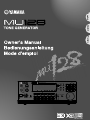 1
1
-
 2
2
-
 3
3
-
 4
4
-
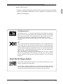 5
5
-
 6
6
-
 7
7
-
 8
8
-
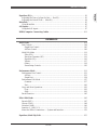 9
9
-
 10
10
-
 11
11
-
 12
12
-
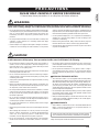 13
13
-
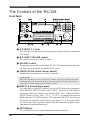 14
14
-
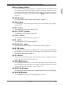 15
15
-
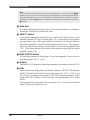 16
16
-
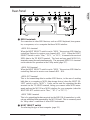 17
17
-
 18
18
-
 19
19
-
 20
20
-
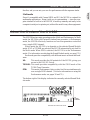 21
21
-
 22
22
-
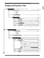 23
23
-
 24
24
-
 25
25
-
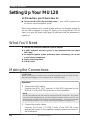 26
26
-
 27
27
-
 28
28
-
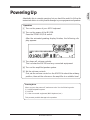 29
29
-
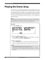 30
30
-
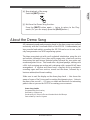 31
31
-
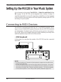 32
32
-
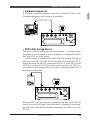 33
33
-
 34
34
-
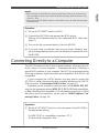 35
35
-
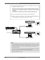 36
36
-
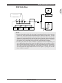 37
37
-
 38
38
-
 39
39
-
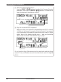 40
40
-
 41
41
-
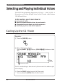 42
42
-
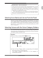 43
43
-
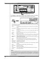 44
44
-
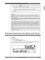 45
45
-
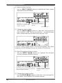 46
46
-
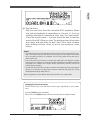 47
47
-
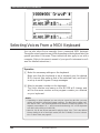 48
48
-
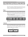 49
49
-
 50
50
-
 51
51
-
 52
52
-
 53
53
-
 54
54
-
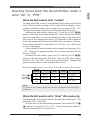 55
55
-
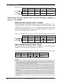 56
56
-
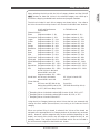 57
57
-
 58
58
-
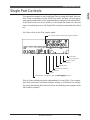 59
59
-
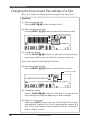 60
60
-
 61
61
-
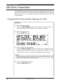 62
62
-
 63
63
-
 64
64
-
 65
65
-
 66
66
-
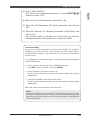 67
67
-
 68
68
-
 69
69
-
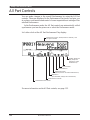 70
70
-
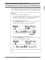 71
71
-
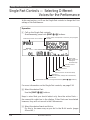 72
72
-
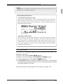 73
73
-
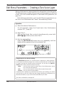 74
74
-
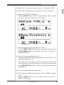 75
75
-
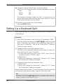 76
76
-
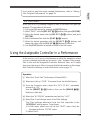 77
77
-
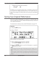 78
78
-
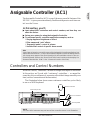 79
79
-
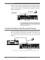 80
80
-
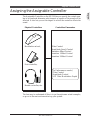 81
81
-
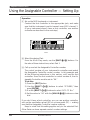 82
82
-
 83
83
-
 84
84
-
 85
85
-
 86
86
-
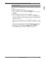 87
87
-
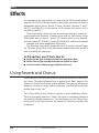 88
88
-
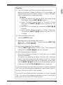 89
89
-
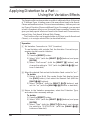 90
90
-
 91
91
-
 92
92
-
 93
93
-
 94
94
-
 95
95
-
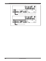 96
96
-
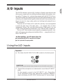 97
97
-
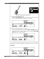 98
98
-
 99
99
-
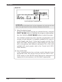 100
100
-
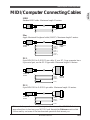 101
101
-
 102
102
-
 103
103
-
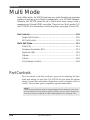 104
104
-
 105
105
-
 106
106
-
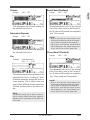 107
107
-
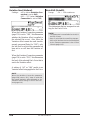 108
108
-
 109
109
-
 110
110
-
 111
111
-
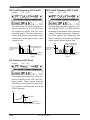 112
112
-
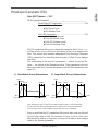 113
113
-
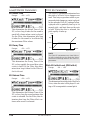 114
114
-
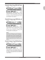 115
115
-
 116
116
-
 117
117
-
 118
118
-
 119
119
-
 120
120
-
 121
121
-
 122
122
-
 123
123
-
 124
124
-
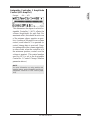 125
125
-
 126
126
-
 127
127
-
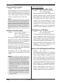 128
128
-
 129
129
-
 130
130
-
 131
131
-
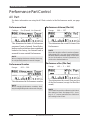 132
132
-
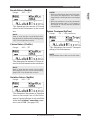 133
133
-
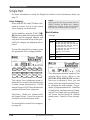 134
134
-
 135
135
-
 136
136
-
 137
137
-
 138
138
-
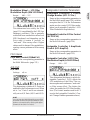 139
139
-
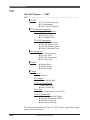 140
140
-
 141
141
-
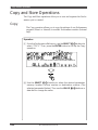 142
142
-
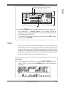 143
143
-
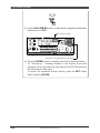 144
144
-
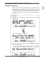 145
145
-
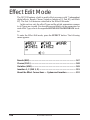 146
146
-
 147
147
-
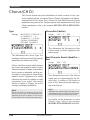 148
148
-
 149
149
-
 150
150
-
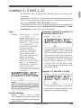 151
151
-
 152
152
-
 153
153
-
 154
154
-
 155
155
-
 156
156
-
 157
157
-
 158
158
-
 159
159
-
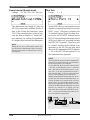 160
160
-
 161
161
-
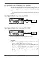 162
162
-
 163
163
-
 164
164
-
 165
165
-
 166
166
-
 167
167
-
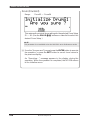 168
168
-
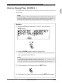 169
169
-
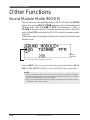 170
170
-
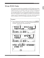 171
171
-
 172
172
-
 173
173
-
 174
174
-
 175
175
-
 176
176
-
 177
177
-
 178
178
-
 179
179
-
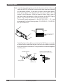 180
180
-
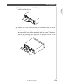 181
181
-
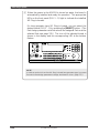 182
182
-
 183
183
-
 184
184
-
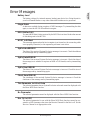 185
185
-
 186
186
-
 187
187
-
 188
188
-
 189
189
-
 190
190
-
 191
191
-
 192
192
-
 193
193
-
 194
194
-
 195
195


in andere talen
- English: Yamaha MU128 User manual
- italiano: Yamaha MU128 Manuale utente
- русский: Yamaha MU128 Руководство пользователя
- français: Yamaha MU128 Manuel utilisateur
- español: Yamaha MU128 Manual de usuario
- Deutsch: Yamaha MU128 Benutzerhandbuch
- português: Yamaha MU128 Manual do usuário
- dansk: Yamaha MU128 Brugermanual
- suomi: Yamaha MU128 Ohjekirja
- čeština: Yamaha MU128 Uživatelský manuál
- svenska: Yamaha MU128 Användarmanual
- Türkçe: Yamaha MU128 Kullanım kılavuzu
- polski: Yamaha MU128 Instrukcja obsługi
- română: Yamaha MU128 Manual de utilizare