
English Français Italiano Español Deutsch Nederlands
SPH-EVO93DAB
SPH-EVO64DAB
RDS AV RECEIVER
AUTORADIO MULTIMÉDIA
SINTOLETTORE AV CON RDS
RECEPTOR AV CON RDS
RDS-AV-RECEIVER
RDS AV-ONTVANGER
Installation Manual
Manuel d'installation
Manuale d'installazione
Manual de instalación
Installationsanleitung
Installatiehandleiding

2En
• Do not operate this product, any
applications, or the rear view camera
option (if purchased) if doing so will
divert your attention in any way from the
safe operation of your vehicle. Always
observe safe driving rules and follow all
existing traffic regulations. If you
experience difficulty in operating this
product, pull over, park your vehicle in a
safe location and apply the handbrake
before making the necessary
adjustments.
• Do not install this product where it may
(i) obstruct the driver’s vision,
(ii) impair the performance of any of the
vehicle’s operating systems of safety
features, including airbags, hazard lamp
buttons, or
(iii) impair the driver’s ability to safely
operate the vehicle.
In some cases, it may not be possible to
install this product because of the vehicle
type or the shape of the vehicle interior.
WARNING
Pioneer does not recommend that you
install this product yourself. This product is
designed for professional installation only.
We recommend that only authorised
Pioneer service personnel, who have
special training and experience in mobile
electronics, set up and install this product.
NEVER SERVICE THIS PRODUCT YOURSELF.
Installing or servicing this product and its
connecting cables may expose you to the
risk of electric shock or other hazards, and
can cause damage to this product that is
not covered by warranty.
CAUTION
• Secure all wiring with cable clamps or
electrical tape. Do not allow any bare
wiring to remain exposed.
• Do not directly connect the yellow lead of
this product to the vehicle battery. If the
lead is directly connected to the battery,
engine vibration may eventually cause
the insulation to fail at the point where
the wire passes from the passenger
compartment into the engine
compartment. If the yellow lead’s
insulation tears as a result of contact with
metal parts, short-circuiting can occur,
resulting in considerable danger.
• It is extremely dangerous to allow cables
to become wound around the steering
column or gearstick. Be sure to install this
product, its cables, and wiring away in
such so that they will not obstruct or
hinder driving.
• Make sure that the cables and wires will
not interfere with or become caught in
any of the vehicle’s moving parts,
especially the steering wheel, gearstick,
handbrake, sliding seat tracks, doors, or
any of the vehicle’s controls.
Connection
Precautions
Your new product and this
manual
Important safeguards
Precautions before
connecting the system
• Do not route wires where they will be
exposed to high temperatures. If the
insulation heats up, wires may become
damaged, resulting in a short circuit or
malfunction and permanent damage to
the product.
• Do not shorten any leads. If you do, the
protection circuit (fuse holder, fuse
resistor or filter, etc.) may fail to work
properly.
• Never feed power to other electronic
products by cutting the insulation of the
power supply lead of this product and
tapping into the lead. The current
capacity of the lead will be exceeded,
causing overheating.
• Use this unit with a 12-volt battery and
negative earthing only. Failure to do so
may result in a fire or malfunction.
• To avoid shorts in the electrical system,
be sure to disconnect the (–) battery
cable before installation.
WARNING
• When speaker output is used by 4
channels , use speakers over 50 W
(Maximum input power) and between 4
Ω to 8 Ω (impedance value). Do not use 1
Ω to 3 Ω speakers for this unit.
• When rear speaker output is used by 2 Ω
of subwoofer, use speakers over 70 W
(Maximum input power).
*Please refer to connection for a
connection method.
• The black lead is earth. Please earth this
lead separately from the earth of high
current products such as power amps. Do
not earth more than one product
together with the earth from another
product. For example, you must
separately earth any amp unit away from
the earth of this product. Connecting
earths together can cause a fire and/or
damage the products if their earths
became detached.
• When replacing the fuse, be sure to only
use a fuse of the rating prescribed on this
product.
• When disconnecting a connector, pull the
connector itself. Do not pull the lead, as
you may pull it out of the connector.
• This product cannot be installed in a
vehicle without ACC (accessory) position
on the ignition switch.
• To avoid short-circuiting, cover the
disconnected lead with insulating tape. It
is especially important to insulate all
unused speaker leads, which if left
uncovered may cause a short circuit.
• For connecting a power amp or other
devices to this product, refer to the
manual for the product to be connected.
• The graphical symbol placed on
the product means direct current.
• When the ignition switch is turned on
(ACC ON), a control signal is output
through the blue/white lead. Connect to
an external power amp’s system remote
control terminal, the auto-aerial relay
control terminal, or the aerial booster
power control terminal (max. 300 mA 12
Before installing this
product
To prevent damage
Notice for the blue/
white lead
ACC position
No ACC position

3En
English
V DC). The control signal is output
through the blue/white lead, even if the
audio source is switched off.
Important
When this product is in [Power OFF] mode,
the control signal is also turned off. If
[Power OFF] mode is cancelled, the control
signal is output again and the aerial is
extended with the auto aerial function (if
the aerial is being used). Be careful so that
the extended aerial does not come into
contact with any obstacles.
GPS aerial 3.55 m
Microphone 3 m
Monitor cable connector
Connect to LCD screen.
Digital Radio aerial input
Aerial jack
This product
Pre out supply
Power supply
Fuse (10A)
RGB cable (supplied with Navigation
system)
Pioneer navigation system
Contact your dealer to inquire about
the connectable navigation unit.
Wired remote input
Hard-wired remote control adaptor can
be connected (sold separately).
WARNING
IMPROPER CONNECTION MAY RESULT IN
SERIOUS DAMAGE OR INJURY
INCLUDING ELECTRICAL SHOCK, AND
INTERFERENCE WITH THE OPERATION
OF THE VEHICLE'S ANTILOCK BRAKING
SYSTEM, AUTOMATIC TRANSMISSION
AND SPEEDOMETER INDICATION.
Rear panel (main
terminals)
Power cord
To power supply
Depending on the kind of vehicle, the
function of 2* and 4* may be different.
In this case, be sure to connect 1* to 4*
and 3* to 2*.
Yellow (2*)
Back-up (or accessory)
Yellow (1*)
Connect to the constant 12 V supply
terminal.
Red (4*)
Accessory (or back-up)
Red (3*)
Connect to terminal controlled by
ignition switch (12 V DC).
Connect leads of the same colour to
each other.
Orange/white
To lighting switch terminal.
Black (earth)
To vehicle (metal) body.
Blue/white (5*)
The pin position of the ISO connector
will differ depending on the type of
vehicle. Connect 5* and 6* when Pin 5 is
an aerial control type. In another type of
vehicle, never connect 5* and 6*.
Blue/white (6*)
Connect to auto-aerial relay control
terminal (max. 300 mA 12 V DC).
Blue/white
Connect to system control terminal of
the power amp (max. 300 mA 12 V DC).
Violet/white
Of the two lead wires connected to the
back lamp, connect the one in which
the voltage changes when the gear shift
is in the REVERSE (R) position. This
connection enables the unit to sense
whether the car is moving forwards or
backwards.
Pink
Car speed signal input
Light green
Used to detect the ON/OFF status of the
handbrake. This lead must be
connected to the power supply side of
the handbrake switch.
If this connection is made incorrectly
or omitted, certain functions of this
product will be unusable.
Connection method
Clamp the lead (1) then clamp firmly
with needle-nosed pliers (2).
Power supply side
Handbrake switch
Earth side
Speaker leads
White: Front left + or high range left +
White/black: Front left – or high range
left –

4En
Grey: Front right + or high range right +
Grey/black: Front right – or high range
right –
Green: Rear left + or middle range left +
Green/black: Rear left – or middle range
left –
Violet: Rear right + or middle range
right +
Violet/black: Rear right – or middle
range right –
ISO connector
In some vehicles, the ISO connector
may be divided into two. In this case, be
sure to connect to both connectors.
NOTES
• The position of the speed detection
circuit and the position of the handbrake
switch vary depending on the vehicle
model. For details, consult your
authorised Pioneer dealer or an
installation professional.
• When a subwoofer is connected to this
product instead of a rear speaker, change
the rear output setting in the initial
setting. The subwoofer output of this
product is monaural.
• When using a subwoofer of 2 Ω, be sure
to connect the subwoofer to the violet
and violet/black leads of this unit. Do not
connect anything to the green and
green/black leads.
Important
The speaker leads are not used when this connection is in use.
Subwoofer output (SUBWOOFER OUTPUT) 23 cm (STD)
Low range output (NW)
RCA cable (sold separately)
Power amp
Front output (FRONT OUTPUT) 15 cm (STD)
High range output (NW)
Rear output (REAR OUTPUT) 15 cm (STD)
Middle range output (NW)
Yellow/black (MUTE)
If you use an equipment with Mute function, wire this lead to the Audio Mute lead on
that equipment. If not, keep the Audio Mute lead free of any connections.
Pre out cord
To pre out supply
System remote control
Connect to Blue/white cable (max. 300 mA 12 V DC).
Power amp (sold separately)

5En
English
Rear speaker (STD)
Middle range speaker (NW)
Front speaker (STD)
High range speaker (NW)
Subwoofer (STD)
Low range speaker (NW)
NOTE
Select the appropriate speaker mode between standard mode (STD) and network mode
(NW). For details, refer to the Operation Manual.
NOTES
• For details on how to connect an external
device using a separately sold cable, refer
to the manual for the cable.
• For details concerning the connection,
operations and compatibility of the
iPhone, refer to the Operation Manual.
• For details concerning the connection
and operations of the smartphone, refer
to the Operation Manual.
• The supplied USB Type-C® cable and the
USB Type-C to USB Type-A adaptor are for
connecting a USB storage device to this
unit only. Do not use the cable and the
adaptor for other products or purposes.
This product
USB Type-C port
USB Type-C cable 1.5 m
USB Type-C to USB Type-A adaptor
USB interface cable for iPhone (CD-IU52)
(sold separately)
iPhone
TIP
When a USB Type-C to Lightning
connector cable (Apple Inc. product) (sold
separately) is used to connect this unit to
an iPhone that supports USB-PD, quick
charging is performed for the iPhone.
NOTE
When you use a USB Type-C to Lightning
connector cable (Apple Inc. product) (sold
separately), follow the instructions
provided with the cable.
This product
USB Type-C port
USB Type-C cable 1.5 m
USB Type-C to USB Type-C interface
cable (CD-CCU500) (sold separately)
Smartphone
TIPS
• Use the supplied USB Type-C to USB
Type-A adaptor with a USB Type-A to
micro USB B cable (CD-MU200) (sold
separately) if your smartphone has a
micro USB B port.
• When a USB Type-C to USB Type-C cable
(sold separately) is used to connect this
unit to a smartphone, quick charging is
performed.
NOTES
• If you use a cable other than those
suggested in the illustration, the main
unit may not function properly.
• Android is a trademark of Google LLC.
iPhone and
smartphone
iPhone
Smartphone (Android™
device)

6En
When you use the rear view camera, the
rear view image is automatically switched
from the video by moving the gearstick to
REVERSE (R). Camera View mode also
allows you to check what is behind you
while driving.
WARNING
USE INPUT ONLY FOR REVERSE OR MIRROR
IMAGE REAR VIEW CAMERA. OTHER USE
MAY RESULT IN INJURY OR DAMAGE.
CAUTION
• The screen image may appear reversed.
• With the rear view camera you can keep
an eye on trailers, or back into a tight
parking spot. Do not use for
entertainment purposes.
• Objects in rear view may appear closer or
more distant than in reality.
• The image area of full-screen images
displayed while backing or checking the
rear of the vehicle may differ slightly.
This product
Pre out supply
Power supply
To pre out supply
To power supply
Pre out cord
Power cord
Violet/white (REVERSE-GEAR SIGNAL
INPUT)
Brown (REAR VIEW CAMERA IN) 23 cm
Yellow (SECOND CAMERA INPUT) 23
cm
Rear view camera (ND-BC8) (sold
separately)
To video output
RCA power supply cable (supplied with
ND-BC8)
RCA cable (sold separately)
View camera (sold separately)
Camera
NOTES
• Connect only the rear view camera to
brown cable. Do not connect any other
equipment.
• Some appropriate settings are required
to use rear view cameras. For details, refer
to the Operation Manual.
This product
Pre out supply
To pre out supply
Pre out cord
AUX input (AUX IN) 15 cm
Mini-jack AV cable (sold separately)
Yellow
Red, white
RCA cables (sold separately)
To video output
To audio output
External video component (sold
separately)
NOTE
The appropriate setting is required to use
the external video component. For details,
refer to the Operation Manual.
CAUTION
Be sure to use a mini-jack AV cable (sold
separately) for wiring. If you use other
cables, the wiring position might differ
resulting in disturbed images and sounds.
This product
Micro HDMI port
Micro HDMI to HDMI cable (sold
separately)
HDMI device (sold separately)
External video
component
Using an AUX input
Using an HDMI input
L : Left audio (White)
R : Right audio (Red)
V : Video (Yellow)
G : Earth

7En
English
This product
Pre out supply
To pre out supply
Pre out cord
Yellow (REAR MONITOR OUTPUT) 30
cm
RCA cable (sold separately)
To Video input
Rear display with RCA input (sold
separately)
WARNING
NEVER install the rear display in a location
that enables the driver to watch the video
source while driving.
This product’s rear video output is for
connection of a display to enable
passengers in the rear seats to watch the
video source.
Rear display
CAUTION
• Never install this product in places where,
or in a manner that:
–Could injure the driver or passengers if
the vehicle stops suddenly.
– May interfere with the driver’s operation
of the vehicle, such as on the floor in
front of the driver’s seat, or close to the
steering wheel or gearstick.
• To ensure proper installation, be sure to
use the supplied parts in the manner
specified. If any parts are not supplied
with this product, use compatible parts in
the manner specified after you have the
part compatibility checked by your
dealer. If parts other than supplied or
compatible ones are used, they may
damage internal parts of this product or
they may work loose and the product
may become detached.
• It is extremely dangerous to allow cables
to become wound around the steering
column or gearstick. Be sure to install this
product, its cables, and wiring away in
such so that they will not obstruct or
hinder driving.
• Make sure that leads cannot get caught
in a door or the sliding mechanism of a
seat, resulting in a short circuit.
• Please confirm the proper function of
your vehicle’s other equipment after
installation of this product.
• Do not install this product where it may
(i) obstruct the driver’s vision,
(ii) impair the performance of any of the
vehicle’s operating systems or safety
features, including airbags, hazard lamp
buttons or
(iii) impair the driver’s ability to safely
operate the vehicle.
• Never install this product in front of or
next to the place in the dashboard, door,
or pillar from which one of your vehicle’s
airbags would deploy. Please refer to your
vehicle’s owner’s manual for reference to
the deployment area of the frontal
airbags.
• Consult with your nearest dealer if
installation requires drilling holes or
other modifications of the vehicle.
• Before making a final installation of this
product, temporarily connect the wiring
to confirm that the connections are
correct and the system works properly.
• Do not install this product in places
subject to high temperatures or
humidity, such as:
–Places close to a heater, vent or air
conditioner.
– Places exposed to direct sunlight, such
as on top of the dashboard.
– Places that may be exposed to rain,
such as close to the door or on the
vehicle’s floor.
• Install this product horizontally on a
surface within 0 to 40 degrees tolerance
(within 5 degrees to the left or right).
Improper installation of the unit with the
surface tilted more than these tolerances
increases the potential for errors in the
Installation
Precautions before
installation
Before installing
Installation notes

8En
vehicle’s location display, and might
otherwise cause reduced display
performance.
• When installing, to ensure proper heat
dispersal when using this unit, make sure
you leave ample space behind the rear
panel and wrap any loose cables so they
are not blocking the vents.
• Do not forcibly insert this unit into the
dashboard/console when installing.
Applying excessive force to the
connectors (HDMI and USB Type-C) may
cause a malfunction.
• The cords must not cover up the area
shown in the figure below. This is
necessary to allow the amplifiers to
radiate freely.
Do not cover this area
Installation tips
The following procedure describes how to
use the supplied parts to install this
product with the LCD screen attached to
the unit. It is also possible to install this
product so that the LCD screen is separate
from the unit. For details, visit the Pioneer
website for your region.
For some types of vehicles, it is necessary
to use an installation kit (sold separately)
when installing. For details, visit the
Pioneer website for your region.
1 First attach the supplied side brackets
to the LCD screen ( ), then attach
them to this unit ( ). After that,
connect the monitor cable to the LCD
screen ( ).
Side bracket (for attaching LCD
screen to unit)
Leave ample
space
5 cm
5 cm
Installation using the screw
holes on the side of this
product
Binding head screw (5 mm)
Be sure to use the screws supplied
with this product.
Monitor cable
Attach the monitor cable to the unit
with heat resistant tape (sold
separately).
2 Fasten this product to the factory
radio-mounting bracket.
Position this product so that its screw
holes are aligned with the screw holes
of the bracket, and tighten the screws at
three locations on each side.
Use either the binding head screws or
flush surface screws, depending on the
shape of the bracket’s screw holes.
TIP
The amount of this unit's protrusion from
the dashboard/console can be adjusted by
shifting the position of the screw hole of
this unit to the factory radio-mounting
bracket.
Factory radio-mounting bracket
If the pawl interferes with
installation, you may bend it down
out of the way.
Dashboard or console
Binding head screw (8 mm) or flush
surface screw
Be sure to use the screws supplied
with this product.
CAUTION
Do not cut the GPS aerial lead to shorten it
or use an extension to make it longer.
Altering the aerial cable could result in a
short circuit or malfunction and
permanent damage to this product.
• The aerial should be installed on a level
surface where radio waves will be
blocked as little as possible. Radio waves
cannot be received by the aerial if
reception from the satellite is blocked.
Dashboard
Rear shelf
• When installing the GPS aerial inside the
vehicle, be sure to use the metal sheet
provided with your system. If this is not
Installing the GPS
aerial
Installation notes

9En
English
used, the reception sensitivity will be
poor.
• Do not cut the accessory metal sheet.
This would reduce the sensitivity of the
GPS aerial.
• Take care not to pull the aerial lead when
removing the GPS aerial. The lead may
become detached.
• Do not paint the GPS aerial, as this may
affect its performance.
WARNING
Do not install the GPS aerial over any sensors or vents on the dashboard of the vehicle, as
doing so may interfere with the proper functioning of such sensors or vents and may
compromise the ability of the metal sheet under the GPS aerial to properly and securely
affix to the dashboard.
GPS aerial
Metal sheet
Peel off the protective sheet on the rear.
Double-sided tape
Clamps
Use clamps to secure the lead where necessary inside the vehicle.
NOTES
• Affix the metal sheet on the surface as level as possible where the GPS aerial faces the
window.
• Affix the GPS aerial on the metal sheet using the double-sided tape.
• The metal sheet contains a strong adhesive which may leave a mark on the surface if it is
removed.
• When attaching the metal sheet, do not cut it into small pieces.
• Some models use window glass that does not allow signals from GPS satellites to pass
through. On such models, install the GPS aerial on the outside of the vehicle.
When installing the aerial inside the vehicle (on the dashboard or rear
shelf)
Make sure the surface is free of
moisture, dust, grime, oil, etc.,
before affixing the metal sheet.

10En
• Install the microphone in a place where
its direction and distance from the driver
make it easiest to pick up the driver’s
voice.
• Be sure to turn off (ACC OFF) the product
before connecting the microphone.
• Depending on the vehicle model, the
microphone cable length may be too
short when you mount the microphone
on the sun visor. In such cases, install the
microphone on the steering column.
1 Fit the microphone lead into the
groove.
Microphone lead
Groove
2 Attach the microphone clip to the sun
visor.
Microphone clip
Clamps
Use separately sold clamps to secure
the lead where necessary inside the
vehicle.
Install the microphone on the sun visor
when it is in the up position. It cannot
recognise the driver’s voice if the sun
visor is in the down position.
1 Detach the microphone base from the
microphone clip by sliding the
microphone base while pressing the
tab.
Tab
Microphone base
2 Mount the microphone on the
steering column.
Installing the
microphone
Mounting on the sun visor
Installation on the steering
column
Double-sided tape
Clamps
Use separately sold clamps to secure
the lead where necessary inside the
vehicle.
NOTE
Install the microphone on the steering
column, keeping it away from the steering
wheel.
The microphone angle can be adjusted.
Adjusting the microphone angle

11En
English

2Fr
• Veillez à ne pas utiliser ce produit, les
applications ou la caméra de recul en
option (si vous en possédez une), car cela
risquerait de vous distraire et de
compromettre votre sécurité à bord du
véhicule. Veillez à toujours respecter les
règles de conduite sécuritaire et la
réglementation en vigueur en matière de
circulation routière. Si vous avez des
difficultés à utiliser ce produit, garez votre
véhicule dans un endroit sûr et serrez le
frein de stationnement avant d’effectuer
les réglages nécessaires.
• N’installez pas ce produit dans un endroit
où il est susceptible
(i) de gêner la vision du conducteur,
(ii) d’empêcher le déclenchement ou
l’utilisation des systèmes de sécurité,
notamment des airbags ou des feux de
détresse, ou
(iii) d’empêcher le conducteur d’utiliser le
véhicule en toute sécurité.
Dans certains cas, il peut être impossible
d’installer ce produit selon le type de
véhicule ou la forme de son habitacle.
ATTENTION
Pioneer vous déconseille d’installer vous-
même ce produit. Ce produit doit être
installé par un professionnel. Pour installer
et configurer ce produit, nous vous
recommandons de faire appel à un
technicien agréé Pioneer, qui possède les
compétences et l’expérience nécessaires
en matière d’électronique mobile. VEILLEZ
À NE JAMAIS RÉPARER VOUS-MÊME CE
PRODUIT. L’installation ou la réparation de
ce produit et de ses câbles de connexion
peut vous exposer à un risque de décharge
électrique ou à d’autres dangers, et peut
entraîner des dommages non couverts par
la garantie.
PRÉCAUTION
• Fixez tous les câbles à l’aide de serre-
câbles ou de ruban isolant. Ne laissez
aucun fil dénudé apparent.
• Ne raccordez pas directement le fil jaune
de ce produit à la batterie du véhicule. Si
vous raccordez ce fil directement à la
batterie, les vibrations du moteur
risquent de détériorer l’isolant au point
où le fil passe de l’habitacle au
compartiment moteur. Si l’isolant du fil
jaune venait à se rompre au contact de
pièces métalliques, un court-circuit
risquerait de se produire et de mettre en
danger le conducteur et les passagers.
• Il est extrêmement dangereux de laisser
les câbles s’enrouler autour du volant ou
du levier de vitesses. Veillez à installer ce
produit, ses câbles et ses fils de telle sorte
qu’ils ne gênent pas la conduite.
• Assurez-vous que les fils et les câbles ne
gêneront pas le mouvement des parties
Connexion
Précautions
Votre nouveau produit et le
guide qui l’accompagne
Précautions
importantes
Précautions avant de
connecter le système
mobiles du véhicule (notamment le
volant, le levier de vitesses, le frein de
stationnement, les rails coulissants des
sièges, les portières ou toute autre
commande du véhicule) ou ne se
coinceront pas dedans.
• N’acheminez pas les fils dans des endroits
soumis à des températures élevées. La
chaleur générée risque de chauffer
l’isolant et d’endommager les fils, ce qui
peut provoquer un court-circuit ou un
dysfonctionnement et entraîner des
dommages irréversibles.
• Ne raccourcissez aucun fil. Le cas échéant,
le circuit de protection (porte-fusibles,
résistance ou filtre de protection, etc.)
risque de ne pas fonctionner
correctement.
• Veillez à ne jamais couper l’isolant du fil
d’alimentation de ce produit en vue
d’utiliser ce fil pour alimenter d’autres
produits électroniques. Cela risque
d’entraîner le dépassement de la capacité
nominale du fil et de provoquer une
surchauffe.
• Utilisez ce produit avec une batterie de
12 volts et une mise à la terre du pôle
négatif uniquement. Dans le cas
contraire, un dysfonctionnement ou un
incendie risque de se produire.
• Pour éviter les courts-circuits dans le
système électrique, veillez à débrancher
le câble (–) de la batterie avant de
procéder à l’installation.
ATTENTION
• Lorsque la sortie des haut-parleurs est
utilisée par 4 canaux, utilisez des haut-
parleurs de plus de 50 W (puissance
maximale en entrée) et dont la valeur
d’impédance est comprise entre 4 Ω et 8
Ω. N’utilisez pas des haut-parleurs de 1 Ω
à 3 Ω avec cet appareil.
• Lorsque la sortie du haut-parleur arrière
est utilisée par un haut-parleur
d’extrêmes-graves de 2 Ω, utilisez des
haut-parleurs de plus de 70 W (puissance
maximale en entrée).
*Reportez-vous à la section Connexion
pour connaître la méthode de connexion.
• Le fil noir est le fil de mise à la terre.
Mettez-le à la terre séparément des
produits à courant élevé tels que les
amplificateurs de puissance. Évitez de
raccorder plusieurs produits à la terre
d’un autre produit. Par exemple, chaque
amplificateur de puissance doit être mis à
la terre séparément de la masse de ce
produit. Le raccordement de plusieurs
masses risque de provoquer un incendie
et/ou d’endommager les produits si les
fils de mise à la terre sont déconnectés.
• Lors du remplacement du fusible, utilisez
uniquement un fusible respectant
l’intensité indiquée sur le produit.
• Lorsque vous débranchez un connecteur,
ne tirez que sur le connecteur. Ne tirez
pas le fil, car vous pourriez le déloger du
connecteur.
• Il est impossible d’installer ce produit
dans un véhicule dont l’interrupteur
d’allumage ne dispose pas d’une position
ACC (accessoire).
Avant d’installer ce
produit
Pour éviter les
dommages

3Fr
Français
• Pour éviter les courts-circuits, couvrez le
fil de déconnexion de ruban isolant. Il est
particulièrement important d’isoler tous
les fils de haut-parleur non utilisés ; si ces
fils restent dénudés, ils risquent de
provoquer un court-circuit.
• Pour raccorder des amplificateurs de
puissance ou d’autres appareils à ce
produit, reportez-vous au manuel de
l’appareil à raccorder.
• Le symbole graphique situé sur le
produit représente le courant continu.
• Lorsque vous allumez le moteur
(interrupteur d’allumage en position ACC
ON), un signal de commande est transmis
via le fil bleu/blanc. Raccordez ce fil à la
borne de commande à distance d’un
amplificateur de puissance externe, à la
borne de commande du relais de
l’antenne automatique ou à la borne de
commande d’alimentation de
l’amplificateur d’antenne (max. 300 mA
12 V c.c.). Le signal de commande est
transmis via le fil bleu/blanc, même si la
source audio est désactivée.
Important
Lorsque ce produit est en mode [Power
OFF], le signal de commande est
également désactivé. Si le mode [Power
OFF] est annulé, le signal de commande est
à nouveau émis, et l’antenne sort à l’aide
de la fonction d’antenne automatique (si
l’antenne est utilisée). Veillez à ce que
l’antenne sortie évite tout contact avec un
obstacle.
Antenne GPS 3,55 m
Microphone 3 m
Connecteur pour câble de moniteur
Connectez-vous à l’écran LCD.
Entrée d’antenne radio numérique
Prise d’antenne
Ce produit
Alimentation pre-out
Alimentation
Fusible (10A)
Câble RGB (fourni avec le système de
navigation)
Système de navigation Pioneer
Contactez votre revendeur pour
connaître les systèmes de navigation
pris en charge.
Entrée de la télécommande câblée
Remarque concernant
le fil bleu/blanc
Position ACC
Pas de position ACC
Panneau arrière
(bornes principales)
Il est possible de raccorder un
adaptateur de télécommande fixe
(vendu séparément).
ATTENTION
TOUTE CONNEXION INCORRECTE
RISQUE D’ENTRAÎNER DES DOMMAGES
ET MATÉRIELS GRAVES, NOTAMMENT
UNE DÉCHARGE ÉLECTRIQUE ET DES
INTERFÉRENCES AVEC L’UTILISATION DU
SYSTÈME D’ANTIBLOCAGE DES ROUES
(ABS) DU VÉHICULE, DE LA
TRANSMISSION AUTOMATIQUE ET
D’INDICATION DE LA VITESSE.
À l’alimentation
Selon le type de véhicule, la fonction de
2* et 4* peut différer. Dans ce cas, veillez
à raccorder 1* à 4* et 3* à 2*.
Jaune (2*)
Secours (ou accessoire)
Jaune (1*)
À raccorder à la borne d’alimentation
constante 12 V.
Rouge (4*)
Accessoire (ou secours)
Rouge (3*)
À raccorder à la borne commandée par
l’interrupteur d’allumage (12 V c.c.).
Câble d’alimentation

4Fr
Raccordez ensemble les fils de même
couleur.
Orange/blanc
À la borne de l’interrupteur d’éclairage.
Noir (terre)
À la carrosserie (métal) du véhicule.
Bleu/blanc (5*)
La position des broches du connecteur
ISO peut différer selon le type de
véhicule. Raccordez 5* et 6* lorsque la
broche 5 est un type de commande
d’antenne. Dans un autre type de
véhicule, ne connectez jamais 5* et 6*.
Bleu/blanc (6*)
Raccordez à la borne de commande du
relais d’antenne automatique (max.
300 mA 12 V c.c.).
Bleu/blanc
À raccorder à la borne de commande
système de l’amplificateur de puissance
(max. 300 mA 12 V c.c.).
Violet/blanc
Parmi les deux fils conducteurs
connectés au feu arrière, raccordez celui
dont la tension change lorsque la
marche arrière est enclenchée REVERSE
(R). Cette connexion permet à l’appareil
de détecter si le véhicule avance ou
recule.
Rose
Entrée du signal de vitesse du véhicule
Vert clair
Ce fil permet de détecter l’état de
marche/arrêt du frein de
stationnement. Ce fil doit être raccordé
au côté de l’alimentation du contacteur
du frein de stationnement.
Si ce raccordement est mal fait ou
omis, vous ne pourrez pas utiliser
certaines fonctions de ce produit.
Méthode de connexion
Raccordez le fil (1), puis fixez fermement
les pinces à becs fins (2).
Côté de l’alimentation
Contacteur du frein de stationnement
Côté terre
Fils des haut-parleurs
Blanc : Avant gauche + ou aigus gauche
+
Blanc/noir : Avant gauche – ou aigus
gauche –
Gris : Avant droit + ou aigus droit +
Gris/noir : Avant droit – ou aigus droit –
Vert : Arrière gauche + ou médiums
gauche +
Vert/noir : Arrière gauche – ou médiums
gauche –
Violet : Arrière droit + ou médiums droit
+
Violet/noir : Arrière droit – ou médiums
droit –
Connecteur ISO
Dans certains véhicules, le connecteur
ISO peut être divisé en deux. Dans ce
cas, veillez à le raccorder aux deux
connecteurs.
REMARQUES
• La position du circuit de détection de
vitesse et la position du contacteur du
frein de stationnement varient en
fonction du modèle du véhicule. Pour
plus de détails, contactez votre
revendeur Pioneer agréé ou un
installateur professionnel.
• Lorsque vous raccordez un haut-parleur
d’extrêmes-graves à ce produit plutôt
qu’un haut-parleur arrière, modifiez le
réglage de sortie arrière lors de la
configuration initiale. La sortie du haut-
parleur d’extrêmes-graves de ce produit
est monophonique.
• Lorsque vous utilisez un haut-parleur
d’extrêmes-graves de 2 Ω, veillez à le
raccorder aux fils violet et violet/noir de
cet appareil. Ne branchez aucun appareil
aux fils vert et vert/noir.
Important
Les fils de haut-parleur ne sont pas utilisés lors de l’utilisation de cette connexion.
Sortie du haut-parleur d’extrêmes graves (SUBWOOFER OUTPUT) 23 cm (STD)
Sortie des graves (NW)
Câble RCA (vendu séparément)
Amplificateur de puissance
Sortie avant (FRONT OUTPUT) 15 cm (STD)
Sortie des aigus (NW)
Sortie arrière (REAR OUTPUT) 15 cm (STD)
Sortie des médiums (NW)
Jaune/noir (MUTE)
Si vous utilisez un équipement muni d’une fonction de désactivation du son, branchez
ce fil au fil de désactivation du son de cet équipement. Dans le cas contraire, ne
raccordez pas le fil de désactivation du son.
Cordon pre-out
À l’alimentation pre-out
Amplificateur de puissance (vendu séparément)

5Fr
Français
Télécommande du système
Raccordez au câble bleu/blanc (max. 300 mA 12 V c.c).
Haut-parleur arrière (STD)
Haut-parleur de médiums (NW)
Haut-parleur avant (STD)
Haut-parleur d’aigus (NW)
Haut-parleur d’extrêmes-graves (STD)
Haut-parleur de graves (NW)
REMARQUE
Sélectionnez le mode de haut-parleur approprié, à savoir le mode standard (STD) ou le
mode réseau (NW). Pour en savoir plus, consultez le manuel d’utilisation.
REMARQUES
• Pour en savoir plus sur le mode de
connexion d’un périphérique externe à
l’aide d’un câble vendu séparément,
consultez le manuel qui accompagne ce
câble.
• Pour en savoir plus sur la connexion,
l’utilisation et la compatibilité du iPhone,
consultez le manuel d’utilisation.
• Pour en savoir plus sur la connexion et
l’utilisation d’un smartphone, consultez
le manuel d’utilisation.
• Le câble USB Type-C® fourni et
l’adaptateur USB Type-C pour USB Type-A
servent à raccorder un périphérique de
stockage USB à cet appareil uniquement.
N’utilisez pas le câble et l’adaptateur pour
d’autres produits ou à d’autres fins.
Ce produit
Port USB Type-C
Câble USB Type-C de 1,5 m
Adaptateur USB Type-C pour USB Type-
A
Câble d’interface USB pour iPhone (CD-
IU52) (vendu séparément)
iPhone
CONSEIL
Lorsqu’un câble de connecteur USB Type-C
pour Lightning (produit Apple Inc.) (vendu
séparément) est utilisé pour raccorder cet
appareil à un iPhone prenant en charge
USB-PD, une recharge rapide est effectuée
pour l’iPhone.
REMARQUE
Lorsque vous utilisez un câble de
connecteur USB Type-C pour Lightning
(produit Apple Inc.) (vendu séparément),
suivez les instructions fournies avec le
câble.
Ce produit
Port USB Type-C
Câble USB Type-C de 1,5 m
Câble USB Type-C vers USB Type-C (CD-
CCU500) (vendu séparément)
Smartphone
CONSEILS
• Utilisez l’adaptateur USB Type-C pour
USB Type-A fourni avec un câble micro
USB Type-A pour USB B (CD-MU200)
(vendu séparément) si votre smartphone
dispose d’un port micro USB B.
• Lorsqu’un câble USB Type-C pour USB
Type-C (vendu séparément) est utilisé
pour raccorder cet appareil à un
smartphone, une recharge rapide est
effectuée.
iPhone et smartphone
iPhone
Smartphone
(périphérique Android™)

6Fr
REMARQUES
• Si vous utilisez un câble autre que ceux
suggérés dans l’illustration, l’appareil
principal peut ne pas fonctionner
correctement.
• Android est une marque de Google LLC.
Lorsque vous utilisez la caméra de recul, les
images vidéo sont automatiquement
remplacées par celle de la caméra de recul
dès que vous enclenchez la marche arrière
REVERSE (R). Le mode Vue Caméra vous
permet également de contrôler les objets
derrière vous lorsque vous conduisez.
ATTENTION
UTILISEZ CETTE ENTRÉE UNIQUEMENT
POUR REPRODUIRE LES IMAGES DE LA
CAMÉRA DE RECUL. TOUTE AUTRE
UTILISATION RISQUE D’ENTRAÎNER DES
DOMMAGES MATÉRIELS OU CORPORELS.
PRÉCAUTION
• L’image affichée à l’écran peut être
inversée.
• La caméra de recul vous permet de
contrôler les véhicules remorqués ou de
vous garer dans un endroit étroit. Ne
l’utilisez pas à des fins de divertissement.
• Les objets à l’arrière peuvent vous
sembler plus proches ou plus éloignés
qu’ils ne le sont en réalité.
• En mode plein écran, les images affichées
lorsque vous faites marche arrière ou
lorsque vous contrôlez les objets à
l’arrière du véhicule peuvent légèrement
différer.
Ce produit
Alimentation pre-out
Alimentation
À l’alimentation pre-out
À l’alimentation
Cordon pre-out
Câble d’alimentation
Violet/blanc (REVERSE-GEAR SIGNAL
INPUT)
Marron (REAR VIEW CAMERA IN) 23 cm
Jaune (SECOND CAMERA INPUT)
23 cm
Caméra de recul (ND-BC8) (vendue
séparément)
À la sortie vidéo
Câble d’alimentation RCA (fourni avec le
ND-BC8)
Câble RCA (vendu séparément)
Caméra de vision (vendue séparément)
Caméra
REMARQUES
• Raccordez uniquement la caméra de
recul au câble marron. Ne raccordez
aucun autre équipement.
• Certains réglages sont requis pour utiliser
la caméra de recul. Pour en savoir plus,
consultez le manuel d’utilisation.
Ce produit
Alimentation pre-out
À l’alimentation pre-out
Cordon pre-out
Entrée AUX (AUX IN) 15 cm
Câble AV avec mini-prise (vendu
séparément)
Jaune
Rouge, blanc
Câbles RCA (vendus séparément)
À la sortie vidéo
À la sortie audio
Composant vidéo externe (vendu
séparément)
REMARQUE
Le réglage approprié est requis pour
utiliser un composant vidéo externe. Pour
en savoir plus, consultez le manuel
d’utilisation.
PRÉCAUTION
Veillez à utiliser un câble AV mini-jack
(vendu séparément) pour le raccordement.
Si vous utilisez d’autres câbles, la position
de raccordement pourra différer selon les
images et les sons déformés.
Ce produit
Port micro HDMI
Composant vidéo externe
Utiliser une entrée AUX
Utiliser une entrée HDMI
L: Audio gauche
(blanc)
R : Audio droit
(rouge)
V: Vidéo (jaune)
G : Terre

7Fr
Français
Câble micro HDMI à HDMI (vendu
séparément)
Dispositif HDMI (vendu séparément)
Ce produit
Alimentation pre-out
À l’alimentation pre-out
Cordon pre-out
Jaune (REAR MONITOR OUTPUT) 30
cm
Câble RCA (vendu séparément)
À l’entrée vidéo
Écran arrière avec entrée RCA (vendu
séparément)
ATTENTION
Veillez à ne JAMAIS installer l’écran arrière
dans un endroit où le conducteur est
susceptible de regarder la source vidéo
tout en conduisant.
La borne de sortie vidéo arrière du produit
permet de raccorder un écran afin que les
passagers arrière puissent regarder la
source vidéo.
Affichage arrière
PRÉCAUTION
• N’installez jamais ce produit dans des
endroits :
–susceptibles de blesser le conducteur
ou les passagers en cas d’arrêt soudain
du véhicule ;
–peut gêner la conduite du véhicule,
notamment sur le plancher devant le
siège du conducteur ou à proximité du
volant ou du levier de vitesses.
• Pour assurer une installation correcte,
utilisez les pièces fournies de la manière
spécifiée. Si certaines pièces ne sont pas
fournies avec ce produit, utilisez des
pièces compatibles en suivant les
instructions après vous être assuré de
leur compatibilité auprès de votre
revendeur. L’utilisation de pièces non
compatibles risque d’endommager les
composants internes de ce produit ; ces
pièces peuvent par ailleurs se desserrer et
provoquer la chute du produit.
• Il est extrêmement dangereux de laisser
les câbles s’enrouler autour du volant ou
du levier de vitesses. Veillez à installer ce
produit, ses câbles et ses fils de telle sorte
qu’ils ne gênent pas la conduite.
• Assurez-vous que les fils ne peuvent pas
être coincés dans une portière ou dans le
mécanisme coulissant d’un siège, ce qui
entraînerait un court-circuit.
• Assurez-vous du bon fonctionnement
des autres équipements de votre
véhicule après l’installation de ce produit.
• N’installez pas ce produit dans un endroit
où il est susceptible
(i) de gêner la vision du conducteur,
(ii) d’empêcher le déclenchement ou
l’utilisation des systèmes de sécurité,
notamment des airbags ou des feux de
détresse, ou
(iii) d’empêcher le conducteur d’utiliser le
véhicule en toute sécurité.
• N’installez jamais ce produit devant ou à
côté du tableau de bord, de la portière ou
du montant à l’endroit où se déclenchent
les airbags du véhicule. Consultez le
mode d’emploi de votre véhicule pour
connaître la zone de déploiement des
airbags avant.
• Prenez contact avec le revendeur le plus
proche s’il s’avère nécessaire de pratiquer
des trous ou d’effectuer d’autres
modifications sur le véhicule.
• Avant de prendre la décision finale
d’installer ce produit, raccordez
temporairement les câbles pour
confirmer que les connexions sont
correctes et que le système fonctionne
normalement.
• N’installez pas ce produit dans des
endroits soumis à une humidité ou à des
températures élevées, notamment :
–prêt d’un radiateur, d’une grille de
ventilation ou du climatiseur ;
– dans des endroits exposés aux rayons
directs du soleil, par exemple sur le
tableau de bord ;
Installation
Précautions avant
l’installation
Avant l’installation
Remarques concernant
l’installation

8Fr
– dans des endroits pouvant être exposés
à la pluie, notamment près de la
portière ou sur le plancher du véhicule.
• Installez ce produit horizontalement sur
une surface dont l’inclinaison oscille
entre 0 et 40 degrés (de 5 degrés vers la
gauche ou vers la droite). Toute
installation incorrecte de l’appareil sur
une surface dont l’inclinaison ne respecte
pas la plage spécifiée augmente le risque
d’erreurs et peut réduire les
performances d’affichage.
• Lors de l’installation, laissez suffisamment
d’espace derrière le panneau arrière pour
permettre une dissipation correcte de la
chaleur et enroulez les câbles volants de
façon qu’ils ne bloquent pas les orifices
d’aération.
• Ne pas forcer l’insertion de cette unité
dans le tableau de bord/la console lors de
l’installation. Appliquer une force
excessive au niveau des connecteurs
(HDMI et USB Type-C) peut causer des
problèmes de fonctionnement.
• Les cordons ne doivent pas couvrir la
zone indiquée dans la figure ci-dessous.
Ceci est nécessaire pour permettre aux
amplificateurs d’émettre librement.
Ne pas couvrir cette zone
Conseils d’installation
La procédure suivante décrit comment
utiliser les pièces fournies pour installer ce
produit avec l’écran LCD fixé à l’appareil. Il
est également possible d’installer ce
produit de sorte que l’écran LCD soit
séparé de l’appareil. Pour plus de détails,
visitez le site web Pioneer de votre région.
Pour l’installation dans certains types de
véhicules, il est nécessaire d’utiliser un kit
d’installation (vendu séparément). Pour
plus de détails, visitez le site web Pioneer
de votre région.
1 Fixez d’abord les supports latéraux
fournis à l’écran LCD ( ), puis fixez-les
à cet appareil ( ). Après cela,
branchez le câble du moniteur à
l’écran LCD ( ).
Laisser un
espace
suffisant
5cm
5cm
Installation à l’aide des
trous de vis situés sur
les côtés de l’appareil
Support latéral (pour fixer l’écran LCD
à l’appareil)
Vis de pression (5 mm)
Veillez à utiliser les vis fournies avec
ce produit.
Câble du moniteur
Fixez le câble du moniteur à
l’appareil avec un ruban résistant à la
chaleur (vendu séparément).
2 Fixez l’appareil au support de
montage de la radio fourni en
standard.
Positionnez l’appareil de façon à aligner
les trous de vis à ceux du support, puis
serrez les vis aux trois emplacements de
chaque côté.
Utilisez les vis de pression ou les vis à
tête fraisée, selon la forme des trous de
vis du support.
CONSEIL
La valeur de la protubérance de cet
appareil par rapport au tableau de bord/à
la console peut être ajustée en décalant la
position du trou de vis de cet appareil sur
le support de montage de la radio
d’origine.
Support de montage de la radio
fourni en standard
Si le cliquet vous empêche d’installer
le produit, vous pouvez le plier vers
le bas.
Tableau de bord ou console
Vis de pression (8 mm) ou vis à tête
fraisée
Veillez à utiliser les vis fournies avec
ce produit.
PRÉCAUTION
Ne coupez pas le câble d’antenne GPS pour
le raccourcir ou n’utilisez pas d’extension
pour le rallonger. Modifier le câble
d’antenne risque de provoquer un court-
circuit ou un dysfonctionnement et des
dommages matériels irréversibles sur ce
produit.
Installer l’antenne GPS

9Fr
Français
• L’antenne doit être installée sur une
surface plane où les ondes radio seront
bloquées le moins possible. L’antenne ne
peut pas recevoir les ondes radio si la
réception par satellite est coupée.
Tableau de bord
Plage arrière
• Lorsque vous installez l’antenne GPS au
sein du véhicule, veillez à utiliser la film
métallique fourni avec votre système. Si
vous ne le faites pas, la sensibilité de
réception sera mauvaise.
• Ne coupez pas le film métallique en
guide d’accessoire. Cela réduirait la
sensibilité de l’antenne GPS.
• Veillez à ne pas tirer sur le fil d’antenne
lorsque vous retirez l’antenne GPS. Le fil
pourrait se détacher.
• Ne peignez pas l’antenne GPS, car cela
pourrait avoir une incidence sur son
fonctionnement.
Remarques concernant
l’installation
ATTENTION
N’installez pas l’antenne GPS sur des capteurs ou des grilles de ventilation sur le tableau de
bord du véhicule, car vous risquez d’interférer sur le bon fonctionnement de ces capteurs
ou grilles de ventilation, et d'empêcher le film métallique sous l’antenne GPS de venir se
fixer correctement et en toute sécurité sur le tableau de bord.
Antenne GPS
Film métallique
Ôtez la feuille de protection à l’arrière.
Ruban adhésif double face
Pinces
Utilisez des pinces pour fixer le fil aux points nécessaires dans le véhicule.
REMARQUES
• Fixez le film métallique sur la surface la plus plate possible où l’antenne GPS se trouve face
à la fenêtre.
• Fixez l’antenne GPS sur le film métallique à l’aide du ruban adhésif double face.
• La feuille métallique contient un adhésif tenace qui peut laisser une marque sur la surface
si vous le retirez.
• Une fois la feuille métallique fixée, ne la coupez pas en petits morceaux.
• Certains modèles utilisent une vitre pour ne pas que les signaux des satellites GPS passent
à travers. Sur ces modèles, installez l’antenne GPS à l’extérieur du véhicule.
Lorsque vous installez l’antenne au sein du véhicule (sur le tableau de
bord ou sur la plage arrière)
Veillez à ce que la surface ne
soit pas humide, sale, ou
revêtue de poussière ou
d’huile, etc., avant de fixer le
film métallique.

10Fr
• Installez le microphone en respectant
l’orientation et la distance adéquates afin
de faciliter la détection de la voix du
conducteur.
• Éteignez l’appareil en coupant le moteur
(ACC OFF) avant de raccorder le
microphone.
• En fonction du modèle du véhicule, il se
peut que la longueur du câble du
microphone soit trop courte lors de
l’installation du microphone sur le pare-
soleil. Dans ce cas, installez le
microphone sur la colonne de direction.
1 Insérez le fil du microphone dans la
rainure.
Fil du microphone
Rainure
2 Fixez le clip du microphone sur le
pare-soleil.
Clip du microphone
Pinces
Utilisez des pinces vendues
séparément pour fixer le fil aux
points nécessaires dans le véhicule.
Installez le microphone sur le pare-soleil
lorsque celui-ci est relevé. Le
microphone ne peut pas détecter la
voix du conducteur si le pare-soleil est
abaissé.
1 Détachez la base du microphone du
clip en la faisant glisser tout en
appuyant sur l’onglet.
Onglet
Base du microphone
2 Installez le microphone sur le système
de commandes du volant.
Installation du
microphone
Montage sur le pare-soleil
Installation sur le système de
commandes du volant
Ruban adhésif double face
Pinces
Utilisez des pinces vendues
séparément pour fixer le fil aux
points nécessaires dans le véhicule.
REMARQUE
Installez le microphone sur le système de
commandes du volant, en le maintenant
hors de portée du volant.
Vous pouvez régler l’angle du microphone.
Réglage de l’angle du
microphone

11Fr
Français

2It
• Non utilizzare il prodotto, le applicazioni
o l’opzione di videocamera per vista
posteriore (se acquistata) se ciò distoglie
l’attenzione del guidatore dall’uso in
sicurezza del veicolo. Rispettare sempre
le regola per una guida sicura e seguire le
normative esistenti sul traffico. In caso di
difficoltà nell’uso del prodotto, accostare,
parcheggiare il veicolo in un luogo sicuro
e inserire il freno di stazionamento prima
di eseguire eventuali regolazioni.
• Non installare il prodotto dove potrebbe
(i) ostruire la visuale del conducente,
(ii) pregiudicare le prestazioni di qualsiasi
funzione di sicurezza del sistema
operativo del veicolo, inclusi airbag,
quattro frecce o
(iii) interferire con la capacità del
guidatore di utilizzare il veicolo in
sicurezza.
In alcuni casi, potrebbe non essere
possibile installare questo prodotto a
causa del tipo di veicolo o della forma
dell’interno del veicolo.
AVVERTENZA
Pioneer sconsiglia di installare questo
prodotto in autonomia. Questo prodotto è
stato pensato solo per l’installazione da
parte di professionisti. È consigliabile che
solo personale di assistenza autorizzato
Pioneer, adeguatamente formati e dotati
dell’esperienza necessaria con i dispositivi
mobili elettronici, installi e imposti questo
prodotto. NON ESEGUIRE MAI OPERAZIONI
DI ASSISTENZA SUL PRODOTTO IN
AUTONOMIA. L’installazione e la
manutenzione del prodotto e dei relativi
cavi di connessione può esporre l’utente al
rischio di scosse elettriche o altri rischi e
può causare danni al prodotto che non
sono coperti da garanzia.
ATTENZIONE
• Fissare il cablaggio con morsetti o nastro
isolante. Non permettere che alcun cavo
scoperto rimanga esposto.
• Non collegare direttamente il filo giallo
del prodotto alla batteria del veicolo. Se il
cavo è collegato direttamente alla
batteria, le vibrazioni del motore
potrebbero interrompere l’isolamento
nel punto in cui il filo passa dall’abitacolo
al vano motore. Se l’isolamento del cavo
giallo si usura a causa del contatto con le
parti metalliche, potrebbero verificarsi
cortocircuiti con conseguente notevole
pericolo.
• È estremamente pericoloso lasciare i cavi
avvolti intorno al piantone dello sterzo o
alla leva del cambio. Assicurarsi di
installare il prodotto, i cavi e i cablaggi in
modo che non impediscano o ostacolino
la guida.
Connessione
Precauzioni
Il nuovo prodotto e il presente
manuale
Norme di sicurezza
importanti
Precauzioni prima della
connessione del
sistema
• Assicurarsi che i cavi e i fili non
interferiscano o rimangano bloccati in
una qualsiasi parte mobile del veicolo,
soprattutto il volante, la leva del cambio,
il freno di stazionamento, i binari di
scorrimento del sedile, le portiere o uno
qualsiasi dei comandi del veicolo.
• Non far passare i cavi dove saranno
esposti a temperature elevate. Se
l’isolamento si riscalda, i cavi possono
danneggiarsi, provocando un corto
circuito o malfunzionamenti e danni
permanenti al prodotto.
• Non accorciare i cavi. In caso contrario, il
circuito di protezione (supporto per
fusibili, resistore fusibile o filtro, ecc.)
potrebbe non funzionare correttamente.
• Non alimentare mai altri prodotti
elettronici tagliando l’isolamento del
cavo di alimentazione del prodotto e
flettendo il cavo. La capacità di corrente
del cavo verrà superata, causando il
surriscaldamento.
• Utilizzare questa unità solo con batterie
da 12 volt e massa negativa. Il mancato
rispetto di questa procedura potrebbe
causare un incendio o
malfunzionamento.
• Al fine di evitare interruzioni nel sistema
elettrico, accertarsi di scollegare il cavo
della batteria (–) prima dell’installazione.
AVVERTENZA
• Quando l’uscita dell’altoparlante viene
utilizzata da 4 canali, utilizzare gli
altoparlanti oltre 50 W (massima potenza
in ingresso) e tra i 4 Ω e gli 8 Ω (valore di
impedenza). Per questa unità, non
utilizzare altoparlanti tra 1 Ω e 3 Ω.
• Quando l’uscita dell’altoparlante
posteriore viene utilizzata da 2 Ω di
subwoofer, usare gli altoparlanti oltre 70
W (potenza massima in ingresso).
*Fare riferimento alla connessione per un
metodo di connessione.
• Il cavo nero è la terra. Collegare a terra
questo cavo separatamente dalla messa a
terra di prodotti ad alta corrente, come gli
amplificatori. Non mettere a terra più di
un prodotto con la messa a terra di un
altro prodotto. Per esempio, è necessario
mettere a terra separatamente qualsiasi
unità di amplificazione dalla messa a terra
di questo prodotto. L’unione dei
collegamenti di messa a terra può
causare incendi e/o danneggiare i
prodotti se la loro messa a terra viene
scollegata.
• Quando si sostituisce il fusibile, verificare
di utilizzare solo un fusibile con
classificazione indicata per questo
prodotto.
• Per scollegare un connettore, tirare il
connettore stesso. Non tirare il cavo, per
evitare di staccarlo dal connettore.
• Questo prodotto non può essere
installato su un veicolo senza posizione
ACC (accessorio) sull’interruttore di
accensione.
• Per evitare cortocircuiti, coprire il cavo
scollegato con nastro isolante. È
particolarmente importante isolare tutti i
fili dell’altoparlante non utilizzati che, se
lasciati scoperti, potrebbero causare un
corto circuito.
Prima di installare
questo prodotto
Per evitare danni
Posizione ACC
Senza posizione ACC

3It
Italiano
• Per la connessione di un amplificatore di
potenza o altri dispositivi a questo
prodotto, fare riferimento al manuale del
prodotto da connettere.
• Il simbolo grafico situato sul
prodotto significa corrente continua.
• Quando l’interruttore di accensione è
attivato (ACC ON), attraverso il cavo blu/
bianco viene emesso un segnale di
controllo. Collegarsi al terminale di
controllo remoto del sistema
dell’amplificatore di potenza esterno, al
terminale di controllo relè antenna-auto
o al terminale di controllo
dell’amplificatore di potenza dell’antenna
(max. 300 mA 12 V CC). Il segnale di
controllo viene emesso attraverso il cavo
blu/bianco, anche se la sorgente audio è
disattivata.
Importante
Quando il prodotto si trova in modalità
[Power OFF], anche il segnale di controllo è
disattivato. Se si cancella la modalità
[Power OFF] il segnale di controllo viene
emesso di nuovo e l’antenna si allunga con
la funzione di antenna automatica (quando
si utilizza l’antenna). Far attenzione per
evitare che l’antenna allungata non entri in
contatto con qualche ostacolo.
Antenna GPS 3,55 m
Microfono 3 m
Connettore cavo monitor
Collegamento allo schermo LCD.
Ingresso antenna radio digitale
Jack antenna
Questo prodotto
Alimentazione preout
Alimentazione
Fusibile (10A)
Cavo RGB (in dotazione con il sistema di
navigazione)
Sistema di navigazione Pioneer
Contattare il rivenditore per
informazioni sull’unità di navigazione
collegabile.
Ingresso remoto cablato
Può essere collegato un adattatore
cablato per il controllo remoto (venduto
separatamente).
Nota per il cavo blu/
bianco
Pannello posteriore
(terminali principali)
AVVERTENZA
UN COLLEGAMENTO NON CORRETTO
POTREBBE CAUSARE DANNI GRAVI O
INFORTUNI, COMPRESE SCOSSE
ELETTRICHE E INTERFERENZE CON IL
FUNZIONAMENTO DEL SISTEMA DI
FRENATA ANTIBLOCCAGGIO DEL
VEICOLO, DEL CAMBIO AUTOMATICO E
DELLE INDICAZIONI DEL CONTAGIRI.
Per l’alimentazione
In base al tipo di veicolo, la funzione di
2* e 4* può variare. In questo caso,
verificare di aver collegato 1* a 4* e 3* a
2*.
Giallo (2*)
Back-up (o accessorio)
Giallo (1*)
Effettuare il collegamento al terminale
di alimentazione 12 V costante.
Rosso (4*)
Accessorio (o back-up)
Rosso (3*)
Effettuare il collegamento al terminale
controllato dall’interruttore di
accensione (12 V CC).
Collegare tra loro i cavi dello stesso
colore.
Arancione/bianco
Al terminale dell’interruttore di
alimentazione.
Nero (terra)
Al corpo del veicolo (metallo).
Blu/bianco (5*)
La posizione del pin del connettore ISO
varia in base al tipo di veicolo.
Connettere 5* e 6* quando Pin 5 è un
tipo di controllo antenna. In un altro
tipo di veicolo, non collegare mai 5* e
6*.
Blu/bianco (6*)
Collegare al terminale di controllo relè
antenna automatica (max. 300 mA 12 V
CC).
Blu/bianco
Collegarsi al terminale di controllo del
sistema dell’amplificatore di potenza
(max. 300 mA 12 V CC).
Viola/bianco
Uno dei due fili conduttori collegato alla
luce posteriore, collegare quello la cui
tensione cambia quando il cambio
marcia è in posizione RETRO (R). Questo
collegamento permette all’unità di
percepire se il veicolo si muove in avanti
o indietro.
Rosa
Ingresso del segnale di velocità
dell’auto
Cavo di alimentazione

4It
Verde chiaro
Utilizzato per rilevare lo stato ON/OFF
del freno di stazionamento. Questo
cavo deve essere collegato al lato
alimentazione dell’interruttore del freno
di stazionamento.
Se questo collegamento viene
omesso o eseguito non
correttamente, alcune funzionalità
del prodotto non saranno utilizzabili.
Metodo di collegamento
Bloccare il cavo (1), quindi bloccare
saldamente con pinze ad ago (2).
Lato alimentazione
Interruttore del freno di stazionamento
Lato massa
Cavi altoparlante
Bianco: Sinistro anteriore + o sinistro
gamma alta +
Bianco/nero: Sinistro anteriore – o
sinistro gamma alta –
Grigio: Destro anteriore + o destro
gamma alta +
Grigio/nero: Destro anteriore – o destro
gamma alta –
Verde: Sinistro posteriore + o sinistro
gamma media +
Verde/nero: Sinistro posteriore – o
sinistro gamma media –
Viola: Destro posteriore + o destro
gamma media +
Viola/nero: Destro posteriore – o destro
gamma media –
Connettore ISO
In alcuni veicoli, il connettore ISO può
essere diviso in due. In questo caso,
verificare di aver collegato entrambi i
connettori.
NOTE
• La posizione del circuito di rilevamento
velocità e la posizione dell’interruttore
del freno di stazionamento cambiano in
base al modello di veicolo. Per dettagli,
consultare il proprio rivenditore Pioneer
autorizzato o un installatore.
• Quando al prodotto viene collegato un
subwoofer invece di un altoparlante
posteriore, modificare l’impostazione di
uscita posteriore nell’impostazione
iniziale. L’uscita subwoofer di questo
prodotto è Mono.
• Quando si utilizza un subwoofer di 2 Ω,
accertarsi di collegare il subwoofer al
cavo viola e viola/nero dell’unità. Non
collegare nulla ai cavi verde e verde/nero.
Importante
I cavi dell’altoparlante non vengono utilizzati quando questa connessione è in uso.
Uscita subwoofer (SUBWOOFER OUTPUT) 23 cm (STD)
Uscita gamma bassa (NW)
Cavo RCA (venduto separatamente)
Amp. di potenza
Uscita anteriore (FRONT OUTPUT) 15 cm (STD)
Uscita gamma alta (NW)
Uscita posteriore (REAR OUTPUT) 15 cm (STD)
Uscita gamma media (NW)
Giallo/nero (MUTE)
Se si usa un’apparecchiatura con funzione Silenzioso, collegare il cavo al cavo di
disattivazione audio sull’apparecchiatura. In caso contrario, lasciare il cavo di
disattivazione audio libero da collegamenti.
Cavo preout
All’alimentazione preout
Amplificatore di potenza (venduto separatamente)

5It
Italiano
Telecomando del sistema
Collegare al cavo Blu/bianco (max. 300 mA 12 V CC).
Altoparlante posteriore (STD)
Altoparlante gamma media (NW)
Altoparlante anteriore (STD)
Altoparlante gamma alta (NW)
Subwoofer (STD)
Altoparlante gamma bassa (NW)
NOTA
Selezionare la modalità altoparlante appropriata tra la modalità standard (STD) e la
modalità di rete (NW). Per dettagli, fare riferimento al manuale di funzionamento.
NOTE
• Per dettagli su come collegare un
dispositivo esterno utilizzando un cavo
venduto separatamente, consultare il
manuale per il cavo.
• Per i dettagli riguardanti i collegamenti, il
funzionamento e la compatibilità del
iPhone, fare riferimento al Manuale di
funzionamento.
• Per i dettagli riguardanti i collegamenti e
il funzionamento dello smartphone, fare
riferimento al Manuale di funzionamento.
• Il cavo in dotazione USB Type-C® e
l’adattatore da USB Type-C a USB Type-A
sono dedicati al collegamento di un
dispositivi di archiviazione USB solo a
questa unità. Non usare il cavo e
l'adattatore per altri prodotti o altri scopi.
Questo prodotto
Porta USB Type-C
Cavo USB Type-C da 1,5 m
Adattatore da USB Type-C a USB Type-A
Cavo interfaccia USB per iPhone (CD-
IU52) (venduto separatamente)
iPhone
SUGGERIMENTO
Quando viene utilizzato un cavo
connettore da USB Type-C a Lightning
(prodotto Apple Inc.) (venduto
separatamente) per collegare l’unità a un
iPhone che supporti USB-PD, viene
eseguito per la ricarica rapida per l’iPhone.
NOTA
Quando si utilizza un cavo connettore da
USB Type-C a Lightning (prodotto Apple
Inc.) (venduto separatamente), seguire le
istruzioni fornite con il cavo.
Questo prodotto
Porta USB Type-C
Cavo USB Type-C da 1,5 m
Cavo di interfaccia da USB Type-C a USB
Type-C (CD-CCU500) (venduto
separatamente)
Smartphone
SUGGERIMENTI
• Usare l’adattatore da USB Type-C a USB
Type-A in dotazione con un cavo USB
Type-A a micro USB B (CD-MU200)
(venduto separatamente) se lo
smartphone è dotato di porta micro USB
B.
• Quando viene utilizzato un cavo da USB
Type-C a USB Type-C (venduto
separatamente) per collegare l’unità a
uno smartphone, viene eseguita la
ricarica rapida.
iPhone e smartphone
iPhone
Smartphone
(dispositivo Android™)

6It
NOTE
• Se si utilizza un cavo diverso da quelli
suggeriti nella figura, l’unità principale
potrebbe non funzionare correttamente.
• Android è un marchio di Google LLC.
Quando si utilizza una videocamera per
vista posteriore, l’immagine della vista
posteriore passa automaticamente dal
video spostando il cambio su RETRO (R).
La modalità Vista videocamera consente
inoltre di controllare la presenza di oggetti
o persone dietro il veicolo durante la guida.
AVVERTENZA
UTILIZZARE L’INGRESSO SOLO PER LA
VIDEOCAMERA A VISTA POSTERIORE CON
IMMAGINE SPECULARE O INVERTITA.
UTILIZZI DIVERSI POSSONO CAUSARE
LESIONI O DANNI.
ATTENZIONE
• L’immagine dello schermo potrebbe
apparire invertita.
• Con una videocamera per vista
posteriore, è possibile tenere sotto
controllo i rimorchi o entrare in un
parcheggio stretto. Non utilizzare per
scopi di intrattenimento.
• Gli oggetti nella vista posteriore
potrebbero apparire più vicini o più
distanti di quelli che sono nella realtà.
• L’area dell’immagine delle immagini a
schermo interno visualizzata durante la
retromarcia o mentre si controlla la parte
posteriore del veicolo potrebbe variare
leggermente.
Questo prodotto
Alimentazione preout
Alimentazione
All’alimentazione preout
Per l’alimentazione
Cavo preout
Cavo di alimentazione
Viola/bianco (REVERSE-GEAR SIGNAL
INPUT)
Marrone (REAR VIEW CAMERA IN) 23
cm
Giallo (SECOND CAMERA INPUT) 23 cm
Videocamera per retromarcia (ND-BC8)
(venduto separatamente)
All’uscita video
Cavo di alimentazione RCA (in
dotazione con ND-BC8)
Cavo RCA (venduto separatamente)
Videocamera per retromarcia (venduto
separatamente)
Videocamera
NOTE
• Collegare solo la videocamera per la
retromarcia al cavo marrone. Non
collegare altre apparecchiature.
• Per l’uso delle videocamere per vista
posteriore sono richieste alcune
impostazioni appropriate. Per dettagli,
fare riferimento al manuale di
funzionamento.
Questo prodotto
Alimentazione preout
All’alimentazione preout
Cavo preout
Ingresso AUX (AUX IN) 15 cm
Cavo AV mini-jack (venduto
separatamente)
Giallo
Rosso, bianco
Cavi RCA (venduto separatamente)
All’uscita video
All’uscita audio
Componente video esterno (venduto
separatamente)
NOTA
Per usare il componente video esterno, è
richiesta un’impostazione appropriata. Per
dettagli, fare riferimento al manuale di
funzionamento.
ATTENZIONE
Per il collegamento utilizzare un cavo AV
mini-jack (venduto separatamente). Se si
usano altri tipi di cavo, la posizione del
cablaggio potrebbe essere diversa e
causare disturbi all’audio e al video.
Questo prodotto
Componenti video esterni
Uso dell’ingresso AUX
Uso dell’ingresso HDMI
L : Audio sinistro
(bianco)
R : Audio destro
(rosso)
V : Video (giallo)
G : Massa

7It
Italiano
Porta micro HDMI
Da micro HDMI a cavo HDMI (venduto
separatamente)
Dispositivo HDMI (venduto
separatamente)
Questo prodotto
Alimentazione preout
All’alimentazione preout
Cavo preout
Giallo (REAR MONITOR OUTPUT) 30 cm
Cavo RCA (venduto separatamente)
All’ingresso video
Display posteriore con ingresso RCA
(venduto separatamente)
AVVERTENZA
Non installare MAI il display posteriore in
una posizione che consenta al guidatore di
guardare la sorgente video durante la
guida.
L’uscita video posteriore del prodotto è
dedicata al collegamento di un display per
consentire ai passeggeri sui sedili
posteriori di guardare le sorgenti video.
Display posteriore
ATTENZIONE
• Non installare mai il prodotto in luoghi
dove o in maniera che:
–possa ferire il conducente o i passeggeri
se il veicolo si arresta improvvisamente.
–possa interferire nella guida del veicolo,
come ad esempio sul pavimento
davanti al sedile del conducente o
vicino al volante o alla leva del cambio.
• Per garantire una corretta installazione,
usare le parti in dotazione nella maniera
corretta. Se alcune parti non sono state
fornite con il prodotto, usare parti
compatibili nel modo specificato, dopo
aver verificato la compatibilità delle parti
con il rivenditore. Se vengono utilizzate
parti diverse da quelle fornite o
compatibili, potrebbero danneggiare le
parti interne di questo prodotto o restare
allentate, causando lo scollegamento del
prodotto.
• È estremamente pericoloso lasciare i cavi
avvolti intorno al piantone dello sterzo o
alla leva del cambio. Assicurarsi di
installare il prodotto, i cavi e i cablaggi in
modo che non impediscano o ostacolino
la guida.
• Verificare che i cavi non si possano
impigliare nelle portiere o nel
meccanismo di scorrimento dei sedili,
causando un cortocircuito.
• Dopo l’installazione di questo prodotto,
verificare il funzionamento corretto delle
altre apparecchiature del veicolo.
• Non installare il prodotto in punti in cui
potrebbe
(i) ostruire la visuale del guidatore,
(ii) pregiudicare le prestazioni di qualsiasi
sistema di azionamento o delle funzioni
di sicurezza del veicolo, inclusi airbag e
frecce di emergenza o
(iii) interferire con la capacità del
guidatore di utilizzare il veicolo in
condizioni di sicurezza.
• Non installare mai il prodotto davanti o
accanto al cruscotto, alla porta o al
montante, dove potrebbero trovarsi gli
airbag. Fare riferimento al manuale
dell’utente del veicolo per riferimenti
sull’area in cui sono distribuiti gli airbag
frontali.
• Rivolgersi al rivenditore se l’installazione
richiede la creazione di fori o altre
modifiche del veicolo.
• Prima di effettuare l’installazione finale
del prodotto, collegare
temporaneamente il cablaggio per
confermare che le connessioni siano
corrette e che il sistema funzioni
correttamente.
• Non installare il prodotto in luoghi
soggetti ad alte temperature o umidità,
come ad esempio:
– nelle vicinanze delle bocchette dell’aria
calda, della ventilazione o dell’aria
condizionata.
–in luoghi esposti alla luce diretta del
sole, ad esempio la parte superiore del
cruscotto.
Installazione
Precauzioni prima
dell’installazione
Prima dell’installazione
Note di installazione

8It
–luoghi che potrebbero essere esposti
alla pioggia, come ad esempio vicino
alla porta o sul pavimento del veicolo.
• Installare il prodotto in orizzontale su una
superficie con una tolleranza da 0 a 40
gradi (entro 5 gradi a sinistra o a destra).
L’installazione errata dell’unità su una
superficie con inclinazione superiore a
queste tolleranze aumenta il rischio di
errori nella visualizzazione della
posizione del veicolo e potrebbe causare
una riduzione delle prestazioni del
display.
• Per assicurare un’adeguata dispersione
del calore del prodotto nel corso del suo
utilizzo, durante l’installazione si
raccomanda di lasciare ampio spazio
dietro il pannello posteriore e di
avvolgere i cavi allentati affinché non
ostruiscano le bocche di ventilazione.
• Durante l’installazione, non inserire
forzatamente l’unità nel cruscotto/
console. L’applicazione di forza eccessiva
ai connettori (HDMI e USB Type-C) può
causare malfunzionamenti.
• I cavi non devono coprire l’area indicata
nella seguente figura. In questo modo gli
amplificatori possono irradiare
liberamente.
Non coprire questa area
Consigli di installazione
La seguente procedura descrive come
utilizzare i componenti in dotazione per
installare il prodotto con lo schermo LCD
collegato all’unità. È anche possibile
installare il prodotto n modo che lo
schermo LCD sia separato dall’unità. Per
dettagli, visitare il sito web Pioneer per del
proprio Paese.
Per alcuni tipi di veicoli, per l’installazione è
necessario usare un apposito kit (venduto
separatamente). Per dettagli, visitare il sito
web Pioneer per del proprio Paese.
1 Prima fissare le staffe laterali in
dotazione allo schermo LCD ( ),
quindi collegarle all’unità ( ). Quindi,
collegare il cavo del monito allo
schermo LCD ( ).
Lasciare
ampio spazio
5 cm
5 cm
Installazione
utilizzando i fori per
vite sul lato del
prodotto
Staffa laterale (per collegare lo
schermo LCD all’unità)
Vite a testa cilindrica (5 mm)
Assicurarsi di utilizzare le viti fornite
con il prodotto.
Cavo del monitor
Collegare il cavo del monitor all’unità
con un nastro resistente al calore
(venduto separatamente).
2 Fissare il prodotto alla staffa di
montaggio radio di fabbrica.
Posizionare il prodotto in modo che i
fori delle viti siano allineati con i fori
delle viti della staffa e serrare le viti nelle
tre posizione su ogni lato.
Utilizzare viti a testa cilindrica o a testa
piatta, in base alla forma dei fori per viti
della staffa.
SUGGERIMENTO
La quantità di sporgenza dal cruscotto/
console può essere regolata spostando la
posizione del foro per vite dell’unità verso
la staffa di montaggio radio di fabbrica.
Staffa montaggio radio di fabbrica
Se il nottolino interferisce con
l’installazione, è possibile spostarlo.
Cruscotto o console
Serraggio della vite a testa rinforzata
(8 mm) o a testa piatta
Assicurarsi di utilizzare le viti fornite
con il prodotto.
ATTENZIONE
Non tagliare il cavo dell’antenna GPS per
accorciarlo né usare una prolunga per
allungarlo. L’alterazione della lunghezza
del cavo dell’antenna potrebbe causare
cortocircuiti o malfunzionamenti e danni
permanenti a questo prodotto.
Installazione
dell’antenna GPS

9It
Italiano
• L’antenna dovrà essere installata su una
superficie piana, su cui le onde radio
saranno bloccate il meno possibile. Le
onde radio non possono essere ricevute
dall’antenna se la ricezione dal satellite
fosse ostacolata.
Cruscotto
Ripiano posteriore
• Nell’installare l’antenna GPS all’interno
del veicolo, utilizzare la lastra metallica
fornita con il proprio sistema. Se non
fosse utilizzata, la sensibilità della
ricezione diminuisce.
• Non tagliare la lastra metallica accessoria.
Si potrebbe ridurre la sensibilità
dell’antenna GPS.
• Nel rimuovere l’antenna, fare attenzione
a non tirare il cavo dell’antenna GPS. Il
cavo potrebbe staccarsi.
• Non verniciare l’antenna GPS, per non
influire sulle sue prestazioni.
Note di installazione
AVVERTENZA
Non installare l’antenna GPS sui sensori o sulle feritoie del cruscotto del veicolo, perché
potrebbe interferire con il funzionamento corretto di quei sensori o quelle feritoie e
potrebbe compromettere la funzione della lastra metallica sotto l’antenna GPS, da montare
correttamente e saldamente al cruscotto.
Antenna GPS
Lastra metallica
Rimuovere il foglio protettivo sul retro.
Nastro biadesivo
Morsetti
Utilizzare dei morsetti per fissare il cavo laddove necessario all’interno del veicolo.
NOTE
• Fissare la lastra metallica sulla superficie più in piano possibile, facendo in modo che
l’antenna GPS sia rivolta verso il parabrezza.
• Fissare l’antenna GPS sulla lastra metallica con il nastro biadesivo.
• La lastra metallica contiene un forte adesivo che potrebbe lasciare un segno sulla
superficie se fosse rimosso.
• Per montare la lastra metallica, non tagliarla in piccoli pezzi.
• Alcuni modelli montano vetri da parabrezza che non fanno passare i segnali dai satelliti
GPS. Su tali modelli, installare l’antenna GPS all’esterno del veicolo.
Installazione dell’antenna all’interno del veicolo (sul cruscotto o sul
ripiano posteriore)
Verificare che la superficie sia
priva di umidità, polvere,
sporcizia, olio, ecc. prima di
montare la lastra metallica.

10It
• Installare il microfono in un posto in cui la
direzione e la distanza dal conducente ne
semplifichino l’acquisizione della voce.
• Prima di collegare il microfono, accertarsi
che il prodotto sia spento (ACC OFF).
• A seconda del modello del veicolo, la
lunghezza del cavo del microfono
potrebbe risultare insufficiente quando si
installa il microfono sul parasole. In tal
caso, installare il microfono sulla colonna
di sterzo.
1 Inserire il cavo del microfono nella
scanalatura.
Cavo del microfono
Scanalatura
2 Fissare la clip del microfono al
parasole.
Clip del microfono
Morsetti
Utilizzare i morsetti (non forniti) per
fissare il cavo laddove necessario
all’interno del veicolo.
Installare il microfono sul parasole
quando si trova in posizione alzata. Se
l’aletta parasole si trova in posizione
abbassata, non è in grado di riconoscere
la voce del guidatore.
1 Scollegare la base del microfono dalla
clip del microfono facendo scorrere la
base del microfono premendo la
linguetta.
Linguetta
Base del microfono
2 Montare il microfono sul volante.
Installazione del
microfono
Montaggio sull’aletta parasole
Installazione sul volante
Nastro biadesivo
Morsetti
Utilizzare i morsetti (non forniti) per
fissare il cavo laddove necessario
all’interno del veicolo.
NOTA
Installare il microfono sul piantone dello
sterzo, lontano dal volante.
È possibile regolare l’angolazione del
microfono.
Regolazione dell’angolazione
del microfono

11It
Italiano

2Es
• No utilice este producto, ninguna de sus
aplicaciones ni la opción de cámara de
visión trasera (en caso de haberla
adquirido) si al hacerlo desvía su atención
de la operación segura de su vehículo.
Observe siempre las reglas de
conducción seguras y siga todas las
normas de circulación vigentes. Si tiene
dificultades para utiliza este producto,
estacione su vehículo en un lugar seguro
y accione el freno de mano antes de
realizar los ajustes necesarios.
• No instale este producto donde pueda
(i) obstruir la visión del conductor,
(ii) perjudicar el funcionamiento de
cualquiera de los sistemas de seguridad
del vehículo, incluidos airbags, botones
de luz de emergencia o
(iii) perjudicar la capacidad del conductor
para conducir con seguridad el vehículo.
En algunos casos, puede que no sea
posible instalar este producto debido al
tipo de vehículo o a la forma del interior
del vehículo.
ADVERTENCIA
Pioneer no recomienda que instale este
producto usted mismo. Este producto está
diseñado para instalación profesional
solamente. Recomendamos que solo
instale y configure este producto personal
de servicio autorizado de Pioneer con
formación y experiencia especial en
dispositivos electrónicos móviles. NUNCA
REPARE ESTE PRODUCTO USTED MISMO. La
instalación o reparación de este producto y
sus cables de conexión pueden exponerle
a descargas eléctricas u otros peligros y
puede causar daños al producto que no
están cubiertos por la garantía.
PRECAUCIÓN
• Asegure todo el cableado con
abrazaderas de cables o cinta aislante. No
deje ningún cable pelado expuesto.
• No conecte directamente el cable
amarillo de este producto a la batería del
vehículo. Si el cable está conectado
directamente a la batería, las vibraciones
del motor pueden hacer que el
aislamiento falle en el punto donde el
cable pasa desde el compartimento de
pasajeros al compartimento del motor. Si
el aislamiento del cable amarillo se
desgarra como resultado del contacto
con partes metálicas, puede ocurrir un
cortocircuito y provocar un peligro
considerable.
• Es extremadamente peligroso permitir
que los cables se enrollen alrededor de la
columna de dirección o de la palanca de
cambios. Asegúrese de instalar este
producto, sus cables y el cableado de
manera que no obstruyan o dificulten la
conducción.
Conexión
Precauciones
Su nuevo producto y este
manual
Precauciones
importantes
Precauciones antes de
conectar el sistema
• Asegúrese de que los cables no
interfieran ni queden atrapados en
ninguna de las partes móviles del
vehículo, especialmente el volante, la
palanca de cambios, el freno de mano, los
raíles deslizantes del asiento, las puertas
o cualquiera de los controles del vehículo.
• No pase los cables por zonas que queden
expuestas a altas temperaturas. Si el
aislamiento se calienta, los cables pueden
resultar dañados y provocar un
cortocircuito o un error de
funcionamiento y dañar
permanentemente el producto.
• No acorte ningún cable. Si lo hace, el
circuito de protección (portafusibles,
resistencia o filtro de fusibles, etc.) podría
no funcionar correctamente.
• Nunca suministre alimentación a otros
productos electrónicos cortando el
aislamiento del cable de alimentación de
este producto y tocando el cable. Se
sobrepasará la capacidad actual del
cable, provocando sobrecalentamiento.
• Utilice esta unidad con una batería de
12 voltios y solo tierra negativa. En caso
contrario, podría provocar un incendio o
un error de funcionamiento.
• Para evitar cortocircuitos en el sistema
electrónico, asegúrese de desconectar el
cable de la batería (–) antes de la
instalación.
ADVERTENCIA
• Si la salida de altavoces es utilizada por
4 canales, utilice altavoces de más de
50 W (potencia de entrada máxima) y
entre 4 Ω y 8 Ω (valor de impedancia). No
utilice altavoces de 1 Ω a 3 Ω para esta
unidad.
• Si la salida de altavoz trasero es utilizada
por 2 Ω de subwoofer, utilice altavoces de
más de 70 W (potencia de entrada
máxima).
*Consulte la conexión para ver el método
de conexión.
• El cable negro es el cable de tierra.
Conecte este cable independientemente
del cable de tierra de productos de alta
intensidad como amplificadores de
potencia. No conecte a tierra más de un
producto con el cable de tierra de otro
producto. Por ejemplo, debe conectar a
tierra por separado las unidades de
amplificación, no con la toma de tierra de
este producto. Si conecta tomas de tierra
juntas podría provocar un incendio y/o
averiar los productos si se separan las
conexiones de tierra.
• Cuando reemplace el fusible, asegúrese
de usar solamente un fusible de la
clasificación prescrita en este producto.
• Cuando desconecte un conector, tire del
mismo conector. No tire del cable, ya que
podría sacarlo del conector.
• Este producto no se puede instalar en un
vehículo sin posición ACC (accesorio) en
el interruptor de encendido.
• Para evitar cortocircuitos, cubra el cable
desconectado con cinta aislante. Es
especialmente importante aislar todos
los cables de altavoz no utilizados; si se
dejan descubiertos podrían causar un
cortocircuito.
• Para conectar un amplificador de
potencia u otros dispositivos a este
Antes de instalar este
producto
Para evitar daños
Con posición ACC
Sin posición ACC

3Es
Español
producto, consulte el manual del
producto que quiera conectar.
• El símbolo gráfico colocado en el
producto significa corriente continua.
• Con el interruptor de encendido activado
(ACC ON), se emite una señal de control a
través del cable azul/blanco. Conecte este
cable a un terminal de control remoto de
amplificador de potencia externo del
sistema, al terminal de control de relé de
antena automática o al terminal de
control de potencia de refuerzo de
antena (máx. 300 mA 12 V CC). La señal
de control se emite a través del cable
azul/blanco, incluso si la fuente de audio
está desconectada.
Importante
Cuando este producto se encuentra en
modo [Power OFF], la señal de control
también se apaga. Si se cancela el modo
[Power OFF], la señal de control se vuelve a
emitir y la antena se extiende con la
función de antena automática (si se está
usando la antena). Tenga cuidado de que la
antena extendida no entre en contacto con
ningún obstáculo.
Antena GPS de 3,55 m
Micrófono de 3 m
Conector de cable del monitor
Conectar con pantalla LCD.
Entrada de antena Digital Radio
Toma de antena
Este producto
Suministro de salida previa
Fuente de alimentación
Fusible (10A)
Cable RGB (suministrado con el sistema
de navegación)
Sistema de navegación Pioneer
Póngase en contacto con su
distribuidor si tiene dudas sobre la
unidad de navegación conectable.
Entrada remota con cable
Admite conexión de adaptador de
control remoto con cable (vendido por
separado).
Aviso sobre el cable
azul/blanco
Panel posterior
(terminales
principales)
ADVERTENCIA
UNA CONEXIÓN INCORRECTA PUEDE
OCASIONAR DAÑOS O LESIONES
GRAVES, INCLUYENDO DESCARGAS
ELÉCTRICAS E INTERFERENCIAS CON LA
OPERACIÓN DEL SISTEMA DE FRENADO
ANTIBLOQUEO DEL VEHÍCULO, LA
TRANSMISIÓN AUTOMÁTICA Y LA
INDICACIÓN DEL VELOCÍMETRO.
A la fuente de alimentación
Dependiendo del tipo de vehículo, la
función de 2* y 4* puede variar. En este
caso, es importante conectar 1* a 4* y 3*
a 2*.
Amarillo (2*)
Reserva (o accesorio)
Amarillo (1*)
Conéctelo al terminal de suministro
constante de 12 V.
Rojo (4*)
Accesorio (o reserva)
Rojo (3*)
Conéctelo al terminal controlado por el
interruptor de encendido (12 V CC).
Conecte los cables del mismo color.
Naranja/blanco
Al terminal del interruptor de
iluminación.
Negro (tierra)
A la carrocería (metálica) del vehículo.
Azul/blanco (5*)
La posición de los pines del conector
ISO variará en función del tipo de
vehículo. Conecte 5* y 6* si el pin 5 es
un tipo de control de antena. En otro
tipo de vehículo, no conecte nunca 5* ni
6*.
Azul/blanco (6*)
Conéctelo al terminal de control de relé
de antena automática (máx.
300 mA 12 V CC).
Azul/blanco
Conéctelo al terminal de control de
amplificador de potencia del sistema
(máx. 300 mA 12 V CC).
Violeta/blanco
De los dos cables conectados a la luz
trasera, conecte el cable cuya tensión
cambie al poner la palanca de cambios
en la posición de marcha atrás (R). Esta
conexión permite a la unidad detectar si
el vehículo se mueve hacia adelante o
hacia atrás.
Rosa
Entrada de la señal de velocidad del
vehículo
Verde claro
Cable de alimentación

4Es
Se utiliza para detectar el estado de
conexión/desconexión del freno de
estacionamiento. Este cable debe
conectarse al lado de la fuente de
alimentación del interruptor del freno
de estacionamiento.
Si esta conexión se realiza de forma
incorrecta o se omite, ciertas
funciones del producto quedarán
inservibles.
Método de conexión
Fije el cable (1) y, después, fíjelo
firmemente con pinzas de punta de
aguja (2).
Lado de la fuente de alimentación
Interruptor del freno de
estacionamiento
Tierra
Cables de altavoz
Blanco: Delantero izquierdo + o
izquierdo de rango alto +
Blanco/negro: Delantero izquierdo – o
izquierdo de rango alto –
Gris: Delantero derecho + o derecho de
rango alto +
Gris/negro: Delantero derecho – o
derecho de rango alto –
Verde: Trasero izquierdo + o izquierdo
de rango medio +
Verde/negro: Trasero izquierdo – o
izquierdo de rango medio –
Violeta: Trasero derecho + o derecho de
rango medio +
Violeta/negro: Trasero derecho – o
derecho de rango medio –
Conector ISO
En algunos vehículos, el conector ISO
puede dividirse en dos. En este caso,
asegúrese de conectarlo a ambos
conectores.
NOTAS
• La posición del circuito de detección de
velocidad y la posición del interruptor del
freno de estacionamiento varían en
función del modelo de vehículo. Para los
detalles, consulte a su distribuidor
autorizado de Pioneer o a un instalador
profesional.
• Si se conecta un subwoofer a este
producto en lugar de un altavoz trasero,
cambie el ajuste de salida trasera en la
configuración inicial. La salida del
subwoofer de este producto es
monoaural.
• Cuando utilice un subwoofer de 2 Ω,
asegúrese de que conectar el subwoofer
a los cables violeta y violeta/negro de
esta unidad. No conecte nada a los cables
verde y verde/negro.
Importante
Los cables de altavoz no se utilizan cuando esta conexión está en uso.
Salida del subwoofer (SUBWOOFER OUTPUT) de 23 cm (STD)
Salida de rango bajo (NW)
Cable RCA (vendido por separado)
Amplificador de potencia
Salida frontal (FRONT OUTPUT) de 15 cm (STD)
Salida de rango alto (NW)
Salida posterior (REAR OUTPUT) de 15 cm (STD)
Salida de rango medio (NW)
Amarillo/negro (MUTE)
Si utiliza un equipo con función de silencio, conecte este cable al cable de silencio de
audio de dicho equipo. En caso contrario, no conecte el cable de silencio de audio.
Cable de salida previa
A suministro de salida previa
Mando a distancia del sistema
Amplificador de potencia (vendido por separado)

5Es
Español
Conéctelo al cable Azul/blanco (máx. 300 mA 12 V CC).
Altavoz trasero (STD)
Altavoz de rango medio (NW)
Altavoz delantero (STD)
Altavoz de rango alto (NW)
Subwoofer (STD)
Altavoz de rango bajo (NW)
NOTA
Cambie el modo de altavoz entre el modo estándar (STD) o el modo de red (NW) según
corresponda. Para obtener más información, consulte el Manual de operación.
NOTAS
• Para obtener más información sobre
cómo conectar un dispositivo externo
mediante un cable que se vende por
separado, consulte el manual del cable.
• Para obtener más información sobre la
conexión, las operaciones y la
compatibilidad del iPhone, consulte el
Manual de operación.
• Para obtener más información sobre la
conexión y las operaciones del
smartphone, consulte el Manual de
operación.
• El cable de suministro USB Type-C® y el
adaptador USB Type-C a USB Type-A son
para conectar un dispositivo de
almacenamiento USB a esta unidad solo.
No utilice el cable ni el adaptador para
otros productos o fines.
Este producto
Puerto USB Type-C
Cable USB Type-C de 1,5 m
Adaptador USB Type-C a USB Type-A
Cable de interfaz USB para iPhone (CD-
IU52) (vendido por separado)
iPhone
SUGERENCIA
Si se utiliza un cable de conector USB Type-
C a Lightning (producto de Apple Inc.) (se
vende por separado) para conectar esta
unidad a un iPhone compatible con USB-
PD, se realiza una carga rápida para el
iPhone.
NOTA
Si utiliza un cable de conector USB Type-C
a Lightning (producto Apple Inc.) (se vende
por separado), siga las instrucciones
proporcionadas con el cable.
Este producto
Puerto USB Type-C
Cable USB Type-C de 1,5 m
Cable de interfaz USB Type-C a USB
Type-C (CD-CCU500) (se vende por
separado)
Smartphone
SUGERENCIAS
• Utilice el adaptador suministrado USB
Type-C a USB Type-A con un cable USB
Type-A a micro USB B (CD-MU200) (se
vende por separado) si su smartphone
tiene un puerto micro USB B.
• Si se utiliza un cable USB Type-C a USB
Type-C (se vende por separado) para
conectar esta unidad a un smartphone,
se realiza una carga rápida.
iPhone y smartphone
iPhone
Smartphone
(dispositivo Android™)

6Es
NOTAS
• Si utiliza un cable distinto a los sugeridos
en la ilustración, es posible que la unidad
principal no funcione correctamente.
• Android es una marca de Google LLC.
Cuando se utiliza una cámara de visión
trasera, la imagen de visión trasera se
visualiza automáticamente al mover la
palanca de cambios a la posición de
marcha atrás (R). El modo Vista de
cámara también le permite comprobar lo
que tiene detrás mientras conduce.
ADVERTENCIA
UTILICE ESTA ENTRADA ÚNICAMENTE
PARA IMÁGENES EN MARCHA ATRÁS O DE
LA CÁMARA DE VISIÓN TRASERA
ESPECULAR. CUALQUIER OTRO USO
PODRÍA DERIVAR EN LESIONES O DAÑOS.
PRECAUCIÓN
• La imagen en pantalla puede aparecer
invertida.
• Con la cámara de visión trasera puede
vigilar un remolque o dar marcha atrás
para aparcar en un lugar difícil. No debe
usarse como divertimento.
• Si utiliza la visión trasera, es posible que
parezca que los objetos están más cerca o
más lejos de lo que están en realidad.
• El área de la imagen en pantalla completa
que aparece al dar marcha atrás o al
comprobar la parte trasera del vehículo
puede diferir ligeramente.
Este producto
Suministro de salida previa
Fuente de alimentación
A suministro de salida previa
A la fuente de alimentación
Cable de salida previa
Cable de alimentación
Violeta/blanco (REVERSE-GEAR
SIGNAL INPUT)
Marrón (REAR VIEW CAMERA IN) de 23
cm
Amarillo (SECOND CAMERA INPUT) de
23 cm
Cámara de visión trasera (ND-BC8)
(vendido por separado)
A la salida de vídeo
Cable de alimentación RCA
(suministrado con ND-BC8)
Cable RCA (vendido por separado)
Cámara de visión trasera (vendido por
separado)
Cámara
NOTAS
• Conecte solamente la cámara de visión
trasera al cable marrón. No conecte
ningún otro equipo.
• Para utilizar cámaras de visión trasera es
preciso llevar a cabo algunos ajustes. Para
obtener más información, consulte el
Manual de operación.
Este producto
Suministro de salida previa
A suministro de salida previa
Cable de salida previa
Entrada AUX (AUX IN) de 15 cm
Cable AV minijack (vendido por
separado)
Amarillo
Rojo, blanco
Cables RCA (vendido por separado)
A la salida de vídeo
A salida de audio
Componente de vídeo externo (vendido
por separado)
NOTA
Para utilizar el componente de vídeo
externo, es preciso realizar el ajuste
pertinente. Para obtener más información,
consulte el Manual de operación.
PRECAUCIÓN
Asegúrese de usar un cable AV minijack
(vendido por separado) para la conexión. Si
utiliza otros cables, la posición del
cableado podría diferir, ocasionando
imágenes y sonidos con interferencias.
Este producto
Componente de vídeo
externo
Uso de una entrada AUX
Uso de una entrada HDMI
L : Audio izquierdo
(Blanco)
R: Audio derecho
(Rojo)
V: Vídeo (Amarillo)
G: Tierra

7Es
Español
Puerto micro HDMI
Cable micro HDMI a HDMI (vendido por
separado)
Dispositivo HDMI (vendido por
separado)
Este producto
Suministro de salida previa
A suministro de salida previa
Cable de salida previa
Amarillo (REAR MONITOR OUTPUT) de
30 cm
Cable RCA (vendido por separado)
A entrada de vídeo
Pantalla trasera con entrada RCA (se
vende por separado)
ADVERTENCIA
NUNCA instale la pantalla trasera en un
lugar que permita al conductor ver la
fuente de vídeo mientras conduce.
La salida de vídeo trasera de este producto
sirve para conectar una pantalla que
permite a los pasajeros de los asientos
traseros ver la fuente de vídeo.
Pantalla trasera
PRECAUCIÓN
• Nunca instale este producto en lugares
en los que puedan darse las situaciones
siguientes:
–Pudiese dañar al conductor o a los
pasajeros si el vehículo se detuviese de
repente.
–Pudiese afectar a la conducción del
vehículo, por ejemplo en el suelo
delante del asiento del conductor o
cerca del volante o de la palanca de
cambios.
• Para garantizar una instalación adecuada,
utilice las piezas suministradas de la
forma especificada. Si no se suministran
piezas con este producto, utilice piezas
compatibles de la forma indicada
después de haber comprobado a través
de su distribuidor la compatibilidad de
dichas piezas. Si utiliza otras piezas que
no hayan sido suministradas o que no
sean compatibles, podrían estropear las
piezas internas del producto, o podrían
aflojarse y hacer que se desprenda el
producto.
• Es extremadamente peligroso permitir
que los cables se enrollen alrededor de la
columna de dirección o de la palanca de
cambios. Asegúrese de instalar este
producto, sus cables y el cableado de
manera que no obstruyan o dificulten la
conducción.
• Asegúrese de que los cables no quedan
atrapados en una puerta o en el
mecanismo de deslizamiento de un
asiento, lo que ocasionaría un
cortocircuito.
• Confirme el correcto funcionamiento del
resto del equipamiento del vehículo tras
instalar este producto.
• No instale este producto donde pueda
(i) obstruir la visión del conductor,
(ii) perjudicar el funcionamiento de
cualquiera de los sistemas de seguridad
del vehículo, incluidos airbags, botones
de luz de emergencia o
(iii) perjudicar la capacidad del conductor
para conducir con seguridad el vehículo.
• No instale este producto delante o cerca
del salpicadero, de la puerta o del pilar
desde el que se abriría uno de los airbags
del vehículo. Consulte el manual del
propietario de su vehículo para obtener
información sobre el área de uso de los
airbags delanteros.
• Póngase en contacto con su distribuidor
más cercano si la instalación requiere
perforar alguna superficie u otras
modificaciones del vehículo.
• Antes de realizar la instalación final de
este producto, conecte el cableado
temporalmente y asegúrese de que todo
está conectado correctamente y que el
sistema funciona debidamente.
• No instale este producto en lugares en los
que pueda estar expuesto a altas
temperaturas o a humedad, como por
ejemplo:
Instalación
Precauciones previas a
la instalación
Antes de la instalación
Notas acerca de la
instalación

8Es
– Lugares cercanos a un calefactor,
conducto de ventilación o aire
acondicionado.
– Lugares expuestos a la luz solar directa,
tales como el salpicadero.
– Lugares que pudieran verse expuestos a
lluvia, como las proximidades de una
puerta o en el suelo del vehículo.
• Instale este producto en horizontal en
una superficie con una tolerancia de
entre 0 y 40 grados (5 grados a la
izquierda o a la derecha). Si la unidad se
instala de forma incorrecta con una
inclinación de la superficie que supere
estas tolerancias, aumentará la
posibilidad de que aparezcan errores en
la pantalla de ubicación del vehículo, y
podría disminuir el rendimiento de dicha
pantalla.
• Cuando instale el sistema, para garantizar
una correcta dispersión del calor durante
el uso de este producto, asegúrese de
dejar un amplio espacio por detrás del
panel trasero y enrollar los cables sueltos
de modo que no bloqueen las aberturas
de ventilación.
• No utilice la fuerza al introducir esta
unidad en el salpicadero/consola durante
la instalación. La aplicación de una fuerza
excesiva a los conectores (HDMI y USB
Type-C) puede provocar un
funcionamiento incorrecto.
• Los cables no deben tapar el área
indicada en la figura que aparece a
continuación. De lo contrario, los
amplificadores no podrán emitir
libremente.
No cubrir esta área
Sugerencias de instalación
El siguiente procedimiento describe cómo
utilizar las piezas suministradas para
instalar este producto con la pantalla LCD
conectada a la unidad. También se puede
instalar este producto para que la pantalla
LCD esté separada de la unidad. Para
obtener detalles, visite el sitio web de
Pioneer para su zona.
Para algunos tipos de vehículos, es
necesario utilizar un kit de instalación
(vendido por separado) al instalar. Para
obtener detalles, visite el sitio web de
Pioneer para su zona.
1 Primero fije los soportes laterales
suministrados a la pantalla LCD ( ), a
continuación, conéctelos a esta
unidad ( ). Después, conecte el cable
del monitor a la pantalla LCD ( ).
Deje un
amplio
espacio
5 cm
5 cm
Instalación utilizando
los orificios del lateral
de este producto
Soporte lateral (para conectar la
pantalla LCD a la unidad)
Tornillo de cabeza segmentada (5
mm)
Asegúrese de que utiliza los tornillos
suministrados con este producto.
Cable del monitor
Conecte el cable del monitor a la
unidad con cinta resistente al calor
(vendido por separado).
2 Fije este producto al soporte de
montaje de radio de fábrica.
Coloque este producto de manera que
sus orificios estén alineados con los
orificios del soporte, y apriete los
tornillos en tres puntos de cada lado.
Utilice los tornillos de cabeza
segmentada o los tornillos de superficie
plana, dependiendo de la forma de los
orificios del tornillo del soporte.
SUGERENCIA
La cantidad de saliente de esta unidad del
panel/consola puede ajustarse cambiando
la posición del orificio del tornillo de esta
unidad al soporte de montaje de radio de
fábrica.
Soporte de montaje de radio de
fábrica
Si la lengüeta afecta a la instalación,
puede doblarla y apartarla.
Salpicadero o consola
Tornillo de cabeza segmentada (8
mm) o tornillo de superficie plana
Asegúrese de que utiliza los tornillos
suministrados con este producto.
PRECAUCIÓN
No corte el cable de la antena GPS para
acortarlo ni use una extensión para
alargarlo. Alterar el cable de la antena
puede ocasionar cortocircuitos o fallos de
funcionamiento y daños permanentes en
este producto.
Instalación de la
antena GPS

9Es
Español
• La antena debe instalarse en una
superficie nivelada en la que las ondas de
radio se bloqueen lo menos posible. La
antena no puede recibir ondas de radio si
la recepción del satélite está bloqueada.
Salpicadero
Repisa posterior
• Al instalar la antena GPS en el interior del
vehículo, asegúrese de usar la lámina de
metal que se proporciona con su sistema.
Si no la usa, la sensibilidad de la
recepción será débil.
• No corte la lámina de metal
complementaria. Ello podría reducir la
sensibilidad de la antena GPS.
• Tenga cuidado de no tirar del cable de la
antena al extraer la antena GPS. Podría
desconectar el cable.
• No pinte la antena GPS, ya que podría
afectar a su rendimiento.
Notas acerca de la instalación
ADVERTENCIA
No instale la antena GPS sobre sensores o aberturas de ventilación en el salpicadero del
vehículo, ya que de hacerlo podría interferir en el correcto funcionamiento de dichos
sensores o ventilación y afectar a la capacidad de la lámina de metal bajo la antena GPS de
fijarse al salpicadero de forma correcta y segura.
Antena GPS
Lámina de metal
Retire la lámina protectora de la parte posterior.
Cinta de doble cara
Abrazaderas
Utilice abrazaderas para fijar el cable en el interior del vehículo donde sea necesario.
NOTAS
• Fije la lámina de metal en la superficie tan nivelada como sea posible donde la antena GPS
se dirige a la ventana.
• Fije la antena GPS en la lámina de metal usando cinta de doble cara.
• La lámina de metal contiene un potente adhesivo que dejará marcas en la superficie si se
retira.
• Al fijar la lámina de metal, no la corte en piezas pequeñas.
• Algunos modelos usan un tipo de vidrio en las ventanas que no permite que pasen las
señales de los satélites GPS. En estos modelos, instale la antena GPS en el exterior del
vehículo.
Durante la instalación de la antena en el interior del vehículo (en el
salpicadero o repisa trasera)
Asegúrese de que la superficie
está libre de humedad, polvo,
suciedad, aceites, etc. Antes de
fijar la lámina de metal.

10Es
• Instale el micrófono de tal forma que esté
correctamente orientado y a la distancia
correcta del conductor para que resulte
fácil captar la voz del conductor.
• Asegúrese de apagar (ACC OFF) el
producto antes de conectar el micrófono.
• Dependiendo del modelo del vehículo, la
longitud del cable del micrófono puede
ser demasiado corta cuando monta el
micrófono en el parasol. En tales casos,
instale el micrófono en la columna de
dirección.
1 Coloque el cable del micrófono en la
ranura.
Cable del micrófono
Ranura
2 Fije el clip del micrófono al parasol.
Clip del micrófono
Abrazaderas
Utilice abrazaderas (se venden por
separado) para fijar el cable en el
interior del vehículo donde sea
necesario.
Instale el micrófono con el parasol
plegado hacia arriba. No se reconocerá
la voz del conductor si el parasol está
bajado.
1 Desconecte la base del micrófono de
su clip deslizándola a la vez que pulsa
la lengüeta.
Lengüeta
Base del micrófono
2 Monte el micrófono en la columna de
dirección.
Instalación del
micrófono
Montaje en el parasol
Instalación en la columna de
dirección
Cinta de doble cara
Abrazaderas
Utilice abrazaderas (se venden por
separado) para fijar el cable en el
interior del vehículo donde sea
necesario.
NOTA
Instale el micrófono en la columna de
dirección, alejado del volante.
Es posible ajustar el ángulo del micrófono.
Ajuste del ángulo del micrófono

11Es
Español

2De
• Dieses Produkt, Applikationen und die
Heckkameraoption (sofern erworben)
dürfen während der Fahrt nicht bedient
werden, da Ihre Aufmerksamkeit dem
sicheren Betrieb des Fahrzeugs gelten
muss. Das Gerät darf den Fahrer niemals
von der Einhaltung wichtiger
Sicherheitsrichtlinien und der
allgemeinen Verkehrsregeln abhalten.
Wenn Sie Probleme beim Betrieb des
Produkts haben, fahren Sie an die Seite,
parken Sie Ihr Fahrzeug an einem
sicheren Ort und ziehen Sie die
Handbremse an, bevor Sie die
notwendigen Einstellungen vornehmen.
• Installieren Sie dieses Produkt so, dass es
(i) die Sicht des Fahrers nicht
beeinträchtigt,
(ii) die Funktion der
Fahrzeugbetriebssysteme oder der
Sicherheitsfunktionen, einschließlich der
Airbags und der Warnleuchten, nicht
behindert und
(iii) den Fahrer nicht beim sicheren
Führen des Fahrzeugs stört.
In einigen Fällen kann dieses Produkt
aufgrund des Fahrzeugtyps oder der
Gestaltung des Fahrzeuginnenraums
möglicherweise nicht installiert werden.
WARNUNG
Pioneer empfiehlt nicht, dieses Produkt
eigenhändig zu installieren. Dieses Produkt
ist nur zur professionellen Installation
vorgesehen. Wir empfehlen, dass nur
autorisiertes Pioneer-Servicepersonal, das
speziell ausgebildet wurde und
entsprechende Erfahrung in mobiler
Elektronik besitzt, dieses Produkte
einrichtet und installiert. REPARIEREN SIE
DIESES PRODUKT KEINESFALLS SELBST.
Installations- oder Wartungsarbeiten an
diesem Produkt und seinen
Anschlusskabeln können Sie der Gefahr
von Stromschlägen und anderen Risiken
aussetzen und Schäden am Produkt
verursachen, die nicht durch die Garantie
abgedeckt werden.
VORSICHT
• Sichern Sie die gesamte Verkabelung mit
Kabelklemmen oder Isolierband. Achten
Sie darauf, dass keine „nackte”
Verkabelung offenliegt.
• Schließen Sie das gelbe Kabel dieses
Produktes nicht direkt an die
Fahrzeugbatterie an. Falls das Kabel
direkt an die Batterie angeschlossen wird,
können Motorvibrationen die Isolierung
an dem Punkt außer Kraft setzen, an dem
das Kabel von der Fahrgastzelle in den
Anschluss
Vorsichtsmaßnahmen
Ihr neues Produkt und diese
Anleitung
Wichtige
Sicherheitshinweise
Vor dem Anschließen des
Systems zu beachten
Motorraum führt. Falls die gelbe
Kabelisolierung durch den Kontakt mit
Metallteilen beschädigt wird, kann ein
Kurzschluss auftreten und zu erheblichen
Gefahren führen.
• Es ist extrem gefährlich, wenn zugelassen
wird, dass sich das Kabel um die
Lenksäule oder den Schalthebel wickelt.
Achten Sie darauf, dieses Produkt, seine
Kabel und die Verdrahtung so zu
installieren, dass sie die Fahrt nicht
blockieren oder behindern.
• Es muss sichergestellt sein, dass die Kabel
nicht die Bedienung von beweglichen
Fahrzeugteilen, insbesondere des
Lenkrads, des Schalthebels, der
Handbremse, der Sitzführungsschienen,
der Türen und der Bedienelemente des
Fahrzeugs, behindern oder sich in
solchen Komponenten verfangen.
• Verlegen Sie die Kabel nicht an Stellen, an
denen sie hohen Temperaturen
ausgesetzt sind. Falls sich die Isolierung
erhitzt, können Kabel beschädigt werden,
was Kurzschlüsse oder Fehlfunktionen
sowie dauerhafte Schäden am Produkt
zur Folge haben kann.
• Kabel sollten grundsätzlich nicht gekürzt
werden. Durch Kürzen der Kabel kann es
eventuell zu einem Versagen der
Sicherheitsschaltung kommen
(Sicherungshalter, Sicherungswiderstand
oder Filter usw.).
• Niemals durch Anzapfen der
Versorgungsleitung dieses Produkts
Strom an andere elektronische Produkte
ableiten. Derartige Eingriffe führen zum
Überschreiten der Stromkapazität und
Überhitzen des Kabels.
• Verwenden Sie dieses Gerät nur mit einer
12-Volt-Batterie und negativer Erdung.
Andernfalls kann es zu einem Brand oder
einer Fehlfunktion kommen.
• Um Kurzschlüsse im elektrischen System
zu verhindern, ist unbedingt vor dem
Einbau das Minus-Batteriekabel (–)
abzuklemmen.
WARNUNG
• Wenn der Lautsprecherausgang von 4
Kanälen verwendet wird, verwenden Sie
Lautsprecher über 50 W (maximale
Eingangsleistung) und zwischen 4 Ω und
8 Ω (Impedanzwert). Verwenden Sie für
dieses Gerät keine 1-Ω- bis 3-Ω-
Lautsprecher.
• Wenn der hintere Lautsprecherausgang
von 2 Ω des Subwoofers verwendet wird,
verwenden Sie Lautsprecher über 70 W
(maximale Eingangsleistung).
*Informationen zur Anschlussmethode
finden Sie unter Anschluss.
• Die schwarze Leitung ist Masse. Bitte
erden Sie diese Leitung separat von der
Masse von Hochstromprodukten, wie
Endverstärkern. Erden Sie nicht mehr als
ein Produkt gemeinsam mit der Masse
• Unsachgemäßer Einbau kann zum
Erlöschen der Garantie des
Fahrzeugherstellers führen.
• Beachten Sie alle Vorschriften und
Sicherheitshinweise des Kfz-Herstellers,
insbesondere die Vorschriften zu
Alarmanlage, Wegfahrsperre und Airbag!
Vor dem Einbau dieses
Produkts
Zur Vermeidung von
Schäden

3De
Deutsch
von einem anderen Produkt. Beispiel: Sie
müssen einen Verstärker fern von der
Masse dieses Produktes erden. Die
Verbindung von Massen kann einen
Brand und/oder Schäden an den
Produkten verursachen, wenn sich die
Massen lösen.
• Achten Sie beim Sicherungswechsel
darauf, ausschließlich Sicherungen zu
verwenden, deren Anschlusswerte den
Angaben am Produkt entsprechen.
• Wenn Sie einen Stecker abziehen, fassen
Sie am Stecker selbst an. Ziehen Sie nicht
am Kabel, da Sie es sonst möglicherweise
aus dem Stecker ziehen.
• Dieses Produkt kann nur in Fahrzeuge
eingebaut werden, deren Zündschalter
eine ACC-Position (für Zubehör)
aufweisen.
• Bedecken Sie die getrennte Leitung zur
Vermeidung eines Kurzschlusses mit
Isolierband. Es ist sehr wichtig, alle nicht
verwendeten Lautsprecherleitungen zu
isolieren, die andernfalls einen
Kurzschluss verursachen könnten.
• Entnehmen Sie Einzelheiten zum
Anschluss eines Leistungsverstärkers
oder anderer Geräte an dieses Produkt
deren Bedienungsanleitung.
• Das am Produkt angebrachte grafische
Symbol bedeutet Gleichstrom.
• Wenn die Zündung eingeschaltet ist (ACC
ON), wird ein Steuersignal über die blaue/
weiße Leitung ausgegeben. Stellen Sie
eine Verbindung zum System-
Fernsteuerungsterminal eines externen
Endverstärkers, zum Auto-
Antennenrelais-Steuerungsterminal oder
zum Antennenverstärker-
Leistungssteuerungsterminal her (max.
300 mA, 12 V DC). Das Steuersignal wird
über die blaue/weiße Leitung
ausgegeben, selbst wenn die
Audioquelle abgeschaltet ist.
Wichtig
Wenn sich dieses Produkt im [Power OFF]-
Modus befindet, ist das Steuersignal auch
deaktiviert. Wenn der [Power OFF]-Modus
abgebrochen wird, wird das Steuersignal
wieder ausgegeben und die Antenne wird
mit der Auto-Antennenfunktion
ausgefahren (wenn die Antenne
verwendet wird). Achten Sie darauf, das die
ausgefahrene Antenne nicht in Kontakt mit
Hindernissen kommt.
Anmerkung zum blau/
weißen Kabel
ACC-Position
Keine ACC-Position
GPS Antenne 3,55 m
Mikrofon 3 m
Monitorkabelanschluss
Für die Verbindung mit dem LCD-
Bildschirm.
Digitalradio-Antenneneingang
Antennenbuchse
Dieses Produkt
Pre-Ausgangsversorgung
Netzteil
Sicherung (10A)
RGB-Kabel (mit Navigationssystem
geliefert)
Pioneer-Navigationssystem
Bitte erkundigen Sie sich bei Ihrem
Händler nach dem anschließbaren
Navigationsgerät.
Kabelgebundener
Fernsteuerungseingang
Ein festverdrahteter
Fernbedienungsadapter kann
angeschlossen werden (separat
erhältlich).
WARNUNG
EIN FALSCHER ANSCHLUSS KANN ZU
ERNSTHAFTEN SCHÄDEN ODER
VERLETZUNGEN EINSCHLIESSLICH
STROMSCHLAG SOWIE
BETRIEBSSTÖRUNGEN DES
ANTIBLOCKIERSYSTEMS, DES
AUTOMATIKGETRIEBES UND DER
GESCHWINDIGKEITSANZEIGE DES
FAHRZEUGS FÜHREN.
Rückseite
(Hauptbuchsen)
Stromkabel

4De
Zur Stromversorgung
Je nach Fahrzeugart kann die Funktion
von 2* und 4* abweichen. In diesem Fall
müssen Sie 1* mit 4* und 3* mit 2*
verbinden.
Gelb (2*)
Sicherung (oder Zubehör)
Gelb (1*)
Mit konstantem 12-V-
Versorgungsterminal verbinden.
Rot (4*)
Zubehör (oder Sicherung)
Rot (3*)
Mit dem durch den Zündschalter (12 V
DC) gesteuerten Terminal verbinden.
Verbinden Sie Leitungen derselben
Farbe miteinander.
Orange/Weiß
An Beleuchtungsschalterterminal.
Schwarz (Masse)
An Fahrzeugkörper (Metall).
Blau/Weiß (5*)
Die Stiftposition des ISO-Anschlusses
variiert je nach Fahrzeugtyp. Verbinden
Sie 5* und 6*, wenn Kontakt 5 ein
Antennensteuerungstyp ist. In anderen
Fahrzeugtypen niemals 5* und 6*
verbinden.
Blau/Weiß (6*)
Mit Auto-Antennenrelais-
Steuerungsterminal verbinden (max.
300 mA, 12 V DC).
Blau/Weiß
Mit Systemsteuerungsterminal des
Leistungsverstärkers verbinden (max.
300 mA, 12 V DC).
Violett/Weiß
Verbinden Sie von den beiden mit dem
Rücklicht verbundenen Leitungen die
eine, in der sich die Spannung ändert,
wenn das Getriebe in den
Rückwärtsgang (R) geschaltet wird.
Dieser Anschluss ermöglicht dem Gerät
die Erkennung, ob sich das Fahrzeug
vorwärts oder rückwärts bewegt.
Rosa
Signaleingang
Fahrzeuggeschwindigkeit
Hellgrün
Zur Erkennung des EIN/AUS-Status der
Handbremse. Diese Leitung muss mit
der Stromversorgungsseite des
Handbremsenschalters verbunden
werden.
Wenn diese Verbindung falsch oder
nicht erfolgt, sind einige Funktionen
dieses Produkts nicht verwendbar.
Verbindungsmethode
Klemmen Sie die Leitung (1) fest und
klemmen Sie sie dann mit einer
Spitzzange (2) sorgfältig fest.
Stromversorgungsseite
Handbremsenschalter
Masseseite
Lautsprecherleitungen
Weiß: Front links + oder Hochton links +
Weiß/Schwarz: Front links – oder
Hochton links –
Grau: Front rechts + oder Hochton
rechts +
Grau/Schwarz: Front rechts – oder
Hochton rechts –
Grün: Heck links + oder Mittelton links +
Grün/Schwarz: Heck links – oder
Mittelton links –
Violett: Heck rechts + oder Mittelton
rechts +
Violett/Schwarz: Heck rechts – oder
Mittelton rechts –
ISO-Anschluss
In einigen Fahrzeugen kann der ISO-
Anschluss in zwei Teile aufgeteilt sein. In
diesem Fall müssen Sie beide
Anschlüsse verbinden.
HINWEISE
• Die Position der Geschwindigkeits-
Erkennungsschaltung und die Position
des Handbremsenschalters ist vom
Fahrzeugmodell abhängig. Einzelheiten
erfahren Sie bei Ihrem autorisierten
Pioneer-Händler oder einem
Einbauspezialisten.
• Wenn ein Subwoofer an diesem Produkt
anstatt an einem Hecklautsprecher
angeschlossen ist, ändern Sie die
Heckausgangseinstellung in der
Ersteinstellung. Der Subwoofer-Ausgang
diese Produktes ist monaural.
• Bei Verwendung eines Subwoofers von
2 Ω müssen Sie den Subwoofer mit den
violetten und violetten/schwarzen
Leitungen dieses Gerätes verbinden.
Schließen Sie nichts an die grünen und
grünen/schwarzen Leitungen an.

5De
Deutsch
Wichtig
Die Lautsprecherleitungen werden nicht verwendet, wenn diese Verbindung genutzt wird.
Subwoofer-Ausgang (SUBWOOFER OUTPUT) 23 cm (STD)
Tiefton-Ausgang (NW)
RCA-Kabel (separat erhältlich)
Leistungsverstärker
Frontausgang (FRONT OUTPUT) 15 cm (STD)
Hochton-Ausgang (NW)
Heckausgang (REAR OUTPUT) 15 cm (STD)
Mittelton-Ausgang (NW)
Gelb/schwarz (MUTE)
Falls Sie ein Gerät mit Stummschaltungsfunktion nutzen, verbinden Sie diese Leitung
mit der Audiostummschaltungsleitung an diesem Gerät. Falls nicht, halten Sie die
Audiostummschaltungsleitung von jeglichen Verbindungen frei.
Pre-Ausgangskabel
An Pre-Ausgangsversorgung
Systemfernsteuerung
Leistungsverstärker (separat erhältlich)
Mit blauem/weißem Kabel verbinden (max. 300 mA 12 V DC).
Hecklautsprecher (STD)
Mittelton-Lautsprecher (NW)
Frontlautsprecher (STD)
Hochtonlautsprecher (NW)
Subwoofer (STD)
Tiefton-Lautsprecher (NW)
HINWEIS
Wählen Sie den geeigneten Lautsprechermodus, das heißt, Standardmodus (STD) oder
Netzwerkmodus (NW). Einzelheiten finden Sie in der Bedienungsanleitung.

6De
HINWEISE
• Einzelheiten zum Anschluss an ein
externes Gerät über ein separat
erhältliches Kabel finden Sie in der
Bedienungsanleitung des Kabels.
• Einzelheiten zum Anschluss, der
Bedienung und Kompatibilität des
iPhone finden Sie in der
Bedienungsanleitung.
• Einzelheiten zum Anschluss und der
Bedienung des Smartphones finden Sie
in der Bedienungsanleitung.
• Das mitgelieferte USB Type-C®-Kabel und
der USB Type-C-auf-USB Type-A-Adapter
sind nur für den Anschluss eines USB-
Speichergeräts an dieses Gerät
konzipiert. Verwenden Sie das Kabel und
den Adapter nicht für andere Produkte
oder Zwecke.
Dieses Produkt
USB Type-C-Anschluss
USB Type-C-Kabel 1,5 m
USB Type-C-auf-USB Type-A-Adapter
USB-Schnittstellenkabel für iPhone (CD-
IU52) (separat erhältlich)
iPhone
TIPP
Wenn ein USB Type-C-auf-Lightning-
Anschlusskabel (Produkt von Apple Inc.)
(separat erhältlich) verwendet wird, um
dieses Gerät mit einem iPhone zu
verbinden, das USB-PD unterstützt, wird
beim iPhone eine Schnellladung
durchgeführt.
HINWEIS
Wenn Sie ein USB Type-C-auf-Lightning-
Verbindungskabel verwenden (Produkt
von Apple Inc.) (separat erhältlich),
befolgen Sie die Anweisungen im
Lieferumfang des Kabels.
Dieses Produkt
USB Type-C-Anschluss
USB Type-C-Kabel 1,5 m
USB Type-C-auf-USB Type-C-
Schnittstellenkabel (CD-CCU500)
(separat erhältlich)
Smartphone
TIPPS
• Verwenden Sie den mitgelieferte USB
Type-C-auf-USB Type-A-Adapter mit
einem USB Type-A-auf-Micro-USB B-
Kabel (CD-MU200) (separat erhältlich),
wenn Ihr Smartphone über einen Micro-
USB B-Anschluss verfügt.
• Wenn ein USB Type-C-auf-USB Type-C-
Kabel (separat erhältlich) verwendet wird,
iPhone und
Smartphone
iPhone
Smartphone
(Android™-Gerät)
um dieses Gerät mit einem Smartphone
zu verbinden, wird eine Schnellladung
durchgeführt.
HINWEISE
• Wenn Sie ein anderes Kabel als die
verwenden, die in der Abbildung
vorgeschlagen werden, funktioniert das
Hauptgerät möglicherweise nicht
ordnungsgemäß.
• Android ist eine Marke von Google LLC.
Wenn Sie die Heckkamera nutzen,
wechselt das Video automatisch durch
Einstellen des Schalthebels auf den
Rückwärtsgang (R) zum Heckkamerabild.
Der Kamerasteuerung-Modus ermöglicht
Ihnen auch die Prüfung dessen, was sich
während der Fahrt hinter Ihnen befindet.
WARNUNG
EINGANG NUR FÜR DIE RÜCKWÄRTSFAHR-
ODER SPIEGELBILDFUNKTION DER
HECKKAMERA VERWENDEN. ANDERE
VERWENDUNGSZWECKE KÖNNEN ZU
VERLETZUNGEN ODER SCHÄDEN FÜHREN.
VORSICHT
• Das Bild kann spiegelverkehrt angezeigt
werden.
• Mit der Heckkamera können Sie
Anhänger im Auge behalten oder
rückwärts in einen engen Parkplatz
einparken. Darf nicht zu
Unterhaltungszwecken verwendet
werden.
• In Rückansicht dargestellte Objekte
können weiter weg oder näher
erscheinen, als sie tatsächlich sind.
• Der Bildbereich von beim
Rückwärtsfahren oder Prüfen der
Rückseite des Fahrzeuges angezeigten
Vollbildern kann leicht variieren.
Dieses Produkt
Pre-Ausgangsversorgung
Netzteil
An Pre-Ausgangsversorgung
Zur Stromversorgung
Pre-Ausgangskabel
Stromkabel
Violett/Weiß (REVERSE-GEAR SIGNAL
INPUT)
Braun (REAR VIEW CAMERA IN) 23 cm
Gelb (SECOND CAMERA INPUT) 23 cm
Heckkamera (ND-BC8) (separat
erhältlich)
An Videoausgang
RCA-Stromversorgungskabel (im
Lieferumfang des ND-BC8)
RCA-Kabel (separat erhältlich)
Vorderansicht-Kamera (separat
erhältlich)
Kamera

7De
Deutsch
HINWEISE
• Verbinden Sie nur die Heckkamera mit
dem braunen Kabel. Schließen Sie kein
anderes Gerät an.
• Einige geeignete Einstellungen sind zur
Nutzung von Heckkameras erforderlich.
Einzelheiten finden Sie in der
Bedienungsanleitung.
Dieses Produkt
Pre-Ausgangsversorgung
An Pre-Ausgangsversorgung
Pre-Ausgangskabel
AUX-Eingang (AUX IN) 15 cm
Miniklinkenstecker-AV-Kabel (separat
erhältlich)
Gelb
Rot, Weiß
RCA-Kabel (separat erhältlich)
An Videoausgang
An Audioausgang
Externe Videokomponente (separat
erhältlich)
HINWEIS
Die geeignete Einstellung ist zur Nutzung
der externen Videokomponente
erforderlich. Einzelheiten finden Sie in der
Bedienungsanleitung.
VORSICHT
Achten Sie darauf, ein Mini-Buchsen-AV-
Kabel (separat erhältlich) für die
Verdrahtung zu verwenden. Wenn Sie ein
anderes Kabel verwenden, kann die
Verdrahtungsposition abweichen und zu
Bild- und Tonstörungen führen.
Externe
Videokomponente
Verwenden eines AUX-Eingangs
Verwenden eines HDMI-
Eingangs
L: Audio links (weiß)
R: Audio rechts (rot)
V: Video (gelb)
G: Erdung
Dieses Produkt
Micro-HDMI-Anschluss
Micro-HDMI-auf-HDMI-Kabel (separat
erhältlich)
HDMI-Gerät (separat erhältlich)
Dieses Produkt
Pre-Ausgangsversorgung
An Pre-Ausgangsversorgung
Pre-Ausgangskabel
Gelb (REAR MONITOR OUTPUT) 30 cm
RCA-Kabel (separat erhältlich)
An Videoeingang
Heck-Display mit RCA-Eingang (separat
erhältlich)
WARNUNG
Bauen Sie das Heck-Display NIEMALS an
einer Stelle ein, die es dem Fahrer
ermöglicht, die Videoquelle während der
Fahrt zu sehen.
Der Heck-Videoausgang dieses Produkts ist
für den Anschluss eines Displays
vorgesehen, auf dem Passagiere auf den
hinteren Sitzen ein Video ansehen können.
Heck-Display

8De
VORSICHT
• Dieses Produkt niemals so einbauen,
dass:
– Der Fahrer oder Beifahrer bei einem
plötzlichen Bremsmanöver verletzt
werden könnte.
– Der Fahrer beim Führen des Fahrzeugs
behindert wird, wie beispielsweise auf
dem Boden vor dem Fahrersitz oder
nahe dem Lenkrad oder Schalthebel.
• Stellen Sie zur Gewährleistung einer
geeigneten Installation sicher, die
mitgelieferten Teile in der angegebenen
Weise zu nutzen. Falls irgendwelche Teile
nicht mit diesem Produkt geliefert
werden, nutzen Sie kompatible Teile auf
die angegebene Weise, nachdem Sie die
Kompatibilität der Teile über Ihren
Händler geprüft haben. Falls andere als
die gelieferten oder kompatiblen Teile
verwendet werden, können sie interne
Teile dieses Produktes beschädigen oder
sich lockern und das Produkt kann sich
lösen.
• Es ist extrem gefährlich, wenn zugelassen
wird, dass sich das Kabel um die
Lenksäule oder den Schalthebel wickelt.
Achten Sie darauf, dieses Produkt, seine
Kabel und die Verdrahtung so zu
installieren, dass sie die Fahrt nicht
blockieren oder behindern.
• Stellen Sie sicher, dass Leitungen nicht in
einer Tür oder dem Verstellmechanismus
einer Tür eingeklemmt werden können,
was zu einem Kurzschluss führt.
• Überprüfen Sie nach dem Einbau dieses
Produkts, ob die anderen Geräte in Ihrem
Fahrzeug einwandfrei funktionieren.
• Bauen Sie dieses Produkt so ein, dass es
(i) die Sicht des Fahrers nicht
beeinträchtigt,
(ii) die Funktion der
Fahrzeugbetriebssysteme oder
Sicherheitsfunktionen, einschließlich der
Airbags und der Warnleuchten, nicht
behindert und
(iii) den Fahrer nicht beim sicheren
Führen des Fahrzeugs stört.
• Bauen Sie dieses Produkt niemals in dem
Bereich des Armaturenbretts, einer Tür
oder einer Säule ein, in dem sich bei
einem Aufprall ein Airbag entfaltet.
Einzelheiten zum Entfaltungsbereich der
Frontairbags finden Sie im
Benutzerhandbuch Ihres Fahrzeugs.
• Wenden Sie sich an einen Fachhändler in
der Nähe, wenn zum Einbau des Geräts
Löcher gebohrt oder andere
Veränderungen am Fahrzeug
vorgenommen werden müssen.
• Ehe Sie das Produkt endgültig einbauen,
schließen Sie die Kabel provisorisch an
und vergewissern sich, dass die
Verbindungen korrekt hergestellt wurden
und das System ordnungsgemäß
arbeitet.
Installation
Vor der Installation zu
beachten
Vor dem Einbau
• Bauen Sie dieses Produkt nicht an einem
Ort ein, wo eine hohe Temperatur oder
Luftfeuchtigkeit herrschen kann, wie z. B.:
– Plätze in der Nähe einer Heizung,
Lüftung oder Klimaanlage.
– Plätze mit direkter Sonneneinstrahlung,
wie z. B. auf dem Armaturenbrett.
– Plätze, die Regen ausgesetzt sind, wie
z. B. in Türnähe oder auf dem
Fahrzeugboden.
• Installieren Sie dieses Produkt horizontal
auf einer Oberfläche innerhalb einer
Toleranz von 0 bis 40 Grad (innerhalb 5
Grad nach links oder rechts). Die
unsachgemäße Installation des Gerätes
mit einer Neigung der Oberfläche
jenseits dieser Toleranzen erhöht die
Gefahr von Fehlern bei der
Fahrzeugpositionsanzeige; zudem kann
dies die Anzeigeleistung beeinträchtigen.
• Damit die bei Betrieb dieses Geräts
entwickelte Wärme richtig abgeleitet
werden kann, sorgen Sie beim Einbau
dafür, dass ausreichend Platz hinter der
Rückwand bleibt, und wickeln Sie lockere
Kabel so, dass diese keine Öffnungen
blockieren können.
• Führen Sie dieses Gerät bei der
Installation nicht mit Gewalt in das
Armaturenbrett/die Konsole ein. Wenn
übermäßige Kraft auf die Anschlüsse
(HDMI und USB Type-C) ausgeübt wird,
kann dies zu einer Fehlfunktion führen.
• Die Kabel dürfen nicht den in der
Abbildung unten dargestellten Bereich
bedecken. Das ist erforderlich, damit die
Verstärker ungehindert senden können.
Bedecken Sie diesen Bereich nicht
Installationstipps
Nachfolgend wird die Verwendung der
mitgelieferten Teile zum Installieren dieses
Produkts mit am Gerät angebrachtem LCD-
Bildschirm beschrieben. Das Produkt kann
auch mit vom Gerät getrenntem LCD-
Bildschirm installiert werden. Einzelheiten
Hinweise zur
Installation
Installation mit Hilfe
der
Schraubenbohrungen
an der Seite dieses
Produkts
Reichlich
Platz lassen
5cm
5cm

9De
Deutsch
finden Sie auf der Pioneer-Website Ihrer
Region.
Bei einigen Fahrzeugen muss ein
Installationssatz (separat erhältlich) zur
Installation verwendet werden.
Einzelheiten finden Sie auf der Pioneer-
Website Ihrer Region.
1 Bringen Sie zunächst die
mitgelieferten Seitenhalterungen am
LCD-Bildschirm an ( ) und bringen
Sie diese dann an diesem Gerät an
( ). Verbinden Sie dann das
Monitorkabel mit dem LCD-Bildschirm
().
Seitenhalterung (zum Anbringen des
LCD-Bildschirms am Gerät)
Verbindungskopfschraube (5 mm)
Verwenden Sie unbedingt die mit
diesem Produkt mitgelieferten
Schrauben.
Monitorkabel
Bringen Sie das Monitorkabel mit
hitzebeständigem Klebeband
(separat erhältlich) am Gerät an.
2 Befestigen Sie dieses Produkt in der
vorinstallierten Radio-
Montagehalterung.
Positionieren Sie dieses Produkt so, dass
seine Schraubenbohrungen mit den
Schraubenbohrungen der Halterung
zur Deckung kommen, und ziehen Sie
die Schrauben an drei Stellen an jeder
Seite an.
Verwenden Sie entweder
Verbindungskopfschrauben oder
Senkschrauben, je nach Form der
Schraubbohrungen an der Halterung.
TIPP
Sie können durch das Verschieben der
Position der Schraubenbohrung dieses
Geräts gegenüber der vorinstallierten
Radio-Montagehalterung verändern, wie
stark das Gerät aus dem Armaturenbrett/
der Konsole herausragt.
Vorinstallierte Radio-
Montagehalterung
Falls die Sperrklinke bei der
Installation stört, können Sie sie nach
unten biegen.
Armaturenbrett oder Konsole
Verbindungskopfschraube (8 mm)
oder Senkschraube
Verwenden Sie unbedingt die mit
diesem Produkt mitgelieferten
Schrauben.
VORSICHT
Schneiden Sie die Leitung der GPS-
Antenne nicht ab, um es zu kürzen und
verwenden Sie keine Verlängerung, um es
zu verlängern. Eine Veränderung des
Antennenkabels kann zu einem
Kurzschluss oder einer Fehlfunktion führen
und dauerhafte Schäden an diesem
Produkt zur Folge haben.
• Die Antenne muss auf einer ebenen
Oberfläche installiert werden, wo
Funkwellen möglichst wenig gestört
werden. Die Antenne kann keine
Funkwellen empfangen, wenn der
Satellitenempfang blockiert ist.
Armaturenbrett
Hutablage
• Achten Sie bei der Installation der GPS-
Antenne im Fahrzeuginnenraum darauf,
das mit Ihrem System gelieferte Blech zu
verwenden. Wenn es nicht verwendet
wird, ist die Empfangsempfindlichkeit
schlecht.
• Schneiden Sie das Zubehör-Blech nicht
zu. Das würde die Empfindlichkeit der
GPS-Antenne reduzieren.
• Achten Sie darauf, nicht an der
Antennenleitung zu ziehen, wenn Sie die
GPS-Antenne entfernen. Die Leitung
könnte sich lösen.
• Streichen Sie die GPS Antenne nicht, da
dies ihre Leistung beeinträchtigen
könnte.
Installieren der GPS-
Antenne
Hinweise zur Installation

10De
WARNUNG
Installieren Sie die GPS Antenne nicht über Sensoren oder Lüftungsöffnungen auf dem
Armaturenbrett des Fahrzeugs, da dies die ordnungsgemäße Funktion solcher Sensoren
oder Lüftungen stören und die einwandfreie und sichere Haftungsfähigkeit des Blechs
unter der GPS Antenne am Armaturenbrett beeinträchtigen könnte.
GPS-Antenne
Blech
Ziehen Sie den Schutzfolie an der Rückseite ab.
Doppelseitiges Klebeband
Kabelklemmen
Sichern Sie das Kabel je nach Bedarf mit Kabelklemmen im Fahrzeuginnenraum.
HINWEISE
• Bringen Sie das Blech möglichst gerade dort an der Oberfläche an, wo die GPS-Antenne in
Richtung Fenster zeigt.
• Bringen Sie die GPS-Antenne mit doppelseitigem Klebeband auf dem Blech an.
• Das Blech enthält einen starken Klebstoff, der einen Fleck auf der Oberfläche hinterlassen
kann, wenn es entfernt wird.
• Schneiden Sie das Blech nicht in kleine Stücke, wenn Sie es befestigen.
• Einige Modelle nutzen ein Fensterglas, die GPS-Satellitensignale nicht durchdringen
können. Installieren Sie die GPS-Antenne bei solchen Modellen außen am Fahrzeug.
Bei der Installation der Antenne im Fahrzeuginnenraum (auf dem
Armaturenbrett oder der Hutablage)
Stellen Sie sicher, dass die
Oberfläche frei von
Feuchtigkeit, Staub, Schmutz,
Öl usw. ist, bevor Sie das Blech
anbringen.
• Bauen Sie das Mikrofon so ein, dass die
Richtung und der Abstand zum Fahrer
ideal sind, um die Stimme des Fahrers
optimal zu empfangen.
• Schalten Sie unbedingt das Produkt aus
(ACC OFF), bevor Sie das Mikrofon
anschließen.
• Je nach Fahrzeugmodell ist das
Mikrofonkabel eventuell zu kurz, wenn
Sie dieses an der Sonnenblende
montieren. Montieren Sie das Mikrofon in
diesem Fall am Lenkrad.
1 Legen Sie das Mikrofonkabel in die
Nut.
Mikrofonkabel
Nut
2 Befestigen Sie den Mikrofon-Clip an
der Sonnenblende.
Mikrofon-Clip
Kabelklemmen
Sichern Sie das Kabel je nach Bedarf
mit getrennt erhältlichen
Kabelklemmen im
Fahrzeuginnenraum.
Installieren Sie das Mikrofon an der
Sonnenblende, wenn sie nach oben
geklappt ist. Es kann die Stimme des
Fahrers nicht erkennen, wenn die
Sonnenblende nach unten geklappt ist.
1 Lösen Sie den Mikrofonsockel vom
Mikrofon-Clip, indem Sie auf die
Zunge drücken und den
Mikrofonsockel dabei herausschieben.
Zunge
Mikrofonsockel
2 Befestigen Sie das Mikrofon an der
Lenksäule.
Doppelseitiges Klebeband
Einbau des Mikrofons
Montage an der Sonnenblende
Befestigung an der Lenksäule

11De
Deutsch
Kabelklemmen
Sichern Sie das Kabel je nach Bedarf
mit getrennt erhältlichen
Kabelklemmen im
Fahrzeuginnenraum.
HINWEIS
Installieren Sie das Mikrofon an der
Lenksäule in ausreichendem Abstand zum
Lenkrad.
Der Mikrofonwinkel kann angepasst
werden.
Anpassen des Mikrofonwinkels

2Nl
• Bedien dit product, de toepassingen of
de optie van de achteruitkijkcamera (mits
aangeschaft) niet als dit uw aandacht
voor het veilig besturen van uw voertuig
belemmert. Houdt u zich altijd aan de
verkeersregels voor veilig rijgedrag en
volg altijd alle verkeersborden. Als het
bedienen van dit product u niet
gemakkelijk af gaat, parkeer uw voertuig
dan op een veilige locatie en zet uw
voertuig op de handrem voordat u de
nodige handelingen verricht.
• Monteer dit product niet waar
(i) het zicht van de bestuurder
belemmerd wordt,
(ii) de functie van een van de
bedieningsonderdelen of
veiligheidsmaatregelen belemmerd
wordt, waaronder airbags, de knoppen
voor gevarenverlichting, of
(iii) het de mogelijkheid van de
bestuurder belemmert om het voertuig
veilig te besturen.
In sommige gevallen is het niet mogelijk
om dit product te monteren vanwege het
type voertuig of de vorm van het
interieur in het voertuig.
WAARSCHUWING
Pioneer raadt het u af om dit product zelf
te monteren. Dit product is gemaakt om
uitsluitend op professionele wijze
gemonteerd te worden. Wij raden aan om
dit product alleen te laten monteren en
installeren door erkende medewerkers van
Pioneer die voor mobiele elektronica een
speciale opleiding hebben gevolgd en veel
ervaring hebben. VOER ONDERHOUD AAN
DIT PRODUCT NOOIT ZELF UIT. De
installatie of het onderhoud aan dit
product inclusief de aansluitkabels kunnen
u blootstellen aan het gevaar van een
elektrische schok of andere gevaren, en
kan bovendien schade aan dit product
veroorzaken die niet door de garantie
gedekt wordt.
LET OP
• Maak alle bedrading stevig vast met
kabelklemmen of tape voor
elektrakabels. Zorg dat de bedrading niet
komt bloot te liggen.
• Sluit de gele draad van dit product niet
rechtstreeks op de accu van uw voertuig
aan. Als de gele draad rechtstreeks op de
accu van uw voertuig wordt aangesloten,
dan kan de trilling van de motor ervoor
zorgen dat de isolatie disfunctioneert op
Aansluiten
Voorzorgsmaatregelen
Uw nieuwe product en deze
handleiding
Belangrijke
veiligheidsmaatregelen
Voorzorgsmaatregelen
voordat het systeem
wordt aangesloten
het punt waar de draad vanuit de
passagiersruimte het
motorcompartiment binnenkomt. Als de
isolatie van de gele draad slijt als gevolg
van contact met metalen onderdelen, de
kan er kortsluiting ontstaan met
aanzienlijke schade tot gevolg.
• Het is extreem gevaarlijk om de kabels
om het stuurwiel of de versnellingspook
te wikkelen. Zorg dat dit product, de
kabels en de bedrading ervan zodanig
worden gemonteerd en weggewerkt dat
het geen belemmering vormt voor het
veilig besturen van het voertuig.
• Zorg ervoor dat de kabels en de
bedrading geen bewegende onderdelen
van het voertuig in de weg zitten of
daarin bekneld of verstrikt raken, vooral
het stuurwiel, de parkeerrem, de
versnellingspook, deuren of andere
bedieningsmechanismen van het
voertuig.
• Werk kabels en draden niet weg langs
plekken waar ze aan hoge temperaturen
worden blootgesteld. Als de isolatie
warm wordt, kunnen draden beschadigd
raken, wat tot kortsluiting of een storing
leidt en permanente schade aan het
product kan veroorzaken.
• Zorg ervoor dat de draden geen
kortsluiting maken. Als de draden wel
kortsluiting maken, dan kan de
beveiliging (zekeringhouder,
zekeringweerstand of filter enz.) mogelijk
niet goed functioneren.
• Voorzie andere elektronische producten
nooit van stroom door de buitenlaag van
de stroomdraad van dit product weg te
snijden om de stroomdraad van een
ander elektronisch product op aan te
sluiten. De stroomcapaciteit van de
stroomdraad zal worden overschreden,
wat oververhitting veroorzaakt.
• Gebruik dit product uitsluitend met een
12-volt batterij en negatieve aarde. Als u
dat niet doet, dan kan dat leiden tot
brand of storing.
• Om kortsluiting in het systeem te
voorkomen, dient u de accukabel (–) los
te koppelen voordat u dit product
monteert.
WAARSCHUWING
• Wanneer de uitgang van de luidspreker
door 4 kanalen gebruikt wordt , gebruik
dan luidsprekers van meer dan 50 W
(Max. ingangsvermogen) en tussen 4 Ω
en 8 Ω (impedantiewaarde). Gebruik
geen luidsprekers van 1 Ω tot 3 Ω voor dit
apparaat.
• Wanneer de uitgang van de luidspreker
achter gebruikt wordt door 2 Ω van de
subwoofer, gebruik dan luidsprekers van
meer dan 70 W (Max. ingangsvermogen).
*Raadpleeg het hoofdstuk Aansluiten
voor een manier voor aansluiten.
• De zwarte draad is de massa. Sluit deze
massadraad apart aan van de
massadraden van sterkstroomproducten,
zoals stroomversterkers. Sluit de
massadraad van dit product niet met
meer dan één massadraad van een ander
product aan. U moet de massadraad van
een stroomversterker bijvoorbeeld apart
aansluiten van de massadraad van dit
product. Het gezamenlijk aansluiten kan
brand en/of schade aan de producten
veroorzaken als de massadraden
losraken.
• Zorg tijdens het vervangen/
terugplaatsen van een zekering dat u
Voordat dit product
gemonteerd
wordt
Voorkomen van schade

3Nl
Nederlands
alleen een zekering gebruikt met de
sterkte die op dit product vermeld staat.
• Wanneer u een aansluiting loskoppelt,
pak dan de stekker zelf beet. Trek niet aan
de kabel, aangezien u de kabel uit de
stekker kan lostrekken.
• Dit product kan niet worden gemonteerd
in een voertuig zonder ACC (accessoire)-
stand op de contactschakelaar.
• Om kortsluiting te voorkomen dient u de
losgekoppelde draad met isolatietape af
te dekken. Het is vooral belangrijk om alle
ongebruikte luidsprekerdraden af te
dekken omdat ze niet afgedekt een
kortsluiting kunnen veroorzaken.
• Voor het aansluiten van een
stroomversterker of andere apparaten op
dit product verwijzen wij u naar de
handleiding van het apparaat dat u wilt
aansluiten.
• Het grafische symbool op het
product duidt gelijkstroom aan.
• Wanneer de contactschakelaar in de
stand ACC ON wordt gezet , wordt een
besturingssignaal door de blauw/witte
draad verstuurd. Sluit aan op een
afstandsbediening van een externe
stroomversterker, de relais van de
automatische antenne, of de
stroombediening van de antennebooster
(max. 300 mA 12 V DC). Het
besturingssignaal loopt door de blauw/
witte draad, zelfs als de geluidsbron is
uitgeschakeld.
Belangrijk
Wanneer dit product in [Power OFF]-
modus staat, wordt ook het
besturingssignaal uitgeschakeld. Als de
[Power OFF]-modus geannuleerd wordt,
wordt het besturingssignaal weer
doorgegeven en wordt de antenne
uitgeschoven met de automatische
antennefunctie (mits de antenne gebruikt
wordt). Pas op dat de uitgeschoven
antenne niet in contact met eventuele
obstakels komt.
GPS antenne 3,55 m
Microfoon 3 m
Kabelaansluiting monitor
Sluit aan op het LCD-scherm.
Antenne-ingang digitale radio
Antennestekker
Opmerking voor de
blauw/witte draad
ACC-stand
Geen ACC-stand
Achterpaneel
(hoofdaansluitingen)
Dit product
Pre-uitgangvoeding
Voeding
Zekering (10A)
RGB-kabel (meegeleverd bij
navigatiesysteem)
Pioneer navigatiesysteem
Vraag uw dealer om informatie over het
aansluitbare navigatiesysteem.
Ingang bekabelde afstandsbediening
Adapter voor bekabelde
afstandsbediening kan worden
aangesloten (apart verkocht).
WAARSCHUWING
HET VERKEERD AANSLUITEN KAN
LEIDEN TOT ERNSTIGE SCHADE OF
ERNSTIG LETSEL, WAARONDER
ELEKTRISCHE SCHOK, EN STORING MET
DE WERKING VAN HET
ANTIBLOKKEERREMSYSTEEM, DE
AUTOMATISCHE VERSNELLING EN DE
WERKING VAN DE SNELHEIDSMETER.
Naar voeding
Afhankelijk van het type voertuig kan
de functie van 2* en 4* afwijken. Zorg in
dit geval dat 1* op 4* en 3* op 2* wordt
aangesloten.
Geel (2*)
Back-up (of accessoire)
Geel (1*)
Aansluiten op de constante 12 V-
stekker.
Rood (4*)
Accessoire (of back-up)
Rood (3*)
Stroomkabel

4Nl
Aansluiten op de aansluiting die onder
aansturing van de contactschakelaar
staat (12 V DC).
Sluit draden van dezelfde kleur op
elkaar aan.
Oranje/wit
Naar de aansluiting van de
verlichtingsschakelaar.
Zwart (massa)
Naar het chassis (metaal) van het
voertuig.
Blauw/wit (5*)
De pin-positie van de ISO-stekker
verschilt, afhankelijk van het type
voertuig. Sluit 5* en 6* aan als Pin 5 van
het type antennebesturing is. Sluit 5* en
6* nooit op elkaar aan in een ander type
voertuig.
Blauw/wit (6*)
Aansluiten op de relais van de
automatische antenne (max. 300 mA 12
V DC).
Blauw/wit
Aansluiten op
systeembedieningsaansluiting van de
stroomversterker (max. 300 mA 12 V
DC).
Lichtpaars/wit
Sluit van de twee draden die op de
lamp achter aangesloten worden de
draad aan waarvan de spanning wijzigt
wanneer de versnellingspook in de
stand ACHTERUIT (R) staat. Met deze
aansluiting kan het apparaat meten of
het voertuig vooruit of achteruit rijdt.
Roze
Autosnelheid signaalingang
Lichtgroen
Wordt gebruikt om de stand ON/OFF
van de parkeerrem te detecteren. Deze
draad moet worden aangesloten aan de
kant van de parkeerremschakelaar die
van stroom voorzien wordt.
Als u deze aansluiting niet of
verkeerd aanbrengt, zijn bepaalde
functies van dit product onbruikbaar.
Aansluitmethode
Klem de draad (1) en klem vervolgens
stevig vast met een punttang (2).
Kant van de stroomtoevoer
Parkeerremschakelaar
De kant van de massa
Luidsprekerdraden
Wit: Links vóór + of hoge tonen links +
Wit/zwart: Links vóór – of hoge tonen
links –
Grijs: Rechts vóór + of hoge tonen
rechts +
Grijs/zwart: Rechts vóór – of hoge tonen
rechts –
Groen: Links achter + of middentonen
links +
Groen/zwart: Links achter – of
middentonen links –
Lichtpaars: Rechts achter + of
middentonen rechts +
Lichtpaars/zwart: Rechts achter – of
middentonen rechts –
ISO-stekker
In sommige voertuigen kan de ISO-
stekker in tweeën gedeeld zijn. Zorg er
in dit geval voor dat beide stekkers
worden aangesloten.
OPMERKINGEN
• De positie van het circuit van de
snelheidsdetectie en de positie van de
parkeerremschakelaar variëren
afhankelijk van het model voertuig.
Raadpleeg voor meer informatie uw
erkende dealer van Pioneer of een
professionele installateur.
• Wanneer in plaats van een luidspreker
achter een subwoofer op dit product
wordt aangesloten, verander de instelling
van de uitgang achter dan naar de
oorspronkelijke instelling. De subwoofer-
uitgang van dit product geeft mono-
geluid.
• Zorg bij het gebruik van een subwoofer
van 2 Ω dat u deze aansluit op de
lichtpaarse en lichtpaarse/zwarte draden
van het apparaat. Sluit niets aan op de
groene en groen/zwarte draden.

5Nl
Nederlands
Belangrijk
De luidsprekerdraden worden niet gebruikt wanneer deze aansluiting in gebruik is.
Uitgang subwoofer (SUBWOOFER OUTPUT) 23 cm (STD)
Uitgang van lage tonen (NW)
RCA-kabel (apart verkocht)
Stroomversterker
Uitgang voorkant (FRONT OUTPUT) 15 cm (STD)
Uitgang van hoge tonen (NW)
Uitgang achterkant (REAR OUTPUT) 15 cm (STD)
Uitgang van middentonen (NW)
Geel/zwart (MUTE)
Als u een apparaat gebruikt waarop de functie Dempen aanwezig is, sluit deze draad dan
aan op de draad voor Audio dempen van dat apparaat. Als u een dergelijk apparaat niet
gebruikt, sluit de draad voor Audio dempen dan NERGENS op aan.
Pre-uitgang snoer
Naar Pre-uitgang voeding
Afstandsbediening van het systeem
Stroomversterker (apart verkocht)
Aansluiten op blauw/witte kabel (max. 300 mA 12 V DC).
Luidspreker achter (STD)
Luidspreker middentonen (NW)
Luidspreker vóór (STD)
Luidspreker hoge tonen (NW)
Subwoofer (STD)
Luidspreker lage tonen (NW)
OPMERKING
Selecteer de juiste luidsprekermodus tussen standaardmodus (STD) en netwerkmodus
(NW). Raadpleeg de bedieningshandleiding voor meer informatie.

6Nl
OPMERKINGEN
• Raadpleeg de handleiding van de kabel
voor meer informatie over het aansluiten
van een extern apparaat met behulp van
een apart gekochte kabel.
• Raadpleeg de bedieningshandleiding
voor meer informatie over het aansluiten,
de bediening en de compatibiliteit van
de iPhone.
• Raadpleeg de bedieningshandleiding
voor meer informatie over het aansluiten
en bedienen van de smartphone.
• De meegeleverde USB Type-C®-kabel en
de USB Type-C naar USB Type-A-adapter
worden uitsluitend gebruikt om een USB-
opslagapparaat op dit apparaat aan te
sluiten. Gebruik de kabel en de adapter
niet voor andere producten of
doeleinden.
Dit product
USB Type-C-aansluiting
USB Type-C kabel 1,5 m
USB Type-C naar USB Type-A-adapter
USB-interfacekabel voor iPhone (CD-
IU52) (apart verkocht)
iPhone
TIP
Wanneer u een USB Type-C naar Lightning-
aansluitkabel (Apple Inc. product)
(afzonderlijk verkocht) gebruikt om dit
apparaat aan te sluiten op een iPhone dat
USB-PD ondersteunt, wordt de iPhone snel
opgeladen.
OPMERKING
Wanneer u een USB Type-C naar Lightning-
aansluitkabel gebruikt (Apple Inc.-product)
(afzonderlijk verkocht), volg dan de
instructies die bij de kabel zijn
meegeleverd.
Dit product
USB Type-C-aansluiting
USB Type-C kabel 1,5 m
USB Type-C naar USB Type-C-
interfacekabel (CD-CCU500)
(afzonderlijk verkocht)
Smartphone
TIPS
• Gebruik de meegeleverde USB Type-C
naar USB Type-A-adapter met een USB
Type-A naar micro USB B-kabel (CD-
MU200) (afzonderlijk verkocht) als uw
smartphone over een micro USB B-poort
beschikt.
• Wanneer u een USB Type-C naar USB
Type-C-kabel (afzonderlijk verkocht)
gebruikt om dit apparaat op een
smartphone aan te sluiten, dan wordt de
smartphone snel opgeladen.
iPhone en smartphone
iPhone
Smartphone
(Android™-toestel)
OPMERKINGEN
• Als u een andere kabel gebruikt dan de
kabel die in de afbeelding wordt
voorgesteld, functioneert het
hoofdapparaat mogelijk niet correct.
• Android is een handelsmerk van Google
LLC.
Wanneer u de achteruitkijkcamera
gebruikt, dan wisselt de beeldweergave
van de video automatisch door de
versnellingspook in de stand ACHTERUIT
(R) te zetten. Cameraweergave kunt u ook
controleren wat zich tijdens het rijden
achter uw voertuig bevindt.
WAARSCHUWING
GEBRUIK DE INGANG UITSLUITEND VOOR
ACHTERUIT OF SPIEGELBEELD VAN DE
ACHTERUITKIJKCAMERA. ANDER GEBRUIK
KAN RESULTEREN IN LETSEL OF SCHADE.
LET OP
• De schermweergave kan in spiegelbeeld
verschijnen.
• Met de achteruitkijkcamera kunt u een
eventuele aanhanger in de gaten houden
of achteruitkijken in een kleine
parkeerplaats. Gebruik de camera niet
voor entertainmentdoeleinden.
• De afstand van voorwerpen tot de
achteruitkijkcamera kunnen groter of
kleiner lijken dan dat deze in
werkelijkheid is.
• De beeldweergave op volledige
schermgrootte kan tijdens het
achteruitrijden of het controleren van
wat zich achter uw voertuig bevindt
enigszins afwijken.
Dit product
Pre-uitgang voeding
Voeding
Naar Pre-uitgang voeding
Naar voeding
Pre-uitgang snoer
Stroomkabel
Lichtpaars/wit (REVERSE-GEAR
SIGNAL INPUT)
Bruin (REAR VIEW CAMERA IN) 23 cm
Geel (SECOND CAMERA INPUT) 23 cm
Achteruitkijkcamera (ND-BC8) (apart
verkocht)
Naar video-uitgang
RCA-stroomkabel (meegeleverd met
ND-BC8)
RCA-kabel (apart verkocht)
Achteruitkijkcamera (apart verkocht)
Camera

7Nl
Nederlands
OPMERKINGEN
• Sluit uitsluitend de achteruitkijkcamera
op de bruine kabel aan. Sluit geen andere
apparaten aan.
• Voor het gebruik van
achteruitkijkcamera's zijn bepaalde
instellingen vereist. Raadpleeg de
bedieningshandleiding voor meer
informatie.
Dit product
Pre-uitgang voeding
Naar Pre-uitgang voeding
Pre-uitgang snoer
AUX ingang (AUX IN) 15 cm
Kabel voor AV ministekker (apart
verkocht)
Geel
Rood, wit
RCA-kabels (apart verkocht)
Naar video-uitgang
Naar audio-uitgang
Extern video-onderdeel (apart verkocht)
OPMERKING
Voor het gebruik van een extern video-
onderdeel is een bepaalde instelling
vereist. Raadpleeg de
bedieningshandleiding voor meer
informatie.
LET OP
Zorg dat u voor de bedrading een AV-kabel
met ministekker gebruikt (apart verkocht).
Als u andere kabels gebruikt, kan de
posities van draden afwijken wat tot
storingen in beeld- en geluidweergave
leidt.
Extern videocomponent
Het gebruik van een AUX-ingang
Het gebruik van een HDMI-
ingang
L : Audio links (wit)
R : Audio rechts
(rood)
V : Video (geel)
G : Aarde
Dit product
Micro HDMI-port
Micro HDMI naar HDMI-kabel
(afzonderlijk verkocht)
HDMI-apparaat (apart verkocht)
Dit product
Pre-uitgang voeding
Naar Pre-uitgang voeding
Pre-uitgang snoer
Geel (REAR MONITOR OUTPUT) 30 cm
RCA-kabel (apart verkocht)
Naar video-ingang
Scherm aan de achterkant met RCA-
ingang (afzonderlijk verkocht)
WAARSCHUWING
Monteer het beeldscherm voor achterin
NOOIT op een locatie waardoor de
bestuurder tijdens het rijden een video kan
bekijken.
De uitgang van dit product voor video
achter is voor het aansluiten van een
beeldscherm zodat passagiers achterin een
video kunnen bekijken.
Beeldscherm voor
achterin

8Nl
LET OP
• Monteer dit product nooit op plaatsen
waar, of op een manier waardoor:
– De bestuurder of de passagiers letsel
kunnen oplopen als het voertuig
plotseling stopt.
– Kan het veilig besturen van het voertuig
belemmeren, zoals op de vloer aan de
voorkant van de bestuurdersstoel, of
dicht bij het stuurwiel of de
versnellingspook.
• Zorg dat u voor een goede installatie de
meegeleverde onderdelen op de juiste
manier gebruikt. Als bepaalde
onderdelen niet standaard bij dit product
worden meegeleverd, gebruik dan
uitsluitend compatibele onderdelen op
de gespecificeerde manier nadat u
compatibiliteit ervan bij uw dealer
gecontroleerd heeft. Als u onderdelen
gebruikt die niet zijn meegeleverd en niet
compatibel zijn, dan kunnen ze de
onderdelen aan de binnenkant van dit
product beschadigen of de werking van
het product uitschakelen.
• Het is extreem gevaarlijk om de kabels
om het stuurwiel of de versnellingspook
te wikkelen. Zorg dat dit product, de
kabels en de bedrading ervan zodanig
worden gemonteerd en weggewerkt dat
het geen belemmering vormt voor het
veilig besturen van het voertuig.
• Zorg dat de bedrading niet tussen een
deur en de carrosserie of een
schuifmechanisme van een stoel bekneld
kan raken, wat tot kortsluiting kan leiden.
• Controleer of u na het inbouwen van dit
product aan al deze voorwaarden
voldoet en het product goed heeft
ingebouwd.
• Monteer dit product niet waar
(i) het zicht van de bestuurder
belemmerd wordt,
(ii) de functie van een van de
bedieningsonderdelen of
veiligheidsmaatregelen belemmerd
wordt, waaronder airbags, de knoppen
voor gevarenverlichting, of
(iii) het de mogelijkheid van de
bestuurder belemmert om het voertuig
veilig te besturen.
• Monteer dit product nooit vóór of naast
de locatie in het dashboard, de deur, of
de stijl van waaruit de airbag geactiveerd
kan worden. Raadpleeg de handleiding
van uw voertuig ter referentie voor de
locaties waar de airbags zich aan de
voorkant bevinden.
• Raadpleeg uw dichtstbijzijnde dealer als
voor de installatie boorgaten in of andere
wijzigingen aan uw voertuig nodig zijn.
• Sluit, voordat u dit product in de
definitieve opstelling aansluit, de draden
tijdelijk aan om te controleren of alle
aansluitingen goed zijn en het systeem
goed functioneert.
• Monteer dit product niet op locaties die
blootstaan aan hoge temperaturen of
hoge luchtvochtigheid, zoals:
Installatie
Voorzorgsmaatregelen
voor installatie
Vóór installatie
Opmerkingen voor de
installatie
– Locaties in de buurt van een
verwarming, ventilator of
airconditioner.
– Locaties die blootgesteld worden aan
direct zonlicht, zoals boven op het
dashboard.
– Locaties die blootgesteld worden aan
regen, zoals dicht bij het portier of op
de vloer van het voertuig.
• Monteer dit product horizontaal op een
oppervlak met een tolerantie van 0 tot 40
graden (binnen 5 graden naar links of
naar rechts). Als het product niet goed
gemonteerd wordt waarbij het oppervlak
meer gekanteld is dan de
tolerantiewaarde, dan neemt de kans op
fouten in de beeldweergave in het
voertuig toe en kan anderzijds een
slechte beeldweergave veroorzaken.
• Om verzekerd te zijn van voldoende
ventilatie bij gebruik van dit product,
dient u er bij de installatie voor te zorgen
dat u achter het achterpaneel voldoende
ruimte vrij laat, en dient u eventuele losse
kabels vast te binden zodat deze de
ventilatie-openingen niet kunnen
blokkeren.
• Gebruik geen overdreven kracht bij het
installeren van dit toestel in het
dashboard/console. Onnodig veel druk
uitoefenen op de aansluitingen (HDMI en
USB Type-C) kan een storing
veroorzaken.
• De kabels mogen het gebied dat in de
onderstaande afbeelding wordt
weergegeven, niet bedekken. Dit is nodig
omdat de versterkers ongehinderd geluid
moeten kunnen weergeven.
Bedek dit gebied niet
Installatietips
De volgende procedure beschrijft hoe u de
geleverde onderdelen gebruikt om dit
product te installeren met het LCD-scherm
op het apparaat bevestigd. U kunt dit
product ook installeren met het LCD-
scherm gescheiden van het apparaat. Voor
meer informatie gaat u naar de website
van Pioneer voor uw regio.
Bij sommige modellen van voertuigen
moet u de installatiekit (afzonderlijk
verkocht) gebruiken voor de installatie.
Voor meer informatie gaat u naar de
website van Pioneer voor uw regio.
1 Bevestig eerst de meegeleverde
zijbeugels aan het LCD-scherm ( );
vervolgens maakt u ze vast aan dit
apparaat ( ). Sluit daarna de
monitorkabel aan op het LCD-scherm
().
Zorg voor
voldoende
vrije ruimte
5 cm
5 cm
Installatie met behulp
van de schroefgaten
aan de zijkant van dit
product

9Nl
Nederlands
Zijbeugel (om het LCD-scherm aan
het apparaat te bevestigen)
Stelschroef (5 mm)
Gebruik alleen de schroeven die bij
dit product zijn geleverd.
Monitorkabel
Maak de monitorkabel vast aan het
apparaat met hittebestendige tape
(afzonderlijk verkocht).
2 Bevestig dit product aan de standaard
montagebeugel.
Breng dit product zodanig in positie dat
de schroefgaten ervan op dezelfde
hoogte als de schroefgaten in de beugel
komen en draai per kant de drie
schroeven vast.
Gebruik de stelschroeven of de
platkopschroeven, afhankelijk van de
vorm van de schroefgaten van de
beugel.
TIP
De afstand die het apparaat uit het
dashboard/de console steekt, kan worden
aangepast door de positie van het
schroefgat van dit apparaat te verschuiven
naar de standaard montagebeugel voor de
radio.
Standaard montagebeugel voor de
radio
Als de pal de installatie in de weg zit,
dan kunt u deze verbuigen.
Dashboard of console
Stelschroef (8 mm) of platkopschroef
Gebruik alleen de schroeven die bij
dit product zijn geleverd.
LET OP
Snijd niet de kabel van de GPS-antenne
door om deze korter of langer te maken.
Aanpassingen aan de antennekabel kan
leiden tot kortsluiting of permanente
beschadiging van dit product.
Montage van de GPS-
antenne
• De antenne dient gemonteerd te worden
op een vlakke ondergrond waar
radiogolven zo min mogelijk gehinderd
worden. De antenne kan geen
radiogolven ontvangen als
satellietontvangst geblokkeerd is.
Dashboard
Hoedenplank
• Wanneer u de GPS-antenne in het
voertuig monteert, zorg dan dat u de
metalen plaat gebruikt die bij uw
systeem is meegeleverd. Als u deze plaat
niet gebruik, kan de ontvangst minder
goed tot slecht zijn.
• Beschadig de metalen plaat niet. Dit kan
de gevoeligheid van de GPS-antenne
aantasten.
• Trek niet aan de antennekabel zelf
wanneer u de GPS-antenne verwijdert.
De kabel kan losraken.
• Verf de GPS-antenne niet, aangezien dit
de ontvangst kan aantasten.
Opmerkingen voor de installatie

10Nl
WAARSCHUWING
Plaats de GPS-antenne niet boven sensoren of ventilatieroosters op het dashboard van het
voertuig omdat dit de juiste werking van dergelijke sensoren of roosters kan aantasten en
de metalen plaat onder de GPS-antenne ook niet goed en stevig op het dashboard kan
worden gemonteerd.
GPS-antenne
Metalen plaat
Verwijder de beschermfolie aan de achterkant.
Dubbelzijdig plakband
Klemmen
Gebruik klemmen om de draad waar nodig in het voertuig vast te klemmen.
OPMERKINGEN
• Bevestig de metalen plaat zo vlak mogelijk op de ondergrond waar de GPS-antenne op de
voorruit of achterruit gericht is.
• Bevestig de GPS-antenne op de metalen plaat met behulp van dubbelzijdig plakband.
• De metalen plaat bevat een sterk kleefmiddel die na het verwijderen van de metalen plaat
een zichtbare plek achterlaat.
• Snijd de metalen plaat niet in kleinere stukjes wanneer u de plaat bevestigt.
• Sommige modellen voertuigen gebruiken voor de ruiten een glassoort die geen signalen
van GPS-satellieten doorlaat. Op dergelijke voertuigen dient u de GPS-antenne aan de
buitenkant van het voertuig te monteren.
Wanneer u de antenne aan de binnenkant van het voertuig monteert
(op het dashboard of de hoedenplank)
Zorg dat het oppervlak vrij is
van vocht, stof, vuil, olie, enz.
voordat u de metalen plaat
bevestigt.
• Monteer de microfoon op een locatie
waar de richting en de afstand tot de
bestuurder de stem van de bestuurder
het beste kunnen oppikken.
• Zorg ervoor dat u via (ACC OFF) het
product heeft uitgeschakeld voordat u de
microfoon aansluit.
• Afhankelijk van het voertuigmodel kan
de microfoonkabel te kort zijn als u de
microfoon op de zonneklep bevestigt.
Installeer in dat geval de microfoon op de
stuurkolom.
1 Monteer de microfoondraad in de
gleuf.
Microfoondraad
Gleuf
2 Bevestig de microfoonklem aan de
zonneklep.
Microfoonklem
Klemmen
Gebruik apart verkrijgbare klemmen
om de draad waar nodig in het
voertuig vast te klemmen.
Monteer de microfoon op de zonneklep
wanneer deze omhoog geklapt is. De
microfoon kan de stem van de
bestuurder niet herkennen wanneer de
zonneklep omlaag is.
1 Verwijder de microfoonstandaard uit
de microfoonklem door de
microfoonstandaard te verschuiven
terwijl u op de tab drukt.
Tab
Microfoonstandaard
2 Monteer de microfoon op de
stuurkolom.
De microfoon
installeren
Montage op de zonneklep
Montage op de stuurkolom

11Nl
Nederlands
Dubbelzijdig plakband
Klemmen
Gebruik apart verkrijgbare klemmen
om de draad waar nodig in het
voertuig vast te klemmen.
OPMERKING
Monteer de microfoon op de stuurkolom,
maar zorg dat de microfoon de werking
van het stuur niet hindert.
De hoek van de microfoon kan worden
aangepast.
De hoek van de microfoon
afstellen

12Nl

13Nl
Nederlands

© 2020 PIONEER CORPORATION
<CRD5212-A> EW5
Documenttranscriptie
English Français SPH-EVO93DAB SPH-EVO64DAB Italiano RDS AV RECEIVER AUTORADIO MULTIMÉDIA SINTOLETTORE AV CON RDS RECEPTOR AV CON RDS RDS-AV-RECEIVER RDS AV-ONTVANGER Español Deutsch Nederlands Installation Manual Manuel d'installation Manuale d'installazione Manual de instalación Installationsanleitung Installatiehandleiding Connection Precautions Your new product and this manual • Do not operate this product, any applications, or the rear view camera option (if purchased) if doing so will divert your attention in any way from the safe operation of your vehicle. Always observe safe driving rules and follow all existing traffic regulations. If you experience difficulty in operating this product, pull over, park your vehicle in a safe location and apply the handbrake before making the necessary adjustments. • Do not install this product where it may (i) obstruct the driver’s vision, (ii) impair the performance of any of the vehicle’s operating systems of safety features, including airbags, hazard lamp buttons, or (iii) impair the driver’s ability to safely operate the vehicle. In some cases, it may not be possible to install this product because of the vehicle type or the shape of the vehicle interior. Important safeguards WARNING Pioneer does not recommend that you install this product yourself. This product is designed for professional installation only. We recommend that only authorised Pioneer service personnel, who have special training and experience in mobile 2 En electronics, set up and install this product. NEVER SERVICE THIS PRODUCT YOURSELF. Installing or servicing this product and its connecting cables may expose you to the risk of electric shock or other hazards, and can cause damage to this product that is not covered by warranty. Precautions before connecting the system CAUTION • Secure all wiring with cable clamps or electrical tape. Do not allow any bare wiring to remain exposed. • Do not directly connect the yellow lead of this product to the vehicle battery. If the lead is directly connected to the battery, engine vibration may eventually cause the insulation to fail at the point where the wire passes from the passenger compartment into the engine compartment. If the yellow lead’s insulation tears as a result of contact with metal parts, short-circuiting can occur, resulting in considerable danger. • It is extremely dangerous to allow cables to become wound around the steering column or gearstick. Be sure to install this product, its cables, and wiring away in such so that they will not obstruct or hinder driving. • Make sure that the cables and wires will not interfere with or become caught in any of the vehicle’s moving parts, especially the steering wheel, gearstick, handbrake, sliding seat tracks, doors, or any of the vehicle’s controls. • Do not route wires where they will be exposed to high temperatures. If the insulation heats up, wires may become damaged, resulting in a short circuit or malfunction and permanent damage to the product. • Do not shorten any leads. If you do, the protection circuit (fuse holder, fuse resistor or filter, etc.) may fail to work properly. • Never feed power to other electronic products by cutting the insulation of the power supply lead of this product and tapping into the lead. The current capacity of the lead will be exceeded, causing overheating. together with the earth from another product. For example, you must separately earth any amp unit away from the earth of this product. Connecting earths together can cause a fire and/or damage the products if their earths became detached. • When replacing the fuse, be sure to only use a fuse of the rating prescribed on this product. • When disconnecting a connector, pull the connector itself. Do not pull the lead, as you may pull it out of the connector. • This product cannot be installed in a vehicle without ACC (accessory) position on the ignition switch. Before installing this product • Use this unit with a 12-volt battery and negative earthing only. Failure to do so may result in a fire or malfunction. • To avoid shorts in the electrical system, be sure to disconnect the (–) battery cable before installation. To prevent damage WARNING • When speaker output is used by 4 channels , use speakers over 50 W (Maximum input power) and between 4 Ω to 8 Ω (impedance value). Do not use 1 Ω to 3 Ω speakers for this unit. • When rear speaker output is used by 2 Ω of subwoofer, use speakers over 70 W (Maximum input power). *Please refer to connection for a connection method. • The black lead is earth. Please earth this lead separately from the earth of high current products such as power amps. Do not earth more than one product ACC position No ACC position • To avoid short-circuiting, cover the disconnected lead with insulating tape. It is especially important to insulate all unused speaker leads, which if left uncovered may cause a short circuit. • For connecting a power amp or other devices to this product, refer to the manual for the product to be connected. • The graphical symbol placed on the product means direct current. Notice for the blue/ white lead • When the ignition switch is turned on (ACC ON), a control signal is output through the blue/white lead. Connect to an external power amp’s system remote control terminal, the auto-aerial relay control terminal, or the aerial booster power control terminal (max. 300 mA 12 V DC). The control signal is output through the blue/white lead, even if the audio source is switched off. Rear panel (main terminals) GPS aerial 3.55 m Microphone 3 m Monitor cable connector Connect to LCD screen. Digital Radio aerial input Aerial jack This product Pre out supply Power cord WARNING IMPROPER CONNECTION MAY RESULT IN SERIOUS DAMAGE OR INJURY INCLUDING ELECTRICAL SHOCK, AND INTERFERENCE WITH THE OPERATION OF THE VEHICLE'S ANTILOCK BRAKING SYSTEM, AUTOMATIC TRANSMISSION AND SPEEDOMETER INDICATION. To power supply Depending on the kind of vehicle, the function of 2* and 4* may be different. In this case, be sure to connect 1* to 4* and 3* to 2*. Yellow (2*) Back-up (or accessory) Yellow (1*) Connect to the constant 12 V supply terminal. Red (4*) Accessory (or back-up) Red (3*) Connect to terminal controlled by ignition switch (12 V DC). Connect leads of the same colour to each other. Orange/white To lighting switch terminal. Black (earth) To vehicle (metal) body. Blue/white (5*) The pin position of the ISO connector will differ depending on the type of vehicle. Connect 5* and 6* when Pin 5 is an aerial control type. In another type of vehicle, never connect 5* and 6*. Blue/white (6*) Connect to auto-aerial relay control terminal (max. 300 mA 12 V DC). Blue/white Connect to system control terminal of the power amp (max. 300 mA 12 V DC). Violet/white Of the two lead wires connected to the back lamp, connect the one in which the voltage changes when the gear shift is in the REVERSE (R) position. This connection enables the unit to sense whether the car is moving forwards or backwards. Pink Car speed signal input Light green Used to detect the ON/OFF status of the handbrake. This lead must be connected to the power supply side of the handbrake switch. If this connection is made incorrectly or omitted, certain functions of this product will be unusable. Connection method Clamp the lead (1) then clamp firmly with needle-nosed pliers (2). Power supply side Handbrake switch Earth side Speaker leads White: Front left + or high range left + White/black: Front left – or high range left – En English Important When this product is in [Power OFF] mode, the control signal is also turned off. If [Power OFF] mode is cancelled, the control signal is output again and the aerial is extended with the auto aerial function (if the aerial is being used). Be careful so that the extended aerial does not come into contact with any obstacles. Power supply Fuse (10A) RGB cable (supplied with Navigation system) Pioneer navigation system Contact your dealer to inquire about the connectable navigation unit. Wired remote input Hard-wired remote control adaptor can be connected (sold separately). 3 Grey: Front right + or high range right + Grey/black: Front right – or high range right – Green: Rear left + or middle range left + Green/black: Rear left – or middle range left – Violet: Rear right + or middle range right + Violet/black: Rear right – or middle range right – ISO connector In some vehicles, the ISO connector may be divided into two. In this case, be sure to connect to both connectors. Power amp (sold separately) Important The speaker leads are not used when this connection is in use. NOTES • The position of the speed detection circuit and the position of the handbrake switch vary depending on the vehicle model. For details, consult your authorised Pioneer dealer or an installation professional. • When a subwoofer is connected to this product instead of a rear speaker, change the rear output setting in the initial setting. The subwoofer output of this product is monaural. • When using a subwoofer of 2 Ω, be sure to connect the subwoofer to the violet and violet/black leads of this unit. Do not connect anything to the green and green/black leads. Subwoofer output (SUBWOOFER OUTPUT) 23 cm (STD) Low range output (NW) RCA cable (sold separately) Power amp Front output (FRONT OUTPUT) 15 cm (STD) High range output (NW) Rear output (REAR OUTPUT) 15 cm (STD) Middle range output (NW) Yellow/black (MUTE) If you use an equipment with Mute function, wire this lead to the Audio Mute lead on that equipment. If not, keep the Audio Mute lead free of any connections. Pre out cord To pre out supply System remote control Connect to Blue/white cable (max. 300 mA 12 V DC). 4 En Rear speaker (STD) Middle range speaker (NW) Front speaker (STD) High range speaker (NW) Subwoofer (STD) Low range speaker (NW) NOTES • For details on how to connect an external device using a separately sold cable, refer to the manual for the cable. • For details concerning the connection, operations and compatibility of the iPhone, refer to the Operation Manual. • For details concerning the connection and operations of the smartphone, refer to the Operation Manual. • The supplied USB Type-C® cable and the USB Type-C to USB Type-A adaptor are for connecting a USB storage device to this unit only. Do not use the cable and the adaptor for other products or purposes. iPhone NOTE When you use a USB Type-C to Lightning connector cable (Apple Inc. product) (sold separately), follow the instructions provided with the cable. Smartphone (Android™ device) English NOTE Select the appropriate speaker mode between standard mode (STD) and network mode (NW). For details, refer to the Operation Manual. iPhone and smartphone This product USB Type-C port USB Type-C cable 1.5 m USB Type-C to USB Type-C interface cable (CD-CCU500) (sold separately) Smartphone TIPS This product USB Type-C port USB Type-C cable 1.5 m USB Type-C to USB Type-A adaptor USB interface cable for iPhone (CD-IU52) (sold separately) iPhone TIP When a USB Type-C to Lightning connector cable (Apple Inc. product) (sold separately) is used to connect this unit to an iPhone that supports USB-PD, quick charging is performed for the iPhone. • Use the supplied USB Type-C to USB Type-A adaptor with a USB Type-A to micro USB B cable (CD-MU200) (sold separately) if your smartphone has a micro USB B port. • When a USB Type-C to USB Type-C cable (sold separately) is used to connect this unit to a smartphone, quick charging is performed. NOTES • If you use a cable other than those suggested in the illustration, the main unit may not function properly. • Android is a trademark of Google LLC. En 5 NOTES Camera • Connect only the rear view camera to brown cable. Do not connect any other equipment. • Some appropriate settings are required to use rear view cameras. For details, refer to the Operation Manual. When you use the rear view camera, the rear view image is automatically switched from the video by moving the gearstick to REVERSE (R). Camera View mode also allows you to check what is behind you while driving. External video component WARNING USE INPUT ONLY FOR REVERSE OR MIRROR IMAGE REAR VIEW CAMERA. OTHER USE MAY RESULT IN INJURY OR DAMAGE. CAUTION • The screen image may appear reversed. • With the rear view camera you can keep an eye on trailers, or back into a tight parking spot. Do not use for entertainment purposes. • Objects in rear view may appear closer or more distant than in reality. • The image area of full-screen images displayed while backing or checking the rear of the vehicle may differ slightly. NOTE Using an AUX input The appropriate setting is required to use the external video component. For details, refer to the Operation Manual. CAUTION Be sure to use a mini-jack AV cable (sold separately) for wiring. If you use other cables, the wiring position might differ resulting in disturbed images and sounds. L : Left audio (White) R : Right audio (Red) V : Video (Yellow) G : Earth This product Pre out supply Power supply To pre out supply To power supply Pre out cord Power cord Violet/white (REVERSE-GEAR SIGNAL INPUT) Brown (REAR VIEW CAMERA IN) 23 cm Yellow (SECOND CAMERA INPUT) 23 cm Rear view camera (ND-BC8) (sold separately) To video output RCA power supply cable (supplied with ND-BC8) RCA cable (sold separately) View camera (sold separately) Using an HDMI input This product Pre out supply 6 En To pre out supply Pre out cord AUX input (AUX IN) 15 cm Mini-jack AV cable (sold separately) Yellow Red, white RCA cables (sold separately) To video output To audio output External video component (sold separately) This product Micro HDMI port Micro HDMI to HDMI cable (sold separately) HDMI device (sold separately) Rear display Installation This product Pre out supply To pre out supply Pre out cord Yellow (REAR MONITOR OUTPUT) 30 cm RCA cable (sold separately) To Video input Rear display with RCA input (sold separately) WARNING NEVER install the rear display in a location that enables the driver to watch the video source while driving. This product’s rear video output is for connection of a display to enable passengers in the rear seats to watch the video source. CAUTION • Never install this product in places where, or in a manner that: – Could injure the driver or passengers if the vehicle stops suddenly. – May interfere with the driver’s operation of the vehicle, such as on the floor in front of the driver’s seat, or close to the steering wheel or gearstick. • To ensure proper installation, be sure to use the supplied parts in the manner specified. If any parts are not supplied with this product, use compatible parts in the manner specified after you have the part compatibility checked by your dealer. If parts other than supplied or compatible ones are used, they may damage internal parts of this product or they may work loose and the product may become detached. • It is extremely dangerous to allow cables to become wound around the steering column or gearstick. Be sure to install this product, its cables, and wiring away in such so that they will not obstruct or hinder driving. • Make sure that leads cannot get caught in a door or the sliding mechanism of a seat, resulting in a short circuit. • Please confirm the proper function of your vehicle’s other equipment after installation of this product. • Do not install this product where it may (i) obstruct the driver’s vision, (ii) impair the performance of any of the vehicle’s operating systems or safety features, including airbags, hazard lamp buttons or (iii) impair the driver’s ability to safely operate the vehicle. • Never install this product in front of or next to the place in the dashboard, door, or pillar from which one of your vehicle’s airbags would deploy. Please refer to your vehicle’s owner’s manual for reference to the deployment area of the frontal airbags. English Precautions before installation Before installing • Consult with your nearest dealer if installation requires drilling holes or other modifications of the vehicle. • Before making a final installation of this product, temporarily connect the wiring to confirm that the connections are correct and the system works properly. Installation notes • Do not install this product in places subject to high temperatures or humidity, such as: – Places close to a heater, vent or air conditioner. – Places exposed to direct sunlight, such as on top of the dashboard. – Places that may be exposed to rain, such as close to the door or on the vehicle’s floor. • Install this product horizontally on a surface within 0 to 40 degrees tolerance (within 5 degrees to the left or right). Improper installation of the unit with the surface tilted more than these tolerances increases the potential for errors in the En 7 vehicle’s location display, and might otherwise cause reduced display performance. Installation using the screw holes on the side of this product Installation tips • When installing, to ensure proper heat dispersal when using this unit, make sure you leave ample space behind the rear panel and wrap any loose cables so they are not blocking the vents. 5 cm Leave ample space For some types of vehicles, it is necessary to use an installation kit (sold separately) when installing. For details, visit the Pioneer website for your region. 1 5 cm • Do not forcibly insert this unit into the dashboard/console when installing. Applying excessive force to the connectors (HDMI and USB Type-C) may cause a malfunction. • The cords must not cover up the area shown in the figure below. This is necessary to allow the amplifiers to radiate freely. 2 The following procedure describes how to use the supplied parts to install this product with the LCD screen attached to the unit. It is also possible to install this product so that the LCD screen is separate from the unit. For details, visit the Pioneer website for your region. First attach the supplied side brackets to the LCD screen ( ), then attach them to this unit ( ). After that, connect the monitor cable to the LCD screen ( ). Binding head screw (5 mm) Be sure to use the screws supplied with this product. Monitor cable Attach the monitor cable to the unit with heat resistant tape (sold separately). Fasten this product to the factory radio-mounting bracket. Position this product so that its screw holes are aligned with the screw holes of the bracket, and tighten the screws at three locations on each side. Use either the binding head screws or flush surface screws, depending on the shape of the bracket’s screw holes. TIP The amount of this unit's protrusion from the dashboard/console can be adjusted by shifting the position of the screw hole of this unit to the factory radio-mounting bracket. Factory radio-mounting bracket If the pawl interferes with installation, you may bend it down out of the way. Dashboard or console Binding head screw (8 mm) or flush surface screw Be sure to use the screws supplied with this product. Installing the GPS aerial CAUTION Do not cut the GPS aerial lead to shorten it or use an extension to make it longer. Altering the aerial cable could result in a short circuit or malfunction and permanent damage to this product. Installation notes • The aerial should be installed on a level surface where radio waves will be blocked as little as possible. Radio waves cannot be received by the aerial if reception from the satellite is blocked. Do not cover this area Side bracket (for attaching LCD screen to unit) 8 En Dashboard Rear shelf • When installing the GPS aerial inside the vehicle, be sure to use the metal sheet provided with your system. If this is not When installing the aerial inside the vehicle (on the dashboard or rear shelf) WARNING Do not install the GPS aerial over any sensors or vents on the dashboard of the vehicle, as doing so may interfere with the proper functioning of such sensors or vents and may compromise the ability of the metal sheet under the GPS aerial to properly and securely affix to the dashboard. English used, the reception sensitivity will be poor. • Do not cut the accessory metal sheet. This would reduce the sensitivity of the GPS aerial. • Take care not to pull the aerial lead when removing the GPS aerial. The lead may become detached. • Do not paint the GPS aerial, as this may affect its performance. Make sure the surface is free of moisture, dust, grime, oil, etc., before affixing the metal sheet. GPS aerial Metal sheet Peel off the protective sheet on the rear. Double-sided tape Clamps Use clamps to secure the lead where necessary inside the vehicle. NOTES • Affix the metal sheet on the surface as level as possible where the GPS aerial faces the window. • Affix the GPS aerial on the metal sheet using the double-sided tape. • The metal sheet contains a strong adhesive which may leave a mark on the surface if it is removed. • When attaching the metal sheet, do not cut it into small pieces. • Some models use window glass that does not allow signals from GPS satellites to pass through. On such models, install the GPS aerial on the outside of the vehicle. En 9 Installing the microphone • Install the microphone in a place where its direction and distance from the driver make it easiest to pick up the driver’s voice. • Be sure to turn off (ACC OFF) the product before connecting the microphone. • Depending on the vehicle model, the microphone cable length may be too short when you mount the microphone on the sun visor. In such cases, install the microphone on the steering column. Microphone clip Clamps Use separately sold clamps to secure the lead where necessary inside the vehicle. Install the microphone on the sun visor when it is in the up position. It cannot recognise the driver’s voice if the sun visor is in the down position. Mounting on the sun visor 1 Fit the microphone lead into the groove. Installation on the steering column 1 2 Microphone lead Groove Attach the microphone clip to the sun visor. 2 10 En Detach the microphone base from the microphone clip by sliding the microphone base while pressing the tab. Tab Microphone base Mount the microphone on the steering column. Double-sided tape Clamps Use separately sold clamps to secure the lead where necessary inside the vehicle. NOTE Install the microphone on the steering column, keeping it away from the steering wheel. Adjusting the microphone angle The microphone angle can be adjusted. English 11 En Connexion Précautions Votre nouveau produit et le guide qui l’accompagne • Veillez à ne pas utiliser ce produit, les applications ou la caméra de recul en option (si vous en possédez une), car cela risquerait de vous distraire et de compromettre votre sécurité à bord du véhicule. Veillez à toujours respecter les règles de conduite sécuritaire et la réglementation en vigueur en matière de circulation routière. Si vous avez des difficultés à utiliser ce produit, garez votre véhicule dans un endroit sûr et serrez le frein de stationnement avant d’effectuer les réglages nécessaires. • N’installez pas ce produit dans un endroit où il est susceptible (i) de gêner la vision du conducteur, (ii) d’empêcher le déclenchement ou l’utilisation des systèmes de sécurité, notamment des airbags ou des feux de détresse, ou (iii) d’empêcher le conducteur d’utiliser le véhicule en toute sécurité. Dans certains cas, il peut être impossible d’installer ce produit selon le type de véhicule ou la forme de son habitacle. Précautions importantes ATTENTION Pioneer vous déconseille d’installer vousmême ce produit. Ce produit doit être 2 Fr installé par un professionnel. Pour installer et configurer ce produit, nous vous recommandons de faire appel à un technicien agréé Pioneer, qui possède les compétences et l’expérience nécessaires en matière d’électronique mobile. VEILLEZ À NE JAMAIS RÉPARER VOUS-MÊME CE PRODUIT. L’installation ou la réparation de ce produit et de ses câbles de connexion peut vous exposer à un risque de décharge électrique ou à d’autres dangers, et peut entraîner des dommages non couverts par la garantie. Précautions avant de connecter le système PRÉCAUTION • Fixez tous les câbles à l’aide de serrecâbles ou de ruban isolant. Ne laissez aucun fil dénudé apparent. • Ne raccordez pas directement le fil jaune de ce produit à la batterie du véhicule. Si vous raccordez ce fil directement à la batterie, les vibrations du moteur risquent de détériorer l’isolant au point où le fil passe de l’habitacle au compartiment moteur. Si l’isolant du fil jaune venait à se rompre au contact de pièces métalliques, un court-circuit risquerait de se produire et de mettre en danger le conducteur et les passagers. • Il est extrêmement dangereux de laisser les câbles s’enrouler autour du volant ou du levier de vitesses. Veillez à installer ce produit, ses câbles et ses fils de telle sorte qu’ils ne gênent pas la conduite. • Assurez-vous que les fils et les câbles ne gêneront pas le mouvement des parties mobiles du véhicule (notamment le volant, le levier de vitesses, le frein de stationnement, les rails coulissants des sièges, les portières ou toute autre commande du véhicule) ou ne se coinceront pas dedans. • N’acheminez pas les fils dans des endroits soumis à des températures élevées. La chaleur générée risque de chauffer l’isolant et d’endommager les fils, ce qui peut provoquer un court-circuit ou un dysfonctionnement et entraîner des dommages irréversibles. • Ne raccourcissez aucun fil. Le cas échéant, le circuit de protection (porte-fusibles, résistance ou filtre de protection, etc.) risque de ne pas fonctionner correctement. • Veillez à ne jamais couper l’isolant du fil d’alimentation de ce produit en vue d’utiliser ce fil pour alimenter d’autres produits électroniques. Cela risque d’entraîner le dépassement de la capacité nominale du fil et de provoquer une surchauffe. Avant d’installer ce produit • Utilisez ce produit avec une batterie de 12 volts et une mise à la terre du pôle négatif uniquement. Dans le cas contraire, un dysfonctionnement ou un incendie risque de se produire. • Pour éviter les courts-circuits dans le système électrique, veillez à débrancher le câble (–) de la batterie avant de procéder à l’installation. Pour éviter les dommages ATTENTION • Lorsque la sortie des haut-parleurs est utilisée par 4 canaux, utilisez des hautparleurs de plus de 50 W (puissance maximale en entrée) et dont la valeur d’impédance est comprise entre 4 Ω et 8 Ω. N’utilisez pas des haut-parleurs de 1 Ω à 3 Ω avec cet appareil. • Lorsque la sortie du haut-parleur arrière est utilisée par un haut-parleur d’extrêmes-graves de 2 Ω, utilisez des haut-parleurs de plus de 70 W (puissance maximale en entrée). *Reportez-vous à la section Connexion pour connaître la méthode de connexion. • Le fil noir est le fil de mise à la terre. Mettez-le à la terre séparément des produits à courant élevé tels que les amplificateurs de puissance. Évitez de raccorder plusieurs produits à la terre d’un autre produit. Par exemple, chaque amplificateur de puissance doit être mis à la terre séparément de la masse de ce produit. Le raccordement de plusieurs masses risque de provoquer un incendie et/ou d’endommager les produits si les fils de mise à la terre sont déconnectés. • Lors du remplacement du fusible, utilisez uniquement un fusible respectant l’intensité indiquée sur le produit. • Lorsque vous débranchez un connecteur, ne tirez que sur le connecteur. Ne tirez pas le fil, car vous pourriez le déloger du connecteur. • Il est impossible d’installer ce produit dans un véhicule dont l’interrupteur d’allumage ne dispose pas d’une position ACC (accessoire). l’antenne sortie évite tout contact avec un obstacle. Position ACC Pas de position ACC Panneau arrière (bornes principales) Il est possible de raccorder un adaptateur de télécommande fixe (vendu séparément). Câble d’alimentation Français ATTENTION TOUTE CONNEXION INCORRECTE RISQUE D’ENTRAÎNER DES DOMMAGES ET MATÉRIELS GRAVES, NOTAMMENT UNE DÉCHARGE ÉLECTRIQUE ET DES INTERFÉRENCES AVEC L’UTILISATION DU SYSTÈME D’ANTIBLOCAGE DES ROUES (ABS) DU VÉHICULE, DE LA TRANSMISSION AUTOMATIQUE ET D’INDICATION DE LA VITESSE. • Pour éviter les courts-circuits, couvrez le fil de déconnexion de ruban isolant. Il est particulièrement important d’isoler tous les fils de haut-parleur non utilisés ; si ces fils restent dénudés, ils risquent de provoquer un court-circuit. • Pour raccorder des amplificateurs de puissance ou d’autres appareils à ce produit, reportez-vous au manuel de l’appareil à raccorder. • Le symbole graphique situé sur le produit représente le courant continu. Remarque concernant le fil bleu/blanc • Lorsque vous allumez le moteur (interrupteur d’allumage en position ACC ON), un signal de commande est transmis via le fil bleu/blanc. Raccordez ce fil à la borne de commande à distance d’un amplificateur de puissance externe, à la borne de commande du relais de l’antenne automatique ou à la borne de commande d’alimentation de l’amplificateur d’antenne (max. 300 mA 12 V c.c.). Le signal de commande est transmis via le fil bleu/blanc, même si la source audio est désactivée. Important Lorsque ce produit est en mode [Power OFF], le signal de commande est également désactivé. Si le mode [Power OFF] est annulé, le signal de commande est à nouveau émis, et l’antenne sort à l’aide de la fonction d’antenne automatique (si l’antenne est utilisée). Veillez à ce que Antenne GPS 3,55 m Microphone 3 m Connecteur pour câble de moniteur Connectez-vous à l’écran LCD. Entrée d’antenne radio numérique Prise d’antenne Ce produit Alimentation pre-out Alimentation Fusible (10A) Câble RGB (fourni avec le système de navigation) Système de navigation Pioneer Contactez votre revendeur pour connaître les systèmes de navigation pris en charge. Entrée de la télécommande câblée À l’alimentation Selon le type de véhicule, la fonction de 2* et 4* peut différer. Dans ce cas, veillez à raccorder 1* à 4* et 3* à 2*. Jaune (2*) Secours (ou accessoire) Jaune (1*) À raccorder à la borne d’alimentation constante 12 V. Rouge (4*) Accessoire (ou secours) Rouge (3*) À raccorder à la borne commandée par l’interrupteur d’allumage (12 V c.c.). Fr 3 Raccordez ensemble les fils de même couleur. Orange/blanc À la borne de l’interrupteur d’éclairage. Noir (terre) À la carrosserie (métal) du véhicule. Bleu/blanc (5*) La position des broches du connecteur ISO peut différer selon le type de véhicule. Raccordez 5* et 6* lorsque la broche 5 est un type de commande d’antenne. Dans un autre type de véhicule, ne connectez jamais 5* et 6*. Bleu/blanc (6*) Raccordez à la borne de commande du relais d’antenne automatique (max. 300 mA 12 V c.c.). Bleu/blanc À raccorder à la borne de commande système de l’amplificateur de puissance (max. 300 mA 12 V c.c.). Violet/blanc Parmi les deux fils conducteurs connectés au feu arrière, raccordez celui dont la tension change lorsque la marche arrière est enclenchée REVERSE (R). Cette connexion permet à l’appareil de détecter si le véhicule avance ou recule. Rose Entrée du signal de vitesse du véhicule Vert clair Ce fil permet de détecter l’état de marche/arrêt du frein de stationnement. Ce fil doit être raccordé au côté de l’alimentation du contacteur du frein de stationnement. Si ce raccordement est mal fait ou omis, vous ne pourrez pas utiliser certaines fonctions de ce produit. Méthode de connexion Raccordez le fil (1), puis fixez fermement les pinces à becs fins (2). Côté de l’alimentation Contacteur du frein de stationnement Côté terre 4 Fr Fils des haut-parleurs Blanc : Avant gauche + ou aigus gauche + Blanc/noir : Avant gauche – ou aigus gauche – Gris : Avant droit + ou aigus droit + Gris/noir : Avant droit – ou aigus droit – Vert : Arrière gauche + ou médiums gauche + Vert/noir : Arrière gauche – ou médiums gauche – Violet : Arrière droit + ou médiums droit + Violet/noir : Arrière droit – ou médiums droit – Connecteur ISO Dans certains véhicules, le connecteur ISO peut être divisé en deux. Dans ce cas, veillez à le raccorder aux deux connecteurs. Amplificateur de puissance (vendu séparément) Important Les fils de haut-parleur ne sont pas utilisés lors de l’utilisation de cette connexion. REMARQUES • La position du circuit de détection de vitesse et la position du contacteur du frein de stationnement varient en fonction du modèle du véhicule. Pour plus de détails, contactez votre revendeur Pioneer agréé ou un installateur professionnel. • Lorsque vous raccordez un haut-parleur d’extrêmes-graves à ce produit plutôt qu’un haut-parleur arrière, modifiez le réglage de sortie arrière lors de la configuration initiale. La sortie du hautparleur d’extrêmes-graves de ce produit est monophonique. • Lorsque vous utilisez un haut-parleur d’extrêmes-graves de 2 Ω, veillez à le raccorder aux fils violet et violet/noir de cet appareil. Ne branchez aucun appareil aux fils vert et vert/noir. Sortie du haut-parleur d’extrêmes graves (SUBWOOFER OUTPUT) 23 cm (STD) Sortie des graves (NW) Câble RCA (vendu séparément) Amplificateur de puissance Sortie avant (FRONT OUTPUT) 15 cm (STD) Sortie des aigus (NW) Sortie arrière (REAR OUTPUT) 15 cm (STD) Sortie des médiums (NW) Jaune/noir (MUTE) Si vous utilisez un équipement muni d’une fonction de désactivation du son, branchez ce fil au fil de désactivation du son de cet équipement. Dans le cas contraire, ne raccordez pas le fil de désactivation du son. Cordon pre-out À l’alimentation pre-out Télécommande du système Raccordez au câble bleu/blanc (max. 300 mA 12 V c.c). Haut-parleur arrière (STD) Haut-parleur de médiums (NW) Haut-parleur avant (STD) Haut-parleur d’aigus (NW) Haut-parleur d’extrêmes-graves (STD) Haut-parleur de graves (NW) REMARQUE Sélectionnez le mode de haut-parleur approprié, à savoir le mode standard (STD) ou le mode réseau (NW). Pour en savoir plus, consultez le manuel d’utilisation. iPhone et smartphone REMARQUES REMARQUE Lorsque vous utilisez un câble de connecteur USB Type-C pour Lightning (produit Apple Inc.) (vendu séparément), suivez les instructions fournies avec le câble. Smartphone (périphérique Android™) Français • Pour en savoir plus sur le mode de connexion d’un périphérique externe à l’aide d’un câble vendu séparément, consultez le manuel qui accompagne ce câble. • Pour en savoir plus sur la connexion, l’utilisation et la compatibilité du iPhone, consultez le manuel d’utilisation. • Pour en savoir plus sur la connexion et l’utilisation d’un smartphone, consultez le manuel d’utilisation. • Le câble USB Type-C® fourni et l’adaptateur USB Type-C pour USB Type-A servent à raccorder un périphérique de stockage USB à cet appareil uniquement. N’utilisez pas le câble et l’adaptateur pour d’autres produits ou à d’autres fins. séparément) est utilisé pour raccorder cet appareil à un iPhone prenant en charge USB-PD, une recharge rapide est effectuée pour l’iPhone. iPhone Ce produit Port USB Type-C Câble USB Type-C de 1,5 m Câble USB Type-C vers USB Type-C (CDCCU500) (vendu séparément) Smartphone CONSEILS Ce produit Port USB Type-C Câble USB Type-C de 1,5 m Adaptateur USB Type-C pour USB TypeA Câble d’interface USB pour iPhone (CDIU52) (vendu séparément) iPhone CONSEIL • Utilisez l’adaptateur USB Type-C pour USB Type-A fourni avec un câble micro USB Type-A pour USB B (CD-MU200) (vendu séparément) si votre smartphone dispose d’un port micro USB B. • Lorsqu’un câble USB Type-C pour USB Type-C (vendu séparément) est utilisé pour raccorder cet appareil à un smartphone, une recharge rapide est effectuée. Lorsqu’un câble de connecteur USB Type-C pour Lightning (produit Apple Inc.) (vendu Fr 5 REMARQUES REMARQUES • Si vous utilisez un câble autre que ceux suggérés dans l’illustration, l’appareil principal peut ne pas fonctionner correctement. • Android est une marque de Google LLC. • Raccordez uniquement la caméra de recul au câble marron. Ne raccordez aucun autre équipement. • Certains réglages sont requis pour utiliser la caméra de recul. Pour en savoir plus, consultez le manuel d’utilisation. Caméra Composant vidéo externe Lorsque vous utilisez la caméra de recul, les images vidéo sont automatiquement remplacées par celle de la caméra de recul dès que vous enclenchez la marche arrière REVERSE (R). Le mode Vue Caméra vous permet également de contrôler les objets derrière vous lorsque vous conduisez. Utiliser une entrée AUX 6 Fr REMARQUE Le réglage approprié est requis pour utiliser un composant vidéo externe. Pour en savoir plus, consultez le manuel d’utilisation. PRÉCAUTION Veillez à utiliser un câble AV mini-jack (vendu séparément) pour le raccordement. Si vous utilisez d’autres câbles, la position de raccordement pourra différer selon les images et les sons déformés. ATTENTION UTILISEZ CETTE ENTRÉE UNIQUEMENT POUR REPRODUIRE LES IMAGES DE LA CAMÉRA DE RECUL. TOUTE AUTRE UTILISATION RISQUE D’ENTRAÎNER DES DOMMAGES MATÉRIELS OU CORPORELS. PRÉCAUTION • L’image affichée à l’écran peut être inversée. • La caméra de recul vous permet de contrôler les véhicules remorqués ou de vous garer dans un endroit étroit. Ne l’utilisez pas à des fins de divertissement. • Les objets à l’arrière peuvent vous sembler plus proches ou plus éloignés qu’ils ne le sont en réalité. • En mode plein écran, les images affichées lorsque vous faites marche arrière ou lorsque vous contrôlez les objets à l’arrière du véhicule peuvent légèrement différer. Cordon pre-out Entrée AUX (AUX IN) 15 cm Câble AV avec mini-prise (vendu séparément) Jaune Rouge, blanc Câbles RCA (vendus séparément) À la sortie vidéo À la sortie audio Composant vidéo externe (vendu séparément) Ce produit Alimentation pre-out Alimentation À l’alimentation pre-out À l’alimentation Cordon pre-out Câble d’alimentation Violet/blanc (REVERSE-GEAR SIGNAL INPUT) Marron (REAR VIEW CAMERA IN) 23 cm Jaune (SECOND CAMERA INPUT) 23 cm Caméra de recul (ND-BC8) (vendue séparément) À la sortie vidéo Câble d’alimentation RCA (fourni avec le ND-BC8) Câble RCA (vendu séparément) Caméra de vision (vendue séparément) L : Audio gauche (blanc) R : Audio droit (rouge) V : Vidéo (jaune) G : Terre Utiliser une entrée HDMI Ce produit Alimentation pre-out À l’alimentation pre-out Ce produit Port micro HDMI Câble micro HDMI à HDMI (vendu séparément) Dispositif HDMI (vendu séparément) Affichage arrière ATTENTION Veillez à ne JAMAIS installer l’écran arrière dans un endroit où le conducteur est susceptible de regarder la source vidéo tout en conduisant. Installation Précautions avant l’installation PRÉCAUTION • N’installez jamais ce produit dans des endroits : – susceptibles de blesser le conducteur ou les passagers en cas d’arrêt soudain du véhicule ; – peut gêner la conduite du véhicule, notamment sur le plancher devant le siège du conducteur ou à proximité du volant ou du levier de vitesses. • Pour assurer une installation correcte, utilisez les pièces fournies de la manière spécifiée. Si certaines pièces ne sont pas fournies avec ce produit, utilisez des pièces compatibles en suivant les instructions après vous être assuré de leur compatibilité auprès de votre revendeur. L’utilisation de pièces non compatibles risque d’endommager les composants internes de ce produit ; ces pièces peuvent par ailleurs se desserrer et provoquer la chute du produit. • Il est extrêmement dangereux de laisser les câbles s’enrouler autour du volant ou du levier de vitesses. Veillez à installer ce produit, ses câbles et ses fils de telle sorte qu’ils ne gênent pas la conduite. • Assurez-vous que les fils ne peuvent pas être coincés dans une portière ou dans le mécanisme coulissant d’un siège, ce qui entraînerait un court-circuit. • Assurez-vous du bon fonctionnement des autres équipements de votre véhicule après l’installation de ce produit. • N’installez pas ce produit dans un endroit où il est susceptible (i) de gêner la vision du conducteur, (ii) d’empêcher le déclenchement ou l’utilisation des systèmes de sécurité, notamment des airbags ou des feux de détresse, ou (iii) d’empêcher le conducteur d’utiliser le véhicule en toute sécurité. • N’installez jamais ce produit devant ou à côté du tableau de bord, de la portière ou du montant à l’endroit où se déclenchent les airbags du véhicule. Consultez le mode d’emploi de votre véhicule pour connaître la zone de déploiement des airbags avant. Français Ce produit Alimentation pre-out À l’alimentation pre-out Cordon pre-out Jaune (REAR MONITOR OUTPUT) 30 cm Câble RCA (vendu séparément) À l’entrée vidéo Écran arrière avec entrée RCA (vendu séparément) La borne de sortie vidéo arrière du produit permet de raccorder un écran afin que les passagers arrière puissent regarder la source vidéo. Avant l’installation • Prenez contact avec le revendeur le plus proche s’il s’avère nécessaire de pratiquer des trous ou d’effectuer d’autres modifications sur le véhicule. • Avant de prendre la décision finale d’installer ce produit, raccordez temporairement les câbles pour confirmer que les connexions sont correctes et que le système fonctionne normalement. Remarques concernant l’installation • N’installez pas ce produit dans des endroits soumis à une humidité ou à des températures élevées, notamment : – prêt d’un radiateur, d’une grille de ventilation ou du climatiseur ; – dans des endroits exposés aux rayons directs du soleil, par exemple sur le tableau de bord ; Fr 7 – dans des endroits pouvant être exposés à la pluie, notamment près de la portière ou sur le plancher du véhicule. • Installez ce produit horizontalement sur une surface dont l’inclinaison oscille entre 0 et 40 degrés (de 5 degrés vers la gauche ou vers la droite). Toute installation incorrecte de l’appareil sur une surface dont l’inclinaison ne respecte pas la plage spécifiée augmente le risque d’erreurs et peut réduire les performances d’affichage. Ne pas couvrir cette zone Installation à l’aide des trous de vis situés sur les côtés de l’appareil Conseils d’installation • Lors de l’installation, laissez suffisamment d’espace derrière le panneau arrière pour permettre une dissipation correcte de la chaleur et enroulez les câbles volants de façon qu’ils ne bloquent pas les orifices d’aération. 5 cm Laisser un espace suffisant 5 cm • Ne pas forcer l’insertion de cette unité dans le tableau de bord/la console lors de l’installation. Appliquer une force excessive au niveau des connecteurs (HDMI et USB Type-C) peut causer des problèmes de fonctionnement. • Les cordons ne doivent pas couvrir la zone indiquée dans la figure ci-dessous. Ceci est nécessaire pour permettre aux amplificateurs d’émettre librement. 8 Fr La procédure suivante décrit comment utiliser les pièces fournies pour installer ce produit avec l’écran LCD fixé à l’appareil. Il est également possible d’installer ce produit de sorte que l’écran LCD soit séparé de l’appareil. Pour plus de détails, visitez le site web Pioneer de votre région. Pour l’installation dans certains types de véhicules, il est nécessaire d’utiliser un kit d’installation (vendu séparément). Pour plus de détails, visitez le site web Pioneer de votre région. 1 Fixez d’abord les supports latéraux fournis à l’écran LCD ( ), puis fixez-les à cet appareil ( ). Après cela, branchez le câble du moniteur à l’écran LCD ( ). 2 Support latéral (pour fixer l’écran LCD à l’appareil) Vis de pression (5 mm) Veillez à utiliser les vis fournies avec ce produit. Câble du moniteur Fixez le câble du moniteur à l’appareil avec un ruban résistant à la chaleur (vendu séparément). Fixez l’appareil au support de montage de la radio fourni en standard. Positionnez l’appareil de façon à aligner les trous de vis à ceux du support, puis serrez les vis aux trois emplacements de chaque côté. Utilisez les vis de pression ou les vis à tête fraisée, selon la forme des trous de vis du support. Support de montage de la radio fourni en standard Si le cliquet vous empêche d’installer le produit, vous pouvez le plier vers le bas. Tableau de bord ou console Vis de pression (8 mm) ou vis à tête fraisée Veillez à utiliser les vis fournies avec ce produit. Installer l’antenne GPS CONSEIL La valeur de la protubérance de cet appareil par rapport au tableau de bord/à la console peut être ajustée en décalant la position du trou de vis de cet appareil sur le support de montage de la radio d’origine. PRÉCAUTION Ne coupez pas le câble d’antenne GPS pour le raccourcir ou n’utilisez pas d’extension pour le rallonger. Modifier le câble d’antenne risque de provoquer un courtcircuit ou un dysfonctionnement et des dommages matériels irréversibles sur ce produit. Remarques concernant l’installation • L’antenne doit être installée sur une surface plane où les ondes radio seront bloquées le moins possible. L’antenne ne peut pas recevoir les ondes radio si la réception par satellite est coupée. Lorsque vous installez l’antenne au sein du véhicule (sur le tableau de bord ou sur la plage arrière) ATTENTION N’installez pas l’antenne GPS sur des capteurs ou des grilles de ventilation sur le tableau de bord du véhicule, car vous risquez d’interférer sur le bon fonctionnement de ces capteurs ou grilles de ventilation, et d'empêcher le film métallique sous l’antenne GPS de venir se fixer correctement et en toute sécurité sur le tableau de bord. Tableau de bord Plage arrière • Lorsque vous installez l’antenne GPS au sein du véhicule, veillez à utiliser la film métallique fourni avec votre système. Si vous ne le faites pas, la sensibilité de réception sera mauvaise. • Ne coupez pas le film métallique en guide d’accessoire. Cela réduirait la sensibilité de l’antenne GPS. • Veillez à ne pas tirer sur le fil d’antenne lorsque vous retirez l’antenne GPS. Le fil pourrait se détacher. • Ne peignez pas l’antenne GPS, car cela pourrait avoir une incidence sur son fonctionnement. Français Veillez à ce que la surface ne soit pas humide, sale, ou revêtue de poussière ou d’huile, etc., avant de fixer le film métallique. Antenne GPS Film métallique Ôtez la feuille de protection à l’arrière. Ruban adhésif double face Pinces Utilisez des pinces pour fixer le fil aux points nécessaires dans le véhicule. REMARQUES • Fixez le film métallique sur la surface la plus plate possible où l’antenne GPS se trouve face à la fenêtre. • Fixez l’antenne GPS sur le film métallique à l’aide du ruban adhésif double face. • La feuille métallique contient un adhésif tenace qui peut laisser une marque sur la surface si vous le retirez. • Une fois la feuille métallique fixée, ne la coupez pas en petits morceaux. • Certains modèles utilisent une vitre pour ne pas que les signaux des satellites GPS passent à travers. Sur ces modèles, installez l’antenne GPS à l’extérieur du véhicule. Fr 9 Installation du microphone • Installez le microphone en respectant l’orientation et la distance adéquates afin de faciliter la détection de la voix du conducteur. • Éteignez l’appareil en coupant le moteur (ACC OFF) avant de raccorder le microphone. • En fonction du modèle du véhicule, il se peut que la longueur du câble du microphone soit trop courte lors de l’installation du microphone sur le paresoleil. Dans ce cas, installez le microphone sur la colonne de direction. Clip du microphone Pinces Utilisez des pinces vendues séparément pour fixer le fil aux points nécessaires dans le véhicule. Installez le microphone sur le pare-soleil lorsque celui-ci est relevé. Le microphone ne peut pas détecter la voix du conducteur si le pare-soleil est abaissé. Montage sur le pare-soleil 1 Insérez le fil du microphone dans la rainure. Installation sur le système de commandes du volant 1 2 Fil du microphone Rainure Fixez le clip du microphone sur le pare-soleil. 2 10 Fr Détachez la base du microphone du clip en la faisant glisser tout en appuyant sur l’onglet. Onglet Base du microphone Installez le microphone sur le système de commandes du volant. Ruban adhésif double face Pinces Utilisez des pinces vendues séparément pour fixer le fil aux points nécessaires dans le véhicule. REMARQUE Installez le microphone sur le système de commandes du volant, en le maintenant hors de portée du volant. Réglage de l’angle du microphone Vous pouvez régler l’angle du microphone. Français 11 Fr Connessione Precauzioni Il nuovo prodotto e il presente manuale • Non utilizzare il prodotto, le applicazioni o l’opzione di videocamera per vista posteriore (se acquistata) se ciò distoglie l’attenzione del guidatore dall’uso in sicurezza del veicolo. Rispettare sempre le regola per una guida sicura e seguire le normative esistenti sul traffico. In caso di difficoltà nell’uso del prodotto, accostare, parcheggiare il veicolo in un luogo sicuro e inserire il freno di stazionamento prima di eseguire eventuali regolazioni. • Non installare il prodotto dove potrebbe (i) ostruire la visuale del conducente, (ii) pregiudicare le prestazioni di qualsiasi funzione di sicurezza del sistema operativo del veicolo, inclusi airbag, quattro frecce o (iii) interferire con la capacità del guidatore di utilizzare il veicolo in sicurezza. In alcuni casi, potrebbe non essere possibile installare questo prodotto a causa del tipo di veicolo o della forma dell’interno del veicolo. Norme di sicurezza importanti AVVERTENZA Pioneer sconsiglia di installare questo prodotto in autonomia. Questo prodotto è stato pensato solo per l’installazione da 2 It parte di professionisti. È consigliabile che solo personale di assistenza autorizzato Pioneer, adeguatamente formati e dotati dell’esperienza necessaria con i dispositivi mobili elettronici, installi e imposti questo prodotto. NON ESEGUIRE MAI OPERAZIONI DI ASSISTENZA SUL PRODOTTO IN AUTONOMIA. L’installazione e la manutenzione del prodotto e dei relativi cavi di connessione può esporre l’utente al rischio di scosse elettriche o altri rischi e può causare danni al prodotto che non sono coperti da garanzia. Precauzioni prima della connessione del sistema ATTENZIONE • Fissare il cablaggio con morsetti o nastro isolante. Non permettere che alcun cavo scoperto rimanga esposto. • Non collegare direttamente il filo giallo del prodotto alla batteria del veicolo. Se il cavo è collegato direttamente alla batteria, le vibrazioni del motore potrebbero interrompere l’isolamento nel punto in cui il filo passa dall’abitacolo al vano motore. Se l’isolamento del cavo giallo si usura a causa del contatto con le parti metalliche, potrebbero verificarsi cortocircuiti con conseguente notevole pericolo. • È estremamente pericoloso lasciare i cavi avvolti intorno al piantone dello sterzo o alla leva del cambio. Assicurarsi di installare il prodotto, i cavi e i cablaggi in modo che non impediscano o ostacolino la guida. • Assicurarsi che i cavi e i fili non interferiscano o rimangano bloccati in una qualsiasi parte mobile del veicolo, soprattutto il volante, la leva del cambio, il freno di stazionamento, i binari di scorrimento del sedile, le portiere o uno qualsiasi dei comandi del veicolo. • Non far passare i cavi dove saranno esposti a temperature elevate. Se l’isolamento si riscalda, i cavi possono danneggiarsi, provocando un corto circuito o malfunzionamenti e danni permanenti al prodotto. • Non accorciare i cavi. In caso contrario, il circuito di protezione (supporto per fusibili, resistore fusibile o filtro, ecc.) potrebbe non funzionare correttamente. • Non alimentare mai altri prodotti elettronici tagliando l’isolamento del cavo di alimentazione del prodotto e flettendo il cavo. La capacità di corrente del cavo verrà superata, causando il surriscaldamento. Prima di installare questo prodotto • Utilizzare questa unità solo con batterie da 12 volt e massa negativa. Il mancato rispetto di questa procedura potrebbe causare un incendio o malfunzionamento. • Al fine di evitare interruzioni nel sistema elettrico, accertarsi di scollegare il cavo della batteria (–) prima dell’installazione. Per evitare danni AVVERTENZA • Quando l’uscita dell’altoparlante viene utilizzata da 4 canali, utilizzare gli altoparlanti oltre 50 W (massima potenza in ingresso) e tra i 4 Ω e gli 8 Ω (valore di impedenza). Per questa unità, non utilizzare altoparlanti tra 1 Ω e 3 Ω. • Quando l’uscita dell’altoparlante posteriore viene utilizzata da 2 Ω di subwoofer, usare gli altoparlanti oltre 70 W (potenza massima in ingresso). *Fare riferimento alla connessione per un metodo di connessione. • Il cavo nero è la terra. Collegare a terra questo cavo separatamente dalla messa a terra di prodotti ad alta corrente, come gli amplificatori. Non mettere a terra più di un prodotto con la messa a terra di un altro prodotto. Per esempio, è necessario mettere a terra separatamente qualsiasi unità di amplificazione dalla messa a terra di questo prodotto. L’unione dei collegamenti di messa a terra può causare incendi e/o danneggiare i prodotti se la loro messa a terra viene scollegata. • Quando si sostituisce il fusibile, verificare di utilizzare solo un fusibile con classificazione indicata per questo prodotto. • Per scollegare un connettore, tirare il connettore stesso. Non tirare il cavo, per evitare di staccarlo dal connettore. • Questo prodotto non può essere installato su un veicolo senza posizione ACC (accessorio) sull’interruttore di accensione. Posizione ACC Senza posizione ACC • Per evitare cortocircuiti, coprire il cavo scollegato con nastro isolante. È particolarmente importante isolare tutti i fili dell’altoparlante non utilizzati che, se lasciati scoperti, potrebbero causare un corto circuito. • Per la connessione di un amplificatore di potenza o altri dispositivi a questo prodotto, fare riferimento al manuale del prodotto da connettere. • Il simbolo grafico situato sul prodotto significa corrente continua. Pannello posteriore (terminali principali) AVVERTENZA UN COLLEGAMENTO NON CORRETTO POTREBBE CAUSARE DANNI GRAVI O INFORTUNI, COMPRESE SCOSSE ELETTRICHE E INTERFERENZE CON IL FUNZIONAMENTO DEL SISTEMA DI FRENATA ANTIBLOCCAGGIO DEL VEICOLO, DEL CAMBIO AUTOMATICO E DELLE INDICAZIONI DEL CONTAGIRI. Nota per il cavo blu/ bianco Antenna GPS 3,55 m Microfono 3 m Connettore cavo monitor Collegamento allo schermo LCD. Ingresso antenna radio digitale Jack antenna Questo prodotto Alimentazione preout Alimentazione Fusibile (10A) Cavo RGB (in dotazione con il sistema di navigazione) Sistema di navigazione Pioneer Contattare il rivenditore per informazioni sull’unità di navigazione collegabile. Ingresso remoto cablato Può essere collegato un adattatore cablato per il controllo remoto (venduto separatamente). Per l’alimentazione In base al tipo di veicolo, la funzione di 2* e 4* può variare. In questo caso, verificare di aver collegato 1* a 4* e 3* a 2*. Giallo (2*) Back-up (o accessorio) Giallo (1*) Effettuare il collegamento al terminale di alimentazione 12 V costante. Rosso (4*) Accessorio (o back-up) Rosso (3*) Effettuare il collegamento al terminale controllato dall’interruttore di accensione (12 V CC). Collegare tra loro i cavi dello stesso colore. Arancione/bianco Al terminale dell’interruttore di alimentazione. Nero (terra) Al corpo del veicolo (metallo). Blu/bianco (5*) La posizione del pin del connettore ISO varia in base al tipo di veicolo. Connettere 5* e 6* quando Pin 5 è un tipo di controllo antenna. In un altro tipo di veicolo, non collegare mai 5* e 6*. Blu/bianco (6*) Collegare al terminale di controllo relè antenna automatica (max. 300 mA 12 V CC). Blu/bianco Collegarsi al terminale di controllo del sistema dell’amplificatore di potenza (max. 300 mA 12 V CC). Viola/bianco Uno dei due fili conduttori collegato alla luce posteriore, collegare quello la cui tensione cambia quando il cambio marcia è in posizione RETRO (R). Questo collegamento permette all’unità di percepire se il veicolo si muove in avanti o indietro. Rosa Ingresso del segnale di velocità dell’auto It Italiano • Quando l’interruttore di accensione è attivato (ACC ON), attraverso il cavo blu/ bianco viene emesso un segnale di controllo. Collegarsi al terminale di controllo remoto del sistema dell’amplificatore di potenza esterno, al terminale di controllo relè antenna-auto o al terminale di controllo dell’amplificatore di potenza dell’antenna (max. 300 mA 12 V CC). Il segnale di controllo viene emesso attraverso il cavo blu/bianco, anche se la sorgente audio è disattivata. Importante Quando il prodotto si trova in modalità [Power OFF], anche il segnale di controllo è disattivato. Se si cancella la modalità [Power OFF] il segnale di controllo viene emesso di nuovo e l’antenna si allunga con la funzione di antenna automatica (quando si utilizza l’antenna). Far attenzione per evitare che l’antenna allungata non entri in contatto con qualche ostacolo. Cavo di alimentazione 3 Verde chiaro Utilizzato per rilevare lo stato ON/OFF del freno di stazionamento. Questo cavo deve essere collegato al lato alimentazione dell’interruttore del freno di stazionamento. Se questo collegamento viene omesso o eseguito non correttamente, alcune funzionalità del prodotto non saranno utilizzabili. Metodo di collegamento Bloccare il cavo (1), quindi bloccare saldamente con pinze ad ago (2). Lato alimentazione Interruttore del freno di stazionamento Lato massa Cavi altoparlante Bianco: Sinistro anteriore + o sinistro gamma alta + Bianco/nero: Sinistro anteriore – o sinistro gamma alta – Grigio: Destro anteriore + o destro gamma alta + Grigio/nero: Destro anteriore – o destro gamma alta – Verde: Sinistro posteriore + o sinistro gamma media + Verde/nero: Sinistro posteriore – o sinistro gamma media – Viola: Destro posteriore + o destro gamma media + Viola/nero: Destro posteriore – o destro gamma media – Connettore ISO In alcuni veicoli, il connettore ISO può essere diviso in due. In questo caso, verificare di aver collegato entrambi i connettori. NOTE • La posizione del circuito di rilevamento velocità e la posizione dell’interruttore del freno di stazionamento cambiano in base al modello di veicolo. Per dettagli, consultare il proprio rivenditore Pioneer autorizzato o un installatore. 4 It • Quando al prodotto viene collegato un subwoofer invece di un altoparlante posteriore, modificare l’impostazione di uscita posteriore nell’impostazione iniziale. L’uscita subwoofer di questo prodotto è Mono. • Quando si utilizza un subwoofer di 2 Ω, accertarsi di collegare il subwoofer al cavo viola e viola/nero dell’unità. Non collegare nulla ai cavi verde e verde/nero. Amplificatore di potenza (venduto separatamente) Importante I cavi dell’altoparlante non vengono utilizzati quando questa connessione è in uso. Uscita subwoofer (SUBWOOFER OUTPUT) 23 cm (STD) Uscita gamma bassa (NW) Cavo RCA (venduto separatamente) Amp. di potenza Uscita anteriore (FRONT OUTPUT) 15 cm (STD) Uscita gamma alta (NW) Uscita posteriore (REAR OUTPUT) 15 cm (STD) Uscita gamma media (NW) Giallo/nero (MUTE) Se si usa un’apparecchiatura con funzione Silenzioso, collegare il cavo al cavo di disattivazione audio sull’apparecchiatura. In caso contrario, lasciare il cavo di disattivazione audio libero da collegamenti. Cavo preout All’alimentazione preout Telecomando del sistema Collegare al cavo Blu/bianco (max. 300 mA 12 V CC). Altoparlante posteriore (STD) Altoparlante gamma media (NW) Altoparlante anteriore (STD) Altoparlante gamma alta (NW) Subwoofer (STD) Altoparlante gamma bassa (NW) NOTA Selezionare la modalità altoparlante appropriata tra la modalità standard (STD) e la modalità di rete (NW). Per dettagli, fare riferimento al manuale di funzionamento. iPhone e smartphone NOTE NOTA Quando si utilizza un cavo connettore da USB Type-C a Lightning (prodotto Apple Inc.) (venduto separatamente), seguire le istruzioni fornite con il cavo. Smartphone (dispositivo Android™) Italiano • Per dettagli su come collegare un dispositivo esterno utilizzando un cavo venduto separatamente, consultare il manuale per il cavo. • Per i dettagli riguardanti i collegamenti, il funzionamento e la compatibilità del iPhone, fare riferimento al Manuale di funzionamento. • Per i dettagli riguardanti i collegamenti e il funzionamento dello smartphone, fare riferimento al Manuale di funzionamento. • Il cavo in dotazione USB Type-C® e l’adattatore da USB Type-C a USB Type-A sono dedicati al collegamento di un dispositivi di archiviazione USB solo a questa unità. Non usare il cavo e l'adattatore per altri prodotti o altri scopi. separatamente) per collegare l’unità a un iPhone che supporti USB-PD, viene eseguito per la ricarica rapida per l’iPhone. iPhone Questo prodotto Porta USB Type-C Cavo USB Type-C da 1,5 m Cavo di interfaccia da USB Type-C a USB Type-C (CD-CCU500) (venduto separatamente) Smartphone SUGGERIMENTI Questo prodotto Porta USB Type-C Cavo USB Type-C da 1,5 m Adattatore da USB Type-C a USB Type-A Cavo interfaccia USB per iPhone (CDIU52) (venduto separatamente) iPhone SUGGERIMENTO Quando viene utilizzato un cavo connettore da USB Type-C a Lightning (prodotto Apple Inc.) (venduto • Usare l’adattatore da USB Type-C a USB Type-A in dotazione con un cavo USB Type-A a micro USB B (CD-MU200) (venduto separatamente) se lo smartphone è dotato di porta micro USB B. • Quando viene utilizzato un cavo da USB Type-C a USB Type-C (venduto separatamente) per collegare l’unità a uno smartphone, viene eseguita la ricarica rapida. It 5 NOTE NOTE • Se si utilizza un cavo diverso da quelli suggeriti nella figura, l’unità principale potrebbe non funzionare correttamente. • Android è un marchio di Google LLC. • Collegare solo la videocamera per la retromarcia al cavo marrone. Non collegare altre apparecchiature. • Per l’uso delle videocamere per vista posteriore sono richieste alcune impostazioni appropriate. Per dettagli, fare riferimento al manuale di funzionamento. Videocamera Quando si utilizza una videocamera per vista posteriore, l’immagine della vista posteriore passa automaticamente dal video spostando il cambio su RETRO (R). La modalità Vista videocamera consente inoltre di controllare la presenza di oggetti o persone dietro il veicolo durante la guida. Componenti video esterni Uso dell’ingresso AUX AVVERTENZA UTILIZZARE L’INGRESSO SOLO PER LA VIDEOCAMERA A VISTA POSTERIORE CON IMMAGINE SPECULARE O INVERTITA. UTILIZZI DIVERSI POSSONO CAUSARE LESIONI O DANNI. ATTENZIONE • L’immagine dello schermo potrebbe apparire invertita. • Con una videocamera per vista posteriore, è possibile tenere sotto controllo i rimorchi o entrare in un parcheggio stretto. Non utilizzare per scopi di intrattenimento. • Gli oggetti nella vista posteriore potrebbero apparire più vicini o più distanti di quelli che sono nella realtà. • L’area dell’immagine delle immagini a schermo interno visualizzata durante la retromarcia o mentre si controlla la parte posteriore del veicolo potrebbe variare leggermente. NOTA Per usare il componente video esterno, è richiesta un’impostazione appropriata. Per dettagli, fare riferimento al manuale di funzionamento. ATTENZIONE Per il collegamento utilizzare un cavo AV mini-jack (venduto separatamente). Se si usano altri tipi di cavo, la posizione del cablaggio potrebbe essere diversa e causare disturbi all’audio e al video. Questo prodotto Alimentazione preout Alimentazione All’alimentazione preout Per l’alimentazione Cavo preout Cavo di alimentazione Viola/bianco (REVERSE-GEAR SIGNAL INPUT) Marrone (REAR VIEW CAMERA IN) 23 cm Giallo (SECOND CAMERA INPUT) 23 cm Videocamera per retromarcia (ND-BC8) (venduto separatamente) All’uscita video Cavo di alimentazione RCA (in dotazione con ND-BC8) Cavo RCA (venduto separatamente) Videocamera per retromarcia (venduto separatamente) L : Audio sinistro (bianco) R : Audio destro (rosso) V : Video (giallo) G : Massa Uso dell’ingresso HDMI Questo prodotto 6 It Alimentazione preout All’alimentazione preout Cavo preout Ingresso AUX (AUX IN) 15 cm Cavo AV mini-jack (venduto separatamente) Giallo Rosso, bianco Cavi RCA (venduto separatamente) All’uscita video All’uscita audio Componente video esterno (venduto separatamente) Questo prodotto Porta micro HDMI Da micro HDMI a cavo HDMI (venduto separatamente) Dispositivo HDMI (venduto separatamente) Display posteriore AVVERTENZA Non installare MAI il display posteriore in una posizione che consenta al guidatore di Installazione Precauzioni prima dell’installazione ATTENZIONE • Non installare mai il prodotto in luoghi dove o in maniera che: – possa ferire il conducente o i passeggeri se il veicolo si arresta improvvisamente. – possa interferire nella guida del veicolo, come ad esempio sul pavimento davanti al sedile del conducente o vicino al volante o alla leva del cambio. • Per garantire una corretta installazione, usare le parti in dotazione nella maniera corretta. Se alcune parti non sono state fornite con il prodotto, usare parti compatibili nel modo specificato, dopo aver verificato la compatibilità delle parti con il rivenditore. Se vengono utilizzate parti diverse da quelle fornite o compatibili, potrebbero danneggiare le parti interne di questo prodotto o restare allentate, causando lo scollegamento del prodotto. • È estremamente pericoloso lasciare i cavi avvolti intorno al piantone dello sterzo o alla leva del cambio. Assicurarsi di installare il prodotto, i cavi e i cablaggi in modo che non impediscano o ostacolino la guida. • Verificare che i cavi non si possano impigliare nelle portiere o nel meccanismo di scorrimento dei sedili, causando un cortocircuito. • Dopo l’installazione di questo prodotto, verificare il funzionamento corretto delle altre apparecchiature del veicolo. • Non installare il prodotto in punti in cui potrebbe (i) ostruire la visuale del guidatore, (ii) pregiudicare le prestazioni di qualsiasi sistema di azionamento o delle funzioni di sicurezza del veicolo, inclusi airbag e frecce di emergenza o (iii) interferire con la capacità del guidatore di utilizzare il veicolo in condizioni di sicurezza. • Non installare mai il prodotto davanti o accanto al cruscotto, alla porta o al montante, dove potrebbero trovarsi gli airbag. Fare riferimento al manuale dell’utente del veicolo per riferimenti sull’area in cui sono distribuiti gli airbag frontali. Italiano Questo prodotto Alimentazione preout All’alimentazione preout Cavo preout Giallo (REAR MONITOR OUTPUT) 30 cm Cavo RCA (venduto separatamente) All’ingresso video Display posteriore con ingresso RCA (venduto separatamente) guardare la sorgente video durante la guida. L’uscita video posteriore del prodotto è dedicata al collegamento di un display per consentire ai passeggeri sui sedili posteriori di guardare le sorgenti video. Prima dell’installazione • Rivolgersi al rivenditore se l’installazione richiede la creazione di fori o altre modifiche del veicolo. • Prima di effettuare l’installazione finale del prodotto, collegare temporaneamente il cablaggio per confermare che le connessioni siano corrette e che il sistema funzioni correttamente. Note di installazione • Non installare il prodotto in luoghi soggetti ad alte temperature o umidità, come ad esempio: – nelle vicinanze delle bocchette dell’aria calda, della ventilazione o dell’aria condizionata. – in luoghi esposti alla luce diretta del sole, ad esempio la parte superiore del cruscotto. It 7 – luoghi che potrebbero essere esposti alla pioggia, come ad esempio vicino alla porta o sul pavimento del veicolo. • Installare il prodotto in orizzontale su una superficie con una tolleranza da 0 a 40 gradi (entro 5 gradi a sinistra o a destra). L’installazione errata dell’unità su una superficie con inclinazione superiore a queste tolleranze aumenta il rischio di errori nella visualizzazione della posizione del veicolo e potrebbe causare una riduzione delle prestazioni del display. Non coprire questa area Installazione utilizzando i fori per vite sul lato del prodotto Consigli di installazione • Per assicurare un’adeguata dispersione del calore del prodotto nel corso del suo utilizzo, durante l’installazione si raccomanda di lasciare ampio spazio dietro il pannello posteriore e di avvolgere i cavi allentati affinché non ostruiscano le bocche di ventilazione. 5 cm Lasciare ampio spazio La seguente procedura descrive come utilizzare i componenti in dotazione per installare il prodotto con lo schermo LCD collegato all’unità. È anche possibile installare il prodotto n modo che lo schermo LCD sia separato dall’unità. Per dettagli, visitare il sito web Pioneer per del proprio Paese. Per alcuni tipi di veicoli, per l’installazione è necessario usare un apposito kit (venduto separatamente). Per dettagli, visitare il sito web Pioneer per del proprio Paese. 1 5 cm • Durante l’installazione, non inserire forzatamente l’unità nel cruscotto/ console. L’applicazione di forza eccessiva ai connettori (HDMI e USB Type-C) può causare malfunzionamenti. • I cavi non devono coprire l’area indicata nella seguente figura. In questo modo gli amplificatori possono irradiare liberamente. 8 It Prima fissare le staffe laterali in dotazione allo schermo LCD ( ), quindi collegarle all’unità ( ). Quindi, collegare il cavo del monito allo schermo LCD ( ). 2 Staffa laterale (per collegare lo schermo LCD all’unità) Vite a testa cilindrica (5 mm) Assicurarsi di utilizzare le viti fornite con il prodotto. Cavo del monitor Collegare il cavo del monitor all’unità con un nastro resistente al calore (venduto separatamente). Fissare il prodotto alla staffa di montaggio radio di fabbrica. Posizionare il prodotto in modo che i fori delle viti siano allineati con i fori delle viti della staffa e serrare le viti nelle tre posizione su ogni lato. Utilizzare viti a testa cilindrica o a testa piatta, in base alla forma dei fori per viti della staffa. SUGGERIMENTO La quantità di sporgenza dal cruscotto/ console può essere regolata spostando la posizione del foro per vite dell’unità verso la staffa di montaggio radio di fabbrica. Staffa montaggio radio di fabbrica Se il nottolino interferisce con l’installazione, è possibile spostarlo. Cruscotto o console Serraggio della vite a testa rinforzata (8 mm) o a testa piatta Assicurarsi di utilizzare le viti fornite con il prodotto. Installazione dell’antenna GPS ATTENZIONE Non tagliare il cavo dell’antenna GPS per accorciarlo né usare una prolunga per allungarlo. L’alterazione della lunghezza del cavo dell’antenna potrebbe causare cortocircuiti o malfunzionamenti e danni permanenti a questo prodotto. Note di installazione • L’antenna dovrà essere installata su una superficie piana, su cui le onde radio saranno bloccate il meno possibile. Le onde radio non possono essere ricevute dall’antenna se la ricezione dal satellite fosse ostacolata. Installazione dell’antenna all’interno del veicolo (sul cruscotto o sul ripiano posteriore) AVVERTENZA Non installare l’antenna GPS sui sensori o sulle feritoie del cruscotto del veicolo, perché potrebbe interferire con il funzionamento corretto di quei sensori o quelle feritoie e potrebbe compromettere la funzione della lastra metallica sotto l’antenna GPS, da montare correttamente e saldamente al cruscotto. Verificare che la superficie sia priva di umidità, polvere, sporcizia, olio, ecc. prima di montare la lastra metallica. Italiano Cruscotto Ripiano posteriore • Nell’installare l’antenna GPS all’interno del veicolo, utilizzare la lastra metallica fornita con il proprio sistema. Se non fosse utilizzata, la sensibilità della ricezione diminuisce. • Non tagliare la lastra metallica accessoria. Si potrebbe ridurre la sensibilità dell’antenna GPS. • Nel rimuovere l’antenna, fare attenzione a non tirare il cavo dell’antenna GPS. Il cavo potrebbe staccarsi. • Non verniciare l’antenna GPS, per non influire sulle sue prestazioni. Antenna GPS Lastra metallica Rimuovere il foglio protettivo sul retro. Nastro biadesivo Morsetti Utilizzare dei morsetti per fissare il cavo laddove necessario all’interno del veicolo. NOTE • Fissare la lastra metallica sulla superficie più in piano possibile, facendo in modo che l’antenna GPS sia rivolta verso il parabrezza. • Fissare l’antenna GPS sulla lastra metallica con il nastro biadesivo. • La lastra metallica contiene un forte adesivo che potrebbe lasciare un segno sulla superficie se fosse rimosso. • Per montare la lastra metallica, non tagliarla in piccoli pezzi. • Alcuni modelli montano vetri da parabrezza che non fanno passare i segnali dai satelliti GPS. Su tali modelli, installare l’antenna GPS all’esterno del veicolo. It 9 Installazione del microfono • Installare il microfono in un posto in cui la direzione e la distanza dal conducente ne semplifichino l’acquisizione della voce. • Prima di collegare il microfono, accertarsi che il prodotto sia spento (ACC OFF). • A seconda del modello del veicolo, la lunghezza del cavo del microfono potrebbe risultare insufficiente quando si installa il microfono sul parasole. In tal caso, installare il microfono sulla colonna di sterzo. Clip del microfono Morsetti Utilizzare i morsetti (non forniti) per fissare il cavo laddove necessario all’interno del veicolo. Installare il microfono sul parasole quando si trova in posizione alzata. Se l’aletta parasole si trova in posizione abbassata, non è in grado di riconoscere la voce del guidatore. Montaggio sull’aletta parasole 1 Inserire il cavo del microfono nella scanalatura. Installazione sul volante 1 2 Cavo del microfono Scanalatura Fissare la clip del microfono al parasole. 2 10 It Scollegare la base del microfono dalla clip del microfono facendo scorrere la base del microfono premendo la linguetta. Linguetta Base del microfono Montare il microfono sul volante. Nastro biadesivo Morsetti Utilizzare i morsetti (non forniti) per fissare il cavo laddove necessario all’interno del veicolo. NOTA Installare il microfono sul piantone dello sterzo, lontano dal volante. Regolazione dell’angolazione del microfono È possibile regolare l’angolazione del microfono. Italiano 11 It Conexión Precauciones Su nuevo producto y este manual • No utilice este producto, ninguna de sus aplicaciones ni la opción de cámara de visión trasera (en caso de haberla adquirido) si al hacerlo desvía su atención de la operación segura de su vehículo. Observe siempre las reglas de conducción seguras y siga todas las normas de circulación vigentes. Si tiene dificultades para utiliza este producto, estacione su vehículo en un lugar seguro y accione el freno de mano antes de realizar los ajustes necesarios. • No instale este producto donde pueda (i) obstruir la visión del conductor, (ii) perjudicar el funcionamiento de cualquiera de los sistemas de seguridad del vehículo, incluidos airbags, botones de luz de emergencia o (iii) perjudicar la capacidad del conductor para conducir con seguridad el vehículo. En algunos casos, puede que no sea posible instalar este producto debido al tipo de vehículo o a la forma del interior del vehículo. Precauciones importantes ADVERTENCIA Pioneer no recomienda que instale este producto usted mismo. Este producto está diseñado para instalación profesional 2 Es solamente. Recomendamos que solo instale y configure este producto personal de servicio autorizado de Pioneer con formación y experiencia especial en dispositivos electrónicos móviles. NUNCA REPARE ESTE PRODUCTO USTED MISMO. La instalación o reparación de este producto y sus cables de conexión pueden exponerle a descargas eléctricas u otros peligros y puede causar daños al producto que no están cubiertos por la garantía. Precauciones antes de conectar el sistema PRECAUCIÓN • Asegure todo el cableado con abrazaderas de cables o cinta aislante. No deje ningún cable pelado expuesto. • No conecte directamente el cable amarillo de este producto a la batería del vehículo. Si el cable está conectado directamente a la batería, las vibraciones del motor pueden hacer que el aislamiento falle en el punto donde el cable pasa desde el compartimento de pasajeros al compartimento del motor. Si el aislamiento del cable amarillo se desgarra como resultado del contacto con partes metálicas, puede ocurrir un cortocircuito y provocar un peligro considerable. • Es extremadamente peligroso permitir que los cables se enrollen alrededor de la columna de dirección o de la palanca de cambios. Asegúrese de instalar este producto, sus cables y el cableado de manera que no obstruyan o dificulten la conducción. • Asegúrese de que los cables no interfieran ni queden atrapados en ninguna de las partes móviles del vehículo, especialmente el volante, la palanca de cambios, el freno de mano, los raíles deslizantes del asiento, las puertas o cualquiera de los controles del vehículo. • No pase los cables por zonas que queden expuestas a altas temperaturas. Si el aislamiento se calienta, los cables pueden resultar dañados y provocar un cortocircuito o un error de funcionamiento y dañar permanentemente el producto. • No acorte ningún cable. Si lo hace, el circuito de protección (portafusibles, resistencia o filtro de fusibles, etc.) podría no funcionar correctamente. • Nunca suministre alimentación a otros productos electrónicos cortando el aislamiento del cable de alimentación de este producto y tocando el cable. Se sobrepasará la capacidad actual del cable, provocando sobrecalentamiento. Antes de instalar este producto • Utilice esta unidad con una batería de 12 voltios y solo tierra negativa. En caso contrario, podría provocar un incendio o un error de funcionamiento. • Para evitar cortocircuitos en el sistema electrónico, asegúrese de desconectar el cable de la batería (–) antes de la instalación. Para evitar daños ADVERTENCIA • Si la salida de altavoces es utilizada por 4 canales, utilice altavoces de más de 50 W (potencia de entrada máxima) y entre 4 Ω y 8 Ω (valor de impedancia). No utilice altavoces de 1 Ω a 3 Ω para esta unidad. • Si la salida de altavoz trasero es utilizada por 2 Ω de subwoofer, utilice altavoces de más de 70 W (potencia de entrada máxima). *Consulte la conexión para ver el método de conexión. • El cable negro es el cable de tierra. Conecte este cable independientemente del cable de tierra de productos de alta intensidad como amplificadores de potencia. No conecte a tierra más de un producto con el cable de tierra de otro producto. Por ejemplo, debe conectar a tierra por separado las unidades de amplificación, no con la toma de tierra de este producto. Si conecta tomas de tierra juntas podría provocar un incendio y/o averiar los productos si se separan las conexiones de tierra. • Cuando reemplace el fusible, asegúrese de usar solamente un fusible de la clasificación prescrita en este producto. • Cuando desconecte un conector, tire del mismo conector. No tire del cable, ya que podría sacarlo del conector. • Este producto no se puede instalar en un vehículo sin posición ACC (accesorio) en el interruptor de encendido. Con posición ACC Sin posición ACC • Para evitar cortocircuitos, cubra el cable desconectado con cinta aislante. Es especialmente importante aislar todos los cables de altavoz no utilizados; si se dejan descubiertos podrían causar un cortocircuito. • Para conectar un amplificador de potencia u otros dispositivos a este producto, consulte el manual del producto que quiera conectar. • El símbolo gráfico colocado en el producto significa corriente continua. Panel posterior (terminales principales) Aviso sobre el cable azul/blanco • Con el interruptor de encendido activado (ACC ON), se emite una señal de control a través del cable azul/blanco. Conecte este cable a un terminal de control remoto de amplificador de potencia externo del sistema, al terminal de control de relé de antena automática o al terminal de control de potencia de refuerzo de antena (máx. 300 mA 12 V CC). La señal de control se emite a través del cable azul/blanco, incluso si la fuente de audio está desconectada. Antena GPS de 3,55 m Micrófono de 3 m Conector de cable del monitor Conectar con pantalla LCD. Entrada de antena Digital Radio Toma de antena Este producto Suministro de salida previa Fuente de alimentación Fusible (10A) Cable RGB (suministrado con el sistema de navegación) Sistema de navegación Pioneer Póngase en contacto con su distribuidor si tiene dudas sobre la unidad de navegación conectable. Entrada remota con cable Admite conexión de adaptador de control remoto con cable (vendido por separado). ADVERTENCIA UNA CONEXIÓN INCORRECTA PUEDE OCASIONAR DAÑOS O LESIONES GRAVES, INCLUYENDO DESCARGAS ELÉCTRICAS E INTERFERENCIAS CON LA OPERACIÓN DEL SISTEMA DE FRENADO ANTIBLOQUEO DEL VEHÍCULO, LA TRANSMISIÓN AUTOMÁTICA Y LA INDICACIÓN DEL VELOCÍMETRO. A la fuente de alimentación Dependiendo del tipo de vehículo, la función de 2* y 4* puede variar. En este caso, es importante conectar 1* a 4* y 3* a 2*. Amarillo (2*) Reserva (o accesorio) Amarillo (1*) Conéctelo al terminal de suministro constante de 12 V. Rojo (4*) Accesorio (o reserva) Rojo (3*) Conéctelo al terminal controlado por el interruptor de encendido (12 V CC). Conecte los cables del mismo color. Naranja/blanco Al terminal del interruptor de iluminación. Negro (tierra) A la carrocería (metálica) del vehículo. Azul/blanco (5*) La posición de los pines del conector ISO variará en función del tipo de vehículo. Conecte 5* y 6* si el pin 5 es un tipo de control de antena. En otro tipo de vehículo, no conecte nunca 5* ni 6*. Azul/blanco (6*) Conéctelo al terminal de control de relé de antena automática (máx. 300 mA 12 V CC). Azul/blanco Conéctelo al terminal de control de amplificador de potencia del sistema (máx. 300 mA 12 V CC). Violeta/blanco De los dos cables conectados a la luz trasera, conecte el cable cuya tensión cambie al poner la palanca de cambios en la posición de marcha atrás (R). Esta conexión permite a la unidad detectar si el vehículo se mueve hacia adelante o hacia atrás. Rosa Entrada de la señal de velocidad del vehículo Verde claro Es Español Importante Cuando este producto se encuentra en modo [Power OFF], la señal de control también se apaga. Si se cancela el modo [Power OFF], la señal de control se vuelve a emitir y la antena se extiende con la función de antena automática (si se está usando la antena). Tenga cuidado de que la antena extendida no entre en contacto con ningún obstáculo. Cable de alimentación 3 Se utiliza para detectar el estado de conexión/desconexión del freno de estacionamiento. Este cable debe conectarse al lado de la fuente de alimentación del interruptor del freno de estacionamiento. Si esta conexión se realiza de forma incorrecta o se omite, ciertas funciones del producto quedarán inservibles. Método de conexión Fije el cable (1) y, después, fíjelo firmemente con pinzas de punta de aguja (2). Lado de la fuente de alimentación Interruptor del freno de estacionamiento Tierra Cables de altavoz Blanco: Delantero izquierdo + o izquierdo de rango alto + Blanco/negro: Delantero izquierdo – o izquierdo de rango alto – Gris: Delantero derecho + o derecho de rango alto + Gris/negro: Delantero derecho – o derecho de rango alto – Verde: Trasero izquierdo + o izquierdo de rango medio + Verde/negro: Trasero izquierdo – o izquierdo de rango medio – Violeta: Trasero derecho + o derecho de rango medio + Violeta/negro: Trasero derecho – o derecho de rango medio – Conector ISO En algunos vehículos, el conector ISO puede dividirse en dos. En este caso, asegúrese de conectarlo a ambos conectores. NOTAS • La posición del circuito de detección de velocidad y la posición del interruptor del freno de estacionamiento varían en función del modelo de vehículo. Para los 4 Es detalles, consulte a su distribuidor autorizado de Pioneer o a un instalador profesional. • Si se conecta un subwoofer a este producto en lugar de un altavoz trasero, cambie el ajuste de salida trasera en la configuración inicial. La salida del subwoofer de este producto es monoaural. • Cuando utilice un subwoofer de 2 Ω, asegúrese de que conectar el subwoofer a los cables violeta y violeta/negro de esta unidad. No conecte nada a los cables verde y verde/negro. Amplificador de potencia (vendido por separado) Importante Los cables de altavoz no se utilizan cuando esta conexión está en uso. Salida del subwoofer (SUBWOOFER OUTPUT) de 23 cm (STD) Salida de rango bajo (NW) Cable RCA (vendido por separado) Amplificador de potencia Salida frontal (FRONT OUTPUT) de 15 cm (STD) Salida de rango alto (NW) Salida posterior (REAR OUTPUT) de 15 cm (STD) Salida de rango medio (NW) Amarillo/negro (MUTE) Si utiliza un equipo con función de silencio, conecte este cable al cable de silencio de audio de dicho equipo. En caso contrario, no conecte el cable de silencio de audio. Cable de salida previa A suministro de salida previa Mando a distancia del sistema Conéctelo al cable Azul/blanco (máx. 300 mA 12 V CC). Altavoz trasero (STD) Altavoz de rango medio (NW) Altavoz delantero (STD) Altavoz de rango alto (NW) Subwoofer (STD) Altavoz de rango bajo (NW) NOTA Cambie el modo de altavoz entre el modo estándar (STD) o el modo de red (NW) según corresponda. Para obtener más información, consulte el Manual de operación. iPhone y smartphone NOTAS • Para obtener más información sobre cómo conectar un dispositivo externo mediante un cable que se vende por separado, consulte el manual del cable. • Para obtener más información sobre la conexión, las operaciones y la compatibilidad del iPhone, consulte el Manual de operación. • Para obtener más información sobre la conexión y las operaciones del smartphone, consulte el Manual de operación. • El cable de suministro USB Type-C® y el adaptador USB Type-C a USB Type-A son para conectar un dispositivo de almacenamiento USB a esta unidad solo. No utilice el cable ni el adaptador para otros productos o fines. vende por separado) para conectar esta unidad a un iPhone compatible con USBPD, se realiza una carga rápida para el iPhone. NOTA Si utiliza un cable de conector USB Type-C a Lightning (producto Apple Inc.) (se vende por separado), siga las instrucciones proporcionadas con el cable. Smartphone (dispositivo Android™) iPhone Español Este producto Puerto USB Type-C Cable USB Type-C de 1,5 m Cable de interfaz USB Type-C a USB Type-C (CD-CCU500) (se vende por separado) Smartphone SUGERENCIAS Este producto Puerto USB Type-C Cable USB Type-C de 1,5 m Adaptador USB Type-C a USB Type-A Cable de interfaz USB para iPhone (CDIU52) (vendido por separado) iPhone • Utilice el adaptador suministrado USB Type-C a USB Type-A con un cable USB Type-A a micro USB B (CD-MU200) (se vende por separado) si su smartphone tiene un puerto micro USB B. • Si se utiliza un cable USB Type-C a USB Type-C (se vende por separado) para conectar esta unidad a un smartphone, se realiza una carga rápida. SUGERENCIA Si se utiliza un cable de conector USB TypeC a Lightning (producto de Apple Inc.) (se Es 5 NOTAS NOTAS • Si utiliza un cable distinto a los sugeridos en la ilustración, es posible que la unidad principal no funcione correctamente. • Android es una marca de Google LLC. • Conecte solamente la cámara de visión trasera al cable marrón. No conecte ningún otro equipo. • Para utilizar cámaras de visión trasera es preciso llevar a cabo algunos ajustes. Para obtener más información, consulte el Manual de operación. Cámara Cuando se utiliza una cámara de visión trasera, la imagen de visión trasera se visualiza automáticamente al mover la palanca de cambios a la posición de marcha atrás (R). El modo Vista de cámara también le permite comprobar lo que tiene detrás mientras conduce. Componente de vídeo externo NOTA Uso de una entrada AUX ADVERTENCIA UTILICE ESTA ENTRADA ÚNICAMENTE PARA IMÁGENES EN MARCHA ATRÁS O DE LA CÁMARA DE VISIÓN TRASERA ESPECULAR. CUALQUIER OTRO USO PODRÍA DERIVAR EN LESIONES O DAÑOS. PRECAUCIÓN • La imagen en pantalla puede aparecer invertida. • Con la cámara de visión trasera puede vigilar un remolque o dar marcha atrás para aparcar en un lugar difícil. No debe usarse como divertimento. • Si utiliza la visión trasera, es posible que parezca que los objetos están más cerca o más lejos de lo que están en realidad. • El área de la imagen en pantalla completa que aparece al dar marcha atrás o al comprobar la parte trasera del vehículo puede diferir ligeramente. Para utilizar el componente de vídeo externo, es preciso realizar el ajuste pertinente. Para obtener más información, consulte el Manual de operación. PRECAUCIÓN Asegúrese de usar un cable AV minijack (vendido por separado) para la conexión. Si utiliza otros cables, la posición del cableado podría diferir, ocasionando imágenes y sonidos con interferencias. Este producto Suministro de salida previa Fuente de alimentación A suministro de salida previa A la fuente de alimentación Cable de salida previa Cable de alimentación Violeta/blanco (REVERSE-GEAR SIGNAL INPUT) Marrón (REAR VIEW CAMERA IN) de 23 cm Amarillo (SECOND CAMERA INPUT) de 23 cm Cámara de visión trasera (ND-BC8) (vendido por separado) A la salida de vídeo Cable de alimentación RCA (suministrado con ND-BC8) Cable RCA (vendido por separado) Cámara de visión trasera (vendido por separado) L : Audio izquierdo (Blanco) R: Audio derecho (Rojo) V: Vídeo (Amarillo) G: Tierra Uso de una entrada HDMI Este producto 6 Es Suministro de salida previa A suministro de salida previa Cable de salida previa Entrada AUX (AUX IN) de 15 cm Cable AV minijack (vendido por separado) Amarillo Rojo, blanco Cables RCA (vendido por separado) A la salida de vídeo A salida de audio Componente de vídeo externo (vendido por separado) Este producto Puerto micro HDMI Cable micro HDMI a HDMI (vendido por separado) Dispositivo HDMI (vendido por separado) Pantalla trasera Instalación Precauciones previas a la instalación PRECAUCIÓN • Nunca instale este producto en lugares en los que puedan darse las situaciones siguientes: – Pudiese dañar al conductor o a los pasajeros si el vehículo se detuviese de repente. – Pudiese afectar a la conducción del vehículo, por ejemplo en el suelo delante del asiento del conductor o cerca del volante o de la palanca de cambios. • Para garantizar una instalación adecuada, utilice las piezas suministradas de la forma especificada. Si no se suministran piezas con este producto, utilice piezas compatibles de la forma indicada después de haber comprobado a través de su distribuidor la compatibilidad de dichas piezas. Si utiliza otras piezas que no hayan sido suministradas o que no sean compatibles, podrían estropear las piezas internas del producto, o podrían aflojarse y hacer que se desprenda el producto. • Es extremadamente peligroso permitir que los cables se enrollen alrededor de la columna de dirección o de la palanca de cambios. Asegúrese de instalar este producto, sus cables y el cableado de manera que no obstruyan o dificulten la conducción. • Asegúrese de que los cables no quedan atrapados en una puerta o en el mecanismo de deslizamiento de un asiento, lo que ocasionaría un cortocircuito. • Confirme el correcto funcionamiento del resto del equipamiento del vehículo tras instalar este producto. • No instale este producto donde pueda (i) obstruir la visión del conductor, (ii) perjudicar el funcionamiento de cualquiera de los sistemas de seguridad del vehículo, incluidos airbags, botones de luz de emergencia o (iii) perjudicar la capacidad del conductor para conducir con seguridad el vehículo. • No instale este producto delante o cerca del salpicadero, de la puerta o del pilar desde el que se abriría uno de los airbags del vehículo. Consulte el manual del propietario de su vehículo para obtener información sobre el área de uso de los airbags delanteros. Español Este producto Suministro de salida previa A suministro de salida previa Cable de salida previa Amarillo (REAR MONITOR OUTPUT) de 30 cm Cable RCA (vendido por separado) A entrada de vídeo Pantalla trasera con entrada RCA (se vende por separado) ADVERTENCIA NUNCA instale la pantalla trasera en un lugar que permita al conductor ver la fuente de vídeo mientras conduce. La salida de vídeo trasera de este producto sirve para conectar una pantalla que permite a los pasajeros de los asientos traseros ver la fuente de vídeo. Antes de la instalación • Póngase en contacto con su distribuidor más cercano si la instalación requiere perforar alguna superficie u otras modificaciones del vehículo. • Antes de realizar la instalación final de este producto, conecte el cableado temporalmente y asegúrese de que todo está conectado correctamente y que el sistema funciona debidamente. Notas acerca de la instalación • No instale este producto en lugares en los que pueda estar expuesto a altas temperaturas o a humedad, como por ejemplo: Es 7 – Lugares cercanos a un calefactor, conducto de ventilación o aire acondicionado. – Lugares expuestos a la luz solar directa, tales como el salpicadero. – Lugares que pudieran verse expuestos a lluvia, como las proximidades de una puerta o en el suelo del vehículo. • Instale este producto en horizontal en una superficie con una tolerancia de entre 0 y 40 grados (5 grados a la izquierda o a la derecha). Si la unidad se instala de forma incorrecta con una inclinación de la superficie que supere estas tolerancias, aumentará la posibilidad de que aparezcan errores en la pantalla de ubicación del vehículo, y podría disminuir el rendimiento de dicha pantalla. Type-C) puede provocar un funcionamiento incorrecto. • Los cables no deben tapar el área indicada en la figura que aparece a continuación. De lo contrario, los amplificadores no podrán emitir libremente. No cubrir esta área Instalación utilizando los orificios del lateral de este producto Sugerencias de instalación • Cuando instale el sistema, para garantizar una correcta dispersión del calor durante el uso de este producto, asegúrese de dejar un amplio espacio por detrás del panel trasero y enrollar los cables sueltos de modo que no bloqueen las aberturas de ventilación. 5 cm Deje un amplio espacio 5 cm • No utilice la fuerza al introducir esta unidad en el salpicadero/consola durante la instalación. La aplicación de una fuerza excesiva a los conectores (HDMI y USB 8 Es El siguiente procedimiento describe cómo utilizar las piezas suministradas para instalar este producto con la pantalla LCD conectada a la unidad. También se puede instalar este producto para que la pantalla LCD esté separada de la unidad. Para obtener detalles, visite el sitio web de Pioneer para su zona. Para algunos tipos de vehículos, es necesario utilizar un kit de instalación (vendido por separado) al instalar. Para obtener detalles, visite el sitio web de Pioneer para su zona. 1 Primero fije los soportes laterales suministrados a la pantalla LCD ( ), a continuación, conéctelos a esta unidad ( ). Después, conecte el cable del monitor a la pantalla LCD ( ). 2 Soporte lateral (para conectar la pantalla LCD a la unidad) Tornillo de cabeza segmentada (5 mm) Asegúrese de que utiliza los tornillos suministrados con este producto. Cable del monitor Conecte el cable del monitor a la unidad con cinta resistente al calor (vendido por separado). Fije este producto al soporte de montaje de radio de fábrica. Coloque este producto de manera que sus orificios estén alineados con los orificios del soporte, y apriete los tornillos en tres puntos de cada lado. Utilice los tornillos de cabeza segmentada o los tornillos de superficie plana, dependiendo de la forma de los orificios del tornillo del soporte. Soporte de montaje de radio de fábrica Si la lengüeta afecta a la instalación, puede doblarla y apartarla. Salpicadero o consola Tornillo de cabeza segmentada (8 mm) o tornillo de superficie plana Asegúrese de que utiliza los tornillos suministrados con este producto. Instalación de la antena GPS SUGERENCIA La cantidad de saliente de esta unidad del panel/consola puede ajustarse cambiando la posición del orificio del tornillo de esta unidad al soporte de montaje de radio de fábrica. PRECAUCIÓN No corte el cable de la antena GPS para acortarlo ni use una extensión para alargarlo. Alterar el cable de la antena puede ocasionar cortocircuitos o fallos de funcionamiento y daños permanentes en este producto. Notas acerca de la instalación • La antena debe instalarse en una superficie nivelada en la que las ondas de radio se bloqueen lo menos posible. La antena no puede recibir ondas de radio si la recepción del satélite está bloqueada. Durante la instalación de la antena en el interior del vehículo (en el salpicadero o repisa trasera) ADVERTENCIA No instale la antena GPS sobre sensores o aberturas de ventilación en el salpicadero del vehículo, ya que de hacerlo podría interferir en el correcto funcionamiento de dichos sensores o ventilación y afectar a la capacidad de la lámina de metal bajo la antena GPS de fijarse al salpicadero de forma correcta y segura. Asegúrese de que la superficie está libre de humedad, polvo, suciedad, aceites, etc. Antes de fijar la lámina de metal. Español Salpicadero Repisa posterior • Al instalar la antena GPS en el interior del vehículo, asegúrese de usar la lámina de metal que se proporciona con su sistema. Si no la usa, la sensibilidad de la recepción será débil. • No corte la lámina de metal complementaria. Ello podría reducir la sensibilidad de la antena GPS. • Tenga cuidado de no tirar del cable de la antena al extraer la antena GPS. Podría desconectar el cable. • No pinte la antena GPS, ya que podría afectar a su rendimiento. Antena GPS Lámina de metal Retire la lámina protectora de la parte posterior. Cinta de doble cara Abrazaderas Utilice abrazaderas para fijar el cable en el interior del vehículo donde sea necesario. NOTAS • Fije la lámina de metal en la superficie tan nivelada como sea posible donde la antena GPS se dirige a la ventana. • Fije la antena GPS en la lámina de metal usando cinta de doble cara. • La lámina de metal contiene un potente adhesivo que dejará marcas en la superficie si se retira. • Al fijar la lámina de metal, no la corte en piezas pequeñas. • Algunos modelos usan un tipo de vidrio en las ventanas que no permite que pasen las señales de los satélites GPS. En estos modelos, instale la antena GPS en el exterior del vehículo. Es 9 Instalación del micrófono • Instale el micrófono de tal forma que esté correctamente orientado y a la distancia correcta del conductor para que resulte fácil captar la voz del conductor. • Asegúrese de apagar (ACC OFF) el producto antes de conectar el micrófono. • Dependiendo del modelo del vehículo, la longitud del cable del micrófono puede ser demasiado corta cuando monta el micrófono en el parasol. En tales casos, instale el micrófono en la columna de dirección. Clip del micrófono Abrazaderas Utilice abrazaderas (se venden por separado) para fijar el cable en el interior del vehículo donde sea necesario. Instale el micrófono con el parasol plegado hacia arriba. No se reconocerá la voz del conductor si el parasol está bajado. Montaje en el parasol 1 Coloque el cable del micrófono en la ranura. Instalación en la columna de dirección 1 2 Cable del micrófono Ranura Fije el clip del micrófono al parasol. 2 10 Es Desconecte la base del micrófono de su clip deslizándola a la vez que pulsa la lengüeta. Lengüeta Base del micrófono Monte el micrófono en la columna de dirección. Cinta de doble cara Abrazaderas Utilice abrazaderas (se venden por separado) para fijar el cable en el interior del vehículo donde sea necesario. NOTA Instale el micrófono en la columna de dirección, alejado del volante. Ajuste del ángulo del micrófono Es posible ajustar el ángulo del micrófono. Español 11 Es Anschluss Vorsichtsmaßnahmen Ihr neues Produkt und diese Anleitung • Dieses Produkt, Applikationen und die Heckkameraoption (sofern erworben) dürfen während der Fahrt nicht bedient werden, da Ihre Aufmerksamkeit dem sicheren Betrieb des Fahrzeugs gelten muss. Das Gerät darf den Fahrer niemals von der Einhaltung wichtiger Sicherheitsrichtlinien und der allgemeinen Verkehrsregeln abhalten. Wenn Sie Probleme beim Betrieb des Produkts haben, fahren Sie an die Seite, parken Sie Ihr Fahrzeug an einem sicheren Ort und ziehen Sie die Handbremse an, bevor Sie die notwendigen Einstellungen vornehmen. • Installieren Sie dieses Produkt so, dass es (i) die Sicht des Fahrers nicht beeinträchtigt, (ii) die Funktion der Fahrzeugbetriebssysteme oder der Sicherheitsfunktionen, einschließlich der Airbags und der Warnleuchten, nicht behindert und (iii) den Fahrer nicht beim sicheren Führen des Fahrzeugs stört. In einigen Fällen kann dieses Produkt aufgrund des Fahrzeugtyps oder der Gestaltung des Fahrzeuginnenraums möglicherweise nicht installiert werden. 2 De Wichtige Sicherheitshinweise WARNUNG Pioneer empfiehlt nicht, dieses Produkt eigenhändig zu installieren. Dieses Produkt ist nur zur professionellen Installation vorgesehen. Wir empfehlen, dass nur autorisiertes Pioneer-Servicepersonal, das speziell ausgebildet wurde und entsprechende Erfahrung in mobiler Elektronik besitzt, dieses Produkte einrichtet und installiert. REPARIEREN SIE DIESES PRODUKT KEINESFALLS SELBST. Installations- oder Wartungsarbeiten an diesem Produkt und seinen Anschlusskabeln können Sie der Gefahr von Stromschlägen und anderen Risiken aussetzen und Schäden am Produkt verursachen, die nicht durch die Garantie abgedeckt werden. Vor dem Anschließen des Systems zu beachten VORSICHT • Sichern Sie die gesamte Verkabelung mit Kabelklemmen oder Isolierband. Achten Sie darauf, dass keine „nackte” Verkabelung offenliegt. • Schließen Sie das gelbe Kabel dieses Produktes nicht direkt an die Fahrzeugbatterie an. Falls das Kabel direkt an die Batterie angeschlossen wird, können Motorvibrationen die Isolierung an dem Punkt außer Kraft setzen, an dem das Kabel von der Fahrgastzelle in den Motorraum führt. Falls die gelbe Kabelisolierung durch den Kontakt mit Metallteilen beschädigt wird, kann ein Kurzschluss auftreten und zu erheblichen Gefahren führen. • Es ist extrem gefährlich, wenn zugelassen wird, dass sich das Kabel um die Lenksäule oder den Schalthebel wickelt. Achten Sie darauf, dieses Produkt, seine Kabel und die Verdrahtung so zu installieren, dass sie die Fahrt nicht blockieren oder behindern. • Es muss sichergestellt sein, dass die Kabel nicht die Bedienung von beweglichen Fahrzeugteilen, insbesondere des Lenkrads, des Schalthebels, der Handbremse, der Sitzführungsschienen, der Türen und der Bedienelemente des Fahrzeugs, behindern oder sich in solchen Komponenten verfangen. • Verlegen Sie die Kabel nicht an Stellen, an denen sie hohen Temperaturen ausgesetzt sind. Falls sich die Isolierung erhitzt, können Kabel beschädigt werden, was Kurzschlüsse oder Fehlfunktionen sowie dauerhafte Schäden am Produkt zur Folge haben kann. • Kabel sollten grundsätzlich nicht gekürzt werden. Durch Kürzen der Kabel kann es eventuell zu einem Versagen der Sicherheitsschaltung kommen (Sicherungshalter, Sicherungswiderstand oder Filter usw.). • Niemals durch Anzapfen der Versorgungsleitung dieses Produkts Strom an andere elektronische Produkte ableiten. Derartige Eingriffe führen zum Überschreiten der Stromkapazität und Überhitzen des Kabels. • Unsachgemäßer Einbau kann zum Erlöschen der Garantie des Fahrzeugherstellers führen. • Beachten Sie alle Vorschriften und Sicherheitshinweise des Kfz-Herstellers, insbesondere die Vorschriften zu Alarmanlage, Wegfahrsperre und Airbag! Vor dem Einbau dieses Produkts • Verwenden Sie dieses Gerät nur mit einer 12-Volt-Batterie und negativer Erdung. Andernfalls kann es zu einem Brand oder einer Fehlfunktion kommen. • Um Kurzschlüsse im elektrischen System zu verhindern, ist unbedingt vor dem Einbau das Minus-Batteriekabel (–) abzuklemmen. Zur Vermeidung von Schäden WARNUNG • Wenn der Lautsprecherausgang von 4 Kanälen verwendet wird, verwenden Sie Lautsprecher über 50 W (maximale Eingangsleistung) und zwischen 4 Ω und 8 Ω (Impedanzwert). Verwenden Sie für dieses Gerät keine 1-Ω- bis 3-ΩLautsprecher. • Wenn der hintere Lautsprecherausgang von 2 Ω des Subwoofers verwendet wird, verwenden Sie Lautsprecher über 70 W (maximale Eingangsleistung). *Informationen zur Anschlussmethode finden Sie unter Anschluss. • Die schwarze Leitung ist Masse. Bitte erden Sie diese Leitung separat von der Masse von Hochstromprodukten, wie Endverstärkern. Erden Sie nicht mehr als ein Produkt gemeinsam mit der Masse von einem anderen Produkt. Beispiel: Sie müssen einen Verstärker fern von der Masse dieses Produktes erden. Die Verbindung von Massen kann einen Brand und/oder Schäden an den Produkten verursachen, wenn sich die Massen lösen. • Achten Sie beim Sicherungswechsel darauf, ausschließlich Sicherungen zu verwenden, deren Anschlusswerte den Angaben am Produkt entsprechen. • Wenn Sie einen Stecker abziehen, fassen Sie am Stecker selbst an. Ziehen Sie nicht am Kabel, da Sie es sonst möglicherweise aus dem Stecker ziehen. • Dieses Produkt kann nur in Fahrzeuge eingebaut werden, deren Zündschalter eine ACC-Position (für Zubehör) aufweisen. ACC-Position Keine ACC-Position Anmerkung zum blau/ weißen Kabel • Wenn die Zündung eingeschaltet ist (ACC ON), wird ein Steuersignal über die blaue/ Rückseite (Hauptbuchsen) angeschlossen werden (separat erhältlich). Stromkabel WARNUNG EIN FALSCHER ANSCHLUSS KANN ZU ERNSTHAFTEN SCHÄDEN ODER VERLETZUNGEN EINSCHLIESSLICH STROMSCHLAG SOWIE BETRIEBSSTÖRUNGEN DES ANTIBLOCKIERSYSTEMS, DES AUTOMATIKGETRIEBES UND DER GESCHWINDIGKEITSANZEIGE DES FAHRZEUGS FÜHREN. Wichtig Wenn sich dieses Produkt im [Power OFF]Modus befindet, ist das Steuersignal auch deaktiviert. Wenn der [Power OFF]-Modus abgebrochen wird, wird das Steuersignal wieder ausgegeben und die Antenne wird mit der Auto-Antennenfunktion ausgefahren (wenn die Antenne verwendet wird). Achten Sie darauf, das die ausgefahrene Antenne nicht in Kontakt mit Hindernissen kommt. GPS Antenne 3,55 m Mikrofon 3 m Monitorkabelanschluss Für die Verbindung mit dem LCDBildschirm. Digitalradio-Antenneneingang Antennenbuchse Dieses Produkt Pre-Ausgangsversorgung Netzteil Sicherung (10A) RGB-Kabel (mit Navigationssystem geliefert) Pioneer-Navigationssystem Bitte erkundigen Sie sich bei Ihrem Händler nach dem anschließbaren Navigationsgerät. Kabelgebundener Fernsteuerungseingang Ein festverdrahteter Fernbedienungsadapter kann Deutsch • Bedecken Sie die getrennte Leitung zur Vermeidung eines Kurzschlusses mit Isolierband. Es ist sehr wichtig, alle nicht verwendeten Lautsprecherleitungen zu isolieren, die andernfalls einen Kurzschluss verursachen könnten. • Entnehmen Sie Einzelheiten zum Anschluss eines Leistungsverstärkers oder anderer Geräte an dieses Produkt deren Bedienungsanleitung. • Das am Produkt angebrachte grafische Symbol bedeutet Gleichstrom. weiße Leitung ausgegeben. Stellen Sie eine Verbindung zum SystemFernsteuerungsterminal eines externen Endverstärkers, zum AutoAntennenrelais-Steuerungsterminal oder zum AntennenverstärkerLeistungssteuerungsterminal her (max. 300 mA, 12 V DC). Das Steuersignal wird über die blaue/weiße Leitung ausgegeben, selbst wenn die Audioquelle abgeschaltet ist. De 3 Zur Stromversorgung Je nach Fahrzeugart kann die Funktion von 2* und 4* abweichen. In diesem Fall müssen Sie 1* mit 4* und 3* mit 2* verbinden. Gelb (2*) Sicherung (oder Zubehör) Gelb (1*) Mit konstantem 12-VVersorgungsterminal verbinden. Rot (4*) Zubehör (oder Sicherung) Rot (3*) Mit dem durch den Zündschalter (12 V DC) gesteuerten Terminal verbinden. 4 De Verbinden Sie Leitungen derselben Farbe miteinander. Orange/Weiß An Beleuchtungsschalterterminal. Schwarz (Masse) An Fahrzeugkörper (Metall). Blau/Weiß (5*) Die Stiftposition des ISO-Anschlusses variiert je nach Fahrzeugtyp. Verbinden Sie 5* und 6*, wenn Kontakt 5 ein Antennensteuerungstyp ist. In anderen Fahrzeugtypen niemals 5* und 6* verbinden. Blau/Weiß (6*) Mit Auto-AntennenrelaisSteuerungsterminal verbinden (max. 300 mA, 12 V DC). Blau/Weiß Mit Systemsteuerungsterminal des Leistungsverstärkers verbinden (max. 300 mA, 12 V DC). Violett/Weiß Verbinden Sie von den beiden mit dem Rücklicht verbundenen Leitungen die eine, in der sich die Spannung ändert, wenn das Getriebe in den Rückwärtsgang (R) geschaltet wird. Dieser Anschluss ermöglicht dem Gerät die Erkennung, ob sich das Fahrzeug vorwärts oder rückwärts bewegt. Rosa Signaleingang Fahrzeuggeschwindigkeit Hellgrün Zur Erkennung des EIN/AUS-Status der Handbremse. Diese Leitung muss mit der Stromversorgungsseite des Handbremsenschalters verbunden werden. Wenn diese Verbindung falsch oder nicht erfolgt, sind einige Funktionen dieses Produkts nicht verwendbar. Verbindungsmethode Klemmen Sie die Leitung (1) fest und klemmen Sie sie dann mit einer Spitzzange (2) sorgfältig fest. Stromversorgungsseite Handbremsenschalter Masseseite Lautsprecherleitungen Weiß: Front links + oder Hochton links + Weiß/Schwarz: Front links – oder Hochton links – Grau: Front rechts + oder Hochton rechts + Grau/Schwarz: Front rechts – oder Hochton rechts – Grün: Heck links + oder Mittelton links + Grün/Schwarz: Heck links – oder Mittelton links – Violett: Heck rechts + oder Mittelton rechts + Violett/Schwarz: Heck rechts – oder Mittelton rechts – ISO-Anschluss In einigen Fahrzeugen kann der ISOAnschluss in zwei Teile aufgeteilt sein. In diesem Fall müssen Sie beide Anschlüsse verbinden. HINWEISE • Die Position der GeschwindigkeitsErkennungsschaltung und die Position des Handbremsenschalters ist vom Fahrzeugmodell abhängig. Einzelheiten erfahren Sie bei Ihrem autorisierten Pioneer-Händler oder einem Einbauspezialisten. • Wenn ein Subwoofer an diesem Produkt anstatt an einem Hecklautsprecher angeschlossen ist, ändern Sie die Heckausgangseinstellung in der Ersteinstellung. Der Subwoofer-Ausgang diese Produktes ist monaural. • Bei Verwendung eines Subwoofers von 2 Ω müssen Sie den Subwoofer mit den violetten und violetten/schwarzen Leitungen dieses Gerätes verbinden. Schließen Sie nichts an die grünen und grünen/schwarzen Leitungen an. Leistungsverstärker (separat erhältlich) Wichtig Die Lautsprecherleitungen werden nicht verwendet, wenn diese Verbindung genutzt wird. Mit blauem/weißem Kabel verbinden (max. 300 mA 12 V DC). Hecklautsprecher (STD) Mittelton-Lautsprecher (NW) Frontlautsprecher (STD) Hochtonlautsprecher (NW) Subwoofer (STD) Tiefton-Lautsprecher (NW) HINWEIS Wählen Sie den geeigneten Lautsprechermodus, das heißt, Standardmodus (STD) oder Netzwerkmodus (NW). Einzelheiten finden Sie in der Bedienungsanleitung. Deutsch Subwoofer-Ausgang (SUBWOOFER OUTPUT) 23 cm (STD) Tiefton-Ausgang (NW) RCA-Kabel (separat erhältlich) Leistungsverstärker Frontausgang (FRONT OUTPUT) 15 cm (STD) Hochton-Ausgang (NW) Heckausgang (REAR OUTPUT) 15 cm (STD) Mittelton-Ausgang (NW) Gelb/schwarz (MUTE) Falls Sie ein Gerät mit Stummschaltungsfunktion nutzen, verbinden Sie diese Leitung mit der Audiostummschaltungsleitung an diesem Gerät. Falls nicht, halten Sie die Audiostummschaltungsleitung von jeglichen Verbindungen frei. Pre-Ausgangskabel An Pre-Ausgangsversorgung Systemfernsteuerung De 5 iPhone und Smartphone HINWEISE • Einzelheiten zum Anschluss an ein externes Gerät über ein separat erhältliches Kabel finden Sie in der Bedienungsanleitung des Kabels. • Einzelheiten zum Anschluss, der Bedienung und Kompatibilität des iPhone finden Sie in der Bedienungsanleitung. • Einzelheiten zum Anschluss und der Bedienung des Smartphones finden Sie in der Bedienungsanleitung. • Das mitgelieferte USB Type-C®-Kabel und der USB Type-C-auf-USB Type-A-Adapter sind nur für den Anschluss eines USBSpeichergeräts an dieses Gerät konzipiert. Verwenden Sie das Kabel und den Adapter nicht für andere Produkte oder Zwecke. TIPP Wenn ein USB Type-C-auf-LightningAnschlusskabel (Produkt von Apple Inc.) (separat erhältlich) verwendet wird, um dieses Gerät mit einem iPhone zu verbinden, das USB-PD unterstützt, wird beim iPhone eine Schnellladung durchgeführt. HINWEIS Wenn Sie ein USB Type-C-auf-LightningVerbindungskabel verwenden (Produkt von Apple Inc.) (separat erhältlich), befolgen Sie die Anweisungen im Lieferumfang des Kabels. Smartphone (Android™-Gerät) Dieses Produkt USB Type-C-Anschluss USB Type-C-Kabel 1,5 m USB Type-C-auf-USB Type-CSchnittstellenkabel (CD-CCU500) (separat erhältlich) Smartphone 6 De HINWEISE • Wenn Sie ein anderes Kabel als die verwenden, die in der Abbildung vorgeschlagen werden, funktioniert das Hauptgerät möglicherweise nicht ordnungsgemäß. • Android ist eine Marke von Google LLC. Kamera Wenn Sie die Heckkamera nutzen, wechselt das Video automatisch durch Einstellen des Schalthebels auf den Rückwärtsgang (R) zum Heckkamerabild. Der Kamerasteuerung-Modus ermöglicht Ihnen auch die Prüfung dessen, was sich während der Fahrt hinter Ihnen befindet. WARNUNG EINGANG NUR FÜR DIE RÜCKWÄRTSFAHRODER SPIEGELBILDFUNKTION DER HECKKAMERA VERWENDEN. ANDERE VERWENDUNGSZWECKE KÖNNEN ZU VERLETZUNGEN ODER SCHÄDEN FÜHREN. iPhone Dieses Produkt USB Type-C-Anschluss USB Type-C-Kabel 1,5 m USB Type-C-auf-USB Type-A-Adapter USB-Schnittstellenkabel für iPhone (CDIU52) (separat erhältlich) iPhone um dieses Gerät mit einem Smartphone zu verbinden, wird eine Schnellladung durchgeführt. TIPPS • Verwenden Sie den mitgelieferte USB Type-C-auf-USB Type-A-Adapter mit einem USB Type-A-auf-Micro-USB BKabel (CD-MU200) (separat erhältlich), wenn Ihr Smartphone über einen MicroUSB B-Anschluss verfügt. • Wenn ein USB Type-C-auf-USB Type-CKabel (separat erhältlich) verwendet wird, VORSICHT • Das Bild kann spiegelverkehrt angezeigt werden. • Mit der Heckkamera können Sie Anhänger im Auge behalten oder rückwärts in einen engen Parkplatz einparken. Darf nicht zu Unterhaltungszwecken verwendet werden. • In Rückansicht dargestellte Objekte können weiter weg oder näher erscheinen, als sie tatsächlich sind. • Der Bildbereich von beim Rückwärtsfahren oder Prüfen der Rückseite des Fahrzeuges angezeigten Vollbildern kann leicht variieren. Dieses Produkt Pre-Ausgangsversorgung Netzteil An Pre-Ausgangsversorgung Zur Stromversorgung Pre-Ausgangskabel Stromkabel Violett/Weiß (REVERSE-GEAR SIGNAL INPUT) Braun (REAR VIEW CAMERA IN) 23 cm Gelb (SECOND CAMERA INPUT) 23 cm Heckkamera (ND-BC8) (separat erhältlich) An Videoausgang RCA-Stromversorgungskabel (im Lieferumfang des ND-BC8) RCA-Kabel (separat erhältlich) Vorderansicht-Kamera (separat erhältlich) HINWEISE • Verbinden Sie nur die Heckkamera mit dem braunen Kabel. Schließen Sie kein anderes Gerät an. • Einige geeignete Einstellungen sind zur Nutzung von Heckkameras erforderlich. Einzelheiten finden Sie in der Bedienungsanleitung. Externe Videokomponente Pre-Ausgangsversorgung An Pre-Ausgangsversorgung Pre-Ausgangskabel AUX-Eingang (AUX IN) 15 cm Miniklinkenstecker-AV-Kabel (separat erhältlich) Gelb Rot, Weiß RCA-Kabel (separat erhältlich) An Videoausgang An Audioausgang Externe Videokomponente (separat erhältlich) Dieses Produkt Micro-HDMI-Anschluss Micro-HDMI-auf-HDMI-Kabel (separat erhältlich) HDMI-Gerät (separat erhältlich) ermöglicht, die Videoquelle während der Fahrt zu sehen. Der Heck-Videoausgang dieses Produkts ist für den Anschluss eines Displays vorgesehen, auf dem Passagiere auf den hinteren Sitzen ein Video ansehen können. Heck-Display HINWEIS Verwenden eines AUX-Eingangs Die geeignete Einstellung ist zur Nutzung der externen Videokomponente erforderlich. Einzelheiten finden Sie in der Bedienungsanleitung. VORSICHT Achten Sie darauf, ein Mini-Buchsen-AVKabel (separat erhältlich) für die Verdrahtung zu verwenden. Wenn Sie ein anderes Kabel verwenden, kann die Verdrahtungsposition abweichen und zu Bild- und Tonstörungen führen. Verwenden eines HDMIEingangs Deutsch L: Audio links (weiß) R: Audio rechts (rot) V: Video (gelb) G: Erdung Dieses Produkt Pre-Ausgangsversorgung An Pre-Ausgangsversorgung Pre-Ausgangskabel Gelb (REAR MONITOR OUTPUT) 30 cm RCA-Kabel (separat erhältlich) An Videoeingang Heck-Display mit RCA-Eingang (separat erhältlich) WARNUNG Bauen Sie das Heck-Display NIEMALS an einer Stelle ein, die es dem Fahrer Dieses Produkt De 7 Installation Vor der Installation zu beachten VORSICHT • Dieses Produkt niemals so einbauen, dass: – Der Fahrer oder Beifahrer bei einem plötzlichen Bremsmanöver verletzt werden könnte. – Der Fahrer beim Führen des Fahrzeugs behindert wird, wie beispielsweise auf dem Boden vor dem Fahrersitz oder nahe dem Lenkrad oder Schalthebel. • Stellen Sie zur Gewährleistung einer geeigneten Installation sicher, die mitgelieferten Teile in der angegebenen Weise zu nutzen. Falls irgendwelche Teile nicht mit diesem Produkt geliefert werden, nutzen Sie kompatible Teile auf die angegebene Weise, nachdem Sie die Kompatibilität der Teile über Ihren Händler geprüft haben. Falls andere als die gelieferten oder kompatiblen Teile verwendet werden, können sie interne Teile dieses Produktes beschädigen oder sich lockern und das Produkt kann sich lösen. • Es ist extrem gefährlich, wenn zugelassen wird, dass sich das Kabel um die Lenksäule oder den Schalthebel wickelt. Achten Sie darauf, dieses Produkt, seine Kabel und die Verdrahtung so zu installieren, dass sie die Fahrt nicht blockieren oder behindern. • Stellen Sie sicher, dass Leitungen nicht in einer Tür oder dem Verstellmechanismus einer Tür eingeklemmt werden können, was zu einem Kurzschluss führt. 8 De Hinweise zur Installation • Überprüfen Sie nach dem Einbau dieses Produkts, ob die anderen Geräte in Ihrem Fahrzeug einwandfrei funktionieren. • Bauen Sie dieses Produkt so ein, dass es (i) die Sicht des Fahrers nicht beeinträchtigt, (ii) die Funktion der Fahrzeugbetriebssysteme oder Sicherheitsfunktionen, einschließlich der Airbags und der Warnleuchten, nicht behindert und (iii) den Fahrer nicht beim sicheren Führen des Fahrzeugs stört. • Bauen Sie dieses Produkt niemals in dem Bereich des Armaturenbretts, einer Tür oder einer Säule ein, in dem sich bei einem Aufprall ein Airbag entfaltet. Einzelheiten zum Entfaltungsbereich der Frontairbags finden Sie im Benutzerhandbuch Ihres Fahrzeugs. • Bauen Sie dieses Produkt nicht an einem Ort ein, wo eine hohe Temperatur oder Luftfeuchtigkeit herrschen kann, wie z. B.: – Plätze in der Nähe einer Heizung, Lüftung oder Klimaanlage. – Plätze mit direkter Sonneneinstrahlung, wie z. B. auf dem Armaturenbrett. – Plätze, die Regen ausgesetzt sind, wie z. B. in Türnähe oder auf dem Fahrzeugboden. • Installieren Sie dieses Produkt horizontal auf einer Oberfläche innerhalb einer Toleranz von 0 bis 40 Grad (innerhalb 5 Grad nach links oder rechts). Die unsachgemäße Installation des Gerätes mit einer Neigung der Oberfläche jenseits dieser Toleranzen erhöht die Gefahr von Fehlern bei der Fahrzeugpositionsanzeige; zudem kann dies die Anzeigeleistung beeinträchtigen. Vor dem Einbau • Wenden Sie sich an einen Fachhändler in der Nähe, wenn zum Einbau des Geräts Löcher gebohrt oder andere Veränderungen am Fahrzeug vorgenommen werden müssen. • Ehe Sie das Produkt endgültig einbauen, schließen Sie die Kabel provisorisch an und vergewissern sich, dass die Verbindungen korrekt hergestellt wurden und das System ordnungsgemäß arbeitet. 5 cm Reichlich Platz lassen 5 cm • Führen Sie dieses Gerät bei der Installation nicht mit Gewalt in das Armaturenbrett/die Konsole ein. Wenn übermäßige Kraft auf die Anschlüsse (HDMI und USB Type-C) ausgeübt wird, kann dies zu einer Fehlfunktion führen. • Die Kabel dürfen nicht den in der Abbildung unten dargestellten Bereich bedecken. Das ist erforderlich, damit die Verstärker ungehindert senden können. Bedecken Sie diesen Bereich nicht • Damit die bei Betrieb dieses Geräts entwickelte Wärme richtig abgeleitet werden kann, sorgen Sie beim Einbau dafür, dass ausreichend Platz hinter der Rückwand bleibt, und wickeln Sie lockere Kabel so, dass diese keine Öffnungen blockieren können. Installation mit Hilfe der Schraubenbohrungen an der Seite dieses Produkts Installationstipps Nachfolgend wird die Verwendung der mitgelieferten Teile zum Installieren dieses Produkts mit am Gerät angebrachtem LCDBildschirm beschrieben. Das Produkt kann auch mit vom Gerät getrenntem LCDBildschirm installiert werden. Einzelheiten finden Sie auf der Pioneer-Website Ihrer Region. Bei einigen Fahrzeugen muss ein Installationssatz (separat erhältlich) zur Installation verwendet werden. Einzelheiten finden Sie auf der PioneerWebsite Ihrer Region. 1 Bringen Sie zunächst die mitgelieferten Seitenhalterungen am LCD-Bildschirm an ( ) und bringen Sie diese dann an diesem Gerät an ( ). Verbinden Sie dann das Monitorkabel mit dem LCD-Bildschirm ( ). Positionieren Sie dieses Produkt so, dass seine Schraubenbohrungen mit den Schraubenbohrungen der Halterung zur Deckung kommen, und ziehen Sie die Schrauben an drei Stellen an jeder Seite an. Verwenden Sie entweder Verbindungskopfschrauben oder Senkschrauben, je nach Form der Schraubbohrungen an der Halterung. Armaturenbrett oder Konsole Verbindungskopfschraube (8 mm) oder Senkschraube Verwenden Sie unbedingt die mit diesem Produkt mitgelieferten Schrauben. Installieren der GPSAntenne TIPP Sie können durch das Verschieben der Position der Schraubenbohrung dieses Geräts gegenüber der vorinstallierten Radio-Montagehalterung verändern, wie stark das Gerät aus dem Armaturenbrett/ der Konsole herausragt. VORSICHT Schneiden Sie die Leitung der GPSAntenne nicht ab, um es zu kürzen und verwenden Sie keine Verlängerung, um es zu verlängern. Eine Veränderung des Antennenkabels kann zu einem Kurzschluss oder einer Fehlfunktion führen und dauerhafte Schäden an diesem Produkt zur Folge haben. verwenden. Wenn es nicht verwendet wird, ist die Empfangsempfindlichkeit schlecht. • Schneiden Sie das Zubehör-Blech nicht zu. Das würde die Empfindlichkeit der GPS-Antenne reduzieren. • Achten Sie darauf, nicht an der Antennenleitung zu ziehen, wenn Sie die GPS-Antenne entfernen. Die Leitung könnte sich lösen. • Streichen Sie die GPS Antenne nicht, da dies ihre Leistung beeinträchtigen könnte. Hinweise zur Installation • Die Antenne muss auf einer ebenen Oberfläche installiert werden, wo Funkwellen möglichst wenig gestört werden. Die Antenne kann keine Funkwellen empfangen, wenn der Satellitenempfang blockiert ist. Deutsch 2 Seitenhalterung (zum Anbringen des LCD-Bildschirms am Gerät) Verbindungskopfschraube (5 mm) Verwenden Sie unbedingt die mit diesem Produkt mitgelieferten Schrauben. Monitorkabel Bringen Sie das Monitorkabel mit hitzebeständigem Klebeband (separat erhältlich) am Gerät an. Befestigen Sie dieses Produkt in der vorinstallierten RadioMontagehalterung. Vorinstallierte RadioMontagehalterung Falls die Sperrklinke bei der Installation stört, können Sie sie nach unten biegen. Armaturenbrett Hutablage • Achten Sie bei der Installation der GPSAntenne im Fahrzeuginnenraum darauf, das mit Ihrem System gelieferte Blech zu De 9 Bei der Installation der Antenne im Fahrzeuginnenraum (auf dem Armaturenbrett oder der Hutablage) WARNUNG Installieren Sie die GPS Antenne nicht über Sensoren oder Lüftungsöffnungen auf dem Armaturenbrett des Fahrzeugs, da dies die ordnungsgemäße Funktion solcher Sensoren oder Lüftungen stören und die einwandfreie und sichere Haftungsfähigkeit des Blechs unter der GPS Antenne am Armaturenbrett beeinträchtigen könnte. Stellen Sie sicher, dass die Oberfläche frei von Feuchtigkeit, Staub, Schmutz, Öl usw. ist, bevor Sie das Blech anbringen. • Bauen Sie das Mikrofon so ein, dass die Richtung und der Abstand zum Fahrer ideal sind, um die Stimme des Fahrers optimal zu empfangen. • Schalten Sie unbedingt das Produkt aus (ACC OFF), bevor Sie das Mikrofon anschließen. • Je nach Fahrzeugmodell ist das Mikrofonkabel eventuell zu kurz, wenn Sie dieses an der Sonnenblende montieren. Montieren Sie das Mikrofon in diesem Fall am Lenkrad. Befestigung an der Lenksäule 1 Montage an der Sonnenblende 1 GPS-Antenne Blech Ziehen Sie den Schutzfolie an der Rückseite ab. Doppelseitiges Klebeband Kabelklemmen Sichern Sie das Kabel je nach Bedarf mit Kabelklemmen im Fahrzeuginnenraum. Mikrofon-Clip Kabelklemmen Sichern Sie das Kabel je nach Bedarf mit getrennt erhältlichen Kabelklemmen im Fahrzeuginnenraum. Installieren Sie das Mikrofon an der Sonnenblende, wenn sie nach oben geklappt ist. Es kann die Stimme des Fahrers nicht erkennen, wenn die Sonnenblende nach unten geklappt ist. Einbau des Mikrofons 2 Lösen Sie den Mikrofonsockel vom Mikrofon-Clip, indem Sie auf die Zunge drücken und den Mikrofonsockel dabei herausschieben. Legen Sie das Mikrofonkabel in die Nut. Mikrofonkabel Nut Befestigen Sie den Mikrofon-Clip an der Sonnenblende. 2 Zunge Mikrofonsockel Befestigen Sie das Mikrofon an der Lenksäule. HINWEISE • Bringen Sie das Blech möglichst gerade dort an der Oberfläche an, wo die GPS-Antenne in Richtung Fenster zeigt. • Bringen Sie die GPS-Antenne mit doppelseitigem Klebeband auf dem Blech an. • Das Blech enthält einen starken Klebstoff, der einen Fleck auf der Oberfläche hinterlassen kann, wenn es entfernt wird. • Schneiden Sie das Blech nicht in kleine Stücke, wenn Sie es befestigen. • Einige Modelle nutzen ein Fensterglas, die GPS-Satellitensignale nicht durchdringen können. Installieren Sie die GPS-Antenne bei solchen Modellen außen am Fahrzeug. 10 De Doppelseitiges Klebeband Kabelklemmen Sichern Sie das Kabel je nach Bedarf mit getrennt erhältlichen Kabelklemmen im Fahrzeuginnenraum. HINWEIS Installieren Sie das Mikrofon an der Lenksäule in ausreichendem Abstand zum Lenkrad. Anpassen des Mikrofonwinkels Der Mikrofonwinkel kann angepasst werden. Deutsch De 11 Aansluiten Voorzorgsmaatregelen Uw nieuwe product en deze handleiding • Bedien dit product, de toepassingen of de optie van de achteruitkijkcamera (mits aangeschaft) niet als dit uw aandacht voor het veilig besturen van uw voertuig belemmert. Houdt u zich altijd aan de verkeersregels voor veilig rijgedrag en volg altijd alle verkeersborden. Als het bedienen van dit product u niet gemakkelijk af gaat, parkeer uw voertuig dan op een veilige locatie en zet uw voertuig op de handrem voordat u de nodige handelingen verricht. • Monteer dit product niet waar (i) het zicht van de bestuurder belemmerd wordt, (ii) de functie van een van de bedieningsonderdelen of veiligheidsmaatregelen belemmerd wordt, waaronder airbags, de knoppen voor gevarenverlichting, of (iii) het de mogelijkheid van de bestuurder belemmert om het voertuig veilig te besturen. In sommige gevallen is het niet mogelijk om dit product te monteren vanwege het type voertuig of de vorm van het interieur in het voertuig. 2 Nl Belangrijke veiligheidsmaatregelen WAARSCHUWING Pioneer raadt het u af om dit product zelf te monteren. Dit product is gemaakt om uitsluitend op professionele wijze gemonteerd te worden. Wij raden aan om dit product alleen te laten monteren en installeren door erkende medewerkers van Pioneer die voor mobiele elektronica een speciale opleiding hebben gevolgd en veel ervaring hebben. VOER ONDERHOUD AAN DIT PRODUCT NOOIT ZELF UIT. De installatie of het onderhoud aan dit product inclusief de aansluitkabels kunnen u blootstellen aan het gevaar van een elektrische schok of andere gevaren, en kan bovendien schade aan dit product veroorzaken die niet door de garantie gedekt wordt. Voorzorgsmaatregelen voordat het systeem wordt aangesloten LET OP • Maak alle bedrading stevig vast met kabelklemmen of tape voor elektrakabels. Zorg dat de bedrading niet komt bloot te liggen. • Sluit de gele draad van dit product niet rechtstreeks op de accu van uw voertuig aan. Als de gele draad rechtstreeks op de accu van uw voertuig wordt aangesloten, dan kan de trilling van de motor ervoor zorgen dat de isolatie disfunctioneert op het punt waar de draad vanuit de passagiersruimte het motorcompartiment binnenkomt. Als de isolatie van de gele draad slijt als gevolg van contact met metalen onderdelen, de kan er kortsluiting ontstaan met aanzienlijke schade tot gevolg. • Het is extreem gevaarlijk om de kabels om het stuurwiel of de versnellingspook te wikkelen. Zorg dat dit product, de kabels en de bedrading ervan zodanig worden gemonteerd en weggewerkt dat het geen belemmering vormt voor het veilig besturen van het voertuig. • Zorg ervoor dat de kabels en de bedrading geen bewegende onderdelen van het voertuig in de weg zitten of daarin bekneld of verstrikt raken, vooral het stuurwiel, de parkeerrem, de versnellingspook, deuren of andere bedieningsmechanismen van het voertuig. • Werk kabels en draden niet weg langs plekken waar ze aan hoge temperaturen worden blootgesteld. Als de isolatie warm wordt, kunnen draden beschadigd raken, wat tot kortsluiting of een storing leidt en permanente schade aan het product kan veroorzaken. • Zorg ervoor dat de draden geen kortsluiting maken. Als de draden wel kortsluiting maken, dan kan de beveiliging (zekeringhouder, zekeringweerstand of filter enz.) mogelijk niet goed functioneren. • Voorzie andere elektronische producten nooit van stroom door de buitenlaag van de stroomdraad van dit product weg te snijden om de stroomdraad van een ander elektronisch product op aan te sluiten. De stroomcapaciteit van de stroomdraad zal worden overschreden, wat oververhitting veroorzaakt. Voordat dit product gemonteerd wordt • Gebruik dit product uitsluitend met een 12-volt batterij en negatieve aarde. Als u dat niet doet, dan kan dat leiden tot brand of storing. • Om kortsluiting in het systeem te voorkomen, dient u de accukabel (–) los te koppelen voordat u dit product monteert. Voorkomen van schade WAARSCHUWING • Wanneer de uitgang van de luidspreker door 4 kanalen gebruikt wordt , gebruik dan luidsprekers van meer dan 50 W (Max. ingangsvermogen) en tussen 4 Ω en 8 Ω (impedantiewaarde). Gebruik geen luidsprekers van 1 Ω tot 3 Ω voor dit apparaat. • Wanneer de uitgang van de luidspreker achter gebruikt wordt door 2 Ω van de subwoofer, gebruik dan luidsprekers van meer dan 70 W (Max. ingangsvermogen). *Raadpleeg het hoofdstuk Aansluiten voor een manier voor aansluiten. • De zwarte draad is de massa. Sluit deze massadraad apart aan van de massadraden van sterkstroomproducten, zoals stroomversterkers. Sluit de massadraad van dit product niet met meer dan één massadraad van een ander product aan. U moet de massadraad van een stroomversterker bijvoorbeeld apart aansluiten van de massadraad van dit product. Het gezamenlijk aansluiten kan brand en/of schade aan de producten veroorzaken als de massadraden losraken. • Zorg tijdens het vervangen/ terugplaatsen van een zekering dat u alleen een zekering gebruikt met de sterkte die op dit product vermeld staat. • Wanneer u een aansluiting loskoppelt, pak dan de stekker zelf beet. Trek niet aan de kabel, aangezien u de kabel uit de stekker kan lostrekken. • Dit product kan niet worden gemonteerd in een voertuig zonder ACC (accessoire)stand op de contactschakelaar. ACC-stand Geen ACC-stand • Om kortsluiting te voorkomen dient u de losgekoppelde draad met isolatietape af te dekken. Het is vooral belangrijk om alle ongebruikte luidsprekerdraden af te dekken omdat ze niet afgedekt een kortsluiting kunnen veroorzaken. • Voor het aansluiten van een stroomversterker of andere apparaten op dit product verwijzen wij u naar de handleiding van het apparaat dat u wilt aansluiten. • Het grafische symbool op het product duidt gelijkstroom aan. witte draad, zelfs als de geluidsbron is uitgeschakeld. Belangrijk Wanneer dit product in [Power OFF]modus staat, wordt ook het besturingssignaal uitgeschakeld. Als de [Power OFF]-modus geannuleerd wordt, wordt het besturingssignaal weer doorgegeven en wordt de antenne uitgeschoven met de automatische antennefunctie (mits de antenne gebruikt wordt). Pas op dat de uitgeschoven antenne niet in contact met eventuele obstakels komt. Achterpaneel (hoofdaansluitingen) Opmerking voor de blauw/witte draad GPS antenne 3,55 m Microfoon 3 m Kabelaansluiting monitor Sluit aan op het LCD-scherm. Antenne-ingang digitale radio Antennestekker Stroomkabel WAARSCHUWING HET VERKEERD AANSLUITEN KAN LEIDEN TOT ERNSTIGE SCHADE OF ERNSTIG LETSEL, WAARONDER ELEKTRISCHE SCHOK, EN STORING MET DE WERKING VAN HET ANTIBLOKKEERREMSYSTEEM, DE AUTOMATISCHE VERSNELLING EN DE WERKING VAN DE SNELHEIDSMETER. Naar voeding Afhankelijk van het type voertuig kan de functie van 2* en 4* afwijken. Zorg in dit geval dat 1* op 4* en 3* op 2* wordt aangesloten. Geel (2*) Back-up (of accessoire) Geel (1*) Aansluiten op de constante 12 Vstekker. Rood (4*) Accessoire (of back-up) Rood (3*) Nl Nederlands • Wanneer de contactschakelaar in de stand ACC ON wordt gezet , wordt een besturingssignaal door de blauw/witte draad verstuurd. Sluit aan op een afstandsbediening van een externe stroomversterker, de relais van de automatische antenne, of de stroombediening van de antennebooster (max. 300 mA 12 V DC). Het besturingssignaal loopt door de blauw/ Dit product Pre-uitgangvoeding Voeding Zekering (10A) RGB-kabel (meegeleverd bij navigatiesysteem) Pioneer navigatiesysteem Vraag uw dealer om informatie over het aansluitbare navigatiesysteem. Ingang bekabelde afstandsbediening Adapter voor bekabelde afstandsbediening kan worden aangesloten (apart verkocht). 3 Aansluiten op de aansluiting die onder aansturing van de contactschakelaar staat (12 V DC). Sluit draden van dezelfde kleur op elkaar aan. Oranje/wit Naar de aansluiting van de verlichtingsschakelaar. Zwart (massa) Naar het chassis (metaal) van het voertuig. Blauw/wit (5*) De pin-positie van de ISO-stekker verschilt, afhankelijk van het type voertuig. Sluit 5* en 6* aan als Pin 5 van het type antennebesturing is. Sluit 5* en 6* nooit op elkaar aan in een ander type voertuig. Blauw/wit (6*) Aansluiten op de relais van de automatische antenne (max. 300 mA 12 V DC). Blauw/wit Aansluiten op systeembedieningsaansluiting van de stroomversterker (max. 300 mA 12 V DC). Lichtpaars/wit Sluit van de twee draden die op de lamp achter aangesloten worden de draad aan waarvan de spanning wijzigt wanneer de versnellingspook in de stand ACHTERUIT (R) staat. Met deze aansluiting kan het apparaat meten of het voertuig vooruit of achteruit rijdt. Roze Autosnelheid signaalingang Lichtgroen Wordt gebruikt om de stand ON/OFF van de parkeerrem te detecteren. Deze draad moet worden aangesloten aan de kant van de parkeerremschakelaar die van stroom voorzien wordt. Als u deze aansluiting niet of verkeerd aanbrengt, zijn bepaalde functies van dit product onbruikbaar. 4 Nl Aansluitmethode Klem de draad (1) en klem vervolgens stevig vast met een punttang (2). Kant van de stroomtoevoer Parkeerremschakelaar De kant van de massa Luidsprekerdraden Wit: Links vóór + of hoge tonen links + Wit/zwart: Links vóór – of hoge tonen links – Grijs: Rechts vóór + of hoge tonen rechts + Grijs/zwart: Rechts vóór – of hoge tonen rechts – Groen: Links achter + of middentonen links + Groen/zwart: Links achter – of middentonen links – Lichtpaars: Rechts achter + of middentonen rechts + Lichtpaars/zwart: Rechts achter – of middentonen rechts – ISO-stekker In sommige voertuigen kan de ISOstekker in tweeën gedeeld zijn. Zorg er in dit geval voor dat beide stekkers worden aangesloten. OPMERKINGEN • De positie van het circuit van de snelheidsdetectie en de positie van de parkeerremschakelaar variëren afhankelijk van het model voertuig. Raadpleeg voor meer informatie uw erkende dealer van Pioneer of een professionele installateur. • Wanneer in plaats van een luidspreker achter een subwoofer op dit product wordt aangesloten, verander de instelling van de uitgang achter dan naar de oorspronkelijke instelling. De subwooferuitgang van dit product geeft monogeluid. • Zorg bij het gebruik van een subwoofer van 2 Ω dat u deze aansluit op de lichtpaarse en lichtpaarse/zwarte draden van het apparaat. Sluit niets aan op de groene en groen/zwarte draden. Stroomversterker (apart verkocht) Belangrijk De luidsprekerdraden worden niet gebruikt wanneer deze aansluiting in gebruik is. Aansluiten op blauw/witte kabel (max. 300 mA 12 V DC). Luidspreker achter (STD) Luidspreker middentonen (NW) Luidspreker vóór (STD) Luidspreker hoge tonen (NW) Subwoofer (STD) Luidspreker lage tonen (NW) OPMERKING Selecteer de juiste luidsprekermodus tussen standaardmodus (STD) en netwerkmodus (NW). Raadpleeg de bedieningshandleiding voor meer informatie. Nederlands Uitgang subwoofer (SUBWOOFER OUTPUT) 23 cm (STD) Uitgang van lage tonen (NW) RCA-kabel (apart verkocht) Stroomversterker Uitgang voorkant (FRONT OUTPUT) 15 cm (STD) Uitgang van hoge tonen (NW) Uitgang achterkant (REAR OUTPUT) 15 cm (STD) Uitgang van middentonen (NW) Geel/zwart (MUTE) Als u een apparaat gebruikt waarop de functie Dempen aanwezig is, sluit deze draad dan aan op de draad voor Audio dempen van dat apparaat. Als u een dergelijk apparaat niet gebruikt, sluit de draad voor Audio dempen dan NERGENS op aan. Pre-uitgang snoer Naar Pre-uitgang voeding Afstandsbediening van het systeem Nl 5 iPhone en smartphone OPMERKINGEN • Raadpleeg de handleiding van de kabel voor meer informatie over het aansluiten van een extern apparaat met behulp van een apart gekochte kabel. • Raadpleeg de bedieningshandleiding voor meer informatie over het aansluiten, de bediening en de compatibiliteit van de iPhone. • Raadpleeg de bedieningshandleiding voor meer informatie over het aansluiten en bedienen van de smartphone. • De meegeleverde USB Type-C®-kabel en de USB Type-C naar USB Type-A-adapter worden uitsluitend gebruikt om een USBopslagapparaat op dit apparaat aan te sluiten. Gebruik de kabel en de adapter niet voor andere producten of doeleinden. (afzonderlijk verkocht) gebruikt om dit apparaat aan te sluiten op een iPhone dat USB-PD ondersteunt, wordt de iPhone snel opgeladen. OPMERKING Wanneer u een USB Type-C naar Lightningaansluitkabel gebruikt (Apple Inc.-product) (afzonderlijk verkocht), volg dan de instructies die bij de kabel zijn meegeleverd. Smartphone (Android™-toestel) Dit product USB Type-C-aansluiting USB Type-C kabel 1,5 m USB Type-C naar USB Type-Cinterfacekabel (CD-CCU500) (afzonderlijk verkocht) Smartphone TIPS TIP Wanneer u een USB Type-C naar Lightningaansluitkabel (Apple Inc. product) 6 Nl Camera Wanneer u de achteruitkijkcamera gebruikt, dan wisselt de beeldweergave van de video automatisch door de versnellingspook in de stand ACHTERUIT (R) te zetten. Cameraweergave kunt u ook controleren wat zich tijdens het rijden achter uw voertuig bevindt. WAARSCHUWING GEBRUIK DE INGANG UITSLUITEND VOOR ACHTERUIT OF SPIEGELBEELD VAN DE ACHTERUITKIJKCAMERA. ANDER GEBRUIK KAN RESULTEREN IN LETSEL OF SCHADE. iPhone Dit product USB Type-C-aansluiting USB Type-C kabel 1,5 m USB Type-C naar USB Type-A-adapter USB-interfacekabel voor iPhone (CDIU52) (apart verkocht) iPhone OPMERKINGEN • Als u een andere kabel gebruikt dan de kabel die in de afbeelding wordt voorgesteld, functioneert het hoofdapparaat mogelijk niet correct. • Android is een handelsmerk van Google LLC. • Gebruik de meegeleverde USB Type-C naar USB Type-A-adapter met een USB Type-A naar micro USB B-kabel (CDMU200) (afzonderlijk verkocht) als uw smartphone over een micro USB B-poort beschikt. • Wanneer u een USB Type-C naar USB Type-C-kabel (afzonderlijk verkocht) gebruikt om dit apparaat op een smartphone aan te sluiten, dan wordt de smartphone snel opgeladen. LET OP • De schermweergave kan in spiegelbeeld verschijnen. • Met de achteruitkijkcamera kunt u een eventuele aanhanger in de gaten houden of achteruitkijken in een kleine parkeerplaats. Gebruik de camera niet voor entertainmentdoeleinden. • De afstand van voorwerpen tot de achteruitkijkcamera kunnen groter of kleiner lijken dan dat deze in werkelijkheid is. • De beeldweergave op volledige schermgrootte kan tijdens het achteruitrijden of het controleren van wat zich achter uw voertuig bevindt enigszins afwijken. Dit product Pre-uitgang voeding Voeding Naar Pre-uitgang voeding Naar voeding Pre-uitgang snoer Stroomkabel Lichtpaars/wit (REVERSE-GEAR SIGNAL INPUT) Bruin (REAR VIEW CAMERA IN) 23 cm Geel (SECOND CAMERA INPUT) 23 cm Achteruitkijkcamera (ND-BC8) (apart verkocht) Naar video-uitgang RCA-stroomkabel (meegeleverd met ND-BC8) RCA-kabel (apart verkocht) Achteruitkijkcamera (apart verkocht) OPMERKINGEN • Sluit uitsluitend de achteruitkijkcamera op de bruine kabel aan. Sluit geen andere apparaten aan. • Voor het gebruik van achteruitkijkcamera's zijn bepaalde instellingen vereist. Raadpleeg de bedieningshandleiding voor meer informatie. Extern videocomponent Pre-uitgang voeding Naar Pre-uitgang voeding Pre-uitgang snoer AUX ingang (AUX IN) 15 cm Kabel voor AV ministekker (apart verkocht) Geel Rood, wit RCA-kabels (apart verkocht) Naar video-uitgang Naar audio-uitgang Extern video-onderdeel (apart verkocht) Dit product Micro HDMI-port Micro HDMI naar HDMI-kabel (afzonderlijk verkocht) HDMI-apparaat (apart verkocht) Beeldscherm voor achterin WAARSCHUWING Monteer het beeldscherm voor achterin NOOIT op een locatie waardoor de bestuurder tijdens het rijden een video kan bekijken. De uitgang van dit product voor video achter is voor het aansluiten van een beeldscherm zodat passagiers achterin een video kunnen bekijken. OPMERKING Het gebruik van een AUX-ingang Voor het gebruik van een extern videoonderdeel is een bepaalde instelling vereist. Raadpleeg de bedieningshandleiding voor meer informatie. LET OP Zorg dat u voor de bedrading een AV-kabel met ministekker gebruikt (apart verkocht). Als u andere kabels gebruikt, kan de posities van draden afwijken wat tot storingen in beeld- en geluidweergave leidt. L : Audio links (wit) R : Audio rechts (rood) V : Video (geel) G : Aarde Het gebruik van een HDMIingang Nederlands Dit product Pre-uitgang voeding Naar Pre-uitgang voeding Pre-uitgang snoer Geel (REAR MONITOR OUTPUT) 30 cm RCA-kabel (apart verkocht) Naar video-ingang Scherm aan de achterkant met RCAingang (afzonderlijk verkocht) Dit product Nl 7 Installatie Voorzorgsmaatregelen voor installatie LET OP • Monteer dit product nooit op plaatsen waar, of op een manier waardoor: – De bestuurder of de passagiers letsel kunnen oplopen als het voertuig plotseling stopt. – Kan het veilig besturen van het voertuig belemmeren, zoals op de vloer aan de voorkant van de bestuurdersstoel, of dicht bij het stuurwiel of de versnellingspook. • Zorg dat u voor een goede installatie de meegeleverde onderdelen op de juiste manier gebruikt. Als bepaalde onderdelen niet standaard bij dit product worden meegeleverd, gebruik dan uitsluitend compatibele onderdelen op de gespecificeerde manier nadat u compatibiliteit ervan bij uw dealer gecontroleerd heeft. Als u onderdelen gebruikt die niet zijn meegeleverd en niet compatibel zijn, dan kunnen ze de onderdelen aan de binnenkant van dit product beschadigen of de werking van het product uitschakelen. • Het is extreem gevaarlijk om de kabels om het stuurwiel of de versnellingspook te wikkelen. Zorg dat dit product, de kabels en de bedrading ervan zodanig worden gemonteerd en weggewerkt dat het geen belemmering vormt voor het veilig besturen van het voertuig. • Zorg dat de bedrading niet tussen een deur en de carrosserie of een schuifmechanisme van een stoel bekneld kan raken, wat tot kortsluiting kan leiden. 8 Nl • Controleer of u na het inbouwen van dit product aan al deze voorwaarden voldoet en het product goed heeft ingebouwd. • Monteer dit product niet waar (i) het zicht van de bestuurder belemmerd wordt, (ii) de functie van een van de bedieningsonderdelen of veiligheidsmaatregelen belemmerd wordt, waaronder airbags, de knoppen voor gevarenverlichting, of (iii) het de mogelijkheid van de bestuurder belemmert om het voertuig veilig te besturen. • Monteer dit product nooit vóór of naast de locatie in het dashboard, de deur, of de stijl van waaruit de airbag geactiveerd kan worden. Raadpleeg de handleiding van uw voertuig ter referentie voor de locaties waar de airbags zich aan de voorkant bevinden. Vóór installatie • Raadpleeg uw dichtstbijzijnde dealer als voor de installatie boorgaten in of andere wijzigingen aan uw voertuig nodig zijn. • Sluit, voordat u dit product in de definitieve opstelling aansluit, de draden tijdelijk aan om te controleren of alle aansluitingen goed zijn en het systeem goed functioneert. Opmerkingen voor de installatie • Monteer dit product niet op locaties die blootstaan aan hoge temperaturen of hoge luchtvochtigheid, zoals: – Locaties in de buurt van een verwarming, ventilator of airconditioner. – Locaties die blootgesteld worden aan direct zonlicht, zoals boven op het dashboard. – Locaties die blootgesteld worden aan regen, zoals dicht bij het portier of op de vloer van het voertuig. • Monteer dit product horizontaal op een oppervlak met een tolerantie van 0 tot 40 graden (binnen 5 graden naar links of naar rechts). Als het product niet goed gemonteerd wordt waarbij het oppervlak meer gekanteld is dan de tolerantiewaarde, dan neemt de kans op fouten in de beeldweergave in het voertuig toe en kan anderzijds een slechte beeldweergave veroorzaken. uitoefenen op de aansluitingen (HDMI en USB Type-C) kan een storing veroorzaken. • De kabels mogen het gebied dat in de onderstaande afbeelding wordt weergegeven, niet bedekken. Dit is nodig omdat de versterkers ongehinderd geluid moeten kunnen weergeven. • Om verzekerd te zijn van voldoende ventilatie bij gebruik van dit product, dient u er bij de installatie voor te zorgen dat u achter het achterpaneel voldoende ruimte vrij laat, en dient u eventuele losse kabels vast te binden zodat deze de ventilatie-openingen niet kunnen blokkeren. Installatietips 5 cm Zorg voor voldoende vrije ruimte 5 cm • Gebruik geen overdreven kracht bij het installeren van dit toestel in het dashboard/console. Onnodig veel druk Bedek dit gebied niet Installatie met behulp van de schroefgaten aan de zijkant van dit product De volgende procedure beschrijft hoe u de geleverde onderdelen gebruikt om dit product te installeren met het LCD-scherm op het apparaat bevestigd. U kunt dit product ook installeren met het LCDscherm gescheiden van het apparaat. Voor meer informatie gaat u naar de website van Pioneer voor uw regio. Bij sommige modellen van voertuigen moet u de installatiekit (afzonderlijk verkocht) gebruiken voor de installatie. Voor meer informatie gaat u naar de website van Pioneer voor uw regio. 1 Bevestig eerst de meegeleverde zijbeugels aan het LCD-scherm ( ); vervolgens maakt u ze vast aan dit apparaat ( ). Sluit daarna de monitorkabel aan op het LCD-scherm ( ). Opmerkingen voor de installatie • De antenne dient gemonteerd te worden op een vlakke ondergrond waar radiogolven zo min mogelijk gehinderd worden. De antenne kan geen radiogolven ontvangen als satellietontvangst geblokkeerd is. 2 TIP De afstand die het apparaat uit het dashboard/de console steekt, kan worden aangepast door de positie van het schroefgat van dit apparaat te verschuiven naar de standaard montagebeugel voor de radio. Standaard montagebeugel voor de radio Als de pal de installatie in de weg zit, dan kunt u deze verbuigen. Dashboard of console Stelschroef (8 mm) of platkopschroef Gebruik alleen de schroeven die bij dit product zijn geleverd. Montage van de GPSantenne Dashboard Hoedenplank • Wanneer u de GPS-antenne in het voertuig monteert, zorg dan dat u de metalen plaat gebruikt die bij uw systeem is meegeleverd. Als u deze plaat niet gebruik, kan de ontvangst minder goed tot slecht zijn. • Beschadig de metalen plaat niet. Dit kan de gevoeligheid van de GPS-antenne aantasten. • Trek niet aan de antennekabel zelf wanneer u de GPS-antenne verwijdert. De kabel kan losraken. • Verf de GPS-antenne niet, aangezien dit de ontvangst kan aantasten. Nederlands Zijbeugel (om het LCD-scherm aan het apparaat te bevestigen) Stelschroef (5 mm) Gebruik alleen de schroeven die bij dit product zijn geleverd. Monitorkabel Maak de monitorkabel vast aan het apparaat met hittebestendige tape (afzonderlijk verkocht). Bevestig dit product aan de standaard montagebeugel. Breng dit product zodanig in positie dat de schroefgaten ervan op dezelfde hoogte als de schroefgaten in de beugel komen en draai per kant de drie schroeven vast. Gebruik de stelschroeven of de platkopschroeven, afhankelijk van de vorm van de schroefgaten van de beugel. LET OP Snijd niet de kabel van de GPS-antenne door om deze korter of langer te maken. Aanpassingen aan de antennekabel kan leiden tot kortsluiting of permanente beschadiging van dit product. Nl 9 Wanneer u de antenne aan de binnenkant van het voertuig monteert (op het dashboard of de hoedenplank) WAARSCHUWING Plaats de GPS-antenne niet boven sensoren of ventilatieroosters op het dashboard van het voertuig omdat dit de juiste werking van dergelijke sensoren of roosters kan aantasten en de metalen plaat onder de GPS-antenne ook niet goed en stevig op het dashboard kan worden gemonteerd. Zorg dat het oppervlak vrij is van vocht, stof, vuil, olie, enz. voordat u de metalen plaat bevestigt. De microfoon installeren • Monteer de microfoon op een locatie waar de richting en de afstand tot de bestuurder de stem van de bestuurder het beste kunnen oppikken. • Zorg ervoor dat u via (ACC OFF) het product heeft uitgeschakeld voordat u de microfoon aansluit. • Afhankelijk van het voertuigmodel kan de microfoonkabel te kort zijn als u de microfoon op de zonneklep bevestigt. Installeer in dat geval de microfoon op de stuurkolom. Microfoonklem Klemmen Gebruik apart verkrijgbare klemmen om de draad waar nodig in het voertuig vast te klemmen. Monteer de microfoon op de zonneklep wanneer deze omhoog geklapt is. De microfoon kan de stem van de bestuurder niet herkennen wanneer de zonneklep omlaag is. Montage op de zonneklep 1 Monteer de microfoondraad in de gleuf. Montage op de stuurkolom 1 GPS-antenne Metalen plaat Verwijder de beschermfolie aan de achterkant. Dubbelzijdig plakband Klemmen Gebruik klemmen om de draad waar nodig in het voertuig vast te klemmen. 2 Microfoondraad Gleuf Bevestig de microfoonklem aan de zonneklep. Verwijder de microfoonstandaard uit de microfoonklem door de microfoonstandaard te verschuiven terwijl u op de tab drukt. OPMERKINGEN • Bevestig de metalen plaat zo vlak mogelijk op de ondergrond waar de GPS-antenne op de voorruit of achterruit gericht is. • Bevestig de GPS-antenne op de metalen plaat met behulp van dubbelzijdig plakband. • De metalen plaat bevat een sterk kleefmiddel die na het verwijderen van de metalen plaat een zichtbare plek achterlaat. • Snijd de metalen plaat niet in kleinere stukjes wanneer u de plaat bevestigt. • Sommige modellen voertuigen gebruiken voor de ruiten een glassoort die geen signalen van GPS-satellieten doorlaat. Op dergelijke voertuigen dient u de GPS-antenne aan de buitenkant van het voertuig te monteren. 10 Nl 2 Tab Microfoonstandaard Monteer de microfoon op de stuurkolom. Dubbelzijdig plakband Klemmen Gebruik apart verkrijgbare klemmen om de draad waar nodig in het voertuig vast te klemmen. OPMERKING Monteer de microfoon op de stuurkolom, maar zorg dat de microfoon de werking van het stuur niet hindert. De hoek van de microfoon afstellen De hoek van de microfoon kan worden aangepast. Nederlands Nl 11 12 Nl Nederlands 13 Nl © 2020 PIONEER CORPORATION <CRD5212-A> EW5-
 1
1
-
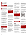 2
2
-
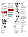 3
3
-
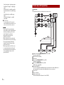 4
4
-
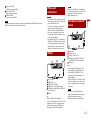 5
5
-
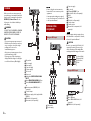 6
6
-
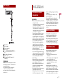 7
7
-
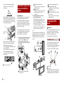 8
8
-
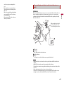 9
9
-
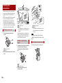 10
10
-
 11
11
-
 12
12
-
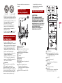 13
13
-
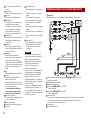 14
14
-
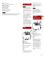 15
15
-
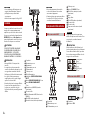 16
16
-
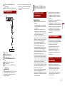 17
17
-
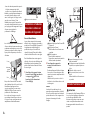 18
18
-
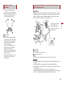 19
19
-
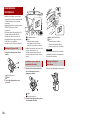 20
20
-
 21
21
-
 22
22
-
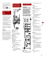 23
23
-
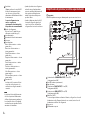 24
24
-
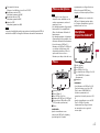 25
25
-
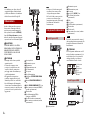 26
26
-
 27
27
-
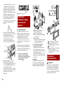 28
28
-
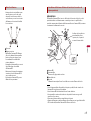 29
29
-
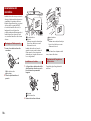 30
30
-
 31
31
-
 32
32
-
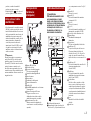 33
33
-
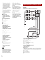 34
34
-
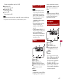 35
35
-
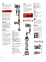 36
36
-
 37
37
-
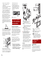 38
38
-
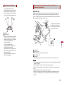 39
39
-
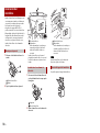 40
40
-
 41
41
-
 42
42
-
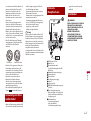 43
43
-
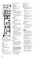 44
44
-
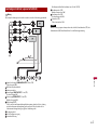 45
45
-
 46
46
-
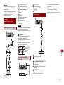 47
47
-
 48
48
-
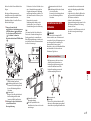 49
49
-
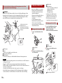 50
50
-
 51
51
-
 52
52
-
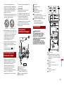 53
53
-
 54
54
-
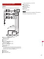 55
55
-
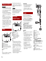 56
56
-
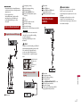 57
57
-
 58
58
-
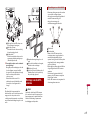 59
59
-
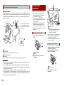 60
60
-
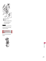 61
61
-
 62
62
-
 63
63
-
 64
64


