
© 2018 COPYRIGHT LOTRONIC SA
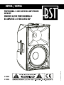
PROFESSIONAL 2-WAY ACTIVE BI-AMP SPEAKER
WITH DSP
ENCEINTE ACTIVE PROFESSIONNELLE
BI-AMPLIFIEE A 2 VOIES AVEC DSP
DSP12A / DSP15A
Code:
17-2835
17-2836
EN -INSTRUCTION MANUAL - p. 2
FR - MANUEL D’UTILISATION - p. 8
DE - BEDIENUNGSANLEITUNG - S. 14
NL - HANDLEIDING - p.20
ES - MANUAL DE INSTRUCCIONES - p. 26

2 • DSP12A / DSP15A • EN
Thank you for having chosen our DSP12A / DSP15A speaker box. For your own
safety, please read this user manual carefully before installing the device.
SAFETY INTRODUCTION
• Please read the manual carefully and keep it for future reference.
• All safety instructions and warnings must be adhered to. They are part of the manual and must be kept
with the manual.
• Any guarantee claims are rendered invalid if damage occurs due to non-observance of these operating
instructions. We assume no liability for any consequent damage.
• We assume no liability for personal injury or damage to property caused by incorrect handling or nonob-
servance of the safety instructions. Any guarantee claims expire in such cases.
• Unauthorized conversions and/or modications of the appliance are not permitted for safety and licensing
reasons (CE).
• The appliance is approved for operation in dry, closed rooms only. Do not operate the device nearby water,
such as in bathrooms or nearby swimming pools.
• The appliance may not be exposed to extreme temperatures (< +5°C / > +35°C) in operation.
• The appliance may not be subjected to strong vibrations or heavy mechanical strain.
• The appliance may not be exposed to excessive moisture (due to dripping or sprayed water, for example).
• Do not place any recipients lled with liquids, such as glasses or vases, on top of or directly next to the
appliance. They could fall over, causing water to enter the appliance. Never pour out liquids above the
appliance. Do not place any small objects, such as coins or paper clips, on the appliance since they could
fall inside the appliance. You run a high risk of causing a re or life-threatening electrocution! If any liquid
or objects enter the appliance nevertheless, pull the mains plug out of the socket immediately and contact
a specialist.
• The appliance has been constructed according to protection class l. The power plug must only be plugged
into a protection class I outlet. The voltage and frequency must exactly be the same as stated on the device.
Wrong voltages or power outlets can lead to the destruction of the device and to lethal electrical shock.
• 110- 240 Vac, 50/60 Hz mains socket may be used as source of power for the appliance. Never try to operate
the appliance with any other voltage.
• Only pull the mains plug out of the socket by the intended gripping surface. Do not pull it by the cable.
• Never plug the mains plug in or out with damp or wet hands.
• Always pull the mains plug out of the mains socket:
• Before cleaning the appliance
• If there is a thunderstorm
• If you will not be using the appliance for a long period of time (>1 week)

EN • DSP12A / DSP15A • 3
• Electrical appliances must be kept out of the reach of children. Be particularly careful if children are pre-
sent. Children are not aware of the hazards involved in handing electrical appliances improperly. Children
could attempt to poke objects into the appliance. There is a life-threatening danger of electrocution.
• Do not leave the appliance unattended while operating it.
• Never place the appliance on an unstable or movable surface. Persons could be injured or the appliance
damaged by it falling down.
• When using a rack, make sure it is in a stable position and is transported securely. Installation on uneven,
slanted surfaces or stopping the rack abruptly during transport can result in the rack overturning or ap-
pliances falling from or out of the rack and injuring people.
• Live components can be exposed by opening covers or removing components (unless this can be done wi-
thout tools). Contact points can also be live. If the appliance has to be opened in order to calibrate, service,
repair or replace components or assemblies, all of its poles must be disconnected from all sources of vol-
tage rst. If the appliance has to be kept open and under voltage during maintenance or repairs, this work
may only be carried out by a specialist who is familiar with the risks involved and the relevant regulations.
• Never connect the appliance directly after transferring it from a cold to a warm room. The condensation
water that forms could destroy the appliance or result in an electric shock. Allow the device to reach
room temperature before connecting it. Wait until the condensation water has evaporated. This can take
some hours.
• Do not place any naked ames such as those of burning candles on or next to the appliance.
• Do not place the appliance on soft surfaces such as carpets or beds. Do not cover the air vents of the
appliance. Do not obstruct the air circulation with objects such as magazines, table cloths or curtains. This
prevents the dissipation of heat from the appliance and can result in overheating.
• Only use the appliance in a moderate climate, not in tropical environments.
• All persons involved in operating, installing and servicing the appliance and putting it into service must be
trained and qualied accordingly and observe these operating instructions.
• Defective mains cables may only be replaced by specialists. Danger of shock hazard!
• Do not leave the packaging material lying around carelessly since it can become a source of danger for
children playing with it.
• The accident prevention regulations and the regulations of the employers’ liability insurance association
should be observed at commercial institutions.
• If you are not sure about the correct connection or if questions arise which are not answered by the
operating instructions, please do not hesitate to contact support or a specialist of your choice. Consult a
specialist if you are in doubt about the operating principle or the safety of the product.

4 • DSP12A / DSP15A • EN
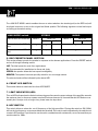
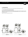
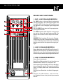
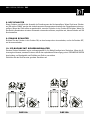
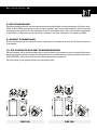
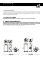
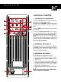
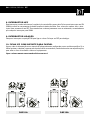
CONTROLS & FUNCTIONS
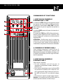
1. MIC/LINE INPUT SECTION
The female XLR connector in this section accepts
balanced MIC or LINE level signals. By using the
LINE/MIC switch, it is possible to adapt the gain to
the microphone or line level signal.
The LEVEL knob allows to adjust the input signal
level.
The THRU connector (male XLR type) produces
exactly the same signal that arrives at the input.
You can use it to daisy-chain several DSP speakers.
NOTE: Please note that the input connector does
not supply + 48V phantom power, so you can use
condenser microphones only if they are self-powe-
red.
2. LINE 2 INPUT SECTION
This section includes 2x 6.35mm jacks (L/MONO, R)
to connect music instruments, mixers etc. The input
audio signal can be adjusted via the relative knob.
3. LINE 3 INPUT SECTION
This panel section includes:
• One 3.5mm mini jack connector for the connec-
tion of mobile phones, tablets, computers, etc.
• Two unbalanced inputs for RCA pin jacks that
can be used to connect any external stereo de-
vice such as MP3 player, CD player, mixer, etc.
• One knob to adjust the input audio signal.
Note: The mini-jack and RCA stereo inputs cannot
be used at the same time.
4. LINK OUT SECTION
The audio signals from the «LINK OUT» XLR
connector are sent (routed from each INPUT) to a
connected speaker. They are line level signals and
therefore, the MIC LINE switch must be set to the
LINE position on the connected speaker.

EN • DSP12A / DSP15A • 5
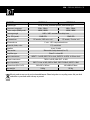
The «LINK OUT MODE» switch enables the user to select whether the mixed signal (on the DSP box) will
be played in stereo or mono on the original and linked speaker. The following signals are mixed and output
according to the switch setting.
LINK MODE switch STEREO MONO
Input of the rst DSPxxA box INPUT 1 INPUT 2/3 INPUT 1 INPUT 2/3
L R L R
Output of the first DSPxxA
box
√ √ - √
Output of the linked DSPxxA
box
√ - √ √
5. DSP PRESETS PANEL SECTION
This section allows to match the speaker’s response to the relevant applications. Press the PRESET switch
and scroll through following modes:
LIVE: The ideal preset for most «live» applications
DJ: Recommended for installations in discos and clubs
SPEECH: the speaker allows the best speech intelligibility
MONITOR: The speaker becomes specially suited for use as a stage monitor.
The selected mode will be indicated by the related LED.
6. FRONT LED SWITCH
This switch allows to switch the blue front LED ON/OFF
7. LIMIT INDICATOR (LED)
This red LED indicates that the limiter has been triggered because the output voltage of the amplier exceeds
the maximum level, or because a power overload has been detected. It is normal that this LED ashes occa-
sionally but if it stays on for a longer time, please lower the input level.
8. HPF SWITCH
This switch allows to select the cut-off frequency of the high-pass lter. Placing this switch to ON (120Hz)
will cut the low frequency components below the threshold. If the unit is used independently, the switch must
remain in OFF position. If you intend to use the unit in combination with a subwoofer, we recommend that you
set this switch to 120Hz.

6 • DSP12A / DSP15A • EN
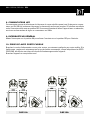
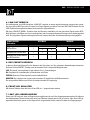
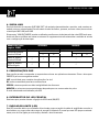
9. POWER SWITCH
Press the switch to the ON position to turn the speaker on and to the OFF position to turn it off.
10. IEC SOCKET WITH FUSE HOLDER
Plug the power cord into an AC socket properly congured for your particular model. If the fuse blows, replace
it only by the recommended fuse type as described in SPECIFICATIONS in order to prevent the risk of re
and damage to the unit.
Plug the unit only into an earthed mains outlet!
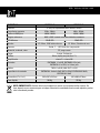
DSP12A DSP15A

EN • DSP12A / DSP15A • 7
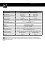
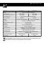
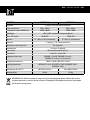
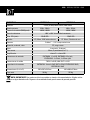
MODEL DSP12A DSP15A
System type 2-way, bi-amp powered speaker, bass reex type
Frequency response 52Hz - 20kHz 49Hz - 20kHz
Power output (RMS/peak) 400W / 800W 450W / 900W
Coverage angle H90° x V90° constant directivity horn
Max. SPL (peak) 132dB SPL 133dB SPL
LF transducer 12" woofer, 2.38" voice coil 15" woofer, 3" voice coil
HF transducer 1" exit - 1.35" compression driver
Material, nish, color PP, matt black
Handles 1x top, 2x side
Pole socket 35mm with 2-way feature (0 or 7°)
Amplier type Class D + class AB
Input connectors INPUT 1: 1x XLR, INPUT 2: 2x Jack, INPUT 3: 1x RCA, 1x 3.5mm Jack
Output connectors THRU: 1x XLR, LINK OUT: 1x XLR
Input impedance
INPUT1: Line In 3kΩ, MIC In 70kΩ, INPUT2: 20kΩ, INPUT3: 10kΩ
Dimensions (W x H x D) 362 x 597 x 347mm 445 x 698 x 376mm
Net weight 18.6kg 22.3kg
Electric products must not be put into household waste. Please bring them to a recycling center. Ask your local
authorities or your dealer about the way to proceed.

8 • DSP12A / DSP15A • FR
Merci d’avoir choisi notre enceinte DSP12A / DSP15A. Pour votre propre sécurité,
veuillez lire attentivement ce manuel avant d’installer l’appareil.
CONSIGNES DE SÉCURITÉ
• Lire attentivement le manuel et le conserver pour référence ultérieure.
• Respecter toutes les consignes de sécurité et avertissements. Ils font partie du manuel et doivent être
conservés avec le manuel.
• Nous déclinons toute responsabilité pour des dommages aux biens et aux personnes dus à une mauvaise
manipulation ou le non-respect des instructions d’utilisation. Nous n’assumons aucune responsabilité pour
les dommages consécutifs.
• Nous n’assumons aucune responsabilité pour les dommages corporels ou matériels causés par une ma-
nipulation incorrecte ou le non-respect des consignes de sécurité. Dans ce cas, le droit de garantie ne
s’applique pas.
• Des modications non-autorisées de l’appareil sont interdites pour des raisons de sécurité et de licence
(CE).
• Utiliser uniquement à l’intérieur dans une pièce sèche et fermée. Ne pas utiliser à proximité d’eau tel que
dans une salle de bains ou à proximité d’une piscine.
• Ne pas exposer l’appareil à des températures extrêmes (<5°C / >35°C) pendant le fonctionnement.
• Tenir à l’abri des vibrations fortes et des contraintes mécaniques.
• Tenir à l’abri de l’humidité extrême (due à de l’eau pulvérisée p.ex.)
• Ne pas placer de récipients remplis de liquides tels que des vases ou des verres sur ou juste à côté de
l’appareil. Ils risquent de tomber et verser le liquide à l’intérieur de l’appareil. Ne jamais verser de liquides
au-dessus de l’appareil. Ne pas placer de petits objets tels que des pièces ou des trombones sur l’appareil
car ils risquent de tomber à l’intérieur. Vous risquez de provoquer un incendie ou une électrocution. Si un
liquide ou un objet pénètre dans l’appareil, débranchez immédiatement la prise secteur et contactez un
spécialiste.
• L’appareil a été construit selon la classe de protection l. La che d’alimentation ne doit être branchée que
dans une prise de protection de classe I. La tension et la fréquence doivent être exactement les mêmes
que celles indiquées sur l’appareil. Des tensions ou des prises de courant incorrectes peuvent entraîner
la destruction de l’appareil et provoquer un choc électrique mortel.
• L’appareil doit être alimenté en 110V - 240Vac 50/60Hz. Ne jamais essayer d’alimenter l’appareil avec une
autre tension.
• Ne pas utiliser dans un environnement tropical. Pour débrancher la che secteur, tirez toujours sur la
che, jamais sur le cordon.
• Ne jamais brancher ou débrancher la che secteur avec des mains mouillées.
• Débranchez toujours l’appareil du secteur:
• avant de nettoyer l’appareil
• pendant un orage
• en cas de non-utilisation prolongée (> 1 semaine)

FR • DSP12A / DSP15A • 9
• Tenir les appareils électriques hors de la portée des enfants. Soyez particulièrement vigilants en présence
d’enfants. Les enfants ne sont pas conscients du danger d’un appareil électrique. Ils pourraient essayer
d’insérer un objet à l’intérieur de l’appareil Danger d’électrocution !
• Ne pas laisser l’appareil sans surveillance pendant son fonctionnement.
• Ne jamais placer l’appareil sur une surface instable ou mobile. L’appareil risque de blesser une personne
ou de s’abîmer en tombant.
• Si vous utilisez un rack, assurez-vous qu’il est installé dans une position stable et transportez-le avec
précaution. L’arrêt brutal pendant le transport peut faire basculer le rack en faisant tomber l’appareil.
L’appareil risque de blesser une personne ou de s’abîmer en tombant.
• Les composants sous tension peuvent être exposés en ouvrant les couvercles ou en enlevant des com-
posants (sauf si cela peut être fait sans outils). Les points de contact peuvent également être en ligne.
Si l’appareil doit être ouvert pour étalonner, entretenir, réparer ou remplacer des composants ou des
ensembles, tous ses pôles doivent d’abord être déconnectés de toutes les sources de tension. Si l’appareil
doit rester ouvert et sous tension pendant l’entretien ou les réparations, ce travail ne doit être effectué que
par un spécialiste connaissant les risques encourus et les réglementations en vigueur.
• Ne branchez jamais l’appareil directement après le transfert d’une pièce froide à une pièce chaude. L’eau
de condensation qui se forme peut détruire l’appareil ou provoquer un choc électrique. Laissez l’appareil
atteindre la température ambiante avant de le connecter. Attendez que l’eau de condensation se soit
évaporée. Cela peut prendre quelques heures.
• Ne pas placer de amme ouverte telle qu’une bougie sur ou à côté de l’appareil.
• Ne placez pas l’appareil sur des surfaces molles telles que des tapis ou des lits. Ne couvrez pas les ouver-
tures d’aération de l’appareil. N’obstruez pas la circulation d’air avec des objets tels que des magazines,
des nappes ou des rideaux. Cela empêche la dissipation de la chaleur de l’appareil et peut entraîner une
surchauffe.
• Utiliser l’appareil uniquement dans un environnement modéré. Ne pas utiliser dans un environnement
tropical.
• Toutes les personnes impliquées dans l’utilisation, l’installation et la maintenance de cet appareil doivent
être formées et qualiées et respecter ces consignes.
• Remplacer les câbles secteur défectueux uniquement par un spécialiste. Risque d’électrocution!
• Ne laissez pas le matériel d’emballage traîner par négligence car cela peut devenir une source de danger
pour les enfants qui jouent.
• Les règlements de prévention des accidents doivent être respectés.
• Si vous n’êtes pas sûr de la bonne connexion ou si vous avez des questions auxquelles le mode d’emploi ne
répond pas, n’hésitez pas à demander conseil à un spécialiste ou votre revendeur. Consulter un spécialiste
si vous avez des doutes sur le principe de fonctionnement ou la sécurité du produit.

10 • DSP12A / DSP15A • FR
COMMANDES ET FONCTIONS
1. SECTION DU PANNEAU
D’ENTREE MIC / LINE
Le connecteur XLR femelle de cette section accepte
les signaux de niveau MIC ou LINE symétrique.
En utilisant le commutateur LINE / MIC, il est pos-
sible d’adapter le gain au signal du microphone ou
de la ligne.
Le bouton LEVEL permet d’ajuster le niveau du si-
gnal d’entrée.
Le connecteur THRU (type XLR mâle) produit exac-
tement le même signal qui arrive à l’entrée. Vous
pouvez l’utiliser pour connecter en chaîne plusieurs
enceintes DSP.
ATTENTION : Veuillez noter que le connecteur
d’entrée ne fournit pas d’alimentation fantôme 48
V, vous pouvez donc utiliser des microphones à
condensateur uniquement s’ils sont auto-alimentés.
2. PANNEAU D’ENTREE LINE 2
Cette section comprend 2 jacks 6,35 mm (L
(gauche)/ MONO, R (droite)) pour connecter des
instruments de musique, des tables de mixage, etc.
Le signal audio d’entrée peut être réglé via le bou-
ton correspondant.
3. SECTION DU PANNEAU
D’ENTREE LINE 3
Cette section comprend :
• Un mini connecteur jack 3,5 mm pour la
connexion de téléphones mobiles, tablettes, or-
dinateurs, etc.
• Deux entrées asymétriques pour les ches RCA
qui peuvent être utilisées pour connecter n’im-
porte quel appareil stéréo externe tel qu’un lec-
teur MP3, un lecteur CD, une table de mixage,
etc.
• Un bouton pour ajuster le signal audio d’entrée.
Attention : Les entrées mini-jack et RCA stéréo ne
peuvent pas être utilisées en même temps.

FR • DSP12A / DSP15A • 11
4. SECTION DE SORTIE LINK
Les signaux audio du connecteur XLR «LINK OUT» sont envoyés (acheminés depuis chaque entrée) vers une
enceinte connectée. Ce sont des signaux de niveau ligne et par conséquent, le commutateur MIC LINE doit
être réglé sur la position LINE sur l’enceinte connectée.
Le commutateur «LINK OUT MODE» permet à l’utilisateur de choisir si le signal mixé (sur l’enceinte DSP)
sera reproduit en stéréo ou en mono sur l’enceinte originale et reliée. Les signaux suivants sont mélangés et
acheminé vers la sortie en fonction du réglage du commutateur.
Interrupteur
LINK MODE
STÉRÉO MONO
Entrée de la 1. enceinte
DSPxxA
ENTRÉE 1 ENTRÉE 2/3 ENTRÉE 1 ENTRÉE 2/3
L (gauche) R (droite) L (gauche) R (droite)
Sortie de la 1. enceinte
DSPxxA
√ √ √
Sortie de la 2ème en-
ceinte DSPxxA
√ √ √
5. SECTION DES PRESETS DSP
Cette section permet d’adapter l’image sonore de l’enceinte aux différentes applications. Appuyez sur le
commutateur PRESET et faites déler les modes suivants:
LIVE: Le préréglage idéal pour la plupart des applications «en direct»
DJ: Recommandé pour les installations dans les discothèques et les clubs
SPEECH (discours): Le haut-parleur permet la meilleure intelligibilité de la parole
MONITOR: Convient particulièrement à l’utilisation en tant que moniteur de scène.
Le mode sélectionné sera indiqué par la LED correspondante.
6. INTERRUPTEUR LED EN FACADE
Ce commutateur permet d’allumer / éteindre la LED frontale bleue
7. INDICATEUR DE LIMITE (LED)
Cette LED rouge indique que le limiteur a été déclenché car la tension de sortie de l’amplicateur dépasse le
niveau maximum, ou parce qu’une surcharge a été détectée. Il est normal que cette LED clignote occasion-
nellement mais si elle reste allumée plus longtemps, veuillez baisser le niveau d’entrée.

12 • DSP12A / DSP15A • FR
DSP12A DSP15A
8. COMMUTATEUR HPF
Ce commutateur permet de sélectionner la fréquence de coupure du ltre passe-haut. En plaçant ce commu-
tateur sur ON (120 Hz), les basses fréquences en dessous du seuil seront coupées. Si l’enceinte est utilisée
seule, l’interrupteur doit rester en position OFF. Si vous avez l’intention d’utiliser l’appareil avec un subwoofer,
nous vous recommandons de régler ce commutateur sur 120Hz.
9. INTERRUPTEUR GÉNÉRAL
Mettez l’interrupteur sur la position ON pour allumer l’enceinte et sur la position OFF pour l’éteindre.
10. PRISE IEC AVEC PORTE-FUSIBLE
Branchez le cordon d’alimentation sur une prise secteur correctement congurée pour votre modèle. Si le
fusible saute, remplacez-le uniquement par le type de fusible recommandé, comme indiqué dans les SPÉCI-
FICATIONS, an d’éviter tout risque d’incendie et d’endommagement de l’appareil.
Branchez l’appareil sur une prise de terre!

FR • DSP12A / DSP15A • 13
RÉF. DSP12A DSP15A
Type de système 2-voies, enceinte active bi-ampliée, bass reex
Bande passante 52Hz - 20kHz 49Hz - 20kHz
Puissance de sortie (RMS/crête) 400W / 800W 450W / 900W
Couverture sonore H90° x V90° pavillon à directivité constante
SPL max. (crête) 132dB SPL 133dB SPL
Transducteur BF Boomer 12" , bobine mobile 2.38" Boomer 15" , bobine mobile 3"
Transducteur HF Sortie 1" - HP à compression 1.35"
Materiau, nition, couleur PP, noir mat
Poignées 1x au-dessus, 2x latérales
Insert 35mm à 2 positions (0 ou 7°)
Amplicateur Class D + class AB
Connecteurs d’entrée ENTREE 1: 1 XLR, ENTREE 2: 2 Jack, ENTREE 3: 1 RCA, 1 Jack 3.5mm
Connecteurs de sortie THRU: 1 XLR, LINK OUT: 1 XLR
Impédance d’entrée
ENTREE1: Ligne 3kΩ, Micro 70kΩ, ENTREE2: 20kΩ, ENTREE3: 10kΩ
Dimensions (L x H x l) 362 x 597 x 347mm 445 x 698 x 376mm
Poids net 18.6kg 22.3kg
NOTE IMPORTANTE : Les produits électriques ne doivent pas être mis au rebut avec les ordures ménagères.
Veuillez les faire recycler à un point de collecte spécialisé. Consultez les autorités locales ou votre revendeur sur
la façon de les recycler.

14 • DSP12A / DSP15A • DE
Vielen Dank, dass Sie sich für unsere Lautsprecherbox DSP12A / DSP15A
entschieden haben. Bitte lesen Sie diese Bedienungsanleitung zu Ihrer eigenen
Sicherheit sorgfältig durch, bevor Sie das Gerät installieren.
SICHERHEITSHINWEISE
• Aufmerksam die Anleitung durchlesen und für spätere Bezugnahme aufbewahren.
• Alle Sicherheitshinweise und Warnungen müssen beachtet werden. Sie sind Teil des Handbuchs und
müssen zusammen mit dem Handbuch aufbewahrt werden.
• Etwaige Gewährleistungsansprüche erlöschen, wenn Schäden durch Nichtbeachtung dieser Bedienung-
sanleitung entstehen. Für Folgeschäden übernehmen wir keine Haftung.
• Wir übernehmen keine Haftung für Personen- oder Sachschäden, die durch unsachgemäße Handhabung
oder Nichtbeachtung der Sicherheitshinweise verursacht werden. In solchen Fällen erlöschen Garan-
tieansprüche.
• Eigenmächtige Umbauten und / oder Veränderungen am Gerät sind aus Sicherheits- und Lizenzgründen
(CE) nicht erlaubt.
• Das Gerät ist nur für den Betrieb in trockenen, geschlossenen Räumen zugelassen. Betreiben Sie das Gerät
nicht in der Nähe von Wasser, z. B. im Badezimmer oder in der Nähe eines Swimming Pools.
• Das Gerät darf während des Betriebs keinen extremen Temperaturen (<5 ° C /> 35 ° C) ausgesetzt werden.
• Das Gerät darf keinen starken Vibrationen oder starken mechanischen Belastungen ausgesetzt werden.
• Das Gerät darf keiner übermäßigen Feuchtigkeit ausgesetzt werden (z. B. durch Tropfen oder Spritzwas-
ser).
• Keine mit Flüssigkeiten gefüllten Behälter wie Gläser oder Vasen auf oder neben das Gerät stellen. Sie
könnten umkippen und die Flüssigkeit ins Gehäuseinneren dringen lassen. Niemals Flüssigkeiten über das
Gerät gießen. Stellen Sie keine kleinen Gegenstände wie Münzen oder Büroklammern auf das Gerät, da
diese in das Gerät fallen könnten. Sie riskieren ein Feuer oder einen lebensgefährlichen Stromschlag!
Wenn Flüssigkeiten oder Gegenstände ins Gehäuseinnere dringen, sofort den Netzstecker abziehen und
einen Fachmann zu Rate ziehen.
• Das Gerät wurde gemäß Schutzklasse l gebaut. Der Netzstecker darf nur in eine Schutzklasse I-Steckdose
eingesteckt werden. Die Spannung und Frequenz müssen genau mit den Angaben auf dem Gerät übe-
reinstimmen. Falsche Spannungen oder Steckdosen können zur Zerstörung des Gerätes und zu tödlichen
Stromschlägen führen.
• 110-240 Vac, 50/60 Hz Steckdose kann als Stromquelle für das Gerät verwendet werden. Versuchen Sie
niemals, das Gerät mit einer anderen Spannung zu betreiben.
• Beim Abkoppeln des Geräts vom Netz immer nur am Stecker anfassen. Niemals am Kabel ziehen.
• Niemals den Netzstecker mit feuchten oder nassen Händen anfassen.
• Ziehen Sie immer den Netzstecker aus der Steckdose:
• Vor dem Reinigen des Geräts
• Wenn es ein Gewitter gibt
• Wenn Sie das Gerät längere Zeit nicht benutzen (> 1 Woche)

DE • DSP12A / DSP15A • 15
• Elektrogeräte von Kindern fernhalten. In Anwesenheit von Kindern besonders vorsichtig sein. Kinder sind
sich der Gefahren beim Umgang mit Elektrogeräten nicht bewusst. Kinder könnten versuchen, Gegenstände
ins Gehäuse zu stecken. Es besteht die Gefahr von tödlichem Stromschlag.
• Lassen Sie das Gerät während des Betriebs nicht unbeaufsichtigt.
• Niemals das Gerät auf eine instabile oder bewegliche Fläche stellen. Menschen könnten verletzt oder das
Gerät beim Fallen beschädigt werden.
• Stellen Sie bei Verwendung eines Racks sicher, dass es sich in einer stabilen Position bendet und sicher
transportiert wird. Die Installation auf unebenen, schrägen Oberächen oder das abrupte Anhalten des
Racks während des Transports kann dazu führen, dass das Rack umkippt oder Geräte aus dem Rack fallen
oder herausfallen und Personen verletzen.
• Spannungsführende Teile können durch Öffnen von Abdeckungen oder Entfernen von Komponenten frei-
gelegt werden (sofern dies nicht ohne Werkzeuge möglich ist). Kontaktpunkte können auch spannungs-
führend sein. Wenn das Gerät zum Kalibrieren, Warten, Reparieren oder Ersetzen von Komponenten oder
Baugruppen geöffnet werden muss, müssen alle Pole zuerst von allen Spannungsquellen getrennt werden.
Wenn das Gerät bei Wartungs- oder Reparaturarbeiten geöffnet und unter Spannung gehalten wird, dürfen
diese Arbeiten nur von einem Fachmann ausgeführt werden, der mit den damit verbundenen Gefahren und
den einschlägigen Vorschriften vertraut ist.
• Schließen Sie das Gerät niemals direkt an, nachdem Sie es von einem kalten in einen warmen Raum ge-
bracht haben. Das entstehende Kondenswasser kann das Gerät zerstören oder einen elektrischen Schlag
verursachen. Lassen Sie das Gerät vor dem Anschließen Raumtemperatur erreichen. Warten Sie, bis das
Kondenswasser verdampft ist. Dies kann einige Stunden dauern.
• Kein offenes Feuer wie brennende Kerzen auf oder neben das Gerät stellen.
• Stellen Sie das Gerät nicht auf weiche Oberächen wie Teppiche oder Betten. Decken Sie die Lüftungs-
öffnungen des Geräts nicht ab. Behindern Sie nicht die Luftzirkulation durch Gegenstände wie Magazine,
Tischdecken oder Vorhänge. Dies verhindert die Wärmeableitung vom Gerät und kann zu einer Überhitzung
führen.
• Das Gerät nur in gemäßigten Klimazonen und nicht in tropischer Umgebung benutzen.
• Alle Personen, die mit der Bedienung, Installation, Wartung und Reparatur zu tun haben, müssen ausge-
bildet und entsprechend erfahren sein und diese Hinweise beachten.
• Defekte Netzkabel dürfen nur von Fachpersonal ersetzt werden. Es besteht Stromschlaggefahr!
• Lassen Sie das Verpackungsmaterial nicht achtlos liegen, da es für spielende Kinder zu einer Gefahren-
quelle werden kann.
• Wenn Sie sich über den richtigen Anschluss nicht im Klaren sind oder Fragen haben, die nicht in der
Anleitung beantwortet sind, wenden Sie sich an Ihren Fachhändler oder einen Fachmann Ihrer Wahl.
Wenn Sie Zweifel zur Bedienung oder Sicherheit des Geräts haben, wenden Sie sich an einen Fachmann.

16 • DSP12A / DSP15A • DE
REGLER UND FUNKTIONEN
1. MIC / LINE-EINGANGSBEREICH
Die XLR-Buchse in diesem Bereich akzeptiert
symmetrische MIC- oder LINE-Pegel-Signale. Mit
dem LINE / MIC-Schalter kann die Verstärkung an
das Mikrofon- oder Linepegel-Signal angepasst
werden.
Mit dem LEVEL-Regler kann der Eingangssignalpe-
gel eingestellt werden.
Der THRU-Verbinder (XLR-Stecker) erzeugt genau
das gleiche Signal das am Eingang anliegt. Sie
können damit mehrere DSP-Lautsprecher kaska-
dieren.
HINWEIS: Bitte beachten Sie, dass der Eingang-
sanschluss keine 48-V-Phantomspeisung liefert,
so dass Sie Kondensatormikrofone nur verwenden
können, wenn sie über ihre eigene Versorgung ver-
fügen.
2. LINE 2-EINGANGSBEREICH
Dieser Abschnitt enthält 2x 6,35 mm Buchsen (L /
MONO, R) zum Anschluss von Musikinstrumenten,
Mischpulten usw. Das Audioeingangssignal kann
mit dem entsprechenden Knopf eingestellt werden.
3. LINE 3-EINGANGSBEREICH
Dieser Bereich beinhaltet:
Einen 3,5 mm Klinkenstecker für den Anschluss von
Mobiltelefonen, Tablet PCs, Computern usw.
Zwei asymmetrische Eingänge für Cinch-Buchsen,
die zum Anschluß externer Stereogeräte wie MP3-
Player, CD-Player, Mixer usw. verwendet werden
können.
Ein Knopf zum Einstellen des Audio-Eingangssi-
gnals.
Hinweis: Die Mini-Klinken- und Cinch-Ste-
reo-Eingänge können nicht gleichzeitig verwendet
werden.

DE • DSP12A / DSP15A • 17
4. LINK OUT BEREICH
Die Audiosignale vom XLR-Anschluss «LINK OUT» werden an einen angeschlossenen Lautsprecher gesen-
det (von jedem INPUT geroutet. Sie sind Line-Pegel-Signale und daher muss der MIC LINE-Schalter auf die
LINE-Position des angeschlossenen Lautsprechers eingestellt sein.
Mit dem «LINK OUT MODE» -Schalter kann der Benutzer auswählen, ob das gemischte Signal (an der DSP-
Box) in Stereo oder Mono auf dem ursprünglichen und dem angeschlossenen Lautsprecher wiedergegeben
wird. Die folgenden Signale werden gemischt und entsprechend der Schaltereinstellung weitergegeben.
LINK MODE
Schalter
STEREO MONO
Eingang der ersten
DSPxxA-Box
EINGANG
1
EINGANG 2/3 EINGANG 1 EINGANG 2/3
L R L R
Ausgang der DSPxxA-Box √ √ √
Ausgang der angeschlosse-
nen DSPxxA-Box
√ √ √
5. DSP PRESETS BEREICH
In diesem Abschnitt können Sie die Antwort des Sprechers auf die relevanten Anwendungen anpassen.
Drücken Sie den PRESET-Schalter und durchlaufen Sie die folgenden Möglichkeiten:
LIVE: Die ideale Voreinstellung für die meisten «Live» -Anwendungen
DJ: Empfohlen für Installationen in Diskotheken und Clubs
SPEECH (Sprache): Schwerpunkt Sprachverständlichkeit
MONITOR: Der Lautsprecher eignet sich besonders für den Einsatz als Bühnenmonitor.
Der ausgewählte Modus wird durch die entsprechende LED angezeigt.
6. FRONT-LED SCHALTER
Mit diesem Schalter kann die blaue Front-LED ein- / ausgeschaltet werden
7. LIMIT LED (GRENZANZEIGE)
Diese rote LED zeigt an, dass der Begrenzer ausgelöst wurde, weil die Ausgangsspannung des Verstärkers
den Maximalpegel überschreitet oder weil eine Überlast erkannt wurde. Es ist normal, dass diese LED ge-
legentlich blinkt, aber wenn sie für längere Zeit eingeschaltet bleibt, senken Sie bitte den Eingangspegel.

18 • DSP12A / DSP15A • DE
8. HPF-SCHALTER
Dieser Schalter ermöglicht die Auswahl der Grenzfrequenz des Hochpasslters. Wenn Sie diesen Schalter
auf ON stellen (120Hz), werden die niederfrequenten Komponenten unterhalb des Schwellenwerts heraus-
geltert. Wenn das Gerät allein verwendet wird, muss der Schalter in der Position OFF bleiben. Wenn Sie
das Gerät in Kombination mit einem Subwoofer verwenden möchten, empfehlen wir, diesen Schalter auf 120
Hz einzustellen.
9. EIN/AUS SCHALTER
Drücken Sie den Schalter in die Position ON, um den Lautsprecher einzuschalten, und in die Position OFF,
um ihn auszuschalten.
10. IEC-BUCHSE MIT SICHERUNGSHALTER
Stecken Sie das Netzkabel in eine ordnungsgemäß für Ihr Modell kongurierte Steckdose. Wenn die Si-
cherung durchbrennt, ersetzen Sie sie nur durch den empfohlenen Sicherungstyp, wie in TECHNISCHE DATEN
beschrieben, um Brandgefahr und Schäden am Gerät zu vermeiden.
Schließen Sie das Gerät an eine geerdete Steckdose an!
DSP12A DSP15A

DE • DSP12A / DSP15A • 19
MODELL DSP12A DSP15A
System 2-Weg, bi-amp Aktivbox, Bassreex
Frequenzbereich 52Hz - 20kHz 49Hz - 20kHz
Ausgangsleistung (RMS/Spitze) 400W / 800W 450W / 900W
Flächenabdeckung H90° x V90° konstante Richtcharakteristik
Max. SPL (Spitze) 132dB SPL 133dB SPL
Tieftöner 12" / 30cm, 2.38" Schwingspule 15" 38cm, 3" Schwingspule
Hochtöner 1" Ausgang - 1.35" Drukkammertreiber
Material, Ausführung, Farbe PP, mattschwarz
Handgriffe 1x oben, 2x seitlich
Stativeinsatz 35mm mit 2 Stellwinkeln (0 oder 7°)
Verstärker Klasse D + Klasse AB
Eingangsverbinder EINGANG 1: 1x XLR, EINGANG 2: 2x Klinke,
EINGANG 3: 1x Cinch, 1x 3.5mm Klinke
Ausgangsverbinder THRU: 1x XLR, LINK OUT: 1x XLR
Eingangsimpedanz
EINGANG1: Line In 3kΩ, MIC In 70kΩ, EINGANG2: 20kΩ,
EINGANG3: 10kΩ
Abmessungen (B x H x T) 362 x 597 x 347mm 445 x 698 x 376mm
Nettogewicht 18.6kg 22.3kg
WICHTIGER HINWEIS: Elektrogeräte gehören nicht in den Hausmüll. Sie müssen in speziellen Betrieben recycelt
werden. Wenden Sie sich hierzu an die örtlichen Behörden oder Ihren Fachhändler!

20 • DSP12A / DSP15A • NL
Bedankt dat je hebt gekozen voor onze DSP12A / DSP15A-luidsprekerkast. Lees
voor uw eigen veiligheid deze gebruikershandleiding aandachtig voordat u het
apparaat installeert.
VEILIGHEIDSINSTRUCTIES
• Aandachtig de handleiding lezen en bewaren.
• Alle veiligheidsinstructies en waarschuwingen moeten worden opgevolgd. Ze maken deel uit van de han-
dleiding en moeten bij de handleiding worden bewaard.
• Alle garantieclaims worden ongeldig als er schade optreedt als gevolg van het niet in acht nemen van deze
bedieningsinstructies. Wij aanvaarden geen aansprakelijkheid voor enige daaruit voortvloeiende schade.
• Wij aanvaarden geen aansprakelijkheid voor persoonlijk letsel of schade aan eigendommen veroorzaakt
door onjuiste behandeling of het niet in acht nemen van de veiligheidsinstructies. Alle garantieclaims
vervallen in dergelijke gevallen.
• Ongeoorloofde conversies en / of aanpassingen van het apparaat zijn om veiligheids- en licentieredenen
(CE) niet toegestaan.
• Het apparaat is alleen goedgekeurd voor gebruik in droge, gesloten ruimten. Gebruik het apparaat niet in
de buurt van water, zoals in badkamers of in de buurt van zwembaden.
• Het apparaat mag tijdens het gebruik niet worden blootgesteld aan extreme temperaturen (<5 ° C /> 35 ° C).
• Het apparaat mag niet worden blootgesteld aan sterke trillingen of zware mechanische belasting.
• Het apparaat mag niet worden blootgesteld aan overmatig vocht (bijvoorbeeld door druppelend of
sproeiwater).
• Plaats geen ontvangers gevuld met vloeistoffen, zoals glazen of vazen, op of direct naast het apparaat.
Ze kunnen omvallen, waardoor water in het apparaat binnendringt. Giet nooit vloeistoffen uit boven het
toestel. Plaats geen kleine voorwerpen, zoals munten of paperclips, op het apparaat, want deze kunnen in
het apparaat vallen. U loopt een hoog risico op brand of levensbedreigende elektrocutie! Als er vloeistof
of voorwerpen in het apparaat dringen, trek dan onmiddellijk de stekker uit het stopcontact en raadpleeg
een deskundige.
• Het apparaat is gebouwd volgens beschermingsklasse l. De stekker mag alleen op een stopcontact van
beschermingsklasse I worden aangesloten. De spanning en frequentie moeten exact dezelfde zijn als
aangegeven op het apparaat. Verkeerde spanningen of stopcontacten kunnen leiden tot vernietiging van
het apparaat en tot dodelijke elektrische schokken.
• 110-240 Vac, 50/60 Hz stopcontact kan worden gebruikt als stroombron voor het apparaat. Gebruik het
apparaat nooit met een ander voltage.
• Trek de stekker alleen uit het stopcontact via de ervoor bepaalde oppervlak. Niet aan het kabel trekken.
• Nooit de stekker met vochtige of natte handen aanraken.
• Trek altijd de stekker uit het stopcontact:
• Voordat u het apparaat schoonmaakt
• in geval van onweer
• Als u het apparaat gedurende een lange periode (> 1 week) niet zult gebruiken

NL • DSP12A / DSP15A • 21
• Elektrische apparaten buiten het bereik van kinderen houden. Wees vooral voorzichtig wanneer er kinderen
aanwezig zijn. Kinderen zijn zich niet bewust van de gevaren die betrokken zijn bij elektrische apparaten.
Kinderen kunnen proberen voorwerpen in het apparaat te stekken. Er is een levensbedreigend gevaar van
stroomslag.
• Laat het apparaat niet onbeheerd achter tijdens het gebruik.
• Plaats het apparaat nooit op een instabiele of beweegbare ondergrond. Mensen kunnen gewond raken of
het apparaat wordt beschadigd door het vallen.
• Wanneer u een rek gebruikt, moet u ervoor zorgen dat deze zich in een stabiele positie bevindt en veilig
wordt vervoerd. Installatie op ongelijke, schuine oppervlakken of abrupt stoppen van het rek tijdens het
transport kan ertoe leiden dat het rek kantelt of dat apparaten uit het rek vallen en mensen verwonden.
• Live-componenten kunnen worden blootgesteld door afdekkingen te openen of componenten te verwijde-
ren (tenzij dit zonder gereedschap kan worden gedaan). Contactpunten kunnen ook live zijn. Als het appa-
raat moet worden geopend om componenten of assemblages te kalibreren, onderhouden, repareren of ver-
vangen, moeten alle polen eerst van alle spanningsbronnen worden losgekoppeld. Als het apparaat tijdens
onderhoud of reparaties open en onder spanning moet worden gehouden, mogen deze werkzaamheden
alleen worden uitgevoerd door een specialist die bekend is met de risico's en de relevante voorschriften.
• Sluit het apparaat nooit direct aan nadat het van een koude naar een warme ruimte is overgebracht. Het
condenswater dat ontstaat, kan het apparaat beschadigen of een elektrische schok veroorzaken. Laat het
apparaat op kamertemperatuur komen voordat u het aansluit. Wacht tot het condenswater is verdampt.
Dit kan enkele uren duren.
• Plaats geen open vlammen, zoals brandende kaarsen op of naast het apparaat.
• Plaats het apparaat niet op zachte ondergronden zoals tapijten of bedden. Dek de ventilatieopeningen van
het apparaat niet af. Blokkeer de luchtcirculatie niet met voorwerpen zoals tijdschriften, tafelkleden of
gordijnen. Dit voorkomt de afvoer van warmte uit het apparaat en kan oververhitting veroorzaken.
• Gebruik het apparaat alleen in een gematigd klimaat, niet in een tropische omgeving.
• Alle personen die dit apparaat gebruiken, installeren of onderhouden moeten gekwaliceerd zijn en deze
gebruiksaanwijzing naleven.
• Defecte stroomkabels mogen enkel vervangen worden door een vakman. Gevaar van elektrische schok!
• Laat het verpakkingsmateriaal niet achteloos rondslingeren, want het kan een bron van gevaar vormen
voor kinderen die ermee spelen.
• Als u niet zeker bent over de correcte aansluiting of als er vragen zijn die niet worden beantwoord door
de gebruiksaanwijzing, contacteer een specialist. Raadpleeg een specialist indien u twijfel heeft aan het
werkingsprincipe of de veiligheid van het product

22 • DSP12A / DSP15A • NL
BEDIENINGSELEMENTEN
EN FUNCTIES
1. MIC / LINE INGANGSBEREIK
De XLR-connector in deze sectie accepteert geba-
lanceerde MIC- of LINE-niveausignalen. Door de
LINE / MIC-schakelaar te gebruiken, is het moge-
lijk om de gain aan te passen aan het microfoon- of
lijnniveau-signaal.
Met de LEVEL-knop kunt u het ingangssignaalni-
veau regelen.
De THRU-connector (XLR-plug) produceert precies
hetzelfde signaal dat aankomt bij de ingang. U kunt
het gebruiken om verschillende DSP-luidsprekers
in serie te schakelen.
LET OP: Merk op dat de ingangsconnector geen
48V fantoomvoeding levert, dus u kunt condensa-
tormicrofoons alleen gebruiken als deze op eigen
energie werken.
2. LINE 2 INGANGSBEREIK
Dit bereik bevat 2x 6,35 mm-aansluitingen (L /
MONO, R) om muziekinstrumenten, mixers enz.
Aan te sluiten. Het ingangsaudiosignaal kan wor-
den aangepast via de relatieve knop.
3. LINE 3 INGANGSBEREIK
Dit bereik bevat:
• Eén 3,5 mm mini-jack-connector voor de
aansluiting van mobiele telefoons, tablets, com-
puters, etc.
• Twee ongebalanceerde ingangen voor
RCA-connectoren die kunnen worden gebruikt
om een extern stereotoestel zoals MP3-speler,
CD-speler, mixer enz. aan te sluiten.
• Eén knop om het ingangsaudiosignaal aan te
passen.
Let op: De mini-jack en RCA stereo-ingangen kun-
nen niet tegelijkertijd worden gebruikt.

NL • DSP12A / DSP15A • 23
4. LINK OUT BEREIK
De audiosignalen van de "LINK OUT" XLR-connector worden verzonden (gerouteerd van elke INPUT) naar
een aangesloten luidspreker. Dit zijn lijnniveausignalen en daarom moet de MIC LINE-schakelaar op de
aangesloten luidspreker op de LIJN-positie worden ingesteld.
Met de schakelaar "LINK OUT MODE" kan de gebruiker selecteren of het gemengde signaal (in de DSP-box)
in stereo of mono op de twee luidsprekers wordt afgespeeld. De volgende signalen worden gemengd en
uitgevoerd volgens de schakelaarinstelling.
LINK MODE
schakelaar
STEREO MONO
Ingang van de eerste
DSPxxA-doos
INPUT 1 INPUT 2/3 INPUT 1 INPUT 2/3
L R L R
Uitgang van de eerste
DSPxxA-doos
√ √ √
Uitgang van de gekoppelde
DSPxxA-box
√ √ √
5. DSP PRESETS BEREIK
In dit bereik kan de geluidsweergave van de luidspreker op de relevante applicaties worden afgestemd. Druk
op de PRESET-schakelaar en blader door de volgende modi:
LIVE: De ideale voorinstelling voor de meeste "live" -toepassingen
DJ: Aanbevolen voor installaties in disco's en clubs
SPEECH: Gebruik deze instelling als de luidspreker wordt gebruik voor spraak en presentaties.
MONITOR: Gebruik deze instelling als de luidspreker word gebruikt als podium monitor.
De geselecteerde modus wordt aangegeven door de relatieve LED.
6. FRONT LED-SCHAKELAAR
Met deze schakelaar kan de blauwe LED aan de voorzijde worden in- of uitgeschakeld
7. LIMIT INDICATOR (LED)
Deze rode LED geeft aan dat de limiter is geactiveerd omdat de uitgangsspanning van de versterker het
maximale niveau overschrijdt, of omdat een vermogensoverbelasting is gedetecteerd. Het is normaal dat deze
LED af en toe knippert, maar als deze langer aan blijft, verlaag dan het ingangsniveau.

24 • DSP12A / DSP15A • NL
8. HPF-SCHAKELAAR
Met deze schakelaar kan de grensfrequentie van het hoogdoorlaatlter worden geselecteerd. Als deze scha-
kelaar op ON (120Hz) wordt gezet, worden de lage frequentie onder de drempel verwijdert. Als het apparaat
zelfstandig wordt gebruikt, moet de schakelaar in de UIT-stand blijven staan. Als u van plan bent het apparaat
te gebruiken in combinatie met een subwoofer, raden wij u aan deze schakelaar in te stellen op 120Hz.
9. AAN/UIT SCHAKELAAR
Druk de schakelaar naar de ON-positie om de luidspreker in te schakelen en naar de UIT-stand om deze uit
te schakelen.
10. IEC-CONTACTDOOS MET ZEKERINGHOUDER
Sluit het netsnoer aan op een stopcontact dat op de juiste manier is gecongureerd voor uw specieke model.
Als de zekering doorbrandt, vervang deze dan alleen door het aanbevolen type zekering zoals beschreven in
SPECIFICATIES om het risico van brand en schade aan de unit te voorkomen.
Sluit het toestel op een geaard lichtnet stopcontactdoos aan!
DSP12A DSP15A

NL • DSP12A / DSP15A • 25
MODEL DSP12A DSP15A
Systeem 2-weg, bi-amp actiefbox, basreex
Frequentiebereik 52Hz - 20kHz 49Hz - 20kHz
Uitgangsvermogen (RMS/piek) 400W / 800W 450W / 900W
Afdekking H90° x V90° constante richtgevoeligheid
Max. SPL (piek) 132dB SPL 133dB SPL
Woofer 12" / 30cm, 2.38" spreekspoel 15" 38cm, 3" spreekspoel
Tweeter 1" uitgang - 1.35" compressiehorn
Materiaal, uitvoering, kleur PP, matzwart
Handgrepen 1x boven, 2x zijdelijk
Pole mount 35mm met 2 posities (0 of 7°)
Versterker classe D + classe AB
Ingangsconnectoren INGANG 1: 1x XLR, INGANG 2: 2x jack,
INGANG 3: 1x Cinch, 1x 3.5mm jack
Uitgangsconnectoren THRU: 1x XLR, LINK OUT: 1x XLR
Ingangsimpedantie
INGANG1: Line In 3kΩ, MIC In 70kΩ, INGANG2: 20kΩ,
INGANG3: 10kΩ
Afmetingen (B x H x D) 362 x 597 x 347mm 445 x 698 x 376mm
Nettogewicht 18.6kg 22.3kg
BELANGRIJK: De elektrische producten mogen niet bij het huisvuil gegooid worden. Gelieve deze te laten
recycleren daar waar er centra’s hiervoor voorzien is. Raadpleeg de plaatselijke autoriteiten of uw verkoper
ivm de manier van recycleren

26 • DSP12A / DSP15A • ES
Gracias por haber escogido nuestro bafle DSP12A / DSP15A. Por su propia
seguridad, lea atentamente este manual antes de instalar y usar el equipo.
INSTRUCCIONES DE SEGURIDAD
• Lea atentamente este manual que contiene informaciones importantes de la instalación, uso y manteni-
miento de este equipo.
• Conserve el manual para consultas futuras. Si el equipo cambia de propietario algún día asegúrese de
que recibe el manual.
• Declinamos cualquier responsabilidad por daños a bienes o/y personas, producidas por un mal uso o el no
respetar las instrucciones de seguridad. No asumimos ninguna responsabilidad por los daños ocasionados.
En ese caso, el derecho a garantía no se aplicará.
• Las modicaciones no autorizadas del equipo están totalmente prohibidas por razones de seguridad y de
licencia (CE).
• Utilizar solo en interiores, en una sala seca y cerrada. No utilizar cerca del agua como puede ser un lavabo
o cerca de una piscina.
• No exponga el equipo a temperaturas extremas (<5°C / >35°C) ni almacenado ni durante su funcionamiento.
• Proteger el equipo de vibraciones fuertes tensiones mecánicas.
• Proteger el equipo de la humedad extrema tal como el agua pulverizada, humedad ambiente…
• No coloque recipientes con líquidos encima o en las proximidades del equipo, ya que se puede verter el
contenido dentro del equipo y producir daños materiales y con riesgo de descarga eléctrica a personas.
Jamás vierta líquido encima del equipo. No colocar pequeños objetos ya que pueden introducirse dentro
del equipo. Puede provocar un incendio o una electrocución. Si un líquido u objeto penetra dentro del
equipo, desenchufe inmediatamente el enchufe de la corriente y contacte con un especialista.
• El equipo está construido según la clase de protección l. La clavija de alimentación solamente puede ser
conectada en una toma de protección de classe I. La tensión y la frecuencia deben ser exactamente las
mismas que las indicadas en el equipo. Las tensiones o las tomas de corriente incorrectas pueden provocar
la destrucción del equipo y provocar una descarga eléctrica mortal.
• El equipo debe ser alimentado en 110V - 240Vac 50/60Hz. No intente jamás de alimentar el equipo con otra
tensión.
• No utilizar en un ambiente tropical. Para desenchufar el enchufe, tire siempre de la clavija, jamás del cable.
• Jamás enchufe o desenchufe el enchufe de corriente con las manos mojadas.
• Desenchufe siempre el equipo de la corriente:
• Antes de limpiar el equipo
• Durante una tormenta
• En caso de no utilización prolongada (> 1 semana)
• Mantenga los aparatos eléctricos fuera del alcance de los niños. Sea especialmente precavido en pre-
sencia de niños. Los niños no son conscientes del daño que puede producir un equipo eléctrico. Podían
intentar meter algún objeto en el interior del equipo con el consecuente Peligro de

ES • DSP12A / DSP15A • 27
• No deje el equipo sin vigilancia durante su funcionamiento.
• Jamás coloque el equipo en una supercie inestable o móvil. El equipo sufre riego de caerse y dañar a una
persona o/y al propio equipo.
• Si utiliza un rack, asegúrese que está instalado en una posición estable y transpórtelo con sumo cuidado.
Una parada en seco durante el transporte, puede hacer bascular el rack y caer el equipo. El equipo puede
dañar a una persona o romperse en la caída.
• Los componentes con tensión electrica, pueden quedar expuestos al abrir las cubiertas o al quitar los
componentes (a menos que esto se pueda hacer sin herramientas). Los puntos de contacto también pue-
den estar sometidos a corriente. Si el dispositivo debe estar abierto para calibrar, reparar, reparar o
reemplazar componentes o ensambles, todos sus enchufes, primero, deben desconectarse de todas las
fuentes de voltaje. Si la unidad debe permanecer abierta y con corriente durante el mantenimiento o las
reparaciones, este trabajo solo debe realizarlo un especialista que conozca los riesgos involucrados y las
reglamentaciones vigentes.
• Jamás enchufe el equipo cunado pase de un lugar frío a uno caliente. El agua de la condensación que se
forma, puede provocar daños al equipo y descargas eléctricas.
• Esperar que el equipo se adapte a la nueva temperatura ambiente antes de enchufarlo.
• No colocar una llama, como por ejemplo una vela, cerca del equipo.
• No colocar el aparato en un lugar blando, tal como una alfombra o colchón.
• No obstruir los oricios de ventilación, ya que puede producir un sobrecalentamiento del equipo.
• Utilice el equipo en ambientes moderados, no lo utilice en ambientes tropicales.
• Todo usuario del equipo ha de conocer todas estas normas de seguridad del equipo y respetarlas.
• Para cambiar los cables de corriente defectuoso, solo lo puede hacer un especialista ya que tiene riesgo
de electrocución.
• NO deje a los niños jugar con el material de embalaje, constituye un peligro potencial para ellos.
• Los reglamentos de prevención de accidentes deben de ser respetados.
• Si usted no sabe conectarlo o hacerlo funcionar, pida ayuda a un profesional.

28 • DSP12A / DSP15A • ES
CONTROLES Y FUNCIONES
1. SECCION DEL PANEL
DE ENTRADA MIC / LINE
El conector XLR hembra de esta sección, acep-
ta las señales de nivel MIC o LINE simétrica.
Utilizando el conmutador LINE / MIC, es posible
adaptar la ganancia a la señal de un micrófono
o de una línea.
El botón LEVEL permite ajustar la señal de en-
trada.
El conector THRU (tipo XLR macho) produce
exactamente la misma señal que llega a la en-
trada. Puede usarlo para conectar más unidades
de baes DSP en cadena.
ATENCION: Tenga en cuenta que el conector de
entrada no tiene alimentación Phantome 48V,
por lo que si utiliza un micrófono de conden-
sador, este, deberá ser auto alimentado.
2. PANEL DE ENTRADA LINE 2
Esta sección, cuenta con 2 backs 6,35 mm (L
(Izquierdo)/ MONO, R (derecho)) para conectar
los instrumentos de músico, mesas de mezclas,
etc. La señal audio de entrada puede ser ajus-
tada vía al botón correspondiente.
3. SECCION DE PANEL DE
ENTRADA LINE 3
Esta sección, cuenta con:
• Un mini conector Jack 3,5 mm para la
conexión de teléfonos móviles, tablets, orde-
nadores, etc.
• Dos entradas asimétricas por clavijas RCA
a las que puede conectar cualquier aparato
externo a nivel de línea, como por ejemplo
un lector MP3, un lector CD, una mesa de
mezclas, etc.
• Un botón para ajustar la señal de audio de
entrada.
Atencion: Las entradas mini-Jack y RCA estéreo
no pueden ser usadas al mismo tiempo.

ES • DSP12A / DSP15A • 29
4. SECCION DE SALIDA LINK
Las señales de audio del conector XLR "LINK OUT" son enviadas (enrutado desde cada entrada) hacía un
altavoz conectado. Estas son señales a nivel de línea y en consecuencia, el conmutador MIC/LINE del bae
donde se conectará, deberá estar en posición LINE.
El conmutador "LINK OUT MODE" permite al usuario seleccionar si la señal mezclada (en el altavoz DSP) será
reproducida en estero o mono en el bae principal y en el conectado. Las señales siguientes son mezcladas
y enrutadas hacía la salida en función del ajuste del conmutador.
Interruptor LINK
MODE
ESTEREO MONO
Entrada del altavoz
DSPxxA de origen
ENTRA-
DA 1
ENTRADA 2/3 ENTRA-
DA 1
ENTRADA 2/3
L
(Izquierdo)
R
(derecho)
L
(Izquierdo)
R
(derecho)
Salida del altavoz de
origen DSPxxA
√ √ √
Salida del altavoz
DSPxx a conectar
√ √ √
5. SECCION DE PRESETS DSP
Esta sección permite adaptar la imagen sonora del altavoz a las diferentes aplicaciones. Apriete en el conmu-
tador PRESET y hágalas pasar de la manera siguiente:
LIVE: El ajuste ideal para la mayoría de aplicaciones « en directo »
DJ: Recomendado para las instalaciones en discotecas y clubs
SPEECH (discurso): El altavoz, permite la mejora en el entendimiento de la palabra
MONITOR: Adecuado, particularmente, para su utilización como monitor de escenario.
EL modo seleccionado será indicado por el LED correspondiente.
6. INTERRUPTOR LED EN EL FRONTAL
Este conmutador permite encender/apagar el LED frontal azul
7. INDICADER DE LIMITE (LED)
Este LED rojo, indica que el limitador se ha activado porque la tensión de salida del amplicador, pasa del nivel
máximo, o bien, porque se ha detectado una sobrecarga. Es normal, que este LED parpadee ocasionalmente,
pero si permaneciera encendido todo el rato, ha de bajar el nivel de entrada.

30 • DSP12A / DSP15A • ES
8. CONMUTADOR HPF
Este conmutador, permite seleccionar la frecuencia de corte del ltro paso-alto. Colocando este conmutador
en ON (120 Hz), las frecuencias bajas, por debajo de este nivel, serán cortadas. Si el altavoz es utilizado solo,
el interruptor, ha de permanecer en posición OFF. Si tiene la intención de utilizar un subwoofer, le recomen-
damos ajustar este conmutador en 120Hz.
9. INTERRUPTOR GENERAL
Ponga el interruptor en posición ON para encender el altavoz y en posición OFF para apagarlo.
10. TOMA IEC CON PORTA FUSIBLE
Conecte el cable de alimentación en una toma de corriente que ofrezca las características adecuadas a las
necesidades del equipo. Si el fusible se rompe, cámbielo únicamente por uno de idénticas características,
tal y como indica en las ESPECIFICACIONES, para evitar cualquier riesgo de incendio o daño.
Este equipo ha de ser conectado a un enchufe con toma de tierra
DSP12A DSP15A

ES • DSP12A / DSP15A • 31
MODELO DSP12A DSP15A
Sistema 2-vias, bi-amp bae activo, bass reex
Banda pasante 52Hz - 20kHz 49Hz - 20kHz
Potencia de salida (RMS/peak) 400W / 800W 450W / 900W
Área de cobertura H90° x V90° directividad constante
Max. SPL (piek) 132dB SPL 133dB SPL
Woofer 12" / 30cm, 2.38" bobina de voz 15" 38cm, 3" bobina de voz
Tweeter Salida 1" - 1.35" compression horn
Material, acabado, color PP, negro mate
Asas 1x superior, 2x lateral
Pole mount 35mm, 2 positiones (0 o 7°)
Amplicador classe D + classe AB
Conectores de entrada ENTRADA 1: 1x XLR, ENTRADA 2: 2x jack,
ENTRADA 3: 1x Cinch, 1x 3.5mm jack
Connectores de salida THRU: 1x XLR, LINK OUT: 1x XLR
Impedancia de entrada
ENTRADA1: Linea In 3kΩ, MIC In 70kΩ, ENTRADA2: 20kΩ,
ENTRADA3: 10kΩ
Dimensiones (L x A x P) 362 x 597 x 347mm 445 x 698 x 376mm
Peso neto 18.6kg 22.3kg
NOTA IMPORTANTE: Los productos eléctricos no deben ser tirados a la basura doméstica. Hágalos reciclar
en un lugar destinado a ello. Pregunte a las autoridades locales para la manera de proceder para ello

32 • DSP12A / DSP15A • PT
Obrigado por ter escolhido o sistema DSP12A / DSP15A. Para sua própria
segurança, leia atentamente este manual de instruções antes de instalar o
dispositivo.
NORMAS DE SEGURANÇA
• Por favor, leia atentamente o manual e guarde-o para referência futura.
• Todas as advertências de segurança e avisos devem ser respeitados. Fazem parte do manual e devem
ser mantidos com o manual.
• Quaisquer reclamações de garantia são invalidadas se ocorrerem danos devido à não observância das
instruções de utilização. Não assumimos qualquer responsabilidade por qualquer dano consequente.
• Não assumimos nenhuma responsabilidade por danos pessoais ou danos à propriedade causados pelo
uso incorreto ou pela inobservância das instruções de segurança. Quaisquer reclamações de garantia
expiram em tais casos.
• Não são permitidas conversões não autorizadas e / ou modicações do equipamento por motivos de
segurança e licenciamento (CE).
• O equipamento deve ser usado somente em salas secas e fechadas. Não use o equipamento próximo a
água, como em casa de banho ou piscinas.
• O equipamento não pode ser exposto a temperaturas extremas (<+5°C/>+35°C) em funcionamento.
• O equipamento não pode ser submetido a fortes vibrações ou a esforços mecânicos pesados.
• O equipamento não pode ser exposto a ambientes com humidade excessiva (devido a riscos de conden-
sação no interior da estrutura).
• Não coloque recipientes com líquidos, como copos ou vasos, em cima ou diretamente ao lado do equipa-
mento. Eles podem cair, fazendo com que a água entre no equipamento. Nunca derrame líquidos sobre
o equipamento. Não coloque objetos pequenos, como moedas ou clipes de papel, no equipamento, pois
eles podem cair dentro do equipamento. Corre um grande risco de causar um incêndio ou choque elétrico.
Se, no entanto, entrar algum líquido ou objeto, retire imediatamente a cha da tomada e contacte o seu
distribuidor ou um técnico qualicado.
• O equipamento foi construído de acordo com a classe de proteção l. A cha elétrica só deve ser ligada
a uma tomada com proteção. A tensão e a frequência devem ser exatamente as mesmas indicadas no
dispositivo. Tensões erradas ou extensões elétricas com outras especicações podem levar à destruição
do dispositivo e a choques elétricos letais.
• A tensão de trabalho são 110- 240Vac, 50/60 Hz. Não use com valores de voltagem diferentes.
• Retire o cabo de alimentação da tomada pela cha. Não puxe pelo cabo.
• Nunca ligue ou desligue a cha da tomada com as mãos húmidas ou molhadas.
• Retire a cha da tomada elétrica nas seguintes circunstâncias:
• Antes de limpar o equipamento
• Em caso de tempestade
• Se não utilizar o equipamento por um longo período de tempo (> 1 semana)
• Os equipamentos elétricos devem ser mantidos fora do alcance de crianças. Seja particularmente cui-

PT • DSP12A / DSP15A • 33
dadoso se as crianças estiverem presentes. As crianças não estão conscientes dos riscos envolvidos na
entrega de equipamentos elétricos indevidamente. As crianças podem tentar meter objetos no equipa-
mento. ATENÇÃO: risco de choque elétrico.
• Não deixe o equipamento sem vigilância durante a utilização.
• Nunca coloque o equipamento sobre uma superfície instável ou móvel. Poderão ocorrer ferimentos ou
risco de queda.
• Ao usar uma rack, verique se está numa posição estável e é transportado com segurança. A instalação
em superfícies irregulares e inclinadas ou a paragem repentina do rack durante o transporte pode resultar
na queda do dos equipamentos.
• Os componentes ativos podem ser expostos abrindo capas ou removendo componentes (a menos que seja
feito sem ferramentas). Os pontos de contato também podem estar ativos. Se o equipamento tiver que ser
aberto para calibrar, reparar ou substituir componentes, todos os seus polos devem ser desligados de to-
das as fontes de tensão. Se o equipamento tiver de ser mantido aberto e sob tensão durante a manutenção
ou reparações, este trabalho só pode ser realizado por um especialista que esteja familiarizado com os
riscos envolvidos e com os regulamentos relevantes.
• Nunca ligue o equipamento diretamente após transferi-lo de um local frio para um quente. A água de
condensação que se forma pode destruir o equipamento ou resultar em choque elétrico. Deixe o dispositivo
atingir a temperatura ambiente antes de o voltar a ligar. Aguarde até que a água de condensação tenha
evaporado. Pode levar algumas horas.
• Não exponha a chamas, como velas ou perto de qualquer fonte de calor.
• Não coloque o equipamento em superfícies macias, como tapetes ou camas. Não cubra as saídas de ar
do equipamento. Não obstrua a circulação de ar com objetos como revistas, toalhas de mesa ou cortinas.
Isso evita a dissipação de calor do equipamento e pode resultar em sobreaquecimento.
• Use o equipamento apenas em clima moderado, não em ambientes tropicais.
• Todas as pessoas envolvidas na operação, instalação e manutenção do equipamento e a colocação em
serviço devem ter conhecimento de todas as normas de segurança e utilização.
• Cabos de alimentação defeituosos só podem ser substituídos por técnicos qualicados. Perigo de choque
elétrico!
• Não deixe o material da embalagem por aí descuidadamente, pois ele pode se tornar uma fonte de perigo
para as crianças brincarem com ele.
• Os regulamentos de prevenção de acidentes e os regulamentos da associação de seguros de responsa-
bilidade do empregador devem ser observados em instituições comerciais.
• Se não tiver a certeza sobre a ligação correta ou se surgirem dúvidas que não sejam respondidas pelas
instruções, não hesite em entrar em contato com o suporte ou com um especialista de sua escolha.
Consulte um especialista se tiver dúvidas sobre o princípio de funcionamento ou a segurança do produto.

34 • DSP12A / DSP15A • PT
CONTROLOS E FUNÇÕES
1. ENTRADAS DE LINHA/MIC
O conector XLR fêmea nesta seção aceita sinais
de linha e microfone balanceados.
No interruptor LINE/MIC é possível controlar
o ganho do microfone e o nível da entrada de
linha.
O botão LEVEL permite ajustar o nível do sinal
de entrada.
O conector THRU (macho XLR) produz exata-
mente o mesmo sinal que chega à entrada. Pode
ser usado para ligar várias colunas com DSP.
NOTA: por favor, note que o conector de entrada
não fornece alimentação Phantom + 48V. Pode
usar microfones condensadores somente se
eles forem autoalimentados.
2. ENTRADA DE LINHA 2
Esta secção inclui 2 fichas Jack 6.35mm
(L/MONO, R) para ligar instrumentos musicais,
misturadores, etc. O nível de áudio à entrada
pode ser regulado no botão.
3. ENTRADA DE LINHA 3
Este painel inclui as seguintes secções:
• Uma ficha Jack 3.5mm para ligar disposi-
tivos móveis, Smartphones, Tablets, compu-
tadores, etc.
• Duas entradas não balanceadas RCA que
podem ser usadas para ligar equipamentos
de áudio externos, tais como, leitores MP3,
leitores CD, misturadores, etc.
• Um botão para ajustar o nível de áudio à en-
trada.
NOTA: as entradas Stereo Jack e RCA mão po-
dem ser usadas em simultâneo.

PT • DSP12A / DSP15A • 35
4. SAÍDA LINK
Os sinais de áudio do conector XLR "LINK OUT" são enviados (encaminhados a partir de cada uma das en-
tradas) para uma coluna ligada. Eles são sinais de nível de linha e, portanto, na outra coluna, deve colocar
o interruptor MIC LINE para LINE.
O interruptor "LINK OUT MODE" permite ao utilizador escolher se o sinal misturado (na caixa DSP) será repro-
duzido em Stereo ou Mono em ambas as colunas. Os seguintes sinais são misturados e emitidos de acordo
com a conguração do interruptor.
Modo do inter-
ruptor LINK
STEREO MONO
Entrada do sistema
primário DSPxxA
ENTRADA 1 ENTRADAS 2/3 ENTRADA 1 ENTRADA 2/3
L R L R
Saída do sistema
primário DSPxxA
√ √ √
Saída do sistema
DSPxxA ligado
√ √ √
5. PREDEFINIÇÕES DSP
Esta secção permite corresponder a resposta das colunas aos aplicativos relevantes. Prima o interruptor
PRESET e percorra os seguintes modos:
LIVE: o modo ideal para a maioria das aplicações "ao vivo"
DJ: modo recomendado para bares ou discotecas
SPEECH: o sistema permite a melhor inteligibilidade dos discursos
MONITOR: a coluna torna-se especialmente adequada para uso como monitor de palco.
O modo selecionado será indicado pelo LED.
6. INTERRUPTOR DO LED FRONTAL
Este interruptor permite alternar a ligação do LED frontal (ON/OFF).
7. INDICADOR LIMITE (LED)
Este LED vermelho indica que o limitador foi acionado porque a tensão de saída do amplicador excedeu o
nível máximo, ou porque uma sobrecarga de energia foi detetada. É normal que este LED pisque ocasional-
mente, mas se car ligado por mais tempo, diminua o nível de entrada.

36 • DSP12A / DSP15A • PT
8. INTERRUPTOR HPF
Este interruptor permite selecionar a frequência de corte do ltro passa-alta. Colocar este interruptor em ON
(120Hz) cortará os componentes de baixa frequência abaixo do limite. Se a coluna for usada a solo, o inter-
ruptor deve permanecer em OFF. Se pretende usar a coluna juntamente com um subwoofer, recomendamos
que coloque o interruptor para 120Hz.
9. INTERRUPTOR LIGAÇÃO
Coloque o interruptor na posição ON para ligar a coluna. Coloque em OFF para desligar.
10. FICHA IEC COM SUPORTE PARA FUSÍVEL
Ligue o cabo de alimentação a uma tomada AC adequadamente congurada para o modelo especíco. Se o
fusível queimar, substitua-o apenas pelo tipo de fusível recomendado, conforme descrito nas especicações,
para evitar o risco de incêndio e danos ao equipamento.
Ligue a coluna somente numa tomada elétrica com terra!
DSP12A DSP15A

PT • DSP12A / DSP15A • 37
MODELO DSP12A DSP15A
Sistema 2-vias, Bi-amplicada BASS REFLEX activo
Frequência resposta 52Hz - 20kHz 49Hz - 20kHz
Potência RMS/pico 400W / 800W 450W / 900W
Ângulo cobertura H90° x V90° corneta com directividade constante
SPL Máximo 132dB SPL 133dB SPL
Woofer 12" / 30cm, 2.38" bobina de voz 15" 38cm, 3" bobina de voz
Tweeter Saìda 1" - 1.35" Driver de compressão
Material, acabado, color PP, negro mate
Pegas 1x topo, 2x laterais
Orifício 35mm, dupla posição (0 ou 7°)
Amplicador classe D + classe AB
Entradas ENTRADA 1: 1x XLR, ENTRADA 2: 2x jack,
ENTRADA 3: 1x RCA, 1x 3.5mm jack
Saìdas THRU: 1x XLR, LINK OUT: 1x XLR
Impedância de entrada
ENTRADA1: Linha In 3kΩ, MIC In 70kΩ, ENTRADA2: 20kΩ,
ENTRADA3: 10kΩ
Dimensões (C x A x L) 362 x 597 x 347mm 445 x 698 x 376mm
Peso liquido 18.6kg 22.3kg
NOTA IMPORTANTE: Produtos eléctricos não deverão ser postos em contentores de lixo caseiros. Por
favor, deposite-os em contentores para reciclagem. Questione as autoridades locais ou onde adquiriu o produto
sobre como deverá proceder.

© 2018 COPYRIGHT LOTRONIC SA
PROFESSIONAL 2-WAY ACTIVE BI-AMP SPEAKER
WITH DSP
ENCEINTE ACTIVE PROFESSIONNELLE
BI-AMPLIFIEE A 2 VOIES AVEC DSP
DSP12A / DSP15A
17-2835
17-2836
-
 1
1
-
 2
2
-
 3
3
-
 4
4
-
 5
5
-
 6
6
-
 7
7
-
 8
8
-
 9
9
-
 10
10
-
 11
11
-
 12
12
-
 13
13
-
 14
14
-
 15
15
-
 16
16
-
 17
17
-
 18
18
-
 19
19
-
 20
20
-
 21
21
-
 22
22
-
 23
23
-
 24
24
-
 25
25
-
 26
26
-
 27
27
-
 28
28
-
 29
29
-
 30
30
-
 31
31
-
 32
32
-
 33
33
-
 34
34
-
 35
35
-
 36
36
-
 37
37
-
 38
38


BST 17-2836 de handleiding
- Type
- de handleiding
in andere talen
- français: BST 17-2836 Le manuel du propriétaire
- español: BST 17-2836 El manual del propietario
- Deutsch: BST 17-2836 Bedienungsanleitung
- português: BST 17-2836 Manual do proprietário
Gerelateerde papieren
Andere documenten
-
 Ibiza Light WIFI12A de handleiding
-
Yamaha DXR10 de handleiding
-
Alto MIXPACK 10 Handleiding
-
Ibiza Sound COMBO210 de handleiding
-
-
Rotel RSP-1576 de handleiding
-
-
Yamaha DXR15 MKII 15 Inch Powered Loudspeaker Handleiding
-
JBSYSTEMS LIGHT PSA-8 Handleiding
-
Yamaha MS300 Handleiding
