GYS LCD SPACEVIEW 5-9/9-13 de handleiding
- Categorie
- Lassysteem
- Type
- de handleiding

FR 02-04 / 23-26
EN 05-07 / 23-26
DE 08-10/ 23-26
ES 11-13 / 23-26
RU 14-16 / 23-26
V7 - 20/01/2020 - Ref. 040717
IT 17-19 / 23-26
NL 20-22 / 23-26

FR
2
Le masque SPACEVIEW 5-9/9-13 est conforme à la directive 89/686 CEE relative aux équipements de protection individuelle. Cette conformité est établie par le respect des
normes EN 175, EN 166, EN 168 et EN 379.
Organismes notiés
Cellule : Cagoule / Ecran de garde :
N° identication : 0196 N° identication : 1883
Ce manuel est destiné à vous aider dans l’utilisation du masque SPACEVIEW 5-9/9-13, livré prêt à l’emploi. Pour votre protection, lisez attentivement ces instructions avant
l’utilisation et informez-vous convenablement auprès de votre responsable de sécurité.
AVANT UTILISATION
-Vérier le bon état général du masque, les réglages du serre-tête.
-Vérier le bon positionnement et l’état des écrans de garde et du ltre. En cas d’anomalie, veuiller procéder à sa remise en état.
-Vérier que les 4 détecteurs (7) et les 2 cellules (6) ne soient pas obturés par des poussières ou des débris.
-Vérier que les lms protecteurs sont retirés sur les écrans de garde extérieur et intérieur.
-Vérier que le voyant rouge (4) est éteint sinon procéder au changement des batteries (10).
-Vériez si le niveau de protection correspond aux procédés de soudage employés. Pour vous aider dans votre choix, référez vous au tableau «Procédés de soudage».
FONCTIONNEMENT
Le masque opto-électronique SPACEVIEW 5-9/9-13 commute instantanément de l’état clair à l’état foncé à l’amorçage de l’arc, et retourne à l’état clair lorsque l’arc s’arrête.
1
5
8
6
9
2 3
4
7
10
6
1. Potentiomètre «Sensitivity»
2. Potentiomètre «Delay»
3. Commutateur de teinte 5-9/9-13
4. Voyant alarme faible charge
5. Écran de protection
6. Cellule solaire
7. Détecteurs
8. Filtre
9. Potentiomètre «soudage-Grind»
10. Pile lithium 3V (x2) CR2032
• Potentiomètre interne « Sensitivity » : Réglage de sensibilité en fonction de :
- La lumière ambiante: Hors soudage, tourner le bouton vers la position la + sensible (max), puis revenir progressivement vers « min » jusqu’à ce que la
cellule passe au clair.
- Du procédé de soudage : Position « max » pour le soudage TIG basse intensité / Position médiane pour la plupart des procédés de soudage
• Potentiomètre interne « Delay » : Temps de retour à l’état clair.
Permet de retarder le temps de retour à l’état clair pour se protéger des rayonnements en n de soudure.
Le commutateur intérieur permet de choisir la plage de réglage soit sur 5-9 ou 9-13.
Le bouton extérieur permet de régler la teinte en fonction de la position du commutateur intérieur.
• Commutateur « GRIND » : Pour les opérations hors soudage type meulage, il est possible de déconnecter le capteur en basculant sur le mode “GRIND”.
ATTENTION : bien veillez à remettre le connecteur sur « WELD » avant toute opération de soudage.
PRÉCAUTIONS
• Le masque est utilisable pour tous les types de procédés de soudage excepté le soudage Oxyacétylène, le soudage laser et au gaz.
• Un écran de garde extérieur et intérieur doivent être placés systématiquement de part et d’autre du ltre. L’absence d’écran peut provoquer des dommages irréversibles et
un danger pour votre sécurité.
Teinte claire 4
Teinte foncée 5-9 / 9-13
Dimension du ltre 114 x 133 x 9 mm
Temps de réaction 0,0001 s
Alimentation Solaire + pile
Poids 530 gr
Champs de vision 100 x 93 mm
Champs d’application MMA 5>400 / TIG 2>300 / MIG-MAG 5>400 / Grind
Garantie 1 an
Temps d’utilisation -5°C / + 55°C
Température de stockage -20°C / + 70°C
RÉGLAGE SERRE-TÊTE
Le masque SPACEVIEW 5-9/9-13 est équipé d’un serre-tête qui offre 4 réglages au soudeur : largeur , hauteur (1), inclinaison (2) et ajustement longitudinal (3)

FR
3
1
3
2
ENTRETIEN / MAINTENANCE
• Date / Délai de péremption : Pas de date de péremption pour ce produit mais avant chaque utilisation l’état de votre masque SPACEVIEW 5-9/9-13 doit être vérié.
Le masque SPACEVIEW 5-9/9-13 ne doit pas chuter au sol.
Ne pas placer d’objets lourds ou d’outils sur ou dans le masque an de ne pas endommager le ltre ou les écrans de garde.
La détérioration du ltre optoélectronique ou de son écran de garde réduit la vision et le niveau de protection. Remplacez immédiatement les éléments détériorés.
• N’utilisez aucun outil pour enlever des éléments du masque ou du ltre, ceci pouvant entraîner des dommages pouvant provoquer des blessures ou annuler la garantie.
• Nettoyer le ltre Optéo-électronique avec un coton propre ou un chiffon spécial pour objectifs.
• Nettoyer et changer régulièrement les écrans de garde.
• Nettoyer l’intérieur et l’extérieur du masque avec un détergent-désinfectant neutre.
• N’utilisez pas de solvant.
REMPLACEMENT DE L’ ÉCRAN DE GARDE EXTÉRIEUR
2
3
A
1
L’écran de garde extérieur (2) est extractible en plaçant un doigt sous le l’écran
sur le point (A) du masque (1).
Lors du changement d’écran, penser à retirer , au préalable, le lm protecteur
(3). Ce lm ne peut être enlevé quand l’écran de garde est déjà en position
dans le masque.
REMPLACEMENT DE L’ ÉCRAN DE GARDE INTÉRIEUR (10)
WARNING
A
10
11
Pour changer l’écran de garde intérieur (10) , faîtes le glisser, vers le bas, en placant
le doigt sur le point (A.)
Lors du changement, penser à retirer , au préalable, le lm protecteur (11)
REMPLACEMENT DES PILES
Le ltre opto-électronique utilise 2 piles de 3V au lithium (CR2032). Lorsque le voyant rouge «Alarme faible charge» (4) s’allume, vous devez procéder au
changement des 2 piles.
Suivre les instructions ci-dessous pour le changement de piles :
- Tirer sur le cache (10) et ensuite retirer la pile.
- Replacer la nouvelle pile dans son logement . La polarité « +» doit rester visible.
- Replacer le cache (10).
- Procéder à la même opération pour la seconde pile.
- Les piles remplacées, le voyant «Alarme faible charge» (4) doit rester éteint.
- Il est conseillé de remplacer les deux piles, une fois par an.
AVERTISSEMENT :
- Recycler les piles lithium usagées. Les piles sont considérées en Europe comme déchets dangereux.
- Ne pas jeter dans la poubelle, à déposer uniquement dans les bacs de collecte pour piles usagées.
ATTENTION
• Cet équipement est destiné uniquement à la protection des yeux contre les rayonnements ultraviolet et infrarouge, les projections incandescentes et
étincelles provoquées lors des opérations de soudage et coupage.
• Le masque SPACEVIEW 5-9/9-13 n’est pas conçu pour vous protéger contre des chocs importants ou des impacts tels que, des fragments de disques
abrasifs ou de disques de meulage, pierres et autres outils de meulage, mécanismes explosifs ou liquides corrosifs … (liste non exhaustive).
Une protection appropriée doit être utilisée lorsque ces dangers existent.
• Le bandeau du serre-tête peut éventuellement engendrer des allergies chez les personnes sensibles.
• Le ltre opto-électronique du masque SPACEVIEW 5-9/9-13 n’est pas étanche et ne fonctionnera pas correctement s’il a été en contact avec de l’eau.
• Les températures d’utilisation du ltre opto-électronique sont de -5°C à +55°C.
• Les températures de stockage du masque SPACEVIEW 5-9/9-13 sont de -20°C à +70°C.
ANOMALIES ET REMÈDES
Le Filtre optoélectronique ne fonctionne pas
Activer la charge solaire en exposant la cellule à la lumière pendant 20 à 30 minutes. vérier et
changer les piles si nécessaire. (alarme faible charge)
Vérier que le potentiomètre est bien sur la position « soudage » (5-9 / 9-13)
Le ltre optoélectronique reste en teinte foncée quand il n’y a pas
d’arc ou quand l’arc est éteint
Vérier les détecteurs et nettoyer si nécessaire.
Ajuster la sensibilité en position basse. Si l’endroit de soudure est extrêmement lumineux, il est
recommandé de réduire le niveau de luminosité.

4
FR
Commutation incontrôlée et scintillement: Le ltre bascule en teinte
claire et foncée pendant la phase de soudage
Vérier que les détecteurs soient bien dans l’axe de l’arc électrique, sans obstacle. Tourner le
réglage de sensibilité vers max.
Les cotés sont plus clairs que la zone centrale du ltre
optoélectronique
C’est une caractéristique naturelle des LCD, ce symptôme n’est pas dangereux pour les yeux.
Cependant pour un confort maximum, essayer de garder un angle de vue proche des 90°
ÉTIQUETTE DE SÉCURITÉ
Cette étiquette est afchée à l’intérieur du masque de soudage. Il est important que l’utilisateur comprenne la signication des symboles de sécurité. Les numéros de la
liste correspondent aux numéros des images.
?
1
A
2
6
6.1
6.2
6.3
7
8
3
4
5
Légende :
A. Attention! Prendre garde! Il existe des dangers possibles, comme indiqué par les différents symboles.
1. Lire attentivement les instructions avant d’utiliser le matériel ou de souder.
2. Ne pas retirer l’étiquette de prévention et ne pas peindre sur cette étiquette.
3. Respecter les consignes de réglages et d’entretien du ltre, des écrans de garde, du serre-tête et de la cagoule.
4. Inspectez soigneusement le masque et son ltre UV/IR. Remplacer immédiatement les pièces usées ou endommagées. Fissurés, rayés, les verres ltrants ou les écrans de
garde réduisent sérieusement la protection. Remplacer les immédiatement pour éviter d’endommager vos yeux.
5. Attention, si le ltre UV/ IR ne se teinte pas en soudage ou en découpage, arrêter immédiatement. (Consulter la notice d’instructions)
6. Le rayonnement de l’arc peut provoquer des brûlures aux yeux et sur la peau.
6.1. Utiliser un masque de soudage avec une ltration ou une opacité correcte. Porter des vêtements de protection complets.
6.2. Le masque, le ltre et les écrans de garde ne garantissent pas une protection illimitée contre des chocs ou des impacts importants, des mécanismes explosifs ou liquides
corrosifs. Eviter le soudage ou le découpage dans ces environnements sévères.
6.3. Ne pas souder ou découper au dessus de votre tête avec ce masque.
7. Eloignez votre tête de la zone enfumée. Utilisez une ventilation forcée ou un système local d’aspiration pour éliminer les fumées.
8. Le soudage-découpage oxyacétylène, au laser ou au gaz n’est pas autorisé avec ce masque.

EN
5
The welding helmet SPACEVIEW 5-9/9-13 complies with EEC directives 89/686 CEE. This conrmity is established in compliance with EN 175, EN 166, EN 168 and EN 379.
Notied bodies / organisations :
Cell : Welding hood / Protection
screen :
Identication number : 0196 Identication number : 1883
This welding helmet is delivered ready for use. For your protection, please read carrefully these instructions and consult with a qualied instructor prior to operation.
BEFORE WELDING
-Check that the welding helmet is in good condition and headband adjustment.
-Check whether the front cover lens, the front frame and lter are inserted and xed in place. In case of anomalie, please proceed to its reconditionning.
-Make sure that the 4 sensors (7) and the 2 cells (6) are not obstructed by dust or debris.
-Make sure that the protection lms on both screens are removed.
-Make sure that the red light (4) is off, otherwise change the batteries (10).
-Check that the protection level matches your welding processes. Please refer to the following chart to help your choice (cf. welding process board)
OPERATION
The SPACEVIEW 5-9/9-13 auto-darkening welding helmet switches from light to dark state when a welding arc is struck. The auto-darkening welding helmet switches back to
the light state when the arc stops.
1
5
8
6
9
2 3
4
7
10
6
1. Sensitivity control knob
2. Delay time control knob
3. Shade adjustment 5-9/9-13
4. Low battery alarm
5. LCD protection plate
6. Solar cell
7. Sensors
8. Filter
9. Potentionmeter «Welding-Grinding»
10. Pile lithium 3V (x2) CR2032
• Internal sensitivity potentiometer : Sensitivity adjustable according to :
- Light ambient: Without welding, turn the sensitivity setting towards «max», then turn the sensitivity setting towards «low» until lter lightens.
- Welding process: «Max» position for low amperage TIG rpocess / Medium range for most application.
• Internal delay potentionmeter: Controls the delay for the helmet to switch back to clear after welding.
Delay is designed for slower switching time to clear state to eliminate remained bright rays.
The internal shade range selector allows to choose the shade range between 5-9 or 9-13.
The external potentiometer allows to adjust the shade according to the selected shade range.
• “GRIND” knob : For non-welding operation, you can switch off the lter on « Grind » mode. The Grind led will blink to conrm the lter is off.
WARNING: To be protected before welding, carefully check the switch to be on WELD mode
PRECAUTIONS
• The welding helmet is suitable for use with virtually all welding processes except Oxy-Acetylene welding, laser welding and gas welding.
• Standard protective screens must be installed on both inside and outside surfaces of the module. Failure to use protective screens may constitute a safety hazard or result in
irreparable damage to the module.
Clear shade 4
Dark shade 5-9 / 9-13
Filter dimension 114 x 133 x 9 mm
Reaction speed 0,0001 s
Power supply Solar + batteries
Weight 530 gr
Field of vision 100 x 93 mm
Applications MMA 5>400 / TIG 2>300 / MIG-MAG 5>400 / Grind
Warranty 1 year
Application temperature -5°C / + 55°C
Storage temperature -20°C / + 70°C
HEADBAND ADJUSTMENT
The SPACEVIEW 5-9/9-13 is equipped with a headband which can be adjsuted in multiple ways to suit the welder: width, height (1), longitudinal inclination (3) and adjust-
ment (2).

EN
6
1
3
2
MAINTENANCE
• Expiration date: No expiration date for this product but the state of the SPACEVIEW 5-9/9-13 welding helmet must be checked before each use.
The welding helmet must not fall down.
Do not put any heavy tools/objects in or on the helmet in order not to damage the lter or the protective screens.
The deterioration of the lter or its protective screen can reduce the vision eld or the protection level. Replace the damaged parts.
• Do not use any tools or other sharp objects to remove any components of lter or helmet. Doing so may damage lter or helmet preventing proper function, possibly causing
injury or cancellation of the warranty.
• Clean the lter with a clean cotton or with a special rag for lens.
• Clean and change protective screens on a regular basis.
• Clean the inside and the outside of the helmet with a neutral disinfectant product.
• Do not use any solvent.
REPLACING THE EXTERNAL PROTECTIVE SCREEN
2
3
A
1
The outer protection screen (2) can be removed by placing a nger under
the screen on (A) of the helmet (1).
When changing the screen, make sure that the protective lm (3) has
been removed. This lm must be removed only when the protection
screen is in position in the helmet.
REPLACING THE INTERNAL PROTECTIVE SCREEN (10)
WARNING
A
10
11
The internal protection screen (10) is removable by sliding it down by
placing a nger on (A).
When changing the screen, make sure you remove the protective screen
(11)
REPLACING BATTERIES
The opto-electronic lter uses 2 x 3V lithium batteries (CR2032). When the red light «Low battery alarm» (4) is on, batteries must be changed.
Follow the instructions below to change batteries:
- Pull the cover (10) and remove the battery.
- Place a new battery in position. Polarity «+» must stay visible.
- Place the cover (10) back and position the slider on «locker closed»
- Do the same process for the other battery.
- Once the batteries have been replaced, the indicator «Low battery alarm» (4) must stay off.
- We recommend to replace the batteries once a year.
CAUTION
- Recycle used lithium batteries. In Europe, batteries are considered as dangerous waste.
- Do not throw in the bin. To drop off only in collection point for used batteries.
WARNING
• Use the welding helmet only for eye and face protection against harmful ultra violet and infrared radiation, sparks and spatter from welding.
• This product will not protect you against serious impact hazards such as, fragments of grinding wheels or abrasive discs, stones, or other grinding
tools, explosive devices or corrosive liquids (non exhaustive list). Appropriate protection must be used where these hazards exist.
• The hairband may cause allergies to sensitive people.
• The opto-electronic lter of the SPACEVIEW 5-9/9-13 is not waterproof and will not work properly if it has been in contact with water.
• Application temperature of the lter is from -5°C to +55°C.
• Storage temperature of the SPACEVIEW 5-9/9-13 is from -20°C to +70°C.
TROUBLESHOOTING
The optoelectronic lter does not work
Activate the solar charge by exposing the cell to the light for 20 to 30 minutes.
Check and change battery if necessary. (Low charge level)
Make sure that the potentiometer is set to the «welding» position (5-9 / 9-13)
Filter stays dark after the weld arc is extinguished or when no arc is present
Check and clean detectors if needed.
Adjust sensitivity knob to the lowest position. If the ambient light around the
welding area is extremely bright it is recommended to reduce the light level.

7
EN
Uncontrolled switching or ickering:
Filter darkens and then lightens while the welding arc is present
Check arc sensors are not blocked from direct access to the arc light. Adjust the
sensitivity to a higher setting
Side of the lter is lighter than the center of viewing area It is a natural feature of LCD’s, this symptom is not dangerous for the eyes.
However for a maximum comfort, try to keep a viewing angle of around 90°
SAFETY LABEL
This label is displayed inside the welding helmet. It is important that the user understands the safety symbols signication. The list numbers match image numbers.
?
1
A
2
6
6.1
6.2
6.3
7
8
3
4
5
Legend :
A. Warning ! Beware ! There are possible dangers as per the different symbols.
1. Read the instructions carefully before using the product or before welding.
2. Do not remove the warning label and do not paint on it.
3. Follow settings instructions and maintenance of the lter, the protective screens, the headband and the hood.
4. Inspect the helmet and the UV/IR lter carefully. Replace damaged or worn parts immediately. Cracked, scratched, lter glasses and protective screens decrease protec-
tion. Replace them immediately to avoid damaging your eyes.
5. Warning, if the UV/IR lter does not tint whilst welding or cutting, stop immediately and consult the user manual.
6. Arc radiation can cause eyes and skin burns.
6.1. Use a welding helmet with a good ltration or opacity. Wear complete protective clothing..
6.2. The helmet, lter and protective screen do not gurantee unlimited protection against, shocks, impacts, explosions or corrosive liquid. Avoid welding or cutting in rough
envirionment.
6.3. Do not weld or cut above your head with this helmet.
7. Keep your head away from the smoke-lled area. Use a forced ventilation or a local aspiration system to eliminate smoke.
8. The oxyacetylene welding-cutting, laser or gas is not authorised with this helmet.

DE
8
Der LCD SPACEVIEW 5-9/9-13 Schweißhelm ist richtlinienkonform mit der europäischen Richtlinie über persönliche Schutzausrüstungen 89/686 CEE und stimmt mit den erwei-
terten Normen EN 175, EN 166 und EN 168 überein.
Notizierte Stellen:
Zelle : Maske / Schutzschirm:
Identikationsnummer: 0196 Identikationsnummer: 1883
Der Schweißhelm wird betriebsbereit ausgeliefert. Zu Ihrem Schutz und um sicherzustellen, dass der SPACEVIEW 5-9/9-13 Schweißhelm
richtig funktioniert, lesen Sie bitte die Betriebsanleitung sorgfältig durch und befragen Sie Ihren Experten für Sicherheit.
VOR DEM GEBRAUCH
- Den guten Zustand des Helmes, die Regelung des Schweibandes prüfen.
- Den korrekten Sitz und den guten Zustand der Scheiben und des Filters prüfen. Bei Fehler, überholen.
- Sicherstellen, dass die 4 Sensoren (7) und die Zelle (6) nicht mit Staub und Schmutz bedeckt sind.
- Sicherstellen, dass die Folien von den Außen- und Innenscheiben entfernt sind.
- Sicherstellen, dass die rote LED (4) nicht leuchtet. Ggf. Batterie ersetzen (10).
- Stellen Sie die richtige Abdunkelungsstufe für den Schweißprozess ein. Die passende Abdunkelungsstufe entnehmen Sie der Tabelle "Schweißverfahren".
BETRIEB
Der optoelektronische LCD SPACEVIEW 5-9/9-13 Schweißhelm schaltet bei Erkennung eines Lichtbogens selbsttätig auf Abdunkelung. Nach Schweißende wird automatisch auf
Klarsicht umgeschaltet.
1
5
8
6
9
2 3
4
7
10
6
1. «Sensivity»-Regler
2. «Delay»-Regler
3. Stufen-Regler 5-9/9-13
4. Anzeige für geringen Batterieladestand
5. Vorsatzscheibe
6. Solarzelle
7. Sensoren
8. Filter
9. Drehregler «WELD/GRIND»
10. Netzkabel (Batterie Lithium 3V (x2) CR2032)
• Interner «Sensitivity»-Regler: Einstellung der
Empndlichkeit anhand:
- Umgebungslicht: außerhalb des Schweißzyklus, drehen Sie den Knopf bis zur maximalen Position («Max»), dann drehen Sie progressiv den Knopf nach«Min»
zurück bis die Zelle wieder hell wird.
- Schweiß-Methode: für WIG Schweißen mit niedriger Intensität, stellen Sie die Position «Max» ; für die meisten Schweißarbeiten, Mittelstellung.
• Interner «Delay»-Regler:
Mit diesem Regler können Sie die Reaktionszeit einstellen.
Der interne Regler erlaubt die Einstellung des Bereichs, entweder auf 5-9 oder auf 9-13.
Der externe Regler erlaubt die Einstellung der Stufe nach dem ausgewählten Stufenbereich.
• «GRIND» Schalter: Wenn Sie nicht schweißen, können Sie die Sensoren beim Einschalten des «GRIND» Modus (Schleifen) abschalten.
WARNUNG: setzen Sie vor jedem Schweiß-Vorgang den Drehregler unbedingt auf «WELD». WARNUNG: Damit Sie beim Schweißen geschützt sind, prüfen
Sie sorgfältig die Einstellung.
SICHERHEITSHINWEISE
• Der SPACEVIEW 5-9/9-13 Schweißhelm ist für fast alle Schweißarbeiten – mit Ausnahme von Sauerstoff-/ Acetylenschweißen, Laserschweißen und Gaslöten – geeignet.
• Vorsatzscheiben müssen sowohl auf der Innen- als auch der Außenseite des Filters montiert sein. Ein Fehlen dieser Scheiben kann zu einem Sicherheitsrisiko und zu einer
irreparablen Beschädigung der Filterkassette führen.
Hellstude 4
Dunkelstufe 5-9 / 9-13
Maße des Filters 114 x 133 x 9 mm
Reaktionszeit 0,0001 s
Energieversorgung Solar + Batterien
Gewicht 530 g
Sichtfeld 100 x 93 mm
Einsatzbereiche MMA 5>400 / TIG 2>300 / MIG-MAG 5>400 / Grind
Garantie 1 Jahr
Betriebstemperatur -5°C / + 55°C
Lagertemperatur -20°C / + 70°C
REGELUNG DES SCHWEISSBANDES
Der LCD SPACEVIEW 5-9/9-13 ist mit einem Komfortschweißband ausgestattet, das sich auf vier verschiedene Arten anpassen lässt: Durchmesser (1), Höhe, Winkel (2)und
Weite (3).

DE
9
1
3
2
WARTUNG UND INSTANDHALTUNG
• Überprüfen Sie regelmäßig den Zustand Ihres LCD SPACEVIEW 5-9/9-13 Schweißhelms. Der SPACEVIEW 5-9/9-13 Schweißhelm darf nicht auf den Boden fallen. Stellen Sie
keine schwere Gegenstände oder Werkzeuge auf oder in den Schweißhelm, damit der Sensor und die Vorsatzscheiben nicht beschädigt werden.
Die Beschädigung des optoelektronischen Sensors oder Ihrer Scheibe beschränkt die Sicht und den Schutz. Die beschädigten Teile umgehend ersetzen.
• Benutzen Sie keine Werkzeuge oder scharfen Gegenstände, um Filter oder Helmteile zu wechseln. Sie könnten das Filtermodul und den Film beschädigen und in seiner
Funktion einschränken, womit Sie die Garantieansprüche außer Kraft setzen.
• Den optoelektronischen Sensor mit einem Baumwolltuch und einem Tuch speziell für Objektive reinigen.
• Die Scheiben regelmäßig reinigen und ersetzen.
• Innerhalb und außerhalb des Schweißhelmes mit einem neutralen Desinfektionsmittel/Detergens reinigen.
• Kein Lösemittel benutzen.
ERSETZEN DER AUSSENSCHEIBE
2
3
A
1
Die Außenscheibe (2) ist durch Druck auf den Punkt (A) des Helmes (1) unter der
Scheibe entfernbar.
Beim Ersetzen einer Scheibe, die Folie (3) vorher entfernen. Die Folie kann nicht
entfernt werden, sobald die Scheibe in den Helm eingesetzt ist.
ERSETZEN DER INNENSCHEIBE (10)
WARNING
A
10
11
Zum Ersetzen der Innenscheibe (10), lösen Sie diese durch Druck auf Punkt (A).
Beim Ersetzen einer Scheibe vorher die Folie (11) entfernen.
ERSETZEN DER BATTERIEN
Der optoelektronische Sensor nutzt 2 Lithium-Ionen-Batterien 3 V (CR2032). Wenn die rote LED «schwache Batterie» (4) leuchtet, sind die 2 Batterien
zu ersetzen.
Beachten Sie die Anweisungen (s. unten) zum Ersetzen der Batterien:
- Die Abdeckung (10) abnehmen und danach, die Batterie entfernen.
- Die neue Batterien ins Fach einsetzen. Die Polarität «+» soll sichtbar bleiben.
- Die Abdeckung (10) erneut einsetzen und den Scheiber auf «geschlossenes Vorhängeschloss» drehen.
- Den selben Vorgang für die zweite Batterie durchführen.
- Sobald die Batterien ersetzt sind, sollte die LED «schwache Batterie» (4) nicht leuchten.
- Empfohlen ist das jährliche Ersetzen der zweiten Batterien.
ACHTUNG:
- Die Lithium-Ionen-Batterien wiederverwerten. Die Batterien sind in Europa als gefährliche Abfallmaterialen eingestuft.
- Nicht wegwerfen, nur in Aufnahmebehälter für verbrauchte Batterien deponieren.
HINWEISE UND WARNUNGEN
• Verwenden Sie den Schweißhelm ausschließlich als Augen- und Gesichtsschutz vor ultravioletter und Infrarotstrahlung, Funken und Spritzern, die bei
Schweiß- und Schneidearbeiten entstehen.
• Der LCD SPACEVIEW 5-9/9-13 Schweißhelm schützt Sie nicht gegen schweißbedingte Gefahren wie abspringende Schleiffragmente, Steine oder Wer-
kzeugteile, explosive Gegenstände, ätzende Flüssigkeiten usw. Treffen Sie ausreichende Schutzvorkehrungen, wenn Sie in entsprechenden Gefahrenbe-
reichen bzw. unter Risikobedingungen arbeiten.
• Das Schweißband kann bei Personen mit empndlicher Haut möglicherweise Allergien hervorrufen.
• Der optoelektronische Sensor des LCD SPACEVIEW 5-9/9-13 Schweißhelmes ist nicht wasserdicht und kann möglicherweise nicht korrekt funktionieren,
nachdem er mit Wasser in Berührung gekommen ist.
• Die Betriebstemperatur des optoelektronischen Sensor liegt zwischen -5°C und +55°C.
• Die Lagertempreratur des LCD SPACEVIEW 5-9/9-13 Schweißhelmes liegt zwischen -20°C und +70°C.
FEHLER UND LÖSUNGEN
Der optoeletronische Sensor funktioniert nicht.
Setzen Sie die Solarzelle 20 bis 30 Minuten dem Sonnenlicht aus, damit sich
diese auaden kann – die Batterie prüfen und gegebenfalls wechseln (Entladung-
Kontrollicht).
Prüfen ob der Schalter auf WELD Modus eingestellt ist (5-9 / 9-13).
Filter bleibt abgedunkelt, obwohl der Lichtbogen bereits erloschen bzw. kein
Lichtbogen vorhanden ist
Überprüfen Sie die Sensoren und reinigen Sie sie gegebenenfalls.
Stellen Sie die Lichtempndlichkeit auf einen entsprechenden niedrigeren Wert ein.

10
DE
Unkontrolliertes Schalten oder Flackern :
Der Filter wechselt zu einer Dunkelstufe und Hellstufe während des Schweißens.
Achten Sie darauf, dass die Sensoren nicht vom Lichtbogen abgeschirmt sind bzw.
verdeckt werden. Stellen Sie die Lichtempndlichkeit auf einen höheren Wert ein.
Die Seiten des Filters sind heller als die Mitte des Sichtfeldes.
Normales Verhalten eines LCD Filter. Dies ist für die Augen ungefährlich. Achten
Sie jedoch darauf stets den Idealwinkel von 90° zum Werkstück einzuhalten, um
maximalen Schutz beim Schweißen zu ermöglichen.
SICHERHEITSETIKETT
Dieses Etikett bendet sich auf der Helminnenseite. Wichtig ist, dass der Anwender die Bedeutung der Sicherheitszeichen versteht. Die Nummer der Liste entsprechen den
Zeichennummern.
?
1
A
2
6
6.1
6.2
6.3
7
8
3
4
5
Zeichenerklärung :
A. Achtung! Bitte beachten! Mögliche Gefahren sind vorhanden, wie es mit den Zeichen abgebildet worden ist.
1. Lesen Sie sorgfältig die Anweisungen vor der Benutzung des Helmes oder vor dem Schweißen.
2. Entfernen Sie das Sicherheitsetikett nicht und bemalen Sie es nicht.
3. Beachten Sie die Anweisungen bezüglich Regelung und Wartung des Filters, der Scheiben, des Schweißbandes und der Schweissschutzhaube.
4. Überprüfen Sie sorgfältig den Zustand des Helmes und des UV/IR Filters. Ersetzen Sie sofort die abgenutzten oder beschädigten Teile. Wenn die Gläser oder Scheiben
gerissen oder beschädigt sind, ist der Schutz deutlich reduziert. Ersetzen Sie diese sofort, damit die Augen nicht geschädigt werden.
5. Achtung: Falls der UV/IR Filter beim Schweißen oder Schneiden nicht auf Abdunkelung schaltet, beenden Sie ihre Arbeit sofort. (s.Betriebsanleitung)
6. Der Lichtbogen kann zu Augen- und Hautverbrennungen führen.
6.1. Benutzen Sie einen Schweißerhelm mit einer entsprechenden Filtrierung und Opazität. Tragen Sie eine vollständige Schutzkleidung.
6.2. Der Schweißerhelm, der Filter und die Scheiben sorgen nicht für einen unbeschränkten Schutz gegen bedeutende Stöße und Schläge, explosive Gegenstände oder
ätzende Flüssigkeiten. Vermeiden Sie das Schweißen oder das Schneiden in solchen rauen Umgebungen.
6.3. Schweißen oder Schneiden Sie mit diesem Schweißerhelm nicht über Kopf.
7. Entfernen Sie Ihren Kopf vom verraucherten Bereich. Verwenden Sie eine Fremdbelüftung oder ein lokales Absaugsystem zur Entfernung der Rauches.
8. Das Sauerstoff-/ Acetylenschweißen, Laserschweißen und Gaslöten dürfen nicht mit diesem Helm durchgeführt werden.

ES
11
La máscara SPACEVIEW 5-9/9-13 se ajusta a las directivas 89/686 CEE sobre los equipos de protección individual. Esta conformidad se establece por el cumplimiento de las
normas EN 175, EN 166, EN 168 y EN 379.
Organismos noticados:
Célula: Capucha / Pantalla de protección :
Nº de identicación: 0196 Nº de identicación: 1883
Este manual le ayudará a entender el uso de la máscara SPACEVIEW 5-9/9-13, la cual está lista para usarse. Lea atentamente estás instrucciones para su protección antes de
su uso e infórmese adecuadamente de la protección que necesita.
ANTES DE SU USO
-Compruebe el buen estado general de la máscara y los ajustes de la sujeción para la cabeza.
-Compruebe el buen posicionamiento de la máscara y el estado de las pantallas protectoras y del ltro. En caso de anomalía, póngalo como debe ser.
-Compruebe que los cuatro detectores (7) y la célula (6) no estén obstruidos por el polvo o por restos.
-Compruebe que los lms protectores estén retirados de las pantallas de protección exterior e interior.
-Compruebe que el indicador rojo (4) esté apagado, cambie las pilas de lo contrario (10).
-Compruebe que el nivel de protección corresponde a los procedimientos de soldadura empleados. Para elegir el nivel, véase la tabla de «procesos de soldadura».
FUNCIONAMIENTO
La máscara optoelectrónica SPACEVIEW 5-9/9-13 cambia de claro a oscuro con el cebado del arco, y vuelve al estado claro cuando el arco se detiene.
1
5
8
6
9
2 3
4
7
10
6
1. Potenciómetro «sensitivity»
2. Potenciómetro «Delay»
3. Conmutador de tinte 5-9/9-13.
4. Indicador de alarma de carga débil
5. Pantalla de protección
6. Célula solar
7. Sensores
8. Filtro
9. Potenciómetro «Weld-Grind» (soldadura - amoladora)
10. Pila litio (CR2032) x2
• Potenciómetro interno « Sensitivity » : Ajuste de la sensibilidad en función de :
- La luz ambiente: cuando no esté soldando, ponga el botón en la posición más sensible (máx), y vaya disminuyendo progresivamente hacia « min » hasta
que la célula se aclare.
- Durante la soldadura : En « max » para la soldadura TIG de baja intensidad / Posición media para la mayoría de soldaduras
• Potenciómetro interno « Delay » : tiempo de retorno al estado claro.
Permite retardar el tiempo de retorno al estado claro para protegerse de la radiación del nal de la soldadura.
El conmutador interior permite elegir la zona de ajuste, entre 5 y 9 o entre 9 y 13.
El botón exterior permite ajuste el tinte en función de la posición del conmutador interior.
• Posición « GRIND » : Para las operaciones de pulido, se puede poner el potenciómetro externo en modo “GRIND”.
Cuidado: Vuelva a ponerlo en WELD antes de cualquier operación de soldadura.
PRECAUCIONES
• La máscara se puede usar para todos los tipos de procesos de soldadura excepto la soldadura con Oxyacetyleno, la soldadura láser y al gas.
• Debe haber siempre una pantalla protectora a ambos lados del ltro. La ausencia de estas pantallas puede provocar daños irreversibles y poner en peligro su seguridad.
Tinte claro 4
Tinte oscuro 5-9 / 9-13
Dimensiones del ltro 114 x 133 x 9 mm
Tiempo de reacción 0,0001 s
Alimentación eléctrica Solar + pilas
Peso 530 gr
Campos de visión 100 x 93 mm
Campos de aplicación MMA 5>400 / TIG 2>300 / MIG-MAG 5>400 / Grind
Garantía 1 año
Tiempo de uso -5°C / + 55°C
Temperatura de almacenaje -20°C / + 70°C
AJUSTE PARA LA CABEZA
La máscara SPACEVIEW 5-9/9-13 tiene una diadema de ajuste con 4 ajustes: anchura, altura (1), inclinación (2)y ajuste longitudinal (3).

ES
12
1
3
2
MANTENIMIENTO
• Compruebe con frecuencia su máscara SPACEVIEW 5-9/9-13.
La máscara SPACEVIEW 5-9/9-13 no debe caerse al suelo.
No coloque objetos pesados o herramientas sobre o en la máscara para evitar que se dañen el ltro o las pantallas de protección.
El deterioro del ltro optoelectrónico o de las pantallas protectoras reducen la visión y el nivel de protección. Reemplace inmediatamente los elementos deteriorados.
• No utilice ninguna herramienta para quitar los elementos de la máscara o del ltro, ya que esto podría dañar el producto que provoquen heridas o la anulación de la
garantía.
• Limpie el ltro optoelectrónico con un algodón limpio o un trapo para objetos.
• Limpie y cambie de forma regular las pantallas de protección.
• Limpie el interior y el exterior de la máscara con un detergente desinfectante neutro.
• No utilice disolvente.
REEMPLAZO DE LA PANTALLA DE PROTECCIÓN EXTERNA
2
3
A
1
La pantalla protectora exterior (2) se puede extraer poniendo un dedo
sobre la pantalla en el punto (A) de la máscara (1).
Cuando cambie la pantalla, recuerde retirar antes el lm protector (3).
Este lm protector se puede quitar cuando la pantalla protectora está
posicionada en la máscara.
REEMPLAZO DE LA PANTALLA DE PROTECCIÓN INTERNA (10)
WARNING
A
10
11
Para cambiar la pantalla de protección interior (10), deslícela hacia abajo
colocando un dedo en el punto (A.). Cuando realice el cambio, recuerde
retirar antes el lm protector (11).
REEMPLAZO DE LAS PILAS
El ltro optoelectrónico utiliza 2 pilas de 3V de litio (CR2032). Cuando el indicador rojo de «Alarma de carga débil» (4) está encendido, debe cambiar las
dos pilas.
Siga las instrucciones siguiente para el cambio de las pilas:
- Tire de la tapa (10) y retire la pila.
- Reemplace la nueva pila en su lugar. La polaridad « +» debe seguir estando visible.
- Vuelva a poner la tapa (10) y coloque el cursor en «candado cerrado».
- Efectúe la misma operación para la segunda pila.
- Una vez reemplazadas, el indicador «Alarma de carga débil» (4) debe quedar apagado.
- Se aconseja cambiar las dos pilas una vez al año.
Aviso:
- Recicle las pilas de litio gastadas. En Europa las pilas están consideradas como desechos peligrosos.
- No los tire a la basura. Se deben depositar en un contenedor para pilas usadas.
ATENCIÓN
• Este equipo está destinado únicamente a la protección de los ojos contra la radiación ultravioleta e infrarroja, las proyecciones incandescentes y las
chispas provocadas durante la soldadura y el corte.
• La máscara SPACEVIEW 5-9/9-13 no está diseñada para protegerle contra choques importantes o impactos como los fragmentos de discos abrasivos o
discos de pulido, piedras y otras herramientas de pulido, mecanismos explosivos o líquidos corrosivos... (listado no exhaustivo). Se debe contar con una
protección apropiada cuando existen estos peligros.
• La diadema de ajuste para la cabeza puede provocar alergias a personas sensibles.
• El ltro optoelectrónico de la máscara SPACEVIEW 5-9/9-13 no es impermeable y no funcionará correctamente si ha entrado en contacto con el agua.
• Las temperaturas de uso del ltro optoelectrónico son de -5°C a +55°C.
• Las temperaturas de almacenaje de la máscara SPACEVIEW 5-9/9-13 son de -20°C a +70°C.
ANOMAÍAS Y SOLUCIONES
El ltro optoelectrónico no funciona.
Active la carga solar exponiendo la célula a la luz durante 20 a 30 minutos ; compruebe y
cambie las pilas si fuese necesario. (alarma de carga débil)
Compruebe que el potenciómetro esté en posición « WELD »
El ltro optoelectrónico sigue en tinte oscuro cuando no hay arco o
cuando el arco se apaga.
Compruebe los sensores y límpielos si fuese necesario.
Ajuste la sensibilidad en posición baja. Si el lugar donde realiza la soldadura es
extremadamente luminoso, se recomienda reducir el nivel de luminosidad.

13
ES
Cambio incontrolado y destellos:
El ltro cambia a tinte claro y oscuro durante la etapa de soldadura.
Compruebe que los sensores estén bien centrados al arco eléctrico, sin obstáculos. Ajuste la
sensibilidad al máximo.
Los costados son más claros que la zona central del ltro optoelectrónico.
Es una característica natural de los LCD, no es peligroso para los ojos. Sin embargo, para un
mayor confort, intente guardar un ángulo de visión cercano a los 90º
ETIQUETA DE SEGURIDAD
Esta etiqueta se encuentra en el interior de la máscara de soldadura. Es importante que el usuario comprenda el signicado de los símbolos de seguridad. Los números de
la lista corresponden a los números de las imágenes.
?
1
A
2
6
6.1
6.2
6.3
7
8
3
4
5
Leyenda :
A. ¡Atención! Tenga cuidado Existen varios peligros, como indicado por los diferentes símbolos.
1. Lea atentamente las instrucciones antes de utilizar el material o de soldar.
2. No retire la etiqueta de prevención y no pinte sobre ella.
3. Respete las consignas de ajuste y mantenimiento del ltro, las pantallas de protección, la sujeción y el pasamontañas.
4. Examine con cuidado la máscara y su ltro UV/IR. Reemplace inmediatamente las piezas usadas o dañadas. La protección que ofrecen los vidrios de ltro o las pantallas
de protección se ven afectadas si estos están surados o rayados. Reemplacelos inmediatamente para envitar que se dañen sus ojos.
5. Atención, si el ltro UV/IR no se tiñe al soldar o al cortar, deténgase inmediatamente. (consulte el manual de instrucciones)
6. La radiación luminosa del arco puede provocar quemaduras en los ojos y la piel.
6.1. Utilice una máscara de soldadura con un ltro o una opacidad correcta. Lleve ropa de protección completa.
6.2. La máscara, el ltro y las pantallas de protección no aseguran una protección ilimitada contra golpes o impactos importantes, mecanismos explosivos o líquidos corrosi-
vos.Evite la soldadura y el corte en estos ambientes extremos.
6.3. No suelde o corte por encima de su cabeza con esta marca.
7. Aleje su cabeza de la zona de humos. Utilice una ventilación forzada o un sistema loca de aspiración para eliminar los humos.
8. La soldadura-corte con oxyacetileno, laser o gas no se debeb realizar con esta máscara.

RU
14
Маска SPACEVIEW 5-9/9-13 соответствует директиве 89/686 CEE для средств индивидуальной защиты. Это соответствие установлено соблюдением следующих
норм: EN 175, EN 166, EN 168 et EN 369.
Зарегистрированные организации:
Элемент: Шлем / Защитный экран:
Идентификационный номер: 0196 Идентификационный номер: 1883
Эта инструкция поможет вам использовать маску SPACEVIEW 5-9/9-13, готовую к использованию. Для вашей безопасности, внимательно прочтите данные указание
перед использованием, а также пройдите инструктаж у вашего руководителя по безопасности.
ПЕРЕД ИСПОЛЬЗОВАНИЕМ
-Убедитесь, что маска в хорошем состоянии и отрегулируйте обхват обруча.
-Проверьте правильное положение и состояние защитных экранов и фильтра. При наличии аномалии, приведите маску в исправное состояние.
-Убедитесь, что 4 датчика (7) и элемент (6) не покрыты пылью или налетом.
-Убедитесь, что защитные пленки с внутреннего и внешнего экрана были отклеены.
-Проверьте, что красный индикатор (4) не горит, в обратном случае поменяйте батарейку (10).
-Убедитесь, что уровень защиты соответствует применяемому методу сварки. Чтобы помочь вам в вашем выборе смотрите таблицу «Методы сварки».
ПРИНЦИП ДЕЙСТВИЯ
Оптоэлектронная маска SPACEVIEW 5-9/9-13 мгновенно переходит в затемненное состояние при поджиге дуги и возвращает в исходное состояние как только дуга
затухает.
1
5
8
6
9
2 3
4
7
10
6
1. Потенциометр «sensitivity»
2. Потенциометр «Delay»
3. Переключатель уровня затемнения 5-9/9-13.
4. Индикатор «Недостаточно заряда»
5. Защитный экран
6. Солнечный элемент
7. Датчики
8. Фильтр
9. Потенциометр «Сварка-Шлифовка»
10. Литиевая батарейка (CR2032) x2
• Внутренний потенциометр «Sensitivity»: Настройка чувствительности в зависимости от:
- Окружающего освещения: прежде чем начать сварку, поверните кнопку в в сторону + sensible (max), затем постепенно в сторону «min» пока
элемент не посветлеет.
- В соответствии с методом сварки: Положение «max» для сварки TIG на слабых токах / Среднее положение для большинства методов сварки.
• Внутренний потенциометр «Delay»: Время возвращения в светлое состояние.
Позволяет ввести задержку времени возвращения в светлое состояние, чтобы защититься против излучения в конце сварки.
Внутренний переключатель позволяет выбрать шкалу регулировки 5-9 либо 9-13.
Внешняя кнопка позволяет отрегулировать уровень затемнения в зависимости от положения внутреннего переключателя.
- Положение «Шлифовка»: Для операций помимо сварки, например, для шлифования возможно отсоединить датчик, перейдя в режим “GRIND”.
ВНИМАНИЕ : не забудьте снова поставить внешний переключатель на режим «Сварка».
МЕРЫ ПРЕДОСТОРОЖНОСТИ
• Маска может быть использована для всех методов сварки кроме Ацетилено-кислородной, лазерной и газовой
сварки.
• Внешний и внутренний защитные экраны должны быть систематически помещены по обе стороны фильтра. Отсутствие экрана может вызвать непоправимый
ущерб и опасность для вашей безопасности.
Светлый 4
Темный 5-9 / 9-13
Размеры фильтра 114 x 133 x 9 мм
Время реагирования 0,0001 сек
Питание Солнечное + батарейки
Вес 530 гр
Зона обзора 100 X 93 мм
Области применения MMA 5>400 / TIG 2>300 / MIG-MAG 5>400 / Grind
Гарантия 1 год
Температура
использования
-5°C / + 55°C
Температура хранения -20°C / + 70°C
НАСТРОЙКА ГОЛОВНОГО ОБРУЧА
Маска SPACEVIEW 5-9/9-13 оснащена обручем который сварщик может подогнать по 4 параметрам: ширина, высота (1), наклон (2) и продольная посадка (3).

RU
15
1
3
2
УХОД / ОБСЛУЖИВАНИЕ
• Регулярно проверяйте свою маску SPACEVIEW 5-9/9-13.
Маска SPACEVIEW 5-9/9-13 не должна падать на пол.
Не кладите на или в маску тяжелые вещи чтобы не повредить фильтр или защитные экраны.
Повреждение оптоэлектронного фильтра или его защитного экрана ухудшит обзор и уровень защиты. Незамедлительно заменяйте испорченные детали.
• Не пытайтесь снять с помощью инструментов детали маски или фильтра, это может привести к повреждениям, ранениям или отмене гарантии.
• Протирайте оптоэлектронный фильтр ватой или специальной тканью для объективов.
• Очищайте и регулярно меняйте защитные экраны.
• Протирайте внутреннюю и внешнюю поверхность маски с помощью нейтрального дезинфицирующего моющего средства.
• Не используйте растворитель .
ЗАМЕНА ВНЕШНЕГО ЗАЩИТНОГО ЭКРАНА
2
3
A
1
Внешний защитный экран (2) можно вынуть поместив палец в точку (A) под
экраном (1).
Во время замены экрана не забудьте снять заранее защитную пленку (3). Эту
пленку будет невозможно убрать после замены экрана.
ЗАМЕНА ВНУТРЕННЕГО ЗАЩИТНОГО ЭКРАНА (10)
WARNING
A
10
11
Для смены внутреннего защитного экрана (10), передвиньте его вниз
нажимая палцем на точку (A). Во время замены экрана не забудьте снять
заранее защитную пленку (11)
ЗАМЕНА БАТАРЕЕК
Оптоэлектронный фильтр работает на 2-х литиевых батарейках на 3В (CR2032). Когда загорится красный индикатор «Недостаточно заряда» (4),
необходимо заменить обе батарейки.
Для замены батареек, следуйте перечисленным ниже указаниям:
- Потяните за крышку (10) и достаньте батарейку.
- Поместите новую батарейку в ее гнездо. Полярность «+» должна быть на видимой части батарейки.
- Поместите крышку на прежнее место (10) и установите курсор на положение «закрыть замок».
- Повторите процедуру для второй батарейки.
- После замены батареек индикатор «Недостаточно заряда» (4) не должен гореть.
- Советуется заменять обе батарейки один раз в год.
ПРЕДУПРЕЖДЕНИЕ:
- Использованные литиевые батарейки должны быть отданы на переработку. Батарейки относятся к категории опасных отходов.
- Не выбрасывать в мусорку, а поместить в специальный сборник для использованных батареек.
ВНИМАНИЕ!
• Это оборудование предназначено исключительно для защиты глаз против ультрафиолетового и инфракрасного излучения, раскаленных брызг
металла и искр, возникающих при сварке и резке.
• Маска SPACEVIEW 5-9/9-13 не разработана для того, чтобы защитить вас от сильных ударов или, например, попаданий фрагментов абразивных
или шлифовальных дисков, камней и других шлифовальных инструментов, взрывоопасных механизмов или едких веществ … (список не
полный). Надлежащие защитные средства должны быть использованы, когда такая опасность существует.
• Лента обруча может вызвать аллергии у чувствительных людей.
• Оптоэлектронный фильтр маски SPACEVIEW 5-9/9-13 не является водонепроницаемым, в случае контакта с водой он не будет нормально
работать.
• Температурные пределы использования оптоэлектронного фильтра: от -5°C до +55°C.
• Температурные пределы хранения маски SPACEVIEW 5-9/9-13: от -20°C до +70°C.
НЕИСПРАВНОСТИ И ИХ УСТРАНЕНИЕ
Оптоэлектронный фильтр не работает
Активируйте солнечный заряд, выставив элемент на свет в течение 20 - 30 минут – проверьте
и при надобности замените батарейки. (Недостаточно заряда)
Убедитесь, что потенциометр находится в положении «сварка» (5-9 / 9-13)
Фильтр остается темного оттенка, когда нет дуги или когда дуга
затухла
Проверьте датчики и почистите их при надобности.
Отрегулируйте чувствительность на нижнее положение. Если помещение, где вы варите,
слишком светлое, то рекомендуется снизить уровень освещенности.

16
RU
Бесконтрольное переключение и мигание:
Фильтр самопроизвольно переходит в светлое и темное
состояние во время сварки
Убедитесь, что датчики находятся в направлении электрической дуги и между ними нет
препятствий. Настройте чувствительность на максимум.
Боковые части фильтра светлее, чем центральная зона Это естественное свойство экранов LCD. Этот симптом не опасен для глаз. Тем не менее, для
максимального комфорта постарайтесь сохранять угол поля зрения около 90°
СТИКЕР ТЕХНИКИ БЕЗОПАСНОСТИ
Этот стикер находится внутри сварочной маски. Очень важно, чтобы пользователь знал значение символов техники безопасности. Номера в списке соответствуют
номерам картинок.
?
1
A
2
6
6.1
6.2
6.3
7
8
3
4
5
Легенда :
A. Внимание! Предупреждаем! Существует различные вероятности риска, как указано на символах.
1. Внимательно прочитайте инструкции перед использованием инструмента или сваркой.
2. Не снимать предупреждающий стикер и не закрашивать его.
3. Соблюдайте указания по настройке и уходу за фильтром, защитными экранами, обруча и шлема.
4. Внимательно проверяйте маску и ее фильтр ИК/УФ . Немедленно заменяйте изношенные или поврежденные детали. Потресканные, поцарапанные фильтрующие
стекла и защитные экраны значительное снижают уровень защиты. Немедленно замените их чтобы не повредить глаза.
5. Внимание! Если фильтр ИК/УФ не затемняется при сварке или резке немедленно остановитесь. (Посмотрите в инструкции по использованию)
6. Излучения дуги могут обжечь глаза и кожу.
6.1. Используйте сварочную маску с фильтрацией или с соответствующим затемнением. Носите защитную одежду в полном составе.
6.2. Маска, фильтр и защитные экраны не гарантируют стопроцентную защиту от сильных ударов, взрывных механизмов или коррозийных жидкостей. Не
проводите сварочных работ и работ по резке в таких условиях.
6.3. Не варите и не режьте над головой с этой маской.
7. Держите голову на расстоянии от задымленной зоны. Используйте принудительную вентиляцию или систему локальной вытяжки для удаления дыма.
8. Оксиацетиленовая, лазерная или газовая сварка-резка не разрешены для этой маски.

17
IT
La maschera SPACEVIEW 5-9/9-13 è conforme alla direttiva 89/686 CEE relativa ai dispositivi di protezione individuale. Questa conformità è stabilità dal rispetto delle norme
EN 175, EN 166, EN 168 et EN 379.
Enti noticati
Cellula : Casco / Schermo iniziale :
N° identicazione: 0196 N° identicazione : 1883
Questo manuale è destinato ad aiutarvi nell’utilizzo della maschera SPACEVIEW 5-9/9-13, consegnata pronta all’uso. Per la vostra protezione, leggete attentamente queste
istruzioni prima dell’utilizzo e informatevi adeguatamente presso il vostro responsabile della sicurezza.
PRIMA DELL’USO
-Controllate il buon stato generale della maschera, la regolazione della crociera.
-Controllare il buon posizionamento e lo stato dello schermo di protezione e del ltro. In caso di anomalie, vogliate procedere al suo ripristino.
-Controllare che i 4 sensori (7) e le 2 cellule (6) non siano ostruite da polveri o detriti.
-Controllate che i lm di protezione siano stati tolti su entrambi gli schermi protettivi interni/esterni.
-Controllare che la spia rossa (4) sia spenta altrimenti provvedere a cambiare le batterie (10).
-Controllare se il livello di protezione è adatto al procedimento di saldatura in uso. Per aiutarvi nella vostra scelta, fatte riferimento alla tabella «Procedimenti di saldatura».
FUNZIONAMENTO
La maschera optoelettronica SPACEVIEW 5-9/9-13 commuta istantaneamente dallo stato chiaro allo stato scuro con l’innesco dell’arco e ritorna allo stato chiaro quanto l’arco
si arresta.
1
5
8
6
9
2 3
4
7
10
6
1. Potenziometro «Sensibilità-Sensitivity»
2. Potenziometro «Ritardante-Delay»
3. Commutatore di tinta/oscuramento 5-9/9-13
4. Spia allarme di carica debole
5. Schermo di protezione
6. Cellule solari
7. Rilevatore
8. Filtro
9. Potenziometro «Saldatura-Molatura»
10. Batterie litio 3V (x2) CR2032
• Potenziometro interno « Sensibilità-Sensitivity » : Regolazione di sensibilità in funzione di :
- della luce ambiente: prima di saldare, girare il pulsante verso le posizione + sensibile (max), poi ritornare progressivamente verso « min » no a quando la
cellula diventa chiara.
- del processo di saldatura : Posizione « max » per la saldatura TIG bassa intensità / Posizione media per la maggior parte dei processi di saldatura
• Potenziometro interno « Ritardo-Delay» : Tempo di ritorno al chiaro.
Permette di ritardare il tempo di ritorno allo stato «chiaro» per proteggersi dall’irragiamento al termine della saldatura.
Il commuttatore interno permette di scegliere l’intervallo di regolazione 5-9 o 9-13.
Il pulsante esterno permette di regolare la tinta/l’oscuramento in funzione della posizione del commutatore interne.
• Commutatore « MOLATURA-GRIND » : Per le operazioni di molatura, è possibile disconnetere il sensore commutando sulla modalità “MOLATURA-GRIND”.
ATTENZIONE : attenzione di rimettere il regolatore su « SALDATURA-WELD » prima di ogni operazione di saldatura.
PRECAUZIONI
• La maschera è utilizzabile per tutti i tipi di processi di saldatura ad eccezione dei processi di saldatura Oxyacetylene, la saldatura laser e gas.
• Uno schermo di protezione esterno ed interno devono essere piazzati sistematicamente da una parte e dall’altra del ltro. L’assenza di vetri di protezione può provocare dei
danni irreversibili e un pericolo per la vostra sicurezza.
Tinta chiara 4
Tinta scura 5-9 / 9-13
Dimensioni del ltro 114 x 133 x 9 mm
Tempo di reazione 0,0001 s
Alimentazione Solare + batterie
Peso 530 gr
Campo di visione 100 x 93 mm
Champs d’applicazione MMA 5>400 / TIG 2>300 / MIG-MAG 5>400 / Grind
Garanzia 1 an
Tempo di utilizzo -5°C / + 55°C
Temperatura di stoccaggio -20°C / + 70°C
REGOLAZIONE CROCIERA
La maschera SPACEVIEW 5-9/9-13 è equipaggiata di una crociera che con 4 regolazioni per il saldatore : larghezza, altezza (1), inclinazione (2) e sistemazione longitudinale (3).

18
IT
1
3
2
MANUTENZIONE
• Data / scadenza: Non esiste una data di scadenza per questo prodotto, ma prima di ogni uso vericare do stato della maschera SPACEVIEW 5-9/9-13.
La maschera SPACEVIEW 5-9/9-13 non deve cadere a terra.
Non riporrre oggetti pesanti o attrezzi sopra o dentro la maschera onde evitare di rovinare il ltro o gli shermi protettivi.
Il deterioramento del ltro optoelettronico o del suo schermo di protezione riduce il livello di protezione. Rimpiazzare immediatamente gli elementi deteriorati.
• Non utilizzate nessun attrezzo per togliere dei componenti della maschera o del ltro, questo potrebbe comportare dei danni che possono anche provocare delle ferite o
annullare la garanzia.
• Pulire il ltro optoelettronico con un cotone pulito o con uno straccio speciale per obiettivi.
• Pulire e cambiate regolarmente gli schermi di protezione.
• Pulire l’interno e l’esterno della maschera con un detergente-disinfettante neutro.
• Non utilzzare solventi.
REMPLACEMENT DE L’ ÉCRAN DE GARDE EXTÉRIEUR
2
3
A
1
Lo schermo di protezione esterno (2) può essere estratto piazzando un dito
sotto lo schermo sul punto (A) della maschera (1).
Durante la sostituzione dello schermo/vetrino, ricordatevi di togliere prima il
lm di protezione (3). Questo lm non può essere tolto quando lo schermo di
protezione è già posizionato nella maschera.
REMPLACEMENT DE L’ ÉCRAN DE GARDE INTÉRIEUR (10)
WARNING
A
10
11
Per cambiare lo schermo di protezione interno (11) , fatelo scivolare verso il basso,
piazzando il dito sul punto (A.)
Durante la sostituzione, pensate a togliere prima il lm di protezione (12).
SOSTITUZIONE DELLE BATTERIE
Il ltro optoelettronico utilizza 2 batterie da 3V al litio (CR2032). Quando la spia rossa «Allarme carica debole» (4) si accende, dovete procedere alla
sostituzione delle batterie.
proseguire come sotto indicato per cambiare le batterie :
- Tirare il coperchio (10) e poi ritirare le batterie.
-Sostituire le nuove batterie negli appositi spazi . La polarità « +» deve rimanere visibile.
- Riposizionare il coperchio (10).
- Procedere allo stesso modo con la seconda batteria.
- Una volta sostituite le batterie, la spia «Allarme carica debole» (4) deve risultare spenta.
- E’ consigliato sostiture entrambe le batterie, una volta all’anno.
AVVERTENZE :
- Riciclare le batterie lithium usate. Le batterie sono considerate in Europa come dei riuti pericolosi.
- Non gettatele nella spazzatura, vanno depositate esclusivamente nei contenitori per la raccolta di batterie esauste.
ATTENZIONE
• Questo dispositivo è destinato solamente alla protezione degli occhi contro i raggi ultravioletti e infrarossi, dagli schizzi incandescenti e scintille provo-
cate durante les operazioni di saldatura e taglio.
• La maschera SPACEVIEW 5-9/9-13 non è concepita per proteggervi contro gli chocs importanti o gli impatti da, frammenti di dischi abrasivi o dischi di
molatura, sassi e altri attrezzi di molatura, dispositivi esplosivi o liquidi corrosivi … (lista solo indicativa e non esaustiva).
Una protezione appropriata deve essere utilizzata quando esistono dei pericoli.
• La fascia della crociera può generare eventuali allergie nelle persone sensibili.
• Il ltro optoelettronico della maschera SPACEVIEW 5-9/9-13 non è stagno e non funzionerà correctement se è stato in contatto con dell’acqua.
• Le temperature d’utilizzo del ltro optoelettronico sono da -5°C a +55°C.
• Le temperature di stoccaggio della maschera SPACEVIEW 5-9/9-13 vanno da -20°C a +70°C.
ANOMALIE E SOLUZIONI
Il ltro optoelettronico non funziona
Attivare la ricarica solare esponendo le cellule alla luce per 20 - 30 minuti. Controllare e sostituire
le batterie se necessario. (allarme carica debole).
Controllare che il potenziometro sia ben posizionato su « saldatura » (5-9 / 9-13)
Il ltro optoelettronico rimane oscurato quando non c'è l'arco o
quando l'arco è spento.
Controllare i sensori e pulirli se necessario.
Posizionare la sensibilità su posizione bassa. Se il luogo di saldatura è estremamente luminoso, è
raccomandato di ridurre il livello di luminosità.

19
IT
Commutazione non controllata e luccichio: il ltro passa alle tinta
chiara e scura durante la fase della saldatura.
Controllare che i sensori siano nell'asse dell'arco elettrico, senza ostacoli. Posizionare la
regolazione di sensibilità verso il massimo.
I lati sono più chiari della zona centrale del ltro optoelettronico.
E' una cartteristica naturale degli LCD, questo fenomeno non è pericoloso per gli occhi.
Tuttavia per un confort massimo, cercate di mantenere un angolo di visibilità vicino ai 90°.
ETICHETTA DI SICUREZZA
Questa etichetta è apposta all’interno della maschera di saldatura. È importante che l’utente capisca il signicato dei simboli di sicurezza. I numeri della lista
corrispondono ai numeri delle immagini.
?
1
A
2
6
6.1
6.2
6.3
7
8
3
4
5
Legenda:
A. Attenzione! Fare attenzione! Esistono pericoli possibili, come indicato dai differenti simboli.
1. Leggere attentamente le istruzioni prima di usare il materiale o prima di saldare.
2. Non ritirare l’etichetta di prevenzione e non dipingere sull’etichetta.
3. Rispettare le istruzioni di regolazione e di manutenzione del ltro, degli schermi, della fascia regolabile e del passamontagna.
4. Ispezionare accuratamente la maschera e il suo vetro UV/IR. Sostituire immediatamente le parti usate o danneggiate. Se fessurati o rigati i vetri di protezione o gli schermi
hanno il livello di protezione seriamente ridotto. Sostituire immediatamente per evitare di danneggiare gli occhi.
5. Attenzione, se il ltro UV/ IR non si oscura in saldatura o taglio, fermarsi immediatamente. (Consultare il manuale d’uso)
6. L’irradiazione dell’arco può provocare bruciature agli occhi e sulla pelle.
6.1. Usare una maschera di saldatura con ltro e opacità adatti e corretti.. Portare vestiti di protezione completi.
6.2. La maschera Le masque, le ltre et les écrans de garde ne garantissent pas une protection illimitée contre des chocs ou des impacts importants, des mécanismes explo-
sifs ou liquides
corrosifs. Evitare la saldatura o il taglio in ambienti difcili.
6.3. Non saldare o tagliare al di sopra della testa con questa maschera.
7. Allontanare la testa dalle zone fumose. Usare la ventilazione forzata o un sistema locale di aspirazione per eliminare i fumi.
8. La saldatura-taglio ossiacetilene, laser o gas non è autorizzata con questa maschera.

20
NL
De lashelm SPACEVIEW 5-9/9-13 is vervaardigd volgens de richtlijnen 89/686 EC. Deze overeenkomst is opgesteld volgens de EN 175 en EN 379 normen.
Genoticeerde instanties :
Cel : Kap / Spatglas :
Identicatie nummer : 0196 Identicatie nummer : 1883
Deze handleiding is bedoeld om u te helpen bij gebruik van de lashelm SPACEVIEW 5-9/9-13, die klaar is voor gebruik. Lees, met het oog op uw veiligheid, a.u.b aandachtig
deze gebruiksaanwijzing door en laat u goed voorlichten door uw veiligheidsmanager.
VOOR GEBRUIK
- Controleer de goede staat van de lashelm
- De instellingen van de hoofdband.
- Controleer de juiste positie en de toestand van het spatglas en het lter. In geval van een afwijking, gelieve eerst het defect (laten) herstellen.
- Controleer of de 4 detectoren en de cel niet verstopt of bedekt zijn door stof of vuil.
- Controleer of het beschermfolie van de buitenste en binnenste van het spatglas verwijderd is .
- Controleer of het rode lampje (4) uitgeschakeld is, zoniet vervang de batterijen (10).
- Controleer of het beschermingsniveau overeenstemt met de lastechniek. Om u te helpen bij uw keuze, kijk in de « lastechnieken » tabel.
WERKING
Bij boogontsluiting schakelt de opto-elektronische lashelm SPACEVIEW 5-9/9-13 direct van de heldere naar de donkere tint. Hij schakelt terug naar de heldere tint bij afwe-
zigheid van de lasboog.
1
5
8
6
9
2 3
4
7
10
6
1. Draaiknop «sensitivity»
2. Draaiknop «Delay»
3. Schakelaar 5-9/9-13
4. Laag laad niveau alarm lampje
5. Spatglas
6. Zonnecel
7. Detectoren
8. Filter
9. Draaiknop «lassen-Grind»
10. Lithium batterij 3V (x2) CR2032
• Interne draaiknop «Sensitivity»: Regelt de gevoeligheid afhankelijk van:
- Licht in de lasruimte : Draai, voor of na het lasproces, de knop richting + (max gevoeligheid), draai daarna geleidelijk terug richting «min» tot de lens helder
wordt.
-De gebruikte lastechnieken: Positie «max» voor TIG lassen met lage intensiteit / Midden positie voor de meeste lastechnieken.
• Interne draaiknop «Delay»: Benodigde tijd om terug te keren op heldere tint.
Vertraagt de terugkeer naar een helderder niveau en biedt zo een betere bescherming tegen de lichtstraling aan het einde van het lasprocedure.
Met de regelknop aan de binnenzijde kan het bereik gekozen worden, van 5 tot 9 of van 9 tot 13.
Met de buitenste knop kan de tint afgesteld worden, afhankelijk van de instelling van de regelknop aan de binnenkant.
• Schakelaar «GRIND»: Voor ander gebruik dan lassen zoals slijpen, is het mogelijk om de sensor uit te zetten en naar de mode «GRIND» te schakelen.
WAARSCHUWING: Voor u begint met lassen, zet de schakelaar terug op «WELD».
VOORZORGSMAATREGELEN
• Het masker is geschikt voor alle lastechnieken behalve autogeen lassen, laserlassen of spuitpistool.
• Een extern en intern spatglas dienen systematisch geplaatst te worden aan beide kanten van de lter. Afwezigheid van spatglas kan ernstig en blijvend letsel veroorzaken
en een gevaar vormen voor uw veiligheid.
Heldere tint
4
Donkere tint
5-9 / 9-13
Afmetingen van de lter
114 x 133 x 9 mm
Reactietijd
0,0001 s
Stroomvoorziening Zonnecel + batterijen
Gewicht
530 gr
Gezichtsveld
100 x 93 mm
Te gebruiken voor
MMA 5>400 / TIG 2>300 / MIG-MAG 5>400 / slijpen
Garantie
1 jaar
Gebruikstemperatuur
-5°C / + 55°C
Bewaartemperatuur
-20°C / + 70°C
INSTELLING HOOFDBAND
De SPACEVIEW 5-9/9-13 lashelm is uitgerust met een hoofdband die aan de lasser 4 instellingen biedt : breedte, hoogte (1), kantelhoek (2) en verstelling in lengterichting
(3).

21
NL
1
3
2
ONDERHOUD
• Controleer regelmatig uw SPACEVIEW 5-9/9-13 lashelm.
De SPACEVIEW 5-9/9-13 lashelm mag niet op de grond vallen.
Plaats geen zware voorwerpen of gereedschappen op of in de lashelm om het lter of het spatglas niet te beschadigen.
Beschadiging van het lter of de lens reduceert het gezichtsvermogen en het beschermingsniveau. Vervang onmiddellijk de beschadigde onderdelen.
• Gebruik nooit een gereedschap om de onderdelen van helm of lter weg te halen. Dit kan tot beschadigingen leiden die letsels kunnen veroorzaken en de garantie annuleren.
• Reinig het opto-electronisch lter met een schone katoen of een speciale lenzen doek.
• Regelmatig de spatglas reinigen en vervangen.
• Reinig de binnen- en de buitenkant van de lashelm met een neutraal reinigings-ontsmettings middel.
• Gebruik geen oplosmiddel.
VERVANGEN VAN HET EXTERNE SPATGLAS
2
3
A
1
Het buitenste scherm (2) kunt u er uithalen door het plaatsen van een vinger onder
het scherm op het punt (A) van de helm (1).
Als u het scherm vervangt, vergeet niet het beschermfolie (3) van tevoren te
verwijderen. Dit beschermfolie kan niet worden verwijderd wanneer het scherm al
in de helm geplaatst is.
VERVANGEN VAN HET INTERNE SPATGLAS (10)
WARNING
A
10
11
Om het binnenste scherm (10) te vervangen, leg uw vinger op punt A en laat het
naar beneden glijden. Als u het scherm vervangt, vergeet niet het beschermfolie (11)
van tevoren te verwijderen.
VERVANGEN VAN BATTERIJEN
2 3V lithium batterijen (CR2032) zijn nodig voor het opto-electronisch lter. Indien het rode «laag laadniveau alarm» lampje (4) brandt, dient u de 2 batterijen te vervangen.
Volg de onderstaande instructies voor het vervangen van de batterijen:
- Verwijder de cel van de lashelm.
- Trek het batterijklepje open aan de onderkant van de cel.
- Plaats de nieuwe batterij. De «+» polariteit moet zichtbaar zijn.
- Plaats het batterijklepje terug
- Voer dezelfde handeling voor de tweede batterij.
- Na het vervangen van de batterijen, dient het «laag laadniveau alarm» lampje (4) uit te zijn.
- Het wordt aanbevolen om beide batterijen een keer per jaar te vervangen.
WAARSCHUWING:
- De gebruikte lithiumbatterijen zijn recycleerbaar. Deze batterijen worden beschouwd als gevaarlijk afval in Europa.
- Niet weggooien met het huishoudelijk afval, maar in verzamelbak voor lege batterijen werpen.
LET OP
• Deze uitrusting is uitsluitend bedoeld voor bescherming van de ogen tegen ultraviolette en infrarode straling, wegspringende scherfjes en vonken die bij het lassen of snijden
voorkomen.
De lashelm SPACEVIEW 5-9/9-13 is niet geschikt als bescherming tegen zware schokken of impact van slijpschijven, stenen, explosieve of vloeibare corrosieve middelen...
(onvolledige lijst). Een adequate bescherming dient gebruikt te worden bij aanwezigheid van deze gevaren.
• De hoofdband kan allergische reacties veroorzaken bij hiervoor gevoelige personen.
• De opto-elektronische SPACEVIEW 5-9/9-13 lter masker is niet waterdicht en zal niet goed functioneren als het in contact met water is geweest.
• Gebruikstemperatuur van opto-elektronische lter is van -5 ° C tot + 55 ° C
• De opslagtemperatuur van SPACEVIEW 5-9/9-13 masker is van -20 ° C tot + 70 ° C
AFWIJKINGEN EN OPLOSSINGEN
De opto-elektronische lter werkt niet.
Activeer de zonnecel door deze gedurende 20 tot 30 minuten aan het licht bloot te stellen -
controleer en vervang de batterijen indien nodig. Laag laad niveau alarm
Controleer of de schakelaar op «lassen» staat (5-9 / 9-13).
De lter blijft donker bij afwezigheid van de vlamboog
Controleer de detectoren et maak deze indien nodig schoon.
Stel in op lage gevoeligheid. Bij een zeer helder verlichte lasruimte wordt geadviseerd om de
helderheidsgraad lager in te stellen.

22
NL
Ongecontroleerde schakeling en ikkering:
De lter schakelt van heldere naar donkere tint tijdens het lassen.
Controleer of de detectoren zonder belemmeringen in de as van vlamboog staan. Draai de
gevoeligheidsknop op max.
De zijkanten zijn helderder dan de centrale zone van de opto-
elektronische lter
Dit is een natuurlijke eigenschap van de LCD, dit symptoom is niet gevaarlijk voor de ogen. Houd
echter voor maximaal comfort een hoek van 90° aan.
VEILIGHEIDSLABEL
Dit label wordt weergegeven aan de binnenkant van de lashelm. Het is belangrijk dat de gebruiker de betekenis van veiligheidssymbolen begrijpt. De nummers van de lijst
corresponderen met de nummers van de afbeeldingen.
?
1
A
2
6
6.1
6.2
6.3
7
8
3
4
5
Legenda :
A. Let op! Pas op! Er bestaan potentiële gevaren, zoals aangegeven door de verschillende symbolen.
1. Lees aandachtig de instructies door voor het gebruik van deze uitrusting of het lassen.
2. Het waarschuwingslabel niet verwijderen en er niet overheen schilderen.
3. Volg nauwkeurig de instructies op voor het instellen en het onderhoud van het lter, de schermen, de hoofdband en de bivakmuts.
4. Inspecteer voorzichtig en nauwkeurig de lashelm en het UV / IR-lter. Vervang onmiddellijk versleten of beschadigde onderdelen. Gebarsten of bekraste lterglazen of
schermen verminderen beduidend de bescherming . Vervang ze onmiddellijk om schade aan uw ogen te voorkomen.
5. Waarschuwing : indien de UV-lter / IR is niet donker wordt tijdens het lassen of snijden, onmiddellijk stoppen. (Raadpleeg de handleiding)
6. De straling van de lasboog kan ogen verbranden en verwondingen aan de huid veroorzaken.
6.1. Gebruik een lashelm met de juiste ltratie of bescherming. Draag volledig beschermende kleding.
6.2. De lashelm, het lter en de schermen kunnen geen onbeperkte bescherming garanderen tegen schokken of zware stoten, explosieve mechanismen of corrosieve vloeis-
toffen . Vermijd het lassen of snijden in ruwe of niet geschikte omgevingen.
6.3. Niet lassen of snijden boven uw hoofd met deze lashelm.
7. Blijf met uw hoofd ver van de rook zone. Gebruik een constante ventilatie of een plaatselijk afzuigsysteem voor het verwijderen van de rook.
8. Autogeen lassen of snijden met deze lashelm is niet toegestaan.

23
MARQUAGE DU FILTRE / FILTER MARKING / FILTERKENNZEICHNUNG / MARCADO DEL FILTRO / МАРКИРОВКА ФИЛЬТРА /
MARCATURA DEL FILTRO
Chaque ltre optoélectronique possède un marquage conforme à la norme EN 379/ Each optoelectronic lter is stamped in accordance
with standard EN 379/ Beide optoelektronischen Filter haben eine Kennzeichung richtlinienkonform mit der Norm EN 379./ Cada ltro op-
toelectrónico posee un marcado conforme a la norma EN 379/ Каждый оптоэлектронный фильтр отмечен маркировкой соответствия
норме EN 379 / Ogni ltro optoelettronico ha una marcatura conforme alla norma EN 379.
4 5 13 WWH 1 1 1 2 379
FR Numéro d’échelon à l’état clair
EN Light shade number
DE Hellstufe
ES Número de grado al estado claro
RU Номер светлого оттенка
IT Livelli dello stato di chiaro
NL Niveaunummer bij heldere tint
FR Numéro d’échelon à l’état foncé le plus clair
EN Clear dark shade number
DE Hellere Dunkelstufe
ES Número de grado al estado oscuro más claro
RU Номер самого светлого затемнения
IT Livelli dello stato di oscuramento più chiaro
NL Helderste niveau nummer bij donkere tint
FR Numéro d’échelon à l’état foncé
EN Dark shade number
DE Dunkelstufe
ES Número de grado al estado oscuro
RU Номер темного оттенка
IT Livelli allo stato si oscuramento
NL Niveau nummer bij donkere tint
FR Identication du fabricant
EN Manufacturer identication
DE Kennung des Herstellers
ES Identicación del fabricante
RU Маркировка производителя
IT Identicazione del fabbricante
NL Identicatie van de fabrikant
FR Classe optique
EN Optical class
DE Optische Klasse
ES Clase óptica
RU Оптический класс
IT Classe ottica
NL Optische klasse
FR Classe de diffusion de la lumière
EN Diffusion of light class
DE Streulichtklasse
ES Clase de difusión de la luz
RU Класс рассеивания света
IT Classe di diffusione della luce
NL Lichtdiffusie klasse
FR Classe de variation du facteur de transmission dans le visible
EN Variations in Luminous transmittance class
DE Homogenitätsklasse
ES Clase de variación del factor de transmisión en el visible
RU Класс колебания коэффициента пропускания света в видимом
IT Classe di variazione del coefciente del passaggio al campo di visibilità/schiarimento
NL Lichtdoorlaadbaardheidsklasse
FR Dépendance angulaire du facteur de transmission de la lumière
EN Angle dependence of luminous transmittance class (optional)
DE Winkeleigenschaft
ES Dependencia angular del factor de transmisión de la luz
RU Угловая зависимость коэффициента пропускания света
IT Condizionamento del coefciente di passaggio al campo di visibilità/schiarimento in funzione dall’angolazione
NL Hoekafhankelijkheidsklasse
FR Numéro de la présente norme
EN Number of standard
DE Normung
ES Número de la presente norma
RU Номер нормы
IT Numero della presente norma
NL Normnummer

24
PROCÉDÉ DE SOUDAGE / WELDING PROCESS / SCHWEISSMETHODEN / PROCESO DE SOLDADURA / МЕТОД СВАРКИ / PROCEDI-
MENTO DI SALDATURA
Procédé de soudage / Welding process / Schweißmethoden / proceso de soldadura / метод сварки
FR
Intensité courant Electrodes enrobées MAG TIG MIG métaux lourd MIG alliages légers Gougeage arc air Coupage plasma
Soudage au jet
plasma
EN
current intensity Coated electrodes MAG TIG heavy metals light alloys arc air gouging plasma cutting plasma welding
DE
Stromstärke Umhüllte Elektroden E-Hand WIG MIG-Stahlschweißen MIG Aluschweißen
Thermisches
Abschmelzen
Plasma-Schneiden sPlasmaschweißen
ES
intensidad de
corriente
Electrodos revestidos MAG TIG MIG metales pesados MIG metales ligeros
ranurado con arco
de aire
corte de plasma
soldadura con chorro
de plasma
RU
сила тока
электроды с
обмазкой
МАГ ТИГ
сварка МИГ
тяжелых металлов
сварка МИГ легких
сплавов
воздушно-дуговая
строжка
плазменная резка плазменная сварка
IT
Intensità corrente Elettrodo rivestito MAG TIG MIG metalli pesanti MIG leghe leggere
Scriccatura ad arco
e aria
Taglio plasma
Saldatura a getto di
plasma
NL
сила тока
электроды с
обмазкой
МАГ ТИГ
сварка МИГ
тяжелых металлов
сварка МИГ легких
сплавов
воздушно-дуговая
строжка
плазменная резка плазменная сварка
5
8
8
8
9
10
10
9
4
6
5
10
15
6
30
9
40
9
7
60
8
70
10
10
10
100
9
125
11
11
10
10
10
150
11
11
11
175
12
11
11 12
11
200
12
12
225
12
12
13
250
12 13 12
275
300
13
13
13
350
13 14
400
13 14
450
14
14
15
500
600
14
PIÈCES DÉTACHÉES / PARTS LIST / ERSATZTEILE / REPUESTOS / ЗАПАСНЫЕ ЧАСТИ / PARTI DI RICAMBIO
FR EN DE ES RU IT NL
1
Écran de garde
extérieur
Outer protection
lens
Äußere
Vorsatzscheibe
Pantalla de
guardia exterior
Внешний
защитный экран
Schermo di
protezione
esterna
Externe
beschermlens
2 Filtre Filter Filter Filtro Фильтр Filtro Filter
3
Écran de garde
intérieur
Inner protection
lens
Innere
Vorsatzscheibe
Pantalla de
guardia interior
Внутренний
защитный экран
Schermo di
protezione interna
Interne
beschermlens
4 Serre-tête Headgear Stimband Cinta Обруч Crociera Hoofdband
5
Bandeau
anti-transpirant
Anti-perspirant
headband
Schweißband
Cinta anti
transpirante
Лента для пота
fascia anti-
traspirante
Anti-transpiratie
hoofdband
4
5
Ref. 043466
1
2 3
104 x 96
(x5)
Ref. 043596
114 x 133
(x10)
Ref. 043893

25
Die Garantie ist ab Kaufdatum 1 Jahr gültig.
Sollten Sie einen Artikel als fehlerhaft zurückgeben, senden Sie die Ware (mit der Rücksendung verbundene Kosten und Gefahren sind vom Kunden zu
tragen) an Ihren Lieferant zurück mit:
• dem Kaufbeleg mit Kaufdatum (der Kassenbon, die Rechnung…)
• dem nachfolgenden Brief zur Erläuterung des Fehlers.
Nach Ablauf der Gewährleistungsfrist :
Nach der Annahme des Kostenvoranschlags durch den Kunden erledigt unser Kundendienst die Reparatur.
DIE GARANTIE ERSTRECKT SICH NICHT AUF FOLGENDES:
- Spritzspuren: Schweißen ohne Schutzscheibe (Vorsatzscheibe)
- die elektrooptische Zelle ist geöffnet
- die Zelle ist beschädigt
- der Garantieanspruch ist abgelaufen
- Transportschaden
- normalen Verschleiß von Teilen
ANMERKUNGEN ZUM FEHLER:
keine Abdunkelung während der Schweißarbeiten
Veränderung der Abdunkelung während der Schweißarbeiten
Flüssigkristallfehler
Intermittierende Fehler
Sonstiges
Schweiß-Methode
Stromstärke
Certicat de garantie FRANCE
Valable 1 an à compter de la date d’achat.
à remplir par le vendeur :
Référence du produit :
Date d’achat :
Nom de l’acheteur :
Conditions hors garantie :
- Présence de grattons : travail sans vitre de protection (écran de garde)
- Verre cassée
- Période de garantie expirée
- Avarie due au transport
Vos remarques :
Perd la teinte en cours de travail
Modie la teinte en cours de travail
Panne intermittente
Autres ...
Méthode de soudure :
Ampérage :
Après l’année de garantie, notre SAV assure les réparations après acceptation d’un devis.
Cachet du vendeur :
ATTENTION !
Nous vous rappelons que nous n’acceptons pas
les ports dûs, en revanche le retour des appareils
réparés sera pris en charge par notre société.
TOOL IT - GYS «SAV»
134 boulevard des Loges - BP 4159
53941 Saint-Berthevin cedex
Fax SAV : 02 43 01 23 75
Garantieschein
TOOL IT - GYS «KD»
Professor-Wieler-Straße 11
52070 Aachen
Fax KD: 0241-189-23-71-9

26
NOTES
-
 1
1
-
 2
2
-
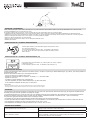 3
3
-
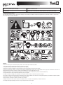 4
4
-
 5
5
-
 6
6
-
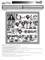 7
7
-
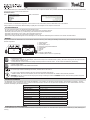 8
8
-
 9
9
-
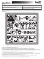 10
10
-
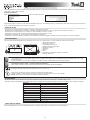 11
11
-
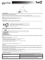 12
12
-
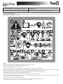 13
13
-
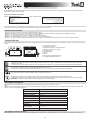 14
14
-
 15
15
-
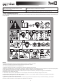 16
16
-
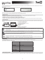 17
17
-
 18
18
-
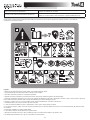 19
19
-
 20
20
-
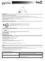 21
21
-
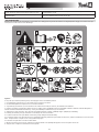 22
22
-
 23
23
-
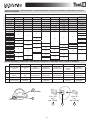 24
24
-
 25
25
-
 26
26


GYS LCD SPACEVIEW 5-9/9-13 de handleiding
- Categorie
- Lassysteem
- Type
- de handleiding
in andere talen
Gerelateerde papieren
-
GYS LCD SPACE 11 TRUE COLOR HELMET de handleiding
-
GYS HAND HELD MASK - LENSE N11 - 105x50 de handleiding
-
GYS LCD MASTER 11 TRUE COLOR de handleiding
-
Tool it FLIP-FLAP WELDING HELMET de handleiding
-
-
-
-
-
-
GYS LCD PANORAMIC 3XL HELMET de handleiding
Andere documenten
-
Parkside PSHL 2 B1 Operation And Safety Notes Translation Of The Original Instructions
-
Westfalia 992037 Handleiding
-
Beta 7042LCD Handleiding
-
Parkside PSHL 2 A2 Operation And Safety Notes Translation Of The Original Instructions
-
ESAB Eye Tech 5-13 Head protection Handleiding
-
Telwin TEL195 Handleiding
-
Güde GSH-K Handleiding