
PRODUCT OF
DO8141
Handleiding Ventilator
Mode d’emploi Ventilateur
Gebrauchsanleitung Ventilator
Instruction booklet Fan
Manual de instrucciones Ventilador
Návod k použití Stojanový ventilátor
Návod na použitie Stojanový ventilátor

Lees aandachtig alle instructies - bewaar deze handleiding voor latere raadpleging.
Lisez attentivement les instructions - gardez le mode d’emploi pour utilisation ultérieur.
Lesen Sie genau die Anweisungen - bewahren Sie die Gebrauchsanleitung für spätere
heranziehung.
Read all instructions carefully - save this instruction manual for future reference.
Lea detenidamente todas las instrucciones - Conserve este manual para futura referencia.
Před použitím si důkladně přečtěte tento manuál - manuál si uschovejte i pro případ
budoucího nahlédnutí.
Pred použitím si dôkladne prečítajte tento manuál - manuál si uschovajte aj pre prípad
budúceho nahliadnutie.
NL Nederlands 3
FR Français 11
DE Deutsch 19
EN English 27
ES Espagnol 35
CZ Čeština 43
SK Slovenčina 50

3
DO8141
www.domo-elektro.be
NL
GARANTIE
Geachte klant,
Al onze producten ondergaan steeds een strenge kwaliteitscontrole,
alvorens ze aan je worden aangeboden. Mocht je desondanks toch nog
problemen hebben met jouw toestel, dan betreuren wij dit ten zeerste.
In dat geval verzoeken wij je contact op te nemen met onze klantendienst.
Onze medewerkers zullen je met plezier verder helpen.
+32 14 21 71 91 [email protected]
Maandag – Donderdag : 8.30u – 12.00u en van 13.00u – 17.00u
Vrijdag : 8.30u – 12.00u en van 13.00u – 16.30u
Dit apparaat heeft een garantietermijn van 2 jaar vanaf de datum van aankoop. Gedurende
de garantieperiode zal de distributeur volledige verantwoording op zich nemen voor
gebreken die aanwijsbaar berusten op materiaal- of constructiefouten. Wanneer dergelijke
gebreken voorkomen, zal het apparaat, indien nodig, vervangen of gerepareerd worden. De
garantieperiode van 2 jaar zal op dit moment niet terug beginnen, maar loopt verder tot 2
jaar na de aankoop van het toestel. De garantie wordt verleend op basis van het kassaticket.
Indien je apparaat defect is binnen de garantietermijn van 2 jaar, dan mag je het toestel
samen met het originele kassaticket binnenbrengen in de winkel waar je het toestel hebt
aangekocht.
De garantie op accessoires en onderdelen die onderhevig zijn aan slijtage, bedraagt 6
maanden.
De garantie en verantwoordelijkheid/aansprakelijkheid van de leverancier en fabrikant
vervallen automatisch in de volgende gevallen:
· Bij het niet naleven van de instructies in deze handleiding.
· Bij verkeerde aansluiting, vb. te hoge elektrische spanning.
· Bij verkeerd, hardhandig of abnormaal gebruik.
· Bij onvoldoende of verkeerd onderhoud.
· Bij herstelling of wijziging van het toestel door de consument of niet gemachtigde derden.
· Bij gebruik van onderdelen of accessoires welke niet worden aanbevolen of geleverd door
de leverancier / fabrikant.

4
DO8141
NL
VEILIGHEIDSVOORSCHRIFTEN
Wanneer je elektrische toestellen gebruikt, moeten volgende veiligheidsinstructies in acht
genomen worden:
· Lees deze instructies zorgvuldig door. Bewaar deze handleiding om later te raadplegen.
· Dit toestel mag gebruikt worden door kinderen vanaf 16 jaar en ouder, en door personen
met een fysieke of sensoriële beperking of mensen met een beperkte mentale capaciteit
of gebrek aan ervaring of kennis, op voorwaarde dat deze personen toezicht krijgen of
instructies hebben gekregen over het gebruik van het toestel op een veilige manier en dat
ze ook de gevaren kennen bij het gebruik van het toestel.
· Kinderen mogen niet met het toestel spelen.
· Onderhoud en reiniging van het toestel mogen niet gebeuren door kinderen, tenzij ze
ouder zijn dan 16 jaar en toezicht krijgen. Hou het toestel en het snoer buiten het bereik
van kinderen jonger dan 16 jaar.
Dit toestel is geschikt om te gebruiken in de huishoudelijke omgeving en in gelijkaardige
omgevingen zoals:
· Keukenhoek voor personeel van winkels, kantoren en andere gelijkaardige professionele
omgevingen
· Boerderijen
· Hotel- en motelkamers en andere omgevingen met een residentieel karakter
· Gastenkamers, of gelijkaardige
· Opgelet: het toestel mag niet gebruikt worden met een externe timer of een aparte
afstandsbediening.
· Lees alle instructies voor gebruik.
· Kijk voor gebruik na of het voltage vermeld op het toestel overeenkomt met het voltage
van het elektriciteitsnet bij je thuis.
· Laat het snoer niet op een heet oppervlak of over de rand van een tafel of aanrecht
hangen.
· Gebruik het toestel nooit wanneer het snoer of de stekker beschadigd is, na een slechte
werking van het toestel of wanneer het toestel beschadigd is. Breng het toestel dan naar
het dichtsbijzijnde gekwaliceerde service center voor nazicht en reparatie.
· Streng toezicht is noodzakelijk wanneer het toestel door of in de buurt van kinderen
gebruikt wordt.
· Het gebruik van accessoires die niet aanbevolen of verkocht worden door de fabrikant, kan
brand, elektrische schokken of verwondingen veroorzaken.
· Trek de stekker uit het stopcontact wanneer het toestel niet in gebruik is, vooraleer
onderdelen te monteren of demonteren en vooraleer het toestel te reinigen. Zet eerst alle
knoppen in de ‘uit’-stand en trek de stekker bij de stekker zelf uit het stopcontact. Trek
nooit aan het snoer om de stekker uit het stopcontact te trekken.

5
DO8141
www.domo-elektro.be
NL
· Laat een werkend toestel niet zonder toezicht achter.
· Zet dit toestel nooit op of in de buurt van een gasvuur of elektrisch vuur of op een plaats
waar het in contact zou kunnen komen met een warm toestel.
· Gebruik het toestel niet buiten.
· Gebruik het toestel enkel voor het doel waarvoor het bestemd is.
· Gebruik het toestel altijd op een stevig, droog, een oppervlak.
· Gebruik het toestel alleen voor huishoudelijk gebruik. De fabrikant is niet verantwoordelijk
voor ongelukken die een gevolg zijn van verkeerd gebruik van het toestel, of het niet
naleven van de regels zoals ze vermeld zijn in deze handleiding.
· Alle herstellingen, buiten het gewone onderhoud van het toestel, moeten uitgevoerd
worden door de fabrikant of zijn dienst na verkoop.
· Dompel het toestel, het elektrisch snoer of de stekker nooit onder in water of een andere
vloeistof.
· Zorg ervoor dat kinderen het elektrisch snoer of het toestel niet kunnen aanraken.
· Hou het snoer uit de buurt van scherpe randen en hete onderdelen of andere
warmtebronnen.
· Verwijder voor het eerste gebruik alle verpakkingsmaterialen en eventuele promotionele
stickers.
· Gebruik deze ventilator niet op natte of vochtige plaatsen. Plaats het toestel niet dicht bij
een badkuip of ander waterreservoir.
ONDERDELEN
1. Grill
2. Controlepaneel
3. Uitschuiare buis
4. Blokkeringsring
5. Voetbevestiging met 4 poten
6. Handvat
7. Ventilatorbladen
8. Oscillatieknop
9. Afstandsbediening
Blade
Screw the lock nut of grill clockwise,
and in the meantime, fix the rear grill.
Pull the blade to rotate after installing,
so as to ensure that the blade can be
normally rotated.
Body key
Buckle
Screw
1. Align Screw Holes on the outer ring
of both the Front and Rear Guards,
with the Positioning Clip aligned as
illustrated.
2. Press down all the Buckles to fasten the
Front Guard with the Rear Guard. At the
Screw Holes, tighten the separated screw
and nut.
Front and Rear Guard Installation
Turn counterclockwise and loosen for
performing height adjustment.
Height Adjustment
Tilt Adjustment
Horizontal Swing
Speed display Timer display
Considerate Hint:
Effective Range of Remote Control: within 5 m distance and
30-degree deflection in front of Product.
Battery
“ON/OFF” key
“TIMER”key
“SPEED” key
Considerate Hint:
Remove ①②parts from the
component before performing
installation.
Support Installation
Align the Column Pipe
connection plate with
holes on the support and
tighten screws.
1
Blade
Screw the lock nut of grill clockwise,
and in the meantime, fix the rear grill.
Pull the blade to rotate after installing,
so as to ensure that the blade can be
normally rotated.
Body key
Buckle
Screw
1. Align Screw Holes on the outer ring
of both the Front and Rear Guards,
with the Positioning Clip aligned as
illustrated.
2. Press down all the Buckles to fasten the
Front Guard with the Rear Guard. At the
Screw Holes, tighten the separated screw
and nut.
Front and Rear Guard Installation
Turn counterclockwise and loosen for
performing height adjustment.
Height Adjustment
Tilt Adjustment
Horizontal Swing
Speed display Timer display
Considerate Hint:
Effective Range of Remote Control: within 5 m distance and
30-degree deflection in front of Product.
Battery
“ON/OFF” key
“TIMER”key
“SPEED” key
Considerate Hint:
Remove ①②parts from the
component before performing
installation.
Support Installation
Align the Column Pipe
connection plate with
holes on the support and
tighten screws.
2
3
4
5
6
7
8
9
Blade
Screw the lock nut of grill clockwise,
and in the meantime, fix the rear grill.
Pull the blade to rotate after installing,
so as to ensure that the blade can be
normally rotated.
Body key
Buckle
Screw
1. Align Screw Holes on the outer ring
of both the Front and Rear Guards,
with the Positioning Clip aligned as
illustrated.
2. Press down all the Buckles to fasten the
Front Guard with the Rear Guard. At the
Screw Holes, tighten the separated screw
and nut.
Front and Rear Guard Installation
Turn counterclockwise and loosen for
performing height adjustment.
Height Adjustment
Tilt Adjustment
Horizontal Swing
Speed display Timer display
Considerate Hint:
Effective Range of Remote Control: within 5 m distance and
30-degree deflection in front of Product.
Battery
“ON/OFF” key
“TIMER”key
“SPEED” key
Considerate Hint:
Remove ①②parts from the
component before performing
installation.
Support Installation
Align the Column Pipe
connection plate with
holes on the support and
tighten screws.

6
DO8141
NL
MONTAGE
BEVESTIGING VAN DE VOET EN MOTORGEDEELTE
Plaats de vier poten van de voet in de voetbevestiging. Zorg ervoor dat de poten goed op hun
plaats zitten.
Bevestig de voetbevestiging aan de uitschuiare buis en maak deze vast aan de buis met de
sluitingsring en de vlinderschroef.
Motor
Motor shaft
Install by
aligning
Rear grill
Lock nut of grill
Lock nut of blade
Blade
Screw the lock nut of grill clockwise,
and in the meantime, fix the rear grill.
Lock nut of blade
anticlockwise,
and then install the
front fan cover.
Pull the blade to rotate after installing,
so as to ensure that the blade can be
normally rotated.
Front grill
①①
Body key
0
1
2
3
Buckle
Screw
1. Align Screw Holes on the outer ring
of both the Front and Rear Guards,
with the Positioning Clip aligned as
illustrated.
2. Press down all the Buckles to fasten the
Front Guard with the Rear Guard. At the
Screw Holes, tighten the separated screw
and nut.
Front and Rear Guard Installation
Support Installation
Align the Column Pipe with
holes on the support and
tighten screws.
Considerate Hint:
Remove ①②parts from the
component before performing
installation.
Turn counterclockwise and loosen for
performing height adjustment.
Height Adjustment
Height Adjustment Key
Tilt Adjustment
Manual
Swing Pull-knob
Push-down to swing
Pull-up for static
Horizontal Swing
Maak de blokkeringsring los en schuif het bovenste gedeelte van de buis volledig uit en
blokkeer de buis op deze hoogte door de blokkeringsring opnieuw aan te draaien. Zorg ervoor
dat de blokkeringsring goed is aangedraaid voor je het motorgedeelte monteert. Maak de
grote schroef achteraan het controlepaneel los (a). Plaats daarna het motorgedeelte op de
uitschuiare buis. Maak de grote schroef terug vast, zorg ervoor dat de schroef in lijn staat
met de uitsparing in de uitschuiare buis. De grote schroef moet volledige vast gedraaid zijn
alvorens de ventilator te gebruiken.
Blade
Screw the lock nut of grill clockwise,
and in the meantime, fix the rear grill.
Pull the blade to rotate after installing,
so as to ensure that the blade can be
normally rotated.
Body key
Buckle
Screw
1. Align Screw Holes on the outer ring
of both the Front and Rear Guards,
with the Positioning Clip aligned as
illustrated.
2. Press down all the Buckles to fasten the
Front Guard with the Rear Guard. At the
Screw Holes, tighten the separated screw
and nut.
Front and Rear Guard Installation
Turn counterclockwise and loosen for
performing height adjustment.
Height Adjustment
Tilt Adjustment
Horizontal Swing
Speed display Timer display
Considerate Hint:
Effective Range of Remote Control: within 5 m distance and
30-degree deflection in front of Product.
Battery
“ON/OFF” key
“TIMER”key
“SPEED” key
Considerate Hint:
Remove ①②parts from the
component before performing
installation.
Support Installation
Align the Column Pipe
connection plate with
holes on the support and
tighten screws.
a

7
DO8141
www.domo-elektro.be
NL
BEVESTIGING GRILL EN VENTILATORBLADEN
Plaats de achterkant van de grill op de motoraandrijving. Zet deze vast met de open plastic
schroef. Plaats de ventilatorbladen om de motoraandrijving. Zorg ervoor dat de pin op de
motoraandrijving perfect past achteraan in de ventilatorbladen. Zet de ventilatorbladen vast
op de motoraandrijving met de gesloten plastic schroef.
Blade
Screw the lock nut of grill clockwise,
and in the meantime, fix the rear grill.
Pull the blade to rotate after installing,
so as to ensure that the blade can be
normally rotated.
Body key
Buckle
Screw
1. Align Screw Holes on the outer ring
of both the Front and Rear Guards,
with the Positioning Clip aligned as
illustrated.
2. Press down all the Buckles to fasten the
Front Guard with the Rear Guard. At the
Screw Holes, tighten the separated screw
and nut.
Front and Rear Guard Installation
Turn counterclockwise and loosen for
performing height adjustment.
Height Adjustment
Tilt Adjustment
Horizontal Swing
Speed display Timer display
Considerate Hint:
Effective Range of Remote Control: within 5 m distance and
30-degree deflection in front of Product.
Battery
“ON/OFF” key
“TIMER”key
“SPEED” key
Considerate Hint:
Remove ①②parts from the
component before performing
installation.
Support Installation
Align the Column Pipe
connection plate with
holes on the support and
tighten screws.
Plaats de grill vooraan op de grill achteraan en bevestig ze aan elkaar met behulp van de
bevestigingsclip.
Blade
Screw the lock nut of grill clockwise,
and in the meantime, fix the rear grill.
Pull the blade to rotate after installing,
so as to ensure that the blade can be
normally rotated.
Body key
Buckle
Screw
1. Align Screw Holes on the outer ring
of both the Front and Rear Guards,
with the Positioning Clip aligned as
illustrated.
2. Press down all the Buckles to fasten the
Front Guard with the Rear Guard. At the
Screw Holes, tighten the separated screw
and nut.
Front and Rear Guard Installation
Turn counterclockwise and loosen for
performing height adjustment.
Height Adjustment
Tilt Adjustment
Horizontal Swing
Speed display Timer display
Considerate Hint:
Effective Range of Remote Control: within 5 m distance and
30-degree deflection in front of Product.
Battery
“ON/OFF” key
“TIMER”key
“SPEED” key
Considerate Hint:
Remove ①②parts from the
component before performing
installation.
Support Installation
Align the Column Pipe
connection plate with
holes on the support and
tighten screws.
GEBRUIK
Steek de stekker in het stopcontact. Zet de ventilator aan met de knop: ON/OFF
Motor
Motor shaft
Rear grill
Lock nut of grill
Lock nut of blade
Blade
Screw the lock nut of grill clockwise,
and in the meantime, fix the rear grill.
Lock nut of blade
anticlockwise,
and then install the
front fan cover.
Pull the blade to rotate after installing,
so as to ensure that the blade can be
normally rotated.
Front grill
①
Tighten
knob
①
Body key
Buckle
Screw
1. Align Screw Holes on the outer ring
of both the Front and Rear Guards,
with the Positioning Clip aligned as
illustrated.
2. Press down all the Buckles to fasten the
Front Guard with the Rear Guard. At the
Screw Holes, tighten the separated screw
and nut.
Front and Rear Guard Installation
Turn counterclockwise and loosen for
performing height adjustment.
Height Adjustment
Height Adjustment Key
Tilt Adjustment
Manual
Swing Pull-knob
Push-down to swing
Pull-up for static
Horizontal Swing
Speed display Timer display
ON/OFF
Install by
aligning
Considerate Hint:
Effective Range of Remote Control: within 5 m distance and
30-degree deflection in front of Product.
Battery
“ON/OFF” key
“TIMER”key
“SPEED” key
Pole
Supporting
Considerate Hint:
Remove ①②parts from the
component before performing
installation.
Screw
②
Support Installation
Align the Column Pipe
connection plate with
holes on the support and
tighten screws.
CONTROLEPANEEL
1. Snelheidsregeling
2. Timer
3. Aan-uitknop
4. Indicatielampjes snelheid
5. Indicatielampjes timer
Motor
Motor shaft
Rear grill
Lock nut of grill
Lock nut of blade
Blade
Screw the lock nut of grill clockwise,
and in the meantime, fix the rear grill.
Lock nut of blade
anticlockwise,
and then install the
front fan cover.
Pull the blade to rotate after installing,
so as to ensure that the blade can be
normally rotated.
Front grill
①
Tighten
knob
①
Body key
Buckle
Screw
1. Align Screw Holes on the outer ring
of both the Front and Rear Guards,
with the Positioning Clip aligned as
illustrated.
2. Press down all the Buckles to fasten the
Front Guard with the Rear Guard. At the
Screw Holes, tighten the separated screw
and nut.
Front and Rear Guard Installation
Turn counterclockwise and loosen for
performing height adjustment.
Height Adjustment
Height Adjustment Key
Tilt Adjustment
Manual
Swing Pull-knob
Push-down to swing
Pull-up for static
Horizontal Swing
Speed display Timer display
SPEED
TIMER
ON/OFF
Install by
aligning
Considerate Hint:
Effective Range of Remote Control: within 5 m distance and
30-degree deflection in front of Product.
Battery
“ON/OFF” key
“TIMER”key
“SPEED” key
Pole
Supporting
Considerate Hint:
Remove ①②parts from the
component before performing
installation.
Screw
②
Support Installation
Align the Column Pipe
connection plate with
holes on the support and
tighten screws.
1
2
3
Blade
Screw the lock nut of grill clockwise,
and in the meantime, fix the rear grill.
Pull the blade to rotate after installing,
so as to ensure that the blade can be
normally rotated.
Body key
Buckle
Screw
1. Align Screw Holes on the outer ring
of both the Front and Rear Guards,
with the Positioning Clip aligned as
illustrated.
2. Press down all the Buckles to fasten the
Front Guard with the Rear Guard. At the
Screw Holes, tighten the separated screw
and nut.
Front and Rear Guard Installation
Turn counterclockwise and loosen for
performing height adjustment.
Height Adjustment
Tilt Adjustment
Horizontal Swing
Speed display Timer display
4h
2h
1h
Considerate Hint:
Effective Range of Remote Control: within 5 m distance and
30-degree deflection in front of Product.
Battery
“ON/OFF” key
“TIMER”key
“SPEED” key
Considerate Hint:
Remove ①②parts from the
component before performing
installation.
Support Installation
Align the Column Pipe
connection plate with
holes on the support and
tighten screws.
5
4

8
DO8141
NL
AFSTANDSBEDIENING
1. Speed: snelheidsregeling
2. ON/OFF: aan-uitknop
3. Timer
SPEED
Motor
Motor shaft
Rear grill
Lock nut of grill
Lock nut of blade
Blade
Screw the lock nut of grill clockwise,
and in the meantime, fix the rear grill.
Lock nut of blade
anticlockwise,
and then install the
front fan cover.
Pull the blade to rotate after installing,
so as to ensure that the blade can be
normally rotated.
Front grill
①
Tighten
knob
①
Body key
Buckle
Screw
1. Align Screw Holes on the outer ring
of both the Front and Rear Guards,
with the Positioning Clip aligned as
illustrated.
2. Press down all the Buckles to fasten the
Front Guard with the Rear Guard. At the
Screw Holes, tighten the separated screw
and nut.
Front and Rear Guard Installation
Turn counterclockwise and loosen for
performing height adjustment.
Height Adjustment
Height Adjustment Key
Tilt Adjustment
Manual
Swing Pull-knob
Push-down to swing
Pull-up for static
Horizontal Swing
Speed display Timer display
SPEED
Install by
aligning
Considerate Hint:
Effective Range of Remote Control: within 5 m distance and
30-degree deflection in front of Product.
Battery
“ON/OFF” key
“TIMER”key
“SPEED” key
Pole
Supporting
Considerate Hint:
Remove ①②parts from the
component before performing
installation.
Screw
②
Support Installation
Align the Column Pipe
connection plate with
holes on the support and
tighten screws.
Regel de snelheid met de knop SPEED. Op het controlepaneel gaat een lampje branden bij de
gekozen snelheid:
Blade
Screw the lock nut of grill clockwise,
and in the meantime, fix the rear grill.
Pull the blade to rotate after installing,
so as to ensure that the blade can be
normally rotated.
Body key
Buckle
Screw
1. Align Screw Holes on the outer ring
of both the Front and Rear Guards,
with the Positioning Clip aligned as
illustrated.
2. Press down all the Buckles to fasten the
Front Guard with the Rear Guard. At the
Screw Holes, tighten the separated screw
and nut.
Front and Rear Guard Installation
Turn counterclockwise and loosen for
performing height adjustment.
Height Adjustment
Tilt Adjustment
Horizontal Swing
Speed display Timer display
Considerate Hint:
Effective Range of Remote Control: within 5 m distance and
30-degree deflection in front of Product.
Battery
“ON/OFF” key
“TIMER”key
“SPEED” key
Considerate Hint:
Remove ①②parts from the
component before performing
installation.
Support Installation
Align the Column Pipe
connection plate with
holes on the support and
tighten screws.
: lage snelheid
Blade
Screw the lock nut of grill clockwise,
and in the meantime, fix the rear grill.
Pull the blade to rotate after installing,
so as to ensure that the blade can be
normally rotated.
Body key
Buckle
Screw
1. Align Screw Holes on the outer ring
of both the Front and Rear Guards,
with the Positioning Clip aligned as
illustrated.
2. Press down all the Buckles to fasten the
Front Guard with the Rear Guard. At the
Screw Holes, tighten the separated screw
and nut.
Front and Rear Guard Installation
Turn counterclockwise and loosen for
performing height adjustment.
Height Adjustment
Tilt Adjustment
Horizontal Swing
Speed display Timer display
Considerate Hint:
Effective Range of Remote Control: within 5 m distance and
30-degree deflection in front of Product.
Battery
“ON/OFF” key
“TIMER”key
“SPEED” key
Considerate Hint:
Remove ①②parts from the
component before performing
installation.
Support Installation
Align the Column Pipe
connection plate with
holes on the support and
tighten screws.
: gemiddelde snelheid
Blade
Screw the lock nut of grill clockwise,
and in the meantime, fix the rear grill.
Pull the blade to rotate after installing,
so as to ensure that the blade can be
normally rotated.
Body key
Buckle
Screw
1. Align Screw Holes on the outer ring
of both the Front and Rear Guards,
with the Positioning Clip aligned as
illustrated.
2. Press down all the Buckles to fasten the
Front Guard with the Rear Guard. At the
Screw Holes, tighten the separated screw
and nut.
Front and Rear Guard Installation
Turn counterclockwise and loosen for
performing height adjustment.
Height Adjustment
Tilt Adjustment
Horizontal Swing
Speed display Timer display
Considerate Hint:
Effective Range of Remote Control: within 5 m distance and
30-degree deflection in front of Product.
Battery
“ON/OFF” key
“TIMER”key
“SPEED” key
Considerate Hint:
Remove ①②parts from the
component before performing
installation.
Support Installation
Align the Column Pipe
connection plate with
holes on the support and
tighten screws.
: hoge snelheid
TIMER
Motor
Motor shaft
Rear grill
Lock nut of grill
Lock nut of blade
Blade
Screw the lock nut of grill clockwise,
and in the meantime, fix the rear grill.
Lock nut of blade
anticlockwise,
and then install the
front fan cover.
Pull the blade to rotate after installing,
so as to ensure that the blade can be
normally rotated.
Front grill
①
Tighten
knob
①
Body key
Buckle
Screw
1. Align Screw Holes on the outer ring
of both the Front and Rear Guards,
with the Positioning Clip aligned as
illustrated.
2. Press down all the Buckles to fasten the
Front Guard with the Rear Guard. At the
Screw Holes, tighten the separated screw
and nut.
Front and Rear Guard Installation
Turn counterclockwise and loosen for
performing height adjustment.
Height Adjustment
Height Adjustment Key
Tilt Adjustment
Manual
Swing Pull-knob
Push-down to swing
Pull-up for static
Horizontal Swing
Speed display Timer display
TIMER
Install by
aligning
Considerate Hint:
Effective Range of Remote Control: within 5 m distance and
30-degree deflection in front of Product.
Battery
“ON/OFF” key
“TIMER”key
“SPEED” key
Pole
Supporting
Considerate Hint:
Remove ①②parts from the
component before performing
installation.
Screw
②
Support Installation
Align the Column Pipe
connection plate with
holes on the support and
tighten screws.
Je kan een timer instellen van 1 uur tot 7 uur met de TIMER-knop. De ingestelde tijd kan je
aezen op het controlepaneel. Het is de som van de tijden, waarvan het indicatielampje
oplicht. Dus:
Blade
Screw the lock nut of grill clockwise,
and in the meantime, fix the rear grill.
Pull the blade to rotate after installing,
so as to ensure that the blade can be
normally rotated.
Body key
Buckle
Screw
1. Align Screw Holes on the outer ring
of both the Front and Rear Guards,
with the Positioning Clip aligned as
illustrated.
2. Press down all the Buckles to fasten the
Front Guard with the Rear Guard. At the
Screw Holes, tighten the separated screw
and nut.
Front and Rear Guard Installation
Turn counterclockwise and loosen for
performing height adjustment.
Height Adjustment
Tilt Adjustment
Horizontal Swing
Speed display Timer display
1h
Considerate Hint:
Effective Range of Remote Control: within 5 m distance and
30-degree deflection in front of Product.
Battery
“ON/OFF” key
“TIMER”key
“SPEED” key
Considerate Hint:
Remove ①②parts from the
component before performing
installation.
Support Installation
Align the Column Pipe
connection plate with
holes on the support and
tighten screws.
••••
Blade
Screw the lock nut of grill clockwise,
and in the meantime, fix the rear grill.
Pull the blade to rotate after installing,
so as to ensure that the blade can be
normally rotated.
Body key
Buckle
Screw
1. Align Screw Holes on the outer ring
of both the Front and Rear Guards,
with the Positioning Clip aligned as
illustrated.
2. Press down all the Buckles to fasten the
Front Guard with the Rear Guard. At the
Screw Holes, tighten the separated screw
and nut.
Front and Rear Guard Installation
Turn counterclockwise and loosen for
performing height adjustment.
Height Adjustment
Tilt Adjustment
Horizontal Swing
Speed display Timer display
2h
Considerate Hint:
Effective Range of Remote Control: within 5 m distance and
30-degree deflection in front of Product.
Battery
“ON/OFF” key
“TIMER”key
“SPEED” key
Considerate Hint:
Remove ①②parts from the
component before performing
installation.
Support Installation
Align the Column Pipe
connection plate with
holes on the support and
tighten screws.
• • • •
Blade
Screw the lock nut of grill clockwise,
and in the meantime, fix the rear grill.
Pull the blade to rotate after installing,
so as to ensure that the blade can be
normally rotated.
Body key
Buckle
Screw
1. Align Screw Holes on the outer ring
of both the Front and Rear Guards,
with the Positioning Clip aligned as
illustrated.
2. Press down all the Buckles to fasten the
Front Guard with the Rear Guard. At the
Screw Holes, tighten the separated screw
and nut.
Front and Rear Guard Installation
Turn counterclockwise and loosen for
performing height adjustment.
Height Adjustment
Tilt Adjustment
Horizontal Swing
Speed display Timer display
4h
Considerate Hint:
Effective Range of Remote Control: within 5 m distance and
30-degree deflection in front of Product.
Battery
“ON/OFF” key
“TIMER”key
“SPEED” key
Considerate Hint:
Remove ①②parts from the
component before performing
installation.
Support Installation
Align the Column Pipe
connection plate with
holes on the support and
tighten screws.
••••
duur 1 2 3 4 5 6 7
De ventilator zal automatisch uitschakelen wanneer de ingestelde tijd verstreken is.
OSCILLATIE
Om de oscillatie aan te zetten, druk je de oscillatieknop in. Om de oscillatie terug uit te zetten,
trek je de knop omhoog. Bij oscillatie zal het toestel afwisselend naar links en rechts draaien
om de lucht beter te verspreiden.
Blade
Screw the lock nut of grill clockwise,
and in the meantime, fix the rear grill.
Pull the blade to rotate after installing,
so as to ensure that the blade can be
normally rotated.
Body key
Buckle
Screw
1. Align Screw Holes on the outer ring
of both the Front and Rear Guards,
with the Positioning Clip aligned as
illustrated.
2. Press down all the Buckles to fasten the
Front Guard with the Rear Guard. At the
Screw Holes, tighten the separated screw
and nut.
Front and Rear Guard Installation
Turn counterclockwise and loosen for
performing height adjustment.
Height Adjustment
Tilt Adjustment
Horizontal Swing
Speed display Timer display
Considerate Hint:
Effective Range of Remote Control: within 5 m distance and
30-degree deflection in front of Product.
Battery
“ON/OFF” key
“TIMER”key
“SPEED” key
Considerate Hint:
Remove ①②parts from the
component before performing
installation.
Support Installation
Align the Column Pipe
connection plate with
holes on the support and
tighten screws.
1 2
3

9
DO8141
www.domo-elektro.be
NL
VENTILATIERICHTING
Om de ventilatierichting naar boven of onder aan te passen druk of trek zacht aan de grill om
zo de richting naar boven of onder aan te passen.
Blade
Screw the lock nut of grill clockwise,
and in the meantime, fix the rear grill.
Pull the blade to rotate after installing,
so as to ensure that the blade can be
normally rotated.
Body key
Buckle
Screw
1. Align Screw Holes on the outer ring
of both the Front and Rear Guards,
with the Positioning Clip aligned as
illustrated.
2. Press down all the Buckles to fasten the
Front Guard with the Rear Guard. At the
Screw Holes, tighten the separated screw
and nut.
Front and Rear Guard Installation
Turn counterclockwise and loosen for
performing height adjustment.
Height Adjustment
Tilt Adjustment
Horizontal Swing
Speed display Timer display
Considerate Hint:
Effective Range of Remote Control: within 5 m distance and
30-degree deflection in front of Product.
Battery
“ON/OFF” key
“TIMER”key
“SPEED” key
Considerate Hint:
Remove ①②parts from the
component before performing
installation.
Support Installation
Align the Column Pipe
connection plate with
holes on the support and
tighten screws.
HOOGTE INSTELLEN
De hoogte van de ventilator kan je aanpassen door de blokkeringsring los te draaien en zo de
uitschuiare buis langer of korter te maken. Maak daarna de blokkeringsring opnieuw stevig
vast alvorens de ventilator in werking te stellen.
Blade
Screw the lock nut of grill clockwise,
and in the meantime, fix the rear grill.
Pull the blade to rotate after installing,
so as to ensure that the blade can be
normally rotated.
Body key
Buckle
Screw
1. Align Screw Holes on the outer ring
of both the Front and Rear Guards,
with the Positioning Clip aligned as
illustrated.
2. Press down all the Buckles to fasten the
Front Guard with the Rear Guard. At the
Screw Holes, tighten the separated screw
and nut.
Front and Rear Guard Installation
Turn counterclockwise and loosen for
performing height adjustment.
Height Adjustment
Tilt Adjustment
Horizontal Swing
Speed display Timer display
Considerate Hint:
Effective Range of Remote Control: within 5 m distance and
30-degree deflection in front of Product.
Battery
“ON/OFF” key
“TIMER”key
“SPEED” key
Considerate Hint:
Remove ①②parts from the
component before performing
installation.
Support Installation
Align the Column Pipe
connection plate with
holes on the support and
tighten screws.
REINIGING EN ONDERHOUD
· Dit toestel heeft weinig onderhoud nodig. Probeer nooit om de ventilator zelf te herstellen,
maar laat hem bij een defect nakijken en/of repareren door een gekwaliceerd persoon.
· Alvorens de ventilator te monteren of te reinigen moet de stekker uit het stopcontact zijn
verwijderd.
· Hou de achterkant van het motorgedeelte vrij van stof en andere materialen om een vrije
circulatie van lucht rond de motor mogelijk te maken. Demonteer de ventilator niet om
stof uit het motorgedeelte te verwijderen.
· Je kan de buitenkant van het toestel schoonmaken met een zachte vochtige doek en een
milde detergent. Droog het toestel daarna zorgvuldig af.
· Gebruik geen schurende of agressieve middelen om het toestel te reinigen.
· Zorg er voor dat er geen water in het motorgedeelte van het toestel terechtkomt.

10
DO8141
NL
MILIEURICHTLIJNEN
Dit symbool op het product of op de verpakking wijst erop dat
dit product niet als huishoudafval mag worden behandeld.
Het moet naar een plaats worden gebracht waar elektrische
en elektronische apparatuur wordt gerecycleerd. Als je ervoor
zorgt dat dit product op de correcte manier wordt verwijderd,
voorkom je mogelijk voor mens en milieu negatieve gevolgen
die zich zouden kunnen voordoen in geval van verkeerde
afvalbehandeling. Voor meer details in verband met het
recycleren van dit product, neem je best contact op met de
gemeentelijke instanties, het bedrijf of de dienst belast met
de verwijdering van huishoudafval of de winkel waar je het
product hebt gekocht.
Het verpakkingsmateriaal is recycleerbaar. Behandel de
verpakking milieubewust.

11
DO8141
www.domo-elektro.be
FR
GARANTIE
Cher client,
Tous nos produits sont soumis à des contrôles qualité stricts avant
d’être proposés à la vente. Si vous deviez toutefois rencontrer
un problème avec votre appareil, nous le déplorons vivement.
Dans ce cas, nous vous invitons à prendre contact avec notre service à la clientèle.
Nos collaboratrices se feront un plaisir de vous aider !
+32 14 21 71 91 [email protected]
Du lundi au jeudi : 8 h 30 – 12 h et 13 h – 17 h
Vendredi : 8 h 30 – 12 h et 13 h – 16 h 30
Cet appareil est garanti 2 ans à compter de la date d’achat. Durant la période de garantie, le
distributeur assumera l’entière responsabilité en cas de défauts de fonctionnement (matériel)
ou de fabrication. Si un tel problème survient, l’appareil sera remplacé ou réparé. La période
de garantie de 2 ans ne reprend pas à zéro, mais se poursuit (jusqu’à 2 ans à compter de la
date d’achat de l’appareil). La garantie est accordée sur la base du ticket de caisse.
Pour les accessoires et les éléments d’usure, une garantie de 6 mois s’applique.
La garantie et la responsabilité du fournisseur et du fabricant n’ont plus eet dans les cas
suivants :
· Les instructions du manuel n’ont pas été suivies.
· Mauvais raccordement, par ex. tension électrique trop forte.
· Utilisation contraire, brutale ou anormale.
· Entretien insusant ou non conforme.
· Réparation ou modication de l’appareil par le consommateur ou un tiers non autorisé.
· Utilisation d’éléments ou d’accessoires qui ne sont pas recommandés ou fournis par le
fournisseur/fabricant.

12
DO8141
FR
CONSIGNES DE SÉCURITÉ
Les consignes de sécurité suivantes doivent être respectées lors de l’utilisation de tout
appareil électrique:
· Lisez ces consignes très attentivement. Conservez ce mode d’emploi an de pouvoir le
consulter ultérieurement.
· Cet appareil peut être utilisé par des enfants âgés d’au moins 16 ans et par des personnes
ayant des capacités physiques, sensorielles ou mentales réduites ou dénuées d’expérience
ou de connaissance, s’ils (si elles) sont correctement surveillé(e)s ou si des instructions
relatives à l’utilisation de l’appareil en toute sécurité leur ont été données et si les risques
encourus ont été appréhendés.
· Veillez à ce que les enfants ne puissent pas jouer avec l’appareil. L’entretien et le nettoyage
de l’appareil ne peuvent pas s’eectuer par des enfants, à moins qu’ils aient plus de 16 ans
et qu’ils soient sous surveillance. Gardez l’appareil et le cordon hors de la portée d’enfants
de moins de 16 ans.
Cet appareil est destiné à un usage domestique ou à d’autres usages comme:
· Dans la cuisine du personnel dans des magasins, des bureaux ou d’autres lieux mis en
rapport avec l’environnement de travail.
· Dans les fermes.
· Dans les chambres d’hôtels, de motels et d’autres lieux avec un caractère résidentiel.
· Dans les chambres d’hôtes ou similaires.
· Attention: l’appareil ne peut pas être utilisé avec une minuterie externe ou une commande
à distance séparée.
· Veuillez lire toutes les instructions avant d’utiliser l’appareil.
· Vériez avant usage si la tension indiquée sur l’appareil correspond à la tension du réseau
électrique de votre domicile.
· Ne laissez pas le cordon pendre sur une surface chaude ou sur le rebord d’une table.
· N’utilisez jamais l’appareil lorsque le cordon ou la che sont endommagés, après un
mauvais fonctionnement de l’appareil ou lorsque l’appareil est endommagé. Amenez alors
l’appareil au centre de services le plus proche pour contrôle et réparation.
· Soyez très attentif lorsque l’appareil est utilisé par des enfants ou à proximité d’enfants.
· L’utilisation d’accessoires non préconisés par le fabricant peut provoquer un incendie, une
électrocution ou des blessures.
· Retirez la che de la prise lorsque l’appareil n’est pas utilisé, avant d’installer ou d’enlever
des pièces et avant de nettoyer l’appareil. Mettez tous les boutons en position « arrêt » et
retirez la che de la prise. Ne tirez jamais sur le câble pour retirer la che de la prise.
· Ne laissez jamais un appareil en service sans surveillance.
· Ne placez jamais cet appareil sur ou à proximité d’un feu au gaz ou d’un feu électrique où il
pourrait entrer en contact avec un appareil chaud.

13
DO8141
www.domo-elektro.be
FR
· N’utilisez pas l’appareil à l’extérieur.
· Utilisez l’appareil uniquement dans le but auquel il est destiné.
· Utilisez toujours l’appareil sur une surface solide, sèche et plane.
· Cet appareil ne convient qu’à un usage domestique. Le fabricant décline toute
responsabilité pour des accidents qui découleraient d’un mauvais usage de l’appareil ou du
non-respect des instructions fournies dans ce manuel.
· Toutes les réparations, en dehors de l’entretien ordinaire de l’appareil, doivent être
réalisées par le fabricant ou son service après-vente.
· N’immergez jamais le cordon électrique, la che ou l’appareil lui-même dans l’eau ou tout
autre milieu liquide.
· Veillez à ce que les enfants ne puissent pas toucher à l’appareil ou au cordon électrique.
· Tenez le cordon éloigné de rebords tranchants et de pièces brûlantes ou d’autres sources
de chaleur.
· Avant la première utilisation, enlevez tous les éléments d’emballage et les éventuels
autocollants promotionnels.
· N’utilisez pas ce ventilateur dans des endroits mouillés ou humides. Ne placez pas
l’appareil à proximité d’une baignoire ou d’un autre réservoir d’eau.
PARTIES
1. Grille
2. Panneau de contrôle
3. Tube extensible
4. Bague de blocage
5. Base à 4 pieds
6. Poignée
7. Pales du ventilateur
8. Bouton d’oscillation
9. Télécommande
Blade
Screw the lock nut of grill clockwise,
and in the meantime, fix the rear grill.
Pull the blade to rotate after installing,
so as to ensure that the blade can be
normally rotated.
Body key
Buckle
Screw
1. Align Screw Holes on the outer ring
of both the Front and Rear Guards,
with the Positioning Clip aligned as
illustrated.
2. Press down all the Buckles to fasten the
Front Guard with the Rear Guard. At the
Screw Holes, tighten the separated screw
and nut.
Front and Rear Guard Installation
Turn counterclockwise and loosen for
performing height adjustment.
Height Adjustment
Tilt Adjustment
Horizontal Swing
Speed display Timer display
Considerate Hint:
Effective Range of Remote Control: within 5 m distance and
30-degree deflection in front of Product.
Battery
“ON/OFF” key
“TIMER”key
“SPEED” key
Considerate Hint:
Remove ①②parts from the
component before performing
installation.
Support Installation
Align the Column Pipe
connection plate with
holes on the support and
tighten screws.
1
Blade
Screw the lock nut of grill clockwise,
and in the meantime, fix the rear grill.
Pull the blade to rotate after installing,
so as to ensure that the blade can be
normally rotated.
Body key
Buckle
Screw
1. Align Screw Holes on the outer ring
of both the Front and Rear Guards,
with the Positioning Clip aligned as
illustrated.
2. Press down all the Buckles to fasten the
Front Guard with the Rear Guard. At the
Screw Holes, tighten the separated screw
and nut.
Front and Rear Guard Installation
Turn counterclockwise and loosen for
performing height adjustment.
Height Adjustment
Tilt Adjustment
Horizontal Swing
Speed display Timer display
Considerate Hint:
Effective Range of Remote Control: within 5 m distance and
30-degree deflection in front of Product.
Battery
“ON/OFF” key
“TIMER”key
“SPEED” key
Considerate Hint:
Remove ①②parts from the
component before performing
installation.
Support Installation
Align the Column Pipe
connection plate with
holes on the support and
tighten screws.
2
3
4
5
6
7
8
9
Blade
Screw the lock nut of grill clockwise,
and in the meantime, fix the rear grill.
Pull the blade to rotate after installing,
so as to ensure that the blade can be
normally rotated.
Body key
Buckle
Screw
1. Align Screw Holes on the outer ring
of both the Front and Rear Guards,
with the Positioning Clip aligned as
illustrated.
2. Press down all the Buckles to fasten the
Front Guard with the Rear Guard. At the
Screw Holes, tighten the separated screw
and nut.
Front and Rear Guard Installation
Turn counterclockwise and loosen for
performing height adjustment.
Height Adjustment
Tilt Adjustment
Horizontal Swing
Speed display Timer display
Considerate Hint:
Effective Range of Remote Control: within 5 m distance and
30-degree deflection in front of Product.
Battery
“ON/OFF” key
“TIMER”key
“SPEED” key
Considerate Hint:
Remove ①②parts from the
component before performing
installation.
Support Installation
Align the Column Pipe
connection plate with
holes on the support and
tighten screws.

14
DO8141
FR
MONTAGE
ASSEMBLAGE DU PIED ET DU MOTEUR
Placez les quatre éléments du pied dans la base. Assurez-vous que les éléments soient bien en
place.
Assemblez la base au tube extensible, et xez-la au moyen du pignon et de la vis papillon.
Motor
Motor shaft
Install by
aligning
Rear grill
Lock nut of grill
Lock nut of blade
Blade
Screw the lock nut of grill clockwise,
and in the meantime, fix the rear grill.
Lock nut of blade
anticlockwise,
and then install the
front fan cover.
Pull the blade to rotate after installing,
so as to ensure that the blade can be
normally rotated.
Front grill
①①
Body key
0
1
2
3
Buckle
Screw
1. Align Screw Holes on the outer ring
of both the Front and Rear Guards,
with the Positioning Clip aligned as
illustrated.
2. Press down all the Buckles to fasten the
Front Guard with the Rear Guard. At the
Screw Holes, tighten the separated screw
and nut.
Front and Rear Guard Installation
Support Installation
Align the Column Pipe with
holes on the support and
tighten screws.
Considerate Hint:
Remove ①②parts from the
component before performing
installation.
Turn counterclockwise and loosen for
performing height adjustment.
Height Adjustment
Height Adjustment Key
Tilt Adjustment
Manual
Swing Pull-knob
Push-down to swing
Pull-up for static
Horizontal Swing
Détachez la bague de blocage, retirez complètement la partie supérieure du tube, et bloquez
ce dernier à cette hauteur en revissant la bague de blocage.
Assurez-vous que la bague de blocage soit bien serrée avant d’installer le moteur. Dévissez la
grande vis située à l’arrière du panneau de commande (a). Placez ensuite le moteur sur le tube
extensible. Revissez la grande vis tout en veillant à ce qu’elle soit alignée avec l’évidement
dans le tube extensible. La grande vis doit être bien serrée avant que vous n’utilisiez le
ventilateur.
Blade
Screw the lock nut of grill clockwise,
and in the meantime, fix the rear grill.
Pull the blade to rotate after installing,
so as to ensure that the blade can be
normally rotated.
Body key
Buckle
Screw
1. Align Screw Holes on the outer ring
of both the Front and Rear Guards,
with the Positioning Clip aligned as
illustrated.
2. Press down all the Buckles to fasten the
Front Guard with the Rear Guard. At the
Screw Holes, tighten the separated screw
and nut.
Front and Rear Guard Installation
Turn counterclockwise and loosen for
performing height adjustment.
Height Adjustment
Tilt Adjustment
Horizontal Swing
Speed display Timer display
Considerate Hint:
Effective Range of Remote Control: within 5 m distance and
30-degree deflection in front of Product.
Battery
“ON/OFF” key
“TIMER”key
“SPEED” key
Considerate Hint:
Remove ①②parts from the
component before performing
installation.
Support Installation
Align the Column Pipe
connection plate with
holes on the support and
tighten screws.
a
ASSEMBLAGE DES GRILLES ET DES PALES DU VENTILATEUR
Placez la face arrière de la grille sur l’axe moteur. Fixez-la à l’aide de la vis à tête ouverte en
plastique. Montez les pales du ventilateur sur l’axe moteur. Assurez-vous que l’ergot présent
sur l’axe moteur soit bien positionné à l’arrière des pales du ventilateur. Fixez les pales du
ventilateur sur l’axe moteur à l’aide de la vis à tête fermée en plastique.

15
DO8141
www.domo-elektro.be
FR
Blade
Screw the lock nut of grill clockwise,
and in the meantime, fix the rear grill.
Pull the blade to rotate after installing,
so as to ensure that the blade can be
normally rotated.
Body key
Buckle
Screw
1. Align Screw Holes on the outer ring
of both the Front and Rear Guards,
with the Positioning Clip aligned as
illustrated.
2. Press down all the Buckles to fasten the
Front Guard with the Rear Guard. At the
Screw Holes, tighten the separated screw
and nut.
Front and Rear Guard Installation
Turn counterclockwise and loosen for
performing height adjustment.
Height Adjustment
Tilt Adjustment
Horizontal Swing
Speed display Timer display
Considerate Hint:
Effective Range of Remote Control: within 5 m distance and
30-degree deflection in front of Product.
Battery
“ON/OFF” key
“TIMER”key
“SPEED” key
Considerate Hint:
Remove ①②parts from the
component before performing
installation.
Support Installation
Align the Column Pipe
connection plate with
holes on the support and
tighten screws.
Placez la grille avant sur la grille arrière, puis assemblez les grilles au moyen du clip de xation.
Blade
Screw the lock nut of grill clockwise,
and in the meantime, fix the rear grill.
Pull the blade to rotate after installing,
so as to ensure that the blade can be
normally rotated.
Body key
Buckle
Screw
1. Align Screw Holes on the outer ring
of both the Front and Rear Guards,
with the Positioning Clip aligned as
illustrated.
2. Press down all the Buckles to fasten the
Front Guard with the Rear Guard. At the
Screw Holes, tighten the separated screw
and nut.
Front and Rear Guard Installation
Turn counterclockwise and loosen for
performing height adjustment.
Height Adjustment
Tilt Adjustment
Horizontal Swing
Speed display Timer display
Considerate Hint:
Effective Range of Remote Control: within 5 m distance and
30-degree deflection in front of Product.
Battery
“ON/OFF” key
“TIMER”key
“SPEED” key
Considerate Hint:
Remove ①②parts from the
component before performing
installation.
Support Installation
Align the Column Pipe
connection plate with
holes on the support and
tighten screws.
UTILISATION
Branchez l’appareil. Allumez le ventilateur en tournant le bouton MARCHE / ARRÊT
Motor
Motor shaft
Rear grill
Lock nut of grill
Lock nut of blade
Blade
Screw the lock nut of grill clockwise,
and in the meantime, fix the rear grill.
Lock nut of blade
anticlockwise,
and then install the
front fan cover.
Pull the blade to rotate after installing,
so as to ensure that the blade can be
normally rotated.
Front grill
①
Tighten
knob
①
Body key
Buckle
Screw
1. Align Screw Holes on the outer ring
of both the Front and Rear Guards,
with the Positioning Clip aligned as
illustrated.
2. Press down all the Buckles to fasten the
Front Guard with the Rear Guard. At the
Screw Holes, tighten the separated screw
and nut.
Front and Rear Guard Installation
Turn counterclockwise and loosen for
performing height adjustment.
Height Adjustment
Height Adjustment Key
Tilt Adjustment
Manual
Swing Pull-knob
Push-down to swing
Pull-up for static
Horizontal Swing
Speed display Timer display
ON/OFF
Install by
aligning
Considerate Hint:
Effective Range of Remote Control: within 5 m distance and
30-degree deflection in front of Product.
Battery
“ON/OFF” key
“TIMER”key
“SPEED” key
Pole
Supporting
Considerate Hint:
Remove ①②parts from the
component before performing
installation.
Screw
②
Support Installation
Align the Column Pipe
connection plate with
holes on the support and
tighten screws.
PANNEAU DE COMMANDE
1. Bouton de sélection de vitesse
2. Minuterie
3. Bouton marche / arrêt
4. Témoins lumineux de la vitesse
5. Témoins lumineux de la minuterie
Motor
Motor shaft
Rear grill
Lock nut of grill
Lock nut of blade
Blade
Screw the lock nut of grill clockwise,
and in the meantime, fix the rear grill.
Lock nut of blade
anticlockwise,
and then install the
front fan cover.
Pull the blade to rotate after installing,
so as to ensure that the blade can be
normally rotated.
Front grill
①
Tighten
knob
①
Body key
Buckle
Screw
1. Align Screw Holes on the outer ring
of both the Front and Rear Guards,
with the Positioning Clip aligned as
illustrated.
2. Press down all the Buckles to fasten the
Front Guard with the Rear Guard. At the
Screw Holes, tighten the separated screw
and nut.
Front and Rear Guard Installation
Turn counterclockwise and loosen for
performing height adjustment.
Height Adjustment
Height Adjustment Key
Tilt Adjustment
Manual
Swing Pull-knob
Push-down to swing
Pull-up for static
Horizontal Swing
Speed display Timer display
SPEED
TIMER
ON/OFF
Install by
aligning
Considerate Hint:
Effective Range of Remote Control: within 5 m distance and
30-degree deflection in front of Product.
Battery
“ON/OFF” key
“TIMER”key
“SPEED” key
Pole
Supporting
Considerate Hint:
Remove ①②parts from the
component before performing
installation.
Screw
②
Support Installation
Align the Column Pipe
connection plate with
holes on the support and
tighten screws.
1
2
3
Blade
Screw the lock nut of grill clockwise,
and in the meantime, fix the rear grill.
Pull the blade to rotate after installing,
so as to ensure that the blade can be
normally rotated.
Body key
Buckle
Screw
1. Align Screw Holes on the outer ring
of both the Front and Rear Guards,
with the Positioning Clip aligned as
illustrated.
2. Press down all the Buckles to fasten the
Front Guard with the Rear Guard. At the
Screw Holes, tighten the separated screw
and nut.
Front and Rear Guard Installation
Turn counterclockwise and loosen for
performing height adjustment.
Height Adjustment
Tilt Adjustment
Horizontal Swing
Speed display Timer display
4h
2h
1h
Considerate Hint:
Effective Range of Remote Control: within 5 m distance and
30-degree deflection in front of Product.
Battery
“ON/OFF” key
“TIMER”key
“SPEED” key
Considerate Hint:
Remove ①②parts from the
component before performing
installation.
Support Installation
Align the Column Pipe
connection plate with
holes on the support and
tighten screws.
5
4

16
DO8141
FR
TÉLÉCOMMANDE
1. Speed : bouton de sélection de vitesse
2. ON/OFF : Bouton marche / arrêt
3. Minuterie
SPEED
Motor
Motor shaft
Rear grill
Lock nut of grill
Lock nut of blade
Blade
Screw the lock nut of grill clockwise,
and in the meantime, fix the rear grill.
Lock nut of blade
anticlockwise,
and then install the
front fan cover.
Pull the blade to rotate after installing,
so as to ensure that the blade can be
normally rotated.
Front grill
①
Tighten
knob
①
Body key
Buckle
Screw
1. Align Screw Holes on the outer ring
of both the Front and Rear Guards,
with the Positioning Clip aligned as
illustrated.
2. Press down all the Buckles to fasten the
Front Guard with the Rear Guard. At the
Screw Holes, tighten the separated screw
and nut.
Front and Rear Guard Installation
Turn counterclockwise and loosen for
performing height adjustment.
Height Adjustment
Height Adjustment Key
Tilt Adjustment
Manual
Swing Pull-knob
Push-down to swing
Pull-up for static
Horizontal Swing
Speed display Timer display
SPEED
Install by
aligning
Considerate Hint:
Effective Range of Remote Control: within 5 m distance and
30-degree deflection in front of Product.
Battery
“ON/OFF” key
“TIMER”key
“SPEED” key
Pole
Supporting
Considerate Hint:
Remove ①②parts from the
component before performing
installation.
Screw
②
Support Installation
Align the Column Pipe
connection plate with
holes on the support and
tighten screws.
Sélectionnez la vitesse de ventilation souhaitée en appuyant sur le bouton SPEED. La vitesse
choisie est indiquée sur l’écran LED :
Blade
Screw the lock nut of grill clockwise,
and in the meantime, fix the rear grill.
Pull the blade to rotate after installing,
so as to ensure that the blade can be
normally rotated.
Body key
Buckle
Screw
1. Align Screw Holes on the outer ring
of both the Front and Rear Guards,
with the Positioning Clip aligned as
illustrated.
2. Press down all the Buckles to fasten the
Front Guard with the Rear Guard. At the
Screw Holes, tighten the separated screw
and nut.
Front and Rear Guard Installation
Turn counterclockwise and loosen for
performing height adjustment.
Height Adjustment
Tilt Adjustment
Horizontal Swing
Speed display Timer display
Considerate Hint:
Effective Range of Remote Control: within 5 m distance and
30-degree deflection in front of Product.
Battery
“ON/OFF” key
“TIMER”key
“SPEED” key
Considerate Hint:
Remove ①②parts from the
component before performing
installation.
Support Installation
Align the Column Pipe
connection plate with
holes on the support and
tighten screws.
:vitesse faible
Blade
Screw the lock nut of grill clockwise,
and in the meantime, fix the rear grill.
Pull the blade to rotate after installing,
so as to ensure that the blade can be
normally rotated.
Body key
Buckle
Screw
1. Align Screw Holes on the outer ring
of both the Front and Rear Guards,
with the Positioning Clip aligned as
illustrated.
2. Press down all the Buckles to fasten the
Front Guard with the Rear Guard. At the
Screw Holes, tighten the separated screw
and nut.
Front and Rear Guard Installation
Turn counterclockwise and loosen for
performing height adjustment.
Height Adjustment
Tilt Adjustment
Horizontal Swing
Speed display Timer display
Considerate Hint:
Effective Range of Remote Control: within 5 m distance and
30-degree deflection in front of Product.
Battery
“ON/OFF” key
“TIMER”key
“SPEED” key
Considerate Hint:
Remove ①②parts from the
component before performing
installation.
Support Installation
Align the Column Pipe
connection plate with
holes on the support and
tighten screws.
: vitesse moyenne
Blade
Screw the lock nut of grill clockwise,
and in the meantime, fix the rear grill.
Pull the blade to rotate after installing,
so as to ensure that the blade can be
normally rotated.
Body key
Buckle
Screw
1. Align Screw Holes on the outer ring
of both the Front and Rear Guards,
with the Positioning Clip aligned as
illustrated.
2. Press down all the Buckles to fasten the
Front Guard with the Rear Guard. At the
Screw Holes, tighten the separated screw
and nut.
Front and Rear Guard Installation
Turn counterclockwise and loosen for
performing height adjustment.
Height Adjustment
Tilt Adjustment
Horizontal Swing
Speed display Timer display
Considerate Hint:
Effective Range of Remote Control: within 5 m distance and
30-degree deflection in front of Product.
Battery
“ON/OFF” key
“TIMER”key
“SPEED” key
Considerate Hint:
Remove ①②parts from the
component before performing
installation.
Support Installation
Align the Column Pipe
connection plate with
holes on the support and
tighten screws.
: vitesse élevée
TIMER
Motor
Motor shaft
Rear grill
Lock nut of grill
Lock nut of blade
Blade
Screw the lock nut of grill clockwise,
and in the meantime, fix the rear grill.
Lock nut of blade
anticlockwise,
and then install the
front fan cover.
Pull the blade to rotate after installing,
so as to ensure that the blade can be
normally rotated.
Front grill
①
Tighten
knob
①
Body key
Buckle
Screw
1. Align Screw Holes on the outer ring
of both the Front and Rear Guards,
with the Positioning Clip aligned as
illustrated.
2. Press down all the Buckles to fasten the
Front Guard with the Rear Guard. At the
Screw Holes, tighten the separated screw
and nut.
Front and Rear Guard Installation
Turn counterclockwise and loosen for
performing height adjustment.
Height Adjustment
Height Adjustment Key
Tilt Adjustment
Manual
Swing Pull-knob
Push-down to swing
Pull-up for static
Horizontal Swing
Speed display Timer display
TIMER
Install by
aligning
Considerate Hint:
Effective Range of Remote Control: within 5 m distance and
30-degree deflection in front of Product.
Battery
“ON/OFF” key
“TIMER”key
“SPEED” key
Pole
Supporting
Considerate Hint:
Remove ①②parts from the
component before performing
installation.
Screw
②
Support Installation
Align the Column Pipe
connection plate with
holes on the support and
tighten screws.
Le bouton TIMER vous permet de programmer un timer de 1 heure à 7 heures. Le délai
programmé s’ache sur l’écran LCD. Ce délai programmé est la somme des délais à côté
desquels une petite boule est allumée. Donc :
Blade
Screw the lock nut of grill clockwise,
and in the meantime, fix the rear grill.
Pull the blade to rotate after installing,
so as to ensure that the blade can be
normally rotated.
Body key
Buckle
Screw
1. Align Screw Holes on the outer ring
of both the Front and Rear Guards,
with the Positioning Clip aligned as
illustrated.
2. Press down all the Buckles to fasten the
Front Guard with the Rear Guard. At the
Screw Holes, tighten the separated screw
and nut.
Front and Rear Guard Installation
Turn counterclockwise and loosen for
performing height adjustment.
Height Adjustment
Tilt Adjustment
Horizontal Swing
Speed display Timer display
1h
Considerate Hint:
Effective Range of Remote Control: within 5 m distance and
30-degree deflection in front of Product.
Battery
“ON/OFF” key
“TIMER”key
“SPEED” key
Considerate Hint:
Remove ①②parts from the
component before performing
installation.
Support Installation
Align the Column Pipe
connection plate with
holes on the support and
tighten screws.
• • • •
Blade
Screw the lock nut of grill clockwise,
and in the meantime, fix the rear grill.
Pull the blade to rotate after installing,
so as to ensure that the blade can be
normally rotated.
Body key
Buckle
Screw
1. Align Screw Holes on the outer ring
of both the Front and Rear Guards,
with the Positioning Clip aligned as
illustrated.
2. Press down all the Buckles to fasten the
Front Guard with the Rear Guard. At the
Screw Holes, tighten the separated screw
and nut.
Front and Rear Guard Installation
Turn counterclockwise and loosen for
performing height adjustment.
Height Adjustment
Tilt Adjustment
Horizontal Swing
Speed display Timer display
2h
Considerate Hint:
Effective Range of Remote Control: within 5 m distance and
30-degree deflection in front of Product.
Battery
“ON/OFF” key
“TIMER”key
“SPEED” key
Considerate Hint:
Remove ①②parts from the
component before performing
installation.
Support Installation
Align the Column Pipe
connection plate with
holes on the support and
tighten screws.
• • • •
Blade
Screw the lock nut of grill clockwise,
and in the meantime, fix the rear grill.
Pull the blade to rotate after installing,
so as to ensure that the blade can be
normally rotated.
Body key
Buckle
Screw
1. Align Screw Holes on the outer ring
of both the Front and Rear Guards,
with the Positioning Clip aligned as
illustrated.
2. Press down all the Buckles to fasten the
Front Guard with the Rear Guard. At the
Screw Holes, tighten the separated screw
and nut.
Front and Rear Guard Installation
Turn counterclockwise and loosen for
performing height adjustment.
Height Adjustment
Tilt Adjustment
Horizontal Swing
Speed display Timer display
4h
Considerate Hint:
Effective Range of Remote Control: within 5 m distance and
30-degree deflection in front of Product.
Battery
“ON/OFF” key
“TIMER”key
“SPEED” key
Considerate Hint:
Remove ①②parts from the
component before performing
installation.
Support Installation
Align the Column Pipe
connection plate with
holes on the support and
tighten screws.
• • • •
heures 1 2 3 4 5 6 7
Le ventilateur s’éteindra automatiquement lorsque le délai programmé est écoulé.
OSCILLATION
Ce bouton vous permet d’activer/désactiver la fonction d’oscillation. Si cette fonction est
activée, le ventilateur pivotera alternativement vers la gauche et vers la droite, en vue d’une
meilleure dispersion de l’air.
Blade
Screw the lock nut of grill clockwise,
and in the meantime, fix the rear grill.
Pull the blade to rotate after installing,
so as to ensure that the blade can be
normally rotated.
Body key
Buckle
Screw
1. Align Screw Holes on the outer ring
of both the Front and Rear Guards,
with the Positioning Clip aligned as
illustrated.
2. Press down all the Buckles to fasten the
Front Guard with the Rear Guard. At the
Screw Holes, tighten the separated screw
and nut.
Front and Rear Guard Installation
Turn counterclockwise and loosen for
performing height adjustment.
Height Adjustment
Tilt Adjustment
Horizontal Swing
Speed display Timer display
Considerate Hint:
Effective Range of Remote Control: within 5 m distance and
30-degree deflection in front of Product.
Battery
“ON/OFF” key
“TIMER”key
“SPEED” key
Considerate Hint:
Remove ①②parts from the
component before performing
installation.
Support Installation
Align the Column Pipe
connection plate with
holes on the support and
tighten screws.
1 2
3

17
DO8141
www.domo-elektro.be
FR
INCLINAISON DU VENTILATEUR
Pour modier l’inclinaison du ventilateur (vers le haut ou vers le bas), poussez ou tirez
doucement la grille.
Blade
Screw the lock nut of grill clockwise,
and in the meantime, fix the rear grill.
Pull the blade to rotate after installing,
so as to ensure that the blade can be
normally rotated.
Body key
Buckle
Screw
1. Align Screw Holes on the outer ring
of both the Front and Rear Guards,
with the Positioning Clip aligned as
illustrated.
2. Press down all the Buckles to fasten the
Front Guard with the Rear Guard. At the
Screw Holes, tighten the separated screw
and nut.
Front and Rear Guard Installation
Turn counterclockwise and loosen for
performing height adjustment.
Height Adjustment
Tilt Adjustment
Horizontal Swing
Speed display Timer display
Considerate Hint:
Effective Range of Remote Control: within 5 m distance and
30-degree deflection in front of Product.
Battery
“ON/OFF” key
“TIMER”key
“SPEED” key
Considerate Hint:
Remove ①②parts from the
component before performing
installation.
Support Installation
Align the Column Pipe
connection plate with
holes on the support and
tighten screws.
HAUTEUR DU VENTILATEUR
Vous pouvez changer la hauteur du ventilateur en tournant dans le sens antihorlogique la
bague de blocage, et en allongeant ou en raccourcissant le tube extensible. Fixez bien la
bague de blocage avant de redémarrer le ventilateur.
Blade
Screw the lock nut of grill clockwise,
and in the meantime, fix the rear grill.
Pull the blade to rotate after installing,
so as to ensure that the blade can be
normally rotated.
Body key
Buckle
Screw
1. Align Screw Holes on the outer ring
of both the Front and Rear Guards,
with the Positioning Clip aligned as
illustrated.
2. Press down all the Buckles to fasten the
Front Guard with the Rear Guard. At the
Screw Holes, tighten the separated screw
and nut.
Front and Rear Guard Installation
Turn counterclockwise and loosen for
performing height adjustment.
Height Adjustment
Tilt Adjustment
Horizontal Swing
Speed display Timer display
Considerate Hint:
Effective Range of Remote Control: within 5 m distance and
30-degree deflection in front of Product.
Battery
“ON/OFF” key
“TIMER”key
“SPEED” key
Considerate Hint:
Remove ①②parts from the
component before performing
installation.
Support Installation
Align the Column Pipe
connection plate with
holes on the support and
tighten screws.
NETTOYAGE ET ENTRETIEN
· Cet appareil requiert peu d’entretien. Ne tentez jamais de réparer le ventilateur vous-
même. En cas de problème, conez-le et/ou faites-le réparer par une personne qualiée.
· Avant de monter ou de nettoyer le ventilateur, retirez la che de la prise de courant.
· Veillez à ce que rien n’obstrue l’arrière du moteur (poussière ou autres) an que l’air circule
librement autour de celui-ci. Ne démontez pas le ventilateur pour enlever la poussière sur
le moteur.
· Vous pouvez nettoyer l’extérieur de l’appareil à l’aide d’un chion humide et d’un détergent
doux. Ensuite, faites bien sécher l’appareil.
· N’utilisez pas de produits agressifs ou abrasifs pour nettoyer l’appareil.
· Veillez à empêcher toute inltration d’eau dans le moteur de l’appareil.

18
DO8141
FR
MISE AU REBUT
Ce symbole sur le produit ou son emballage indique que
ce produit ne peut être traité comme déchet ménager. Il
doit plutôt être remis au point de ramassage concerné,
se chargeant du recyclage du matériel électrique et
électronique. En vous assurant que ce produit est éliminé
correctement, vous favorisez la prévention des conséquences
négatives pour l’environnement et la santé humaine qui,
sinon, seraient le résulat d’un traitement inapproprié des
déchets de ce produit. Pour obtenir plus de détails sur le
recyclage de ce produit, veuillez prendre contact avec le
bureau municipal de votre région, votre service d’éliminiation
des déchets ménagers ou le magasin où vous avez acheté le
produit.
L’emballage est recyclable. Traitez l’emballage
écologiquement.

19
DO8141
www.domo-elektro.be
DE
GARANTIE
Sehr geehrter Kunde,
Sämtliche unserer Produkte unterliegen einer strengen Qualitätskontrolle,
bevor Sie Ihnen angeboten werden. Sollten dennoch
Probleme mit Ihrem Gerät auftreten, bedauern wir dies zutiefst.
Wir möchten Sie in diesem Fall bitten, unseren Kundenservice zu kontaktieren.
Unsere Mitarbeiter helfen Ihnen gern weiter!
+32 14 21 71 91 [email protected]
Montag – Donnerstag: 8:30 Uhr – 12:00 Uhr und von 13:00 Uhr – 17:00 Uhr
Freitag: 8:30 Uhr – 12:00 Uhr und von 13:00 Uhr – 16:30 Uhr
Dieses Gerät hat eine Garantiefrist von 2 Jahren ab dem Kaufdatum. Während der Garantiezeit
übernimmt der Hersteller die vollständige Verantwortung für Mängel, die nachweislich auf
Material- oder Konstruktionsfehler zurückzuführen sind. Wenn derartige Mängel auftreten,
wird das Gerät wenn nötig ausgetauscht oder repariert. Die Garantiezeit von 2 Jahren beginnt
in diesem Moment nicht erneut, sondern sie läuft bis 2 Jahre nach dem Kaufdatum weiter. Die
Garantie wird auf der Grundlage des Kassenbons gewährt.
Die Garantie auf Accessoires und Verschleißteile beträgt 6 Monate.
Die Garantie und die Verantwortung/Haftung des Lieferanten und Herstellers entfallen
automatisch in den folgenden Fällen:
· Bei Nichtbeachtung der Anweisungen in dieser Bedienungsanleitung.
· Bei falschem Anschluss, z.B. bei einer zu hohen Stromspannung.
· Bei falscher, grober oder abnormaler Verwendung.
· Bei unzureichender oder falscher Wartung.
· Bei vom Verbraucher oder von nicht ermächtigten Dritten vorgenommenen Reparaturen
oder Änderungen am Gerät.
· Bei der Verwendung von Ersatzteilen oder Accessoires, die nicht vom Lieferanten /
Hersteller empfohlen oder geliefert werden.

20
DO8141
DE
SICHERHEITSVORKEHRUNGEN
Wenn Sie elektrische Geräte verwenden, müssen folgende Sicherheitshinweise beachtet
werden:
· Lesen Sie diese Hinweise sorgfältig durch. Bewahren Sie diese Bedienungsanleitung zum
späteren Nachschlagen auf.
· Dieses Gerät darf von Kindern ab 16 Jahren oder älter gebraucht werden. Ebenso dürfen
Personen mit körperlicher bzw. leichter geistiger Behinderung sowie Personen mit
eingeschränkter Erfahrung das Gerät betätigen. Dies unter der Voraussetzung, dass diese
Personen ausreichende Anweisungen sowohl zum Gebrauch des Gerätes, als auch zu den
hiermit verbundenen Gefahren erhalten haben.
· Kinder dürfen nicht mit dem Gerät spielen. Die Pege und Wartung des Gerätes darf
nicht von Kindern ausgeführt werden, es sei denn, dass dies unter Aufsicht passiert und
es sich um Kinder handelt, die älter als 16 Jahre sind und im Voraus ausreichend über den
Gebrauch/die Wartung informiert worden sind. Sorgen Sie dafür, dass sich das Gerät nicht
in Anwesenheit von Kindern unter 16 Jahren bendet.
Dieses Gerät eignet sich zum Gebrauch im Haushalt oder ähnlichen Umgebungen, wie z.B.:
· Küchenzeile für Personal in Geschäften, Büros oder anderen professionellen Umgebungen
· Bauernhöfe
· Hotel-/Motel-/Gästezimmer u.ä.
· Achtung: das Gerät darf nicht mit einer externen Zeitschaltuhr oder Fernbedienung
gebraucht werden.
· Bitte alle Anweisungen vor dem Gebrauch durchlesen.
· Vor der Benutzung prüfen, ob die Spannung, die auf dem Gerät angegeben ist, mit der
Spannung Ihres Stromnetzes übereinstimmt.
· Lassen Sie das Netzkabel nicht über den Tisch oder die Anrichte hängen, oder in Kontakt
mit heißen Oberächen kommen.
· Benutzen Sie das Gerät niemals, wenn die Kabelschnur oder der Stecker beschädigt
ist, nach beeinträchtigtem Funktionieren des Gerätes, oder wenn das Gerät beschädigt
ist. Bringen Sie in solchen Fällen das Gerät zur nächsten qualizierten Servicestelle zur
Überprüfung und/oder Reparatur.
· Beim Einsatz des Gerätes in Anwesenheit von Kindern ist strenge Aufsicht geboten.
· Die Verwendung von Zubehör, das nicht vom Hersteller empfohlen oder verkauft wird,
besteht die Gefahr von Brand, elektrischen Schlages oder von Verletzungen.
· Ziehen Sie den Stecker aus der Steckdose, wenn das Gerät nicht im Einsatz ist, Einzelteile
montiert oder demontiert werden, oder das Gerät gereinigt wird. Ziehen Sie den Stecker
direkt am Stecker selber und nicht an der Kabelschnur aus der Steckdose.
· Lassen Sie das im Betrieb bendliche Gerät nicht unbeaufsichtigt.
· Stellen Sie das Gerät nicht in der Nähe oder auf einer Gasamme, einer elektrischen Platte

21
DO8141
www.domo-elektro.be
DE
oder an einer Stelle ab, auf der es in Kontakt mit einem Elektroofen oder einem anderen
heißen Geräten kommen kann.
· Benutzen Sie das Gerät nicht im Freien.
· Benutzen Sie das Gerät ausschließlich für den Zweck, für den es gedacht ist.
· Stellen Sie das Gerät immer auf eine stabile, ache und trockene Oberäche.
· Das Gerät ist nur auf den privaten Gebrauch ausgelegt. Der Hersteller ist nicht
verantwortlich für Unfälle, die als Folge von unsachgemäßem Gebrauch des Geräts oder
Nichtbefolgen der in dieser Anleitung aufgeführten Regeln entstehen.
· Sämtliche Reparaturen, abgesehen von der gewöhnlichen Pege, sind durch den Hersteller
oder dessen Kundendienst zu übernehmen.
· Das Gerät, das Kabel oder den Stecker niemals in Wasser oder in andere Flüssigkeiten
tauchen.
· Sorgen Sie dafür, dass Kinder das Netzkabel oder das Gerät nicht berühren können.
· Netzkabel vor scharfen Kanten, heißen Gegen-ständen oder anderen Wärmequellen
schützen.
· Beim ersten Gebrauch Verpackungsmaterial und mögliche Werbeauleber komplett
entfernen.
· Verwenden Sie den Ventilator nicht in Nass- oder Feuchträumen. Stellen Sie den Ventilator
nicht in die Nähe der Badewanne oder einem anderen Wasserbecken.
TEILE
1. Gitter
2. Bedienpaneel
3. Ausziehbares Rohr
4. Blockierungsring
5. Fußbefestigung mit 4 Füßen
6. Gri
7. Ventilatorblätter
8. Oszillationstaste
9. Fernbedienung
Blade
Screw the lock nut of grill clockwise,
and in the meantime, fix the rear grill.
Pull the blade to rotate after installing,
so as to ensure that the blade can be
normally rotated.
Body key
Buckle
Screw
1. Align Screw Holes on the outer ring
of both the Front and Rear Guards,
with the Positioning Clip aligned as
illustrated.
2. Press down all the Buckles to fasten the
Front Guard with the Rear Guard. At the
Screw Holes, tighten the separated screw
and nut.
Front and Rear Guard Installation
Turn counterclockwise and loosen for
performing height adjustment.
Height Adjustment
Tilt Adjustment
Horizontal Swing
Speed display Timer display
Considerate Hint:
Effective Range of Remote Control: within 5 m distance and
30-degree deflection in front of Product.
Battery
“ON/OFF” key
“TIMER”key
“SPEED” key
Considerate Hint:
Remove ①②parts from the
component before performing
installation.
Support Installation
Align the Column Pipe
connection plate with
holes on the support and
tighten screws.
1
Blade
Screw the lock nut of grill clockwise,
and in the meantime, fix the rear grill.
Pull the blade to rotate after installing,
so as to ensure that the blade can be
normally rotated.
Body key
Buckle
Screw
1. Align Screw Holes on the outer ring
of both the Front and Rear Guards,
with the Positioning Clip aligned as
illustrated.
2. Press down all the Buckles to fasten the
Front Guard with the Rear Guard. At the
Screw Holes, tighten the separated screw
and nut.
Front and Rear Guard Installation
Turn counterclockwise and loosen for
performing height adjustment.
Height Adjustment
Tilt Adjustment
Horizontal Swing
Speed display Timer display
Considerate Hint:
Effective Range of Remote Control: within 5 m distance and
30-degree deflection in front of Product.
Battery
“ON/OFF” key
“TIMER”key
“SPEED” key
Considerate Hint:
Remove ①②parts from the
component before performing
installation.
Support Installation
Align the Column Pipe
connection plate with
holes on the support and
tighten screws.
2
3
4
5
6
7
8
9
Blade
Screw the lock nut of grill clockwise,
and in the meantime, fix the rear grill.
Pull the blade to rotate after installing,
so as to ensure that the blade can be
normally rotated.
Body key
Buckle
Screw
1. Align Screw Holes on the outer ring
of both the Front and Rear Guards,
with the Positioning Clip aligned as
illustrated.
2. Press down all the Buckles to fasten the
Front Guard with the Rear Guard. At the
Screw Holes, tighten the separated screw
and nut.
Front and Rear Guard Installation
Turn counterclockwise and loosen for
performing height adjustment.
Height Adjustment
Tilt Adjustment
Horizontal Swing
Speed display Timer display
Considerate Hint:
Effective Range of Remote Control: within 5 m distance and
30-degree deflection in front of Product.
Battery
“ON/OFF” key
“TIMER”key
“SPEED” key
Considerate Hint:
Remove ①②parts from the
component before performing
installation.
Support Installation
Align the Column Pipe
connection plate with
holes on the support and
tighten screws.

22
DO8141
DE
MONTAGE
BEFESTIGUNG DES FUSSES UND DES MOTORSEGMENTS
Montieren Sie die vier Füße des Fußes in der Fußbefestigung. Achten Sie darauf, dass die
Füße gut verankert sind.
Befestigen Sie die Fußbefestigung an dem ausziehbaren Rohr und schrauben Sie diese
mithilfe der Unterlegscheibe und der Flügelmutter fest.
Motor
Motor shaft
Install by
aligning
Rear grill
Lock nut of grill
Lock nut of blade
Blade
Screw the lock nut of grill clockwise,
and in the meantime, fix the rear grill.
Lock nut of blade
anticlockwise,
and then install the
front fan cover.
Pull the blade to rotate after installing,
so as to ensure that the blade can be
normally rotated.
Front grill
①①
Body key
0
1
2
3
Buckle
Screw
1. Align Screw Holes on the outer ring
of both the Front and Rear Guards,
with the Positioning Clip aligned as
illustrated.
2. Press down all the Buckles to fasten the
Front Guard with the Rear Guard. At the
Screw Holes, tighten the separated screw
and nut.
Front and Rear Guard Installation
Support Installation
Align the Column Pipe with
holes on the support and
tighten screws.
Considerate Hint:
Remove ①②parts from the
component before performing
installation.
Turn counterclockwise and loosen for
performing height adjustment.
Height Adjustment
Height Adjustment Key
Tilt Adjustment
Manual
Swing Pull-knob
Push-down to swing
Pull-up for static
Horizontal Swing
Lockern Sie den Blockierungsring und fahren Sie den oberen Teil des Rohrs komplett aus und
blockieren Sie das Rohr in dieser Höhe, indem Sie den Blockierungsring erneut festziehen
Achten Sie vor der Montage des Motorsegments darauf, dass der Blockierungsring festsitzt.
Entfernen Sie die große Schraube auf der Rückseite des Bedienpaneels (a). Montieren Sie das
Motorsegment anschließend auf dem ausziehbaren Rohr. Befestigen Sie die große Schraube
erneut. Achten Sie darauf, dass sich die Schraube genau in der Aussparung des ausziehbaren
Rohrs bendet. Bevor Sie den Ventilator verwenden, muss die große Schraube festgedreht
sein.
Blade
Screw the lock nut of grill clockwise,
and in the meantime, fix the rear grill.
Pull the blade to rotate after installing,
so as to ensure that the blade can be
normally rotated.
Body key
Buckle
Screw
1. Align Screw Holes on the outer ring
of both the Front and Rear Guards,
with the Positioning Clip aligned as
illustrated.
2. Press down all the Buckles to fasten the
Front Guard with the Rear Guard. At the
Screw Holes, tighten the separated screw
and nut.
Front and Rear Guard Installation
Turn counterclockwise and loosen for
performing height adjustment.
Height Adjustment
Tilt Adjustment
Horizontal Swing
Speed display Timer display
Considerate Hint:
Effective Range of Remote Control: within 5 m distance and
30-degree deflection in front of Product.
Battery
“ON/OFF” key
“TIMER”key
“SPEED” key
Considerate Hint:
Remove ①②parts from the
component before performing
installation.
Support Installation
Align the Column Pipe
connection plate with
holes on the support and
tighten screws.
a
BEFESTIGUNG VON GITTER UND VENTILATORBLÄTTERN
Setzen Sie die Rückseite des Gitters auf den Motorantrieb. Befestigen Sie es mit der oenen
Plastikschraube. Montieren Sie die Ventilatorblätter um den Motorantrieb. Achten Sie
darauf, dass der Bolzen auf dem Motorantrieb perfekt auf die Rückseite der Ventilatorblätter
passt. Befestigen Sie die Ventilatorblätter mit der geschlossenen Plastikschraube auf dem
Motorantrieb.

23
DO8141
www.domo-elektro.be
DE
Blade
Screw the lock nut of grill clockwise,
and in the meantime, fix the rear grill.
Pull the blade to rotate after installing,
so as to ensure that the blade can be
normally rotated.
Body key
Buckle
Screw
1. Align Screw Holes on the outer ring
of both the Front and Rear Guards,
with the Positioning Clip aligned as
illustrated.
2. Press down all the Buckles to fasten the
Front Guard with the Rear Guard. At the
Screw Holes, tighten the separated screw
and nut.
Front and Rear Guard Installation
Turn counterclockwise and loosen for
performing height adjustment.
Height Adjustment
Tilt Adjustment
Horizontal Swing
Speed display Timer display
Considerate Hint:
Effective Range of Remote Control: within 5 m distance and
30-degree deflection in front of Product.
Battery
“ON/OFF” key
“TIMER”key
“SPEED” key
Considerate Hint:
Remove ①②parts from the
component before performing
installation.
Support Installation
Align the Column Pipe
connection plate with
holes on the support and
tighten screws.
Befestigen Sie das vordere Gitter auf dem hinteren Gitter und befestigen Sie beide mit dem
Befestigungsclip aneinander.
Blade
Screw the lock nut of grill clockwise,
and in the meantime, fix the rear grill.
Pull the blade to rotate after installing,
so as to ensure that the blade can be
normally rotated.
Body key
Buckle
Screw
1. Align Screw Holes on the outer ring
of both the Front and Rear Guards,
with the Positioning Clip aligned as
illustrated.
2. Press down all the Buckles to fasten the
Front Guard with the Rear Guard. At the
Screw Holes, tighten the separated screw
and nut.
Front and Rear Guard Installation
Turn counterclockwise and loosen for
performing height adjustment.
Height Adjustment
Tilt Adjustment
Horizontal Swing
Speed display Timer display
Considerate Hint:
Effective Range of Remote Control: within 5 m distance and
30-degree deflection in front of Product.
Battery
“ON/OFF” key
“TIMER”key
“SPEED” key
Considerate Hint:
Remove ①②parts from the
component before performing
installation.
Support Installation
Align the Column Pipe
connection plate with
holes on the support and
tighten screws.
GEBRAUCH
Stecken Sie den Stecker in die Steckdose. Ventilator durch Drehen an dem Knopf einschalten:
AN/AUS
Motor
Motor shaft
Rear grill
Lock nut of grill
Lock nut of blade
Blade
Screw the lock nut of grill clockwise,
and in the meantime, fix the rear grill.
Lock nut of blade
anticlockwise,
and then install the
front fan cover.
Pull the blade to rotate after installing,
so as to ensure that the blade can be
normally rotated.
Front grill
①
Tighten
knob
①
Body key
Buckle
Screw
1. Align Screw Holes on the outer ring
of both the Front and Rear Guards,
with the Positioning Clip aligned as
illustrated.
2. Press down all the Buckles to fasten the
Front Guard with the Rear Guard. At the
Screw Holes, tighten the separated screw
and nut.
Front and Rear Guard Installation
Turn counterclockwise and loosen for
performing height adjustment.
Height Adjustment
Height Adjustment Key
Tilt Adjustment
Manual
Swing Pull-knob
Push-down to swing
Pull-up for static
Horizontal Swing
Speed display Timer display
ON/OFF
Install by
aligning
Considerate Hint:
Effective Range of Remote Control: within 5 m distance and
30-degree deflection in front of Product.
Battery
“ON/OFF” key
“TIMER”key
“SPEED” key
Pole
Supporting
Considerate Hint:
Remove ①②parts from the
component before performing
installation.
Screw
②
Support Installation
Align the Column Pipe
connection plate with
holes on the support and
tighten screws.
BEDIENPANEEL
1. Geschwindigkeitseinstellung
2. Timer
3. An-/Ausschalter
4. Kontrollleuchten Geschwindigkeit
5. Kontrollleuchten Timer
Motor
Motor shaft
Rear grill
Lock nut of grill
Lock nut of blade
Blade
Screw the lock nut of grill clockwise,
and in the meantime, fix the rear grill.
Lock nut of blade
anticlockwise,
and then install the
front fan cover.
Pull the blade to rotate after installing,
so as to ensure that the blade can be
normally rotated.
Front grill
①
Tighten
knob
①
Body key
Buckle
Screw
1. Align Screw Holes on the outer ring
of both the Front and Rear Guards,
with the Positioning Clip aligned as
illustrated.
2. Press down all the Buckles to fasten the
Front Guard with the Rear Guard. At the
Screw Holes, tighten the separated screw
and nut.
Front and Rear Guard Installation
Turn counterclockwise and loosen for
performing height adjustment.
Height Adjustment
Height Adjustment Key
Tilt Adjustment
Manual
Swing Pull-knob
Push-down to swing
Pull-up for static
Horizontal Swing
Speed display Timer display
SPEED
TIMER
ON/OFF
Install by
aligning
Considerate Hint:
Effective Range of Remote Control: within 5 m distance and
30-degree deflection in front of Product.
Battery
“ON/OFF” key
“TIMER”key
“SPEED” key
Pole
Supporting
Considerate Hint:
Remove ①②parts from the
component before performing
installation.
Screw
②
Support Installation
Align the Column Pipe
connection plate with
holes on the support and
tighten screws.
1
2
3
Blade
Screw the lock nut of grill clockwise,
and in the meantime, fix the rear grill.
Pull the blade to rotate after installing,
so as to ensure that the blade can be
normally rotated.
Body key
Buckle
Screw
1. Align Screw Holes on the outer ring
of both the Front and Rear Guards,
with the Positioning Clip aligned as
illustrated.
2. Press down all the Buckles to fasten the
Front Guard with the Rear Guard. At the
Screw Holes, tighten the separated screw
and nut.
Front and Rear Guard Installation
Turn counterclockwise and loosen for
performing height adjustment.
Height Adjustment
Tilt Adjustment
Horizontal Swing
Speed display Timer display
4h
2h
1h
Considerate Hint:
Effective Range of Remote Control: within 5 m distance and
30-degree deflection in front of Product.
Battery
“ON/OFF” key
“TIMER”key
“SPEED” key
Considerate Hint:
Remove ①②parts from the
component before performing
installation.
Support Installation
Align the Column Pipe
connection plate with
holes on the support and
tighten screws.
5
4

24
DO8141
DE
FERNBEDIENUNG
1. Speed: Einstellung der Geschwindigkeit
2. ON/OFF: An-/Ausschalter
3. Timer
SPEED
Motor
Motor shaft
Rear grill
Lock nut of grill
Lock nut of blade
Blade
Screw the lock nut of grill clockwise,
and in the meantime, fix the rear grill.
Lock nut of blade
anticlockwise,
and then install the
front fan cover.
Pull the blade to rotate after installing,
so as to ensure that the blade can be
normally rotated.
Front grill
①
Tighten
knob
①
Body key
Buckle
Screw
1. Align Screw Holes on the outer ring
of both the Front and Rear Guards,
with the Positioning Clip aligned as
illustrated.
2. Press down all the Buckles to fasten the
Front Guard with the Rear Guard. At the
Screw Holes, tighten the separated screw
and nut.
Front and Rear Guard Installation
Turn counterclockwise and loosen for
performing height adjustment.
Height Adjustment
Height Adjustment Key
Tilt Adjustment
Manual
Swing Pull-knob
Push-down to swing
Pull-up for static
Horizontal Swing
Speed display Timer display
SPEED
Install by
aligning
Considerate Hint:
Effective Range of Remote Control: within 5 m distance and
30-degree deflection in front of Product.
Battery
“ON/OFF” key
“TIMER”key
“SPEED” key
Pole
Supporting
Considerate Hint:
Remove ①②parts from the
component before performing
installation.
Screw
②
Support Installation
Align the Column Pipe
connection plate with
holes on the support and
tighten screws.
Wählen Sie die gewünschte Lüftungsgeschwindigkeit, indem Sie die SPEED-Taste drücken.
Die ausgewählte Geschwindigkeit wird auf dem LED-Display angezeigt:
Blade
Screw the lock nut of grill clockwise,
and in the meantime, fix the rear grill.
Pull the blade to rotate after installing,
so as to ensure that the blade can be
normally rotated.
Body key
Buckle
Screw
1. Align Screw Holes on the outer ring
of both the Front and Rear Guards,
with the Positioning Clip aligned as
illustrated.
2. Press down all the Buckles to fasten the
Front Guard with the Rear Guard. At the
Screw Holes, tighten the separated screw
and nut.
Front and Rear Guard Installation
Turn counterclockwise and loosen for
performing height adjustment.
Height Adjustment
Tilt Adjustment
Horizontal Swing
Speed display Timer display
Considerate Hint:
Effective Range of Remote Control: within 5 m distance and
30-degree deflection in front of Product.
Battery
“ON/OFF” key
“TIMER”key
“SPEED” key
Considerate Hint:
Remove ①②parts from the
component before performing
installation.
Support Installation
Align the Column Pipe
connection plate with
holes on the support and
tighten screws.
:Niedrige Geschwindigkeitsstufe
Blade
Screw the lock nut of grill clockwise,
and in the meantime, fix the rear grill.
Pull the blade to rotate after installing,
so as to ensure that the blade can be
normally rotated.
Body key
Buckle
Screw
1. Align Screw Holes on the outer ring
of both the Front and Rear Guards,
with the Positioning Clip aligned as
illustrated.
2. Press down all the Buckles to fasten the
Front Guard with the Rear Guard. At the
Screw Holes, tighten the separated screw
and nut.
Front and Rear Guard Installation
Turn counterclockwise and loosen for
performing height adjustment.
Height Adjustment
Tilt Adjustment
Horizontal Swing
Speed display Timer display
Considerate Hint:
Effective Range of Remote Control: within 5 m distance and
30-degree deflection in front of Product.
Battery
“ON/OFF” key
“TIMER”key
“SPEED” key
Considerate Hint:
Remove ①②parts from the
component before performing
installation.
Support Installation
Align the Column Pipe
connection plate with
holes on the support and
tighten screws.
: Mittlere Geschwindigkeitsstufe
Blade
Screw the lock nut of grill clockwise,
and in the meantime, fix the rear grill.
Pull the blade to rotate after installing,
so as to ensure that the blade can be
normally rotated.
Body key
Buckle
Screw
1. Align Screw Holes on the outer ring
of both the Front and Rear Guards,
with the Positioning Clip aligned as
illustrated.
2. Press down all the Buckles to fasten the
Front Guard with the Rear Guard. At the
Screw Holes, tighten the separated screw
and nut.
Front and Rear Guard Installation
Turn counterclockwise and loosen for
performing height adjustment.
Height Adjustment
Tilt Adjustment
Horizontal Swing
Speed display Timer display
Considerate Hint:
Effective Range of Remote Control: within 5 m distance and
30-degree deflection in front of Product.
Battery
“ON/OFF” key
“TIMER”key
“SPEED” key
Considerate Hint:
Remove ①②parts from the
component before performing
installation.
Support Installation
Align the Column Pipe
connection plate with
holes on the support and
tighten screws.
: Hohe Geschwindigkeitsstufe
TIMER
Motor
Motor shaft
Rear grill
Lock nut of grill
Lock nut of blade
Blade
Screw the lock nut of grill clockwise,
and in the meantime, fix the rear grill.
Lock nut of blade
anticlockwise,
and then install the
front fan cover.
Pull the blade to rotate after installing,
so as to ensure that the blade can be
normally rotated.
Front grill
①
Tighten
knob
①
Body key
Buckle
Screw
1. Align Screw Holes on the outer ring
of both the Front and Rear Guards,
with the Positioning Clip aligned as
illustrated.
2. Press down all the Buckles to fasten the
Front Guard with the Rear Guard. At the
Screw Holes, tighten the separated screw
and nut.
Front and Rear Guard Installation
Turn counterclockwise and loosen for
performing height adjustment.
Height Adjustment
Height Adjustment Key
Tilt Adjustment
Manual
Swing Pull-knob
Push-down to swing
Pull-up for static
Horizontal Swing
Speed display Timer display
TIMER
Install by
aligning
Considerate Hint:
Effective Range of Remote Control: within 5 m distance and
30-degree deflection in front of Product.
Battery
“ON/OFF” key
“TIMER”key
“SPEED” key
Pole
Supporting
Considerate Hint:
Remove ①②parts from the
component before performing
installation.
Screw
②
Support Installation
Align the Column Pipe
connection plate with
holes on the support and
tighten screws.
Mithilfe der TIMER-Taste können Sie einen Zeitraum zwischen 1 und 7 Stunden einstellen. Die
eingestellte Zeit können Sie auf dem LED-Display ablesen. Es ist die Summe der Zeiten, neben
der der Punkt aueuchtet. Also:
Blade
Screw the lock nut of grill clockwise,
and in the meantime, fix the rear grill.
Pull the blade to rotate after installing,
so as to ensure that the blade can be
normally rotated.
Body key
Buckle
Screw
1. Align Screw Holes on the outer ring
of both the Front and Rear Guards,
with the Positioning Clip aligned as
illustrated.
2. Press down all the Buckles to fasten the
Front Guard with the Rear Guard. At the
Screw Holes, tighten the separated screw
and nut.
Front and Rear Guard Installation
Turn counterclockwise and loosen for
performing height adjustment.
Height Adjustment
Tilt Adjustment
Horizontal Swing
Speed display Timer display
1h
Considerate Hint:
Effective Range of Remote Control: within 5 m distance and
30-degree deflection in front of Product.
Battery
“ON/OFF” key
“TIMER”key
“SPEED” key
Considerate Hint:
Remove ①②parts from the
component before performing
installation.
Support Installation
Align the Column Pipe
connection plate with
holes on the support and
tighten screws.
• • • •
Blade
Screw the lock nut of grill clockwise,
and in the meantime, fix the rear grill.
Pull the blade to rotate after installing,
so as to ensure that the blade can be
normally rotated.
Body key
Buckle
Screw
1. Align Screw Holes on the outer ring
of both the Front and Rear Guards,
with the Positioning Clip aligned as
illustrated.
2. Press down all the Buckles to fasten the
Front Guard with the Rear Guard. At the
Screw Holes, tighten the separated screw
and nut.
Front and Rear Guard Installation
Turn counterclockwise and loosen for
performing height adjustment.
Height Adjustment
Tilt Adjustment
Horizontal Swing
Speed display Timer display
2h
Considerate Hint:
Effective Range of Remote Control: within 5 m distance and
30-degree deflection in front of Product.
Battery
“ON/OFF” key
“TIMER”key
“SPEED” key
Considerate Hint:
Remove ①②parts from the
component before performing
installation.
Support Installation
Align the Column Pipe
connection plate with
holes on the support and
tighten screws.
• • • •
Blade
Screw the lock nut of grill clockwise,
and in the meantime, fix the rear grill.
Pull the blade to rotate after installing,
so as to ensure that the blade can be
normally rotated.
Body key
Buckle
Screw
1. Align Screw Holes on the outer ring
of both the Front and Rear Guards,
with the Positioning Clip aligned as
illustrated.
2. Press down all the Buckles to fasten the
Front Guard with the Rear Guard. At the
Screw Holes, tighten the separated screw
and nut.
Front and Rear Guard Installation
Turn counterclockwise and loosen for
performing height adjustment.
Height Adjustment
Tilt Adjustment
Horizontal Swing
Speed display Timer display
4h
Considerate Hint:
Effective Range of Remote Control: within 5 m distance and
30-degree deflection in front of Product.
Battery
“ON/OFF” key
“TIMER”key
“SPEED” key
Considerate Hint:
Remove ①②parts from the
component before performing
installation.
Support Installation
Align the Column Pipe
connection plate with
holes on the support and
tighten screws.
••••
Dauer 1 2 3 4 5 6 7
Der Ventilator schaltet sich nach Ablauf der eingestellten Zeit automatisch aus.
OSZILLATION
Zum Einschalten der Oszillation drücken Sie die Oszillationstaste. Zum Ausschalten
der Oszillation ziehen Sie die Taste nach oben. Bei der Oszillation dreht sich das Gerät
abwechselnd nach links und rechts, um dadurch die Luft besser zu verteilen.
Blade
Screw the lock nut of grill clockwise,
and in the meantime, fix the rear grill.
Pull the blade to rotate after installing,
so as to ensure that the blade can be
normally rotated.
Body key
Buckle
Screw
1. Align Screw Holes on the outer ring
of both the Front and Rear Guards,
with the Positioning Clip aligned as
illustrated.
2. Press down all the Buckles to fasten the
Front Guard with the Rear Guard. At the
Screw Holes, tighten the separated screw
and nut.
Front and Rear Guard Installation
Turn counterclockwise and loosen for
performing height adjustment.
Height Adjustment
Tilt Adjustment
Horizontal Swing
Speed display Timer display
Considerate Hint:
Effective Range of Remote Control: within 5 m distance and
30-degree deflection in front of Product.
Battery
“ON/OFF” key
“TIMER”key
“SPEED” key
Considerate Hint:
Remove ①②parts from the
component before performing
installation.
Support Installation
Align the Column Pipe
connection plate with
holes on the support and
tighten screws.
1 2
3

25
DO8141
www.domo-elektro.be
DE
RICHTUNG DES VENTILATORS
Um die Richtung des Ventilators nach unten oder oben zu verstellen, drücken oder ziehen Sie
leicht am Grill. Damit verändern Sie die Richtung nach oben oder unten.
Blade
Screw the lock nut of grill clockwise,
and in the meantime, fix the rear grill.
Pull the blade to rotate after installing,
so as to ensure that the blade can be
normally rotated.
Body key
Buckle
Screw
1. Align Screw Holes on the outer ring
of both the Front and Rear Guards,
with the Positioning Clip aligned as
illustrated.
2. Press down all the Buckles to fasten the
Front Guard with the Rear Guard. At the
Screw Holes, tighten the separated screw
and nut.
Front and Rear Guard Installation
Turn counterclockwise and loosen for
performing height adjustment.
Height Adjustment
Tilt Adjustment
Horizontal Swing
Speed display Timer display
Considerate Hint:
Effective Range of Remote Control: within 5 m distance and
30-degree deflection in front of Product.
Battery
“ON/OFF” key
“TIMER”key
“SPEED” key
Considerate Hint:
Remove ①②parts from the
component before performing
installation.
Support Installation
Align the Column Pipe
connection plate with
holes on the support and
tighten screws.
HÖHE DES VENTILATORS
Die Höhe des Ventilators kann durch das Lösen des Blockierungsrings eingestellt werden.
Dadurch kann das ausziehbare Rohr verlängert oder verkürzt werden. Befestigen Sie den
Blockierungsring anschließend wieder gut, bevor Sie den Ventilator in Betrieb nehmen.
Blade
Screw the lock nut of grill clockwise,
and in the meantime, fix the rear grill.
Pull the blade to rotate after installing,
so as to ensure that the blade can be
normally rotated.
Body key
Buckle
Screw
1. Align Screw Holes on the outer ring
of both the Front and Rear Guards,
with the Positioning Clip aligned as
illustrated.
2. Press down all the Buckles to fasten the
Front Guard with the Rear Guard. At the
Screw Holes, tighten the separated screw
and nut.
Front and Rear Guard Installation
Turn counterclockwise and loosen for
performing height adjustment.
Height Adjustment
Tilt Adjustment
Horizontal Swing
Speed display Timer display
Considerate Hint:
Effective Range of Remote Control: within 5 m distance and
30-degree deflection in front of Product.
Battery
“ON/OFF” key
“TIMER”key
“SPEED” key
Considerate Hint:
Remove ①②parts from the
component before performing
installation.
Support Installation
Align the Column Pipe
connection plate with
holes on the support and
tighten screws.
REINIGUNG UND WARTUNG
· Dieses Gerät ist wartungsarm. Reparieren Sie den Ventilator niemals selbst, sondern
lassen Sie ihn bei einem Defekt von einem qualizierten Fachmann kontrollieren und/oder
reparieren.
· Bevor Sie den Ventilator montieren oder reinigen, müssen Sie den Stecker aus der
Steckdose ziehen.
· Halten Sie die Rückseite des Motorsegments frei von Staub und anderen Materialien.
Dadurch ermöglichen Sie eine freie Luftzirkulation im Motor. Demontieren Sie den
Ventilator nicht, um Staub aus dem Motorsegment zu entfernen.
· Reinigen Sie das Äußere des Geräts mit einem weichen, feuchten Tuch und einem milden
Reinigungsmittel. Trocknen Sie das Gerät anschließend sorgfältig ab.
· Verwenden Sie zur Reinigung des Geräts keine scheuernden oder aggressiven
Reinigungsmittel.
· Achten Sie darauf, dass kein Wasser in das Motorsegment des Geräts gelangt.

26
DO8141
DE
ENTSORGEN
Dieses Symbol auf dem Produkt oder seiner Verpackung
weist darauf hin, dass dieses Produkt nicht als normaler
Haushaltsabfall zu behandeln ist, sondern an einem
Sammelpunkt für das Recyling von elektrischen und
elektronischen Geräten abgegeben werden muss. Durch Ihren
Beitrag zum korrekten Entsorgen dieses Produkts schützen
Sie die Umwelt und die Gesundheit Ihrer Mitmenschen.
Umwelt und Gesundheit werden durch falsches Entsorgen
gefährdet. Weitere Informationen über das Recycling dieses
Produkts erhalten Sie von Ihren Rathaus, Ihrer Müllabfuhr
oder dem Geschäft, in dem Sie das Produkt gekauft haben.
Das Verpackungsmaterial ist wiederverwertbar. Entsorgen
Sie die Verpackung umweltgerecht und führen Sie sie der
Wertstosammlung zu.

27
DO8141
www.domo-elektro.be
EN
WARRANTY
Dear client ,
All of our products are always submitted to a strict quality control before they are sold to you.
Should you nevertheless experience problems with your device, we sincerely regret this.
In that case, we kindly request you to contact our customer service.
Our sta will gladly assist you.
+32 14 21 71 91 [email protected]
Monday – Thursday: 8.30 – 12.00 and 13.00 – 17.00
Friday: 8.30 – 12.00 and 13.00 – 16.30
This appliance has a two year warranty period. During this period the manufacturer is
responsible for any failures that are the direct result of construction failure. When these
failures occur the appliance will be repaired or replaced if necessary. The warranty will not be
valid when the damage to the appliance is caused by wrong use, not following the instructions
or repairs executed by a third party. The guarantee is issued with the original till receipt. All
parts, which are subject to wear, are excluded from the warranty.
If your device breaks down within the 2-year warranty period, you can return the device
together with your receipt to the shop where you purchased it.
The guarantee on accessories and components that are liable to wear-and-tear is only 6
months.
The guarantee and responsibility of the supplier and manufacturer lapse automatically in the
following cases:
· If the instructions in this manual have not been followed.
· In case of incorrect connection, e.g., electrical voltage that is too high.
· In case of incorrect, rough or abnormal use.
· In case of insucient or incorrect maintenance.
· In case of repairs or alterations to the device by the consumer or non-authorised third
parties.
· If the customer used parts or accessories that are not recommended or provided by the
supplier / manufacturer.

28
DO8141
EN
SAFETY INSTRUCTIONS
When using electrical appliances, basic safety precautions should always be taken, including
the following:
· Read all instructions carefully. Keep this manual for future reference.
· This appliance may be used by children from the age of 16 and up, and also by persons with
a physical or sensorly limitation, as well as mentally limited persons or persons with a lack
of experience and knowledge. But only on the condition that these persons have received
the necessary instructions on how to use this appliance in a safe way and know the dangers
that can occur by using this appliance.
· Children cannot be allowed to play with the appliance.
· Maintenance and cleaning of the appliance may not be done by children, unless they
are older than 16 years old and are under supervision. Keep the appliance out of reach of
children younger than 16 years old.
This appliance is suitable to be used in a household environment and in similar surroundings
such as:
· Kitchen for personnel of shops, oces or other similar professional surroundings
· Farms
· Hotel or motel rooms and other surroundings with a residential character
· Guest rooms or similar
· Attention: This appliance cannot be used with an external timer or a separate remote
control.
· Before use, check if the voltage stated on the appliance corresponds with the voltage of
the power net at your home.
· Do not let the cord hang on a hot surface or on the edge of a table or counter top.
· Never use the appliance when the cord or plug is damaged, after malfunction or when the
appliance itself is damaged. In that case, take the appliance to the nearest qualied service
center for check-up and repair.
· Close supervision is necessary when the appliance is used near or by children.
· The use of accessories that are not recommended or sold by the manufacturer can cause
re, electrical shock or injuries.
· Unplug the appliance when it is not in use, before assembling or disassembling any parts
and before cleaning the appliance. Put all buttons and knobs into the ‘o’ position and
unplug the appliance by grasping the plug. Never unplug by pulling the cord.
· Do not leave a working appliance unattended.
· Never place this appliance near a gas stove or electrical stove or in a place where it may
come into contact with a warm appliance.
· Do not use the appliance outdoors.

29
DO8141
www.domo-elektro.be
EN
· Only use the appliance for its intended use.
· Always use the appliance on a steady, dry and level surface.
· Only use the appliance for domestic use. The manufacturer can not be held responsible for
accidents that result from improper use of the appliance or not following the instructions
described in this manual.
· All repairs should be carried out by the manufacturer or its aftersales service.
· Never immerse the appliance, the cord or the plug in water or any other liquid.
· Make sure that children do not touch the cord or appliance.
· Keep the cord away from sharp edges and hot parts or other heat sources.
· Before use, remove all packaging materials and any promotional stickers.
· Do not use this fan in any wet or humid areas. Do not place the fan too close to a bath tub
or any other water container.
PARTS
1. Grill
2. Control Panel
3. Telescopic tube
4. Clamp
5. Base mount with 4 feet
6. Handle
7. Fan blades
8. Oscillation button
9. Remote control
ASSEMBLY
FASTENING THE BASE AND THE MOTOR
Position the four feet of the base in the base mount. Make sure that the feet are inserted
properly.
Position the telescopic tube in the base mount and fasten the tube with the pinion and the
buttery screw.
Blade
Screw the lock nut of grill clockwise,
and in the meantime, fix the rear grill.
Pull the blade to rotate after installing,
so as to ensure that the blade can be
normally rotated.
Body key
Buckle
Screw
1. Align Screw Holes on the outer ring
of both the Front and Rear Guards,
with the Positioning Clip aligned as
illustrated.
2. Press down all the Buckles to fasten the
Front Guard with the Rear Guard. At the
Screw Holes, tighten the separated screw
and nut.
Front and Rear Guard Installation
Turn counterclockwise and loosen for
performing height adjustment.
Height Adjustment
Tilt Adjustment
Horizontal Swing
Speed display Timer display
Considerate Hint:
Effective Range of Remote Control: within 5 m distance and
30-degree deflection in front of Product.
Battery
“ON/OFF” key
“TIMER”key
“SPEED” key
Considerate Hint:
Remove ①②parts from the
component before performing
installation.
Support Installation
Align the Column Pipe
connection plate with
holes on the support and
tighten screws.
1
Blade
Screw the lock nut of grill clockwise,
and in the meantime, fix the rear grill.
Pull the blade to rotate after installing,
so as to ensure that the blade can be
normally rotated.
Body key
Buckle
Screw
1. Align Screw Holes on the outer ring
of both the Front and Rear Guards,
with the Positioning Clip aligned as
illustrated.
2. Press down all the Buckles to fasten the
Front Guard with the Rear Guard. At the
Screw Holes, tighten the separated screw
and nut.
Front and Rear Guard Installation
Turn counterclockwise and loosen for
performing height adjustment.
Height Adjustment
Tilt Adjustment
Horizontal Swing
Speed display Timer display
Considerate Hint:
Effective Range of Remote Control: within 5 m distance and
30-degree deflection in front of Product.
Battery
“ON/OFF” key
“TIMER”key
“SPEED” key
Considerate Hint:
Remove ①②parts from the
component before performing
installation.
Support Installation
Align the Column Pipe
connection plate with
holes on the support and
tighten screws.
2
3
4
5
6
7
8
9
Blade
Screw the lock nut of grill clockwise,
and in the meantime, fix the rear grill.
Pull the blade to rotate after installing,
so as to ensure that the blade can be
normally rotated.
Body key
Buckle
Screw
1. Align Screw Holes on the outer ring
of both the Front and Rear Guards,
with the Positioning Clip aligned as
illustrated.
2. Press down all the Buckles to fasten the
Front Guard with the Rear Guard. At the
Screw Holes, tighten the separated screw
and nut.
Front and Rear Guard Installation
Turn counterclockwise and loosen for
performing height adjustment.
Height Adjustment
Tilt Adjustment
Horizontal Swing
Speed display Timer display
Considerate Hint:
Effective Range of Remote Control: within 5 m distance and
30-degree deflection in front of Product.
Battery
“ON/OFF” key
“TIMER”key
“SPEED” key
Considerate Hint:
Remove ①②parts from the
component before performing
installation.
Support Installation
Align the Column Pipe
connection plate with
holes on the support and
tighten screws.

30
DO8141
EN
Motor
Motor shaft
Install by
aligning
Rear grill
Lock nut of grill
Lock nut of blade
Blade
Screw the lock nut of grill clockwise,
and in the meantime, fix the rear grill.
Lock nut of blade
anticlockwise,
and then install the
front fan cover.
Pull the blade to rotate after installing,
so as to ensure that the blade can be
normally rotated.
Front grill
①①
Body key
0
1
2
3
Buckle
Screw
1. Align Screw Holes on the outer ring
of both the Front and Rear Guards,
with the Positioning Clip aligned as
illustrated.
2. Press down all the Buckles to fasten the
Front Guard with the Rear Guard. At the
Screw Holes, tighten the separated screw
and nut.
Front and Rear Guard Installation
Support Installation
Align the Column Pipe with
holes on the support and
tighten screws.
Considerate Hint:
Remove ①②parts from the
component before performing
installation.
Turn counterclockwise and loosen for
performing height adjustment.
Height Adjustment
Height Adjustment Key
Tilt Adjustment
Manual
Swing Pull-knob
Push-down to swing
Pull-up for static
Horizontal Swing
Loosen the clamp and extend the top part of the tube completely and block the tube at this
height by tightening the clamp again.
Make sure that the clamp is tightened before mounting the motor. Loosen the large screw
at the back of the control panel (a). Place the motor on the telescopic tube. Tighten the large
screw again, making sure that the screw is aligned with the recess in the telescopic tube. The
large screw must be fully tightened prior to using the fan.
Blade
Screw the lock nut of grill clockwise,
and in the meantime, fix the rear grill.
Pull the blade to rotate after installing,
so as to ensure that the blade can be
normally rotated.
Body key
Buckle
Screw
1. Align Screw Holes on the outer ring
of both the Front and Rear Guards,
with the Positioning Clip aligned as
illustrated.
2. Press down all the Buckles to fasten the
Front Guard with the Rear Guard. At the
Screw Holes, tighten the separated screw
and nut.
Front and Rear Guard Installation
Turn counterclockwise and loosen for
performing height adjustment.
Height Adjustment
Tilt Adjustment
Horizontal Swing
Speed display Timer display
Considerate Hint:
Effective Range of Remote Control: within 5 m distance and
30-degree deflection in front of Product.
Battery
“ON/OFF” key
“TIMER”key
“SPEED” key
Considerate Hint:
Remove ①②parts from the
component before performing
installation.
Support Installation
Align the Column Pipe
connection plate with
holes on the support and
tighten screws.
a
FASTENING THE GRILL AND THE FAN BLADES
Place the back of the grill on the motor drive. Secure it using the open plastic screw. Place the
fan blades on the motor drive. Make sure the pin on the motor drive ts perfectly behind the
fan blades. Secure the fan blades on the motor drive using the closed plastic screw.

31
DO8141
www.domo-elektro.be
EN
Blade
Screw the lock nut of grill clockwise,
and in the meantime, fix the rear grill.
Pull the blade to rotate after installing,
so as to ensure that the blade can be
normally rotated.
Body key
Buckle
Screw
1. Align Screw Holes on the outer ring
of both the Front and Rear Guards,
with the Positioning Clip aligned as
illustrated.
2. Press down all the Buckles to fasten the
Front Guard with the Rear Guard. At the
Screw Holes, tighten the separated screw
and nut.
Front and Rear Guard Installation
Turn counterclockwise and loosen for
performing height adjustment.
Height Adjustment
Tilt Adjustment
Horizontal Swing
Speed display Timer display
Considerate Hint:
Effective Range of Remote Control: within 5 m distance and
30-degree deflection in front of Product.
Battery
“ON/OFF” key
“TIMER”key
“SPEED” key
Considerate Hint:
Remove ①②parts from the
component before performing
installation.
Support Installation
Align the Column Pipe
connection plate with
holes on the support and
tighten screws.
Position the front grill on the rear grill and fasten them together with the help of the attaching
clip.
Blade
Screw the lock nut of grill clockwise,
and in the meantime, fix the rear grill.
Pull the blade to rotate after installing,
so as to ensure that the blade can be
normally rotated.
Body key
Buckle
Screw
1. Align Screw Holes on the outer ring
of both the Front and Rear Guards,
with the Positioning Clip aligned as
illustrated.
2. Press down all the Buckles to fasten the
Front Guard with the Rear Guard. At the
Screw Holes, tighten the separated screw
and nut.
Front and Rear Guard Installation
Turn counterclockwise and loosen for
performing height adjustment.
Height Adjustment
Tilt Adjustment
Horizontal Swing
Speed display Timer display
Considerate Hint:
Effective Range of Remote Control: within 5 m distance and
30-degree deflection in front of Product.
Battery
“ON/OFF” key
“TIMER”key
“SPEED” key
Considerate Hint:
Remove ①②parts from the
component before performing
installation.
Support Installation
Align the Column Pipe
connection plate with
holes on the support and
tighten screws.
USE
Put the plug in the mains. Switch the fan on with the button: ON/OFF
Motor
Motor shaft
Rear grill
Lock nut of grill
Lock nut of blade
Blade
Screw the lock nut of grill clockwise,
and in the meantime, fix the rear grill.
Lock nut of blade
anticlockwise,
and then install the
front fan cover.
Pull the blade to rotate after installing,
so as to ensure that the blade can be
normally rotated.
Front grill
①
Tighten
knob
①
Body key
Buckle
Screw
1. Align Screw Holes on the outer ring
of both the Front and Rear Guards,
with the Positioning Clip aligned as
illustrated.
2. Press down all the Buckles to fasten the
Front Guard with the Rear Guard. At the
Screw Holes, tighten the separated screw
and nut.
Front and Rear Guard Installation
Turn counterclockwise and loosen for
performing height adjustment.
Height Adjustment
Height Adjustment Key
Tilt Adjustment
Manual
Swing Pull-knob
Push-down to swing
Pull-up for static
Horizontal Swing
Speed display Timer display
ON/OFF
Install by
aligning
Considerate Hint:
Effective Range of Remote Control: within 5 m distance and
30-degree deflection in front of Product.
Battery
“ON/OFF” key
“TIMER”key
“SPEED” key
Pole
Supporting
Considerate Hint:
Remove ①②parts from the
component before performing
installation.
Screw
②
Support Installation
Align the Column Pipe
connection plate with
holes on the support and
tighten screws.
CONTROL PANEL
1. Speed control
2. Timer
3. On-o button
4. Indicator light for speed
5. Indication light for timer
Motor
Motor shaft
Rear grill
Lock nut of grill
Lock nut of blade
Blade
Screw the lock nut of grill clockwise,
and in the meantime, fix the rear grill.
Lock nut of blade
anticlockwise,
and then install the
front fan cover.
Pull the blade to rotate after installing,
so as to ensure that the blade can be
normally rotated.
Front grill
①
Tighten
knob
①
Body key
Buckle
Screw
1. Align Screw Holes on the outer ring
of both the Front and Rear Guards,
with the Positioning Clip aligned as
illustrated.
2. Press down all the Buckles to fasten the
Front Guard with the Rear Guard. At the
Screw Holes, tighten the separated screw
and nut.
Front and Rear Guard Installation
Turn counterclockwise and loosen for
performing height adjustment.
Height Adjustment
Height Adjustment Key
Tilt Adjustment
Manual
Swing Pull-knob
Push-down to swing
Pull-up for static
Horizontal Swing
Speed display Timer display
SPEED
TIMER
ON/OFF
Install by
aligning
Considerate Hint:
Effective Range of Remote Control: within 5 m distance and
30-degree deflection in front of Product.
Battery
“ON/OFF” key
“TIMER”key
“SPEED” key
Pole
Supporting
Considerate Hint:
Remove ①②parts from the
component before performing
installation.
Screw
②
Support Installation
Align the Column Pipe
connection plate with
holes on the support and
tighten screws.
1
2
3
Blade
Screw the lock nut of grill clockwise,
and in the meantime, fix the rear grill.
Pull the blade to rotate after installing,
so as to ensure that the blade can be
normally rotated.
Body key
Buckle
Screw
1. Align Screw Holes on the outer ring
of both the Front and Rear Guards,
with the Positioning Clip aligned as
illustrated.
2. Press down all the Buckles to fasten the
Front Guard with the Rear Guard. At the
Screw Holes, tighten the separated screw
and nut.
Front and Rear Guard Installation
Turn counterclockwise and loosen for
performing height adjustment.
Height Adjustment
Tilt Adjustment
Horizontal Swing
Speed display Timer display
4h
2h
1h
Considerate Hint:
Effective Range of Remote Control: within 5 m distance and
30-degree deflection in front of Product.
Battery
“ON/OFF” key
“TIMER”key
“SPEED” key
Considerate Hint:
Remove ①②parts from the
component before performing
installation.
Support Installation
Align the Column Pipe
connection plate with
holes on the support and
tighten screws.
5
4

32
DO8141
EN
REMOTE CONTROL
1. Speed: speed control
2. ON/OFF: on-o button
3. Timer
SPEED
Motor
Motor shaft
Rear grill
Lock nut of grill
Lock nut of blade
Blade
Screw the lock nut of grill clockwise,
and in the meantime, fix the rear grill.
Lock nut of blade
anticlockwise,
and then install the
front fan cover.
Pull the blade to rotate after installing,
so as to ensure that the blade can be
normally rotated.
Front grill
①
Tighten
knob
①
Body key
Buckle
Screw
1. Align Screw Holes on the outer ring
of both the Front and Rear Guards,
with the Positioning Clip aligned as
illustrated.
2. Press down all the Buckles to fasten the
Front Guard with the Rear Guard. At the
Screw Holes, tighten the separated screw
and nut.
Front and Rear Guard Installation
Turn counterclockwise and loosen for
performing height adjustment.
Height Adjustment
Height Adjustment Key
Tilt Adjustment
Manual
Swing Pull-knob
Push-down to swing
Pull-up for static
Horizontal Swing
Speed display Timer display
SPEED
Install by
aligning
Considerate Hint:
Effective Range of Remote Control: within 5 m distance and
30-degree deflection in front of Product.
Battery
“ON/OFF” key
“TIMER”key
“SPEED” key
Pole
Supporting
Considerate Hint:
Remove ①②parts from the
component before performing
installation.
Screw
②
Support Installation
Align the Column Pipe
connection plate with
holes on the support and
tighten screws.
Select the desired air speed by pressing the SPEED button. The selected speed will be
indicated on the LED display:
Blade
Screw the lock nut of grill clockwise,
and in the meantime, fix the rear grill.
Pull the blade to rotate after installing,
so as to ensure that the blade can be
normally rotated.
Body key
Buckle
Screw
1. Align Screw Holes on the outer ring
of both the Front and Rear Guards,
with the Positioning Clip aligned as
illustrated.
2. Press down all the Buckles to fasten the
Front Guard with the Rear Guard. At the
Screw Holes, tighten the separated screw
and nut.
Front and Rear Guard Installation
Turn counterclockwise and loosen for
performing height adjustment.
Height Adjustment
Tilt Adjustment
Horizontal Swing
Speed display Timer display
Considerate Hint:
Effective Range of Remote Control: within 5 m distance and
30-degree deflection in front of Product.
Battery
“ON/OFF” key
“TIMER”key
“SPEED” key
Considerate Hint:
Remove ①②parts from the
component before performing
installation.
Support Installation
Align the Column Pipe
connection plate with
holes on the support and
tighten screws.
:low speed
Blade
Screw the lock nut of grill clockwise,
and in the meantime, fix the rear grill.
Pull the blade to rotate after installing,
so as to ensure that the blade can be
normally rotated.
Body key
Buckle
Screw
1. Align Screw Holes on the outer ring
of both the Front and Rear Guards,
with the Positioning Clip aligned as
illustrated.
2. Press down all the Buckles to fasten the
Front Guard with the Rear Guard. At the
Screw Holes, tighten the separated screw
and nut.
Front and Rear Guard Installation
Turn counterclockwise and loosen for
performing height adjustment.
Height Adjustment
Tilt Adjustment
Horizontal Swing
Speed display Timer display
Considerate Hint:
Effective Range of Remote Control: within 5 m distance and
30-degree deflection in front of Product.
Battery
“ON/OFF” key
“TIMER”key
“SPEED” key
Considerate Hint:
Remove ①②parts from the
component before performing
installation.
Support Installation
Align the Column Pipe
connection plate with
holes on the support and
tighten screws.
: medium speed
Blade
Screw the lock nut of grill clockwise,
and in the meantime, fix the rear grill.
Pull the blade to rotate after installing,
so as to ensure that the blade can be
normally rotated.
Body key
Buckle
Screw
1. Align Screw Holes on the outer ring
of both the Front and Rear Guards,
with the Positioning Clip aligned as
illustrated.
2. Press down all the Buckles to fasten the
Front Guard with the Rear Guard. At the
Screw Holes, tighten the separated screw
and nut.
Front and Rear Guard Installation
Turn counterclockwise and loosen for
performing height adjustment.
Height Adjustment
Tilt Adjustment
Horizontal Swing
Speed display Timer display
Considerate Hint:
Effective Range of Remote Control: within 5 m distance and
30-degree deflection in front of Product.
Battery
“ON/OFF” key
“TIMER”key
“SPEED” key
Considerate Hint:
Remove ①②parts from the
component before performing
installation.
Support Installation
Align the Column Pipe
connection plate with
holes on the support and
tighten screws.
: high speed
TIMER
Motor
Motor shaft
Rear grill
Lock nut of grill
Lock nut of blade
Blade
Screw the lock nut of grill clockwise,
and in the meantime, fix the rear grill.
Lock nut of blade
anticlockwise,
and then install the
front fan cover.
Pull the blade to rotate after installing,
so as to ensure that the blade can be
normally rotated.
Front grill
①
Tighten
knob
①
Body key
Buckle
Screw
1. Align Screw Holes on the outer ring
of both the Front and Rear Guards,
with the Positioning Clip aligned as
illustrated.
2. Press down all the Buckles to fasten the
Front Guard with the Rear Guard. At the
Screw Holes, tighten the separated screw
and nut.
Front and Rear Guard Installation
Turn counterclockwise and loosen for
performing height adjustment.
Height Adjustment
Height Adjustment Key
Tilt Adjustment
Manual
Swing Pull-knob
Push-down to swing
Pull-up for static
Horizontal Swing
Speed display Timer display
TIMER
Install by
aligning
Considerate Hint:
Effective Range of Remote Control: within 5 m distance and
30-degree deflection in front of Product.
Battery
“ON/OFF” key
“TIMER”key
“SPEED” key
Pole
Supporting
Considerate Hint:
Remove ①②parts from the
component before performing
installation.
Screw
②
Support Installation
Align the Column Pipe
connection plate with
holes on the support and
tighten screws.
You can set the timer from 1 hour upto 7 hours with the TIMER button. The set time is
indicated on the LED display. It is the sum of the time indications next to which the red dot is
lit. So:
Blade
Screw the lock nut of grill clockwise,
and in the meantime, fix the rear grill.
Pull the blade to rotate after installing,
so as to ensure that the blade can be
normally rotated.
Body key
Buckle
Screw
1. Align Screw Holes on the outer ring
of both the Front and Rear Guards,
with the Positioning Clip aligned as
illustrated.
2. Press down all the Buckles to fasten the
Front Guard with the Rear Guard. At the
Screw Holes, tighten the separated screw
and nut.
Front and Rear Guard Installation
Turn counterclockwise and loosen for
performing height adjustment.
Height Adjustment
Tilt Adjustment
Horizontal Swing
Speed display Timer display
1h
Considerate Hint:
Effective Range of Remote Control: within 5 m distance and
30-degree deflection in front of Product.
Battery
“ON/OFF” key
“TIMER”key
“SPEED” key
Considerate Hint:
Remove ①②parts from the
component before performing
installation.
Support Installation
Align the Column Pipe
connection plate with
holes on the support and
tighten screws.
• • • •
Blade
Screw the lock nut of grill clockwise,
and in the meantime, fix the rear grill.
Pull the blade to rotate after installing,
so as to ensure that the blade can be
normally rotated.
Body key
Buckle
Screw
1. Align Screw Holes on the outer ring
of both the Front and Rear Guards,
with the Positioning Clip aligned as
illustrated.
2. Press down all the Buckles to fasten the
Front Guard with the Rear Guard. At the
Screw Holes, tighten the separated screw
and nut.
Front and Rear Guard Installation
Turn counterclockwise and loosen for
performing height adjustment.
Height Adjustment
Tilt Adjustment
Horizontal Swing
Speed display Timer display
2h
Considerate Hint:
Effective Range of Remote Control: within 5 m distance and
30-degree deflection in front of Product.
Battery
“ON/OFF” key
“TIMER”key
“SPEED” key
Considerate Hint:
Remove ①②parts from the
component before performing
installation.
Support Installation
Align the Column Pipe
connection plate with
holes on the support and
tighten screws.
• • • •
Blade
Screw the lock nut of grill clockwise,
and in the meantime, fix the rear grill.
Pull the blade to rotate after installing,
so as to ensure that the blade can be
normally rotated.
Body key
Buckle
Screw
1. Align Screw Holes on the outer ring
of both the Front and Rear Guards,
with the Positioning Clip aligned as
illustrated.
2. Press down all the Buckles to fasten the
Front Guard with the Rear Guard. At the
Screw Holes, tighten the separated screw
and nut.
Front and Rear Guard Installation
Turn counterclockwise and loosen for
performing height adjustment.
Height Adjustment
Tilt Adjustment
Horizontal Swing
Speed display Timer display
4h
Considerate Hint:
Effective Range of Remote Control: within 5 m distance and
30-degree deflection in front of Product.
Battery
“ON/OFF” key
“TIMER”key
“SPEED” key
Considerate Hint:
Remove ①②parts from the
component before performing
installation.
Support Installation
Align the Column Pipe
connection plate with
holes on the support and
tighten screws.
• • • •
time 1 2 3 4 5 6 7
The fan will automatically switch o when the set time has passed.
OSCILLATION
To allow the fan to oscillate, push in the oscillation button. To stop the fan from oscillating,
pull the button up. When it is switched on, it will alternately turn to left and right to better
spread the air.
Blade
Screw the lock nut of grill clockwise,
and in the meantime, fix the rear grill.
Pull the blade to rotate after installing,
so as to ensure that the blade can be
normally rotated.
Body key
Buckle
Screw
1. Align Screw Holes on the outer ring
of both the Front and Rear Guards,
with the Positioning Clip aligned as
illustrated.
2. Press down all the Buckles to fasten the
Front Guard with the Rear Guard. At the
Screw Holes, tighten the separated screw
and nut.
Front and Rear Guard Installation
Turn counterclockwise and loosen for
performing height adjustment.
Height Adjustment
Tilt Adjustment
Horizontal Swing
Speed display Timer display
Considerate Hint:
Effective Range of Remote Control: within 5 m distance and
30-degree deflection in front of Product.
Battery
“ON/OFF” key
“TIMER”key
“SPEED” key
Considerate Hint:
Remove ①②parts from the
component before performing
installation.
Support Installation
Align the Column Pipe
connection plate with
holes on the support and
tighten screws.
1 2
3

33
DO8141
www.domo-elektro.be
EN
DIRECT THE VENTILATION
To direct the ventilation up or down, push down or pull up gently on the grill to adjust the
direction up or down.
Blade
Screw the lock nut of grill clockwise,
and in the meantime, fix the rear grill.
Pull the blade to rotate after installing,
so as to ensure that the blade can be
normally rotated.
Body key
Buckle
Screw
1. Align Screw Holes on the outer ring
of both the Front and Rear Guards,
with the Positioning Clip aligned as
illustrated.
2. Press down all the Buckles to fasten the
Front Guard with the Rear Guard. At the
Screw Holes, tighten the separated screw
and nut.
Front and Rear Guard Installation
Turn counterclockwise and loosen for
performing height adjustment.
Height Adjustment
Tilt Adjustment
Horizontal Swing
Speed display Timer display
Considerate Hint:
Effective Range of Remote Control: within 5 m distance and
30-degree deflection in front of Product.
Battery
“ON/OFF” key
“TIMER”key
“SPEED” key
Considerate Hint:
Remove ①②parts from the
component before performing
installation.
Support Installation
Align the Column Pipe
connection plate with
holes on the support and
tighten screws.
HEIGHT OF THE FAN
The height of the fan can be adjusted by loosening the clamp and lengthening or shortening
the telescopic tube. Then tighten the clamp rmly before turning the fan on.
Blade
Screw the lock nut of grill clockwise,
and in the meantime, fix the rear grill.
Pull the blade to rotate after installing,
so as to ensure that the blade can be
normally rotated.
Body key
Buckle
Screw
1. Align Screw Holes on the outer ring
of both the Front and Rear Guards,
with the Positioning Clip aligned as
illustrated.
2. Press down all the Buckles to fasten the
Front Guard with the Rear Guard. At the
Screw Holes, tighten the separated screw
and nut.
Front and Rear Guard Installation
Turn counterclockwise and loosen for
performing height adjustment.
Height Adjustment
Tilt Adjustment
Horizontal Swing
Speed display Timer display
Considerate Hint:
Effective Range of Remote Control: within 5 m distance and
30-degree deflection in front of Product.
Battery
“ON/OFF” key
“TIMER”key
“SPEED” key
Considerate Hint:
Remove ①②parts from the
component before performing
installation.
Support Installation
Align the Column Pipe
connection plate with
holes on the support and
tighten screws.
CLEANING AND MAINTENANCE
· This fan requires very little maintenance. Never try to repair the fan yourself. If it is
defective, have it checked and/or repaired by a qualied person.
· Prior to assembling the fan or cleaning it, remove the plug from the outlet.
· Keep the rear grill free of dust and other substances in order to allow free circulation of the
air around the motor. Do not disassemble the fan to remove dust from the motor.
· You may clean the exterior of the machine with a soft moist cloth and a mild detergent.
Carefully dry the machine afterwards.
· Never use corrosive or abrasive products to clean the machine.
· Make sure that no water gets into the motor of the machine.

34
DO8141
EN
ENVIRONMENTAL GUIDELINES
This symbol on the product or on its packaging indicates
that this product may not be treated as household waste.
Instead it must be brought to the applicable collection point
for recycling of electrical and electronic equipment. By
ensuring this product is disposed of correctly, you will help
prevent potential negative consequences for the environment
and human health, which could otherwise be caused by
inappropriate waste handling of this product. For more
detailed information about recycling of this product, please
contact your local city oce, your household waste disposal
service or the shop where you purchased the product.
The packaging is recyclable. Please treat the packaging
ecologically.

35
DO8141
www.domo-elektro.be
ES
GARANTIA
Este aparato tiene un periodo de garantía de 2 años a partir de la fecha de compra. Durante
el periodo de garantía, el distribuidor será completamente responsable de los defectos
directamente asignables a errores del material y fabricación. Cuando se detecten este tipo de
errores, y siempre que se estime necesario, el aparato se sustituirá o reparará. A partir de ese
momento, el periodo de garantía de 2 años no volverá a iniciarse, sino que seguirá siendo de 2
años a partir del momento de compra. La garantía se concede sobre la base del recibo de caja.
La garantía de los accesorios y componentes sujetos a desgaste es de 6 meses.
La garantía y la responsabilidad/imputabilidad del proveedor y el fabricante expiran
automáticamente en los siguientes casos:
· Cuando no se cumplan las instrucciones que aparecen en este manual.
· En el caso de una conexión inadecuada, por ejemplo, a una tensión eléctrica demasiado
alta.
· En caso de uso incorrecto, brusco o anormal.
· En caso de insuciente o incorrecto mantenimiento.
· Si el consumidor o un tercero no autorizado realizan reparaciones o modicaciones en el
aparato.
· Si se usan componentes o accesorios que no están recomendados o que no son
suministrados por el proveedor/fabricante.

36
DO8141
ES
INSTRUCCIONES DE SEGURIDAD
Cuando utilice aparatos eléctricos, se deben seguir las instrucciones de seguridad
mencionadas a continuación:
· Lea detenidamente estas instrucciones. Conserve este manual para consultarlo
posteriormente.
· Este aparato está diseñado para ser utilizado por niños a partir de 8 años de edad y por
personas con discapacidades físicas, sensoriales o mentales, o por personas que no
dispongan de suciente experiencia y conocimientos, a no ser que sean supervisados o
instruidos inicialmente en la utilización segura del aparato y los posibles peligros.
· Los niños deben estar siempre bajo supervisión, para asegurar que no juegan con el
aparato.
· El mantenimiento y la limpieza del aparato no pueden efectuarse por niños, a no ser que
tengan más de 8 años de edad y sean supervisados. Mantenga el aparato y el cordón
eléctrico fuera del alcance de niños menores de 8 años.
Este aparato está diseñado para ser utilizado en un entorno doméstico y en entornos similares
como:
· En la cocina para el personal de tiendas, ocinas y otros entornos profesionales similares.
· En las ncas.
· En las habitaciones de hoteles y moteles y otros entornos con un carácter residencial.
· En los cuartos de huéspedes o similares.
· Atención: el aparato no puede ser utilizado con un temporizador externo o un mando a
distancia separado.
· Lea todas las instrucciones antes del uso.
· Antes de utilizarlo, compruebe si el voltaje indicado en el aparato corresponde al voltaje de
la electricidad de su casa.
· No permita que el cable cuelgue sobre una supercie o el borde de una mesa o encimera.
· No utilice nunca el aparato si el cable o el enchufe están dañados, después de un mal
funcionamiento de la unidad o si están dañados. Lleve el aparato al distribuidor autorizado
más cercano centro para la inspección y reparación.
· Se requiere supervisión cuando el aparato es usado por o cerca de niños.
· El uso de accesorios no recomendados o vendidos por el fabricante puede causar
incendios, descargas eléctricas o lesiones.
· Desenchufe la toma de corriente cuando no se usa, para montar o desmontar piezas y
antes de limpiarlo. Ponga todos los botones en posición desconectado (“o”) y desconecte
el enchufe de la toma de corriente. Nunca tire del cable para desenchufarlo.
· No deje que el aparato funcione sin supervisión.
· No encienda nunca el aparato cerca de una estufa de gas o eléctrica, ni en un lugar donde
pueda entrar en contacto con un horno eléctrico o con otro aparato caliente.

37
DO8141
www.domo-elektro.be
ES
· No utilice el aparato en el exterior.
· Utilice el aparato sólo para el n para el que se ha fabricado.
· Coloque siempre el aparato sobre una supercie rme, horizontal y seca.
· Utilice el aparato sólo para uso doméstico. El fabricante no es responsable de los
accidentes que resulten del uso incorrecto del aparato, ni del incumplimiento de las normas
establecidas en este manual.
· Todas las reparaciones aparte del mantenimiento ordinario de la unidad deben ser
efectuadas por el fabricante o por su servicio post-venta.
· No sumerja nunca el aparato, el cable o el enchufe en agua o cualquier otro líquido.
· Asegúrese de que los niños no puedan tocar el cable eléctrico o el aparato.
· Mantenga el cable alejado de bordes alados y piezas calientes u otras fuentes de calor.
· Antes del primer uso retire todos los materiales de embalaje y etiquetas de promoción.
· No use este ventilador en lugares que están mojados o húmedos. No coloque el dispositivo
cerca de una bañera o de otro recipiente con agua.
PIEZAS
1. Parrilla
2. Panel de control
3. Tubo telescópico
4. Anillo de bloqueo
5. Fijación de base con 4 patas
6. Empuñadura
7. Aspas del ventilador
8. Botón de oscilación
9. Mando a distancia
MONTAJE
FIJACIÓN DE LA BASE Y DE LA UNIDAD DE MOTOR
Coloque las cuatro patas de la base en la jación de base. Asegúrese de que las patas encajan
correctamente. Fije la jación de base al tubo telescópico y je este al tubo con el piñón y el
tornillo de mariposa.
Blade
Screw the lock nut of grill clockwise,
and in the meantime, fix the rear grill.
Pull the blade to rotate after installing,
so as to ensure that the blade can be
normally rotated.
Body key
Buckle
Screw
1. Align Screw Holes on the outer ring
of both the Front and Rear Guards,
with the Positioning Clip aligned as
illustrated.
2. Press down all the Buckles to fasten the
Front Guard with the Rear Guard. At the
Screw Holes, tighten the separated screw
and nut.
Front and Rear Guard Installation
Turn counterclockwise and loosen for
performing height adjustment.
Height Adjustment
Tilt Adjustment
Horizontal Swing
Speed display Timer display
Considerate Hint:
Effective Range of Remote Control: within 5 m distance and
30-degree deflection in front of Product.
Battery
“ON/OFF” key
“TIMER”key
“SPEED” key
Considerate Hint:
Remove ①②parts from the
component before performing
installation.
Support Installation
Align the Column Pipe
connection plate with
holes on the support and
tighten screws.
1
Blade
Screw the lock nut of grill clockwise,
and in the meantime, fix the rear grill.
Pull the blade to rotate after installing,
so as to ensure that the blade can be
normally rotated.
Body key
Buckle
Screw
1. Align Screw Holes on the outer ring
of both the Front and Rear Guards,
with the Positioning Clip aligned as
illustrated.
2. Press down all the Buckles to fasten the
Front Guard with the Rear Guard. At the
Screw Holes, tighten the separated screw
and nut.
Front and Rear Guard Installation
Turn counterclockwise and loosen for
performing height adjustment.
Height Adjustment
Tilt Adjustment
Horizontal Swing
Speed display Timer display
Considerate Hint:
Effective Range of Remote Control: within 5 m distance and
30-degree deflection in front of Product.
Battery
“ON/OFF” key
“TIMER”key
“SPEED” key
Considerate Hint:
Remove ①②parts from the
component before performing
installation.
Support Installation
Align the Column Pipe
connection plate with
holes on the support and
tighten screws.
2
3
4
5
6
7
8
9
Blade
Screw the lock nut of grill clockwise,
and in the meantime, fix the rear grill.
Pull the blade to rotate after installing,
so as to ensure that the blade can be
normally rotated.
Body key
Buckle
Screw
1. Align Screw Holes on the outer ring
of both the Front and Rear Guards,
with the Positioning Clip aligned as
illustrated.
2. Press down all the Buckles to fasten the
Front Guard with the Rear Guard. At the
Screw Holes, tighten the separated screw
and nut.
Front and Rear Guard Installation
Turn counterclockwise and loosen for
performing height adjustment.
Height Adjustment
Tilt Adjustment
Horizontal Swing
Speed display Timer display
Considerate Hint:
Effective Range of Remote Control: within 5 m distance and
30-degree deflection in front of Product.
Battery
“ON/OFF” key
“TIMER”key
“SPEED” key
Considerate Hint:
Remove ①②parts from the
component before performing
installation.
Support Installation
Align the Column Pipe
connection plate with
holes on the support and
tighten screws.

38
DO8141
ES
Motor
Motor shaft
Install by
aligning
Rear grill
Lock nut of grill
Lock nut of blade
Blade
Screw the lock nut of grill clockwise,
and in the meantime, fix the rear grill.
Lock nut of blade
anticlockwise,
and then install the
front fan cover.
Pull the blade to rotate after installing,
so as to ensure that the blade can be
normally rotated.
Front grill
①①
Body key
0
1
2
3
Buckle
Screw
1. Align Screw Holes on the outer ring
of both the Front and Rear Guards,
with the Positioning Clip aligned as
illustrated.
2. Press down all the Buckles to fasten the
Front Guard with the Rear Guard. At the
Screw Holes, tighten the separated screw
and nut.
Front and Rear Guard Installation
Support Installation
Align the Column Pipe with
holes on the support and
tighten screws.
Considerate Hint:
Remove ①②parts from the
component before performing
installation.
Turn counterclockwise and loosen for
performing height adjustment.
Height Adjustment
Height Adjustment Key
Tilt Adjustment
Manual
Swing Pull-knob
Push-down to swing
Pull-up for static
Horizontal Swing
Aoje el anillo de bloqueo y deslice la parte superior del tubo sacándola completamente hacia
fuera. A continuación, bloquee el tubo a esta altura apretando el anillo de bloqueo de nuevo
Asegúrese de que el anillo de bloqueo está bien apretado antes de montar la parte del motor.
Aoje el tornillo grande que se encuentra detrás del panel de control (a). A continuación,
coloque la parte del motor en el tubo telescópico. Vuelva a apretar el tornillo grande,
asegúrese de que el tornillo está alineado con la muesca del tubo telescópico. El tornillo
grande se debe apretar completamente antes de utilizar el ventilador.
Blade
Screw the lock nut of grill clockwise,
and in the meantime, fix the rear grill.
Pull the blade to rotate after installing,
so as to ensure that the blade can be
normally rotated.
Body key
Buckle
Screw
1. Align Screw Holes on the outer ring
of both the Front and Rear Guards,
with the Positioning Clip aligned as
illustrated.
2. Press down all the Buckles to fasten the
Front Guard with the Rear Guard. At the
Screw Holes, tighten the separated screw
and nut.
Front and Rear Guard Installation
Turn counterclockwise and loosen for
performing height adjustment.
Height Adjustment
Tilt Adjustment
Horizontal Swing
Speed display Timer display
Considerate Hint:
Effective Range of Remote Control: within 5 m distance and
30-degree deflection in front of Product.
Battery
“ON/OFF” key
“TIMER”key
“SPEED” key
Considerate Hint:
Remove ①②parts from the
component before performing
installation.
Support Installation
Align the Column Pipe
connection plate with
holes on the support and
tighten screws.
a
FIJACIÓN DE LA PARRILLA Y DE LAS ASPAS DEL VENTILADOR
Coloque la parte posterior de la rejilla contra el motor. Fíjela con el tornillo de plástico abierto.
Coloque las aspas del ventilador en el motor. Asegúrese de que el pasador del motor se adapta
perfectamente a la parte posterior de las aspas del ventilador. Fije las aspas del ventilador al
motor con el tornillo de plástico cerrado.

39
DO8141
www.domo-elektro.be
ES
Blade
Screw the lock nut of grill clockwise,
and in the meantime, fix the rear grill.
Pull the blade to rotate after installing,
so as to ensure that the blade can be
normally rotated.
Body key
Buckle
Screw
1. Align Screw Holes on the outer ring
of both the Front and Rear Guards,
with the Positioning Clip aligned as
illustrated.
2. Press down all the Buckles to fasten the
Front Guard with the Rear Guard. At the
Screw Holes, tighten the separated screw
and nut.
Front and Rear Guard Installation
Turn counterclockwise and loosen for
performing height adjustment.
Height Adjustment
Tilt Adjustment
Horizontal Swing
Speed display Timer display
Considerate Hint:
Effective Range of Remote Control: within 5 m distance and
30-degree deflection in front of Product.
Battery
“ON/OFF” key
“TIMER”key
“SPEED” key
Considerate Hint:
Remove ①②parts from the
component before performing
installation.
Support Installation
Align the Column Pipe
connection plate with
holes on the support and
tighten screws.
Coloque la parrilla delantera sobre la parrilla trasera y je las parrillas entre sí con ayuda del
clip de jación.
Blade
Screw the lock nut of grill clockwise,
and in the meantime, fix the rear grill.
Pull the blade to rotate after installing,
so as to ensure that the blade can be
normally rotated.
Body key
Buckle
Screw
1. Align Screw Holes on the outer ring
of both the Front and Rear Guards,
with the Positioning Clip aligned as
illustrated.
2. Press down all the Buckles to fasten the
Front Guard with the Rear Guard. At the
Screw Holes, tighten the separated screw
and nut.
Front and Rear Guard Installation
Turn counterclockwise and loosen for
performing height adjustment.
Height Adjustment
Tilt Adjustment
Horizontal Swing
Speed display Timer display
Considerate Hint:
Effective Range of Remote Control: within 5 m distance and
30-degree deflection in front of Product.
Battery
“ON/OFF” key
“TIMER”key
“SPEED” key
Considerate Hint:
Remove ①②parts from the
component before performing
installation.
Support Installation
Align the Column Pipe
connection plate with
holes on the support and
tighten screws.
USO
Introduzca el enchufe en la toma de corriente. Encienda el ventilador con el botón. ON/OFF
Motor
Motor shaft
Rear grill
Lock nut of grill
Lock nut of blade
Blade
Screw the lock nut of grill clockwise,
and in the meantime, fix the rear grill.
Lock nut of blade
anticlockwise,
and then install the
front fan cover.
Pull the blade to rotate after installing,
so as to ensure that the blade can be
normally rotated.
Front grill
①
Tighten
knob
①
Body key
Buckle
Screw
1. Align Screw Holes on the outer ring
of both the Front and Rear Guards,
with the Positioning Clip aligned as
illustrated.
2. Press down all the Buckles to fasten the
Front Guard with the Rear Guard. At the
Screw Holes, tighten the separated screw
and nut.
Front and Rear Guard Installation
Turn counterclockwise and loosen for
performing height adjustment.
Height Adjustment
Height Adjustment Key
Tilt Adjustment
Manual
Swing Pull-knob
Push-down to swing
Pull-up for static
Horizontal Swing
Speed display Timer display
ON/OFF
Install by
aligning
Considerate Hint:
Effective Range of Remote Control: within 5 m distance and
30-degree deflection in front of Product.
Battery
“ON/OFF” key
“TIMER”key
“SPEED” key
Pole
Supporting
Considerate Hint:
Remove ①②parts from the
component before performing
installation.
Screw
②
Support Installation
Align the Column Pipe
connection plate with
holes on the support and
tighten screws.
PANEL DE CONTROL
1. Control de velocidad
2. Temporizador
3. Botón de encendido/apagado
4. Lámparas indicadoras de velocidad
5. Lámparas indicadoras del temporizador
Motor
Motor shaft
Rear grill
Lock nut of grill
Lock nut of blade
Blade
Screw the lock nut of grill clockwise,
and in the meantime, fix the rear grill.
Lock nut of blade
anticlockwise,
and then install the
front fan cover.
Pull the blade to rotate after installing,
so as to ensure that the blade can be
normally rotated.
Front grill
①
Tighten
knob
①
Body key
Buckle
Screw
1. Align Screw Holes on the outer ring
of both the Front and Rear Guards,
with the Positioning Clip aligned as
illustrated.
2. Press down all the Buckles to fasten the
Front Guard with the Rear Guard. At the
Screw Holes, tighten the separated screw
and nut.
Front and Rear Guard Installation
Turn counterclockwise and loosen for
performing height adjustment.
Height Adjustment
Height Adjustment Key
Tilt Adjustment
Manual
Swing Pull-knob
Push-down to swing
Pull-up for static
Horizontal Swing
Speed display Timer display
SPEED
TIMER
ON/OFF
Install by
aligning
Considerate Hint:
Effective Range of Remote Control: within 5 m distance and
30-degree deflection in front of Product.
Battery
“ON/OFF” key
“TIMER”key
“SPEED” key
Pole
Supporting
Considerate Hint:
Remove ①②parts from the
component before performing
installation.
Screw
②
Support Installation
Align the Column Pipe
connection plate with
holes on the support and
tighten screws.
1
2
3
Blade
Screw the lock nut of grill clockwise,
and in the meantime, fix the rear grill.
Pull the blade to rotate after installing,
so as to ensure that the blade can be
normally rotated.
Body key
Buckle
Screw
1. Align Screw Holes on the outer ring
of both the Front and Rear Guards,
with the Positioning Clip aligned as
illustrated.
2. Press down all the Buckles to fasten the
Front Guard with the Rear Guard. At the
Screw Holes, tighten the separated screw
and nut.
Front and Rear Guard Installation
Turn counterclockwise and loosen for
performing height adjustment.
Height Adjustment
Tilt Adjustment
Horizontal Swing
Speed display Timer display
4h
2h
1h
Considerate Hint:
Effective Range of Remote Control: within 5 m distance and
30-degree deflection in front of Product.
Battery
“ON/OFF” key
“TIMER”key
“SPEED” key
Considerate Hint:
Remove ①②parts from the
component before performing
installation.
Support Installation
Align the Column Pipe
connection plate with
holes on the support and
tighten screws.
5
4

40
DO8141
ES
MANDO A DISTANCIA
1. Speed: regulación de velocidad
2. ON/OFF: botón de encendido/apagado
3. Temporizador
SPEED
Motor
Motor shaft
Rear grill
Lock nut of grill
Lock nut of blade
Blade
Screw the lock nut of grill clockwise,
and in the meantime, fix the rear grill.
Lock nut of blade
anticlockwise,
and then install the
front fan cover.
Pull the blade to rotate after installing,
so as to ensure that the blade can be
normally rotated.
Front grill
①
Tighten
knob
①
Body key
Buckle
Screw
1. Align Screw Holes on the outer ring
of both the Front and Rear Guards,
with the Positioning Clip aligned as
illustrated.
2. Press down all the Buckles to fasten the
Front Guard with the Rear Guard. At the
Screw Holes, tighten the separated screw
and nut.
Front and Rear Guard Installation
Turn counterclockwise and loosen for
performing height adjustment.
Height Adjustment
Height Adjustment Key
Tilt Adjustment
Manual
Swing Pull-knob
Push-down to swing
Pull-up for static
Horizontal Swing
Speed display Timer display
SPEED
Install by
aligning
Considerate Hint:
Effective Range of Remote Control: within 5 m distance and
30-degree deflection in front of Product.
Battery
“ON/OFF” key
“TIMER”key
“SPEED” key
Pole
Supporting
Considerate Hint:
Remove ①②parts from the
component before performing
installation.
Screw
②
Support Installation
Align the Column Pipe
connection plate with
holes on the support and
tighten screws.
Seleccione la velocidad del ventilador deseada pulsando el botón SPEED. La velocidad
seleccionada se indica en la pantalla led:
Blade
Screw the lock nut of grill clockwise,
and in the meantime, fix the rear grill.
Pull the blade to rotate after installing,
so as to ensure that the blade can be
normally rotated.
Body key
Buckle
Screw
1. Align Screw Holes on the outer ring
of both the Front and Rear Guards,
with the Positioning Clip aligned as
illustrated.
2. Press down all the Buckles to fasten the
Front Guard with the Rear Guard. At the
Screw Holes, tighten the separated screw
and nut.
Front and Rear Guard Installation
Turn counterclockwise and loosen for
performing height adjustment.
Height Adjustment
Tilt Adjustment
Horizontal Swing
Speed display Timer display
Considerate Hint:
Effective Range of Remote Control: within 5 m distance and
30-degree deflection in front of Product.
Battery
“ON/OFF” key
“TIMER”key
“SPEED” key
Considerate Hint:
Remove ①②parts from the
component before performing
installation.
Support Installation
Align the Column Pipe
connection plate with
holes on the support and
tighten screws.
:velocidad baja
Blade
Screw the lock nut of grill clockwise,
and in the meantime, fix the rear grill.
Pull the blade to rotate after installing,
so as to ensure that the blade can be
normally rotated.
Body key
Buckle
Screw
1. Align Screw Holes on the outer ring
of both the Front and Rear Guards,
with the Positioning Clip aligned as
illustrated.
2. Press down all the Buckles to fasten the
Front Guard with the Rear Guard. At the
Screw Holes, tighten the separated screw
and nut.
Front and Rear Guard Installation
Turn counterclockwise and loosen for
performing height adjustment.
Height Adjustment
Tilt Adjustment
Horizontal Swing
Speed display Timer display
Considerate Hint:
Effective Range of Remote Control: within 5 m distance and
30-degree deflection in front of Product.
Battery
“ON/OFF” key
“TIMER”key
“SPEED” key
Considerate Hint:
Remove ①②parts from the
component before performing
installation.
Support Installation
Align the Column Pipe
connection plate with
holes on the support and
tighten screws.
:velocidad media
Blade
Screw the lock nut of grill clockwise,
and in the meantime, fix the rear grill.
Pull the blade to rotate after installing,
so as to ensure that the blade can be
normally rotated.
Body key
Buckle
Screw
1. Align Screw Holes on the outer ring
of both the Front and Rear Guards,
with the Positioning Clip aligned as
illustrated.
2. Press down all the Buckles to fasten the
Front Guard with the Rear Guard. At the
Screw Holes, tighten the separated screw
and nut.
Front and Rear Guard Installation
Turn counterclockwise and loosen for
performing height adjustment.
Height Adjustment
Tilt Adjustment
Horizontal Swing
Speed display Timer display
Considerate Hint:
Effective Range of Remote Control: within 5 m distance and
30-degree deflection in front of Product.
Battery
“ON/OFF” key
“TIMER”key
“SPEED” key
Considerate Hint:
Remove ①②parts from the
component before performing
installation.
Support Installation
Align the Column Pipe
connection plate with
holes on the support and
tighten screws.
: velocidad alta
TIMER
Motor
Motor shaft
Rear grill
Lock nut of grill
Lock nut of blade
Blade
Screw the lock nut of grill clockwise,
and in the meantime, fix the rear grill.
Lock nut of blade
anticlockwise,
and then install the
front fan cover.
Pull the blade to rotate after installing,
so as to ensure that the blade can be
normally rotated.
Front grill
①
Tighten
knob
①
Body key
Buckle
Screw
1. Align Screw Holes on the outer ring
of both the Front and Rear Guards,
with the Positioning Clip aligned as
illustrated.
2. Press down all the Buckles to fasten the
Front Guard with the Rear Guard. At the
Screw Holes, tighten the separated screw
and nut.
Front and Rear Guard Installation
Turn counterclockwise and loosen for
performing height adjustment.
Height Adjustment
Height Adjustment Key
Tilt Adjustment
Manual
Swing Pull-knob
Push-down to swing
Pull-up for static
Horizontal Swing
Speed display Timer display
TIMER
Install by
aligning
Considerate Hint:
Effective Range of Remote Control: within 5 m distance and
30-degree deflection in front of Product.
Battery
“ON/OFF” key
“TIMER”key
“SPEED” key
Pole
Supporting
Considerate Hint:
Remove ①②parts from the
component before performing
installation.
Screw
②
Support Installation
Align the Column Pipe
connection plate with
holes on the support and
tighten screws.
Con el botón TIMER se puede establecer un temporizador de 1 horas a 7 horas. El tiempo
ajustado se puede leer en la pantalla led. Es la suma de los tiempos, además se enciende la
bombilla. Por lo tanto:
Blade
Screw the lock nut of grill clockwise,
and in the meantime, fix the rear grill.
Pull the blade to rotate after installing,
so as to ensure that the blade can be
normally rotated.
Body key
Buckle
Screw
1. Align Screw Holes on the outer ring
of both the Front and Rear Guards,
with the Positioning Clip aligned as
illustrated.
2. Press down all the Buckles to fasten the
Front Guard with the Rear Guard. At the
Screw Holes, tighten the separated screw
and nut.
Front and Rear Guard Installation
Turn counterclockwise and loosen for
performing height adjustment.
Height Adjustment
Tilt Adjustment
Horizontal Swing
Speed display Timer display
1h
Considerate Hint:
Effective Range of Remote Control: within 5 m distance and
30-degree deflection in front of Product.
Battery
“ON/OFF” key
“TIMER”key
“SPEED” key
Considerate Hint:
Remove ①②parts from the
component before performing
installation.
Support Installation
Align the Column Pipe
connection plate with
holes on the support and
tighten screws.
• • • •
Blade
Screw the lock nut of grill clockwise,
and in the meantime, fix the rear grill.
Pull the blade to rotate after installing,
so as to ensure that the blade can be
normally rotated.
Body key
Buckle
Screw
1. Align Screw Holes on the outer ring
of both the Front and Rear Guards,
with the Positioning Clip aligned as
illustrated.
2. Press down all the Buckles to fasten the
Front Guard with the Rear Guard. At the
Screw Holes, tighten the separated screw
and nut.
Front and Rear Guard Installation
Turn counterclockwise and loosen for
performing height adjustment.
Height Adjustment
Tilt Adjustment
Horizontal Swing
Speed display Timer display
2h
Considerate Hint:
Effective Range of Remote Control: within 5 m distance and
30-degree deflection in front of Product.
Battery
“ON/OFF” key
“TIMER”key
“SPEED” key
Considerate Hint:
Remove ①②parts from the
component before performing
installation.
Support Installation
Align the Column Pipe
connection plate with
holes on the support and
tighten screws.
• • • •
Blade
Screw the lock nut of grill clockwise,
and in the meantime, fix the rear grill.
Pull the blade to rotate after installing,
so as to ensure that the blade can be
normally rotated.
Body key
Buckle
Screw
1. Align Screw Holes on the outer ring
of both the Front and Rear Guards,
with the Positioning Clip aligned as
illustrated.
2. Press down all the Buckles to fasten the
Front Guard with the Rear Guard. At the
Screw Holes, tighten the separated screw
and nut.
Front and Rear Guard Installation
Turn counterclockwise and loosen for
performing height adjustment.
Height Adjustment
Tilt Adjustment
Horizontal Swing
Speed display Timer display
4h
Considerate Hint:
Effective Range of Remote Control: within 5 m distance and
30-degree deflection in front of Product.
Battery
“ON/OFF” key
“TIMER”key
“SPEED” key
Considerate Hint:
Remove ①②parts from the
component before performing
installation.
Support Installation
Align the Column Pipe
connection plate with
holes on the support and
tighten screws.
• • • •
horas 1 2 3 4 5 6 7
El ventilador se apagará automáticamente cuando haya transcurrido el tiempo ajustado.
OSCILACIÓN
Para encender la oscilación, presione el botón de oscilación. Para volver a apagar la
oscilación, tire del botón hacia arriba. Cuando se enciende la oscilación, el aparato girará
alternativamente hacia la izquierda y hacia la derecha para distribuir mejor el aire.
Blade
Screw the lock nut of grill clockwise,
and in the meantime, fix the rear grill.
Pull the blade to rotate after installing,
so as to ensure that the blade can be
normally rotated.
Body key
Buckle
Screw
1. Align Screw Holes on the outer ring
of both the Front and Rear Guards,
with the Positioning Clip aligned as
illustrated.
2. Press down all the Buckles to fasten the
Front Guard with the Rear Guard. At the
Screw Holes, tighten the separated screw
and nut.
Front and Rear Guard Installation
Turn counterclockwise and loosen for
performing height adjustment.
Height Adjustment
Tilt Adjustment
Horizontal Swing
Speed display Timer display
Considerate Hint:
Effective Range of Remote Control: within 5 m distance and
30-degree deflection in front of Product.
Battery
“ON/OFF” key
“TIMER”key
“SPEED” key
Considerate Hint:
Remove ①②parts from the
component before performing
installation.
Support Installation
Align the Column Pipe
connection plate with
holes on the support and
tighten screws.
1 2
3

41
DO8141
www.domo-elektro.be
ES
AJUSTAR LA DIRECCIÓN DE LA VENTILACIÓN
Con el n de ajustar la dirección de la ventilación hacia arriba o hacia abajo presione o tire
suavemente de la parrilla para dirigir la dirección hacia arriba o hacia abajo.
Blade
Screw the lock nut of grill clockwise,
and in the meantime, fix the rear grill.
Pull the blade to rotate after installing,
so as to ensure that the blade can be
normally rotated.
Body key
Buckle
Screw
1. Align Screw Holes on the outer ring
of both the Front and Rear Guards,
with the Positioning Clip aligned as
illustrated.
2. Press down all the Buckles to fasten the
Front Guard with the Rear Guard. At the
Screw Holes, tighten the separated screw
and nut.
Front and Rear Guard Installation
Turn counterclockwise and loosen for
performing height adjustment.
Height Adjustment
Tilt Adjustment
Horizontal Swing
Speed display Timer display
Considerate Hint:
Effective Range of Remote Control: within 5 m distance and
30-degree deflection in front of Product.
Battery
“ON/OFF” key
“TIMER”key
“SPEED” key
Considerate Hint:
Remove ①②parts from the
component before performing
installation.
Support Installation
Align the Column Pipe
connection plate with
holes on the support and
tighten screws.
LA ALTURA DEL VENTILADOR
La altura del ventilador se puede ajustar aojando el anillo de bloqueo y alargando o
acortando el tubo telescópico. A continuación, vuelva a jar rmemente el anillo de bloqueo
antes de poner en marcha el ventilador.
Blade
Screw the lock nut of grill clockwise,
and in the meantime, fix the rear grill.
Pull the blade to rotate after installing,
so as to ensure that the blade can be
normally rotated.
Body key
Buckle
Screw
1. Align Screw Holes on the outer ring
of both the Front and Rear Guards,
with the Positioning Clip aligned as
illustrated.
2. Press down all the Buckles to fasten the
Front Guard with the Rear Guard. At the
Screw Holes, tighten the separated screw
and nut.
Front and Rear Guard Installation
Turn counterclockwise and loosen for
performing height adjustment.
Height Adjustment
Tilt Adjustment
Horizontal Swing
Speed display Timer display
Considerate Hint:
Effective Range of Remote Control: within 5 m distance and
30-degree deflection in front of Product.
Battery
“ON/OFF” key
“TIMER”key
“SPEED” key
Considerate Hint:
Remove ①②parts from the
component before performing
installation.
Support Installation
Align the Column Pipe
connection plate with
holes on the support and
tighten screws.
LIMPIEZA Y MANTENIMIENTO
· Este aparato requiere poco mantenimiento. Nunca intente reparar el ventilador por su
cuenta. En caso de avería, encargue su inspección y/o reparación a una persona cualicada.
· Antes de montar o limpiar el ventilador, el enchufe se debe retirar de la toma de corriente.
· Mantenga el lado posterior de la parte del motor libre de polvo y de otros materiales con el
n de permitir una libre circulación del aire alrededor del motor. No desmonte el ventilador
para eliminar el polvo de la unidad de motor.
· Puede limpiar el exterior del aparato con un paño húmedo suave y con un detergente
suave. Seque el aparato cuidadosamente.
· No utilice productos abrasivos o agresivos para limpiar el aparato.
· Asegúrese de que no entra agua en el compartimento del motor de la unidad.

42
DO8141
ES
DIRECTRICES MEDIOAMBIENTALES
El símbolo en el producto o en el embalaje indica que este
producto no puede ser tratado como residuo doméstico. Se
debe llevar a un lugar en el que se reciclan equipos eléctricos
y electrónicos. Si se asegura de que este producto se desecha
correctamente, usted ayudará a evitar posibles consecuencias
negativas para las personas y el medio ambiente que serían
causadospor un tratamiento de residuos inadecuado. Para
obtener información más detallada sobre el reciclaje de
este producto, póngase en contacto con su ayuntamiento, o
con la empresa o departamento responsable del servicio de
recogida de basura doméstica, o con la tienda donde adquirió
el producto.
El material de embalaje es reciclable. Trate el embalaje de una
manera medioambientalmente responsable.

43
DO8141
www.domo-elektro.be
CZ
ZÁRUKA
Pro záruku začínající dnem prodeje spotřebiče platí na území ČR tyto podmínky:
1. trvání záruky: 2 roky
2. poskytování záruky:
a) záruční opravu provedeme podle našeho zvážení opravou nebo výměnou vadných dílů,
jestliže tyto závady vznikly prokazatelně vadou materiálu nebo chybou při výrobě
b) záruční oprava bude provedena jen při předložení tohoto záručního listu a dokladu o
zaplacení
c) jestliže dojde k opravě nebo výměně spotřebiče v záruční době, záruční doba se prodlužuje
3. záruka se nevztahuje
a) na mechanické poškození
b) nesprávné používání v rozporu s návodem k použití
1. záruka zaniká:
- při použití spotřebiče jinak než v domácnosti
- při provádění opravy nebo změny na spotřebiči osobou jinou než pověřenou naším servisem
Na tento spotřebič poskytujeme záruku na nedostatky, které jsou označeny jako
výrobní chyby nebo chyby materiálu. Záruční doba začíná dnem prodeje a je uznána po
předložení potvrzeného tohoto záručního listu nebo orig.dokladu o zaplacení + tento
nepotvrzený, ale vyplněný ZL pro záznam opravy. Případné reklamace můžete uplatnit v
místě nákupu tohoto přístroje nebo v servisním středisku rmy:
Domo-elektro s.r.o. Hluboká 147, 34506 Kdyně viz www.domo-elektro.cz
tel. 379 789 684 nebo na [email protected] , tel. 379 422 550

44
DO8141
CZ
BEZPEČNOSTNÍ POKYNY
· Při používání jakkéhokoli el. spotřebiče dbejte zvýšené opatrnosti a dodržujte určitá
bezpečnostní pravidla:
· Pečlivě si přečtěte tento manuál. Po přečtení ho uschovje pro případné další informace.
· Přečtěte si pečlivě tento návod k použití a uschovejte si jej pro pozdější nahlédnutí a radu.
· Tento přístroj byl vyroben pouze pro využití v domácnosti a smí být používán výhradně
podle pokynů uvedených níže.
· Tento přístroj nesmí být samostatně obsluhován osobami s mentální nebo motorickou
poruchou a také lidmi bez základních zkušeností pro obsluhu. Obsluhu je nutno řádně
proškolit, seznámit ji s možnými riziky nebo nechat pracovat pod dozorem. Zvláště dětem
není dovoleno si s přístrojem hrát nebo jej samostatně obsluhovat. Údržbu a čištění
přístroje nesmí provádět děti mladší 16 let.
· Přístroj nesmí být používán po extrémně dlouhou dobu jako profesionální přístroje. Je
určen zvláště do kuchyněk pracovních kolektivů, kanceláří, hotelových pokojů nebo
podobných zařízení pro nárazové použití.
· Pozor: Tento přístroj je zakázáno používat s externím časovačem nebo jiným dálkovým
ovládáním.
· Před použitím si důkladně přečtěte návod použití.
· Před každým použitím si řádně zkontrolujte parametry el. sítě a zda je vhodná pro zapojení
přístroje. Požadované hodnoty naleznete na výrobním štítku.
· Přívodní kabel nenechávejte viset přes ostré hrany ani ležet na horkém povrchu.
· Nikdy nepoužívejte přístroj s poškozeným kabelem, spadl-li vám nepoužívejte ani přístroj
s viditelným porušením. V těchto případech vyhledejte nejbližší odborný servis a nechte
přístroj zkontrolovat, případně odborně opravit.
· Pokud jsou v blízkosti přístroje děti, dbejte maximílní opatrnosti.
· Nikdy nepoužívejte neoriginální příslušenství, mohlo by způsobit požár nebo riziko
poranění el. proudem.
· Pokud přístroj nebudete používat delší dobu vypojte ho z el. sítě. Před rozebíráním i
skladáním částí přístroje jej také vypojte z el. sítě. Nikdy netahejte pouze za kabel, ale
vypojujte pomocí tahem za zástrčku.
· Nenechávejte přístroj bez dozoru.
· Neumisťujte přístroj do blízkosti el. ani plynového sporáku, ani jiného tepelného zdroje.
· Nikdy nepoužívejte přístroj ve venkovním prostředí.
· Přístroj používejte pouze jak je doporučeno a zamýšleno výrobcem.
· Přístroje vždy stavte jen na pevné, stabilní a suché místo.
· Přístroj je určen pouze pro použití v domácnostech. Výrobce ani prodejce není schopen
držet záruku ani odpovědnost za vzniklá rizika z nedodržení těchto zásad nebo
nesprávného používání.
· Veškeré opravy musí být prováděny pouze v odborném servise.

45
DO8141
www.domo-elektro.be
CZ
· Přístroj je určen pouze pro použití v domácnostech. Výrobce ani prodejce není schopen
držet záruku ani odpovědnost za vzniklá rizika z nedodržení těchto zásad nebo
nesprávného používání.
· Děti se nesmí dotýkat přívodního kabelu ani zástrčky.
· Veškeré opravy musí být prováděny pouze v odborném servise.
· Před prvním použítím odstraňte veškeré reklamní a ochranné polepy.
· Nepoužívejte ventilátor ve vlhkém nebo mokrém prostředí. Ventilátor neumisťujte do
blízkosti vany, sprchy ani jiných objektů s vodou.
ČÁSTI
1. Ochranná mřížka
2. Ovládací panel
3. Teleskopická trubice
4. Zajišťovací matice
5. Křížový podstavec
6. Rukojeť
7. Vrtule
8. Spínač oscilace
9. Dálkový ovladač
SESTAVENÍ
SESTAVENÍ PODSTAVCE A MOTORU
Všechny 4 části křížového podstavce namontujte k základně. Ujistěte se, že jsou vloženy
správně a dostatečně pevně.
Na takto sestavený kříž nasaďte teleskopickou trubici a zespodu ji zajistěte „motýlkovým“
šroubem.
Blade
Screw the lock nut of grill clockwise,
and in the meantime, fix the rear grill.
Pull the blade to rotate after installing,
so as to ensure that the blade can be
normally rotated.
Body key
Buckle
Screw
1. Align Screw Holes on the outer ring
of both the Front and Rear Guards,
with the Positioning Clip aligned as
illustrated.
2. Press down all the Buckles to fasten the
Front Guard with the Rear Guard. At the
Screw Holes, tighten the separated screw
and nut.
Front and Rear Guard Installation
Turn counterclockwise and loosen for
performing height adjustment.
Height Adjustment
Tilt Adjustment
Horizontal Swing
Speed display Timer display
Considerate Hint:
Effective Range of Remote Control: within 5 m distance and
30-degree deflection in front of Product.
Battery
“ON/OFF” key
“TIMER”key
“SPEED” key
Considerate Hint:
Remove ①②parts from the
component before performing
installation.
Support Installation
Align the Column Pipe
connection plate with
holes on the support and
tighten screws.
1
Blade
Screw the lock nut of grill clockwise,
and in the meantime, fix the rear grill.
Pull the blade to rotate after installing,
so as to ensure that the blade can be
normally rotated.
Body key
Buckle
Screw
1. Align Screw Holes on the outer ring
of both the Front and Rear Guards,
with the Positioning Clip aligned as
illustrated.
2. Press down all the Buckles to fasten the
Front Guard with the Rear Guard. At the
Screw Holes, tighten the separated screw
and nut.
Front and Rear Guard Installation
Turn counterclockwise and loosen for
performing height adjustment.
Height Adjustment
Tilt Adjustment
Horizontal Swing
Speed display Timer display
Considerate Hint:
Effective Range of Remote Control: within 5 m distance and
30-degree deflection in front of Product.
Battery
“ON/OFF” key
“TIMER”key
“SPEED” key
Considerate Hint:
Remove ①②parts from the
component before performing
installation.
Support Installation
Align the Column Pipe
connection plate with
holes on the support and
tighten screws.
2
3
4
5
6
7
8
9
Blade
Screw the lock nut of grill clockwise,
and in the meantime, fix the rear grill.
Pull the blade to rotate after installing,
so as to ensure that the blade can be
normally rotated.
Body key
Buckle
Screw
1. Align Screw Holes on the outer ring
of both the Front and Rear Guards,
with the Positioning Clip aligned as
illustrated.
2. Press down all the Buckles to fasten the
Front Guard with the Rear Guard. At the
Screw Holes, tighten the separated screw
and nut.
Front and Rear Guard Installation
Turn counterclockwise and loosen for
performing height adjustment.
Height Adjustment
Tilt Adjustment
Horizontal Swing
Speed display Timer display
Considerate Hint:
Effective Range of Remote Control: within 5 m distance and
30-degree deflection in front of Product.
Battery
“ON/OFF” key
“TIMER”key
“SPEED” key
Considerate Hint:
Remove ①②parts from the
component before performing
installation.
Support Installation
Align the Column Pipe
connection plate with
holes on the support and
tighten screws.

46
DO8141
CZ
Uvolněte aretovací matici a vysuňte si teleskopickou
trubici na požadovanou výšku. Poté opět utáhněte
a zaaretujte. Zkontrolujte zda je matice dostatečně
dotažena.
Uvolněte utahovací šroub na zadní části ovládacího panelu
(a) , nasaďte motorovou část na teleskopickou trubku
a dostatečně utáhněte šroubem zpět. Před samotným
spuštěním ventilátoru, ještě jednou zkontrolujte, zda je
aretovací matice teleskopické trubky a utahovací šroub u
motoru dostatečně utažený.
SESTAVENÍ OCHRANNÝCH MŘÍŽEK A VRTULE
Sejměte pojistnou matici z hřídelky motoru (nebo najděte samostatně v balení) a nasaďte
zadní ochrannou mřížku až za hřídel a otevřenou plastovou maticí důkladně upevněte. Poté
nasaďte vrtuli ventilátoru na hřídel, tak aby se pevně zaaretovala do předdělaných otvorů.
Pomocí uzavřené pojistné matice vrtuli dostatečně upevněte.
Nasaďte přední ochrannou mřížku a pomocí klipů zajistěte mřížky k sobě.
Motor
Motor shaft
Install by
aligning
Rear grill
Lock nut of grill
Lock nut of blade
Blade
Screw the lock nut of grill clockwise,
and in the meantime, fix the rear grill.
Lock nut of blade
anticlockwise,
and then install the
front fan cover.
Pull the blade to rotate after installing,
so as to ensure that the blade can be
normally rotated.
Front grill
①①
Body key
0
1
2
3
Buckle
Screw
1. Align Screw Holes on the outer ring
of both the Front and Rear Guards,
with the Positioning Clip aligned as
illustrated.
2. Press down all the Buckles to fasten the
Front Guard with the Rear Guard. At the
Screw Holes, tighten the separated screw
and nut.
Front and Rear Guard Installation
Support Installation
Align the Column Pipe with
holes on the support and
tighten screws.
Considerate Hint:
Remove ①②parts from the
component before performing
installation.
Turn counterclockwise and loosen for
performing height adjustment.
Height Adjustment
Height Adjustment Key
Tilt Adjustment
Manual
Swing Pull-knob
Push-down to swing
Pull-up for static
Horizontal Swing
Blade
Screw the lock nut of grill clockwise,
and in the meantime, fix the rear grill.
Pull the blade to rotate after installing,
so as to ensure that the blade can be
normally rotated.
Body key
Buckle
Screw
1. Align Screw Holes on the outer ring
of both the Front and Rear Guards,
with the Positioning Clip aligned as
illustrated.
2. Press down all the Buckles to fasten the
Front Guard with the Rear Guard. At the
Screw Holes, tighten the separated screw
and nut.
Front and Rear Guard Installation
Turn counterclockwise and loosen for
performing height adjustment.
Height Adjustment
Tilt Adjustment
Horizontal Swing
Speed display Timer display
Considerate Hint:
Effective Range of Remote Control: within 5 m distance and
30-degree deflection in front of Product.
Battery
“ON/OFF” key
“TIMER”key
“SPEED” key
Considerate Hint:
Remove ①②parts from the
component before performing
installation.
Support Installation
Align the Column Pipe
connection plate with
holes on the support and
tighten screws.
a
Blade
Screw the lock nut of grill clockwise,
and in the meantime, fix the rear grill.
Pull the blade to rotate after installing,
so as to ensure that the blade can be
normally rotated.
Body key
Buckle
Screw
1. Align Screw Holes on the outer ring
of both the Front and Rear Guards,
with the Positioning Clip aligned as
illustrated.
2. Press down all the Buckles to fasten the
Front Guard with the Rear Guard. At the
Screw Holes, tighten the separated screw
and nut.
Front and Rear Guard Installation
Turn counterclockwise and loosen for
performing height adjustment.
Height Adjustment
Tilt Adjustment
Horizontal Swing
Speed display Timer display
Considerate Hint:
Effective Range of Remote Control: within 5 m distance and
30-degree deflection in front of Product.
Battery
“ON/OFF” key
“TIMER”key
“SPEED” key
Considerate Hint:
Remove ①②parts from the
component before performing
installation.
Support Installation
Align the Column Pipe
connection plate with
holes on the support and
tighten screws.

47
DO8141
www.domo-elektro.be
CZ
POUŽITÍ
Přístroj zapojte do el. sítě a zapněte stiskem tlačítka ON/OFF.
OVLÁDACÍ PANEL
1. Nastavení rychlosti
2. Časovač
3. Hlavní spínač
4. Světelná kontrolka zvolené rychlosti
5. Světelná kontrolka nastavení časovače
DÁLKOVÉ OVLÁDÁNÍ
1. SPEED: nastavení rychlosti ventilace
2. ON/OFF: hlavní spínač
3. TIMER: časovač
RYCHLOST VENTILACE (SPEED)
Opakovaným stiskem tohoto tlačítka si můžete navolit požadovanou rychlost ventilace. Pro
větší přehlednost bude zvolený stupeň vždy světelně zvýrazněn.
Blade
Screw the lock nut of grill clockwise,
and in the meantime, fix the rear grill.
Pull the blade to rotate after installing,
so as to ensure that the blade can be
normally rotated.
Body key
Buckle
Screw
1. Align Screw Holes on the outer ring
of both the Front and Rear Guards,
with the Positioning Clip aligned as
illustrated.
2. Press down all the Buckles to fasten the
Front Guard with the Rear Guard. At the
Screw Holes, tighten the separated screw
and nut.
Front and Rear Guard Installation
Turn counterclockwise and loosen for
performing height adjustment.
Height Adjustment
Tilt Adjustment
Horizontal Swing
Speed display Timer display
Considerate Hint:
Effective Range of Remote Control: within 5 m distance and
30-degree deflection in front of Product.
Battery
“ON/OFF” key
“TIMER”key
“SPEED” key
Considerate Hint:
Remove ①②parts from the
component before performing
installation.
Support Installation
Align the Column Pipe
connection plate with
holes on the support and
tighten screws.
:Pomalá rychlost ventilace
Blade
Screw the lock nut of grill clockwise,
and in the meantime, fix the rear grill.
Pull the blade to rotate after installing,
so as to ensure that the blade can be
normally rotated.
Body key
Buckle
Screw
1. Align Screw Holes on the outer ring
of both the Front and Rear Guards,
with the Positioning Clip aligned as
illustrated.
2. Press down all the Buckles to fasten the
Front Guard with the Rear Guard. At the
Screw Holes, tighten the separated screw
and nut.
Front and Rear Guard Installation
Turn counterclockwise and loosen for
performing height adjustment.
Height Adjustment
Tilt Adjustment
Horizontal Swing
Speed display Timer display
Considerate Hint:
Effective Range of Remote Control: within 5 m distance and
30-degree deflection in front of Product.
Battery
“ON/OFF” key
“TIMER”key
“SPEED” key
Considerate Hint:
Remove ①②parts from the
component before performing
installation.
Support Installation
Align the Column Pipe
connection plate with
holes on the support and
tighten screws.
:Střední rychlost
Blade
Screw the lock nut of grill clockwise,
and in the meantime, fix the rear grill.
Pull the blade to rotate after installing,
so as to ensure that the blade can be
normally rotated.
Body key
Buckle
Screw
1. Align Screw Holes on the outer ring
of both the Front and Rear Guards,
with the Positioning Clip aligned as
illustrated.
2. Press down all the Buckles to fasten the
Front Guard with the Rear Guard. At the
Screw Holes, tighten the separated screw
and nut.
Front and Rear Guard Installation
Turn counterclockwise and loosen for
performing height adjustment.
Height Adjustment
Tilt Adjustment
Horizontal Swing
Speed display Timer display
Considerate Hint:
Effective Range of Remote Control: within 5 m distance and
30-degree deflection in front of Product.
Battery
“ON/OFF” key
“TIMER”key
“SPEED” key
Considerate Hint:
Remove ①②parts from the
component before performing
installation.
Support Installation
Align the Column Pipe
connection plate with
holes on the support and
tighten screws.
: Maximální rychlost ventilace
ČASOVAČ (TIMER)
Tímto tlačítkem můžete nastavit automatický časovač v rozmezí 1 – 7 hodiny. Požadovaný čas
volíte stiskem tlačítka TIMER. Navolený čas je vždy součet hodnot, u kterých svítí „tečka“ (v
řádce nad sebou).
V níže přiložené tabulce je názorně ukázán způsob nastavení časovače.
Po uplynutí nastaveného času se přístroj automaticky vypne.
Motor
Motor shaft
Rear grill
Lock nut of grill
Lock nut of blade
Blade
Screw the lock nut of grill clockwise,
and in the meantime, fix the rear grill.
Lock nut of blade
anticlockwise,
and then install the
front fan cover.
Pull the blade to rotate after installing,
so as to ensure that the blade can be
normally rotated.
Front grill
①
Tighten
knob
①
Body key
Buckle
Screw
1. Align Screw Holes on the outer ring
of both the Front and Rear Guards,
with the Positioning Clip aligned as
illustrated.
2. Press down all the Buckles to fasten the
Front Guard with the Rear Guard. At the
Screw Holes, tighten the separated screw
and nut.
Front and Rear Guard Installation
Turn counterclockwise and loosen for
performing height adjustment.
Height Adjustment
Height Adjustment Key
Tilt Adjustment
Manual
Swing Pull-knob
Push-down to swing
Pull-up for static
Horizontal Swing
Speed display Timer display
ON/OFF
Install by
aligning
Considerate Hint:
Effective Range of Remote Control: within 5 m distance and
30-degree deflection in front of Product.
Battery
“ON/OFF” key
“TIMER”key
“SPEED” key
Pole
Supporting
Considerate Hint:
Remove ①②parts from the
component before performing
installation.
Screw
②
Support Installation
Align the Column Pipe
connection plate with
holes on the support and
tighten screws.
Motor
Motor shaft
Rear grill
Lock nut of grill
Lock nut of blade
Blade
Screw the lock nut of grill clockwise,
and in the meantime, fix the rear grill.
Lock nut of blade
anticlockwise,
and then install the
front fan cover.
Pull the blade to rotate after installing,
so as to ensure that the blade can be
normally rotated.
Front grill
①
Tighten
knob
①
Body key
Buckle
Screw
1. Align Screw Holes on the outer ring
of both the Front and Rear Guards,
with the Positioning Clip aligned as
illustrated.
2. Press down all the Buckles to fasten the
Front Guard with the Rear Guard. At the
Screw Holes, tighten the separated screw
and nut.
Front and Rear Guard Installation
Turn counterclockwise and loosen for
performing height adjustment.
Height Adjustment
Height Adjustment Key
Tilt Adjustment
Manual
Swing Pull-knob
Push-down to swing
Pull-up for static
Horizontal Swing
Speed display Timer display
SPEED
TIMER
ON/OFF
Install by
aligning
Considerate Hint:
Effective Range of Remote Control: within 5 m distance and
30-degree deflection in front of Product.
Battery
“ON/OFF” key
“TIMER”key
“SPEED” key
Pole
Supporting
Considerate Hint:
Remove ①②parts from the
component before performing
installation.
Screw
②
Support Installation
Align the Column Pipe
connection plate with
holes on the support and
tighten screws.
1
2
3
Blade
Screw the lock nut of grill clockwise,
and in the meantime, fix the rear grill.
Pull the blade to rotate after installing,
so as to ensure that the blade can be
normally rotated.
Body key
Buckle
Screw
1. Align Screw Holes on the outer ring
of both the Front and Rear Guards,
with the Positioning Clip aligned as
illustrated.
2. Press down all the Buckles to fasten the
Front Guard with the Rear Guard. At the
Screw Holes, tighten the separated screw
and nut.
Front and Rear Guard Installation
Turn counterclockwise and loosen for
performing height adjustment.
Height Adjustment
Tilt Adjustment
Horizontal Swing
Speed display Timer display
4h
2h
1h
Considerate Hint:
Effective Range of Remote Control: within 5 m distance and
30-degree deflection in front of Product.
Battery
“ON/OFF” key
“TIMER”key
“SPEED” key
Considerate Hint:
Remove ①②parts from the
component before performing
installation.
Support Installation
Align the Column Pipe
connection plate with
holes on the support and
tighten screws.
5
4
Blade
Screw the lock nut of grill clockwise,
and in the meantime, fix the rear grill.
Pull the blade to rotate after installing,
so as to ensure that the blade can be
normally rotated.
Body key
Buckle
Screw
1. Align Screw Holes on the outer ring
of both the Front and Rear Guards,
with the Positioning Clip aligned as
illustrated.
2. Press down all the Buckles to fasten the
Front Guard with the Rear Guard. At the
Screw Holes, tighten the separated screw
and nut.
Front and Rear Guard Installation
Turn counterclockwise and loosen for
performing height adjustment.
Height Adjustment
Tilt Adjustment
Horizontal Swing
Speed display Timer display
Considerate Hint:
Effective Range of Remote Control: within 5 m distance and
30-degree deflection in front of Product.
Battery
“ON/OFF” key
“TIMER”key
“SPEED” key
Considerate Hint:
Remove ①②parts from the
component before performing
installation.
Support Installation
Align the Column Pipe
connection plate with
holes on the support and
tighten screws.
1 2
3
Motor
Motor shaft
Rear grill
Lock nut of grill
Lock nut of blade
Blade
Screw the lock nut of grill clockwise,
and in the meantime, fix the rear grill.
Lock nut of blade
anticlockwise,
and then install the
front fan cover.
Pull the blade to rotate after installing,
so as to ensure that the blade can be
normally rotated.
Front grill
①
Tighten
knob
①
Body key
Buckle
Screw
1. Align Screw Holes on the outer ring
of both the Front and Rear Guards,
with the Positioning Clip aligned as
illustrated.
2. Press down all the Buckles to fasten the
Front Guard with the Rear Guard. At the
Screw Holes, tighten the separated screw
and nut.
Front and Rear Guard Installation
Turn counterclockwise and loosen for
performing height adjustment.
Height Adjustment
Height Adjustment Key
Tilt Adjustment
Manual
Swing Pull-knob
Push-down to swing
Pull-up for static
Horizontal Swing
Speed display Timer display
SPEED
Install by
aligning
Considerate Hint:
Effective Range of Remote Control: within 5 m distance and
30-degree deflection in front of Product.
Battery
“ON/OFF” key
“TIMER”key
“SPEED” key
Pole
Supporting
Considerate Hint:
Remove ①②parts from the
component before performing
installation.
Screw
②
Support Installation
Align the Column Pipe
connection plate with
holes on the support and
tighten screws.
Motor
Motor shaft
Rear grill
Lock nut of grill
Lock nut of blade
Blade
Screw the lock nut of grill clockwise,
and in the meantime, fix the rear grill.
Lock nut of blade
anticlockwise,
and then install the
front fan cover.
Pull the blade to rotate after installing,
so as to ensure that the blade can be
normally rotated.
Front grill
①
Tighten
knob
①
Body key
Buckle
Screw
1. Align Screw Holes on the outer ring
of both the Front and Rear Guards,
with the Positioning Clip aligned as
illustrated.
2. Press down all the Buckles to fasten the
Front Guard with the Rear Guard. At the
Screw Holes, tighten the separated screw
and nut.
Front and Rear Guard Installation
Turn counterclockwise and loosen for
performing height adjustment.
Height Adjustment
Height Adjustment Key
Tilt Adjustment
Manual
Swing Pull-knob
Push-down to swing
Pull-up for static
Horizontal Swing
Speed display Timer display
TIMER
Install by
aligning
Considerate Hint:
Effective Range of Remote Control: within 5 m distance and
30-degree deflection in front of Product.
Battery
“ON/OFF” key
“TIMER”key
“SPEED” key
Pole
Supporting
Considerate Hint:
Remove ①②parts from the
component before performing
installation.
Screw
②
Support Installation
Align the Column Pipe
connection plate with
holes on the support and
tighten screws.
Blade
Screw the lock nut of grill clockwise,
and in the meantime, fix the rear grill.
Pull the blade to rotate after installing,
so as to ensure that the blade can be
normally rotated.
Body key
Buckle
Screw
1. Align Screw Holes on the outer ring
of both the Front and Rear Guards,
with the Positioning Clip aligned as
illustrated.
2. Press down all the Buckles to fasten the
Front Guard with the Rear Guard. At the
Screw Holes, tighten the separated screw
and nut.
Front and Rear Guard Installation
Turn counterclockwise and loosen for
performing height adjustment.
Height Adjustment
Tilt Adjustment
Horizontal Swing
Speed display Timer display
1h
Considerate Hint:
Effective Range of Remote Control: within 5 m distance and
30-degree deflection in front of Product.
Battery
“ON/OFF” key
“TIMER”key
“SPEED” key
Considerate Hint:
Remove ①②parts from the
component before performing
installation.
Support Installation
Align the Column Pipe
connection plate with
holes on the support and
tighten screws.
••••
Blade
Screw the lock nut of grill clockwise,
and in the meantime, fix the rear grill.
Pull the blade to rotate after installing,
so as to ensure that the blade can be
normally rotated.
Body key
Buckle
Screw
1. Align Screw Holes on the outer ring
of both the Front and Rear Guards,
with the Positioning Clip aligned as
illustrated.
2. Press down all the Buckles to fasten the
Front Guard with the Rear Guard. At the
Screw Holes, tighten the separated screw
and nut.
Front and Rear Guard Installation
Turn counterclockwise and loosen for
performing height adjustment.
Height Adjustment
Tilt Adjustment
Horizontal Swing
Speed display Timer display
2h
Considerate Hint:
Effective Range of Remote Control: within 5 m distance and
30-degree deflection in front of Product.
Battery
“ON/OFF” key
“TIMER”key
“SPEED” key
Considerate Hint:
Remove ①②parts from the
component before performing
installation.
Support Installation
Align the Column Pipe
connection plate with
holes on the support and
tighten screws.
• • • •
Blade
Screw the lock nut of grill clockwise,
and in the meantime, fix the rear grill.
Pull the blade to rotate after installing,
so as to ensure that the blade can be
normally rotated.
Body key
Buckle
Screw
1. Align Screw Holes on the outer ring
of both the Front and Rear Guards,
with the Positioning Clip aligned as
illustrated.
2. Press down all the Buckles to fasten the
Front Guard with the Rear Guard. At the
Screw Holes, tighten the separated screw
and nut.
Front and Rear Guard Installation
Turn counterclockwise and loosen for
performing height adjustment.
Height Adjustment
Tilt Adjustment
Horizontal Swing
Speed display Timer display
4h
Considerate Hint:
Effective Range of Remote Control: within 5 m distance and
30-degree deflection in front of Product.
Battery
“ON/OFF” key
“TIMER”key
“SPEED” key
Considerate Hint:
Remove ①②parts from the
component before performing
installation.
Support Installation
Align the Column Pipe
connection plate with
holes on the support and
tighten screws.
••••
horas 1 2 3 4 5 6 7

48
DO8141
CZ
OSCILACE (OSCILLATION)
Lze zapnout a vypnout automatickou oscilaci. Pokud je oscilace zapnutá,
ventilátor se bude otáčet zleva doprava, aby se lépe a rychleji ochladil okolní
prostor.
NASTAVENÍ VERTIKÁLNÍHO SMĚRU
Ventilátor můžete naklánět i ve vertikálním směru. Stačí tlačit/táhnout za
ochrannou mřížku a tím si nastavit směr ventilace.
VÝŠKA VENTILÁTORU
Pokud je potřeba upravit výšku celého ventilátoru, povolte aretovací matici na
noze, nastavte výšku a teleskopickou trubici opět maticí zajistěte.
ČIŠTĚNÍ A ÚDRŽBA
· Tento typ ventilátoru je na údržbu velmi snadný. Nikdy se jej nepokoušejte opravovat sami
doma. Pokud je jakkoli poškozen, nebo nefunguje, vždy vyhledejte odborný proškolený
servis.
· Před každým rozebíráním či čištěním, ventilátor vždy vypojte z el. sítě.
· Ochranné mřížky udržujte po celou dobu čisté, bez jakýchkoli nánosů prachu a jiných
pevných částic. Jedině tak zajistíte správnou cirkulaci vzduchu. Kvůli odstranění prachu
není potřeba ventilátor kompletně rozebírat, stačí otírat vlhkým hadrem. Vždy po čištění
ventilátor důkladně vysušte.
· Na čistění nikdy nepoužívejte drsné čistící prostředky, abyste ventilátor nepoškrábali.
· Zajistěte, aby se nikdy nedostala voda ani vlhkost do motorové části.
Blade
Screw the lock nut of grill clockwise,
and in the meantime, fix the rear grill.
Pull the blade to rotate after installing,
so as to ensure that the blade can be
normally rotated.
Body key
Buckle
Screw
1. Align Screw Holes on the outer ring
of both the Front and Rear Guards,
with the Positioning Clip aligned as
illustrated.
2. Press down all the Buckles to fasten the
Front Guard with the Rear Guard. At the
Screw Holes, tighten the separated screw
and nut.
Front and Rear Guard Installation
Turn counterclockwise and loosen for
performing height adjustment.
Height Adjustment
Tilt Adjustment
Horizontal Swing
Speed display Timer display
Considerate Hint:
Effective Range of Remote Control: within 5 m distance and
30-degree deflection in front of Product.
Battery
“ON/OFF” key
“TIMER”key
“SPEED” key
Considerate Hint:
Remove ①②parts from the
component before performing
installation.
Support Installation
Align the Column Pipe
connection plate with
holes on the support and
tighten screws.

49
DO8141
www.domo-elektro.be
CZ
OHLED NA ŽÍVOTNÍ PROSTŘEDÍ
Symbol na přístroji či na jeho obalu znamená, že s tímto
výrobkem není možno nakládat jako s běžným domovním
odpadem, nýbrž musí být odevzdán na místech určených
ke sběru a likvidaci elektrických a elektronických zařízení.
Dodržením tohoto doporučení chráníte životní prostředí a
zdraví spoluobčanů. Více informací o možnostech likvidace
nebezpečného odpadu obdržíte na obecních nebo městských
úřadech, sběrných dvorech nebo v prodejně, kde jste přístroj
zakoupili.
Obalové materiály jsou recyklovatelné, nakládejte s nimi
podle předpisů pro životní prostředí.

50
DO8141
SK
ZÁRUKA
Pre záruku začínajúcich dňom predaja spotrebiča platí na území SR tieto podmienky:
1. trvania záruky: 2 roky
2. poskytovanie záruky:
a) záručnú opravu vykonáme podľa nášho zvážení opravou alebo výmenou chybných dielov,
ak tieto závady vznikli preukázateľne chybou materiálu alebo chybou pri výrobe
b) záručná oprava bude vykonaná len pri predložení tohto záručného listu a dokladu o
zaplatenie
c) ak dôjde k oprave alebo výmene spotrebiča v záručnej dobe, záručná doba sa predlžuje.
3. záruka sa nevzťahuje
a) na mechanické poškodenie
b) nesprávne používanie v rozpore s návodom na použitie
1. záruka zaniká:
- Pri použití spotrebiča inak ako v domácnosti
- Pri vykonávaní opravy alebo zmeny na spotrebiči osobou inou ako poverenou naším
servisom
Na tento spotrebič poskytujeme záruku na nedostatky, ktoré sú označené ako výrobné
chyby alebo chyby materiálu. Záručná doba začína dňom predaja a je uznaná po predložení
potvrdeného tohoto záručného listu alebo orig.dokladu o zaplatení + tento nepotvrdený, ale
vyplnený ZL pre záznam opravy. Prípadné reklamácie môžete uplatniť v mieste nákupu tohto
prístroja alebo v servisnom stredisku rmy:
Domo-elektro s.r.o. Hluboká 147, 34506 Kdyně pozri www.domo-elektro.cz
tel. 379 789 684 alebo na [email protected], tel. 379 422 550

51
DO8141
www.domo-elektro.be
SK
BEZPEČNOSTNÉ POKYNY
Pri používaní akéhokoľvek el. spotrebiče dbajte na zvýšenú opatrnosť a dodržujte určitá
bezpečnostné pravidlá:
· Starostlivo si prečítajte tento manuál. po prečítaní ho uschovať pre prípadné ďalšie
informácie.
· Prečítajte si pozorne tento návod na použitie na uschovajte si ho pre neskoršie nahliadnutie
a radu. Tento prístroj bol vyrobený len pre využitie v domácnosti a smie byť používaný
výhradne podľa pokynov uvedených nižšie.
· Tento prístroj nesmie byť samostatne obsluhovaný osobami s mentálnou alebo motorickou
poruchou a tiež ľuďmi bez základných skúseností pre obsluhu. Obsluhu je nutné riadne
preškoliť, zoznámiť ju s možnými rizikami alebo nechať pracovať pod dozorom. Zvlášť
deťom nie je dovolené si s prístrojom hrať alebo ho samostatne obsluhovať. Údržbu a
čistenie prístroja nesmie vykonávať deti mladšie 16 rokov.
· Prístroj nesmie byť používaný po extrémne dlhú dobu ako profesionálne prístroje. Je
určený najmä do kuchyniek pracovných kolektívov, kancelárií, hotelových izieb alebo
podobných zariadení pre nárazové použitie. Pozor: Tento prístroj je zakázané používať s
externým časovačom alebo iným diaľkovým ovládaním.
· Pred použitím si dôkladne prečítajte návod na použitie
· Pred každým použitím si riadne skontrolujte parametre el. siete a či je vhodná pre
zapojenie prístroja. Požadované hodnoty nájdete na výrobnom štítku.
· Prívodný kábel nenechávajte visieť cez ostré hrany ani ležať na horúcom povrchu.
· Nikdy nepoužívajte prístroj s poškodeným káblom, spadol chcete vám nepoužívajte ani
prístroj s viditeľným porušením. V týchto prípadoch vyhľadajte najbližší odborný servis a
nechajte prístroj skontrolovať, prípadne odborne opraviť.
· Ak sú v blízkosti prístroja deti, dbajte maximílní opatrnosti.
· Nikdy nepoužívajte neoriginálne príslušenstvo, mohlo by spôsobiť požiar alebo riziko
poranenia el. prúdom.
· Pokiaľ prístroj nebudete používať dlhšiu dobu vypojte ho z el. siete. Pred rozoberaním
aj skladaním častí prístroja ho tiež vypojte z el. siete. Nikdy neťahajte iba za kábel, ale
vypojujte pomocou ťahom za zástrčku.
· Nenechávajte prístroj bez dozoru.
· Neumiestňujte prístroj do blízkosti el. ani plynového sporáka, ani iného tepelného zdroja.
· Nikdy nepoužívajte prístroj vo vonkajšom prostredí.
· Prístroj používajte iba ako sa odporúča a zamýšľané výrobcom.
· Prístroje vždy stavajte len na pevné, stabilné a suché miesto.
· Prístroj je určený len pre použitie v domácnostiach. Výrobca ani predajca nie je schopný
držať záruku ani zodpovednosť za vzniknuté riziká z nedodržania týchto zásad alebo
nesprávneho používania.
· Všetky opravy musia byť vykonávané len v odbornom servise.

52
DO8141
SK
· Prístroj je určený len pre použitie v domácnostiach. Výrobca ani predajca nie je schopný
držať záruku ani zodpovednosť za vzniknuté riziká z nedodržania týchto zásad alebo
nesprávneho používania.
· Deti sa nesmú dotýkať prívodného kábla ani zástrčky.
· Všetky opravy musia byť vykonávané len v odbornom servise.
· Pred prvým použitím odstráňte všetky reklamné a ochranné polepy.
· Nepoužívajte ventilátor vo vlhkom alebo mokrom prostredí. Ventilátor neumiestňujte do
blízkosti vane, sprchy ani iných objektov s vodou.
ČASTI
1. Ochranná mriežka
2. Ovládací panel
3. Teleskopická trubica
4. Zaisťovacie matice
5. Krížový podstavec
6. Rukoväť
7. Vrtuľa
8. Spínač oscilácie
9. Diaľkový ovládač
ZOSTAVENIE
ZOSTAVENIE PODSTAVCA A MOTORA
Všetky 4 časti krížového podstavca namontujte k základni. Uistite sa, že sú vložené správne a
dostatočne pevne.
Na takto zostavený kríž nasaďte teleskopickú trubicu a zospodu ju zaistite skrutkou.
Blade
Screw the lock nut of grill clockwise,
and in the meantime, fix the rear grill.
Pull the blade to rotate after installing,
so as to ensure that the blade can be
normally rotated.
Body key
Buckle
Screw
1. Align Screw Holes on the outer ring
of both the Front and Rear Guards,
with the Positioning Clip aligned as
illustrated.
2. Press down all the Buckles to fasten the
Front Guard with the Rear Guard. At the
Screw Holes, tighten the separated screw
and nut.
Front and Rear Guard Installation
Turn counterclockwise and loosen for
performing height adjustment.
Height Adjustment
Tilt Adjustment
Horizontal Swing
Speed display Timer display
Considerate Hint:
Effective Range of Remote Control: within 5 m distance and
30-degree deflection in front of Product.
Battery
“ON/OFF” key
“TIMER”key
“SPEED” key
Considerate Hint:
Remove ①②parts from the
component before performing
installation.
Support Installation
Align the Column Pipe
connection plate with
holes on the support and
tighten screws.
1
Blade
Screw the lock nut of grill clockwise,
and in the meantime, fix the rear grill.
Pull the blade to rotate after installing,
so as to ensure that the blade can be
normally rotated.
Body key
Buckle
Screw
1. Align Screw Holes on the outer ring
of both the Front and Rear Guards,
with the Positioning Clip aligned as
illustrated.
2. Press down all the Buckles to fasten the
Front Guard with the Rear Guard. At the
Screw Holes, tighten the separated screw
and nut.
Front and Rear Guard Installation
Turn counterclockwise and loosen for
performing height adjustment.
Height Adjustment
Tilt Adjustment
Horizontal Swing
Speed display Timer display
Considerate Hint:
Effective Range of Remote Control: within 5 m distance and
30-degree deflection in front of Product.
Battery
“ON/OFF” key
“TIMER”key
“SPEED” key
Considerate Hint:
Remove ①②parts from the
component before performing
installation.
Support Installation
Align the Column Pipe
connection plate with
holes on the support and
tighten screws.
2
3
4
5
6
7
8
9
Blade
Screw the lock nut of grill clockwise,
and in the meantime, fix the rear grill.
Pull the blade to rotate after installing,
so as to ensure that the blade can be
normally rotated.
Body key
Buckle
Screw
1. Align Screw Holes on the outer ring
of both the Front and Rear Guards,
with the Positioning Clip aligned as
illustrated.
2. Press down all the Buckles to fasten the
Front Guard with the Rear Guard. At the
Screw Holes, tighten the separated screw
and nut.
Front and Rear Guard Installation
Turn counterclockwise and loosen for
performing height adjustment.
Height Adjustment
Tilt Adjustment
Horizontal Swing
Speed display Timer display
Considerate Hint:
Effective Range of Remote Control: within 5 m distance and
30-degree deflection in front of Product.
Battery
“ON/OFF” key
“TIMER”key
“SPEED” key
Considerate Hint:
Remove ①②parts from the
component before performing
installation.
Support Installation
Align the Column Pipe
connection plate with
holes on the support and
tighten screws.
Motor
Motor shaft
Install by
aligning
Rear grill
Lock nut of grill
Lock nut of blade
Blade
Screw the lock nut of grill clockwise,
and in the meantime, fix the rear grill.
Lock nut of blade
anticlockwise,
and then install the
front fan cover.
Pull the blade to rotate after installing,
so as to ensure that the blade can be
normally rotated.
Front grill
①①
Body key
0
1
2
3
Buckle
Screw
1. Align Screw Holes on the outer ring
of both the Front and Rear Guards,
with the Positioning Clip aligned as
illustrated.
2. Press down all the Buckles to fasten the
Front Guard with the Rear Guard. At the
Screw Holes, tighten the separated screw
and nut.
Front and Rear Guard Installation
Support Installation
Align the Column Pipe with
holes on the support and
tighten screws.
Considerate Hint:
Remove ①②parts from the
component before performing
installation.
Turn counterclockwise and loosen for
performing height adjustment.
Height Adjustment
Height Adjustment Key
Tilt Adjustment
Manual
Swing Pull-knob
Push-down to swing
Pull-up for static
Horizontal Swing

53
DO8141
www.domo-elektro.be
SK
Uvoľnite aretovacie maticu a vysuňte si teleskopickú trubicu
na požadovanú výšku. Potom opäť utiahnite a zaaretujte.
Skontrolujte či je matica dostatočne dotiahnutá.
Uvoľnite uťahovací skrutku na zadnej časti ovládacieho panelu
(a), nasaďte motorovú časť na teleskopickú rúrku a dostatočne
utiahnite skrutkou späť. Pred samotným spustením
ventilátora, ešte raz skontrolujte, či je aretovacie matica
teleskopickej rúrky a skrutka pri motore dostatočne utiahnutý.
ZOSTAVENIE OCHRANNÝCH MRIEŽOK A VRTULE
Odstráňte poistnú maticu z osi motora (alebo nájdite
samostatne v balení) a nasaďte zadný ochrannú mriežku až za
hriadeľ a otvorenú plastovou maticou dôkladne upevnite.
Potom nasaďte vrtuľu ventilátora na hriadeľ, tak aby sa pevne zaaretovala do předdělaných
otvorov. Pomocou uzavreté poistné matice vrtuľu dostatočne upevnite.
Nasaďte prednú ochrannú mriežku a pomocou klipov zaistite mriežky k sebe.
POUŽITIE
Prístroj zapojte do el. siete a zapnite stlačením tlačítka ON / OFF.
OVLÁDACÍ PANEL
1. Nastavenie rýchlosti
2. Časovač
3. Hlavný spínač
4. Svetelná kontrolka zvolenej rýchlosti
5. Svetelná kontrolka nastavenie časovača
Blade
Screw the lock nut of grill clockwise,
and in the meantime, fix the rear grill.
Pull the blade to rotate after installing,
so as to ensure that the blade can be
normally rotated.
Body key
Buckle
Screw
1. Align Screw Holes on the outer ring
of both the Front and Rear Guards,
with the Positioning Clip aligned as
illustrated.
2. Press down all the Buckles to fasten the
Front Guard with the Rear Guard. At the
Screw Holes, tighten the separated screw
and nut.
Front and Rear Guard Installation
Turn counterclockwise and loosen for
performing height adjustment.
Height Adjustment
Tilt Adjustment
Horizontal Swing
Speed display Timer display
Considerate Hint:
Effective Range of Remote Control: within 5 m distance and
30-degree deflection in front of Product.
Battery
“ON/OFF” key
“TIMER”key
“SPEED” key
Considerate Hint:
Remove ①②parts from the
component before performing
installation.
Support Installation
Align the Column Pipe
connection plate with
holes on the support and
tighten screws.
a
Blade
Screw the lock nut of grill clockwise,
and in the meantime, fix the rear grill.
Pull the blade to rotate after installing,
so as to ensure that the blade can be
normally rotated.
Body key
Buckle
Screw
1. Align Screw Holes on the outer ring
of both the Front and Rear Guards,
with the Positioning Clip aligned as
illustrated.
2. Press down all the Buckles to fasten the
Front Guard with the Rear Guard. At the
Screw Holes, tighten the separated screw
and nut.
Front and Rear Guard Installation
Turn counterclockwise and loosen for
performing height adjustment.
Height Adjustment
Tilt Adjustment
Horizontal Swing
Speed display Timer display
Considerate Hint:
Effective Range of Remote Control: within 5 m distance and
30-degree deflection in front of Product.
Battery
“ON/OFF” key
“TIMER”key
“SPEED” key
Considerate Hint:
Remove ①②parts from the
component before performing
installation.
Support Installation
Align the Column Pipe
connection plate with
holes on the support and
tighten screws.
Blade
Screw the lock nut of grill clockwise,
and in the meantime, fix the rear grill.
Pull the blade to rotate after installing,
so as to ensure that the blade can be
normally rotated.
Body key
Buckle
Screw
1. Align Screw Holes on the outer ring
of both the Front and Rear Guards,
with the Positioning Clip aligned as
illustrated.
2. Press down all the Buckles to fasten the
Front Guard with the Rear Guard. At the
Screw Holes, tighten the separated screw
and nut.
Front and Rear Guard Installation
Turn counterclockwise and loosen for
performing height adjustment.
Height Adjustment
Tilt Adjustment
Horizontal Swing
Speed display Timer display
Considerate Hint:
Effective Range of Remote Control: within 5 m distance and
30-degree deflection in front of Product.
Battery
“ON/OFF” key
“TIMER”key
“SPEED” key
Considerate Hint:
Remove ①②parts from the
component before performing
installation.
Support Installation
Align the Column Pipe
connection plate with
holes on the support and
tighten screws.
Motor
Motor shaft
Rear grill
Lock nut of grill
Lock nut of blade
Blade
Screw the lock nut of grill clockwise,
and in the meantime, fix the rear grill.
Lock nut of blade
anticlockwise,
and then install the
front fan cover.
Pull the blade to rotate after installing,
so as to ensure that the blade can be
normally rotated.
Front grill
①
Tighten
knob
①
Body key
Buckle
Screw
1. Align Screw Holes on the outer ring
of both the Front and Rear Guards,
with the Positioning Clip aligned as
illustrated.
2. Press down all the Buckles to fasten the
Front Guard with the Rear Guard. At the
Screw Holes, tighten the separated screw
and nut.
Front and Rear Guard Installation
Turn counterclockwise and loosen for
performing height adjustment.
Height Adjustment
Height Adjustment Key
Tilt Adjustment
Manual
Swing Pull-knob
Push-down to swing
Pull-up for static
Horizontal Swing
Speed display Timer display
ON/OFF
Install by
aligning
Considerate Hint:
Effective Range of Remote Control: within 5 m distance and
30-degree deflection in front of Product.
Battery
“ON/OFF” key
“TIMER”key
“SPEED” key
Pole
Supporting
Considerate Hint:
Remove ①②parts from the
component before performing
installation.
Screw
②
Support Installation
Align the Column Pipe
connection plate with
holes on the support and
tighten screws.
Blade
Screw the lock nut of grill clockwise,
and in the meantime, fix the rear grill.
Pull the blade to rotate after installing,
so as to ensure that the blade can be
normally rotated.
Body key
Buckle
Screw
1. Align Screw Holes on the outer ring
of both the Front and Rear Guards,
with the Positioning Clip aligned as
illustrated.
2. Press down all the Buckles to fasten the
Front Guard with the Rear Guard. At the
Screw Holes, tighten the separated screw
and nut.
Front and Rear Guard Installation
Turn counterclockwise and loosen for
performing height adjustment.
Height Adjustment
Tilt Adjustment
Horizontal Swing
Speed display Timer display
Considerate Hint:
Effective Range of Remote Control: within 5 m distance and
30-degree deflection in front of Product.
Battery
“ON/OFF” key
“TIMER”key
“SPEED” key
Considerate Hint:
Remove ①②parts from the
component before performing
installation.
Support Installation
Align the Column Pipe
connection plate with
holes on the support and
tighten screws.
Motor
Motor shaft
Rear grill
Lock nut of grill
Lock nut of blade
Blade
Screw the lock nut of grill clockwise,
and in the meantime, fix the rear grill.
Lock nut of blade
anticlockwise,
and then install the
front fan cover.
Pull the blade to rotate after installing,
so as to ensure that the blade can be
normally rotated.
Front grill
①
Tighten
knob
①
Body key
Buckle
Screw
1. Align Screw Holes on the outer ring
of both the Front and Rear Guards,
with the Positioning Clip aligned as
illustrated.
2. Press down all the Buckles to fasten the
Front Guard with the Rear Guard. At the
Screw Holes, tighten the separated screw
and nut.
Front and Rear Guard Installation
Turn counterclockwise and loosen for
performing height adjustment.
Height Adjustment
Height Adjustment Key
Tilt Adjustment
Manual
Swing Pull-knob
Push-down to swing
Pull-up for static
Horizontal Swing
Speed display Timer display
SPEED
TIMER
ON/OFF
Install by
aligning
Considerate Hint:
Effective Range of Remote Control: within 5 m distance and
30-degree deflection in front of Product.
Battery
“ON/OFF” key
“TIMER”key
“SPEED” key
Pole
Supporting
Considerate Hint:
Remove ①②parts from the
component before performing
installation.
Screw
②
Support Installation
Align the Column Pipe
connection plate with
holes on the support and
tighten screws.
1
2
3
Blade
Screw the lock nut of grill clockwise,
and in the meantime, fix the rear grill.
Pull the blade to rotate after installing,
so as to ensure that the blade can be
normally rotated.
Body key
Buckle
Screw
1. Align Screw Holes on the outer ring
of both the Front and Rear Guards,
with the Positioning Clip aligned as
illustrated.
2. Press down all the Buckles to fasten the
Front Guard with the Rear Guard. At the
Screw Holes, tighten the separated screw
and nut.
Front and Rear Guard Installation
Turn counterclockwise and loosen for
performing height adjustment.
Height Adjustment
Tilt Adjustment
Horizontal Swing
Speed display Timer display
4h
2h
1h
Considerate Hint:
Effective Range of Remote Control: within 5 m distance and
30-degree deflection in front of Product.
Battery
“ON/OFF” key
“TIMER”key
“SPEED” key
Considerate Hint:
Remove ①②parts from the
component before performing
installation.
Support Installation
Align the Column Pipe
connection plate with
holes on the support and
tighten screws.
5
4

54
DO8141
SK
DIAĽKOVÉ OVLÁDANIE
1. SPEED: nastavenie rýchlosti ventilácie
2. ON/OFF: hlavný spínač
3. TIMER: časovač
RÝCHLOSŤ VENTILÁCIE (SPEED)
Opakovaným stlačením tohto tlačidla si môžete navoliť požadovanú rýchlosť ventilácie. Pre
väčšiu prehľadnosť bude zvolený stupeň vždy svetelne zvýraznený.
Blade
Screw the lock nut of grill clockwise,
and in the meantime, fix the rear grill.
Pull the blade to rotate after installing,
so as to ensure that the blade can be
normally rotated.
Body key
Buckle
Screw
1. Align Screw Holes on the outer ring
of both the Front and Rear Guards,
with the Positioning Clip aligned as
illustrated.
2. Press down all the Buckles to fasten the
Front Guard with the Rear Guard. At the
Screw Holes, tighten the separated screw
and nut.
Front and Rear Guard Installation
Turn counterclockwise and loosen for
performing height adjustment.
Height Adjustment
Tilt Adjustment
Horizontal Swing
Speed display Timer display
Considerate Hint:
Effective Range of Remote Control: within 5 m distance and
30-degree deflection in front of Product.
Battery
“ON/OFF” key
“TIMER”key
“SPEED” key
Considerate Hint:
Remove ①②parts from the
component before performing
installation.
Support Installation
Align the Column Pipe
connection plate with
holes on the support and
tighten screws.
:Pomalá rýchlosť ventilácie
Blade
Screw the lock nut of grill clockwise,
and in the meantime, fix the rear grill.
Pull the blade to rotate after installing,
so as to ensure that the blade can be
normally rotated.
Body key
Buckle
Screw
1. Align Screw Holes on the outer ring
of both the Front and Rear Guards,
with the Positioning Clip aligned as
illustrated.
2. Press down all the Buckles to fasten the
Front Guard with the Rear Guard. At the
Screw Holes, tighten the separated screw
and nut.
Front and Rear Guard Installation
Turn counterclockwise and loosen for
performing height adjustment.
Height Adjustment
Tilt Adjustment
Horizontal Swing
Speed display Timer display
Considerate Hint:
Effective Range of Remote Control: within 5 m distance and
30-degree deflection in front of Product.
Battery
“ON/OFF” key
“TIMER”key
“SPEED” key
Considerate Hint:
Remove ①②parts from the
component before performing
installation.
Support Installation
Align the Column Pipe
connection plate with
holes on the support and
tighten screws.
:Stredná rýchlosť
Blade
Screw the lock nut of grill clockwise,
and in the meantime, fix the rear grill.
Pull the blade to rotate after installing,
so as to ensure that the blade can be
normally rotated.
Body key
Buckle
Screw
1. Align Screw Holes on the outer ring
of both the Front and Rear Guards,
with the Positioning Clip aligned as
illustrated.
2. Press down all the Buckles to fasten the
Front Guard with the Rear Guard. At the
Screw Holes, tighten the separated screw
and nut.
Front and Rear Guard Installation
Turn counterclockwise and loosen for
performing height adjustment.
Height Adjustment
Tilt Adjustment
Horizontal Swing
Speed display Timer display
Considerate Hint:
Effective Range of Remote Control: within 5 m distance and
30-degree deflection in front of Product.
Battery
“ON/OFF” key
“TIMER”key
“SPEED” key
Considerate Hint:
Remove ①②parts from the
component before performing
installation.
Support Installation
Align the Column Pipe
connection plate with
holes on the support and
tighten screws.
: Maximálna rýchlosť ventilácie
ČASOVAČ (TIMER)
Týmto tlačidlom môžete nastaviť automatický časovač v rozmedzí 1 - 7 hodiny. Požadovaný
čas volíte stlačením tlačidla TIMER. Navolený čas je vždy súčet hodnôt, u ktorých svieti
“bodka” (v riadku nad sebou).
V nižšie priloženej tabuľke je názorne ukázaný spôsob nastavenia časovača.
Po uplynutí nastaveného času sa prístroj automaticky vypne.
OSCILÁCIE (OSCILLATION)
Možno zapnúť a vypnúť automatickú osciláciu. Ak je oscilácie zapnutá,
ventilátor sa bude otáčať zľava doprava, aby sa lepšie a rýchlejšie ochladil
okolitý priestor.
NASTAVENIE VERTIKÁLNEHO SMERU
Ventilátor môžete nakláňať i vo vertikálnom smere. Stačí tlačiť / ťahať za ochrannú mriežku a
tým si nastaviť smer ventilácie.
Blade
Screw the lock nut of grill clockwise,
and in the meantime, fix the rear grill.
Pull the blade to rotate after installing,
so as to ensure that the blade can be
normally rotated.
Body key
Buckle
Screw
1. Align Screw Holes on the outer ring
of both the Front and Rear Guards,
with the Positioning Clip aligned as
illustrated.
2. Press down all the Buckles to fasten the
Front Guard with the Rear Guard. At the
Screw Holes, tighten the separated screw
and nut.
Front and Rear Guard Installation
Turn counterclockwise and loosen for
performing height adjustment.
Height Adjustment
Tilt Adjustment
Horizontal Swing
Speed display Timer display
Considerate Hint:
Effective Range of Remote Control: within 5 m distance and
30-degree deflection in front of Product.
Battery
“ON/OFF” key
“TIMER”key
“SPEED” key
Considerate Hint:
Remove ①②parts from the
component before performing
installation.
Support Installation
Align the Column Pipe
connection plate with
holes on the support and
tighten screws.
1 2
3
Motor
Motor shaft
Rear grill
Lock nut of grill
Lock nut of blade
Blade
Screw the lock nut of grill clockwise,
and in the meantime, fix the rear grill.
Lock nut of blade
anticlockwise,
and then install the
front fan cover.
Pull the blade to rotate after installing,
so as to ensure that the blade can be
normally rotated.
Front grill
①
Tighten
knob
①
Body key
Buckle
Screw
1. Align Screw Holes on the outer ring
of both the Front and Rear Guards,
with the Positioning Clip aligned as
illustrated.
2. Press down all the Buckles to fasten the
Front Guard with the Rear Guard. At the
Screw Holes, tighten the separated screw
and nut.
Front and Rear Guard Installation
Turn counterclockwise and loosen for
performing height adjustment.
Height Adjustment
Height Adjustment Key
Tilt Adjustment
Manual
Swing Pull-knob
Push-down to swing
Pull-up for static
Horizontal Swing
Speed display Timer display
SPEED
Install by
aligning
Considerate Hint:
Effective Range of Remote Control: within 5 m distance and
30-degree deflection in front of Product.
Battery
“ON/OFF” key
“TIMER”key
“SPEED” key
Pole
Supporting
Considerate Hint:
Remove ①②parts from the
component before performing
installation.
Screw
②
Support Installation
Align the Column Pipe
connection plate with
holes on the support and
tighten screws.
Motor
Motor shaft
Rear grill
Lock nut of grill
Lock nut of blade
Blade
Screw the lock nut of grill clockwise,
and in the meantime, fix the rear grill.
Lock nut of blade
anticlockwise,
and then install the
front fan cover.
Pull the blade to rotate after installing,
so as to ensure that the blade can be
normally rotated.
Front grill
①
Tighten
knob
①
Body key
Buckle
Screw
1. Align Screw Holes on the outer ring
of both the Front and Rear Guards,
with the Positioning Clip aligned as
illustrated.
2. Press down all the Buckles to fasten the
Front Guard with the Rear Guard. At the
Screw Holes, tighten the separated screw
and nut.
Front and Rear Guard Installation
Turn counterclockwise and loosen for
performing height adjustment.
Height Adjustment
Height Adjustment Key
Tilt Adjustment
Manual
Swing Pull-knob
Push-down to swing
Pull-up for static
Horizontal Swing
Speed display Timer display
TIMER
Install by
aligning
Considerate Hint:
Effective Range of Remote Control: within 5 m distance and
30-degree deflection in front of Product.
Battery
“ON/OFF” key
“TIMER”key
“SPEED” key
Pole
Supporting
Considerate Hint:
Remove ①②parts from the
component before performing
installation.
Screw
②
Support Installation
Align the Column Pipe
connection plate with
holes on the support and
tighten screws.
Blade
Screw the lock nut of grill clockwise,
and in the meantime, fix the rear grill.
Pull the blade to rotate after installing,
so as to ensure that the blade can be
normally rotated.
Body key
Buckle
Screw
1. Align Screw Holes on the outer ring
of both the Front and Rear Guards,
with the Positioning Clip aligned as
illustrated.
2. Press down all the Buckles to fasten the
Front Guard with the Rear Guard. At the
Screw Holes, tighten the separated screw
and nut.
Front and Rear Guard Installation
Turn counterclockwise and loosen for
performing height adjustment.
Height Adjustment
Tilt Adjustment
Horizontal Swing
Speed display Timer display
1h
Considerate Hint:
Effective Range of Remote Control: within 5 m distance and
30-degree deflection in front of Product.
Battery
“ON/OFF” key
“TIMER”key
“SPEED” key
Considerate Hint:
Remove ①②parts from the
component before performing
installation.
Support Installation
Align the Column Pipe
connection plate with
holes on the support and
tighten screws.
• • • •
Blade
Screw the lock nut of grill clockwise,
and in the meantime, fix the rear grill.
Pull the blade to rotate after installing,
so as to ensure that the blade can be
normally rotated.
Body key
Buckle
Screw
1. Align Screw Holes on the outer ring
of both the Front and Rear Guards,
with the Positioning Clip aligned as
illustrated.
2. Press down all the Buckles to fasten the
Front Guard with the Rear Guard. At the
Screw Holes, tighten the separated screw
and nut.
Front and Rear Guard Installation
Turn counterclockwise and loosen for
performing height adjustment.
Height Adjustment
Tilt Adjustment
Horizontal Swing
Speed display Timer display
2h
Considerate Hint:
Effective Range of Remote Control: within 5 m distance and
30-degree deflection in front of Product.
Battery
“ON/OFF” key
“TIMER”key
“SPEED” key
Considerate Hint:
Remove ①②parts from the
component before performing
installation.
Support Installation
Align the Column Pipe
connection plate with
holes on the support and
tighten screws.
• • • •
Blade
Screw the lock nut of grill clockwise,
and in the meantime, fix the rear grill.
Pull the blade to rotate after installing,
so as to ensure that the blade can be
normally rotated.
Body key
Buckle
Screw
1. Align Screw Holes on the outer ring
of both the Front and Rear Guards,
with the Positioning Clip aligned as
illustrated.
2. Press down all the Buckles to fasten the
Front Guard with the Rear Guard. At the
Screw Holes, tighten the separated screw
and nut.
Front and Rear Guard Installation
Turn counterclockwise and loosen for
performing height adjustment.
Height Adjustment
Tilt Adjustment
Horizontal Swing
Speed display Timer display
4h
Considerate Hint:
Effective Range of Remote Control: within 5 m distance and
30-degree deflection in front of Product.
Battery
“ON/OFF” key
“TIMER”key
“SPEED” key
Considerate Hint:
Remove ①②parts from the
component before performing
installation.
Support Installation
Align the Column Pipe
connection plate with
holes on the support and
tighten screws.
••••
horas 1 2 3 4 5 6 7
Blade
Screw the lock nut of grill clockwise,
and in the meantime, fix the rear grill.
Pull the blade to rotate after installing,
so as to ensure that the blade can be
normally rotated.
Body key
Buckle
Screw
1. Align Screw Holes on the outer ring
of both the Front and Rear Guards,
with the Positioning Clip aligned as
illustrated.
2. Press down all the Buckles to fasten the
Front Guard with the Rear Guard. At the
Screw Holes, tighten the separated screw
and nut.
Front and Rear Guard Installation
Turn counterclockwise and loosen for
performing height adjustment.
Height Adjustment
Tilt Adjustment
Horizontal Swing
Speed display Timer display
Considerate Hint:
Effective Range of Remote Control: within 5 m distance and
30-degree deflection in front of Product.
Battery
“ON/OFF” key
“TIMER”key
“SPEED” key
Considerate Hint:
Remove ①②parts from the
component before performing
installation.
Support Installation
Align the Column Pipe
connection plate with
holes on the support and
tighten screws.

55
DO8141
www.domo-elektro.be
SK
VÝŠKA VENTILÁTORA
Pokiaľ je potrebné upraviť výšku celého ventilátora, povoľte aretovacie maticu
na nohe, nastavte výšku a teleskopickú trubicu opäť maticou zaistite.
ČISTENIE A ÚDRŽBA
· Tento typ ventilátora je na údržbu veľmi jednoduchý. Nikdy sa ho nepokúšajte opravovať
sami doma. Pokiaľ je akokoľvek poškodený, alebo nefunguje, vždy vyhľadajte odborný
preškolený servis.
· Pred každým rozoberaním či čistením, ventilátor vždy vypojte z el. siete.
· Ochranné mriežky udržujte po celú dobu čisté, bez akýchkoľvek nánosov prachu a iných
pevných častíc. Jedine tak zaistíte správnu cirkuláciu vzduchu. Kvôli odstránenie prachu nie
je potreba ventilátor kompletne rozoberať, stačí utierať vlhkou handrou. Vždy po čistení
ventilátor dôkladne vysušte.
· Na čistenie nikdy nepoužívajte drsné čistiace prostriedky, aby ste ventilátor nepoškriabali.
· Zaistite, aby sa nikdy nedostala voda ani vlhkosť do motorovej časti.
OHĽAD NA ŽIVOTNÉ PROSTREDIE
Symbol na prístroji alebo na jeho obale znamená, že s
týmto výrobkom nie je možné nakladať ako s domovým
odpadom, ale musí byť odovzdaný na miestach určených
na zber a likvidáciu elektrických a elektronických zariadení.
Dodržaním tohto odporúčania chránite životné prostredie
a zdravie spoluobčanov. Viac informácií o možnostiach
likvidácie nebezpečného odpadu obdržíte na obecných alebo
mestských úradoch, zberných dvoroch alebo v predajni, kde
ste prístroj zakúpili.
Obalové materiály sú recyklovateľné, nakladajte s nimi podľa
predpisov pre životné prostredie.
Blade
Screw the lock nut of grill clockwise,
and in the meantime, fix the rear grill.
Pull the blade to rotate after installing,
so as to ensure that the blade can be
normally rotated.
Body key
Buckle
Screw
1. Align Screw Holes on the outer ring
of both the Front and Rear Guards,
with the Positioning Clip aligned as
illustrated.
2. Press down all the Buckles to fasten the
Front Guard with the Rear Guard. At the
Screw Holes, tighten the separated screw
and nut.
Front and Rear Guard Installation
Turn counterclockwise and loosen for
performing height adjustment.
Height Adjustment
Tilt Adjustment
Horizontal Swing
Speed display Timer display
Considerate Hint:
Effective Range of Remote Control: within 5 m distance and
30-degree deflection in front of Product.
Battery
“ON/OFF” key
“TIMER”key
“SPEED” key
Considerate Hint:
Remove ①②parts from the
component before performing
installation.
Support Installation
Align the Column Pipe
connection plate with
holes on the support and
tighten screws.

LINEA 2000 bvba - Dompel 9 - 2200 Herentals - Belgium - Tel: +32 14 21 71 91 - Fax: +32 14 21 54 63
BESTEL
de originele
Domo-accessoires
en -onderdelen
online via:
of scan hier:
COMMANDEZ
d’authentiques
accessoires et
pièces Domo en
ligne sur:
ou scannez ici:
BESTELLEN SIE
die Domo
Original-Zubehör
und -Ersatzteile
online über:
oder hier scannen:
ORDER
the original
Domo
accessories and
parts online at:
or scan here:
webshop.domo-elektro.be
Webshop
-
 1
1
-
 2
2
-
 3
3
-
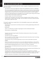 4
4
-
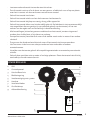 5
5
-
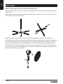 6
6
-
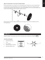 7
7
-
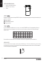 8
8
-
 9
9
-
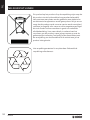 10
10
-
 11
11
-
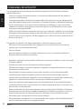 12
12
-
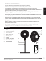 13
13
-
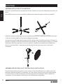 14
14
-
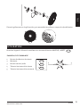 15
15
-
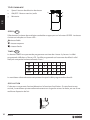 16
16
-
 17
17
-
 18
18
-
 19
19
-
 20
20
-
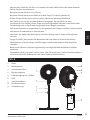 21
21
-
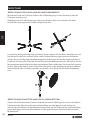 22
22
-
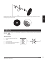 23
23
-
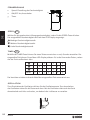 24
24
-
 25
25
-
 26
26
-
 27
27
-
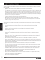 28
28
-
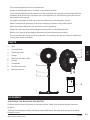 29
29
-
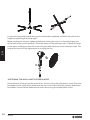 30
30
-
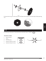 31
31
-
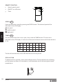 32
32
-
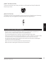 33
33
-
 34
34
-
 35
35
-
 36
36
-
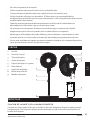 37
37
-
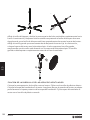 38
38
-
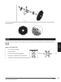 39
39
-
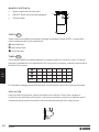 40
40
-
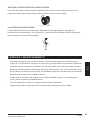 41
41
-
 42
42
-
 43
43
-
 44
44
-
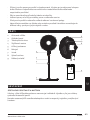 45
45
-
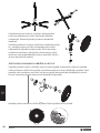 46
46
-
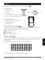 47
47
-
 48
48
-
 49
49
-
 50
50
-
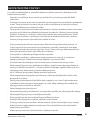 51
51
-
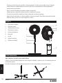 52
52
-
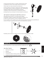 53
53
-
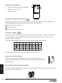 54
54
-
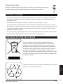 55
55
-
 56
56


in andere talen
- English: Domo DO8141 User manual
- français: Domo DO8141 Manuel utilisateur
- español: Domo DO8141 Manual de usuario
- Deutsch: Domo DO8141 Benutzerhandbuch
- slovenčina: Domo DO8141 Používateľská príručka


