
YAMAHA ELECTRONICS CORPORATION, USA
6660 ORANGETHORPE AVE., BUENA PARK, CALIF. 90620, U.S.A.
YAMAHA CANADA MUSIC LTD.
135 MILNER AVE., SCARBOROUGH, ONTARIO M1S 3R1, CANADA
YAMAHA ELECTRONIK EUROPA G.m.b.H.
SIEMENSSTR. 22-34, 25462 RELLINGEN BEI HAMBURG, GERMANY
YAMAHA ELECTRONIQUE FRANCE S.A.
RUE AMBROISE CROIZAT BP70 CROISSY-BEAUBOURG 77312 MARNE-LA-VALLEE CEDEX02, FRANCE
YAMAHA ELECTRONICS (UK) LTD.
YAMAHA HOUSE, 200 RICKMANSWORTH ROAD WATFORD, HERTS WD18 7GQ, ENGLAND
YAMAHA SCANDINAVIA A.B.
J A WETTERGRENS GATA 1, BOX 30053, 400 43 VÄSTRA FRÖLUNDA, SWEDEN
YAMAHA MUSIC AUSTRALIA PTY, LTD.
17-33 MARKET ST., SOUTH MELBOURNE, 3205 VIC., AUSTRALIA
©
2006 All rights reserved.
Printed in Malaysia WH83010
YSP-900
YSP-900
Digital Sound Projector
Système Acoustique Numérique
E
OWNER’S MANUAL
MODE D’EMPLOI
MANUALE DI ISTRUZIONI
MANUAL DE INSTRUCCIONES
YSP-900_E-cv.fm Page 1 Friday, August 11, 2006 2:46 PM

CAUTION: READ THIS BEFORE OPERATING THIS UNIT.
i En
1 To assure the finest performance, please read this manual
carefully. Keep it in a safe place for future reference.
2 Install this sound system in a well ventilated, cool, dry, clean
place with at least 5 cm of space above (or below) this unit –
away from direct sunlight, heat sources, vibration, dust, moisture,
and/or cold.
3 Locate this unit away from other electrical appliances, motors, or
transformers to avoid humming sounds.
4 Do not expose this unit to sudden temperature changes from cold
to hot, and do not locate this unit in an environment with high
humidity (i.e. a room with a humidifier) to prevent condensation
inside this unit, which may cause an electrical shock, fire,
damage to this unit, and/or personal injury.
5 Avoid installing this unit where foreign object may fall onto this
unit and/or this unit may be exposed to liquid dripping or
splashing. On the top of this unit, do not place:
– Other components, as they may cause damage and/or
discoloration on the surface of this unit.
– Burning objects (i.e. candles), as they may cause fire, damage
to this unit, and/or personal injury.
– Containers with liquid in them, as they may fall and liquid
may cause electrical shock to the user and/or damage to this
unit.
6 Do not cover this unit with a newspaper, tablecloth, curtain, etc.
in order not to obstruct heat radiation. If the temperature inside
this unit rises, it may cause fire, damage to this unit, and/or
personal injury.
7 Do not plug in this unit to a wall outlet until all connections are
complete.
8 Do not operate this unit upside-down. It may overheat, possibly
causing damage.
9 Do not use force on switches, knobs and/or cords.
10 When disconnecting the power cable from the wall outlet, grasp
the plug; do not pull the cable.
11 Do not clean this unit with chemical solvents; this might damage
the finish. Use a clean, dry cloth.
12 Only voltage specified on this unit must be used. Using this unit
with a higher voltage than specified is dangerous and may cause
fire, damage to this unit, and/or personal injury. YAMAHA will
not be held responsible for any damage resulting from use of this
unit with a voltage other than specified.
13 To prevent damage by lightning, keep the power cable
disconnected from a wall outlet or this unit during a lightning
storm.
14 Do not attempt to modify or fix this unit. Contact qualified
YAMAHA service personnel when any service is needed.
The cabinet should never be opened for any reasons.
15 When not planning to use this unit for long periods of time (i.e.
vacation), disconnect the AC power plug from the wall outlet.
16 Be sure to read the “TROUBLESHOOTING” section on
common operating errors before concluding that this unit is
faulty.
17 Before moving this unit, press STANDBY/ON to set this unit in
standby mode, and disconnect the AC power plug from the wall
outlet.
18 Condensation will form when the surrounding temperature
changes suddenly. Disconnect the power cable from the outlet,
then leave the unit alone.
19 When using the unit for a long time, the unit may become warm.
Turn the power off, then leave the unit alone for cooling.
20 Install this unit near the AC outlet and where the AC power plug
can be reached easily.
CAUTION: READ THIS BEFORE OPERATING THIS UNIT.
WARNING
TO REDUCE THE RISK OF FIRE OR ELECTRIC SHOCK,
DO NOT EXPOSE THIS UNIT TO RAIN OR MOISTURE.
This unit is not disconnected from the AC power source as
long as it is connected to the AC wall outlet, even if this unit
itself is turned off. This state is called the standby mode. In
this state, this unit is designed to consume a very small
quantity of power.
FOR U.K. CUSTOMERS
If the socket outlets in the home are not suitable for the plug
supplied with this appliance, it should be cut off and an
appropriate 3 pin plug fitted. For details, refer to the
instructions described below. Note that the plug severed from
the mains lead must be destroyed, as a plug with bared
flexible cord is hazardous if engaged in a live socket outlet.
IMPORTANT
THE WIRES IN MAINS LEAD ARE COLOURED IN
ACCORDANCE WITH THE FOLLOWING CODE:
Blue: NEUTRAL
Brown: LIVE
As the colours of the wires in the mains lead of this apparatus
may not correspond with the coloured markings identifying
the terminals in your plug, proceed as follows:
The wire which is coloured BLUE must be connected to the
terminal which is marked with the letter N or coloured
BLACK. The wire which is coloured BROWN must be
connected to the terminal which is marked with the letter L or
coloured RED. Make sure that neither core is connected to the
earth terminal of the three pin plug.
CAUTION
Danger of explosion if battery is incorrectly replaced. Replace
only with the same or equivalent type.
CAUTION
Use of controls or adjustments or performance of procedures
other than those specified herein may result in hazardous
radiation exposure.

1 En
PREPARATIONINTRODUCTION
BASIC
OPERATION
ADVANCED
OPERATION
ADDITIONAL
INFORMATION
SETUP
English
OVERVIEW ........................................................... 2
FEATURES............................................................. 3
USING THIS MANUAL........................................ 4
SUPPLIED ACCESSORIES ................................. 5
CONTROLS AND FUNCTIONS ......................... 6
Front panel ................................................................. 6
Front panel display .................................................... 7
Rear panel .................................................................. 8
Remote control........................................................... 9
INSTALLATION ................................................. 11
Before installing this unit......................................... 11
Installing this unit .................................................... 11
CONNECTIONS .................................................. 14
Connecting a TV...................................................... 15
Connecting a DVD player/recorder ......................... 16
Connecting a VCR................................................... 17
Connecting a digital satellite tuner or
a cable TV tuner .................................................. 18
Connecting other external components ................... 19
Connecting a subwoofer .......................................... 20
Connecting the power supply cable......................... 21
GETTING STARTED.......................................... 22
Installing batteries in the remote control ................. 22
Operation range of the remote control..................... 22
Using the remote control ......................................... 23
Turning on the power............................................... 23
USING SET MENU.............................................. 24
Displaying the OSD................................................. 24
The flow chart of SET MENU................................. 25
CHANGING OSD LANGUAGE ........................ 26
AUTO SETUP (IntelliBeam) ............................... 27
The flow chart of AUTO SETUP ............................ 27
Installing the optimizer microphone........................ 28
Using AUTO SETUP (IntelliBeam)........................ 29
USING THE SYSTEM MEMORY .................... 34
Convenient usage of the system memory ................ 34
Saving settings......................................................... 34
Loading settings....................................................... 35
PLAYBACK.......................................................... 37
Selecting the input source........................................ 37
Playing back sources................................................ 38
Adjusting the volume............................................... 39
Muting the sound ..................................................... 39
ENJOYING SURROUND SOUND .................... 40
5 beam...................................................................... 40
Stereo plus 3 beam................................................... 41
3 beam...................................................................... 41
Enjoying 2-channel sources
in surround sound ................................................ 43
Enjoying TV in surround sound .............................. 44
Adjusting surround mode parameters...................... 45
ENJOYING STEREO SOUND ...........................46
Stereo playback........................................................ 46
PLAYING BACK SOUND CLEARLY
(My beam) ..........................................................47
Using auto-adjust function....................................... 47
Using manual-adjust function.................................. 48
USING SOUND FIELD PROGRAMS................49
What is a sound field? ............................................. 49
Turning on CINEMA DSP programs ...................... 50
Turning off CINEMA DSP programs ..................... 51
Adjusting CINEMA DSP effect levels.................... 51
USING THE VOLUME MODE
(Night listening mode/TV volume
equal mode)........................................................52
USING BASS SOUND ENHANCER
(TruBass)............................................................54
USING THE SLEEP TIMER ..............................55
Setting the sleep timer ............................................. 55
Canceling the sleep timer ........................................ 56
MANUAL SETUP.................................................57
Using MANUAL SETUP........................................ 58
BEAM MENU ......................................................... 59
SOUND MENU....................................................... 63
INPUT MENU......................................................... 65
DISPLAY MENU.................................................... 67
ADJUSTING THE AUDIO BALANCE .............68
Using the test tone ................................................... 68
Using the audio output being played back............... 69
SELECTING THE INPUT MODE .....................71
ADJUSTING SYSTEM PARAMETERS ...........72
Using the system parameters ................................... 72
Setting the MEMORY PROTECT .......................... 72
Setting the MAX VOLUME.................................... 73
Setting the TURN ON VOLUME ........................... 74
Setting the DEMO MODE ...................................... 74
Setting the FACTORY PRESET............................. 75
REMOTE CONTROL FEATURES ...................77
Setting remote control codes ................................... 77
Controlling other components ................................. 78
Using the TV macro ................................................ 80
TROUBLESHOOTING .......................................82
GLOSSARY...........................................................85
Audio formats .......................................................... 85
Audio information ................................................... 85
INDEX....................................................................86
SPECIFICATIONS...............................................87
CONTENTS
INTRODUCTION
PREPARATION
SETUP
BASIC OPERATION
ADVANCED OPERATION
ADDITIONAL INFORMATION

OVERVIEW
2 En
It is generally accepted that in order to fully enjoy the benefits of surround sound at home, you must endure the agony of
wiring and installing a great number of speakers in the hope that your listening room will give you the same kind of
surround sound experience as your local movie theater.
YAMAHA YSP-900 Digital Sound Projector challenges this preconception that complicated speaker setup and
troublesome wiring go hand-in-hand with the enjoyment of multi-channel surround sound.
This slimline unit does away with the need for complicated wiring and installation worries, leaving you with a unit that is
not only easy to set up, but which is also capable of reproducing the kind of powerful surround sound you have been
waiting for from its built-in 2 woofers and 21 full-range small speakers.
You can fine-tune the parameters of this unit to adjust the delay time for separate sound beams, resulting in highly
directional sound that comes in on the listening position from all directions.
The YSP-900 projects sound beams containing surround sound information for the front right (R), front left (L), surround
right (SR) and surround left (SL) speaker positions, which are reflected off the walls of your listening room before
reaching the actual listening position. With the addition of center (C) sound beams, this Digital Sound Projector creates
true-to-life 5.1 channel surround sound that makes you feel as if there are actual speakers around the room.
Sit back and enjoy the real sound experience of this simple, yet stylish Digital Sound Projector.
OVERVIEW
SL
SR
R
L
C
Listening position
Imaginary
surround left
speaker
Imaginary
surround right
speaker
Imaginary
front left
speaker
Imaginary
front right
speaker
Imaginary
center
speaker

FEATURES
3 En
INTRODUCTION
English
Digital Sound Projector
This unit employs the digital sound projector technology
that allows one slim unit to control and steer multiple
channels of sound to generate multi channel surround
sound, thus eliminating the need for satellite loudspeakers
and cabling normally associated with conventional
surround sound systems. This unit is also equipped with
the following beam modes so that you can enjoy the
surround sound.
◆ 5 beam
◆ Stereo plus 3 beam
◆ 3 beam
This unit also employs the stereo playback and my beam.
My beam
This unit employs the my beam so that you can achieve a
clear sound in noisy environment. You can adjust the
beam angle manually or automatically using the supplied
remote control.
Cinema DSP Digital
This unit employs the Cinema DSP Digital technology
developed by YAMAHA Electronics Corp. so that you can
experience movies at home with all the dramatic sound
impact that the director intended to convey.
Versatile Remote Control
The supplied remote control come with preset remote
control codes to be used to control the DVD player, VCR,
cable TV tuner and digital satellite tuner connected to this
unit. In addition, the remote control is equipped with the
macro capability so that you can perform a series of
operations with the press of a single button.
AUTO SETUP (IntelliBeam)
This unit employs the automatic sound beam and acoustic
optimization technology with the aid of the supplied
optimizer microphone so that you can avoid troublesome
listening-based speaker setup and achieve highly accurate
sound beam adjustments that best match your listening
environment.
Compatibility with the Newest Technologies
This unit employs decoders compatible with Dolby
Digital, DTS (Digital Theater Systems), Dolby Pro Logic,
Dolby Pro Logic II and DTS Neo:6.
◆ Dolby Digital
This is the standard audio signal format used on DVDs and
other purely digital media. This surround technology deliver
high-quality digital audio for up to 5.1 discrete channels to
produce a directional and more realistic effect.
◆ DTS (Digital Theater Systems)
This is an audio signal format used on DVDs and other purely
digital media. This surround technology deliver high-quality
digital audio for up to 5.1 discrete channels to produce a
directional and more realistic effect.
◆ Dolby Pro Logic
This sophisticated, matrix decoding technology up-converts
any 2 channel source audio to a 5.1 channel full bandwidth
playback, resulting in a surround sound experience.
◆ Dolby Pro Logic II
This is fundamentally a redesigned version of Dolby Pro
Logic that employs 2 stereo surround channels, a subwoofer
and a greatly enhanced steering logic. As a result, this
improved technology provides an exceptionally stable sound
field that simulates 5.1 to a much greater degree than the
original Dolby Pro Logic. In addition, Dolby Pro Logic II
features Movie, Music and Game modes specifically designed
for movies, music and games respectively.
◆ DTS Neo:6
This technology decodes the conventional 2 channel sources
for 6 channel playback, enabling playback with the full-range
channels with higher separation. Music mode and Cinema
mode are available to play back music and movie sources
respectively.
The “ ” logo and “IntelliBeam” are trademarks of
YAMAHA Corporation.
The “ ” logo and “Cinema DSP” are registered
trademarks of YAMAHA Corporation.
Manufactured under license from Dolby Laboratories.
“Dolby”, “Pro Logic”, and the double-D symbol are trademarks
of Dolby Laboratories.
“DTS” and “Neo:6” are trademarks of Digital Theater Systems,
Inc.
Manufactured under license from 1 Ltd. Worldwide patents
applied for.
The “ ” logo and “Digital Sound Projector
™
” are trademarks
of 1 Ltd.
TruBass, SRS and the “ ” symbol are registered trademarks
of SRS Labs, Inc. TruBass technology is incorporated under
license from SRS Labs, Inc.
FEATURES

USING THIS MANUAL
4 En
• This manual describes how to connect and operate this unit. For details regarding the operation of external components, refer to the
supplied owner’s manual for the component.
• Some operations can be performed by using either the buttons on the main unit or on the remote control. In such cases, the operation is
described using remote control operation.
• y indicates a tip for your operation.
• This manual is printed prior to production. Design and specifications are subject to change in part as a result of improvements, etc. In
case of differences between the manual and product, the product has priority.
1 Install this unit in your listening room.
See “INSTALLATION” on page 11.
2 Connect this unit to your TV and other external components.
See “CONNECTIONS” on page 14.
3 Prepare the remote control and turn on the power of this unit.
See “GETTING STARTED” on page 22.
4 Run AUTO SETUP.
See “AUTO SETUP (IntelliBeam)” on page 27.
5 Play back a source.
See “PLAYBACK” on page 37.
6 Change the beam modes and/or CINEMA DSP settings.
See “ENJOYING SURROUND SOUND” on page 40.
7 Run MANUAL SETUP to fine-tune settings and/or set remote control codes.
See “MANUAL SETUP” on page 57 and “REMOTE CONTROL FEATURES” on page 77.
USING THIS MANUAL
Notes
If you want to make additional settings
and adjustments

SUPPLIED ACCESSORIES
5 En
INTRODUCTION
English
Check that you have received all of the following parts.
SUPPLIED ACCESSORIES
POWER
POWER
STANDBY/ON
STEREO
MY BEAM
INPUT2
TV
TV
21
SLEEP
CH LEVEL MENU
RETURN
TEST
TV VOL
VOLUME
MUTE TV INPUT TV MUTE
ENTER
SURROUND
OFF
CODE SET
SPORTS
AV
3
4
56
789
0
+10
5BEAM
ST+3BEAM
3BEAM
MUSIC MOVIE
VOL MODE
AUTO
SETUP
INPUTMODE
MACROINPUT1
AUX
YSP
TV/AV
CH
TV
STB VCR DVD
Remote control (×1)
Batteries (×2)
(AA, R6, UM-3)
OSD video pin cable (×1)
Optimizer microphone (×1)
Fasteners (×4)
Audio pin cable (×1)
Digital audio pin cable (×1)
Optical cable (×1)
Cable clamp (×1)
Cardboard microphone
stand (×1)
(Orange)
(White/Red)
(Yellow)

CONTROLS AND FUNCTIONS
6 En
1 OPTIMIZER MIC jack
Use to connect the supplied optimizer microphone to be
used to run AUTO SETUP (see page 28).
2 Front panel display
Shows information about the operational status of this
unit.
3 Remote control sensor
Receives infrared signals from the remote control.
4 INPUT
Press repeatedly to switch between input sources (TV,
STB, VCR, DVD or AUX). See page 37 for details.
Outputs a test tone to experience the sound beam (see
page 68).
5 VOLUME –/+
Controls the volume level of all audio channels (see
page 39).
6 STANDBY/ON
Turns on the power of this unit or sets it to the standby
mode (see page 23).
• When you turn on the power of this unit, you will hear a click
and there will be a 4 to 5-second delay before it can reproduce
sound.
• In the standby mode, this unit consumes a small amount of
power in order to receive infrared-signals from the remote
control.
CONTROLS AND FUNCTIONS
Front panel
1 2 3
4 5 6
STANDBY/ONVOLUME
+
INPUT
Notes

CONTROLS AND FUNCTIONS
7 En
INTRODUCTION
English
1 NIGHT indicator
Lights up when one of the night listening modes is
selected (see page 52).
2 SLEEP indicator
Lights up when the sleep timer is turned on (see page 55).
3 Decoder indicators
Light up when the corresponding decoder of this unit is in
operation (see page 42).
4 Volume level indicator
Shows the current volume level (see page 39).
5 Multi-information display
Shows information when you adjust the parameters of this
unit.
y
You can adjust the brightness of the front panel display using the
DISPLAY MENU parameters in MANUAL SETUP (see
page 67).
Front panel display
NIGHT SLEEP PCM PL
m
ft
mS
dB
VOLDIGITAL
5
412 3

CONTROLS AND FUNCTIONS
8 En
1 VCR analog audio input jacks
Use to make an analog connection to your VCR
(see page 17).
2 TV/STB analog audio input jacks
Use to make an analog connection to your TV, digital
satellite tuner and cable TV tuner (see pages 15 and 18).
3 SUBWOOFER OUT jack
Use to connect a subwoofer (see page 20).
4 VIDEO OUT jack
Use to connect to the video input terminal of your TV to
display the OSD of this unit (see page 15).
5 TV/STB OPTICAL DIGITAL INPUT jack
Use to connect a TV, digital satellite tuner and cable TV
tuner via an optical digital connection (see pages 15 and
18).
6 AUX OPTICAL DIGITAL INPUT jack
Use to connect an external component via an optical
digital connection (see page 19).
7 DVD COAXIAL DIGITAL INPUT jack
Use to connect a DVD player via a coaxial digital
connection (see page 16).
8 AC power supply cable
Use to connect to the AC wall outlet (see page 21).
Rear panel
8
1234 5 6 7
VCR
SUBWOOFER
TV/STB
AUDIO INPUT
OUT
OPTICAL
DIGITAL INPUT
TV/STB VIDEO
AUX
DVD
COAXIAL
(Europe model)

CONTROLS AND FUNCTIONS
9 En
INTRODUCTION
English
The functions of some buttons change depending on the
position of the operation mode selector (S). This section
basically describes the functions of the remote control
used to control this unit.
y
You can also control other components using the remote control
once you set the appropriate remote control codes. See
“Controlling other components” on page 78 for details.
1 Infrared window
Outputs infrared control signals. Aim this window at the
component you want to operate.
2 STANDBY/ON
Sets this system to the standby mode (see page 23).
3 Transmission indicator
Lights up when infrared control signals are being output.
4 Input selector buttons
Use to select an input source (STB, VCR, DVD, AUX or
TV).
Use to change the control area of the remote control.
(S: TV/AV)
5 VOL MODE
Turns on or off the volume modes (see page 52).
6 AUTO SETUP
Use to enter the AUTO SETUP menu (see page 27).
7 Numeric buttons
Use to enter numbers. (S: TV/AV)
8 STEREO
Use the playback sources in 2-channel stereo (see
page 46).
9 Sound field program buttons
Use to select sound field programs (see page 49).
0 CH LEVEL
Adjusts the volume level of each channel (see page 69).
A Cursor buttons / / / , ENTER
Use to select and adjust SET MENU items.
Use to select DVD menu items. (S: TV/AV)
B TEST
Outputs a test tone when adjusting the output level of each
speaker (see page 68).
C VOLUME +/–
Increases or decreases the volume level of this unit (see
page 39).
D MUTE
Mutes the sound. Press again to restore the audio output to
the previous volume level (see page 39).
E TV INPUT
Switches the input source or the TV (see page 78).
F DVD player/VCR control buttons
Use to control the DVD player or the VCR (see pages 78
and 79).
G My beam microphone
Use to collect the test tones from this unit when using the
my beam auto-adjust function (see page 48).
Remote control
POWER
POWER
STANDBY/ON
STEREO
MY BEAM
INPUT2
TV
TV
21
SLEEP
CH LEVEL MENU
RETURN
TEST
TV VOL
VOLUME
MUTE
TV INPUT TV MUTE
ENTER
SURROUND
OFF
CODE SET
SPORTS
AV
3
4
56
789
0
+10
5BEAM
ST+3BEAM 3BEAM
MUSIC MOVIE
VOL MODE
AUTO
SETUP
INPUTMODE
MACROINPUT1
AUX
YSP
TV/AV
CH
TV
STB VCR DVD

CONTROLS AND FUNCTIONS
10 En
H TV POWER
Turns on the power of the TV or sets it to the standby
mode (see page 78).
I AV POWER
Turns on the power of the selected component or sets it to
the standby mode (see pages 78 and 79).
J INPUT1/INPUT2
Selects the input source of the TV (see page 78).
K MACRO
Use to set the TV macro (see page 80).
L SLEEP
Sets the sleep timer (see page 55).
M INPUTMODE
Switches between input modes (AUTO, DTS or
ANALOG). See page 71 for details.
N Beam mode buttons
Change the beam mode settings (see pages 40, 46 and 47).
O SURROUND
Selects the surround mode for playback (see page 40).
P MY BEAM
Use to select the my beam as the beam mode (see
page 48).
Q TruBass
Use to effectively reproduce the bass sound (see page 54).
R MENU
Displays the setup menu on your TV monitor (see
pages 29 and 58).
Displays the DVD menu. (S: TV/AV)
S Operation mode selector
Selects the operation mode of this unit. Select YSP when
operating this unit and select TV/AV when operating the
TV or other AV components set up the appropriate remote
control codes.
T RETURN
Use to select sleep timer settings or return to the previous
SET MENU screen.
Use to return to the previous DVD menu screen or exit the
DVD menu. (S: TV/AV)
U TV VOL +/–
Adjusts the volume level of the TV (see page 78).
V CH +/–
Switches between channels of the TV or the VCR (see
pages 78 and 79).
W TV MUTE, CODE SET
Mutes the audio output of the TV (see page 78).
Use to set up remote control codes (see page 77).

INSTALLATION
11 En
PREPARATION
English
This section describes a suitable installation location to install the unit using a metal wall bracket, a rack or a stand.
This unit creates surround sound by reflecting projected
sound beams off the walls of your listening room. The
surround sound effects produced by this unit may not be
sufficient when the unit is installed in the following
locations.
• Rooms with surfaces inadequate for reflecting sound
beams
• Rooms with acoustically absorbent surfaces
• Rooms with measurements outside the following range
W (3 to 7 m) x H (2 to 3.5 m) x D (3 to 7 m)
• Rooms with less than 1.8 m from the listening position
to the speaker positions
• Rooms where objects such as furniture are likely to
obstruct the path of sound beams
• Rooms where the listening position is close to the walls
• Rooms where the listening position is not in front of
this unit
Make sure you leave an adequate amount of ventilation
space so that heat can escape. Make at least 5 cm of space
above or below this unit.
• We do not recommend installing this unit so that it is positioned
directly on the floor of your listening room. Please install this
unit using a metal wall bracket, rack or stand.
• This unit weighs 9.0 kg. Be sure to install this unit where it will
not fall subject to vibrations, such as from an earthquake, and
where it is out of the reach of children.
• When using a cathode-ray tube (CRT) TV, do not install this
unit directly above your TV.
• This unit is shielded against magnetic rays. However, if the
picture on your TV screen becomes blurred or distorted, we
recommend moving the speakers away from your TV.
Install this unit where there are no obstacles such as
furniture obstructing the path of sound beams. Otherwise,
the desired surround sound effects may not be achieved.
You may install this unit in parallel with the wall or in the
corner.
Parallel installation
Install this unit in the exact center of the wall when it is
measured from the left and right corners.
Corner installation
Install this unit in the corner at a 40º to 50º angle from the
adjacent walls.
INSTALLATION
Before installing this unit
Notes
5 cm or more
Rear
Front
Side view
Installing this unit
An object, such as furniture
40° to 50°
An object, such as furniture

12 En
INSTALLATION
■ Installation examples
Example 1
Install this unit as close to the exact center of the wall as possible.
Example 2
Install this unit so that the sound beams can be reflected off the walls.
Example 3
Install this unit as close to the exact front of your normal listening position.

13 En
INSTALLATION
PREPARATION
English
■ Using a metal wall bracket
You can use the optional metal wall bracket to mount this
unit on the wall in your listening room.
y
Refer to the instructions supplied with the metal bracket for
details on how to attach the metal bracket to the wall or how to
attach this unit to the metal bracket.
■ Using a stand
You can mount your TV on the stand placed on a
commercially available rack to install this unit under your
TV.
y
Refer to the instructions supplied with the stand for details on
how to install the stand or how to mount this unit and the TV on
the stand.
■ Using a rack
You can install this unit either above or under your TV in a
commercially available rack.
Make sure that the rack is large enough to allow adequate
ventilation space around this unit (see page 11) and that it is
strong enough to support the weight of both this unit and your TV.
■ Affixing this unit
Peel off the film from each of the four supplied fasteners
and then secure them to the bottom four corners of this
unit and the top of the rack, etc.
• Do not install this unit on top of a slanted surface. This unit may
fall over and cause injury.
• Make sure you wipe the surface of the rack, etc. before securing
the fasteners. Applying the tape to a dirty or wet surface will
weaken the sticking power of the tape, and this unit may fall as
a result.
This unit
TV
Metal wall bracket
TV
This unit
Stand
Note
Notes
When this unit is installed above your TV
When this unit is installed under your TV
1
2
This unit
Peel off
the film
Fasteners

CONNECTIONS
14 En
This unit is equipped with two optical digital jacks, one coaxial digital jack and two types of analog jacks for connecting
external components such as your TV, DVD player, VCR, digital satellite tuner, cable TV tuner and game console.
Further, by connecting a subwoofer to this unit, you can enjoy reinforced low bass sounds. For details on how to connect
various types of external components to this unit, see pages 15 to 20.
• Do not connect this unit or other components to the main power until all connections between components are
complete.
• Unplug the power supply cable before changing connections, moving or cleaning this unit.
CONNECTIONS
CAUTION
TV
This unit
Audio connection
Video connection
Digital satellite tuner, cable TV
tuner or game console
DVD player Subwoofer VCR
Optical fiber cable
To prevent cables from becoming unplugged, place the supplied
cable clamp with the open side facing upward, attach it to the rear
panel of this unit in a suitable position and then affix cables in the
cable clamp.
Attach to this unit

15 En
CONNECTIONS
PREPARATION
English
You can connect a TV to this unit and display the OSD for easy viewing when you adjust the system parameters in SET
MENU.
y
To prevent the optical cable from being unplugged, affix the optical cable in the supplied cable clamp (see page 14).
If you connect this unit to the analog audio and optical digital audio output jacks at the same time as shown in the left illustration below,
the digital audio signals output at the optical digital output jack take priority over the analog audio signals output at the analog audio
output jacks.
■ Digital and analog audio connections
Cables used for connections
■ Video connections
Cables used for connections
Connecting a TV
Note
VCR
SUBWOOFER
TV/STB
AUDIO INPUT
OUT
OPTICAL
DIGITAL INPUT
TV/STB VIDEO
AUX
DVD
COAXIAL
Rear panel of this unit
TV
Analog audio
output
Optical digital
output
RL
Remove the caps if
attached
Check the direction
Optical cable (supplied)
Audio pin cable
(White)
(Red)
(White)
(Red)
VCR
SUBWOOFER
TV/STB
AUDIO INPUT
OUT
OPTICAL
DIGITAL INPUT
TV/STB VIDEO
AUX
DVD
COAXIAL
TV
Video
input
Rear panel of this unit
OSD video pin cable (supplied)
(Yellow)(Yellow)

16 En
CONNECTIONS
To connect a DVD player/recorder, connect the coaxial digital output jack on your DVD player to the coaxial digital
input jack (DVD COAXIAL) on this unit.
If there is no coaxial digital output jack on your DVD player/recorder, use them with optical digital connection.
y
To prevent the optical cable from being unplugged, affix the optical cable in the supplied cable clamp (see page 14).
• Check that your DVD player/recorder is properly set to output Dolby Digital and DTS digital audio signals. If not, adjust the system
settings of your DVD player/recorder. For details, refer to the operation manual supplied with your DVD player/recorder.
• If your DVD player/recorder does not have a coaxial digital output jack, make an optical digital audio connection instead.
Cables used for connections
Connecting a DVD player/recorder
Notes
VCR
SUBWOOFER
TV/STB
AUDIO INPUT
OUT
OPTICAL
DIGITAL INPUT
TV/STB VIDEO
AUX
DVD
COAXIAL
Rear panel of this unit
Video signal to a TV
Coaxial digital
output
Analog audio
output
Coaxial digital
output
L
R
DVD/VCR combo
player/recorder
DVD player/recorder
Video signal to a TV
Audio pin cable
(White)
(Red)
(White)
(Red)
Digital audio pin cable (supplied)
(Orange)(Orange)

17 En
CONNECTIONS
PREPARATION
English
To connect a VCR, connect the analog audio output jacks on your VCR to the analog audio input jacks (VCR R/L) on
this unit.
Connect red plugs to the right jacks and white plugs to the left jacks.
Cables used for connections
Connecting a VCR
VCR
SUBWOOFER
TV/STB
AUDIO INPUT
OUT
OPTICAL
DIGITAL INPUT
TV/STB VIDEO
AUX
DVD
COAXIAL
Video signal to a TV
Rear panel of this unit
Analog audio
output
R
L
VCR
Audio pin cable
(White)
(Red)
(White)
(Red)

18 En
CONNECTIONS
To connect a digital satellite tuner or a cable TV tuner, connect the optical digital output jack on your digital satellite
tuner or cable TV tuner to the optical digital input jack (TV/STB OPTICAL) on this unit. In addition, connect the analog
audio output jacks on your VCR to the analog audio input jacks (TV/STB R/L) on this unit.
Connect red plugs to the right jacks and white plugs to the left jacks.
y
To prevent the optical cable from being unplugged, affix the optical cable in the supplied cable clamp (see page 14).
If your TV and tuner connected to this unit do not support digital broadcasting, connect the analog audio output jacks (TV/STB R/L) on
this unit to the analog audio output jacks on your TV.
Cables used for connections
Connecting a digital satellite tuner or a cable TV tuner
Note
VCR
SUBWOOFER
TV/STB
AUDIO INPUT
OUT
OPTICAL
DIGITAL INPUT
TV/STB VIDEO
AUX
DVD
COAXIAL
Video signal to a TV
Rear panel of this unit
Digital satellite tuner or a cable TV tuner
Optical digital
output
Analog audio
output
L
R
Analog audio
output
L
R
TV
Optical cable (supplied)
Audio pin cable
(White)
(Red)
(White)
(Red)

19 En
CONNECTIONS
PREPARATION
English
To connect other external components, connect the optical digital output jack on the component to the optical digital
input jack (AUX OPTICAL) on this unit.
You can connect a DVD player/recorder or a component that supports optical digital connections.
y
To prevent the optical cable from being unplugged, affix the optical cable in the supplied cable clamp (see page 14).
Cables used for connections
Connecting other external components
VCR
SUBWOOFER
TV/STB
AUDIO INPUT
OUT
OPTICAL
DIGITAL INPUT
TV/STB VIDEO
AUX
DVD
COAXIAL
Optical digital
output
Video signal to a TV
Game console, etc.
Rear panel of this unit
Optical cable (supplied)

20 En
CONNECTIONS
To connect a subwoofer, connect the monaural input jack on your subwoofer to the monaural audio output jack
(SUBWOOFER OUT) on this unit.
No sound will be output from a subwoofer when only this connection has been made. To output sounds from a
subwoofer, turn on the power of your subwoofer and then run AUTO SETUP (see page 27) or select SWFR for BASS
OUT in SUBWOOFER SET (see page 63).
Cables used for connections
Connecting a subwoofer
VCR
SUBWOOFER
TV/STB
AUDIO INPUT
OUT
OPTICAL
DIGITAL INPUT
TV/STB VIDEO
AUX
DVD
COAXIAL
Monaural
input
Subwoofer
Rear panel of this unit
Subwoofer pin cable

21 En
CONNECTIONS
PREPARATION
English
Once all other connections are complete, plug the power supply cable into the AC wall outlet.
Connecting the power supply cable
To the AC outlet

GETTING STARTED
22 En
1 Press and hold the mark on the battery
cover and then slide off the cover.
2 Insert the two supplied batteries (AA, R6,
UM-3) into the battery compartment.
Make sure you insert the batteries according to the
polarity markings (+/–).
3 Close the battery cover.
• Change all of the batteries if you notice the following
conditions; the operation range of the remote control decreases,
the indicator does not blink or its light becomes dim.
• Do not use old batteries together with new ones.
• Do not use different types of batteries (such as alkaline and
manganese batteries) together. Read the packaging carefully as
these different types of batteries may have the same shape and
color.
• Exhausted batteries may leak. If the batteries have leaked,
dispose of them immediately. Avoid touching the leaked
material or letting it come into contact with clothing, etc. Clean
the battery compartment thoroughly before installing new
batteries.
• Do not throw away batteries with general house waste. Dispose
of them correctly in accordance with your local regulations.
• The contents of the memory stored in the remote control may be
erased in the following cases:
– The remote control is left without batteries for more than 2
minutes.
– Exhausted batteries remain in the remote control.
– The buttons on the remote control are accidentally pressed
when you change batteries.
• If the memory stored in the remote control is unwantedly
erased, insert new batteries and reset the remote control codes
again.
y
Remove the transparent sheet before using the remote
control.
You can control other components by setting the appropriate
The remote control transmits a directional infrared beam.
Use the remote control within 6 m of this unit and point it
toward the remote control sensor on this unit during
operation.
• Do not spill water or other liquids on the remote control.
• Do not drop the remote control.
• Do not leave or store the remote control in the following types
of conditions:
– places of high humidity, such as near a bath
– places of high temperatures, such as near a heater or a stove
– places of extremely low temperatures
– dusty places
• Do not expose the remote control sensor on this unit to direct
sunlight or lighting such as inverted fluorescent lamps.
• If the batteries grow old, the effective operation distance of the
remote control decreases considerably. If this happens, replace
the batteries with two new ones as soon as possible.
GETTING STARTED
Installing batteries in the remote
control
Notes
Press
Operation range of the remote
control
Notes
Approximately
6 m

GETTING STARTED
23 En
SETUP
English
This section describes how to control this unit using the
supplied remote control. The functions of the remote
control change depending on the position of the operation
mode selector. Set the operation mode selector to YSP to
switch to the operation mode of this unit. The buttons on
the remote control numbered 1 to 4 are operational only
when you select YSP. Also, functions of the buttons
numbered 5 to 9 vary depending on the position of the
operation mode selector. The corresponding functions of
the buttons, see page 9.
y
You can control other components by setting the appropriate
remote control codes (see page 77). Once the remote control code
for each input source (DVD, VCR, STB, TV or AUX) is set, see
“Controlling other components” on page 78 for further
information on the specific functions of the available remote
control buttons for each input source.
1 Press STANDBY/ON on the front panel or on
the remote control to turn on the power of
this unit.
The volume level appears in the front panel display
and then the input source and beam mode currently
selected are displayed.
2 Press STANDBY/ON on the front panel or on
the remote control again to set this unit to
the standby mode.
When the unit is in the standby mode, only STANDBY/ON on the
front panel or on the remote control is operational, and the other
control buttons on the front panel or on the remote control are not
operational until the power of this unit is turned on.
Using the remote control
STEREO
MY BEAM
INPUT2
TV
21
SLEEP
CH LEVEL MENU
RETURN
TEST
TV VOL
VOLUME
ENTER
SURROUND
OFF
SPORTS
3
4
56
789
0
+10
5BEAM
ST+3BEAM 3BEAM
MUSIC MOVIE
VOL MODE
AUTO
SETUP
INPUTMODE
MACROINPUT1
AUX
YSP
TV/AV
CH
TV
STB VCR DVD
4
1
2
3
STEREO
MY BEAM
INPUT2
TV
21
SLEEP
CH LEVEL MENU
RETURN
TEST
TV VOL
VOLUME
ENTER
SURROUND
OFF
SPORTS
3
4
56
789
0
+10
5BEAM
ST+3BEAM 3BEAM
MUSIC MOVIE
VOL MODE
AUTO
SETUP
INPUTMODE
MACROINPUT1
AUX
YSP
TV/AV
CH
TV
STB VCR DVD
6
5
8
9
7
Operational buttons only when YSP is
selected
Function-varying buttons
Turning on the power
Note
STANDBY/ONVOLUME
++
POWER
POWER
STANDBY/ON
INPUT2
TV
TV
AV
MACROINPUT1
AUX
TV
STB VCR DVD
STANDBY/ON
or
Front panel
Remote control

USING SET MENU
24 En
This section simply describes how to display the OSD (on-screen display) of this unit on your TV screen and set the
parameters for your listening room. Once this is complete, you can enjoy real surround sound while watching TV in the
comfort of your own home.
1 Check that the video input jack on your TV is
connected to the VIDEO OUT jack of this unit
to display the OSD of this unit.
2 Press STANDBY/ON on the front panel or on
the remote control to turn on the power of
this unit.
3 Turn on the power of your TV.
The following screen appears on your TV.
If the OSD does not appear, use the remote control
provided with your TV to switch the video input until
the OSD appears.
USING SET MENU
Displaying the OSD
STANDBY/ON
or
Front panel
Remote control
Push [MENU] to begin set-up
YSP-900
OSD screen example

USING SET MENU
25 En
SETUP
English
The following diagram illustrates the overall flow of the setup procedure.
The flow chart of SET MENU
Run AUTO SETUP (IntelliBeam).
See “AUTO SETUP (IntelliBeam)” on page 27.
Look for a remedy.
See “Error messages for AUTO SETUP” on page 33 for a complete list of error
messages and possible remedies.
Play back audio signals or adjust the settings for the beam mode and the CINEMA DSP.
See “PLAYBACK” on page 37.
Run MANUAL SETUP.
See “MANUAL SETUP” on page 57.
y
• If you cannot clearly hear a sound beam from a specific channel, adjust settings for
SETTING PARAMETERS (see page 59) or for BEAM ADJUSTMENT (see page 60) in
BEAM MENU.
• If there are acoustically absorbent objects such as curtains in the path of the sound beams,
adjust settings for TREBLE GAIN in BEAM MENU (see page 62).
If an error occurs
If you want to make additional settings
and adjustments
Run LANGUAGE SETUP.
See “CHANGING OSD LANGUAGE” on page 26.

CHANGING OSD LANGUAGE
26 En
This feature allows you to select the language of your choice that appears in the SET MENU of this unit.
1 Set the operation mode selector to YSP to
switch to the operation mode of this unit.
2 Press MENU on the remote control.
The SET MENU screen appears on your TV.
y
• The control buttons used for SET MENU are displayed on
the bottom of the screen.
• To return to the previous screen while using SET MENU,
press RETURN on the remote control.
• To cancel the SET MENU screen, press MENU once
more.
• You can also perform the following operations in the front
panel display.
3 Press / to select LANGUAGE SETUP
and then press ENTER.
The following screen appears on your TV.
4 Press / to select the language and
then press ENTER.
Choices: ENGLISH (English), DEUTSCH (German),
Français (French), ESPAÑOL (Spanish)
CHANGING OSD LANGUAGE
YSP
TV/AV
MENU
;MEMORY
;AUTO SETUP
;MANUAL SETUP
;LANGUAGE SETUP
[ ]/[ ]:Up/Down
[ENTER]:Enter
SET MENU
.
p
p
ENTER
ENTER
ENGLISH
DEUTSCH
Francais
ESPANOL
[ ]/[ ]:Select
[ENTER]:Return
LANGUAGE SETUP
p
p
.
ENTER
ENTER

AUTO SETUP (INTELLIBEAM)
27 En
SETUP
English
This unit creates a sound field by reflecting sound beams on the walls of your listening room and broadening the
cohesion of all the channels. Just as you would arrange the speaker position of other audio systems, you need to set the
beam angle to enjoy the best possible sound from this unit.
This unit employs the beam optimization and sound optimization features with the aid of the supplied optimizer
microphone, allowing you to avoid troublesome listening-based setup and achieving highly accurate sound adjustments
that best match your listening environment. We call these 2 features “IntelliBeam” generically.
The beam optimization creates the best possible surround sound field without manually setting the parameters for your
listening room.
The sound optimization feature performs the following checks and automatically makes appropriate sound adjustments.
DISTANCE:
Checks the distance of each beam from this unit and adjusts the delay of each channel so that each sound beam reaches
the listening position at the same time.
EQUALIZING:
Adjusts frequency and levels of each channel’s parametric equalizer to reduce coloration across the channels and create a
cohesive sound field. The sound optimization feature incorporates three parameters (frequency, level and Q factor) for
each of the seven bands in its parametric equalizer to provide highly precise automatic adjustment of frequency
characteristics.
LEVEL:
Checks and adjusts the sound output level of each channel.
This unit performs a series of checks to optimize the beam angle, delay, volume and quality. You can choose to optimize
all or part of the parameters.
*
1
The beam angle checking procedure is skipped if SOUND
OPTIMZ only is selected.
*
2
The sound optimization procedure is skipped if BEAM
OPTIMZ only is selected.
*
3
The subwoofer checking procedure is skipped if BEAM
OPTIMZ only is selected.
AUTO SETUP (IntelliBeam)
The flow chart of AUTO SETUP
*1
*2 *3
Checking the environment of
your listening room
Optimizing the beam angle
Checking the subwoofer
Optimizing the beam delay,
frequency and volume
Beam
optimization
Sound
optimization
Notes

AUTO SETUP (IntelliBeam)
28 En
The supplied optimizer microphone collects and analyzes the sound that this unit produces in your actual listening
environment. Follow the procedure below to connect the optimizer microphone to this unit and make sure that the
optimizer microphone is placed in a proper location and that there are no large obstacles between the optimizer
microphone and the walls in your listening room.
• After you have completed the AUTO SETUP procedure, be sure to disconnect the optimizer microphone.
• The optimizer microphone is sensitive to heat.
– Keep it away from direct sunlight.
– Do not place it on top of this unit.
• Do not connect the optimizer microphone to an extension cable as doing so may result in an inaccurate sound optimization.
• An error may occur during the AUTO SETUP procedure if the optimizer microphone is not properly placed in your listening room. To
avoid the possibility of an error:
– Do not place the optimizer microphone to the extreme right or left from the center of this unit.
– Do not place the optimizer microphone within 1.8 m (6.0 ft) from the front of this unit.
– Do not place the optimizer microphone more than 1 m (3.3 ft) upper or lower from the center height of this unit.
• Make sure that there are no obstacles between the optimizer microphone and the walls in your listening room as these objects obstruct
the path of sound beams. However, any objects that are in contact with the walls will be regarded as a protruding part of the walls.
• The best possible results are achieved if the optimizer microphone is placed at the same height as your ears would be when you are
seated in your listening position. However, if this is not possible, you can manually fine-tune the sound beam angle and balance the
sound beam output levels using MANUAL SETUP (see page 57) once the AUTO SETUP procedure is completed.
• If a subwoofer with adjustable volume and crossover/high cut frequency controls is connected to this unit, set the volume between 10
and 12 o’clock as viewed on a conventional clockface and set the crossover/high cut frequency to the maximum.
1 Press STANDBY/ON on the front panel or on
the remote control to turn off the power of
this unit.
2 Connect the supplied optimizer microphone
to the OPTIMIZER MIC jack on the front
panel.
3 Place the optimizer microphone on a flat
level surface more than 1.8 m (6.0 ft) from the
front of the unit and within 1 m (3.3 ft) upper
or lower from the center height of the unit
with the optimizer microphone head upward
at your normal listening position.
Be sure to place the optimizer microphone on an imaginary
center line drawn from this unit.
y
You may want to use the supplied cardboard microphone stand
to affix the optimizer microphone at the same height as your
ears would be when you are seated in your listening position.
Installing the optimizer microphone
Notes
VOLUME
MIN
MAX
MIN MAX
CROSSOVER
HIGH CUT
Subwoofer
STANDBY/ON
or
Front panel
Remote control
OPTIMIZER MIC
Note
Optimizer
microphone
More than
1.8 m (6.0 ft)
Within 1 m (3.3 ft)
upper or lower
from the center
Cardboard
microphone stand
Sofa

AUTO SETUP (IntelliBeam)
29 En
SETUP
English
■ Assembling the supplied cardboard
microphone stand
You will find three separate parts (one circular-shaped part
and two longitudinal-shaped parts) of the cardboard
microphone stand originally put together.
1 Disassemble the three parts of the cardboard
microphone stand originally put together.
2 Insert one of the longitudinal-shaped part
into the crevice of the other longitudinal-
shaped part.
3 Place the circular-shaped part on top of the
two combined longitudinal-shaped parts.
4 Place the supplied optimizer microphone on
top of the circular-shaped part.
Once the optimizer microphone is firmly connected to this
unit and properly placed in your listening room, follow the
procedure below to start the AUTO SETUP procedure.
You can also enter the AUTO SETUP procedure simply by
pressing and holding AUTO SETUP on the remote control
for more than 2 seconds. In this case, this unit performs
both of the beam optimization and sound optimization
procedures.
Optimizer
microphone
Center line
12
34
Using AUTO SETUP (IntelliBeam)
POWER
POWER
STANDBY/ON
STEREO
MY BEAM
INPUT2
TV
TV
21
SLEEP
CH LEVEL MENU
RETURN
TEST
ENTER
SURROUND
OFF
SPORTS
AV
3
4
56
789
0
+10
5BEAM
ST+3BEAM 3BEAM
MUSIC MOVIE
VOL MODE
AUTO
SETUP
INPUTMODE
MACROINPUT1
AUX
YSP
TV/AV
TV
STB VCR DVD
STANDBY/ONVOLUME
++

AUTO SETUP (IntelliBeam)
30 En
• Make sure that your listening room is as quiet as possible while
this unit is performing the AUTO SETUP procedure.
• To achieve the best results possible, evacuate yourself from
your listening room until the AUTO SETUP procedure is
completed so that you may not obstruct the path of sound
beams.
• Be advised that it is normal for loud test tones to be output
during the AUTO SETUP procedure.
• The AUTO SETUP procedure may not be run successfully if
this unit is installed in one of the rooms described in “Before
installing this unit” on page 11. In such cases, run MANUAL
SETUP (see page 57) to manually adjust the corresponding
parameters.
• If an error occurs, an error buzzer is played, the AUTO SETUP
procedure stops and then an error message appears on the
screen. See “Error messages for AUTO SETUP” on page 33 for
appropriate remedies.
y
• The AUTO SETUP procedure takes about 3 minutes maximum.
A chime is played when the AUTO SETUP procedure is run
successfully.
• If there are curtains in your listening room, we recommend
following the procedure below.
1. Open the curtains to improve sound reflection.
2. Run BEAM OPTIMZ only.
3. Close the curtains.
4. Run SOUND OPTIMZ only.
• You can save the settings optimized by the AUTO SETUP
procedure (see page 34). A set of settings optimized according
to specific conditions of your listening environment can be
recalled later depending on the varying conditions of your
listening environment (see page 35).
1 Press STANDBY/ON on the front panel or on
the remote control to turn on the power of
this unit.
If a subwoofer is connected to this unit, turn on the
power of the subwoofer.
2 Set the operation mode selector to YSP to
switch to the operation mode of this unit.
3 Press MENU on the remote control.
The SET MENU screen appears on your TV.
y
• The control buttons used for SET MENU are displayed on
the bottom of the screen.
• To return to the previous screen while using SET MENU,
press RETURN on the remote control.
• To cancel the SET MENU screen, press MENU again.
• You can start the BEAM+SOUND OPTIMZ procedure
simply by pressing and holding AUTO SETUP on the
remote control for more than 2 seconds. Step 4 and 5 are
skipped and then the screen shown in step 5 is displayed
on your TV. Start the AUTO SETUP procedure from
step 6.
• You can also perform the following operations in the front
panel display.
4 Press / on the remote control to select
AUTO SETUP and then press ENTER.
The following screen appears on your TV.
Notes
STANDBY/ON
or
Front panel
Remote control
YSP
TV/AV
MENU
;MEMORY
;AUTO SETUP
;MANUAL SETUP
;LANGUAGE SETUP
[ ]/[ ]:Up/Down
[ENTER]:Enter
SET MENU
.
p
p
ENTER
ENTER
1)BEAM+SOUND OPTIMZ
2)BEAM OPTIMZ only
3)SOUND OPTIMZ only
[ ]/[ ]:Up/Down
[ENTER]:Enter
;AUTO SETUP
.
p
p

AUTO SETUP (IntelliBeam)
31 En
SETUP
English
5 Press / to select BEAM+SOUND
OPTIMZ, BEAM OPTIMZ only or SOUND
OPTIMZ only and then press ENTER.
The following screen appears on your TV.
BEAM+SOUND OPTIMZ
(Beam optimization and sound optimization)
Use to optimize the beam angle, delay, volume and quality
so that the parameters best match your listening
environment.
It is recommended that you should select this optimization
feature in the following cases:
• If you make settings for the first time.
• If the unit has been relocated.
• If your listening room has been restructured.
• If the objects in your listening room (furniture, etc.)
have been rearranged.
This menu takes about 3 minutes.
BEAM OPTIMZ only
(Beam optimization only)
Use to optimize the beam angle so that the parameter best
matches your listening environment.
This menu takes about 1 minute.
SOUND OPTIMZ only
(Sound optimization only)
Use to optimize the beam delay, volume and quality so
that the parameters best match your listening environment.
It is recommended that you should select this optimization
feature in the following cases:
• If you have opened or closed the curtains in your
listening room before using this unit.
• If you have manually set the beam angle.
This menu takes about 2 minutes.
You must optimize the beam angle in the BEAM OPTIMZ only
procedure before starting the SOUND OPTIMZ only procedure.
6 Check the following points once again before
starting the AUTO SETUP procedure.
• Is the optimizer microphone firmly connected to
this unit?
• Is the optimizer microphone placed in a proper
location?
• Are there any large obstacles in between the
optimizer microphone and the walls in your
listening room?
7 Press ENTER to start the AUTO SETUP
procedure.
The following screen appears on your TV and the
AUTO SETUP procedure starts in 10 seconds.
Evacuate yourself from your listening room before
starting the AUTO SETUP procedure.
If an error occurs, an error buzzer is played and an
error message is displayed. See “Error messages for
AUTO SETUP” on page 33 for a complete list of
error messages and their proper remedies. Follow the
instructions and perform the AUTO SETUP
procedure again.
Note
ENTER
ENTER
PREPARATION & CHECK
Please connect the MIC.
Please place the MIC at least
1.8m/6ft away from the YSP
unit. The MIC should be set
at ear level when seated.
Measurement takes about 3min.
After [ENTER] is pressed,
please leave the room.
[ENTER]:Start [RETURN]:Cancel
AUTO SETUP
WILL BEGIN in 10SEC
Please leave the room.
**--------
[RETURN]:Cancel
AUTO SETUP START
ENTER

AUTO SETUP (IntelliBeam)
32 En
8 Check that the following screen is displayed
on your TV.
The results of the AUTO SETUP procedure are
displayed on your TV.
y
• If ‘‘ENVIRONMENT CHECK [FAILED]’’ is
displayed, we recommend running the AUTO SETUP
procedure again. For details, see step 9.
• If ‘‘SUB WOOFER: NOT APPLICABLE’’ is
displayed even though a subwoofer is connected to this
unit, increase the volume level of the subwoofer and
run the AUTO SETUP procedure again.
• Depending on the environment of your listening room,
the beam angle of front left and right, and surround left
and right may be set to the same value even if 5BEAM
is displayed as a result.
9 Press ENTER to confirm the results or press
RETURN to cancel the results.
The following screen is displayed temporarily for 2
seconds and then disappears from your TV.
If ‘‘ENVIRONMENT CHECK [FAILED]’’ is displayed
in step 8, the following screen is displayed after pressing
ENTER. In this case, see ERROR E-1 in “Error messages
for AUTO SETUP” on page 33. Press ENTER to exit the
AUTO SETUP and then run the procedure again from
step 3.
10 Disconnect the optimizer microphone from
the OPTIMIZER MIC jack on the front panel.
MEASUREMENT COMPLETE
BEAM MODE :5 BEAM
SUB WOOFER:NOT APPLICABLE
[ENTER]:Save set-up.
[RETURN]:Do not save set-up.
SHOW RESULT
Example 1
MEASUREMENT COMPLETE
ENVIRONMENT CHECK[FAILED]
BEAM MODE :5 BEAM
SUB WOOFER:YES
[ENTER]:Save set-up.
[RETURN]:Do not save set-up.
SHOW RESULT
Example 2
AUTO SETUP COMPLETE
Please remove the MIC from
the YSP and the listening
position.
ENTER
AUTO SETUP COMPLETE
Your YSP unit may not be set
up correctly.
We recommend you try again.
Please press [ENTER] key to
exit.
OPTIMIZER MIC

AUTO SETUP (IntelliBeam)
33 En
SETUP
English
■ Error messages for AUTO SETUP
Before the AUTO SETUP procedure starts
While the AUTO SETUP procedure is in progress
If one of the errors shown below except E-1 is displayed, press RETURN. In case you have started the AUTO SETUP
procedure by pressing AUTO SETUP on the remote control in step 3, run the procedure again from step 3 after once the
screen disappears. In case you have started the AUTO SETUP procedure by pressing MENU on the remote control in
step 3, run the procedure again from step 4 after the screen in step 3 is displayed. Run the MANUAL SETUP if the
problem is difficult to be saved.
Error message Cause Remedy
See
page
ERROR E-2
No MIC Detected. Please check
MIC connection and re-try.
The optimizer microphone is not
connected to this unit.
Connect the optimizer microphone to
this unit.
28
Error message Cause Remedy
See
page
ERROR E-1
Please test in quieter environment.
There is too much unwanted noise in
your listening room.
Make sure that your listening room is as
quiet as possible. You may want to
choose certain hours during the day
when there is not much noise coming
from outside.
—
ERROR E-2
No MIC detected. Please check
MIC connection and re-try.
The optimizer microphone was
disconnected while the AUTO SETUP
procedure was in progress.
Make sure that the optimizer microphone
is firmly connected to this unit.
28
ERROR E-3
Unexpected control is detected.
Please re-try.
Some other operations were performed
on this unit while the AUTO SETUP
procedure was in progress.
Do not perform any other operations
while the AUTO SETUP procedure is in
progress.
—
ERROR E-4
Please check MIC position. MIC
should be set in front of YSP.
The optimizer microphone is not placed
in front of this unit.
Make sure that the optimizer microphone
is installed in front of this unit.
28
ERROR E-5
Please check MIC position. MIC
should be set above 1.8m/6ft.
The optimizer microphone is not placed
in the right distance from this unit.
Make sure that the optimizer microphone
is installed more than 1.8 m from the
front of this unit and within 1 m from the
center height of this unit.
28
ERROR E-6
Volume level is lower than
expected. Please check MIC
position/connection and re-try.
The optimizer microphone cannot collect
the sound produced by this unit because
the sound output level is too low.
Make sure that the optimizer microphone
is firmly connected to this unit and
placed in a proper location. If the
problem persists, contact the nearest
YAMAHA service center for assistance.
28
ERROR E-7
Unexpected error happened.
Please re-try.
An internal system error occurred. Repeat the AUTO SETUP procedure.
—

USING THE SYSTEM MEMORY
34 En
You can save the current settings adjusted in SET MENU
in the system memory of this unit. It is handy to save
certain settings according to the varying conditions of
your listening environment. For example, if there are
curtains in the path of beams, the effectiveness of the
beams will vary depending on whether the curtains are
open or closed.
1 Set the operation mode selector to YSP to
switch to the operation mode of this unit.
2 Press MENU on the remote control.
The SET MENU screen appears on your TV.
y
• The control buttons used for SET MENU are displayed on
the bottom of the screen.
• To return to the previous screen while using SET MENU,
press RETURN on the remote control.
• To cancel the SET MENU screen, press MENU once
more.
• You can also perform the following operations in the front
panel display.
3 Press / to select MEMORY and then
press ENTER.
The following screen appears on your TV.
4 Press / to select SAVE and then press
ENTER.
The following screen appears on your TV.
USING THE SYSTEM MEMORY
Convenient usage of the system
memory
Saving settings
When the curtains are
open
When the curtains are
closed
YSP
TV/AV
MENU
;MEMORY
;AUTO SETUP
;MANUAL SETUP
;LANGUAGE SETUP
[ ]/[ ]:Up/Down
[ENTER]:Enter
SET MENU
.
p
p
ENTER
ENTER
1)LOAD
2)SAVE
[ ]/[ ]:Up/Down
[ENTER]:Enter
;MEMORY
.
p
p
ENTER
ENTER
MEMORY1
MEMORY2
MEMORY3
[ ]/[ ]:Select
[ENTER]:Enter
p
1)MEMORY SAVE
p
p

USING THE SYSTEM MEMORY
35 En
SETUP
English
5 Press / to select MEMORY1,
MEMORY2 or MEMORY3 and then press
ENTER.
The following screen appears on your TV.
6 Press ENTER again.
The new parameters are saved as MEMORY1,
MEMORY2 or MEMORY3. Once the parameters are
saved, the display returns to the SET MENU screen.
7 Press MENU to exit.
The SET MENU screen disappears from your TV.
You can recall the settings saved in “Saving settings” on
page 34 according to the varying conditions of your
listening environment.
1 Set the operation mode selector to YSP to
switch to the operation mode of this unit.
2 Press MENU on the remote control.
The SET MENU screen appears on your TV.
y
• The control buttons used for SET MENU are displayed on
the bottom of the screen.
• To return to the previous screen while using SET MENU,
press RETURN on the remote control.
• To cancel the SET MENU screen, press MENU once
more.
• You can also perform the following operations in the front
panel display.
3 Press / to select MEMORY and then
press ENTER.
The following screen appears on your TV.
ENTER
ENTER
MEMORY1 Save Now ?
Push [ENTER] to Save
2)MEMORY SAVE
MEMORY1 Saving
2)MEMORY SAVE
ENTER
;MEMORY
;AUTO SETUP
;MANUAL SETUP
;LANGUAGE SETUP
[ ]/[ ]:Up/Down
[ENTER]:Enter
SET MENU
.
p
p
MENU
Loading settings
YSP
TV/AV
MENU
;MEMORY
;AUTO SETUP
;MANUAL SETUP
;LANGUAGE SETUP
[ ]/[ ]:Up/Down
[ENTER]:Enter
SET MENU
.
p
p
ENTER
ENTER
1)LOAD
2)SAVE
[ ]/[ ]:Up/Down
[ENTER]:Enter
;MEMORY
.
p
p

USING THE SYSTEM MEMORY
36 En
4 Press / to select LOAD and then press
ENTER.
The following screen appears on your TV.
5 Press / to select MEMORY1,
MEMORY2 or MEMORY3 and then press
ENTER.
The following screen appears on your TV.
6 Press ENTER again.
The new parameters are saved as MEMORY1,
MEMORY2 or MEMORY3. Once the parameters are
saved, the display returns to the SET MENU screen.
7 Press MENU to exit.
The SET MENU screen disappears from your TV.
ENTER
ENTER
MEMORY1
MEMORY2
MEMORY3
[ ]/[ ]:Select
[ENTER]:Enter
1)MEMORY LOAD
p
p
p
ENTER
ENTER
MEMORY1 Load Now ?
Push [ENTER] to Load
1)MEMORY LOAD
MEMORY1 Loading
1)MEMORY LOAD
ENTER
;MEMORY
;AUTO SETUP
;MANUAL SETUP
;LANGUAGE SETUP
[ ]/[ ]:Up/Down
[ENTER]:Enter
SET MENU
.
p
p
MENU

PLAYBACK
37 En
BASIC
OPERATION
English
You can play back sound from the components connected
to this unit simply by pressing INPUT on the front panel
repeatedly or pressing one of the input selector buttons
(TV, STB, VCR, DVD or AUX) on the remote control.
The name of the selected input source and the type of the
corresponding input mode appear in the front panel
display.
■ Front panel operations
Press INPUT on the front panel repeatedly to
toggle between TV, DVD, VCR and AUX.
The name of the corresponding input source and the type
of the current input mode are shown in the front panel
display.
■ Remote control operations
Set the operation mode selector to YSP to switch
to the operation mode of this unit and then press
TV on the remote control to play back a TV
program.
Set the operation mode selector to YSP to switch
to the operation mode of this unit and then press
STB on the remote control to play back a satellite
broadcast.
Set the operation mode selector to YSP to switch
to the operation mode of this unit and then press
DVD on the remote control to play back a DVD.
PLAYBACK
Selecting the input source
STEREO
MY BEAM
INPUT2
TV
21
SLEEP
CH LEVEL MENU
RETURN
TEST
ENTER
SURROUND
OFF
SPORTS
3
4
56
789
0
+10
5BEAM
ST+3BEAM 3BEAM
MUSIC MOVIE
VOL MODE
AUTO
SETUP
INPUTMODE
MACROINPUT1
AUX
YSP
TV/AV
TV
STB VCR DVD
STANDBY/ONVOLUME
+
+
INPUT
TV
VOL
Name of the selected
input source
Type of the selected
input mode
YSP
TV/AV
STB
VOL
YSP
TV/AV
DVD
VOL
YSP
TV/AV

38 En
PLAYBACK
Set the operation mode selector to YSP to switch
to the operation mode of this unit and then press
VCR on the remote control to play back a video
tape.
Set the operation mode selector to YSP to switch
to the operation mode of this unit and then press
AUX on the remote control to play back a
component connected to the AUX jack on the
rear panel of this unit.
Once an input source is selected (see page 37), you can
play back the selected input source.
This section uses a DVD player as an example of the playback
source.
y
For details on the TV and the DVD player you are using, refer to
the owner’s manual supplied with the TV and the DVD player.
1 Turn on the power of your DVD player using
the remote control supplied with the DVD
player.
2 Switch to the video input on your TV using
the remote control supplied with the TV so
that the DVD menu screen is displayed.
3 If necessary, turn down the volume of your
TV until you cannot hear any sound.
4 Set the operation mode selector to YSP to
switch to the operation mode of this unit.
5 Press DVD on the remote control to select
DVD as the input source.
6 Play back the DVD on your DVD player using
the supplied remote control.
Audio signals from your DVD player are output from
this unit.
y
• You can check the digital signal being input at the DVD player
with the digital connection (optical/coaxial). Press ST+3BEAM
on the remote control while playing back a DVD recorded in 5.1
channel. The or indicator lights up when
this unit detects the 5.1 channel signal input at the optical/
coaxial jack. If the indicator lights up, confirm the digital
connection and the settings of the digital output, bitstream
output, and/or DTS output of the DVD player.
• If the output volume is too low, increase the volume on this unit
to around 45.
• If you have set the appropriate remote control codes for your
TV and DVD player, you can use the remote control supplied
with this unit to operate these components. For details on how
to set remote control codes, see page 77.
Playing back sources
Note
VCR
VOL
YSP
TV/AV
AUX
VOL
YSP
TV/AV
YSP
TV/AV
DVD
DIGITAL
PCM

39 En
PLAYBACK
BASIC
OPERATION
English
Press VOLUME +/– on the front panel or on the
remote control to increase or decrease the
volume level.
The numeric value of the volume level appears in the front
panel display.
Control range: MIN (minimum), 01 to 99,
MAX (maximum)
• The volume level of all input sources (including multi-channel
as well as stereo sources) changes at the same time.
• One of the volume level increases or decreases each time you
press VOLUME +/–.
• You can continuously increase or decrease the volume level if
you press and hold VOLUME +/–.
1 Press MUTE on the remote control to mute
the sound.
AUDIO MUTE ON appears in the front panel
display, and the volume level indicator flashes.
2 Press MUTE on the remote control again (or
press VOLUME +/–) to resume the sound
output.
AUDIO MUTE OFF appears temporarily in the front
panel display (or the numeric value of the current
volume level appears if you press VOLUME +/–),
and the volume level indicator lights up.
The sound output of all input sources (including multi-channel as
well as stereo sources) is muted at the same time.
y
You can select whether the sound output is to be muted
completely or by 20 dB when you press MUTE (see page 64).
Adjusting the volume
Notes
STANDBY/ONVOLUME
+
+
INPUT
TV VOL
VOLUME
MUTE
TV INPUT TV MUTE
CODE SET
CH
VOLUME
+
+
VOLUME
VOL
or
Front panel
Remote control
Muting the sound
Note
TV VOL
VOLUME
MUTE
TV INPUT TV MUTE
CODE SET
CH
VOL
MUTE
Flashes
VOL
VOLUME
Lights up
MUTE
or

ENJOYING SURROUND SOUND
40 En
You can enjoy multi channel surround sound by changing the beam mode using the beam mode buttons on the remote
control. Select 3 beam, 5 beam and stereo plus 3 beam for multi channel playback.
When ANGLE TO WALL OR CORNER is set in MANUAL SETUP (see page 59), 5 beam and 3 beam cannot be selected.
1 Set the operation mode selector to YSP to
switch to the operation mode of this unit.
2 Press one of the beam mode buttons
(5BEAM, ST+3BEAM or 3BEAM) to select the
desired beam mode for 5.1-channel play
back.
Outputs sound beams from the front left and right, center,
and surround left and right channels. This mode is ideal
for enjoying surround sound effects to the fullest when
watching DVDs recorded in a multi-channel format or
playing back 2-channel sources in a multi-channel format.
Press 5BEAM on the remote control to select the
5 beam.
• To achieve the best surround sound effect, make sure that there
are no obstacles placed in the path of sound beams in that the
objects may prevent the beams from rebounding directly off the
walls in your listening room.
• The front left and right sound beams are output towards the
walls in your listening room.
ENJOYING SURROUND SOUND
Note
STEREO
MY BEAM
21
SLEEP
CH LEVEL MENU
RETURN
TEST
SURROUND
OFF
SPORTS
3
4
56
789
0
+10
5BEAM
ST+3BEAM 3BEAM
MUSIC MOVIE
VOL MODE
AUTO
SETUP
INPUTMODE
YSP
TV/AV
ENTER
YSP
TV/AV
2
1
3
5BEAM
ST+3BEAM
3BEAM
5 beam
Notes
1
5BEAM

41 En
ENJOYING SURROUND SOUND
BASIC
OPERATION
English
Outputs normal sound from the front left and right
channels and sound beams from the center and surround
left and right channels. This mode is ideal for watching
live recordings on a DVD. Vocals and instrumental sounds
can be heard close to the center of the listening position
while sound reflections from the venue itself can be heard
on your right and left, giving you the feeling that you are
sitting right in front of the stage.
Press ST+3BEAM on the remote control to select
the stereo plus 3 beam.
The front left and right sound beams are output directly to the
listening position.
Outputs sound beams from the front left and right and
center channels. This mode is ideal for enjoying movies
with the whole family. Because the listening position area
is widened, you can enjoy excellent quality surround
sound over a wider area. In addition, you can use this
mode when the listening position is close to the backside
of the wall and the surround left and right beams cannot
reflect.
Press 3BEAM on the remote control to select the
3 beam.
y
You can achieve a more realistic surround effect if you adjust
settings for IMAGE LOCATION in BEAM MENU (see page 62).
• When you play back multi-channel sources, surround left and
right signals are mixed down and output from the front left and
right channels.
• The front left and right sound beams are output towards the
walls in your listening room.
Stereo plus 3 beam
Note
2
ST+3BEAM
3 beam
Notes
3
3BEAM

42 En
ENJOYING SURROUND SOUND
■ Decoder indicators
Depending on the input source and the selected surround
mode, the indicators in the front panel display light up as
follows:
y
• You can select an input mode (AUTO, DTS or ANALOG) by
pressing INPUTMODE on the remote control repeatedly (see
page 71).
• Discs encoded in DTS-ES or Dolby Digital 5.1 EX will be
played back in DTS or Dolby Digital.
■ Surround modes and recommended
sources
• Surround modes are available when the beam mode is set to a
setting other than the stereo playback or the my beam as the
beam mode.
• When you select an input source (see page 37), the surround
mode used for the previously selected input source is selected.
• If the power of this unit is turned off and on again, the surround
mode used for the previously selected input source before the
power was turned off is selected.
• The surround modes are available only when the CINEMA DSP
programs are turned off (see page 51) or when the movie
program is selected as the CINEMA DSP program (see
page 50).
• Only Dolby Pro Logic, Dolby Pro Logic II Movie and DTS
Neo:6 Cinema are available when the movie program is selected
as the CINEMA DSP program (see page 50).
• If the surround modes are not available, “Prohibit” appears in
the front panel display when you press SURROUND on the
remote control.
• The surround modes are available only when 2-channel signals
are being input. If you try to switch between the surround
modes when 5.1 channel signals are being input, “Prohibit”
appears in the front panel display.
Status Indicator
When PCM signals are being
input
When DTS digital signals are
being input or when DTS Neo:6
is selected
When Dolby Digital signals are
being input
When Dolby Pro Logic is
selected
When Dolby Pro Logic II is
selected
PCM
DIGITAL
PL
PL
Surround mode
Recommended
source
Dolby Pro Logic – All sources
Dolby Pro Logic II
Movie
Music
Game
Movies
Music
Games
DTS Neo:6
Cinema
Music
Movies
Music
Notes

43 En
ENJOYING SURROUND SOUND
BASIC
OPERATION
English
This unit can decode 2-channel sources for 5.1 channel
playback so that you can enjoy a variety of surround sound
effects by switching the surround mode.
y
The surround modes are available only when the CINEMA DSP
programs are turned off (see page 51) or when the movie program
is selected as the CINEMA DSP program (see page 50). In
addition, the beam mode must be set to the 5 beam, the stereo
plus 3 beam or the 3 beam (see page 40).
1 Set the operation mode selector to YSP to
switch to the operation mode of this unit.
2 Press SURROUND on the remote control
repeatedly (or press SURROUND and then
press / ) to switch between surround
modes.
Enjoying 2-channel sources
in surround sound
STEREO
MY BEAM
21
CH LEVEL MENU
RETURN
TEST
ENTER
SURROUND
OFF
SPORTS
3
4
56
789
0
+10
5BEAM
ST+3BEAM 3BEAM
MUSIC MOVIE
YSP
TV/AV
YSP
TV/AV
6
SURROUND
6
SURROUND
ENTER
or
PRO LOGIC
PLII Movie
PLII Music
PLII Game
Neo:6 Cinema
Neo:6 Music
Example of the surround
mode display in the front
panel display when the
CINEMA DSP program is
turned off

44 En
ENJOYING SURROUND SOUND
You can enjoy analog audio signals output from your TV
in real surround sound.
y
Before performing the steps below, set the volume of this unit to
30. If necessary, adjust the volume level in step 4 below.
1 Select the TV channel you want to watch.
To select a TV channel, use the remote control
supplied with your TV.
2 Set the operation mode selector to YSP to
switch to the operation mode of this unit.
3 Press TV on the remote control.
This unit outputs audio signals from your TV.
4 If you hear sound from your TV speakers,
reduce the volume level of your TV until you
can no longer hear any audio being output.
To reduce the TV volume level, use the remote
control supplied with your TV.
5 Press VOLUME +/– on the remote control to
adjust the volume level.
6 Press SURROUND repeatedly (or press
SURROUND and then press / ) on the
remote control to select a surround mode.
Signals input from 2-channel sources are played back
on multiple channels.
For more information on surround modes, see
page 42.
Enjoying TV in surround sound
STEREO
MY BEAM
INPUT2
TV
21
SLEEP
CH LEVEL MENU
RETURN
TEST
TV VOL
VOLUME
ENTER
SURROUND
OFF
SPORTS
3
4
56
789
0
+10
5BEAM
ST+3BEAM 3BEAM
MUSIC MOVIE
VOL MODE
AUTO
SETUP
INPUTMODE
MACROINPUT1
YSP
TV/AV
CH
TV
YSP
TV/AV
TV
VOLUME
6
SURROUND
6
SURROUND
ENTER
or

45 En
ENJOYING SURROUND SOUND
BASIC
OPERATION
English
You can configure the parameters for Dolby Pro Logic II
Music and DTS Neo:6 Music to fine-tune the surround
sound effect.
1 Repeat steps 1 and 2 in “Enjoying 2-channel
sources in surround sound” on page 43 and
select PL II Music or Neo:6 Music.
2 Press / to select the parameter.
3 Press / to configure the parameter.
■ When Dolby Pro Logic II Music is
selected
PANORAMA
Gives front left and right channel sound a wraparound
effect, distributed throughout the entire surround
sound field to give you an expansive feeling.
Choices: ON/OFF
Default setting: OFF
DIMENSION
Adjusts the difference in volume between front and
surround channels to the volume balance you desire.
Control range: –3 (toward the surround direction) to
+3 (toward the front direction)
Default setting: STD
CT WIDTH
Distributes the center channel sound to the left and
right. If set to 0, center channel sounds output only
from the center channel.
Control range: 0 to 7
Default setting: 3
■ When DTS Neo:6 Music is selected
C. IMAGE
Adjusts the center image from three channels (front
and center) to varying degrees.
Control range: 0.0 (wider) to 1.0 (toward the center)
Default setting: 0.3
Adjusting surround mode
parameters
STEREO
MY BEAM
21
CH LEVEL MENU
RETURN
TEST
ENTER
SURROUND
OFF
SPORTS
3
4
56
789
0
+10
5BEAM
ST+3BEAM 3BEAM
MUSIC MOVIE
YSP
TV/AV
ENTER
ENTER

ENJOYING STEREO SOUND
46 En
You can enjoy 2-channel stereo playback by changing the
beam mode to the stereo playback using the beam mode
buttons on the remote control. The normal sounds are
output from the front and left channels in the 2-channel
stereo. This is ideal for playing back hi-fi sources, such as
CDs, and can be used to replace your TV speakers.
1 Set the operation mode selector to YSP to
switch to the operation mode of this unit.
2 Press STEREO on the remote control to
select the stereo playback as a beam mode.
• When you play back multi-channel sources, all signals except
those for the front left and right channels are mixed down and
output from the front left and right channels. No audio is output
from the center and rear channels.
• The surround mode becomes disabled when the stereo playback
is selected as the beam mode.
• When you play back Dolby Digital audio signals in the stereo
playback, the dynamic range becomes compressed. If the
volume level decreases to the extreme, use other beam modes
except the my beam.
• If the stereo playback is selected as the beam mode, the
surround modes (see page 42) and the CINEMA DSP programs
(see page 50) become ineffective.
ENJOYING STEREO SOUND
Stereo playback
STEREO
MY BEAM
21
SLEEP
CH LEVEL MENU
RETURN
TEST
SURROUND
OFF
SPORTS
3
4
56
789
0
+10
5BEAM
ST+3BEAM 3BEAM
MUSIC MOVIE
VOL MODE
AUTO
SETUP
INPUTMODE
YSP
TV/AV
ENTER
YSP
TV/AV
4
STEREO
Notes

PLAYING BACK SOUND CLEARLY (MY BEAM)
47 En
BASIC
OPERATION
English
You can improve listenability in a noisy environment by changing the beam mode to the my beam, outputs sound beams
directly to the listening position in a single channel. In addition, the my beam is also ideal if you do not want the sound
beams to be reflected on the walls in your listening room or if you do not disturb others asleep while enjoying music or
movies at night.
If the my beam is selected as the beam mode, the surround modes (see page 42), the CINEMA DSP programs (see page 49) and the
TruBass (see page 54) become ineffective. In addition, no audio is output from the subwoofer connected to this unit.
The my beam microphone on the remote control collects
the test tones from this unit, and then the beam angle is
automatically adjusted.
1 Set the operation mode selector to YSP to
switch to the operation mode of this unit.
2 Press and hold MY BEAM on the remote
control more than 2 seconds.
A test tone is output twice from this unit. Keep
pointing the remote control toward this unit during
the test tones are being output so that the my beam
microphone can collect the test tones.
Control range: L50° to R50°
Operation guarantee range: 6 m, L30° to R30°
• If an error occurs, an error buzzer is played and MY BEAM
ERROR is displayed on the front panel display.
• An error may occur if the listening room is noisy. Make sure
that the listening room is as quiet as possible during the test
tones are being output.
• Do not shake or move the remote control during the test tones
are being output.
• Do not cover the my beam microphone on the remote control
during the test tones are being output.
• The batteries in the remote control may be week if the remote
control does not function properly. In such case, replace all the
batteries and then try the procedure again.
PLAYING BACK SOUND CLEARLY (My beam)
Note
POWER
POWER
STANDBY/ON
TV
AV
STEREO
MY BEAM
21
CH LEVEL MENU
RETURN
TEST
ENTER
SURROUND
OFF
SPORTS
3
4
56
789
0
+10
5BEAM
ST+3BEAM 3BEAM
MUSIC MOVIE
YSP
TV/AV
My beam
microphone
Using auto-adjust function
YSP
TV/AV
5
MY BEAM
Notes

48 En
PLAYING BACK SOUND CLEARLY (My beam)
You can adjust the beam angle manually while playing
back an input source. This function is also ideal if the
listening position is out of the operation guarantee range
of the auto-adjust function.
1 Set the operation mode selector to YSP to
switch to the operation mode of this unit.
2 Press MY BEAM on the remote control.
MY BEAM is displayed in the front panel display.
3 Press / while MY BEAM is displayed to
adjust the angle.
Control range: L90° to R90°
• Press repeatedly to increase the horizontal angle
on the left side.
• Press repeatedly to increase the horizontal angle
on the right side.
Using manual-adjust function
YSP
TV/AV
5
MY BEAM
ENTER
VOL

USING SOUND FIELD PROGRAMS
49 En
BASIC
OPERATION
English
This unit is equipped with a variety of precise digital decoders that allow you to enjoy multi-channel playback from
stereo or multi-channel sources. This unit is also equipped with a YAMAHA CINEMA DSP (digital sound field
processing) chip containing several sound field programs which you can use to enhance your playback experience. Most
of the sound field programs are precise digital recreations of actual acoustic environments found in famous concert halls,
music venues and movie theaters.
y
The YAMAHA CINEMA DSP modes are compatible with all Dolby Digital, DTS and Dolby Surround sources.
Choose a sound field program based on your listening preference and do not purely rely on the name of the sound field program itself.
A significant factor that creates the rich, full tones of a live instrument are the multiple reflections from the walls of the
room. In addition to making the sound live, these reflections enable the listener to tell where the player is situated as well
as the size and shape of the room in which the listening is sitting.
■ Elements of a sound field
In any environment, there are two distinct types of sound reflections that combine with the direct sound coming straight
to our ears from the player’s instrument to make up the sound field.
Early reflections
Reflected sounds reach our ears extremely rapidly (50 ms to 80 ms after the direct sound) after reflecting from one
surface only (from the ceiling or a wall, for example). Early reflections help add clarity to the direct sound.
Reverberations
These are caused by reflections from more than one surface (i.e. wall, ceiling, the back of the room, etc.) so numerous
that they merge together to form a continuous sonic afterglow. They are non-directional and lessen the clarity of the direct
sound.
Direct sound, early reflections and subsequent reverberation taken together help us to determine the subjective size and
shape of the room, and it is this information that the digital sound field processor reproduces in order to create sound
fields.
If you could create the appropriate early reflections and subsequent reverberations in your listening room, you would be
able to create your own listening environment. The acoustics in your room could be changed to those of a concert hall, a
dance floor or a listening room of virtually any size at all. This ability to create sound fields at will is exactly what
YAMAHA has done with the CINEMA DSP technology.
USING SOUND FIELD PROGRAMS
Note
What is a sound field?

50 En
USING SOUND FIELD PROGRAMS
You can select from three different sound field programs
(MUSIC, MOVIE and SPORTS) depending on the type of
sources you want to enjoy.
• The CINEMA DSP programs are not available if the stereo
playback (see page 46) or the my beam (see page 47) is selected
as the beam mode.
• If the CINEMA DSP programs are not available, “Prohibit”
appears in the front panel display when you press one of the
sound field program buttons on the remote control.
■ Music program
Select this sound field program when you play music
sources. This program produces a vibrant atmosphere and
lets you feel as if you are seated in an actual rock or jazz
concert hall.
1 Set the operation mode selector to YSP to
switch to the operation mode of this unit.
2 Press MUSIC on the remote control to select
the music sound field program.
■ Movie program
Select this sound field program when you play movie
sources, especially the ones encoded in Dolby Digital,
DTS or Dolby Surround. This program clearly reproduces
dialog and sound effects, thus creating a broad and
expansive cinematic space amid silence.
1 Set the operation mode selector to YSP to
switch to the operation mode of this unit.
2 Press MOVIE on the remote control to select
the movie sound field program.
■ Sports program
Select this sound field program when you play sports
sources. This program densely concentrates the vocal
sound of the commentator in the center while broadening
the sound from the audience or the environment all around
your listening room.
1 Set the operation mode selector to YSP to
switch to the operation mode of this unit.
2 Press SPORTS on the remote control to
select the sports sound field program.
Turning on CINEMA DSP programs
Notes
STEREO
MY BEAM
21
CH LEVEL MENU
RETURN
TEST
SURROUND
OFF
SPORTS
3
4
56
789
0
+10
5BEAM
ST+3BEAM 3BEAM
MUSIC MOVIE
YSP
TV/AV
ENTER
YSP
TV/AV
7
MUSIC
YSP
TV/AV
8
MOVIE
YSP
TV/AV
9
SPORTS

51 En
USING SOUND FIELD PROGRAMS
BASIC
OPERATION
English
Turn off the CINEMA DSP programs if you want to enjoy
the original sound without the sound field program effect.
1 Set the operation mode selector to YSP to
switch to the operation mode of this unit.
2 Press OFF on the remote control to turn off
the sound field programs.
CINEMA DSP OFF is shown in the front panel
display.
You can enjoy good quality sound with the factory preset
parameters. However, you can also adjust the effect level
of the CINEMA DSP programs relative to the level of the
direct sound so that each sound field program can reflect
your listening environment and your preference even more
accurately.
1 Set the operation mode selector to YSP to
switch to the operation mode of this unit.
2 Press MUSIC, MOVIE or SPORTS on the
remote control to select the desired sound
field program.
3 Press / on the remote control.
DSP LEVEL is shown in the front panel display.
4 Press / on the remote control to adjust
the effect level of the CINEMA DSP programs.
Control range: –6 dB to +3 dB
• A larger value increases the effect level.
• A smaller value decreases the effect level.
Turning off CINEMA DSP programs
YSP
TV/AV
OFF
0
VOL
Adjusting CINEMA DSP effect levels
YSP
TV/AV
9
SPORTS
8
MOVIE
7
MUSIC
or or
VOL
ENTER

USING THE VOLUME MODE (NIGHT LISTENING MODE/TV VOLUME EQUAL MODE)
52 En
The night listening modes are designed to improve listenability at lower volumes or at night. In addition, you can limit
the volume level of the TV so that it will not vary suddenly to a great extent whenever the contents being broadcast
change (i.e. due to commercials, etc.).
1 Set the operation mode selector to YSP to
switch to the operation mode of this unit.
2 Press VOL MODE on the remote control
repeatedly to select NIGHT:CINEMA,
NIGHT:MUSIC, TV EQUAL VOL or OFF.
The NIGHT indicator lights up in the front panel
display when NIGHT:CINEMA or NIGHT:MUSIC
is selected.
• Select NIGHT:CINEMA when watching films to
reduce the dynamic range of film soundtracks and
make dialog easier to hear at lower volumes.
• Select NIGHT:MUSIC when listening to music
sources to preserve ease-of-listening for all sounds.
• Select TV EQUAL VOL when watching TV
programs.
• Select OFF to turn off the volume mode.
USING THE VOLUME MODE
(Night listening mode/TV volume equal mode)
STEREO
MY BEAM
INPUT2
TV
21
SLEEP
CH LEVEL MENU
RETURN
TEST
SURROUND
OFF
SPORTS
3
4
56
789
0
+10
5BEAM
ST+3BEAM 3BEAM
MUSIC MOVIE
VOL MODE
AUTO
SETUP
INPUTMODE
MACROINPUT1
YSP
TV/AV
TV
ENTER
YSP
TV/AV
NIGHT:CINEMA
NIGHT:MUSIC
TV EQUAL VOL
OFF
VOL MODE
NIGHT
Lights up

53 En
USING THE VOLUME MODE (Night listening mode/TV volume equal mode)
BASIC
OPERATION
English
3 Press / on the remote control to adjust
the effect level of compression while
NIGHT:CINEMA, NIGHT:MUSIC or TV EQUAL
VOL is displayed.
• Select Effect.Lvl:MIN for minimum compression.
• Select Effect.Lvl:MID for standard compression.
• Select Effect.Lvl:MAX for maximum
compression.
The volume mode settings are canceled if you press
STANDBY/ON on the front panel or on the remote control
or if you disconnect the power supply cable from the AC
wall outlet.
Note
Effect.Lvl:MIN
Effect.Lvl:MID
Effect.Lvl:MAX
ENTER

USING BASS SOUND ENHANCER (TRUBASS)
54 En
This unit can produce the perception of an improved low frequency performance with the aid of the SRS TruBass
technology, which improves bass even without a subwoofer and provides deeper, richer bass in the presence of a
subwoofer.
The TruBass is not available when the my beam is selected as the beam mode (see page 47).
1 Set the operation mode selector to YSP to
switch to the operation mode of this unit.
2 Press on the remote control.
The current setting (TruBass ON or TruBass OFF) is
shown in the front panel display.
3 Press on the remote control repeatedly
to select TruBass ON or TruBass OFF.
• Select TruBass OFF to turn off the TruBass.
USING BASS SOUND ENHANCER (TruBass)
Note
STEREO
MY BEAM
21
CH LEVEL MENU
RETURN
TEST
ENTER
SURROUND
OFF
SPORTS
3
4
56
789
0
+10
5BEAM
ST+3BEAM 3BEAM
MUSIC MOVIE
YSP
TV/AV
YSP
TV/AV
VOL
VOL
or
TruBass ON
TruBass OFF

USING THE SLEEP TIMER
55 En
BASIC
OPERATION
English
Use this feature to automatically set this unit to the standby mode after a specified time period. The sleep timer is useful
if you are going to sleep after a certain amount of time while this unit is still playing back a source.
1 Set the operation mode selector to YSP to
switch to the operation mode of this unit.
2 Press SLEEP on the remote control
repeatedly to set the amount of time for the
sleep timer.
Choices: 120min, 90min, 60min, 30min, OFF
The SLEEP indicator in the front panel display
flashes while switching the amount of time for the
sleep timer.
Each time you press SLEEP on the remote control,
the front panel display changes as shown below.
3 Wait for a few seconds without operating this
unit to confirm the setting for the sleep timer.
The SLEEP indicator lights up in the front panel
display, indicating that the sleep timer is activated.
USING THE SLEEP TIMER
Setting the sleep timer
STEREO
MY BEAM
21
SLEEP
CH LEVEL MENU
RETURN
TEST
SURROUND
OFF
SPORTS
3
4
56
789
0
+10
5BEAM
ST+3BEAM 3BEAM
MUSIC MOVIE
VOL MODE
AUTO
SETUP
INPUTMODE
YSP
TV/AV
ENTER
YSP
TV/AV
SLEEP
SLEEP
Flashes
SLEEP
SLEEP 120min
SLEEP 90min
SLEEP 60min
SLEEP 30min
SLEEP OFF
SLEEP
Lights up

56 En
USING THE SLEEP TIMER
1 Set the operation mode selector to YSP to
switch to the operation mode of this unit.
2 Press SLEEP on the remote control
repeatedly so that SLEEP OFF appears in the
front panel display.
3 Wait for a few seconds without operating this
unit to confirm the setting for the sleep timer.
The SLEEP indicator disappears from the front panel
display, indicating that the sleep timer is deactivated.
The previous setting for the sleep timer before you deactivate it is
stored in the system memory and automatically restored when
you make a new setting next time.
y
The sleep timer setting can also be deactivated if you press
STANDBY/ON on the front panel or on the remote control to set
this unit to the standby mode or unplug the power supply cable
from the AC outlet.
Canceling the sleep timer
Note
YSP
TV/AV
SLEEP
VOL
SLEEP OFF
SLEEP
Disappears

MANUAL SETUP
57 En
ADVANCED
OPERATION
English
To achieve the best quality surround sound, you can use MANUAL SETUP to fine-tune the listening environment
parameters, as well as to make advanced settings for sound signals, sound beams, digital input and the OSD. Change the
initial settings (indicated in bold under each parameter) to reflect the needs of your own listening environment.
y
• You can save the settings optimized by the AUTO SETUP procedure (see page 34). A set of settings optimized according to specific
conditions of your listening environment can be recalled later depending on the varying conditions of your listening environment (see
page 35).
• Most of the parameters in SOUND MENU and BEAM MENU are automatically set when you run AUTO SETUP (see page 27). Use
SOUND MENU and BEAM MENU to make additional adjustments.
• BEAM MENU allows you to make settings for the surround sound effects normally available in the speaker settings menu.
• Make settings for the parameters in BEAM MENU first before you make settings for the parameters in SOUND MENU, INPUT
MENU and DISPLAY MENU.
SOUND MENU
Use to manually adjust various parameters related to the sound output.
BEAM MENU
Use to manually adjust various parameters related to the sound beam output.
INPUT MENU
Use to manually adjust various parameters related to the audio and video input.
DISPLAY MENU
Use to manually adjust various parameters related to the display.
MANUAL SETUP
Item Features Page
TONE CONTROL Adjusts the output level of high-frequency or low-frequency sound.
63
SUBWOOFER SET Adjusts the various subwoofer settings.
63
MUTE LEVEL Adjusts the muting level.
64
AUDIO DELAY Adjusts audio delay.
64
ROOM EQ Adjusts the tonal quality of the listening room.
64
DD/DTS Dynamic Range Adjusts the dynamic range of Dolby Digital or DTS signals.
64
Item Features Page
SETTING PARAMETERS Adjusts listening room and listening position settings.
59
BEAM ADJUSTMENT Adjusts various beam settings.
60
IMAGE LOCATION Adjusts the sound position of the front left and right channels.
62
Item Features Page
INPUT ASSIGNMENT Assigns jacks according to the component to be used.
65
INPUT MODE Selects the initial input of the source.
65
INPUT TRIM Adjusts the input level of the source.
65
INPUT RENAME Renames the displayed input source.
66
Item Features Page
DIMMER SET Adjusts the brightness of the display.
67
OSD SET Adjusts the display position and the background color of the OSD.
67
UNIT SET Changes the display unit of measurement.
67

58 En
MANUAL SETUP
Use the remote control to access and adjust each
parameter.
y
You can adjust the SET MENU parameters while the unit is
reproducing sound.
1 Set the operation mode selector to YSP to
switch to the operation mode of this unit.
2 Press MENU on the remote control.
The SET MENU screen appears on your TV.
y
• The control buttons used for SET MENU are displayed on
the bottom of the screen.
• To return to the previous screen while using SET MENU,
press RETURN on the remote control.
• To cancel the SET MENU screen, press MENU once
more.
• You can also perform the following operations in the front
panel display.
3 Press / to select MANUAL SETUP and
then press ENTER.
The following screen appears on your TV.
4 Press / to select a sub menu and then
press ENTER.
5 Press / / / and ENTER to configure
each parameter.
6 Press MENU to exit.
The OSD disappears from your TV screen.
Using MANUAL SETUP
STEREO
MY BEAM
21
CH LEVEL MENU
RETURN
TEST
SURROUND
OFF
SPORTS
3
4
56
789
0
+10
5BEAM
ST+3BEAM 3BEAM
MUSIC MOVIE
YSP
TV/AV
ENTER
YSP
TV/AV
MENU
;MEMORY
;AUTO SETUP
;MANUAL SETUP
;LANGUAGE SETUP
[ ]/[ ]:Up/Down
[ENTER]:Enter
SET MENU
.
p
p
ENTER
ENTER
1)SOUND MENU
2)BEAM MENU
3)INPUT MENU
4)DISPLAY MENU
[ ]/[ ]:Up/Down
[ENTER]:Enter
;MANUAL SETUP
.
p
p
ENTER
ENTER
ENTER
MENU

59 En
MANUAL SETUP
ADVANCED
OPERATION
English
Use to manually adjust various parameters related to the
sound beam output.
SET MENU → MANUAL SETUP → BEAM MENU
y
You can adjust the sound beam output level of each channel in
“ADJUSTING THE AUDIO BALANCE” (see page 68).
■ SETTING PARAMETERS
(Setting parameters)
Use to set the position of this unit in your listening room
and the distance of this unit from the listening position.
When you make settings for each parameter, other related
parameters are automatically adjusted to best match your
listening environment.
If you make adjustments in SETTING PARAMETERS, the beam
optimization settings made in the AUTO SETUP procedure will
be lost. If you want to keep the beam optimization settings made
in the AUTO SETUP and make further adjustments, adjust
settings in BEAM ADJUSTMENT first (see page 60).
INSTALLED POSITION
(Installed position of this unit)
Use to adjust the installed position of this unit.
Choices: FLAT TO WALL (Parallel to wall installation),
ANGLE TO WALL OR CORNER
(Corner installation)
• Select FLAT TO WALL if this unit is installed in
parallel with the wall in your listening room. Adjust the
width and length of your listening room as well as the
distance of the listening position from this unit and the
distance of the center of this unit from the left wall.
Choices for the room width and length:
2.0 m to 12.0 m
Choices for the listening position from this unit:
1.8 m to 9.0 m
Choices for the listening position from the left wall:
0.6 m to 11.4 m
BEAM MENU
Note
A)SETTING PARAMETERS
B)BEAM ADJUSTMENT
C)IMAGE LOCATION
[ ]/[ ]:Up/Down
[ENTER]:Enter
2)BEAM MENU
.
p
p
INSTALLED POSITION
;;;;;FLAT TO WALL
[ ]/[ ]:Up/Down [ ]/[ ]:Sel
[ENTER]:Return
A)SETTING PARAMETERS 1/3
p
p
.
p
p
FLAT TO WALL
ANGLE TO WALL
OR CORNER
Listening position
from the left wall
Listening position
from the unit
Room width
Room length
A)SETTING PARAMETERS 2/3
|
-------[ 5.4m ]-
|
4.9m
|
[ ]/[ ]:Up/Down [ ]/[ ]:Sel
[ENTER]:Return
p
p
p
p
--------|
2.7m [ 2.5m ]
|
[ ]/[ ]:Up/Down [ ]/[ ]:Sel
[ENTER]:Return
A)SETTING PARAMETERS 3/3
p
p
p
p
Room width and length
Listening position from the
unit and the left wall

60 En
MANUAL SETUP
• Select ANGLE TO WALL OR CORNER if this unit is
installed in the corner in your listening room. Adjust
the width and length of your listening room as well as
the distance of the listening position from this unit.
Choices for the room width and length:
2.0 m to 12.0 m
Choices for the listening position from this unit:
1.8 m to 9.0 m
When you set the INSTALLED POSITION parameter in
MANUAL SETUP (see page 59), the parameters newly set for
the width and length of your listening room are automatically set
as the factory default value.
■ BEAM ADJUSTMENT (Beam adjustment)
Use to manually adjust the various beam settings. We
recommend that you select 5 beam as the beam mode
before adjusting these parameters.
• When INSTALLED POSITION is adjusted in MANUAL
SETUP (see page 59), the factory default value is automatically
set for this parameter except CENTER in FOCAL LENGTH
(see page 61).
• Depending on the beam mode settings (see pages 40 and 46),
some channel positions may not be available for selection. In
this case, “– –” is displayed. When using the stereo plus 3 beam
as the beam mode, set the surround left and right signals to be
output from the front left and right channels.
HORIZONTAL ANGLE (Horizontal angle)
Use to adjust the horizontal angle of beams for each
channel. By adjusting the horizontal angle of the beams,
you can optimize the sound beam paths. A test tone is
automatically output.
Choices: L90° to R90°
Adjust towards L (left) to move the direction of the output
to the left and adjust towards R (right) to move it to the
right.
Note
Listening position
from the unit
Room length
Room width
----- 5.4m ---
|
[ 5.4m ]
|
|
[ ]/[ ]:Up/Down [ ]/[ ]:Sel
[ENTER]:Return
A)SETTING PARAMETERS 2/3
p
p
p
p
\
[ 2.5m ]
\
[ ]/[ ]:Up/Down [ ]/[ ]:Sel
[ENTER]:Return
A)SETTING PARAMETERS 3/3
p
p
p
p
Room width and length
Listening position from
the unit
Notes
a)HORIZONTAL ANGLE
b)BEAM TRAVEL LENGTH
c)FOCAL LENGTH
d)TREBLE GAIN
[ ]/[ ]:Up/Down
[ENTER]:Enter
B)BEAM ADJUSTMENT
.
p
p
(−)
(+)
(+)
(−)
5 beam
Front L
L65deg L90 R90
0(deg)
[ ]/[ ]:Up/Down [ ]/[ ]:Sel
[ENTER]:Return
*
a)HORIZONTAL ANGLE 1/5
p
p
p
p

61 En
MANUAL SETUP
ADVANCED
OPERATION
English
BEAM TRAVEL LENGTH (Beam travel length)
A certain amount of delay must be applied to the sound
from each channel so that all sound will arrive at the
listening position at the same time. This menu sets the
distance that sound beams travel after being output and
reflected off the wall until they arrive at the listening
position and adjust the delay applied to the respective
channel.
The lines in the illustration below indicate the distance.
Choices: 0.3 m to 24.0 m
• Front L adjusts the distance the front left channel
sound beams travel.
• Front R adjusts the distance the front right channel
sound beams travel.
• Center adjusts the distance the center channel sound
beams travel.
• Surround L adjusts the distance the surround left
channel sound beams travel.
• Surround R adjusts the distance the surround right
channel sound beams travel.
y
We recommend that you use the setting optimized by the AUTO
SETUP (see page 27). Set this menu only when you changed the
HORIZONTAL ANGLE (see page 60).
FOCAL LENGTH (Focal length)
Use to set the distance from the front of this unit to the
focal point of output for each channel and adjust an
expansive feeling of each channel.
The focal points except the center channel should be set
near the reflection points on the walls. The shorter the
distance, more the expansion.
Choices: –1.0 m to +13.0 m
Adjust towards – (minus) to move the focus outward and
adjust towards + (plus) to move the focus towards the
normal position.
• Front L adjusts the focal length for the front left sound
beams.
• Front R adjusts the focal length for the front right
sound beams.
• Center adjusts the focal length for the center sound
beams. Initial setting: –0.5 m
• Surround L adjusts the focal length for the surround
left sound beams.
• Surround R adjusts the focal length for the surround
right sound beams.
y
We recommend that you use the initial setting (–0.5 m) for the
center channel.
5 beam
Front L;;;;;;;6.0m
Front R;;;;;;;6.0m
Center;;;;;;;;2.5m
Surround L;;;;9.1m
Surround R;;;;9.1m
[ ]/[ ]:Up/Down [ ]/[ ]:Sel
[ENTER]:Return
b)BEAM TRAVEL LENGTH
p
p
.
p
p
focal length
focal point
sweet spot
Front left channel Center channel
5 beam
Front L;;;;;;+1.5m
Front R;;;;;;+1.5m
Center;;;;;;;-0.5m
Surround L;;;+2.3m
Surround R;;;+2.3m
[ ]/[ ]:Up/Down [ ]/[ ]:Sel
[ENTER]:Return
c)FOCAL LENGTH
p
p
.
p
p

62 En
MANUAL SETUP
TREBLE GAIN (Treble gain)
Use to adjust the high frequency output level of each
channel.
y
If the reflection point of the front left and right or surround left
and right sound beams is a curtain or other acoustically absorbent
surface, you can achieve more effective surround sound by
increasing the treble level for those sound beams.
Choices: –12.0 dB to +12.0 dB
Initial setting: 0 dB
• FL adjusts the high frequency output level of the front
left channel.
• FR adjusts the high frequency output level of the front
right channel.
• C adjusts the high frequency output level of the center
channel.
• SL adjusts the high frequency output level of the
surround left channel.
• SR adjusts the high frequency output level of the
surround right channel.
■ IMAGE LOCATION (Image location)
Use to adjust the direction from which the front left and
right channel sound is heard so that the each sound can be
heard closer to the center channel.
Use this feature to redirect audio signals if the sound
coming from the front left and right seems unnatural, such
as when your listening position is not the center of your
listening room.
You can only adjust this parameter when 3 beam or 5
beam is selected as the beam mode (see page 40).
Choices: ON, OFF
Setting range: 0% to 95%
Initial setting: 0%
LEFT (Left)
Adjusts audio signals towards the left.
The higher the percentage, the louder the output from the
center.
RIGHT (Right)
Adjusts audio signals towards the right.
The higher the percentage, the louder the output from the
center.
-5beam+
Front L;;;;;;;;0dB
Front R;;;;;;;;0dB
Center;;;;;;;;;0dB
Surround L;;;;;0dB
Surround R;;;;;0dB
[ ]/[ ]:Up/Down [ ]/[ ]:Sel
[ENTER]:Return
d)TREBLE GAIN
p
p
.
p
p
------
------
------
------
------
p
OFF )ON
LCR
LEFT;;;;;;;;;;;0%
RIGHT;;;;;;;;;;0%
[ ]/[ ]:Up/Down [ ]/[ ]:Sel
[ENTER]:Return
C)IMAGE LOCATION
p
p
.
p
p
Without adjustment
With the front left
channel adjusted
Without adjustment
With the front right
channel adjusted

63 En
MANUAL SETUP
ADVANCED
OPERATION
English
Use to manually adjust various parameters related to the
sound output.
SET MENU → MANUAL SETUP → SOUND MENU
■ TONE CONTROL (Tone control)
You can adjust the tonal quality of the sound beams.
TREBLE (Treble)
Use to adjust the high frequency response.
Choices: –12 dB to +12 dB
Initial setting: 0 dB
BASS (Bass)
Use to adjust the low frequency response.
Choices: –12 dB to +12 dB
Initial setting: 0 dB
■ SUBWOOFER SET (Subwoofer set)
Use to manually adjust various subwoofer settings.
BASS OUT (Bass out)
Low-frequency (bass) signals can be directed to the
subwoofer and/or the front left and right channels. This
setting also determines the routing of LFE (low-frequency
effect) signals found in Dolby Digital or DTS sources.
Choices: SWFR (subwoofer), FRONT
• Select SWFR if you connect a subwoofer. LFE and
low-frequency signals from other channels are directed
to the subwoofer.
• Select FRONT if you do not use a subwoofer. LFE and
low-frequency signals from other channels are directed
to the front left and right channels.
CROSS OVER (Cross over)
When BASS OUT is set to SWFR, you can use this
feature to select a cross-over (cut-off) frequency for all
low-frequency signals. All frequencies below the selected
frequency will be sent to the subwoofer speaker position.
Choices: 80Hz, 100Hz, 120Hz
LFE LEVEL (Low-frequency effect level)
Select to adjust the output level of the LFE (low-frequency
effect) channel according to the capacity of your
subwoofer. The LFE channel carries low-frequency
special effects which are only added to certain scenes.
This setting is effective only when this unit decodes Dolby
Digital or DTS signals.
Choices: –20 to 0 dB
DISTANCE (Distance)
Select to adjust the distance of the subwoofer from the
listening position.
Choices: 0.3 to 15.0 m
Initial setting: 3.0 m
SOUND MENU
A)TONE CONTROL
B)SUBWOOFER SET
C)MUTE LEVEL
D)AUDIO DELAY
E)ROOM EQ
F)DD/DTS Dynamic Range
[ ]/[ ]:Up/Down
[ENTER]:Enter
1)SOUND MENU
.
p
p
-+
TREBLE;;;;;0dB
-+
BASS;;;;;;;0dB
[ ]/[ ]:Up/Down [ ]/[ ]:Sel
[ENTER]:Return
A)TONE CONTROL
p
p
.
p
p
------
------
BASS OUT;;;;;FRONT
CROSS OVER;;;100Hz
LFE LEVEL;;;;;;0dB
DISTANCE;;;;;;3.0m
[ ]/[ ]:Up/Down [ ]/[ ]:Sel
[ENTER]:Return
B)SUBWOOFER SET
p
p
.
p
p

64 En
MANUAL SETUP
■ MUTE LEVEL (Muting level)
Use to adjust how much the mute function reduces the
volume level.
Choices: MUTE, –20 dB
• Select MUTE to completely halt all sound output.
• Select –20 dB to reduce the current volume level by
20 dB.
■ AUDIO DELAY (Audio delay)
Use to delay the sound output and synchronize it with the
video image. This may be necessary when using certain
LCD monitors or projectors.
Choices: 0 to 160 msec
■ ROOM EQ (Room equalizer)
Use to change the tonal qualities of your listening room
when the unit is mounted on the wall.
Choices: MOUNTING (Mount type),
REFLECTING (Reflectivity type)
MOUNTING (Mount type)
Use to enhance medium to low range sounds.
Choices: WALL (Wall mount), SHELF (Shelf mount)
• Select WALL if this unit is mounted on the wall in your
listening room.
• Select SHELF if this unit is mounted on the shelf in
your listening room.
REFLECTING (Reflectivity type)
Use to select the reflectivity of your listening room.
Choices: NORMAL (Normal), HI ECHO (High echo)
• Select NORMAL if your listening room has a normal
reflectivity.
• Select HI ECHO if your listening room has highly
reflective surfaces such as concrete walls.
■ DD/DTS Dynamic Range
(Dynamic range of Dolby Digital and
DTS signals)
Use to select the amount of dynamic range compression.
This setting is effective only when the unit is decoding
Dolby Digital and DTS signals. Dynamic range is the
difference between the smallest sound that can be heard
above the noise of the equipment and the biggest sound
that can be heard without distortion.
Choices: MIN (minimum), STD (standard),
MAX (maximum)
Select to adjust the dynamic range compression.
• Select MIN for listening to sources at low volume
levels.
• Select STD for general use.
• Select MAX for feature films.
MUTE -20dB
[ ]/[ ]:Select
[ENTER]:Return
p
p
C)MUTE LEVEL
p
AUDIO DELAY;;;;;0msec
[ ]/[ ]:Select
[ENTER]:Return
p
p
D)AUDIO DELAY
MOUNTING;;;;;SHELF
REFLECTING;;;NORMAL
[ ]/[ ]:Up/Down [ ]/[ ]:Sel
[ENTER]:Return
E
)ROOM EQ
p
p
.
p
p
MIN STD MAX
[ ]/[ ]:Select
[ENTER]:Return
p
p
F)DD/DTS Dynamic Range
p

65 En
MANUAL SETUP
ADVANCED
OPERATION
English
Use to manually adjust various parameters related to the
audio and video input.
SET MENU → MANUAL SETUP → INPUT MENU
■ INPUT ASSIGNMENT (Input assignment)
Use to assign the optical and coaxial digital input jacks of
this unit to other components if the initial settings of this
unit do not correspond to your needs. By assigning other
components to the input jacks on this unit, you can display
the name of the connected component in the front panel
display and OSD, and operate the component with the
input selector button of the same name. If you connect a
component to the input jacks of this unit and do not assign
it, the default component name for that input jack is
displayed in the front panel and OSD when selected.
• Select OPTICAL IN (1) to assign components to the
TV OPTICAL IN jack of this unit.
Choices: TV, VCR
• Select OPTICAL IN (2) to assign components to the
AUX OPTICAL IN jack of this unit.
Choices: AUX, DVD
• Select COAXIAL IN to assign components to the
COAXIAL IN jack of this unit.
Choices: DVD, AUX
■ INPUT MODE (Input mode)
Use to designate the input mode for the input sources
connected to the DIGITAL INPUT jacks when you turn on
the power of this unit. For information on the types of
audio signals that can be output by this unit, see “Surround
modes and recommended sources” on page 42.
Choices: AUTO, LAST
• Select AUTO to allow this unit to automatically detect
the type of input signal and select the appropriate input
mode.
• Select LAST to set this unit to automatically select the
last input mode used for that input source. If the type of
input signal is different from the setting, no sounds will
be produced.
■ INPUT TRIM (Input trim)
Use to adjust the input level of the input source.
• Select TV ANALOG to adjust the level of audio and
video signals input at the TV/STB analog audio input
jacks of this unit.
Control range: –6.0 dB to 0.0 dB
Initial setting: –3.0 dB
• Select TV OPTICAL to adjust the level of audio and
video signals input at the TV OPTICAL IN jack of this
unit.
Control range: –6.0 dB to 0.0 dB
Initial setting: –3.0 dB
• Select VCR ANALOG to adjust the level of audio and
video signals input at the VCR analog audio input
jacks of this unit.
Control range: –6.0 dB to 0.0 dB
Initial setting: –3.0 dB
• Select AUX OPTICAL to adjust the level of audio and
video signals input at the AUX OPTICAL IN jack of
this unit.
Control range: –6.0 dB to 0.0 dB
Initial setting: –3.0 dB
• Select DVD COAXIAL to adjust the level of audio and
video signals input at the COAXIAL IN jack of this
unit.
Control range: –6.0 dB to 0.0 dB
Initial setting: –3.0 dB
INPUT MENU
A)INPUT ASSIGNMENT
B)INPUT MODE
C)INPUT TRIM
D)INPUT RENAME
[ ]/[ ]:Up/Down
[ENTER]:Enter
3 INPUT MENU
.
p
p
OPTICAL IN
(1);;;;; TV
(TV)
(2);;;;; AUX
( AUX )
[ ]/[ ]:Up/Down [ ]/[ ]:Sel
[ENTER]:Return
A)INPUT ASSIGNMENT 1/2
p
p
.
p
p
COAXIAL IN
(3);;;;; DVD
( DVD )
[ ]/[ ]:Up/Down [ ]/[ ]:Sel
[ENTER]:Return
A)INPUT ASSIGNMENT 2/2
p
p
.
p
p
AUTO LAST
[ ]/[ ]:Select
[ENTER]:Return
p
p
B)INPUT MODE
p
TV ANALOG;;;-3.0dB
OPTICAL;;-3.0dB
VCR ANALOG;;;-3.0dB
AUX COAXIAL;;-3.0dB
DVD COAXIAL;;-3.0dB
[ ]/[ ]:Up/Down [ ]/[ ]:Sel
[ENTER]:Return
C)INPUT TRIM
p
p
.
p
p

66 En
MANUAL SETUP
■ INPUT RENAME (Input rename)
Use to change the name of the input source in the OSD
and the front panel display. Press an input selector button
(TV, STB, DVD, VCR, or AUX) to select the component
you want to change the name for and then perform the
following procedure.
1 Press / to place the _ (underbar) under
the space or the character you want to edit.
The _ (underbar) flashes.
2 Press / to select the desired character.
• You can use up to 8 characters for each input.
• Press to change the character in the following
order or press to go in the reverse order:
A to Z, a space, 0 to 9, a space, a to z, a space, #, *,
+, etc.
3 Repeat steps 1 to 3 to rename each input.
4 Press ENTER to exit.
The new names are registered, and the display returns
to the previous screen.
DVD -> DVD
[ ]/[ ]:Position
[ ]/[ ]:Character
[ENTER]:Return
D)INPUT RENAME
p
p
p
p
ENTER
ENTER
ENTER

67 En
MANUAL SETUP
ADVANCED
OPERATION
English
Use to manually adjust various parameters related to the
display.
SET MENU → MANUAL SETUP → DISPLAY MENU
■ DIMMER SET (Dimmer settings)
Use to adjust the brightness of the front panel display.
STANDARD DIMMER (Standard dimmer)
Use to adjust the brightness of the front panel display
when you operate this unit by using the control buttons on
the front panel or on the remote control.
Choices: –2, –1, OFF
AUTO DIMMER (Auto dimmer)
If no operation is performed for a specified period, the
front panel display dims. Use to adjust the brightness of
the front panel display in this case.
Choices: OFF (the same brightness as the STANDARD
DIMMER setting), –1 to –3 (based on the
STANDARD DIMMER setting), DISPLAY OFF
■ OSD SET (OSD settings)
Use to adjust the display position and the background
color of the OSD.
OSD SHIFT (OSD shift)
Use to adjust the vertical position of the OSD. Adjust
towards the – (minus) direction to raise the position of the
OSD, and adjust towards the + (plus) direction to lower it.
Choices: –5 to +5
Initial setting: 0
OSD BACK COLOR (OSD background color)
Use to select the background color of the OSD.
Choices: BLUE, GRAY
■ UNIT SET (Unit settings)
Use this to change the display unit of measurement.
Choices: METERS, FEET
• Select METERS to input distances in meters.
• Select FEET to input distances in feet.
DISPLAY MENU
A)DIMMER SET
B)OSD SET
C)UNIT SET
[ ]/[ ]:Up/Down
[ENTER]:Enter
4 DISPLAY MENU
.
p
p
STANDARD DIMMER;;;;;OFF
AUTO DIMMER
;;;;;;;;;;;;;OFF
[ ]/[ ]:Up/Down [ ]/[ ]:Sel
[ENTER]:Return
A)DIMMER SET
p
p
.
p
p
OSD SHIFT;;;;;;;;0
OSD BACK COLOR;;;BLUE
[ ]/[ ]:Up/Down [ ]/[ ]:Sel
[ENTER]:Return
B)OSD SET
p
p
.
p
p
METERS FEET
[ ]/[ ]:Select
[ENTER]:Return
p
p
C)UNIT SET
p

ADJUSTING THE AUDIO BALANCE
68 En
You can adjust the sound beam output level of each channel by using the test tone or the audio output being played back
in each beam mode to achieve a more true-to-life surround sound experience.
You can use the test tone feature to output a test tone from
each channel to manually balance the channel levels.
Use the test tone to set channel levels so that the volume
level of each channel is identical when heard from your
listening position.
1 Set the operation mode selector to YSP to
switch to the operation mode of this unit.
2 Press TEST on the remote control.
TEST FRONT L appears in the front panel display
and a test tone is output from the front left channel.
3 Press / to select the channel you want
to adjust.
The front panel display changes as follows.
TEST SWFR is only available when a subwoofer is connected to
this unit and SWFR is selected for BASS OUT in SOUND
MENU (see page 63).
4 Press / to adjust channel volumes.
Control range: –10 dB to +10 dB
ADJUSTING THE AUDIO BALANCE
Using the test tone
CH LEVEL MENU
RETURN
TEST
ENTER
OFF
0
+10
YSP
TV/AV
YSP
TV/AV
TEST
VOL
TEST FRONT L
Note
ENTER
TEST FRONT L
TEST CENTER
TEST FRONT R
TEST SUR.R
TEST SUR.L
TEST SWFR
ENTER

69 En
ADJUSTING THE AUDIO BALANCE
ADVANCED
OPERATION
English
5 Press TEST when you have completed all
your adjustments.
• All the channel levels cannot be adjusted when the stereo
playback or my beam is selected as the beam mode (see
pages 46 and 47).
• FRONT L/R cannot be adjusted when the stereo plus 3 beam is
selected as the beam mode (see page 41).
• FRONT L/R are automatically adjusted depending on the
settings of the other channels when the stereo plus 3 beam or
stereo playback is selected as the beam mode (see pages 41 and
46).
y
If the level of a particular channel cannot be adjusted, – –dB
appears in the front panel display.
You can also manually adjust the channel levels while
playing back an input source such as a DVD.
1 Set the operation mode selector to YSP to
switch to the operation mode of this unit.
2 Press CH LEVEL repeatedly (or press
CH LEVEL and then / ) to select the
channel you want to adjust.
The front panel display changes as follows.
Notes
TEST
Using the audio output being
played back
CH LEVEL MENU
RETURN
TEST
ENTER
OFF
0
+10
YSP
TV/AV
YSP
TV/AV
CH LEVEL
ENTER
CH LEVEL
FRONT L +1.0dB
CENTER -2.5dB
FRONT R +1.0dB
SUR.R +2.0dB
SUR.L +2.0dB
SWFR --dB
or

70 En
ADJUSTING THE AUDIO BALANCE
SWFR is only available when a subwoofer is connected to this
unit and SWFR is selected for BASS OUT in SOUND MENU
(see page 63).
3 Press / to adjust channel volumes.
Control range: –10 dB to +10 dB
4 Wait for a few seconds without operating this
unit when you have completed your
adjustment.
• All the channel levels cannot be adjusted when the stereo
playback is selected as the beam mode (see page 46).
• FRONT L/R cannot be adjusted when the stereo plus 3 is
selected as the beam mode (see page 41).
• Only CENTER can be adjusted when the my beam is selected
as the beam mode (see page 47).
• FRONT L/R are automatically adjusted depending on the
settings of the other channels when the stereo plus 3 beam or
stereo playback is selected as the beam mode (see pages 41 and
46).
y
If the level of a particular channel cannot be adjusted, – –dB
appears in the front panel display.
Note
Notes
ENTER

SELECTING THE INPUT MODE
71 En
ADVANCED
OPERATION
English
You can select the type of audio input signals of the selected input source according to your preference or the conditions
of the input source.
y
We recommend setting the input mode to AUTO in most cases.
1 Set the operation mode selector to YSP to
switch to the operation mode of this unit.
2 Press one of the input selector buttons on
the remote control to select the desired input
source.
3 Press INPUTMODE on the remote control
repeatedly to toggle between input modes.
• The input mode of VCR is fixed to ANALOG. However, if the
TV OPTICAL IN jack of this unit is assigned to VCR, AUTO,
DTS and ANALOG become available as the input mode of
VCR (see page 65).
• ANALOG is not available as the input mode of DVD and AUX.
•AUTO
Automatically selects audio input signals in the following
priority order:
1) Dolby Digital or DTS
2) PCM
3) Analog
Use this input mode in most cases.
•DTS
Selects only digital signals encoded in DTS.
Compared to AUTO, this input mode provides greater
stability while playing back CDs or LDs encoded in DTS.
• ANALOG
Selects only analog signals.
Even when both digital and analog signals are input
simultaneously, only analog signals are selected.
y
You can adjust the default input mode to be selected when the
power of this unit is turned on (see page 65).
SELECTING THE INPUT MODE
POWER
POWER
STANDBY/ON
INPUT2
TV
TV
SLEEP
AV
VOL MODE
AUTO
SETUP
INPUTMODE
MACROINPUT1
AUX
TV
STB VCR DVD
YSP
TV/AV
AUX
DVDVCRSTB
TV
TV AUTO
TV DTS
TV ANALOG
DVD AUTO
DVD DTS
AUX AUTO
AUX DTS
INPUTMODE
When TV or STB
is selected as
the input source
When DVD is
selected as the
input source
When AUX is
selected as the
input source
Notes

ADJUSTING SYSTEM PARAMETERS
72 En
This unit has additional menus that are displayed in the front panel display. These menus offer additional operations to
adjust and customize the way this unit operates.
Follow the procedure below to enter the system
parameters.
1 Press STANDBY/ON on the front panel to
turn off the power of this unit.
2 Press and hold INPUT on the front panel and
then press STANDBY/ON on the front panel
to turn on the power of this unit.
MEMORY PROTECT is shown in the front panel
display.
3 Release INPUT on the front panel.
You can protect the settings you saved in the system
memory of this unit from being accidentally erased or
unwantedly changed.
1 Repeat steps 1 to 3 in “Using the system
parameters” on this page.
2 Set the operation mode selector to YSP to
switch to the operation mode of this unit.
3 Confirm that MEMORY PROTECT is shown in
the front panel display and then press
ENTER.
ADJUSTING SYSTEM PARAMETERS
Using the system parameters
STANDBY/ONVOLUME
++
INPUT
CH LEVEL MENU
RETURN
TEST
ENTER
YSP
TV/AV
STANDBY/ON
INPUT
STANDBY/ON
VOL
MEMORY PROTECT
Setting the MEMORY PROTECT
INPUT
YSP
TV/AV
ENTER
VOL
MEMORY PROTECT

73 En
ADJUSTING SYSTEM PARAMETERS
ADVANCED
OPERATION
English
4 Press / to switch between PROTECT: ON
and PROTECT: OFF.
• Select PROTECT: ON to activate the protection
feature.
• Select PROTECT: OFF to deactivate the protection
feature.
5 Press STANDBY/ON on the front panel to set
this unit to the standby mode.
The new setting will be activated when you turn on
the power of this unit next time.
You can set the maximum volume level so that this unit
will not output sound beyond the limited volume level.
1 Repeat steps 1 to 3 in “Using the system
parameters” on page 72.
2 Set the operation mode selector to YSP to
switch to the operation mode of this unit.
3 Press / on the remote control so that
MAX VOLUME SET is shown in the front
panel display.
4 Press ENTER.
5 Press / to adjust the maximum volume
level.
Control range: MAX, 99 to 01, MIN
Control step: 1
6 Press STANDBY/ON on the front panel to set
this unit to the standby mode.
The new setting for the maximum volume level will
be activated when you turn on the power of this unit
next time.
Setting the MAX VOLUME
ENTER
VOL
PROTECT: ON
VOL
PROTECT: OFF
STANDBY/ON
YSP
TV/AV
ENTER
VOL
MAX VOLUME SET
ENTER
ENTER
STANDBY/ON

74 En
ADJUSTING SYSTEM PARAMETERS
You can set the initial volume level when the power of this
unit is turned on.
1 Repeat steps 1 to 3 in “Using the system
parameters” on page 72.
2 Set the operation mode selector to YSP to
switch to the operation mode of this unit.
3 Press / on the remote control so that
TURN ON VOLUME is shown in the front
panel display.
4 Press ENTER.
5 Press / to adjust the initial volume level.
Control range: MAX, 99 to 01, OFF
Control step: 1
6 Press STANDBY/ON on the front panel to set
this unit to the standby mode.
The new setting for the maximum volume level will
be activated when you turn on the power of this unit
next time.
You can test the beam output from this unit to experience
the sound beam.
y
You can also perform this function simply by pressing INPUT on
the front panel. A sound beam is output from this unit when you
press and hold INPUT for more than 2 seconds. The sound beam
shuttles between left and right twice, and then stops.
1 Repeat steps 1 to 3 in “Using the system
parameters” on page 72.
2 Set the operation mode selector to YSP to
switch to the operation mode of this unit.
3 Press / on the remote control so that
DEMO MODE is shown in the front panel
display.
Setting the TURN ON VOLUME
YSP
TV/AV
ENTER
VOL
TURN ON VOLUME
ENTER
ENTER
Setting the DEMO MODE
STANDBY/ON
YSP
TV/AV
ENTER
VOL
DEMO MODE

75 En
ADJUSTING SYSTEM PARAMETERS
ADVANCED
OPERATION
English
4 Press / to switch between DEMO: ON
and DEMO: OFF.
• Select DEMO: ON to activate the demo mode.
• Select DEMO: OFF to deactivate the demo mode.
5 Press STANDBY/ON on the front panel to set
this unit to the standby mode.
The new setting will be activated when you turn on
the power of this unit next time.
Press ENTER to test the sound beam.
The sound beam being output shuttles between left
and right. Press ENTER again to stop shuttling.
You can reset all of the parameters of this unit to the
factory presets. This procedure completely resets ALL the
parameters in SET MENU.
After performing the following procedure you must run the
AUTO SETUP again to match your surround sound environment.
1 Repeat steps 1 to 3 in “Using the system
parameters” on page 72.
2 Set the operation mode selector to YSP to
switch to the operation mode of this unit.
3 Press / on the remote control so that
FACTORY PRESET is shown in the front
panel display.
4 Press ENTER.
ENTER
VOL
DEMO: ON
VOL
DEMO: OFF
STANDBY/ON
Setting the FACTORY PRESET
Note
YSP
TV/AV
ENTER
VOL
FACTORY PRESET
ENTER

76 En
ADJUSTING SYSTEM PARAMETERS
5 Press / to switch between PRESET:
RESET and PRESET: CANCEL.
• Select PRESET: RESET to reset all of the current
settings.
• Select PRESET: CANCEL to cancel the resetting
procedure.
6 Press STANDBY/ON on the front panel to set
this unit to the standby mode.
The new setting will be activated when you turn on
the power of this unit next time.
ENTER
VOL
PRESET: RESET
VOL
PRESET: CANCEL
STANDBY/ON

REMOTE CONTROL FEATURES
77 En
ADVANCED
OPERATION
English
In addition to controlling this unit, the remote control can also operate other A/V components made by YAMAHA and
other manufacturers. To control other components, you must set up the remote control with the appropriate remote
control codes and set the operation mode selector to TV/AV to change the control area.
Depending on the external A/V component you are using, you may not be able to operate the component with the remote control, even
if a remote control code is set. In this case, operate the component using the supplied remote control.
You can control other components by setting the
appropriate remote control codes. Codes can be set up for
each input area (TV, STB, DVD, VCR and AUX).
For a complete list of available remote control codes, refer
to “LIST OF REMOTE CONTROL CODES” at the end of
this manual.
1 Press and hold CODE SET on the remote
control and then press one of the input
selector buttons to select the input source
you want to set a remote control code for.
The transmission indicator flashes twice and then
remains lit.
Proceed to step 2 while holding down CODE SET.
2 Press the numeric buttons to enter the
remote control code while holding down
CODE SET.
3 Refer to “Controlling other components” on
page 78 to operate the external component
using the remote control.
If the external component functions correctly, the
remote control code setup was successful.
If the external component does not function correctly,
the remote control code may be incorrect. Confirm
that the remote control code is correct (see “LIST OF
REMOTE CONTROL CODES” at the end of this
manual) and start over from step 1.
If the manufacturer of your component has more than one code,
try each of them until you find the correct one.
REMOTE CONTROL FEATURES
Note
Setting remote control codes
STEREO
MY BEAM
INPUT2
TV
21
SLEEP
CH LEVEL MENU
RETURN
TEST
TV VOL
VOLUME
MUTE
TV INPUT TV MUTE
ENTER
SURROUND
OFF
CODE SET
SPORTS
3
4
56
789
0
+10
5BEAM
ST+3BEAM 3BEAM
MUSIC MOVIE
VOL MODE
AUTO
SETUP
INPUTMODE
MACROINPUT1
AUX
YSP
TV/AV
CH
TV
STB VCR DVD
TV MUTE
CODE SET
While holding
down, press
AUX
DVDVCRSTB
TV
Note
If the remote control is without batteries for more than
2 minutes, or if exhausted batteries remain in the
remote control, the contents of the memory may be
cleared. When the memory is cleared, insert new
batteries and reset the remote control codes.
When changing the batteries, be careful not to press
any of the buttons on the remote control. Doing so will
clear the contents of the memory.
6
9
9
SPORTS
SURROUND
SPORTS
Setting example: YAMAHA DVD input area
TV MUTE
CODE SET
While holding
down, press

78 En
REMOTE CONTROL FEATURES
■ Operating your TV
Set the operation mode selector to TV/AV and
then press TV to select TV as the input source.
The control area of the remote control changes to the TV
operation mode.
1 TV POWER
Turns on or off the power of your TV.
2 TV INPUT1/2
Selects the input source of the TV.
3 Numeric buttons
Selects a TV channel for playback.
4 CH +/–
Switches between the available TV channels.
5 TV VOL +/–
Adjusts the audio output level of the TV.
6 TV INPUT
Switches the input source for the TV.
7 TV MUTE
Temporarily mutes audio output from the TV.
■ Operating your DVD player
Set the operation mode selector to TV/AV and then
press DVD to select DVD as the input source.
The control area of the remote control changes to the DVD
operation mode.
1 AV POWER
Turns on or off the power of your DVD player.
2 Numeric buttons
Use to enter numeric digits.
3 MENU
Displays the DVD menu.
4 Cursor buttons / / / , ENTER
Use to select DVD menu items.
5 RETURN
Use to return to the previous DVD menu screen or exit the
DVD menu.
6 Operation buttons for DVD and VCR players
Use to perform DVD player operations, such as play and
stop.
Controlling other components
TV
YSP
TV/AV
POWER
POWER
STANDBY/ON
STEREO
MY BEAM
INPUT2
TV
TV
21
SLEEP
CH LEVEL MENU
RETURN
TEST
TV VOL
VOLUME
MUTE
TV INPUT TV MUTE
ENTER
SURROUND
OFF
CODE SET
SPORTS
AV
3
4
56
789
0
+10
5BEAM
ST+3BEAM 3BEAM
MUSIC MOVIE
VOL MODE
AUTO
SETUP
INPUTMODE
MACROINPUT1
AUX
YSP
TV/AV
CH
TV
STB VCR DVD
7
3
4
6
1
2
5
DVD
YSP
TV/AV
POWER
POWER
STANDBY/ON
STEREO
MY BEAM
INPUT2
TV
TV
21
SLEEP
CH LEVEL MENU
RETURN
TEST
TV VOL
VOLUME
MUTE
TV INPUT TV MUTE
ENTER
SURROUND
OFF
CODE SET
SPORTS
AV
3
4
56
789
0
+10
5BEAM
ST+3BEAM 3BEAM
MUSIC MOVIE
VOL MODE
AUTO
SETUP
INPUTMODE
MACROINPUT1
AUX
YSP
TV/AV
CH
TV
STB VCR DVD
5
2
6
1
3
4

79 En
REMOTE CONTROL FEATURES
ADVANCED
OPERATION
English
■ Operating your VCR
Set the operation mode selector to TV/AV and
then press VCR to select VCR as the input
source.
The control area of the remote control changes to the VCR
operation mode.
1 AV POWER
Turns on or off the power of your VCR.
2 CH +/–
Switches between the available VCR channels.
3 Operation buttons for DVD and VCR
Use to perform VCR operations, such as play and stop.
■ Operating your STB
(CATV/Satellite tuner)
Set the operation mode selector to TV/AV and
then press STB to select STB as the input
source.
The control area of the remote control changes to the STB
operation mode.
1 AV POWER
Turns on or off the power of your STB.
2 Numeric buttons
Use to enter numeric digits.
3 CH +/–
Switches between the available STB channels.
VCR
YSP
TV/AV
POWER
POWER
STANDBY/ON
STEREO
MY BEAM
INPUT2
TV
TV
21
SLEEP
CH LEVEL MENU
RETURN
TEST
TV VOL
VOLUME
MUTE
TV INPUT TV MUTE
ENTER
SURROUND
OFF
CODE SET
SPORTS
AV
3
4
56
789
0
+10
5BEAM
ST+3BEAM 3BEAM
MUSIC MOVIE
VOL MODE
AUTO
SETUP
INPUTMODE
MACROINPUT1
AUX
YSP
TV/AV
CH
TV
STB VCR DVD
2
3
1
STB
YSP
TV/AV
POWER
POWER
STANDBY/ON
STEREO
MY BEAM
INPUT2
TV
TV
21
SLEEP
CH LEVEL MENU
RETURN
TEST
TV VOL
VOLUME
MUTE
TV INPUT TV MUTE
ENTER
SURROUND
OFF
CODE SET
SPORTS
AV
3
4
56
789
0
+10
5BEAM
ST+3BEAM 3BEAM
MUSIC MOVIE
VOL MODE
AUTO
SETUP
INPUTMODE
MACROINPUT1
AUX
YSP
TV/AV
CH
TV
STB VCR DVD
2
3
1

80 En
REMOTE CONTROL FEATURES
The TV macro feature makes it possible to perform a
series of operations with the press of a single button. For
example, when you want to play a DVD, you would
normally turn on the component, select DVD as the input
source and press the play button to start playback. The TV
macro feature lets you perform all of these operations
simply by pressing the DVD macro button.
• Be sure to set up a remote control code for your TV before
setting macros.
• The ways to set macros differ if your TV does not have the
tuning capability.
• If you press any control buttons on the remote control other than
the ones used to set macros while setting macros, the setting
procedure is automatically canceled.
• If it takes more than 10 seconds in steps 2 and 3, the setting
procedure is automatically canceled. In this case, repeat from
step 1.
■ Setting macros for the TV with the
tuning capability
1 Press and hold CODE SET on the remote
control and then press one of the input
selector buttons to select the input source
you want to set macros for.
Proceed to step 2 while holding down CODE SET.
2 Press MACRO on the remote control while
holding down CODE SET.
3 Press CH +/– or the numeric buttons to select
the TV channel.
Check that the TV screen changes to the tuner screen.
4 Press TV INPUT on the remote control
repeatedly so that the screen changes to the
display of the input source selected in step 1.
5 Press ENTER on the remote control to
confirm the macro setting.
Using the TV macro
Notes
POWER
POWER
STANDBY/ON
STEREO
MY BEAM
INPUT2
TV
TV
21
SLEEP
CH LEVEL MENU
RETURN
TEST
TV VOL
VOLUME
MUTE
TV INPUT TV MUTE
ENTER
SURROUND
OFF
CODE SET
SPORTS
AV
3
4
56
789
0
+10
5BEAM
ST+3BEAM 3BEAM
MUSIC MOVIE
VOL MODE
AUTO
SETUP
INPUTMODE
MACROINPUT1
AUX
YSP
TV/AV
CH
TV
STB VCR DVD
TV MUTE
CODE SET
AUX
DVDVCRSTB
TV
While holding
down, press
TV MUTE
CODE SET
MACRO
While holding
down, press
CH
2
1
STEREO
OFF
3
4
56
789
0
+10
5BEAM
ST+3BEAM
3BEAM
MY BEAM SURROUND
MUSIC MOVIE SPORTS
or
TV INPUT
ENTER

81 En
REMOTE CONTROL FEATURES
ADVANCED
OPERATION
English
■ Setting macros for the TV without the
tuning capability
1 Press and hold CODE SET on the remote
control and then press one of the input
selector buttons to select the input source
you want to set macros for.
Proceed to step 2 while holding down CODE SET.
2 Press MACRO on the remote control while
holding down CODE SET.
3 Press INPUT1 on the remote control.
4 Press CH +/– or TV INPUT on the remote
control repeatedly so that the screen
changes to the display of the input source
selected in step 1.
5 Press ENTER on the remote control to
confirm the setting.
■ Operating macros
1 Set the operation mode selector to YSP to
switch to the operation mode of this unit.
2 Press and hold one of the input selector
buttons for approximately 2 seconds to
select the input source you want to operate
macros for.
The TV input changes at the same time the input
mode changes.
■ Canceling the macros
1 Press and hold CODE SET on the remote
control and then press one of the input
selector buttons to select the input source
you want to cancel the macros for.
Proceed to step 2 while holding down CODE SET.
2 Press MACRO on the remote control while
holding down CODE SET.
3 Press ENTER on the remote control to cancel
the macros.
AUX
DVDVCRSTB
TV
TV MUTE
CODE SET
While holding
down, press
TV MUTE
CODE SET
MACRO
While holding
down, press
INPUT1
TV INPUT
CH
or
ENTER
YSP
TV/AV
AUX
DVDVCRSTB
TV
TV MUTE
CODE SET
AUX
DVDVCRSTB
TV
While holding
down, press
TV MUTE
CODE SET
MACRO
While holding
down, press
ENTER

TROUBLESHOOTING
82 En
Refer to the chart below when this unit does not function properly. If the problem you are experiencing is not listed below
or if the instruction below does not help, set this unit to the standby mode, disconnect the power supply cable and contact
the nearest authorized YAMAHA dealer or service center.
■ General
TROUBLESHOOTING
Problem Cause Remedy
See
page
This unit fails to turn on when
STANDBY/ON is pressed, or enters
the standby mode soon after the
power has been turned on.
The power supply cable is not firmly
connected to the AC wall outlet.
Connect the power supply cable firmly to
the AC wall outlet.
21
This unit has been exposed to a strong
external electric shock (such as lightning
and strong static electricity).
Set this unit to the standby mode,
disconnect the power supply cable, plug
it back in after 30 seconds, then use it
normally.
—
This unit suddenly enters the
standby mode.
The internal temperature becomes too
high and the overheat protection circuitry
has been activated.
Wait about 1 hour for this unit to cool
down and then turn it back on.
—
The sleep timer has turned the unit off. Turn on the power, and play the source
again.
—
No sound. Incorrect input or output cable
connections.
Connect the cables properly. If the
problem persists, the cables may be
defective.
14
No appropriate input source has been
selected.
Select an appropriate input source with
INPUT or the input selector buttons.
37
The volume is turned down. Turn up the volume.
39
The sound is muted. Press MUTE or VOLUME +/– on the
remote control to resume audio output
and then adjust the volume level.
39
Signals this unit cannot reproduce (such
as PCM signals with more than 96 kHz
of sampling frequency) are being
received from source component.
Play a source whose signals can be
reproduced by this unit.
—
Change the system settings of the source
component.
—
The sound suddenly goes off. The sleep timer has turned the unit off. Turn on the power, and play the source
again.
—
The sound is muted. Press MUTE or VOLUME +/– on the
remote control to resume audio output
and then adjust the volume level.
39
No sound from the effect
channels.
You are playing back the source or
program in the stereo mode or my beam
mode.
Press one of the beam mode buttons on
the remote control to select a multi-
channel playback mode and then try to
play back the source or program once
more.
40
No sound from the center channel. The output level of the center channel is
set to minimum.
Raise the level of the center channel.
68
No sound from the surround
channels.
The output level of the surround
channels is set to minimum.
Raise the output level of the surround
channels.
68
No sound from the subwoofer. BASS OUT in SUBWOOFER SET is set
to FRONT.
Select SWFR.
63
The source does not contain low bass
signals.

83 En
TROUBLESHOOTING
ADDITIONAL
INFORMATION
English
Problem Cause Remedy
See
page
Distorted or too little bass sound. CROSS OVER in SUBWOOFER SET is
set incorrectly.
Set CROSS OVER correctly.
63
One of the night listening modes is
currently selected.
Turn off the night listening modes.
52
Too much bass sound. TruBass is currently turned on. Turn off TruBass.
54
The volume level of the subwoofer is too
high.
Turn down the volume level of the
subwoofer.
—
Surround sound effects are
insubstantial.
The listening room is not a regular shape. Install this unit in a square or rectangular
shaped room.
—
There is no wall in the path of the sound
beam.
Try placing a flat object, such as a board,
in the path of the sound beam.
—
Dolby Digital or DTS sources
cannot be played. (Dolby Digital or
DTS indicator does not light up in
the front panel display.)
The connected component is not set to
output Dolby Digital or DTS digital
signals.
Make an appropriate setting following
the operating instructions for your
component.
—
The input mode is set to ANALOG. Set the input mode to AUTO.
71
There is noise interference when a
subwoofer is not connected to this
unit.
The protection circuitry was in operation
because a source with strong bass
elements was played back.
Turn down the volume level.
39
Select SWFR for BASS OUT.
63
Connect a subwoofer and adjust settings
for SUBWOOFER SET.
63
Low frequency sounds are
distorted.
CROSS OVER in SUBWOOFER SET is
set incorrectly.
Set CROSS OVER correctly.
63
On-screen display does not
appear.
The OSD video pin cable is not
connected properly.
Connect the cable properly.
15
This unit does not operate
properly.
The internal microcomputer has been
frozen by an external electric shock
(such as lightning or excessive static
electricity) or by a power supply with
low voltage.
Disconnect the AC power supply cable
from the outlet and then plug it in again
after about 30 seconds.
—
There is noise interference from
digital or high-frequency
equipment.
This unit is too close to the digital or
high-frequency equipment.
Move this unit further away from such
equipment.
—
This unit does not output effect
sounds properly.
The original source includes surround
effects.
Disable surround effect settings on this
unit.
—
My beam auto-adjust function
does not work.
The listening room is too noisy. Keep the listening room as quiet as
possible.
—
Try manual adjustment.
48
The sound reflectivity of the listening
room is too much.
Set REFLECTING to HI ECHO.
64
The remote control may be operated
outside of the remote control operation
range.
The remote control will function within a
maximum range of 6 m and no more than
30 degrees off-axis from the front panel.
22

84 En
TROUBLESHOOTING
■ Remote control
Problem Cause Remedy
See
page
The remote control does not work
and/or function properly.
Wrong distance or angle. The remote control will function within a
maximum range of 6 m and no more than
30 degrees off-axis from the front panel.
22
Direct sunlight or lighting (from an
inverter type of fluorescent lamp, etc.) is
striking the remote control sensor of this
unit.
Reposition this unit.
—
The batteries are weak. Replace all batteries.
22
You cannot operate external
components with this unit’s
remote control.
The external component you want to
operate is not selected as the input
source.
Press INPUT on the front panel or the
input selector buttons on the remote
control to select the external component
you want to operate.
37
The remote control code was not
correctly set.
Set the remote control code correctly or
try another code for the same
manufacturer using the “LIST OF
REMOTE CONTROL CODES” at the
end of this manual.
77
Even if the remote control code is
correctly set, there are some models that
do not respond to the remote control.
Use the remote control supplied with the
external component.
—
The cursor buttons do not work
during SET MENU operation.
The operation mode selector was
unwantedly set to TV/AV.
Set the operation mode selector to YSP.
—
You cannot use the my beam auto-
adjust function.
Wrong distance or angle. The remote control will function within a
maximum range of 6 m and no more than
30 degrees off-axis from the front panel.
22

GLOSSARY
85 En
ADDITIONAL
INFORMATION
English
■ Dolby Digital
Dolby Digital is a digital surround sound system that gives
you completely independent multi-channel audio. With 3
front channels (left, center, and right), and 2 surround
stereo channels, Dolby Digital provides 5 full-range audio
channels. With an additional channel especially for bass
effects, called LFE (low frequency effect), the system has
a total of 5.1-channels (LFE is counted as 0.1 channel). By
using 2-channel stereo for the surround channels, more
accurate moving sound effects and surround sound
environment are possible than with Dolby Surround. The
wide dynamic range (from maximum to minimum
volume) reproduced by the 5 full-range channels and the
precise sound orientation generated using digital sound
processing provide listeners with previously unheard of
excitement and realism.
With this unit, any sound environment from monaural up
to a 5.1-channel configuration can be freely selected for
your enjoyment.
■ Dolby Pro Logic II
Dolby Pro Logic II is an improved technique used to
decode vast numbers of existing Dolby Surround software.
This new technology enables a discrete 5-channel
playback with 2 front left and right channels, 1 center
channel, and 2 surround left and right channels (instead of
only 1 surround channel for conventional Pro Logic
technology). Music and Game modes are also available for
2-channel sources in addition to the Movie mode.
■ Dolby Surround
Dolby Surround uses a 4 channel analog recording system
to reproduce realistic and dynamic sound effects: 2 front
left and right channels (stereo), a center channel for dialog
(monaural), and a surround channel for special sound
effects (monaural). The surround channel reproduces
sound within a narrow frequency range.
Dolby Surround is widely used with nearly all video tapes
and laser discs, and in many TV and cable broadcasts as
well. The Dolby Pro Logic decoder built into this unit
employs a digital signal processing system that
automatically stabilizes the volume on each channel to
enhance moving sound effects and directionality.
■ DTS (Digital Theater Systems)
Digital Surround
DTS digital surround was developed to replace the analog
soundtracks of movies with a 6-channel digital sound
track, and is now rapidly gaining popularity in movie
theaters around the world. Digital Theater Systems Inc.
has developed a home theater system so that you can enjoy
the depth of sound and natural spatial representation of
DTS digital surround in your home. This system produces
practically distortion-free 6-channel sound (technically, a
left, right and center channels, 2 surround channels, plus
an LFE 0.1 channel as a subwoofer, for a total of 5.1-
channels). The unit incorporates a DTS-ES decoder that
enables 6.1-channel reproduction by adding the surround
back channel to existing 5.1-channel format.
■ DTS Neo:6
Neo:6 decodes the conventional 2-channel sources for 6
channel playback by the specific decoder. It enables
playback with the full-range channels with higher
separation just like digital discrete signal playback. Two
modes are available; Music mode for playing music
sources and Cinema mode for movies.
■ PCM (Linear PCM)
Linear PCM is a signal format under which an analog
audio signal is digitized, recorded and transmitted without
using any compression. This is used as a method of
recording CDs and DVD audio. The PCM system uses a
technique for sampling the size of the analog signal per
very small unit of time. Standing for pulse code
modulation, the analog signal is encoded as pulses and
then modulated for recording.
■ LFE 0.1 channel
This channel is for the reproduction of low bass signals.
The frequency range for this channel is 20 Hz to 120 Hz.
This channel is counted as 0.1 because it only enforces a
low frequency range compared to the full-range
reproduced by the other 5/6 channels in Dolby Digital or
DTS 5.1/6.1-channel systems.
GLOSSARY
Audio formats
Audio information

INDEX
86 En
AUTO SETUP (IntelliBeam) ......................................... 27
Beam mode......................................................... 40, 46, 47
Cable clamp.................................................................... 14
Cardboard microphone stand.......................................... 29
Dolby Digital.................................................................. 42
Dolby Pro Logic ............................................................. 42
Dolby Pro Logic II.......................................................... 42
DTS ................................................................................ 42
DTS Neo: 6..................................................................... 42
Dynamic range................................................................ 64
Front panel display ........................................................... 7
LFE 0.1 channel.............................................................. 85
MANUAL SETUP ......................................................... 57
MEMORY ................................................................ 34, 35
My beam......................................................................... 47
On-screen display (OSD)................................................ 24
Optimizer microphone....................................................28
PCM................................................................................85
Power supply cable.........................................................21
Remote control......................................................9, 22, 23
Remote control code ....................................................... 77
SET MENU ....................................................................24
Sleep timer ...................................................................... 55
Sound field program ....................................................... 49
Surround mode................................................................40
Test tone..........................................................................68
TruBass ...........................................................................54
TV macro ........................................................................80
Volume mode .................................................................. 52
INDEX
A
B
C
D
F
L
M
O
P
R
S
T
V

SPECIFICATIONS
87 En
ADDITIONAL
INFORMATION
English
AMP SECTION
• Maximum Output Power (EIAJ)
................................................. 2 W (1 kHz, 10% THD, 4 Ω) × 21
20 W (100 Hz, 10% THD, 4 Ω) × 2
SPEAKER SECTION
Small dia. speakers ........ 4 cm cone magnetic shielding type × 21
Woofers ...........................10 cm cone magnetic shielding type × 2
• Input Jacks
AUDIO VCR, TV/STB (Analog) (1 V, 32 kΩ) ... 2 pairs (Analog)
AUDIO TV/STB, AUX (Optical) ................................. 2 (Digital)
AUDIO DVD (Coaxial) .................................................1 (Digital)
• Output Jacks
SUBWOOFER OUT (1.5 V, less than 120 Hz) ...... 1 (Subwoofer)
VIDEO OUT (1 Vp-p, 75 Ω) ............................................ 1 (OSD)
• System Connector Jack
OPTIMIZER MIC ....................................... 1 (Microphone input)
GENERAL
• Power Supply
[Australia model] ............................................... AC 240 V, 50 Hz
[U.K. and Europe models] ................................. AC 230 V, 50 Hz
[China model] ..................................................... AC 220 V, 50 Hz
[Korea model] .................................................... AC 220 V, 60 Hz
[General model] ................................... AC 110–120 V, 50/60 Hz
[Asia model] .......................................... AC 220–240 V, 50/60 Hz
• Power Consumption ................................................................. 30 W
• Standby Power Consumption ...................................... 0.1 W or less
• Dimensions (W x H x D) ................................ 800 × 153 × 115 mm
• Weight .................................................................................... 9.0 kg
*
Specifications are subject to change without notice.
SPECIFICATIONS

i
LIST OF REMOTE CONTROL CODES
LISTE DES CODES DE COMMANDE
LISTA DEI CODICI DI TELECOMANDO
LISTA DE CÓDIGOS DE MANDO A DISTANCIA
TV
ADMIRAL 292, 293, 216
AIWA 294, 276, 283, 284
AKAI 295, 296
ALBA
296
AOC 297
BELL &
HOWELL 292
BESTAR 298
BLAUPUNKT 229, 222
BLUE SKY 298
BRANDT 223
BROC SONIC 297
BUSH 296
BYD:SIGN 201, 202
CLATRONIC 298
CRAIG 224
CROSLEX 225
CURTIS MATHIS
297, 226
DAEWOO 297, 298, 224,
227, 228
DAYTRON 239
DUAL 298
DWIN 293, 281
EMERSON 297, 224, 239, 232
FURGUSON 223, 265, 266
FIRST LINE 298
FISHER 295, 233
FRABA 298
FUJITSU 289
FUNAI 277, 278
GE 293, 297, 234,
235, 236
GOODMANS 296, 298, 223
GRUNDIG 229, 238, 249
HITACHI 297, 239, 242,
243, 285, 206
ICE 296
IRRADIO 296
ITT/NOKIA 244, 245
JC PENNY 293, 297, 234, 237
JVC 296, 246, 247, 286
KENDO 298
KTV 297, 239
LG/GOLDSTAR
297, 298, 239, 237
LOEWE 298, 248
LXI 293, 297, 225,
226, 233, 298
MAGNAVOX 297, 225, 239, 298
MARANTZ 298, 210
MATSUI 295
MEDION 203, 204, 298
MEMOREX 297, 216
MITSUBISHI 299, 297, 259, 287
NAD 226, 255
NEC 297, 252, 282
NOKIA 244, 245
NOKIA OCEANIC
245
NORDMENDE 265, 266
ONWA 296
PANASONIC 234, 235, 236,
253, 288, 211
PHILCO 297, 225, 239, 298
PHILIPS 298, 225, 205
PIONEER 226, 235, 254,
255, 268
PORTLAND 297, 256
PROSCAN 293, 221
PROSCAN 231, 241, 251
PROTON 297, 250, 260, 270
QUASAR 234, 235
RADIO SHACK299, 293, 297
RCA 293, 297, 234,
256, 257, 258, 221
RUNCO 220, 230, 271
SABA 223, 269, 265, 266
SAMPO 281, 297, 280
SAMSUNG 297, 239, 248,
262, 275
SANYO 295, 233, 279,
272, 273, 274, 212
SCHNEIDER 296
SCOTT 297
SHARP 292, 239, 232, 213
SIEMENS 229
SIGNATURE 216
SIGNATURE 292
SONY 263, 214
SYLVANIA 297, 225, 298
SYNPHONIC 217, 218, 219
TELEFUNKUN269, 264, 265, 266
THOMSON 223, 266
TOSHIBA 292, 226, 267, 215
VIDECH 297, 242
WARDS 297, 239, 232, 216
YAMAHA 299, 292, 242,
285, 287, 253, 206
ZENITH 216, 261, 271
DVD PLAYER
AIWA 648, 649
APEX DIGITAL
652, 653, 654
BYD:SIGN 678, 679
DAEWOO 655
DENON 623, 624, 682
FUNAI 625
HARMAN/KARDON
656, 657
HITACHI 626
JVC 627
KENWOOD 628
KLH 658
LG/GOLDSTAR
645, 663, 664
MARANTZ 699, 659
MITSUBISHI 629
ONKYO 632, 633, 634
PANASONIC 623, 635, 668,
672, 682, 683, 684
PHILIPS 699, 647, 659
PIONEER 636, 637, 638,
673, 674, 675, 685
686, 687
RCA 639
SAMSUNG 642
SHARP 643
SONY 644, 676, 677
SYLVANIA 662
SYMPHONIC 662
THOMSON 646
TOSHIBA 634, 665, 666, 667
YAMAHA 699, 622, 623,
647, 682
ZERITH 663, 664
VCR
ADMIRAL 395
AIWA 396, 397, 398, 329
AKAI 322, 323, 324
AUDIO DYNAMIC
392, 394
BELL & HOWELL
393
BLAUPUNKT 325, 326
BROC SONIC 327
BUSH 322
CANON 325, 328
CGM 396, 332
CITIZEN 396
CRAIG 396, 363
CURTHIS MATHIS
397, 328, 333
DAEWOO 328, 334, 335
DBX 392, 394
DIMENSIA 333
DYNATECH 397
EMERSON 327, 334, 396, 397
FISHER 393, 336
FUNAI 397
GE 328, 333, 387
GO VIDEO 321, 331, 341,
351, 353, 363
GOODMANS 334, 337
GRUNDIG 332, 338
HITACHI 325, 333, 349,
342, 343
INSTANT REPLAY
325, 328
ITT/NOKIA 393
JC PENNY 392, 393, 394,
328, 333, 349,
396, 363
JVC 392, 394, 344,
345, 346, 347
KENDO 396
KENWOOD 392, 394, 396
LG/GOLDSTAR
396, 388
LOEWE 396, 337
LUXOR 395
LXI 393, 396, 397,
336, 349
MAGNAVOX 325, 326, 328
MARANTZ 392, 394
MARTA 396
MATSUI 396
MEMOREX 328, 336, 396, 397
MINOLTA 333, 349
MITSUBISHI 399, 344, 348,
359, 353, 352
MTC 363, 397
MULTITECH 397, 348, 354
NEC 392, 394, 344, 383
NOKIA 393, 395
NOKIA OCEANIC
395
OKANO 323
OLYMPIC 325, 328
ORION 327
PANASONIC 325, 328, 339,
355, 378, 384,
385, 386
PENTAX 333, 349
PHILCO 325, 328, 397
PHILLIPS 325, 326, 328,
337, 356, 357
PHONOLA 337
PILOT 396
PIONEER 325
QUASAR 325, 328
RCA/PROSCAN
325, 326, 328,
333, 335, 349,
358, 363, 397
REALISTIC 393, 397, 328,
336, 359, 362,
396, 363
SAMSUNG 354, 358, 363,
364, 365, 366
SANSUI 394
SANYO 393, 336, 367
SCHNEIDER 337
SCOTT 399, 335, 336,
348, 359, 354, 358
SELECO 322
SHARP 395, 362, 382
SIEMENS 393
SIGNATURE 2000
395, 397
SONY 368, 379, 372,
373, 374, 375
SYLVANIA 397, 325, 326, 328
SYMPHONIC 397
TANDBERG 334
TANDY 39 7
TASHIRO 3 96
TATUNG 392, 394
TEAC 392, 394, 397
TECHNICS 325, 328
TEKNIKA 396
TELEFUNKUN
376, 377
THOMAS 397
THORN 393, 396
TOSHIBA 335, 389
TOTEVISION 363, 396
UNITECH 363
UNIVERSUM 396, 327, 376
VIDEOSONIC 363
W.WHOUSE 396
WARDS 395, 396, 336,
362, 397, 363
YAMAHA 399, 392, 393, 394
ZERITH 344, 361, 368,
371, 379, 396, 397

ii
CABLE TV TUNER
ABC 739, 752, 753,
755, 758, 759, 762
GENERAL INSTRUMENT
722
HAMIN 723, 724, 725,
726, 727
HITACHI 722
JEROLD 722, 728, 729,
732, 733, 734,
735, 736, 737
MAGNAVOX 738
MOTOROLA 748
OAK 739, 742, 743
PANASONIC 744, 745, 746,
747, 783, 784
PHILLIPS 763, 764, 765,
766, 767, 768
PIONEER 748, 785, 747
RADIO SHACK749
SCIENTIFIC ATLANTA
752, 753, 754
SONY 756, 757
TOCOM 755
UNIVERSAL 769, 772, 773,
774, 775
VIEWSTAR 764, 766, 776,
777, 778, 779, 782
SATELLITE TUNER
ECHOSTAR 822
GE 837, 838, 839
GENERAL INSTRUMENT
823
HITACHI 824
HUGHES 843, 844, 845, 846
JVC 822
MAGNAVOX 825
PANASONIC 826, 829
PHILLIPS 825, 843, 844,
845, 846, 847,
848, 849
PRIMESTAR 827
PROSCAN 837, 838, 839, 842
RADIO SHACK
828
RCA 837, 838, 839, 842
SAMSUNG 852
SONY 832, 835
TOSHIBA 833, 836
UNIDEN 825
ZENITH 834

YAMAHA ELECTRONICS CORPORATION, USA
6660 ORANGETHORPE AVE., BUENA PARK, CALIF. 90620, U.S.A.
YAMAHA CANADA MUSIC LTD.
135 MILNER AVE., SCARBOROUGH, ONTARIO M1S 3R1, CANADA
YAMAHA ELECTRONIK EUROPA G.m.b.H.
SIEMENSSTR. 22-34, 25462 RELLINGEN BEI HAMBURG, GERMANY
YAMAHA ELECTRONIQUE FRANCE S.A.
RUE AMBROISE CROIZAT BP70 CROISSY-BEAUBOURG 77312 MARNE-LA-VALLEE CEDEX02, FRANCE
YAMAHA ELECTRONICS (UK) LTD.
YAMAHA HOUSE, 200 RICKMANSWORTH ROAD WATFORD, HERTS WD18 7GQ, ENGLAND
YAMAHA SCANDINAVIA A.B.
J A WETTERGRENS GATA 1, BOX 30053, 400 43 VÄSTRA FRÖLUNDA, SWEDEN
YAMAHA MUSIC AUSTRALIA PTY, LTD.
17-33 MARKET ST., SOUTH MELBOURNE, 3205 VIC., AUSTRALIA
©
2006 All rights reserved.
Printed in Malaysia WH83010
YSP-900
YSP-900
Digital Sound Projector
Système Acoustique Numérique
E
OWNER’S MANUAL
MODE D’EMPLOI
MANUALE DI ISTRUZIONI
MANUAL DE INSTRUCCIONES
YSP-900_E-cv.fm Page 1 Friday, August 11, 2006 2:46 PM

Connect external component such as a TV or DVD player to this unit.
Connect your TV or DVD player to this unit using appropriate cables as shown below. Connecting a subwoofer enhances bass sound for listening enjoyment.
For further information on connecting other components, see pages 14 to 20 in the Owner’s Manual.
QUICK REFERENCE GUIDE
C2006 All rights reserved.
Decide where to install this unit.
Install this unit where there are no objects such as furniture obstructing the path of sound beams. Otherwise, the desired
surround sound effects may not be achieved. You may install this unit in parallel with the wall or in the corner.
Connecting external components to this unit
Installing this unit
When installing this unit under your TV, place it in a
TV cabinet as shown below.
Make sure that the cabinet is large enough to allow
adequate ventilation space around this unit.
To enjoy better surround effects, place this unit
on the upper shelf to keep it away from the floor.
When installing this unit above your TV, place it on
the top panel of a commercially available rack as
shown below.
Make sure that the top panel of the rack is wide and
stable enough to support the weight of this unit.
This quick reference guide explains steps to connect a TV and a DVD player to this unit and achieve the
surround sound effects in a quick, easy manner. For detailed operation, refer to the Owner’s Manual.
Install this unit either above or under your TV.
Please read the following for reference. For further information on installation, see pages 11 to 13 in the Owner’s Manual.
Make sure you use the supplied fasteners to prevent an accidental fall of this unit (see page 13 in the Owner’s
Manual).
Install this unit in the exact center of the wall when it is
measured from the left and right corners.
Install this unit in the corner at a 40˚ to 50˚ angle from
the adjacent walls.
40˚ to 50˚
An object, such as furniture
An object, such as furniture
More than
1.8 m (6.0 ft)
Within 1 m (3.3 ft)
upper or lower
from the center
Optimizer
microphone
Cardboard
microphone
stand
Sofa
Place the optimizer microphone on the extended center
line of this unit and 1.8 m (6.0 ft) or more away from it.
Also, make sure place the optimizer microphone within
1 m (3.3 ft) upper or lower from the center height of this
unit.
Optimizer
microphone
Center line
Setting up the listening environment automatically
Connect the optimizer microphone to this unit.
You can automatically adjust the various channel settings that best match your listening environment using the supplied optimizer microphone. Follow the procedure
below to connect the optimizer microphone to this unit and place it in a proper location.
Set the optimizer microphone at your normal listening position. Use the supplied cardboard microphone stand or a tripod to place the
optimizer microphone at the same height as your ears would be when you are seated.
Assemble the cardboard microphone stand and place the
optimizer microphone on the top of the stand.
Optimizer microphone (supplied)
Cardboard microphone stand (supplied)
If you have set the optimizer microphone,
follow the steps on the backside to start
the AUTO SETUP procedure.
Continued
on the back
Connect the optimizer microphone to the OPTIMIZER MIC jack on the front panel.
Printed in Malaysia WH90310
Coaxial
digital
output
Optical
digital
output
Analog
audio
output
1
2
L
R
Video
output
Video
input
VCR
SUBWOOFER
TV/STB
AUDIO INPUT OUT
OPTICAL
DIGITAL INPUT
TV/STB VIDEO AUX DVD
COAXIAL
Monaural
input
DVD playerTV
This unit
To the AC outlet
Subwoofer
y
If a subwoofer is connected to this unit, turn on the
power of your subwoofer and then carry out the
AUTO SETUP procedure (see the backside) or
select “SWFR” for “BASS OUT” in “SUBWOOFER
SET” (see page 63 in the Owner’s Manual).
Cables used for connections
Connect cables in the following order.
1 Audio pin cable (supplied)
2 Optical cable (supplied)
3 OSD (On-Screen Display) video pin cable (supplied)
4 Digital audio pin cable (supplied)
5 DVD video pin cable
6 Subwoofer pin cable (in case you connect a subwoofer)
1
43
2
5
6
Do not plug the power supply cable into a wall
outlet until all connections are complete.
Unplug the power supply cable before changing
connections, moving or cleaning this unit.
English

Check the following points.
Is the optimizer microphone firmly connected to this unit?
Is the optimizer microphone placed in a proper loacation?
Are there any large obstacles in between the optimizer microphone and the
walls in your listening room?
The AUTO SETUP procedure starts in 10 seconds after pressing ENTER
on step 7. To achieve the best results possible, evacuate yourself for your
listening room until the AUTO SETUP procedure is completed.
To cancel the AUTO SETUP procedure after it is started, press RETURN.
The AUTO SETUP procedure takes about 3 minutes.
Press ENTER to start the AUTO SETUP procedure.
The following screen appears on the TV and the AUTO SETUP procedure
starts in 10 seconds.
The setup screen automatically changes during the AUTO SETUP
procedure.
If any error occurs, the corresponding error message appears on the screen.
In this case, see “Error messages for AUTO SETUP” on page 33 in the
Owner’s Manual and then follow the instructions. To start the AUTO SETUP
procedure once again, press RETURN and then carry out the procedure from
step 5.
When the AUTO SETUP procedure is complete, the following screen
appears on the TV.
*
This is an example of the result screen.
The result may differ depending on the
environment.
Press ENTER.
The result is confirmed and the following screen appears on the TV for 2
seconds and then the menu screen disappears from the TV.
The new settings are automatically saved in the system memory.
Disconnect the optimizer microphone and keep it in a safe place.
Enjoy TV or DVD audio in surround sound.
For instructions on your TV or DVD player, refer to the owner’s manual supplied with each component.
Before carrying out the procedure below, set the volume of this unit to 30. If necessary, adjust the volume level in
step 4.
Enjoying surround sound
Carry out the AUTO SETUP (IntelliBeam) procedure to adjust the settings that
best match your listening environment.
This unit employs the YAMAHA IntelliBeam technology with the aid of the supplied optimizer microphone, allowing you to achieve highly accurate sound adjustments
that best match your listening environment. Be advised that it is normal for loud test tones to be output during the AUTO SETUP procedure. Make sure that there are
no children around in the listening room while the AUTO SETUP procedure is in progress.
Press STANDBY/ON on
the remote control.
The power of this unit turns on.
If a subwoofer with adjustable volume and
crossover/high cut frequency controls is
connected to this unit, set the volume
between 10 and 12 o’clock as viewed on
a conventional clockface and set the
crossover/high cut frequency to the
maximum.
Turn on the power of your TV.
Select the appropriate video input
on your TV.
Set the operation mode selector to YSP.
Press and hold AUTO SETUP for more than 2
seconds.
The menu screen appears on the TV.
If the menu screen does not appear, check the video pin cable (connection
3 in the diagram on the front page) is connected properly and then press
YSP followed by MENU.
If you hear sound output from your TV speakers, turn down the volume level
until you cannot hear any sound.
Use the remote control supplied with your TV.
Press VOLUME +/– on the remote control to adjust
the volume level of this unit.
Press one of the beam mode buttons on the
remote control to select the desired beam mode.
Select one of the three beam modes that best matches the current input source of
this unit.
For further information on the beam modes, see page 40 in the Owner’s Manual.
To fine-tune the listening environment parameters manually or make advanced settings for
speaker positions, sound beams, etc., see “MANUAL SETUP” on page 57 in the Owner’s Manual.
TV VOL
VOLUME
MUTE
TV INPUT TV MUTE
CH
STEREO
MY BEAM SURROUND
SPORTS
5BEAM
ST+3BEAM 3BEAM
MUSIC MOVIE
213
4
56
789
PREPARATION & CHECK
Please connect the MIC.
Please place the MIC at least
1.8m/6ft away from the YSP
unit. The MIC should be set
at ear level when seated.
Measurement takes about 3min.
After [ENTER] is pressed,
please leave the room.
[ENTER]:Start [RETURN]:Cancel
AUTO SETUP
INPUT2
TV
213
SLEEP
5BEAM
ST+3BEAM 3BEAM
VOL MODE
AUTO
SETUP
INPUTMODE
MACROINPUT1
AUX
TV
STB VCR DVD
CH LEVEL MENU
RETURN
TEST
ENTER
YSP
TV/AV
Will begin in 10sec
Please leave the room
**--------
[RETURN]:Cancel
AUTO SETUP START
AUTO SETUP COMPLETE
Please remove the MIC from
the YSP and the listening
position.
POWER
POWER
STANDBY/ON
TV
TV
AV
AUXSTB VCR DVD
MEASUREMENT COMPLETE
BEAM MODE :5 BEAM
SUBWOOFER:NOT APPLICABLE
[ENTER]:Save set-up.
[RETURN]:Do not save set-up.
SHOW RESULT
3
4
8
7
4
5
6
2
Select the TV channel using
the remote control supplied
with your TV.
INPUT2
TV
SLEEPVOL MODE
AUTO
SETUP
INPUTMODE
MACROINPUT1
TV
INPUT2
TV
SLEEPVOL MODE
AUTO
SETUP
INPUTMODE
MACROINPUT1
AUX
TV
STB VCR DVD
Select the DVD video input on your
TV.
Enjoying TV in surround sound
3
1
3
1
Enjoying DVDs in surround sound
1
VOLUME
MIN MAX
CROSSOVER/
HIGH CUT
MIN MAX
Subwoofer
CH LEVEL MENU
RETURN
TEST
ENTER
YSP
TV/AV
Continued
from the front
5
2
CH LEVEL MENU
RETURN
TEST
ENTER
YSP
TV/AV
Set the operation mode selector to YSP .
Press TV on the remote
control of this unit.
This unit switches to the TV playback mode.
Press DVD on the remote control of this unit,
and then start playback on the DVD player.
This unit switches to the DVD playback mode.
CH LEVEL MENU
RETURN
TEST
ENTER
YSP
TV/AV
6

C2006 All rights reserved.
Printed in Malaysia WJ02600
Coaxial
digital
output
Optical
digital
output
Analog
audio
output
1
2
L
R
Video
output
Video
input
VCR
SUBWOOFER
TV/STB
AUDIO INPUT OUT
OPTICAL
DIGITAL INPUT
TV/STB VIDEO AUX DVD
COAXIAL
Monaural
input
TV
1
43
2
5
6
Connectez les appareils externes tels qu’un poste de télévision ou un lecteur de DVD a l’appareil.
Pour la connexion, utilisez les câbles adaptés (voir ci-dessous). En connectant un caisson de graves, vous apprécierez mieux encore le rendu des graves.
Pour de plus amples informations sur la connexion d’autres appareils, reportez-vous aux pages 14 à 20 du Mode d’emploi.
GUIDE DE REFERENCE RAPIDE
Lecteur de DVD
Choisissez l’emplacement de l’appareil.
Installez l’appareil à un endroit où des meubles ou d’autres objects ne risquent pas de faire obstacle aux faisceaux sonores émis. Sinon, vous
n’obtiendrez pas les affects d’ambiance souhaités. Vous pouvez installer cet appareil parallèment à un mur ou dans un angle de la piece.
L’appareil
Connexion des appareils externes
Installation de l’appareil
Si vous installez l’appareil sous votre poste de télévision,
placez-le dans un meubleTV comme ci-dessous.
Assurez-vous que le meuble est assez grand pour
garantir l’a
é
ration autour de l’appareil.
Pour obtenir un meilleur son surround, placez
l’appareil sur la dernière étagère, le plus loin
possible du sol.
Si vous installez l’appareil au-dessus de votre poste de
télévision, placez-le sur la planche supérieure d’un
meuble vendu dans le commerce (voir ci-dessous).
Assurez-vous que la planche sup
é
rieure du meuble
est suffisamment large et stable pour supporter le
poids de l’appareil.
Ce guide de référence vous explique comment procéder pour connecter une télévision ou un lecteur
de DVD à cet appreil afin d’obtenir rapidement le son surround que vous recherchez. Pour le détail des
fonctions, veuillez vous reporter au Mode d’emploi.
Installez l’appareil au-dessus ou en dessous de votre poste
de télévision.
Veuillez lire attentivement ce qui suit. Pour de plus amples informations sur l’installation, reportez-vous aux pages 11 et 13 du Mode d’emploi.
Veuillez à utiliser les fixations fournies pour éviter toute chute accidentelle de l’apprareil (voir page 13 du Mode d’emploi).
Installez cet appareil au centre du mur dans le sens
de la longueur.
Installez cet appareil dans un angle du mur à 40˚ à
50˚ des murs adjacents.
40˚ à 50˚
Un objet, par exemple un meuble Un objet, par exemple un meuble
A une prise
secteur
Caisson de graves
Plus de
1,8 m
À moins de 1 m
verticalement de part et
d’autre de l’axe de l’appareil
Microphone
optimiseur
Support de
microphone
plat
Fauteuil
Posez le microphone d’optimisation dans l’axe horizontal
de cet appareil à au moins 1,8 m de l’appareil. Le
microphone devrait être posé à moins de 1 m
verticalement de l’axe de l’appareil.
y
Si un caisson de graves est connecté à l’appareil,
mettez votre caisson de graves sous tension et
exécutez la procédure AUTO SETUP (voir au verso) ou
sélectionnez “SWFR” pour “BASS OUT” dans
“SUBWOOFER SET” (voir page 63 du Mode d’emploi).
Miccrophone
optimiseur
Axe
Câbles utilisés pour les raccordements
Connectez les câbles en respectant l’ordre suivant.
1 Câble audio à broche (fourni)
2
Câble à fibres optiques
(fourni)
3 Câble vidéo pour affichage sur l’écran (OSD) (fourni)
4 Câble audionumerique à broche (fourni)
5 Câble vidéo à broche
6
Câble à fiches pour le caisson de graves
(si vous en connectez un)
Réglage automatique de l’ambiance d’écoute
Connectez le microphone d’optimisation à l’appareil.
Vous pouvez ajuster automatiquement les réglages des canaux avec le microphone d’optimisation fourni pour harmoniser au mieux votre ambiance d’écoute. Pour
connecter le microphone d’optimisation à l’appareil et le placer au bon endroit, suivez la procédure suivante.
Réglez le microphone à votre niveau d’écoute normal. Utilisez le support de micro fourni ou un trépied ou placez le microphone à la
même hauteur que vos oreilles lorsque vous êtes assis.
Montez le support en carton et posez le microphone
d’optimisation dessus.
Microphone optimiseur (fourni)
Support de microphone plat (fourni)
Une fois le microphone d’optimisation réglé,
suivez les indications fournies au verso pour
lancer la procédure AUTO SETUP.
Suite
au verso
Raccordez le microphone d’optimisation à la prise OPTIMIZER MIC sur la face avant.
Ne branchez le cordon d’alimentation sur une
prise secteur que lorsque tous les autres
raccordements ont été effectués.
Débranchez le cordon d’alimentation avant de
changer les raccordements, de déplacer ou de
nettoyer l’appareil.
Français
ATTENTION

TV VOL
VOLUME
MUTE
TV INPUT TV MUTE
CH
STEREO
MY BEAM SURROUND
SPORTS
5BEAM
ST+3BEAM 3BEAM
MUSIC MOVIE
213
4
56
789
INPUT2
TV
213
SLEEP
5BEAM
ST+3BEAM 3BEAM
VOL MODE
AUTO
SETUP
INPUTMODE
MACROINPUT1
AUX
TV
STB VCR DVD
CH LEVEL MENU
RETURN
TEST
ENTER
YSP
TV/AV
automatique
Debut du reglage dans
10 sec.
SVP sortez de la piece
**--------
[RETURN]:Annulation
Demarrage reglage
Installation Auto effectuee
SVP retirez le micro de
l' YSP et de la position
d'ecoute
POWER
POWER
STANDBY/ON
TV
TV
AV
AUXSTB VCR DVD
Mesures effectuees
Mode faisceaux:5 Beam
Subwoofer:Pas applicable
[ENTER]:Enregistrer
les reglages
[RETURN]:Ne pas enregistrer
les reglages
Affichage resultat
3
4
8
7
4
5
6
2
INPUT2
TV
SLEEPVOL MODE
AUTO
SETUP
INPUTMODE
MACROINPUT1
TV
INPUT2
TV
SLEEPVOL MODE
AUTO
SETUP
INPUTMODE
MACROINPUT1
AUX
TV
STB VCR DVD
3
1
3
1
1
VOLUME
MIN MAX
CROSSOVER/
HIGH CUT
MIN MAX
Subwoofer
CH LEVEL MENU
RETURN
TEST
ENTER
YSP
TV/AV
5
2
CH LEVEL MENU
RETURN
TEST
ENTER
YSP
TV/AV
CH LEVEL MENU
RETURN
TEST
ENTER
YSP
TV/AV
6
Regardez la télévision ou un DVD audio en profitant du son surround.
Pour les instructions sur votre poste de télévision ou lecteur de DVD, reportez-vous au mode d’emploi fourni avec chaque
appareil.
Avant de passer à la procédure ci-dessous, réglez le volume de l’appareil sur 30. S’ll le faut, réglez le volume à l’étape 4.
Utilisation du son d’ambiance
Pour définir les réglages les mieux adaptés à votre ambiance d’écoute, lancez
la procédure AUTO SETUP (IntelliBeam).
Cet appareil qui bénéficie de la technologie intelliBeam de Yamaha avec microphone d’optimisation inclus, vous permet des réglages sonores d’une extrême précision,
en parfaite harmonie avec votre ambiance d’écoute. Sachez qu’il est normal que les sons d’essai puissants soient restitués pendant la procédure AUTO SETUP.
Faites
en sorte qu’il n’y ait pas d’enfants dans la pi
è
ce pendant le d
é
roulement de la proc
é
dure AUTO SETUP.
Si vous entendez des sons sortir des haut-parleurs de votre télé, baissez le
volume jusqu’à ce que vous n’entendiez plus rien.
Utilisez le boîtier de télécommande fourni avec le téléviseur.
Pour régler le volume de l’appareil, appuyez sur la
touche VOLUME +/
-
de la télécommande.
Appuyez sur l’un des boutons de mode faisceau de
la télécommande pour sélectionner le mode
faisceau souhaité.
Parmi les trois modes de faisceau sélectionnez celui qui correspond le mieux à la
source sélectionnée sur cet appareil.
Pour de plus amples informations sur les modes faisceau, reportez-vous à la page
40 du Mode d’emploi.
Pour régler manuellement les paramétres d’écoute ou effectuer des réglages sophistiqués pour
l’emplacement des enceintes, les faisceaux sonores, etc., reportez-vous à “MANUAL SETUP” à la
page 57 du Mode d’emploi.
Sélectionnez le canal TV á
l’aide de la télécommande
fournie avec le poste de
télévision.
Sélectionnez l’entrée DVD vidéo sur
votre poste de télévision.
Écoute de la télévision avec son d’ambiance
Les DVD en son surround
Suite du recto
Réglez le sélecteur de mode de fonctionnement sur
YSP.
Sur la télécommande de
l’appareil, appuyez sur TV.
L’appareil passes en mode de lecture TV.
Sur la télécommande de l’appareil,
appuyez sur DVD, puis lancez le
mode lecture sur le lecteur de DVD.
L’appareil passe en mode de lecture des DVD.
Vérifiez les points suivants.
Est-ce que le microphone optimiseur est bien raccordé à appareil?
Est-ce que le microphone optimiseur est installé au bon endroit?
Y a-t-il de gros obstacles entre le microphone optimiseur et les murs dans
la pièce?
La procédure AUTO SETUP commence 10 secondes après que vous ayez
appuyé sur ENTER à l’étape 7. Pour obtenir les meilleurs résultats
possible, restez hors de la pièce pendant toute la procédure.
Pour annuler la procédure AUTO SETUP lorsqu’elle a commencé, appuyez
sur RETURN.
La procédure AUTO SETUP dure environ 3 minutes.
Appuyez sur ENTER pour lancer la proc
é
dure
AUTO SETUP.
L’écran suivant apparaît sur l’ecran du téléviseur et la procédure
AUTO SETUP commence 10 secondes plus tard.
L’écran de réglage change automatiquement pendant la procédure AUTO SETUP.
En cas d’erreur, le message d’erreur correspondant apparaît sur l’écran. Si le
cas se présente, reportez-vous à “Messages d’erreur pour AUTO SETUP” à
la page 33 dans le Mode d’emploi et suivez les instructions pour résoudre le
problème. Pour redémarrer la procédure AUTO SETUP, appuyez sur
RETURN puis exécutez la procédure depuis l’étape 5.
Lorsque la procédure AUTO SETUP est terminée, l’écran suivant apparaît
sur le poste de télévision.
*
Ceci est un exemple d’écran de
résultats.
Le résultat peut être différent selon
l’environnement.
Appuyez sur ENTER.
Le résultat vous est confirmé et l’écran suivant apparaît sur le poste de
télévision pendant 2 secondes, puis le menu disparaît.
Les nouveaux réglages sont automatiquement sauvegardés dans la mémoire
du système. Débranchez le microphone d’optimisation et rangez-le en lieu
sûr.
Appuyez sur la touche
STANDBY/ON de la
télécommande.
L’appareil s’allume.
Si le caisson de graves raccordé à cet
appareil a des commandes de réglage du
volume et de la fréquence de transition et
de coupure des aigus, réglez le volume
entre les positions 10 et 12 heures d’une
montre et la fréquence de transition/
coupure des aigus au niveau maximal.
Allumez votre poste de télévision.
Sur votre poste de télévision, sélectionnez
l’entrée vidéo qui convient.
Réglez le sélecteur de mode de
fonctionnement sur YSP.
Appuyez au moins 2 secondes sur AUTO
SETUP.
Le menu apparaît sur le poste de télévision.
S’il n’apparaît pas, vérifiez si le câble vidéo à prise cinch (connexion 3 sur le
schéma de la première page) est bien branché, et appuyez sur YSP puis sur
MENU.
y
Vous pouvez sélectionner la langue indiquée dans les informations OSD en
procédant de la façon suivante.
Réglez le sélecteur de mode de fonctionnement sur YSP Appuyez sur MENU
Appuyez sur
/ pour sélectionner LANGUAGE SETUP Appuyez sur ENTER
Appuyez sur
/ pour sélectionner la langue Appuyez sur ENTER
Preparation et controle
SVP connectez le micro
SVP installer le micro a
plus de 1.8m de l' YSP
Le micro doit etre installe
au niveau du point d'ecoute
Mesures Effect. en 3min.
Apres appuyez sur ENTER
SVP quittez la piece
[ENTER]:Demar. [RETURN]:Reto
Instal. AUTO

C2006 All rights reserved.
Printed in Malaysia WJ02590
Coaxial
digital
output
Optical
digital
output
Analog
audio
output
1
2
L
R
Video
output
Video
input
VCR
SUBWOOFER
TV/STB
AUDIO INPUT OUT
OPTICAL
DIGITAL INPUT
TV/STB VIDEO AUX DVD
COAXIAL
Monaural
input
1
43
2
5
6
Conexión de componentes externos como una TV o un reproductor DVD a esta unidad.
Conecte su TV o reproductor DVD a la unidad utilizando los cables adecuados, tal como se muestra en el siguiente gráfico. Conectando un subwoofer se mejora el sonido de los
bajos, para disfrutar más de la escucha. Para obtener más información sobre cómo conectar otros componentes, consulte las páginas 14 a 20 en el Manual de Instrucciones.
GUÍA RÁPIDA DE REFERENCIA
Reproductor de DVD
TV
Decidir dónde instalar la unidad.
Instale esta unidad donde no haya obstáculos como, por ejemplo, muebles obstruyendo la trayectoria de los haces sonoros. De lo
contrario no se obtendrán los efectos de sonido surround deseados. Puede Instalar esta unidad paralela a una pared o en una esquina.
Esta unidad
Conexión de los componentes externos a esta unidad
Instalación de esta unidad
Si instala la unidad debajo de su TV, sitúela en un
mueble para TV, tal como se ilustra más abajo.
Asegúrese de que el mueble sea lo bastante ancho para
permitir una ventilación adecuada alrededor de la unidad.
Para disfrutar mejor de los efectos surround,
coloque la unidad en la estantería superior, lo más
lejos posible del suelo.
Si instala la unidad encima de su TV, colóquela en el
panel superior de una estantería, disponible en los
comercios, tal como se ilustra más abajo.
Asegúrese de que el panel superior de la estantería
sea lo bastante ancho y estable como para aguantar
el peso de la unidad.
La presente guía rápida de referencia explica los pasos a seguir para conectar una TV y un reproductor
DVD a esta unidad y conseguir los efectos de sonido surround de forma rápida y sencilla. Para detalles
sobre su funcionamiento, consultar el Manual de Instrucciones.
Instalar la unidad encima o debajo de su TV.
Sírvase leer la siguiente información de referencia. Para más información sobre la instalación, ver las páginas 11 y 13 del
Manual de Instrucciones.
Asegúrese de utilizer los elementos de fijación incluidos, para evitar que la unidad pueda caerse accidentalmente
(ver página 13 del Manual de Instrucciones).
Instale esta unidad en el centro exacto de la pared
según se mide desde las esquinas derecha e izquierda.
Instale esta unidad en una esquina a un ángulo de
40˚ a 50˚ de las paredes adyacentes.
40˚ a 50˚
Un objeto como, por ejemplo, un mueble Un objeto como, por ejemplo, un mueble
A la toma
de CA
Altavoz de
subgraves
A más de
1,8 m
Dentro de 1 m
por encima o por
debajo del centro
Micrófono
optimizador
Soporte de
cartón para
micrófono
Sofá
Ponga el micrófono optimizador sobre la línea central
extendida de esta unidad y a 1,8 m o más alejado de ella.
Además, asegúrese de colocar el micrófono optimizador
dentro de 1 m por encima o por debajo de la altura
central de esta unidad.
y
Si se conecta un subwoofer a esta unidad,
encender el subwoofer y a continuación efectuar
el procedimiento AJUSTE AUTOMÁTICO (ver
reverso) o seleccionar “SWFR” para “BASS OUT”
en “SUBWOOFER SET” (ver página 63 en el
Manual de Instrucciones).
Micrófono
optimizador
Línea central
Cables utilizados para las conexiones
Conectar los cables en el siguiente orden.
1 Cable de audio con clavijas (suministrado)
2 Cable óptico (suministrado)
3 Cable de vídeo OSD con clavijas (suministrado)
4 Cable de audio digital con clavijas (suministrado)
5 Cable de vídeo con clavijas
6 Cable de altavoz de subgraves (si conecta un subwoofer)
Ajuste automático del entorno de escucha
Conectar el micrófono optimizador a esta unidad.
Puede ajustar automáticamente las distintas selecciones de canales que mejor se ajusten a su entorno de escucha, utilizando el micrófono optimizador incluido. Siga el
siguiente procedimiento para conectar el micrófono optimizador a esta unidad, y colóquelo en el lugar adecuado.
Sitúe el micrófono optimizador en su posición habitual de escucha. Utilice el soporte de cartón incluido o un trípode para colocar el micrófono optimizador
a la misma altura en que estarían sus oídos cuando está sentado.
Monte el soporte de cartón y coloque encima el
micrófono optimizador.
Micrófono optimizador (suministrado)
Soporte de cartón para micrófono (suministrado)
Una vez programado el micrófono optimizador, siga
los pasos que figuran en el reverso, para iniciar el
procedimiento de AJUSTE AUTOMÁTICO.
Continúa en
el reverso
Conecte el micrófono optimizador a la toma OPTIMIZER MIC del lado izquierdo de esta unidad.
No enchufe el cable de alimentación en una
toma de corriente hasta después de finalizar
todas las conexiones.
Desenchufe el cable de alimentación antes
de cambiar conexiones, mover este aparato
o limpiarlo.
PRECAUCIÓN
Español

Compruebe los siguientes puntos.
¿Está el micrófono optimizador firmemente conectado a esta unidad?
¿Está el micrófono optimizador colocado en un lugar adecuado?
¿Hay abstáculos grandes entre el micrófono optimizador y las paredes de
su habitación de escucha?
El procedimiento AUTO SETUP empieza 10 segundos después de pulsar
ENTER en el paso 7. Para obtener los mejores resultados posibles, salga
de su sala de escucha hasta que termine el procedimiento AUTO SETUP.
Para cancelar el procedimiento AUTO SETUP después de haber
empezado, pulse RETURN.
El procedimiento AUTO SETUP tarda unos 3 minutos.
Pulse ENTER para empezar el procedimiento
AUTO SETUP.
La pantalla siguiente aparece en su TV y el procedimiento AUTO SETUP
empieza en 10 segundos.
La pantalla de configuración cambia automáticamente durante el
procedimiento AUTO SETUP.
Si se produce un error, en mensaje de error correspondiente aparece en la
pantalla. En este caso, consulte “Mensaje de error para AUTO SETUP” en la
página 33 del manual del propietario y luego siga las instrucciones. Para
iniciar de nuevo el procedimiento AUTO SETUP, pulse RETURN y luego
realice el procedimiento desde el paso 5.
Cuando termine el procedimiento AUTO SETUP aparecerá la pantalla
siguiente en el televisor.
* Éste es un ejemplo de la pantalla del
resultado. El resultado puede cambiar
dependiendo del medio ambiente.
Pulse ENTER.
El resultado se confirma y la pantalla siguiente aparece en el televisor
durante 2 segundos, y luego, la pantalla del menú desaparece de la pantalla
del televisor.
Los nuevos ajustes se guardan automáticamente en la memoria del sistema.
Desconecte el micrófono optimizador y guárdelo en un lugar seguro.
Disfrute de la TV o de un DVD audio con sonido surround.
Si necesita instrucciones sobre su TV o reproductor DVD, consulte el manual de instrucciones suministrado con cada componente.
Antes de efectuar el siguiente procedimiento, ajuste el volumen de la unidad en 30. Si fuese necesario, ajuste el nivel de volumen tal
como se describe en el paso 4.
Disfrute del sonido surround
Efectúe el procedimiento de AUTO SETUP (IntelliBeam) para seleccionar los
ajustes que mejor correspondan a su entorno de escucha.
Esta unidad emplea la tecnología IntelliBeam de YAMAHA que, con ayuda del micrófono optimizador incluido, le permite seleccionar con gran precisión los ajustes de
sonido que mejor correspondan a su entorno de escucha. Téngase en cuenta que es normal que se emitan tonalidades bastante fuertes de prueba, durante el
procedimiento de AUTO SETUP. Asegúrense de que no hay niños pequeños en la habitación mientras se efectúa el procedimiento de AJUSTE AUTOMÁTICO.
Presione STANDBY/ON
en el mando a distancia.
La unidad se encenderá.
Si se conecta a esta unidad un altavoz de
subgraves con controles de volumen
ajustable y control de frecuencia de cruce/
frecuencia de corte alta, ajuste el volumen
entre las 10 y las 12 en punto según se
mira un reloj convencional y ajuste la
frecuencia de cruce/frecuencia de corte alta
al máximo.
Encienda su TV.
Seleccione la entrada vídeo apropiada en su
TV.
Ponga el selector del modo de operación en YSP.
Mantenga pulsado AUTO SETUP durante más
de 2 segundos.
La pantalla del menú aparece en el televisor.
Si no aparece la pantalla del menú, compruebe que el cable con clavijas de
vídeo (conexión 3 en el diagrama de la página frontal) esté conectado
correctamente y pulse YSP seguido de MENU.
y
Puede seleccionar el idioma mostrado en la OSD ejecutando los pasos de abajo.
Ponga el selector del modo de operación en YSP Pulse MENU Pulse /
para seleccionar LANGUAGE SETUP Pulse ENTER Pulse / para
seleccionar el idioma Pulse ENTER
Si le llega algún sonido de los altovoces de la TV, baje el nivel de volumen
hasta que deje de oírlo.
Utilice para ello el mando a distancia de su TV.
Presione VOLUME +/– en el mando a distancia para
ajustar el volumen de esta unidad.
Presione uno de los botones de los haces de sonido en
el mando a distancia para seleccionar el modo elegido.
Seleccione uno de los tres modos de haces que mejor se adapten a la fuente de
entrada actual de esta unidad.
Para más información sobre los modos de haces de sonido, consultar la página 40 del
Manual de Instrucciones.
Para un ajuste manual de los parámetros del entorno de escucha, o para realizar ajustes
avanzados de la colocación de altavoces, haces de sonido, etc., consulte “MANUAL SETUP” en la
página 57 del Manual de Instrucciones.
TV VOL
VOLUME
MUTE
TV INPUT TV MUTE
CH
STEREO
MY BEAM SURROUND
SPORTS
5BEAM
ST+3BEAM 3BEAM
MUSIC MOVIE
213
4
56
789
PREPARACION Y COMPROBACION
Por favor conectar MIC
Posicionar MIC por lo menos
a 1.8m/6ft del YSP
El MIC debe posicionarse
alaaltura del oido sentado
Medidas duraran aprox. 3min
Pulse [ENTER] y salga de sala
[ENTER]:Comenzar
[RETURN]:Cancelar
CONFIG. AUTOMATICA
INPUT2
TV
213
SLEEP
5BEAM
ST+3BEAM 3BEAM
VOL MODE
AUTO
SETUP
INPUTMODE
MACROINPUT1
AUX
TV
STB VCR DVD
CH LEVEL MENU
RETURN
TEST
ENTER
YSP
TV/AV
AUTOMATICA
COMENZAR EN 10 S.
Por favor salga de la sala
**--------
[RETURN]:Cancelar
COMIENZO CONFIG.
CONFIG. AUTOMATICA COMPLETA
Por favor quitar MIC
del YSP
POWER
POWER
STANDBY/ON
TV
TV
AV
AUXSTB VCR DVD
MEDIDA COMPLETA
MODO BEAM:5 BEAM
SUBWOOFER:NO APLICABLE
[ENTER]:Almacenar config.
[RETURN]:No almacenar
config.
MOSTRAR RESULTADO
3
4
8
7
4
5
6
2
Seleccione el canal de TV
utilizando el mando a
distancia de su TV.
INPUT2
TV
SLEEPVOL MODE
AUTO
SETUP
INPUTMODE
MACROINPUT1
TV
INPUT2
TV
SLEEPVOL MODE
AUTO
SETUP
INPUTMODE
MACROINPUT1
AUX
TV
STB VCR DVD
Seleccione la entrada de vídeo DVD
en su TV.
Para disfrutar de la TV con sonido surround
3
1
3
1
Disfrutar de DVD con sonido surround
1
Altavoz de subgraves
CH LEVEL MENU
RETURN
TEST
ENTER
YSP
TV/AV
Continúa de
la otra cara
5
2
CH LEVEL MENU
RETURN
TEST
ENTER
YSP
TV/AV
Ponga el selector de modo de funcionamiento en YSP.
Presione TV en el mando a
distancia de esta unidad.
La unidad pasa a modo de reproducción de TV.
Presione DVD en el mando a distancia
de esta unidad, y a continuación inicie
la reproducción en el reproductor DVD.
La unidad pasa al modo de reproducción DVD.
CH LEVEL MENU
RETURN
TEST
ENTER
YSP
TV/AV
6
VOLUME
MIN MAX
CROSSOVER/
HIGH CUT
MIN MAX
Documenttranscriptie
YSP-900_E-cv.fm Page 1 Friday, August 11, 2006 2:46 PM E YSP-900 © 2006 YAMAHA ELECTRONICS CORPORATION, USA 6660 ORANGETHORPE AVE., BUENA PARK, CALIF. 90620, U.S.A. YAMAHA CANADA MUSIC LTD. 135 MILNER AVE., SCARBOROUGH, ONTARIO M1S 3R1, CANADA YAMAHA ELECTRONIK EUROPA G.m.b.H. SIEMENSSTR. 22-34, 25462 RELLINGEN BEI HAMBURG, GERMANY YAMAHA ELECTRONIQUE FRANCE S.A. RUE AMBROISE CROIZAT BP70 CROISSY-BEAUBOURG 77312 MARNE-LA-VALLEE CEDEX02, FRANCE YAMAHA ELECTRONICS (UK) LTD. YAMAHA HOUSE, 200 RICKMANSWORTH ROAD WATFORD, HERTS WD18 7GQ, ENGLAND YAMAHA SCANDINAVIA A.B. J A WETTERGRENS GATA 1, BOX 30053, 400 43 VÄSTRA FRÖLUNDA, SWEDEN YAMAHA MUSIC AUSTRALIA PTY, LTD. 17-33 MARKET ST., SOUTH MELBOURNE, 3205 VIC., AUSTRALIA All rights reserved. Printed in Malaysia WH83010 YSP-900 Digital Sound Projector Système Acoustique Numérique OWNER’S MANUAL MODE D’EMPLOI MANUALE DI ISTRUZIONI MANUAL DE INSTRUCCIONES CAUTION: READ THIS BEFORE OPERATING THIS UNIT. CAUTION: READ THIS BEFORE OPERATING THIS UNIT. 1 2 3 4 5 6 7 8 9 10 11 12 13 14 15 16 17 18 19 20 To assure the finest performance, please read this manual carefully. Keep it in a safe place for future reference. Install this sound system in a well ventilated, cool, dry, clean place with at least 5 cm of space above (or below) this unit – away from direct sunlight, heat sources, vibration, dust, moisture, and/or cold. Locate this unit away from other electrical appliances, motors, or transformers to avoid humming sounds. Do not expose this unit to sudden temperature changes from cold to hot, and do not locate this unit in an environment with high humidity (i.e. a room with a humidifier) to prevent condensation inside this unit, which may cause an electrical shock, fire, damage to this unit, and/or personal injury. Avoid installing this unit where foreign object may fall onto this unit and/or this unit may be exposed to liquid dripping or splashing. On the top of this unit, do not place: – Other components, as they may cause damage and/or discoloration on the surface of this unit. – Burning objects (i.e. candles), as they may cause fire, damage to this unit, and/or personal injury. – Containers with liquid in them, as they may fall and liquid may cause electrical shock to the user and/or damage to this unit. Do not cover this unit with a newspaper, tablecloth, curtain, etc. in order not to obstruct heat radiation. If the temperature inside this unit rises, it may cause fire, damage to this unit, and/or personal injury. Do not plug in this unit to a wall outlet until all connections are complete. Do not operate this unit upside-down. It may overheat, possibly causing damage. Do not use force on switches, knobs and/or cords. When disconnecting the power cable from the wall outlet, grasp the plug; do not pull the cable. Do not clean this unit with chemical solvents; this might damage the finish. Use a clean, dry cloth. Only voltage specified on this unit must be used. Using this unit with a higher voltage than specified is dangerous and may cause fire, damage to this unit, and/or personal injury. YAMAHA will not be held responsible for any damage resulting from use of this unit with a voltage other than specified. To prevent damage by lightning, keep the power cable disconnected from a wall outlet or this unit during a lightning storm. Do not attempt to modify or fix this unit. Contact qualified YAMAHA service personnel when any service is needed. The cabinet should never be opened for any reasons. When not planning to use this unit for long periods of time (i.e. vacation), disconnect the AC power plug from the wall outlet. Be sure to read the “TROUBLESHOOTING” section on common operating errors before concluding that this unit is faulty. Before moving this unit, press STANDBY/ON to set this unit in standby mode, and disconnect the AC power plug from the wall outlet. Condensation will form when the surrounding temperature changes suddenly. Disconnect the power cable from the outlet, then leave the unit alone. When using the unit for a long time, the unit may become warm. Turn the power off, then leave the unit alone for cooling. Install this unit near the AC outlet and where the AC power plug can be reached easily. i En WARNING TO REDUCE THE RISK OF FIRE OR ELECTRIC SHOCK, DO NOT EXPOSE THIS UNIT TO RAIN OR MOISTURE. This unit is not disconnected from the AC power source as long as it is connected to the AC wall outlet, even if this unit itself is turned off. This state is called the standby mode. In this state, this unit is designed to consume a very small quantity of power. FOR U.K. CUSTOMERS If the socket outlets in the home are not suitable for the plug supplied with this appliance, it should be cut off and an appropriate 3 pin plug fitted. For details, refer to the instructions described below. Note that the plug severed from the mains lead must be destroyed, as a plug with bared flexible cord is hazardous if engaged in a live socket outlet. IMPORTANT THE WIRES IN MAINS LEAD ARE COLOURED IN ACCORDANCE WITH THE FOLLOWING CODE: Blue: NEUTRAL Brown: LIVE As the colours of the wires in the mains lead of this apparatus may not correspond with the coloured markings identifying the terminals in your plug, proceed as follows: The wire which is coloured BLUE must be connected to the terminal which is marked with the letter N or coloured BLACK. The wire which is coloured BROWN must be connected to the terminal which is marked with the letter L or coloured RED. Make sure that neither core is connected to the earth terminal of the three pin plug. CAUTION Danger of explosion if battery is incorrectly replaced. Replace only with the same or equivalent type. CAUTION Use of controls or adjustments or performance of procedures other than those specified herein may result in hazardous radiation exposure. CONTENTS Enjoying 2-channel sources in surround sound ................................................ 43 Enjoying TV in surround sound .............................. 44 Adjusting surround mode parameters...................... 45 ENJOYING STEREO SOUND ...........................46 Front panel ................................................................. 6 Front panel display .................................................... 7 Rear panel .................................................................. 8 Remote control........................................................... 9 Using auto-adjust function....................................... 47 Using manual-adjust function.................................. 48 PREPARATION INSTALLATION ................................................. 11 Before installing this unit......................................... 11 Installing this unit .................................................... 11 CONNECTIONS .................................................. 14 USING SOUND FIELD PROGRAMS................49 What is a sound field? ............................................. 49 Turning on CINEMA DSP programs ...................... 50 Turning off CINEMA DSP programs ..................... 51 Adjusting CINEMA DSP effect levels .................... 51 USING THE VOLUME MODE (Night listening mode/TV volume equal mode)........................................................52 USING BASS SOUND ENHANCER (TruBass)............................................................54 USING THE SLEEP TIMER ..............................55 Setting the sleep timer ............................................. 55 Canceling the sleep timer ........................................ 56 SETUP Connecting a TV...................................................... 15 Connecting a DVD player/recorder ......................... 16 Connecting a VCR................................................... 17 Connecting a digital satellite tuner or a cable TV tuner .................................................. 18 Connecting other external components ................... 19 Connecting a subwoofer .......................................... 20 Connecting the power supply cable......................... 21 Stereo playback........................................................ 46 PLAYING BACK SOUND CLEARLY (My beam) ..........................................................47 PREPARATION OVERVIEW ........................................................... 2 FEATURES............................................................. 3 USING THIS MANUAL ........................................ 4 SUPPLIED ACCESSORIES ................................. 5 CONTROLS AND FUNCTIONS ......................... 6 INTRODUCTION INTRODUCTION ADVANCED OPERATION MANUAL SETUP.................................................57 GETTING STARTED.......................................... 22 Installing batteries in the remote control ................. 22 Operation range of the remote control..................... 22 Using the remote control ......................................... 23 Turning on the power............................................... 23 USING SET MENU.............................................. 24 ADJUSTING THE AUDIO BALANCE .............68 Using the test tone ................................................... 68 Using the audio output being played back............... 69 SELECTING THE INPUT MODE .....................71 ADJUSTING SYSTEM PARAMETERS ...........72 USING THE SYSTEM MEMORY .................... 34 REMOTE CONTROL FEATURES ...................77 Convenient usage of the system memory ................ 34 Saving settings ......................................................... 34 Loading settings....................................................... 35 Setting remote control codes ................................... 77 Controlling other components ................................. 78 Using the TV macro ................................................ 80 BASIC OPERATION PLAYBACK.......................................................... 37 Selecting the input source........................................ 37 Playing back sources................................................ 38 Adjusting the volume............................................... 39 Muting the sound ..................................................... 39 TROUBLESHOOTING .......................................82 GLOSSARY...........................................................85 Audio formats .......................................................... 85 Audio information ................................................... 85 INDEX....................................................................86 SPECIFICATIONS...............................................87 5 beam...................................................................... 40 Stereo plus 3 beam................................................... 41 3 beam...................................................................... 41 1 En English ENJOYING SURROUND SOUND .................... 40 ADDITIONAL INFORMATION ADDITIONAL INFORMATION The flow chart of AUTO SETUP ............................ 27 Installing the optimizer microphone........................ 28 Using AUTO SETUP (IntelliBeam)........................ 29 Using the system parameters ................................... 72 Setting the MEMORY PROTECT .......................... 72 Setting the MAX VOLUME.................................... 73 Setting the TURN ON VOLUME ........................... 74 Setting the DEMO MODE ...................................... 74 Setting the FACTORY PRESET ............................. 75 CHANGING OSD LANGUAGE ........................ 26 AUTO SETUP (IntelliBeam) ............................... 27 ADVANCED OPERATION Displaying the OSD................................................. 24 The flow chart of SET MENU................................. 25 Using MANUAL SETUP ........................................ 58 BEAM MENU ......................................................... 59 SOUND MENU....................................................... 63 INPUT MENU......................................................... 65 DISPLAY MENU.................................................... 67 BASIC OPERATION SETUP OVERVIEW OVERVIEW It is generally accepted that in order to fully enjoy the benefits of surround sound at home, you must endure the agony of wiring and installing a great number of speakers in the hope that your listening room will give you the same kind of surround sound experience as your local movie theater. YAMAHA YSP-900 Digital Sound Projector challenges this preconception that complicated speaker setup and troublesome wiring go hand-in-hand with the enjoyment of multi-channel surround sound. This slimline unit does away with the need for complicated wiring and installation worries, leaving you with a unit that is not only easy to set up, but which is also capable of reproducing the kind of powerful surround sound you have been waiting for from its built-in 2 woofers and 21 full-range small speakers. You can fine-tune the parameters of this unit to adjust the delay time for separate sound beams, resulting in highly directional sound that comes in on the listening position from all directions. The YSP-900 projects sound beams containing surround sound information for the front right (R), front left (L), surround right (SR) and surround left (SL) speaker positions, which are reflected off the walls of your listening room before reaching the actual listening position. With the addition of center (C) sound beams, this Digital Sound Projector creates true-to-life 5.1 channel surround sound that makes you feel as if there are actual speakers around the room. Sit back and enjoy the real sound experience of this simple, yet stylish Digital Sound Projector. Imaginary front right speaker R C SR L SL Imaginary surround right speaker Imaginary front left speaker Imaginary center speaker Listening position Imaginary surround left speaker 2 En FEATURES FEATURES My beam This unit employs the my beam so that you can achieve a clear sound in noisy environment. You can adjust the beam angle manually or automatically using the supplied remote control. Cinema DSP Digital This unit employs the Cinema DSP Digital technology developed by YAMAHA Electronics Corp. so that you can experience movies at home with all the dramatic sound impact that the director intended to convey. Versatile Remote Control The supplied remote control come with preset remote control codes to be used to control the DVD player, VCR, cable TV tuner and digital satellite tuner connected to this unit. In addition, the remote control is equipped with the macro capability so that you can perform a series of operations with the press of a single button. The “ ” logo and “IntelliBeam” are trademarks of YAMAHA Corporation. The “ ” logo and “Cinema DSP” are registered trademarks of YAMAHA Corporation. AUTO SETUP (IntelliBeam) This unit employs the automatic sound beam and acoustic optimization technology with the aid of the supplied optimizer microphone so that you can avoid troublesome listening-based speaker setup and achieve highly accurate sound beam adjustments that best match your listening environment. INTRODUCTION Digital Sound Projector This unit employs the digital sound projector technology that allows one slim unit to control and steer multiple channels of sound to generate multi channel surround sound, thus eliminating the need for satellite loudspeakers and cabling normally associated with conventional surround sound systems. This unit is also equipped with the following beam modes so that you can enjoy the surround sound. ◆ 5 beam ◆ Stereo plus 3 beam ◆ 3 beam This unit also employs the stereo playback and my beam. Compatibility with the Newest Technologies This unit employs decoders compatible with Dolby Digital, DTS (Digital Theater Systems), Dolby Pro Logic, Dolby Pro Logic II and DTS Neo:6. ◆ Dolby Digital This is the standard audio signal format used on DVDs and other purely digital media. This surround technology deliver high-quality digital audio for up to 5.1 discrete channels to produce a directional and more realistic effect. ◆ DTS (Digital Theater Systems) This is an audio signal format used on DVDs and other purely digital media. This surround technology deliver high-quality digital audio for up to 5.1 discrete channels to produce a directional and more realistic effect. ◆ Dolby Pro Logic This sophisticated, matrix decoding technology up-converts any 2 channel source audio to a 5.1 channel full bandwidth playback, resulting in a surround sound experience. ◆ Dolby Pro Logic II This is fundamentally a redesigned version of Dolby Pro Logic that employs 2 stereo surround channels, a subwoofer and a greatly enhanced steering logic. As a result, this improved technology provides an exceptionally stable sound field that simulates 5.1 to a much greater degree than the original Dolby Pro Logic. In addition, Dolby Pro Logic II features Movie, Music and Game modes specifically designed for movies, music and games respectively. ◆ DTS Neo:6 This technology decodes the conventional 2 channel sources for 6 channel playback, enabling playback with the full-range channels with higher separation. Music mode and Cinema mode are available to play back music and movie sources respectively. “DTS” and “Neo:6” are trademarks of Digital Theater Systems, Inc. Manufactured under license from 1 Ltd. Worldwide patents applied for. The “ ” logo and “Digital Sound Projector™” are trademarks of 1 Ltd. TruBass, SRS and the “ ” symbol are registered trademarks of SRS Labs, Inc. TruBass technology is incorporated under license from SRS Labs, Inc. 3 En English Manufactured under license from Dolby Laboratories. “Dolby”, “Pro Logic”, and the double-D symbol are trademarks of Dolby Laboratories. USING THIS MANUAL USING THIS MANUAL Notes • This manual describes how to connect and operate this unit. For details regarding the operation of external components, refer to the supplied owner’s manual for the component. • Some operations can be performed by using either the buttons on the main unit or on the remote control. In such cases, the operation is described using remote control operation. • y indicates a tip for your operation. • This manual is printed prior to production. Design and specifications are subject to change in part as a result of improvements, etc. In case of differences between the manual and product, the product has priority. 1 Install this unit in your listening room. See “INSTALLATION” on page 11. 2 Connect this unit to your TV and other external components. See “CONNECTIONS” on page 14. 3 Prepare the remote control and turn on the power of this unit. See “GETTING STARTED” on page 22. 4 Run AUTO SETUP. See “AUTO SETUP (IntelliBeam)” on page 27. 5 Play back a source. See “PLAYBACK” on page 37. 6 Change the beam modes and/or CINEMA DSP settings. See “ENJOYING SURROUND SOUND” on page 40. If you want to make additional settings and adjustments 7 Run MANUAL SETUP to fine-tune settings and/or set remote control codes. See “MANUAL SETUP” on page 57 and “REMOTE CONTROL FEATURES” on page 77. 4 En SUPPLIED ACCESSORIES SUPPLIED ACCESSORIES Remote control (×1) Optical cable (×1) POWER POWER STANDBY/ON AV STB Batteries (×2) (AA, R6, UM-3) INTRODUCTION Check that you have received all of the following parts. TV VCR DVD AUX INPUT1 TV INPUT2 MACRO TV AUTO VOL MODE SETUP INPUTMODE SLEEP 5BEAM ST+3BEAM OSD video pin cable (×1) 1 2 3 STEREO MY BEAM SURROUND 4 5 6 MUSIC MOVIE SPORTS 7 8 9 (Yellow) OFF 0 +10 CH LEVEL Digital audio pin cable (×1) 3BEAM (Orange) MENU TV/AV Optimizer microphone (×1) Audio pin cable (×1) ENTER YSP RETURN TEST VOLUME CH MUTE TV INPUT TV VOL (White/Red) TV MUTE CODE SET Cable clamp (×1) Fasteners (×4) Cardboard microphone stand (×1) English 5 En CONTROLS AND FUNCTIONS CONTROLS AND FUNCTIONS Front panel 1 2 4 5 INPUT VOLUME 1 OPTIMIZER MIC jack Use to connect the supplied optimizer microphone to be used to run AUTO SETUP (see page 28). 2 Front panel display Shows information about the operational status of this unit. 3 Remote control sensor Receives infrared signals from the remote control. 4 INPUT Press repeatedly to switch between input sources (TV, STB, VCR, DVD or AUX). See page 37 for details. Outputs a test tone to experience the sound beam (see page 68). 5 VOLUME –/+ Controls the volume level of all audio channels (see page 39). 6 En 3 6 + STANDBY/ON 6 STANDBY/ON Turns on the power of this unit or sets it to the standby mode (see page 23). Notes • When you turn on the power of this unit, you will hear a click and there will be a 4 to 5-second delay before it can reproduce sound. • In the standby mode, this unit consumes a small amount of power in order to receive infrared-signals from the remote control. CONTROLS AND FUNCTIONS Front panel display 2 NIGHT SLEEP 3 PCM INTRODUCTION 1 4 DIGITAL PL VOL m ft mS dB 5 1 NIGHT indicator Lights up when one of the night listening modes is selected (see page 52). 2 SLEEP indicator Lights up when the sleep timer is turned on (see page 55). 3 Decoder indicators Light up when the corresponding decoder of this unit is in operation (see page 42). 4 Volume level indicator Shows the current volume level (see page 39). 5 Multi-information display Shows information when you adjust the parameters of this unit. y You can adjust the brightness of the front panel display using the DISPLAY MENU parameters in MANUAL SETUP (see page 67). English 7 En CONTROLS AND FUNCTIONS Rear panel 8 1 VCR 2 TV/STB AUDIO INPUT 3 4 SUBWOOFER VIDEO OUT 5 (Europe model) 6 AUX TV/STB OPTICAL 7 DVD COAXIAL DIGITAL INPUT 1 VCR analog audio input jacks Use to make an analog connection to your VCR (see page 17). 6 AUX OPTICAL DIGITAL INPUT jack Use to connect an external component via an optical digital connection (see page 19). 2 TV/STB analog audio input jacks Use to make an analog connection to your TV, digital satellite tuner and cable TV tuner (see pages 15 and 18). 7 DVD COAXIAL DIGITAL INPUT jack Use to connect a DVD player via a coaxial digital connection (see page 16). 3 SUBWOOFER OUT jack Use to connect a subwoofer (see page 20). 8 AC power supply cable Use to connect to the AC wall outlet (see page 21). 4 VIDEO OUT jack Use to connect to the video input terminal of your TV to display the OSD of this unit (see page 15). 5 TV/STB OPTICAL DIGITAL INPUT jack Use to connect a TV, digital satellite tuner and cable TV tuner via an optical digital connection (see pages 15 and 18). 8 En CONTROLS AND FUNCTIONS Remote control y You can also control other components using the remote control once you set the appropriate remote control codes. See “Controlling other components” on page 78 for details. POWER POWER STANDBY/ON AV TV 1 Infrared window Outputs infrared control signals. Aim this window at the component you want to operate. 2 STANDBY/ON Sets this system to the standby mode (see page 23). 3 Transmission indicator Lights up when infrared control signals are being output. INTRODUCTION The functions of some buttons change depending on the position of the operation mode selector (S). This section basically describes the functions of the remote control used to control this unit. 4 Input selector buttons Use to select an input source (STB, VCR, DVD, AUX or TV). Use to change the control area of the remote control. (S: TV/AV) 5 VOL MODE Turns on or off the volume modes (see page 52). STB VCR DVD INPUT1 AUX TV INPUT2 MACRO TV AUTO VOL MODE SETUP INPUTMODE SLEEP 5BEAM ST+3BEAM 3BEAM 1 2 3 STEREO 7 Numeric buttons Use to enter numbers. (S: TV/AV) MY BEAM SURROUND 4 5 6 MUSIC MOVIE SPORTS 7 8 9 OFF 0 6 AUTO SETUP Use to enter the AUTO SETUP menu (see page 27). +10 CH LEVEL MENU TV/AV ENTER YSP RETURN TEST VOLUME CH TV VOL MUTE TV INPUT TV MUTE CODE SET 8 STEREO Use the playback sources in 2-channel stereo (see page 46). 9 Sound field program buttons Use to select sound field programs (see page 49). 0 CH LEVEL Adjusts the volume level of each channel (see page 69). A Cursor buttons / / / , ENTER Use to select and adjust SET MENU items. Use to select DVD menu items. (S: TV/AV) B TEST Outputs a test tone when adjusting the output level of each speaker (see page 68). C VOLUME +/– Increases or decreases the volume level of this unit (see page 39). D MUTE Mutes the sound. Press again to restore the audio output to the previous volume level (see page 39). E TV INPUT Switches the input source or the TV (see page 78). G My beam microphone Use to collect the test tones from this unit when using the my beam auto-adjust function (see page 48). 9 En English F DVD player/VCR control buttons Use to control the DVD player or the VCR (see pages 78 and 79). CONTROLS AND FUNCTIONS H TV POWER Turns on the power of the TV or sets it to the standby mode (see page 78). I AV POWER Turns on the power of the selected component or sets it to the standby mode (see pages 78 and 79). J INPUT1/INPUT2 Selects the input source of the TV (see page 78). K MACRO Use to set the TV macro (see page 80). L SLEEP Sets the sleep timer (see page 55). M INPUTMODE Switches between input modes (AUTO, DTS or ANALOG). See page 71 for details. N Beam mode buttons Change the beam mode settings (see pages 40, 46 and 47). O SURROUND Selects the surround mode for playback (see page 40). P MY BEAM Use to select the my beam as the beam mode (see page 48). Q TruBass Use to effectively reproduce the bass sound (see page 54). R MENU Displays the setup menu on your TV monitor (see pages 29 and 58). Displays the DVD menu. (S: TV/AV) S Operation mode selector Selects the operation mode of this unit. Select YSP when operating this unit and select TV/AV when operating the TV or other AV components set up the appropriate remote control codes. T RETURN Use to select sleep timer settings or return to the previous SET MENU screen. Use to return to the previous DVD menu screen or exit the DVD menu. (S: TV/AV) U TV VOL +/– Adjusts the volume level of the TV (see page 78). V CH +/– Switches between channels of the TV or the VCR (see pages 78 and 79). W TV MUTE, CODE SET Mutes the audio output of the TV (see page 78). Use to set up remote control codes (see page 77). 10 En INSTALLATION INSTALLATION This section describes a suitable installation location to install the unit using a metal wall bracket, a rack or a stand. Before installing this unit Install this unit where there are no obstacles such as furniture obstructing the path of sound beams. Otherwise, the desired surround sound effects may not be achieved. You may install this unit in parallel with the wall or in the corner. Parallel installation Install this unit in the exact center of the wall when it is measured from the left and right corners. PREPARATION This unit creates surround sound by reflecting projected sound beams off the walls of your listening room. The surround sound effects produced by this unit may not be sufficient when the unit is installed in the following locations. • Rooms with surfaces inadequate for reflecting sound beams • Rooms with acoustically absorbent surfaces • Rooms with measurements outside the following range W (3 to 7 m) x H (2 to 3.5 m) x D (3 to 7 m) • Rooms with less than 1.8 m from the listening position to the speaker positions • Rooms where objects such as furniture are likely to obstruct the path of sound beams • Rooms where the listening position is close to the walls • Rooms where the listening position is not in front of this unit Make sure you leave an adequate amount of ventilation space so that heat can escape. Make at least 5 cm of space above or below this unit. Installing this unit An object, such as furniture Side view 5 cm or more Corner installation Install this unit in the corner at a 40º to 50º angle from the adjacent walls. 40° to 50° Front Rear Notes An object, such as furniture English • We do not recommend installing this unit so that it is positioned directly on the floor of your listening room. Please install this unit using a metal wall bracket, rack or stand. • This unit weighs 9.0 kg. Be sure to install this unit where it will not fall subject to vibrations, such as from an earthquake, and where it is out of the reach of children. • When using a cathode-ray tube (CRT) TV, do not install this unit directly above your TV. • This unit is shielded against magnetic rays. However, if the picture on your TV screen becomes blurred or distorted, we recommend moving the speakers away from your TV. 11 En INSTALLATION ■ Installation examples Example 1 Install this unit as close to the exact center of the wall as possible. Example 2 Install this unit so that the sound beams can be reflected off the walls. Example 3 Install this unit as close to the exact front of your normal listening position. 12 En INSTALLATION ■ Using a metal wall bracket ■ Using a rack You can use the optional metal wall bracket to mount this unit on the wall in your listening room. You can install this unit either above or under your TV in a commercially available rack. Metal wall bracket When this unit is installed above your TV This unit PREPARATION TV y Refer to the instructions supplied with the metal bracket for details on how to attach the metal bracket to the wall or how to attach this unit to the metal bracket. ■ Using a stand You can mount your TV on the stand placed on a commercially available rack to install this unit under your TV. Stand When this unit is installed under your TV Note Make sure that the rack is large enough to allow adequate ventilation space around this unit (see page 11) and that it is strong enough to support the weight of both this unit and your TV. ■ Affixing this unit TV Peel off the film from each of the four supplied fasteners and then secure them to the bottom four corners of this unit and the top of the rack, etc. This unit This unit y Peel off 2 the film Refer to the instructions supplied with the stand for details on how to install the stand or how to mount this unit and the TV on the stand. 1 Fasteners Notes • Do not install this unit on top of a slanted surface. This unit may fall over and cause injury. • Make sure you wipe the surface of the rack, etc. before securing the fasteners. Applying the tape to a dirty or wet surface will weaken the sticking power of the tape, and this unit may fall as a result. English 13 En CONNECTIONS CONNECTIONS This unit is equipped with two optical digital jacks, one coaxial digital jack and two types of analog jacks for connecting external components such as your TV, DVD player, VCR, digital satellite tuner, cable TV tuner and game console. Further, by connecting a subwoofer to this unit, you can enjoy reinforced low bass sounds. For details on how to connect various types of external components to this unit, see pages 15 to 20. CAUTION • Do not connect this unit or other components to the main power until all connections between components are complete. • Unplug the power supply cable before changing connections, moving or cleaning this unit. Audio connection Video connection TV This unit DVD player Subwoofer VCR To prevent cables from becoming unplugged, place the supplied cable clamp with the open side facing upward, attach it to the rear panel of this unit in a suitable position and then affix cables in the cable clamp. 14 En Digital satellite tuner, cable TV tuner or game console Optical fiber cable Attach to this unit CONNECTIONS Connecting a TV You can connect a TV to this unit and display the OSD for easy viewing when you adjust the system parameters in SET MENU. y To prevent the optical cable from being unplugged, affix the optical cable in the supplied cable clamp (see page 14). Note If you connect this unit to the analog audio and optical digital audio output jacks at the same time as shown in the left illustration below, the digital audio signals output at the optical digital output jack take priority over the analog audio signals output at the analog audio output jacks. ■ Video connections TV TV Analog audio output R PREPARATION ■ Digital and analog audio connections Optical digital output Video input L Remove the caps if attached Check the direction Rear panel of this unit VCR TV/STB AUDIO INPUT SUBWOOFER VIDEO OUT AUX TV/STB OPTICAL Rear panel of this unit VCR DVD COAXIAL TV/STB AUDIO INPUT DIGITAL INPUT Cables used for connections OUT AUX TV/STB OPTICAL DVD COAXIAL DIGITAL INPUT Cables used for connections Audio pin cable (White) SUBWOOFER VIDEO OSD video pin cable (supplied) (White) (Yellow) (Yellow) (Red) (Red) Optical cable (supplied) English 15 En CONNECTIONS Connecting a DVD player/recorder To connect a DVD player/recorder, connect the coaxial digital output jack on your DVD player to the coaxial digital input jack (DVD COAXIAL) on this unit. If there is no coaxial digital output jack on your DVD player/recorder, use them with optical digital connection. y To prevent the optical cable from being unplugged, affix the optical cable in the supplied cable clamp (see page 14). Notes • Check that your DVD player/recorder is properly set to output Dolby Digital and DTS digital audio signals. If not, adjust the system settings of your DVD player/recorder. For details, refer to the operation manual supplied with your DVD player/recorder. • If your DVD player/recorder does not have a coaxial digital output jack, make an optical digital audio connection instead. DVD/VCR combo player/recorder DVD player/recorder Video signal to a TV Video signal to a TV Analog audio output R Coaxial digital output Coaxial digital output L Rear panel of this unit VCR TV/STB SUBWOOFER VIDEO AUDIO INPUT TV/STB AUX OPTICAL OUT DVD COAXIAL DIGITAL INPUT Cables used for connections Digital audio pin cable (supplied) Audio pin cable (White) (Orange) (Red) 16 En (White) (Orange) (Red) CONNECTIONS Connecting a VCR To connect a VCR, connect the analog audio output jacks on your VCR to the analog audio input jacks (VCR R/L) on this unit. Connect red plugs to the right jacks and white plugs to the left jacks. VCR Video signal to a TV PREPARATION Analog audio output R L Rear panel of this unit VCR TV/STB SUBWOOFER VIDEO AUDIO INPUT TV/STB AUX OPTICAL OUT DVD COAXIAL DIGITAL INPUT Cables used for connections Audio pin cable (White) (Red) (White) (Red) English 17 En CONNECTIONS Connecting a digital satellite tuner or a cable TV tuner To connect a digital satellite tuner or a cable TV tuner, connect the optical digital output jack on your digital satellite tuner or cable TV tuner to the optical digital input jack (TV/STB OPTICAL) on this unit. In addition, connect the analog audio output jacks on your VCR to the analog audio input jacks (TV/STB R/L) on this unit. Connect red plugs to the right jacks and white plugs to the left jacks. y To prevent the optical cable from being unplugged, affix the optical cable in the supplied cable clamp (see page 14). Note If your TV and tuner connected to this unit do not support digital broadcasting, connect the analog audio output jacks (TV/STB R/L) on this unit to the analog audio output jacks on your TV. TV Digital satellite tuner or a cable TV tuner Video signal to a TV Analog audio output Analog audio output R R L Optical digital output L Rear panel of this unit VCR TV/STB SUBWOOFER VIDEO AUDIO INPUT OUT TV/STB AUX OPTICAL DVD COAXIAL DIGITAL INPUT Cables used for connections Optical cable (supplied) Audio pin cable (White) (Red) 18 En (White) (Red) CONNECTIONS Connecting other external components To connect other external components, connect the optical digital output jack on the component to the optical digital input jack (AUX OPTICAL) on this unit. You can connect a DVD player/recorder or a component that supports optical digital connections. y To prevent the optical cable from being unplugged, affix the optical cable in the supplied cable clamp (see page 14). Game console, etc. PREPARATION Video signal to a TV Optical digital output Rear panel of this unit VCR TV/STB SUBWOOFER VIDEO AUDIO INPUT OUT TV/STB AUX OPTICAL DVD COAXIAL DIGITAL INPUT Cables used for connections Optical cable (supplied) English 19 En CONNECTIONS Connecting a subwoofer To connect a subwoofer, connect the monaural input jack on your subwoofer to the monaural audio output jack (SUBWOOFER OUT) on this unit. No sound will be output from a subwoofer when only this connection has been made. To output sounds from a subwoofer, turn on the power of your subwoofer and then run AUTO SETUP (see page 27) or select SWFR for BASS OUT in SUBWOOFER SET (see page 63). Subwoofer Monaural input Rear panel of this unit VCR TV/STB SUBWOOFER VIDEO AUDIO INPUT OUT TV/STB AUX OPTICAL DIGITAL INPUT Cables used for connections Subwoofer pin cable 20 En DVD COAXIAL CONNECTIONS Connecting the power supply cable Once all other connections are complete, plug the power supply cable into the AC wall outlet. PREPARATION To the AC outlet English 21 En GETTING STARTED GETTING STARTED Installing batteries in the remote control y Remove the transparent sheet before using the remote control. Press Operation range of the remote control You can control other components by setting the appropriate 1 Press and hold the mark on the battery cover and then slide off the cover. 2 Insert the two supplied batteries (AA, R6, UM-3) into the battery compartment. Make sure you insert the batteries according to the polarity markings (+/–). 3 Close the battery cover. The remote control transmits a directional infrared beam. Use the remote control within 6 m of this unit and point it toward the remote control sensor on this unit during operation. Approximately 6m Notes • Change all of the batteries if you notice the following conditions; the operation range of the remote control decreases, the indicator does not blink or its light becomes dim. • Do not use old batteries together with new ones. • Do not use different types of batteries (such as alkaline and manganese batteries) together. Read the packaging carefully as these different types of batteries may have the same shape and color. • Exhausted batteries may leak. If the batteries have leaked, dispose of them immediately. Avoid touching the leaked material or letting it come into contact with clothing, etc. Clean the battery compartment thoroughly before installing new batteries. • Do not throw away batteries with general house waste. Dispose of them correctly in accordance with your local regulations. • The contents of the memory stored in the remote control may be erased in the following cases: – The remote control is left without batteries for more than 2 minutes. – Exhausted batteries remain in the remote control. – The buttons on the remote control are accidentally pressed when you change batteries. • If the memory stored in the remote control is unwantedly erased, insert new batteries and reset the remote control codes again. 22 En Notes • Do not spill water or other liquids on the remote control. • Do not drop the remote control. • Do not leave or store the remote control in the following types of conditions: – places of high humidity, such as near a bath – places of high temperatures, such as near a heater or a stove – places of extremely low temperatures – dusty places • Do not expose the remote control sensor on this unit to direct sunlight or lighting such as inverted fluorescent lamps. • If the batteries grow old, the effective operation distance of the remote control decreases considerably. If this happens, replace the batteries with two new ones as soon as possible. GETTING STARTED Using the remote control Turning on the power This section describes how to control this unit using the supplied remote control. The functions of the remote control change depending on the position of the operation mode selector. Set the operation mode selector to YSP to switch to the operation mode of this unit. The buttons on the remote control numbered 1 to 4 are operational only when you select YSP. Also, functions of the buttons numbered 5 to 9 vary depending on the position of the operation mode selector. The corresponding functions of the buttons, see page 9. y VOLUME + STANDBY/ON You can control other components by setting the appropriate remote control codes (see page 77). Once the remote control code for each input source (DVD, VCR, STB, TV or AUX) is set, see “Controlling other components” on page 78 for further information on the specific functions of the available remote control buttons for each input source. POWER POWER STANDBY/ON Operational buttons only when YSP is selected STB VCR TV DVD AUX TV INPUT2 MACRO SETUP INPUT1 AV TV STB VCR DVD AUX TV INPUT2 MACRO INPUT1 TV 1 5BEAM ST+3BEAM 3BEAM 2 3 1 STEREO MY BEAM SURROUND 4 5 6 MUSIC MOVIE SPORTS 7 8 9 OFF CH LEVEL Press STANDBY/ON on the front panel or on the remote control to turn on the power of this unit. The volume level appears in the front panel display and then the input source and beam mode currently selected are displayed. 4 +10 0 2 1 AUTO VOL MODE SETUP INPUTMODE SLEEP MENU or TV/AV STANDBY/ON ENTER YSP 3 Front panel RETURN TEST VOLUME TV VOL CH 2 Function-varying buttons 5 STB VCR DVD INPUT1 Note TV 1 6 STEREO Press STANDBY/ON on the front panel or on the remote control again to set this unit to the standby mode. AUX TV INPUT2 MACRO AUTO VOL MODE SETUP INPUTMODE SLEEP 5BEAM Remote control ST+3BEAM 3BEAM 2 3 When the unit is in the standby mode, only STANDBY/ON on the front panel or on the remote control is operational, and the other control buttons on the front panel or on the remote control are not operational until the power of this unit is turned on. MY BEAM SURROUND 4 5 6 MUSIC MOVIE SPORTS 7 8 9 OFF 0 +10 CH LEVEL 8 English 7 MENU TV/AV ENTER YSP RETURN TEST VOLUME CH 9 TV VOL 23 En USING SET MENU USING SET MENU Displaying the OSD This section simply describes how to display the OSD (on-screen display) of this unit on your TV screen and set the parameters for your listening room. Once this is complete, you can enjoy real surround sound while watching TV in the comfort of your own home. 1 Check that the video input jack on your TV is connected to the VIDEO OUT jack of this unit to display the OSD of this unit. 2 Press STANDBY/ON on the front panel or on the remote control to turn on the power of this unit. or 3 Turn on the power of your TV. The following screen appears on your TV. YSP-900 Push [MENU] to begin set-up OSD screen example STANDBY/ON Front panel 24 En Remote control If the OSD does not appear, use the remote control provided with your TV to switch the video input until the OSD appears. USING SET MENU The flow chart of SET MENU The following diagram illustrates the overall flow of the setup procedure. Run LANGUAGE SETUP. See “CHANGING OSD LANGUAGE” on page 26. Run AUTO SETUP (IntelliBeam). See “AUTO SETUP (IntelliBeam)” on page 27. If an error occurs SETUP Look for a remedy. See “Error messages for AUTO SETUP” on page 33 for a complete list of error messages and possible remedies. Play back audio signals or adjust the settings for the beam mode and the CINEMA DSP. See “PLAYBACK” on page 37. If you want to make additional settings and adjustments Run MANUAL SETUP. See “MANUAL SETUP” on page 57. y • If you cannot clearly hear a sound beam from a specific channel, adjust settings for SETTING PARAMETERS (see page 59) or for BEAM ADJUSTMENT (see page 60) in BEAM MENU. • If there are acoustically absorbent objects such as curtains in the path of the sound beams, adjust settings for TREBLE GAIN in BEAM MENU (see page 62). English 25 En CHANGING OSD LANGUAGE CHANGING OSD LANGUAGE This feature allows you to select the language of your choice that appears in the SET MENU of this unit. 1 Set the operation mode selector to YSP to switch to the operation mode of this unit. 4 Press / to select the language and then press ENTER. TV/AV YSP ENTER 2 Press MENU on the remote control. The SET MENU screen appears on your TV. SET MENU MENU . ;MEMORY ;AUTO SETUP ;MANUAL SETUP ;LANGUAGE SETUP p p [ ]/[ ]:Up/Down [ENTER]:Enter y • The control buttons used for SET MENU are displayed on the bottom of the screen. • To return to the previous screen while using SET MENU, press RETURN on the remote control. • To cancel the SET MENU screen, press MENU once more. • You can also perform the following operations in the front panel display. 3 ENTER Press / to select LANGUAGE SETUP and then press ENTER. The following screen appears on your TV. ENTER ENTER LANGUAGE SETUP 26 En p p . ENGLISH DEUTSCH Francais ESPANOL [ ]/[ ]:Select [ENTER]:Return Choices: ENGLISH (English), DEUTSCH (German), Français (French), ESPAÑOL (Spanish) AUTO SETUP (INTELLIBEAM) AUTO SETUP (IntelliBeam) This unit creates a sound field by reflecting sound beams on the walls of your listening room and broadening the cohesion of all the channels. Just as you would arrange the speaker position of other audio systems, you need to set the beam angle to enjoy the best possible sound from this unit. This unit employs the beam optimization and sound optimization features with the aid of the supplied optimizer microphone, allowing you to avoid troublesome listening-based setup and achieving highly accurate sound adjustments that best match your listening environment. We call these 2 features “IntelliBeam” generically. The beam optimization creates the best possible surround sound field without manually setting the parameters for your listening room. The sound optimization feature performs the following checks and automatically makes appropriate sound adjustments. DISTANCE: Checks the distance of each beam from this unit and adjusts the delay of each channel so that each sound beam reaches the listening position at the same time. EQUALIZING: Adjusts frequency and levels of each channel’s parametric equalizer to reduce coloration across the channels and create a cohesive sound field. The sound optimization feature incorporates three parameters (frequency, level and Q factor) for each of the seven bands in its parametric equalizer to provide highly precise automatic adjustment of frequency characteristics. SETUP LEVEL: Checks and adjusts the sound output level of each channel. The flow chart of AUTO SETUP This unit performs a series of checks to optimize the beam angle, delay, volume and quality. You can choose to optimize all or part of the parameters. Notes Checking the environment of your listening room *1 Optimizing the beam angle Beam optimization *1 The beam angle checking procedure is skipped if SOUND OPTIMZ only is selected. *2 The sound optimization procedure is skipped if BEAM OPTIMZ only is selected. *3 The subwoofer checking procedure is skipped if BEAM OPTIMZ only is selected. *2 *3 Checking the subwoofer Optimizing the beam delay, frequency and volume Sound optimization English 27 En AUTO SETUP (IntelliBeam) Installing the optimizer microphone The supplied optimizer microphone collects and analyzes the sound that this unit produces in your actual listening environment. Follow the procedure below to connect the optimizer microphone to this unit and make sure that the optimizer microphone is placed in a proper location and that there are no large obstacles between the optimizer microphone and the walls in your listening room. Notes • After you have completed the AUTO SETUP procedure, be sure to disconnect the optimizer microphone. • The optimizer microphone is sensitive to heat. – Keep it away from direct sunlight. – Do not place it on top of this unit. • Do not connect the optimizer microphone to an extension cable as doing so may result in an inaccurate sound optimization. • An error may occur during the AUTO SETUP procedure if the optimizer microphone is not properly placed in your listening room. To avoid the possibility of an error: – Do not place the optimizer microphone to the extreme right or left from the center of this unit. – Do not place the optimizer microphone within 1.8 m (6.0 ft) from the front of this unit. – Do not place the optimizer microphone more than 1 m (3.3 ft) upper or lower from the center height of this unit. • Make sure that there are no obstacles between the optimizer microphone and the walls in your listening room as these objects obstruct the path of sound beams. However, any objects that are in contact with the walls will be regarded as a protruding part of the walls. • The best possible results are achieved if the optimizer microphone is placed at the same height as your ears would be when you are seated in your listening position. However, if this is not possible, you can manually fine-tune the sound beam angle and balance the sound beam output levels using MANUAL SETUP (see page 57) once the AUTO SETUP procedure is completed. • If a subwoofer with adjustable volume and crossover/high cut frequency controls is connected to this unit, set the volume between 10 and 12 o’clock as viewed on a conventional clockface and set the crossover/high cut frequency to the maximum. CROSSOVER HIGH CUT VOLUME MIN MAX MIN MAX Subwoofer 1 Press STANDBY/ON on the front panel or on the remote control to turn off the power of this unit. or STANDBY/ON Front panel 2 Remote control Connect the supplied optimizer microphone to the OPTIMIZER MIC jack on the front panel. OPTIMIZER MIC 3 Place the optimizer microphone on a flat level surface more than 1.8 m (6.0 ft) from the front of the unit and within 1 m (3.3 ft) upper or lower from the center height of the unit with the optimizer microphone head upward at your normal listening position. Note Be sure to place the optimizer microphone on an imaginary center line drawn from this unit. y You may want to use the supplied cardboard microphone stand to affix the optimizer microphone at the same height as your ears would be when you are seated in your listening position. Optimizer microphone Within 1 m (3.3 ft) upper or lower from the center More than 1.8 m (6.0 ft) Cardboard microphone stand 28 En Sofa AUTO SETUP (IntelliBeam) Using AUTO SETUP (IntelliBeam) Once the optimizer microphone is firmly connected to this unit and properly placed in your listening room, follow the procedure below to start the AUTO SETUP procedure. You can also enter the AUTO SETUP procedure simply by pressing and holding AUTO SETUP on the remote control for more than 2 seconds. In this case, this unit performs both of the beam optimization and sound optimization procedures. Center line Optimizer microphone ■ Assembling the supplied cardboard microphone stand You will find three separate parts (one circular-shaped part and two longitudinal-shaped parts) of the cardboard microphone stand originally put together. + STANDBY/ON SETUP 1 VOLUME 2 POWER POWER STANDBY/ON STB VCR INPUT1 AV TV DVD AUX TV INPUT2 MACRO TV AUTO VOL MODE SETUP INPUTMODE SLEEP 5BEAM ST+3BEAM 3BEAM 1 2 3 STEREO 3 4 MY BEAM SURROUND 4 5 6 MUSIC MOVIE SPORTS 7 8 9 OFF 0 +10 CH LEVEL MENU TV/AV ENTER Disassemble the three parts of the cardboard microphone stand originally put together. 2 Insert one of the longitudinal-shaped part into the crevice of the other longitudinalshaped part. 3 Place the circular-shaped part on top of the two combined longitudinal-shaped parts. 4 Place the supplied optimizer microphone on top of the circular-shaped part. YSP TEST RETURN English 1 29 En AUTO SETUP (IntelliBeam) 3 Notes • Make sure that your listening room is as quiet as possible while this unit is performing the AUTO SETUP procedure. • To achieve the best results possible, evacuate yourself from your listening room until the AUTO SETUP procedure is completed so that you may not obstruct the path of sound beams. • Be advised that it is normal for loud test tones to be output during the AUTO SETUP procedure. • The AUTO SETUP procedure may not be run successfully if this unit is installed in one of the rooms described in “Before installing this unit” on page 11. In such cases, run MANUAL SETUP (see page 57) to manually adjust the corresponding parameters. • If an error occurs, an error buzzer is played, the AUTO SETUP procedure stops and then an error message appears on the screen. See “Error messages for AUTO SETUP” on page 33 for appropriate remedies. SET MENU MENU . ;MEMORY ;AUTO SETUP ;MANUAL SETUP ;LANGUAGE SETUP p p [ ]/[ ]:Up/Down [ENTER]:Enter y • The control buttons used for SET MENU are displayed on the bottom of the screen. • To return to the previous screen while using SET MENU, press RETURN on the remote control. • To cancel the SET MENU screen, press MENU again. • You can start the BEAM+SOUND OPTIMZ procedure simply by pressing and holding AUTO SETUP on the remote control for more than 2 seconds. Step 4 and 5 are skipped and then the screen shown in step 5 is displayed on your TV. Start the AUTO SETUP procedure from step 6. • You can also perform the following operations in the front panel display. y • The AUTO SETUP procedure takes about 3 minutes maximum. A chime is played when the AUTO SETUP procedure is run successfully. • If there are curtains in your listening room, we recommend following the procedure below. 1. Open the curtains to improve sound reflection. 2. Run BEAM OPTIMZ only. 3. Close the curtains. 4. Run SOUND OPTIMZ only. • You can save the settings optimized by the AUTO SETUP procedure (see page 34). A set of settings optimized according to specific conditions of your listening environment can be recalled later depending on the varying conditions of your listening environment (see page 35). Press MENU on the remote control. The SET MENU screen appears on your TV. 4 Press / on the remote control to select AUTO SETUP and then press ENTER. The following screen appears on your TV. ENTER 1 ENTER Press STANDBY/ON on the front panel or on the remote control to turn on the power of this unit. If a subwoofer is connected to this unit, turn on the power of the subwoofer. ;AUTO SETUP or . 1)BEAM+SOUND OPTIMZ 2)BEAM OPTIMZ only 3)SOUND OPTIMZ only STANDBY/ON Front panel Remote control 2 Set the operation mode selector to YSP to switch to the operation mode of this unit. TV/AV YSP 30 En p p [ ]/[ ]:Up/Down [ENTER]:Enter AUTO SETUP (IntelliBeam) 5 Press / to select BEAM+SOUND OPTIMZ, BEAM OPTIMZ only or SOUND OPTIMZ only and then press ENTER. The following screen appears on your TV. ENTER 6 Check the following points once again before starting the AUTO SETUP procedure. • Is the optimizer microphone firmly connected to this unit? • Is the optimizer microphone placed in a proper location? • Are there any large obstacles in between the optimizer microphone and the walls in your listening room? 7 Press ENTER to start the AUTO SETUP procedure. The following screen appears on your TV and the AUTO SETUP procedure starts in 10 seconds. Evacuate yourself from your listening room before starting the AUTO SETUP procedure. ENTER AUTO SETUP PREPARATION & CHECK Please connect the MIC. Please place the MIC at least 1.8m/6ft away from the YSP unit. The MIC should be set at ear level when seated. Measurement takes about 3min. After [ENTER] is pressed, please leave the room. [ENTER]:Start [RETURN]:Cancel BEAM+SOUND OPTIMZ (Beam optimization and sound optimization) Use to optimize the beam angle, delay, volume and quality so that the parameters best match your listening environment. It is recommended that you should select this optimization feature in the following cases: • If you make settings for the first time. • If the unit has been relocated. • If your listening room has been restructured. • If the objects in your listening room (furniture, etc.) have been rearranged. This menu takes about 3 minutes. BEAM OPTIMZ only (Beam optimization only) Use to optimize the beam angle so that the parameter best matches your listening environment. This menu takes about 1 minute. SETUP ENTER AUTO SETUP START WILL BEGIN in 10SEC Please leave the room. **-------[RETURN]:Cancel If an error occurs, an error buzzer is played and an error message is displayed. See “Error messages for AUTO SETUP” on page 33 for a complete list of error messages and their proper remedies. Follow the instructions and perform the AUTO SETUP procedure again. SOUND OPTIMZ only (Sound optimization only) Use to optimize the beam delay, volume and quality so that the parameters best match your listening environment. It is recommended that you should select this optimization feature in the following cases: • If you have opened or closed the curtains in your listening room before using this unit. • If you have manually set the beam angle. This menu takes about 2 minutes. English Note You must optimize the beam angle in the BEAM OPTIMZ only procedure before starting the SOUND OPTIMZ only procedure. 31 En AUTO SETUP (IntelliBeam) 8 Check that the following screen is displayed on your TV. The results of the AUTO SETUP procedure are displayed on your TV. 10 Disconnect the optimizer microphone from the OPTIMIZER MIC jack on the front panel. Example 1 SHOW RESULT MEASUREMENT COMPLETE BEAM MODE :5 BEAM SUB WOOFER:NOT APPLICABLE [ENTER]:Save set-up. [RETURN]:Do not save set-up. Example 2 SHOW RESULT MEASUREMENT COMPLETE ENVIRONMENT CHECK[FAILED] BEAM MODE :5 BEAM SUB WOOFER:YES [ENTER]:Save set-up. [RETURN]:Do not save set-up. y • If ‘‘ENVIRONMENT CHECK [FAILED]’’ is displayed, we recommend running the AUTO SETUP procedure again. For details, see step 9. • If ‘‘SUB WOOFER: NOT APPLICABLE’’ is displayed even though a subwoofer is connected to this unit, increase the volume level of the subwoofer and run the AUTO SETUP procedure again. • Depending on the environment of your listening room, the beam angle of front left and right, and surround left and right may be set to the same value even if 5BEAM is displayed as a result. 9 Press ENTER to confirm the results or press RETURN to cancel the results. The following screen is displayed temporarily for 2 seconds and then disappears from your TV. AUTO SETUP COMPLETE ENTER Please remove the MIC from the YSP and the listening position. If ‘‘ENVIRONMENT CHECK [FAILED]’’ is displayed in step 8, the following screen is displayed after pressing ENTER. In this case, see ERROR E-1 in “Error messages for AUTO SETUP” on page 33. Press ENTER to exit the AUTO SETUP and then run the procedure again from step 3. AUTO SETUP COMPLETE Your YSP unit may not be set up correctly. We recommend you try again. Please press [ENTER] key to exit. 32 En OPTIMIZER MIC AUTO SETUP (IntelliBeam) ■ Error messages for AUTO SETUP Before the AUTO SETUP procedure starts Error message ERROR E-2 No MIC Detected. Please check MIC connection and re-try. Cause The optimizer microphone is not connected to this unit. Remedy Connect the optimizer microphone to this unit. See page 28 While the AUTO SETUP procedure is in progress If one of the errors shown below except E-1 is displayed, press RETURN. In case you have started the AUTO SETUP procedure by pressing AUTO SETUP on the remote control in step 3, run the procedure again from step 3 after once the screen disappears. In case you have started the AUTO SETUP procedure by pressing MENU on the remote control in step 3, run the procedure again from step 4 after the screen in step 3 is displayed. Run the MANUAL SETUP if the problem is difficult to be saved. Error message Cause Remedy See page There is too much unwanted noise in your listening room. Make sure that your listening room is as quiet as possible. You may want to choose certain hours during the day when there is not much noise coming from outside. — ERROR E-2 No MIC detected. Please check MIC connection and re-try. The optimizer microphone was disconnected while the AUTO SETUP procedure was in progress. Make sure that the optimizer microphone is firmly connected to this unit. 28 ERROR E-3 Unexpected control is detected. Please re-try. Some other operations were performed on this unit while the AUTO SETUP procedure was in progress. Do not perform any other operations while the AUTO SETUP procedure is in progress. — ERROR E-4 Please check MIC position. MIC should be set in front of YSP. The optimizer microphone is not placed in front of this unit. Make sure that the optimizer microphone is installed in front of this unit. 28 ERROR E-5 Please check MIC position. MIC should be set above 1.8m/6ft. The optimizer microphone is not placed in the right distance from this unit. Make sure that the optimizer microphone is installed more than 1.8 m from the front of this unit and within 1 m from the center height of this unit. 28 ERROR E-6 Volume level is lower than expected. Please check MIC position/connection and re-try. The optimizer microphone cannot collect the sound produced by this unit because the sound output level is too low. Make sure that the optimizer microphone is firmly connected to this unit and placed in a proper location. If the problem persists, contact the nearest YAMAHA service center for assistance. 28 ERROR E-7 Unexpected error happened. Please re-try. An internal system error occurred. Repeat the AUTO SETUP procedure. — SETUP ERROR E-1 Please test in quieter environment. English 33 En USING THE SYSTEM MEMORY USING THE SYSTEM MEMORY Convenient usage of the system memory 3 You can save the current settings adjusted in SET MENU in the system memory of this unit. It is handy to save certain settings according to the varying conditions of your listening environment. For example, if there are curtains in the path of beams, the effectiveness of the beams will vary depending on whether the curtains are open or closed. When the curtains are open Press / to select MEMORY and then press ENTER. The following screen appears on your TV. ENTER ENTER When the curtains are closed ;MEMORY . 1)LOAD 2)SAVE 4 Saving settings 1 p p [ ]/[ ]:Up/Down [ENTER]:Enter Press / to select SAVE and then press ENTER. The following screen appears on your TV. Set the operation mode selector to YSP to switch to the operation mode of this unit. ENTER TV/AV ENTER YSP 2 Press MENU on the remote control. The SET MENU screen appears on your TV. SET MENU MENU y • The control buttons used for SET MENU are displayed on the bottom of the screen. • To return to the previous screen while using SET MENU, press RETURN on the remote control. • To cancel the SET MENU screen, press MENU once more. • You can also perform the following operations in the front panel display. 34 En MEMORY2 MEMORY3 [ ]/[ ]:Select [ENTER]:Enter p p p [ ]/[ ]:Up/Down [ENTER]:Enter p MEMORY1 p . ;MEMORY ;AUTO SETUP ;MANUAL SETUP ;LANGUAGE SETUP 1)MEMORY SAVE USING THE SYSTEM MEMORY 5 Press / to select MEMORY1, MEMORY2 or MEMORY3 and then press ENTER. The following screen appears on your TV. Loading settings You can recall the settings saved in “Saving settings” on page 34 according to the varying conditions of your listening environment. 1 ENTER Set the operation mode selector to YSP to switch to the operation mode of this unit. ENTER TV/AV YSP 2 2)MEMORY SAVE Press MENU on the remote control. The SET MENU screen appears on your TV. MEMORY1 Save Now ? SET MENU MENU . ;MEMORY ;AUTO SETUP ;MANUAL SETUP ;LANGUAGE SETUP Push [ENTER] to Save Press ENTER again. The new parameters are saved as MEMORY1, MEMORY2 or MEMORY3. Once the parameters are saved, the display returns to the SET MENU screen. SETUP 6 p p [ ]/[ ]:Up/Down [ENTER]:Enter y • The control buttons used for SET MENU are displayed on the bottom of the screen. • To return to the previous screen while using SET MENU, press RETURN on the remote control. • To cancel the SET MENU screen, press MENU once more. • You can also perform the following operations in the front panel display. 2)MEMORY SAVE MEMORY1 Saving ENTER 3 Press / to select MEMORY and then press ENTER. The following screen appears on your TV. SET MENU . ;MEMORY ;AUTO SETUP ;MANUAL SETUP ;LANGUAGE SETUP ENTER ENTER 7 p p [ ]/[ ]:Up/Down [ENTER]:Enter Press MENU to exit. The SET MENU screen disappears from your TV. ;MEMORY . 1)LOAD 2)SAVE MENU p p [ ]/[ ]:Up/Down [ENTER]:Enter English 35 En USING THE SYSTEM MEMORY 4 Press / to select LOAD and then press ENTER. The following screen appears on your TV. 6 Press ENTER again. The new parameters are saved as MEMORY1, MEMORY2 or MEMORY3. Once the parameters are saved, the display returns to the SET MENU screen. 1)MEMORY LOAD ENTER ENTER MEMORY1 Loading ENTER 1)MEMORY LOAD p MEMORY1 MEMORY2 MEMORY3 SET MENU . ;MEMORY ;AUTO SETUP ;MANUAL SETUP ;LANGUAGE SETUP p p [ ]/[ ]:Select [ENTER]:Enter 5 Press / to select MEMORY1, MEMORY2 or MEMORY3 and then press ENTER. The following screen appears on your TV. 7 Press MENU to exit. The SET MENU screen disappears from your TV. MENU ENTER ENTER 1)MEMORY LOAD MEMORY1 Load Now ? Push [ENTER] to Load 36 En p p [ ]/[ ]:Up/Down [ENTER]:Enter PLAYBACK PLAYBACK Selecting the input source You can play back sound from the components connected to this unit simply by pressing INPUT on the front panel repeatedly or pressing one of the input selector buttons (TV, STB, VCR, DVD or AUX) on the remote control. The name of the selected input source and the type of the corresponding input mode appear in the front panel display. ■ Front panel operations Press INPUT on the front panel repeatedly to toggle between TV, DVD, VCR and AUX. The name of the corresponding input source and the type of the current input mode are shown in the front panel display. ■ Remote control operations Set the operation mode selector to YSP to switch to the operation mode of this unit and then press TV on the remote control to play back a TV program. TV/AV TV YSP VOL INPUT VOLUME + STANDBY/ON Name of the selected input source STB VCR DVD AUX TV INPUT2 MACRO TV AUTO VOL MODE SETUP INPUTMODE SLEEP 5BEAM ST+3BEAM 3BEAM 1 2 3 STEREO Set the operation mode selector to YSP to switch to the operation mode of this unit and then press STB on the remote control to play back a satellite broadcast. MY BEAM SURROUND 4 5 6 MUSIC MOVIE SPORTS 7 8 9 TV/AV BASIC OPERATION INPUT1 Type of the selected input mode STB YSP OFF 0 +10 CH LEVEL MENU VOL TV/AV ENTER YSP TEST RETURN Set the operation mode selector to YSP to switch to the operation mode of this unit and then press DVD on the remote control to play back a DVD. TV/AV DVD YSP VOL English 37 En PLAYBACK Set the operation mode selector to YSP to switch to the operation mode of this unit and then press VCR on the remote control to play back a video tape. TV/AV 3 If necessary, turn down the volume of your TV until you cannot hear any sound. 4 Set the operation mode selector to YSP to switch to the operation mode of this unit. VCR YSP TV/AV YSP VOL 5 Set the operation mode selector to YSP to switch to the operation mode of this unit and then press AUX on the remote control to play back a component connected to the AUX jack on the rear panel of this unit. DVD 6 TV/AV Press DVD on the remote control to select DVD as the input source. AUX YSP Play back the DVD on your DVD player using the supplied remote control. Audio signals from your DVD player are output from this unit. y VOL Playing back sources Once an input source is selected (see page 37), you can play back the selected input source. Note This section uses a DVD player as an example of the playback source. y For details on the TV and the DVD player you are using, refer to the owner’s manual supplied with the TV and the DVD player. 1 Turn on the power of your DVD player using the remote control supplied with the DVD player. 2 Switch to the video input on your TV using the remote control supplied with the TV so that the DVD menu screen is displayed. 38 En • You can check the digital signal being input at the DVD player with the digital connection (optical/coaxial). Press ST+3BEAM on the remote control while playing back a DVD recorded in 5.1 DIGITAL or channel. The indicator lights up when this unit detects the 5.1 channel signal input at the optical/ coaxial jack. If the PCM indicator lights up, confirm the digital connection and the settings of the digital output, bitstream output, and/or DTS output of the DVD player. • If the output volume is too low, increase the volume on this unit to around 45. • If you have set the appropriate remote control codes for your TV and DVD player, you can use the remote control supplied with this unit to operate these components. For details on how to set remote control codes, see page 77. PLAYBACK Adjusting the volume Muting the sound VOLUME CH TV VOL MUTE TV INPUT TV MUTE CODE SET 1 INPUT VOLUME VOLUME + STANDBY/ON CH Press MUTE on the remote control to mute the sound. AUDIO MUTE ON appears in the front panel display, and the volume level indicator flashes. TV VOL MUTE MUTE TV INPUT TV MUTE CODE SET Flashes VOL 2 VOLUME or VOLUME Press MUTE on the remote control again (or press VOLUME +/–) to resume the sound output. AUDIO MUTE OFF appears temporarily in the front panel display (or the numeric value of the current volume level appears if you press VOLUME +/–), and the volume level indicator lights up. BASIC OPERATION Press VOLUME +/– on the front panel or on the remote control to increase or decrease the volume level. The numeric value of the volume level appears in the front panel display. Control range: MIN (minimum), 01 to 99, MAX (maximum) + VOLUME MUTE Front panel or Remote control VOL Lights up Notes • The volume level of all input sources (including multi-channel as well as stereo sources) changes at the same time. • One of the volume level increases or decreases each time you press VOLUME +/–. • You can continuously increase or decrease the volume level if you press and hold VOLUME +/–. VOL Note y You can select whether the sound output is to be muted completely or by 20 dB when you press MUTE (see page 64). 39 En English The sound output of all input sources (including multi-channel as well as stereo sources) is muted at the same time. ENJOYING SURROUND SOUND ENJOYING SURROUND SOUND You can enjoy multi channel surround sound by changing the beam mode using the beam mode buttons on the remote control. Select 3 beam, 5 beam and stereo plus 3 beam for multi channel playback. Note When ANGLE TO WALL OR CORNER is set in MANUAL SETUP (see page 59), 5 beam and 3 beam cannot be selected. 5 beam AUTO VOL MODE SETUP INPUTMODE SLEEP 5BEAM ST+3BEAM 3BEAM 1 2 3 STEREO MY BEAM SURROUND 4 5 6 MUSIC MOVIE SPORTS 7 8 9 OFF 0 +10 CH LEVEL MENU Outputs sound beams from the front left and right, center, and surround left and right channels. This mode is ideal for enjoying surround sound effects to the fullest when watching DVDs recorded in a multi-channel format or playing back 2-channel sources in a multi-channel format. Press 5BEAM on the remote control to select the 5 beam. TV/AV ENTER YSP 5BEAM RETURN TEST 1 1 Set the operation mode selector to YSP to switch to the operation mode of this unit. Notes TV/AV YSP 2 Press one of the beam mode buttons (5BEAM, ST+3BEAM or 3BEAM) to select the desired beam mode for 5.1-channel play back. 40 En 5BEAM ST+3BEAM 3BEAM 1 2 3 • To achieve the best surround sound effect, make sure that there are no obstacles placed in the path of sound beams in that the objects may prevent the beams from rebounding directly off the walls in your listening room. • The front left and right sound beams are output towards the walls in your listening room. ENJOYING SURROUND SOUND Stereo plus 3 beam 3 beam Outputs normal sound from the front left and right channels and sound beams from the center and surround left and right channels. This mode is ideal for watching live recordings on a DVD. Vocals and instrumental sounds can be heard close to the center of the listening position while sound reflections from the venue itself can be heard on your right and left, giving you the feeling that you are sitting right in front of the stage. Outputs sound beams from the front left and right and center channels. This mode is ideal for enjoying movies with the whole family. Because the listening position area is widened, you can enjoy excellent quality surround sound over a wider area. In addition, you can use this mode when the listening position is close to the backside of the wall and the surround left and right beams cannot reflect. Press ST+3BEAM on the remote control to select the stereo plus 3 beam. Press 3BEAM on the remote control to select the 3 beam. ST+3BEAM 2 3BEAM 3 y You can achieve a more realistic surround effect if you adjust settings for IMAGE LOCATION in BEAM MENU (see page 62). Notes Note • When you play back multi-channel sources, surround left and right signals are mixed down and output from the front left and right channels. • The front left and right sound beams are output towards the walls in your listening room. BASIC OPERATION The front left and right sound beams are output directly to the listening position. English 41 En ENJOYING SURROUND SOUND ■ Decoder indicators Depending on the input source and the selected surround mode, the indicators in the front panel display light up as follows: Status When PCM signals are being input Indicator PCM When DTS digital signals are being input or when DTS Neo:6 is selected When Dolby Digital signals are being input When Dolby Pro Logic is selected When Dolby Pro Logic II is selected Recommended source Surround mode Dolby Pro Logic – All sources Dolby Pro Logic II Movie Music Game Movies Music Games DTS Neo:6 Cinema Music Movies Music Notes DIGITAL PL PL y • You can select an input mode (AUTO, DTS or ANALOG) by pressing INPUTMODE on the remote control repeatedly (see page 71). • Discs encoded in DTS-ES or Dolby Digital 5.1 EX will be played back in DTS or Dolby Digital. 42 En ■ Surround modes and recommended sources • Surround modes are available when the beam mode is set to a setting other than the stereo playback or the my beam as the beam mode. • When you select an input source (see page 37), the surround mode used for the previously selected input source is selected. • If the power of this unit is turned off and on again, the surround mode used for the previously selected input source before the power was turned off is selected. • The surround modes are available only when the CINEMA DSP programs are turned off (see page 51) or when the movie program is selected as the CINEMA DSP program (see page 50). • Only Dolby Pro Logic, Dolby Pro Logic II Movie and DTS Neo:6 Cinema are available when the movie program is selected as the CINEMA DSP program (see page 50). • If the surround modes are not available, “Prohibit” appears in the front panel display when you press SURROUND on the remote control. • The surround modes are available only when 2-channel signals are being input. If you try to switch between the surround modes when 5.1 channel signals are being input, “Prohibit” appears in the front panel display. ENJOYING SURROUND SOUND Enjoying 2-channel sources in surround sound This unit can decode 2-channel sources for 5.1 channel playback so that you can enjoy a variety of surround sound effects by switching the surround mode. 2 Press SURROUND on the remote control repeatedly (or press SURROUND and then press / ) to switch between surround modes. SURROUND y 6 The surround modes are available only when the CINEMA DSP programs are turned off (see page 51) or when the movie program is selected as the CINEMA DSP program (see page 50). In addition, the beam mode must be set to the 5 beam, the stereo plus 3 beam or the 3 beam (see page 40). or SURROUND 5BEAM ST+3BEAM 3BEAM 1 2 3 STEREO 6 ENTER MY BEAM SURROUND 4 5 6 MUSIC MOVIE SPORTS 7 8 9 OFF 0 +10 CH LEVEL MENU PRO LOGIC TV/AV ENTER YSP RETURN TEST PLII Movie PLII Music 1 TV/AV PLII Game Neo:6 Cinema YSP Neo:6 Music BASIC OPERATION Set the operation mode selector to YSP to switch to the operation mode of this unit. Example of the surround mode display in the front panel display when the CINEMA DSP program is turned off English 43 En ENJOYING SURROUND SOUND Enjoying TV in surround sound 5 You can enjoy analog audio signals output from your TV in real surround sound. Press VOLUME +/– on the remote control to adjust the volume level. VOLUME y Before performing the steps below, set the volume of this unit to 30. If necessary, adjust the volume level in step 4 below. INPUT1 TV INPUT2 MACRO TV AUTO VOL MODE SETUP INPUTMODE SLEEP 5BEAM ST+3BEAM 3BEAM 1 2 3 STEREO MY BEAM SURROUND 4 5 6 MUSIC MOVIE SPORTS 7 8 9 OFF +10 0 CH LEVEL MENU 6 Press SURROUND repeatedly (or press SURROUND and then press / ) on the remote control to select a surround mode. Signals input from 2-channel sources are played back on multiple channels. For more information on surround modes, see page 42. TV/AV ENTER SURROUND YSP RETURN TEST VOLUME CH 6 TV VOL or SURROUND 6 1 Select the TV channel you want to watch. To select a TV channel, use the remote control supplied with your TV. 2 Set the operation mode selector to YSP to switch to the operation mode of this unit. TV/AV YSP 3 Press TV on the remote control. This unit outputs audio signals from your TV. TV 4 If you hear sound from your TV speakers, reduce the volume level of your TV until you can no longer hear any audio being output. To reduce the TV volume level, use the remote control supplied with your TV. 44 En ENTER ENJOYING SURROUND SOUND Adjusting surround mode parameters You can configure the parameters for Dolby Pro Logic II Music and DTS Neo:6 Music to fine-tune the surround sound effect. 5BEAM ST+3BEAM 3BEAM 1 2 3 STEREO MY BEAM SURROUND 4 5 6 MUSIC MOVIE SPORTS 7 8 9 OFF 0 +10 CH LEVEL MENU TV/AV ENTER YSP RETURN TEST 1 2 Repeat steps 1 and 2 in “Enjoying 2-channel sources in surround sound” on page 43 and select PL II Music or Neo:6 Music. Press / to select the parameter. ■ When Dolby Pro Logic II Music is selected PANORAMA Gives front left and right channel sound a wraparound effect, distributed throughout the entire surround sound field to give you an expansive feeling. Choices: ON/OFF Default setting: OFF DIMENSION Adjusts the difference in volume between front and surround channels to the volume balance you desire. Control range: –3 (toward the surround direction) to +3 (toward the front direction) Default setting: STD CT WIDTH Distributes the center channel sound to the left and right. If set to 0, center channel sounds output only from the center channel. Control range: 0 to 7 Default setting: 3 ■ When DTS Neo:6 Music is selected ENTER 3 Press / BASIC OPERATION C. IMAGE Adjusts the center image from three channels (front and center) to varying degrees. Control range: 0.0 (wider) to 1.0 (toward the center) Default setting: 0.3 to configure the parameter. ENTER English 45 En ENJOYING STEREO SOUND ENJOYING STEREO SOUND Stereo playback Notes You can enjoy 2-channel stereo playback by changing the beam mode to the stereo playback using the beam mode buttons on the remote control. The normal sounds are output from the front and left channels in the 2-channel stereo. This is ideal for playing back hi-fi sources, such as CDs, and can be used to replace your TV speakers. AUTO VOL MODE SETUP INPUTMODE SLEEP 5BEAM ST+3BEAM 3BEAM 1 2 3 STEREO MY BEAM SURROUND 4 5 6 MUSIC MOVIE SPORTS 7 8 9 OFF 0 +10 CH LEVEL MENU TV/AV ENTER YSP RETURN TEST 1 Set the operation mode selector to YSP to switch to the operation mode of this unit. TV/AV YSP 2 Press STEREO on the remote control to select the stereo playback as a beam mode. STEREO 4 46 En • When you play back multi-channel sources, all signals except those for the front left and right channels are mixed down and output from the front left and right channels. No audio is output from the center and rear channels. • The surround mode becomes disabled when the stereo playback is selected as the beam mode. • When you play back Dolby Digital audio signals in the stereo playback, the dynamic range becomes compressed. If the volume level decreases to the extreme, use other beam modes except the my beam. • If the stereo playback is selected as the beam mode, the surround modes (see page 42) and the CINEMA DSP programs (see page 50) become ineffective. PLAYING BACK SOUND CLEARLY (MY BEAM) PLAYING BACK SOUND CLEARLY (My beam) You can improve listenability in a noisy environment by changing the beam mode to the my beam, outputs sound beams directly to the listening position in a single channel. In addition, the my beam is also ideal if you do not want the sound beams to be reflected on the walls in your listening room or if you do not disturb others asleep while enjoying music or movies at night. My beam microphone POWER POWER STANDBY/ON AV TV 5BEAM ST+3BEAM 3BEAM 1 2 3 STEREO MY BEAM SURROUND 4 5 6 MUSIC MOVIE SPORTS 7 8 9 OFF 0 +10 CH LEVEL MENU TV/AV ENTER YSP RETURN TEST Note Using auto-adjust function The my beam microphone on the remote control collects the test tones from this unit, and then the beam angle is automatically adjusted. 1 Set the operation mode selector to YSP to switch to the operation mode of this unit. TV/AV YSP 2 Notes • If an error occurs, an error buzzer is played and MY BEAM ERROR is displayed on the front panel display. • An error may occur if the listening room is noisy. Make sure that the listening room is as quiet as possible during the test tones are being output. • Do not shake or move the remote control during the test tones are being output. • Do not cover the my beam microphone on the remote control during the test tones are being output. • The batteries in the remote control may be week if the remote control does not function properly. In such case, replace all the batteries and then try the procedure again. BASIC OPERATION If the my beam is selected as the beam mode, the surround modes (see page 42), the CINEMA DSP programs (see page 49) and the TruBass (see page 54) become ineffective. In addition, no audio is output from the subwoofer connected to this unit. Press and hold MY BEAM on the remote control more than 2 seconds. A test tone is output twice from this unit. Keep pointing the remote control toward this unit during the test tones are being output so that the my beam microphone can collect the test tones. Control range: L50° to R50° Operation guarantee range: 6 m, L30° to R30° MY BEAM English 5 47 En PLAYING BACK SOUND CLEARLY (My beam) Using manual-adjust function You can adjust the beam angle manually while playing back an input source. This function is also ideal if the listening position is out of the operation guarantee range of the auto-adjust function. 1 Set the operation mode selector to YSP to switch to the operation mode of this unit. TV/AV YSP 2 Press MY BEAM on the remote control. MY BEAM is displayed in the front panel display. MY BEAM 5 3 Press / while MY BEAM is displayed to adjust the angle. Control range: L90° to R90° • Press repeatedly to increase the horizontal angle on the left side. • Press repeatedly to increase the horizontal angle on the right side. ENTER VOL 48 En USING SOUND FIELD PROGRAMS USING SOUND FIELD PROGRAMS This unit is equipped with a variety of precise digital decoders that allow you to enjoy multi-channel playback from stereo or multi-channel sources. This unit is also equipped with a YAMAHA CINEMA DSP (digital sound field processing) chip containing several sound field programs which you can use to enhance your playback experience. Most of the sound field programs are precise digital recreations of actual acoustic environments found in famous concert halls, music venues and movie theaters. y The YAMAHA CINEMA DSP modes are compatible with all Dolby Digital, DTS and Dolby Surround sources. Note Choose a sound field program based on your listening preference and do not purely rely on the name of the sound field program itself. What is a sound field? A significant factor that creates the rich, full tones of a live instrument are the multiple reflections from the walls of the room. In addition to making the sound live, these reflections enable the listener to tell where the player is situated as well as the size and shape of the room in which the listening is sitting. ■ Elements of a sound field In any environment, there are two distinct types of sound reflections that combine with the direct sound coming straight to our ears from the player’s instrument to make up the sound field. Early reflections Reflected sounds reach our ears extremely rapidly (50 ms to 80 ms after the direct sound) after reflecting from one surface only (from the ceiling or a wall, for example). Early reflections help add clarity to the direct sound. Direct sound, early reflections and subsequent reverberation taken together help us to determine the subjective size and shape of the room, and it is this information that the digital sound field processor reproduces in order to create sound fields. BASIC OPERATION Reverberations These are caused by reflections from more than one surface (i.e. wall, ceiling, the back of the room, etc.) so numerous that they merge together to form a continuous sonic afterglow. They are non-directional and lessen the clarity of the direct sound. If you could create the appropriate early reflections and subsequent reverberations in your listening room, you would be able to create your own listening environment. The acoustics in your room could be changed to those of a concert hall, a dance floor or a listening room of virtually any size at all. This ability to create sound fields at will is exactly what YAMAHA has done with the CINEMA DSP technology. English 49 En USING SOUND FIELD PROGRAMS Turning on CINEMA DSP programs You can select from three different sound field programs (MUSIC, MOVIE and SPORTS) depending on the type of sources you want to enjoy. Notes • The CINEMA DSP programs are not available if the stereo playback (see page 46) or the my beam (see page 47) is selected as the beam mode. • If the CINEMA DSP programs are not available, “Prohibit” appears in the front panel display when you press one of the sound field program buttons on the remote control. 5BEAM ST+3BEAM 3BEAM 1 2 3 STEREO ■ Movie program Select this sound field program when you play movie sources, especially the ones encoded in Dolby Digital, DTS or Dolby Surround. This program clearly reproduces dialog and sound effects, thus creating a broad and expansive cinematic space amid silence. 1 TV/AV YSP 2 MY BEAM SURROUND 4 5 6 MUSIC MOVIE SPORTS 7 8 9 Set the operation mode selector to YSP to switch to the operation mode of this unit. Press MOVIE on the remote control to select the movie sound field program. MOVIE 8 OFF 0 +10 CH LEVEL MENU ■ Sports program TV/AV ENTER YSP RETURN TEST Select this sound field program when you play sports sources. This program densely concentrates the vocal sound of the commentator in the center while broadening the sound from the audience or the environment all around your listening room. ■ Music program Select this sound field program when you play music sources. This program produces a vibrant atmosphere and lets you feel as if you are seated in an actual rock or jazz concert hall. 1 Set the operation mode selector to YSP to switch to the operation mode of this unit. TV/AV 1 YSP Set the operation mode selector to YSP to switch to the operation mode of this unit. 2 TV/AV Press SPORTS on the remote control to select the sports sound field program. YSP SPORTS 9 2 Press MUSIC on the remote control to select the music sound field program. MUSIC 7 50 En USING SOUND FIELD PROGRAMS Turning off CINEMA DSP programs Adjusting CINEMA DSP effect levels Turn off the CINEMA DSP programs if you want to enjoy the original sound without the sound field program effect. You can enjoy good quality sound with the factory preset parameters. However, you can also adjust the effect level of the CINEMA DSP programs relative to the level of the direct sound so that each sound field program can reflect your listening environment and your preference even more accurately. 1 Set the operation mode selector to YSP to switch to the operation mode of this unit. 1 TV/AV YSP 2 Press OFF on the remote control to turn off the sound field programs. CINEMA DSP OFF is shown in the front panel display. Set the operation mode selector to YSP to switch to the operation mode of this unit. TV/AV YSP 2 OFF 0 Press MUSIC, MOVIE or SPORTS on the remote control to select the desired sound field program. MUSIC 7 MOVIE or 8 SPORTS or 9 VOL 3 Press / on the remote control. DSP LEVEL is shown in the front panel display. BASIC OPERATION VOL 4 Press / on the remote control to adjust the effect level of the CINEMA DSP programs. ENTER Control range: –6 dB to +3 dB • A larger value increases the effect level. • A smaller value decreases the effect level. English 51 En USING THE VOLUME MODE (NIGHT LISTENING MODE/TV VOLUME EQUAL MODE) USING THE VOLUME MODE (Night listening mode/TV volume equal mode) The night listening modes are designed to improve listenability at lower volumes or at night. In addition, you can limit the volume level of the TV so that it will not vary suddenly to a great extent whenever the contents being broadcast change (i.e. due to commercials, etc.). INPUT1 TV INPUT2 MACRO TV AUTO VOL MODE SETUP INPUTMODE SLEEP 5BEAM ST+3BEAM 3BEAM 1 2 3 STEREO 2 Press VOL MODE on the remote control repeatedly to select NIGHT:CINEMA, NIGHT:MUSIC, TV EQUAL VOL or OFF. VOL MODE MY BEAM SURROUND 4 5 6 MUSIC MOVIE SPORTS 7 8 9 OFF 0 +10 CH LEVEL MENU TV/AV NIGHT:CINEMA ENTER YSP RETURN TEST 1 NIGHT:MUSIC Set the operation mode selector to YSP to switch to the operation mode of this unit. TV/AV YSP TV EQUAL VOL OFF The NIGHT indicator lights up in the front panel display when NIGHT:CINEMA or NIGHT:MUSIC is selected. NIGHT Lights up • Select NIGHT:CINEMA when watching films to reduce the dynamic range of film soundtracks and make dialog easier to hear at lower volumes. • Select NIGHT:MUSIC when listening to music sources to preserve ease-of-listening for all sounds. • Select TV EQUAL VOL when watching TV programs. • Select OFF to turn off the volume mode. 52 En USING THE VOLUME MODE (Night listening mode/TV volume equal mode) 3 Press / on the remote control to adjust the effect level of compression while NIGHT:CINEMA, NIGHT:MUSIC or TV EQUAL VOL is displayed. ENTER Effect.Lvl:MIN Effect.Lvl:MID Effect.Lvl:MAX • Select Effect.Lvl:MIN for minimum compression. • Select Effect.Lvl:MID for standard compression. • Select Effect.Lvl:MAX for maximum compression. Note BASIC OPERATION The volume mode settings are canceled if you press STANDBY/ON on the front panel or on the remote control or if you disconnect the power supply cable from the AC wall outlet. English 53 En USING BASS SOUND ENHANCER (TRUBASS) USING BASS SOUND ENHANCER (TruBass) This unit can produce the perception of an improved low frequency performance with the aid of the SRS TruBass technology, which improves bass even without a subwoofer and provides deeper, richer bass in the presence of a subwoofer. Note The TruBass is not available when the my beam is selected as the beam mode (see page 47). 5BEAM ST+3BEAM 3BEAM 1 2 3 STEREO 3 MY BEAM SURROUND 4 5 6 MUSIC MOVIE SPORTS 7 8 9 Press on the remote control repeatedly to select TruBass ON or TruBass OFF. OFF 0 +10 CH LEVEL MENU TV/AV ENTER YSP RETURN TEST 1 TruBass ON TruBass OFF Set the operation mode selector to YSP to switch to the operation mode of this unit. TV/AV YSP 2 Press on the remote control. The current setting (TruBass ON or TruBass OFF) is shown in the front panel display. VOL or VOL 54 En • Select TruBass OFF to turn off the TruBass. USING THE SLEEP TIMER USING THE SLEEP TIMER Use this feature to automatically set this unit to the standby mode after a specified time period. The sleep timer is useful if you are going to sleep after a certain amount of time while this unit is still playing back a source. Each time you press SLEEP on the remote control, the front panel display changes as shown below. Setting the sleep timer SLEEP AUTO VOL MODE SETUP INPUTMODE SLEEP 5BEAM ST+3BEAM 3BEAM 1 2 3 STEREO MY BEAM SURROUND 4 5 6 MUSIC MOVIE SPORTS 7 8 9 SLEEP 120min SLEEP 90min SLEEP 60min SLEEP 30min SLEEP OFF OFF 0 +10 CH LEVEL MENU TV/AV ENTER YSP RETURN TEST 1 Set the operation mode selector to YSP to switch to the operation mode of this unit. 3 TV/AV 2 Press SLEEP on the remote control repeatedly to set the amount of time for the sleep timer. Choices: 120min, 90min, 60min, 30min, OFF The SLEEP indicator in the front panel display flashes while switching the amount of time for the sleep timer. BASIC OPERATION YSP Wait for a few seconds without operating this unit to confirm the setting for the sleep timer. The SLEEP indicator lights up in the front panel display, indicating that the sleep timer is activated. SLEEP Lights up SLEEP SLEEP Flashes English 55 En USING THE SLEEP TIMER Canceling the sleep timer 1 Set the operation mode selector to YSP to switch to the operation mode of this unit. TV/AV YSP 2 Press SLEEP on the remote control repeatedly so that SLEEP OFF appears in the front panel display. SLEEP VOL SLEEP 3 OFF Wait for a few seconds without operating this unit to confirm the setting for the sleep timer. The SLEEP indicator disappears from the front panel display, indicating that the sleep timer is deactivated. SLEEP Disappears Note The previous setting for the sleep timer before you deactivate it is stored in the system memory and automatically restored when you make a new setting next time. y The sleep timer setting can also be deactivated if you press STANDBY/ON on the front panel or on the remote control to set this unit to the standby mode or unplug the power supply cable from the AC outlet. 56 En MANUAL SETUP MANUAL SETUP To achieve the best quality surround sound, you can use MANUAL SETUP to fine-tune the listening environment parameters, as well as to make advanced settings for sound signals, sound beams, digital input and the OSD. Change the initial settings (indicated in bold under each parameter) to reflect the needs of your own listening environment. y • You can save the settings optimized by the AUTO SETUP procedure (see page 34). A set of settings optimized according to specific conditions of your listening environment can be recalled later depending on the varying conditions of your listening environment (see page 35). • Most of the parameters in SOUND MENU and BEAM MENU are automatically set when you run AUTO SETUP (see page 27). Use SOUND MENU and BEAM MENU to make additional adjustments. • BEAM MENU allows you to make settings for the surround sound effects normally available in the speaker settings menu. • Make settings for the parameters in BEAM MENU first before you make settings for the parameters in SOUND MENU, INPUT MENU and DISPLAY MENU. SOUND MENU Use to manually adjust various parameters related to the sound output. Item Features Page TONE CONTROL Adjusts the output level of high-frequency or low-frequency sound. 63 SUBWOOFER SET Adjusts the various subwoofer settings. 63 MUTE LEVEL Adjusts the muting level. 64 AUDIO DELAY Adjusts audio delay. 64 ROOM EQ Adjusts the tonal quality of the listening room. 64 DD/DTS Dynamic Range Adjusts the dynamic range of Dolby Digital or DTS signals. 64 BEAM MENU Use to manually adjust various parameters related to the sound beam output. Item Features Page SETTING PARAMETERS Adjusts listening room and listening position settings. 59 BEAM ADJUSTMENT Adjusts various beam settings. 60 IMAGE LOCATION Adjusts the sound position of the front left and right channels. 62 Item Features Page INPUT ASSIGNMENT Assigns jacks according to the component to be used. 65 INPUT MODE Selects the initial input of the source. 65 INPUT TRIM Adjusts the input level of the source. 65 INPUT RENAME Renames the displayed input source. 66 ADVANCED OPERATION INPUT MENU Use to manually adjust various parameters related to the audio and video input. DISPLAY MENU Use to manually adjust various parameters related to the display. Item Features Page Adjusts the brightness of the display. 67 OSD SET Adjusts the display position and the background color of the OSD. 67 UNIT SET Changes the display unit of measurement. 67 57 En English DIMMER SET MANUAL SETUP Using MANUAL SETUP 3 Use the remote control to access and adjust each parameter. 5BEAM ST+3BEAM 3BEAM 1 2 3 STEREO MY BEAM SURROUND 4 5 6 MUSIC MOVIE SPORTS 7 8 9 Press / to select MANUAL SETUP and then press ENTER. The following screen appears on your TV. ENTER ENTER OFF 0 +10 CH LEVEL MENU TV/AV ENTER ;MANUAL SETUP YSP RETURN TEST . 1)SOUND MENU 2)BEAM MENU 3)INPUT MENU 4)DISPLAY MENU p p [ ]/[ ]:Up/Down [ENTER]:Enter y You can adjust the SET MENU parameters while the unit is reproducing sound. 1 Set the operation mode selector to YSP to switch to the operation mode of this unit. 4 Press / to select a sub menu and then press ENTER. TV/AV YSP ENTER 2 ENTER Press MENU on the remote control. The SET MENU screen appears on your TV. SET MENU MENU . ;MEMORY ;AUTO SETUP ;MANUAL SETUP ;LANGUAGE SETUP 5 Press / / / each parameter. and ENTER to configure p p [ ]/[ ]:Up/Down [ENTER]:Enter y • The control buttons used for SET MENU are displayed on the bottom of the screen. • To return to the previous screen while using SET MENU, press RETURN on the remote control. • To cancel the SET MENU screen, press MENU once more. • You can also perform the following operations in the front panel display. ENTER 6 Press MENU to exit. The OSD disappears from your TV screen. MENU 58 En MANUAL SETUP BEAM MENU Use to manually adjust various parameters related to the sound beam output. SET MENU → MANUAL SETUP → BEAM MENU • Select FLAT TO WALL if this unit is installed in parallel with the wall in your listening room. Adjust the width and length of your listening room as well as the distance of the listening position from this unit and the distance of the center of this unit from the left wall. Listening position from the left wall 2)BEAM MENU . A)SETTING PARAMETERS B)BEAM ADJUSTMENT C)IMAGE LOCATION Listening position from the unit p p [ ]/[ ]:Up/Down [ENTER]:Enter Room length y Use to set the position of this unit in your listening room and the distance of this unit from the listening position. When you make settings for each parameter, other related parameters are automatically adjusted to best match your listening environment. Choices for the room width and length: 2.0 m to 12.0 m Choices for the listening position from this unit: 1.8 m to 9.0 m Choices for the listening position from the left wall: 0.6 m to 11.4 m A)SETTING PARAMETERS 2/3 Note p p p p [ ]/[ ]:Up/Down [ ]/[ ]:Sel [ENTER]:Return p A)SETTING PARAMETERS 1/3 . INSTALLED POSITION ;;;;;FLAT TO WALL p [ ]/[ ]:Up/Down [ ]/[ ]:Sel [ENTER]:Return p If you make adjustments in SETTING PARAMETERS, the beam optimization settings made in the AUTO SETUP procedure will be lost. If you want to keep the beam optimization settings made in the AUTO SETUP and make further adjustments, adjust settings in BEAM ADJUSTMENT first (see page 60). | -------[ 5.4m ]| 4.9m | Room width and length A)SETTING PARAMETERS 3/3 Listening position from the unit and the left wall --------| 2.7m [ 2.5m ] | p p [ ]/[ ]:Up/Down [ ]/[ ]:Sel [ENTER]:Return INSTALLED POSITION (Installed position of this unit) Use to adjust the installed position of this unit. Choices: FLAT TO WALL (Parallel to wall installation), ANGLE TO WALL OR CORNER (Corner installation) FLAT TO WALL ADVANCED OPERATION p p ■ SETTING PARAMETERS (Setting parameters) Room width p You can adjust the sound beam output level of each channel in “ADJUSTING THE AUDIO BALANCE” (see page 68). ANGLE TO WALL OR CORNER English 59 En MANUAL SETUP • Select ANGLE TO WALL OR CORNER if this unit is installed in the corner in your listening room. Adjust the width and length of your listening room as well as the distance of the listening position from this unit. Listening position from the unit ■ BEAM ADJUSTMENT (Beam adjustment) Use to manually adjust the various beam settings. We recommend that you select 5 beam as the beam mode before adjusting these parameters. Notes • When INSTALLED POSITION is adjusted in MANUAL SETUP (see page 59), the factory default value is automatically set for this parameter except CENTER in FOCAL LENGTH (see page 61). • Depending on the beam mode settings (see pages 40 and 46), some channel positions may not be available for selection. In this case, “– –” is displayed. When using the stereo plus 3 beam as the beam mode, set the surround left and right signals to be output from the front left and right channels. Room width Room length B)BEAM ADJUSTMENT Choices for the room width and length: 2.0 m to 12.0 m Choices for the listening position from this unit: 1.8 m to 9.0 m | [ 5.4m ] | | p p Room width and length p p [ ]/[ ]:Up/Down [ ]/[ ]:Sel [ENTER]:Return A)SETTING PARAMETERS 3/3 Listening position from the unit p ----- 5.4m --- [ ]/[ ]:Up/Down [ENTER]:Enter p A)SETTING PARAMETERS 2/3 . a)HORIZONTAL ANGLE b)BEAM TRAVEL LENGTH c)FOCAL LENGTH d)TREBLE GAIN HORIZONTAL ANGLE (Horizontal angle) Use to adjust the horizontal angle of beams for each channel. By adjusting the horizontal angle of the beams, you can optimize the sound beam paths. A test tone is automatically output. (−) (+) (+) (−) \ [ 2.5m ] \ p p p p [ ]/[ ]:Up/Down [ ]/[ ]:Sel [ENTER]:Return Note When you set the INSTALLED POSITION parameter in MANUAL SETUP (see page 59), the parameters newly set for the width and length of your listening room are automatically set as the factory default value. Choices: L90° to R90° Adjust towards L (left) to move the direction of the output to the left and adjust towards R (right) to move it to the right. a)HORIZONTAL ANGLE5 beam 1/5 Front L L65deg L90 R90 * p 60 En p p p 0(deg) [ ]/[ ]:Up/Down [ ]/[ ]:Sel [ENTER]:Return MANUAL SETUP BEAM TRAVEL LENGTH (Beam travel length) A certain amount of delay must be applied to the sound from each channel so that all sound will arrive at the listening position at the same time. This menu sets the distance that sound beams travel after being output and reflected off the wall until they arrive at the listening position and adjust the delay applied to the respective channel. The lines in the illustration below indicate the distance. FOCAL LENGTH (Focal length) Use to set the distance from the front of this unit to the focal point of output for each channel and adjust an expansive feeling of each channel. The focal points except the center channel should be set near the reflection points on the walls. The shorter the distance, more the expansion. focal length focal point sweet spot b)BEAM TRAVEL LENGTH 5 beam . Front L;;;;;;;6.0m Front R;;;;;;;6.0m Center;;;;;;;;2.5m Surround L;;;;9.1m Surround R;;;;9.1m p p p p [ ]/[ ]:Up/Down [ ]/[ ]:Sel [ENTER]:Return We recommend that you use the setting optimized by the AUTO SETUP (see page 27). Set this menu only when you changed the HORIZONTAL ANGLE (see page 60). Center channel Choices: –1.0 m to +13.0 m Adjust towards – (minus) to move the focus outward and adjust towards + (plus) to move the focus towards the normal position. • Front L adjusts the focal length for the front left sound beams. • Front R adjusts the focal length for the front right sound beams. • Center adjusts the focal length for the center sound beams. Initial setting: –0.5 m • Surround L adjusts the focal length for the surround left sound beams. • Surround R adjusts the focal length for the surround right sound beams. y ADVANCED OPERATION y Front left channel We recommend that you use the initial setting (–0.5 m) for the center channel. c)FOCAL LENGTH 5 beam . Front L;;;;;;+1.5m Front R;;;;;;+1.5m Center;;;;;;;-0.5m Surround L;;;+2.3m Surround R;;;+2.3m p p Choices: 0.3 m to 24.0 m • Front L adjusts the distance the front left channel sound beams travel. • Front R adjusts the distance the front right channel sound beams travel. • Center adjusts the distance the center channel sound beams travel. • Surround L adjusts the distance the surround left channel sound beams travel. • Surround R adjusts the distance the surround right channel sound beams travel. p p [ ]/[ ]:Up/Down [ ]/[ ]:Sel [ENTER]:Return English 61 En MANUAL SETUP TREBLE GAIN (Treble gain) Use to adjust the high frequency output level of each channel. y If the reflection point of the front left and right or surround left and right sound beams is a curtain or other acoustically absorbent surface, you can achieve more effective surround sound by increasing the treble level for those sound beams. ■ IMAGE LOCATION (Image location) Use to adjust the direction from which the front left and right channel sound is heard so that the each sound can be heard closer to the center channel. Use this feature to redirect audio signals if the sound coming from the front left and right seems unnatural, such as when your listening position is not the center of your listening room. You can only adjust this parameter when 3 beam or 5 beam is selected as the beam mode (see page 40). Choices: ON, OFF Setting range: 0% to 95% Initial setting: 0% C)IMAGE LOCATION . OFF C p L )ON R LEFT;;;;;;;;;;;0% RIGHT;;;;;;;;;;0% p p p [ ]/[ ]:Up/Down [ ]/[ ]:Sel [ENTER]:Return p Choices: –12.0 dB to +12.0 dB Initial setting: 0 dB • FL adjusts the high frequency output level of the front left channel. • FR adjusts the high frequency output level of the front right channel. • C adjusts the high frequency output level of the center channel. • SL adjusts the high frequency output level of the surround left channel. • SR adjusts the high frequency output level of the surround right channel. LEFT (Left) Adjusts audio signals towards the left. The higher the percentage, the louder the output from the center. Without adjustment With the front left channel adjusted d)TREBLE GAIN -5beam+ . Front L;;;;;;;;0dB -----Front R;;;;;;;;0dB -----Center;;;;;;;;;0dB -----Surround L;;;;;0dB -----Surround R;;;;;0dB ------ p p p p [ ]/[ ]:Up/Down [ ]/[ ]:Sel [ENTER]:Return RIGHT (Right) Adjusts audio signals towards the right. The higher the percentage, the louder the output from the center. Without adjustment 62 En With the front right channel adjusted MANUAL SETUP ■ SUBWOOFER SET (Subwoofer set) SOUND MENU Use to manually adjust various subwoofer settings. p p [ ]/[ ]:Up/Down [ENTER]:Enter ■ TONE CONTROL (Tone control) You can adjust the tonal quality of the sound beams. A)TONE CONTROLTREBLE;;;;;0dB - p p + -----+ ------ p p [ ]/[ ]:Up/Down [ ]/[ ]:Sel [ENTER]:Return TREBLE (Treble) Use to adjust the high frequency response. Choices: –12 dB to +12 dB Initial setting: 0 dB BASS (Bass) Use to adjust the low frequency response. Choices: –12 dB to +12 dB Initial setting: 0 dB p p . A)TONE CONTROL B)SUBWOOFER SET C)MUTE LEVEL D)AUDIO DELAY E)ROOM EQ F)DD/DTS Dynamic Range BASS;;;;;;;0dB BASS OUT;;;;;FRONT CROSS OVER;;;100Hz LFE LEVEL;;;;;;0dB DISTANCE;;;;;;3.0m p [ ]/[ ]:Up/Down [ ]/[ ]:Sel [ENTER]:Return 1)SOUND MENU . B)SUBWOOFER SET . p Use to manually adjust various parameters related to the sound output. SET MENU → MANUAL SETUP → SOUND MENU BASS OUT (Bass out) Low-frequency (bass) signals can be directed to the subwoofer and/or the front left and right channels. This setting also determines the routing of LFE (low-frequency effect) signals found in Dolby Digital or DTS sources. Choices: SWFR (subwoofer), FRONT • Select SWFR if you connect a subwoofer. LFE and low-frequency signals from other channels are directed to the subwoofer. • Select FRONT if you do not use a subwoofer. LFE and low-frequency signals from other channels are directed to the front left and right channels. CROSS OVER (Cross over) When BASS OUT is set to SWFR, you can use this feature to select a cross-over (cut-off) frequency for all low-frequency signals. All frequencies below the selected frequency will be sent to the subwoofer speaker position. Choices: 80Hz, 100Hz, 120Hz DISTANCE (Distance) Select to adjust the distance of the subwoofer from the listening position. Choices: 0.3 to 15.0 m Initial setting: 3.0 m ADVANCED OPERATION LFE LEVEL (Low-frequency effect level) Select to adjust the output level of the LFE (low-frequency effect) channel according to the capacity of your subwoofer. The LFE channel carries low-frequency special effects which are only added to certain scenes. This setting is effective only when this unit decodes Dolby Digital or DTS signals. Choices: –20 to 0 dB English 63 En MANUAL SETUP ■ MUTE LEVEL (Muting level) Use to adjust how much the mute function reduces the volume level. Choices: MUTE, –20 dB • Select MUTE to completely halt all sound output. • Select –20 dB to reduce the current volume level by 20 dB. C)MUTE LEVEL pMUTE Use to select the amount of dynamic range compression. This setting is effective only when the unit is decoding Dolby Digital and DTS signals. Dynamic range is the difference between the smallest sound that can be heard above the noise of the equipment and the biggest sound that can be heard without distortion. Choices: MIN (minimum), STD (standard), MAX (maximum) p p -20dB ■ DD/DTS Dynamic Range (Dynamic range of Dolby Digital and DTS signals) [ ]/[ ]:Select [ENTER]:Return F)DD/DTS Dynamic Range p ■ AUDIO DELAY (Audio delay) Use to delay the sound output and synchronize it with the video image. This may be necessary when using certain LCD monitors or projectors. Choices: 0 to 160 msec D)AUDIO DELAY AUDIO DELAY;;;;;0msec p p [ ]/[ ]:Select [ENTER]:Return ■ ROOM EQ (Room equalizer) Use to change the tonal qualities of your listening room when the unit is mounted on the wall. Choices: MOUNTING (Mount type), REFLECTING (Reflectivity type) E)ROOM EQ . MOUNTING;;;;;SHELF REFLECTING;;;NORMAL p p p p [ ]/[ ]:Up/Down [ ]/[ ]:Sel [ENTER]:Return MOUNTING (Mount type) Use to enhance medium to low range sounds. Choices: WALL (Wall mount), SHELF (Shelf mount) • Select WALL if this unit is mounted on the wall in your listening room. • Select SHELF if this unit is mounted on the shelf in your listening room. REFLECTING (Reflectivity type) Use to select the reflectivity of your listening room. Choices: NORMAL (Normal), HI ECHO (High echo) • Select NORMAL if your listening room has a normal reflectivity. • Select HI ECHO if your listening room has highly reflective surfaces such as concrete walls. 64 En STD pMAX p MIN [ ]/[ ]:Select [ENTER]:Return Select to adjust the dynamic range compression. • Select MIN for listening to sources at low volume levels. • Select STD for general use. • Select MAX for feature films. MANUAL SETUP ■ INPUT MODE (Input mode) INPUT MENU Use to manually adjust various parameters related to the audio and video input. SET MENU → MANUAL SETUP → INPUT MENU Use to designate the input mode for the input sources connected to the DIGITAL INPUT jacks when you turn on the power of this unit. For information on the types of audio signals that can be output by this unit, see “Surround modes and recommended sources” on page 42. Choices: AUTO, LAST 3 INPUT MENU . A)INPUT B)INPUT C)INPUT D)INPUT B)INPUT MODE ASSIGNMENT MODE TRIM RENAME pAUTO LAST p p p p [ ]/[ ]:Up/Down [ENTER]:Enter [ ]/[ ]:Select [ENTER]:Return TV TV AUX AUX ) ) p p . (1);;;;; ( (2);;;;; ( p p [ ]/[ ]:Up/Down [ ]/[ ]:Sel [ENTER]:Return A)INPUT ASSIGNMENT 2/2 COAXIAL IN DVD DVD p ) p . (3);;;;; ( p p [ ]/[ ]:Up/Down [ ]/[ ]:Sel [ENTER]:Return Use to adjust the input level of the input source. C)INPUT TRIM . TV VCR AUX DVD ANALOG;;;-3.0dB OPTICAL;;-3.0dB ANALOG;;;-3.0dB COAXIAL;;-3.0dB COAXIAL;;-3.0dB p [ ]/[ ]:Up/Down [ ]/[ ]:Sel [ENTER]:Return 65 En English • Select TV ANALOG to adjust the level of audio and video signals input at the TV/STB analog audio input jacks of this unit. Control range: –6.0 dB to 0.0 dB Initial setting: –3.0 dB • Select TV OPTICAL to adjust the level of audio and video signals input at the TV OPTICAL IN jack of this unit. Control range: –6.0 dB to 0.0 dB Initial setting: –3.0 dB • Select VCR ANALOG to adjust the level of audio and video signals input at the VCR analog audio input jacks of this unit. Control range: –6.0 dB to 0.0 dB Initial setting: –3.0 dB • Select AUX OPTICAL to adjust the level of audio and video signals input at the AUX OPTICAL IN jack of this unit. Control range: –6.0 dB to 0.0 dB Initial setting: –3.0 dB • Select DVD COAXIAL to adjust the level of audio and video signals input at the COAXIAL IN jack of this unit. Control range: –6.0 dB to 0.0 dB Initial setting: –3.0 dB ADVANCED OPERATION • Select COAXIAL IN to assign components to the COAXIAL IN jack of this unit. Choices: DVD, AUX ■ INPUT TRIM (Input trim) p A)INPUTOPTICAL ASSIGNMENT 1/2 IN • Select AUTO to allow this unit to automatically detect the type of input signal and select the appropriate input mode. • Select LAST to set this unit to automatically select the last input mode used for that input source. If the type of input signal is different from the setting, no sounds will be produced. p Use to assign the optical and coaxial digital input jacks of this unit to other components if the initial settings of this unit do not correspond to your needs. By assigning other components to the input jacks on this unit, you can display the name of the connected component in the front panel display and OSD, and operate the component with the input selector button of the same name. If you connect a component to the input jacks of this unit and do not assign it, the default component name for that input jack is displayed in the front panel and OSD when selected. • Select OPTICAL IN (1) to assign components to the TV OPTICAL IN jack of this unit. Choices: TV, VCR • Select OPTICAL IN (2) to assign components to the AUX OPTICAL IN jack of this unit. Choices: AUX, DVD p ■ INPUT ASSIGNMENT (Input assignment) MANUAL SETUP ■ INPUT RENAME (Input rename) Use to change the name of the input source in the OSD and the front panel display. Press an input selector button (TV, STB, DVD, VCR, or AUX) to select the component you want to change the name for and then perform the following procedure. D)INPUT RENAME DVD -> DVD p p 1 p p [ ]/[ ]:Position [ ]/[ ]:Character [ENTER]:Return Press / to place the _ (underbar) under the space or the character you want to edit. The _ (underbar) flashes. ENTER 2 Press / to select the desired character. • You can use up to 8 characters for each input. • Press to change the character in the following order or press to go in the reverse order: A to Z, a space, 0 to 9, a space, a to z, a space, #, *, +, etc. ENTER 3 Repeat steps 1 to 3 to rename each input. 4 Press ENTER to exit. The new names are registered, and the display returns to the previous screen. ENTER 66 En MANUAL SETUP ■ OSD SET (OSD settings) DISPLAY MENU Use to manually adjust various parameters related to the display. SET MENU → MANUAL SETUP → DISPLAY MENU Use to adjust the display position and the background color of the OSD. B)OSD SET . OSD SHIFT;;;;;;;;0 OSD BACK COLOR;;;BLUE p p 4 DISPLAY MENU p p [ ]/[ ]:Up/Down [ ]/[ ]:Sel [ENTER]:Return . A)DIMMER SET B)OSD SET C)UNIT SET p p [ ]/[ ]:Up/Down [ENTER]:Enter ■ DIMMER SET (Dimmer settings) Use to adjust the brightness of the front panel display. A)DIMMER SET . STANDARD DIMMER;;;;;OFF AUTO DIMMER ;;;;;;;;;;;;;OFF p p p p [ ]/[ ]:Up/Down [ ]/[ ]:Sel [ENTER]:Return OSD SHIFT (OSD shift) Use to adjust the vertical position of the OSD. Adjust towards the – (minus) direction to raise the position of the OSD, and adjust towards the + (plus) direction to lower it. Choices: –5 to +5 Initial setting: 0 OSD BACK COLOR (OSD background color) Use to select the background color of the OSD. Choices: BLUE, GRAY ■ UNIT SET (Unit settings) AUTO DIMMER (Auto dimmer) If no operation is performed for a specified period, the front panel display dims. Use to adjust the brightness of the front panel display in this case. Choices: OFF (the same brightness as the STANDARD DIMMER setting), –1 to –3 (based on the STANDARD DIMMER setting), DISPLAY OFF C)UNIT SET pMETERS p FEET p STANDARD DIMMER (Standard dimmer) Use to adjust the brightness of the front panel display when you operate this unit by using the control buttons on the front panel or on the remote control. Choices: –2, –1, OFF Use this to change the display unit of measurement. Choices: METERS, FEET [ ]/[ ]:Select [ENTER]:Return • Select METERS to input distances in meters. • Select FEET to input distances in feet. ADVANCED OPERATION English 67 En ADJUSTING THE AUDIO BALANCE ADJUSTING THE AUDIO BALANCE You can adjust the sound beam output level of each channel by using the test tone or the audio output being played back in each beam mode to achieve a more true-to-life surround sound experience. 3 Using the test tone You can use the test tone feature to output a test tone from each channel to manually balance the channel levels. Use the test tone to set channel levels so that the volume level of each channel is identical when heard from your listening position. Press / to select the channel you want to adjust. The front panel display changes as follows. TEST FRONT L TEST CENTER ENTER OFF 0 +10 CH LEVEL TEST FRONT R MENU TEST SUR.R TV/AV ENTER YSP RETURN TEST TEST SUR.L TEST SWFR 1 Set the operation mode selector to YSP to switch to the operation mode of this unit. TEST SWFR is only available when a subwoofer is connected to this unit and SWFR is selected for BASS OUT in SOUND MENU (see page 63). TV/AV YSP 2 Note Press TEST on the remote control. TEST FRONT L appears in the front panel display and a test tone is output from the front left channel. 4 Press / to adjust channel volumes. TEST ENTER Control range: –10 dB to +10 dB VOL TEST FRONT L 68 En ADJUSTING THE AUDIO BALANCE 5 Press TEST when you have completed all your adjustments. TEST Using the audio output being played back You can also manually adjust the channel levels while playing back an input source such as a DVD. OFF 0 Notes • All the channel levels cannot be adjusted when the stereo playback or my beam is selected as the beam mode (see pages 46 and 47). • FRONT L/R cannot be adjusted when the stereo plus 3 beam is selected as the beam mode (see page 41). • FRONT L/R are automatically adjusted depending on the settings of the other channels when the stereo plus 3 beam or stereo playback is selected as the beam mode (see pages 41 and 46). +10 CH LEVEL MENU TV/AV ENTER YSP RETURN TEST 1 Set the operation mode selector to YSP to switch to the operation mode of this unit. y If the level of a particular channel cannot be adjusted, – –dB appears in the front panel display. TV/AV YSP 2 Press CH LEVEL repeatedly (or press CH LEVEL and then / ) to select the channel you want to adjust. The front panel display changes as follows. CH LEVEL or CH LEVEL ENTER ADVANCED OPERATION FRONT L +1.0dB CENTER -2.5dB FRONT R +1.0dB SUR.R +2.0dB SUR.L +2.0dB --dB 69 En English SWFR ADJUSTING THE AUDIO BALANCE Note SWFR is only available when a subwoofer is connected to this unit and SWFR is selected for BASS OUT in SOUND MENU (see page 63). 3 Press / to adjust channel volumes. ENTER Control range: –10 dB to +10 dB 4 Wait for a few seconds without operating this unit when you have completed your adjustment. Notes • All the channel levels cannot be adjusted when the stereo playback is selected as the beam mode (see page 46). • FRONT L/R cannot be adjusted when the stereo plus 3 is selected as the beam mode (see page 41). • Only CENTER can be adjusted when the my beam is selected as the beam mode (see page 47). • FRONT L/R are automatically adjusted depending on the settings of the other channels when the stereo plus 3 beam or stereo playback is selected as the beam mode (see pages 41 and 46). y If the level of a particular channel cannot be adjusted, – –dB appears in the front panel display. 70 En SELECTING THE INPUT MODE SELECTING THE INPUT MODE You can select the type of audio input signals of the selected input source according to your preference or the conditions of the input source. y We recommend setting the input mode to AUTO in most cases. Notes STB • The input mode of VCR is fixed to ANALOG. However, if the TV OPTICAL IN jack of this unit is assigned to VCR, AUTO, DTS and ANALOG become available as the input mode of VCR (see page 65). • ANALOG is not available as the input mode of DVD and AUX. POWER POWER STANDBY/ON VCR INPUT1 AV TV DVD AUX TV INPUT2 MACRO TV AUTO VOL MODE SETUP INPUTMODE SLEEP 1 Set the operation mode selector to YSP to switch to the operation mode of this unit. • DTS Selects only digital signals encoded in DTS. Compared to AUTO, this input mode provides greater stability while playing back CDs or LDs encoded in DTS. TV/AV YSP 2 Press one of the input selector buttons on the remote control to select the desired input source. STB VCR DVD • ANALOG Selects only analog signals. Even when both digital and analog signals are input simultaneously, only analog signals are selected. y AUX You can adjust the default input mode to be selected when the power of this unit is turned on (see page 65). TV ADVANCED OPERATION 3 • AUTO Automatically selects audio input signals in the following priority order: 1) Dolby Digital or DTS 2) PCM 3) Analog Use this input mode in most cases. Press INPUTMODE on the remote control repeatedly to toggle between input modes. INPUTMODE TV AUTO DVD AUTO AUX AUTO TV DTS DVD DTS AUX DTS TV ANALOG When DVD is selected as the input source When AUX is selected as the input source English When TV or STB is selected as the input source 71 En ADJUSTING SYSTEM PARAMETERS ADJUSTING SYSTEM PARAMETERS This unit has additional menus that are displayed in the front panel display. These menus offer additional operations to adjust and customize the way this unit operates. Using the system parameters 3 Release INPUT on the front panel. Follow the procedure below to enter the system parameters. INPUT Setting the MEMORY PROTECT You can protect the settings you saved in the system memory of this unit from being accidentally erased or unwantedly changed. INPUT VOLUME + 1 Repeat steps 1 to 3 in “Using the system parameters” on this page. 2 Set the operation mode selector to YSP to switch to the operation mode of this unit. STANDBY/ON CH LEVEL MENU TV/AV ENTER YSP RETURN TEST TV/AV YSP 1 Press STANDBY/ON on the front panel to turn off the power of this unit. 3 Confirm that MEMORY PROTECT is shown in the front panel display and then press ENTER. STANDBY/ON VOL 2 MEMORY PROTECT Press and hold INPUT on the front panel and then press STANDBY/ON on the front panel to turn on the power of this unit. MEMORY PROTECT is shown in the front panel display. ENTER INPUT STANDBY/ON VOL MEMORY PROTECT 72 En ADJUSTING SYSTEM PARAMETERS 4 Press / to switch between PROTECT: ON and PROTECT: OFF. 3 Press / on the remote control so that MAX VOLUME SET is shown in the front panel display. ENTER ENTER VOL PROTECT: ON VOL MAX VOLUME SET VOL PROTECT: OFF 4 Press ENTER. • Select PROTECT: ON to activate the protection feature. • Select PROTECT: OFF to deactivate the protection feature. 5 Press STANDBY/ON on the front panel to set this unit to the standby mode. ENTER 5 Press level. / to adjust the maximum volume STANDBY/ON The new setting will be activated when you turn on the power of this unit next time. ENTER You can set the maximum volume level so that this unit will not output sound beyond the limited volume level. 1 Repeat steps 1 to 3 in “Using the system parameters” on page 72. 2 Set the operation mode selector to YSP to switch to the operation mode of this unit. ADVANCED OPERATION Setting the MAX VOLUME Control range: MAX, 99 to 01, MIN Control step: 1 6 Press STANDBY/ON on the front panel to set this unit to the standby mode. STANDBY/ON TV/AV YSP The new setting for the maximum volume level will be activated when you turn on the power of this unit next time. English 73 En ADJUSTING SYSTEM PARAMETERS Setting the TURN ON VOLUME 6 You can set the initial volume level when the power of this unit is turned on. 1 2 Repeat steps 1 to 3 in “Using the system parameters” on page 72. Press STANDBY/ON on the front panel to set this unit to the standby mode. STANDBY/ON The new setting for the maximum volume level will be activated when you turn on the power of this unit next time. Set the operation mode selector to YSP to switch to the operation mode of this unit. Setting the DEMO MODE TV/AV You can test the beam output from this unit to experience the sound beam. YSP 3 y Press / on the remote control so that TURN ON VOLUME is shown in the front panel display. You can also perform this function simply by pressing INPUT on the front panel. A sound beam is output from this unit when you press and hold INPUT for more than 2 seconds. The sound beam shuttles between left and right twice, and then stops. 1 Repeat steps 1 to 3 in “Using the system parameters” on page 72. 2 Set the operation mode selector to YSP to switch to the operation mode of this unit. ENTER TV/AV YSP VOL TURN ON VOLUME 4 Press ENTER. ENTER 5 Press / 3 Press / on the remote control so that DEMO MODE is shown in the front panel display. ENTER to adjust the initial volume level. VOL DEMO MODE ENTER Control range: MAX, 99 to 01, OFF Control step: 1 74 En ADJUSTING SYSTEM PARAMETERS 4 Press / to switch between DEMO: ON and DEMO: OFF. Setting the FACTORY PRESET You can reset all of the parameters of this unit to the factory presets. This procedure completely resets ALL the parameters in SET MENU. Note ENTER After performing the following procedure you must run the AUTO SETUP again to match your surround sound environment. VOL DEMO: ON 1 Repeat steps 1 to 3 in “Using the system parameters” on page 72. 2 Set the operation mode selector to YSP to switch to the operation mode of this unit. TV/AV YSP VOL DEMO: OFF 3 • Select DEMO: ON to activate the demo mode. • Select DEMO: OFF to deactivate the demo mode. 5 Press / on the remote control so that FACTORY PRESET is shown in the front panel display. Press STANDBY/ON on the front panel to set this unit to the standby mode. ENTER STANDBY/ON The new setting will be activated when you turn on the power of this unit next time. Press ENTER to test the sound beam. The sound beam being output shuttles between left and right. Press ENTER again to stop shuttling. VOL 4 ADVANCED OPERATION FACTORY PRESET Press ENTER. ENTER English 75 En ADJUSTING SYSTEM PARAMETERS 5 Press / to switch between PRESET: RESET and PRESET: CANCEL. ENTER VOL PRESET: RESET VOL PRESET: CANCEL • Select PRESET: RESET to reset all of the current settings. • Select PRESET: CANCEL to cancel the resetting procedure. 6 Press STANDBY/ON on the front panel to set this unit to the standby mode. STANDBY/ON The new setting will be activated when you turn on the power of this unit next time. 76 En REMOTE CONTROL FEATURES REMOTE CONTROL FEATURES In addition to controlling this unit, the remote control can also operate other A/V components made by YAMAHA and other manufacturers. To control other components, you must set up the remote control with the appropriate remote control codes and set the operation mode selector to TV/AV to change the control area. Note Depending on the external A/V component you are using, you may not be able to operate the component with the remote control, even if a remote control code is set. In this case, operate the component using the supplied remote control. Setting remote control codes 2 You can control other components by setting the appropriate remote control codes. Codes can be set up for each input area (TV, STB, DVD, VCR and AUX). For a complete list of available remote control codes, refer to “LIST OF REMOTE CONTROL CODES” at the end of this manual. Press the numeric buttons to enter the remote control code while holding down CODE SET. Setting example: YAMAHA DVD input area SURROUND 6 TV MUTE While holding down, press STB VCR DVD INPUT1 SPORTS 9 CODE SET AUX TV INPUT2 MACRO SPORTS 9 TV AUTO VOL MODE SETUP INPUTMODE SLEEP 5BEAM ST+3BEAM 3BEAM 1 2 3 STEREO 3 MY BEAM SURROUND 4 5 6 MUSIC MOVIE SPORTS 7 8 9 OFF 0 +10 CH LEVEL MENU TV/AV ENTER YSP RETURN TEST VOLUME CH TV VOL Refer to “Controlling other components” on page 78 to operate the external component using the remote control. If the external component functions correctly, the remote control code setup was successful. If the external component does not function correctly, the remote control code may be incorrect. Confirm that the remote control code is correct (see “LIST OF REMOTE CONTROL CODES” at the end of this manual) and start over from step 1. MUTE TV INPUT If the manufacturer of your component has more than one code, try each of them until you find the correct one. TV MUTE CODE SET 1 Press and hold CODE SET on the remote control and then press one of the input selector buttons to select the input source you want to set a remote control code for. The transmission indicator flashes twice and then remains lit. Proceed to step 2 while holding down CODE SET. STB TV MUTE VCR DVD If the remote control is without batteries for more than 2 minutes, or if exhausted batteries remain in the remote control, the contents of the memory may be cleared. When the memory is cleared, insert new batteries and reset the remote control codes. When changing the batteries, be careful not to press any of the buttons on the remote control. Doing so will clear the contents of the memory. AUX English While holding down, press ADVANCED OPERATION Note TV CODE SET 77 En REMOTE CONTROL FEATURES Controlling other components ■ Operating your TV ■ Operating your DVD player Set the operation mode selector to TV/AV and then press TV to select TV as the input source. The control area of the remote control changes to the TV operation mode. Set the operation mode selector to TV/AV and then press DVD to select DVD as the input source. The control area of the remote control changes to the DVD operation mode. TV TV/AV DVD TV/AV YSP YSP POWER POWER STANDBY/ON AV POWER POWER STANDBY/ON TV AV TV 1 STB VCR DVD INPUT1 AUX TV INPUT2 MACRO 1 2 STB AUX AUTO VOL MODE SETUP INPUTMODE SLEEP 5BEAM ST+3BEAM 3BEAM 5BEAM ST+3BEAM 3BEAM 1 2 3 1 2 3 STEREO MY BEAM SURROUND 2 4 5 6 MUSIC MOVIE SPORTS 7 8 9 0 MY BEAM SURROUND 4 5 6 MUSIC MOVIE SPORTS 8 9 OFF +10 CH LEVEL 0 MENU 4 ENTER YSP RETURN TEST CH +10 CH LEVEL TV/AV VOLUME STEREO 7 OFF MENU 3 TV/AV ENTER YSP RETURN TEST TV VOL VOLUME CH TV VOL MUTE TV INPUT TV MUTE 5 5 4 MUTE 6 DVD TV INPUT2 MACRO TV AUTO VOL MODE SETUP INPUTMODE SLEEP 3 VCR INPUT1 TV TV INPUT TV MUTE CODE SET 7 CODE SET 6 1 TV POWER Turns on or off the power of your TV. 1 AV POWER Turns on or off the power of your DVD player. 2 TV INPUT1/2 Selects the input source of the TV. 2 Numeric buttons Use to enter numeric digits. 3 Numeric buttons Selects a TV channel for playback. 3 MENU Displays the DVD menu. 4 CH +/– Switches between the available TV channels. 5 TV VOL +/– Adjusts the audio output level of the TV. 6 TV INPUT Switches the input source for the TV. 7 TV MUTE Temporarily mutes audio output from the TV. 78 En 4 Cursor buttons / / Use to select DVD menu items. / , ENTER 5 RETURN Use to return to the previous DVD menu screen or exit the DVD menu. 6 Operation buttons for DVD and VCR players Use to perform DVD player operations, such as play and stop. REMOTE CONTROL FEATURES ■ Operating your VCR Set the operation mode selector to TV/AV and then press VCR to select VCR as the input source. The control area of the remote control changes to the VCR operation mode. ■ Operating your STB (CATV/Satellite tuner) Set the operation mode selector to TV/AV and then press STB to select STB as the input source. The control area of the remote control changes to the STB operation mode. VCR TV/AV YSP STB TV/AV YSP POWER POWER STANDBY/ON AV TV STB VCR DVD INPUT1 POWER POWER STANDBY/ON 1 AV TV 1 AUX TV INPUT2 MACRO TV STB AUTO VOL MODE SETUP INPUTMODE SLEEP VCR DVD INPUT1 5BEAM ST+3BEAM 3BEAM 1 2 3 STEREO AUX TV INPUT2 MACRO TV AUTO VOL MODE SETUP INPUTMODE SLEEP MY BEAM SURROUND 4 5 6 5BEAM ST+3BEAM 3BEAM MUSIC MOVIE SPORTS 1 2 3 7 8 9 STEREO 2 OFF 0 +10 CH LEVEL MENU MY BEAM SURROUND 4 5 6 MUSIC MOVIE SPORTS 7 8 9 OFF 0 TV/AV +10 ENTER YSP MENU RETURN TEST VOLUME CH LEVEL CH TV/AV TV VOL ENTER YSP RETURN TEST 2 MUTE TV INPUT VOLUME CH TV VOL MUTE TV INPUT TV MUTE TV MUTE CODE SET 3 3 ADVANCED OPERATION CODE SET 1 AV POWER Turns on or off the power of your VCR. 2 CH +/– Switches between the available VCR channels. 3 Operation buttons for DVD and VCR Use to perform VCR operations, such as play and stop. 1 AV POWER Turns on or off the power of your STB. 2 Numeric buttons Use to enter numeric digits. 3 CH +/– Switches between the available STB channels. English 79 En REMOTE CONTROL FEATURES ■ Setting macros for the TV with the tuning capability Using the TV macro The TV macro feature makes it possible to perform a series of operations with the press of a single button. For example, when you want to play a DVD, you would normally turn on the component, select DVD as the input source and press the play button to start playback. The TV macro feature lets you perform all of these operations simply by pressing the DVD macro button. Notes 1 Press and hold CODE SET on the remote control and then press one of the input selector buttons to select the input source you want to set macros for. Proceed to step 2 while holding down CODE SET. TV MUTE • Be sure to set up a remote control code for your TV before setting macros. • The ways to set macros differ if your TV does not have the tuning capability. • If you press any control buttons on the remote control other than the ones used to set macros while setting macros, the setting procedure is automatically canceled. • If it takes more than 10 seconds in steps 2 and 3, the setting procedure is automatically canceled. In this case, repeat from step 1. STB While holding down, press CODE SET 2 VCR AUX DVD TV Press MACRO on the remote control while holding down CODE SET. TV MUTE While holding down, press MACRO CODE SET POWER POWER STANDBY/ON STB VCR INPUT1 AV TV DVD AUX 3 Press CH +/– or the numeric buttons to select the TV channel. Check that the TV screen changes to the tuner screen. TV INPUT2 MACRO TV CH AUTO VOL MODE SETUP INPUTMODE SLEEP 5BEAM ST+3BEAM 3BEAM 1 2 3 STEREO or MY BEAM SURROUND 5BEAM ST+3BEAM 1 2 3 STEREO MY BEAM SURROUND 3BEAM 4 5 6 MUSIC MOVIE SPORTS 7 8 9 4 5 6 MUSIC MOVIE SPORTS OFF 7 8 9 0 +10 OFF 0 +10 CH LEVEL MENU 4 TV/AV ENTER YSP Press TV INPUT on the remote control repeatedly so that the screen changes to the display of the input source selected in step 1. RETURN TEST TV INPUT VOLUME CH TV VOL MUTE TV INPUT TV MUTE CODE SET 5 Press ENTER on the remote control to confirm the macro setting. ENTER 80 En REMOTE CONTROL FEATURES ■ Setting macros for the TV without the tuning capability ■ Operating macros 1 1 Press and hold CODE SET on the remote control and then press one of the input selector buttons to select the input source you want to set macros for. Proceed to step 2 while holding down CODE SET. TV MUTE STB DVD AUX TV/AV YSP 2 While holding down, press TV CODE SET 2 VCR Set the operation mode selector to YSP to switch to the operation mode of this unit. Press and hold one of the input selector buttons for approximately 2 seconds to select the input source you want to operate macros for. The TV input changes at the same time the input mode changes. Press MACRO on the remote control while holding down CODE SET. TV MUTE While holding down, press STB MACRO VCR AUX DVD TV CODE SET ■ Canceling the macros 3 Press INPUT1 on the remote control. 1 INPUT1 4 Press CH +/– or TV INPUT on the remote control repeatedly so that the screen changes to the display of the input source selected in step 1. Press and hold CODE SET on the remote control and then press one of the input selector buttons to select the input source you want to cancel the macros for. Proceed to step 2 while holding down CODE SET. TV MUTE While holding down, press STB VCR DVD AUX TV CODE SET CH 2 Press MACRO on the remote control while holding down CODE SET. TV MUTE While holding down, press MACRO ADVANCED OPERATION TV INPUT or CODE SET 5 Press ENTER on the remote control to confirm the setting. 3 Press ENTER on the remote control to cancel the macros. ENTER ENTER English 81 En TROUBLESHOOTING TROUBLESHOOTING Refer to the chart below when this unit does not function properly. If the problem you are experiencing is not listed below or if the instruction below does not help, set this unit to the standby mode, disconnect the power supply cable and contact the nearest authorized YAMAHA dealer or service center. ■ General Problem Cause Remedy See page This unit fails to turn on when STANDBY/ON is pressed, or enters the standby mode soon after the power has been turned on. The power supply cable is not firmly connected to the AC wall outlet. Connect the power supply cable firmly to the AC wall outlet. 21 This unit has been exposed to a strong external electric shock (such as lightning and strong static electricity). Set this unit to the standby mode, disconnect the power supply cable, plug it back in after 30 seconds, then use it normally. — This unit suddenly enters the standby mode. The internal temperature becomes too high and the overheat protection circuitry has been activated. Wait about 1 hour for this unit to cool down and then turn it back on. — The sleep timer has turned the unit off. Turn on the power, and play the source again. — Incorrect input or output cable connections. Connect the cables properly. If the problem persists, the cables may be defective. 14 No appropriate input source has been selected. Select an appropriate input source with INPUT or the input selector buttons. 37 The volume is turned down. Turn up the volume. 39 The sound is muted. Press MUTE or VOLUME +/– on the remote control to resume audio output and then adjust the volume level. 39 Signals this unit cannot reproduce (such as PCM signals with more than 96 kHz of sampling frequency) are being received from source component. Play a source whose signals can be reproduced by this unit. — Change the system settings of the source component. — The sleep timer has turned the unit off. Turn on the power, and play the source again. — The sound is muted. Press MUTE or VOLUME +/– on the remote control to resume audio output and then adjust the volume level. 39 No sound from the effect channels. You are playing back the source or program in the stereo mode or my beam mode. Press one of the beam mode buttons on the remote control to select a multichannel playback mode and then try to play back the source or program once more. 40 No sound from the center channel. The output level of the center channel is set to minimum. Raise the level of the center channel. 68 No sound from the surround channels. The output level of the surround channels is set to minimum. Raise the output level of the surround channels. 68 No sound from the subwoofer. BASS OUT in SUBWOOFER SET is set to FRONT. Select SWFR. 63 No sound. The sound suddenly goes off. The source does not contain low bass signals. 82 En TROUBLESHOOTING Cause Distorted or too little bass sound. CROSS OVER in SUBWOOFER SET is set incorrectly. Set CROSS OVER correctly. One of the night listening modes is currently selected. Turn off the night listening modes. TruBass is currently turned on. Turn off TruBass. 54 The volume level of the subwoofer is too high. Turn down the volume level of the subwoofer. — The listening room is not a regular shape. Install this unit in a square or rectangular shaped room. — There is no wall in the path of the sound beam. Try placing a flat object, such as a board, in the path of the sound beam. — The connected component is not set to output Dolby Digital or DTS digital signals. Make an appropriate setting following the operating instructions for your component. — The input mode is set to ANALOG. Set the input mode to AUTO. 71 The protection circuitry was in operation because a source with strong bass elements was played back. Turn down the volume level. 39 Select SWFR for BASS OUT. 63 Connect a subwoofer and adjust settings for SUBWOOFER SET. 63 Too much bass sound. Surround sound effects are insubstantial. Dolby Digital or DTS sources cannot be played. (Dolby Digital or DTS indicator does not light up in the front panel display.) There is noise interference when a subwoofer is not connected to this unit. Remedy See page Problem 63 52 CROSS OVER in SUBWOOFER SET is set incorrectly. Set CROSS OVER correctly. 63 On-screen display does not appear. The OSD video pin cable is not connected properly. Connect the cable properly. 15 This unit does not operate properly. The internal microcomputer has been frozen by an external electric shock (such as lightning or excessive static electricity) or by a power supply with low voltage. Disconnect the AC power supply cable from the outlet and then plug it in again after about 30 seconds. — There is noise interference from digital or high-frequency equipment. This unit is too close to the digital or high-frequency equipment. Move this unit further away from such equipment. — This unit does not output effect sounds properly. The original source includes surround effects. Disable surround effect settings on this unit. — My beam auto-adjust function does not work. The listening room is too noisy. Keep the listening room as quiet as possible. — Try manual adjustment. 48 The sound reflectivity of the listening room is too much. Set REFLECTING to HI ECHO. 64 The remote control may be operated outside of the remote control operation range. The remote control will function within a maximum range of 6 m and no more than 30 degrees off-axis from the front panel. 22 ADDITIONAL INFORMATION Low frequency sounds are distorted. English 83 En TROUBLESHOOTING ■ Remote control Problem The remote control does not work and/or function properly. Cause Remedy See page Wrong distance or angle. The remote control will function within a maximum range of 6 m and no more than 30 degrees off-axis from the front panel. 22 Direct sunlight or lighting (from an inverter type of fluorescent lamp, etc.) is striking the remote control sensor of this unit. Reposition this unit. — The batteries are weak. Replace all batteries. 22 The external component you want to operate is not selected as the input source. Press INPUT on the front panel or the input selector buttons on the remote control to select the external component you want to operate. 37 The remote control code was not correctly set. Set the remote control code correctly or try another code for the same manufacturer using the “LIST OF REMOTE CONTROL CODES” at the end of this manual. 77 Even if the remote control code is correctly set, there are some models that do not respond to the remote control. Use the remote control supplied with the external component. — The cursor buttons do not work during SET MENU operation. The operation mode selector was unwantedly set to TV/AV. Set the operation mode selector to YSP. — You cannot use the my beam autoadjust function. Wrong distance or angle. The remote control will function within a maximum range of 6 m and no more than 30 degrees off-axis from the front panel. 22 You cannot operate external components with this unit’s remote control. 84 En GLOSSARY GLOSSARY Audio formats ■ Dolby Digital Dolby Digital is a digital surround sound system that gives you completely independent multi-channel audio. With 3 front channels (left, center, and right), and 2 surround stereo channels, Dolby Digital provides 5 full-range audio channels. With an additional channel especially for bass effects, called LFE (low frequency effect), the system has a total of 5.1-channels (LFE is counted as 0.1 channel). By using 2-channel stereo for the surround channels, more accurate moving sound effects and surround sound environment are possible than with Dolby Surround. The wide dynamic range (from maximum to minimum volume) reproduced by the 5 full-range channels and the precise sound orientation generated using digital sound processing provide listeners with previously unheard of excitement and realism. With this unit, any sound environment from monaural up to a 5.1-channel configuration can be freely selected for your enjoyment. ■ Dolby Pro Logic II Dolby Pro Logic II is an improved technique used to decode vast numbers of existing Dolby Surround software. This new technology enables a discrete 5-channel playback with 2 front left and right channels, 1 center channel, and 2 surround left and right channels (instead of only 1 surround channel for conventional Pro Logic technology). Music and Game modes are also available for 2-channel sources in addition to the Movie mode. ■ Dolby Surround DTS digital surround was developed to replace the analog soundtracks of movies with a 6-channel digital sound track, and is now rapidly gaining popularity in movie theaters around the world. Digital Theater Systems Inc. has developed a home theater system so that you can enjoy the depth of sound and natural spatial representation of DTS digital surround in your home. This system produces practically distortion-free 6-channel sound (technically, a left, right and center channels, 2 surround channels, plus an LFE 0.1 channel as a subwoofer, for a total of 5.1channels). The unit incorporates a DTS-ES decoder that enables 6.1-channel reproduction by adding the surround back channel to existing 5.1-channel format. ■ DTS Neo:6 Neo:6 decodes the conventional 2-channel sources for 6 channel playback by the specific decoder. It enables playback with the full-range channels with higher separation just like digital discrete signal playback. Two modes are available; Music mode for playing music sources and Cinema mode for movies. ■ PCM (Linear PCM) Linear PCM is a signal format under which an analog audio signal is digitized, recorded and transmitted without using any compression. This is used as a method of recording CDs and DVD audio. The PCM system uses a technique for sampling the size of the analog signal per very small unit of time. Standing for pulse code modulation, the analog signal is encoded as pulses and then modulated for recording. Audio information ■ LFE 0.1 channel This channel is for the reproduction of low bass signals. The frequency range for this channel is 20 Hz to 120 Hz. This channel is counted as 0.1 because it only enforces a low frequency range compared to the full-range reproduced by the other 5/6 channels in Dolby Digital or DTS 5.1/6.1-channel systems. ADDITIONAL INFORMATION Dolby Surround uses a 4 channel analog recording system to reproduce realistic and dynamic sound effects: 2 front left and right channels (stereo), a center channel for dialog (monaural), and a surround channel for special sound effects (monaural). The surround channel reproduces sound within a narrow frequency range. Dolby Surround is widely used with nearly all video tapes and laser discs, and in many TV and cable broadcasts as well. The Dolby Pro Logic decoder built into this unit employs a digital signal processing system that automatically stabilizes the volume on each channel to enhance moving sound effects and directionality. ■ DTS (Digital Theater Systems) Digital Surround English 85 En INDEX INDEX A AUTO SETUP (IntelliBeam) ......................................... 27 B Beam mode......................................................... 40, 46, 47 C Cable clamp .................................................................... 14 Cardboard microphone stand.......................................... 29 D Dolby Digital .................................................................. 42 Dolby Pro Logic ............................................................. 42 Dolby Pro Logic II.......................................................... 42 DTS ................................................................................ 42 DTS Neo: 6..................................................................... 42 Dynamic range................................................................ 64 F Front panel display ........................................................... 7 L LFE 0.1 channel.............................................................. 85 M MANUAL SETUP ......................................................... 57 MEMORY ................................................................ 34, 35 My beam......................................................................... 47 86 En O On-screen display (OSD)................................................ 24 Optimizer microphone .................................................... 28 P PCM ................................................................................ 85 Power supply cable ......................................................... 21 R Remote control...................................................... 9, 22, 23 Remote control code ....................................................... 77 S SET MENU .................................................................... 24 Sleep timer ...................................................................... 55 Sound field program ....................................................... 49 Surround mode................................................................ 40 T Test tone.......................................................................... 68 TruBass ........................................................................... 54 TV macro ........................................................................ 80 V Volume mode .................................................................. 52 SPECIFICATIONS SPECIFICATIONS AMP SECTION • Maximum Output Power (EIAJ) ................................................. 2 W (1 kHz, 10% THD, 4 Ω) × 21 20 W (100 Hz, 10% THD, 4 Ω) × 2 SPEAKER SECTION Small dia. speakers ........ 4 cm cone magnetic shielding type × 21 Woofers ...........................10 cm cone magnetic shielding type × 2 GENERAL • Power Supply [Australia model] ............................................... AC 240 V, 50 Hz [U.K. and Europe models] ................................. AC 230 V, 50 Hz [China model] ..................................................... AC 220 V, 50 Hz [Korea model] .................................................... AC 220 V, 60 Hz [General model] ................................... AC 110–120 V, 50/60 Hz [Asia model] .......................................... AC 220–240 V, 50/60 Hz • Input Jacks AUDIO VCR, TV/STB (Analog) (1 V, 32 kΩ) ... 2 pairs (Analog) AUDIO TV/STB, AUX (Optical) ................................. 2 (Digital) AUDIO DVD (Coaxial) .................................................1 (Digital) • Power Consumption ................................................................. 30 W • Output Jacks SUBWOOFER OUT (1.5 V, less than 120 Hz) ...... 1 (Subwoofer) VIDEO OUT (1 Vp-p, 75 Ω) ............................................ 1 (OSD) • Weight .................................................................................... 9.0 kg • System Connector Jack OPTIMIZER MIC ....................................... 1 (Microphone input) • Standby Power Consumption ...................................... 0.1 W or less • Dimensions (W x H x D) ................................ 800 × 153 × 115 mm * Specifications are subject to change without notice. ADDITIONAL INFORMATION English 87 En LIST OF REMOTE CONTROL CODES LISTE DES CODES DE COMMANDE LISTA DEI CODICI DI TELECOMANDO LISTA DE CÓDIGOS DE MANDO A DISTANCIA TV ADMIRAL 292, 293, 216 AIWA 294, 276, 283, 284 AKAI 295, 296 ALBA 296 AOC 297 BELL & HOWELL 292 BESTAR 298 BLAUPUNKT 229, 222 BLUE SKY 298 BRANDT 223 BROC SONIC 297 BUSH 296 BYD:SIGN 201, 202 CLATRONIC 298 CRAIG 224 CROSLEX 225 CURTIS MATHIS 297, 226 DAEWOO 297, 298, 224, 227, 228 DAYTRON 239 DUAL 298 DWIN 293, 281 EMERSON 297, 224, 239, 232 FURGUSON 223, 265, 266 FIRST LINE 298 FISHER 295, 233 FRABA 298 FUJITSU 289 FUNAI 277, 278 GE 293, 297, 234, 235, 236 GOODMANS 296, 298, 223 GRUNDIG 229, 238, 249 HITACHI 297, 239, 242, 243, 285, 206 ICE 296 IRRADIO 296 ITT/NOKIA 244, 245 JC PENNY 293, 297, 234, 237 JVC 296, 246, 247, 286 KENDO 298 KTV 297, 239 LG/GOLDSTAR 297, 298, 239, 237 LOEWE 298, 248 LXI 293, 297, 225, 226, 233, 298 MAGNAVOX 297, 225, 239, 298 MARANTZ 298, 210 MATSUI 295 MEDION 203, 204, 298 MEMOREX 297, 216 MITSUBISHI 299, 297, 259, 287 NAD 226, 255 NEC 297, 252, 282 NOKIA 244, 245 NOKIA OCEANIC 245 NORDMENDE 265, 266 ONWA 296 PANASONIC 234, 235, 236, 253, 288, 211 i PHILCO PHILIPS PIONEER 297, 225, 239, 298 298, 225, 205 226, 235, 254, 255, 268 PORTLAND 297, 256 PROSCAN 293, 221 PROSCAN 231, 241, 251 PROTON 297, 250, 260, 270 QUASAR 234, 235 RADIO SHACK299, 293, 297 RCA 293, 297, 234, 256, 257, 258, 221 RUNCO 220, 230, 271 SABA 223, 269, 265, 266 SAMPO 281, 297, 280 SAMSUNG 297, 239, 248, 262, 275 SANYO 295, 233, 279, 272, 273, 274, 212 SCHNEIDER 296 SCOTT 297 SHARP 292, 239, 232, 213 SIEMENS 229 SIGNATURE 216 SIGNATURE 292 SONY 263, 214 SYLVANIA 297, 225, 298 SYNPHONIC 217, 218, 219 TELEFUNKUN 269, 264, 265, 266 THOMSON 223, 266 TOSHIBA 292, 226, 267, 215 VIDECH 297, 242 WARDS 297, 239, 232, 216 YAMAHA 299, 292, 242, 285, 287, 253, 206 ZENITH 216, 261, 271 DVD PLAYER AIWA 648, 649 APEX DIGITAL 652, 653, 654 BYD:SIGN 678, 679 DAEWOO 655 DENON 623, 624, 682 FUNAI 625 HARMAN/KARDON 656, 657 HITACHI 626 JVC 627 KENWOOD 628 KLH 658 LG/GOLDSTAR 645, 663, 664 MARANTZ 699, 659 MITSUBISHI 629 ONKYO 632, 633, 634 PANASONIC 623, 635, 668, 672, 682, 683, 684 PHILIPS 699, 647, 659 PIONEER 636, 637, 638, 673, 674, 675, 685 686, 687 RCA 639 SAMSUNG 642 SHARP 643 SONY SYLVANIA SYMPHONIC THOMSON TOSHIBA YAMAHA ZERITH 644, 676, 677 662 662 646 634, 665, 666, 667 699, 622, 623, 647, 682 663, 664 VCR ADMIRAL 395 AIWA 396, 397, 398, 329 AKAI 322, 323, 324 AUDIO DYNAMIC 392, 394 BELL & HOWELL 393 BLAUPUNKT 325, 326 BROC SONIC 327 BUSH 322 CANON 325, 328 CGM 396, 332 CITIZEN 396 CRAIG 396, 363 CURTHIS MATHIS 397, 328, 333 DAEWOO 328, 334, 335 DBX 392, 394 DIMENSIA 333 DYNATECH 397 EMERSON 327, 334, 396, 397 FISHER 393, 336 FUNAI 397 GE 328, 333, 387 GO VIDEO 321, 331, 341, 351, 353, 363 GOODMANS 334, 337 GRUNDIG 332, 338 HITACHI 325, 333, 349, 342, 343 INSTANT REPLAY 325, 328 ITT/NOKIA 393 JC PENNY 392, 393, 394, 328, 333, 349, 396, 363 JVC 392, 394, 344, 345, 346, 347 KENDO 396 KENWOOD 392, 394, 396 LG/GOLDSTAR 396, 388 LOEWE 396, 337 LUXOR 395 LXI 393, 396, 397, 336, 349 MAGNAVOX 325, 326, 328 MARANTZ 392, 394 MARTA 396 MATSUI 396 MEMOREX 328, 336, 396, 397 MINOLTA 333, 349 MITSUBISHI 399, 344, 348, 359, 353, 352 MTC 363, 397 MULTITECH 397, 348, 354 NEC 392, 394, 344, 383 NOKIA 393, 395 NOKIA OCEANIC 395 OKANO 323 OLYMPIC 325, 328 ORION 327 PANASONIC 325, 328, 339, 355, 378, 384, 385, 386 PENTAX 333, 349 PHILCO 325, 328, 397 PHILLIPS 325, 326, 328, 337, 356, 357 PHONOLA 337 PILOT 396 PIONEER 325 QUASAR 325, 328 RCA/PROSCAN 325, 326, 328, 333, 335, 349, 358, 363, 397 REALISTIC 393, 397, 328, 336, 359, 362, 396, 363 SAMSUNG 354, 358, 363, 364, 365, 366 SANSUI 394 SANYO 393, 336, 367 SCHNEIDER 337 SCOTT 399, 335, 336, 348, 359, 354, 358 SELECO 322 SHARP 395, 362, 382 SIEMENS 393 SIGNATURE 2000 395, 397 SONY 368, 379, 372, 373, 374, 375 SYLVANIA 397, 325, 326, 328 SYMPHONIC 397 TANDBERG 334 TANDY 397 TASHIRO 396 TATUNG 392, 394 TEAC 392, 394, 397 TECHNICS 325, 328 TEKNIKA 396 TELEFUNKUN 376, 377 THOMAS 397 THORN 393, 396 TOSHIBA 335, 389 TOTEVISION 363, 396 UNITECH 363 UNIVERSUM 396, 327, 376 VIDEOSONIC 363 W.WHOUSE 396 WARDS 395, 396, 336, 362, 397, 363 YAMAHA 399, 392, 393, 394 ZERITH 344, 361, 368, 371, 379, 396, 397 CABLE TV TUNER ABC 739, 752, 753, 755, 758, 759, 762 GENERAL INSTRUMENT 722 HAMIN 723, 724, 725, 726, 727 HITACHI 722 JEROLD 722, 728, 729, 732, 733, 734, 735, 736, 737 MAGNAVOX 738 MOTOROLA 748 OAK 739, 742, 743 PANASONIC 744, 745, 746, 747, 783, 784 PHILLIPS 763, 764, 765, 766, 767, 768 PIONEER 748, 785, 747 RADIO SHACK749 SCIENTIFIC ATLANTA 752, 753, 754 SONY 756, 757 TOCOM 755 UNIVERSAL 769, 772, 773, 774, 775 VIEWSTAR 764, 766, 776, 777, 778, 779, 782 SATELLITE TUNER ECHOSTAR 822 GE 837, 838, 839 GENERAL INSTRUMENT 823 HITACHI 824 HUGHES 843, 844, 845, 846 JVC 822 MAGNAVOX 825 PANASONIC 826, 829 PHILLIPS 825, 843, 844, 845, 846, 847, 848, 849 PRIMESTAR 827 PROSCAN 837, 838, 839, 842 RADIO SHACK 828 RCA 837, 838, 839, 842 SAMSUNG 852 SONY 832, 835 TOSHIBA 833, 836 UNIDEN 825 ZENITH 834 ii YSP-900_E-cv.fm Page 1 Friday, August 11, 2006 2:46 PM E YSP-900 © 2006 YAMAHA ELECTRONICS CORPORATION, USA 6660 ORANGETHORPE AVE., BUENA PARK, CALIF. 90620, U.S.A. YAMAHA CANADA MUSIC LTD. 135 MILNER AVE., SCARBOROUGH, ONTARIO M1S 3R1, CANADA YAMAHA ELECTRONIK EUROPA G.m.b.H. SIEMENSSTR. 22-34, 25462 RELLINGEN BEI HAMBURG, GERMANY YAMAHA ELECTRONIQUE FRANCE S.A. RUE AMBROISE CROIZAT BP70 CROISSY-BEAUBOURG 77312 MARNE-LA-VALLEE CEDEX02, FRANCE YAMAHA ELECTRONICS (UK) LTD. YAMAHA HOUSE, 200 RICKMANSWORTH ROAD WATFORD, HERTS WD18 7GQ, ENGLAND YAMAHA SCANDINAVIA A.B. J A WETTERGRENS GATA 1, BOX 30053, 400 43 VÄSTRA FRÖLUNDA, SWEDEN YAMAHA MUSIC AUSTRALIA PTY, LTD. 17-33 MARKET ST., SOUTH MELBOURNE, 3205 VIC., AUSTRALIA All rights reserved. Printed in Malaysia WH83010 YSP-900 Digital Sound Projector Système Acoustique Numérique OWNER’S MANUAL MODE D’EMPLOI MANUALE DI ISTRUZIONI MANUAL DE INSTRUCCIONES English Connecting external components to this unit Connect external component such as a TV or DVD player to this unit. YSP-900 Connect your TV or DVD player to this unit using appropriate cables as shown below. Connecting a subwoofer enhances bass sound for listening enjoyment. For further information on connecting other components, see pages 14 to 20 in the Owner’s Manual. QUICK REFERENCE GUIDE Cables used for connections TV Connect cables in the following order. DVD player 1 2 3 4 5 6 This quick reference guide explains steps to connect a TV and a DVD player to this unit and achieve the surround sound effects in a quick, easy manner. For detailed operation, refer to the Owner’s Manual. Analog audio output Installing this unit Video input Optical digital output L 1 R 2 5 Video output Coaxial digital output Audio pin cable (supplied) Optical cable (supplied) OSD (On-Screen Display) video pin cable (supplied) Digital audio pin cable (supplied) DVD video pin cable Subwoofer pin cable (in case you connect a subwoofer) CAUTION ・Do not plug the power supply cable into a wall outlet until all connections are complete. ・Unplug the power supply cable before changing connections, moving or cleaning this unit. Decide where to install this unit. Install this unit where there are no objects such as furniture obstructing the path of sound beams. Otherwise, the desired surround sound effects may not be achieved. You may install this unit in parallel with the wall or in the corner. Install this unit in the exact center of the wall when it is measured from the left and right corners. An object, such as furniture 2 1 3 4 Install this unit in the corner at a 40˚ to 50˚ angle from the adjacent walls. To the AC outlet This unit An object, such as furniture 6 40˚ to 50˚ VCR TV/STB SUBWOOFER TV/STB VIDEO AUX OPTICAL AUDIO INPUT OUT DVD Monaural input COAXIAL DIGITAL INPUT Subwoofer y If a subwoofer is connected to this unit, turn on the power of your subwoofer and then carry out the AUTO SETUP procedure (see the backside) or select “SWFR” for “BASS OUT” in “SUBWOOFER SET” (see page 63 in the Owner’s Manual). Setting up the listening environment automatically Connect the optimizer microphone to this unit. You can automatically adjust the various channel settings that best match your listening environment using the supplied optimizer microphone. Follow the procedure below to connect the optimizer microphone to this unit and place it in a proper location. Install this unit either above or under your TV. Connect the optimizer microphone to the OPTIMIZER MIC jack on the front panel. Cardboard microphone stand (supplied) Please read the following for reference. For further information on installation, see pages 11 to 13 in the Owner’s Manual. Make sure you use the supplied fasteners to prevent an accidental fall of this unit (see page 13 in the Owner’s Manual). Assemble the cardboard microphone stand and place the optimizer microphone on the top of the stand. OPTIMIZER MIC When installing this unit above your TV, place it on the top panel of a commercially available rack as shown below. Make sure that the top panel of the rack is wide and stable enough to support the weight of this unit. When installing this unit under your TV, place it in a TV cabinet as shown below. Make sure that the cabinet is large enough to allow adequate ventilation space around this unit. To enjoy better surround effects, place this unit on the upper shelf to keep it away from the floor. INPUT − VOLUME + STANDBY/ON OPTIMIZER MIC Optimizer microphone (supplied) Set the optimizer microphone at your normal listening position. Use the supplied cardboard microphone stand or a tripod to place the optimizer microphone at the same height as your ears would be when you are seated. Place the optimizer microphone on the extended center line of this unit and 1.8 m (6.0 ft) or more away from it. Also, make sure place the optimizer microphone within 1 m (3.3 ft) upper or lower from the center height of this unit. Optimizer microphone Within 1 m (3.3 ft) upper or lower from the center More than 1.8 m (6.0 ft) Cardboard microphone stand Printed in Malaysia WH90310 Sofa Center line Optimizer microphone If you have set the optimizer microphone, follow the steps on the backside to start the AUTO SETUP procedure. C2006 Continued on the back All rights reserved. Continued from the front Carry out the AUTO SETUP (IntelliBeam) procedure to adjust the settings that best match your listening environment. Enjoying surround sound This unit employs the YAMAHA IntelliBeam technology with the aid of the supplied optimizer microphone, allowing you to achieve highly accurate sound adjustments that best match your listening environment. Be advised that it is normal for loud test tones to be output during the AUTO SETUP procedure. Make sure that there are no children around in the listening room while the AUTO SETUP procedure is in progress. Enjoy TV or DVD audio in surround sound. 1 6 Press STANDBY/ON on the remote control. STANDBY/ON POWER POWER AV ・Is the optimizer microphone firmly connected to this unit? ・Is the optimizer microphone placed in a proper loacation? ・Are there any large obstacles in between the optimizer microphone and the walls in your listening room? ・The AUTO SETUP procedure starts in 10 seconds after pressing ENTER on step 7. To achieve the best results possible, evacuate yourself for your listening room until the AUTO SETUP procedure is completed. ・To cancel the AUTO SETUP procedure after it is started, press RETURN. ・The AUTO SETUP procedure takes about 3 minutes. TV The power of this unit turns on. STB VCR DVD AUX TV If a subwoofer with adjustable volume and crossover/high cut frequency controls is connected to this unit, set the volume between 10 and 12 o’clock as viewed on a conventional clockface and set the crossover/high cut frequency to the maximum. CROSSOVER/ HIGH CUT VOLUME MIN MAX MIN For instructions on your TV or DVD player, refer to the owner’s manual supplied with each component. Before carrying out the procedure below, set the volume of this unit to 30. If necessary, adjust the volume level in step 4. Check the following points. Enjoying TV in surround sound 1 Select the TV channel using the remote control supplied Enjoying DVDs in surround sound 1 Select the DVD video input on your TV. with your TV. MAX Subwoofer 2 2 Turn on the power of your TV. 7 CH LEVEL TV/AV Press ENTER to start the AUTO SETUP procedure. ENTER YSP CH LEVEL Select the appropriate video input on your TV. MENU AUTO SETUP START Will begin in 10sec TV/AV Please leave the room ENTER YSP RETURN TEST 3 **-------[RETURN]:Cancel Press TV on the remote control of this unit. This unit switches to the TV playback mode. 4 The setup screen automatically changes during the AUTO SETUP procedure. If any error occurs, the corresponding error message appears on the screen. In this case, see “Error messages for AUTO SETUP” on page 33 in the Owner’s Manual and then follow the instructions. To start the AUTO SETUP procedure once again, press RETURN and then carry out the procedure from step 5. Set the operation mode selector to YSP. CH LEVEL MENU RETURN TEST The following screen appears on the TV and the AUTO SETUP procedure starts in 10 seconds. 3 MENU Set the operation mode selector to YSP . INPUT1 3 Press DVD on the remote control of this unit, and then start playback on the DVD player. This unit switches to the DVD playback mode. TV INPUT2 MACRO STB VCR TV INPUT1 AUTO VOL MODE SETUP INPUTMODE SLEEP DVD AUX TV INPUT2 MACRO TV AUTO VOL MODE SETUP INPUTMODE SLEEP When the AUTO SETUP procedure is complete, the following screen appears on the TV. TV/AV ENTER YSP TEST RETURN SHOW RESULT MEASUREMENT COMPLETE BEAM MODE :5 BEAM SUBWOOFER:NOT APPLICABLE * This is an example of the result screen. 4 The result may differ depending on the environment. If you hear sound output from your TV speakers, turn down the volume level until you cannot hear any sound. Use the remote control supplied with your TV. [ENTER]:Save set-up. [RETURN]:Do not save set-up. 5 Press and hold AUTO SETUP for more than 2 seconds. The menu screen appears on the TV. If the menu screen does not appear, check the video pin cable (connection 3 in the diagram on the front page) is connected properly and then press YSP followed by MENU. STB VCR DVD AUX TV INPUT2 MACRO INPUT1 TV AUTO VOL MODE SETUP INPUTMODE SLEEP 5BEAM ST+3BEAM 3BEAM 1 2 3 AUTO SETUP PREPARATION & CHECK Please connect the MIC. Please place the MIC at least 1.8m/6ft away from the YSP unit. The MIC should be set at ear level when seated. Measurement takes about 3min. After [ENTER] is pressed, please leave the room. [ENTER]:Start [RETURN]:Cancel 5 8 VOLUME CH TV VOL MUTE TV INPUT TV MUTE 5BEAM ST+3BEAM 3BEAM 1 2 3 Press VOLUME +/– on the remote control to adjust the volume level of this unit. Press ENTER. The result is confirmed and the following screen appears on the TV for 2 seconds and then the menu screen disappears from the TV. The new settings are automatically saved in the system memory. Disconnect the optimizer microphone and keep it in a safe place. CH LEVEL MENU AUTO SETUP COMPLETE TV/AV ENTER YSP TEST Please remove the MIC from the YSP and the listening position. 6 Press one of the beam mode buttons on the remote control to select the desired beam mode. Select one of the three beam modes that best matches the current input source of this unit. For further information on the beam modes, see page 40 in the Owner’s Manual. STEREO MY BEAM SURROUND 4 5 6 MUSIC MOVIE SPORTS 7 8 9 RETURN To fine-tune the listening environment parameters manually or make advanced settings for speaker positions, sound beams, etc., see “MANUAL SETUP” on page 57 in the Owner’s Manual. Français Connexion des appareils externes Connectez les appareils externes tels qu’un poste de télévision ou un lecteur de DVD a l’appareil. YSP-900 Pour la connexion, utilisez les câbles adaptés (voir ci-dessous). En connectant un caisson de graves, vous apprécierez mieux encore le rendu des graves. Pour de plus amples informations sur la connexion d’autres appareils, reportez-vous aux pages 14 à 20 du Mode d’emploi. GUIDE DE REFERENCE RAPIDE Câbles utilisés pour les raccordements TV Connectez les câbles en respectant l’ordre suivant. Lecteur de DVD 1 2 3 4 5 6 Ce guide de référence vous explique comment procéder pour connecter une télévision ou un lecteur de DVD à cet appreil afin d’obtenir rapidement le son surround que vous recherchez. Pour le détail des fonctions, veuillez vous reporter au Mode d’emploi. Analog audio output Installation de l’appareil Video input Optical digital output L 1 R 2 5 Video output Coaxial digital output Câble audio à broche (fourni) Câble à fibres optiques (fourni) Câble vidéo pour affichage sur l’écran (OSD) (fourni) Câble audionumerique à broche (fourni) Câble vidéo à broche Câble à fiches pour le caisson de graves (si vous en connectez un) ATTENTION Choisissez l’emplacement de l’appareil. Installez l’appareil à un endroit où des meubles ou d’autres objects ne risquent pas de faire obstacle aux faisceaux sonores émis. Sinon, vous n’obtiendrez pas les affects d’ambiance souhaités. Vous pouvez installer cet appareil parallèment à un mur ou dans un angle de la piece. Installez cet appareil au centre du mur dans le sens de la longueur. Un objet, par exemple un meuble 2 1 3 4 Installez cet appareil dans un angle du mur à 40˚ à 50˚ des murs adjacents. L’appareil A une prise secteur 6 TV/STB SUBWOOFER TV/STB VIDEO 40˚ à 50˚ AUX OPTICAL AUDIO INPUT OUT DVD Monaural input COAXIAL DIGITAL INPUT y Si un caisson de graves est connecté à l’appareil, mettez votre caisson de graves sous tension et exécutez la procédure AUTO SETUP (voir au verso) ou sélectionnez “SWFR” pour “BASS OUT” dans “SUBWOOFER SET” (voir page 63 du Mode d’emploi). Un objet, par exemple un meuble VCR ・Ne branchez le cordon d’alimentation sur une prise secteur que lorsque tous les autres raccordements ont été effectués. ・Débranchez le cordon d’alimentation avant de changer les raccordements, de déplacer ou de nettoyer l’appareil. Caisson de graves Réglage automatique de l’ambiance d’écoute Connectez le microphone d’optimisation à l’appareil. Vous pouvez ajuster automatiquement les réglages des canaux avec le microphone d’optimisation fourni pour harmoniser au mieux votre ambiance d’écoute. Pour connecter le microphone d’optimisation à l’appareil et le placer au bon endroit, suivez la procédure suivante. Installez l’appareil au-dessus ou en dessous de votre poste de télévision. Raccordez le microphone d’optimisation à la prise OPTIMIZER MIC sur la face avant. Support de microphone plat (fourni) Veuillez lire attentivement ce qui suit. Pour de plus amples informations sur l’installation, reportez-vous aux pages 11 et 13 du Mode d’emploi. Veuillez à utiliser les fixations fournies pour éviter toute chute accidentelle de l’apprareil (voir page 13 du Mode d’emploi). Montez le support en carton et posez le microphone d’optimisation dessus. OPTIMIZER MIC INPUT Si vous installez l’appareil au-dessus de votre poste de télévision, placez-le sur la planche supérieure d’un meuble vendu dans le commerce (voir ci-dessous). Assurez-vous que la planche supérieure du meuble est suffisamment large et stable pour supporter le poids de l’appareil. Si vous installez l’appareil sous votre poste de télévision, placez-le dans un meubleTV comme ci-dessous. Assurez-vous que le meuble est assez grand pour garantir l’aération autour de l’appareil. Pour obtenir un meilleur son surround, placez l’appareil sur la dernière étagère, le plus loin possible du sol. − VOLUME + STANDBY/ON OPTIMIZER MIC Microphone optimiseur (fourni) Réglez le microphone à votre niveau d’écoute normal. Utilisez le support de micro fourni ou un trépied ou placez le microphone à la même hauteur que vos oreilles lorsque vous êtes assis. Posez le microphone d’optimisation dans l’axe horizontal de cet appareil à au moins 1,8 m de l’appareil. Le microphone devrait être posé à moins de 1 m verticalement de l’axe de l’appareil. Microphone optimiseur À moins de 1 m verticalement de part et d’autre de l’axe de l’appareil Plus de 1,8 m Support de microphone plat Printed in Malaysia WJ02600 Fauteuil Axe Miccrophone optimiseur Une fois le microphone d’optimisation réglé, suivez les indications fournies au verso pour lancer la procédure AUTO SETUP. C2006 Suite au verso All rights reserved. Pour définir les réglages les mieux adaptés à votre ambiance d’écoute, lancez la procédure AUTO SETUP (IntelliBeam). Suite du recto Utilisation du son d’ambiance Cet appareil qui bénéficie de la technologie intelliBeam de Yamaha avec microphone d’optimisation inclus, vous permet des réglages sonores d’une extrême précision, en parfaite harmonie avec votre ambiance d’écoute. Sachez qu’il est normal que les sons d’essai puissants soient restitués pendant la procédure AUTO SETUP. Faites en sorte qu’il n’y ait pas d’enfants dans la pièce pendant le déroulement de la procédure AUTO SETUP. Regardez la télévision ou un DVD audio en profitant du son surround. 1 6 Appuyez sur la touche STANDBY/ON de la télécommande. STANDBY/ON POWER POWER AV ・Est-ce que le microphone optimiseur est bien raccordé à appareil? ・Est-ce que le microphone optimiseur est installé au bon endroit? ・Y a-t-il de gros obstacles entre le microphone optimiseur et les murs dans la pièce? ・La procédure AUTO SETUP commence 10 secondes après que vous ayez appuyé sur ENTER à l’étape 7. Pour obtenir les meilleurs résultats possible, restez hors de la pièce pendant toute la procédure. ・Pour annuler la procédure AUTO SETUP lorsqu’elle a commencé, appuyez sur RETURN. ・La procédure AUTO SETUP dure environ 3 minutes. TV L’appareil s’allume. STB VCR DVD AUX TV Si le caisson de graves raccordé à cet appareil a des commandes de réglage du volume et de la fréquence de transition et de coupure des aigus, réglez le volume entre les positions 10 et 12 heures d’une montre et la fréquence de transition/ coupure des aigus au niveau maximal. CROSSOVER/ HIGH CUT VOLUME MIN MAX MIN MAX Pour les instructions sur votre poste de télévision ou lecteur de DVD, reportez-vous au mode d’emploi fourni avec chaque appareil. Avant de passer à la procédure ci-dessous, réglez le volume de l’appareil sur 30. S’ll le faut, réglez le volume à l’étape 4. Vérifiez les points suivants. Écoute de la télévision avec son d’ambiance Les DVD en son surround 1 1 Sélectionnez le canal TV á l’aide de la télécommande fournie avec le poste de télévision. 2 Réglez le sélecteur de mode de fonctionnement sur YSP. Sélectionnez l’entrée DVD vidéo sur votre poste de télévision. Subwoofer 2 Allumez votre poste de télévision. 7 Appuyez sur ENTER pour lancer la procédure CH LEVEL MENU TV/AV ENTER YSP RETURN TEST AUTO SETUP. 3 L’écran suivant apparaît sur l’ecran du téléviseur et la procédure AUTO SETUP commence 10 secondes plus tard. Sur votre poste de télévision, sélectionnez l’entrée vidéo qui convient. CH LEVEL MENU TV/AV ENTER YSP RETURN TEST 4 Demarrage reglage automatique 3 Debut du reglage dans 10 sec. L’appareil passe en mode de lecture des DVD. **-------[RETURN]:Annulation INPUT1 L’écran de réglage change automatiquement pendant la procédure AUTO SETUP. En cas d’erreur, le message d’erreur correspondant apparaît sur l’écran. Si le cas se présente, reportez-vous à “Messages d’erreur pour AUTO SETUP” à la page 33 dans le Mode d’emploi et suivez les instructions pour résoudre le problème. Pour redémarrer la procédure AUTO SETUP, appuyez sur RETURN puis exécutez la procédure depuis l’étape 5. MENU Lorsque la procédure AUTO SETUP est terminée, l’écran suivant apparaît sur le poste de télévision. TV/AV ENTER YSP RETURN Mesures effectuees Mode faisceaux:5 Beam Subwoofer:Pas applicable [ENTER]:Enregistrer les reglages [RETURN]:Ne pas enregistrer les reglages Appuyez au moins 2 secondes sur AUTO SETUP. Le menu apparaît sur le poste de télévision. S’il n’apparaît pas, vérifiez si le câble vidéo à prise cinch (connexion 3 sur le schéma de la première page) est bien branché, et appuyez sur YSP puis sur MENU. STB VCR DVD AUX TV INPUT2 MACRO INPUT1 TV AUTO VOL MODE SETUP INPUTMODE SLEEP 5BEAM ST+3BEAM 3BEAM 1 2 3 Instal. AUTO Preparation et controle SVP connectez le micro SVP installer le micro a plus de 1.8m de l' YSP Le micro doit etre installe au niveau du point d'ecoute Mesures Effect. en 3min. Apres appuyez sur ENTER SVP quittez la piece [ENTER]:Demar. [RETURN]:Reto y Vous pouvez sélectionner la langue indiquée dans les informations OSD en procédant de la façon suivante. Réglez le sélecteur de mode de fonctionnement sur YSP→ Appuyez sur MENU → Appuyez sur / pour sélectionner LANGUAGE SETUP → Appuyez sur ENTER → Appuyez sur / pour sélectionner la langue → Appuyez sur ENTER TV INPUT2 MACRO STB VCR DVD AUX TV INPUT2 MACRO TV AUTO VOL MODE SETUP INPUTMODE SLEEP 4 * Ceci est un exemple d’écran de Si vous entendez des sons sortir des haut-parleurs de votre télé, baissez le volume jusqu’à ce que vous n’entendiez plus rien. Utilisez le boîtier de télécommande fourni avec le téléviseur. résultats. Le résultat peut être différent selon l’environnement. 5 8 INPUT1 AUTO VOL MODE SETUP INPUTMODE SLEEP Affichage resultat 5 Sur la télécommande de l’appareil, appuyez sur DVD, puis lancez le mode lecture sur le lecteur de DVD. TV fonctionnement sur YSP. TEST 3 L’appareil passes en mode de lecture TV. SVP sortez de la piece Réglez le sélecteur de mode de CH LEVEL Sur la télécommande de l’appareil, appuyez sur TV. VOLUME CH TV VOL MUTE TV INPUT TV MUTE 5BEAM ST+3BEAM 3BEAM 1 2 3 Pour régler le volume de l’appareil, appuyez sur la touche VOLUME +/- de la télécommande. Appuyez sur ENTER. Le résultat vous est confirmé et l’écran suivant apparaît sur le poste de télévision pendant 2 secondes, puis le menu disparaît. Les nouveaux réglages sont automatiquement sauvegardés dans la mémoire du système. Débranchez le microphone d’optimisation et rangez-le en lieu sûr. CH LEVEL MENU Installation Auto effectuee TV/AV ENTER YSP TEST RETURN SVP retirez le micro de l' YSP et de la position d'ecoute 6 Appuyez sur l’un des boutons de mode faisceau de la télécommande pour sélectionner le mode faisceau souhaité. Parmi les trois modes de faisceau sélectionnez celui qui correspond le mieux à la source sélectionnée sur cet appareil. Pour de plus amples informations sur les modes faisceau, reportez-vous à la page 40 du Mode d’emploi. STEREO MY BEAM SURROUND 4 5 6 MUSIC MOVIE SPORTS 7 8 9 Pour régler manuellement les paramétres d’écoute ou effectuer des réglages sophistiqués pour l’emplacement des enceintes, les faisceaux sonores, etc., reportez-vous à “MANUAL SETUP” à la page 57 du Mode d’emploi. Español Conexión de los componentes externos a esta unidad Conexión de componentes externos como una TV o un reproductor DVD a esta unidad. YSP-900 Conecte su TV o reproductor DVD a la unidad utilizando los cables adecuados, tal como se muestra en el siguiente gráfico. Conectando un subwoofer se mejora el sonido de los bajos, para disfrutar más de la escucha. Para obtener más información sobre cómo conectar otros componentes, consulte las páginas 14 a 20 en el Manual de Instrucciones. GUÍA RÁPIDA DE REFERENCIA Cables utilizados para las conexiones Conectar los cables en el siguiente orden. TV 1 2 3 4 5 6 Reproductor de DVD La presente guía rápida de referencia explica los pasos a seguir para conectar una TV y un reproductor DVD a esta unidad y conseguir los efectos de sonido surround de forma rápida y sencilla. Para detalles sobre su funcionamiento, consultar el Manual de Instrucciones. Analog audio output Instalación de esta unidad Video input Optical digital output L 1 R 2 5 Video output Coaxial digital output Cable de audio con clavijas (suministrado) Cable óptico (suministrado) Cable de vídeo OSD con clavijas (suministrado) Cable de audio digital con clavijas (suministrado) Cable de vídeo con clavijas Cable de altavoz de subgraves (si conecta un subwoofer) PRECAUCIÓN Decidir dónde instalar la unidad. Instale esta unidad donde no haya obstáculos como, por ejemplo, muebles obstruyendo la trayectoria de los haces sonoros. De lo contrario no se obtendrán los efectos de sonido surround deseados. Puede Instalar esta unidad paralela a una pared o en una esquina. Instale esta unidad en el centro exacto de la pared según se mide desde las esquinas derecha e izquierda. Un objeto como, por ejemplo, un mueble 2 1 3 4 Instale esta unidad en una esquina a un ángulo de 40˚ a 50˚ de las paredes adyacentes. Esta unidad A la toma de CA Un objeto como, por ejemplo, un mueble 6 VCR TV/STB SUBWOOFER TV/STB VIDEO 40˚ a 50˚ AUX OPTICAL AUDIO INPUT OUT DVD Monaural input COAXIAL DIGITAL INPUT Altavoz de subgraves ・No enchufe el cable de alimentación en una toma de corriente hasta después de finalizar todas las conexiones. ・Desenchufe el cable de alimentación antes de cambiar conexiones, mover este aparato o limpiarlo. y Si se conecta un subwoofer a esta unidad, encender el subwoofer y a continuación efectuar el procedimiento AJUSTE AUTOMÁTICO (ver reverso) o seleccionar “SWFR” para “BASS OUT” en “SUBWOOFER SET” (ver página 63 en el Manual de Instrucciones). Ajuste automático del entorno de escucha Conectar el micrófono optimizador a esta unidad. Puede ajustar automáticamente las distintas selecciones de canales que mejor se ajusten a su entorno de escucha, utilizando el micrófono optimizador incluido. Siga el siguiente procedimiento para conectar el micrófono optimizador a esta unidad, y colóquelo en el lugar adecuado. Instalar la unidad encima o debajo de su TV. Conecte el micrófono optimizador a la toma OPTIMIZER MIC del lado izquierdo de esta unidad. Sírvase leer la siguiente información de referencia. Para más información sobre la instalación, ver las páginas 11 y 13 del Manual de Instrucciones. Asegúrese de utilizer los elementos de fijación incluidos, para evitar que la unidad pueda caerse accidentalmente (ver página 13 del Manual de Instrucciones). Soporte de cartón para micrófono (suministrado) Monte el soporte de cartón y coloque encima el micrófono optimizador. OPTIMIZER MIC INPUT Si instala la unidad encima de su TV, colóquela en el panel superior de una estantería, disponible en los comercios, tal como se ilustra más abajo. Asegúrese de que el panel superior de la estantería sea lo bastante ancho y estable como para aguantar el peso de la unidad. Si instala la unidad debajo de su TV, sitúela en un mueble para TV, tal como se ilustra más abajo. Asegúrese de que el mueble sea lo bastante ancho para permitir una ventilación adecuada alrededor de la unidad. Para disfrutar mejor de los efectos surround, coloque la unidad en la estantería superior, lo más lejos posible del suelo. − VOLUME + STANDBY/ON OPTIMIZER MIC Micrófono optimizador (suministrado) Sitúe el micrófono optimizador en su posición habitual de escucha. Utilice el soporte de cartón incluido o un trípode para colocar el micrófono optimizador a la misma altura en que estarían sus oídos cuando está sentado. Ponga el micrófono optimizador sobre la línea central extendida de esta unidad y a 1,8 m o más alejado de ella. Además, asegúrese de colocar el micrófono optimizador dentro de 1 m por encima o por debajo de la altura central de esta unidad. Micrófono optimizador Dentro de 1 m por encima o por debajo del centro A más de 1,8 m Soporte de cartón para micrófono Printed in Malaysia WJ02590 Sofá Línea central Micrófono optimizador Una vez programado el micrófono optimizador, siga los pasos que figuran en el reverso, para iniciar el procedimiento de AJUSTE AUTOMÁTICO. C2006 Continúa en el reverso All rights reserved. Continúa de la otra cara Efectúe el procedimiento de AUTO SETUP (IntelliBeam) para seleccionar los ajustes que mejor correspondan a su entorno de escucha. Disfrute del sonido surround Esta unidad emplea la tecnología IntelliBeam de YAMAHA que, con ayuda del micrófono optimizador incluido, le permite seleccionar con gran precisión los ajustes de sonido que mejor correspondan a su entorno de escucha. Téngase en cuenta que es normal que se emitan tonalidades bastante fuertes de prueba, durante el procedimiento de AUTO SETUP. Asegúrense de que no hay niños pequeños en la habitación mientras se efectúa el procedimiento de AJUSTE AUTOMÁTICO. Disfrute de la TV o de un DVD audio con sonido surround. 1 6 Presione STANDBY/ON en el mando a distancia. STANDBY/ON POWER POWER AV ・¿Está el micrófono optimizador firmemente conectado a esta unidad? ・¿Está el micrófono optimizador colocado en un lugar adecuado? ・¿Hay abstáculos grandes entre el micrófono optimizador y las paredes de su habitación de escucha? ・El procedimiento AUTO SETUP empieza 10 segundos después de pulsar ENTER en el paso 7. Para obtener los mejores resultados posibles, salga de su sala de escucha hasta que termine el procedimiento AUTO SETUP. ・Para cancelar el procedimiento AUTO SETUP después de haber empezado, pulse RETURN. ・El procedimiento AUTO SETUP tarda unos 3 minutos. TV La unidad se encenderá. STB VCR DVD AUX TV Si se conecta a esta unidad un altavoz de subgraves con controles de volumen ajustable y control de frecuencia de cruce/ frecuencia de corte alta, ajuste el volumen entre las 10 y las 12 en punto según se mira un reloj convencional y ajuste la frecuencia de cruce/frecuencia de corte alta al máximo. VOLUME MIN MAX CROSSOVER/ HIGH CUT MIN MAX Si necesita instrucciones sobre su TV o reproductor DVD, consulte el manual de instrucciones suministrado con cada componente. Antes de efectuar el siguiente procedimiento, ajuste el volumen de la unidad en 30. Si fuese necesario, ajuste el nivel de volumen tal como se describe en el paso 4. Compruebe los siguientes puntos. Para disfrutar de la TV con sonido surround Disfrutar de DVD con sonido surround 1 1 Seleccione el canal de TV utilizando el mando a distancia de su TV. 2 Ponga el selector de modo de funcionamiento en YSP. Seleccione la entrada de vídeo DVD en su TV. Altavoz de subgraves 2 3 Encienda su TV. 7 CH LEVEL MENU TV/AV Pulse ENTER para empezar el procedimiento AUTO SETUP. ENTER YSP RETURN TEST La pantalla siguiente aparece en su TV y el procedimiento AUTO SETUP empieza en 10 segundos. Seleccione la entrada vídeo apropiada en su CH LEVEL TV. MENU COMIENZO CONFIG. AUTOMATICA COMENZAR TV/AV ENTER 3 EN 10 S. Por favor salga de la sala La unidad pasa a modo de reproducción de TV. YSP RETURN TEST Presione TV en el mando a distancia de esta unidad. **-------[RETURN]:Cancelar 3 Presione DVD en el mando a distancia de esta unidad, y a continuación inicie la reproducción en el reproductor DVD. La unidad pasa al modo de reproducción DVD. 4 Ponga el selector del modo de operación en YSP. CH LEVEL INPUT1 La pantalla de configuración cambia automáticamente durante el procedimiento AUTO SETUP. Si se produce un error, en mensaje de error correspondiente aparece en la pantalla. En este caso, consulte “Mensaje de error para AUTO SETUP” en la página 33 del manual del propietario y luego siga las instrucciones. Para iniciar de nuevo el procedimiento AUTO SETUP, pulse RETURN y luego realice el procedimiento desde el paso 5. MENU TV/AV TV INPUT2 MACRO TV AUTO VOL MODE SETUP INPUTMODE SLEEP STB VCR INPUT1 DVD AUX TV INPUT2 MACRO TV AUTO VOL MODE SETUP INPUTMODE SLEEP ENTER YSP TEST Cuando termine el procedimiento AUTO SETUP aparecerá la pantalla siguiente en el televisor. RETURN MOSTRAR RESULTADO MEDIDA COMPLETA MODO BEAM:5 BEAM SUBWOOFER:NO APLICABLE 5 [ENTER]:Almacenar config. [RETURN]:No almacenar config. Mantenga pulsado AUTO SETUP durante más * Éste es un ejemplo de la pantalla del resultado. El resultado puede cambiar dependiendo del medio ambiente. STB VCR DVD AUX TV INPUT2 MACRO INPUT1 TV AUTO VOL MODE SETUP INPUTMODE SLEEP 5BEAM ST+3BEAM 3BEAM 1 2 3 CONFIG. AUTOMATICA PREPARACION Y COMPROBACION Por favor conectar MIC Posicionar MIC por lo menos a 1.8m/6ft del YSP El MIC debe posicionarse a la altura del oido sentado Medidas duraran aprox. 3min Pulse [ENTER] y salga de sala [ENTER]:Comenzar [RETURN]:Cancelar 8 VOLUME CH TV VOL MUTE TV INPUT TV MUTE 5BEAM ST+3BEAM 3BEAM 1 2 3 Presione VOLUME +/– en el mando a distancia para ajustar el volumen de esta unidad. Pulse ENTER. El resultado se confirma y la pantalla siguiente aparece en el televisor durante 2 segundos, y luego, la pantalla del menú desaparece de la pantalla del televisor. Los nuevos ajustes se guardan automáticamente en la memoria del sistema. Desconecte el micrófono optimizador y guárdelo en un lugar seguro. CH LEVEL MENU CONFIG. AUTOMATICA COMPLETA y Puede seleccionar el idioma mostrado en la OSD ejecutando los pasos de abajo. Ponga el selector del modo de operación en YSP→ Pulse MENU → Pulse / para seleccionar LANGUAGE SETUP → Pulse ENTER → Pulse / para seleccionar el idioma → Pulse ENTER Si le llega algún sonido de los altovoces de la TV, baje el nivel de volumen hasta que deje de oírlo. Utilice para ello el mando a distancia de su TV. 5 de 2 segundos. La pantalla del menú aparece en el televisor. Si no aparece la pantalla del menú, compruebe que el cable con clavijas de vídeo (conexión 3 en el diagrama de la página frontal) esté conectado correctamente y pulse YSP seguido de MENU. 4 TV/AV ENTER YSP TEST Por favor quitar MIC del YSP 6 Presione uno de los botones de los haces de sonido en el mando a distancia para seleccionar el modo elegido. Seleccione uno de los tres modos de haces que mejor se adapten a la fuente de entrada actual de esta unidad. Para más información sobre los modos de haces de sonido, consultar la página 40 del Manual de Instrucciones. STEREO MY BEAM SURROUND 4 5 6 MUSIC MOVIE SPORTS 7 8 9 RETURN Para un ajuste manual de los parámetros del entorno de escucha, o para realizar ajustes avanzados de la colocación de altavoces, haces de sonido, etc., consulte “MANUAL SETUP” en la página 57 del Manual de Instrucciones.-
 1
1
-
 2
2
-
 3
3
-
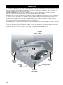 4
4
-
 5
5
-
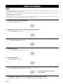 6
6
-
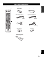 7
7
-
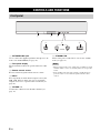 8
8
-
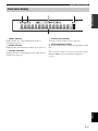 9
9
-
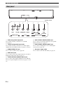 10
10
-
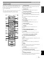 11
11
-
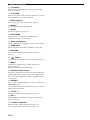 12
12
-
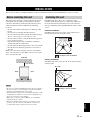 13
13
-
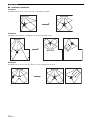 14
14
-
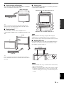 15
15
-
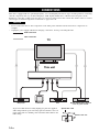 16
16
-
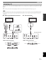 17
17
-
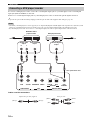 18
18
-
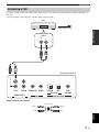 19
19
-
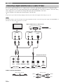 20
20
-
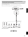 21
21
-
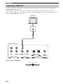 22
22
-
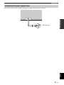 23
23
-
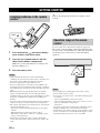 24
24
-
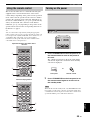 25
25
-
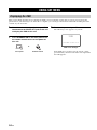 26
26
-
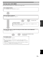 27
27
-
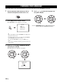 28
28
-
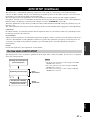 29
29
-
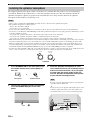 30
30
-
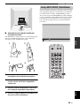 31
31
-
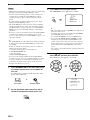 32
32
-
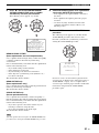 33
33
-
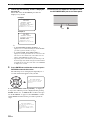 34
34
-
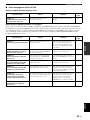 35
35
-
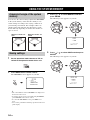 36
36
-
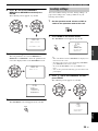 37
37
-
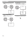 38
38
-
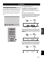 39
39
-
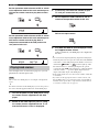 40
40
-
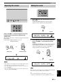 41
41
-
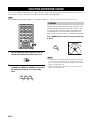 42
42
-
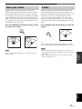 43
43
-
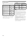 44
44
-
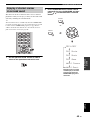 45
45
-
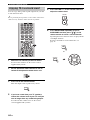 46
46
-
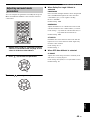 47
47
-
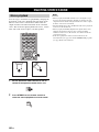 48
48
-
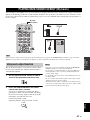 49
49
-
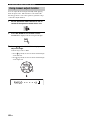 50
50
-
 51
51
-
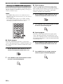 52
52
-
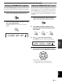 53
53
-
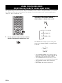 54
54
-
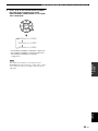 55
55
-
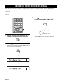 56
56
-
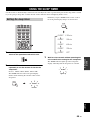 57
57
-
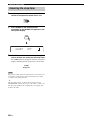 58
58
-
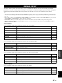 59
59
-
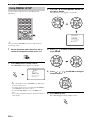 60
60
-
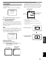 61
61
-
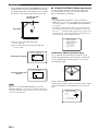 62
62
-
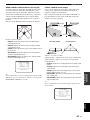 63
63
-
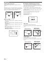 64
64
-
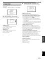 65
65
-
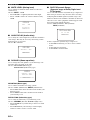 66
66
-
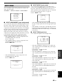 67
67
-
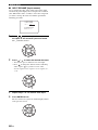 68
68
-
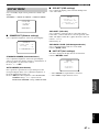 69
69
-
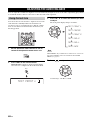 70
70
-
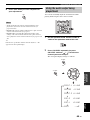 71
71
-
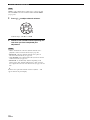 72
72
-
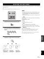 73
73
-
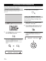 74
74
-
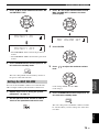 75
75
-
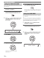 76
76
-
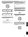 77
77
-
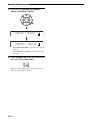 78
78
-
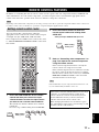 79
79
-
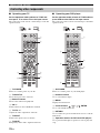 80
80
-
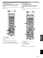 81
81
-
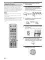 82
82
-
 83
83
-
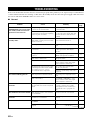 84
84
-
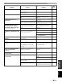 85
85
-
 86
86
-
 87
87
-
 88
88
-
 89
89
-
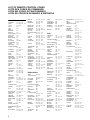 90
90
-
 91
91
-
 92
92
-
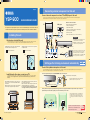 93
93
-
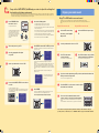 94
94
-
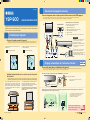 95
95
-
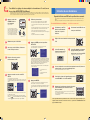 96
96
-
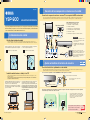 97
97
-
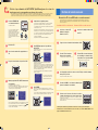 98
98


in andere talen
- English: Yamaha YSP-900 Owner's manual
- italiano: Yamaha YSP-900 Manuale del proprietario
- français: Yamaha YSP-900 Le manuel du propriétaire
- Deutsch: Yamaha YSP-900 Bedienungsanleitung
- dansk: Yamaha YSP-900 Brugervejledning
- svenska: Yamaha YSP-900 Bruksanvisning
- Türkçe: Yamaha YSP-900 El kitabı
- română: Yamaha YSP-900 Manualul proprietarului
Gerelateerde artikelen
-
Yamaha YSP-1100 de handleiding
-
Yamaha Digital Sound Projector YSP-3000 de handleiding
-
Yamaha YSP-3050BL Handleiding
-
Yamaha YSP-4000 de handleiding
-
Yamaha YSP-600 de handleiding
-
-
-
Yamaha YSP800S - Digital Sound Projector Five CH Speaker de handleiding
-
-