
DPX–1
Digital Cinema Projector
Projecteur Cinema Numerique
UCA
OWNER’S MANUAL
MODE D’EMPLOI

Caution: Read this before operating this unit.
• To assure the finest performance, please read this manual
carefully. Keep it in a safe place for future reference.
Installation
• Install this unit in a well-ventilated, cool, dry, clean place with
at least 10 cm clearance on the top, right and left, and at the
back of this unit — away from direct sunlight, heat sources,
vibration, dust, moisture, and/or cold.
• Locate this unit away from other electrical appliances, motors,
or transformers to avoid humming sounds. To prevent fire or
electrical shock, do not place this unit where it may get
exposed to rain, water, and/or any type of liquid.
• Do not expose this unit to sudden temperature changes from
cold to hot, and do not locate this unit in an environment with
high humidity (i.e. a room with a humidifier) to prevent
condensation inside this unit, which may cause an electrical
shock, fire, damage to this unit, and/or personal injury.
• On the top of this unit, do not place:
– Other components, as they may cause damage and/or
discoloration on the surface of this unit.
– Burning objects (i.e. candles), as they may cause fire,
damage to this unit, and/or personal injury.
– Containers with liquid in them, as they may cause electrical
shock to the user and/or damage to this unit.
• Do not cover this unit with a newspaper, tablecloth, curtain, etc.
in order not to restrict heat dissipation. If the temperature inside
this unit rises too much, it may cause fire, damage to this unit,
and/or personal injury.
• When installing this unit on the ceiling, make sure the ceiling
has sufficient strength to support this unit and the ceiling
mounts for an extended period of time. Installation must be
performed only by qualified service personnel.
Operation
• Remove the lens cap before starting any operation of this unit
to prevent the heat from staying around the lens. Operation
with the cap on may cause damage to this unit.
• Do not plug in this unit to a wall outlet until all connections are
complete.
• Only the voltage specified on this unit must be used. Using this
unit with a higher voltage than specified is dangerous and may
cause fire, damage to this unit, and/or personal injury.
YAMAHA will not be held responsible for any damage
resulting from use of this unit with a voltage other than that
specified.
• Do not use force on switches, knobs and/or cords.
• Do not operate this unit upside-down. It may overheat, possibly
causing damage.
• Take care of this unit so that no foreign objects and/or liquid
drop inside this unit.
• To prevent damage by lightning, disconnect the power cord
from the wall outlet during an electrical storm.
• Do not look into the lens while this unit is turned on. It may
cause serious damage to your eyesight.
• Before moving this unit, press STANDBY/ON to set this unit
in the standby mode, and disconnect the AC power plug from
the wall outlet.
• Do not attempt to modify or fix this unit. Contact qualified
YAMAHA service personnel when any service is needed. The
cabinet should never be opened for any reason.
• When not planning to use this unit for a long period of time
(i.e. vacation), disconnect the AC power plug from the wall
outlet.
• When disconnecting the power cord from the wall outlet, grasp
the plug; do not pull the cord.
• Be sure to read the “TROUBLESHOOTING” section on
common operating errors before concluding that this unit is
faulty.
Others
• Clean the lens carefully so as not to create any scratches by
using a blower or lens paper.
• Replace the lamp when the LAMP/COVER indicator flashes in
red after the lamp usage has exceeded 1000 hours. Follow the
lamp replacement procedure described in this manual.
IMPORTANT
THE WIRES IN THIS MAINS LEAD ARE COLOURED IN
ACCORDANCE WITH THE FOLLOWING CODE:
GREEN-AND-YELLOW: EARTH
BLUE: NEUTRAL
BROWN: LIVE
As the colours of the wires in the mains lead of this apparatus may
not correspond with the coloured markings identifying the
terminals in your plug, proceed as follows:
The wire which is coloured GREEN-AND-YELLOW must be
connected to the terminal in the plug which is marked by the letter
E or by the safety earth symbol or coloured GREEN or GREEN-
and-YELLOW.
The wire which is coloured BLUE must be connected to the
terminal which is marked with the letter N or coloured BLACK.
The wire which is coloured BROWN must be connected to the
terminal which is marked with the letter L or coloured RED.
For U.K. customers
If the socket outlets in the home are not suitable for the plug
supplied with this appliance, it should be cut off and an appropriate
3 pin plug fitted. For details, refer to the instructions described
below.
Note
• The plug severed from the mains lead must be destroyed, as a plug with
bared flexible cord is hazardous if engaged in a live socket outlet.
For Canadian Customers
To prevent electric shock, match wide blade of plug to
wide slot and fully insert.
This Class B digital apparatus complies with Canadian ICES-
003.
I

English
If this unit is not correctly installed in an appropriate place, it may cause fire or failure, or damage to this unit may result. Carefully choose
the place to install this unit by avoiding the places listed below.
1. Places where the temperature and humidity vary greatly
• Do not install this unit in a place where the temperature and humidity become extremely high or the temperature becomes extremely
low.
• This unit must be used within a temperature range of 5—35°C.
2. Places without adequate ventilation
• Install this unit with at least 10 cm (4 inch) of ventilation space on the top, right and left, and at the back of this unit.
• Do not cover the ventilation slots of this unit not to obstruct the heat dissipation.
• Install this unit on the firm surface.
• Do not cover this unit with a tablecloth, etc.
• Make sure there is nothing to get sucked into the ventilation slots so that the temperature of this unit does not become too high.
3. Places where it gets dusty
• If the air filters are blocked with dust, the temperature of this unit may become too high.
4. Places with too much vibration or impact
• Vibration and impact can damage parts of this unit.
5. Places where this unit gets exposed to water or high humidity
• If this unit is exposed to water or high humidity, it may cause a fire or electrical shock.
6. Unstable places
• If this unit is installed on an unstable or an inclined tabletop, it may fall and cause damage to this unit or personal injury.
Important
• Make sure no light other than the projecting light directly falls on the screen to ensure vivid high-contrast images.
Inappropriate places for installation
II

E-1
INTRODUCTION
INSTALLATION
CONNECTIONS
BASIC OPERATION
MENU
ADDITIONAL
INFORMATION
English
PRECAUTIONS
ENGLISH
Introduction
Features
Contents
INTRODUCTION
Features ............................................. 1
Controls and functions
Front panel and terminal panel ............................................. 2
Control panel ........................................................................ 3
Remote control ..................................................................... 4
Loading the batteries in the remote control .......................... 4
MENU
Menu structure
IMAGE ............................................................................... 15
SIGNAL ............................................................................. 16
INITIAL ............................................................................. 17
SETUP ................................................................................ 17
Menu operation
Menu screen and operating buttons .................................... 18
Basic menu operation ......................................................... 19
Submenu ............................................................................. 20
Basic submenu operation.................................................... 21
One-touch image menu ...................................................... 24
Changing the menu location ............................................... 24
Memory function
Selecting the memory setting number ................................ 25
Resetting to the factory setting ........................................... 26
INSTALLATION
How to install
Screen and projection distance ............................................. 5
Screen setting ....................................................................... 6
Setting “SCREEN ASPECT” ............................................... 6
Adjusting with “DIGITAL LENS SHIFT”........................... 6
Installation methods ............................................................. 7
CONNECTIONS
How to connect
Connecting a video component ............................................ 8
Connecting a computer ......................................................... 9
BASIC OPERATION
Using this unit
Turning on the power ......................................................... 10
Focusing ............................................................................. 10
Selecting the input source................................................... 11
STILL—freezing the image ............................................... 11
HIDE—turning off the image temporarily ......................... 11
Selecting “ASPECT” .......................................................... 12
Turning off this unit ............................................................ 14
Indicators ............................................................................ 14
ADDITIONAL INFORMATION
Additional information
Glossary .............................................................................. 27
Projectable signals .............................................................. 28
Menu items and input signals ............................................. 29
Message display ................................................................. 30
Maintenance
Regular care ........................................................................ 31
Cleaning the filter ............................................................... 31
Replacing the lamp cartridge .............................................. 32
Troubleshooting .................................. 33
Specifications
Specifications ..................................................................... 34
Accessories ......................................................................... 34
Dimensional drawing ......................................................... 35
Thank you for purchasing this YAMAHA product. We hope it will give you many years of trouble-free enjoyment. For the best performance,
read this manual carefully. It will guide you in operating your YAMAHA product.
• High-brightness and high-contrast images achieved by DLP™
technology
• 0.9-inch large DMD™ chips to ensure superior image quality
• Rich gray-scale tones achieved by the tri-segment color wheel
• Quiet operation with a noise as low as 30dB by Yamaha sound
effect technology
(DLP™ and DMD™ are trademarks of Texas Instruments.)
• Wide variety of input terminals to support the latest video
formats
• Superior image quality achieved by high-performance 3-2 pull-
down detection
• Six memory settings

E-2
Controls and functions
RS-232C
DVITRIGGER OUT
RGB
/
YPBPR
/
YCBCR
D4 VIDEOINPUT A
INPUT BVIDEOS VIDEO
VDG
/
YR
/
PR
/
CR
HD/SYNC
B
/
PB
/
CB
8
12345 6 7
90 q w
Focus ring, zoom ring
Focuses and zooms the lens
Remote sensor
Lens
Ventilation (exhaust) slot
Terminal panel <side>
1—5 INPUT A (BNC jacks)
These jacks receive component video and RGB signals.
Component video signals from an A/V component are sent to
the 1—3 jacks. RGB signals from a computer are sent to the
1—5 jacks. Use a BNC cable when connecting this unit to
another component.
1 G/Y (G or luminance signal)
2 B/PB/CB (B or color-difference signal)
3 R/P
R/CR (R or color-difference signal)
4 HD/SYNC (horizontal sync signal, composite sync signal)
5 VD (vertical synchronous signal)
6 D4 VIDEO (D connector)
This connector receives video signals from the D connector of
an A/V component and is compatible with the D1—D4 format.
* This connector is designed for the Japanese D format only.
7 RS-232C (D-Sub 9-pin)
This connector is used for an examination in the factory.
8 S VIDEO (mini DIN jack)
This jack receives S video signals from the S video jack on an
A/V component. Use an S video cable when connecting this
unit to another component.
9 VIDEO (pin jack)
This terminal is for the composite signal from the video
terminal of the A/V component. Use a video pin cable.
0 INPUT B (D-Sub 15-pin)
This connector receives component video and RGB signals
(RGB/YP
BPR/YCBCR) from an A/V component or a computer.
Use a D-Sub monitor cable when connecting this unit to
another component.
q TRIGGER OUT (mini jack)
This jack outputs signals to control external components. A
potential of +12V will be provided while this unit is projecting.
w DVI (DVI connector)
This connector receives DVI signals (digital RGB) from a
computer.
■ Front panel and terminal panel
Lens cap

E-3
INTRODUCTION
English
1 indicator (P.14)
2 STANDBY/ON button (P.10)
Secondary power button
Turns on and sets this unit in the standby mode. This button is
effective only when the primary power switch is turned on.
Standby mode
In this mode, this unit consumes a small amount of power to
receive infrared siganls from the remote control.
3 LAMP/COVER indicator (P.14)
4 TEMP/FAN indicator (P.14)
5 FILM indicator (P.14)
6 INPUT button (P.11)
Turns on and off the menu to select the input terminal and the
input signal.
■ Control panel
Controls and functions
SELECTESCAPE
INPUTSTANBY/ON
FILM
MENUPATTERN
TEMP
/
FAN
LAMP
/
COVER
STANDBY
/
ON
PATTERN MENU
INPUT
LAMP
/
COVER
TEMP
/
FAN
FILM
ESCAPE
SELECT
DIGITAL CINEMA PROJECTOR DPX–1
1234567 89 0 q
Rear remote control
sensor
Ventilation (intake) slots / filter
covers
AC inlet
To plug in the supplied power cord.
Power switch
Primary power switch.
“ ” turns on and sets this unit in the
standby mode.
“ ” turns off this unit.
Adjusters
To fine-adjust the projection angle
Control panel <on the rear>
7 PATTERN button (P.10)
Turns on and off the stored test patterns on the screen.
8 MENU button (P.18)
Turns on and off the menu to set or adjust the parameters
necessary for projection.
9 ESCAPE button (P.18)
Closes the submenu.
0 Cursor buttons (P.18)
Used for the operation of h, g, –, and +.
q SELECT button (P.18)
Confirms the new setting entry, or opens the submenu.

E-4
Controls and functions
■ Remote control
The corresponding buttons on the control panel and the remote
control perform same functions. Use the remote control by aiming
at the remote control sensor located on the front or back of this
unit, within a distance of 7 m (23 feet). This unit may not respond
when the remote control is not close enough to the vertical line to
the sensor.
1 AUTO button
Readjusts the most appropriate setting for the signal type.
2 PATTERN button (P.10)
Turns on and off the stored test patterns on the screen.
3 STANDBY/ON button (P.10)
Turns on and sets this unit in the standby mode. This button is
effective only when the primary power switch is turned on.
4 MENU button (P.18)
Turns on and off the menu display to set and adjust the
parameters necessary for projection.
5 ESCAPE button (P.18)
Closes the submenu.
6 Light switch
Lights the operation buttons on the remote control for approxi-
mately 10 seconds when pushed upward or downward.
7 Cursor buttons (P.18)
Used for the operation of h, g, –, and +.
8 SELECT button (P.18)
Confirms the new setting entry, or opens the submenu. Press
the center of the button for this function.
9 ASPECT button (P.12)
Selects the display aspect ratio for the images to be projected.
When pressed, the current display aspect ratio is displayed.
When pressed again within 2 seconds, the next display aspect
ratio is displayed.
0 INPUT button (P.11)
Turns on and off the menu display to select the input terminal
and the input signal.
q RESET button (P.18)
Resets the parameter to its factory setting when pressed while
adjusting the parameter on the menu.
w STILL button (P.11)
Stops a moving image to display a still image of the desired
frame. Press again to cancel this function.
e HIDE button (P.11)
Temporarily turns off the image being projected. Press again to
cancel this function.
r INPUT area
Directly selects the input terminal.
t MEMORY area (P.25)
Directly calls up the stored memory setting information.
■ Loading the batteries in the remote
control
1. Remove the battery compartment cover from the
back of the remote control.
2. Insert two batteries (AA, UM-3 or R6 type) according
to the polarity markings on the inside of the battery
compartment.
3. Close the cover until it snaps into place.
Important
• If you find that the remote control must be used closer to
this unit than usual, the batteries are weak. Replace the
batteries with new ones.
• Do not mix new and old, or different types of battery.
• Remove the batteries from the remote control when planning
not to use for a long period of time.
• If the batteries have leaked, wipe the inside of the battery
compartment before loading new ones.
AUTO
ESCAPE
SELECT
ASPECT
RESET STILL
INPUT
MEMORY
HIDE
S VIDEO
A
123
456
DVI
VIDEO
BD4
INPUT
MENU
PATT
PATTERN
STANDBY/ON
1
2
5
6
7
9
q
w
r
t
3
4
8
0
e
1
3
2

E-5
English
INSTALLATION
INSTALLATION
How to install
4:3 Screen
16:9 Screen
There are four ways this unit can be installed:
installing on a tabletop in front of the screen,
mounting on the ceiling in front of the screen,
installing on a tabletop behind a semi-translucent screen,
mounting on the ceiling behind a semi-translucent screen.
It is necessary to set the installation method for “INSTALLATION” in the menu group 4 <SETUP> on the menu described later. (See page
17.)
■ Screen and projection distance
The ideal position (projection distance [L]) to install this unit is determined by the screen aspect ratio (4:3 or 16:9) and the size (length of the
diagonal line across the screen). It is possible to adjust the projection distance within the range from Wide to Tele. by using the zoom
function. Use the following information as illustrated in the figure below to determine the best position for installation.
Screen size
(inch)
60
80
100
120
150
200
(m)
2.4—2.9
3.2—3.9
4.0—4.9
4.8—5.8
6.1—7.3
8.1—9.8
Zoom function
Tele.
Wide
Tele.
Wide
Tele.
Wide
Smaller
Screen size
Larger
Projection distance
Screen size
(inch)
60
80
100
120
150
200
(m)
2.6—3.2
3.5—4.2
4.4—5.3
5.3—6.4
6.6—8.0
8.8—10.6
Zoom function
Tele.
Wide
Tele.
Wide
Tele.
Wide
Projection distance
Smaller
Screen size
Larger
Projection distance [L] Wide/Tele.
(feet, inch)
7’ 10”— 9’ 6”
10’ 6”— 12’ 10”
13’ 1”— 16’
15’ 9”— 19’
20’— 23’ 11”
26’ 7”— 32’ 2”
(feet, inch)
8’ 6”— 10’ 6”
11’ 6”— 13’ 9”
14’ 5”— 17’ 5”
17’ 5”— 21’
21’ 8”— 26’ 3”
28’ 10”— 34’ 9”
Projection distance [L] Wide/Tele.
Important
• Projection distance is the horizontal distance from the lens surface of this unit to the screen. The lens is recessed for 4 cm (1-1/2
inch) from this unit’s exterior.

E-6
How to install
■ Screen setting
The screen height depends on your screen size. This unit projects
facing slightly upward, although projecting symmetrically about
the lens center on the horizontal axis. The following charts show
the height [H] from the lens center to the screen bottom. Consider
dimension [H] when determining the position to set your screen.
12°—15°
*
*
This unit
Center of image
Center of lens
Projection distance [L]
Height to the screen [H]
4:3 screen
Screen size
(diagonal)
16:9 screen
Screen size
(diagonal)
4:3 Screen
16:9 Screen
(When “DIGITAL LENS SHIFT” is set to 0)
Screen size
(inch)
60
80
100
120
150
200
(cm)
18
24
30
36
45
59
Screen size
(inch)
60
80
100
120
150
200
(cm)
32
42
53
64
80
106
Screen size
(inch)
60
80
100
120
150
200
(cm)
19—44
26—59
32—74
39—89
49—111
65—145
■ Adjusting with “DIGITAL LENS SHIFT”
When “SCREEN ASPECT” in the menu group 4 <SETUP> on
the menu is set to “16:9”, the projected image can be vertically
adjusted within the range shown on the right by digitally changing
[H] (the height from the lens center to the screen bottom). See page
17.
*
See “DIGITAL LENS SHIFT”
described in the next section.
Height to the screen bottom [H]
(inch)
7- 1/16
9- 7/16
11- 13/16
14- 3/16
17- 3/4
23- 1/4
Height to the screen bottom [H]
(inch)
12- 5/8
16- 1/2
20- 7/8
25- 3/16
31- 1/2
41- 3/4
Height to the screen bottom [H]
(inch)
7-1/2— 17-5/16
10-1/4— 23-1/4
12-5/8— 29-1/8
15-3/8— 35
19-3/8— 43-3/4
25-5/8— 57
■ Setting “SCREEN ASPECT”
It is necessary to set the screen aspect ratio (4:3 or 16:9) depending on your screen in order to properly project images on the entire area of
the screen. When the 16:9 screen is used and “SCREEN ASPECT” is set to “16:9”, it is possible to project 4:3 video signals on the entire
screen without losing any part of the image off screen. It is also possible to adjust the projected image vertically as described in the next
section. See “SCREEN ASPECT” in the menu group 4 <SETUP> described on page 17.

E-7
English
INSTALLATION
2. Mounting on the ceiling
Important
• Never attempt to mount this unit on the ceiling by yourself. Consult with your local authorized dealer or any
reliable contractor.
A ceiling mount bracket (optional) is needed for mounting this unit on the ceiling.
The vertically reversed illustration of the screen installation position shown page 6 helps determine how far the screen should be set from the
ceiling. The height can be determined by adding [H] described on page 6 and the height of the ceiling mount bracket [C] as shown in the
following illustration. When this unit is installed on the ceiling, “FRONT/CEILING” in the menu group 4 <SETUP> must be selected on
the menu. (See page 17.) The projected image can be vertically adjusted within a certain range by changing the value in “DIGITAL LENS
SHIFT” on the menu when “SCREEN ASPECT” on the menu is set to “16:9”. See page 6 for details.
3. Rear projection
You can watch images projected on the back of a semi-translucent screen while sitting on the other side of the screen. The screen position can
be determined by simply following the front setting procedures described above. For this setting, “REAR/TABLE” or “REAR/CEILING”
must be selected for “INSTALLATION” in the menu group 4 <SETUP> on the menu. (See page 17.)
■ Installation methods
1. Installing on a tabletop
How to install
Low ceiling
S: 20 cm (8 inch)
High ceiling
L: 90 to 147 cm (3 to 5 feet)
(adjustable every 3 cm (1-3/16 inch))
Screen
Projection distance [L]
See page 5.
Ceiling
[H] See page 6.
Floor
Projection distance [L]
See page 5.
Screen
[H] See page 6.
8 cm (3-1/8 inch) to the lens center
Table height
This unit projects images when set on a tabletop with a certain
height in front of the screen. The table height and [H] described on
page 6 must be determined first to decide on how high the screen
should be set for the best result. The height from this unit’s bottom
to the lens center is 8 cm (3-1/8 inch). The position of the screen
(the height from the floor to the screen bottom) can be easily
determined by adding these three figures.
For example, if you are setting this unit on a tabletop with a height
of 50 cm (20 inch), you need to set your screen at a height of <50
cm + 8 cm + [H] cm (20 inch + 3-1/8 inch + [H] inch)> from the
floor.
Adjusters
Adjusting with the adjusters
When this unit is installed on a tabletop, the position of the image
can be adjusted by using the adjusters located at the bottom front of
this unit.
Adjust the height by rotating the movable part of the two screw-
type adjusters at the front bottom of this unit. The adjustment range
of these adjusters is 2.5 cm (1 inch). If loosened completely, they
will come off.
[C]

E-8
• Before making connections, make sure that the power of this unit and other components is turned off.
• Some components require different connection methods and have different jack names. Refer to the operation instructions for each
component to be connected to this unit.
• Plug in this unit correctly to prevent from creating noise or troubles.
■ Connecting a video component
There are five types of video connections available on this unit for A/V components as shown in the illustration below. Connect video output
signals from A/V components to this unit by following the illustration below with the correct cables and adapters.
◆ Note ◆
• When connecting A/V component to INPUT A component jacks, make sure to match the Y/PB/PR or Y/CB/CR of the A/V component and this unit to be
connected. Also refer to the operation instructions for the A/V component. HD/SYNC and VD need to be connected for RGB video signals in some cases.
CONNECTION
How to connect
Input
VIDEO
S VIDEO
INPUT A
INPUT B
D4 *
Type of signal
Composite video
S video
Component video/RGB video
Component video/RGB video
Component video
Type of jack
Pin jack
Mini DIN jack
BNC jack x 3—5
D-Sub 15-pin connector
D4 connector
RS-232C
DVITRIGGER OUT
RGB
/
YP
B
P
R
/
YC
B
C
R
D4 VIDEOINPUT A
INPUT BVIDEOS VIDEO
VDG
/
YR
/
P
R
/
C
R
HD/SYNC
B
/
P
B
/
C
B
G
/
YR
/
P
R
/
C
R
B
/
P
B
/
C
B
Video pin cable
S video cable
Converting plug
Pin cable
BNC cable for
component
D connector cable
D-Sub monitor cable
Video
output jack
S video
output jack
Component/RGB video output
jack/connector
D1—D4 output
connector
Video outputs of various A/V components
D-Sub
BNC jacksPin jacks
* This connector is designed for the Japanese D format only.

E-9
English
CONNECTIONS
How to connect
■ Connecting a computer
There are three types of terminals to connect this unit to a computer as listed below. Use the correct cables for the terminals to be connected.
◆ Note ◆
• See 2 <SIGNAL> on the menu described on page 16 for setting the type of image input signal.
Input
INPUT A
INPUT B
DVI
Type of signal
RGB analog
RGB analog
RGB digital
Type of jack
BNC jack x 5
D-Sub 15-pin connector
DVI connector
RS-232C
DVITRIGGER OUT
RGB
/
YPBPR
/
YCBCR
D4 VIDEOINPUT A
INPUT BVIDEOS VIDEO
VDG
/
YR
/
PR
/
CR
HD/SYNC
B
/
PB
/
CB
DVI cable (digital only)
D-Sub monitor cable
DVI output
terminal
Monitor output
terminal
Computer
BNC monitor cable

E-10
This section describes the basic projecting operation after installa-
tion and connection have been completed.
Detailed settings must be made for installation, screen, input signal
and so on, by following the menu setting procedure described in
the section starting on page 15.
■ Turning on the power
Remove the lens cap before starting any operation of this unit.
1. Plug the supplied power cord into the AC inlet on the
rear of this unit. Then plug the cord into the wall
outlet.
2. Turn on the power switch of this unit. The
indicator lights up in red in a few seconds.
3. Press the STANDBY/ON button, the indicator
flashes in green and the lamp inside this unit lights
up.
The
indicator stops flashing and lights steadily after about
30 seconds and this unit is ready for projection.
Important
• Never turn off the power switch or unplug this unit
while the
indicator is lit or flashing in green.
This causes significant damage to the lamp and
may result in its shorter life or failure.
BASIC OPERATION
Using this unit
indicator
Power switch
SELECTESCAPE
INPUTSTANBY/ON
FILM
MENUPATTERN
TEMP
/
FAN
LAMP
/
COVER
AC inlet
indicator
(Flashing in green → lights steadily in green)
STANDBY
/
ON
PATTERN
INPUT
LAMP
/
COVER
TEMP
/
FAN
FILM
AUTO
ESCAPE
SELECT
ASPECT
RESET STILL HIDE
INPUT
MENU
PATT
PATTERN
STANDBY/ON
STANDBY/ON
■ Focusing
Press the PATTERN button to project the stored test pattern.
Adjust the lens so that it comes into focus by rotating the focus
ring. The image size can be also adjusted with the zoom ring.
There are two test patterns. Choose whichever is desired by
pressing the + or – button.
Press the PATTERN button again to close the test pattern.
Zoom ring
Focus ring
PATTERN MENU
INPUT
R
TEMP
/
FAN
FILM
ESCAPE
PATTERN
Lens

E-11
English
BASIC OPERATION
Using this unit
■ Selecting the input source
Press the INPUT button to display the menu for input signals on
the screen. Select the input terminal and the input signal to be
projected by pressing the h or g button, and confirm the selection
by pressing the SELECT button.
Input Source Signal to be projected
VIDEO Composite video signals input from an A/V component to
the VIDEO jack
S VIDEO S video signals input from an A/V component to the S
VIDEO jack
INPUT A <COMPONENT>
Component signals input to INPUT A (BNC jacks)
INPUT A <RGB PC>
RGB signals input from a computer to INPUT A (BNC
jacks)
INPUT A <RGB TV>
RGB signals input from an A/V component to INPUT A
(BNC jacks)
INPUT B <COMPONENT>
Component signals input to INPUT B (D-Sub 15-pin
connector)
INPUT B <RGB PC>
RGB signals input from a computer to INPUT B (D-Sub
15-pin connector)
INPUT B <RGB TV>
RGB signals input from an A/V component to INPUT B
(D-Sub 15-pin connector)
DVI Digital RGB signals input from a computer to the DVI
connector
D4 VIDEO Component signal input from an A/V component to the
D4 VIDEO connector
PATTERN MENU
INPUT
LAMP
/
COVER
TEMP
/
FAN
FILM
ESCAPE
SELECT
AUTO
ESCAPE
SELECT
ASPECT
RESET STILL HIDE
INPUT
MENU
PATT
PATTERN
STANDBY/ON
INPUT
ASPECT
SELECT
STILL
HIDE
◆ Notes ◆
• When an ordinary video signal or an interlaced video signal of a 24-
frame/second film is input, the interlace/progressive (i/p) conversion
circuit built into this unit automatically identifies the type of signals. If
the signals of a film is input, the FILM indicator lights up in blue. Some
contents cannot be correctly detected.
• When the interlaced video signals of a film is input, this unit detects it
and the FILM indicator lights up in blue.
• When the signal from an A/V component or computer is input, it does
not go through i/p conversion, and the FILM indicator does not light up
in this case.
• This unit is compatible with VGA, SVGA, XGA, and SXGA for the
RGB signal from a computer. It is recommended to set to XGA to enjoy
clearer images when the screen aspect ratio is set to “4:3”.
• When this unit is set to display the output signals on both the LCD of a
notebook computer and on an external monitor, the image may not be
correctly displayed on the external monitor. In this case, set this unit to
display on only the external monitor. Refer to the operation instructions
of the computer for details.
• Press the AUTO button located on upper left on the remote control if the
image is not correctly projected (black or distorted images) when the
input signal is switched.
■ STILL—freezing the image
Press the STILL button on the remote control to capture the desired
frame of a moving image. This function can be effectively used to
adjust the image quality. Press the STILL button again to resume
normal projection.
■ HIDE—turning off the image temporarily
Press the HIDE button on the remote control to turn off the image
temporarily. Press the HIDE button again to bring back the image
that has been turned off.
• VGA, XGA, and SXGA are trademarks of International
Business Machines Corporation.
• SVGA is a trademark of Video Electronics Standards Associa-
tion.

E-12
Using this unit
Input signal
Normal 4:3 image
Letter box
Squeeze
(Vista size)
Squeeze
(Cinema scope
size)
HDTV
RGB PC
Input image Aspect
NORMAL
ZOOM
NORMAL
SQUEEZE
THROUGH
-SQUEEZE-
SQUEEZE
NORMAL
ZOOM
THROUGH
NORMAL
Projected
image
■ Selecting “ASPECT”
“ASPECT” selects the most appropriate way of displaying the image on the screen for the six common types of signals listed below.
Available parameters for “ASPECT” change depending on the “SCREEN ASPECT” setting. This unit has the “AUTO” mode which auto-
matically detects the type of signals and changes the display aspect. This mode is effective when information about the signal type is
included in the signal.
Press the ASPECT button for the desired display aspect.
1 Video signal of the 4:3 screen aspect from ordinary TV or video
2 Letterbox video signal
3 Squeezed video signal (Vista size)
4 Squeezed video signal (Cinema scope size)
5 Hi vision (HDTV) 16:9 video signal
6 RGB signal
● Available aspect modes when “SCREEN ASPECT” is set to “4:3”
1 AUTO
When the input signal is letterbox or squeeze, this mode detects
it and automatically switches to the most appropriate mode.
This mode is effective only when the signal is sent with
information about its type.
2 NORMAL
This mode projects the image horizontally in full on the screen
without cutting any input signal.
3 SQUEEZE
This mode desqueezes the video which has been recorded as
horizontally squeezed. The image is projected in the original
format after having passed through this circuit.
4 ZOOM
The central part of the image is scaled up. Both sides of the
input image lie offscreen.
5 THROUGH
The signal is projected as it is input without scaling up or
down.
6 THROUGH -SQUEEZE-
This mode scales up only the width of the image without
changing the height.
[Examples]

E-13
English
BASIC OPERATION
Input signal
Normal 4:3 image
Letter box
Squeeze
(Vista size)
Squeeze
(Cinema scope
size)
HDTV
RGB PC
Input image Aspect
NORMAL
ZOOM
ZOOM
-SUBTITLE-
SQUEEZE
THROUGH
-SQUEEZE-
SQUEEZE
NORMAL
NORMAL
Projected
image
SUBTITLE
● Available aspect modes when “SCREEN ASPECT” is set to “16:9”
Using this unit
1 AUTO
When the input signal is in letterbox or squeeze, this mode
detects it and automatically switches to the most appropriate
mode. This mode is effective only when the signal is sent with
information about its type.
2 NORMAL
This mode projects the image vertically in full on the screen
without cutting any input signal.
3 SQUEEZE
This mode desqueezes the video which has been recorded as
horizontally squeezed. The image is projected in the original
format after having passed through this circuit.
4 ZOOM
This mode projects the signal input as letterbox on the entire
screen of 16:9 aspect ratio.
5 ZOOM -SUBTITLE-
This mode projects the video in letterbox with subtitles on the
screen most appropriately.
“ZOOM -SUBTITLE-” in “ASPECT” in the menu group 2
<SIGNAL> has the following two items. See -Exception- on
page 20 for the adjustment procedure.
• SUBTITLE AREA
adjusts the subtitle area.
• V SCROLL
adjusts the subtitle position by vertically scrolling the
projected image.
6 THROUGH
The signal is projected as it is input without scaling up or
down.
7 THROUGH -SQUEEZE-
This mode scales up only the width of the image without
changing the height.
[Examples]

E-14
■ Turning off this unit
1. When you have finished using this unit, press the
STANDBY/ON button.
There will be a message to confirm turning off this unit. Press
the STANDBY/ON button again to turn off this unit. The lamp
turns off and the indicator flashes in orange while the fan
is rotating to cool the lamp for approximately two minutes.
This unit cannot be turned back on by pressing the STANDBY/
ON button in this state.
2. When the lamp has cooled down, the indicator
stops flashing and steadily lights in red.
3. Turn off the power switch after making sure that the
fan has completely stopped and that the
indicator is lit in red.
Important
• While the fan is rotating and the indicator is
flashing in orange, never turn off the power switch
or unplug this unit. This will cause significant
damage to the lamp and may result in its shorter
life or failure.
■ Indicators
There are four indicators on this unit to display the operating status
of this unit.
1
Off The power is turned off.
Lights in red In the standby mode
Flashes in green Getting ready to start operation
Lights in green Operating
Flashes in orange Cooling the lamp
2 LAMP/COVER
Off Normal
Lights in red The lamp cover is not correctly attached.
The air filter cover is not correctly
attached.
Flashes in red (1-second intervals)
The lamp usage has exceeded 1000
hours.
Flashes in red (0.5-second intervals)
The lamp usage has exceeded 1100
hours.
The lamp has burnt out.
3 TEMP/FAN
Off Normal
Lights in red The temperature inside this unit is
abnormally high.
Flashes in red The cooling fan is out of order.
4 FILM
Lights in blue This unit has detected the interlaced
signal (480i) of 24-frame/second film
and is converting it to progressive
images.
Off Video signals other than the interlaced
signal (480i) of 24-frame/second film are
being input.
STANDBY
/
ON
PATTERN MENU
INPUT
LAMP
/
COVER
TEMP
/
FAN
FILM
1 234
indicator
(flashes)
STANDBY
/
ON
PATTERN
INPUT
LAMP
/
COVER
TEMP
/
FAN
FILM
AUTO
ESCAPE
SELECT
ASPECT
RESET STILL HIDE
INPUT
MENU
PATT
PATTERN
STANDBY/ON
STANDBY/ON
Using this unit

E-15
English
MENU
MENU
Menu structure
It is necessary to make various settings on the menu so that this unit can achieve the best performance. The menu has a three-level hierarchy;
menu group, menu item, and submenu for some menu items. Listed below are the four menu groups.
1 <IMAGE> To adjust the image quality. Available items depend on the type of input signal.
2 <SIGNAL> To make settings for the connected input signal. Available items depend on the type of input signal.
3 <INITIAL> To make your own initial setting for several menu items.
4 <SETUP> To make settings for installation, screen aspect, key stone effect correction and so on.
Each menu group described above consists of the following items. The parameters for these items can be adjusted as you wish by following
the menu operation procedures described from page 18.
S
means that the item has a submenu.
■ 1 <IMAGE> ........... Adjustment cannot be made without any input signal.
Input signal
Video/Component/
RGB TV
Video/Component/
RGB
Video/Component/
RGB
Video/Component/
RGB
Video/Component/
RGB
Video
Video
Component
Video/Component/
RGB
Video/Component/
RGB
Video/Component/
RGB
Menu item
BLACK LEVEL
Adjusts the level of blackness while maintaining the peak white brightness.
CONTRAST
The ratio of light versus dark. If increased too high, the whole image becomes light and the
white portion of the image tends to be saturated. If decreased too low, the whole image becomes
dark and flat.
BRIGHTNESS
Controls the total brightness of an image. When adjusted too high, the black portion of the
image becomes grayish and the white portion of the image tends to be saturated. When adjusted
too low, the entire image becomes darker.
GAMMA TRIM
Adjusts the response of the color gradation and gray-scale of the image. There are five patterns
available. Select the appropriate pattern depending on the content to be projected.
SHARPNESS
Adjusts the clearness of the image edges. The higher value creates clearer edges. The lower
value creates a softer image with the less noise element.
HUE
Adjusts the hue. When adjusted to the negative direction, red increases. When adjusted to the
positive direction, blue increases. (Adjustment at the SECAM setting is not effective.)
SATURATION
Adjusts the depth of a color. When adjusted to the negative direction, the color becomes lighter.
When adjusted to the positive direction, the color becomes deeper.
COLOR BOOST
Boosts the color saturation. The higher value makes the color tends to be saturated and becomes
deeper.
COLOR TEMP
Adjusts the color of the image to be projected. The higher setting adds more blue and the lower
setting adds more red. Select the appropriate setting depending on the content to be projected.
WHITE BALANCE
S
Fine-adjusts the balance of each color (R, G, B).
CONTRAST (R, G, B)
BRIGHTNESS (R, G, B)
WHITE BOOST
Optically adjusts the luster of the white part of the projected image.
Adjustment range
–64 to 32
–128 to 127
–128 to 127
A/B/C/D/E
1 to 5
–128 to 127
–128 to 127
0 to 127
LOW/MID-L/MID/HIGH
50% to 124%
–12.4% to 12.4%
0 to 10
The three menu items described above are to adjust the input and output characteristics for the image brightness of the luminance
signal. The graphs below show how these items can be adjusted.
BRIGHTNESS
White
Black White
Input signal
CONTRAST
White
Black White
Input signal
BLACK LEVEL
White
Black White
Output image
Input signal

E-16
Menu structure
Input signal
Video/Component/RGB
Video/Component
Video/Component
Video
Video/Component
Video
Video/Component
RGB
RGB
RGB
RGB
RGB
■ 2 <SIGNAL>......... Adjustment cannot be made without any input signal.
Menu item
ASPECT
S
Sets the aspect ratio of displaying the image on the screen. “AUTO” automatically switches
to the most appropriate mode. “NORMAL” (THROUGH) projects the image as the input
signal is sent. “SQUEEZE” desqueezes the squeezed image. “ZOOM” projects the image
scaled up with a certain ratio. “ZOOM -SUBTITLE-” displays the subtitle. “THROUGH
-SQUEEZE-” displays the image with its width scaled up. Available items depend on the
“SCREEN ASPECT” setting and the type of input signals.
The “AUTO” setting may not switch to the most appropriate mode for some sources. If it
doesn’t, make a setting manually.
“ZOOM -SUBTITLE-” has further items to be adjusted
SUBTITLE AREA: adjusts the subtitle area.
V SCROLL: adjusts the subtitle position by vertically scrolling the projected image.
SUBTITLE MASK
Darkens the brightness of the characters in the subtitles when playing the film in letterbox
with subtitles (except for HDTV).
MASK POSITION
Changes the effective height for the “SUBTITLE MASK” adjustment (except for HDTV).
3D Y/C SEPARATION
Suppresses the rainbow-like color crossing the image of fine vertical stripes or annoying dot
interference on the image edge when the video signal is input. This adjustment is available
only for the composite signal in NTSC mode.
NOISE REDUCTION
Effectively reduces the noise included in the luminance signal and color signal by digital
processing when playing the source with a relatively large amount of noise in order to
create a more vivid image (interlaced signal only, except for HDTV).
VIDEO TYPE
Selects VCR when playing video tapes in order to ensure synchronization, and selects DVD
when playing other sources.
SETUP LEVEL
Adjusts the black level difference of the image signal. Select 0% for a signal with no
difference from the pedestal level, and 7.5% for a signal with higher black level.
DOT PHASE
Fine-adjusts the phase of the RGB signal input from the computer for clearest display of the
characters and lines of the image (except for DVI).
SIZE H
Adjusts the horizontal size of the projected image (except for DVI).
SHIFT H
Adjusts the horizontal position of the projected image (except for DVI).
SHIFT V
Adjusts the vertical position of the projected image (except for DVI).
SIGNAL STATUS
Displays the resolution and sync. frequency of the input signal.
Choice/adjustment range
AUTO/NORMAL/
SQUEEZE/ZOOM/ZOOM
-SUBTITLE-
S
(SUBTITLE AREA, V
SCROLL)/THROUGH/
THROUGH -SQUEEZE-
0 to 99
0 to 99
OFF/ON
–10 to 10
ON/OFF
OFF/1/2/3
DVD/VCR
0%/7.5%
0 to 31
–2047 to 2048
0 to 100
0 to 100
—
100
0
%
Image signal
Pedestal level
Black level

E-17
English
MENU
Menu structure
■ 4 <SETUP>
Menu item
INSTALLATION
S
There are four methods to install this unit; tabletop or on-ceiling for front or rear projection. The image can
be inverted or rotated according to the setting for the installation method.
SCREEN ASPECT
Selects 4:3 or 16:9 depending on the screen to be used. If 16:9 is selected, vertical adjustment of the image
can be made by changing the value of the item “DIGITAL LENS SHIFT”. And automatically makes an
adjustment to project the 4:3 input signal without losing any part of it off screen.
* DIGITAL LENS SHIFT
The image on the screen can be vertically adjusted within a certain range by digital processing. h moves the
image upward and g downward. This adjustment is available only when the screen aspect ratio is set to 16:9.
KEYSTONE
If this unit projects on a the screen with some elevation or depression angle at its installation, the image on
the screen is distorted into a trapezoid. This parameter electrically corrects the distortion. Increase the value
when the upper part of the image is wider. Decrease the value when the lower part if the image is wider.
KEYSTONE MODE
There are two modes; “FULL” that corrects the key stone effect without changing the vertical length of the
image, and “NORMAL” that makes vertical correction by shifting the bottom at the same time. Select the
appropriate mode to make correction depending on your installation.
R/C SENSOR
S
Sets the remote control sensor to be used. This unit has its remote control sensor in two locations: at the front
and the rear.
Choice/adjustment range
FRONT/TABLE, FRONT/CEILING,
REAR/TABLE, REAR/CEILING
4:3/16:9*
–96 to 96
–128 to 127
NORMAL/FULL
FRONT&REAR/FRONT/REAR
■ 3 <INITIAL>
Menu item
COLOR SYSTEM
S
Selects the color system when the video signal is input among NTSC, NTSC4.43, PAL, PAL-M, PAL-N,
PAL60, SECAM. AUTO should normally be selected so that the appropriate color system can be
automatically selected depending on the input signal. However, PAL-M should be selected when the
input signal is PAL-M.
INPUT A SIGNAL
S
Selects the type of input signal sent to the INPUT A jacks.
INPUT B SIGNAL
S
Selects the type of input signal sent to the INPUT B jacks.
LANGUAGE
S
Selects the language used on the menu.
POWER SAVING
When no signal is received at the input jacks for longer than 15 minutes, this unit automatically turns off
the lamp and enters the standby mode if ON is selected.
LAMP RUNNING TIME
S
Displays the total lamp running time. The lamp running time can be reset on the submenu.
RESET
S
Resets all parameters on the menu or parameters in the memory to the factory settings.
Choice
AUTO/NTSC/NTSC4.43/PAL/PAL-M/PAL-N/
PAL60/SECAM
COMPONENT/RGB PC/RGB TV
COMPONENT/RGB PC/RGB TV
/ENGLISH/DEUTSCH/ESPAÑOL/
FRANÇAIS/ITALIANO/
OFF/ON
—
ALL SETTINGS/ALL MEMORIES/
CURRENT MEMORY
1Normal correction
This correction shifts the bottom of the projected image to correct
the horizontal distortion.
When the upper part of the image is wider than the
lower part, increase the value to the positive (+)
direction.
When the lower part of the image is wider than the
upper part, decrease the value to the negative (–)
direction.
2Full correction
This correction adjusts the horizontal distortion without changing
the vertical length of the projected image.
When the upper part of the image is wider than the
lower part, increase the value to the positive (+)
direction.
When the lower part of the image is wider than the
upper part, decrease the value to the negative (–)
direction.

E-18
■ Menu screen and operating buttons
This section provides you with general information about the menu screen and operating buttons on the remote control and this unit’s control
panel for easier operation. Please read it carefully before starting to operate the menu.
Menu operation
MOVE MENU WINDOW
IMAGE SIGNAL INITIAL SETUP
COLOR SYSTEM AUTO
COMPONENT
RGB PC
ENGLISH
2H.
INPUT A SIGNAL
INPUT B SIGNAL
LANGUAGE
POWER SAVING
LAMP RUNNING TIME
RESET
ESCAPE: EXIT MEMORY1 VIDEO
OFF ON
LANGUAGE
ESPAÑOL
FRANÇAIS
ITALIANO
DEUTSCH
ENGLISH
MOVE MENU WINDOW
Menu group
Menu item
Help message Memory setting
number Input signal
Submenu
parameter
1 MENU button
Opens or closes the menu.
2 Cursor buttons
+/– (for side-to-side movements)
• Select a menu group.
• Open or closes a submenu.
• Select or changes a setting.
h/g (for up and down movements)
• Select a menu item.
• Select or changes a setting.
3 SELECT button
• Opens a submenu.
• Confirms a new setting when adjusting “COLOR SYS-
TEM”, “INPUT A SIGNAL”, “INPUT B SIGNAL”, or R/
C SENSOR”.
• Opens a one-touch image menu when the menu screen has
not been opened.
4 MEMORY 1 to 6 button (Remote control only)
Selects a memory setting number.
5 RESET button (Remote control only)
Resets the parameter setting to the factory setting.
Items without factory settings cannot be reset.
6 ESCAPE button
• Returns the cursor to the menu group hierarchy from the
menu item hierarchy.
• Returns to the menu from the MOVE MENU WINDOW.
• Closes the submenu.
• Closes the menu when the cursor is on one of the menu
groups.
• Closes the one-touch image menu.
The menu has a three-level hierarchy: menu group, menu item, and
submenu for some menu items.
PATTERN MENU
INPUT
ESCAPE
SELECT
16 2 3
AUTO
ESCAPE
SELECT
ASPECT
RESET STILL
INPUT
MEMORY
HIDE
S VIDEO
A
123
456
DVI
VIDEO
BD4
INPUT
MENU
PATT
PATTERN
STANDBY/ON
1
2
3
4
6
5
Parameter
Submenu mark

E-19
English
MENU
Menu operation
AUTO
ESCAPE
SELECT
ASPECT
RESET STILL HIDE
INPUT
MENU
PATT
PATTERN
STANDBY/ON
5
3, 5
4
1, 6
2, 4
STANDBY
/
ON
PATTERN MENU
INPUT
LAMP
/
COVER
TEMP
/
FAN
FILM
ESCAPE
SELECT
2, 4
5 3, 51, 6
■ Basic menu operation
To ensure proper projection, start with setting and adjustment for the menu group “SETUP”.
1. Press the MENU button to open the menu.
The previous menu screen opens if menu operation has already
been performed.
2. Press the + or – button to select a menu group.
MENU
MENU
Remote control
or
Control panel
MOVE MENU WINDOW
IMAGE SIGNAL INITIAL SETUP
BLACK LEVEL 0
CONTRAST 0
BRIGHTNESS 0
HUE 0
SATURATION
COLOR BOOST
GAMMA TRIM
MEMORY1 VIDEO
A B C D E
1 2 3 4 5SHARPNESS
0
0
MOVE MENU WINDOW
IMAGE SIGNAL INITIAL SETUP
INSTALLATION FRONT/TABLE
FRONT&REAR
SCREEN ASPECT
KEYSTONE 0
KEYSTONE MODE
R/C SENSOR
4:3 16:9
NORMAL FULL
MEMORY1 VIDEO
SELECT
Remote control
or
Control panel
3. Press the g button to enter the menu item hierarchy.
Then select an item to be adjusted by pressing the h or g
button.
4. Select or change the parameter by pressing the + or –
button.
SELECT
IMAGE SIGNAL INITIAL SETUP
INSTALLATION FRONT/TABLE
FRONT&REAR
SCREEN ASPECT
KEYSTONE 0
KEYSTONE MODE
R/C SENSOR
4:3 16:9
NORMAL FULL
MEMORY1 VIDEO
Remote control
or
Control panel
IMAGE SIGNAL INITIAL SETUP
INSTALLATION FRONT/TABLE
FRONT&REAR
SCREEN ASPECT
KEYSTONE 0
KEYSTONE MODE
R/C SENSOR
DIGITAL LENS SHIFT
4:3 16:9
NORMAL FULL
MEMORY1 VIDEO
SELECT
Remote control
or
Control panel

E-20
Menu operation
Some items are adjusted by increasing or decreasing the value on
the scale, and others by selecting a number or a word.
Press the RESET button to reset the parameter to the factory
setting. (Items without a factory setting cannot be reset.)
5. Press the h or g button to move the cursor to the
next item.
First return to the menu group by pressing the ESCAPE or h
button if the next item belongs to the another menu group.
Then follow the previous steps 2—4 to continue menu setting.
6. Press the MENU button to close the menu when
setting has been completed.
KEYSTONE 0
KEYSTONE MODE
NORMAL FULL
SELECT
Remote control
or
Control panel
MENU
MENU
Remote control
or
Control panel
■ Submenu
Following is a list of the menu items that have a submenu.
Submenu operation varies according to the menu item selected.
Follow the steps of the applicable submenu operation group.
Menu items with a submenu
Submenu operation
group
C
A
B
B
B
A
D
D
A
A
B
Operation group A: Press the SELECT or + button to open the
submenu. Select the desired parameter by pressing the h or g
button, and then press the ESCAPE or – button to close the
submenu.
Operation group B: Press the SELECT or + button to open the
submenu. Select the desired parameter by pressing the h or g
button, and then confirm the new setting by pressing the SELECT
button. After the setting has been confirmed, press the ESCAPE or
– button to close the submenu.
Operation group C: Press the SELECT or + button to open the
submenu. Select the submenu item by pressing the h or g button,
and then change the parameter by pressing the h or g button.
It is not necessary to confirm the new setting.
Operation group D: Press the SELECT or + button to open the
submenu, which is in the form of messages. Perform menu
operation by following the direction in the message. The submenu
for this group is explained in the section on pages 22 and 23.
-Exception-
* When the menu item “SCREEN ASPECT” in the menu group
“SETUP” is set to “16:9”
If “ZOOM -SUBTITLE-” is selected in the submenu for
“ASPECT”, there is an additional menu to make your desired
setting. Press the SELECT button to open the additional menu.
There are two items, “SUBTITLE AREA” and “V SCROLL”.
Select the item to be adjusted by pressing the h or g button.
Set the desired value by pressing the + or – button. Press the
ESCAPE button to close the additional menu.
Menu group
IMAGE
SIGNAL
INITIAL
SETUP
Menu item
WHITE BALANCE
ASPECT*
COLOR SYSTEM
INPUT A SIGNAL
INPUT B SIGNAL
LANGUAGE
LAMP RUNNING
TIME
RESET
INSTALLATION
DIGITAL LENS
SHIFT
R/C SENSOR

E-21
English
MENU
Menu operation
■ Basic submenu operation
[Operation groups A and B]
1. Select the menu item to be adjusted by following
steps 1—3 in “Basic menu operation”.
The submenu mark “
” appears on the right side of the item.
2. Press the SELECT or + button to open the submenu.
IMAGE SIGNAL INITIAL SETUP
COLOR SYSTEM AUTO
COMPONENT
RGB PC
ENGLISH
2H.
INPUT A SIGNAL
INPUT B SIGNAL
LANGUAGE
POWER SAVING
LAMP RUNNING TIME
RESET
MEMORY1 VIDEO
OFF ON
SELECT
SELECT
Remote control
or
Control panel
IMAGE SIGNAL INITIAL SETUP
ENGLISH
DEUTSCH
ESPAÑOL
FRANÇAIS
ITALIANO
LANGUAGE
ESCAPE: EXIT MEMORY1 VIDEO
3. Select the submenu parameter by pressing the h or g
button.
Press the RESET button to reset the parameter to the factory
setting. (Items without a factory setting cannot be reset.)
When setting “COLOR SYSTEM”, “INPUT A SIGNAL”,
“INPUT B SIGNAL”, or “R/C SENSOR”, the following step
[Operation group B only] is necessary.
[Operation group B only]
Press the SELECT button to confirm the new setting and close
the submenu. Setting cannot be changed for the above items if
not confirmed by the SELECT button.
To reset the parameter to the factory setting, press the RESET
button when the submenu has been opened.
4. Press the MENU button to close the menu.
Press the ESCAPE or – button to return to the previous screen
if continuing to adjust settings.
SELECT
Remote control
or
Control panel
ENGLISH
DEUTSCH
ESPAÑOL
FRANÇAIS
ITALIANO
VIDEO
BILD SIGNAL EINST. AUFST.
SPRACHE
SPEICHER1ESCAPE: VERLASSEN
SELECT
SELECT
Remote control
or
Control panel
MENU
MENU
Remote control
or
Control panel

E-22
IMAGE SIGNAL INITIAL SETUP
COLOR SYSTEM AUTO
COMPONENT
RGB PC
ENGLISH
2H.
INPUT A SIGNAL
INPUT B SIGNAL
LANGUAGE
POWER SAVING
LAMP RUNNING TIME
RESET
MEMORY1 VIDEO
OFF ON
IMAGE SIGNAL INITIAL SETUP
PRESS ”SELECT” TO RESET
LAMP RUNNING TIME ON
”YES”.
ESCAPE: EXIT MEMORY1 VIDEO
LAMP RUNNING TIME 2H.
NO
YES
Menu operation
● Submenu operation—“WHITE BALANCE”
[Operation group C]
1. Select the menu item “WHITE BALANCE” in the menu
group “IMAGE” by following steps 1—3 in “Basic
menu operation”.
The submenu mark “
” appears on the right side of the item.
2. Press the SELECT or + button to open the submenu.
3. Select the submenu item by pressing the h or g
button.
IMAGE SIGNAL INITIAL SETUP
WHITE BALANCE
WHITE BOOST 0
MEMORY1 VIDEO
COLOR TEMP LOW
MID-L
MID HIGH
IMAGE SIGNAL INITIAL SETUP
WHITE BALANCE
CONTRAST R 100%
MEMORY1 VIDEO
CONTRAST G 100%
CONTRAST B 100%
BRIGHTNESS R 0%
BRIGHTNESS G 0%
BRIGHTNESS B 0%
ESCAPE: EXIT
4. Select the value by pressing the + or – button.
Press the RESET button to reset the parameter to the factory
setting.
5. Press the MENU button to close the menu.
Press the ESCAPE button to return to the previous screen if
continuing to adjust settings. The – button does not close the
submenu to return to the previous screen for this parameter.
● Submenu operation—“LAMP RUNNING TIME”
[Operation group D]
1. Select the menu item “LAMP RUNNING TIME” in the
menu group “INITIAL” by following steps 1—3 in
“Basic menu operation”.
The submenu mark “
” appears on the right side of the item.
2. Press the SELECT or + button to open the confirma-
tion message screen.
IMAGE SIGNAL INITIAL SETUP
WHITE BALANCE
CONTRAST R 100%
MEMORY1 VIDEO
CONTRAST G 100%
CONTRAST B 100%
BRIGHTNESS R 0%
BRIGHTNESS G 0%
BRIGHTNESS B 0%
ESCAPE: EXIT
IMAGE SIGNAL INITIAL SETUP
WHITE BALANCE
CONTRAST R 100%
MEMORY1 VIDEO
CONTRAST G 100%
CONTRAST B 80%
BRIGHTNESS R 0%
BRIGHTNESS G 0%
BRIGHTNESS B 0%
ESCAPE: EXIT

E-23
English
MENU
3. Select the submenu item to be reset by pressing the
h or g button.
4. Press the SELECT or + button to open the confirma-
tion message screen.
5. Press the SELECT button to reset to the factory
setting.
The menu closes after the parameters have been reset to the
factory settings.
Menu operation
IMAGE SIGNAL INITIAL SETUP
ESCAPE: EXIT MEMORY1 VIDEO
LAMP RUNNING TIME 2H.
NO
YES
PRESS ”SELECT” TO RESET
LAMP RUNNING TIME ON
”YES”.
3. Select “YES” by pressing the h or g button, and then
press the SELECT button to reset the lamp running
time to 0.
4. Press the MENU button to close the menu.
● Submenu operation—“RESET”
[Operation group D]
1. Select the menu item “RESET” in the menu group
“INITIAL” by following steps 1—3 in “Basic menu
operation”.
The submenu mark “
” appears on the right side of the item.
2. Press the SELECT or + button to open the submenu.
IMAGE SIGNAL INITIAL SETUP
COLOR SYSTEM AUTO
COMPONENT
RGB PC
ENGLISH
2H.
INPUT A SIGNAL
INPUT B SIGNAL
LANGUAGE
POWER SAVING
LAMP RUNNING TIME
RESET
MEMORY1 VIDEO
OFF ON
IMAGE SIGNAL INITIAL SETUP
RESET
CURRENT MEMORY
ALL MEMORIES
ALL SETTINGS
ESCAPE: EXIT MEMORY1 VIDEO
IMAGE SIGNAL INITIAL SETUP
RESET
CURRENT MEMORY
ALL MEMORIES
ALL SETTINGS
ESCAPE: EXIT MEMORY1 VIDEO
IMAGE SIGNAL INITIAL SETUP
PRESS ”SELECT” TO RESET
TO FACTORY SETTINGS.
ESCAPE: EXIT MEMORY1 VIDEO

E-24
Menu operation
■ One-touch image menu
1. Press the SELECT button to open the one-touch
image menu when the menu has not been opened.
The image menu items appear at the bottom of the screen one
after another. The previous parameter appears once menu
operation has been performed.
The displayed item turns off if no operation is performed
within five seconds.
2. Select the item to be adjusted by pressing the h and
g button.
3. Select the value by pressing the + or – button.
Press the RESET button to reset the parameter to the factory
setting.
4. Press the SELECT or ESCAPE button to close the
one-touch menu.
SELECT
SELECT
Remote control
or
Control panel
BLACK LEVEL 0
SELECT
Remote control
or
Control panel
CONTRAST 0
CONTRAST 100
SELECT
Remote control
or
Control panel
ESCAPE
SELECT
ESCAPE
SELECT
Remote control
or
Control panel
■ Changing the menu location
1. Press the ESCAPE or h button to return the cursor to
the menu group.
2. Press the h button to enter the “MOVE MENU WIN-
DOW”.
3. Change the location of the menu by pressing the +, –,
h, or g button.
4. Press the ESCAPE button to return to the menu after
the location has been decided.
ESCAPE
SELECT
ESCAPE
Remote control
or
Control panel
MOVE MENU WINDOW
IMAGE SIGNAL INITIAL SETUP
INSTALLATION FRONT/TABLE
FRONT&REAR
SCREEN ASPECT
KEYSTONE 0
KEYSTONE MODE
R/C SENSOR
4:3 16:9
NORMAL FULL
MEMORY1 VIDEO
MOVE MENU WINDOW
SETUP
ESCAPE: EXIT MEMORY1 VIDEO
SELECT
Remote control
or
Control panel
SELECT
Remote control
or
Control panel
ESCAPE
ESCAPE
Remote control
or
Control panel

E-25
English
MENU
This unit has a memory function that can store six settings to
project different types of input sources in the most appropriate
manner. Select one of these six settings that is most suitable for
your projection. Although six settings have already been prepared,
each parameter in the settings can be changed and restored as you
wish. The following lists the menu items that can be stored in
memory.
Memory function
■ Selecting the memory setting number
To select by operating the remote control
Press the number of the desired memory setting among the
MEMORY 1—6 buttons.
To select by operating the menu
1. Press the MENU button to open the menu.
2. Press the g button to enter the memory setting
number at the bottom of the screen.
IMAGE
BLACK LEVEL
CONTRAST
BRIGHTNESS
GAMMA TRIM
SHARPNESS
HUE
SATURATION
COLOR BOOST
COLOR TEMP
WHITE BALANCE
WHITE BOOST
SIGNAL
3D Y/C SEPARATION
NOISE REDUCTION
VIDEO TYPE
SETUP LEVEL
MEMORY
123
456
IMAGE SIGNAL INITIAL SETUP
AUTO
MOMORY1 VIDEO
OFF ON
0% 7.5%
DVD VCR
OFF 1 2 3
3D Y/C SEPARATION
ASPECT
NOISE REDUCTION
VIDEO TYPE
SETUP LEVEL
SUBTITLE MASK
MASK POSITION
0
+
: EDIT
OFF ON
3. Press the + button to open the submenu.
4. Select the desired memory setting number by
pressing the h or g button.
5. Press the ESCAPE button to close the submenu.
IMAGE SIGNAL INITIAL SETUP
ESCAPE: EXIT MEMORY6
MEMORY5
MEMORY4
MEMORY3
MEMORY2
MEMORY1
VIDEO
ESCAPE
MENU

E-26
Memory function
■ Resetting to the factory setting
For one parameter
Select the parameter to be reset to the factory setting by following
steps 1—3 in “Basic menu operation”. Press the RESET button on
the remote control to reset to the factory setting. (Items without a
factory setting cannot be reset.)
For all parameters in the memory setting being
selected
Select “CURRENT MEMORY” on the submenu by following
“Submenu operation—RESET” on page 23. Press the SELECT or
+ button to open the confirmation message screen. Press the
SELECT button to reset to the factory setting.
For all parameters in six memory settings
Select “ALL MEMORIES” on the submenu by following
“Submenu operation—RESET” on page 23. Press the SELECT or
+ button to open the confirmation message screen. Press the
SELECT button to reset to the factory setting.
SELECT
SELECT
IMAGE SIGNAL INITIAL SETUP
PRESS ”SELECT” TO RESET
CURRENT MEMORY.
ESCAPE: EXIT MEMORY1 VIDEO
Remote control
or
Control panel
IMAGE SIGNAL INITIAL SETUP
PRESS ”SELECT” TO RESET
ALL MEMORIES.
ESCAPE: EXIT MEMORY1 VIDEO
SELECT
SELECT
Remote control
or
Control panel

E-27
English
ADDITIONAL
INFORMATION
ADDITIONAL INFORMATION
■ Glossary
DLP™ technology
This stands for Digital Light Processing. DLP uses the DMD™
optical semiconductor chip developed by Texas Instruments.
Component video signal
This signal is sent with its luminance signal and color signal
independent. It creates higher image quality compared with an
ordinary composite video signal because it bypasses the mixing
and separating circuits. This signal is sent in three lines: the
luminance signal (Y) and two color difference signals (P
B/CB,
P
R/CR).
S video signal
S stands for Separate. This signal is sent with its luminance
signal (Y) and color signal (C) separately. A 4-pin mini DIN
connector and cable are used for connection.
Composite video signal
This is the most common type of video signal. The luminance
signal and color signal are sent combined in one line. Mixing
and separating processes are necessary on both the send and
receive sides. A pin cable is used for connection.
RGB signal
An RGB signal transmits color information by using a numeric
representation of the primary colors of red, green and blue
separately. When the signal is received, it can be expressed in
various colors by adding and mixing colors. This signal is
widely used for sending and receiving color images between
computers. Horizontal and vertical sync signals are also
necessary.
D connector
* This connector is designed for the Japanese D format only.
This connector is used for sending and receiving the image
signal between the latest type of A/V components. This
connector can receive the component signal by using a D
connector cable. There are five levels (D1—D5) of perfor-
mance characteristics. This unit is compatible with D1, 2, 3,
and 4.
DVI connector
A digital RGB signal is sent from a computer to this connector
differencially. A 24-pin connector and cable are used for
connection.
Standby
The state under which the circuit to receive infrared-signals
from the remote control is activated but other main circuits are
turned off. A small amount of power is consumed in this state.
Test pattern
Test patterns are stored in this unit to adjust the position and
focus of the projected image on the screen.
Aspect ratio (aspect)
This basically means the length-to-width ratio of an image.
This unit’s menu deals with two kinds of aspect ratio: the
screen aspect that sets the length-to-width ratio of the screen to
be used, and the display aspect that changes the size and aspect
ratio of the images to be projected for different types of input
signal.
Additional information
Ceiling mount bracket
This is the mounting hardware used when hanging this unit
from the ceiling. Two types of ceiling mount bracket (low
ceiling and high ceiling) are available for different heights of
the ceiling. These mounts are optional.
Interlace
The common type of scanning for most televisions. It divides
into two fields: even and odd numbered lines of the field to
build one frame of an image.
Progressive
This displays all the scanning lines of the entire frame at one
time. It greatly reduces the flicker that is more noticeable on a
larger screen to create a sharp and smooth image. This unit
projects by progressive scanning.
Key stone
If this unit has an elevation or depression angle when project-
ing on the screen, the image is distorted in a trapezoid. This
item electrically corrects the distortion. Two types of correction
are available; “Normal correction” and “Full correction”.
Letter box
This is the method to convert the content of a film in landscape
orientation to 4:3 signal. It is possible to watch the landscape
image without trimming by adding a black bar on the top and
bottom of the screen. Vertical resolution may be sacrificed to
some extent.
Squeeze
This method horizontally squeezes the film so that the aspect
ratio is 4:3 when recording the film on a video medium. The
squeezed image must be passed through the desqueezing circuit
otherwise the image remains in a slender shape.
Vista size
One of the film sizes. The aspect ratio is 1.85:1 in North
America and 1.66:1 in Europe.
Cinema scope size
This is the widest film size that uses a 70 mm film. The aspect
ratio is 2.35:1.
• DLP™ and DMD™ are trademarks of Texas Instruments.

E-28
Additional information
■ Projectable signals
The following charts show the types and formats of the signals that can be projected by this unit. Any signals not listed below may not be
properly projected.
1. TV format 1 ------ Composite or S video signals sent to the VIDEO or S VIDEO input terminal
Type of signal
NTSC
PAL
SECAM
PAL60
NTSC4.43
PAL-M
PAL-N
V active
(lines)
480
576
576
480
480
480
576
f
(V)
(Hz)
59.94
50.00
50.00
59.94
59.94
59.94
50.00
Color signal
(MHz)
3.5795
4.43
4.406, 4.25
4.43
4.43
3.5756
3.582
Color system
NTSC
PAL
SECAM
PAL
NTSC
PAL
PAL
4. PC format 2 ------ Digital signals sent to the DVI input terminal
2. TV format 2 ------- Component or RGB signals sent to the INPUT A, B, or component signals sent to the D4 input terminal
Type of signal
480i
576i
480p
720p
1035i
1080i
H active
(pixels)
720
720
720
1280
1920
1920
V active
(lines)
483
576
480
720
1035
1080
f
(H)
(kHz)
15.734
15.625
31.469
45.000
33.750
33.716
f
(V)
(Hz)
59.940
50.000
59.940
59.940
60.000
59.940
3. PC format 1 ------ Analog RGB signals sent to the INPUT A or B input terminal
Type of signal
VGA@60Hz
VGA@72Hz
VGA@75Hz
VGA@85Hz
SVGA@56Hz
SVGA@60Hz
SVGA@72Hz
SVGA@75Hz
SVGA@85Hz
XGA@60Hz
XGA@70Hz
XGA@75Hz
XGA@85Hz
1152x864@75Hz
1280x960@60Hz
SXGA@60Hz
SXGA@75Hz
Mac13”
Mac16”
Mac19”
Mac21”
H active
(pixels)
640
640
640
640
800
800
800
800
800
1024
1024
1024
1024
1152
1280
1280
1280
640
832
1024
1152
V active
(lines)
480
480
480
480
600
600
600
600
600
768
768
768
768
864
960
1024
1024
480
624
768
870
f
(H)
(kHz)
31.469
37.861
37.500
43.269
35.156
37.879
48.077
46.875
53.674
48.363
56.476
60.023
68.677
67.500
60.000
63.981
79.976
35.000
49.725
60.241
68.681
f
(V)
(Hz)
59.940
72.809
75.000
85.008
56.250
60.317
72.188
75.000
85.061
60.004
70.069
75.029
84.997
75.000
60.000
60.020
75.025
66.666
74.550
74.926
75.061
VESA
Apple
Type of signal
VGA@60Hz
SVGA@60Hz
XGA@60Hz
1280x960@60Hz
SXGA@60Hz
H active
(pixels)
640
800
1024
1280
1280
V active
(lines)
480
600
768
960
1024
f
(H)
(kHz)
31.469
37.879
48.363
60.000
63.981
f
(V)
(Hz)
59.940
60.316
60.003
60.000
60.019
VESA
• VESA is trademark of Video Electronics Standards Association.
• Macintosh is a trademark of Apple Computer, Inc.

E-29
English
ADDITIONAL
INFORMATION
Additional information
■ Menu items and input signals
A menu item can or cannot be adjusted depending on the type of input signal. The following list shows the types of input signals that can be
adjusted for each item in the menu groups 1 <IMAGE> and 2 <SIGNAL>. Most of these items can store their settings in the memory
(MEMORY 1—6). Refer to page 25. The items in the menu groups 3 <INITIAL> and 4 <SETUP> store their settings in this unit when
adjusted.
<IMAGE>
MENU ITEM
BLACK LEVEL
CONTRAST
BRIGHTNESS
GAMMA TRIM
SHARPNESS*
HUE**
SATURATION**
COLOR BOOST
COLOR TEMP
WHITE BALANCE
CONTRAST (RGB)
BRIGHTNESS (RGB)
WHITE BOOST
NOTE
M
M
M
M
M
M
M
M
M
M
M
M
Type of input signal
Composite/
S video signal
✓
✓
✓
✓
✓
✓
✓
✓
✓
✓
✓
Component signal
(480i—1080i)
✓
✓
✓
✓
✓
✓
✓
✓
✓
✓
RGB PC/DVI
✓
✓
✓
✓
✓
✓
✓
✓
✓
<SIGNAL>
MENU ITEM
ASPECT
SUBTITLE MASK
MASK POSITION
3D Y/C SEPARATION
NOISE REDUCTION
VIDEO TYPE
SETUP LEVEL
DOT PHASE
SIZE H
SHIFT H
SHIFT V
SIGNAL STATUS
NOTE
A
M
M
M
M
S
S
S
S
Composite/
S video signal
Type of input signal
NTSC
✓
✓
✓
✓
✓
✓
✓
NTSC-S
✓
✓
✓
✓
✓
✓
Others
✓
✓
✓
✓
✓
Component signal
480i
✓
✓
✓
✓
✓
480p
✓
✓
✓
✓
576i
✓
✓
✓
✓
720i/1080i
✓
✓
PC signal
RGB
✓
✓
✓
✓
✓
✓
DVI
✓
✓
◆ Note ◆
M: Items that can be stored in memory. Six patterns can be stored and recalled by pressing the MEMORY button on the remote control.
S: Several patterns of the latest information can be stored in this unit depending on the type of input signals. This is convenient when projecting the RGB
signals.
A: Depending on the setting for “SCREEN ASPECT”, one display aspect can be stored for each type of input signal listed below.
SCREEN
ASPECT
4:3
16:9
ASPECT
AUTO
NORMAL
SQUEEZE
ZOOM
THROUGH
THROUGH -SQUEEZE-
AUTO
NORMAL
SQUEEZE
ZOOM
ZOOM -SUBTITLE-
THROUGH
THROUGH -SQUEEZE-
Type of input signal
Ordinary video signal
(Composite, S video, 480i/
480p/576i)
✓
✓
✓
✓
✓
✓
✓
✓
✓
✓
✓
✓
✓
HDTV signal
(720p/1080i)
✓
✓
✓
PC signal
(RGB/DVI)
✓
✓
✓
✓
✓
✓
✓
✓
✓
RGB TV
✓
✓
✓
✓
✓
✓
✓
✓
✓
* Three kinds of setting can be stored in memory for different types of input signals (ordinary video signal, HDTV, RGB PC/DVI).
** “HUE” and “SATURATION” cannot be adjusted when the input signal is SECAM.

E-30
Message
NO SIGNAL
INPUT A <COMPONENT> (Example)
OUT OF RANGE
UNKNOWN FORMAT
AUTO SYNC...
STILL
STILL OFF
MEMORY 1—6
ESCAPE:EXIT (Example)
LAMP REPLACEMENT TIME HAS
COME. PLEASE REPLACE WITH A
NEW LAMP.
PRESS “ESCAPE” TO REMOVE THIS
INDICATION.
PRESS AGAIN FOR STANDBY.
■ Message display
Condition
This unit is not receiving any input signal.
The input name selected by the INPUT button is displayed. It will turn off 1 minute after the signal has
been input.
This unit cannot receive the PC signal that is coming into this unit.
This unit cannot receive the video signal that is coming into this unit.
This unit is making the most appropriate setting according to the input RGB signal being received.
The STILL (freezing the image) function has been activated.
The STILL (freezing the image) function has been cancelled.
The memory setting number selected is displayed and turns off after 1 minute.
Help messages are displayed for easier menu operation.
This message is displayed when the power switch is turned on after the lamp running time has exceeded
1000 hours. Press the ESCAPE button to turn off the message.
This unit will enter the standby mode and the lamp will turn off if the STANDBY/ON button is pressed
again.
Additional information

E-31
English
ADDITIONAL
INFORMATION
Maintenance
■ Regular care
Disconnect the power cable from this unit before starting regular
care. Clean the housing of this unit with a soft cloth. If heavily
soiled, use a damp cloth with a mild detergent and then wipe with a
dry cloth again. Do not use strong detergents or solvents such as
alcohol or thinner to prevent from damaging the finish or shape of
the unit. When cleaning the housing, do not directly touch or rub
the lens.
■ Cleaning the filter
If dust has accumulated on the filter attached in the ventilation slot,
the air does not circulate well and the temperature inside this unit
will rise. This may cause damage to this unit. Clean the filter every
200 hours. If you find difficulty clearing the dust, replace it with
new one.
1. Turn off the power and disconnect the power cable
from this unit.
2. Pull down the filter holders located on the rear of this
unit. Remove the filter frame by pulling it toward you
and then downward.
3. Remove the wire remains placed inside the filter
frame that snaps into place behind four tabs. Then
remove the thin sponge filter from both sides.
4. Carefully clean and wash the removed filters to
eliminate accumulated dust.
5. After the cleaned filters are completely dry, put them
back on this unit. If they are not refitted correctly, the
lamp will not turn on.
Important
• If the filter is heavily soiled, replace it with the new one
supplied.
• When you need more filters for replacement, contact the
store where this unit was purchased.

E-32
■ Replacing the lamp cartridge
Important
• Make sure to use the lamp cartridge PJL-112 for
replacement. Other cartridge is not applicable to
this unit.
The lamp used as the source of light is a consumable and will
gradually lose its brightness over the course of usage. It is
recommended that the lamp should be replaced when its usage
exceeds 1000 hours in order to enjoy the best image possible.
“LAMP RUNNING TIME” in the menu group 3 <INITIAL> tells
you how many hours the lamp has been used so far. The LAMP/
COVER indicator also lets you know the lamp replacement timing
by flashing in red after the lamp usage has exceeded 1000 hours.
(See page 14.) A message to replace the lamp will be displayed on
the screen as well. Follow the following steps to replace the lamp
with a new one.
For details, consult the store where this unit was purchased.
Important
• Before starting to replace the lamp cartridge, turn off the
power, disconnect the power cable after the fan has com-
pletely stopped, and wait at least one hour for the lamp to
cool down.
• Do not remove any other screws than those specified in the
following steps.
1. Carefully place this unit upside down on cloth spread
on the floor to prevent from creating any scratches.
2. Loosen the adjuster to remove the lamp cover.
3. Loosen the screws of the lamp cover.
4. Remove the lamp cover.
Maintenance
Lamp cover
5. Completely loosen the three screws securing the
lamp cartridge.
6. Hold the handle and pull up the lamp cartridge.
7. Secure the new lamp cartridge with the screws by
reversing the steps described above.
8. Put the lamp cover back and secure it with the
screws.
If it is not correctly installed, the lamp will not light up.
9. Turn on the power switch and reset the “LAMP
RUNNING TIME” on the menu when the lamp is
turned on. (See page 22.)
Lamp cartridge
Adjuster

E-33
English
ADDITIONAL
INFORMATION
Troubleshooting
Problem
This unit does not turn on.
No picture
Image is unstable.
Picture is blurred.
Remote control does not work correctly.
LAMP/COVER indicator lights up.
LAMP/COVER indicator flashes.
TEMP/FAN indicator lights up.
TEMP/FAN indicator flashes.
Remedy
Turn on the power switch.
Wait a little longer. This unit does not turn on for 2
minutes after the power switch has been turned off to
protect the lamp.
Correctly attach the filter cover.
Correctly attach the lamp cover.
Remove the lens cap.
Check the connection.
Select the correct input signal with the INPUT button.
Press the AUTO button.
Select the correct input signal.
Press the HIDE button again to cancel the HIDE
function.
Make an appropriate setting on the computer to
display on the external monitor. (Also refer to the
operation instructions of the computer.)
Correctly connect the cables to the appropriate
terminals.
Adjust the focus of the lens with the focus ring.
Adjust the projection angle and direction, and the
height of this unit.
Replace both batteries with new ones.
Select an appropriate remote control sensor.
Select the other sensor in “R/C SENSOR” on the
menu that the fluorescent lamps will not interfere
with.
Tightly attach the filter cover.
Tightly attach the lamp cover.
Replace the lamp with a new one.
Replace the lamp with a new one.
Check that the ventilation slots are not covered.
Contact the store where this unit was purchased.
Cause
The power switch is not turned on.
You attempted to turn on this unit again just after
having turned off the power switch.
The filter cover is not correctly attached.
The lamp cover is not correctly attached.
The lens cap has not been removed.
This unit is not correctly connected to the other
components.
The input signal has not been correctly selected.
The input signal has not been correctly selected in
“INPUT A SIGNAL” and “INPUT B SIGNAL” on the
menu.
The picture is turned off temporarily by the HIDE
function.
The computer is not set to display on the external
monitor.
The connection cables are not correctly connected to
this unit.
The lens is not correctly focused.
This unit and the screen are not placed squarely (90
degrees).
The batteries are exhausted.
The remote control sensor is not correctly selected in
“R/C SENSOR” on the menu.
There is a fluorescent lamp near the remote control
sensor being used.
The filter cover is not correctly attached.
The lamp cover is not correctly attached.
The lamp has exceeded its specified usage hours.
The lamp has burned out.
The temperature inside this unit is extremely high.
The fan is broken.

E-34
Specifications
■ Specifications
Optical
Projection mode .......................... DLP™ (Digital Light Processing)
Images of 1024 x 768 pixels, 0.9 inch
Lens ..................................................... f=35 to 42 mm F=2.7 to 3.0
Manual zoom (x 1.2)
Manual focus
Lamp .......................................................................120 W VIP lamp
Image size ................................................... 200 inches at maximum
Projection distance 10.6 m (35 ft.) (wide image, 16:9 screen)
Luminosity ................................................................... 800 ANSI lm
Contrast ratio ........................................................................... 900:1
Electrical
Color mode .................................. NTSC, PAL, SECAM, NTSC4.43,
PAL-M, PAL-N, PAL60
Scanning frequency .......................... H:15 to 80 kHz;V:50 to 85 Hz
Input
VIDEO Composite signal
1Vp-p/75Ω, negative sync.
S VIDEO S video signal
Y: 1Vp-p/75Ω, negative sync.
C: 0.286 or 0.3Vp-p/75Ω
D4 VIDEO Component signal
Y with sync.: 1Vp-p/75Ω, negative sync.
(480i, 576i, 480p)
Y with sync.: 1Vp-p/75Ω, 3 values sync.
(1035i, 1080i, 720p)
P
B, PR: 0.7Vp-p/75Ω
INPUT A/INPUT B
Component signal
Y with sync.: 1Vp-p/75Ω, negative sync.
(480i, 576i, 480p)
Y with sync.: 1Vp-p/75Ω, 3 values sync.
(1035i, 1080i, 720p)
P
B, PR: 0.7Vp-p/75Ω
RGB signal
G with sync.: 1Vp-p/75Ω, negative sync.
(480i, 576i, 480p)
G with sync.: 1Vp-p/75Ω, 3 values sync.
(1035i, 1080i, 720p)
G: 0.7Vp-p/75Ω (when using HD/VD or SYNC)
B, R: 0.7Vp-p/75Ω
HD, VD: TTL level (positive and negative)/2.2 kΩ
SYNC: 2Vp-p/2.2kΩ, negative sync. (480i, 576i)
DVI Digital RGB signal
Controls
Remote ........................................................ RS-232C (D-Sub 9 pin)
Trigger ................................................ +12 V when the power is on;
0 V when the power is off (mini jack)
Remote control sensor
....................................................................... 1 in front and 1 at rear
General
Usable temperature range .............................................. 5°C to 35°C
Usable humidity range
30% to 85% (There should be no condensation.)
Power supply ................... AC 100 to 120 V/220 to 240 V, 50/60 Hz
Power consumption ................................................................ 185 W
Standby mode ...................................................................... 10 W
Dimension ................................... 415 (W) x 129 (H) x 422 (D) mm
16-3/8 (W) x 5-1/16 (H) x 16-5/8 (D) inch
Weight................................................................ 7.8 kg (17 lbs 3 oz)
■ Accessories
• Power cord 1
• Plug adapter 1
• Wireless remote control 1
• Batteries (AA, UM-3 or R6) 2
• Pin/BNC adapter 3
• Lens cap 1
• Filter for replacement 2
• Owner’s Manual 1
* Specifications are subject to change without notice.

E-35
English
ADDITIONAL
INFORMATION
Specifications
■ Dimensional drawing
DIGITAL CINEMA PROJECTOR DPX–1
STANDBY
/
ON
INPUT
LAMP
/
COVER
TEMP
/
FAN
PATTERN
FILM
MENU
ESCAPE
SELECT
RS-232C
DVITRIGGER OUT
RGB
/
YP
B
P
R
/
YC
B
C
R
D4 VIDEOINPUT A
INPUT BVIDEOS VIDEO
VDG
/
YR
/
P
R
/
C
R
HD/SYNC
B
/
P
B
/
C
B
SELECTESCAPE
INPUTSTANBY/ON
FILM
MENUPATTERN
TEMP
/
FAN
LAMP
/
COVER
129
5-1/16
422
16-5/8
415
16-5/16
80
3-1/8
150
5-7/8
55
2-3/16
200
7-7/8
19090
7-1/23-9/16

YAMAHA ELECTRONICS CORPORATION, USA 6660 ORANGETHORPE AVE., BUENA PARK, CALIF. 90620, U.S.A.
YAMAHA CANADA MUSIC LTD. 135 MILNER AVE., SCARBOROUGH, ONTARIO M1S 3R1, CANADA
YAMAHA ELECTRONIK EUROPA G.m.b.H. SIEMENSSTR. 22-34, 25462 RELLINGEN BEI HAMBURG, F.R. OF GERMANY
YAMAHA ELECTRONIQUE FRANCE S.A. RUE AMBROISE CROIZAT BP70 CROISSY-BEAUBOURG 77312 MARNE-LA-VALLEE CEDEX02, FRANCE
YAMAHA ELECTRONICS (UK) LTD. YAMAHA HOUSE, 200 RICKMANSWORTH ROAD WATFORD, HERTS WD1 7JS, ENGLAND
YAMAHA SCANDINAVIA A.B. J A WETTERGRENS GATA 1, BOX 30053, 400 43 VÄSTRA FRÖLUNDA, SWEDEN
YAMAHA MUSIC AUSTRALIA PTY, LTD. 17-33 MARKET ST., SOUTH MELBOURNE, 3205 VIC., AUSTRALIA
Printed in Japan V707760-2
Documenttranscriptie
UCA DPX–1 Digital Cinema Projector Projecteur Cinema Numerique OWNER’S MANUAL MODE D’EMPLOI Caution: Read this before operating this unit. • To assure the finest performance, please read this manual carefully. Keep it in a safe place for future reference. • When not planning to use this unit for a long period of time (i.e. vacation), disconnect the AC power plug from the wall outlet. Installation • When disconnecting the power cord from the wall outlet, grasp the plug; do not pull the cord. • Install this unit in a well-ventilated, cool, dry, clean place with at least 10 cm clearance on the top, right and left, and at the back of this unit — away from direct sunlight, heat sources, vibration, dust, moisture, and/or cold. • Locate this unit away from other electrical appliances, motors, or transformers to avoid humming sounds. To prevent fire or electrical shock, do not place this unit where it may get exposed to rain, water, and/or any type of liquid. • Do not expose this unit to sudden temperature changes from cold to hot, and do not locate this unit in an environment with high humidity (i.e. a room with a humidifier) to prevent condensation inside this unit, which may cause an electrical shock, fire, damage to this unit, and/or personal injury. • On the top of this unit, do not place: – Other components, as they may cause damage and/or discoloration on the surface of this unit. • Be sure to read the “TROUBLESHOOTING” section on common operating errors before concluding that this unit is faulty. Others • Clean the lens carefully so as not to create any scratches by using a blower or lens paper. • Replace the lamp when the LAMP/COVER indicator flashes in red after the lamp usage has exceeded 1000 hours. Follow the lamp replacement procedure described in this manual. IMPORTANT THE WIRES IN THIS MAINS LEAD ARE COLOURED IN ACCORDANCE WITH THE FOLLOWING CODE: GREEN-AND-YELLOW: BLUE: BROWN: – Burning objects (i.e. candles), as they may cause fire, damage to this unit, and/or personal injury. – Containers with liquid in them, as they may cause electrical shock to the user and/or damage to this unit. • Do not cover this unit with a newspaper, tablecloth, curtain, etc. in order not to restrict heat dissipation. If the temperature inside this unit rises too much, it may cause fire, damage to this unit, and/or personal injury. • When installing this unit on the ceiling, make sure the ceiling has sufficient strength to support this unit and the ceiling mounts for an extended period of time. Installation must be performed only by qualified service personnel. Operation • Remove the lens cap before starting any operation of this unit to prevent the heat from staying around the lens. Operation with the cap on may cause damage to this unit. • Do not plug in this unit to a wall outlet until all connections are complete. • Only the voltage specified on this unit must be used. Using this unit with a higher voltage than specified is dangerous and may cause fire, damage to this unit, and/or personal injury. YAMAHA will not be held responsible for any damage resulting from use of this unit with a voltage other than that specified. • Do not use force on switches, knobs and/or cords. • Do not operate this unit upside-down. It may overheat, possibly causing damage. • Take care of this unit so that no foreign objects and/or liquid drop inside this unit. • To prevent damage by lightning, disconnect the power cord from the wall outlet during an electrical storm. • Do not look into the lens while this unit is turned on. It may cause serious damage to your eyesight. • Before moving this unit, press STANDBY/ON to set this unit in the standby mode, and disconnect the AC power plug from the wall outlet. • Do not attempt to modify or fix this unit. Contact qualified YAMAHA service personnel when any service is needed. The cabinet should never be opened for any reason. I EARTH NEUTRAL LIVE As the colours of the wires in the mains lead of this apparatus may not correspond with the coloured markings identifying the terminals in your plug, proceed as follows: The wire which is coloured GREEN-AND-YELLOW must be connected to the terminal in the plug which is marked by the letter E or by the safety earth symbol or coloured GREEN or GREENand-YELLOW. The wire which is coloured BLUE must be connected to the terminal which is marked with the letter N or coloured BLACK. The wire which is coloured BROWN must be connected to the terminal which is marked with the letter L or coloured RED. For U.K. customers If the socket outlets in the home are not suitable for the plug supplied with this appliance, it should be cut off and an appropriate 3 pin plug fitted. For details, refer to the instructions described below. Note • The plug severed from the mains lead must be destroyed, as a plug with bared flexible cord is hazardous if engaged in a live socket outlet. For Canadian Customers To prevent electric shock, match wide blade of plug to wide slot and fully insert. This Class B digital apparatus complies with Canadian ICES003. Inappropriate places for installation If this unit is not correctly installed in an appropriate place, it may cause fire or failure, or damage to this unit may result. Carefully choose the place to install this unit by avoiding the places listed below. 1. Places where the temperature and humidity vary greatly • Do not install this unit in a place where the temperature and humidity become extremely high or the temperature becomes extremely low. • This unit must be used within a temperature range of 5—35°C. 2. Places without adequate ventilation • Install this unit with at least 10 cm (4 inch) of ventilation space on the top, right and left, and at the back of this unit. • Do not cover the ventilation slots of this unit not to obstruct the heat dissipation. • Install this unit on the firm surface. • Do not cover this unit with a tablecloth, etc. • Make sure there is nothing to get sucked into the ventilation slots so that the temperature of this unit does not become too high. 3. Places where it gets dusty • If the air filters are blocked with dust, the temperature of this unit may become too high. 4. Places with too much vibration or impact • Vibration and impact can damage parts of this unit. 5. Places where this unit gets exposed to water or high humidity • If this unit is exposed to water or high humidity, it may cause a fire or electrical shock. 6. Unstable places • If this unit is installed on an unstable or an inclined tabletop, it may fall and cause damage to this unit or personal injury. Important • Make sure no light other than the projecting light directly falls on the screen to ensure vivid high-contrast images. English II PRECAUTIONS ENGLISH Thank you for purchasing this YAMAHA product. We hope it will give you many years of trouble-free enjoyment. For the best performance, read this manual carefully. It will guide you in operating your YAMAHA product. Features • Wide variety of input terminals to support the latest video formats • 0.9-inch large DMD™ chips to ensure superior image quality • Superior image quality achieved by high-performance 3-2 pulldown detection • Rich gray-scale tones achieved by the tri-segment color wheel • Six memory settings • Quiet operation with a noise as low as 30dB by Yamaha sound effect technology (DLP™ and DMD™ are trademarks of Texas Instruments.) INSTALLATION • High-brightness and high-contrast images achieved by DLP™ technology INTRODUCTION Introduction Contents MENU Features ............................................. 1 Controls and functions Menu structure Front panel and terminal panel ............................................. Control panel ........................................................................ Remote control ..................................................................... Loading the batteries in the remote control .......................... 2 3 4 4 INSTALLATION Screen and projection distance ............................................. Screen setting ....................................................................... Setting “SCREEN ASPECT” ............................................... Adjusting with “DIGITAL LENS SHIFT” ........................... Installation methods ............................................................. 5 6 6 6 7 Menu operation Menu screen and operating buttons .................................... Basic menu operation ......................................................... Submenu ............................................................................. Basic submenu operation .................................................... One-touch image menu ...................................................... Changing the menu location ............................................... Selecting the memory setting number ................................ 25 Resetting to the factory setting ........................................... 26 ADDITIONAL INFORMATION How to connect Additional information 27 28 29 30 Maintenance Using this unit 10 10 11 11 11 12 14 14 Regular care ........................................................................ 31 Cleaning the filter ............................................................... 31 Replacing the lamp cartridge .............................................. 32 Troubleshooting .................................. 33 Specifications Specifications ..................................................................... 34 Accessories ......................................................................... 34 Dimensional drawing ......................................................... 35 ADDITIONAL INFORMATION Turning on the power ......................................................... Focusing ............................................................................. Selecting the input source ................................................... STILL—freezing the image ............................................... HIDE—turning off the image temporarily ......................... Selecting “ASPECT” .......................................................... Turning off this unit ............................................................ Indicators ............................................................................ Glossary .............................................................................. Projectable signals .............................................................. Menu items and input signals ............................................. Message display ................................................................. MENU BASIC OPERATION 18 19 20 21 24 24 Memory function CONNECTIONS Connecting a video component ............................................ 8 Connecting a computer ......................................................... 9 15 16 17 17 BASIC OPERATION How to install IMAGE ............................................................................... SIGNAL ............................................................................. INITIAL ............................................................................. SETUP ................................................................................ CONNECTIONS INTRODUCTION English E-1 Controls and functions ■ Front panel and terminal panel Focus ring, zoom ring Focuses and zooms the lens Remote sensor Lens cap Lens Ventilation (exhaust) slot Terminal panel <side> 8 9 0 q w RGB/YPBPR/YCBCR S VIDEO VIDEO INPUT B TRIGGER OUT INPUT A G/Y B/PB/CB 1 R/PR/CR 2 4 1—5 INPUT A (BNC jacks) These jacks receive component video and RGB signals. Component video signals from an A/V component are sent to the 1—3 jacks. RGB signals from a computer are sent to the 1—5 jacks. Use a BNC cable when connecting this unit to another component. 1 G/Y (G or luminance signal) 2 B/PB/CB (B or color-difference signal) 3 R/PR/CR (R or color-difference signal) 4 HD/SYNC (horizontal sync signal, composite sync signal) 5 VD (vertical synchronous signal) 6 D4 VIDEO (D connector) This connector receives video signals from the D connector of an A/V component and is compatible with the D1—D4 format. * This connector is designed for the Japanese D format only. 7 RS-232C (D-Sub 9-pin) This connector is used for an examination in the factory. E-2 RS-232C VD HD/SYNC 3 DVI D4 VIDEO 5 6 7 8 S VIDEO (mini DIN jack) This jack receives S video signals from the S video jack on an A/V component. Use an S video cable when connecting this unit to another component. 9 VIDEO (pin jack) This terminal is for the composite signal from the video terminal of the A/V component. Use a video pin cable. 0 INPUT B (D-Sub 15-pin) This connector receives component video and RGB signals (RGB/YPBPR/YCBCR) from an A/V component or a computer. Use a D-Sub monitor cable when connecting this unit to another component. q TRIGGER OUT (mini jack) This jack outputs signals to control external components. A potential of +12V will be provided while this unit is projecting. w DVI (DVI connector) This connector receives DVI signals (digital RGB) from a computer. ■ Control panel Power switch C IN E M A P R O J E C T O R D P X –1 Primary power switch. “ ” turns on and sets this unit in the standby mode. “ ” turns off this unit. INTRODUCTION Controls and functions D IG IT A L AC inlet To plug in the supplied power cord. STANBY/ON ESCAPE INPUT LAMP /COVER TEMP /FAN PATTERN FILM SELECT MENU Rear remote control sensor Ventilation (intake) slots / filter covers Adjusters To fine-adjust the projection angle Control panel <on the rear> SELECT STANDBY/ON ESCAPE INPUT LAMP /COVER 1 1 TEMP /FAN FILM PATTERN 2 3 4 5 6 7 indicator (P.14) 2 STANDBY/ON button (P.10) Secondary power button Turns on and sets this unit in the standby mode. This button is effective only when the primary power switch is turned on. Standby mode In this mode, this unit consumes a small amount of power to receive infrared siganls from the remote control. 3 LAMP/COVER indicator (P.14) 4 TEMP/FAN indicator (P.14) 5 FILM indicator (P.14) MENU 8 9 0 q 7 PATTERN button (P.10) Turns on and off the stored test patterns on the screen. 8 MENU button (P.18) Turns on and off the menu to set or adjust the parameters necessary for projection. 9 ESCAPE button (P.18) Closes the submenu. 0 Cursor buttons (P.18) Used for the operation of h, g, –, and +. q SELECT button (P.18) Confirms the new setting entry, or opens the submenu. 6 INPUT button (P.11) English Turns on and off the menu to select the input terminal and the input signal. E-3 Controls and functions ■ Remote control 0 INPUT button (P.11) The corresponding buttons on the control panel and the remote control perform same functions. Use the remote control by aiming at the remote control sensor located on the front or back of this unit, within a distance of 7 m (23 feet). This unit may not respond when the remote control is not close enough to the vertical line to the sensor. Turns on and off the menu display to select the input terminal and the input signal. q RESET button (P.18) Resets the parameter to its factory setting when pressed while adjusting the parameter on the menu. w STILL button (P.11) 1 Stops a moving image to display a still image of the desired frame. Press again to cancel this function. STANDBY/ON AUTO 2 5 6 3 PATTERN PATT ESCAPE MENU 4 e HIDE button (P.11) Temporarily turns off the image being projected. Press again to cancel this function. 8 SELECT 7 9 q w r INPUT area ASPECT RESET STILL INPUT 0 HIDE e Directly selects the input terminal. t MEMORY area (P.25) Directly calls up the stored memory setting information. INPUT r S VIDEO VIDEO A DVI B D4 MEMORY t 1 2 3 4 5 6 ■ Loading the batteries in the remote control 1 3 2 1 AUTO button Readjusts the most appropriate setting for the signal type. 2 PATTERN button (P.10) Turns on and off the stored test patterns on the screen. 3 STANDBY/ON button (P.10) Turns on and sets this unit in the standby mode. This button is effective only when the primary power switch is turned on. 4 MENU button (P.18) 1. Remove the battery compartment cover from the back of the remote control. 2. Insert two batteries (AA, UM-3 or R6 type) according to the polarity markings on the inside of the battery compartment. Turns on and off the menu display to set and adjust the parameters necessary for projection. 5 ESCAPE button (P.18) 3. Close the cover until it snaps into place. Closes the submenu. 6 Light switch Lights the operation buttons on the remote control for approximately 10 seconds when pushed upward or downward. 7 Cursor buttons (P.18) Used for the operation of h, g, –, and +. 8 SELECT button (P.18) Confirms the new setting entry, or opens the submenu. Press the center of the button for this function. 9 ASPECT button (P.12) Selects the display aspect ratio for the images to be projected. When pressed, the current display aspect ratio is displayed. When pressed again within 2 seconds, the next display aspect ratio is displayed. E-4 Important • If you find that the remote control must be used closer to this unit than usual, the batteries are weak. Replace the batteries with new ones. • Do not mix new and old, or different types of battery. • Remove the batteries from the remote control when planning not to use for a long period of time. • If the batteries have leaked, wipe the inside of the battery compartment before loading new ones. INSTALLATION How to install There are four ways this unit can be installed: installing on a tabletop in front of the screen, mounting on the ceiling in front of the screen, installing on a tabletop behind a semi-translucent screen, mounting on the ceiling behind a semi-translucent screen. It is necessary to set the installation method for “INSTALLATION” in the menu group 4 <SETUP> on the menu described later. (See page 17.) ■ Screen and projection distance 4:3 Screen Screen size (inch) 60 80 100 120 150 200 Projection distance [L] Wide/Tele. (m) (feet, inch) 2.4—2.9 7’ 10”— 9’ 6” 3.2—3.9 10’ 6”— 12’ 10” 4.0—4.9 13’ 1”— 16’ 4.8—5.8 15’ 9”— 19’ 6.1—7.3 20’— 23’ 11” 8.1—9.8 26’ 7”— 32’ 2” on cti om Zo Wid e fun INSTALLATION The ideal position (projection distance [L]) to install this unit is determined by the screen aspect ratio (4:3 or 16:9) and the size (length of the diagonal line across the screen). It is possible to adjust the projection distance within the range from Wide to Tele. by using the zoom function. Use the following information as illustrated in the figure below to determine the best position for installation. Tele . ce an n tio c oje Pr t dis Wid e Tele . Wid e er Small Tele . n size Scree r Large 16:9 Screen Screen size (inch) 60 80 100 120 150 200 Projection distance [L] Wide/Tele. (m) (feet, inch) 2.6—3.2 8’ 6”— 10’ 6” 3.5—4.2 11’ 6”— 13’ 9” 4.4—5.3 14’ 5”— 17’ 5” 5.3—6.4 17’ 5”— 21’ 6.6—8.0 21’ 8”— 26’ 3” 8.8—10.6 28’ 10”— 34’ 9” n tio nc om Zo Wid e Tele . ce an n tio c oje Pr Wid e fu t dis Tele . Wid e Tele . ller ize en s Scre er Larg Sma Important • Projection distance is the horizontal distance from the lens surface of this unit to the screen. The lens is recessed for 4 cm (1-1/2 inch) from this unit’s exterior. English E-5 How to install ■ Screen setting 4:3 screen The screen height depends on your screen size. This unit projects facing slightly upward, although projecting symmetrically about the lens center on the horizontal axis. The following charts show the height [H] from the lens center to the screen bottom. Consider dimension [H] when determining the position to set your screen. er ent mag of i Screen size (diagonal) e 16:9 screen * C 12°—15° This unit Screen size (diagonal) Center of lens Projection distance [L] Height to the screen [H] * *See “DIGITAL LENS SHIFT” described in the next section. 4:3 Screen 16:9 Screen (When “DIGITAL LENS SHIFT” is set to 0) Screen size (inch) 60 80 100 120 150 200 Height to the screen bottom [H] (cm) (inch) 18 7- 1/16 24 9- 7/16 30 11- 13/16 36 14- 3/16 45 17- 3/4 59 23- 1/4 Screen size (inch) 60 80 100 120 150 200 Height to the screen bottom [H] (cm) (inch) 32 12- 5/8 42 16- 1/2 53 20- 7/8 64 25- 3/16 80 31- 1/2 106 41- 3/4 ■ Setting “SCREEN ASPECT” It is necessary to set the screen aspect ratio (4:3 or 16:9) depending on your screen in order to properly project images on the entire area of the screen. When the 16:9 screen is used and “SCREEN ASPECT” is set to “16:9”, it is possible to project 4:3 video signals on the entire screen without losing any part of the image off screen. It is also possible to adjust the projected image vertically as described in the next section. See “SCREEN ASPECT” in the menu group 4 <SETUP> described on page 17. ■ Adjusting with “DIGITAL LENS SHIFT” When “SCREEN ASPECT” in the menu group 4 <SETUP> on the menu is set to “16:9”, the projected image can be vertically adjusted within the range shown on the right by digitally changing [H] (the height from the lens center to the screen bottom). See page 17. E-6 Screen size (inch) 60 80 100 120 150 200 Height to the screen bottom [H] (inch) (cm) 19—44 7-1/2— 17-5/16 26—59 10-1/4— 23-1/4 32—74 12-5/8— 29-1/8 39—89 15-3/8— 35 49—111 19-3/8— 43-3/4 65—145 25-5/8— 57 How to install ■ Installation methods 1. Installing on a tabletop Projection distance [L] See page 5. Screen [H] See page 6. INSTALLATION This unit projects images when set on a tabletop with a certain height in front of the screen. The table height and [H] described on page 6 must be determined first to decide on how high the screen should be set for the best result. The height from this unit’s bottom to the lens center is 8 cm (3-1/8 inch). The position of the screen (the height from the floor to the screen bottom) can be easily determined by adding these three figures. For example, if you are setting this unit on a tabletop with a height of 50 cm (20 inch), you need to set your screen at a height of <50 cm + 8 cm + [H] cm (20 inch + 3-1/8 inch + [H] inch)> from the floor. 8 cm (3-1/8 inch) to the lens center Table height Floor Adjusting with the adjusters When this unit is installed on a tabletop, the position of the image can be adjusted by using the adjusters located at the bottom front of this unit. Adjust the height by rotating the movable part of the two screwtype adjusters at the front bottom of this unit. The adjustment range of these adjusters is 2.5 cm (1 inch). If loosened completely, they will come off. Adjusters 2. Mounting on the ceiling Important • Never attempt to mount this unit on the ceiling by yourself. Consult with your local authorized dealer or any reliable contractor. A ceiling mount bracket (optional) is needed for mounting this unit on the ceiling. The vertically reversed illustration of the screen installation position shown page 6 helps determine how far the screen should be set from the ceiling. The height can be determined by adding [H] described on page 6 and the height of the ceiling mount bracket [C] as shown in the following illustration. When this unit is installed on the ceiling, “FRONT/CEILING” in the menu group 4 <SETUP> must be selected on the menu. (See page 17.) The projected image can be vertically adjusted within a certain range by changing the value in “DIGITAL LENS SHIFT” on the menu when “SCREEN ASPECT” on the menu is set to “16:9”. See page 6 for details. Low ceiling S: 20 cm (8 inch) Ceiling [C] High ceiling L: 90 to 147 cm (3 to 5 feet) (adjustable every 3 cm (1-3/16 inch)) [H] See page 6. Screen Projection distance [L] See page 5. 3. Rear projection E-7 English You can watch images projected on the back of a semi-translucent screen while sitting on the other side of the screen. The screen position can be determined by simply following the front setting procedures described above. For this setting, “REAR/TABLE” or “REAR/CEILING” must be selected for “INSTALLATION” in the menu group 4 <SETUP> on the menu. (See page 17.) CONNECTION How to connect • Before making connections, make sure that the power of this unit and other components is turned off. • Some components require different connection methods and have different jack names. Refer to the operation instructions for each component to be connected to this unit. • Plug in this unit correctly to prevent from creating noise or troubles. ■ Connecting a video component There are five types of video connections available on this unit for A/V components as shown in the illustration below. Connect video output signals from A/V components to this unit by following the illustration below with the correct cables and adapters. Input Type of signal Composite video S video Component video/RGB video Component video/RGB video Component video VIDEO S VIDEO INPUT A INPUT B D4 * Type of jack Pin jack Mini DIN jack BNC jack x 3—5 D-Sub 15-pin connector D4 connector * This connector is designed for the Japanese D format only. Video pin cable S video cable RGB/YPBPR/YCBCR S VIDEO VIDEO INPUT B TRIGGER OUT INPUT A G/Y B/PB/CB Converting plug R/PR/CR HD/SYNC DVI D4 VIDEO RS-232C VD BNC cable for component D connector cable Pin cable D-Sub monitor cable G/Y Video output jack S video output jack Pin jacks B/PB/CB R/PR/CR BNC jacks D-Sub D1—D4 output connector Component/RGB video output jack/connector Video outputs of various A/V components ◆ Note ◆ • When connecting A/V component to INPUT A component jacks, make sure to match the Y/PB/PR or Y/CB/CR of the A/V component and this unit to be connected. Also refer to the operation instructions for the A/V component. HD/SYNC and VD need to be connected for RGB video signals in some cases. E-8 How to connect ■ Connecting a computer There are three types of terminals to connect this unit to a computer as listed below. Use the correct cables for the terminals to be connected. Input INPUT A INPUT B DVI Type of signal RGB analog RGB analog RGB digital Type of jack BNC jack x 5 D-Sub 15-pin connector DVI connector DVI cable (digital only) D-Sub monitor cable RGB/YPBPR/YCBCR S VIDEO VIDEO INPUT B TRIGGER OUT INPUT A DVI output terminal B/PB/CB R/PR/CR HD/SYNC DVI D4 VIDEO RS-232C CONNECTIONS G/Y VD Monitor output terminal BNC monitor cable Computer ◆ Note ◆ • See 2 <SIGNAL> on the menu described on page 16 for setting the type of image input signal. English E-9 BASIC OPERATION Using this unit This section describes the basic projecting operation after installation and connection have been completed. Detailed settings must be made for installation, screen, input signal and so on, by following the menu setting procedure described in the section starting on page 15. ■ Focusing Press the PATTERN button to project the stored test pattern. Adjust the lens so that it comes into focus by rotating the focus ring. The image size can be also adjusted with the zoom ring. PATTERN ■ Turning on the power ESCAPE INPUT Remove the lens cap before starting any operation of this unit. R TEMP /FAN PATTERN FILM MENU 1. Plug the supplied power cord into the AC inlet on the rear of this unit. Then plug the cord into the wall outlet. indicator Zoom ring STANBY/ON ESCAPE INPUT LAMP /COVER TEMP /FAN PATTERN FILM SELECT MENU Focus ring Power switch AC inlet Lens 2. Turn on the power switch of this unit. The indicator lights up in red in a few seconds. 3. Press the STANDBY/ON button, the indicator flashes in green and the lamp inside this unit lights up. indicator stops flashing and lights steadily after about The 30 seconds and this unit is ready for projection. indicator (Flashing in green → lights steadily in green) STANDBY/ON STANDBY/ON INPUT LAMP /COVER TEMP /FAN FILM PATTERN AUTO PATTERN PATT MENU ESCAPE SELECT STANDBY/ON INPUT ASPECT RESET STILL HIDE Important • Never turn off the power switch or unplug this unit indicator is lit or flashing in green. while the This causes significant damage to the lamp and may result in its shorter life or failure. E-10 There are two test patterns. Choose whichever is desired by pressing the + or – button. Press the PATTERN button again to close the test pattern. Using this unit ■ Selecting the input source ◆ Notes ◆ Press the INPUT button to display the menu for input signals on the screen. Select the input terminal and the input signal to be projected by pressing the h or g button, and confirm the selection by pressing the SELECT button. • When an ordinary video signal or an interlaced video signal of a 24frame/second film is input, the interlace/progressive (i/p) conversion circuit built into this unit automatically identifies the type of signals. If the signals of a film is input, the FILM indicator lights up in blue. Some contents cannot be correctly detected. • When the interlaced video signals of a film is input, this unit detects it and the FILM indicator lights up in blue. • When the signal from an A/V component or computer is input, it does not go through i/p conversion, and the FILM indicator does not light up in this case. • This unit is compatible with VGA, SVGA, XGA, and SXGA for the RGB signal from a computer. It is recommended to set to XGA to enjoy clearer images when the screen aspect ratio is set to “4:3”. • When this unit is set to display the output signals on both the LCD of a notebook computer and on an external monitor, the image may not be correctly displayed on the external monitor. In this case, set this unit to display on only the external monitor. Refer to the operation instructions of the computer for details. • Press the AUTO button located on upper left on the remote control if the image is not correctly projected (black or distorted images) when the input signal is switched. Input Source VIDEO Signal to be projected Composite video signals input from an A/V component to the VIDEO jack S VIDEO S video signals input from an A/V component to the S VIDEO jack INPUT A <COMPONENT> Component signals input to INPUT A (BNC jacks) INPUT A <RGB PC> RGB signals input from a computer to INPUT A (BNC jacks) INPUT A <RGB TV> RGB signals input from an A/V component to INPUT A (BNC jacks) INPUT B <COMPONENT> Component signals input to INPUT B (D-Sub 15-pin connector) INPUT B <RGB PC> RGB signals input from a computer to INPUT B (D-Sub 15-pin connector) INPUT B <RGB TV> RGB signals input from an A/V component to INPUT B (D-Sub 15-pin connector) DVI Digital RGB signals input from a computer to the DVI connector D4 VIDEO Component signal input from an A/V component to the D4 VIDEO connector TEMP /FAN FILM PATTERN Press the STILL button on the remote control to capture the desired frame of a moving image. This function can be effectively used to adjust the image quality. Press the STILL button again to resume normal projection. ■ HIDE—turning off the image temporarily Press the HIDE button on the remote control to turn off the image temporarily. Press the HIDE button again to bring back the image that has been turned off. MENU BASIC OPERATION SELECT ESCAPE INPUT LAMP /COVER ■ STILL—freezing the image STANDBY/ON AUTO PATTERN PATT ESCAPE MENU SELECT SELECT INPUT ASPECT ASPECT RESET INPUT STILL HIDE STILL HIDE • SVGA is a trademark of Video Electronics Standards Association. E-11 English • VGA, XGA, and SXGA are trademarks of International Business Machines Corporation. Using this unit ■ Selecting “ASPECT” “ASPECT” selects the most appropriate way of displaying the image on the screen for the six common types of signals listed below. Available parameters for “ASPECT” change depending on the “SCREEN ASPECT” setting. This unit has the “AUTO” mode which automatically detects the type of signals and changes the display aspect. This mode is effective when information about the signal type is included in the signal. Press the ASPECT button for the desired display aspect. 1 Video signal of the 4:3 screen aspect from ordinary TV or video 2 Letterbox video signal 3 Squeezed video signal (Vista size) 4 Squeezed video signal (Cinema scope size) 5 Hi vision (HDTV) 16:9 video signal 6 RGB signal ● Available aspect modes when “SCREEN ASPECT” is set to “4:3” 1 AUTO [Examples] When the input signal is letterbox or squeeze, this mode detects it and automatically switches to the most appropriate mode. This mode is effective only when the signal is sent with information about its type. 2 NORMAL This mode projects the image horizontally in full on the screen without cutting any input signal. 3 SQUEEZE This mode desqueezes the video which has been recorded as horizontally squeezed. The image is projected in the original format after having passed through this circuit. 4 ZOOM The central part of the image is scaled up. Both sides of the input image lie offscreen. 5 THROUGH The signal is projected as it is input without scaling up or down. 6 THROUGH -SQUEEZEThis mode scales up only the width of the image without changing the height. Input signal Input image Aspect Normal 4:3 image NORMAL Letter box ZOOM NORMAL Squeeze (Vista size) SQUEEZE THROUGH -SQUEEZE- Squeeze (Cinema scope size) SQUEEZE HDTV NORMAL ZOOM RGB PC THROUGH NORMAL E-12 Projected image Using this unit ● Available aspect modes when “SCREEN ASPECT” is set to “16:9” 1 AUTO [Examples] When the input signal is in letterbox or squeeze, this mode detects it and automatically switches to the most appropriate mode. This mode is effective only when the signal is sent with information about its type. 2 NORMAL This mode projects the image vertically in full on the screen without cutting any input signal. 3 SQUEEZE This mode desqueezes the video which has been recorded as horizontally squeezed. The image is projected in the original format after having passed through this circuit. 4 ZOOM This mode projects the signal input as letterbox on the entire screen of 16:9 aspect ratio. 5 ZOOM -SUBTITLEThis mode projects the video in letterbox with subtitles on the screen most appropriately. “ZOOM -SUBTITLE-” in “ASPECT” in the menu group 2 <SIGNAL> has the following two items. See -Exception- on page 20 for the adjustment procedure. • SUBTITLE AREA adjusts the subtitle area. Input signal Input image Aspect Normal 4:3 image NORMAL Letter box ZOOM ZOOM -SUBTITLE- Squeeze (Vista size) Projected image SUBTITLE SQUEEZE THROUGH -SQUEEZE- Squeeze (Cinema scope size) SQUEEZE HDTV NORMAL RGB PC NORMAL • V SCROLL adjusts the subtitle position by vertically scrolling the projected image. BASIC OPERATION 6 THROUGH The signal is projected as it is input without scaling up or down. 7 THROUGH -SQUEEZEThis mode scales up only the width of the image without changing the height. English E-13 Using this unit ■ Turning off this unit ■ Indicators 1. When you have finished using this unit, press the There are four indicators on this unit to display the operating status of this unit. STANDBY/ON button. There will be a message to confirm turning off this unit. Press the STANDBY/ON button again to turn off this unit. The lamp turns off and the indicator flashes in orange while the fan is rotating to cool the lamp for approximately two minutes. This unit cannot be turned back on by pressing the STANDBY/ ON button in this state. STANDBY/ON INPUT LAMP /COVER indicator (flashes) 1 INPUT TEMP /FAN FILM FILM PATTERN MENU 2 3 4 STANDBY/ON STANDBY/ON LAMP /COVER TEMP /FAN PATTERN AUTO 1 PATTERN PATT MENU ESCAPE SELECT STANDBY/ON INPUT ASPECT RESET 2. When the lamp has cooled down, the STILL HIDE indicator stops flashing and steadily lights in red. 3. Turn off the power switch after making sure that the fan has completely stopped and that the indicator is lit in red. Important • While the fan is rotating and the indicator is flashing in orange, never turn off the power switch or unplug this unit. This will cause significant damage to the lamp and may result in its shorter life or failure. Off Lights in red Flashes in green Lights in green Flashes in orange 2 LAMP/COVER Off Lights in red Normal The lamp cover is not correctly attached. The air filter cover is not correctly attached. Flashes in red (1-second intervals) The lamp usage has exceeded 1000 hours. Flashes in red (0.5-second intervals) The lamp usage has exceeded 1100 hours. The lamp has burnt out. 3 TEMP/FAN Off Lights in red Flashes in red Normal The temperature inside this unit is abnormally high. The cooling fan is out of order. 4 FILM Lights in blue Off E-14 The power is turned off. In the standby mode Getting ready to start operation Operating Cooling the lamp This unit has detected the interlaced signal (480i) of 24-frame/second film and is converting it to progressive images. Video signals other than the interlaced signal (480i) of 24-frame/second film are being input. MENU Menu structure It is necessary to make various settings on the menu so that this unit can achieve the best performance. The menu has a three-level hierarchy; menu group, menu item, and submenu for some menu items. Listed below are the four menu groups. 1 <IMAGE> To adjust the image quality. Available items depend on the type of input signal. 2 <SIGNAL> To make settings for the connected input signal. Available items depend on the type of input signal. 3 <INITIAL> To make your own initial setting for several menu items. 4 <SETUP> To make settings for installation, screen aspect, key stone effect correction and so on. Each menu group described above consists of the following items. The parameters for these items can be adjusted as you wish by following the menu operation procedures described from page 18. S means that the item has a submenu. ■ 1 <IMAGE> ........... Adjustment cannot be made without any input signal. Input signal Video/Component/ RGB TV Video/Component/ RGB Video/Component/ RGB Menu item BLACK LEVEL Adjusts the level of blackness while maintaining the peak white brightness. CONTRAST The ratio of light versus dark. If increased too high, the whole image becomes light and the white portion of the image tends to be saturated. If decreased too low, the whole image becomes dark and flat. BRIGHTNESS Controls the total brightness of an image. When adjusted too high, the black portion of the image becomes grayish and the white portion of the image tends to be saturated. When adjusted too low, the entire image becomes darker. Adjustment range –64 to 32 –128 to 127 –128 to 127 The three menu items described above are to adjust the input and output characteristics for the image brightness of the luminance signal. The graphs below show how these items can be adjusted. BLACK LEVEL White CONTRAST White BRIGHTNESS White Output image Black Video/Component/ RGB Video/Component/ RGB Video Component Video/Component/ RGB Video/Component/ RGB Video/Component/ RGB Black White Input signal Black GAMMA TRIM Adjusts the response of the color gradation and gray-scale of the image. There are five patterns available. Select the appropriate pattern depending on the content to be projected. SHARPNESS Adjusts the clearness of the image edges. The higher value creates clearer edges. The lower value creates a softer image with the less noise element. HUE Adjusts the hue. When adjusted to the negative direction, red increases. When adjusted to the positive direction, blue increases. (Adjustment at the SECAM setting is not effective.) SATURATION Adjusts the depth of a color. When adjusted to the negative direction, the color becomes lighter. When adjusted to the positive direction, the color becomes deeper. COLOR BOOST Boosts the color saturation. The higher value makes the color tends to be saturated and becomes deeper. COLOR TEMP Adjusts the color of the image to be projected. The higher setting adds more blue and the lower setting adds more red. Select the appropriate setting depending on the content to be projected. WHITE BALANCE S Fine-adjusts the balance of each color (R, G, B). CONTRAST (R, G, B) BRIGHTNESS (R, G, B) WHITE BOOST Optically adjusts the luster of the white part of the projected image. White Input signal A/B/C/D/E 1 to 5 –128 to 127 MENU Video White Input signal –128 to 127 0 to 127 LOW/MID-L/MID/HIGH 50% to 124% –12.4% to 12.4% 0 to 10 English E-15 Menu structure ■ 2 <SIGNAL> ......... Adjustment cannot be made without any input signal. Input signal Video/Component/RGB Video/Component Video/Component Video Video/Component Video Video/Component Menu item ASPECT S Sets the aspect ratio of displaying the image on the screen. “AUTO” automatically switches to the most appropriate mode. “NORMAL” (THROUGH) projects the image as the input signal is sent. “SQUEEZE” desqueezes the squeezed image. “ZOOM” projects the image scaled up with a certain ratio. “ZOOM -SUBTITLE-” displays the subtitle. “THROUGH -SQUEEZE-” displays the image with its width scaled up. Available items depend on the “SCREEN ASPECT” setting and the type of input signals. The “AUTO” setting may not switch to the most appropriate mode for some sources. If it doesn’t, make a setting manually. “ZOOM -SUBTITLE-” has further items to be adjusted SUBTITLE AREA: adjusts the subtitle area. V SCROLL: adjusts the subtitle position by vertically scrolling the projected image. SUBTITLE MASK Darkens the brightness of the characters in the subtitles when playing the film in letterbox with subtitles (except for HDTV). MASK POSITION Changes the effective height for the “SUBTITLE MASK” adjustment (except for HDTV). 3D Y/C SEPARATION Suppresses the rainbow-like color crossing the image of fine vertical stripes or annoying dot interference on the image edge when the video signal is input. This adjustment is available only for the composite signal in NTSC mode. NOISE REDUCTION Effectively reduces the noise included in the luminance signal and color signal by digital processing when playing the source with a relatively large amount of noise in order to create a more vivid image (interlaced signal only, except for HDTV). VIDEO TYPE Selects VCR when playing video tapes in order to ensure synchronization, and selects DVD when playing other sources. SETUP LEVEL Adjusts the black level difference of the image signal. Select 0% for a signal with no difference from the pedestal level, and 7.5% for a signal with higher black level. Choice/adjustment range AUTO/NORMAL/ SQUEEZE/ZOOM/ZOOM -SUBTITLE- S (SUBTITLE AREA, V SCROLL)/THROUGH/ THROUGH -SQUEEZE- 0 to 99 0 to 99 OFF/ON –10 to 10 ON/OFF OFF/1/2/3 DVD/VCR 0%/7.5% Image signal % 100 Pedestal level 0 Black level RGB RGB RGB RGB RGB E-16 DOT PHASE Fine-adjusts the phase of the RGB signal input from the computer for clearest display of the characters and lines of the image (except for DVI). SIZE H Adjusts the horizontal size of the projected image (except for DVI). SHIFT H Adjusts the horizontal position of the projected image (except for DVI). SHIFT V Adjusts the vertical position of the projected image (except for DVI). SIGNAL STATUS Displays the resolution and sync. frequency of the input signal. 0 to 31 –2047 to 2048 0 to 100 0 to 100 — Menu structure ■ 3 <INITIAL> Menu item COLOR SYSTEM S Selects the color system when the video signal is input among NTSC, NTSC4.43, PAL, PAL-M, PAL-N, PAL60, SECAM. AUTO should normally be selected so that the appropriate color system can be automatically selected depending on the input signal. However, PAL-M should be selected when the input signal is PAL-M. INPUT A SIGNAL S Selects the type of input signal sent to the INPUT A jacks. INPUT B SIGNAL S Selects the type of input signal sent to the INPUT B jacks. LANGUAGE S Selects the language used on the menu. POWER SAVING When no signal is received at the input jacks for longer than 15 minutes, this unit automatically turns off the lamp and enters the standby mode if ON is selected. LAMP RUNNING TIME S Displays the total lamp running time. The lamp running time can be reset on the submenu. RESET S Resets all parameters on the menu or parameters in the memory to the factory settings. Choice AUTO/NTSC/NTSC4.43/PAL/PAL-M/PAL-N/ PAL60/SECAM COMPONENT/RGB PC/RGB TV COMPONENT/RGB PC/RGB TV /ENGLISH/DEUTSCH/ESPAÑOL/ FRANÇAIS/ITALIANO/ OFF/ON — ALL SETTINGS/ALL MEMORIES/ CURRENT MEMORY ■ 4 <SETUP> Menu item INSTALLATION S There are four methods to install this unit; tabletop or on-ceiling for front or rear projection. The image can be inverted or rotated according to the setting for the installation method. SCREEN ASPECT Selects 4:3 or 16:9 depending on the screen to be used. If 16:9 is selected, vertical adjustment of the image can be made by changing the value of the item “DIGITAL LENS SHIFT”. And automatically makes an adjustment to project the 4:3 input signal without losing any part of it off screen. * DIGITAL LENS SHIFT The image on the screen can be vertically adjusted within a certain range by digital processing. h moves the image upward and g downward. This adjustment is available only when the screen aspect ratio is set to 16:9. KEYSTONE If this unit projects on a the screen with some elevation or depression angle at its installation, the image on the screen is distorted into a trapezoid. This parameter electrically corrects the distortion. Increase the value when the upper part of the image is wider. Decrease the value when the lower part if the image is wider. KEYSTONE MODE There are two modes; “FULL” that corrects the key stone effect without changing the vertical length of the image, and “NORMAL” that makes vertical correction by shifting the bottom at the same time. Select the appropriate mode to make correction depending on your installation. Choice/adjustment range FRONT/TABLE, FRONT/CEILING, REAR/TABLE, REAR/CEILING 4:3/16:9* –96 to 96 –128 to 127 NORMAL/FULL 2Full correction This correction adjusts the horizontal distortion without changing the vertical length of the projected image. When the upper part of the image is wider than the lower part, increase the value to the positive (+) direction. When the upper part of the image is wider than the lower part, increase the value to the positive (+) direction. When the lower part of the image is wider than the upper part, decrease the value to the negative (–) direction. When the lower part of the image is wider than the upper part, decrease the value to the negative (–) direction. MENU 1Normal correction This correction shifts the bottom of the projected image to correct the horizontal distortion. R/C SENSOR S Sets the remote control sensor to be used. This unit has its remote control sensor in two locations: at the front and the rear. FRONT&REAR/FRONT/REAR English E-17 Menu operation ■ Menu screen and operating buttons This section provides you with general information about the menu screen and operating buttons on the remote control and this unit’s control panel for easier operation. Please read it carefully before starting to operate the menu. MOVE MENU WINDOW MOVE MENU WINDOW IMAGE Menu group Menu item SIGNAL INITIAL COLOR SYSTEM AUTO INPUT A SIGNAL COMPONENT INPUT B SIGNAL RGB PC LANGUAGE ENGLISH POWER SAVING OFF LAMP RUNNING TIME 2H. SETUP The menu has a three-level hierarchy: menu group, menu item, and submenu for some menu items. Parameter ENGLISH LANGUAGE ON DEUTSCH ESPAÑOL FRANÇAIS RESET Submenu parameter ITALIANO ESCAPE: EXIT MEMORY1 VIDEO Help message Memory setting number Submenu mark Input signal 1 MENU button Opens or closes the menu. STANDBY/ON PATTERN AUTO 2 Cursor buttons PATT 6 MENU ESCAPE +/– (for side-to-side movements) 1 • Select a menu group. 2 • Open or closes a submenu. SELECT • Select or changes a setting. h/g (for up and down movements) 3 INPUT ASPECT • Select a menu item. 5 RESET STILL • Select or changes a setting. HIDE 3 SELECT button INPUT S VIDEO A DVI • Opens a submenu. VIDEO B D4 • Confirms a new setting when adjusting “COLOR SYSTEM”, “INPUT A SIGNAL”, “INPUT B SIGNAL”, or R/ C SENSOR”. MEMORY 1 2 3 4 5 6 4 • Opens a one-touch image menu when the menu screen has not been opened. 4 MEMORY 1 to 6 button (Remote control only) Selects a memory setting number. 1 6 2 3 5 RESET button (Remote control only) Resets the parameter setting to the factory setting. Items without factory settings cannot be reset. SELECT ESCAPE INPUT PATTERN MENU 6 ESCAPE button • Returns the cursor to the menu group hierarchy from the menu item hierarchy. • Returns to the menu from the MOVE MENU WINDOW. • Closes the submenu. • Closes the menu when the cursor is on one of the menu groups. • Closes the one-touch image menu. E-18 Menu operation ■ Basic menu operation To ensure proper projection, start with setting and adjustment for the menu group “SETUP”. STANDBY/ON AUTO 2, 4 PATTERN PATT 5 ESCAPE MENU 1, 6 SELECT STANDBY/ON ESCAPE INPUT LAMP /COVER TEMP /FAN PATTERN FILM MENU 3, 5 SELECT 2, 4 ASPECT 4 RESET INPUT STILL 1, 6 5 3, 5 HIDE 1. Press the MENU button to open the menu. The previous menu screen opens if menu operation has already been performed. 3. Press the g button to enter the menu item hierarchy. Then select an item to be adjusted by pressing the h or g button. MENU MENU or or SELECT Remote control Control panel MOVE MENU WINDOW IMAGE SIGNAL Remote control INITIAL BLACK LEVEL 0 CONTRAST 0 BRIGHTNESS 0 GAMMA TRIM IMAGE 1 HUE 0 SATURATION 0 COLOR BOOST 0 SIGNAL INITIAL INSTALLATION A SHARPNESS Control panel SETUP B 2 C D 3 4 MEMORY1 FRONT/TABLE SCREEN ASPECT E 4:3 16:9 KEYSTONE MODE NORMAL FULL R/C SENSOR FRONT&REAR KEYSTONE 5 SETUP 0 VIDEO 2. Press the + or – button to select a menu group. MEMORY1 VIDEO 4. Select or change the parameter by pressing the + or – button. SELECT or MENU SELECT Remote control or Control panel MOVE MENU WINDOW IMAGE SIGNAL INITIAL SETUP INSTALLATION FRONT/TABLE SCREEN ASPECT 4:3 16:9 KEYSTONE MODE NORMAL FULL R/C SENSOR FRONT&REAR KEYSTONE 0 Remote control IMAGE Control panel SIGNAL SETUP INSTALLATION FRONT/TABLE SCREEN ASPECT 4:3 16:9 KEYSTONE MODE NORMAL FULL R/C SENSOR FRONT&REAR DIGITAL LENS SHIFT KEYSTONE MEMORY1 INITIAL 0 VIDEO MEMORY1 VIDEO English E-19 Menu operation Some items are adjusted by increasing or decreasing the value on the scale, and others by selecting a number or a word. KEYSTONE 0 KEYSTONE MODE NORMAL FULL Press the RESET button to reset the parameter to the factory setting. (Items without a factory setting cannot be reset.) 5. Press the h or g button to move the cursor to the next item. ■ Submenu Following is a list of the menu items that have a submenu. Submenu operation varies according to the menu item selected. Follow the steps of the applicable submenu operation group. Menu items with a submenu Menu group IMAGE SIGNAL INITIAL First return to the menu group by pressing the ESCAPE or h button if the next item belongs to the another menu group. Then follow the previous steps 2—4 to continue menu setting. SELECT or Remote control SETUP Control panel 6. Press the MENU button to close the menu when setting has been completed. MENU MENU or Remote control Control panel Menu item WHITE BALANCE ASPECT* COLOR SYSTEM INPUT A SIGNAL INPUT B SIGNAL LANGUAGE LAMP RUNNING TIME RESET INSTALLATION DIGITAL LENS SHIFT R/C SENSOR Submenu operation group C A B B B A D D A A B Operation group A: Press the SELECT or + button to open the submenu. Select the desired parameter by pressing the h or g button, and then press the ESCAPE or – button to close the submenu. Operation group B: Press the SELECT or + button to open the submenu. Select the desired parameter by pressing the h or g button, and then confirm the new setting by pressing the SELECT button. After the setting has been confirmed, press the ESCAPE or – button to close the submenu. Operation group C: Press the SELECT or + button to open the submenu. Select the submenu item by pressing the h or g button, and then change the parameter by pressing the h or g button. It is not necessary to confirm the new setting. Operation group D: Press the SELECT or + button to open the submenu, which is in the form of messages. Perform menu operation by following the direction in the message. The submenu for this group is explained in the section on pages 22 and 23. -Exception* When the menu item “SCREEN ASPECT” in the menu group “SETUP” is set to “16:9” If “ZOOM -SUBTITLE-” is selected in the submenu for “ASPECT”, there is an additional menu to make your desired setting. Press the SELECT button to open the additional menu. There are two items, “SUBTITLE AREA” and “V SCROLL”. Select the item to be adjusted by pressing the h or g button. Set the desired value by pressing the + or – button. Press the ESCAPE button to close the additional menu. E-20 Menu operation ■ Basic submenu operation 3. Select the submenu parameter by pressing the h or g button. [Operation groups A and B] or SELECT 1. Select the menu item to be adjusted by following steps 1—3 in “Basic menu operation”. The submenu mark “ ” appears on the right side of the item. Remote control IMAGE SIGNAL INITIAL Control panel SETUP BILD COLOR SYSTEM AUTO INPUT A SIGNAL COMPONENT INPUT B SIGNAL RGB PC LANGUAGE ENGLISH POWER SAVING OFF LAMP RUNNING TIME 2H. SIGNAL EINST. AUFST. ENGLISH SPRACHE ON DEUTSCH ESPAÑOL FRANÇAIS RESET ITALIANO MEMORY1 VIDEO ESCAPE: VERLASSEN 2. Press the SELECT or + button to open the submenu. SELECT or SELECT Press the RESET button to reset the parameter to the factory setting. (Items without a factory setting cannot be reset.) Control panel SIGNAL INITIAL SETUP [Operation group B only] Press the SELECT button to confirm the new setting and close the submenu. Setting cannot be changed for the above items if not confirmed by the SELECT button. SELECT ENGLISH LANGUAGE VIDEO When setting “COLOR SYSTEM”, “INPUT A SIGNAL”, “INPUT B SIGNAL”, or “R/C SENSOR”, the following step [Operation group B only] is necessary. Remote control IMAGE SPEICHER1 DEUTSCH ESPAÑOL SELECT or FRANÇAIS ITALIANO Remote control ESCAPE: EXIT MEMORY1 VIDEO Control panel To reset the parameter to the factory setting, press the RESET button when the submenu has been opened. 4. Press the MENU button to close the menu. MENU MENU MENU Remote control or Control panel Press the ESCAPE or – button to return to the previous screen if continuing to adjust settings. English E-21 Menu operation ● Submenu operation—“WHITE BALANCE” Press the RESET button to reset the parameter to the factory setting. [Operation group C] 1. Select the menu item “WHITE BALANCE” in the menu group “IMAGE” by following steps 1—3 in “Basic menu operation”. The submenu mark “ ” appears on the right side of the item. IMAGE 4. Select the value by pressing the + or – button. SIGNAL INITIAL COLOR TEMP SETUP LOW MID-L MID HIGH IMAGE SIGNAL INITIAL SETUP WHITE BALANCE CONTRAST R 100% CONTRAST G 100% CONTRAST B 80% BRIGHTNESS R 0% BRIGHTNESS G 0% BRIGHTNESS B 0% WHITE BALANCE WHITE BOOST 0 ESCAPE: EXIT MEMORY1 VIDEO 5. Press the MENU button to close the menu. Press the ESCAPE button to return to the previous screen if continuing to adjust settings. The – button does not close the submenu to return to the previous screen for this parameter. MEMORY1 VIDEO 2. Press the SELECT or + button to open the submenu. IMAGE SIGNAL INITIAL SETUP WHITE BALANCE ● Submenu operation—“LAMP RUNNING TIME” [Operation group D] CONTRAST R 100% 1. Select the menu item “LAMP RUNNING TIME” in the CONTRAST G 100% CONTRAST B 100% menu group “INITIAL” by following steps 1—3 in “Basic menu operation”. BRIGHTNESS R 0% BRIGHTNESS G 0% BRIGHTNESS B 0% ESCAPE: EXIT The submenu mark “ ” appears on the right side of the item. IMAGE MEMORY1 VIDEO 3. Select the submenu item by pressing the h or g button. IMAGE SIGNAL INITIAL SETUP SIGNAL INITIAL COLOR SYSTEM AUTO INPUT A SIGNAL COMPONENT INPUT B SIGNAL RGB PC LANGUAGE ENGLISH POWER SAVING OFF LAMP RUNNING TIME 2H. SETUP ON RESET WHITE BALANCE CONTRAST R 100% CONTRAST G 100% CONTRAST B 100% BRIGHTNESS R 0% BRIGHTNESS G 0% BRIGHTNESS B 0% ESCAPE: EXIT MEMORY1 VIDEO 2. Press the SELECT or + button to open the confirmation message screen. IMAGE MEMORY1 SIGNAL INITIAL SETUP VIDEO PRESS ”SELECT” TO RESET LAMP RUNNING TIME ON ”YES”. LAMP RUNNING TIME 2H. NO YES ESCAPE: EXIT E-22 MEMORY1 VIDEO Menu operation 3. Select “YES” by pressing the h or g button, and then press the SELECT button to reset the lamp running time to 0. 3. Select the submenu item to be reset by pressing the h or g button. IMAGE IMAGE SIGNAL INITIAL SIGNAL INITIAL SETUP SETUP PRESS ”SELECT” TO RESET LAMP RUNNING TIME ON ”YES”. ALL SETTINGS LAMP RUNNING TIME 2H. NO ALL MEMORIES RESET YES CURRENT MEMORY ESCAPE: EXIT ESCAPE: EXIT MEMORY1 MEMORY1 VIDEO VIDEO 4. Press the SELECT or + button to open the confirma4. Press the MENU button to close the menu. tion message screen. IMAGE ● Submenu operation—“RESET” INITIAL SETUP PRESS ”SELECT” TO RESET [Operation group D] 1. SIGNAL TO FACTORY SETTINGS. Select the menu item “RESET” in the menu group “INITIAL” by following steps 1—3 in “Basic menu operation”. The submenu mark “ ” appears on the right side of the item. ESCAPE: EXIT IMAGE SIGNAL INITIAL COLOR SYSTEM AUTO INPUT A SIGNAL COMPONENT INPUT B SIGNAL RGB PC LANGUAGE ENGLISH POWER SAVING OFF LAMP RUNNING TIME 2H. MEMORY1 VIDEO SETUP 5. Press the SELECT button to reset to the factory setting. The menu closes after the parameters have been reset to the factory settings. ON RESET MEMORY1 VIDEO 2. Press the SELECT or + button to open the submenu. SIGNAL INITIAL MENU IMAGE SETUP ALL SETTINGS RESET ALL MEMORIES CURRENT MEMORY ESCAPE: EXIT MEMORY1 VIDEO English E-23 Menu operation ■ One-touch image menu ■ Changing the menu location 1. Press the SELECT button to open the one-touch 1. Press the ESCAPE or h button to return the cursor to image menu when the menu has not been opened. The image menu items appear at the bottom of the screen one after another. The previous parameter appears once menu operation has been performed. The displayed item turns off if no operation is performed within five seconds. the menu group. ESCAPE ESCAPE or SELECT SELECT Remote control Control panel MOVE MENU WINDOW or SELECT IMAGE SIGNAL INITIAL INSTALLATION Remote control Control panel BLACK LEVEL FRONT/TABLE SCREEN ASPECT 0 4:3 16:9 KEYSTONE MODE NORMAL FULL R/C SENSOR FRONT&REAR KEYSTONE 2. Select the item to be adjusted by pressing the h and SETUP 0 g button. MEMORY1 VIDEO or SELECT 2. Press the h button to enter the “MOVE MENU WINDOW”. Remote control Control panel CONTRAST SELECT 0 3. Select the value by pressing the + or – button. or Remote control Control panel MOVE MENU WINDOW SETUP or SELECT Remote control Control panel CONTRAST 100 Press the RESET button to reset the parameter to the factory setting. ESCAPE: EXIT 4. Press the SELECT or ESCAPE button to close the one-touch menu. ESCAPE SELECT h, or g button. or SELECT Remote control VIDEO 3. Change the location of the menu by pressing the +, –, ESCAPE SELECT MEMORY1 or Control panel Remote control Control panel 4. Press the ESCAPE button to return to the menu after the location has been decided. ESCAPE ESCAPE Remote control E-24 or Control panel Memory function This unit has a memory function that can store six settings to project different types of input sources in the most appropriate manner. Select one of these six settings that is most suitable for your projection. Although six settings have already been prepared, each parameter in the settings can be changed and restored as you wish. The following lists the menu items that can be stored in memory. IMAGE BLACK LEVEL CONTRAST BRIGHTNESS GAMMA TRIM SHARPNESS HUE SATURATION COLOR BOOST COLOR TEMP WHITE BALANCE WHITE BOOST SIGNAL 3D Y/C SEPARATION NOISE REDUCTION VIDEO TYPE SETUP LEVEL 3. Press the + button to open the submenu. IMAGE SIGNAL INITIAL SETUP MEMORY1 MEMORY2 MEMORY3 MEMORY4 MEMORY5 ESCAPE: EXIT ■ Selecting the memory setting number MEMORY6 VIDEO 4. Select the desired memory setting number by pressing the h or g button. To select by operating the remote control Press the number of the desired memory setting among the MEMORY 1—6 buttons. MEMORY 1 2 3 4 5 6 5. Press the ESCAPE button to close the submenu. ESCAPE To select by operating the menu 1. Press the MENU button to open the menu. MENU 2. Press the g button to enter the memory setting number at the bottom of the screen. SIGNAL INITIAL ASPECT SETUP AUTO OFF SUBTITLE MASK MASK POSITION ON 0 3D Y/C SEPARATION OFF NOISE REDUCTION OFF VIDEO TYPE DVD VCR SETUP LEVEL 0% 7.5% +: EDIT MENU IMAGE ON 1 2 MOMORY1 3 VIDEO English E-25 Memory function ■ Resetting to the factory setting For one parameter Select the parameter to be reset to the factory setting by following steps 1—3 in “Basic menu operation”. Press the RESET button on the remote control to reset to the factory setting. (Items without a factory setting cannot be reset.) For all parameters in the memory setting being selected Select “CURRENT MEMORY” on the submenu by following “Submenu operation—RESET” on page 23. Press the SELECT or + button to open the confirmation message screen. Press the SELECT button to reset to the factory setting. SELECT or SELECT Remote control IMAGE Control panel SIGNAL INITIAL SETUP PRESS ”SELECT” TO RESET CURRENT MEMORY. ESCAPE: EXIT MEMORY1 VIDEO For all parameters in six memory settings Select “ALL MEMORIES” on the submenu by following “Submenu operation—RESET” on page 23. Press the SELECT or + button to open the confirmation message screen. Press the SELECT button to reset to the factory setting. SELECT or SELECT Remote control IMAGE Control panel SIGNAL INITIAL SETUP PRESS ”SELECT” TO RESET ALL MEMORIES. ESCAPE: EXIT E-26 MEMORY1 VIDEO ADDITIONAL INFORMATION Additional information ■ Glossary DLP™ technology This stands for Digital Light Processing. DLP uses the DMD™ optical semiconductor chip developed by Texas Instruments. Component video signal This signal is sent with its luminance signal and color signal independent. It creates higher image quality compared with an ordinary composite video signal because it bypasses the mixing and separating circuits. This signal is sent in three lines: the luminance signal (Y) and two color difference signals (PB/CB, PR/CR). S video signal S stands for Separate. This signal is sent with its luminance signal (Y) and color signal (C) separately. A 4-pin mini DIN connector and cable are used for connection. Composite video signal This is the most common type of video signal. The luminance signal and color signal are sent combined in one line. Mixing and separating processes are necessary on both the send and receive sides. A pin cable is used for connection. RGB signal An RGB signal transmits color information by using a numeric representation of the primary colors of red, green and blue separately. When the signal is received, it can be expressed in various colors by adding and mixing colors. This signal is widely used for sending and receiving color images between computers. Horizontal and vertical sync signals are also necessary. D connector * This connector is designed for the Japanese D format only. This connector is used for sending and receiving the image signal between the latest type of A/V components. This connector can receive the component signal by using a D connector cable. There are five levels (D1—D5) of performance characteristics. This unit is compatible with D1, 2, 3, and 4. DVI connector Ceiling mount bracket This is the mounting hardware used when hanging this unit from the ceiling. Two types of ceiling mount bracket (low ceiling and high ceiling) are available for different heights of the ceiling. These mounts are optional. Interlace The common type of scanning for most televisions. It divides into two fields: even and odd numbered lines of the field to build one frame of an image. Progressive This displays all the scanning lines of the entire frame at one time. It greatly reduces the flicker that is more noticeable on a larger screen to create a sharp and smooth image. This unit projects by progressive scanning. Key stone If this unit has an elevation or depression angle when projecting on the screen, the image is distorted in a trapezoid. This item electrically corrects the distortion. Two types of correction are available; “Normal correction” and “Full correction”. Letter box This is the method to convert the content of a film in landscape orientation to 4:3 signal. It is possible to watch the landscape image without trimming by adding a black bar on the top and bottom of the screen. Vertical resolution may be sacrificed to some extent. Squeeze This method horizontally squeezes the film so that the aspect ratio is 4:3 when recording the film on a video medium. The squeezed image must be passed through the desqueezing circuit otherwise the image remains in a slender shape. Vista size One of the film sizes. The aspect ratio is 1.85:1 in North America and 1.66:1 in Europe. Cinema scope size This is the widest film size that uses a 70 mm film. The aspect ratio is 2.35:1. A digital RGB signal is sent from a computer to this connector differencially. A 24-pin connector and cable are used for connection. Standby The state under which the circuit to receive infrared-signals from the remote control is activated but other main circuits are turned off. A small amount of power is consumed in this state. Test pattern ADDITIONAL INFORMATION Test patterns are stored in this unit to adjust the position and focus of the projected image on the screen. Aspect ratio (aspect) • DLP™ and DMD™ are trademarks of Texas Instruments. E-27 English This basically means the length-to-width ratio of an image. This unit’s menu deals with two kinds of aspect ratio: the screen aspect that sets the length-to-width ratio of the screen to be used, and the display aspect that changes the size and aspect ratio of the images to be projected for different types of input signal. Additional information ■ Projectable signals The following charts show the types and formats of the signals that can be projected by this unit. Any signals not listed below may not be properly projected. 1. TV format 1 ------ Composite or S video signals sent to the VIDEO or S VIDEO input terminal Type of signal NTSC PAL SECAM PAL60 NTSC4.43 PAL-M PAL-N V active (lines) f (V) (Hz) 480 576 576 480 480 480 576 59.94 50.00 50.00 59.94 59.94 59.94 50.00 Color signal (MHz) 3.5795 4.43 4.406, 4.25 4.43 4.43 3.5756 3.582 Color system NTSC PAL SECAM PAL NTSC PAL PAL 2. TV format 2 ------- Component or RGB signals sent to the INPUT A, B, or component signals sent to the D4 input terminal Type of signal H active (pixels) 480i 576i 480p 720p 1035i 1080i V active (lines) 720 720 720 1280 1920 1920 483 576 480 720 1035 1080 f (H) (kHz) 15.734 15.625 31.469 45.000 33.750 33.716 f (V) (Hz) 59.940 50.000 59.940 59.940 60.000 59.940 3. PC format 1 ------ Analog RGB signals sent to the INPUT A or B input terminal VESA Apple Type of signal VGA@60Hz VGA@72Hz VGA@75Hz VGA@85Hz SVGA@56Hz SVGA@60Hz SVGA@72Hz SVGA@75Hz SVGA@85Hz XGA@60Hz XGA@70Hz XGA@75Hz XGA@85Hz 1152x864@75Hz 1280x960@60Hz SXGA@60Hz SXGA@75Hz Mac13” Mac16” Mac19” Mac21” H active (pixels) 640 640 640 640 800 800 800 800 800 1024 1024 1024 1024 1152 1280 1280 1280 640 832 1024 1152 V active (lines) 480 480 480 480 600 600 600 600 600 768 768 768 768 864 960 1024 1024 480 624 768 870 f (H) (kHz) 31.469 37.861 37.500 43.269 35.156 37.879 48.077 46.875 53.674 48.363 56.476 60.023 68.677 67.500 60.000 63.981 79.976 35.000 49.725 60.241 68.681 f (V) (Hz) 59.940 72.809 75.000 85.008 56.250 60.317 72.188 75.000 85.061 60.004 70.069 75.029 84.997 75.000 60.000 60.020 75.025 66.666 74.550 74.926 75.061 4. PC format 2 ------ Digital signals sent to the DVI input terminal VESA Type of signal VGA@60Hz SVGA@60Hz XGA@60Hz 1280x960@60Hz SXGA@60Hz H active (pixels) 640 800 1024 1280 1280 V active (lines) 480 600 768 960 1024 • VESA is trademark of Video Electronics Standards Association. • Macintosh is a trademark of Apple Computer, Inc. E-28 f (H) (kHz) 31.469 37.879 48.363 60.000 63.981 f (V) (Hz) 59.940 60.316 60.003 60.000 60.019 Additional information ■ Menu items and input signals A menu item can or cannot be adjusted depending on the type of input signal. The following list shows the types of input signals that can be adjusted for each item in the menu groups 1 <IMAGE> and 2 <SIGNAL>. Most of these items can store their settings in the memory (MEMORY 1—6). Refer to page 25. The items in the menu groups 3 <INITIAL> and 4 <SETUP> store their settings in this unit when adjusted. <IMAGE> Type of input signal MENU ITEM BLACK LEVEL CONTRAST BRIGHTNESS GAMMA TRIM SHARPNESS* HUE** SATURATION** COLOR BOOST COLOR TEMP WHITE BALANCE CONTRAST (RGB) BRIGHTNESS (RGB) WHITE BOOST NOTE M M M M M M M M M Component signal (480i—1080i) ✓ ✓ ✓ ✓ ✓ RGB TV ✓ ✓ ✓ ✓ ✓ RGB PC/DVI ✓ ✓ ✓ ✓ ✓ ✓ ✓ ✓ ✓ ✓ ✓ ✓ ✓ ✓ ✓ ✓ ✓ ✓ ✓ ✓ ✓ ✓ Composite/ S video signal ✓ ✓ ✓ ✓ ✓ ✓ ✓ M M M * Three kinds of setting can be stored in memory for different types of input signals (ordinary video signal, HDTV, RGB PC/DVI). ** “HUE” and “SATURATION” cannot be adjusted when the input signal is SECAM. <SIGNAL> Type of input signal MENU ITEM ASPECT SUBTITLE MASK MASK POSITION 3D Y/C SEPARATION NOISE REDUCTION VIDEO TYPE SETUP LEVEL DOT PHASE SIZE H SHIFT H SHIFT V SIGNAL STATUS NOTE A M M M M S S S S NTSC ✓ ✓ ✓ ✓ ✓ ✓ ✓ Composite/ S video signal NTSC-S Others ✓ ✓ ✓ ✓ ✓ ✓ ✓ ✓ ✓ ✓ ✓ 480i ✓ ✓ ✓ Component signal 480p 576i 720i/1080i ✓ ✓ ✓ ✓ ✓ ✓ ✓ ✓ ✓ PC signal DVI RGB ✓ ✓ ✓ ✓ ✓ ✓ ✓ ✓ ✓ ✓ ✓ ◆ Note ◆ M: Items that can be stored in memory. Six patterns can be stored and recalled by pressing the MEMORY button on the remote control. S: Several patterns of the latest information can be stored in this unit depending on the type of input signals. This is convenient when projecting the RGB signals. A: Depending on the setting for “SCREEN ASPECT”, one display aspect can be stored for each type of input signal listed below. Type of input signal SCREEN ASPECT 4:3 AUTO NORMAL SQUEEZE ZOOM THROUGH THROUGH -SQUEEZEAUTO NORMAL SQUEEZE ZOOM ZOOM -SUBTITLETHROUGH THROUGH -SQUEEZE- HDTV signal (720p/1080i) PC signal (RGB/DVI) ✓ ✓ ✓ ✓ ✓ ✓ ✓ ADDITIONAL INFORMATION 16:9 ASPECT Ordinary video signal (Composite, S video, 480i/ 480p/576i) ✓ ✓ ✓ ✓ ✓ ✓ ✓ ✓ ✓ ✓ ✓ ✓ ✓ ✓ ✓ ✓ ✓ ✓ English E-29 Additional information ■ Message display Message Condition NO SIGNAL This unit is not receiving any input signal. INPUT A <COMPONENT> (Example) The input name selected by the INPUT button is displayed. It will turn off 1 minute after the signal has been input. OUT OF RANGE This unit cannot receive the PC signal that is coming into this unit. UNKNOWN FORMAT This unit cannot receive the video signal that is coming into this unit. AUTO SYNC... This unit is making the most appropriate setting according to the input RGB signal being received. STILL The STILL (freezing the image) function has been activated. STILL OFF The STILL (freezing the image) function has been cancelled. MEMORY 1—6 The memory setting number selected is displayed and turns off after 1 minute. ESCAPE:EXIT (Example) Help messages are displayed for easier menu operation. LAMP REPLACEMENT TIME HAS COME. PLEASE REPLACE WITH A NEW LAMP. PRESS “ESCAPE” TO REMOVE THIS INDICATION. This message is displayed when the power switch is turned on after the lamp running time has exceeded 1000 hours. Press the ESCAPE button to turn off the message. PRESS AGAIN FOR STANDBY. This unit will enter the standby mode and the lamp will turn off if the STANDBY/ON button is pressed again. E-30 Maintenance ■ Regular care 3. Remove the wire remains placed inside the filter frame that snaps into place behind four tabs. Then remove the thin sponge filter from both sides. Disconnect the power cable from this unit before starting regular care. Clean the housing of this unit with a soft cloth. If heavily soiled, use a damp cloth with a mild detergent and then wipe with a dry cloth again. Do not use strong detergents or solvents such as alcohol or thinner to prevent from damaging the finish or shape of the unit. When cleaning the housing, do not directly touch or rub the lens. ■ Cleaning the filter If dust has accumulated on the filter attached in the ventilation slot, the air does not circulate well and the temperature inside this unit will rise. This may cause damage to this unit. Clean the filter every 200 hours. If you find difficulty clearing the dust, replace it with new one. 1. Turn off the power and disconnect the power cable from this unit. 2. Pull down the filter holders located on the rear of this unit. Remove the filter frame by pulling it toward you and then downward. 4. Carefully clean and wash the removed filters to eliminate accumulated dust. 5. After the cleaned filters are completely dry, put them back on this unit. If they are not refitted correctly, the lamp will not turn on. Important • If the filter is heavily soiled, replace it with the new one supplied. • When you need more filters for replacement, contact the store where this unit was purchased. ADDITIONAL INFORMATION English E-31 Maintenance ■ Replacing the lamp cartridge 5. Completely loosen the three screws securing the lamp cartridge. Important • Make sure to use the lamp cartridge PJL-112 for replacement. Other cartridge is not applicable to this unit. The lamp used as the source of light is a consumable and will gradually lose its brightness over the course of usage. It is recommended that the lamp should be replaced when its usage exceeds 1000 hours in order to enjoy the best image possible. “LAMP RUNNING TIME” in the menu group 3 <INITIAL> tells you how many hours the lamp has been used so far. The LAMP/ COVER indicator also lets you know the lamp replacement timing by flashing in red after the lamp usage has exceeded 1000 hours. (See page 14.) A message to replace the lamp will be displayed on the screen as well. Follow the following steps to replace the lamp with a new one. For details, consult the store where this unit was purchased. Lamp cartridge 6. Hold the handle and pull up the lamp cartridge. Important • Before starting to replace the lamp cartridge, turn off the power, disconnect the power cable after the fan has completely stopped, and wait at least one hour for the lamp to cool down. • Do not remove any other screws than those specified in the following steps. 1. Carefully place this unit upside down on cloth spread on the floor to prevent from creating any scratches. 7. Secure the new lamp cartridge with the screws by reversing the steps described above. 8. Put the lamp cover back and secure it with the screws. If it is not correctly installed, the lamp will not light up. 9. Turn on the power switch and reset the “LAMP Adjuster 2. Loosen the adjuster to remove the lamp cover. 3. Loosen the screws of the lamp cover. 4. Remove the lamp cover. Lamp cover E-32 RUNNING TIME” on the menu when the lamp is turned on. (See page 22.) Troubleshooting Problem This unit does not turn on. No picture Cause Remedy The power switch is not turned on. Turn on the power switch. You attempted to turn on this unit again just after having turned off the power switch. Wait a little longer. This unit does not turn on for 2 minutes after the power switch has been turned off to protect the lamp. The filter cover is not correctly attached. Correctly attach the filter cover. The lamp cover is not correctly attached. Correctly attach the lamp cover. The lens cap has not been removed. Remove the lens cap. This unit is not correctly connected to the other components. Check the connection. The input signal has not been correctly selected. Select the correct input signal with the INPUT button. Press the AUTO button. The input signal has not been correctly selected in “INPUT A SIGNAL” and “INPUT B SIGNAL” on the menu. Select the correct input signal. The picture is turned off temporarily by the HIDE function. Press the HIDE button again to cancel the HIDE function. The computer is not set to display on the external monitor. Make an appropriate setting on the computer to display on the external monitor. (Also refer to the operation instructions of the computer.) Image is unstable. The connection cables are not correctly connected to this unit. Correctly connect the cables to the appropriate terminals. Picture is blurred. The lens is not correctly focused. Adjust the focus of the lens with the focus ring. This unit and the screen are not placed squarely (90 degrees). Adjust the projection angle and direction, and the height of this unit. The batteries are exhausted. Replace both batteries with new ones. The remote control sensor is not correctly selected in “R/C SENSOR” on the menu. Select an appropriate remote control sensor. There is a fluorescent lamp near the remote control sensor being used. Select the other sensor in “R/C SENSOR” on the menu that the fluorescent lamps will not interfere with. The filter cover is not correctly attached. Tightly attach the filter cover. The lamp cover is not correctly attached. Tightly attach the lamp cover. The lamp has exceeded its specified usage hours. Replace the lamp with a new one. The lamp has burned out. Replace the lamp with a new one. TEMP/FAN indicator lights up. The temperature inside this unit is extremely high. Check that the ventilation slots are not covered. TEMP/FAN indicator flashes. The fan is broken. Contact the store where this unit was purchased. Remote control does not work correctly. LAMP/COVER indicator lights up. LAMP/COVER indicator flashes. ADDITIONAL INFORMATION English E-33 Specifications ■ Specifications Controls Optical Remote ........................................................ RS-232C (D-Sub 9 pin) Projection mode .......................... DLP™ (Digital Light Processing) Images of 1024 x 768 pixels, 0.9 inch Lens ..................................................... f=35 to 42 mm F=2.7 to 3.0 Manual zoom (x 1.2) Manual focus Trigger ................................................ +12 V when the power is on; 0 V when the power is off (mini jack) Remote control sensor ....................................................................... 1 in front and 1 at rear Lamp ....................................................................... 120 W VIP lamp Image size ................................................... 200 inches at maximum Projection distance 10.6 m (35 ft.) (wide image, 16:9 screen) Luminosity ................................................................... 800 ANSI lm Contrast ratio ........................................................................... 900:1 General Usable temperature range .............................................. 5°C to 35°C Usable humidity range 30% to 85% (There should be no condensation.) Power supply ................... AC 100 to 120 V/220 to 240 V, 50/60 Hz Electrical Color mode .................................. NTSC, PAL, SECAM, NTSC4.43, PAL-M, PAL-N, PAL60 Scanning frequency .......................... H:15 to 80 kHz;V:50 to 85 Hz Power consumption ................................................................ 185 W Standby mode ...................................................................... 10 W Dimension ................................... 415 (W) x 129 (H) x 422 (D) mm 16-3/8 (W) x 5-1/16 (H) x 16-5/8 (D) inch Weight ................................................................ 7.8 kg (17 lbs 3 oz) Input VIDEO S VIDEO ■ Accessories Composite signal 1Vp-p/75Ω, negative sync. S video signal Y: 1Vp-p/75Ω, negative sync. C: 0.286 or 0.3Vp-p/75Ω D4 VIDEO Component signal Y with sync.: 1Vp-p/75Ω, negative sync. (480i, 576i, 480p) Y with sync.: 1Vp-p/75Ω, 3 values sync. (1035i, 1080i, 720p) PB, PR: 0.7Vp-p/75Ω INPUT A/INPUT B Component signal Y with sync.: 1Vp-p/75Ω, negative sync. (480i, 576i, 480p) Y with sync.: 1Vp-p/75Ω, 3 values sync. (1035i, 1080i, 720p) PB, PR: 0.7Vp-p/75Ω RGB signal G with sync.: 1Vp-p/75Ω, negative sync. (480i, 576i, 480p) G with sync.: 1Vp-p/75Ω, 3 values sync. (1035i, 1080i, 720p) G: 0.7Vp-p/75Ω (when using HD/VD or SYNC) B, R: 0.7Vp-p/75Ω HD, VD: TTL level (positive and negative)/2.2 kΩ SYNC: 2Vp-p/2.2kΩ, negative sync. (480i, 576i) DVI E-34 Digital RGB signal • Power cord 1 • Plug adapter 1 • Wireless remote control 1 • Batteries (AA, UM-3 or R6) 2 • Pin/BNC adapter 3 • Lens cap 1 • Filter for replacement 2 • Owner’s Manual 1 * Specifications are subject to change without notice. Specifications 415 16-5/16 ESCAPE MENU PATTERN INPUT FILM STANDBY/ON LAMP /COVER TEMP /FAN 150 5-7/8 DIGITAL CINEMA PROJECTOR DPX–1 SELECT ■ Dimensional drawing 80 3-1/8 422 16-5/8 VIDEO INPUT B TRIGGER OUT INPUT A G/Y 90 3-9/16 B/PB/CB R/PR/CR HD/SYNC DVI D4 VIDEO VD RS-232C 129 5-1/16 RGB/YPBPR/YCBCR S VIDEO 190 7-1/2 STANBY/ON LAMP /COVER TEMP /FAN FILM MENU 200 7-7/8 PATTERN 55 2-3/16 INPUT SELECT ADDITIONAL INFORMATION ESCAPE English E-35 YAMAHA YAMAHA YAMAHA YAMAHA YAMAHA YAMAHA YAMAHA ELECTRONICS CORPORATION, USA 6660 ORANGETHORPE AVE., BUENA PARK, CALIF. 90620, U.S.A. CANADA MUSIC LTD. 135 MILNER AVE., SCARBOROUGH, ONTARIO M1S 3R1, CANADA ELECTRONIK EUROPA G.m.b.H. SIEMENSSTR. 22-34, 25462 RELLINGEN BEI HAMBURG, F.R. OF GERMANY ELECTRONIQUE FRANCE S.A. RUE AMBROISE CROIZAT BP70 CROISSY-BEAUBOURG 77312 MARNE-LA-VALLEE CEDEX02, FRANCE ELECTRONICS (UK) LTD. YAMAHA HOUSE, 200 RICKMANSWORTH ROAD WATFORD, HERTS WD1 7JS, ENGLAND SCANDINAVIA A.B. J A WETTERGRENS GATA 1, BOX 30053, 400 43 VÄSTRA FRÖLUNDA, SWEDEN MUSIC AUSTRALIA PTY, LTD. 17-33 MARKET ST., SOUTH MELBOURNE, 3205 VIC., AUSTRALIA Printed in Japan V707760-2-
 1
1
-
 2
2
-
 3
3
-
 4
4
-
 5
5
-
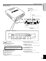 6
6
-
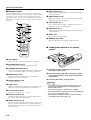 7
7
-
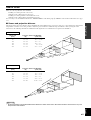 8
8
-
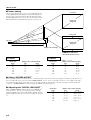 9
9
-
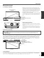 10
10
-
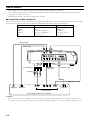 11
11
-
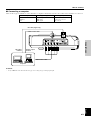 12
12
-
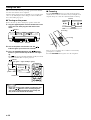 13
13
-
 14
14
-
 15
15
-
 16
16
-
 17
17
-
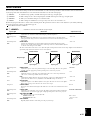 18
18
-
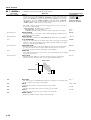 19
19
-
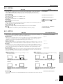 20
20
-
 21
21
-
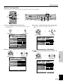 22
22
-
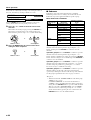 23
23
-
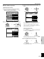 24
24
-
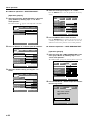 25
25
-
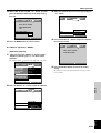 26
26
-
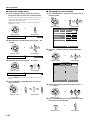 27
27
-
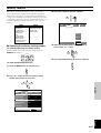 28
28
-
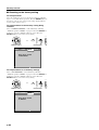 29
29
-
 30
30
-
 31
31
-
 32
32
-
 33
33
-
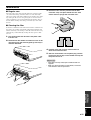 34
34
-
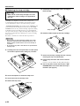 35
35
-
 36
36
-
 37
37
-
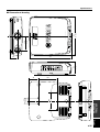 38
38
-
 39
39


in andere talen
- English: Yamaha DPX-1 Owner's manual
- italiano: Yamaha DPX-1 Manuale del proprietario
- русский: Yamaha DPX-1 Инструкция по применению
- français: Yamaha DPX-1 Le manuel du propriétaire
- español: Yamaha DPX-1 El manual del propietario
- Deutsch: Yamaha DPX-1 Bedienungsanleitung
- português: Yamaha DPX-1 Manual do proprietário
- dansk: Yamaha DPX-1 Brugervejledning
- čeština: Yamaha DPX-1 Návod k obsluze
- svenska: Yamaha DPX-1 Bruksanvisning
- Türkçe: Yamaha DPX-1 El kitabı
- polski: Yamaha DPX-1 Instrukcja obsługi
- română: Yamaha DPX-1 Manualul proprietarului
Gerelateerde papieren
-
Yamaha DPX-1 de handleiding
-
-
-
-
-
-
-
-
-
Yamaha DPX-1200 Handleiding