
SERVICE MANUAL
Cassette Player section
Tape track 4-track 2-channel stereo
Wow and flutter 0.08 % (WRMS)
Frequency response 30 – 18,000 Hz
Signal-to-noise ratio
Tuner section
FM
Tuning range 87.5 – 108.0 MHz
Aerial terminal External aerial connector
Intermediate frequency 10.7 MHz/450 kHz
Usable sensitivity 9 dBf
Selectivity 75 dB at 400 kHz
Signal-to-noise ratio 67 dB (stereo),
69 dB (mono)
Harmonic distortion at 1 kHz
0.5 % (stereo),
0.3 % (mono)
Separation 35 dB at 1 kHz
Frequency response 30 – 15,000 Hz
MW/LW
Tuning range MW: 531 – 1,602 kHz
LW: 153 – 279 kHz
Aerial terminal External aerial connector
Intermediate frequency 10.7 MHz/450 kHz
Sensitivity MW: 30 µV
LW: 40 µV
Power amplifier section
Outputs Speaker outputs
(sure seal connectors)
Speaker impedance 4 – 8 ohms
Maximum power output 50 W × 4 (at 4 ohms)
General
Outputs Audio outputs (rear)
Power aerial relay control
lead
Power amplifier control lead
Inputs Telephone ATT control
terminal
BUS control input terminal
BUS audio input terminal
Remote controller input
terminal
Aerial input terminal
Tone controls Low:
±10 dB at 60 Hz (XPLOD)
Mid:
±10 dB at 1 kHz (XPLOD)
High
±10 dB at 10 kHz (XPLOD)
Power requirements 12 V DC car battery
(negative earth)
Dimensions Approx. 178 × 50 × 180
mm (w/h/d)
Mounting dimensions Approx. 182 × 53 × 161
mm (w/h/d)
Mass Approx. 1.2 kg
Supplied accessories Parts for installation and
connections (1 set)
Front panel case (1)
Note
This unit cannot be connected to a digital preamplifier
or an equalizer which is Sony BUS system compatible.
Design and specifications are subject to change
without notice.
Cassette type
TYPE II, IV 61 dB
TYPE I 58 dB
FM/MW/LW CASSETTE CAR STEREO
AEP Model
UK Model
XR-CA670X
Ver 1.0 2003.02
9-877-004-01 Sony Corporation
2003B0500-1 e Vehicle Company
C 2003.02 Published by Sony Engineering Corporation
Model Name Using Similar Mechanism XR-CA630X
Tape Transport Mechanism Type MG-25M-136
SPECIFICATIONS

2
XR-CA670X
Notes on chip component replacement
•Never reuse a disconnected chip component.
• Notice that the minus side of a tantalum capacitor may be dam-
aged by heat.
Flexible Circuit Board Repairing
•Keep the temperature of the soldering iron around 270 ˚C dur-
ing repairing.
• Do not touch the soldering iron on the same conductor of the
circuit board (within 3 times).
• Be careful not to apply force on the conductor when soldering
or unsoldering.
TABLE OF CONTENTS
SERVICING NOTES
............................................... 2
1. GENERAL
Location of Controls ....................................................... 3
Setting the Clock ............................................................. 3
2. DISASSEMBLY
2-1. Disassembly Flow ........................................................... 7
2-2. Sub Panel Section............................................................ 7
2-3. Mechanism Deck (MG-25M-136) .................................. 8
2-4. MAIN Board ................................................................... 8
3. ASSEMBLY
3-1. Assembly Flow................................................................ 9
3-2. Housing ........................................................................... 10
3-3. Arm (Suction) ................................................................. 10
3-4. Lever (LDG-A)/(LDG-B) ............................................... 11
3-5. Gear (LDG-FT) ............................................................... 11
3-6. Guide (C)......................................................................... 12
3-7. Mounting Position of Capstan/Reel Motor (M901) ....... 12
4. MECHANICAL ADJUSTMENTS....................... 13
5. ELECTRICAL ADJUSTMENTS
Tape Deck Section .......................................................... 13
Tuner Section .................................................................. 13
6. DIAGRAMS
6-1. Note for Printed Wiring Boards and
Schematic Diagrams ....................................................... 14
6-2. Printed Wiring Board – MAIN Board – ......................... 15
6-3. Schematic Diagram – MAIN Board (1/3) – ................... 16
6-4. Schematic Diagram – MAIN Board (2/3) – ................... 17
6-5. Schematic Diagram – MAIN Board (3/3) – ................... 18
6-6. Printed Wiring Board – SUB Board – ............................ 19
6-7. Schematic Diagram – SUB Board – ............................... 19
6-8. Printed Wiring Board – KEY Board –............................ 20
6-9. Schematic Diagram – KEY Board – .............................. 21
6-10. IC Pin Function Description ........................................... 23
7. EXPLODED VIEWS
7-1. Chassis Section ............................................................... 26
7-2. Front Panel Section ......................................................... 27
7-3. Mechanism Deck Section (MG-25M-136)..................... 28
8. ELECTRICAL PARTS LIST ............................... 29
SERVICING NOTES
SERVICE POSITION
In checking the key board and main board, prepare two jigs
(connection cable J-2502-066-2 and
connection cable for F/P to main J-2502-071-1).
main board
sub board
(CN801)
mechanism deck
main board (CN351)
key board
(CN901)
connect jig
(connection cable
for F/P to main J-2502-071-1)
to the key board (CN901) and
sub board (CN801).
connect jig
(connection cable J-2502-066-2)
to the main board (CN351) and
mechanism deck.
sub panel
assy

3
XR-CA670X
Setting the clock
The clock uses a 24-hour digital indication.
Example: To set the clock to 10:08
1
Press (DSPL) for 2 seconds.
The hour indication flashes.
1Press the volume +/– button to set
the hour.
2Press (SEL).
The minute indication flashes.
3Press the volume +/– button to set
the minute.
2
Press (DSPL).
The clock starts.
After the clock setting is completed, the
display returns to normal play mode.
Tip
You can set the clock automatically with the RDS
feature (page 15).
to go forward
to go back
to go forward
to go back
SECTION 1
GENERAL
This section is extracted from
instruction manual.
Location of controls
a SOURCE (Power on/Tape/Radio/CD/
MD) button
Selecting the source
b SEL (select) button
Selecting items.
c Volume +/– button
d Display window
e SEEK +/– button
Tape:
Fast-forwarding, reversing a tape Automatic
Music Sensor
Radio:
Tuning in stations automatically/finding a
station manually.
CD/MD:
Skipping tracks/fast-forwarding, reversing a
track.
f DSPL (display mode change) button
g OPEN button
h DSO button
i ATT (attenuate) button
j MODE (o) button
Changing the operation
k AF button
l SENS/BTM/MTL button
m RESET button (located on the front side of
the unit, behind the front panel)
n Number buttons
Tape:
(3): REP
(5): BL SKIP
(6): ATA
Radio:
Storing the desired station on each number
button.
CD (MP3 files)/MD:
(1): DISC –
(2): DISC +
(3): REP
(4): SHUF
MP3 files:
(5): ALBM –
(6): ALBM +
o PTY (programme type) /LIST button
p TA button
q Z (eject) button (located on the front side
of the unit, behind the front panel)
r OFF (Stop/Power off) button*
s Receptor for the card remote
commander
t EQ3 button
* Warning when installing in a car without
an ACC (accessory) position on the
ignition switch
After turning off the ignition, be sure to press
and hold (OFF) on the unit until the display
disappears.
Otherwise, the display does not turn off and this
causes battery drain.
LIST
AF SENS
BTM/MTL
SEL
ATT
M
O
D
E
S
O
U
R
C
E
PTY TA
123456
OFF
O
P
E
N
DSO EQ3
SEEK
D
S
P
L
XR-CA670X
REP
SHUF
BL SKIP/
ALBM /ATA
DISC

4
XR-CA670X
Auxiliary power connector
Hilfsstromanschluss
Connecteur d’alimentation auxiliaire
Connettore di alimentazione ausiliaria
Hulpvoedingsaansluiting
4
Yellow
Gelb
Jaune
Giallo
Geel
continuous power supply
permanente Stromversorgung
alimentation continue
alimentazione continua
continu voeding
the car without ACC position
Fahrzeug ohne Zubehörposition (ACC)
Voiture sans position ACC
macchina priva di posizione ACC
auto zonder ACC stand
Red
Rot
Rouge
Rosso
Rood
Red
Rot
Rouge
Rosso
Rood
Yellow
Gelb
Jaune
Giallo
Geel
Yellow
Gelb
Jaune
Giallo
Geel
Red
Rot
Rouge
Rosso
Rood
switched power supply
geschaltete Stromversorgung
alimentation commutée
alimentazione commutata
geschakelde voeding
7
4
Yellow
Gelb
Jaune
Giallo
Geel
switched power supply
geschaltete Stromversorgung
alimentation commutée
alimentazione commutata
geschakelde voeding
Red
Rot
Rouge
Rosso
Rood
Red
Rot
Rouge
Rosso
Rood
Yellow
Gelb
Jaune
Giallo
Geel
Yellow
Gelb
Jaune
Giallo
Geel
Red
Rot
Rouge
Rosso
Rood
continuous power supply
permanente Stromversorgung
alimentation continue
alimentazione continua
continu voeding
7
Red
Rot
Rouge
Rosso
Rood
Red
Rot
Rouge
Rosso
Rood
Yellow
Gelb
Jaune
Giallo
Geel
Yellow
Gelb
Jaune
Giallo
Geel
13 57
24 68
57
48
AUDIO
OUT
REAR
BUS
AUDIO
IN
3
Yellow
Gelb
Jaune
Giallo
Geel
Blue
Blau
Bleu
Blu
Blauw
continuous power supply
permanente Stromversorgung
alimentation continue
alimentazione continua
continu voeding
power aerial control
Motorantennensteuerung
commande d’antenne électrique
comando dell’antenna elettrica
automatische antenne
7
8
4
5
Red
Rot
Rouge
Rosso
Rood
Black
Schwarz
Noir
Nero
Zwart
switched power supply
geschaltete Stromversorgung
alimentation commutée
alimentazione commutata
geschakelde voeding
earth
Masse
masse
terra
aarding
Source selector (not
supplied)
Signalquellenwähler
(nicht mitgeliefert)
Sélecteur de source
(non fourni)
Selettore di fonte
(non in dotazione)
Geluidsbronkiezer
(niet bijgeleverd)
XA-C30
Supplied with the CD/MD changer
Mit dem CD/MD-Wechsler geliefert
Fourni avec le changeur de CD/MD
In dotazione con il cambia CD/MD
Geleverd met de CD/MD-wisselaar
Supplied with XA-C30
Mit dem XA-C30 geliefert
Fourni avec le XA-C30
In dotazione con il modello XA-C30
Geleverd met de XA-C30
5
from car aerial
*
1
von Autoantenne
*
1
de l’antenne de la voiture
*
1
dall’antenna dell’auto
*
1
van een auto-antenne
*
1
Fuse (10 A)
Sicherung (10 A)
Fusible (10 A)
Fusibile (10 A)
Zekering (10 A)
6
AUDIO OUT REAR
BUS AUDIO IN
REMOTE IN
BUS CONTROL IN
AMP REM
Light blue
Hellblau
Bleu ciel
Azzurro
Hemelsblauw
Blue/white striped
Blauweiß
Rayé bleu/blanc
A strisce blu e bianche
Blauw/wit gestreept
1
2
3
4
Speaker, Rear, Right
Lautsprecher hinten rechts
haut-parleur, arrière, droit
Diffusore, posteriore, destro
Luidspreker, achter, rechts
Speaker, Rear, Right
Lautsprecher hinten rechts
haut-parleur, arrière, droit
Diffusore, posteriore, destro
Luidspreker, achter, rechts
Speaker, Front, Right
Lautsprecher vorne rechts
haut-parleur, avant, droit
Diffusore, anteriore, destro
Luidspreker, voor, rechts
Speaker, Front, Right
Lautsprecher vorne rechts
haut-parleur, avant, droit
Diffusore, anteriore, destro
Luidspreker, voor, rechts
5
6
7
8
Speaker, Front, Left
Lautsprecher vorne links
haut-parleur, avant, gauche
Diffusore, anteriore, sinistro
Luidspreker, voor, links
Speaker, Front, Left
Lautsprecher vorne links
haut-parleur, avant, gauche
Diffusore, anteriore, sinistro
Luidspreker, voor, links
Speaker, Rear, Left
Lautsprecher hinten links
haut-parleur, arrière, gauche
Diffusore, posteriore, sinistro
Luidspreker, achter, links
Speaker, Rear, Left
Lautsprecher hinten links
haut-parleur, arrière, gauche
Diffusore, posteriore, sinistro
Luidspreker, achter, links
Purple
Violett
Mauve
Viola
Paars
Negative polarity positions 2, 4, 6, and 8 have striped cords.
An den negativ gepolten Positionen 2, 4, 6 und 8 befinden sich gestreifte Adern.
Les positions de polarité négative 2, 4, 6 et 8 sont dotées de cordons rayés.
Le posizioni a polarità negativa 2, 4, 6 e 8 hanno cavi rigati.
De posities voor negatieve polariteit (2, 4, 6 en 8) hebben gestreepte kabels.
Green
Grün
Vert
Verde
Groen
White
Weiß
Blanc
Bianco
Wit
Grey
Grau
Gris
Grigio
Grijs
+
–
+
–
+
–
+
–
*
1
Note for the aerial connecting
If your car aerial is an ISO (International
Organisation for Standardisation) type,
use the supplied adaptor 5 to connect it.
First connect the car aerial to the supplied
adaptor, then connect it to the aerial jack
of the master unit.
*
2
Insert with the cord upwards
*
3
RCA pin cord (not supplied)
*
1
Hinweis zum Anschließen der Antenne
Wenn Ihre Fahrzeugantenne der
ISO-Norm (ISO = International
Organization for Standardization -
Internationale Normungsgemeinschaft)
entspricht, schließen Sie sie mithilfe des
mitgelieferten Adapters 5 an.
Verbinden Sie zuerst die Fahrzeugantenne
mit dem mitgelieferten Adapter und
verbinden Sie diesen dann mit der
Antennenbuchse des Hauptgeräts.
*
2
Mit dem Kabel nach oben einsetzen
*
3
Cinchkabel (nicht mitgeliefert)
*
1
Remarque sur le raccordement de
l’antenne
Si votre antenne de voiture est de type
ISO (Organisation internationale de
normalisation), utilisez l’adaptateur fourni
5 pour la raccorder.
Raccordez d’abord l’antenne de voiture à
l’adaptateur fourni et, ensuite, à la prise
d’antenne de l’appareil principal.
*
2
Insérez avec le câble vers le haut
*
3
Cordon à broche RCA (non fourni)
from the car’s speaker connector
vom Lautsprecheranschluss des Fahrzeugs
du connecteur de haut-parleur de la voiture
dal connettore del diffusore dell’auto
van de autoluidsprekerstekker
from the car’s power connector
vom Stromanschluss des Fahrzeugs
du connecteur d’alimentation de la voiture
dal connettore di alimentazione dell’auto
van de autovoedingsstekker
A
ATT
B
See “Power connection diagram” on the reverse side for details.
Näheres dazu finden Sie im „Stromanschlussdiagramm”.
Blättern Sie dazu bitte um.
Voir le “
Schéma de connexion d’alimentation
” au verso pour plus
de détails.
Per ulteriori informazioni, vedere “Diagramma dei collegamenti
di alimentazione” che si trova sul retro.
Zie “Voedingsaansluitschema” op de achterkant voor meer
details.
*
2
*
1
Nota per il collegamento dell’antenna
Se l’antenna dell’auto è di tipo ISO
(International Organization
Standardization), utilizzare l’adattatore 5
in dotazione per collegarla.
Collegare prima l’antenna della macchina
all’adattatore in dotazione, quindi
collegarla alla presa dell’antenna
dell’apparecchio principale.
*
2
Inserire con il cavo rivolto verso l’alto
*
3
Cavo a piedini RCA (non in dotazione)
*
1
Opmerking bij de antenne-aansluiting
Indien uw auto is uitgerust met een
antenne van het type ISO (International
Organisation for Standardization), moet u
die aansluiten met behulp van de
meegeleverde adapter 5.
Sluit eerst de auto-antenne aan op de
meegeleverde adapter en vervolgens de
antennestekker op het hoofdtoestel.
*
2
Plaatsen met het snoer naar boven
*
3
Tulpstekkersnoer (niet bijgeleverd)
Max. supply current 0.3 A
max. Versorgungsstrom 0,3 A
Courant d’alimentation maximum 0,3 A
Alimentazione massima fornita 0,3 A
Max. voedingsstroom 0,3 A
Positions 1, 2, 3 and 6 do not have pins.
An Position 1, 2, 3 und 6 befinden sich keine Stifte.
Les positions 1, 2, 3 et 6 ne comportent pas de broches.
Le posizioni 1, 2, 3 e 6 non hanno piedini.
De posities 1, 2, 3 en 6 hebben geen pins.
*
3
2 A
B
BUS AUDIO IN
BUS CONTROL IN
BUS AUDIO IN
BUS CONTROL IN
Source selector*
Signalquellenwähler*
Sélecteur de source*
Selettore di fonte*
Geluidsbronkiezer*
XA-C30
* not supplied
nicht mitgeliefert
non fourni
non in dotazione
niet bijgeleverd
AUDIO OUT
REAR
Power connection diagram
Auxiliary power connector may vary depending on
the car. Check your car’s auxiliary power connector
diagram to make sure the connections match
correctly. There are three basic types (illustrated
below). You may need to switch the positions of the
red and yellow leads in the car stereo’s power
connecting cord.
After matching the connections and switched
power supply leads correctly, connect the unit to
the car’s power supply. If you have any questions
and problems connecting your unit that are not
covered in this manual, please consult the car
dealer.
Voedingsaansluitschema
De hulpvoedingsaansluiting kan verschillen
afhankelijk van de auto. Controleer het
voedingsaansluitschema dat bij dit toestel wordt
geleverd om te zien of de aansluitingen kloppen. Er
zijn drie basistypes (zie illustratie hieronder). Het is
mogelijk dat u de posities van de rode en gele
kabels in het aansluitsnoer van het car
audiosysteem moet omwisselen.
Als de aansluitingen en geschakelde
voedingskabels kloppen, sluit u het toestel aan op
de voeding van de auto. Indien u nog vragen of
problemen hebt in verband met het aansluiten van
het toestel die niet in deze handleiding vermeld
staan, raadpleeg dan de autodealer.
Diagramma dei collegamenti di
alimentazione
Il connettore di alimentazione ausiliaria può variare
a seconda della macchina.
Controllare il diagramma del connettore di
alimentazione ausiliaria della macchina per essere
sicuri che le connessioni corrispondano
correttamente. Vi sono tre tipi di base (illustrazione
sotto). Potrà essere necessario cambiare le posizioni
dei cavi rosso e giallo nel cavo di alimentazione
dello stereo della macchina. Dopo aver fatto
corrispondere le connessioni e aver commutato i
cavi di alimentazione, collegare l’apparecchio
all’alimentazione della macchina. Se si hanno
domande o se sorgono problemi che non sono stati
trattati nel manuale relativi ai collegamenti
dell’apparecchio, contattare l’autoconcessionario.
Schéma de connexion
d’alimentation
Le connecteur d’alimentation auxiliaire peut varier
suivant le type de voiture. Vérifiez le schéma du
connecteur d’alimentation auxiliaire de votre
voiture pour vous assurer que les connexions
correspondent. Il en existe trois types de base
(illustrés ci-dessous). Il se peut que vous deviez
commuter la position du fil rouge et jaune du
cordon d’alimentation de l’autoradio.
Après avoir établi les connexions et commuté
correctement les fils d’alimentation, raccordez
l’appareil à l’alimentation de la voiture. Si vous
avez des questions ou des difficultés à propos de
cet appareil qui ne sont pas abordées dans le
présent mode d’emploi, consultez votre revendeur
automobile.
Stromanschlussdiagramm
Der Hilfsstromanschluss kann je nach Fahrzeugtyp
unterschiedlich sein. Sehen Sie im
Hilfsstromanschlussdiagramm für Ihr Fahrzeug
nach, wie die Verbindung ordnungsgemäß
vorgenommen werden muss. Es gibt, wie unten
abgebildet, drei grundlegende Typen.
Sie müssen möglicherweise die rote und gelbe
Leitung des Stromversorgungskabels der
Autostereoanlage vertauschen.
Stellen Sie die Anschlüsse her, schließen Sie die
geschalteten Stromversorgungsleitungen richtig an
und verbinden Sie dann das Gerät mit der
Stromversorgung Ihres Fahrzeugs. Wenn beim
Anschließen des Geräts Fragen oder Probleme
auftreten, die in dieser Bedienungsanleitung nicht
erläutert werden, wenden Sie sich bitte an den
Autohändler.

5
XR-CA670X
Cautions
• This unit is designed for negative earth 12 V DC operation only.
• Do not get the wires under a screw, or caught in moving parts
(e.g. seat railing).
• Before making connections, turn the car ignition off to avoid short
circuits.
• Connect the power connecting cord 6 to the unit and speakers
before connecting it to the auxiliary power connector.
• Run all earth wires to a common earth point.
• Be sure to insulate any loose unconnected wires with electrical
tape for safety.
Notes on the power supply cord (yellow)
•When connecting this unit in combination with other stereo
components, the connected car circuit’s rating must be higher than
the sum of each component’s fuse.
•When no car circuits are rated high enough, connect the unit
directly to the battery.
Parts list (1)
• The numbers in the list are keyed to those in the instructions.
• The bracket 1 and the protection collar 4 are attached to the unit
before shipping. Before mounting the unit, use the release keys 7
to remove the bracket 1 and the protection collar 4 from the
unit. For details, see “Removing the protection collar and the
bracket (4)” on the reverse side of the sheet.
• Keep the release keys 7 for the future use as they are also
necessary if you remove the unit from your car.
Caution
Handle the bracket 1 carefully to avoid injuring your fingers.
Note
Before installing, make sure that the catches on both sides of the
bracket 1 are bent inwards 2 mm. If the catches are straight or bent
outwards, the unit will not be installed securely and may spring out.
Connection example (2)
Notes (2-A)
• Be sure to connect the earth cord before connecting the amplifier.
• If you connect an optional power amplifier and do not use the
built-in amplifier, the beep sound will be deactivated.
Tip (2-B-
)
For connecting two or more CD/MD changers, the source selector XA-
C30 (optional) is necessary.
Connection diagram (3)
A
To AMP REMOTE IN of an optional power amplifier
This connection is only for amplifiers. Connecting any other
system may damage the unit.
B
To the interface cable of a car telephone
Warning
If you have a power aerial without a relay box, connecting this unit
with the supplied power connecting cord 6 may damage the aerial.
Notes on the control leads
• The power aerial control lead (blue) supplies +12 V DC when you
turn on the tuner or when you activate the AF (Alternative
Frequency), TA (Traffic Announcement) function.
• When your car has built-in FM/MW/LW aerial in the rear/side glass,
connect the power aerial control lead (blue) or the accessory power
input lead (red) to the power terminal of the existing aerial
booster. For details, consult your dealer.
•A power aerial without a relay box cannot be used with this unit.
Memory hold connection
When the yellow power input lead is connected, power will always
be supplied to the memory circuit even when the ignition switch is
turned off.
Notes on speaker connection
• Before connecting the speakers, turn the unit off.
• Use speakers with an impedance of 4 to 8 ohms, and with
adequate power handling capacities to avoid its damage.
• Do not connect the speaker terminals to the car chassis, or connect
the terminals of the right speakers with those of the left speaker.
• Do not connect the earth lead of this unit to the negative (–)
terminal of the speaker.
• Do not attempt to connect the speakers in parallel.
• Connect only passive speakers. Connecting active speakers (with
built-in amplifiers) to the speaker terminals may damage the unit.
• To avoid a malfunction, do not use the built-in speaker wires
installed in your car if the unit shares a common negative (–) lead
for the right and left speakers.
• Do not connect the unit’s speaker cords to each other.
Note on connection
If speaker and amplifier are not connected correctly, "FAILURE"
appears in the display. In this case, make sure the speaker and
amplifier are connected correctly.
Précautions
• Cet appareil est conçu pour fonctionner sur un courant continu de
12 V avec une masse négative uniquement.
• Evitez de fixer des vis sur les câbles ou de coincer ceux-ci dans des
pièces mobiles (par exemple, armature de siège).
• Avant d’effectuer des raccordements, éteignez le moteur pour
éviter les courts-circuits.
• Branchez le cordon d’alimention 6 sur l’appareil et les haut-
parleurs avant de le brancher sur le connecteur d’alimentation
auxiliaire.
• Rassemblez tous les fils de terre en un point de masse
commun.
• Par mesure de sécurité, veillez à isoler tout fil ou câble non
connecté avec du chatterton.
Remarques sur le cordon d’alimentation (jaune)
• Lorsque cet appareil est raccordé à d’autres appareils stéréo, la
valeur nominale des circuits de la voiture raccordée doit être
supérieure à la somme des fusibles de chaque appareil.
• Si aucun circuit de la voiture n’est assez puissant, raccordez
directement l’appareil à la batterie.
Liste des composants (1)
• Les numéros de la liste correspondent à ceux des instructions.
• Le support 1 et le tour de protection 4 sont fixés à l’appareil
avant de quitter l’usine. Avant le montage de l’appareil, utilisez
les clés de déblocage 7 pour détacher le support 1 et le tour de
protection 4 de l’appareil. Pour de plus amples informations,
reportez-vous à la section “Retrait du tour de protection et du
support (4)” au verso de la feuille.
• Conservez les clés de déblocage 7 pour une utilisation
ultérieure car vous en aurez également besoin pour retirer
l’appareil de votre véhicule.
Précaution
Manipulez précautionneusement le support 1 pour éviter de vous
blesser aux doigts.
Remarque
Avant l’installation, assurez-vous que les loquets des deux côtés du
support 1 sont bien pliés de 2 mm vers l’intérieur. Si les loquets sont
droits ou pliés vers l’extérieur, l’appareil ne peut pas être fixé
solidement et peut se détacher.
Exemple de raccordement (2)
Remarques (2-A)
• Raccordez d’abord le fil de masse avant de connecter
l’amplificateur.
• Si vous raccordez un amplificateur de puissance en option et que
vous n’utilisez pas l’amplificateur intégré, le bip sonore est
désactivé.
Conseil (2-B-
)
Dans le cas du raccordement de deux changeurs de CD/MD ou plus, le
sélecteur de source XA-C30 (en option) est indispensable.
Schéma de connexion (3)
A
Au niveau du AMP REMOTE IN d’un amplificateur de puissance
en option
Ce raccordement existe seulement pour les amplificateurs. Le
raccordement à tout autre système peut endommager l’appareil.
B
Vers le câble d’interface d’un téléphone de voiture
Avertissement
Si vous disposez d’une antenne électrique sans boîtier de relais, le
branchement de cet appareil au moyen du cordon d’alimentation fourni
6 risque d’endommager l’antenne.
Remarques sur les fils de commande
• Le fil de commande (bleu) fournit du courant continu de +12 V
lorsque vous allumez le sélecteur de canaux ou lorsque vous activez
la fonction TA (messages de radioguidage) en AF (fréquence
alternative).
• Lorsque votre voiture est équipée d’une antenne FM/MW/LW
intégrée dans la vitre arrière/latérale, raccordez le fil de commande
de l’antenne (bleu) ou l’entrée d’alimentation des accessoires
(rouge) à la borne de l’amplificateur d’antenne existant. Pour plus
de détails, consultez votre revendeur.
• Une antenne électrique sans boîtier de relais ne peut pas être
utilisée avec cet appareil.
Connexion pour la conservation de la mémoire
Lorsque le fil d’entrée d’alimentation jaune est connecté, le circuit de
la mémoire est alimenté en permanence même si la clé de contact est
en position d’arrêt.
Remarques sur la connexion des haut-parleurs
• Avant de raccorder les haut-parleurs, mettre l’appareil hors
tension.
• Utiliser des haut-parleurs ayant une impédance de 4 à 8 ohms et
une capacité adéquate sous peine de les endommager.
• Ne pas raccorder les bornes du système de haut-parleurs au châssis
de la voiture et ne pas connecter les bornes du haut-parleur droit à
celles du haut-parleur gauche.
• Ne pas raccorder le câble de masse de cet appareil à la borne
négative
(–) du haut-parleur.
• Ne pas tenter de raccorder les haut-parleurs en parallèle.
• Ne pas connecter d’enceintes actives (avec amplificateurs intégrés)
aux bornes d’enceinte de cet appareil, pour éviter d’endommager
l’appareil. Veiller à raccorder des enceintes passives uniquement.
• Pour éviter tout dysfonctionnement, ne pas utiliser pas les fils des
haut-parleurs intégrés installés dans votre voiture si l’appareil
dispose d’un fil négatif commun (–) pour les haut-parleurs droit et
gauche.
• Ne pas raccorder entre eux les cordons des haut-parleurs de
l’appareil.
Remarque sur le raccordement
Si les enceintes et l’amplificateur ne sont pas raccordés correctement,
le message “FAILURE” s’affiche. Dans ce cas, assurez-vous que les
enceintes et l’amplificateur sont raccordés correctement.
Vorsicht
• Dieses Gerät ist ausschließlich für den Betrieb bei 12 V
Gleichstrom (negative Erdung) bestimmt.
•Achten Sie darauf, dass die Kabel nicht unter einer Schraube oder
zwischen beweglichen Teilen wie z. B. in einer Sitzschiene
eingeklemmt werden.
• Schalten Sie, bevor Sie irgendwelche Anschlüsse vornehmen, die
Zündung des Fahrzeugs aus, um Kurzschlüsse zu vermeiden.
•Verbinden Sie das Stromversorgungskabel 6 mit dem Gerät und
den Lautsprechern, bevor Sie es mit dem Hilfsstromanschluss
verbinden.
• Schließen Sie alle Erdungskabel an einen gemeinsamen
Massepunkt an.
•Aus Sicherheitsgründen müssen alle losen, nicht angeschlossenen
Drähte mit Isolierband isoliert werden.
Hinweise zum Stromversorgungskabel (gelb)
•Wenn Sie dieses Gerät zusammen mit anderen
Stereokomponenten anschließen, muss der Autostromkreis, an
den die Geräte angeschlossen sind, eine höhere Leistung
aufweisen als die Summe der Sicherungen der einzelnen
Komponenten.
•Wenn kein Autostromkreis eine so hohe Leistung aufweist,
schließen Sie das Gerät direkt an die Batterie an.
Teileliste (1)
• Die Nummern in der Liste sind dieselben wie im Erläuterungstext.
• Die Halterung 1 und die Schutzumrandung 4 werden vor dem
Ausliefern am Gerät angebracht. Bevor Sie das Gerät montieren,
nehmen Sie die Halterung 1 und die Schutzumrandung 4
mithilfe der Löseschlüssel 7 bitte vom Gerät ab. Einzelheiten
dazu finden Sie unter „Abnehmen der Schutzumrandung und der
Halterung (4)“ auf der Rückseite dieses Blattes.
• Bewahren Sie die Löseschlüssel 7 für den späteren Gebrauch
auf. Sie werden z. B. benötigt, wenn Sie das Gerät aus dem
Fahrzeug ausbauen wollen.
Sicherheitshinweis
Seien Sie beim Umgang mit der Halterung 1 vorsichtig, damit Sie
sich nicht die Hände verletzen.
Hinweis
Vergewissern Sie sich vor dem Installieren, dass die Verriegelungen
an beiden Seiten der Halterung 1 um 2 mm nach innen gebogen
sind. Wenn die Verriegelungen gerade oder nach außen gebogen
sind, lässt sich das Gerät nicht sicher installieren und kann
herausspringen.
Anschlussbeispiel (2)
Hinweise (2-A)
• Schließen Sie unbedingt zuerst das Massekabel an, bevor Sie den
Verstärker anschließen.
• Wenn Sie einen gesondert erhältlichen Endverstärker anschließen
und den integrierten Verstärker nicht benutzen, wird der Signalton
deaktiviert.
Tipp (2-B-
)
Zum Anschließen von zwei oder mehr CD/MD-Wechslern wird der
gesondert erhältliche Signalquellenwähler XA-C30 benötigt .
Anschlussdiagramm (3)
A
An AMP REMOTE IN des gesondert erhältlichen Endverstärkers
Dieser Anschluss ist ausschließlich für Verstärker gedacht.
Schließen Sie nichts anderes daran an. Andernfalls kann das Gerät
beschädigt werden.
B
An Schnittstellenkabel eines Autotelefons
Warnung
Wenn Sie eine Motorantenne ohne Relaiskästchen verwenden, kann
durch Anschließen dieses Geräts mit dem mitgelieferten
Stromversorgungskabel 6 die Antenne beschädigt werden.
Hinweise zu den Steuerleitungen
• Die Motorantennen-Steuerleitung (blau) liefert + 12 V Gleichstrom,
wenn Sie den Tuner einschalten oder die AF-
(Alternativfrequenzsuche) oder die TA-Funktion
(Verkehrsdurchsagen) aktivieren.
• Wenn das Fahrzeug mit einer in der Heck-/Seitenfensterscheibe
integrierten FM (UKW)/MW/LW-Antenne ausgestattet ist, schließen
Sie die Motorantennen-Steuerleitung (blau) oder die
Zubehörstromversorgungsleitung (rot) an den
Stromversorgungsanschluss des vorhandenen Antennenverstärkers
an. Näheres dazu erfahren Sie bei Ihrem Händler.
• Es kann nur eine Motorantenne mit Relaiskästchen angeschlossen
werden.
Stromversorgung des Speichers
Wenn die gelbe Stromversorgungsleitung angeschlossen ist, wird der
Speicher stets (auch bei ausgeschalteter Zündung) mit Strom
versorgt.
Hinweise zum Lautsprecheranschluss
• Schalten Sie das Gerät aus, bevor Sie die Lautsprecher anschließen.
• Verwenden Sie Lautsprecher mit einer Impedanz zwischen 4 und 8
Ohm und ausreichender Belastbarkeit. Ansonsten können die
Lautsprecher beschädigt werden.
• Verbinden Sie die Lautsprecheranschlüsse nicht mit dem
Wagenchassis und verbinden Sie auch nicht die Anschlüsse des
rechten mit denen des linken Lautsprechers.
• Verbinden Sie die Masseleitung dieses Geräts nicht mit dem
negativen
(–) Lautsprecheranschluss.
• Versuchen Sie nicht, Lautsprecher parallel anzuschließen.
• An die Lautsprecheranschlüsse dieses Geräts dürfen nur
Passivlautsprecher angeschlossen werden. Schließen Sie keine
Aktivlautsprecher (Lautsprecher mit eingebauten Verstärkern) an,
da das Gerät sonst beschädigt werden könnte.
• Um Fehlfunktionen zu vermeiden, verwenden Sie nicht die im
Fahrzeug installierten, integrierten Lautsprecherleitungen, wenn
am Ende eine gemeinsame negative (–) Leitung für den rechten
und den linken Lautsprecher verwendet wird.
• Verbinden Sie nicht die Lautsprecherkabel des Geräts miteinander.
Hinweis zum Anschließen
Wenn Lautsprecher und Verstärker nicht richtig angeschlossen sind,
erscheint „FAILURE“ im Display. Vergewissern Sie sich in diesem Fall,
dass Lautsprecher und Verstärker richtig angeschlossen sind.
Let op!
• Dit apparaat is ontworpen voor gebruik op gelijkstroom van een
12 Volts auto-accu, negatief geaard.
• Zorg ervoor dat de draden niet onder een schroef of tussen
bewegende onderdelen (b.v. zetelrail) terechtkomen.
• Alvorens aansluitingen te verrichten moet u het contact uitzetten
om kortsluiting te vermijden.
• Sluit het netsnoer 6 aan op het toestel en de luidsprekers
vooraleer u het op de hulpvoedingsaansluiting aansluit.
• Sluit alle aarddraden op een gemeenschappelijk aardpunt aan.
• Voorzie niet aangesloten draden om veiligheidsredenen altijd van
isolatietape.
Opmerkingen bij de voedingskabel (geel)
•Wanneer u dit toestel aansluit samen met andere componenten,
moet het vermogen van de aangesloten autostroomkring groter
zijn dan de som van de zekeringen van elke component
afzonderlijk.
•Wanneer het vermogen ontoereikend is, moet u het toestel
rechtstreeks aansluiten op de batterij.
Onderdelenlijst (1)
• De nummers in de afbeelding verwijzen naar die in de montage-
aanwijzingen.
• De beugel 1 en de beschermende rand 4 worden bevestigd op
het toestel voordat dit wordt verzonden. Voordat u het toestel
plaatst, moet u de ontgrendelingssleutels 7 gebruiken om de
beugel 1 en de beschermende rand 4 te verwijderen van het
toestel. Zie “De beschermende rand en de beugel verwijderen
(4)” aan de achterzijde van dit vel voor meer informatie.
• Bewaar de ontgrendelingssleutels 7 voor toekomstig gebruik
omdat u deze ook nodig hebt om het toestel uit de auto te
verwijderen.
Opgelet
Houd de beugel 1 voorzichtig vast zodat u uw vingers niet
verwondt.
Opmerking
Voordat u het toestel installeert, moet u de grepen aan beide zijden
van de beugel 1 2 mm naar binnen buigen. Als de grepen recht zijn
of naar buiten gebogen, kan het toestel niet goed worden bevestigd
en kan dit losschieten.
Voorbeeldaansluitingen (2)
Opmerkingen (2-A)
• Sluit eerst de massakabel aan alvorens de versterker aan te sluiten.
• Als u een los verkrijgbare vermogensversterker aansluit en de
ingebouwde versterker niet gebruikt, is de pieptoon uitgeschakeld.
Tip (2-B-
)
Om twee of meer CD/MD-wisselaars aan te sluiten, hebt u de
geluidsbronkiezer XA-C30 (optioneel) nodig.
Aansluitschema (3)
A
Naar AMP REMOTE IN van een los verkrijgbare
vermogensversterker
Deze aansluiting is alleen bedoeld voor versterkers. Door een
ander systeem aan te sluiten kan het toestel worden beschadigd.
B
Naar het interface-snoer van een autotelefoon
Opgelet
Indien u een elektrische antenne heeft zonder relaiskast, kan het
aansluiten van deze eenheid met het bijgeleverde netsnoer 6 de antenne
beschadigen.
Opmerking betreffende de aansluitsnoeren
• De antennevoedingskabel (blauw) levert +12 V gelijkstroom
wanneer u de tuner aanschakelt of de AF (Alternative Frequency),
TA (Traffic Announcement) functie activeert.
• Wanneer uw auto is uitgerust met een FM/MW/LW-antenne in de
achterruit/voorruit, moet u de antennevoedingskabel (blauw) of de
hulpvoedingskabel (rood) aansluiten op de voedingsingang van de
bestaande antenneversterker. Raadpleeg uw dealer voor meer
details.
• Met dit apparaat is het niet mogelijk een automatische antenne
zonder relaishuis te gebruiken.
Instandhouden van het geheugen
Zolang de gele stroomdraad is aangesloten, blijft de
stroomvoorziening van het geheugen intact, ook wanneer het
contact van de auto wordt uitgeschakeld.
Opmerkingen betreffende het aansluiten van de luidsprekers
• Zorg dat het apparaat is uitgeschakeld, alvorens de luidsprekers
aan te sluiten.
• Gebruik luidsprekers met een impedantie van 4 tot 8 Ohm en let
op dat die het vermogen van de versterker kunnen verwerken. Als
dit wordt verzuimd, kunnen de luidsprekers ernstig beschadigd
raken.
• Verbind in geen geval de aansluitingen van de luidsprekers met het
chassis van de auto en sluit de aansluitingen van de rechter en
linker luidspreker niet op elkaar aan.
• Verbind de massakabel van dit toestel niet met de negatieve (–)
aansluiting van de luidspreker.
• Probeer nooit de luidsprekers parallel aan te sluiten.
• Sluit geen actieve luidsprekers (met ingebouwde versterkers) aan
op de luidspreker-aansluiting van dit apparaat. Dit zal leiden tot
beschadiging van de actieve luidsprekers. Sluit dus altijd uitsluitend
luidsprekers zonder ingebouwde versterker aan.
• Om defecten te vermijden mag u de bestaande
luidsprekerbedrading in uw auto niet gebruiken wanneer er een
gemeenschappelijke negatieve (–) draad is voor de rechter en
linker luidsprekers.
• Verbind de luidsprekerdraden niet met elkaar.
Opmerking over aansluiten
Als de luidspreker en versterker niet correct zijn aangesloten, wordt
“FAILURE” in het display weergegeven. In dit geval moet u zorgen
dat de luidspreker en versterker correct zijn aangesloten.
Attenzione
• Questo apparecchio è stato progettato per l’uso solo a 12 V CC con
massa negativa.
• Evitare che i cavi rimangano bloccati da una vite o incastrati nelle
parti mobili (ad esempio nelle guide scorrevoli dei sedili).
• Prima di effettuare i collegamenti, spegnere il motore
dell’automobile onde evitare di causare cortocircuiti.
• Collegare il cavo di collegamento dell’alimentazione 6
all’apparecchio e ai diffusori prima di collegarlo al connettore di
alimentazione ausiliare.
• Portare tutti i cavi di massa a un punto di massa comune.
• Per sicurezza, assicurarsi di isolare qualsiasi cavo non collegato
mediante apposito nastro.
Note sul cavo di alimentazione (giallo)
• Se questo apparecchio viene collegato in combinazione con altri
componenti stereo, la potenza nominale dei circuiti
dell’automobile collegati deve essere superiore a quella prodotta
dalla somma dei fusibili di ciascun componente.
• Se la potenza nominale dei circuiti dell’automobile non è
sufficiente, collegare l’apparecchio direttamente alla batteria.
Elenco dei componenti (1)
•I numeri nella lista corrispondono a quelli riportati nelle
istruzioni.
• La staffa 1 e la cornice di protezione 4 vengono applicati
all’unità in fabbrica. Prima di installare l’unità, utilizzare le chiavi
di rilascio 7 per rimuovere la staffa 1 e la cornice di protezione
4 dall’apparecchio. Per ulteriori informazioni, vedere
“Rimozione della staffa e della cornice di protezione (4)” sul lato
opposto del foglio.
• Conservare le chiavi di rilascio 7 per un uso futuro in quanto
sono necessarie per rimuovere l’unità dall’auto.
Attenzione
Maneggiare la staffa 1 con cautela per evitare di ferirsi le mani.
Nota
Prima di installare l’unità, accertarsi di ripiegare i fermi presenti su
entrambi i lati della staffa 1 verso l’interno di 2 mm. Se i fermi sono
diritti o ripiegati verso l’esterno, l’apparecchio non verrà installato in
modo sicuro e potrebbe non essere saldo.
Esempi di collegamento (2)
Note (2-A)
• Assicurarsi di collegare il cavo di terra prima di collegare
l’apparecchio all’amplificatore.
• Se si collega un amplificatore di potenza opzionale e non si utilizza
l’amplificatore incorporato, il segnale acustico verrà disattivato.
Suggerimento (2-B-
)
Per collegare due o più cambia CD/MD, si deve utilizzare il selettore
di fonte XA-C30 (opzionale).
Schema di collegamento (3)
A
A AMP REMOTE IN di un amplificatore di potenza opzionale
Questo collegamento è riservato esclusivamente agli
amplificatori. Non collegare un tipo di sistema diverso onde
evitare di causare danni all’apparecchio.
B
Al cavo di interfaccia di un telefono per auto
Avvertenza
Quando si collega l’apparecchio con il cavo di alimentazione in
dotazione 6, si potrebbe danneggiare l’antenna elettrica se questa non
ha la scatola a relè.
Note sui cavi di controllo
• Il cavo (blu) di controllo dell’antenna elettrica fornisce
alimentazione pari a +12 V CC quando si attiva il sintonizzatore o
le funzioni TA (notiziario sul traffico) e AF (frequenza alternativa).
• Se l’automobile è dotata di antenna FM/MW/LW incorporata nel
vetro posteriore/laterale, collegare il cavo (blu) di controllo
dell’antenna elettrica o il cavo (rosso) di ingresso
dell’alimentazione opzionale al terminale di alimentazione del
preamplificatore dell’antenna esistente. Per ulteriori informazioni,
consultare il proprio fornitore.
• Non è possibile usare un’antenna elettrica senza scatola a relè con
questo apparecchio.
Collegamento per la conservazione della memoria
Quando il cavo di ingresso alimentazione giallo è collegato, viene
sempre fornita alimentazione al circuito di memoria anche quando
l’interruttore di accensione è spento.
Note sul collegamento dei diffusori
• Prima di collegare i diffusori spegnere l’apparecchio.
• Usare diffusori di impedenza compresa tra 4 e 8 ohm e con capacità
di potenza adeguata, onde evitare che vengano danneggiati.
• Non collegare i terminali del sistema diffusori al telaio dell’auto e
non collegare i terminali del diffusore destro a quelli del diffusore
sinistro.
• Non collegare il cavo di terra di questo apparecchio al terminale
negativo (–) del diffusore.
• Non collegare i diffusori in parallelo.
• Assicurarsi di collegare soltanto diffusori passivi, poiché il
collegamento di diffusori attivi, dotati di amplificatori incorporati,
ai terminali dei diffusori potrebbe danneggiare l’apparecchio.
• Per evitare problemi di funzionamento, non utilizzare i cavi dei
diffusori incorporati installati nell’automobile se l’apparecchio
condivide un cavo comune negativo (–) per i diffusori destro e
sinistro.
• Non collegare fra loro i cavi dei diffusori dell’apparecchio.
Nota sui collegamenti
Se l’amplificatore e il diffusore non sono collegati correttamente,
“FAILURE” viene visualizzato nel display. In tal caso, accertarsi che
l’amplificatore e il diffusore siano collegati correttamente.
1
1
1
1
1
Fermo
Greep
Loquet
Verriegelung
Catch

6
XR-CA670X
4
1
2
4
7
7
c
c
c
1
Orient the release key
correctly.
Richten Sie den
Löseschlüssel korrekt aus.
Orientez correctement la
clé de déblocage.
Orientare la chiavetta di
rilascio nel modo corretto.
Plaats de
ontgrendelingssleutel op
de juiste manier.
Face the hook inwards.
Der Haken muss nach innen
weisen.
Tournez le crochet vers
l’intérieur.
Con il gancetto rivolto verso
l’interno.
Het haakje moet naar binnen
wijzen.
Précautions
• Choisir soigneusement l’emplacement de
l’installation afin que l’appareil ne gêne pas la
conduite normale du véhicule.
• Eviter d’installer l’appareil dans un endroit exposé à
de la poussière, de la saleté, des vibrations violentes
ou à des températures élevées, comme en plein
soleil ou à proximité d’une bouche d’air chaud.
• Pour garantir un montage sûr, n’utiliser que le
matériel de montage fourni.
Réglage de l’angle de montage
Ajuster l’inclinaison à un angle inférieur à 20°.
Retrait du tour de protection et
du support (4)
Avant d’installer l’appareil, retirez le tour de
protection 4 et le support 1 de l’appareil.
1
Retirez le tour de protection 4.
1 Accrochez les clés de déblocage 7
simultanément dans le tour de protection 4.
2 Tirez sur les clés de déblocage 7 pour retirer le
tour de protection 4.
2
Retirez le support 1.
1 Insérez les deux clés de déblocage 7
simultanément entre l’appareil et le support 1
jusqu’au déclic indiquant qu’elles sont en place.
2 Tirez le support 1 vers le bas, puis tirez
l’appareil vers le haut pour les séparer.
Exemple de montage (5)
Installation dans le tableau de bord
Remarques
• Plier ces griffes pour assurer une prise correcte si
nécessaire (5-2).
• Assurez-vous que les 4 taquets du tour de protection
4 sont correctement insérés dans les fentes de
l’appareil (5-3).
Retrait et pose de la façade
(6)
Avant d’installer l’appareil, déposer la façade.
6-A Retrait
Avant de déposer la façade, ne pas oublier d’appuyer
sur (OFF). Appuyer ensuite sur (OPEN), puis faire
glisser la façade vers la droite et extraire le côté
gauche.
6-B Fixation
Fixer la partie A de la façade sur la partie B de
l’appareil, comme indiqué sur l’illustration, puis
appuyer sur le côté gauche jusqu’au déclic
Avertissement en cas
d’installation dans une voiture
dont le contact ne comporte pas
de position ACC (accessoires)
Après avoir coupé le moteur, n’oubliez pas de
maintenir la touche
(OFF)
sur l’appareil enfoncée
jusqu’à ce que l’affichage disparaisse.
Sinon, l’affichage n’est pas désactivé et la batterie se
décharge.
Touche RESET
Après avoir retiré la façade, une fois que l’installation
et les raccordements sont terminés, appuyez sur la
touche RESET avec un stylo à bille, etc.
Precautions
• Choose the installation location carefully so that the
unit will not interfere with normal driving operations.
• Avoid installing the unit in areas subject to dust, dirt,
excessive vibration, or high temperature, such as in
direct sunlight or near heater ducts.
• Use only the supplied mounting hardware for a safe
and secure installation.
Mounting angle adjustment
Adjust the mounting angle to less than 20°.
Removing the protection collar
and the bracket (4)
Before installing the unit, remove the protection
collar 4 and the bracket 1 from the unit.
1
Remove the protection collar 4.
1 Engage the release keys 7 together with the
protection collar 4.
2 Pull out the release keys 7 to remove the
protection collar 4.
2
Remove the bracket 1.
1 Insert both release keys 7 together between the
unit and the bracket 1 until they click.
2 Pull down the bracket 1, then pull up the unit to
separate.
Mounting example (5)
Installation in the dashboard
Notes
• Bend these claws outward for a tight fit, if necessary
(5-2).
•Make sure that the 4 catches on the protection collar
4 are properly engaged in the slots of the unit (5-3).
How to detach and attach the
front panel (6)
Before installing the unit, detach the front panel.
6-A To detach
Before detaching the front panel, be sure to press (OFF).
Press (OPEN), then slide the front panel to the right
side, and pull out the left side.
6-B To attach
Place the hole A in the front panel onto the spindle B
on the unit as illustrated, then push the left side in.
Warning when installing in a car
without ACC (accessory) position
on the ignition key switch
After turning off the ignition, be sure to press and
hold (OFF) on the unit until the display disappears.
Otherwise, the display does not turn off and this causes
battery drain.
RESET button
When the installation and connections are completed, be
sure to press the RESET button with a ballpoint pen,
etc., after detaching the front panel.
Vorsichtsmaßnahmen
• Wählen Sie den Einbauort sorgfältig so aus, dass das
Gerät beim Fahren nicht hinderlich ist.
• Bauen Sie das Gerät so ein, dass es keinen hohen
Temperaturen (keinem direkten Sonnenlicht, keiner
Warmluft von der Heizung), keinem Staub, keinem
Schmutz und keinen starken Vibrationen ausgesetzt
ist.
• Für eine sichere Befestigung verwenden Sie stets nur
die mitgelieferten Montageteile.
Hinweis zum Montagewinkel
Das Gerät sollte in einem Winkel von weniger als 20°
montiert werden.
Abnehmen der Schutzumrandung
und der Halterung (4)
Nehmen Sie vor dem Installieren des Geräts die
Schutzumrandung 4 und die Halterung 1 vom
Gerät ab.
1
Entfernen Sie die Schutzumrandung 4.
1 Setzen Sie beide Löseschlüssel 7 an der
Schutzumrandung 4 an.
2 Ziehen Sie die Schutzumrandung 4 mithilfe der
Löseschlüssel 7 heraus.
2
Entfernen Sie die Halterung 1.
1 Führen Sie beide Löseschlüssel 7 zwischen dem
Gerät und der Halterung 1 ein, bis sie mit einem
Klicken einrasten.
2 Ziehen Sie die Halterung 1 nach unten und das
Gerät nach oben, um die beiden zu trennen.
Montagebeispiel (5)
Installation im Armaturenbrett
Hinweise
• Falls erforderlich, diese Klammern für einen sicheren
Halt hochbiegen (5-2).
• Achten Sie darauf, die 4 Verriegelungen an der
Schutzumrandung 4 korrekt in die Aussparungen am
Gerät einzusetzen (5-3).
Abnehmen und Anbringen der
Frontplatte (6)
Nehmen Sie die Frontplatte vor dem Einbau des
Geräts ab.
6-A Abnehmen
Schalten Sie das Gerät vor dem Abnehmen der
Frontplatte unbedingt mit (OFF) aus. Drücken Sie
(OPEN) und ziehen Sie sie auf sich zu heraus.
6-B Anbringen
Setzen Sie Teil A der Frontplatte wie in der Abbildung
dargestellt an Teil B des Geräts an und drücken Sie die
linke Seite der Frontplatte an, bis sie mit einem Klicken
einrastet.
Warnhinweis zur Installation des
Geräts in einem Auto mit
Zündschloss ohne Zubehörposition
ACC oder I
Nachdem Sie die Zündung ausgeschaltet haben,
halten Sie am Gerät unbedingt
(OFF)
gedrückt, bis
die Anzeige ausgeblendet wird.
Andernfalls wird die Anzeige nicht ausgeschaltet und
der Autobatterie wird Strom entzogen.
Taste RESET
Wenn Sie das Gerät eingebaut und alle Anschlüsse
vorgenommen haben, müssen Sie die Frontplatte
abnehmen und mit einem Kugelschreiber oder einem
anderen spitzen Gegenstand die Taste RESET drücken.
Voorzorgsmaatregelen
• Kies de installatieplaats zorgvuldig zodat het toestel
de bestuurder niet hindert tijdens het rijden.
• Installeer het apparaat niet op plaatsen waar het
blootgesteld wordt aan hoge temperaturen, b.v. in
direct zonlicht of bij de warme luchtstroom van de
autoverwarming, aan sterke trillingen, of waar het in
contact komt met veel stof of vuil.
• Gebruik voor het veilig en stevig monteren van het
apparaat uitsluitend de bijgeleverde montage-
onderdelen.
Maximale montagehoek
Installeer het apparaat nooit onder een hoek van meer
dan 20° met het horizontale vlak.
De beschermende rand en de
beugel verwijderen (4)
Voordat u het toestel gaat installeren, moet u de
beschermende rand 4 en de beugel 1
verwijderen van het toestel.
1
Verwijder de beschermende rand 4.
1 Bevestig de ontgrendelingssleutels 7 op de
beschermende rand 4.
2 Trek de ontgrendelingssleutels 7 naar u toe om
de beschermende rand 4 te verwijderen.
2
Verwijder de beugel 1.
1 Plaats de ontgrendelingssleutels 7 tussen het
toestel en de beugel 1 tot deze vastklikken.
2 Trek de beugel 1 omlaag en trek het toestel
omhoog om deze van elkaar te scheiden.
Montagevoorbeeld (5)
Montage in het dashboard
Opmerkingen
•Indien nodig kunt u deze lipjes ombuigen voor een
steviger bevestiging (5-2).
• De 4 grepen op de beschermende rand 4 moeten
goed in de sleuven van het toestel zijn geplaatst (5-3).
Verwijderen en bevestigen van het
afneembare voorpaneel (6)
Verwijder, alvorens met het installeren te beginnen,
het afneembare voorpaneel.
6-A Verwijderen
Vergeet niet, voordat u het voorpaneel verwijdert, eerst
op (OFF) te drukken. Druk vervolgens op de (OPEN)
toets en trek het naar u toe.
6-B Bevestigen
Breng deel A van het voorpaneel aan op deel B van het
apparaat zoals afgebeeld en druk op de linkerzijde tot
deze vastklikt.
Opgelet bij het monteren in een
auto waarvan het contactslot geen
ACC (accessory) stand heeft
Als de motor is uitgeschakeld, moet u op (OFF)
drukken en deze toets ingedrukt houden tot de
weergave verdwijnt.
Als u dit niet doet, wordt de weergave niet
uitgeschakeld en raakt de batterij uitgeput.
RESET-toets
Na het installeren en verrichten van alle aansluitingen,
moet u altijd het voorpaneel verwijderen en de RESET-
toets indrukken met een balpen of dergelijke.
Precauzioni
• Scegliere con attenzione la posizione per
l’installazione in modo che l’apparecchio non
interferisca con le operazioni di guida del conducente.
• Evitare di installare l’apparecchio dove sia soggetto ad
alte temperature, come alla luce solare diretta o al
getto di aria calda dell’impianto di riscaldamento, o
dove possa essere soggetto a polvere, sporco e
vibrazioni eccessive.
• Usare solo il materiale di montaggio in dotazione per
un’installazione stabile e sicura.
Regolazione dell’angolo di montaggio
Regolare l’angolo di montaggio in modo che sia
inferiore a 20°.
Rimozione della staffa e della
cornice di protezione (4)
Prima di installare l’apparecchio, rimuovere la
cornice di protezione 4 e la staffa 1
dall’apparecchio.
1
Rimuovere la cornice di protezione 4.
1 Inserire le chiavette di rilascio 7 insieme alla
cornice di protezione 4.
2 Per rimuovere la cornice di protezione 4, estrarre
le chiavette di rilascio 7.
2
Rimuovere la staffa 1.
1 Inserire contemporaneamente entrambe le
chiavette di rilascio 7 tra l’apparecchio e la staffa
1 fino a che non scattano in posizione.
2 Estrarre la staffa 1, quindi sollevare
l’apparecchio per rimuovere la staffa.
Esempio di montaggio (5)
Installazione nel cruscotto
Note
• Piegare verso l’esterno questi morsetti per
un’installazione più sicura, se necessario (5-2).
• Assicurarsi che i 4 fermi sulla cornice di protezione 4
siano correttamente inseriti negli alloggiamenti
dell’apparecchio (5-3).
Come rimuovere e reinserire il
pannello anteriore (6)
Prima di installare l’apparecchio rimuovere il
pannello anteriore.
6-A Per rimuoverlo
Prima di rimuovere il pannello anteriore, premere
(OFF). Premere (OPEN), quindi tirare verso di sé il
pannello anteriore.
6-B Per reinserirlo
Applicare la parte A del pannello anteriore alla parte B
dell’apparecchio come mostrato nell’illustrazione e
premere il lato sinistro fino a sentire uno scatto.
Informazioni importanti per quando si
effettua l’installazione su un’auto
sprovvista della posizione ACC
sull’interruttore di accensione
Dopo avere spento il motore, assicurarsi di tenere
premuto
(OFF)
sull’apparecchio finché il display non
scompare.
Diversamente, il display non viene disattivato e questo
potrebbe causare lo scaricamento della batteria.
Tasto RESET
Una volta rimosso il pannello anteriore e dopo aver
terminato l’installazione e i collegamenti, assicurarsi di
premere il tasto RESET con la punta di una penna a
sfera, e così via.
6 AB
1
182 m
m
53 m
m
Dashboard
Armaturenbrett
Tableau de bord
Cruscotto
Dashboard
Fire wall
Motorraumtrennwand
Paroi ignifuge
Parete tagliafiamma
Brandschot
4
2
3
1
1
5
2
3
1
2
c
B
A
claws
Klammern
griffes
Morsetti
klemhaken

7
XR-CA670X
SECTION 2
DISASSEMBLY
Note: Follow the disassembly procedure in the numerical order given.
2-2. SUB PANEL SECTION
• This set can be disassembled in the order shown below.
2-1. DISASSEMBLY FLOW
SET
2-2. SUB PANEL SECTION
(Page 7)
FRONT PANEL SECTION
Note: Illustration of disassembly is omitted.
2-4. MAIN BOARD
(Page 8)
2-3. MECHANISM DECK (MG-25M-136)
(Page 8)
6
two claws
1
screw (PTT2.6
×
6)
2
cover
7
9
sub panel section
3
two screws
(PTT2.6
×
6)
8
flexible flat (14core) cable
(CN701)
4
claw
5
claw

8
XR-CA670X
2-4. MAIN BOARD
2-3. MECHANISM DECK (MG-25M-136)
3
screw (PTT2.6
⋅
6)
4
mechanism deck
(MG-25M-136)
1
flexible board
(CN301)
2
flexible board
(CN351)
1
two screws
(PTT2.6
⋅
6
)
3
three ground point screws
(PTT2.6
⋅
6)
2
two screws
(PTT2.6
⋅
6)
4
rubber cap (25)
5
main board

XR-CA670X
9
SECTION 3
ASSEMBLY
• This set can be assembled in the order shown below.
3-1. ASSEMBLY FLOW
3-2. HOUSING
(Page 10)
3-3. ARM (SUCTION)
(Page 10)
3-4. LEVER (LDG-A)/(LDG-B)
(Page 11)
3-5. GEAR (LDG-FT)
(Page 11)
3-6. GUIDE (C)
(Page 12)
3-7. MOUNTING POSITION OF
CAPSTAN/REEL MOTOR (M901)
(Page 12)

XR-CA670X
10
3-2. HOUSING
3-3. ARM (SUCTION)
Note: Follow the assembly procedure in the numerical order given.
A part
C part
B part
D part
8 Hold the hanger by
bending the claw.
6 Fit projection on D part.
4 Fit claw on B part.
3 Put the housing
under A part.
5 Fit projection on C part.
1 Install the catch to the hanger.
2 Install the hanger onto
two claws of the housing.
7 Hold the hanger by bending the claw.
hanger
housing
2 Move the arm (suction) in the arrow
direction and fit on projection.
1 Fit the arm (suction) on the shaft.
projection

XR-CA670X
11
3-4. LEVER (LDG-A) / (LDG-B)
3-5. GEAR (LDG-FT)
shaft A
shaft B
shaft C
1 Fit the lever (LDG-A) on
shafts A – C and install it.
shaft A
shaft B
2 Fit the lever (LDG-B) on
shafts A and B and
install it.
3 type-E stop ring 2.0
gear (LDG-D)
5 gear (LDG-FT)
6 polyethylene washer
2 tension spring (LD-2)
2 tension spring (LD-1)
gear (LDG-FB)
lever (LDG-A)
hole
hole
4 Align hole in the gear (LDG-D)
with hole the lever (LDG-A).
3 Move the lever (LDG-B
)
in the arrow direction.
1

XR-CA670X
12
3-6. GUIDE (C)
3-7. MOUNTING POSITION OF CAPSTAN/REEL MOTOR (M901)
2 guide (C)
1 three claws
two precision screw
s
(P2
×
2)
Note: Mount the motor so that the
angle between of the
motor and the hole for the
screw becomes 30
°
as
shown in this figure.
capstan/reel motor
(M901)
30˚

13
XR-CA670X
Procedure:
1. Put the set into the FWD PB mode.
2. Adjust adjustment resistor for inside capstan motor so that the
reading on the frequency counter becomes 3,000 Hz.
Specification: Constant speed
Adjustment Location:
Tape Speed Adjustment
– SET UPPER VIEW –
SECTION 4
MECHANICAL ADJUSTMENTS
TAPE TENSION MEASUREMENT
1. Clean the following parts with a denatured-alcohol-moistened
swab:
playback head pinch roller
rubber belt capstan
idler
2. Demagnetize the playback head with a head demagnetizer.
3. Do not use a magnetized screwdriver for the adjustments.
4. The adjustments should be performed with the power supply
voltage (14.4 V) unless otherwise noted.
TORQUE MEASUREMENT
Mode Torque Meter Meter Reading
2.95 – 6.37 mN•m
Forward CQ-102C (30 – 65 g•cm)
(0.42 – 0.90 oz•inch)
Forward
0.05 – 0.44 mN•m
CQ-102C (0.5 – 4.5g•cm)
Back Tension
(0.01 – 0.06 oz•inch)
2.95 – 6.37 mN•m
Reverse CQ-102RC (30 – 65 g•cm)
(0.42 – 0.90 oz•inch)
Reverse
0.05 – 0.44 mN•m
CQ-102RC (0.5 – 4.5g•cm)
Back Tension
(0.01 – 0.06 oz•inch)
5.89 – 19.61 mN•m
FF, REW CQ-201B (60 – 200 g•cm)
(0.83 – 2.78 oz•inch)
Mode Tension Meter Meter Reading
Forward CQ-403A
more than 60 g
(more than 2.12 oz)
Reverse CQ-403R
more than 60 g
(more than 2.12 oz)
SECTION 5
ELECTRICAL ADJUSTMENTS
0 dB=0.775 V
TAPE SPEED ADJUSTMENT
Setting:
Frequency counter
2,955 to 3,075 Hz
TAPE DECK SECTION
frequency counter
test tape
WS-48A
(3 kHz, 0 dB)
set
AUDIO OUT REAR jack (J331)
–
+
10 k
Ω
TUNER SECTION
Tuner section adjustments are done automatically in this set.

14
XR-CA670X
2.6 Vp-p
22.4
µ
s
5.1 Vp-
p
30.5
µ
s
2.6 Vp-p
54.2 ns
4.5 Vp-p
231 ns
SECTION 6
DIAGRAMS
6-1. NOTE FOR PRINTED WIRING BOARDS AND SCHEMATIC DIAGRAMS
Note on Schematic Diagram:
• All capacitors are in µF unless otherwise noted. pF: µµF
50 WV or less are not indicated except for electrolytics
and tantalums.
• All resistors are in Ω and
1
/
4
W or less unless otherwise
specified.
• C : panel designation.
• A : B+ Line.
•Power voltage is dc 14.4V and fed with regulated dc power
supply from ACC and BATT cords.
•Voltages and waveforms are dc with respect to ground
under no-signal (detuned) conditions.
no mark : FM
[]: TAPE PLAYBACK
∗
: Impossible to measure
•Voltages are taken with a VOM (Input impedance 10 MΩ).
Voltage variations may be noted due to normal produc-
tion tolerances.
•Waveforms are taken with a oscilloscope.
Voltage variations may be noted due to normal produc-
tion tolerances.
• Circled numbers refer to waveforms.
• Signal path.
F : FM
f : MW/LW
E : TAPE PLAYBACK
L : BUS AUDIO IN
Note on Printed Wiring Board:
• X : parts extracted from the component side.
• Y : parts extracted from the conductor side.
•
: Pattern from the side which enables seeing.
(The other layers' patterns are not indicated.)
Caution:
Pattern face side: Parts on the pattern face side seen from
(Conductor Side) the pattern face are indicated.
Parts face side: Parts on the parts face side seen from
(Component Side) the parts face are indicated.
•Waveforms
– MAIN Board –
1 IC51 4 (OSCO)
2 IC501 qs (OSC2)
3 IC501 qh (XO)
– KEY Board –
4 IC901 uf (OSC)

XR-CA670X
1515
D23 J-8
D352 I-14
D479 F-10
D581 H-14
D582 H-14
D584 G-14
D585 G-14
D586 G-14
D601 E-14
D609 G-12
D612 F-11
D613 F-11
D617 F-12
D618 E-12
D671 L-9
D701 K-9
D710 M-4
D711 M-4
D712 M-4
D713 M-4
D714 L-5
D715 M-5
D716 M-5
D717 M-4
D718 M-4
D719 M-5
D751 E-9
D752 E-10
D753 E-9
D754 E-9
D755 E-10
D756 D-10
D757 D-11
D758 E-10
IC51 K-3
IC301 I-5
IC351 K-14
IC401 F-5
IC501 J-9
IC581 G-13
IC602 L-11
IC751 C-8
Q22 J-7
Q301 I-6
Q353 I-13
Q354 I-14
Q431 D-6
Q441 C-5
Q451 C-5
Q461 D-5
Q478 F-10
Q479 F-10
Q581 H-14
Q631 F-12
Q641 M-7
Q651 G-10
Q664 K-9
CN581
D352
R352
L501
TH501
X501
X502
C301
C354
C356
CN701
C403
C11
C12
C14
C51
C308
C309
X51
C751
C755
C757
C758
D751
D752
D753
D754
D755
D756
D757
D758
D618
D617
D612
D613
R651
R631
C622
C623
S702
CNP601
C510
JW1
JW
2
JW
3
JW
5
JW6
JW7
JW8
JW9
JW10
JW11
JW
13
JW14
JW
16
JW
17
JW
18
JW
20
JW21
JW22
JW23
JW24
JW25
JW
28
JW29
JW31
JW
33
JW
34
JW37
JW
38
JW
39
JW40
JW41
JW42
JW47
JW
48
JW
50
JW51
JW
52
JW53
JW54
JW
58
JW
59
JW
64
JW
65
JW
66
JW67
JW68
JW69
JW70
JW71
JW72
JW73
JW74
JW75
JW76
JW77
JW78
JW79
JW81
JW82
JW83
JW85
JW86
JW87
JW89
JW90
JW91
JW93
JW
94
JW95
JW96
JW97
JW99
JW100
JW101
JW102
JW
103
JW
104
JW
105
JW106
JW108
JW
109
JW110
JW
111
JW112
JW113
JW114
JW115
JW116
JW
117
JW118
JW119
JW120
JW121
JW122
JW123
JW
125
JW126
JW127
JW129
JW
201
JW
202
JW
203
JW
204
C479
TU1
L500
D601
C601
C631
JW
15
JW80
R641
R642
R29
R715
R404
JW49
R304
R609
JW88
R581
R582
JW30
JW84
JW63
C752
JW
61
R672
JW27
JW26
JW32
JW
36
JW62
JW
56
JW
45
S502
JW
57
JW
35
C302
C759
C756
R554
C583
C412
C422
JW124
IC751
JW43
C461C431
C441
C451
C401
JW
46
JW
98
Q354
Q581
Q353
IC581
IC351
JC401
Q22
IC51
Q301
Q451
Q441
Q431
Q461
JC402
JC403
C764C765
D609
D581
D582
Q651
Q631
Q641
D719
D701
D671
Q664
Q478
Q479
D479
D714
D23
C621
C511
C504
C505
C503
C502
C517
C501
C516
C515
C101
C102
C201
C202
C306
C305
C103
C104
C204
C203
C304
C303
C15
C13
C411
C421
C17
C18
C402
C452
C442
C432
C462
C82
C753
C514
C581
R718
R710
R717
R711
R702
R301
R204
R203
R205
R103
R104
R105
R302
R303
JC301
R403
R402
R461
R441
R431
R451
R432
R434
R454
R442
R452
R462
R464
R433
R242
R241R142
R141
R443
R453
C766
C762
C763
R550
R526
R522
R521
R520
R674
R508
JC503
R524
R546
R547
R530
R529
R654
R518
R636
R653
R751
R652
R544
R673
R506
R505
R504
R502
R509
R543
R542
R501
R551
R507
R671
R621
R540
R541
R538
R539
R537
C353
C358
R353
R354
R584
R583
R586
R632
R634
R633
C619
C618
C617
C602
C609
R519
R701
R713
JC302
JC303
R528
R503
R479
R516
JC751
C105
C205
C454
C444C242
C142
R401
R421
R422
R552
IC301
R553
C61
C58
C62
C81
R60
C59
C54
C55
C56
R62
R61
R716
R57
C57
R56
C754
R752
C506
C19
R523
R11
R12
R411
R412
IC501
R54
IC602
R51
D710D711
D716
D717
C143
C243
C86
JC502
R531
L11
L12
C521
C413
C423
C310
C87
JC81
IC401
C85
JC11
R444
JC404
R463
D586
D584
D585
D712 D713 D715D718
C357
C351
C352
C244
C144
C716C717C710C711
C715C718C713C712
1
25
26
50
75
51
76
100
MAIN BOARD
1-687-315- 11
J10
FM/MW/LW
ANTENNA
L R
BUS AUDIO
IN
L R
AUDIO OUT
REAR
J331
(CHASSIS)
(TUNER UNIT)
7
6
2
1
HP901
PLAYBACK
HEAD
CN301
(CHASSIS)
2
1
14
13
A
SUB BOARD
FU601
RESET
(NOSE DETECT)
(CHASSIS)
11
10
2
1
M901
CAPSTAN/
REEL
M
MECHANISM
BLOCK
CN351
123
456
78
1
23
78
456
(FRONT VIEW)
TO
CNP601
1 2 3 4 5 6 7 8 9 10 11 12 13 14 15 16
A
B
C
D
E
F
G
H
I
J
K
L
17
M
3
2
1
REMOTE IN
J671
BUS CONTROL IN
CN581
(FOR SONY BUS)
1 9
WHT/BLK
GRN/BLK
VIO/BLK
GRY/BLK
BLU/WHT
LIGHT BLU
YEL
WHT
GRN
VIO
GRY
BLU
RED
BLK
2 10
3 11
4 12
5 13
6 14
7 15
8 16
RL+ RL–
GRN/BLK
WHT/BLK
GRY/BLK
VIO/BLK
GRN
WHT
GRY
VIO
FL+
FL–
FR+ FR–
RR+ RR–
ACC GND
BLK
YEL
RED
BLU
ANT REM
NC BATT
NC NC
ATT
NC
AMP REM
6-2. PRINTED WIRING BOARD – MAIN Board –
(Page 19)
• Semiconductor
Location
Ref. No. Location

XR-CA670X
1616
6-3. SCHEMATIC DIAGRAM – MAIN Board (1/3) – • See page 14 for Waveform. • See page 22 for IC Block Diagrams.
C403
R434
R443
R463
R404
C12
R11
L12
2.2µH
R12
C19
C14
C15
C13
C87
C85
C411
C423
R422
C422
R421
R431
R451
R461
R441
C412
R412R411
C413
C143
C243 R241
R141
R242
R142
C441
R442
C402
Q441
Q461
C432R432
C431
R433
R453
C451
R452
Q451
Q431
R444 C442
C452R454
Q478
Q479
C751
D751
D752
D753
D754
D755
D756
D757
D758
C754
R752
C762
D612
C763
C602
C601
D609
C619
D618
C618
D617
C617
C609
C765 C764
C766
C752
C755
C756
C757
C758
C759
R401
R403
R402
C401
IC401
C479
R479D479
R464 C462
C461
R462
CNP601
C81
C242C142
C444 C454
C82
J10
JC11
JC81
C11
R29
D23
Q22
C18
C17
C59L11
C61C62 C58 R60
C51
R51
JC401
IC51
R56
R61
R57
C54
R54
C57
JC404
JC403
JC402
FU601
J331
C421
JC751
C55
R62
C56
D613
TU1
L500
R609
D601
C144
C244
X51
IC751
47
16V
1k
47k
47k
10
100
10V
100
100
0.01
47
16V
0.1
0.1
0.001
0.01
0.22
0.0015
10k
0.012
10k
100
100
100
100
0.012
10k10k
0.0015
0.0022
0.0022 10k
10k
1k
1k
10
16V 100
0.01
DTC314TK
DTC314TK
0.47100
10
16V
47k
47k
10
16V 100
DTC314TK
DTC314TK
1k 0.47
0.471k
DTC144EKA
DTA114EKA
22
16V
1SR139
1SR139
1SR139
1SR139
1SR139
1SR139
1SR139
1SR139
47p
100
0.01
1SR139
0.01
0.1
3300
16V
MA8068-M
0.001
1SR139
0.001
1SR139
0.001
0.1
0.1 0.1
0.22
2.2
50V
10 16V
10 16V
10 16V
10 16V
100 10V
30k
100
100
10
16V
BD3802F
47
16V
47MA111
1k 0.47
10
16V
100
16P
0.22
100p100p
100p 100p
0.001
0
0
4.7
25V
100
UDZ-5.1B
DTC144EKA
0.01
0.01
330p2.2µH
2.2560p 0.1 10
47
16V
0
0
SAA6588T/V2
10
0
470
10p
22k
0.001
0
0
0
10A
32V
4P
0.22
0
22p
0
0.1
1SR139
1k
1N5404TU
1
50V
1
50V
4.332MHz
TDA8588J/N1
A1
A2
A3
A4
A5
A6
A7
A8
A9
A10
A11
A12
A13
A14
A15
A16
B7
B6
B5
B4
B3
B2
B1
A19
A18
A17
I2C-SCL
I2C-SDA
EEP
-S
CL
EE
P
-S
D
A
I2C-S
CL
I2C-S
D
A
AMPON
DIAG
TAPE-RCH
TAPE-LCH
I2C
-SD
A
I2
C
-SC
L
I2C-SDA
I2C-SCL
FL+
FL-
RL+
RL-
RR+
RR-
FR+
TEST
FL+
FL-
RL+
RL-
RR+
RR-
FR+
FR-
AMP-R
ANT-R
AMP-R
FR-
ANT-R
RL-
RL-
FL-
FL-
FR-
FR-
RR-
RR-
RL+
RL+
FL+
FL+
FR+
FR+
RR+
RR+
GND
GND
BATT
BATT
ACC
ACC
ANT REM
ANT REM
AMP REM
MRO
MPTH
TCON
OSCO
OSCI
VSSD
VDDD
DAVN
SDA
SCL
PSWN
MAD
AFIN
VDDA
VSSA
MPX
VREF
SCOUT
CIN
LVI N
(CHASSIS)
FL+
FL-
RL+
RL-
RR+
RR-
FR+
FR-
AMP-R
ANT-R
ACC
GND
+B
+B
+B
+B
TEST
ILL(NC)
TEL
(CHASSIS)
(CHASSIS)
(CHASSIS)
(1/3)
TUX-030//Q
(TUNER UNIT)
NOISE
DETECT
DISCHARGE
SWITCH
RDS DECODER
INPUT SELECT,
ELECTRICAL VOLUME
MUTING
MUTING
MUTING
MUTING
MUTING
Q478,479
CONTROL
L R L R
REAR
AUDIO OUT
AUDIO IN
BUS
POWER AMP
ATT
ANTENNA
FM/MW/LW
(Page 17)
(Page 18)

XR-CA670X
1717
6-4. SCHEMATIC DIAGRAM – MAIN Board (2/3) – • See page 14 for Waveforms. • See page 22 for IC Block Diagrams.
C354
C511
CN301
CN351
C201
C101
C102
C202
R204
R203
C302
C303
C301
C310
C304
R301
C204
C104
C308 C309
C105
R303C306
R302C305
R553
R529R530R508
C521
C753
R751
R503
C353
R521
R522
R523
R516
R518R550
R526
R554
IC501
R524
R546
R547
R541
R540
R538
R537
R539
R519
R552
C357
C352
C351
IC351
C358
R353
R544
R501
C505
C504
C503
X501
R502
C510
R551
C517
C516
C515
C501
C506C502
R506
R505
R504
C514
C356
Q353
Q354
R103
R354
R352
R507
Q664
R542R543
JC502
S502
D352
JC302
JC303
JC503
Q301
JC301
HP901
R520
C205
R304
C103
IC301
R205
C203
M901
X502
R509
R528
R104
R105
10
16V
0.01
7P
11P
330p
330p
330p
330p
15k
10k
22
16V
0.01
22
16V
0.047
0.1
330k
0.1
0.1
10
16V
1
50V
1
4.7k0.47
15k0.01
100k
10k10k100k
0.01
0.22
47k
100k
0.01
22k
22k
22k
100k
100k10k
100k
22k
MN101C49KSK
100k
0
0
100k
100k
100k
100k
100k
100k
100k
0.1
0.1
0.1
LB1930M
0.01
4.7k
100
22k
18p
22p
15p
18.432MHz
220
47
16V
0
0.001
0.001
0.001
0.047
0.0110p
2.2k
2.2k
2.2k
0.0022
220
16V
DTC114EKA
2SB1132-R
10k
10k
1.5
47k
L501
0.47µH
DTA114EKA
100k100k
0
1SR139
0
0
0
2SC2412K
0
47k
1
10
0.01
HA12231FP
27k
0.01
32.768KHz
220
100k
15k
27k
A1
A2
A3
A4
A5
A6
A7
A8
A9
A10
A11
A12
A13
A14
A15
A16
C1
C2
A19
A18
A17
C3
C4
C5
C6
C7
C8
C9
C10
C11
C12
C13
T
E
L
A
C
C
T
E
S
T
R
C
IN
1
RCIN0
U
N
5
U
N
3
U
N
4
KEY1
KEY0
L-CLK
EEP-SDA
EEP-SCL
T
A
7
T
A
8
TA2
TA6
TA5
TA3
TA4
T
A
2
T
A
6
T
A
5
T
A
3
T
A
4
T
A
8
T
A
7
T
A
9
I2
C
-S
C
L
I2
C
-S
D
A
L-CE
L-DA
A
M
P
O
N
D
IA
G
SIR
TAPE-RCH
TAPE-LCH
TA9
UN1
UN2
1
2
3
4
5
6
7
1
2
3
4
5
6
7
G
N
D
VREF
FIN
R
R
IN
R
FINL
RINL
EQOL EQOR
TAIL TAIR
OUTL OUTR
RIP
MSDET
MS
VCCF/R
MUTE
N/M
MSG
GND
F-R(CH)
R(CH)-COM
R-R(CH)
R-L(CH)
L(CH)-COM
F-L(CH)
C-MOTOR
GND
LM+
LM-
GND
REEL1
+B(8.5V)
POS3
POS2
POS0
POS1
B
E
E
P
A
C
C
IN
T
EL
A
T
T
D
A
V
N
SIR
C
S
N
IL
T
U
N
O
N
N
CO
B
U
S
S
O
BU
S
S
I
B
U
S
C
K
O
N
C
O
N
C
O
ATT
T
U
A
T
TIN
VREF-
VSM KEYIN1
KEYIN0
VREF
VDD
VSS
MMOD
QUALITY
LCDSO
LCDCE
LCDCKO
SYSRST
BUSON
NIL
NIL
NCO
NCO
NCO
DSTSEL
D
A
V
S
S
D
A
V
D
D
N
C
O
D
O
O
R
IN
D
N
C
O
N
C
O
R
EL
_
T
PO
S
3
P
O
S
2
P
O
S
0
PO
S
1
LM
_
L
O
LM
_
E
J
CM
_
O
N
N
O
S
E
S
W
N
S_
M
A
S
K
N
C
O
N
C
O
N
C
O
N
C
O
N
C
O
N
C
O
A
D
_
O
N
D
O
O
R
S
W
NCO
N_ROUT
MTLON
TAPATT
NCO
NCO
VOLATT
NCO
NCO
NCO
NCO
NCO
NCO
NCO
NCO
DIAG
NCO
TUATT
RC_IN1
TESTIN
FLASH_W
AMSIN
AMSON
K
E
Y
A
C
K
SYSTEM CONTROLLER
LOADING MOTOR DRIVE
(2/3)
SWITCH
KEY ACTIVE
B
U
_IN
N
IH
(V
D
D
)
R
ES
E
T
N
C
O
N
CO
N
IH
(V
D
D
)
1
2C
C
KO
1
2C
S
IO
S
T
B
XO
XI
OSC1
OSC2
RC_IN0
T
A
P
EO
N
EE_SIO
EE_CKO
(NOSE DETECT)
Q353,354
CAPSTAN/REEL
MOTOR DRIVE
AUTO
MUSIC
SENSOR
CONTROL
TAPE EQUALIZER,
L
R
R
L
FWD
REV
(PLAYBACK)
MECHANISM
BLOCK
(CAPSTAN/REEL)
AUTO MUSIC SENSOR
(Page 16)
(Page 18)

XR-CA670X
1818
6-5. SCHEMATIC DIAGRAM – MAIN Board (3/3) – • See page 22 for IC Block Diagram.
R636
CN701
R652 R651
R653R654
R702
R701
D584
D585
D586
D701
R583
R584
R674
TH501
D671
R672
R673
R671
C583
R716
R717
R718
R713
R710
R711
R715
D719
R641 R642
Q641
D581
D582
R582
R581
R633 R631
R632
C631
R634
IC602
R621
C621
C622 C623
Q631
IC581
C581
R586
Q581
C86
D714
Q651
J671
S702
CN581
R531
D
7
16
D7
12
D
7
17
D
7
13
D7
18
D
7
15
D
711
D
710
C
710
C
711
C
712
C
71
3
C
715
C
71
6
C
71
7
C
71
8
100k
14P
47k 1k
10k10k
10k
10k
UDZ-18B
MA2ZD14001SO
UDZ-18B
MA111
100
100
220k
MA111
100
10k
100
470
16V
100
100
100
100
100
100
100
UDZ-18B
1k 1k
FMC2A
UDZ-6.2B
UDZ-18B
1k
15k
47k 4.7k
47k
2.2
50V
4.7k
XC61CN4302MR
100k
0.1
0.1F
5.5V
100
10V
2SC2412K
BA8270F
0.1
0
DTC114EKA
0.001
UDZ-18B
2SC2412K
8P
100k
M
A
8
06
8-M
M
A
8068-M
M
A8
06
8-M
M
A
8
06
8-M
M
A8068-M
M
A
8068-M
M
A
806
8-M
M
A806
8-M
0
.1
0.1
0
.1
10
0p
0
.1
1
00p
10
0p
1
00p
B
7
B
5
B
3
B
2
B6
B4
C1
C2
B1
C3
C4
C5
C6
C7
C8
C9
C10
C11
C12
C13
TEL
ACC
RCIN1
RCIN0
L-CLK
L-DA
L-CE
KEY0
KEY1
UN3
UN4
UN5
UN1
UN2
SIR
GND
FLASH-W
SIRCS
RE-0(NC)
RE-1(NC)
KEY-1
KEY-0
LCD-CE
LCD-DATA
LCD-CLK
+B
DOOR-IND
GND
DOOR-SW
(CHASSIS)
B/U-C
CLK-IN
RST
VCC
GND
DATA
OUT
IN
DATA
DATA
I/O
VREF
CLK
BATT
RST
BUS-ON
BUS-IN
(3/3)
BUS ON
BUS DATA
BUS CLK
B+
RESET
LED DRIVE
SHIFT
LEVEL
ACCESSORY
CHECK
RESET
RST V
G
GENERATOR
RESET SIGNAL
BATTERY
DETECT
SONY BUS INTERFACE
-2
-1
BUS CONTROL IN
(FOR SONY BUS)
REMOTE IN
(Page 17)
(Page 16)
(Page 19)

XR-CA670X
1919
CN801
LSW801
(COMPONENT SIDE)
SUB BOARD
1-687-316-
11
(11)
S1 S2
A1 K1
B
KEY BOARD
CN901
SUB BOARD
(CONDUCTOR SIDE)
1-687-316-
11
(11)
A
MAIN BOARD
CN701
114
6-6. PRINTED WIRING BOARD – SUB Board – 6-7. SCHEMATIC DIAGRAM – SUB Board –
(Page 15)
(Page 20)
CN801
LSW801(1/2)
LSW801(2/2)
14P
LDA
LCE
K-1
SIR
SIR
K-0
LCK
K-0
K-1
LDA
LCE
LCK
NC1
NC0
NC1
NC0
SIRCS
+B
KEY-0
GND
GND
LCD-DATA
LCD-CE
LCD-CLK
+B
DOOR-SW
GND
DOOR-IND
DOOR-SW
+B
LCD-CLK
LCD-DATA
LCD-CE
SIRCS
GND
KEY-1
FLASH-W
KEY-1
KEY-0
RE-1 (NC)
RE-0 (NC)
RE-0 (NC)
RE-1 (NC)
14
1
(Page 18)
(Page 21)

XR-CA670X
2020
S903
LSW904
LSW905
LSW906
LSW907
LSW908
LSW909
LSW910
S911
LSW912
LSW915
LSW916
LSW917
LSW918
LSW919
LSW922
LSW901
R911
R904
R912
R913
LSW913
LED953 LED903
LSW914
LED911
LED952
IC971
LED933
R950
R951
R966
R967
R936
R935
S902
LED954
LSW921
LSW920
LED951
LED934
R986
R988
C982
C984
R987
C983
C981
C985
C986
R981
R982
R983
R985
R989
R990
D901
R975
R976
R977
R979
R978
R980
R971
R972
R901
R902
R903
R905
R906
R907
R908
R909
R910
R914
R915
R916
R917
R918
R919
R920
R921
D981
R941
R942
R946
R947
D983
D902
C971
R970
CN901
R927
R928
R960
R961
R962
R934
R931
R930
IC901
R929
(COMPONENT SIDE)
KEY BOARD
1-686-744-
12
(12)
A
K
A
K
A
K
4
3
21
4
3
2
1
4
3
2
1
432
1
4
3
21
S2 S1
A1 K1
S2 S1
K1 A1
S2 S1
K1 A1
S2 S1
K1 A1
S2 S1
K1 A1
S2 S1
K1 A1
S2 S1
K1 A1
S2 S1
K1 A1
S2 S1
K1 A1
S2 S1
K1 A1
2
1
4
3
432
1
1
2
3
4
AK
A
K
A
K
4
3
21
432
1
3772
361
LCD901
LIQUID CRYSTAL DISPLAY
SOURCE
LED954, S902
SEL
ATT
+
−
(VOLUME)
MODE
LSW908
DSO
LED903, 953, S903
LED903, 911,
LED951
−
954
KA
BTM/MTL
SENS
LSW910
DISC −
1
LSW922
DISC +
2
LSW921
REP
3
LSW920
SHUF
4
LSW919
BL SKIP/ALBM −
5
LSW918
ALBM +/ATA
6
LSW917
TA
LSW915
AF
LSW909
LIST
PTY
LSW916
LCD
BACK
LIGHT
LCD
BACK
LIGHT
−
+
SEEK
OFF
DSPL
EQ3
LED911, 951, S911
120
60 41
61
80
40
21
KEY BOARD
(CONDUCTOR SIDE)
1-686-744-
12
(12)
B
SUB BOARD
CN801
1 2 3 4 5 6 7 8 9 10 11 12 13
A
B
C
D
E
F
G
H
SEEK
+
−
−
6-8. PRINTED WIRING BOARD – KEY Board –
Ref. No. Location
Ref. No. Location
• Semiconductor Location
(Page 19)
D901 G-10
D902 G-10
D981 G-6
D983 G-5
IC901 G-7
IC971 C-13
LED903 C-1
LED911 C-13
LED933 C-11
LED934 C-3
LED951 C-13
LED952 C-12
LED953 C-1
LED954 A-2
Ref. No. Location

XR-CA670X
2121
6-9. SCHEMATIC DIAGRAM – KEY Board – • See page 14 for Waveform.
R990
R986
R988
R987
C971
R983
R982
R981
LSW901(1/2)
LSW904(1/2)
LSW905(1/2)
LSW906(1/2)
LSW907(1/2)
LSW908(1/2)
LSW909(1/2)
LSW910(1/2)
LSW912(1/2)
LSW913(1/2)
LSW914(1/2)
LSW915(1/2)
LSW916(1/2)
LSW917(1/2)
LSW918(1/2)
LSW919(1/2)
LSW920(1/2)
LSW921(1/2)
LSW922(1/2)
IC901
IC971
R972
R979
R980
R978
R975
R976
R977
R985
C984
C983C985R989
C982
C981
D981
D983
C986
LED903
LED953
R966
R967
R960
R961
R962
R951
R950
R946
R947R942
R941
R935
R936
R934
LED951
LED911
R931
R930
LED933
LED934
S911
S902
S903
R911R901
R902 R912
R913R903
R904 R914
R915R905
R906 R916
R917R907
R908 R918
R919R909
R910 R920
R921
R971
CN901
LCD901
R970
D901
R927
R928
R929
LED952
LED954
D902
LSW912(2/2)
LSW913(2/2)
LSW914(2/2)
LSW901(2/2)
LSW919(2/2)
LSW915(2/2)
LSW916(2/2) LSW920(2/2)
LSW921(2/2)LSW917(2/2)
LSW918(2/2) LSW922(2/2)
LSW906(2/2)
LSW909(2/2)
LSW910(2/2)
LSW904(2/2)
LSW908(2/2)
LSW907(2/2)
LSW905(2/2)
1M
1k
1k
1k
0.1
150
150
150
LC75874W
RS-770
100
470
470
470
470
470
470
0
0.1
0.11000p39k
0.022
0.022
UDZSTE-175.1B
MA111
0.22
CL-195SR
CL-195SR
100
330
100
100
150
68
100
100
6868
100
100
68
47
CL-195SR
CL-195SR
470
47
NSCW505T-ARS
NSCW505T-ARS
680680
680 680
680680
1k 1k
1.5k1.5k
1.5k 1.5k
2.2k2.2k
3.3k 3.3k
4.7k4.7k
6.8k 6.8k
10k
1k
14P
0
UMZ6.8ENTR
100
68
47
CL-195SR
CL-195SR
UDZSTE-1718B
LS6J3M-1SR
LS6J3M-1SR
LS6J3M-1SR
LS6J3M-1SR
LS9J3M-1SR
LS9J3M-1SR
LS9J3M-1SR LS9J3M-1SR
LS9J3M-1SRLS9J3M-1SR
LS9J3M-1SR LS9J3M-1SR
LS6J3M-1SR
LS9J3M-1SR
LS9J3M-1SR
LS6J3M-1SR
LS6J3M-1SR
LS6J3M-1SR
LS6J3M-1SR
S
E
G
2
9
S
E
G
3
0
S
E
G
3
1
S
E
G
3
2
S
E
G
3
3
S
E
G
3
4
S
E
G
3
5
S
E
G
3
6
S
E
G
3
7
S
E
G
3
8
S
E
G
3
9
S
E
G
4
0
S
E
G
4
1
S
E
G
4
2
S
E
G
4
3
S
E
G
4
4
S
E
G
4
5
S
E
G
4
6
S
E
G
4
7
S
E
G
4
8
S
E
G
4
9
S
E
G
5
0
S
E
G
5
1
S
E
G
5
2
S
E
G
5
3
S
E
G
5
4
S
E
G
5
5
S
E
G
5
6
S
E
G
5
7
S
E
G
5
8
S
E
G
5
9
S
E
G
6
0
S
E
G
6
1
S
E
G
6
2
S
E
G
6
3
S
E
G
6
4
SEG21
SEG22
SEG23
SEG24
SEG25
SEG26
SEG27
SEG28
SEG29
SEG30
SEG31
SEG32
SEG33
SEG34
SEG35
SEG36
SEG37
SEG38
SEG39
SEG40
S
E
G
4
1
S
E
G
4
2
S
E
G
4
3
S
E
G
4
4
S
E
G
4
5
S
E
G
4
6
S
E
G
4
7
S
E
G
4
8
S
E
G
4
9
S
E
G
5
0
S
E
G
5
1
S
E
G
5
2
S
E
G
5
3
S
E
G
5
4
S
E
G
5
5
S
E
G
5
6
S
E
G
5
7
S
E
G
5
8
S
E
G
5
9
S
E
G
6
0
SEG61
SEG62
SEG63
SEG64
COM1
COM2
COM3
COM4
CL
CE
DI
S
1
S
2
S
3
S
4
S
5
S
6
S
7
S
8
S
9
S
1
0
S
1
1
S
1
2
S
1
3
S
1
4
S
1
5
S
1
6
S
1
7
S
1
8
S
1
9
S
2
0
S
1
S
2
S
3
S
4
S
5
S
6
S
7
S
8
S
9
S
1
0
S
1
1
S
1
2
S
1
3
S
1
4
S
1
5
S
1
6
S
1
7
S
1
8
S
1
9
S
2
0
S
2
1
S
2
2
S
2
3
S
2
4
S
2
5
S
2
6
S
2
7
S
2
8
DI
CE
CL
C
O
M
1
C
O
M
2
C
O
M
3
C
O
M
4
C
O
M
1
C
O
M
2
C
O
M
3
C
O
M
4
DOOR-SW
+B
LCD-CLK
LCD-CE
LCD-DATA
RE-1 (NC)
GND
GND
FLASH-W
KEY-1
KEY-0
+B
SIRCS
VDD
VLCD
VLCD2
VLCD3
VSS
OSC
INH
CE
CL
DI
RE-0 (NC)
REMOTE CONTROL
RECEIVER
SEG61
SEG62
SEG63
SEG64
COM1
COM2
COM3
COM4
SEG60
SE
G59
SE
G50
SE
G51
SE
G52
SE
G53
SE
G
54
SEG
55
SE
G
56
SE
G57
SE
G58
SEG
49
SEG
48
SEG
47
SE
G
46
SEG
45
SE
G
44
SE
G43
SE
G42
SEG41
SEG40
SEG30
SEG39
SEG38
SEG37
SEG36
SEG35
SEG34
SEG33
SEG32
SEG31
SEG21
SEG29
SEG28
SEG27
SEG26
SEG25
SEG24
SEG23
SEG22
S1
S2
0
S
19
S1
8
S17
S
16
S
15
S
14
S
13
S12
S
11
S
10
S
2
S
3
S4
S5
S6
S7
S8
S9
LIQUID CRYSTAL DISPLAY
S
1
S2
0
S1
9
S18
S17
S1
6
S1
5
S1
4
S1
3
S1
2
S1
1
S1
0
S2
S3
S
4
S
5
S
6
S
7
S
8
S
9
C
O
M
1
C
O
M
2
C
O
M
3
C
OM
4
CO
M
2
CO
M
3
CO
M
4
CO
M
1
S28
S2
7
S2
6
S2
5
S2
4
S23
S2
2
S21
S
EG
40
SE
G
30
S
EG
39
S
EG
38
S
EG
37
S
EG
36
S
EG
35
S
EG
34
SEG
33
SE
G
32
S
EG
31
S
EG
2
9
SE
G6
0
SEG
5
9
S
EG
50
SEG
51
SEG
52
SEG
53
SEG
54
S
EG
5
5
SE
G
5
6
SE
G
57
SEG
5
8
SEG
49
S
EG
4
8
S
EG
47
SEG
46
SEG
45
SEG
44
SEG
43
SEG
42
SE
G
41
S
EG
6
1
SEG
6
2
SEG
63
SEG
64
LIQUID CRYSTAL DISPLAY DRIVER
DSPL
EQ3
+
-
SEEK
ALBM+/ATA
BL SKIP/ALBM-
5
6
SHUF
4
REP
3
DISC +
2
DISC -
1
TA
LIST
PTY
OFF
SOURCE
BTM/MTL
SENS
ATT
-(VOLUME)
+(VOLUME)
SEL
DSO
AF
MODE
(LCD BACK LIGHT)
LED933,934
DSPL
EQ3
LED911,951
+
-
SEEK
OFF
-
+
SEEK
ALBM+/ATA
BL SKIP/ALBM-
5
6
TA
LIST
PTY
SHUF
4
REP
3
DISC +
2
DISC -
1
SEL
ATT
-
+
(VOLUME)
SOURCE
DSO
AF
MODE
LED903,953
BTM/MTL
SENS
(Page 19)

XR-CA670X
2222
• IC Block Diagrams
– MAIN Board –
IC51 SAA6588T/V2-518 IC301 HA12231FP
IC351 LB1930M-TLM IC401 BD3802F-FE2
IC581 BA8270F-E2 IC751 TDA8588J/N1/M5
SCOUT
MRO
MPTH
TCON
OSCO
OSCI
VSSD
VDDD
DAVN
SDA
VREF
MPX
VSSA
VDDA
AFIN
MAD
PSWN
SCL
2
1
6
15
11
1316
14
12
INTERFACE
REGISTER
SIGNAL QUALITY
DECODER
CLOCKED
COMPARATOR
POWER SUPPLY
& RESET
TEST
CONTROL
OSCILLATOR
& CLOCK
PAUSE
DETECTOR
MULTI
PATH
DETECTOR
57kHz
8th ORDER
BAND-PASS FILTER
RDS/RDBS
DECODER
RDS/RDBS
DEMODULATOR
IIC BUS SLAVE
TRANSCEIVER
17
18
CIN
19
LVIN
20
87
DATA
CLOCK
DATA
CLOCK
4
4
5
9 10
3
4 5
20
GND
19
FIN (L)
18
RIN (L)
17
EQOUT (L)
16
TAI (L)
15
PBOUT (L)
14
RIP
13
MS DET
12
MS
11
VCC
1
VREF
2
FIN (R)
3
RIN (R)
4
EQOUT (R)
5
TAI (R)
6
PBOUT (R)
7
MS GV
8
120/70
9
MUTE
10
FOR/REV
LOW PASS
FILTER
RECT
MS
INPUT
AMP
INPUT
AMP
MA
1
2
3
4
5
6
7
8
9
10
VCC
IN2
S-GND
IN1
NC
NC
OUT2
NC
P-GND
OUT1
CONTROL
CIRCUIT
MOTOR
DRIVE
CIRCUIT
BUFFER
BUFFER
28 27 26 25 24 23 22 21 20 19 18 17
I
2
C BUS
LOGIC
16 15
VCO
FADER
(0 to –58,
–∞dB)
FADER
(0 to –58,
–∞dB)
FADER
(0 to –58,
–∞dB)
FADER
(0 to –58,
–∞dB)
EFFECT (OFF,6dB,
10dB,14dB)
EFFECT (OFF,6dB,
10dB,14dB)
BASS,TREBLE, MIDDLE
(–15dB to +15dB, 1dB STEP)
BASS,TREBLE, MIDDLE
(–15dB to +15dB, 1dB STEP)
VOLUME
(+23 to –79dB, –∞ dB
1dB STEP)
VOLUME
(+23 to –79dB, –∞ dB
1dB STEP)
INPUT GAIN
(0 to 15dB,1dB STEP)
INPUT SELECTOR
(4 STEREO INCLUDE 1 ISOLATION INPUT)
INPUT GAIN
(0 to 15dB,1dB STEP)
MUTE MUTE
6 7 8 9 10 11 123 4 521
D-GND
A-GND FIL BUS-
RCH
AN BUS-
LCH
TU-
RCH
TU-
LCH
CD-
RCH
CD-
LCH
D1 D2 DS11
13
DS21
14
DS31
SDA SCL MUTE SEL ADJ VCC
OUT-
RL
OUT-
RR
OUT-
FL
OUT-
FR
DS32 DS22 DS12
VCC
VCC/2
ON OFF ON OFF
TONE
PASS
TONE
PASS
1
2
3
4
5
6
7 8
9
10
14
13
12
11
BUS ON
SWITCH
RESET
SWITCH
BATTERY
SWITCH
BUS ON
RST
BATT
CLK
VREF
DATA
GND
VCC
RST
BUS ON
CLK IN
BU IN
DATA IN
DATA OUT
ENABLE
LOGIC
STANDBY/
MUTE
BATTERY
DETECTION
CHIP DETECT/
DIAGNOSTIC
PROTECTION/
DIAGNOSTIC
SWITCH
REGULATOR
SWITCH
REFERENCE
VOLTAGE
LOADDUMP
PROTECTION
TEMPERATURE
PROTECTION
BACK-UP
SWITCHREGULATOR
1
3
5
7
9
11
13
15
17
19
21
23
25
27
29
31
33
35
37
2
4
6
16
18
20
22
24
26
28
30
32
34
36
TAB
OUT-FL-
OUT-FL+
OUT-RL-
OUT-RL+
IN-RL
S-GND
IN-RR
OUT-RR+
OUT-RR-
OUT-FR+
OUT-FR-
DIAG
ANT-REM
AMP-REM
TU5V
TAPE8.5V
VP
B.UP+B
SDA
SCL
VP2
PGND3
SVR
IN-FL
IN-FR
BEEP
PGND2
VP1
STB
PGND1
RST
CRES
AUDIO8.3V
GND
PANEL+B
CBU
RR
VP
FR
I
2
C BUS
MUTE
FL
RL
14
12
8
10
MUTE

23
XR-CA670X
6-10. IC PIN FUNCTION DESCRIPTION
• MAIN BOARD IC501 MN101C49KSK (SYSTEM CONTROLLER)
Pin No. Pin Name I/O Description
1VREF– I Reference voltage (0V) input terminal (for A/D converter)
2VSM I FM and AM signal meter voltage detection signal input from the tuner unit (A/D input)
3 NIL I Not used
4
KEYIN1
IKey input terminal (A/D input)
5
KEYIN0
IKey input terminal (A/D input)
6
RC_IN0
I Rotary remote commander key input terminal (A/D input)
7
QUALITY
INoise level detection signal input from the tuner unit (A/D input)
8 NIL I Not used
9 DSTSEL I Destination setting terminal
10 VREF+ I Reference voltage (+5V) input terminal (for A/D converter)
11
VDD —
Power supply terminal (+5V)
12
OSC2
OMain system clock output terminal (18.432 MHz)
13
OSC1
IMain system clock input terminal (18.432 MHz)
14
VSS —
Ground terminal
15
XI
I Sub system clock input terminal (32.768 kHz)
16
XO
O Sub system clock output terminal (32.768 kHz)
17 MMOD I
Selection signal of memory mode input terminal
“L”: single chip mode (fixed at “L” in this set)
18
LCDSO
O Serial data output to the liquid crystal display driver
19
LCDCE
O Chip enable signal output to the liquid crystal display driver “H” active
20
LCDCKO
O Serial data transfer clock signal output to the liquid crystal display driver
21 to 23 NCO O Not used
24 SYSRST O
System reset signal output to the SONY bus interface “L”: reset
25 BUSON
O Bus interface control signal output to the SONY bus interface “L”: bus on
26 KEYACK
I
Input of acknowledge signal for the key entry Acknowledge signal is input to accept function
and eject keys in the power off status On at input of “H”
27
DAVN I Synchronized detection signal of RDS data block input from the RDS decoder “H” active
28 BU_IN
I Battery detection signal input from the SONY bus interface “L” is input at low voltage
29
SIRCS
I
SIRCS remote control signal input from the remote control receiver
30
TUATT IN
I
Tuner muting on/off control signal input from the tuner unit “L”: muting on
31 NIL I Not used
32 VDD2
I
Power supply terminal (+5V)
33 RESET I
System reset signal input from the reset signal generator and reset switch “L”: reset
“L” is input for several 100 msec after power on, then it changes to “H”
34
TUNON O Tuner system power supply on/off control signal output “H”: tuner power on
35
BEEP O Beep sound drive signal output to the power amplifier
36, 37
NCO O Not used
38 ACCIN
IAccessory detection signal input “L”: accessory on
39
NCO O Not used
40
TELATT I
Telephone attenuate signal input At input of “H”, the signal is attenuated by –20 dB
Not used
41
NIH I Not used
42 BUSSO
O Serial data output to the SONY bus interface
43 BUSSI
I Serial data input from the SONY bus interface
44 BUSCKO
O Serial data transfer clock signal output to the SONY bus interface

24
XR-CA670X
Pin No. Pin Name I/O Description
45 I2CSIO I/O
Two-way data bus with the tuner unit and electrical volume
46
NCO O Not used
47 I2CCKO O
Serial data transfer clock signal output to the tuner unit and electrical volume
48 STB O
Standby on/off control signal output to the power amplifier
“L”: standby mode, “H”: amplifier on
49
NCO O Not used
50 ATT
O Audio line muting on/off control signal output “H”: muting on
51
NCO O Not used
52 AMSON O
Tape auto music sensor control signal output
“L”: auto music sensor on
53 N_ROUT O
Forward/reverse control signal output
“L”: reverse direction, “H”: forward direction
54
MTLON
I/O
METAL control in/out terminal
At initial mode: valid/invalid selection input of METAL function (valid at “L” input)
At normal mode: METAL on/off control signal output
(METAL on at “H” output)
55 TAPATT O
Tape muting on/off control signal output “H”: muting on
Active at ATA, FF/REW mode
56
NCO O Not used
57 AMSIN I
Whether a music is present or not is detected at auto music sensor
“L”: music is present, “H”: music is not present
58
NCO O Not used
59 VOLATT
O Pre amplifier muting on/off control signal output to the electrical volume “L”: muting on
60 to 64
NCO O Not used
65
FLASH_W
I
Internal flash memory data write mode detection signal input terminal “L”: data write mode
Not used
66 TESTIN
I Setting terminal for the test mode “L”: test mode, normally fixed at “H”
67 RC_IN1
I Rotary remote commander shift key input terminal “L”: shift key on
68 to 70
NCO O Not used
71
DIAG I State input from power amplifier
72
TUATT O Tuner muting on/off control signal output to the tuner unit “L”: muting on
73
NCO O Not used
74 EE_SIO I/O Two-way data bus for tuner EEPROM with the tuner unit
75
EE_CKO O
Two-way bus clock signal for tuner EEPROM with the tuner unit
76, 77 NCO O Not used
78
DOORSW I
Front panel open/close detection signal input “L” is input when the front panel is closed
79
DOORIND
O
LED drive signal output of the cassete tape slot illumination and Z indicator
“H”: LED on “H” is output to turn on the LED when front panel is opened
80, 81 NCO O Not used
82 AD ON
O
A/D converter power control signal output
When the KEYACK (pin wh) that controls reference voltage power for key A/D conversion input
is active, “L” is output from this terminal to enable the input
83
NCO O Not used
84 REL_T I
Rotation detection signal input from supply reel sensor and take-up reel sensor on the mechanism
deck
85 POS3 I
86 POS2 I
87 POS0 I
88 POS1 I
Tape position (EJECT/FF/REW/REV/
FWD mode) detect input from the tape
operation switch on the deck mechanism
POS3: “L”: REV and EJECT mode, “H”: others mode
POS2: “L”: REW mode, “H”: others mode
POS0: “L”: EJECT mode, “H”: others mode
POS1: “L”: PLAY and FF in FWD mode, and REW
in REV mode
,
“H”: others mode

25
XR-CA670X
Pin No. Pin Name I/O Description
89 LM_LO O
Motor drive signal output to the loading motor drive “H” active
(For the loading direction and forward side operation)
90 LM_EJ O
Motor drive signal output to the loading motor drive “H” active
(For the eject direction and reverse side operation)
91 TAPEON O
Power on/off control signal output of the loading motor drive and capstan/reel motor
“H”: motor on Not used
92 CM_ON O
Capstan/reel motor drive signal output “H”: motor on
93 NOSESW I
Front panel block remove/attach detection signal input from the nose detection switch
“L”: front panel is attached, “H”: front panel is removed
94
NS_MASK O Discharge control signal output for the noise detection circuit “H”: discharge
95 DAVSS —
Ground terminal (for D/A converter)
96 to 99
NCO O Not used
100 DAVDD —
Power supply terminal (+5V) (for D/A converter)

26
XR-CA670X
7-1. CHASSIS SECTION
SECTION 7
EXPLODED VIEWS
• Items marked “*” are not stocked since they
are seldom required for routine service. Some
delay should be anticipated when ordering
these items.
• The mechanical parts with no reference num-
ber in the exploded views are not supplied.
• Accessories are given in the last of the elec-
trical parts list.
NOTE:
• -XX and -X mean standardized parts, so they
may have some difference from the original
one.
• Color Indication of Appearance Parts
Example:
KNOB, BALANCE (WHITE) . . . (RED)
↑↑
Parts Color Cabinet's Color
Ref. No. Part No. Description Remark
Ref. No. Part No. Description Remark
1 X-3382-790-1 PANEL ASSY, SUB
2 1-792-195-11 CABLE, FLEXIBLE FLAT (14CORE)
3 X-3381-381-3 LOCK ASSY
4 1-687-316-11 SUB BOARD
5 3-040-990-01 BUTTON (EJECT) (Z)
6 3-935-003-01 SPRING, TORSION
7 3-027-437-12 DOOR, CASSETTE
8 X-3376-699-6 GEAR ASSY
9 3-243-177-01 CUSHION (SUB PANEL)
11 3-376-464-11 SCREW (+PTT 2.6X6), GROUND POINT
* 12 3-046-991-02 SPACER (COVER R)
* 13 3-046-990-01 SPACER (COVER L)
14 A-3274-652-A MAIN BOARD, COMPLETE
15 3-012-859-21 CAP (25), RUBBER
16 3-246-481-01 PLATE (TU), GROUND
17 3-030-909-03 DAMPER, OIL
18 3-713-786-51 SCREW (M2X3)
20 1-776-527-61 CORD (WITH CONNECTOR) (ISO) (POWER)
22 3-042-244-01 SCREW (T)
FU601 1-532-877-11 FUSE (BLADE TYPE) (AUTO FUSE) (10A/32V)
TU1 A-3220-887-A TUNER UNIT (TUX-030//Q)
#1 7-685-792-09 SCREW +PTT 2.6X6 (S)
MG-25M-136
#1
#1
FU601
TU1
#1
#1
#1
front panel section
not
supplied
not
supplied
not supplied
1
22
22
3
2
9
4
5
6
7
13
11
14
16
15
20
12
not
supplied
18
17
8

27
XR-CA670X
7-2. FRONT PANEL SECTION
Ref. No. Part No. Description Remark
Ref. No. Part No. Description Remark
51 A-3337-205-A PANEL COMPLETE ASSY, FRONT
52 3-246-778-01 SPRING (OPEN)
53 X-3382-881-1 PANEL (SV) ASSY, FRONT
54 X-3383-105-4 BUTTON ASSY (S)
55 X-3382-702-3 PANEL ASSY, FRONT BACK
56 1-694-976-11 CONDUCTIVE BOARD, CONNECTION
57 X-3383-264-1 CASE ASSY
58 3-253-597-01 SHEET (S)
59 3-252-202-01 SHEET (ESD)
LCD901 1-805-076-11 DISPLAY PANEL, LIQUID CRYSTAL
#2 7-685-106-19 SCREW +P 2X10 TYPE2 NON-SLIT
not supplied
not supplied
not supplied
not supplied
not supplied
not supplied
not supplied
(key board)
not
supplied
not
supplied
not
supplied
LCD901
#2
not supplied
55
56
57
52
59
58
53
54
51

28
XR-CA670X
7-3. MECHANISM DECK SECTION
(MG-25M-136)
Ref. No. Part No. Description Remark
Ref. No. Part No. Description Remark
151 A-3291-667-A CLUTCH (FR) ASSY
* 152 3-019-130-01 LEVER (LDG-A)
* 153 3-019-131-05 LEVER (LDG-B)
154 3-228-690-01 SPRING (LD-1), TENSION
155 3-020-540-01 SPRING (LD-2), TENSION
156 3-020-542-01 GEAR (LOADING FT)
157 3-341-753-11 WASHER, POLYETHYLENE
158 3-020-533-01 HOUSING
* 159 3-020-532-02 ARM (SUCTION)
160 3-020-534-01 HANGER
161 3-933-346-01 CATCHER
160
159
158
155
154
153
152
156
157
163
161
162
164
166
167
151
168
168
HP901
not supplied
M901
#7
#6
165
A
A
162 3-933-344-22 GUIDE (C)
163 3-927-100-21 SCREW (+PS 2X10), SPECIAL
164 3-364-151-01 WASHER
165 A-3220-832-A MECHANISM DECK ASSY
166 3-017-302-01 BELT (25)
167 3-026-636-01 FLYWHEEL (F)
168 3-701-437-21 WASHER
HP901 1-500-196-31 HEAD, MAGNETIC (PLAYBACK)
M901 A-3291-665-A MOTOR ASSY, MAIN (CAPSTAN/REEL)
#6 7-624-104-04 STOP RING 2.0, TYPE-E
#7 7-627-553-17 PRECISION SCREW +2X2 TYPE 3

29
XR-CA670X
SECTION 8
ELECTRICAL PARTS LIST KEY
Ref. No. Part No. Description Remark Ref. No. Part No. Description Remark
KEY BOARD
**********
1-694-976-11 CONDUCTIVE BOARD, CONNECTION
< CAPACITOR >
C971 1-107-826-11 CERAMIC CHIP 0.1uF 10% 16V
C981 1-164-227-11 CERAMIC CHIP 0.022uF 10% 25V
C982 1-164-227-11 CERAMIC CHIP 0.022uF 10% 25V
C983 1-107-826-11 CERAMIC CHIP 0.1uF 10% 16V
C984 1-107-826-11 CERAMIC CHIP 0.1uF 10% 16V
C985 1-162-964-11 CERAMIC CHIP 0.001uF 10% 50V
C986 1-127-715-11 CERAMIC CHIP 0.22uF 10% 16V
< CONNECTOR >
CN901 1-817-158-21 PLUG, CONNECTOR 14P
< DIODE >
D901 8-719-085-72 DIODE UMZ6.8ENTR
D902 8-719-083-66 DIODE UDZSTE-1718B
D981 8-719-069-54 DIODE UDZSTE-175.1B
D983 8-719-404-50 DIODE MA111-TX
< IC >
IC901 8-759-826-21 IC LC75874W
IC971 6-600-163-01 IC RS-770
< LIQUID CRYSTAL DISPLAY >
LCD901 1-805-076-11 DISPLAY PANEL, LIQUID CRYSTAL
< LED >
LED903 6-500-450-01 LED CL-195SR-CD-T (DSO)
LED911 6-500-450-01 LED CL-195SR-CD-T (EQ3)
LED933 6-500-459-01 LED NSCW505T-ARS (LCD BACK LIGHT)
LED934 6-500-459-01 LED NSCW505T-ARS (LCD BACK LIGHT)
LED951 6-500-450-01 LED CL-195SR-CD-T (EQ3)
LED952 6-500-450-01 LED CL-195SR-CD-T
(SEEK + > M – . m)
LED953 6-500-450-01 LED CL-195SR-CD-T (DSO)
LED954 6-500-450-01 LED CL-195SR-CD-T (SOURCE)
< SWITCH >
LSW901 1-771-476-11 SWITCH, KEY BOARD (WITH LED) (OFF)
NOTE:
• Due to standardization, replacements in the
parts list may be different from the parts speci-
fied in the diagrams or the components used
on the set.
• -XX and -X mean standardized parts, so they
may have some difference from the original
one.
• RESISTORS
All resistors are in ohms.
METAL: Metal-film resistor.
METAL OXIDE: Metal oxide-film resistor.
F: nonflammable
• Items marked “*” are not stocked since they
are seldom required for routine service.
Some delay should be anticipated when order-
ing these items.
• SEMICONDUCTORS
In each case, u: µ, for example:
uA. . : µA. . uPA. . : µPA. .
uPB. . : µPB. . uPC. . : µPC. .
uPD. . : µPD. .
• CAPACITORS
uF: µF
• COILS
uH: µH
When indicating parts by reference
number, please include the board.
LSW904 1-771-476-11 SWITCH, KEY BOARD (WITH LED) (SEL)
LSW905 1-771-476-11 SWITCH, KEY BOARD (WITH LED)
(+ (VOLUME))
LSW906 1-771-476-11 SWITCH, KEY BOARD (WITH LED)
(– (VOLUME))
LSW907 1-771-476-11 SWITCH, KEY BOARD (WITH LED) (ATT)
LSW908 1-771-476-11 SWITCH, KEY BOARD (WITH LED)
(MODE o)
LSW909 1-771-883-31 SWITCH, TACTILE (WITH LED) (AF)
LSW910 1-771-883-31 SWITCH, TACTILE (WITH LED)
(BTM/MTL, SENS)
LSW912 1-771-476-11 SWITCH, KEY BOARD (WITH LED) (DSPL)
LSW913 1-771-476-11 SWITCH, KEY BOARD (WITH LED)
(+ > M, SEEK)
LSW914 1-771-476-11 SWITCH, KEY BOARD (WITH LED)
(– . m, SEEK)
LSW915 1-771-883-31 SWITCH, TACTILE (WITH LED) (TA)
LSW916 1-771-883-31 SWITCH, TACTILE (WITH LED) (LIST, PTY)
LSW917 1-771-883-31 SWITCH, TACTILE (WITH LED)
(6, ALBM +/ATA)
LSW918 1-771-883-31 SWITCH, TACTILE (WITH LED)
(5, BL SKIP/ALBM –)
LSW919 1-771-883-31 SWITCH, TACTILE (WITH LED) (4, SHUF)
LSW920 1-771-883-31 SWITCH, TACTILE (WITH LED) (3, REP)
LSW921 1-771-883-31 SWITCH, TACTILE (WITH LED) (2, DISC +)
LSW922 1-771-883-31 SWITCH, TACTILE (WITH LED) (1, DISC –)
< RESISTOR >
R901 1-216-819-11 METAL CHIP 680 5% 1/10W
R902 1-216-819-11 METAL CHIP 680 5% 1/10W
R903 1-216-819-11 METAL CHIP 680 5% 1/10W
R904 1-216-821-11 METAL CHIP 1K 5% 1/10W
R905 1-216-823-11 METAL CHIP 1.5K 5% 1/10W
R906 1-216-823-11 METAL CHIP 1.5K 5% 1/10W
R907 1-216-825-11 METAL CHIP 2.2K 5% 1/10W
R908 1-216-827-11 METAL CHIP 3.3K 5% 1/10W
R909 1-216-829-11 METAL CHIP 4.7K 5% 1/10W
R910 1-218-867-11 METAL CHIP 6.8K 5% 1/10W
R911 1-216-819-11 METAL CHIP 680 5% 1/10W
R912 1-216-819-11 METAL CHIP 680 5% 1/10W
R913 1-216-819-11 METAL CHIP 680 5% 1/10W
R914 1-216-821-11 METAL CHIP 1K 5% 1/10W
R915 1-216-823-11 METAL CHIP 1.5K 5% 1/10W
R916 1-216-823-11 METAL CHIP 1.5K 5% 1/10W
R917 1-216-825-11 METAL CHIP 2.2K 5% 1/10W

Ref. No. Part No. Description Remark
Ref. No. Part No. Description Remark
30
XR-CA670X
KEY MAIN
R918 1-216-827-11 METAL CHIP 3.3K 5% 1/10W
R919 1-216-829-11 METAL CHIP 4.7K 5% 1/10W
R920 1-218-867-11 METAL CHIP 6.8K 5% 1/10W
R921 1-216-833-11 METAL CHIP 10K 5% 1/10W
R927 1-216-025-11 RES-CHIP 100 5% 1/10W
R928 1-216-021-00 METAL CHIP 68 5% 1/10W
R929 1-216-017-00 RES-CHIP 47 5% 1/10W
R930 1-216-017-00 RES-CHIP 47 5% 1/10W
R931 1-216-041-11 RES-CHIP 470 5% 1/10W
R934 1-216-017-00 RES-CHIP 47 5% 1/10W
R935 1-216-025-11 RES-CHIP 100 5% 1/10W
R936 1-216-021-00 METAL CHIP 68 5% 1/10W
R941 1-216-025-11 RES-CHIP 100 5% 1/10W
R942 1-216-021-00 METAL CHIP 68 5% 1/10W
R946 1-216-025-11 RES-CHIP 100 5% 1/10W
R947 1-216-021-00 METAL CHIP 68 5% 1/10W
R950 1-216-025-11 RES-CHIP 100 5% 1/10W
R951 1-216-021-00 METAL CHIP 68 5% 1/10W
R960 1-216-025-00 RES-CHIP 100 5% 1/10W
R961 1-216-025-00 RES-CHIP 100 5% 1/10W
R962 1-216-029-00 RES-CHIP 150 5% 1/10W
R966 1-216-025-11 RES-CHIP 100 5% 1/10W
R967 1-216-037-00 METAL CHIP 330 5% 1/10W
R970 1-216-864-11 SHORT CHIP 0
R971 1-216-821-11 METAL CHIP 1K 5% 1/10W
R972 1-216-809-11 METAL CHIP 100 5% 1/10W
R975 1-216-817-11 METAL CHIP 470 5% 1/10W
R976 1-216-817-11 METAL CHIP 470 5% 1/10W
R977 1-216-817-11 METAL CHIP 470 5% 1/10W
R978 1-216-817-11 METAL CHIP 470 5% 1/10W
R979 1-216-817-11 METAL CHIP 470 5% 1/10W
R980 1-216-817-11 METAL CHIP 470 5% 1/10W
R981 1-216-811-11 METAL CHIP 150 5% 1/10W
R982 1-216-811-11 METAL CHIP 150 5% 1/10W
R983 1-216-811-11 METAL CHIP 150 5% 1/10W
R985 1-216-864-11 SHORT CHIP 0
R986 1-216-821-11 METAL CHIP 1K 5% 1/10W
R987 1-216-821-11 METAL CHIP 1K 5% 1/10W
R988 1-216-821-11 METAL CHIP 1K 5% 1/10W
R989 1-216-840-11 METAL CHIP 39K 5% 1/10W
R990 1-216-857-11 METAL CHIP 1M 5% 1/10W
< SWITCH >
S902 1-771-884-31 SWITCH, TACTILE (SOURCE)
S903 1-771-884-31 SWITCH, TACTILE (DSO)
S911 1-771-884-31 SWITCH, TACTILE (EQ3)
**************************************************************
A-3274-652-A MAIN BOARD, COMPLETE
*********************
7-685-134-19 SCREW +P 2.6X8 TYPE2 NON-SLIT
7-685-793-09 SCREW +PTT 2.6X8 (S)
7-685-795-09 SCREW +PTT 2.6X12 (S)
< CAPACITOR >
C11 1-126-163-11 ELECT 4.7uF 20% 50V
C12 1-124-584-00 ELECT 100uF 20% 10V
C13 1-107-826-11 CERAMIC CHIP 0.1uF 10% 16V
C14 1-124-589-11 ELECT 47uF 20% 16V
C15 1-107-826-11 CERAMIC CHIP 0.1uF 10% 16V
C17 1-162-964-11 CERAMIC CHIP 0.001uF 10% 50V
C18 1-162-964-11 CERAMIC CHIP 0.001uF 10% 50V
C19 1-162-970-11 CERAMIC CHIP 0.01uF 10% 25V
C51 1-124-589-11 ELECT 47uF 20% 16V
C54 1-162-915-11 CERAMIC CHIP 10PF 0.5PF 50V
C55 1-162-919-11 CERAMIC CHIP 22PF 5% 50V
C56 1-107-826-11 CERAMIC CHIP 0.1uF 10% 16V
C57 1-162-964-11 CERAMIC CHIP 0.001uF 10% 50V
C58 1-107-826-11 CERAMIC CHIP 0.1uF 10% 16V
C59 1-162-959-11 CERAMIC CHIP 330PF 5% 50V
C61 1-164-505-11 CERAMIC CHIP 2.2uF 16V
C62 1-164-739-11 CERAMIC CHIP 560PF 5% 50V
C81 1-115-467-11 CERAMIC CHIP 0.22uF 10% 10V
C82 1-162-964-11 CERAMIC CHIP 0.001uF 10% 50V
C85 1-162-970-11 CERAMIC CHIP 0.01uF 10% 25V
C86 1-162-964-11 CERAMIC CHIP 0.001uF 10% 50V
C87 1-162-964-11 CERAMIC CHIP 0.001uF 10% 50V
C101 1-162-959-11 CERAMIC CHIP 330PF 5% 50V
C102 1-162-959-11 CERAMIC CHIP 330PF 5% 50V
C103 1-162-970-11 CERAMIC CHIP 0.01uF 10% 25V
C104 1-107-826-11 CERAMIC CHIP 0.1uF 10% 16V
C105 1-109-982-11 CERAMIC CHIP 1uF 10% 10V
C142 1-163-251-11 CERAMIC CHIP 100PF 5% 50V
C143 1-162-966-11 CERAMIC CHIP 0.0022uF 10% 50V
C144 1-104-942-11 ELECT 1uF 20% 50V
C201 1-162-959-11 CERAMIC CHIP 330PF 5% 50V
C202 1-162-959-11 CERAMIC CHIP 330PF 5% 50V
C203 1-162-970-11 CERAMIC CHIP 0.01uF 10% 25V
C204 1-107-826-11 CERAMIC CHIP 0.1uF 10% 16V
C205 1-109-982-11 CERAMIC CHIP 1uF 10% 10V
C242 1-163-251-11 CERAMIC CHIP 100PF 5% 50V
C243 1-162-966-11 CERAMIC CHIP 0.0022uF 10% 50V
C244 1-104-942-11 ELECT 1uF 20% 50V
C301 1-124-234-00 ELECT 22uF 20% 16V
C302 1-124-234-00 ELECT 22uF 20% 16V
C303 1-162-970-11 CERAMIC CHIP 0.01uF 10% 25V
C304 1-107-826-11 CERAMIC CHIP 0.1uF 10% 16V
C305 1-162-970-11 CERAMIC CHIP 0.01uF 10% 25V
C306 1-125-891-11 CERAMIC CHIP 0.47uF 10% 10V
C308 1-124-233-11 ELECT 10uF 20% 16V
C309 1-126-160-11 ELECT 1uF 20% 50V
C310 1-165-176-11 CERAMIC CHIP 0.047uF 10% 16V
C351 1-164-156-11 CERAMIC CHIP 0.1uF 25V
C352 1-164-156-11 CERAMIC CHIP 0.1uF 25V
C353 1-162-974-11 CERAMIC CHIP 0.01uF 50V
C354 1-124-233-11 ELECT 10uF 20% 16V
C356 1-126-934-11 ELECT 220uF 20% 16V
C357 1-164-156-11 CERAMIC CHIP 0.1uF 25V
C358 1-162-974-11 CERAMIC CHIP 0.01uF 50V
C401 1-124-233-11 ELECT 10uF 20% 16V
C402 1-162-970-11 CERAMIC CHIP 0.01uF 10% 25V
C403 1-124-589-11 ELECT 47uF 20% 16V
C411 1-115-467-11 CERAMIC CHIP 0.22uF 10% 10V
C412 1-136-154-00 FILM 0.012uF 5% 50V
C413 1-162-965-11 CERAMIC CHIP 0.0015uF 10% 50V

Ref. No. Part No. Description Remark
Ref. No. Part No. Description Remark
31
XR-CA670X
C421 1-115-467-11 CERAMIC CHIP 0.22uF 10% 10V
C422 1-136-154-00 FILM 0.012uF 5% 50V
C423 1-162-965-11 CERAMIC CHIP 0.0015uF 10% 50V
C431 1-124-233-11 ELECT 10uF 20% 16V
C432 1-125-891-11 CERAMIC CHIP 0.47uF 10% 10V
C441 1-124-233-11 ELECT 10uF 20% 16V
C442 1-125-891-11 CERAMIC CHIP 0.47uF 10% 10V
C444 1-163-251-11 CERAMIC CHIP 100PF 5% 50V
C451 1-124-233-11 ELECT 10uF 20% 16V
C452 1-125-891-11 CERAMIC CHIP 0.47uF 10% 10V
C454 1-163-251-11 CERAMIC CHIP 100PF 5% 50V
C461 1-124-233-11 ELECT 10uF 20% 16V
C462 1-125-891-11 CERAMIC CHIP 0.47uF 10% 10V
C479 1-124-589-11 ELECT 47uF 20% 16V
C501 1-165-176-11 CERAMIC CHIP 0.047uF 10% 16V
C502 1-162-915-11 CERAMIC CHIP 10PF 0.5PF 50V
C503 1-162-917-11 CERAMIC CHIP 15PF 5% 50V
C504 1-162-919-11 CERAMIC CHIP 22PF 5% 50V
C505 1-162-918-11 CERAMIC CHIP 18PF 5% 50V
C506 1-162-970-11 CERAMIC CHIP 0.01uF 10% 25V
C510 1-124-589-11 ELECT 47uF 20% 16V
C511 1-162-970-11 CERAMIC CHIP 0.01uF 10% 25V
C514 1-162-966-11 CERAMIC CHIP 0.0022uF 10% 50V
C515 1-162-964-11 CERAMIC CHIP 0.001uF 10% 50V
C516 1-162-964-11 CERAMIC CHIP 0.001uF 10% 50V
C517 1-162-964-11 CERAMIC CHIP 0.001uF 10% 50V
C521 1-162-970-11 CERAMIC CHIP 0.01uF 10% 25V
C581 1-107-826-11 CERAMIC CHIP 0.1uF 10% 16V
C583 1-126-935-11 ELECT 470uF 20% 16V
C601 1-107-885-31 ELECT 3300uF 20% 16V
C602 1-164-004-11 CERAMIC CHIP 0.1uF 10% 25V
C609 1-165-319-11 CERAMIC CHIP 0.1uF 50V
C617 1-163-009-11 CERAMIC CHIP 0.001uF 10% 50V
C618 1-163-009-11 CERAMIC CHIP 0.001uF 10% 50V
C619 1-163-009-11 CERAMIC CHIP 0.001uF 10% 50V
C621 1-107-826-11 CERAMIC CHIP 0.1uF 10% 16V
C622 1-125-710-11 DOUBLE LAYER 0.1F 5.5V
C623 1-124-584-00 ELECT 100uF 20% 10V
C631 1-124-257-00 ELECT 2.2uF 20% 50V
C710 1-165-319-11 CERAMIC CHIP 0.1uF 50V
C711 1-165-319-11 CERAMIC CHIP 0.1uF 50V
C712 1-165-319-11 CERAMIC CHIP 0.1uF 50V
C713 1-163-251-11 CERAMIC CHIP 100PF 5% 50V
C715 1-165-319-11 CERAMIC CHIP 0.1uF 50V
C716 1-163-251-11 CERAMIC CHIP 100PF 5% 50V
C717 1-163-251-11 CERAMIC CHIP 100PF 5% 50V
C718 1-163-251-11 CERAMIC CHIP 100PF 5% 50V
C751 1-124-234-00 ELECT 22uF 20% 16V
C752 1-124-257-00 ELECT 2.2uF 20% 50V
C753 1-115-467-11 CERAMIC CHIP 0.22uF 10% 10V
C754 1-162-923-11 CERAMIC CHIP 47PF 5% 50V
C755 1-124-233-11 ELECT 10uF 20% 16V
C756 1-124-233-11 ELECT 10uF 20% 16V
C757 1-124-233-11 ELECT 10uF 20% 16V
C758 1-124-233-11 ELECT 10uF 20% 16V
C759 1-124-584-00 ELECT 100uF 20% 10V
C762 1-162-970-11 CERAMIC CHIP 0.01uF 10% 25V
C763 1-162-970-11 CERAMIC CHIP 0.01uF 10% 25V
C764 1-164-004-11 CERAMIC CHIP 0.1uF 10% 25V
C765 1-164-004-11 CERAMIC CHIP 0.1uF 10% 25V
C766 1-115-467-11 CERAMIC CHIP 0.22uF 10% 10V
< CONNECTOR >
CN301 1-785-694-11 CONNECTOR, FFC/FPC 7P
CN351 1-784-490-11 CONNECTOR, FFC/FPC 11P
CN581 1-580-907-31 PLUG, CONNECTOR (BUS CONTROL IN)
CN701 1-784-456-11 CONNECTOR, FFC/FPC 14P
CNP601 1-774-701-21 PIN, CONNECTOR 16P
< DIODE >
D23 8-719-976-99 DIODE DTZ5.1B
D352 8-719-970-02 DIODE 1SR139-400
D479 8-719-404-50 DIODE MA111-TX
D581 8-719-056-82 DIODE UDZ-TE-17-6.2B
D582 8-719-056-93 DIODE UDZ-TE-17-18B
D584 8-719-056-93 DIODE UDZ-TE-17-18B
D585 8-719-072-70 DIODE MA2ZD14001S0
D586 8-719-056-93 DIODE UDZ-TE-17-18B
D601 8-719-049-38 DIODE 1N5404TU
D609 8-719-977-12 DIODE DTZ6.8B
D612 8-719-970-02 DIODE 1SR139-400
D613 8-719-970-02 DIODE 1SR139-400
D617 8-719-970-02 DIODE 1SR139-400
D618 8-719-970-02 DIODE 1SR139-400
D671 8-719-404-50 DIODE MA111-TX
D701 8-719-404-50 DIODE MA111-TX
D710 8-719-977-12 DIODE DTZ6.8B
D711 8-719-977-12 DIODE DTZ6.8B
D712 8-719-977-12 DIODE DTZ6.8B
D713 8-719-977-12 DIODE DTZ6.8B
D714 8-719-056-93 DIODE UDZ-TE-17-18B
D715 8-719-977-12 DIODE DTZ6.8B
D716 8-719-977-12 DIODE DTZ6.8B
D717 8-719-977-12 DIODE DTZ6.8B
D718 8-719-977-12 DIODE DTZ6.8B
D719 8-719-056-93 DIODE UDZ-TE-17-18B
D751 8-719-970-02 DIODE 1SR139-400
D752 8-719-970-02 DIODE 1SR139-400
D753 8-719-970-02 DIODE 1SR139-400
D754 8-719-970-02 DIODE 1SR139-400
D755 8-719-970-02 DIODE 1SR139-400
D756 8-719-970-02 DIODE 1SR139-400
D757 8-719-970-02 DIODE 1SR139-400
D758 8-719-970-02 DIODE 1SR139-400
< IC >
IC51 6-703-809-01 IC SAA6588T/V2-518
IC301 6-703-669-01 IC HA12231FP
IC351 8-759-527-33 IC LB1930M-TLM
IC401 6-703-304-01 IC BD3802F-FE2
IC501 6-802-514-01 IC MN101C49KSK
IC581 8-759-449-89 IC BA8270F-E2
IC602 8-759-682-69 IC XC61CN4302MR
IC751 6-703-375-11 IC TDA8588J/N1/M5
MAIN

Ref. No. Part No. Description Remark
Ref. No. Part No. Description Remark
32
XR-CA670X
< JACK >
J10 1-815-185-12 JACK (ANT) (FM/MW/LW ANTENNA)
J331 1-774-699-12 JACK, PIN 4P
(BUS AUDIO IN, AUDIO OUT REAR)
J671 1-566-822-41 JACK (REMOTE IN)
< SHORT >
JC11 1-216-864-11 SHORT CHIP 0
JC81 1-216-296-00 SHORT CHIP 0
JC301 1-216-864-11 SHORT CHIP 0
JC302 1-216-864-11 SHORT CHIP 0
JC303 1-216-864-11 SHORT CHIP 0
JC401 1-216-296-00 SHORT CHIP 0
JC402 1-216-296-00 SHORT CHIP 0
JC403 1-216-296-00 SHORT CHIP 0
JC404 1-216-864-11 SHORT CHIP 0
JC502 1-216-864-11 SHORT CHIP 0
JC503 1-216-864-11 SHORT CHIP 0
JC751 1-216-296-00 SHORT CHIP 0
< COIL >
L11 1-469-844-11 INDUCTOR 2.2uH
L12 1-469-844-11 INDUCTOR 2.2uH
L500 1-419-476-11 COIL, CHOKE 250uH
L501 1-410-750-41 INDUCTOR 0.47uH
< TRANSISTOR >
Q22 1-801-806-11 TRANSISTOR DTC144EKA
Q301 8-729-120-28 TRANSISTOR 2SC1623-L5L6
Q353 8-729-900-53 TRANSISTOR DTC114EK
Q354 8-729-106-60 TRANSISTOR 2SB1115A
Q431 8-729-920-21 TRANSISTOR DTC314TK-T-146
Q441 8-729-920-21 TRANSISTOR DTC314TK-T-146
Q451 8-729-920-21 TRANSISTOR DTC314TK-T-146
Q461 8-729-920-21 TRANSISTOR DTC314TK-T-146
Q478 1-801-806-11 TRANSISTOR DTC144EKA
Q479 8-729-027-23 TRANSISTOR DTA114EKA-T146
Q581 8-729-900-53 TRANSISTOR DTC114EK
Q631 8-729-120-28 TRANSISTOR 2SC1623-L5L6
Q641 8-729-047-76 TRANSISTOR FMC2A-T148
Q651 8-729-120-28 TRANSISTOR 2SC1623-L5L6
Q664 8-729-027-23 TRANSISTOR DTA114EKA-T146
< RESISTOR >
R11 1-216-809-11 METAL CHIP 100 5% 1/10W
R12 1-216-809-11 METAL CHIP 100 5% 1/10W
R29 1-247-807-31 CARBON 100 5% 1/4W
R51 1-216-864-11 SHORT CHIP 0
R54 1-216-837-11 METAL CHIP 22K 5% 1/10W
R56 1-216-797-11 METAL CHIP 10 5% 1/10W
R57 1-216-817-11 METAL CHIP 470 5% 1/10W
R60 1-216-797-11 METAL CHIP 10 5% 1/10W
R61 1-216-864-11 SHORT CHIP 0
R62 1-216-864-11 SHORT CHIP 0
R103 1-216-833-11 METAL CHIP 10K 5% 1/10W
R104 1-216-835-11 METAL CHIP 15K 5% 1/10W
R105 1-216-838-11 METAL CHIP 27K 5% 1/10W
R141 1-216-833-11 METAL CHIP 10K 5% 1/10W
R142 1-216-821-11 METAL CHIP 1K 5% 1/10W
R203 1-216-833-11 METAL CHIP 10K 5% 1/10W
R204 1-216-835-11 METAL CHIP 15K 5% 1/10W
R205 1-216-838-11 METAL CHIP 27K 5% 1/10W
R241 1-216-833-11 METAL CHIP 10K 5% 1/10W
R242 1-216-821-11 METAL CHIP 1K 5% 1/10W
R301 1-216-851-11 METAL CHIP 330K 5% 1/10W
R302 1-216-835-11 METAL CHIP 15K 5% 1/10W
R303 1-216-829-11 METAL CHIP 4.7K 5% 1/10W
R304 1-249-393-11 CARBON 10 5% 1/4W
R352 1-249-383-11 CARBON 1.5 5% 1/4W
R353 1-216-829-11 METAL CHIP 4.7K 5% 1/10W
R354 1-216-833-11 METAL CHIP 10K 5% 1/10W
R401 1-218-882-11 METAL CHIP 30K 0.5% 1/10W
R402 1-216-809-11 METAL CHIP 100 5% 1/10W
R403 1-216-809-11 METAL CHIP 100 5% 1/10W
R404 1-249-393-11 CARBON 10 5% 1/4W
R411 1-216-833-11 METAL CHIP 10K 5% 1/10W
R412 1-216-833-11 METAL CHIP 10K 5% 1/10W
R421 1-216-833-11 METAL CHIP 10K 5% 1/10W
R422 1-216-833-11 METAL CHIP 10K 5% 1/10W
R431 1-216-809-11 METAL CHIP 100 5% 1/10W
R432 1-216-809-11 METAL CHIP 100 5% 1/10W
R433 1-216-841-11 METAL CHIP 47K 5% 1/10W
R434 1-216-821-11 METAL CHIP 1K 5% 1/10W
R441 1-216-809-11 METAL CHIP 100 5% 1/10W
R442 1-216-809-11 METAL CHIP 100 5% 1/10W
R443 1-216-841-11 METAL CHIP 47K 5% 1/10W
R444 1-216-821-11 METAL CHIP 1K 5% 1/10W
R451 1-216-809-11 METAL CHIP 100 5% 1/10W
R452 1-216-809-11 METAL CHIP 100 5% 1/10W
R453 1-216-841-11 METAL CHIP 47K 5% 1/10W
R454 1-216-821-11 METAL CHIP 1K 5% 1/10W
R461 1-216-809-11 METAL CHIP 100 5% 1/10W
R462 1-216-809-11 METAL CHIP 100 5% 1/10W
R463 1-216-841-11 METAL CHIP 47K 5% 1/10W
R464 1-216-821-11 METAL CHIP 1K 5% 1/10W
R479 1-216-805-11 METAL CHIP 47 5% 1/10W
R501 1-216-837-11 METAL CHIP 22K 5% 1/10W
R502 1-216-813-11 METAL CHIP 220 5% 1/10W
R503 1-216-845-11 METAL CHIP 100K 5% 1/10W
R504 1-216-825-11 METAL CHIP 2.2K 5% 1/10W
R505 1-216-825-11 METAL CHIP 2.2K 5% 1/10W
R506 1-216-825-11 METAL CHIP 2.2K 5% 1/10W
R507 1-216-841-11 METAL CHIP 47K 5% 1/10W
R508 1-216-845-11 METAL CHIP 100K 5% 1/10W
R509 1-216-813-11 METAL CHIP 220 5% 1/10W
R516 1-216-845-11 METAL CHIP 100K 5% 1/10W
R518 1-216-845-11 METAL CHIP 100K 5% 1/10W
R519 1-216-845-11 METAL CHIP 100K 5% 1/10W
R520 1-216-841-11 METAL CHIP 47K 5% 1/10W
R521 1-216-837-11 METAL CHIP 22K 5% 1/10W
R522 1-216-837-11 METAL CHIP 22K 5% 1/10W
R523 1-216-837-11 METAL CHIP 22K 5% 1/10W
R524 1-216-845-11 METAL CHIP 100K 5% 1/10W
R526 1-216-845-11 METAL CHIP 100K 5% 1/10W
R528 1-216-845-11 METAL CHIP 100K 5% 1/10W
MAIN

Ref. No. Part No. Description Remark
Ref. No. Part No. Description Remark
33
XR-CA670X
R529 1-216-833-11 METAL CHIP 10K 5% 1/10W
R530 1-216-833-11 METAL CHIP 10K 5% 1/10W
R531 1-216-845-11 METAL CHIP 100K 5% 1/10W
R537 1-216-845-11 METAL CHIP 100K 5% 1/10W
R538 1-216-845-11 METAL CHIP 100K 5% 1/10W
R539 1-216-845-11 METAL CHIP 100K 5% 1/10W
R540 1-216-845-11 METAL CHIP 100K 5% 1/10W
R541 1-216-845-11 METAL CHIP 100K 5% 1/10W
R542 1-216-845-11 METAL CHIP 100K 5% 1/10W
R543 1-216-845-11 METAL CHIP 100K 5% 1/10W
R544 1-216-809-11 METAL CHIP 100 5% 1/10W
R546 1-216-864-11 SHORT CHIP 0
R547 1-216-864-11 SHORT CHIP 0
R550 1-216-833-11 METAL CHIP 10K 5% 1/10W
R551 1-216-864-11 SHORT CHIP 0
R552 1-216-845-11 METAL CHIP 100K 5% 1/10W
R553 1-216-845-11 METAL CHIP 100K 5% 1/10W
R554 1-249-433-11 CARBON 22K 5% 1/4W
R581 1-249-431-11 CARBON 15K 5% 1/4W
R582 1-249-417-11 CARBON 1K 5% 1/4W
R583 1-216-809-11 METAL CHIP 100 5% 1/10W
R584 1-216-809-11 METAL CHIP 100 5% 1/10W
R586 1-216-864-11 SHORT CHIP 0
R609 1-249-417-11 CARBON 1K 5% 1/4W
R621 1-216-845-11 METAL CHIP 100K 5% 1/10W
R631 1-249-425-11 CARBON 4.7K 5% 1/4W
R632 1-216-841-11 METAL CHIP 47K 5% 1/10W
R633 1-216-841-11 METAL CHIP 47K 5% 1/10W
R634 1-216-829-11 METAL CHIP 4.7K 5% 1/10W
R636 1-216-845-11 METAL CHIP 100K 5% 1/10W
R641 1-249-417-11 CARBON 1K 5% 1/4W
R642 1-249-417-11 CARBON 1K 5% 1/4W
R651 1-249-417-11 CARBON 1K 5% 1/4W
R652 1-216-841-11 METAL CHIP 47K 5% 1/10W
R653 1-216-833-11 METAL CHIP 10K 5% 1/10W
R654 1-216-833-11 METAL CHIP 10K 5% 1/10W
R671 1-216-809-11 METAL CHIP 100 5% 1/10W
R672 1-247-807-31 CARBON 100 5% 1/4W
R673 1-218-871-11 METAL CHIP 10K 0.5% 1/10W
R674 1-216-849-11 METAL CHIP 220K 5% 1/10W
R701 1-218-871-11 METAL CHIP 10K 0.5% 1/10W
R702 1-218-871-11 METAL CHIP 10K 0.5% 1/10W
R710 1-216-809-11 METAL CHIP 100 5% 1/10W
R711 1-216-809-11 METAL CHIP 100 5% 1/10W
R713 1-216-809-11 METAL CHIP 100 5% 1/10W
R715 1-247-807-31 CARBON 100 5% 1/4W
R716 1-216-809-11 METAL CHIP 100 5% 1/10W
R717 1-216-809-11 METAL CHIP 100 5% 1/10W
R718 1-216-809-11 METAL CHIP 100 5% 1/10W
R751 1-216-841-11 METAL CHIP 47K 5% 1/10W
R752 1-216-809-11 METAL CHIP 100 5% 1/10W
< SWITCH >
S502 1-786-458-11 SWITCH, PUSH (1 KEY) (NOSE DETECT)
S702 1-692-431-21 SWITCH, TACTILE (RESET)
MAIN SUB
< THERMISTOR >
TH501 1-803-350-21 THERMISTOR, POSITIVE
< TUNER >
TU1 A-3220-887-A TUNER UNIT (TUX-030//Q)
< VIBRATOR >
X51 1-579-242-41 VIBRATOR, CRYSTAL (4.332MHz)
X501 1-781-294-21 VIBRATOR, CRYSTAL (18.432MHz)
X502 1-567-098-41 VIBRATOR, CRYSTAL (32.768kHz)
**************************************************************
1-687-316-11 SUB BOARD
**********
< CONNECTOR >
CN801 1-817-159-11 SOCKET, CONNECTOR 14P
< SWITCH >
LSW801 1-771-883-31 SWITCH, TACTILE (WITH LED) (Z)
**************************************************************
MISCELLANEOUS
**************
2 1-792-195-11 CABLE, FLEXIBLE FLAT (14CORE)
20 1-776-527-61 CORD (WITH CONNECTOR) (ISO) (POWER)
56 1-694-989-11 CONDUCTIVE BOARD, CONNECTION
FU601 1-532-877-11 FUSE (BLADE TYPE) (AUTO FUSE) (10A/32V)
HP901 1-500-196-31 HEAD, MAGNETIC (PLAYBACK)
M901 A-3291-665-A MOTOR ASSY, MAIN (CAPSTAN/REEL)
***********************************************************
ACCESSORIES
************
3-247-837-31 MANUAL, INSTRUCTION (ENGLISH, GERMAN,
FRENCH, ITALIAN, DUTCH)
3-247-838-31 MANUAL, INSTRUCTION INSTALL (ENGLISH,
GERMAN, FRENCH, ITALIAN, DUTCH)
***********************************************************

Ref. No. Part No. Description Remark
Ref. No. Part No. Description Remark
34
XR-CA670X
PARTS FOR INSTALLATION AND CONNECTIONS
**************************************
501 X-3382-647-1 FRAME ASSY, FITTING
502 3-246-443-01 COLLAR
503 3-246-471-01 KEY (FRAME)
504 1-776-527-61 CORD (WITH CONNECTOR) (ISO) (POWER)
505 X-3382-926-1 SCREW ASSY (BS), FITTING
506 1-465-459-21 ADAPTER, ANTENNA
502
503 504
COLLAR
× 1
KEY (FRAME)
× 2
POWER CORD
× 1
FITTING SCREW
× 1
BUSHING
× 1
ANTENNA ADAPTER
× 1
501
FRAME ASSY
× 1
505
FITTING SCREW ASSY (BS)
506
-
 1
1
-
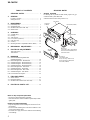 2
2
-
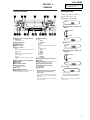 3
3
-
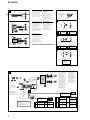 4
4
-
 5
5
-
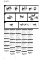 6
6
-
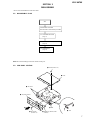 7
7
-
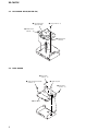 8
8
-
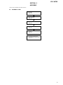 9
9
-
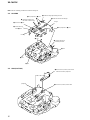 10
10
-
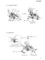 11
11
-
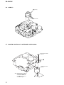 12
12
-
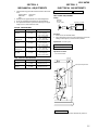 13
13
-
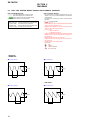 14
14
-
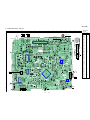 15
15
-
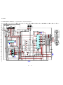 16
16
-
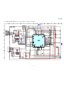 17
17
-
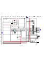 18
18
-
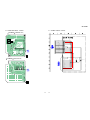 19
19
-
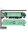 20
20
-
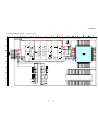 21
21
-
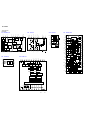 22
22
-
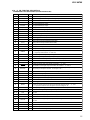 23
23
-
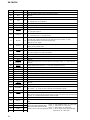 24
24
-
 25
25
-
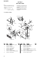 26
26
-
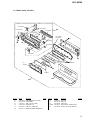 27
27
-
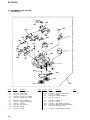 28
28
-
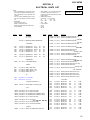 29
29
-
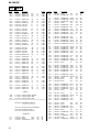 30
30
-
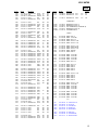 31
31
-
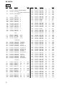 32
32
-
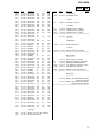 33
33
-
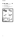 34
34


in andere talen
- English: Sony XR-CA670X User manual
- italiano: Sony XR-CA670X Manuale utente
- français: Sony XR-CA670X Manuel utilisateur
- Deutsch: Sony XR-CA670X Benutzerhandbuch
Gerelateerde papieren
Andere documenten
-
Shimano SL-MS52 Service Instructions
-
iGuzzini R961 Installatie gids
-
-
WowWee CHiP's de handleiding
-
Märklin 51099 User Instructions
-
Shimano RD-C201 Service Instructions
-
Paso C56/12-TW de handleiding
-
Shimano FC-R553 Service Instructions
-
Marantec Digital 342 de handleiding
-
Kenwood kenwood station monitor Handleiding